Embed Size (px)
Citation preview
http://iaeme.com/Home/journal/IJCIET 639 [email protected]
International Journal of Civil Engineering and Technology (IJCIET) Volume 9, Issue 1, January 2018, pp. 639 651, Article ID: IJCIET_09_01_062 –Available online at http://http://iaeme.com/Home/issue/IJCIET?Volume=9&Issue=1 ISSN Print: 0976-6308 and ISSN Online: 0976-6316
© IAEME Publication Indexed Scopus
DESIGN AND ANALYSIS OF FOOT OVER BRIDE USING STADDPRO
T. Prashanth
BE Student, Department of Civil Engineering, Saveetha School of Engineering, Chennai, Tamilnadu, India
V. Gokulnath
A itant Professor, Department of Civil Engineering, ssSaveetha School of Engineering, Chennai, Tamilnadu, India
ABSTRACT Footbridges are needed where there is a separate pathway must be supplied for
human beings to move site visitors flows or some physical impediment, along with a river. The masses they convey are, with regards to toll road or railway bridges, pretty modest, and in most circumstances a reasonably light structure is needed. They are,
but, often required to give a protracted clear span, and stiffness then becomes an crucial consideration. The bridges are frequently required very virtually on view to the general public and consequently the advent deserves careful attention.
Steel offers financial and appealing kinds of creation which suit all of the requirements demanded of a footbridge. Due to fast creation of a massive quantity of foot over bridges, many existing bridges placed in seismic zones are poor to face up to
earthquakes. In order fulfil the requirement of this improved visitors in the limited land the length of bridge will become medium to large. During an earthquake, failure of shape starts at factors of weak spot. Generally, weak spot is due to geometry, mass
discontinuity and stiffness of shape. In this undertaking we can layout for a most appropriate foot over bridge together with connection details and additionally
estimation of structural components at the side of foundation detailing for the foot over bridge structure. Key words: Foot over bridge, stiffness, earthquake, foundation etc..
Cite this Article: T. Prashanth and V. Gokulnath, Design and Analysis of Foot Over Bride Using Stadd Pro. International Journal of Civil Engineering and Technology,9(1), 2018, pp. 639 651. -http://iaeme.com/Home/issue/IJCIET?Volume=9&Issue=1
1. INTRODUCTION A steel truss footbridge was chosen as the best alternative for ranges of 10 to 20m, and
conceivably up to 25m, when it is unrealistic to build wharfs for transitional backings for pillar sort footbridges. It ought to likewise be considered for ranges more than 10m when docks are conceivable. The points of interest are thought to be:
T. Prashanth and V. Gokulnath
http://iaeme.com/Home/journal/IJCIET 640 [email protected]
The steel areas required ought to be accessible in principle asset focuses - The segments are probably going to be more uniform fit as a fiddle and size than timber segments,
permitting clear development of standard truss plans - Joints are less demanding to make than in timber trusses .
It ought to be conceivable to develop a standard outline in a medium measured workshop in advantageous estimated parts for transport to site. Get together on location includes darting the parts together and fitting a timber deck, errands that can be done under supervision of a capable expert by neighborhood craftsmen and others talented in utilizing their hands.
There are 3 levels at which the scaffold might be separated into parts for transportation: i. Singular individuals that are predrilled in the workshop, transported and catapulted together on location. For this situation each piece must be conveyed 24km starting from the road a precarious track to the footbridge site. This technique requires extensive exact penetrating of openings in the workshop and cautious get together on location. ii. The steel individuals are cut and welded up into boards in the workshop and the boards
penetrated for catapulting together. Boards are transported to site and darted together on location. This fundamentally lessens pre-penetrating and get together work. Boards may weigh up to around 100kg. iii. Boards are shot together in the workshop into modules that are transported to site. The modules are shot together on location. This will require the slightest get together work nearby.
Modules are probably going to weigh up to 300 to 400kg and will be very massive to transport. This technique is just liable to be conceivable if there is access for trucks
specifically to the footbridge site.
2. LITERATURE REVIEW Synthesis of quantitative and qualitative evidence for accident analysis in risk based highway planning, states the quantitative and qualitative evidence for the accident analysis road space
is a scarce resource so accumulation of future volume traffic is taken into account. The forecasting for the future volume traffic is calculated and appropriate junctions are provided (Ref.2) Physical method of traffic control, states the designing and control of signals at the various junctions on the basis of traffic flow and time period for the particular junction (Ref.3) Signal control at intersections, states the different methods of signal design and provides information about trial cycle method in which traffic volume count for every 15 minutes is taken into consideration for each junction (Ref.4) Road safety management using Weight-age analysis, states the method of weight-age analysis in which accident severity index is calculated and design criteria is decided based on the accident cost ratio (Ref.5)
Necessity People are unaware about traffic at junctions. While crossing the road this may lead to loss of life or injury, in order to reduce this effect there is a necessity for foot over bridge at most critical junctions: Regulation of the traffic flow and time delay. Reducing the number of accidents. Long sight clearance distance. Free movement of pedestrians.
Design and Analysis of Foot Over Bride Using Stadd Pro
http://iaeme.com/Home/journal/IJCIET 641 [email protected]
Scope Foot-over bridge for most critical junction. Estimation of structural component of foot-over Bridge. This project includes accident analysis and design of each junction. Traffic forecasting for future ten years with signal design.
3. METHODOLOGY The target of this venture is to outline a Foot over scaffold , alongside association
&foundation points of interest, and to dissect it, beneath said fundamental parameters are considered:
Broad writing review by alluding books, specialized papers did to comprehend essential idea of subject. i. Selection of a suitable model of foot over scaffold. ii. Computation of burdens and choice of preparatory cross-segments of different auxiliary individuals.
iii. Geometrical demonstrating and basic investigation of foot over scaffold for different stacking conditions according to IS Codal arrangements. iv. Interpretation of results. Following exploration must be completed for meeting the above destinations: v. Now foot over bridge are demonstrated and investigated as a three dimensional structure utilizing STADD.Pro V8 vi. STAAD pro highlights cutting edge UI, perception devices, capable investigation and plan motors with cutting edge limited component (FEM) and dynamic examination abilities. From show era, investigation and configuration to representation and result confirmation STAAD genius is the expert first decision. STAAD expert was created by rehearsing engineers far and wide. It has advanced more than 20 years and meets the necessities of ISO 9001 confirmation.
STAAD or (STAAD.Pro) is an auxiliary investigation and outline PC program initially created by Research Engineers International at Yorba Linda, CA in year 1997. In late 2005,
Research Engineers International was purchased a more established adaptation called STAAD-III for windows is utilized by Iowa State University for instructive purposes for
common and basic specialists. At first it was utilized for DOS-Window framework. The business form STAAD Pro is a standout amongst the most generally utilized basic
investigation and outline programming. It underpins a few steel, cement and timber configuration codes.
Configuration of Foot over Bridge A foot over bridge of 21m high is analyzed and designed.
The configuration of the tower is as follows: Span of bridge = 21 m
Height of bridge = 8.50 m Width of pedestrian = 3 m
Spacing between each truss = 3 m Type of truss = warren truss
T. Prashanth and V. Gokulnath
http://iaeme.com/Home/journal/IJCIET 642 [email protected]
4. ANALYSIS AND DESIGN Analysis and design is done by using STAAD.Pro software, with code book IRC: 24-
2001(Ref.11) .Load coming to the plate is calculated using the Equation 4.1
P=Ṕ-(40L-300/9)
P=Live load per meter.
Ṕ=4000 N/m2
L=Effective span in meters, 21 m.
P=3927 N/m2
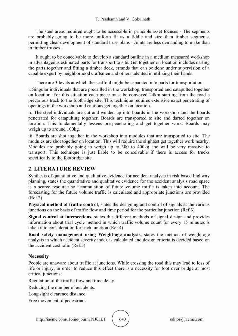
The structure model is shown from STAAD.Pro the structure is made by connecting node to node distance as shown in the Figure 4.1
Figure 4.1 Geometry of the structure
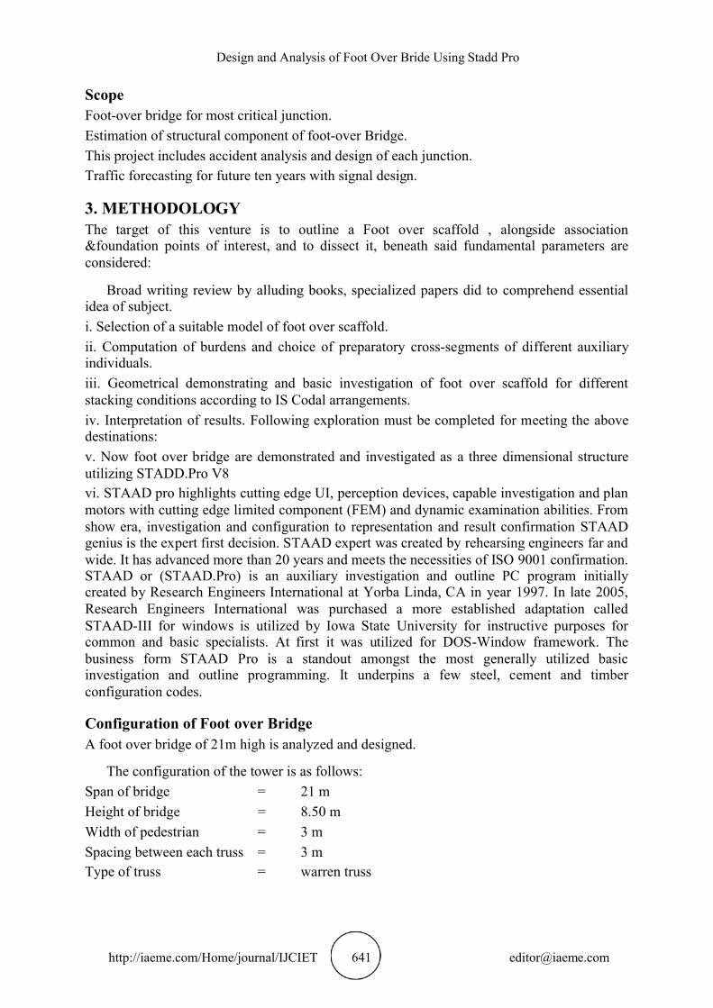
Figure 4.2 Section Property ISA 60*60*6
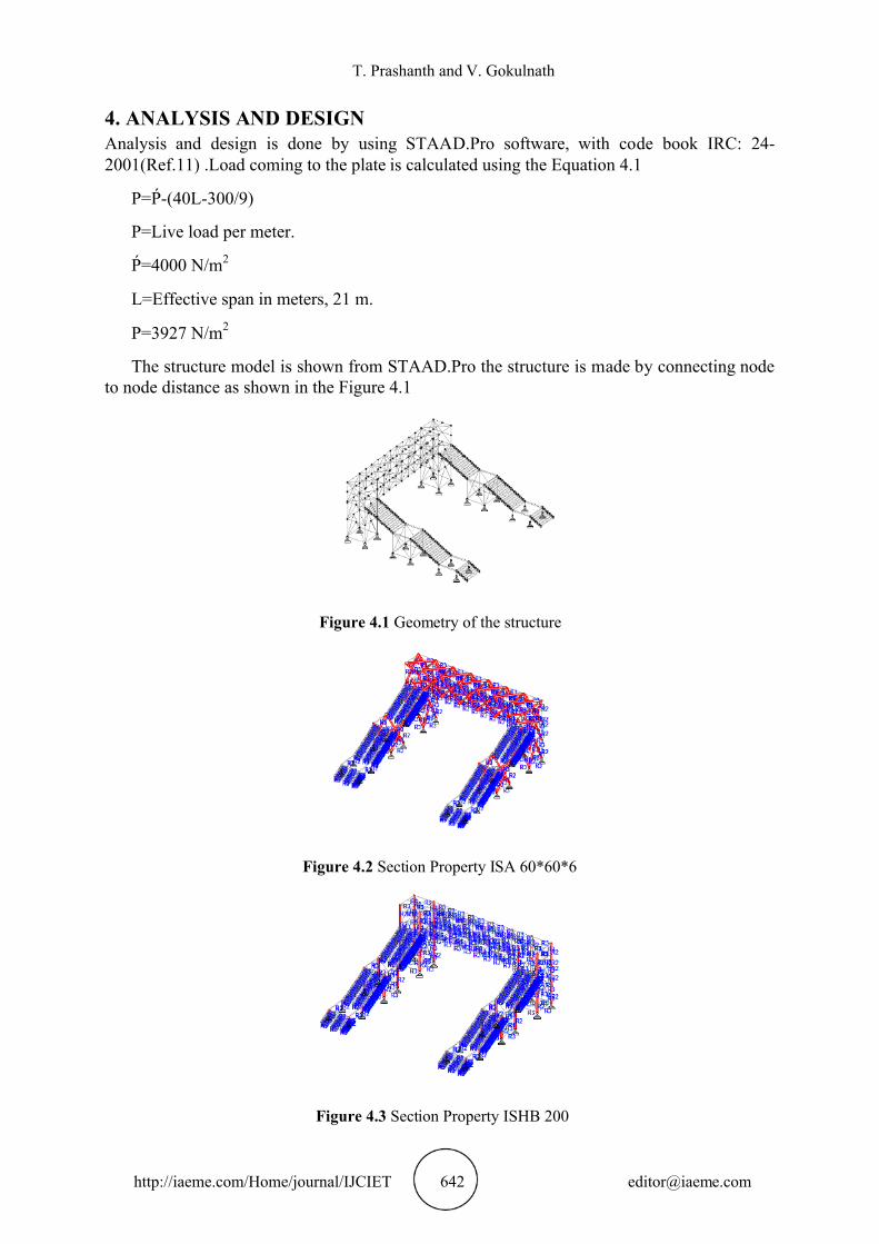
Figure 4.3 Section Property ISHB 200
Design and Analysis of Foot Over Bride Using Stadd Pro
http://iaeme.com/Home/journal/IJCIET 643 [email protected]
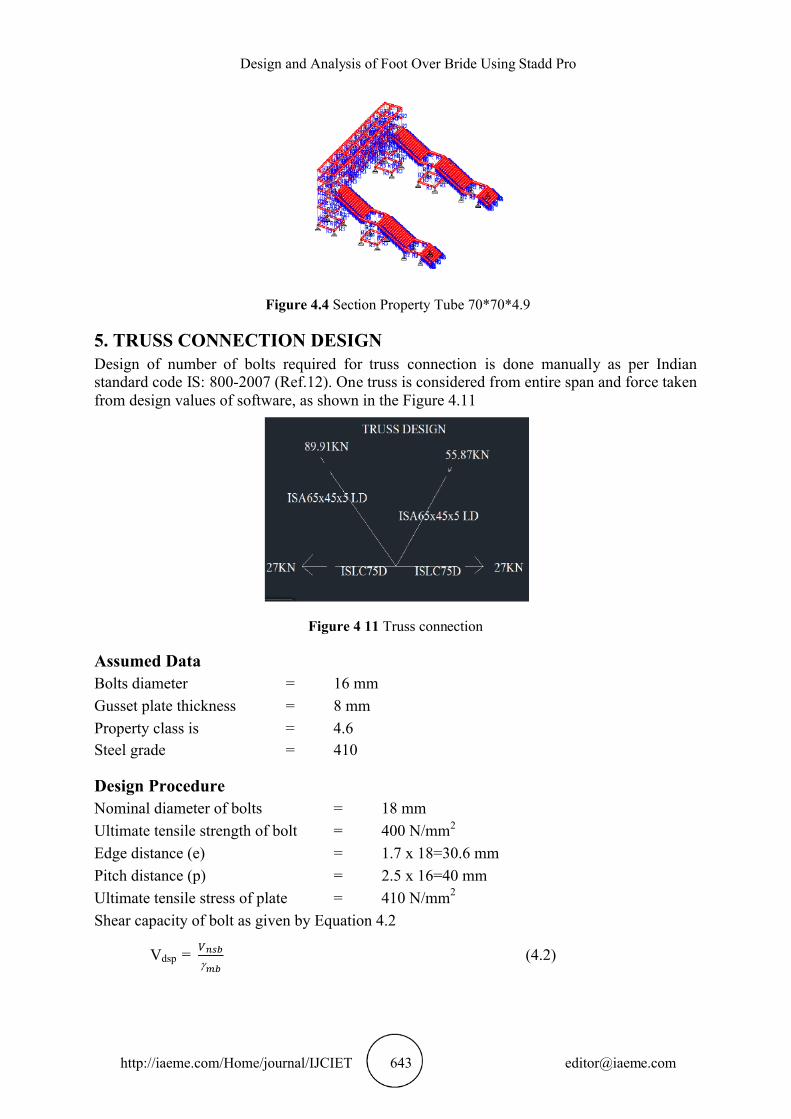
Figure 4.4 Section Property Tube 70*70*4.9
5. TRUSS CONNECTION DESIGN Design of number of bolts required for truss connection is done manually as per Indian
standard code IS: 800-2007 (Ref.12). One truss is considered from entire span and force taken from design values of software, as shown in the Figure 4.11
Figure 4 11 Truss connection
Assumed Data Bolts diameter = 16 mm
Gusset plate thickness = 8 mm Property class is = 4.6
Steel grade = 410
Design Procedure Nominal diameter of bolts = 18 mm
Ultimate tensile strength of bolt = 400 N/mm2 Edge distance (e) = 1.7 x 18=30.6 mm Pitch distance (p) = 2.5 x 16=40 mm
Ultimate tensile stress of plate = 410 N/mm2 Shear capacity of bolt as given by Equation 4.2
Vdsp =
(4.2)
T. Prashanth and V. Gokulnath
http://iaeme.com/Home/journal/IJCIET 644 [email protected]
Where,
=nominal shear capacity of bolts.
=partial safety factor is 1.25
Nominal shear capacity of bolts as given in the Equation 4.3
=
(4.3)
= 400 N/mm2 = 2 = 157 mm2
By substituting, shear capacity of bolt = 58 kN
Bearing capacity of bolt as given in Equation 4.4
Vnpb =
(4.4)
= 0.50
= 16 mm
= 8 mm
= 400 N/mm2
= 1.25
By substituting, bearing capacity of bolt = 51.2 KN
No of bolts required is force divided by bearing capacity of bolt
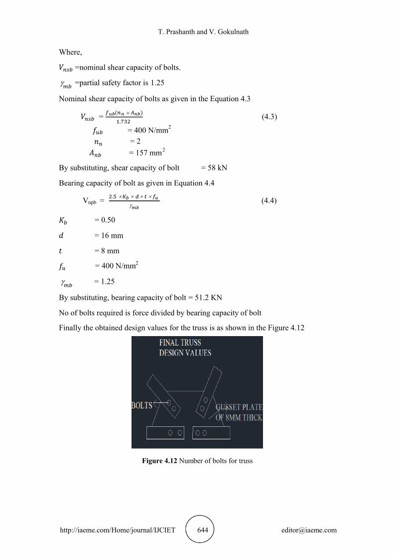
Finally the obtained design values for the truss is as shown in the Figure 4.12
Figure 4.12 Number of bolts for truss
Design and Analysis of Foot Over Bride Using Stadd Pro
http://iaeme.com/Home/journal/IJCIET 645 [email protected]
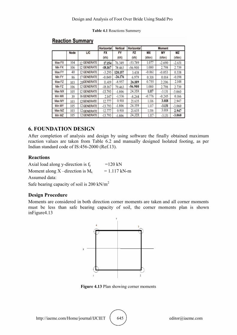
Table 4.1 Reactions Summery
6. FOUNDATION DESIGN After completion of analysis and design by using software the finally obtained maximum
reaction values are taken from Table 6.2 and manually designed Isolated footing, as per Indian standard code of IS:456-2000 (Ref.13).
Reactions Axial load along y-direction is fy =120 kN Moment along X direction is M– x = 1.117 kN-m Assumed data: Safe bearing capacity of soil is 200 kN/m2
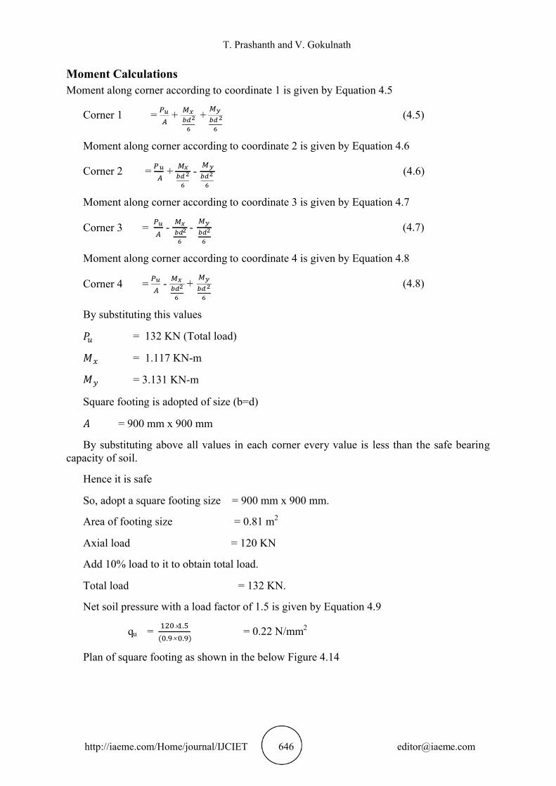
Design Procedure Moments are considered in both direction corner moments are taken and all corner moments
must be less than safe bearing capacity of soil, the corner moments plan is shown inFigure4.13
Figure 4.13 Plan showing corner moments
T. Prashanth and V. Gokulnath
http://iaeme.com/Home/journal/IJCIET 646 [email protected]
Moment Calculations Moment along corner according to coordinate 1 is given by Equation 4.5
Corner 1 =
+
+
(4.5)
Moment along corner according to coordinate 2 is given by Equation 4.6
Corner 2 =
+
-
(4.6)
Moment along corner according to coordinate 3 is given by Equation 4.7
Corner 3 =
-
-
(4.7)
Moment along corner according to coordinate 4 is given by Equation 4.8
Corner 4 =
-
+
(4.8)
By substituting this values
132 KN (Total load) =
= 1.117 KN- m
= 3.131 KN-m
Square footing is adopted of size (b=d)
= 900 mm x 900 mm
By substituting above all values in each corner every value is less than the safe bearing capacity of soil.
Hence it is safe
So, adopt a square footing size = 900 mm x 900 mm.
Area of footing size = 0.81 m2
Axial load = 120 KN
Add 10% load to it to obtain total load.
Total load = 132 K N.
Net soil pressure with a load factor of 1.5 is given by Equation 4.9
qu =
= 0.22 N/mm2
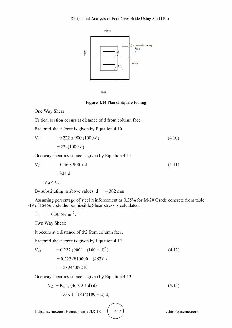
Plan of square footing as shown in the below Figure 4.14
Design and Analysis of Foot Over Bride Using Stadd Pro
http://iaeme.com/Home/journal/IJCIET 647 [email protected]
Figure 4.14 Plan of Square footing
One Way Shear:
Critical section occurs at distance of d from column face.
Factored shear force is given by Equation 4.10
Vul = 0.222 x 900 (1000-d) (4.10)
= 234(1000-d)
One way shear resistance is given by Equation 4.11
V cl = 0.36 x 900 x d (4.11)
= 324 d
Vul < Vcl
By substituting in above values, d = 382 mm
Assuming percentage of steel reinforcement as 0.25% for M-20 Grade concrete from table -19 of IS456 code the permissible Shear stress is calculated.
Tc = 0.36 N/mm2 .
Two Way Shear:
It occurs at a distance of d/2 from column face.
Factored shear force is given by Equation 4.12
V u2 = 0.222 (9002 (100 + d)– 2 ) (4.12)
= 0.222 (810000 (482)– 2 )
= 128244.072 N
One way shear resistance is given by Equation 4.13
Vc2 = Ks Tc (4(100 + d) d) (4.13)
= 1.0 x 1.118 (4(100 + d) d)
T. Prashanth and V. Gokulnath
http://iaeme.com/Home/journal/IJCIET 648 [email protected]
Vu2 < Vc2
By substituting in above values, d = 170 mm
From both one and two way shear, one way shear is most
Critical so , adopt d = 382 mm
Clear cover = 40 mm
Total overall depth, D = 460 mm
Reinforcement Details:
Mu = 222 x 1 x 0.40 x 0.40/2
= 17.76 kN- m/m
Steel required is calculated from Equation 4.14
Ast =
(1-
) (4.14)
b = 1000 mm
d = 382 mm
fck = 20 N/mm2
fy = 415 N/mm2
The stress value is given by Equation 4.15
R =
(4.15)
By substituting in above values Ast =130 mm2
Minimum steel required is given by Equation 4.16
But minimum steel is = 0.12% b x D (4.16)
= 552 mm2
So, adopt minimum steel of Ast = 552 mm2
Diameter of bars = 12 mm.
Spacing between the bars = 1000 x area of one bar/ Ast
= 225 mm c/c
Number of bars = 5
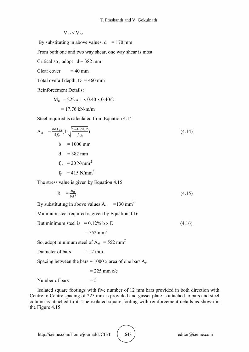
Isolated square footings with five number of 12 mm bars provided in both direction with Centre to Centre spacing of 225 mm is provided and gusset plate is attached to bars and steel column is attached to it. The isolated square footing with reinforcement details as shown in the Figure 4.15
Design and Analysis of Foot Over Bride Using Stadd Pro
http://iaeme.com/Home/journal/IJCIET 649 [email protected]
Figure 4.15 Reinforcement details
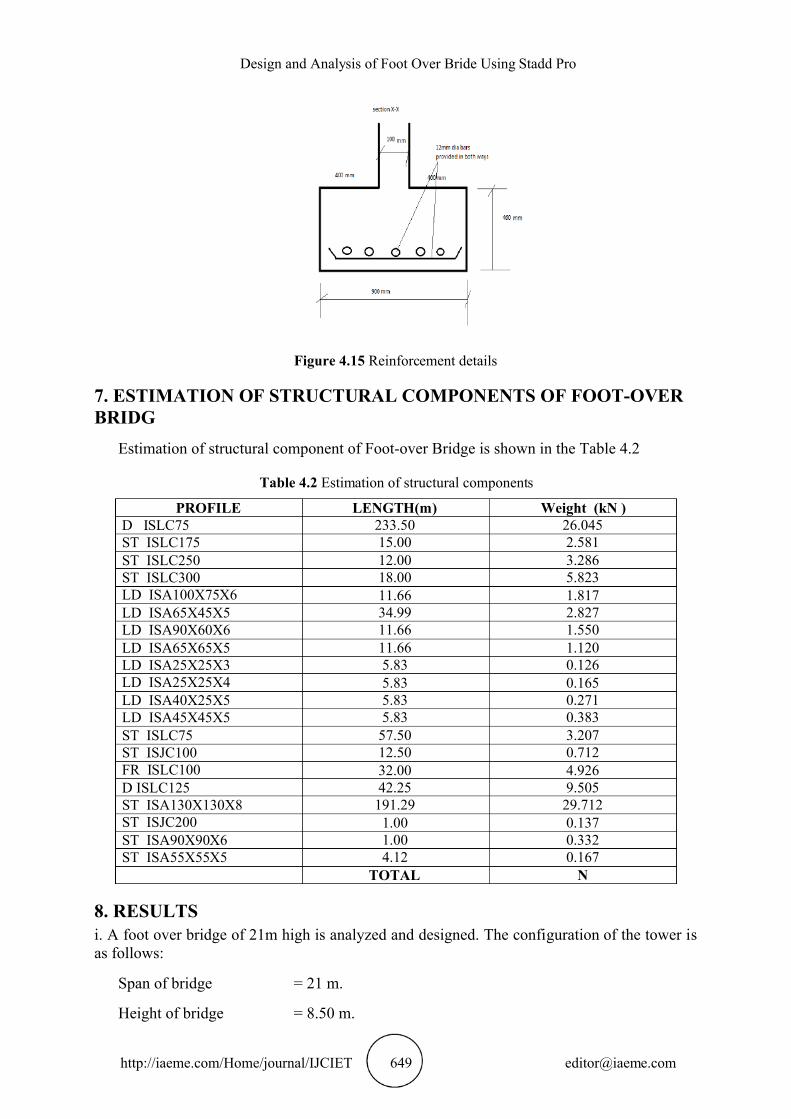
7. ESTIMATION OF STRUCTURAL COMPONENTS OF FOOT-OVER BRIDG
Estimation of structural component of Foot-over Bridge is shown in the Table 4.2
Table 4.2 Estimation of structural components
PROFILE LENGTH(m) Weight (kN ) D ISLC75 233.50 26.045 ST ISLC175 15.00 2.581 ST ISLC250 12.00 3.286 ST ISLC300 18.00 5.823 LD ISA100X75X6 11.66 1.817 LD ISA65X45X5 34.99 2.827 LD ISA90X60X6 11.66 1.550 LD ISA65X65X5 11.66 1.120 LD ISA25X25X3 5.83 0.126 LD ISA25X25X4 5.83 0.165 LD ISA40X25X5 5.83 0.271 LD ISA45X45X5 5.83 0.383 ST ISLC75 57.50 3.207 ST ISJC100 12.50 0.712 FR ISLC100 32.00 4.926 D ISLC125 42.25 9.505 ST ISA130X130X8 191.29 29.712 ST ISJC200 1.00 0.137 ST ISA90X90X6 1.00 0.332 ST ISA55X55X5 4.12 0.167 TOTAL N
8. RESULTS i. A foot over bridge of 21m high is analyzed and designed. The configuration of the tower is as follows:
Span of bridge = 21 m.
Height of bridge = 8.50 m.
T. Prashanth and V. Gokulnath
http://iaeme.com/Home/journal/IJCIET 650 [email protected]
Width of pedestrian =3 m.
Spacing between each truss = 3 m.
Type of truss = warren truss ii. Wind load is calculated using STADD.Pro V8i using IS: 875(Part 3)1987[3] . The total wind load acting on the structure is 2719 Kg. iii. Design has been done according to IS: 802 using STADD.Pro and following results are obtained:
Total weight of steel required in superstructure = 9758 Kg.
Materials required in Super Structure
Table 5.1 Structure design
S. No Profile Length(m) Weight(Kg)
1 ISA 60*60*6 120.33 2130
2 ISHB 200 170.63 2019
3 TUBE 70*70*4.9 418.69 5609
Total 9758
4) An isolated Foundation of square footings with five number of 12 mm bars provided in both direction with Centre to Centre spacing of 225 mm is provided and gusset plate is
attached to bars and steel column is attached to it. 5) Estimation of structural components of foot over bridge has been done and total weight id given as 94.61 KN
9. CONCLUSIONS In the present era, technology in construction is growing at a rapid phase which require
adequate knowledge in construction and designing for foot over bridge means like structural components of foot over bridge, columns, beams, loadings on foot over bridge etc. So there is need for proper estimation while designing and analyzing the foot over bridge.
If we could optimize the design of foot over bridge and use more resources, it will save a lot of money and resources. In olden day’s angle sections are used in making of truss in
structure of foot over bridge, currently tubular sections are preferred as they are more economical.
The wind load acting on foot over bridge will be comparatively less in magnitude as it is open structure with more openings, but failure of the towers is mainly due to High Intensity Winds and Earthquakes. So high factor of safety should be given to wind loads and seismic loads.
REFERENCES [1] IRC: 6-2014 Section II (Loads and Stresses) standard specifications and code of practice –
for road bridges.
[2] Engström, B., (2011). Design and analysis of deep beams, plates and other discontinuity regions. Department of Civil and Environmental Engineering, Chalmers
UniversityofTechnology, Göteborg
Design and Analysis of Foot Over Bride Using Stadd Pro
http://iaeme.com/Home/journal/IJCIET 651 [email protected]
[3] Blaauwendraad, J. (2010) Plates and FEM - Surprises and Pitfalls. Springer, Dordrecht. [4] -Emrani, M., Engström, B., Johansson, M. & Johansson, P. (2008): Bärande Al
konstruktioner Del 1 (Load bearing structures part 1. In Swedish). Department of Civil and Environmental Engineering, Chalmers University of Technology, Goteborg.
[5] Sustainable Bridges (2007): Non-Linear Analysis and Remaining Fatigue Life of Reinforced Concrete Bridges. Sustainable Bridges - Assessment for Future Traffic
Demands and Longer Lives.
[6] Durkee, Jackson, “Steel Bridge Construction”, Bridge Engineering Handbook, Crcpress, PP 45-58, 2000.
[7] -structure interaction: beneficial or G. Mylonakis and G. Gazetas. “Seismic soildetrimental”, Journal of Earthquake Engineering, 4(03):277–301, 2000.
[8] Granath, P., “Distribution of Support Reaction Against A Steel Girder On A Launching Shoe.” Journal of Constructional Steel Research, Vol. 47, No.3, Pp. 245-270, 1998.
[9] Durkee, Jackson L., “Foot Over Bridge Erected By Launching”, Journal Of The Structural Division, ASCE, Vol. 98, No. ST7, Proc. Paper 9028, Pp. 1443-1463, July,1997
[10] M. Ciampoli and P.E. Pinto. “Effects of soil-structure interaction on inelastic seismic response of bridge piers”. Journal of structural engineering, 121(5):806–814, 1995.
[11] M.Ciampoli and P.E. Pinto. “Effects of soil-structureinteraction on inelastic seismic response of bridge piers”. Journal of structural engineeri –ng, 121(5):806 814, 1995.
[12] J.C. Wilson and B.S. Tan. “Bridge abutments: assessing their influence on earthquake response of meloland road overpass.” Journal of Engineering Mechanics, 1 –16(8):1838
1856, 1990.
[13] S. Rajesh, Design of A Steel Foot Over Bridge In A Railway Station, International Journal of Civil Engineering and Technology, 8(8), 2017, pp. 1533 1548. –
AUTHOR DETAILS T.PRASHANTH, BE Student, Department of Civil Engineering, Saveetha School of
Engineering, Saveetha University, Chennai-602105. Mr. GOKULNATHV. , Asst. Professor, Department of Civil Engineering, Saveetha School of Engineering, Saveetha University, Chennai-602105.