Embed Size (px)
Citation preview
_____________________________________________________________________________________________________ *Corresponding author: E-mail: [email protected];
Journal of Experimental Agriculture International 42(7): 66-75, 2020; Article no.JEAI.60144 ISSN: 2457-0591 (Past name: American Journal of Experimental Agriculture, Past ISSN: 2231-0606)
Design and Manufacture of a Groundnut Sheller
Jean-Louis Comlan Fannou1,2, Guy Clarence Semassou1*, Kouamy Victorin Chegnimonhan3, Gbodja Sonoudouto1, Gérard Degan1,2,
Emile Adjibadé Sanya1,2, André Fanou1 and Germain Houndekpondji1
1Laboratory of Applied Energy and Mechanics (LEMA), Polytechnic School of Abomey-Calavi,
01 BP 2009 Cotonou, Benin. 2National Higher School of Energy and Processes Engineering (ENSGEP)/UNSTIM BP 2282 GOHO
Abomey, Benin. 3Thermics and Energy Laboratory of Nantes, (LTEN) - CNRS, UMR 6607, BP 50609, 44306 Nantes,
France.
Authors’ contributions
This work was carried out in collaboration among all authors. Author JLCF designed the study, performed the statistical analysis, wrote the protocol and wrote the first draft of the manuscript. Authors GCS and KVC managed the analyses of the study. Author GS managed the literature
searches. All authors read and approved the final manuscript.
Article Information
DOI: 10.9734/JEAI/2020/v42i730555 Editor(s):
(1) Dr. Rusu Teodor, University of Agricultural Sciences and Veterinary Medicine of Cluj-Napoca (USAMVCN), Romania. Reviewers:
(1) Tawanda Mushiri, University of Zimbabwe (UZ), Zimbabwe. (2) K. B. Bhushan, Vigyan Prasar, India.
Complete Peer review History: http://www.sdiarticle4.com/review-history/60144
Received 02 June 2020 Accepted 07 August 2020 Published 15 August 2020
ABSTRACT
Groundnut shelling is one of the important operations in the peanut harvesting process. Indeed, one of the major constraints in the groundnut production process in developing countries is the tedious task of shelling. It is with the aim of removing this constraint that a prototype groundnut sheller was produced including the dimensioning and design of all the constituent parts. The main components of the stripper are: The frame, the threshing machine, the concave, the fan and the motor. The nominal production capacity of the machine is 378 tons per year and per season with an electric power of 1.6 HP. The cost of the machine is US$ 475, affordable for small local producers. Finally, an economic profitability study of the machine was carried out and presented. It reveals a minimum production of 2.2 tons per year and per season to pay back the initial investment cost of the acquisition.
Original Research Article
Fannou et al.; JEAI, 42(7): 66-75, 2020; Article no.JEAI.60144
67
Keywords: Groundnut; shelling; husker; economic return.
1. INTRODUCTION Agriculture is the basis of Benin's economy. It contributes about 23% to Gross Domestic Product (GDP), provides about 75% of the State's export earnings and employs about 70% of the working population [1]. The agricultural sector is characterized by the predominance of family-type farms and is vulnerable to climatic variability. The production and transformation processes of some oilseeds such as groundnuts have not undergone major changes despite technological advances. Groundnut production in Benin faces many problems, especially during harvesting (de-seeding or threshing). Groundnut shelling is the operation of separating the groundnut pods from the hull. According to authors, it’s the most difficult operation during harvest [2]. Over the past few years, a great deal of successful work has been done on the design and construction of groundnut shellers. On the Beninese market, there are Japanese pedal threshers that were originally designed for rice and have been adapted for groundnut. But they were not suitable because the pod must be presented to the threshing elements while holding the leaves in hand to facilitate hulling, which results in low yields compared to manual work [3]. A small pedal-type threshing machine has been designed specifically for groundnuts by the Agronomy Division of Dharwar College of Agriculture in India, but the pod is made of wood, which makes it difficult to use in its present form in tropical Africa [4]. In the Congo, a prototype of a small crank-driven threshing machine has been developed that quadruples the yield of manual threshing, but requires human power to turn it [5]. Now that the areas sown by producers are increasingly large, non-motorized equipment is less suitable for carrying out the necessary work. It is becoming imperative to consider motorized equipment to facilitate the work. Recently, small motorized threshing machines in models ranging from 0.7 to 1.4 kW and weighing about 100 kilograms have appeared on the markets. Tests with these threshing machines in the Congo have yielded conclusive results, but only the bunch has to be presented to the thresher, which complicates operations. In addition, manual sorting is also essential after shelling [3]. The FAO threshing machine often requires several threshing stages, which increases space requirements. In addition, the machine is
expensive and difficult to manufacture. The CEEMAT (Centre for the Study and Experimentation of Agricultural Machinery in the Tropics, in French) threshing machine, on the other hand, has the disadvantage of having an irregularity in the threshing all along the threshing unit and a very high price compared to the capacity of our producers, which would limit the purchase by the producers [6]. The threshing machine designed by Cissé, whose manufacture requires gears, is very cumbersome [7]. In addition, the peanut pods are shelled by the feeding system (the two drums), which alters the conservation of the peanut pod. It is also intended only for dry peanuts only. Recent advances have been observed in the manufacture of peanut huskers or straw choppers in the local market, such as the groundnut shelling and separating machine made in India [8]. The design is very simple and eco-friendly which uses simple mechanism properties such as shelling system, automatic separating system and crushing chamber. But it has a major drawback which is labour intensive and also it consumes lots of time. Output is about 20-30 kg/hour. We can also cite the small scale Peanut shelling machine designed in Soudan which capacity was assumed to be 180 kg/hr [9]. The power system consists of the electric motor and belt and pulley drives by which it runs the shelling roller and the blower. The shelling is achieved by shelling beaters on the drum by both rubbing and beating against a stationary plate called concave. Clean seeds are obtained by the blower action which blows the chaff and other debris from seeds. On the same way, a power groundnut sheller was designed and fabricated in Farm Machinery and Postharvest Process Engineering (FMPE) Division, Bangladesh Agricultural Research Institute (BARI), Gazipur during 2011-13 [10]. The developed groundnut sheller was capable to work continuously and facilitate winnowing. Moreover, it can separate unshelled groundnut from the shelled groundnut with simple 0.37 kW electric motor. In Nigeria, a local groundnut sheller was modified to improved performance and incorporate cleaning unit [11]. The sheller was constructed from locally available materials with a compact and robust design that suit the local requirements. In some, several groundnut shelling equipment was reported in the literature. But threshing or husking of groundnuts with combustion engine
Fannou et al.; JEAI, 42(7): 66-75, 2020; Article no.JEAI.60144
68
threshers remains marginal in Benin. In fact, Beninese farmers face many constraints in terms of tool supply: Support, insufficient advice on choosing their equipment; low purchasing power, which does not allow them to have access to quality equipment; difficulties in obtaining credit, and spare parts are difficult to obtain for most imported equipment. It is in response to these constraints that this study aimed to design and build a locally manufactured husking machine that is innovative in terms of its robustness, low cost and adaptation to the capacity of the users.
2. MATERIALS AND METHODS
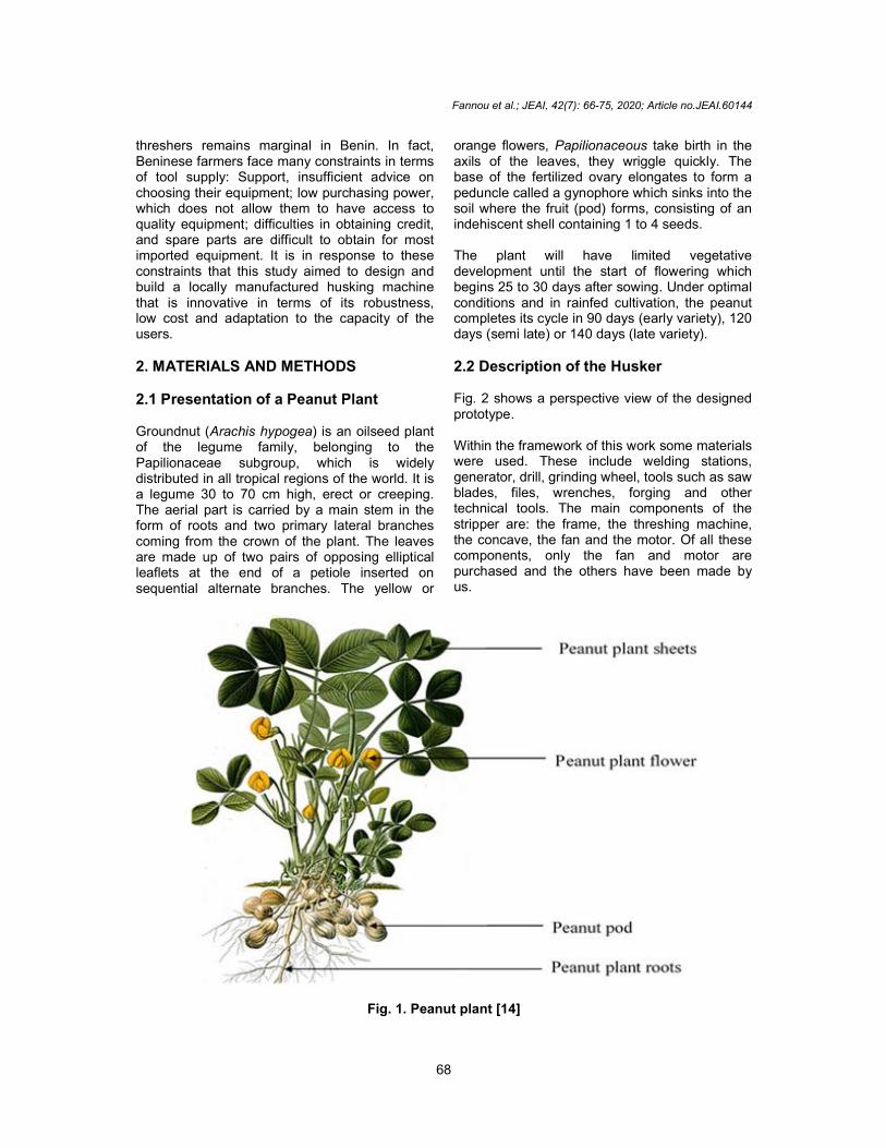
2.1 Presentation of a Peanut Plant Groundnut (Arachis hypogea) is an oilseed plant of the legume family, belonging to the Papilionaceae subgroup, which is widely distributed in all tropical regions of the world. It is a legume 30 to 70 cm high, erect or creeping. The aerial part is carried by a main stem in the form of roots and two primary lateral branches coming from the crown of the plant. The leaves are made up of two pairs of opposing elliptical leaflets at the end of a petiole inserted on sequential alternate branches. The yellow or
orange flowers, Papilionaceous take birth in the axils of the leaves, they wriggle quickly. The base of the fertilized ovary elongates to form a peduncle called a gynophore which sinks into the soil where the fruit (pod) forms, consisting of an indehiscent shell containing 1 to 4 seeds. The plant will have limited vegetative development until the start of flowering which begins 25 to 30 days after sowing. Under optimal conditions and in rainfed cultivation, the peanut completes its cycle in 90 days (early variety), 120 days (semi late) or 140 days (late variety).
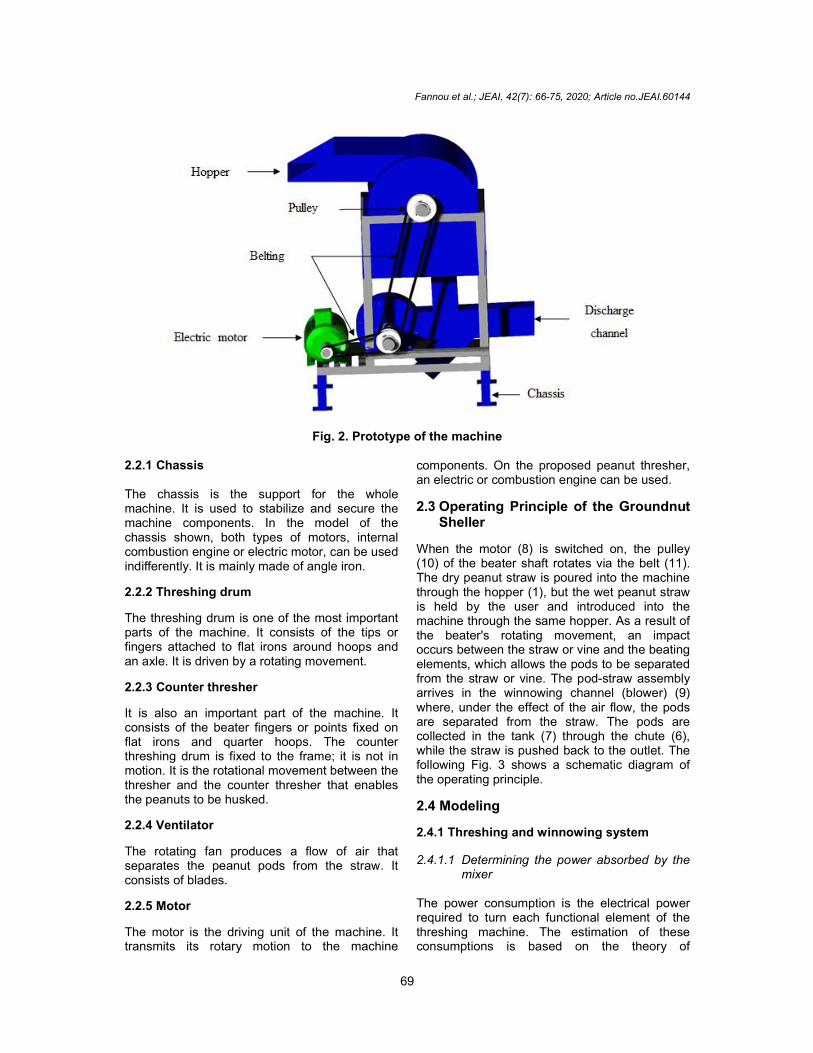
2.2 Description of the Husker Fig. 2 shows a perspective view of the designed prototype. Within the framework of this work some materials were used. These include welding stations, generator, drill, grinding wheel, tools such as saw blades, files, wrenches, forging and other technical tools. The main components of the stripper are: the frame, the threshing machine, the concave, the fan and the motor. Of all these components, only the fan and motor are purchased and the others have been made by us.
Fig. 1. Peanut plant [14]
Fannou et al.; JEAI, 42(7): 66-75, 2020; Article no.JEAI.60144
69
Fig. 2. Prototype of the machine 2.2.1 Chassis The chassis is the support for the whole machine. It is used to stabilize and secure the machine components. In the model of the chassis shown, both types of motors, internal combustion engine or electric motor, can be used indifferently. It is mainly made of angle iron.
2.2.2 Threshing drum
The threshing drum is one of the most important parts of the machine. It consists of the tips or fingers attached to flat irons around hoops and an axle. It is driven by a rotating movement.
2.2.3 Counter thresher
It is also an important part of the machine. It consists of the beater fingers or points fixed on flat irons and quarter hoops. The counter threshing drum is fixed to the frame; it is not in motion. It is the rotational movement between the thresher and the counter thresher that enables the peanuts to be husked.
2.2.4 Ventilator
The rotating fan produces a flow of air that separates the peanut pods from the straw. It consists of blades.
2.2.5 Motor
The motor is the driving unit of the machine. It transmits its rotary motion to the machine
components. On the proposed peanut thresher, an electric or combustion engine can be used.
2.3 Operating Principle of the Groundnut Sheller
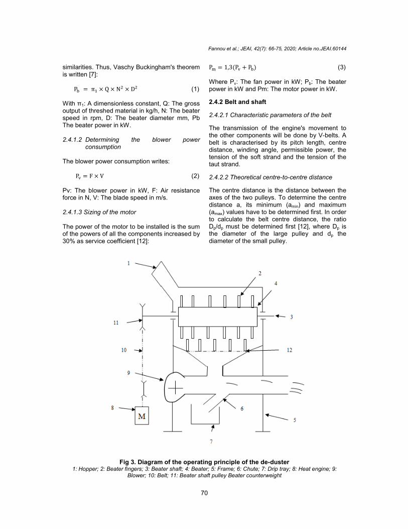
When the motor (8) is switched on, the pulley (10) of the beater shaft rotates via the belt (11). The dry peanut straw is poured into the machine through the hopper (1), but the wet peanut straw is held by the user and introduced into the machine through the same hopper. As a result of the beater's rotating movement, an impact occurs between the straw or vine and the beating elements, which allows the pods to be separated from the straw or vine. The pod-straw assembly arrives in the winnowing channel (blower) (9) where, under the effect of the air flow, the pods are separated from the straw. The pods are collected in the tank (7) through the chute (6), while the straw is pushed back to the outlet. The following Fig. 3 shows a schematic diagram of the operating principle.
2.4 Modeling
2.4.1 Threshing and winnowing system
2.4.1.1 Determining the power absorbed by the mixer
The power consumption is the electrical power required to turn each functional element of the threshing machine. The estimation of these consumptions is based on the theory of
similarities. Thus, Vaschy Buckingham's theorem is written [7]:
P� = π� × Q × N � × D� With π1: A dimensionless constant, Q: output of threshed material in kg/h, N: speed in rpm, D: The beater diameter mm, Pb The beater power in kW. 2.4.1.2 Determining the blower power
consumption The blower power consumption writes:
P� = F × V Pv: The blower power in kW, F: Air force in N, V: The blade speed in m/s. 2.4.1.3 Sizing of the motor The power of the motor to be installed is the sum of the powers of all the components increased by 30% as service coefficient [12]:
Fig 3. Diagram of the operating principle of the de1: Hopper; 2: Beater fingers; 3: Beater shaft; 4: Beater; 5: Frame; 6: Chute; 7: Drip tray; 8: Heat engine; 9:
Blower; 10: Belt; 11: Beater shaft pulley Beater counterweight
Fannou et al.; JEAI, 42(7): 66-75, 2020; Article no.
70
similarities. Thus, Vaschy Buckingham's theorem
(1)
dimensionless constant, Q: The gross output of threshed material in kg/h, N: The beater
beater diameter mm, Pb
Determining the blower power
blower power consumption writes:
(2)
Air resistance blade speed in m/s.
The power of the motor to be installed is the sum powers of all the components increased by
P� = 1,3(P� + P�) Where Pv: The fan power in kW; Ppower in kW and Pm: The motor power in kW.
2.4.2 Belt and shaft
2.4.2.1 Characteristic parameters of the belt
The transmission of the engine's movement to the other components will be done by Vbelt is characterised by its pitch length, centre distance, winding angle, permissible power, the tension of the soft strand and the tension of the taut strand.
2.4.2.2 Theoretical centre-to-centre distance
The centre distance is the distance between the axes of the two pulleys. To determine the centre distance a, its minimum (amin) and maximum (amax) values have to be determined first. In order to calculate the belt centre distance, the ratio Dp/dp must be determined first [12], where Dthe diameter of the large pulley and ddiameter of the small pulley.
Diagram of the operating principle of the de-duster 1: Hopper; 2: Beater fingers; 3: Beater shaft; 4: Beater; 5: Frame; 6: Chute; 7: Drip tray; 8: Heat engine; 9:
Blower; 10: Belt; 11: Beater shaft pulley Beater counterweight
; Article no.JEAI.60144
(3)
fan power in kW; Pb: The beater motor power in kW.
Characteristic parameters of the belt
The transmission of the engine's movement to the other components will be done by V-belts. A belt is characterised by its pitch length, centre distance, winding angle, permissible power, the
and the tension of the
centre distance
The centre distance is the distance between the axes of the two pulleys. To determine the centre
) and maximum determined first. In order
to calculate the belt centre distance, the ratio must be determined first [12], where Dp is
the diameter of the large pulley and dp the
1: Hopper; 2: Beater fingers; 3: Beater shaft; 4: Beater; 5: Frame; 6: Chute; 7: Drip tray; 8: Heat engine; 9:
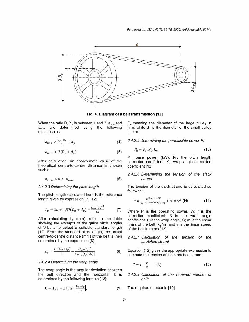
Fig. 4. When the ratio Dp/dp is between 1 and 3, aamax are determined using the following relationships:
���� ≥�� � ��
�+ ��
���� < 3(�� + �� )
After calculation, an approximate value of the theoretical centre-to-centre distance is chosen such as:
a��� ≤ a < a���
2.4.2.3 Determining the pitch length
The pitch length calculated here is the reference length given by expression (7) [12].
�� = 2� + 1,57��� + ���+���� �
��
After calculating Lp (mm), refer to the table showing the excerpts of the guide pitch lengths of V-belts to select a suitable standard length [12]. From the standard pitch length, the actual centre-to-centre distance (mm) of the belt is then determined by the expression (8):
�� =��
�
���� � �� �
�−
��� � �� ��
�����
���� � �� ��
2.4.2.4 Determining the wrap angle
The wrap angle is the angular deviation between the belt direction and the horizontal. It is determined by the following formula [12]:
θ = 180 − 2sin� � �� � � ��
���,
Fannou et al.; JEAI, 42(7): 66-75, 2020; Article no.
71
Diagram of a belt transmission [12]
is between 1 and 3, amin and are determined using the following
(4)
(5)
After calculation, an approximate value of the centre distance is chosen
(6)
Determining the pitch length
The pitch length calculated here is the reference
�� ��
� (7)
(mm), refer to the table showing the excerpts of the guide pitch lengths
belts to select a suitable standard length [12]. From the standard pitch length, the actual
centre distance (mm) of the belt is then
�� (8)
Determining the wrap angle
The wrap angle is the angular deviation between the belt direction and the horizontal. It is determined by the following formula [12]:
(9)
Dp meaning the diameter of the large pulley in mm, while dp is the diameter of the small pulley in mm. 2.4.2.5 Determining the permissible power P
�� = ��.��.��
Pb, base power (kW); KL, the pitch correction coefficient; Kθ: wrap angle correction coefficient [12].
2.4.2.6 Determining the tension of the slack strand
The tension of the slack strand is calculated as followed:
t=���θ ��� (β �)⁄⁄
�(� �� ��θ ��� (β �)⁄⁄ )+ m × v� (N)
Where P is the operating power, W; f is the correction coefficient; β is the wrap angle coefficient; θ is the wrap angle, C; m is the linear mass of the belt, kg/m
3 and v is the linear speed
of the belt in mm/s [12]. 2.4.2.7 Calculation of the tension of the
stretched strand Equation (12) gives the appropriate expression to compute the tension of the stretched strand:
T = �+�
� (N)
2.4.2.8 Calculation of the required number of
belts The required number is [10]:
; Article no.JEAI.60144
meaning the diameter of the large pulley in is the diameter of the small pulley
Determining the permissible power Pa
(10)
, the pitch length : wrap angle correction
Determining the tension of the slack
The tension of the slack strand is calculated as
(N) (11)
the operating power, W; f is the correction coefficient; β is the wrap angle coefficient; θ is the wrap angle, C; m is the linear
and v is the linear speed
Calculation of the tension of the
Equation (12) gives the appropriate expression to compute the tension of the stretched strand:
(12)
Calculation of the required number of
Fannou et al.; JEAI, 42(7): 66-75, 2020; Article no.JEAI.60144
72
n =��
��, (13)
Where Ps is the operating power in kW; Pa is the permissible power in kW. 2.4.3 Calculation of shaft parameters To calculate the diameter of the shafts, the Westinghouse code was used [7].
d = ���× ��
�� (
�
��)� + (
� �
��)��
�/�
(N) (14)
With C: The transmissible torque N.mm; Mt: The total bending moment N.mm; Re: The elastic strength MPa; σD: the endurance limit MPa and FS the safety factor. After the shaft diameter has been calculated, its safety is checked according to the Von Mises-Hencky theorem [7]:
n =� ′�
σ′ (15)
Where σ′� is the plastic strength and σ′ the
bending strength.
2.4.4 Estimated cost of the machine
The estimated global cost (Cg) of the machine depends on the parameters listed below [13]:
Raw material costs (Cm); Design office cost (Ce); Machining cost of Cu parts; Manufacturing cost Cf.
Thus,
�� = �� + �� + �� + �� (16)
2.4.5 Calculating the economic viability of the machine
The calculation of the economic profitability of the groundnut thresher is made starting from a minimum threshold of 200 Kg of groundnut (leaves and pods). For this calculation, the income, variable and fixed expenses, gross margin, net margin and the threshold quantity of groundnut to be threshed per year are taken into account [1].
2.4.5.1 Calculation of income
With this peanut thresher 200 Kg of processed peanuts (tops + pod) provide 50 kg of peanut
pods, i.e. 25% of peanut pods. Currently the price per kilogram of groundnut is 225 XOF. Thus the recipes are as follows:
Total recipe=P×Q (17)
With Q the quantity of groundnut processed per 200 Kg of raw groundnut (hull + pod) and P the price of one kilogram of groundnut pod.
2.4.5.2 Calculation of the variable charges
There are two types of expenses. The purchase of the 200 Kg of raw groundnut (leaves + pod) and all other expenses that go into the threshing of the groundnut (fuel, labour, repair and maintenance of equipment). Variable charges (costs) are equal to the sum of all expenses directly involved in threshing.
2.4.5.3 Calculation of the fix charges
Fixed costs correspond to expenditure incurred regardless of the quantity produced. They include expenditure on replacement of equipment after five years of use and costs that must be engaged even before production begins (workshop, purchase of machinery, etc.).
Fix cost =��× �
�� (18)
With At: The total annuity; Q: The base quantity; Qa: The annual quantity that can be shelled.
2.4.5.4 Calculation of gross and net margin
The producer's gain after threshing the peanut is assessed by calculating gross and net margins.
Gross margin = Revenue-Variable costs (19)
The difference between gross margin and depreciation and amortization expense is the net margin. It is this margin that takes fixed costs into account.
Net margin= Gross margin - depreciation expense (20)
2.4.5.5 Break-even Quantity Calculation
The break-even point is calculated (SRCA) [1]:
�� �� =������ ����� ���� × ������
����� ������ (21)
2.4.6 Calculation of the percentage of equipment used
The percentage of the capacity of the equipment used is the percentage of production for which
Fannou et al.; JEAI, 42(7): 66-75, 2020; Article no.JEAI.60144
73
the gross margin covers the fixed costs. This percentage is calculated by the following formula:
% Capacity used= �� �� × ���
������ (22)
2.4.7 Calculation of technical capacity
Capacité techniqque= Q × Nm × Hj × Dv (23)
With Q: Hourly output; Nm: Number of working months; Hj: Daily working hour; Dv: Lifetime
2.4.8 Calculation of the threshold quantity
Threshold quantity = Useful capacity×Technical capacity (24)
3. RESULTS AND DISCUSSION
3.1 Results The results obtained from the application of the mathematical models of each part of the threshing machine are shown in Tables 1 to 3.
Table 1. Value the characteristic parameter of the threshing, winnowing system and typical
motor
Parameter Value Threshing diameter Rotation frequency (tr/min) 600
Hoyrly flow rate Q (kg/h) 700 Threshing drum diameter D (mm) 300 Power consumption Pb (W) 593,64
Winnowing system Drag force F (N) 11,2 Blade speed V (m/s) 5,86 Power consumption Pv (W) 262,67
Motor Driving power Pm (W) 1113 Engine speed N (tr/mn) 1600
Table 2. Value of the characteristic parameter of the belt drive system between motor and
blower, thresher and blower and parameter of the shafts Parameter Value Drive system between motor and blower
Operating power Ps (W) 1113 Belt linear speed V (m/s) 5,94 Centre distance a (mm) 407 Winding angle θ (°) 161,44 Belt pitch length Lp (mm) 12,5 Basic power Pb (kW) 0,83 Permissible power Pa (kW) 0,737 Number of belts n 2 Soft strand strength t (N) 204,88 Strand strength T (N) 392,28
Drive system between thresher and blower
Operating power Ps (W) 771,7 Belt linear speed V (m/s) 9,92 Centre distance a (mm) 214,13 Winding angle θ (°) 175,7 Belt pitch length Lp (mm) 719 Basic power Pb (kW) 2 Permissible power Pa (kW) 1,49 Number of belts n 1 Soft strand strength t (N) 91,17 Strand strength T (N) 168,96
Parameters of the shafts
Diameter d (mm) 35,2 Safety factor according to Von Mises-Hencky 7,31 Diameter d (mm) 20 Safety factor according to Von Mises-Hencky 3
Fannou et al.; JEAI, 42(7): 66-75, 2020; Article no.JEAI.60144
74
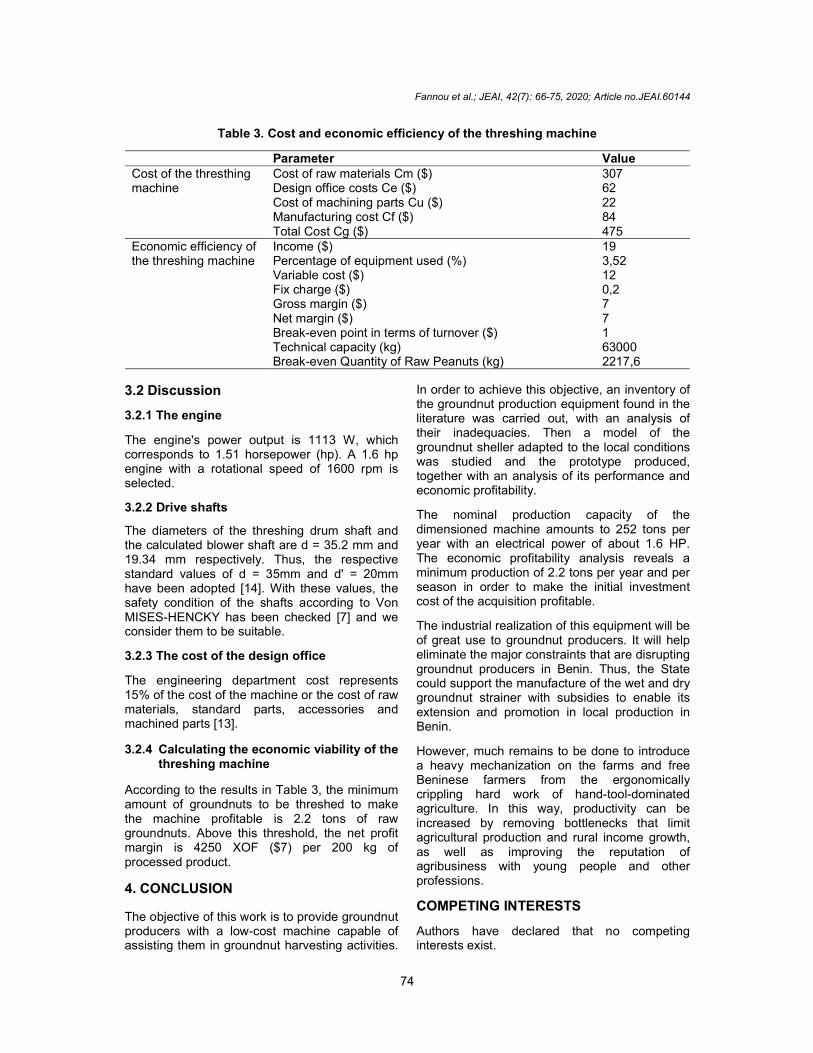
Table 3. Cost and economic efficiency of the threshing machine
Parameter Value Cost of the thresthing machine
Cost of raw materials Cm ($) 307 Design office costs Ce ($) 62 Cost of machining parts Cu ($) 22 Manufacturing cost Cf ($) 84 Total Cost Cg ($) 475
Economic efficiency of the threshing machine
Income ($) 19 Percentage of equipment used (%) 3,52 Variable cost ($) 12 Fix charge ($) 0,2 Gross margin ($) 7 Net margin ($) 7 Break-even point in terms of turnover ($) 1 Technical capacity (kg) 63000 Break-even Quantity of Raw Peanuts (kg) 2217,6
3.2 Discussion
3.2.1 The engine
The engine's power output is 1113 W, which corresponds to 1.51 horsepower (hp). A 1.6 hp engine with a rotational speed of 1600 rpm is selected.
3.2.2 Drive shafts
The diameters of the threshing drum shaft and the calculated blower shaft are d = 35.2 mm and 19.34 mm respectively. Thus, the respective standard values of d = 35mm and d' = 20mm have been adopted [14]. With these values, the safety condition of the shafts according to Von MISES-HENCKY has been checked [7] and we consider them to be suitable.
3.2.3 The cost of the design office
The engineering department cost represents 15% of the cost of the machine or the cost of raw materials, standard parts, accessories and machined parts [13].
3.2.4 Calculating the economic viability of the threshing machine
According to the results in Table 3, the minimum amount of groundnuts to be threshed to make the machine profitable is 2.2 tons of raw groundnuts. Above this threshold, the net profit margin is 4250 XOF ($7) per 200 kg of processed product.
4. CONCLUSION
The objective of this work is to provide groundnut producers with a low-cost machine capable of assisting them in groundnut harvesting activities.
In order to achieve this objective, an inventory of the groundnut production equipment found in the literature was carried out, with an analysis of their inadequacies. Then a model of the groundnut sheller adapted to the local conditions was studied and the prototype produced, together with an analysis of its performance and economic profitability.
The nominal production capacity of the dimensioned machine amounts to 252 tons per year with an electrical power of about 1.6 HP. The economic profitability analysis reveals a minimum production of 2.2 tons per year and per season in order to make the initial investment cost of the acquisition profitable.
The industrial realization of this equipment will be of great use to groundnut producers. It will help eliminate the major constraints that are disrupting groundnut producers in Benin. Thus, the State could support the manufacture of the wet and dry groundnut strainer with subsidies to enable its extension and promotion in local production in Benin.
However, much remains to be done to introduce a heavy mechanization on the farms and free Beninese farmers from the ergonomically crippling hard work of hand-tool-dominated agriculture. In this way, productivity can be increased by removing bottlenecks that limit agricultural production and rural income growth, as well as improving the reputation of agribusiness with young people and other professions.
COMPETING INTERESTS
Authors have declared that no competing interests exist.
Fannou et al.; JEAI, 42(7): 66-75, 2020; Article no.JEAI.60144
75
REFERENCES 1. Sossou CH. Support for the course in
economics of agricultural holdings. University of Abomey-Calavi. 2019;3-11.
2. Ministry of Agriculture, Livestock and Fisheries. Relaunch of groundnut cultivation in Benin. 2000;2-3,5-7,13-15.
3. Delhove: Information note on small farm equipment. Agricultural. Inst. Nat. Agro Study. Congo: Yangambi. 1960;79.
4. Hosmani, Patil. A peanut threshing machine that does the work of five men. Indian Farming. 1964;XIV(3):17.
5. Martin G. Washing peanuts from the mouth (Advice I. R. H. O.). Oilseeds. XVII(6):549- 553.
6. Laeousse G, Gordron E. Mechanization of peanut cultivation, particularly in the French-speaking countries of tropical Africa and Madagascar. O.R.S.T.O.M. Reference Collection n° 1515. 1965;18:20-21.
7. Papa C. Study and design of a peanut threshing machine. Polytechnic School of Thiès. 1988;14-19,21-22,31-40,59.
8. Adwal R, Ghadge R, Awad S, Khare GN. A review on design and fabrication of
groundnut shelling and separate machine. International Research Journal of Engineering and Technology (IRJET). 2017;04.
9. Khabbab M, Khalid B, El Kareem A. Design and manufacture of peanut shelling machine. University of Khartoum, Faculty of Engineering, Mechanical Department and Agricultural and Biological Department; 2015.
10. Hoque MA, Hossain MZ, Hossain MA. Design and development of a power groundnut sheller, Bangladesh. J. Agril. Res. 2018;43(4):631-645.
11. Muhammad AI, Isiaka M. Modification of locally developed groundnut sheller. Bayero Journal of Engineering and Technology (BJET). 2019;14(2):169-182.
12. Fanchon JL. Industrial Science and Technology Guide; Nathan/VUEF, AFNOR. 2001;246,261,269,293,376,379-383.
13. Fanou A. Study, design and realisation of a banana trunk shredding mill. Polytechnic School of Abomey-Calavi. 2019;74- 75.
14. Available:https://en.wikipedia.org/wiki/Peanut
_________________________________________________________________________________ © 2020 Fannou et al.; This is an Open Access article distributed under the terms of the Creative Commons Attribution License (http://creativecommons.org/licenses/by/4.0), which permits unrestricted use, distribution, and reproduction in any medium, provided the original work is properly cited.
Peer-review history: The peer review history for this paper can be accessed here:
http://www.sdiarticle4.com/review-history/60144


