Embed Size (px)
Citation preview

Fusion Engineering and Design 80 (2006) 181–200
Design approach of the ARIES-AT power coreand vacuum vessel cost assessment
Lester M. Waganera,∗, Farrokh Najmabadib, Mark Tillackb,Xueren Wangb, Laila El-Guebalyc, and
The ARIES Teama The Boeing Company, Mail Code S111-1300, PO Box 516, St. Louis, MO 63166, USA
b University of California at San Diego, San Diego, CA, USAc University of Wisconsin, Madison, WI, USA
Accepted 1 June 2005Available online 10 October 2005
Abstract
The complexity of fusion power plants require the integration of many diverse and important system requirements to achievea design approach that is viewed as a commercially viable electric plant. The ARIES-AT power core design builds upon ahistory of fusion power core designs that evolve along with physics and engineering advances. The baseline design point isoptimized for maximum performance and minimum capital cost based upon the ARIES systems code results, along with physicsa high planta vacuumv res could ber©
K
1
p
f
(
makwer
asma
entsringsigne
0
nd engineering analyses. The ARIES-AT power core is designed to be quick and easily maintainable to achievevailability. A key element to achieve the high availability is the integration of the core elements with the design of theessel. The vacuum vessel design is developed in more detail to assure the key assembly and maintenance featuealized at an affordable cost.
2005 Elsevier B.V. All rights reserved.
eywords: ARIES; Fusion; Tokamak; Maintenance; Availability; Power core; Vacuum vessel
. Power core design philosophy
The improved physics understanding of advancedlasma confinement modes, which have been advanced
∗ Corresponding author. Tel.: +1 314 233 8617;ax: +1 314 234 4506.
E-mail address: [email protected]. Waganer).
in recent years, have lead to more efficient tokaplasma and power core configurations for poplant designs. The prior ARIES-RS[1] power coredesign reflects many of the new reverse shear plconfinement improvements. The ARIES-AT[2]design improves upon these plasma confinemto incorporate several new plasma and engineeadvancements. The goal of the engineering deof ARIES-AT is to increase the credibility of th
920-3796/$ – see front matter © 2005 Elsevier B.V. All rights reserved.doi:10.1016/j.fusengdes.2005.06.353

182 L.M. Waganer et al. / Fusion Engineering and Design 80 (2006) 181–200
Fig. 1. Schematic representation of power core elements in cross-section and plan views.
power core engineering by achieving a high degreeof systems integration while obtaining a maintainabledesign with high availability for a reasonable capitaland operational cost.
The starting point is to understand how the mainte-nance approach affects the power core design. Waganerconducts an analysis concluding that the ARIES-ATpower core maintenance approach[3] permits a com-plete power core sector to be extracted and replacedwith a refurbished unit from the plant hot cell. This isdetermined to be the most reliable and expedient coremaintenance approach for a tokamak power core. Thisapproach was previously used in the ARIES-RS powercore design[4].
Extracting a complete power core sector requirespositioning the poloidal field (PF) coils in regionsabove and below the removable power core sectorcomponents. All other systems, such as the vacuum
pumping ports and RF, or neutral beam systems, arelocated away from this central, outboard region. Thetoroidal field (TF) coils are sufficiently large to pro-vide adequate clearance between the coils to extract acomplete power core sector. The traditional constanttension coil shape is changed to a wider “D” shape toimprove the maintenance access. These D-shaped coilsrequire additional coil structural reinforcement.Fig. 1illustrates the wider toroidal coils and the relocationof the poloidal field coils to enable the 1/16 sector tobe withdrawn out between them. The plasma majorradius, minor radius, and elongation are drawn to scalealong with representative thickness of the power coreelements.
All life-limited (non life-of-plant) elements havenearly identical power core lifetimes to improve theplant availability. Removal and replacement of thepower core sectors containing all these life-limited

L.M. Waganer et al. / Fusion Engineering and Design 80 (2006) 181–200 183
elements significantly improve the change out of life-limited components. Otherwise, the plant availabilitydecreases due to many plant shutdowns to replacesmaller components on non-optimized maintenanceschedules. El-Guebaly[5] addresses this issue in thedesign of ARIES-AT by tailoring the materials, place-ment of the materials, and the component thicknesseswith compatible lifetimes for the inner and outer blan-kets and divertor modules. On the outboard region, anadditional second blanket component is employed toenhance the tritium breeding and energy extraction.This second blanket is a life-of-plant component, whichgreatly helps the plant availability. Just outside the blan-kets and divertors, a life-of-plant shield region providesadequate shielding for the superconducting TF and PFmagnets.
These blanket and shield components are designedto operate at high temperatures (≥1000◦C) to extractthe maximum useful thermal energy from the fusionneutrons. Careful routing of the lithium lead (LiPb)coolant lines provides maximum cooling to the highestheat flux regions, principally in the divertors and thefirst walls. Since the shields encompass or encircle allthe life-limited core components, they are designed asstructural elements for attachment of the life-limitedcomponents. This approach enables a complete self-supporting power core sector that is withdrawn andreinserted into the power core as a self-contained sector.This integral unit is the entirety of the high-temperatureportion of the power core. This approach simplifies thes
hightv corea essell valo tiono ele-m tlyr
hedr Thel erc atlye nce.A n-t owerc rom
the plant hot cell. The design approach stresses the useof a minimal number of coolant and electrical con-nections to be disconnected and reconnected with thepower core sectors. The removed power core sectorsare extracted into sealed casks connected with the vac-uum vessel port enclosures. These casks contain andtransport the sectors to and from the hot cell to mini-mize the spread of irradiated dust and debris.
2. Power core design approach
The ARIES-AT power core design builds uponmany features of the ARIES-RS design[4]. Horizontalremoval and replacement of a power core sector (i.e.,1/16 of the torus) is a key feature of ARIES-RS, and isan important design goal for ARIES-AT. The ARIES-RS design affirms the value of horizontal removal ofthe large sectors containing all life-limited compo-nents attached to a removable life-of-plant structure. Areview of the ARIES-RS design indicates vacuum ves-sel is more complicated than necessary and the designof other power core elements could be improved.
The design of the ARIES-AT tokamak power coreis a refinement based on many prior tokamak powerplant designs. Choosing the number of TF coils as 16is a compromise between acceptable toroidal field rip-ple and adequate maintenance access. The selection ofthe double null plasma is attractive because the heatingand particle exhaust load is shared on two divertor sec-t . Thea sedb l oft ld bew nt iso ight on-s elyc r ther ssivea tor.A t toa
top saryt ma.T rgep oils.
ector plumbing.The vacuum vessel completely surrounds the
emperature, removable sector as shown inFig. 1. Thisessel provides a vacuum boundary for the plasmand supports the core elements. The vacuum v
ocally extends between the TF coils to allow remof the individual power core sectors. The integraf the vacuum vessel with the other power coreents is critical to the ability to quickly and efficien
emove, and replace the core sectors.Maintenance of the power core is accomplis
emotely to not endanger the power plant workers.evel of neutron-induced radioactivity inside the powore, even during non-operational periods, grexceeds the levels allowable for hands-on maintenas described in Ref.[3], fully automated, remote mai
enance equipment disconnects and removes pore sectors to be replaced with refurbished units f
ions and the plasma is balanced and symmetricalbility to maintain the upper divertor region is eay removing an entire power core sector. Contro
he plasma location and tendency to disrupt shouell understood and accomplished when this plaperational. Superconducting coils (either low or h
emperature) are attractive for their low power cumption. The first wall and blanket should closonform to the plasma shape. Plasma control foeverse shear is accomplished by embedding pand active control coils within the power core secn efficient vacuum vessel is an enabling elemenchieve high maintainability and availability.
The primary function of the vacuum vessel isrovide the high-level vacuum environment neces
o achieve and maintain high-quality fusion plashe vessel must be a leak-tight structure with laorts in each of the 16 core sectors between TF c

184 L.M. Waganer et al. / Fusion Engineering and Design 80 (2006) 181–200
These ports allow maintenance access for removal andreplacement of complete sectors of the power core.The vacuum vessel contains and supports the powercore thermal elements of the blanket, shield, and diver-tor. The vacuum vessel is located between the high-temperature core and the superconducting coils. Thislocation of the vacuum vessel provides the additionalneutron shielding for the coils. The interior shield-ing is designed such that the vacuum vessel is a life-time core element. Low temperature water circulatingbetween the vacuum vessel structural walls removesany waste heat not contained and extracted by the high-temperature power core.
The preliminary thickness of the power core ele-ments and the coil system surrounding the initialplasma equilibrium field line plots initiated the defini-tion of the power core elements. Nominal thicknessesand material allocations are assigned based upon previ-ous similar design solutions. Design assumptions andCAD models are refined as neutronic models and areconstructed and analyzed. Preliminary inboard, out-board, and vertical material builds[5] are defined andrefined to yield a suitable, balanced solution for surfaceand volume heating fluxes, burnup fractions, tritiumbreeding ratio, and estimated component operationallifetimes. These radial and vertical build definitionsare used to generally define the possible envelope ofthe vacuum vessel.
The component adjacent to the plasma inboard andoutboard regions is the first wall and inner blanket( -p ec ontp iredl u-t ondb Then ronsa notr ther-m ientt per-a romt uumv
edc first
wall/blanket, outboard first wall/blanket, and the diver-tor to significantly improve the maintainability andavailability associated with the power core.
Since the plasma is a double-null plasma and thedivertors are slot divertors, there is no credible meansto provide a structural element bridging the inner andouter blanket regions to form an integral structure. Anintegral structure is necessary to allow the simultane-ous removal of all the life-limited structure as a singleintegral piece. Therefore, the shield is designed to func-tion as the primary structural member for the sector.This structural concept allows the removal of a com-plete sector of the power core. However, this approachrequires removal of the life-of-plant components, suchas the second outboard blanket (Blanket-II) and thehigh-temperature shield, as schematically shown inFig. 1. Different maintenance scenarios relating toreplacement schemes and refurbishment approachesare assessed[3] in an ARIES-AT maintenance task.The recommended maintenance approach is to remove8 of the 16 sectors every 2 years. These sectors areimmediately replaced with sectors previously removedand refurbished, off-line, during normal operation.
To meet both the neutronic and thermal coil pro-tection requirements, the combination of the first wall,blanket, shield, and vacuum vessel must be sufficientlyneutronically dense to protect the TF coil supercon-ductor to the level of 1019 n/cm2 (En > 0.1 MeV) overthe lifetime of the plant. The evolving design of thefirst wall, blanket, and shield, to maximize the con-v ndt entd vac-u lled,l NL9 ls isfi s asa h isc .
ared ntalm sizec con-d smac
ringg osto
Blanket-I), both of which are limited-lifetime comonents. Likewise, the divertor is a limited-lifetimomponent. Since the neutron flux is at a maximumhe outboard region, a second blanket[5] (Blanket-II) isrovided in this outboard region to obtain the requ
evel of tritium breeding. Due to the significant neron attenuation by the first blanket region, the seclanket is designed as a life-of-plant component.ext layer, away from the plasma, shields the neutnd extracts most of the remaining thermal energyecovered by the blanket components. The level ofal energy recovered in this shield region is suffic
o justify operating the shield at the same high temture as the blankets to recover high-quality heat f
he shield. Thus all core elements inside the vacessel operate at a high temperature.
The simultaneous replacement of all life-limitomponents is highly desirable for the inboard
ersion of the high-energy neutrons into tritium ahermal energy production, yielded a highly efficiesign that enabled a simple and cost effectiveum vessel design. The design uses a double-wa
ow-activation, ferritic steel (such as F82H or ORCr-2WVTa) vessel. The space between the wallled with water and tungsten carbide (WC) spheredditional shielding material. This design approacost-effective from the manufacturing point of view
The outboard PF coils near the midplaneesigned to be located above or below the horizoaintenance ports to enable extraction of the full
ore sectors. Extensive equilibrium analyses areucted to obtain flux surfaces with the correct plaonfiguration.
After interaction between physics and engineeroups, the final power core design incorporated mf the desired physics and engineering features.Fig. 2

L.M. Waganer et al. / Fusion Engineering and Design 80 (2006) 181–200 185
Fig. 2. Cross-section view of ARIES-AT power core.
is a cross-sectional elevation view of the ARIES-ATpower core. The highly elongated, double-null plasmawith high triagularity is surrounded by a close fitting,high-temperature SiC structural first wall and blan-ket modules. Divertor regions are located at the topand bottom of the plasma. A vertical stabilizing shellis located between the Blankets-I and -II. The high-temperature shield is located immediately outside theblanket regions. This shield also serves as the high-temperature structural frame supporting the first wall,blanket, and divertor modules. Located on the inner
surface of the vacuum vessel door are vertical positioncoils that run toroidally. These coils have joints that canbe broken for door removal. On the door, there are alsoresistive wall mode feedback coils that are window orsaddle coils. These coils would be removed with thedoor.
Fig. 3 shows the high-temperature elements ofa removable power core sector. These elements arethe life-limited first wall, blanket, and divertor sys-tems along with the life-of-plant high-temperatureshield that also functions as a structure supporting and

186 L.M. Waganer et al. / Fusion Engineering and Design 80 (2006) 181–200
aligning the first wall, blanket, and divertors. The firstwall, blankets, and divertor elements are attached tothe high-temperature shield that completely encirclesthese life-limited elements. This figure shows how the22.5◦ sector (one of 16) is self-supporting, and capableof being removed into a sealed cask for transport to thehot cell for refurbishment.
The plan view of the power core at the midplane,Fig. 4, presents the detailed layout and the radial buildof the high-temperature core, vacuum vessel, and coils.This view shows the inner first wall and blanket closestto the plasma on the inboard region. These first walland blanket elements have a design lifetime of four
full power years (FPY). Further inboard are the high-temperature shield (that serves as the high-temperaturecore structural support), vacuum vessel, and TF coilinner legs. This is a typical arrangement for a tokamakpower core.
Outboard, the blanket region is subdivided intoan inner zone (FW/Blanket-I) having an operationallifetime of four FPY and the next zone (Blanket-II) with an operational life equal to the plant life-time, see Ref.[5]. The next outboard element is thestructural high-temperature shield. Outside the shield,space is provided for plumbing and plasma stabiliza-tion coils. As described previously, the intent is to
Fig. 3. Cross-sectional and isometric view
s of ARIES-AT blanket/divertor/shield.
L.M. Waganer et al. / Fusion Engineering and Design 80 (2006) 181–200 187
Fig. 3. (Continued ).
remove all of the high-temperature core elements asa single integral unit through the maintenance port.Parting lines between adjacent sectors extend fromthe junction between Blankets-I and -II. The port isdesigned to accommodate this width. The sector widthis at a maximum condition on the power core mid-plane and less at other elevations. The vacuum ves-sel door is curved to match the outer curved surfaceof the shield plus plumbing space. The vacuum ves-sel doors are secured with large pneumatic, lockingscrew jacks. These jacks are shown in both an openand closed position inFig. 4. After the vessel is evac-uated, these devices are redundant. During mainte-nance, they swing out of the way into pockets in thevacuum vessel port to facilitate sector removal. Thevacuum doors are sealed for vacuum by a reweldablebellows.
3. Conceptual design of the vacuum vessel
The preliminary vacuum vessel definition describedin the previous section established the parameter andoption design space for the power core necessary tomeet the overall system requirements. The next step isto refine the vacuum vessel geometry within the boundsand constraints of the plasma shape and the other powercore elements. Computer aided design (CAD) modelsare constructed to accurately define components, assessdesign options, and examine geometry constraints con-sistent with horizontal sector removal.
The vacuum vessel is designed as a double-walled,spool-shaped structure supporting the removable blan-kets and shield elements.Fig. 5 is an isometric ofthe inner spool assembly that is a permanent struc-ture to support the power core elements and form the

188 L.M. Waganer et al. / Fusion Engineering and Design 80 (2006) 181–200
Fig. 4. Plan view of ARIES-AT power core.
inner vacuum vessel boundary. This simple shape iseasy to fabricate and should be relatively inexpen-sive.
The fabrication process for the innermost wall is toweld together bump-formed, 2-cm-thick plates into aleak-tight vessel wall. Vertical ribs will be welded to thewall to support the second outer wall. If the shieldingmaterial is in a block form, it could be added before theouter closure plates are added. If the shielding materialis a bulk form, such as spheres, it can be added afterthe assembly is formed.
The spool would probably be assembled in quad-rants with field welds at the construction site. Thesewelds are recessed or protected from neutrons to allowfuture rewelding, if necessary. After each quadrant isinstalled, the TF coils for that quadrant are broughtradially into the correct position and translated cir-cumferentially into final position. The final quadrantrequires a tailored assembly procedure with an internalconstruction joint.Fig. 6 shows the overall dimen-
sions of the inner spool assembly in an elevationview.
Fig. 7 shows 32 ribs extending vertically in thecylindrical section to connect the inner and outerwalls. These ribs vertically direct the flow of the watercoolant. Additional ribs continue in the circular curvedtransition area and into the radial flange areas. Watercoolant connections for each flow passage, not shown,supply water coolant ingress and egress.
Outboard of the spool assembly, removable doors,and frame assemblies complete the vacuum vesselassembly. The size of the core sector being removeddefines the door opening over the height of the sector.The door is contoured to closely fit the outer surfaceof the shield, but allows sufficient space for vacuumconductance from top to bottom of the vessel. There isalso a requirement to provide space for plasma controlcoils on the inner surface of the vacuum vessel. Thepower core cross-section,Fig. 2, shows the curvatureof the door and the provision for the feedback coils.

L.M. Waganer et al. / Fusion Engineering and Design 80 (2006) 181–200 189
Fig. 5. Vacuum vessel spool assembly.
Fig. 7. Spool structural details.
Fig. 6. Vacuum vessel spool dimensions.

190 L.M. Waganer et al. / Fusion Engineering and Design 80 (2006) 181–200
Fig. 8. Cross-section of vacuum vessel door.
The elevation cross-section,Fig. 8, defines the doorcurvature.
The two cross-sections through the door at mid-plane and near the top of the door are shown inFig. 9.The door is subdivided into several compartments tochannel the cooling water flow from bottom to top.The door thickness of 25 cm gives a reasonable shield-
Fig. 9. Door cross-section details.
ing thickness and door stiffness. The thickness andmaterials are refined during detailed design and anal-ysis [5]. There is a step completely around the doorto provide a positive door engagement and alignmentand to help reduce the neutron streaming around thedoor.
While the general curvature and height is definedfrom the side view cross-section, the width of thedoor is determined from the plan view cross-sectionat various elevations through the door region. Themidplane of the power core is shown previously in

L.M. Waganer et al. / Fusion Engineering and Design 80 (2006) 181–200 191
Fig. 4. Fig. 4 shows the parting line between coresectors extending radially from the inner radii ofthe inboard high-temperature shield out to the innerradii of the outboard high-temperature shield. Fromthat point outward, the parting line deviates from aradial line to a line parallel to the centerline of thepower core sector and the vacuum vessel port. Thetwo parallel parting lines, plus a clearance allowance,establishes the door, doorframe, and port enclosuregeometries.
The preliminary vacuum vessel doorframe detailsare shown inFig. 10. This figure shows one of the 16subassemblies of the doorframe. When assembled, thesubassemblies form complete rings for the upper andlower door flanges. The curved center sections formadjacent vertical doorframes. Joining the frames in themiddle of the opening allows greater strength edgedoorframes. Cooling water is introduced at two loca-tions on the bottom frame and flows up to the upperframe and coolant outlets.
The geometry definition of the removable sectors isdiscussed earlier. The parting line for the sectors devi-ates from a radial direction to a direction parallel to thecenterline of the sector at the intersection point betweenthe outboard Blankets-I and -II. This location allows allBlanket-I elements to be completely removed duringplanned maintenance actions.
Most of the Blanket-II and the high-temperatureshield elements are also removed. However, there isa small wedge of Blanket-II and the high-temperatures lifeo eld Thew e int turec ater-c
tecta ves-s in-t entlyl singt sporte ater-c tingb gestt dera sure
is provided for each of the 16 ports. The ports extendout to just beyond the cryostat. In the midplane planview, shown inFig. 4, the port enclosures are onlyslightly larger than the width and height of the vacuumvessel doors and the power core sector to minimizethe size of the enclosures and to allow the TF coilsto be as close to the plasma as possible. A trimetricview of the port enclosures is shown in a final vac-uum vessel assembly figure discussed in a subsequentparagraph.
The enclosures provide a feature to help secure andhold the vacuum vessel door in place. During opera-tion, an interior vacuum provides a positive pressuredifferential on the door to hold the vacuum vessel doorin place against the circumferential door flange. Toprovide a positive means of securing the door, underall possible operational and accident conditions, 10or more locking screw jacks around the perimeter ofeach door will swing out from recessed pockets in theport enclosure to engage and secure the doors dur-ing operation as shown inFig. 12. The pockets allowquick repositioning of the jack into the port enclo-sure wall for removal of the door and sector duringmaintenance.
Fig. 13shows the same power core midplane planview as shown inFig. 4. However, in this view, the sec-tor is being withdrawn into the vacuum maintenanceport. The view also shows the vacuum port door inthe maintenance port enclosure. These elements arewithdrawn in separate operations. This view is usedt lane.T atedi
ith-d isd Thec porte mentc
v andp blyf thep uump poola d asq bec tive.
hield that permanently remains in the core for thef the plant as shown inFig. 11. The vacuum vessoorframe supports the high-temperature wedge.edge is constructed of materials similar to thos
he second blanket and shield. The high-temperaoolant for these elements is routed through the wooled frame.
Port enclosures are designed to help prond isolate the volumes outside the vacuumel from radioactive contamination during the maenance actions. These enclosures are sufficiarge to accommodate the mobile containers houhe removed components and maintenance/tranquipment. These enclosures are double-walled, wooled, ferritic steel structures. The thermal heay neutrons in the enclosure is low enough to sug
hat the next iteration level of design might consistrengthened single-walled structure. One enclo
o construct the necessary clearances on the midphis view also shows the door-securing jacks rot
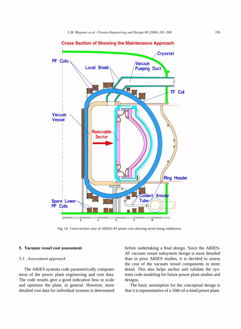
nto their stowed position.The companion elevation view of the sector w
rawal is shown inFig. 14. The vacuum vessel doorisconnected and is located in the port enclosure.ore sector is moved and is just starting to enter thenclosure. The maintenance transporter or containasks are not shown in this view.
Fig. 15shows a 270◦ isometric view of the vacuumessel with the inner spool, doorframes, doors,ort enclosures installed. The inner spool assem
orms the inner, upper, and lower boundaries oflasma chamber vacuum region. Cryogenic vacumping ducts are connected to the top of the sssembly. In the current design, they are defineuite lengthy, but the cryogenic pumps shouldlosely located to the vacuum vessel to be effec

192 L.M. Waganer et al. / Fusion Engineering and Design 80 (2006) 181–200
Fig. 10. Door frame details.

L.M. Waganer et al. / Fusion Engineering and Design 80 (2006) 181–200 193
Fig. 11. High-temperature wedge design.
Closure of the outer perimeter of the vacuum vessel isaccomplished with removable curved vacuum vesseldoors that allow access to the interior of the core.These doors are withdrawn through the port enclosuresfor access to the power core sectors (doors are notshown inFig. 15). The large port enclosures attach tothe doorframes. They isolate the port passageway fromthe interior of cryostat enclosing the TF and PF coils.Doors on the end of the enclosures are required, butnot shown or discussed. The port enclosures are largeenough to allow withdrawal of complete power coresectors (1/16 of entire power core). Gravity supports,shown below the vessel, support the static and seismicloads of the entire power core.
4. Maintenance system design approach
The prior section discussed the basic core config-uration and design development to enable a completesector removal and replacement approach. This section
Fig. 12. Door secu
ring devices.
194 L.M. Waganer et al. / Fusion Engineering and Design 80 (2006) 181–200
Fig. 13. Withdrawal of power core sector.
presents the design approach for the maintenance sys-tem of the power core.
The maintenance approach must be capable of:quickly extracting and replacing the core sectors; ade-quately contain the dust and debris from the core andthe maintenance operations; apply to both scheduledand unscheduled maintenance actions; have low capi-tal cost for the buildings, maintenance equipment, andspares; have minimal radioactive waste; and have a highlevel of system reliability.
Several maintenance options are evaluated[3] forthe above maintenance criteria. The most attractiveoption is the mobile cask system. A mobile cask system[6] is also selected for the ITER divertor and horizon-tal port modules. Mobile casks are designed to houseARIES-AT vacuum vessel door or a power core sec-tor plus a transporter, move from the hot cell throughan air lock and maintenance corridor, and dock to theextremity of the port enclosure. A generic transporter is
shown inFig. 16. Upon cask docking, double doors onthe mobile cask and the port enclosure open to allow theonboard transporter access to the vacuum vessel door.After disconnecting the door mechanical, hydraulic,and electrical connections, the vacuum vessel door ismoved into the cask and transported to the hot cell.Then the cask and transporter return to disconnect andremove the power core sector. The complete sequenceof operations is illustrated inFig. 17. Sufficient radialclearance space is provided in the maintenance corri-dor to allow full access of casks to all port regions. Asdescribed in Ref.[3], removal of one half of the powercore sectors at one maintenance period matches wellwith the balance of plant maintenance periods, has areasonable set of maintenance spares and equipment,and produces an attractive inherent availability. Mul-tiple casks and transporters are used to speed mainte-nance actions to achieve a competitive plant availabilityfactor.
L.M. Waganer et al. / Fusion Engineering and Design 80 (2006) 181–200 195
Fig. 14. Cross-section view of ARIES-AT power core showing sector being withdrawn.
5. Vacuum vessel cost assessment
5.1. Assessment approach
The ARIES systems code parametrically computesmost of the power plant engineering and cost data.The code results give a good indication how to scaleand optimize the plant, in general. However, moredetailed cost data for individual systems is determined
before undertaking a final design. Since the ARIES-AT vacuum vessel subsystem design is more detailedthan in prior ARIES studies, it is decided to assessthe cost of the vacuum vessel components in moredetail. This also helps anchor and validate the sys-tems code modeling for future power plant studies anddesigns.
The basic assumption for the conceptual design isthat it is representative of a 10th-of-a-kind power plant.

196 L.M. Waganer et al. / Fusion Engineering and Design 80 (2006) 181–200
Fig. 15. Cutout view of ARIES-AT vacuum vessel.
Thus, no development or tooling charges is assessedagainst the capital cost. Also, the learning curve isapplied to the 10th unit. Costs are expressed in US$2000.
The entire vacuum vessel assembly is constructedof welded ferritic steel. The construction techniqueis a double-walled vessel with water-cooling betweenthe faceplates. To enhance the neutronic effectiveness,spheres of tungsten carbide are added in the inter-spaces. Techniques to fabricate the components areevaluated. Material quantities are estimated with appro-priate wastage for the fabrication process used. Thenominal material thicknesses of 2 cm are used on thespool assembly and the port enclosures. Material thick-nesses of 3 cm are assumed to reduce the stresses in thdoors and doorframes. No detailed design and stressanalysis is done at this stage. The masses of the majorvacuum vessel components are shown inTable 1.
Table 1Summary of vacuum vessel component masses
Component Each massa (kg) Quantity Total massa (kg)
Spool assembly 136,043 1 136,043Removable doors 13,208 16 211,328Doorframes 3,352 16 53,632Port enclosuresb 44,528 16 712,448
Total 1,113,451
a Structure only, WC shielding materials and cooling water notincluded.
ures.
The large plates for the spool assembly are flatplates, rolled plates, or stampings with cost estimatesfrom vendors. Cost estimates are obtained from ven-dors for the explosively formed doors. The door anddoorframes incorporate extruded Z-section materials toprovide an inexpensive means to form the flanges. Costestimates for these Z-sections are provided by extrusionvendors. Welding and welding inspection estimates aredetermined by size and length of weld. Labor costsare representative of recent fabrication subcontracts.Allowances are added for vacuum construction andinspection. Nominal fees and a sufficient contingencyare applied. The summary costs of the major vacuumvessel components are shown inTable 2.
As shown above, this assembly is fabricated withconventional techniques and the cost estimates are con-sistent with the cost of large welded, vacuum structures.Table 3summarizes the unit costs for the major compo-nents. These unit costs help validate that the estimatesare reasonable for the type of material and fabricationprocess. These are provided as data for the ARIES sys-tems code.
5.2. Discussion of cost results
Examination ofTable 2shows that the fabricationcost of the vacuum vessel dominates the cost of the vac-uum vessel assembly as its 87% of the total (US$ 25.9out of 29.6 million). Application of innovative designor fabrication approaches should help bring this coste thec (nots ss,b eld-i ng ah rts,s es,w eret ande resw onede f thet ightb monl allys
ova-t ional
b Mass of port enclosures includes the outer port door structe
lement lower. Within the fabrication cost element,ost of welding represents 69% of the overall costhown inTable 2). Welding is a rather mature proceut there are new innovations, such as friction stir w
ng, that may help to reduce the cost while achieviigher quality weld. Also using more preformed pauch as the Z-section extrusions for the doorframould help lower the costs. The interior bulkheads w
he single most costly element on spool, doors,nclosures (52%). Using integrally stiffened structuould help reduce these cost elements. As mentiarlier, the port enclosures are very costly (55% o
otal cost), but they are 64% of the total mass. It me possible to reduce these costs by using com
arger port enclosure or using single-walled, integrtiffened, uncooled structures.
This vacuum vessel design approach is an innive approach with a reasonable cost using convent

L.M. Waganer et al. / Fusion Engineering and Design 80 (2006) 181–200 197
Fig. 16. Generic sector transporter.
Table 2Summary of vacuum vessel component costs
Component Total mass (kg) Material cost (US$) Fabrication cost (US$) Total cost (US$)
Spool assembly 136,043 494,30 2,614,897 3,108,327Removable doors 211,328 859,863 6,241,880 7,101,743Doorframes 53,632 356,555 2,736,320 3,092,875Port enclosuresa 712,448 2,020,698 14,309,096 16,329,794
Total 1,113,451 3,730,546 25,902,193 29,632,739
Contingency (20%) 5,926,739Prime contractor fee (12%) 3,555,929Total subsystem cost 39,115,216
Costs are expressed in 2002 dollars.a Mass of port enclosures includes the outer port door structures.

198 L.M. Waganer et al. / Fusion Engineering and Design 80 (2006) 181–200
Fig. 17. Sequence of maintenance operations removing vacuum vessel doors and power core sectors.

L.M. Waganer et al. / Fusion Engineering and Design 80 (2006) 181–200 199
Fig. 18. Isometric view of ARIES-AT power core.
Table 3Unit costs of vacuum vessel components
Component $/kg
Spool assembly 30Removable doors 44Doorframes 76Port enclosuresa 30Composite rate 35
Costs are expressed in 2002 dollars.a Mass of port enclosures includes the outer port door structures.
fabrication processes. Additional design and analysiseffort is needed to optimize the design and validate thatit is ready to proceed to fabrication. Design and fabrica-tion improvements may be investigated to significantlyimprove the cost of this subsystem.
6. Summary
A design approach is defined for the ARIES-ATpower core that supports advanced tokamak confine-ment schemes, high efficiency power conversion, lowactivation materials, reduced waste products, and highplant safety (no evacuation plan is needed) to yield ahighly maintainable and available plant. This design
approach features low cost fabrication of componentsand high availability that results in a fusion plant withan attractive cost of electricity.
The integration of all these elements into a com-plete power core is shown inFig. 18. This isometricview shows the cryostat surrounding the vacuum ves-sel, coils, and core elements. The coils and core ele-ments employs all the most current capabilities of theadvanced plasma confinement approaches. The designuses the high-temperature blanket technology to obtaina high efficiency thermal conversion approach. Effi-cient coil structures enable TF and PF coil systems toenable rapid maintenance of power cores. The entirepower core is specifically designed to enable rapidreplacement of the power core, obtain a high-plantavailability, and achieve a low cost of electricity.
References
[1] M.S. Tillack, The ARIES Team, Engineering overview ofARIES-RS tokamak power plant, in: Proceedings of the 19thSymposium on Fusion Technology, Lisbon, September 16–20,1996.
[2] F. Najmabadi and The ARIES Team, The ARIES-AT advancedtokamak, advanced technology fusion power plant, Fus. Eng.Des. 80 (2006) 3–23.

200 L.M. Waganer et al. / Fusion Engineering and Design 80 (2006) 181–200
[3] L.M. Waganer and The ARIES Team, maintenance system defi-nition and analysis, Fusion Eng. Des. J. 80 (2006) 161–180.
[4] S. Malang, F. Najmabadi, L.M. Waganer, M.S. Tillack, ARIES-RS maintenance approach for high availability, in: Proceedingsof the Fourth International Symposium on Fusion Nuclear Tech-nology, Tokyo, April 1997.
[5] L. El-Guebaly, Nuclear performance assessment for ARIES-AT,Fusion Eng. Des. J. 80 (2006) 99–110.
[6] K. Shibanuma, T. Burgess, et al., Overview of ITER remotehandling, in: Proceedings of the 16th IEEE/NPS Sympo-sium on Fusion Engineering, University of Illinois, September30–October 5, 1995.


