Embed Size (px)
Citation preview
Proceedings of the 1998 IEEE International Conference on Robotics & Automation
Leuven, Belgium - May 1998
DESIGN CONSIDERATIONS OF NEW SIX IDEGREES-OF-FREEDOM PARALLEL ROBOTS
N. Sima’an, D. Gloman, M. Shoham Department of Mechanical Engineering .
Technion - Israel Institute of Technology, :Haifa 32000, Israel Email : [email protected]
Abstract
This paper describes the structure of three types of parallel robots and compares their performances in the sense of size and static forces. The motivation for this investigation is to construct a robot that best fits a given medical application. The requirements are to cover a given work volume with a given orientation and to maintain the robot within the smallest cube possible. Among the structures examined, three are presented since two are modipcations of known structures and the third is a new one.
I Introduction
The exponential growth of publication on parallel robots in the last five years points to the potentid embedded in this structure that has not yet been fully e.uploited. A survey of papers whose title includes the word robots, reveals that the number of papers dealing in particular with parallel structure has gone up from 1% in 1985 to 9% in 1996. This clearly indicates the trend of the research in the field. A typical example is the manufacturing area. The recently introduced parallel structured machine tools by Ingersoll-Rand [7] and Giddings-Lewis [ 111 opens the door for much research on the application of parallel robots in manufacturing as appears for example in the 1997 CIRP Annals.
Numerous investigations were aimed at new structures of parallel robots. We refer the reader to Merlet’s comprehensive study where he collected and grouped different parallel structures by their Degrees Of Freedom @OF) (see Merlet - web page 191). In the six DOF section, different structures are grouped by their types of joints e.g. W S , RRRS, etc. (where R stands for Revolute, P for Prismatic and S for Spherical joint). The ones not falling within these categories are collected under the title of “robots with various kinematic chains “.
Some structures use flexible members thus reducing their mechanical complexity by saving joints (e.g. [6,10]).
The three structures presented here are not included in the above mentioned list. Two structures are modifications of the USR and RSPR robots (where U stands for ai Universal joint), and the third is a new structure which utilizes double planar robots. The idea of this structure stems from Merkle’s [SI and Daniali’s [j] works.
The structures of the new parallel robots are presented next. In Section 3 the Jacobian matrices of the three presented robots are derived. These matrices were used to derive the a t t ic forces and examine singularity. Section 4 presents simulation results from which minimal dimensions and actuating forces of each robot structure needed to achieve the given task are derived.
2 Kinematic structure of the robots
In this section the kinematic structures of the three suggested robots are given. The kinematic chains are described by abbreviations of the joint types, starting from the base platl‘om and ending at the moving platform. All letters denoting joint types are encircled and shown in figures corre:sponding to each robot. (see Figs. 2.1, 2.2, 2.3).
2.1 USR robot
The USR robot consists of three identical kinematic chains connecting the base and the moving platform, each one has two links. One link is connected to the base platform by a Ujoint, the other link is connected to the moving p l a t b m by an R joint, and the two links are connected in between by an S joint. The lower link of each kinematic chain is oriented in space by a (differential drive, controlling its yaw and pitch angles relative to the base platform.(Fig. 2.1)
This s t r u t m e is a variation of the structure described by Cleary [4] which uses URS joint cobmination for each
0-7803-4300-~-5/98 $10.00 0 1998 IEEE 1327

kinematical chain, controlling the pitch and roll of the lower links. The structure we examined has, however, a reverse order of joints - a revolute joint connecting the links to the moving platform, and a spherical joint between the links. This modification prevents collision between links.
Stationary Base// I
Figure 2.1 : USR parallel robot
2.2 RSPR robot
'This structure consists of three identical kinematic chains connecting the base and the moving platform. Each chain contains a lower link rotating around a pivot perpendicular to the base platform , and is offset placed from the center of the base. At the other end of the lower link a prismatic actuator is attached by a spherical joint. The upper end of the prismatic actuator is connected to the moving platform by a revolute joint. The revolute joints axes constitute an equilateral triangle in the plane of the moving platform (see Fig. 2.2).
This structure is distinguished by the location of the lower link revolute axes being placed offset from the center of the base platform. Comparison between RSPR structure and the structure suggested by Alizade [l] which uses R F J S kinematic chains, shows that due to the different order of joints, RSPR robot overcomes certain singularities (90° rotation about a vertical axis) that exist in W S arrangement, and reduces actuator forces as will be shown in section 4. On the other hand it should be noticed that the work volume of the RRPS is larger. Using the swept volume analysis [I21 reveals that when eccentricity is eliminated in RSPR robot then both RSPR and RRPS have the same swept volume of the kinematic chains' upper e'xtremities. Since RSPR robot has an R joint at the end of each kinematic chain, which imposes additional prependicularity constrains, it results in a smaller vertex space and work volume than RRPS robot.
Figure 2.2: RSPR parallel robot
2.3 Double circular-triangular robot
This new m c t u r e is composed of hvo 3 DOF planar mechanisms. These planar mechanisms are different from the planar'mechanism suggested by Daniali [j] since they use a circular-triangular combination rather than triangular- trian,aular one, thus providing much higher orientation capability (theoretically unlimited). The robot (shown in Fig. 2.3) has two similar planar mechanisms each one consists of a stationary circle and a moving triangle which is connected to the circle by three passive sliders pivoted on axes. The active joints actuate the location of these three pivot axes along the circumference of the stationa.ry circle.
1 End effector
TrianGIar StatiGaary Lead Screw I Frames\ g, Prismatic H Joint Supported
on U Joint
Lb
Figure 2.3 : Double circle-triangle robot
Two sets of this structure are used to construct a six- DOF robot. Each structure contributes three-DOF, namely, moves the triangle in a plane and rotates the triangle about an axis normal to this plane. With two such sets, a line connecting the triangle's centers is actuated in four-DOF. The output link is located along this line and the additional hvo-DOFs are obtained by controlling the
1328

rotational motion of the moveable triangles. Each triangle's center contains a U joint and is connected to the output link at one triangle's center through a prismatic joint and at the other through a helical joint (nut and a lead screw). Rotational motion of the output link about the line connecting the centers is acheved by rotating the first movable triangle (the prismatic joint) while motion along the line is acheved by rotating both triangles at Meren t angles. Unllke the planar mechanism suggested by Daniali [j], which allows maximum 60" rotation, the planar circle-triangle based mechanism allows fkll rotation and therefore practical use of the lead screw.
3 Robot performances
In the present research we aim at designing a robot for accurate remote manipulation of a laparoscopic laser dissection tool. Laparoscopic surgery has gained increasing popularity in recent years and many operative procedures are nowadays performed by h s minimally invasive approach, requiring fine dexterity and accurate micro surgical t echque . Utilizing laser for cutting operations is a highly demanding task since it requires the surgeon to manipulate the bulky apparatus of laparoscope, camexa and laser guiding system in a constrained environment with high accuracy. Manipulating the laparoscope with an accurate robotic manipulator controlled remotely by the surgeon is therefore, an attractive approach. A parallel robot structure better fits these medical requirements. This robot structure is much more compact then the commonly used serial one, more rigid and accurate and its inherent limitation of small work volume is an advantage in medical applications where the required motion is small and safety is of utmost importance.
We examined the different parallel robots performances from several aspects: the ability to access a given work volume with a given orientation, the required forces/torques at the active joints and limitations due to singularities and spherical joints mechanical limitation. To check for robot's work volume we used the trivial inverse kinematics solution. We avoid the singularity where the Plucker coordinates of the lines stemming from the Jacobian matrices are four in a plane and hence dependent. This is the only singularity observed in the neighborhood of the work volume we examined (For a detailed singularity analysis of a series of parallel robots using line geometry, see [ 2 ] ) . For the static forces/torques analysis we used the Jacobian matrices the derivation of which are given below.
The Jacobian matrix transforms forces exerted by the moving platform into active joint's forces/torques.
For parallel robots the equation :
(1) r = J S,
determines The relation behveen the actuators generalized forces 6x1 vector. 5 , and the external wrench, se , exerted by the mcn-ing platform on the environment. This equation is used next to determine the Jacobian matrices of the three structures.
For both USR and RSPR robots the upper part is identical, therefor we derive Jacobian matrix 5 of t lus common part.
Fig. 3.1 shows only one kinematic chain out of identical three. The moving platform is connected to a link Ai \ ia a revolute joint. The moving platform exerts a n-rench se on the environment, the lower end of the link is connected to another link Bi by a spherical joint.
r
M o v i n g p l a t f o r m \
Revolute
F igu re 3.1: Common p a r t of USR a n d RSPR robo t s t ruc tu res
We will use the following symbols in our discussion: ' - unit vector. '
S F - unit vector dong revolute joint axis. i 2 i - unit vector parallel to f- passing through the
spherical joint S. R - rotation matrix from the moving platform to world coordinate system. p; - vector from movihg platform's center to 'i'th revolute joint.
Since LinkAi is connected to link B; by a spherical joint and to the moving platform by a revolute joint, i t is capable of exerting force in the direction of zliand moment in the direction of i x S l l on the moving platform. Link Bj can exert on link A, forces of
magnitudef7h in the direction of ? I ; and F2; in the direction of i 2 j
- unit vector along link A ~ .
1329

After some algebraic manipulation one obtains :
3 = [ P l , , P * 2 , P l j : P 2 1 , P 2 ? . P 2 3 1 i r i = 1.273 (2) where p 1; and p 2i are 6x1 plucker coordinates of lines j l i and bi, respectively, written relative to point ‘0’
and represented in world coordinates by:
3.1 Jacobian matrix of USR robot
Let Tn; and Tr;; be scalar quantities representing the magnitudes of the moments applied by the active U joint on link Bi along i n i , i,i respectively (see Fig. 2.1), where Snj , S,.j are unit vectors along the rotation axes of the U joint. Let I,, denote a vector representing the lower link B, from the U to the S joint.
Static equilibrium at point U yields: Tni = ( lb j x (Fliili + Fzii2i)) - s^,j i = 1,2,3 (4.1)
Tri = ( l b j X (FljS1j + F2i;zj))-Sri i = 1,2,3 (4.2) Using Eqs. (1),(2) one obtains :
Define’ vi as a 1 x 6 vector having 1 at the i’th column and zeroes otherwise, then :
-T-1 Fu = v;J s, i = 1,2,3
- F2i = vi+3JT-‘se i = 1,2,3 (6.2)
Substituting in Eqs. (4.1),(4.2) yields :
i = 52,3 aFter some algebraic manipulation one obtains:
r .I
and the inverse transpose of the Jacobian matrix of the USR robot is given by the matrix in the right hand side.
3.2 Jacobian matrix of RSPR robot
Since the u p p r part of t h s robot is identical to the previous one, Eq. (6) is used and substituted in the e.upression of the moments at the lower link.
The moments at the lower rotating links are:
Fol lor~ng the same steps as for the USR robot one obtains the inverse transpose of the Jacobian matrix, on the right hand side of the following equation:
r
3.3 Jacobian matrix of the double circular-triangular robot
This robot has hvo similar planar mechanisms at its upper and lower parts hence it is use l l to derive the Jacobian matrix €or the planar robot and utilize this matrix to derive the Jacobian matrix of the spatial robot.
Moving Triangular ’‘ ?<Frame
Circular 1 ‘ kame Figure 3.2 : Planar circular-triangular robot
The following additional symbols will be used in this section : J - Jacobian maviv of the planar robot, oc, of - center p in ts of the base circle and the moving triangle respectively. p - position vector from 0, tO o, . ti - active sliders position vectors i = 1,2,3. se ~ e.xtemal force and torque exerted by the robot on the environment. f, - force applied by the planar robot in the plane of the moving triangle. T, - magnitude of torque applied byf the plmar robot, perpendicular to the moving triangle.
-

R, - rotation matrix, transforming vectors from i to j coordinate system. g,- h c t i o n which relates between input moment and
the output moment of the U joint ( T,, = g, *To,, ). 1 - screw lead with a right handed helix. 7 - effciency of lead screw.
planar robot is obtained as: From static equilibrium the Jacobian matrix of the
ai
The relation between actuator forces and exerted forcedmoments by the moving triangle ft , T, is given by:
For the spatial robot we will use indices p and b to refer to the upper and the lower planar robots.
First we decompose the exerted forcdtorque in end effectors coordinate system (see Fig. 2.3). From static equilibrium for the lead screw oneobtains:
4, i o
F i g u r e 3 . 3 : P a r a m e t e r s o f !ead s c r e w
Where rp and r, are forces applied by the upper and Iower planar robots on the screw, written in end effector attached system.
Using Eqs. (12-14) one obtains: r i
where matrices N,and Nbare given by Eq. (15), and
vector v, is a 1.6 row vector with 1 at the i'th column and zeroes othernise.
r r
Defining generalized forces as [rp,.rblr we find the
imerse t~aispasc of the Jacobian matrix, given in the right hand side of the following equation:
c
4 Simulation goal and results
The goal of this investigation was to design a robot that can manipulate surgical tools within a given work volume, with a given force and accuracy, to minimize its size and to obtain a robot which can be realized from design poinit of Liew.
The desired work volume is a 40x40~20 mm cube. The robot has to reach all points within this cube with an orientation of up to 20". The robot should fit into a cube smaller than 200600x200 mm.
All simulations use the inverse kinematic solution of each structure to check for accesibility while different robot dimensions. such as: base radius, moving platform radius and initial height, were examined. The simulations e.uluded robots Rhich contain singular points within the desired work volume, and robots, which exceed the limitation of 30" spherical joint inclination angle.
The dimensions of the smallest robot of each structure are shown iii table 4.1. All dimensions are in milimeters and Correspond to figures at section 2. Smaller robots were also found, but design considerations such as joint and motor siizes and mechanical feasability exluded them from the final List.
In initial position the platforms are parallel at a distance H, and the center of the moving platform coincides with the center of the workspace cube.
Forces for each robot were computed along a diagonal linear path from the lower comer of the workspace cube, (point [-20,-:!0,-10]) to the upper comer of the cube (point [20,20,10]), xvhile keeping the moving platform with an orientation of 20" rotation about [1,1,1] a i s .
1331

The results are shown in Figs. 4.1 to 4.1, The external wrench applied by the robots is se = [7,7,7 N ,0.7,0.7,0.7 Nml - .__ .
Fig. 4.4 shows a comDarison between RSPR and m between RSPR and RRPS robot [I] with RSPR having zero eccentricity. T h s ,figure with Fig. 4.2 shows that placing the R joints on the moving platform requires less torques at the active R joints (about 37%) while the linear actuator forces in both robots are almost the same.
IRSPR Actuator Forces and Moments I ,wm, . , 0.18
0.38
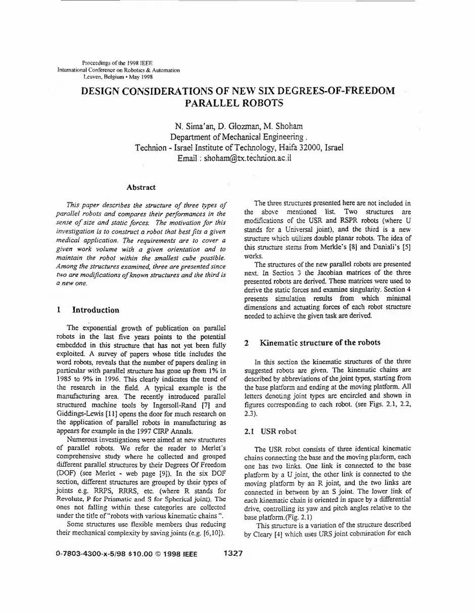
Figs. 4.5 to 4.7 show models of each robot (The USR robot in this figure is in a singular position as one of the links is coplanar with the moving platform).
1332
h Actuator Forces for Double Circular-Triangular robe
IC: CG 003 DO4 O E 006 ID
Path len,ath [MI Figure 4.3
N m 092
0%
027
om
Path length [MJ Figure 4.4
5 Conclusions
The goal of this investigation was to construct a robot that best fits a given medical application. Among severd structures that were investigated three parallel robots are presented. The Double circular-triangular Robot is a novel Structure with a considerably different structure than the &ugh, Stewart platform. The RSPR robot is a variation of a known structure with a different location and order of joints that reduces required actuator forces and reduces sin,dar positions. By changing the order of the joints the USR robot enhances the performances of a known Structure
Jacobian matrices of all three robots were derived. Simulation results compare the three structures from desired work volume and active joints forces/torques points of view.
Among the three presented robots, the RSPR robot k g fits the required task. This robot has the simplest design and the largest work volume. The USR robot has
one practical limitation at the spherical joints because of large inclination angles and the use of Werential drive. The Double-Planar robot exceeds the task limitations with its enveloping volume and requires large actuator forces.
F i g u r e 4.6 : RSPR r o b o t
r
Figure 4.5: Double circular-triangular robot
Acknowledgments
This research was supported by the hilitchel-Sorf Foundation and by the fund for the promotion of research at thc Tcchnion.
References
[ I ] Alizacle, RI. and 'Tagiyev, N.R. - "A Forward and Reverse Displacement Analysis of a 6-DOF in-Parallel Manipulatoi'. .Ifechanism and Machine Theory, I.bl.29, IYO. I . 1994, JY. 115-124.
[ 2 ] Ben-Horin, R. "Design Parameters of Parallel Robots", Ph.D. Thesis, Technion, Haifa. Israel, 1998.
[3] CIRP A d s . Vol. 46, 1997.
[-I] Cleary, IC.. Uebel. M., - '' Jacobian Formulation for a Novel GDOF Parallel Manipulator '' , Proc. E E E Conference on Roboltics and Automation. 1994, Vol. 3. pp. 2377-2332
[j] Daniali.. M.H.R. Zsombar-blurray, P.J., and Angeles,, J : .. The Kinematics of a Three DOF Planar and Spherical Double Triangular Parallel Manipulators", Computational Kinematics, eds. Angeles, J., Kovacs, P., Hommel, G., Klurver Academic Publishers, 1993, pp. 153-164.
[SI Hara, A. and Sugimoto, K., "Synthesis of Parallel blicrommipulators", Asme Transactions. Journal of .Lfechanisl;ns, Transmissions and Automafion in Design. Vol. I1 I , 1989, pp. 34-39.
[7] Lindem,T. J., : ''OctaIheQral Machine with a He.uapodlal Triangular Servostrut Section". US patent 540 1128, Ingersoll Milling Machine Comlpany, Rockforcl, E. 1995.
[SI Merkle, :RC., A New Family of Six Degrees of Freedom Positional Dlwices " , Nanofechno/ogy, Vol. 8, NO. 2, 1997, pp. 47-52.
[9] Merlet, J.P., Web Page 1997 hrtp.iMa!.fr/prisme/persoMe~merlet"erl~:t-eng. htl.
[ IO] Pernette:, E., Henein, S., Magnani, I., Clavel, R., "Design of Parallel Robots in Microrobotics", ROBOTI(TA. Vol. IS, pp. 4171120, July-Aupst 1997.
[ 111 Sheldon. P.C.." Six Puis Machine Tool ". US patent 5385935. Giddings & lewis, Inc., fond du Lac, WI, 1995.
[ 121 Zhiming. J., "Workspace Analysis of Stewart Platforms Lia Vertex Space", Journal ofRobotic Systems. VoI. 11(7), pp. 631439, 1994.
1333


![Libertà del robot? Sull'etica delle macchine intelligenti [Freedom of Robots? On ethics of intelligent machines]](https://img.pdfslide.net/doc/110x75/6359657c10f2bd48220e2a5a/liberta-del-robot-sulletica-delle-macchine-intelligenti-freedom-of-robots-on.jpg)


