Embed Size (px)
Citation preview
MAY 29, 2015 / HMC ARCHITECTS i
GROSSMONT • CUYAMACA COMMUNITY COLLEGE DISTRICT - DISTRICT GUIDELINES + STANDARDS
District Guidelines + Standards Document Team
Architect
Program ManagerGafcon Inc.
Acoustical ConsultantWaveguide
Audio Visual + Information Technology ConsultantWaveguide
CivilNolte
Door Hardware ConsultantPeter Campos
Electrical ConsultantTanner Engineering
Landscape Architecture KTU + A LandLab
Lighting ConsultantHorton, Lees Brogden
Mechanical/PlumbingSC Engineering
Waterproofi ng ConsultantIndependent Roofi ng Consultants
GCCCD faculty and staff
DISTRICT GUIDELINES + STANDARDS
Grossmont• Cuyamaca Community College
District 8800 Grossmont College Drive
El Cajon, CA 92020
GCCCD
HMC ARCHITECTS / ii
DISTRICT GUIDELINES + STANDARDS - GROSSMONT• CUYAMACA COMMUNITY COLLEGE DISTRICT
TABLE OF CONTENTS
Standards DocumentOverview1
Part A
2 3 Space Guidelines
Introduction
ClassroomsConference RoomsOffi cesCorridors + Collaborative SpacesToilet RoomsCustodial RoomsElevator CabsTechnology RoomsMechanical RoomsElectrical Rooms
Introduction
2013 Facilities Master Plan
Cuyamaca CollegeCampus Setting + CharacterGoals + ObjectivesSpecifi c Design GuidelinesSite DesignArchitectural DesignExterior Building MaterialsGraphics + SignageCampus Site FurnitureParking + Circulation
Grossmont CollegeCampus Setting + CharacterGoals + ObjectivesSpecifi c Design GuidelinesSite DesignArchitectural DesignExterior Building MaterialsGraphics + SignageCampus Site FurnitureParking + Circulation
District ServicesBackgroundLocation for District Services
Introduction
Use of Guidelines + Standards
Part APart BPart CPart DPart EPart FPart GPart HPart I
Part APart BPart CPart DPart EPart FPart GPart HPart I
Part JPart K
Part APart BPart CPart D
Part EPart FPart GPart HPart IPart J
Campus Design Guidelines
MAY 29, 2015 / HMC ARCHITECTS iii
GROSSMONT • CUYAMACA COMMUNITY COLLEGE DISTRICT - DISTRICT GUIDELINES + STANDARDS
4 Material + BuildingSystems Standards
Introduction
ConcreteMasonryMetalsWood, Plastics, Composites Thermal + Moisture ProtectionOpeningsFinishesSpecialtiesFurnishingsConveying Equipment PlumbingHVACElectrical Communications/TechnologyElectronic Safety + Security Exterior Improvements Acoustical + Sound Isolation
A Appendix
Division 3Division 4 Division 5Division 6Division 7
Division 8Division 9Division 10Division 12Division 14Division 22Division 23 Division 26Division 27
Division 28Division 32Division 51
Appendix A Roofing Guidline Drawings
Sinage Guidelines Drawings
Lighting Guideline Matrix
IT and Cabling Information
District Preferred AV Products/Details
Irrigation Zone Color Codes
Resolution 16-004
Door Hardware
*If Division is not listed it is not applicable.
Appendix B
Appendix C
Appendix G
Appendix D
Appendix E
Appendix F
Appendix H
HMC ARCHITECTS / iv
DISTRICT GUIDELINES + STANDARDS - GROSSMONT• CUYAMACA COMMUNITY COLLEGE DISTRICT
Steering Committee
Ken EmmonsBruce FarnhamTim FloodSue RearicArleen SateleKatrina VanderWoudeWei Zhou
Space/Room Guidelines
Vaunette AllenSherri BraaksmaKurt BrauerTim CorcoranVirginia DudleyKen EmmonsBruce FarnhamMarsha GableOralee HolderLinda JensenNicole JonesLisa Ledri-AguilarBarbara LovelessDonna MarquezBrian NathMike ReeseDenise SchulmeyerPeter UtgaardSusan WorkingEddie Vasquez
Electrical Guidelines + Standards
Dan CornettKen EmmonsBruce FarnhamRicardo GaliciaJon LangteauDouglas PlattBeau Simi
ACKNOWLEDGEMENTS
Staff and Faculty Committee Participants
Security + Hardware Guidelines + Standards
Dan CornettCliff DiamondRick DavidsonKen EmmonsBruce FarnhamTim FloodSue GondaAlicia MunozBrian NathVictor PerrySue RearicArleen SateleDenise SchulmeyerChris Weiss
Landscape + Civil Guidelines + Standards
Ken EmmonsBruce FarnhamJohn HeimasterJack NewmanDonald Schultz
Plumbing + Mechanical Guidelines + Standards
James DuddyKen EmmonsBruce FarnhamSal Espiritu
Moisture + Roofi ng Guidelines + Standards
Kurt BrauerKen EmmonsBruce FarnhamSal Espiritu
Technology/AV + Acoustics Guidelines + Standards
Cynthia BourgetSherri BraaksmaKen EmmonsBruce FarnhamTim FloodStan MalleyBrian NathJohn OakesKerry Kilber RebmanJohn StephensDave SteinmetzEvan Wirig
Finishes + Signage Guidelines + Standards
Joe BalestreriMartin DuBordKen EmmonsBruce Farnham
Gafcon + District Participation All Task Forces
Jim DaviesLarry FugalAaron GoldeDale SwitzerRandy Clark
MAY 29, 2015 / HMC ARCHITECTS
GROSSMONT CUYAMACA COMMUNITY COLLEGE DISTRICT – DISTRICT GUIDELINES + STANDARDS
1-1
INTRODUCTION
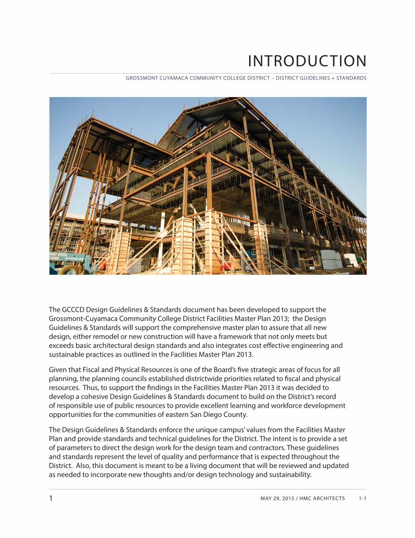
The GCCCD Design Guidelines & Standards document has been developed to support the Grossmont-Cuyamaca Community College District Facilities Master Plan 2013; the Design Guidelines & Standards will support the comprehensive master plan to assure that all new design, either remodel or new construction will have a framework that not only meets but exceeds basic architectural design standards and also integrates cost eff ective engineering and sustainable practices as outlined in the Facilities Master Plan 2013.
Given that Fiscal and Physical Resources is one of the Board’s fi ve strategic areas of focus for all planning, the planning councils established districtwide priorities related to fi scal and physical resources. Thus, to support the fi ndings in the Facilities Master Plan 2013 it was decided to develop a cohesive Design Guidelines & Standards document to build on the District’s record of responsible use of public resources to provide excellent learning and workforce development opportunities for the communities of eastern San Diego County.
The Design Guidelines & Standards enforce the unique campus’ values from the Facilities Master Plan and provide standards and technical guidelines for the District. The intent is to provide a set of parameters to direct the design work for the design team and contractors. These guidelines and standards represent the level of quality and performance that is expected throughout the District. Also, this document is meant to be a living document that will be reviewed and updated as needed to incorporate new thoughts and/or design technology and sustainability.
1
GROSSMONT CUYAMACA COMMUNITY COLLEGE DISTRICT – DISTRICT GUIDELINES + STANDARDS
GCCCD01 OVERVIEW1-2
USE OF GUIDELINES + STANDARDS
1A
GUIDELINES
First of all it should be understood that this document contains both Guidelines and Standards.Guidelines are defi ned as a tool to develop the desired design parameters of the built environment, whether a building, a room or any physical feature. Guidelines are not prescriptive nor rigid. They imply an intent and a “guide” to develop a design. The Guidelines are described in Sections 2 & 3.
SECTION 2:Section 2 is intended to communicate the foundational concepts that underlie the GCCCD Design Standards. They refl ect both lessons learned from past experiences and emerging priorities. Section 2 provides the boundaries ensuring a cohesive campus identity unique to each college. This section augments the 2003 Architectural Design Guidelines that have been in use for the past decade.
SECTION 3:Section 3 describes various spaces that will re-occur in buildings such as classrooms, offi ces, conference rooms, restrooms, corridors and support spaces. These guidelines are not intended to be prescriptive but allow the design of spaces to be fl exible, functional, and adaptable allowing for changes that will occur in the future. Certain very specifi c uses such as Labs and specialized teaching spaces are not shown in our guidelines; they will be further developed by the designer and user groups and will be specifi c to that project.
STANDARDS
Standards are defi ned as a specifi c or prescriptive requirement that defi nes in much more detail than a guideline how a defi ned element of a building must perform. These performance standards are described in Section 4 and are developed into ‘divisions’ based on the Construction Specifi cation Institute; this is a professional architect/ engineer standard used in the construction of facilities.
SECTION 4Section 4 of this document is intended to outline performance criteria that are important to the District for the major building/site systems and materials in future construction projects. Although Section 4 is organized in Divisions based on the 2010 MasterFormat® it is not written as or intended to be considered as product specifi cations that would be included in a project manual but rather provide criteria, locations, and desired design approach for systems and materials that would be used in a project.
Part A
MAY 29, 2015 / HMC ARCHITECTS
GROSSMONT CUYAMACA COMMUNITY COLLEGE DISTRICT – DISTRICT GUIDELINES + STANDARDS
1-3
SUSTAINABILIT Y
Grossmont-Cuyamaca Community College District understands and encourages sustainability as an integral design process which cannot be isolated and should be applied to each and every discipline by each and every stakeholder. The adjacent icon is therefore used throughout the handbook to highlight key opportunities for sustainable measures.
It is important that sustainability be the hallmark of each new and modernized building in the District. These guidelines and standards do not include code requirements as they will change over time and the design professionals are required to meet codes and local regulations. The California Building Code is now incorporating effi cient performance criteria such as CAL Green and new Title 24 energy standards. CAL Green reinforces the sustainability goals that are already stated in our Facilities Master Plan:
• Planning and Design• Energy effi ciency• Water effi ciency and reduction• Material conservation and resource effi ciency• Indoor air quality• Environmental quality
SUMMARY
It is expected that these Design Guidelines & Standards will be a time-saving and cost-saving benefi t to the District, from design, through construction and continue to long-term maintenance. There will be a consistency of design and level of quality that is expected by each college and the District. The guidelines and standards are generic for the overall projects throughout the District. Specifi c design teams shall use them to assist in the design process while the design teams overlay detailed project specifi c detail to each design.
1A
MAY 29, 2015 / HMC ARCHITECTS
GROSSMONT CUYAMACA COMMUNITY COLLEGE DISTRICT – DISTRICT GUIDELINES + STANDARDS
2-1
INTRODUCTION
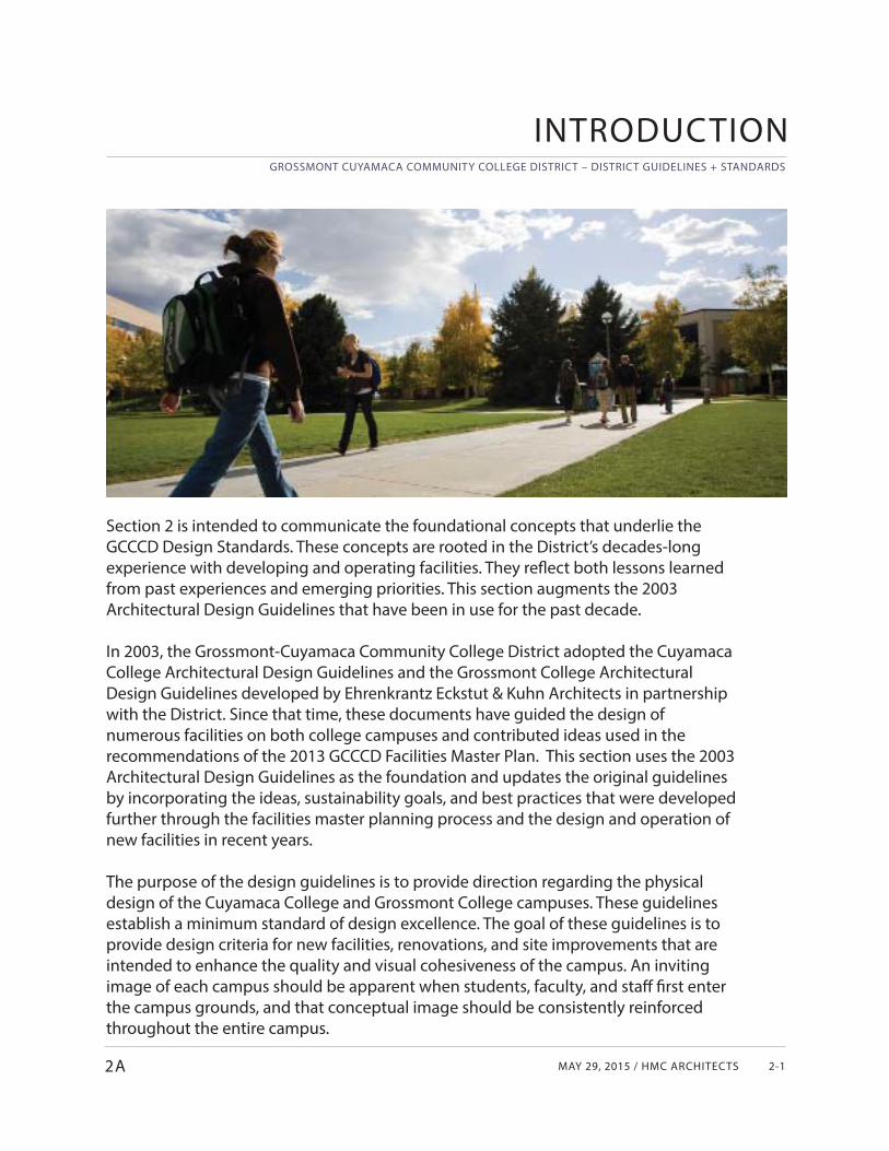
Section 2 is intended to communicate the foundational concepts that underlie the GCCCD Design Standards. These concepts are rooted in the District’s decades-long experience with developing and operating facilities. They refl ect both lessons learned from past experiences and emerging priorities. This section augments the 2003 Architectural Design Guidelines that have been in use for the past decade.
In 2003, the Grossmont-Cuyamaca Community College District adopted the Cuyamaca College Architectural Design Guidelines and the Grossmont College Architectural Design Guidelines developed by Ehrenkrantz Eckstut & Kuhn Architects in partnership with the District. Since that time, these documents have guided the design of numerous facilities on both college campuses and contributed ideas used in the recommendations of the 2013 GCCCD Facilities Master Plan. This section uses the 2003 Architectural Design Guidelines as the foundation and updates the original guidelines by incorporating the ideas, sustainability goals, and best practices that were developed further through the facilities master planning process and the design and operation of new facilities in recent years.
The purpose of the design guidelines is to provide direction regarding the physical design of the Cuyamaca College and Grossmont College campuses. These guidelines establish a minimum standard of design excellence. The goal of these guidelines is to provide design criteria for new facilities, renovations, and site improvements that are intended to enhance the quality and visual cohesiveness of the campus. An inviting image of each campus should be apparent when students, faculty, and staff fi rst enter the campus grounds, and that conceptual image should be consistently reinforced throughout the entire campus.
2A
GROSSMONT CUYAMACA COMMUNITY COLLEGE DISTRICT – DISTRICT GUIDELINES + STANDARDS
GCCCD01 OVERVIEW2-2 2
FACILITIES MASTER PLAN SUMMARY2013
MAY 29, 2015 / HMC ARCHITECTS
GROSSMONT CUYAMACA COMMUNITY COLLEGE DISTRICT – DISTRICT GUIDELINES + STANDARDS
2-3
SUMMARY
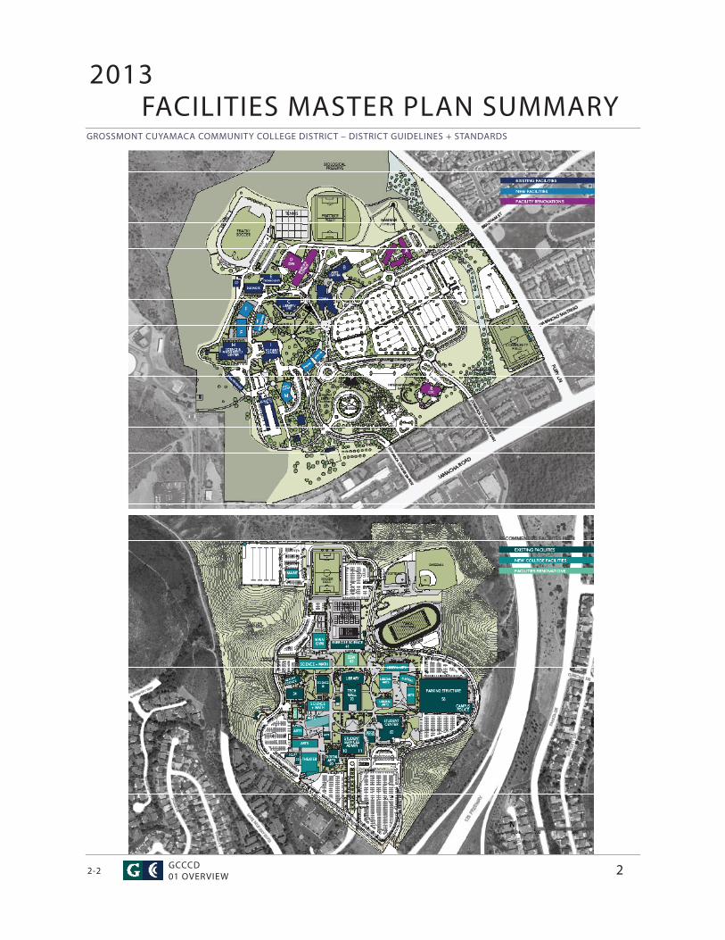
The 2013 GCCCD Facilities Master Plan (FMP) was created to translate the District’s priorities for student learning and success into recommendations for the development of facilities at each college campus. Its specifi c purposes are to:
• Provide long-range guidance for the development of new facilities that will be needed to support the projected academic program of instruction and support services.
• Identify the needs for the refurbishment, repair, or replacement of existing facilities that will be needed to support current academic program of instruction and support services.
• Include and integrate current construction and maintenance plans.• Describe the District’s plans for environmental sustainability.
The Facilities Master Plan includes a chapter each for Cuyamaca College, for Grossmont College, and for District Services. It also includes a chapter on districtwide planning for sustainability and technology. As noted in one of the purposes listed above, sustainability is an important objective for the design and operation of all district facilities and the design guidelines have been updated to align with this objective.
The FMP documents the analysis of existing conditions and recommends a number of projects in the categories of new facilities, renovation + re-purposing, site improvements, and sustainability. The FMP provides a broadly held vision for the development of future facilities, but much work is needed prior to the construction of these recommended projects. These GCCCD Design Standards represent part of the detailed work that is required to support the successful implementation of the FMP. The two documents should be used in tandem to guide the development of each campus.
The process to develop the Facilities Master Plan was broadly participatory, involving interactive workshops. The master plan refl ects input from many stakeholders who represent those who will be learning and working on these campuses in the coming years. Through this process, Development Concepts and Design Objectives were established to guide the programming, design, and operation of facilities on each college campus. One of the goals for this document is to update the District’s architectural guidelines with these ideas. To accomplish this goal, a summary of the FMP Development Concept and the complete list of Design Objectives for each college have been included in Section 2. In addition, the Specifi c Design Guidelines have been expanded where appropriate to align with these design objectives.
2

GROSSMONT CUYAMACA COMMUNITY COLLEGE DISTRICT – DISTRICT STANDARDS
CUYAMACA COLLEGE02 CAMPUS DESIGN GUIDELINES2-4
MAY 29,2015 / HMC ARCHITECTS
GROSSMONT CUYAMACA COMMUNITY COLLEGE DISTRICT – DISTRICT STANDARDS
2-52A
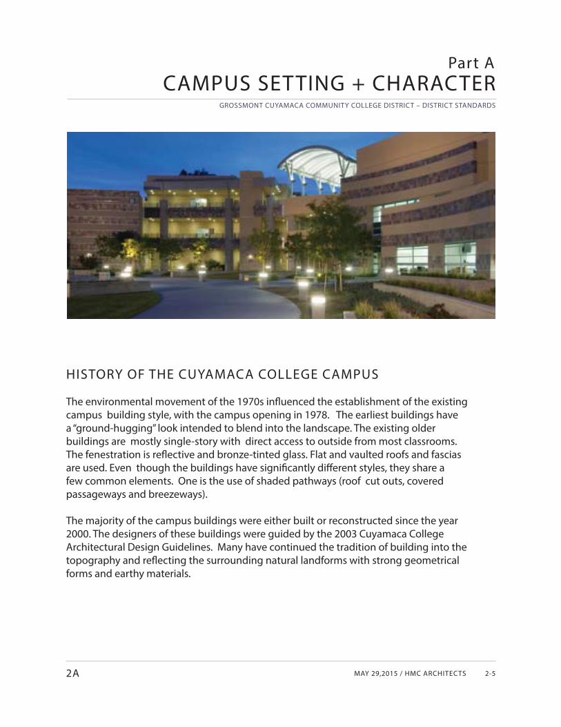
HISTORY OF THE CUYAMACA COLLEGE CAMPUS
The environmental movement of the 1970s infl uenced the establishment of the existing campus building style, with the campus opening in 1978. The earliest buildings have a “ground-hugging” look intended to blend into the landscape. The existing older buildings are mostly single-story with direct access to outside from most classrooms. The fenestration is refl ective and bronze-tinted glass. Flat and vaulted roofs and fascias are used. Even though the buildings have signifi cantly diff erent styles, they share a few common elements. One is the use of shaded pathways (roof cut outs, covered passageways and breezeways).
The majority of the campus buildings were either built or reconstructed since the year 2000. The designers of these buildings were guided by the 2003 Cuyamaca College Architectural Design Guidelines. Many have continued the tradition of building into the topography and refl ecting the surrounding natural landforms with strong geometrical forms and earthy materials.
CAMPUS SETTING + CHARACTERPart A
GROSSMONT CUYAMACA COMMUNITY COLLEGE DISTRICT – DISTRICT STANDARDS
CUYAMACA COLLEGE02 CAMPUS DESIGN GUIDELINES2-6
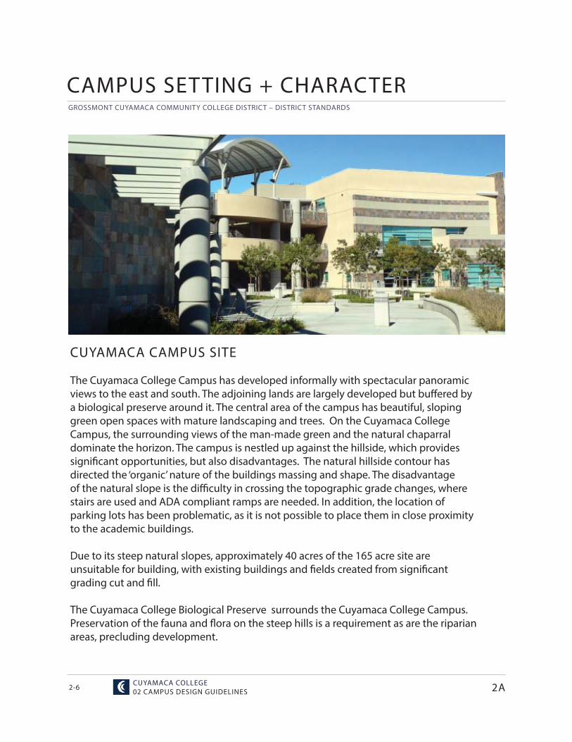
CUYAMACA CAMPUS SITE
The Cuyamaca College Campus has developed informally with spectacular panoramic views to the east and south. The adjoining lands are largely developed but buff ered by a biological preserve around it. The central area of the campus has beautiful, sloping green open spaces with mature landscaping and trees. On the Cuyamaca College Campus, the surrounding views of the man-made green and the natural chaparral dominate the horizon. The campus is nestled up against the hillside, which provides signifi cant opportunities, but also disadvantages. The natural hillside contour has directed the ‘organic’ nature of the buildings massing and shape. The disadvantage of the natural slope is the diffi culty in crossing the topographic grade changes, where stairs are used and ADA compliant ramps are needed. In addition, the location of parking lots has been problematic, as it is not possible to place them in close proximity to the academic buildings.
Due to its steep natural slopes, approximately 40 acres of the 165 acre site are unsuitable for building, with existing buildings and fi elds created from signifi cant grading cut and fi ll.
The Cuyamaca College Biological Preserve surrounds the Cuyamaca College Campus. Preservation of the fauna and fl ora on the steep hills is a requirement as are the riparian areas, precluding development.
CAMPUS SETTING + CHARACTER
2A
MAY 29,2015 / HMC ARCHITECTS
GROSSMONT CUYAMACA COMMUNITY COLLEGE DISTRICT – DISTRICT STANDARDS
2-7
STUDENT IMPRESSIONS
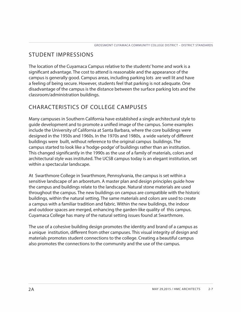
The location of the Cuyamaca Campus relative to the students’ home and work is a signifi cant advantage. The cost to attend is reasonable and the appearance of the campus is generally good. Campus areas, including parking lots are well lit and have a feeling of being secure. However, students feel that parking is not adequate. One disadvantage of the campus is the distance between the surface parking lots and the classroom/administration buildings.
CHARACTERISTICS OF COLLEGE CAMPUSES
Many campuses in Southern California have established a single architectural style to guide development and to promote a unifi ed image of the campus. Some examples include the University of California at Santa Barbara, where the core buildings were designed in the 1950s and 1960s. In the 1970s and 1980s, a wide variety of diff erent buildings were built, without reference to the original campus buildings. The campus started to look like a ‘hodge-podge’ of buildings rather than an institution. This changed signifi cantly in the 1990s as the use of a family of materials, colors and architectural style was instituted. The UCSB campus today is an elegant institution, set within a spectacular landscape.
At Swarthmore College in Swarthmore, Pennsylvania, the campus is set within a sensitive landscape of an arboretum. A master plan and design principles guide how the campus and buildings relate to the landscape. Natural stone materials are used throughout the campus. The new buildings on campus are compatible with the historic buildings, within the natural setting. The same materials and colors are used to create a campus with a familiar tradition and fabric. Within the new buildings, the indoor and outdoor spaces are merged, enhancing the garden-like quality of this campus. Cuyamaca College has many of the natural setting issues found at Swarthmore.
The use of a cohesive building design promotes the identity and brand of a campus as a unique institution, diff erent from other campuses. This visual integrity of design and materials promotes student connections to the college. Creating a beautiful campus also promotes the connections to the community and the use of the campus.
2A
GROSSMONT CUYAMACA COMMUNITY COLLEGE DISTRICT – DISTRICT STANDARDS
CUYAMACA COLLEGE02 CAMPUS DESIGN GUIDELINES2-8
FIRST IMPRESSIONS
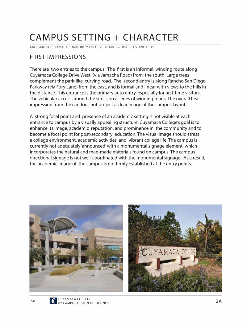
There are two entries to the campus. The fi rst is an informal, winding route along Cuyamaca College Drive West (via Jamacha Road) from the south. Large trees complement the park-like, curving road. The second entry is along Rancho San Diego Parkway (via Fury Lane) from the east, and is formal and linear with views to the hills in the distance. This entrance is the primary auto entry, especially for fi rst-time visitors. The vehicular access around the site is on a series of winding roads. The overall fi rst impression from the car does not project a clear image of the campus layout.
A strong focal point and presence of an academic setting is not visible at each entrance to campus by a visually appealing structure. Cuyamaca College’s goal is to enhance its image, academic reputation, and prominence in the community and to become a focal point for post-secondary education. The visual image should stress a college environment, academic activities, and vibrant college life. The campus is currently not adequately ‘announced’ with a monumental signage element, which incorporates the natural and man-made materials found on campus. The campus directional signage is not well-coordinated with the monumental signage. As a result, the academic image of the campus is not fi rmly established at the entry points.
2A
CAMPUS SETTING + CHARACTER
MAY 29,2015 / HMC ARCHITECTS
GROSSMONT CUYAMACA COMMUNITY COLLEGE DISTRICT – DISTRICT STANDARDS
2-9
CUYAMACA COLLEGE CHARACTERISTICS
The Cuyamaca College campus presents opportunities and challenges. Among its assets are the following.
• The campus is a hidden gem with a unique sense-of-place.• The campus contains unique programs, features, and land uses, such as the Ornamental
Horticulture Nursery, the Water Conservation Garden, and the Nature Preserve.• The college is concluding a successful building program, which provided new and
reconstructed facilities.
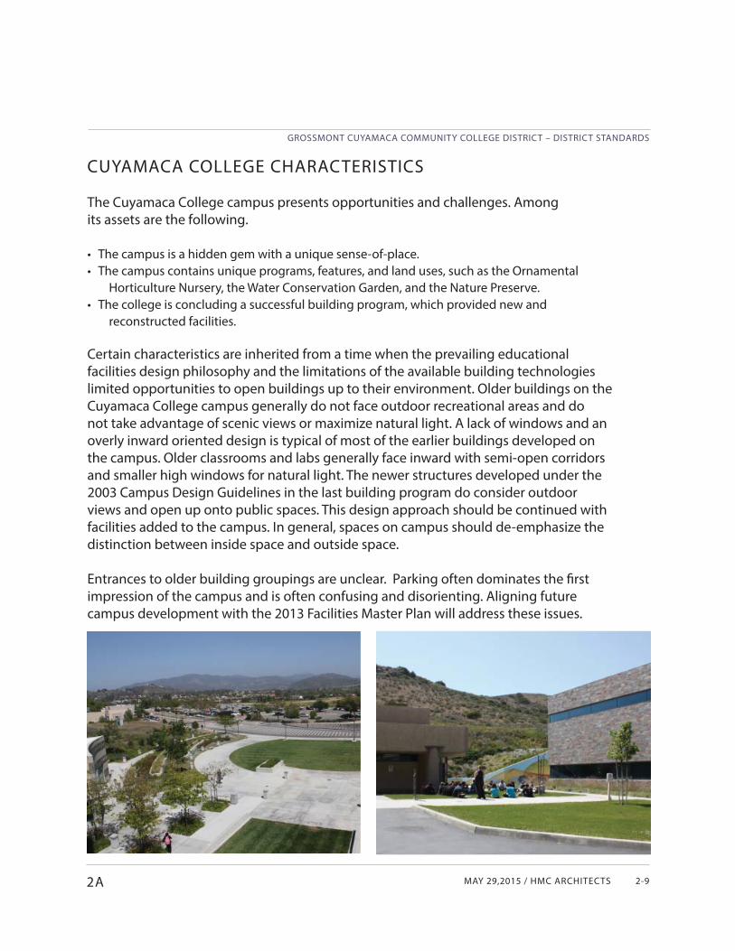
Certain characteristics are inherited from a time when the prevailing educational facilities design philosophy and the limitations of the available building technologies limited opportunities to open buildings up to their environment. Older buildings on the Cuyamaca College campus generally do not face outdoor recreational areas and do not take advantage of scenic views or maximize natural light. A lack of windows and an overly inward oriented design is typical of most of the earlier buildings developed on the campus. Older classrooms and labs generally face inward with semi-open corridors and smaller high windows for natural light. The newer structures developed under the 2003 Campus Design Guidelines in the last building program do consider outdoor views and open up onto public spaces. This design approach should be continued with facilities added to the campus. In general, spaces on campus should de-emphasize the distinction between inside space and outside space.
Entrances to older building groupings are unclear. Parking often dominates the fi rst impression of the campus and is often confusing and disorienting. Aligning future campus development with the 2013 Facilities Master Plan will address these issues.
2A
GROSSMONT CUYAMACA COMMUNITY COLLEGE DISTRICT – DISTRICT STANDARDS
CUYAMACA COLLEGE02 CAMPUS DESIGN GUIDELINES2-10
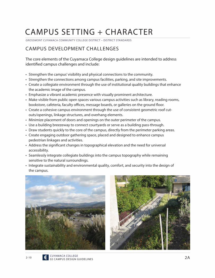
CAMPUS DEVELOPMENT CHALLENGES
The core elements of the Cuyamaca College design guidelines are intended to address identifi ed campus challenges and include:
• Strengthen the campus’ visibility and physical connections to the community.• Strengthen the connections among campus facilities, parking, and site improvements.• Create a collegiate environment through the use of institutional quality buildings that enhance
the academic image of the campus.• Emphasize a vibrant academic presence with visually prominent architecture.• Make visible from public open spaces various campus activities such as library, reading rooms,
bookstore, cafeteria, faculty offi ces, message boards, or galleries on the ground floor.• Create a cohesive campus environment through the use of consistent geometric roof cut-
outs/openings, linkage structures, and overhang elements.• Minimize placement of doors and openings on the outer perimeter of the campus.• Use a building breezeway to connect courtyards or serve as a building pass-through.• Draw students quickly to the core of the campus, directly from the perimeter parking areas.• Create engaging outdoor gathering space, placed and designed to enhance campus pedestrian linkages and activities.• Address the signifi cant changes in topographical elevation and the need for universal accessibility.• Seamlessly integrate collegiate buildings into the campus topography while remaining
sensitive to the natural surroundings.• Integrate sustainability and environmental quality, comfort, and security into the design of the campus.
2A
CAMPUS SETTING + CHARACTER
MAY 29,2015 / HMC ARCHITECTS
GROSSMONT CUYAMACA COMMUNITY COLLEGE DISTRICT – DISTRICT STANDARDS
2-11
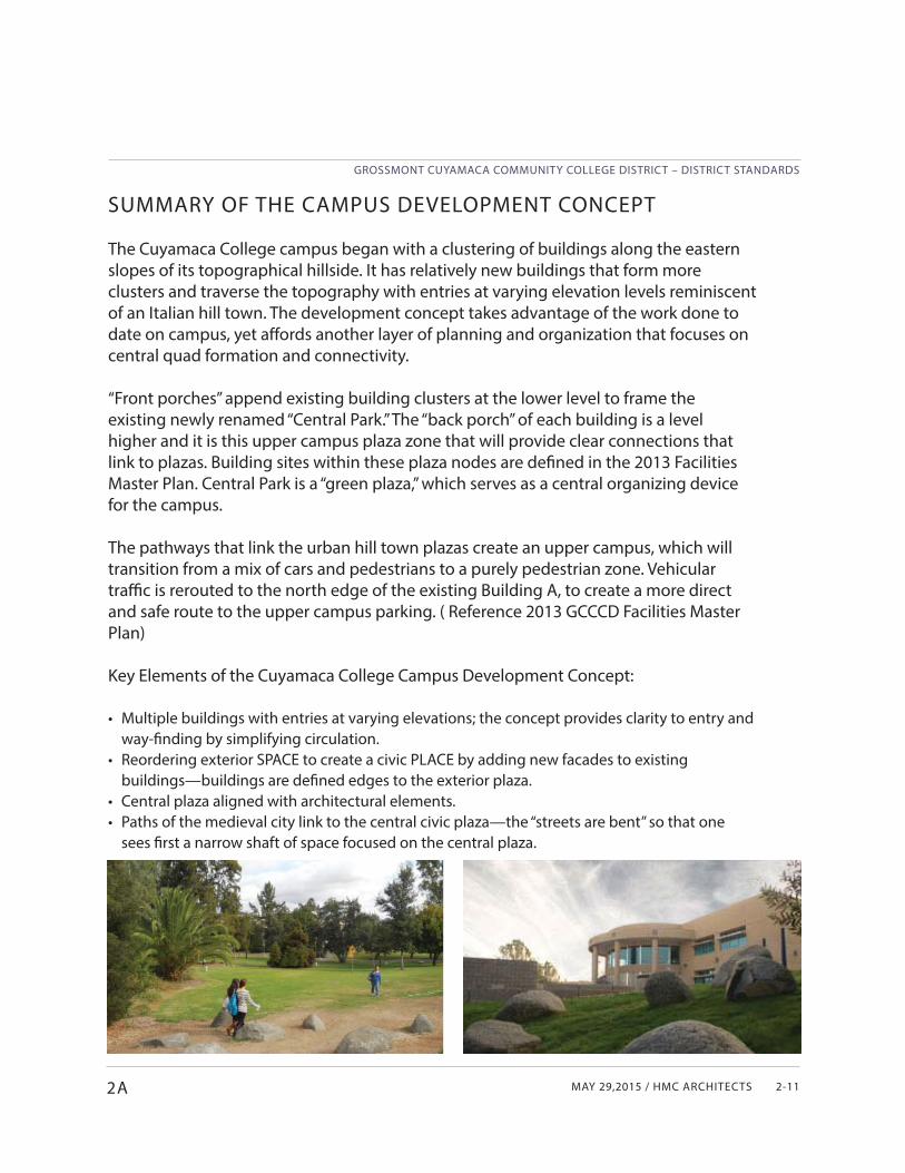
SUMMARY OF THE CAMPUS DEVELOPMENT CONCEPT
The Cuyamaca College campus began with a clustering of buildings along the eastern slopes of its topographical hillside. It has relatively new buildings that form more clusters and traverse the topography with entries at varying elevation levels reminiscent of an Italian hill town. The development concept takes advantage of the work done to date on campus, yet aff ords another layer of planning and organization that focuses on central quad formation and connectivity.
“Front porches” append existing building clusters at the lower level to frame the existing newly renamed “Central Park.” The “back porch” of each building is a level higher and it is this upper campus plaza zone that will provide clear connections that link to plazas. Building sites within these plaza nodes are defi ned in the 2013 Facilities Master Plan. Central Park is a “green plaza,” which serves as a central organizing device for the campus.
The pathways that link the urban hill town plazas create an upper campus, which will transition from a mix of cars and pedestrians to a purely pedestrian zone. Vehicular traffi c is rerouted to the north edge of the existing Building A, to create a more direct and safe route to the upper campus parking. ( Reference 2013 GCCCD Facilities Master Plan)
Key Elements of the Cuyamaca College Campus Development Concept:
• Multiple buildings with entries at varying elevations; the concept provides clarity to entry and way-fi nding by simplifying circulation.
• Reordering exterior SPACE to create a civic PLACE by adding new facades to existing buildings—buildings are defi ned edges to the exterior plaza.
• Central plaza aligned with architectural elements.• Paths of the medieval city link to the central civic plaza—the “streets are bent” so that one
sees fi rst a narrow shaft of space focused on the central plaza.
2A
GROSSMONT CUYAMACA COMMUNITY COLLEGE DISTRICT – DISTRICT STANDARDS
CUYAMACA COLLEGE02 CAMPUS DESIGN GUIDELINES2-12
Part B
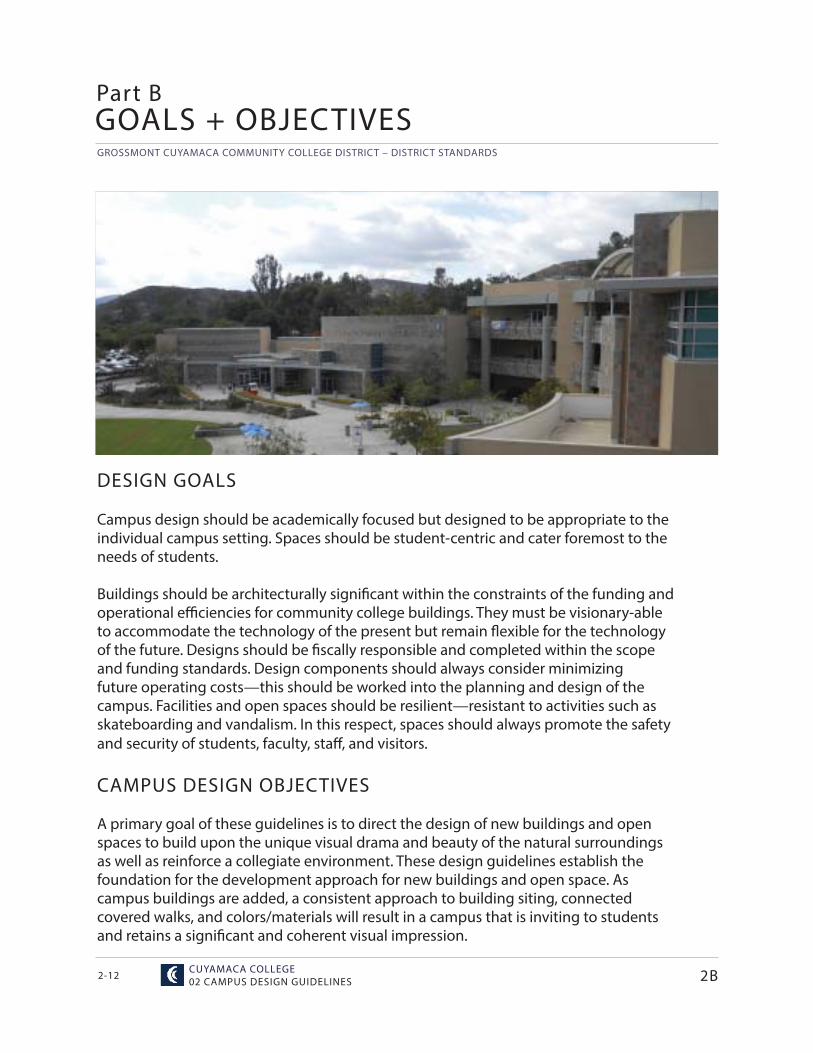
DESIGN GOALS
Campus design should be academically focused but designed to be appropriate to the individual campus setting. Spaces should be student-centric and cater foremost to the needs of students.
Buildings should be architecturally signifi cant within the constraints of the funding and operational effi ciencies for community college buildings. They must be visionary-able to accommodate the technology of the present but remain flexible for the technology of the future. Designs should be fiscally responsible and completed within the scope and funding standards. Design components should always consider minimizing future operating costs—this should be worked into the planning and design of the campus. Facilities and open spaces should be resilient—resistant to activities such as skateboarding and vandalism. In this respect, spaces should always promote the safety and security of students, faculty, staff , and visitors.
CAMPUS DESIGN OBJECTIVES
A primary goal of these guidelines is to direct the design of new buildings and open spaces to build upon the unique visual drama and beauty of the natural surroundings as well as reinforce a collegiate environment. These design guidelines establish the foundation for the development approach for new buildings and open space. As campus buildings are added, a consistent approach to building siting, connected covered walks, and colors/materials will result in a campus that is inviting to students and retains a signifi cant and coherent visual impression.
GOALS + OBJECTIVES
2B
MAY 29,2015 / HMC ARCHITECTS
GROSSMONT CUYAMACA COMMUNITY COLLEGE DISTRICT – DISTRICT STANDARDS
2-132B
As part of the 2013 facilities master planning process, the following Campus Design Objectives were updated through discussions with the Cuyamaca College Extended Master Plan Task Force. The input of the Task Force expresses the needs and insights of stakeholders with day-to-day experience with working and learning on the campus.
• Create a strong academic character for the campus through the design of collegiate-quality buildings.
• Design the campus so that as a whole, it is largely defi ned and perceived by its buildings in harmony with lush open spaces and the natural environment.
• Provide a strong sense of “entry,” a gateway to the campus, to enhance community relations.• Reinforce the “heart” of the campus, the “Central Park”, as the principal open space for
gathering.• Establish the existing LRC, new Student Center, and Communication Arts buildings as the
primary buildings focused on the Central Park.• New buildings should be respectful of and compatible with the signifi cant aspects of the
original campus buildings and open spaces.• Use design elements, building materials, landscaping and walkways to emphasize a cohesive
and connected, as well as outwardly focused campus.• Make public spaces attractive, and where appropriate, expand spaces to be used for public
events.• Enhance the connection to the immediate surrounding uses (the Water Conservation Garden
and Museum), establishing view corridors to signifi cant buildings, entrances and the hills.• Provide safe and comfortable pathway connections from parking to the campus core.• New buildings and development should ensure the fi nancial viability of the College as a
whole, i.e. new buildings should be cost-eff ective to build and maintain.• Design for the sustainable and high-performance operation of open spaces and buildings.• Create quality indoor environments for students and employees—considering aesthetics,
ergonomics, fl exible use, acoustics, indoor air quality, and resource effi ciency. • Support learning anytime and anywhere throughout the campus.• Incorporate student and public art into the campus environment.• Create welcoming, human scaled outdoor and indoor gathering spaces to promote
collaborative learning and student engagement. Provide appropriate furniture and technology connectivity.
• Design with an awareness of environmental conditions to effi ciently maximize comfort and health.
• Design for universal accessibility to all facilities and services.• Design to promote safety and security, including fi re safety of the site.
GROSSMONT CUYAMACA COMMUNITY COLLEGE DISTRICT – DISTRICT STANDARDS
CUYAMACA COLLEGE02 CAMPUS DESIGN GUIDELINES2-14
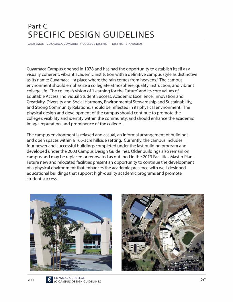
Cuyamaca Campus opened in 1978 and has had the opportunity to establish itself as a visually coherent, vibrant academic institution with a defi nitive campus style as distinctive as its name: Cuyamaca - “a place where the rain comes from heavens.” The campus environment should emphasize a collegiate atmosphere, quality instruction, and vibrant college life. The college’s vision of “Learning for the Future” and its core values of Equitable Access, Individual Student Success, Academic Excellence, Innovation and Creativity, Diversity and Social Harmony, Environmental Stewardship and Sustainability, and Strong Community Relations, should be refl ected in its physical environment. The physical design and development of the campus should continue to promote the college’s visibility and identity within the community, and should enhance the academic image, reputation, and prominence of the college.
The campus environment is relaxed and casual, an informal arrangement of buildings and open spaces within a 165-acre hillside setting. Currently, the campus includes four newer and successful buildings completed under the last building program and developed under the 2003 Campus Design Guidelines. Older buildings also remain on campus and may be replaced or renovated as outlined in the 2013 Facilities Master Plan. Future new and relocated facilities present an opportunity to continue the development of a physical environment that enhances the academic presence with well-designed educational buildings that support high-quality academic programs and promote student success.
2C
Part CSPECIFIC DESIGN GUIDELINES
MAY 29,2015 / HMC ARCHITECTS
GROSSMONT CUYAMACA COMMUNITY COLLEGE DISTRICT – DISTRICT STANDARDS
2-152C
SITE DESIGN
EDUCATIONAL RESOURCESFlexible outdoor Classrooms• Integrate the academic programming of indoor and
outdoor space.• Provide a range of fl exible spaces to accommodate a
variety of learning activities.• Provide appropriate support utilities and technology
connectivity.• Highlight sustainable campus facilities and operations
with displays and interpretive signage.Nature Preserve• Emphasize adjacencies to Nature Preserves through the use of view corridors and the strategic placement of plazas, outdoor rooms, and trail heads.• Provide interpretive pathway signage. • Restore and preserve adjacent habitat with endemic plant materials.• Do not specify invasive or non-native plant species of any type in areas adjacent to nature preserves and riparian habitats.• Do not specify excessively bright and unshielded light- ing in adjacent areas.• Locate educational and interpretive signage along pedestrian pathways.• Locate outdoor classrooms adjacent to the Nature Preserve and Riparian Habitat.
CAMPUS GATEWAYS• Locate monument signage, planting species and hardscape elements that unify the exterior visual and physical appeal of the campus with the total landscape character at all access points along major roadways.• Incorporate regional materials, such as boulders or stone for signage.• Ensure that signage is well lit and oriented towards roadways for maximum visibility.Entering the Campus• Provide safe, clear, accessible paths for pedestrians entering and exiting the campus in both day-to-day and emergency situations.• Ensure that pedestrian entrances are well lit and in- clude appropriate signage for way-fi nding.• Provide universally accessible paths of travel. • Provide linkages that anticipate the shortest path of travel between entries, campus open spaces, and buildings.
PEDESTRIAN LINKAGES• Strengthen the pedestrian linkages and provide
universal accessibility between all campus facilities and open spaces.
• Design the campus system of pedestrian linkages in a holistic manner, establishing a logical hierarchy that is integrated with a robust way-fi nding system.
• Design pedestrian linkages to accommodate the anticipated level of use.
Traversing Parking Areas• Provide pedestrian paths that are separated from vehicular routes for safe circulation through parking lots.• Employ consistent use of iconic plant material or vertical elements and lighting to visually identify pedestrian paths.• Minimize crossing of pedestrian and vehicular paths and design necessary crossing points to promote safety.• Provide shaded seating at intervals along pedestrian paths through large parking lots.
Linking the Campus Core• Create direct relationships between well-defi ned areas
of campus through the use of unifi ed and consistent paving, lighting, and landscape furnishings.
• Implement shade trees and trellises along pedestrian pathways for comfort but maintain clear sight lines.
• Provide water bottle fi lling stations and shaded seating at regular intervals.
• Integrate emergency access routes into the landscape design by using alternative paving surfaces where applicable to reduce visual impact of vehicular path.
• Allow paths to frame and focus views of destinations as pedestrians approach elements such as plazas and portals.
Portals• Defi ne through the use of a strong linear axis, consistent paving, lighting, textures, colors, and planting.• Place signage to clearly defi ne building names, entries, and accessible paths.• Defi ne portals through use of vertical elements .• Frame pedestrian views and visual connections across campus.
GROSSMONT CUYAMACA COMMUNITY COLLEGE DISTRICT – DISTRICT STANDARDS
CUYAMACA COLLEGE02 CAMPUS DESIGN GUIDELINES2-16 2C
SPECIFIC DESIGN GUIDELINES
Vertical Linkages• Locate vertical linkages in exterior locations that can
be accessed when buildings are closed.• Provide exterior building elevators and stairs in
locations that are adjacent or part of major pedestrian links and portals.
• Provide signage that clearly illustrates the accessible links to all campus plateaus.
OPEN SPACES• Respect the informal nature of open space and
building settings.• Soften/integrate buildings and open spaces by using
landscaping and transitional elements such as trellises.• Orient building entrances toward plazas.• Provide opportunities for a diverse range of activities.• Maintain consistency with common materials, street
amenities, and site furnishings.• Make public open spaces inviting, during the day and
at night.• Capture views to the surrounding hills and valleys
between buildings.• Recognize the arid nature of the environment and
minimize the use of water. (e.g. water conservation gardens).
• To the extent that it is practical, ensure that open spaces are universally accessible.
Central Park• Ensure universal accessibility to all areas of Central
Park and to the surrounding buildings.• Support a variety of uses and gathering activities.• Defi ne passive and active recreation areas using open
turf areas, tree placement, shade, and ground cover selection.
• Use pervious walking surfaces with appropriate sub-base and drainage for plazas.
• Plant drought-tolerant borders and less thirsty turf varieties to reduce the need for irrigation while maintaining a park-like quality.
• Preserve existing trees to maintain the “arboretum” quality of Central Park.
• Identify native and adapted specimen trees using interpretive signage where appropriate.
Plazas• Orient buildings with corridor views facing open
spaces.• Use intimate-scaled courtyards to promote multi-level
student, faculty, and community interaction.
• Implement a consistent landscape palette using identifi ed appropriate plants (section 4).
• Use pervious surfaces for walking and to accommodate emergency vehicles where appropriate.
• Maximize solar orientation of seating areas for morning sunlight and minimize the exposure to prevailing winds and afternoon sun.
• Ensure that plazas are well lit for typical night time use and special events. Include suffi cient electricalconnections per program.
• Ensure good visibility for supervision and security.
ACTIVE GROUND-FLOOR USES• Make visible from public spaces various campus activities: library, reading rooms, bookstore, cafeteria,
professor offi ces, message boards or galleries on the ground fl oor, towards public spaces.
• Create any exterior entrances to classrooms from within courtyards.
• Draw students directly to the core of the campus from parking areas.
VIEW OPPORTUNITIES• Combine new points of entry to capitalize on views.• Capture views to the surrounding scenery from plazas
and building interiors.
TREES AND LANDSCAPING• Use appropriate trees as a part of new building and open space planning (Refer to Section 4) (for acceptable species).
• Design landscaping to protect and frame sight line views to the surrounding hillsides and other scenic
areas.
ARCHITECTURAL DESIGN
BUILDING MASSING + ORIENTATION• Continue the use of bold geometries that manipulate
light and shadow.• Use asymmetrical building forms when appropriate.
BUILDING STYLE• Advocate a contemporary architectural style with key
elements preserved.• Continue the use of bold and curvilinear building forms.• Avoid overly inward-focused building designs.• Maximize natural light using windows.• Use asymmetrical building forms when appropriate.
MAY 29,2015 / HMC ARCHITECTS
GROSSMONT CUYAMACA COMMUNITY COLLEGE DISTRICT – DISTRICT STANDARDS
2-17
BUILDING ENTRANCES• Use a single, grand-scale entrance or place prominent
entrances at main sides of buildings if appropriate.• Place entrances to open onto plazas or portals that form
a strong connection to primary pedestrian linkages.• Ensure that entrances are well-lit.• Encourage articulated rather than fl at facades.• Do not use dark or refl ective glass, which creates an
uninviting appearance.• Make building entrances obvious and visible from the
Central Park.
EXPRESSION LINES• Emphasize the horizontal when designing building walls.• Use lightweight materials for the top section of walls.• Emphasize horizontal lines in two- and three-story
structures.• Avoid large blank walls that face plazas or core activity
areas on campus.
ROOFTOPS• Use large overhangs to provide shade from the summer
sun and allow passive heating in the winter.• Use high-albedo “cool” roofi ng surface materials.• Consider views of lower roofs from higher levels,
balconies, and windows.• Minimize visibility of obtrusive equipment.• Design roofs to use daylight harvesting strategies.
COVERED WALKWAYS • Use covered or shaded structures to alleviate sun and
heat.• Use shaded walkways to link buildings and primary open
spaces at appropriate adjacencies.• Use skylights to bring natural light back to areas
darkened by overhangs.• Use covered or shaded structures to provide student
gathering areas.• Do not obscure or block overhang passageways.• Do not locate planters within overhang drip lines.• Integrate covered walkways and canopies with
architectural design styles and building design.• Covered walkways should be constructed using low- maintenance materials. Powder-coated metals are preferred over wood or wood substitutes.
OTHER DESIGN FEATURES • Incorporate visually identifi able vertical elements,
sculpture, and other public art into the campus design.
2C
MECHANICAL EQUIPMENT • MEP equipment should not be openly visible.• Roof-mounted equipment should be shielded from all view.
VENDING MACHINES• Vending equipment should not be visually intrusive• Vending areas should be shielded from the sun and
weather• Vending should be safe, secure, and well lit.• Avoid placement in deep alcoves or secluded areas for
security.
TRASH ENCLOSURES + LOADING FACILITIES• Locate trash and recycling bins in enclosures.• Plan the location of trash and recycling facilities to allow
easy cleaning and management.
INDOOR ENVIRONMENTAL QUALITY• Design to a high standard of aesthetic quality.• Design for universal accessibility and clear way-finding
throughout all spaces.• Reduce sources of indoor air pollution such as cleaning
and pest control chemicals and building materials, equipment, and furniture that emit volatile organic compounds and other pollutants.
• Design for eff ective ventilation and thermal comfort.• Design acoustic environments that reduce distracting
noise and improve aural communication.• Design for optimal lighting quality and reduced glare.• Design for ergonomic comfort.• Provide occupants with a connection to the outdoors by
providing glare-free natural lighting and views.• Design buildings to be safe and secure environments for
learning using CPTED principles.• Equip buildings for monitoring and optimizing the
indoor environment.
ENERGY + WATER• Design in accordance with the GCCCD standards for
energy and water use intensity. • Employ the building occupants at the start of the
programming process for input. • Explore and select strategies that take advantage of
synergies to optimize building performance. • Equip buildings for monitoring and optimizing energy and
water using systems.• Explore opportunities to integrate photovoltaic systems
into the design of facilities.
GROSSMONT CUYAMACA COMMUNITY COLLEGE DISTRICT – DISTRICT STANDARDS
CUYAMACA COLLEGE02 CAMPUS DESIGN GUIDELINES2-18 2C
SPECIFIC DESIGN GUIDELINES
ENVIRONMENTALLY PREFERRED MATERIALS• Build and furnish with durable and easily maintained
materials.• Build with materials that are locally sourced, rapidly
renewable, contain recycled content, and are likely to be recycled or reused.• Maintain healthy indoor air quality by selecting
appropriate building materials and furnishings, with a proven track record of lantern performance
WASTE REDUCTION + MANAGEMENT• Follow best practices for the management of demolition
materials and construction waste.• Explore on-campus opportunities to reuse materials
from demolished facilities and site work.• Design buildings with space to support the campus
recycling plan.
EXTERIOR BUILDING MATERIALS
CONCRETE BLOCK WALLS, CONCRETE COL-UMNS, OTHER BUILDING MATERIALS• Stone walls and detailing where appropriate• Smooth wall materials, including concrete/masonry walls• Textured material• Lighter palette of color for major massing• Articulated simple roof structures with standing seam
metal roofs• Round concrete columns • Large glass elements FENESTRATION + GLASS WALLS• Use clear anodized aluminum mullions with double pane
low-e glass.• Use large expanses of glass at building entrances if
appropriate.
EXTERIOR LIGHTING• Lighting fi xtures should be LED fi xtures or other proven
energy effi cient lighting systems can also be considered. Other options should be reviewed with District.
• Provide lighting for safe and secure night time use of the campus . Include consistent lighting on circulation pathways with a fi xture every 25-30 ft providing illumination of a person’s face 30 ft away.
• Use increased lighting levels at primary entrances.• Avoid the use of in-ground lights.• Locate lights in area where they can be easily maintained.
• Avoid placing lights in ceilings over stairs.• Make provisions for lighting special outdoor
performances, activities, and events.• Design site lighting to minimize or shield light from
adjacent neighborhoods and nature preserves.• Prohibit exposure of habitat and astronomical observation
areas to high-frequency spectrum lighting. HANDRAILS• Choose railing styles that add to the cohesive quality of
the campus.• Use bent tube steel in simple shapes and forms.• Avoid painted handrails. CONCRETE STAIRS + PAVING• Integrate stairs, planter walls, and seating into paving
design.• Use edge detailing on integral colored concrete.• Implement long lasting durable materials that require
minimal maintenance.• Use integral color in concrete. Do not use stain concrete
or applied coatings.• Minimize use of large aggregated textured paving due to maintenance issues.
GRAPHICS + SIGNAGE
CAMPUS WAY-FINDING + SIGNAGE• Understand the campus-wide way-finding plan and how it addresses the requirements for all facilities and
elements of the campus circulation systems. • Understand how each building and site improvement project functions as a part of the campus-wide fabric and include the appropriate way- finding elements in the project scope.• Support clear way-finding and direct connectivity for users with mobility limitations.• Use trees and plant material and architectural elements to assist in campus way-finding. • Incorporate educational and interpretive signage to highlight public art, sustainable facilities, and other features.
BUILDING NAMES, WAY-FINDING, + SIGNAGE• Place building names in highly visible areas of exterior building walls with consistent type font established for the campus.
MAY 29,2015 / HMC ARCHITECTS
GROSSMONT CUYAMACA COMMUNITY COLLEGE DISTRICT – DISTRICT STANDARDS
2-19
PARKING + CIRCULATION
DRIVEWAYS• Place primary vehicular routes away from primary
pedestrian circulation.• Employ round-abouts to improve flow at busy
intersections.• Separate pedestrian and bicycle circulation from
vehicular routes.• Minimize pedestrian crossings.• Design driveways to maximize storm water runoff
capture into adjacent detention areas.
PASSENGER LOADING ZONES + BUS STOPS• Separate loading zones from main vehicular routes.• Provide adequate stacking space to accommodate
waiting vehicles.• Provide seating, shade, refuse receptacles, and access
to restrooms.
BICYCLE PATHS + STORAGE• Connect to the public network of bicycle paths.• Provide bicycle routes throughout the campus.• Separate bicycle routes from vehicular and pedestrian circulation. • Provide consolidated bicycle storage at key portals on campus and integrated with new and existing facilities.• Use bicycle storage that is consistent with campus standards (Section 4).• Place bicycle storage in hardscape or gravel.
PARKING• Provide adequate stacking space and multiple
entrances/exits to parking areas.• Direct pedestrians to walkways that connect parking
areas to campus portals.• Screen parking areas with landscape elements.• Use appropriate trees and other landscape elements to
break up large expanses of surface parking.• Orient parking lots to maximize storm water runoff
capture into adjacent detention areas.• Orient parking lots to maximize accessibility to
buildings and major areas of campus.• Locate canopy trees along walkways to provide relief
the sun and reduce the heat island eff ect.• Provide preferred parking for carpools and alternative
fuel vehicles. • Provide electric vehicle charging stations.
2C
CAMPUS SITE FURNITURE
FURNITURE• Integrate campus furniture with the landscape and
hardscape when appropriate.• Be consistent with campus architectural elements when
choosing furnishing styles.• Place movable outdoor furniture only in courtyards or
controlled and highly visible areas.• Provide convenience outlets into adjacent walls.• Provide trash and recycling receptacles along main
circulation routes and building entrances.• Use trash and recycling receptacles that are consistent
with campus standards (Section 4).• Use metal mesh loose outdoor tables and chairs. Avoid pedestal base on tables.• Skateboard deterrents shall be a part of any bench design, not applied hardware afterwards.
SHADE STRUCTURES• Consider the location of shade trees and building overhangs when planning the location of shade structures and use these elements in concert to provide the desired level of shading along pedestrian linkages and in outdoor gathering spaces.• Avoid shading gathering spaces from the morning sun, especially during the cool weather season.• Be consistent with campus architectural elements when designing shade structures.• Use shade structures to provide intermittent resting points along exposed primary pathways.• Integrate overhead shade structures at dining plazas and gathering spaces when shade is needed.• Soften/integrate building and open space with trellis elements.
STUDENT + PUBLIC ART• Provide opportunities for the display of art in buildings,
courtyards, and gathering areas throughout campus. • Integrate art within the landscape and public spaces.• Locate in a highly visible and secure area.• Provide interpretive signage and lighting.• Provide support for technology, audio/visual, and lighting for outdoor performance venues.
GROSSMONT CUYAMACA COMMUNITY COLLEGE DISTRICT – DISTRICT STANDARDS
CUYAMACA COLLEGE02 CAMPUS DESIGN GUIDELINES2-20
Part DSITE DESIGN
EDUCATIONAL RESOURCES
Every square foot of the campus has the potential to enrich the education of students and the campus site design should provide and support learning opportunities. Provide connectivity to technology and explore opportunities for outdoor teaching and active learning spaces. Health, wellness and exercise science activities, expression and exhibition of learning in the academic disciplines that is occurring throughout the campus should also be explored. Demonstrate sustainable facility and site design principles and design places to feature public and student art.
Both college campuses manage substantial areas within their boundaries which are maintained as natural habitat and learning resources. There are opportunities to reintroduce native plant material, natural or constructed shelters, and water and food sources into the campus core to extend and support the adjacent natural habitat. Educational signage shall designate restoration areas for both public awareness and protection of newly established plants.
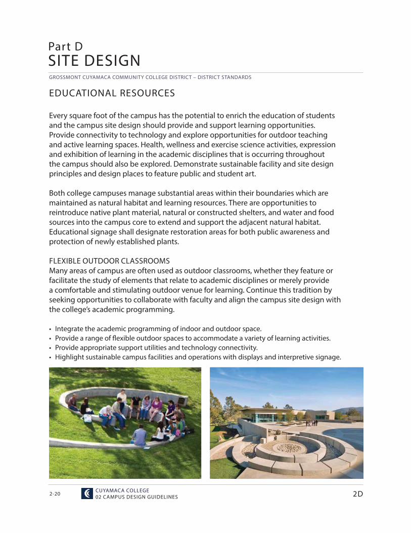
FLEXIBLE OUTDOOR CLASSROOMSMany areas of campus are often used as outdoor classrooms, whether they feature or facilitate the study of elements that relate to academic disciplines or merely provide a comfortable and stimulating outdoor venue for learning. Continue this tradition by seeking opportunities to collaborate with faculty and align the campus site design with the college’s academic programming.
• Integrate the academic programming of indoor and outdoor space.• Provide a range of fl exible outdoor spaces to accommodate a variety of learning activities.• Provide appropriate support utilities and technology connectivity.• Highlight sustainable campus facilities and operations with displays and interpretive signage.
2D
MAY 29,2015 / HMC ARCHITECTS
GROSSMONT CUYAMACA COMMUNITY COLLEGE DISTRICT – DISTRICT STANDARDS
2-21
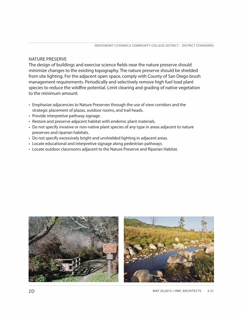
NATURE PRESERVEThe design of buildings and exercise science fi elds near the nature preserve should minimize changes to the existing topography. The nature preserve should be shielded from site lighting. For the adjacent open space, comply with County of San Diego brush management requirements. Periodically and selectively remove high fuel load plant species to reduce the wildfi re potential. Limit clearing and grading of native vegetation to the minimum amount.
• Emphasize adjacencies to Nature Preserves through the use of view corridors and the strategic placement of plazas, outdoor rooms, and trail heads.
• Provide interpretive pathway signage .• Restore and preserve adjacent habitat with endemic plant materials.• Do not specify invasive or non-native plant species of any type in areas adjacent to nature
preserves and riparian habitats.• Do not specify excessively bright and unshielded lighting in adjacent areas.• Locate educational and interpretive signage along pedestrian pathways.• Locate outdoor classrooms adjacent to the Nature Preserve and Riparian Habitat.
2D
GROSSMONT CUYAMACA COMMUNITY COLLEGE DISTRICT – DISTRICT STANDARDS
CUYAMACA COLLEGE02 CAMPUS DESIGN GUIDELINES2-22
SITE DESIGN
2D
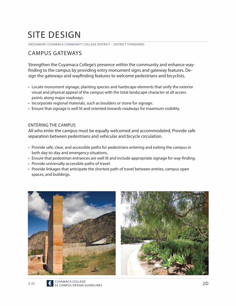
CAMPUS GATEWAYS
Strengthen the Cuyamaca College’s presence within the community and enhance way-fi nding to the campus by providing entry monument signs and gateway features. De-sign the gateways and wayfi nding features to welcome pedestrians and bicyclists.
• Locate monument signage, planting species and hardscape elements that unify the exterior visual and physical appeal of the campus with the total landscape character at all access points along major roadways.
• Incorporate regional materials, such as boulders or stone for signage.• Ensure that signage is well lit and oriented towards roadways for maximum visibility.
ENTERING THE CAMPUSAll who enter the campus must be equally welcomed and accommodated. Provide safe separation between pedestrians and vehicular and bicycle circulation.
• Provide safe, clear, and accessible paths for pedestrians entering and exiting the campus in both day-to-day and emergency situations.
• Ensure that pedestrian entrances are well lit and include appropriate signage for way-fi nding.• Provide universally accessible paths of travel. • Provide linkages that anticipate the shortest path of travel between entries, campus open
spaces, and buildings.
MAY 29,2015 / HMC ARCHITECTS
GROSSMONT CUYAMACA COMMUNITY COLLEGE DISTRICT – DISTRICT STANDARDS
2-23
PEDESTRIAN LINKAGES
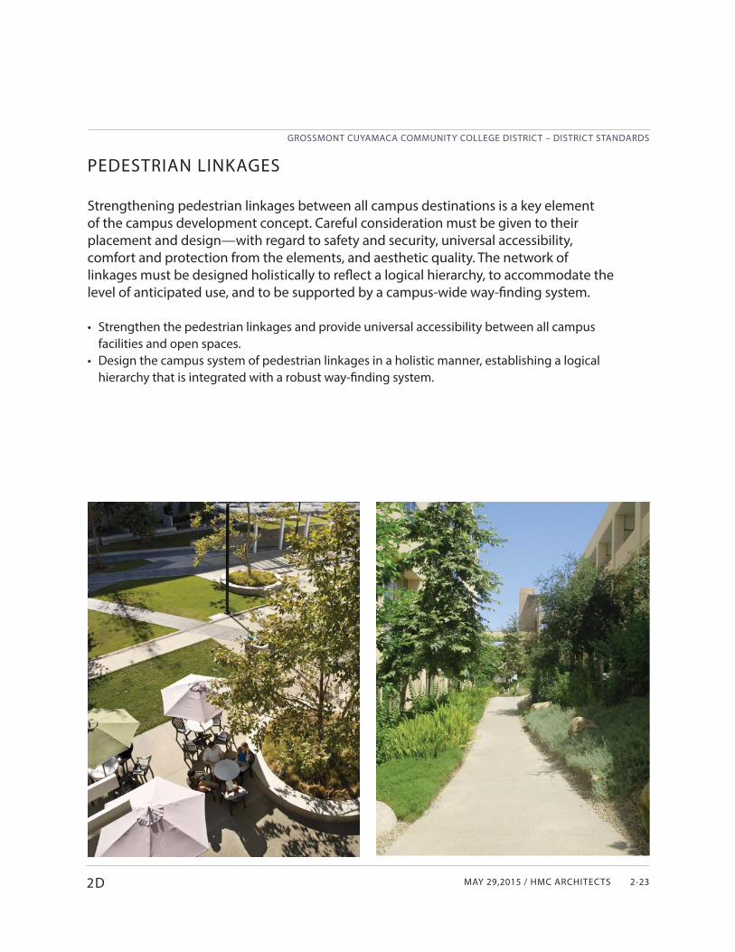
Strengthening pedestrian linkages between all campus destinations is a key element of the campus development concept. Careful consideration must be given to their placement and design—with regard to safety and security, universal accessibility, comfort and protection from the elements, and aesthetic quality. The network of linkages must be designed holistically to refl ect a logical hierarchy, to accommodate the level of anticipated use, and to be supported by a campus-wide way-fi nding system.
• Strengthen the pedestrian linkages and provide universal accessibility between all campus facilities and open spaces.
• Design the campus system of pedestrian linkages in a holistic manner, establishing a logical hierarchy that is integrated with a robust way-fi nding system.
2D
GROSSMONT CUYAMACA COMMUNITY COLLEGE DISTRICT – DISTRICT STANDARDS
CUYAMACA COLLEGE02 CAMPUS DESIGN GUIDELINES2-24
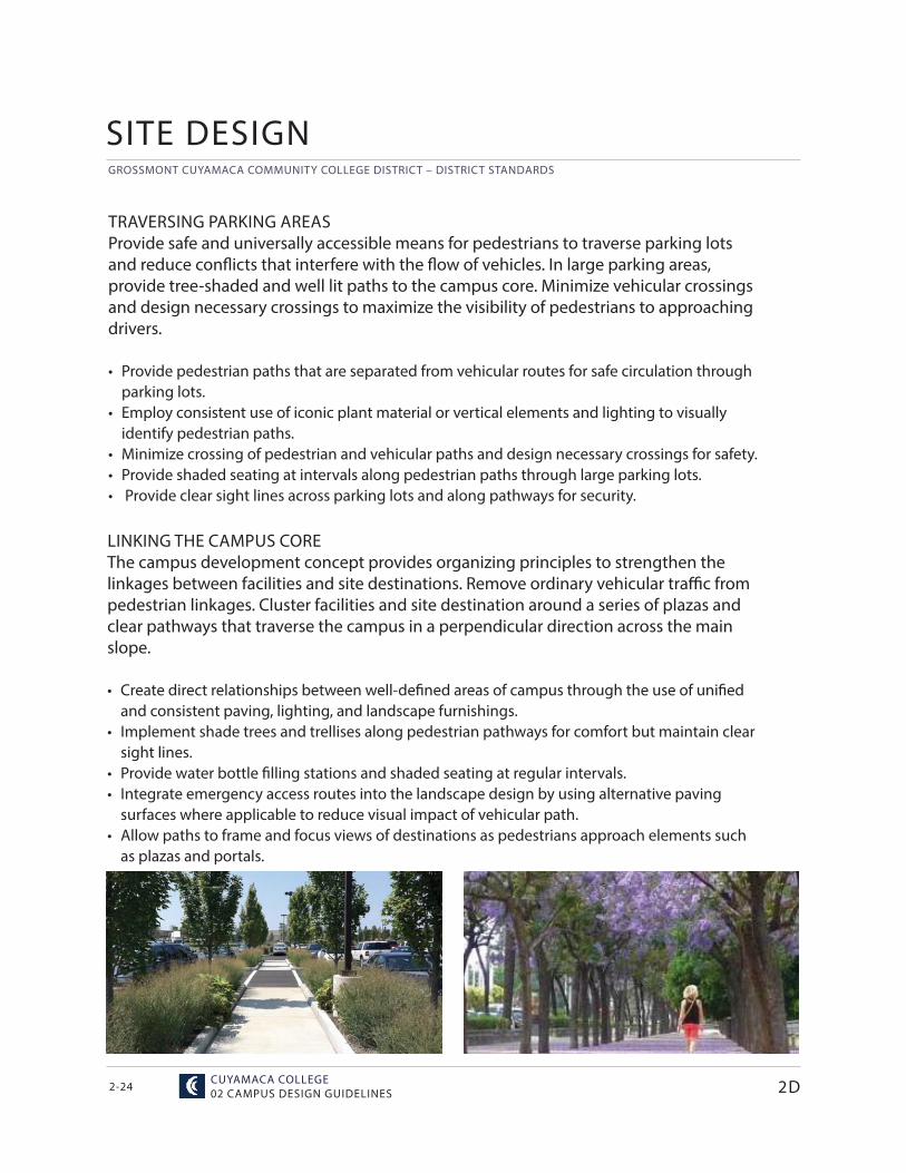
LINKING THE CAMPUS COREThe campus development concept provides organizing principles to strengthen the linkages between facilities and site destinations. Remove ordinary vehicular traffi c from pedestrian linkages. Cluster facilities and site destination around a series of plazas and clear pathways that traverse the campus in a perpendicular direction across the main slope.
• Create direct relationships between well-defi ned areas of campus through the use of unifi ed and consistent paving, lighting, and landscape furnishings.
• Implement shade trees and trellises along pedestrian pathways for comfort but maintain clear sight lines.
• Provide water bottle fi lling stations and shaded seating at regular intervals.• Integrate emergency access routes into the landscape design by using alternative paving
surfaces where applicable to reduce visual impact of vehicular path.• Allow paths to frame and focus views of destinations as pedestrians approach elements such
as plazas and portals.
SITE DESIGN
2D
TRAVERSING PARKING AREASProvide safe and universally accessible means for pedestrians to traverse parking lots and reduce confl icts that interfere with the fl ow of vehicles. In large parking areas, provide tree-shaded and well lit paths to the campus core. Minimize vehicular crossings and design necessary crossings to maximize the visibility of pedestrians to approaching drivers.
• Provide pedestrian paths that are separated from vehicular routes for safe circulation through parking lots.
• Employ consistent use of iconic plant material or vertical elements and lighting to visually identify pedestrian paths.
• Minimize crossing of pedestrian and vehicular paths and design necessary crossings for safety.• Provide shaded seating at intervals along pedestrian paths through large parking lots.• Provide clear sight lines across parking lots and along pathways for security.
MAY 29,2015 / HMC ARCHITECTS
GROSSMONT CUYAMACA COMMUNITY COLLEGE DISTRICT – DISTRICT STANDARDS
2-25
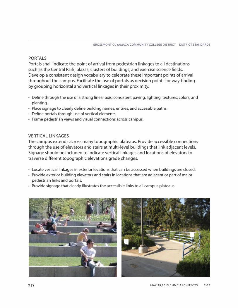
PORTALSPortals shall indicate the point of arrival from pedestrian linkages to all destinations such as the Central Park, plazas, clusters of buildings, and exercise science fi elds. Develop a consistent design vocabulary to celebrate these important points of arrival throughout the campus. Facilitate the use of portals as decision points for way-fi nding by grouping horizontal and vertical linkages in their proximity.
• Defi ne through the use of a strong linear axis, consistent paving, lighting, textures, colors, and planting.
• Place signage to clearly defi ne building names, entries, and accessible paths.• Defi ne portals through use of vertical elements.• Frame pedestrian views and visual connections across campus.
VERTICAL LINKAGESThe campus extends across many topographic plateaus. Provide accessible connections through the use of elevators and stairs at multi-level buildings that link adjacent levels. Signage should be included to indicate vertical linkages and locations of elevators to traverse diff erent topographic elevations grade changes.
• Locate vertical linkages in exterior locations that can be accessed when buildings are closed.• Provide exterior building elevators and stairs in locations that are adjacent or part of major
pedestrian links and portals.• Provide signage that clearly illustrates the accessible links to all campus plateaus.
2D
GROSSMONT CUYAMACA COMMUNITY COLLEGE DISTRICT – DISTRICT STANDARDS
CUYAMACA COLLEGE02 CAMPUS DESIGN GUIDELINES2-26
OPEN SPACES
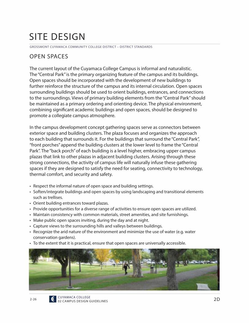
The current layout of the Cuyamaca College Campus is informal and naturalistic. The “Central Park” is the primary organizing feature of the campus and its buildings. Open spaces should be incorporated with the development of new buildings to further reinforce the structure of the campus and its internal circulation. Open spaces surrounding buildings should be used to orient buildings, entrances, and connections to the surroundings. Views of primary building elements from the “Central Park” should be maintained as a primary ordering and orienting device. The physical environment, combining signifi cant academic buildings and open spaces, should be designed to promote a collegiate campus atmosphere.
In the campus development concept gathering spaces serve as connectors between exterior space and building clusters. The plaza focuses and organizes the approach to each building that surrounds it. For the buildings that surround the “Central Park”, “front porches” append the building clusters at the lower level to frame the “Central Park”. The “back porch” of each building is a level higher, embracing upper campus plazas that link to other plazas in adjacent building clusters. Arising through these strong connections, the activity of campus life will naturally infuse these gathering spaces if they are designed to satisfy the need for seating, connectivity to technology, thermal comfort, and security and safety.
• Respect the informal nature of open space and building settings.• Soften/integrate buildings and open spaces by using landscaping and transitional elements
such as trellises.• Orient building entrances toward plazas.• Provide opportunities for a diverse range of activities to ensure open spaces are utilized.• Maintain consistency with common materials, street amenities, and site furnishings.• Make public open spaces inviting, during the day and at night.• Capture views to the surrounding hills and valleys between buildings.• Recognize the arid nature of the environment and minimize the use of water (e.g. water
conservation gardens).• To the extent that it is practical, ensure that open spaces are universally accessible.
SITE DESIGN
2D
MAY 29,2015 / HMC ARCHITECTS
GROSSMONT CUYAMACA COMMUNITY COLLEGE DISTRICT – DISTRICT STANDARDS
2-272D
CENTRAL PARKAt the heart of the campus, this unique amenity often referenced as the Grand Lawn, serves as a multipurpose civic-scaled “green plaza” that welcomes pedestrians coming from the main parking areas. Providing a generously sized main plaza at the portal from the main parking area and “front porch” plazas appended to the surrounding buildings, will allow for a greater variety of uses that must be programmed and supported by the utility infrastructure.
• Ensure universal accessibility to all areas of Central Park and to the surrounding buildings.• Support a variety of uses and gathering activities.• Defi ne passive and active recreation areas using open turf areas, tree placement, shade, and
ground cover selection.• Use pervious walking surfaces with appropriate sub-base and drainage for plazas.• Plant drought-tolerant borders and less thirsty turf varieties to reduce the need for irrigation
while maintaining a park-like quality.• Maintain the “Arboretum” quality of Central Park.• Identify native and adapted specimen trees using interpretive signage where appropriate.
PLAZASWhere plazas are defi ned by the facades and entrances to surrounding buildings, they provide a more formal transition to these buildings. They are enlivened by the indoor-outdoor connection and the expression of the learning that occurs in adjacent buildings. These plazas should provide protected, safe, and comfortable spaces for a variety of activities.
• Implement a consistent landscape palette using identifi ed appropriate plants (see Section 4).• Use pervious surfaces for walking and to accommodate emergency vehicles where
appropriate.• Maximize solar orientation of seating areas for morning sunlight and minimize the exposure to
prevailing winds and afternoon sun.• Ensure that plazas are well lit for typical night time use and special events.• Ensure good visibility for supervision and security.• Orient buildings with corridor views facing open spaces.• Use intimate-scaled courtyards to promote multi-level student, faculty, and community
interaction.
GROSSMONT CUYAMACA COMMUNITY COLLEGE DISTRICT – DISTRICT STANDARDS
CUYAMACA COLLEGE02 CAMPUS DESIGN GUIDELINES2-28
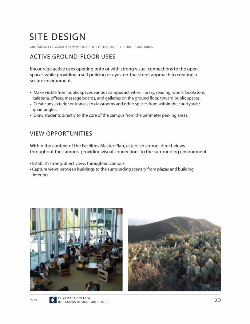
ACTIVE GROUND-FLOOR USES
Encourage active uses opening onto or with strong visual connections to the open spaces while providing a self policing or eyes-on-the-street approach to creating a secure environment.
• Make visible from public spaces various campus activities: library, reading rooms, bookstore, cafeteria, offi ces, message boards, and galleries on the ground fl oor, toward public spaces.• Create any exterior entrances to classrooms and other spaces from within the courtyards/ quadrangles.• Draw students directly to the core of the campus from the perimeter parking areas.
VIEW OPPORTUNITIES
Within the context of the Facilities Master Plan, establish strong, direct views throughout the campus, providing visual connections to the surrounding environment.
• Establish strong, direct views throughout campus.• Capture views between buildings to the surrounding scenery from plazas and building interiors.
SITE DESIGN
2D
MAY 29,2015 / HMC ARCHITECTS
GROSSMONT CUYAMACA COMMUNITY COLLEGE DISTRICT – DISTRICT STANDARDS
2-29
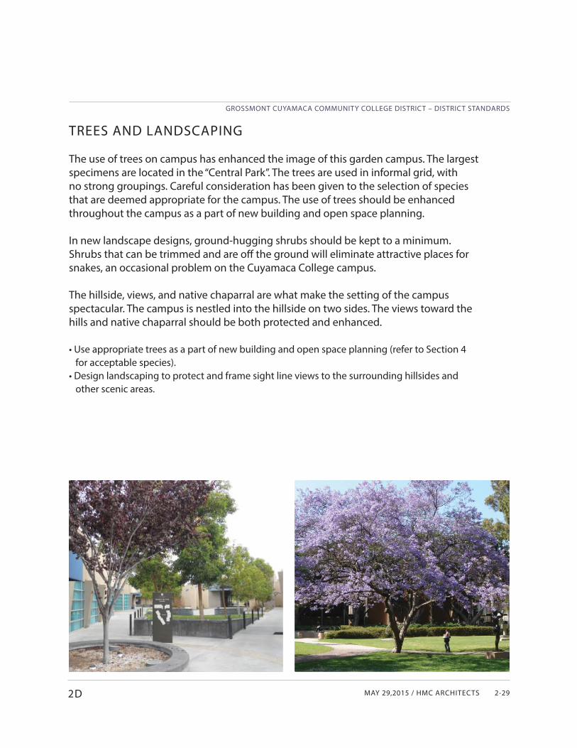
TREES AND LANDSCAPING
The use of trees on campus has enhanced the image of this garden campus. The largest specimens are located in the “Central Park”. The trees are used in informal grid, with no strong groupings. Careful consideration has been given to the selection of species that are deemed appropriate for the campus. The use of trees should be enhanced throughout the campus as a part of new building and open space planning.
In new landscape designs, ground-hugging shrubs should be kept to a minimum. Shrubs that can be trimmed and are off the ground will eliminate attractive places for snakes, an occasional problem on the Cuyamaca College campus.
The hillside, views, and native chaparral are what make the setting of the campus spectacular. The campus is nestled into the hillside on two sides. The views toward the hills and native chaparral should be both protected and enhanced.
• Use appropriate trees as a part of new building and open space planning (refer to Section 4 for acceptable species).• Design landscaping to protect and frame sight line views to the surrounding hillsides and other scenic areas.
2D
GROSSMONT CUYAMACA COMMUNITY COLLEGE DISTRICT – DISTRICT STANDARDS
CUYAMACA COLLEGE02 CAMPUS DESIGN GUIDELINES2-30
Part EARCHITECTURAL DESIGN
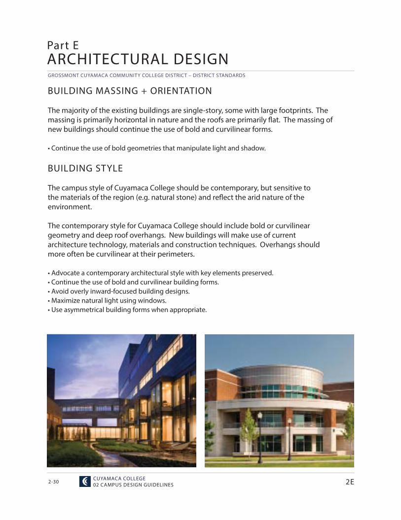
BUILDING MASSING + ORIENTATION
The majority of the existing buildings are single-story, some with large footprints. The massing is primarily horizontal in nature and the roofs are primarily fl at. The massing of new buildings should continue the use of bold and curvilinear forms.
• Continue the use of bold geometries that manipulate light and shadow.
BUILDING STYLE
The campus style of Cuyamaca College should be contemporary, but sensitive to the materials of the region (e.g. natural stone) and refl ect the arid nature of the environment.
The contemporary style for Cuyamaca College should include bold or curvilinear geometry and deep roof overhangs. New buildings will make use of current architecture technology, materials and construction techniques. Overhangs should more often be curvilinear at their perimeters.
• Advocate a contemporary architectural style with key elements preserved.• Continue the use of bold and curvilinear building forms.• Avoid overly inward-focused building designs.• Maximize natural light using windows.• Use asymmetrical building forms when appropriate.
2E
MAY 29,2015 / HMC ARCHITECTS
GROSSMONT CUYAMACA COMMUNITY COLLEGE DISTRICT – DISTRICT STANDARDS
2-31
BUILDING ENTRANCES
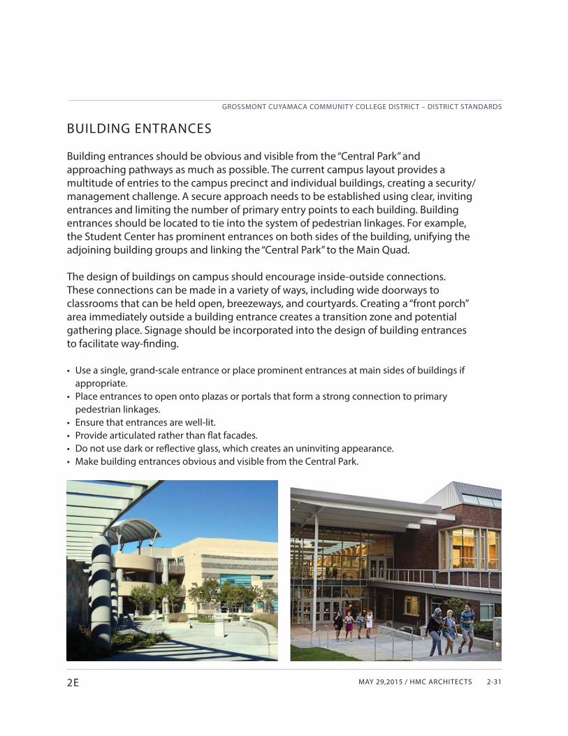
Building entrances should be obvious and visible from the “Central Park” and approaching pathways as much as possible. The current campus layout provides a multitude of entries to the campus precinct and individual buildings, creating a security/management challenge. A secure approach needs to be established using clear, inviting entrances and limiting the number of primary entry points to each building. Building entrances should be located to tie into the system of pedestrian linkages. For example, the Student Center has prominent entrances on both sides of the building, unifying the adjoining building groups and linking the “Central Park” to the Main Quad.
The design of buildings on campus should encourage inside-outside connections. These connections can be made in a variety of ways, including wide doorways to classrooms that can be held open, breezeways, and courtyards. Creating a “front porch” area immediately outside a building entrance creates a transition zone and potential gathering place. Signage should be incorporated into the design of building entrances to facilitate way-finding.
• Use a single, grand-scale entrance or place prominent entrances at main sides of buildings if appropriate.
• Place entrances to open onto plazas or portals that form a strong connection to primary pedestrian linkages.
• Ensure that entrances are well-lit.• Provide articulated rather than fl at facades.• Do not use dark or refl ective glass, which creates an uninviting appearance.• Make building entrances obvious and visible from the Central Park.
2E
GROSSMONT CUYAMACA COMMUNITY COLLEGE DISTRICT – DISTRICT STANDARDS
CUYAMACA COLLEGE02 CAMPUS DESIGN GUIDELINES2-32
EXPRESSION LINES
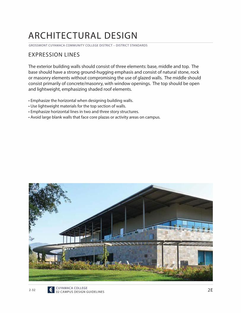
The exterior building walls should consist of three elements: base, middle and top. The base should have a strong ground-hugging emphasis and consist of natural stone, rock or masonry elements without compromising the use of glazed walls. The middle should consist primarily of concrete/masonry, with window openings. The top should be open and lightweight, emphasizing shaded roof elements.
• Emphasize the horizontal when designing building walls.• Use lightweight materials for the top section of walls.• Emphasize horizontal lines in two and three story structures.• Avoid large blank walls that face core plazas or activity areas on campus.
2E
ARCHITECTURAL DESIGN
MAY 29,2015 / HMC ARCHITECTS
GROSSMONT CUYAMACA COMMUNITY COLLEGE DISTRICT – DISTRICT STANDARDS
2-332E
ROOFTOPS
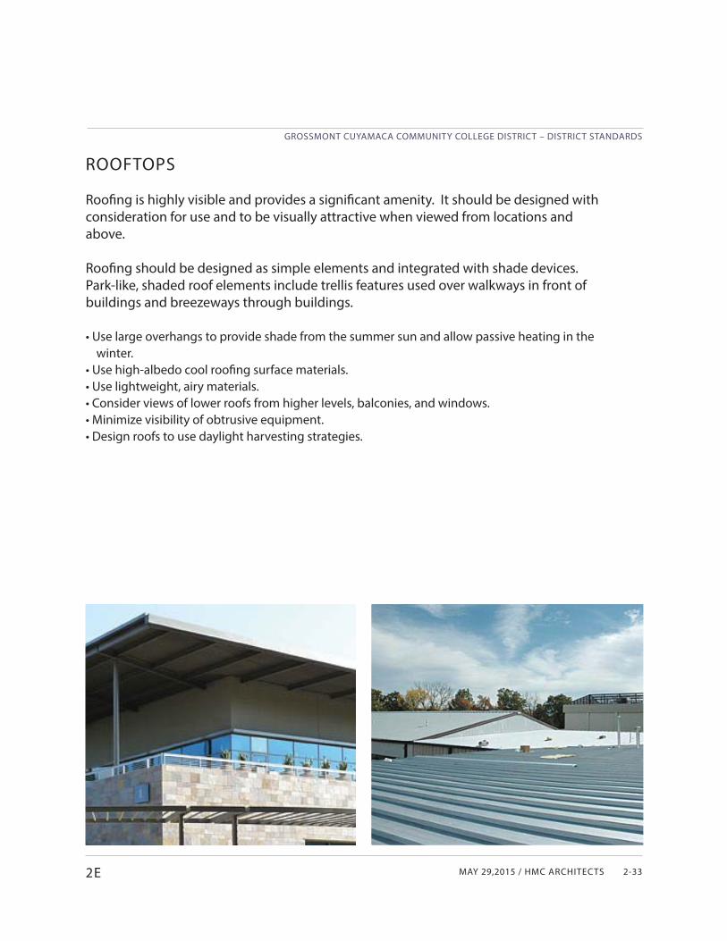
Roofi ng is highly visible and provides a signifi cant amenity. It should be designed with consideration for use and to be visually attractive when viewed from locations and above.
Roofi ng should be designed as simple elements and integrated with shade devices. Park-like, shaded roof elements include trellis features used over walkways in front of buildings and breezeways through buildings.
• Use large overhangs to provide shade from the summer sun and allow passive heating in the winter.
• Use high-albedo cool roofi ng surface materials.• Use lightweight, airy materials.• Consider views of lower roofs from higher levels, balconies, and windows.• Minimize visibility of obtrusive equipment.• Design roofs to use daylight harvesting strategies.
GROSSMONT CUYAMACA COMMUNITY COLLEGE DISTRICT – DISTRICT STANDARDS
CUYAMACA COLLEGE02 CAMPUS DESIGN GUIDELINES2-34
COVERED WALKWAYS
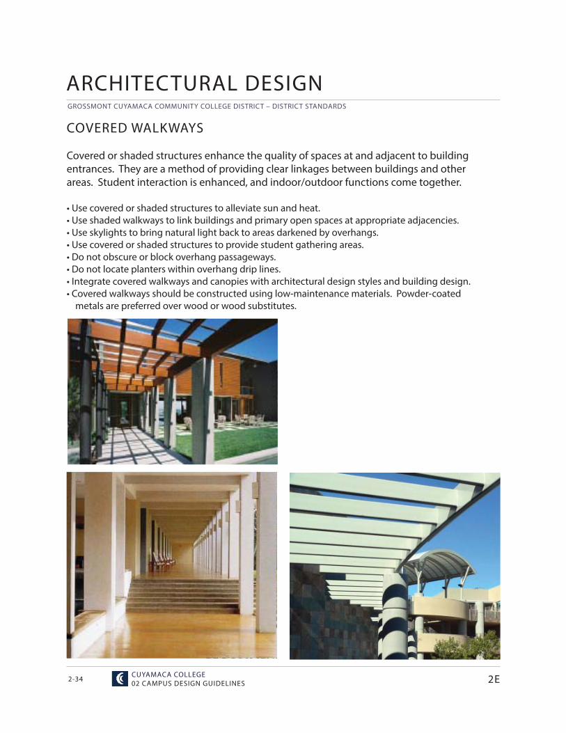
Covered or shaded structures enhance the quality of spaces at and adjacent to building entrances. They are a method of providing clear linkages between buildings and other areas. Student interaction is enhanced, and indoor/outdoor functions come together.
• Use covered or shaded structures to alleviate sun and heat.• Use shaded walkways to link buildings and primary open spaces at appropriate adjacencies.• Use skylights to bring natural light back to areas darkened by overhangs.• Use covered or shaded structures to provide student gathering areas.• Do not obscure or block overhang passageways.• Do not locate planters within overhang drip lines.• Integrate covered walkways and canopies with architectural design styles and building design.• Covered walkways should be constructed using low-maintenance materials. Powder-coated metals are preferred over wood or wood substitutes.
2E
ARCHITECTURAL DESIGN
MAY 29,2015 / HMC ARCHITECTS
GROSSMONT CUYAMACA COMMUNITY COLLEGE DISTRICT – DISTRICT STANDARDS
2-352E
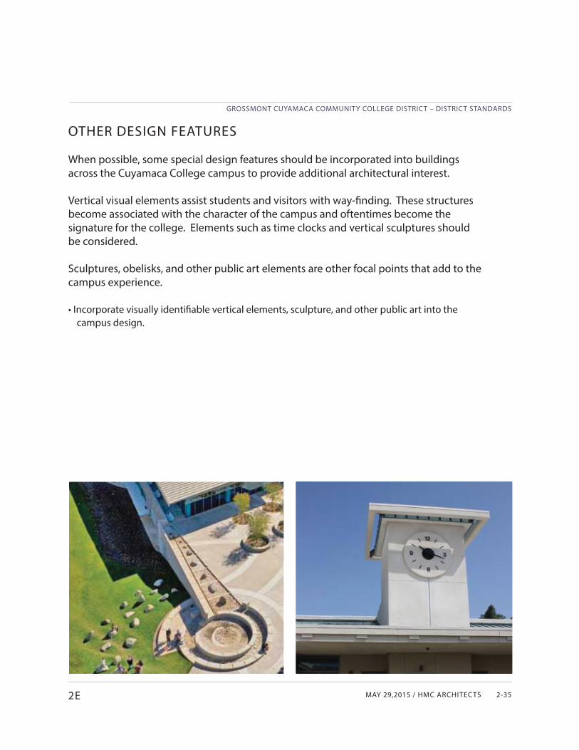
OTHER DESIGN FEATURES
When possible, some special design features should be incorporated into buildings across the Cuyamaca College campus to provide additional architectural interest.
Vertical visual elements assist students and visitors with way-fi nding. These structures become associated with the character of the campus and oftentimes become the signature for the college. Elements such as time clocks and vertical sculptures should be considered.
Sculptures, obelisks, and other public art elements are other focal points that add to the campus experience.
• Incorporate visually identifi able vertical elements, sculpture, and other public art into the campus design.
GROSSMONT CUYAMACA COMMUNITY COLLEGE DISTRICT – DISTRICT STANDARDS
CUYAMACA COLLEGE02 CAMPUS DESIGN GUIDELINES2-36
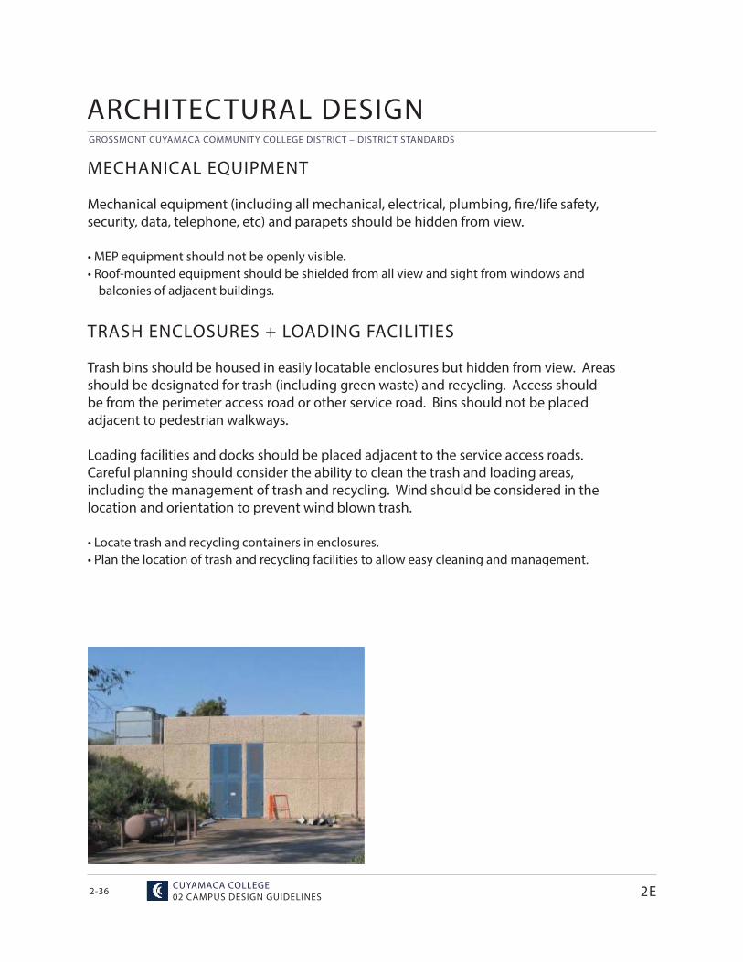
MECHANICAL EQUIPMENT
Mechanical equipment (including all mechanical, electrical, plumbing, fi re/life safety, security, data, telephone, etc) and parapets should be hidden from view.
• MEP equipment should not be openly visible.• Roof-mounted equipment should be shielded from all view and sight from windows and
balconies of adjacent buildings.
2E
ARCHITECTURAL DESIGN
TRASH ENCLOSURES + LOADING FACILITIES
Trash bins should be housed in easily locatable enclosures but hidden from view. Areas should be designated for trash (including green waste) and recycling. Access should be from the perimeter access road or other service road. Bins should not be placed adjacent to pedestrian walkways.
Loading facilities and docks should be placed adjacent to the service access roads. Careful planning should consider the ability to clean the trash and loading areas, including the management of trash and recycling. Wind should be considered in the location and orientation to prevent wind blown trash.
• Locate trash and recycling containers in enclosures.• Plan the location of trash and recycling facilities to allow easy cleaning and management.
MAY 29,2015 / HMC ARCHITECTS
GROSSMONT CUYAMACA COMMUNITY COLLEGE DISTRICT – DISTRICT STANDARDS
2-372E
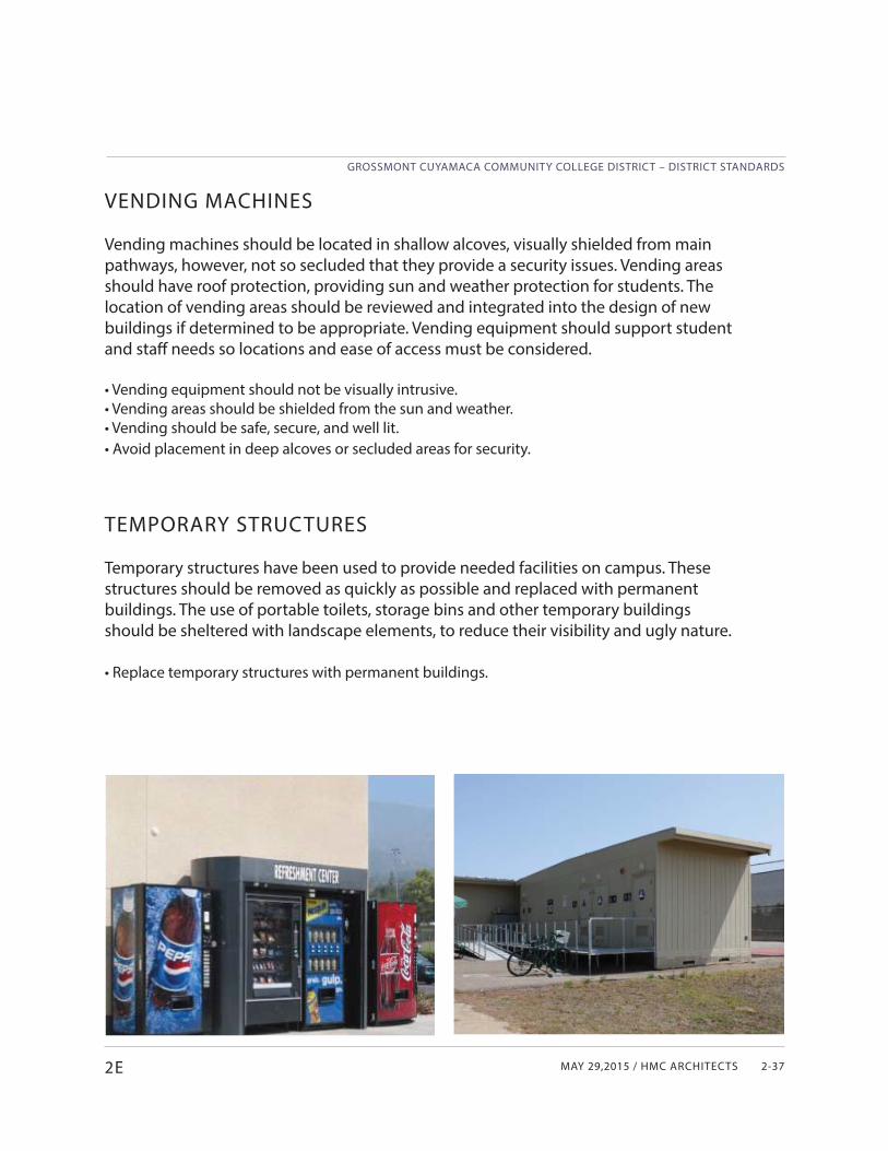
VENDING MACHINES
Vending machines should be located in shallow alcoves, visually shielded from main pathways, however, not so secluded that they provide a security issues. Vending areas should have roof protection, providing sun and weather protection for students. The location of vending areas should be reviewed and integrated into the design of new buildings if determined to be appropriate. Vending equipment should support student and staff needs so locations and ease of access must be considered.
• Vending equipment should not be visually intrusive.• Vending areas should be shielded from the sun and weather.• Vending should be safe, secure, and well lit.• Avoid placement in deep alcoves or secluded areas for security.
TEMPORARY STRUCTURES
Temporary structures have been used to provide needed facilities on campus. These structures should be removed as quickly as possible and replaced with permanent buildings. The use of portable toilets, storage bins and other temporary buildings should be sheltered with landscape elements, to reduce their visibility and ugly nature.
• Replace temporary structures with permanent buildings.
GROSSMONT CUYAMACA COMMUNITY COLLEGE DISTRICT – DISTRICT STANDARDS
CUYAMACA COLLEGE02 CAMPUS DESIGN GUIDELINES2-38 2E
ARCHITECTURAL DESIGN
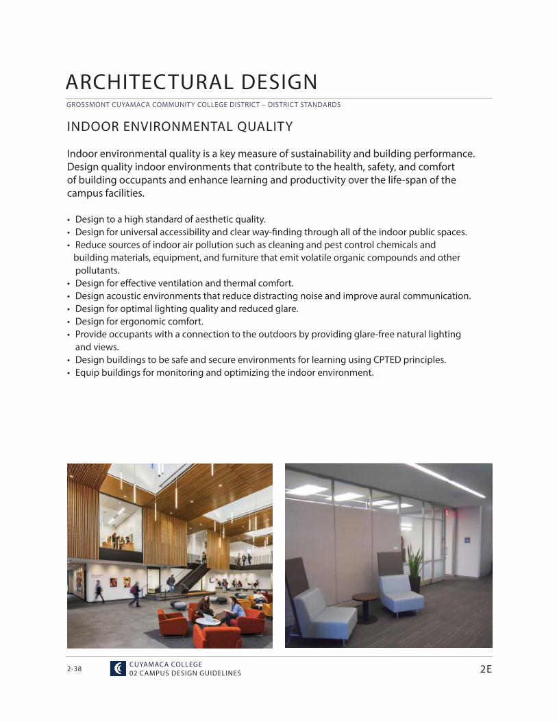
INDOOR ENVIRONMENTAL QUALITY
Indoor environmental quality is a key measure of sustainability and building performance. Design quality indoor environments that contribute to the health, safety, and comfort of building occupants and enhance learning and productivity over the life-span of the campus facilities.
• Design to a high standard of aesthetic quality.• Design for universal accessibility and clear way-fi nding through all of the indoor public spaces.• Reduce sources of indoor air pollution such as cleaning and pest control chemicals and
building materials, equipment, and furniture that emit volatile organic compounds and otherpollutants.
• Design for eff ective ventilation and thermal comfort.• Design acoustic environments that reduce distracting noise and improve aural communication.• Design for optimal lighting quality and reduced glare.• Design for ergonomic comfort.• Provide occupants with a connection to the outdoors by providing glare-free natural lighting
and views.• Design buildings to be safe and secure environments for learning using CPTED principles.• Equip buildings for monitoring and optimizing the indoor environment.
MAY 29,2015 / HMC ARCHITECTS
GROSSMONT CUYAMACA COMMUNITY COLLEGE DISTRICT – DISTRICT STANDARDS
2-392E
ENERGY + WATER
Design new facilities, major renovations, and site improvement projects to minimize the use of water and energy, including electricity and fuel. Use technology to measure and improve energy and water conservation.
• Design in accordance with the GCCCD standards for energy and water use intensity. • Employ the building occupants at the start of the programming process for input. • Explore and select strategies that take advantage of synergies to optimize building
performance. • Equip buildings for monitoring and optimizing energy and water using systems.• Explore opportunities to integrate photovoltaic systems into the design of facilities.
ENVIRONMENTALLY PREFERRED MATERIALS
Design new facilities, major renovations, and site improvement projects to use environmentally preferred materials.
• Build and furnish with durable and easily maintained materials.• Build with materials that are locally sourced, rapidly renewable, contain recycled content, and
are likely to be recycled or reused.• Maintain healthy indoor air quality by selecting appropriate building materials and furnishings.
WASTE REDUCTION + MANAGEMENT
Design and equip new facilities, major renovations, and site improvement projects to support campus programs to reduce and divert waste from landfi lls.
• Follow best practices for the management of demolition materials and construction waste.• Explore on-campus opportunities to reuse materials from demolished facilities and site work.• Design buildings with space to support the campus recycling plan.
GROSSMONT CUYAMACA COMMUNITY COLLEGE DISTRICT – DISTRICT STANDARDS
CUYAMACA COLLEGE02 CAMPUS DESIGN GUIDELINES2-40
Part F
CONCRETE/MASONRY WALLS, COLUMNS, + OTHER NATURAL BUILDING MATERIALS
The materials listed in the guidelines below should be used with new (and redesigned existing) buildings and open spaces on campus. The use of materials should be designed in a contemporary manner, with reference to the method of application within the existing campus buildings. The use of ‘stucco’ is generally acceptable in certain areas where the material will not get damaged or abused.
CONCRETE/MASONRY WALLS & CONCRETE COLUMNSThe use of smooth wall materials, such as concrete/masonry, should be prominent throughout new campus buildings as well as remodeled existing buildings. Concrete/masonry should be painted in a buff color or earth tones with some accents. Building materials should refl ect an institutional quality and feeling. Expressed columns should be used on the exterior of buildings.
OTHER BUILDING MATERIALSOther materials, in earth tones, can be introduced into the building and landscape design. Materials such as stone and limestone can be used in horizontal banding, to provide a cap to landscape or stair walls and to create a horizontal line at the base of buildings
The following materials should be used:
• Stone walls and detailing where appropriate• Smooth wall materials, including concrete/masonry walls• Textured material • Lighter palette of color for major massing• Articulated simple roof structures with standing seam metal roofs• Round concrete columns • Stone wall application, in buff or natural earth tones• Large glass elements
EXTERIOR BUILDING MATERIALS
2F
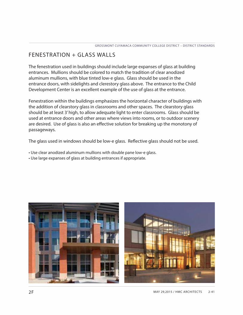
MAY 29,2015 / HMC ARCHITECTS
GROSSMONT CUYAMACA COMMUNITY COLLEGE DISTRICT – DISTRICT STANDARDS
2-412F
FENESTRATION + GLASS WALLS
The fenestration used in buildings should include large expanses of glass at building entrances. Mullions should be colored to match the tradition of clear anodized aluminum mullions, with blue tinted low-e glass. Glass should be used in the entrance doors, with sidelights and clerestory glass above. The entrance to the Child Development Center is an excellent example of the use of glass at the entrance.
Fenestration within the buildings emphasizes the horizontal character of buildings with the addition of clearstory glass in classrooms and other spaces. The clearstory glass should be at least 3’ high, to allow adequate light to enter classrooms. Glass should be used at entrance doors and other areas where views into rooms, or to outdoor scenery are desired. Use of glass is also an eff ective solution for breaking up the monotony of passageways.
The glass used in windows should be low-e glass. Refl ective glass should not be used.
• Use clear anodized aluminum mullions with double pane low-e glass.• Use large expanses of glass at building entrances if appropriate.
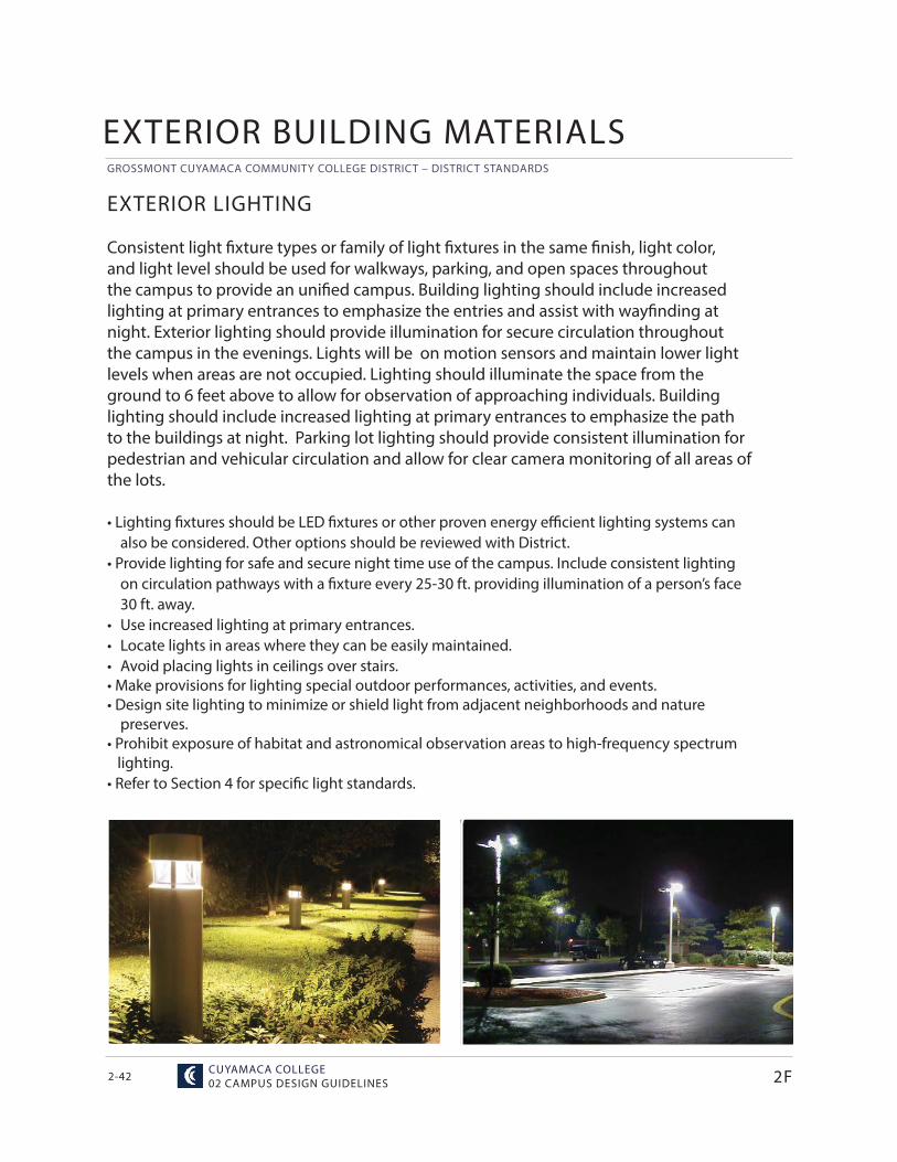
GROSSMONT CUYAMACA COMMUNITY COLLEGE DISTRICT – DISTRICT STANDARDS
CUYAMACA COLLEGE02 CAMPUS DESIGN GUIDELINES2-42 2F
EXTERIOR BUILDING MATERIALS
EXTERIOR LIGHTING
Consistent light fi xture types or family of light fi xtures in the same fi nish, light color, and light level should be used for walkways, parking, and open spaces throughout the campus to provide an unifi ed campus. Building lighting should include increased lighting at primary entrances to emphasize the entries and assist with wayfi nding at night. Exterior lighting should provide illumination for secure circulation throughout the campus in the evenings. Lights will be on motion sensors and maintain lower light levels when areas are not occupied. Lighting should illuminate the space from the ground to 6 feet above to allow for observation of approaching individuals. Building lighting should include increased lighting at primary entrances to emphasize the path to the buildings at night. Parking lot lighting should provide consistent illumination for pedestrian and vehicular circulation and allow for clear camera monitoring of all areas of the lots.
• Lighting fi xtures should be LED fi xtures or other proven energy effi cient lighting systems can also be considered. Other options should be reviewed with District.
• Provide lighting for safe and secure night time use of the campus. Include consistent lighting on circulation pathways with a fi xture every 25-30 ft. providing illumination of a person’s face 30 ft. away.
• Use increased lighting at primary entrances.• Locate lights in areas where they can be easily maintained. • Avoid placing lights in ceilings over stairs. • Make provisions for lighting special outdoor performances, activities, and events.• Design site lighting to minimize or shield light from adjacent neighborhoods and nature
preserves.• Prohibit exposure of habitat and astronomical observation areas to high-frequency spectrum lighting.• Refer to Section 4 for specifi c light standards.
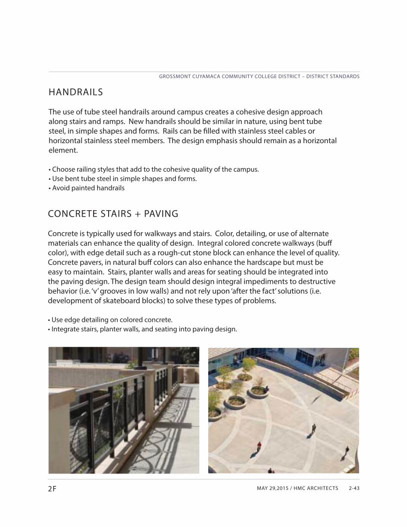
MAY 29,2015 / HMC ARCHITECTS
GROSSMONT CUYAMACA COMMUNITY COLLEGE DISTRICT – DISTRICT STANDARDS
2-432F
HANDRAILS
The use of tube steel handrails around campus creates a cohesive design approach along stairs and ramps. New handrails should be similar in nature, using bent tube steel, in simple shapes and forms. Rails can be fi lled with stainless steel cables or horizontal stainless steel members. The design emphasis should remain as a horizontal element.
• Choose railing styles that add to the cohesive quality of the campus.• Use bent tube steel in simple shapes and forms.• Avoid painted handrails
CONCRETE STAIRS + PAVING
Concrete is typically used for walkways and stairs. Color, detailing, or use of alternate materials can enhance the quality of design. Integral colored concrete walkways (buff color), with edge detail such as a rough-cut stone block can enhance the level of quality. Concrete pavers, in natural buff colors can also enhance the hardscape but must be easy to maintain. Stairs, planter walls and areas for seating should be integrated into the paving design. The design team should design integral impediments to destructive behavior (i.e. ‘v’ grooves in low walls) and not rely upon ‘after the fact’ solutions (i.e. development of skateboard blocks) to solve these types of problems.
• Use edge detailing on colored concrete. • Integrate stairs, planter walls, and seating into paving design.
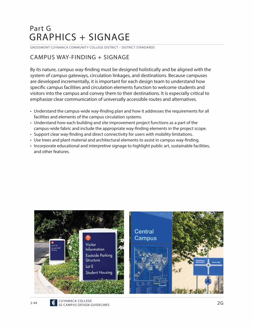
GROSSMONT CUYAMACA COMMUNITY COLLEGE DISTRICT – DISTRICT STANDARDS
CUYAMACA COLLEGE02 CAMPUS DESIGN GUIDELINES2-44
CAMPUS WAY-FINDING + SIGNAGE
By its nature, campus way-fi nding must be designed holistically and be aligned with the system of campus gateways, circulation linkages, and destinations. Because campuses are developed incrementally, it is important for each design team to understand how specifi c campus facilities and circulation elements function to welcome students and visitors into the campus and convey them to their destinations. It is especially critical to emphasize clear communication of universally accessible routes and alternatives.
• Understand the campus-wide way-fi nding plan and how it addresses the requirements for all facilities and elements of the campus circulation systems.
• Understand how each building and site improvement project functions as a part of the campus-wide fabric and include the appropriate way-fi nding elements in the project scope.
• Support clear way-fi nding and direct connectivity for users with mobility limitations.• Use trees and plant material and architectural elements to assist in campus way-finding. • Incorporate educational and interpretive signage to highlight public art, sustainable facilities,
and other features.
Part GGRAPHICS + SIGNAGE
2G
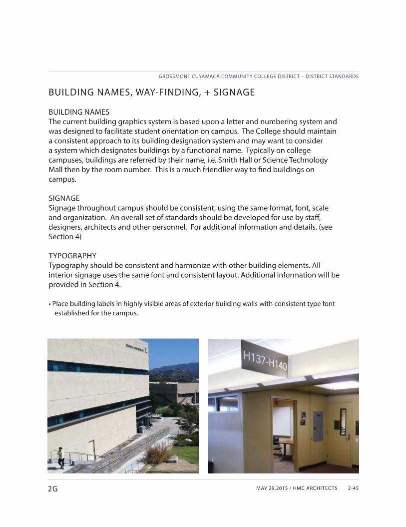
MAY 29,2015 / HMC ARCHITECTS
GROSSMONT CUYAMACA COMMUNITY COLLEGE DISTRICT – DISTRICT STANDARDS
2-45
BUILDING NAMES, WAY-FINDING, + SIGNAGE
BUILDING NAMESThe current building graphics system is based upon a letter and numbering system and was designed to facilitate student orientation on campus. The College should maintain a consistent approach to its building designation system and may want to consider a system which designates buildings by a functional name. Typically on college campuses, buildings are referred by their name, i.e. Smith Hall or Science Technology Mall then by the room number. This is a much friendlier way to fi nd buildings on campus. SIGNAGESignage throughout campus should be consistent, using the same format, font, scale and organization. An overall set of standards should be developed for use by staff , designers, architects and other personnel. For additional information and details. (see Section 4) TYPOGRAPHYTypography should be consistent and harmonize with other building elements. All interior signage uses the same font and consistent layout. Additional information will be provided in Section 4.
• Place building labels in highly visible areas of exterior building walls with consistent type font established for the campus.
2G
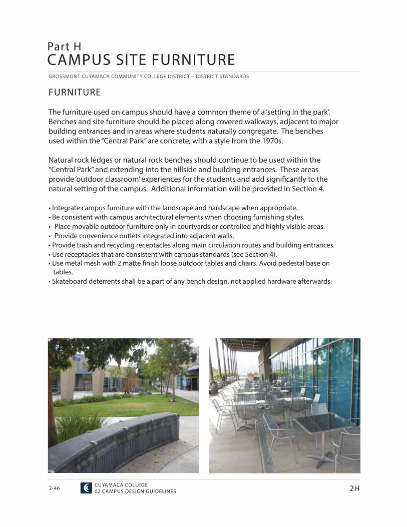
GROSSMONT CUYAMACA COMMUNITY COLLEGE DISTRICT – DISTRICT STANDARDS
CUYAMACA COLLEGE02 CAMPUS DESIGN GUIDELINES2-46
FURNITURE
The furniture used on campus should have a common theme of a ‘setting in the park’. Benches and site furniture should be placed along covered walkways, adjacent to major building entrances and in areas where students naturally congregate. The benches used within the “Central Park” are concrete, with a style from the 1970s.
Natural rock ledges or natural rock benches should continue to be used within the “Central Park” and extending into the hillside and building entrances. These areas provide ‘outdoor classroom’ experiences for the students and add signifi cantly to the natural setting of the campus. Additional information will be provided in Section 4.
• Integrate campus furniture with the landscape and hardscape when appropriate.• Be consistent with campus architectural elements when choosing furnishing styles.• Place movable outdoor furniture only in courtyards or controlled and highly visible areas.• Provide convenience outlets integrated into adjacent walls.• Provide trash and recycling receptacles along main circulation routes and building entrances.• Use receptacles that are consistent with campus standards (see Section 4).• Use metal mesh with 2 matte fi nish loose outdoor tables and chairs. Avoid pedestal base on tables.• Skateboard deterrents shall be a part of any bench design, not applied hardware afterwards.
Part HCAMPUS SITE FURNITURE
2H
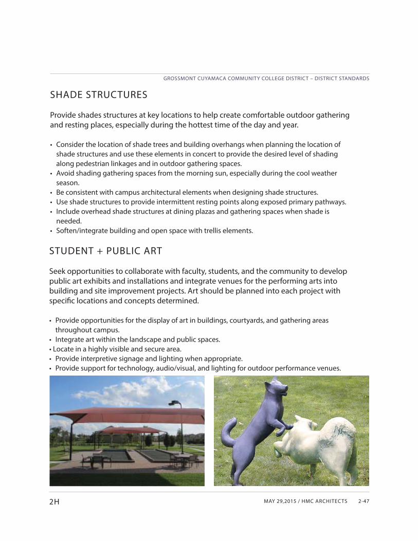
MAY 29,2015 / HMC ARCHITECTS
GROSSMONT CUYAMACA COMMUNITY COLLEGE DISTRICT – DISTRICT STANDARDS
2-47
SHADE STRUCTURES
Provide shades structures at key locations to help create comfortable outdoor gathering and resting places, especially during the hottest time of the day and year.
• Consider the location of shade trees and building overhangs when planning the location of shade structures and use these elements in concert to provide the desired level of shading along pedestrian linkages and in outdoor gathering spaces.
• Avoid shading gathering spaces from the morning sun, especially during the cool weather season.
• Be consistent with campus architectural elements when designing shade structures.• Use shade structures to provide intermittent resting points along exposed primary pathways.• Include overhead shade structures at dining plazas and gathering spaces when shade is
needed.• Soften/integrate building and open space with trellis elements.
2H
STUDENT + PUBLIC ART
Seek opportunities to collaborate with faculty, students, and the community to develop public art exhibits and installations and integrate venues for the performing arts into building and site improvement projects. Art should be planned into each project with specifi c locations and concepts determined.
• Provide opportunities for the display of art in buildings, courtyards, and gathering areas throughout campus.
• Integrate art within the landscape and public spaces.• Locate in a highly visible and secure area.• Provide interpretive signage and lighting when appropriate.• Provide support for technology, audio/visual, and lighting for outdoor performance venues.
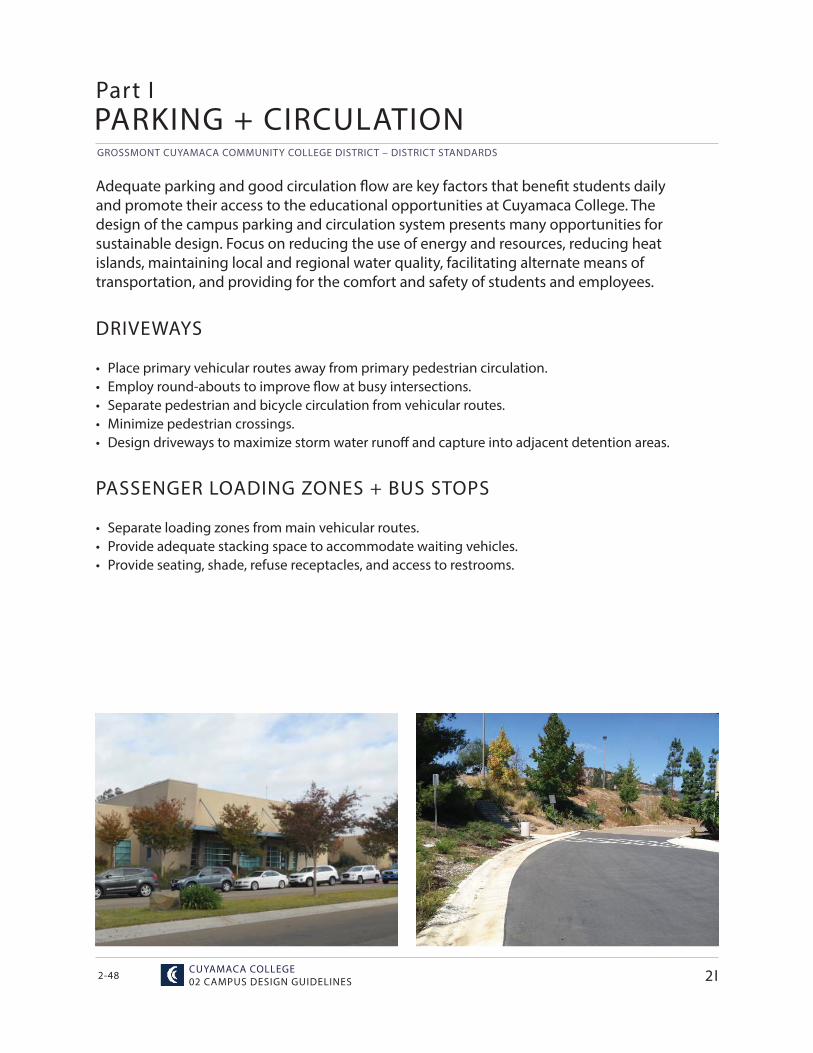
GROSSMONT CUYAMACA COMMUNITY COLLEGE DISTRICT – DISTRICT STANDARDS
CUYAMACA COLLEGE02 CAMPUS DESIGN GUIDELINES2-48
Adequate parking and good circulation fl ow are key factors that benefi t students daily and promote their access to the educational opportunities at Cuyamaca College. The design of the campus parking and circulation system presents many opportunities for sustainable design. Focus on reducing the use of energy and resources, reducing heat islands, maintaining local and regional water quality, facilitating alternate means of transportation, and providing for the comfort and safety of students and employees.
DRIVEWAYS
• Place primary vehicular routes away from primary pedestrian circulation.• Employ round-abouts to improve fl ow at busy intersections.• Separate pedestrian and bicycle circulation from vehicular routes.• Minimize pedestrian crossings.• Design driveways to maximize storm water runoff and capture into adjacent detention areas.
Part IPARKING + CIRCULATION
PASSENGER LOADING ZONES + BUS STOPS
• Separate loading zones from main vehicular routes.• Provide adequate stacking space to accommodate waiting vehicles.• Provide seating, shade, refuse receptacles, and access to restrooms.
2I
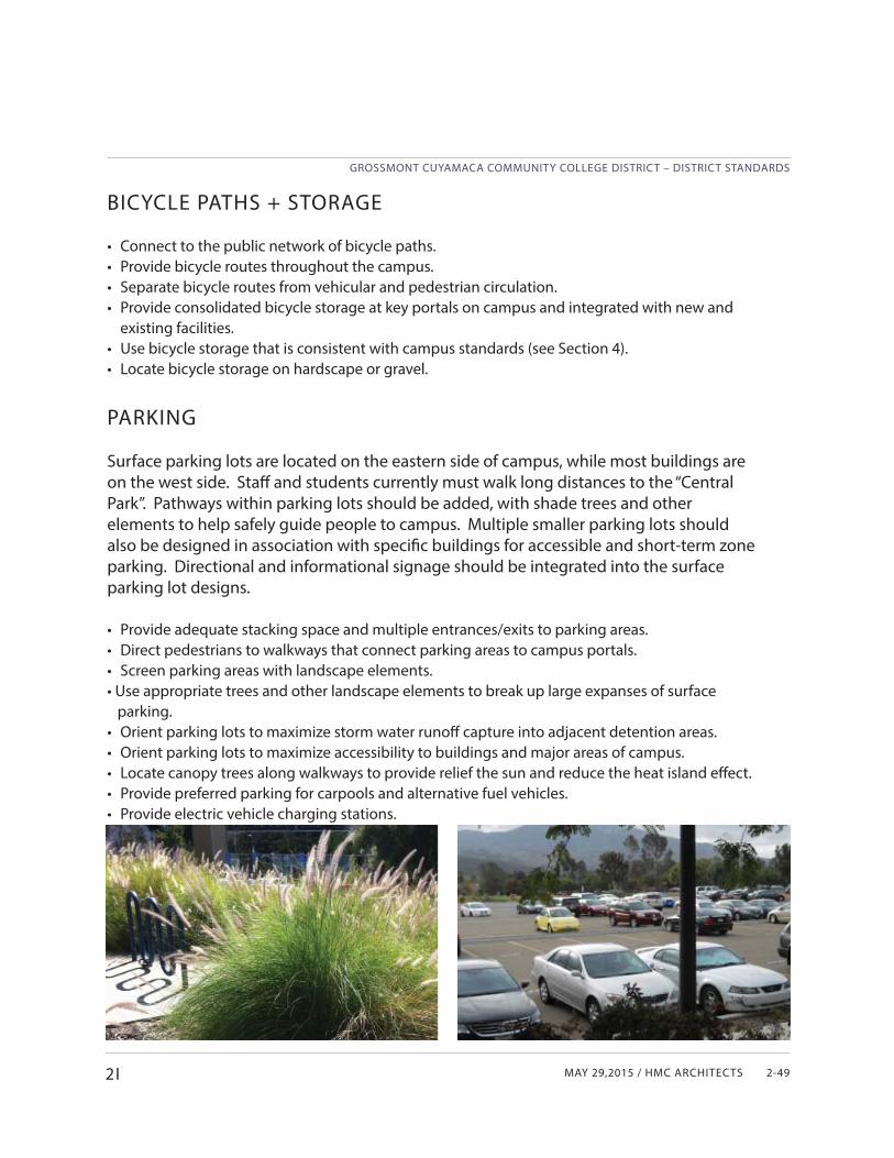
MAY 29,2015 / HMC ARCHITECTS
GROSSMONT CUYAMACA COMMUNITY COLLEGE DISTRICT – DISTRICT STANDARDS
2-49
BICYCLE PATHS + STORAGE
• Connect to the public network of bicycle paths.• Provide bicycle routes throughout the campus.• Separate bicycle routes from vehicular and pedestrian circulation. • Provide consolidated bicycle storage at key portals on campus and integrated with new and
existing facilities.• Use bicycle storage that is consistent with campus standards (see Section 4).• Locate bicycle storage on hardscape or gravel.
PARKING
Surface parking lots are located on the eastern side of campus, while most buildings are on the west side. Staff and students currently must walk long distances to the “Central Park”. Pathways within parking lots should be added, with shade trees and other elements to help safely guide people to campus. Multiple smaller parking lots should also be designed in association with specifi c buildings for accessible and short-term zone parking. Directional and informational signage should be integrated into the surface parking lot designs.
• Provide adequate stacking space and multiple entrances/exits to parking areas.• Direct pedestrians to walkways that connect parking areas to campus portals.• Screen parking areas with landscape elements.• Use appropriate trees and other landscape elements to break up large expanses of surface parking.• Orient parking lots to maximize storm water runoff capture into adjacent detention areas.• Orient parking lots to maximize accessibility to buildings and major areas of campus.• Locate canopy trees along walkways to provide relief the sun and reduce the heat island eff ect.• Provide preferred parking for carpools and alternative fuel vehicles. • Provide electric vehicle charging stations.
2I

GROSSMONT CUYAMACA COMMUNITY COLLEGE DISTRICT – DISTRICT STANDARDS
GROSSMONT COLLEGE02 CAMPUS DESIGN GUIDELINES2-50
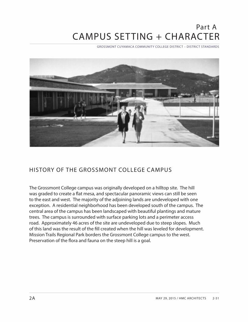
MAY 29, 2015 / HMC ARCHITECTS
GROSSMONT CUYAMACA COMMUNITY COLLEGE DISTRICT – DISTRICT STANDARDS
2-512A
HISTORY OF THE GROSSMONT COLLEGE CAMPUS
The Grossmont College campus was originally developed on a hilltop site. The hill was graded to create a fl at mesa, and spectacular panoramic views can still be seen to the east and west. The majority of the adjoining lands are undeveloped with one exception. A residential neighborhood has been developed south of the campus. The central area of the campus has been landscaped with beautiful plantings and mature trees. The campus is surrounded with surface parking lots and a perimeter access road. Approximately 46 acres of the site are undeveloped due to steep slopes. Much of this land was the result of the fi ll created when the hill was leveled for development. Mission Trails Regional Park borders the Grossmont College campus to the west. Preservation of the fl ora and fauna on the steep hill is a goal.
CAMPUS SETTING + CHARACTERPart A
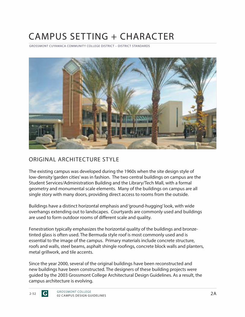
GROSSMONT CUYAMACA COMMUNITY COLLEGE DISTRICT – DISTRICT STANDARDS
GROSSMONT COLLEGE02 CAMPUS DESIGN GUIDELINES2-52
ORIGINAL ARCHITECTURE STYLE
The existing campus was developed during the 1960s when the site design style of low-density ‘garden cities’ was in fashion. The two central buildings on campus are the Student Services/Administration Building and the Library/Tech Mall, with a formal geometry and monumental scale elements. Many of the buildings on campus are all single story with many doors, providing direct access to rooms from the outside.
Buildings have a distinct horizontal emphasis and ‘ground-hugging’ look, with wide overhangs extending out to landscapes. Courtyards are commonly used and buildings are used to form outdoor rooms of diff erent scale and quality.
Fenestration typically emphasizes the horizontal quality of the buildings and bronze-tinted glass is often used. The Bermuda style roof is most commonly used and is essential to the image of the campus. Primary materials include concrete structure, roofs and walls, steel beams, asphalt shingle roofi ngs, concrete block walls and planters, metal grillwork, and tile accents.
Since the year 2000, several of the original buildings have been reconstructed and new buildings have been constructed. The designers of these building projects were guided by the 2003 Grossmont College Architectural Design Guidelines. As a result, the campus architecture is evolving.
2A
CAMPUS SETTING + CHARACTER
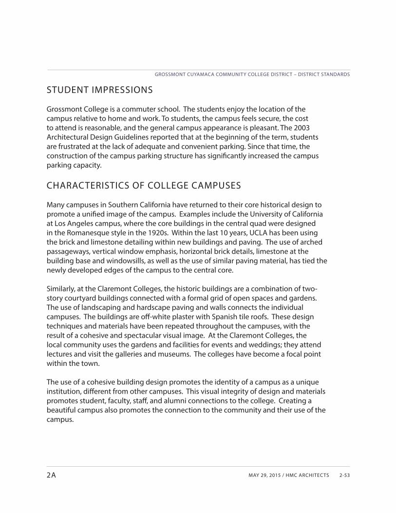
MAY 29, 2015 / HMC ARCHITECTS
GROSSMONT CUYAMACA COMMUNITY COLLEGE DISTRICT – DISTRICT STANDARDS
2-532A
STUDENT IMPRESSIONS
Grossmont College is a commuter school. The students enjoy the location of the campus relative to home and work. To students, the campus feels secure, the cost to attend is reasonable, and the general campus appearance is pleasant. The 2003 Architectural Design Guidelines reported that at the beginning of the term, students are frustrated at the lack of adequate and convenient parking. Since that time, the construction of the campus parking structure has signifi cantly increased the campus parking capacity.
CHARACTERISTICS OF COLLEGE CAMPUSES
Many campuses in Southern California have returned to their core historical design to promote a unifi ed image of the campus. Examples include the University of California at Los Angeles campus, where the core buildings in the central quad were designed in the Romanesque style in the 1920s. Within the last 10 years, UCLA has been using the brick and limestone detailing within new buildings and paving. The use of arched passageways, vertical window emphasis, horizontal brick details, limestone at the building base and windowsills, as well as the use of similar paving material, has tied the newly developed edges of the campus to the central core.
Similarly, at the Claremont Colleges, the historic buildings are a combination of two-story courtyard buildings connected with a formal grid of open spaces and gardens. The use of landscaping and hardscape paving and walls connects the individual campuses. The buildings are off -white plaster with Spanish tile roofs. These design techniques and materials have been repeated throughout the campuses, with the result of a cohesive and spectacular visual image. At the Claremont Colleges, the local community uses the gardens and facilities for events and weddings; they attend lectures and visit the galleries and museums. The colleges have become a focal point within the town.
The use of a cohesive building design promotes the identity of a campus as a unique institution, diff erent from other campuses. This visual integrity of design and materials promotes student, faculty, staff , and alumni connections to the college. Creating a beautiful campus also promotes the connection to the community and their use of the campus.
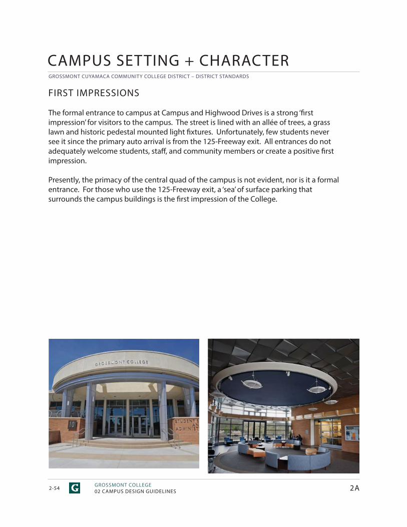
GROSSMONT CUYAMACA COMMUNITY COLLEGE DISTRICT – DISTRICT STANDARDS
GROSSMONT COLLEGE02 CAMPUS DESIGN GUIDELINES2-54
FIRST IMPRESSIONS
The formal entrance to campus at Campus and Highwood Drives is a strong ‘fi rst impression’ for visitors to the campus. The street is lined with an allée of trees, a grass lawn and historic pedestal mounted light fi xtures. Unfortunately, few students never see it since the primary auto arrival is from the 125-Freeway exit. All entrances do not adequately welcome students, staff , and community members or create a positive fi rst impression.
Presently, the primacy of the central quad of the campus is not evident, nor is it a formal entrance. For those who use the 125-Freeway exit, a ‘sea’ of surface parking that surrounds the campus buildings is the fi rst impression of the College.
CAMPUS SETTING + CHARACTER
2A
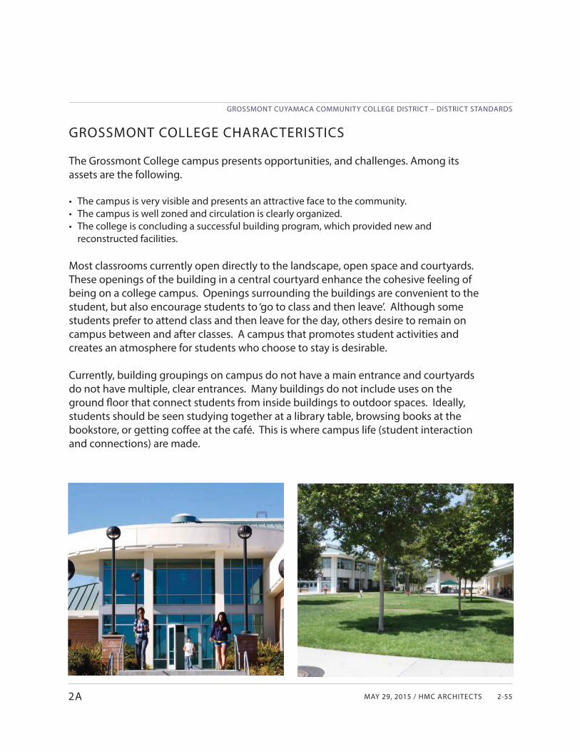
MAY 29, 2015 / HMC ARCHITECTS
GROSSMONT CUYAMACA COMMUNITY COLLEGE DISTRICT – DISTRICT STANDARDS
2-55
GROSSMONT COLLEGE CHARACTERISTICS
The Grossmont College campus presents opportunities, and challenges. Among its assets are the following.
• The campus is very visible and presents an attractive face to the community.• The campus is well zoned and circulation is clearly organized.• The college is concluding a successful building program, which provided new and
reconstructed facilities.
Most classrooms currently open directly to the landscape, open space and courtyards. These openings of the building in a central courtyard enhance the cohesive feeling of being on a college campus. Openings surrounding the buildings are convenient to the student, but also encourage students to ‘go to class and then leave’. Although some students prefer to attend class and then leave for the day, others desire to remain on campus between and after classes. A campus that promotes student activities and creates an atmosphere for students who choose to stay is desirable.
Currently, building groupings on campus do not have a main entrance and courtyards do not have multiple, clear entrances. Many buildings do not include uses on the ground fl oor that connect students from inside buildings to outdoor spaces. Ideally, students should be seen studying together at a library table, browsing books at the bookstore, or getting coff ee at the café. This is where campus life (student interaction and connections) are made.
2A
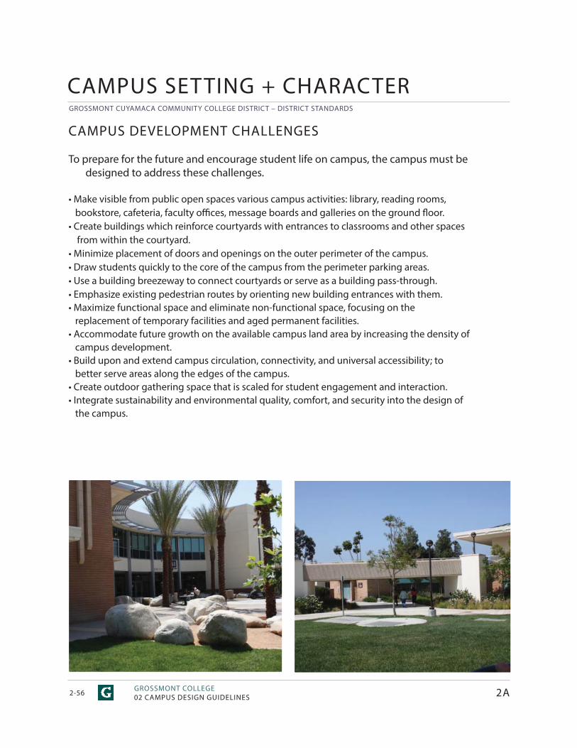
GROSSMONT CUYAMACA COMMUNITY COLLEGE DISTRICT – DISTRICT STANDARDS
GROSSMONT COLLEGE02 CAMPUS DESIGN GUIDELINES2-56
CAMPUS DEVELOPMENT CHALLENGES
To prepare for the future and encourage student life on campus, the campus must be designed to address these challenges.
• Make visible from public open spaces various campus activities: library, reading rooms, bookstore, cafeteria, faculty offi ces, message boards and galleries on the ground fl oor.• Create buildings which reinforce courtyards with entrances to classrooms and other spaces
from within the courtyard.• Minimize placement of doors and openings on the outer perimeter of the campus. • Draw students quickly to the core of the campus from the perimeter parking areas.• Use a building breezeway to connect courtyards or serve as a building pass-through.• Emphasize existing pedestrian routes by orienting new building entrances with them.• Maximize functional space and eliminate non-functional space, focusing on the replacement of temporary facilities and aged permanent facilities.• Accommodate future growth on the available campus land area by increasing the density of campus development.• Build upon and extend campus circulation, connectivity, and universal accessibility; to better serve areas along the edges of the campus.• Create outdoor gathering space that is scaled for student engagement and interaction.• Integrate sustainability and environmental quality, comfort, and security into the design of the campus.
2A
CAMPUS SETTING + CHARACTER
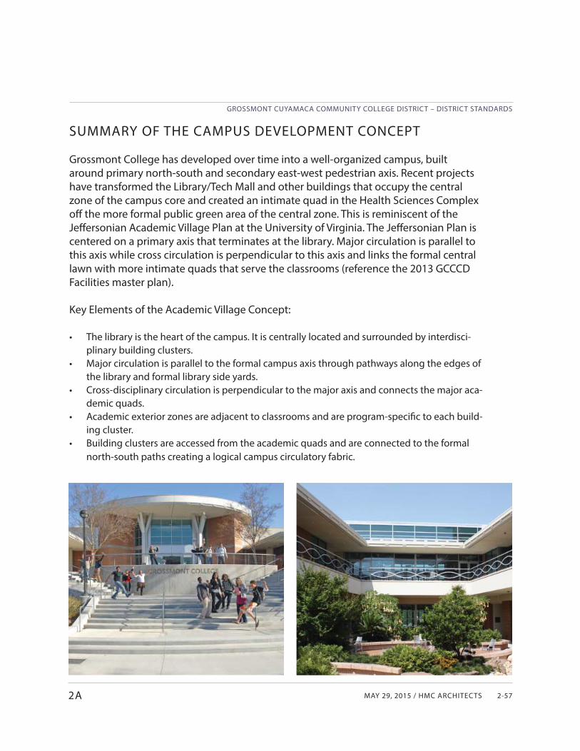
MAY 29, 2015 / HMC ARCHITECTS
GROSSMONT CUYAMACA COMMUNITY COLLEGE DISTRICT – DISTRICT STANDARDS
2-57
SUMMARY OF THE CAMPUS DEVELOPMENT CONCEPT
Grossmont College has developed over time into a well-organized campus, built around primary north-south and secondary east-west pedestrian axis. Recent projects have transformed the Library/Tech Mall and other buildings that occupy the central zone of the campus core and created an intimate quad in the Health Sciences Complex off the more formal public green area of the central zone. This is reminiscent of the Jeff ersonian Academic Village Plan at the University of Virginia. The Jeff ersonian Plan is centered on a primary axis that terminates at the library. Major circulation is parallel to this axis while cross circulation is perpendicular to this axis and links the formal central lawn with more intimate quads that serve the classrooms (reference the 2013 GCCCD Facilities master plan).
Key Elements of the Academic Village Concept:
• The library is the heart of the campus. It is centrally located and surrounded by interdisci-plinary building clusters.
• Major circulation is parallel to the formal campus axis through pathways along the edges of the library and formal library side yards.
• Cross-disciplinary circulation is perpendicular to the major axis and connects the major aca-demic quads.
• Academic exterior zones are adjacent to classrooms and are program-specifi c to each build-ing cluster.
• Building clusters are accessed from the academic quads and are connected to the formal north-south paths creating a logical campus circulatory fabric.
2A
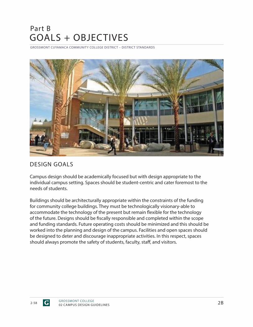
GROSSMONT CUYAMACA COMMUNITY COLLEGE DISTRICT – DISTRICT STANDARDS
GROSSMONT COLLEGE02 CAMPUS DESIGN GUIDELINES2-58
Part B
DESIGN GOALS
Campus design should be academically focused but with design appropriate to the individual campus setting. Spaces should be student-centric and cater foremost to the needs of students.
Buildings should be architecturally appropriate within the constraints of the funding for community college buildings. They must be technologically visionary-able to accommodate the technology of the present but remain fl exible for the technology of the future. Designs should be fi scally responsible and completed within the scope and funding standards. Future operating costs should be minimized and this should be worked into the planning and design of the campus. Facilities and open spaces should be designed to deter and discourage inappropriate activities. In this respect, spaces should always promote the safety of students, faculty, staff , and visitors.
GOALS + OBJECTIVES
2B
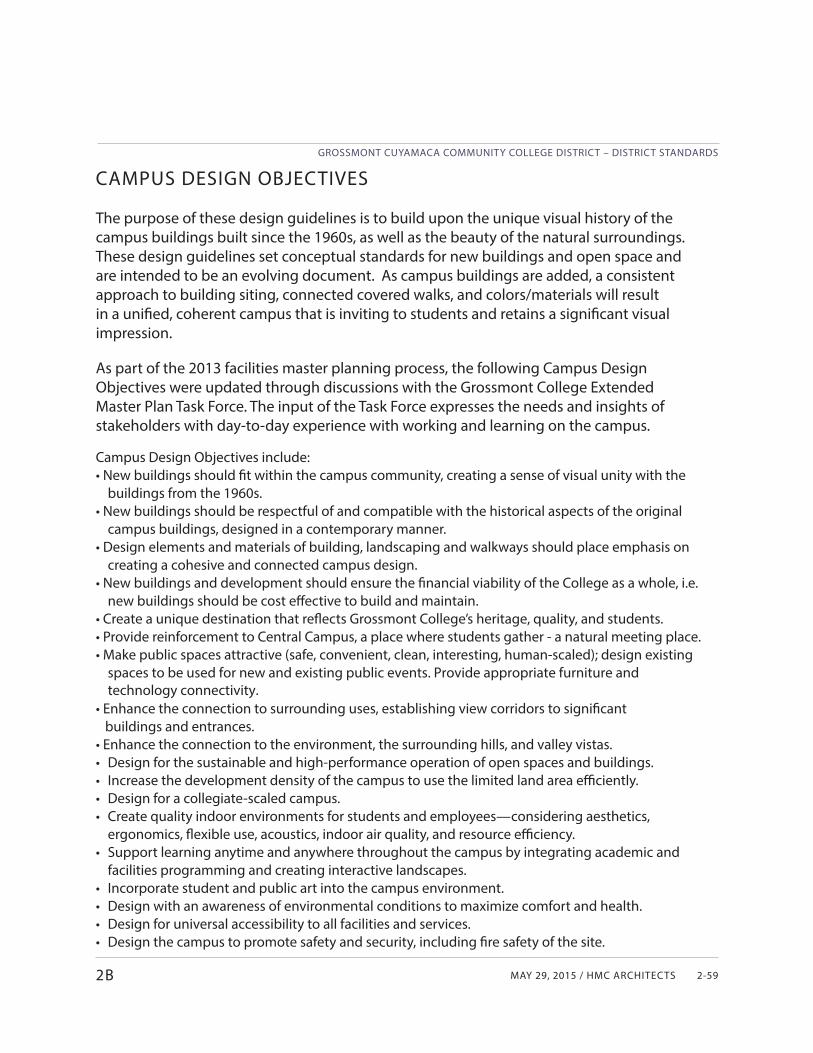
MAY 29, 2015 / HMC ARCHITECTS
GROSSMONT CUYAMACA COMMUNITY COLLEGE DISTRICT – DISTRICT STANDARDS
2-592B
CAMPUS DESIGN OBJECTIVES
The purpose of these design guidelines is to build upon the unique visual history of the campus buildings built since the 1960s, as well as the beauty of the natural surroundings. These design guidelines set conceptual standards for new buildings and open space and are intended to be an evolving document. As campus buildings are added, a consistent approach to building siting, connected covered walks, and colors/materials will result in a unifi ed, coherent campus that is inviting to students and retains a signifi cant visual impression.
As part of the 2013 facilities master planning process, the following Campus Design Objectives were updated through discussions with the Grossmont College Extended Master Plan Task Force. The input of the Task Force expresses the needs and insights of stakeholders with day-to-day experience with working and learning on the campus.
Campus Design Objectives include:• New buildings should fi t within the campus community, creating a sense of visual unity with the
buildings from the 1960s.• New buildings should be respectful of and compatible with the historical aspects of the original
campus buildings, designed in a contemporary manner.• Design elements and materials of building, landscaping and walkways should place emphasis on
creating a cohesive and connected campus design.• New buildings and development should ensure the fi nancial viability of the College as a whole, i.e.
new buildings should be cost eff ective to build and maintain.• Create a unique destination that refl ects Grossmont College’s heritage, quality, and students.• Provide reinforcement to Central Campus, a place where students gather - a natural meeting place.• Make public spaces attractive (safe, convenient, clean, interesting, human-scaled); design existing
spaces to be used for new and existing public events. Provide appropriate furniture and technology connectivity.
• Enhance the connection to surrounding uses, establishing view corridors to signifi cant buildings and entrances.• Enhance the connection to the environment, the surrounding hills, and valley vistas.• Design for the sustainable and high-performance operation of open spaces and buildings.• Increase the development density of the campus to use the limited land area effi ciently.• Design for a collegiate-scaled campus.• Create quality indoor environments for students and employees—considering aesthetics,
ergonomics, fl exible use, acoustics, indoor air quality, and resource effi ciency.• Support learning anytime and anywhere throughout the campus by integrating academic and
facilities programming and creating interactive landscapes.• Incorporate student and public art into the campus environment.• Design with an awareness of environmental conditions to maximize comfort and health.• Design for universal accessibility to all facilities and services.• Design the campus to promote safety and security, including fi re safety of the site.
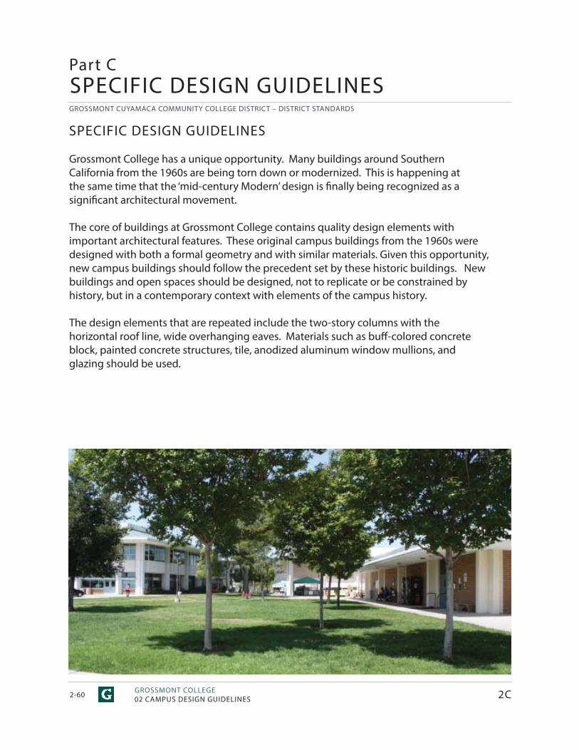
GROSSMONT CUYAMACA COMMUNITY COLLEGE DISTRICT – DISTRICT STANDARDS
GROSSMONT COLLEGE02 CAMPUS DESIGN GUIDELINES2-60
SPECIFIC DESIGN GUIDELINES
Grossmont College has a unique opportunity. Many buildings around Southern California from the 1960s are being torn down or modernized. This is happening at the same time that the ‘mid-century Modern’ design is fi nally being recognized as a signifi cant architectural movement.
The core of buildings at Grossmont College contains quality design elements with important architectural features. These original campus buildings from the 1960s were designed with both a formal geometry and with similar materials. Given this opportunity, new campus buildings should follow the precedent set by these historic buildings. New buildings and open spaces should be designed, not to replicate or be constrained by history, but in a contemporary context with elements of the campus history.
The design elements that are repeated include the two-story columns with the horizontal roof line, wide overhanging eaves. Materials such as buff -colored concrete block, painted concrete structures, tile, anodized aluminum window mullions, and glazing should be used.
2C
Part CSPECIFIC DESIGN GUIDELINES
MAY 29, 2015 / HMC ARCHITECTS
GROSSMONT CUYAMACA COMMUNITY COLLEGE DISTRICT – DISTRICT STANDARDS
2-612C
SITE DESIGN
EDUCATIONAL RESOURCESNature Preserve• Create overlooks for users to enjoy the Preserve.• Restore native habitat at Preserve perimeters as part of
the campus landscape.• Create/restore trailhead connections to the Grossmont
campus.• Integrate interpretive and educational signage at
trailheads and overlooks.• Create opportunities for students to restore and
maintain the Nature Preserve through class curriculum or as part of extracurricular groups.
Learning Gardens + Flexible Outdoor Space• Emphasize the use of low water use, low maintenance
native and Mediterranean material.• Demonstrate storm water management elements at
landscape edges and within landscape areas.• Integrate the academic programming of indoor and
outdoor space.• Provide a range of flexible spaces to accommodate a
variety of learning activities.• Provide appropriate support utilities and technology
connectivity.• Highlight sustainable campus facilities and operations
with displays and interpretive signage.
CAMPUS GATEWAYSEntering the campus• Use specimen trees to provide a ceremonial entrance
to campus. • Provide complimentary and accent planting at campus
monumentation.• Provide safe, clear, and accessible paths for
pedestrians entering and exiting the campus in both day-to-day and emergency situations.• Use consistent paving types, colors and patterns to
delineate pedestrian entrances into campus.• Orient pedestrian entries to maximize pedestrian
safety.• Ensure that pedestrian entrances are well lit and
include appropriate signage for way-finding.• Provide universally accessible paths of travel.• Provide linkages that anticipate the shortest path of
travel between entries, campus open spaces, and buildings.
PEDESTRIAN LINKAGES• Build upon the existing system of pedestrian linkages and provide universal accessibility between all campus
facilities and open spaces.• Strengthen and integrate the way-finding system to align with the hierarchy of pedestrian linkages.• Design pedestrian linkages to accommodate the anticipated level of use.Traversing Parking Areas• Provide pedestrian paths that are separated from vehicular routes for safe circulation through parking
lots.• Employ consistent use of iconic plant material or vertical elements and lighting to visually identify
pedestrian paths.• Minimize crossing of pedestrian and vehicular paths and design necessary crossing points to promote
safety.• Provide shaded seating at intervals along pedestrian paths through large parking lots.Portals• Limit the number of primary building entries from outside of campus.• Direct students from parking areas to the campus center.• Organize room entrances around a central interior quad or internal passageway.• Use plant material to delineate portals into campus.• Use consistent paving types, colors and patterns to delineate portals into campus. • Incorporate architectural elements such as shade structures and/or pilasters at key entry points. • Integrate all landscape elements with lighting and signage as appropriate.Linking the Campus Core• Incorporate emergency and maintenance access with
pedestrian pathways.• Use hardscape and landscape elements to soften
appearance of emergency and maintenance access.• Link gathering spaces or quads at key intervals along
campus pathways.• Provide iconic plant palette along campus core
linkages. • Use consistent paving types, colors, and patterns to
connect campus core linkages.• Integrate all landscape elements with lighting and
signage as appropriate.• Provide shaded resting places at intervals along long
paths to perimeter parking and facilities.
GROSSMONT CUYAMACA COMMUNITY COLLEGE DISTRICT – DISTRICT STANDARDS
GROSSMONT COLLEGE02 CAMPUS DESIGN GUIDELINES2-62
SPECIFIC DESIGN GUIDELINES
2C
Vertical Linkages• Provide elevators stairs, ramps and bridges as necessary to overcome obstacles such as roadways,
elevation grade changes or conflicting uses. • Locate vertical linkages in exterior locations that can be accessed when buildings are closed.
OPEN SPACES• Create varying scales of open spaces - open spaces should serve diff erent purposes.• Orient building entrances toward open spaces and quads.• Provide opportunities for a diverse range of activities.• Use streetscape imagery, consisting of regularly spaced lights, benches, trash cans, and consistent surfaces.• Maintain consistency with common materials, street amenities, and site furnishings.• Make plaza areas inviting during the day and at night.• Link outdoor public spaces with circulation.• Use landscaping to emphasize views/direction.• To the extent that it is practical, ensure that open spaces are universally accessible.Quads and Courtyards• Use trees for shade and vertical elements.• Incorporate low water use, low maintenance native and
climate appropriate plant material.• Use specialty paving to create unique spaces.• Integrate all landscape elements with lighting and signage as appropriate.• Incorporate site furniture as appropriate for the specifi c
use.• Use intimate-scaled courtyards to promote multi-level student, faculty, and community interaction.• Orient buildings with corridor views leading to the courtyard.
ACTIVE GROUND-FLOOR USES• Make visible from public spaces various campus activities: library, reading rooms, bookstore, cafeteria,
faculty offices, message boards and galleries on the ground floor, toward public spaces.
• Create entrances to classrooms and other spaces from within the courtyards/quadrangles.• Draw students directly to the core of the campus from
the perimeter parking areas.
VIEW OPPORTUNITIES• Combine new points of entry with ‘great rooms’.
(pedestrian friendly spaces that are created at the exterior of building groupings) capitalizing on
scenic views.• Capture views between buildings to the surrounding
hills and valleys.
ARCHITECTURAL DESIGN BUILDING MASS + ORIENTATION• Emphasize the horizontal plane of the roof.• Use large overhangs.• Use articulated facades.• Emphasize main entrance to building.
BUILDING ENTRANCES• Signage should be incorporated into the design of
building entrances to facilitate way-finding.• Use a primary, visible, and appropriately scaled
entrance to the building.• Emphasize building height.• Use vertical columns.• Use full-story glass on building facades.• Use side-lights at doorways.• Create an inviting appearance with transparent glazing
and glass doors.• Ensure that entrances are well-lit.• Encourage articulated rather than flat facades.
EXPRESSION LINES• Use uniform palette of materials for building walls.• Consider using diff ering materials at the floor and roof
lines to emphasize a horizontal appearance.• Emphasize horizontal elements, banding, etc. ROOFTOPS• Use architectural metal roofs as a design feature.• Emphasize horizontal expression.• Paint the underside of overhangs off -white.• Minimize visibility of obtrusive equipment.• Use high-albedo cool roofing surface materials.• Use large overhangs to provide shade from the
summer sun and allow passive heating in the winter.• Design roofs to allow for daylight harvesting strategies.
MAY 29, 2015 / HMC ARCHITECTS
GROSSMONT CUYAMACA COMMUNITY COLLEGE DISTRICT – DISTRICT STANDARDS
2-632C
COVERED WALKWAYS• Include covered walkways attached to buildings.• Do not obscure or block overhang passageways.• Do not have site planters within overhang drip lines.• Include covered structures for circulation paths when appropriate.
OTHER DESIGN FEATURES• Incorporate public or student art into the campus
design.
MECHANICAL EQUIPMENT• MEP equipment and venting equipment should not be
openly visible.• Roof-mounted equipment should be shielded from
ground view and from above views from higher levels.
VENDING MACHINES• Vending equipment should not be visually intrusive.• Vending areas should be shielded from the sun and
weather.• Vending areas should be safe, secure and well lit.• Avoid placement in deep alcoves or secluded areas for
security. TRASH ENCLOSURES + LOADING FACILITIES• Locate trash and recycling containers in enclosures.• Plan the location of trash and recycling facilities to
allow easy cleaning and management. INDOOR ENVIRONMENTAL QUALITY• Design to a high standard of aesthetic quality.• Design for universal accessibility and clear way-finding through all of the indoor public spaces.• Reduce sources of indoor air pollution such as cleaning and pest control chemicals and building materials, equipment, and furniture that emit volatile organic compounds and other pollutants.• Design for eff ective ventilation and thermal comfort.• Design acoustic environments that reduce distracting noise and improve aural communication.• Design for optimal lighting quality and reduced glare.• Design for ergonomic comfort.• Provide occupants with a connection to the outdoors by providing glare-free natural lighting and views.• Design buildings to be safe and secure environments for learning using CPTED principles.• Equip buildings for monitoring and optimizing the indoor environment.
ENERGY + WATER• Design in accordance with the GCCCD standards for
energy and water use intensity. • Employ the building occupants at the start of the
programming process for input. • Explore and select strategies that take advantage of
synergies to optimize building performance. • Equip buildings for monitoring and optimizing energy
and water using systems.• Explore opportunities to integrate photovoltaic
systems into the design of facilities.
ENVIRONMENTALLY PREFERRED MATERIALS• Build and furnish with durable and easily maintained
materials.• Build with materials that are locally sourced, rapidly
renewable, contain recycled content, and are likely to be recycled or reused.
• Maintain healthy indoor air quality by selecting appropriate building materials and furnishings, with a proven track record for lantern performance.
WASTE REDUCTION + MANAGEMENT• Follow best practices for the management of
demolition materials and construction waste.• Explore on-campus opportunities to reuse materials
from demolished facilities and site work.• Design buildings with space to support the campus
recycling plan.
EXTERIOR BUILDING MATERIALS CONCRETE BLOCK WALLS, CONCRETE COL-UMNS, OTHER BUILDING MATERIALS• Buff -colored large concrete block walls• Concrete roof structures with coff ered ceiling detail,
painted off -while• Concrete columns in ‘X’ and ‘T’ shapes• Green standing seam metal sloped roofs• Anodized aluminum window mullions (at large window
wall systems)• Painted aluminum window mullions (at clerestory and
individual windows)• Double Pane Low-e glass• Limestone, or other similar natural materials in buff , off -
white, or other earth tones• Beige brick• Exterior wall tile in buff , off -white, or other earth tones
GROSSMONT CUYAMACA COMMUNITY COLLEGE DISTRICT – DISTRICT STANDARDS
GROSSMONT COLLEGE02 CAMPUS DESIGN GUIDELINES2-64 2C
SPECIFIC DESIGN GUIDELINES
FENESTRATION + GLASS WALLS• Use anodized aluminum mullions with low-e glass.• Use large expanses of glass at building entrances. EXTERIOR LIGHTING• Use increased lighting at primary entrances.• Lighting fi xtures should be LED fi xtures or other
proven energy effi cient lighting systems can also be considered. Other options must be reviewed by District.
• Provide lighting for safe and secure night time use of the campus . Include consistent lighting on circulation pathways with a fi xture every 25-30 ft providing illumination of a person’s face 30 ft away.
• Avoid the use of in-ground lights.• Locate lights in area where they can be easily maintained.• Avoid placing lights in ceilings over stairs.• Make provisions for lighting special outdoor
performances, activities, and events.• Design site lighting to minimize or shield light from
adjacent neighborhoods and nature preserves.• Prohibit exposure of habitat and astronomical
observation areas to high-frequency spectrum lighting.
HANDRAILS• Choose railing styles that add to the cohesive quality
of the campus.• Use bent tube steel in simple shapes and forms.• Avoid painted handrails. CONCRETE STAIRS + PAVING• Use edge detailing on colored concrete. • Integrate stairs, planter walls, and seating into paving
design.
GRAPHICS + SIGNAGE
CAMPUS WAY-FINDING + SIGNAGE• Understand the campus-wide way-finding plan and
how it addresses the requirements for all facilities and elements of the campus circulation systems.
• Understand how each building and site improvement project functions as a part of the campus wide fabric and include the appropriate way-finding elements in the project scope.
• Support clear way-finding and direct connectivity for users with mobility limitations.
• Use trees and plant material and architectural elements to assist in campus way-finding.
• Incorporate educational and interpretive signage to highlight public art, sustainable facilities, and other features.
BUILDING NAMES, WAY-FINDING, + SIGNAGE• Place building names in highly visible areas of exterior
building walls.• Building and room identifi cation should be consistent
and promote ease of way-fi nding.• Coordinate with building and room numbering standards.
CAMPUS SITE FURNITURE
FURNITURE• Be consistent with campus architectural elements when
choosing furnishing styles.• Place movable furniture in courtyards or controlled
areas.• Use metal mesh loose tables and chairs. Avoid using
pedestal base tables.• Integrate site furniture within the landscape and
hardscape when appropriate.• Consider boulders for seating elements.• Provide trash and recycling receptacles along main circulation routes and building entrances.
SHADE STRUCTURE• Consider the location of shade trees and building
overhangs when planning the location of shade structures and use these elements in concert to provide the desired level of shading along pedestrian linkages and in outdoor gathering spaces.
• Avoid shading gathering spaces from the morning sun, especially during the cool weather season.
• Be consistent with campus architectural elements when designing shade structures.
• Use shade structures to provide intermittent resting points along exposed primary pathways.
• Integrate overhead shade structures at dining plazas and gathering spaces.
• Avoid using wood for shade structures.
STUDENT + PUBLIC ART• Provide opportunities for the display of art in buildings,
courtyards, and gathering areas throughout campus. • Integrate art within the landscape and in site furnishing
and signage elements when appropriate.• Provide interpretive signage and lighting when
appropriate.
MAY 29, 2015 / HMC ARCHITECTS
GROSSMONT CUYAMACA COMMUNITY COLLEGE DISTRICT – DISTRICT STANDARDS
2-652C
• Provide support for technology, audio/visual, and lighting for outdoor performance venues.
PARKING + CIRCULATION PASSENGER LOADING ZONES + BUS STOPS• Separate loading zones from main vehicular routes.• Provide adequate stacking space to accommodate
waiting vehicles.• Provide shade shelters and trees at bus stops.• Provide benches and refuse receptacles at bus stops
and loading zones.
BICYCLE PATHS + STORAGE• Connect to the public network of bicycle paths.• Provide Class I bicycle paths and signage along
campus loop road.• Provide consolidated bicycle storage at key portals on
campus.• Use bicycle storage that is consistent with campus
architectural elements.• Use bicycle storage made from sustainable materials
for best cost value.• Place bicycle storage in hardscape or gravel.
PARKING• Soften parking areas with landscape elements.• Utilize low water use, low maintenance native and
climate appropriate plant material in landscaping.• Provide trees in parking lot medians and islands to
reduce heat island eff ect.• Integrate storm water features into the parking lot
medians and islands.• Maintain landscape to avoid obstructing vehicular lines
of sight.• Provide preferred parking for carpools and alternative
fuel vehicles. • Provide electric vehicle charging stations.
CAMPUS PERIMETER• Projects to alter or improve the Perimeter Road must
provide a safe pedestrian route along the side of the road.
• Pedestrians should be directed to safe crossing points along primary circulation routes.
• Manage the flow of storm water to prevent erosion at the campus edge.
• Incorporate tree planting along loop road. • Provide enhanced slope planting along roadways and
campus edges.
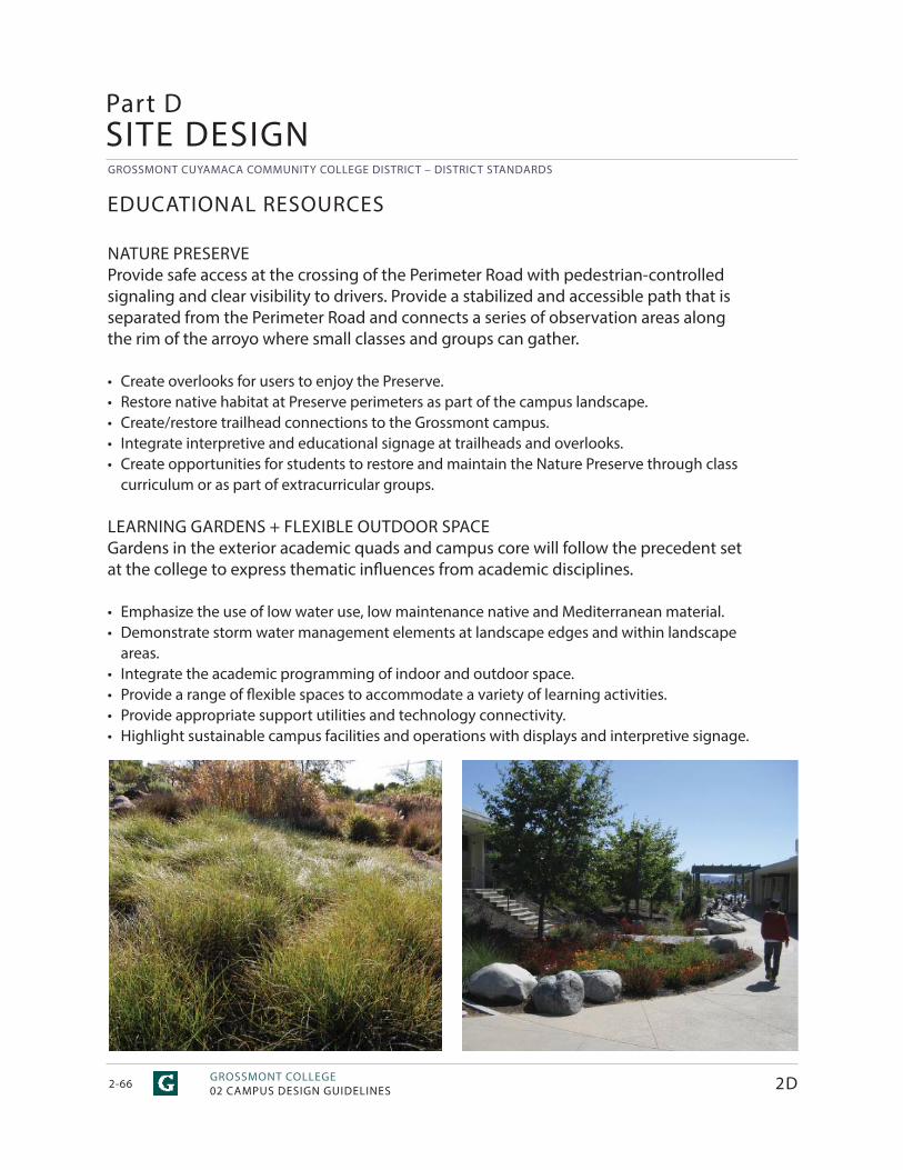
GROSSMONT CUYAMACA COMMUNITY COLLEGE DISTRICT – DISTRICT STANDARDS
GROSSMONT COLLEGE02 CAMPUS DESIGN GUIDELINES2-66
Part DSITE DESIGN
EDUCATIONAL RESOURCES
NATURE PRESERVEProvide safe access at the crossing of the Perimeter Road with pedestrian-controlled signaling and clear visibility to drivers. Provide a stabilized and accessible path that is separated from the Perimeter Road and connects a series of observation areas along the rim of the arroyo where small classes and groups can gather.
• Create overlooks for users to enjoy the Preserve.• Restore native habitat at Preserve perimeters as part of the campus landscape.• Create/restore trailhead connections to the Grossmont campus.• Integrate interpretive and educational signage at trailheads and overlooks.• Create opportunities for students to restore and maintain the Nature Preserve through class
curriculum or as part of extracurricular groups.
LEARNING GARDENS + FLEXIBLE OUTDOOR SPACEGardens in the exterior academic quads and campus core will follow the precedent set at the college to express thematic infl uences from academic disciplines.
• Emphasize the use of low water use, low maintenance native and Mediterranean material.• Demonstrate storm water management elements at landscape edges and within landscape
areas.• Integrate the academic programming of indoor and outdoor space.• Provide a range of fl exible spaces to accommodate a variety of learning activities.• Provide appropriate support utilities and technology connectivity.• Highlight sustainable campus facilities and operations with displays and interpretive signage.
2D
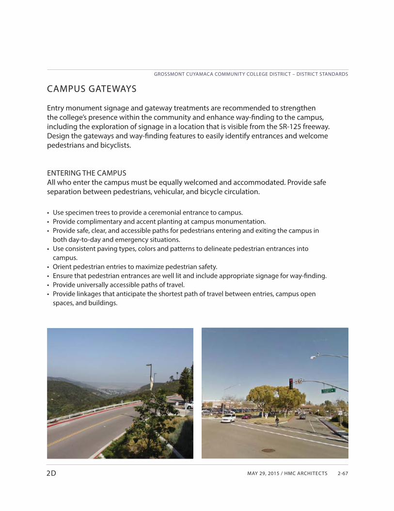
MAY 29, 2015 / HMC ARCHITECTS
GROSSMONT CUYAMACA COMMUNITY COLLEGE DISTRICT – DISTRICT STANDARDS
2-67
CAMPUS GATEWAYS
Entry monument signage and gateway treatments are recommended to strengthen the college’s presence within the community and enhance way-fi nding to the campus, including the exploration of signage in a location that is visible from the SR-125 freeway. Design the gateways and way-fi nding features to easily identify entrances and welcome pedestrians and bicyclists.
ENTERING THE CAMPUSAll who enter the campus must be equally welcomed and accommodated. Provide safe separation between pedestrians, vehicular, and bicycle circulation.
• Use specimen trees to provide a ceremonial entrance to campus.• Provide complimentary and accent planting at campus monumentation.• Provide safe, clear, and accessible paths for pedestrians entering and exiting the campus in
both day-to-day and emergency situations.• Use consistent paving types, colors and patterns to delineate pedestrian entrances into
campus.• Orient pedestrian entries to maximize pedestrian safety.• Ensure that pedestrian entrances are well lit and include appropriate signage for way-finding.• Provide universally accessible paths of travel.• Provide linkages that anticipate the shortest path of travel between entries, campus open
spaces, and buildings.
2D
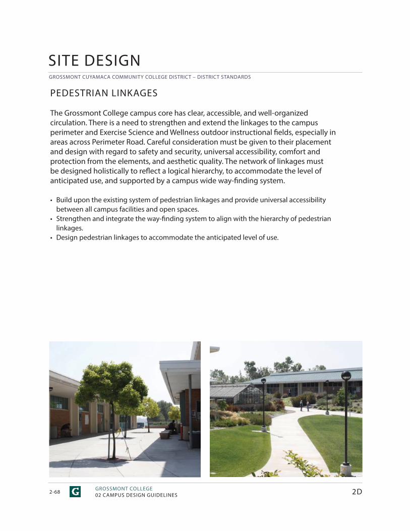
GROSSMONT CUYAMACA COMMUNITY COLLEGE DISTRICT – DISTRICT STANDARDS
GROSSMONT COLLEGE02 CAMPUS DESIGN GUIDELINES2-68
PEDESTRIAN LINKAGES
The Grossmont College campus core has clear, accessible, and well-organized circulation. There is a need to strengthen and extend the linkages to the campus perimeter and Exercise Science and Wellness outdoor instructional fi elds, especially in areas across Perimeter Road. Careful consideration must be given to their placement and design with regard to safety and security, universal accessibility, comfort and protection from the elements, and aesthetic quality. The network of linkages must be designed holistically to refl ect a logical hierarchy, to accommodate the level of anticipated use, and supported by a campus wide way-fi nding system.
• Build upon the existing system of pedestrian linkages and provide universal accessibility between all campus facilities and open spaces.
• Strengthen and integrate the way-fi nding system to align with the hierarchy of pedestrian linkages.
• Design pedestrian linkages to accommodate the anticipated level of use.
SITE DESIGN
2D
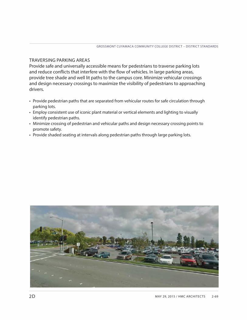
MAY 29, 2015 / HMC ARCHITECTS
GROSSMONT CUYAMACA COMMUNITY COLLEGE DISTRICT – DISTRICT STANDARDS
2-69
TRAVERSING PARKING AREASProvide safe and universally accessible means for pedestrians to traverse parking lots and reduce confl icts that interfere with the fl ow of vehicles. In large parking areas, provide tree shade and well lit paths to the campus core. Minimize vehicular crossings and design necessary crossings to maximize the visibility of pedestrians to approaching drivers.
• Provide pedestrian paths that are separated from vehicular routes for safe circulation through parking lots.
• Employ consistent use of iconic plant material or vertical elements and lighting to visually identify pedestrian paths.
• Minimize crossing of pedestrian and vehicular paths and design necessary crossing points to promote safety.
• Provide shaded seating at intervals along pedestrian paths through large parking lots.
2D
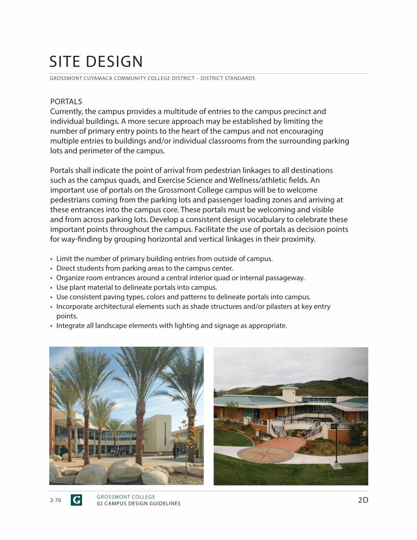
GROSSMONT CUYAMACA COMMUNITY COLLEGE DISTRICT – DISTRICT STANDARDS
GROSSMONT COLLEGE02 CAMPUS DESIGN GUIDELINES2-70 2D
SITE DESIGN
PORTALSCurrently, the campus provides a multitude of entries to the campus precinct and individual buildings. A more secure approach may be established by limiting the number of primary entry points to the heart of the campus and not encouraging multiple entries to buildings and/or individual classrooms from the surrounding parking lots and perimeter of the campus.
Portals shall indicate the point of arrival from pedestrian linkages to all destinations such as the campus quads, and Exercise Science and Wellness/athletic fi elds. An important use of portals on the Grossmont College campus will be to welcome pedestrians coming from the parking lots and passenger loading zones and arriving at these entrances into the campus core. These portals must be welcoming and visible and from across parking lots. Develop a consistent design vocabulary to celebrate these important points throughout the campus. Facilitate the use of portals as decision points for way-fi nding by grouping horizontal and vertical linkages in their proximity.
• Limit the number of primary building entries from outside of campus.• Direct students from parking areas to the campus center.• Organize room entrances around a central interior quad or internal passageway.• Use plant material to delineate portals into campus.• Use consistent paving types, colors and patterns to delineate portals into campus. • Incorporate architectural elements such as shade structures and/or pilasters at key entry
points. • Integrate all landscape elements with lighting and signage as appropriate.
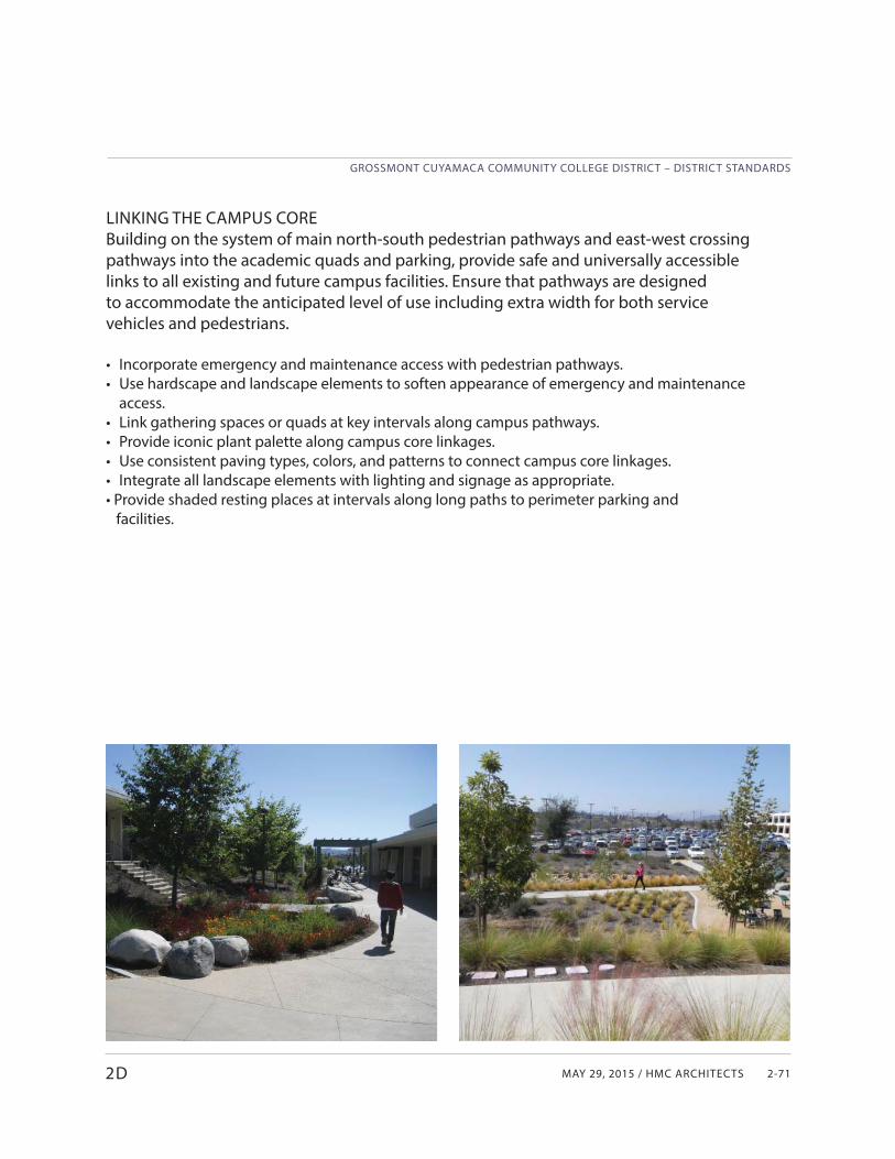
MAY 29, 2015 / HMC ARCHITECTS
GROSSMONT CUYAMACA COMMUNITY COLLEGE DISTRICT – DISTRICT STANDARDS
2-71
LINKING THE CAMPUS COREBuilding on the system of main north-south pedestrian pathways and east-west crossing pathways into the academic quads and parking, provide safe and universally accessible links to all existing and future campus facilities. Ensure that pathways are designed to accommodate the anticipated level of use including extra width for both service vehicles and pedestrians.
• Incorporate emergency and maintenance access with pedestrian pathways.• Use hardscape and landscape elements to soften appearance of emergency and maintenance
access.• Link gathering spaces or quads at key intervals along campus pathways.• Provide iconic plant palette along campus core linkages. • Use consistent paving types, colors, and patterns to connect campus core linkages.• Integrate all landscape elements with lighting and signage as appropriate.• Provide shaded resting places at intervals along long paths to perimeter parking and facilities.
2D
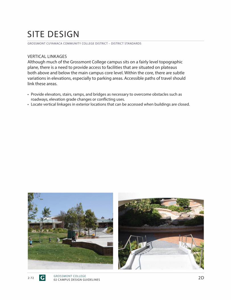
GROSSMONT CUYAMACA COMMUNITY COLLEGE DISTRICT – DISTRICT STANDARDS
GROSSMONT COLLEGE02 CAMPUS DESIGN GUIDELINES2-72 2D
SITE DESIGN
VERTICAL LINKAGESAlthough much of the Grossmont College campus sits on a fairly level topographic plane, there is a need to provide access to facilities that are situated on plateaus both above and below the main campus core level. Within the core, there are subtle variations in elevations, especially to parking areas. Accessible paths of travel should link these areas.
• Provide elevators, stairs, ramps, and bridges as necessary to overcome obstacles such as roadways, elevation grade changes or confl icting uses.
• Locate vertical linkages in exterior locations that can be accessed when buildings are closed.
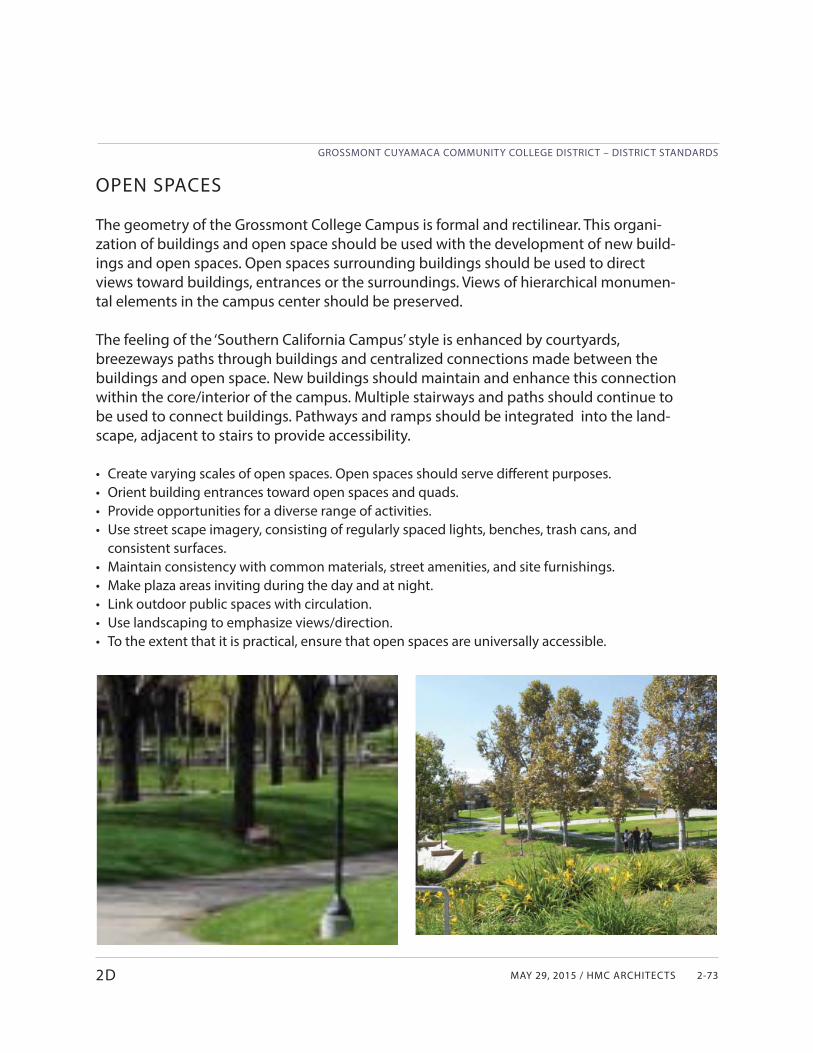
MAY 29, 2015 / HMC ARCHITECTS
GROSSMONT CUYAMACA COMMUNITY COLLEGE DISTRICT – DISTRICT STANDARDS
2-73
OPEN SPACES
The geometry of the Grossmont College Campus is formal and rectilinear. This organi-zation of buildings and open space should be used with the development of new build-ings and open spaces. Open spaces surrounding buildings should be used to direct views toward buildings, entrances or the surroundings. Views of hierarchical monumen-tal elements in the campus center should be preserved.
The feeling of the ‘Southern California Campus’ style is enhanced by courtyards, breezeways paths through buildings and centralized connections made between the buildings and open space. New buildings should maintain and enhance this connection within the core/interior of the campus. Multiple stairways and paths should continue to be used to connect buildings. Pathways and ramps should be integrated into the land-scape, adjacent to stairs to provide accessibility.
• Create varying scales of open spaces. Open spaces should serve diff erent purposes.• Orient building entrances toward open spaces and quads.• Provide opportunities for a diverse range of activities.• Use street scape imagery, consisting of regularly spaced lights, benches, trash cans, and
consistent surfaces.• Maintain consistency with common materials, street amenities, and site furnishings.• Make plaza areas inviting during the day and at night.• Link outdoor public spaces with circulation.• Use landscaping to emphasize views/direction.• To the extent that it is practical, ensure that open spaces are universally accessible.
2D
GROSSMONT CUYAMACA COMMUNITY COLLEGE DISTRICT – DISTRICT STANDARDS
GROSSMONT COLLEGE02 CAMPUS DESIGN GUIDELINES2-74 2D
SITE DESIGN
QUADS AND COURTYARDSThe use of courtyard spaces and courtyard buildings should be emphasized as the campus tradition. Courtyards should be an intimate scale, to promote natural gathering and greeting opportunities. Large courtyards promote a ‘feeling of being alone’ in a large space, which does not promote the safety and security needed throughout the campus. Courtyards of a small scale provide a density of activity, i.e. a place where there are a number of students and staff , promoting a safe and secure environment.
Security considerations for public safety should also be incorporated in the design. Clear lines of sight should be developed to all building entrances to promote an easily accessible and ‘self-policed’ passage between campus spaces.
The courtyard formed by the Fine Arts Buildings is a good example of a smaller, well-proportioned space. The building is inward oriented, with corridor views leading to the courtyard. The building has deep overhang roofs and covered walkways, which provide for a clear path of travel, shaded walks, and an emphasis on the horizontal massing of the buildings. New buildings in a similar style should be encouraged on the Grossmont College Campus.
Quads and courtyards are intended to be the heart and connective tissue of the academic clusters. Strong physical and visual connections to interior space will naturally attract students to these gathering spaces to study, collaborate, and socialize. The design of these spaces must satisfy the need for seating, connectivity to technology, thermal comfort, and security and safety. They must provide a variety of spaces in order to accommodate many diff erent uses and activity levels. Programming and design of quads must be done with the programming and design of the adjacent academic building clusters to realize the ideal of an integrated design. The Health Sciences Complex serves as a model, using medicinal plants and herbs to fi ll this intimate courtyard. The scale and multi-level access successfully attract student engagement and interaction.
• Use trees for shade and vertical elements.• Incorporate low water use, low maintenance native and climate appropriate plant material.• Use specialty paving to create unique spaces.• Integrate all landscape elements with lighting and signage as appropriate.• Incorporate site furniture as appropriate for specifi c use.• Use intimate-scaled courtyards to promote multi-level student, faculty, and community
interaction.• Orient buildings with corridor views leading to the courtyard.
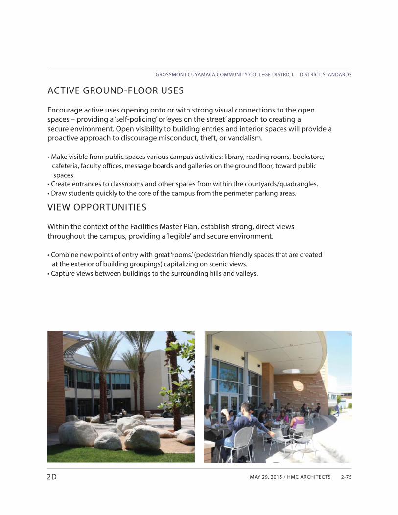
MAY 29, 2015 / HMC ARCHITECTS
GROSSMONT CUYAMACA COMMUNITY COLLEGE DISTRICT – DISTRICT STANDARDS
2-75
VIEW OPPORTUNITIES
Within the context of the Facilities Master Plan, establish strong, direct views throughout the campus, providing a ‘legible’ and secure environment.
• Combine new points of entry with great ‘rooms.’ (pedestrian friendly spaces that are created at the exterior of building groupings) capitalizing on scenic views.• Capture views between buildings to the surrounding hills and valleys.
2D
ACTIVE GROUND-FLOOR USES
Encourage active uses opening onto or with strong visual connections to the open spaces – providing a ‘self-policing’ or ‘eyes on the street’ approach to creating a secure environment. Open visibility to building entries and interior spaces will provide a proactive approach to discourage misconduct, theft, or vandalism.
• Make visible from public spaces various campus activities: library, reading rooms, bookstore, cafeteria, faculty offi ces, message boards and galleries on the ground fl oor, toward public
spaces.• Create entrances to classrooms and other spaces from within the courtyards/quadrangles.• Draw students quickly to the core of the campus from the perimeter parking areas.
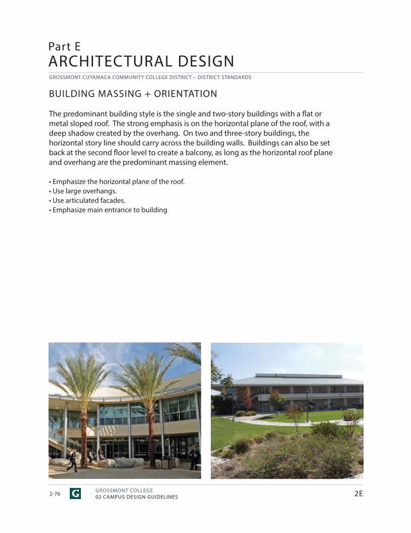
GROSSMONT CUYAMACA COMMUNITY COLLEGE DISTRICT – DISTRICT STANDARDS
GROSSMONT COLLEGE02 CAMPUS DESIGN GUIDELINES2-76
Part EARCHITECTURAL DESIGN
BUILDING MASSING + ORIENTATION
The predominant building style is the single and two-story buildings with a fl at or metal sloped roof. The strong emphasis is on the horizontal plane of the roof, with a deep shadow created by the overhang. On two and three-story buildings, the horizontal story line should carry across the building walls. Buildings can also be set back at the second fl oor level to create a balcony, as long as the horizontal roof plane and overhang are the predominant massing element.
• Emphasize the horizontal plane of the roof.• Use large overhangs.• Use articulated facades.• Emphasize main entrance to building
2E
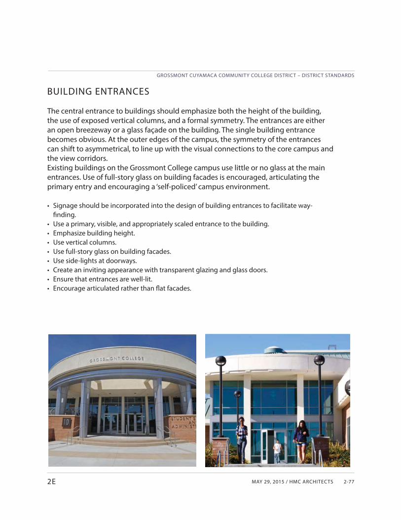
MAY 29, 2015 / HMC ARCHITECTS
GROSSMONT CUYAMACA COMMUNITY COLLEGE DISTRICT – DISTRICT STANDARDS
2-77
BUILDING ENTRANCES
The central entrance to buildings should emphasize both the height of the building, the use of exposed vertical columns, and a formal symmetry. The entrances are either an open breezeway or a glass façade on the building. The single building entrance becomes obvious. At the outer edges of the campus, the symmetry of the entrances can shift to asymmetrical, to line up with the visual connections to the core campus and the view corridors. Existing buildings on the Grossmont College campus use little or no glass at the main entrances. Use of full-story glass on building facades is encouraged, articulating the primary entry and encouraging a ‘self-policed’ campus environment. • Signage should be incorporated into the design of building entrances to facilitate way-
finding. • Use a primary, visible, and appropriately scaled entrance to the building.• Emphasize building height.• Use vertical columns.• Use full-story glass on building facades.• Use side-lights at doorways.• Create an inviting appearance with transparent glazing and glass doors.• Ensure that entrances are well-lit.• Encourage articulated rather than fl at facades.
2E
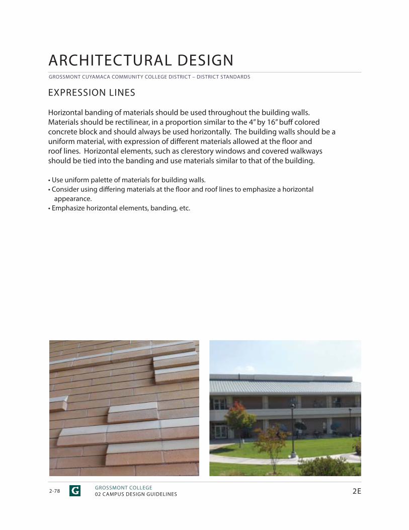
GROSSMONT CUYAMACA COMMUNITY COLLEGE DISTRICT – DISTRICT STANDARDS
GROSSMONT COLLEGE02 CAMPUS DESIGN GUIDELINES2-78
EXPRESSION LINES
Horizontal banding of materials should be used throughout the building walls. Materials should be rectilinear, in a proportion similar to the 4” by 16” buff coloredconcrete block and should always be used horizontally. The building walls should be a uniform material, with expression of diff erent materials allowed at the fl oor and roof lines. Horizontal elements, such as clerestory windows and covered walkways should be tied into the banding and use materials similar to that of the building.
• Use uniform palette of materials for building walls.• Consider using diff ering materials at the fl oor and roof lines to emphasize a horizontal
appearance.• Emphasize horizontal elements, banding, etc.
ARCHITECTURAL DESIGN
2E
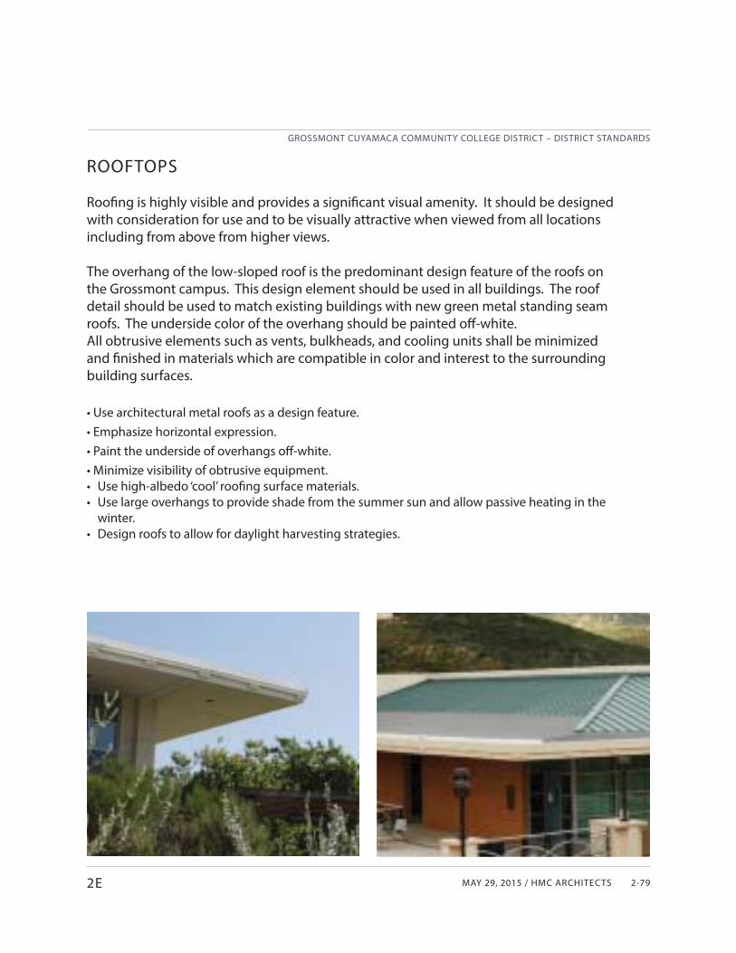
MAY 29, 2015 / HMC ARCHITECTS
GROSSMONT CUYAMACA COMMUNITY COLLEGE DISTRICT – DISTRICT STANDARDS
2-792E
ROOFTOPS
Roofi ng is highly visible and provides a signifi cant visual amenity. It should be designed with consideration for use and to be visually attractive when viewed from all locations including from above from higher views.
The overhang of the low-sloped roof is the predominant design feature of the roofs on the Grossmont campus. This design element should be used in all buildings. The roof detail should be used to match existing buildings with new green metal standing seam roofs. The underside color of the overhang should be painted off -white.All obtrusive elements such as vents, bulkheads, and cooling units shall be minimized and fi nished in materials which are compatible in color and interest to the surrounding building surfaces.
• Use architectural metal roofs as a design feature.• Emphasize horizontal expression.• Paint the underside of overhangs off -white.• Minimize visibility of obtrusive equipment.• Use high-albedo ‘cool’ roofi ng surface materials.• Use large overhangs to provide shade from the summer sun and allow passive heating in the
winter.• Design roofs to allow for daylight harvesting strategies.
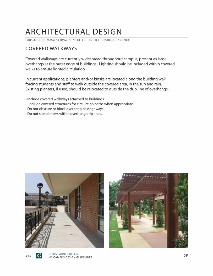
GROSSMONT CUYAMACA COMMUNITY COLLEGE DISTRICT – DISTRICT STANDARDS
GROSSMONT COLLEGE02 CAMPUS DESIGN GUIDELINES2-80
COVERED WALKWAYS
Covered walkways are currently widespread throughout campus, present as large overhangs at the outer edge of buildings. Lighting should be included within covered walks to ensure lighted circulation.
In current applications, planters and/or kiosks are located along the building wall, forcing students and staff to walk outside the covered area, in the sun and rain. Existing planters, if used, should be relocated to outside the drip line of overhangs.
• Include covered walkways attached to buildings.• Include covered structures for circulation paths when appropriate.• Do not obscure or block overhang passageways.• Do not site planters within overhang drip lines.
2E
ARCHITECTURAL DESIGN
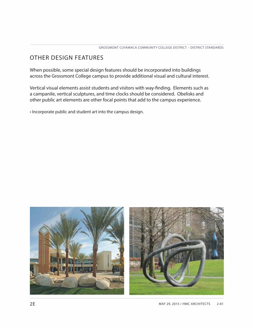
MAY 29, 2015 / HMC ARCHITECTS
GROSSMONT CUYAMACA COMMUNITY COLLEGE DISTRICT – DISTRICT STANDARDS
2-812E
OTHER DESIGN FEATURES
When possible, some special design features should be incorporated into buildings across the Grossmont College campus to provide additional visual and cultural interest.
Vertical visual elements assist students and visitors with way-fi nding. Elements such as a campanile, vertical sculptures, and time clocks should be considered. Obelisks and other public art elements are other focal points that add to the campus experience.
• Incorporate public and student art into the campus design.
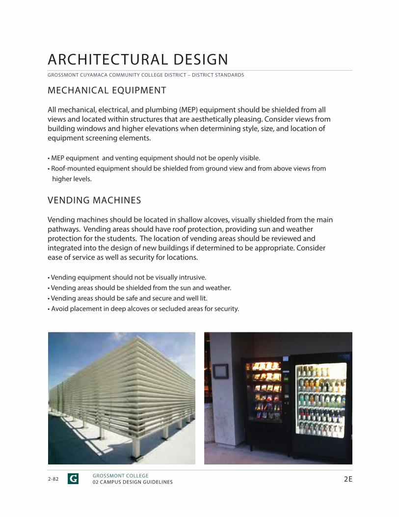
GROSSMONT CUYAMACA COMMUNITY COLLEGE DISTRICT – DISTRICT STANDARDS
GROSSMONT COLLEGE02 CAMPUS DESIGN GUIDELINES2-82
MECHANICAL EQUIPMENT
All mechanical, electrical, and plumbing (MEP) equipment should be shielded from all views and located within structures that are aesthetically pleasing. Consider views from building windows and higher elevations when determining style, size, and location of equipment screening elements.
• MEP equipment and venting equipment should not be openly visible.• Roof-mounted equipment should be shielded from ground view and from above views from higher levels.
VENDING MACHINES
Vending machines should be located in shallow alcoves, visually shielded from the main pathways. Vending areas should have roof protection, providing sun and weather protection for the students. The location of vending areas should be reviewed and integrated into the design of new buildings if determined to be appropriate. Consider ease of service as well as security for locations.
• Vending equipment should not be visually intrusive.• Vending areas should be shielded from the sun and weather.• Vending areas should be safe and secure and well lit.• Avoid placement in deep alcoves or secluded areas for security.
2E
ARCHITECTURAL DESIGN
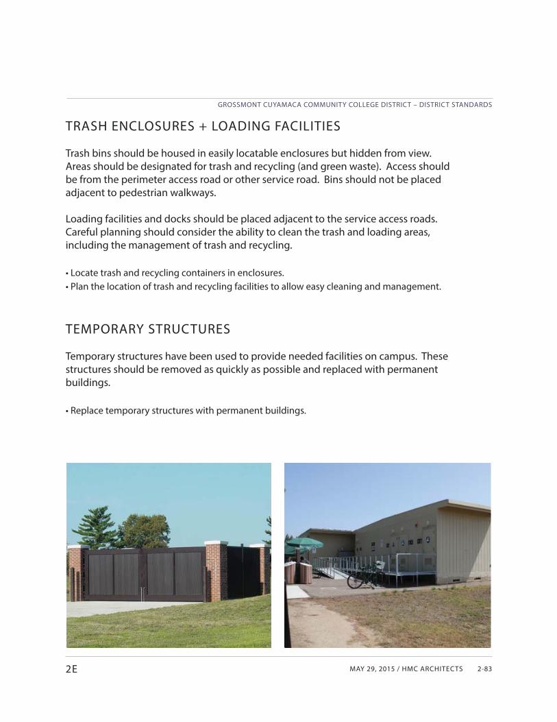
MAY 29, 2015 / HMC ARCHITECTS
GROSSMONT CUYAMACA COMMUNITY COLLEGE DISTRICT – DISTRICT STANDARDS
2-832E
TRASH ENCLOSURES + LOADING FACILITIES
Trash bins should be housed in easily locatable enclosures but hidden from view. Areas should be designated for trash and recycling (and green waste). Access should be from the perimeter access road or other service road. Bins should not be placed adjacent to pedestrian walkways.
Loading facilities and docks should be placed adjacent to the service access roads. Careful planning should consider the ability to clean the trash and loading areas, including the management of trash and recycling.
• Locate trash and recycling containers in enclosures.• Plan the location of trash and recycling facilities to allow easy cleaning and management.
TEMPORARY STRUCTURES
Temporary structures have been used to provide needed facilities on campus. These structures should be removed as quickly as possible and replaced with permanent buildings.
• Replace temporary structures with permanent buildings.
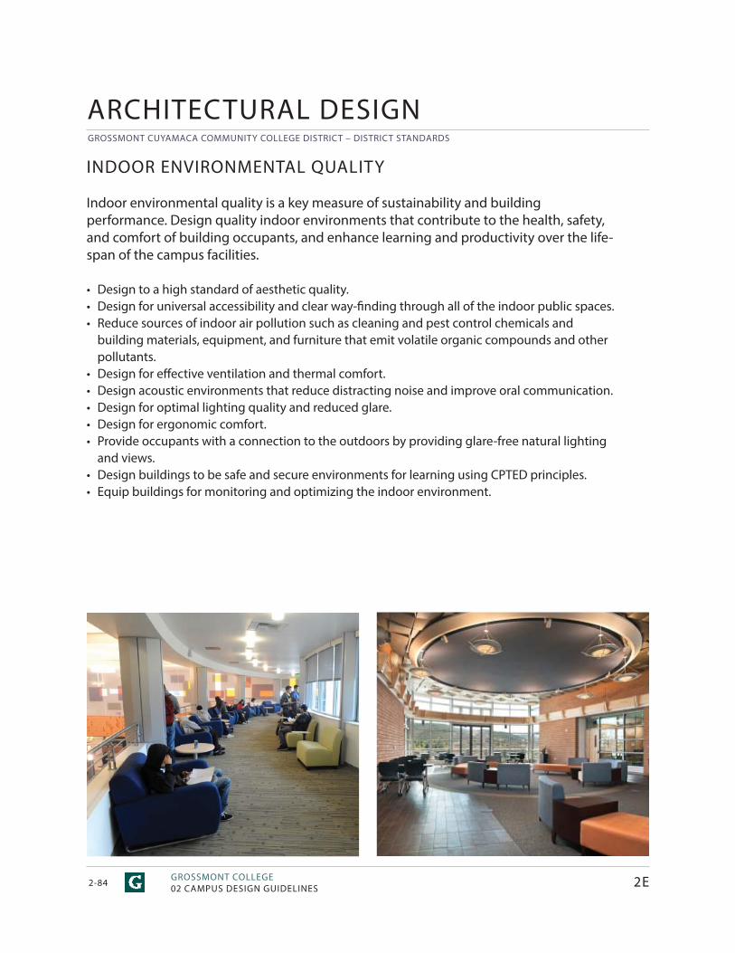
GROSSMONT CUYAMACA COMMUNITY COLLEGE DISTRICT – DISTRICT STANDARDS
GROSSMONT COLLEGE02 CAMPUS DESIGN GUIDELINES2-84 2E
ARCHITECTURAL DESIGN
INDOOR ENVIRONMENTAL QUALITY
Indoor environmental quality is a key measure of sustainability and building performance. Design quality indoor environments that contribute to the health, safety, and comfort of building occupants, and enhance learning and productivity over the life-span of the campus facilities.
• Design to a high standard of aesthetic quality.• Design for universal accessibility and clear way-fi nding through all of the indoor public spaces.• Reduce sources of indoor air pollution such as cleaning and pest control chemicals and
building materials, equipment, and furniture that emit volatile organic compounds and other pollutants.
• Design for eff ective ventilation and thermal comfort.• Design acoustic environments that reduce distracting noise and improve oral communication.• Design for optimal lighting quality and reduced glare.• Design for ergonomic comfort.• Provide occupants with a connection to the outdoors by providing glare-free natural lighting
and views.• Design buildings to be safe and secure environments for learning using CPTED principles.• Equip buildings for monitoring and optimizing the indoor environment.
MAY 29, 2015 / HMC ARCHITECTS
GROSSMONT CUYAMACA COMMUNITY COLLEGE DISTRICT – DISTRICT STANDARDS
2-852E
ENERGY + WATER
Design new facilities, major renovations, and site improvement projects to minimize the use of water and energy, including electricity and fuel. Use technology to measure and improve energy and water conservation. Refer to Section 4 for specifi c standards for systems and fi xtures.
• Design in accordance with the GCCCD standards for energy and water use intensity. • Employ the building occupants at the start of the programming process for input. • Explore and select strategies that take advantage of synergies to optimize building
performance. • Equip buildings for monitoring and optimizing energy and water using systems.• Explore opportunities to integrate photovoltaic systems into the design of facilities.
ENVIRONMENTALLY PREFERRED MATERIALS
Design new facilities, major renovations, and site improvement projects to use environmentally preferred materials.
• Build and furnish with durable and easily maintained materials.• Build with materials that are locally sourced, rapidly renewable, contain recycled content, and
are likely to be recycled or reused.• Maintain healthy indoor air quality by selecting appropriate building materials and furnishings.
with a proven track record for lantern performance.
WASTE REDUCTION + MANAGEMENT
Design and equip new facilities, major renovations, and site improvement projects to support campus programs to reduce and divert waste from landfi lls.
• Follow best practices for the management of demolition materials and construction waste.• Explore on-campus opportunities to reuse materials from demolished facilities and sitework.• Design buildings with space to support the campus recycling plan.
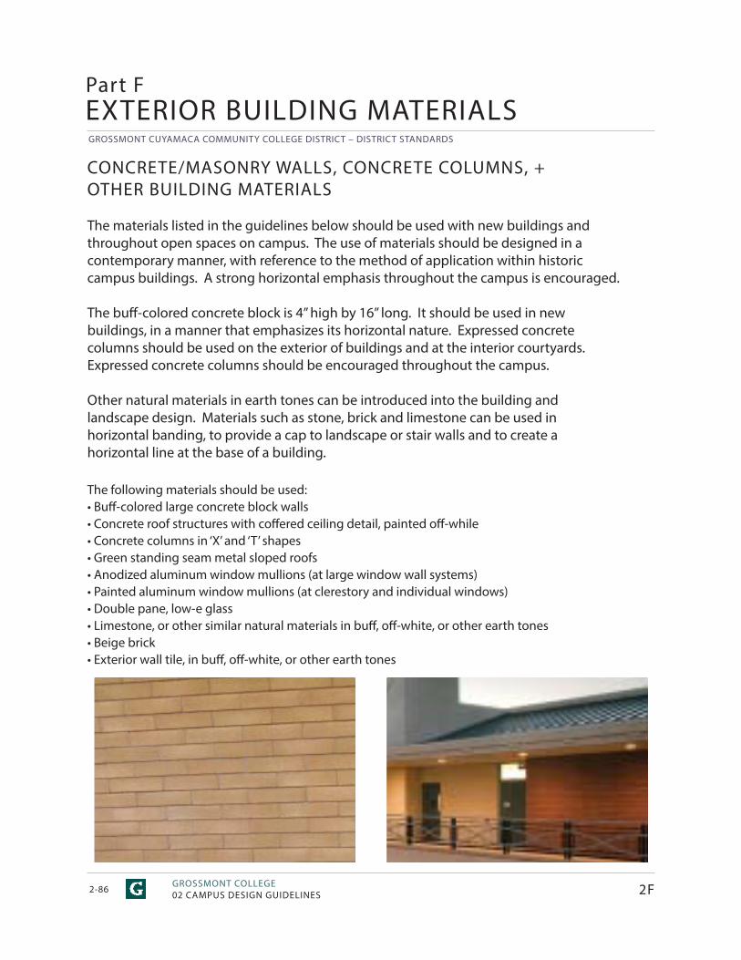
GROSSMONT CUYAMACA COMMUNITY COLLEGE DISTRICT – DISTRICT STANDARDS
GROSSMONT COLLEGE02 CAMPUS DESIGN GUIDELINES2-86
Part F
CONCRETE/MASONRY WALLS, CONCRETE COLUMNS, + OTHER BUILDING MATERIALS
The materials listed in the guidelines below should be used with new buildings and throughout open spaces on campus. The use of materials should be designed in a contemporary manner, with reference to the method of application within historic campus buildings. A strong horizontal emphasis throughout the campus is encouraged.
The buff -colored concrete block is 4” high by 16” long. It should be used in new buildings, in a manner that emphasizes its horizontal nature. Expressed concrete columns should be used on the exterior of buildings and at the interior courtyards. Expressed concrete columns should be encouraged throughout the campus.
Other natural materials in earth tones can be introduced into the building and landscape design. Materials such as stone, brick and limestone can be used in horizontal banding, to provide a cap to landscape or stair walls and to create a horizontal line at the base of a building.
The following materials should be used:• Buff -colored large concrete block walls• Concrete roof structures with coff ered ceiling detail, painted off -while• Concrete columns in ‘X’ and ‘T’ shapes• Green standing seam metal sloped roofs• Anodized aluminum window mullions (at large window wall systems)• Painted aluminum window mullions (at clerestory and individual windows)• Double pane, low-e glass• Limestone, or other similar natural materials in buff , off -white, or other earth tones• Beige brick• Exterior wall tile, in buff , off -white, or other earth tones
EXTERIOR BUILDING MATERIALS
2F
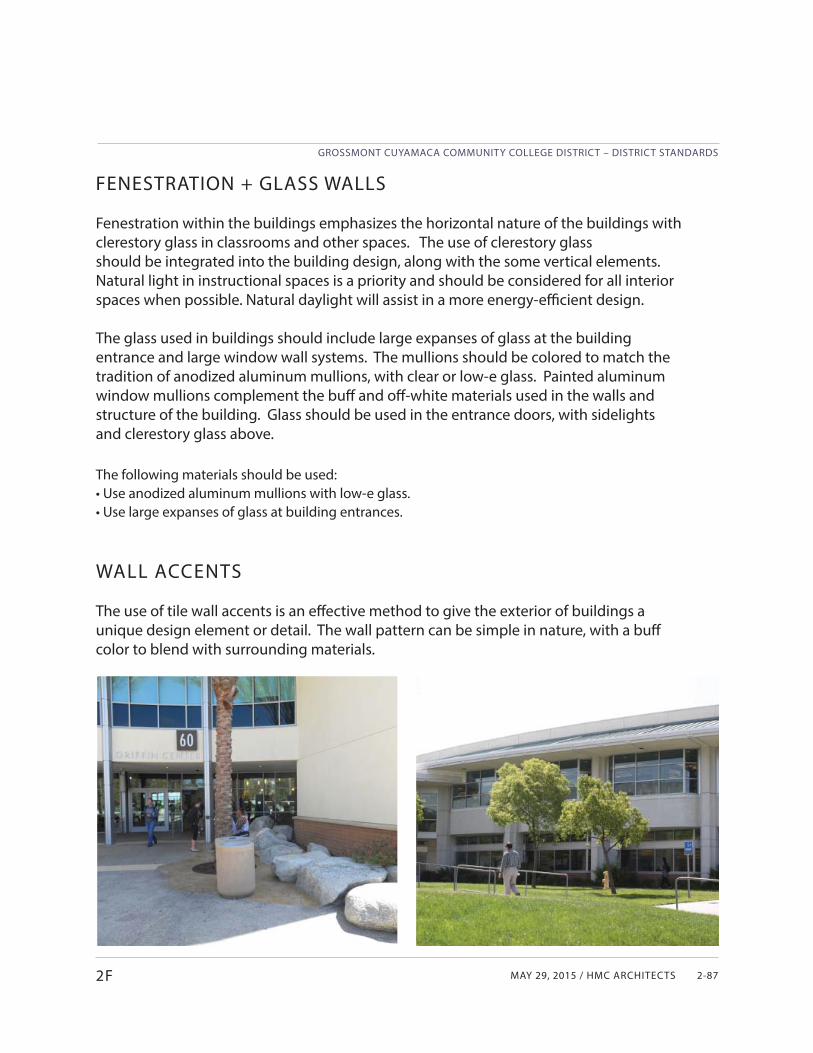
MAY 29, 2015 / HMC ARCHITECTS
GROSSMONT CUYAMACA COMMUNITY COLLEGE DISTRICT – DISTRICT STANDARDS
2-872F
FENESTRATION + GLASS WALLS
Fenestration within the buildings emphasizes the horizontal nature of the buildings with clerestory glass in classrooms and other spaces. The use of clerestory glass should be integrated into the building design, along with the some vertical elements. Natural light in instructional spaces is a priority and should be considered for all interior spaces when possible. Natural daylight will assist in a more energy-effi cient design.
The glass used in buildings should include large expanses of glass at the building entrance and large window wall systems. The mullions should be colored to match the tradition of anodized aluminum mullions, with clear or low-e glass. Painted aluminum window mullions complement the buff and off -white materials used in the walls and structure of the building. Glass should be used in the entrance doors, with sidelights and clerestory glass above.
The following materials should be used:• Use anodized aluminum mullions with low-e glass.• Use large expanses of glass at building entrances.
WALL ACCENTS
The use of tile wall accents is an eff ective method to give the exterior of buildings a unique design element or detail. The wall pattern can be simple in nature, with a buff color to blend with surrounding materials.
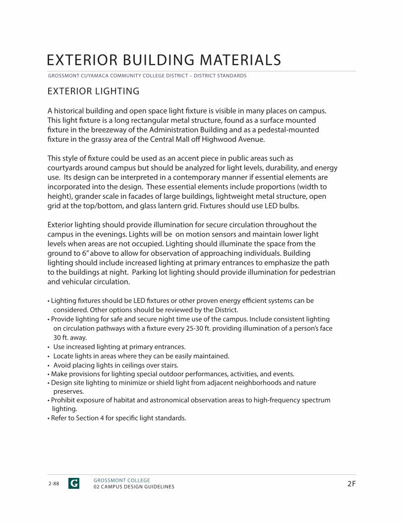
GROSSMONT CUYAMACA COMMUNITY COLLEGE DISTRICT – DISTRICT STANDARDS
GROSSMONT COLLEGE02 CAMPUS DESIGN GUIDELINES2-88
EXTERIOR LIGHTING
A historical building and open space light fi xture is visible in many places on campus. This light fi xture is a long rectangular metal structure, found as a surface mounted fi xture in the breezeway of the Administration Building and as a pedestal-mounted fi xture in the grassy area of the Central Mall off Highwood Avenue.
This style of fi xture could be used as an accent piece in public areas such as courtyards around campus but should be analyzed for light levels, durability, and energy use. Its design can be interpreted in a contemporary manner if essential elements are incorporated into the design. These essential elements include proportions (width to height), grander scale in facades of large buildings, lightweight metal structure, open grid at the top/bottom, and glass lantern grid. Fixtures should use LED bulbs.
Exterior lighting should provide illumination for secure circulation throughout the campus in the evenings. Lights will be on motion sensors and maintain lower light levels when areas are not occupied. Lighting should illuminate the space from the ground to 6” above to allow for observation of approaching individuals. Building lighting should include increased lighting at primary entrances to emphasize the path to the buildings at night. Parking lot lighting should provide illumination for pedestrian and vehicular circulation.
• Lighting fi xtures should be LED fi xtures or other proven energy effi cient systems can beconsidered. Other options should be reviewed by the District.
• Provide lighting for safe and secure night time use of the campus. Include consistent lightingon circulation pathways with a fi xture every 25-30 ft. providing illumination of a person’s face 30 ft. away.
• Use increased lighting at primary entrances.• Locate lights in areas where they can be easily maintained.• Avoid placing lights in ceilings over stairs.• Make provisions for lighting special outdoor performances, activities, and events.• Design site lighting to minimize or shield light from adjacent neighborhoods and nature
preserves.• Prohibit exposure of habitat and astronomical observation areas to high-frequency spectrum lighting.• Refer to Section 4 for specifi c light standards.
EXTERIOR BUILDING MATERIALS
2F
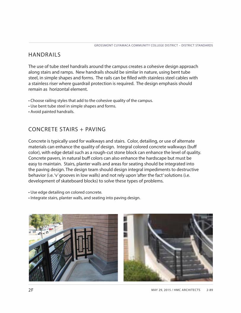
MAY 29, 2015 / HMC ARCHITECTS
GROSSMONT CUYAMACA COMMUNITY COLLEGE DISTRICT – DISTRICT STANDARDS
2-892F
HANDRAILS
The use of tube steel handrails around the campus creates a cohesive design approach along stairs and ramps. New handrails should be similar in nature, using bent tube steel, in simple shapes and forms. The rails can be fi lled with stainless steel cables with a stainless riser where guardrail protection is required. The design emphasis should remain as horizontal element.
• Choose railing styles that add to the cohesive quality of the campus.• Use bent tube steel in simple shapes and forms.• Avoid painted handrails.
CONCRETE STAIRS + PAVING
Concrete is typically used for walkways and stairs. Color, detailing, or use of alternate materials can enhance the quality of design. Integral colored concrete walkways (buff color), with edge detail such as a rough-cut stone block can enhance the level of quality. Concrete pavers, in natural buff colors can also enhance the hardscape but must be easy to maintain. Stairs, planter walls and areas for seating should be integrated into the paving design. The design team should design integral impediments to destructive behavior (i.e. ‘v’ grooves in low walls) and not rely upon ‘after the fact’ solutions (i.e. development of skateboard blocks) to solve these types of problems.
• Use edge detailing on colored concrete. • Integrate stairs, planter walls, and seating into paving design.
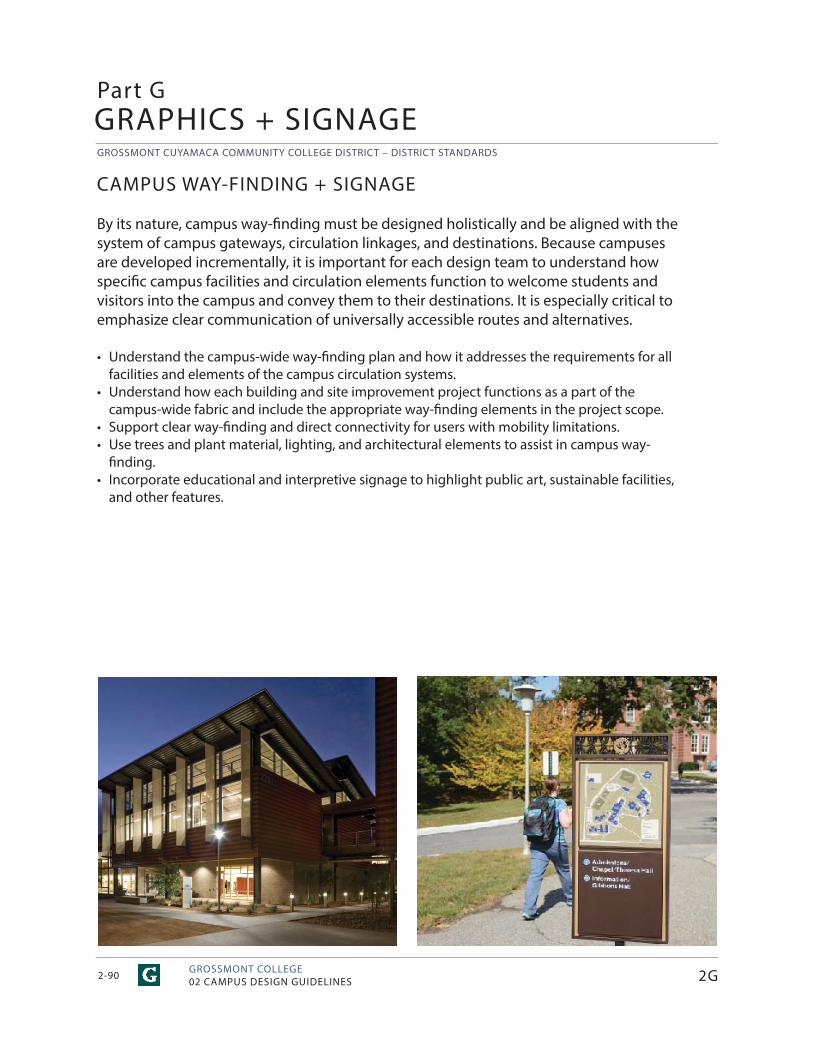
GROSSMONT CUYAMACA COMMUNITY COLLEGE DISTRICT – DISTRICT STANDARDS
GROSSMONT COLLEGE02 CAMPUS DESIGN GUIDELINES2-90
CAMPUS WAY-FINDING + SIGNAGE
By its nature, campus way-fi nding must be designed holistically and be aligned with the system of campus gateways, circulation linkages, and destinations. Because campuses are developed incrementally, it is important for each design team to understand how specifi c campus facilities and circulation elements function to welcome students and visitors into the campus and convey them to their destinations. It is especially critical to emphasize clear communication of universally accessible routes and alternatives.
• Understand the campus-wide way-fi nding plan and how it addresses the requirements for all facilities and elements of the campus circulation systems.
• Understand how each building and site improvement project functions as a part of the campus-wide fabric and include the appropriate way-fi nding elements in the project scope.
• Support clear way-fi nding and direct connectivity for users with mobility limitations.• Use trees and plant material, lighting, and architectural elements to assist in campus way-
finding. • Incorporate educational and interpretive signage to highlight public art, sustainable facilities,
and other features.
Part GGRAPHICS + SIGNAGE
2G
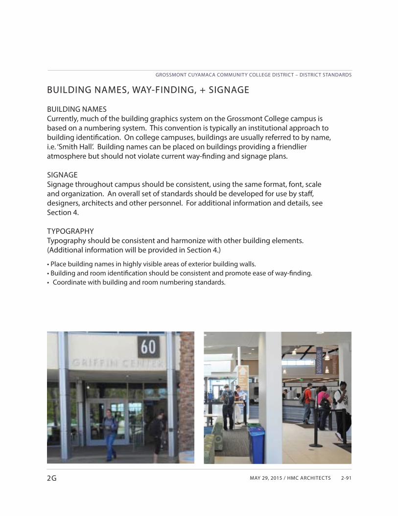
MAY 29, 2015 / HMC ARCHITECTS
GROSSMONT CUYAMACA COMMUNITY COLLEGE DISTRICT – DISTRICT STANDARDS
2-91
BUILDING NAMES, WAY-FINDING, + SIGNAGE
BUILDING NAMESCurrently, much of the building graphics system on the Grossmont College campus is based on a numbering system. This convention is typically an institutional approach to building identifi cation. On college campuses, buildings are usually referred to by name, i.e. ‘Smith Hall’. Building names can be placed on buildings providing a friendlier atmosphere but should not violate current way-fi nding and signage plans.
SIGNAGESignage throughout campus should be consistent, using the same format, font, scale and organization. An overall set of standards should be developed for use by staff , designers, architects and other personnel. For additional information and details, see Section 4.
TYPOGRAPHYTypography should be consistent and harmonize with other building elements. (Additional information will be provided in Section 4.)
• Place building names in highly visible areas of exterior building walls.• Building and room identifi cation should be consistent and promote ease of way-fi nding.• Coordinate with building and room numbering standards.
2G
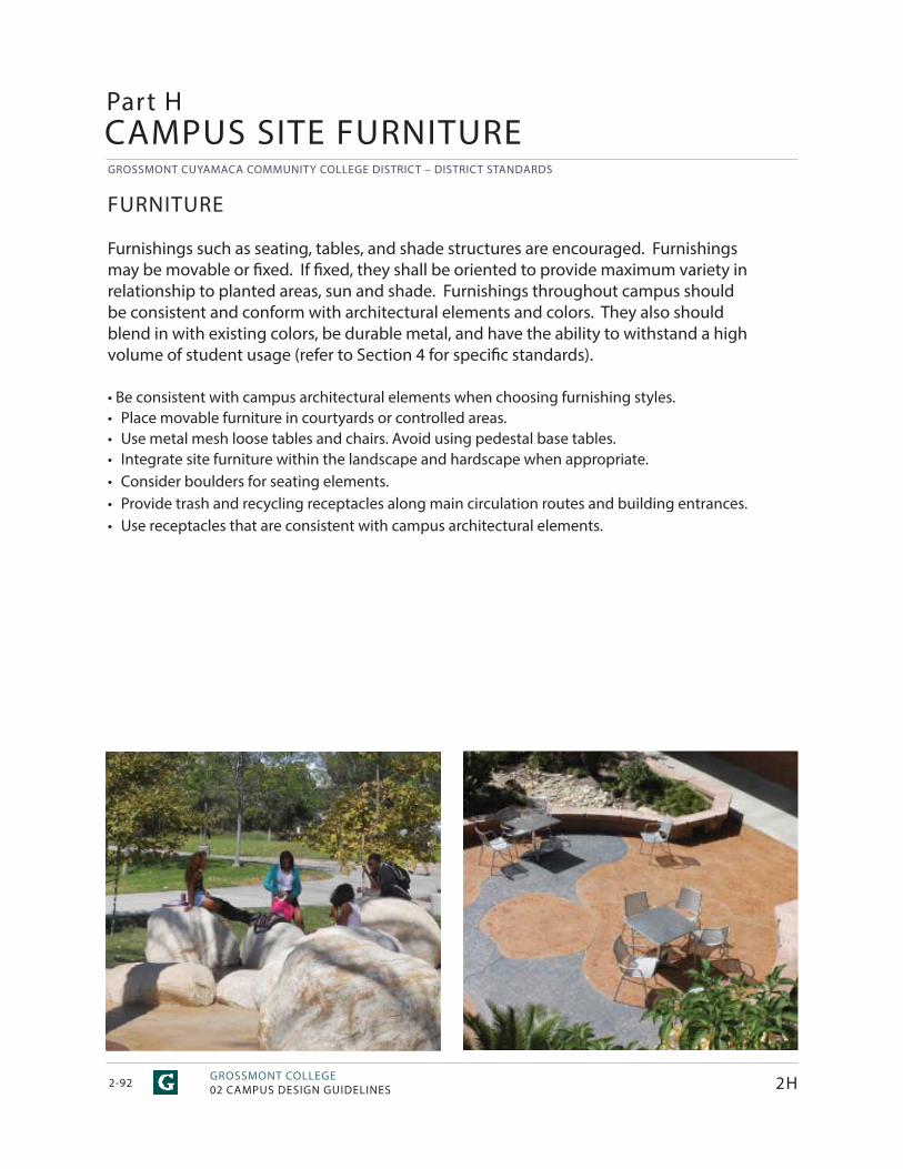
GROSSMONT CUYAMACA COMMUNITY COLLEGE DISTRICT – DISTRICT STANDARDS
GROSSMONT COLLEGE02 CAMPUS DESIGN GUIDELINES2-92
FURNITURE
Furnishings such as seating, tables, and shade structures are encouraged. Furnishings may be movable or fi xed. If fi xed, they shall be oriented to provide maximum variety in relationship to planted areas, sun and shade. Furnishings throughout campus should be consistent and conform with architectural elements and colors. They also should blend in with existing colors, be durable metal, and have the ability to withstand a high volume of student usage (refer to Section 4 for specifi c standards).
• Be consistent with campus architectural elements when choosing furnishing styles.• Place movable furniture in courtyards or controlled areas.• Use metal mesh loose tables and chairs. Avoid using pedestal base tables.• Integrate site furniture within the landscape and hardscape when appropriate.• Consider boulders for seating elements.• Provide trash and recycling receptacles along main circulation routes and building entrances.• Use receptacles that are consistent with campus architectural elements.
Part HCAMPUS SITE FURNITURE
2H
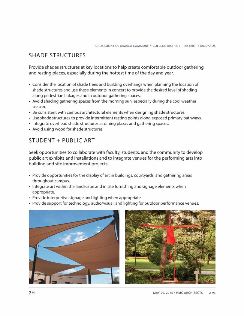
MAY 29, 2015 / HMC ARCHITECTS
GROSSMONT CUYAMACA COMMUNITY COLLEGE DISTRICT – DISTRICT STANDARDS
2-93
SHADE STRUCTURES
Provide shades structures at key locations to help create comfortable outdoor gathering and resting places, especially during the hottest time of the day and year.
• Consider the location of shade trees and building overhangs when planning the location of shade structures and use these elements in concert to provide the desired level of shading along pedestrian linkages and in outdoor gathering spaces.
• Avoid shading gathering spaces from the morning sun, especially during the cool weather season.
• Be consistent with campus architectural elements when designing shade structures.• Use shade structures to provide intermittent resting points along exposed primary pathways.• Integrate overhead shade structures at dining plazas and gathering spaces.• Avoid using wood for shade structures.
2H
STUDENT + PUBLIC ART
Seek opportunities to collaborate with faculty, students, and the community to develop public art exhibits and installations and to integrate venues for the performing arts into building and site improvement projects.
• Provide opportunities for the display of art in buildings, courtyards, and gathering areas throughout campus.
• Integrate art within the landscape and in site furnishing and signage elements when appropriate.
• Provide interpretive signage and lighting when appropriate.• Provide support for technology, audio/visual, and lighting for outdoor performance venues.
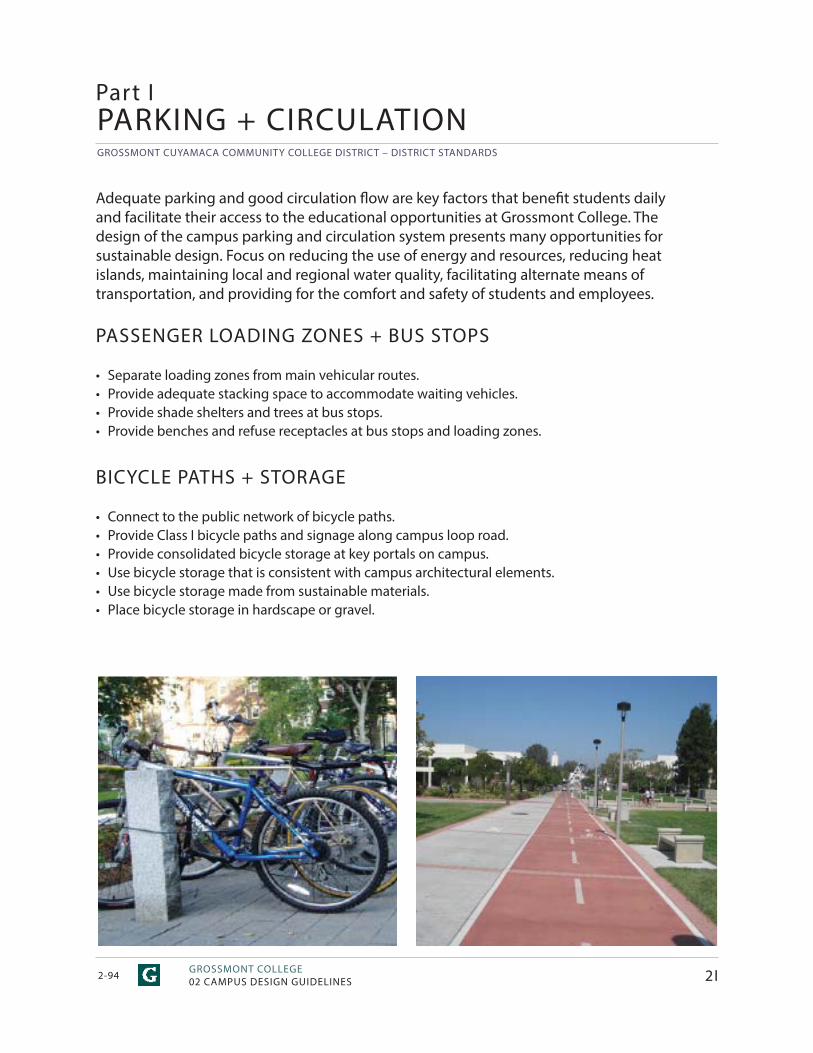
GROSSMONT CUYAMACA COMMUNITY COLLEGE DISTRICT – DISTRICT STANDARDS
GROSSMONT COLLEGE02 CAMPUS DESIGN GUIDELINES2-94 2I
Part IPARKING + CIRCULATION
Adequate parking and good circulation fl ow are key factors that benefi t students daily and facilitate their access to the educational opportunities at Grossmont College. The design of the campus parking and circulation system presents many opportunities for sustainable design. Focus on reducing the use of energy and resources, reducing heat islands, maintaining local and regional water quality, facilitating alternate means of transportation, and providing for the comfort and safety of students and employees.
PASSENGER LOADING ZONES + BUS STOPS
• Separate loading zones from main vehicular routes.• Provide adequate stacking space to accommodate waiting vehicles.• Provide shade shelters and trees at bus stops.• Provide benches and refuse receptacles at bus stops and loading zones.
BICYCLE PATHS + STORAGE
• Connect to the public network of bicycle paths.• Provide Class I bicycle paths and signage along campus loop road.• Provide consolidated bicycle storage at key portals on campus.• Use bicycle storage that is consistent with campus architectural elements.• Use bicycle storage made from sustainable materials.• Place bicycle storage in hardscape or gravel.
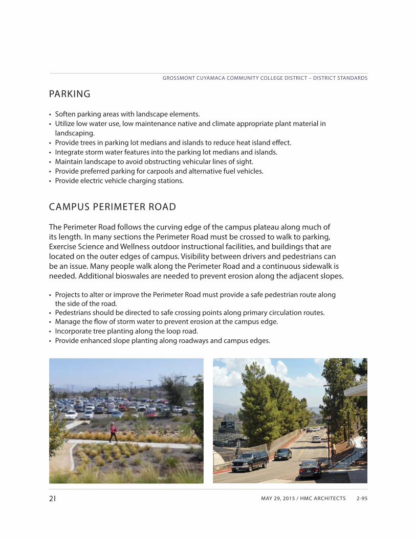
MAY 29, 2015 / HMC ARCHITECTS
GROSSMONT CUYAMACA COMMUNITY COLLEGE DISTRICT – DISTRICT STANDARDS
2-952I
PARKING
• Soften parking areas with landscape elements.• Utilize low water use, low maintenance native and climate appropriate plant material in
landscaping.• Provide trees in parking lot medians and islands to reduce heat island eff ect.• Integrate storm water features into the parking lot medians and islands.• Maintain landscape to avoid obstructing vehicular lines of sight.• Provide preferred parking for carpools and alternative fuel vehicles. • Provide electric vehicle charging stations.
CAMPUS PERIMETER ROAD
The Perimeter Road follows the curving edge of the campus plateau along much of its length. In many sections the Perimeter Road must be crossed to walk to parking, Exercise Science and Wellness outdoor instructional facilities, and buildings that are located on the outer edges of campus. Visibility between drivers and pedestrians can be an issue. Many people walk along the Perimeter Road and a continuous sidewalk is needed. Additional bioswales are needed to prevent erosion along the adjacent slopes.
• Projects to alter or improve the Perimeter Road must provide a safe pedestrian route along the side of the road.
• Pedestrians should be directed to safe crossing points along primary circulation routes.• Manage the fl ow of storm water to prevent erosion at the campus edge.• Incorporate tree planting along the loop road. • Provide enhanced slope planting along roadways and campus edges.

GROSSMONT CUYAMACA COMMUNITY COLLEGE DISTRICT – DISTRICT STANDARDS
GCCCD02 CAMPUS DESIGN GUIDELINES - DISTRICT SERVICES2-96
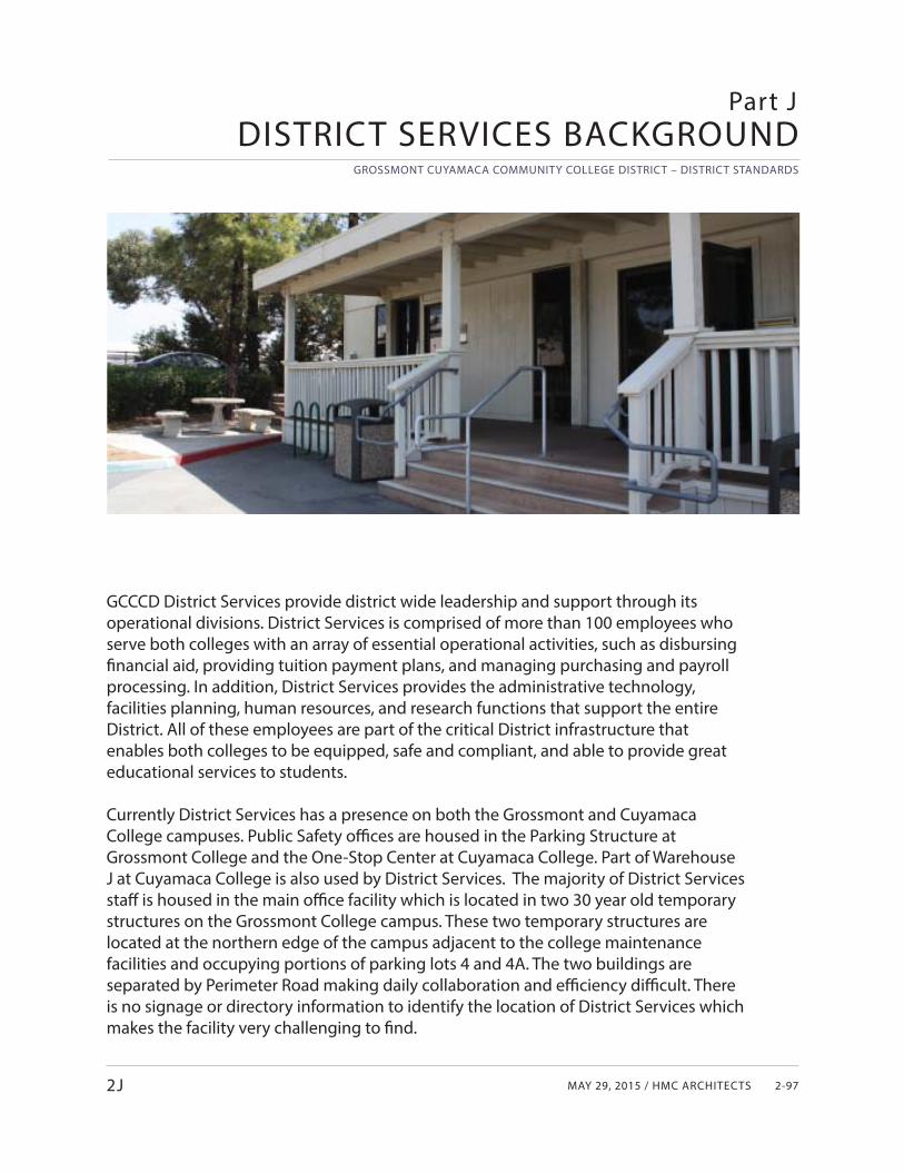
MAY 29, 2015 / HMC ARCHITECTS
GROSSMONT CUYAMACA COMMUNITY COLLEGE DISTRICT – DISTRICT STANDARDS
2-972J
GCCCD District Services provide district wide leadership and support through its operational divisions. District Services is comprised of more than 100 employees who serve both colleges with an array of essential operational activities, such as disbursing fi nancial aid, providing tuition payment plans, and managing purchasing and payroll processing. In addition, District Services provides the administrative technology, facilities planning, human resources, and research functions that support the entire District. All of these employees are part of the critical District infrastructure that enables both colleges to be equipped, safe and compliant, and able to provide great educational services to students.
Currently District Services has a presence on both the Grossmont and Cuyamaca College campuses. Public Safety offi ces are housed in the Parking Structure at Grossmont College and the One-Stop Center at Cuyamaca College. Part of Warehouse J at Cuyamaca College is also used by District Services. The majority of District Services staff is housed in the main offi ce facility which is located in two 30 year old temporary structures on the Grossmont College campus. These two temporary structures are located at the northern edge of the campus adjacent to the college maintenance facilities and occupying portions of parking lots 4 and 4A. The two buildings are separated by Perimeter Road making daily collaboration and effi ciency diffi cult. There is no signage or directory information to identify the location of District Services which makes the facility very challenging to fi nd.
DISTRICT SERVICES BACKGROUNDPart J
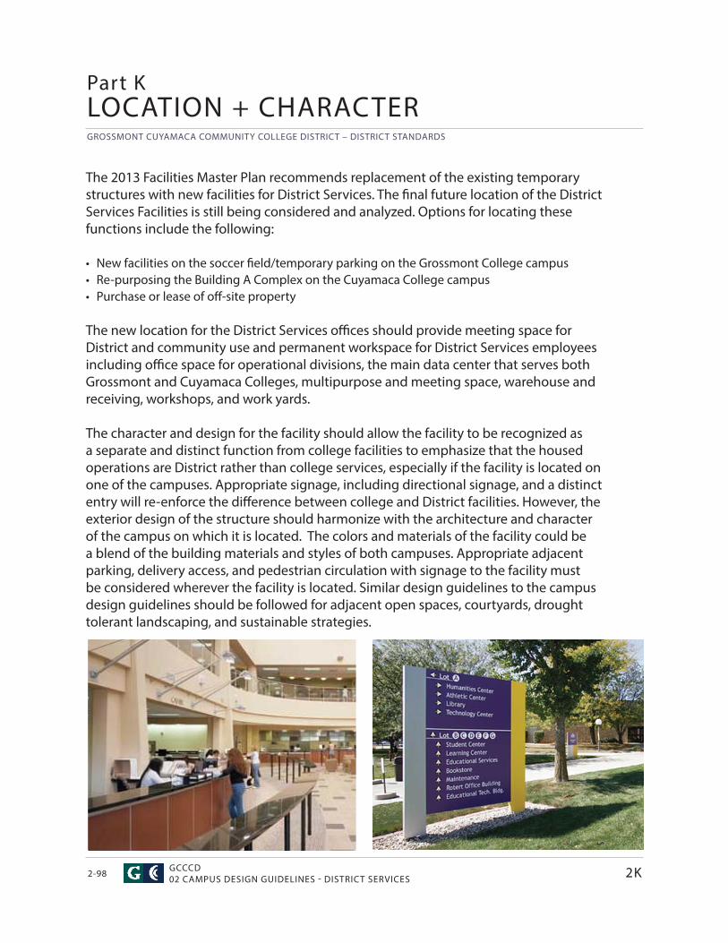
GROSSMONT CUYAMACA COMMUNITY COLLEGE DISTRICT – DISTRICT STANDARDS
GCCCD02 CAMPUS DESIGN GUIDELINES - DISTRICT SERVICES2-98
Part KLOCATION + CHARACTER
The 2013 Facilities Master Plan recommends replacement of the existing temporary structures with new facilities for District Services. The fi nal future location of the District Services Facilities is still being considered and analyzed. Options for locating these functions include the following:
• New facilities on the soccer fi eld/temporary parking on the Grossmont College campus• Re-purposing the Building A Complex on the Cuyamaca College campus• Purchase or lease of off -site property
The new location for the District Services offi ces should provide meeting space for District and community use and permanent workspace for District Services employees including offi ce space for operational divisions, the main data center that serves both Grossmont and Cuyamaca Colleges, multipurpose and meeting space, warehouse and receiving, workshops, and work yards.
The character and design for the facility should allow the facility to be recognized as a separate and distinct function from college facilities to emphasize that the housed operations are District rather than college services, especially if the facility is located on one of the campuses. Appropriate signage, including directional signage, and a distinct entry will re-enforce the diff erence between college and District facilities. However, the exterior design of the structure should harmonize with the architecture and character of the campus on which it is located. The colors and materials of the facility could be a blend of the building materials and styles of both campuses. Appropriate adjacent parking, delivery access, and pedestrian circulation with signage to the facility must be considered wherever the facility is located. Similar design guidelines to the campus design guidelines should be followed for adjacent open spaces, courtyards, drought tolerant landscaping, and sustainable strategies.
2K

MAY 29, 2015 / HMC ARCHITECTS
GROSSMONT CUYAMACA COMMUNITY COLLEGE DISTRICT – DISTRICT STANDARDS
2-992K
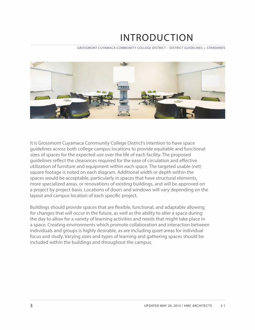
UPDATED MAY 29, 2015 / HMC ARCHITECTS
GROSSMONT CUYAMACA COMMUNITY COLLEGE DISTRICT – DISTRICT GUIDELINES + STANDARDS
3-1
INTRODUCTION
3
It is Grossmont Cuyamaca Community College District’s intention to have space guidelines across both college campus locations to provide equitable and functional sizes of spaces for the expected use over the life of each facility. The proposed guidelines refl ect the clearances required for the ease of circulation and eff ective utilization of furniture and equipment within each space. The targeted usable (net) square footage is noted on each diagram. Additional width or depth within the spaces would be acceptable, particularly in spaces that have structural elements, more specialized areas, or renovations of existing buildings, and will be approved on a project by project basis. Locations of doors and windows will vary depending on the layout and campus location of each specifi c project.
Buildings should provide spaces that are fl exible, functional, and adaptable allowing for changes that will occur in the future, as well as the ability to alter a space during the day to allow for a variety of learning activities and needs that might take place in a space. Creating environments which promote collaboration and interaction between individuals and groups is highly desirable, as are including quiet areas for individual focus and study. Varying sizes and types of learning and gathering spaces should be included within the buildings and throughout the campus.
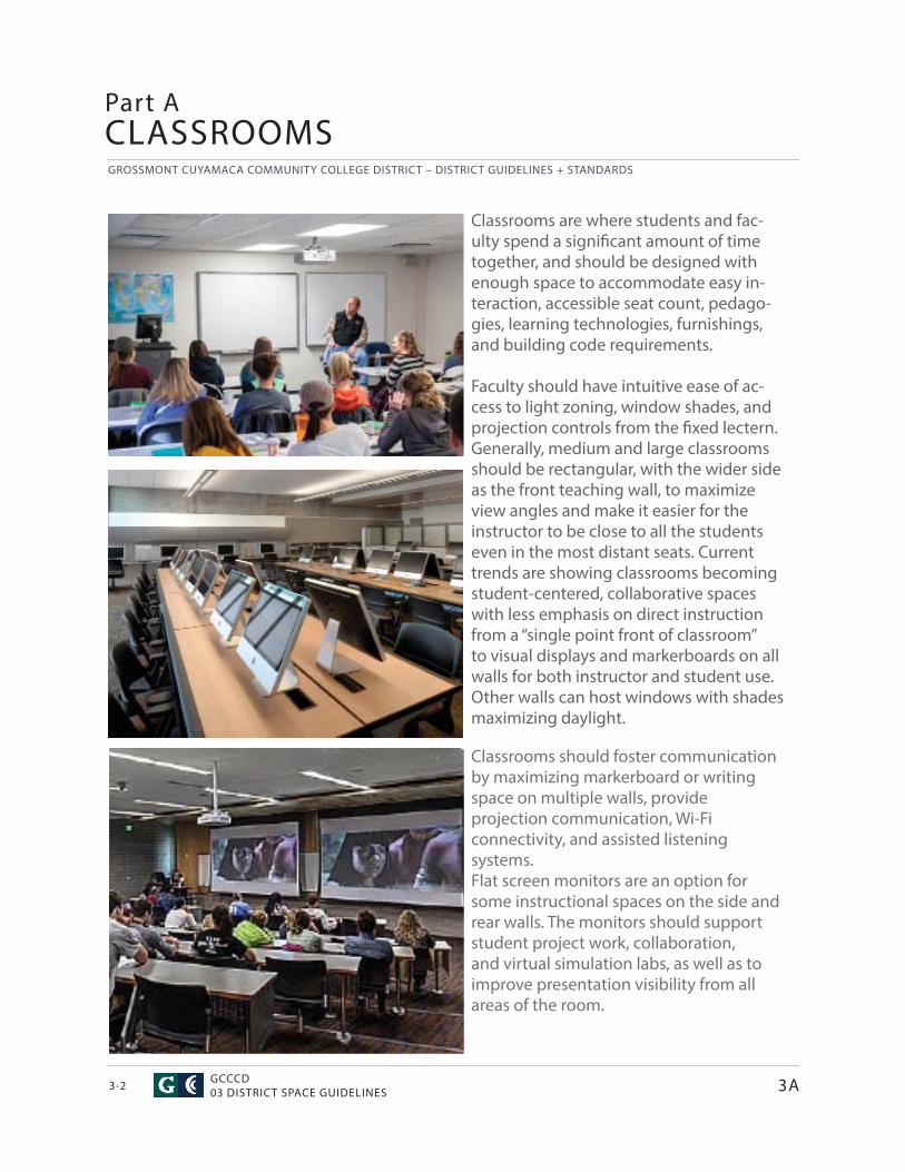
GROSSMONT CUYAMACA COMMUNITY COLLEGE DISTRICT – DISTRICT GUIDELINES + STANDARDS
GCCCD03 DISTRICT SPACE GUIDELINES3-2
Classrooms are where students and fac-ulty spend a signifi cant amount of time together, and should be designed with enough space to accommodate easy in-teraction, accessible seat count, pedago-gies, learning technologies, furnishings, and building code requirements.
Faculty should have intuitive ease of ac-cess to light zoning, window shades, and projection controls from the fi xed lectern. Generally, medium and large classrooms should be rectangular, with the wider side as the front teaching wall, to maximize view angles and make it easier for the instructor to be close to all the students even in the most distant seats. Current trends are showing classrooms becoming student-centered, collaborative spaces with less emphasis on direct instruction from a “single point front of classroom” to visual displays and markerboards on all walls for both instructor and student use. Other walls can host windows with shades maximizing daylight.
CLASSROOMSPart A
Classrooms should foster communication by maximizing markerboard or writing space on multiple walls, provide projection communication, Wi-Fi connectivity, and assisted listening systems. Flat screen monitors are an option for some instructional spaces on the side and rear walls. The monitors should support student project work, collaboration, and virtual simulation labs, as well as to improve presentation visibility from all areas of the room.
3A
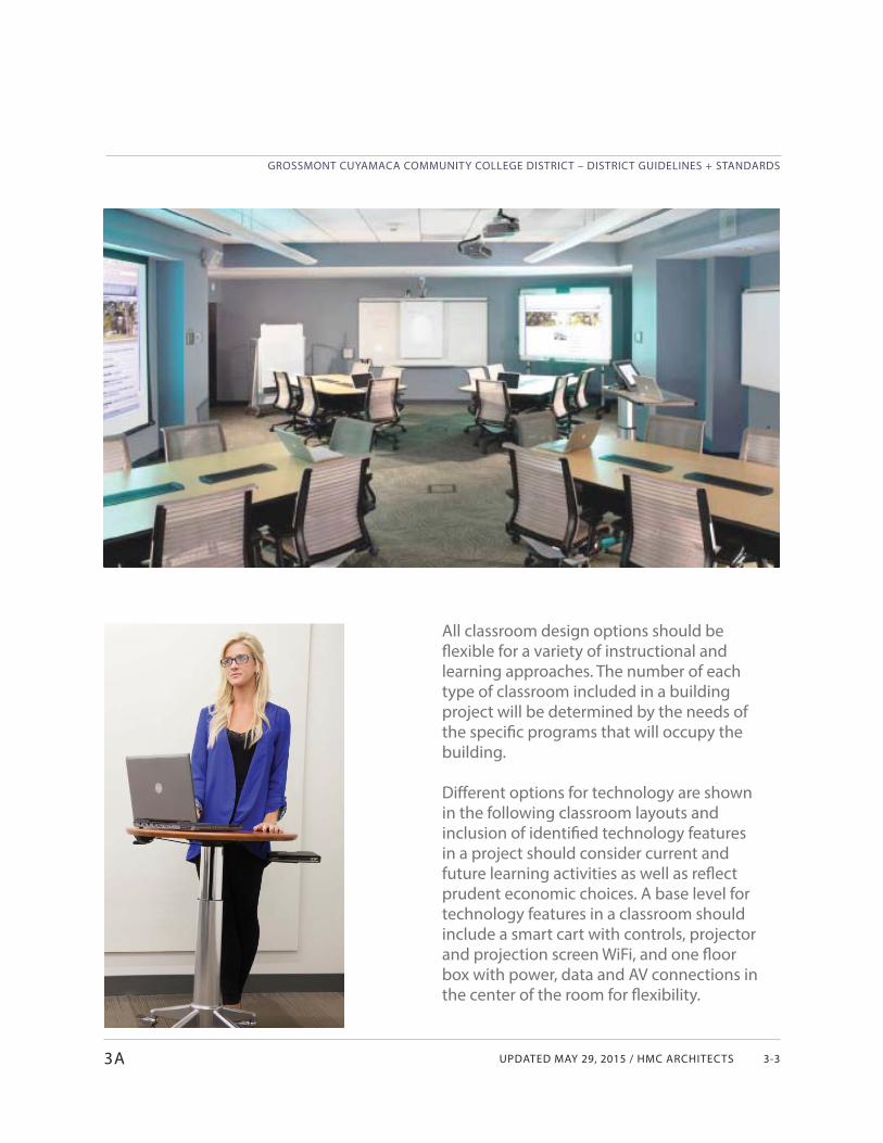
UPDATED MAY 29, 2015 / HMC ARCHITECTS
GROSSMONT CUYAMACA COMMUNITY COLLEGE DISTRICT – DISTRICT GUIDELINES + STANDARDS
3-3
All classroom design options should be fl exible for a variety of instructional and learning approaches. The number of each type of classroom included in a building project will be determined by the needs of the specifi c programs that will occupy the building.
Diff erent options for technology are shown in the following classroom layouts and inclusion of identifi ed technology features in a project should consider current and future learning activities as well as refl ect prudent economic choices. A base level for technology features in a classroom should include a smart cart with controls, projector and projection screen WiFi, and one fl oor box with power, data and AV connections in the center of the room for fl exibility.
3A
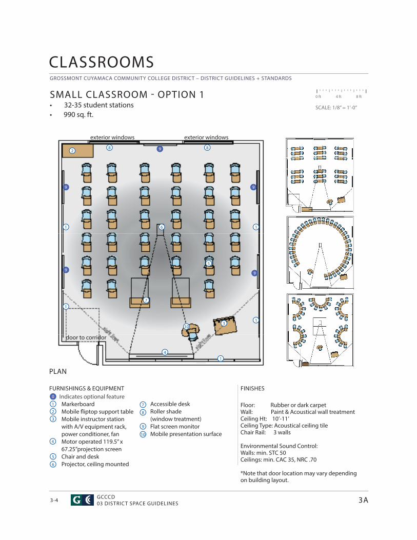
GROSSMONT CUYAMACA COMMUNITY COLLEGE DISTRICT – DISTRICT GUIDELINES + STANDARDS
GCCCD03 DISTRICT SPACE GUIDELINES3-4
Accessible deskRoller shade (window treatment)Flat screen monitorMobile presentation surface
CLASSROOMS
FURNISHINGS & EQUIPMENT Indicates optional feature
MarkerboardMobile fl iptop support tableMobile instructor station with A/V equipment rack, power conditioner, fanMotor operated 119.5” x 67.25”projection screenChair and deskProjector, ceiling mounted
FINISHES
Floor: Rubber or dark carpetWall: Paint & Acoustical wall treatment Ceiling Ht: 10’-11’ Ceiling Type: Acoustical ceiling tileChair Rail: 3 walls Environmental Sound Control: Walls: min. STC 50Ceilings: min. CAC 35, NRC .70
*Note that door location may vary depending on building layout.
PLAN
SMALL CLASSROOM - OPTION 1• 32-35 student stations• 990 sq. ft.
0 ft 4 ft 8 ft
SCALE: 1/8” = 1’-0”
1
4
3
7
6
2
1
5
4
8
7
3
2
6
5
9
8
10
1
10
8
1
1
3A
1
0
9
99
9
9
door to corridor
exterior windows exterior windows
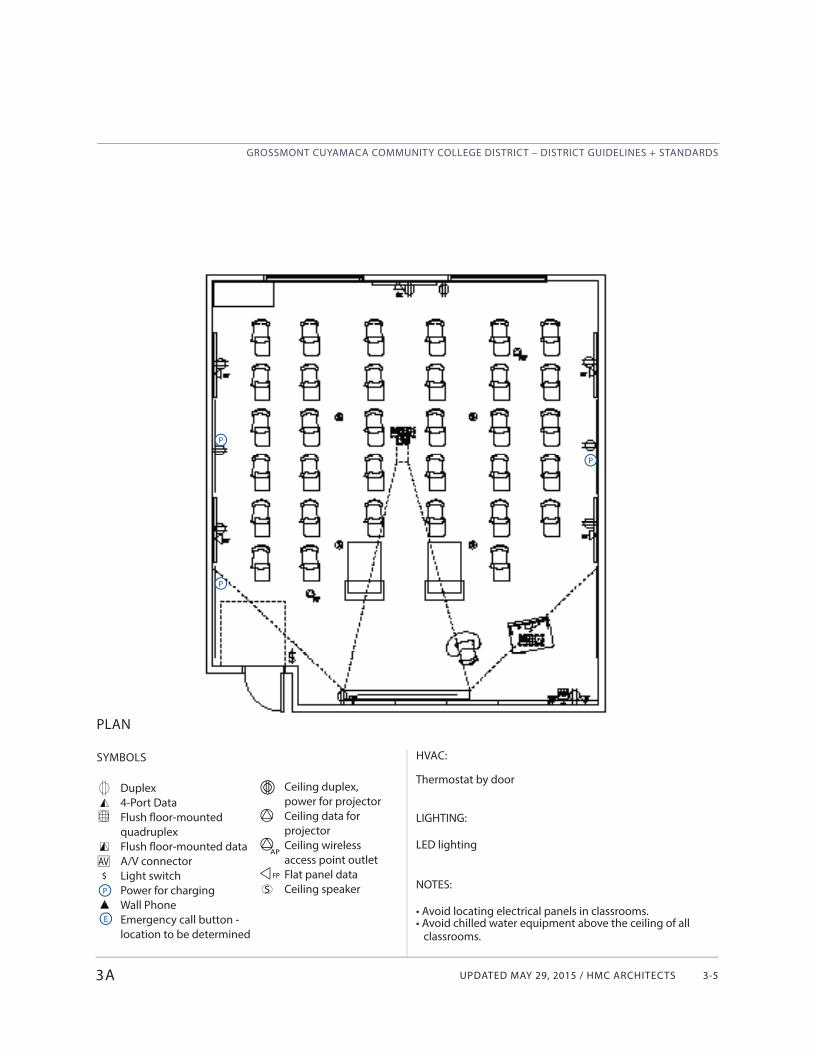
UPDATED MAY 29, 2015 / HMC ARCHITECTS
GROSSMONT CUYAMACA COMMUNITY COLLEGE DISTRICT – DISTRICT GUIDELINES + STANDARDS
3-5
Ceiling duplex, power for projectorCeiling data for projectorCeiling wireless access point outletFlat panel dataCeiling speaker
SYMBOLS
Duplex4-Port DataFlush fl oor-mounted quadruplexFlush fl oor-mounted data A/V connectorLight switchPower for chargingWall PhoneEmergency call button - location to be determined
HVAC:
Thermostat by door
LIGHTING:
LED lighting
NOTES:
• Avoid locating electrical panels in classrooms.• Avoid chilled water equipment above the ceiling of all classrooms.
PLAN
3A
AV$
P
P
P
E
S
AP
FP
P
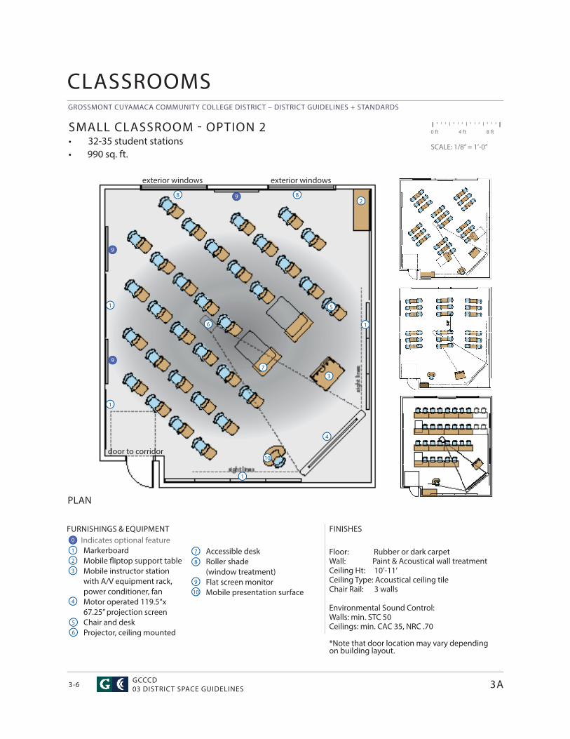
GROSSMONT CUYAMACA COMMUNITY COLLEGE DISTRICT – DISTRICT GUIDELINES + STANDARDS
GCCCD03 DISTRICT SPACE GUIDELINES3-6
Accessible deskRoller shade (window treatment)Flat screen monitorMobile presentation surface
CLASSROOMS
FURNISHINGS & EQUIPMENT Indicates optional feature
MarkerboardMobile fl iptop support tableMobile instructor station with A/V equipment rack, power conditioner, fanMotor operated 119.5”x 67.25” projection screenChair and deskProjector, ceiling mounted
FINISHES
Floor: Rubber or dark carpetWall: Paint & Acoustical wall treatment Ceiling Ht: 10’-11’ Ceiling Type: Acoustical ceiling tileChair Rail: 3 walls
Environmental Sound Control: Walls: min. STC 50Ceilings: min. CAC 35, NRC .70
*Note that door location may vary depending on building layout.
PLAN
SMALL CLASSROOM - OPTION 2• 32-35 student stations• 990 sq. ft.
0 ft 4 ft 8 ft
SCALE: 1/8” = 1’-0”
1
4
3
7
6
2
2
5
4
83
6
5
9
8
10
10
1
1
7
8
1
1
3A
0
9
9
9
door to corridor
exterior windows exterior windows
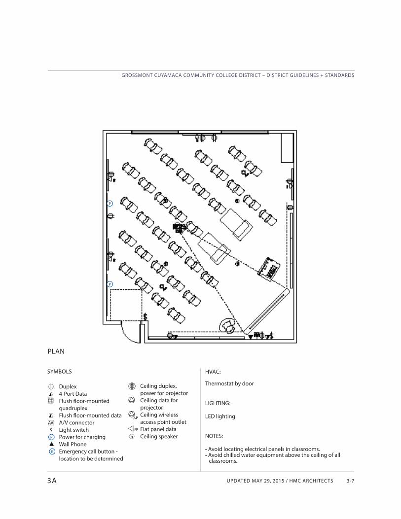
UPDATED MAY 29, 2015 / HMC ARCHITECTS
GROSSMONT CUYAMACA COMMUNITY COLLEGE DISTRICT – DISTRICT GUIDELINES + STANDARDS
3-7
SYMBOLS
Duplex4-Port DataFlush fl oor-mounted quadruplexFlush fl oor-mounted data A/V connectorLight switchPower for chargingWall PhoneEmergency call button - location to be determined
PLAN
3A
AV$
P
P
P
E
Ceiling duplex, power for projectorCeiling data for projectorCeiling wireless access point outletFlat panel dataCeiling speakerS
AP
FP
HVAC:
Thermostat by door
LIGHTING:
LED lighting
NOTES:
• Avoid locating electrical panels in classrooms.• Avoid chilled water equipment above the ceiling of all classrooms.
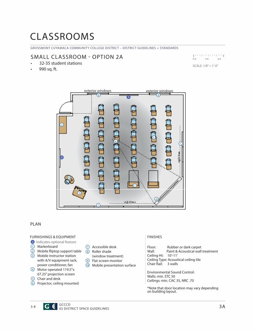
GROSSMONT CUYAMACA COMMUNITY COLLEGE DISTRICT – DISTRICT GUIDELINES + STANDARDS
GCCCD03 DISTRICT SPACE GUIDELINES3-8
Accessible deskRoller shade (window treatment)Flat screen monitorMobile presentation surface
CLASSROOMS
FURNISHINGS & EQUIPMENT Indicates optional feature
MarkerboardMobile fl iptop support tableMobile instructor station with A/V equipment rack, power conditioner, fanMotor operated 119.5”x 67.25” projection screenChair and deskProjector, ceiling mounted
FINISHES
Floor: Rubber or dark carpetWall: Paint & Acoustical wall treatment Ceiling Ht: 10’-11’ Ceiling Type: Acoustical ceiling tileChair Rail: 3 walls
Environmental Sound Control: Walls: min. STC 50Ceilings: min. CAC 35, NRC .70
*Note that door location may vary depending on building layout.
PLAN
SMALL CLASSROOM - OPTION 2A• 32-35 student stations• 990 sq. ft.
0 ft 4 ft 8 ft
SCALE: 1/8” = 1’-0”
1
4
3
7
6
2
2
5
4
83
6
5
9
8
10
10
7
8
1
1
3A
0
9
9
exterior windows exterior windows
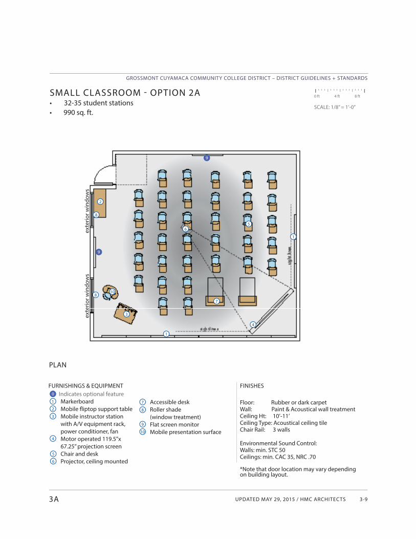
UPDATED MAY 29, 2015 / HMC ARCHITECTS
GROSSMONT CUYAMACA COMMUNITY COLLEGE DISTRICT – DISTRICT GUIDELINES + STANDARDS
3-93A
Accessible deskRoller shade (window treatment)Flat screen monitorMobile presentation surface
FURNISHINGS & EQUIPMENT Indicates optional feature
MarkerboardMobile fl iptop support tableMobile instructor station with A/V equipment rack, power conditioner, fanMotor operated 119.5”x 67.25” projection screenChair and deskProjector, ceiling mounted
FINISHES
Floor: Rubber or dark carpetWall: Paint & Acoustical wall treatment Ceiling Ht: 10’-11’ Ceiling Type: Acoustical ceiling tileChair Rail: 3 walls
Environmental Sound Control: Walls: min. STC 50Ceilings: min. CAC 35, NRC .70
*Note that door location may vary depending on building layout.
PLAN
SMALL CLASSROOM - OPTION 2A• 32-35 student stations• 990 sq. ft.
0 ft 4 ft 8 ft
SCALE: 1/8” = 1’-0”
1
4
3
7
6
2
2
5
4
83
6
5
9
8
10
10
1
1
7
8
0
9
9
exte
rior w
indo
ws
exte
rior w
indo
ws
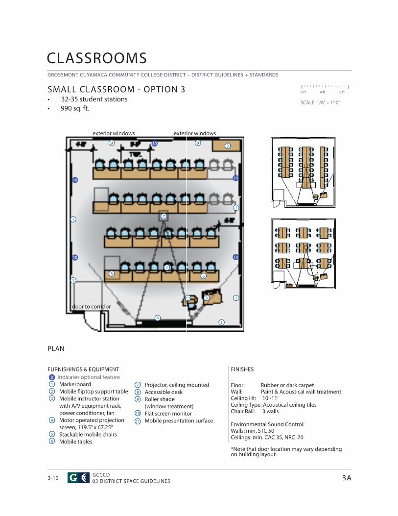
GROSSMONT CUYAMACA COMMUNITY COLLEGE DISTRICT – DISTRICT GUIDELINES + STANDARDS
GCCCD03 DISTRICT SPACE GUIDELINES3-10
CLASSROOMS
FURNISHINGS & EQUIPMENT Indicates optional feature
MarkerboardMobile fl iptop support tableMobile instructor station with A/V equipment rack, power conditioner, fanMotor operated projection screen, 119.5” x 67.25”Stackable mobile chairsMobile tables
FINISHES
Floor: Rubber or dark carpetWall: Paint & Acoustical wall treatment Ceiling Ht: 10’-11’ Ceiling Type: Acoustical ceiling tiles Chair Rail: 3 walls Environmental Sound Control: Walls: min. STC 50Ceilings: min. CAC 35, NRC .70
*Note that door location may vary depending on building layout.
PLAN
SMALL CLASSROOM - OPTION 3• 32-35 student stations• 990 sq. ft.
0 ft 4 ft 8 ft
SCALE: 1/8” = 1’-0”
1
1
4
4
7
7
2
2
5
5
8
8
3
3
6
6
9
9
Projector, ceiling mountedAccessible deskRoller shade (window treatment)Flat screen monitorMobile presentation surface
10
1
11
11
3A
9
1
1
1
0
10 10
1010
10
door to corridor
exterior windows exterior windows
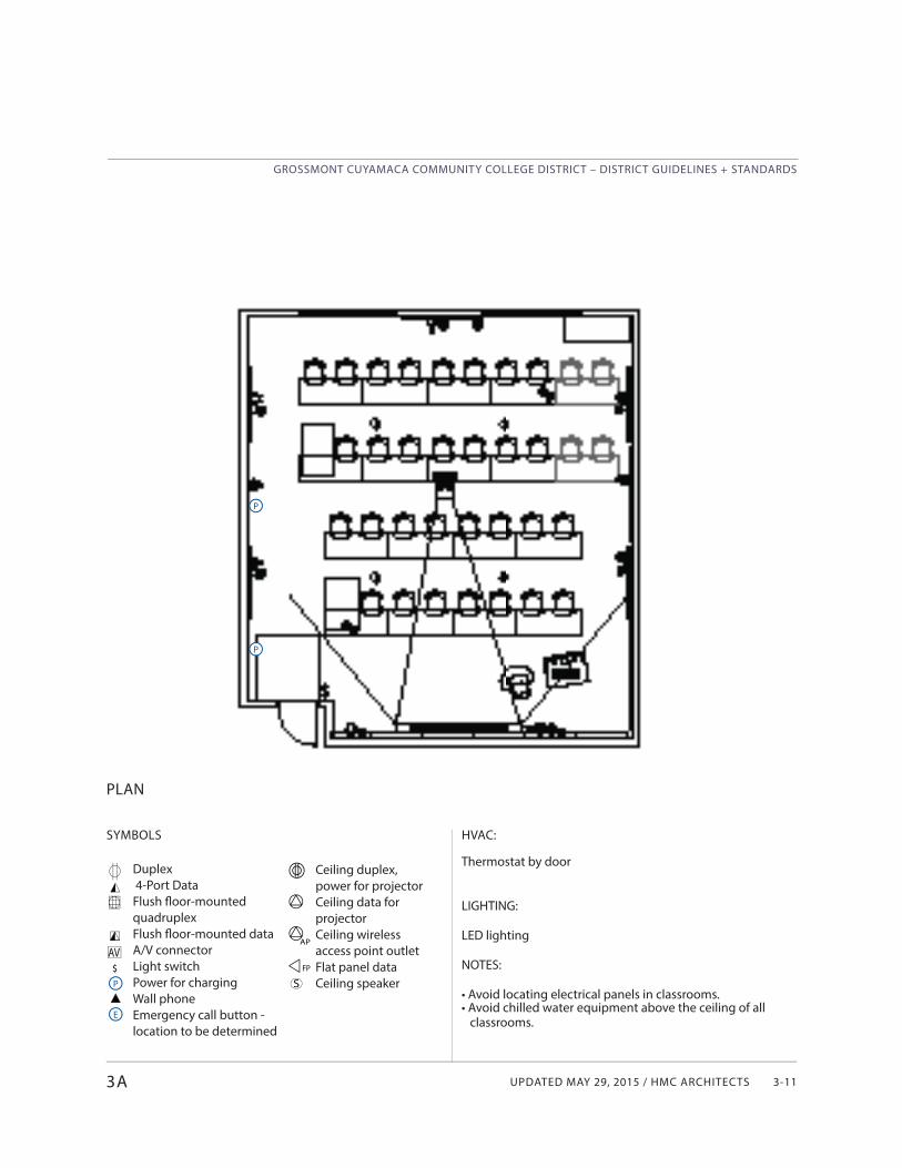
UPDATED MAY 29, 2015 / HMC ARCHITECTS
GROSSMONT CUYAMACA COMMUNITY COLLEGE DISTRICT – DISTRICT GUIDELINES + STANDARDS
3-113A
SYMBOLS
Duplex 4-Port DataFlush fl oor-mounted quadruplexFlush fl oor-mounted data A/V connectorLight switchPower for chargingWall phoneEmergency call button - location to be determined
PLAN
AV$P
P
P
E
Ceiling duplex, power for projectorCeiling data for projectorCeiling wireless access point outletFlat panel dataCeiling speakerS
AP
FP
HVAC:
Thermostat by door
LIGHTING:
LED lighting
NOTES:
• Avoid locating electrical panels in classrooms.• Avoid chilled water equipment above the ceiling of all classrooms.
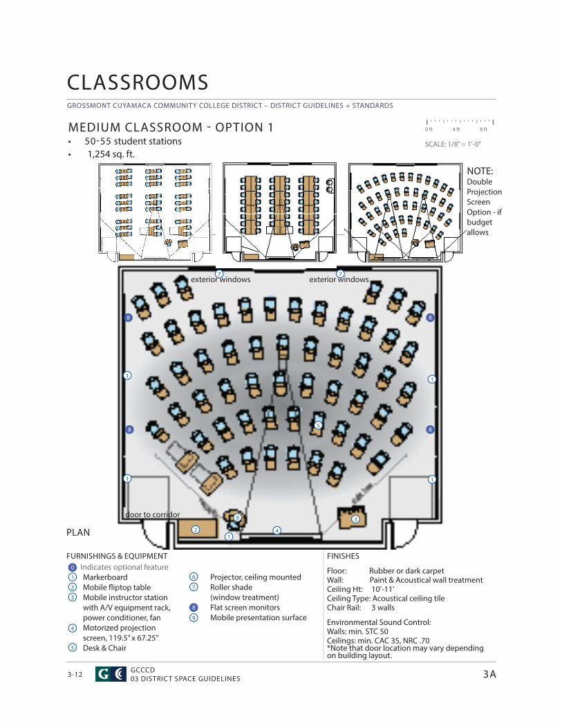
GROSSMONT CUYAMACA COMMUNITY COLLEGE DISTRICT – DISTRICT GUIDELINES + STANDARDS
GCCCD03 DISTRICT SPACE GUIDELINES3-12
CLASSROOMS
FURNISHINGS & EQUIPMENT Indicates optional feature
MarkerboardMobile fl iptop tableMobile instructor station with A/V equipment rack, power conditioner, fanMotorized projection screen, 119.5” x 67.25”Desk & Chair
FINISHES
Floor: Rubber or dark carpetWall: Paint & Acoustical wall treatment Ceiling Ht: 10’-11’ Ceiling Type: Acoustical ceiling tileChair Rail: 3 walls
Environmental Sound Control: Walls: min. STC 50Ceilings: min. CAC 35, NRC .70*Note that door location may vary depending on building layout.
PLAN
MEDIUM CLASSROOM - OPTION 1• 50-55 student stations• 1,254 sq. ft.
0 ft 4 ft 8 ft
SCALE: 1/8” = 1’-0”
1
1
4
4
7
7
2
2
5
5
3
3
6
9
Projector, ceiling mountedRoller shade (window treatment)Flat screen monitorsMobile presentation surface
11
1 1
3A
NOTE:Double Projection Screen Option - if budget allows
0
8 8
88
door to corridor
exterior windows exterior windows7
9
8
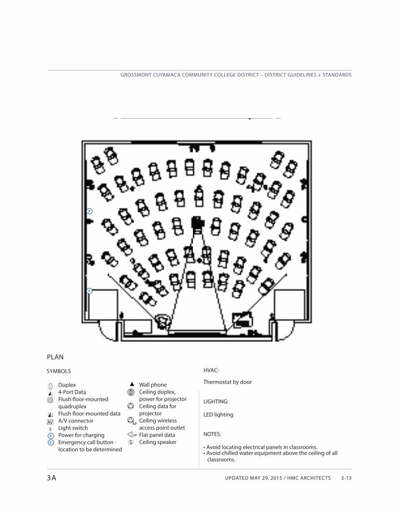
UPDATED MAY 29, 2015 / HMC ARCHITECTS
GROSSMONT CUYAMACA COMMUNITY COLLEGE DISTRICT – DISTRICT GUIDELINES + STANDARDS
3-13
Wall phoneCeiling duplex, power for projectorCeiling data for projectorCeiling wireless access point outletFlat panel dataCeiling speaker
SYMBOLS
Duplex4-Port DataFlush fl oor-mounted quadruplexFlush fl oor-mounted data A/V connectorLight switchPower for chargingEmergency call button - location to be determined
PLAN
3A
AV$P
P
P
E S
AP
FP
HVAC:
Thermostat by door
LIGHTING:
LED lighting
NOTES:
• Avoid locating electrical panels in classrooms.• Avoid chilled water equipment above the ceiling of all classrooms.
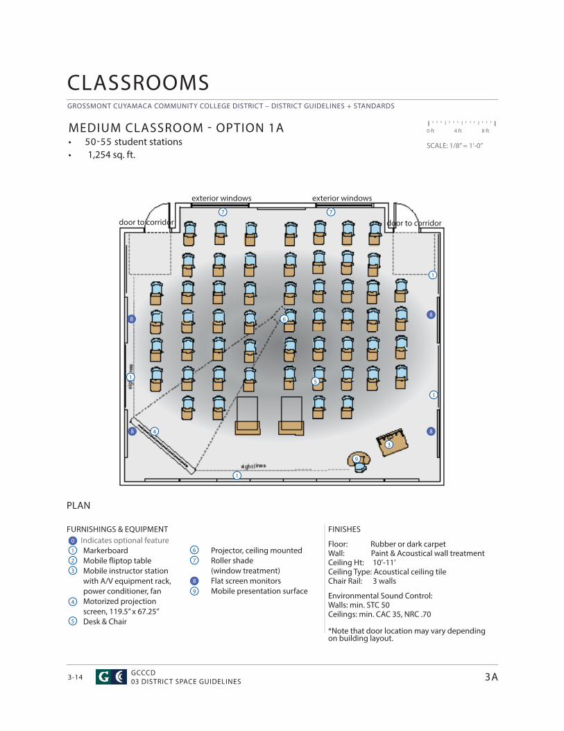
GROSSMONT CUYAMACA COMMUNITY COLLEGE DISTRICT – DISTRICT GUIDELINES + STANDARDS
GCCCD03 DISTRICT SPACE GUIDELINES3-14
CLASSROOMS
FURNISHINGS & EQUIPMENT Indicates optional feature
MarkerboardMobile fl iptop tableMobile instructor station with A/V equipment rack, power conditioner, fanMotorized projection screen, 119.5” x 67.25”Desk & Chair
FINISHES
Floor: Rubber or dark carpetWall: Paint & Acoustical wall treatment Ceiling Ht: 10’-11’ Ceiling Type: Acoustical ceiling tileChair Rail: 3 walls
Environmental Sound Control: Walls: min. STC 50Ceilings: min. CAC 35, NRC .70
*Note that door location may vary depending on building layout.
PLAN
MEDIUM CLASSROOM - OPTION 1A• 50-55 student stations• 1,254 sq. ft.
0 ft 4 ft 8 ft
SCALE: 1/8” = 1’-0”
1
4
4
7
7
2
5
5
3
3
6
9
Projector, ceiling mountedRoller shade (window treatment)Flat screen monitorsMobile presentation surface
1
1
1
1
3A
0
8 8
88
door to corridor
exterior windows exterior windows
7
9
8
door to corridor
6
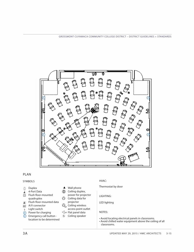
UPDATED MAY 29, 2015 / HMC ARCHITECTS
GROSSMONT CUYAMACA COMMUNITY COLLEGE DISTRICT – DISTRICT GUIDELINES + STANDARDS
3-15
Wall phoneCeiling duplex, power for projectorCeiling data for projectorCeiling wireless access point outletFlat panel dataCeiling speaker
SYMBOLS
Duplex4-Port DataFlush fl oor-mounted quadruplexFlush fl oor-mounted data A/V connectorLight switchPower for chargingEmergency call button - location to be determined
PLAN
3A
AV$P
P
P
E S
AP
FP
HVAC:
Thermostat by door
LIGHTING:
LED lighting
NOTES:
• Avoid locating electrical panels in classrooms.• Avoid chilled water equipment above the ceiling of all classrooms.
P
P
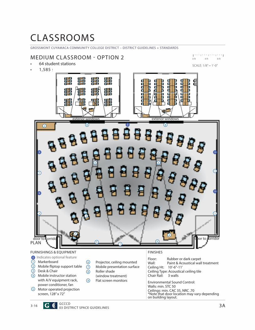
GROSSMONT CUYAMACA COMMUNITY COLLEGE DISTRICT – DISTRICT GUIDELINES + STANDARDS
GCCCD03 DISTRICT SPACE GUIDELINES3-16
0 ft 4 ft 8 ft
SCALE: 1/8” = 1’-0”
FURNISHINGS & EQUIPMENT Indicates optional feature
MarkerboardMobile fl iptop support tableDesk & ChairMobile instructor station with A/V equipment rack, power conditioner, fanMotor operated projection screen, 128” x 72”
FINISHES
Floor: Rubber or dark carpetWall: Paint & Acoustical wall treatment Ceiling Ht: 10’-6”-11’ Ceiling Type: Acoustical ceiling tile Chair Rail: 3 walls
Environmental Sound Control: Walls: min. STC 50Ceilings: min. CAC 35, NRC .70*Note that door location may vary depending on building layout.
PLAN
MEDIUM CLASSROOM - OPTION 2• 64 student stations• 1,585 sq. ft.
1
1
4
4
7
7
2
2
5
5
8
8
3
3
6
5
9
Projector, ceiling mountedMobile presentation surfaceRoller shade (window treatment)Flat screen monitors
11
6
8
1
1
6
CLASSROOMS
3A
0
9
99
9
9
door to corridor
exterior windows exterior windows
door to corridor
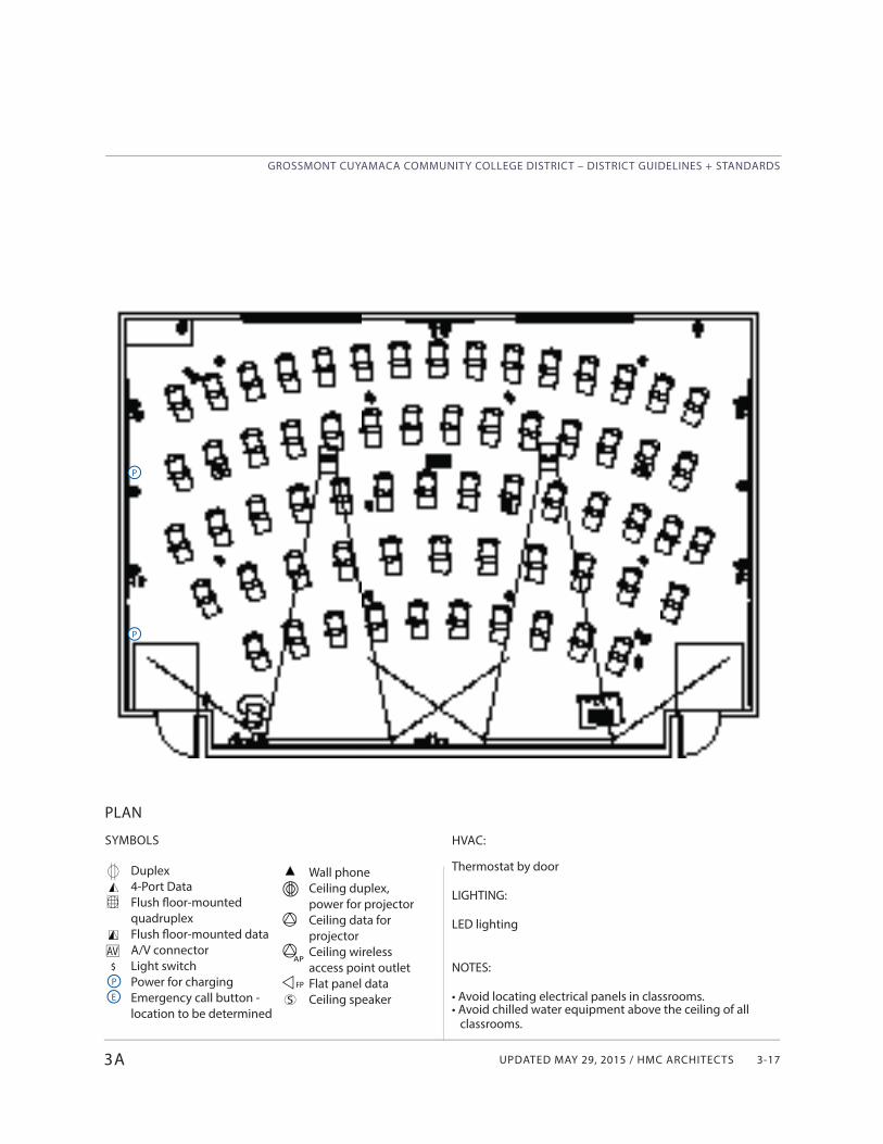
UPDATED MAY 29, 2015 / HMC ARCHITECTS
GROSSMONT CUYAMACA COMMUNITY COLLEGE DISTRICT – DISTRICT GUIDELINES + STANDARDS
3-17
Wall phoneCeiling duplex, power for projectorCeiling data for projectorCeiling wireless access point outletFlat panel dataCeiling speaker
SYMBOLS
Duplex4-Port DataFlush fl oor-mounted quadruplexFlush fl oor-mounted data A/V connectorLight switchPower for chargingEmergency call button - location to be determined
PLAN
3A
AV$P
P
P
E S
AP
FP
HVAC:
Thermostat by door
LIGHTING:
LED lighting
NOTES:
• Avoid locating electrical panels in classrooms.• Avoid chilled water equipment above the ceiling of all classrooms.
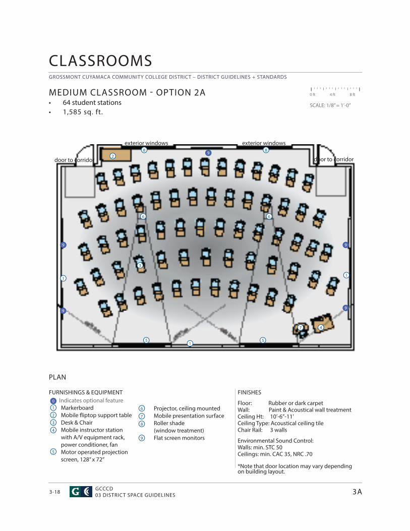
GROSSMONT CUYAMACA COMMUNITY COLLEGE DISTRICT – DISTRICT GUIDELINES + STANDARDS
GCCCD03 DISTRICT SPACE GUIDELINES3-18
0 ft 4 ft 8 ft
SCALE: 1/8” = 1’-0”
FURNISHINGS & EQUIPMENT Indicates optional feature
MarkerboardMobile fl iptop support tableDesk & ChairMobile instructor station with A/V equipment rack, power conditioner, fanMotor operated projection screen, 128” x 72”
FINISHES
Floor: Rubber or dark carpetWall: Paint & Acoustical wall treatment Ceiling Ht: 10’-6”-11’ Ceiling Type: Acoustical ceiling tile Chair Rail: 3 walls
Environmental Sound Control: Walls: min. STC 50Ceilings: min. CAC 35, NRC .70
*Note that door location may vary depending on building layout.
PLAN
MEDIUM CLASSROOM - OPTION 2A• 64 student stations• 1,585 sq. ft.
1
4
4
7
7
2
2
5
5
8
8
3
3
6
5
9
Projector, ceiling mountedMobile presentation surfaceRoller shade (window treatment)Flat screen monitors
11
6
8
1
6
CLASSROOMS
3A
0
9
99
9
9
door to corridor
exterior windows exterior windows
door to corridor
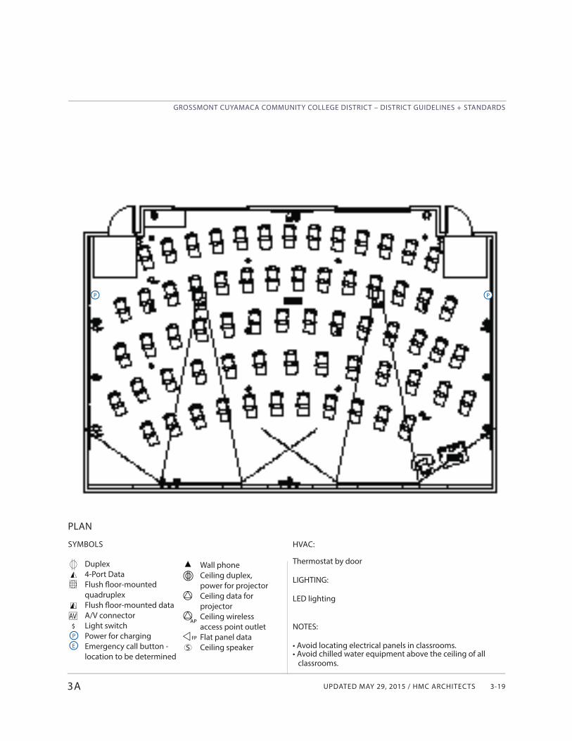
UPDATED MAY 29, 2015 / HMC ARCHITECTS
GROSSMONT CUYAMACA COMMUNITY COLLEGE DISTRICT – DISTRICT GUIDELINES + STANDARDS
3-19
Wall phoneCeiling duplex, power for projectorCeiling data for projectorCeiling wireless access point outletFlat panel dataCeiling speaker
SYMBOLS
Duplex4-Port DataFlush fl oor-mounted quadruplexFlush fl oor-mounted data A/V connectorLight switchPower for chargingEmergency call button - location to be determined
PLAN
3A
AV$P
PP
E S
AP
FP
HVAC:
Thermostat by door
LIGHTING:
LED lighting
NOTES:
• Avoid locating electrical panels in classrooms.• Avoid chilled water equipment above the ceiling of all classrooms.
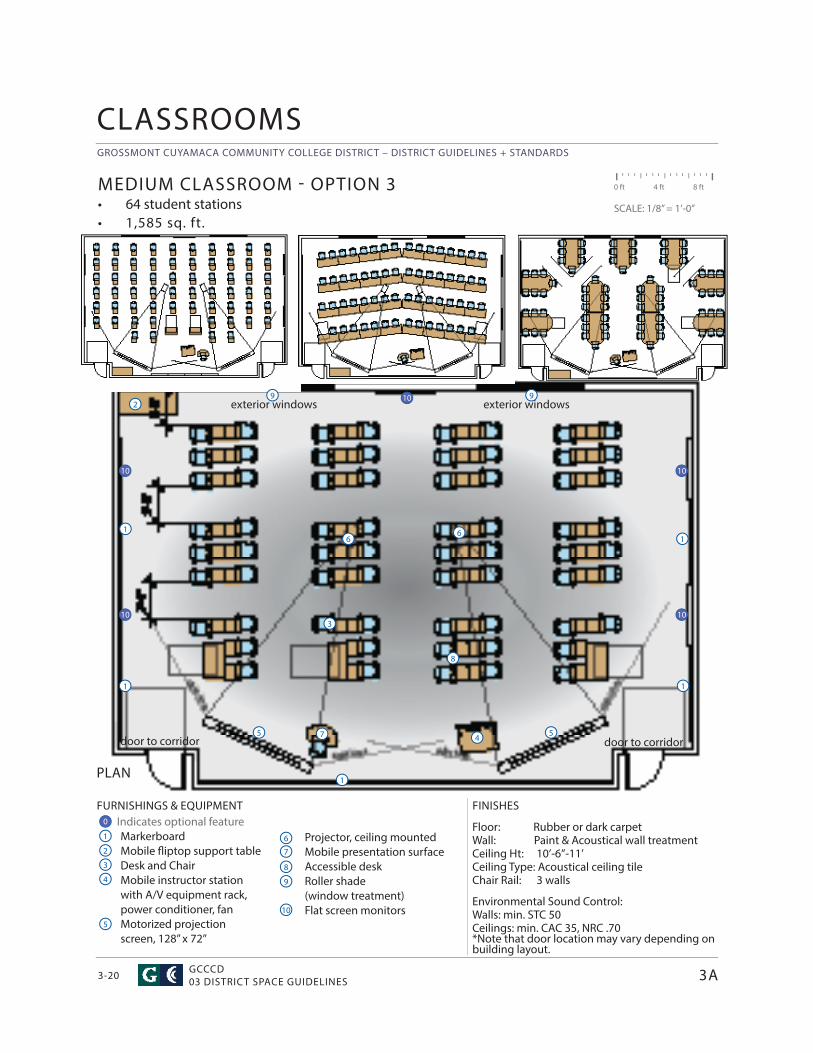
GROSSMONT CUYAMACA COMMUNITY COLLEGE DISTRICT – DISTRICT GUIDELINES + STANDARDS
GCCCD03 DISTRICT SPACE GUIDELINES3-20
Projector, ceiling mountedMobile presentation surfaceAccessible deskRoller shade (window treatment)Flat screen monitors
CLASSROOMS
0 ft 4 ft 8 ft
SCALE: 1/8” = 1’-0”
FURNISHINGS & EQUIPMENT Indicates optional feature
MarkerboardMobile fl iptop support tableDesk and ChairMobile instructor station with A/V equipment rack, power conditioner, fanMotorized projection screen, 128” x 72”
FINISHES
Floor: Rubber or dark carpetWall: Paint & Acoustical wall treatment Ceiling Ht: 10’-6”-11’ Ceiling Type: Acoustical ceiling tile Chair Rail: 3 walls
Environmental Sound Control:Walls: min. STC 50Ceilings: min. CAC 35, NRC .70*Note that door location may vary depending on building layout.
PLAN
MEDIUM CLASSROOM - OPTION 3• 64 student stations• 1,585 sq. ft.
1
1
4
4
7
7
2
2
5
5
8
8
3
1
6
6
9
9
10
16
3A
5
3
9
1
1
10 10
1010
0
10
door to corridor
exterior windows exterior windows
door to corridor
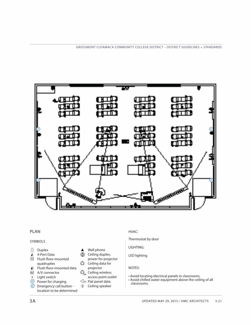
UPDATED MAY 29, 2015 / HMC ARCHITECTS
GROSSMONT CUYAMACA COMMUNITY COLLEGE DISTRICT – DISTRICT GUIDELINES + STANDARDS
3-21
Wall phoneCeiling duplex, power for projectorCeiling data for projectorCeiling wireless access point outletFlat panel dataCeiling speaker
3A
SYMBOLS
Duplex4-Port DataFlush fl oor-mounted quadruplexFlush fl oor-mounted data A/V connectorLight switchPower for chargingEmergency call button - location to be determined
PLAN
AV$P
P
P
E
P
P
S
AP
FP
HVAC:
Thermostat by door
LIGHTING:
LED lighting
NOTES:
• Avoid locating electrical panels in classrooms.• Avoid chilled water equipment above the ceiling of all classrooms.
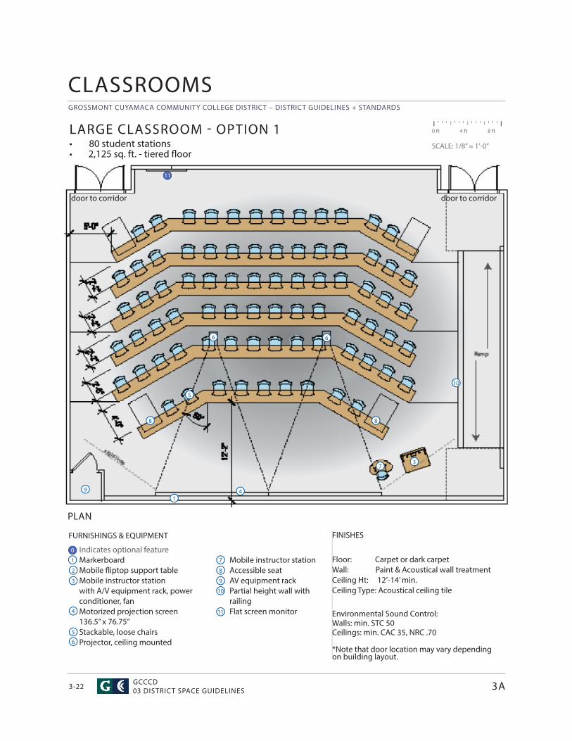
GROSSMONT CUYAMACA COMMUNITY COLLEGE DISTRICT – DISTRICT GUIDELINES + STANDARDS
GCCCD03 DISTRICT SPACE GUIDELINES3-22
FURNISHINGS & EQUIPMENT
Indicates optional feature Markerboard Mobile fl iptop support table Mobile instructor station with A/V equipment rack, power conditioner, fan Motorized projection screen 136.5” x 76.75” Stackable, loose chairs Projector, ceiling mounted
CLASSROOMS
3A
FINISHES
Floor: Carpet or dark carpet Wall: Paint & Acoustical wall treatment Ceiling Ht: 12’-14’ min. Ceiling Type: Acoustical ceiling tile
Environmental Sound Control:Walls: min. STC 50Ceilings: min. CAC 35, NRC .70
*Note that door location may vary depending on building layout.
0 ft 4 ft 8 ft
SCALE: 1/8” = 1’-0”
LARGE CLASSROOM - OPTION 1• 80 student stations• 2,125 sq. ft. - tiered fl oor
Mobile instructor station Accessible seat AV equipment rack Partial height wall with railing Flat screen monitor
PLAN
1
4
7
2
5
8
3
6
1
3
4
5
6
7
88
9
9
6
10
10
11
0
11
door to corridordoor to corridor
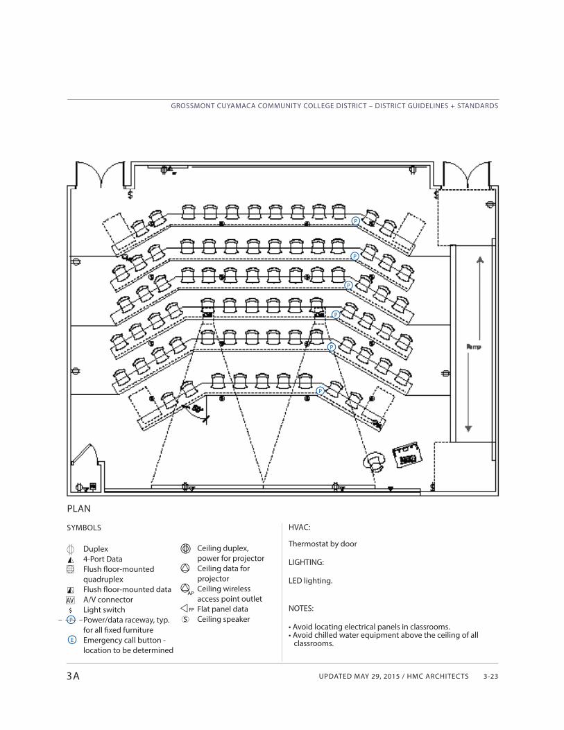
UPDATED MAY 29, 2015 / HMC ARCHITECTS
GROSSMONT CUYAMACA COMMUNITY COLLEGE DISTRICT – DISTRICT GUIDELINES + STANDARDS
3-233A
SYMBOLS
Duplex4-Port DataFlush fl oor-mounted quadruplexFlush fl oor-mounted data A/V connectorLight switchPower/data raceway, typ. for all fi xed furnitureEmergency call button - location to be determined
PLAN
AV$P
P
P
P
P
P
P
Ceiling duplex, power for projectorCeiling data for projectorCeiling wireless access point outletFlat panel dataCeiling speakerS
AP
FP
HVAC:
Thermostat by door
LIGHTING:
LED lighting.
NOTES:
• Avoid locating electrical panels in classrooms.• Avoid chilled water equipment above the ceiling of all classrooms.E
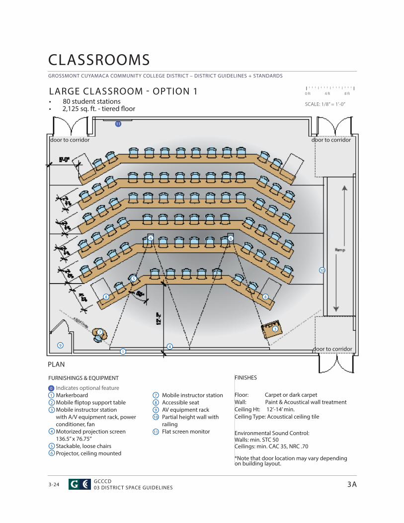
GROSSMONT CUYAMACA COMMUNITY COLLEGE DISTRICT – DISTRICT GUIDELINES + STANDARDS
GCCCD03 DISTRICT SPACE GUIDELINES3-24
FURNISHINGS & EQUIPMENT
Indicates optional feature Markerboard Mobile fl iptop support table Mobile instructor station with A/V equipment rack, power conditioner, fan Motorized projection screen 136.5” x 76.75” Stackable, loose chairs Projector, ceiling mounted
CLASSROOMS
3A
FINISHES
Floor: Carpet or dark carpet Wall: Paint & Acoustical wall treatment Ceiling Ht: 12’-14’ min. Ceiling Type: Acoustical ceiling tile
Environmental Sound Control:Walls: min. STC 50Ceilings: min. CAC 35, NRC .70
*Note that door location may vary depending on building layout.
0 ft 4 ft 8 ft
SCALE: 1/8” = 1’-0”
LARGE CLASSROOM - OPTION 1• 80 student stations• 2,125 sq. ft. - tiered fl oor
Mobile instructor station Accessible seat AV equipment rack Partial height wall with railing Flat screen monitor
PLAN
1
4
7
2
5
8
3
6
1
3
4
5
6
7
88
9
9
6
10
10
11
0
11
door to corridor
door to corridor
door to corridor
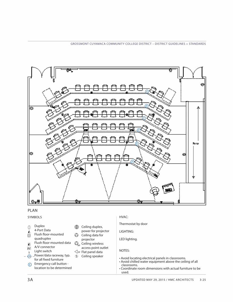
UPDATED MAY 29, 2015 / HMC ARCHITECTS
GROSSMONT CUYAMACA COMMUNITY COLLEGE DISTRICT – DISTRICT GUIDELINES + STANDARDS
3-253A
SYMBOLS
Duplex4-Port DataFlush fl oor-mounted quadruplexFlush fl oor-mounted data A/V connectorLight switchPower/data raceway, typ. for all fi xed furnitureEmergency call button - location to be determined
PLAN
AV$P
P
P
P
P
P
P
Ceiling duplex, power for projectorCeiling data for projectorCeiling wireless access point outletFlat panel dataCeiling speakerS
AP
FP
HVAC:
Thermostat by door
LIGHTING:
LED lighting.
NOTES:
• Avoid locating electrical panels in classrooms.• Avoid chilled water equipment above the ceiling of all classrooms.• Coordinate room dimensions with actual furniture to be used.
E
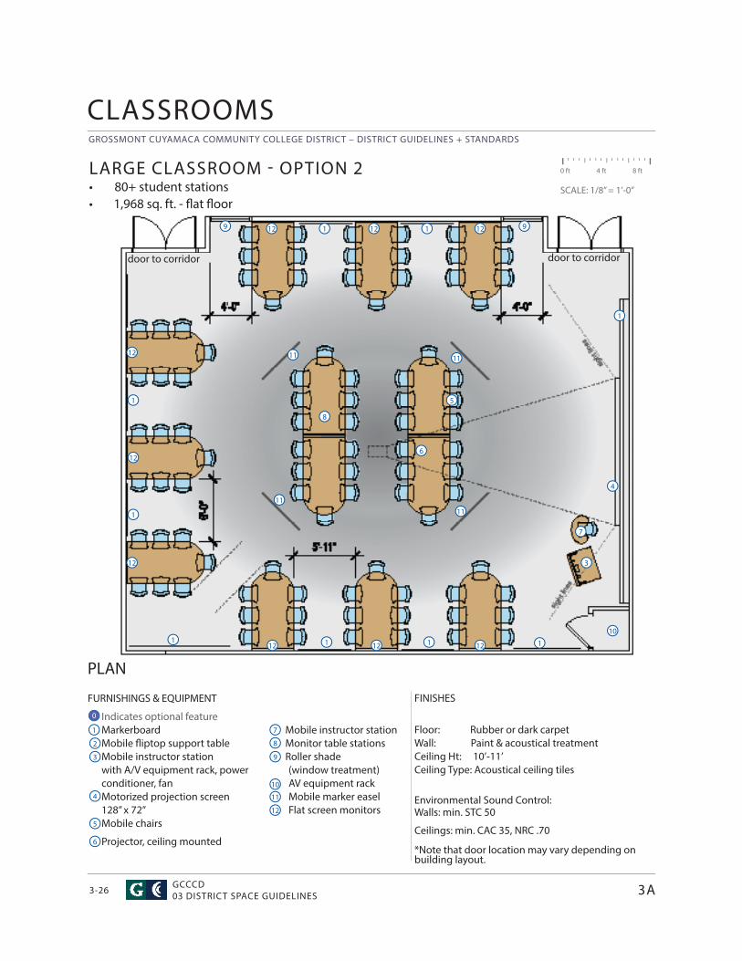
GROSSMONT CUYAMACA COMMUNITY COLLEGE DISTRICT – DISTRICT GUIDELINES + STANDARDS
GCCCD03 DISTRICT SPACE GUIDELINES3-26
Mobile instructor station Monitor table stations Roller shade
(window treatment)AV equipment rackMobile marker easelFlat screen monitors
CLASSROOMS
3A
PLAN
FURNISHINGS & EQUIPMENT
Indicates optional feature Markerboard Mobile fl iptop support table Mobile instructor station with A/V equipment rack, power conditioner, fan Motorized projection screen 128” x 72” Mobile chairs
Projector, ceiling mounted
FINISHES
Floor: Rubber or dark carpet Wall: Paint & acoustical treatment Ceiling Ht: 10’-11’ Ceiling Type: Acoustical ceiling tiles
Environmental Sound Control: Walls: min. STC 50
Ceilings: min. CAC 35, NRC .70 *Note that door location may vary depending on building layout.
LARGE CLASSROOM - OPTION 2• 80+ student stations• 1,968 sq. ft. - fl at fl oor
0 ft 4 ft 8 ft
SCALE: 1/8” = 1’-0”
1
4
7
2
5
8
3
6
3
4
5
1
8
7
6
9
9 9
1 1
1
1
1 1
1 110
1111
10
11
12
12
12
12
12 12 12
12 12 12
11 11
0
door to corridordoor to corridor
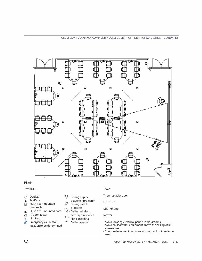
UPDATED MAY 29, 2015 / HMC ARCHITECTS
GROSSMONT CUYAMACA COMMUNITY COLLEGE DISTRICT – DISTRICT GUIDELINES + STANDARDS
3-273A
SYMBOLS
DuplexTel/DataFlush fl oor-mounted quadruplexFlush fl oor-mounted data A/V connectorLight switchEmergency call button - location to be determined
PLAN
AV$
Ceiling duplex, power for projectorCeiling data for projectorCeiling wireless access point outletFlat panel dataCeiling speakerS
AP
FP
HVAC:
Thermostat by door
LIGHTING:
LED lighting.
NOTES:
• Avoid locating electrical panels in classrooms.• Avoid chilled water equipment above the ceiling of all classrooms.• Coordinate room dimensions with actual furniture to be used.
E
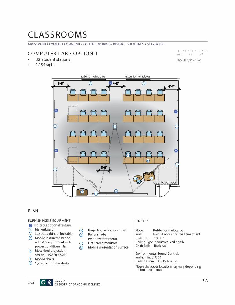
GROSSMONT CUYAMACA COMMUNITY COLLEGE DISTRICT – DISTRICT GUIDELINES + STANDARDS
GCCCD03 DISTRICT SPACE GUIDELINES3-28
CLASSROOMS
FURNISHINGS & EQUIPMENT Indicates optional feature
MarkerboardStorage cabinet - lockableMobile instructor station with A/V equipment rack, power conditioner, fanMotorized projection screen, 119.5” x 67.25”Mobile chairsSystem computer desks
FINISHES
Floor: Rubber or dark carpetWall: Paint & acoustical wall treatment Ceiling Ht: 10’-11’ Ceiling Type: Acoustical ceiling tileChair Rail: Back wall
Environmental Sound Control: Walls: min. STC 50Ceilings: min. CAC 35, NRC .70
*Note that door location may vary depending on building layout.
PLAN
COMPUTER LAB - OPTION 1• 32 student stations• 1,154 sq ft
0 ft 4 ft 8 ft
SCALE: 1/8” = 1’-0”
1
1
4
4
7
7
2
2
5
5
8
8
3
3
6
9
Projector, ceiling mountedRoller shade (window treatment)Flat screen monitorsMobile presentation surface10
10
11
1
1
8
3A
6
0
9 9
99
9
exterior windows exterior windows
door to corridor
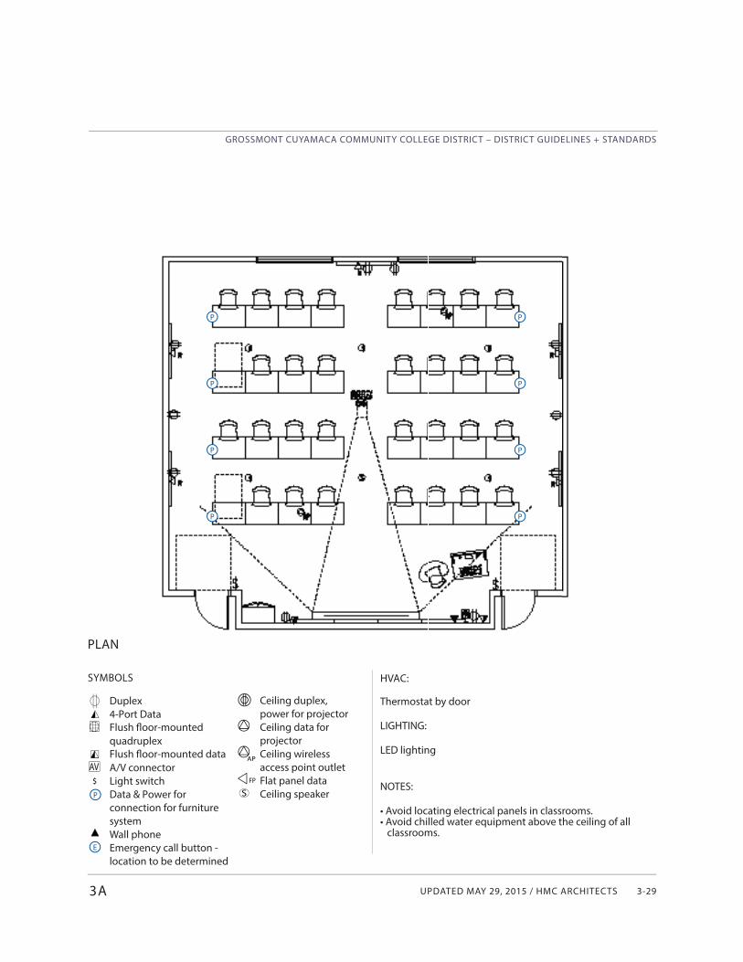
UPDATED MAY 29, 2015 / HMC ARCHITECTS
GROSSMONT CUYAMACA COMMUNITY COLLEGE DISTRICT – DISTRICT GUIDELINES + STANDARDS
3-29
SYMBOLS
Duplex4-Port DataFlush floor-mounted quadruplexFlush floor-mounted data A/V connectorLight switchData & Power for connection for furniture systemWall phoneEmergency call button - location to be determined
PLAN
3A
AV$
P
P
P
P
P
P
P
P
P
E
Ceiling duplex, power for projectorCeiling data for projectorCeiling wireless access point outletFlat panel dataCeiling speakerS
AP
FP
HVAC:
Thermostat by door
LIGHTING:
LED lighting
NOTES:
• Avoid locating electrical panels in classrooms.• Avoid chilled water equipment above the ceiling of all
classrooms.
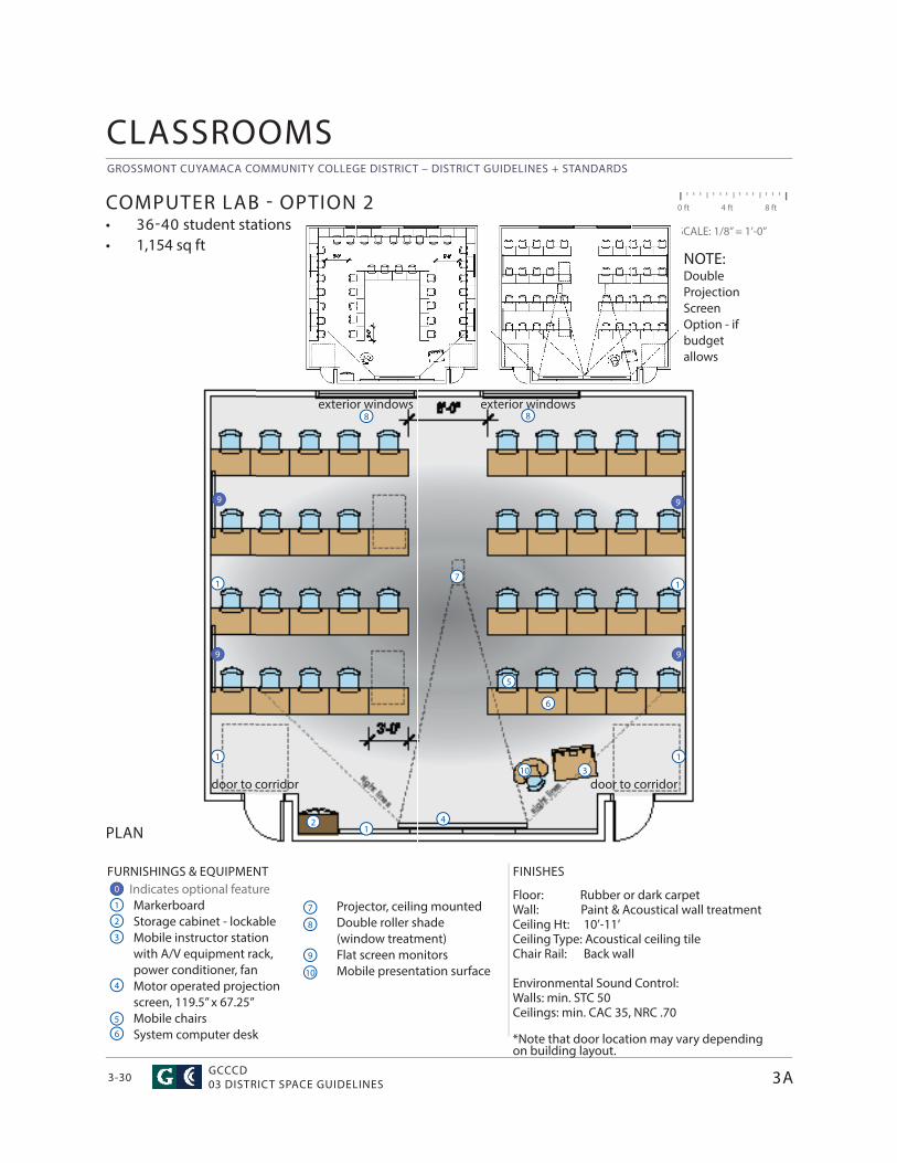
GROSSMONT CUYAMACA COMMUNITY COLLEGE DISTRICT – DISTRICT GUIDELINES + STANDARDS
GCCCD03 DISTRICT SPACE GUIDELINES3-30
Projector, ceiling mountedDouble roller shade (window treatment)Flat screen monitorsMobile presentation surface
CLASSROOMS
FURNISHINGS & EQUIPMENT Indicates optional feature
MarkerboardStorage cabinet - lockableMobile instructor station with A/V equipment rack, power conditioner, fanMotor operated projection screen, 119.5” x 67.25”Mobile chairsSystem computer desk
FINISHES
Floor: Rubber or dark carpetWall: Paint & Acoustical wall treatment Ceiling Ht: 10’-11’ Ceiling Type: Acoustical ceiling tileChair Rail: Back wall
Environmental Sound Control: Walls: min. STC 50Ceilings: min. CAC 35, NRC .70
*Note that door location may vary depending on building layout.
PLAN
COMPUTER LAB - OPTION 2• 36-40 student stations• 1,154 sq ft
0 ft 4 ft 8 ft
SCALE: 1/8” = 1’-0”
1
1
4
4
7
7
2
2
5
5
8
8
3
3
6
9
10
10
1
1
8
3A
6
1
1
0
9 9
99
NOTE:Double Projection Screen Option - if budget allows
exterior windows exterior windows
door to corridordoor to corridor
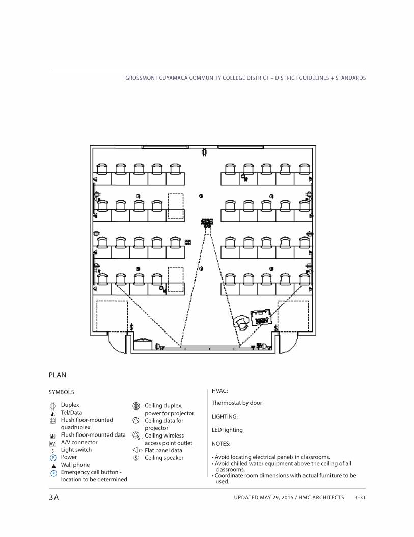
UPDATED MAY 29, 2015 / HMC ARCHITECTS
GROSSMONT CUYAMACA COMMUNITY COLLEGE DISTRICT – DISTRICT GUIDELINES + STANDARDS
3-31
SYMBOLS
DuplexTel/DataFlush fl oor-mounted quadruplexFlush fl oor-mounted data A/V connectorLight switchPowerWall phoneEmergency call button - location to be determined
PLAN
3A
AV$P
E
Ceiling duplex, power for projectorCeiling data for projectorCeiling wireless access point outletFlat panel dataCeiling speakerS
AP
FP
HVAC:
Thermostat by door
LIGHTING:
LED lighting
NOTES:
• Avoid locating electrical panels in classrooms.• Avoid chilled water equipment above the ceiling of all classrooms.• Coordinate room dimensions with actual furniture to be used.
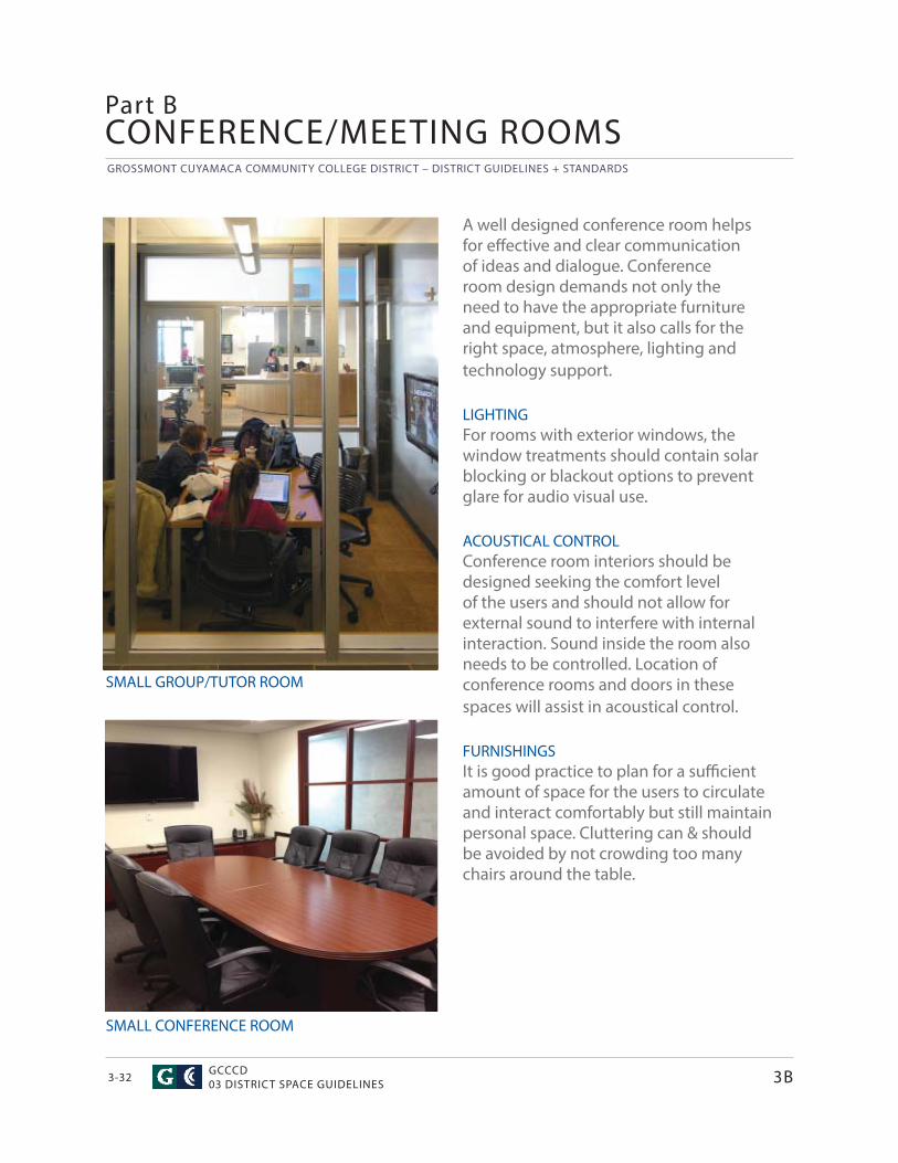
GROSSMONT CUYAMACA COMMUNITY COLLEGE DISTRICT – DISTRICT GUIDELINES + STANDARDS
GCCCD03 DISTRICT SPACE GUIDELINES3-32
CONFERENCE/MEETING ROOMS
SMALL GROUP/TUTOR ROOM
SMALL CONFERENCE ROOM
A well designed conference room helps for eff ective and clear communication of ideas and dialogue. Conference room design demands not only the need to have the appropriate furniture and equipment, but it also calls for the right space, atmosphere, lighting and technology support.
LIGHTINGFor rooms with exterior windows, the window treatments should contain solar blocking or blackout options to prevent glare for audio visual use.
ACOUSTICAL CONTROLConference room interiors should be designed seeking the comfort level of the users and should not allow for external sound to interfere with internal interaction. Sound inside the room also needs to be controlled. Location of conference rooms and doors in these spaces will assist in acoustical control.
FURNISHINGSIt is good practice to plan for a suffi cient amount of space for the users to circulate and interact comfortably but still maintain personal space. Cluttering can & should be avoided by not crowding too many chairs around the table.
Part B
3B
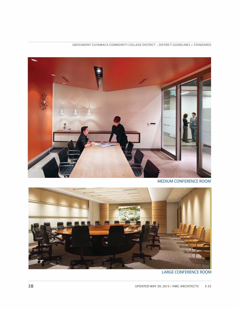
UPDATED MAY 29, 2015 / HMC ARCHITECTS
GROSSMONT CUYAMACA COMMUNITY COLLEGE DISTRICT – DISTRICT GUIDELINES + STANDARDS
3-33
MEDIUM CONFERENCE ROOM
LARGE CONFERENCE ROOM
3B
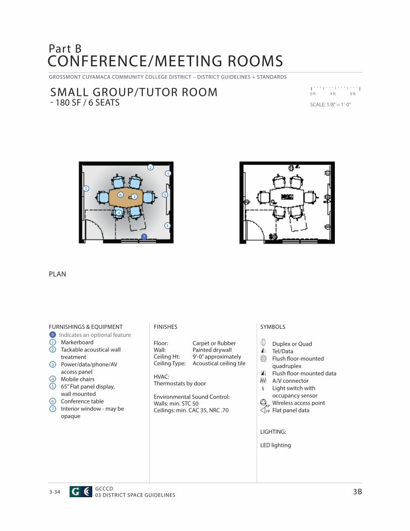
GROSSMONT CUYAMACA COMMUNITY COLLEGE DISTRICT – DISTRICT GUIDELINES + STANDARDS
GCCCD03 DISTRICT SPACE GUIDELINES3-34
CONFERENCE/MEETING ROOMSPart B
$
AV
FURNISHINGS & EQUIPMENT Indicates an optional feature
MarkerboardTackable acoustical wall treatmentPower/data/phone/AVaccess panelMobile chairs65” Flat panel display, wall mountedConference tableInterior window - may be opaque
SYMBOLS
Duplex or QuadTel/DataFlush fl oor-mounted quadruplexFlush fl oor-mounted data A/V connectorLight switch withoccupancy sensorWireless access pointFlat panel data
LIGHTING:
LED lighting
FINISHES
Floor: Carpet or RubberWall: Painted drywallCeiling Ht: 9’-0” approximatelyCeiling Type: Acoustical ceiling tile
HVAC:Thermostats by door
Environmental Sound Control: Walls: min. STC 50Ceilings: min. CAC 35, NRC .70
PLAN
SMALL GROUP/TUTOR ROOM - 180 SF / 6 SEATS
0 ft 4 ft 8 ft
SCALE: 1/8” = 1’-0”
1
1
4
5
2
5
6
3
3
6
4
1
3B
12
APFP
7
0
7
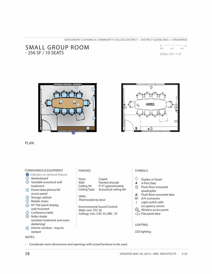
UPDATED MAY 29, 2015 / HMC ARCHITECTS
GROSSMONT CUYAMACA COMMUNITY COLLEGE DISTRICT – DISTRICT GUIDELINES + STANDARDS
3-35
SYMBOLS
Duplex or Quad4-Port DataFlush fl oor-mounted quadruplexFlush fl oor-mounted data A/V connectorLight switch withoccupancy sensorWireless access pointFlat panel data
LIGHTING:
LED lighting
FURNISHINGS & EQUIPMENT Indicates an optional feature
MarkerboardTackable acoustical wall treatmentPower/data/phone/AV access panelStorage cabinetMobile chairs65” Flat panel display, wall mountedConference tableRoller shade(window treatment and room darkening)Interior window - may be opaque
$
AV
FINISHES
Floor: CarpetWall: Painted drywallCeiling Ht: 9’-0” approximatelyCeiling Type: Acoustical ceiling tile
HVAC:Thermostats by door
Environmental Sound Control: Walls: min. STC 50Ceilings: min. CAC 35, NRC .70
PLAN
SMALL GROUP ROOM - 256 SF / 10 SEATS
0 ft 4 ft 8 ft
SCALE: 1/8” = 1’-0”
1
1
4
4
7
7
2
2
5
8
8
3
3
6
65
3B
2
AP
FP
3
9
0
9
NOTES:
• Coordinate room dimensions and openings with actual furniture to be used.
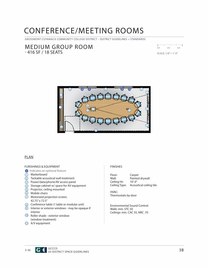
GROSSMONT CUYAMACA COMMUNITY COLLEGE DISTRICT – DISTRICT GUIDELINES + STANDARDS
GCCCD03 DISTRICT SPACE GUIDELINES3-36
FURISHINGS & EQUIPMENT Indicates an optional feature
MarkerboardTackable acoustical wall treatmentPower/data/phone/AV access panelStorage cabinet w/ space for AV equipment Projector, ceiling mountedMobile chairsMotorized projection screen, 42.75” x 72.5”Conference table (1 table or modular unit) Interior or exterior windows - may be opaque if interiorRoller shade - exterior window(window treatment)A/V equipment
FINISHES
Floor: CarpetWall: Painted drywallCeiling Ht: 10’-0”Ceiling Type: Acoustical ceiling tile
HVAC:Thermostats by door
Environmental Sound Control: Walls: min. STC 50Ceilings: min. CAC 35, NRC .70
PLAN
MEDIUM GROUP ROOM - 416 SF / 18 SEATS
0 ft 4 ft 8 ft
SCALE: 1/8” = 1’-0”
1
1
4
4
7
7
2
2
5
5
8
8
3
3
6
6
9
1
3B
CONFERENCE/MEETING ROOMS
2 2 21
3
0
99 1010
10
11
11
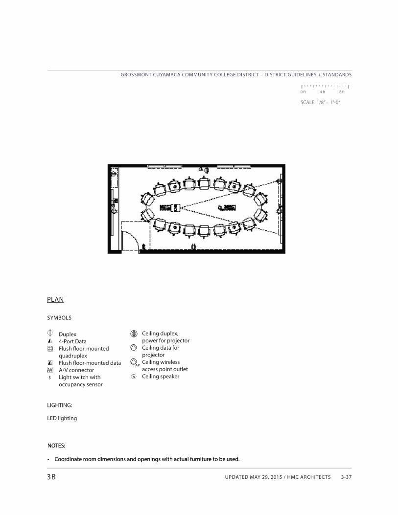
UPDATED MAY 29, 2015 / HMC ARCHITECTS
GROSSMONT CUYAMACA COMMUNITY COLLEGE DISTRICT – DISTRICT GUIDELINES + STANDARDS
3-37
$
AV
SYMBOLS
Duplex4-Port DataFlush fl oor-mounted quadruplexFlush fl oor-mounted data A/V connectorLight switch withoccupancy sensor
LIGHTING:
LED lighting
PLAN
3B
0 ft 4 ft 8 ft
SCALE: 1/8” = 1’-0”
Ceiling duplex, power for projectorCeiling data for projectorCeiling wireless access point outletCeiling speakerS
AP
NOTES:
• Coordinate room dimensions and openings with actual furniture to be used.
NOTES:
• Coordinate room dimensions and openings with actual furniture to be used.
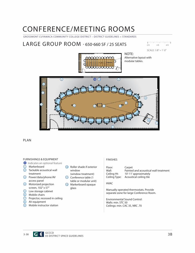
GROSSMONT CUYAMACA COMMUNITY COLLEGE DISTRICT – DISTRICT GUIDELINES + STANDARDS
GCCCD03 DISTRICT SPACE GUIDELINES3-38
CONFERENCE/MEETING ROOMS
FURNISHINGS & EQUIPMENT Indicates an optional feature
MarkerboardTackable acoustical wall treatmentPower/data/phone/AV access panelMotorized projection screen, 102” x 57”Low storage cabinetMobile chairsProjector, recessed in ceilingAV equipmentMobile instructor station
FINISHES
Floor: CarpetWall: Painted and acoustical wall treatmentCeiling Ht: 10’-11’ approximatelyCeiling Type: Acoustical ceiling tile
HVAC
Manually operated thermostats. Provide separate zone for large Conference Room.
Environmental Sound Control: Walls: min. STC 50Ceilings: min. CAC 35, NRC .70
PLAN
LARGE GROUP ROOM - 650-660 SF / 25 SEATS 0 ft 4 ft 8 ft
SCALE: 1/8” = 1’-0”
1
1
4
4
7
7
2
2
5
5
8
8
3
3
6
6
9
9
Roller shade if exterior window (window treatment)Conference table (1 table or modular unit)Markerboard opaque glass
10
11
12
3
10 2
3B
2
111
3
NOTE:Alternative layout withmodular tables.
0
12
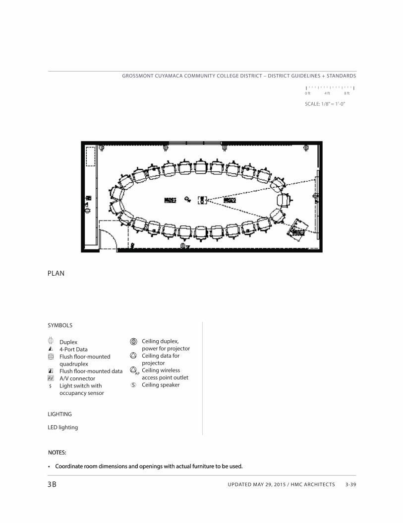
UPDATED MAY 29, 2015 / HMC ARCHITECTS
GROSSMONT CUYAMACA COMMUNITY COLLEGE DISTRICT – DISTRICT GUIDELINES + STANDARDS
3-39
$
AV
SYMBOLS
Duplex4-Port DataFlush fl oor-mounted quadruplexFlush fl oor-mounted data A/V connectorLight switch withoccupancy sensor
LIGHTING
LED lighting
PLAN
0 ft 4 ft 8 ft
SCALE: 1/8” = 1’-0”
3B
Ceiling duplex, power for projectorCeiling data for projectorCeiling wireless access point outletCeiling speakerS
AP
NOTES:
• Coordinate room dimensions and openings with actual furniture to be used.
NOTES:
• Coordinate room dimensions and openings with actual furniture to be used.
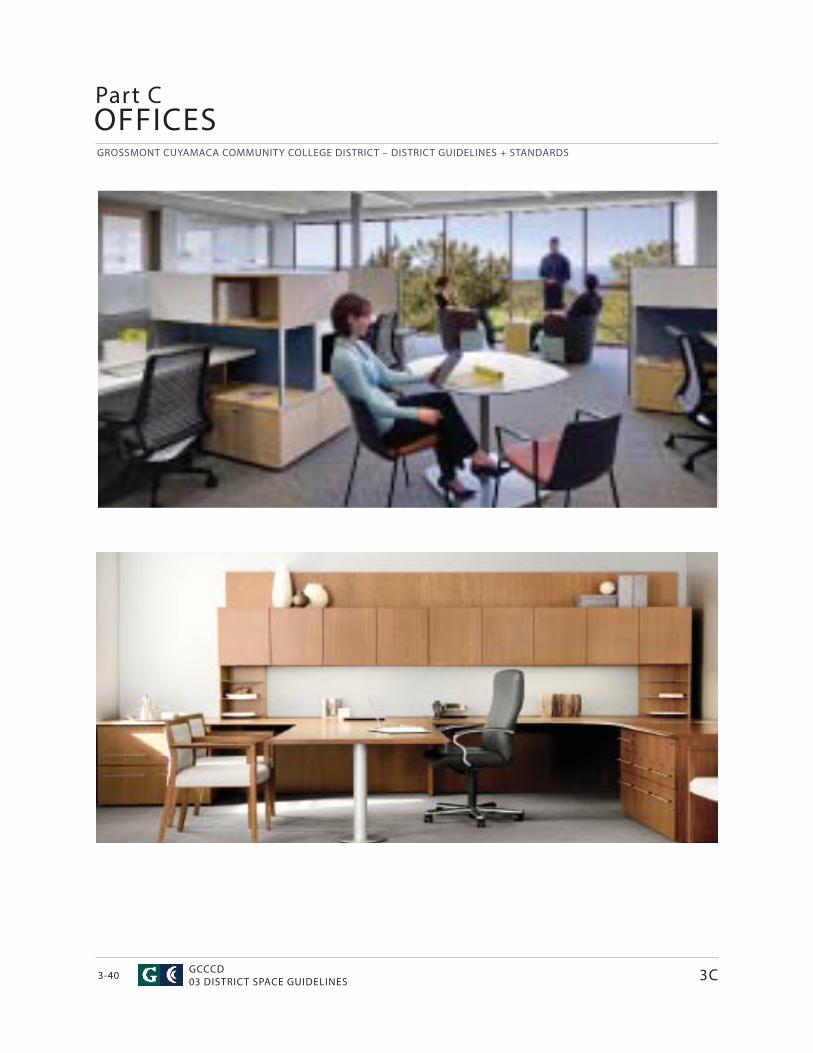
GROSSMONT CUYAMACA COMMUNITY COLLEGE DISTRICT – DISTRICT GUIDELINES + STANDARDS
GCCCD03 DISTRICT SPACE GUIDELINES3-40
OFFICESPart C
3C
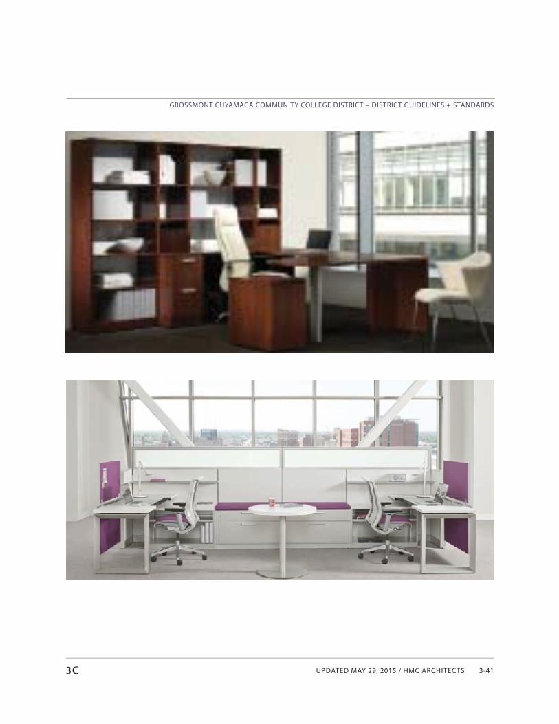
UPDATED MAY 29, 2015 / HMC ARCHITECTS
GROSSMONT CUYAMACA COMMUNITY COLLEGE DISTRICT – DISTRICT GUIDELINES + STANDARDS
3-413C
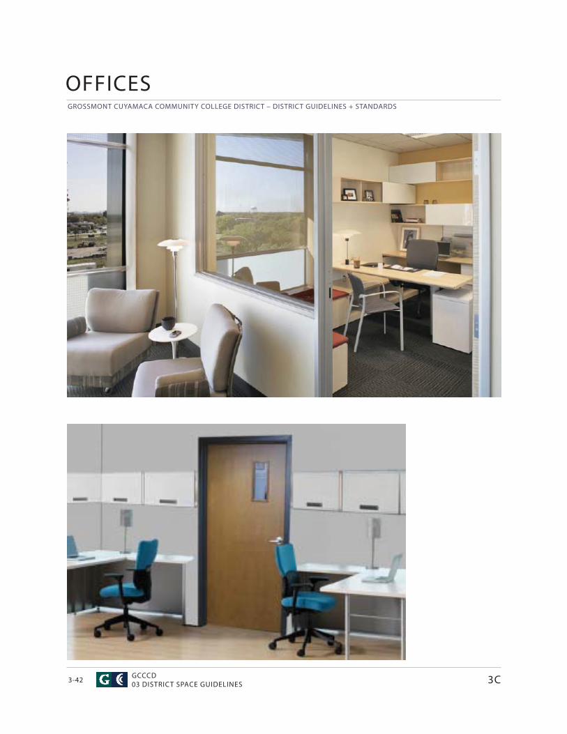
GROSSMONT CUYAMACA COMMUNITY COLLEGE DISTRICT – DISTRICT GUIDELINES + STANDARDS
GCCCD03 DISTRICT SPACE GUIDELINES3-42
OFFICES
3C
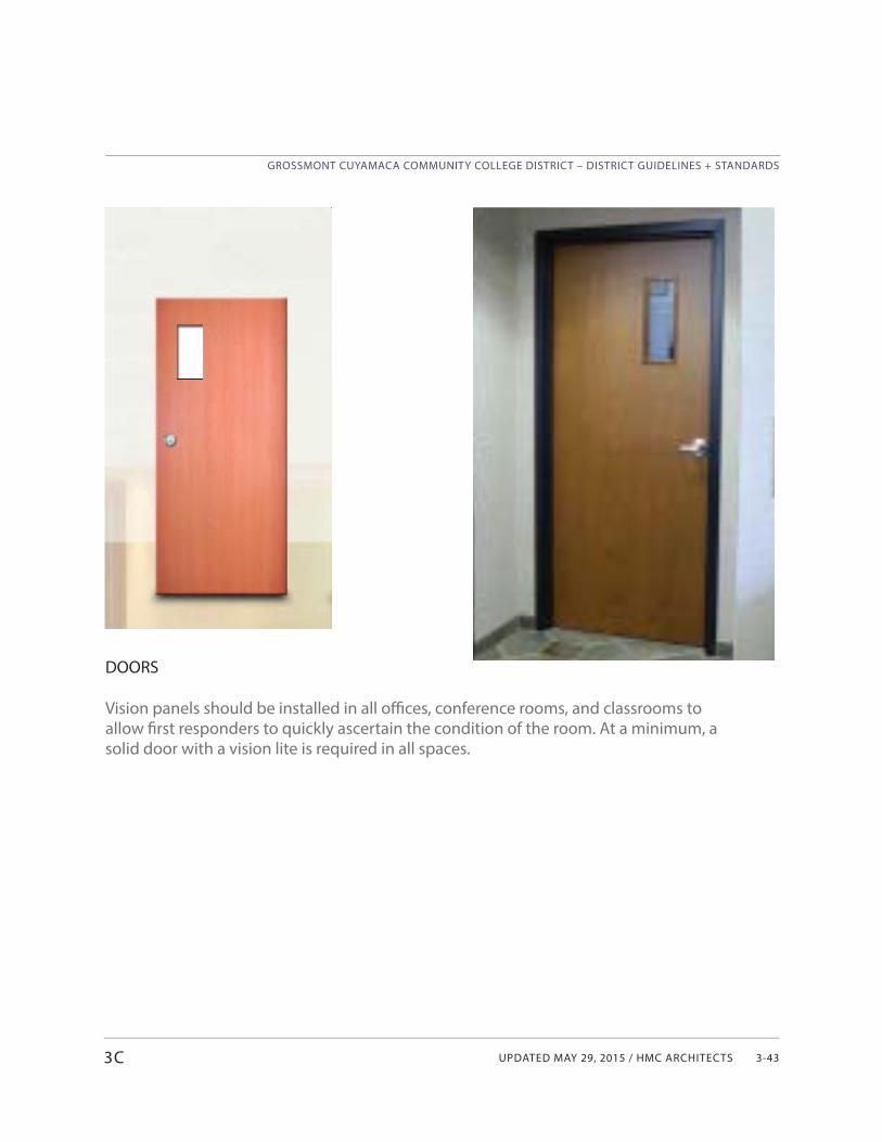
UPDATED MAY 29, 2015 / HMC ARCHITECTS
GROSSMONT CUYAMACA COMMUNITY COLLEGE DISTRICT – DISTRICT GUIDELINES + STANDARDS
3-43
DOORS
Vision panels should be installed in all offi ces, conference rooms, and classrooms to allow fi rst responders to quickly ascertain the condition of the room. At a minimum, a solid door with a vision lite is required in all spaces.
3C
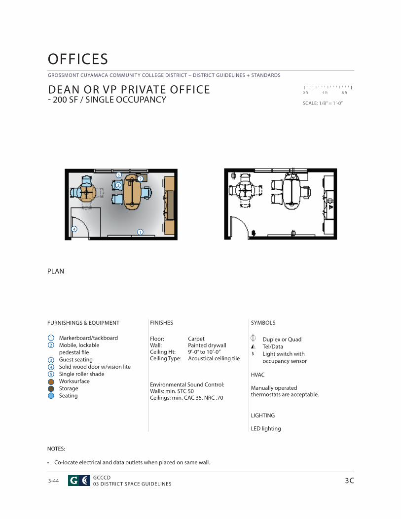
GROSSMONT CUYAMACA COMMUNITY COLLEGE DISTRICT – DISTRICT GUIDELINES + STANDARDS
GCCCD03 DISTRICT SPACE GUIDELINES3-44
SYMBOLS
Duplex or QuadTel/DataLight switch withoccupancy sensor
HVAC
Manually operated thermostats are acceptable.
LIGHTING
LED lighting
OFFICES
$
FURNISHINGS & EQUIPMENT
Markerboard/tackboardMobile, lockable pedestal fi leGuest seatingSolid wood door w/vision liteSingle roller shadeWorksurfaceStorageSeating
FINISHES
Floor: Carpet Wall: Painted drywallCeiling Ht: 9’-0” to 10’-0”Ceiling Type: Acoustical ceiling tile
Environmental Sound Control:Walls: min. STC 50Ceilings: min. CAC 35, NRC .70
PLAN
DEAN OR VP PRIVATE OFFICE - 200 SF / SINGLE OCCUPANCY
0 ft 4 ft 8 ft
SCALE: 1/8” = 1’-0”
1
1
4
4
2
2
5
5
3
3
NOTES:
• Co-locate electrical and data outlets when placed on same wall.
3C
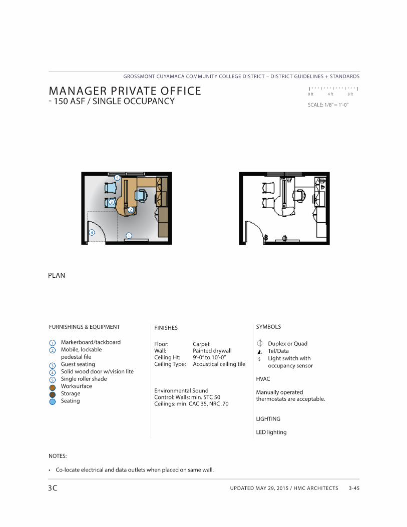
UPDATED MAY 29, 2015 / HMC ARCHITECTS
GROSSMONT CUYAMACA COMMUNITY COLLEGE DISTRICT – DISTRICT GUIDELINES + STANDARDS
3-45
PLAN
MANAGER PRIVATE OFFICE- 150 ASF / SINGLE OCCUPANCY
0 ft 4 ft 8 ft
SCALE: 1/8” = 1’-0”
14
2
5
3
NOTES:
• Co-locate electrical and data outlets when placed on same wall.
$
FINISHES
Floor: Carpet Wall: Painted drywallCeiling Ht: 9’-0” to 10’-0”Ceiling Type: Acoustical ceiling tile
Environmental Sound Control: Walls: min. STC 50Ceilings: min. CAC 35, NRC .70
1
4
2
5
3
FURNISHINGS & EQUIPMENT
Markerboard/tackboardMobile, lockable pedestal fi leGuest seatingSolid wood door w/vision lite Single roller shadeWorksurfaceStorageSeating
SYMBOLS
Duplex or QuadTel/DataLight switch withoccupancy sensor
HVAC
Manually operated thermostats are acceptable.
LIGHTING
LED lighting
3C
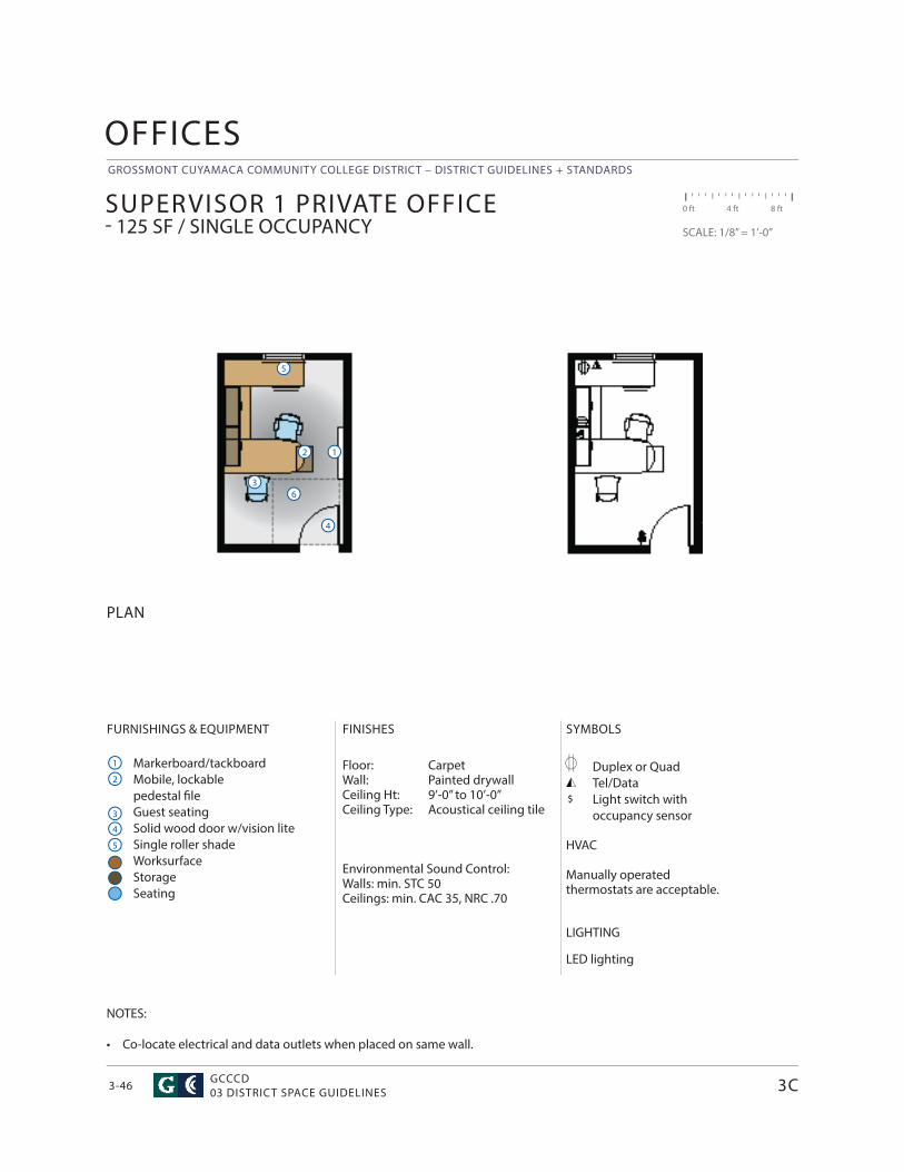
GROSSMONT CUYAMACA COMMUNITY COLLEGE DISTRICT – DISTRICT GUIDELINES + STANDARDS
GCCCD03 DISTRICT SPACE GUIDELINES3-46
OFFICES
$
FURNISHINGS & EQUIPMENT
Markerboard/tackboardMobile, lockable pedestal fi leGuest seatingSolid wood door w/vision liteSingle roller shadeWorksurfaceStorageSeating
SYMBOLS
Duplex or QuadTel/DataLight switch withoccupancy sensor
HVAC
Manually operated thermostats are acceptable.
LIGHTING
LED lighting
FINISHES
Floor: Carpet Wall: Painted drywallCeiling Ht: 9’-0” to 10’-0”Ceiling Type: Acoustical ceiling tile
Environmental Sound Control:Walls: min. STC 50Ceilings: min. CAC 35, NRC .70
PLAN
SUPERVISOR 1 PRIVATE OFFICE - 125 SF / SINGLE OCCUPANCY
0 ft 4 ft 8 ft
SCALE: 1/8” = 1’-0”
1
1
4
4
2
2
5
5
3
36
NOTES:
• Co-locate electrical and data outlets when placed on same wall.
3C
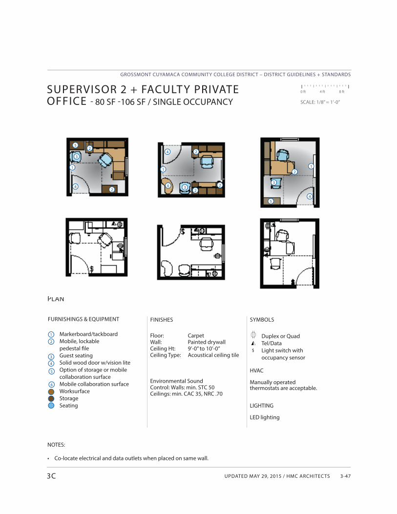
UPDATED MAY 29, 2015 / HMC ARCHITECTS
GROSSMONT CUYAMACA COMMUNITY COLLEGE DISTRICT – DISTRICT GUIDELINES + STANDARDS
3-47
FURNISHINGS & EQUIPMENT
Markerboard/tackboardMobile, lockable pedestal fi leGuest seatingSolid wood door w/vision liteOption of storage or mobile collaboration surfaceMobile collaboration surfaceWorksurfaceStorageSeating
SYMBOLS
Duplex or QuadTel/DataLight switch withoccupancy sensor
HVAC
Manually operated thermostats are acceptable.
LIGHTING
LED lighting
PLAN
SUPERVISOR 2 + FACULT Y PRIVATE OFFICE - 80 SF -106 SF / SINGLE OCCUPANCY
0 ft 4 ft 8 ft
SCALE: 1/8” = 1’-0”
1
42
3
NOTES:
• Co-locate electrical and data outlets when placed on same wall.
$
FINISHES
Floor: Carpet Wall: Painted drywallCeiling Ht: 9’-0” to 10’-0”Ceiling Type: Acoustical ceiling tile
Environmental Sound Control: Walls: min. STC 50Ceilings: min. CAC 35, NRC .70
1
4
2
3
3C
1
4 2
3
2
22
5
6
5
6
12
3
45
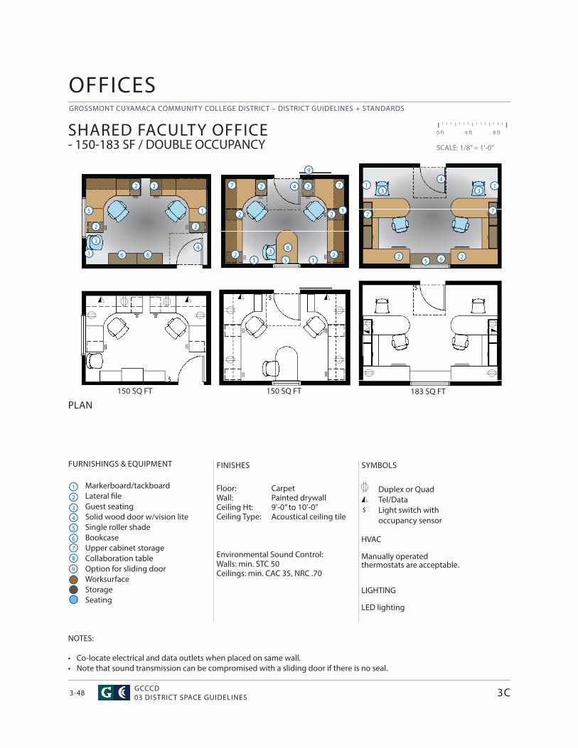
GROSSMONT CUYAMACA COMMUNITY COLLEGE DISTRICT – DISTRICT GUIDELINES + STANDARDS
GCCCD03 DISTRICT SPACE GUIDELINES3-48
OFFICES
$
FURNISHINGS & EQUIPMENT
Markerboard/tackboardLateral fi leGuest seatingSolid wood door w/vision liteSingle roller shadeBookcase Upper cabinet storageCollaboration tableOption for sliding doorWorksurfaceStorageSeating
SYMBOLS
Duplex or QuadTel/DataLight switch withoccupancy sensor
HVAC
Manually operated thermostats are acceptable.
LIGHTING
LED lighting
FINISHES
Floor: Carpet Wall: Painted drywallCeiling Ht: 9’-0” to 10’-0”Ceiling Type: Acoustical ceiling tile
Environmental Sound Control:Walls: min. STC 50Ceilings: min. CAC 35, NRC .70
PLAN
SHARED FACULTY OFFICE- 150-183 SF / DOUBLE OCCUPANCY
0 ft 4 ft 8 ft
SCALE: 1/8” = 1’-0”
1
1
4
4
2
2
5
5
3
3
6
NOTES:
• Co-locate electrical and data outlets when placed on same wall.• Note that sound transmission can be compromised with a sliding door if there is no seal.
$
1
2
2 2
6
6
3C
1
4
2
53
7
$
12
2 28
7
1
7
8
9
9
2 2
$
183 SQ FT150 SQ FT150 SQ FT
1 1
2 2
3 3
4
5
7 7
6
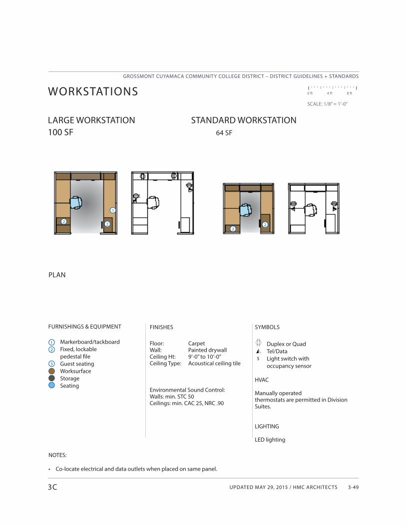
UPDATED MAY 29, 2015 / HMC ARCHITECTS
GROSSMONT CUYAMACA COMMUNITY COLLEGE DISTRICT – DISTRICT GUIDELINES + STANDARDS
3-49
FURNISHINGS & EQUIPMENT
Markerboard/tackboardFixed, lockable pedestal fi leGuest seatingWorksurfaceStorageSeating
PLAN
WORKSTATIONS
LARGE WORKSTATION STANDARD WORKSTATION100 SF 64 SF
0 ft 4 ft 8 ft
SCALE: 1/8” = 1’-0”
1
22
NOTES:
• Co-locate electrical and data outlets when placed on same panel.
$
FINISHES
Floor: Carpet Wall: Painted drywallCeiling Ht: 9’-0” to 10’-0”Ceiling Type: Acoustical ceiling tile
Environmental Sound Control:Walls: min. STC 50Ceilings: min. CAC 25, NRC .90
1
2
3
SYMBOLS
Duplex or QuadTel/DataLight switch withoccupancy sensor
HVAC
Manually operated thermostats are permitted in Division Suites.
LIGHTING
LED lighting
2
3C
2
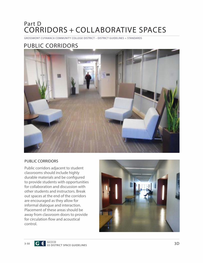
GROSSMONT CUYAMACA COMMUNITY COLLEGE DISTRICT – DISTRICT GUIDELINES + STANDARDS
GCCCD03 DISTRICT SPACE GUIDELINES3-50
CORRIDORS + COLLABORATIVE SPACES
PUBLIC CORRIDORS
Public corridors adjacent to student classrooms should include highly durable materials and be confi gured to provide students with opportunities for collaboration and discussion with other students and instructors. Break out spaces at the end of the corridors are encouraged as they allow for informal dialogue and interaction. Placement of these areas should be away from classroom doors to provide for circulation fl ow and acoustical control.
PUBLIC CORRIDORS
Part D
3D
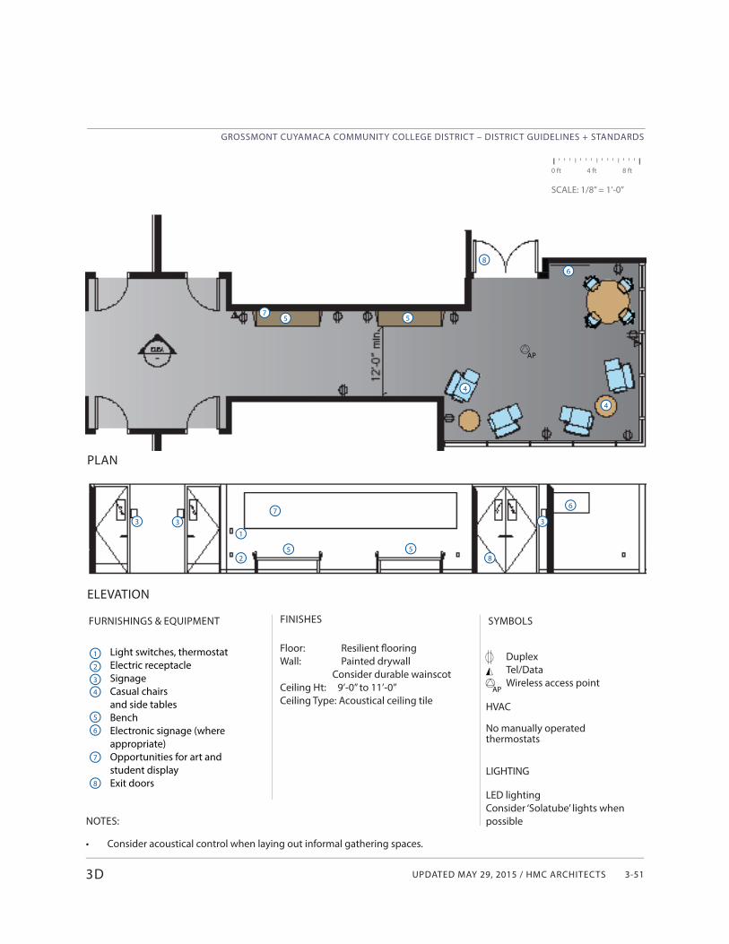
UPDATED MAY 29, 2015 / HMC ARCHITECTS
GROSSMONT CUYAMACA COMMUNITY COLLEGE DISTRICT – DISTRICT GUIDELINES + STANDARDS
3-51
FINISHES
Floor: Resilient fl ooringWall: Painted drywall Consider durable wainscotCeiling Ht: 9’-0” to 11’-0”Ceiling Type: Acoustical ceiling tile
SYMBOLSFURNISHINGS & EQUIPMENT
Light switches, thermostatElectric receptacleSignageCasual chairs and side tablesBenchElectronic signage (where appropriate)Opportunities for art and student displayExit doors
0 ft 4 ft 8 ft
SCALE: 1/8” = 1’-0”
NOTES:
• Consider acoustical control when laying out informal gathering spaces.
DuplexTel/DataWireless access point
HVAC
No manually operatedthermostats
LIGHTING
LED lightingConsider ‘Solatube’ lights when possible
3D
PLAN
ELEVATION
1
2
3
4
5
3 3 3
1
25 5
5 5
4
4
AP
AP
76
8
6
7
8
68
7
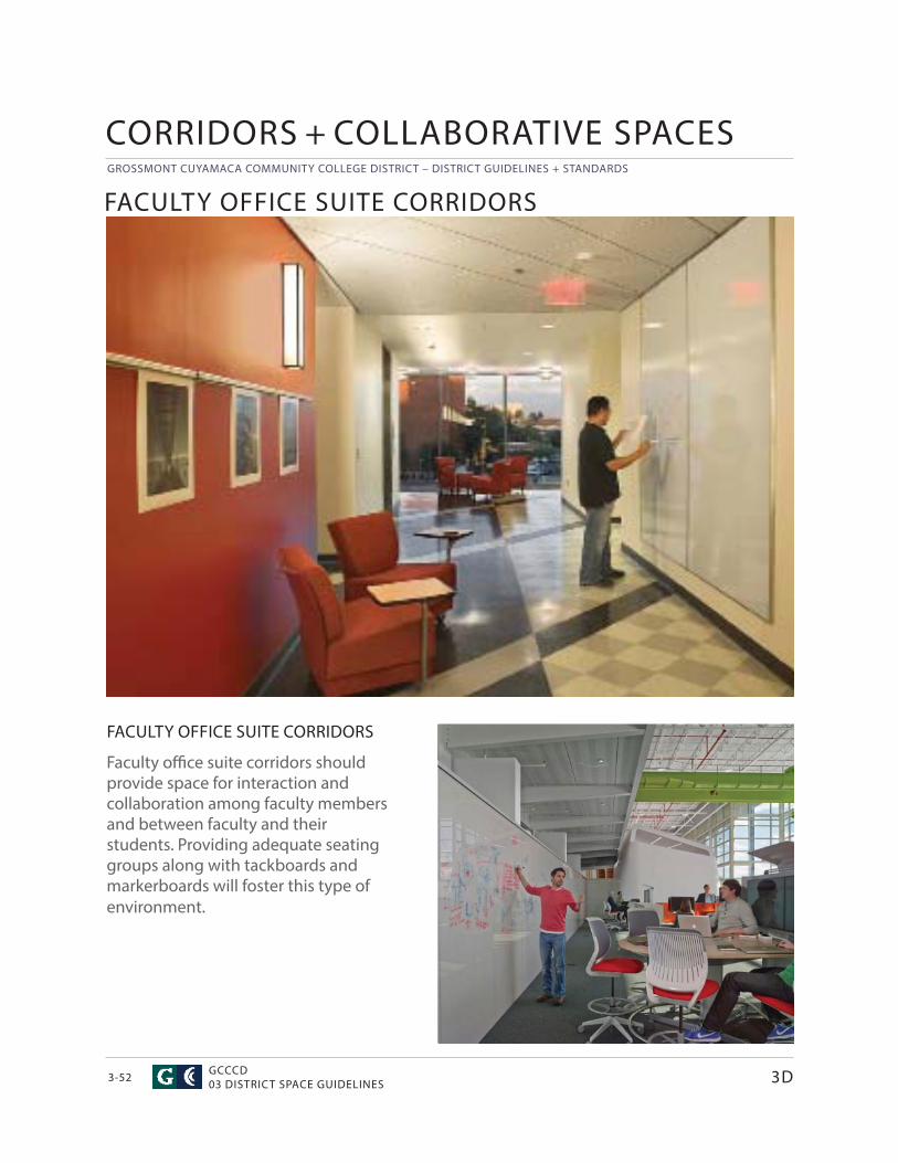
GROSSMONT CUYAMACA COMMUNITY COLLEGE DISTRICT – DISTRICT GUIDELINES + STANDARDS
GCCCD03 DISTRICT SPACE GUIDELINES3-52
Faculty offi ce suite corridors should provide space for interaction and collaboration among faculty members and between faculty and their students. Providing adequate seating groups along with tackboards and markerboards will foster this type of environment.
FACULTY OFFICE SUITE CORRIDORS
FACULTY OFFICE SUITE CORRIDORS
3D
CORRIDORS + COLLABORATIVE SPACES
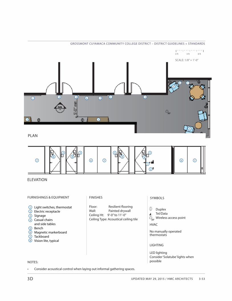
UPDATED MAY 29, 2015 / HMC ARCHITECTS
GROSSMONT CUYAMACA COMMUNITY COLLEGE DISTRICT – DISTRICT GUIDELINES + STANDARDS
3-53
7
0 ft 4 ft 8 ft
SCALE: 1/8” = 1’-0”
3D
FINISHES
Floor: Resilient fl ooringWall: Painted drywallCeiling Ht: 9’-0” to 11’-0”Ceiling Type: Acoustical ceiling tile
SYMBOLSFURNISHINGS & EQUIPMENT
Light switches, thermostatElectric receptacleSignageCasual chairs and side tablesBenchMagnetic markerboardTackboardVision lite, typical
NOTES:
• Consider acoustical control when laying out informal gathering spaces.
DuplexTel/DataWireless access point
HVAC
No manually operatedthermostats
LIGHTING
LED lightingConsider ‘Solatube’ lights when possible
PLAN
ELEVATION
1
2
3
4
5
3 3 3
1
2
5 5
6
7
8
3
6 7
6 73 3 33
7
7
6 7
6 7
4
4
8 8 8 8
AP
AP
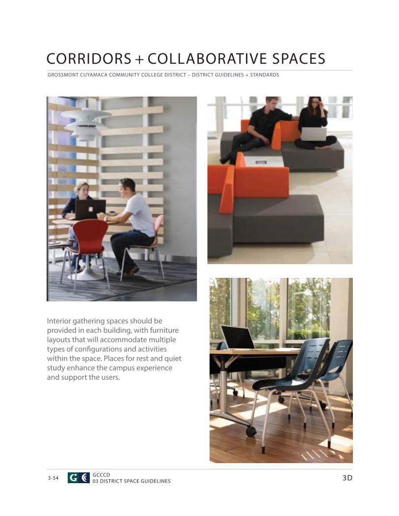
GROSSMONT CUYAMACA COMMUNITY COLLEGE DISTRICT – DISTRICT GUIDELINES + STANDARDS
GCCCD03 DISTRICT SPACE GUIDELINES3-54
Interior gathering spaces should be provided in each building, with furniture layouts that will accommodate multiple types of confi gurations and activities within the space. Places for rest and quiet study enhance the campus experience and support the users.
3D
CORRIDORS + COLLABORATIVE SPACES
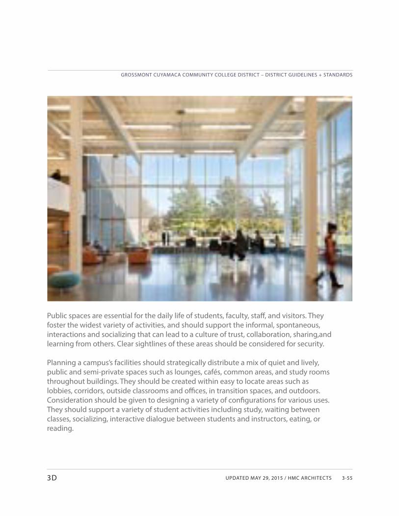
UPDATED MAY 29, 2015 / HMC ARCHITECTS
GROSSMONT CUYAMACA COMMUNITY COLLEGE DISTRICT – DISTRICT GUIDELINES + STANDARDS
3-55
Public spaces are essential for the daily life of students, faculty, staff , and visitors. They foster the widest variety of activities, and should support the informal, spontaneous, interactions and socializing that can lead to a culture of trust, collaboration, sharing,and learning from others. Clear sightlines of these areas should be considered for security.
Planning a campus’s facilities should strategically distribute a mix of quiet and lively, public and semi-private spaces such as lounges, cafés, common areas, and study rooms throughout buildings. They should be created within easy to locate areas such as lobbies, corridors, outside classrooms and offi ces, in transition spaces, and outdoors. Consideration should be given to designing a variety of confi gurations for various uses. They should support a variety of student activities including study, waiting between classes, socializing, interactive dialogue between students and instructors, eating, or reading.
3D
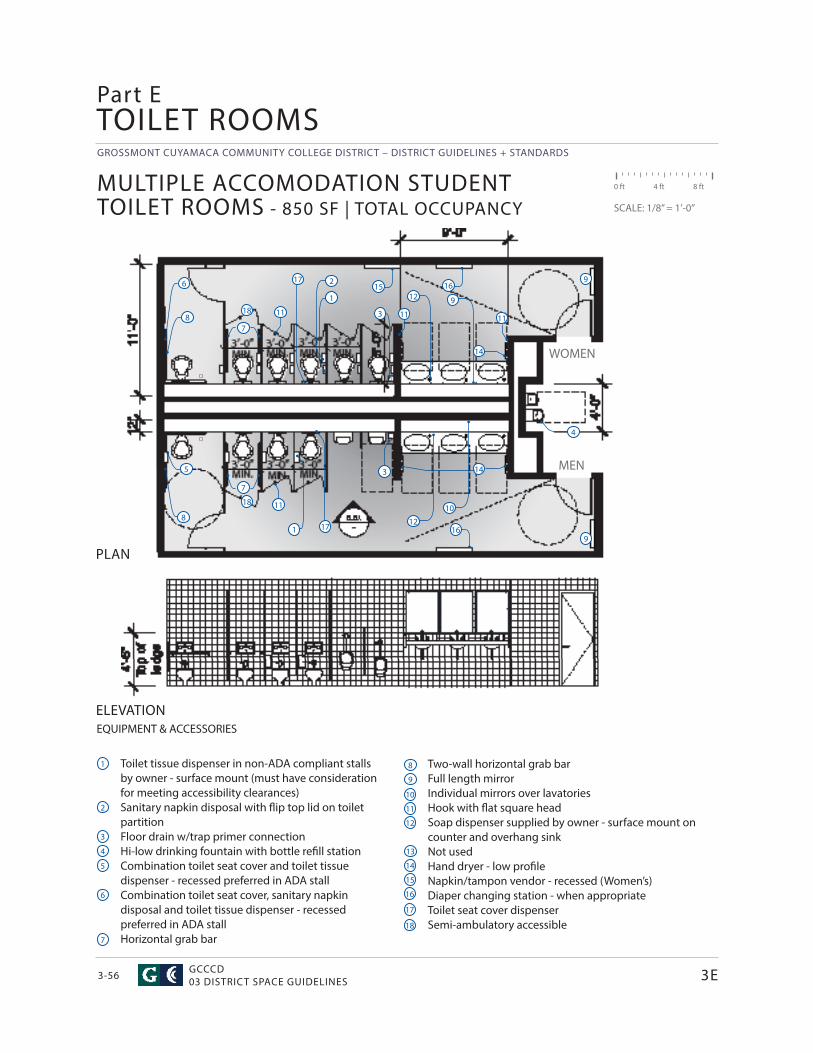
GROSSMONT CUYAMACA COMMUNITY COLLEGE DISTRICT – DISTRICT GUIDELINES + STANDARDS
GCCCD03 DISTRICT SPACE GUIDELINES3-56
EQUIPMENT & ACCESSORIES
Toilet tissue dispenser in non-ADA compliant stalls by owner - surface mount (must have consideration for meeting accessibility clearances)Sanitary napkin disposal with fl ip top lid on toilet partitionFloor drain w/trap primer connectionHi-low drinking fountain with bottle refi ll stationCombination toilet seat cover and toilet tissue dispenser - recessed preferred in ADA stallCombination toilet seat cover, sanitary napkin disposal and toilet tissue dispenser - recessed preferred in ADA stallHorizontal grab bar
TOILET ROOMS
ELEVATION
MEN
WOMEN
MULTIPLE ACCOMODATION STUDENT TOILET ROOMS - 850 SF | TOTAL OCCUPANCY
0 ft 4 ft 8 ft
SCALE: 1/8” = 1’-0”
Two-wall horizontal grab barFull length mirrorIndividual mirrors over lavatoriesHook with fl at square headSoap dispenser supplied by owner - surface mount on counter and overhang sinkNot usedHand dryer - low profi leNapkin/tampon vendor - recessed (Women’s)Diaper changing station - when appropriateToilet seat cover dispenser Semi-ambulatory accessible
PLAN
Part E
3E
1
2
1
3
3
4
5
6
8
8
7
7
9
9
14
14
16
16
9
10
12
1215
17
17
11
11 11 11
18
18
1
2
3
4
5
6
7
8
9
10
11
12
13
14
15
16
17
18
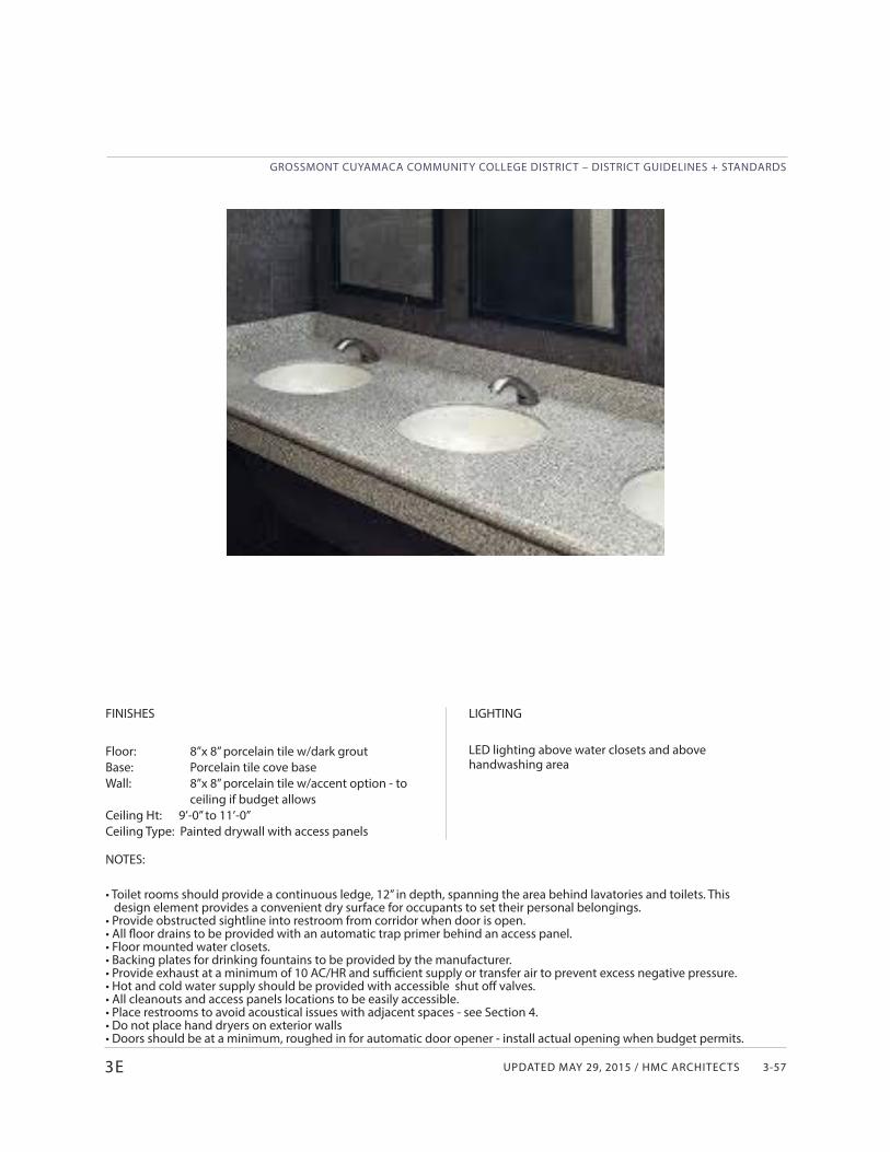
UPDATED MAY 29, 2015 / HMC ARCHITECTS
GROSSMONT CUYAMACA COMMUNITY COLLEGE DISTRICT – DISTRICT GUIDELINES + STANDARDS
3-57
FINISHES
Floor: 8”x 8” porcelain tile w/dark grout Base: Porcelain tile cove baseWall: 8”x 8” porcelain tile w/accent option - to ceiling if budget allows Ceiling Ht: 9’-0” to 11’-0”Ceiling Type: Painted drywall with access panels
NOTES:
• Toilet rooms should provide a continuous ledge, 12” in depth, spanning the area behind lavatories and toilets. This design element provides a convenient dry surface for occupants to set their personal belongings.• Provide obstructed sightline into restroom from corridor when door is open.• All fl oor drains to be provided with an automatic trap primer behind an access panel.• Floor mounted water closets. • Backing plates for drinking fountains to be provided by the manufacturer.• Provide exhaust at a minimum of 10 AC/HR and suffi cient supply or transfer air to prevent excess negative pressure.• Hot and cold water supply should be provided with accessible shut off valves. • All cleanouts and access panels locations to be easily accessible.• Place restrooms to avoid acoustical issues with adjacent spaces - see Section 4.• Do not place hand dryers on exterior walls• Doors should be at a minimum, roughed in for automatic door opener - install actual opening when budget permits.
LIGHTING
LED lighting above water closets and above handwashing area
3E
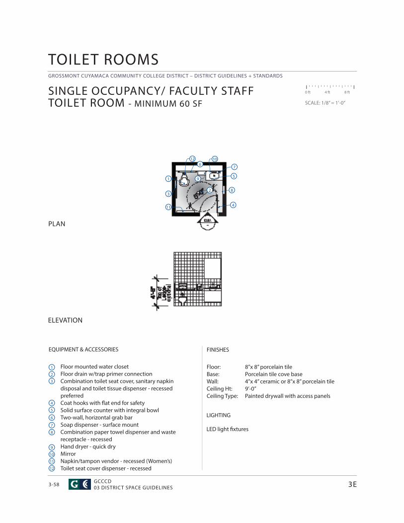
GROSSMONT CUYAMACA COMMUNITY COLLEGE DISTRICT – DISTRICT GUIDELINES + STANDARDS
GCCCD03 DISTRICT SPACE GUIDELINES3-58
EQUIPMENT & ACCESSORIES
Floor mounted water closetFloor drain w/trap primer connectionCombination toilet seat cover, sanitary napkin disposal and toilet tissue dispenser - recessed preferredCoat hooks with fl at end for safety Solid surface counter with integral bowlTwo-wall, horizontal grab barSoap dispenser - surface mountCombination paper towel dispenser and waste receptacle - recessedHand dryer - quick dryMirrorNapkin/tampon vendor - recessed (Women’s)Toilet seat cover dispenser - recessed
FINISHES
Floor: 8”x 8” porcelain tile Base: Porcelain tile cove base Wall: 4”x 4” ceramic or 8”x 8” porcelain tileCeiling Ht: 9’-0” Ceiling Type: Painted drywall with access panels
SINGLE OCCUPANCY/ FACULTY STAFF TOILET ROOM - MINIMUM 60 SF
0 ft 4 ft 8 ft
SCALE: 1/8” = 1’-0”
ELEVATION
PLAN
TOILET ROOMS
LIGHTING
LED light fi xtures
3E
1
23
4
5
67
8
9
10
11
12
1
2
3
4
5
6
7
8
9
10
11
12
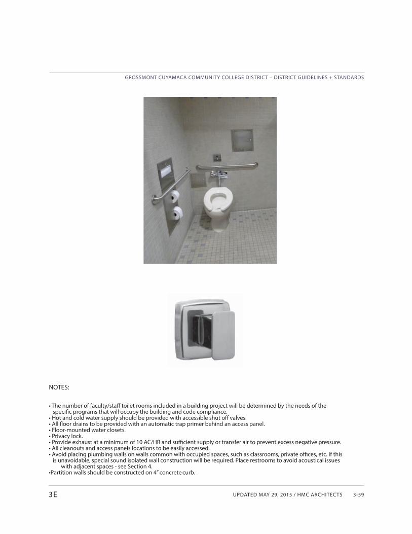
UPDATED MAY 29, 2015 / HMC ARCHITECTS
GROSSMONT CUYAMACA COMMUNITY COLLEGE DISTRICT – DISTRICT GUIDELINES + STANDARDS
3-59
NOTES:
• The number of faculty/staff toilet rooms included in a building project will be determined by the needs of the specifi c programs that will occupy the building and code compliance.
• Hot and cold water supply should be provided with accessible shut off valves.• All fl oor drains to be provided with an automatic trap primer behind an access panel.• Floor-mounted water closets. • Privacy lock.• Provide exhaust at a minimum of 10 AC/HR and suffi cient supply or transfer air to prevent excess negative pressure.• All cleanouts and access panels locations to be easily accessed.• Avoid placing plumbing walls on walls common with occupied spaces, such as classrooms, private offi ces, etc. If this
is unavoidable, special sound isolated wall construction will be required. Place restrooms to avoid acoustical issues with adjacent spaces - see Section 4.
• Partition walls should be constructed on 4” concrete curb.
3E
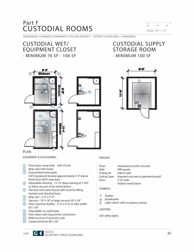
GROSSMONT CUYAMACA COMMUNITY COLLEGE DISTRICT – DISTRICT GUIDELINES + STANDARDS
GCCCD03 DISTRICT SPACE GUIDELINES3-60
EQUIPMENT & ACCESSORIES
Floor basin (mop sink) with 4”curb Mop rack with hooksGround fault interrupter(GFI) receptacle located approximately 2’-0” above fi nish fl oor (AFF) near doorAdjustable shelving - 12-16” deep starting at 3’ AFF to allow vacuum to be stored belowHot and cold water faucet with hook for fi lling buckets and attached hose Mop cart - 2’-0” x 5’-0”Vacuum - 18” x 18” or large vacuum 34” x 28”Floor machine (buff er) - 2’-0” x 4’-0” or rider buff er 63” x 36”Step ladder on wall hooksFloor drain with trap primer connectionWalls to sit on 4” concrete curbCarpet extractor 48” x 20”
CUSTODIAL ROOMS
FINISHES
Floor: Hardened smooth concreteWall: FRP panelsCeiling Ht: Slab to slab Ceiling Type: Exposed concrete or painted drywall Door: 3’-0” wide Hollow metal frame
SYMBOLS
DuplexQuadruplexLight switch with occupancy sensor
LIGHTING
LED utility lights
$
CUSTODIAL WET/EQUIPMENT CLOSET - MINIMUM 76 SF - 106 SF
CUSTODIAL SUPPLY STORAGE ROOM - MINIMUM 100 SF
0 ft 4 ft 8 ft
SCALE: 1/8” = 1’-0”
PLAN
Part F
3F
1
7
4
2
5
6
8
9
103
10
3
4
1
11
2
3
4
5
6
7
8
9
10
11
1
7
4
2
5
6
8
9
10
11
12
12
UPDATED MAY 29, 2015 / HMC ARCHITECTS
GROSSMONT CUYAMACA COMMUNITY COLLEGE DISTRICT – DISTRICT GUIDELINES + STANDARDS
3-61
CUSTODIAL WET EQUIPMENT CLOSET
• Strategically located on all fl oors throughout a building. • All buildings should have at least one larger custodial closet to accommodate larger cleaning equipment • Locate closet to avoid moving equipment long distances. • Doors shall swing out and shall be large enough to permit free movement of boxes and equipment (3’-0” min).• Provide adequate ventilation.
CUSTODIAL SUPPLY STORAGE ROOM
• One room per building for bulk storage of custodial supplies is required. • Locate on ground fl oor near elevator or loading dock to avoid moving equipment long distances. • Doors shall swing out and shall be large enough to permit free movement of boxes and equipment. • Provide adequate ventilation.
NOTES:
• Backfl ow preventers, pressure regulators etc. are not allowed in custodial rooms.• Provide exhaust at a minimum of 10 AC/HR.• All equipment rooms shall be designed and located to facilitate the removal, transport, and replacement of the largest equipment component housed within the room. Consider an oversized door to facilitate equipment.• Prevent doors from swinging into path of travel.
3F
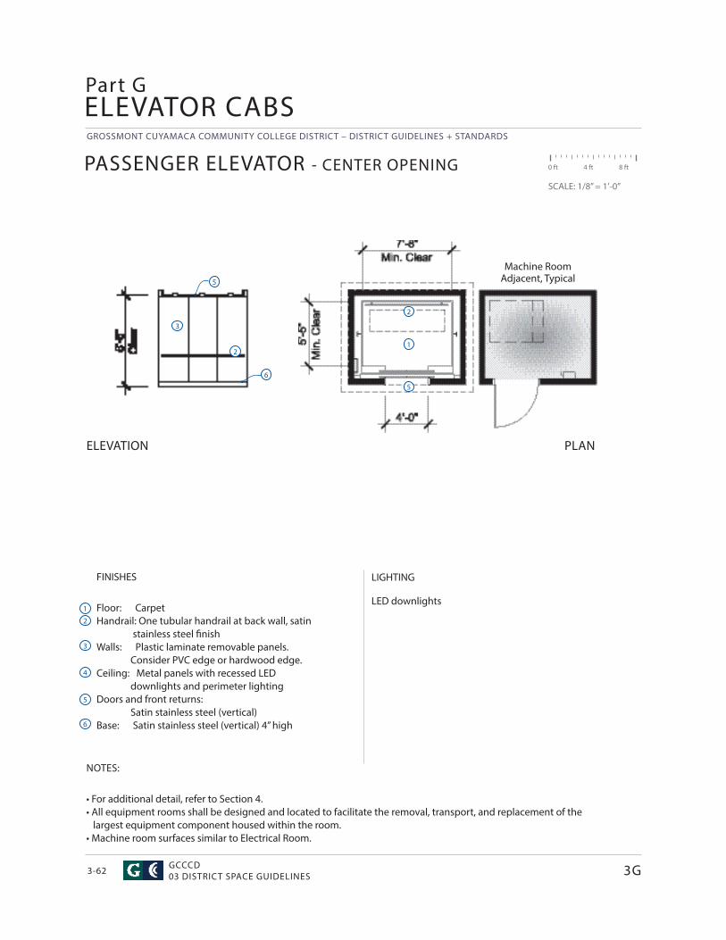
GROSSMONT CUYAMACA COMMUNITY COLLEGE DISTRICT – DISTRICT GUIDELINES + STANDARDS
GCCCD03 DISTRICT SPACE GUIDELINES3-62
FINISHES
Floor: CarpetHandrail: One tubular handrail at back wall, satin stainless steel fi nishWalls: Plastic laminate removable panels. Consider PVC edge or hardwood edge. Ceiling: Metal panels with recessed LED downlights and perimeter lighting Doors and front returns: Satin stainless steel (vertical)Base: Satin stainless steel (vertical) 4” high
ELEVATOR CABS
LIGHTING
LED downlights
Machine Room Adjacent, Typical
NOTES:
• For additional detail, refer to Section 4.• All equipment rooms shall be designed and located to facilitate the removal, transport, and replacement of the largest equipment component housed within the room.• Machine room surfaces similar to Electrical Room.
PASSENGER ELEVATOR - CENTER OPENING 0 ft 4 ft 8 ft
SCALE: 1/8” = 1’-0”
ELEVATION PLAN
Part G
3G
1
2
3
4
5
6
1
2
5
6
5
2
3
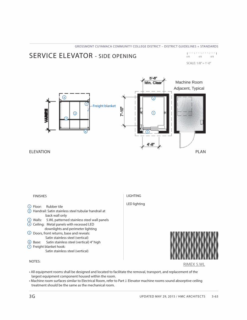
UPDATED MAY 29, 2015 / HMC ARCHITECTS
GROSSMONT CUYAMACA COMMUNITY COLLEGE DISTRICT – DISTRICT GUIDELINES + STANDARDS
3-63
FINISHES
Floor: Rubber tileHandrail: Satin stainless steel tubular handrail at back wall onlyWalls: 5.WL patterned stainless steel wall panels Ceiling: Metal panels with recessed LED downlights and perimeter lightingDoors, front returns, base and reveals: Satin stainless steel (vertical)Base: Satin stainless steel (vertical) 4” highFreight blanket hook: Satin stainless steel (vertical)
LIGHTING
LED lighting
Machine Room Adjacent, Typical
Freight blanket
NOTES:
• All equipment rooms shall be designed and located to facilitate the removal, transport, and replacement of the largest equipment component housed within the room.• Machine room surfaces similar to Electrical Room, refer to Part J. Elevator machine rooms sound absorptive ceiling treatment should be the same as the mechanical room.
SERVICE ELEVATOR - SIDE OPENING 0 ft 4 ft 8 ft
SCALE: 1/8” = 1’-0”
ELEVATION PLAN
3G
1
2
3
4
5
6
7
1
2
5
2
3
4
7
6
RIMEX 5.WL
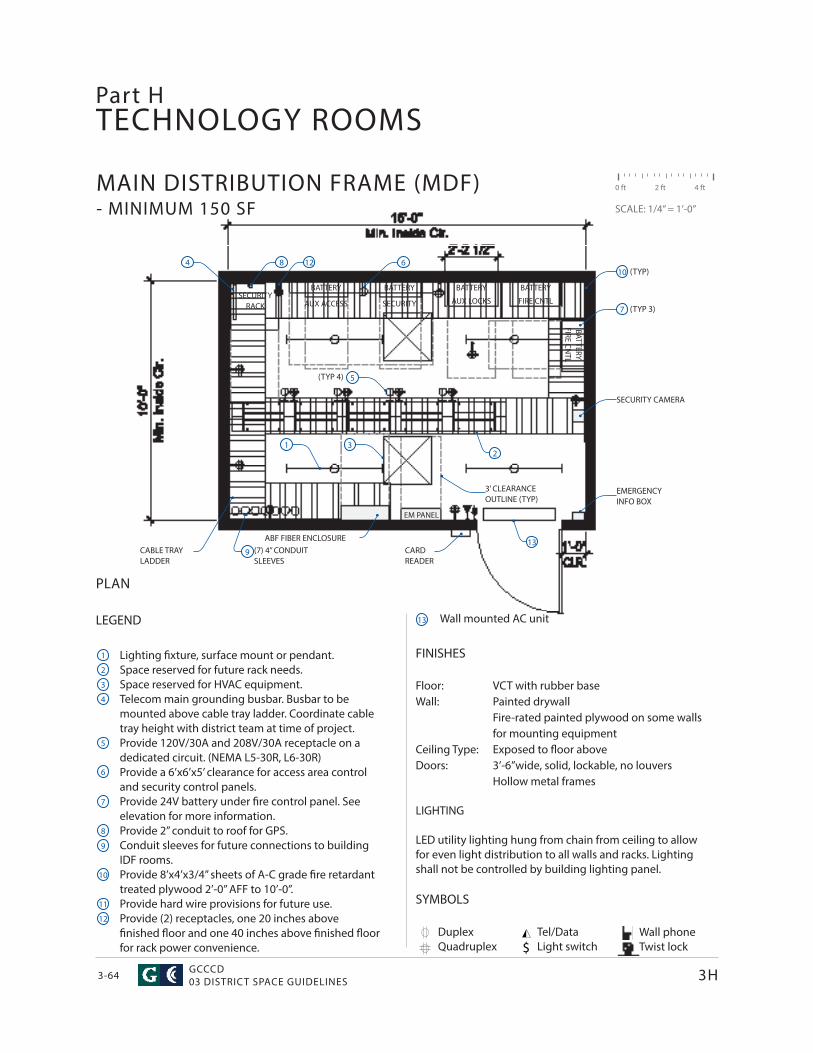
GROSSMONT CUYAMACA COMMUNITY COLLEGE DISTRICT – DISTRICT GUIDELINES + STANDARDS
GCCCD03 DISTRICT SPACE GUIDELINES3-64
TECHNOLOGY ROOMS
FINISHES
Floor: VCT with rubber baseWall: Painted drywall Fire-rated painted plywood on some walls for mounting equipmentCeiling Type: Exposed to fl oor aboveDoors: 3’-6”wide, solid, lockable, no louvers Hollow metal frames
LIGHTING
LED utility lighting hung from chain from ceiling to allow for even light distribution to all walls and racks. Lighting shall not be controlled by building lighting panel.
LEGEND
Lighting fi xture, surface mount or pendant.Space reserved for future rack needs.Space reserved for HVAC equipment.Telecom main grounding busbar. Busbar to be mounted above cable tray ladder. Coordinate cable tray height with district team at time of project.Provide 120V/30A and 208V/30A receptacle on a dedicated circuit. (NEMA L5-30R, L6-30R)Provide a 6’x6’x5’ clearance for access area control and security control panels.Provide 24V battery under fi re control panel. See elevation for more information.Provide 2” conduit to roof for GPS.Conduit sleeves for future connections to building IDF rooms.Provide 8’x4’x3/4” sheets of A-C grade fi re retardant treated plywood 2’-0” AFF to 10’-0”.Provide hard wire provisions for future use.Provide (2) receptacles, one 20 inches above fi nished fl oor and one 40 inches above fi nished fl oor for rack power convenience.
SYMBOLS
0 ft 2 ft 4 ft
SCALE: 1/4” = 1’-0”
MAIN DISTRIBUTION FRAME (MDF) - MINIMUM 150 SF
PLAN
DuplexQuadruplex $
Part H
3H
1
2
3
4
5
6
7
8
9
10
11
1
4 8
9
12
13
12 6
32
5(TYP 4)
13
10 (TYP)
7 (TYP 3)
Wall mounted AC unit
SECURITY CAMERA
EMERGENCY INFO BOX
3’ CLEARANCE OUTLINE (TYP)
CABLE TRAY LADDER
(7) 4” CONDUIT SLEEVES
CARD READER
ABF FIBER ENCLOSURE
SECURITY RACK
BATTERY
AUX ACCESS
BATTERY
SECURITY
BATTERY
AUX LOCKS
BATTERY
FIRE CNTL
BATTERYFIRE CN
TL
EM PANEL
Tel/DataLight switch
Wall phoneTwist lock
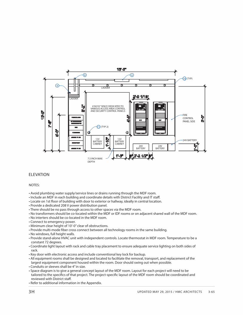
UPDATED MAY 29, 2015 / HMC ARCHITECTS
GROSSMONT CUYAMACA COMMUNITY COLLEGE DISTRICT – DISTRICT GUIDELINES + STANDARDS
3-653H
NOTES:
• Avoid plumbing water supply/service lines or drains running through the MDF room.• Include an MDF in each building and coordinate details with District Facility and IT staff .• Locate on 1st fl oor of building with door to exterior or hallway, ideally in central location.• Provide a dedicated 208 V power distribution panel.• There should be no pass through access to other spaces via the MDF room.• No transformers should be co-located within the MDF or IDF rooms or on adjacent shared wall of the MDF room.• No interters should be co-located in the MDF room.• Connect to emergency power. • Minimum clear height of 10’-0” clear of obstructions.• Provide multi-mode fi ber cross connect between all technology rooms in the same building.• No windows, full height walls.• Provide stand-alone HVAC unit with independent controls. Locate thermostat in MDF room. Temperature to be a constant 72 degrees.• Coordinate light layout with rack and cable tray placement to ensure adequate service lighting on both sides of rack.• Key door with electronic access and include conventional key lock for backup.• All equipment rooms shall be designed and located to facilitate the removal, transport, and replacement of the largest equipment component housed within the room. Door should swing out when possible.• Conduits or sleeves shall be 4” in size.• Space diagram is to give a general concept layout of the MDF room. Layout for each project will need to be tailored to the specifi cs of that project. The project-specifi c layout of the MDF room should be coordinated and reviewed with District staff .• Refer to additional information in the Appendix.
ELEVATION
6’X6’X5” SPACE DEDICATED TO VARIOUS ACCESS AREA CONTROL AND SECURITY CONTROL PANELS
10 (TYP)
FIRE CONTROL PANEL SIDE
24V BATTERY
24VBATTERY
24VBATTERY
12VBATTERYCABINET
12VBATTERYCABINET
11 (TYP 2)
68
4LADDER
LADDER
7.5 INCH MAX DEPTH
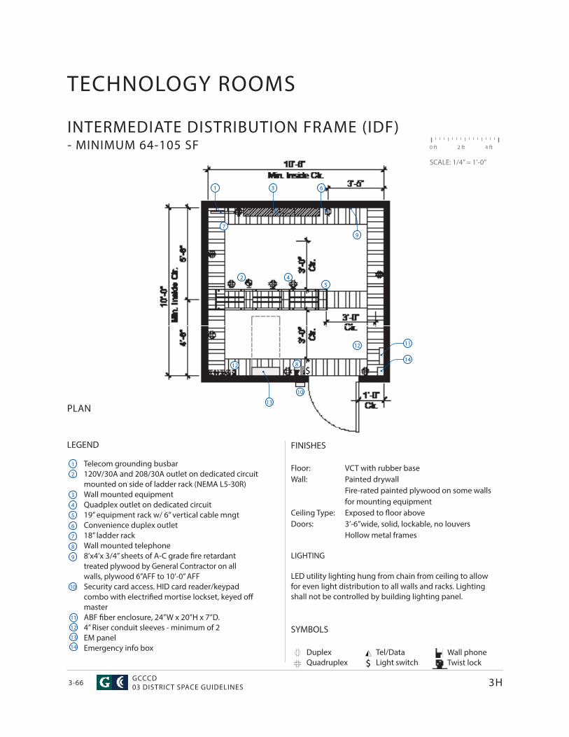
GROSSMONT CUYAMACA COMMUNITY COLLEGE DISTRICT – DISTRICT GUIDELINES + STANDARDS
GCCCD03 DISTRICT SPACE GUIDELINES3-66
LEGEND
Telecom grounding busbar120V/30A and 208/30A outlet on dedicated circuit mounted on side of ladder rack (NEMA L5-30R)Wall mounted equipmentQuadplex outlet on dedicated circuit19” equipment rack w/ 6” vertical cable mngtConvenience duplex outlet18” ladder rackWall mounted telephone8’x4’x 3/4” sheets of A-C grade fi re retardant treated plywood by General Contractor on all walls, plywood 6”AFF to 10’-0” AFFSecurity card access. HID card reader/keypad combo with electrifi ed mortise lockset, keyed off masterABF fi ber enclosure, 24”W x 20”H x 7”D.4” Riser conduit sleeves - minimum of 2EM panelEmergency info box
TECHNOLOGY ROOMS
INTERMEDIATE DISTRIBUTION FRAME (IDF) - MINIMUM 64-105 SF 0 ft 2 ft 4 ft
SCALE: 1/4” = 1’-0”
$
3H
1
2
3
4
5
6
7
8
9
10
11
1
2
3
45
6
7
8
10
12
13
12
12
PLAN
FINISHES
Floor: VCT with rubber baseWall: Painted drywall
Fire-rated painted plywood on some walls for mounting equipment
Ceiling Type: Exposed to fl oor aboveDoors: 3’-6”wide, solid, lockable, no louvers
Hollow metal frames
LIGHTING
LED utility lighting hung from chain from ceiling to allow for even light distribution to all walls and racks. Lighting shall not be controlled by building lighting panel.
SYMBOLS
DuplexQuadruplex $
Tel/DataLight switch
Wall phoneTwist lock
9
11
13
14
14
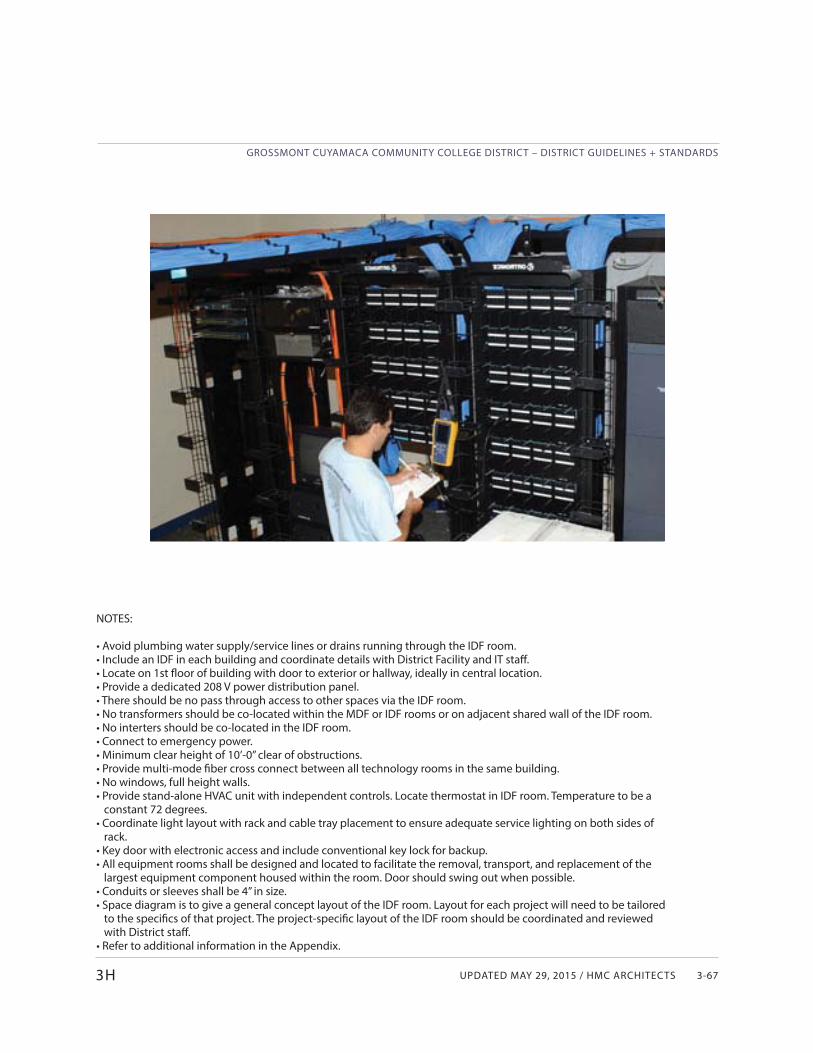
UPDATED MAY 29, 2015 / HMC ARCHITECTS
GROSSMONT CUYAMACA COMMUNITY COLLEGE DISTRICT – DISTRICT GUIDELINES + STANDARDS
3-673H
NOTES:
• Avoid plumbing water supply/service lines or drains running through the IDF room.• Include an IDF in each building and coordinate details with District Facility and IT staff .• Locate on 1st fl oor of building with door to exterior or hallway, ideally in central location.• Provide a dedicated 208 V power distribution panel.• There should be no pass through access to other spaces via the IDF room.• No transformers should be co-located within the MDF or IDF rooms or on adjacent shared wall of the IDF room.• No interters should be co-located in the IDF room.• Connect to emergency power. • Minimum clear height of 10’-0” clear of obstructions.• Provide multi-mode fi ber cross connect between all technology rooms in the same building.• No windows, full height walls.• Provide stand-alone HVAC unit with independent controls. Locate thermostat in IDF room. Temperature to be a constant 72 degrees.• Coordinate light layout with rack and cable tray placement to ensure adequate service lighting on both sides of rack.• Key door with electronic access and include conventional key lock for backup.• All equipment rooms shall be designed and located to facilitate the removal, transport, and replacement of the largest equipment component housed within the room. Door should swing out when possible.• Conduits or sleeves shall be 4” in size.• Space diagram is to give a general concept layout of the IDF room. Layout for each project will need to be tailored to the specifi cs of that project. The project-specifi c layout of the IDF room should be coordinated and reviewed with District staff .• Refer to additional information in the Appendix.
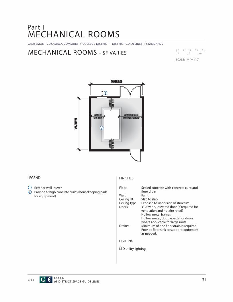
GROSSMONT CUYAMACA COMMUNITY COLLEGE DISTRICT – DISTRICT GUIDELINES + STANDARDS
GCCCD03 DISTRICT SPACE GUIDELINES3-68
MECHANICAL ROOMS
FINISHES
Floor: Sealed concrete with concrete curb and fl oor drainWall: PaintCeiling Ht: Slab to slabCeiling Type: Exposed to underside of structure Doors: 3’-0” wide, louvered door (if required for ventilation and not fi re rated) Hollow metal frames Hollow metal, double, exterior doors where applicable for large units.Drains: Minimum of one fl oor drain is required. Provide fl oor sink to support equipment as needed.
LIGHTING
LED utility lighting
MECHANICAL ROOMS - SF VARIES
LEGEND
Exterior wall louverProvide 4” high concrete curbs (housekeeping padsfor equipment)
Part I
3I
0 ft 2 ft 4 ft
SCALE: 1/4” = 1’-0”
1
2
1
2
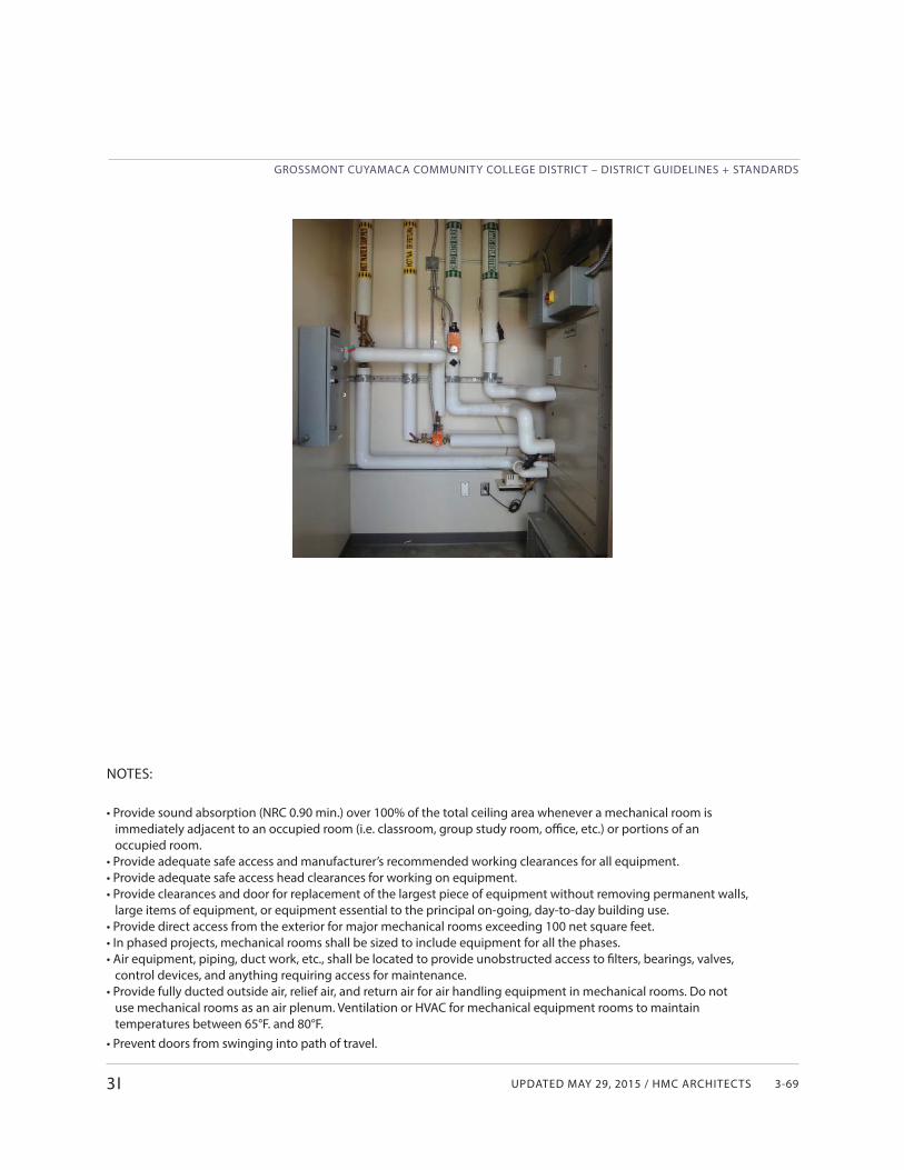
UPDATED MAY 29, 2015 / HMC ARCHITECTS
GROSSMONT CUYAMACA COMMUNITY COLLEGE DISTRICT – DISTRICT GUIDELINES + STANDARDS
3-69
NOTES:
• Provide sound absorption (NRC 0.90 min.) over 100% of the total ceiling area whenever a mechanical room is immediately adjacent to an occupied room (i.e. classroom, group study room, offi ce, etc.) or portions of an occupied room.• Provide adequate safe access and manufacturer’s recommended working clearances for all equipment. • Provide adequate safe access head clearances for working on equipment. • Provide clearances and door for replacement of the largest piece of equipment without removing permanent walls, large items of equipment, or equipment essential to the principal on-going, day-to-day building use. • Provide direct access from the exterior for major mechanical rooms exceeding 100 net square feet.• In phased projects, mechanical rooms shall be sized to include equipment for all the phases.• Air equipment, piping, duct work, etc., shall be located to provide unobstructed access to fi lters, bearings, valves, control devices, and anything requiring access for maintenance. • Provide fully ducted outside air, relief air, and return air for air handling equipment in mechanical rooms. Do not use mechanical rooms as an air plenum. Ventilation or HVAC for mechanical equipment rooms to maintain temperatures between 65°F. and 80°F.• Prevent doors from swinging into path of travel.
3I
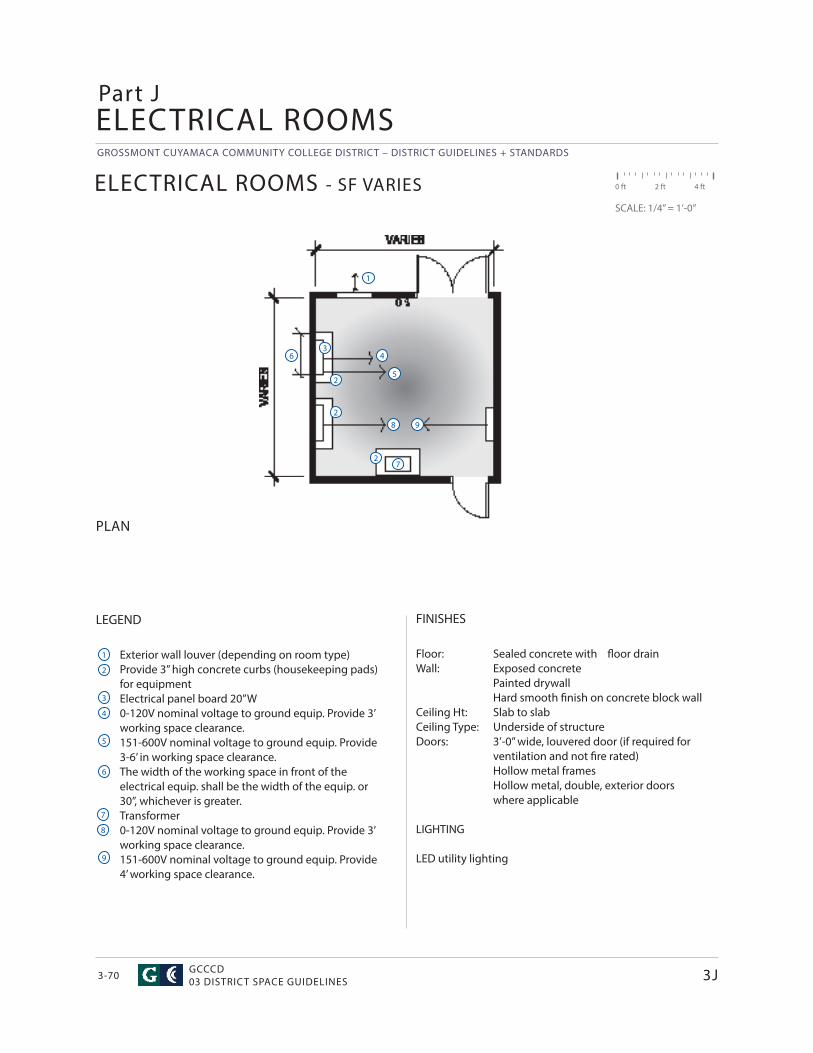
GROSSMONT CUYAMACA COMMUNITY COLLEGE DISTRICT – DISTRICT GUIDELINES + STANDARDS
GCCCD03 DISTRICT SPACE GUIDELINES3-70
ELECTRICAL ROOMS
ELECTRICAL ROOMS - SF VARIES
FINISHES
Floor: Sealed concrete with fl oor drainWall: Exposed concrete Painted drywall Hard smooth fi nish on concrete block wallCeiling Ht: Slab to slabCeiling Type: Underside of structure Doors: 3’-0” wide, louvered door (if required for ventilation and not fi re rated) Hollow metal frames Hollow metal, double, exterior doors where applicable
LIGHTING
LED utility lighting
LEGEND
Exterior wall louver (depending on room type)Provide 3” high concrete curbs (housekeeping pads) for equipmentElectrical panel board 20”W0-120V nominal voltage to ground equip. Provide 3’ working space clearance.151-600V nominal voltage to ground equip. Provide 3-6’ in working space clearance.The width of the working space in front of the electrical equip. shall be the width of the equip. or 30”, whichever is greater.Transformer0-120V nominal voltage to ground equip. Provide 3’ working space clearance.151-600V nominal voltage to ground equip. Provide 4’ working space clearance.
PLAN
Part J
3J
0 ft 2 ft 4 ft
SCALE: 1/4” = 1’-0”
1
2
1
2
6 4
5
3
7
8 9
3
4
5
8
6
7
9
2
2
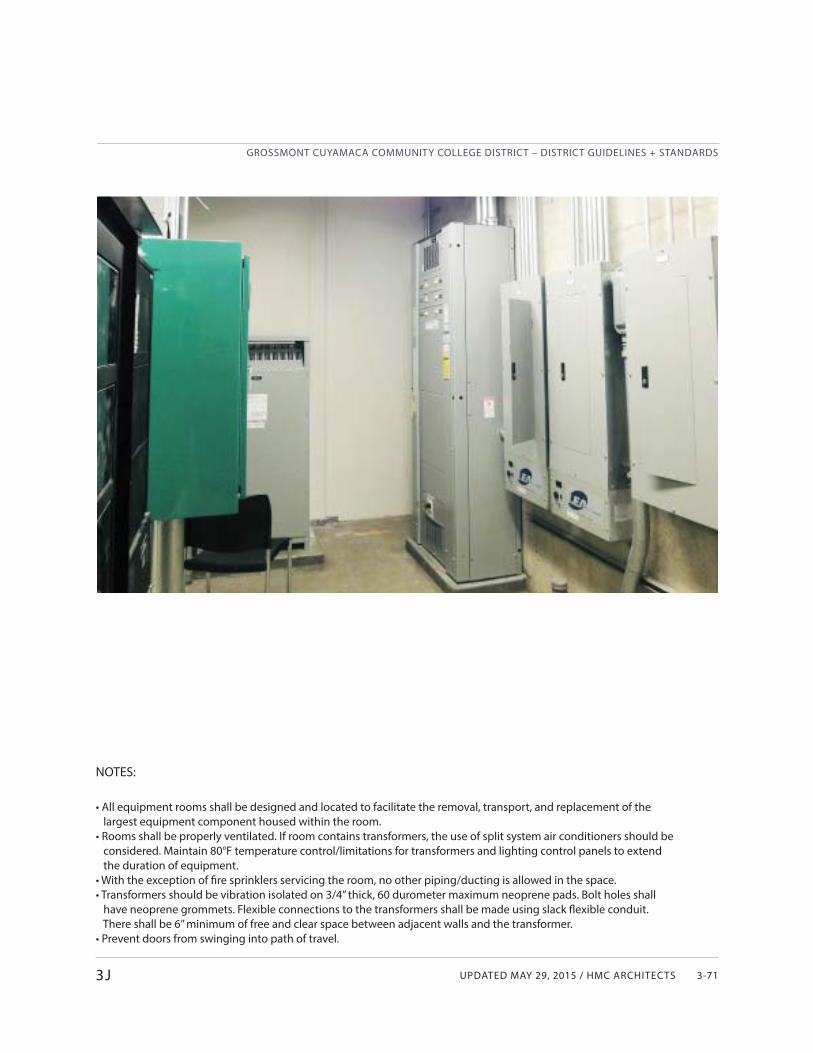
UPDATED MAY 29, 2015 / HMC ARCHITECTS
GROSSMONT CUYAMACA COMMUNITY COLLEGE DISTRICT – DISTRICT GUIDELINES + STANDARDS
3-71
NOTES:
• All equipment rooms shall be designed and located to facilitate the removal, transport, and replacement of the largest equipment component housed within the room. • Rooms shall be properly ventilated. If room contains transformers, the use of split system air conditioners should be considered. Maintain 80°F temperature control/limitations for transformers and lighting control panels to extend the duration of equipment.• With the exception of fi re sprinklers servicing the room, no other piping/ducting is allowed in the space.• Transformers should be vibration isolated on 3/4” thick, 60 durometer maximum neoprene pads. Bolt holes shall have neoprene grommets. Flexible connections to the transformers shall be made using slack fl exible conduit. There shall be 6” minimum of free and clear space between adjacent walls and the transformer.• Prevent doors from swinging into path of travel.
3J

Updated Nov. 19, 2015/ HMC aRCHIteCtS
GRoSSMoNt CUYaMaCa CoMMUNItY CoLLeGe dIStRICt – dIStRICt GUIdeLINeS + StaNdaRdS
4-1
INTRODUCTION
Section 4 of this document is intended to outline performance criteria that are important to the District for the major building/site systems and materials in future construction projects. Although Section 4 is organized in Divisions based on the 2010 MasterFormat® it is not written as or intended to be considered as product specifications that would be included in a project manual but rather provide criteria, locations, and desired design approach for systems and materials that would be used in a project. This Section does not include project procedures, requirements, or general and existing conditions which will be covered in other documents. The Section starts with Division 1 and only covers main materials and systems that would typically be used on a campus project and where clear performance standards have been established by the District. Therefore there will be numerical Divisions that are not included in this Section.
All design teams are responsible for meeting all federal, state, and local code and regulatory agency requirements. Such requirements, which do continually change, are not included in this Section but must be met for all projects. It is expected that a high level of professional standard of care and best practices be applied to each particular discipline on every project.
This Section is not intended to be all encompassing of every component of every future facility project, but rather provide and facilitate a mutual understanding of expectations and design requirements for projects within the District. Some standards will be campus specific and thoseare noted in the individual Divisions. Information in this section is supplemented with additional charts and drawings for reference in the Appendix.
4
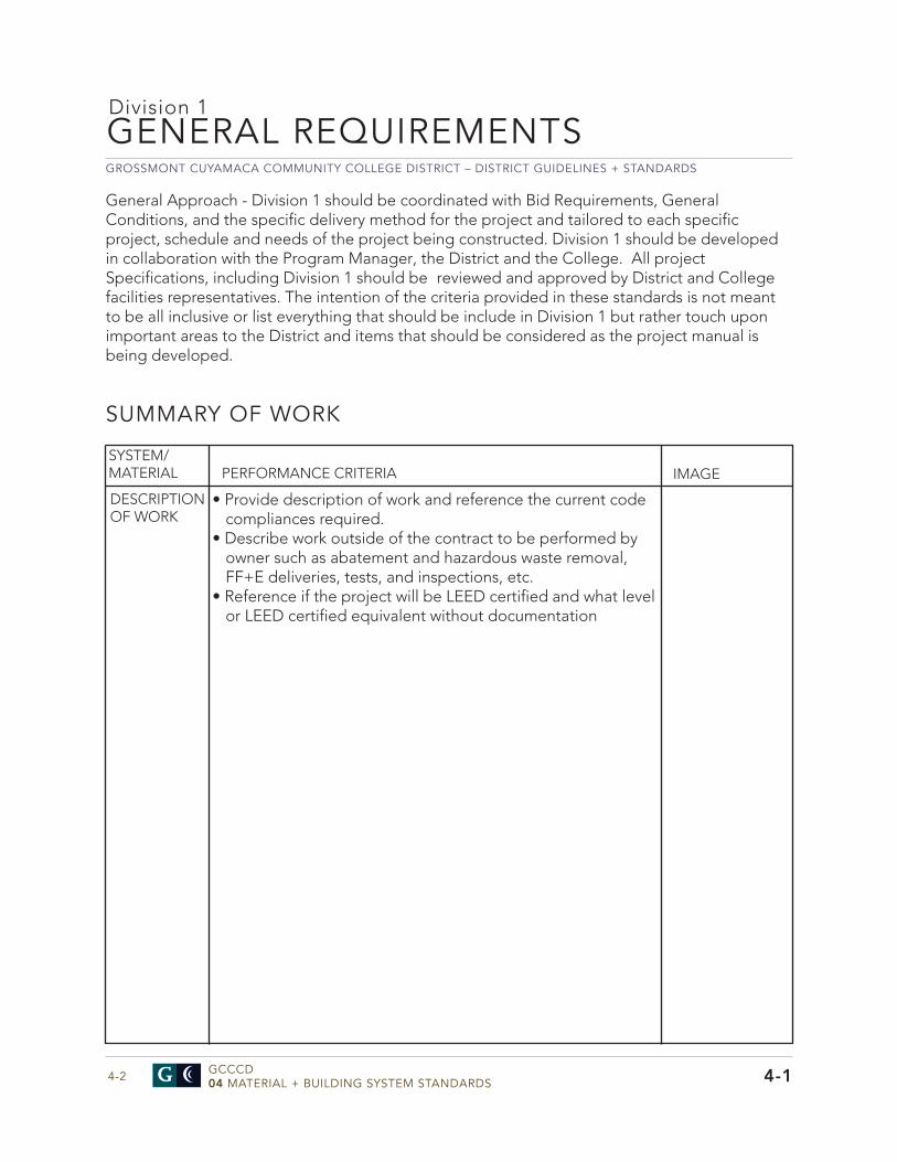
GROSSMONT CUYAMACA COMMUNITY COLLEGE DISTRICT – DISTRICT GUIDELINES + STANDARDS
GCCCD04 MATERIAL + BUILDING SYSTEM STANDARDS4-2
GENERAL REQUIREMENTS
4-1
Division 1
SUMMARY OF WORK
• Provide description of work and reference the current codecompliances required.
• Describe work outside of the contract to be performed byowner such as abatement and hazardous waste removal,FF+E deliveries, tests, and inspections, etc.
• Reference if the project will be LEED certified and what levelor LEED certified equivalent without documentation
SYSTEM/MATERIAL PERFORMANCE CRITERIA IMAGE
DESCRIPTION OF WORK
General Approach - Division 1 should be coordinated with Bid Requirements, General Conditions, and the specific delivery method for the project and tailored to each specific project, schedule and needs of the project being constructed. Division 1 should be developed in collaboration with the Program Manager, the District and the College. All project Specifications, including Division 1 should be reviewed and approved by District and College facilities representatives. The intention of the criteria provided in these standards is not meant to be all inclusive or list everything that should be include in Division 1 but rather touch upon important areas to the District and items that should be considered as the project manual is being developed.
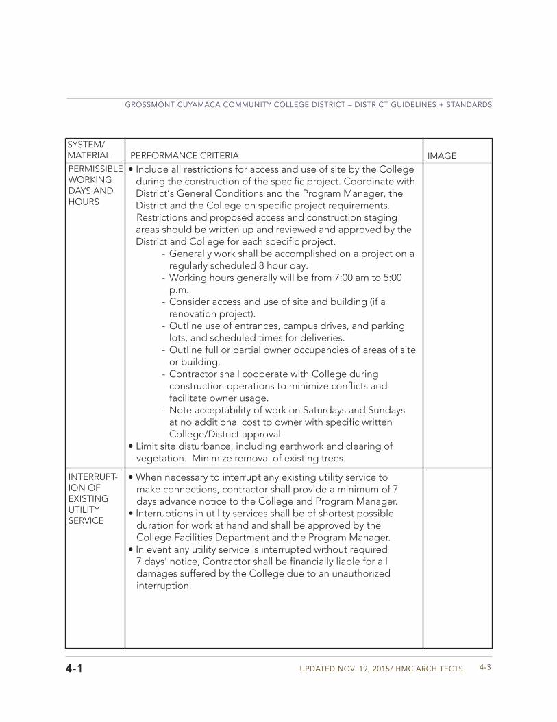
Updated Nov. 19, 2015/ HMC aRCHIteCtS
GRoSSMoNt CUYaMaCa CoMMUNItY CoLLeGe dIStRICt – dIStRICt GUIdeLINeS + StaNdaRdS
4-34-1
SYSTEM/MATERIAL PERFORMANCE CRITERIA IMAGEPERMISSIBLE WORKING DAYS AND HOURS
• Include all restrictions for access and use of site by the College during the construction of the specific project. Coordinate with District’s General Conditions and the Program Manager, the District and the College on specific project requirements. Restrictions and proposed access and construction staging areas should be written up and reviewed and approved by the District and College for each specific project.
- Generally work shall be accomplished on a project on a regularly scheduled 8 hour day.
- Working hours generally will be from 7:00 am to 5:00 p.m.
- Consider access and use of site and building (if a renovation project).
- Outline use of entrances, campus drives, and parking lots, and scheduled times for deliveries.
- Outline full or partial owner occupancies of areas of site or building.
- Contractor shall cooperate with College during construction operations to minimize conflicts andfacilitate owner usage.
- Note acceptability of work on Saturdays and Sundays at no additional cost to owner with specific writtenCollege/District approval.
• Limit site disturbance, including earthwork and clearing ofvegetation. Minimize removal of existing trees.
• When necessary to interrupt any existing utility service tomake connections, contractor shall provide a minimum of 7days advance notice to the College and Program Manager.
• Interruptions in utility services shall be of shortest possibleduration for work at hand and shall be approved by theCollege Facilities Department and the Program Manager.
• In event any utility service is interrupted without required7 days’ notice, Contractor shall be financially liable for alldamages suffered by the College due to an unauthorizedinterruption.
INTERRUPT-ION OF EXISTING UTILITY SERVICE
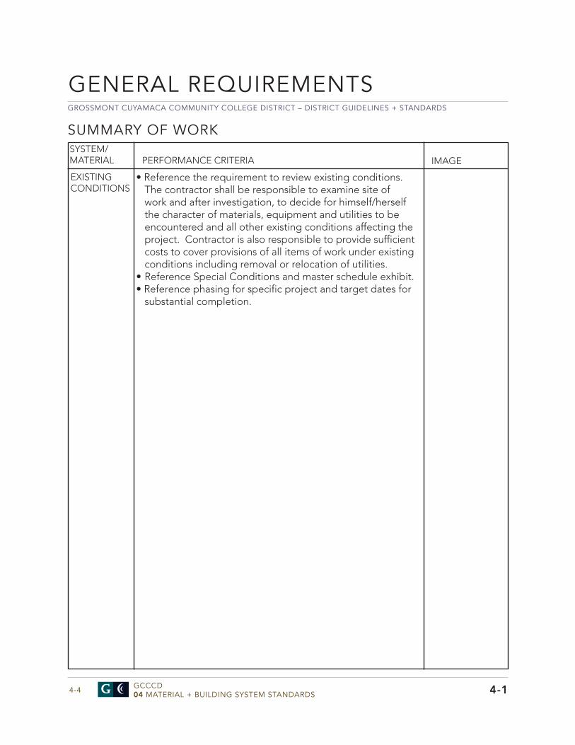
GROSSMONT CUYAMACA COMMUNITY COLLEGE DISTRICT – DISTRICT GUIDELINES + STANDARDS
GCCCD04 MATERIAL + BUILDING SYSTEM STANDARDS4-4
GENERAL REQUIREMENTS
SUMMARY OF WORK
• Reference the requirement to review existing conditions.The contractor shall be responsible to examine site ofwork and after investigation, to decide for himself/herselfthe character of materials, equipment and utilities to beencountered and all other existing conditions affecting theproject. Contractor is also responsible to provide sufficientcosts to cover provisions of all items of work under existingconditions including removal or relocation of utilities.
• Reference Special Conditions and master schedule exhibit.• Reference phasing for specific project and target dates for
substantial completion.
SYSTEM/MATERIAL PERFORMANCE CRITERIA IMAGE
EXISTING CONDITIONS
4-1
Updated Nov. 19, 2015/ HMC aRCHIteCtS
GRoSSMoNt CUYaMaCa CoMMUNItY CoLLeGe dIStRICt – dIStRICt GUIdeLINeS + StaNdaRdS
4-5
pRICE AND pAYMENT pROCEDURESSYSTEM/MATERIAL PERFORMANCE CRITERIA IMAGEALTERNATES • Consider proposing bid “alternates” (add or deduct) on a
project if and when applicable or appropriate to help protect the budget.
• An “alternate” is an amount proposed by bidders and stated on the Bid Form for certain work defined in the biddingrequirements that may be added to or deducted from the base bid amount if Owner decides to accept a corresponding change either in the amount of construction to be completed or in the products, materials, equipment, systems, or installation methods described in the Contract Documents.
• Alternates should be clearly outlined in contract documents. The items should be clearly defined and the limits of thealternative should also be included in the contract documents.
UNIT PRICES AND ALLOW-ANCES
• Include “unit prices” on the bid form when requested. Unit price is an amount proposed and stated in the Bid Form as price per unit of measurement for materials or services or both that will be added to or deducted from the contract price by change order in the event estimated quantities of work/materials required by the contract documents are increased or decreased. The owner reserves right to reject the contractor’s measurement of work-in-place that involves use of established unit prices, and to have this work measured by independent surveyor acceptable to the contractor at owner’s expense.
• Include both cash allowances and material allowances in the contract bid when requested. Coordinate all allowances with the Program Manager, the District, and the College. Make sure bid documents clearly require the allowances to be included in the contract sum. Direct contractor to include cost for materials, delivery, un-packaging, unloading, storage if any, taxes and installation costs.
4-1
• Coordinate with Program Manager and District to determine what to include as alternates to allow for inclusion in bidding documents and forms.
GROSSMONT CUYAMACA COMMUNITY COLLEGE DISTRICT – DISTRICT GUIDELINES + STANDARDS
GCCCD04 MATERIAL + BUILDING SYSTEM STANDARDS4-6
pRICE AND pAYMENT pROCEDURES
• Reference procedures for changes in project work. • All change orders shall be reviewed by Division of State
Architect (DSA) and all change orders dealing with Structure, Life Safety, and Access must be approved by DSA.
• If in Public R/W or the purview of another agency ( i.e. Water District), the agency approval is also required.
• For minor changes, the Program Manager and Architect will issue supplemental instructions for changes not requiring adjustments to contract sum or contract time. Document appropriately for project certification by DSA
• For minor changes, the Program Manager and Architect will issue supplemental instructions for changes not requiring adjustments to contract sum or contract time. Document appropriately for certification by DSA
• Design professional will issue an ASI through the Program Manager with appropriate documentation for owner initiated project changes to the work which may require adjustment to the contract sum or contract time and include appropriate DSA documentation forms. Require the contractor to submit a quotation in the time frame designated in the General and Supplementary Conditions estimating cost adjustments to the Contract Sum and the Contract Time necessary to execute the change.
• If latent or changed conditions require modificationsto the contract, the contractor may initiate a claim by submitting a request for a change to the PM/CM and Architect. The request must include a statement outlining reasons for change of work. The contractor must provide a complete description of the proposed change with detailed breakdown of labor, materials and cost. Indicate the effect of the proposed change on the contract sum and the contract time. Include an updated construction schedule that indicates the effect of the change, including, but not
SYSTEM/MATERIAL PERFORMANCE CRITERIA IMAGE
CHANGES IN WORK
GENERAL REQUIREMENTS
4-1
Updated Nov. 19, 2015/ HMC aRCHIteCtS
GRoSSMoNt CUYaMaCa CoMMUNItY CoLLeGe dIStRICt – dIStRICt GUIdeLINeS + StaNdaRdS
4-7
SYSTEM/MATERIAL PERFORMANCE CRITERIA IMAGE
limited to, changes in activity duration, start and finish time , and activity relationships.
• Construction Change Directives, which instruct the contractor to proceed with a change in the project work, for subsequent inclusion in a Change Order may be issued by the Architect. Change directives must be accompanied by appropriate DSA documentation forms. Construction Change Directives should contain a complete description of change in the work and designate method to be followed to determine change in the contract sum or the contract time. Maintain detailed records on a time and material basis of work required by the Construction Change Directive.
• Change Orders Procedures: On District’s approval of a Change Order Request, the Architect and Program Manager will issue a Change Order for signatures of the District and contractor on the designated form.
• Change Orders shall include the following: - Stipulated Price Change Order: Based on contractor’s change order request as approved by the Architect.
- Time and Material Change Orders: Submit itemized account and supporting data after completion of change within time limits indicated in Conditions of Contract. The Architect and Program Manager will determine change allowable in contract price and contract time as provided in contract documents.
- Maintain detailed records of work done on time and material basis. Provide full information required for evaluation of proposed changes, and to substantiate costs for changes in project work.
- The Program Manager will issue change orders for signature of parties as provided in Conditions of the Contract.
- For pre-determined unit prices and quantities, change order will be executed on fixed unit price basis. Forunit costs or quantities of units of work that are not pre-determined, execute work under a construction change directive. Change in contract price or contract time will be computed as specified for a time and materialchange order.
4-1
GROSSMONT CUYAMACA COMMUNITY COLLEGE DISTRICT – DISTRICT GUIDELINES + STANDARDS
GCCCD04 MATERIAL + BUILDING SYSTEM STANDARDS4-8
pRICE AND pAYMENT pROCEDURES
• Schedules of values should be referenced.• The contractor shall submit application for progress
payment in accordance with the General and Supplementary Conditions.
SYSTEM/MATERIAL PERFORMANCE CRITERIA IMAGE
SCHEDULE OF VALUES
GENERAL REQUIREMENTS
4-1
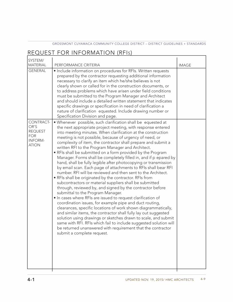
Updated Nov. 19, 2015/ HMC aRCHIteCtS
GRoSSMoNt CUYaMaCa CoMMUNItY CoLLeGe dIStRICt – dIStRICt GUIdeLINeS + StaNdaRdS
4-9
SYSTEM/MATERIAL PERFORMANCE CRITERIA IMAGE
REQUEST FOR INFORMATION (RFIs)
GENERAL • Include information on procedures for RFIs. Written requests prepared by the contractor requesting additional information necessary to clarify an item which he/she believes is not clearly shown or called for in the construction documents, or to address problems which have arisen under field conditionsmust be submitted to the Program Manager and Architect and should include a detailed written statement that indicates specific drawings or specification in need of clarification anature of clarification equested. Include drawing number or Specification Division and page.
CONTRACT-OR’S REQUEST FOR INFORM-ATION
• Whenever possible, such clarification shall be equested at the next appropriate project meeting, with response entered into meeting minutes. When clarification at the constructionmeeting is not possible, because of urgency of need, or complexity of item, the contractor shall prepare and submit a written RFI to the Program Manager and Architect.
• RFIs shall be submitted on a form provided by the Program Manager. Forms shall be completely filled in, and if p epared by hand, shall be fully legible after photocopying or transmission by email scan. Each page of attachments to RFIs shall bear RFI number. RFI will be reviewed and then sent to the Architect.
• RFIs shall be originated by the contractor. RFIs from subcontractors or material suppliers shall be submitted through, reviewed by, and signed by the contractor before submittal to the Program Manager.
• In cases where RFIs are issued to request clarification ofcoordination issues, for example pipe and duct routing, clearances, specific locations of work shown diagrammatically,and similar items, the contractor shall fully lay out suggested solution using drawings or sketches drawn to scale, and submit same with RFI. RFIs which fail to include suggested solution will be returned unanswered with requirement that the contractor submit a complete request.
4-1
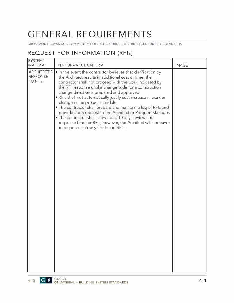
GROSSMONT CUYAMACA COMMUNITY COLLEGE DISTRICT – DISTRICT GUIDELINES + STANDARDS
GCCCD04 MATERIAL + BUILDING SYSTEM STANDARDS4-10
REQUEST FOR INFORMATION (RFIs)
• In the event the contractor believes that clarification by the Architect results in additional cost or time, the contractor shall not proceed with the work indicated by the RFI response until a change order or a construction change directive is prepared and approved.
• RFIs shall not automatically justify cost increase in work orchange in the project schedule.
• The contractor shall prepare and maintain a log of RFIs andprovide upon request to the Architect or Program Manager.
• The contractor shall allow up to 10 days review andresponse time for RFIs, however, the Architect will endeavorto respond in timely fashion to RFIs.
SYSTEM/MATERIAL PERFORMANCE CRITERIA IMAGE
ARCHITECT’S RESPONSE TO RFIs
GENERAL REQUIREMENTS
4-1
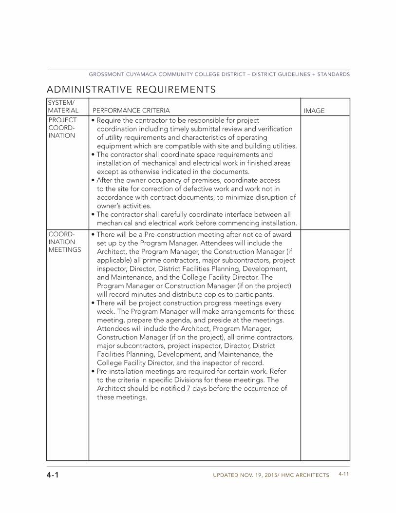
Updated Nov. 19, 2015/ HMC aRCHIteCtS
GRoSSMoNt CUYaMaCa CoMMUNItY CoLLeGe dIStRICt – dIStRICt GUIdeLINeS + StaNdaRdS
4-11
SYSTEM/MATERIAL PERFORMANCE CRITERIA IMAGE
ADMINISTRATIVE REQUIREMENTS
PROJECT COORD-INATION
• Require the contractor to be responsible for projectcoordination including timely submittal review and verificationof utility requirements and characteristics of operatingequipment which are compatible with site and building utilities.
• The contractor shall coordinate space requirements andinstallation of mechanical and electrical work in finished areas except as otherwise indicated in the documents.
• After the owner occupancy of premises, coordinate accessto the site for correction of defective work and work not inaccordance with contract documents, to minimize disruption ofowner’s activities.
• The contractor shall carefully coordinate interface between allmechanical and electrical work before commencing installation.
COORD-INATION MEETINGS
• There will be a Pre-construction meeting after notice of awardset up by the Program Manager. Attendees will include theArchitect, the Program Manager, the Construction Manager (ifapplicable) all prime contractors, major subcontractors, projectinspector, Director, District Facilities Planning, Development,and Maintenance, and the College Facility Director. TheProgram Manager or Construction Manager (if on the project)will record minutes and distribute copies to participants.
• There will be project construction progress meetings everyweek. The Program Manager will make arrangements for thesemeeting, prepare the agenda, and preside at the meetings.Attendees will include the Architect, Program Manager,Construction Manager (if on the project), all prime contractors,major subcontractors, project inspector, Director, DistrictFacilities Planning, Development, and Maintenance, theCollege Facility Director, and the inspector of record.
• Pre-installation meetings are required for certain work. Referto the criteria in specific Divisions for these meetings. TheArchitect should be notified 7 days before the occurrence ofthese meetings.
4-1
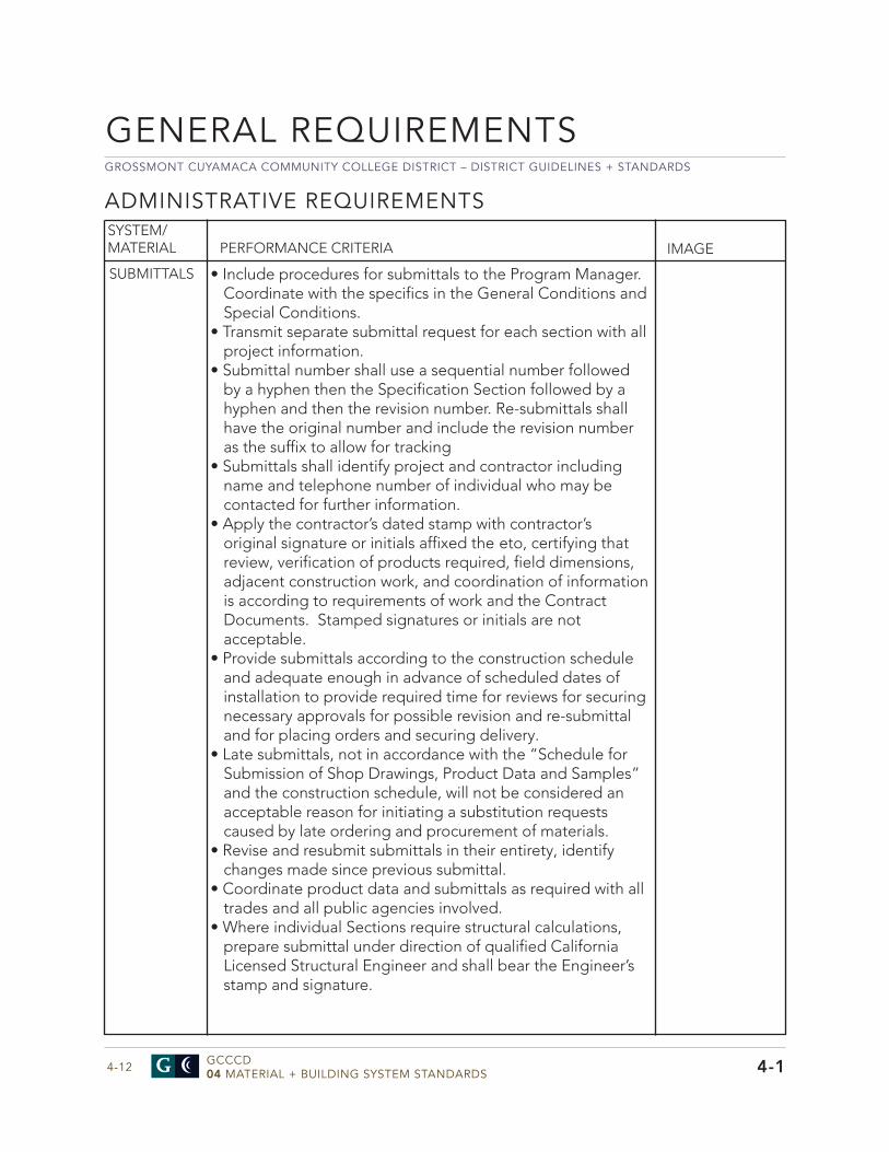
GROSSMONT CUYAMACA COMMUNITY COLLEGE DISTRICT – DISTRICT GUIDELINES + STANDARDS
GCCCD04 MATERIAL + BUILDING SYSTEM STANDARDS4-12
ADMINISTRATIVE REQUIREMENTS
• Include procedures for submittals to the Program Manager.Coordinate with the specifics in the General Conditions andSpecial Conditions.
• Transmit separate submittal request for each section with allproject information.
• Submittal number shall use a sequential number followedby a hyphen then the Specification Section followed by ahyphen and then the revision number. Re-submittals shallhave the original number and include the revision numberas the suffix to allow for tracking
• Submittals shall identify project and contractor includingname and telephone number of individual who may becontacted for further information.
• Apply the contractor’s dated stamp with contractor’soriginal signature or initials affixed the eto, certifying that review, verification of products required, field dimensions, adjacent construction work, and coordination of information is according to requirements of work and the Contract Documents. Stamped signatures or initials are not acceptable.
• Provide submittals according to the construction scheduleand adequate enough in advance of scheduled dates ofinstallation to provide required time for reviews for securingnecessary approvals for possible revision and re-submittaland for placing orders and securing delivery.
• Late submittals, not in accordance with the “Schedule forSubmission of Shop Drawings, Product Data and Samples”and the construction schedule, will not be considered anacceptable reason for initiating a substitution requestscaused by late ordering and procurement of materials.
• Revise and resubmit submittals in their entirety, identifychanges made since previous submittal.
• Coordinate product data and submittals as required with alltrades and all public agencies involved.
• Where individual Sections require structural calculations,prepare submittal under direction of qualified CaliforniaLicensed Structural Engineer and shall bear the Engineer’sstamp and signature.
SYSTEM/MATERIAL PERFORMANCE CRITERIA IMAGE
SUBMITTALS
GENERAL REQUIREMENTS
4-1
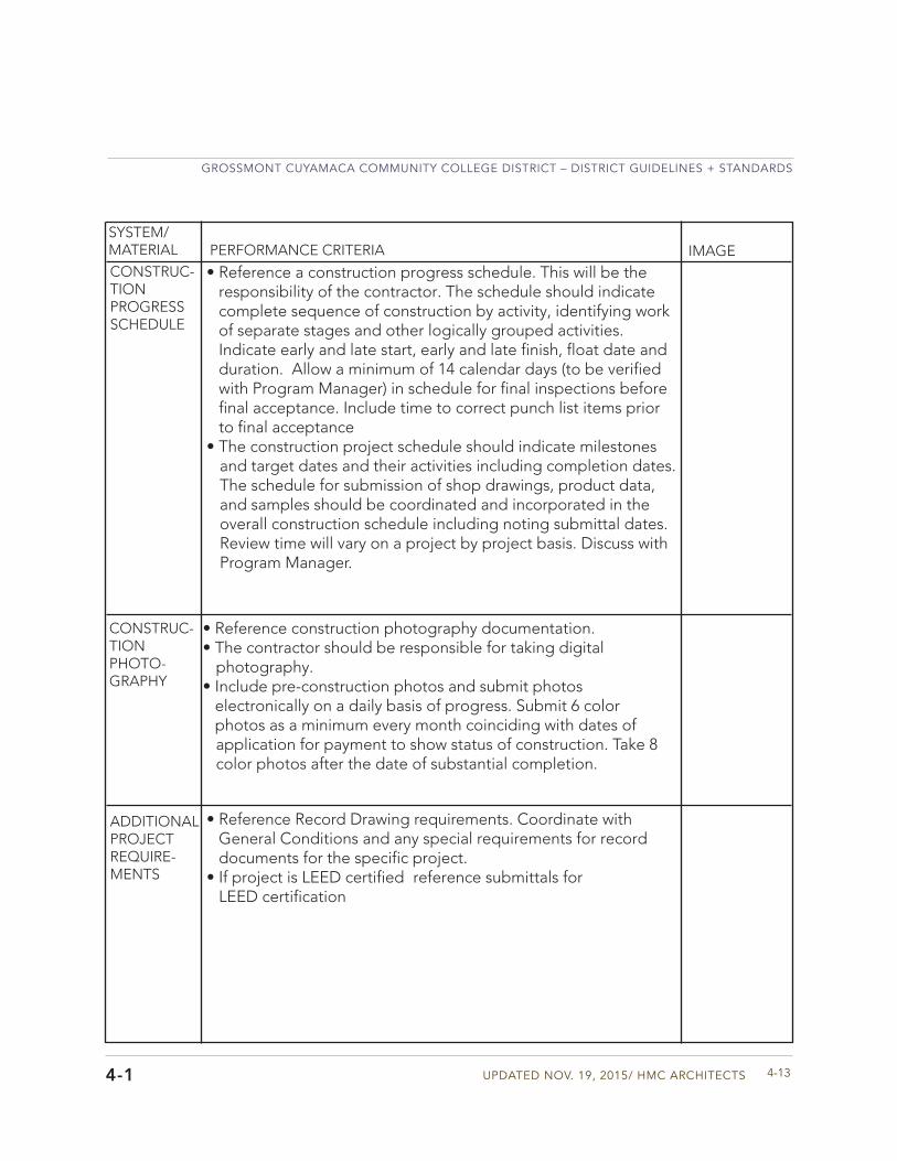
Updated Nov. 19, 2015/ HMC aRCHIteCtS
GRoSSMoNt CUYaMaCa CoMMUNItY CoLLeGe dIStRICt – dIStRICt GUIdeLINeS + StaNdaRdS
4-13
SYSTEM/MATERIAL PERFORMANCE CRITERIA IMAGECONSTRUC-TION PROGRESS SCHEDULE
• Reference a construction progress schedule. This will be the responsibility of the contractor. The schedule should indicate complete sequence of construction by activity, identifying work of separate stages and other logically grouped activities. Indicate early and late start, early and late finish, float date and duration. Allow a minimum of 14 calendar days (to be verified with Program Manager) in schedule for final inspections before final acceptance. Include time to correct punch list items prior to final acceptance
• The construction project schedule should indicate milestonesand target dates and their activities including completion dates.The schedule for submission of shop drawings, product data,and samples should be coordinated and incorporated in theoverall construction schedule including noting submittal dates.Review time will vary on a project by project basis. Discuss withProgram Manager.
CONSTRUC-TION PHOTO-GRAPHY
• Reference construction photography documentation.• The contractor should be responsible for taking digital
photography.• Include pre-construction photos and submit photos
electronically on a daily basis of progress. Submit 6 colorphotos as a minimum every month coinciding with dates ofapplication for payment to show status of construction. Take 8color photos after the date of substantial completion.
ADDITIONAL PROJECT REQUIRE-MENTS
• Reference Record Drawing requirements. Coordinate withGeneral Conditions and any special requirements for recorddocuments for the specific project.
• If project is LEED certified reference submittals forLEED certification
4-1
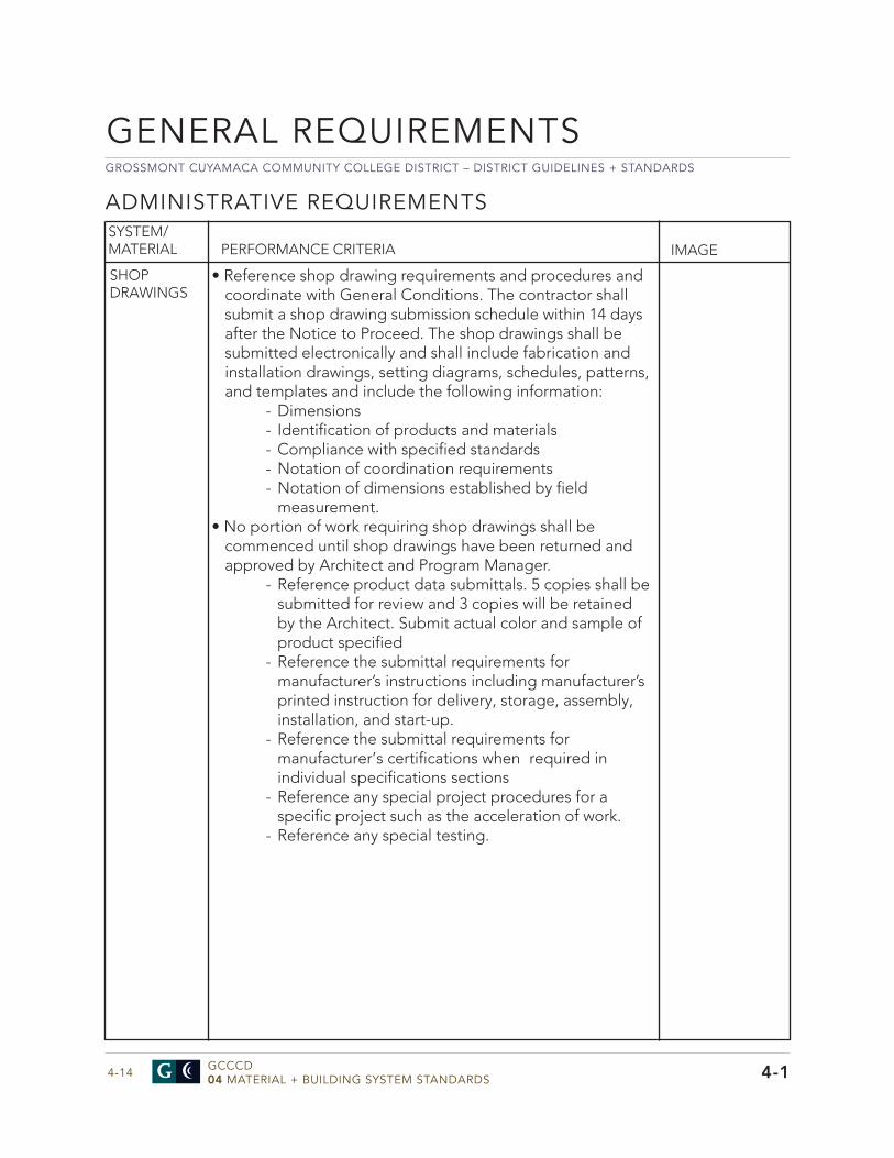
GROSSMONT CUYAMACA COMMUNITY COLLEGE DISTRICT – DISTRICT GUIDELINES + STANDARDS
GCCCD04 MATERIAL + BUILDING SYSTEM STANDARDS4-14
ADMINISTRATIVE REQUIREMENTS
• Reference shop drawing requirements and procedures andcoordinate with General Conditions. The contractor shallsubmit a shop drawing submission schedule within 14 daysafter the Notice to Proceed. The shop drawings shall besubmitted electronically and shall include fabrication andinstallation drawings, setting diagrams, schedules, patterns,and templates and include the following information:
- Dimensions- Identification of products and materials- Compliance with specified standards- Notation of coordination requirements- Notation of dimensions established by field
measurement.• No portion of work requiring shop drawings shall be
commenced until shop drawings have been returned and approved by Architect and Program Manager.
- Reference product data submittals. 5 copies shall be submitted for review and 3 copies will be retained by the Architect. Submit actual color and sample of product specified
- Reference the submittal requirements for manufacturer’s instructions including manufacturer’s printed instruction for delivery, storage, assembly, installation, and start-up.
- Reference the submittal requirements for manufacturer’s certifications when required in individual specifications sections
- Reference any special project procedures for a specific project such as the acceleration of work.
- Reference any special testing.
SYSTEM/MATERIAL PERFORMANCE CRITERIA IMAGE
SHOP DRAWINGS
GENERAL REQUIREMENTS
4-1
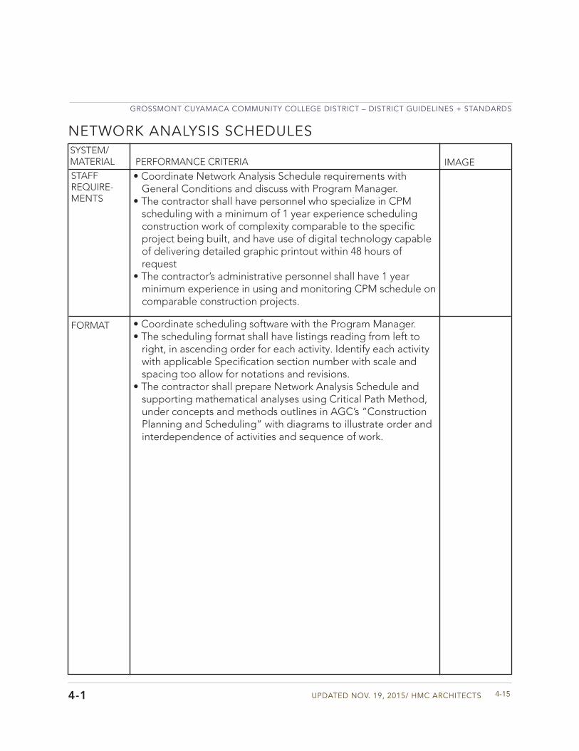
Updated Nov. 19, 2015/ HMC aRCHIteCtS
GRoSSMoNt CUYaMaCa CoMMUNItY CoLLeGe dIStRICt – dIStRICt GUIdeLINeS + StaNdaRdS
4-15
SYSTEM/MATERIAL PERFORMANCE CRITERIA IMAGESTAFF REQUIRE-MENTS
• Coordinate Network Analysis Schedule requirements withGeneral Conditions and discuss with Program Manager.
• The contractor shall have personnel who specialize in CPMscheduling with a minimum of 1 year experience schedulingconstruction work of complexity comparable to the specificproject being built, and have use of digital technology capableof delivering detailed graphic printout within 48 hours ofrequest
• The contractor’s administrative personnel shall have 1 yearminimum experience in using and monitoring CPM schedule oncomparable construction projects.
FORMAT • Coordinate scheduling software with the Program Manager.• The scheduling format shall have listings reading from left to
right, in ascending order for each activity. Identify each activitywith applicable Specification section number with scale andspacing too allow for notations and revisions.
• The contractor shall prepare Network Analysis Schedule andsupporting mathematical analyses using Critical Path Method,under concepts and methods outlines in AGC’s “ConstructionPlanning and Scheduling” with diagrams to illustrate order andinterdependence of activities and sequence of work.
NETWORK ANALYSIS SCHEDULES
4-1
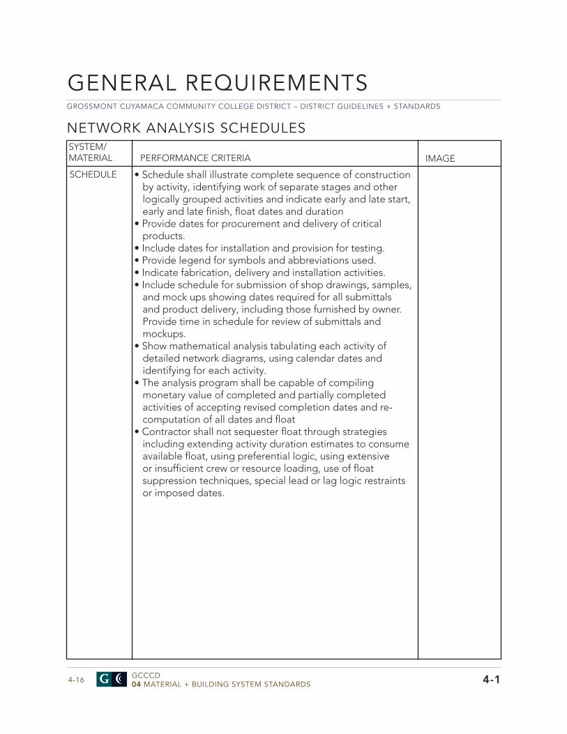
GROSSMONT CUYAMACA COMMUNITY COLLEGE DISTRICT – DISTRICT GUIDELINES + STANDARDS
GCCCD04 MATERIAL + BUILDING SYSTEM STANDARDS4-16
NETWORK ANALYSIS SCHEDULES
• Schedule shall illustrate complete sequence of constructionby activity, identifying work of separate stages and otherlogically grouped activities and indicate early and late start,early and late finish, float dates and duration
• Provide dates for procurement and delivery of criticalproducts.
• Include dates for installation and provision for testing.• Provide legend for symbols and abbreviations used.• Indicate fabrication, delivery and installation activities.• Include schedule for submission of shop drawings, samples,
and mock ups showing dates required for all submittalsand product delivery, including those furnished by owner.Provide time in schedule for review of submittals andmockups.
• Show mathematical analysis tabulating each activity ofdetailed network diagrams, using calendar dates andidentifying for each activity.
• The analysis program shall be capable of compilingmonetary value of completed and partially completedactivities of accepting revised completion dates and re-computation of all dates and float
• Contractor shall not sequester float through strategiesincluding extending activity duration estimates to consume available float, using preferential logic, using extensiveor insufficient crew or resource loading, use of float suppression techniques, special lead or lag logic restraints or imposed dates.
SYSTEM/MATERIAL PERFORMANCE CRITERIA IMAGE
SCHEDULE
GENERAL REQUIREMENTS
4-1
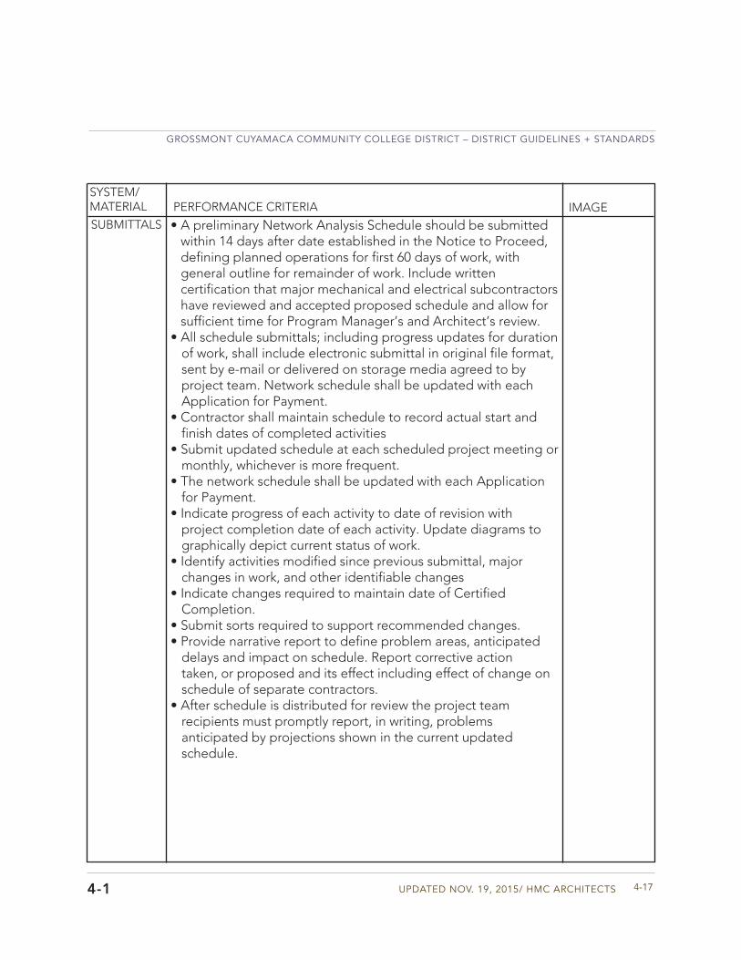
Updated Nov. 19, 2015/ HMC aRCHIteCtS
GRoSSMoNt CUYaMaCa CoMMUNItY CoLLeGe dIStRICt – dIStRICt GUIdeLINeS + StaNdaRdS
4-17
SYSTEM/MATERIAL PERFORMANCE CRITERIA IMAGESUBMITTALS • A preliminary Network Analysis Schedule should be submitted
within 14 days after date established in the Notice to Proceed, defining planned operations for first 60 days of work, with general outline for remainder of work. Include written certification that major mechanical and electrical subcontractors have reviewed and accepted proposed schedule and allow for sufficient time for Program Manager’s and Architect’s review.
• All schedule submittals; including progress updates for durationof work, shall include electronic submittal in original file format,sent by e-mail or delivered on storage media agreed to byproject team. Network schedule shall be updated with eachApplication for Payment.
• Contractor shall maintain schedule to record actual start andfinish dates of completed activities
• Submit updated schedule at each scheduled project meeting ormonthly, whichever is more frequent.
• The network schedule shall be updated with each Applicationfor Payment.
• Indicate progress of each activity to date of revision withproject completion date of each activity. Update diagrams tographically depict current status of work.
• Identify activities modified since previous submittal, majorchanges in work, and other identifiable changes
• Indicate changes required to maintain date of CertifiedCompletion.
• Submit sorts required to support recommended changes.• Provide narrative report to define problem areas, anticipated
delays and impact on schedule. Report corrective actiontaken, or proposed and its effect including effect of change onschedule of separate contractors.
• After schedule is distributed for review the project teamrecipients must promptly report, in writing, problemsanticipated by projections shown in the current updatedschedule.
4-1
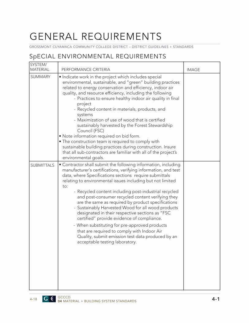
GROSSMONT CUYAMACA COMMUNITY COLLEGE DISTRICT – DISTRICT GUIDELINES + STANDARDS
GCCCD04 MATERIAL + BUILDING SYSTEM STANDARDS4-18
SpECIAL ENVIRONMENTAL REQUIREMENTS
• Indicate work in the project which includes specialenvironmental, sustainable, and “green” building practicesrelated to energy conservation and efficiency, indoor airquality, and resource efficiency, including the following
- Practices to ensure healthy indoor air quality in finalproject
- Recycled content in materials, products, and systems
- Maximization of use of wood that is certifiedsustainably harvested by the Forest Stewardship Council (FSC)
• Note information required on bid form.• The construction team is required to comply with
sustainable building practices during construction. Insurethat all sub-contractors are familiar with all of the project’senvironmental goals.
SYSTEM/MATERIAL PERFORMANCE CRITERIA IMAGE
SUMMARY
• Contractor shall submit the following information, including manufacturer’s certifications, verifying information, and test data, where Specifications sections require submittals relating to environmental issues including but not limited to:
- Recycled content including post-industrial recycled and post-consumer recycled content verifying they are the same as required by product specifications
- Sustainably Harvested Wood for all wood products designated in their respective sections as “FSC certified” provide evidence of compliance.
- When substituting for pre-approved products that are required to comply with Indoor Air Quality, submit emission test data produced by an acceptable testing laboratory.
SUBMITTALS
GENERAL REQUIREMENTS
4-1
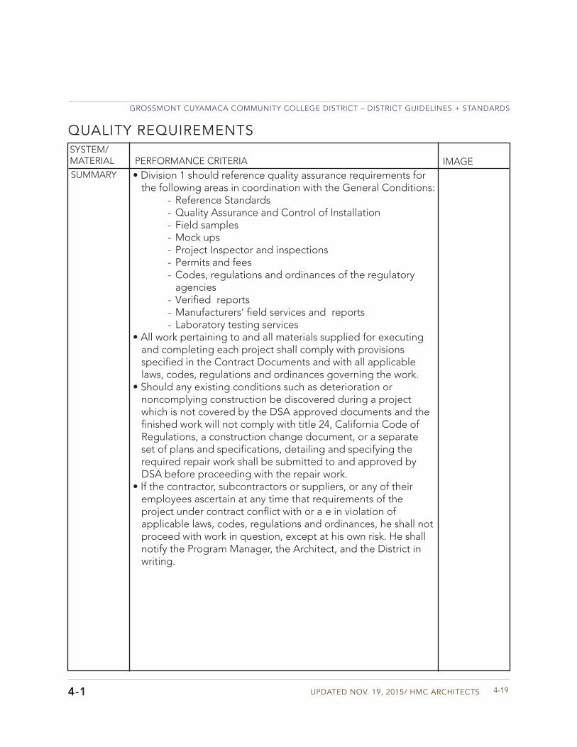
Updated Nov. 19, 2015/ HMC aRCHIteCtS
GRoSSMoNt CUYaMaCa CoMMUNItY CoLLeGe dIStRICt – dIStRICt GUIdeLINeS + StaNdaRdS
4-19
SYSTEM/MATERIAL PERFORMANCE CRITERIA IMAGESUMMARY • Division 1 should reference quality assurance requirements for
the following areas in coordination with the General Conditions: - Reference Standards - Quality Assurance and Control of Installation - Field samples - Mock ups - Project Inspector and inspections - Permits and fees - Codes, regulations and ordinances of the regulatory agencies
- Verified reports- Manufacturers’ field services and reports - Laboratory testing services
• All work pertaining to and all materials supplied for executingand completing each project shall comply with provisions specified in the Contract Documents and with all applicablelaws, codes, regulations and ordinances governing the work.
• Should any existing conditions such as deterioration ornoncomplying construction be discovered during a project which is not covered by the DSA approved documents and the finished work will not comply with title 24, California Code of Regulations, a construction change document, or a separate set of plans and specifications, detailing and specifying the required repair work shall be submitted to and approved by DSA before proceeding with the repair work.
• If the contractor, subcontractors or suppliers, or any of theiremployees ascertain at any time that requirements of the project under contract conflict with or a e in violation of applicable laws, codes, regulations and ordinances, he shall not proceed with work in question, except at his own risk. He shall notify the Program Manager, the Architect, and the District in writing.
QUALITY REQUIREMENTS
4-1
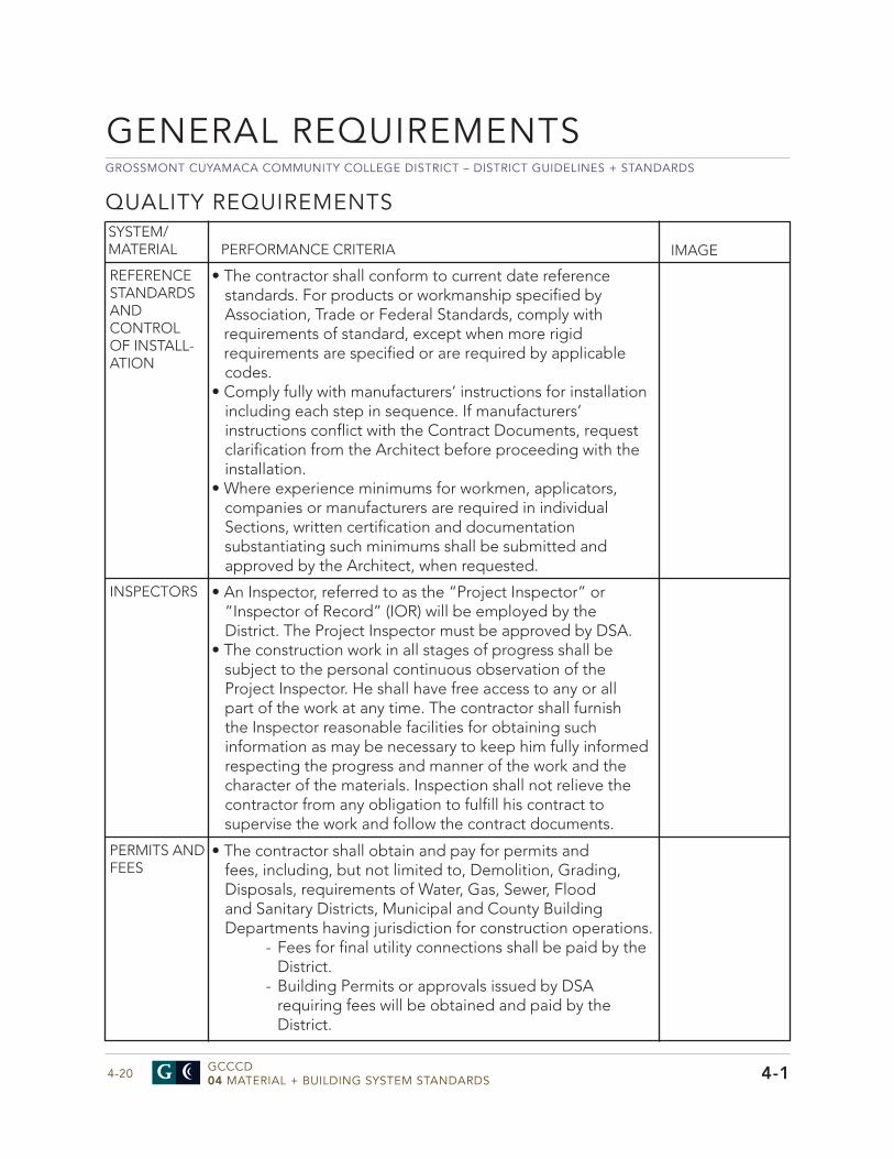
GROSSMONT CUYAMACA COMMUNITY COLLEGE DISTRICT – DISTRICT GUIDELINES + STANDARDS
GCCCD04 MATERIAL + BUILDING SYSTEM STANDARDS4-20
QUALITY REQUIREMENTS
• The contractor shall conform to current date reference standards. For products or workmanship specified by Association, Trade or Federal Standards, comply with requirements of standard, except when more rigid requirements are specified or are required by applicable codes.
• Comply fully with manufacturers’ instructions for installationincluding each step in sequence. If manufacturers’ instructions conflict with the Contract Documents, request clarification from the Architect before proceeding with the installation.
• Where experience minimums for workmen, applicators,companies or manufacturers are required in individualSections, written certification and documentationsubstantiating such minimums shall be submitted andapproved by the Architect, when requested.
SYSTEM/MATERIAL PERFORMANCE CRITERIA IMAGE
REFERENCE STANDARDS AND CONTROL OF INSTALL-ATION
• An Inspector, referred to as the “Project Inspector” or“Inspector of Record” (IOR) will be employed by theDistrict. The Project Inspector must be approved by DSA.
• The construction work in all stages of progress shall besubject to the personal continuous observation of theProject Inspector. He shall have free access to any or allpart of the work at any time. The contractor shall furnishthe Inspector reasonable facilities for obtaining suchinformation as may be necessary to keep him fully informedrespecting the progress and manner of the work and thecharacter of the materials. Inspection shall not relieve thecontractor from any obligation to fulfill his contract tosupervise the work and follow the contract documents.
INSPECTORS
• The contractor shall obtain and pay for permits andfees, including, but not limited to, Demolition, Grading,Disposals, requirements of Water, Gas, Sewer, Floodand Sanitary Districts, Municipal and County BuildingDepartments having jurisdiction for construction operations.
- Fees for final utility connections shall be paid by theDistrict.
- Building Permits or approvals issued by DSA requiring fees will be obtained and paid by the District.
PERMITS AND FEES
GENERAL REQUIREMENTS
4-1
Updated Nov. 19, 2015/ HMC aRCHIteCtS
GRoSSMoNt CUYaMaCa CoMMUNItY CoLLeGe dIStRICt – dIStRICt GUIdeLINeS + StaNdaRdS
4-21
SYSTEM/MATERIAL PERFORMANCE CRITERIA IMAGEVERIFIED REPORTS
• The contractor shall comply with CAC and issue verified reports through the Architect as required. The Program Manager and District shall be copied on all verified reports.
MANU-FACTURERS’ FIELD SERVICES AND REPORTS
• When specified in individual Specification Sections, product suppliers or manufacturers shall provide qualified staff personnel to observe site conditions, conditions of surfaces and installation, quality of workmanship, start-up of equipment, test, adjust and balance of equipment and as applicable, initiate instructions when necessary.
• Manufacturers’ representatives shall provide a written report ofobservations, site decisions or instructions given to applicatorsor installers that are supplemental or contrary to manufacturers’written instructions submitted to the Program Manager,Architect, and District.
4-1
GROSSMONT CUYAMACA COMMUNITY COLLEGE DISTRICT – DISTRICT GUIDELINES + STANDARDS
GCCCD04 MATERIAL + BUILDING SYSTEM STANDARDS4-22
QUALITY REQUIREMENTS
• The District will employ and pay for services of independenttesting laboratory and special inspectors approved by theArchitect and DSA to perform inspection and testing.
• Offsite fabrication requiring inspection and testing: submitthe qualifications of inspectors and laboratory, includingproposals for services, to the District, Program Manager andArchitect for approval of qualifications and costs
• For initial testing required for a project the District shall paythe IOR, Testing Laboratory or both.
• When initial testing fails, the IOR and Testing Laboratorycosts attributable to required retesting shall be borne by thecontractor and deducted by change order from funds due.
• When tests and inspections are required on an overtimebasis, initial payment will be made by District. At completionof the project, all costs for overtime testing and inspectionswill be deducted from the contractor’s final payment bychange order.
• When materials tested fail to meet requirements specified,they shall be promptly corrected, removed and replaced, re-inspected/retested in a manner required by the Architect.
• Submit laboratory reports verifying tests and inspectionsrequired have been completed and complies with thecontract documents.
• Laboratories shall be licensed to conduct testing andinspection operations in California and shall be approved byDSA and supervised by a State Licensed Civil Engineer whoshall certify and sign all reports.
• Immediately upon testing laboratory determination of atest failure, the laboratory shall telephone the results of testto the Program Manager and Architect. On the same day,laboratory shall send written test results to the District, IOR,special inspector, the contractor, and the structural engineer.
• Laboratory testing authority and the contractor’sresponsibilities should be outlined.
- The laboratory should not alter requirements of contract documents.
- The laboratory may not approve or accept any portion of the work or assume contractor’s responsibilities including stopping work or interpreting codes.
SYSTEM/MATERIAL PERFORMANCE CRITERIA IMAGE
LABORATORY TESTING
GENERAL REQUIREMENTS
4-1
Updated Nov. 19, 2015/ HMC aRCHIteCtS
GRoSSMoNt CUYaMaCa CoMMUNItY CoLLeGe dIStRICt – dIStRICt GUIdeLINeS + StaNdaRdS
4-23
SYSTEM/MATERIAL PERFORMANCE CRITERIA IMAGE
- The contractor shall deliver to laboratory at designated location, adequate samples of materials proposed to be used which require testing. Selection of materials to be tested shall be by the laboratory or District’s representative and not by the contractor.
- The contractor shall notify the Program Manager, the Architect, Project Inspector and laboratory 48 hours prior to expected time for operations requiring inspection and testing services.
- The contractor shall execute and submit a Statement of Responsibility regarding special inspections and testing required for principle wind- and seismic-load bearing systems to the Project Inspector, Program Manager, and the Architect.
- The District, Project Inspector, or the Architect shall have the right to reject materials and workmanship that are defective or to require their correction. Rejected workmanship shall be satisfactorily corrected and rejected materials shall be removed from the premises without cost to the District. If the contractor fails to correct such rejected work within a reasonable time, outlined by written notice, the District will correct the work and charge the expense to the contractor by change order.
- If the testing laboratory is ready to test according to the established schedule, but is prevented from testing or taking specimens due to incompleteness of the work, extra charges for testing attributable to the delay shall be charged to the contractor by change order.
- Any material shipped by the contractor from the source of supply prior to having satisfactorily passed designated testing and inspection or prior to the receipt of notice from said representative that such testing and inspection will not be required, shall not be incorporated in the project.
• Schedule of Structural tests and inspections. - Field testing of concrete slabs, moisture testing per ASTM F1869 -2009. The test area should be at the
4-1
GROSSMONT CUYAMACA COMMUNITY COLLEGE DISTRICT – DISTRICT GUIDELINES + STANDARDS
GCCCD04 MATERIAL + BUILDING SYSTEM STANDARDS4-24
QUALITY REQUIREMENTSSYSTEM/MATERIAL PERFORMANCE CRITERIA IMAGE
same temperature and humidity expected during normal use, minimum testing conditions shall be 75+ 10 degrees F. and 50+ 10% relative humidity. Maintain these conditions 48 hours prior to, and during testing. Alkalinity testing: per ASTM F710, ranges shall not exceed those recommended by the flooring manufacturer.
- Anchors complying with requirements of DSA Interpretations of Regulations (IR) 19-1 and allowable shear and tension values and test loads shall be acceptable to DSA. Post-installed anchors must be listed in a current evaluation report issued by an evaluation agency recognized by DSA.
- Reports shall be submitted to the Program Manager, Architect, and District. All requirements for expansion-type anchors and epoxy-type adhesive anchors as well as testing for these anchors should be outlined in Quality Requirements of Division 1.
- Powder-actuated fasteners may be used for limited application provided they meet allowable shear and tension loads. Quality Requirements of Division 1 should outline the requirements, when fasteners can be used, and required testing.
GENERAL REQUIREMENTS
4-1
Updated Nov. 19, 2015/ HMC aRCHIteCtS
GRoSSMoNt CUYaMaCa CoMMUNItY CoLLeGe dIStRICt – dIStRICt GUIdeLINeS + StaNdaRdS
4-25
SYSTEM/MATERIAL PERFORMANCE CRITERIA IMAGESUMMARY • Division 1 should reference the following areas information for
Temporary Facilities and Controls: - Temporary Utilities - Temporary controls including exterior and interior barriers, enclosures, fencing, protection of work, and security
- Construction facilities including project site access, parking, progress cleaning, project sign, and field office trailer
- Special Controls including waste management disposal facilities, water control, dust control, erosion and sediment Control, noise control, pollution control.
- Fire safety during construction through all phases of the project complying with all code and state and fi e local requirements
- Many requirements will be made on a project by project basis depending on the nature and location of the project. All details for Temporary Construction Facilities Controls should be developed collaboratively with the Program Manager, District, and College.
• The contractor shall provide a site plan to show temporaryfacilities, utility hookups, staging areas, and parking areas for construction personnel and a phasing plan. Concept construction and phasing plans may be included in the Contract Documents and contractor submittal plans will confirmacceptance and provide additional detail.
• The contractor with the District and Program Manager shallcoordinate location, extent and type of construction staging area.
• The contractor shall provide and maintain required facilities andenclosures. Existing facilities shall not be used.
TEMpORARY FACILITIES AND CONTROLS
4-1
GROSSMONT CUYAMACA COMMUNITY COLLEGE DISTRICT – DISTRICT GUIDELINES + STANDARDS
GCCCD04 MATERIAL + BUILDING SYSTEM STANDARDS4-26
TEMpORARY FACILITIES AND CONTROLSSYSTEM/MATERIAL PERFORMANCE CRITERIA IMAGE
TEMPORARY CONTROLS
• The contractor shall provide barriers to preventunauthorized entry to construction areas and to protectexisting facilities, and adjacent properties from damagefrom construction operations and demolition and allow fordaily activities at the College. Coordinate with College.
• Contractor shall protect installed work and provide specialprotection where specified in individual SpecificationSections and prohibit traffic from newly landscaped.
• Contractor shall construct and maintain temporary roadsaccessing public thoroughfares to serve construction areaand modify as needed, public access to parking lots.
• Contractor shall provide means of removing mud fromvehicle wheels before entering streets.
SAFETY AND SECURITY
• The contractor shall provide and maintain access to fi ehydrants, free of obstructions. Where required by localfi e authority, provide and maintain a 26 foot wide fi eapparatus access road.
• Coordinate with District’s security program and campuspolice. Replace or repair, to District’s satisfaction, allsurfaces or items damaged by graffiti during course ofconstruction within 48 hours.
• Where security or fi e detection systems are disabled forany reason, including where District/College has givenapproval for such system shutdown, provide fi e watch andsecurity guard service as directed by District/College at noadditional cost to the project.
FIELDOFFICE
• The contractor shall provide a field office trailer.• The facility shall be weather tight with lighting, electrical
outlets, communications capabilities, heating, cooling andventilating equipment and equipped to adequately conductmeetings for construction operations, minimum size; 480 sq.ft.
• Quantity of portable chemical toilet facilities shall be basedon total number of workers and shall be in accordance withCAL/OSHA standards
• Cost of use permits, occupancy permits and related fees,if any required by Governing Authorities for temporaryconstruction facilities, shall be paid by the contractor.
• Maintain facility until Substantial Completion of entireproject. Remove within 1 week of Substantial Completion.
GENERAL REQUIREMENTS
4-1
Updated Nov. 19, 2015/ HMC aRCHIteCtS
GRoSSMoNt CUYaMaCa CoMMUNItY CoLLeGe dIStRICt – dIStRICt GUIdeLINeS + StaNdaRdS
4-27
SYSTEM/MATERIAL PERFORMANCE CRITERIA IMAGEPROTECTIONOF WORK
• The contractor is responsible for protecting completed work.• The contractor is responsible for the proper care and
protection of all materials and equipment on the site.• Provide temporary and removable protection for installed
products. Control activity in immediate work area to minimizedamage.
• Prohibit traffic from landscaped areas.• The contractor shall provide property insurance and protection.• The contractor shall remove temporary above grade or buried
utilities, equipment, facilities, materials prior to CertifiedCompletion inspection and clean and repair damage causedby installation or use of temporary work.
RELOCATIONOF UTILITIES
• The relocation of the any utilities should be addressed in theTemporary Facilities and Controls Section of Division 1.
• This section should be coordinated with the Project Manager,District and College.
• The contractor shall not have responsibility of removal,relocation or protection of public utility facilities that are notidentified by the District in the construction documents. TheDistrict shall compensate the contractor for costs of locatingand repairing damage not due to failure of contractor toexercise reasonable care in removing and relocating suchpublic utility facilities.
• If the contractor, while performing the contract, discoverspublic utility facilities not identified in the contract documents,he shall immediately notify the District and utility in writing.Contractor shall not be assessed liquidated damages for delaywhen delay was caused by failure of the District to provide forrelocation for utility facilities.
4-1
GROSSMONT CUYAMACA COMMUNITY COLLEGE DISTRICT – DISTRICT GUIDELINES + STANDARDS
GCCCD04 MATERIAL + BUILDING SYSTEM STANDARDS4-28
TEMpORARY FACILITIES AND CONTROLSSYSTEM/MATERIAL PERFORMANCE CRITERIA IMAGE
POLLUTION + NOISECONTROL
• Water control should be addressed. Surface water, rainwateror subsurface water or other liquids should not be allowedto accumulate in or about premises and project vicinity.Should such conditions be encountered or develop, controlwater or other liquid shall be suitably disposed of by meansof temporary pumps, piping, drainage lines, troughs,ditches, dams or other methods as reviewed by the ProgramManager and the Architect and approved by authorityhaving jurisdiction.
• Dust control should be addressed. - Earthwork operations must be conducted in a manner to prevent windblown dust and dirt from interfering with progress of work, the College’s activities in existing occupied structures and in areas immediately adjacent as well. Dry high winds often occur on both campuses and constant precaution should be taken to control dirt and dust on the campus.
- Water construction areas as required minimizing accumulation of dust and dirt.
- Water spray or cover with tarpaulins truckloads of soil to additionally minimize generation of dust and dirt from construction operations.
- Prevent dust and dirt from accumulating on walks, roadways, parking areas and from washing into sewer and storm drain lines.
• Erosion and sediment control should be addressed. - The contractor should plan and execute construction by methods to control surface drainage from cuts and fills from borrow and waste disposal areas. Prevent erosion and sedimentation.
- The contractor should construct fill and waste areas by selective placement to avoid erosive surface silts or clays.
- Earthwork should be inspected to detect evidence of erosion and sedimentation; and promptly corrected if there is a problem.
- This section should be coordinated with the Storm Water Pollution Prevention Plan (SWPP) requirements.
GENERAL REQUIREMENTS
4-1
Updated Nov. 19, 2015/ HMC aRCHIteCtS
GRoSSMoNt CUYaMaCa CoMMUNItY CoLLeGe dIStRICt – dIStRICt GUIdeLINeS + StaNdaRdS
4-29
SYSTEM/MATERIAL PERFORMANCE CRITERIA IMAGE
• Noise control should be addressed. Excessive noise whereadjacent to College functions should be avoided. Coordinatework with excessive noise with the College for appropriatetiming of work.
- The contractor should provide a Noise Control Plan after the contract is awarded, prior to the commencement of the work. The contractor shall meet with the District, the Program Manager, and the College to discuss the proposed Noise Control Plan and to develop mutual understanding relative to College functions and needs and details of the plan.
• Pollution control should be addressed. - The contractor should provide methods, means and facilities to prevent contamination of soil, water and atmosphere from discharge of noxious, toxic substances and pollutants produced by construction operations. Approach and procedures must comply with state and local regulatory requirements and anti-pollution ordinances during course of construction and disposal operations.
- Burning of refuse, debris or other materials will not be permitted on site.
• Waste disposal facilities should be addressed and coordinatedwith input from the District, the Program Manager, and the College.
- Comply with requirements of authorities having jurisdiction. Remove loose refuse and dispose off site legally.
- The contractor shall provide and maintain trash bins of appropriate size on the project site. Trash bins shall be serviced on an as needed basis or as designated by the District and College.
- The contractor shall provide enclosed waste chutes for higher fall over 8 ft. Provide disposals sufficiently sizedto prevent debris from scattering around areas.
- When using demolition chutes on a project, chute opening must be sealed when not in use. The chute and dumpster shall be sprayed with water to maintain dust control.
4-1
GROSSMONT CUYAMACA COMMUNITY COLLEGE DISTRICT – DISTRICT GUIDELINES + STANDARDS
GCCCD04 MATERIAL + BUILDING SYSTEM STANDARDS4-30
TEMpORARY FACILITIES AND CONTROLSSYSTEM/MATERIAL PERFORMANCE CRITERIA IMAGE
- Do not use the College’s disposal systems or any waste or recycling bins.
GENERAL REQUIREMENTS
4-1
Updated Nov. 19, 2015/ HMC aRCHIteCtS
GRoSSMoNt CUYaMaCa CoMMUNItY CoLLeGe dIStRICt – dIStRICt GUIdeLINeS + StaNdaRdS
4-31
SYSTEM/MATERIAL PERFORMANCE CRITERIA IMAGE
PROTECTIONOF EXISTING FACILITIES
• Protection of existing facilities and sitework should beaddressed. Coordinate with the Program Manager, District,and College to develop a site plan showing proposed routeof construction equipment and how disturbance and damageto existing sitework will be minimized. This will become part ofthe contract documents.
• The contractor shall protect sidewalks, curbs, entry areas andutilities.
• The contractor shall preserve and protect all structures,equipment, and vegetation (such as trees, shrubs, and grass)and irrigation on or adjacent to the work site, which are notto be removed and which do not unreasonably interfere withthe work required under this contract. The contractor shallonly remove trees when specifically authorized to do so, andshall avoid damaging vegetation that will remain in place.If any limbs or branches of trees are broken during contractperformance, or by the careless operation of equipment,or by workmen, the contractor shall trim those limbs orbranches with a clean cut and paint the cut with a tree pruningcompound as directed by the Program Manager and incoordination with the District and College.
• The contractor shall protect from damage all existingimprovements and utilities at or near the work site and onadjacent property of a third party, the locations of which aremade known to or should be known by the contractor. Thecontractor shall be responsible to repair any damage to thosefacilities, including those that are the property of a third party,resulting from failure to comply with the requirements of thiscontract or failure to exercise reasonable care in performingthe work.
• The contractor is responsible to repair landscaped areas,irrigation and sidewalks and any other damaged facilitieswhere trucks, erection equipment or other constructionequipment were used in removal and replacement of anyequipment during construction, repairing damaged areas tomatch existing construction to satisfaction of the District andCollege, and at no additional cost to the District.
• The contractor is responsible is responsible for cleaning upnails, and all construction debris to protect against personal orvehicular harm.
4-1
GROSSMONT CUYAMACA COMMUNITY COLLEGE DISTRICT – DISTRICT GUIDELINES + STANDARDS
GCCCD04 MATERIAL + BUILDING SYSTEM STANDARDS4-32
TEMpORARY FACILITIES AND CONTROLSSYSTEM/MATERIAL PERFORMANCE CRITERIA IMAGE
DRESS CODE • The contractor conduct and dress code should beaddressed.
• Contractor’s and subcontractors’ personnel shallobserve and abide by District and College requirementsconcerning appropriate conduct, loud noise (unrelated toconstruction activities) and dress requirements for a safeand un-disturbing work place. Conduct work activities in aprofessional manner at all times.
• Dress Code requirements include contractor’s personnelshall wear traditional work attire or uniforms without logos,graphics or wording detrimental to a college environment.Logos, graphics or wording for business identificationpurposes are acceptable.
• Contractors and subcontractors shall wear orange safetyvests along with other required safety attire including hard hats and safety glasses.
• Identification badges issued by the District shall be worn atall times and displayed in full view and not concealed.
• No radios are permitted on the job site.• The District/College reserves the right to remove any
person(s) not observing conduct and dress requirements specified herein.
GENERAL REQUIREMENTS
4-1
ANIMALS • Contractors’ and workers’ pets or animals any kind or notpermitted on the campus, including being retained in avehicle.
Updated Nov. 19, 2015/ HMC aRCHIteCtS
GRoSSMoNt CUYaMaCa CoMMUNItY CoLLeGe dIStRICt – dIStRICt GUIdeLINeS + StaNdaRdS
4-33
SYSTEM/MATERIAL PERFORMANCE CRITERIA IMAGE
MOBILIzATION • Mobilization and demobilization should be addressed.• This section should be coordinated with the Program Manager,
the District, and the College.• The work consists of the mobilization and demobilization
of the contractor’s forces and equipment necessary for performing the work required under the contract. It does not include mobilization and demobilization for specific items ofwork for which payment is provided elsewhere in the contract. Mobilization will not be considered as work in fulfilling thecontract requirements for commencement of work.
- Mobilization shall include all activities and associated costs for transportation of contractor’s personnel, equipment, and operating supplies to the site; establishment of offices, buildings, and other necessarygeneral facilities for the contractor’s operations at the site; premiums paid for performance and payment bonds including coinsurance and reinsurance agreements as applicable.
- Demobilization shall include all activities and costs for transportation of personnel, equipment, and supplies not required or included in the contract from the site; including the disassembly, removal, and site cleanup of offices, buildings, and other facilities assembled on thesite specifically for this contract
- This work includes mobilization and demobilization required by the contract at the time of award. If additional mobilization and demobilization activities and costs are required during the performance of the contract as a result of changed, deleted, or added items of work for which the contractor is entitled to an adjustment in contract price, compensation for such costs will be included in the price adjustment for the item or items of work changed or added.
4-1
GROSSMONT CUYAMACA COMMUNITY COLLEGE DISTRICT – DISTRICT GUIDELINES + STANDARDS
GCCCD04 MATERIAL + BUILDING SYSTEM STANDARDS4-34
TEMpORARY FACILITIES AND CONTROLSSYSTEM/MATERIAL PERFORMANCE CRITERIA IMAGE
INTERIM LIFE SAFETYMEASURES
• INTERIM LIFE SAFETY MEASURES (ILSM) should beaddressed.
• This section should be coordinated with all applicablecodes and local requirements. This section should becoordinated with the Program Manager, the District, andthe Sheriff on site.
• The contractor shall ensure that exits provide free and un-obstructive egress.
• The contractor shall ensure free and unobstructed access toemergency departments and services for emergency forces.
• The contractor shall ensure that fi e alarm, detection,and suppression systems, as well as structural andcompartmentalized features of fi e safety outside theconstruction area are not impaired or compromised.
• The contractor shall ensure that temporary constructionbarricades and barricade doors are smoke tight and madeof non-combustible or limited combustible materials thatwill not contribute to the development of smoke or fi e.
• The contractor shall provide a Safety Standards Proceduresmanual to the Program Manager and District upon contract.
• The contractor shall provide additional fi e-fightingequipment and user-training for his personnel.
• The contractor shall ensure the prohibition of smoking byhis personnel.
• The contractor shall develop and enforce storage anddebris-removal practices that reduce the flammable andcombustible fi e load of the construction area to the lowestlevel necessary for daily operations.
• The contractor shall conduct a minimum of one fi e drillevery month throughout the duration of the project.
• The contractor shall provide daily hazard surveillance ofthe construction area with special attention to excavations, construction storage, and field offices
• The contractor shall track all safety occurrences and providea log to the Program Manager each week.
GENERAL REQUIREMENTS
4-1
Updated Nov. 19, 2015/ HMC aRCHIteCtS
GRoSSMoNt CUYaMaCa CoMMUNItY CoLLeGe dIStRICt – dIStRICt GUIdeLINeS + StaNdaRdS
4-35
SYSTEM/MATERIAL PERFORMANCE CRITERIA IMAGE
MATERIALS • Materials for temporary work may be new or used but areadequate in capacity for required use and loads.
• Electrical materials should be appropriate for the project andmeet all code requirements. Special project needs for thissection should be reviewed with the Project Manager, theDistrict, and the College.
• Portable and fixed mechanical equipment may be new orused, temporary units that will not damage constructionmaterials or processes, that will not create unhealthyconditions for workers and that can be operated withapproval from the authorities having jurisdiction. Only devisesthat burn either natural gas or fuel oil may be used.
4-1
GROSSMONT CUYAMACA COMMUNITY COLLEGE DISTRICT – DISTRICT GUIDELINES + STANDARDS
GCCCD04 MATERIAL + BUILDING SYSTEM STANDARDS4-36
VEHICULAR ACCESS AND pARKINGSYSTEM/MATERIAL PERFORMANCE CRITERIA IMAGE
SUMMARY • Division 1 should reference the following areas informationfor Vehicular Access and Parking:
- Signs, Signals and devices - Construction Parking Control - Access from both land and air - Flagmen - Flares and Lights - Hauling Routes - Traffic Signs and Signal - Removal of construction signs
• Coordinate this section on a per project basis with theProgram Manager, the District, the Sheriff, the Collage, and the CAPS office .
• Confine construction traffic to designated haul routes.• Provide traffic control at critical areas of haul routes to
regulate traffic, to minimize interference with public traffic
GENERAL REQUIREMENTS
4-1
Updated Nov. 19, 2015/ HMC aRCHIteCtS
GRoSSMoNt CUYaMaCa CoMMUNItY CoLLeGe dIStRICt – dIStRICt GUIdeLINeS + StaNdaRdS
4-37
SYSTEM/MATERIAL PERFORMANCE CRITERIA IMAGE
SUMMARY • Division 1 should address control of construction noise on theproject sites.
• This section should specify the control of noise arising fromconstruction operations and associated activities.
• Noise control measures specified are an obligation of thecontractor with the costs included within the various contractitems of work.
• After the contract is awarded, prior to the commencementof the work, the contractor shall meet with the ProgramManager, the District, and the College to discuss theproposed Noise Control Plan and to develop mutualunderstanding relative to details of the plan.
• The plan should outline time duration of any noise and theimpact of the noise.
CONTROL OF CONSTRUCTION NOISE
4-1
NOISECONTROL
• The contractor should provide equipment, sound-deadeningdevices, and take noise abatement measures that arenecessary to comply with the requirements specified in theplan.
• Sound level for noise exposure due to the construction shallbe measured every 5 successive working days while loudwork is performed.
• Design team shall coordinate with Program Managerand District to identify specific construction noise controlmitigation measures on a project by project basis.
GROSSMONT CUYAMACA COMMUNITY COLLEGE DISTRICT – DISTRICT GUIDELINES + STANDARDS
GCCCD04 MATERIAL + BUILDING SYSTEM STANDARDS4-38
STORM WATER pOLLUTION CONTROLSYSTEM/MATERIAL PERFORMANCE CRITERIA IMAGE
SUMMARY • Division 1 should address Storm Water Pollution Control forthe project. This section should be written and coordinatedwith the project civil engineer.
• Requirements for compliance with the Storm WaterPollution Prevention Plan (SWPPP) developed specificallyfor a project are the responsibility of the civil engineer.
- SWPPP shall satisfy mandates of Federal Clean Water Act as enforced by State of California Water Resources Control Board and its Regional Water Quality Boards and all other applicable requirements.
- The civil engineer is responsible for filing the Noticeof Intent and obtaining the permit.
- The civil engineer is responsible for payment of application and annual fees required by the State Water Resources Control Board (SWRCB) up until the date of Substantial Completion and will be reimbursed by the District or compensated in their fee.
• SWPPP requires compliance of all trades on project that useor manipulate materials of any nature which can potentially enter natural storm-water drainage system.
• Representative materials controlled by SWPPP includeerosion of native soils and fill materials, leakage or spillsfrom construction vehicles and machinery, stored fuels, concrete truck washout, chemical treatments, curing, compounds, paints, plasters, paving materials, adhesives and sealants, trash and general construction debris, pesticides, fertilizers, and any other material which can be carried by running water or percolate into earth.
• The contractor is required to submit documentationcertifying compliance with the SWPPP and notification ofagencies of completion of operations providing all closeout submittals and documents.
• The contractor shall be responsible for paying thenecessary permit fees and complying with State Water Resources Control Board Order No. 92-08-DWQ, implementing provisions of the Clean Water Act relating to storm water discharges.
• The civil engineer shall obtain the necessary General Permit
GENERAL REQUIREMENTS
4-1
Updated Nov. 19, 2015/ HMC aRCHIteCtS
GRoSSMoNt CUYaMaCa CoMMUNItY CoLLeGe dIStRICt – dIStRICt GUIdeLINeS + StaNdaRdS
4-39
SYSTEM/MATERIAL PERFORMANCE CRITERIA IMAGE
SUMMARY
CONTROL OF CONSTRUCTION NOISE
4-1
from the State Water Resources Control Board and develop and implement Storm Water Pollution Prevention Plan in accordance with the State Water Resources Control Board requirements prior to commencing any portion of construction that will disturb land (i.e.; excavation, grading, etc.).
• A copy of the plan shall be provided to the ProgramManager, the District and the Architect and the civil engineer shall certify, in writing, compliance with the relevant rules, regulations and laws.
• At completion of work, the contractor shall remove temporarySWPPP measures and dispose of any pollutants in legal manner offsite, or as otherwise required by SWPPP.
• The civil engineer shall prepare and file closeoutdocumentation certifying compliance with the requirements of the SWPPP in original form to the approving agencies and copies to the Program Manger, the District and the Architect.
GROSSMONT CUYAMACA COMMUNITY COLLEGE DISTRICT – DISTRICT GUIDELINES + STANDARDS
GCCCD04 MATERIAL + BUILDING SYSTEM STANDARDS4-40
pRODUCT REQUIREMENTSSYSTEM/MATERIAL PERFORMANCE CRITERIA IMAGE
SUMMARY • Division 1 should address General Product Requirementsfor the project including:
- Definition of products- Transportation and handling of products - Storage and protection- Product options- Substitutions
• Where products are specified by reference standards or bydescription only, provide products meeting those standards or that description, made by a manufacturer acceptable to the Architect. Where products are specified by namingone or more manufacturers, provide products of one of the named manufacturers that meets or exceeds specifications
• Where any specific article, device, equipment, product,material, fixture, patented process, form, method, or type of construction is indicated or specified by name, make, trade name, or catalog number, whether with or without the phrase “or equal,” such specification shall be deemed to establish the minimum qualities of function, dimension, appearance, and performance (collectively the Basis of Design) for that material, process, or article. Such specification shall be deemed to be followed by the phrase “or equal.” When the phrase “or equal” is used or implied, it shall mean an equivalent product, approved by the Architect in accordance with the specific requirements.
• Manufacturers and products listed in Specificationsform basis for design and quality intended. Bidders may propose substitutions of equal design and quality and must be accompanied by completed Request Form in the bidding documents. Submit separate form for each proposed substitution. Substitution requests, if any, shall be submitted to the Architect 10 calendar days prior to the bid opening date. The Architect will issue addenda if accepted. This will allow all bidders to also bid on the accepted substitution.
• Where expressly noted “no substitutions” in individualSections, no product options are permitted.
GENERAL REQUIREMENTS
4-1
Updated Nov. 19, 2015/ HMC aRCHIteCtS
GRoSSMoNt CUYaMaCa CoMMUNItY CoLLeGe dIStRICt – dIStRICt GUIdeLINeS + StaNdaRdS
4-41
SYSTEM/MATERIAL PERFORMANCE CRITERIA IMAGE
TRANSPORT AND HANDLING
CONTROL OF CONSTRUCTION NOISE
4-1
• Transport and handle products in accordance withmanufacturer’s instructions.
• Promptly inspect shipments to assure that products complywith requirements, quantities are correct and products areundamaged.
• Provide equipment and personnel to handle products bymethods to prevent soiling, disfigurement or damage.
OWNER FURNISHEDWORK
• There will be some owner-furnished and owner-installedfurnishing, equipment and work and should be noted in thissection. This work will be on a project by project basis so thissection should be coordinated and reviewed with the ProgramManager, the District, and the College. These items will benoted in the contract documents as OFOI (owner furnished,owner installed.)
GROSSMONT CUYAMACA COMMUNITY COLLEGE DISTRICT – DISTRICT GUIDELINES + STANDARDS
GCCCD04 MATERIAL + BUILDING SYSTEM STANDARDS4-42
Ex ECUTION REQUIREMENTSSYSTEM/MATERIAL PERFORMANCE CRITERIA IMAGE
SUMMARY • Division 1 should address Execution Requirements for theproject including:
- Field engineering and surveying - Requirements and limitations for cutting and patching of work
- Cleaning throughout construction period - Project Record Documents - Closeout procedures - Adjusting - Operation and maintenance data - Warranty and guarantee - Spare parts and maintenance materials - Instruction to owner’s personnel
• Coordinate Execution Requirements with the ProgramManager, the District, and the College on a specific project basis.
• Closeout procedure should be detailed with specificrequirements for the specific project.
GENERAL REQUIREMENTS
4-1
Updated Nov. 19, 2015/ HMC aRCHIteCtS
GRoSSMoNt CUYaMaCa CoMMUNItY CoLLeGe dIStRICt – dIStRICt GUIdeLINeS + StaNdaRdS
4-43
SYSTEM/MATERIAL PERFORMANCE CRITERIA IMAGE
SUMMARY
CONSTRUCTION WASTE MANAGEMENT
4-1
• Division 1 should address Construction Waste Managementfor the project.
• The Section should cover contractor requirements forpreparation, implementation, reporting and documentationof a Waste Management Plan for reusing, recycling, salvageor disposal of non-hazardous waste materials generatedduring demolition and/or new construction (Construction &Demolition (C&D) Waste), to foster material recovery and re-use and to minimize disposal in landfills
• Collection and separation of all construction waste materialsgenerated on-site, reuse or recycling on-site, transportation to approved recyclers or reuse organizations, or transportation to legally designated landfills, for the purpose of recycling salvaging and/or reusing a minimum of 75% of the construction waste generated.
• The contractor should designate an on-site person to beresponsible for instructing workers and overseeing the sortingand recording of waste/recyclable materials.
• The contractor should provide waste management monthlyprogress reports.
GROSSMONT CUYAMACA COMMUNITY COLLEGE DISTRICT – DISTRICT GUIDELINES + STANDARDS
GCCCD04 MATERIAL + BUILDING SYSTEM STANDARDS4-44
SITE CONSTRUCTION
4-2
Division 2
BUILDING DEMOLITION
• The contractor shall obtain and maintain current licenses andpermits required by authorities having jurisdiction to conductdemolition operations including hauling and disposal ofdebris.
• Sound level for noise exposure due to the construction shallbe measured every 5 successive working days while loudwork is performed. site improvements, indicated to remain.
• Outline the salvage of designated building and facilitycomponents based on the specific project and coordination with the Program Manager, the District and College.
• Include what structures or portions of structures andappurtenances shall be demolished.
• The control shall address safety, dust, and sound control.
SYSTEM/MATERIAL PERFORMANCE CRITERIA IMAGE
SUMMARY
General Approach: Division 2 should be coordinated with Bid Requirements, General Conditions, and the specific delivery method for the project and tailored to each specific schedule and needs of the project being constructed. Division 2 should be developed in collaboration with the Program Manager, the District and the College. Coordinate and reference any Hazmat and existing conditions reports. All project Specifications, including Division 2 should be reviewed and approved with a signature by District and College facilities representatives. The intention of the criteria provided in these standards is not meant to be all inclusive or list everything that should be include in Division 2 but rather touch upon work that might be needed for a project. Not all of these sections will be required for every project. Some specialty projects or projects with unique conditions may need information not listed in this criteria.
• Note if hazardous material abatement, handling anddisposal is part of the project.
• If materials, believed to contain asbestos, PCBs or lead, thathave not been rendered harmless, are encountered, andnot noted to be handled or disposed of as part of the workin the project, stop work in the affected area and notify theProgram Manager.
HAzARDOUSMATERIALS
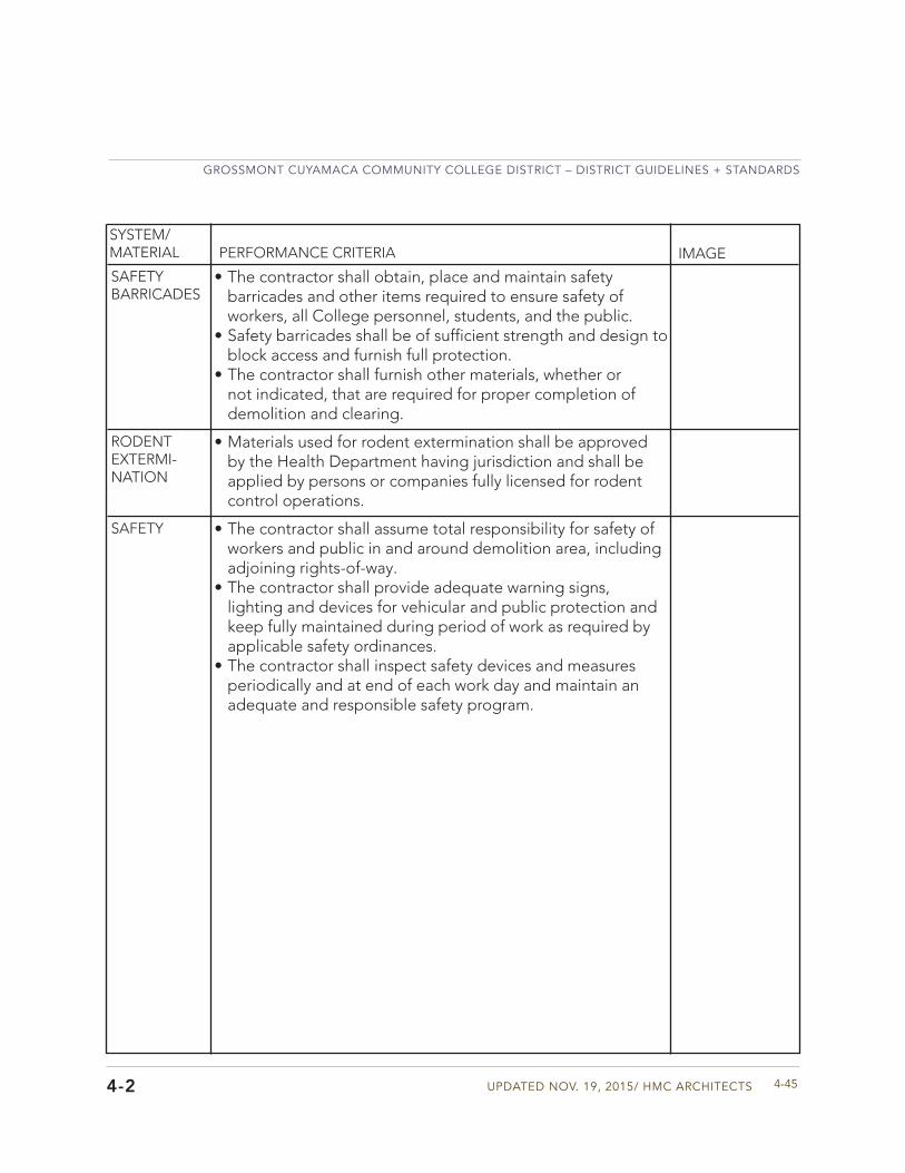
Updated Nov. 19, 2015/ HMC aRCHIteCtS
GRoSSMoNt CUYaMaCa CoMMUNItY CoLLeGe dIStRICt – dIStRICt GUIdeLINeS + StaNdaRdS
4-454-2
SYSTEM/MATERIAL PERFORMANCE CRITERIA IMAGE
• The contractor shall obtain, place and maintain safetybarricades and other items required to ensure safety ofworkers, all College personnel, students, and the public.
• Safety barricades shall be of sufficient strength and design toblock access and furnish full protection.
• The contractor shall furnish other materials, whether ornot indicated, that are required for proper completion ofdemolition and clearing.
SAFETYBARRICADES
• Materials used for rodent extermination shall be approvedby the Health Department having jurisdiction and shall beapplied by persons or companies fully licensed for rodentcontrol operations.
RODENTEXTERMI-NATION
• The contractor shall assume total responsibility for safety ofworkers and public in and around demolition area, includingadjoining rights-of-way.
• The contractor shall provide adequate warning signs,lighting and devices for vehicular and public protection andkeep fully maintained during period of work as required byapplicable safety ordinances.
• The contractor shall inspect safety devices and measuresperiodically and at end of each work day and maintain anadequate and responsible safety program.
SAFETY
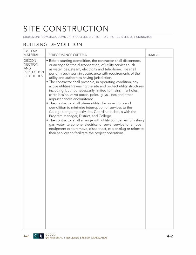
GROSSMONT CUYAMACA COMMUNITY COLLEGE DISTRICT – DISTRICT GUIDELINES + STANDARDS
GCCCD04 MATERIAL + BUILDING SYSTEM STANDARDS4-46
• Before starting demolition, the contractor shall disconnect,or arrange for the disconnection, of utility services suchas water, gas, steam, electricity and telephone. He shallperform such work in accordance with requirements of theutility and authorities having jurisdiction.
• The contractor shall preserve, in operating condition, anyactive utilities traversing the site and protect utility structuresincluding, but not necessarily limited to mains, manholes,catch basins, valve boxes, poles, guys, lines and otherappurtenances encountered.
• The contractor shall phase utility disconnections anddemolition to minimize interruption of services to theCollege’s ongoing activities. Coordinate details with theProgram Manager, District, and College.
• The contractor shall arrange with utility companies furnishinggas, water, telephone, electrical or sewer service to removeequipment or to remove, disconnect, cap or plug or relocatetheir services to facilitate the project operations.
DISCON-NECTIONAND PROTECTIONOF UTILITIES
BUILDING DEMOLITIONSYSTEM/MATERIAL PERFORMANCE CRITERIA IMAGE
SITE CONSTRUCTION
4-2
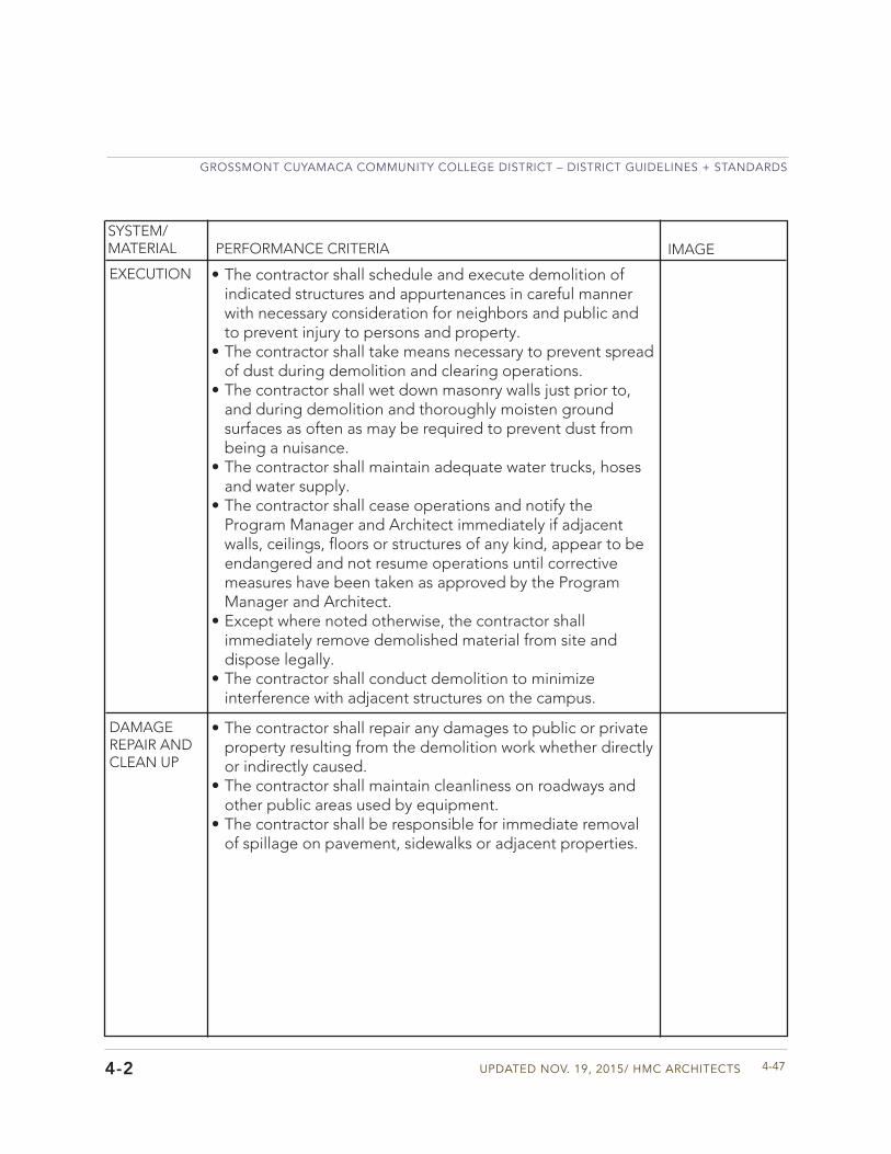
Updated Nov. 19, 2015/ HMC aRCHIteCtS
GRoSSMoNt CUYaMaCa CoMMUNItY CoLLeGe dIStRICt – dIStRICt GUIdeLINeS + StaNdaRdS
4-47
SYSTEM/MATERIAL PERFORMANCE CRITERIA IMAGE
4-2
• The contractor shall schedule and execute demolition ofindicated structures and appurtenances in careful mannerwith necessary consideration for neighbors and public andto prevent injury to persons and property.
• The contractor shall take means necessary to prevent spreadof dust during demolition and clearing operations.
• The contractor shall wet down masonry walls just prior to,and during demolition and thoroughly moisten groundsurfaces as often as may be required to prevent dust frombeing a nuisance.
• The contractor shall maintain adequate water trucks, hosesand water supply.
• The contractor shall cease operations and notify theProgram Manager and Architect immediately if adjacent walls, ceilings, floors or structures of any kind, appear to be endangered and not resume operations until corrective measures have been taken as approved by the ProgramManager and Architect.
• Except where noted otherwise, the contractor shallimmediately remove demolished material from site anddispose legally.
• The contractor shall conduct demolition to minimizeinterference with adjacent structures on the campus.
EXECUTION
• The contractor shall repair any damages to public or privateproperty resulting from the demolition work whether directlyor indirectly caused.
• The contractor shall maintain cleanliness on roadways andother public areas used by equipment.
• The contractor shall be responsible for immediate removalof spillage on pavement, sidewalks or adjacent properties.
DAMAGEREPAIR AND CLEAN UP
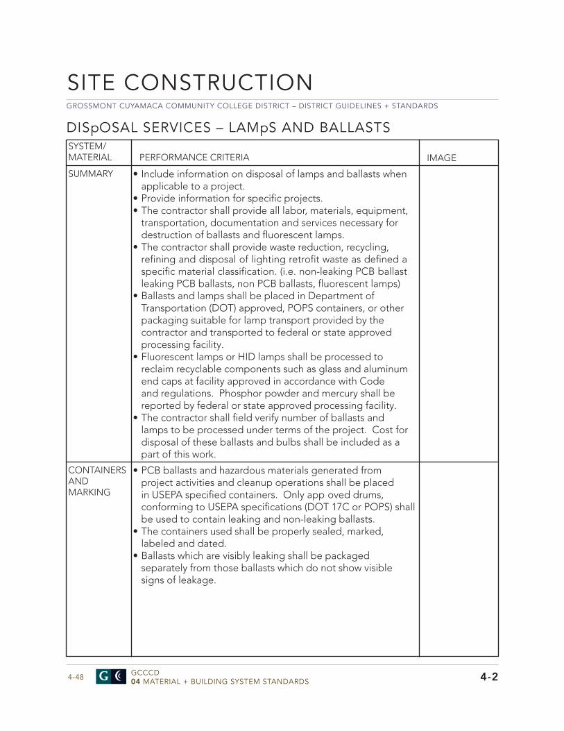
GROSSMONT CUYAMACA COMMUNITY COLLEGE DISTRICT – DISTRICT GUIDELINES + STANDARDS
GCCCD04 MATERIAL + BUILDING SYSTEM STANDARDS4-48
• Include information on disposal of lamps and ballasts whenapplicable to a project.
• Provide information for specific projects.• The contractor shall provide all labor, materials, equipment,
transportation, documentation and services necessary fordestruction of ballasts and fluorescent lamps.
• The contractor shall provide waste reduction, recycling,refining and disposal of lighting retrofit waste as defined a specific material classification. (i.e. non-leaking PCB ballast leaking PCB ballasts, non PCB ballasts, fluorescent lamps)
• Ballasts and lamps shall be placed in Department ofTransportation (DOT) approved, POPS containers, or otherpackaging suitable for lamp transport provided by thecontractor and transported to federal or state approvedprocessing facility.
• Fluorescent lamps or HID lamps shall be processed toreclaim recyclable components such as glass and aluminumend caps at facility approved in accordance with Codeand regulations. Phosphor powder and mercury shall bereported by federal or state approved processing facility.
• The contractor shall field verify number of ballasts andlamps to be processed under terms of the project. Cost fordisposal of these ballasts and bulbs shall be included as apart of this work.
SUMMARY
DISpOSAL SERVICES – LAMpS AND BALLASTSSYSTEM/MATERIAL PERFORMANCE CRITERIA IMAGE
SITE CONSTRUCTION
4-2
• PCB ballasts and hazardous materials generated fromproject activities and cleanup operations shall be placedin USEPA specified containers. Only app oved drums,conforming to USEPA specifications (DOT 17C or POPS) shallbe used to contain leaking and non-leaking ballasts.
• The containers used shall be properly sealed, marked,labeled and dated.
• Ballasts which are visibly leaking shall be packagedseparately from those ballasts which do not show visiblesigns of leakage.
CONTAINERS AND MARKING
Updated Nov. 19, 2015/ HMC aRCHIteCtS
GRoSSMoNt CUYaMaCa CoMMUNItY CoLLeGe dIStRICt – dIStRICt GUIdeLINeS + StaNdaRdS
4-49
SYSTEM/MATERIAL PERFORMANCE CRITERIA IMAGE
4-2
• Ballasts shall be transported to TSCA permitted processing/destruction facility.
• PCB containing capacitors, components, debris and pottingcompound shall be transported to a TSCA permittedincineration facility for ultimate destruction.
• For disposal of leaking PCB ballasts and associated waste,the contractor and/or subcontractor and vehicles mustbe licensed for transportation and hauling of regulatedmaterials/hazardous waste. Drivers of these vehiclesshall be trained in laws, rules and regulations governingtransportation of PCB materials. Vehicles must be plainlymarked as specified by DO , USEPA, State Departmentof Health Services, State Police and State Department ofTransportation.
• Recovered lamp components must be certified as nonhazardous through TCLP analysis.
TRANSPORT-ATION TODESTRUC-TION/ SERVICING FACILITIES
• The contractor shall coordinate all activities under thisSection with the Program Manager.
• The contractor shall provide information as to number of ballasts loading per ballasts on fluorescent tubes per same service.
• The contractor shall provide the Program Manager and theDistrict with comprehensive information on all firms to beinvolved in PCB and lamp related work activities as part ofthe project prior to commencement of the project.
• The contractor shall provide the Program Manager andDistrict with comprehensive documentation of work activitiesupon completion of the work and prior to final payment.
DOCUMENT-ATION
GROSSMONT CUYAMACA COMMUNITY COLLEGE DISTRICT – DISTRICT GUIDELINES + STANDARDS
GCCCD04 MATERIAL + BUILDING SYSTEM STANDARDS4-50
• Include this section when applicable to the project whenneeding to clean substrate and apply encapsulant coatingover lead-based paint. Tailor to the specific details ofthe work on the project. Refer to any Existing ConditionsReports.
SUMMARY
LEAD pAINT REMEDIATION – ENCApSULATIONSYSTEM/MATERIAL PERFORMANCE CRITERIA IMAGE
SITE CONSTRUCTION
4-2
• The contractor, sub-contractor, and material supplier, atany tier, and their employees or agents must follow theprocedures in the SWPPP.
• There should be a pre-installation meeting for this work.• The contractor shall submit product data for each type of
encapsulant and accessory item including certifications forrecycled content and VOC content.
• Product shall include a written warranty for 20 years.
ADMINI-STRATIVE REQUIRE-MENTS
Updated Nov. 19, 2015/ HMC aRCHIteCtS
GRoSSMoNt CUYaMaCa CoMMUNItY CoLLeGe dIStRICt – dIStRICt GUIdeLINeS + StaNdaRdS
4-51
SYSTEM/MATERIAL PERFORMANCE CRITERIA IMAGE
• Include this section when a specific project includes abatement, lead related construction work or painting of lead-containing materials and/or lead based paint.
• This section should reference the District’s Lead AbatementReport for the project.
• Include information for the following: - Policy and Procedures - Site Security - Emergency Planning - Licensing - Contractor Qualification - Training - Exposure Assessment - Submittals - Employee Protective Equipment - Execution of Lead Related Contraction Work - Execution of Abatement - Waste Handling and Transportation - Monitoring
SUMMARY
4-2
LEAD ABATEMENT AND LEAD RELATED CONSTRUCTION WORK
• The District has a zero-tolerance policy for uncontrolledlead releases during lead related construction work, leadcontaining paint disturbance, or abatement activities. A leadrelease requiring an emergency response is any disturbanceresulting in the uncontrolled release of lead containingmaterials. Upon observation of any visual emissions, thecontractor should immediately stop the work, vacate thework area, and provide written notification to the ProgramManager.
• The Program Manager shall provide oversight for all projectsthat have the potential to disturb lead containing paint orlead based paint. Prior to the commencement of such work,the contractor should provide written notification to theProgram Manager.
POLICY AND PROCEDURES

GROSSMONT CUYAMACA COMMUNITY COLLEGE DISTRICT – DISTRICT GUIDELINES + STANDARDS
GCCCD04 MATERIAL + BUILDING SYSTEM STANDARDS4-52
• The work area is restricted to authorized, trained, andprotected personnel. A list of authorized personnel will beestablished and posted at the entrance of the work area bythe Program Manager prior to commencement of the work.
• The contractor shall report to the Program Manager anyunauthorized entry into the work area. Following notification,a written report of the incident shall be provided to theProgram Manager.
• Access to the abatement work area shall be through the“Decontamination Enclosure System” only. All other meansof access shall be blocked or locked so as to prevent entryto or exit from the work area. Emergency exits shall beoperable from inside the work area.
• The contractor shall maintain the work area security duringabatement and/or lead related construction work. All workareas and ancillary equipment accessible to non-authorizedpersonnel shall be protected from unauthorized access byconstructing a barrier.
SITE SECURITY
LEAD ABATEMENT AND LEAD RELATED CONSTRUCTION WORKSYSTEM/MATERIAL PERFORMANCE CRITERIA IMAGE
SITE CONSTRUCTION
4-2
Updated Nov. 19, 2015/ HMC aRCHIteCtS
GRoSSMoNt CUYaMaCa CoMMUNItY CoLLeGe dIStRICt – dIStRICt GUIdeLINeS + StaNdaRdS
4-53
SYSTEM/MATERIAL PERFORMANCE CRITERIA IMAGE
• Emergency planning and procedures shall be developed,submitted, reviewed, and agreed to by the ProgramManager and the District prior to the commencement oflead-related construction and/or abatement work.
• Emergency procedures shall be provided in the writtenlanguages understood by all employees working on theproject and shall be prominently posted at the entranceof the “Decontamination Enclosure System.” Prior toentering the work area, all parties must read and sign theseprocedures to acknowledge receipt and understandingof the work area layout, location of emergency exits, andemergency procedures.
• Emergency planning shall consider the effects of fi e,explosion, toxic atmospheres, electrical hazards, slips, trips and falls, confined spaces, and heat related injury. The contractor shall develop and provide written procedures and training to all employees.
• Employees shall be trained in evacuation procedures in theevent of workplace emergencies.
• In the event of non-life threatening situations requiringmedical treatment, injured or otherwise incapacitatedemployees shall decontaminate following normal procedureswith assistance from fellow workers if necessary, beforeexiting the work area.
• Telephone numbers of all emergency response personnelshall be prominently posted at the entrance of theDecontamination Enclosure System along with the locationof the nearest telephone. In addition to the 911 emergencynumber, the contractor shall post the address and telephonenumber of the nearest emergency medical services provider.
• The contractor shall provide at least one 4A/60BC drychemical extinguisher in the decontamination compartment.All workers shall be trained in the proper operation of fi eextinguishers.
• Emergency exits shall be provided and clearly markedwith arrows or other clearly visible markings to permit easyidentification f om anywhere within the work area.
EMERGENCY PLANNING
4-2
GROSSMONT CUYAMACA COMMUNITY COLLEGE DISTRICT – DISTRICT GUIDELINES + STANDARDS
GCCCD04 MATERIAL + BUILDING SYSTEM STANDARDS4-54
LEAD ABATEMENT AND LEAD RELATED CONSTRUCTION WORKSYSTEM/MATERIAL PERFORMANCE CRITERIA IMAGE
• The work shall be performed by an entity appropriatelylicensed in the State of California in accordance with allregulations.
LICENSING
SITE CONSTRUCTION
4-2
• Exits shall be secured to prevent access fromuncontaminated areas while still permitting emergencyegress. Exits shall be properly sealed with polyethylenesheeting, which can be cut to permit emergency egress.Emergency exits may lead through the “DecontaminationEnclosure System” or other alternative exits as required byfi e officials
Updated Nov. 19, 2015/ HMC aRCHIteCtS
GRoSSMoNt CUYaMaCa CoMMUNItY CoLLeGe dIStRICt – dIStRICt GUIdeLINeS + StaNdaRdS
4-55
SYSTEM/MATERIAL PERFORMANCE CRITERIA IMAGE
4-2
MOLD REMEDIATION
SUMMARY • Include this section when removal and disposal of mold isrequired on a project.
• Coordinate the details of this section for the specific projectwith the Program Manager and the District.
• Include information for the following: - References and Standards - Pre-construction meeting - Submittals - Quality Assurance - Containment - Protective Clothing - Respiratory Protection - Hepa Filter Equipment - Cleaning Agent - Project Monitoring and Air Sampling - Hazard Communication - Temporary Utilities - Containment Barriers - Negative Pressure - Record Keeping/Daily Log - Clearance Preparation - Final Clearance Inspections - Post-Remediation Air Sampling - Restoration of Utilities, Firestopping and Finishes
GROSSMONT CUYAMACA COMMUNITY COLLEGE DISTRICT – DISTRICT GUIDELINES + STANDARDS
GCCCD04 MATERIAL + BUILDING SYSTEM STANDARDS4-56
CONCRETE
4-3
CAST IN pLACE CONCRETE
Division 3
• Portland Cement - ASTM C150• Concrete Aggregate - ASTM C33• Structural Concrete for Buildings - ACI 301• Sheet Materials for Curing Concrete - ASTM C171• Standard Methods of Sampling and Testing Fly Ash and
Natural Pozzolans for Use as a Mineral Admixture inPortland Cement Concrete - ASTM C 311
• Coal Fly Ash and Raw or Calcined Natural Pozzolan for useas a Mineral Admixture in Concrete - ASTM C618
• IR 19-3 Interpretation of Regulations, Fly Ash and NaturalPozzolans Used in Concrete
• Water Vapor Transmission of Materials - ASTM E96• Test Method for Measuring Moisture Vapor Emission -
ASTM F1869• Determining Relative Humidity in Concrete Floor Slabs
Using In-Situ Probes - ASTM F2170• Aggregate for Stone Concrete: ASTM C33• Aggregate for Lightweight Concrete: ASTM C330• Fly ash may be used at 15% replacement of the Portland
cement, at a 1:1 replacement ratio by weight. The flyash shall meet the requirements of ASTM C 618 with theexception that the Loss on Ignition (a measure of the lossin mass of a fly ash sample when placed in a 750 degreesC oven) shall not exceed 1.0%. Only Class F material ispermitted, CBC Section 1903A.5. When fly ash is used thequantity of water shall be determined on a water-cementplus fly ash basis
SYSTEM/MATERIAL PERFORMANCE CRITERIACONCRETE MATERIALS
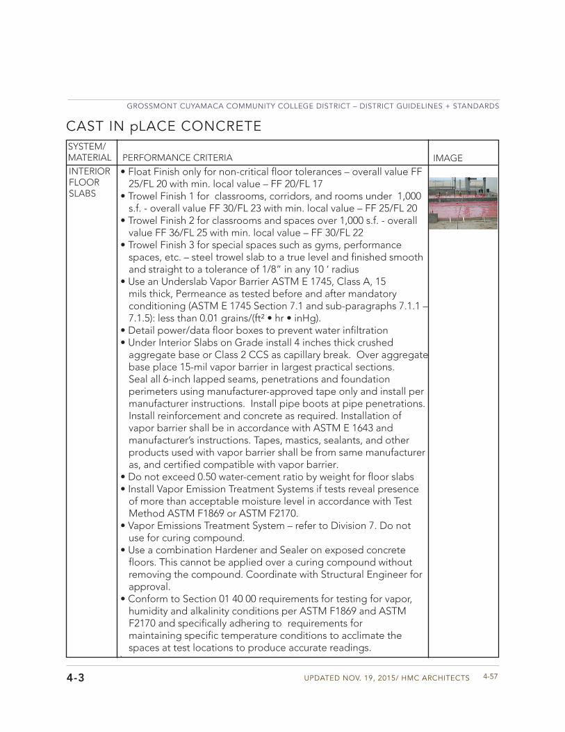
Updated Nov. 19, 2015/ HMC aRCHIteCtS
GRoSSMoNt CUYaMaCa CoMMUNItY CoLLeGe dIStRICt – dIStRICt GUIdeLINeS + StaNdaRdS
4-574-3
CAST IN pLACE CONCRETESYSTEM/MATERIAL PERFORMANCE CRITERIA IMAGEINTERIOR FLOOR SLABS
• Float Finish only for non-critical floor tolerances – overall value FF25/FL 20 with min. local value – FF 20/FL 17
• Trowel Finish 1 for classrooms, corridors, and rooms under 1,000s.f. - overall value FF 30/FL 23 with min. local value – FF 25/FL 20
• Trowel Finish 2 for classrooms and spaces over 1,000 s.f. - overallvalue FF 36/FL 25 with min. local value – FF 30/FL 22
• Trowel Finish 3 for special spaces such as gyms, performancespaces, etc. – steel trowel slab to a true level and finished smoothand straight to a tolerance of 1/8” in any 10 ‘ radius
• Use an Underslab Vapor Barrier ASTM E 1745, Class A, 15mils thick, Permeance as tested before and after mandatoryconditioning (ASTM E 1745 Section 7.1 and sub-paragraphs 7.1.1 –7.1.5): less than 0.01 grains/(ft² • hr • inHg).
• Detail power/data floor boxes to prevent water infiltration• Under Interior Slabs on Grade install 4 inches thick crushed
aggregate base or Class 2 CCS as capillary break. Over aggregate base place 15-mil vapor barrier in largest practical sections.Seal all 6-inch lapped seams, penetrations and foundation perimeters using manufacturer-approved tape only and install per manufacturer instructions. Install pipe boots at pipe penetrations. Install reinforcement and concrete as required. Installation of vapor barrier shall be in accordance with ASTM E 1643 and manufacturer’s instructions. Tapes, mastics, sealants, and other products used with vapor barrier shall be from same manufacturer as, and certified compatible with vapor barrier.
• Do not exceed 0.50 water-cement ratio by weight for floor slabs• Install Vapor Emission Treatment Systems if tests reveal presence
of more than acceptable moisture level in accordance with TestMethod ASTM F1869 or ASTM F2170.
• Vapor Emissions Treatment System – refer to Division 7. Do notuse for curing compound.
• Use a combination Hardener and Sealer on exposed concretefloors. This cannot be applied over a curing compound withoutremoving the compound. Coordinate with Structural Engineer forapproval.
• Conform to Section 01 40 00 requirements for testing for vapor,humidity and alkalinity conditions per ASTM F1869 and ASTMF2170 and specifically adhering to requirements formaintaining specific temperature conditions to acclimate thespaces at test locations to produce accurate readings.
`
GROSSMONT CUYAMACA COMMUNITY COLLEGE DISTRICT – DISTRICT GUIDELINES + STANDARDS
GCCCD04 MATERIAL + BUILDING SYSTEM STANDARDS4-58
MASONRY
4-4
MORTAR AND GROUT
Division 4
• Portland Cement - ASTM C150, Type l or ll• Hydrated Lime – ASTM C207, Type S• Chemical mixtures for concrete - 494• Use colored pigmented mortar for face brick, special finish
CMU or CMU veneer units• Color of mortar to match or coordinate with existing
buildings on campus• Selected mortar color must be part of a mockup and
approved• Do not use anti-freeze compounds to lower the freezing
point of mortar• When atmosphere is extremely dry, dampen the masonry
surfaces with a light fog spray for 3 days during the curingperiod for mortar.
• Minimum compressive strength after 28 days, 1800 psi
SYSTEM/MATERIAL PERFORMANCE CRITERIA IMAGE
MORTAR
GROUT
General Approach - Exterior masonry for building facades should support the District’s intension of creating a cohesive and unified appearance on campus. Masonry design should support the District’s sustainable initiative and allow for energy efficient operation. Masonry detailing on facades should avoid horizontal ledges where birds will perch or nest and exterior openings or niches where birds, bees, or insects can create nests or hives. Consider the need for utility interface and signage mounting in detailing in modular layout. The project budget must be considered in the selection and use of masonry and stone in the design.
• Aggregates for masonry grout - ASTM C476• Grout for masonry – ASTM C476• Use fine g out for cavity behind masonry and brick cavity
and at grouted door frames and course grout for all filledcell masonry.
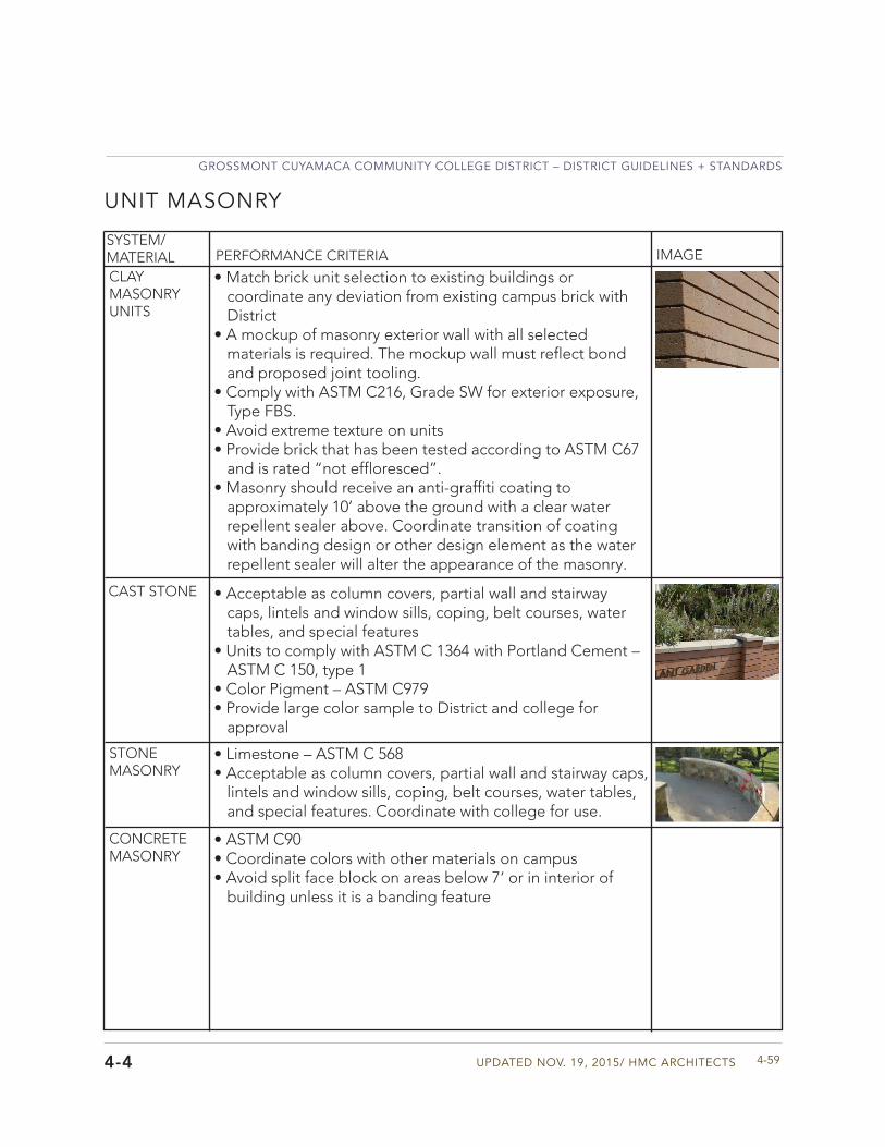
Updated Nov. 19, 2015/ HMC aRCHIteCtS
GRoSSMoNt CUYaMaCa CoMMUNItY CoLLeGe dIStRICt – dIStRICt GUIdeLINeS + StaNdaRdS
4-594-4
UNIT MASONRY
SYSTEM/MATERIAL PERFORMANCE CRITERIA IMAGE
CLAY MASONRY UNITS
CAST STONE
STONE MASONRY
• Match brick unit selection to existing buildings orcoordinate any deviation from existing campus brick withDistrict
• A mockup of masonry exterior wall with all selectedmaterials is required. The mockup wall must reflect bondand proposed joint tooling.
• Comply with ASTM C216, Grade SW for exterior exposure,Type FBS.
• Avoid extreme texture on units• Provide brick that has been tested according to ASTM C67
and is rated “not effloresced”.• Masonry should receive an anti-graffiti coating to
approximately 10’ above the ground with a clear waterrepellent sealer above. Coordinate transition of coatingwith banding design or other design element as the waterrepellent sealer will alter the appearance of the masonry.
• Acceptable as column covers, partial wall and stairwaycaps, lintels and window sills, coping, belt courses, watertables, and special features
• Units to comply with ASTM C 1364 with Portland Cement –ASTM C 150, type 1
• Color Pigment – ASTM C979• Provide large color sample to District and college for
approval
• Limestone – ASTM C 568• Acceptable as column covers, partial wall and stairway caps,
lintels and window sills, coping, belt courses, water tables,and special features. Coordinate with college for use.
CONCRETE MASONRY
• ASTM C90• Coordinate colors with other materials on campus• Avoid split face block on areas below 7‘ or in interior of
building unless it is a banding feature
GROSSMONT CUYAMACA COMMUNITY COLLEGE DISTRICT – DISTRICT GUIDELINES + STANDARDS
GCCCD04 MATERIAL + BUILDING SYSTEM STANDARDS4-60
METALS
4-5
STRUCTURAL STEEL/METAL FRAMING
Division 5
.
• Structural Steel and fasteners shall be manufactured inthe United States. Fabricators shall furnish proof of U.S. manufacture and should be within a 160 mile distance off site.
• Fabricator and erector shall be companies specializing inperforming structural steel work with a minimum of 5 years ofexperience in this area.
• If applicable on a project, erect a mockup for architecturalexposed structural steel for approval before installing entirearea of project.
SYSTEM/MATERIAL PERFORMANCE CRITERIA IMAGE
QUALITY
HORIzONTAL FRAMING MEMBERS
• Design of floor members shall include consideration of therelative perceptibility of floor vibrations based on the useof the space as well as requirements to avoid mechanicalequipment vibration.
• Design steel floor systems to conform to AcceptanceCriteria for Human Comfort as outlined in the AISC SteelDesign Guide Series 11 – Floor Vibrations Due to HumanActivity.
SUSTAINABLE APPROACH
• Provide structural steel with a minimum of 90% post-consumer recycled content
FINISH • Finish all exposed steel unless specifically app oved bycollege and District.
ACOUSTICAL • Design metal deck to meet acoustical performance criteriaoutlined in Division 51.
• If proposing the use of exposed metal deck for an occupiedspace discuss and receive approval from college andDistrict.
SYSTEM/MATERIAL PERFORMANCE CRITERIA IMAGE
METAL DECK
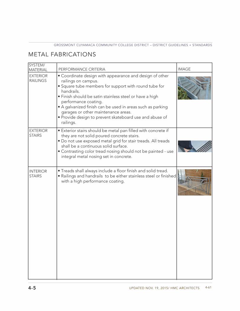
Updated Nov. 19, 2015/ HMC aRCHIteCtS
GRoSSMoNt CUYaMaCa CoMMUNItY CoLLeGe dIStRICt – dIStRICt GUIdeLINeS + StaNdaRdS
4-614-5
METAL FABRICATIONS
SYSTEM/MATERIAL PERFORMANCE CRITERIA IMAGE
EXTERIOR RAILINGS
• Coordinate design with appearance and design of otherrailings on campus.
• Square tube members for support with round tube forhandrails.
• Finish should be satin stainless steel or have a highperformance coating.
• A galvanized finish can be used in areas such as parkinggarages or other maintenance areas.
• Provide design to prevent skateboard use and abuse ofrailings.
EXTERIOR STAIRS
• Exterior stairs should be metal pan filled with concrete ifthey are not solid poured concrete stairs.
• Do not use exposed metal grid for stair treads. All treadsshall be a continuous solid surface.
• Contrasting color tread nosing should not be painted - useintegral metal nosing set in concrete.
INTERIOR STAIRS
• Treads shall always include a floor finish and solid tread.• Railings and handrails to be either stainless steel or finished
with a high performance coating.
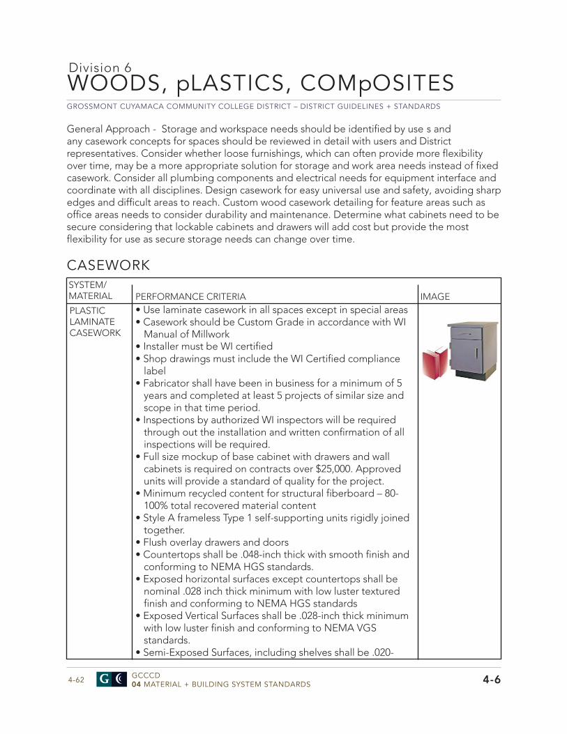
GROSSMONT CUYAMACA COMMUNITY COLLEGE DISTRICT – DISTRICT GUIDELINES + STANDARDS
GCCCD04 MATERIAL + BUILDING SYSTEM STANDARDS4-62
WOODS, pLASTICS, COMpOSITES
4-6
CASEWORK
Division 6
• Use laminate casework in all spaces except in special areas• Casework should be Custom Grade in accordance with WI
Manual of Millwork• Installer must be WI certified• Shop drawings must include the WI Certified compliance
label• Fabricator shall have been in business for a minimum of 5
years and completed at least 5 projects of similar size andscope in that time period.
• Inspections by authorized WI inspectors will be requiredthrough out the installation and written confirmation of allinspections will be required.
• Full size mockup of base cabinet with drawers and wallcabinets is required on contracts over $25,000. Approvedunits will provide a standard of quality for the project.
• Minimum recycled content for structural fiberboard – 80-100% total recovered material content
• Style A frameless Type 1 self-supporting units rigidly joinedtogether.
• Flush overlay drawers and doors• Countertops shall be .048-inch thick with smooth finish and
conforming to NEMA HGS standards.• Exposed horizontal surfaces except countertops shall be
nominal .028 inch thick minimum with low luster texturedfinish and conforming to NEMA HGS standards
• Exposed Vertical Surfaces shall be .028-inch thick minimumwith low luster finish and conforming to NEMA VGSstandards.
• Semi-Exposed Surfaces, including shelves shall be .020-
SYSTEM/MATERIAL PERFORMANCE CRITERIA IMAGE
PLASTIC LAMINATE CASEWORK
General Approach - Storage and workspace needs should be identified by use s and any casework concepts for spaces should be reviewed in detail with users and District representatives. Consider whether loose furnishings, which can often provide more flexibility over time, may be a more appropriate solution for storage and work area needs instead of fixed casework. Consider all plumbing components and electrical needs for equipment interface and coordinate with all disciplines. Design casework for easy universal use and safety, avoiding sharp edges and difficult areas to reach. Custom wood casework detailing for feature areas such as office areas needs to consider durability and maintenance. Determine what cabinets need to be secure considering that lockable cabinets and drawers will add cost but provide the most flexibility for use as secure storage needs can change over time.
Updated Nov. 19, 2015/ HMC aRCHIteCtS
GRoSSMoNt CUYaMaCa CoMMUNItY CoLLeGe dIStRICt – dIStRICt GUIdeLINeS + StaNdaRdS
4-634-6
CASEWORK
SYSTEM/MATERIAL PERFORMANCE CRITERIA IMAGE
PLASTIC LAMINATE CASEWORK
inch thick CLS cabinet liner conforming to NEMA standards or melamine.
• Backing Sheet on Concealed Surfaces shall be .020-inch thick,conforming to NEMA CLS standards for cabinet liner. Must use to balance face laminate.
• Edge banding on all doors and drawers – 3 mm high impactPVC. Barbed T banding not acceptable.
• Edge banding on countertops or worksurfaces – 3 mm highimpact PVC. Barbed T banding not acceptable.
• Finished hardwood edge accepted in specific office or highprofile areas if not in a wet area
• 1mm PVC edge on all shelves• AG Fiber Particleboard shall comply with ANSI A208
formaldehyde-free binder• Medium density fiberboard shall comply with ANSI 208.2
formaldehyde-free binder• Shelves to be adjustable in most casework – ¾” thick if 24” or
less, 1” thick if over 24”• Provide removable or false backs for access or concealment of
heating or plumbing items. Coordinate utility cutouts with alldisciplines/trades. Provide grommets and covers.
• Scribe tops to walls and other adjoining vertical surfaces. Providebacksplashes only in wet areas or where desired by college.
• Filler Strips: Provide as needed to close spaces betweencabinets and walls, ceilings, and indicated equipment. Fabricatefrom same material and with same finish as cabinets
• Reinforce bottoms on wide drawers with front to back insetstiffeners, 1 at 24 inch wide drawers, 2 at 36 inch and 4 at 48 inch;glue, fasten, and seal perimeter with hot melt adhesive.
• Drawer box shall be a maximum of 1” less in height than draweropening in face of cabinet.
• Kick space should be finished with rubber base used in the space• Avoid using solid dark colors as they are difficult to clean and
avoid very light solid colors for countertops. Do not use texturedlaminate on countertops or worksurfaces.
• The manufacturer shall warrant products from delamination,loose edges, defective or broken hardware, broken casters,loose wood trim, and horizontal or vertical members comingapart from each other and in general against defects in materialsor workmanship for 5 full years after substantial completion.
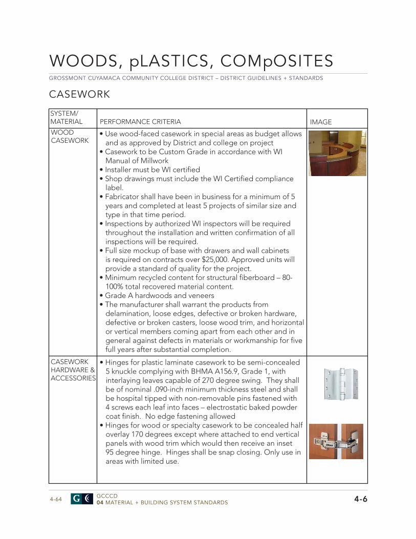
GROSSMONT CUYAMACA COMMUNITY COLLEGE DISTRICT – DISTRICT GUIDELINES + STANDARDS
GCCCD04 MATERIAL + BUILDING SYSTEM STANDARDS4-64
WOODS, pLASTICS, COMpOSITES
4-6
CASEWORK
• Use wood-faced casework in special areas as budget allowsand as approved by District and college on project
• Casework to be Custom Grade in accordance with WIManual of Millwork
• Installer must be WI certified• Shop drawings must include the WI Certified compliance
label.• Fabricator shall have been in business for a minimum of 5
years and completed at least 5 projects of similar size andtype in that time period.
• Inspections by authorized WI inspectors will be requiredthroughout the installation and written confirmation of allinspections will be required.
• Full size mockup of base with drawers and wall cabinetsis required on contracts over $25,000. Approved units willprovide a standard of quality for the project.
• Minimum recycled content for structural fiberboard – 80-100% total recovered material content.
• Grade A hardwoods and veneers• The manufacturer shall warrant the products from
delamination, loose edges, defective or broken hardware,defective or broken casters, loose wood trim, and horizontalor vertical members coming apart from each other and ingeneral against defects in materials or workmanship for fivefull years after substantial completion.
SYSTEM/MATERIAL PERFORMANCE CRITERIA IMAGE
WOOD CASEWORK
CASEWORK HARDWARE & ACCESSORIES
• Hinges for plastic laminate casework to be semi-concealed5 knuckle complying with BHMA A156.9, Grade 1, withinterlaying leaves capable of 270 degree swing. They shallbe of nominal .090-inch minimum thickness steel and shallbe hospital tipped with non-removable pins fastened with4 screws each leaf into faces – electrostatic baked powdercoat finish. No edge fastening allowed
• Hinges for wood or specialty casework to be concealed halfoverlay 170 degrees except where attached to end verticalpanels with wood trim which would then receive an inset95 degree hinge. Hinges shall be snap closing. Only use inareas with limited use.
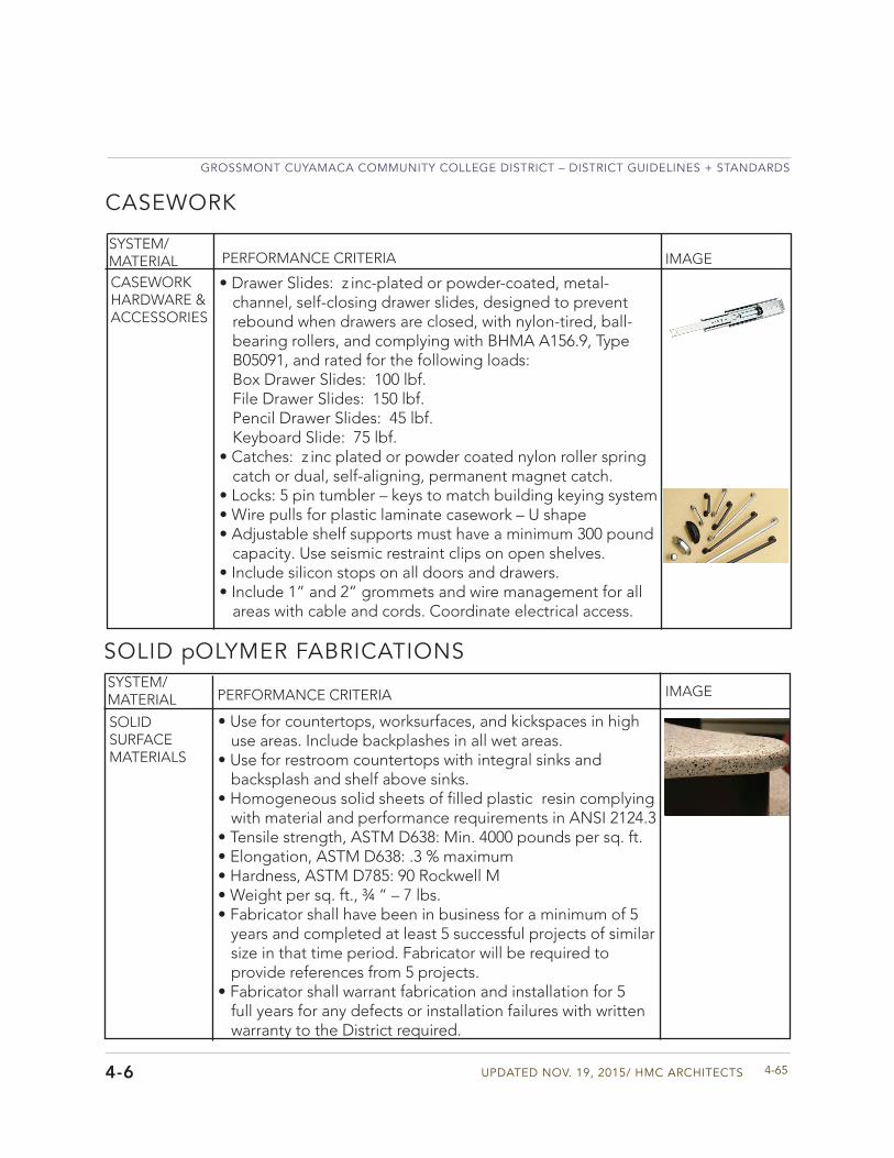
Updated Nov. 19, 2015/ HMC aRCHIteCtS
GRoSSMoNt CUYaMaCa CoMMUNItY CoLLeGe dIStRICt – dIStRICt GUIdeLINeS + StaNdaRdS
4-654-6
CASEWORK
SYSTEM/MATERIAL PERFORMANCE CRITERIA IMAGE
CASEWORK HARDWARE & ACCESSORIES
• Drawer Slides: z inc-plated or powder-coated, metal-channel, self-closing drawer slides, designed to preventrebound when drawers are closed, with nylon-tired, ball-bearing rollers, and complying with BHMA A156.9, TypeB05091, and rated for the following loads:Box Drawer Slides: 100 lbf.File Drawer Slides: 150 lbf.Pencil Drawer Slides: 45 lbf.Keyboard Slide: 75 lbf.
• Catches: z inc plated or powder coated nylon roller springcatch or dual, self-aligning, permanent magnet catch.
• Locks: 5 pin tumbler – keys to match building keying system• Wire pulls for plastic laminate casework – U shape• Adjustable shelf supports must have a minimum 300 pound
capacity. Use seismic restraint clips on open shelves.• Include silicon stops on all doors and drawers.• Include 1” and 2” grommets and wire management for all
areas with cable and cords. Coordinate electrical access.
SOLID pOLYMER FABRICATIONSSYSTEM/MATERIAL PERFORMANCE CRITERIA IMAGE
SOLID SURFACE MATERIALS
• Use for countertops, worksurfaces, and kickspaces in highuse areas. Include backplashes in all wet areas.
• Use for restroom countertops with integral sinks andbacksplash and shelf above sinks.
• Homogeneous solid sheets of filled plastic resin complyingwith material and performance requirements in ANSI 2124.3
• Tensile strength, ASTM D638: Min. 4000 pounds per sq. ft.• Elongation, ASTM D638: .3 % maximum• Hardness, ASTM D785: 90 Rockwell M• Weight per sq. ft., ¾ “ – 7 lbs.• Fabricator shall have been in business for a minimum of 5
years and completed at least 5 successful projects of similarsize in that time period. Fabricator will be required toprovide references from 5 projects.
• Fabricator shall warrant fabrication and installation for 5full years for any defects or installation failures with writtenwarranty to the District required.
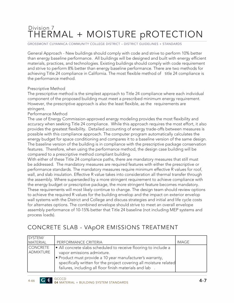
GROSSMONT CUYAMACA COMMUNITY COLLEGE DISTRICT – DISTRICT GUIDELINES + STANDARDS
GCCCD04 MATERIAL + BUILDING SYSTEM STANDARDS4-66
General Approach - New buildings should comply with code and strive to perform 10% better than energy baseline performance. All buildings will be designed and built with energy efficient materials, practices, and technologies. Existing buildings should comply with code requirement and strive to perform 8% better than energy baseline performance. There are two methods for achieving Title 24 compliance in California. The most flexible method of title 24 compliance is the performance method.
Prescriptive MethodThe prescriptive method is the simplest approach to Title 24 compliance where each individual component of the proposed building must meet a prescribed minimum energy requirement. However, the prescriptive approach is also the least flexible, as the requirements are stringent. Performance MethodThe use of Energy Commission-approved energy modeling provides the most flexibility and accuracy when seeking Title 24 compliance. While this approach requires the most effort, it also provides the greatest flexibility. Detailed accounting of energy trade-offs between measures is possible with this compliance approach. The computer program automatically calculates the energy budget for space conditioning and compares it to a baseline version of the same design. The baseline version of the building is in compliance with the prescriptive package conservation features. Therefore, when using the performance method, the design case building will be compared to a prescriptive method compliant building. With either of these Title 24 compliance paths, there are mandatory measures that still must be addressed. The mandatory measures are required features with either the prescriptive or performance standards. The mandatory measures require minimum effective R values for roof, wall, and slab insulation. Effective R value takes into consideration all thermal transfer through the assembly. Where superseded by a more stringent requirement to achieve compliance with the energy budget or prescriptive package, the more stringent feature becomes mandatory. These requirements will most likely continue to change. The design team should review options to achieve the required R values for the building envelop and the impact on exterior envelop wall systems with the District and College and discuss strategies and initial and life cycle costs for alternates options. The combined envelope should strive to meet an overall envelope assembly performance of 10-15% better that Title 24 baseline (not including MEP systems and process loads).
THERMAL + MOISTURE pROTECTION
4-7
CONCRETE SLAB - VApOR EMISSIONS TREATMENT
Division 7
• All concrete slabs scheduled to receive flooring to include avapor emissions admixture.
• Product must provide a 10 year manufacturer’s warranty,specifically written for the project covering all moisture related failures, including all floor finish materials and lab .
SYSTEM/MATERIAL PERFORMANCE CRITERIA IMAGECONCRETE ADMIXTURE
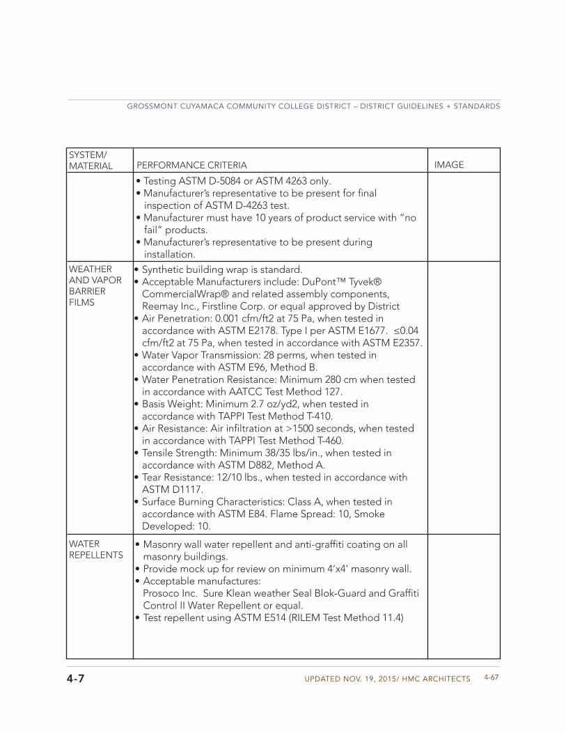
Updated Nov. 19, 2015/ HMC aRCHIteCtS
GRoSSMoNt CUYaMaCa CoMMUNItY CoLLeGe dIStRICt – dIStRICt GUIdeLINeS + StaNdaRdS
4-674-7
WEATHER AND VAPOR BARRIER FILMS
WATER REPELLENTS
• Synthetic building wrap is standard.• Acceptable Manufacturers include: DuPont™ Tyvek®
CommercialWrap® and related assembly components,Reemay Inc., Firstline Corp. or equal approved by District
• Air Penetration: 0.001 cfm/ft2 at 75 Pa, when tested inaccordance with ASTM E2178. Type I per ASTM E1677. ≤0.04cfm/ft2 at 75 Pa, when tested in accordance with ASTM E2357.
• Water Vapor Transmission: 28 perms, when tested inaccordance with ASTM E96, Method B.
• Water Penetration Resistance: Minimum 280 cm when testedin accordance with AATCC Test Method 127.
• Basis Weight: Minimum 2.7 oz/yd2, when tested inaccordance with TAPPI Test Method T-410.
• Air Resistance: Air infiltration at >1500 seconds, when testedin accordance with TAPPI Test Method T-460.
• Tensile Strength: Minimum 38/35 lbs/in., when tested inaccordance with ASTM D882, Method A.
• Tear Resistance: 12/10 lbs., when tested in accordance withASTM D1117.
• Surface Burning Characteristics: Class A, when tested inaccordance with ASTM E84. Flame Spread: 10, SmokeDeveloped: 10.
• Masonry wall water repellent and anti-graffiti coating on allmasonry buildings.
• Provide mock up for review on minimum 4’x4’ masonry wall.• Acceptable manufactures:
Prosoco Inc. Sure Klean weather Seal Blok-Guard and GraffitiControl II Water Repellent or equal.
• Test repellent using ASTM E514 (RILEM Test Method 11.4)
SYSTEM/MATERIAL PERFORMANCE CRITERIA IMAGE
• Testing ASTM D-5084 or ASTM 4263 only.• Manufacturer’s representative to be present for final
inspection of ASTM D-4263 test.• Manufacturer must have 10 years of product service with “no
fail” products.• Manufacturer’s representative to be present during
installation.
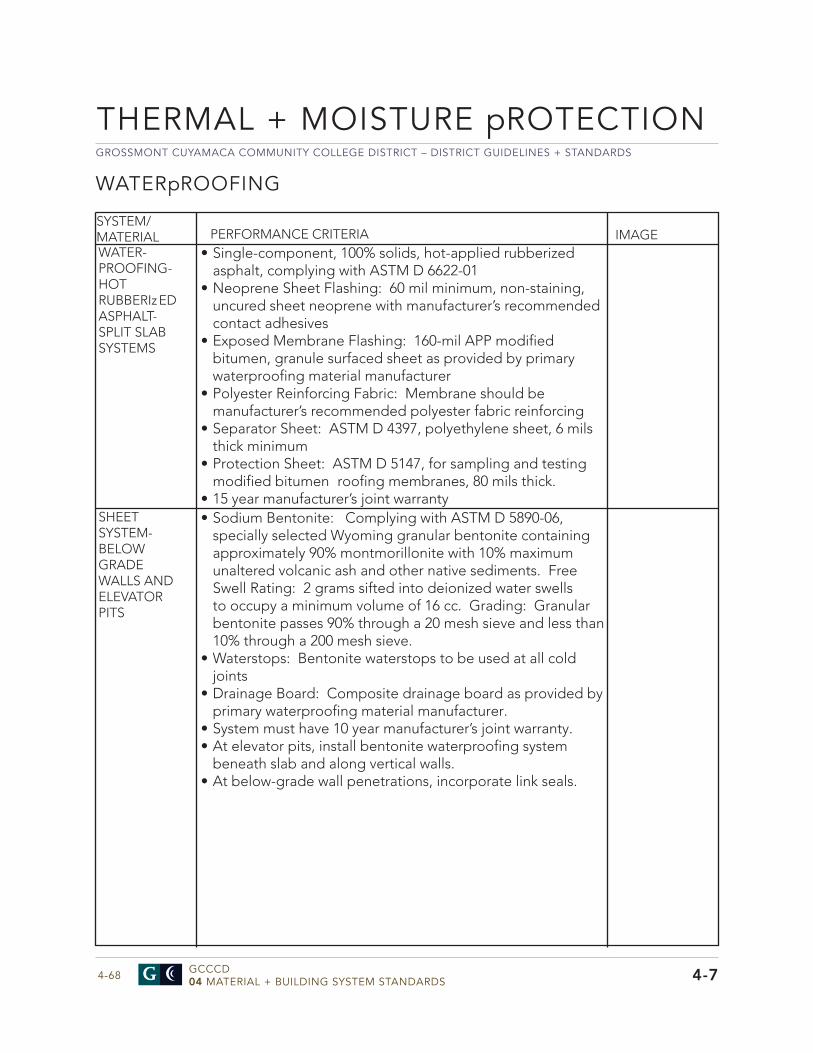
GROSSMONT CUYAMACA COMMUNITY COLLEGE DISTRICT – DISTRICT GUIDELINES + STANDARDS
GCCCD04 MATERIAL + BUILDING SYSTEM STANDARDS4-68
THERMAL + MOISTURE pROTECTION
4-7
WATERpROOFING
SYSTEM/MATERIAL PERFORMANCE CRITERIA IMAGEWATER- PROOFING- HOT RUBBERIzED ASPHALT- SPLIT SLAB SYSTEMS
SHEET SYSTEM- BELOW GRADE WALLS AND ELEVATOR PITS
• Single-component, 100% solids, hot-applied rubberizedasphalt, complying with ASTM D 6622-01
• Neoprene Sheet Flashing: 60 mil minimum, non-staining,uncured sheet neoprene with manufacturer’s recommendedcontact adhesives
• Exposed Membrane Flashing: 160-mil APP modifiedbitumen, granule surfaced sheet as provided by primarywaterproofing material manufacturer
• Polyester Reinforcing Fabric: Membrane should bemanufacturer’s recommended polyester fabric reinforcing
• Separator Sheet: ASTM D 4397, polyethylene sheet, 6 milsthick minimum
• Protection Sheet: ASTM D 5147, for sampling and testingmodified bitumen roofing membranes, 80 mils thick.
• 15 year manufacturer’s joint warranty• Sodium Bentonite: Complying with ASTM D 5890-06,
specially selected Wyoming granular bentonite containingapproximately 90% montmorillonite with 10% maximumunaltered volcanic ash and other native sediments. FreeSwell Rating: 2 grams sifted into deionized water swellsto occupy a minimum volume of 16 cc. Grading: Granularbentonite passes 90% through a 20 mesh sieve and less than10% through a 200 mesh sieve.
• Waterstops: Bentonite waterstops to be used at all coldjoints
• Drainage Board: Composite drainage board as provided byprimary waterproofing material manufacturer.
• System must have 10 year manufacturer’s joint warranty.• At elevator pits, install bentonite waterproofing system
beneath slab and along vertical walls.• At below-grade wall penetrations, incorporate link seals.
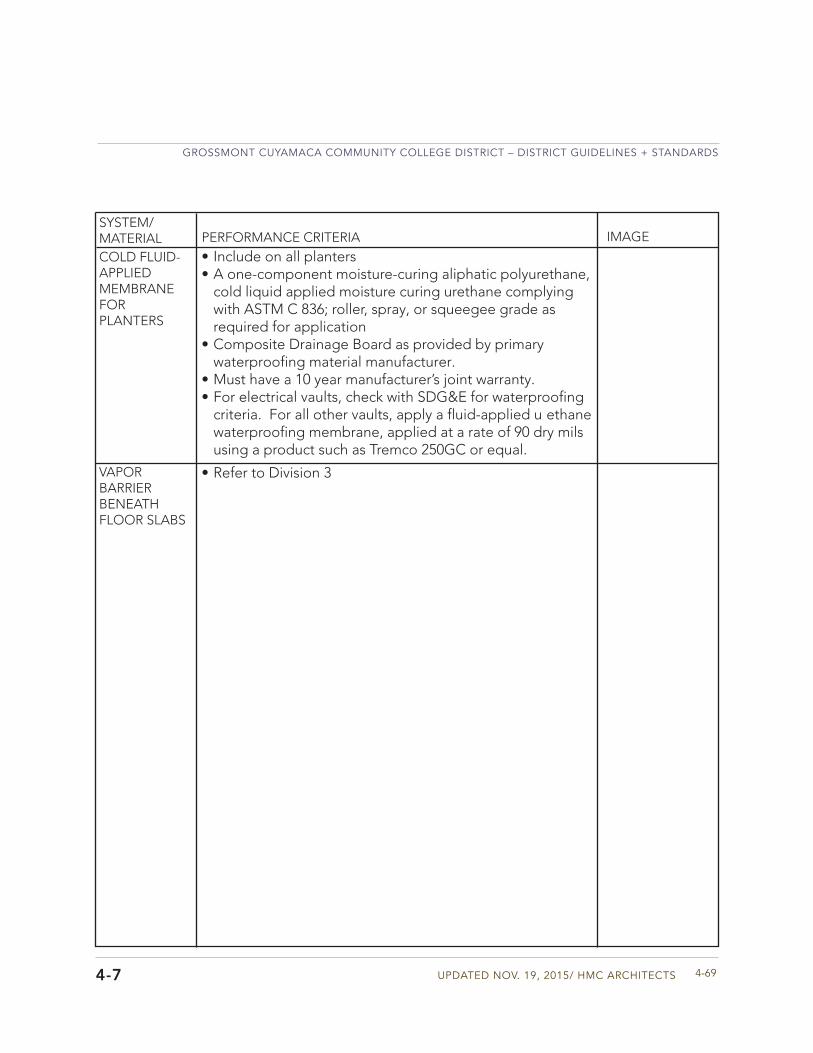
Updated Nov. 19, 2015/ HMC aRCHIteCtS
GRoSSMoNt CUYaMaCa CoMMUNItY CoLLeGe dIStRICt – dIStRICt GUIdeLINeS + StaNdaRdS
4-694-7
COLD FLUID- APPLIED MEMBRANE FOR PLANTERS
• Include on all planters• A one-component moisture-curing aliphatic polyurethane,
cold liquid applied moisture curing urethane complyingwith ASTM C 836; roller, spray, or squeegee grade asrequired for application
• Composite Drainage Board as provided by primarywaterproofing material manufacturer.
• Must have a 10 year manufacturer’s joint warranty.• For electrical vaults, check with SDG&E for waterproofing
criteria. For all other vaults, apply a fluid-applied u ethanewaterproofing membrane, applied at a rate of 90 dry milsusing a product such as Tremco 250GC or equal.
VAPOR BARRIER BENEATH FLOOR SLABS
• Refer to Division 3
SYSTEM/MATERIAL PERFORMANCE CRITERIA IMAGE
GROSSMONT CUYAMACA COMMUNITY COLLEGE DISTRICT – DISTRICT GUIDELINES + STANDARDS
GCCCD04 MATERIAL + BUILDING SYSTEM STANDARDS4-70
THERMAL + MOISTURE pROTECTION
4-7
• System to provide for expansion and contraction within system components caused by cycling temperature range of 170 degrees F without causing detrimental effects to system or components
• Design and size members to withstand dead loads and liveloads and dead loads caused by pressure and suction ofwind as calculated in accordance with requirements of theCBC and ASCE 7.
• Uniform Load: A static air design load of 20 PSF shallbe applied in the positive and negative direction inaccordance with ASTM E330
• Limit water infiltration to zero at 8 pounds force per squarefoot per ASTM E331.
• Sound attenuation through wall system, not less than STC38 measured in accordance with ASTM E413. Refer toDivision 51 for additional criteria.
• Mock ups are required for all window systems and curtainwall assemblies.
• Water testing of all window assemblies should be specifiedto meet ASTM Standards.
SYSTEM/MATERIAL
WINDOWS AND CURTAIN WALL
PERFORMANCE CRITERIA IMAGESYSTEM PERFORMANCE
Updated Nov. 19, 2015/ HMC aRCHIteCtS
GRoSSMoNt CUYaMaCa CoMMUNItY CoLLeGe dIStRICt – dIStRICt GUIdeLINeS + StaNdaRdS
4-714-7
SYSTEM/MATERIAL PERFORMANCE CRITERIA IMAGE
NEW ROOF- LOW-SLOPED ROOF MEMBRANE SYSTEM
ROOFING
• Adhered Systems: Minimum 80-mil thick fiber glass reinforced membrane with a lacquer coating manufactured using an extrusion coating process. Membrane shall conform to ASTM D4434-96 (or latest revision), “Standard for Polyvinyl Chloride Sheet Roofing.” Classification: type II, Grade I.
• Approved Manufacturers: Sarnafil, remco, and JohnsManville
• Color of all membrane shall be “Energy Star Tan” or thepreferred “Tan.” The membrane shall have an initial solar reflectance of 73% and a corresponding emissivity of 85%. In combination the total solar reflectance index value (SRI) of the membrane shall be 89 and must meet standards of the State of California Title 24 latest requirements.
• VOC compliant adhesive for membrane attachment.• 60-mil thick fiber glass reinforced membrane with a lacquer
coating for base and wall flashings• Walkpad layout from roof access to and around all
serviceable mechanical units.• Polyisocyanurate rigid roof insulation board shall be used
for pre-tapered systems and for meeting project R-valuecriteria. Insulation board shall receive a cover boardminimum 1/4” thick, with a DensDeck Prime board orequal. Insulation and cover board may be mechanicallyattached or adhered using a Factory Mutual approved low-rise foam adhesive.
• Penetrations shall receive either pre-fabricated boots orfield-fabricated boots, including stainless steel cinch bandsand sealant. The top edge of the boots shall receive astorm collar fabricated from the single-ply roof membraneand attached using a secondary cinch band and sealant.
• The roof system shall provide a 30-Year Full-SystemWarranty from the roofing material manufacturer. The warranty shall include for an 80-mph wind uplift. A manufacturer’s should be on site observing installation.
GROSSMONT CUYAMACA COMMUNITY COLLEGE DISTRICT – DISTRICT GUIDELINES + STANDARDS
GCCCD04 MATERIAL + BUILDING SYSTEM STANDARDS4-72
THERMAL + MOISTURE pROTECTION
4-7
ROOFING
SYSTEM/MATERIAL PERFORMANCE CRITERIA IMAGE
• Manufacturer to provide inspection services duringwarranty period, per manufacturer’s criteria. Owner willcontact manufacturer to arrange for roofing inspection.Inspection will include a report indicating any routinemaintenance required as well as any repairs that arerequired (these may be covered under warranty or be non-warranty related).
NEW ROOF- LOW-SLOPED ROOF MEMBRANE SYSTEM
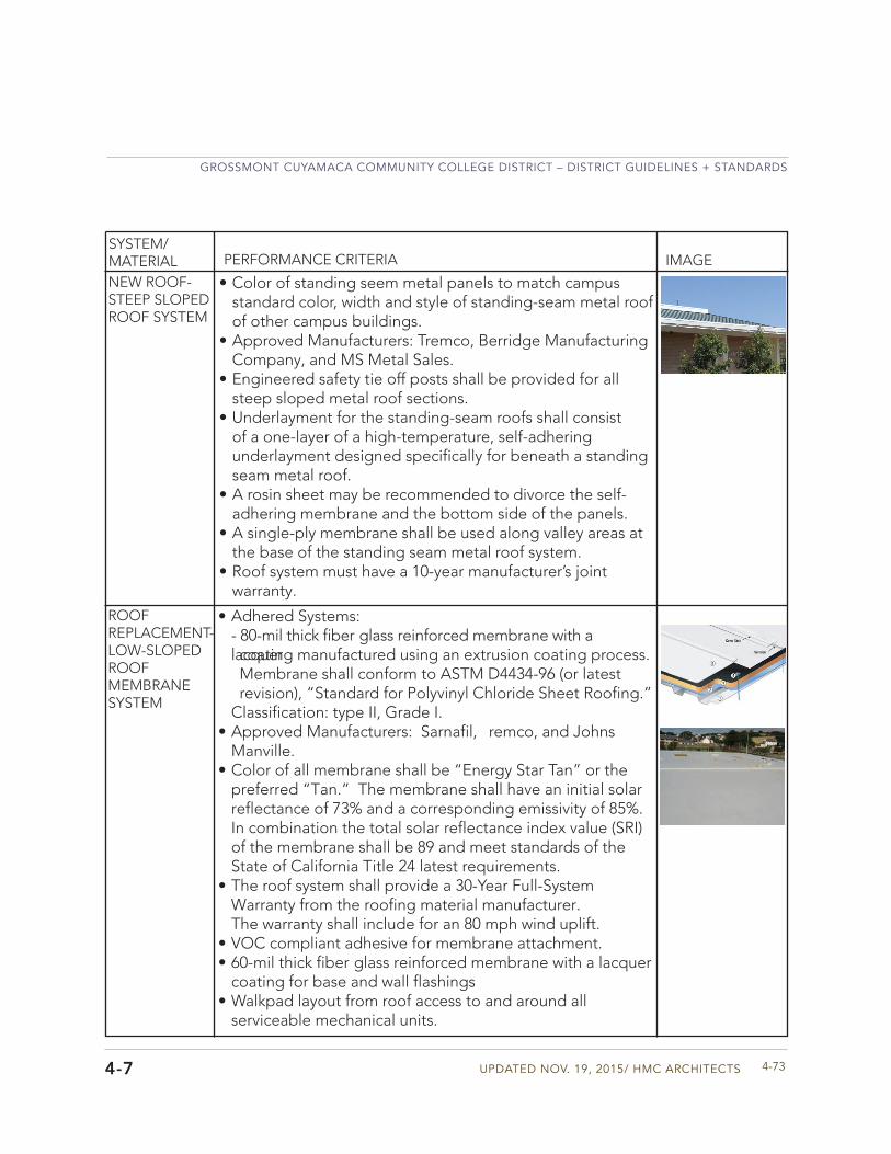
Updated Nov. 19, 2015/ HMC aRCHIteCtS
GRoSSMoNt CUYaMaCa CoMMUNItY CoLLeGe dIStRICt – dIStRICt GUIdeLINeS + StaNdaRdS
4-734-7
• Color of standing seem metal panels to match campusstandard color, width and style of standing-seam metal roofof other campus buildings.
• Approved Manufacturers: Tremco, Berridge ManufacturingCompany, and MS Metal Sales.
• Engineered safety tie off posts shall be provided for allsteep sloped metal roof sections.
• Underlayment for the standing-seam roofs shall consistof a one-layer of a high-temperature, self-adheringunderlayment designed specifically for beneath a standingseam metal roof.
• A rosin sheet may be recommended to divorce the self-adhering membrane and the bottom side of the panels.
• A single-ply membrane shall be used along valley areas atthe base of the standing seam metal roof system.
• Roof system must have a 10-year manufacturer’s jointwarranty.
SYSTEM/MATERIAL PERFORMANCE CRITERIA IMAGE
NEW ROOF- STEEP SLOPED ROOF SYSTEM
ROOF REPLACEMENT- LOW-SLOPED ROOF MEMBRANE SYSTEM
•
Adhered Systems:- 80-mil thick fiber glass reinforced membrane with a lacquer coating manufactured using an extrusion coating process. Membrane shall conform to ASTM D4434-96 (or latest revision), “Standard for Polyvinyl Chloride Sheet Roofing.” Classification: type II, Grade I.
• Approved Manufacturers: Sarnafil, remco, and JohnsManville.
• Color of all membrane shall be “Energy Star Tan” or thepreferred “Tan.” The membrane shall have an initial solar reflectance of 73% and a corresponding emissivity of 85%. In combination the total solar reflectance index value (SRI) of the membrane shall be 89 and meet standards of the State of California Title 24 latest requirements.
• The roof system shall provide a 30-Year Full-SystemWarranty from the roofing material manufacturer. The warranty shall include for an 80 mph wind uplift.
• VOC compliant adhesive for membrane attachment.• 60-mil thick fiber glass reinforced membrane with a lacquer
coating for base and wall flashings• Walkpad layout from roof access to and around all
serviceable mechanical units.
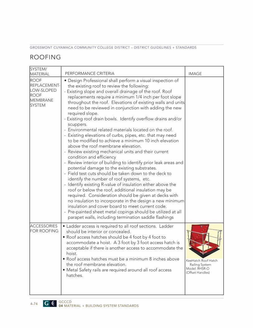
GROSSMONT CUYAMACA COMMUNITY COLLEGE DISTRICT – DISTRICT GUIDELINES + STANDARDS
GCCCD04 MATERIAL + BUILDING SYSTEM STANDARDS4-74
SYSTEM/MATERIAL PERFORMANCE CRITERIA IMAGE
ROOF REPLACEMENT- LOW-SLOPED ROOF MEMBRANE SYSTEM
• Design Professional shall perform a visual inspection ofthe existing roof to review the following:
- Existing slope and overall drainage of the roof. Roof replacements require a minimum 1/4 inch per foot slopethroughout the roof. Elevations of existing walls and unitsneed to be reviewed in conjunction with adding the newrequired slope.
- Existing roof drain bowls. Identify overflow drains and/orscuppers.
- Environmental related materials located on the roof.- Existing elevations of curbs, pipes, etc. that may need
to be modified to achieve a minimum 10 inch elevationabove the roof membrane elevation.
- Review existing mechanical units and their current condition and efficiency
- Review interior of building to identify prior leak areas and potential damage to the existing substrates.
- Field test cuts should be taken down to the deck to identify the number of roof systems, etc.
- Identify existing R-value of insulation either above the roof or below the roof, additional insulation may be required. Consideration should be given at decks with no insulation to incorporate in the design a new minimum insulation and cover board to meet current code.
- Pre-painted sheet metal copings should be utilized at all parapet walls, including termination saddle flashings
ROOFING
ACCESSORIES FOR ROOFING
• Ladder access is required to all roof sections. Laddershould be interior or concealed.
• Roof access hatches should be 4 foot by 4 foot toaccommodate a hoist. A 3 foot by 3 foot access hatch isacceptable if there is another access to accommodate thehoist.
• Roof access hatches must be a minimum 8 inches abovethe roof membrane elevation.
• Metal Safety rails are required around all roof accesshatches.
KeeHatch Roof Hatch Railing System
Model: RHSR-O(Offset Handles)

Updated Nov. 19, 2015/ HMC aRCHIteCtS
GRoSSMoNt CUYaMaCa CoMMUNItY CoLLeGe dIStRICt – dIStRICt GUIdeLINeS + StaNdaRdS
4-75
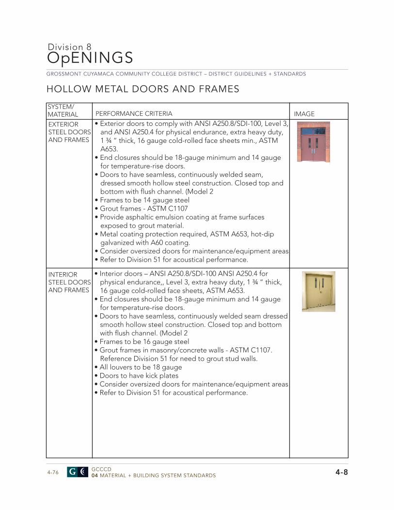
GROSSMONT CUYAMACA COMMUNITY COLLEGE DISTRICT – DISTRICT GUIDELINES + STANDARDS
GCCCD04 MATERIAL + BUILDING SYSTEM STANDARDS4-76
OpENINGS
4-8
HOLLOW METAL DOORS AND FRAMES
Division 8
• Exterior doors to comply with ANSI A250.8/SDI-100, Level 3,and ANSI A250.4 for physical endurance, extra heavy duty,1 ¾ “ thick, 16 gauge cold-rolled face sheets min., ASTMA653.
• End closures should be 18-gauge minimum and 14 gaugefor temperature-rise doors.
• Doors to have seamless, continuously welded seam,dressed smooth hollow steel construction. Closed top andbottom with flush channel. (Model 2
• Frames to be 14 gauge steel• Grout frames - ASTM C1107• Provide asphaltic emulsion coating at frame surfaces
exposed to grout material.• Metal coating protection required, ASTM A653, hot-dip
galvanized with A60 coating.• Consider oversized doors for maintenance/equipment areas• Refer to Division 51 for acoustical performance.
SYSTEM/MATERIAL PERFORMANCE CRITERIA IMAGE
EXTERIOR STEEL DOORS AND FRAMES
INTERIOR STEEL DOORS AND FRAMES
• Interior doors – ANSI A250.8/SDI-100 ANSI A250.4 forphysical endurance,, Level 3, extra heavy duty, 1 ¾ “ thick,16 gauge cold-rolled face sheets, ASTM A653.
• End closures should be 18-gauge minimum and 14 gaugefor temperature-rise doors.
• Doors to have seamless, continuously welded seam dressedsmooth hollow steel construction. Closed top and bottomwith flush channel. (Model 2
• Frames to be 16 gauge steel• Grout frames in masonry/concrete walls - ASTM C1107.
Reference Division 51 for need to grout stud walls.• All louvers to be 18 gauge• Doors to have kick plates• Consider oversized doors for maintenance/equipment areas• Refer to Division 51 for acoustical performance.
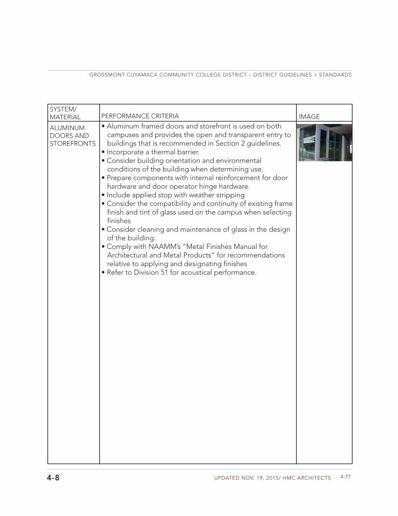
Updated Nov. 19, 2015/ HMC aRCHIteCtS
GRoSSMoNt CUYaMaCa CoMMUNItY CoLLeGe dIStRICt – dIStRICt GUIdeLINeS + StaNdaRdS
4-774-8
ALUMINUM DOORS AND STOREFRONTS
• Aluminum framed doors and storefront is used on bothcampuses and provides the open and transparent entry tobuildings that is recommended in Section 2 guidelines.
• Incorporate a thermal barrier.• Consider building orientation and environmental
conditions of the building when determining use.• Prepare components with internal reinforcement for door
hardware and door operator hinge hardware.• Include applied stop with weather stripping.• Consider the compatibility and continuity of existing frame
finish and tint of glass used on the campus when selectingfinishes
• Consider cleaning and maintenance of glass in the designof the building.
• Comply with NAAMM’s “Metal Finishes Manual forArchitectural and Metal Products” for recommendationsrelative to applying and designating finishes
• Refer to Division 51 for acoustical performance.
SYSTEM/MATERIAL PERFORMANCE CRITERIA IMAGE
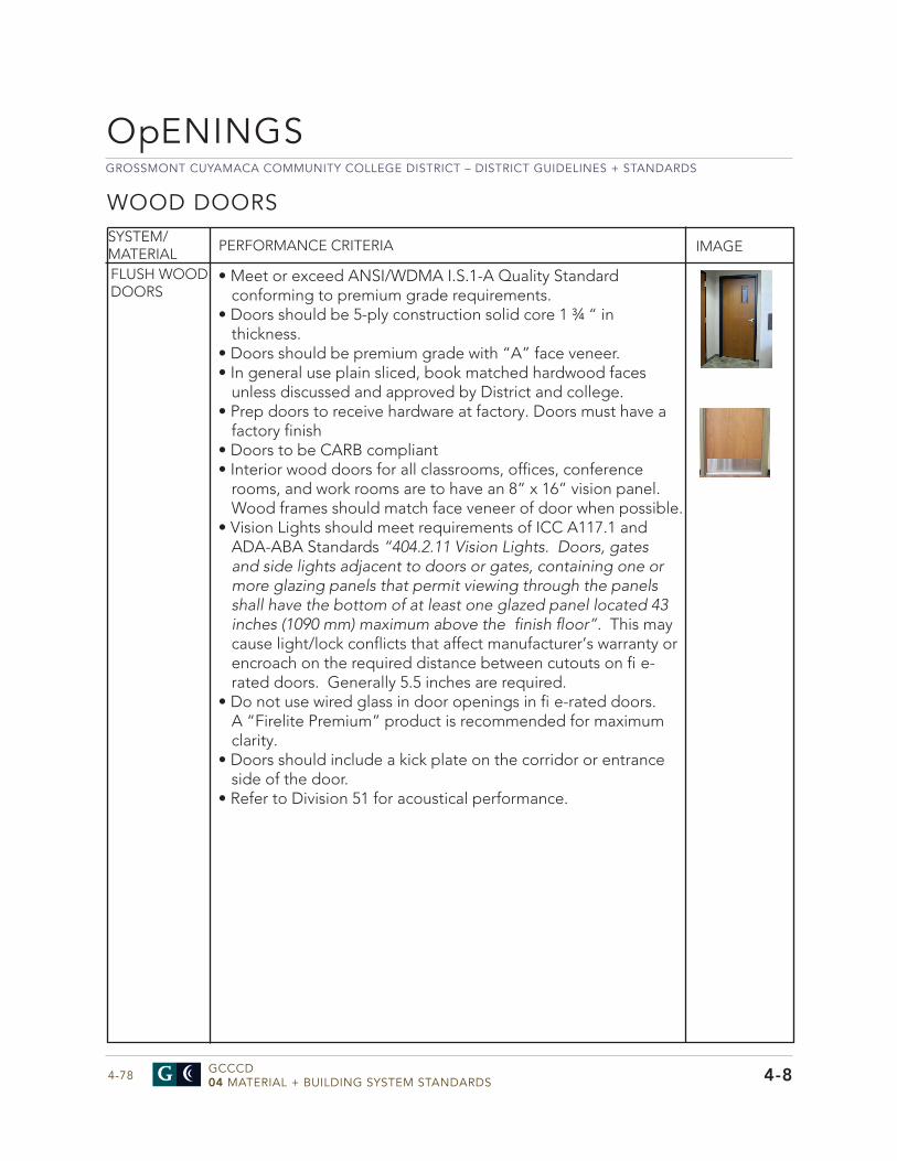
GROSSMONT CUYAMACA COMMUNITY COLLEGE DISTRICT – DISTRICT GUIDELINES + STANDARDS
GCCCD04 MATERIAL + BUILDING SYSTEM STANDARDS4-78
SYSTEM/MATERIAL PERFORMANCE CRITERIA IMAGE
FLUSH WOOD DOORS
• Meet or exceed ANSI/WDMA I.S.1-A Quality Standardconforming to premium grade requirements.
• Doors should be 5-ply construction solid core 1 ¾ “ inthickness.
• Doors should be premium grade with “A” face veneer.• In general use plain sliced, book matched hardwood faces
unless discussed and approved by District and college.• Prep doors to receive hardware at factory. Doors must have a
factory finish• Doors to be CARB compliant• Interior wood doors for all classrooms, offices, conference
rooms, and work rooms are to have an 8” x 16” vision panel.Wood frames should match face veneer of door when possible.
• Vision Lights should meet requirements of ICC A117.1 andADA-ABA Standards “404.2.11 Vision Lights. Doors, gates and side lights adjacent to doors or gates, containing one or more glazing panels that permit viewing through the panels shall have the bottom of at least one glazed panel located 43 inches (1090 mm) maximum above the finish floor”. This may cause light/lock conflicts that affect manufacturer’s warranty or encroach on the required distance between cutouts on fi e-rated doors. Generally 5.5 inches are required.
• Do not use wired glass in door openings in fi e-rated doors.A “Firelite Premium” product is recommended for maximumclarity.
• Doors should include a kick plate on the corridor or entranceside of the door.
• Refer to Division 51 for acoustical performance.
WOOD DOORS
4-8
OpENINGS
Updated Nov. 19, 2015/ HMC aRCHIteCtS
GRoSSMoNt CUYaMaCa CoMMUNItY CoLLeGe dIStRICt – dIStRICt GUIdeLINeS + StaNdaRdS
4-794-8
WINDOWS
• Aluminum windows that comply with AAMA/NWWDA101/I.S.2. for performance class and performance gradeshould be used for punched opening.
• Other approaches to window products should be approvedby the District and the college.
• Thickness of material shall not be less than .125 inch.Frames shall be factory glazed.
• Exterior windows should not be operable unless approvedby District and college.
• Do not include units with integral blinds.• Windows shall be glazed with tempered glass where
subject to human impact.• Consider the compatibility and continuity of existing frame
finish and tint of glass used on the campus when selectingfinishes
• Frame finish should comply with NAAMM s “MetalFinishes Manual for Architectural and Metal Products” forrecommendations relative to applying and designatingfinishes
• Provide a mock-up of a wall with sample window duringconstruction for approval before ordering all windows.Approved sample will be the standard for installationquality.
• Refer to Division 51 for acoustical performance.
SYSTEM/MATERIAL PERFORMANCE CRITERIA IMAGEEXTERIOR WINDOWS
GROSSMONT CUYAMACA COMMUNITY COLLEGE DISTRICT – DISTRICT GUIDELINES + STANDARDS
GCCCD04 MATERIAL + BUILDING SYSTEM STANDARDS4-80
SYSTEM/MATERIAL PERFORMANCE CRITERIA IMAGE
GENERAL • Use Tubular daylighting devices when possible to bring innatural light to interior spaces and save on energy costs forlighting.
• Coordinate light levels and placement in spaces with electricalengineer to and other lighting sources.
• The unit shall consist of a roof dome, reflective tube, addiffuser.
• Manufacturer should be Solatube or equal.
TUBULAR DAYLIGHTING DEVICES (TDD)
4-8
OpENINGS
Updated Nov. 19, 2015/ HMC aRCHIteCtS
GRoSSMoNt CUYaMaCa CoMMUNItY CoLLeGe dIStRICt – dIStRICt GUIdeLINeS + StaNdaRdS
4-814-8
• Tubular Daylighting Devices General : Transparent roof-mounted skylight dome and self-flashing curb,reflective tube, and ceiling level diffuser assembly,transferring sunlight to interior spaces.
• Flashing Base should be one piece, seamless, leak-proofflashing functioning as base support for dome and top of tube and identify if Roof Flashing Turret Extensions are required for specific project.
• All units in instructional spaces and conference roomsshall include a local dimmer control utilizing a butterflybaffle design of “Spectralight Infinity” reflective materialto minimize shadowing when in use. Provide with dimmerswitch and cable. Coordinate with bank of light switched ininstructional space.
• Use a wire suspension kit when additional bracing to thestructure is required for the unit.
• Provide exhaust fan and exhaust vent cap if needed.Switches shall be located on wall adjacent to dimmerswitch.
• Install in accordance with manufacturer’s printedinstructions. After installation of first unit, field test tdetermine adequacy of installation. Conduct water testin presence of Inspector and Architect, and ProgramManager for acceptance. Correct installation procedure ifneeded before proceeding with installation of subsequentunits.
SYSTEM/MATERIAL PERFORMANCE CRITERIA IMAGETDD UNIT
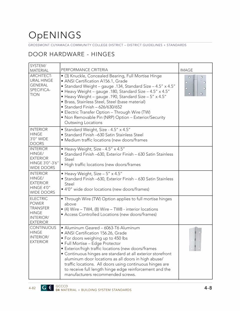
GROSSMONT CUYAMACA COMMUNITY COLLEGE DISTRICT – DISTRICT GUIDELINES + STANDARDS
GCCCD04 MATERIAL + BUILDING SYSTEM STANDARDS4-82
• Aluminum Geared – 6063-T6 Aluminum• ANSI Certification 156.26, Grade• For doors weighing up to 450 lbs• Full Mortise – Edge Protector• Exterior/high traffic locations (new doors/frames• Continuous hinges are standard at all exterior storefront
aluminum door locations as all doors in high abuse/traffic locations. All doors using continuous hinges areto receive full length hinge edge reinforcement and themanufacturers recommended screws.
OpENINGS
4-8
DOOR HARDWARE - HINGES
SYSTEM/MATERIAL PERFORMANCE CRITERIA IMAGEARCHITECT-URAL HINGE GENERAL SPECIFICA-TION
INTERIOR HINGE3’0” WIDE DOORSINTERIOR HINGE/EXTERIOR HINGE 3’0”-3’6” WIDE DOORSINTERIOR HINGE/EXTERIOR HINGE 4’0” WIDE DOORS
• (3) Knuckle, Concealed Bearing, Full Mortise Hinge• ANSI Certification A156.1, Grade• Standard Weight – gauge .134, Standard Size – 4.5” x 4.5”• Heavy Weight – gauge .180, Standard Size – 4.5” x 4.5”• Heavy Weight – gauge .190, Standard Size – 5” x 4.5”• Brass, Stainless Steel, Steel (base material)• Standard Finish – 626/630/652• Electric Transfer Option – Through Wire (TW)• Non Removable Pin (NRP) Option – Exterior/Security
Outswing Locations
• Standard Weight, Size - 4.5” x 4.5”• Standard Finish –630 Satin Stainless Steel• Medium traffic locations (new doors/frames
• Heavy Weight, Size - 4.5” x 4.5”• Standard Finish –630, Exterior Finish – 630 Satin Stainless
Steel• High traffic locations (new doors/frames
• Heavy Weight, Size – 5” x 4.5”• Standard Finish –630, Exterior Finish – 630 Satin Stainless
Steel• 4’0” wide door locations (new doors/frames)
ELECTRIC POWER TRANSFER HINGEINTERIOR/EXTERIORCONTINUOUS HINGE INTERIOR/EXTERIOR
• Through Wire (TW) Option applies to full mortise hingesabove
• (4) Wire – TW4, (8) Wire – TW8 - interior locations• Access Controlled Locations (new doors/frames)
Updated Nov. 19, 2015/ HMC aRCHIteCtS
GRoSSMoNt CUYaMaCa CoMMUNItY CoLLeGe dIStRICt – dIStRICt GUIdeLINeS + StaNdaRdS
4-834-8
SYSTEM/MATERIAL PERFORMANCE CRITERIA IMAGE
CONTINUOUS HINGE EXISTING INTERIOR/EXTERIOR
• Aluminum Geared – 6063-T6 Aluminum• ANSI Certification 156.26, Grade• For doors weighing up to 550 lbs• Full Surface – Center Pivot - Adjustable• Exterior/high traffic locations (existing doors/frames
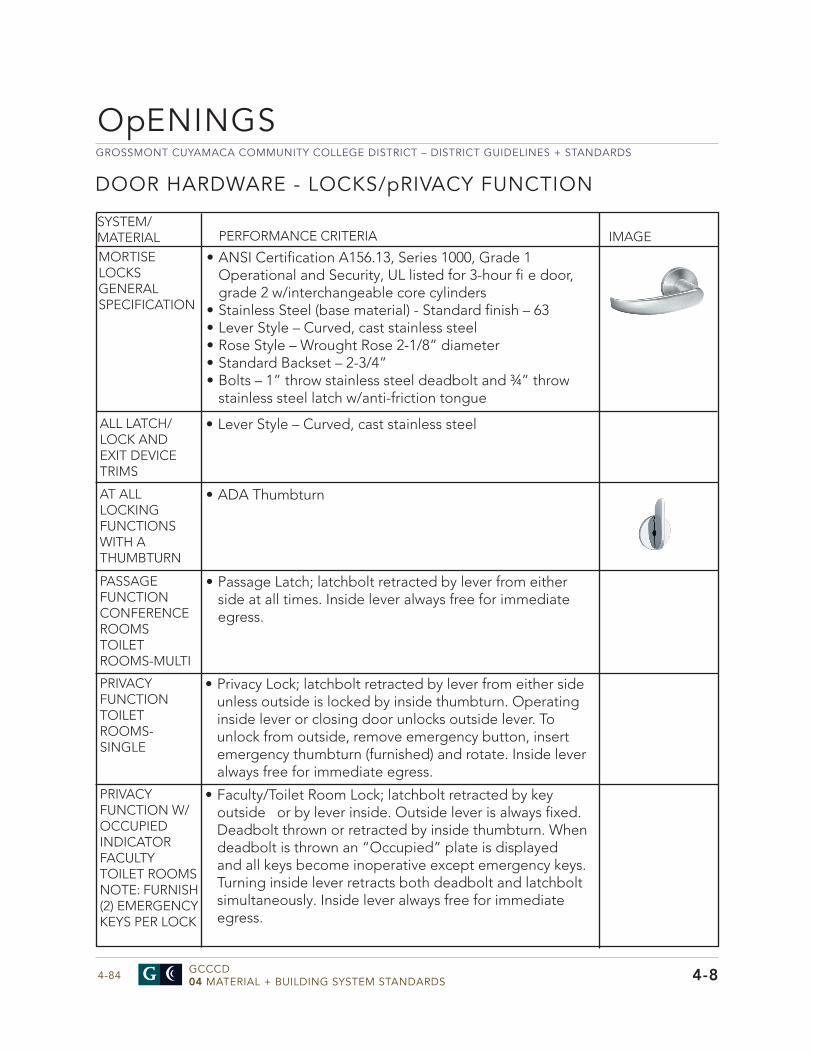
GROSSMONT CUYAMACA COMMUNITY COLLEGE DISTRICT – DISTRICT GUIDELINES + STANDARDS
GCCCD04 MATERIAL + BUILDING SYSTEM STANDARDS4-84
DOOR HARDWARE - LOCKS/pRIVACY FUNCTION
SYSTEM/MATERIAL PERFORMANCE CRITERIA IMAGE
MORTISE LOCKS GENERAL SPECIFICATION
ALL LATCH/LOCK AND EXIT DEVICE TRIMS
AT ALL LOCKING FUNCTIONS WITH A THUMBTURN
PASSAGE FUNCTIONCONFERENCE ROOMSTOILET ROOMS-MULTI
• ANSI Certification A156.13, Series 1000, Grade 1Operational and Security, UL listed for 3-hour fi e door,grade 2 w/interchangeable core cylinders
• Stainless Steel (base material) - Standard finish – 63• Lever Style – Curved, cast stainless steel• Rose Style – Wrought Rose 2-1/8” diameter• Standard Backset – 2-3/4”• Bolts – 1” throw stainless steel deadbolt and ¾” throw
stainless steel latch w/anti-friction tongue
4-8
• Lever Style – Curved, cast stainless steel
• ADA Thumbturn
• Passage Latch; latchbolt retracted by lever from eitherside at all times. Inside lever always free for immediateegress.
PRIVACY FUNCTION TOILET ROOMS-SINGLE
• Privacy Lock; latchbolt retracted by lever from either sideunless outside is locked by inside thumbturn. Operatinginside lever or closing door unlocks outside lever. Tounlock from outside, remove emergency button, insertemergency thumbturn (furnished) and rotate. Inside leveralways free for immediate egress.
PRIVACY FUNCTION W/OCCUPIED INDICATORFACULTY TOILET ROOMS NOTE: FURNISH (2) EMERGENCY KEYS PER LOCK
• Faculty/Toilet Room Lock; latchbolt retracted by keyoutside or by lever inside. Outside lever is always fixed.Deadbolt thrown or retracted by inside thumbturn. Whendeadbolt is thrown an “Occupied” plate is displayedand all keys become inoperative except emergency keys.Turning inside lever retracts both deadbolt and latchboltsimultaneously. Inside lever always free for immediateegress.
OpENINGS
UPDATED NOV. 19, 2015/ HMC ARCHITECTS
GROSSMONT CUYAMACA COMMUNITY COLLEGE DISTRICT – DISTRICT GUIDELINES + STANDARDS
4-854-8
SYSTEM/MATERIAL PERFORMANCE CRITERIA IMAGEPRIVATEOFFICE
CLASSROOM FUNCTION: ENTRY OFFICE, CORRIDOR CONFERENCE ROOMSCLASSROOM FUNCTION: CLASSROOM DOORS
STOREROOM FUNCTION: FACILITIES/JANITOR/UTILITY
• Entrance Lock; latchbolt retracted by lever from either sideunless outside is locked by inside thumbturn or by keyoutside. Deadbolt thrown or retracted by thumbturn. Outsidelever remains locked until thumbturn returned to verticalposition. Keyed access only from outside when locked. Insidelever always free for immediate egress.
• Classroom Lock; latchbolt retracted by lever from either sideunless outside is locked by key. Unlocked/locked by keyoutside. Can be left unlocked, cannot be locked without a key.Inside lever always free for immediate egress.
• Classroom Security Holdback Lock-w/Vandal resistant outsidetrim; latchbolt retracted by inside lever or by key outside.Outside trim can be locked from inside the classroom.Electronic card access only from outside when locked. Insidelever always free for immediate egress.
• Storeroom Lock; latchbolt retracted by inside lever or by keyoutside. Outside lever is always fi xed. Keyed access only fromoutside when locked. Inside lever always free for immediateegress.
• Storeroom Lock w/Deadbolt; latchbolt retracted by inside lever orby key outside. Outside lever is always fi xed. Deadbolt thrown orretracted by key outside or thumbturn inside. Keyed access onlyfrom outside when locked. Inside lever always free for egress.
• Electrifi ed Lock w/Request to Exit (RX); outside leverelectrically unlocked by 24V AC or DC aft er presentation of avalid access credential. An internal micro-switch (RX) monitorsthe lever action to signal the use of the opening to securitysystems. Latchbolt retracted by inside lever or by key outside.Outside lever cannot be left unlocked. Inside lever always freefor immediate egress.
• Coordinate electrifi ed lock with District’s Access controlcompany” Millennium Group.
• Install on all classroom, o ffi ce, conference room, storage andMDF and IDF rooms. Install at department and administrationsuite doors. Install on all exterior doors.
• Other doors may require Electronic Mortise Locks. Coordinateall locations with District and college staff . See Division 28.
STOREROOM W/DEADBOLT FUNCTION: PERIMETER/SECURITYELECTRONIC MORTISE LOCKS ELECTRICALLY UNLOCKED FUNCTION (FAIL SECURE) INTERIOR/ EXTERIOR ACCESS CONTROLLED
ALL DOORS • Refer to spreadsheet in Appendix H for additional clarifi cation
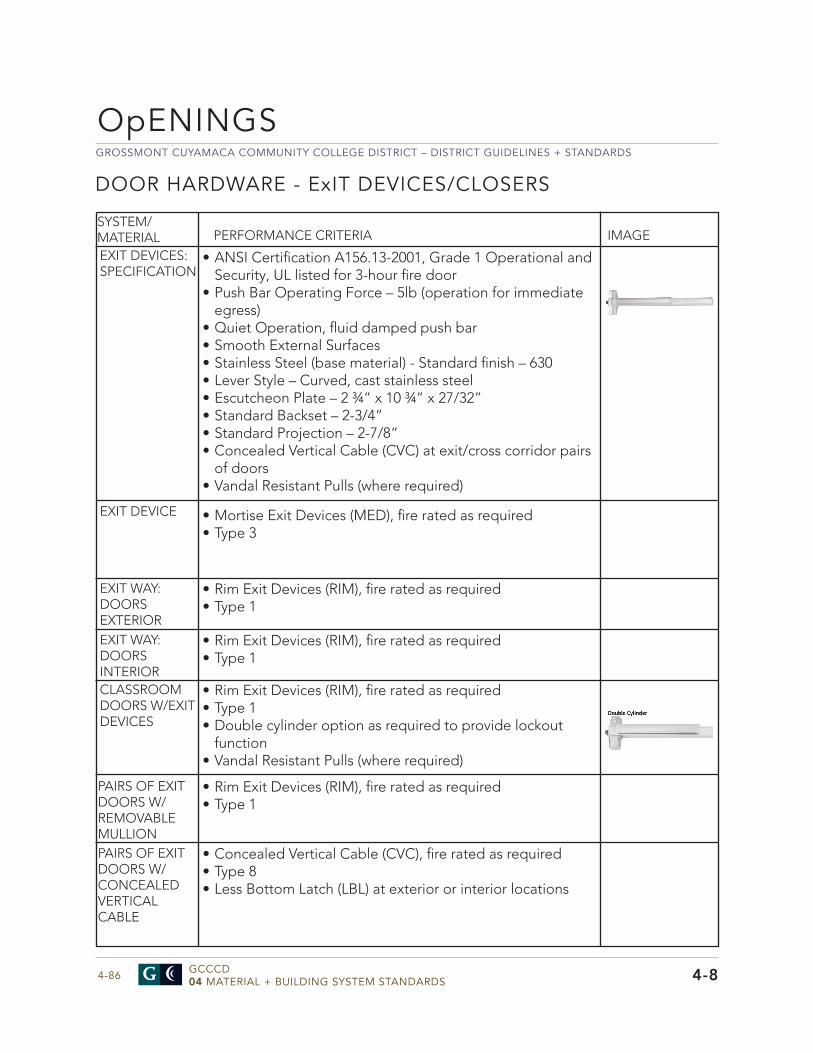
GROSSMONT CUYAMACA COMMUNITY COLLEGE DISTRICT – DISTRICT GUIDELINES + STANDARDS
GCCCD04 MATERIAL + BUILDING SYSTEM STANDARDS4-86
DOOR HARDWARE - ExIT DEVICES/CLOSERS
SYSTEM/MATERIAL PERFORMANCE CRITERIA IMAGE
EXIT DEVICES: SPECIFICATION
EXIT DEVICE
EXIT WAY: DOORS EXTERIOREXIT WAY: DOORS INTERIOR
• ANSI Certifi cation A156.13-2001, Grade 1 Operational andSecurity, UL listed for 3-hour fi re door
• Push Bar Operating Force – 5lb (operation for immediateegress)
• Quiet Operation, fl uid damped push bar• Smooth External Surfaces• Stainless Steel (base material) - Standard fi nish – 630• Lever Style – Curved, cast stainless steel• Escutcheon Plate – 2 ¾” x 10 ¾” x 27/32”• Standard Backset – 2-3/4”• Standard Projection – 2-7/8”• Concealed Vertical Cable (CVC) at exit/cross corridor pairs
of doors• Vandal Resistant Pulls (where required)
4-8
CLASSROOM DOORS W/EXIT DEVICES
PAIRS OF EXIT DOORS W/REMOVABLE MULLIONPAIRS OF EXIT DOORS W/CONCEALED VERTICAL CABLE
• Mortise Exit Devices (MED), fi re rated as required• Type 3
• Rim Exit Devices (RIM), fi re rated as required• Type 1
• Rim Exit Devices (RIM), fi re rated as required• Type 1• Double cylinder option as required to provide lockout
function• Vandal Resistant Pulls (where required)
• Rim Exit Devices (RIM), fi re rated as required• Type 1
• Concealed Vertical Cable (CVC), fi re rated as required• Type 8• Less Bottom Latch (LBL) at exterior or interior locations
• Rim Exit Devices (RIM), fi re rated as required• Type 1
OpENINGS
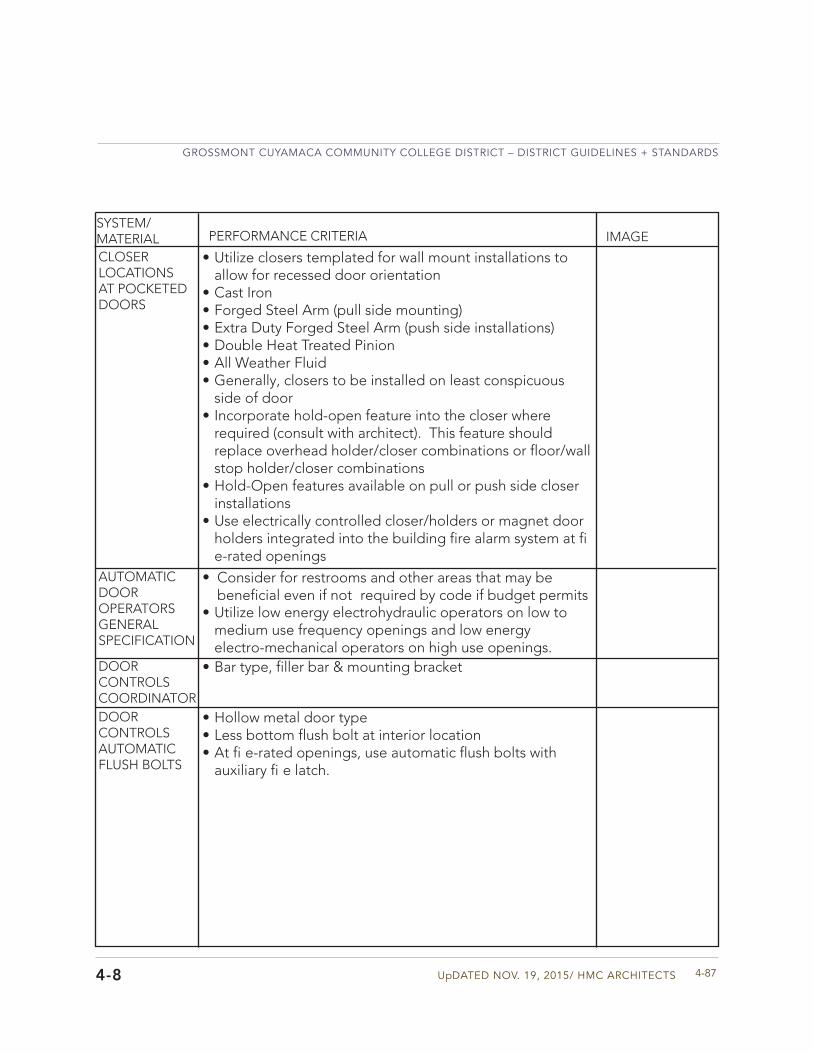
UpDATED NOV. 19, 2015/ HMC ARCHITECTS
GROSSMONT CUYAMACA COMMUNITY COLLEGE DISTRICT – DISTRICT GUIDELINES + STANDARDS
4-874-8
SYSTEM/MATERIAL PERFORMANCE CRITERIA IMAGE
CLOSER LOCATIONS AT POCKETED DOORS
AUTOMATIC DOOR OPERATORS GENERAL SPECIFICATION
DOOR CONTROLS COORDINATORDOOR CONTROLSAUTOMATIC FLUSH BOLTS
• Utilize closers templated for wall mount installations toallow for recessed door orientation
• Cast Iron• Forged Steel Arm (pull side mounting)• Extra Duty Forged Steel Arm (push side installations)• Double Heat Treated Pinion• All Weather Fluid• Generally, closers to be installed on least conspicuous
side of door• Incorporate hold-open feature into the closer where
required (consult with architect). This feature shouldreplace overhead holder/closer combinations or floor/wallstop holder/closer combinations
• Hold-Open features available on pull or push side closerinstallations
• Use electrically controlled closer/holders or magnet doorholders integrated into the building fire alarm system at fie-rated openings
• Consider for restrooms and other areas that may bebeneficial even if not required by code if budget permits
• Utilize low energy electrohydraulic operators on low tomedium use frequency openings and low energyelectro-mechanical operators on high use openings.
• Bar type, filler bar & mounting bracket
• Hollow metal door type• Less bottom flush bolt at interior location• At fi e-rated openings, use automatic flush bolts with
auxiliary fi e latch.
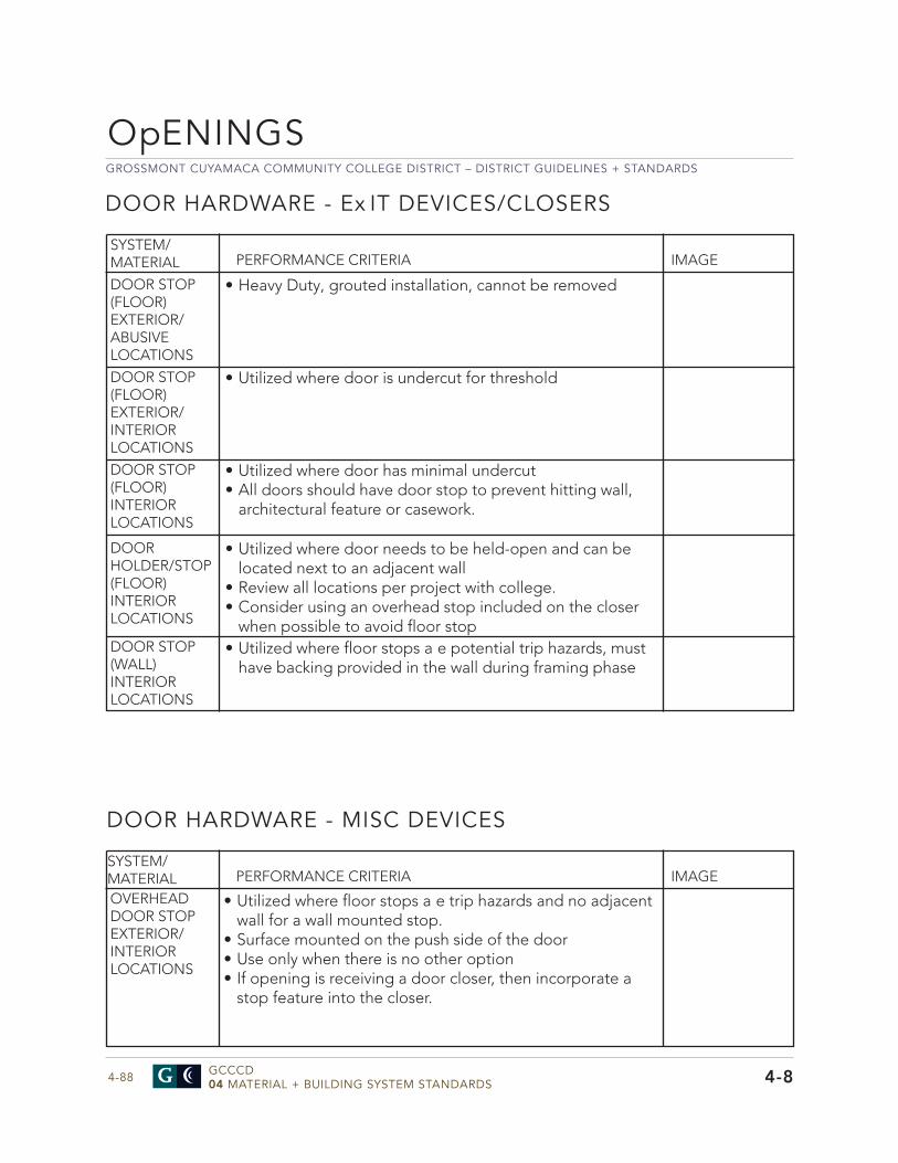
GROSSMONT CUYAMACA COMMUNITY COLLEGE DISTRICT – DISTRICT GUIDELINES + STANDARDS
GCCCD04 MATERIAL + BUILDING SYSTEM STANDARDS4-88 4-8
DOOR HARDWARE - MISC DEVICES
SYSTEM/MATERIAL PERFORMANCE CRITERIA IMAGE
OVERHEAD DOOR STOPEXTERIOR/INTERIOR LOCATIONS
• Utilized where floor stops a e trip hazards and no adjacentwall for a wall mounted stop.
• Surface mounted on the push side of the door• Use only when there is no other option• If opening is receiving a door closer, then incorporate a
stop feature into the closer.
OpENINGS
SYSTEM/MATERIAL PERFORMANCE CRITERIA IMAGE
DOOR HOLDER/STOP (FLOOR)INTERIOR LOCATIONS
• Utilized where door needs to be held-open and can belocated next to an adjacent wall
• Review all locations per project with college.• Consider using an overhead stop included on the closer
when possible to avoid floor stop• Utilized where floor stops a e potential trip hazards, must
have backing provided in the wall during framing phaseDOOR STOP (WALL)INTERIOR LOCATIONS
DOOR STOP (FLOOR)EXTERIOR/ABUSIVE LOCATIONS
• Heavy Duty, grouted installation, cannot be removed
DOOR STOP (FLOOR)EXTERIOR/INTERIOR LOCATIONS
• Utilized where door is undercut for threshold
DOOR STOP (FLOOR)INTERIOR LOCATIONS
• Utilized where door has minimal undercut• All doors should have door stop to prevent hitting wall,
architectural feature or casework.
DOOR HARDWARE - Ex IT DEVICES/CLOSERS
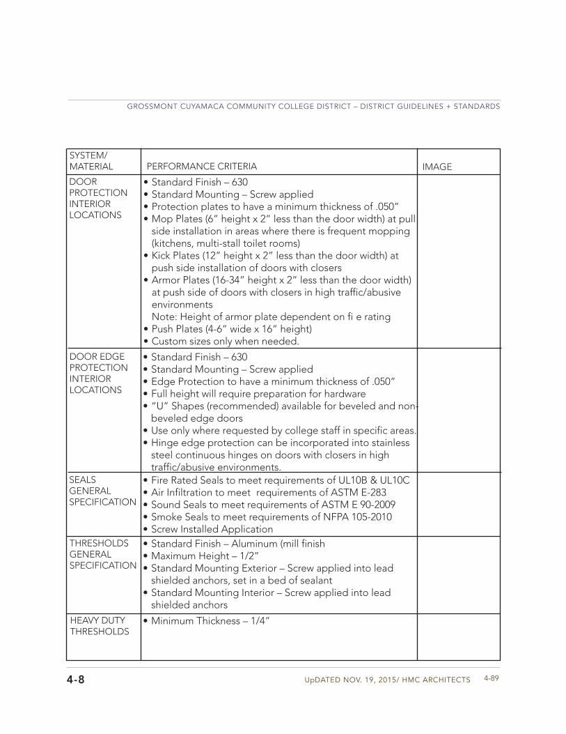
UpDATED NOV. 19, 2015/ HMC ARCHITECTS
GROSSMONT CUYAMACA COMMUNITY COLLEGE DISTRICT – DISTRICT GUIDELINES + STANDARDS
4-894-8
DOOR PROTECTIONINTERIOR LOCATIONS
DOOR EDGE PROTECTIONINTERIOR LOCATIONS
SEALSGENERAL SPECIFICATION
THRESHOLDSGENERAL SPECIFICATION
HEAVY DUTY THRESHOLDS
• Standard Finish – 630• Standard Mounting – Screw applied• Protection plates to have a minimum thickness of .050”• Mop Plates (6” height x 2” less than the door width) at pull
side installation in areas where there is frequent mopping(kitchens, multi-stall toilet rooms)
• Kick Plates (12” height x 2” less than the door width) atpush side installation of doors with closers
• Armor Plates (16-34” height x 2” less than the door width)at push side of doors with closers in high traffic/abusiveenvironmentsNote: Height of armor plate dependent on fi e rating
• Push Plates (4-6” wide x 16” height)• Custom sizes only when needed.
• Standard Finish – 630• Standard Mounting – Screw applied• Edge Protection to have a minimum thickness of .050”• Full height will require preparation for hardware• “U” Shapes (recommended) available for beveled and non-
beveled edge doors• Use only where requested by college staff in specific areas.• Hinge edge protection can be incorporated into stainless
steel continuous hinges on doors with closers in hightraffic/abusive environments.
• Standard Finish – Aluminum (mill finish• Maximum Height – 1/2”• Standard Mounting Exterior – Screw applied into lead
shielded anchors, set in a bed of sealant• Standard Mounting Interior – Screw applied into lead
shielded anchors
• Fire Rated Seals to meet requirements of UL10B & UL10C• Air Infiltration to meet requirements of ASTM E-283• Sound Seals to meet requirements of ASTM E 90-2009• Smoke Seals to meet requirements of NFPA 105-2010• Screw Installed Application
• Minimum Thickness – 1/4”
SYSTEM/MATERIAL PERFORMANCE CRITERIA IMAGE
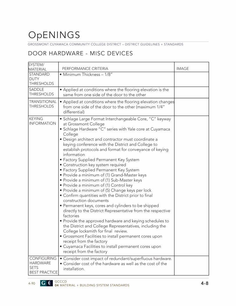
GROSSMONT CUYAMACA COMMUNITY COLLEGE DISTRICT – DISTRICT GUIDELINES + STANDARDS
GCCCD04 MATERIAL + BUILDING SYSTEM STANDARDS4-90
OpENINGS
SYSTEM/MATERIAL PERFORMANCE CRITERIA IMAGE
SADDLE THRESHOLDS
TRANSITIONAL THRESHOLDS
KEYING INFORMATION
• Applied at conditions where the flooring elevation is thesame from one side of the door to the other
• Applied at conditions where the flooring elevation changesfrom one side of the door to the other (maximum 1/4”differential)
• Schlage Large Format Interchangeable Core, “C” keywayat Grossmont College
• Schlage Hardware “C” series with Yale core at CuyamacaCollege
• Design architect and contractor must coordinate akeying conference with the District and College toestablish protocols and format for conveyance of keyinginformation
• Factory Supplied Permanent Key System• Construction key system required• Factory Supplied Permanent Key System• Provide a minimum of (1) Grand-Master keys• Provide a minimum of (1) Sub-Master keys• Provide a minimum of (1) Control key• Provide a minimum of (5) Change keys per lock• Confirm quantities with the District prior to final
construction documents• Permanent keys, cores and cylinders to be shipped
directly to the District Representative from the respectivefactories
• Provide the approved hardware and keying schedules tothe District and College Representatives, including theCollege locksmith for final review.
• Grossmont Facilities to install permanent cores uponreceipt from the factory
• Cuyamaca Facilities to install permanent cores uponreceipt from the factory
STANDARD DUTY THRESHOLDS
• Minimum Thickness – 1/8”
DOOR HARDWARE - MISC DEVICES
4-8
CONFIGURINGHARDWARE SETSBEST PRACTICE
• Consider cost impact of redundant/superfluous hardware.• Consider cost of the hardware as well as the cost of the
installation.
UpDATED NOV. 19, 2015/ HMC ARCHITECTS
GROSSMONT CUYAMACA COMMUNITY COLLEGE DISTRICT – DISTRICT GUIDELINES + STANDARDS
4-91
GLAZING
• Exterior glazing will be greatly influenced by title24 requirements.
• Glazing tint color should be coordinated with Section 2 andother buildings on campus.
• Avoid using clear glass.• Installed glazing systems shall withstand normal thermal
movement and wind without failure including loss or glassbreakage.
• Air and Watertight infiltration per ASTM E283 and ASTME331
• Perform installation in accordance with GANA GlazingManual and GANA Sealant Manual and IGMA/SIGMAGlazing Manual, Class CBA.
• All glazing shall have a 1 year manufacturer’s warranty fromsubstantial completion for defective products includingbroken, cracked, or otherwise damaged glass not causedby vandalism.
• Sealed glass units shall have a 10 year manufacturer’sspecial warranty from seal failure, and interpane dustingor misting. Complete unit replacement required for failurerequired.
SYSTEM/MATERIAL PERFORMANCE CRITERIA IMAGE
EXTERIOR GLAz ING
MIRROR GLASS
• Use safety glass mirrors in restrooms.• Safety glass shall comply with ANSI z971.1 and testing
requirements of 16 CFR Part 1201
• Float glass should comply with ASTM C 1036 Type 1,Quality Q3.
• Heat treated glass products, fully tempered glass shouldcomply with ASTM C 1048, Type 1, Quality Q3.
• Laminated glass units should comply with ASTM C1172.
GENERAL GLASS STANDARDS
4-8
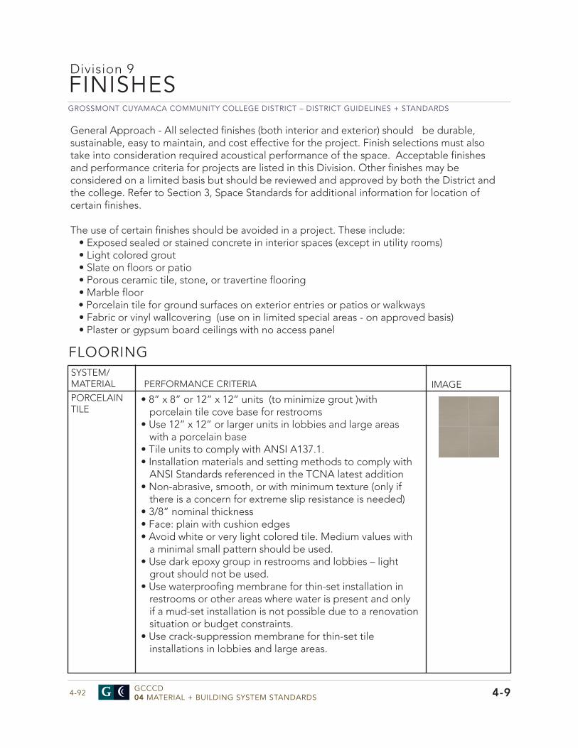
GROSSMONT CUYAMACA COMMUNITY COLLEGE DISTRICT – DISTRICT GUIDELINES + STANDARDS
GCCCD04 MATERIAL + BUILDING SYSTEM STANDARDS4-92
FINISHES
4-9
Division 9
• 8” x 8” or 12” x 12” units (to minimize grout )withporcelain tile cove base for restrooms
• Use 12” x 12” or larger units in lobbies and large areaswith a porcelain base
• Tile units to comply with ANSI A137.1.• Installation materials and setting methods to comply with
ANSI Standards referenced in the TCNA latest addition• Non-abrasive, smooth, or with minimum texture (only if
there is a concern for extreme slip resistance is needed)• 3/8” nominal thickness• Face: plain with cushion edges• Avoid white or very light colored tile. Medium values with
a minimal small pattern should be used.• Use dark epoxy group in restrooms and lobbies – light
grout should not be used.• Use waterproofing membrane for thin-set installation in
restrooms or other areas where water is present and onlyif a mud-set installation is not possible due to a renovationsituation or budget constraints.
• Use crack-suppression membrane for thin-set tileinstallations in lobbies and large areas.
SYSTEM/MATERIAL
FLOORING
PERFORMANCE CRITERIA IMAGEPORCELAIN TILE
General Approach - All selected finishes (both interior and exterior) should be durable, sustainable, easy to maintain, and cost effective for the project. Finish selections must also take into consideration required acoustical performance of the space. Acceptable finishes and performance criteria for projects are listed in this Division. Other finishes may be considered on a limited basis but should be reviewed and approved by both the District and the college. Refer to Section 3, Space Standards for additional information for location of certain finishes.
The use of certain finishes should be avoided in a project. These include:• Exposed sealed or stained concrete in interior spaces (except in utility rooms)• Light colored grout• Slate on floors or patio• Porous ceramic tile, stone, or travertine flooring• Marble floor• Porcelain tile for ground surfaces on exterior entries or patios or walkways• Fabric or vinyl wallcovering (use on in limited special areas - on approved basis)• Plaster or gypsum board ceilings with no access panel
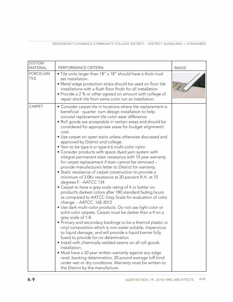
UpDATED NOV. 19, 2015/ HMC ARCHITECTS
GROSSMONT CUYAMACA COMMUNITY COLLEGE DISTRICT – DISTRICT GUIDELINES + STANDARDS
4-934-9
SYSTEM/MATERIAL PERFORMANCE CRITERIA IMAGE
PORCELAIN TILE
CARPET • Consider carpet tile in locations where tile replacement isbeneficial - quarter -turn design installation to helpconceal replacement tile color wear difference
• Roll goods are acceptable in certain areas and should beconsidered for appropriate areas for budget alignment/cost.
• Use carpet on open stairs unless otherwise discussed andapproved by District and college.
• Yarn to be type 6 or type 6.6 multi-color nylon• Consider products with space dyed yarn system with
integral permanent stain resistance with 10 year warrantyfor carpet replacement if stain cannot be removed –provide manufacture’s letter to District for warranty.
• Static resistance of carpet construction to provide aminimum of 3.0Kv resistance at 20 percent R.H. at 70degrees F. –AATCC 134
• Carpet to have a grey scale rating of 4 or better onproduct’s darkest colors after 180 standard fading hoursas compared to AATCC Grey Scale for evaluation of colorchange. - AATCC 16E-2012
• Use dark multi-color products. Do not use light color orsolid color carpets. Carpet must be darker than a 4 on agrey scale of 1-8.
• Primary and secondary backings to be a thermal plastic orvinyl composition which is non-water soluble, imperviousto liquid damage, and will provide a liquid barrier fullyfused to provide for no delamination
• Install with chemically welded seams on all roll goodsinstallation.
• Must have a 20 year written warranty against any edgeravel, backing delamination, 20 pound average tuff bindunder wet or dry conditions. Warranty must be written tothe District by the manufacture.
• Tile units larger than 18” x 18” should have a thick mudset installation.
• Metal edge protection strips should be used on floor tileinstallations with a flush floor finish for all installation
• Provide a 2 % or other agreed on amount with college ofrepair stock tile from same color run as installation.
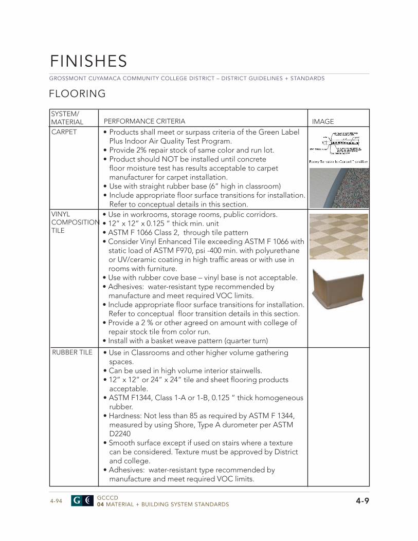
GROSSMONT CUYAMACA COMMUNITY COLLEGE DISTRICT – DISTRICT GUIDELINES + STANDARDS
GCCCD04 MATERIAL + BUILDING SYSTEM STANDARDS4-94
SYSTEM/MATERIAL PERFORMANCE CRITERIA IMAGE
CARPET
VINYL COMPOSITION TILE
FLOORING
4-9
• Products shall meet or surpass criteria of the Green LabelPlus Indoor Air Quality Test Program.
• Provide 2% repair stock of same color and run lot.• Product should NOT be installed until concrete
floor moisture test has results acceptable to carpetmanufacturer for carpet installation.
• Use with straight rubber base (6” high in classroom)• Include appropriate floor surface transitions for installation.
Refer to conceptual details in this section.• Use in workrooms, storage rooms, public corridors.• 12” x 12” x 0.125 “ thick min. unit• ASTM F 1066 Class 2, through tile pattern• Consider Vinyl Enhanced Tile exceeding ASTM F 1066 with
static load of ASTM F970, psi -400 min. with polyurethaneor UV/ceramic coating in high traffic areas or with use inrooms with furniture.
• Use with rubber cove base – vinyl base is not acceptable.• Adhesives: water-resistant type recommended by
manufacture and meet required VOC limits.• Include appropriate floor surface transitions for installation.
Refer to conceptual floor transition details in this section.• Provide a 2 % or other agreed on amount with college of
repair stock tile from color run.• Install with a basket weave pattern (quarter turn)
RUBBER TILE • Use in Classrooms and other higher volume gatheringspaces.
• Can be used in high volume interior stairwells.• 12” x 12” or 24” x 24” tile and sheet flooring products
acceptable.• ASTM F1344, Class 1-A or 1-B, 0.125 “ thick homogeneous
rubber.• Hardness: Not less than 85 as required by ASTM F 1344,
measured by using Shore, Type A durometer per ASTMD2240
• Smooth surface except if used on stairs where a texturecan be considered. Texture must be approved by Districtand college.
• Adhesives: water-resistant type recommended bymanufacture and meet required VOC limits.
FINISHES
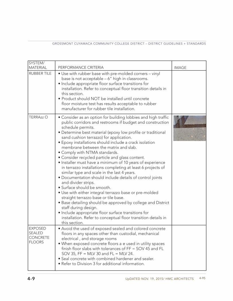
UpDATED NOV. 19, 2015/ HMC ARCHITECTS
GROSSMONT CUYAMACA COMMUNITY COLLEGE DISTRICT – DISTRICT GUIDELINES + STANDARDS
4-954-9
SYSTEM/MATERIAL PERFORMANCE CRITERIA IMAGE
EXPOSED SEALED CONCRETE FLOORS
TERRAzz O
• Use with rubber base with pre-molded corners – vinylbase is not acceptable – 6” high in classrooms.
• Include appropriate floor surface transitions forinstallation. Refer to conceptual floor transition details inthis section.
• Product should NOT be installed until concretefloor moisture test has results acceptable to rubbermanufacturer for rubber tile installation.
RUBBER TILE
• Consider as an option for building lobbies and high trafficpublic corridors and restrooms if budget and constructionschedule permits.
• Determine best material (epoxy low profile or traditionalsand cushion terrazzo) for application.
• Epoxy installations should include a crack isolationmembrane between the matrix and slab.
• Comply with NTMA standards.• Consider recycled particle and glass content.• Installer must have a minimum of 10 years of experience
in terrazzo installations completing at least 6 projects ofsimilar type and scale in the last 4 years.
• Documentation should include details of control jointsand divider strips.
• Surface should be smooth.• Use with either integral terrazzo base or pre-molded
straight terrazzo base or tile base.• Base detailing should be approved by college and District
staff during design.• Include appropriate floor surface transitions for
installation. Refer to conceptual floor transition details inthis section.
• Avoid the used of exposed sealed and colored concretefloors in any spaces other than custodial, mechanicalelectrical , and storage rooms
• When exposed concrete floors a e used in utility spacesfinish floor slabs with tolerances of FF = SOV 45 and FLSOV 35, FF = MLV 30 and FL = MLV 24.
• Seal concrete with combined hardener and sealer.• Refer to Division 3 for additional information.
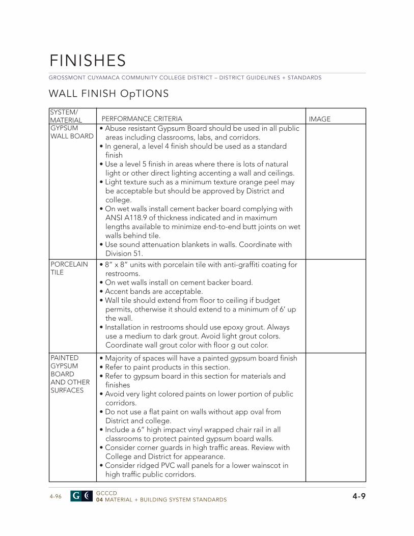
GROSSMONT CUYAMACA COMMUNITY COLLEGE DISTRICT – DISTRICT GUIDELINES + STANDARDS
GCCCD04 MATERIAL + BUILDING SYSTEM STANDARDS4-96
FINISHES
4-9
WALL FINISH OpTIONS
• Abuse resistant Gypsum Board should be used in all publicareas including classrooms, labs, and corridors.
• In general, a level 4 finish should be used as a standardfinish
• Use a level 5 finish in areas where there is lots of naturallight or other direct lighting accenting a wall and ceilings.
• Light texture such as a minimum texture orange peel maybe acceptable but should be approved by District andcollege.
• On wet walls install cement backer board complying withANSI A118.9 of thickness indicated and in maximumlengths available to minimize end-to-end butt joints on wetwalls behind tile.
• Use sound attenuation blankets in walls. Coordinate withDivision 51.
SYSTEM/MATERIAL PERFORMANCE CRITERIA IMAGEGYPSUM WALL BOARD
PORCELAIN TILE
• 8” x 8” units with porcelain tile with anti-graffiti coating forrestrooms.
• On wet walls install on cement backer board.• Accent bands are acceptable.• Wall tile should extend from floor to ceiling if budget
permits, otherwise it should extend to a minimum of 6’ upthe wall.
• Installation in restrooms should use epoxy grout. Alwaysuse a medium to dark grout. Avoid light grout colors.Coordinate wall grout color with floor g out color.
PAINTED GYPSUM BOARD AND OTHER SURFACES
• Majority of spaces will have a painted gypsum board finish• Refer to paint products in this section.• Refer to gypsum board in this section for materials and
finishes• Avoid very light colored paints on lower portion of public
corridors.• Do not use a flat paint on walls without app oval from
District and college.• Include a 6” high impact vinyl wrapped chair rail in all
classrooms to protect painted gypsum board walls.• Consider corner guards in high traffic areas. Review with
College and District for appearance.• Consider ridged PVC wall panels for a lower wainscot in
high traffic public corridors.
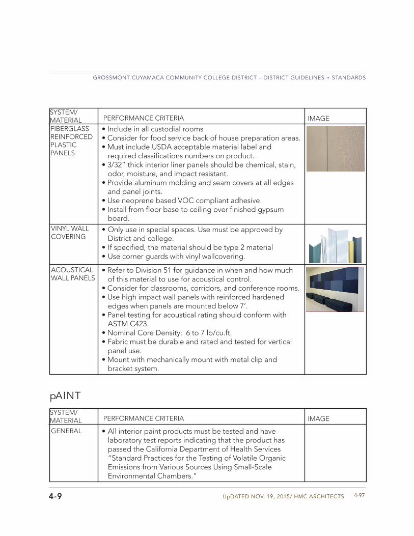
UpDATED NOV. 19, 2015/ HMC ARCHITECTS
GROSSMONT CUYAMACA COMMUNITY COLLEGE DISTRICT – DISTRICT GUIDELINES + STANDARDS
4-974-9
SYSTEM/MATERIAL PERFORMANCE CRITERIA IMAGE
FIBERGLASS REINFORCED PLASTIC PANELS
VINYL WALL COVERING
ACOUSTICAL WALL PANELS
• Include in all custodial rooms• Consider for food service back of house preparation areas.• Must include USDA acceptable material label and
required classifications numbers on product.• 3/32” thick interior liner panels should be chemical, stain,
odor, moisture, and impact resistant.• Provide aluminum molding and seam covers at all edges
and panel joints.• Use neoprene based VOC compliant adhesive.• Install from floor base to ceiling over finished gypsum
board.
• Only use in special spaces. Use must be approved byDistrict and college.
• If specified, the material should be type 2 material• Use corner guards with vinyl wallcovering.
• Refer to Division 51 for guidance in when and how muchof this material to use for acoustical control.
• Consider for classrooms, corridors, and conference rooms.• Use high impact wall panels with reinforced hardened
edges when panels are mounted below 7’.• Panel testing for acoustical rating should conform with
ASTM C423.• Nominal Core Density: 6 to 7 lb/cu.ft.• Fabric must be durable and rated and tested for vertical
panel use.• Mount with mechanically mount with metal clip and
bracket system.
SYSTEM/MATERIAL PERFORMANCE CRITERIA IMAGE
GENERAL • All interior paint products must be tested and havelaboratory test reports indicating that the product haspassed the California Department of Health Services“Standard Practices for the Testing of Volatile OrganicEmissions from Various Sources Using Small-ScaleEnvironmental Chambers.”
pAINT
GROSSMONT CUYAMACA COMMUNITY COLLEGE DISTRICT – DISTRICT GUIDELINES + STANDARDS
GCCCD04 MATERIAL + BUILDING SYSTEM STANDARDS4-98
FINISHES
4-9
pAINT
SYSTEM/MATERIAL PERFORMANCE CRITERIA IMAGE
GENERAL
EXTERIOR • New or previously painted stucco, plaster, concrete – satinfinis
- Primer/Sealer -latex, MPI #4, 8mils wet, 3.2 mils dry- 2 coats – latex, MPI #15 with gloss level 3-4, 4 mils wet, 1.5 mils dry per coat
• New Concrete masonry block – satin finish- Block filler – latex, 8.0 mils DFT/coat- 2 coats – latex, MPI #15 with gloss level 3-4, 4 mils wet, 1.5 mils dry per coat
• Wood – avoid painted exterior wood finishes• Steel hollow metal doors and frames – water-based light
industrial coating- semi-gloss- Primer/Sealer- rust inhibitive water-based, MPI #107, 5-10 mils wet, 2-4 mils dry- 2 coats – water-based latex, MPI #163 with gloss level 5, 4 mils wet, 1.5 mils dry per coat
• High performance coating on shop primed ferrous metal-semi-gloss
- Coat 1 epoxy urethane MPI #108 , 7-13 mils wet, 5-10 mils dry
• Paint colors will be selected prior to commencement ofconstruction. All paint colors and finishes must be reviewedand approved by the District and college.
• Before proceeding with paint application of entire building,a mock-up should be completed of one finished surface(vertical and horizontal) of each color scheme for approvalby the District and College of color, finish texture, andworkmanship. Approved mockups will serve as a minimumstandard for painted work though out the project.
• Painting contractor shall have 5 years of experience withpainting installation and have references for 5 successfulprojects of a similar scale.
• Upon completion of project contractor shall provide acomprehensive digital coating maintenance manual whichincludes paint color number, color formula, and color strikeoff of each paint color used on the project and its location.
• One gallon of each color of paint clearly labeled withcolor, color formula, and date should be turned over to thecollege for touch up.
UpDATED NOV. 19, 2015/ HMC ARCHITECTS
GROSSMONT CUYAMACA COMMUNITY COLLEGE DISTRICT – DISTRICT GUIDELINES + STANDARDS
4-994-9
SYSTEM/MATERIAL PERFORMANCE CRITERIA IMAGE
EXTERIOR
INTERIOR • New gypsum board walls and ceilings– should be eggshellfinis
- Primer - latex, MPI #149 X-Green, 4 mils wet, 1.5 mils dry- 2 coats – latex, MPI #52 X-Green with gloss level 3, 4 mils wet, 1.7 mils dry per coat (John what is the difference between MPI # 52 and #145)
• Water-based dry-fall system - fla- Top coat – flat latex, MPI #118, 6 mils wet, 1.7 mils dry
• Hollow metal doors and window/door frames – water-basedlight industrial coating – semi-gloss
- Primer – water-based, rust-inhibitive MPI #107, 5-10 mils wet, 2-4 mils dry- 2 coats – semi-gloss water based epoxy, MPI #153
with gloss level 5, 4 mils wet, 1.5 mils dry per coat
• Metals including hollow metal doors and window/doorframes – latex– semi-gloss
- Primer – water-based acrylic, rust-inhibitive, MPI #107, 5-10 mils wet, 2-4 mils dry- 2 coats – semi-gloss water based epoxy, MPI #147
X-Green with gloss level 5, 2.5-4 mils dry per coat
• New wood painted surfaces- semi-gloss- Primer/sealer – latex, MPI #39, 4 mils wet, 1.4 mils dry - 2 coats –latex, MPI #43 with gloss level 4, 4 mils wet, 1.6 mils dry per coat
• New wood painted surfaces- eggshell- Primer/sealer – latex, MPI #39, 4 mils wet, 1.4 mils dry
- Coat 2+3 – , epoxy urethane MPI #174 with gloss level 5, 4.5 mils wet, 3 mils dry per coat
• High performance coating on previously painted metal- Coat 1- epoxy MPI #108 , 7-13 mils wet, 5-10 mils dry- Coat 2-3 – , epoxy urethane MPI #174 with gloss level 5, 4.5 mils wet, 3 mils dry per coat
• Concrete steps of ramps – avoid painted steps/rampsexcept visual cue steps
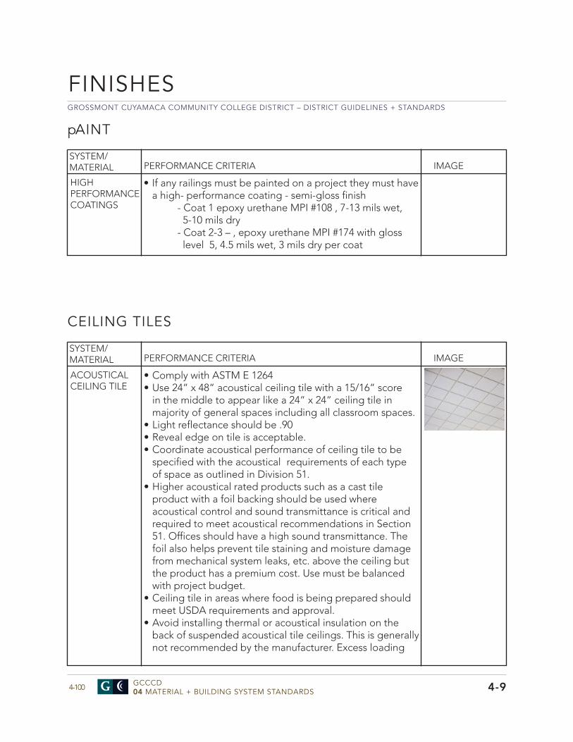
GROSSMONT CUYAMACA COMMUNITY COLLEGE DISTRICT – DISTRICT GUIDELINES + STANDARDS
GCCCD04 MATERIAL + BUILDING SYSTEM STANDARDS4-100
FINISHES
4-9
pAINT
• Comply with ASTM E 1264• Use 24” x 48” acoustical ceiling tile with a 15/16” score
in the middle to appear like a 24” x 24” ceiling tile inmajority of general spaces including all classroom spaces.
• Light reflectance should be .90• Reveal edge on tile is acceptable.• Coordinate acoustical performance of ceiling tile to be
specified with the acoustical requirements of each typeof space as outlined in Division 51.
• Higher acoustical rated products such as a cast tileproduct with a foil backing should be used whereacoustical control and sound transmittance is critical andrequired to meet acoustical recommendations in Section51. Offices should have a high sound transmittance. Thefoil also helps prevent tile staining and moisture damagefrom mechanical system leaks, etc. above the ceiling butthe product has a premium cost. Use must be balancedwith project budget.
• Ceiling tile in areas where food is being prepared shouldmeet USDA requirements and approval.
• Avoid installing thermal or acoustical insulation on theback of suspended acoustical tile ceilings. This is generallynot recommended by the manufacturer. Excess loading
SYSTEM/MATERIAL PERFORMANCE CRITERIA IMAGE
ACOUSTICAL CEILING TILE
• If any railings must be painted on a project they must havea high- performance coating - semi-gloss finish
- Coat 1 epoxy urethane MPI #108 , 7-13 mils wet, 5-10 mils dry- Coat 2-3 – , epoxy urethane MPI #174 with gloss level 5, 4.5 mils wet, 3 mils dry per coat
HIGH PERFORMANCE COATINGS
SYSTEM/MATERIAL PERFORMANCE CRITERIA IMAGE
CEILING TILES
UpDATED NOV. 19, 2015/ HMC ARCHITECTS
GROSSMONT CUYAMACA COMMUNITY COLLEGE DISTRICT – DISTRICT GUIDELINES + STANDARDS
4-1014-9
SYSTEM/MATERIAL PERFORMANCE CRITERIA IMAGE
ACOUSTICAL CEILING TILE GRID
GYPSUM BOARD AND PLATER CEILINGS
EXPOSED CEILINGS
• Restrooms should have a drywall or hard lid ceiling systemwith large, well placed access panels.
• All gypsum board and plaster ceilings should have anaccess panel for above ceiling maintenance. Accesslocation and size should be coordinated with aboveceiling systems and reviewed and approved by Districtand college.
• If hard lid ceilings are used in a space, acoustical controlmust be address with other finishes to meet acousticalrequirements of that space.
• Generally ceiling tile grid should be a standard 15/16”metal grid system conforming to ASTM C635, ASTM E84,and ASTM E580.
• Specialized ceilings such as a concealed spline system ora decorative suspended system can be used as a designfeature in certain public areas but should be minimized.Coordination with light bulb replacement, above ceilingaccess, and system cleaning must be considered in theselection and final ceiling design. All specialty ceilingsystems should be reviewed and approved by the Districtand college.
• Utility rooms such as custodial closets, mechanical andelectrical rooms, or large maintenance storage roomsshould have an exposed ceiling. MDF and IDF roomsshould have a lay in tile ceiling.
• Generally exposed ceilings are discouraged in occupiedspaces since they don’t provide acoustical control,minimize light reflectance, and a e often costly to visuallycontrol utility coordination for a finished space. Anydesign proposing to have an exposed ceiling should bediscussed and approved by the District and college.
caused by added weight of insulation can cause sagging and unsafe installations. Condensation may occur if ceiling insulation places the dew point inside the plenum.
• Use of specialty ceiling tile should be reviewed andapproved by District and college.
• Recycled content should be a minimum of 80%
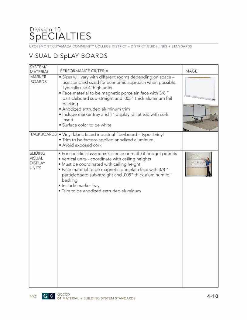
GROSSMONT CUYAMACA COMMUNITY COLLEGE DISTRICT – DISTRICT GUIDELINES + STANDARDS
GCCCD04 MATERIAL + BUILDING SYSTEM STANDARDS4-102
SpECIALTIES
4-10
VISUAL DISpLAY BOARDS
Division 10
• Sizes will vary with different rooms depending on space –use standard sized for economic approach when possible.Typically use 4’ high units.
• Face material to be magnetic porcelain face with 3/8 “particleboard sub-straight and .005” thick aluminum foilbacking
• Anodized extruded aluminum trim• Include marker tray and 1” display rail at top with cork
insert• Surface color to be white
SYSTEM/MATERIAL PERFORMANCE CRITERIA IMAGEMARKER BOARDS
TACKBOARDS • Vinyl fabric faced industrial fiberboard – type II vinyl• Trim to be factory-applied anodized aluminum.• Avoid exposed cork
SLIDING VISUAL DISPLAY UNITS
• For specific classrooms (science or math) if budget permits• Vertical units - coordinate with ceiling heights• Must be coordinated with ceiling height• Face material to be magnetic porcelain face with 3/8 “
particleboard sub-straight and .005” thick aluminum foilbacking
• Include marker tray• Trim to be anodized extruded aluminum
UpDATED NOV. 19, 2015/ HMC ARCHITECTS
GROSSMONT CUYAMACA COMMUNITY COLLEGE DISTRICT – DISTRICT GUIDELINES + STANDARDS
4-1034-10
SYSTEM/MATERIAL PERFORMANCE CRITERIA IMAGE
EXTERIOR SIGNAGE
BUILDING IDENTIFICA-TION
• Building identification should be post mounted tobuildings.
• Buildings on the Grossmont College Campus are labelednumerically.
• Buildings on the Cuyamaca College Campus are labeledalphabetically .
• Building name should be under the building identificationletter or number.
• Building letters and numbers shall be fabricated fromwelded aluminum sheet and painted with an epoxypolymer coating. Characters shall be smooth, flat faces,sharp corners, and precisely formed lines and profiles, freefrom pits, scale, and holes, or other defects.
• Metal finish shall comply with NAAMM “Metal FinishesManual” for finish designations and applicationsrecommendations. (AA – Aluminum Association)
• Some letters are stainless steel. Refer to specific signagedrawings for each college in the appendix for specificmaterials, finish, and font
SIGNAGESignage General Approach - Signage Standards were developed for the District in 2011. Refer to the graphics for more detailed information for signage standards and sizes in the Appendix of this document. All buildings, parking lots, and gathering areas should be identified on campus along with a wayfinding map directory at key entry points on each campus. Directional signs need to be included. Specific types of interior and exterior signs for a project and surrounding areas are identified in the signage drawings in the Appendix for both colleges. All signage should be consistent on the campus and follow the standards with the same color and font.
• Projects involving any parking lots should include primaryand secondary parking lot signage.
• Parking lots should be identified with Lot number onsignage located on light poles.
• Primary directories should be placed at key circulationpoints for easy wayfinding
• Directional signage should be placed along the roads andat pedestrian path intersections.
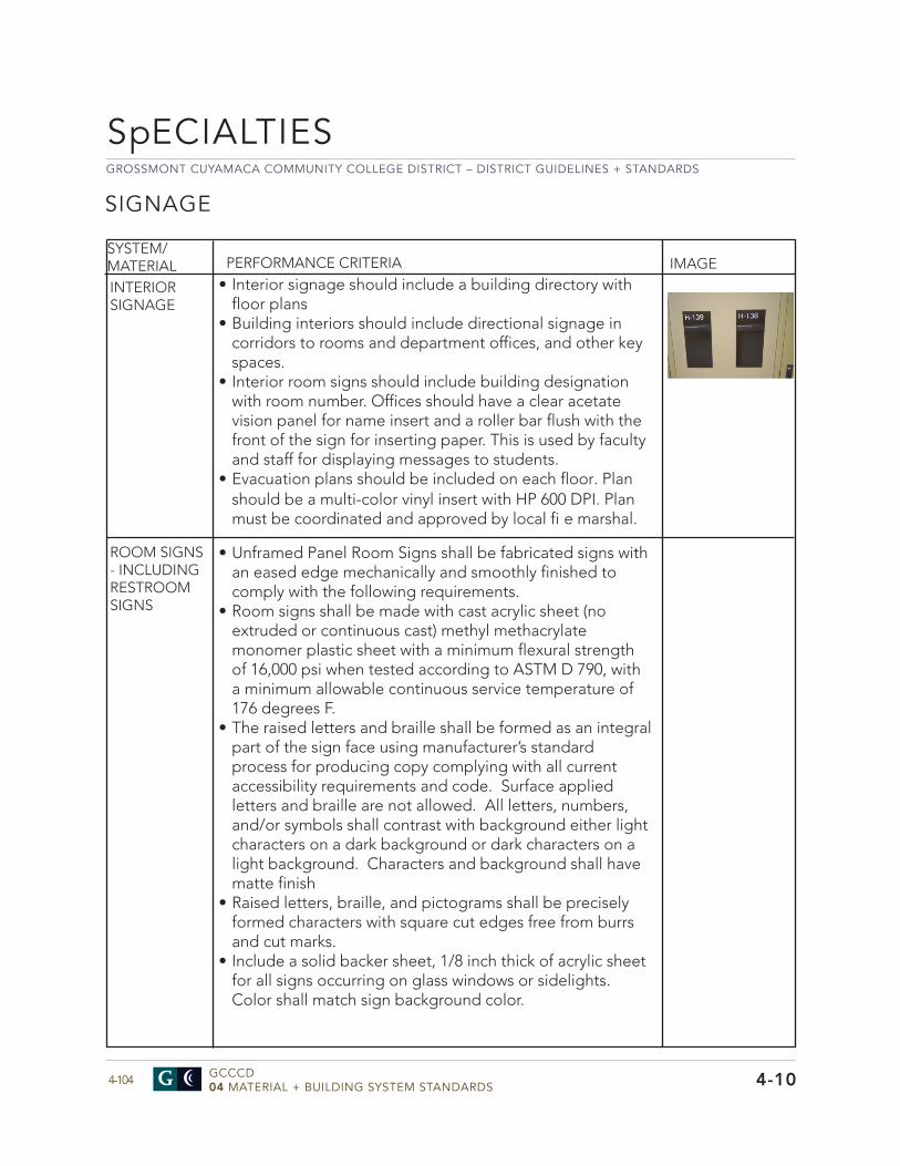
GROSSMONT CUYAMACA COMMUNITY COLLEGE DISTRICT – DISTRICT GUIDELINES + STANDARDS
GCCCD04 MATERIAL + BUILDING SYSTEM STANDARDS4-104
SIGNAGE
SYSTEM/MATERIAL PERFORMANCE CRITERIA IMAGE
INTERIOR SIGNAGE
ROOM SIGNS - INCLUDING RESTROOM SIGNS
• Unframed Panel Room Signs shall be fabricated signs withan eased edge mechanically and smoothly finished tocomply with the following requirements.
• Room signs shall be made with cast acrylic sheet (noextruded or continuous cast) methyl methacrylatemonomer plastic sheet with a minimum flexural strengthof 16,000 psi when tested according to ASTM D 790, witha minimum allowable continuous service temperature of176 degrees F.
• The raised letters and braille shall be formed as an integralpart of the sign face using manufacturer’s standardprocess for producing copy complying with all currentaccessibility requirements and code. Surface appliedletters and braille are not allowed. All letters, numbers,and/or symbols shall contrast with background either lightcharacters on a dark background or dark characters on alight background. Characters and background shall havematte finish
• Raised letters, braille, and pictograms shall be preciselyformed characters with square cut edges free from burrsand cut marks.
• Include a solid backer sheet, 1/8 inch thick of acrylic sheetfor all signs occurring on glass windows or sidelights.Color shall match sign background color.
• Interior signage should include a building directory withfloor plans
• Building interiors should include directional signage incorridors to rooms and department offices, and other keyspaces.
• Interior room signs should include building designationwith room number. Offices should have a clear acetatevision panel for name insert and a roller bar flush with thefront of the sign for inserting paper. This is used by facultyand staff for displaying messages to students.
• Evacuation plans should be included on each floor. Planshould be a multi-color vinyl insert with HP 600 DPI. Planmust be coordinated and approved by local fi e marshal.
4-10
SpECIALTIES
UpDATED NOV. 19, 2015/ HMC ARCHITECTS
GROSSMONT CUYAMACA COMMUNITY COLLEGE DISTRICT – DISTRICT GUIDELINES + STANDARDS
4-1054-10
SYSTEM/MATERIAL PERFORMANCE CRITERIA IMAGE
ROOM NUMBERS
• Room numbers on signs should match numbers onarchitectural plans. Design team must plan out roomnumbers for plan room numbers on constructiondocuments for effective wayfinding in the facility andreview room number layout with District and college forapproval before finalizing plan room numbers. This willallow coordination with Record Set Documents and finalproject model, the Fire Alarm System, room keying andother critical space related and digitally stored informationwith the actual signage room number.
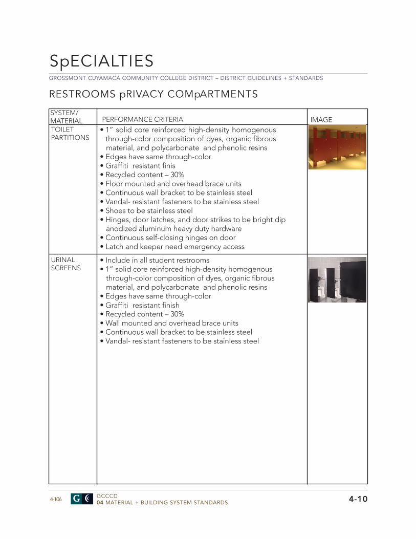
GROSSMONT CUYAMACA COMMUNITY COLLEGE DISTRICT – DISTRICT GUIDELINES + STANDARDS
GCCCD04 MATERIAL + BUILDING SYSTEM STANDARDS4-106
SpECIALTIES
4-10
RESTROOMS pRIVACY COMpARTMENTS
• 1” solid core reinforced high-density homogenousthrough-color composition of dyes, organic fibrousmaterial, and polycarbonate and phenolic resins
• Edges have same through-color• Graffiti resistant finis• Recycled content – 30%• Floor mounted and overhead brace units• Continuous wall bracket to be stainless steel• Vandal- resistant fasteners to be stainless steel• Shoes to be stainless steel• Hinges, door latches, and door strikes to be bright dip
anodized aluminum heavy duty hardware• Continuous self-closing hinges on door• Latch and keeper need emergency access
SYSTEM/MATERIAL PERFORMANCE CRITERIA IMAGETOILET PARTITIONS
URINAL SCREENS
• Include in all student restrooms• 1” solid core reinforced high-density homogenous
through-color composition of dyes, organic fibrous material, and polycarbonate and phenolic resins
• Edges have same through-color• Graffiti resistant finish• Recycled content – 30%• Wall mounted and overhead brace units• Continuous wall bracket to be stainless steel• Vandal- resistant fasteners to be stainless steel
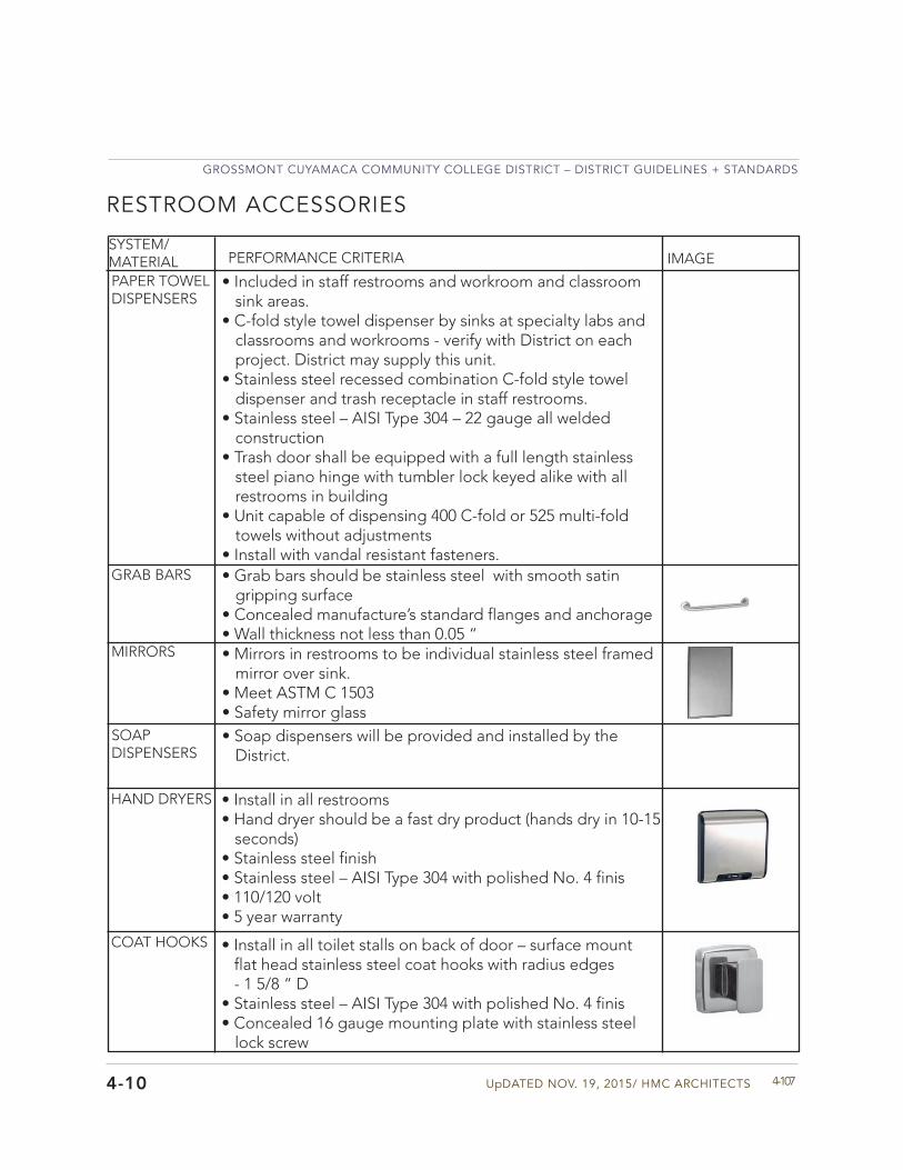
UpDATED NOV. 19, 2015/ HMC ARCHITECTS
GROSSMONT CUYAMACA COMMUNITY COLLEGE DISTRICT – DISTRICT GUIDELINES + STANDARDS
4-1074-10
RESTROOM ACCESSORIES
SYSTEM/MATERIAL PERFORMANCE CRITERIA IMAGE
PAPER TOWEL DISPENSERS
GRAB BARS
MIRRORS
SOAP DISPENSERS
• Included in staff restrooms and workroom and classroomsink areas.
• C-fold style towel dispenser by sinks at specialty labs andclassrooms and workrooms - verify with District on eachproject. District may supply this unit.
• Stainless steel recessed combination C-fold style toweldispenser and trash receptacle in staff restrooms.
• Stainless steel – AISI Type 304 – 22 gauge all weldedconstruction
• Trash door shall be equipped with a full length stainlesssteel piano hinge with tumbler lock keyed alike with allrestrooms in building
• Unit capable of dispensing 400 C-fold or 525 multi-foldtowels without adjustments
• Install with vandal resistant fasteners.• Grab bars should be stainless steel with smooth satin
gripping surface• Concealed manufacture’s standard flanges and anchorage• Wall thickness not less than 0.05 “• Mirrors in restrooms to be individual stainless steel framed
mirror over sink.• Meet ASTM C 1503• Safety mirror glass• Soap dispensers will be provided and installed by the
District.
HAND DRYERS • Install in all restrooms• Hand dryer should be a fast dry product (hands dry in 10-15
seconds)• Stainless steel finish• Stainless steel – AISI Type 304 with polished No. 4 finis• 110/120 volt• 5 year warranty
COAT HOOKS • Install in all toilet stalls on back of door – surface mountflat head stainless steel coat hooks with radius edges- 1 5/8 “ D
• Stainless steel – AISI Type 304 with polished No. 4 finis• Concealed 16 gauge mounting plate with stainless steel
lock screw
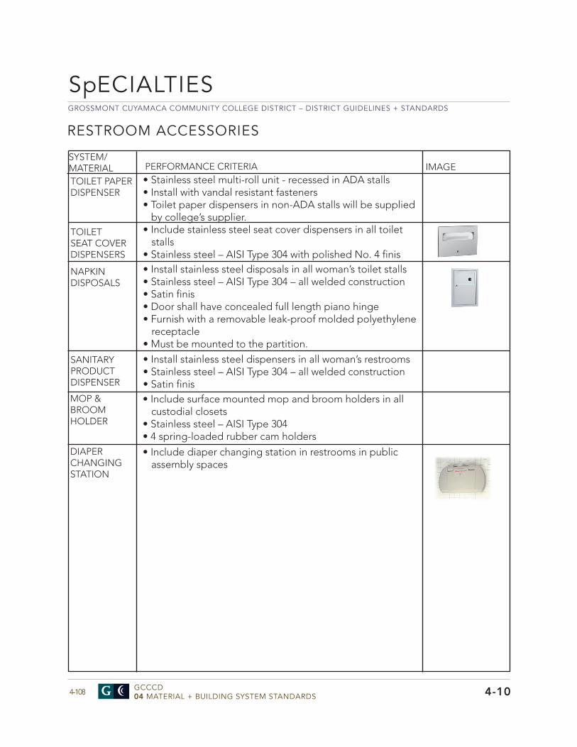
GROSSMONT CUYAMACA COMMUNITY COLLEGE DISTRICT – DISTRICT GUIDELINES + STANDARDS
GCCCD04 MATERIAL + BUILDING SYSTEM STANDARDS4-108 4-10
RESTROOM ACCESSORIES
SYSTEM/MATERIAL PERFORMANCE CRITERIA IMAGE
TOILET PAPER DISPENSER
TOILET SEAT COVER DISPENSERS
NAPKIN DISPOSALS
SANITARY PRODUCT DISPENSER
• Stainless steel multi-roll unit - recessed in ADA stalls• Install with vandal resistant fasteners• Toilet paper dispensers in non-ADA stalls will be supplied
by college’s supplier.• Include stainless steel seat cover dispensers in all toilet
stalls• Stainless steel – AISI Type 304 with polished No. 4 finis• Install stainless steel disposals in all woman’s toilet stalls• Stainless steel – AISI Type 304 – all welded construction• Satin finis• Door shall have concealed full length piano hinge• Furnish with a removable leak-proof molded polyethylene
receptacle• Must be mounted to the partition.• Install stainless steel dispensers in all woman’s restrooms• Stainless steel – AISI Type 304 – all welded construction• Satin finis
MOP & BROOM HOLDER
• Include surface mounted mop and broom holders in allcustodial closets
• Stainless steel – AISI Type 304• 4 spring-loaded rubber cam holders
DIAPER CHANGING STATION
• Include diaper changing station in restrooms in publicassembly spaces
SpECIALTIES

UpDATED NOV. 19, 2015/ HMC ARCHITECTS
GROSSMONT CUYAMACA COMMUNITY COLLEGE DISTRICT – DISTRICT GUIDELINES + STANDARDS
4-109
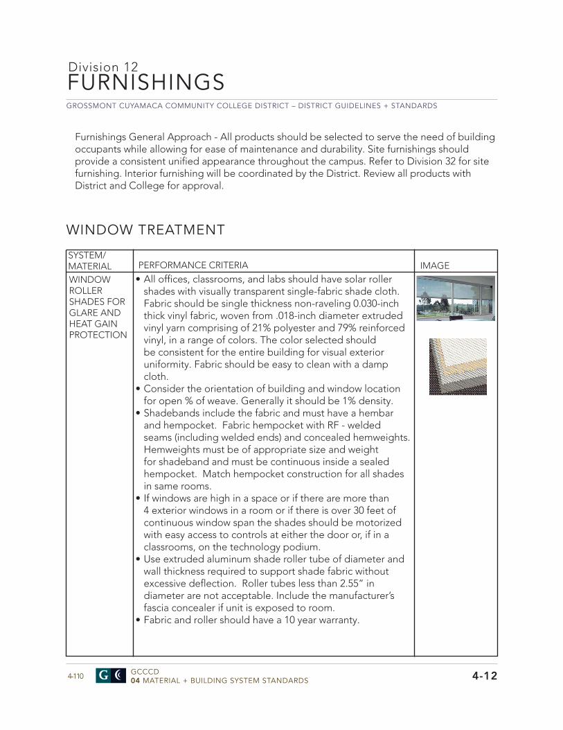
GROSSMONT CUYAMACA COMMUNITY COLLEGE DISTRICT – DISTRICT GUIDELINES + STANDARDS
GCCCD04 MATERIAL + BUILDING SYSTEM STANDARDS4-110 4-12
FURNISHINGS
WINDOW TREATMENT
Division 12
• All offices, classrooms, and labs should have solar rollershades with visually transparent single-fabric shade cloth.Fabric should be single thickness non-raveling 0.030-inchthick vinyl fabric, woven from .018-inch diameter extrudedvinyl yarn comprising of 21% polyester and 79% reinforcedvinyl, in a range of colors. The color selected shouldbe consistent for the entire building for visual exterioruniformity. Fabric should be easy to clean with a dampcloth.
• Consider the orientation of building and window locationfor open % of weave. Generally it should be 1% density.
• Shadebands include the fabric and must have a hembarand hempocket. Fabric hempocket with RF - weldedseams (including welded ends) and concealed hemweights.Hemweights must be of appropriate size and weightfor shadeband and must be continuous inside a sealedhempocket. Match hempocket construction for all shadesin same rooms.
• If windows are high in a space or if there are more than4 exterior windows in a room or if there is over 30 feet ofcontinuous window span the shades should be motorizedwith easy access to controls at either the door or, if in aclassrooms, on the technology podium.
• Use extruded aluminum shade roller tube of diameter andwall thickness required to support shade fabric withoutexcessive deflection. Roller tubes less than 2.55” indiameter are not acceptable. Include the manufacturer’sfascia concealer if unit is exposed to room.
• Fabric and roller should have a 10 year warranty.
SYSTEM/MATERIAL PERFORMANCE CRITERIA IMAGE
WINDOW ROLLER SHADES FOR GLARE AND HEAT GAIN PROTECTION
Furnishings General Approach - All products should be selected to serve the need of building occupants while allowing for ease of maintenance and durability. Site furnishings should provide a consistent unified appearance throughout the campus. Refer to Division 32 for site furnishing. Interior furnishing will be coordinated by the District. Review all products with District and College for approval.
UpDATED NOV. 19, 2015/ HMC ARCHITECTS
GROSSMONT CUYAMACA COMMUNITY COLLEGE DISTRICT – DISTRICT GUIDELINES + STANDARDS
4-1114-12
WINDOW TREATMENTS
SYSTEM/MATERIAL PERFORMANCE CRITERIA IMAGE
BLACKOUT SHADES
• Provide blackout shades where noted in the spacestandards or in specialty spaces such as physics labsrequiring complete darkness in a room or where there arewindows facing west or southwest. Develop a solar modeland then discuss and confirm with user and college
• Provide black out shade on a dual roller shade unit withother solar window shades.
• Fade resistant fabric should be 100% opaque polyester withacrylic backing. Fabric must be easy to clean with a dampcloth. Fabric should have a 10 year warranty.
• Review all locations for blackout shades with District.
MOTOR CONTROL SYSTEM FOR MOTORIzED SHADES
• Provide power to each shade motor via individual3-conductor line voltage circuits connecting each motor tothe relay based intelligent controllers.
• Control system components provide appropriate (spike andbrown out) over-current protection (+/- 10% of line voltage)for each of the four individual motor circuits and shall berated by UL or ETL as a recognized component of thissystem and tested as an integrated system.
• Motor control system allows each group of four shademotors in any combination to be controlled by each offour local switch ports, with up to fourteen possible “sub-group” combinations via local 3-button wall switches andall at once via a master 3-button switch. System shall allowfor overlapping switch combinations from 2 or more localswitches.
• Multiple “sub-groups” from different IQ/MLC controlcomponents may be combined to form “groups” operatedby a single 3-button wall switch, from either the master portor in series from a local switch port.
• Control system shall have two standard operating modes:Normal Mode allowing the shades to be stopped anywherein the window’s opening height and Uniform Modeallowing the shades to only be stopped at the predefinedintermediate stop positions. Both modes shall allow for allup/all down positioning.
• Control system components shall allow for interface withlow voltage Audio Visual system components via a drycontact terminal block.
• Motors on units to have a 5 year warranty.
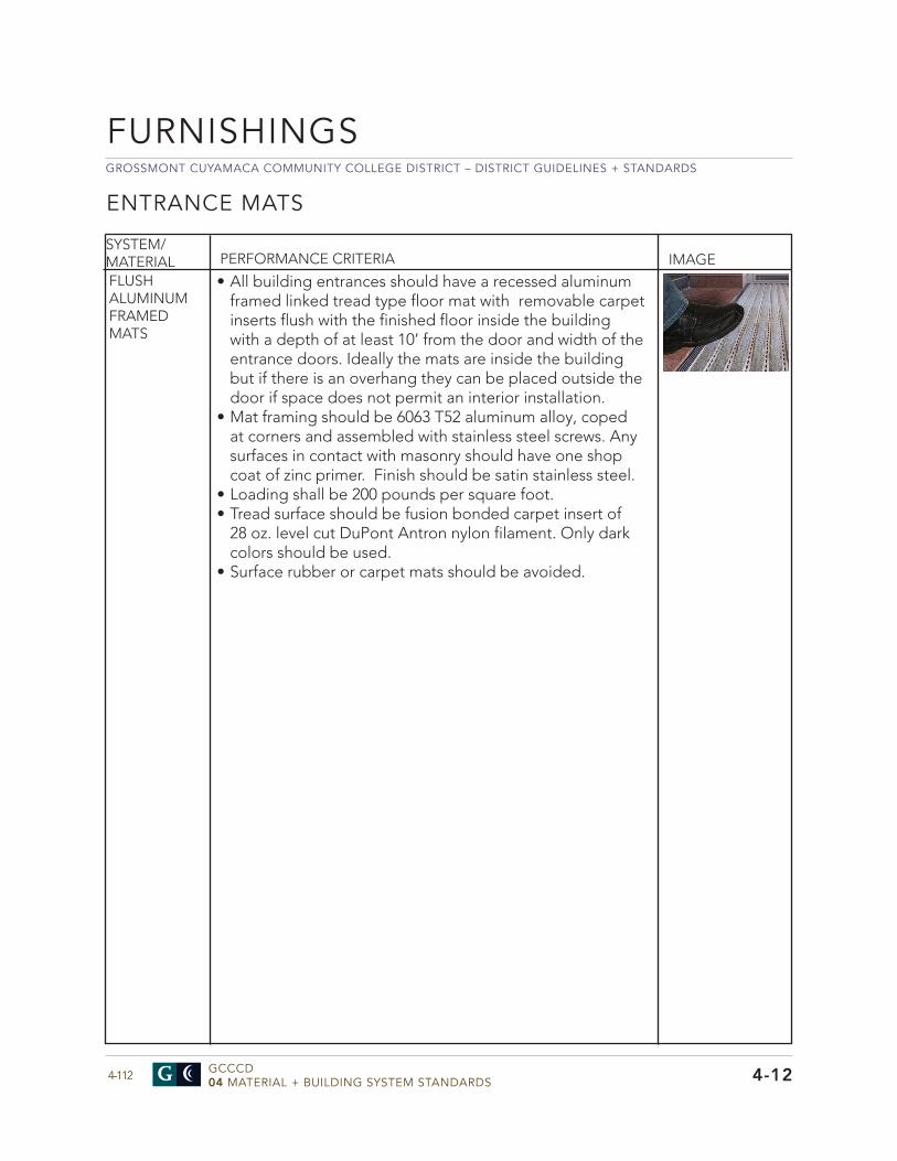
GROSSMONT CUYAMACA COMMUNITY COLLEGE DISTRICT – DISTRICT GUIDELINES + STANDARDS
GCCCD04 MATERIAL + BUILDING SYSTEM STANDARDS4-112
FURNISHINGS
4-12
ENTRANCE MATS
SYSTEM/MATERIAL PERFORMANCE CRITERIA IMAGE
• All building entrances should have a recessed aluminumframed linked tread type floor mat with removable carpetinserts flush with the finished floor inside the buildingwith a depth of at least 10’ from the door and width of theentrance doors. Ideally the mats are inside the buildingbut if there is an overhang they can be placed outside thedoor if space does not permit an interior installation.
• Mat framing should be 6063 T52 aluminum alloy, copedat corners and assembled with stainless steel screws. Anysurfaces in contact with masonry should have one shopcoat of zinc primer. Finish should be satin stainless steel.
• Loading shall be 200 pounds per square foot.• Tread surface should be fusion bonded carpet insert of
28 oz. level cut DuPont Antron nylon filament. Only darkcolors should be used.
• Surface rubber or carpet mats should be avoided.
FLUSH ALUMINUM FRAMED MATS

UpDATED NOV. 19, 2015/ HMC ARCHITECTS
GROSSMONT CUYAMACA COMMUNITY COLLEGE DISTRICT – DISTRICT GUIDELINES + STANDARDS
4-113
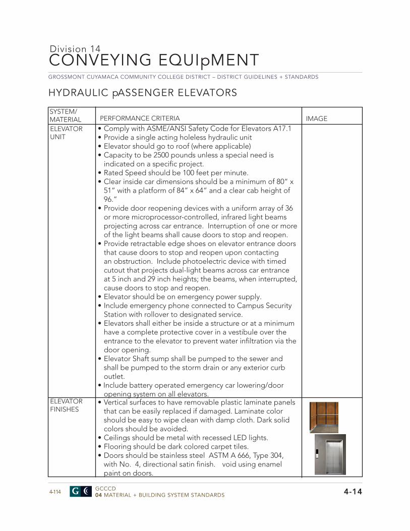
GROSSMONT CUYAMACA COMMUNITY COLLEGE DISTRICT – DISTRICT GUIDELINES + STANDARDS
GCCCD04 MATERIAL + BUILDING SYSTEM STANDARDS4-114
CONVEYING EQUIpMENT
4-14
HYDRAULIC pASSENGER ELEVATORS
Division 14
• Comply with ASME/ANSI Safety Code for Elevators A17.1• Provide a single acting holeless hydraulic unit• Elevator should go to roof (where applicable)• Capacity to be 2500 pounds unless a special need is
indicated on a specific project.• Rated Speed should be 100 feet per minute.• Clear inside car dimensions should be a minimum of 80” x
51” with a platform of 84” x 64” and a clear cab height of96.”
• Provide door reopening devices with a uniform array of 36or more microprocessor-controlled, infrared light beamsprojecting across car entrance. Interruption of one or moreof the light beams shall cause doors to stop and reopen.
• Provide retractable edge shoes on elevator entrance doorsthat cause doors to stop and reopen upon contactingan obstruction. Include photoelectric device with timedcutout that projects dual-light beams across car entranceat 5 inch and 29 inch heights; the beams, when interrupted,cause doors to stop and reopen.
• Elevator should be on emergency power supply.• Include emergency phone connected to Campus Security
Station with rollover to designated service.• Elevators shall either be inside a structure or at a minimum
have a complete protective cover in a vestibule over theentrance to the elevator to prevent water infiltration via thedoor opening.
• Elevator Shaft sump shall be pumped to the sewer andshall be pumped to the storm drain or any exterior curboutlet.
• Include battery operated emergency car lowering/dooropening system on all elevators.
SYSTEM/MATERIAL PERFORMANCE CRITERIA IMAGE
ELEVATOR UNIT
ELEVATOR FINISHES
• Vertical surfaces to have removable plastic laminate panelsthat can be easily replaced if damaged. Laminate colorshould be easy to wipe clean with damp cloth. Dark solidcolors should be avoided.
• Ceilings should be metal with recessed LED lights.• Flooring should be dark colored carpet tiles.• Doors should be stainless steel ASTM A 666, Type 304,
with No. 4, directional satin finish. void using enamelpaint on doors.

UpDATED NOV. 19, 2015/ HMC ARCHITECTS
GROSSMONT CUYAMACA COMMUNITY COLLEGE DISTRICT – DISTRICT GUIDELINES + STANDARDS
4-115
GROSSMONT CUYAMACA COMMUNITY COLLEGE DISTRICT – DISTRICT GUIDELINES + STANDARDS
GCCCD04 MATERIAL + BUILDING SYSTEM STANDARDS4-116
FIRE SUppRESSION SYSTEMS
4-21
• Fire sprinkler design shall comply with NFPA 13Guidelines, local fi e code, and design guidelinesprovided by the Authority Having Jurisdiction (AHJ).
• Fire sprinkler design shall comply with NFPA 13Guidelines, local fi e code, and design guidelinesprovided by the Authority Having Jurisdiction (AHJ).
• Fire At least one tamper shut-off valve shall be providedfor each floor of a building
• The consulting engineer shall determine design approachfor fi e risers, lateral lines, sprinkler heads, flow switchesand other components and coordinate with design teamand District. The consulting engineer will determine flowrequirements and sprinkler head design configurations.
• Areas where the introduction of water from a fi esprinkler system would have devastating effect oncontinuing operation such as computer, server andtelecommunication rooms shall be protected by a cleanagent fi e suppression system. Non-ozone depletingagents such as HFC-227ea and FM-200 shall be used.
• CFC agents such as Halon® are prohibited.
SYSTEM/MATERIAL PERFORMANCE CRITERIA IMAGE
FIRE SUppRESSION DESIGN
GENERAL DESIGN GUIDELINES
Division 21

UpDATED NOV. 19, 2015/ HMC ARCHITECTS
GROSSMONT CUYAMACA COMMUNITY COLLEGE DISTRICT – DISTRICT GUIDELINES + STANDARDS
4-117
GROSSMONT CUYAMACA COMMUNITY COLLEGE DISTRICT – DISTRICT GUIDELINES + STANDARDS
GCCCD04 MATERIAL + BUILDING SYSTEM STANDARDS4-118
pLUMBING
4-22
Division 22
Plumbing General Approach - The design for the project plumbing systems shall provide efficient and reliable system operation as well as ease of maintenance. The design and installation of the plumbing systems shall be in accordance with all regulatory agencies.
Plumbing systems shall be designed in accordance with American Society of Plumbing Engineers (ASPE) Standards and provide efficient and easily maintained systems. System designs shall consider life cycle owning and operating costs as well as first costs to provide the District with the best value Plumbing systems. Efficiency measures that have a total lifecycle cost payback within 10-years or 50 percent of the equipment life shall be considered.
Plumbing system design shall provide access to and working space for ease of maintenance around all equipment and system components that require access for operation or maintenance. All equipment shall be installed per the manufacturer’s recommendations. Where the word “should” is used in the manufacturer’s instructions, substitute the word “shall”. Provide access panels for access to system components above hard lid ceilings that require service, adjustment, or periodic maintenance. Service access for all systems and equipment shall meet OSHA requirements.
The District has set the goal to strive for overall building energy efficiency to exceed the requirements of California T-24 Energy Standards by 20%. Provide higher building efficiencies where required to meet project LEED energy targets. Submit supporting documentation using California approved computer simulation program. Buildings that do not meet this goal require justification indicating the program basis for the lower overall building efficiency
Plumbing Exterior to Structures General Approach – The general approach to plumbing exterior to structures is to provide reliable service for the least amount of capital cost while providing a system that does not require a great deal of maintenance. When maintenance is required the access, cost and man-hours required are factors to consider when designing a system or adding to an existing system. Exterior plumbing systems to the building or structure include storm drains, sewer or waste water, domestic water supply, irrigation, and natural gas. Irrigation is covered in Division 32.
All Irrigation lines shall be assumed to be Reclaimed Water in the Future. As reclaimed water irrigation lines shall be treated as sewer lines with respect to spacing required from water supply required by the State Department of Environmental Health and shall maintain a 10 foot separation edge to edge. This spacing is only required on main lines and is not required on the actual irrigation distribution that is beyond the sectional operation valve at the irrigation main line. Point of Connections or POC’s for the plumbing systems are covered in Division 32. The design guidelines and requirements for design are different inside and outside of structures. Each section for the different systems will discuss the performance criteria for that part of the project.
Every building shall be metered separately. The building plumbing concept design shall be coordinated with the District master infrastructure team and submitted to the District for review and approval prior to proceeding with the final building design and documentation.
UpDATED NOV. 19, 2015/ HMC ARCHITECTS
GROSSMONT CUYAMACA COMMUNITY COLLEGE DISTRICT – DISTRICT GUIDELINES + STANDARDS
4-1194-22
SYSTEM/MATERIAL PERFORMANCE CRITERIA IMAGE
GENERAL
STORM DRAIN SYSTEMS
• The Storm Drain Systems for Cuyamaca and Grossmont Collegeshave been analyzed in the Utility master plan. Cuyamaca is in theCounty of San Diego and Grossmont is in the City of El Cajon.Storm drains should be sized using hydrology developed by theCounty of San Diego Hydrology Manual (latest edition) using themodified rational method.
• Maximum runoff flows conveyed in the storm drains shall be openchannel flow in a 10 year storm event. Any pipe flowing more than 80% full shall be considered flowing full and the maximum capacity of the pipe considered not more than full flow capacity
• Flows from Storm events greater than 10 years and up to 100years shall be contained inside the storm drain system and theEnergy Grade Line or EGL shall never be above the finishedsurface grade and the Hydraulic Grade Line shall be 6-inchesbelow the top of grate or the inlet opening as occurs. Pressureflow on RCP pipes over five feet in equivalent water height s llhave an O-ring gasket. Designer should be aware that gasketpipe and beveled end RCP requires special order and a longerlead time during construction. The preference would be to adda cleanout or make the pipe size larger than use special orderitems.
• On grade inlets must be designed for full interception for the 50year storm event and may bypass up to 15% of the flow for a 100year storm event. Sag Inlets must be designed for full interceptionfor a 100 year storm event. Coordinate with the county of SanDiego Hydraulic Design Manual (latest edition).
• All plans for storm drains shall show plan and profile with utilitycrossings and the HGL and EGL plotted for the 100 year stormevent. Velocity and flow for the pipe each shall also be shown.
• Storm drain pipes shall not be routed underneath buildings.
• Code Differences-The plumbing code dictates roof drain and overflow piping. Exterior to the building the code is the CountyHydrology and hydraulics manuals. The Plumbing Code assumesa static rain intensity. The Hydrology manual assumes themaximum flow in any pipe is time dependent and requires thatinlets and pipes be checked for capacity when the runoff flow is atits maximum.
CODE
GROSSMONT CUYAMACA COMMUNITY COLLEGE DISTRICT – DISTRICT GUIDELINES + STANDARDS
GCCCD04 MATERIAL + BUILDING SYSTEM STANDARDS4-120
pLUMBING
4-22
SYSTEM/MATERIAL PERFORMANCE CRITERIA IMAGE
RUNOFF FLOWING ALONG CURBS
STORM DRAIN SYSTEMS
• Asphalt Dikes are not to be used.• When Runoff will collect at a parking lot or pavement
edge, there will be a concrete gutter. The preference is touse the regional standard Type G Curb and Gutter per G-2of the regional standards.
CLEANOUTS
CATCH BASINS AND CURB INLETS
• Catch basins shall be pre-cast or cast concrete with ADAcompliant grates in walkways and bike friendly type gratesin roadways.
• Precast Catch basins shall be square in grate size and thegrate shall be one of three sizes: 12”, 18” or 24”.
• Pipe connected to precast basins shall connect to the sideof the catch basin and never the bottom.
• Cast concrete inlets and curb inlets shall be San Diegoregional standards (Latest Edition)
• Pipes up to 8” in Diameter may use a Sewer type cleanoutwith a spacing of less than 90 feet between cleanouts.
• Storm drain cleanouts are to be San Diego Regionalstandard D-9 Type A Cleanout. The Size is a minimum of 4feet and shall be one foot larger on the internal dimensionthan the largest pipe diameter connected. The largestcleanout by standard is an A-8 which is 4 feet by 8 feetinside.
• If larger cleanouts are required then the cleanout must bedesigned by a civil or structural engineer.
• All manhole covers and grates shall be bolted down in atleast two places for grates and three places for Manholecovers.
• Cleanout access must not be in a walk path and must beaccessible at all times.
STORM DRAIN PIPE
• Diameter or 18” and larger shall be RCP or ReinforcedConcrete Pipe.
• Diameters 15” to 6” size pipe shall be SDR 35, PVC pipe.• No double wall or single corrugated wall HDPE pipe
allowed• No storm drains shall be below 6” in diameter. Landscaping
and foundation drains may be 4” in diameter but 6” ispreferred.
UpDATED NOV. 19, 2015/ HMC ARCHITECTS
GROSSMONT CUYAMACA COMMUNITY COLLEGE DISTRICT – DISTRICT GUIDELINES + STANDARDS
4-1214-22
SYSTEM/MATERIAL PERFORMANCE CRITERIA IMAGE
TRASH ENCLOSURES
• Storm runoff is not allowed to run into or through a trashcollection container enclosure.
• Trash container enclosures must be covered and gated.Container must not be visible from the outside surroundingarea.
SYSTEM/MATERIAL PERFORMANCE CRITERIA IMAGE
GENERAL
• Consult Utilities Master Plan for each campus. Preliminarydesign documentation is available. Water supply andpressures can be found in the water portion of the UtilityMaster Plan.
WATER
• Water Supply for the Grossmont College is provided byPadre Dam Water district. Cuyamaca College is suppliedby Otay Water District. Both water districts use the samestandard, label W.A.S. for Water Agency Standards. AllWater mains and services will comply with this W.A.S.standard.
• Code Differences – The plumbing codes size pipes arebased on Fixture units. The W.A.S. and the civil engineeringcommunity size water mains are for fi e hydrant flow and thenumber of people using the campus at any one time. Thesizes from these two calculations can yield different results.The most restrictive calculation shall apply.
WATER MAIN ROUTING
CODE
• No concentrated runoff may be directed back on thepavement after being collected in a gutter. The flow mustenter a catch basin, curb inlet or planter. Once in theplanter the flow must enter the storm drain via an inlet orsub-drain.
• No runoff flow may be directed over a slope edge. Therunoff must collected and conveyed in the storm drain
• Runoff flow may not be directed in concentrated form overa walking path or walkway surface.
• Landscaped areas may not drain over the walkway.
RUNOFF FLOWING ALONG CURBS
GROSSMONT CUYAMACA COMMUNITY COLLEGE DISTRICT – DISTRICT GUIDELINES + STANDARDS
GCCCD04 MATERIAL + BUILDING SYSTEM STANDARDS4-122 4-22
SYSTEM/MATERIAL PERFORMANCE CRITERIA IMAGE
WATER MAIN
WATER
• Water mains shall maintain California Department ofHealth separation standards from Sewer lines and irrigationmains 10 feet edge to edge and preferred to be abovethe sewer in elevation. If the water line passes below thesewer main then there are conditions that must be met inorder to be acceptable.
• This includes from the outside edge of a sewer manhole.• Water mains shall maintain a 5 foot separation edge from
an electrical encasement or buried conduit.• Vertical separation in a crossing is 12 inches or one foot
edge to edge• Preferred pipe material is PVC, blue in color.• Minimum Pipe size for mains is 8 inches in diameter.
• Valves and covers should not be in walk ways. If unavoidablethen place to the outer edge of the walkway.
• Valves shall not be inside parking stall locations• A group of valves should not be separated by a fence.
VALVE LOCATION
• Many of the Campus Water mains are Asbestos Cement.Removal of these Mains requires special handling and theexisting pipe will not be cut. Removal requires removingwhole sections of pipe. Disposal requires special handlingdescribed in the W.A.S. Specification
• Connection to the existing ACP pipe end requires anadaptor fitting
• Do NOT plant trees within 10 feet of water mains.
EXISTING MAIN MATERIAL
• The soil near the colleges is corrosive to metals. All metalpipe in the ground shall have a passive cathodic protectionsystem.
• Individual cast iron bends or fittings shall be epoxy coatedand poly wrapped.
• All water lines above 4“ in diameter size shall have cast ironfittings and valves
• Copper lateral line shall have a sacrificial anode at the buildvalve location.
METAL PIPE MATERIALS
pLUMBING
UpDATED NOV. 19, 2015/ HMC ARCHITECTS
GROSSMONT CUYAMACA COMMUNITY COLLEGE DISTRICT – DISTRICT GUIDELINES + STANDARDS
4-1234-22
GENERAL • Sewer collection for the Grossmont College is provided byPadre Dam Water district. Cuyamaca College is collectedby Otay Water District. Both Sewer districts use the samestandard, labeled W.A.S. for Water Agency Standards. Allsewer mains, laterals and Manholes will comply with thisW.A.S. standard.
• Code Differences – The plumbing codes size pipes andvents based on Fixture units. The W.A.S. and the civilengineering community size sewer mains for the number ofpeople using the campus at any one time. The sizes fromthese two types of calculations can yield different results.The most restrictive calculation shall apply. Engineeringjudgment is required to resolve the difference.
SYSTEM/MATERIAL PERFORMANCE CRITERIA IMAGE
SEWER
SEWER • Consult Utilities Master Plan for each campus. Preliminarydesign documentation is available. Water supply andpressures can be found in the water portion of the UtilityMaster Plan.
• Lateral minimum slope is 2.0 %• Cleanouts required at a 90 foot maximum spacing• Cleanout also required for change of direction• Minimum lateral size is 4” in diameter• Per W.A.S Standard Drawing SC-1
CODE
SEWER MANHOLES
• W.A.S. Standard Drawing SM-1• Manholes are generally located in the following areas:
- Change in direction of flow. - Change in pipe size or material. - Change in grade. - Intersections of mains.
• Manhole spacing is typically determined by the availablesewer maintenance methods and equipment. Maximum spacing of manholes shall be four hundred feet (400’) for mains.
• At main ends a manhole is preferred. A cleanout isacceptable ,but is not preferred.
• Manholes shall not be located in the following locations:- Inaccessible areas - Gutters and other depressions or areas subject to inundation - In sidewalks or crosswalks - In driveway aprons
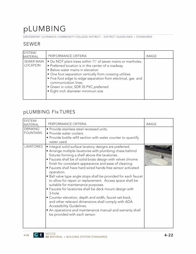
GROSSMONT CUYAMACA COMMUNITY COLLEGE DISTRICT – DISTRICT GUIDELINES + STANDARDS
GCCCD04 MATERIAL + BUILDING SYSTEM STANDARDS4-124 4-22
SYSTEM/MATERIAL PERFORMANCE CRITERIA IMAGE
DRINKING FOUNTAINS
LAVATORIES • Integral solid surface lavatory designs are preferred.• Arrange multiple lavatories with plumbing chase behind
fixtures forming a shelf above the lavatories.• Faucets shall be of solid-brass design with velvet chrome
finish for consistent appearance and ease of cleaning.• Faucets shall have hard wired hands-free sensor activated
operation.• Ball valve type angle stops shall be provided for each faucet
to allow for repair or replacement. Access space shall besuitable for maintenance purposes.
• Faucets for lavatories shall be deck mount design with3-hole.
• Counter elevation, depth and width, faucet set-back,and other relevant dimensions shall comply with ADAAccessibility Guidelines.
• An operations and maintenance manual and warranty shallbe provided with each sensor.
pLUMBING FIx TURES
• Provide stainless steel recessed units.• Provide water coolers.• Provide bottle refill section with water counter to quantify
water used.
SYSTEM/MATERIAL PERFORMANCE CRITERIA IMAGE
SEWER
SEWER MAIN LOCATION
• Do NOT plant trees within 11’ of sewer mains or manholes.• Preferred location is in the center of a roadway• Below water mains in elevation• One foot separation vertically from crossing utilities• Five foot edge to edge separation from electrical, gas and
communication lines• Green in color, SDR 35 PVC preferred• Eight inch diameter minimum size
pLUMBING
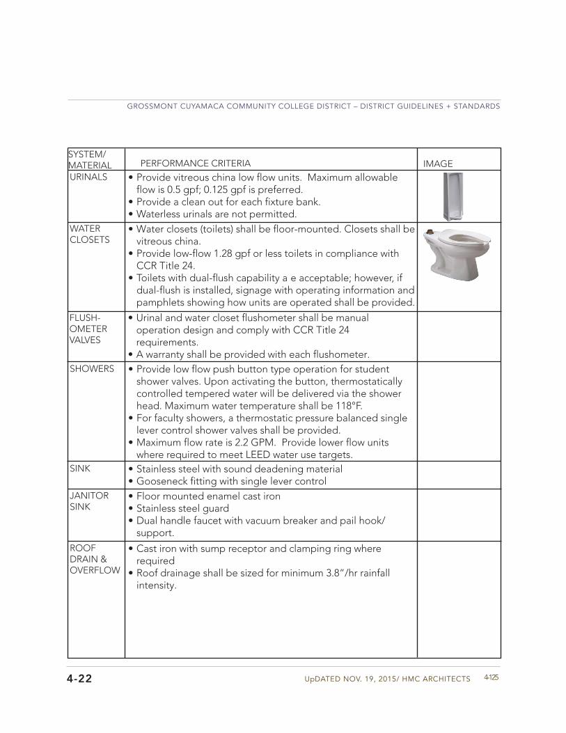
UpDATED NOV. 19, 2015/ HMC ARCHITECTS
GROSSMONT CUYAMACA COMMUNITY COLLEGE DISTRICT – DISTRICT GUIDELINES + STANDARDS
4-1254-22
SYSTEM/MATERIAL PERFORMANCE CRITERIA IMAGEURINALS
WATER CLOSETS
• Provide vitreous china low flow units. Maximum allowableflow is 0.5 gpf; 0.125 gpf is preferred.
• Provide a clean out for each fixture bank.• Waterless urinals are not permitted.• Water closets (toilets) shall be floor-mounted. Closets shall be
vitreous china.• Provide low-flow 1.28 gpf or less toilets in compliance with
CCR Title 24.• Toilets with dual-flush capability a e acceptable; however, if
dual-flush is installed, signage with operating information andpamphlets showing how units are operated shall be provided.
FLUSH-OMETER VALVES
• Urinal and water closet flushometer shall be manualoperation design and comply with CCR Title 24requirements.
• A warranty shall be provided with each flushometer.SHOWERS • Provide low flow push button type operation for student
shower valves. Upon activating the button, thermostaticallycontrolled tempered water will be delivered via the showerhead. Maximum water temperature shall be 118°F.
• For faculty showers, a thermostatic pressure balanced singlelever control shower valves shall be provided.
• Maximum flow rate is 2.2 GPM. Provide lower flow unitswhere required to meet LEED water use targets.
SINK • Stainless steel with sound deadening material• Gooseneck fitting with single lever control
JANITORSINK
• Floor mounted enamel cast iron• Stainless steel guard• Dual handle faucet with vacuum breaker and pail hook/
support.ROOFDRAIN &OVERFLOW
• Cast iron with sump receptor and clamping ring whererequired
• Roof drainage shall be sized for minimum 3.8”/hr rainfallintensity.
GROSSMONT CUYAMACA COMMUNITY COLLEGE DISTRICT – DISTRICT GUIDELINES + STANDARDS
GCCCD04 MATERIAL + BUILDING SYSTEM STANDARDS4-126
pLUMBING
4-22
SOUND CONTROL IN pLUMBING SYSTEM
• Provide cast iron piping for all waste and storm drain pipingabove the ground floor.
• Limit velocity in water piping to 6 FPM maximum velocitywithin building.
• Provide acoustical insulation for restrooms to protectadministrative offices and other occupied space adjacent torestrooms from noise during flush cycles. Refer to Division 51
SYSTEM/MATERIAL PERFORMANCE CRITERIA IMAGE
SOUND CONTROL FEATURES
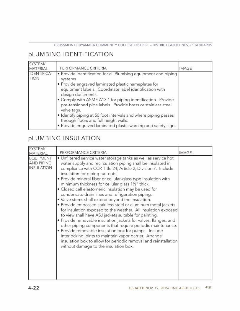
UpDATED NOV. 19, 2015/ HMC ARCHITECTS
GROSSMONT CUYAMACA COMMUNITY COLLEGE DISTRICT – DISTRICT GUIDELINES + STANDARDS
4-1274-22
• Provide identification for all Plumbing equipment and pipingsystems.
• Provide engraved laminated plastic nameplates forequipment labels. Coordinate label identification withdesign documents.
• Comply with ASME A13.1 for piping identification. Providepre-tensioned pipe labels. Provide brass or stainless steelvalve tags.
• Identify piping at 50 foot intervals and where piping passesthrough floors and full height walls.
• Provide engraved laminated plastic warning and safety signs.
SYSTEM/MATERIAL PERFORMANCE CRITERIA IMAGEIDENTIFICA-TION
pLUMBING IDENTIFICATION
• Unfiltered service water storage tanks as well as service hotwater supply and recirculation piping shall be insulated incompliance with CCR Title 24, Article 2, Division 7. Includeinsulation for piping run-outs.
• Provide mineral fiber or cellular-glass type insulation withminimum thickness for cellular glass 1½“ thick.
• Closed cell elastomeric insulation may be used forcondensate drain lines and refrigeration piping.
• Valve stems shall extend beyond the insulation.• Provide embossed stainless steel or aluminum metal jackets
for insulation exposed to the weather. All insulation exposedto view shall have ASJ jackets suitable for painting.
• Provide removable insulation jackets for valves, flanges, andother piping components that require periodic maintenance.
• Provide removable insulation box for pumps. Includeinterlocking joints to maintain vapor barrier. Arrangeinsulation box to allow for periodic removal and reinstallationwithout damage to the insulation box.
SYSTEM/MATERIAL PERFORMANCE CRITERIA IMAGEEQUIPMENT AND PIPING INSULATION
pLUMBING INSULATION
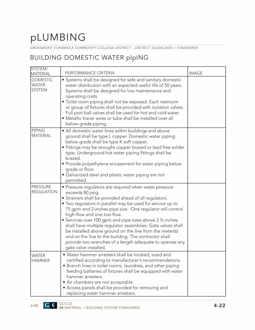
GROSSMONT CUYAMACA COMMUNITY COLLEGE DISTRICT – DISTRICT GUIDELINES + STANDARDS
GCCCD04 MATERIAL + BUILDING SYSTEM STANDARDS4-128
pLUMBING
4-22
PIPING MATERIAL
PRESSURE REGULATION
BUILDING DOMESTIC WATER pIpING
SYSTEM/MATERIAL PERFORMANCE CRITERIA IMAGE
DOMESTIC WATER SYSTEM
• Systems shall be designed for safe and sanitary domesticwater distribution with an expected useful life of 50 years.Systems shall be designed for low maintenance andoperating costs.
• Toilet room piping shall not be exposed. Each restroomor group of fixtures shall be provided with isolation valves.Full port ball valves shall be used for hot and cold water.
• Metallic tracer wires or tube shall be installed over allbelow-grade piping.
• All domestic water lines within buildings and aboveground shall be type L copper. Domestic water pipingbelow grade shall be type K soft copper.
• Fittings may be wrought copper brazed or lead free soldertype. Underground hot water piping fittings shall bebrazed.
• Provide polyethylene encasement for water piping belowgrade or floor.
• Galvanized steel and plastic water piping are notpermitted.
• Pressure regulators are required when water pressureexceeds 80 psig.
• Strainers shall be provided ahead of all regulators.• Two regulators in parallel may be used for service up to
75 gpm and 2-inches pipe size. One regulator will control high-flow and one low-flow.
• Services over 100 gpm and pipe sizes above 2 ½ inchesshall have multiple regulator assemblies. Gate valves shallbe installed above ground on the line from the meter(s)and on the line to the building. The contractor shallprovide two wrenches of a length adequate to operate anygate valve installed.
• Water hammer arresters shall be located, sized andcertified according to manufacturer’s recommendations.
• Branch lines in toilet rooms, laundries, and other pipingfeeding batteries of fixtures shall be equipped with waterhammer arresters.
• Air chambers are not acceptable.• Access panels shall be provided for removing and
replacing water hammer arresters.
WATER HAMMER
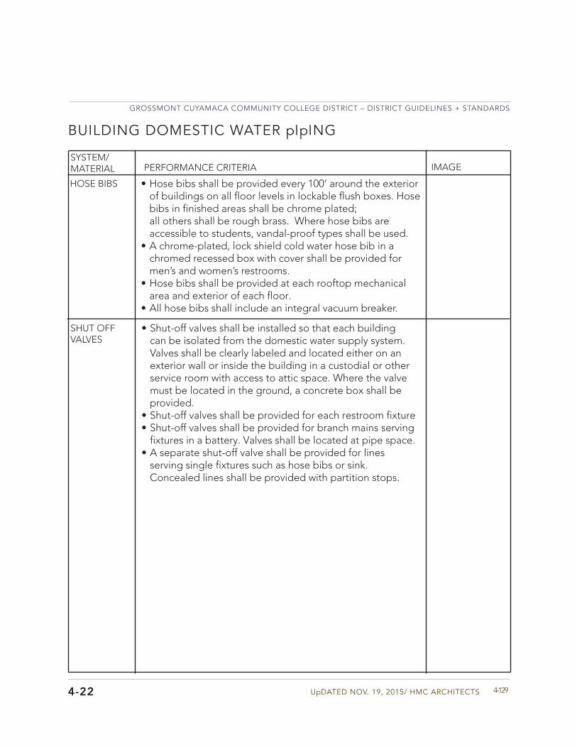
UpDATED NOV. 19, 2015/ HMC ARCHITECTS
GROSSMONT CUYAMACA COMMUNITY COLLEGE DISTRICT – DISTRICT GUIDELINES + STANDARDS
4-1294-22
SYSTEM/MATERIAL PERFORMANCE CRITERIA IMAGE
BUILDING DOMESTIC WATER pIpING
• Hose bibs shall be provided every 100’ around the exteriorof buildings on all floor levels in lockable flush boxes. Hosebibs in finished areas shall be chrome plated;all others shall be rough brass. Where hose bibs areaccessible to students, vandal-proof types shall be used.
• A chrome-plated, lock shield cold water hose bib in achromed recessed box with cover shall be provided formen’s and women’s restrooms.
• Hose bibs shall be provided at each rooftop mechanicalarea and exterior of each floor.
• All hose bibs shall include an integral vacuum breaker.
HOSE BIBS
• Shut-off valves shall be installed so that each buildingcan be isolated from the domestic water supply system.Valves shall be clearly labeled and located either on anexterior wall or inside the building in a custodial or otherservice room with access to attic space. Where the valvemust be located in the ground, a concrete box shall beprovided.
• Shut-off valves shall be provided for each restroom fixture• Shut-off valves shall be provided for branch mains serving
fixtures in a battery. Valves shall be located at pipe space.• A separate shut-off valve shall be provided for lines
serving single fixtures such as hose bibs or sink.Concealed lines shall be provided with partition stops.
SHUT OFF VALVES
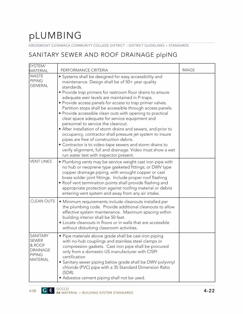
GROSSMONT CUYAMACA COMMUNITY COLLEGE DISTRICT – DISTRICT GUIDELINES + STANDARDS
GCCCD04 MATERIAL + BUILDING SYSTEM STANDARDS4-130
pLUMBING
4-22
SANITARY SEWER AND ROOF DRAINAGE pIpING
SYSTEM/MATERIAL PERFORMANCE CRITERIA IMAGE
WASTE PIPING GENERAL
VENT LINES
SANITARY SEWER & ROOF DRAINAGEPIPING MATERIAL
• Systems shall be designed for easy accessibility andmaintenance. Design shall be of 50+ year qualitystandards.
• Provide trap primers for restroom floor drains to ensureadequate weir levels are maintained in P-traps.
• Provide access panels for access to trap primer valves.Partition stops shall be accessible through access panels.
• Provide accessible clean outs with opening to practicalclear space adequate for service equipment andpersonnel to service the cleanout.
• After installation of storm drains and sewers, and prior tooccupancy, contractor shall pressure jet system to insurepipes are free of construction debris.
• Contractor is to video-tape sewers and storm drains toverify alignment, full and drainage. Video must show a wetrun water test with inspector present.
• Plumbing vents may be service weight cast iron pipe withno hub or neoprene type gasketed fittings; or DWV typecopper drainage piping, with wrought copper or castbrass solder joint fittings. Include proper roof flashing
• Roof vent termination points shall provide flashing andappropriate protection against roofing material or debrisentering vent system and away from any air intake.
CLEAN OUTS • Minimum requirements include cleanouts installed perthe plumbing code. Provide additional cleanouts to alloweffective system maintenance. Maximum spacing withinbuilding interior shall be 50 feet.
• Locate cleanouts in floors or in walls that are accessiblewithout disturbing classroom activities.
• Pipe materials above grade shall be cast-iron pipingwith no-hub couplings and stainless steel clamps orcompression gaskets. Cast iron pipe shall be procuredonly from a domestic US manufacturer with CISPIcertification
• Sanitary sewer piping below grade shall be DWV polyvinylchloride (PVC) pipe with a 35 Standard Dimension Ratio(SDR).
• Asbestos cement piping shall not be used.
UpDATED NOV. 19, 2015/ HMC ARCHITECTS
GROSSMONT CUYAMACA COMMUNITY COLLEGE DISTRICT – DISTRICT GUIDELINES + STANDARDS
4-1314-22
HOT WATER SYSTEMS
SYSTEM/MATERIAL PERFORMANCE CRITERIA IMAGE
GENERAL REQUIRE-MENTS
DOMESTIC WATER HEATERS
• The hot water system shall comply with the UniformPlumbing Code and of CCR Title 24, Article 2, Division 7,Service Water Heating. System components, distributionsystems, hot water requirement estimates, and equipmentsizing shall follow ASHRAE Current Systems Handbook,“Service Water Heating”, recommendations. Wherenational, state or local codes or regulations are morestringent, they shall be used.
• The hot water system shall have adequate capacity forfull recovery. Multiple high efficiency type heaters withfast recovery shall be used for high demand projects.Condensing type domestic water heaters are preferred.
• Re-circulating lines and pump shall be installed on hot watersystems to limit the time for DHW for fixtures to 20 secondsmaximum time. Type L copper shall be used on all circulationsystems. Fittings shall be cast brass copper sweat type.
WATER SOFTENER EQUIpMENT
• Water softeners shall be an ion-exchanging resin typethat uses sodium chloride salt regeneration and dual-tanksoftener system. Continuous monitoring of the waterhardness for regeneration cycles is preferred.
• Installations shall comply with the manufacturer’srecommendations.
SYSTEM/MATERIAL PERFORMANCE CRITERIA IMAGESOFTENER SYSTEM
• Natural gas is the preferred energy source for heatingdomestic hot water. Electric heat may be used for remoteisolated fixtures and when installation of natural gas is costprohibitive.
• Gas water heaters shall be AGA certified, power vented, andglass-lined commercial type. High-efficiency and condensingtype boiler equipment are preferred.
• Ball valves and check valves shall be provided on cold waterpiping and outlet piping at heater and shock absorber andthermometer.
• Hot water piping from the heater shall have an ASTM rated
GROSSMONT CUYAMACA COMMUNITY COLLEGE DISTRICT – DISTRICT GUIDELINES + STANDARDS
GCCCD04 MATERIAL + BUILDING SYSTEM STANDARDS4-132
pLUMBING
4-22
T&P relief valve. • Heaters serving isolated or remote locations, or individual
portable classroom buildings may use electricity as a heat source. In these situations 6-gallon heaters with drain pan or the use of multiple smaller heaters installed in a manifold arrangement may be used. This design is preferred to use of one or two large boilers.
• Electric water heaters shall be of a commercial type withmagnesium anode, immersion type thermostats and heating elements. Heaters shall be UL 174 rated and labeled. Ball valve and check valves shall be provided on cold water piping to the heater; shock absorbers, a ball valve, adjustable thermometers, and an ASME T&P relief valve shall be provided on hot water piping from the heater. Adequate service space shall be provided in front of the heater service panel.
• Electric booster heaters for dishwashers shall be of stainlesssteel and have a rod-type element, aquastat, and T&P relief valve to the outside. Heaters shall be ASME and UL approved.
• Where approved by District, non-storage type instant point-of-service heaters may be used.
• Water heater supply company shall be able to provide localservice and parts.
• Provide expansion tank for DHW systems to control waterexpansion.
HOT WATER SYSTEMS
SYSTEM/MATERIAL PERFORMANCE CRITERIA IMAGE
DOMESTIC WATER HEATERS
UpDATED NOV. 19, 2015/ HMC ARCHITECTS
GROSSMONT CUYAMACA COMMUNITY COLLEGE DISTRICT – DISTRICT GUIDELINES + STANDARDS
4-1334-22
HOT WATER STORAGE TANKS
• Hot water storage tanks shall be rated for 150 psig serviceand display an ASME label. Tanks shall be equipped withmagnesium anodes. Larger storage tanks shall either beunlined steel and equipped with magnesium anodes, orlined with a six millimeter Socco Keysite® or Heresite®coating applied in three coats minimum with bakingbetween each coat.
• Hot water shall be stored in tanks at 140F to controlbacteria growth.
• Hot water storage tanks shall be equipped with a shut offvalve and check valve installed in the cold water supplyto the storage tank and in the hot water outlet side. Athermometer shall also be installed at the hot water outlet.
• Properly sized commercial on-demand tankless waterheaters may be used where approved by the District.
SYSTEM/MATERIAL PERFORMANCE CRITERIA IMAGE
• Solar water heating may be acceptable for certainapplications. Solar water heating systems will bededicated to no more than one building being served.Perform a life cycle cost analysis (LCCA) to determinea cost / benefit ratio. The LCCA shall include factorssuch as costs associated with installation, operationand maintenance, system deterioration, annual utilityconsumption and estimated utility costs. After LCCAreview the District shall determine if the system isacceptable.
• Minimum LLC payback shall be 50 % of the project life ofthe equipment of 10 years whichever is less.
• Solar water heating shall not be designed as central plantgeneration with distribution to multiple buildings.
SOLAR WATER HEATING SYSTEMS
GROSSMONT CUYAMACA COMMUNITY COLLEGE DISTRICT – DISTRICT GUIDELINES + STANDARDS
GCCCD04 MATERIAL + BUILDING SYSTEM STANDARDS4-134
pLUMBING
4-22
HOT WATER TEMpERING VALVES
SYSTEM/MATERIAL PERFORMANCE CRITERIA IMAGEHOT WATER TEMPERING
• Electronic-monitored type thermostatic mixing valves shallbe used to control hot water supply to student showers.Shower water temperature shall not exceed 118°Fdelivered to the fixture to prevent scalding.
• Thermostatic mixing system shall be a point-of-usedesign.
• A separate return loop and circulation pump shall beprovided for each thermostatic mixing valve. Return loopsystems shall be designed to assure that the minimumtempering valve flow required for stable operation ismaintained continuously.
DOMESTIC WATER pUMpS
SYSTEM/MATERIAL PERFORMANCE CRITERIA IMAGE
DHW CIRCULATING PUMPS
• In-line circulating pumps shall have a 150 psig workingpressure. They shall have all bronze body, flanges andimpeller; a stainless steel shaft; and an ODP premiumefficiency motor that is maintenance free self-lubricatedtype.
• Floor-mounted circulating pumps shall be directconnected, close coupled, centrifugal, and rated at1750 RPM. Pumps shall be equipped with enclosed typebronze impellers, a mechanical seal, a drip-proof premiumefficiency moto , and reinforced metal flexible connectionson suction and discharge sides.
• All circulating pumps shall be approved for potable waterservice.
• Provide time of day and thermostatic control for DHWcirculating pumps.
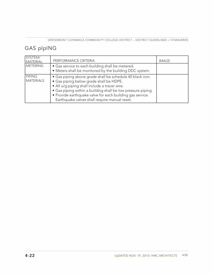
UpDATED NOV. 19, 2015/ HMC ARCHITECTS
GROSSMONT CUYAMACA COMMUNITY COLLEGE DISTRICT – DISTRICT GUIDELINES + STANDARDS
4-1354-22
GAS pIpING
SYSTEM/MATERIAL PERFORMANCE CRITERIA IMAGEMETERING • Gas service to each building shall be metered.
• Meters shall be monitored by the building DDC system.PIPING MATERIALS
• Gas piping above grade shall be schedule 40 black iron.• Gas piping below grade shall be HDPE.• All u/g piping shall include a tracer wire.• Gas piping within a building shall be low pressure piping.• Provide earthquake valve for each building gas service.
Earthquake valves shall require manual reset.
GROSSMONT CUYAMACA COMMUNITY COLLEGE DISTRICT – DISTRICT GUIDELINES + STANDARDS
GCCCD04 MATERIAL + BUILDING SYSTEM STANDARDS4-136
HEATING, VENT., + AIR CONDITIONING
4-23
Division 23
HVAC General Design Approach: The design for the project heating, ventilating and air conditioning (HVAC) systems shall maintain occupant comfort, indoor air quality, acceptable noise levels, energy efficiency, reliable operation, and ease of maintenance. The design of the system and location of equipment shall minimized disruption of college functions.
HVAC systems shall be designed in accordance with ASHRAE Standards and applicable Codes to provide efficient and easily maintained systems. System designs shall consider life cycle owning and operating costs as well as first costs to provide the District with the best value HVAC systems. Efficiency measures that have a total life cycle cost payback within 10-years or 50 percent of the equipment life shall be considered.
HVAC system design shall provide access to and working space for compliance with OSHA standards and ease of maintenance around all equipment and system components that require access for operation or maintenance. All equipment shall be installed per the manufacturer’s recommendations. Provide access panels for access to system components above hard lid ceilings that require service, adjustment, or periodic maintenance.
The District has set the goal to strive for an overall building energy efficiency to exceed the requirements of California T-24 Energy Standards by 20%. Provide higher building efficiencies where required to meet project LEED energy targets. Submit supporting documentation using California approved computer simulation program. Buildings that do not meet this goal require justification indicating the program basis for the lower overall building efficiency
Building HVAC concept designs shall be coordinated with the District master infrastructure teamand submitted to the District for review and approval prior to proceeding with the final buildingdesign and documentation.
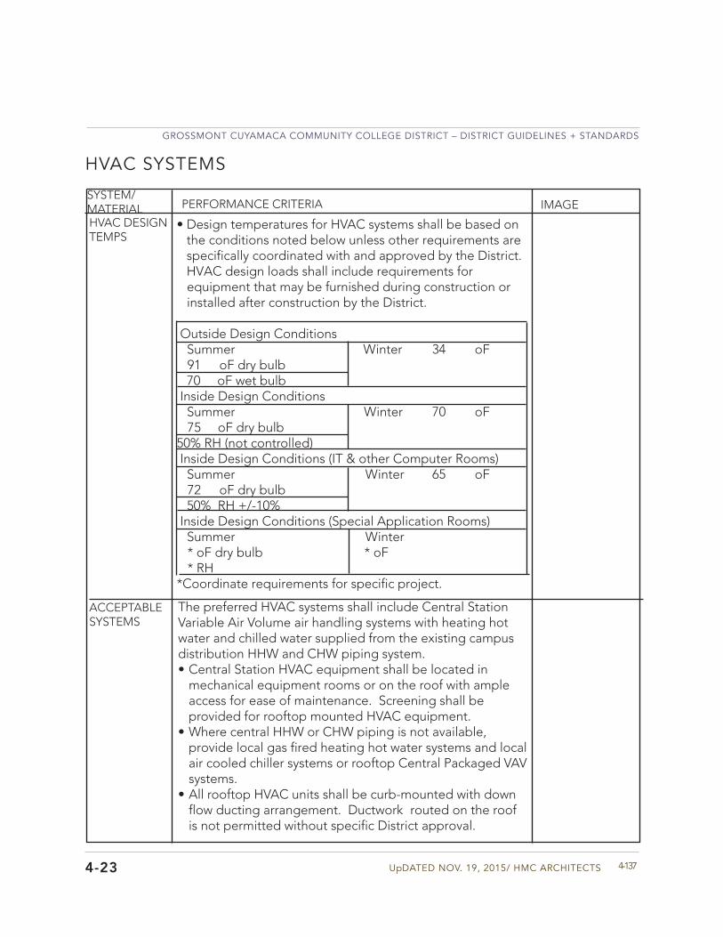
UpDATED NOV. 19, 2015/ HMC ARCHITECTS
GROSSMONT CUYAMACA COMMUNITY COLLEGE DISTRICT – DISTRICT GUIDELINES + STANDARDS
4-137
HEATING, VENT., + AIR CONDITIONING
4-23
HVAC SYSTEMS
SYSTEM/MATERIAL PERFORMANCE CRITERIA IMAGE
HVAC DESIGN TEMPS
ACCEPTABLE SYSTEMS
• Design temperatures for HVAC systems shall be based onthe conditions noted below unless other requirements arespecifically coordinated with and approved by the District.HVAC design loads shall include requirements forequipment that may be furnished during construction orinstalled after construction by the District.
Outside Design Conditions Summer Winter 34 oF
91 oF dry bulb 70 oF wet bulb Inside Design Conditions Summer Winter 70 oF
75 oF dry bulb50% RH (not controlled) Inside Design Conditions (IT & other Computer Rooms) Summer Winter 65 oF
72 oF dry bulb 50% RH +/-10% Inside Design Conditions (Special Application Rooms) Summer Winter
* oF dry bulb * oF* RH
*Coordinate requirements for specific project.
The preferred HVAC systems shall include Central Station Variable Air Volume air handling systems with heating hot water and chilled water supplied from the existing campus distribution HHW and CHW piping system. • Central Station HVAC equipment shall be located in
mechanical equipment rooms or on the roof with ample access for ease of maintenance. Screening shall be provided for rooftop mounted HVAC equipment.
• Where central HHW or CHW piping is not available,provide local gas fired heating hot water systems and local air cooled chiller systems or rooftop Central Packaged VAV systems.
• All rooftop HVAC units shall be curb-mounted with downflow ducting arrangement. Ductwork routed on the roof is not permitted without specific District approval.
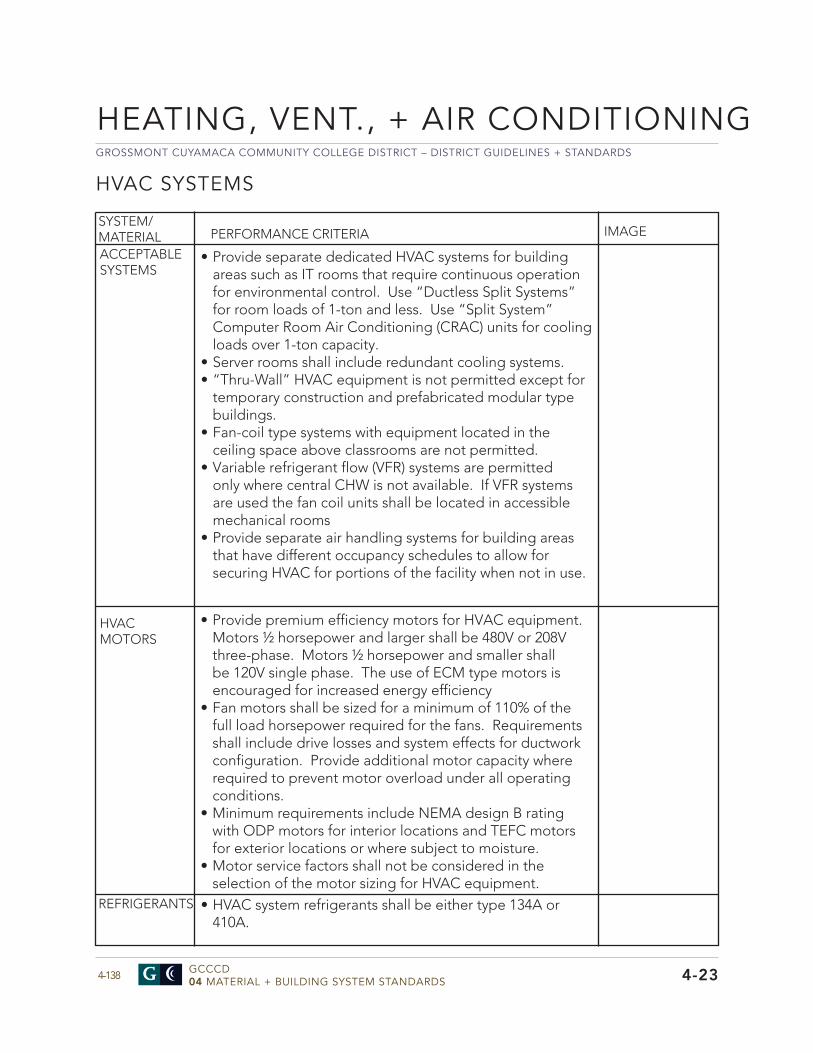
GROSSMONT CUYAMACA COMMUNITY COLLEGE DISTRICT – DISTRICT GUIDELINES + STANDARDS
GCCCD04 MATERIAL + BUILDING SYSTEM STANDARDS4-138
HEATING, VENT., + AIR CONDITIONING
4-23
HVAC SYSTEMS
SYSTEM/MATERIAL PERFORMANCE CRITERIA IMAGE
ACCEPTABLE SYSTEMS
HVAC MOTORS
REFRIGERANTS
• Provide separate dedicated HVAC systems for buildingareas such as IT rooms that require continuous operationfor environmental control. Use “Ductless Split Systems”for room loads of 1-ton and less. Use “Split System”Computer Room Air Conditioning (CRAC) units for coolingloads over 1-ton capacity.
• Server rooms shall include redundant cooling systems.• “Thru-Wall” HVAC equipment is not permitted except for
temporary construction and prefabricated modular typebuildings.
• Fan-coil type systems with equipment located in theceiling space above classrooms are not permitted.
• Variable refrigerant flow (VFR) systems are permittedonly where central CHW is not available. If VFR systemsare used the fan coil units shall be located in accessiblemechanical rooms
• Provide separate air handling systems for building areasthat have different occupancy schedules to allow forsecuring HVAC for portions of the facility when not in use.
• Provide premium efficiency motors for HVAC equipment. Motors ½ horsepower and larger shall be 480V or 208V three-phase. Motors ½ horsepower and smaller shall be 120V single phase. The use of ECM type motors is encouraged for increased energy efficiency
• Fan motors shall be sized for a minimum of 110% of thefull load horsepower required for the fans. Requirementsshall include drive losses and system effects for ductworkconfiguration. Provide additional motor capacity whererequired to prevent motor overload under all operatingconditions.
• Minimum requirements include NEMA design B ratingwith ODP motors for interior locations and TEFC motorsfor exterior locations or where subject to moisture.
• Motor service factors shall not be considered in theselection of the motor sizing for HVAC equipment.
• HVAC system refrigerants shall be either type 134A or410A.
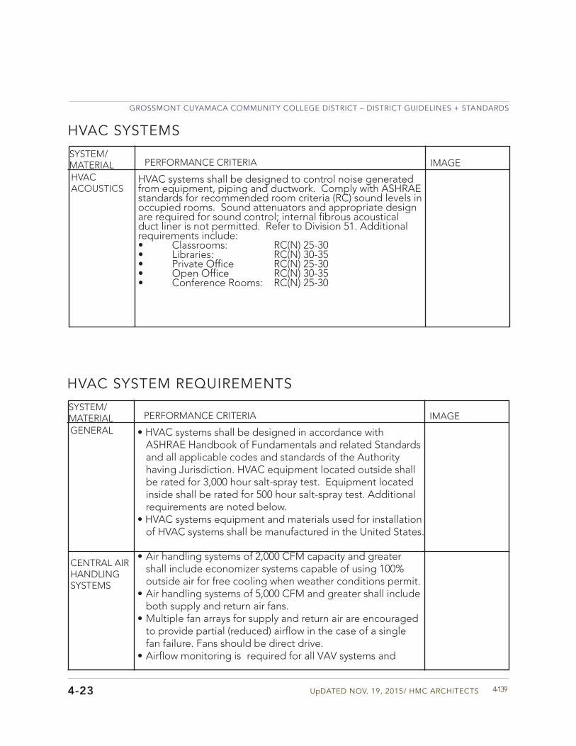
UpDATED NOV. 19, 2015/ HMC ARCHITECTS
GROSSMONT CUYAMACA COMMUNITY COLLEGE DISTRICT – DISTRICT GUIDELINES + STANDARDS
4-1394-23
HVAC SYSTEMS
SYSTEM/MATERIAL PERFORMANCE CRITERIA IMAGE
HVAC ACOUSTICS
HVAC systems shall be designed to control noise generated from equipment, piping and ductwork. Comply with ASHRAE standards for recommended room criteria (RC) sound levels in occupied rooms. Sound attenuators and appropriate design are required for sound control; internal fibrous acoustical duct liner is not permitted. Refer to Division 51. Additional requirements include:• Classrooms: RC(N) 25-30• Libraries: RC(N) 30-35• Private Office RC(N) 25-30• Open Office RC(N) 30-35• Conference Rooms: RC(N) 25-30
HVAC SYSTEM REQUIREMENTS
SYSTEM/MATERIAL PERFORMANCE CRITERIA IMAGE
GENERAL • HVAC systems shall be designed in accordance withASHRAE Handbook of Fundamentals and related Standardsand all applicable codes and standards of the Authorityhaving Jurisdiction. HVAC equipment located outside shallbe rated for 3,000 hour salt-spray test. Equipment locatedinside shall be rated for 500 hour salt-spray test. Additionalrequirements are noted below.
• HVAC systems equipment and materials used for installationof HVAC systems shall be manufactured in the United States.
CENTRAL AIR HANDLING SYSTEMS
• Air handling systems of 2,000 CFM capacity and greatershall include economizer systems capable of using 100%outside air for free cooling when weather conditions permit.
• Air handling systems of 5,000 CFM and greater shall includeboth supply and return air fans.
• Multiple fan arrays for supply and return air are encouragedto provide partial (reduced) airflow in the case of a singlefan failure. Fans should be direct drive.
• Airflow monitoring is required for all VAV systems and
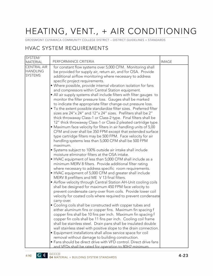
GROSSMONT CUYAMACA COMMUNITY COLLEGE DISTRICT – DISTRICT GUIDELINES + STANDARDS
GCCCD04 MATERIAL + BUILDING SYSTEM STANDARDS4-140
HEATING, VENT., + AIR CONDITIONING
4-23
HVAC SYSTEM REQUIREMENTS
SYSTEM/MATERIAL PERFORMANCE CRITERIA IMAGE
CENTRAL AIR HANDLING SYSTEMS
for constant flow systems over 5,000 CFM. Monitoring shall be provided for supply air, return air, and for OSA. Provide additional airflow monitoring where necessary to address specific project requirements.
• Where possible, provide internal vibration isolation for fansand compressors within Central Station equipment.
• All air supply systems shall include filters with filter gauges tomonitor the filter pressure loss. Gauges shall be marked to indicate the appropriate filter change-out pressure loss.
• To the extent possible standardize filter sizes. Preferred filtersizes are 24”x 24” and 12”x 24” sizes. Prefilters shall be 2”thick throwaway Class-1 or Class-2 type. Final filters shall be12” thick throwaway Class-1 or Class-2 pleated cartridge type.
• Maximum face velocity for filters in air handling units of 5,00CFM and over shall be 350 FPM except that extended surface type cartridge filters may be 500 FPM. Face velocity for airhandling systems less than 5,000 CFM shall be 500 FPM maximum.
• Systems subject to 100% outside air intake shall includemoisture eliminator filters at the OSA intake.
• HVAC equipment of less than 5,000 CFM shall include as aminimum MERV 8 filters. Provide additional filter rating where necessary to address specific room requirements.
• HVAC equipment of 5,000 CFM and greater shall includeMERV 8 prefilters and ME V 13 final filters.
• Airflow velocity through Central Station AH-Unit cooling coilsshall be designed for maximum 450 FPM face velocity to prevent condensate carry-over from coils. Provide lower coil velocity for coated coils where required to prevent condensate carry-over.
• Cooling coils shall be constructed with copper tubes andeither aluminum fins or copper fins. Maximum fin spacing fcopper fins shall be 10 fins per inch. Maximum fin spacing fcopper fin coils shall be 11 fins per inch. Cooling coil frameshall be stainless steel. Drain pans shall be insulated double wall stainless steel with positive slope to the drain connection.
• Equipment installations shall allow service space for coilremoval without damage to building construction.
• Fans should be direct drive with VFD control. Direct drive fansand VFDs shall be rated for operation to 80H2 minimum.
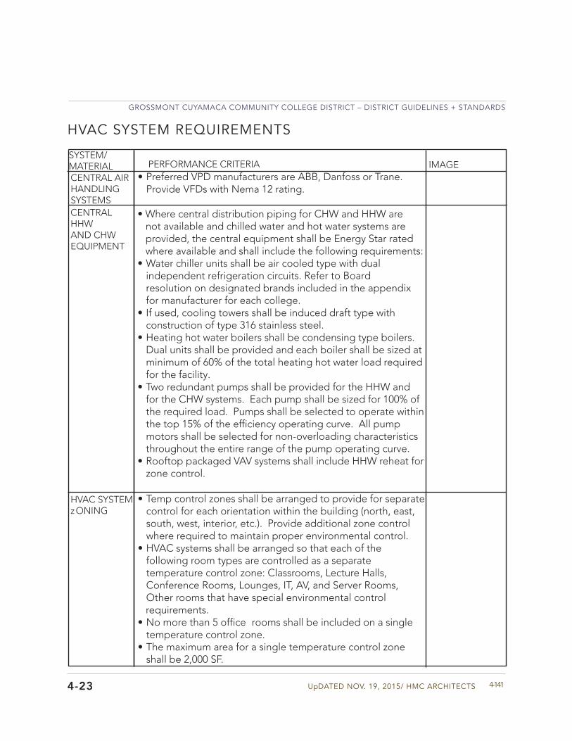
UpDATED NOV. 19, 2015/ HMC ARCHITECTS
GROSSMONT CUYAMACA COMMUNITY COLLEGE DISTRICT – DISTRICT GUIDELINES + STANDARDS
4-1414-23
HVAC SYSTEM REQUIREMENTS
SYSTEM/MATERIAL PERFORMANCE CRITERIA IMAGE
CENTRAL HHW AND CHW EQUIPMENT
HVAC SYSTEM zONING
• Where central distribution piping for CHW and HHW arenot available and chilled water and hot water systems areprovided, the central equipment shall be Energy Star ratedwhere available and shall include the following requirements:
• Water chiller units shall be air cooled type with dualindependent refrigeration circuits. Refer to Boardresolution on designated brands included in the appendixfor manufacturer for each college.
• If used, cooling towers shall be induced draft type withconstruction of type 316 stainless steel.
• Heating hot water boilers shall be condensing type boilers.Dual units shall be provided and each boiler shall be sized atminimum of 60% of the total heating hot water load requiredfor the facility.
• Two redundant pumps shall be provided for the HHW andfor the CHW systems. Each pump shall be sized for 100% ofthe required load. Pumps shall be selected to operate withinthe top 15% of the efficiency operating curve. All pumpmotors shall be selected for non-overloading characteristicsthroughout the entire range of the pump operating curve.
• Rooftop packaged VAV systems shall include HHW reheat forzone control.
• Temp control zones shall be arranged to provide for separatecontrol for each orientation within the building (north, east,south, west, interior, etc.). Provide additional zone controlwhere required to maintain proper environmental control.
• HVAC systems shall be arranged so that each of thefollowing room types are controlled as a separatetemperature control zone: Classrooms, Lecture Halls,Conference Rooms, Lounges, IT, AV, and Server Rooms,Other rooms that have special environmental controlrequirements.
• No more than 5 office rooms shall be included on a singletemperature control zone.
• The maximum area for a single temperature control zoneshall be 2,000 SF.
CENTRAL AIR HANDLING SYSTEMS
• Preferred VPD manufacturers are ABB, Danfoss or Trane.Provide VFDs with Nema 12 rating.
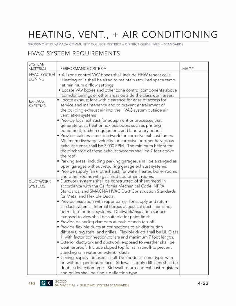
GROSSMONT CUYAMACA COMMUNITY COLLEGE DISTRICT – DISTRICT GUIDELINES + STANDARDS
GCCCD04 MATERIAL + BUILDING SYSTEM STANDARDS4-142
HEATING, VENT., + AIR CONDITIONING
4-23
HVAC SYSTEM REQUIREMENTS
• Locate exhaust fans with clearance for ease of access forservice and maintenance and to prevent entrainment ofthe building exhaust air into the HVAC system outside airventilation systems
• Provide local exhaust for equipment or processes thatgenerate dust, heat or noxious odors such as printingequipment, kitchen equipment, and laboratory hoods.
• Provide stainless steel ductwork for corrosive exhaust fumes.Minimum discharge velocity for corrosive or other hazardousexhaust fumes shall be 3,000 FPM. The minimum height forthe discharge of these exhaust systems shall be 7 feet abovethe roof.
• Parking areas, including parking garages, shall be arranged asopen garages without requiring garage exhaust systems.
• Provide supply fan (not exhaust) for water heater, boiler roomsand other rooms with gas fired equipment rooms.
SYSTEM/MATERIAL PERFORMANCE CRITERIA IMAGE
EXHAUST SYSTEMS
• Ductwork systems shall be constructed of sheet metal inaccordance with the California Mechanical Code, NFPAStandards, and SMACNA HVAC Duct Construction Standardsfor Metal and Flexible Ducts.
• Provide insulation with vapor barrier for supply and returnair duct systems. Internal fibrous acoustical duct liner is notpermitted for duct systems. Ductwork/insulation surfaceexposed to view shall be suitable for paint finish
• Provide balancing dampers at each branch tap-off.• Provide flexible ducts at connections to air distribution
diffusers, registers, and grilles. Flexible ducts shall be UL Class1, with factor connection collars and maximum 7 foot length.
• Exterior ductwork and ductwork exposed to weather shall beweatherproof. Include sloped top for rain runoff to preventstanding rain water on exterior ducts.
• Ceiling supply diffusers shall be modular core type withor without perforated face. Sidewall supply diffusers shall bedouble deflection type. Sidewall return and exhaust registersand grilles shall be single deflection type
DUCTWORKSYSTEMS
HVAC SYSTEM zONING
• All zone control VAV boxes shall include HHW reheat coils.Heating coils shall be sized to maintain required space temp.at minimum airflow settings
• Locate VAV boxes and other zone control components abovecorridor ceilings or other areas outside the classroom areas.
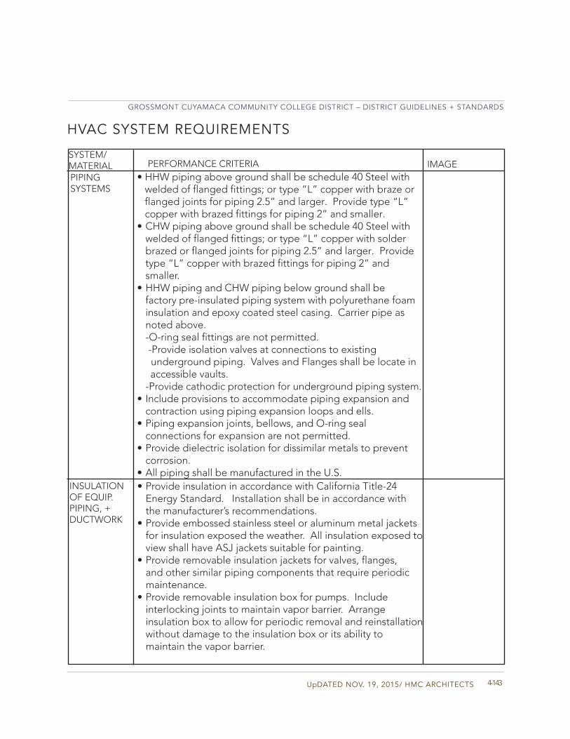
UpDATED NOV. 19, 2015/ HMC ARCHITECTS
GROSSMONT CUYAMACA COMMUNITY COLLEGE DISTRICT – DISTRICT GUIDELINES + STANDARDS
4-143
PERFORMANCE CRITERIASYSTEM/MATERIAL IMAGE
HVAC SYSTEM REQUIREMENTS
PIPINGSYSTEMS
INSULATION OF EQUIP.PIPING, + DUCTWORK
• HHW piping above ground shall be schedule 40 Steel withwelded of flanged fittings; or type “L” copper with braze orflanged joints for piping 2.5” and larger. Provide type “L”copper with brazed fittings for piping 2” and smaller.
• CHW piping above ground shall be schedule 40 Steel withwelded of flanged fittings; or type “L” copper with solderbrazed or flanged joints for piping 2.5” and larger. Providetype “L” copper with brazed fittings for piping 2” andsmaller.
• HHW piping and CHW piping below ground shall befactory pre-insulated piping system with polyurethane foaminsulation and epoxy coated steel casing. Carrier pipe asnoted above.-O-ring seal fittings are not permitted. -Provide isolation valves at connections to existing underground piping. Valves and Flanges shall be locate in
accessible vaults.-Provide cathodic protection for underground piping system.
• Include provisions to accommodate piping expansion andcontraction using piping expansion loops and ells.
• Piping expansion joints, bellows, and O-ring sealconnections for expansion are not permitted.
• Provide dielectric isolation for dissimilar metals to preventcorrosion.
• All piping shall be manufactured in the U.S.• Provide insulation in accordance with California Title-24
Energy Standard. Installation shall be in accordance withthe manufacturer’s recommendations.
• Provide embossed stainless steel or aluminum metal jacketsfor insulation exposed the weather. All insulation exposed toview shall have ASJ jackets suitable for painting.
• Provide removable insulation jackets for valves, flanges,and other similar piping components that require periodicmaintenance.
• Provide removable insulation box for pumps. Includeinterlocking joints to maintain vapor barrier. Arrangeinsulation box to allow for periodic removal and reinstallationwithout damage to the insulation box or its ability tomaintain the vapor barrier.
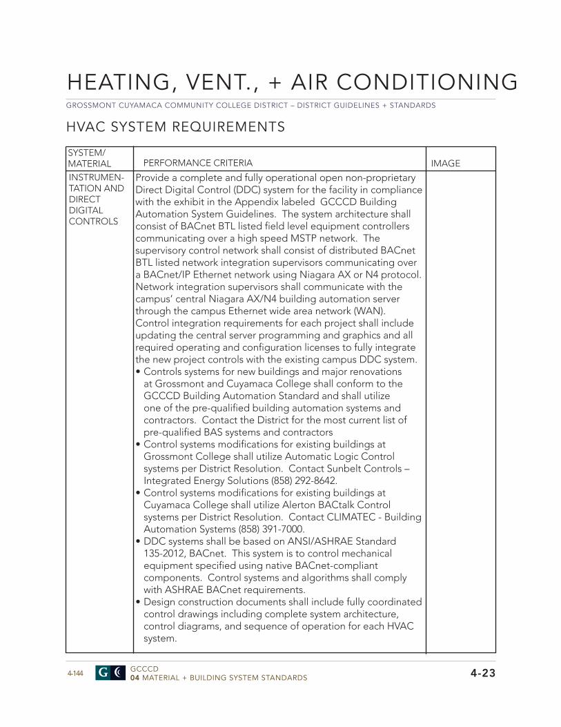
GROSSMONT CUYAMACA COMMUNITY COLLEGE DISTRICT – DISTRICT GUIDELINES + STANDARDS
GCCCD04 MATERIAL + BUILDING SYSTEM STANDARDS4-144
HEATING, VENT., + AIR CONDITIONING
4-23
HVAC SYSTEM REQUIREMENTS
Provide a complete and fully operational open non-proprietary Direct Digital Control (DDC) system for the facility in compliance with the exhibit in the Appendix labeled GCCCD Building Automation System Guidelines. The system architecture shall consist of BACnet BTL listed field level equipment controllers communicating over a high speed MSTP network. The supervisory control network shall consist of distributed BACnet BTL listed network integration supervisors communicating over a BACnet/IP Ethernet network using Niagara AX or N4 protocol. Network integration supervisors shall communicate with the campus’ central Niagara AX/N4 building automation server through the campus Ethernet wide area network (WAN). Control integration requirements for each project shall include updating the central server programming and graphics and all required operating and configuration licenses to fully integrate the new project controls with the existing campus DDC system.• Controls systems for new buildings and major renovations
at Grossmont and Cuyamaca College shall conform to the GCCCD Building Automation Standard and shall utilize one of the pre-qualified building automation systems andcontractors. Contact the District for the most current list of pre-qualified BAS systems and contractors
• Control systems modifications for existing buildings atGrossmont College shall utilize Automatic Logic Control systems per District Resolution. Contact Sunbelt Controls – Integrated Energy Solutions (858) 292-8642.
• Control systems modifications for existing buildings atCuyamaca College shall utilize Alerton BACtalk Control systems per District Resolution. Contact CLIMATEC - Building Automation Systems (858) 391-7000.
• DDC systems shall be based on ANSI/ASHRAE Standard135-2012, BACnet. This system is to control mechanical equipment specified using native BACnet-compliantcomponents. Control systems and algorithms shall comply with ASHRAE BACnet requirements.
• Design construction documents shall include fully coordinatedcontrol drawings including complete system architecture, control diagrams, and sequence of operation for each HVAC system.
SYSTEM/MATERIAL PERFORMANCE CRITERIA IMAGE
INSTRUMEN-TATION ANDDIRECT DIGITALCONTROLS
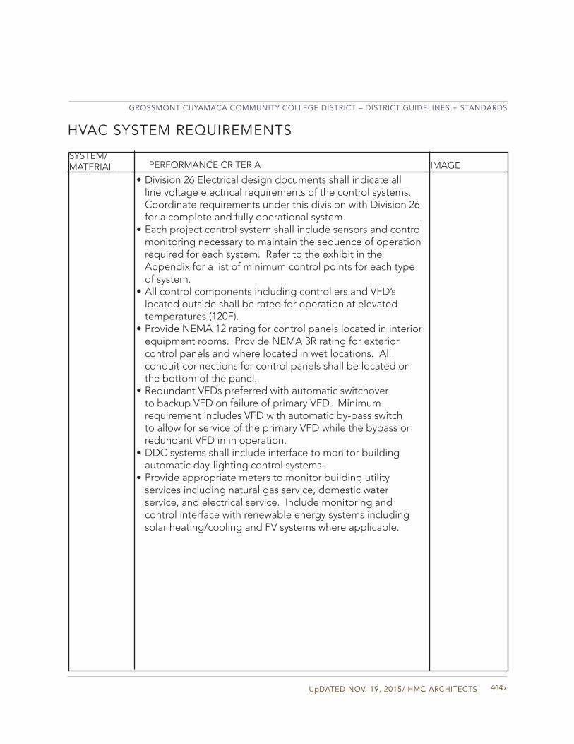
UpDATED NOV. 19, 2015/ HMC ARCHITECTS
GROSSMONT CUYAMACA COMMUNITY COLLEGE DISTRICT – DISTRICT GUIDELINES + STANDARDS
4-145
PERFORMANCE CRITERIASYSTEM/MATERIAL IMAGE
HVAC SYSTEM REQUIREMENTS
• Division 26 Electrical design documents shall indicate allline voltage electrical requirements of the control systems.Coordinate requirements under this division with Division 26for a complete and fully operational system.
• Each project control system shall include sensors and controlmonitoring necessary to maintain the sequence of operationrequired for each system. Refer to the exhibit in theAppendix for a list of minimum control points for each typeof system.
• All control components including controllers and VFD’slocated outside shall be rated for operation at elevatedtemperatures (120F).
• Provide NEMA 12 rating for control panels located in interiorequipment rooms. Provide NEMA 3R rating for exteriorcontrol panels and where located in wet locations. Allconduit connections for control panels shall be located onthe bottom of the panel.
• Redundant VFDs preferred with automatic switchoverto backup VFD on failure of primary VFD. Minimumrequirement includes VFD with automatic by-pass switchto allow for service of the primary VFD while the bypass orredundant VFD in in operation.
• DDC systems shall include interface to monitor buildingautomatic day-lighting control systems.
• Provide appropriate meters to monitor building utilityservices including natural gas service, domestic waterservice, and electrical service. Include monitoring andcontrol interface with renewable energy systems includingsolar heating/cooling and PV systems where applicable.
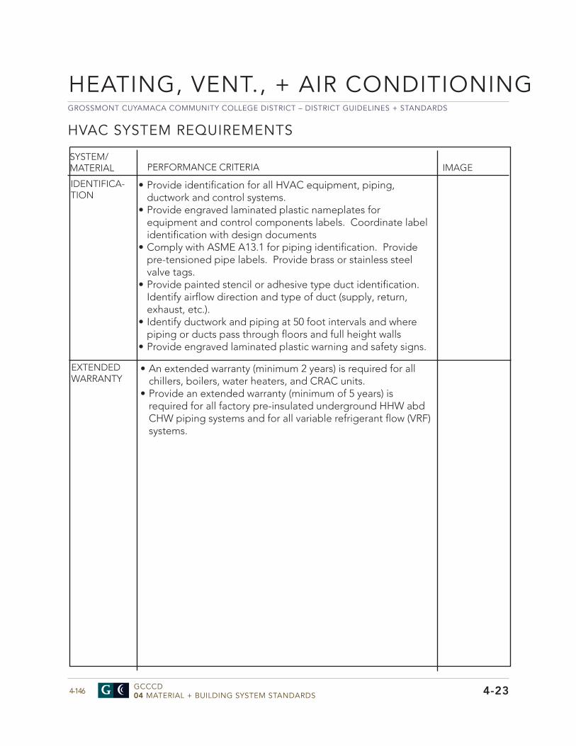
GROSSMONT CUYAMACA COMMUNITY COLLEGE DISTRICT – DISTRICT GUIDELINES + STANDARDS
GCCCD04 MATERIAL + BUILDING SYSTEM STANDARDS4-146
HEATING, VENT., + AIR CONDITIONING
4-23
HVAC SYSTEM REQUIREMENTS
SYSTEM/MATERIAL PERFORMANCE CRITERIA IMAGE
• Provide identification for all HVAC equipment, piping,ductwork and control systems.
• Provide engraved laminated plastic nameplates forequipment and control components labels. Coordinate labelidentification with design documents
• Comply with ASME A13.1 for piping identification. Providepre-tensioned pipe labels. Provide brass or stainless steelvalve tags.
• Provide painted stencil or adhesive type duct identification.Identify airflow direction and type of duct (supply, return,exhaust, etc.).
• Identify ductwork and piping at 50 foot intervals and wherepiping or ducts pass through floors and full height walls
• Provide engraved laminated plastic warning and safety signs.
IDENTIFICA-TION
EXTENDED WARRANTY
• An extended warranty (minimum 2 years) is required for allchillers, boilers, water heaters, and CRAC units.
• Provide an extended warranty (minimum of 5 years) isrequired for all factory pre-insulated underground HHW abdCHW piping systems and for all variable refrigerant flow (VRF)systems.
UpDATED NOV. 19, 2015/ HMC ARCHITECTS
GROSSMONT CUYAMACA COMMUNITY COLLEGE DISTRICT – DISTRICT GUIDELINES + STANDARDS
4-147
HVAC SYSTEM REQUIREMENTS
SYSTEM/MATERIAL PERFORMANCE CRITERIA IMAGE
TESTING, ADJUSTING, BALANCING
• Provide complete Testing and Balancing (TAB) of all air andwater distribution systems and HVAC equipment. Complywith the requirements of AABC or NEBB test and balancestandards.
• Test and Balance contractor shall be certified by AABC orNEBB. TAB contractor shall be a first tier subcontractor.
• Include as part of the TAB requirements Duct Air LeakageTesting (DALT) for all duct systems with a static pressure of 1”and over in accordance with SMACNA HVAC Air Duct LeakageTest Manual, 2nd Edition.
• TAB contractor shall review the construction documentsand provide a pre-TAB report identifying any elements ofthe design that will prevent effective balancing of the HVACsystems. The report shall be submitted within 45 days of theconstruction contract award. No adjustment in contract pricewill be permitted for TAB design issues after the report isissued.
GROSSMONT CUYAMACA COMMUNITY COLLEGE DISTRICT – DISTRICT GUIDELINES + STANDARDS
GCCCD04 MATERIAL + BUILDING SYSTEM STANDARDS4-148
HEATING, VENT., + AIR CONDITIONING
4-23
HVAC SYSTEM REQUIREMENTS
IMAGESYSTEM/MATERIAL PERFORMANCE CRITERIA
• All projects shall include Commissioning in accordance withASHRAE 202.
• Include requirements for LEED Fundamental and EnhancedCommissioning for all LEED certified projects.
• Include commissioning review of all design submittals.• Projects specifications shall include requirements for
contractor commissioning for all HVAC and Plumbing systemsincluding documentation of all commissioning proceduresincluding functional performance of all systems, training, andsystem documentation.
• The District may retain a Third Party CommissioningAuthority to provide independent review and oversight of thecommissioning process. Include requirements for contractorsupport of the District commissioning verification process.
• The District inspector shall be notified of all on-sitecommissioning meetings, site observations, and functionalperformance verification activities.
COMMISSION-ING

UpDATED NOV. 19, 2015/ HMC ARCHITECTS
GROSSMONT CUYAMACA COMMUNITY COLLEGE DISTRICT – DISTRICT GUIDELINES + STANDARDS
4-149
GROSSMONT CUYAMACA COMMUNITY COLLEGE DISTRICT – DISTRICT GUIDELINES + STANDARDS
GCCCD04 MATERIAL + BUILDING SYSTEM STANDARDS4-150
ELECTRICAL
4-26
ELECTRICAL GENERAL pROVISIONS
Division 26
• Contractor shall return all #8 and larger copper wire to theDistrict.
SYSTEM/MATERIAL PERFORMANCE CRITERIA IMAGE
DEMOLITION
Electrical General Design Approach: The focus of all campus design is to create and enhance the learning experience for the students and staff. Key to this experience is a well planned and executed electrical power and lighting controls system.
In addition to the design meeting all applicable codes and regulatory requirements, NFPA standards, and NECA standards for installation, which are outlined in this section. The District has preferences and performance criteria for the electrical and lighting systems Both campuses have strict guidelines for working on energized electrical systems. Personnel are not allowed to access live conductors or bussing. Prior to removal of electrical covers, the associated part of electrical system is de-energized.
The electrical system should be organized to allow District staff to maintain the system in an orderly fashion, while minimizing any disruptions to instruction and other functions on campus. The most successful methodology to minimize classroom disruptions is to focus on specifying cost-effective quality systems and components designed for durability and minimal life cycle costs.
The district has set a target of overall building efficiency to meet the requirements of LEED Silver. This affects lighting, lighting controls, power system controls and transformer design.
Building electrical concept design shall be submitted to the District for review and approval prior to proceeding with the building design. The electrical design approach for each project should consider the campus mater plan, future projects and power needs as well as existing available power and coordination with recent past and proposed future projects for electrical infrastructure.
UpDATED NOV. 19, 2015/ HMC ARCHITECTS
GROSSMONT CUYAMACA COMMUNITY COLLEGE DISTRICT – DISTRICT GUIDELINES + STANDARDS
4-1514-26
INTERIOR ELECTRICAL INFRASTRUCTURE/DISTRIBUTION
SYSTEM/MATERIAL PERFORMANCE CRITERIA IMAGE
PRODUCTSGENERAL
EXECUTIONGENERAL
• Shall be listed by underwriters laboratories and shall bear the U.L label.• Shall be suitable for the environment in which they are located.• Shall be factory assembled per construction documents.• EEOR, utilizing the latest version of SKM, shall provide a
circuit breaker coordination, Short circuit and Arc Flashstudy for the entire system up to the 12KV distributiontransformer regardless of the scope of work.
• Finishes shall be baked enamel factory painted inmanufacturer’s standard color.
• Provide front accessibility for wire ways on each side ofovercurrent protective devices.
• All electrical distribution equipment shall be provided byone manufacturer.
• All devices shall be provided by one manufacturer.• All bussing shall be silver-coated copper.
• Coordinate with other disciplines to identify conflicts withlocations (clearances), notify the engineer of any conflicts
• Coordinate all equip. with structural engineer for anchoring,mounting and concrete housekeeping pad size.
• All equipment shall be installed in accordance withmanufacturer recommendations..
• Install equipment plumb and square to structure andadjacent surfaces.
• Connect and inspect all ground bonds prior to energizingequipment.
• Adjust and set all equipment devices for proper operation.• Test all over-current protection devices for voltage level,
continuity, ground fault and short circuits.• Touch up scratched paint and finishes• Clean interior and exterior closures/equipment/devices
prior to handing over to District.
GROSSMONT CUYAMACA COMMUNITY COLLEGE DISTRICT – DISTRICT GUIDELINES + STANDARDS
GCCCD04 MATERIAL + BUILDING SYSTEM STANDARDS4-152
ELECTRICAL
4-26
INTERIOR ELECTRICAL INFRASTRUCTURE/DISTRIBUTION
• Provide commercial panelboards with bolt-on circuitbreakers.
• Panelboards shall be rated 600VAC and shall not exceed400A amperage capacity.
• Circuit Breakers above 225A shall be electronic-solid state100% rated.
• Provide heavy duty “door-in-door” panelboard covers.• Panelboard circuit quantity shall not exceed 80% of the
available space and capacity. The remaining 20% of spaceand capacity shall be reserved for future loads.
• Provide 20A, single pole circuit breakers in all future spaces.• Load centers are not acceptable.
SYSTEM/MATERIAL PERFORMANCE CRITERIA IMAGE
PANELBOARDSPRODUCTS
PANELBOARDSEXECUTION
• The site safety standard requires all maintenancepersonnel to de-energized panelboards prior to accessingthe conductors or other live parts. In order to minimizedisruption to the students and staff, the District preferssegregated panels at each building for HVAC, EgressLighting (standby emergency power), Normal Lighting,Exterior Lighting and Interior Lighting. This standardincreases the number of panels, but will allow the staff tominimize disruption.
• Panelboards shall be mounted no higher than 6’-0” to thehighest device from finished floor and no lower than 24above finished floor. Provide panel skirts.
• Do not install panelboards in classrooms, offices, conferencerooms or other user occupied spaces in constant use. Installpanelboards in electrical rooms and closets when possible.Installation of a panelboard in a corridor is acceptable.
• Based on the site safety standard, double lugged panels andfeed thru lugs are not allowed. Panels feeding panels shallbe limited to one level.
• Panelboard lugs should only be use only to feed a singlepanelboard enclosure.
• Provide a copper ground bus in each panelboard.• Consider the use of 200% neutral panelboards in areas with
high harmonic loads.• Provide 42 circuit panelboards except in IDF/MDF rooms.• Provide 24 circuit panelboard in IDF rooms. Panelboards
with less than 42 circuits will be considered on case by case.
UpDATED NOV. 19, 2015/ HMC ARCHITECTS
GROSSMONT CUYAMACA COMMUNITY COLLEGE DISTRICT – DISTRICT GUIDELINES + STANDARDS
4-1534-26
SYSTEM/MATERIAL PERFORMANCE CRITERIA IMAGE
SWITCHBOARDSPRODUCTS
• Products shall be dead front, metal enclosed, selfsupporting floor standing sections with housekeeping pads
• Equip with lifting eyes.• Provide with IR scan windows in each section of back of
accessible equipment.• Provide ground bus in each switchboard section with
connecting ground bonds between sections.• Vertical sections shall contain overcurrent protective devices
including circuit breakers and fuses.• Main circuit breakers should be provided and shall be solid
state trip type.• Circuit Breakers above 225A should be electronic-solid state
100% rated.• Provide 25% spare breaker space and load capacity.
PANELBOARDSEXECUTION
• Minimum circuit breaker size in a panelboard should be 20Amps.
• Coordinate IT room panel breaker amperage and phasewith college.
• Provide spare conduits for future. (3) ¾” conduit aboveeach new panel. Stubbed conduit into the nearestaccessible ceiling space.
• Place typewritten panel schedule in a sleeve on the interiorof the panel board indicating loads and areas connected toeach circuit.
TRANSFORMERSPRODUCTS
• Transformers should be designed to an efficiencystandard higher than the lowest legal standard for thepurpose of contributing to LEED Energy andAtmosphere (Optimize Energy Performance) and utilityrebates.
• Transformers designed to the lowest code compliantefficiency standard do not provide the contributionslisted above, are not acceptable for meeting the aboverequirements.
• Transformers should be UL 1561 listed and labeled with K-9rating or above.
• Windings should be continuous wound copper with brazedor welded terminations.
• Maximum winding temperature rise: 130 degree C in a 40degree C maximum ambient.
GROSSMONT CUYAMACA COMMUNITY COLLEGE DISTRICT – DISTRICT GUIDELINES + STANDARDS
GCCCD04 MATERIAL + BUILDING SYSTEM STANDARDS4-154 4-26
ELECTRICAL
INTERIOR ELECTRICAL INFRASTRUCTURE/DISTRIBUTION
SYSTEM/MATERIAL PERFORMANCE CRITERIA IMAGE
TRANSFORMERSPRODUCTS
TRANSFORMERSEXECUTION
• Mount on housekeeping pads.• Provide rubber vibration isolation between transformerand floor, structure or any fixed surface (includingwireways).
• Install all conduit connections to transformer with liquidtight flexible conduit
• Test all transformers for voltage level at primary andsecondary windings.
• Provide premium efficiency motors for HVAC equipment.• Should be fused.
•The use of “buck-boost” and “auto-transformers should belimited.
• Transformers should have IR scan windows.• Insulation and varnish systems: UL recognized 220 degree C
class; epoxy polyester impregnation.• All materials, including those for changing taps, must be
readily accessible by removing a front cover plate.• The transformer shall have a basic impulse level of
10KV BIL.• Neutral terminals shall allow cables for 250% of
nameplate current, accommodating loads requiring200% neutrals.
• Voltage Taps: -15KVA-300KVA, Provide (2) 2-1/2% fullcapacity taps above and (4) 2-1/2% below nominal primaryvoltage.
• Enclosure type shall be NEMA 2 with a minimummanufacturing clearance of 3” to comply with NEC450.9.
• Sound level per KVA rating shall be 3 dB below NEMAstandard.
• Impedance shall be the manufacturer standard.
PRODUCTSBUS DUCTS/MOTOR CONTROL CENTERS
• Evaluated on a project by project basis.
UpDATED NOV. 19, 2015/ HMC ARCHITECTS
GROSSMONT CUYAMACA COMMUNITY COLLEGE DISTRICT – DISTRICT GUIDELINES + STANDARDS
4-1554-26
SYSTEM/MATERIAL PERFORMANCE CRITERIA IMAGE
GENERATORS
SURGE PROTECTIVE DEVICE (SPD)
• Existing generators at each campus are dedicated to code required life safety loads: interior path egress, exterior light fixtures and fi e alarm panels.
• No new generators are anticipated.
DISCONNECTS • Electrical requirements should include drive losses.Provide additional motor capacity where required toprevent motor overload under all operating conditions.
• Minimum requirements include NEMA design B ratingwith ODP motors for interior locations.
• TEFC motors for exterior locations or where subject tomoisture.
• Motor service factors should not be considered in theselection of the motor sizing for HVAC equipment.
• Motors ½ horsepower and larger shall be 480V or 208Vthree phase.
• Motors ½ horsepower and smaller shall be 120V singlephase.
• The use of ECM type motors is encouraged for increasedenergy efficiency
• Fan motors shall be sized for a minimum of 110% of thefull load horsepower required for the fans.
• Provide premium efficiency motors for HVAC equipment.• Should be fused.
• Required only at IT panelboards.• Provide exterior (SPD) directly adjacent to IT panel.
INVERTER/BATTERY PACKS
• Lighting inverter should only be utilized for egress pathlighting that cannot be restored to full capacity in 10seconds or less.
• The use of individual fixture mounted battery packs shouldbe avoided.
GROSSMONT CUYAMACA COMMUNITY COLLEGE DISTRICT – DISTRICT GUIDELINES + STANDARDS
GCCCD04 MATERIAL + BUILDING SYSTEM STANDARDS4-156
ELECTRICAL
4-26
SYSTEM/MATERIAL
GROUNDING AND BONDING
PERFORMANCE CRITERIA IMAGE
GROUNDING FOR PERMANENT STRUCTURES
RACEWAYPRODUCTS
RACEWAYEXECUTION
BOXESPRODUCTS
BOXESEXECUTION
• All items should be listed by underwriters laboratoriesand shall bear the U.L label.
• Rigid Galvanized Steel (RGS) Conduit (aluminum is notallowed).
• Set screw connectors or thread less type are notacceptable
• Each building should be considered a service entrance.• Provide single point ground system; UFER ground, cold
water ground, bond to the fi e sprinkler system andincoming natural gas.
• Connect ground system to IDF ground plate with #1 barecopper.
• Raceway should be seal and plug to eliminate waterentering the conduit.
• Provide pull rope, a minimum of 3/16.”• Provide bushings.• RGS shall be use where conduit is expose to damage or
weather.
• All items shall be listed by underwriter’s laboratories andshall bear the U.L label.
• Junction boxes should be accessible.• Junction boxes should be installed above grade.• Provide pull boxes by each landscape light fixture and light
poles for accessibility.• Connector devices are not allowed.• Maintain a minimum of 12” clear above all accessible
ceiling. Except for connections to devices of fixturesmounted in the ceiling not conduits, junction or pull boxesshould not intrude into this space.
•Organize branch circuit systems to allow for easy accessto all junction boxes and pull boxes. Removal and re-installation of systems that do not meet this criteria will berequired.
RACEWAY AND BOx ES
UpDATED NOV. 19, 2015/ HMC ARCHITECTS
GROSSMONT CUYAMACA COMMUNITY COLLEGE DISTRICT – DISTRICT GUIDELINES + STANDARDS
4-1574-26
LIGHTING CONTROLS
SYSTEM/MATERIAL PERFORMANCE CRITERIA IMAGE
• The head-end system for the GCCCD controls network isa Graphical User Interface located at the security officesof both campus’s. The head-end system coordinates allnetwork communications, locally within one campus andacross campus locations.
• The head-end system is currently configured to provideadditional capacity at each campus up to approximately40 additional medium sized panels, 200 additionalclassrooms of control. Refer to Appendix “diagram A” foradditional information for TECH BULLETIN DLM NetworkConfigurations
• Should the need to expand the system beyond the currentcapacity the designer will need to add components to thehead-end as follows: - Add 1ea LMSM-6e Segment Manager to the head-
end configuration will increase the extensibility of thesystem by 60 additional panels, up to 300 additional rooms.
- LMSM Segment Managers may be added as needed to extend the system as far as required for the campus operations.
HEAD-END SYSTEM
PANEL SYSTEMS
• Panel systems, approximately 30 existing panels at eachcampus currently, are used primarily for building levelcontrols, i.e. the control of building mounted lighting,security or “vandal” lighting, nearby walkway lights,parking area lighting and roadways. Panels may also act asthe “bridging” device for room control networks describedbelow in section 3.
• The District has adopted 3 standardized panels,euphemistically referred to as small, medium and large.These three panel sizes are outlined below and shown asDetails 3, 4 and 5 in the Appendix.
• The small panel provides up to 8 relays for control. Thepanel will accept CAT5 wired devices such as switchesand sensors as required. A complete listing of devices isavailable in the Appendix diagram B DLM wiring details.
• The medium panel supports up to 24 control relayswith 4 dedicated as emergency circuits. Additional EMcircuits may call out up to 6 contactors or 24 total “20A
GROSSMONT CUYAMACA COMMUNITY COLLEGE DISTRICT – DISTRICT GUIDELINES + STANDARDS
GCCCD04 MATERIAL + BUILDING SYSTEM STANDARDS4-158
ELECTRICAL
4-26
LIGHTING CONTROLS
SYSTEM/MATERIAL PERFORMANCE CRITERIA IMAGE
rated poles” of egress lighting circuits. Panel supports connection of CAT5 wired DLM components such as switches or sensors as required for control functions.
• The large panel supports up to 48 control relays with 8dedicated for emergency circuits. Additional EM circuits may be called out up to 6 contactors or 24 total “20A rated poles” of egress lighting circuits. Panel supports connection of CAT5 wired devices such as switches or sensors as required for control functions.
• If a building is sufficiently large to require more than onepanel for control, panels may be locally connected within a building for example using MS/TP BACnet cabling. Any single panel or local network of panels within a building must be connected to the head-end system
• When specifying a panel, or local network of panels asnoted above, a Network Communications Interface is required. To connect new panels to the District Lighting Controls Network a BACnet router is required. The Districts standard configuration for the panel communicationsinterface is as noted in Detail 1 in the Appendix.
• When Specifying a PANEL system there is an additionalrequirement to provide additional GRAPHICS at the head-end. Typically two graphic screen updates are required for any new panel installation, Master Campus Map update and a “quadrant” screen updated graphic to include any GRAPHICAL objects that may be part of the panel system, i.e. building mounted lights, vandal lights, roadway or parking lights as the primary examples.
PANEL SYSTEMS
UpDATED NOV. 19, 2015/ HMC ARCHITECTS
GROSSMONT CUYAMACA COMMUNITY COLLEGE DISTRICT – DISTRICT GUIDELINES + STANDARDS
4-1594-26
SYSTEM/MATERIAL PERFORMANCE CRITERIA IMAGE
• Room controls may be connected to LCP panels or directly to the campus network as required. Room controls would be classrooms, meeting rooms, labs, offices, and common areas such as restrooms etc..
• Rooms are configured using DLM components (Roomcontroller(s), switches, sensors) as required for the specificfunctions, i.e. room controllers are available as relay switchedor dimming controls with devices to accept a single feedcircuit and distribute up to three independently controlledswitch legs per device. Room controllers may be groupedto provide as many independently controlled switchlegs asrequired by the space. Rules for building a room network areincluded in the Appendix “diagram B” DLM wiring details.
• It is the discretion of the District as to any Graphicsrequirements for ROOM CONTROL networks. Currently thereis no implementation of classroom or room level graphics atthe head-end.
• As with panels, room control networks are to be linked to thehead-end system in order to make available programming, scheduling and troubleshooting over the campus wide network. This does not require graphics for these functions, but rather, programming and configuration software exists at the head-end to enable campus wide or inter-campus programming via the network. The connection to the head-end required for any room control networks is outlined below as Detail 2.
• One of these drops, as outlined in Detail 2, is required to linkroom control sub-networks to the campus wide system. Fromthis campus wide network connection a whole sub-networkof rooms, i.e. a block of new classrooms in a new buildingfor example can be linked to the head-end system via thiscommunications node with each independent room requiringonly the LMBC-300 device to make its BACnet connectionto the communications node. So with one of these controlboxes, for example, all the classrooms in a new building couldbe designed and linked into the head-end.
ROOM CONTROLS
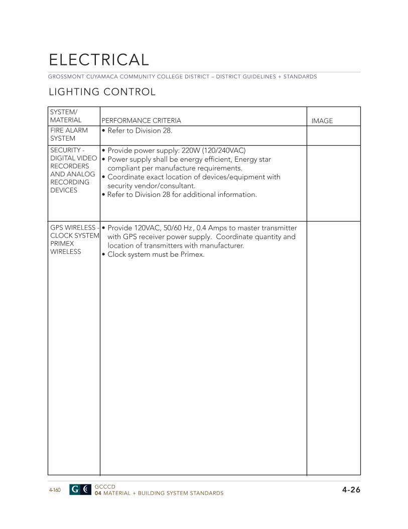
GROSSMONT CUYAMACA COMMUNITY COLLEGE DISTRICT – DISTRICT GUIDELINES + STANDARDS
GCCCD04 MATERIAL + BUILDING SYSTEM STANDARDS4-160
ELECTRICAL
4-26
SYSTEM/MATERIAL
LIGHTING CONTROL
PERFORMANCE CRITERIA IMAGEFIRE ALARM SYSTEM
SECURITY - DIGITAL VIDEO RECORDERS AND ANALOG RECORDING DEVICES
• Refer to Division 28.
• Provide power supply: 220W (120/240VAC)• Power supply shall be energy efficient, Energy star
compliant per manufacture requirements.• Coordinate exact location of devices/equipment with
security vendor/consultant.• Refer to Division 28 for additional information.
GPS WIRELESS - CLOCK SYSTEMPRIMEX WIRELESS
• Provide 120VAC, 50/60 Hz , 0.4 Amps to master transmitterwith GPS receiver power supply. Coordinate quantity andlocation of transmitters with manufacturer.
• Clock system must be Primex.
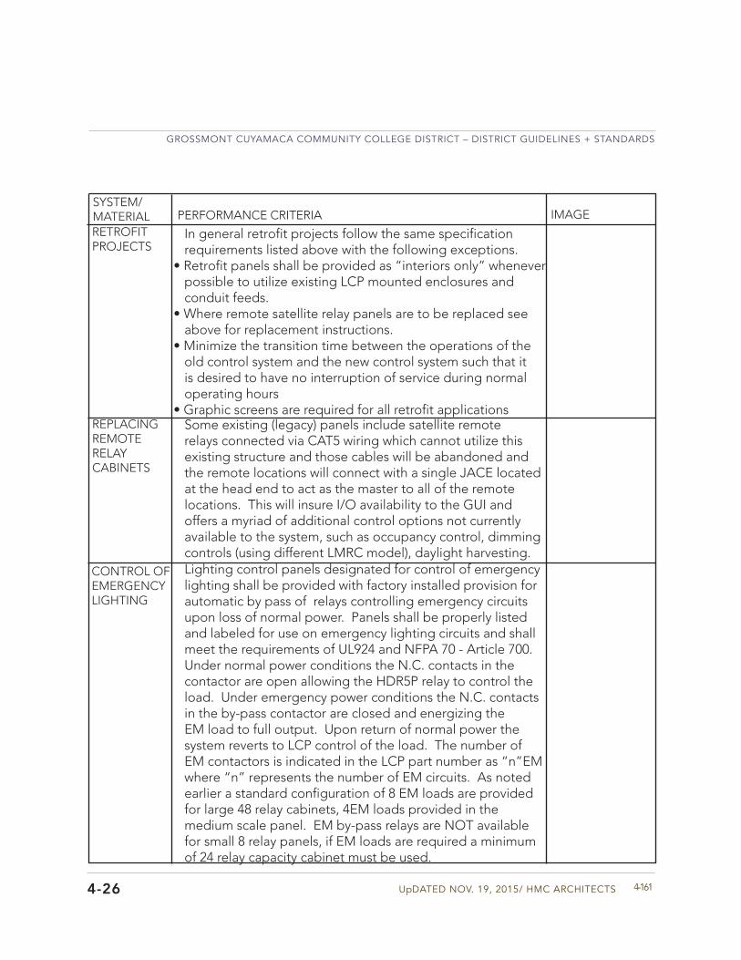
UpDATED NOV. 19, 2015/ HMC ARCHITECTS
GROSSMONT CUYAMACA COMMUNITY COLLEGE DISTRICT – DISTRICT GUIDELINES + STANDARDS
4-1614-26
SYSTEM/MATERIAL PERFORMANCE CRITERIA IMAGE
In general retrofit projects follow the same specification requirements listed above with the following exceptions.
• Retrofit panels shall be provided as “interiors only” wheneverpossible to utilize existing LCP mounted enclosures and conduit feeds.
• Where remote satellite relay panels are to be replaced seeabove for replacement instructions.
• Minimize the transition time between the operations of theold control system and the new control system such that it is desired to have no interruption of service during normal operating hours
• Graphic screens are required for all retrofit applications
RETROFIT PROJECTS
Some existing (legacy) panels include satellite remote relays connected via CAT5 wiring which cannot utilize this existing structure and those cables will be abandoned and the remote locations will connect with a single JACE located at the head end to act as the master to all of the remote locations. This will insure I/O availability to the GUI and offers a myriad of additional control options not currently available to the system, such as occupancy control, dimming controls (using different LMRC model), daylight harvesting.
REPLACING REMOTE RELAY CABINETS
CONTROL OF EMERGENCY LIGHTING
Lighting control panels designated for control of emergency lighting shall be provided with factory installed provision for automatic by pass of relays controlling emergency circuits upon loss of normal power. Panels shall be properly listed and labeled for use on emergency lighting circuits and shall meet the requirements of UL924 and NFPA 70 - Article 700. Under normal power conditions the N.C. contacts in the contactor are open allowing the HDR5P relay to control the load. Under emergency power conditions the N.C. contacts in the by-pass contactor are closed and energizing the EM load to full output. Upon return of normal power the system reverts to LCP control of the load. The number of EM contactors is indicated in the LCP part number as “n”EM where “n” represents the number of EM circuits. As noted earlier a standard configuration of 8 EM loads are provided for large 48 relay cabinets, 4EM loads provided in the medium scale panel. EM by-pass relays are NOT available for small 8 relay panels, if EM loads are required a minimum of 24 relay capacity cabinet must be used.
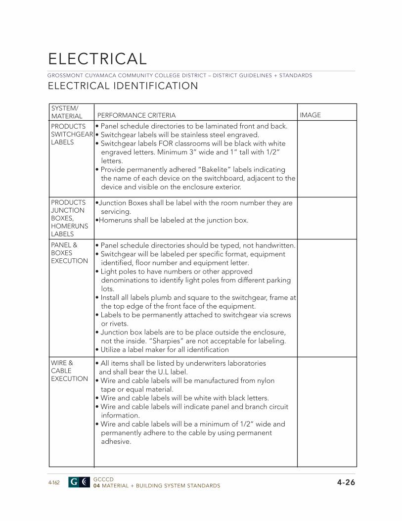
GROSSMONT CUYAMACA COMMUNITY COLLEGE DISTRICT – DISTRICT GUIDELINES + STANDARDS
GCCCD04 MATERIAL + BUILDING SYSTEM STANDARDS4-162 4-26
ELECTRICAL IDENTIFICATION
ELECTRICAL
SYSTEM/MATERIAL PERFORMANCE CRITERIA IMAGE
• Panel schedule directories to be laminated front and back.• Switchgear labels will be stainless steel engraved.• Switchgear labels FOR classrooms will be black with white
engraved letters. Minimum 3” wide and 1” tall with 1/2”letters.
• Provide permanently adhered “Bakelite” labels indicatingthe name of each device on the switchboard, adjacent to thedevice and visible on the enclosure exterior.
PRODUCTSSWITCHGEARLABELS
•Junction Boxes shall be label with the room number they areservicing.
•Homeruns shall be labeled at the junction box.
PRODUCTSJUNCTION BOXES, HOMERUNS LABELS
• Panel schedule directories should be typed, not handwritten.• Switchgear will be labeled per specific format, equipment
identified, floor number and equipment letter.• Light poles to have numbers or other approved
denominations to identify light poles from different parkinglots.
• Install all labels plumb and square to the switchgear, frame atthe top edge of the front face of the equipment.
• Labels to be permanently attached to switchgear via screwsor rivets.
• Junction box labels are to be place outside the enclosure,not the inside. “Sharpies” are not acceptable for labeling.
• Utilize a label maker for all identification
PANEL & BOXESEXECUTION
• All items shall be listed by underwriters laboratoriesand shall bear the U.L label.
• Wire and cable labels will be manufactured from nylontape or equal material.
• Wire and cable labels will be white with black letters.• Wire and cable labels will indicate panel and branch circuit
information.• Wire and cable labels will be a minimum of 1/2” wide and
permanently adhere to the cable by using permanentadhesive.
WIRE & CABLEEXECUTION

UpDATED NOV. 19, 2015/ HMC ARCHITECTS
GROSSMONT CUYAMACA COMMUNITY COLLEGE DISTRICT – DISTRICT GUIDELINES + STANDARDS
4-163
SYSTEM/MATERIAL PERFORMANCE CRITERIA IMAGE
CONDUITEXECUTION
• Conduit paint is not acceptable, use tape.• Emergency power conduit: Purple• Security conduit: Blue• Fire Alarm conduit: Red• Tele/data conduit: Yellow• BMS conduit: Light blue• UPS conduit: Orange
• In addition to taped conduit to identify system; Provideminimum (1) 6” wide tape on each conduit at all terminations, pull boxes and above panelboards with listing of circuits present.
WIRE AND CABLESSYSTEM/MATERIAL PERFORMANCE CRITERIA IMAGE
NEW CONSTRUCT-IONCONDUCTORS
• Provide dedicated neutral for each circuit.• Not acceptable to derate conductors. All homeruns
should be installed per electrical drawings.• Mechanical systems minimum feeder should be a
minimum of #10 AWG.• The use of split bolt connectors and “push-in” type
connectors is strictly prohibited.• All splices #8 and larger should be circumferential
compression type, size pull boxes accordingly.• Aluminum conductors are prohibited.
MINOR REMODELCONSTRUCT-IONCONDUCTORS
• If not installing new panelboards, breaker ties willbe sufficient in lieu of e-pulling circuits to providededicated neutrals.
• If using a new panel for new branch circuits, see newconstruction.
WIRING DEVICES AND CONNECTIONS• Receptacle shall have the ground up.• Plug-ins are not acceptable.• Private and open offices, reception areas, lobbies, kitchens
conference rooms, and copy rooms are required tohave a control receptacle within 6’ of each uncontrolledreceptacle. The color should be green for both campuses.
• Provide commercial duty devices with circuit label spaceon device.
4-26
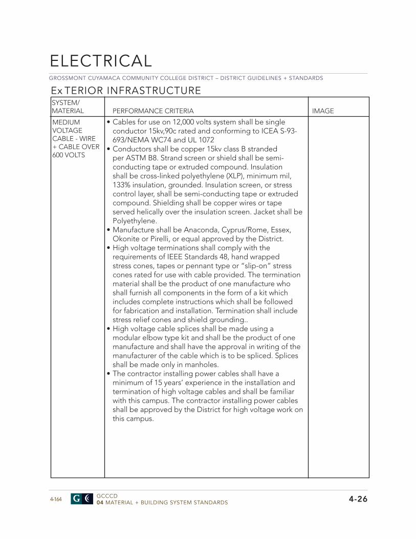
GROSSMONT CUYAMACA COMMUNITY COLLEGE DISTRICT – DISTRICT GUIDELINES + STANDARDS
GCCCD04 MATERIAL + BUILDING SYSTEM STANDARDS4-164
SYSTEM/MATERIAL PERFORMANCE CRITERIA IMAGE
MEDIUM VOLTAGE CABLE - WIRE + CABLE OVER 600 VOLTS
• Cables for use on 12,000 volts system shall be singleconductor 15kv,90c rated and conforming to ICEA S-93-693/NEMA WC74 and UL 1072
• Conductors shall be copper 15kv class B strandedper ASTM B8. Strand screen or shield shall be semi-conducting tape or extruded compound. Insulationshall be cross-linked polyethylene (XLP), minimum mil,133% insulation, grounded. Insulation screen, or stresscontrol layer, shall be semi-conducting tape or extrudedcompound. Shielding shall be copper wires or tapeserved helically over the insulation screen. Jacket shall bePolyethylene.
• Manufacture shall be Anaconda, Cyprus/Rome, Essex,Okonite or Pirelli, or equal approved by the District.
• High voltage terminations shall comply with therequirements of IEEE Standards 48, hand wrappedstress cones, tapes or pennant type or “slip-on” stresscones rated for use with cable provided. The terminationmaterial shall be the product of one manufacture whoshall furnish all components in the form of a kit whichincludes complete instructions which shall be followedfor fabrication and installation. Termination shall includestress relief cones and shield grounding..
• High voltage cable splices shall be made using amodular elbow type kit and shall be the product of onemanufacture and shall have the approval in writing of themanufacturer of the cable which is to be spliced. Splicesshall be made only in manholes.
• The contractor installing power cables shall have aminimum of 15 years’ experience in the installation andtermination of high voltage cables and shall be familiarwith this campus. The contractor installing power cablesshall be approved by the District for high voltage work onthis campus.
Ex TERIOR INFRASTRUCTURE
4-26
ELECTRICAL
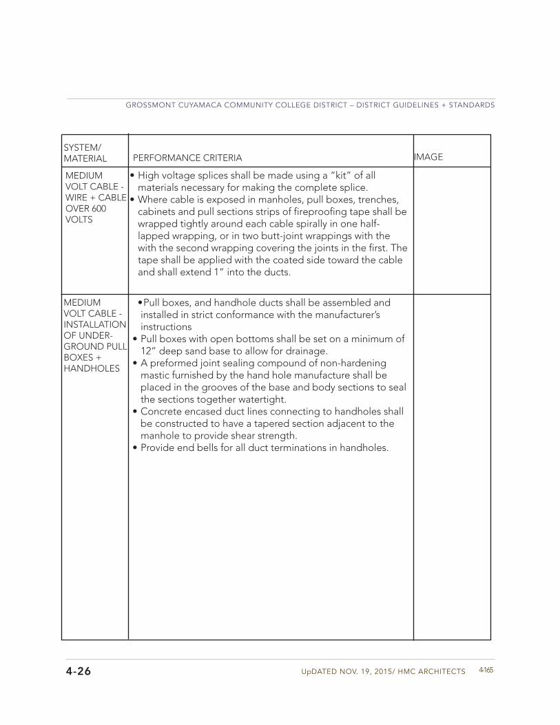
UpDATED NOV. 19, 2015/ HMC ARCHITECTS
GROSSMONT CUYAMACA COMMUNITY COLLEGE DISTRICT – DISTRICT GUIDELINES + STANDARDS
4-165
• High voltage splices shall be made using a “kit” of allmaterials necessary for making the complete splice.
• Where cable is exposed in manholes, pull boxes, trenches,cabinets and pull sections strips of fireproofing tape shall bewrapped tightly around each cable spirally in one half-lapped wrapping, or in two butt-joint wrappings with thewith the second wrapping covering the joints in the first. Thetape shall be applied with the coated side toward the cableand shall extend 1” into the ducts.
SYSTEM/MATERIAL
MEDIUM VOLT CABLE - INSTALLATION OF UNDER-GROUND PULLBOXES + HANDHOLES
PERFORMANCE CRITERIA IMAGE
• Pull boxes, and handhole ducts shall be assembled andinstalled in strict conformance with the manufacturer’s instructions
• Pull boxes with open bottoms shall be set on a minimum of12” deep sand base to allow for drainage.
• A preformed joint sealing compound of non-hardeningmastic furnished by the hand hole manufacture shall beplaced in the grooves of the base and body sections to sealthe sections together watertight.
• Concrete encased duct lines connecting to handholes shallbe constructed to have a tapered section adjacent to themanhole to provide shear strength.
• Provide end bells for all duct terminations in handholes.
MEDIUM VOLT CABLE - WIRE + CABLE OVER 600 VOLTS
4-26
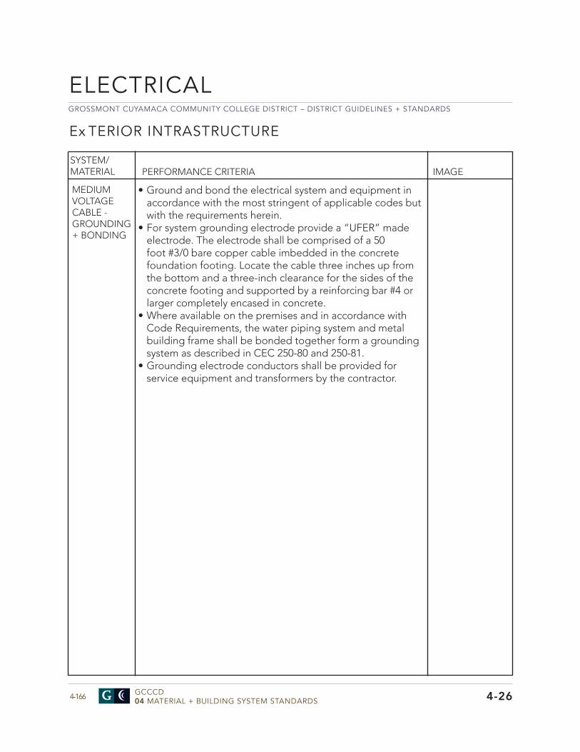
GROSSMONT CUYAMACA COMMUNITY COLLEGE DISTRICT – DISTRICT GUIDELINES + STANDARDS
GCCCD04 MATERIAL + BUILDING SYSTEM STANDARDS4-166
ELECTRICAL
Ex TERIOR INTRASTRUCTURE
SYSTEM/MATERIAL PERFORMANCE CRITERIA IMAGE
MEDIUM VOLTAGE CABLE - GROUNDING + BONDING
• Ground and bond the electrical system and equipment inaccordance with the most stringent of applicable codes butwith the requirements herein.
• For system grounding electrode provide a “UFER” madeelectrode. The electrode shall be comprised of a 50foot #3/0 bare copper cable imbedded in the concretefoundation footing. Locate the cable three inches up fromthe bottom and a three-inch clearance for the sides of theconcrete footing and supported by a reinforcing bar #4 orlarger completely encased in concrete.
• Where available on the premises and in accordance withCode Requirements, the water piping system and metalbuilding frame shall be bonded together form a groundingsystem as described in CEC 250-80 and 250-81.
• Grounding electrode conductors shall be provided forservice equipment and transformers by the contractor.
4-26
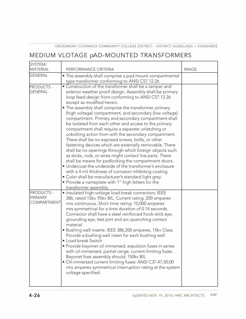
UpDATED NOV. 19, 2015/ HMC ARCHITECTS
GROSSMONT CUYAMACA COMMUNITY COLLEGE DISTRICT – DISTRICT GUIDELINES + STANDARDS
4-167
MEDIUM VLOTAGE pAD-MOUNTED TRANSFORMERS SYSTEM/MATERIAL PERFORMANCE CRITERIA IMAGE
GENERAL • The assembly shall comprise a pad mount compartmentaltype transformer conforming to ANSI C57.12.26
• Construction of the transformer shall be a tamper andexterior weather proof design. Assembly shall be primaryloop feed design front conforming to ANSI C57.12.26except as modified herein.
• The assembly shall comprise the transformer, primary(high voltage) compartment, and secondary (low voltage)compartment. Primary and secondary compartment shallbe isolated from each other and access to the primarycompartment shall require a separate unlatching orunbolting action from with the secondary compartment.There shall be no exposed screws, bolts, or otherfastening devices which are externally removable. Thereshall be no openings through which foreign objects suchas sticks, rods, or wires might contact live parts. Thereshall be means for padlocking the compartment doors.
• Undercoat the underside of the transformer’s enclosurewith a 4 mil thickness of corrosion inhibiting coating.
• Color shall be manufacturer’s standard light grey.• Provide a nameplate with 1” high letters for the
transformer assembly.• Insulated high-voltage load break connectors: IEEE
386, rated 15kv, 95kv BIL. Current rating: 200 amperesrms continuous. Short time rating: 10,000 amperesrms symmetrical for a time duration of 0.14 seconds.Connector shall have a steel reinforced hook-stick eye,grounding eye, test pint and arc-quenching contactmaterial.
• Bushing well inserts: IEEE 386,200 amperes, 15kv Class.Provide a bushing well insert for each bushing well.
• Load-break Switch• Provide bayonet oil-immersed, expulsion fuses in series
with oil-immersed, partial-range, current-limiting fuses.Bayonet fuse assembly should: 150kv BIL
• Oil-immersed current-limiting fuses: ANSI C37.47,50,00rms amperes symmetrical interruption rating at the systemvoltage specified.
PRODUCTS - GENERAL
PRODUCTS - PRIMARYCOMPARTMENT
4-26
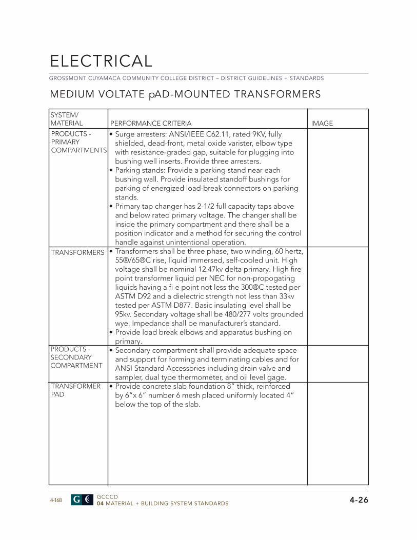
GROSSMONT CUYAMACA COMMUNITY COLLEGE DISTRICT – DISTRICT GUIDELINES + STANDARDS
GCCCD04 MATERIAL + BUILDING SYSTEM STANDARDS4-168
ELECTRICAL
MEDIUM VOLTATE pAD-MOUNTED TRANSFORMERS
SYSTEM/MATERIAL PERFORMANCE CRITERIA IMAGE
• Surge arresters: ANSI/IEEE C62.11, rated 9KV, fullyshielded, dead-front, metal oxide varister, elbow typewith resistance-graded gap, suitable for plugging intobushing well inserts. Provide three arresters.
• Parking stands: Provide a parking stand near eachbushing wall. Provide insulated standoff bushings forparking of energized load-break connectors on parkingstands.
• Primary tap changer has 2-1/2 full capacity taps aboveand below rated primary voltage. The changer shall beinside the primary compartment and there shall be aposition indicator and a method for securing the controlhandle against unintentional operation.
• Transformers shall be three phase, two winding, 60 hertz, 55®/65®C rise, liquid immersed, self-cooled unit. High voltage shall be nominal 12.47kv delta primary. High fire point transformer liquid per NEC for non-propogating liquids having a fi e point not less the 300®C tested per ASTM D92 and a dielectric strength not less than 33kv tested per ASTM D877. Basic insulating level shall be 95kv. Secondary voltage shall be 480/277 volts grounded wye. Impedance shall be manufacturer’s standard.
• Provide load break elbows and apparatus bushing onprimary.
• Secondary compartment shall provide adequate spaceand support for forming and terminating cables and forANSI Standard Accessories including drain valve andsampler, dual type thermometer, and oil level gage.
• Provide concrete slab foundation 8” thick, reinforcedby 6”x 6” number 6 mesh placed uniformly located 4”below the top of the slab.
PRODUCTS - PRIMARY COMPARTMENTS
TRANSFORMERS
PRODUCTS - SECONDARYCOMPARTMENT
TRANSFORMERPAD
4-26
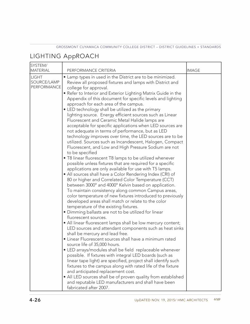
UpDATED NOV. 19, 2015/ HMC ARCHITECTS
GROSSMONT CUYAMACA COMMUNITY COLLEGE DISTRICT – DISTRICT GUIDELINES + STANDARDS
4-169
SYSTEM/MATERIAL PERFORMANCE CRITERIA
LIGHT SOURCE/LAMP PERFORMANCE
• Lamp types in used in the District are to be minimized.Review all proposed fixtures and lamps with District andcollege for approval.
• Refer to Interior and Exterior Lighting Matrix Guide in theAppendix of this document for specific levels and lightingapproach for each area of the campus.
• LED technology shall be utilized as the primarylighting source. Energy efficient sources such as LinearFluorescent and Ceramic Metal Halide lamps areacceptable for specific applications when LED sources arenot adequate in terms of performance, but as LEDtechnology improves over time, the LED sources are to beutilized. Sources such as Incandescent, Halogen, CompactFluorescent, and Low and High Pressure Sodium are notto be specified
• T8 linear fluorescent T8 lamps to be utilized wheneverpossible unless fixtures that are required for a specificapplications are only available for use with T5 lamps.
• All sources shall have a Color Rendering Index (CRI) of80 or higher and Correlated Color Temperature (CCT)between 3000° and 4000° Kelvin based on application.To maintain consistency along common Campus areas,color temperature of new fixtures introduced to previouslydeveloped areas shall match or relate to the colortemperature of the existing fixtures.
• Dimming ballasts are not to be utilized for linearfluorescent sources.
• All linear fluorescent lamps shall be low mercury content;LED sources and attendant components such as heat sinksshall be mercury and lead free.
• Linear Fluorescent sources shall have a minimum ratedsource life of 35,000 hours.
• LED arrays/modules shall be field replaceable wheneverpossible. If fixtures with integral LED boards (such as linear tape light) are specified, project shall identify such fixtures to the campus along with rated life of the fixture and anticipated replacement cost.
• All LED sources shall be of proven quality from establishedand reputable LED manufacturers and shall have beenfabricated after 2007.
LIGHTING AppROACH
IMAGE
4-26
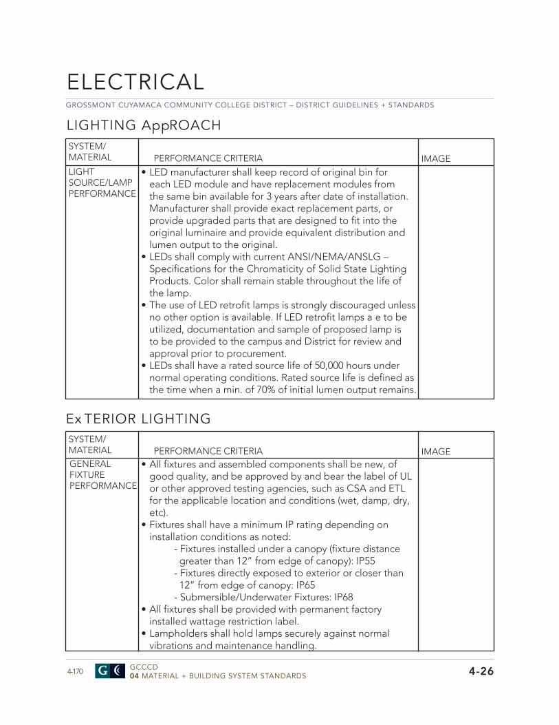
GROSSMONT CUYAMACA COMMUNITY COLLEGE DISTRICT – DISTRICT GUIDELINES + STANDARDS
GCCCD04 MATERIAL + BUILDING SYSTEM STANDARDS4-170
ELECTRICAL
4-26
PERFORMANCE CRITERIA IMAGELIGHT SOURCE/LAMP PERFORMANCE
GENERAL FIXTURE PERFORMANCE
• All fixtures and assembled components shall be new, ofgood quality, and be approved by and bear the label of ULor other approved testing agencies, such as CSA and ETLfor the applicable location and conditions (wet, damp, dry,etc).
• Fixtures shall have a minimum IP rating depending oninstallation conditions as noted:
- Fixtures installed under a canopy (fixture distance greater than 12” from edge of canopy): IP55- Fixtures directly exposed to exterior or closer than 12” from edge of canopy: IP65- Submersible/Underwater Fixtures: IP68
• All fixtures shall be provided with permanent factoryinstalled wattage restriction label.
• Lampholders shall hold lamps securely against normalvibrations and maintenance handling.
SYSTEM/MATERIAL
Ex TERIOR LIGHTING
PERFORMANCE CRITERIA IMAGESYSTEM/MATERIAL
LIGHTING AppROACH
• LED manufacturer shall keep record of original bin foreach LED module and have replacement modules fromthe same bin available for 3 years after date of installation.Manufacturer shall provide exact replacement parts, orprovide upgraded parts that are designed to fit into theoriginal luminaire and provide equivalent distribution andlumen output to the original.
• LEDs shall comply with current ANSI/NEMA/ANSLG –Specifications for the Chromaticity of Solid State LightingProducts. Color shall remain stable throughout the life ofthe lamp.
• The use of LED retrofit lamps is strongly discouraged unlessno other option is available. If LED retrofit lamps a e to beutilized, documentation and sample of proposed lamp isto be provided to the campus and District for review andapproval prior to procurement.
• LEDs shall have a rated source life of 50,000 hours undernormal operating conditions. Rated source life is defined asthe time when a min. of 70% of initial lumen output remains.
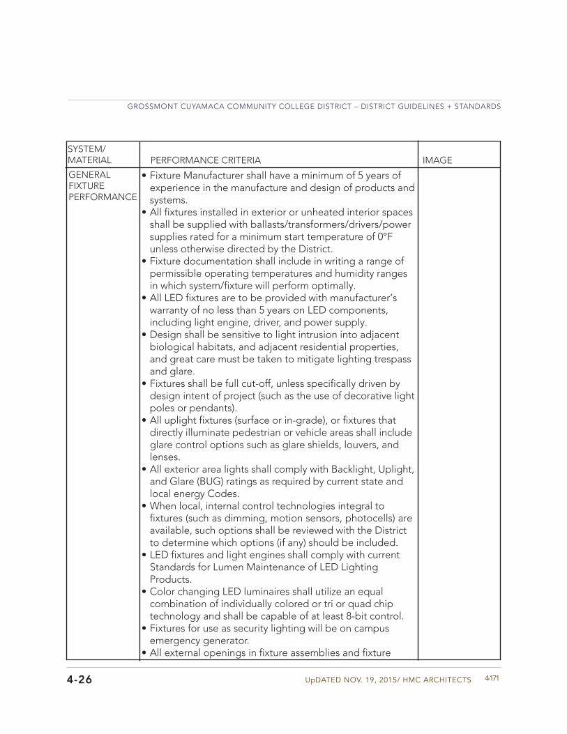
UpDATED NOV. 19, 2015/ HMC ARCHITECTS
GROSSMONT CUYAMACA COMMUNITY COLLEGE DISTRICT – DISTRICT GUIDELINES + STANDARDS
4-1714-26
SYSTEM/MATERIAL PERFORMANCE CRITERIA IMAGE
• Fixture Manufacturer shall have a minimum of 5 years ofexperience in the manufacture and design of products andsystems.
• All fixtures installed in exterior or unheated interior spacesshall be supplied with ballasts/transformers/drivers/powersupplies rated for a minimum start temperature of 0°Funless otherwise directed by the District.
• Fixture documentation shall include in writing a range ofpermissible operating temperatures and humidity rangesin which system/fixture will perform optimally.
• All LED fixtures are to be provided with manufacturer’swarranty of no less than 5 years on LED components,including light engine, driver, and power supply.
• Design shall be sensitive to light intrusion into adjacentbiological habitats, and adjacent residential properties,and great care must be taken to mitigate lighting trespassand glare.
• Fixtures shall be full cut-off, unless specifically driven bydesign intent of project (such as the use of decorative lightpoles or pendants).
• All uplight fixtures (surface or in-grade), or fixtures thatdirectly illuminate pedestrian or vehicle areas shall includeglare control options such as glare shields, louvers, andlenses.
• All exterior area lights shall comply with Backlight, Uplight,and Glare (BUG) ratings as required by current state andlocal energy Codes.
• When local, internal control technologies integral tofixtures (such as dimming, motion sensors, photocells) areavailable, such options shall be reviewed with the Districtto determine which options (if any) should be included.
• LED fixtures and light engines shall comply with currentStandards for Lumen Maintenance of LED LightingProducts.
• Color changing LED luminaires shall utilize an equalcombination of individually colored or tri or quad chiptechnology and shall be capable of at least 8-bit control.
• Fixtures for use as security lighting will be on campusemergency generator.
• All external openings in fixture assemblies and fixture
GENERAL FIXTURE PERFORMANCE
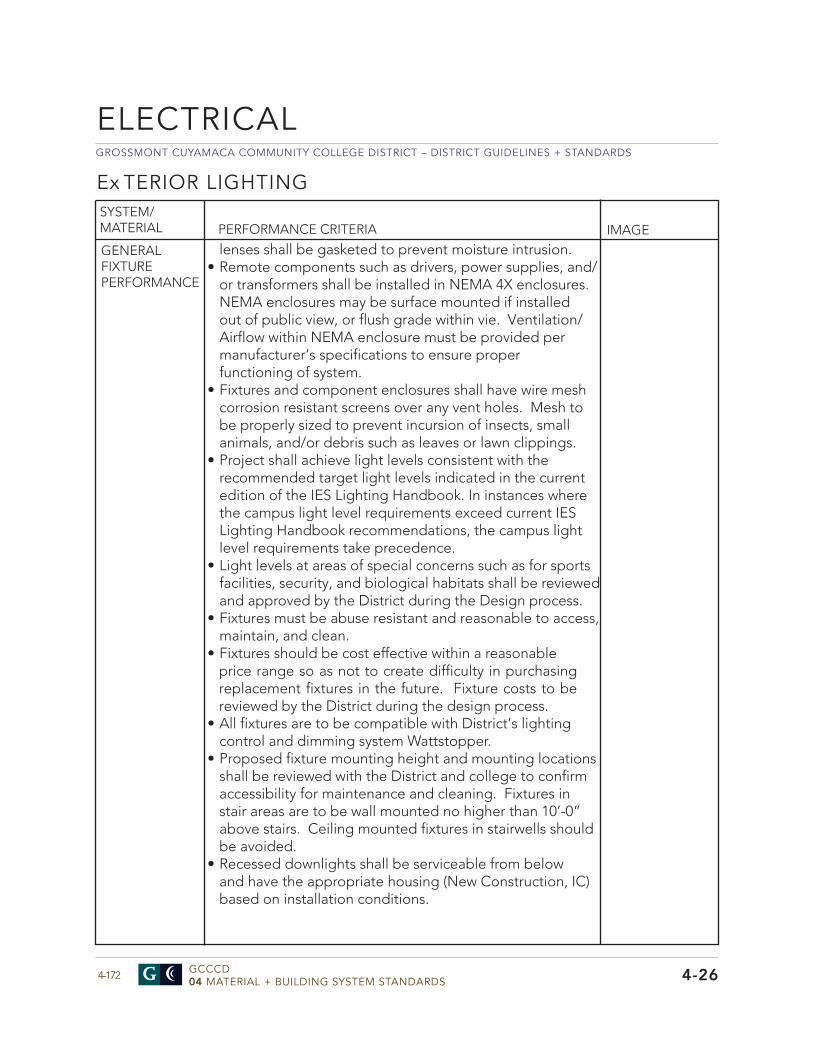
GROSSMONT CUYAMACA COMMUNITY COLLEGE DISTRICT – DISTRICT GUIDELINES + STANDARDS
GCCCD04 MATERIAL + BUILDING SYSTEM STANDARDS4-172
ELECTRICAL
4-26
PERFORMANCE CRITERIA IMAGE
GENERAL FIXTURE PERFORMANCE
SYSTEM/MATERIAL
lenses shall be gasketed to prevent moisture intrusion.• Remote components such as drivers, power supplies, and/
or transformers shall be installed in NEMA 4X enclosures. NEMA enclosures may be surface mounted if installed out of public view, or flush grade within vie. Ventilation/Airflow within NEMA enclosure must be provided per manufacturer’s specifications to ensure proper functioning of system.
• Fixtures and component enclosures shall have wire meshcorrosion resistant screens over any vent holes. Mesh to be properly sized to prevent incursion of insects, small animals, and/or debris such as leaves or lawn clippings.
• Project shall achieve light levels consistent with therecommended target light levels indicated in the current edition of the IES Lighting Handbook. In instances where the campus light level requirements exceed current IES Lighting Handbook recommendations, the campus light level requirements take precedence.
• Light levels at areas of special concerns such as for sportsfacilities, security, and biological habitats shall be reviewed and approved by the District during the Design process.
• Fixtures must be abuse resistant and reasonable to access,maintain, and clean.
• Fixtures should be cost effective within a reasonableprice range so as not to create difficulty in purchasing replacement fixtures in the future. Fixture costs to be reviewed by the District during the design process.
• All fixtures are to be compatible with District’s lightingcontrol and dimming system Wattstopper.
• Proposed fixture mounting height and mounting locationsshall be reviewed with the District and college to confirm accessibility for maintenance and cleaning. Fixtures in stair areas are to be wall mounted no higher than 10’-0” above stairs. Ceiling mounted fixtures in stairwells should be avoided.
• Recessed downlights shall be serviceable from belowand have the appropriate housing (New Construction, IC) based on installation conditions.
Ex TERIOR LIGHTING
UpDATED NOV. 19, 2015/ HMC ARCHITECTS
GROSSMONT CUYAMACA COMMUNITY COLLEGE DISTRICT – DISTRICT GUIDELINES + STANDARDS
4-1734-26
SYSTEM/MATERIAL PERFORMANCE CRITERIA IMAGE
GENERAL FIXTURE PERFORMANCE
• Proposed fixtures must be reviewed by the District andcollege during design to address any concerns priorto procurement and installation. In specific instances,especially with decorative fixtures, sample fixtures shouldbe provided for review.
• Fixtures mounted lower than 10’-0” AFG shall be vandalresistant (including lens), and fixtures and componentsmust be firmly secured with tamper-proof, captivehardware.
• All fixtures shall comply with wind load criteria andoverhead safety requirements. Fixtures and proposedmounting to be reviewed and approved by a licensedStructural Engineer prior to installation.
• Foundations are required for all fixtures mounted on orin grade. In the case of poles, foundation details are tobe developed by Structural Engineer; footings/ pads forbollards and surface mounted accent fixtures may bedeveloped by Architect or Structural Engineer.
• Design team shall verify design and structural integrityof complete foundation (including concrete dimensions,rebar requirements, grounding and conduit requirements,drainage and ground compaction requirements) during theproject documentation process.
• Adjustable fixtures shall include positive aiming andlocking devices to secure fixture focus. Final aiming angleof fixture shall be indicated with small tick marks or similarmarking to allow fixture focus to be restored by campusstaff after maintenance or lamp replacement.
• Identification tags are to be mounted to fixtures at poles,bollards, surface accent fixtures, and NEMA enclosureswith remote components for ease of maintenance.Tags shall include information such as fixture typenumber, lamping, and circuiting information for easeof maintenance. Tags are to be installed out of publicview whenever possible and installed prior to projectcompletion.
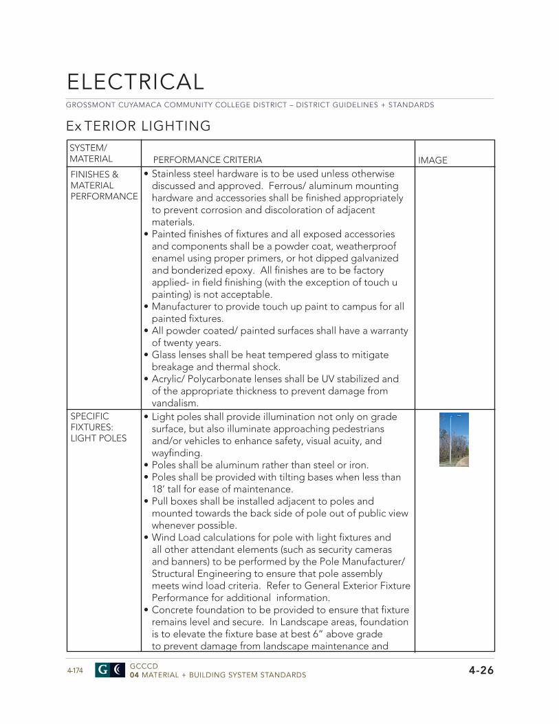
GROSSMONT CUYAMACA COMMUNITY COLLEGE DISTRICT – DISTRICT GUIDELINES + STANDARDS
GCCCD04 MATERIAL + BUILDING SYSTEM STANDARDS4-174
ELECTRICAL
4-26
Ex TERIOR LIGHTING
PERFORMANCE CRITERIA IMAGE
FINISHES & MATERIAL PERFORMANCE
SYSTEM/MATERIAL
• Stainless steel hardware is to be used unless otherwisediscussed and approved. Ferrous/ aluminum mountinghardware and accessories shall be finished appropriatelyto prevent corrosion and discoloration of adjacentmaterials.
• Painted finishes of fixtures and all exposed accessoriesand components shall be a powder coat, weatherproof enamel using proper primers, or hot dipped galvanized and bonderized epoxy. All finishes are to be factory applied- in field finishing (with the exception of touch u painting) is not acceptable.
• Manufacturer to provide touch up paint to campus for allpainted fixtures.
• All powder coated/ painted surfaces shall have a warrantyof twenty years.
• Glass lenses shall be heat tempered glass to mitigatebreakage and thermal shock.
• Acrylic/ Polycarbonate lenses shall be UV stabilized andof the appropriate thickness to prevent damage fromvandalism.
SPECIFIC FIXTURES: LIGHT POLES
• Light poles shall provide illumination not only on gradesurface, but also illuminate approaching pedestriansand/or vehicles to enhance safety, visual acuity, andwayfinding.
• Poles shall be aluminum rather than steel or iron.• Poles shall be provided with tilting bases when less than
18’ tall for ease of maintenance.• Pull boxes shall be installed adjacent to poles and
mounted towards the back side of pole out of public viewwhenever possible.
• Wind Load calculations for pole with light fixtures andall other attendant elements (such as security camerasand banners) to be performed by the Pole Manufacturer/Structural Engineering to ensure that pole assemblymeets wind load criteria. Refer to General Exterior FixturePerformance for additional information.
• Concrete foundation to be provided to ensure that fixtureremains level and secure. In Landscape areas, foundationis to elevate the fixture base at best 6” above gradeto prevent damage from landscape maintenance and
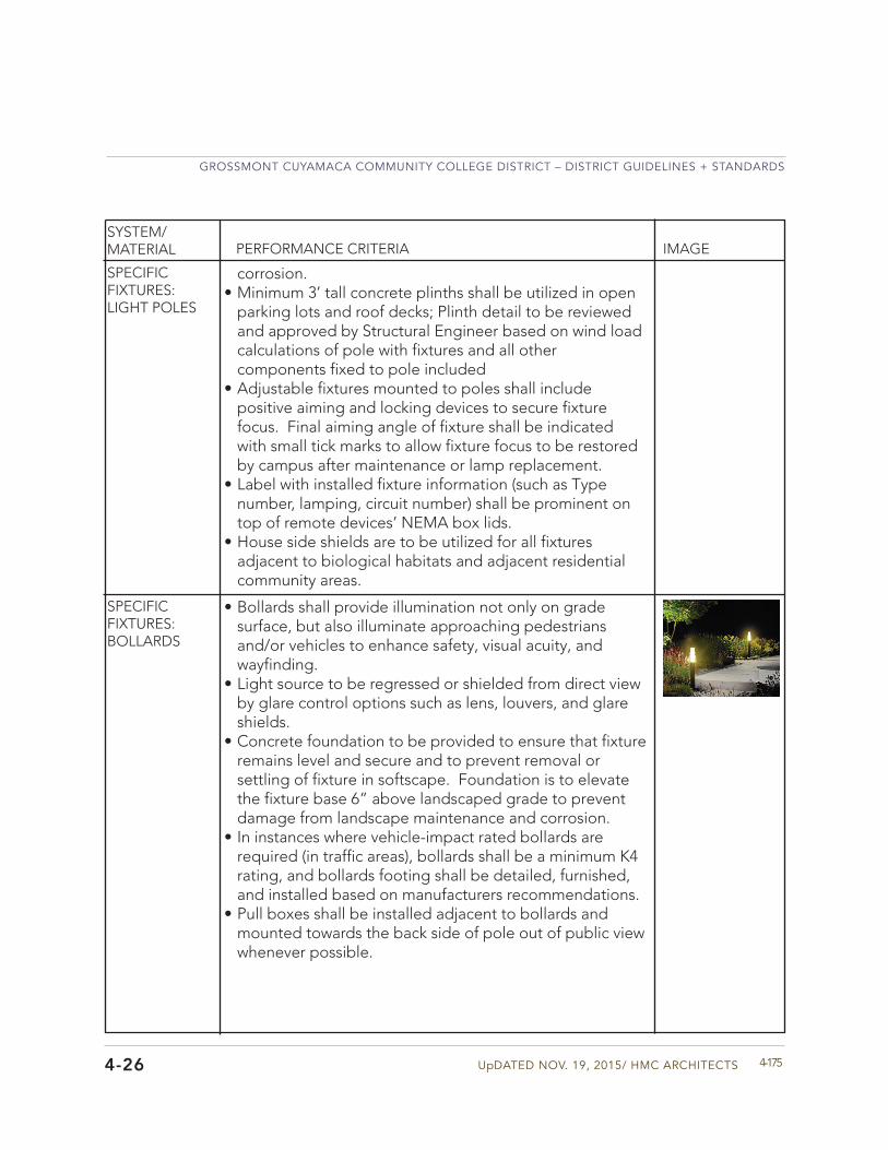
UpDATED NOV. 19, 2015/ HMC ARCHITECTS
GROSSMONT CUYAMACA COMMUNITY COLLEGE DISTRICT – DISTRICT GUIDELINES + STANDARDS
4-1754-26
SYSTEM/MATERIAL PERFORMANCE CRITERIA IMAGE
SPECIFIC FIXTURES: LIGHT POLES
corrosion.• Minimum 3’ tall concrete plinths shall be utilized in open
parking lots and roof decks; Plinth detail to be reviewed and approved by Structural Engineer based on wind load calculations of pole with fixtures and all other components fixed to pole included
• Adjustable fixtures mounted to poles shall includepositive aiming and locking devices to secure fixture focus. Final aiming angle of fixture shall be indicated with small tick marks to allow fixture focus to be restored by campus after maintenance or lamp replacement.
• Label with installed fixture information (such as Typenumber, lamping, circuit number) shall be prominent on top of remote devices’ NEMA box lids.
• House side shields are to be utilized for all fixturesadjacent to biological habitats and adjacent residential community areas.
SPECIFIC FIXTURES: BOLLARDS
• Bollards shall provide illumination not only on gradesurface, but also illuminate approaching pedestriansand/or vehicles to enhance safety, visual acuity, andwayfinding.
• Light source to be regressed or shielded from direct viewby glare control options such as lens, louvers, and glareshields.
• Concrete foundation to be provided to ensure that fixtureremains level and secure and to prevent removal orsettling of fixture in softscape. Foundation is to elevatethe fixture base 6” above landscaped grade to preventdamage from landscape maintenance and corrosion.
• In instances where vehicle-impact rated bollards arerequired (in traffic areas), bollards shall be a minimum K4rating, and bollards footing shall be detailed, furnished,and installed based on manufacturers recommendations.
• Pull boxes shall be installed adjacent to bollards andmounted towards the back side of pole out of public viewwhenever possible.
GROSSMONT CUYAMACA COMMUNITY COLLEGE DISTRICT – DISTRICT GUIDELINES + STANDARDS
GCCCD04 MATERIAL + BUILDING SYSTEM STANDARDS4-176
ELECTRICAL
4-26
Ex TERIOR LIGHTING
PERFORMANCE CRITERIA IMAGESYSTEM/MATERIAL
• In-grade fixtures are discouraged and only used in specialcases with approval of District and college. Installationsmust be executed in accordance with manufacturer’sinstallation requirements.
• There should be drainage provided in accordance withmanufacturer’s installation requirements.
• Internal glare control and/or frosted lenses shall beprovided in all fixtures when direct view into fixtures ispossible.
• Fixtures shall include anti-slip and heat reduction lenses inpedestrian areas.
• Rock guards to be provided for fixtures in non-pedestrianareas.
• Fixtures, if used, shall be drive-over rated for vehiculartraffic areas.
• If fixture is integrated in a tree grate, fixture trim shall besecured to grate and flush with the top of grate.
SPECIFIC FIXTURES: SURFACE-GRADE ACCENT LIGHTS
• Surface fixtures may be installed in non-pedestrian,non-vehicular areas only.
• Fixtures shall be mounted on concrete base/pad to ensurethat fixture remains level and secure and to preventremoval or settling of fixture in softscape. The pad isshould elevate the fixture base 6” above grade to preventdamage from landscape maintenance and corrosion.
• Fixtures shall be specified with glare control options suchas lens, louvers, and glare shields.
• Surface fixtures within reach must be LED and cool to thetouch.
• Pull boxes shall be installed proximal to fixtures andmounted out of public view whenever possible.
SPECIFIC FIXTURES: IN-GRADE ACCENT, WALL WASH, & MARKER LIGHTS
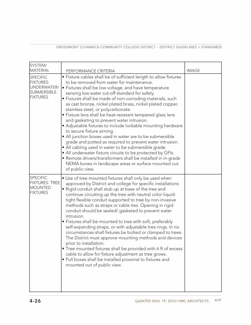
UpDATED NOV. 19, 2015/ HMC ARCHITECTS
GROSSMONT CUYAMACA COMMUNITY COLLEGE DISTRICT – DISTRICT GUIDELINES + STANDARDS
4-1774-26
SYSTEM/MATERIAL PERFORMANCE CRITERIA IMAGE
SPECIFIC FIXTURES: UNDERWATER/SUBMERSIBLE FIXTURES
SPECIFIC FIXTURES: TREE MOUNTED FIXTURES
• Fixture cables shall be of sufficient length to allow fixturesto be removed from water for maintenance.
• Fixtures shall be low voltage, and have temperaturesensing low water cut-off standard for safety.
• Fixtures shall be made of non-corroding materials, suchas cast bronze, nickel plated brass, nickel plated copper,stainless steel, or polycarbonate.
• Fixture lens shall be heat-resistant tempered glass lensand gasketing to prevent water intrusion.
• Adjustable fixtures to include lockable mounting hardwareto secure fixture aiming.
• All junction boxes used in water are to be submersiblegrade and potted as required to prevent water intrusion.
• All cabling used in water to be submersible grade.• All underwater fixture circuits to be protected by GFIs.• Remote drivers/transformers shall be installed in in-grade
NEMA boxes in landscape areas or surface mounted outof public view.
• Use of tree mounted fixtures shall only be used whenapproved by District and college for specific installations
• Rigid conduit shall stub up at base of the tree andcontinue circuiting up the tree with neutral color liquid-tight flexible conduit supported to tree by non-invasivemethods such as straps or cable ties. Opening in rigidconduit should be sealed/ gasketed to prevent waterintrusion.
• Fixtures shall be mounted to tree with soft, preferablyself-expanding straps, or with adjustable tree rings. In nocircumstances shall fixtures be bolted or clamped to trees.The District must approve mounting methods and devicesprior to installation.
• Tree mounted fixtures shall be provided with 6 ft of excesscable to allow for fixture adjustment as tree grows.
• Pull boxes shall be installed proximal to fixtures andmounted out of public view.
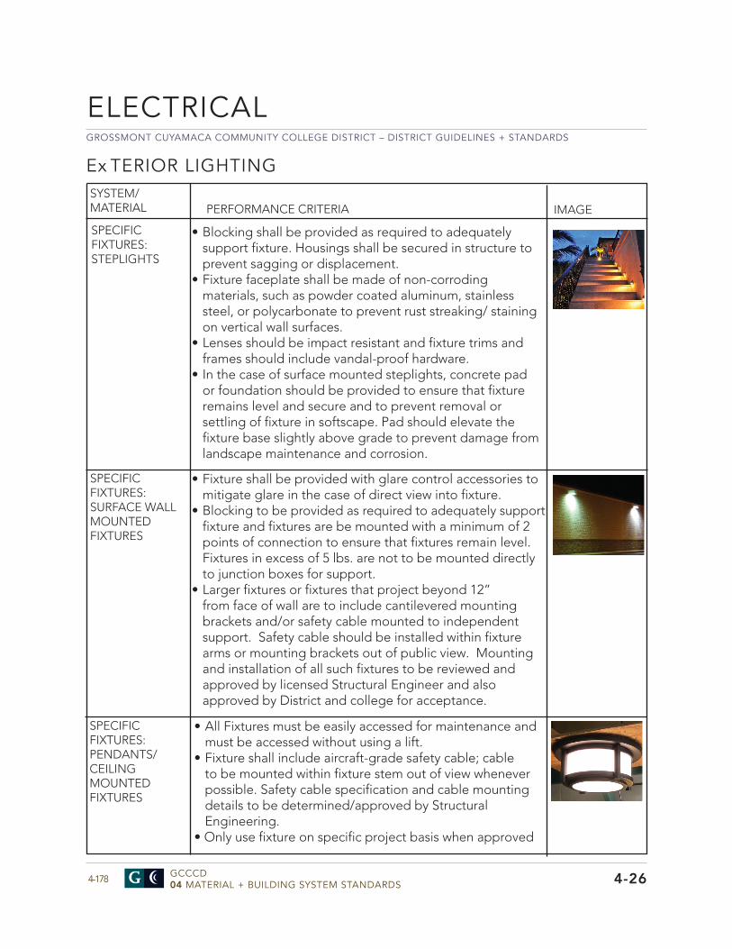
GROSSMONT CUYAMACA COMMUNITY COLLEGE DISTRICT – DISTRICT GUIDELINES + STANDARDS
GCCCD04 MATERIAL + BUILDING SYSTEM STANDARDS4-178
ELECTRICAL
4-26
Ex TERIOR LIGHTING
PERFORMANCE CRITERIA IMAGESYSTEM/MATERIAL
• Blocking shall be provided as required to adequatelysupport fixture. Housings shall be secured in structure toprevent sagging or displacement.
• Fixture faceplate shall be made of non-corrodingmaterials, such as powder coated aluminum, stainlesssteel, or polycarbonate to prevent rust streaking/ stainingon vertical wall surfaces.
• Lenses should be impact resistant and fixture trims andframes should include vandal-proof hardware.
• In the case of surface mounted steplights, concrete pador foundation should be provided to ensure that fixtureremains level and secure and to prevent removal orsettling of fixture in softscape. Pad should elevate thefixture base slightly above grade to prevent damage fromlandscape maintenance and corrosion.
• Fixture shall be provided with glare control accessories tomitigate glare in the case of direct view into fixture.
• Blocking to be provided as required to adequately supportfixture and fixtures are be mounted with a minimum of 2points of connection to ensure that fixtures remain level.Fixtures in excess of 5 lbs. are not to be mounted directlyto junction boxes for support.
• Larger fixtures or fixtures that project beyond 12”from face of wall are to include cantilevered mountingbrackets and/or safety cable mounted to independentsupport. Safety cable should be installed within fixturearms or mounting brackets out of public view. Mountingand installation of all such fixtures to be reviewed andapproved by licensed Structural Engineer and alsoapproved by District and college for acceptance.
SPECIFIC FIXTURES: STEPLIGHTS
SPECIFIC FIXTURES: SURFACE WALL MOUNTED FIXTURES
• All Fixtures must be easily accessed for maintenance andmust be accessed without using a lift.
• Fixture shall include aircraft-grade safety cable; cableto be mounted within fixture stem out of view wheneverpossible. Safety cable specification and cable mountingdetails to be determined/approved by StructuralEngineering.
• Only use fixture on specific project basis when approved
SPECIFIC FIXTURES: PENDANTS/CEILING MOUNTED FIXTURES
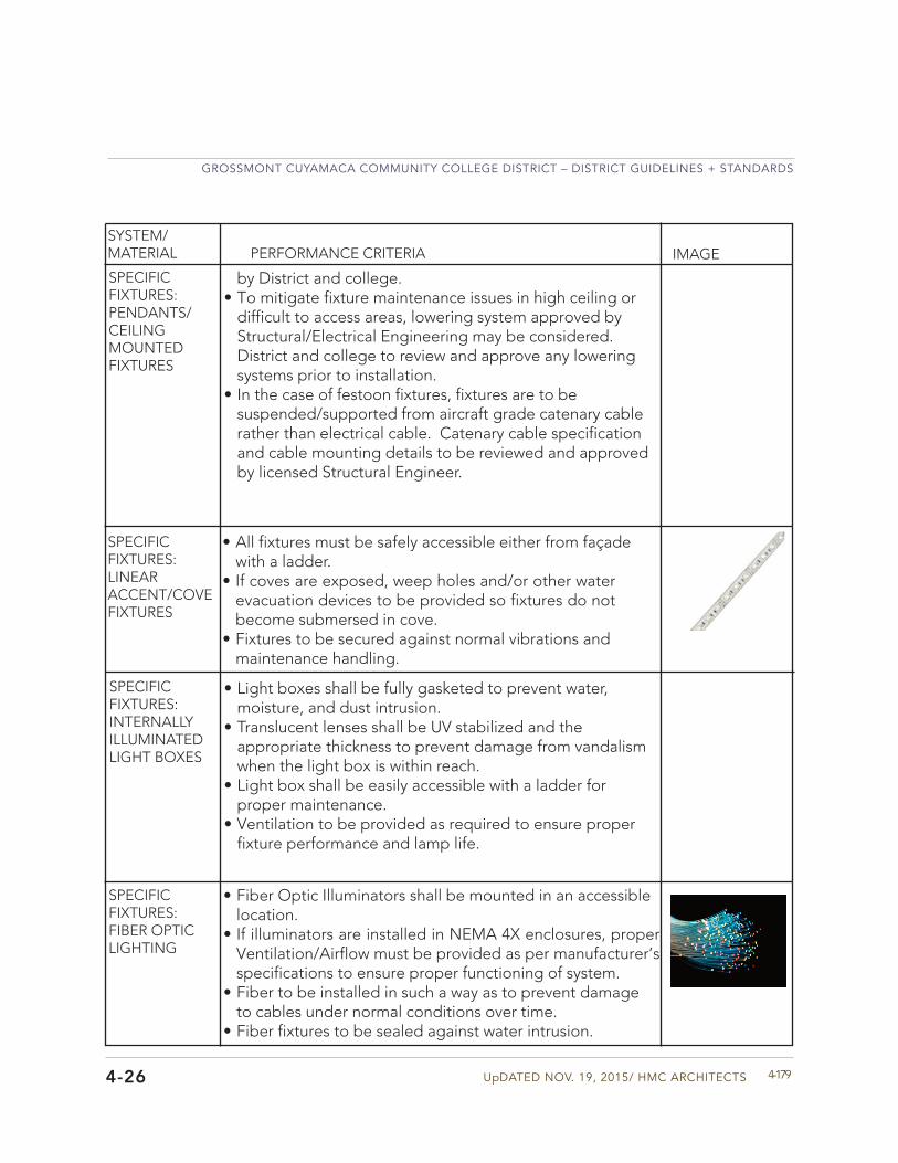
UpDATED NOV. 19, 2015/ HMC ARCHITECTS
GROSSMONT CUYAMACA COMMUNITY COLLEGE DISTRICT – DISTRICT GUIDELINES + STANDARDS
4-1794-26
SYSTEM/MATERIAL PERFORMANCE CRITERIA IMAGE
SPECIFIC FIXTURES: PENDANTS/CEILING MOUNTED FIXTURES
SPECIFIC FIXTURES: LINEAR ACCENT/COVE FIXTURES
• All fixtures must be safely accessible either from façadewith a ladder.
• If coves are exposed, weep holes and/or other waterevacuation devices to be provided so fixtures do notbecome submersed in cove.
• Fixtures to be secured against normal vibrations andmaintenance handling.
SPECIFIC FIXTURES: INTERNALLY ILLUMINATED LIGHT BOXES
• Light boxes shall be fully gasketed to prevent water,moisture, and dust intrusion.
• Translucent lenses shall be UV stabilized and theappropriate thickness to prevent damage from vandalismwhen the light box is within reach.
• Light box shall be easily accessible with a ladder forproper maintenance.
• Ventilation to be provided as required to ensure properfixture performance and lamp life.
by District and college.• To mitigate fixture maintenance issues in high ceiling or
difficult to access areas, lowering system approved byStructural/Electrical Engineering may be considered.District and college to review and approve any loweringsystems prior to installation.
• In the case of festoon fixtures, fixtures are to be suspended/supported from aircraft grade catenary cable rather than electrical cable. Catenary cable specification and cable mounting details to be reviewed and approved by licensed Structural Engineer.
SPECIFIC FIXTURES: FIBER OPTIC LIGHTING
• Fiber Optic Illuminators shall be mounted in an accessiblelocation.
• If illuminators are installed in NEMA 4X enclosures, properVentilation/Airflow must be provided as per manufacturer’sspecifications to ensure proper functioning of system.
• Fiber to be installed in such a way as to prevent damageto cables under normal conditions over time.
• Fiber fixtures to be sealed against water intrusion.
GROSSMONT CUYAMACA COMMUNITY COLLEGE DISTRICT – DISTRICT GUIDELINES + STANDARDS
GCCCD04 MATERIAL + BUILDING SYSTEM STANDARDS4-180
COMMUNICATIONS/TECHNOLOGY
4-27
COMMUNICATIONS GENERAL pROVISIONS
Division 27
• ANSI/TIA-569-C Telecommunications Pathways andSpaces
• ANSI/TIA-1005-A TelecommunicationsInfrastructure Standard for Industrial Premises
• ANSI/TIA-942 Telecommunications InfrastructureStandard for Data Centers
• ANSI/TIA-607-B-1 Generic TelecommunicationsGrounding (Earthing) and Bonding for CustomerPremises
SYSTEM/MATERIAL PERFORMANCE CRITERIA IMAGEAPPLICABLE INDUSTRY STANDARDS TO REFERENCE
APPLICABLE DISTRICTSTANDARDS TO REFERENCE
• Grossmont Cuyamaca Community College DistrictNetwork Cable and Fiber Specifications andInstallation Procedures. (Appendix)
• Space Standards Sections 3• Information in the Appendix
The intent of the Communications and AV Technology Standards is to provide design guidelines for a robust technical infrastructure that facilitates the use of the multimedia, data and communications systems that today’s educational environments demand but remain prudent in cost. The standards have been developed to yield facilities and spaces that have the flexibility to utilize both current and future technologies but final project design must be balanced with the project budget. Refer to the Appendix for additional District information on the Communications/Technology, and cabling requirements.
SYSTEM/MATERIAL PERFORMANCE CRITERIA IMAGE
WALL & CEILING MOUNTED OUTLET CONDUIT
• Outlet conduit shall serve no more than onecommunications outlet. Daisy chaining of outlets is neverallowed.
• Conduit shall be 1” or 1-1/4” EMT per horizontalcommunications cable selection of Cat-6 or Cat-6A. Thecategory type of the cable will vary per building and percampus latest cabling standards.
• Conduits shall run level, straight and parallel to buildingwalls.
• Conduit shall be Schedule 40 PVC when underground orin an inside/outside scenario.
COMMUNICATIONS OUTLET INFRASTRUCTURE
UpDATED NOV. 19, 2015/ HMC ARCHITECTS
GROSSMONT CUYAMACA COMMUNITY COLLEGE DISTRICT – DISTRICT GUIDELINES + STANDARDS
4-1814-27
SYSTEM/MATERIAL PERFORMANCE CRITERIA IMAGE
• Conduit shall be supported every 10 feet minimum andwithin 3 feet of each communications outlet box. Refer tothe latest NEC codes for requirements on conduit support.
• Conduit shall extend to cable tray or wire basket where notaccessible at any point within the run.
• Run shall contain no continuous sections longer than 100feet. If runs total more than 100 feet, a properly sized pullbox shall be provided.
• Run shall contain no more than two 90 degrees of bends atany point or more than 180 degrees of cumulative bendsbetween pull boxes.
• Reamed at the end Provide Bushing• A nylon 1/8” Minimum pull cord shall be installed within all
conduits to allow the ability to pull future cabling.• Maintain minimum bend radius of 6 times the internal
diameter for conduits sizes up to 2”.• Maintain minimum bend radius of 10 times the internal
diameter for conduits sizes greater than 2”.• Do not use a pullbox in lieu of a bend radius for any
conduit. Bend radius must always be produced within theconduit.
• All conduit ends shall be reamed and fitted with bushingsto reduce the amount of damage of cables due to anysharp edges.
WALL & CEILING MOUNTED OUTLET CONDUIT
WALL & CEILING MOUNTED OUTLET BACKBOX
• All mounting heights are to the center line of the devicebackbox unless noted otherwise in the constructiondocuments.
• All boxes shall be flush mounted and concealed.• Electrical outlets shall be provided within 12” of
communication outlets at equal height.• For outlets utilizing Category 6 communications cabling
provide a 4S deep square box at minimum with a singlegang mudring.
• For outlets utilizing Category 6A communications cablingprovide, as a basis of design to support the larger bendradius requirements provide a Siemon 5 square box (orequivalent) complete with radius & slack managementposts, with a single gang mudring.
GROSSMONT CUYAMACA COMMUNITY COLLEGE DISTRICT – DISTRICT GUIDELINES + STANDARDS
GCCCD04 MATERIAL + BUILDING SYSTEM STANDARDS4-182
COMMUNICATIONS/TECHNOLOGY
4-27
SYSTEM/MATERIAL PERFORMANCE CRITERIA IMAGE
WALL MOUNTED BOX FOR FLAT PANELS
• The purpose of the back box is to contain and organizeassociated power outlets, data, signal connections, andelectronics.
• See box requirements under Audiovisual Infrastructure DesignCriteria.
FLOORBOX WITH AUDIOVISUAL & POWER
• Floor boxes with data, AV and power shall contain and provideeasy access to data, communication and AV connections,as well as power outlets for equipment to be used in theirvicinity.
• See box requirements under Audiovisual Infrastructure Design
POKE-THRU WITH AUDIOVISUAL & POWER
• Conduit for the communications outlet shall integrate into thecommunications plate provision of the assembly.
COMMUNICATIONS OUTLET INFRASTRUCTURE
UpDATED NOV. 19, 2015/ HMC ARCHITECTS
GROSSMONT CUYAMACA COMMUNITY COLLEGE DISTRICT – DISTRICT GUIDELINES + STANDARDS
4-1834-27
FLOORBOX WITH DATA & POWER
• Floor boxes shall contain and provide easy access to data,as well as power outlets for equipment to be used in theirvicinity. The construction of the Floor Box with data andpower should permit installation in on-grade, above-gradeand shallow floors
• The floor box with data and power shall maintain segregationof low voltage signals from power with dedicatedcompartments for data and power.
• The floor box with data and power shall be equipped withadjustable feet, mount flush with the floor and permit unimpeded travel and meet Accessibility Guidelines.
• The floor box with data and power shall utilize moveablebarriers and brackets to form partitions, mount connectorsand duplex receptacles as required.
• Floor boxes with data and power shall have covers in a varietyof finishes that are “scrub proof”, preventing liquids from entering the box when floors a e mopped or cleaned.
• On and above grade floor boxes with data and power shallbe of steel construction and have minimum dimensions of13”L x 6”W x 3”D.
• Shallow floor boxes with data and power shall be of steelconstruction and have minimum dimensions of 13”L x 6”W,with a depth not greater than 2-5/8”.
• Must be capable of accommodating a minimum two 20 amp120VAC electrical circuits and 12 CAT-6 data circuits.
• Box should have at a minimum, three (3) 1” concentricknockouts, one (1) 1.25” Knockout, and one (1) 2” knockout.
• Floor box covers should be manufactured to meetrequirements for cast in concrete environment. The coversshould have the capability to accept tile or carpet inserts orsolid covers.
• Conduits feeding floor box need to accommodate the filratio for power and data cables being installed at the specificlocation. Coordinate final configuration with IT P
SYSTEM/MATERIAL PERFORMANCE CRITERIA IMAGE
GROSSMONT CUYAMACA COMMUNITY COLLEGE DISTRICT – DISTRICT GUIDELINES + STANDARDS
GCCCD04 MATERIAL + BUILDING SYSTEM STANDARDS4-184 4-27
COMMUNICATIONS/TECHNOLOGY
SYSTEM/MATERIAL PERFORMANCE CRITERIA IMAGE
FLOORBOX WITHIN RAISED FLOOR
• Must be capable of accommodating a minimum two 20 amp120VAC electrical circuits and 12 CAT-6 data circuits
• Box should have at a minimum, three (3) 1” concentricknockouts, one (1) 1.25” Knockout, and one (1) 2” knockout.
• Floor box covers should be manufactured from die-castaluminum with powder coat finish. The covers should havethe capability to accept tile or carpet inserts or solid covers.
• Conduits feeding floor box need to accommodate the filratio for power and data cables being installed at the specificlocation. Coordinate final configuration with IT P
COMMUNICATIONS OUTLET INFRASTRUCTURE
UpDATED NOV. 19, 2015/ HMC ARCHITECTS
GROSSMONT CUYAMACA COMMUNITY COLLEGE DISTRICT – DISTRICT GUIDELINES + STANDARDS
4-1854-27
POKE-THRU WITH FURNITURE FEED, DATA & POWER
• Poke Through Floor Boxes for furniture feed shall containand route data, as well as power through separatecompartments to one 3/4” conduit opening and one1-1/4” – 2” concentric conduit opening in the cover plate.
• Poke Through Floor Boxes with Data and Power forFurniture Feed
• Poke Through Floor Boxes for furniture feed shall containand route data, as well as power through separatecompartments to one 3/4” conduit opening and one1-1/4” – 2” concentric conduit opening in the cover plate.
• Poke Through floor boxes for Furniture Feed shall have aservice head diameter of less than 8” and mount in a 6”cored hole.
• Poke Through floor boxes for Furniture Feed for use withfurniture shall contain fi e stop material and be capable ofmaintaining the fire rating for 2-hour rated floors
• Poke Through floor boxes shall accept conduit up to 2” indiameter for communications wiring.
SYSTEM/MATERIAL PERFORMANCE CRITERIA IMAGE
SYSTEM/MATERIAL PERFORMANCE CRITERIA IMAGE
GENERAL COMMUNICATIONS CONDUITS
POINT TO POINT COMMUN. CONDUITS
• Conduits shall be supported every 10’ at minimum. Refer tothe latest NEC codes for requirements on conduit support.
• Conduits shall run level, straight and parallel to buildingwalls.
• Where conduit needs to run within a non-accessible ceilingspace to reach the cable tray or wire basket, individualsmaller communications outlet conduits shall congregateinto a properly sized junction box within a nearby accesspanel. A properly sized larger conduit, 2” minimum, shallthen extend into the cable tray or wire basket.
• Where cable tray runs within vaulted or open ceilings,individual smaller conduits serving areas including but notlimited to offices, conference rooms etc. shall extend intothe nearest accessible ceiling space. A properly sized larger
GROSSMONT CUYAMACA COMMUNITY COLLEGE DISTRICT – DISTRICT GUIDELINES + STANDARDS
GCCCD04 MATERIAL + BUILDING SYSTEM STANDARDS4-186
COMMUNICATIONS/TECHNOLOGY
4-27
• Contractor shall provide 2” sleeves into each room toaccess communications outlets wherever a point to pointconduit or cable tray or wire basket is not provided.
COMMUN. CONDUITSSLEEVES
GENERAL COMMUNICATIONS CONDUITS
SYSTEM/MATERIAL PERFORMANCE CRITERIA IMAGE
POINT TO POINT COMMUN. CONDUITS
conduit, 2” minimum, shall then extend from the smaller conduits and into the cable tray within the vaulted or open ceiling.
• Conduits shall run level, straight and parallel to buildingwalls.
• Conduit shall be Schedule 40 PVC when underground or inan inside/outside scenario.
• Conduit shall be supported every 10’ minimum and within 3feet of each communications outlet box. Refer to the latest NEC codes for requirements on conduit support.
• Conduit shall extend to cable tray or wire basket where notaccessible at any point within the run.
• Run shall contain no continuous sections longer than 100’.If runs total more than 100’, a properly sized pull box shall be provided.
• Run shall contain no more than two 90° of bends at anypoint or more than 180° of cumulative bends between pull boxes.
• Reamed at the end Provide Bushing• A nylon 1/8” minimum pull cord shall be installed within all
conduits to allow the ability to pull future cabling.• Maintain minimum bend radius of 6 times the internal
diameter for conduits sizes up to 2”.• Maintain minimum bend radius of 10 times the internal
diameter for conduits sizes greater than 2”.• Do not use a pullbox in lieu of a bend radius for any
conduit. Bend radius must always be produced within theconduit.
• All conduit ends shall be reamed and fitted with bushingsto reduce the amount of damage of cables due to anysharp edges.
• All conduits shall have a blue/green banding & labeled“TEL/DATA USE ONLY” on both ends.
UpDATED NOV. 19, 2015/ HMC ARCHITECTS
GROSSMONT CUYAMACA COMMUNITY COLLEGE DISTRICT – DISTRICT GUIDELINES + STANDARDS
4-1874-27
SYSTEM/MATERIAL PERFORMANCE CRITERIA IMAGE
• 28%: Recommended fill ratio for the cable capacity ofhorizontal pathway conduits that have no more than two 90degree bends (180 degrees total) and are no longer than100 ft. (Per BICSI TDMM)
• 40%: Recommended fill ratio for initial installation of cablein furniture and horizontal pathway. (Per BICSI TDMM)
• 60%: Recommended fill ratio allowed to accommodateunplanned additions after initial installation. This fill ratiorange may be used as an estimate and does not accountfor corners and other factors. (Per BICSI TDMM)
• 100%: BICSI standards specify that a 100% fill capacity ispermissible for a straight sleeve not exceeding 10 feet inlength.
GENERAL COMMUN. CONDUIT FILLS
GROSSMONT CUYAMACA COMMUNITY COLLEGE DISTRICT – DISTRICT GUIDELINES + STANDARDS
GCCCD04 MATERIAL + BUILDING SYSTEM STANDARDS4-188
GENERAL COMMUNICATIONS CONDUITS
SYSTEM/MATERIAL PERFORMANCE CRITERIA IMAGE
COMMUNICATIONS/TECHNOLOGY
4-27
SURFACE MOUNT RACEWAY
• Raceway will be a minimum dual channel raceway forbranch circuit wiring and data network, voice, audio videolow voltage wiring.
• Raceway should be manufactured from aluminum alloy andbe UL Listed.
• Should feature a two piece design with a base and a snap-on cover.
• Minimum size should be a minimum of 8 sq. inches ofinternal volume space of which 4.5 sq. inches for thedata compartment and 3.5 sq. inches for the electricalcompartment.
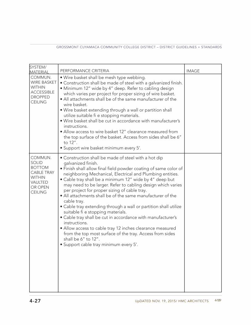
UpDATED NOV. 19, 2015/ HMC ARCHITECTS
GROSSMONT CUYAMACA COMMUNITY COLLEGE DISTRICT – DISTRICT GUIDELINES + STANDARDS
4-189
SYSTEM/MATERIAL PERFORMANCE CRITERIA IMAGE
• Wire basket shall be mesh type webbing.• Construction shall be made of steel with a galvanized finish.• Minimum 12” wide by 4” deep. Refer to cabling design
which varies per project for proper sizing of wire basket.• All attachments shall be of the same manufacturer of the
wire basket.• Wire basket extending through a wall or partition shall
utilize suitable fi e stopping materials.• Wire basket shall be cut in accordance with manufacturer’s
instructions.• Allow access to wire basket 12” clearance measured from
the top surface of the basket. Access from sides shall be 6”to 12”.
• Support wire basket minimum every 5’.
COMMUN. WIRE BASKET WITHIN ACCESSIBLE DROPPED CEILING
• Construction shall be made of steel with a hot dipgalvanized finish.
• Finish shall allow final field powder coating of same color ofneighboring Mechanical, Electrical and Plumbing entities.
• Cable tray shall be a minimum 12” wide by 4” deep butmay need to be larger. Refer to cabling design which variesper project for proper sizing of cable tray.
• All attachments shall be of the same manufacturer of thecable tray.
• Cable tray extending through a wall or partition shall utilizesuitable fi e stopping materials.
• Cable tray shall be cut in accordance with manufacturer’sinstructions.
• Allow access to cable tray 12 inches clearance measuredfrom the top most surface of the tray. Access from sidesshall be 6” to 12”.
• Support cable tray minimum every 5’.
COMMUN. SOLID BOTTOM CABLE TRAY WITHIN VAULTED OR OPEN CEILING
4-27
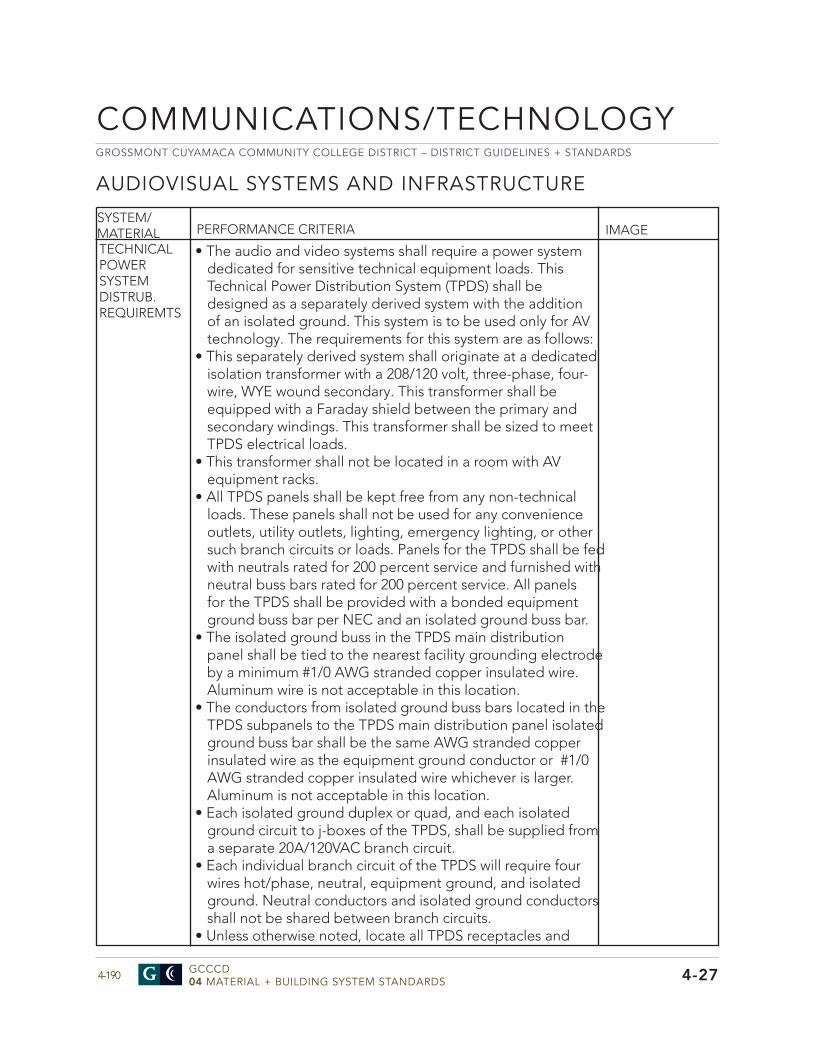
GROSSMONT CUYAMACA COMMUNITY COLLEGE DISTRICT – DISTRICT GUIDELINES + STANDARDS
GCCCD04 MATERIAL + BUILDING SYSTEM STANDARDS4-190
COMMUNICATIONS/TECHNOLOGY
4-27
TECHNICAL POWER SYSTEM DISTRUB. REQUIREMTS
AUDIOVISUAL SYSTEMS AND INFRASTRUCTURE
SYSTEM/MATERIAL PERFORMANCE CRITERIA IMAGE
• The audio and video systems shall require a power systemdedicated for sensitive technical equipment loads. ThisTechnical Power Distribution System (TPDS) shall bedesigned as a separately derived system with the additionof an isolated ground. This system is to be used only for AVtechnology. The requirements for this system are as follows:
• This separately derived system shall originate at a dedicatedisolation transformer with a 208/120 volt, three-phase, four-wire, WYE wound secondary. This transformer shall beequipped with a Faraday shield between the primary andsecondary windings. This transformer shall be sized to meetTPDS electrical loads.
• This transformer shall not be located in a room with AVequipment racks.
• All TPDS panels shall be kept free from any non-technicalloads. These panels shall not be used for any convenienceoutlets, utility outlets, lighting, emergency lighting, or othersuch branch circuits or loads. Panels for the TPDS shall be fedwith neutrals rated for 200 percent service and furnished withneutral buss bars rated for 200 percent service. All panelsfor the TPDS shall be provided with a bonded equipmentground buss bar per NEC and an isolated ground buss bar.
• The isolated ground buss in the TPDS main distributionpanel shall be tied to the nearest facility grounding electrodeby a minimum #1/0 AWG stranded copper insulated wire.Aluminum wire is not acceptable in this location.
• The conductors from isolated ground buss bars located in theTPDS subpanels to the TPDS main distribution panel isolatedground buss bar shall be the same AWG stranded copperinsulated wire as the equipment ground conductor or #1/0AWG stranded copper insulated wire whichever is larger.Aluminum is not acceptable in this location.
• Each isolated ground duplex or quad, and each isolatedground circuit to j-boxes of the TPDS, shall be supplied froma separate 20A/120VAC branch circuit.
• Each individual branch circuit of the TPDS will require fourwires hot/phase, neutral, equipment ground, and isolatedground. Neutral conductors and isolated ground conductorsshall not be shared between branch circuits.
• Unless otherwise noted, locate all TPDS receptacles and
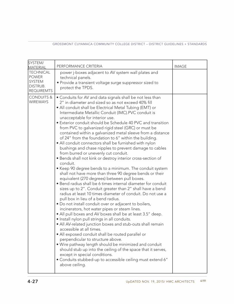
UpDATED NOV. 19, 2015/ HMC ARCHITECTS
GROSSMONT CUYAMACA COMMUNITY COLLEGE DISTRICT – DISTRICT GUIDELINES + STANDARDS
4-1914-27
SYSTEM/MATERIAL PERFORMANCE CRITERIA IMAGE
TECHNICAL POWER SYSTEM DISTRUB. REQUIREMTS
power j-boxes adjacent to AV system wall plates and technical panels.
• Provide a transient voltage surge suppressor sized toprotect the TPDS.
CONDUITS & WIREWAYS
• Conduits for AV and data signals shall be not less than2” in diameter and sized so as not exceed 40% fill
• All conduit shall be Electrical Metal Tubing (EMT) orIntermediate Metallic Conduit (IMC).PVC conduit isunacceptable for interior use.
• Exterior conduit should be Schedule 40 PVC and transitionfrom PVC to galvanized rigid steel (GRC) or must becontained within a galvanized metal sleeve from a distanceof 24” from the foundation to 6” within the building.
• All conduit connectors shall be furnished with nylonbushings and chase nipples to prevent damage to cablesfrom burred or unevenly cut conduit.
• Bends shall not kink or destroy interior cross-section ofconduit.
• Keep 90 degree bends to a minimum. The conduit systemshall not have more than three 90 degree bends or theirequivalent (270 degrees) between pull boxes.
• Bend radius shall be 6 times internal diameter for conduitsizes up to 2”. Conduit greater than 2” shall have a bendradius at least 10 times diameter of conduit. Do not use apull box in lieu of a bend radius.
• Do not install conduit over or adjacent to boilers,incinerators, hot water pipes or steam lines.
• All pull boxes and AV boxes shall be at least 3.5” deep.• Install nylon pull strings in all conduits.• All AV-related junction boxes and stub-outs shall remain
accessible at all times.• All exposed conduit shall be routed parallel or
perpendicular to structure above.• Wire pathway length should be minimized and conduit
should stub up into the ceiling of the space that it serves,except in special conditions.
• Conduits stubbed-up to accessible ceiling must extend 6”above ceiling.
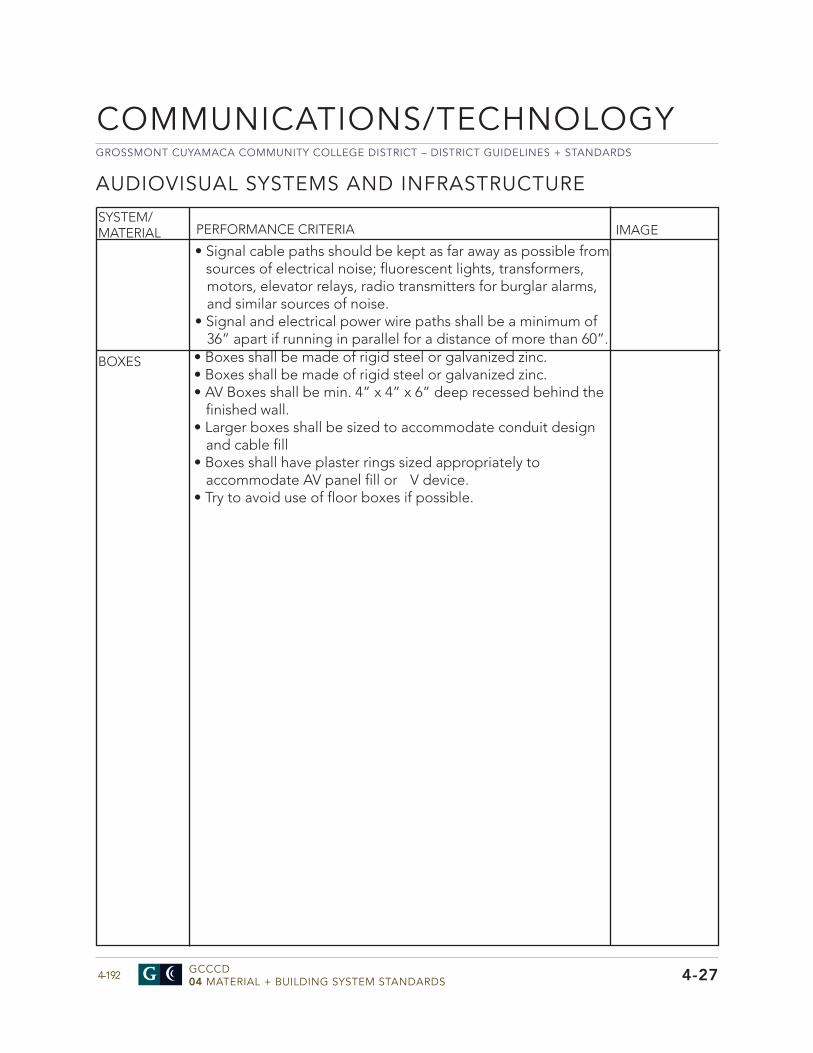
GROSSMONT CUYAMACA COMMUNITY COLLEGE DISTRICT – DISTRICT GUIDELINES + STANDARDS
GCCCD04 MATERIAL + BUILDING SYSTEM STANDARDS4-192
COMMUNICATIONS/TECHNOLOGY
4-27
SYSTEM/MATERIAL PERFORMANCE CRITERIA IMAGE
AUDIOVISUAL SYSTEMS AND INFRASTRUCTURE
• Boxes shall be made of rigid steel or galvanized zinc.• Boxes shall be made of rigid steel or galvanized zinc.• AV Boxes shall be min. 4” x 4” x 6” deep recessed behind the
finished wall.• Larger boxes shall be sized to accommodate conduit design
and cable fill• Boxes shall have plaster rings sized appropriately to
accommodate AV panel fill or V device.• Try to avoid use of floor boxes if possible.
BOXES
• Signal cable paths should be kept as far away as possible fromsources of electrical noise; fluorescent lights, transformers,motors, elevator relays, radio transmitters for burglar alarms,and similar sources of noise.
• Signal and electrical power wire paths shall be a minimum of36” apart if running in parallel for a distance of more than 60”.
UpDATED NOV. 19, 2015/ HMC ARCHITECTS
GROSSMONT CUYAMACA COMMUNITY COLLEGE DISTRICT – DISTRICT GUIDELINES + STANDARDS
4-1934-27
FLOOR BOXES
• AV floor boxes shall contain and provide easy access to data,communication and AV connections, and power forequipment to be used in their vicinity. Two types of boxesshall be used: those that mount in on grade floors conditionsand those that mount above grade floors conditions. Floorboxes shall be installed to prevent any water infiltration
• All floor boxes shall maintain segregation of low voltagesignals from power with dedicated compartments for AV, dataand power.
• All floor boxes shall have covers that meet UL scrub waterrequirements, preventing liquids from entering the box whenfloors are mopped or cleaned.
• On grade floor boxes shall be capable of height adjustmentbefore and after concrete pour and shall mount flush with thefinished floor.
• On grade floor boxes shall be rectangular and manufacturedfrom stamped steel approved for use in above grade and on-grade floor applications. Box shall have minimum dimensionsof 15”L x 11”W x 6”D with a min. of 11 gangs. Floor boxcovers shall have provision for attaching carpet or tile and lowprofile edging for flooring protection. The covers shall open afull 180 degrees.
• Above grade poke-thru boxes shall mount in an 8” cored holeand have a 2 hour fi e rating.
• Floor boxes shall accept conduit up to 2” in diameter forcommunications wiring.
• Must be capable of accommodating a minimum two 20 amp120VAC electrical circuits and 12 CAT-6 data circuits
• Box should have at a minimum, three (3) 1” concentricknockouts, one (1) 1.25” Knockout, and one (1) 2” knockout.
• Floor box covers should be manufactured to meetrequirements for cast in concrete environment. The coversshould have the capability to accept tile or carpet inserts orsolid covers.
• Conduits feeding floor box need to accommodate the filratio for power and data cables being installed at the specificlocation. Coordinate final configuration with IT P
SYSTEM/MATERIAL PERFORMANCE CRITERIA IMAGE
GROSSMONT CUYAMACA COMMUNITY COLLEGE DISTRICT – DISTRICT GUIDELINES + STANDARDS
GCCCD04 MATERIAL + BUILDING SYSTEM STANDARDS4-194
COMMUNICATIONS/TECHNOLOGY
4-27
AUDIOVISUAL SYSTEMS AND INFRASTRUCTURE
SYSTEM/MATERIAL PERFORMANCE CRITERIA IMAGECEILING MOUNTED SPEAKERS
SMART CART - AV LECTERN
• The Smart Cart /AV lectern shall function as a caster-mounted,mobile desk/work surface combined with an instructional lecternthat is capable of organizing and securely storing AV and dataequipment typically required in support of classroom instructionand presentations. Casters shall be locking.
• The cart shall house and provide power outlets and adequateventilation for a tower-type PC, up to 14 RU of standard 19” rack-mounted equipment and ancillary electronics.
• Back of lectern will include a lockable hinged door behindequipment rack keyed differently than presenter’s side door.
• The cabinet doors (presenter’s side), shall be secured by meansof a key lock and swing a full 270 degrees.
• The Smart Cart/AV lectern shall have an option for pull-out, orflip-up side support for a document camera and secure storage.
• Enclosed equip. areas shall have provision for fan ventilation.• Near its base, the cart shall have holes with grommets for the
entry of signal and power cabling.• The top surfaces may be equipped with AV/Data connectivity
centers as well as cutouts to accommodate third party AVcontrols.
• There shall be pull-out shelves for a computer keyboard.• Equipment in the Smart Cart/AV lectern shall be connected to
the AV systems via a floor box at the lectern location
• The enclosure shall have provision for the connection of conduitand signal wire terminals capable of “loop through” connectionswith strain relief.
• Speaker housing shall have provision for the attachment ofsafety wire or straps to secure the assembly to the structure.
• The speaker shall be a full range (6 ohm (nominal)transducer,with min. size 5”, attached to a vented, paintable baffle
• The speaker shall be equipped with a transformer for use in 70.7and 100 volt distributed audio systems.
• The transformer and impedance settings shall be selected byswitch settings on the front baffle
• The speaker shall be equipped with a weather resistant steelgrille.
- Speaker frequency response shall be 85Hz – 22kHz (-3dB) with a range of 68Hz – 18kHz (-10dB).
- The speaker will provide 170° dispersion and 105° coverage in the 1kHz – 6kHz range.

UpDATED NOV. 19, 2015/ HMC ARCHITECTS
GROSSMONT CUYAMACA COMMUNITY COLLEGE DISTRICT – DISTRICT GUIDELINES + STANDARDS
4-1954-27
GROSSMONT CUYAMACA COMMUNITY COLLEGE DISTRICT – DISTRICT GUIDELINES + STANDARDS
GCCCD04 MATERIAL + BUILDING SYSTEM STANDARDS4-196
COMMUNICATIONS/TECHNOLOGY
4-27
SYSTEM/MATERIAL PERFORMANCE CRITERIA IMAGE
AUDIOVISUAL SYSTEMS AND INFRASTRUCTURE
WALL MOUNTED FLAT SCREEN DISPLAYS
• The wall to which the display will be mounted shall bere-enforced sufficiently to support a designed load of 200pounds for most displays (46 - 65 inches). Larger displayswill exceed this criteria and require additional coordination.
• Structural backing shall cover an area not less than 36”wide by 26” high and shall be centered horizontally andvertically on the center point of the display.
• The design of a flat panel niche is highly recommended toreduce the possibility of the flat panel display protrudingbeyond the ADA requirements. A minimum clearance of2” on all side of the display is required.
• The purpose of the back box is to contain and organizedisplay-associated power outlets, data, signal connectionsand electronics, such as signal processors and powersupplies, behind a wall-mounted flat screen display.
• The back box shall mount flush with the finished wallsurface and fit between either metal or wood wall studs
• The box shall have a cover with cable pass-through holesand ventilation.
• The box shall be constructed of 16 gauge steel and haveinternal dimensions not less than 14”w x 10”h x 6”d.
• The back box shall accept conduit up to 2” in diameter forcommunications wiring and at least (2) knockouts for singlegang electrical boxes for power and data as needed.
• All of the infrastructure must be hidden by the flat-paneldisplay.
CEILING MOUNTED PROJECTORS
• The facility surface to which the projector mount willbe attached shall be prepared to support the weightof the specified projector and mount, provide suitableattachment points for the projector mount.
• The projector mount shall consist of two components: thesuspended ceiling kit and the actual mounting hardware.The entire assembly shall provide a secure, lockableattachment point for projectors to be mounted overhead.
• The suspended ceiling kit shall provide a stable and rigidplatform designed for installation on top of a standard 2’x 2’ grid suspended ceiling and have a minimum weightbearing capacity of 125 pounds, depending on loadattachment point.
UpDATED NOV. 19, 2015/ HMC ARCHITECTS
GROSSMONT CUYAMACA COMMUNITY COLLEGE DISTRICT – DISTRICT GUIDELINES + STANDARDS
4-1974-27
SYSTEM/MATERIAL PERFORMANCE CRITERIA IMAGECEILING MOUNTED PROJECTORS
CEILING MOUNTED MOTORIzED PROJECTION SCREEN
• The facility surface to which the screen will be attached shallbe prepared to support the weight of the specified screenassembly, provide suitable attachment points for mounting.
• The projection screen shall be an electric roll-down unitcapable of low voltage control by means of a three-buttonraise/lower/stop wall switch and an interface to permitcontrol by means of a third party control system.
• The non-technical power is to be derived from a systemseparate from the AV technical power.
• The projection screen switch shall be mounted on wall withother switches with an additional controller mounted on thesmart cart.
• The projection screen shall have a 16:10 aspect ratio.• Screen fabric shall be flame retardant and mildew resistant
fiber glass with black masking borders. Viewing surface shall be matte white with viewing angle of 60° and gain of 1.0. Lights in front of the screen shall be on separate switch.
• Case shall be a white powder coated aluminum extrusion,and to shall be self-trimming with a built-in flange aroundthe bottom.
• Though configurations, exact specifications and capacitiesmay vary, the spaces requiring projection will typically fallinto the following groups and should be equipped with theprojection screens of the approximate indicated sizes.
• This platform shall be attached to structure above withcables and hardware permitting height adjustment andsecure, load-bearing support.
• The platform shall have provision for the attachmentof signal connections as well as power outlets for theprojector.
• The platform shall have a minimum of 2 knockouts forsingle gang electrical boxes to accommodate signalconnections as well as power outlets for the projector.
• The platform shall have multiple mounting hole positionswith 1-1/2” NPT threads to accept a projector mountingpipe.
AV TIE LINES • AV tie lines are off-network. They are straight throughcables, and may consist of CAT6, shielded twisted pair orfiber between locations
GROSSMONT CUYAMACA COMMUNITY COLLEGE DISTRICT – DISTRICT GUIDELINES + STANDARDS
GCCCD04 MATERIAL + BUILDING SYSTEM STANDARDS4-198
ELECTRONIC SAFETY + SECURITY
4-28
Division 28
General Approach - The District takes a proactive approach to the security and safety of both campuses. The design of all new projects should incorporate CEPTD (Crime Prevention through Environmental Design) design principles and best practices for creating safe and secure environments for the users. The District augments the CEPTD design approach with electronic security systems including security cameras and monitoring, intrusion systems, and electronic card access to different spaces. Performance criteria for those systems are outlined in this Division. Also refer the Division 26 for additional information. The District is using Bosch Security Systems, Inc. to provide security camera monitoring system and intrusion alarm systems and Millennium Group, Inc. These manufacturers should be specified for these systems.
The intent of the Emergency Notification System (ENS) standard is to provide design guidelines for an extension of existing ENS technology to support new structure construction; the design of such systems to be in compliance with structure configuration and budget constraints. AnENS provides broad-based notification to pertinent on-campus spaces in the event of a crisis or emergency, including natural disasters and acts of terrorism. Emergency communications management is concerned with policies, procedures, and operations that function in concert with an ENS and are established and not included in this standard. The tools involved in an ENS can be as simple as external sirens or as complex as solutions that combine elements such as a campus website, telephony, e-mail, text messaging, digital signage, network pop-ups, and RSS feeds. This standard criteria addresses two of the elements; paging systems and fire alarm panels with voice enunciation.
ELECTRONIC SAFETY + SECURITY
• The Fire Alarm system shall be provided by SimplexGrinnelland interface with the system on both campuses via theexisting Simplex fi e alarm network.
• The Fire Alarm system will also be an emergency voicealarm communication system and shall incorporateaddressable notification appliances.
• The system shall be digital addressable type.• A new intelligent reporting, Class ‘A’ networked, fully
peer-to-peer, microprocessor-controlled fi e detection andemergency voice alarm communication system shall beinstalled in new projects and updated in renovated projects.
SYSTEM/MATERIAL PERFORMANCE CRITERIA IMAGE
GENERAL
FIRE ALARM SYSTEM
UpDATED NOV. 19, 2015/ HMC ARCHITECTS
GROSSMONT CUYAMACA COMMUNITY COLLEGE DISTRICT – DISTRICT GUIDELINES + STANDARDS
4-1994-28
SYSTEM/MATERIAL PERFORMANCE CRITERIA IMAGE
• Alarm, trouble and supervisory signals from all intelligentreporting devices shall be encoded on NFPA Style 4 (ClassB) Signaling Line Circuits (SLC).
• Initiation Device Circuits (IDC) shall be wired Class B (NFPAStyle B) as part of an addressable device connected by theSLC Circuit.
• When fi e alarm condition is detected and reported byone of the system alarm initiating devices, the followingfunctions shall immediately occur:
- System Alarm LEDs shall flash - Local Piezoelectric Signal in Control Panel shall sound at a pulse rate.
- 80-Character LCD Display shall indicated all information associated with fi e alarm condition, including type of alarm point and its location within protected premises.
- Historical Log: Record information associated with fi e alarm control panel condition, along with time and date of occurrence.
- System output programs assigned via control-by-event equations to be activated by particular point in alarm shall be executed, and the associated system outputs (alarm notification appliances and/orrelays) shall be activated.
- Audio Portion of System shall have sound tone (California Temporal Pattern) until system is reset.
FUNCTIONAL OPERATION
GROSSMONT CUYAMACA COMMUNITY COLLEGE DISTRICT – DISTRICT GUIDELINES + STANDARDS
GCCCD04 MATERIAL + BUILDING SYSTEM STANDARDS4-200
• Provide complete, electrically supervised distributed, Class‘A’ networked analog/addressable fi e alarm and controlsystem, with analog initiating devices, and integral multiple-channel voice evacuation.
• The system shall consist of multiple-voice channels with noadditional hardware required for total of 4 channels.
• The system shall incorporate multiprocessor-based controlpanels, including Simplex TrueSite Work Station, IntelligentLoop Interface (IDNET), Intelligent Network Transponders(Mini-Plex), communicating over peer-to-peer token ringnetwork with capacity of up to 150 nodes.
• Each 4100 Node: Incorporate Signaling Line Circuits (SLC),with capacity to support up to 250 analog addressabledevices per SLC.
• Transmit voice data over single pair of wires or fiber opticcable.
• Each Network Node: Incorporate Boolean control-by-eventprogramming, including as a minimum AND, OR, NOT, andTimer functions.
• Control Panels shall have the capability to accept firmwareupgrades via connection with laptop computer, withoutrequirement of replacing microchips.
• The Network shall be based on peer-to-peer token ringtechnology operating at 57.6 K baud, using Class ‘A’configuration (if applicable) and have the capability ofusing twisted-pair wiring, pair of fiber optic cable strandsup to 200 microns, or both, to maximize flexibility in systemconfiguration
• Each Network Node shall have: - Capability of being programmed off-line using Windows-based software supplied by fi e alarm system manufacturer and the capability of being downloaded by connecting laptop computer into any other node in system. Systems that require system software to be downloaded to each transponder at each transponder location are not acceptable.
- Capability of being grouped with any number of additional nodes to produce a “Region”, allowing
SYSTEM/MATERIAL PERFORMANCE CRITERIA IMAGE
FUNCTION-ALITY
FIRE ALARM SYSTEM
4-28
ELECTRONIC SAFETY + SECURITY
UpDATED NOV. 19, 2015/ HMC ARCHITECTS
GROSSMONT CUYAMACA COMMUNITY COLLEGE DISTRICT – DISTRICT GUIDELINES + STANDARDS
4-201
SYSTEM/MATERIAL PERFORMANCE CRITERIA IMAGE
4-28
that group of nodes to act as 1, while retaining peer-to-peer functionality. Systems utilizing “Master/Slave” configurations are not acceptable.
- Capability of annunciating all events within its “Region” or annunciating all events from entire network, on front panel LCD without additional equipment.
• Each Control Panel shall have the capability of storing itsentire program, and allow installer to activate only devices that are installed during construction, without further downloading of system.
• Each system shall be provided with 4 levels of passwordprotection with up to 16 passwords.
• Provide 10 second continuous tone, followed by repeatingprerecorded message, announcing either facility lockdownor evacuation as determined by activation of appropriatemanual pull station in Administration area or MDE room.
AUTOMATICLOCKDOWN/EVACUATION
GROSSMONT CUYAMACA COMMUNITY COLLEGE DISTRICT – DISTRICT GUIDELINES + STANDARDS
GCCCD04 MATERIAL + BUILDING SYSTEM STANDARDS4-202
• LCD Display: 80-character RS-485 based textualannunciator with capability of being mounted locally orremotely. Provides audible and visual annunciation of allalarms and trouble signals. Provide dedicated LEDs for:
- AC Power On: Green - Alarm: Red - Supervisory: Yellow - System Trouble: Yellow - Power Fault: Yellow - Ground Fault: Yellow - System Silenced: Yellow
• 80-Character Alphanumeric Display: Provide status of allanalog/addressable sensors, monitor and control modules. Display shall be backlit liquid crystal type (LCD), clearly visible in dark and under all light conditions.
• Panel shall contain the following 4 functional keys: - Alarm Acknowledge - Trouble Acknowledge - Signal Silence - System Reset/Lamp Test
• Panel shall contain 3 configuration buttons - Menu/Back. - Back Space/Edit. - OK/Enter.
• Panel shall have 12-key telephone-style keypad to permitselection of functions.
SYSTEM/MATERIAL PERFORMANCE CRITERIA IMAGE
LCD DISPLAYMODULE
FIRE ALARM SYSTEM
4-28
ELECTRONIC SAFETY + SECURITY
UpDATED NOV. 19, 2015/ HMC ARCHITECTS
GROSSMONT CUYAMACA COMMUNITY COLLEGE DISTRICT – DISTRICT GUIDELINES + STANDARDS
4-203
SYSTEM/MATERIAL PERFORMANCE CRITERIA IMAGE
INTELLIGENTLOOPINTERFACE
4-28
• The system shall be capable of being programmed by FieldConfiguration Program (FCP), allowing programming to bedownloaded via portable computer from any node onnetwork.
• The supervised serial port shall be provided to operateremote printers and/or video terminals, accept downloadedprogram from portable computer, or provide 80-columnreadout of all alarms, troubles, location descriptions, time,and date. Communication shall be standard ASCII codeoperating from 1,200 to 115,200 baud rate.
• All Loop Interface Modules shall incorporate ownprogramming, log functions, central processor unit, andcontrol-by-event (CBE) programming. If any loop becomesdisabled, each remaining loop driver shall continue tocommunicate with remainder of network and maintainnormal operation. “Degrade” configurations under theseconditions shall not be acceptable.
• Smoke detector alarm verification shall be standard optionwhile allowing other devices such as manual stations andsprinkler flow to create immediate alarm. This featureshall be selectable for smoke sensors that are installed inenvironments prone to nuisance or unwanted alarms.
• All alarm signals shall be automatically latched or “lockedin” at control panel until operated device is returned tonormal and control panel is manually reset. When used forsprinkler flow, “SIGNAL SILENCE” switch may be bypassed,if required by Authority Having Jurisdiction.
• Each SLC and NAC circuit shall be electrically supervisedfor opens, shorts, and ground faults. Occurrence of faultshall activate system trouble circuitry, but shall not interferewith proper operation of other circuits.
• Yellow “SYSTEM TROUBLE” LEDs shall light and systemaudible sounder shall steadily sound when trouble isdetected in system. Failure of power, open or shortcircuits on SLC or NAC circuits, disarrangement in systemwiring, failure of microprocessor or any identificationmodule, or system ground faults shall activate this troublecircuit. Trouble signal shall be acknowledge by operating“TROUBLE ACKNOWLEDGE” switch. This shall silence
GROSSMONT CUYAMACA COMMUNITY COLLEGE DISTRICT – DISTRICT GUIDELINES + STANDARDS
GCCCD04 MATERIAL + BUILDING SYSTEM STANDARDS4-204
SYSTEM/MATERIAL PERFORMANCE CRITERIA IMAGE
FIRE ALARM SYSTEM
4-28
ELECTRONIC SAFETY + SECURITY
sounder. If subsequent trouble conditions occur, trouble circuitry shall resound. During alarm, all trouble signals shall be suppressed with exception of lighting yellow “SYSTEM TROUBLE” LEDs.
• Analog Smoke Sensors: System software shall automaticallyadjust each analog smoke sensor approximately once each week for changes in sensitivity due to effects of component aging or environment, including dust. Each sensor shall maintain its actual sensitivity under adverse conditions to respond to alarm conditions while ignoring factors which generally contribute to nuisance alarms. System trouble circuitry shall activate, display “DIRTY DETECTOR” and “VERY DIRTY DETECTOR” indications and identify individual unit that requires maintenance.
• System software shall automatically test each analogsmoke sensor a minimum of 3 times daily. The test shall be recognized functional test of each photocell (analog photoelectric sensors) and ionization chamber (analog ionization sensors) as required annually by NFPA. The failure of sensor shall activate system trouble circuitry, display “Test Failed” indication, and identify individual device that failed.
• The fi e alarm system shall transmit alarm, supervisory, andtrouble signals with alarm having priority over supervisory and trouble signals.
• System shall provide for all SLC devices on any SLC loop tobe pre-programmed into system. Upon activation of auto programming, only devices that are present shall activate. This allows for system to be commissioned in phases without need of additional downloads.
• System shall provide for setting Environmental DriftCompensation by device. When detector accumulates dust in chamber and reaches unacceptable level buy yet still below allowed limit, control panel shall indicate maintenance alert warning. When detector accumulates dust in chamber above allowed limit, control panel shall indicate maintenance urgent warning.
• Non-reporting type ID shall be available for use for energymanagement or other non-fi e situations. NON-FIRE point
UpDATED NOV. 19, 2015/ HMC ARCHITECTS
GROSSMONT CUYAMACA COMMUNITY COLLEGE DISTRICT – DISTRICT GUIDELINES + STANDARDS
4-205
SYSTEM/MATERIAL PERFORMANCE CRITERIA IMAGE
4-28
operation shall not affect control panel operation nor shall it display message at panel LDC. Activation of NON-FIRE point shall activate control by event logic, but shall not cause indication on control panel.
• 1-Man Walk Test: - System shall provide both basic and advanced walk test for testing entire fi e alarm system. Basic walk test shall allow a single operator to run audible tests on panel. All logic equation automation shall be suspended during test and while annunciators can be enabled for test, all shall default to disabled state. During the advanced walk test, field-suppliedoutput point programming shall react to input stimuli, such as CBE and logic equations. When points are activated in advanced test mode, each initiating event shall latch input. Advanced test shall be audible and shall be used for pull station verification, magnet activated tests on input devices,input and output device, and wiring operation/verification
.
GROSSMONT CUYAMACA COMMUNITY COLLEGE DISTRICT – DISTRICT GUIDELINES + STANDARDS
GCCCD04 MATERIAL + BUILDING SYSTEM STANDARDS4-206
• Detectors: Analog and addressable. Connect to fi e alarmcontrol panel’s Signaling Line Circuits.
• Addressable Thermal and Smoke Detectors: Fire alarmcontrol panel shall permit detector sensitivity adjustmentthrough field programming of system. Sensitivity can beautomatically adjusted by panel on time-of-day basis.
• Using software in each 4100, detectors shall automaticallycompensate for dust accumulation and other slowenvironmental changes that may affect their performance.Detectors shall be listed by UL as meeting calibratedsensitivity test requirements of NFPA.
• Following bases and auxiliary functions shall be available: - Standard base with remote LED output - Sounder base rated at 85 dBA minimum - Form-C relay base rated 30 VDC, 2.0 A - Isolator base
• Detectors shall provide test means whereby they willsimulate alarm condition and report that condition to control panel. Such test shall be initiated at detector itself by activating magnetic switch or initiated remotely on command from control panel.
• Detectors shall store internal identifying type code thatcontrol panel shall use to identify type of device.
• Manual fi e alarm stations shall be non-code, non-breakglass type, equipped with key lock so they may be tested without operating handle.
• The operated station shall be visually apparent, asoperated, at a minimum distance of 100 feet from front or side.
• Stations shall be designed so after actual activation, theycannot be restored to normal except by key reset.
• Manual stations shall be construction of Lexan with clearlyvisible operating instructions provided on cover. The word FIRE shall appear on front of stations in raised letter, 1.75 inches or larger.
• Addressable manual stations shall, on command fromcontrol panel, send data to panel representing state of manual switch and addressable communication module status.
SYSTEM/MATERIAL PERFORMANCE CRITERIA IMAGE
SYSTEM PERIPHERALS
FIRE ALARM SYSTEM
4-28
ELECTRONIC SAFETY + SECURITY

UpDATED NOV. 19, 2015/ HMC ARCHITECTS
GROSSMONT CUYAMACA COMMUNITY COLLEGE DISTRICT – DISTRICT GUIDELINES + STANDARDS
4-207
• Intelligent addressable devices shall be rated at 135degrees F and have rate-of-rise element rated at 15degrees F per minute. Connect via 2 wires to fi e alarmcontrol panel signaling line circuit.
• Intelligent Photoelectric Smoke Detectors: Usephotoelectric (light-scattering) principal to measure smokedensity and shall, on command from control panel, senddata to panel representing analog level of smoke density.
• Intelligent Duct Smoke Detectors - In-Duct Smoke Detector Housing: Use on-board intelligent photoelectric detector, which provides continuous analog monitoring and alarm verificationfrom panel.
- When sufficient smoke is sensed, alarm signal isinitiated and appropriate action taken to shut down or change over air handling systems to help prevent rapid distribution of toxic smoke and fi e gases throughout areas served by duct system.
- Duct Smoke Detectors Mounted above Ceiling or Otherwise Obstructed from Normal View: Provide with remote alarm indicator.
- Each Detector: Install in either supply side or return side duct in accordance with local mechanical code.
• Addressable Dry Contact Monitor Modules - Provide to connect 1 supervised IDC zone of conventional alarm initiating devices (any N>O> dry contact device) to 1 of the fi e alarm control panel SLCs.
- Mount in standard deep electrical box. - IDC z one: Suitable for Style B operation.
• Provide addressable control modules to supervise andcontrol operation of 1 conventional NAC of compatible, 24-VDC powered, polarized audio/visual notificationappliances or UL-listed polarized relays for fan shutdown and other auxiliary control functions.
- Wire control module NAC for Style z or Style Y (Class B/B) with up to 1 amp of inductive signal or 2 amps of resistive signal operation. Relay coil shall be magnetically latched to reduce wiring connection
SYSTEM/MATERIAL PERFORMANCE CRITERIA IMAGE
4-28
GROSSMONT CUYAMACA COMMUNITY COLLEGE DISTRICT – DISTRICT GUIDELINES + STANDARDS
GCCCD04 MATERIAL + BUILDING SYSTEM STANDARDS4-208
SYSTEM/MATERIAL PERFORMANCE CRITERIA IMAGE
FIRE ALARM SYSTEM
4-28
ELECTRONIC SAFETY + SECURITY
requirements and to ensure 100 percent of all auxiliary relay or NACs shall be energized at same time on same pair of wires
- Provide Audio/visual power by separate supervised power circuit from main fi e alarm control panel or from supervised, UL-listed remote power supply.
- Provide audio/visual power by separate supervised power circuit from main fi e alarm control panel or from supervised, UL-listed remote power supply.
• Addressable Relay Modules: - Available for HVAC control and other building functions. Relay shall have 2 Form C sets of contacts that operate in tandem and are rated for a minimum of 2.0 amps resistive or 1.0 amps inductive. Relay coil shall be magnetically latched to reduce wiring connection requirements and to ensure 100 percent of all auxiliary relay or NACs shall be energized at same time on same pair of wires.
- Mount in standard 4-inch square, 2-1/8-inch deep electrical box or to surface-mounted back box.
• Speakers for the system shall have the following criteria: - Compliance with UL 1480. - Operate on 25 or 70 VRMS or with field-selectableoutput taps from 0.25 to 2.0 watts.
- Speakers in Corridors and Public Spaces shall produce nominal sound output of 84 dBA at 10 feet, at one watt tap setting.
- Frequency Response: Minimum of 400 Hz to 4,000 Hz.
- Back of Each Speaker shall be sealed to protect speaker cone from damage and dust.
- Audibility: NFPA 72.• Strobes for the system shall have the following criteria:
- Compliance: ADA and UL 1971. - Maximum Pulse Duration: 0.2 second. - Strobe Intensity: UL 1971. - Flash Rate: UL 1971. - Strobe Candela Rating: Determine by positioning selector switch on back of device.

UpDATED NOV. 19, 2015/ HMC ARCHITECTS
GROSSMONT CUYAMACA COMMUNITY COLLEGE DISTRICT – DISTRICT GUIDELINES + STANDARDS
4-209
SYSTEM/MATERIAL PERFORMANCE CRITERIA IMAGE
4-28
• Speaker/Strobes shall have the following criteria: - Compliance: Speaker – UL 1480. - Operate on 25 or 70 VRMS with field-selectableoutput taps from 0.25 to 2.0 watt.
- Speakers in Corridors and Public Spaces shall produce nominal sound output of 84 dBA at 10 feet at one watt tap setting.
- Frequency Response: Minimum of 400 Hz to 4,000 Hz.
- Back of Each Speaker: Sealed to protect speaker cone from damage and dust.
- Audibility: NFPA 72. - Maximum pulse duration shall be 0.2 second. - Strobe Intensity: UL 1971. - Flash Rate: UL 1971. - Strobe Candela Rating: Determine by positioning selector switch on back of device.
SPARE PARTS CABINET
• NEMA 1 cabinet with hinged lockable door and paintedred to match FACP, sized to accommodate the extramaterials specified. Provide an engraved nameplate toread “FIRE ALARM SYSTEM SPARE PARTS CABINET”.
GROSSMONT CUYAMACA COMMUNITY COLLEGE DISTRICT – DISTRICT GUIDELINES + STANDARDS
GCCCD04 MATERIAL + BUILDING SYSTEM STANDARDS4-210 4-28
ELECTRONIC SAFETY + SECURITY
• Applicable Industry Standards to Reference - All state, local Prevailing Building Codes and regulatory agencies
- Underwriter’s Laboratories (UL) 2572, Control Equipment for Mass Notification System
- BICSI Standards - Occupational Safety and Health Association (OSHA) Requirements
- ANSI/TIA-569-C Telecommunications Pathways and Spaces
- NFPA 72, 2010 edition, National Fire Alarm and Signaling Code
- NFPA 70, 2010 edition, Articles 250, 725, 760, 770, and 800
- National Electrical Manufacturer’s Association (NEMA)
• Applicable Campus Standards to Reference - Grossmont Cuyamaca Community College District Network Cable and Fiber Specifications andInstallation Procedures.
- Division 27, Applicable Communication/ Technology elements
- Division 26, Fire Alarm – Digital, Addressable Fire Alarm and Voice Evacuation System
- All equipment - under Fire Alarm Specification
SYSTEM/MATERIAL PERFORMANCE CRITERIA IMAGE
ENS INFRA-STRUCTURE GENERAL EQUIPMENT PROVISIONS
EMERGENCY NOTIFICATION SYSTEM
UpDATED NOV. 19, 2015/ HMC ARCHITECTS
GROSSMONT CUYAMACA COMMUNITY COLLEGE DISTRICT – DISTRICT GUIDELINES + STANDARDS
4-2114-28
SYSTEM/MATERIAL PERFORMANCE CRITERIA IMAGE
ENS PAGING EQUIPMENT
• Existing Paging Network System Expansion – Providean expansion of the network into a structure for thepurpose of broadcasting emergency informationthrough automatic and manual audible instructions.The expansion of the network shall include, but not belimited to amplifiers, speakers, support material andinfrastructure.
• Provide speakers for indoor and outdoor use. Insureequipment is listed for the purpose designed, withappropriate mounting appliances to support the units.
- Indoor and outdoor speakers shall be ceiling or wall supported with appropriate ceiling or wall support elements including guy wires for seismic considerations.
- Indoor and outdoor speakers shall be listed for 70 volt capacity, and be compatible with the amplifierto which it is connected.
- Indoor and outdoor speakers shall be listed by UL2572 for use as emergency notification devices
- Indoor and outdoor speakers shall be either omnidirectional or directional depending on the desired broadcast parameters.
- Indoor and outdoor speakers shall be fully encased in appropriate raceway for protection and circuit integrity.
- Where mounted indoors, speaker location shall be predicated upon acoustic consideration to include room function, room configuration,acoustical material within a space, and be capable of complete sound annunciation in throughout the structure without audible loss due to attenuation.
- Where mounted outdoors, speakers shall be mounted upon structures for broadcasting surrounding areas.
- Outdoor speakers, where possible, shall be housed in appropriate containers to withstand/mitigate bird habitat or perching.
- Outdoor speaker wire penetrations into a structure shall be made to insure no water shall enter
GROSSMONT CUYAMACA COMMUNITY COLLEGE DISTRICT – DISTRICT GUIDELINES + STANDARDS
GCCCD04 MATERIAL + BUILDING SYSTEM STANDARDS4-212
SYSTEM/MATERIAL PERFORMANCE CRITERIA IMAGE
ENS PAGING EQUIPMENT
EMERGENCY NOTIFICATION SYSTEM
to include inclined punch-through elevation, penetration packing with water-resistant material, or appropriate raceway with packing material.
- Outdoor speaker wiring shall be protected with appropriate raceway listed for outdoor use.
• Audio Amplifier - Amplifiers shall be rated at 70/100 . - Amplifiers shall be listed by UL2572 for use asemergency notification devices
- Amplification shall consist of multiple outputswith appropriate power to support the number of speakers attached.
- The number of amplifiers shall be predicated upon the structure configuration and desired annunciation zones required.
- Actual number of zones shall be determined during design phase in concert with the District.
- Fire Alarm mounted amplifiers shall be wallmounted in the MDF room in a simplex cabinet.
- Amplifiers shall be configured with telephone interface for network connectivity, or IP network capacity.
4-28
ELECTRONIC SAFETY + SECURITY
UpDATED NOV. 19, 2015/ HMC ARCHITECTS
GROSSMONT CUYAMACA COMMUNITY COLLEGE DISTRICT – DISTRICT GUIDELINES + STANDARDS
4-213
SYSTEM/MATERIAL PERFORMANCE CRITERIA IMAGE
4-28
• Building fi e alarm control panels (FACP) shall be providedin compliance with Division 26, Fire Alarm – Digital,Addressable Fire Alarm and Voice Evacuation Systemas outlined in the District Standards. NFPA 72 allowsemergency broadcast for other than fire alarm purposes.
- Voice evacuation shall consist of audio/visual appliances that may be, but not required, for emergency broadcast audio/visual annunciations.
- Audio appliances shall be approved by the California State Fire Marshall (CSFM) for compliance as a unit and configured for a listed system when interconnected to become a part of the building fi e alarm system.
- Audio appliances (speakers) shall also be listed by UL2572 for use as emergency notification devices
- Paging Amplifiers may be inter connected to a building FACP utilizing low-level audio balanced-line signals for non-fi e alarm emergency broadcasts through the building audio appliances utilizing CSFM approved interface modules.
• Fire Alarm Network Expansion - Provide extending connections from the network to a building fire alarm system via the campus infrastructure.
- Building FACP and the Fire Alarm Network control must be listed by the same manufacturer and approved by the CSFM
- According to design, provide necessary appurtenances such as broadcast stations, consisting of microphones, switching appliances, or other required devices.
ENS FIRE ALARM CONTROL PANEL CONNECTION
GROSSMONT CUYAMACA COMMUNITY COLLEGE DISTRICT – DISTRICT GUIDELINES + STANDARDS
GCCCD04 MATERIAL + BUILDING SYSTEM STANDARDS4-214 4-28
• Manufacturer must have manufactured and supportedelectronic access control systems for 15 years with over 20southern California references for successful projects.
• Manufacturer must be responsible for all systemcomponents.
• Manufacturer must be capable of providing manufacturer-employed field service personnel for installation assistanceand continued District support.
• Installers of the system must be trained by themanufacturer.
• Capabilities of manufacturer and system must include:- Access control.- Alarm monitoring.- Identification badging- Programmable relay control.- View events in real time.- Print selected events in real time.- Elevator control.(floor by floor)- Controlled by a computer(Server)- Support Microsoft SQL Server 2005 through 2012 - Control several segregated databases
SYSTEM/MATERIAL PERFORMANCE CRITERIA IMAGE
GENERAL QUALITY ASSURANCE
ELECTRONIC ACCESS CONTROL
ELECTRONIC SAFETY + SECURITY
UpDATED NOV. 19, 2015/ HMC ARCHITECTS
GROSSMONT CUYAMACA COMMUNITY COLLEGE DISTRICT – DISTRICT GUIDELINES + STANDARDS
4-2154-28
SYSTEM/MATERIAL PERFORMANCE CRITERIA IMAGE
SOFTWARE DESIGN
• Native 32-bit, multi-tasking and multi-threaded, runningunder Windows 7/8, Windows 2008/2012 servers.
• Use a GUI (Graphical User Interface) based upon Windowsstandards, including Windows theme support, haveextensive context sensitive on-line help, and providefamiliar icon-driven, tabbed dialog menu options.
• Perform network communications tasks via a separateintegrated application running in background.
• Alarm monitoring, alarm editing, and setup applicationsshall require operator logon to function.
• Must be able to include totally integrated identificationbadging, utilizing same database as access controlsystem. No import or export shall be necessary. Can beadded at any time with no database conversion necessary.
DATABASE:GUARD FOR SOFTWARE
• Support the ODBC standard• Supplied with a full support of Microsoft SQL
2005/2008/2012 database server application to allowarchiving of history, database repair functions, and import/export.
• Support near-real-time import and export of data.• Support automatic update of user access rights as a result
of import process.• Allow for a unique industry standard ISO card number to
be generated on demand as part of import process.• Provide a user partition feature; allows specific system
entities in the database to be seen and manipulated onlyby certain “user Groups”. Such entities can be users, sites,doors, and elevator floors. When the database is dividedinto spheres of control in this way, operators in a givengroup will control data such as sites, doors, users, andaccess groups for their own group(s) only. The databaseitself is complete, but views are generated such thatwhat the operator can view, add, modify, delete or printreports, is limited by the Tenant Group(s) to which theyhave rights to as well as by Operator level.
• Provide “Tenant Wizard” to allow easy operatormanipulation of tenant Group elements- users, doors,sites, and access groups.
GROSSMONT CUYAMACA COMMUNITY COLLEGE DISTRICT – DISTRICT GUIDELINES + STANDARDS
GCCCD04 MATERIAL + BUILDING SYSTEM STANDARDS4-216
ELECTRONIC ACCESS CONTROL
SYSTEM/MATERIAL PERFORMANCE CRITERIA IMAGEGUARDALARM MONITORING SOFTWARE
• Support a minimum of 7 supervised alarm inputs perdoor control Unit with time zone disable feature, and aprogrammable shunt delay timer from 0 to 255 seconds.
• Supervision of alarm points can be either two (Alarm,Reset) or four state (Trigger, Reset, Open and Short)determined at software configuration
• Provide a forced-door entry with an ajar alarm. Forced-door alarm shall have a shunt delay timer of 0 to 255seconds. Ajar alarm shall have a programmable delaytimer of 1 to 255 minutes.
• Support adding name of alarm in a field minimum of 19characters and additional information about each alarm ina “notes” field
• Support prioritizing of alarms to 100 levels.• Support linking specific alarms to relay control devices.• Include a graphical alarm editing application that shall
allow a user to define alarms including graphical maps.Animated icons shall be placed on maps to indicatestandard alarm types such as fi e and break-in. Four levelsof zoom shall be provided for each alarm.
• Require acknowledgment text so personnel monitoringalarms shall provide response information.
• Include an alarm monitor application separate frommain software which shall display alarms graphically inpriority with which they were programmed. Applicationshall be able to be run from any workstation. AllowAlarm acknowledgment from any workstation withsynchronization between workstations.
• Provide alarm monitor with capability to display a userportrait in response to valid or invalid access attempts.
• Provide alarm monitor with support for standard soundcards and wav files so user defined sounds can beplayed for alarms.
• Log-off with password shall be required to quit alarmmonitor.
• Programmable requests for incident reports.• Support up to 4 floor maps per alarm input, available
within one double click directly on the alarm reported onthe alarm monitor
ELECTRONIC SAFETY + SECURITY
4-28
UpDATED NOV. 19, 2015/ HMC ARCHITECTS
GROSSMONT CUYAMACA COMMUNITY COLLEGE DISTRICT – DISTRICT GUIDELINES + STANDARDS
4-217
SYSTEM/MATERIAL PERFORMANCE CRITERIA IMAGE
CLIENT GUARD TOUR SOFTWARE
SCHEDULER; INTEGRATED SOFTWARE
ANALOG CCTV INTEGRATED SOFTWARE MODULE OPTION - DVR
• Include a guard tour or client tour application which canbe run from any workstation on network.
• Provide client tour application for up to 100 tours, with amaximum of 96 intervals each.
• Types of Tours Available:• Global: Assigned to any individual card holder at time
tour is selected.• Individual: Assigned to a card holder at time of creation.• Allow for selective filtering at device level, so as to allow
multiple workstations to run different tours.
• Fully configurable integrated module allowing scheduledactions for any access points of the system, overriding thenormal door unlock/lock set up
• Unlimited number of schedules supported by each tenantgroup
• Configurable actions- Unlock – Lock- Shunt alarms - Adjustable time granularity down to the minute - Yearly, monthly weekly, daily or fixed recurrence pattern- Auto delete schedule after it expires
• Exportable schedule reports
• The CCTV module integrated into the system allowing theviewing of video recorded based upon alarm events.
• Automatically display the appropriate CCTV camera andrecord video instantly in response to an alarm.
• Allow search of recorded video by system alarm event orby alarm time.
• From the CCTV screens it is possible to play back arecorded alarm or record from any camera.
• System allows linking of its alarm events with a group ofcameras.
• The CCTV interface is operable from any workstation ormultiple workstations.
4-28
GROSSMONT CUYAMACA COMMUNITY COLLEGE DISTRICT – DISTRICT GUIDELINES + STANDARDS
GCCCD04 MATERIAL + BUILDING SYSTEM STANDARDS4-218
ELECTRONIC ACCESS CONTROL
SYSTEM/MATERIAL PERFORMANCE CRITERIA IMAGE
SOFTWARE FUNCTIONS
• Capability of automatic Daylight Savings Time.• Does not allow duplication of user names or user ID.• 18 predefined user identification fields, 30 configurations
user ID field, and 1 “Note” page per use. Searchablefields a e: last name, first name, Social Security number ,ID number, department, title, card number, card type, andany of the 30 configurable user field
• Support multiple access reader technologies and protocolon same system simultaneously.
• Should provide multiple “lost card” entries so a lostaccess credential can be easily identified if used
• Support “disable card” function for each accesscredential, with option to control activation and expirationdates in each tenant group if required
• Support a door control unit address and text descriptionname in a field minimum of 19 characters
• Support door control units that total an even or oddnumber on system.
• Support 2 relays included with each door control unit.• Support unlocking a strike/magnetic lock automatically in
accordance with a programmable time zone.• Support unlocking a strike/magnetic lock device at a
defined time, but only after first valid user accesses accessreader.
• Capability of programming relay operating time for usewith such items as a strike or magnetic lock, electric latchretraction devices, as well as gates of all types.
• Provide an audit trail programmable by date and timerange, user(s), and access reader(s).
• Notify when status of a door or relay controller changesbecause of a communication or device problem.
• Support programmable reports viewed on monitor orprinted.
• Support programmable reports on printer in real time.• Provide capability of sorting history events by time, dates,
users, access readers, and operators. Up to 8 Advancedreports with configurable field
• Have ability to print a “dossier” report, which includes aperson’s portrait along with user selected database fields
ELECTRONIC SAFETY + SECURITY
4-28
UpDATED NOV. 19, 2015/ HMC ARCHITECTS
GROSSMONT CUYAMACA COMMUNITY COLLEGE DISTRICT – DISTRICT GUIDELINES + STANDARDS
4-219
SYSTEM/MATERIAL PERFORMANCE CRITERIA IMAGE
SOFTWARE FUNCTIONS
and notes. • Support simultaneously 2 custom ABA formats and 2
Wiegand formats for access readers.• Support combination access readers with one Wiegand
output. Support custom Wiegand outputs from 0 to 50bits, including 32 bits, 37 bits, HID Corporate 1000 program, and Motorola 27 bits.
• Support user pin number along with a card that is enabledby a time zone.
• Support a door pin number that is enabled by a timezone.
• Support anti-Passback modes (global or paired or timed).• Support card start and stop times for each Tenant Group
assigned to a user.• Support relays that can be programmed to operate by a
time zone, alarms, or by events linked to access points.• Have the Owner’s name encrypted and displayed on
monitor.• Able to accept any facility code of card or chip provided.
(0 to 31bit facility code)• Capability to automatically archive transaction data and
be able to select dates of data being archived.• Capability of routing system history to workstations on
network such that if desired, multiple alarm monitoringstations can be maintained, each with separate alarmdisplays.
• Provide an option to run on a Windows supported TCP/IP network with the number of workstations controlled bylicense.
• Provide option of communication to sites using TCP/IPand Millennium Site Ethernet Interface.
• Advise and display on computer monitor status of doorand relay controller(s) if communication or power is lost onsystem.
• Unlimited users• Support system lockdown on programmable “Hot key”
icon.• Both conditional and unconditional lock down options
4-28
GROSSMONT CUYAMACA COMMUNITY COLLEGE DISTRICT – DISTRICT GUIDELINES + STANDARDS
GCCCD04 MATERIAL + BUILDING SYSTEM STANDARDS4-220
ELECTRONIC ACCESS CONTROL
SYSTEM/MATERIAL PERFORMANCE CRITERIA IMAGE
SYSTEM HARDWARE
• System shall be able to be configured from 1 to 100 accessreaders for each site control unit.
• Controllers shall have capacity of memory support, includingreal-time clock for a minimum of 24 hours, in case of AC lossof power and battery backup is exhausted.
• System shall use a 100% fully-distributed architecture inwhich system alarms, access, relays, and elevator controlshall continue to function in a normal mode withoutcomputer communications, or communication to any othersystem panel.
• Site controller shall be able to communicate to computervia EIA standard RS-232, RS-485, leased line, fiber optics,wireless Spread Spectrum modem, or with use of a LantronixEthernet Interface, via TCP/IP protocol.
• Site controller shall have a local relay to monitor status ofcommunications with door control units. In case of devicefailure relay will open, providing a means of triggering anexternal monitoring device.
• Site, door, relay, and elevator controller features shall havecapability to be field upgraded by a firmware change. Suchfirmware upgrades shall be offered as needed to registeredusers on an exchange basis, labor not included.
• Door controller shall support any Wiegand standard basedreaders in any bit format up to 50 total; bit patterns fullyprogrammable within software.
• Door controller shall read Dallas touch chip format directlywithout use of accessory devices.
• Door control Unit shall have ability to read Marlok™ metalkeys using Keylok™ and key readers without use of interfacedevices.
• Example supported reader types include but are notlimited to: Wiegand 13 bit to 50 Bit, Mag stripe, Bar Code,Proximity, Dallas Touchkey, Keypad, Biometrics, combinationkeypad with Wiegand/Proximity/Magnetic stripe.
• Door control Unit shall be able to be programmed forcustom ABA formats from PC software, including ability toignore user specified characters in format
• Door control Unit shall be programmable to accept eithernormal or inverted strobe signals from ABA format readers.
• Same door control Unit shall be programmed for all access
ELECTRONIC SAFETY + SECURITY
4-28
UpDATED NOV. 19, 2015/ HMC ARCHITECTS
GROSSMONT CUYAMACA COMMUNITY COLLEGE DISTRICT – DISTRICT GUIDELINES + STANDARDS
4-221
SYSTEM/MATERIAL PERFORMANCE CRITERIA IMAGE
SYSTEM HARDWARE
reader technologies as specified by means of PC software.• Site control Unit shall buffer last 2,000 events from door
controllers when computer communications has been lost or terminated.
• Each door control Unit shall buffer an additional 2,000 eventswhen site controller buffer has filled
• All system control Units shall have a built-in tamper alarm todetect when a cover to controller is removed.
• Door Control Unit:• Request to Exit input.• Single reader input configuration• Located within 10 feet (3 m) of access reader (Marlok) or as
specified by other reader manufacturer.• Function at full capacity without communications to
computer, and buffer events up to a maximum of 2,000during this period.
• Continue to function on battery backup at a minimum of 9 VDC.
• Door and relay control Unit shall have Form C dry contactconfiguration
• Door and relay control Unit shall have relays with a minimumcurrent rating of 30 V DC at 2 A with solid-state automaticallyre-settable overcurrent protection for contacts.
• Door control Unit shall have a relay that can be programmedby software for: Valid User, Auto Activate, First User AutoActivate, Any User, Rejected User, Dual Custody (2 validtoken to be presented within 5 sec), or Alarm Options.
• Relay control Unit shall have relays that can be configured bysoftware for Time z one Activation, Timed Activation, TimedReleased, First Event Activation, and First Event Releasedand Last Person Out.
• Relay on door controller shall have a programmable timerand settings in software for strike and magnetic lockoperation.
• Door and relay controller shall provide a dedicated tamperalarm to monitor opening of controller mounting boxes.
• Site to door control Unit communication conform to EIARS-485 for a recommended total cable length of 4,000 feet(1,524 m).
4-28
GROSSMONT CUYAMACA COMMUNITY COLLEGE DISTRICT – DISTRICT GUIDELINES + STANDARDS
GCCCD04 MATERIAL + BUILDING SYSTEM STANDARDS4-222
ELECTRONIC ACCESS CONTROL
SYSTEM/MATERIAL PERFORMANCE CRITERIA IMAGE
DOOR CONTROL DEVICE (DCD)
• Designed to control a single access point.• Contains a real-time clock and sufficient memory to provide
access control independent of main PC.• Transaction history shall be automatically buffered when not
on line with PC.• Priority event buffer assures alarms are annunciated in a
timely manner even if history buffer is full.• Power: 9 to 14 V DC, supplied by central power supply; 80
to 110 mA, depending upon reader technology. 225 mAadditional required during unlock of Marlok rotating cylinder(7 seconds maximum). Accessory relays require additional20 mA each.
• Power Protection: Reverse polarity, over voltage, transient.• Reader Technologies Supported: Marlok key, Wiegand
card (any bit format up to 50), ABA/ISO Track 2, proximity,keypad, combination reader/keypad, Dallas TouchKey,biometrics.
• Reader Interfaces Supported: Marlok, clock/data, clock/datainverted, Dallas touch, Wiegand.
• History Buffer: 2,000 transactions.• Priority Event Buffer: 100 transactions.• On-Board Memory and Clock Backup: 24 hours minimum.• Maximum Users Stored in Memory: 10,000.• Alarm Input Points: 7 total, 2-wire supervised, 2 or four state
selectable (EOL resistor) including built-in door contactmonitoring.
• Alarm Input Monitoring Circuit: Analog to digitalconversion.
• Tamper Alarm: On-board switch.• Output Relays: 2 each with Form C contacts rated 2 A, 30 V.• Output Relay Contact Protection: Solid-state polymeric re-
settable.• Connectors: 5 mm plug-on screw terminal.• Address Switches: Rotary, direct-reading 00 to 99.• Communications: Multi-drop RS-485, proprietary protocol,
including T-tap, and Star
ELECTRONIC SAFETY + SECURITY
4-28
UpDATED NOV. 19, 2015/ HMC ARCHITECTS
GROSSMONT CUYAMACA COMMUNITY COLLEGE DISTRICT – DISTRICT GUIDELINES + STANDARDS
4-223
SYSTEM/MATERIAL PERFORMANCE CRITERIA IMAGE
SITE CONTROL UNIT
• System shall be able to be configured from 1 to 100 accessreaders for each site control unit.
• Designed to control a maximum of 100 door control devices(100 Card Readers) and a maximum of 10 relay controldevices (80 relay/outputs).
• Normally used for a single site or building, contains a real-time clock and sufficient memory to supervise site
• Maximum of 1,000 site controllers can be addressed in asystem.
• Transaction history is automatically buffered when not online with PC.
• Priority event buffer assures alarms are annunciated in atimely manner even if history buffer is full.
• On-board switches select operational modes.• Power: 9 to 14 V DC, supplied by central power supply; 50
mA standby, 90 mA maximum.• Power Protection: Reverse polarity, over voltage, transient.• PC to SCU Communications Interface: RS-232, RS-485
4-wire, or TCP/IP.• SCU to DCD Communications Interface: RS-485 multi-drop
2-wire.• Modem Support: Hayes AT command set, 9,600 baud or
greater.• Supervisory Relay: Rated 2 A, 30 V Form C. Opens on-site
fault.• History Buffer: 2,000 transactions.• Priority Event Buffer: 100 transactions.• On-Board Memory and Clock Backup: 24 hours minimum.• Alarms: Lost AC input.• Tamper Alarm: On-board switch.• Connectors: 5 mm screw terminal.• Address Switches: Rotary, direct-reading 000 to 999.• Operating Environment: Between 14 degrees F and 104
degrees F (-10 degrees C and 40 degrees C) with less than90 percent noncondensing humidity.
• Support T-TAP, Daisy Chained or in a Star Topologyconnectivity
4-28
GROSSMONT CUYAMACA COMMUNITY COLLEGE DISTRICT – DISTRICT GUIDELINES + STANDARDS
GCCCD04 MATERIAL + BUILDING SYSTEM STANDARDS4-224
ELECTRONIC ACCESS CONTROL
SYSTEM/MATERIAL PERFORMANCE CRITERIA IMAGE
RELAY CONTROL DEVICE
• Power: 9 to 14 V DC, supplied by central power supply;35 mA standby current, 20 mA additional for each relayactivated.
• Memory and Clock Backup: 24 hours minimum.• Relay Outputs: 7 Form C contacts, rated 30 V DC maximum
at 2 A.• Supervisory Function: Relay 0 on first boa d installed.
Opens on system fault.• Communications: Multi-drop RS-485, proprietary protocol.
Auxiliary programming jack for use with Marlok AP-1 andcable for stand-alone operation.
• Tamper Alarm: On-board switch.• Configuration Jumpers: J3, relay polarity select all 16 relays;
J5, relay override select.• Address Switch: Rotary, direct-reading 0 to 9.• Operating Environment: Between 14 degrees F and 104
degrees F (-10 degrees C and 40 degrees C) with less than90 percent noncondensing humidity.
• Power Supply: Power: [120 V AC, 60 Hz, 2 A, unswitched][240 V AC, 50 Hz, 1 A, unswitched (export)].
• Fuses: 2 A AC input slow-blow, 1 A AC input (export), 8 A(battery output protection).
• Output: 13.8 V DC nominal, 5 A maximum.• Battery Backup: 2 gelled lead acid cell, 6 V DC, 8.0 Ah,
supplied with power supply.• Alarm Outputs: Cover tamper switch and AC or power
supply failure (dry contacts).
TRUNK INTERFACE
• Description: Trunk interface unit provides interface betweenRS-232 PC serial port and site controller(s).
• Power: 120 V AC to 9 V DC power cube, 200 mA.• Serial Input: RS-232-C, DB-9 connector.• Output: RS-485, 2 or 4-wire in 5-pin screw terminal
connector.• Indicators: LED type, power, transmit, receive.• Protection: Reverse DC polarity, communications surges.
ELECTRONIC SAFETY + SECURITY
4-28
UpDATED NOV. 19, 2015/ HMC ARCHITECTS
GROSSMONT CUYAMACA COMMUNITY COLLEGE DISTRICT – DISTRICT GUIDELINES + STANDARDS
4-225
SYSTEM/MATERIAL PERFORMANCE CRITERIA IMAGESITE ETHERNET INTERFACE (SEI)
• The system should be designed to provide communicationsbetween Windows PC and site control unit(s) by means ofEthernet networks utilizing TCP/IP protocol.
• Power: 12 to 15 V DC, supplied by either central powersupply or auxiliary power supply; 800 mA maximum.
• IP Address Setting: Software through RS-232 port.• Data Backup: Nonvolatile memory.• Network Interface: 10 base T, AUI.• SCU Interface: RS-232-C, 9,600 baud.• Communications Protocol (Network): TCP/IP.• Communications Protocol (SCU Interface): Proprietary.
INTRUSION ALARM SYSTEM
SYSTEM/MATERIAL PERFORMANCE CRITERIA IMAGE
4-28
SYSTEMFEATURES
• The system should be designed to provide communicationsbetween Windows PC and site control unit(s) by means of
• Must have remote security control over both wireless +cellular connection and interface with wireless components
• Area re-arm function allowing automatic re-arm afterprogrammable time
• Monitor delay/delay response• Programmable keypad shortcuts allowing to program 32
shortcuts per pad• System must allow for custom functions• The system should be updatable• Universal plug and play (UPnP)• Should include a Domain Name Service(DNS) to central
station allowing system to obtain central station IP address• The system must support up to 1000 users• The system must have dual authentication to unlock doors• Allows for reporting to up to 4 central station destinations• Must have up to 32 programmable areas• System requires 2 passcodes to disarm the system• Provides 256 bit encryption for IP/cellular communications• Provides integrated access control for up to 8 doors• District intrusion alarm standard is Bosch 9412GV
GROSSMONT CUYAMACA COMMUNITY COLLEGE DISTRICT – DISTRICT GUIDELINES + STANDARDS
GCCCD04 MATERIAL + BUILDING SYSTEM STANDARDS4-226
ELECTRONIC SAFETY + SECURITY
4-28
VIDEO SURVEILLANCE SYSTEM
• All fixed cameras shall always be a minidome type formfactor.
• Fixed Camera heights shall be 12 – 14 feet off the groundfor exterior locations.
• Cameras are never be installed where a lift is required toservice. Consider maintenance when locating cameras.
• Cameras shall always be mounted to a solid structuralsupport.
• Fixed dome cameras should be flush mounted wherepossible.
• Dome cameras should have a triple gimbal lens mount.• Cameras shall have an auto focus wizard.• Cameras shall have auto back focus capability.• Fixed dome cameras should always be mounted directly
to the surface of the mounting area (building). Do not usependant arms for building mounted cameras. These areonly cosmetic and they make the cameras more venerableto vandalism.
• All cameras should always have clear bubbles. Never usetinted or smoked dome bubbles. This only reduces thecameras performance.
• Cameras should not be aimed directly into the rising orsetting sun if possible.
• Cameras shall have edge recording capabilities.• Cameras shall all be PoE capable.• Cameras shall all be outdoor specific at a minimum of IP66
rating .• Cameras shall be designed specifically to be vandal
resistant with a rating no less than IK10 rating.• Cameras shall have the ability to support IVA at the camera.• Cameras shall have target and max bit rate control
capability.• Cameras shall have user configurable encoders to maximize
bandwidth management.• All cameras shall produce H.264 or better compression.• Cameras shall all be programmed to record appropriately
upon motion.• Cameras shall produce a minimum of four streams.• Cameras shall have configurable user modes
SYSTEM/MATERIAL PERFORMANCE CRITERIA IMAGE
CAMERA SPECIFICA-TIONS AND INSTALLATION
UpDATED NOV. 19, 2015/ HMC ARCHITECTS
GROSSMONT CUYAMACA COMMUNITY COLLEGE DISTRICT – DISTRICT GUIDELINES + STANDARDS
4-2274-28
SYSTEM/MATERIAL PERFORMANCE CRITERIA IMAGE
CAMERA SPECIFICA-TIONS AND INSTALLATION
• Outdoor cameras shall have user modes default set to“Outdoor”.
• Indoor cameras shall have user modes default set to“Indoor”.
• Cameras installed in locations with poor or inadequatelighting shall have user modes default set to “Low Light”.
• Cameras installed in parking lots or other traffic areas shallhave user modes default set to “Motion”.
• Cameras shall have wide dynamic range capability.• Cameras shall cover all entrances of the campus perimeter.• Cameras shall cover all general areas of congregation.• An indoor camera shall be installed at all IDF or MDF
locations where equipment is installed.• There shall be a camera capturing recognizable video of all
persons entering the main administrative office• Cameras shall never be installed such that they can see
inside any restroom facilities, locker rooms, or other privateareas. Cameras can be installed to capture profile shotsof persons entering or leaving such areas as long as theycannot see inside at anytime.
• All PTz cameras shall have all private and/or sensitiveareas electronically masked and access protected at theadministrator level.
• All PTz cameras shall have a “home” location programmedwith a return dwell time of no more than 10 minutes.
HEAD END SPECIFIC- ATION AND INSTALLATION (VIDEO MGNT SYSTEM AND STORAGE SOLUTION)
• All head end equipment shall be installed in a secure,temperature controlled space.
• All head end equipment shall be installed in equipmentracks or otherwise per recommendations of manufacturer.
• All Head End security equipment shall have UPS powersource.
• All Video Management Systems (VMS) shall haveprogramming capabilities managed by appropriatesecurity log in controls.
• There shall be no acceptable Software SupportAgreements (SSA) unless it is considered to be perpetualthrough the life of the VMS.
• Only NVR / Server based IP Head End Designs areacceptable.
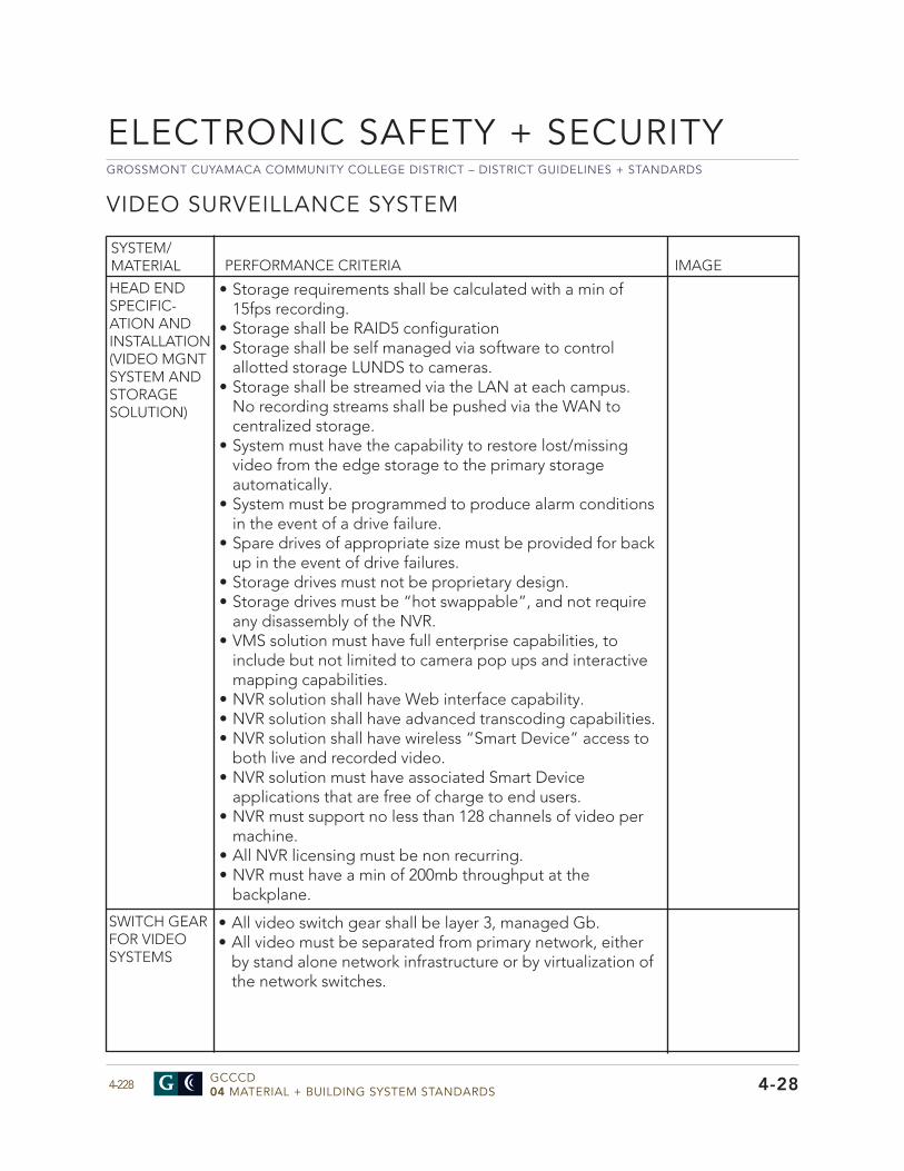
GROSSMONT CUYAMACA COMMUNITY COLLEGE DISTRICT – DISTRICT GUIDELINES + STANDARDS
GCCCD04 MATERIAL + BUILDING SYSTEM STANDARDS4-228
ELECTRONIC SAFETY + SECURITY
4-28
VIDEO SURVEILLANCE SYSTEM
SYSTEM/MATERIAL PERFORMANCE CRITERIA IMAGE
HEAD END SPECIFIC- ATION AND INSTALLATION (VIDEO MGNT SYSTEM AND STORAGE SOLUTION)
• Storage requirements shall be calculated with a min of15fps recording.
• Storage shall be RAID5 configuration• Storage shall be self managed via software to control
allotted storage LUNDS to cameras.• Storage shall be streamed via the LAN at each campus.
No recording streams shall be pushed via the WAN tocentralized storage.
• System must have the capability to restore lost/missingvideo from the edge storage to the primary storageautomatically.
• System must be programmed to produce alarm conditionsin the event of a drive failure.
• Spare drives of appropriate size must be provided for backup in the event of drive failures.
• Storage drives must not be proprietary design.• Storage drives must be “hot swappable”, and not require
any disassembly of the NVR.• VMS solution must have full enterprise capabilities, to
include but not limited to camera pop ups and interactivemapping capabilities.
• NVR solution shall have Web interface capability.• NVR solution shall have advanced transcoding capabilities.• NVR solution shall have wireless “Smart Device” access to
both live and recorded video.• NVR solution must have associated Smart Device
applications that are free of charge to end users.• NVR must support no less than 128 channels of video per
machine.• All NVR licensing must be non recurring.• NVR must have a min of 200mb throughput at the
backplane.
SWITCH GEAR FOR VIDEO SYSTEMS
• All video switch gear shall be layer 3, managed Gb.• All video must be separated from primary network, either
by stand alone network infrastructure or by virtualization ofthe network switches.
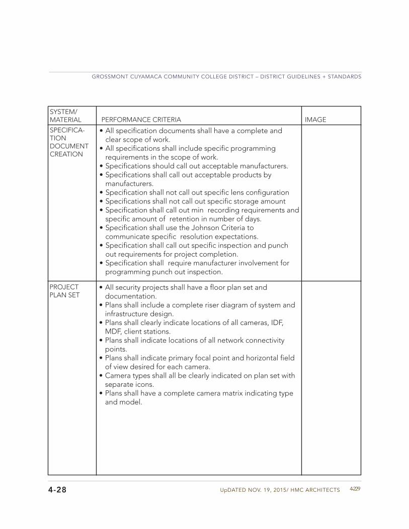
UpDATED NOV. 19, 2015/ HMC ARCHITECTS
GROSSMONT CUYAMACA COMMUNITY COLLEGE DISTRICT – DISTRICT GUIDELINES + STANDARDS
4-2294-28
SYSTEM/MATERIAL PERFORMANCE CRITERIA IMAGE
SPECIFICA- TION DOCUMENT CREATION
• All specification documents shall have a complete andclear scope of work.
• All specifications shall include specific programmingrequirements in the scope of work.
• Specifications should call out acceptable manufacturers.• Specifications shall call out acceptable products by
manufacturers.• Specification shall not call out specific lens configuration• Specifications shall not call out specific storage amount• Specification shall call out min recording requirements and
specific amount of retention in number of days.• Specification shall use the Johnson Criteria to
communicate specific resolution expectations.• Specification shall call out specific inspection and punch
out requirements for project completion.• Specification shall require manufacturer involvement for
programming punch out inspection.
PROJECT PLAN SET
• All security projects shall have a floor plan set anddocumentation.
• Plans shall include a complete riser diagram of system andinfrastructure design.
• Plans shall clearly indicate locations of all cameras, IDF,MDF, client stations.
• Plans shall indicate locations of all network connectivitypoints.
• Plans shall indicate primary focal point and horizontal fieldof view desired for each camera.
• Camera types shall all be clearly indicated on plan set withseparate icons.
• Plans shall have a complete camera matrix indicating typeand model.
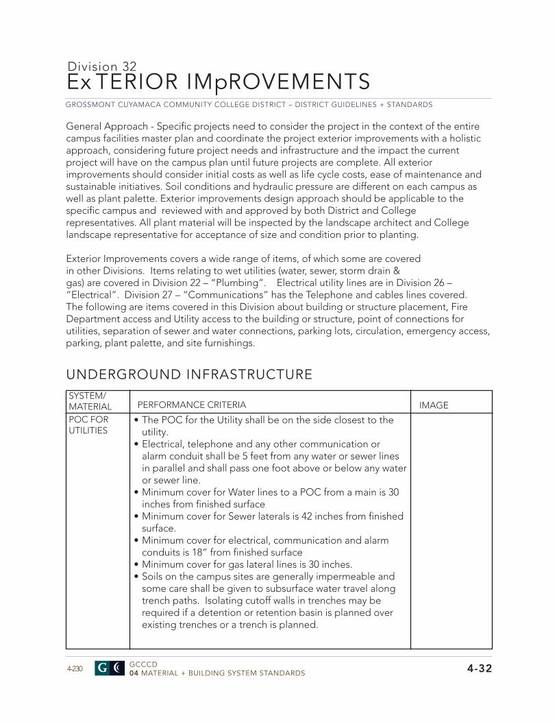
GROSSMONT CUYAMACA COMMUNITY COLLEGE DISTRICT – DISTRICT GUIDELINES + STANDARDS
GCCCD04 MATERIAL + BUILDING SYSTEM STANDARDS4-230 4-32
UNDERGROUND INFRASTRUCTURESYSTEM/MATERIAL PERFORMANCE CRITERIA IMAGE
POC FOR UTILITIES
Ex TERIOR IMpROVEMENTSDivision 32
General Approach - Specific projects need to consider the project in the context of the entire campus facilities master plan and coordinate the project exterior improvements with a holistic approach, considering future project needs and infrastructure and the impact the current project will have on the campus plan until future projects are complete. All exterior improvements should consider initial costs as well as life cycle costs, ease of maintenance and sustainable initiatives. Soil conditions and hydraulic pressure are different on each campus as well as plant palette. Exterior improvements design approach should be applicable to the specific campus and reviewed with and approved by both District and College representatives. All plant material will be inspected by the landscape architect and College landscape representative for acceptance of size and condition prior to planting.
Exterior Improvements covers a wide range of items, of which some are covered in other Divisions. Items relating to wet utilities (water, sewer, storm drain & gas) are covered in Division 22 – “Plumbing”. Electrical utility lines are in Division 26 – “Electrical”. Division 27 – “Communications” has the Telephone and cables lines covered. The following are items covered in this Division about building or structure placement, Fire Department access and Utility access to the building or structure, point of connections for utilities, separation of sewer and water connections, parking lots, circulation, emergency access, parking, plant palette, and site furnishings.
• The POC for the Utility shall be on the side closest to theutility.
• Electrical, telephone and any other communication oralarm conduit shall be 5 feet from any water or sewer linesin parallel and shall pass one foot above or below any wateror sewer line.
• Minimum cover for Water lines to a POC from a main is 30inches from finished surface
• Minimum cover for Sewer laterals is 42 inches from finishedsurface.
• Minimum cover for electrical, communication and alarmconduits is 18” from finished surface
• Minimum cover for gas lateral lines is 30 inches.• Soils on the campus sites are generally impermeable and
some care shall be given to subsurface water travel alongtrench paths. Isolating cutoff walls in trenches may berequired if a detention or retention basin is planned overexisting trenches or a trench is planned.
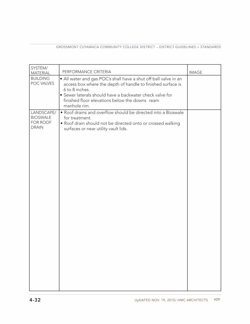
UpDATED NOV. 19, 2015/ HMC ARCHITECTS
GROSSMONT CUYAMACA COMMUNITY COLLEGE DISTRICT – DISTRICT GUIDELINES + STANDARDS
4-231
SYSTEM/MATERIAL PERFORMANCE CRITERIA IMAGE
4-32
BUILDING POC VALVES
• All water and gas POC’s shall have a shut off ball valve in anaccess box where the depth of handle to finished surface is6 to 8 inches.
• Sewer laterals should have a backwater check valve forfinished floor elevations below the downs reammanhole rim.
LANDSCAPE/ BIOSWALE FOR ROOF DRAIN
• Roof drains and overflow should be directed into a Bioswalefor treatment.
• Roof drain should not be directed onto or crossed walkingsurfaces or near utility vault lids.
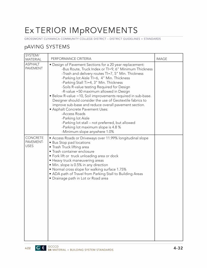
GROSSMONT CUYAMACA COMMUNITY COLLEGE DISTRICT – DISTRICT GUIDELINES + STANDARDS
GCCCD04 MATERIAL + BUILDING SYSTEM STANDARDS4-232 4-32
Ex TERIOR IMpROVEMENTS
pAVING SYSTEMS
SYSTEM/MATERIAL PERFORMANCE CRITERIA IMAGE
ASPHALT PAVEMENT
• Design of Pavement Sections for a 20 year replacement:-Bus Route, Truck Index or TI=9, 6” Minimum Thickness-Trash and delivery routes TI=7, 5” Min. Thickness-Parking lot Aisle TI=6, 4” Min. Thickness-Parking Stall Ti=4, 3” Min. Thickness-Soils R-value testing Required for Design-R-value =50 maximum allowed in Design
• Below R-value =10, Soil improvements required in sub-base.Designer should consider the use of Geotextile fabrics to improve sub-base and reduce overall pavement section.
• Asphalt Concrete Pavement Uses:-Access Roads-Parking lot Aisle-Parking lot stall – not preferred, but allowed-Parking lot maximum slope is 4.8 % -Minimum slope anywhere 1.0%
CONCRETE PAVEMENT- USES
• Access Roads or Driveways over 11.99% longitudinal slope• Bus Stop pad locations• Trash Truck lifting area• Trash container enclosure• Fork lift or truck unloading area or dock• Heavy truck maneuvering areas• Min. slope is 0.5% in any direction• Normal cross slope for walking surface 1.75%• ADA path of Travel from Parking Stall to Building Areas• Drainage path in Lot or Road area
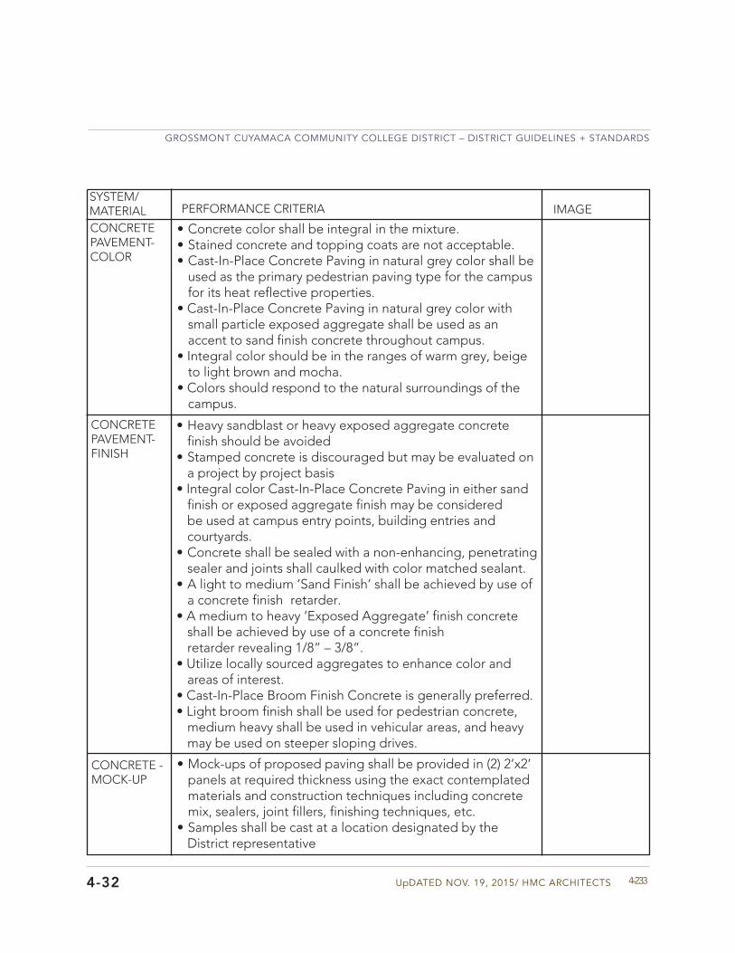
UpDATED NOV. 19, 2015/ HMC ARCHITECTS
GROSSMONT CUYAMACA COMMUNITY COLLEGE DISTRICT – DISTRICT GUIDELINES + STANDARDS
4-2334-32
• Heavy sandblast or heavy exposed aggregate concretefinish should be avoided
• Stamped concrete is discouraged but may be evaluated ona project by project basis
• Integral color Cast-In-Place Concrete Paving in either sandfinish or exposed aggregate finish may be considered be used at campus entry points, building entries and courtyards.
• Concrete shall be sealed with a non-enhancing, penetratingsealer and joints shall caulked with color matched sealant.
• A light to medium ‘Sand Finish’ shall be achieved by use ofa concrete finish retarder.
• A medium to heavy ‘Exposed Aggregate’ finish concreteshall be achieved by use of a concrete finishretarder revealing 1/8” – 3/8”.
• Utilize locally sourced aggregates to enhance color andareas of interest.
• Cast-In-Place Broom Finish Concrete is generally preferred.• Light broom finish shall be used for pedestrian concrete,
medium heavy shall be used in vehicular areas, and heavymay be used on steeper sloping drives.
CONCRETE PAVEMENT- FINISH
SYSTEM/MATERIAL PERFORMANCE CRITERIA IMAGE
CONCRETE - MOCK-UP
• Mock-ups of proposed paving shall be provided in (2) 2’x2’panels at required thickness using the exact contemplatedmaterials and construction techniques including concretemix, sealers, joint fillers, finishing techniques, etc.
• Samples shall be cast at a location designated by theDistrict representative
CONCRETE PAVEMENT- COLOR
• Concrete color shall be integral in the mixture.• Stained concrete and topping coats are not acceptable.• Cast-In-Place Concrete Paving in natural grey color shall be
used as the primary pedestrian paving type for the campusfor its heat reflective properties.
• Cast-In-Place Concrete Paving in natural grey color withsmall particle exposed aggregate shall be used as anaccent to sand finish concrete throughout campus.
• Integral color should be in the ranges of warm grey, beigeto light brown and mocha.
• Colors should respond to the natural surroundings of thecampus.
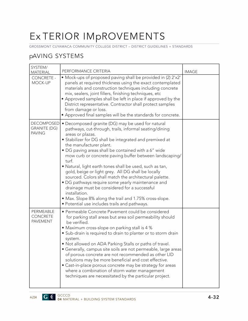
GROSSMONT CUYAMACA COMMUNITY COLLEGE DISTRICT – DISTRICT GUIDELINES + STANDARDS
GCCCD04 MATERIAL + BUILDING SYSTEM STANDARDS4-234
SYSTEM/MATERIAL PERFORMANCE CRITERIA IMAGE
4-32
Ex TERIOR IMpROVEMENTS
DECOMPOSED GRANITE (DG) PAVING
• Decomposed granite (DG) may be used for naturalpathways, cut-through, trails, informal seating/diningareas or plazas.
• Stabilizer for DG shall be integrated and premixed atthe manufacturer plant.
• DG paving areas shall be contained with a 6” widemow curb or concrete paving buffer between landscaping/turf.
• Natural, light earth tones shall be used, such as tan,gold, beige or light grey. All DG shall be locallysourced. Colors shall match the architectural palette.
• DG pathways require some yearly maintenance anddrainage must be considered for a successfulinstallation.
• Max. Slope 8% along the trail and 1.75% cross-slope.• Potential use includes trails and pathways.
• Mock-ups of proposed paving shall be provided in (2) 2’x2’panels at required thickness using the exact contemplatedmaterials and construction techniques including concretemix, sealers, joint fillers, finishing techniques, etc
• Approved samples shall be left in place if approved by theDistrict representative. Contractor shall protect samplesfrom damage or loss.
• Approved final samples will be the standards for concrete.
CONCRETE - MOCK-UP
PERMEABLE CONCRETE PAVEMENT
• Permeable Concrete Pavement could be consideredfor parking stall areas but area soil permeability shouldbe verified.
• Maximum cross-slope on parking stall is 4 %• Sub-drain is required to drain to planter or to storm drain
system.• Not allowed on ADA Parking Stalls or paths of travel.• Generally, campus site soils are not permeable, large areas
of porous concrete are not recommended as other LIDsolutions may be more beneficial and cost effective.
• Cast-in-place porous concrete may be strategy for areaswhere a combination of storm water managementtechniques are necessitated by the particular project.
pAVING SYSTEMS
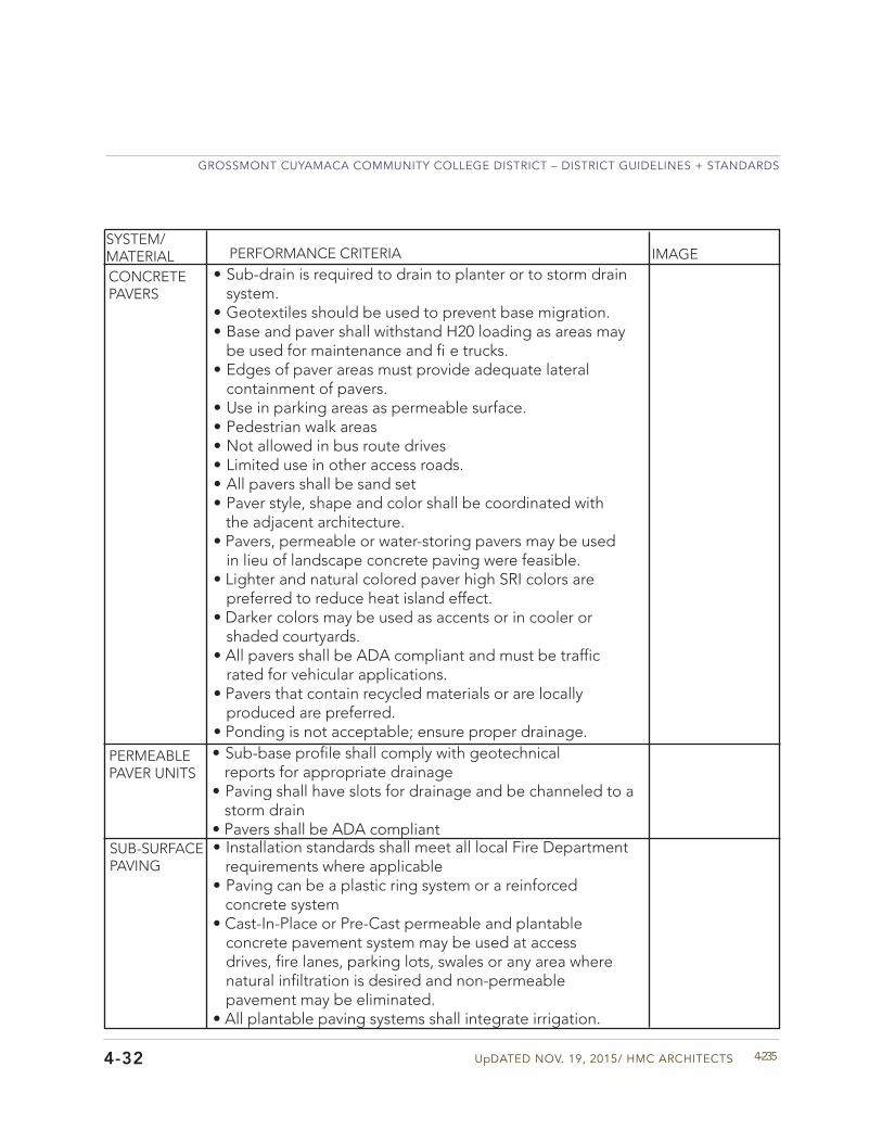
UpDATED NOV. 19, 2015/ HMC ARCHITECTS
GROSSMONT CUYAMACA COMMUNITY COLLEGE DISTRICT – DISTRICT GUIDELINES + STANDARDS
4-2354-32
CONCRETE PAVERS
PERMEABLE PAVER UNITS
• Sub-base profile shall comply with geotechnicalreports for appropriate drainage
• Paving shall have slots for drainage and be channeled to astorm drain
• Pavers shall be ADA compliant
• Sub-drain is required to drain to planter or to storm drainsystem.
• Geotextiles should be used to prevent base migration.• Base and paver shall withstand H20 loading as areas may
be used for maintenance and fi e trucks.• Edges of paver areas must provide adequate lateral
containment of pavers.• Use in parking areas as permeable surface.• Pedestrian walk areas• Not allowed in bus route drives• Limited use in other access roads.• All pavers shall be sand set• Paver style, shape and color shall be coordinated with
the adjacent architecture.• Pavers, permeable or water-storing pavers may be used
in lieu of landscape concrete paving were feasible.• Lighter and natural colored paver high SRI colors are
preferred to reduce heat island effect.• Darker colors may be used as accents or in cooler or
shaded courtyards.• All pavers shall be ADA compliant and must be traffic
rated for vehicular applications.• Pavers that contain recycled materials or are locally
produced are preferred.• Ponding is not acceptable; ensure proper drainage.
SUB-SURFACE PAVING
• Installation standards shall meet all local Fire Departmentrequirements where applicable
• Paving can be a plastic ring system or a reinforcedconcrete system
• Cast-In-Place or Pre-Cast permeable and plantableconcrete pavement system may be used at accessdrives, fire lanes, parking lots, swales or any area wherenatural infiltration is desired and non-permeablepavement may be eliminated.
• All plantable paving systems shall integrate irrigation.
SYSTEM/MATERIAL PERFORMANCE CRITERIA IMAGE
GROSSMONT CUYAMACA COMMUNITY COLLEGE DISTRICT – DISTRICT GUIDELINES + STANDARDS
GCCCD04 MATERIAL + BUILDING SYSTEM STANDARDS4-236 4-32
Ex TERIOR IMpROVEMENTS
SYSTEM/MATERIAL PERFORMANCE CRITERIA IMAGE
LAYOUT • 90 degree stalls and two-way aisles are the most efficientlayout and are the preferred layout method.
• Angled spaces are allowed with one way drive aisles. NotPreferred
• Drive aisles minimum widths are as follows: - 90 degree – 24 feet, two way - 60 degree – 19 Feet, one way - 45 degree – 17 Feet, one way - 30 degree – 15 Feet, one way
PARKING SPACE
• Parking space is 9 feet wide and 20 feet long.• Paved area of parking space may be 18 feet long with 2
feet of over hang over a planter only.• Parking spaces are not preferred to overhang walkways. If
required then the walkway must be increased by two feetto account for overhang.
• ADA spaces must be paved for the entire 20 feet in lengthand must have a parking stop
• Spaces next to walls or obstructions shall be 10 feet inwidth.
pARKING LOTS
TRASH ENCLOSURES
• Storm runoff is not allowed to run into or through a trashcollection container enclosure.
• Trash container enclosures must be covered and gated.Container must not be visible from the outsidesurrounding area.
• There should be a concrete area designed for impact loadequal to full trash container dropped two feet vertically,Trash weight will be 40 lbs. per cubic foot. The trashcontainer pad should be 1.5 times the size footprint of thecontainer being stored.
LANDSCAPE IN PARKING LOTS
• Areas between multiple parking aisles shall be planted. Itis preferred that the ratio of planted area to paved area be25% - 30%
• Provide pedestrians walkable paths between parking aislesthrough planted areas so landscaping is not trampled.
• Parking areas should be directed to flow into planted areasto be treated in a bioswale type planting.
GROSSMONT CUYAMACA COMMUNITY COLLEGE DISTRICT – DISTRICT GUIDELINES + STANDARDS
GCCCD04 MATERIAL + BUILDING SYSTEM STANDARDS4-238
• Expansion or control joints shall be used throughoutthe project and located a maximum of 20’ o.c.
• Joint widths should be kept to a minimum (1/8” preferred)for ease of cleaning
• Expansion or control joint sealants shall match the adjacentconcrete surface
• Doweled construction joints are required where concreteshifting may occur, including at stairs and ramps, wherepaving operations are stopped and started or at differentpaving types
• Score joints shall be saw-cut to ¼ depth of concrete forpedestrian paving and expansion joints shall be 3/8”.
WALKWAY WIDTHS
JOINTING
• Must accommodate infrequent light truck traffic• Must be 12’ adjacent to buildings• Must be 8’ for high use walkways between buildings• Must be 5’ for low use walkways• Must be 10’ minimum where used for some vehicular traffic• Door swings from adjacent space should encroach in path.• Pedestrian path along the roadways for vehicles should not
be against the curb of the roadway -provide 3’ separation.
CONCRETE MOW CURB
• Concrete mow curbs shall be used between turf andplanting areas.
• Concrete mow curbs shall be a minimum of 6” wide• Concrete mow curbs shall be used between turf
areas and decomposed granite (DG) areas.• Concrete mow curbs shall include jointing.• Concrete mow curbs shall be board formed.• Finish for concrete mow curb shall match adjacent paving.
4-32
Ex TERIOR IMpROVEMENTS
pEDESTRIAN CIRCULATION
SYSTEM/MATERIAL PERFORMANCE CRITERIA IMAGE
SEPARATION OF SEWER AND WATER POC
• Sewer connect should always be below water connections.• Sewer and water POC shall be separated by 10 feet edge
to edge. Preference is 12 feet center to center of water andsewer connections.
COVERED ACCESS & HARDSCAPE MINIMIzATION
• Minimize use of impervious surfaces for pedestrian travel.If imperious surface required for ADA access then considerusing an impermeable surface for the required width and apermeable surface for the rest of the pedestrian path.
• Impervious portion could be located under a buildingawning or other covered structure.

UpDATED NOV. 19, 2015/ HMC ARCHITECTS
GROSSMONT CUYAMACA COMMUNITY COLLEGE DISTRICT – DISTRICT GUIDELINES + STANDARDS
4-2374-32
UpDATED NOV. 19, 2015/ HMC ARCHITECTS
GROSSMONT CUYAMACA COMMUNITY COLLEGE DISTRICT – DISTRICT GUIDELINES + STANDARDS
4-239
FIRE DEPARTMENT
• Front entrance must be visible to first respondersduring an emergency response in the normal access tothe Campus.
• Building Identification must also be visible and readable tothe responders from the typical drivable access.
• Coordinate with Local Fire Marshall; must approve access.• Covered parking adjacent to building shall not obstruct fi e
truck ladders access from drive aisle.• Fire Marshall may require drivable access to all sides of
building.
COORDIN- ATION WITH LOCAL FIRE MARSHALL
SYSTEM/MATERIAL PERFORMANCE CRITERIA IMAGE
EMERGENCY ACCESS
FIRE PROTECTION EQUIPMENT
• For building with fi e sprinkler systems the Post indicatorvalve and fi e department connection must be 50 feet awayfrom the building serviced.
• Post indicator and Fire Department connection shallbe marked and visible to first responders position onthe drive access to the Front door (see Front Door toCampus relationship above).
4-32
GROSSMONT CUYAMACA COMMUNITY COLLEGE DISTRICT – DISTRICT GUIDELINES + STANDARDS
GCCCD04 MATERIAL + BUILDING SYSTEM STANDARDS4-240
Ex TERIOR IMpROVEMENTS
4-32
PERFORMANCE CRITERIA IMAGE
LANDSCApE IRRIGATIONSYSTEM/MATERIAL
SYSTEM VALVE MANIFOLDS
IRRIGATION SYSTEMS
• Irrigation systems shall be designed and maintained topromote water conservation and avoid runoff and oversprayonto adjacent properties, non-irrigated areas, walks, roadwaysor structures.
• Irrigation systems shall provide total and uniform coverageof landscape and planting areas. When designing irrigationsystems, ensure allowances for future systems that may extendbeyond the limits of work and sized using sch 40 PVC pipe notto exceed 5’ per second rule for hydrology.
• Calsense compatible systems shall be utilized to ensurecompatibility with the existing irrigation system.
• Quick coupling valves shall have a dedicated isolation valveplaced at a maximum of every 100 ft. along the main line.
• All flow sensors and master valves to be in conduit and wiresare to be Calsense recommended for application.
• Irrigation systems shall be labeled and mapped with college.An accurate as-built laminated drawing shall be provided.
• Mainline isolation valves shall be incorporated into allnew projects throughout campus.
• Quick coupling valves shall have a dedicated isolation valve.• System valve manifolds shall have isolation valves.• System valve manifolds to include up to a maximum of 3
remote control valves in the manifold.• System valve manifolds shall be separated by plants or other
improvements to allow for a more aesthetic appeal in thelandscape and be easy in easy to access locations.
• All flow sensors & master valve wires should be in conduits. Pullextra wires to each manifold.
• Controller Wires to be taped to bottom of mainlines.• All irrigation valves and equipment (backflow p eventer,
master valve, flow sensor , remote control valve, isolation valve,quick coupling valve, boxes, etc.) should not be locatedadjacent to driveways, parking lot approaches, heads ofparking lot stalls, planter corners where most prone toaccessibility safety issues, vehicular damage and lack of accesswith vehicular overhang. Equipment must be sufficientlyprotected, should equipment be required in these locations.
• PVC SCH 80 ball valves (glue in) for buried ball valves shall beutilized to isolate sections of the system while allowing theremainder of the system to function normally.
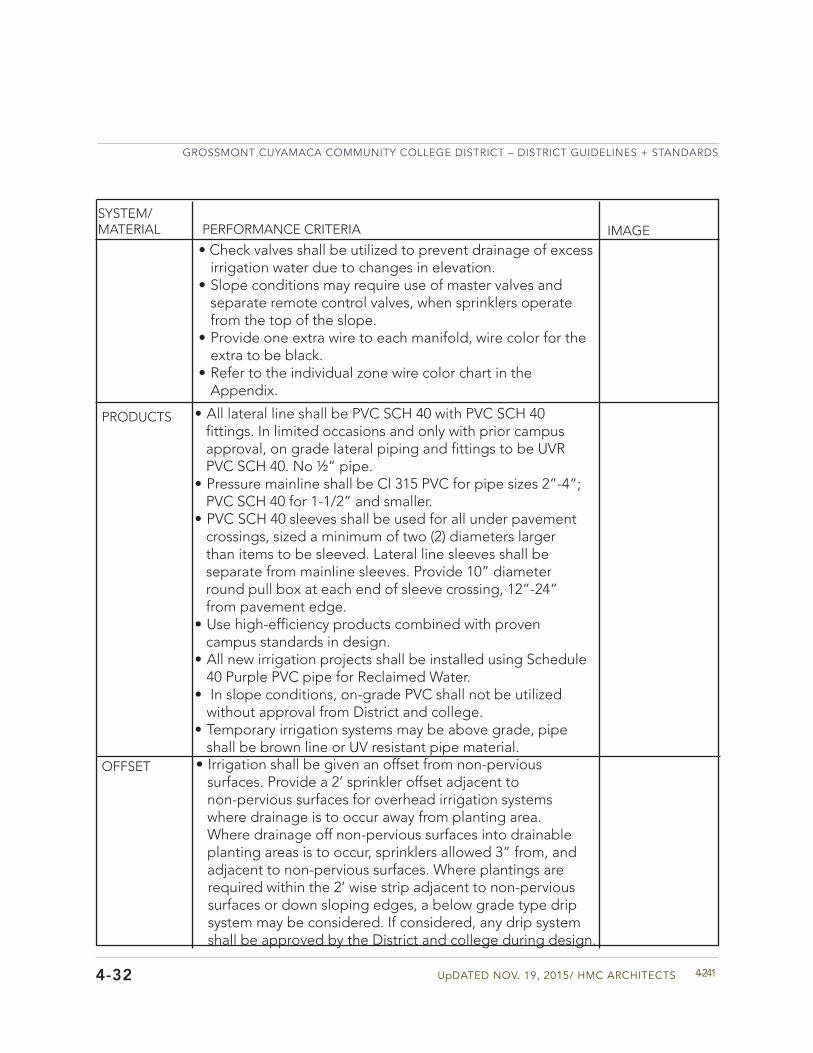
UpDATED NOV. 19, 2015/ HMC ARCHITECTS
GROSSMONT CUYAMACA COMMUNITY COLLEGE DISTRICT – DISTRICT GUIDELINES + STANDARDS
4-241
SYSTEM/MATERIAL PERFORMANCE CRITERIA IMAGE
PRODUCTS
4-32
• All lateral line shall be PVC SCH 40 with PVC SCH 40fittings. In limited occasions and only with prior campusapproval, on grade lateral piping and fittings to be UVRPVC SCH 40. No ½” pipe.
• Pressure mainline shall be Cl 315 PVC for pipe sizes 2”-4”;PVC SCH 40 for 1-1/2” and smaller.
• PVC SCH 40 sleeves shall be used for all under pavementcrossings, sized a minimum of two (2) diameters largerthan items to be sleeved. Lateral line sleeves shall beseparate from mainline sleeves. Provide 10” diameterround pull box at each end of sleeve crossing, 12”-24”from pavement edge.
• Use high-efficiency products combined with provencampus standards in design.
• All new irrigation projects shall be installed using Schedule40 Purple PVC pipe for Reclaimed Water.
• In slope conditions, on-grade PVC shall not be utilizedwithout approval from District and college.
• Temporary irrigation systems may be above grade, pipeshall be brown line or UV resistant pipe material.
• Irrigation shall be given an offset from non-pervioussurfaces. Provide a 2’ sprinkler offset adjacent tonon-pervious surfaces for overhead irrigation systemswhere drainage is to occur away from planting area.Where drainage off non-pervious surfaces into drainableplanting areas is to occur, sprinklers allowed 3” from, andadjacent to non-pervious surfaces. Where plantings arerequired within the 2’ wise strip adjacent to non-pervioussurfaces or down sloping edges, a below grade type dripsystem may be considered. If considered, any drip systemshall be approved by the District and college during design.
OFFSET
• Check valves shall be utilized to prevent drainage of excessirrigation water due to changes in elevation.
• Slope conditions may require use of master valves andseparate remote control valves, when sprinklers operatefrom the top of the slope.
• Provide one extra wire to each manifold, wire color for theextra to be black.
• Refer to the individual zone wire color chart in theAppendix.
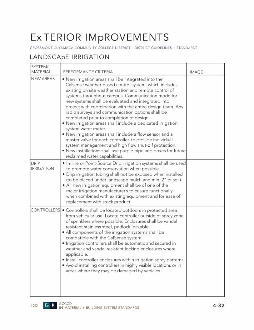
GROSSMONT CUYAMACA COMMUNITY COLLEGE DISTRICT – DISTRICT GUIDELINES + STANDARDS
GCCCD04 MATERIAL + BUILDING SYSTEM STANDARDS4-242
PERFORMANCE CRITERIA IMAGE
CONTROLLERS
Ex TERIOR IMpROVEMENTS
4-32
SYSTEM/MATERIAL
• New irrigation areas shall be integrated into theCalsense weather-based control system, which includesexisting on site weather station and remote control ofsystems throughout campus. Communication mode fornew systems shall be evaluated and integrated intoproject with coordination with the entire design team. Anyradio surveys and communication options shall becompleted prior to completion of design
• New irrigation areas shall include a dedicated irrigationsystem water meter.
• New irrigation areas shall include a flow sensor and amaster valve for each controller, to provide individualsystem management and high flow shut-o f protection.
• New installations shall use purple pipe and boxes for futurereclaimed water capabilities.
NEW AREAS
• Controllers shall be located outdoors in protected areafrom vehicular use. Locate controller outside of spray zoneof sprinklers where possible. Enclosures shall be vandalresistant stainless steel, padlock lockable.
• All components of the irrigation systems shall becompatible with the CalSense system.
• Irrigation controllers shall be automatic and secured inweather and vandal resistant locking enclosures whereapplicable.
• Install controller enclosures within irrigation spray patterns.• Avoid installing controllers in highly visible locations or in
areas where they may be damaged by vehicles.
• In-line or Point-Source Drip irrigation systems shall be usedto promote water conservation when possible.
• Drip irrigation tubing shall not be exposed when installed(to be placed under landscape mulch and min. 2” of soil).
• All new irrigation equipment shall be of one of themajor irrigation manufacturer’s to ensure functionallywhen combined with existing equipment and for ease ofreplacement with stock product.
DRIP IRRIGATION
LANDSCApE IRRIGATION
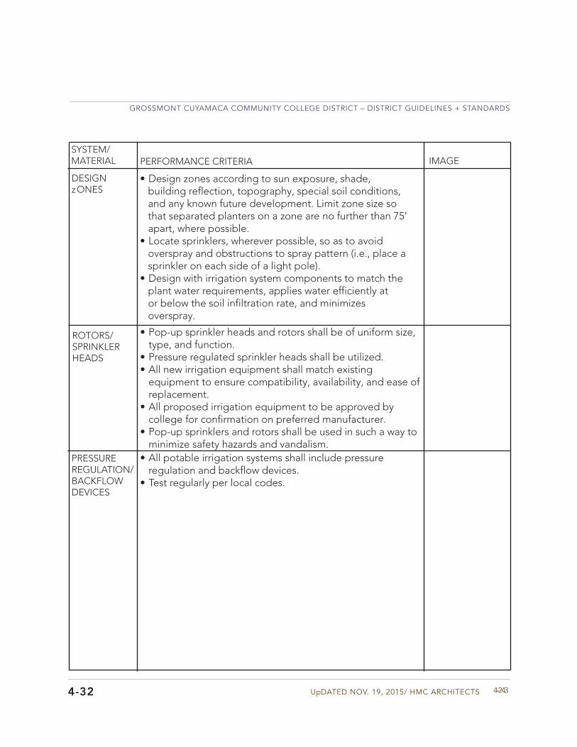
UpDATED NOV. 19, 2015/ HMC ARCHITECTS
GROSSMONT CUYAMACA COMMUNITY COLLEGE DISTRICT – DISTRICT GUIDELINES + STANDARDS
4-243
DESIGN zONES
PERFORMANCE CRITERIA IMAGE
4-32
SYSTEM/MATERIAL
• Design zones according to sun exposure, shade,building reflection, topography, special soil conditions,and any known future development. Limit zone size sothat separated planters on a zone are no further than 75’apart, where possible.
• Locate sprinklers, wherever possible, so as to avoidoverspray and obstructions to spray pattern (i.e., place asprinkler on each side of a light pole).
• Design with irrigation system components to match theplant water requirements, applies water efficiently ator below the soil infiltration rate, and minimizesoverspray.
• All potable irrigation systems shall include pressureregulation and backflow devices.
• Test regularly per local codes.
PRESSURE REGULATION/BACKFLOW DEVICES
• Pop-up sprinkler heads and rotors shall be of uniform size,type, and function.
• Pressure regulated sprinkler heads shall be utilized.• All new irrigation equipment shall match existing
equipment to ensure compatibility, availability, and ease ofreplacement.
• All proposed irrigation equipment to be approved bycollege for confirmation on preferred manufacturer.
• Pop-up sprinklers and rotors shall be used in such a way tominimize safety hazards and vandalism.
ROTORS/SPRINKLER HEADS
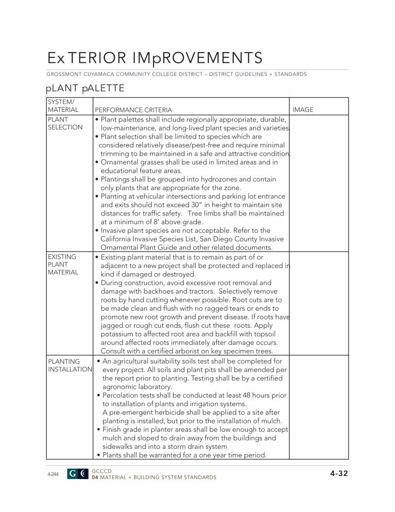
GROSSMONT CUYAMACA COMMUNITY COLLEGE DISTRICT – DISTRICT GUIDELINES + STANDARDS
GCCCD04 MATERIAL + BUILDING SYSTEM STANDARDS4-244
pLANT pALETTE
PERFORMANCE CRITERIA IMAGE
EXISTING PLANT MATERIAL
PLANTING INSTALLATION
• Existing plant material that is to remain as part of oradjacent to a new project shall be protected and replaced inkind if damaged or destroyed.
• During construction, avoid excessive root removal anddamage with backhoes and tractors. Selectively removeroots by hand cutting whenever possible. Root cuts are tobe made clean and flush with no ragged tears or ends topromote new root growth and prevent disease. If roots havejagged or rough cut ends, flush cut these roots. Applypotassium to affected root area and backfill with topsoilaround affected roots immediately after damage occurs.Consult with a certified arborist on key specimen trees.
• An agricultural suitability soils test shall be completed forevery project. All soils and plant pits shall be amended perthe report prior to planting. Testing shall be by a certifiedagronomic laboratory.
• Percolation tests shall be conducted at least 48 hours priorto installation of plants and irrigation systems.A pre-emergent herbicide shall be applied to a site afterplanting is installed, but prior to the installation of mulch.
• Finish grade in planter areas shall be low enough to acceptmulch and sloped to drain away from the buildings andsidewalks and into a storm drain system
• Plants shall be warranted for a one year time period.
4-32
SYSTEM/MATERIAL
PLANT SELECTION
• Plant palettes shall include regionally appropriate, durable,low-maintenance, and long-lived plant species and varieties.
• Plant selection shall be limited to species which are considered relatively disease/pest-free and require minimal
trimming to be maintained in a safe and attractive condition.• Ornamental grasses shall be used in limited areas and in
educational feature areas.• Plantings shall be grouped into hydrozones and contain
only plants that are appropriate for the zone.• Planting at vehicular intersections and parking lot entrance
and exits should not exceed 30” in height to maintain sitedistances for traffic safety. Tree limbs shall be maintainedat a minimum of 8’ above grade.
• Invasive plant species are not acceptable. Refer to theCalifornia Invasive Species List, San Diego County InvasiveOrnamental Plant Guide and other related documents.
Ex TERIOR IMpROVEMENTS
UpDATED NOV. 19, 2015/ HMC ARCHITECTS
GROSSMONT CUYAMACA COMMUNITY COLLEGE DISTRICT – DISTRICT GUIDELINES + STANDARDS
4-245
PERFORMANCE CRITERIA IMAGE
4-32
SYSTEM/MATERIAL
TREES - GROSSMONT
• Tree selections shall be appropriate for the proposedarea. Characteristics such as root systems, maturesize, water requirements, and organic litter should beconsidered during placement to minimize safety hazardsand maintenance issues.
• Trees shall not be planted in an area less than 5’ wide inany direction.
• Proposed trees shall be a minimum of 24” box.• 24” box trees shall be double staked.• 36” box trees and larger shall be triple staked.• Root barriers shall be installed where trees are within 10’
of hardscape .• Trees shall be planted no closer than 5’ from edge
of paving, 15’ from building overhangs, and 10’ fromunderground utilities.
• All trees shall receive an observation tube/tree drainstandpipe to monitor drainage and moisture levels in thesoil.
• Trees planted in turf areas are to have a mulch zonecomparable to the drip line of the tree. Use only shreddedbark mulch material in turf areas.
• Trees in parking lots:-Shall be a minimum of 24”box.-Shall be canopy trees to provide shade and reduce heat island affect.-Shall not drop sap or excessive leaf/flower litter. -Shall be incorporated into islands at the ends of rows and the middle of parking aisles.-Shall be coordinated with parking lot lighting to
avoid blocking light fixtures.• Trees at Gateway:
-- Platanus racemosa – California Sycamore-- Quercus ilex – Holly Oak-- Tipuana tipu – Tipu Tree-- Ulmus parvifolia ‘True Green’ – Evergreen Elm
• Trees at Parking Lot:-- Geijera parvifolia – Australian Willow-- Rhus lancea – African Sumac-- Quercus ilex – Holly Oak-- Ulmus parvifolia ‘True Green’ – Evergreen Elm
GROSSMONT CUYAMACA COMMUNITY COLLEGE DISTRICT – DISTRICT GUIDELINES + STANDARDS
GCCCD04 MATERIAL + BUILDING SYSTEM STANDARDS4-246
pLANT pALETTESYSTEM/MATERIAL PERFORMANCE CRITERIA IMAGE
TREES - GROSSMONT
• Trees at Portals:-- Geijera parvifolia – Australian Willow-- Rhus lancea – African Sumac-- Quercus ilex – Holly Oak-- Ulmus parvifolia ‘True Green’ – Evergreen Elm
• Trees at Quads:-- Fraxinus uhdei – Shamel Ash-- Lagerstroemia indica – Crape Myrtle -- Tipuana tipu – tipu Tree
• Trees at Courtyard:-- Arbutus ‘Marina’ – Strawberry Tree-- Cassia leptophylla – Gold Medallion Tree-- Cercis occidentalis – Western Redbud-- Tabebuia impetiginosa – Pink Trumpet Tree
TREES - CUYAMACA
Ex TERIOR IMpROVEMENTS
4-32
• Tree selections shall be appropriate for the proposed area.Characteristics such as root systems, mature size, waterrequirements, and organic litter should be consideredduring placement to minimize safety hazards andmaintenance issues.
• Trees shall not be planted in an area less than 5’ wide in anydirection.
• Proposed trees shall be a minimum of 24” box.• 24” box trees shall be double staked.• 36” box trees and larger shall be triple staked.• Root barriers shall be installed where trees are within 10’ of
hardscape• Trees shall be planted no closer than 5’ from edge
of paving, 15’ from building overhangs, and 10’ fromunderground utilities.
• All trees shall receive an observation tube/tree drainstandpipe to monitor drainage and moisture levels in thesoil.
• Trees planted in turf areas are to have a mulch zonecomparable to the drip line of the tree. Use only shreddedbark mulch material in turf areas.
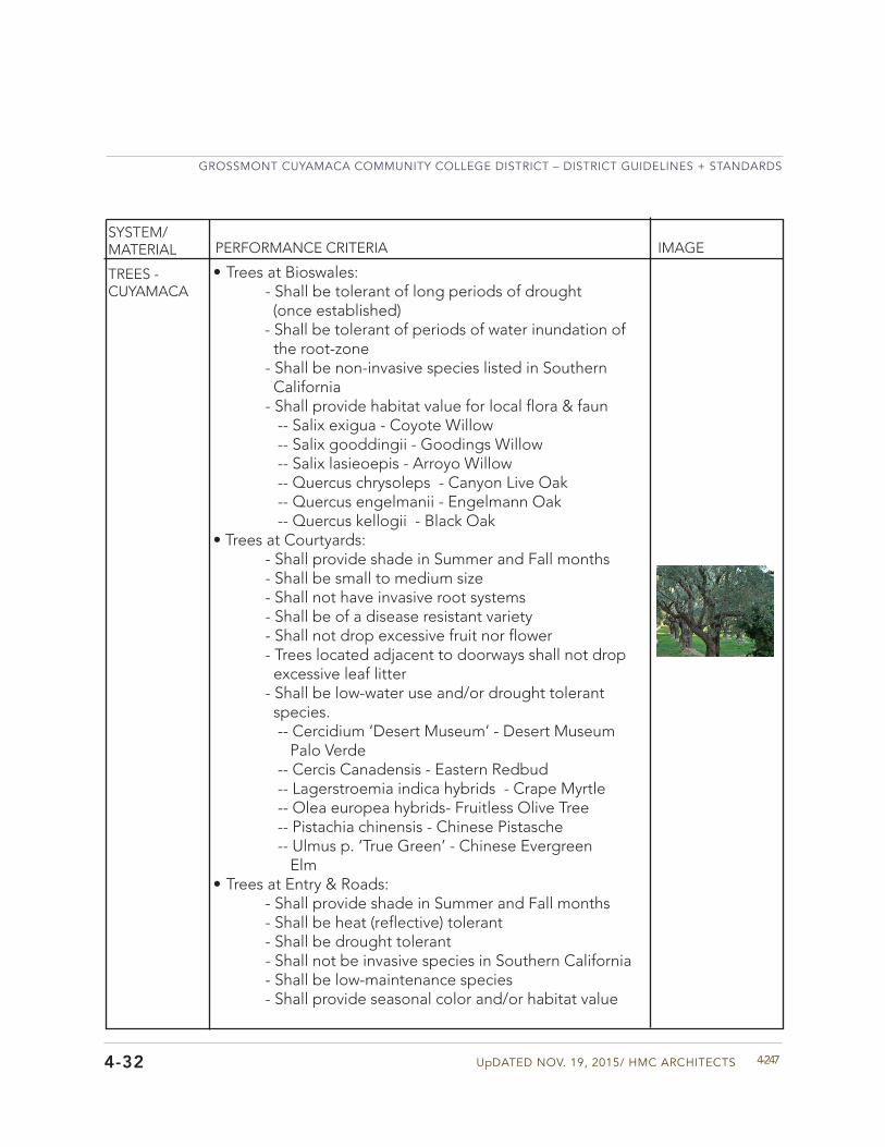
UpDATED NOV. 19, 2015/ HMC ARCHITECTS
GROSSMONT CUYAMACA COMMUNITY COLLEGE DISTRICT – DISTRICT GUIDELINES + STANDARDS
4-247
PERFORMANCE CRITERIA IMAGE
4-32
SYSTEM/MATERIAL
TREES - CUYAMACA
• Trees at Bioswales:- Shall be tolerant of long periods of drought (once established)- Shall be tolerant of periods of water inundation of the root-zone- Shall be non-invasive species listed in Southern California- Shall provide habitat value for local flora & faun -- Salix exigua - Coyote Willow -- Salix gooddingii - Goodings Willow -- Salix lasieoepis - Arroyo Willow -- Quercus chrysoleps - Canyon Live Oak -- Quercus engelmanii - Engelmann Oak -- Quercus kellogii - Black Oak
• Trees at Courtyards:- Shall provide shade in Summer and Fall months- Shall be small to medium size- Shall not have invasive root systems - Shall be of a disease resistant variety- Shall not drop excessive fruit nor flower- Trees located adjacent to doorways shall not drop excessive leaf litter- Shall be low-water use and/or drought tolerant species. -- Cercidium ‘Desert Museum’ - Desert Museum Palo Verde -- Cercis Canadensis - Eastern Redbud -- Lagerstroemia indica hybrids - Crape Myrtle -- Olea europea hybrids- Fruitless Olive Tree -- Pistachia chinensis - Chinese Pistasche -- Ulmus p. ‘True Green’ - Chinese Evergreen Elm
• Trees at Entry & Roads:- Shall provide shade in Summer and Fall months- Shall be heat (reflective) tolerant- Shall be drought tolerant- Shall not be invasive species in Southern California - Shall be low-maintenance species- Shall provide seasonal color and/or habitat value
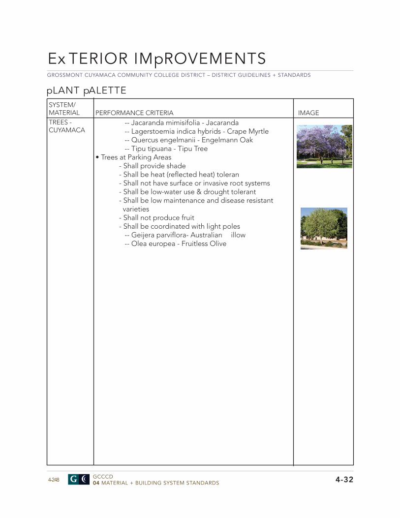
GROSSMONT CUYAMACA COMMUNITY COLLEGE DISTRICT – DISTRICT GUIDELINES + STANDARDS
GCCCD04 MATERIAL + BUILDING SYSTEM STANDARDS4-248
pLANT pALETTE
PERFORMANCE CRITERIA IMAGETREES - CUYAMACA
Ex TERIOR IMpROVEMENTS
4-32
SYSTEM/MATERIAL
-- Jacaranda mimisifolia - Jacaranda -- Lagerstoemia indica hybrids - Crape Myrtle -- Quercus engelmanii - Engelmann Oak -- Tipu tipuana - Tipu Tree
• Trees at Parking Areas- Shall provide shade- Shall be heat (reflected heat) toleran- Shall not have surface or invasive root systems- Shall be low-water use & drought tolerant- Shall be low maintenance and disease resistant varieties- Shall not produce fruit- Shall be coordinated with light poles -- Geijera parviflora- Australian illow -- Olea europea - Fruitless Olive
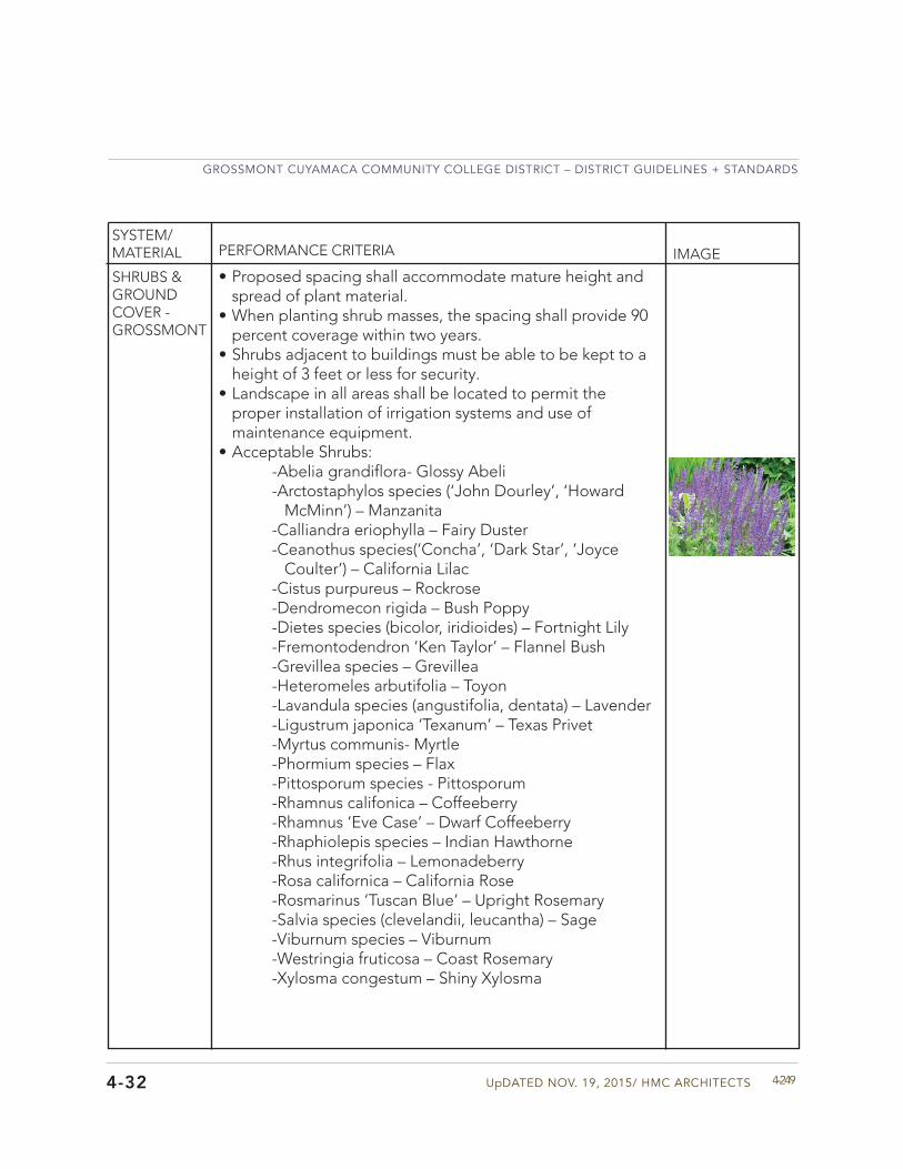
UpDATED NOV. 19, 2015/ HMC ARCHITECTS
GROSSMONT CUYAMACA COMMUNITY COLLEGE DISTRICT – DISTRICT GUIDELINES + STANDARDS
4-249
PERFORMANCE CRITERIA IMAGE
4-32
SYSTEM/MATERIAL
SHRUBS & GROUNDCOVER - GROSSMONT
• Proposed spacing shall accommodate mature height andspread of plant material.
• When planting shrub masses, the spacing shall provide 90percent coverage within two years.
• Shrubs adjacent to buildings must be able to be kept to aheight of 3 feet or less for security.
• Landscape in all areas shall be located to permit theproper installation of irrigation systems and use ofmaintenance equipment.
• Acceptable Shrubs:-Abelia grandiflora- Glossy Abeli-Arctostaphylos species (‘John Dourley’, ‘Howard McMinn’) – Manzanita-Calliandra eriophylla – Fairy Duster-Ceanothus species(‘Concha’, ‘Dark Star’, ‘Joyce Coulter’) – California Lilac-Cistus purpureus – Rockrose -Dendromecon rigida – Bush Poppy-Dietes species (bicolor, iridioides) – Fortnight Lily-Fremontodendron ‘Ken Taylor’ – Flannel Bush-Grevillea species – Grevillea-Heteromeles arbutifolia – Toyon-Lavandula species (angustifolia, dentata) – Lavender-Ligustrum japonica ‘Texanum’ – Texas Privet-Myrtus communis- Myrtle-Phormium species – Flax-Pittosporum species - Pittosporum-Rhamnus califonica – Coffeeberry-Rhamnus ‘Eve Case’ – Dwarf Coffeeberry-Rhaphiolepis species – Indian Hawthorne-Rhus integrifolia – Lemonadeberry-Rosa californica – California Rose-Rosmarinus ‘Tuscan Blue’ – Upright Rosemary-Salvia species (clevelandii, leucantha) – Sage-Viburnum species – Viburnum-Westringia fruticosa – Coast Rosemary-Xylosma congestum – Shiny Xylosma
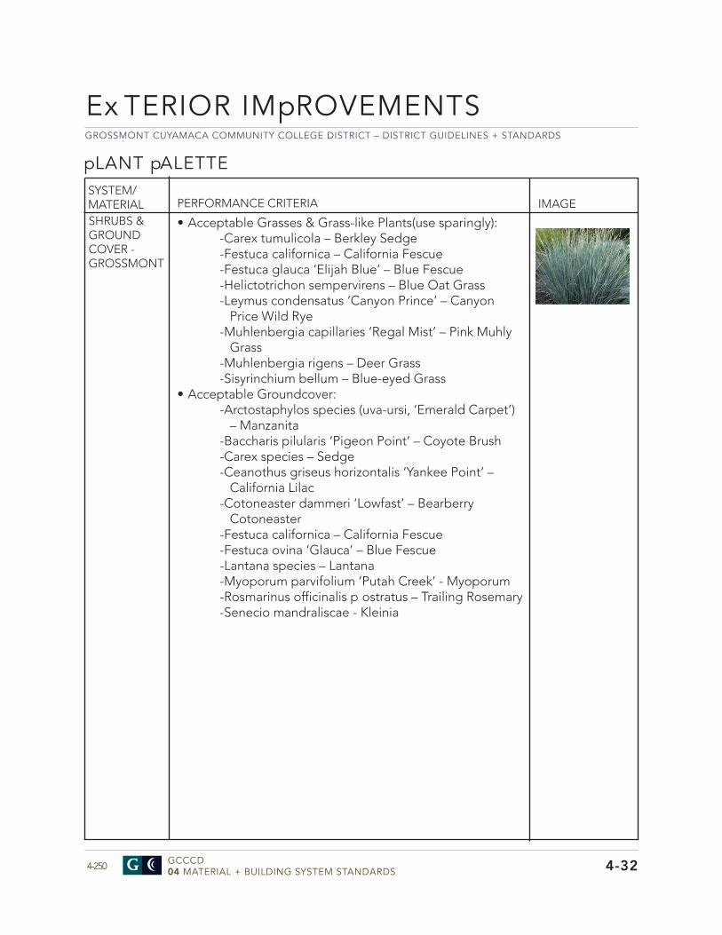
GROSSMONT CUYAMACA COMMUNITY COLLEGE DISTRICT – DISTRICT GUIDELINES + STANDARDS
GCCCD04 MATERIAL + BUILDING SYSTEM STANDARDS4-250
pLANT pALETTE
PERFORMANCE CRITERIA IMAGESHRUBS & GROUNDCOVER - GROSSMONT
Ex TERIOR IMpROVEMENTS
4-32
SYSTEM/MATERIAL
• Acceptable Grasses & Grass-like Plants(use sparingly):-Carex tumulicola – Berkley Sedge-Festuca californica – California Fescue-Festuca glauca ‘Elijah Blue’ – Blue Fescue-Helictotrichon sempervirens – Blue Oat Grass-Leymus condensatus ‘Canyon Prince’ – Canyon Price Wild Rye-Muhlenbergia capillaries ‘Regal Mist’ – Pink Muhly Grass-Muhlenbergia rigens – Deer Grass-Sisyrinchium bellum – Blue-eyed Grass
• Acceptable Groundcover:-Arctostaphylos species (uva-ursi, ‘Emerald Carpet’)
– Manzanita-Baccharis pilularis ‘Pigeon Point’ – Coyote Brush-Carex species – Sedge-Ceanothus griseus horizontalis ‘Yankee Point’ – California Lilac-Cotoneaster dammeri ‘Lowfast’ – Bearberry Cotoneaster-Festuca californica – California Fescue-Festuca ovina ‘Glauca’ – Blue Fescue-Lantana species – Lantana-Myoporum parvifolium ‘Putah Creek’ - Myoporum-Rosmarinus officinalis p ostratus – Trailing Rosemary-Senecio mandraliscae - Kleinia
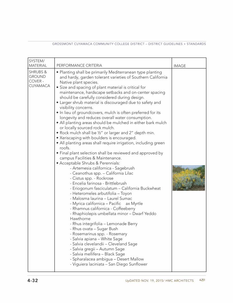
UpDATED NOV. 19, 2015/ HMC ARCHITECTS
GROSSMONT CUYAMACA COMMUNITY COLLEGE DISTRICT – DISTRICT GUIDELINES + STANDARDS
4-251
PERFORMANCE CRITERIA IMAGE
4-32
SYSTEM/MATERIAL
SHRUBS & GROUNDCOVER - CUYAMACA
• Planting shall be primarily Mediterranean type plantingand hardy, garden tolerant varieties of Southern CaliforniaNative plant species.
• Size and spacing of plant material is critical formaintenance, hardscape setbacks and on-center spacingshould be carefully considered during design.
• Larger shrub material is discouraged due to safety andvisibility concerns.
• In lieu of groundcovers, mulch is often preferred for itslongevity and reduces overall water consumption.
• All planting areas should be mulched in either bark mulchor locally sourced rock mulch.
• Rock mulch shall be ½” or larger and 2” depth min.• Xeriscaping with boulders is encouraged.• All planting areas shall require irrigation, including green
roofs.• Final plant selection shall be reviewed and approved by
campus Facilities & Maintenance.• Acceptable Shrubs & Perennials:
- Artemesia californica - Sagebrush- Ceanothus spp. – California Lilac- Cistus spp. - Rockrose- Encelia farinosa - Brittlebrush- Eriogonum fasciculatum – California Buckwheat - Heteromeles arbutifolia – Toyon- Malosma laurina – Laurel Sumac- Myrica californica – Pacific ax Myrtle- Rhamnus californica - Coffeeberry- Rhaphiolepis umbellata minor – Dwarf Yeddo Hawthorne- Rhus integrifolia – Lemonade Berry- Rhus ovata – Sugar Bush- Rosemarinus spp. - Rosemary- Salvia apiana – White Sage- Salvia clevelandii – Cleveland Sage- Salvia gregii – Autumn Sage- Salvia mellifera – Black Sage- Spharalacea ambigua – Desert Mallow- Viguiera laciniata – San Diego Sunflower
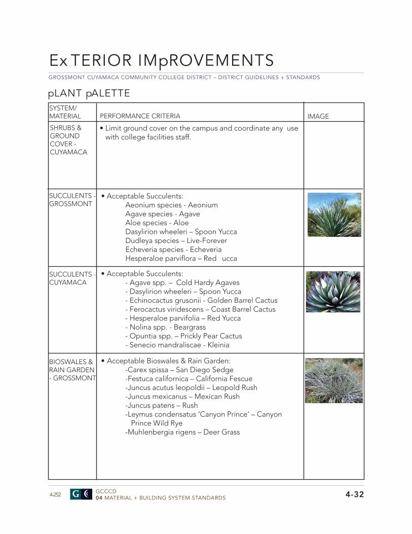
GROSSMONT CUYAMACA COMMUNITY COLLEGE DISTRICT – DISTRICT GUIDELINES + STANDARDS
GCCCD04 MATERIAL + BUILDING SYSTEM STANDARDS4-252
pLANT pALETTE
PERFORMANCE CRITERIA IMAGE
BIOSWALES & RAIN GARDEN - GROSSMONT
SUCCULENTS - GROSSMONT
• Acceptable Succulents:Aeonium species - AeoniumAgave species - AgaveAloe species - AloeDasylirion wheeleri – Spoon YuccaDudleya species – Live-ForeverEcheveria species - EcheveriaHesperaloe parviflora – Red ucca
SUCCULENTS - CUYAMACA
• Acceptable Bioswales & Rain Garden:-Carex spissa – San Diego Sedge-Festuca californica – California Fescue-Juncus acutus leopoldii – Leopold Rush-Juncus mexicanus – Mexican Rush-Juncus patens – Rush-Leymus condensatus ‘Canyon Prince’ – Canyon Prince Wild Rye-Muhlenbergia rigens – Deer Grass
Ex TERIOR IMpROVEMENTS
4-32
SYSTEM/MATERIAL
• Limit ground cover on the campus and coordinate any usewith college facilities staff.
SHRUBS & GROUNDCOVER - CUYAMACA
• Acceptable Succulents:- Agave spp. – Cold Hardy Agaves- Dasylirion wheeleri – Spoon Yucca- Echinocactus grusonii - Golden Barrel Cactus- Ferocactus viridescens – Coast Barrel Cactus- Hesperaloe parvifolia – Red Yucca- Nolina spp. - Beargrass- Opuntia spp. – Prickly Pear Cactus- Senecio mandraliscae - Kleinia
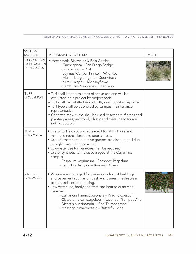
UpDATED NOV. 19, 2015/ HMC ARCHITECTS
GROSSMONT CUYAMACA COMMUNITY COLLEGE DISTRICT – DISTRICT GUIDELINES + STANDARDS
4-253
PERFORMANCE CRITERIA IMAGE
4-32
SYSTEM/MATERIAL
TURF - GROSSMONT
• Turf shall limited to areas of active use and will beevaluated on a project by project basis
• Turf shall be installed as sod rolls, seed is not acceptable• Turf type shall be approved by campus maintenance
representative• Concrete mow curbs shall be used between turf areas and
planting areas; redwood, plastic and metal headers arenot acceptable
TURF - CUYAMACA
• Use of turf is discouraged except for at high use andmulti-use recreational and sports areas.
• Use of ornamental or native grasses are discouraged dueto higher maintenance needs
• Low-water use turf varieties shall be required.• Use of synthetic turf is discouraged at the Cuyamaca
campus.- Paspalum vaginatum – Seashore Paspalum- Cynodon dactylon – Bermuda Grass
BIOSWALES & RAIN GARDEN - CUYAMACA
• Acceptable Bioswales & Rain Garden:- Carex spissa – San Diego Sedge- Juncus spp. – Rush- Leymus ‘Canyon Prince’ – Wild Rye- Muhlenbergia rigens – Deer Grass- Mimulus spp. – Monkeyflowe- Sambucus Mexicana - Elderberry
VINES - CUYAMACA
• Vines are encouraged for passive cooling of buildingsand pavement such as on trash enclosures, mesh-screenpanels, trellises and fencing.
• Low-water use, hardy and frost and heat tolerant vinevarieties:
- Calliandra haematocephala – Pink Powderpuff- Clytostoma callistegoides – Lavender Trumpet Vine - Distictis buccinatoria – Red Trumpet Vine- Mascagnia macroptera – Butterfly vine
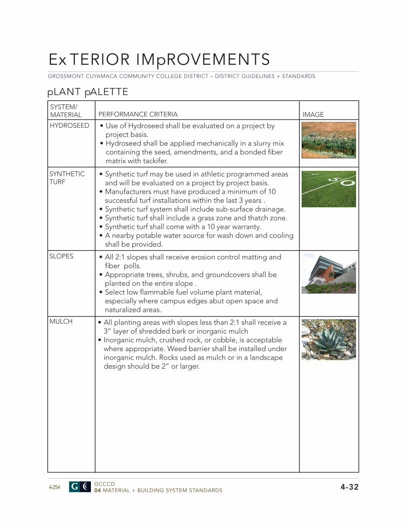
GROSSMONT CUYAMACA COMMUNITY COLLEGE DISTRICT – DISTRICT GUIDELINES + STANDARDS
GCCCD04 MATERIAL + BUILDING SYSTEM STANDARDS4-254
pLANT pALETTE
PERFORMANCE CRITERIA IMAGE
MULCH • All planting areas with slopes less than 2:1 shall receive a3” layer of shredded bark or inorganic mulch
• Inorganic mulch, crushed rock, or cobble, is acceptablewhere appropriate. Weed barrier shall be installed underinorganic mulch. Rocks used as mulch or in a landscapedesign should be 2” or larger.
HYDROSEED
SLOPES
• Use of Hydroseed shall be evaluated on a project byproject basis.
• Hydroseed shall be applied mechanically in a slurry mixcontaining the seed, amendments, and a bonded fibermatrix with tackifer.
SYNTHETIC TURF
• Synthetic turf may be used in athletic programmed areasand will be evaluated on a project by project basis.
• Manufacturers must have produced a minimum of 10successful turf installations within the last 3 years .
• Synthetic turf system shall include sub-surface drainage.• Synthetic turf shall include a grass zone and thatch zone.• Synthetic turf shall come with a 10 year warranty.• A nearby potable water source for wash down and cooling
shall be provided.
• All 2:1 slopes shall receive erosion control matting andfiber polls.
• Appropriate trees, shrubs, and groundcovers shall beplanted on the entire slope .
• Select low flammable fuel volume plant material,especially where campus edges abut open space andnaturalized areas.
Ex TERIOR IMpROVEMENTS
4-32
SYSTEM/MATERIAL
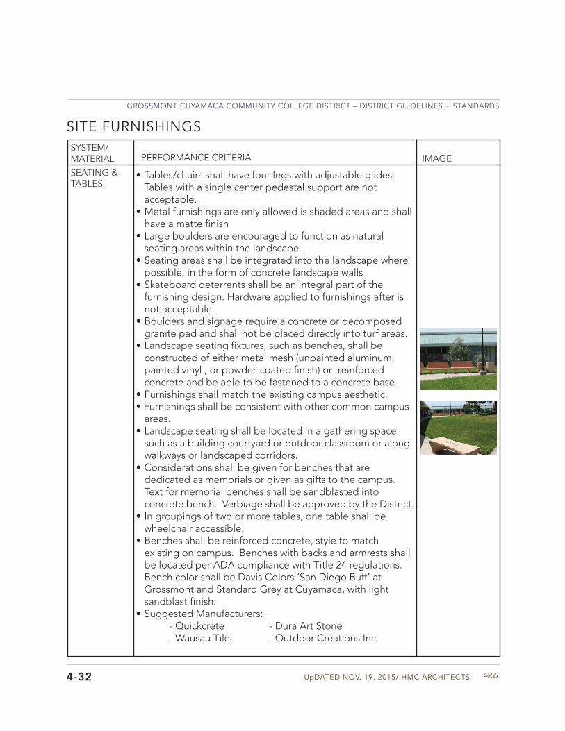
UpDATED NOV. 19, 2015/ HMC ARCHITECTS
GROSSMONT CUYAMACA COMMUNITY COLLEGE DISTRICT – DISTRICT GUIDELINES + STANDARDS
4-255
PERFORMANCE CRITERIA IMAGE
4-32
SYSTEM/MATERIAL
SITE FURNISHINGS
SEATING & TABLES
• Tables/chairs shall have four legs with adjustable glides.Tables with a single center pedestal support are notacceptable.
• Metal furnishings are only allowed is shaded areas and shallhave a matte finish
• Large boulders are encouraged to function as naturalseating areas within the landscape.
• Seating areas shall be integrated into the landscape wherepossible, in the form of concrete landscape walls
• Skateboard deterrents shall be an integral part of thefurnishing design. Hardware applied to furnishings after isnot acceptable.
• Boulders and signage require a concrete or decomposedgranite pad and shall not be placed directly into turf areas.
• Landscape seating fixtures, such as benches, shall beconstructed of either metal mesh (unpainted aluminum,painted vinyl , or powder-coated finish) or reinforcedconcrete and be able to be fastened to a concrete base.
• Furnishings shall match the existing campus aesthetic.• Furnishings shall be consistent with other common campus
areas.• Landscape seating shall be located in a gathering space
such as a building courtyard or outdoor classroom or alongwalkways or landscaped corridors.
• Considerations shall be given for benches that arededicated as memorials or given as gifts to the campus.Text for memorial benches shall be sandblasted intoconcrete bench. Verbiage shall be approved by the District.
• In groupings of two or more tables, one table shall bewheelchair accessible.
• Benches shall be reinforced concrete, style to matchexisting on campus. Benches with backs and armrests shallbe located per ADA compliance with Title 24 regulations.Bench color shall be Davis Colors ‘San Diego Buff’ atGrossmont and Standard Grey at Cuyamaca, with lightsandblast finish.
• Suggested Manufacturers:- Quickcrete - Dura Art Stone- Wausau Tile - Outdoor Creations Inc.
GROSSMONT CUYAMACA COMMUNITY COLLEGE DISTRICT – DISTRICT GUIDELINES + STANDARDS
GCCCD04 MATERIAL + BUILDING SYSTEM STANDARDS4-256
Ex TERIOR IMpROVEMENTS
4-32
PERFORMANCE CRITERIA IMAGESYSTEM/MATERIAL
SITE FURNISHINGS
OUTDOOR CLASSROOM
• Outdoor classrooms should be of a thematic nature,focusing specifically on environmental studies andsustainability.
• Outdoor classrooms should utilize California Native PlantCommunities and specified in the planting section.
• Interpretive signage shall be integrated into outdoorclassrooms areas.
• Avoid the use of wood or recycled wood surfaces orstructures.
• Shade shall be provided by planting or overheadstructures. See shade structures section.
INTERPRETIVE SIGNAGE
• Interpretive signage shall be constructed of a durable vinylor plastic material that will last 20-30 years in the proposedcondition.
• Signage shall be noticeable but visually unobtrusive.• Interpretive signage shall include information on planting
species and natural systems, as applicable.
LANDSCAPE LIGHTING
• Refer to Division 26.
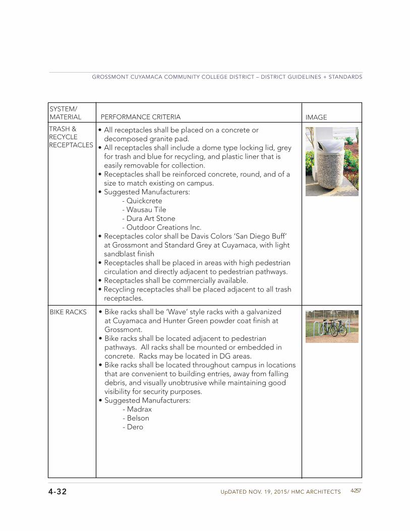
UpDATED NOV. 19, 2015/ HMC ARCHITECTS
GROSSMONT CUYAMACA COMMUNITY COLLEGE DISTRICT – DISTRICT GUIDELINES + STANDARDS
4-2574-32
PERFORMANCE CRITERIA IMAGESYSTEM/MATERIAL
TRASH & RECYCLE RECEPTACLES
• All receptacles shall be placed on a concrete ordecomposed granite pad.
• All receptacles shall include a dome type locking lid, greyfor trash and blue for recycling, and plastic liner that iseasily removable for collection.
• Receptacles shall be reinforced concrete, round, and of asize to match existing on campus.
• Suggested Manufacturers:- Quickcrete- Wausau Tile- Dura Art Stone- Outdoor Creations Inc.
• Receptacles color shall be Davis Colors ‘San Diego Buff’at Grossmont and Standard Grey at Cuyamaca, with light sandblast finish
• Receptacles shall be placed in areas with high pedestriancirculation and directly adjacent to pedestrian pathways.
• Receptacles shall be commercially available.• Recycling receptacles shall be placed adjacent to all trash
receptacles.
• Bike racks shall be ‘Wave’ style racks with a galvanizedat Cuyamaca and Hunter Green powder coat finish atGrossmont.
• Bike racks shall be located adjacent to pedestrianpathways. All racks shall be mounted or embedded inconcrete. Racks may be located in DG areas.
• Bike racks shall be located throughout campus in locationsthat are convenient to building entries, away from fallingdebris, and visually unobtrusive while maintaining goodvisibility for security purposes.
• Suggested Manufacturers:- Madrax- Belson- Dero
BIKE RACKS
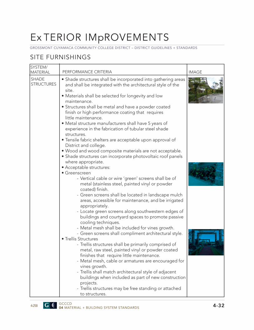
GROSSMONT CUYAMACA COMMUNITY COLLEGE DISTRICT – DISTRICT GUIDELINES + STANDARDS
GCCCD04 MATERIAL + BUILDING SYSTEM STANDARDS4-258
Ex TERIOR IMpROVEMENTS
PERFORMANCE CRITERIA IMAGESYSTEM/MATERIAL
SHADE STRUCTURES
• Shade structures shall be incorporated into gathering areasand shall be integrated with the architectural style of thesite.
• Materials shall be selected for longevity and lowmaintenance.
• Structures shall be metal and have a powder coatedfinish or high performance coating that requireslittle maintenance.
• Metal structure manufacturers shall have 5 years ofexperience in the fabrication of tubular steel shadestructures.
• Tensile fabric shelters are acceptable upon approval ofDistrict and college.
• Wood and wood composite materials are not acceptable.• Shade structures can incorporate photovoltaic roof panels
where appropriate.• Acceptable structures:• Greenscreen
- Vertical cable or wire ‘green’ screens shall be of metal (stainless steel, painted vinyl or powder coated) finish.
- Green screens shall be located in landscape mulch areas, accessible for maintenance, and be irrigated appropriately.
- Locate green screens along southwestern edges of buildings and courtyard spaces to promote passive cooling techniques.
- Metal mesh shall be included for vines growth. - Green screens shall compliment architectural style.
• Trellis Structures - Trellis structures shall be primarily comprised of metal, raw steel, painted vinyl or powder coated finishes that require little maintenance.
- Metal mesh, cable or armatures are encouraged for vines growth.
- Trellis shall match architectural style of adjacent buildings when included as part of new construction projects.
- Trellis structures may be free standing or attached to structures.
4-32
SITE FURNISHINGS
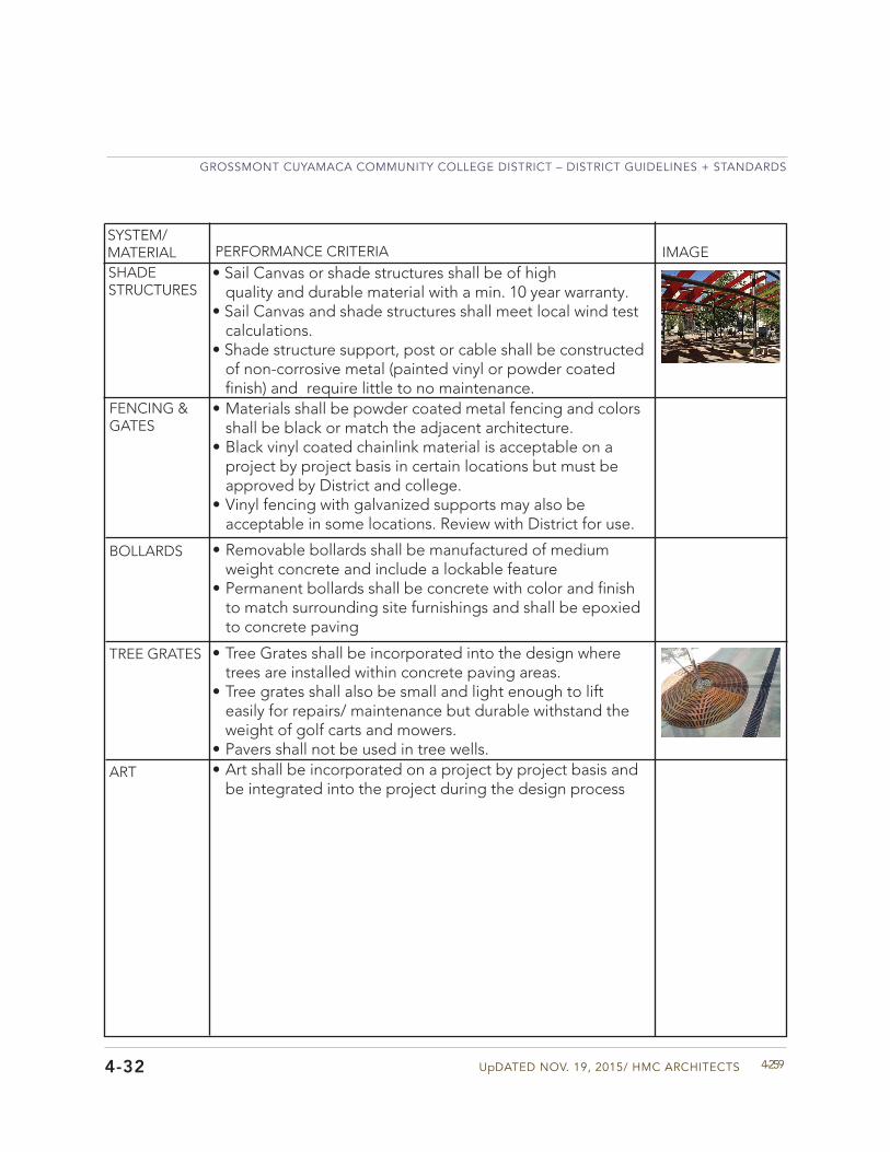
UpDATED NOV. 19, 2015/ HMC ARCHITECTS
GROSSMONT CUYAMACA COMMUNITY COLLEGE DISTRICT – DISTRICT GUIDELINES + STANDARDS
4-2594-32
FENCING & GATES
BOLLARDS
TREE GRATES
ART
• Tree Grates shall be incorporated into the design wheretrees are installed within concrete paving areas.
• Tree grates shall also be small and light enough to lifteasily for repairs/ maintenance but durable withstand theweight of golf carts and mowers.
• Pavers shall not be used in tree wells.
• Materials shall be powder coated metal fencing and colorsshall be black or match the adjacent architecture.
• Black vinyl coated chainlink material is acceptable on aproject by project basis in certain locations but must beapproved by District and college.
• Vinyl fencing with galvanized supports may also beacceptable in some locations. Review with District for use.
• Removable bollards shall be manufactured of mediumweight concrete and include a lockable feature
• Permanent bollards shall be concrete with color and finishto match surrounding site furnishings and shall be epoxiedto concrete paving
• Art shall be incorporated on a project by project basis andbe integrated into the project during the design process
PERFORMANCE CRITERIA IMAGESYSTEM/MATERIAL
• Sail Canvas or shade structures shall be of highquality and durable material with a min. 10 year warranty.
• Sail Canvas and shade structures shall meet local wind testcalculations.
• Shade structure support, post or cable shall be constructedof non-corrosive metal (painted vinyl or powder coatedfinish) and require little to no maintenance.
SHADE STRUCTURES
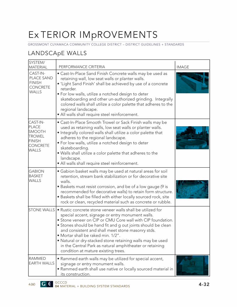
GROSSMONT CUYAMACA COMMUNITY COLLEGE DISTRICT – DISTRICT GUIDELINES + STANDARDS
GCCCD04 MATERIAL + BUILDING SYSTEM STANDARDS4-260
PERFORMANCE CRITERIA IMAGESYSTEM/MATERIAL
4-32
LANDSCApE WALLS
CAST-IN-PLACE SAND FINISH CONCRETE WALLS
• Cast-In-Place Sand Finish Concrete walls may be used asretaining wall, low seat walls or planter walls.
• ‘Light Sand Finish’ shall be achieved by use of a concreteretarder.
• For low walls, utilize a notched design to deterskateboarding and other un-authorized grinding. Integrallycolored walls shall utilize a color palette that adheres to theregional landscape.
• All walls shall require steel reinforcement.
• Cast-In-Place Smooth Trowel or Sack Finish walls may beused as retaining walls, low seat walls or planter walls.
• Integrally colored walls shall utilize a color palette thatadheres to the regional landscape.
• For low walls, utilize a notched design to deterskateboarding.
• Walls shall utilize a color palette that adheres to thelandscape.
• All walls shall require steel reinforcement.
• Gabion basket walls may be used at natural areas for soilretention, stream bank stabilization or for decorative sitewalls.
• Baskets must resist corrosion, and be of a low gauge (9 isrecommended for decorative walls) to retain form structure.
• Baskets shall be filled with either locally sourced rock, siterock or clean, recycled material such as concrete or rubble.
• Rustic concrete stone veneer walls shall be utilized forspecial accent, signage or entry monument walls.
• Stone veneer on CIP or CMU Core wall with CIP foundation.• Stones should be hand fit and g out joints should be clean
and consistent and shall meet stone masonry stds.• Mortar shall be raked min. 1/2”.• Natural or dry-stacked stone retaining walls may be used
in the Central Park as natural amphitheater or retainingcondition at mature existing trees.
• Rammed earth walls may be utilized for special accent,signage or entry monument walls.
• Rammed earth shall use native or locally sourced material inits construction.
RAMMED EARTH WALLS
CAST-IN-PLACE SMOOTH TROWEL FINISH CONCRETE WALLS
GABION BASKET WALLS
STONE WALLS
Ex TERIOR IMpROVEMENTS

UpDATED NOV. 19, 2015/ HMC ARCHITECTS
GROSSMONT CUYAMACA COMMUNITY COLLEGE DISTRICT – DISTRICT GUIDELINES + STANDARDS
4-2614-32
GROSSMONT CUYAMACA COMMUNITY COLLEGE DISTRICT – DISTRICT GUIDELINES + STANDARDS
GCCCD04 MATERIAL + BUILDING SYSTEM STANDARDS4-262
ACOUSTICAL + SOUND ISOLATION
4-51
Division 51
• Avoid placing roof mounted mechanical equipment (air-cooled chillers, cooling towers, package roof top units,air-handling units) directly above Noise Criteria (NC) 35 orlower spaces. NC is a single number rating that consistsof a family of criterion curves and a tangency ratingprocedure. The criterion curves define the limits of octaveband spectra that must not be exceeded to meet occupantacceptance. If this condition cannot be avoided, the designteam’s acoustical consultant should carry out an acousticalanalysis to determine the roof/ceiling construction neededto achieve an NC rating at least five (5) points below thedesign goal background noise levels for the impactedspace(s).
• Avoid placing outdoor mechanical equipment immediatelyadjacent to NC 35 or lower spaces. If this condition cannotbe avoided, the design team’s acoustical consultant shouldcarry out an acoustical analysis to determine the facadeconstruction needed to achieve an NC rating at least five (5)points below the design goal background noise levels forthe impacted space(s).
• The total sound levels inside the impacted space(s), due toindoor and outdoor mechanical equipment noise, shouldnot exceed the design goal background noise levels listedfor the space(s). Design goal background noise levels forthe various spaces are provided below.
SYSTEM/MATERIAL PERFORMANCE CRITERIA IMAGE
EXTERIOR SOUND ISOLATION
General Approach - Providing good acoustic environments within classrooms, labs, meeting rooms and other sound sensitive spaces at the Grossmont and Cuyamaca Colleges is extremely important to the District. Good acoustics enables more effective communication which will foster student learning, relieve listener fatigue and improve interaction between faculty and students. The acoustic design standard below provides guidelines for good acoustical design practices that, when incorporated early in a project, can reduce noise control cost and redesign efforts. The standard addresses exterior noise intrusion, interior sound isolation, room acoustics and building systems noise and vibration control. Good acoustic environments can be achieved in new construction and renovation projects when all aspects of the acoustic design standard are addressed.
SOUND ISOLATION
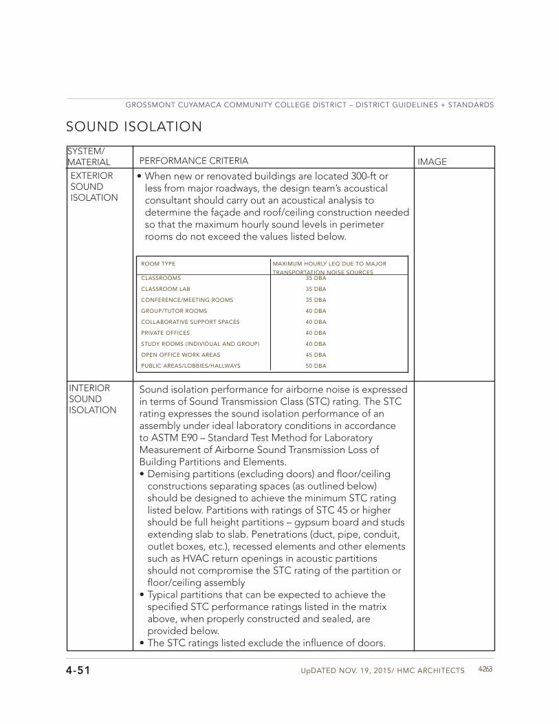
UpDATED NOV. 19, 2015/ HMC ARCHITECTS
GROSSMONT CUYAMACA COMMUNITY COLLEGE DISTRICT – DISTRICT GUIDELINES + STANDARDS
4-2634-51
SOUND ISOLATION
SYSTEM/MATERIAL PERFORMANCE CRITERIA IMAGE
Room Type maximum HouRly leq Due To majoR
TRanspoRTaTion noise souRcesclassRooms 35 DBa
classRoom laB 35 DBa
confeRence/meeTing Rooms 35 DBa
gRoup/TuToR Rooms 40 DBa
collaBoRaTive suppoRT spaces 40 DBa
pRivaTe offices 40 DBa
sTuDy Rooms (inDiviDual anD gRoup) 40 DBa
open office WoRk aReas 45 DBa
puBlic aReas/loBBies/HallWays 50 DBa
• When new or renovated buildings are located 300-ft orless from major roadways, the design team’s acousticalconsultant should carry out an acoustical analysis todetermine the façade and roof/ceiling construction neededso that the maximum hourly sound levels in perimeterrooms do not exceed the values listed below.
EXTERIOR SOUND ISOLATION
INTERIOR SOUND ISOLATION
Sound isolation performance for airborne noise is expressed in terms of Sound Transmission Class (STC) rating. The STC rating expresses the sound isolation performance of an assembly under ideal laboratory conditions in accordance to ASTM E90 – Standard Test Method for Laboratory Measurement of Airborne Sound Transmission Loss of Building Partitions and Elements.• Demising partitions (excluding doors) and floor/ceiling
constructions separating spaces (as outlined below) should be designed to achieve the minimum STC rating listed below. Partitions with ratings of STC 45 or higher should be full height partitions – gypsum board and studs extending slab to slab. Penetrations (duct, pipe, conduit, outlet boxes, etc.), recessed elements and other elements such as HVAC return openings in acoustic partitions should not compromise the STC rating of the partition or floor/ceiling assembly
• Typical partitions that can be expected to achieve thespecified STC performance ratings listed in the matrixabove, when properly constructed and sealed, are provided below.
• The STC ratings listed exclude the influence of doors.
GROSSMONT CUYAMACA COMMUNITY COLLEGE DISTRICT – DISTRICT GUIDELINES + STANDARDS
GCCCD04 MATERIAL + BUILDING SYSTEM STANDARDS4-264 4-51
SYSTEM/MATERIAL
SOUND ISOLATION
PERFORMANCE CRITERIA IMAGE
• Doors located in demising partitions off of corridors shouldprovide STC 30 min. sound isolation performance, except incases where confidential speech privacy is required. Whenconfidential speech privacy is required, STC rated soundcontrol doors equal to the STC rating listed in the matrixabove will be required to maintain confidential speechprivacy. STC 30 sound isolation performance at doorsshould be achieved through the use of solid core wood ordamped hollow metal doors with full perimeter gaskets atthe head, jamb and door bottom. The door bottom gasketshould seal to a solid metal plate, stone or concrete, notcarpet.
• Vision windows in doors or next to doors of NC 35 or lowerspaces should be limited to 5’-2” and have a min. STCrating of 35.
• Doors and windows between adjacent sound sensitivespaces (such as classroom to classroom) should be avoided,otherwise STC rated sound control doors and windowsequal to the STC ratings listed in the matrix will be requiredto maintain sound isolation.
• Monolithic glass wall, large vision lite or door constructionshould not be used where confidential speech privacy isrequired.
• Mechanical and electrical room (equipped withtransformers) doors should provide STC 30 min. soundisolation performance when they are within 30’ of a roomwith an NC 35 or lower background noise level criterion.The door leaf should either be 1-3/4” solid core wood ordamped hollow metal. STC 30 sound isolation performanceshould be achieved with adjustable door gaskets at thehead, jamb and door bottom. A gasketed threshold shouldalso be used at the door bottom.
• Partitions with STC 45 or higher sound isolationperformance should be full height and wall heads should besealed airtight in accordance with the recommended detailsbelow.
• Duct, pipe and conduit penetrations through STC 45 orhigher partitions should be sealed airtight in accordancewith the recommended details below.
INTERIOR SOUND ISOLATION
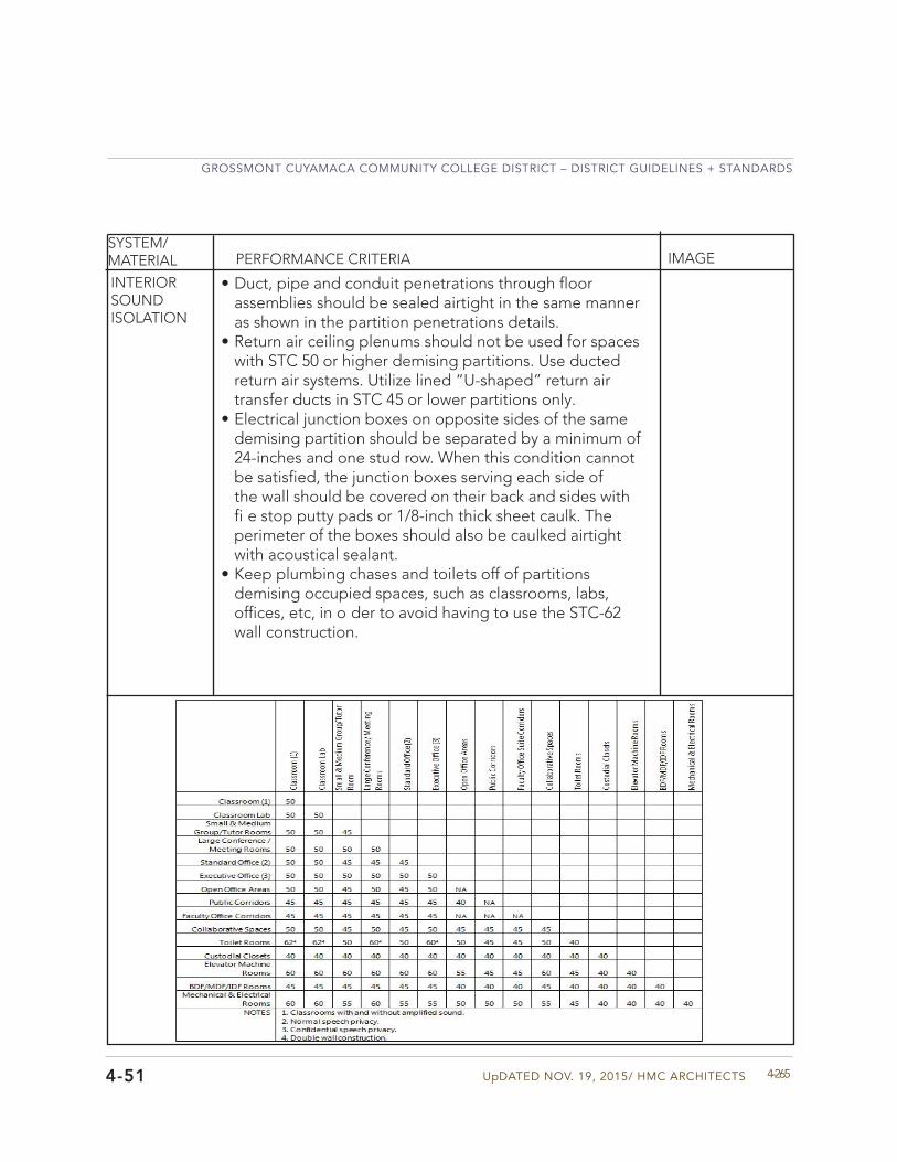
UpDATED NOV. 19, 2015/ HMC ARCHITECTS
GROSSMONT CUYAMACA COMMUNITY COLLEGE DISTRICT – DISTRICT GUIDELINES + STANDARDS
4-2654-51
SYSTEM/MATERIAL PERFORMANCE CRITERIA IMAGE
• Duct, pipe and conduit penetrations through floorassemblies should be sealed airtight in the same manneras shown in the partition penetrations details.
• Return air ceiling plenums should not be used for spaceswith STC 50 or higher demising partitions. Use ductedreturn air systems. Utilize lined “U-shaped” return airtransfer ducts in STC 45 or lower partitions only.
• Electrical junction boxes on opposite sides of the samedemising partition should be separated by a minimum of24-inches and one stud row. When this condition cannotbe satisfied, the junction boxes serving each side ofthe wall should be covered on their back and sides withfi e stop putty pads or 1/8-inch thick sheet caulk. Theperimeter of the boxes should also be caulked airtightwith acoustical sealant.
• Keep plumbing chases and toilets off of partitionsdemising occupied spaces, such as classrooms, labs,offices, etc, in o der to avoid having to use the STC-62wall construction.
INTERIOR SOUND ISOLATION
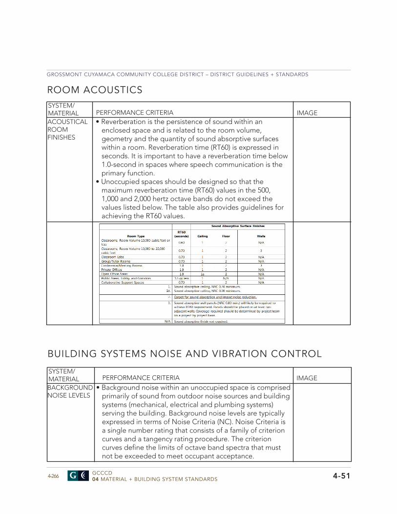
GROSSMONT CUYAMACA COMMUNITY COLLEGE DISTRICT – DISTRICT GUIDELINES + STANDARDS
GCCCD04 MATERIAL + BUILDING SYSTEM STANDARDS4-266 4-51
SYSTEM/MATERIAL
ROOM ACOUSTICS
PERFORMANCE CRITERIA IMAGE• Reverberation is the persistence of sound within an
enclosed space and is related to the room volume,geometry and the quantity of sound absorptive surfaceswithin a room. Reverberation time (RT60) is expressed inseconds. It is important to have a reverberation time below1.0-second in spaces where speech communication is theprimary function.
• Unoccupied spaces should be designed so that themaximum reverberation time (RT60) values in the 500,1,000 and 2,000 hertz octave bands do not exceed thevalues listed below. The table also provides guidelines forachieving the RT60 values.
ACOUSTICAL ROOM FINISHES
SYSTEM/MATERIAL
BUILDING SYSTEMS NOISE AND VIBRATION CONTROL
PERFORMANCE CRITERIA IMAGE• Background noise within an unoccupied space is comprised
primarily of sound from outdoor noise sources and buildingsystems (mechanical, electrical and plumbing systems)serving the building. Background noise levels are typicallyexpressed in terms of Noise Criteria (NC). Noise Criteria isa single number rating that consists of a family of criterioncurves and a tangency rating procedure. The criterioncurves define the limits of octave band spectra that mustnot be exceeded to meet occupant acceptance.
BACKGROUND NOISE LEVELS
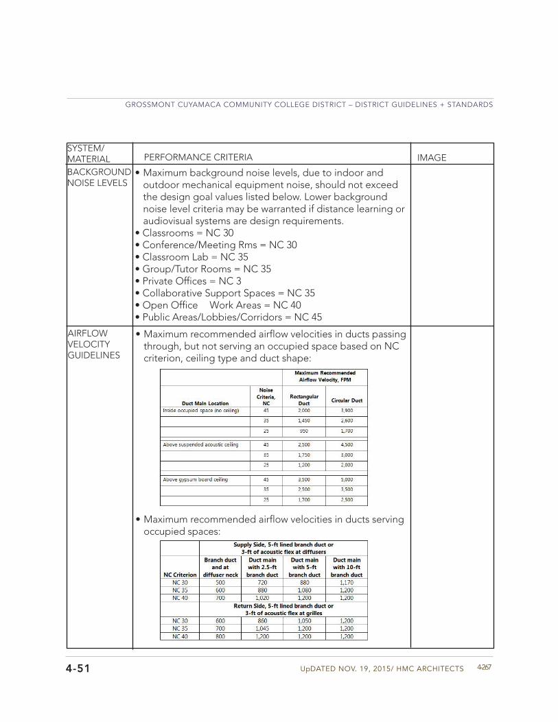
UpDATED NOV. 19, 2015/ HMC ARCHITECTS
GROSSMONT CUYAMACA COMMUNITY COLLEGE DISTRICT – DISTRICT GUIDELINES + STANDARDS
4-2674-51
SYSTEM/MATERIAL PERFORMANCE CRITERIA IMAGE
• Maximum background noise levels, due to indoor andoutdoor mechanical equipment noise, should not exceedthe design goal values listed below. Lower backgroundnoise level criteria may be warranted if distance learning oraudiovisual systems are design requirements.
• Classrooms = NC 30• Conference/Meeting Rms = NC 30• Classroom Lab = NC 35• Group/Tutor Rooms = NC 35• Private Offices = NC 3• Collaborative Support Spaces = NC 35• Open Office Work Areas = NC 40• Public Areas/Lobbies/Corridors = NC 45
BACKGROUND NOISE LEVELS
• Maximum recommended airflow velocities in ducts passingthrough, but not serving an occupied space based on NCcriterion, ceiling type and duct shape:
AIRFLOW VELOCITY GUIDELINES
• Maximum recommended airflow velocities in ducts servingoccupied spaces:
GROSSMONT CUYAMACA COMMUNITY COLLEGE DISTRICT – DISTRICT GUIDELINES + STANDARDS
GCCCD04 MATERIAL + BUILDING SYSTEM STANDARDS4-268 4-51
EQUIpMENT SOUND ISOLATION
• Select the quietest feasible equipment when designing themechanical systems.
• Design duct systems for good aerodynamic flow conditionsto minimize turbulence and regenerated noise. Utilizelow pressure drop fittings, such as 45° taps, on all supplyand return branch duct take offs from duct mains Use thelowest possible duct velocities consistent with the systemparameters.
• Rooftop package units containing compressors and/orcondensing units should not be located directly above NC35 or lower spaces. If package units must be located abovethese spaces because of the lack of rooftop space, anacoustical analysis should be performed to determine thenoise control measures that may be required to achievethe background noise level criterion inside the occupiedspaces. Potential noise control measures may includeusing concrete over metal deck, steel dunnage to raisethe unit off of the roof or an acoustic package inside avibration isolated roof curb. An acoustical package consistsof two layers of exterior grade 1/2” thick gypsum boardthat cover the entire floor area inside the vibration isolatedcurb (except for duct penetrations). 3” thick sound battinsulation is also placed on top of the roof inside the roofcurb. Specific noise control for each project should beprovided by the design team’s acoustic consultant.
• Rooftop package units should not be equipped withbottom inlet and discharge ductwork, unless the unit isinstalled above a space with a background noise levelcriterion of NC 40 or higher. Where ever possible, rooftoppackage units and air-handling units should be configuredfor top, end or side inlet and discharge ductwork whenserving or located above NC 35 or lower spaces. If theseconditions cannot be avoided, the use of circular ductworkand other noise control measures will likely be required tocontrol duct radiated noise in the spaces below. Specificnoise control for each project should be provided by thedesign team’s acoustic consultant.
SYSTEM/MATERIAL PERFORMANCE CRITERIA IMAGE
HVAC ACOUSTIC DESIGN GUIDELINES
UpDATED NOV. 19, 2015/ HMC ARCHITECTS
GROSSMONT CUYAMACA COMMUNITY COLLEGE DISTRICT – DISTRICT GUIDELINES + STANDARDS
4-2694-51
SYSTEM/MATERIAL PERFORMANCE CRITERIA IMAGE
• VAV boxes, exhaust fans or fan coil units should not belocated inside ceilings of NC 35 or lower rooms. Thisequipment should be located in non-noise sensitivespaces, such as corridors or storage closets, and should belocated several feet from the wall of the occupied space.
• Avoid crosstalk conditions by locating main ducts alongcorridors and branching into rooms from the corridor to maximize duct pathway length between spaces. Branch duct should be lined with 1” duct liner or equipped with 3’ of acoustical flex duct to prevent cross talk between adjacent spaces.
• Diffusers and grilles should not be equipped with integralvolume dampers. Locate balancing dampers in supply andreturn ducts at least 5’ from diffusers/grilles. Branch ductsshould be lined with 1” duct liner or equipped with 3’ ofacoustical flex duct between the balancing dampers anddiffusers/grilles.
• Select diffusers and grilles with a published NC rating ofat least 5 to 10 points below the background noise levelcriterion for the occupied space.
• When ducted returns cannot be utilized, return air fromoccupied spaces should be ducted via lined return airtransfer ducts. Return air transfer ducts should be “U”shaped with a 4’ minimum centerline length and 6” longupturn lined elbows at each end. The transfer duct shouldbe located above a ceiling on both sides of the wall.
• Insert DTL-500 Image here.• A complete and thorough acoustical analysis should be
carried out to determine the noise control measures(duct silencers, duct liner, roof construction, etc.) thatwill be required to achieve the maximum recommendedbackground noise levels inside worst case occupiedspaces. The analysis and recommendations should beprovided for all indoor and outdoor mechanical equipmentthat may impact spaces inside new or renovated buildings.
HVAC ACOUSTIC DESIGN GUIDELINES
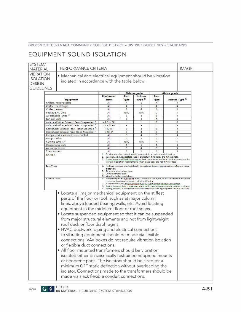
GROSSMONT CUYAMACA COMMUNITY COLLEGE DISTRICT – DISTRICT GUIDELINES + STANDARDS
GCCCD04 MATERIAL + BUILDING SYSTEM STANDARDS4-274 4-51
EQUIPMENT SOUND ISOLATION
• Locate all major mechanical equipment on the stiffest parts of the floor or roof, such as at major column lines, above loaded bearing walls, etc. Avoid locating equipment in the middle of floor or roof spans.
• Locate suspended equipment so that it can be suspended from major structural elements and not from lightweight roof deck or floor diaphragms.
• HVAC ductwork, piping and electrical connections to vibrating equipment should be made via flexible connections. VAV boxes do not require vibration isolation or flexible duct connections.
• All floor mounted transformers should be vibration isolated either on seismically restrained neoprene mounts or neoprene pads. The isolators should be sized for a minimum 0.1” static deflection without overloading the isolator. Connections made to the transformers should be made via slack flexible conduit connections.
SYSTEM/MATERIAL PERFORMANCE CRITERIA IMAGEVIBRATION ISOLATION DESIGN GUIDELINES
• Mechanical and electrical equipment should be vibration isolated in accordance with the table below.
UPDATED MAY 29, 2015/ HMC ARCHITECTS
GROSSMONT CUYAMACA COMMUNITY COLLEGE DISTRICT – DISTRICT GUIDELINES + STANDARDS
4-2754-51
SYSTEM/MATERIAL PERFORMANCE CRITERIA IMAGE
• Housekeeping pads should be located below mechanical and electrical equipment, especially when the equipment is located above grade. Reinforced housekeeping pads should be at least 6” thick and be designed and sized to accommodate the seismic loads that may be imparted on the equipment. Coordinate with the various disciplines regarding documentation of the pads.
VIBRATION ISOLATION DESIGN GUIDELINES

Roofing Roofing Roofing Roofing Guideline Guideline Guideline Guideline DrawingsDrawingsDrawingsDrawings
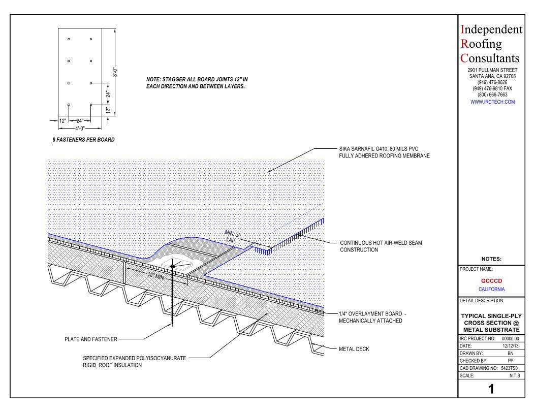
TYPICAL SINGLE-PLY CROSS SECTION @ METAL SUBSTRATE
5423TS01
BNPP
12/12/1300000.00
N.T.S
DATE:DRAWN BY:
SCALE:
CHECKED BY:
IRC PROJECT NO:
CAD DRAWING NO:
DETAIL DESCRIPTION:
(949) 476-9810 FAX
WWW.IRCTECH.COM(800) 666-7663
IndependentRoofingConsultants
2901 PULLMAN STREETSANTA ANA, CA 92705
(949) 476-8626
1
NOTE: STAGGER ALL BOARD JOINTS 12" IN EACH DIRECTION AND BETWEEN LAYERS.
8'-0"
4'-0"12"
12"
24"
8 FASTENERS PER BOARD
24"
1/4" OVERLAYMENT BOARD - MECHANICALLY ATTACHED
PLATE AND FASTENER
SIKA SARNAFIL G410, 80 MILS PVC FULLY ADHERED ROOFING MEMBRANE
CONTINUOUS HOT AIR-WELD SEAM CONSTRUCTION
MIN. 3"LAP
12" MIN.
METAL DECKSPECIFIED EXPANDED POLYISOCYANURATE RIGID ROOF INSULATION
GCCCD CALIFORNIA
PROJECT NAME:
NOTES:
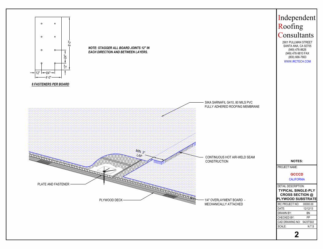
TYPICAL SINGLE-PLY CROSS SECTION @
PLYWOOD SUBSTRATE
5423TS02
BNPP
12/12/1300000.00
N.T.S
DATE:DRAWN BY:
SCALE:
CHECKED BY:
IRC PROJECT NO:
CAD DRAWING NO:
DETAIL DESCRIPTION:
(949) 476-9810 FAX
WWW.IRCTECH.COM(800) 666-7663
IndependentRoofingConsultants
2901 PULLMAN STREETSANTA ANA, CA 92705
(949) 476-8626
2
NOTE: STAGGER ALL BOARD JOINTS 12" IN EACH DIRECTION AND BETWEEN LAYERS.
8'-0"
4'-0"12"
12"
24"
8 FASTENERS PER BOARD
24"
1/4" OVERLAYMENT BOARD - MECHANICALLY ATTACHED
PLATE AND FASTENER
PLYWOOD DECK
SIKA SARNAFIL G410, 80 MILS PVC FULLY ADHERED ROOFING MEMBRANE
CONTINUOUS HOT AIR-WELD SEAM CONSTRUCTION
MIN. 3"LAP
GCCCD CALIFORNIA
PROJECT NAME:
NOTES:
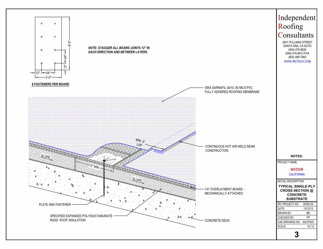
TYPICAL SINGLE-PLY CROSS SECTION @
CONCRETE SUBSTRATE
5423TS03
BNPP
12/12/1300000.00
N.T.S
DATE:DRAWN BY:
SCALE:
CHECKED BY:
IRC PROJECT NO:
CAD DRAWING NO:
DETAIL DESCRIPTION:
(949) 476-9810 FAX
WWW.IRCTECH.COM(800) 666-7663
IndependentRoofingConsultants
2901 PULLMAN STREETSANTA ANA, CA 92705
(949) 476-8626
3
NOTE: STAGGER ALL BOARD JOINTS 12" IN EACH DIRECTION AND BETWEEN LAYERS.
8'-0"
4'-0"12"
12"
24"
8 FASTENERS PER BOARD
24"
1/4" OVERLAYMENT BOARD - MECHANICALLY ATTACHED
PLATE AND FASTENER
SIKA SARNAFIL G410, 80 MILS PVC FULLY ADHERED ROOFING MEMBRANE
CONTINUOUS HOT AIR-WELD SEAM CONSTRUCTION
MIN. 3"LAP
12" MIN.
SLOPE
SLOPE
CONCRETE DECKSPECIFIED EXPANDED POLYISOCYANURATE RIGID ROOF INSULATION
GCCCD CALIFORNIA
PROJECT NAME:
NOTES:
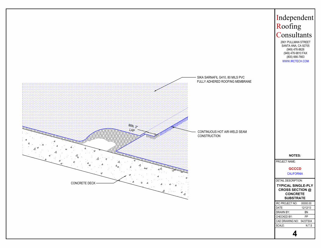
TYPICAL SINGLE-PLY CROSS SECTION @
CONCRETE SUBSTRATE
5423TS04
BNPP
12/12/1300000.00
N.T.S
DATE:DRAWN BY:
SCALE:
CHECKED BY:
IRC PROJECT NO:
CAD DRAWING NO:
DETAIL DESCRIPTION:
(949) 476-9810 FAX
WWW.IRCTECH.COM(800) 666-7663
IndependentRoofingConsultants
2901 PULLMAN STREETSANTA ANA, CA 92705
(949) 476-8626
4
CONCRETE DECK
SIKA SARNAFIL G410, 80 MILS PVC FULLY ADHERED ROOFING MEMBRANE
CONTINUOUS HOT AIR-WELD SEAM CONSTRUCTION
MIN. 3"LAP
GCCCD CALIFORNIA
PROJECT NAME:
NOTES:
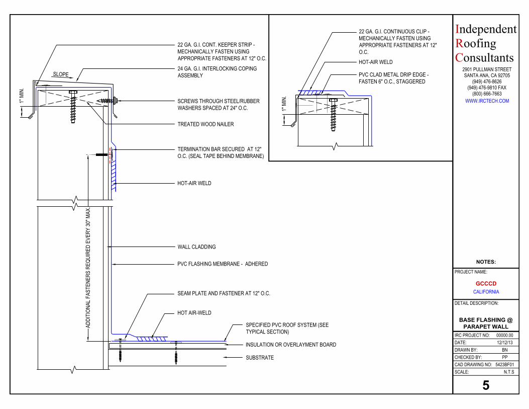
BASE FLASHING @ PARAPET WALL
5423BF01
BNPP
12/12/1300000.00
N.T.S
DATE:DRAWN BY:
SCALE:
CHECKED BY:
IRC PROJECT NO:
CAD DRAWING NO:
DETAIL DESCRIPTION:
(949) 476-9810 FAX
WWW.IRCTECH.COM(800) 666-7663
IndependentRoofingConsultants
2901 PULLMAN STREETSANTA ANA, CA 92705
(949) 476-8626
5
PVC FLASHING MEMBRANE - ADHERED
SEAM PLATE AND FASTENER AT 12" O.C.
HOT AIR-WELD
SPECIFIED PVC ROOF SYSTEM (SEE TYPICAL SECTION)
24 GA. G.I. INTERLOCKING COPING ASSEMBLY
SCREWS THROUGH STEEL/RUBBER WASHERS SPACED AT 24" O.C.
22 GA. G.I. CONT. KEEPER STRIP - MECHANICALLY FASTEN USING APPROPRIATE FASTENERS AT 12" O.C.
SLOPE
ADDI
TION
AL F
ASTE
NERS
REQ
UIRE
D EV
ERY
30" M
AX.
TERMINATION BAR SECURED AT 12" O.C. (SEAL TAPE BEHIND MEMBRANE)
HOT-AIR WELD
TREATED WOOD NAILER
WALL CLADDING
INSULATION OR OVERLAYMENT BOARD
1" M
IN.
SUBSTRATE
1" M
IN.
PVC CLAD METAL DRIP EDGE - FASTEN 6" O.C., STAGGERED
HOT-AIR WELD
22 GA. G.I. CONTINUOUS CLIP - MECHANICALLY FASTEN USING APPROPRIATE FASTENERS AT 12" O.C.
GCCCD CALIFORNIA
PROJECT NAME:
NOTES:
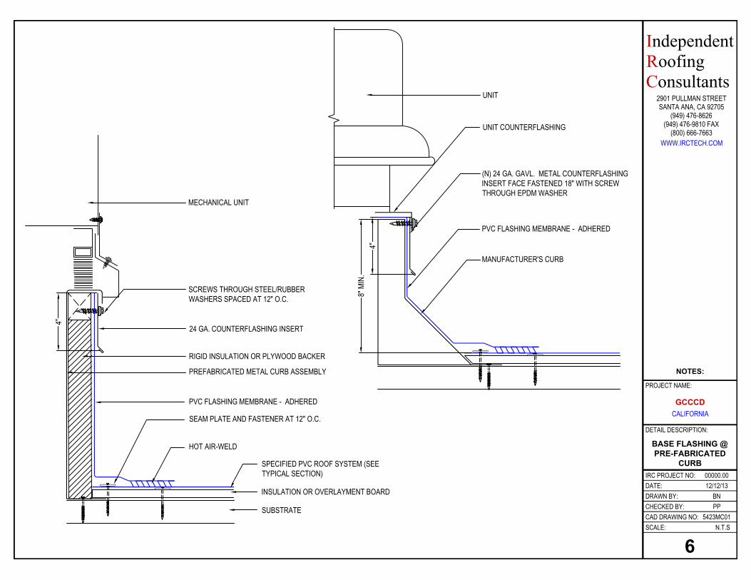
BASE FLASHING @ PRE-FABRICATED
CURB
5423MC01
BNPP
12/12/1300000.00
N.T.S
DATE:DRAWN BY:
SCALE:
CHECKED BY:
IRC PROJECT NO:
CAD DRAWING NO:
DETAIL DESCRIPTION:
(949) 476-9810 FAX
WWW.IRCTECH.COM(800) 666-7663
IndependentRoofingConsultants
2901 PULLMAN STREETSANTA ANA, CA 92705
(949) 476-8626
6
24 GA. COUNTERFLASHING INSERT
4"
PREFABRICATED METAL CURB ASSEMBLY
RIGID INSULATION OR PLYWOOD BACKER
MECHANICAL UNIT
PVC FLASHING MEMBRANE - ADHERED
SEAM PLATE AND FASTENER AT 12" O.C.
HOT AIR-WELD
SPECIFIED PVC ROOF SYSTEM (SEE TYPICAL SECTION)
INSULATION OR OVERLAYMENT BOARD
SUBSTRATE
SCREWS THROUGH STEEL/RUBBER WASHERS SPACED AT 12" O.C.
MANUFACTURER'S CURB
(N) 24 GA. GAVL. METAL COUNTERFLASHING INSERT FACE FASTENED 18" WITH SCREW THROUGH EPDM WASHER
UNIT COUNTERFLASHING
4"
UNIT
8" M
IN.
PVC FLASHING MEMBRANE - ADHERED
GCCCD CALIFORNIA
PROJECT NAME:
NOTES:
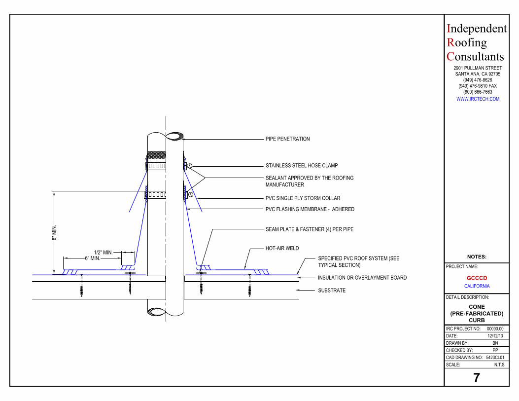
CONE (PRE-FABRICATED)
CURB
5423CL01
BNPP
12/12/1300000.00
N.T.S
DATE:DRAWN BY:
SCALE:
CHECKED BY:
IRC PROJECT NO:
CAD DRAWING NO:
DETAIL DESCRIPTION:
(949) 476-9810 FAX
WWW.IRCTECH.COM(800) 666-7663
IndependentRoofingConsultants
2901 PULLMAN STREETSANTA ANA, CA 92705
(949) 476-8626
7
8" M
IN.
SEAM PLATE & FASTENER (4) PER PIPE
HOT-AIR WELD
STAINLESS STEEL HOSE CLAMP
SEALANT APPROVED BY THE ROOFING MANUFACTURER
PIPE PENETRATION
PVC SINGLE PLY STORM COLLAR
1/2" MIN.6" MIN. SPECIFIED PVC ROOF SYSTEM (SEE
TYPICAL SECTION)
INSULATION OR OVERLAYMENT BOARD
SUBSTRATE
PVC FLASHING MEMBRANE - ADHERED
GCCCD CALIFORNIA
PROJECT NAME:
NOTES:
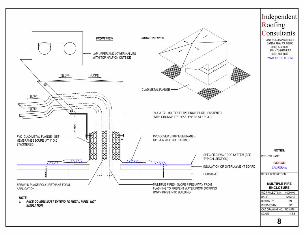
MULTIPLE PIPE ENCLOSURE
5423MP01
BNPP
12/12/1300000.00
N.T.S
DATE:DRAWN BY:
SCALE:
CHECKED BY:
IRC PROJECT NO:
CAD DRAWING NO:
DETAIL DESCRIPTION:
(949) 476-9810 FAX
WWW.IRCTECH.COM(800) 666-7663
IndependentRoofingConsultants
2901 PULLMAN STREETSANTA ANA, CA 92705
(949) 476-8626
8
PVC CLAD METAL FLANGE - SET MEMBRANE SECURE AT 4" O.C. STAGGERED
NOTE:1. FACE COVERS MUST EXTEND TO METAL PIPES, NOT
INSULATION.
SPRAY IN PLACE POLYURETHANE FOAM APPLICATION
LAP UPPER AND LOWER HALVES WITH TOP HALF ON OUTSIDE
24 GA. G.I. MULTIPLE PIPE ENCLOSURE - FASTENED WITH GROMMETTED FASTENERS AT 12" O.C.
MULTIPLE PIPES - SLOPE PIPES AWAY FROM FLASHING TO PREVENT WATER FROM DRIPPING DOWN PIPES INTO BUILDING
FRONT VIEW
CLAD METAL FLANGE
ISOMETRIC VIEW
SLOPE SLOPE
PVC COVER STRIP MEMBRANE - HOT-AIR WELD BOTH SIDES
SLOPE
SLOPE
8" M
IN.
SPECIFIED PVC ROOF SYSTEM (SEE TYPICAL SECTION)
INSULATION OR OVERLAYMENT BOARD
SUBSTRATE
GCCCD CALIFORNIA
PROJECT NAME:
NOTES:

Signage GuidelinesSignage GuidelinesSignage GuidelinesSignage Guidelines ---- DrawingsDrawingsDrawingsDrawings
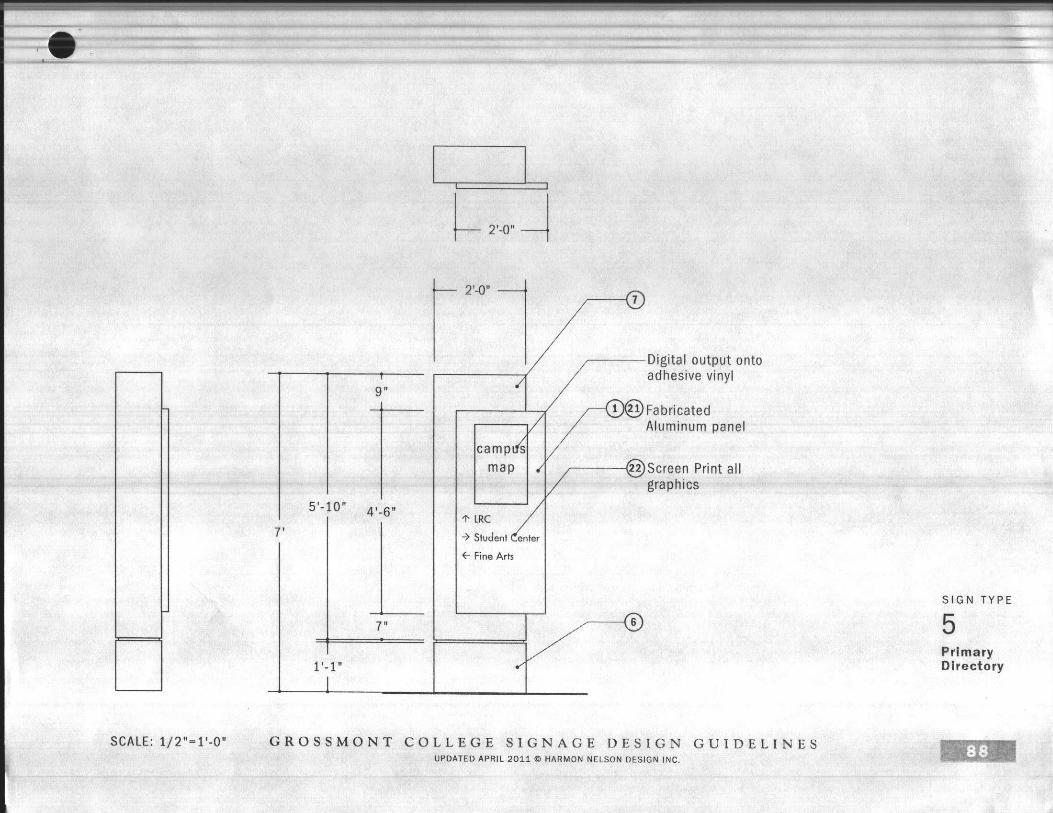
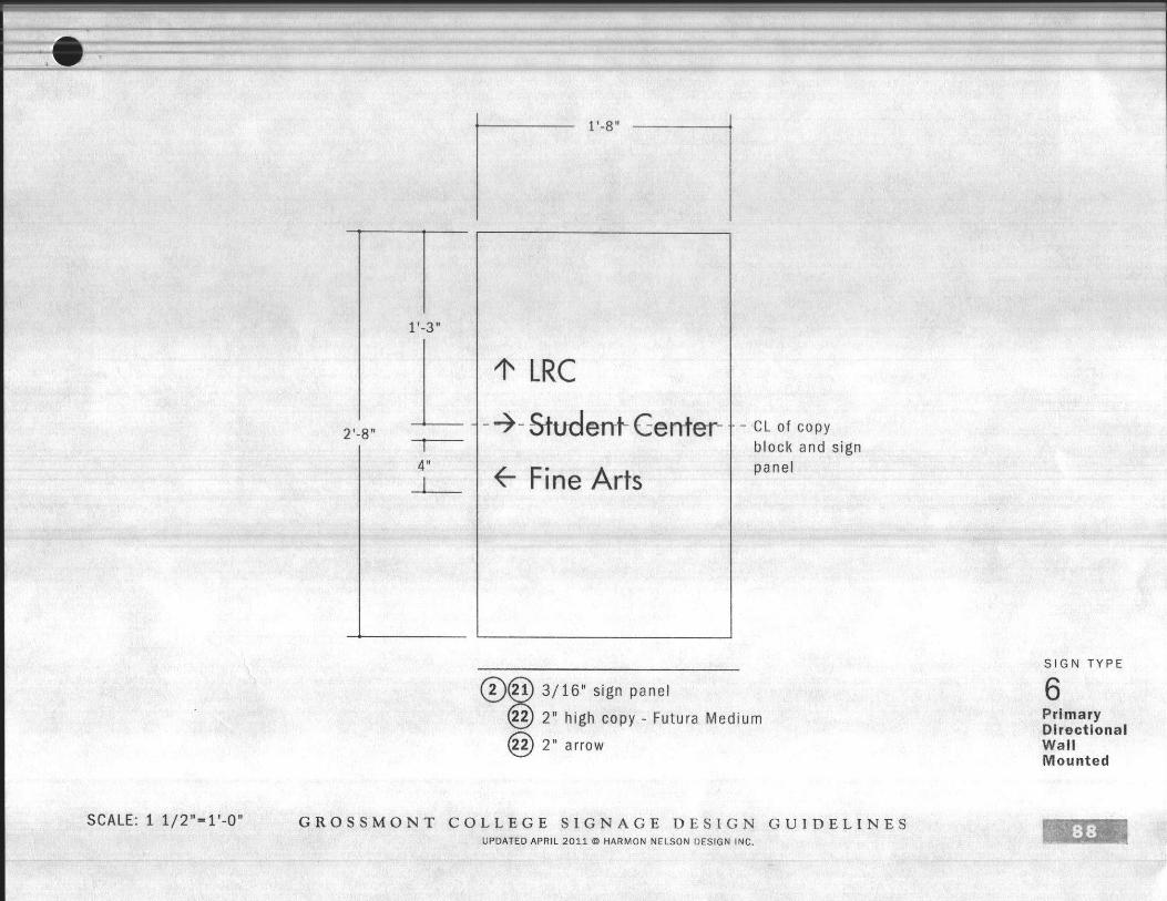
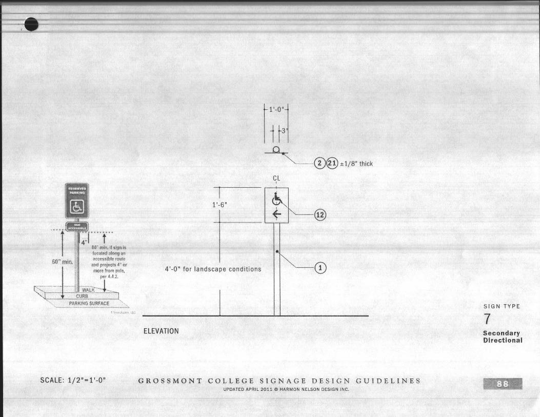
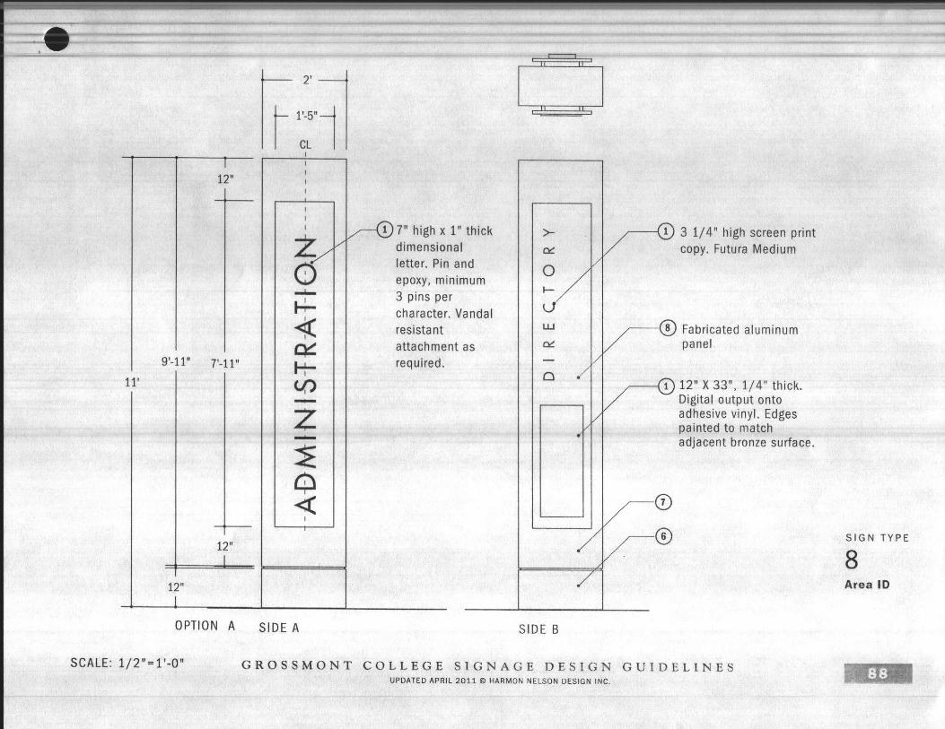
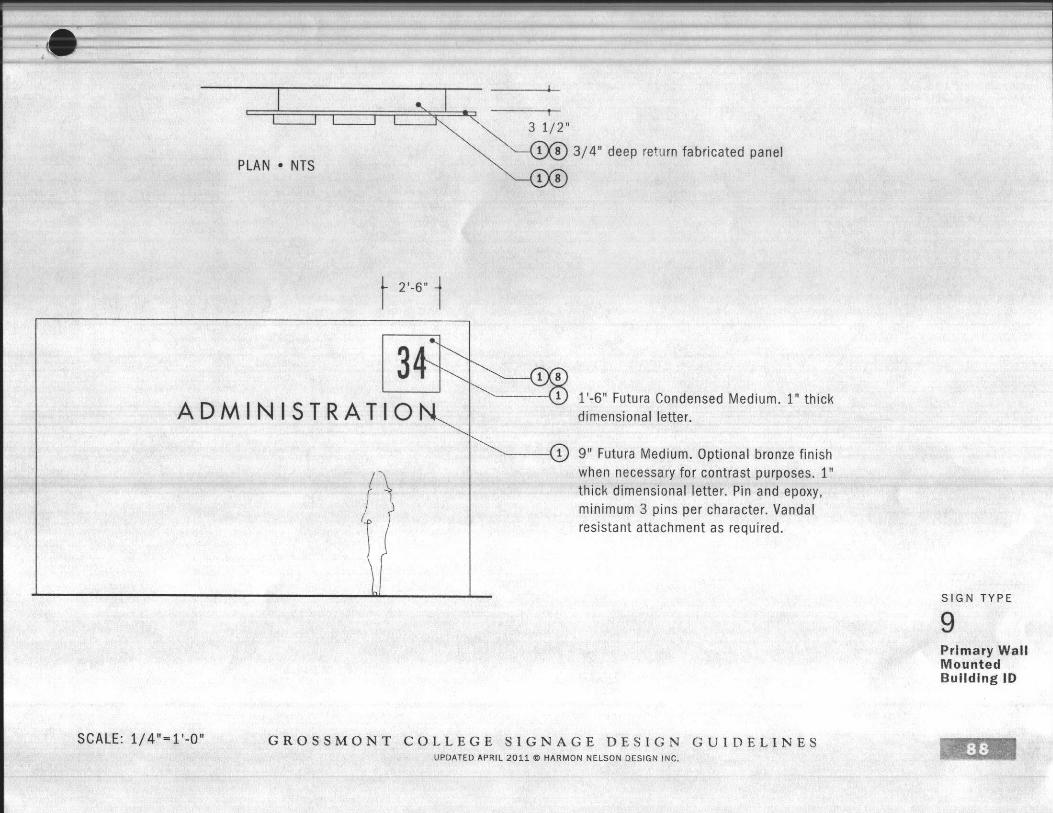
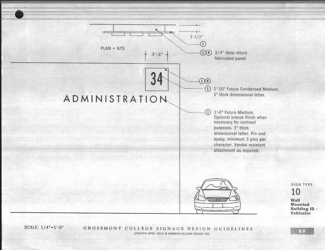
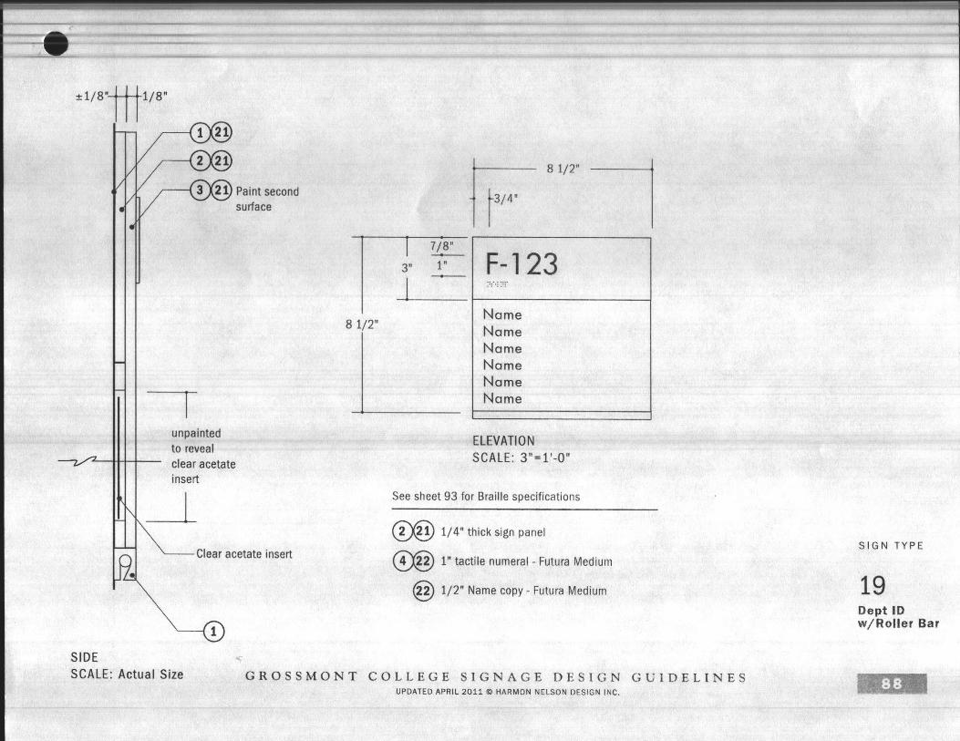
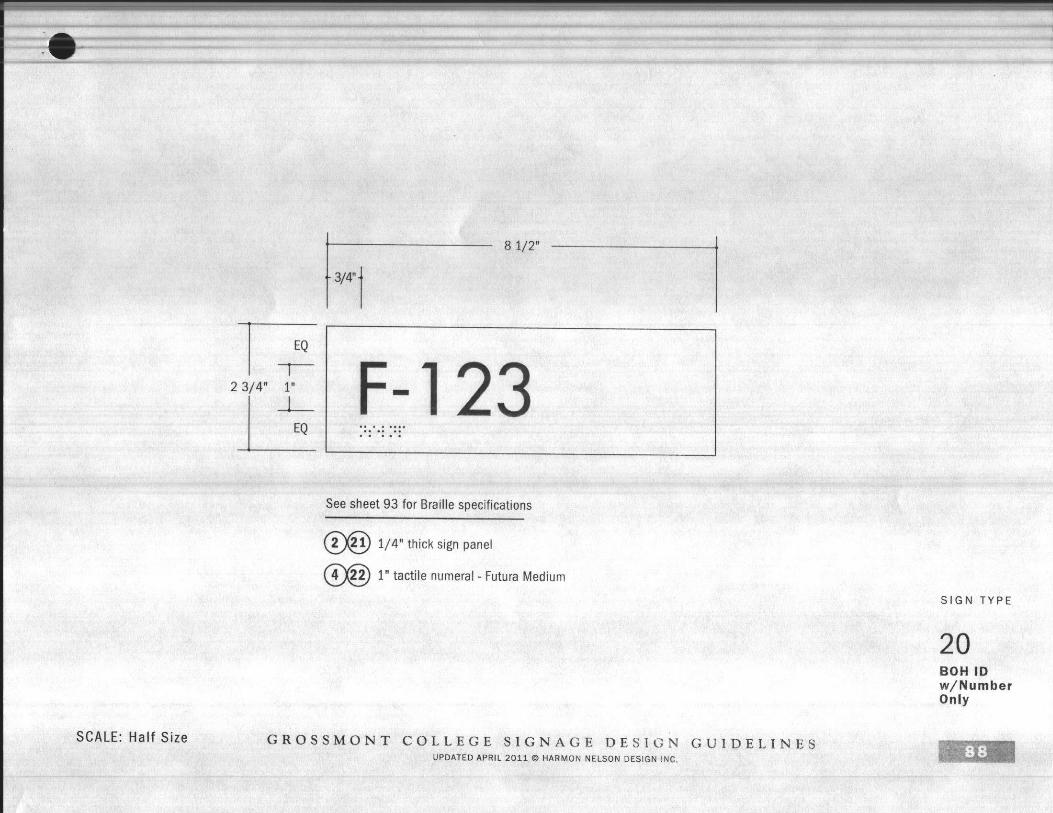
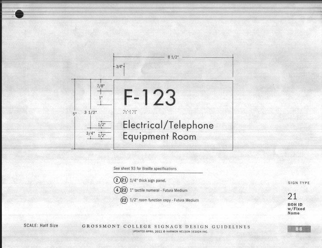
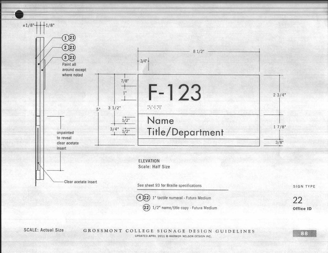
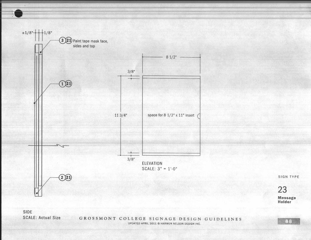
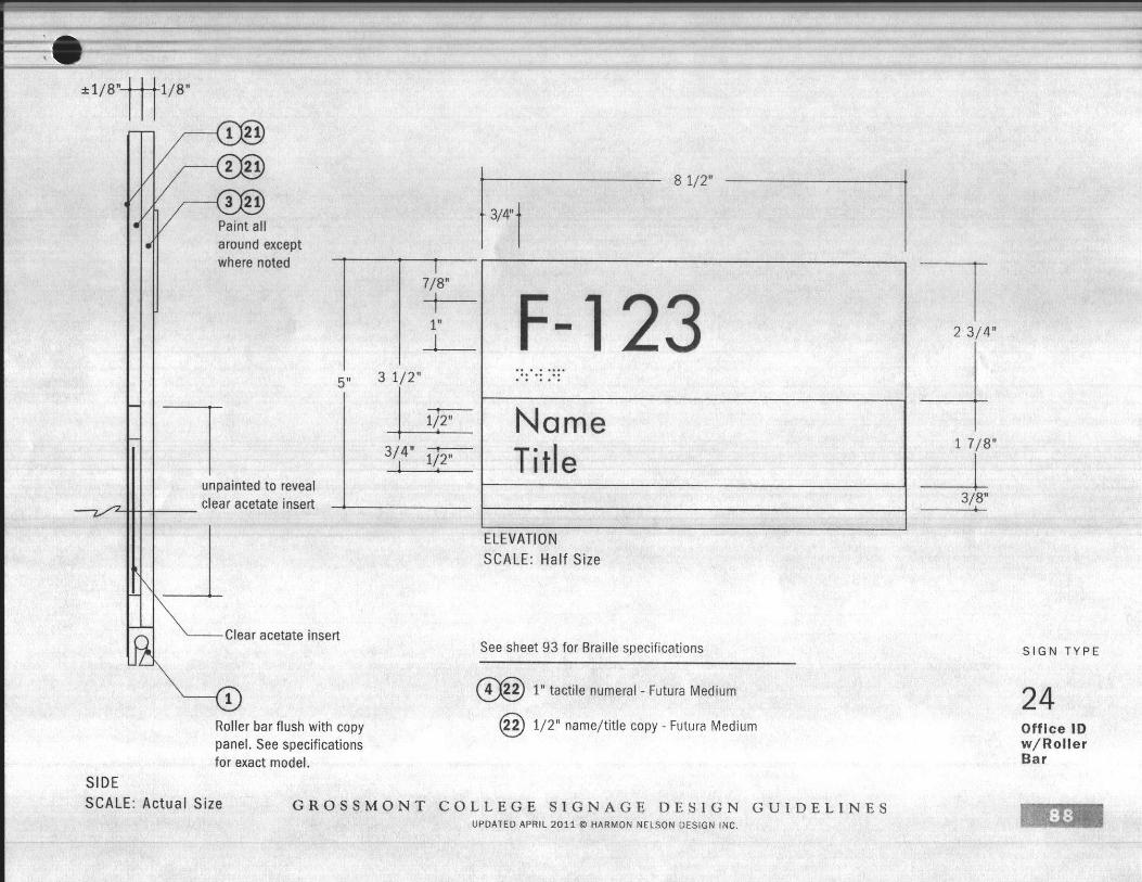
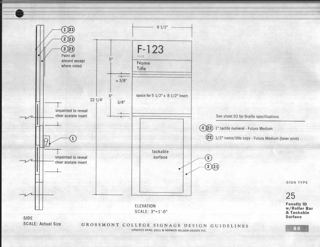
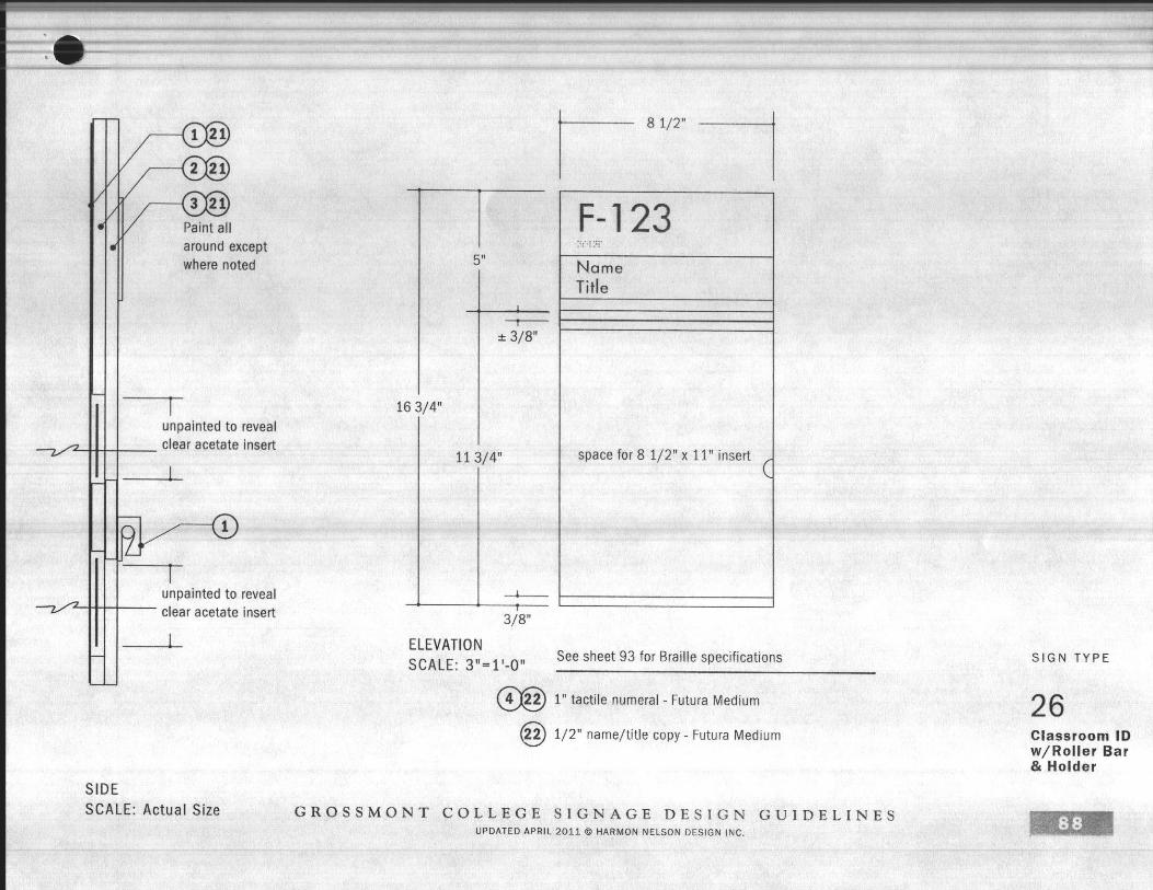
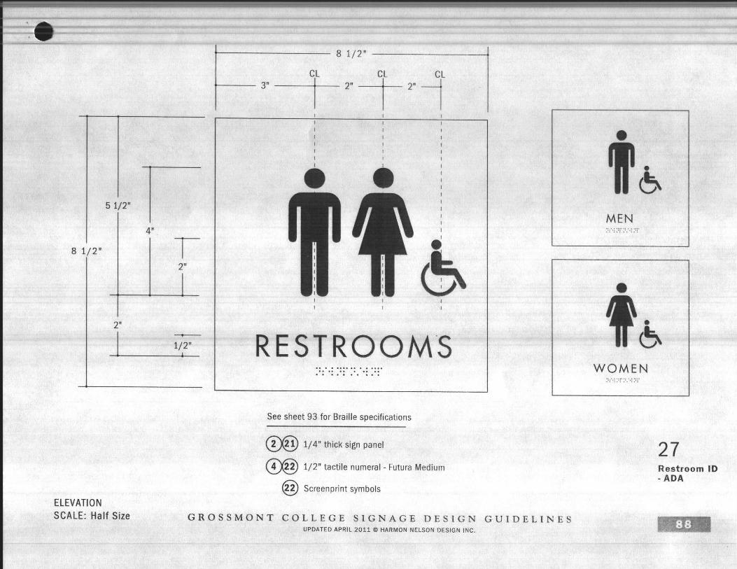
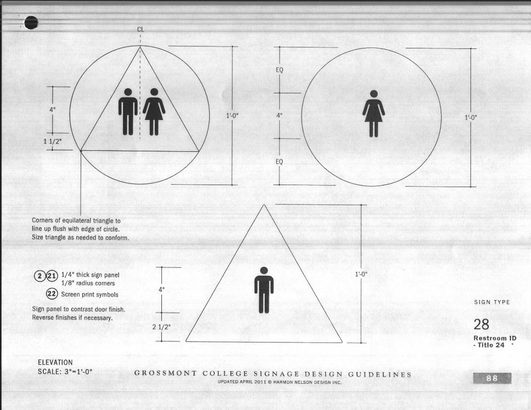
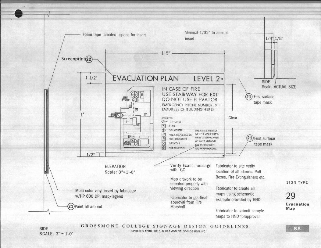
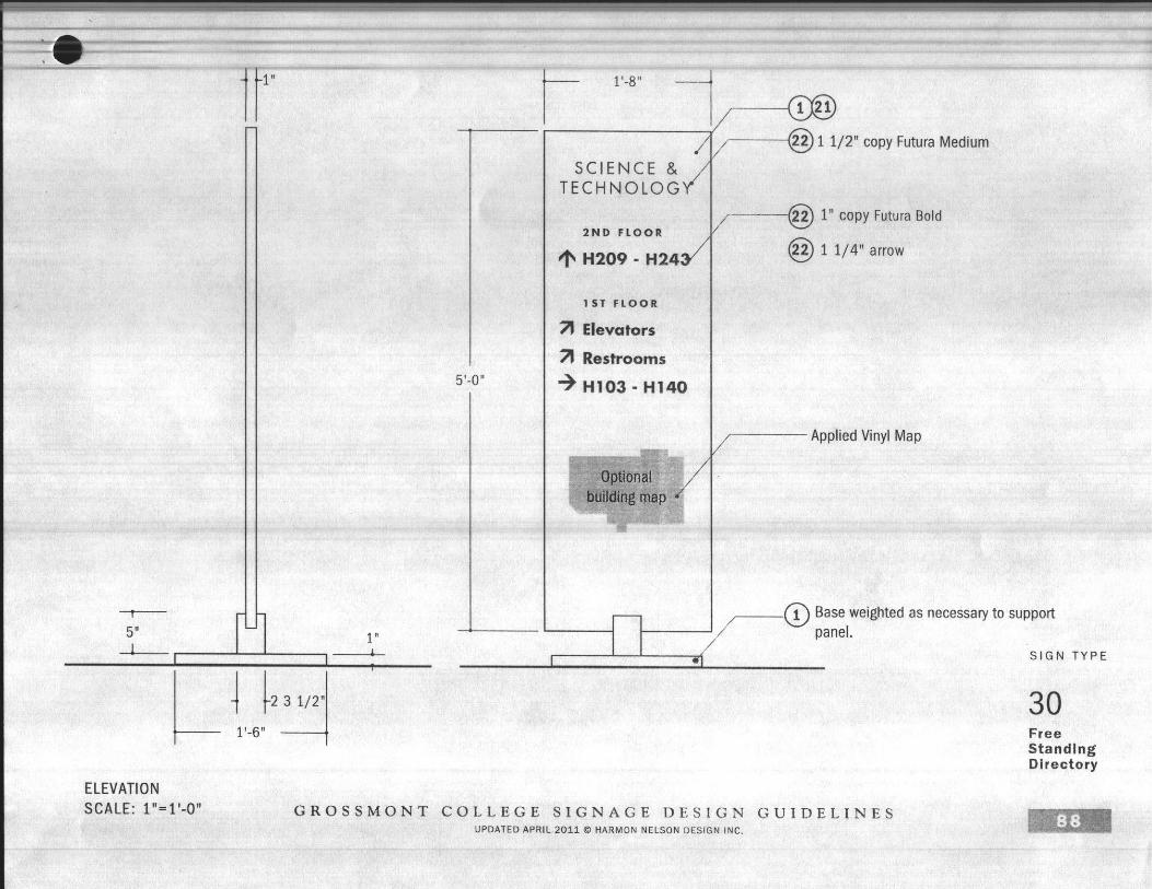
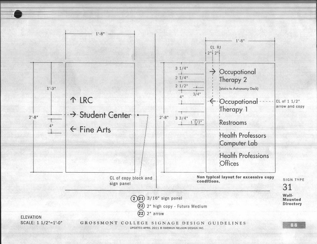
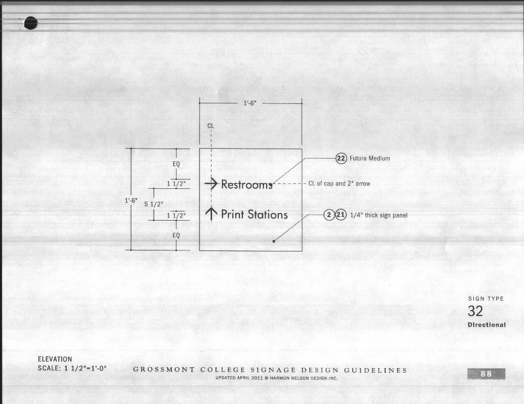
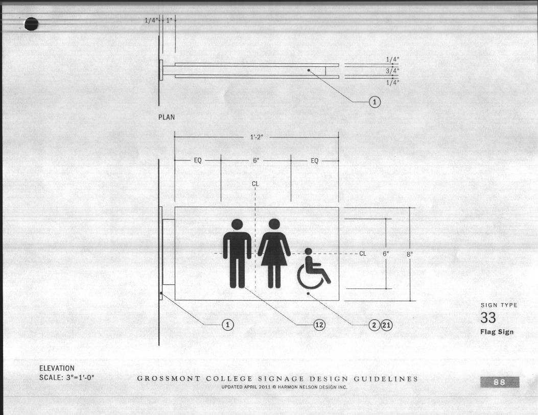
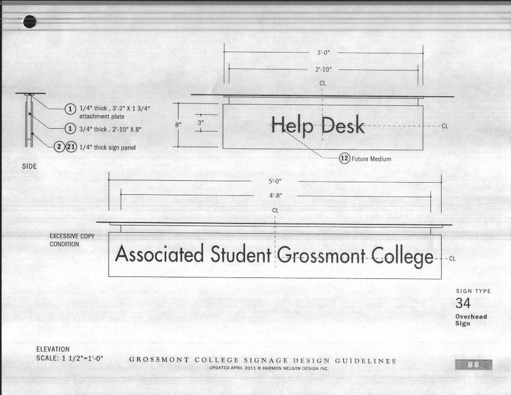
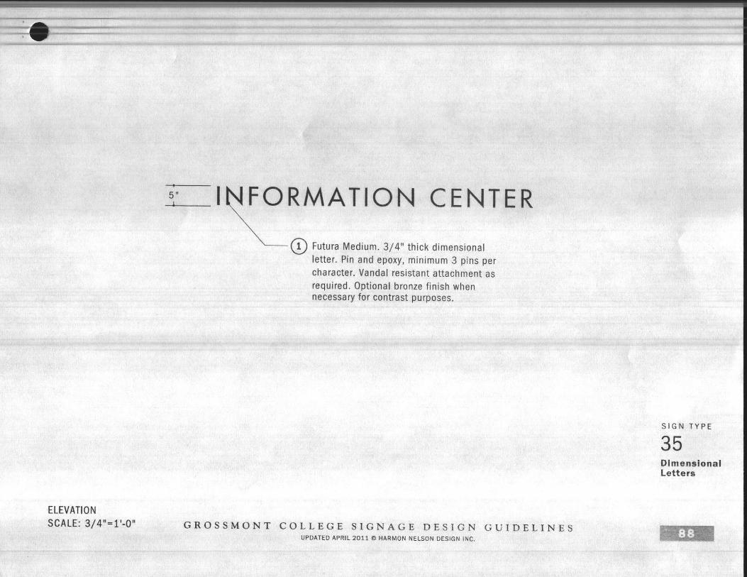
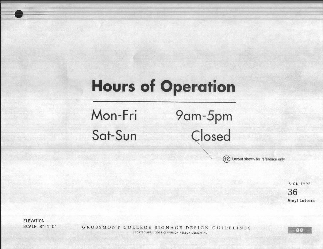
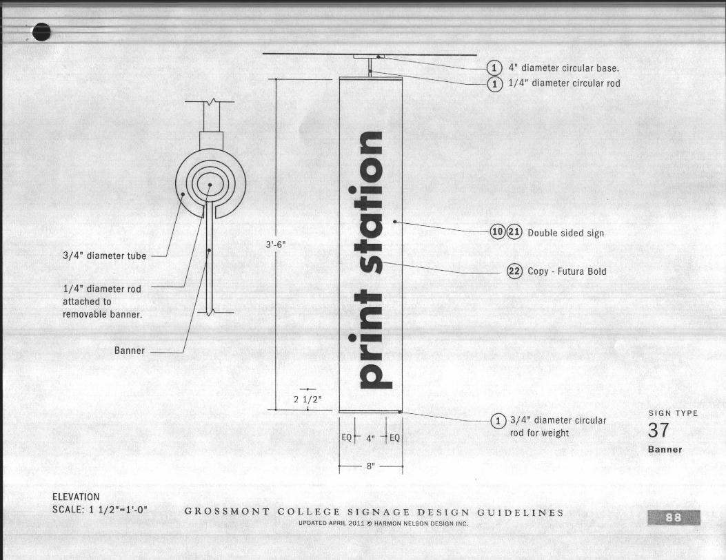
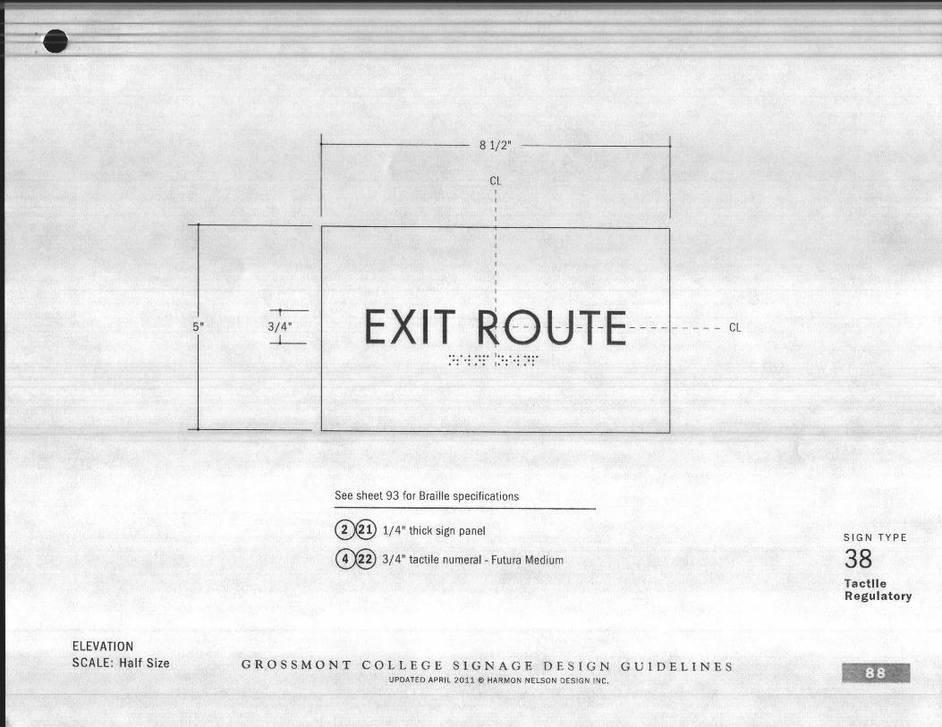
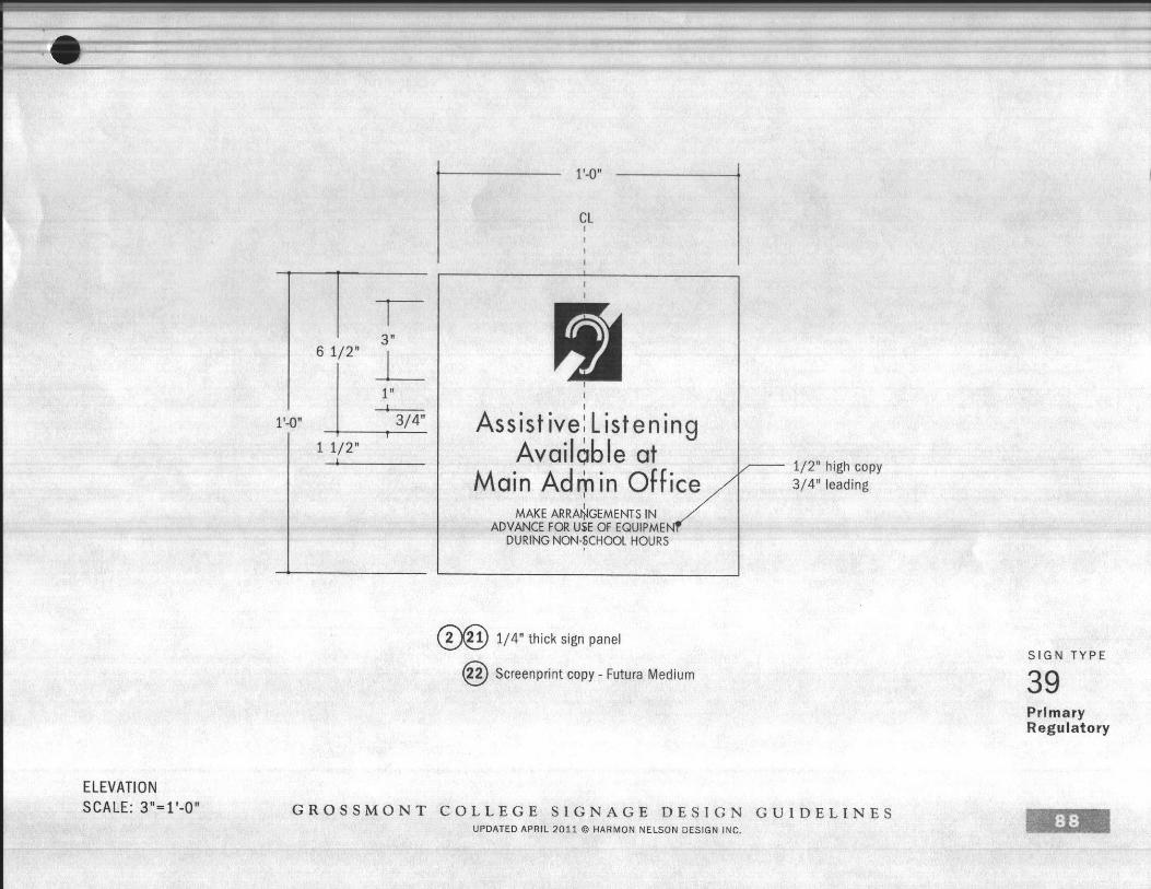
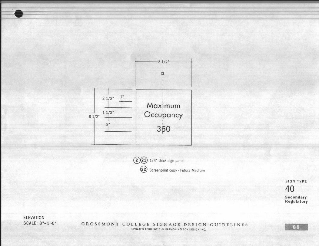
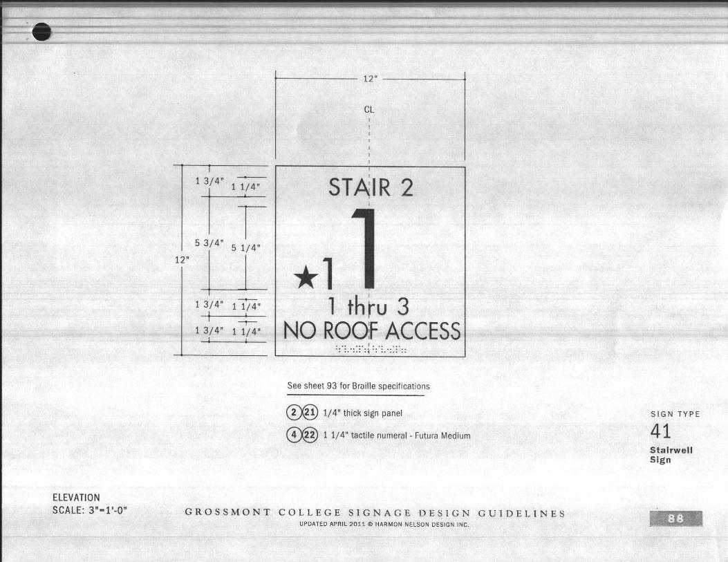
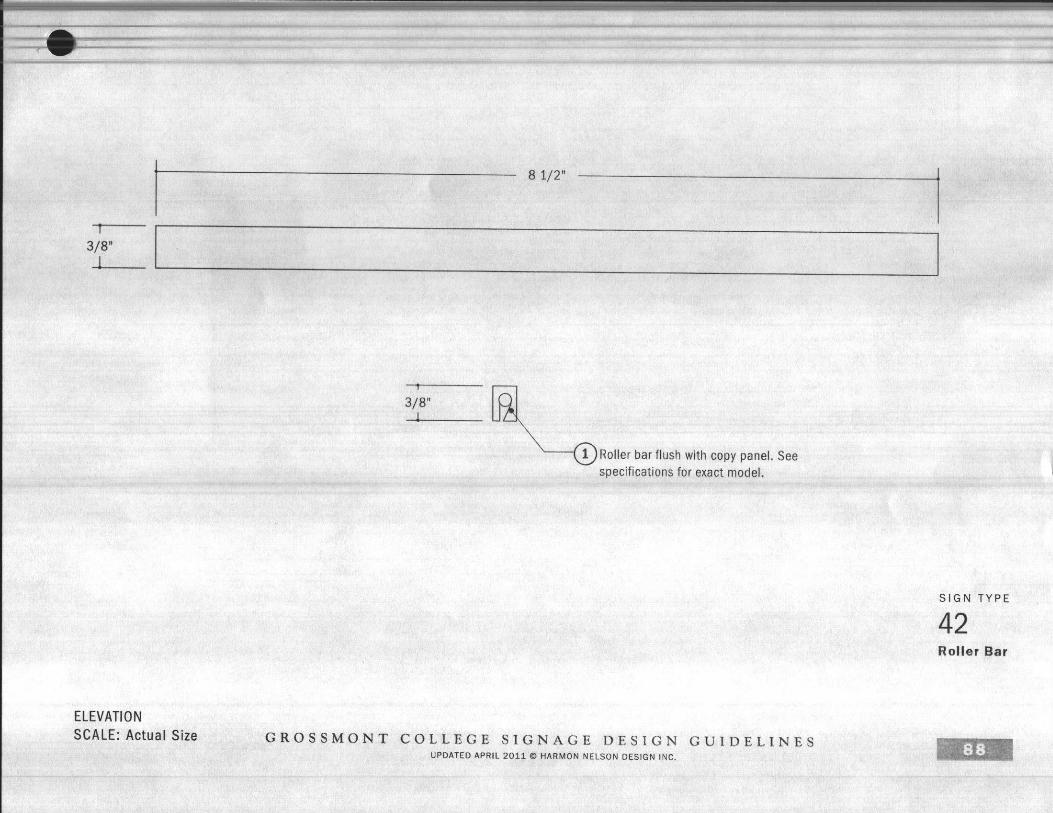
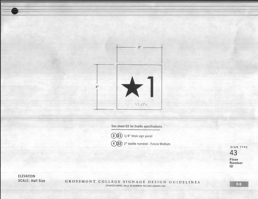
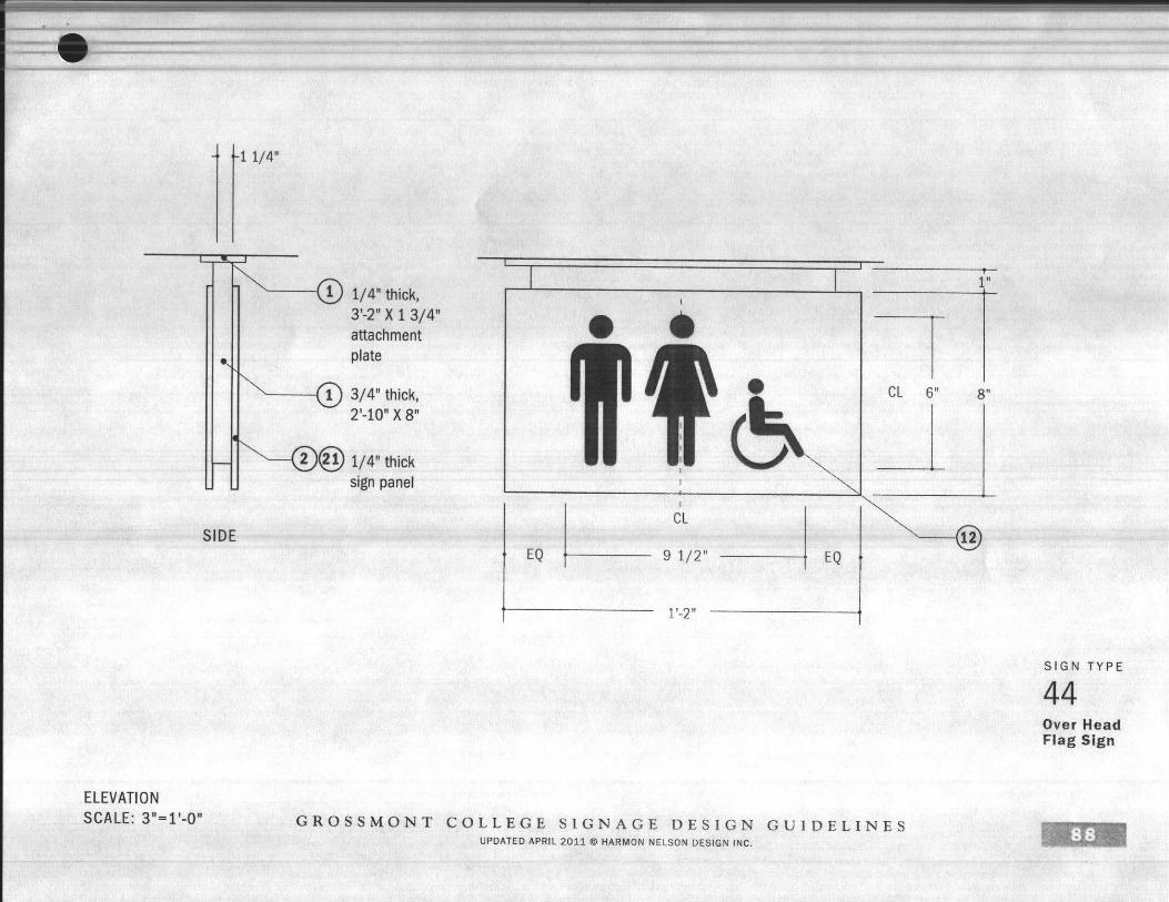
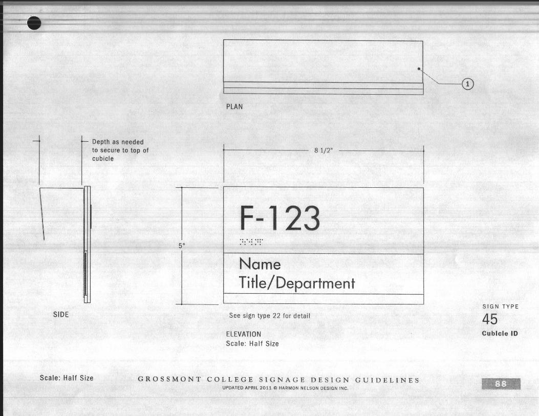
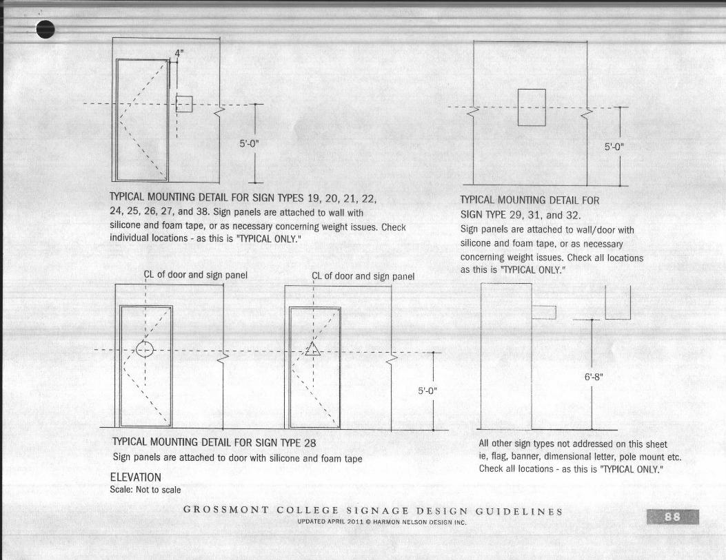
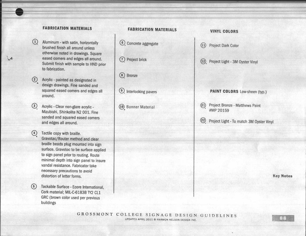
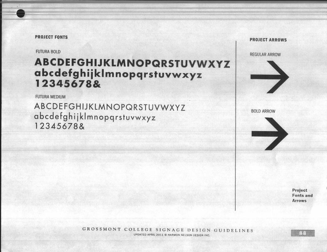
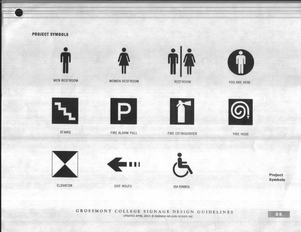
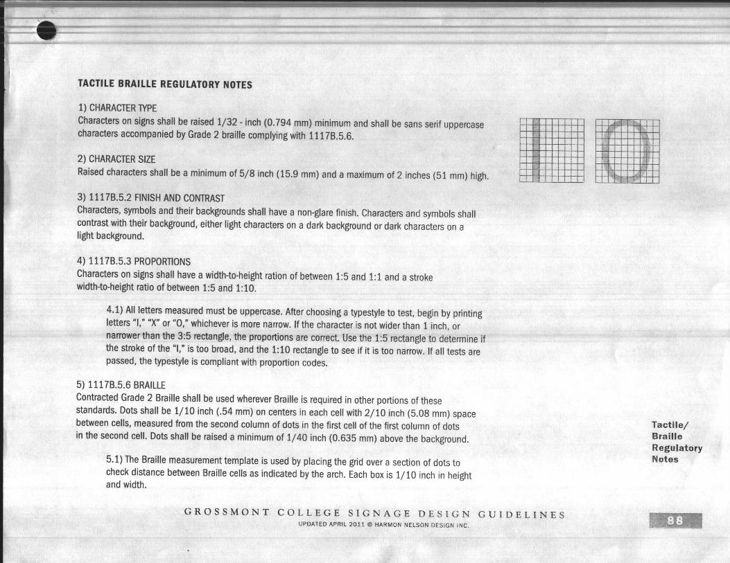

Lighting Guideline MatrixLighting Guideline MatrixLighting Guideline MatrixLighting Guideline Matrix
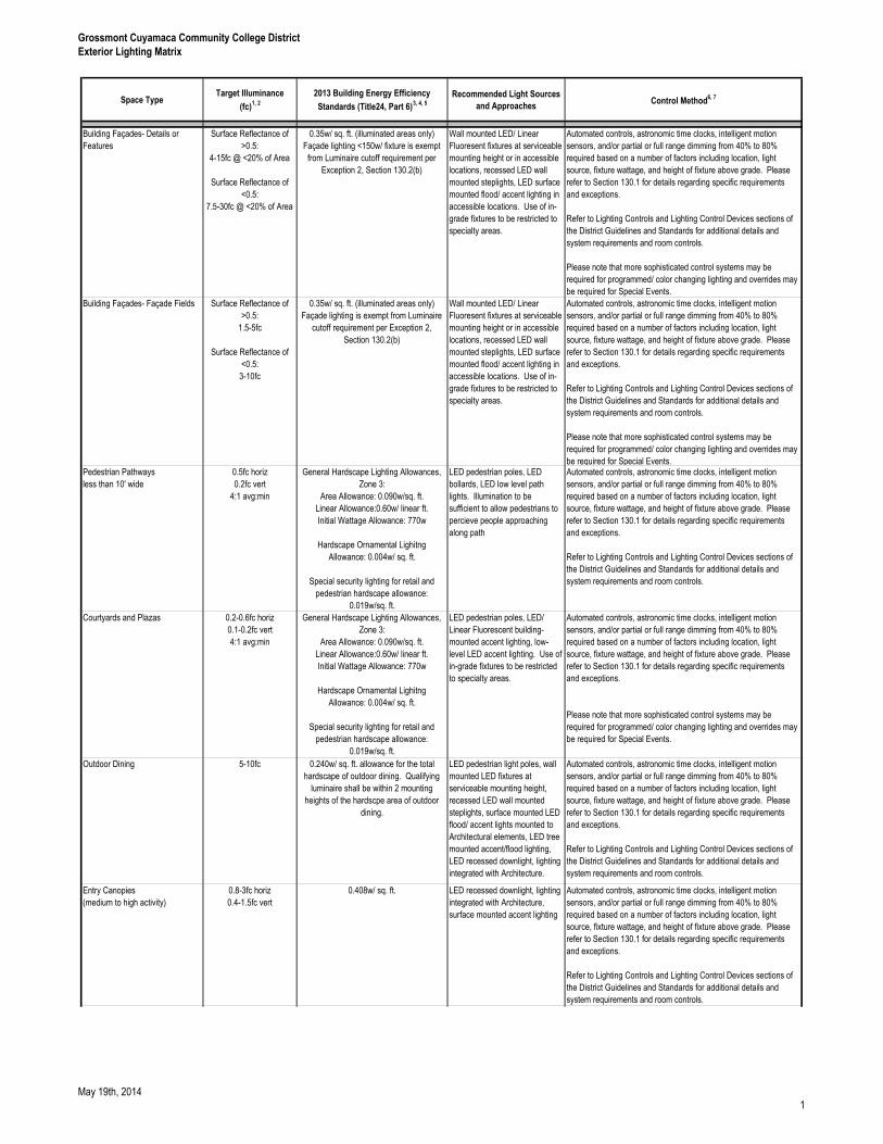
Grossmont Cuyamaca Community College District
Exterior Lighting Matrix
Space TypeTarget Illuminance
(fc)1, 2
2013 Building Energy Efficiency
Standards (Title24, Part 6)3, 4, 5
Recommended Light Sources
and ApproachesControl Method
6, 7
Building Façades- Details or
Features
Surface Reflectance of
>0.5:
4-15fc @ <20% of Area
Surface Reflectance of
<0.5:
7.5-30fc @ <20% of Area
0.35w/ sq. ft. (illuminated areas only)
Façade lighting <150w/ fixture is exempt
from Luminaire cutoff requirement per
Exception 2, Section 130.2(b)
Wall mounted LED/ Linear
Fluoresent fixtures at serviceable
mounting height or in accessible
locations, recessed LED wall
mounted steplights, LED surface
mounted flood/ accent lighting in
accessible locations. Use of in-
grade fixtures to be restricted to
specialty areas.
Automated controls, astronomic time clocks, intelligent motion
sensors, and/or partial or full range dimming from 40% to 80%
required based on a number of factors including location, light
source, fixture wattage, and height of fixture above grade. Please
refer to Section 130.1 for details regarding specific requirements
and exceptions.
Refer to Lighting Controls and Lighting Control Devices sections of
the District Guidelines and Standards for additional details and
system requirements and room controls.
Please note that more sophisticated control systems may be
required for programmed/ color changing lighting and overrides may
be required for Special Events.
Building Façades- Façade Fields Surface Reflectance of
>0.5:
1.5-5fc
Surface Reflectance of
<0.5:
3-10fc
0.35w/ sq. ft. (illuminated areas only)
Façade lighting is exempt from Luminaire
cutoff requirement per Exception 2,
Section 130.2(b)
Wall mounted LED/ Linear
Fluoresent fixtures at serviceable
mounting height or in accessible
locations, recessed LED wall
mounted steplights, LED surface
mounted flood/ accent lighting in
accessible locations. Use of in-
grade fixtures to be restricted to
specialty areas.
Automated controls, astronomic time clocks, intelligent motion
sensors, and/or partial or full range dimming from 40% to 80%
required based on a number of factors including location, light
source, fixture wattage, and height of fixture above grade. Please
refer to Section 130.1 for details regarding specific requirements
and exceptions.
Refer to Lighting Controls and Lighting Control Devices sections of
the District Guidelines and Standards for additional details and
system requirements and room controls.
Please note that more sophisticated control systems may be
required for programmed/ color changing lighting and overrides may
be required for Special Events.Pedestrian Pathways
less than 10' wide
0.5fc horiz
0.2fc vert
4:1 avg:min
General Hardscape Lighting Allowances,
Zone 3:
Area Allowance: 0.090w/sq. ft.
Linear Allowance:0.60w/ linear ft.
Initial Wattage Allowance: 770w
Hardscape Ornamental Lighitng
Allowance: 0.004w/ sq. ft.
Special security lighting for retail and
pedestrian hardscape allowance:
0.019w/sq. ft.
LED pedestrian poles, LED
bollards, LED low level path
lights. Illumination to be
sufficient to allow pedestrians to
percieve people approaching
along path
Automated controls, astronomic time clocks, intelligent motion
sensors, and/or partial or full range dimming from 40% to 80%
required based on a number of factors including location, light
source, fixture wattage, and height of fixture above grade. Please
refer to Section 130.1 for details regarding specific requirements
and exceptions.
Refer to Lighting Controls and Lighting Control Devices sections of
the District Guidelines and Standards for additional details and
system requirements and room controls.
Courtyards and Plazas 0.2-0.6fc horiz
0.1-0.2fc vert
4:1 avg:min
General Hardscape Lighting Allowances,
Zone 3:
Area Allowance: 0.090w/sq. ft.
Linear Allowance:0.60w/ linear ft.
Initial Wattage Allowance: 770w
Hardscape Ornamental Lighitng
Allowance: 0.004w/ sq. ft.
Special security lighting for retail and
pedestrian hardscape allowance:
0.019w/sq. ft.
LED pedestrian poles, LED/
Linear Fluorescent building-
mounted accent lighting, low-
level LED accent lighting. Use of
in-grade fixtures to be restricted
to specialty areas.
Automated controls, astronomic time clocks, intelligent motion
sensors, and/or partial or full range dimming from 40% to 80%
required based on a number of factors including location, light
source, fixture wattage, and height of fixture above grade. Please
refer to Section 130.1 for details regarding specific requirements
and exceptions.
Please note that more sophisticated control systems may be
required for programmed/ color changing lighting and overrides may
be required for Special Events.
Outdoor Dining 5-10fc 0.240w/ sq. ft. allowance for the total
hardscape of outdoor dining. Qualifying
luminaire shall be within 2 mounting
heights of the hardscpe area of outdoor
dining.
LED pedestrian light poles, wall
mounted LED fixtures at
serviceable mounting height,
recessed LED wall mounted
steplights, surface mounted LED
flood/ accent lights mounted to
Architectural elements, LED tree
mounted accent/flood lighting,
LED recessed downlight, lighting
integrated with Architecture.
Automated controls, astronomic time clocks, intelligent motion
sensors, and/or partial or full range dimming from 40% to 80%
required based on a number of factors including location, light
source, fixture wattage, and height of fixture above grade. Please
refer to Section 130.1 for details regarding specific requirements
and exceptions.
Refer to Lighting Controls and Lighting Control Devices sections of
the District Guidelines and Standards for additional details and
system requirements and room controls.
Entry Canopies
(medium to high activity)
0.8-3fc horiz
0.4-1.5fc vert
0.408w/ sq. ft. LED recessed downlight, lighting
integrated with Architecture,
surface mounted accent lighting
Automated controls, astronomic time clocks, intelligent motion
sensors, and/or partial or full range dimming from 40% to 80%
required based on a number of factors including location, light
source, fixture wattage, and height of fixture above grade. Please
refer to Section 130.1 for details regarding specific requirements
and exceptions.
Refer to Lighting Controls and Lighting Control Devices sections of
the District Guidelines and Standards for additional details and
system requirements and room controls.
May 19th, 20141
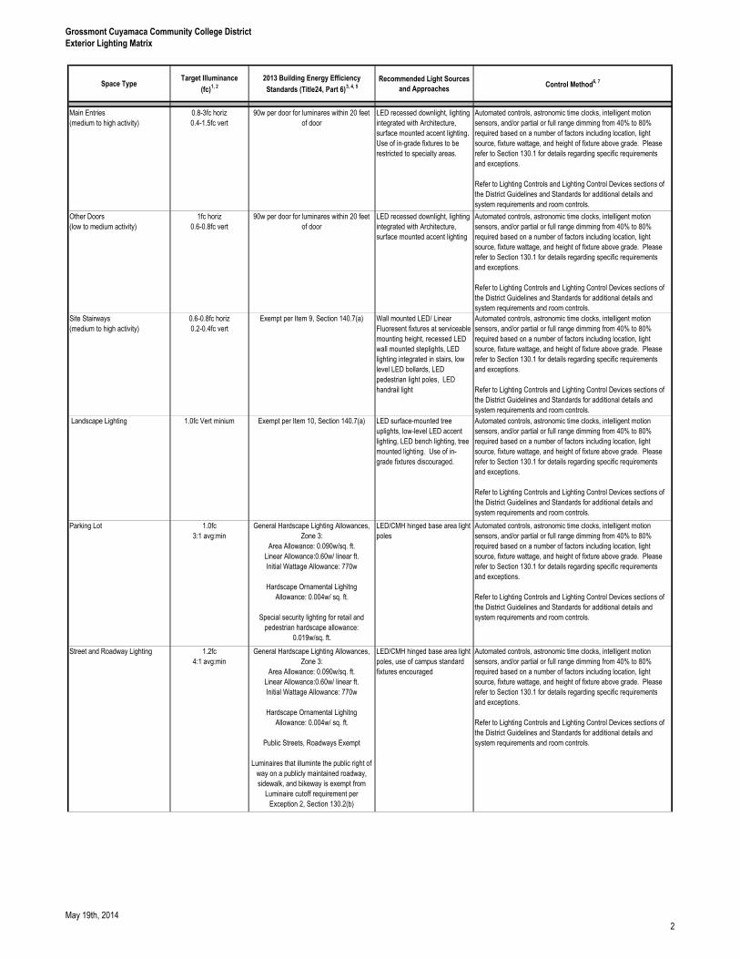
Grossmont Cuyamaca Community College District
Exterior Lighting Matrix
Space TypeTarget Illuminance
(fc)1, 2
2013 Building Energy Efficiency
Standards (Title24, Part 6)3, 4, 5
Recommended Light Sources
and ApproachesControl Method
6, 7
Main Entries
(medium to high activity)
0.8-3fc horiz
0.4-1.5fc vert
90w per door for luminares within 20 feet
of door
LED recessed downlight, lighting
integrated with Architecture,
surface mounted accent lighting.
Use of in-grade fixtures to be
restricted to specialty areas.
Automated controls, astronomic time clocks, intelligent motion
sensors, and/or partial or full range dimming from 40% to 80%
required based on a number of factors including location, light
source, fixture wattage, and height of fixture above grade. Please
refer to Section 130.1 for details regarding specific requirements
and exceptions.
Refer to Lighting Controls and Lighting Control Devices sections of
the District Guidelines and Standards for additional details and
system requirements and room controls.
Other Doors
(low to medium activity)
1fc horiz
0.6-0.8fc vert
90w per door for luminares within 20 feet
of door
LED recessed downlight, lighting
integrated with Architecture,
surface mounted accent lighting
Automated controls, astronomic time clocks, intelligent motion
sensors, and/or partial or full range dimming from 40% to 80%
required based on a number of factors including location, light
source, fixture wattage, and height of fixture above grade. Please
refer to Section 130.1 for details regarding specific requirements
and exceptions.
Refer to Lighting Controls and Lighting Control Devices sections of
the District Guidelines and Standards for additional details and
system requirements and room controls.
Site Stairways
(medium to high activity)
0.6-0.8fc horiz
0.2-0.4fc vert
Exempt per Item 9, Section 140.7(a) Wall mounted LED/ Linear
Fluoresent fixtures at serviceable
mounting height, recessed LED
wall mounted steplights, LED
lighting integrated in stairs, low
level LED bollards, LED
pedestrian light poles, LED
handrail light
Automated controls, astronomic time clocks, intelligent motion
sensors, and/or partial or full range dimming from 40% to 80%
required based on a number of factors including location, light
source, fixture wattage, and height of fixture above grade. Please
refer to Section 130.1 for details regarding specific requirements
and exceptions.
Refer to Lighting Controls and Lighting Control Devices sections of
the District Guidelines and Standards for additional details and
system requirements and room controls.
Landscape Lighting 1.0fc Vert minium Exempt per Item 10, Section 140.7(a) LED surface-mounted tree
uplights, low-level LED accent
lighting, LED bench lighting, tree
mounted lighting. Use of in-
grade fixtures discouraged.
Automated controls, astronomic time clocks, intelligent motion
sensors, and/or partial or full range dimming from 40% to 80%
required based on a number of factors including location, light
source, fixture wattage, and height of fixture above grade. Please
refer to Section 130.1 for details regarding specific requirements
and exceptions.
Refer to Lighting Controls and Lighting Control Devices sections of
the District Guidelines and Standards for additional details and
system requirements and room controls.
Parking Lot 1.0fc
3:1 avg:min
General Hardscape Lighting Allowances,
Zone 3:
Area Allowance: 0.090w/sq. ft.
Linear Allowance:0.60w/ linear ft.
Initial Wattage Allowance: 770w
Hardscape Ornamental Lighitng
Allowance: 0.004w/ sq. ft.
Special security lighting for retail and
pedestrian hardscape allowance:
0.019w/sq. ft.
LED/CMH hinged base area light
poles
Automated controls, astronomic time clocks, intelligent motion
sensors, and/or partial or full range dimming from 40% to 80%
required based on a number of factors including location, light
source, fixture wattage, and height of fixture above grade. Please
refer to Section 130.1 for details regarding specific requirements
and exceptions.
Refer to Lighting Controls and Lighting Control Devices sections of
the District Guidelines and Standards for additional details and
system requirements and room controls.
Street and Roadway Lighting 1.2fc
4:1 avg:min
General Hardscape Lighting Allowances,
Zone 3:
Area Allowance: 0.090w/sq. ft.
Linear Allowance:0.60w/ linear ft.
Initial Wattage Allowance: 770w
Hardscape Ornamental Lighitng
Allowance: 0.004w/ sq. ft.
Public Streets, Roadways Exempt
Luminaires that illuminte the public right of
way on a publicly maintained roadway,
sidewalk, and bikeway is exempt from
Luminaire cutoff requirement per
Exception 2, Section 130.2(b)
LED/CMH hinged base area light
poles, use of campus standard
fixtures encouraged
Automated controls, astronomic time clocks, intelligent motion
sensors, and/or partial or full range dimming from 40% to 80%
required based on a number of factors including location, light
source, fixture wattage, and height of fixture above grade. Please
refer to Section 130.1 for details regarding specific requirements
and exceptions.
Refer to Lighting Controls and Lighting Control Devices sections of
the District Guidelines and Standards for additional details and
system requirements and room controls.
May 19th, 20142
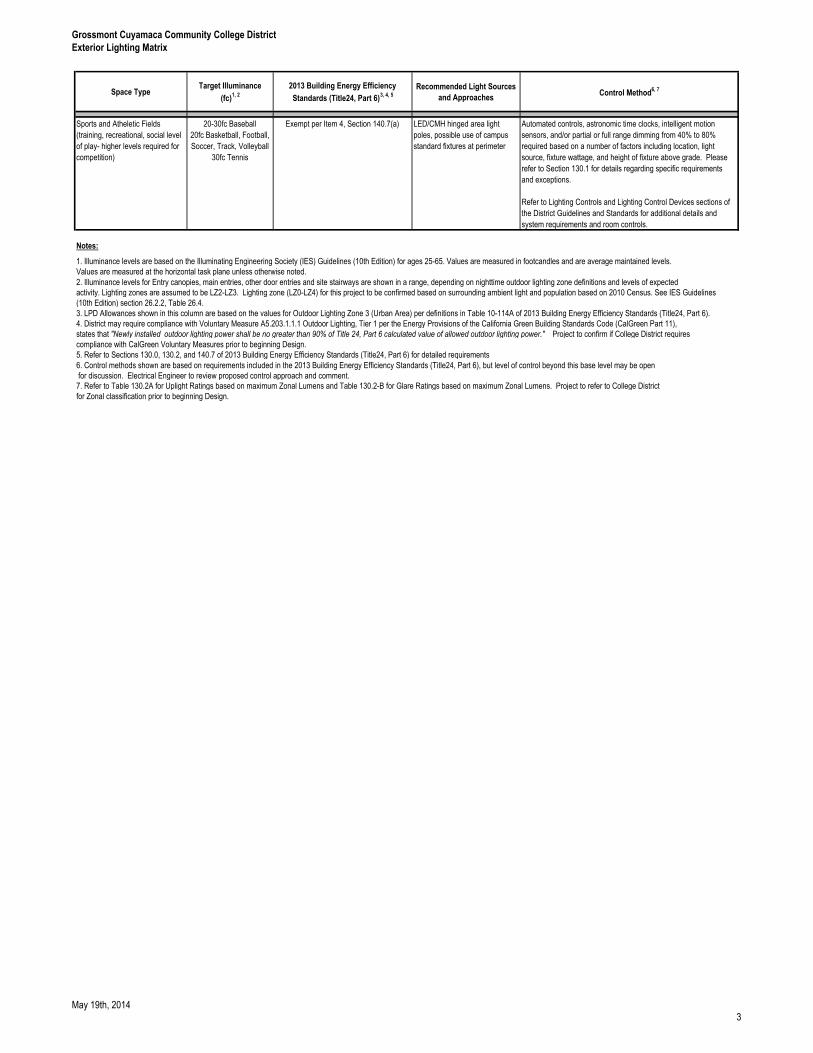
Grossmont Cuyamaca Community College District
Exterior Lighting Matrix
Space TypeTarget Illuminance
(fc)1, 2
2013 Building Energy Efficiency
Standards (Title24, Part 6)3, 4, 5
Recommended Light Sources
and ApproachesControl Method
6, 7
Sports and Atheletic Fields
(training, recreational, social level
of play- higher levels required for
competition)
20-30fc Baseball
20fc Basketball, Football,
Soccer, Track, Volleyball
30fc Tennis
Exempt per Item 4, Section 140.7(a) LED/CMH hinged area light
poles, possible use of campus
standard fixtures at perimeter
Automated controls, astronomic time clocks, intelligent motion
sensors, and/or partial or full range dimming from 40% to 80%
required based on a number of factors including location, light
source, fixture wattage, and height of fixture above grade. Please
refer to Section 130.1 for details regarding specific requirements
and exceptions.
Refer to Lighting Controls and Lighting Control Devices sections of
the District Guidelines and Standards for additional details and
system requirements and room controls.
Notes:
2. Illuminance levels for Entry canopies, main entries, other door entries and site stairways are shown in a range, depending on nighttime outdoor lighting zone definitions and levels of expected
activity. Lighting zones are assumed to be LZ2-LZ3. Lighting zone (LZ0-LZ4) for this project to be confirmed based on surrounding ambient light and population based on 2010 Census. See IES Guidelines
(10th Edition) section 26.2.2, Table 26.4.
3. LPD Allowances shown in this column are based on the values for Outdoor Lighting Zone 3 (Urban Area) per definitions in Table 10-114A of 2013 Building Energy Efficiency Standards (Title24, Part 6).
4. District may require compliance with Voluntary Measure A5.203.1.1.1 Outdoor Lighting, Tier 1 per the Energy Provisions of the California Green Building Standards Code (CalGreen Part 11),
states that "Newly installed outdoor lighting power shall be no greater than 90% of Title 24, Part 6 calculated value of allowed outdoor lighting power." Project to confirm if College District requires
compliance with CalGreen Voluntary Measures prior to beginning Design.
5. Refer to Sections 130.0, 130.2, and 140.7 of 2013 Building Energy Efficiency Standards (Title24, Part 6) for detailed requirements
6. Control methods shown are based on requirements included in the 2013 Building Energy Efficiency Standards (Title24, Part 6), but level of control beyond this base level may be open
for discussion. Electrical Engineer to review proposed control approach and comment.
7. Refer to Table 130.2A for Uplight Ratings based on maximum Zonal Lumens and Table 130.2-B for Glare Ratings based on maximum Zonal Lumens. Project to refer to College District
for Zonal classification prior to beginning Design.
Values are measured at the horizontal task plane unless otherwise noted.
1. Illuminance levels are based on the Illuminating Engineering Society (IES) Guidelines (10th Edition) for ages 25-65. Values are measured in footcandles and are average maintained levels.
May 19th, 20143
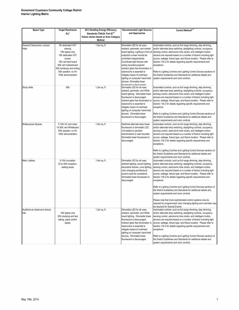
Grossmont Cuyamaca Community College District
Interior Lighting Matrix
Space Type Target Illuminance
(fc)1
2013 Building Energy Efficiency
Standards (Title24, Part 6)2,3
Values shown based on Area Category
Method
Recommended Light Sources
and ApproachesControl Method
4, 5
General Classrooms, Lecture
Halls
5fc dedicated VDT
viewing
15fc laptop only
15fc dedicated VDT
screen
15fc vert tack board
30fc vert markerboard
40fc hardcopy and writing
50fc speaker, no AV
100fc demonstration
1.2w/ sq. ft. Dimmable LED for all uses:
ambient, perimeter, and marker
board lighting. Lighting in front of
projection screen should be
controlled independently.
Coordinate light fixtures with
ceiing mounted projector.
Indirect/ glare free illumination in
classrooms is essential to
mitigate impact of overhead
lighting on computer/ hand-held
devices. Dimmable linear
fluorescent is discouraged
Automated controls, such as full range dimming, step dimming,
and/or alternate lamp switching, daylighting controls, occupancy
sensing control, astronomic time clocks, and intelligent motion
sensors are required based on a number of factors including light
source, wattage, fixture type, and fixture location. Please refer to
Section 130.2 for details regarding specific requirements and
exceptions.
Refer to Lighting Controls and Lighting Control Devices sections of
the District Guidelines and Standards for additional details and
system requirements and room controls.
Study Halls 30fc 1.2w/ sq. ft. Dimmable LED for all uses:
ambient, perimeter, and White
board lighting. Dimmable linear
fluorescent is discouraged.
Indirect/ glare free illumination in
classrooms is essential to
mitigate impact of overhead
lighting on computer/ hand-held
devices. Dimmable linear
fluorescent is discouraged.
Automated controls, such as full range dimming, step dimming,
and/or alternate lamp switching, daylighting controls, occupancy
sensing control, astronomic time clocks, and intelligent motion
sensors are required based on a number of factors including light
source, wattage, fixture type, and fixture location. Please refer to
Section 130.2 for details regarding specific requirements and
exceptions.
Refer to Lighting Controls and Lighting Control Devices sections of
the District Guidelines and Standards for additional details and
system requirements and room controls.
Multipurpose Spaces 5-10fc AV and notes
15-30fc vert Whiteboard
50fc speaker, no AV
100fc demonstration
1.4w/ sq. ft. Switched alternate lamp linear
fluorescent or dimmable LED,
1x4 basket or pendant
direct/indirect or wall mounted.
Dimmable linear fluorescent is
discouraged.
Automated controls, such as full range dimming, step dimming,
and/or alternate lamp switching, daylighting controls, occupancy
sensing control, astronomic time clocks, and intelligent motion
sensors are required based on a number of factors including light
source, wattage, fixture type, and fixture location. Please refer to
Section 130.2 for details regarding specific requirements and
exceptions.
Refer to Lighting Controls and Lighting Control Devices sections of
the District Guidelines and Standards for additional details and
system requirements and room controls.
Main Lobbies 5-10fc circulation
20 to 40fc reception,
waiting areas
1.5w/ sq. ft. Dimmable LED for all uses:
ambient lighting, accent lighting,
decorative fixtures, cove lighting,
color-changing architectural
accent could be considered.
Dimmable linear fluorescent is
discouraged.
Automated controls, such as full range dimming, step dimming,
and/or alternate lamp switching, daylighting controls, occupancy
sensing control, astronomic time clocks, and intelligent motion
sensors are required based on a number of factors including light
source, wattage, fixture type, and fixture location. Please refer to
Section 130.2 for details regarding specific requirements and
exceptions.
Refer to Lighting Controls and Lighting Control Devices sections of
the District Guidelines and Standards for additional details and
system requirements and room controls.
Please note that more sophisticated control systems may be
required for programmed/ color changing lighting and overrides may
be required for Special Events.
Auditoria as classroom/ lecture
hall 15fc laptop only
30fc studying and test
taking, paper and/or
laptop
1.2w/ sq. ft. Dimmable LED for all uses:
ambient, perimeter, and White
board lighting. Dimmable linear
fluorescent is discouraged.
Indirect/ glare free illumination in
classrooms is essential to
mitigate impact of overhead
lighting on computer/ hand-held
devices. Dimmable linear
fluorescent is discouraged.
Automated controls, such as full range dimming, step dimming,
and/or alternate lamp switching, daylighting controls, occupancy
sensing control, astronomic time clocks, and intelligent motion
sensors are required based on a number of factors including light
source, wattage, fixture type, and fixture location. Please refer to
Section 130.2 for details regarding specific requirements and
exceptions.
Refer to Lighting Controls and Lighting Control Devices sections of
the District Guidelines and Standards for additional details and
system requirements and room controls.
May 19th, 2014 1
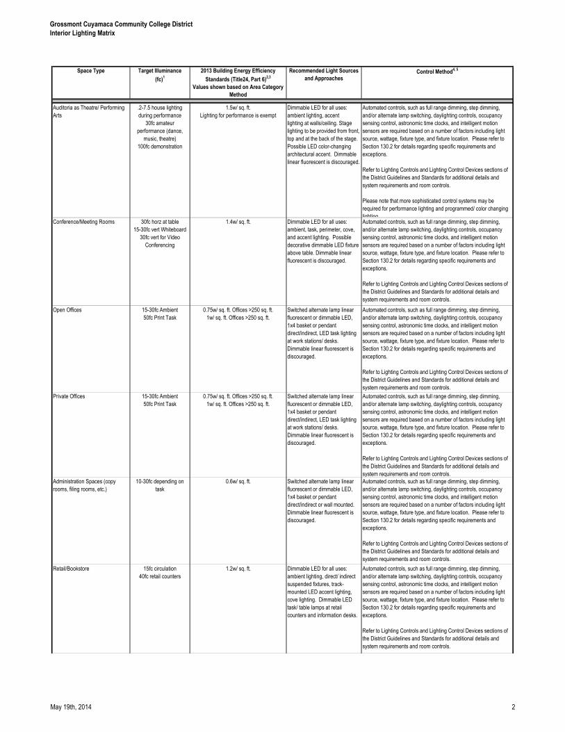
Grossmont Cuyamaca Community College District
Interior Lighting Matrix
Space Type Target Illuminance
(fc)1
2013 Building Energy Efficiency
Standards (Title24, Part 6)2,3
Values shown based on Area Category
Method
Recommended Light Sources
and ApproachesControl Method
4, 5
Auditoria as Theatre/ Performing
Arts
.2-7.5 house lighting
during performance
30fc amateur
performance (dance,
music, theatre)
100fc demonstration
1.5w/ sq. ft.
Lighting for performance is exempt
Dimmable LED for all uses:
ambient lighting, accent
lighting at walls/ceiling. Stage
lighting to be provided from front,
top and at the back of the stage.
Possible LED color-changing
architectural accent. Dimmable
linear fluorescent is discouraged.
Automated controls, such as full range dimming, step dimming,
and/or alternate lamp switching, daylighting controls, occupancy
sensing control, astronomic time clocks, and intelligent motion
sensors are required based on a number of factors including light
source, wattage, fixture type, and fixture location. Please refer to
Section 130.2 for details regarding specific requirements and
exceptions.
Refer to Lighting Controls and Lighting Control Devices sections of
the District Guidelines and Standards for additional details and
system requirements and room controls.
Please note that more sophisticated control systems may be
required for performance lighting and programmed/ color changing
lighting. Conference/Meeting Rooms 30fc horz at table
15-30fc vert Whiteboard
30fc vert for Video
Conferencing
1.4w/ sq. ft. Dimmable LED for all uses:
ambient, task, perimeter, cove,
and accent lighting. Possible
decorative dimmable LED fixture
above table. Dimmable linear
fluorescent is discouraged.
Automated controls, such as full range dimming, step dimming,
and/or alternate lamp switching, daylighting controls, occupancy
sensing control, astronomic time clocks, and intelligent motion
sensors are required based on a number of factors including light
source, wattage, fixture type, and fixture location. Please refer to
Section 130.2 for details regarding specific requirements and
exceptions.
Refer to Lighting Controls and Lighting Control Devices sections of
the District Guidelines and Standards for additional details and
system requirements and room controls.
Open Offices 15-30fc Ambient
50fc Print Task
0.75w/ sq. ft. Offices >250 sq. ft.
1w/ sq. ft. Offices >250 sq. ft.
Switched alternate lamp linear
fluorescent or dimmable LED,
1x4 basket or pendant
direct/indirect, LED task lighting
at work stations/ desks.
Dimmable linear fluorescent is
discouraged.
Automated controls, such as full range dimming, step dimming,
and/or alternate lamp switching, daylighting controls, occupancy
sensing control, astronomic time clocks, and intelligent motion
sensors are required based on a number of factors including light
source, wattage, fixture type, and fixture location. Please refer to
Section 130.2 for details regarding specific requirements and
exceptions.
Refer to Lighting Controls and Lighting Control Devices sections of
the District Guidelines and Standards for additional details and
system requirements and room controls.
Private Offices 15-30fc Ambient
50fc Print Task
0.75w/ sq. ft. Offices >250 sq. ft.
1w/ sq. ft. Offices >250 sq. ft.
Switched alternate lamp linear
fluorescent or dimmable LED,
1x4 basket or pendant
direct/indirect, LED task lighting
at work stations/ desks.
Dimmable linear fluorescent is
discouraged.
Automated controls, such as full range dimming, step dimming,
and/or alternate lamp switching, daylighting controls, occupancy
sensing control, astronomic time clocks, and intelligent motion
sensors are required based on a number of factors including light
source, wattage, fixture type, and fixture location. Please refer to
Section 130.2 for details regarding specific requirements and
exceptions.
Refer to Lighting Controls and Lighting Control Devices sections of
the District Guidelines and Standards for additional details and
system requirements and room controls.
Administration Spaces (copy
rooms, filing rooms, etc.)
10-30fc depending on
task
0.6w/ sq. ft. Switched alternate lamp linear
fluorescent or dimmable LED,
1x4 basket or pendant
direct/indirect or wall mounted.
Dimmable linear fluorescent is
discouraged.
Automated controls, such as full range dimming, step dimming,
and/or alternate lamp switching, daylighting controls, occupancy
sensing control, astronomic time clocks, and intelligent motion
sensors are required based on a number of factors including light
source, wattage, fixture type, and fixture location. Please refer to
Section 130.2 for details regarding specific requirements and
exceptions.
Refer to Lighting Controls and Lighting Control Devices sections of
the District Guidelines and Standards for additional details and
system requirements and room controls.
Retail/Bookstore 15fc circulation
40fc retail counters
1.2w/ sq. ft. Dimmable LED for all uses:
ambient lighting, direct/ indirect
suspended fixtures, track-
mounted LED accent lighting,
cove lighting. Dimmable LED
task/ table lamps at retail
counters and information desks.
Automated controls, such as full range dimming, step dimming,
and/or alternate lamp switching, daylighting controls, occupancy
sensing control, astronomic time clocks, and intelligent motion
sensors are required based on a number of factors including light
source, wattage, fixture type, and fixture location. Please refer to
Section 130.2 for details regarding specific requirements and
exceptions.
Refer to Lighting Controls and Lighting Control Devices sections of
the District Guidelines and Standards for additional details and
system requirements and room controls.
May 19th, 2014 2
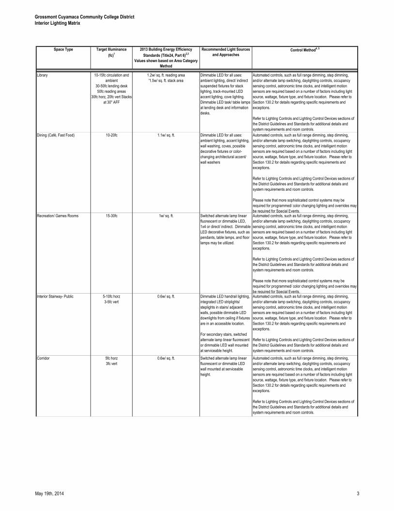
Grossmont Cuyamaca Community College District
Interior Lighting Matrix
Space Type Target Illuminance
(fc)1
2013 Building Energy Efficiency
Standards (Title24, Part 6)2,3
Values shown based on Area Category
Method
Recommended Light Sources
and ApproachesControl Method
4, 5
Library 10-15fc circulation and
ambient
30-50fc lending desk
50fc reading areas
30fc horz, 20fc vert Stacks
at 30" AFF
1.2w/ sq. ft. reading area
'1.5w/ sq. ft. stack area
Dimmable LED for all uses:
ambient lighting, direct/ indirect
suspended fixtures for stack
lighting, track-mounted LED
accent lighting, cove lighting.
Dimmable LED task/ table lamps
at lending desk and information
desks.
Automated controls, such as full range dimming, step dimming,
and/or alternate lamp switching, daylighting controls, occupancy
sensing control, astronomic time clocks, and intelligent motion
sensors are required based on a number of factors including light
source, wattage, fixture type, and fixture location. Please refer to
Section 130.2 for details regarding specific requirements and
exceptions.
Refer to Lighting Controls and Lighting Control Devices sections of
the District Guidelines and Standards for additional details and
system requirements and room controls.
Dining (Café, Fast Food) 10-20fc 1.1w/ sq. ft. Dimmable LED for all uses:
ambient lighting, accent lighting,
wall washing, coves, possible
decorative fixtures or color-
changing architectural accent/
wall washers
Automated controls, such as full range dimming, step dimming,
and/or alternate lamp switching, daylighting controls, occupancy
sensing control, astronomic time clocks, and intelligent motion
sensors are required based on a number of factors including light
source, wattage, fixture type, and fixture location. Please refer to
Section 130.2 for details regarding specific requirements and
exceptions.
Refer to Lighting Controls and Lighting Control Devices sections of
the District Guidelines and Standards for additional details and
system requirements and room controls.
Please note that more sophisticated control systems may be
required for programmed/ color changing lighting and overrides may
be required for Special Events.Recreation/ Games Rooms 15-30fc 1w/ sq. ft. Switched alternate lamp linear
fluorescent or dimmable LED,
1x4 or direct/ indirect. Dimmable
LED decorative fixtures, such as
pendants, table lamps, and floor
lamps may be utilized.
Automated controls, such as full range dimming, step dimming,
and/or alternate lamp switching, daylighting controls, occupancy
sensing control, astronomic time clocks, and intelligent motion
sensors are required based on a number of factors including light
source, wattage, fixture type, and fixture location. Please refer to
Section 130.2 for details regarding specific requirements and
exceptions.
Refer to Lighting Controls and Lighting Control Devices sections of
the District Guidelines and Standards for additional details and
system requirements and room controls.
Please note that more sophisticated control systems may be
required for programmed/ color changing lighting and overrides may
be required for Special Events.Interior Stairway- Public 5-10fc horz
3-5fc vert
0.6w/ sq. ft. Dimmable LED handrail lighting,
integrated LED striplights/
steplights in stairs/ adjacent
walls, possible dimmable LED
downlights from ceiling if fixtures
are in an accessible location.
For secondary stairs, switched
alternate lamp linear fluorescent
or dimmable LED wall mounted
at serviceable height.
Automated controls, such as full range dimming, step dimming,
and/or alternate lamp switching, daylighting controls, occupancy
sensing control, astronomic time clocks, and intelligent motion
sensors are required based on a number of factors including light
source, wattage, fixture type, and fixture location. Please refer to
Section 130.2 for details regarding specific requirements and
exceptions.
Refer to Lighting Controls and Lighting Control Devices sections of
the District Guidelines and Standards for additional details and
system requirements and room controls.
Corridor 5fc horz
3fc vert
0.6w/ sq. ft. Switched alternate lamp linear
fluorescent or dimmable LED
wall mounted at serviceable
height.
Automated controls, such as full range dimming, step dimming,
and/or alternate lamp switching, daylighting controls, occupancy
sensing control, astronomic time clocks, and intelligent motion
sensors are required based on a number of factors including light
source, wattage, fixture type, and fixture location. Please refer to
Section 130.2 for details regarding specific requirements and
exceptions.
Refer to Lighting Controls and Lighting Control Devices sections of
the District Guidelines and Standards for additional details and
system requirements and room controls.
May 19th, 2014 3
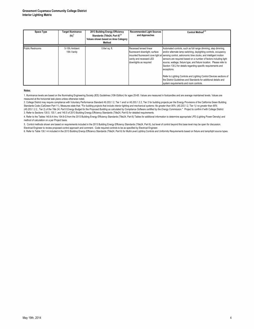
Grossmont Cuyamaca Community College District
Interior Lighting Matrix
Space Type Target Illuminance
(fc)1
2013 Building Energy Efficiency
Standards (Title24, Part 6)2,3
Values shown based on Area Category
Method
Recommended Light Sources
and ApproachesControl Method
4, 5
Public Restrooms 5-10fc Ambient
15fc Vanity
0.6w/ sq. ft. Recessed lensed linear
fluorescent downlight, surface
mounted fluorescent cove light at
vanity and recessed LED
downlights as required
Automated controls, such as full range dimming, step dimming,
and/or alternate lamp switching, daylighting controls, occupancy
sensing control, astronomic time clocks, and intelligent motion
sensors are required based on a number of factors including light
source, wattage, fixture type, and fixture location. Please refer to
Section 130.2 for details regarding specific requirements and
exceptions.
Refer to Lighting Controls and Lighting Control Devices sections of
the District Guidelines and Standards for additional details and
system requirements and room controls.
Notes:
6. Refer to Table 130.1-A included in the 2013 Building Energy Efficiency Standards (Title24, Part 6) for Multi-Level Lighting Controls and Uniformity Requirements based on fixture and lamp/light source types.
1. Illuminance levels are based on the Illuminating Engineering Society (IES) Guidelines (10th Edition) for ages 25-65. Values are measured in footcandles and are average maintained levels. Values are
measured at the horizontal task plane unless otherwise noted.
2. College District may require compliance with Voluntary Performance Standard A5.203.1.2, Tier 1 and/ or A5.203.1.2.2, Tier 2 for building projects per the Energy Provisions of the California Green Building
Standards Code (CalGreen Part 11), Measures state that; "For building projects that include interior lighting and mechanical systems: No greater than 90% (A5.203.1.2, Tier 1)/ no greater than 85%
(A5.203.1.2.2., Tier 2) of the Title 24, Part 6 Energy Budget for the Proposed Building as calculated by Compliance Software certified by the Energy Commission." Project to confirm if with College District
3. Refer to Sections 130.0, 130.1, and 140.5 of 2013 Building Energy Efficiency Standards (Title24, Part 6) for detailed requirements.
4. Refer to the Tables 140.6-A thru 104.6-G from the 2013 Building Energy Efficiency Standards (Title24, Part 6) Tables for additional information to determine appropriate LPD (Lighting Power Density) and
method of calculation on a per Project basis.
5. Control methods shown are based on requirements included in the 2013 Building Energy Efficiency Standards (Title24, Part 6), but level of control beyond this base level may be open for discussion.
Electrical Engineer to review proposed control approach and comment. Code required controls to be as specified by Electrical Engineer.
May 19th, 2014 4
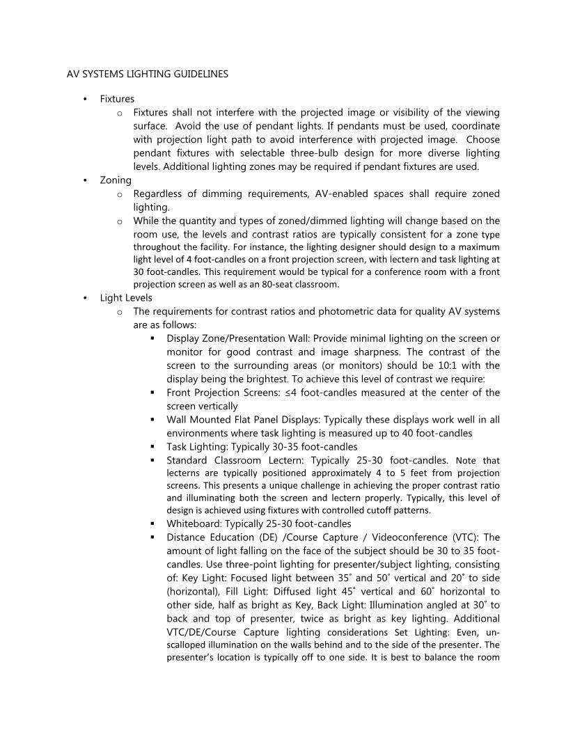
AV SYSTEMS LIGHTING GUIDELINES
• Fixtures
o Fixtures shall not interfere with the projected image or visibility of the viewing
surface. Avoid the use of pendant lights. If pendants must be used, coordinate
with projection light path to avoid interference with projected image. Choose
pendant fixtures with selectable three-bulb design for more diverse lighting
levels. Additional lighting zones may be required if pendant fixtures are used.
• Zoning
o Regardless of dimming requirements, AV-enabled spaces shall require zoned
lighting.
o While the quantity and types of zoned/dimmed lighting will change based on the
room use, the levels and contrast ratios are typically consistent for a zone type
throughout the facility. For instance, the lighting designer should design to a maximum
light level of 4 foot-candles on a front projection screen, with lectern and task lighting at
30 foot-candles. This requirement would be typical for a conference room with a front
projection screen as well as an 80-seat classroom.
• Light Levels
o The requirements for contrast ratios and photometric data for quality AV systems
are as follows:
� Display Zone/Presentation Wall: Provide minimal lighting on the screen or
monitor for good contrast and image sharpness. The contrast of the
screen to the surrounding areas (or monitors) should be 10:1 with the
display being the brightest. To achieve this level of contrast we require:
� Front Projection Screens: ≤4 foot-candles measured at the center of the
screen vertically
� Wall Mounted Flat Panel Displays: Typically these displays work well in all
environments where task lighting is measured up to 40 foot-candles
� Task Lighting: Typically 30-35 foot-candles
� Standard Classroom Lectern: Typically 25-30 foot-candles. Note that
lecterns are typically positioned approximately 4 to 5 feet from projection
screens. This presents a unique challenge in achieving the proper contrast ratio
and illuminating both the screen and lectern properly. Typically, this level of
design is achieved using fixtures with controlled cutoff patterns.
� Whiteboard: Typically 25-30 foot-candles
� Distance Education (DE) /Course Capture / Videoconference (VTC): The
amount of light falling on the face of the subject should be 30 to 35 foot-
candles. Use three-point lighting for presenter/subject lighting, consisting
of: Key Light: Focused light between 35˚ and 50˚ vertical and 20˚ to side
(horizontal), Fill Light: Diffused light 45˚ vertical and 60˚ horizontal to
other side, half as bright as Key, Back Light: Illumination angled at 30˚ to
back and top of presenter, twice as bright as key lighting. Additional
VTC/DE/Course Capture lighting considerations Set Lighting: Even, un-
scalloped illumination on the walls behind and to the side of the presenter. The
presenter’s location is typically off to one side. It is best to balance the room
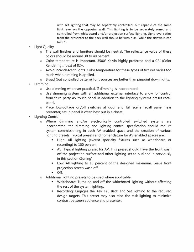
with set lighting that may be separately controlled, but capable of the same
light level on the opposing wall. This lighting is to be separately zoned and
controlled from whiteboard and/or projection surface lighting. Light level ratios
from the presenter to the back wall should be within 3:1 while the sidewalls can
be 5:1.
• Light Quality
o The wall finishes and furniture should be neutral. The reflectance value of these
colors should be around 30 to 40 percent.
o Color temperature is important. 3500° Kelvin highly preferred and a CRI (Color
Rendering Index) of 82+.
o Avoid incandescent lights. Color temperature for these types of fixtures varies too
much when dimming is applied.
o Broad (but controlled pattern) light sources are better than pinpoint down lights.
• Dimming
o Use dimming wherever practical. If dimming is incorporated:
o Use dimming system with an additional external interface to allow for control
from third party AV touch panel in addition to the lighting systems preset recall
panel.
o Place low-voltage on/off switches at door and full scene recall panel near
presenter; setup panel is often best put in a closet.
• Lighting Control
o Where dimming and/or electronically controlled switched systems are
incorporated, the dimming and lighting control specification should require
system commissioning in each AV-enabled space and the creation of various
lighting presets. Typical presets and nomenclature for AV enabled spaces are:
� High: All lighting (except specialty fixtures such as whiteboard or
recording) to 100 percent.
� AV: Typical lighting preset for AV. This preset should have the front wash
off the projection surface and other lighting set to outlined in previously
in this section (Zoning)
� Low: All lighting to 15 percent of the designed maximum. Leave front
projection screen wash off.
� Off.
o Additional lighting presets to be used where applicable:
� Whiteboard: Turns on and off the whiteboard lighting without affecting
the rest of the system lighting.
� Recording: Engages the Key, Fill, Back and Set lighting to the required
design targets. This preset may also raise the task lighting to minimize
contrast between audience and presenter.

IT and Cabling Information IT and Cabling Information IT and Cabling Information IT and Cabling Information
GCCCD IT + CABLING REQUIREMENTS
I) DESIGN GUIDELINES FOR TELECOMMUNICATIONS
A) General Issues
1) A Grossmont-Cuyamaca Community College District Information Systems Designee shall be
assigned to all construction projects
a) The IS designee shall
(1) Be available and participate during all phases of design and during the construction
period.
(2) assist in understanding the current needs of the IT department to support the
student, faculty and staff IT needs within the building
b) GCCCD Information Technology Contacts
(1) Primary contact(s):
Brian Nath
GCCCD Senior Director of Information Systems
619-6447536-1135 (office)
(2) Secondary Contact
Steve Abat
GCCCD Director, Technical Services
619-644-7776 (office)
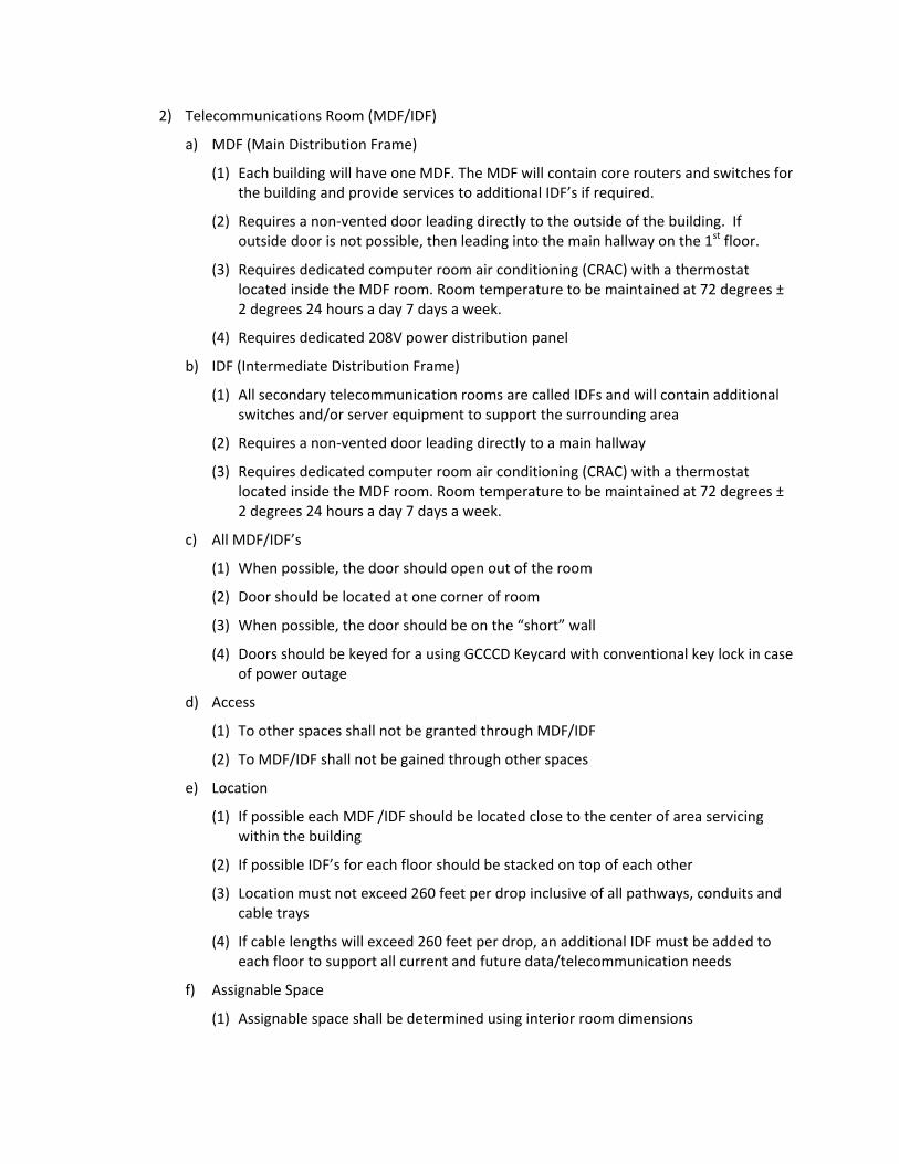
2) Telecommunications Room (MDF/IDF)
a) MDF (Main Distribution Frame)
(1) Each building will have one MDF. The MDF will contain core routers and switches for
the building and provide services to additional IDF’s if required.
(2) Requires a non-vented door leading directly to the outside of the building. If
outside door is not possible, then leading into the main hallway on the 1st
floor.
(3) Requires dedicated computer room air conditioning (CRAC) with a thermostat
located inside the MDF room. Room temperature to be maintained at 72 degrees ±
2 degrees 24 hours a day 7 days a week.
(4) Requires dedicated 208V power distribution panel
b) IDF (Intermediate Distribution Frame)
(1) All secondary telecommunication rooms are called IDFs and will contain additional
switches and/or server equipment to support the surrounding area
(2) Requires a non-vented door leading directly to a main hallway
(3) Requires dedicated computer room air conditioning (CRAC) with a thermostat
located inside the MDF room. Room temperature to be maintained at 72 degrees ±
2 degrees 24 hours a day 7 days a week.
c) All MDF/IDF’s
(1) When possible, the door should open out of the room
(2) Door should be located at one corner of room
(3) When possible, the door should be on the “short” wall
(4) Doors should be keyed for a using GCCCD Keycard with conventional key lock in case
of power outage
d) Access
(1) To other spaces shall not be granted through MDF/IDF
(2) To MDF/IDF shall not be gained through other spaces
e) Location
(1) If possible each MDF /IDF should be located close to the center of area servicing
within the building
(2) If possible IDF’s for each floor should be stacked on top of each other
(3) Location must not exceed 260 feet per drop inclusive of all pathways, conduits and
cable trays
(4) If cable lengths will exceed 260 feet per drop, an additional IDF must be added to
each floor to support all current and future data/telecommunication needs
f) Assignable Space
(1) Assignable space shall be determined using interior room dimensions
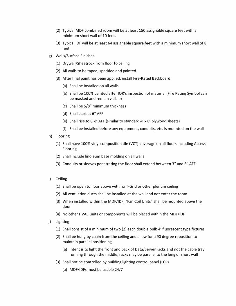
(2) Typical MDF combined room will be at least 150 assignable square feet with a
minimum short wall of 10 feet.
(3) Typical IDF will be at least 64 assignable square feet with a minimum short wall of 8
feet.
g) Walls/Surface Finishes
(1) Drywall/Sheetrock from floor to ceiling
(2) All walls to be taped, spackled and painted
(3) After final paint has been applied, install Fire-Rated Backboard
(a) Shall be installed on all walls
(b) Shall be 100% painted after IOR’s inspection of material (Fire Rating Symbol can
be masked and remain visible)
(c) Shall be 5/8” minimum thickness
(d) Shall start at 6” AFF
(e) Shall rise to 8 ½’ AFF (similar to standard 4’ x 8’ plywood sheets)
(f) Shall be installed before any equipment, conduits, etc. is mounted on the wall
h) Flooring
(1) Shall have 100% vinyl composition tile (VCT) coverage on all floors including Access
Flooring
(2) Shall include linoleum base molding on all walls
(3) Conduits or sleeves penetrating the floor shall extend between 3” and 6” AFF
i) Ceiling
(1) Shall be open to floor above with no T-Grid or other plenum ceiling
(2) All ventilation ducts shall be installed at the wall and not enter the room
(3) When installed within the MDF/IDF, “Fan Coil Units” shall be mounted above the
door
(4) No other HVAC units or components will be placed within the MDF/IDF
j) Lighting
(1) Shall consist of a minimum of two (2) each double bulb 4’ fluorescent type fixtures
(2) Shall be hung by chain from the ceiling and allow for a 90 degree reposition to
maintain parallel positioning
(a) Intent is to light the front and back of Data/Server racks and not the cable tray
running through the middle, racks may be parallel to the long or short wall
(3) Shall not be controlled by building lighting control panel (LCP)
(a) MDF/IDFs must be usable 24/7
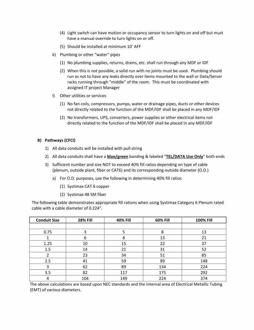
(4) Light switch can have motion or occupancy sensor to turn lights on and off but must
have a manual override to turn lights on or off.
(5) Should be installed at minimum 10’ AFF
k) Plumbing or other “water” pipes
(1) No plumbing supplies, returns, drains, etc. shall run through any MDF or IDF
(2) When this is not possible, a solid run with no joints must be used. Plumbing should
run as not to have any leaks directly over items mounted to the wall or Data/Server
racks running through “middle” of the room. This must be coordinated with
assigned IT project Manager
l) Other utilities or services
(1) No fan coils, compressors, pumps, water or drainage pipes, ducts or other devices
not directly related to the function of the MDF/IDF shall be placed in any MDF/IDF
(2) No transformers, UPS, converters, power supplies or other electrical items not
directly related to the function of the MDF/IDF shall be placed in any MDF/IDF
B) Pathways (CFCI)
1) All data conduits will be installed with pull string
2) All data conduits shall have a blue/green banding & labeled “TEL/DATA Use Only” both ends
3) Sufficient number and size NOT to exceed 40% fill ratios depending on type of cable
(plenum, outside plant, fiber or CAT6) and its corresponding outside diameter (O.D.)
a) For O.D. purposes, use the following in determining 40% fill ratios
(1) Systimax CAT 6 copper
(2) Systimax 48 SM fiber
The following table demonstrates appropriate fill rations when using Systimax Category 6 Plenum rated
cable with a cable diameter of 0.224”.
Conduit Size 28% Fill 40% Fill 60% Fill 100% Fill
0.75 3 5 8 13
1 6 8 13 21
1.25 10 15 22 37
1.5 14 21 31 52
2 23 34 51 85
2.5 41 59 89 148
3 62 89 134 224
3.5 82 117 175 292
4 104 149 224 374
The above calculations are based upon NEC standards and the internal area of Electrical Metallic Tubing
(EMT) of various diameters.
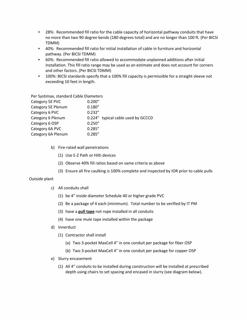
• 28%: Recommended fill ratio for the cable capacity of horizontal pathway conduits that have
no more than two 90 degree bends (180 degrees total) and are no longer than 100 ft. (Per BICSI
TDMM)
• 40%: Recommended fill ratio for initial installation of cable in furniture and horizontal
pathway. (Per BICSI TDMM)
• 60%: Recommended fill ratio allowed to accommodate unplanned additions after initial
installation. This fill ratio range may be used as an estimate and does not account for corners
and other factors. (Per BICSI TDMM)
• 100%: BICSI standards specify that a 100% fill capacity is permissible for a straight sleeve not
exceeding 10 feet in length.
Per Systimax, standard Cable Diameters
Category 5E PVC 0.200”
Category 5E Plenum 0.180”
Category 6 PVC 0.232”
Category 6 Plenum 0.224” typical cable used by GCCCD
Category 6 OSP 0.250”
Category 6A PVC 0.285”
Category 6A Plenum 0.285”
b) Fire-rated wall penetrations
(1) Use E-Z Path or Hilti devices
(2) Observe 40% fill ratios based on same criteria as above
(3) Ensure all fire caulking is 100% complete and inspected by IOR prior to cable pulls
Outside plant
c) All conduits shall
(1) be 4” inside diameter Schedule 40 or higher grade PVC
(2) Be a package of 4 each (minimum). Total number to be verified by IT PM
(3) have a pull tape not rope installed in all conduits
(4) have one mule tape installed within the package
d) Innerduct
(1) Contractor shall install
(a) Two 3-pocket MaxCell 4” in one conduit per package for fiber OSP
(b) Two 3-pocket MaxCell 4” in one conduit per package for copper OSP
e) Slurry encasement
(1) All 4” conduits to be installed during construction will be installed at prescribed
depth using chairs to set spacing and encased in slurry (see diagram below).
4)
(2) Typical
4) Inside Plant
a) Inside conduits, cable trays, pathways and wall penetrations
(1) Shall meet all requirements as specified by IEEE 802.3u
(2) Shall be clearly identified on all DD, DSA and Construction
(3) All conduits and cable trays must have access from an accessible area
(4) The primary pathways for inside plant should be via the above ceiling grid space.
Below or in slab conduits for data should only be utilized when absolutely necessary.
(5) Insid
above ceiling grid areas.
b) Floor Boxes/Wall Access panels
(1) Raised floor/Access flooring
(a)
(b)
(c)
(d)
(e)
Typical depth is 4 feet with 3 feet of coverage over encasement as shown
Inside Plant
Inside conduits, cable trays, pathways and wall penetrations
Shall meet all requirements as specified by IEEE 802.3u
Shall be clearly identified on all DD, DSA and Construction
All conduits and cable trays must have access from an accessible area
The primary pathways for inside plant should be via the above ceiling grid space.
Below or in slab conduits for data should only be utilized when absolutely necessary.
Inside plant should utilize cable tray as the primary means of distribution in the
above ceiling grid areas.
Floor Boxes/Wall Access panels
Raised floor/Access flooring
(a) Submit one with electrical and data compartments configured as a submittal
item.
(b) Comply with requirements of applicable local codes, NEC, UL, and NEMA
Standards pertaining to floor boxes and components. Meet or exceed UL Fire
Classification requirements for recessed and flush style boxes. Listed and
Labeled in accordance with NFPA 70, Articl
(c) Accessibility Compliance: Design device flange to meet ADA Accessibility
Guidelines as to changes in floor and ground surface levels.
(d) Must be capable of accommodating a minimum two 20 amp 120VAC electrical
circuits and 12 CAT
(e) Box should have at a minimum, three (3) 1” concentric knockouts, one (1) 1.25”
Knockout, and one (1) 2” knockout.
depth is 4 feet with 3 feet of coverage over encasement as shown
Inside conduits, cable trays, pathways and wall penetrations
Shall meet all requirements as specified by IEEE 802.3u
Shall be clearly identified on all DD, DSA and Construction
All conduits and cable trays must have access from an accessible area
The primary pathways for inside plant should be via the above ceiling grid space.
Below or in slab conduits for data should only be utilized when absolutely necessary.
e plant should utilize cable tray as the primary means of distribution in the
above ceiling grid areas.
Floor Boxes/Wall Access panels
Raised floor/Access flooring
Submit one with electrical and data compartments configured as a submittal
with requirements of applicable local codes, NEC, UL, and NEMA
Standards pertaining to floor boxes and components. Meet or exceed UL Fire
Classification requirements for recessed and flush style boxes. Listed and
Labeled in accordance with NFPA 70, Articl
Accessibility Compliance: Design device flange to meet ADA Accessibility
Guidelines as to changes in floor and ground surface levels.
Must be capable of accommodating a minimum two 20 amp 120VAC electrical
circuits and 12 CAT-6 data circuits
ld have at a minimum, three (3) 1” concentric knockouts, one (1) 1.25”
Knockout, and one (1) 2” knockout.
depth is 4 feet with 3 feet of coverage over encasement as shown
Inside conduits, cable trays, pathways and wall penetrations
Shall meet all requirements as specified by IEEE 802.3u
Shall be clearly identified on all DD, DSA and Construction
All conduits and cable trays must have access from an accessible area
The primary pathways for inside plant should be via the above ceiling grid space.
Below or in slab conduits for data should only be utilized when absolutely necessary.
e plant should utilize cable tray as the primary means of distribution in the
Floor Boxes/Wall Access panels
Raised floor/Access flooring
Submit one with electrical and data compartments configured as a submittal
with requirements of applicable local codes, NEC, UL, and NEMA
Standards pertaining to floor boxes and components. Meet or exceed UL Fire
Classification requirements for recessed and flush style boxes. Listed and
Labeled in accordance with NFPA 70, Articl
Accessibility Compliance: Design device flange to meet ADA Accessibility
Guidelines as to changes in floor and ground surface levels.
Must be capable of accommodating a minimum two 20 amp 120VAC electrical
6 data circuits
ld have at a minimum, three (3) 1” concentric knockouts, one (1) 1.25”
Knockout, and one (1) 2” knockout.
depth is 4 feet with 3 feet of coverage over encasement as shown
Inside conduits, cable trays, pathways and wall penetrations
Shall meet all requirements as specified by IEEE 802.3u
Shall be clearly identified on all DD, DSA and Construction
All conduits and cable trays must have access from an accessible area
The primary pathways for inside plant should be via the above ceiling grid space.
Below or in slab conduits for data should only be utilized when absolutely necessary.
e plant should utilize cable tray as the primary means of distribution in the
Submit one with electrical and data compartments configured as a submittal
with requirements of applicable local codes, NEC, UL, and NEMA
Standards pertaining to floor boxes and components. Meet or exceed UL Fire
Classification requirements for recessed and flush style boxes. Listed and
Labeled in accordance with NFPA 70, Article 100
Accessibility Compliance: Design device flange to meet ADA Accessibility
Guidelines as to changes in floor and ground surface levels.
Must be capable of accommodating a minimum two 20 amp 120VAC electrical
ld have at a minimum, three (3) 1” concentric knockouts, one (1) 1.25”
depth is 4 feet with 3 feet of coverage over encasement as shown
Inside conduits, cable trays, pathways and wall penetrations
Shall meet all requirements as specified by IEEE 802.3u
Shall be clearly identified on all DD, DSA and Construction Drawings
All conduits and cable trays must have access from an accessible area
The primary pathways for inside plant should be via the above ceiling grid space.
Below or in slab conduits for data should only be utilized when absolutely necessary.
e plant should utilize cable tray as the primary means of distribution in the
Submit one with electrical and data compartments configured as a submittal
with requirements of applicable local codes, NEC, UL, and NEMA
Standards pertaining to floor boxes and components. Meet or exceed UL Fire
Classification requirements for recessed and flush style boxes. Listed and
Accessibility Compliance: Design device flange to meet ADA Accessibility
Guidelines as to changes in floor and ground surface levels.
Must be capable of accommodating a minimum two 20 amp 120VAC electrical
ld have at a minimum, three (3) 1” concentric knockouts, one (1) 1.25”
depth is 4 feet with 3 feet of coverage over encasement as shown
Drawings
All conduits and cable trays must have access from an accessible area
The primary pathways for inside plant should be via the above ceiling grid space.
Below or in slab conduits for data should only be utilized when absolutely necessary.
e plant should utilize cable tray as the primary means of distribution in the
Submit one with electrical and data compartments configured as a submittal
with requirements of applicable local codes, NEC, UL, and NEMA
Standards pertaining to floor boxes and components. Meet or exceed UL Fire
Classification requirements for recessed and flush style boxes. Listed and
Accessibility Compliance: Design device flange to meet ADA Accessibility
Must be capable of accommodating a minimum two 20 amp 120VAC electrical
ld have at a minimum, three (3) 1” concentric knockouts, one (1) 1.25”
The primary pathways for inside plant should be via the above ceiling grid space.
Below or in slab conduits for data should only be utilized when absolutely necessary.
e plant should utilize cable tray as the primary means of distribution in the
Submit one with electrical and data compartments configured as a submittal
Standards pertaining to floor boxes and components. Meet or exceed UL Fire
Must be capable of accommodating a minimum two 20 amp 120VAC electrical
ld have at a minimum, three (3) 1” concentric knockouts, one (1) 1.25”
(f) Floor box covers should be manufactured from die-cast aluminum with powder
coat finish. The covers should have the capability to accept tile or carpet inserts
or solid covers.
(g) Conduits feeding floor box need to accommodate the fill ratio for power and
data cables being installed at the specific location. Coordinate final
configuration with IT PM.
(2) Cast in Concrete
(a) Submit one with electrical and data compartments configured as a submittal
item.
(b) Comply with requirements of applicable local codes, NEC, UL, and NEMA
Standards pertaining to floor boxes and components. Meet or exceed UL Fire
Classification requirements for recessed and flush style boxes. Listed and
Labeled in accordance with NFPA 70, Article 100
(c) Accessibility Compliance: Design device flange to meet ADA Accessibility
Guidelines as to changes in floor and ground surface levels.
(d) Must be capable of accommodating a minimum two 20 amp 120VAC electrical
circuits and 12 CAT-6 data circuits
(e) Box should have at a minimum, three (3) 1” concentric knockouts, one (1) 1.25”
Knockout, and one (1) 2” knockout.
(f) Floor box covers should be manufactured to meet requirements for cast in
concrete environment. The covers should have the capability to accept tile or
carpet inserts or solid covers.
(g) Conduits feeding floor box need to accommodate the fill ratio for power and
data cables being installed at the specific location. Coordinate final
configuration with IT PM.
c) Surface Mounted Raceways
(1) Surface mounted Raceways
(a) Raceway will be a minimum dual channel raceway for branch circuit wiring and
data network, voice, audio video low voltage wiring.
(b) Raceway should be manufactured from aluminum alloy and be UL Listed
(c) Should feature a two piece design with a base and a snap-on cover.
(d) Minimum size should be a minimum of 8 sq. inches of internal volume space of
which 4.5 sq. inches for the data compartment and 3.5 sq. inches for the
electrical compartment.
d) Number of riser conduits/sleeves shall be sufficient between the floors
(1) All conduits or sleeves will be 4” in size

(2) Minimum of two conduits/sleeves for each IDF above or below MDF. Refer to 40%
fill ratios in determining the number conduit/sleeves required. This shall be verified
with IT PM
Example - MDF (1st
Floor) to IDFs on 2nd
, 3rd
and 4th
floors
• MDF to IDF 2nd
floor – minimum 6 conduits/sleeves
• IDF (2nd
floor) to IDF (3rd
Floor) – minimum 4 conduits/sleeves
• IDF (3rd
floor) to IDF (4th
floor) – minimum 2 conduits/sleeves
e) Conduit risers within classrooms, labs, lecture halls, conference rooms and offices
(1) All data drops should be fed by minimum 1” conduits within the wall and/or floors
(2) All data boxes should be Quad electrical J-box with duplex reducer mounted within
the wall
(3) Data boxes should normally have (1) 1” EMT from j-box location to an accessible
ceiling space
(4) If more than 6-8 cable drops are needed, either use;
(a) One each 2” EMT, or
(b) Two each 1” EMT, or
(c) More as prescribed by 40% fill ratio for CAT6 UTP plenum cable per
manufacturer’s specification
f) Recommended penetrations for fire-rated walls are EZ-Path (preferred) and Hilti devices
(1) Quantity and size of these devices should be consistent for the number of cables
that will pass through the wall.
(2) Installation of these devices should include all fire stopping required to maintain fire
rating of fire-rated walls
(3) Wiring contractors will provide fire stopping to the interior of conduits, etc.as
required to maintain fire rating of fire-rated wall
C) Electrical Requirements
5) Power Panels/Distribution Panels (CFCI)
a) A dedicated surface-mounted Power Distribution Panel (sized as necessary to
accommodate the required circuits) should be located in the MDF room. This panel will
provide power (at a minimum) to the main Critical Power IT UPS (Uninterruptible Power
Supply) and convenience outlets within the MDF
b) A surface-mounted Critical Power Distribution Panel (sized appropriately to
accommodate all individual dedicated circuits for all floors in a stack) to be located in
the MDF room. This panel is fed from the output of the Critical Power IT UPS.
6) Ground Bus (CFCI)
a) A ground bus bar is required in each MDF/IDF
b) All ground bus bars are to be the same electrical ground as building ground for electrical
systems for the building
c) Each MDF/IDF ground bus bar shall be tied together with the ground bus bar located in
the MDF
7) Convenience Outlets
a) One Quad Outlet will be located in the middle each wall
(1) If any wall is longer than 10 feet, then place (2) each quad outlets evenly spaced
b) One Duplex Outlet will be located at 96” AFF on the opposite “short” wall from the door
c) One Duplex outlet will be located on the “short” wall adjacent to the door per Intrusion
panel
(1) Verify with District Fire/Alarm team on number of intrusion panels in each MDF/IDF
8) Controls
a) MDF/IDF requires 7/24 service
b) Electrical, lighting and CRAC requirements preclude placing these services on a building
management system
c) District monitoring of lighting and CRAC should be included with local controls for both.
d) HVAC/Lighting Control may be located in the MDF Telco on same short wall adjacent to
Door as Fire/Intrusion alarm systems at 96” AFF or higher
9) Transformers/Inverters
a) No transformers should be co-located within the MDF or IDF rooms
b) No transformers in adjacent rooms should be on common walls with the MDF or IDF
rooms
c) No Inverters should be co-located in any MDF/IDF
10) Telco UPS Requirements (OFCI)
a) District IT will purchase an appropriate size UPS for each MDF/IDF
b) Construction Electrical contractor shall be responsible to provide the appropriate plugs,
outlets, wiring, conduits and installation as required, thus Owner Furnished Equipment
(UPS) and Contractor Installed (all other items not limited to what is described here)
c) District IT will determine which makes and models will be installed for each new
building. This information will include the number of UPS that will be installed, which
MDF/IDFs and make/models of each unit.
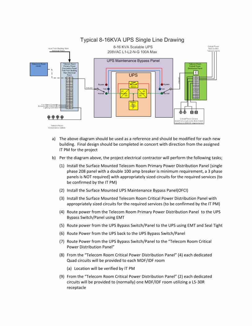
a) The above diagram should be used as a reference and should be modified for each new
building. Final de
IT PM for the project
b) Per the diagram above, the project electrical contractor will perform the following tasks;
(1) Install the Surface Mounted Telecom Room Primary Power Distribution Panel
phase 208 panel with a double 100 amp breaker is minimum requirement, a 3 phase
panels is NOT required} with appropriately sized circuits for the required services (to
be confirmed by the IT PM)
(2) Install the Surface Mounted UPS Maintenance Bypass P
(3) Install the Surface Mounted Telecom Room Critical Power Distribution Panel with
appropriately sized circuits for the required services (to be confirmed by the IT PM)
(4) Route power from the Telecom Room Primary Power Distribution Panel to the UPS
Bypass Switch/Panel using EMT
(5) Route power from the UPS Bypass Switch/Panel to the UPS using EMT and Seal Tight
(6) Route Power from the UPS back to the UPS Bypass Switch/Panel
(7) Route Power from the UPS Bypass Switch/Panel to the “Telecom Room Critical
Power Di
(8) From the “Telecom Room Critical Power Distribution Panel” (4) each dedicated
Quad circuits will be provided to each MDF/IDF room
(a)
(9) From the “Telecom Room Critical Power Distribution Panel” (2) each dedicat
circuits will be provided to (normally) one MDF/IDF room utilizing a L5
receptacle
The above diagram should be used as a reference and should be modified for each new
building. Final design should be completed in concert with direction from the assigned
IT PM for the project
Per the diagram above, the project electrical contractor will perform the following tasks;
Install the Surface Mounted Telecom Room Primary Power Distribution Panel
phase 208 panel with a double 100 amp breaker is minimum requirement, a 3 phase
panels is NOT required} with appropriately sized circuits for the required services (to
be confirmed by the IT PM)
Install the Surface Mounted UPS Maintenance Bypass P
Install the Surface Mounted Telecom Room Critical Power Distribution Panel with
appropriately sized circuits for the required services (to be confirmed by the IT PM)
Route power from the Telecom Room Primary Power Distribution Panel to the UPS
Bypass Switch/Panel using EMT
Route power from the UPS Bypass Switch/Panel to the UPS using EMT and Seal Tight
Route Power from the UPS back to the UPS Bypass Switch/Panel
Route Power from the UPS Bypass Switch/Panel to the “Telecom Room Critical
Power Distribution Panel”
From the “Telecom Room Critical Power Distribution Panel” (4) each dedicated
Quad circuits will be provided to each MDF/IDF room
(a) Location will be verified by IT PM
From the “Telecom Room Critical Power Distribution Panel” (2) each dedicat
circuits will be provided to (normally) one MDF/IDF room utilizing a L5
receptacle
The above diagram should be used as a reference and should be modified for each new
sign should be completed in concert with direction from the assigned
IT PM for the project
Per the diagram above, the project electrical contractor will perform the following tasks;
Install the Surface Mounted Telecom Room Primary Power Distribution Panel
phase 208 panel with a double 100 amp breaker is minimum requirement, a 3 phase
panels is NOT required} with appropriately sized circuits for the required services (to
be confirmed by the IT PM)
Install the Surface Mounted UPS Maintenance Bypass P
Install the Surface Mounted Telecom Room Critical Power Distribution Panel with
appropriately sized circuits for the required services (to be confirmed by the IT PM)
Route power from the Telecom Room Primary Power Distribution Panel to the UPS
Bypass Switch/Panel using EMT
Route power from the UPS Bypass Switch/Panel to the UPS using EMT and Seal Tight
Route Power from the UPS back to the UPS Bypass Switch/Panel
Route Power from the UPS Bypass Switch/Panel to the “Telecom Room Critical
stribution Panel”
From the “Telecom Room Critical Power Distribution Panel” (4) each dedicated
Quad circuits will be provided to each MDF/IDF room
Location will be verified by IT PM
From the “Telecom Room Critical Power Distribution Panel” (2) each dedicat
circuits will be provided to (normally) one MDF/IDF room utilizing a L5
The above diagram should be used as a reference and should be modified for each new
sign should be completed in concert with direction from the assigned
Per the diagram above, the project electrical contractor will perform the following tasks;
Install the Surface Mounted Telecom Room Primary Power Distribution Panel
phase 208 panel with a double 100 amp breaker is minimum requirement, a 3 phase
panels is NOT required} with appropriately sized circuits for the required services (to
be confirmed by the IT PM)
Install the Surface Mounted UPS Maintenance Bypass P
Install the Surface Mounted Telecom Room Critical Power Distribution Panel with
appropriately sized circuits for the required services (to be confirmed by the IT PM)
Route power from the Telecom Room Primary Power Distribution Panel to the UPS
Bypass Switch/Panel using EMT
Route power from the UPS Bypass Switch/Panel to the UPS using EMT and Seal Tight
Route Power from the UPS back to the UPS Bypass Switch/Panel
Route Power from the UPS Bypass Switch/Panel to the “Telecom Room Critical
From the “Telecom Room Critical Power Distribution Panel” (4) each dedicated
Quad circuits will be provided to each MDF/IDF room
Location will be verified by IT PM
From the “Telecom Room Critical Power Distribution Panel” (2) each dedicat
circuits will be provided to (normally) one MDF/IDF room utilizing a L5
The above diagram should be used as a reference and should be modified for each new
sign should be completed in concert with direction from the assigned
Per the diagram above, the project electrical contractor will perform the following tasks;
Install the Surface Mounted Telecom Room Primary Power Distribution Panel
phase 208 panel with a double 100 amp breaker is minimum requirement, a 3 phase
panels is NOT required} with appropriately sized circuits for the required services (to
Install the Surface Mounted UPS Maintenance Bypass P
Install the Surface Mounted Telecom Room Critical Power Distribution Panel with
appropriately sized circuits for the required services (to be confirmed by the IT PM)
Route power from the Telecom Room Primary Power Distribution Panel to the UPS
Route power from the UPS Bypass Switch/Panel to the UPS using EMT and Seal Tight
Route Power from the UPS back to the UPS Bypass Switch/Panel
Route Power from the UPS Bypass Switch/Panel to the “Telecom Room Critical
From the “Telecom Room Critical Power Distribution Panel” (4) each dedicated
Quad circuits will be provided to each MDF/IDF room
From the “Telecom Room Critical Power Distribution Panel” (2) each dedicat
circuits will be provided to (normally) one MDF/IDF room utilizing a L5
The above diagram should be used as a reference and should be modified for each new
sign should be completed in concert with direction from the assigned
Per the diagram above, the project electrical contractor will perform the following tasks;
Install the Surface Mounted Telecom Room Primary Power Distribution Panel
phase 208 panel with a double 100 amp breaker is minimum requirement, a 3 phase
panels is NOT required} with appropriately sized circuits for the required services (to
Install the Surface Mounted UPS Maintenance Bypass Panel(OFCI)
Install the Surface Mounted Telecom Room Critical Power Distribution Panel with
appropriately sized circuits for the required services (to be confirmed by the IT PM)
Route power from the Telecom Room Primary Power Distribution Panel to the UPS
Route power from the UPS Bypass Switch/Panel to the UPS using EMT and Seal Tight
Route Power from the UPS back to the UPS Bypass Switch/Panel
Route Power from the UPS Bypass Switch/Panel to the “Telecom Room Critical
From the “Telecom Room Critical Power Distribution Panel” (4) each dedicated
From the “Telecom Room Critical Power Distribution Panel” (2) each dedicat
circuits will be provided to (normally) one MDF/IDF room utilizing a L5
The above diagram should be used as a reference and should be modified for each new
sign should be completed in concert with direction from the assigned
Per the diagram above, the project electrical contractor will perform the following tasks;
Install the Surface Mounted Telecom Room Primary Power Distribution Panel [single
phase 208 panel with a double 100 amp breaker is minimum requirement, a 3 phase
panels is NOT required} with appropriately sized circuits for the required services (to
Install the Surface Mounted Telecom Room Critical Power Distribution Panel with
appropriately sized circuits for the required services (to be confirmed by the IT PM)
Route power from the Telecom Room Primary Power Distribution Panel to the UPS
Route power from the UPS Bypass Switch/Panel to the UPS using EMT and Seal Tight
Route Power from the UPS Bypass Switch/Panel to the “Telecom Room Critical
From the “Telecom Room Critical Power Distribution Panel” (4) each dedicated
From the “Telecom Room Critical Power Distribution Panel” (2) each dedicated
circuits will be provided to (normally) one MDF/IDF room utilizing a L5-30R
The above diagram should be used as a reference and should be modified for each new
sign should be completed in concert with direction from the assigned
Per the diagram above, the project electrical contractor will perform the following tasks;
[single
phase 208 panel with a double 100 amp breaker is minimum requirement, a 3 phase
panels is NOT required} with appropriately sized circuits for the required services (to
Install the Surface Mounted Telecom Room Critical Power Distribution Panel with
appropriately sized circuits for the required services (to be confirmed by the IT PM)
Route power from the Telecom Room Primary Power Distribution Panel to the UPS
Route power from the UPS Bypass Switch/Panel to the UPS using EMT and Seal Tight
Route Power from the UPS Bypass Switch/Panel to the “Telecom Room Critical
From the “Telecom Room Critical Power Distribution Panel” (4) each dedicated
ed

(a) Location will be verified by IT PM
(10) All circuits and receptacle’s will be labeled at each location
c) In addition, a dedicated wall mounted L6-30R is needed in each IDF. Location to be
determined by assigned IT PM
(1) Separate dedicated circuit from the “Telecom Room Primary Power Distribution
Panel” to each Telco
(2) L6-30R will be mounted on the wall
(a) Location to be verified by IT PM
D) Heat Loads
2) Initial equipment heats loads will be based on the placement of 1-3 core switches in the
MDF and 1-2 Core switches or multiple Stackable Switches in each IDF.
a) Location of the Core Switches will generally be in the 1st floor MDF room but could be
located on an upper floor as directed by the District IT Manager
b) Each Core switch has redundant 1200 watt power supplies and will be at max loads
c) Stackable switches at 375 watts may be distributed throughout the building MDF/IDF
locations
3) MDF will have a minimum of one 12-16 kVA UPS with up to 16kVA load (this includes a core
router switches and servers)
4) Each IDF will have a minimum of 2 and a maximum of 8 switches at 375 watts each (750-
3000 watts) plus any required HP DL380 series servers. Estimating 2-4 servers (800 watts
each) could be added within 1- 2 years after opening building. This could add an additional
1600 - 3200 watts of load in an IDF room.
C) GCCCD Information Systems Designee
1) A GCCCD Information Systems designee will assist the project architect and electrical
engineer to determine the following information;
a) Cable pathways
(1) Cable trays
(2) Conduits
(3) Which manhole will provide District IT backbone facilities
b) J-box locations for;
(1) Data/telephone drops
(2) Emergency phone drops including site located Talk-a-phone
(3) Call box drops
c) Provide location in MDF and/or IDFs for the following items;
(1) Fire panels and Annunciators
(2) Intrusion panels
(3) Wiring (110 blocks)
(4) HVAC controller(s)
(5) Lighting Control panel(s)
d) The GCCCD Information Systems designee will work with Campus A/V coordinator, will
provide assistance with Infrastructure to support A/V equipment
e) Coordinating work of district wiring vendor
f) MDF and IDF room layout
g) Wiring plan
h) Outside Plant Cabling (OSP) both copper and fiber
i) Inside Plant Cabling (ISP) both copper and fiber
j) All other wiring needed for other items, TV, Video-teleconferencing, etc.
k) IT switch locations
l) Assist (with campus A/V coordinator)in coordinating work of district A/V vendor
m) Assist (with District Police) in coordinating work of District Safety Camera vendor.
D) GCCCD Information Systems designee will assist the General Contractor foreman/project
manager or Construction Manager (CM-Multi-Prime contracts) Superintendent/Project
manager with the following;
1) Setting up a meeting to integrate installation of OSP and ISP cabling with District Wiring
Vendor into the Project Master Schedule
2) Setting up a meeting to integrate installation of A/V wiring and equipment into the Project
Master Schedule
3) Coordinating District IT personnel to support network and telephone needs for
commissioning items
4) Coordinating District IT personnel and District Wiring Contractor to support FF&E items for a
successful move-in of District Staff/faculty/Students into new and renovated buildings
5) Be the primary point of contact for District IT related issues during to the construction
period
6) Attending meetings as needed to maintain active communications for District IT during the
construction period.
E) The GCCCD Information Systems (IS) Department works with the architect and engineers to
design the following:
1) Data/telephone cabling pathways
a) Cable Trays
b) Data/Telephone Conduit and Box Locations
c) Conduit Labeling
d) Pull Strings
2) Ladder rack installations in primary corridors/hallways
3) Audio Visual solutions, infrastructure to support (power/conduits/floor box locations)
4) Lighting issues in all classrooms/conference rooms that will have Audio Visual solutions
5) Dedicated power to Audio Visual locations
6) MDF/IDF room (MDF/IDF) size, backboards, lighting, ground bus bars
7) Fire Panel location if in MDF/IDF
8) Alarm Panel location if in MDF/IDF
9) MDF/IDF Dedicated Power Distribution panels
10) MDF/IDF Dedicated CRAC if needed
11) Conduit from nearest campus data manhole to new building
NOTE: All of the above shall be part of the construction contract
F) GCCCD contracts with their own third party vendors to procure and/or install some or all of
the following:
1) UPS and UPS Equipment
2) All racks, cable tray, wire management residing in the MDF/IDF(s)
3) All Data/Telephone Cabling
4) Audio Visual equipment to include possible electric screens in ceiling grid and projector
mounting hardware
5) Telephone solutions, including desktop phones and emergency classroom phones
6) Camera systems, if any
7) All fiber-optic and copper connectivity to new building
8) All fiber-optic and copper cabling in new building
G) The following items shall be accommodated in the construction schedule. Please provide the
assigned GCCCD IS Designee with a copy of the construction schedule and place The assigned
GCCCD IS Designee shall attend the weekly meetings as needed and on a periodic basis to
maintain good communications with the project management team.
1) Completion of MDF/IDF rooms
a) VCT Flooring
b) Walls completed and painted
c) Backboards installed, inspected and painted on all walls
d) Door installed (may be temporary with construction core)
e) Lighting (may be temporary construction lights provided by electrical contractor)
2) Date to begin installation of Outside Plant cabling (both copper and fiber facilities)
3) Date to begin rough in of Inside Plant Cabling (both copper, CAT6 and fiber facilities)
4) Date to complete IT cabling related to commissioning items;
a) HVAC controller
b) EMS
c) LCP
d) PV
e) Elevators
f) Fire Alarm
g) Intrusion Alarm
5) Date to complete IT cabling related to move-in of faculty and staff;
a) Faculty/Staff
b) Computers
c) Phones
d) Fax machines
e) Printers
f) Other IT related items
6) Instructional
a) Computers
b) Emergency Phones
c) Printers
d) Other IT related items
H) Communications between management team and GCCCD IS vendors
1) GCCCD IS Vendors understand construction safety rules, and are bonded and insured. For
each construction project, all GCCCD IS vendors (each worker) shall attend safety
orientation, safety briefings as directed by the GC and/or CM.
2) GCCCD IS Vendors shall attend the weekly foremen meetings as directed by the GC and/or
CM.
3) Conflicts between GCCCD IS Vendors and the GC and/or CM, should be directed to the
assigned IS designee. The IS designee shall resolve the conflict and shall take appropriate
action when conflict involves workmanship, inappropriate conduct and failure to perform
issues. Scheduling issues shall be discussed and corrected as swiftly as possible.
4) The goal of the GCCCD IS department is for a smooth partnership between the District’s
personnel and its vendors, and the project construction team.

District Preferred AV Products/DetailsDistrict Preferred AV Products/DetailsDistrict Preferred AV Products/DetailsDistrict Preferred AV Products/Details
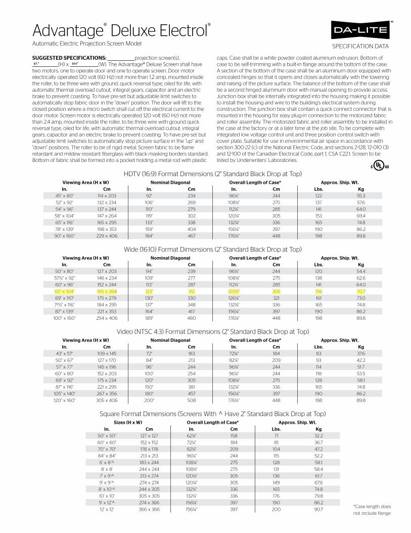
SUGGESTED SPECIFICATIONS: projection screen(s), (H) x (W). The Advantage® Deluxe Screen shall have two motors, one to operate door and one to operate screen. Door motor electrically operated 120 volt (60 Hz) not more than 1.2 amp, mounted inside the roller, to be three wire with ground, quick reversal type, oiled for life, with automatic thermal overload cutout, integral gears, capacitor and an electric brake to prevent coasting. To have pre-set but adjustable limit switches to automatically stop fabric door in the ”down“ position. The door will lift to the closed position where a micro switch shall cut off the electrical current to the door motor. Screen motor is electrically operated 120 volt (60 Hz) not more than 2.4 amp, mounted inside the roller, to be three wire with ground quick reversal type, oiled for life, with automatic thermal overload cutout, integral gears, capacitor and an electric brake to prevent coasting. To have pre-set but adjustable limit switches to automatically stop picture surface in the ”up“ and ”down“ positions. The roller to be of rigid metal. Screen fabric to be flame retardant and mildew resistant fiberglass with black masking borders standard. Bottom of fabric shall be formed into a pocket holding a metal rod with plastic
caps. Case shall be a white powder coated aluminum extrusion. Bottom of case to be self-trimming with a built-in flange around the bottom of the case. A section of the bottom of the case shall be an aluminum door equipped with concealed hinges so that it opens and closes automatically with the lowering and raising of the picture surface. The balance of the bottom of the case shall be a second hinged aluminum door with manual opening to provide access. Junction box shall be internally integrated into the housing making it possible to install the housing and wire to the building’s electrical system during construction. The junction box shall contain a quick connect connector that is mounted in the housing for easy plug-in connection to the motorized fabric and roller assembly. The motorized fabric and roller assembly to be installed in the case at the factory or at a later time at the job site. To be complete with integrated low voltage control unit and three position control switch with cover plate. Suitable for use in environmental air space in accordance with section 300-22 (c) of the National Electric Code, and sections 2-128, 12-010 (3) and 12-100 of the Canadian Electrical Code, part 1, CSA C22.1. Screen to be listed by Underwriters’ Laboratories.
SPECIFICATION DATA
HDTV (16:9) Format Dimensions (2" Standard Black Drop at Top)Viewing Area (H x W) Nominal Diagonal Overall Length of Case* Approx. Ship. Wt.In. Cm In. Cm In. Cm Lbs. Kg
45" x 80" 114 x 203 92" 234 96¼" 244 122 55.3
52" x 92" 132 x 234 106" 269 108¼" 275 137 57.6
54" x 96" 137 x 244 110" 279 112¼" 285 141 64.0
58" x 104" 147 x 264 119" 302 120¼" 305 153 69.4
65" x 116" 165 x 295 133" 338 132¼" 336 165 74.8
78" x 139" 198 x 353 159" 404 156¼" 397 190 86.2
90" x 160" 229 x 406 184" 467 176¼" 448 198 89.8
Wide (16:10) Format Dimensions (2" Standard Black Drop at Top)Viewing Area (H x W) Nominal Diagonal Overall Length of Case* Approx. Ship. Wt.In. Cm In. Cm In. Cm Lbs. Kg
50" x 80" 127 x 203 94" 239 96¼" 244 120 54.4
571⁄2" x 92" 146 x 234 109" 277 108¼" 275 138 62.6
60" x 96" 152 x 244 113" 287 112¼" 285 141 64.0
65" x 104" 165 x 264 123" 312 120¼" 305 156 70.7
69" x 110" 175 x 279 130" 330 126¼" 321 161 73.0
721⁄2" x 116" 184 x 295 137" 348 132¼" 336 165 74.8
87" x 139" 221 x 353 164" 417 156¼" 397 190 86.2
100" x 160" 254 x 406 189" 480 176¼" 448 198 89.8
Video (NTSC 4:3) Format Dimensions (2" Standard Black Drop at Top)Viewing Area (H x W) Nominal Diagonal Overall Length of Case* Approx. Ship. Wt.In. Cm In. Cm In. Cm Lbs. Kg
43" x 57" 109 x 145 72" 183 72¼" 184 83 37.6
50" x 67" 127 x 170 84" 213 82¼" 209 93 42.2
57" x 77" 145 x 196 96" 244 96¼" 244 114 51.7
60" x 80" 152 x 203 100" 254 96¼" 244 118 53.5
69" x 92" 175 x 234 120" 305 108¼" 275 128 58.1
87" x 116" 221 x 295 150" 381 132¼" 336 165 74.8
105" x 140" 267 x 356 180" 457 156¼" 397 190 86.2
120" x 160" 305 x 406 200" 508 176¼" 448 198 89.8
Square Format Dimensions (Screens With ^ Have 2" Standard Black Drop at Top)Sizes (H x W) Overall Length of Case* Approx. Ship. Wt.
In. Cm In. Cm Lbs. Kg50" x 50" 127 x 127 62¼" 158 71 32.2
60" x 60" 152 x 152 72¼" 184 81 36.7
70" x 70" 178 x 178 82¼" 209 104 47.2
84" x 84" 213 x 213 96¼" 244 115 52.2
6' x 8'^ 183 x 244 108¼" 275 128 58.1
8' x 8' 244 x 244 108¼" 275 131 58.4
7' x 9'^ 213 x 274 120¼" 305 136 61.7
9' x 9'^ 274 x 274 120¼" 305 149 67.6
8' x 10'^ 244 x 305 132¼" 336 165 74.8
10' x 10' 305 x 305 132¼" 336 176 79.8
9' x 12'^ 274 x 366 156¼" 397 190 86.2
12' x 12' 366 x 366 156¼" 397 200 90.7*Case length does
not include flange
Advantage® Deluxe Electrol®Automatic Electric Projection Screen Model
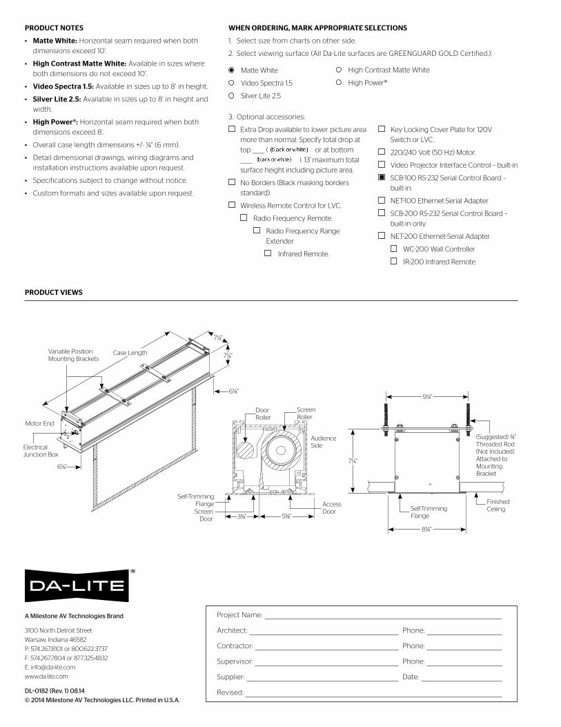
A Milestone AV Technologies Brand
3100 North Detroit Street
Warsaw, Indiana 46582
P: 574.267.8101 or 800.622.3737
F: 574.267.7804 or 877.325.4832
www.da-lite.com
DL–0182 (Rev. 1) 08.14
© 2014 Milestone AV Technologies LLC. Printed in U.S.A.
PRODUCT NOTES
• Matte White: Horizontal seam required when both
dimensions exceed 10'.
• High Contrast Matte White: Available in sizes where
both dimensions do not exceed 10'.
• Video Spectra 1.5: Available in sizes up to 8' in height.
• Silver Lite 2.5: Available in sizes up to 8' in height and
width.
• High Power®: Horizontal seam required when both
dimensions exceed 8'.
• Overall case length dimensions +/- ¼" (6 mm).
• Detail dimensional drawings, wiring diagrams and
installation instructions available upon request.
• Specifications subject to change without notice.
• Custom formats and sizes available upon request.
PRODUCT VIEWS
WHEN ORDERING, MARK APPROPRIATE SELECTIONS
1. Select size from charts on other side.
2. Select viewing surface (All Da-Lite surfaces are GREENGUARD GOLD Certified.):
Matte White
Video Spectra 1.5
Silver Lite 2.5
3. Optional accessories:
Extra Drop available to lower picture area
more than normal. Specify total drop at
top _____ (black or white) or at bottom
_____ (black or white). 13' maximum total
surface height including picture area.
No Borders (Black masking borders
standard).
Wireless Remote Control for LVC.
Radio Frequency Remote.
Radio Frequency Range
Extender
Infrared Remote.
Key Locking Cover Plate for 120V
Switch or LVC.
220/240 Volt (50 Hz) Motor.
Video Projector Interface Control – built-in
SCB-100 RS-232 Serial Control Board –
built-in.
NET-100 Ethernet-Serial Adapter
SCB-200 RS-232 Serial Control Board –
built-in only.
NET-200 Ethernet-Serial Adapter
WC-200 Wall Controller
IR-200 Infrared Remote
Project Name:
Architect: Phone:
Contractor: Phone:
Supervisor: Phone:
Supplier: Date:
Revised:
(Suggested) 3/8" Threaded Rod (Not Included) Attached to Mounting Bracket
9¼"
Finished CeilingSelf-Trimming
Flange
83/4"
7¼"
High Contrast Matte White
High Power®
Door Roller
Screen Roller
Screen Door
Access Door
Audience Side
Self-Trimming Flange
53/8"33/8"
Case LengthVariable Position Mounting Brackets 7¼"
7¼"
61/8"
Motor End
Electrical Junction Box
61/8"
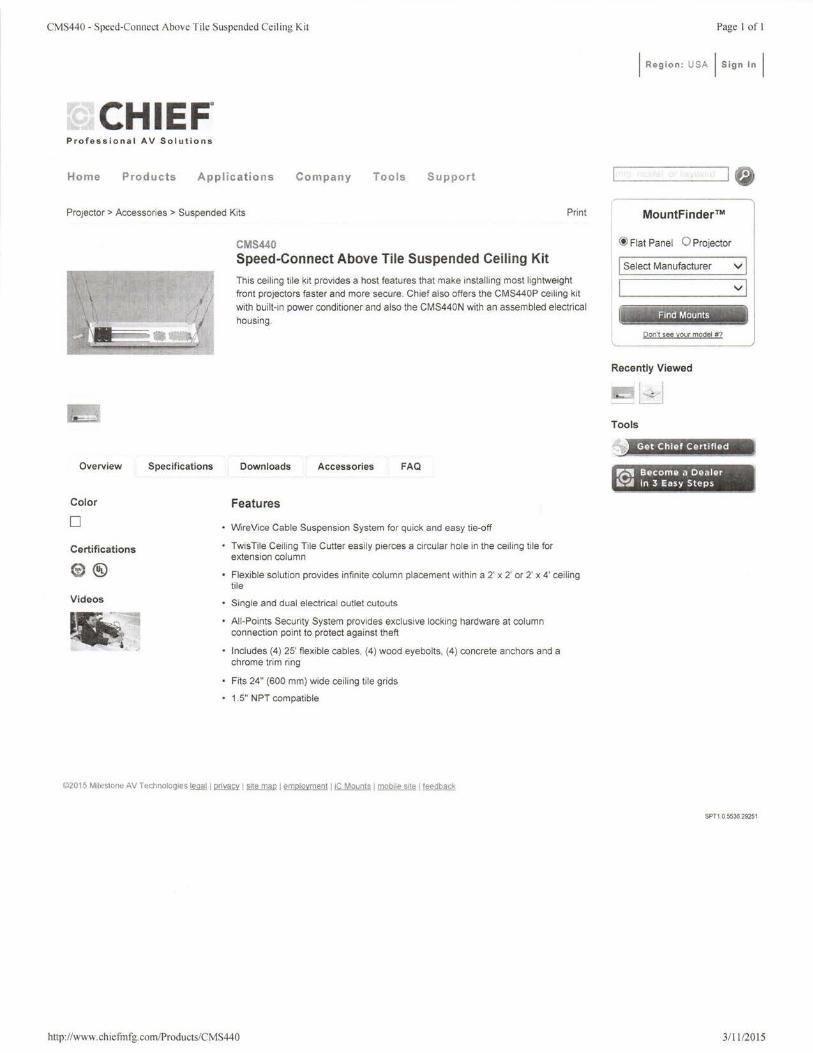
CMS440 - Speed-Connect Above Tile Suspended Ceiling Kit
CHIEF. Professional AV Solutions
Home Products Applications Company Tools Support
Projector> Accessories > Suspended Kits Print
Overview Specifications
Color
0
Certifications
® ® Videos
CMS440 Speed-Connect Above Tile Suspended Ceiling Kit
This cei ling tile kit provides a host features that make installing most lightweight
front projectors faster and more secure. Chief also offers the CMS440P ceiling kit
with built-in power conditioner and also the CMS440N with an assembled electrical
housing .
Downloads Accessories FAQ
Features
WireVice Cable Suspension System for quick and easy tie-off
TwisTile Ceiling Tile Cutter easily pierces a circular hole in the ceiling tile for extension column
• Flexible solution provides infinite column placement within a 2' x 2' or 2' x 4' ceiling tile
Single and dual electrical outlet cutouts
All-Points Security System provides exclusive locking hardware at column connection point to protect against theft
Includes (4) 25' fiexible cables, (4) wood eyebolts, (4) concrete anchors and a chrome trim ring
Fits 24" (600 mm) wide ceiling tile grids
1.5" NPT compatible
©2015 Milestone AV Technologies !fillfil I privacy I site map I employment I iC Mounts I mobile site I feedback
http://www. ch iefmfg. com/Products/CMS440
Page I of I
I Re gio n: USA I Sign In I
•
MountFinder™
@ Flat Panel 0 Projector
I Select Manufacturer v I 1 I vi
Don't see your model #?
Recently Viewed
-- ~ Tools
Get Chief Certified ~~~~~~~-·
'(}.' Becom11 a Deal11r 1
~~ In 3 Easy ~tep_~ _______ ,:
SPT10553629251
3/ 11120 15
RPAU - RPA Universal & Custom Ceiling Projector Mounts
CHIEF. Professional AV Solutions
Home Products A p p l icati o n s Company Tools Support
Projector Mounts> Ceiling > RPA
Overview Specifications
Color
• Certifications
Mountflnder Compatib ili ty
RPAU
RPA Universal & Custom Ceiling Projector Mounts
The RPAU has all of the great features of the RPAO and even more! This Universal Projector Mount is coupled with the newly designed SLBU Universal Interface Bracket. This 2nd Generation Interface Technology has enhanced security and unlimited projector access.
Note: To ensure this mount works with your equipment check the "Compatibility" tab below.
Downloads Accessories FAQ Compatibility
Features
Ships newly designed SLB universal bracket to fit most inverted projectors on the market
Independent roll, pitch and yaw for quick and precise projector image registration
Quick projector connect and disconnect with convenient lamp and filter access on most projectors
• Maintains registration when disconnected and doesn't affect preset adjustments
All-Points™ Security Systems provides exclusive steel into steel locking hardware at all connection points to protect against theft
• Multiple installation options: fiush mount to ceiling, 0.25" threaded rod , or 1.5" NPT threaded extension column
Integrated cable management through top of mount without additional accessories
©2015 Milestone AV Technologies !M.fil I privacy I site map I employment I iC Mounts I mobile site I feedback
http://www.chiefmfg.com/Products/rpau
Page I of I
I Region: USA I Sign In I
•
MountFinder™
@Flat Panel 0 Projector
I Select Manufacturer v I vJ
r~: - - - - -
Don't see your model #?
Recently Viewed
Tools
, Build in MountBuilder ------------~
Find Throw Distance
Get Chief Certified - ______ # ____ ~ __.,
l'(S' Become a Dealer ~~ in 3 Eas y Steps
- ~ - -- _..
SPT1 .0.5536.29251
3/ 12/2015
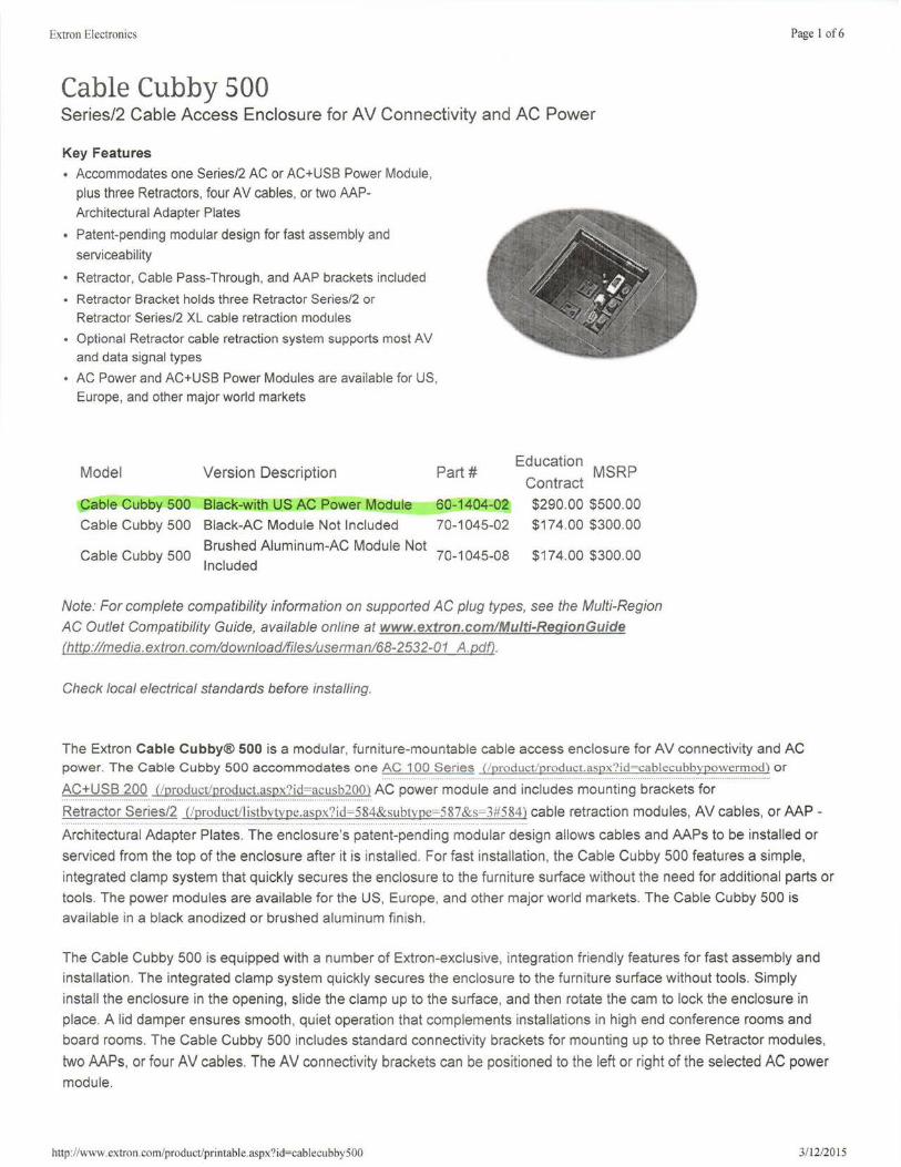
Extron Electronics
Cable Cubby 500 Series/2 Cable Access Enclosure for AV Connectivity and AC Power
Key Features
• Accommodates one Series/2 AC or AC+USB Power Module , plus three Retractors, four AV cables, or two AAPArchitectural Adapter Plates
• Patent-pending modular design for fast assembly and
serviceability
• Retractor, Cable Pass-Through, and AAP brackets included
• Retractor Bracket holds three Retractor Series/2 or Retractor Series/2 XL cable retraction modules
• Optional Retractor cable retraction system supports most AV and data signal types
• AC Power and AC+USB Power Modules are available for US, Europe, and other major world markets
Model Version Description
Cable Cubby 500 Black-with US AC Power Module
Cable Cubby 500 Black-AC Module Not Included
Part# Education MSRP Contract
60-1404-02 $290.00 $500.00
70-1045-02 $174.00 $300.00
Brushed Aluminum-AC Module Not Cable Cubby 500 70-1045-08 $174.00 $300.00
Included
Note: For complete compatibility information on supported AC plug types, see the Multi-Region
AC Outlet Compatibility Guide, available online at www.extron.com/Multi-RegionGuide (http://media.extron.com!download!files/userman/68-2532-01 A. pdf).
Check local electrical standards before installing.
Page I of6
The Extron Cable Cubby® 500 is a modular, furniture-mountable cable access enclosure for AV connectivity and AC power. The Cable Cubby 500 accommodates one AC 100 Series (/product/product.aspx?id=cablecubbypowermod) or
AC+USB 200 C/product/product.aspx?id=acusb200) AC power module and includes mounting brackets for ................................................................................................................................ '
Retractor Series/2 (/product/listbytvpe.aspx?id=584&subtype=587&s=3#584) cable retraction modules, AV cables, or AAP -.. ............................................................................ ........ ..... ............... .. ... ...... .
Architectural Adapter Plates. The enclosure's patent-pending modular design allows cables and AAPs to be installed or
serviced from the top of the enclosure after it is installed . For fast installation, the Cable Cubby 500 features a simple,
integrated clamp system that quickly secures the enclosure to the furniture surface without the need for additional parts or
tools. The power modules are available for the US, Europe, and other major world markets. The Cable Cubby 500 is
available in a black anodized or brushed aluminum fin ish .
The Cable Cubby 500 is equipped with a number of Extron-exclusive, integration friendly features for fast assembly and
installation. The integrated clamp system quickly secures the enclosure to the furniture surface without tools. Simply
install the enclosure in the opening, slide the clamp up to the surface, and then rotate the cam to lock the enclosure in
place. A lid damper ensures smooth , quiet operation that complements installations in high end conference rooms and
board rooms. The Cable Cubby 500 includes standard connectivity brackets for mounting up to three Retractor modules,
two AAPs, or four AV cables. The AV connectivity brackets can be positioned to the left or right of the selected AC power
module.
http://www.extron.com/product/printable.aspx?id=cablecubbySOO 3/ 12/2015
Extron Electronics Page 2 of6
The enclosure's patent-pending modular design allows cables and AAPs to be installed or serviced from the top of the
enclosure after it is installed. The Cable Pass-Through Bracket features a unique, split-ring design that facilitates cable installation wh ile eliminating the need for separate cable grommets. AC Power Modules are available for the US, Europe,
and other major world markets. Most AC 100 Series AC Power Modules provide two unswitched AC outlets. An available
Multi-Region AC outlet is compatible with a variety of AC plug types. To support the growing use of smartphones and
tablets in AV presentation environments, the optional AC 200 Series AC+USB Power Modules provide one or two AC
power outlets, and two 5 VDC USB power outlets with 2.1 A I 10.5 watts of tota l power for charging mobile devices such
as smartphones and tablets. Cable Cubby Series/2 enclosures are UL/c- UL listed and CE compliant. Installation routing templates and other accessories are also avai lable.
To quickly customize AC power and AV connectivity selections for a Cable Cubby 500 installation, the
Cable Cubby Series/2 Builder (!product/ccb/index.aspx?subtype=cablecubbyconfig) is an interactive tool that guides the user through the selection of AC power modules, AV connectivity, cables, and installation accessories. As you build your
Cable Cubby, a bill of materials is prepared automatically. When you 're finished , the Builder allows you to review your
Cable Cubby and make any last minute changes before placing your order (dealer login required).
Included Accessories
Mounting Brackets Capacity Quantity Included
Connectivity Bracket (1) AAP Frame or
1 Cable Pass-Through Plate
AAP Frame (2) Single-space AAPs 1
Cable Pass-Through Plate (4) AV cables 1
Retractor Bracket and Pin (3) Retractors 1
Features
• Accommodates one Series/2 AC or AC+USB Power Module, plus three Retractors, four AV cables, or two AAP- Architectural Adapter Plates
• Patent-pending modular design for fast assembly and serviceability -AV connectivity can be installed or serviced from the top of the enclosure after it is installed.
• Retractor, Cable Pass-Through, and AAP brackets included
• Retractor Bracket holds three Retractor Series/2 or Retractor Series/2 XL cable retraction modules
• Optional Retractor cable retraction system supports most AV and data signal types
• AC Power and AC+USB Power Modules are available for US, Europe, and other major world markets - Most
AC Power Modules provide two unswitched AC outlets. AC+USB Power Modules provide one or two AC outlets and two USB power outlets.
• Available Multi-Region AC outlet is compatib le with a variety of AC plug types
• UUc-UL listed and CE compliant
• US model includes an attached 9.5' power cord
• Integrated side clamps secure enclosure to the furniture surface - Cable Cubby can be secured in place
without additional parts or tools.
• Top surface is available in a black anodized or brushed aluminum finish
• Finish Sample Kit available, part #70-804-01
• Installation routing template available, part #70-1048-80
http://www.extron.com/product/printable.aspx?id=cablecubby500 3/12/2015
Extron Electronics Page 3 of6
• Cable Cubby Builder is available at www.extron.com/cablecubby - Intuitive online tool for enclosure selection,
pricing , and cable and connectivity selection.
• Dimensions: 6.1" L x 6.1" W (15.6 cm L x 15.6 cm W)
OPTIONAL ACCESSORIES
• AC 100 Series Power Modules
• AC+USB 200 Series Power Modules
• Architectural Products Finish Sample Kit
• CableCover
AC Power Modules for Cable Cubby Series/2 Enclosures
AC+USB Power Modules for Cable Cubby Series/2
Enclosures
Finish Swatches for Hideaway Surface Access and Cable
Cubby Enclosures
Under-Table Cable Bag for Cable Cubby and Cable Cubby
Series/2 Enclosures
• Installation Routing Templates For Cable Cubby Series/2 Enclosures
• Cable Cubby Series/2 Connectivity Bracket Kits Supplemental AV Connectivity Brackets for
Cable Cubby Series/2 Enclosures
• Retractor Series/2
• Retractor Series/2 XL
• Retractor
• Retractor XL
• MLC 62 RS EU
• MLC 62 RS MK
• UCM 100
Cable Retraction System with Speed Control for Cable
Cubby Enclosures
Extended Length Cable Retraction System with Speed
Control for Cable Cubby Enclosures
Cable Retraction System for Cable Cubby Enclosures
Extended Length Cable Retraction System for Cable
Cubby Enclosures
Medialink Controller - EU Wall Frame for European
Junction Boxes
Medialink Controller - MK Wall Frame for United Kingdom
Junction Boxes
Universal Controller Mount
• Cable Cubby & HSA Certified Cables
SPECIFICATIONS
Cable Cubby® 500 and 700
General
Power supply (optional)
US AC module Non-US AC module
Mounting
Furniture mount Min./max. table thickness
Enclosure type
Enclosure dimensions
Cable Cubby 500
Top plate (outer rim)
Surface cutout (inside rim)
Enclosure Depth
Cable Cubby 700 Top plate (outer rim) Surface cutout (inside rim)
Enclosure Depth
125 VAC, 50-60 Hz, 12 A max total 240 VAC, 50-60 Hz, 10 A max total
Yes 0.50" to 2.50"
Metal
6.1" L x 6.1" W (15.6 cm L x 15.6 cm W)
5.75" L x 5.75" W (14.6 cm L x 14.6 cm W)
6.5" H (16.5 cm H)
7.5" L x 6.1" W (19.2 cm L x 15.6 cm W)
7.1" L x 5.75" W (18.1cmLx14.6 cm W)
6.5" H (16.5 cm H)
http: //www.extron.com/product/printable.aspx?id=cablecubby500 3/ 12/2015
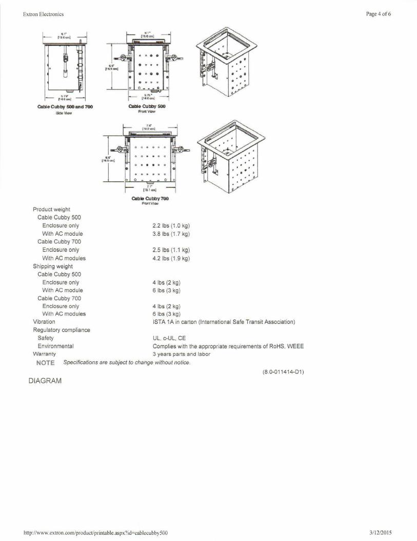
Extron Electronics
Cable CUbby 500 and 700 st»\1om
Product weight
Cable Cubby 500
Enclosure only
With AC module
Cable Cubby 700
Enclosure only
With AC modules
Shipping weight
Cable Cubby 500
Enclosure only
With AC module
Cable Cubby 700
Enclosure only
With AC modules
Vibration
Regulatory compliance
Safety
Environmental Warranty
r-; IJ.S" • 1:1 ••
l)a.:11.111]
L ....
• 0 • p 9 9
2.2 lbs (1.0 kg)
3.8 lbs (1.7 kg)
2.5 lbs (1.1 kg)
4.2 lbs (1.9 kg)
4 lbs (2 kg)
6 lbs (3 kg)
4 lbs (2 kg) 6 lbs (3 kg)
ISTA 1A in carton (International Safe Transit Association)
UL, c-UL, CE
Complies with the appropriate requirements of RoHS, WEEE 3 years parts and labor
NOTE Specifications are subject to change without notice.
(8.0-011414-01)
DIAGRAM
http://www.extron.com/product/printable.aspx?id=cablecubby500
Page 4 of6
3112/2015
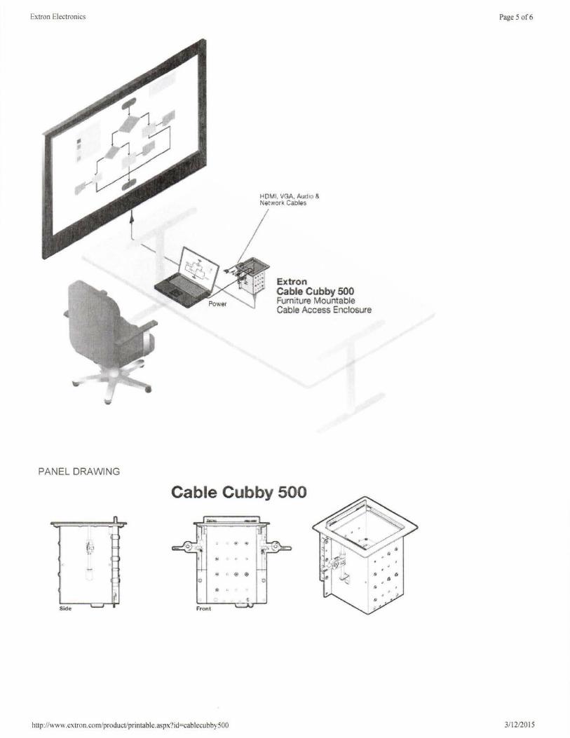
Extron Electronics
PANEL DRAWING
Sida
ll · ·1
"'!I
HDMI, v~A. Audio a Natwork Cable5
Ex tr on Cable Cubby 500 Furniture Mountable Cable Aocess Enclosure
Cable Cubby 500
. .,,,
' @ ®
http://www.extron.com/product/printable.aspx?id=cablecubby500
Page 5 of6
,,
3/12/2015

Extron Electronics Page 6 of6
© 2015 Extron Electronics. Specifications are subject to change without notice.
hnp://www.extron.com/product/printable.aspx?id=cablecubby500 3/ 12/2015
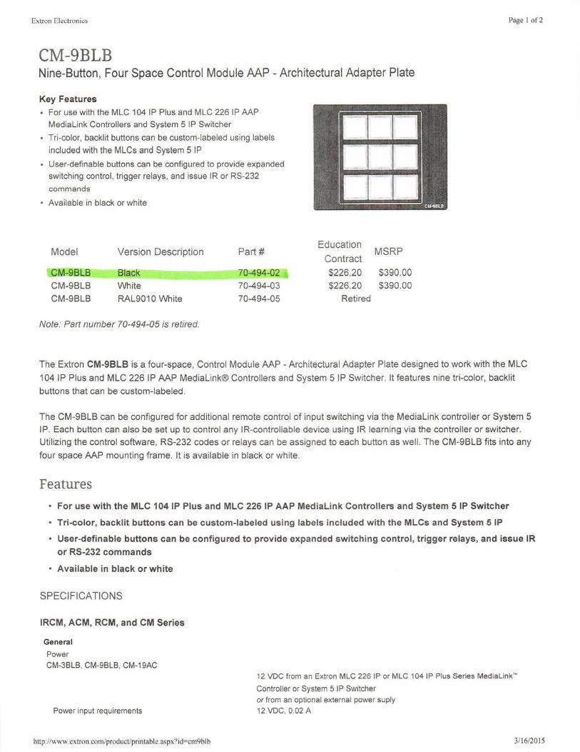
Extron Electronics
CM-9BLB Nine-Button, Four Space Control Module AAP - Architectural Adapter Plate
Key Features
• For use with the MLC 104 IP Plus and MLC 226 IP AAP Medialink Controllers and System 5 IP Switcher
• Tri-color, backlit buttons can be custom-labeled using labels
included with the MLCs and System 5 IP
• User-definable buttons can be configured to provide expanded switching control, trigger relays, and issue IR or RS-232
commands
Available in black or white
Model Version Description Part#
CM-9BLB Black 70-494- 2
CM-9BLB White 70-494-03
CM-9BLB RAL9010 White 70-494-05
Note: Part number 70-494-05 is retired.
Education MSRP
Contract $226.20 $390.00
$226.20 $390.00
Retired
Page I of2
The Extron CM-9BLB is a four-space, Control Module AAP - Architectural Adapter Plate designed to work with the MLC
104 IP Plus and MLC 226 IP AAP MediaLink® Controllers and System 5 IP Switcher. It features nine tri-color, backlit
buttons that can be custom-labeled .
The CM-9BLB can be configured for additional remote control of input switching via the MediaLink controller or System 5 IP. Each button can also be set up to control any IR-controllable device using IR learning via the controller or switcher.
Utilizing the control software, RS-232 codes or relays can be assigned to each button as well. The CM-9BLB fits into any
four space AAP mounting frame. It is available in black or white.
Features • For use with the MLC 104 IP Plus and MLC 226 IP AAP MediaLink Controllers and System 5 IP Switcher
• Tri -color, backlit buttons can be custom-labeled using labels included with the MLCs and System 5 IP
• User-definable buttons can be configured to provide expanded switching control, trigger relays, and issue IR
or RS-232 commands
• Available in black or white
SPECIFICATIONS
IRCM, ACM, RCM, and CM Series
G e ne ra l
Power CM-3BLB, CM-9BLB, CM-19AC
Power input requirements
http://www.extron.com/product/printable.aspx?id=cm9blb
12 VDC from an Extron MLC 226 IP or MLC 104 IP Plus Series Medialink~
Controller or System 5 IP Switcher or from an optional external power suply 12 VDC, 0.02 A
3/16/2015

Extron Electronics
All other models
Power input requirements
Temperature/humidity
Rack mount
Enclosure type
Enclosure dimensions
Page 2 of2
12 VDC from an Extron MediaLink Controller (MLC) or System 5 IP Switcher
12 voe. 0.02 A
Storage: -40 to +158 °F (-40 to +70 °C)/1 0% to 90%, noncondensing
Operating: +32 to +122 °F (0 to +50 °C) / 10% to 90%, noncondensing
Yes, with optional faceplate, and furniture/wall mountable with optional faceplates
or AAP wall plates
Metal
IRCM-VCR, IRCM-DVD, IRCM-Tape, ACM-Tone, ACM-Level , RCM-SC, RCM-SCL T, CM-5BB, CM-3BLB
Faceplate 1.4" H x 3.5" W x 0.1 " D (3.5 cm H x 8.9 cm W x 0.3 cm D) (double space AAP
plate)
Boards 1.3" H x 2.6" W x 0.9" D (3 3 cm H x 6.6 cm W x 2.3 cm D)
(Depth excludes buttons. Allow at least 2.1" (5.3 cm) depth in the wall or
furniture.)
IRCM-DVD+, IRCM-DV+, CM-20BB, CM-98L8, CM-19AC
Faceplate
Boards
Product weight
2.8" H x 3.5" W x 0.1 " D (7.1 cm H x 8.9 cm W x 0.3 cm D) (four space AAP plate)
2.7" H x 2.6" W x 0.9" D (6.9 cm H x 6.6 cm W x 2.3 cm D) (Depth excludes buttons. Allow at least 2.1" (5.3 cm) depth in the wall/furniture.)
IRCM-VCR, IRCM-DVD, IRCM-Tape, ACM-Tone, ACM-Level , RCM-SC, RCM-SCL T, CM-588, CM-38L8
0.1 lbs (<0.1 kg) IRCM-DVD+, IRCM-DV+, CM-20BB, CM-9BLB, CM-19AC
0.2 lbs (0.1 kg )
Shipping weight 1 lbs (1 kg)
Vibration
Listings
Compliances
ISTA 1A in carton (International Safe Transit Association)
UL, CUL as components of the MLC 206, or MLC 226 IP, or MLC 104 IP Plus
Series Medialink'" Controller; or System 5 IP Switcher
CE, FCC Class A, VCCI, AS/NZS, ICES as components of the MLC 206,
MLC2261P, or MLC 104 IP Plus Series MediaLink'" Controller; or System 5 IP
Switcher
Warranty 3 years parts and labor
NOTE Specifications are subject to change without notice.
(7.52-053007-04)
© 2015 Extron Electronics. Specifications are subject to change without notice.
http://www.extron.com/product/printable.aspx?id=cm9blb 3/16/2015
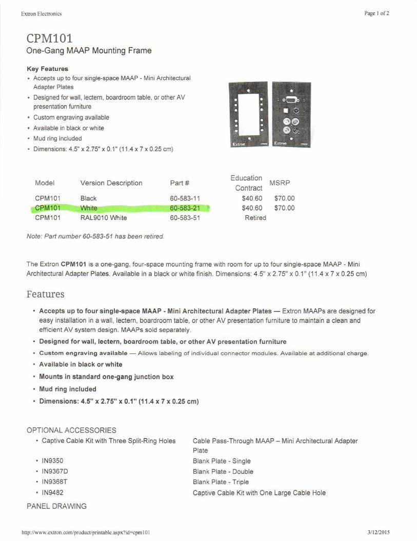
Extron Electronics Page I of2
CPM101 One-Gang MAAP Mounting Frame
Key Features • Accepts up to four single-space MAAP - Mini Architectural
Adapter Plates
• Designed for wall, lectern, boardroom table, or other AV presentation furniture
• Custom engraving available
• Available in black or white
• Mud ring included
• Dimensions: 4.5" x 2.75" x 0.1" (11.4 x 7 x 0.25 cm)
Model
CPM101
CPM101
CPM101
Version Description
Black
White
RAL9010 White
Note: Part number 60-583-51 has been retired.
Part#
60-583-11
60-583-21
60-583-51
Education
Contract
$40.60
$40.60
Retired
MSRP
$70.00
$70.00
The Extron CPM101 is a one-gang, four-space mounting frame with room for up to four single-space MAAP - Mini
Architectural Adapter Plates. Available in a black or white finish. Dimensions: 4.5" x 2. 75" x 0.1" (11.4 x 7 x 0.25 cm)
Features
• Accepts up to four single-space MAAP - Mini Architectural Adapter Plates - Extron MAAPs are designed for
easy installation in a wall, lectern, boardroom table, or other AV presentation furniture to maintain a clean and efficient AV system design . MAAPs sold separately.
• Designed for wall, lectern, boardroom table, or other AV presentation furniture
• Custom engraving available - Allows labeling of individual connector modules. Available at additional charge .
• Available in black or white
• Mounts in standard one-gang junction box
• Mud ring included
• Dimensions: 4.5" x 2.75" x 0.1" (11.4 x 7 x 0.25 cm)
OPTIONAL ACCESSORIES
• Captive Cable Kit with Three Split-Ring Holes
• IN9350
• IN9367D
• IN9368T
• IN9482
PANEL DRAWING
http://www.extron.com/product/printable.aspx?id=cpm I 0 I
Cable Pass-Through MAAP - Mini Architectural Adapter
Plate
Blank Plate - Single
Blank Plate - Double
Blank Plate - Triple
Captive Cable Kit with One Large Cable Hole
3/12/2015
Extron Electronics Page 2 of2
CPM 101
• • e " • I
• " " f:)
• "
" Extron Front
© 2015 Extron Electronics.
http://www.extron.com/product/printable. aspx?id=cpm 1 01 3/ 12/2015
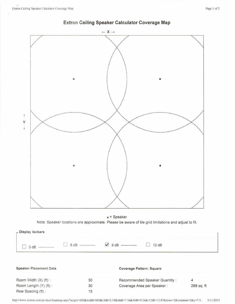
Extron Ceiling Speaker Calculator Coverage Map
Extron Ceiling Speaker Calculator Coverage Map
i y
l
•
..._ __ -......_____ ___ _
•
- x ---+
•
•
/
o =Speaker
Page I of2
Note: Speaker locations are approximate. Please be aware of tile grid limitations and adjust to fit.
1 Display lsoba"
l D 3dB ---
Speaker Placement Data
Room Width (X) (ft) :
Room Length (Y) (ft) :
Row Spacing (ft) :
D 6dB
30 30 15
~ 9dB D 12dB
Coverage Pattern: Square
Recommended Speaker Quantity : 4
Coverage Area per Speaker : 268 sq . ft
http://www.extron.com/product/heatmap.aspx?length=600&width=600&r3db=2. l 9&r6db=7. I 6&r9db=9.24&r I 2db= 12.87 &rows=2&columns=2&y=7.5 ... 3/1 1/20 15
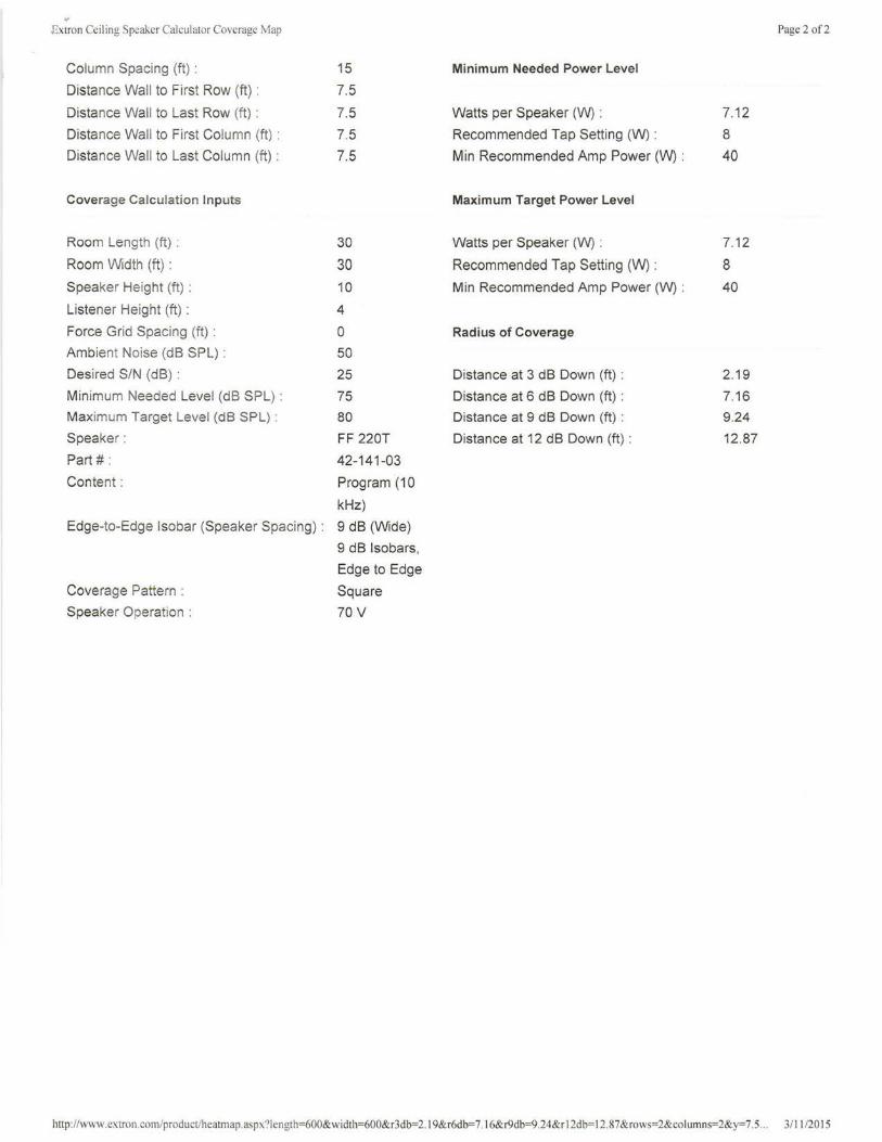
" .Extron Ceiling Speaker Calculator Coverage Map
Column Spacing (ft) :
Distance Wall to First Row (ft) :
Distance Wall to Last Row (ft) :
Distance Wall to First Column (ft) :
Distance Wall to Last Column (ft) :
Coverage Calculation Inputs
Room Length (ft) :
Room Width (ft) :
Speaker Height (ft) :
Listener Height (ft) :
Force Grid Spacing (ft) :
Ambient Noise (dB SPL) :
Desired S/N (dB) :
Minimum Needed Level (dB SPL) :
Maximum Target Level (dB SPL) :
Speaker:
Part #:
Content:
15
7.5
7.5 7.5 7.5
30
30 10
4
0
50
25
75 80
FF 220T
42-141-03
Program (10
kHz)
Edge-to-Edge Isobar (Speaker Spacing) : 9 dB (Wide)
Coverage Pattern :
Speaker Operation :
9 dB Isobars,
Edge to Edge
Square
70V
Minimum Needed Power Level
Watts per Speaker (W) :
Recommended Tap Setting (W) :
Min Recommended Amp Power (W) :
Maximum Target Power Level
Watts per Speaker (W) :
Recommended Tap Setting (W) :
Min Recommended Amp Power (W) :
Radius of Coverage
Distance at 3 dB Down (ft) :
Distance at 6 dB Down (ft) :
Distance at 9 dB Down (ft) :
Distance at 12 dB Down (ft) :
7.12
8
40
7.12
8
40
2.19
7.16
9 .24
12.87
Page 2 of2
http://www.extron.com/product/heatmap.aspx?Iength=600&width=600&r3db=2. I 9&r6db=7. I 6&r9db=9.24&r I 2db= 12.87&rows=2&columns=2&y=7. 5... 3/ 11 /20 15
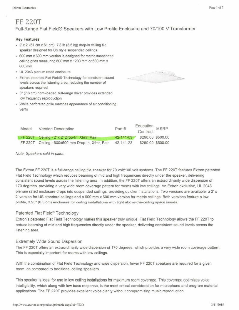
Exiron Electronics
FF 220T Full-Range Flat Field® Speakers with Low Profile Enclosure and 70/100 V Transformer
Key Features
• 2' x 2' (61 cm x 61 cm), 7.8 lb (3.5 kg) drop-in ceiling tile speaker designed for US style suspended ceilings
• 600 mm x 600 mm version is designed for metric suspended ceiling grids measuring 600 mm x 1200 mm or 600 mm x 600mm
• UL 2043 plenum rated enclosure
• Extron patented Flat Field® Technology for consistent sound levels across the listening area, reducing the number of speakers required
• 3" (7.6 cm) horn-loaded, full-range driver provides extended
low frequency reproduction
• White perforated grille matches appearance of air conditioning
vents
Model Version Description
FF 220T Ceiling - 2' x 2' Drop- n, Xfmr, Pair
FF 220T Ceiling - 600x600 mm Drop-In, Xfmr, Pair
Note: Speakers sold in pairs.
Part#
42-141-03
42-141-23
. ......
Education MSRP Contract $290.00 $500.00
$290.00 $500.00
-- ..... __
Page I of 7
The Extron FF 220T is a full-range ceiling tile speaker for 70 volt/100 volt systems. The FF 220T features Extron patented
Flat Field Technology which reduces beaming of mid and high frequencies directly under the speaker, delivering consistent sound levels across the listening area. In addition, the FF 220T offers an extraordinarily wide dispersion of
170 degrees, providing a very wide room coverage pattern for rooms with low ceilings. An Extron exclusive, UL 2043
plenum rated enclosure drops into suspended ceilings, providing quicker installations. Two versions are available: a 2' x
2' version for US standard ceilings and a 600 mm x 600 mm version for metric ceilings. Both versions feature a low profile, 3.25" (8.3 cm) enclosure for ceiling installations with tight above-the-ceiling space issues.
Patented Flat Field® Technology
Extron's patented Flat Field Technology makes this speaker truly unique. Flat Field Technology allows the FF 220T to
reduce beaming of mid and high frequencies directly under the speaker, delivering consistent sound levels across the
listening area.
Extremely Wide Sound Dispersion The FF 220T offers an extraordinarily wide dispersion of 170 degrees, which provides a very wide room coverage pattern .
This is especially important for rooms with low ceilings.
With the combination of Flat Field Technology and wide dispersion , fewer FF 220T speakers are required for a given
room, as compared to traditional ceiling speakers.
This speaker is ideal for use in low ceiling installations for maximum room coverage. This coverage optimizes voice intelligibility, which along with low bass response, is the most critical consideration for microphone and program material
applications. The FF 220T provides excellent voice clarity without compromising music reproduction .
http://www.extron.com/product/printable.aspx?id=ff220t 3/ 11 /2015

Extron Electronics Page 2 of7
The FF 220T offers 70 volt or 100 volt operation and provides power taps for 16, 8, 4, 2, and 1 watt. The power taps are
accessed via speaker wiring connections inside the rear panel. The transformer can be bypassed for 8 ohm operation .
For easy installation, the FF 220T drops into the same space as a standard US or metric ceiling tile, and includes a T-bar
for 2' x 4' ceilings or 600 mm x 1200 mm ceilings. It also provides theft deterrence with a neutral white, perforated steel
grille that matches the appearance of standard air conditioning vents and grid cei lings.
Features
• 2' x 2' (61 cm x 61 cm), 7.8 lb (3.5 kg) drop-in ceiling tile speaker designed for US style suspended ceilings
• 600 mm x 600 mm version is designed for metric suspended ceiling grids measuring 600 mm x 1200 mm or 600 mm x 600 mm
• UL 2043 plenum rated enclosure
• Extron patented Flat Field® Technology for consistent sound levels across the listening area, reducing the
number of speakers required
• 3" (7.6 cm) horn-loaded, full-range driver provides extended low frequency reproduction
• White perforated grille matches appearance of air conditioning vents
• 8 ohm direct or 70/100 volt operation with 16, 8, 4, 2, and 1 watt selectable power taps accessed via speaker
wiring connections inside the rear panel
• Frequency range: 68 Hz to 18 kHz
• 16 watts continuous pink noise, 32 watts continuous program
• Wide 170° dispersion
• 3.25" (8.3 cm) deep low profile enclosure for plenum environments
• 5 year parts and labor warranty
• Designed and manufactured by Extron
OPTIONAL ACCESSORIES
• SPK 14
• SPK 16
• SPK 18
SPECIFICATIONS
FF 220T
Audio/acoustic and electrical
Speaker type
Frequency range
Power capacity
Nominal sensitivity
Nominal coverage angle
Nominal impedance
Driver
Input connector
Tap settings
70 V input 100 V input
General
14 AWG Speaker Cable
16 AWG Speaker Cable
18 AWG Speaker Cable
1-way, full-range, in-ceiling speaker
68 Hz to 18 kHz, -10 dB, half space
16 W (rms) continuous pink noise
32 W (rms) continuous program
86 dB SPL, 1 watt, 1 m, half space
170° conical coverage
8 ohms per speaker
(1) 3" (76.2 mm) paper cone
(1) 10 mm Euro-style captive screw terminal block, 7 pole
16 W, 8 W, 4 W, 2 W, 1 W, null (bypass 8 ohm direct connection) Null, 16 W, 8 W, 4 W, 2 W, 1 W (bypass 8 ohm direct connection)
http://www.extron.com/product/printable.aspx?id=ff220t 311112015
Extron Electronics
Package
Temperature/humidity
Mounting
US version
Metric version
Enclosure type Enclosure outer dimensions
US version (2' x 2')
2 speakers (1 pair) with 2' (61 cm) cross bars
Storage: -40 to +158 °F (-40 to +70 °C) / 10% to 90%, noncondensing
Operating: +32 to +122 °F (0 to +50 °C) 110% to 90%, noncondensing
Drops into 2' x 2' (61 cm x 61 cm) or 2' x 4' (61 cm x 122 cm) suspended tile ceilings
Drops into 600 mm x 600 mm or 600 mm x 1200 mm suspended tile ceilings
Composite. square, with metal grille
3.25" H x 23.75" W x 23.75" L
(8.3 cm H x 60.3 cm W x 60.3 cm L)
Metric version (600 mm x 600 mm) 3.25" H x 23.4" W x 23.4" L
Product weight
Shipping weight
Vibration
Regulatory compliance
Safety
(8.3 cm H x 59.4 cm W x 59.4 cm L)
Single: 7.8 lbs (3.5 kg)
Pair: 21 lbs (10 kg) with mounting kit
ISTA 1A in carton (International Safe Transit Association )
CE, NFPA90A, NFPA70;
Page 3 of7
UL Listed for use in plenum airspaces: meets UL 2043 for heat and smoke release. meets UL 1480 for
Environmental
commercial and professional audio systems Complies with the appropriate requirements of RoHS, and WEEE.
5 years parts and labor Warranty
NOTE All nominal levels are at ±10%.
NOTE Specifications are subject to change without notice.
http://www.extron.com/product/printable.aspx?id=ff220t 3/ 11/2015
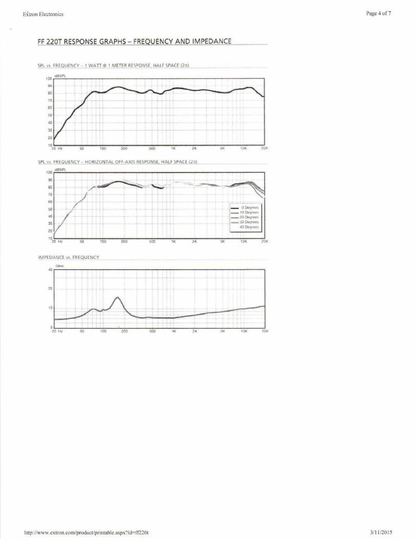
Extron Electronics Page 4 of7
FF 220T RESPONSE GRAPHS - FREQUENCY AND IMPEDANCE
tOO 1SSPI
00
IJll
70
so :.(! I ~ t t 40 I. 30 • + i • 21}
10 ~() H! !>II 100 :100 IK ;>/:. 10K
SPL vs fREQUE~f(Y - H08tl0fil_A"'_Q.Ff..:£-X.IS RES~9N~ Hl•Lf Sl'A(E {..l!:il_
100 0?.sPI
00
/~:: -~ SU - --~----70
00 .. '!'" .... ,....
!ill I ' 0 l)<q!""'
- 10 Dflg•1tff'_;,. .:a I t l . -7'0~!f"'~~
30 t ,. -JO[)e,g!C(t!. ~o Dr;i·oo"
21}
10 20 Kl !)IJ llO 200 lK 2K ~K 10K Nll(
IMPEDANCE"'•· fltEQUEIKY
Ohm 4D . i ?ti + . 1(1 ....
5 20 Hz ~ 1r.o XIO 000 ii< ~.i: ".I( 101( 2CK
http://www.extron.com/product/printable.aspx?id=ff220t 3/11 /2015
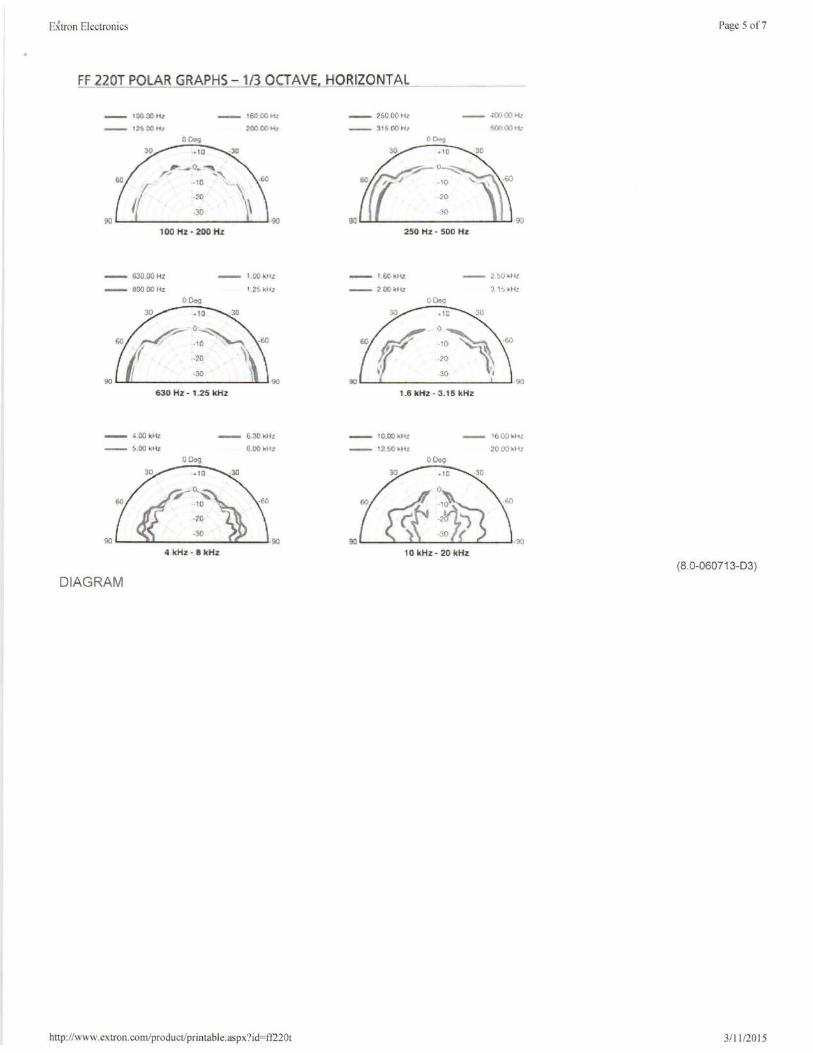
E~tron Electronics
FF 220T POLAR GRAPHS-113 OCTAVE HORIZONTAL
-- 10000tt:
-- 12500H<
-- •6000H< 200 00><,
0 C\!!i -10
,__o • .,... r,. ....
·10
.::io
.:JO 00
1 00 Hz - 200 Hz
- '63D.00Hz
- ll00.00HI
630 Hz - 1.25 l<Hz
- :.i.OOkJtz:
-- S:OOk•k
.i kHz-81cHz
DIAGRAM
,;()
l.OOkllZ
•.2S kll:
http://www.extron.com/product/printable.aspx?id=ft220t
-- 25000H,
-- 3•500Ht
-- ·•00 00 •i: 'iOO 00 .....
250 Hz - 500 Hz
- t.OOkll<
-- 200kllt
1.6 lcHz • 3.15 lcHZ
- fO.OOkltz
-- 12.:.0kllI
10 kHz· 20 kHz
Page 5 of7
(8.0-060713-03)
3/ 11 /2015
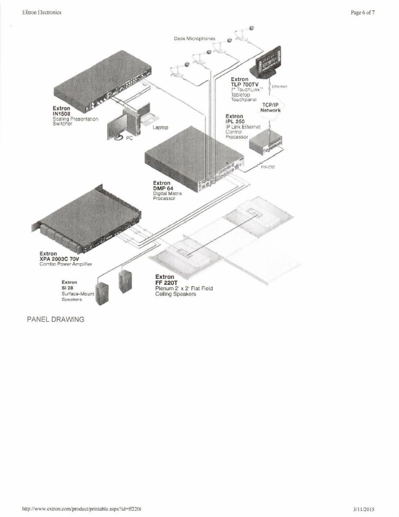
E tron Electronics
Extron IN150S Scaling Pr Switcher esenra11on
Extron XPA ::!003 Co:Jmbo P C 70V • C'\o\'er Amplifier
PANEL DRAWING
http://www .extron.com/ r p oduct/printabl . e.aspx?1d=ff220t
D!!SkM icrophor1es
Extron FF 220T Plenum 2• , Celling sp:a~e~at Field
Extron IPL ~so IPL. C
.,, ink Etllerrie1
... n tr·:ll Proc~ssor
TCP/IP Network
Page 6 of7
J/ 11 /2015
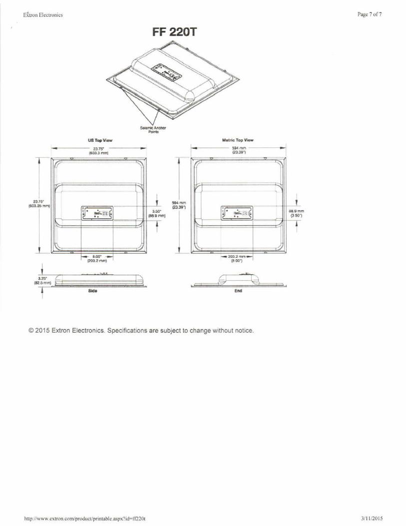
E~tron Electronics
--
.1~ ·
.~m11"9
--
J.:I!!' 1112.s rnlfl)
7-
-v ,
i... ·-
~'
f !
USToplliaw
2375" (6113.3 mml
------
"\
-.
~· ..d--n ~ . .
~ ,_..
8-0!l" .:-1
> •
1a
FF220T
lillalriG Top .,,.,...
- ~g.1 mm (Zl.39"1
--r,.-
-
t mm
3.50" (869 fl'Wlll
.391 jy· ~,._, ~ .. t
-._\.
--- 20a2mm-
CSW"l
1-:
© 2015 Extron Electronics. Specifications are subject to change without notice.
http://www.extron.com/product/printable.aspx?id=ff220t
Page 7 of7
I
I - ':;;:"\
.
'
i SU.Sm m ~50 1
-· t /
3/ 11 /2015
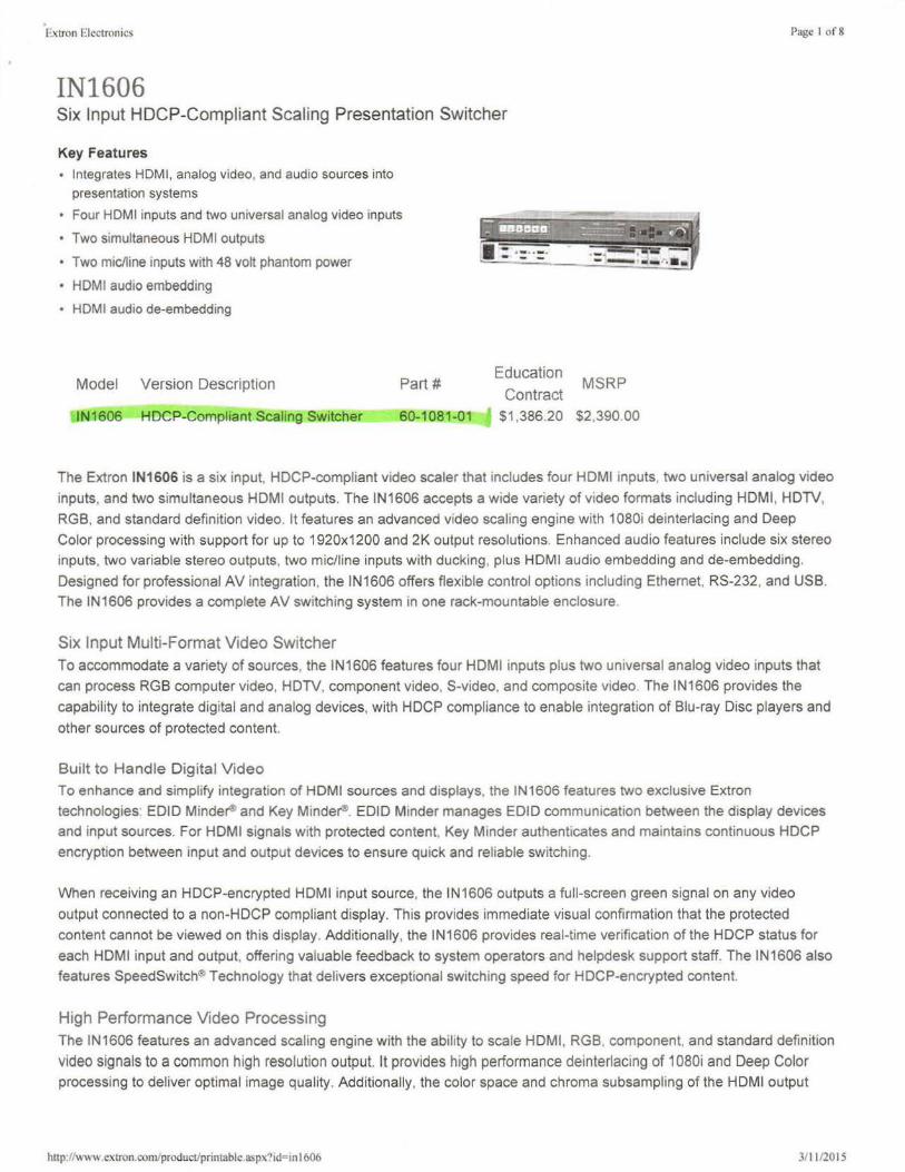
Extron Electronics
IN1606 Six Input HDCP-Compliant Scaling Presentation Switcher
Key Features
• Integrates HDMI, analog video, and audio sources into presentation systems
• Four HDMI inputs and two universal analog video inputs
• Two simultaneous HDMI outputs
• Two mic/line inputs with 48 volt phantom power
• HDMI audio embedding
• HDMI audio de-embedding
Model Version Description Part#
IN1606 HDCP-Compliant Scaling Switcher 60-1081-01
Education MSRP
Contract $1 ,386.20 $2,390.00
Page 1 of8
The Extron IN1606 is a six input, HDCP-compliant video scaler that includes four HDMI inputs, two universal analog video
inputs, and two simultaneous HDMI outputs. The IN1606 accepts a wide variety of video formats including HDMI, HDTV,
RGS, and standard definition video. It features an advanced video scaling engine with 1080i deinterlacing and Deep
Color processing with support for up to 1920x1200 and 2K output resolutions. Enhanced audio features include six stereo
inputs, two variable stereo outputs, two mic/line inputs with ducking, plus HDMI audio embedding and de-embedding.
Designed for professional AV integration, the IN1606 offers flexible control options including Ethernet, RS-232, and USS. The IN1606 provides a complete AV switching system in one rack-mountable enclosure.
Six Input Multi-Format Video Switcher To accommodate a variety of sources, the IN1606 features four HDMI inputs plus two universal analog video inputs that
can process RGS computer video, HDTV, component video, S-video, and composite video. The IN1606 provides the
capability to integrate digital and analog devices, with HDCP compliance to enable integration of Siu-ray Disc players and
other sources of protected content.
Built to Handle Digital Video
To enhance and simplify integration of HDMI sources and displays, the IN1606 features two exclusive Extron
technologies: EDID Minde~ and Key Minder®. EDID Minder manages EDID communication between the display devices
and input sources. For HDMI signals with protected content, Key Minder authenticates and maintains continuous HDCP
encryption between input and output devices to ensure quick and reliable switching.
When receiving an HDCP-encrypted HDMI input source, the IN1606 outputs a full-screen green signal on any video
output connected to a non-HDCP compliant display. This provides immediate visual confirmation that the protected content cannot be viewed on this display. Additionally, the IN1606 provides real-time verification of the HDCP status for
each HDMI input and output, offering valuable feedback to system operators and helpdesk support staff. The IN1606 also features SpeedSwitch® Technology that delivers exceptional switching speed for HDCP-encrypted content.
High Performance Video Processing The IN1606 features an advanced scaling engine with the ability to scale HDMI, RGS, component, and standard definition
video signals to a common high resolution output. It provides high performance deinterlacing of 1080i and Deep Color
processing to deliver optimal image quality. Additionally, the color space and chroma subsampling of the HDMI output
hnp://www extron.com/product/printable.aspx·?id"'in 1606 311 112015

Extron Elec1ronics Page 2 of8
can be automatically set to ensure compatibility with a connected DVI or HDMI display. Automatic 3:2 and 2:2 pulldown
detection maximizes the image quality for content sources originating from film. The IN1606 also uses a digital 30
adaptive comb filter that optimizes decoding of NTSC, PAL, and SECAM sources for integration into systems worldwide.
The IN1606 accepts and outputs signals up to 1920x1200, including HDTV 1080p/60 and 2K. It provides two
simu ltaneous HDMI outputs so that two displays can be driven simultaneously, without the need for additional equipment. Selectable FILL and FOLLOW modes are available to ensure the proper aspect ratio of the output. FILL mode provides
full screen output, while FOLLOW mode preserves the original aspect ratio of the input signal.
Advanced Audio Capabilities The IN1606 features sophisticated audio functionality, including HDMI audio embedding and de-embedding. To suit the
needs of the application, the IN1606 can embed analog input audio signals onto the HDMI outputs or extract embedded HDMI audio. Audio breakaway enables separation of analog audio channels from the corresponding video signals, so that
the analog audio channels can operate as an independent switcher. To support integration into presentation
environments, the IN1606 features two mic/line mixing inputs with ducking and 48 V phantom power. The scaler includes two variable stereo audio outputs, one of which can be configured as dual mono for integration flexibility. The IN 1606 also
provides full control of advanced audio configuration settings through an intuitive Graphical User Interface. Using this
GUI, users can easily adjust audio input and output gain, attenuation, mixing, and ducking parameters.
Multiple Options for Control and Operation
The IN1606 features front panel controls and intuitive on-screen menus for quick access to functions. Remote
configuration and control are available via USB, RS-232, and Ethernet. Housed in a 1 U, full rack width metal enclosure, the IN1606 can easily be integrated into many environments. The IN1606 is ideal in boardrooms where superior
performance is essential, video routing applications where automatic features help simplify system design and keep costs down, and instructional environments for complete integration of digital and analog AV sources and displays.
Features
• Integrates HDMI, analog video, and audio sources into presentation systems - The IN1606 provides
centralized switching for a wide range of AV sources.
• Inputs: Four HDMI; two universal 15-pin HD inputs for RGB, component video, $-video, or composite video;
stereo balanced/unbalanced audio for each input on captive screw; two mic/line audio inputs on captive screw
• Outputs: Two simultaneous HDMI outputs ; one variable stereo audio output on captive screw; one variable stereo audio output configurable as dual mono on captive screw
• Four HDMI inputs and two universal analog video inputs - The IN1606 allows for switching between HDMI and
analog video sources. Two universal analog inputs accept all standard analog video formats, including RGB, HD
component video, S-video, and composite video signals.
• Two simultaneous HDMI outputs - Simultaneous HDMI outputs are available for driving two displays.
• Two mic/line inputs with 48 volt phantom power - Two mic or line level audio sources can be independently
mixed with program audio and embedded onto the HDMI output. Selectable 48 volt phantom power allows the use of
condenser microphones.
• Mic ducking - Automatically reduces program audio when a microphone signal is detected, replacing the need for a separate audio ducking processor.
• Auto-switching between inputs - Auto-switching allows for simple, unmanaged installation in locations such as in a lectern or under a conference table. When multiple inputs are active, the switching priority is configurable.
• HDMI audio embedding - Analog input audio signals can be embedded onto the HDMI output signal.
• HDMI audio de-embedding - Embedded HDMI two-channel PCM audio can be extracted to the analog outputs, or
bitstream formats can be passed to the HDMI outputs.
hnp://\\'\\ w.cxtron.com/product/printable.aspx?1d=in 1606 3/1 112015

Extron Electronics Page 3 of8
• Selectable output rates from 640x480 to 1920x1200, including HDTV 1080p/60 and 2K-Available output rates
include computer video up to 1920x1200, HDTV rates up to 1080p/60, and 2K.
• Advanced scaling engine with 30-bit processing and 1080i deinterlacing - Image scaling and video format
conversion are performed at 30-bit precision for enhanced color accuracy and picture detail. High performance
deinterlacing for 1080i signals from HD sources delivers optimized image quality.
• HDCP compliant - Fully supports HDCP-encrypted sources, with selectable authorization for unencrypted content.
• Supported HDMI specification features include data rates up to 6.75 Gbps, Deep Color, and HD lossless
audio formats
• Key Minder® continuously verifies HDCP compliance for quick, reliable switching - Key Minder authenticates and maintains continuous HDCP encryption between input and output devices to ensure quick and reliable switching
m professional AV environments, while enabling simultaneous distribution of a single source signal to one or more
displays.
• EDID Minder® automatically manages EDID communication between connected devices - EDID Minder
ensures that all sources power up properly and reliably output content for display.
• SpeedSwitch® Technology provides exceptional switching speed for HDCP-encrypted content
• Output muting control - Provides the capability to mute one or all outputs at any time. This allows content to be
viewed on a local monitor prior to appearing on the main presentation display.
• Aspect ratio control - The aspect ratio of the video output can be controlled by selecting a FILL mode, which provides a full screen output, or a FOLLOW mode, which preserves the original aspect ratio of the input signal.
• HDCP authentication and signal presence confirmation - Provides real-time verification of HDCP status for
each digital video input and output. This allows for simple, quick, and easy signal and HDCP verification through front panel LEDs, RS-232, USB, or Ethernet, providing valuable feedback to a system operator or helpdesk support staff.
• HDCP Visual Confirmation provides a green signal when encrypted content is sent to a non-compliant
display - A full-screen green signal is sent when HDCP- encrypted content is transmitted to a non-HDCP
compliant display, providing immediate visual confirmation that protected content cannot be viewed on the display.
• HDMI to DVI Interface Format Correction -Automatically enables or disables embedded audio and lnfoFrames,
and sets the correct color space for proper connection to HDMI and DVI displays.
• Seamless switching - Seamless cut through black and fade through black transition effects are available to
enhance presentations by eliminating distractions during switching.
• Image freeze control - A live image can be frozen using RS-232 serial control, USB, or Ethernet control.
• Auto-Image™ setup - When activated, the unit automatically optimizes the image by analyzing and adjusting to the
video input signal. This can save time and effort in setting up a newly connected source, particularly in presentation
environments where different guest presenter laptops with various output resolutions will be connected.
• Auto Input Memory - When activated, the unit automatically stores size, position, and picture settings based on the
incoming signal. When the same signal is detected again, these image settings are automatically recalled from
memory.
• On-screen menus - Intuitive on-screen menus allow for easy system setup using the front panel controls. Key
parameters such as input and output video formats and resolutions are conveniently grouped on the initial Quick
Setup screen, while additional screens provide full control over the unit's other functions and settings.
• Output Standby Mode - The unit can be set to automatically mute video and sync output to the display device when no active input signal is detected. This allows the projector or flat-panel display to automatically enter into
standby mode to save energy and enhance lamp or panel life.
• Power Save Mode - The unit can be placed in a low power standby state to conserve energy when not in use.
• Picture controls for brightness, contrast, color, tint, and detail, as well as horizontal and vertical positioning,
and sizing
hnp://" W\\ cxtron.com/product/printable.aspx?1d=in 1606 311 1/2015
Extron Electronics Page 4 of8
• Automatic 3:2 and 2:2 pulldown detection - Advanced film mode processing techniques that help maximize
image quality for NTSC, PAL, and HDTV 1080i sources that originated from film.
• Quad standard video decoding - A temporal, 3D adaptive comb filter provides advanced decoding of composite
NTSC 3.58, NTSC 4.43, PAL, and SECAM for integration into systems worldwide.
• User presets - Memory presets are available for each input to store and recall optimized image settings.
• Internal video test patterns and pink noise generator for calibration and setup - The unit offers several video
test patterns and audio pink noise to facilitate proper system setup and calibration of display devices.
• Output volume control - Provides volume control for the audio outputs. Analog audio outputs can be balanced or unbalanced and are available as stereo or independently mixed mono.
• Audio input gain and attenuation - Gain or attenuation can be adjusted for each analog input to eliminate noticeable differences when switching between sources.
• Audio breakaway - Provides the capability to break an analog audio signal away from its corresponding video
signal and route to the audio outputs, allowing the analog audio channels to be operated as a separate switcher.
• Audio switching transitions - The audio output level automatically ramps down and then ramps up to match the
video during switching transitions.
• Integrated audio delay - The audio output is automatically delayed to compensate for latency introduced by the video processing.
• Automatic clip limiter - Detects onset of clipping, automatically reducing gain to eliminate clipping and thereby protecting speakers and amplifiers from distortion.
• Advanced audio configuration - The IN1606 offers complete control of audio input and output gain, attenuation, mixing, and ducking parameters via a user-friendly GUI.
• Front panel security lockout - This feature locks out all front panel functions except for input selection; all
functions however, are available through Ethernet, USB, or RS-232 control.
• Ethernet monitoring and control - Enables control and proactive monitoring over a LAN, WAN, or the Internet. An
intuitive Web interface is included for full configuration of the unit.
• Built-in Web pages - Enables the use of a standard browser for full control and troubleshooting over an intuitive Web interface.
• RS-232 control port - Enables the use of serial commands for integration into a control system. Extron products
use the SIS™ - Simple Instruction Set command protocol, a set of basic ASCII commands that allow for quick and easy programming.
• Front panel USB configuration port - Enables easy configuration without having to access the rear panel.
• Easy setup and commissioning with Extron's PCS - Product Configuration Software - Conveniently configure multiple products using a single software application.
• Rack-mountable 1 U, full rack width metal enclosure
• Includes Locklt® HDMI cable lacing brackets
• Highly reliable, energy-efficient internal universal power supply - The 100-240 VAC, 50/60 Hz, international
power supply provides worldwide power compatibility with
high demonstrated reliability (/company/article.aspx?id=eps ga).
INCLUDED ACCESSORIES
• MBD 149
OPTIONAL ACCESSORIES
http://www.extron.com/product/prin1abi e.aspx'?id=in I 606
1 U, Full Rack Width, Rack Mount and Through-Desk Kit for Four-Piece Enclosure
70-077-03
3/ 11/2015
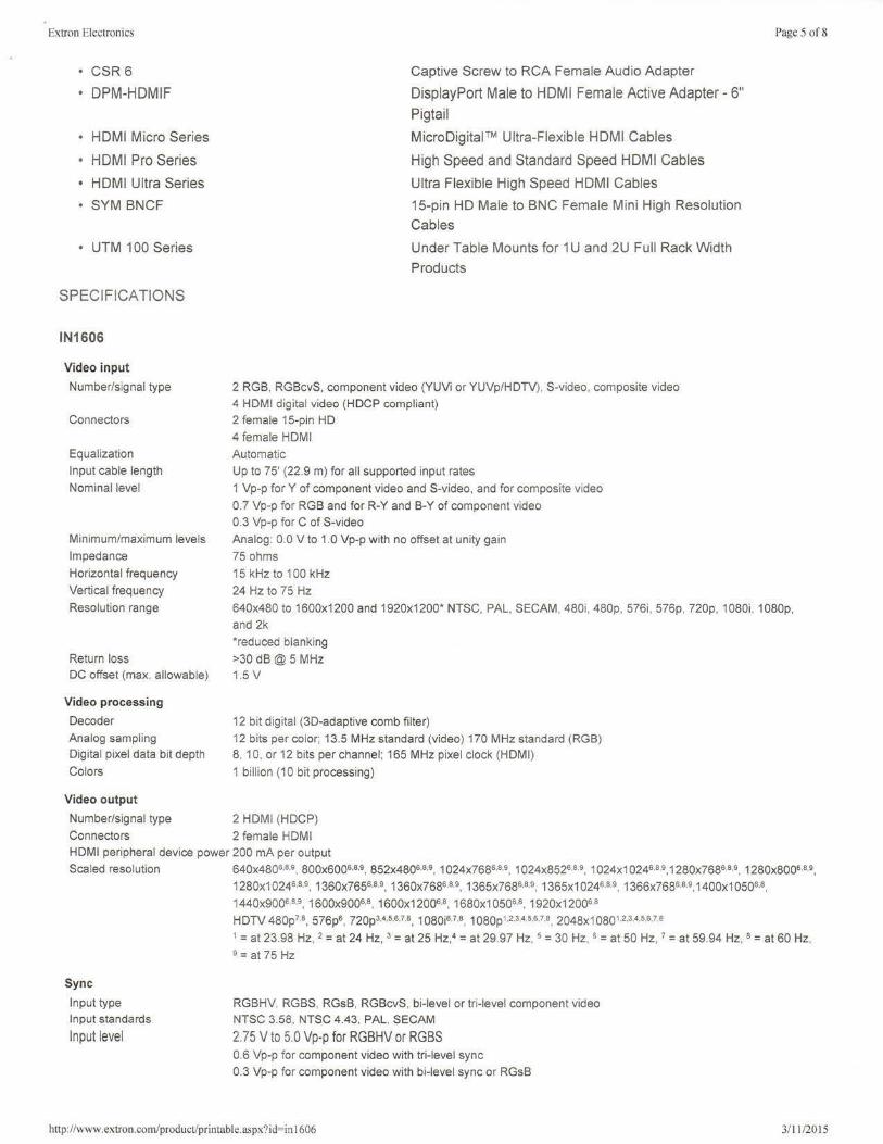
Extron Electronics
• CSR6
• DPM-HDMIF
• HDMI Micro Series
• HDMI Pro Series • HDMI Ultra Series
• SYM BNCF
• UTM 100 Series
SPECIFICATIONS
IN1606
Video input
Number/signal type
Connectors
Equalization
Input cable length
Nominal level
Minimum/maximum levels
Impedance
Horizontal frequency
Vertical frequency
Resolution range
Return loss DC offset (max. allowable)
Video processing
Decoder
Analog sampling Digital pixel data bit depth
Colors
Video output
Number/signal type
Captive Screw to RCA Female Audio Adapter
DisplayPort Male to HDMI Female Active Adapter - 6" Pigtail
MicroDigital™ Ultra-Flexible HDMI Cables
High Speed and Standard Speed HDMI Cables
Ultra Flexible High Speed HDMI Cables
15-pin HD Male to BNC Female Mini High Resolution
Cables
Under Table Mounts for 1 U and 2U Full Rack Width
Products
2 RGB, RGBcvS, component video (YUVi or YUVp/HDTV). S-video, composite video
4 HDMI digital video (HDCP compliant) 2 female 15-pin HD
4 female HDMI
Automatic
Up to 75' (22.9 m) for al l supported input rates
1 Vp-p for Y of component video and S-video, and for composite video
0.7 Vp-p for RGB and for R-Y and B-Y of component video
0.3 Vp-p for C of S-video
Analog: 0.0 V to 1.0 Vp-p with no offset at unity gain
75 ohms
15 kHz to 100 kHz
24 Hz to 75 Hz
Page 5 of8
640x480 to 1600x1200 and 1920x1200" NTSC, PAL. SECAM, 480i, 480p, 576i, 576p, 720p, 1080i, 1080p.
and 2k
•reduced blanking
>30d8@5 MHz 1.5 v
12 bit digital (3D-adaptive comb filter)
12 bits per color; 13.5 MHz standard (video) 170 MHz standard (RGB) 8, 10. or 12 bits per channel: 165 MHz pixel clock (HDMI)
1 bi llion (10 bit processing)
2 HDMI (HDCP)
Connectors 2 female HDMI
HDMI peripheral device power 200 mA per output
Scaled resolution 640x4806 ·8·9 , 800x6006.8·9 , 852x4806·8.9, 1024x7686.8.9, 1024x8526 ·8 ·9 • 1024x10246·8·9 , 1280x7686·8·9 , 1280x8006 ·8·9 ,
1280x10246·8·9, 1360x7656·8·9, 1360x7686·8.9, 1365x7686·8.9, 1365x10246·8.9, 1366x7686·8.9, 1400x105os.s.
1440x900689, 1600x9006.8, 1600x1 2006·8, 1680x105068, 1920x120068
Sync
Input type
Input standards
Input level
HDTV 48Qp7.s, 576p6, 720p3,4.s.s.1.s, 1 080i6,7,a, 1080p 1,2.3.4.o.s,1.s, 2048x 10801,2.J,•.s.s,1.s 1 =at 23.98 Hz, 2 =at 24 Hz, 3 =at 25 Hz,4 =at 29.97 Hz, 5 = 30 Hz, a= at 50 Hz, 7 =at 59.94 Hz, 8 =at 60 Hz, 9 =at 75 Hz
RGBHV, RGBS, RGsB, RGBcvS, bi-level or tri-level component video NTSC 3.58, NTSC 4.43, PAL, SECAM
2.75 V to 5.0 Vp-p for RGBHV or RGBS 0.6 Vp-p for component video with tri-level sync
0.3 Vp-p for component video with bi-level sync or RGsB
http://www.extron.com/product/printable.aspx? id= in 1606 3111/2015
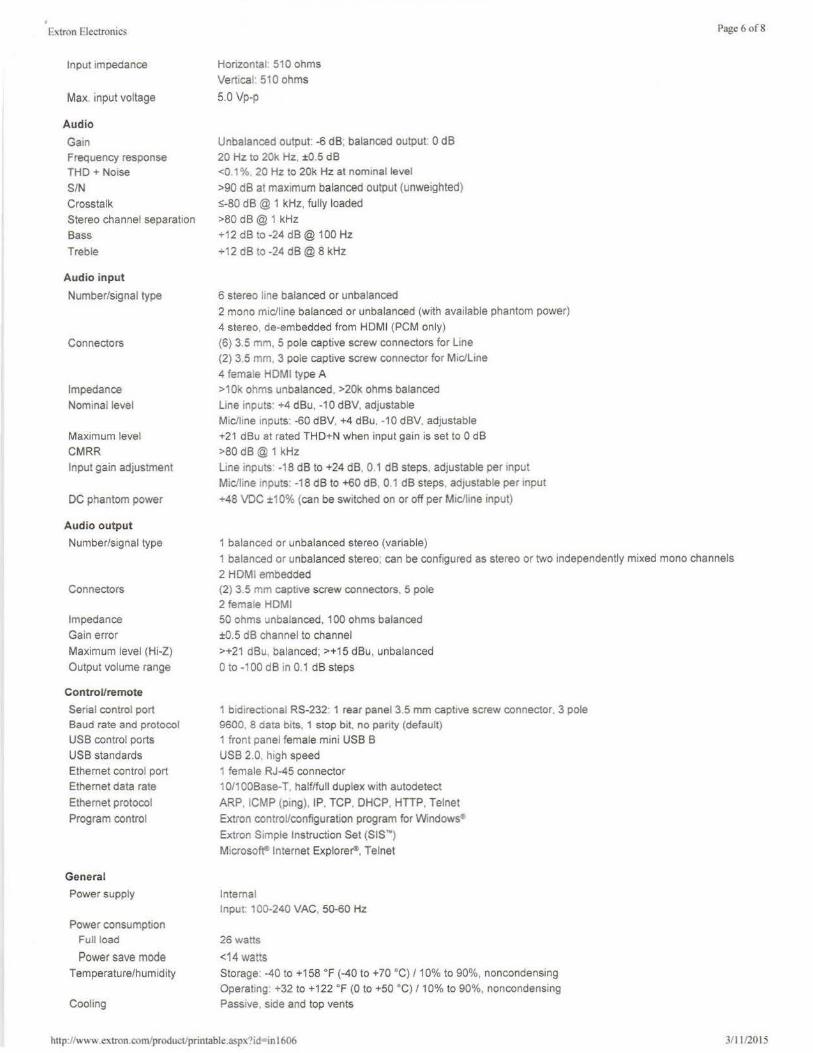
r xtron Electronics
Input impedance
Max. input voltage
Audio
Gain Frequency response THO+ Noise
SIN Crosstalk
Stereo channel separation
Bass
Treble
Audio input
Number/signal type
Connectors
Impedance
Nominal level
Maximum level
CMRR
Input gain adjustment
DC phantom power
Audio output
Number/signal type
Connectors
Impedance
Gain error
Maximum level (Hi-Z)
Output volume range
Control/remote
Serial control port Baud rate and protocol
USS control ports
USB standards
Ethernet control port
Ethernet data rate
Ethernet protocol
Program control
General
Power supply
Power consumption Full load
Power save mode
Temperature/humidity
Cooling
Horizontal 510 ohms
Vertical 510 ohms
5.0 Vp-p
Unbalanced output -6 dB; balanced output· O dB
20 Hz to 20k Hz, ±0.5 dB <0.1 % 20 Hz to 20k Hz at nominal level
>90 dB at maximum balanced output (unweighted)
s-80 dB@ 1 kHz, fully loaded
>80 dB@ 1 kHz
+12 dB to -24 dB@ 100 Hz
+12 dB to -24 dB@ 8 kHz
6 stereo hne balanced or unbalanced
2 mono m1c/line balanced or unbalanced (with available phantom power)
4 stereo, de-embedded from HOMI (PCM only)
(6) 3.5 mm, 5 pole captive screw connectors for Line
(2) 3.5 mm. 3 pole captive screw connector for Mac/Line
4 female HOMI type A
>10k ohms unbalanced, >20k ohms balanced
Line inputs: +4 dBu, -10 dBV, adjustable
Mic/line inputs: -60 dBV. +4 dBu. -10 dBV, adjustable
+21 dBu at rated THO+N when input gain is set to 0 dB
>80 dB@ 1 kHz
Line inputs -18 dB to +24 dB, O 1 dB steps, adjustable per input
Mic/line inputs: -18 dB to +60 dB, 0 1 dB steps adjustable per input
+48 VDC ±10% (can be switched on or off per Mic/line input)
1 balanced or unbalanced stereo (variable)
Page 6 of8
1 balanced or unbalanced stereo: can be configured as stereo or two independently mixed mono channels
2 HDMI embedded (2) 3.5 mm captive screw connectors. 5 pole 2 female HOM!
50 ohms unbalanced, 100 ohms balanced
±0.5 dB channel to channel
>+21 dBu, balanced; >+15 dBu, unbalanced
Oto -100 dB in 0.1 dB steps
1 bidirectional RS-232: 1 rear panel 3.5 mm captive screw connector. 3 pole
9600, 8 data bits. 1 stop bit, no parity (default)
1 front panel female mini USS B
USS 2.0, high speed
1 female RJ-45 connector
10/1 OOBase-T. half/full duplex w ith autodetect
ARP, ICMP (ping), IP, TCP. DHCP, HTIP. Telnet
Extron control/configuration program for Windows•
Extron Simple Instruction Set (SISN)
Microso~ Internet Explore~. Telnet
Internal Input: 100-240 VAC, 50-60 Hz
26 watts
<14 watts
Storage. -40 to +158 °F (-40 to +70 °C)/10% to 90%, noncondensing
Operating· +32 to +122 °F (0 to +50 °C) / 10% to 90%. noncondensing
Passive, side and top vents
hup./lw" '' .extron.com/producl/printable.aspx'?id=in 1606 3/ 11/2015
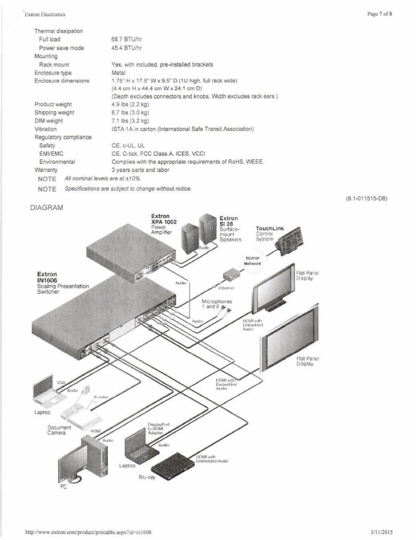
fa tron Electronics
Thermal dissipation Full load
Power save mode Mounting
Rack mount Enclosure type Enclosure dimensions
Product weight Shipping weight DIM weight Vibration Regulatory compliance
Safety EM I/EMC Environmental
Warranty
68.7 BTU/hr
45.4 BTU/hr
Yes. with included. pre-installed brackets Metal 1. 75" H x 17 5" W x 9.5" D (1 U high. full rack wide) (4.4 cm H x 44.4 cm W x 24 1 cm D)
(Depth excludes connectors and knobs. Width excludes rack ears.) 4.9 lbs (2.2 kg) 6.7 lbs (3.0 kg) 7.1 lbs (3 2 kg) ISTA 1A in carton (International Safe Transit Association)
CE, c-UL UL CE. C-t1ck. FCC Class A, ICES, VCCI Complies with the appropriate requirements of RoHS, WEEE 3 years parts and labor
NOTE All nominal levels are al ±10%
NOTE Specifications are subject to change without notice
DIAGRAM
Extron IN1606 Scaling Presentation Switcher
Laptop
Oocu'Tle"t C<imera
Edron XPA 1002 PO'll'Cr Amp fier
http:l/ww\\ .exrron.com/product/printable.aspx'?id-"tn 1606
Ex.tron 5128 Surfaccmovnt Spea~crs
!OUC~l.ink ·~or.rro 5)S'Cm
TCPflP N t11wa11(
Page 7 of8
(81-011515-08)
311112015
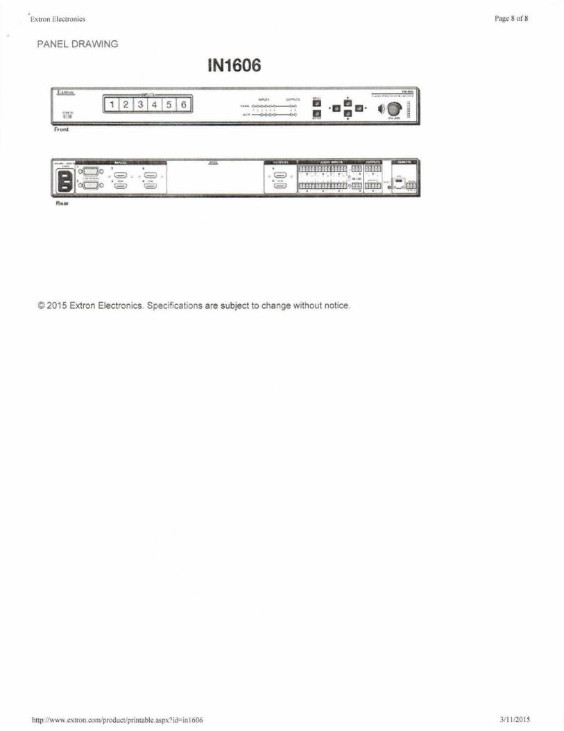
• Extron Electronic~ Page 8 of8
PANEL DRAWING
IN1606
,.-~ .. CCDO 0 0
rronl
© 2015 Extron Electronics. Specifications are subject to change without notice.
http://\\ W\\ .ex1ron.comlproduct/printable.asp' ?id=in 1606 311112015
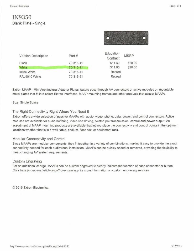
Extron Electronics Page I of I
IN9350 Blank Plate - Single
. . ' - '
• •• • • •
Version Description Part# Education
MSRP Contract
Black 70-315-11 $11.60 $20.00
White 70-315-21 $11.60 $20.00
lnline White 70-315-41 Retired
RAL9010 White 70-315-51 Retired
Extron MAAP - Mini Architectural Adapter Plates feature pass-through AV connectors or active modules on mountable metal plates that fit into select Extron interfaces, MAAP mounting frames and other products that accept MAAPs.
Size: Single Space
The Right Connectivity Right Where You Need It Extron offers a wide selection of passive MAAPs with audio, video, phone, data, power, and control connectors. Active
modules are available for audio buffering, video line driving, twisted pair transmission, control and power output. An
assortment of MAAP mounting products are available that let you place the connectivity and control points in the optimum
locations whether that is in a wall , table, pod ium, floor box, or equipment rack.
Modular Connectivity and Control Since MAAPs are modular components, they fit together in a variety of combinations, making it easy to provide the exact
connectivity needed for each audiovisual installation . MAAPs can be quickly added or removed , providing the flexibility to
meet changing AV system requirements.
Custom Engraving For an additional charge, MAAPs can be custom engraved to clearly indicate the function of each connector or button.
Click here (!company/article.aspx?id=engraving) for more information on custom engraving services.
© 2015 Extron Electronics.
http://www.extron.com/product/printable.aspx?id=in9350 3112/20 15
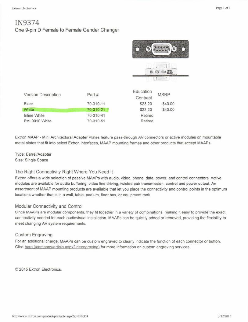
Extron Electronics
IN9374 One 9-pin D Female to Female Gender Changer
Version Description
Black
White
lnline White RAL9010 White
Part#
70-310-11
70-310-21
70-310-41 70-310-51
Education
Contract $23.20
$23.20
Retired
Retired
l . J
MSRP
$40.00
$40.00
Page I of I
Extron MAAP - Mini Architectural Adapter Plates feature pass-through AV connectors or active modu les on mountable
metal plates that fit into select Extron interfaces, MAAP mounting frames and other products that accept MAAPs.
Type: Barrel/Adapter
Size: Single Space
The Right Connectivity Right Where You Need It Extron offers a wide selection of passive MAAPs with audio, video, phone, data, power, and control connectors. Active
modules are available for audio buffering , video line driving, twisted pair transmission, control and power output. An
assortment of MAAP mounting products are available that let you place the connectivity and control points in the optimum
locations whether that is in a wall , table, podium, floor box, or equipment rack.
Modular Connectivity and Control Since MAAPs are modular components, they fit together in a variety of combinations, making it easy to provide the exact
connectivity needed for each audiovisual installation. MAAPs can be quickly added or removed, providing the flexibility to
meet changing AV system requirements.
Custom Engraving
For an additional charge, MAAPs can be custom engraved to clearly indicate the function of each connector or button.
Cl ick here (lcompany/article.aspx?id=engraving) for more information on custom engraving services.
© 2015 Extron Electronics.
http://www.extron.com/product/printable.aspx?id= IN9374 3/12/2015
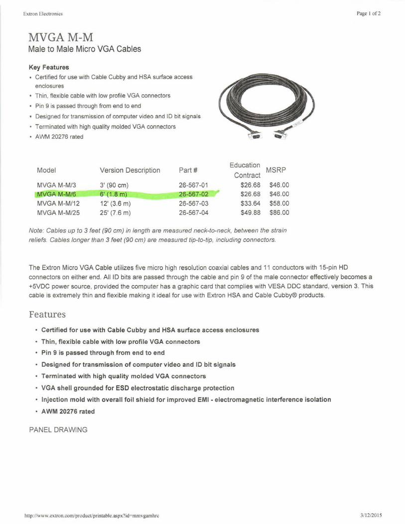
Extron Electronics
MVGAM-M Male to Male Micro VGA Cables
Key Features
• Certified for use with Cable Cubby and HSA surface access enclosures
• Thin, flexible cable with low profile VGA connectors
• Pin 9 is passed through from end to end
• Designed for transmission of computer video and ID bit signals
Terminated with high quality molded VGA connectors
• AWM 20276 rated
Model Version Description Part#
MVGA M-M/3 3' (90 cm) 26-567-01
MVGA M-M/6 6' (1 .8 m) 26-567-02
MVGA M-M/12 12' (3.6 m) 26-567-03
MVGA M-M/25 25' (7 .6 m) 26-567-04
Education MSRP
Contract
$26.68 $46.00
$26.68 $46.00
$33.64 $58.00
$49.88 $86.00
Note: Cables up to 3 feet (90 cm) in length are measured neck-to-neck, between the strain
reliefs. Cables longer than 3 feet (90 cm) are measured tip-to-tip, including connectors.
Page I of2
The Extron Micro VGA Cable utilizes five micro high resolution coaxial cables and 11 conductors with 15-pin HD
connectors on either end. All ID bits are passed through the cable and pin 9 of the male connector effectively becomes a
+5VDC power source, provided the computer has a graph ic card that complies with VESA DOC standard , version 3. This
cable is extremely thin and flexible making it ideal for use with Extron HSA and Cable Cubby® products.
Features
• Certified for use with Cable Cubby and HSA surface access enclosures
• Thin, f lexible cable with low profile VGA connectors
• Pin 9 is passed through from end to end
• Designed for transmission of computer video and ID bit signals
• Terminated with high quality molded VGA connectors
• VGA shell grounded for ESD electrostatic discharge protection
• Injection mold with overall foil shield for improved EMI - electromagnetic interference isolation
• AWM 20276 rated
PANEL DRAWING
http://www.extron.com/product/printable.aspx9id=mmvgamhrc 3/ 12/2015
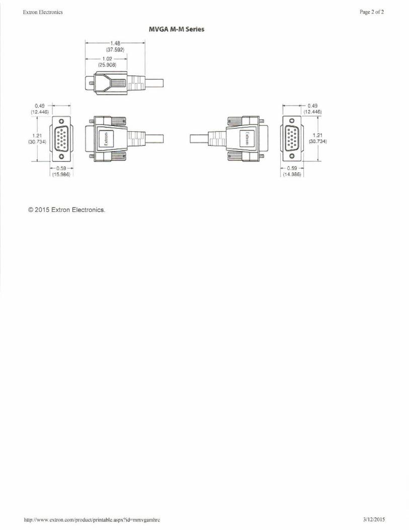
Extron Electronics
0.49-- (12.446)
0.59 [15.986)
© 2015 Extron Electronics.
MVGA M·M Series
http: //www.extron.com/product/printable.aspx?id=mmvgamhrc
1· 0
0
'I a.49 l12.446J
1.21 [30.734)
0_59 (14-986)
Page 2 of2
3/ 12/2015

Extron Electronics
Mini Audio Cables 3.5 mm Male to Male Stereo Audio Cables
Key Features
• Certified for use with Cable Cubby® and HSA surface access enclosures
• Fully shielded, flexible and durable stereo audio cable providing excellent performance
• Ideal for direct connection of audio from a laptop or computer
to any product with a 3.5 mm connection
Terminated with 3.5 mm male mini plugs on each end
Model Version Description Part#
A Mini/2 2' (60 cm) 26-571-01 A ini/6 6' (1 .8 m) 26-571-03
A Mini/12 12' (3.6 m) 26-571-06
A Mini/25 25' (7.6 m) 26-571-07
A Mini/10 10' (3.0 m) 26-571-05
Education MSRP
Contract
$2.32 $4.00
$3.48 $6.00
$4.64 $8.00
$6.96 $12.00
Retired
Note: Part numbers 26-571-02, 26-571-04 and 26-571-05 have been retired. Cables up to 6 feet
(1 . 8 m) in length are measured neck-to-neck, between the strain reliefs. Cables longer than 6 feet
(1.8 m) are measured tip-to-tip, including connectors.
Page I of I
The Mini Audio Cables are ideal for direct connection of audio from a laptop or computer to any of the Extron products
with a 3.5 mm connection, such as the Hideaway® Surface Access enclosures or AV switchers. This cable is fully
shielded and terminated with molded connectors. It is available in a variety of lengths to meet the needs of any
application.
Features • Certified for use with Cable Cubby® and HSA surface access enclosures
• Fully shielded, flexible and durable stereo audio cable providing excellent performance
• Ideal for direct connection of audio from a laptop or computer to any product with a 3.5 mm connection
• Terminated with 3.5 mm male mini plugs on each end
© 2015 Extron Electronics.
http: //www.extron.com/product/printable.aspx?id=35mmstereoc 3/12/2015
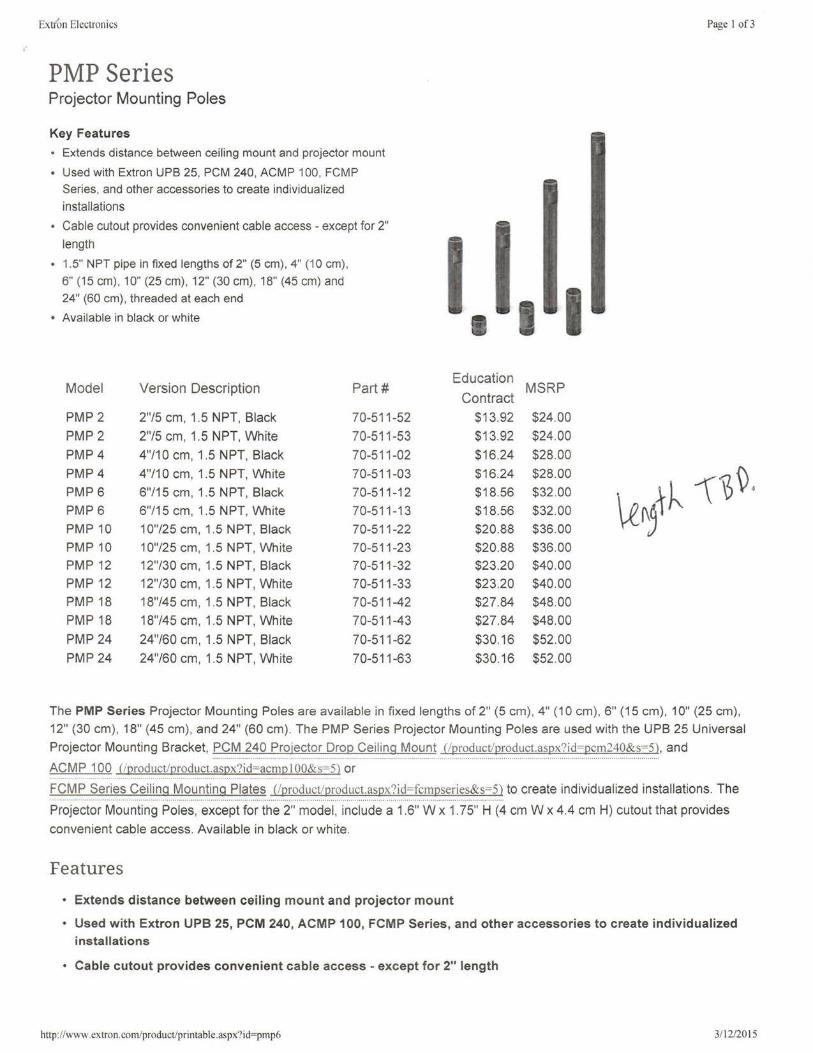
Extfon Electronics
PMP Series Projector Mounting Poles
Key Features
• Extends distance between ceiling mount and projector mount
• Used with Extron UPB 25, PCM 240, ACMP 100, FCMP Series, and other accessories to create individual ized installations
• Cable cutout provides convenient cable access - except for 2"
length
• 1.5" NPT pipe in fixed lengths of 2" (5 cm), 4" (10 cm) , 6" (15 cm), 10" (25 cm), 12" (30 cm), 18" (45 cm) and 24" (60 cm), threaded at each end
• Available in black or white
Model Version Description Part#
PMP 2 2"/5 cm, 1.5 NPT, Black 70-511-52
PMP 2 2"/5 cm, 1.5 NPT, White 70-511-53
PMP4 4"/10 cm, 1.5 NPT, Black 70-51 1-02
PMP4 4"/10 cm, 1.5 NPT, White 70-511-03
PMP6 6"/15 cm, 1.5 NPT, Black 70-511-12
PMP6 6"/15 cm, 1.5 NPT, White 70-511-13
PMP10 10"/25 cm, 1.5 NPT, Black 70-511-22
PMP10 10"/25 cm, 1.5 NPT, White 70-511-23
PMP12 12"/30 cm, 1.5 NPT, Black 70-511-32
PMP12 12"/30 cm, 1.5 NPT, White 70-511-33
PMP18 18"/45 cm, 1.5 NPT, Black 70-511-42
PMP18 18"/45 cm , 1.5 NPT, White 70-511-43
PMP 24 24"/60 cm, 1.5 NPT, Black 70-511-62
PMP 24 24"/60 cm, 1.5 NPT, White 70-511-63
Page 1 of3
I I I Education
MSRP Contract
$13.92 $24.00
$13.92 $24.00
$16.24 $28.00
$16.24 $28.00 -\i~ . $18.56 $32.00
\£~~~ $18.56 $32.00
$20.88 $36.00
$20.88 $36.00
$23.20 $40.00
$23.20 $40.00
$27.84 $48.00
$27.84 $48.00
$30.16 $52.00
$30.16 $52.00
The PMP Series Projector Mounting Poles are available in fixed lengths of 2" (5 cm) , 4" (10 cm), 6" (15 cm), 1 O" (25 cm),
12" (30 cm) , 18" (45 cm) , and 24" (60 cm) . The PMP Series Projector Mounting Poles are used with the UPB 25 Universal
Projector Mounting Bracket, PCM 240 Projector Drop Ceil ing Mount (lproduct/product.aspx?id=pcm240&s=5), and ········································· ....................................................................................... .
ACMP 100 (/product/product.aspx?id=acmp I OO&s=5) or
FCMP Series Ceili ng Mounting Plates (!product/product.aspx?id=fcmpseries&s=5) to create individualized installations. The .......................................................................................... . .................................................. .
Projector Mounting Poles, except for the 2" model, include a 1.6" W x 1. 75" H (4 cm W x 4.4 cm H) cutout that provides
convenient cable access. Available in black or white.
Features
• Extends distance between ceiling mount and projector mount
• Used with Extron UPB 25, PCM 240, ACMP 100, FCMP Series, and other accessories to create individualized installations
• Cable cutout provides convenient cable access - except for 2" length
http://www.extron.com/product/printable.aspx?id=pmp6 3/ 12/2015
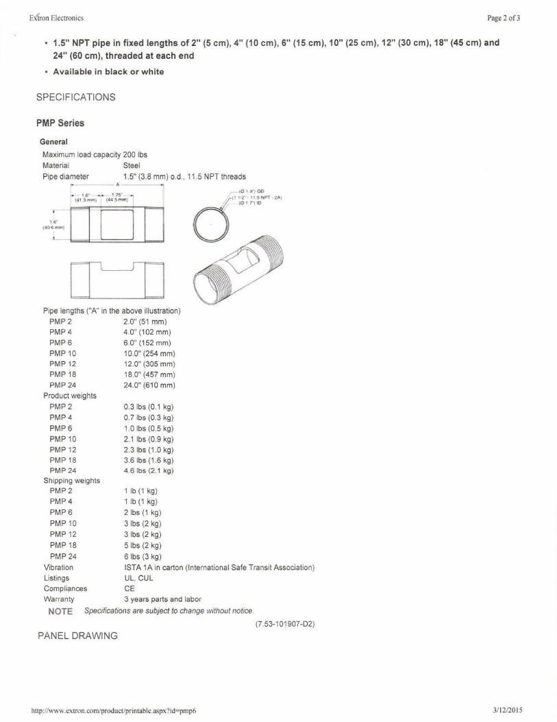
E tron Electronics Page 2 of3
• 1.5" NPT pipe in fixed lengths of 2" (5 cm), 4" (10 cm), 6" (15 cm), 10" (25 cm), 12" (30 cm), 18" (45 cm) and
24" (60 cm), threaded at each end
• Available in black or white
SPECIFICATIONS
PMP Series
General
Maximum load capacity 200 lbs Material Steel
Pipe diameter 1.5" (3.8 mm) o.d. , 11.5 NPT threads - A -
... 1 g• .. ,. 1 '1$.'" .. •~1 '."i ,....., ~ff' ~ rrm ;1
IJDI I D TI
Pipe lengths ("A" in the above illustration) PMP 2 2.0" (51 mm) PMP 4 4.0" (102 mm) PMP 6 6.0" (152 mm)
PMP 10 10.0" (254 mm) PMP 12 12.0" (305 mm) PMP 18 18.0" (457 mm) PMP 24 24.0" (610 mm)
Product weights
PMP2 PMP4
PMP6 PMP10 PMP 12 PMP18 PMP24
Shipping weights PMP 2 PMP4
PMP6
PMP10 PMP 12
PMP18
PMP 24
0.3 lbs (0.1 kg) 0.7 lbs (0.3 kg)
1.0 lbs (0 5 kg) 2.1 lbs (0.9 kg) 2.3 lbs (1 .0 kg) 3.6 lbs (1.6 kg) 4.6 lbs (2.1 kg)
1 lb (1 kg)
1 lb (1 kg)
2 lbs (1 kg )
3 lbs (2 kg)
3 lbs (2 kg)
5 lbs (2 kg)
6 lbs (3 kg)
Vibration Listings Compliances Warranty
ISTA 1A in carton (International Safe Transit Association) UL, CUL
CE
3 years parts and labor
NOTE Specifications are subject to change without notice.
(7.53-101907-02)
PANEL DRAWING
http://www.extron.com/product/printable.aspx?id=pmp6 3/ 12/2015
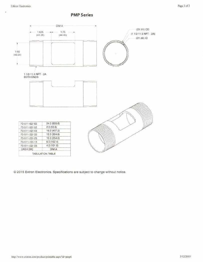
II
E~ron Electronics
PMP Series
1.60 (40.('4f
©201
1 625 (41.21:J )
1112·11 .5 NPT BOTH ENDS . 2A
DIM A
175 144 4$)
5 Extron Electronics S . pec1f1cat1ons
http://www ext · ron.com/ r d p o uct/printable as ?" · px . 1d=pmp6
are subject to chan
Page 3 of3
(0191 ) 00
(1 1.12-11.5 NPT . 2Al
(1211.66) ID .
ge without notice
3/ 12/2015
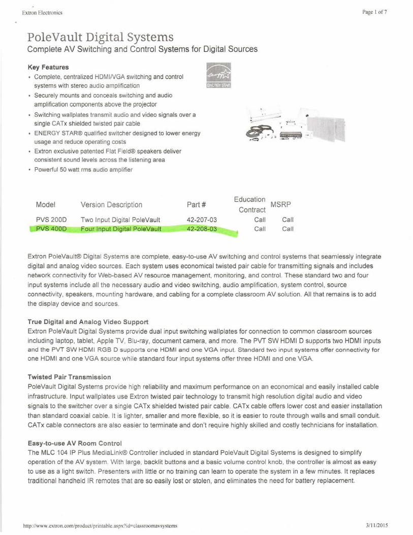
Extron Electronics
PoleVault Digital Systems Complete AV Switching and Control Systems for Digital Sources
Key Features
• Complete, centralized HDMINGA switching and control systems with stereo audio amplification
• Securely mounts and conceals switching and audio amplification components above the projector
• Switching wallplates transmit audio and video signals over a single CATx shielded twisted pair cable
• ENERGY STAR® qualified switcher designed to lower energy usage and reduce operating costs
• Extron exclusive patented Flat Field® speakers deliver consistent sound levels across the listening area
• Powerful 50 watt rms audio amplifier
Model
PVS 200D PVS 400D
Version Description
Two Input Digital PoleVault Four Input Digital PoleVault
Part#
42-207-03 42-208-03
Education
Contract Call Call
• ll!'t-:..... ....... .
MSRP
Call Call
Page I of?
Extron PoleVault® Digital Systems are complete, easy-to-use AV switching and control systems that seamlessly integrate
digital and analog video sources. Each system uses economical twisted pair cable for transmitting signals and includes
network connectivity for Web-based AV resource management, monitoring, and control. These standard two and four
input systems include all the necessary audio and video switching, audio amplification, system control , source
connectivity, speakers, mounting hardware, and cabling for a complete classroom AV solution. All that remains is to add
the display device and sources.
True Digital and Analog Video Support
Extron PoleVault Digital Systems provide dual input switching wallplates for connection to common classroom sources
including laptop, tablet, Apple TV, Blu-ray, document camera , and more. The PVT SW HDMI D supports two HDMI inputs and the PVT SW HDMI RGB D supports one HDMI and one VGA input. Standard two input systems offer connectivity for one HDMI and one VGA source while standard four input systems offer three HDMI and one VGA.
Twisted Pair Transmission
PoleVault Digital Systems provide high reliability and maximum performance on an economical and easily installed cable
infrastructure. Input wallp lates use Extron twisted pair technology to transmit high resolution digital audio and video
signals to the switcher over a single CATx shielded twisted pair cable. CATx cable offers lower cost and easier installation
than standard coaxial cable. It is lighter, smaller and more flexible , so it is easier to route through walls and small conduit.
CATx cable connectors are also easier to terminate and don't requ ire highly skilled and costly technicians for installation.
Easy-to-use AV Room Control
The MLC 104 IP Plus Medialink® Controller included in standard PoleVault Digital Systems is designed to simplify
operation of the AV system. With large, backlit buttons and a basic volume control knob, the controller is almost as easy
to use as a light switch . Presenters with little or no training can learn to operate the system in a few minutes. It replaces
traditional handheld IR remotes that are so easily lost or stolen, and eliminates the need for battery replacement.
hnp://www.extron.com/product/printable.aspx?id=classroomavsystems 3/ 11 /2015

Extron Electronics Page 2 of 7
Network Connectivity
PoleVau lt Digital Systems feature network integration technology specifically engineered to meet the needs of
professional AV environments. This enables administrators and support personnel to manage, monitor, troubleshoot, and
control systems over the network. These networked systems can also track and report usage, providing valuable
information for futu re component purchases. They also include an integrated three port network switch allowing two
additional devices within the classroom to share a single network drop.
Energy Efficiency
As an ENERGY STAR® qualified AV product, the switcher includes two Extron-exclusive power saving modes designed
to lower energy usage and reduce operating costs. Auto Power Save Mode automatically tu rns off the audio amplifier
after 25 minutes if no audio is present. Network Standby Power Save Mode turns off the amplifier, wallplates, Voicelift
receiver, and network switch , and can be scheduled at specific times when the system is not in use or activated by monitoring fo r when the projector is shut down.
Advanced Aud io Capabilities
At the heart of each system is a switcher/amplifier that offers sophisticated audio capabilities. The integrated 50 watt
stereo audio amplifier is able to drive up to four Extron speakers and filling the room with full , rich sound. The Voicelift®
Receiver input simplifies Voicelift Microphone installation. Switched and auxiliary line-level inputs support audio only
sources such as music players or public address systems. A line level output allows system audio to be used for podcasting or assistive listening.
Equipment Mounting
Pole Vault Digital Systems are ideal for classrooms with a ceiling mounted projector. The unique PMK 560 Pole Mount Kit
securely mounts and conceals system components above the projector. A projector drop ceiling mount is included with
adjustable pole and un iversal projector bracket.
Features
• Complete, centralized HOMINGA switching and control systems with stereo audio amplification
• Securely mounts and conceals switching and audio amplification components above the projector
• Switch ing wallplates transmit audio and video signals over a single CATx shielded twisted pair cable
• ENERGY STAR® qualified switcher designed to lower energy usage and reduce operating costs
• Extron exclusive patented Flat Field® speakers deliver consistent sound levels across the listening area
• Powerful 50 watt rms aud io amplifier
• Three port network switch allows two additional devices to share a single network drop
• Network connectivity for Web-based monitoring and rapid problem resolution
• Easy-to-use Medialink controller included
• Simplifies setup; no programming required
• Voicelift Microphone option allows the teacher's voice to be evenly distributed throughout the room
OPTIONAL ACCESSORIES
• PPS 35
• Voicelift Microphone
SPECIFICATIONS
PVS 2000 and PVS 4000 Digital Systems
http://www.extron.com/product/printable.aspx?id=classroomavsystems
Priority Page Sensor for PoleVault Digital Systems
Infrared Wireless Microphone For Use With PoleVault®
and WallVault® Systems
3/11/2015
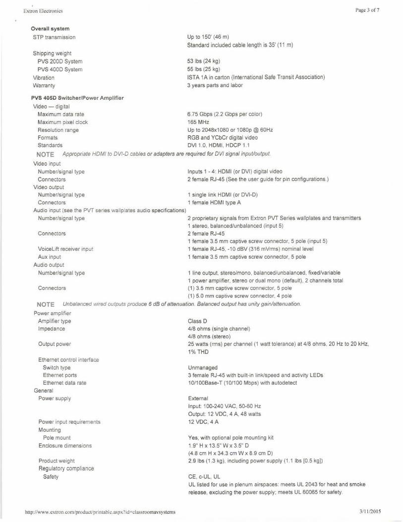
Extron Electronics
Overall system
STP transmission
Shipping weight
PVS 2000 System
PVS 4000 System
Vibration
Warranty
PVS 4050 Switcher/Power Amplifier
Video - digital
Maximum data rate
Maximum pixel clock
Up to 150' (46 m)
Standard included cable length is 35' (11 m)
53 lbs (24 kg)
55 lbs (25 kg)
ISTA 1A in carton (International Safe Transit Association)
3 years parts and labor
6.75 Gbps (2 .2 Gbps per color)
165 MHz
Page 3 of7
Resolution range Up to 2048x1080 or 1080p @ 60Hz
Formats RGB and YCbCr digital video Standards DVI 1.0, HDMI , HDCP 1.1
NOTE Appropriate HOM/ to DV/-0 cables or adapters are required for DVI signal input/output.
Video input
Number/signal type
Connectors
Video output Number/signal type
Connectors
Audio input (see the PVT series wallplates audio specifications)
Number/signal type
Connectors
VoiceLift receiver input
Aux input
Aud io output
Number/signal type
Connectors
Inputs 1 - 4: HOM! (or DVI) digital video
2 female RJ-45 (See the user guide for pin configurations.)
1 single link HDMI (or DVl-D)
1 female HDMI type A
2 proprietary signals from Extron PVT Series wallplates and transmitters 1 stereo, balanced/unbalanced (input 5)
2 female RJ-45 1 female 3.5 mm captive screw connector, 5 pole (input 5)
1 female RJ-45, -10 dBV (316 mVrms) nominal level
1 female 3.5 mm captive screw connector, 5 pole
1 line output, stereo/mono, balanced/unbalanced , fixed/variable 1 power amplifier, stereo or dual mono (default), 2 channels total (1) 3.5 mm captive screw connector, 5 pole (1) 5.0 mm captive screw connector, 4 pole
NOTE Unbalanced wired outputs produce 6 dB of attenuation. Balanced output has unity gain/attenuation.
Power amplifier
Amplifier type
Impedance
Output power
Ethernet control interface
Switch type Ethernet ports
Ethernet data rate
General
Power supply
Power input requirements
Mounting
Pole mount
Enclosure dimensions
Product weight
Regulatory compliance
Safety
http: //www.extron.com/product/printable.aspx?id=classroomavsystems
Class D 418 ohms (single channel)
418 ohms (stereo) 25 watts (rms) per channel (1 watt tolerance) at 418 ohms, 20 Hz to 20 kHz,
1% THO
Unmanaged 3 female RJ-45 with built-in link/speed and activity LEDs
10/100Base-T (10/100 Mbps) with autodetect
External
Input: 100-240 VAC, 50-60 Hz
Output: 12 VDC, 4 A, 48 watts
12VDC, 4A
Yes, with optional pole mounting kit
1.9" H x 13.5" W x 3.5" D (4.8 cm H x 34.3 cm W x 8.9 cm D) 2.9 lbs (1.3 kg) , including power supply (1.1 lbs [0.5 kg))
CE, c-UL, UL UL listed for use in plenum airspaces: meets UL 2043 for heat and smoke
release, excluding the power supply ; meets UL 60065 for safety.
3/11/20 15
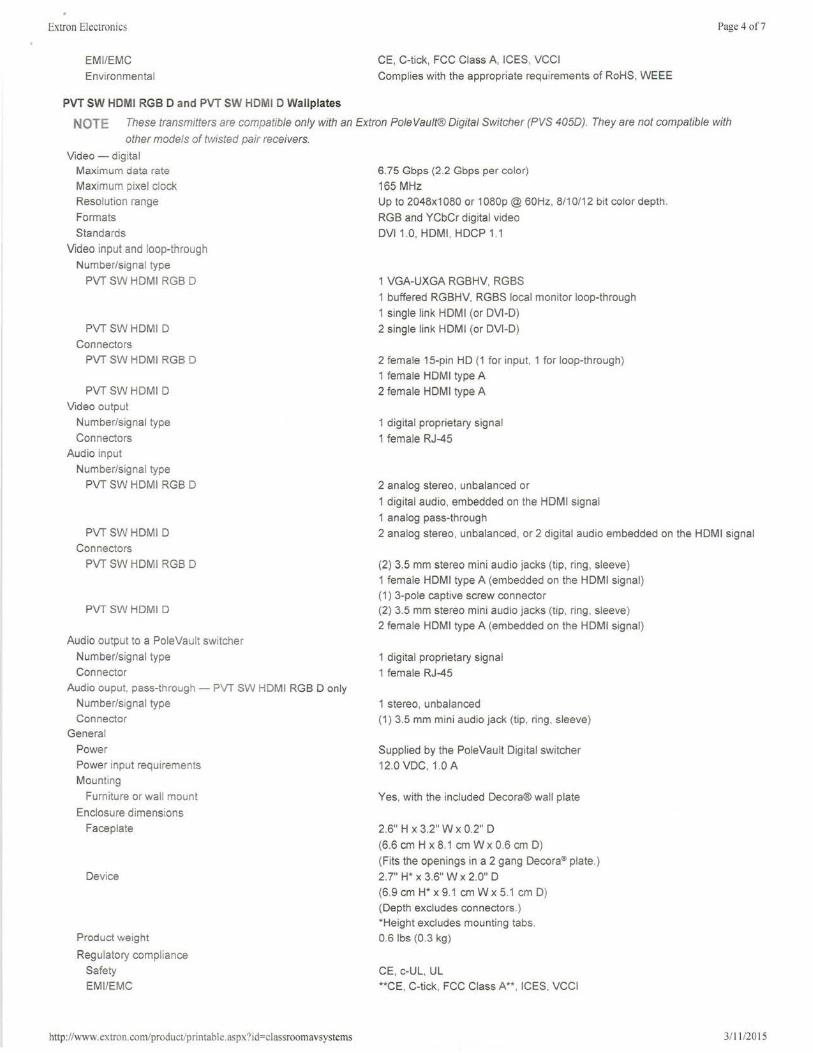
Extron Electronics
EM I/EMC
Environmental
PVT SW HDMI RGB D and PVT SW HDMI D Wallplates
Page 4 of7
CE, C-tick, FCC Class A, ICES, VCCI
Complies with the appropriate requirements of RoHS, WEEE
NOTE These transmitters are compatible only with an Extron Pole Vault® Digital Switcher (PVS 4050). They are not compatible with
other models of twisted pair receivers.
Video - digital Maximum data rate
Maximum pixel clock
Resolution range
Formats
Standards
Video input and loop-through
Number/signal type
PVT SW HDMI RGB D
PVT SWHDMI D
Connectors
PVT SW HDMI RGB D
PVT SWHDMI D
Video output
Number/signal type
Connectors
Audio input
Number/signal type
PVT SW HDMI RGB D
PVTSWHDMI D
Connectors
PVT SW HDMI RGB D
PVTSWHDMI D
Audio output to a PoleVault switcher
Number/signal type
Connector
Audio ouput, pass-throug h - PVT SW HDMI RGB D only
Number/signal type
Connector
General
Power
Power input requi rements
Mounting
Furniture or wall mount
Enclosure dimensions
Faceplate
Device
Product weight
Regu latory compliance
Safety
EM I/EMC
http://www.extron.com/productlprintable.aspx?id=classroomavsystems
6.75 Gbps (2 .2 Gbps per color)
165 MHz
Up to 2048x1080 or 1080p @ 60Hz, 8/10/12 bit color depth.
RGB and YCbCr digital video
DVI 1.0, HDMI, HDCP 1.1
1 VGA-UXGA RGBHV, RGBS
1 buffered RGBHV, RGBS local monitor loop-through
1 single link HDMI (or DVl-D)
2 single link HDMI (or DVl-D)
2 female 15-pin HD (1 for input, 1 for loop-through)
1 female HDMI type A
2 female HDMI type A
1 digital proprietary signal
1 female RJ-45
2 analog stereo, unbalanced or
1 digital audio , embedded on the HDMI signal
1 analog pass-through
2 analog stereo, unbalanced, or 2 digital audio embedded on the HDMI signal
(2) 3.5 mm stereo mini audio jacks (tip, ring, sleeve)
1 female HDMI type A (embedded on the HDMI signal)
(1) 3-pole captive screw connector (2) 3.5 mm stereo mini audio jacks (tip, ring , sleeve)
2 female HDMI type A (embedded on the HDMI signal)
1 digital proprietary signal
1 female RJ-45
1 stereo, unbalanced
(1) 3.5 mm mini audio jack (tip, ring , sleeve)
Supplied by the PoleVault Digital switcher
12.0 VDC, 1 0 A
Yes, with the included Decora® wall plate
2.6" H x 3.2" W x 0.2" D
(6.6 cm H x 8.1 cm W x 0.6 cm D)
(Fits the openings in a 2 gang Decora® plate.)
2.7" H* x 3.6" W x 2 O" D
(6.9 cm H* x 9.1 cm W x 5.1 cm D)
(Depth excludes connectors.)
*Height excludes mounting tabs .
0.6 lbs (0.3 kg)
CE, c-UL, UL
**CE, C-tick, FCC Class A**, ICES, VCCI
3111 /2015
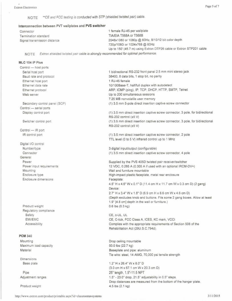
Extron Electronics Page 5 of 7
NOTE **CE and FCC testing is conducted with STP (shielded twisted pair) cable.
Interconnection between PVT wallplates and PVS switcher
Connector
Termination standard
Signal transmission distance
1 female RJ-45 per wallp late
TIA/EIA T568A or T568B 2048x1080 or 1080p @ 60Hz, 8/1 0/12 bit color depth
720p/1080i or 1024x768 @ 60Hz Up to 150' (45 7 m) using Extron DTP26 cable or Extron STP201 cable
NOTE Extron shielded twisted pair cable is strongly recommended for optimal performance.
MLC 104 IP Plus
Control - host ports
Serial host port
Baud rate and protocol
Ethernet host port
Ethernet data rate
Ethernet protocol
Web server
Secondary contro l panel (SCP)
Control - serial ports
Display control port
Switcher control port
Control - IR port
IR control port
Digital 1/0 control
Number/type
Con nector General
Power
Power input requirements
Mounting
Enclosure type
Enclosure dimensions
Product weight
Regulatory compliance
Safety
EM I/EMC
Accessibility
PCM 340
Mounting
Maximum load capacity
Material
Dimensions
Base plate
Pipe
Adjustment ranges
Product weight
http: //www.extron.com/product/printable.aspx? id=classroomavsystems
1 bidirectional RS-232 front panel 2.5 mm mini stereo jack
38400, 8 data bits, 1 stop bit, no parity
1 RJ-45 female
10/1 OOBase-T, half/full duplex with autodetect
ARP, ICMP (ping) , IP, TCP, DHCP, HTTP, SMTP, Telnet
Up to 200 simultaneous sessions
7.25 MB nonvolatile user memory
(1) 3.5 mm 5-pole direct insertion captive screw connector
(1) 3.5 mm direct insertion captive screw connector, 3 pole , for bidirectional
RS-232 control (±5 V)
(1) 3.5 mm direct insertion captive screw connector, 3 pole , for bidirectional
RS-232 control (±5 V)
(1 ) 3.5 mm direct insertion captive screw connector, 2 pole
TTL level (0 to 5 V) infrared control up to 1 MHz
3 digital input/output (configurable)
(1) 3.5 mm direct insertion captive screw connector, 4 pole
Supplied by the PVS 405D twisted pair receiver/switcher
12 VDC, 0.285 A (0.305 A if used with an optional IRCM-DV+)
Wall and furniture mountable
High-impact plastic faceplate, metal rear enclosure
Faceplate:
4.5" H x 4.6" W x 0.1" D (11 .4 cm H x 11. 7 cm W x 0.3 cm D) (2 gang)
Device:
2.7" H x 3.4" W x 1.8" D (6.9 cm H x 8.6 cm W x 4.6 cm D)
(Depth excludes knob and buttons. Fits some 2 gang boxes. Allow at least 1.9" [4 .8 cm] depth in the wall or furn iture.)
0.6 lbs (0.3 kg )
CE, c-UL , UL
CE, C-tick, FCC Class A, ICES, KC mark, VCCI
Complies with the appropriate requirements of Section 508 of the
Rehabi litation Act (29U.S.C.794d ).
Drop ceil ing mountable
50.0 lbs (22.7 kg )
Baseplate and pipe: aluminum
Tie wire: steel , 14 AWG, 70,000 psi tensile strength
1.2" H x 26.4" W x 8.0" D
(3.0 cm H x 67.1 cm W x 20.3 cm D)
25" length, 1.5"-11 .5 NPT 1.5" - 23.0" drop, 21 .5" adjustability in 0.5'' steps.
Drop distances are measured from the bottom of the hanger plate.
4.5 lbs (2 .1 kg )
3/ 11 /2015
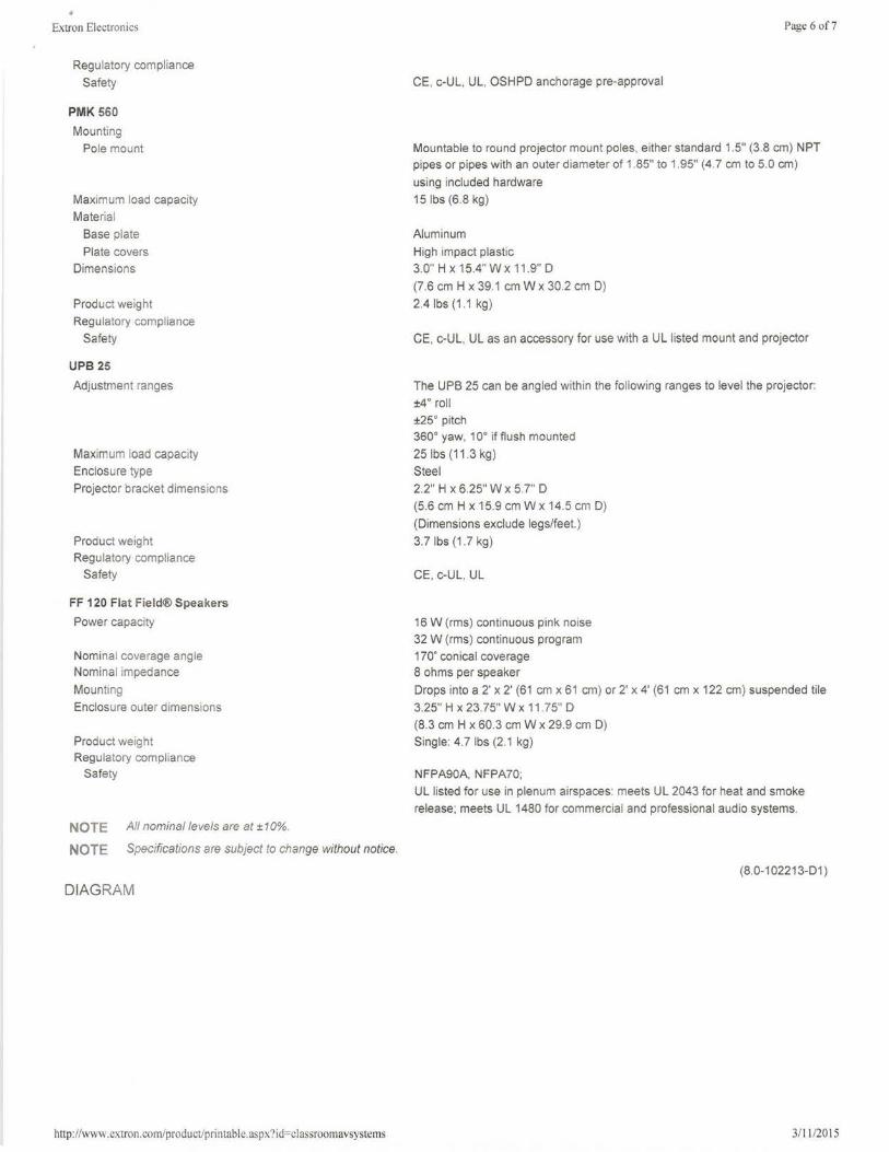
• Extron Electronics
Regulatory compliance
Safety
PMK 560
Mounting
Pole mount
Maximum load capacity
Material
Base plate
Plate covers
Dimensions
Product weight
Regulatory compliance
Safety
UPB 25
Adjustment ranges
Maximum load capacity
Enclosure type
Projector bracket dimensions
Product weight Regu latory compliance
Safety
FF 120 Flat Field® Speakers
Power capacity
Nominal coverage angle Nominal impedance
Mounting
Enclosure outer dimensions
Product weight Regulatory compliance
Safety
NOTE All nominal levels are at ±10%.
NOTE Specifications are subject to change without notice.
DIAGRAM
http://www.extron.com/product/printable.aspx?id=classroomavsystems
Page 6 of7
CE, c-U L, UL, OSHPD anchorage pre-approval
Mountable to round projector mount poles, either standard 1.5" (3.8 cm) NPT pipes or pipes with an outer diameter of 1.85" to 1.95" (4.7 cm to 5.0 cm)
using included hardware
15 lbs (6.8 kg)
Aluminum
High impact plastic
3.0" H x 15.4" W x 11.9" D
(7.6 cm H x 39.1 cmW x 30.2 cm D)
2.4 lbs (1.1 kg )
CE, c-UL, UL as an accessory for use with a UL listed mount and projector
The UPB 25 can be angled within the following ranges to level the projector:
±4° rol l
±25° pitch 360° yaw, 10° if flush mounted
25 lbs (11 .3 kg)
Steel
2.2" H x 6.25" W x 5.7" D
(5.6 cm H x 15.9 cm W x 14.5 cm D)
(Dimensions exclude legs/feet.)
3.7 lbs (1.7 kg )
CE, c-UL, UL
16 W (rms) continuous pink noise
32 W (rms) continuous program
170' conical coverage 8 ohms per speaker
Drops into a 2' x 2' (61 cm x 61 cm) or 2' x 4' (61 cm x 122 cm) suspended tile
3.25" H x 23.75" W x 11.75" D
(8.3 cm H x 60.3 cm W x 29.9 cm D)
Single: 4.7 lbs (2.1 kg)
NFPA90A, NFPA70;
UL listed for use in plenum airspaces: meets UL 2043 for heat and smoke
release; meets UL 1480 for commercial and professional audio systems.
(8.0-102213-01)
3/11 /2015
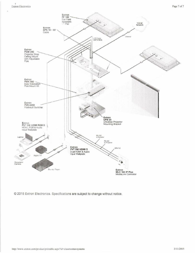
' Extron Electronics
Extron
FF 120 ------ /'' Flat Field ---r Speakers , -1Palr ~
Extron SPK 1 8-35' ~ Cable ~
Extron PCM 340 Projector Drop Ceiling Mount with Adjustable Pole
Extron PVS4050 PoleVault s,vitc het
Extron PVT SW HDMI RGB D HDM I, RGB & Audio Input Wallplate
~
~~I Extron PVTSWHDMID Dual HDMI & Aud io Input Wallplate
.. Appl~ TV
Document C3mern
Extron UPB25
TCP/IP Networ1c:
Universal Projector Mounting Bracket
AS-2:.2 to Proiector
Extron MLC 104 IP Plus Medialink Controller
© 2015 Extron Electronics. Specifications are subject to change without notice.
http://www.extron.com/product/printable.aspx?id=classroomavsystems
Page 7 of7
3/ 11 /2015
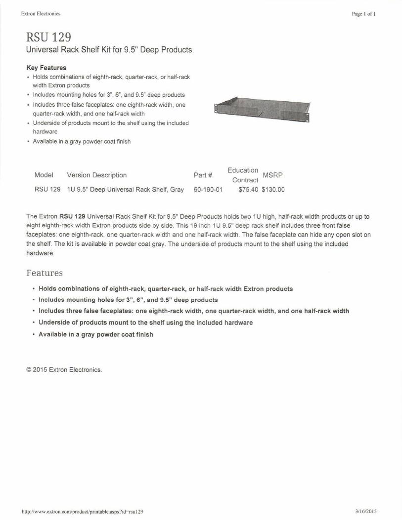
Extron Electronics
RSU 129 Universal Rack Shelf Kit for 9.5" Deep Products
Key Features • Holds combinations of eighth-rack, quarter-rack, or half-rack
width Extron products
• Includes mounting holes for 3", 6", and 9.5" deep products
• Includes three false faceplates: one eighth-rack width , one
quarter-rack width , and one half-rack width
• Underside of products mount to the shelf using the included hardware
• Available in a gray powder coat finish
Model Version Description
RSU 129 1U 9.5" Deep Universal Rack Shelf, Gray
Part#
60-190-01
Education MSRP Contract
$75.40 $130.00
Page 1of1
The Extron RSU 129 Universal Rack Shelf Kit for 9.5" Deep Products holds two 1 U high, half-rack width products or up to
eight eighth-rack width Extron products side by side. This 19 inch 1 U 9.5" deep rack shelf includes three front false
faceplates: one eighth-rack, one quarter-rack width and one half-rack width. The false faceplate can hide any open slot on
the shelf. The kit is available in powder coat gray. The underside of products mount to the shelf using the included
hardware.
Features
• Holds combinations of eighth-rack, quarter-rack, or half-rack width Extron products
• Includes mounting holes for 3", 6", and 9.5" deep products
• Includes three false faceplates: one eighth-rack width, one quarter-rack width, and one half-rack width
• Underside of products mount to the shelf using the included hardware
• Available in a gray powder coat finish
© 2015 Extron Electronics.
http: //www.extron.com/product/printable. aspx?id=rsu 129 3/16/2015
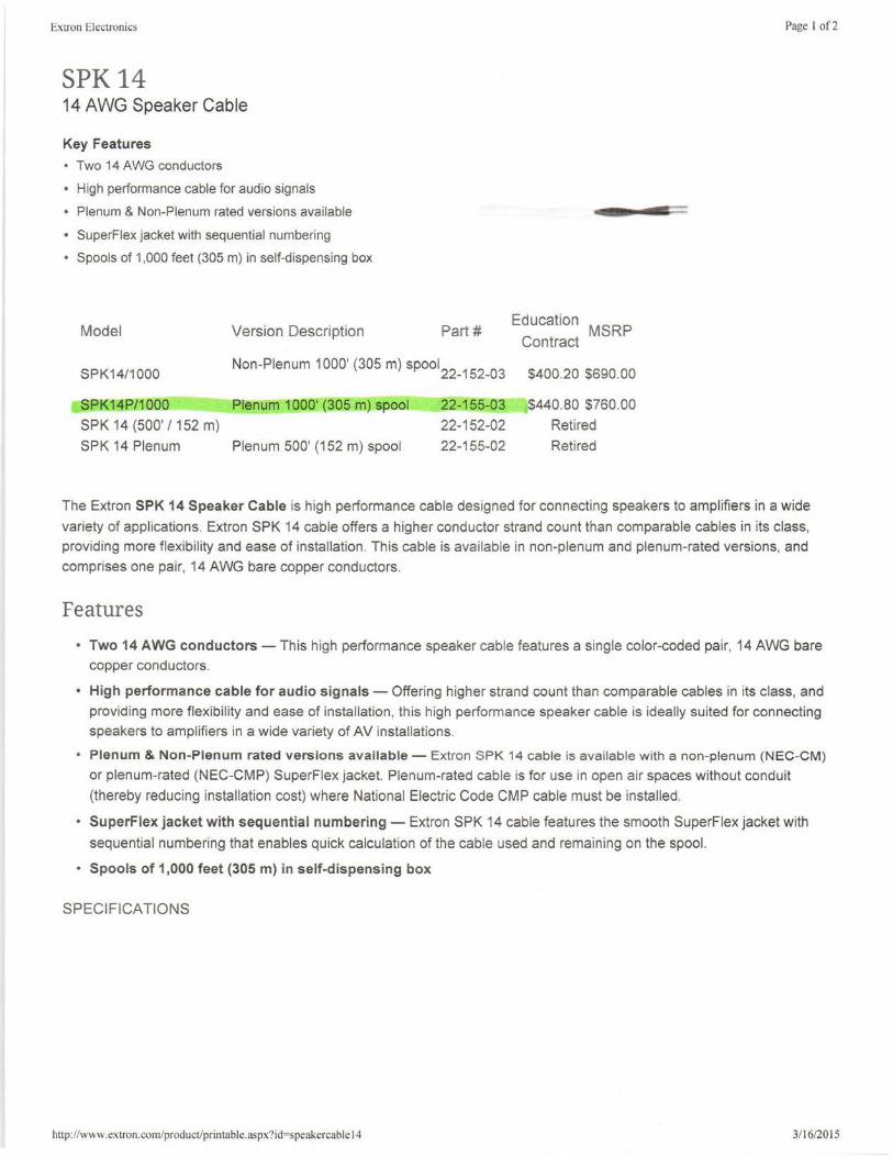
Extron Electronics
SPK 14 14 AWG Speaker Cable
Key Features
• Two 14 AWG conductors
• High performance cable for audio signals
• Plenum & Non-Plenum rated versions available
• SuperFlex jacket with sequential numbering
• Spools of 1,000 feet (305 m) in self-dispensing box
Model Version Description Part# Education MSRP Contract
SPK14/1000 Non-Plenum 1000' (305 m) spool
22_152
_03
$400
.20
$690
.00
SPK14P/1000 Plenum 1000' (305 m) spool 22-155-03 $440.80 $760.00
SPK 14(500'I152 m) 22-152-02 Retired
SPK 14 Plenum Plenum 500' (152 m) spool 22-155-02 Retired
Page I of2
The Extron SPK 14 Speaker Cable is high performance cable designed for connecting speakers to amplifiers in a wide
variety of applications. Extron SPK 14 cable offers a higher conductor strand count than comparable cables in its class, providing more flexibility and ease of installation. This cable is available in non-plenum and plenum-rated versions, and
comprises one pair, 14 AWG bare copper conductors .
Features
• Two 14 AWG conductors - This high performance speaker cable features a single color-coded pair, 14 AWG bare copper conductors.
• High performance cable for audio signals - Offering higher strand count than comparable cables in its class, and
providing more flexibility and ease of installation, this high performance speaker cable is ideally suited for connecting speakers to amplifiers in a wide variety of AV installations.
• Plenum & Non-Plenum rated versions available - Extron SPK 14 cable is available with a non-plenum (NEC-CM)
or plenum-rated (NEC-CMP) SuperFlex jacket. Plenum-rated cable is for use in open air spaces without conduit
(thereby reducing installation cost) where National Electric Code CMP cable must be installed.
• SuperFlex jacket with sequential numbering - Extron SPK 14 cable features the smooth SuperFlex jacket with
sequential numbering that enables quick calculation of the cable used and remaining on the spool.
• Spools of 1,000 feet (305 m) in self-dispensing box
SPECIFICATIONS
http://www. ex tr on.com/product/printable. aspx?id=speakercab I e 14 3/16/2015
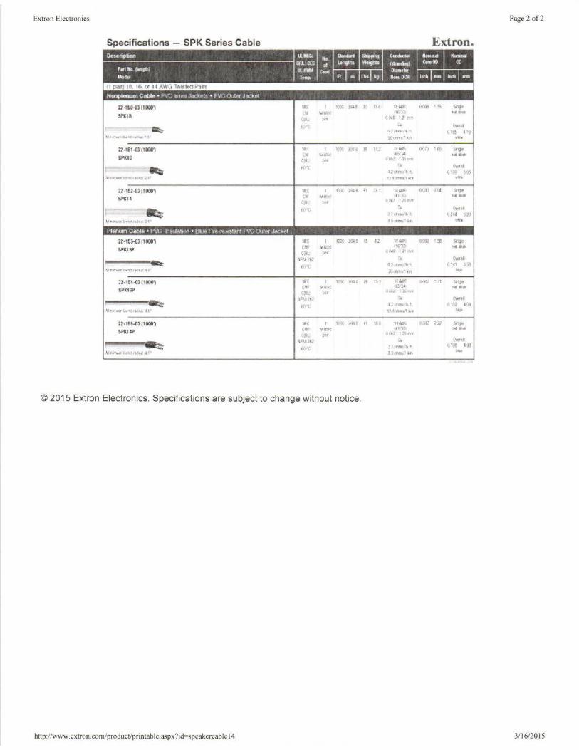
Extron Electronics Page 2 of2
Specifications - SPK Series Cable
22"1fl0-0) 11 iOO~ llOi: 1;:.; >14l ,- 1,:.4 1!/H':. 000! •i;:.. ~
"' MG~t '1t. :~i lttll M.U:li Sof1(1S
r,j)_ ~· ~!'."· 11! nT
i.0''.-f :, C-itttd .. >:i~•hll' ' J. I IJlf! ~ ·~
YI r~·"°"lH"': •.te-.n·' ~ :;'i.h;<l"n'>, .,., .... i2-15HJJ. (HOO') If' l:?t Ill l· M Pl Ii "'1'~ (1(li,; • f(,
"* ·" M!Ul ·t&:!-41 ....... SPKIG
C'-1~ ~· <J(~ .... I )_1MT
f.i1'i .. 1:0Md - JZot~~•.L 01" ~ .. )]
'" •l'••'n!y>'lt1(c~•.r l(I" l:.'! Srtll1~1' .. ,, 22-1£Hl:t1 00IJ 'J Ll:C 1Xi~ )~~ !l :·;, · 141.f.: ~IJ<\) 1114 ~
$WI« ~Ii ~..,.~ ,~LL1 ... .... .:,1 , .. fl(t.' l 1\JrtT
-= ti}"t :.. (.'Mill
1'•1.t-rt..,'Jot UlU l•.~l 1.irimr.11T>h .. ,:rnu• ,~. ''°N'n-./· in n•
22-1~}-{)}llOOIJ~ IH 1-;- )):;f, 1! d:? Hr.:r; 000 '::tl snj>
Sl'Kllli" (:1,! f "'"'"' <IV1:1 Hll IUd
(.iJ_ ,., 1J('4E I}! fU
""'"..., :.t C..1'.I - (4:•i. (i~>:.t~~· t: I),., -~-1 \ir,nuntta"l:i...:•;" tr' .. \lvrn.ih·1 ....
22-15f-ll'J;(IOOIJ'J If{ r1x )l~ t l!" 17,1 H~ (!•)ji '1 ln:I<' i, ~ I hlt~rl ii<~ """" SPK16P C'-!.., ;•• •1lif.;·. 1 l.ln'f
P,J~'t.;.· :. t..W.11
~ l':''t "* ~ <..tiri."J.. t l)1il 4 1).e
'~"',lV!ll.o.t'l!!fe•S'l J. f/' 1:• -12iJTt.1"t1 r••
2?-•~l--1)); (1 OO!ll "" I 1.':\ h1~ n lt~ ~ u~ (!!j.fl j Jil s.-.;. ~14P rvt "'""' 1H'J:'.1 1"414'rt.
• .. }J. rn IJ £.:~~ li\lfn
PliPJl:·t\2 ~ .. (""t!JI
-= t~. >''(: ! i (l'rv;,~lr< r Ul!! •i'
t,t ,JM.,<Mlo>t'>'l',lt'...,,Y ,l(' J ~ttrvf: •r. ... ., .... .. ,.,,.
© 2015 Extron Electron ics. Specifications are subject to change without notice.
http://www.extron.com/product/printable.aspx?id=speakercable 14 3/16/2015
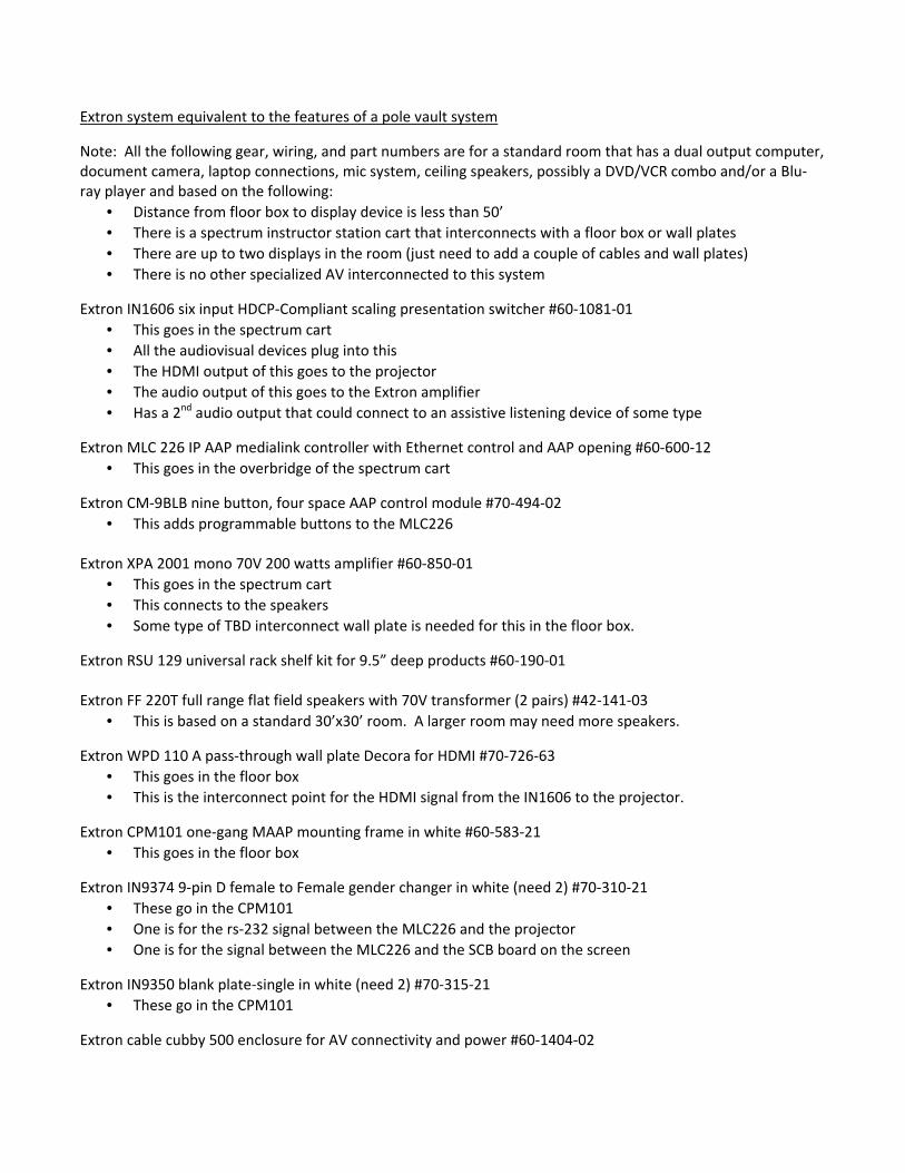
Extron system equivalent to the features of a pole vault system
Note: All the following gear, wiring, and part numbers are for a standard room that has a dual output computer,
document camera, laptop connections, mic system, ceiling speakers, possibly a DVD/VCR combo and/or a Blu-
ray player and based on the following:
• Distance from floor box to display device is less than 50’
• There is a spectrum instructor station cart that interconnects with a floor box or wall plates
• There are up to two displays in the room (just need to add a couple of cables and wall plates)
• There is no other specialized AV interconnected to this system
Extron IN1606 six input HDCP-Compliant scaling presentation switcher #60-1081-01
• This goes in the spectrum cart
• All the audiovisual devices plug into this
• The HDMI output of this goes to the projector
• The audio output of this goes to the Extron amplifier
• Has a 2nd
audio output that could connect to an assistive listening device of some type
Extron MLC 226 IP AAP medialink controller with Ethernet control and AAP opening #60-600-12
• This goes in the overbridge of the spectrum cart
Extron CM-9BLB nine button, four space AAP control module #70-494-02
• This adds programmable buttons to the MLC226
Extron XPA 2001 mono 70V 200 watts amplifier #60-850-01
• This goes in the spectrum cart
• This connects to the speakers
• Some type of TBD interconnect wall plate is needed for this in the floor box.
Extron RSU 129 universal rack shelf kit for 9.5” deep products #60-190-01
Extron FF 220T full range flat field speakers with 70V transformer (2 pairs) #42-141-03
• This is based on a standard 30’x30’ room. A larger room may need more speakers.
Extron WPD 110 A pass-through wall plate Decora for HDMI #70-726-63
• This goes in the floor box
• This is the interconnect point for the HDMI signal from the IN1606 to the projector.
Extron CPM101 one-gang MAAP mounting frame in white #60-583-21
• This goes in the floor box
Extron IN9374 9-pin D female to Female gender changer in white (need 2) #70-310-21
• These go in the CPM101
• One is for the rs-232 signal between the MLC226 and the projector
• One is for the signal between the MLC226 and the SCB board on the screen
Extron IN9350 blank plate-single in white (need 2) #70-315-21
• These go in the CPM101
Extron cable cubby 500 enclosure for AV connectivity and power #60-1404-02

• This goes in the overbridge of the spectrum cart
Extron MVGA M-M male to male micro VGA cable 6’ #26-567-02
• This goes in the cable cubby 500
Extron mini audio cable 3.5mm male to male stereo audio cable 6’ #26-571-03
• This goes in the cable cubby 500
Extron universal projector control cable 50’ #26-518-01
• This goes from the Extron IN9374 (floor box) to the projector
Extron PMP series projector mounting pole, length TBD based on ceiling height, and screen location.
Extron SPK 14 14 AWG speaker cable plenum 1000’ #22-155-03 or equivalent
• About 150’ per room would be needed
HDMI M-M cable with redmere 50’
• Brands: monoprice, vanco, pearstone
• This goes from WPD110A in the floor box to the projector or LCD.
Chief speed-connect above tile suspended ceiling kit with security hardware #CMS440
Chief universal custom & custom ceiling projector mounts with security hardware #RPAU
Other HDMI, displayport to HDMI, dvi to HDMI cables, cat6 some TBD.
• 8 outlet surge protector strip with 10’ power cord
• From IN1606 to floor box – HDMI to HDMI 10’.
• From computer to IN1606 – audio and may be DVI to HDMI or DP to HDMI, TBD.
• From doc cam to IN1606 – may be DVI to HDMI, HDMI to HDMI, or VGA – VGA, TBD.
• From cable cubby to IN1606 for a laptop – HDMI
• From cable cubby to network in floor box – cat6 14’ cable in white
• From computer to network in floor box – cat6 10’ cable in blue
• From MLC226 to network in floor box – cat6 10’ cable in red
• From QLX-D wireless mic receiver to network in floor box – cat6 10’ cable in red
• Interconnect cable from IN1606 to XPA 2001 amplifier
• Interconnect cable from QLX-D wireless receiver to IN1606
• RS-232 cable from MLC226 to IN9374 in floor box for projector control
• RS-232 cable from MLC226 to IN9374 in floor box for screen control
• Speaker cable from XPA 2001 amp to TBD wall plate in floor box for speaker signal
• If we put in a DVD/VCR combo then a composite to RGB cable is needed
• If we put in a Blu-ray player then a 5’ HDMI cable is needed
Shure QLX-D digital wireless system with bodypack transmitter and lavalier mic.
• Wireless band TBD before purchase
Techflex Flexo F6 1½” flexible semi-rigid wrappable split braided tub in black #F6N1.50BLK
• This is used to protect the cables going from the floor box to the cart ~6’
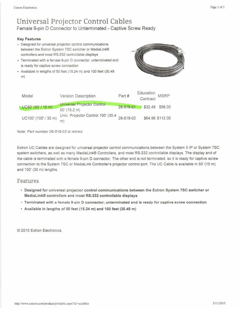
Extron Electronics
Universal Projector Control Cables Female 9-pin D Connector to Unterminated - Captive Screw Ready
Key Features • Designed for universal projector control communications
between the Extron System ?SC switcher or Medialink®
controllers and most RS-232 controllable displays
• Terminated with a female 9-pin D connector; unterminated end
is ready for captive screw connection
• Available in lengths of 50 feet (1 5.24 m) and 100 feet (30.48 m)
Model
UC50' (50' I 15 m)
Version Description
Universal Projector Control
50' (15.2 m)
Part#
26-518-01
Uc100, (
100, / 30
) Univ. Projector Control 100' (30.4 26
_518
_02 m
m)
Note: Part number 26-518-03 is retired.
Education MSRP
Contract
$32.48 $56.00
$64.96 $112.00
Page I of I
Extron UC Cables are designed for universal projector control communications between the System 5 IP or System 7SC
system switchers, as well as many Medialink® Controllers, and most RS-232 controllable displays. The display end of
the cable is terminated with a female 9-pin D connector. The other end is not terminated, so it is ready for captive screw
connection to the System 7SC or Medialink Controller's projector control port. The UC Cable is available in 50' (15 m)
and 100' (30 m) lengths.
Features
• Designed for un iversal projector control communications between the Extron System 7SC switcher or
MediaLink® controllers and most RS-232 controllable displays
• Terminated with a female 9-pin D connector; unterminated end is ready for captive screw connection
• Available in lengths of 50 feet (15.24 m) and 100 feet (30.48 m)
© 2015 Extron Electronics.
http: //www.extron.com/product/printable.aspx9 id=uccables 3/11 /2015
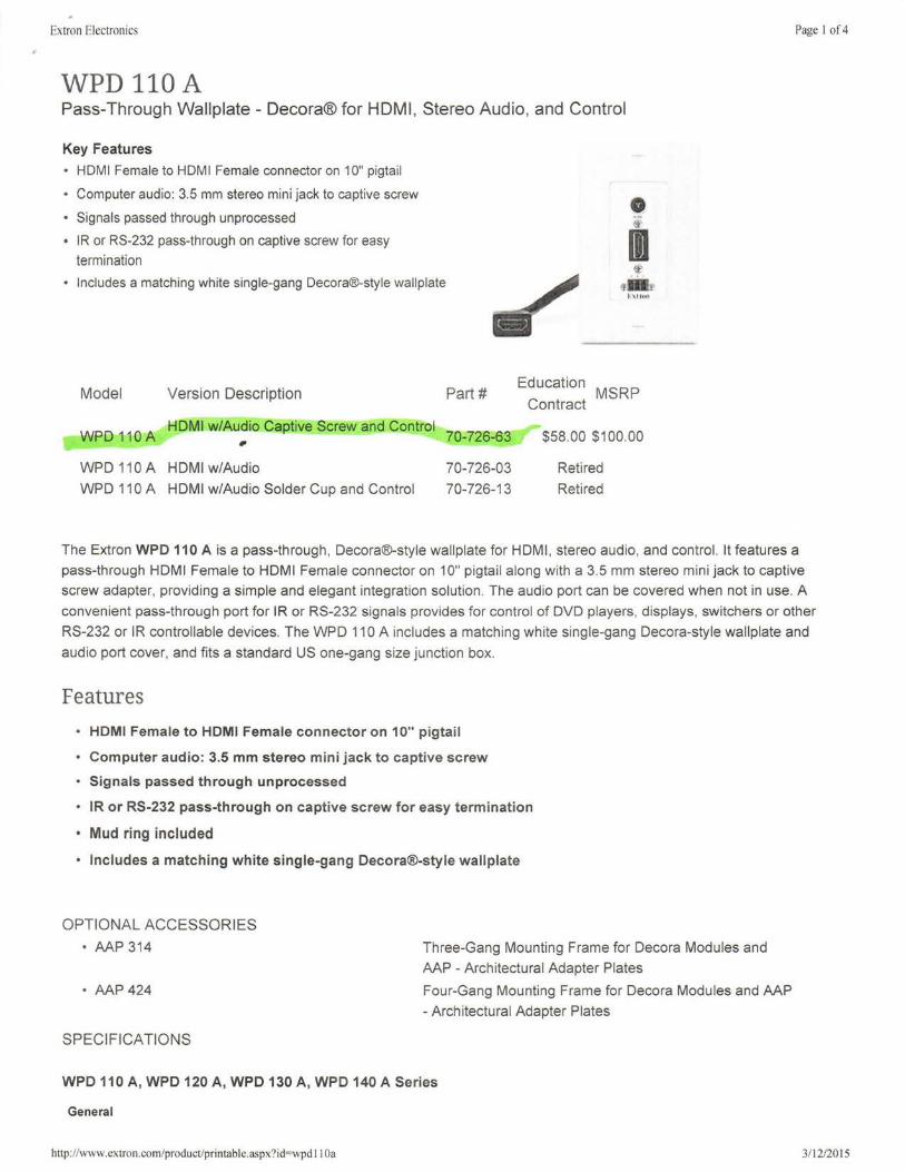
Extron Electronics
WPD 110 A Pass-Through Wallplate - Decora® for HDMI, Stereo Audio, and Control
Key Features
• HDMI Female to HDMI Female connector on 10" pigtail
• Computer audio: 3.5 mm stereo mini jack to captive screw
• Signals passed through unprocessed
• JR or RS-232 pass-through on captive screw for easy termination
• Includes a matching white single-gang Decora®-style wallplate
Model Version Description
WPD 110A HDMI w/Audio Captive Screw and Control ..
WPD 110A HDMI w/Audio
WPD 110 A HDMI w/Audio Solder Cup and Control
• ~·
I t-\l f...,
Part# Education MSRP Contract
70-726-63 $58.00 $100.00
70-726-03 Retired
70-726-13 Retired
Page I of4
The Extron WPD 110 A is a pass-through, Decora®-style wallplate for HDMI, stereo audio, and control. It features a
pass-through HDMI Female to HDMI Female connector on 10" pigtail along with a 3.5 mm stereo mini jack to captive screw adapter, providing a simple and elegant integration solution . The audio port can be covered when not in use. A
convenient pass-through port for IR or RS-232 signals provides for control of DVD players, displays, switchers or other
RS-232 or IR controllable devices. The WPD 110 A includes a matching white single-gang Decora-style wallplate and
audio port cover, and fits a standard US one-gang size junction box.
Features
• HDMI Female to HDMI Female connector on 10" pigtail
• Computer audio: 3.5 mm stereo mini jack to captive screw
• Signals passed through unprocessed
• IR or RS-232 pass-through on captive screw for easy termination
• Mud ring included
• Includes a matching white single-gang Decora®-style wallplate
OPTIONAL ACCESSORIES
• AAP 314
• AAP 424
SPECIFICATIONS
Three-Gang Mounting Frame for Decora Modules and
AAP - Architectural Adapter Plates
Four-Gang Mounting Frame for Decora Modules and AAP
- Architectural Adapter Plates
WPD 110 A, WPD 120 A, WPD 130 A, WPD 140 A Series
General
hnp: //www.extron.com/product/printable.aspx?id=wpd 11 Oa 3/ 12/2015
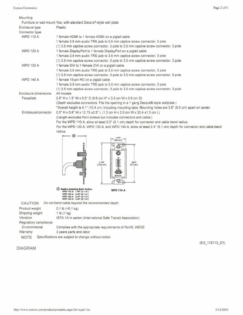
Extron Electronics
Mounting
Furniture or wall mount Yes, with standard Decora®-style wall plate
Enclosure type
Connector type
WPD 110 A
WPD 120 A
WPD 130 A
WPD 140 A
Enclosure dimensions
Faceplate
Enclosure/connector
Plastic
1 female HDMI to 1 female HDMI on a pigtail cable
1 female 3.5 mm audio TRS jack to 3.5 mm captive screw connector, 3 pole
(1) 3.5 mm captive screw connector, 3 pole to 3.5 mm captive screw connector, 3 pole
1 female DisplayPort to 1 female DisplayPort on a pigtail cable
1 female 3.5 mm audio TRS jack to 3.5 mm captive screw connector, 3 pole
(1) 3.5 mm captive screw connector, 3 pole to 3.5 mm captive screw connector, 3 pole
1 female DVI to 1 female DVI on a pigtail cable
1 female 3.5 mm audio TRS jack to 3.5 mm captive screw connector, 3 pole (1) 3.5 mm captive screw connector, 3 pole to 3.5 mm captive screw connector, 3 pole
1 female 15-pin HD on a pigtail cable
1 female 3.5 mm audio TRS jack to 3.5 mm captive screw connector, 3 pole (1) 3.5 mm captive screw connector, 3 pole to 3.5 mm captive screw connector, 3 pole
All models
2.6" H x 1.3" W x 0.3" D (6.6 cm H* x 3.3 cm W x 0.6 cm D)
(Depth excludes connectors. Fits the opening in a 1 gang Decora®-style wallplate.)
*Overall height is 4.1 " (10.4 cm) including mounting tabs. Mounting holes are 3.8" (9.5 cm) apart on center.
05" H x 0.8" W x 12.75 ±05'' L (1.2 cm H x 2.0 cm W x 32.4 ±1 .3 cm L)
(Length excludes front screws but includes connectors and cable. )
For the WPD 110 A, allow at least 2.0" (5.1 cm) depth for connector and cable bend radius.
Page 2 of 4
For the WPD 120 A, WPD 130 A, and WPD 140 A, allow at least 2.4" (61 cm) depth for connector and cable bend
radius.
® Dop91s.-xnr11111iond R.uha• Yll'01101c 1-99" •~1 cm) WFO 120 le 2.40" .;a1 cm) 'llPO 1:;o I< 2.40" •:S.1 cm) 'llPO 140 A: 2..40' •:a 1 cm)
1.41' <SfOcm)
·'· .. WPO 11ilA
CAUTION Do not bend cable beyond the recommended depth.
Product weight
Shipping weight
0.1 lb (<0.1 kg)
1 lb (1 kg)
Vibration !STA 1A in carton (International Safe Transit Association )
Regulatory compliance
Complies with the appropriate requi rements of RoHS, WEEE
3 years parts and labor
Environmental
Warranty
NOTE Specifications are subject to change without notice.
DIAGRAM
http://www.extron.com/product/printable.aspx9id=wpd I I Oa
(8.0_ 112113_D1)
3/12/2015
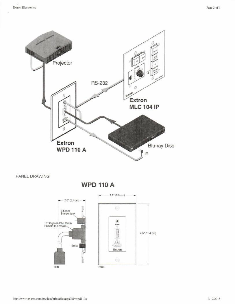
Extron Electronics
PANEL DRAWING
Extron WPD 110 A
WPD 110A
- 2. o· (5.1 crn ~
10· Pigtail HDMI Cable Female to Fil!Tlale
Side
http://www.extron.com/product/printable.aspx?id=wpd 11 Oa
2.7" 16.9 cmj
Ext nm
~ Extron MLC 104 IP
Blu-ray Disc
.', IR ' J
4.5' [11.4 cm)
Page 3 of4
3/ 12/2015

, ~xtron Electronics Page 4 of 4
© 2015 Extron Electronics. Specifications are subject to change without notice.
http://www.extron.com/product/printable.aspx?id=wpd 11 Oa 3/ 12/2015
Extron Electronics
XPA 2001 Mono 70/100 V Amplifier - 200 Watts
Key Features
• 200 watts rms output power: XPA 2001 -70V- 1 x 200 watts@ 70 volts
XPA 2001-100V- 1x200 watts@ 100 volts
• ENERGY STAR® qual ified amplifier
• Professional grade signal-to-noise and THD+N performance
• Extron Patented CDRS™ - Class D Ripple Suppression
• Convection cooled, fanless operation
• Ultra low inrush current - no need for power sequencing
Model
XPA 2001-70V
XPA 2001-100V
Version Description
70 V Mono Amp - 200 Watts
100 V Mono Amp - 200 Watts
Part#
60-850-01
60-850-11
Education
Contract $400.20
$400.20
MSRP
$690.00
$690.00
Page I of6
The Extron XTRA ™ Series XPA 2001 is a half rack 1 U, convection cooled power amplifier delivering 200 watts into a 70
volt or 100 volt line. This professional grade amplifier features a 100 dB signal-to-noise ratio with less than 0.1 % THD+N.
The XPA 2001 is an ENERGY STAR® qualified amplifier with an Extron exclusive, highly efficient, advanced Class D
amplifier design . It also features patented CDRS™ - Class D Ripple Suppression technology that provides a smooth,
clean audio waveform and an improvement in signal fidelity over conventional Class D amplifiers. The XPA 2001 is
housed in a half rack width metal enclosure, conserving rack space and weighing only 2.5 lbs (1.1 kg). The Extron
exclusive, high efficiency design generates very little heat and allows the amplifier to be convection cooled.
Energy Efficient Amplifier with Auto Power-Down
The XPA 2001 ENERGY STAR qualified amplifier is an energy efficient product that conserves energy and reduces
costs. With an auto power-down feature that automatically places the amplifier into standby after 25 minutes of inactivity,
it consumes just 10 watts when idle and less than 1 watt in standby mode.
The XPA 2001 is housed in a compact 1 U, half rack width enclosure. This amplifier is UL 2043 plenum rated when used
with the optional Flexible Conduit Adapter Kit, allowing for a concealed installation above a drop ceiling to prevent theft
while providing convenient placement of AV equipment.
The XPA 2001 delivers 200 watts rms for high impedance speaker systems in voice reinforcement and distributed audio
applications. The XPA 2001 is avai lable in 70 volt and 100 volt models.
The XPA 2001 accepts balanced and unbalanced input signals and includes recessed , detented level controls located on
the rear panel to prevent tampering. These controls allow for adjusting audio system gain structure, or setting individual
levels for each zone. For applications requiring volume adjustment and muting control from a location other than the
amplifier, remote control capabi li ty is available using the optional Extron VCM 100 or VCM 200 analog volume and mute
controller or VC 50 analog volume controller. Additionally, the XPA 2001 includes multiple protection circuits that
momentarily activate when an abnormal condition, such as overheating, is detected. An advanced, automatic clip limiter
protects speakers from clipping distortion.
Features
http: //www.extron.com/product/printable.aspx?id=xpa2001 3111 /2015
Extron Electronics Page 2 of6
• Inputs: Balanced or unbalanced stereo or mono on a 3.5 mm, 5-pole captive screw connector
• Speaker Outputs: Screw-lock, 5 mm, 2-pole captive screw connector
• 200 watts rms output power: XPA 2001-70V -1x200 watts@ 70 volts
XPA 2001-100V -1 x 200 watts@ 100 volts - The XPA 2001 provides ample power output for larger rooms.
• ENERGY STAR® qualified amplifier- The XPA 2001 is an ENERGY STAR qualified amplifier and energy efficient
product that conserves energy and reduces costs.
• Professional grade signal-to-noise and THD+N performance - The XPA 2001 delivers professional grade
performance with 100 dB signal-to-noise ratio and THD+N of less than 0.1 %.
• Extron Patented CDRS™ - Class D Ripple Suppression - CDRS is an Extron Patented technology that provides
a smooth, clean audio waveform and an improvement in signal fidelity over conventional Class D amplifier designs.
CDRS eliminates the high frequency switching ripple characteristic of Class D amplifiers, a source of RF emissions
which can interfere with sensitive AV equipment such as wireless microphones.
• Convection cooled, fanless operation - The XPA 2001 does not require internal fans or vents for cooling,
ensuring quiet, reliable operation. It generates substantially less heat than conventional power amplifiers, making it
ideal for rack-mount applications.
• Ultra low inrush current - no need for power sequencing - Allows multiple XTRA Series amplifiers to be
powered on simultaneously without overloading power circuits. This eliminates the need for power sequencing.
• Power factor correction - removes harmonic content on AC line - The XPA 2001 features power factor
correction technology that smoothes out the high peak currents of the amplifier's current draw, thus minimizing the
presence of high frequency harmonics on the AC power line, and therefore preventing audible artifacts from being
transmitted to other audio equipment in the system.
• Rack-mountable 1 U, half rack width enclosure - The XPA 2001 reduces rack space requirements for many
installations.
• UL 2043 plenum rated when used with optional Flexible Conduit Adapter Kit- The XPA 2001 meets UL 2043
for smoke and heat release for installation within a plenum airspace above a drop ceiling when used with the optional Flexible Conduit Adapter Kit, part# 70-228-02. Above-the-ceiling placement conceals the amplifier to prevent theft, and is convenient for installing equipment when space inside the room is limited.
• Auto power-down with fast power-up - The XPA 2001 meets ENERGY STAR qualification requirements with an
auto power-down feature that automatically places the amplifier into standby after 25 minutes of inactivity,
dramatically reducing power consumption. It quickly returns to full power status in less than one second upon signal detection.
• Rear panel recessed, detented level control - Provides attenuation of input signals for adjusting audio system
gain staging. It is located on the rear panel to prevent users from tampering with level adjustments.
• Automatic clip limiter - Detects actual onset of clipping by comparing input and output waveforms. Gain is
automatically reduced without audible artifacts to protect speakers from clipping distortion.
• Multiple protection circuits - Activate during output shorts, thermal overload, or DC faults to prevent damage to
the amplifier and speakers.
• Remote standby port- Enables the XPA 2001 to be remotely powered down when not in use, reducing operating
cost.
• Remote volume and mute control port - In basic installations without control systems, this port allows the
XPA 2001 to be remotely controlled using the optional Extron VCM 100 or VCM 200 analog volume and mute
controller or VC 50 analog volume controller.
• Input summing - Actively sums incoming left and right channel signals for mono amplification.
• High pass filter - This switch selectable filter rolls off frequencies below 80 Hz to prevent saturation of speaker
transformers.
http: //www.extron.com/product/printable.aspx?id=xpa200 I 3/ 11/2015
Extron Electronics Page 3 of6
• 5 mm screw-lock captive screw speaker connectors - Enable simple, secure connections with 22 to 12 AWG
speaker cables.
• Front and rear-mounted sig nal and protection indication LEDs - Provide convenient indication of input signal
presence and protection circuit activation from both sides of an equipment rack.
• Front panel over-temperature LED - Provides visual indication that the enclosure temperature has exceeded the
optimal value, well in advance of the onset of thermal protection circuitry.
• Highly reliable, energy-efficient internal universal power supply - The 100-240 VAC, 50/60 Hz, international
power supply provides worldwide power compatibility with
high demonstrated rel iability (/company/article.aspx?id=eps ga). ·····································
OPTIONAL ACCESSORIES
• UTS 100 Series
• MLA VC10 Plus
• Flexible Conduit Adapter Kit
• SPK 18
• PPC 25
• RSB 129
• RSU 129
• SF 228T
• SI 26CT
• SI 3CT LP
• vc 50
• VCM 100 AAP
• VCM 100 MAAP
• VCM 200 D
• VCM 200 EU
• VCM 200 MK
SPECIFICATIONS
XPA 2001 Series
Audio
Voltage gain
XPA 2001-70V
XPA2001-100V
Stereo channel separation CMRR
A ud io input
Number/signal type
Connectors
Impedance
Nominal level Maximum level
57x (35 dB)
81x (38 dB)
>75 dB@ 1 kHz
Under Table Shelf System
Volume Control Module
Flexible Conduit Adapter Kit for PS 124 & Select XTRA ™ Series Amplifiers
Pre-cut Speaker Cable
Priority Page Controller
Basic Rack Shelf for 9.5" Deep Products
Universal Rack Shelf Kit for 9.5" Deep Products
Two-Way SoundField® Ceiling Tile Speakers with
8" Woofer and 70/100 V Transformer
Two-Way Ceiling Speakers with 8" Back Can and
70/100 V Transformer
Full-Range Ceiling Speakers with 4" Low Profile Back Can
and 70/100 V Transformer
Volume Control Wallplate
Volume and Mute Controller - AAP Version
Volume and Mute Controller - MAAP Version
Volume and Mute Controller - Decora® Wallplate
Volume and Mute Controller - EU Wall Frame for European Junction Boxes
Volume and Mute Controller - MK Wall Frame for United
Kingdom Junction Boxes
75 dB @ 1 kHz (typical)
1 stereo or 2 mono, balanced/unbalanced
(1) 3.5 mm captive screw connector, 5 pole
>10k ohms unbalanced/balanced, DC coupled
+4 dBu (1.23 Vrms), balanced
+20 dBu (7.75 Vrms), balanced
http: //www. extron. com/product/pri n tab I e. as px? i d=xpa2 00 I 3/11/2015
Extron Electronics
Input sensitivity +4 dBu (1.23 Vrms) if driven by one input
-2 dBu (0.615 Vrms) if both inputs are summed
Input signal detection threshold -40 dBu ±3 dB, balanced
NOTE 0 dBu = 0. 775 Vrms, 0 dBV = 1 Vrms, 0 dBV == 2 dBu
Audio output
Number/signal type XPA 2001-70V
XPA2001-100V
1 mono, 70 V line
1 mono, 100 V line
Connectors (1) 5 mm screw lock captive screw connector, 2 pole
NOTE These connectors accept wires of 22 AWG to 12 AWG.
Load impedance
XPA 2001-?0V
XPA 2001-100V
Amplifier type
Output power
XPA 2001-70V
XPA 2001-100V Frequency response
THO+ Noise
SIN Damping factor
XPA 2001-70V
XPA 2001-100V
High pass filter
Control/remote - amplifier
Control port
Pin configurations
25 ohms minimum
50 ohms minimum
Class D
200 watts rms, 70 V, 1 kHz, <0.1 % THO 200 watts rms, 100 V, 1 kHz, <0.1 % THO
20 Hz to 20 kHz, ±1 dB
<0.1 % @ 1 kHz at 3 dB below clipping
100 dB, 20 Hz - 20 kHz, unweighted
>100@ 25 ohms
>100 @ 50 ohms
80 Hz, 12 dB per octave rolloff (switch selectable)
(1) 3.5 mm captive screw connector, 5 pole
DC volume control (analog) Pin 1 = +10 VDC, 50 mA (max.), pin 2 =volume/mute (variable voltage) , pin 3 = GND
Volume control voltage range 0 V (mute) to 10 V (maximum volume)
Standby power control (contact closure) Pin 4 = GND, pin 5 =standby
General
Power supply
Power consumption
Typical (1/8 power)
XPA 2001-70V
XPA 2001-100V Quiescent
Standby Temperature/humidity
Cooling Thermal dissipation
Standby
Idle
1/8 power (pink noise)
XPA 2001-70V
XPA 2001-100V
Protection
Indication
Mounting Rack mount
Enclosure type
Enclosure dimensions
Product weight
Shipping weight Vibration
Internal Input: 100-240 VAC, 50-60 Hz
70 V (x1 ): 45 watts
100 V (x1 ): 45 watts 12 watts
<1 watt (triggered by contact closure or after 25 minutes [± 5 minutes] with no signal) Storage: -40 to +158 °F (-40 to +70 °C) I 10% to 90%, noncondensing Operating: +32 to +122 °F (0 to +50 °C) I 10% to 90%, noncondensing
Convection, no vents, with internal heat sinks
<1 watt (3 BTU/hr)
12 watts (41 BTU/hr)
70 V (x1 ): 21 watts (71 BTU/hr)
100 V (x1 ): 20 watts (69 BTU/hr)
Clip limiting, thermal, short circuit, DC output Limiter/Protect LED indicates the onset of clip limiting, thermal cycling , or a short circuit
Yes, with optional 1 U rack shelf Metal
1.7" H x 8.7" W x 9.5" D (1 U high, half rack wide)
(4.3 cm H x 22.1cmWx24.1 cm D) 2.5 lbs (1 .1 kg) 5 lbs (3 kg) ISTA 1A in carton (International Safe Transit Association)
http: //www.extron.com/product/printable.aspx?id=xpa2001
Page 4 of6
3/ 11 /2015
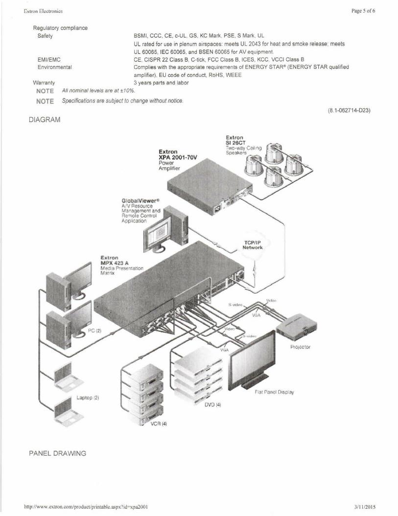
EOxtron EOlectronics
Regulatory compliance
Safety
EM I/EMC
Environmental
BSMI , CCC, CE, c-UL, GS, KC Mark, PSE, S Mark, UL
UL rated for use in plenum airspaces: meets UL 2043 for heat and smoke release: meets
UL 60065, IEC 60065, and BSEN 60065 for AV equipment.
CE, CISPR 22 Class B, C-tick, FCC Class B, ICES, KCC, VCCI Class B Complies with the appropriate requirements of ENERGY STAR® (ENERGY STAR qualified
amplifier), EU code of conduct, RoHS, WEEE
Warranty 3 years parts and labor
NOTE All nominal levels are at ±10%.
NOTE Specifications are subject to change without notice.
Page 5 of6
(8 .1-062714-023)
DIAGRAM
PANEL DRAWING
http: //www.extron.com/product/printable.aspx?id=xpa200 I
Extron XPA~1-70V Power Amplifier
Extroo SI 26CT wo-wa-y Ceil ng
Speakers tr J
TCP/IP "'et work
3/11 /2015
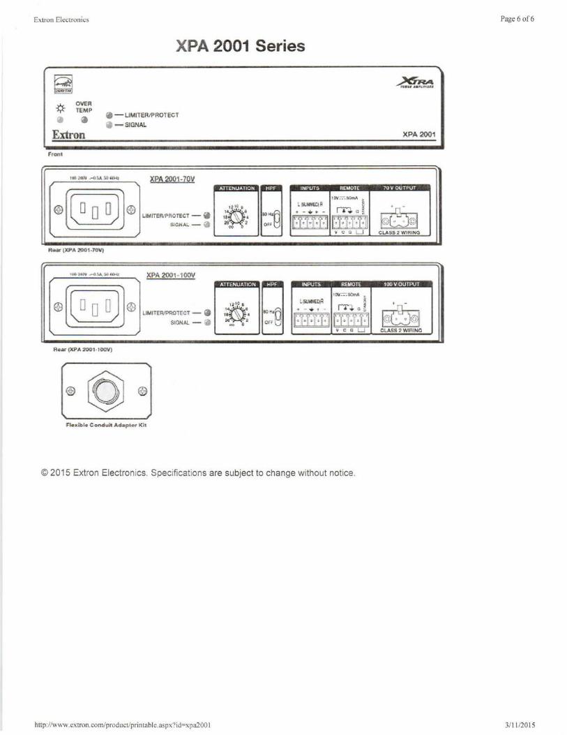
Extron Electronics
XPA 2001 Series
_:r1.c_ OVER ¥ TEMP
a Extron
Fro~•
""ar (XP,A 21HJ'1-7<1Vt
· - LiMITffM'> ROTE'CT a -SfGNAL
XPA 2001-70V
XPA 2001· 100\r
Re-)C.ible- Conduit .Ad .. plcr Kit
. I W-::-:!ltlmA :.
fillol\l!Cl ij rn a[ t - ....... -
ltR1-I IT@r:r-11 • " Q L I
tw :-:-: r,.;m1 l·~lolYErtR S
~ - ,;. t - ~ G~
fit[EI l'·'t78::t:J • c a LJ
© 2015 Extron Electronics. Specifications are subject to change without notice.
http: //www.extron.com/product/printable.aspx?id=xpa200 I
Page 6 of6
XPA 2001
.
~ ~LASS 2 YnR lr<G
I 1• ~•1 11 •-'
~©] CLASS :! WlRIMC
3/11/2015
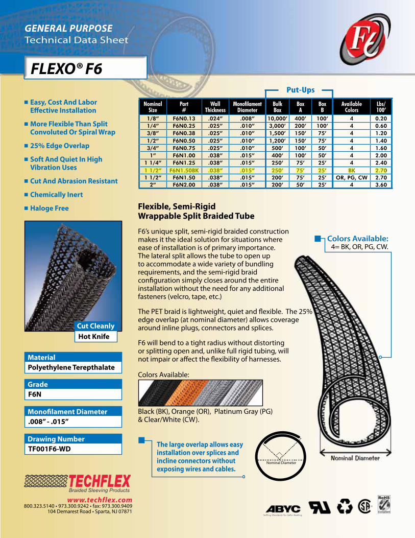
GENERAL PURPOSETechnical Data Sheet
FLEXO® F6
Flexible, Semi-RigidWrappable Split Braided Tube
F6’s unique split, semi-rigid braided constructionmakes it the ideal solution for situations whereease of installation is of primary importance.The lateral split allows the tube to open upto accommodate a wide variety of bundlingrequirements, and the semi-rigid braidconfiguration simply closes around the entireinstallation without the need for any additionalfasteners (velcro, tape, etc.)
The PET braid is lightweight, quiet and flexible. The 25% edge overlap (at nominal diameter) allows coverage around inline plugs, connectors and splices.
F6 will bend to a tight radius without distortingor splitting open and, unlike full rigid tubing, willnot impair or affect the flexibility of harnesses.
Colors Available:
Black (BK), Orange (OR), Platinum Gray (PG) & Clear/White (CW).
Easy, Cost And Labor Effective Installation
More Flexible Than Split Convoluted Or Spiral Wrap
25% Edge Overlap
Soft And Quiet In High Vibration Uses
Cut And Abrasion Resistant
Chemically Inert
Haloge Free
Polyethylene TerepthalateMaterial
F6NGrade
.008” - .015”Monofilament Diameter
TF001F6-WDDrawing Number
Hot KnifeCut Cleanly
www.techflex.com800.323.5140 • 973.300.9242 • fax: 973.300.9409
104 Demarest Road • Sparta, NJ 07871
Colors Available:4= BK, OR, PG, CW.
Nominal Diameter
The large overlap allows easy installation over splices and incline connectors withoutexposing wires and cables.
Nominal Size
Part #
Wall Thickness
Monofilament Diameter
Bulk Box
BoxA
BoxB
Available Colors
Lbs/100’
1/8” F6N0.13 .024” .008” 10,000’ 400’ 100’ 4 0.201/4” F6N0.25 .025” .010” 3,000’ 200’ 100’ 4 0.603/8” F6N0.38 .025” .010” 1,500’ 150’ 75’ 4 1.201/2” F6N0.50 .025” .010” 1,200’ 150’ 75’ 4 1.403/4” F6N0.75 .025” .010” 500’ 100’ 50’ 4 1.601” F6N1.00 .038” .015” 400’ 100’ 50’ 4 2.00
1 1/4” F6N1.25 .038” .015” 250’ 75’ 25’ 4 2.401 1/2” F6N1.50BK .038” .015” 250’ 75’ 25’ BK 2.701 1/2” F6N1.50 .038” .015” 200’ 75’ 25’ OR, PG, CW 2.70
2” F6N2.00 .038” .015” 200’ 50’ 25’ 4 3.60
Put-Ups

GENERAL PURPOSETechnical Data Sheet
FLEXO® F6
ww
w.techflex.com
Abrasion ResistanceMedium Abrasion Test Machine Taber 5150 Abrasion Test WheelCalibrase H-18 Abrasion Test Load 500g Room Temperature 80°F Humidity 74% Some Scuffing Visible500 Test Cycles Significant Wear Is Visible With Several Braid Filaments Broken1,200 Test Cycles Material Destroyed 1,950 Test Cycles Pre-Test Weight5,365.1 mg Post-Test Weight 4,850 mg Test End Loss Of Mass Point Of Destruction 515.1 mg
1=No Effect 4=More Affected 2=Little Effect 5=Severely Affected 3=Affected
Aromatic Solvents ______________ 2Aliphatic Solvents ______________ 1Chlorinated Solvents ____________ 3Weak Bases __________________ 1Salts _________________________ 1Strong Bases___________________2Salt Water 0-S-1926 ____________ 1Hydraulic Fluid MIL-H-5606 _______ 1Lube Oil MIL-L-7808 ____________ 1De-Icing Fluid MIL-A-8243 ________ 1Strong Acids __________________ 3Strong Oxidants ________________ 2Esters/Keytones _______________ 1UV Light ______________________ 1Petroleum ____________________ 1Fungus ASTM G-21 _____________ 1Halogen Free ________________ YesRoHS ______________________ YesSVHC _____________________None
Rating ___________ UL94VO
Monofilament Diameter__.008-.015 ASTM D-204
Flammability Rating________UL94Recommended Cutting___Hot KnifeColors______________________4 Wall Thickness_________.024-.038Tensile Strength (Yarn)_______6-10 ASTM D-2256 Lbs
Specific Gravity ASTM D-792__1.38Moisture Absorption_________.1-.2 % ASTM D-570
Hard Vacuum Data ASTM E-595TML_______________________19CVCM_____________________.00WVR______________________.16Smoke D-Max _______________56 ASTM E-662
Outgassing________________MedOxygen Index________________21 ASTM D-2863
© 2015 Techflex, Inc. - Any unauthorized reproduction, in whole or part, in any medium whatsoever, without the express written permission of Techflex, Inc. is strictly forbidden. Techflex product names and logos are registered trademarks of Techflex, Inc., unless otherwise attributed. The contents and illustrations contained herein are believed to be reliable. Techflex makes no warranties as to their accuracy or completeness and disclaims any liability in connection with their use. Techflex’s only obligations are those in standard terms of
sale for these products and Techflex will not be liable for any consequential or other damages arising due to misuse of these products or typographical errors or omissions. Users should make their own evaluation to determine the suitability of these products for their unique and specific applications. 02-15
Melt PointASTM D-2117
482°F (250°C)
Maximum ContinuousMil-I-23053
257°F (125°C)
Minimum Continuous-94°F (-70°C)
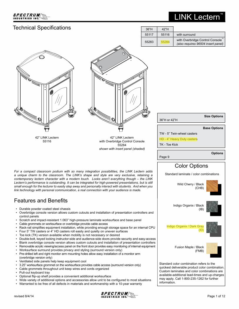
Color OptionsStandard laminate / color combinations
Page 1 of 12revised 8/4/14
LINK Lectern™
Technical Specifications
Standard color combination refers to the quickest deliverable product color combination. Custom laminates and color combinations are available-additional lead-times and up-charges may apply. Call 1-800-235-1262 for further information.
Wild Cherry / Black(CHB)
Indigo Organix / Dark Gray(ID)
Indigo Organix / Black(IB)
Fusion Maple / Black(FMB)
36”H 42”H
55117 55116 with surround
55283 55284 with Overbridge Control Console™
(also requires 96504 insert panel)
For a compact classroom podium with so many integration possibilities, the LINK Lectern adds a unique charm to the classroom. The LINK’s shape and style are very exclusive, retaining a contemporary lectern character with a modern touch. Looks aren’t everything though – the LINK Lectern’s performance is outstanding. It can be integrated for high-powered presentations, but is still small enough for the lecturer to easily step away and personally interact with students. And when you link technology with personal communication, a real connection with your audience is made.
Features and Benefits• Durable powder coated steel chassis• Overbridge console version allows custom cutouts and installation of presentation controllers and
control panels• Scratch and impact-resistant 1.063” high-pressure laminate worksurface and base panel• Cable grommets on worksurface or overbridge provide cable access• Rack-rail simplifies equipment installation, while providing enough storage space for an internal CPU• Four 5” TW casters or 4” HD casters roll easily and quietly on uneven surfaces• Toe kick (TK) version available when mobility is not necessary or desired• Double-bolt, keyed locking instructor-side and audience-side doors provide security and easy-access• Blank overbridge console version allows custom cutouts and installation of presentation controllers• Removable acrylic viewing/access panel on the front door provides easy monitoring of internal equipment• Worksurface surround provides privacy and styling (surround version only)• Pre-drilled left and right monitor arm mounting holes allow easy installation of a monitor arm
(overbridge version only)• Ventilated side panels help keep equipment cool• 3.25” worksurface grommet on the worksurface provides cable access (surround version only)• Cable grommets throughout unit keep wires and cords organized• Pull-out keyboard tray• Optional flip-up shelf provides a convenient additional worksurface• Wide variety of additional options and accessories allow unit to be configured to most situations• Warranted to be free of all defects in materials and workmanship with a 10-year warranty
Options Page 9
Size Options36”H or 42”H
Base Options
TW - 5” Twin-wheel casters
HD - 4” Heavy Duty casters
TK - Toe Kick
42” LINK Lectern55116
42” LINK Lecternwith Overbridge Control Console
55284shown with insert panel (shaded)
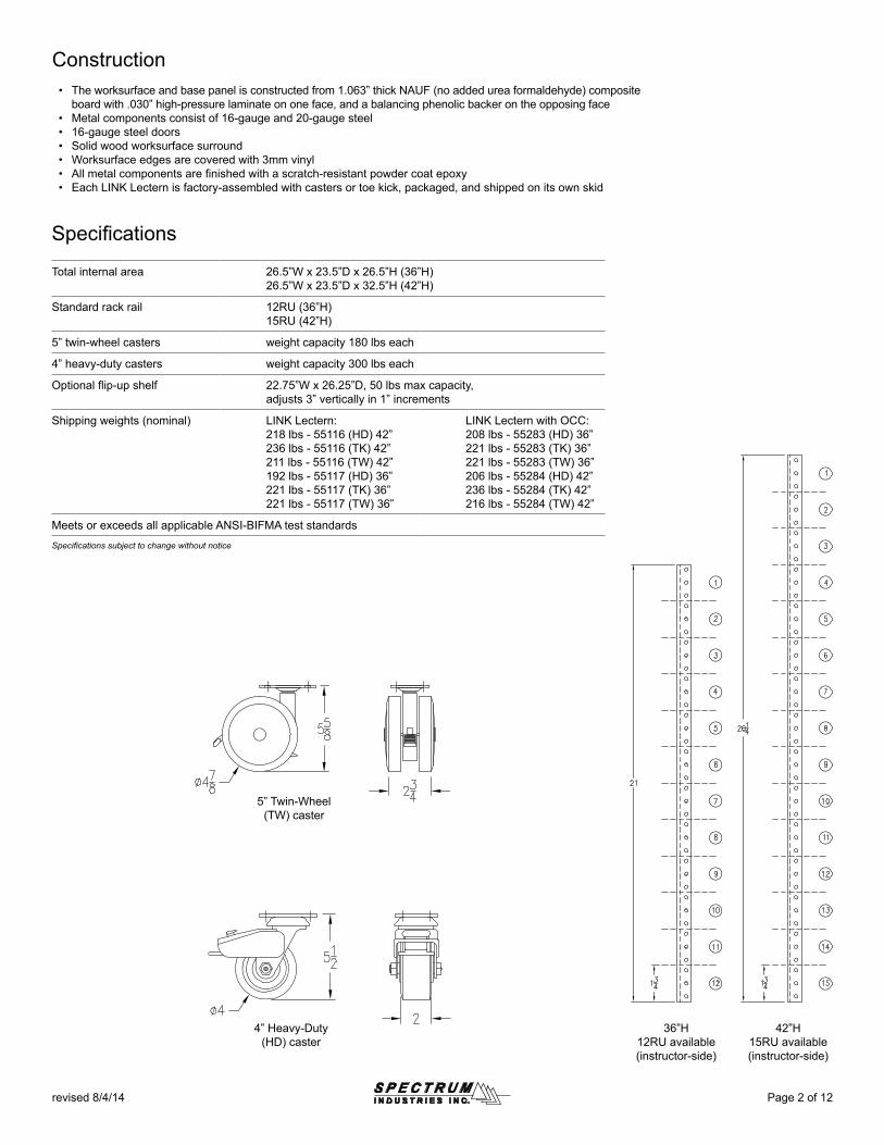
Page 2 of 12revised 8/4/14
Construction• The worksurface and base panel is constructed from 1.063” thick NAUF (no added urea formaldehyde) composite
board with .030” high-pressure laminate on one face, and a balancing phenolic backer on the opposing face• Metal components consist of 16-gauge and 20-gauge steel• 16-gauge steel doors• Solid wood worksurface surround• Worksurface edges are covered with 3mm vinyl• All metal components are finished with a scratch-resistant powder coat epoxy• Each LINK Lectern is factory-assembled with casters or toe kick, packaged, and shipped on its own skid
42”H15RU available(instructor-side)
Specifications
Total internal area 26.5”W x 23.5”D x 26.5”H (36”H)26.5”W x 23.5”D x 32.5”H (42”H)
Standard rack rail 12RU (36”H)15RU (42”H)
5” twin-wheel casters weight capacity 180 lbs each
4” heavy-duty casters weight capacity 300 lbs each
Optional flip-up shelf 22.75”W x 26.25”D, 50 lbs max capacity,adjusts 3” vertically in 1” increments
Shipping weights (nominal) LINK Lectern:218 lbs - 55116 (HD) 42”236 lbs - 55116 (TK) 42”211 lbs - 55116 (TW) 42”192 lbs - 55117 (HD) 36”221 lbs - 55117 (TK) 36”221 lbs - 55117 (TW) 36”
LINK Lectern with OCC:208 lbs - 55283 (HD) 36”221 lbs - 55283 (TK) 36”221 lbs - 55283 (TW) 36”206 lbs - 55284 (HD) 42”236 lbs - 55284 (TK) 42”216 lbs - 55284 (TW) 42”
Meets or exceeds all applicable ANSI-BIFMA test standards
Specifications subject to change without notice
36”H12RU available(instructor-side)
4” Heavy-Duty (HD) caster
5” Twin-Wheel (TW) caster
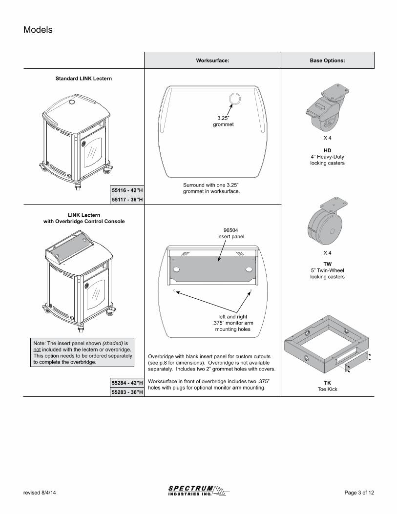
left and right .375” monitor arm mounting holes
3.25” grommet
Page 3 of 12revised 8/4/14
Surround with one 3.25” grommet in worksurface.55116 - 42”H
55117 - 36”H
55284 - 42”H
55283 - 36”H
Base Options:Worksurface:
Models
TW5” Twin-Wheellocking casters
TKToe Kick
X 4
Standard LINK Lectern
Overbridge with blank insert panel for custom cutouts(see p.8 for dimensions). Overbridge is not available separately. Includes two 2” grommet holes with covers.
Worksurface in front of overbridge includes two .375” holes with plugs for optional monitor arm mounting.
LINK Lecternwith Overbridge Control Console
HD4” Heavy-Duty locking casters
X 4
Note: The insert panel shown (shaded) is not included with the lectern or overbridge. This option needs to be ordered separately to complete the overbridge.
96504 insert panel
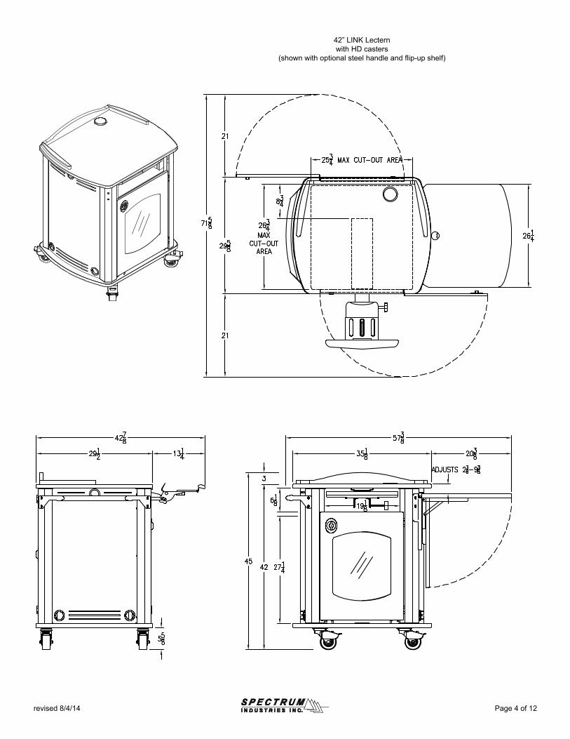
Page 4 of 12revised 8/4/14
42” LINK Lecternwith HD casters
(shown with optional steel handle and flip-up shelf)
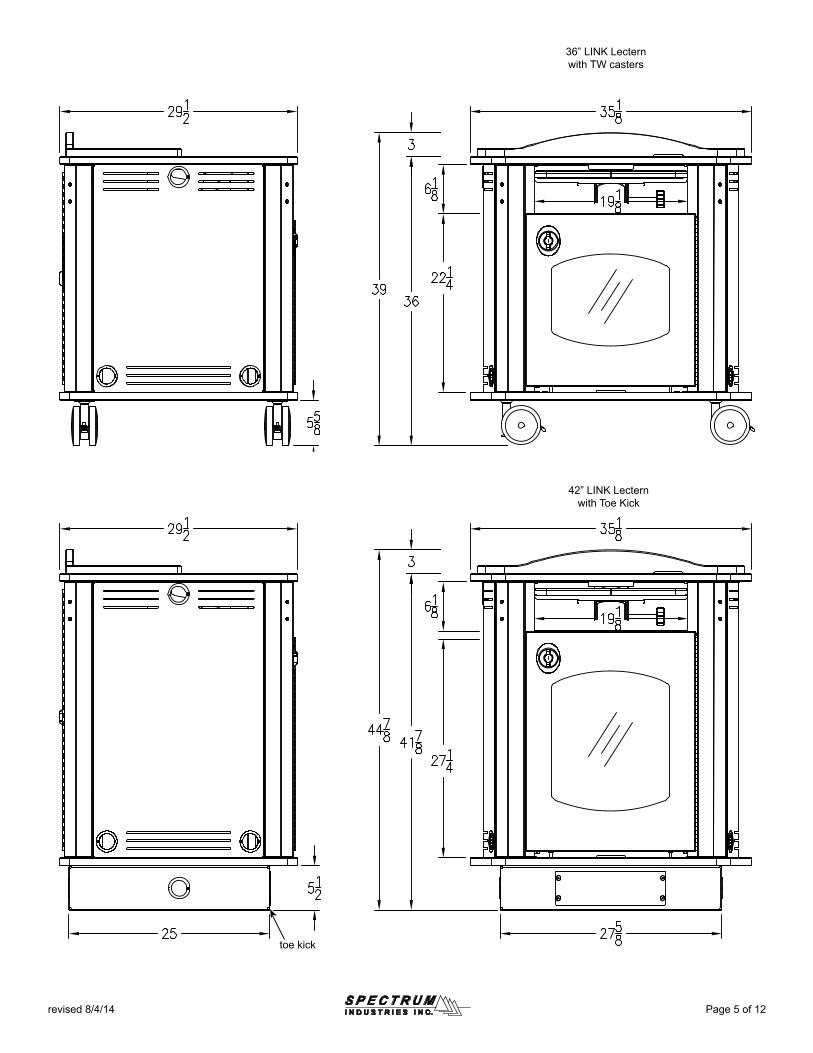
toe kick
42” LINK Lecternwith Toe Kick
Page 5 of 12revised 8/4/14
36” LINK Lectern with TW casters
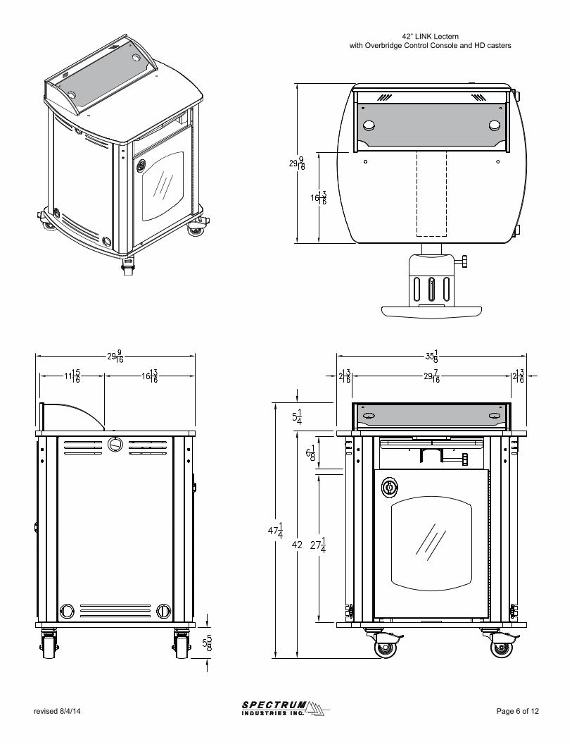
Page 6 of 12revised 8/4/14
42” LINK Lecternwith Overbridge Control Console and HD casters
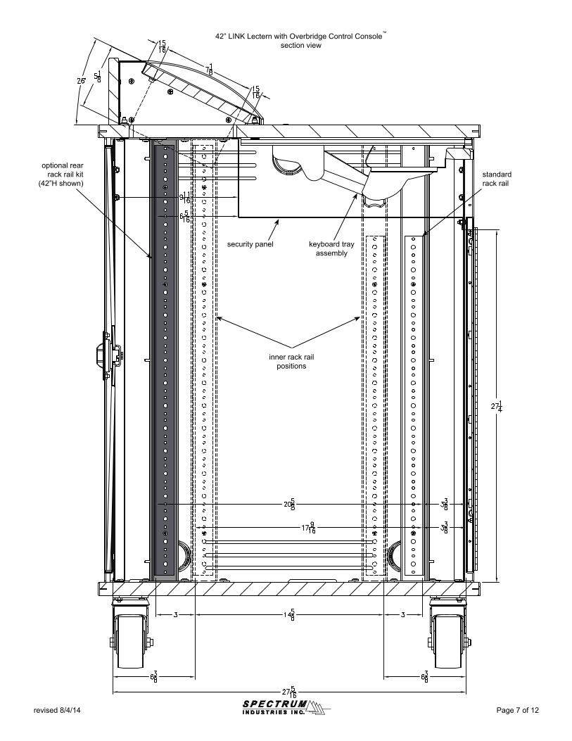
optional rear rack rail kit
(42”H shown)standard rack rail
security panel keyboard tray assembly
inner rack rail positions
Page 7 of 12revised 8/4/14
42” LINK Lectern with Overbridge Control Console™
section view
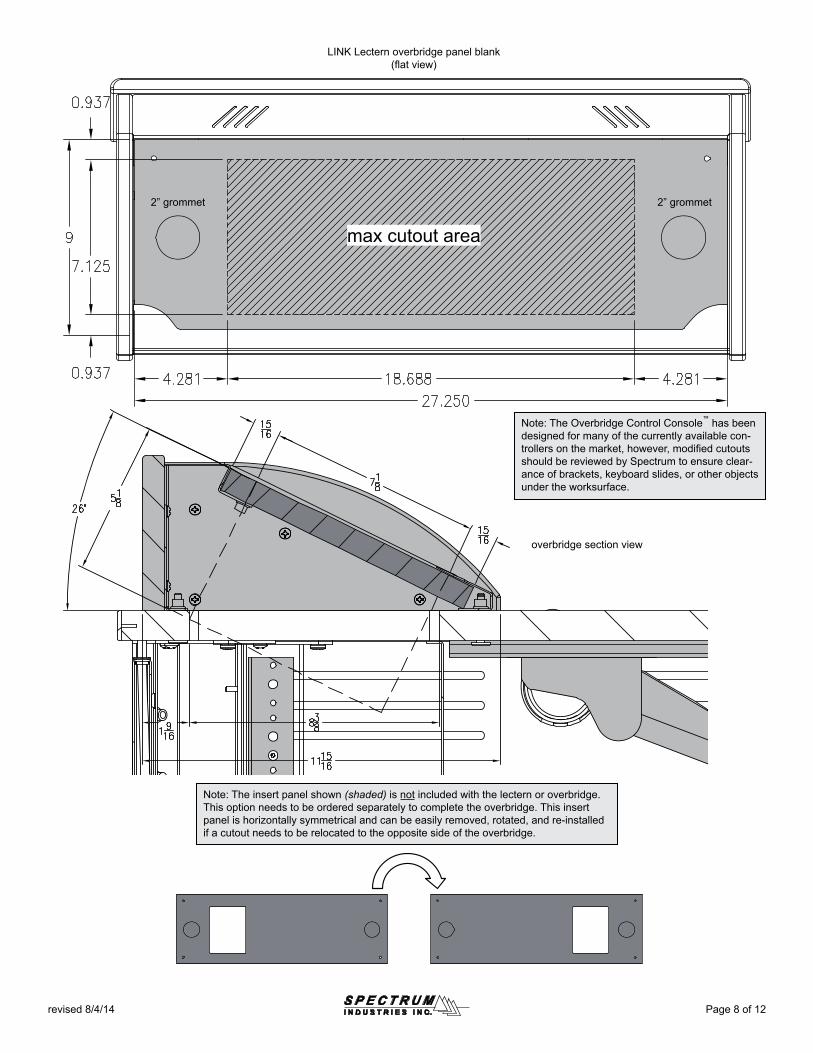
Page 8 of 12revised 8/4/14
2” grommet
LINK Lectern overbridge panel blank(flat view)
overbridge section view
2” grommet
max cutout area
Note: The Overbridge Control Console™ has been designed for many of the currently available con-trollers on the market, however, modified cutouts should be reviewed by Spectrum to ensure clear-ance of brackets, keyboard slides, or other objects under the worksurface.
Note: The insert panel shown (shaded) is not included with the lectern or overbridge. This option needs to be ordered separately to complete the overbridge. This insert panel is horizontally symmetrical and can be easily removed, rotated, and re-installed if a cutout needs to be relocated to the opposite side of the overbridge.
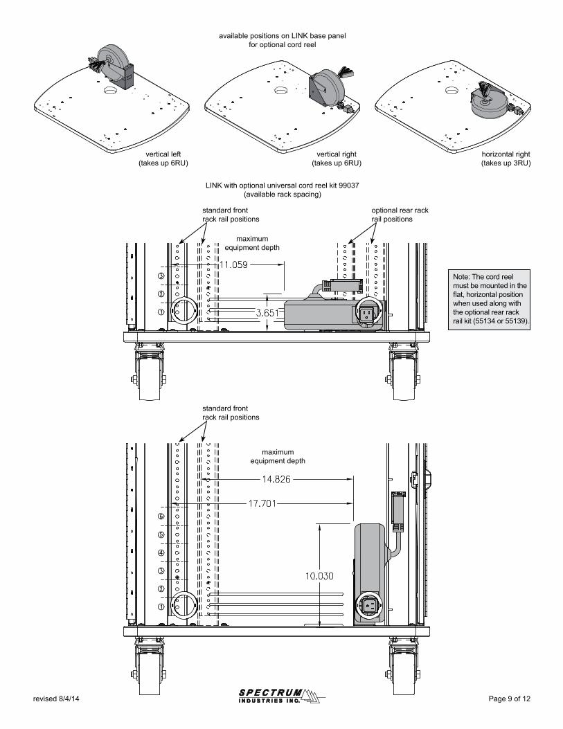
standard front rack rail positions
optional rear rack rail positions
standard front rack rail positions
Page 9 of 12revised 8/4/14
vertical left(takes up 6RU)
vertical right(takes up 6RU)
horizontal right(takes up 3RU)
available positions on LINK base panel for optional cord reel
LINK with optional universal cord reel kit 99037(available rack spacing)
maximum equipment depth
maximum equipment depth
Note: The cord reel must be mounted in the flat, horizontal position when used along with the optional rear rack rail kit (55134 or 55139).
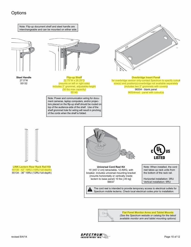
Page 10 of 12revised 8/4/14
Options
Flip-up Shelf22.75”W x 26.25”D
(mounts on left or right side)includes 2” grommet, adjustable-height
(50 lbs max capacity)55140
Steel Handle27.5”W55132
Note: Flip-up document shelf and steel handle are interchangeable and can be mounted on either side.
LINK Lectern Rear Rack Rail Kit55139 - 42” 19RU (15RU full-depth)55134 - 36” 15RU (12RU full-depth)
Flat Panel Monitor Arms and Tablet Mounts(See the Spectrum website or catalog for the latest available monitor arm and tablet mounting options)
Note: Power and communication wiring for docu-ment cameras, laptop computers, and/or projec-tors placed on the flip-up shelf should be routed on top of the audience-side of the shelf. Use of the shelf grommet hole for wiring will result in pinching of the cords when the shelf is folded.
Overbridge Insert Panelfor overbridge version only-contact Spectrum to specify cutout
size(s) and position(s)-overbridge not available separately(includes two 2” grommets with covers)
96504 - blank panel96504mod - panel with cutout(s)
Universal Cord Reel Kit15’ [457.2 cm] retractable, 12 AWG, with
breaker, includes universal mounting bracket(mounts horizontally or vertically inside lectern to base panel) 10 lbs [.45 kg]
99037
Note: When installed, the cord reel takes up rack units from the bottom of the rack rail.
Horizontal installation: 3RUVertical installation: 6RU
The cord reel is intended to provide temporary access to electrical outlets for Spectrum mobile lecterns. Check local electrical codes prior to installation.
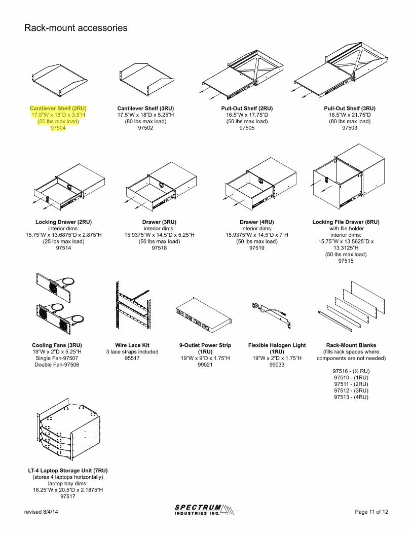
Cantilever Shelf (2RU)17.5”W x 18”D x 3.5”H
(50 lbs max load)97504
Cantilever Shelf (3RU)17.5”W x 18”D x 5.25”H
(80 lbs max load)97502
Pull-Out Shelf (2RU)16.5”W x 17.75”D(50 lbs max load)
97505
Locking Drawer (2RU)interior dims:
15.75”W x 13.6875”D x 2.875”H(25 lbs max load)
97514
Drawer (3RU)interior dims:
15.9375”W x 14.5”D x 5.25”H(50 lbs max load)
97518
Drawer (4RU)interior dims:
15.9375”W x 14.5”D x 7”H(50 lbs max load)
97519
Cooling Fans (3RU)19”W x 2”D x 5.25”H
Single Fan-97507Double Fan-97506
Wire Lace Kit3 lace straps included
95517
Flexible Halogen Light(1RU)
19”W x 2”D x 1.75”H99033
Locking File Drawer (8RU) with fi le holderinterior dims:
15.75”W x 13.5625”D x 13.3125”H
(50 lbs max load)97515
Rack-Mount Blanks(fi lls rack spaces where
components are not needed)
97516 - (1⁄2 RU)97510 - (1RU)97511 - (2RU)97512 - (3RU)97513 - (4RU)
9-Outlet Power Strip(1RU)
19”W x 9”D x 1.75”H99021
Pull-Out Shelf (3RU)16.5”W x 21.75”D(80 lbs max load)
97503
LT-4 Laptop Storage Unit (7RU)(stores 4 laptops horizontally)
laptop tray dims:16.25”W x 20.5”D x 2.1875”H
97517
Rack-mount accessories
Page 11 of 12revised 8/4/14
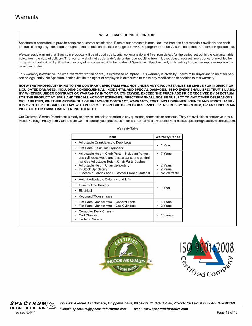
925 First Avenue, PO Box 400, Chippewa Falls, WI 54729 Ph: 800-235-1262, 715-723-6750 Fax: 800-335-0473, 715-738-2309E-mail: [email protected] web: www.spectrumfurniture.com
Page 12 of 12revised 8/4/14
WE WILL MAKE IT RIGHT FOR YOU!
Spectrum is committed to provide complete customer satisfaction. Each of our products is manufactured from the best materials available and each product is stringently monitored throughout the production process through our P.A.C.E. program (Product Assurance to meet Customer Expectations).
We expressly warrant that Spectrum products will be of good quality and workmanship and free from defect for the period set out in the warranty table below from the date of delivery. This warranty shall not apply to defects or damage resulting from misuse, abuse, neglect, improper care, modification or repair not authorized by Spectrum, or any other cause outside the control of Spectrum. Spectrum will, at its sole option, either repair or replace the defective product.
This warranty is exclusive; no other warranty, written or oral, is expressed or implied. This warranty is given by Spectrum to Buyer and to no other per-son or legal entity. No Spectrum dealer, distributor, agent or employee is authorized to make any modification or addition to this warranty.
NOTWITHSTANDING ANYTHING TO THE CONTRARY, SPECTRUM WILL NOT UNDER ANY CIRCUMSTANCES BE LIABLE FOR INDIRECT OR LIQUIDATED DAMAGES, INCLUDING CONSEQUENTIAL, INCIDENTAL AND SPECIAL DAMAGES. IN NO EVENT SHALL SPECTRUM’S LIABIL-ITY, WHETHER UNDER CONTRACT OR WARRANTY, IN TORT OR OTHERWISE, EXCEED THE PURCHASE PRICE RECEIVED BY SPECTRUM FOR THE PRODUCT AT ISSUE AND “RECALL ACTION” EXPENSES. SPECTRUM SHALL NOT BE SUBJECT TO ANY OTHER OBLIGATIONS OR LIABILITIES, WHETHER ARISING OUT OF BREACH OF CONTRACT, WARRANTY, TORT (INCLUDING NEGLIGENCE AND STRICT LIABIL-ITY) OR OTHER THEORIES OF LAW, WITH RESPECT TO PRODUCTS SOLD OR SERVICES RENDERED BY SPECTRUM, OR ANY UNDERTAK-INGS, ACTS OR OMISSIONS RELATING THERETO.
Our Customer Service Department is ready to provide immediate attention to any questions, comments or concerns. They are available to answer your calls Monday through Friday from 7 am to 5 pm CST. In addition your product comments or concerns are welcome via e-mail at: [email protected].
Warranty Table
Item Warranty Period• Adjustable Crank/Electric Desk Legs
• 1 Year• Flat Panel Desk Gas Cylinders
• Adjustable Height Chair Parts – including frames, gas cylinders, wood and plastic parts, and control handles Adjustable Height Chair Parts Casters
• Adjustable Height Chair Upholstery• In-Stock Upholstery• Graded-In Fabrics and Customer Owned Material
• 7 Years
• 2 Years• 2 Years• No Warranty
• Height Adjustable Columns and Lifts
• 1 Year• General Use Casters
• Electrical
• Keyboard/Mouse Trays
• Flat Panel Monitor Arm – General Parts• Flat Panel Monitor Arm – Gas Cylinders
• 5 Years• 2 Years
• Computer Desk Chassis• Cart Chassis• Lectern Chassis
• 10 Years
Warranty
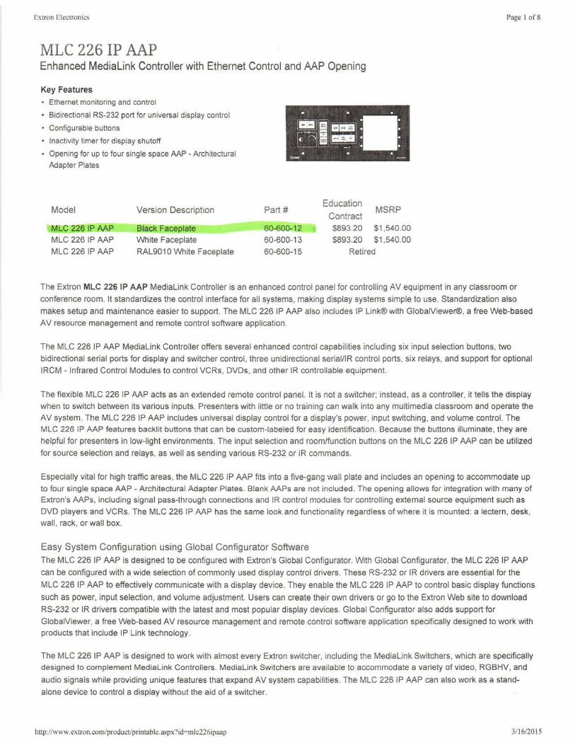
Extron Electronics
MLC 226 IP AAP Enhanced Medialink Controller with Ethernet Control and AAP Opening
Key Features
• Ethernet monitoring and control
• Bidirectional RS-232 port for universal display control
• Configurable buttons
• Inactivity timer for display shutoff
• Opening for up to four single space AAP - Architectural Adapter Plates
Model Version Description
MCC 226 IP AAP Black Faceplate MLC 226 IP AAP White Faceplate MLC 226 IP AAP RAL901 O White Faceplate
Part# Education
MSRP Contract
60-600-12 $893.20 $1,540.00
60-600-13 $893.20 $1,540.00
60-600-15 Retired
Page I of8
The Extron MLC 226 IP AAP Medialink Controller is an enhanced control panel for controlling AV equipment in any classroom or
conference room. It standardizes the control interface for all systems, making display systems simple to use. Standardization also
makes setup and maintenance easier to support. The MLC 226 IP AAP also includes IP Link® with GlobalViewer®, a free Web-based
AV resource management and remote control software application.
The MLC 226 IP AAP Medialink Controller offers several enhanced control capabilities including six input selection buttons, two
bidirectional serial ports for display and switcher control, three unidirectional serial/IR control ports, six relays , and support for optional
IRCM - Infrared Control Modules to control VCRs, DVDs, and other IR controllable equipment.
The flexible MLC 226 IP AAP acts as an extended remote control panel. It is not a switcher; instead, as a controller, it tells the display
when to switch between its various inputs. Presenters with little or no training can walk into any multimedia classroom and operate the AV system. The MLC 226 IP AAP includes universal display control for a display's power, input switching, and volume control. The MLC 226 IP AAP features backlit buttons that can be custom-labeled for easy identification. Because the buttons illuminate, they are
helpful for presenters in low-light environments. The input selection and room/function buttons on the MLC 226 IP AAP can be utilized
for source selection and relays, as well as sending various RS-232 or IR commands.
Especially vital for high traffic areas, the MLC 226 IP AAP fits into a five-gang wall plate and includes an opening to accommodate up to four single space AAP - Architectural Adapter Plates. Blank AAPs are not included. The opening allows for integration with many of Extron's AAPs, including signal pass-through connections and IR control modules for controlling external source equipment such as
DVD players and VCRs. The MLC 226 IP AAP has the same look and functionality regardless of where it is mounted: a lectern, desk, wall, rack, or wall box.
Easy System Configuration using Global Configurator Software The MLC 226 IP AAP is designed to be configured with Extron's Global Configurator. With Global Configurator, the MLC 226 IP AAP
can be configured with a wide selection of commonly used display control drivers. These RS-232 or IR drivers are essential for the
MLC 226 IP AAP to effectively communicate with a display device. They enable the MLC 226 IP AAP to control basic display functions
such as power, input selection , and volume adjustment. Users can create their own drivers or go to the Extron Web site to download
RS-232 or IR drivers compatible with the latest and most popular display devices. Global Configurator also adds support for
GlobalViewer, a free Web-based AV resource management and remote control software application specifically designed to work with products that include IP Link technology.
The MLC 226 IP AAP is designed to work with almost every Extron switcher, including the Medialink Switchers, which are specifically designed to complement MediaLink Controllers. MediaLink Switchers are available to accommodate a variety of video, RGBHV, and
audio signals while providing unique features that expand AV system capabilities. The MLC 226 IP AAP can also work as a stand
alone device to control a display without the aid of a switcher.
http://www.extron.com/product/printable.aspx?id=mlc226ipaap 3/ 16/2015

Extron Electronics Page 2 of 8
Ethernet Control The MLC 226 IP MP is equipped with Ethernet control and is designed to work in conjunction with GlobalViewer, Extron's Web
based AV resource management and remote control application. Together, these form a powerful control solution with the following
features:
• Proactive maintenance - GlobalViewer can store and display information about connected devices like serial numbers, owner
identification, maintenance history, and installed firmware versions. This centralized data can be collected and used to reduce
maintenance costs and guide future purchasing decisions. For instance, a projector can be polled routinely to track lamp usage
and total life time. When lamp usage reaches a predetermined number of hours, the MLC 226 IP MP can send a report via
e-mail.
• Event scheduling - User-defined tasks are easy to configure and schedule with GlobalViewer without the need for traditional
programming. For instance, an administrator may want to turn off all projectors every Friday at close of business. The
administrator can schedule the system to turn off all projectors at a specified time, and raise all projection screens that were left down.
• Remote technical support - Technicians can troubleshoot systems remotely because GlobalViewer provides the real-time
status of connected devices. Information such as connection status, power state, and current input selection is displayed in a
central location. For many connected devices, technicians can toggle power on or off, switch sources, control volume, and more without leaving their office. Many common problems can be resolved without traveling to the equipment.
• Theft alerts - IP Link-enabled products are always on and routinely poll their attached devices for status information. If any
serially controlled device, such as a projector or display, is physically disconnected from the network, the MLC 226 IP MP
monitoring its status will know immediately. In such an event, it can send an e-mail message notifying security personnel of the
possible theft. For fast action , e-mails can be sent to multiple addresses including cell phones and wireless devices.
Data Logger Data Logger is a free Microsoft® Excel-based spreadsheet application that allows administrators to automatically gather up-to-date
lamp hour and usage statistics for multiple rooms of AV equipment. It provides a simple, convenient way to retrieve AV system usage
statistics into a single document for data analysis, collecting critical system information such as frequency of usage for each front panel input and current lamp hours of connected projectors.
Features
• Ethernet monitoring and control - An IP integration technology developed by Extron specifically engineered to meet the
needs of professional AV environments that enables the MLC 226 IP MP to be controlled and proactively monitored over a LAN,
WAN, or the Internet.
• Bidirectional RS-232 port for universal display control - The MLC 226 IP MP has a dedicated port for communicating with virtually any projector or flat panel display via IR or RS-232. Control drivers can be downloaded or created using the intuitive software.
• Discrete ON and OFF display power controls - Simplify system operations and eliminate the need for an external display
remote.
• Two Digital 1/0 ports - Port 1 is selectable as a digital input or digital output and can interface with a variety of devices, such as
sensors, switches, LEDs and relays . Port 2 is selectable as a digital input or power sense input. The power sense input can verify
the On/Off status of a device.
• Three IR/serial ports for one-way control of external devices
• RS-232 port for MediaLink Switcher support - For controlling an optional Extron MediaLink Switcher.
• Six internal relays for control of room functions - Enables control of lighting , screen settings, and other device functions. The relays may be controlled through the front panel , SCP 226 MP Secondary Control Panel , IR 402 remote, or RS-232.
• IR learning for customized control of external sources when used with optional IRCM - Infrared Control Modules
• Supports IP Intercom - The optional IPI 101 MP and IPI 104 MP IP Intercom Modules provide two-way, half-duplex
communications over an IP network between a classroom and remote location such as a help desk.
• Configurable buttons - Can be set up to trigger a variety of functions such as selecting an input, sending a serial or IR
command , or controlling a relay.
hnp://www.extron.com/product/printable.aspx?id=mlc226ipaap 3/ 16/2015
Extron Electronics Page 3 of 8
Macro capability -Any button can be configured to execute multiple actions through the serial and IR control ports. For instance, the touch of a single button could trigger commands to turn on the display, select the display's RGB input, and select an
input on the MLS - Medialink Switcher.
• Tri-color, backlit buttons can be custom labeled for easy identification - Provide easy operation for presenters in low-light
environments.
• Inactivity timer for display shutoff - Adjustable timer control provides automatic shutdown to conserve energy, prevent
plasma burn-in, or extend projector lamp life.
• Front panel security lockout - When the security lockout mode is engaged, the MLC 226 IP AAP's front panel becomes
inoperable unless a user-defined PIN number is entered. No functions of the controller or IR remote can be activated.
• Volume control with volume indication for display or MediaLink Switcher - Allows for convenient, centralized control
without additional remotes. The five LEDs provide clear indication of the current audio setting .
• Integrated high performance Web server - Features a built-in Web server with memory available for storing device drivers,
GlobalViewer, and custom user Web pages.
• Removable button caps - Make it easy to label each button to clearly indicate its function; labels can be quickly changed and
don't require programming or engraving.
• Section 508 Compliant - Meets or exceeds accessibility standards for Electronic Information Technology. For more information about Extron's Commitment to Accessibility please see our Accessibility Page (!company/article.aspx?id=accessibility).
• Supports the Extron Control App
• Optional SCP 226 Secondary Control Panel, part# 60-671-xx - Duplicates the MLC 226 IP AAP's front panel buttons and
offers a second access point within a room.
• Opening for up to four single space AAP - Architectural Adapter Plates - The MLC 226 IP AAP fits into a five-gang wall
plate and includes an opening to accommodate up to four single space AAP - Architectural Adapter Plates. Blank AAPs are not
included. The opening allows for integration with many Extron AAPs, including signal pass-through connections.
• Available in black, white, or RAL9010 white
• Optional mounting kits enable wall-, lectern-, or table-mounting
• Includes MR 500 five-gang mud ring
• Highly reliable, energy-efficient external universal power supply included, replacement part #70-775-01 - Provides
worldwide power compatibility, with high demonstrated rel iability (/company/article.aspx?id=eps ga) and low power consumption for
reduced operating costs .
INCLUDED ACCESSORIES • PS 1210 C
• MR 500
• MR 500
OPTIONAL ACCESSORIES
• NETXC M-M
• CFG Cable
• Universal Projector Control Cables
• IR Emitter and Shield Kits
• IRCM-DV+
• IPI 104 AAP
• MLS 406SA
• MLS 506SA
• CM-9BLB
• SCP 226
• MLM 226 L
• MLM-WB+
·········· ··································· ................................ ............. ....................................................... .
12V, 1A Power Supply on Captive Screw
Five-Gang Mud Ring - Black
Five-Gang Mud Ring - White
Male to Male RJ-45 Network Crossover Cable
9-pin D Female to 2.5 mm TRS Configuration Cable
70-775-01
70-519-52
70-519-53
Female 9-pin D Connector to Unterminated - Captive Screw Ready
IR Emitter Kits for Extron Products With IR Output
Dual-Function DVD and VCR IR Control Module
MLC 226 IP Four-Button IP Intercom Station
Six Input Switcher with Stereo Audio Amplifier
Six Input Switcher with Stereo Audio Amplifier
Nine-Button, Four Space Control Module AAP - Architectural Adapter
Plate
Secondary Control Panel for MLC 226 IP and System 5 IP
Replacement Lectern Mounting Kit for the MLC 226 IP
Lockable Metal Wall Box with Flip-Down 4U Rack Space
http://www.extron.com/product/printable.aspx?id=mlc226ipaap 3/16/2015
Extron Electronics
• CM-3BLB
• IPI 104 AAP
COMPATIBLE SOFTWARE
• Global Configurator
• GlobalViewer Enterprise
• iGVE
• Extron Control
SPECIFICATIONS
MLC 226 Series
IP Intercom
Connection type (IPl- MLC)
Audio
Frequency response
Audio processing
Audio format
Sampling rate
Sample size
Audio latency
Audio output
Number/signal type
Line level output
Communication
Three-Button, Double Space Control Module AAP - Architectural
Adapter Plate
MLC 226 IP Four-Button IP Intercom Station
Free Configuration Software for Touchlink, Medialink, and IP Link
Control Systems
Server-Based AV Resource Management Software
Mobile AV Resource Management App
iPad Control App for Touchlink and Medialink
RJ-45 jack for CAT 5/5e/6 cable
20 Hz to 3.3 kHz, ±1 dB
PCM, µ-law companded
8 kHz 16 bit, µ-law companded to 8 bit
Software: 30 ms through 160 ms
Network: <150 ms, typical
1 mono (for use with an optional IP Intercom) -10 dBV (316 mVrms), unbalanced (via 3.5 mm captive screw connector, 2 pole)
Page 4 of8
Transport bandwidth for IPI control and audio , half duplex 80 kbps (0.08% of 1 OOBase-T)
Ethernet protocol IP (control), TCP (control), UDP (audio)
Control - host ports
Serial host port
Baud rate and protocol Serial control pin configurations
Ethernet host port Ethernet data rate (for network communication)
Ethernet protocol
Ethernet default settings
Web server
Secondary control panel (SCP)
Program control
IR learning frequencies
IR learning distance
Control - relay
Number/type Connectors
Connector configuration
Contact rating
Control - serial ports
2 bidirectional RS-232: 1 rear panel female 9-pin D connector (shared with digital input), 1 front
panel 2.5 mm mini stereo jack
38400 baud, 8 data bits, 1 stop bit, no parity 9-pin D connector: 2 = Tx, 3 = Rx, 5 = GND
Mini stereo jack: tip = Tx, ring = Rx, sleeve= GND
1 female RJ-45 10/1 OOBase-T, half/full duplex with autodetect
ARP , ICMP (ping), IP, TCP, DHCP, HTTP, SMTP, Telnet
Link speed and duplex level = autodetected IP address= 1g2.168.254.254
Subnet mask= 255.255.0.0
Default gateway = 0.0.0.0
DHCP =off
Up to 200 simultaneous sessions
7.25 MB nonvolatile user memory
(1) 3.5 mm 5-pole direct insertion captive screw connector (shared with control module port)
Extron Global Configurator for Windows®
Extron Simple Instruction Set (SIS™)
Microsoft" Internet Explorer®· Telnet
30 kHz to 62 kHz
2" (5.1 cm) to 12" (30.5 cm) from the front panel
6 momentary or latching (configurable via software) (3) 3.5 mm captive screw connectors, 3 pole
Groups A, B, C; each with 1 common and 2 normally open relays (default)
24 voe. 1 A
Display control port (1) 3.5 mm direct insertion captive screw connector, 3 pole , programmable for bidirectional RS-
232 control (±5 V) or TTL level (0 to 5 V) infrared control up to 1 MHz
http: //www.extron.com/product/printable.aspx?id=mlc226ipaap 3/16/2015
Extron Electronics
Switcher control port
Baud rate and protocol (RS-232)
Control - JR/serial ports
IR/serial control ports
Baud rate and protocol
Digital 1/0 control
Number/type
Connector
Pin configuration
Digital inputs
Input voltage range
Input impedance
Programmable pullup
Threshold low to high
Threshold high to low
Digital output
General
Power supply
Power consumption MLC 226 IP DV+
Device
Device and power supply
All other models
Page 5 of8
(1) 3.5 mm direct insertion captive screw connector, 3 pole, for bidirectional RS-232 control (±5 V)
115200 to 300 baud (9600 baud = default) ; 8 (default) or 7 data bits; 1 (default) or 2 stop bits; no
parity (default) , or even or odd parity
(3) 3.5 mm direct insertion captive screw connectors, 2 pole
Programmable: unidirectional RS-232 (±5 V) control, or TTL level (0 to 5 V) infrared control up to
1 MHz
115200 to 300 baud (9600 baud =default) ; 8 (default) or 7 data bits; 1 (default) or 2 stop bits; no
parity (default) , or even or odd parity
1 digital input/output (configurable), 1 digital input
1 rear panel female 9-pin D connector (shared with the serial host port)
(1) 3.5 mm direct insertion captive screw connector (shared with power sense port) 9-pin D connector: 1 = digital input, 5 = GND; power sense =digital in , GND = GND
0-12 voe 28k ohms
2k ohms to +5 voe >2.8 voe <2.o voe 250 mA sink from 24 VDC, maximum
External
Input: 100-240 VAC, 50-60 Hz
Output: 12 VDC, 1 A
Includes MLC 226 IP and IRCM-DV+
5.4 watts, 12 voe 6.5 watts, 100-240 VAC, 50-60 Hz
Device 5.0 watts, 12 VDC
Device and power supply 6.4 watts, 100-240 VAC, 50-60 Hz
NOTE If the MLC powers accessories (control modules, SCPs), the MLC must be powered by its own external power supply, not by a switcher. If
accessories are powered separately, the MLC may be powered by an MLS or PVS switcher.
Temperature/humidity
Cooling
Thermal dissipation
MLC 226 IP DV+
Device
Device and power supply
All other models Device Device and power supply
Mounting
Rack mount
MLC 226 IP DV+
All other models
Furniture or wall mount
MLC 226 IP DV+
All other models
Enclosure type MLC 226 IP, MLC 226 IP DV+
MLC 226 IP AAP, MLC 226 IPL Enclosure dimensions
MLC 226 faceplate
MLC 226 AAP, MLC 226 IP DV+ faceplates
MLC 226 L faceplate
Device
MLC 226 IP DV+
http: //www.extron.com/product/printable.aspx?id=mlc226ipaap
Storage: -40 to +158 °F (-40 to+ 70 °C) / 10% to 90%, noncondensing
Operating: +32 to +122 °F (0 to +50 °C) I 10% to 90%, noncondensing Convection, no vents
Includes MLC 226 IP and IRCM-DV+
18.5 BTU/hr 21.9 BTU/hr
17.0 BTU/hr 21.8 BTU/hr
No Yes , with optional rack mounting kits
Yes
Yes , with optional mounting kits
High-impact plastic faceplate , metal rear enclosure
Metal faceplate , metal rear enclosure
4.5" H x 6.4" W x 0.1" D (11.4 cm H x 16.3 cm W x 0.3 cm D) (3 gang)
4.5" H x 10.0"Wx 0.1" D (11 .4 cm H x 25.4 cm Wx 0.3 cm D) (5 gang)
3.15" H x 6.5" W x 0.1" D (8.0 cm H x 16.5 cm Wx 0.3 cm D)
2.75" H x 5.3" W x 2.0" D (7.0 cm H x 13.5 cm Wx 5.9 cm D) and
2.7" H x 2.6" W x 0.9" D (6.9 cm H x 6.6 cm W x 2.3 cm D) (Depth excludes knob and buttons. Fits some 5 gang boxes. Allow at least 2.1" (5.3 cm) depth in
the wall or furniture.)
3/ 16/20 15
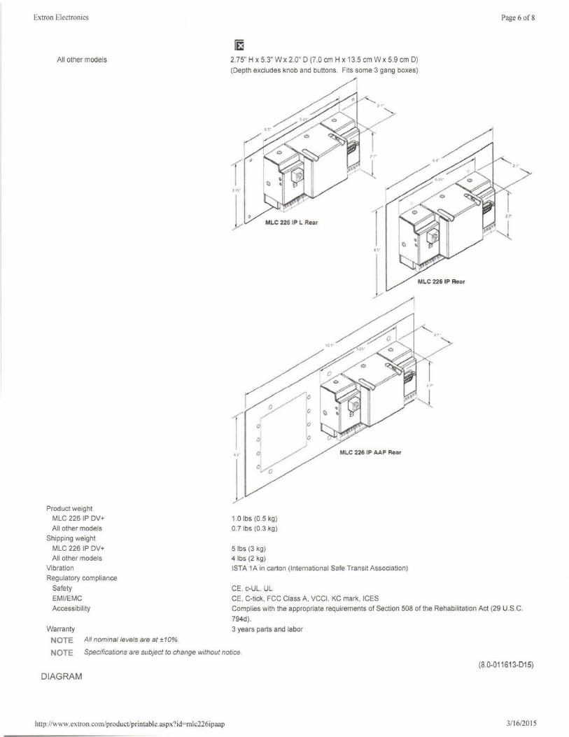
Extron Electronics
All other models
Product weight
MLC 226 IP DV+
All other models
Shipping weight
MLC 226 IP DV+
All other models
Vibration
Regulatory compliance
Safety
EM I/EMC
Accessibility
2.75" H x 5.3" Wx 2.0" D (7.0 cm H x 13.5 cm W x 5.9 cm D) (Depth excludes knob and buttons. Fits some 3 gang boxes)
1.0 lbs (0.5 kg)
0.7 lbs (0.3 kg)
5 lbs (3 kg)
4 lbs (2 kg)
ISTA 1A in carton (International Safe Transit Association)
CE, c-UL, UL
CE, C-tick, FCC Class A, VCCI , KC mark, ICES
Page 6 of 8
Complies with the appropriate requirements of Section 508 of the Rehabilitation Act (29 U.S.C.
794d). Warranty 3 years parts and labor
NOTE All nominal levels are at ±10%.
NOTE Specifications are subject to change without notice.
(8.0-011613-015)
DIAGRAM
http://www.extron.com/product/printable.aspx?id=mlc226ipaap 3/16/2015
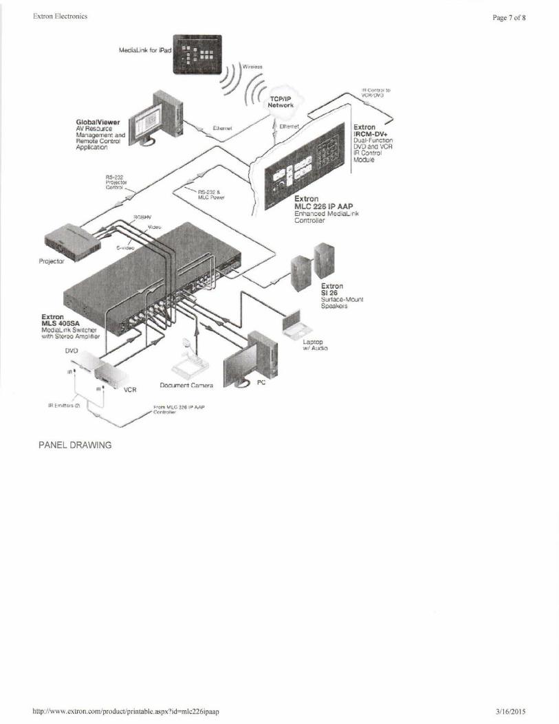
Extron Electronics
R3·2J2 Pro Jet for Coru:r::i--.__.
' VCR
PANEL DRAWING
Documert Cariera
http: //www.extron.com/product/printable.aspx?id=mic226ipaap
Extron MLC 228 IP AAP Enhanced Media r>k Comroller
Laptop wl Audio
Page 7 of8
3/ 16/2015
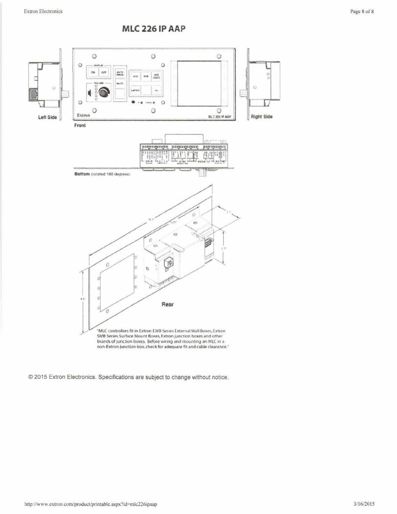
Extron Electronics
Loft Skl11
MLC 226 IP AAP
-0 0 0 0
8 0
"' I .111TO ,_,, •'U% ... ....
r.u u tclll Fg--g ...... 0
0 • •• (-· ~· D
0 {) 0 t:\tro~ MLC ll/~1$' ii.AP
Front
Bottom (101a1 <1 100 do91 o»
Rear 0
"MLC mntroller ~ flt In fic tion EWB Seri~ h!emJI WJll 8ox(». Extron SMB Series Surface Mounf Boxes. Extron junCfion boxes and other br<1n<lHif J1.1nctlon boxe~. B~ore wrrrng and mountin9 an MLC 1n .> nor.-Extron juoction bo•. che<k for adequate fit and cable clearance."
© 2015 Extron Electronics. Specifications are subject to change without notice.
hnp://www.extron.com/product/printable.aspx?id=mlc226ipaap
Page 8 of 8
Right Slcle
3/16/2015
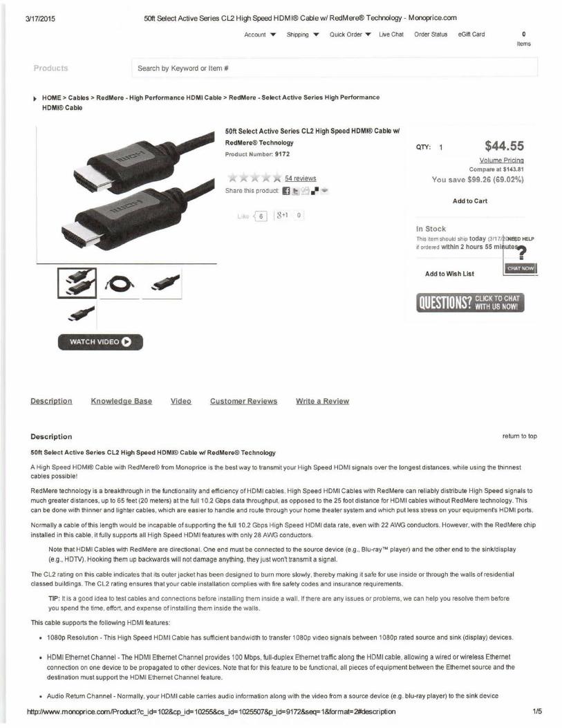
3117/2015 50f! Select Active Series CL2 High Speed HDMI® Cablew/ RedMere® Technology - Monoprice.corn
Account ..,.. Shipping T Quick Order T Live Chat Order Status eGift Card 0 Items
Products Search by Keyword or Item #
~ HOME> Cables> RedMere - High Performance HDMI Cable> RedMere -Select Active Series High Performance
HDMI® Cable
50ft Select Active Series CL2 High Speed HDMI® Cable w/
RedMere® Technology
Product Number: 9172
54 reviews
Share this product: I] •-eJ ,/'
L1k GJ I 8+1 0
QTY: $44.55 Volume Pricing
Compare at $143.81
You save $99.26 (69.02%)
Add to Cart
In Stock This item sh~uld ship today (3117/fCNl!li D HELP
if ordered within 2 hours 55 mlTute~
IHMiwu_ Add to Wish List
WATCH VIDEO 0
Description Knowledge Base Customer Reviews Write a Review
Description return to top
50ft Select Active Series CL2 High Speed HDMI® Cable w/ RedMere® Technology
A High Speed HDMI® Cable with RedMere® from Monoprice is the best way to transmit your High Speed HDMI signals over the longest distances , wh ile using the thinnest cables possible!
RedMere technology is a breakthrough in the functional ity and efficiency of HDMI cables. High Speed HDMI Cables with RedMere can reliably distribute High Speed signals to
much greater distances, up to 65 feet (20 meters) at the full 10.2 Gbps data throughput, as opposed to the 25 foot distance for HDMI cables without RedMere technology. This
can be done with thinner and lighter cables, which are easier to handle and route through your home theater system and which put less stress on your equipment's HDMI ports.
Normally a cable of this length would be incapable of supporting the full 10.2 Gbps High Speed HDMI data rate , even with 22 AWG conductors. However, with the RedMere chip
installed in this cable , it fully supports all High Speed HDMI features with only 28 AWG conductors.
Note that HDMI Cables with RedMere are directional. One end must be connected to the source device (e .g ., Blu-ray™ player) and the other end to the sink/display
(e.g ., HDTV) . Hooking them up backwards will not damage anything , they just won't transmit a signal.
The CL2 rating on this cable indicates that its outer jacket has been designed to burn more slowly, thereby making it safe for use inside or through the walls of residential
classed buildings. The CL2 rating ensures that your cable installation complies with flre safety codes and insurance requirements.
TIP: It is a good idea to test cables and connections before install ing them inside a wall. If there are any issues or problems, we can help you resolve them before
you spend the time. effort, and expense of installing them inside the walls .
This cable supports the following HDMI features :
• 1080p Resolution - This High Speed HDMI Cable has sufficient bandwidth to transfer 1080p video signals between 1080p rated source and sink (display) devices.
• HDMI Ethernet Channel - The HDMI Ethernet Channel provides 100 Mbps, full-duplex Ethernet traffic along the HDMI cable . allowing a wired or wireless Ethernet
connection on one device to be propagated to other devices. Note that for this feature to be functional, all pieces of equipment between the Ethernet source and the
destination must support the HDMI Ethernet Channel feature .
• Audio Return Channel - Normally, your HDMI cable carries audio information along with the video from a source device (e .g. blu-ray player) to the sink device
http://www.monoprice.corn/Product?c_id= 102&cp_id= 10255&cs _id= 1025507&p_id=9172&seq= 1&format=2#descri ption 1/5
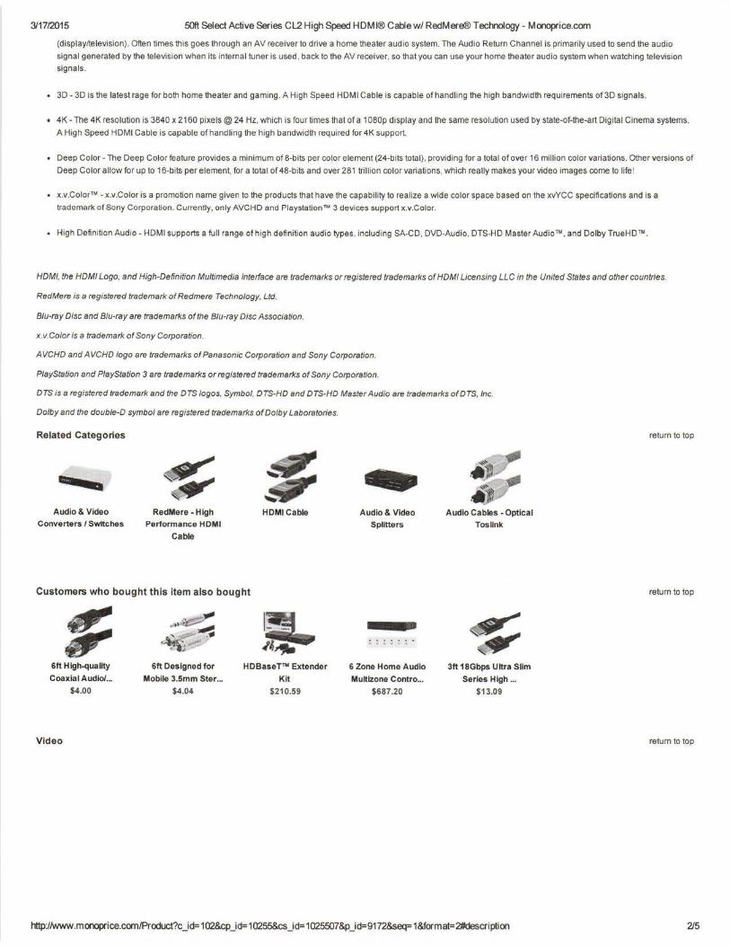
311712015 50ft Select Active Series CL2 High Speed HDMI® Cablew/ RedMere® Technology- Monoprice.com
(display/television). Often times this goes through an AV receiver to drive a home theater audio system. The Audio Return Channel is primarily used to send the audio
signal generated by the television when its internal tuner is used, back to the AV receiver, so that you can use your home theater audio system when watching television
signals.
• 3D - 3D is the latest rage for both home theater and gaming. A High Speed HDMI Cable is capable of handling the high bandwidth requirements of3D signals.
• 4K - The 4K resolution is 3840 x 2160 pixels @ 24 Hz, which is four times that of a 1080p display and the same resolution used by state-of-the-art Digital Cinema systems.
A High Speed HDMI Cable is capable of handling the high bandwidth required for 4K support.
• Deep Color - The Deep Color feature provides a minimum of 8-bits per color element (24-bits total) , providing for a total of over 16 million color variations. Other versions of
Deep Color allow for up to 16-bits per element, for a total of 48-bits and over 281 trillion color variations, which really makes your video images come to life!
• x.v.Color™ - x.v.Color is a promotion name given to the products that have the capability to realize a wide color space based on the xvYCC specifications and is a
trademark of Sony Corporation . Currently, only AVCHD and Playstation™ 3 devices support x.v.Color.
• High Definition Audio - HDMI supports a full range of high definition audio types, including SA-CD, DVD-Audio , DTS-HD Master Audio™, and Dolby TrueHD™.
HDMI. the HOM/ Logo, and High-Definition Multimedia Interface are trademarks or registered trademarks of HOM/ Licensing LLC in the United States and other countries.
RedMere is a registered trademark of Redmere Technology, Ltd.
Blu-ray Disc and Blu-ray are trademarks of the Blu-ray Disc Association.
x. v.Color is a trademark of Sony Corporation.
AVCHD and AVCHD logo are trademarks of Panasonic Corporation and Sony Corporation.
P/ayStation and PlayStation 3 are trademarks or registered trademarks of Sony Corporation.
DTS is a registered trademark and the DTS logos, Symbol, DTS-HD and DTS-HD Master Audio are trademarks of DTS, Inc.
Dolby and the double-D symbol are registered trademarks of Dolby Laboratories.
Related Categories
Audio & Video
Converters I Switches RedMere - High
Performance HDMI
Cable
HDMICable
Customers who bought this item also bought
$ ~ l:L, ~.. ...-!!!
~·-e .,,;: " .,,"" . 6ft High-quality 6ft Designed for HDBaseT™ Extender
Coaxial Audio/ ... Mobile 3.Smm Ster ... Kit
$4.00 $4.04 $210.59
Video
Audio & Video
Splitters
6 Zone Home Audio
Multizone Contro ...
$687.20
Audio Cables - Optical
Tosllnk
~ 3ft 18Gbps Ultra Slim
Series High ...
$13.09
http:/lwww.monoprice.com/Product?c_id=102&cp_id=10255&cs_id=1025507&p_id=9172&seq=1&format=2#description
return to top
return to top
return to top
215
Projector TBD
• WUXGA
• At least 4000 lumens
• HDMI input
• built in closed captioning decoding
• good color reproduction
Da-lite advantage deluxe electrol screen HDTV 16:10 format
• at least 65”H x 104”W 123”D
• needs to have a SCB-100 RS-232 serial control board built in
• bottom of screen must fall at least 4’ from the ground
• larger room may require larger screen
• larger screen may mean ceiling height needs to be increased
• If screen is longer than 10’ wide it should be a tensioned screen
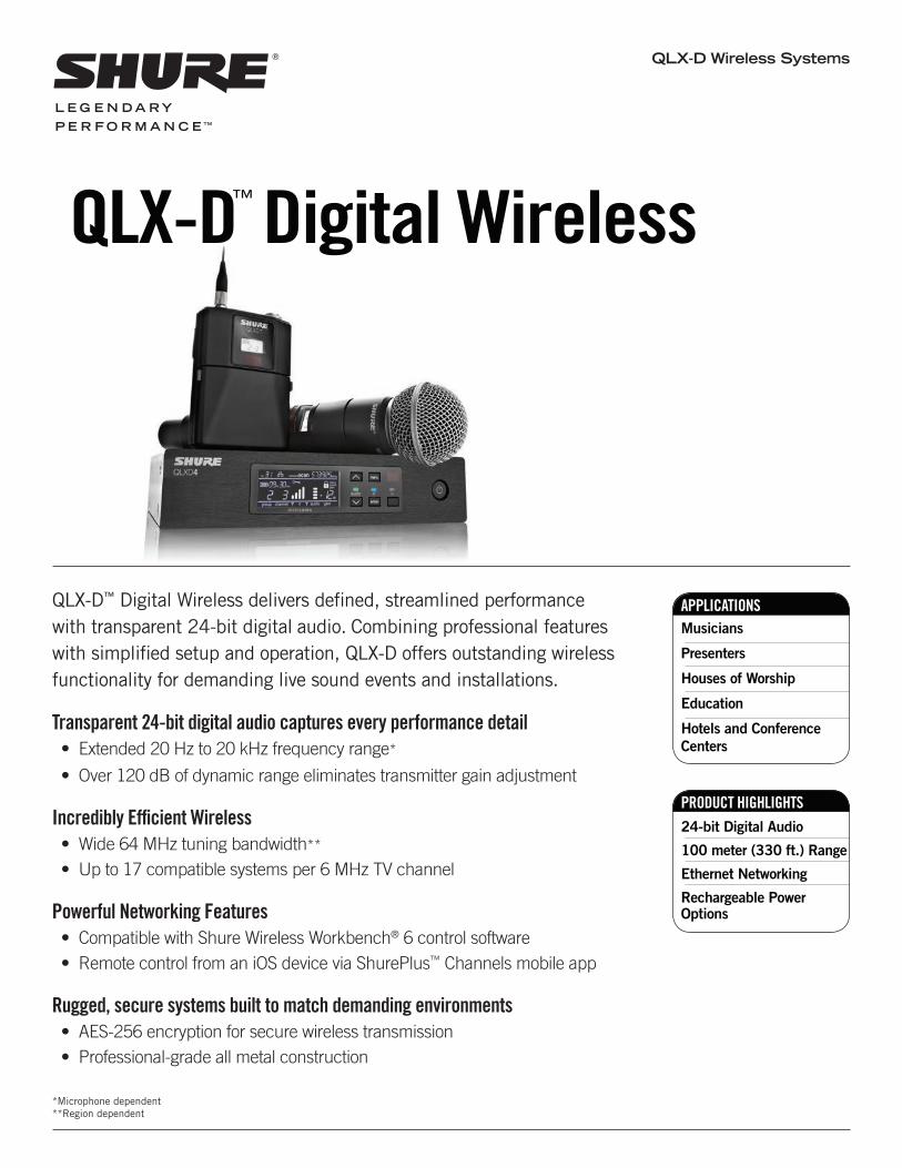
QLX-D Wireless Systems
APPLICATIONSMusicians
Presenters
Houses of Worship
Education
Hotels and Conference Centers
QLX-D™ Digital Wireless
QLX-D™ Digital Wireless delivers defi ned, streamlined performance with transparent 24-bit digital audio. Combining professional features with simplifi ed setup and operation, QLX-D offers outstanding wireless functionality for demanding live sound events and installations.
Transparent 24-bit digital audio captures every performance detail• Extended 20 Hz to 20 kHz frequency range*
• Over 120 dB of dynamic range eliminates transmitter gain adjustment
Incredibly Effi cient Wireless • Wide 64 MHz tuning bandwidth**• Up to 17 compatible systems per 6 MHz TV channel
Powerful Networking Features• Compatible with Shure Wireless Workbench® 6 control software• Remote control from an iOS device via ShurePlus™ Channels mobile app
Rugged, secure systems built to match demanding environments• AES-256 encryption for secure wireless transmission • Professional-grade all metal construction
PRODUCT HIGHLIGHTS24-bit Digital Audio
100 meter (330 ft.) Range
Ethernet Networking
Rechargeable Power Options
*Microphone dependent**Region dependent
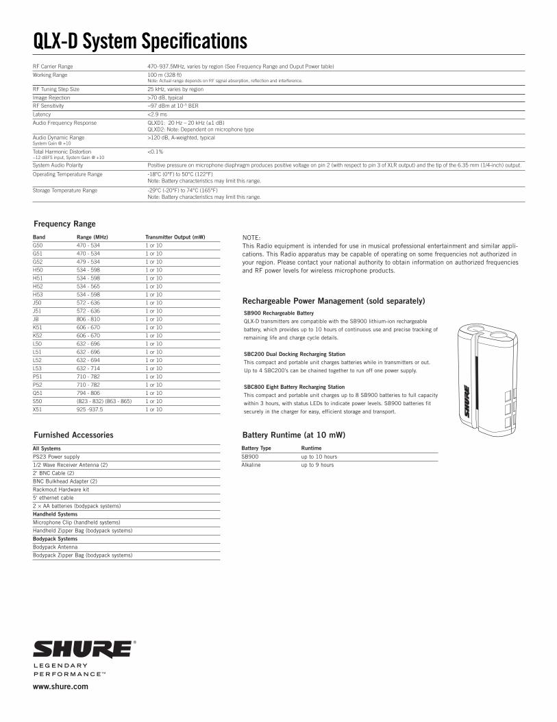
QLX-D System Specifications
www.shure.com
RF Carrier Range 470–937.5MHz, varies by region (See Frequency Range and Ouput Power table)
Working Range 100 m (328 ft)Note: Actual range depends on RF signal absorption, reflection and interference.
RF Tuning Step Size 25 kHz, varies by region
Image Rejection >70 dB, typical
RF Sensitivity −97 dBm at 10−5 BER
Latency <2.9 ms
Audio Frequency Response QLXD1: 20 Hz – 20 kHz (±1 dB)QLXD2: Note: Dependent on microphone type
Audio Dynamic RangeSystem Gain @ +10
>120 dB, A-weighted, typical
Total Harmonic Distortion−12 dBFS input, System Gain @ +10
<0.1%
System Audio Polarity Positive pressure on microphone diaphragm produces positive voltage on pin 2 (with respect to pin 3 of XLR output) and the tip of the 6.35 mm (1/4-inch) output.
Operating Temperature Range -18°C (0°F) to 50°C (122°F)Note: Battery characteristics may limit this range.
Storage Temperature Range -29°C (-20°F) to 74°C (165°F)Note: Battery characteristics may limit this range.
Frequency Range
Band Range (MHz) Transmitter Output (mW)G50 470 - 534 1 or 10
G51 470 - 534 1 or 10
G52 479 - 534 1 or 10
H50 534 - 598 1 or 10
H51 534 - 598 1 or 10
H52 534 - 565 1 or 10
H53 534 - 598 1 or 10
J50 572 - 636 1 or 10
J51 572 - 636 1 or 10
JB 806 - 810 1 or 10
K51 606 - 670 1 or 10
K52 606 - 670 1 or 10
L50 632 - 696 1 or 10
L51 632 - 696 1 or 10
L52 632 - 694 1 or 10
L53 632 - 714 1 or 10
P51 710 - 782 1 or 10
P52 710 - 782 1 or 10
Q51 794 - 806 1 or 10
S50 (823 - 832) (863 - 865) 1 or 10
X51 925 -937.5 1 or 10
Furnished Accessories
All SystemsPS23 Power supply
1/2 Wave Receiver Antenna (2)
2' BNC Cable (2)
BNC Bulkhead Adapter (2)
Rackmout Hardware kit
5' ethernet cable
2 × AA batteries (bodypack systems)
Handheld SystemsMicrophone Clip (handheld systems)
Handheld Zipper Bag (bodypack systems)
Bodypack SystemsBodypack Antenna
Bodypack Zipper Bag (bodypack systems)
Rechargeable Power Management (sold separately)SB900 Rechargeable BatteryQLX-D transmitters are compatible with the SB900 lithium-ion rechargeable
battery, which provides up to 10 hours of continuous use and precise tracking of
remaining life and charge cycle details.
SBC200 Dual Docking Recharging StationThis compact and portable unit charges batteries while in transmitters or out.
Up to 4 SBC200’s can be chained together to run off one power supply.
SBC800 Eight Battery Recharging StationThis compact and portable unit charges up to 8 SB900 batteries to full capacity
within 3 hours, with status LEDs to indicate power levels. SB900 batteries fit
securely in the charger for easy, efficient storage and transport.
Battery Type Runtime
SB900 up to 10 hours
Alkaline up to 9 hours
Battery Runtime (at 10 mW)
NOTE:This Radio equipment is intended for use in musical professional entertainment and similar appli-cations. This Radio apparatus may be capable of operating on some frequencies not authorized in your region. Please contact your national authority to obtain information on authorized frequencies and RF power levels for wireless microphone products.
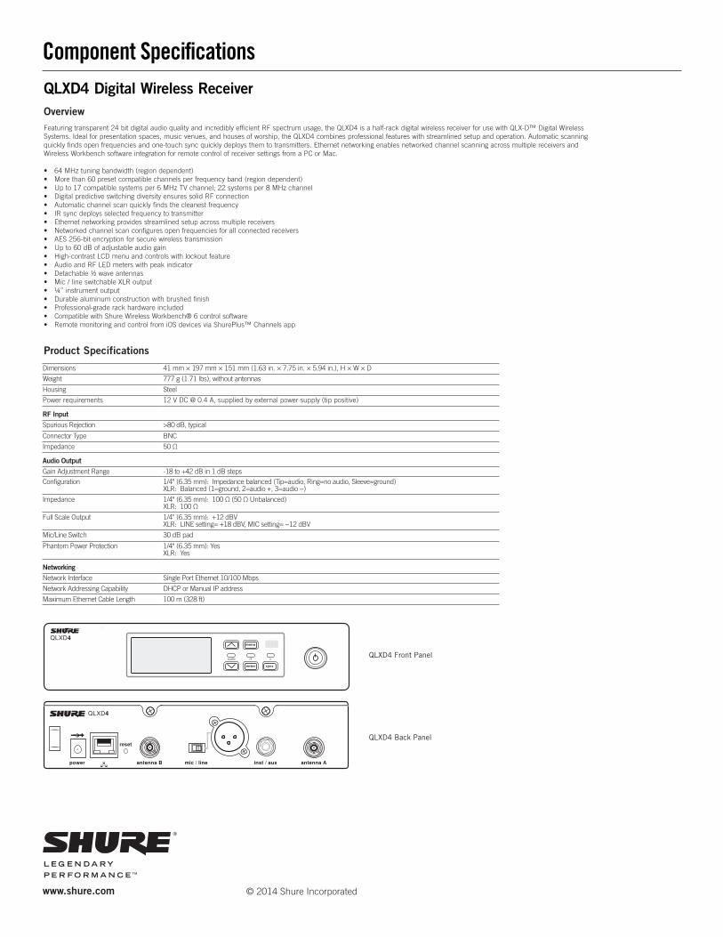
Component Specifi cations
Featuring transparent 24 bit digital audio quality and incredibly efficient RF spectrum usage, the QLXD4 is a half-rack digital wireless receiver for use with QLX-D™ Digital WirelessSystems. Ideal for presentation spaces, music venues, and houses of worship, the QLXD4 combines professional features with streamlined setup and operation. Automatic scanningquickly finds open frequencies and one-touch sync quickly deploys them to transmitters. Ethernet networking enables networked channel scanning across multiple receivers andWireless Workbench software integration for remote control of receiver settings from a PC or Mac.
• 64 MHz tuning bandwidth (region dependent)• More than 60 preset compatible channels per frequency band (region dependent)• Up to 17 compatible systems per 6 MHz TV channel; 22 systems per 8 MHz channel• Digital predictive switching diversity ensures solid RF connection• Automatic channel scan quickly finds the cleanest frequency• IR sync deploys selected frequency to transmitter• Ethernet networking provides streamlined setup across multiple receivers• Networked channel scan configures open frequencies for all connected receivers• AES 256-bit encryption for secure wireless transmission• Up to 60 dB of adjustable audio gain• High-contrast LCD menu and controls with lockout feature• Audio and RF LED meters with peak indicator• Detachable ½ wave antennas• Mic / line switchable XLR output• ¼” instrument output• Durable aluminum construction with brushed finish• Professional-grade rack hardware included• Compatible with Shure Wireless Workbench® 6 control software• Remote monitoring and control from iOS devices via ShurePlus™ Channels app
www.shure.com
Overview
QLXD4 Digital Wireless Receiver
Product Specifications
Dimensions 41 mm × 197 mm × 151 mm (1.63 in. × 7.75 in. × 5.94 in.), H × W × D
Weight 777 g (1.71 lbs), without antennas
Housing Steel
Power requirements 12 V DC @ 0.4 A, supplied by external power supply (tip positive)
RF InputSpurious Rejection >80 dB, typical
Connector Type BNC
Impedance 50 Ω
Audio OutputGain Adjustment Range -18 to +42 dB in 1 dB stepsConfi guration 1/4" (6.35 mm): Impedance balanced (Tip=audio, Ring=no audio, Sleeve=ground)
XLR: Balanced (1=ground, 2=audio +, 3=audio −)
Impedance 1/4" (6.35 mm): 100 Ω (50 Ω Unbalanced)XLR: 100 Ω
Full Scale Output 1/4" (6.35 mm): +12 dBVXLR: LINE setting= +18 dBV, MIC setting= −12 dBV
Mic/Line Switch 30 dB pad
Phantom Power Protection 1/4" (6.35 mm): Yes XLR: Yes
NetworkingNetwork Interface Single Port Ethernet 10/100 Mbps
Network Addressing Capability DHCP or Manual IP address
Maximum Ethernet Cable Length 100 m (328 ft)
QLXD4 Front Panel
QLXD4 Back Panel
© 2014 Shure Incorporated
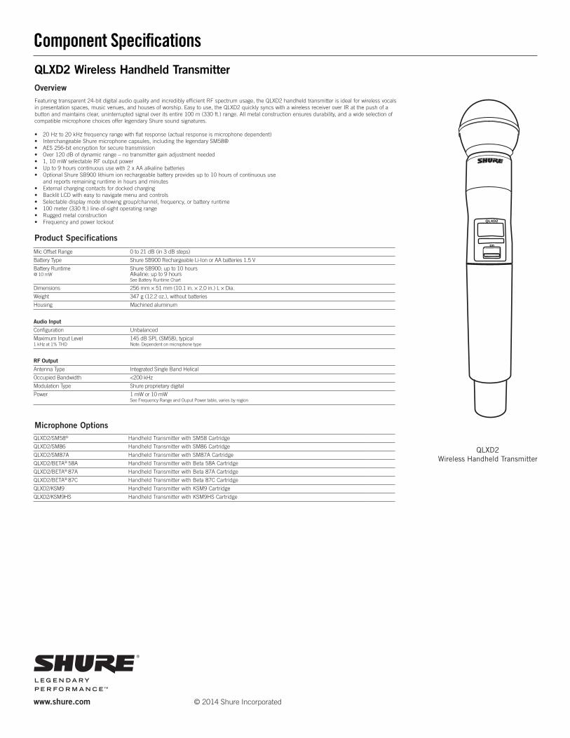
QLXD2 Wireless Handheld Transmitter
Mic Offset Range 0 to 21 dB (in 3 dB steps)
Battery Type Shure SB900 Rechargeable Li-Ion or AA batteries 1.5 V
Battery Runtime@ 10 mW
Shure SB900: up to 10 hoursAlkaline: up to 9 hoursSee Battery Runtime Chart
Dimensions 256 mm × 51 mm (10.1 in. × 2.0 in.) L × Dia.
Weight 347 g (12.2 oz.), without batteries
Housing Machined aluminum
Audio InputConfiguration Unbalanced
Maximum Input Level1 kHz at 1% THD
145 dB SPL (SM58), typicalNote: Dependent on microphone type
RF OutputAntenna Type Integrated Single Band Helical
Occupied Bandwidth <200 kHz
Modulation Type Shure proprietary digital
Power 1 mW or 10 mWSee Frequency Range and Ouput Power table, varies by region
Microphone OptionsQLXD2/SM58® Handheld Transmitter with SM58 Cartridge
QLXD2/SM86 Handheld Transmitter with SM86 Cartridge
QLXD2/SM87A Handheld Transmitter with SM87A Cartridge
QLXD2/BETA® 58A Handheld Transmitter with Beta 58A Cartridge
QLXD2/BETA® 87A Handheld Transmitter with Beta 87A Cartridge
QLXD2/BETA® 87C Handheld Transmitter with Beta 87C Cartridge
QLXD2/KSM9 Handheld Transmitter with KSM9 Cartridge
QLXD2/KSM9HS Handheld Transmitter with KSM9HS Cartridge
Component Specifications
Product Specifications
www.shure.com
QLXD2 Wireless Handheld Transmitter
Featuring transparent 24-bit digital audio quality and incredibly efficient RF spectrum usage, the QLXD2 handheld transmitter is ideal for wireless vocals in presentation spaces, music venues, and houses of worship. Easy to use, the QLXD2 quickly syncs with a wireless receiver over IR at the push of a button and maintains clear, uninterrupted signal over its entire 100 m (330 ft.) range. All metal construction ensures durability, and a wide selection of compatible microphone choices offer legendary Shure sound signatures.
• 20 Hz to 20 kHz frequency range with flat response (actual response is microphone dependent)• Interchangeable Shure microphone capsules, including the legendary SM58®• AES 256-bit encryption for secure transmission• Over 120 dB of dynamic range – no transmitter gain adjustment needed• 1, 10 mW selectable RF output power• Up to 9 hours continuous use with 2 x AA alkaline batteries• Optional Shure SB900 lithium ion rechargeable battery provides up to 10 hours of continuous use and reports remaining runtime in hours and minutes• External charging contacts for docked charging• Backlit LCD with easy to navigate menu and controls• Selectable display mode showing group/channel, frequency, or battery runtime• 100 meter (330 ft.) line-of-sight operating range• Rugged metal construction• Frequency and power lockout
Overview
on
QLXD2
© 2014 Shure Incorporated
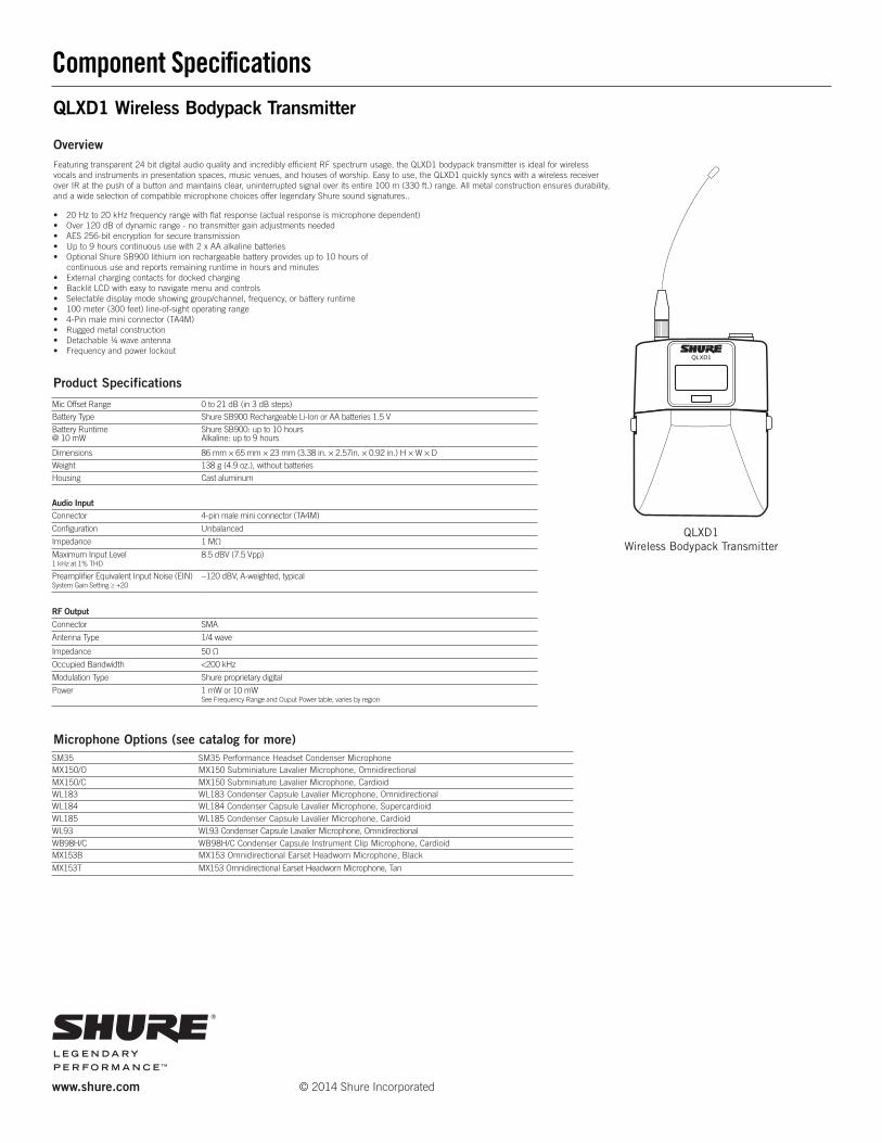
QLXD1 Wireless Bodypack Transmitter
Component Specifications
www.shure.com
QLXD1Wireless Bodypack Transmitter
Featuring transparent 24 bit digital audio quality and incredibly efficient RF spectrum usage, the QLXD1 bodypack transmitter is ideal for wireless vocals and instruments in presentation spaces, music venues, and houses of worship. Easy to use, the QLXD1 quickly syncs with a wireless receiver over IR at the push of a button and maintains clear, uninterrupted signal over its entire 100 m (330 ft.) range. All metal construction ensures durability, and a wide selection of compatible microphone choices offer legendary Shure sound signatures..
• 20 Hz to 20 kHz frequency range with flat response (actual response is microphone dependent)• Over 120 dB of dynamic range - no transmitter gain adjustments needed• AES 256-bit encryption for secure transmission• Up to 9 hours continuous use with 2 x AA alkaline batteries• Optional Shure SB900 lithium ion rechargeable battery provides up to 10 hours of continuous use and reports remaining runtime in hours and minutes• External charging contacts for docked charging• Backlit LCD with easy to navigate menu and controls• Selectable display mode showing group/channel, frequency, or battery runtime• 100 meter (300 feet) line-of-sight operating range• 4-Pin male mini connector (TA4M)• Rugged metal construction• Detachable ¼ wave antenna• Frequency and power lockout
Overview
QLXD1
© 2014 Shure Incorporated
Microphone Options (see catalog for more)
Product Specifications
SM35 SM35 Performance Headset Condenser MicrophoneMX150/O MX150 Subminiature Lavalier Microphone, OmnidirectionalMX150/C MX150 Subminiature Lavalier Microphone, CardioidWL183 WL183 Condenser Capsule Lavalier Microphone, OmnidirectionalWL184 WL184 Condenser Capsule Lavalier Microphone, SupercardioidWL185 WL185 Condenser Capsule Lavalier Microphone, CardioidWL93 WL93 Condenser Capsule Lavalier Microphone, OmnidirectionalWB98H/C WB98H/C Condenser Capsule Instrument Clip Microphone, CardioidMX153B MX153 Omnidirectional Earset Headworn Microphone, Black
MX153T MX153 Omnidirectional Earset Headworn Microphone, Tan
Mic Offset Range 0 to 21 dB (in 3 dB steps)Battery Type Shure SB900 Rechargeable Li-Ion or AA batteries 1.5 VBattery Runtime@ 10 mW
Shure SB900: up to 10 hoursAlkaline: up to 9 hours
Dimensions 86 mm × 65 mm × 23 mm (3.38 in. × 2.57in. × 0.92 in.) H × W × DWeight 138 g (4.9 oz.), without batteriesHousing Cast aluminum
Audio InputConnector 4-pin male mini connector (TA4M)
Configuration Unbalanced
Impedance 1 MΩ
Maximum Input Level1 kHz at 1% THD
8.5 dBV (7.5 Vpp)
Preamplifier Equivalent Input Noise (EIN)System Gain Setting ≥ +20
−120 dBV, A-weighted, typical
RF OutputConnector SMA
Antenna Type 1/4 wave
Impedance 50 Ω
Occupied Bandwidth <200 kHz
Modulation Type Shure proprietary digital
Power 1 mW or 10 mWSee Frequency Range and Ouput Power table, varies by region

Spectrum Industries LINK lectern 42”H w/HD casters 15RU & overbridge control console #55284ID with:
• Modified OCC panel with cut outs for CC500 on left side and MLC 226 IP AAP(5-gang) on right
#96504MOD
• Document Camera shelf #55140ID
• 2RU rack mount cantilever shelf #97504B
• Light monitor arm 4-11.5lbs #95512
• 42” rear rack rail option #55139
• Custom cut laser logo/printed color backer #55145

IrrigationIrrigationIrrigationIrrigation Zone Zone Zone Zone Color CodesColor CodesColor CodesColor Codes
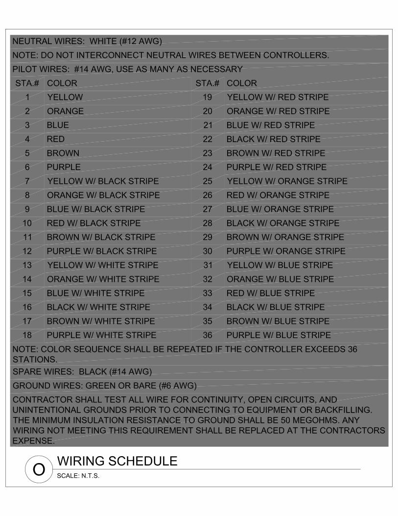
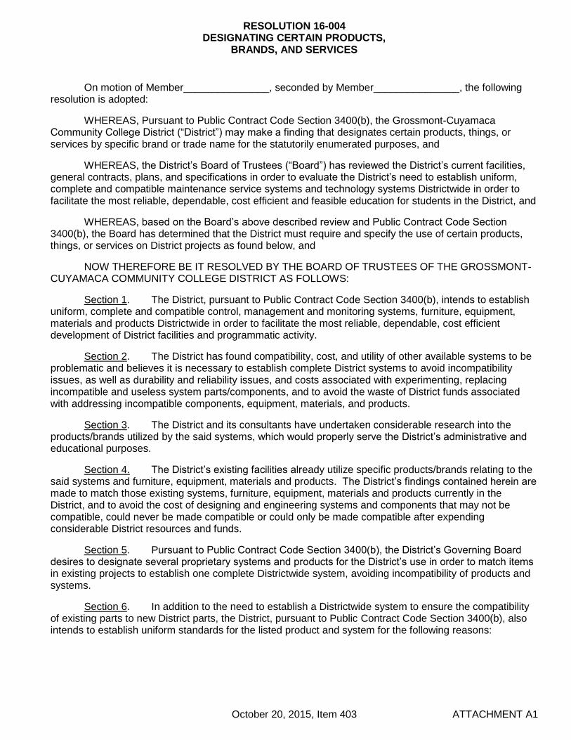
RESOLUTION 16-004 DESIGNATING CERTAIN PRODUCTS,
BRANDS, AND SERVICES
October 20, 2015, Item 403 ATTACHMENT A1
On motion of Member_______________, seconded by Member_______________, the following resolution is adopted:
WHEREAS, Pursuant to Public Contract Code Section 3400(b), the Grossmont-Cuyamaca Community College District (“District”) may make a finding that designates certain products, things, or services by specific brand or trade name for the statutorily enumerated purposes, and
WHEREAS, the District’s Board of Trustees (“Board”) has reviewed the District’s current facilities, general contracts, plans, and specifications in order to evaluate the District’s need to establish uniform, complete and compatible maintenance service systems and technology systems Districtwide in order to facilitate the most reliable, dependable, cost efficient and feasible education for students in the District, and
WHEREAS, based on the Board’s above described review and Public Contract Code Section 3400(b), the Board has determined that the District must require and specify the use of certain products, things, or services on District projects as found below, and
NOW THEREFORE BE IT RESOLVED BY THE BOARD OF TRUSTEES OF THE GROSSMONT-CUYAMACA COMMUNITY COLLEGE DISTRICT AS FOLLOWS:
Section 1. The District, pursuant to Public Contract Code Section 3400(b), intends to establish uniform, complete and compatible control, management and monitoring systems, furniture, equipment, materials and products Districtwide in order to facilitate the most reliable, dependable, cost efficient development of District facilities and programmatic activity.
Section 2. The District has found compatibility, cost, and utility of other available systems to be problematic and believes it is necessary to establish complete District systems to avoid incompatibility issues, as well as durability and reliability issues, and costs associated with experimenting, replacing incompatible and useless system parts/components, and to avoid the waste of District funds associated with addressing incompatible components, equipment, materials, and products.
Section 3. The District and its consultants have undertaken considerable research into the products/brands utilized by the said systems, which would properly serve the District’s administrative and educational purposes.
Section 4. The District’s existing facilities already utilize specific products/brands relating to the said systems and furniture, equipment, materials and products. The District’s findings contained herein are made to match those existing systems, furniture, equipment, materials and products currently in the District, and to avoid the cost of designing and engineering systems and components that may not be compatible, could never be made compatible or could only be made compatible after expending considerable District resources and funds.
Section 5. Pursuant to Public Contract Code Section 3400(b), the District’s Governing Board desires to designate several proprietary systems and products for the District’s use in order to match items in existing projects to establish one complete Districtwide system, avoiding incompatibility of products and systems.
Section 6. In addition to the need to establish a Districtwide system to ensure the compatibility of existing parts to new District parts, the District, pursuant to Public Contract Code Section 3400(b), also intends to establish uniform standards for the listed product and system for the following reasons:
RESOLUTION 16-004 DESIGNATING CERTAIN PRODUCTS,
BRANDS, AND SERVICES
October 20, 2015, Item 403 ATTACHMENT A2
A. Access and Security Systems: Keys, Doors & Door Hardware – MILLENIUM; BOSCH; SCHLAGE Hardware “C” Series (with Schlage core for Grossmont College and Yale core for Cuyamaca College) products are necessary for the District's maintenance system because:
1. The access and security systems implementation will allow for maximum integrity ofthe system by minimizing points of failure.
2. The access and key products assist in the safety and security of the District’sstudents and staff by stopping the duplication of keys by outside vendors.
3. These products and parts are readily available from a variety of sources enabling theDistrict to quickly and easily acquire necessary parts.
4. These products enable Maintenance to stock basic replacement parts for fasterrepairs.
5. These products limit the number of parts Maintenance must stock.
6. These products are more durable and have a longer useful life than comparableproducts/brands.
7. These companies are well established in the industry and have been in business formany years, so new and replacement products are expected to be readily availablein the future.
B. Energy Management System for Existing Buildings Only – ALERTON BACtalk for minor repairs/renovations at Cuyamaca College and AUTOMATED LOGIC CONTROL for minor repairs/renovations at Grossmont College are necessary for the District’s maintenance service system because:
1. These products limit the need for additional staff training in operation and repairs ofthe existing mechanical systems.
2. These companies’ products are compatible with the District’s current systems, aseach manufacturer requires an inventory of parts for that particular manufacturer.Products from other manufacturers are not interchangeable. Thus, any newmanufacturer(s) would add to the District’s cost of inventory.
3. Each manufacturer also requires a separate host computer system for programmingand setting of temperature control.
C. Lighting Management System and Lighting Fixtures – WattStopper System, Primex Master Clock System and additional manufacturers described below are necessary for the District’s maintenance system because:
1. The WattStopper lighting system is compatible and integratable to the existingsystem already in place, is efficient, and is contributing to security, cost savings andeasy maintenance.
2. The Primex clock system has been tested on site and proven to be accurate. It willsynchronize time for all campus clocks via satellite. Its cost is minimal. Dramaticsavings are realized due to the elimination of direct wiring for each new building.
3. These products ensure reliable availability of parts enabling the District to quicklyand easily acquire necessary parts.

RESOLUTION 16-004 DESIGNATING CERTAIN PRODUCTS,
BRANDS, AND SERVICES
October 20, 2015, Item 403 ATTACHMENT A3
4. They enable Maintenance to stock basic replacement parts for faster repairs.
5. They allow the District to limit the number of parts Maintenance must stock.
6. They allow the District to limit the number and types of bulbs that must be purchased and stocked by Custodial Services.
7. These manufacturers allow the District to limit the possibility of having the wrong bulb used in the wrong fixture, which decreases the number of fixture failures and replacements.
8. Accordingly, the District specifies the following lighting and clock products and components:
a. All retrofit exterior street parking lot and pedestrian walkway light poles to be “Kim” with “Cree” light fixtures to match existing.
b. All new exterior street, parking lot and pedestrian walkway lights to be “Kim”.
c. Time Clock – PRIMEX wireless; 12.5 in black face, part #14155, with Transmitter part #14000 with GPS receiver.
D. Irrigation Systems – Calsense Irrigation System products with ET2000e Controller are necessary for the District’s maintenance system because:
1. This system will provide maintenance staff with the ability to centrally control all aspects of irrigation.
2. Other irrigation systems and their parts/components will NOT interface with Calsense.
3. Each manufacturer of other irrigation system parts/components would require an additional, separate host computer system to operate.
4. Ongoing technical support of the system will be provided at no charge for the lifetime of the system.
E. Fire Alarm Systems – Simplex Grinnell products with ESP Controller are necessary for the Fire Alarm, Public Notification and District’s maintenance system because:
1. This system and its component parts have already been installed Districtwide and are monitored by Campus and Parking Services at the Grossmont campus.
2. The backbone network is in place and is a self-monitoring system.
3. This system is integrated into our Districtwide fire alarm monitoring system, is fully functional at both campuses, and it integrates both campuses, which is a unique feature, enhancing safety and control.
4. Introducing another product for new or renovated buildings will greatly reduce the build-in capabilities of the system.
5. Simplex Grinnell is prepared to commit products at a discount rate under future written agreements, as well as technical support.
6. Replacement of parts would be more cost effective for the maintenance staff.
RESOLUTION 16-004 DESIGNATING CERTAIN PRODUCTS,
BRANDS, AND SERVICES
October 20, 2015, Item 403 ATTACHMENT A4
7. Maintenance staff is fully trained on this system.
F. Low Voltage Management and Integration System – Bosch System 3T is necessary for the District’s maintenance system because:
1. The Bosch System shall be used for the integration of the Millenium access control and Bosch security systems. The Bosch system has the ability to integrate several other campus and District systems (lighting control, fire alarm, HVAC, video surveillance, etc.), but this feature shall remain optional for future implementation.
G. Chiller Equipment - Carrier products are necessary for Cuyamaca College’s maintenance system, and York products are necessary for Grossmont College’s maintenance system because:
1. Existing chillers in the Central Power Plant at Cuyamaca College are Carrier products and existing chillers in the Central Power Plant at Grossmont College are York products; as additional chiller capacity is identified, it is essential that the equipment operation be fully coordinated and integrated between all of the chillers.
2. There are existing contracts for maintenance with Carrier and York.
3. These products enable Maintenance to stock basic replacement parts for faster repairs.
4. Replacement of parts would be more cost effective for the maintenance staff.
5. The Carrier and York chillers and related equipment are already in place, are efficient, and are contributing to a reliable and energy efficient cooling system and easy maintenance.
6. Maintenance staff is fully trained on the Carrier and York products.
H. Parking Permit Equipment - LUKE Parking Permit Machines are necessary for the District’s support of students and enforcement of the District’s parking regulations because:
1. The LUKE multi-space pay station has multiple payment options from coins, bills, credit cards, smart cards, and cell phone payment, providing more convenient support for students.
2. LUKE also has a large, full-color screen that’s easy to read, multiple language support, network capability, real-time credit-card authorization, and remote rate configuration, providing more convenient support for students.
3. The LUKE multi-space pay station offers more payment options, better revenue opportunities, and lower cost of ownership for the District, providing maximization of District revenue.
4. The machines are easy to maintain, and by providing a standard of parking pass machines it will facilitate repairs as replacement parts would be universal districtwide.
5. Standardization of machines will provide a consistent user-friendly interface between both campuses.
RESOLUTION 16-004 DESIGNATING CERTAIN PRODUCTS,
BRANDS, AND SERVICES
October 20, 2015, Item 403 ATTACHMENT A5
I. Furniture – Krueger International and Steelcase lines of furniture are necessary for furniture needs for office locations only at the District and Colleges’ to support facilities, students, and curriculum because:
1. An extensive evaluation was performed that included the Director of Facilities, Faculty and Staff at both Colleges as well as the District to review various furniture offerings in an effort to standardize the District’s furniture purchases with both new and existing buildings Districtwide.
2. The manufacturers of these products are well established in the industry and have been in business for many years, so new and replacement products are expected to be readily available in the future.
3. Standardization of these products allows for high volume discount pricing from the manufacturers, resulting in cost savings to the District.
4. Standardization of these products will streamline the interior design and ordering process for new building purchases and remodeling projects.
5. These products enable Campus Facilities & Operations to stock basic replacement parts for faster repairs.
6. These products are already in place and have proven to be high quality and durable products.
J. Uninterruptible Power Supply – APC products are necessary for the District’s required needs to support facilities, students, and curriculum because:
1. These systems are fully integrated, operational, and functional at both campuses, in all three computer room locations (District, Grossmont, Cuyamaca).
2. The staff is fully trained on these systems, which greatly reduces the need for additional staff training in operations and repairs.
3. These systems are fully integrated with the Districtwide monitoring system and are centrally monitored by the Information Systems office.
4. Introducing other products would greatly reduce the integrated features and diminish overall staff effectiveness and efficiency.
5. Enables a single source of contact for maintenance and support – also enhancing staff efficiency and response time.
6. These systems are compatible with the District’s computer and networking systems.
7. APC is well established in the industry and used at many other local community college campuses.
RESOLUTION 16-004 DESIGNATING CERTAIN PRODUCTS,
BRANDS, AND SERVICES
October 20, 2015, Item 403 ATTACHMENT A6
Section 7: The designation of certain products/brands contained herein shall be effective until the District determines the certain products/brands contained herein need to be revised. At that time, a committee designated by District staff will review the products/brands and recommend to the Governing Board either re-adoption or discontinued use of the designated products/brands. The Governing Board shall then consider the committee’s recommendations and re-approve or discontinue the designation of the products/brands contained herein and/or approve additional/replacement products/brands as determined by the Governing Board.
PASSED AND ADOPTED by the Governing Board of the Grossmont-Cuyamaca Community College District of San Diego County, California, this 20th day of October, 2015, by the following vote:
AYES:
NAYS:
ABSENT:
STATE OF CALIFORNIA )
COUNTY OF SAN DIEGO )
I, Greg Barr, Clerk of the Governing Board, do hereby certify that the foregoing is a full, true and correct copy of a resolution duly passed and adopted by said Board at the regularly called and conducted meeting held on said date.
___________________________________________
Clerk of the Governing Board
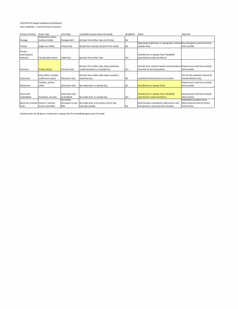
2015 GCCCD Design Guidelines & Standards
Door Hardware - Locks & Privacy Functions
Privacy Function Room Type Lock Type Latchbolt function (how retracted) Deadbolt? Notes Notes #2
Passage
Conference rooms,
multiuse toilets Passage latch By lever from either side at all times. No
Privacy Single use toilets Privacy lock By key from outside, by lever from inside. No
Operating inside lever or closing door unlocks
outside lever.
Has emergency unlock function
from outside.
Privacy
w/occupancy
indicator Faculty toilet rooms Toilet lock By lever from either side. Yes
Outside lever is always fixed. Deadbolt
operated by inside thumbturn.
Entrance Private offices Entrance lock
By lever from either side unless locked by
inside thumbturn or outside key. Yes
Outside lever remains locked until thumbturn
returned to vertical position.
Keyed access only from outside
when locked.
Classroom
Entry office, corridor
conference rooms Classroom lock
By lever from either side unless outside is
locked by key. No Locked/unlocked by key from outside.
Can be left unlocked. Cannot be
locked without a key.
Storeroom
Facilities, janitor,
utility Storeroom lock By inside lever or outside key. No Outside lever is always fixed.
Keyed access only from outside
when locked.
Storeroom
w/deadbolt Perimeter, security
Storeroom lock
w/deadbolt By inside lever or outside key. Yes
Outside lever is always fixed. Deadbolt
operated by inside thumbturn.
Keyed access only from outside
when locked.
Electronic mortise
locks
Interior / exterior
access controlled
Electrified
w/request to exit
(RX)
By inside lever or by access card or key
override outside. No
Electronically unlocked by valid access card.
Outside lever cannot be left unlocked.
Installation locations to be
determined by District Access
Control Plan.
General note: On all doors, inside lever is always free for immediate egress per Fire Code.


