Embed Size (px)
Citation preview
1360IEICE TRANS. COMMUN., VOL.E91–B, NO.5 MAY 2008
PAPER Special Section on Communication Quality
Design of the Cross-Layer QoS Framework for the IEEE 802.16PMP Networks∗
Yi-Ting MAI†a), Nonmember, Chun-Chuan YANG†, Member, and Yu-Hsuan LIN†, Nonmember
SUMMARY As one of the promising techniques in Broadband Wire-less Access (BWA), IEEE 802.16 also namely WiMax provides wide-area,high-speed, and non-line-of-sight wireless transmission to support multi-media services. Four service types are defined in the specification of IEEE802.16 for QoS support. In order to achieve end-to-end multimedia ser-vices, 802.16 QoS must be well integrated with IP QoS. In this paper, wepropose a framework of cross-layer QoS support in the IEEE 802.16 net-work. Two novel mechanisms are proposed in the framework for perfor-mance improvement: Fragment Control and Remapping. Fragment Controlhandles the data frames that belong to the same IP datagram in an atomicmanner to reduce useless transmission. Remapping is concerned with themapping rules from IP QoS to 802.16 QoS and is designed to reduce theimpact of traffic burstiness on buffer management. Simulation study hasshown that the proposed scheme has higher goodput and throughput, andlower delay than the contrast.key words: 802.16, WiMax, PMP, QoS, cross-layer
1. Introduction
Broadband Wireless Access (BWA) technology provides aneasy, time-saving, and low-cost method for deployment ofthe next generation (beyond 3G) network infrastructure.Since 1998, IEEE 802.16 working group has launched astandardization process called Wireless Metropolitan AreaNetwork (Wireless MANT M) for BWA. The most updatedspecification of 802.16 (IEEE Std 802.16-2004) [1] fo-cuses on fixed location wireless access and supports up to134 Mbps data rate. Moreover, the standardization of anew 802.16 interface, 802.16e [2], supports wireless accesswith high mobility, has also been completed recently. TheWiMax Forum (Worldwide Interoperability for MicrowaveAccess) [3], [4] a wireless industry consortium with about100 members including major vendors such as AT&T, Fu-jitsu, Intel, and Siemens Mobile, is supporting 802.16 tech-nology and promoting its commercial use, which means802.16 is becoming the most important technology in BWA.
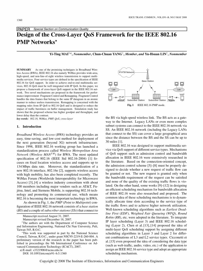
As shown in Fig. 1, the PMP (Point to Multipoint) con-figuration of IEEE 802.16 network consists of a base station(BS) and a couple of subscriber stations (SSs) that connect to
Manuscript received August 31, 2007.Manuscript revised December 18, 2007.†The authors are with the Department of Computer Science
and Information Engineering, National Chi Nan University, Puli,Taiwan 545, R.O.C.
∗This work was supported in part by the National ScienceCouncil, Taiwan, R.O.C., under grant NSC95-2219-E-260-004. Apreliminary version of the research in the paper has been pub-lished in proceedings the 9th International Conference on Ad-vanced Communication Technology (ICACT), 2007.
a) E-mail: [email protected]: 10.1093/ietcom/e91–b.5.1360
Fig. 1 IEEE 802.16 PMP mode.
the BS via high-speed wireless link. The BS acts as a gate-way to the Internet. Legacy LANs or even more complexsubnet systems can connect to the IEEE 802.16 network viaSS. An IEEE 802.16 network (including the Legacy LANsthat connect to the SS) can cover a large geographical areasince the distance between the BS and the SS can be up to30 miles [1].
IEEE 802.16 was designed to support multimedia ser-vice via QoS support of different service types. Mechanismsof QoS support such as admission control and bandwidthallocation in IEEE 802.16 were extensively researched inthe literature. Based on the connection-oriented concept,the admission control scheme [5]–[8] must be properly de-signed to decide whether a new request of traffic flow canbe granted or not. The new request is granted only whenthe bandwidth requirement of the request can be satisfiedand none of the quality of the existing traffic flows is vio-lated. On the other hand, some works [9]–[12] in designingan efficient scheduling mechanism for bandwidth allocationof IEEE 802.16 were also researched and proposed. Thecommon idea of these scheduling mechanisms is to dynam-ically allocate time slots according to the service type ofthe traffic flows and to achieve higher network utilization.Well-known scheduling algorithms such as Earliest Dead-line First (EDF), Weighted Fair Queueing (WFQ), RoundRobin (RR), etc. were adopted in the literature. To integrateIP layer scheduling (Layer 3) and IEEE 802.16 schedul-ing (Layer 2), Chen et al. [13], [14] proposed the idea ofmulti-layer QoS scheduling support by assigning differentscheduling algorithms in Layer 3 and Layer 2 for differ-ent combinations of L3 and L2 service types. Cicconetti etal. [15] even proposed the idea of considering the data type(such as web traffic, audio, video, etc.) of the application toassign an IEEE 802.16 service type and adopt an appropriatescheduling mechanism.
Copyright c© 2008 The Institute of Electronics, Information and Communication Engineers
MAI et al.: DESIGN OF THE CROSS-LAYER QOS FRAMEWORK FOR THE IEEE 802.16 PMP NETWORKS1361
QoS issue for different transmission systems such asEthernet, WLANs, and 3G cellular, has been addressed inthe literature. For Ethernet QoS, Perez et al. [16], [17] pro-posed the idea of multi-layer infrastructure that classifiesand prioritizes the voice and video traffic in order to improvethe performance of collaborative system applications. Wanget al. [18], [19] proposed a cross-layer adaptive scheme toimprove IEEE 802.11e QoS by concurrently adapting eachhost’s MAC-layer parameters based on their application-layer QoS requirements and physical-layer channel con-ditions. Some researches [20], [21] proposed the idea ofmulti-layer QoS scheduling support by assigning differentscheduling algorithms in the physical-layer for different up-per layer service types in 3G cellular networks. Anastacio etal. [22] presented a description of characterization and clas-sification parameters for beyond 3G mobile systems in thecontext of cross-layer design. Since the transmission char-acteristic differs for different transmission systems, QoS de-sign in Ethernet, WLANs, and 3G cannot fit well in IEEE802.16.
Existing research works as mentioned above presentedthe requirement of integrating different layers of QoS sup-porting in IEEE 802.16 or other structures. Their main fo-cus is on multi-layer QoS mapping, and none of them pro-posed a complete framework of integration. In this paper, across-layer QoS framework and associated mechanisms forIEEE 802.16 PMP networks are proposed. In addition tothe basic QoS mechanisms such as mapping from IP ser-vice types to IEEE 802.16 service types, the admission con-trol for QoS flows, and the scheduling scheme as in otherresearch works, two novel mechanisms namely FragmentControl and Remapping are proposed in the framework toimprove network throughput. Fragment Control handles thedata frames that belong to the same IP datagram in an atomicmanner to reduce useless transmission. Remapping is con-cerning about dynamically adjusting the mapping rules fromIP QoS to 802.16 QoS and is designed to reduce the impactof traffic burstiness on buffer management.
The remainder of the paper is organized as follows.First of all, we present the overall architecture as well as thenovel features of the proposed QoS framework in Sect. 2.Key mechanisms in the proposed framework for QoS sup-port in IEEE 802.16 network are presented in Sect. 3. Simu-lation study for performance evaluation and comparisons ispresented in Sect. 4. Finally, Sect. 5 concludes this paper.
2. Cross-Layer QoS Framework
Although the 802.16 standard only defined up to L2 specifi-cation for the BS and SS, the proposed framework requiresthe BS and SS to be equipped with some of the L3 function-alities, such as IP header processing and L3 service classinterpretation, for better service support. Since the trafficflows in the 802.16 network are classified as downlink oruplink, we present the framework in the downlink mode andthe uplink mode respectively in the following:
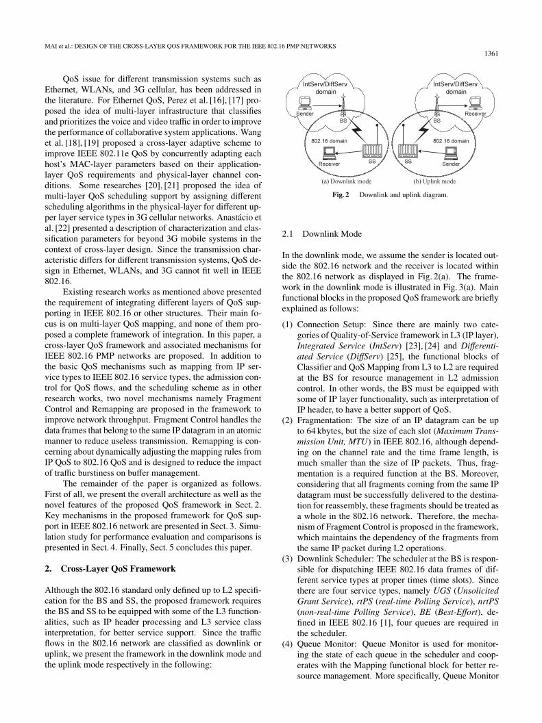
Fig. 2 Downlink and uplink diagram.
2.1 Downlink Mode
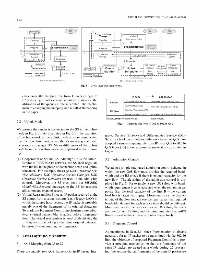
In the downlink mode, we assume the sender is located out-side the 802.16 network and the receiver is located withinthe 802.16 network as displayed in Fig. 2(a). The frame-work in the downlink mode is illustrated in Fig. 3(a). Mainfunctional blocks in the proposed QoS framework are brieflyexplained as follows:
(1) Connection Setup: Since there are mainly two cate-gories of Quality-of-Service framework in L3 (IP layer),Integrated Service (IntServ) [23], [24] and Differenti-ated Service (DiffServ) [25], the functional blocks ofClassifier and QoS Mapping from L3 to L2 are requiredat the BS for resource management in L2 admissioncontrol. In other words, the BS must be equipped withsome of IP layer functionality, such as interpretation ofIP header, to have a better support of QoS.
(2) Fragmentation: The size of an IP datagram can be upto 64 kbytes, but the size of each slot (Maximum Trans-mission Unit, MTU) in IEEE 802.16, although depend-ing on the channel rate and the time frame length, ismuch smaller than the size of IP packets. Thus, frag-mentation is a required function at the BS. Moreover,considering that all fragments coming from the same IPdatagram must be successfully delivered to the destina-tion for reassembly, these fragments should be treated asa whole in the 802.16 network. Therefore, the mecha-nism of Fragment Control is proposed in the framework,which maintains the dependency of the fragments fromthe same IP packet during L2 operations.
(3) Downlink Scheduler: The scheduler at the BS is respon-sible for dispatching IEEE 802.16 data frames of dif-ferent service types at proper times (time slots). Sincethere are four service types, namely UGS (UnsolicitedGrant Service), rtPS (real-time Polling Service), nrtPS(non-real-time Polling Service), BE (Best-Effort), de-fined in IEEE 802.16 [1], four queues are required inthe scheduler.
(4) Queue Monitor: Queue Monitor is used for monitor-ing the state of each queue in the scheduler and coop-erates with the Mapping functional block for better re-source management. More specifically, Queue Monitor
1362IEICE TRANS. COMMUN., VOL.E91–B, NO.5 MAY 2008
Fig. 3 Cross-layer QoS framework.
can change the mapping rule from L3 service type toL2 service type under certain situations to increase theutilization of the queues in the scheduler. The mecha-nism of changing the mapping rule is called Remappingin the paper.
2.2 Uplink Mode
We assume the sender is connected to the SS in the uplinkmode in Fig. 2(b). As illustrated in Fig. 3(b), the operationof the framework in the uplink mode is more complicatedthan the downlink mode, since the SS must negotiate withthe resource manager BS. Major differences of the uplinkmode from the downlink mode are explained in the follow-ing:
(1) Cooperation of SS and BS: Although BS is the admin-istrator in IEEE 802.16 network, the SS shall negotiatewith the BS in the phase of connection setup and uplinkscheduler. For example, message DSA (Dynamic Ser-vice Addition), DSC (Dynamic Service Change), DSD(Dynamic Service Deletion) are used in the admissioncontrol. Moreover, the SS must send out BW REQ(Bandwidth Request) messages to the BS for resourceallocation and channel access.
(2) Virtual Reassembler: Since an IP packet received at theSS comes from a subnet system (e.g. a legacy LAN) inwhich the source host locates, the IP packet is probablymerely one of the fragments of its original datagram.To mark the Fragment Control mechanism more effec-tive, a virtual reassembler is added before fragmenta-tion. The virtual reassembler is used of identifying theIP fragments that belong to the same original datagramby virtually reassembling the fragments.
3. Cross-Layer QoS Mechanisms
3.1 QoS Mapping from L3 to L2
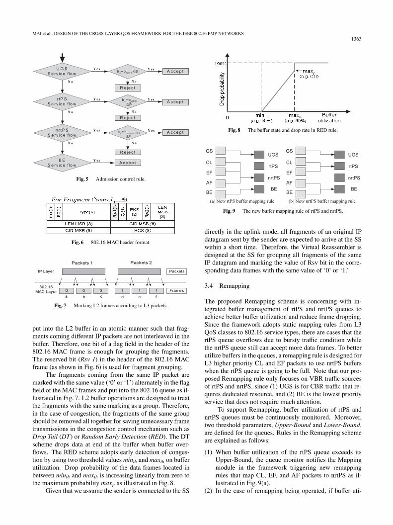
There are mainly two QoS frameworks in IP layer: Inte-
Fig. 4 Mapping rule from IP QoS to 802.16 QoS.
grated Service (IntServ) and Differentiated Service (Diff-Serv), each of them defines different classes of QoS. Weadopted a simple mapping rule from IP layer QoS to 802.16QoS types [13] in our proposed framework as illustrated inFig. 4.
3.2 Admission Control
We adopt a simple rate-based admission control scheme, inwhich the new QoS flow must provide the required band-width and the BS check if there is enough capacity for thenew flow. The algorithm of the admission control is dis-played in Fig. 5. For example, a new UGS flow with band-width requirement bUGS is accepted when the remaining ca-pacity (i.e. the total capacity of the link B — the currentload bC) is larger than bUGS. Moreover, since the charac-teristic of the flow in each service type varies, the requiredbandwidth defined for each service type should be different.More specifically, the peak rate for an UGS flow, the aver-age rate for an rtPS flow, and the minimum rate of an nrtPSflow are used in the admission control respectively.
3.3 Fragment Control
As mentioned in Sect. 2.1, since fragmentation is alwaysnecessary for an IP packet to be transmitted via the 802.16link, the objective of proposed Fragment Control is to pro-vide a grouping mechanism so that the fragments of thesame IP packet are treated as a whole during L2 process-ing. We assume that all fragments of the same IP packet are
MAI et al.: DESIGN OF THE CROSS-LAYER QOS FRAMEWORK FOR THE IEEE 802.16 PMP NETWORKS1363
Fig. 5 Admission control rule.
Fig. 6 802.16 MAC header format.
Fig. 7 Marking L2 frames according to L3 packets.
put into the L2 buffer in an atomic manner such that frag-ments coming different IP packets are not interleaved in thebuffer. Therefore, one bit of a flag field in the header of the802.16 MAC frame is enough for grouping the fragments.The reserved bit (Rsv 1) in the header of the 802.16 MACframe (as shown in Fig. 6) is used for fragment grouping.
The fragments coming from the same IP packet aremarked with the same value (‘0’ or ‘1’) alternately in the flagfield of the MAC frames and put into the 802.16 queue as il-lustrated in Fig. 7. L2 buffer operations are designed to treatthe fragments with the same marking as a group. Therefore,in the case of congestion, the fragments of the same groupshould be removed all together for saving unnecessary frametransmissions in the congestion control mechanism such asDrop Tail (DT) or Random Early Detection (RED). The DTscheme drops data at end of the buffer when buffer over-flows. The RED scheme adopts early detection of conges-tion by using two threshold values minth and maxth on bufferutilization. Drop probability of the data frames located inbetween minth and maxth is increasing linearly from zero tothe maximum probability maxp as illustrated in Fig. 8.
Given that we assume the sender is connected to the SS
Fig. 8 The buffer state and drop rate in RED rule.
Fig. 9 The new buffer mapping rule of rtPS and nrtPS.
directly in the uplink mode, all fragments of an original IPdatagram sent by the sender are expected to arrive at the SSwithin a short time. Therefore, the Virtual Reassembler isdesigned at the SS for grouping all fragments of the sameIP datagram and marking the value of Rsv bit in the corre-sponding data frames with the same value of ‘0’ or ‘1.’
3.4 Remapping
The proposed Remapping scheme is concerning with in-tegrated buffer management of rtPS and nrtPS queues toachieve better buffer utilization and reduce frame dropping.Since the framework adopts static mapping rules from L3QoS classes to 802.16 service types, there are cases that thertPS queue overflows due to bursty traffic condition whilethe nrtPS queue still can accept more data frames. To betterutilize buffers in the queues, a remapping rule is designed forL3 higher priority CL and EF packets to use nrtPS bufferswhen the rtPS queue is going to be full. Note that our pro-posed Remapping rule only focuses on VBR traffic sourcesof rtPS and nrtPS, since (1) UGS is for CBR traffic that re-quires dedicated resource, and (2) BE is the lowest priorityservice that does not require much attention.
To support Remapping, buffer utilization of rtPS andnrtPS queues must be continuously monitored. Moreover,two threshold parameters, Upper-Bound and Lower-Bound,are defined for the queues. Rules in the Remapping schemeare explained as follows:
(1) When buffer utilization of the rtPS queue exceeds itsUpper-Bound, the queue monitor notifies the Mappingmodule in the framework triggering new remappingrules that map CL, EF, and AF packets to nrtPS as il-lustrated in Fig. 9(a).
(2) In the case of remapping being operated, if buffer uti-
1364IEICE TRANS. COMMUN., VOL.E91–B, NO.5 MAY 2008
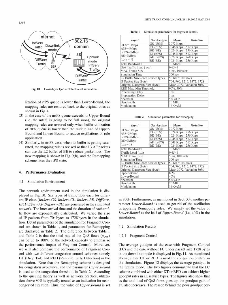
Fig. 10 Cross-layer QoS architecture of simulation.
lization of rtPS queue is lower than Lower-Bound, themapping rules are restored back to the original ones asshown in Fig. 4.
(3) In the case of the nrtPS queue exceeds its Upper-Bound(i.e. the nrtPS is going to be full soon), the originalmapping rules are restored only when buffer utilizationof rtPS queue is lower than the middle line of Upper-Bound and Lower-Bound to reduce oscillations of ruleapplication.
(4) Similarly, in nrtPS case, when its buffer is getting satu-rated, the mapping rule is revised so that L3 AF packetscan use the L2 buffer of BE to reduce packet loss. Thenew mapping is shown in Fig. 9(b), and the Remappingscheme likes the rtPS state.
4. Performance Evaluation
4.1 Simulation Environment
The network environment used in the simulation is dis-played in Fig. 10. Six types of traffic flow each for differ-ent IP class (IntServ-GS, IntServ-CL, IntServ-BE, DiffServ-EF, DiffServ-AF, DiffServ-BE) are generated in the simulatednetwork. The inter-arrival time and the duration of each traf-fic flow are exponentially distributed. We varied the sizeof IP packets from 704 bytes to 1728 bytes in the simula-tion. Detail parameters of the simulation for Fragment Con-trol are shown in Table 1, and parameters for Remappingare displayed in Table 2. The difference between Table 1and Table 2 is that the total rate of the QoS flows (ρQoS)can be up to 100% of the network capacity to emphasizethe performance impact of Fragment Control. Moreover,we will also compare the performance of Fragment Con-trol with two different congestion control schemes namelyDT (Drop Tail) and RED (Random Early Detection) in thesimulation. Note that the Remapping scheme is designedfor congestion avoidance, and the parameter Upper Boundis used as the congestion threshold in Table 2. Accordingto the queuing theory as well as network practice, utiliza-tion above 80% is typically treated as an indication for near-congested situation. Thus, the value of Upper Bound is set
Table 1 Simulation parameters for fragment control.
Table 2 Simulation parameters for remapping.
as 80%. Furthermore, as mentioned in Sect. 3.4, another pa-rameter Lower Bound is used to get rid of the oscillationin applying Remapping rules. We simply set the value ofLower Bound as the half of Upper Bound (i.e. 40%) in thesimulation.
4.2 Simulation Results
4.2.1 Fragment Control
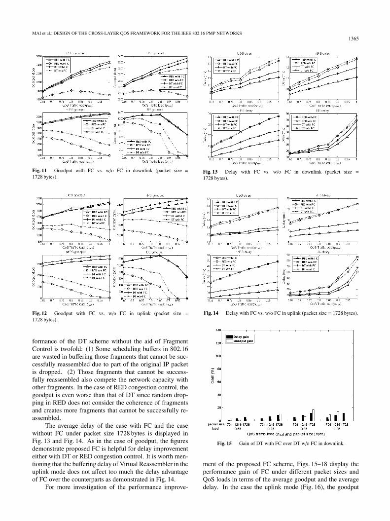
The average goodput of the case with Fragment Control(FC) and the case without FC under packet size 1728 bytesin the downlink mode is displayed in Fig. 11. As mentionedabove, either DT or RED is used for congestion control inthe simulation. Figure 12 displays the average goodput inthe uplink mode. The two figures demonstrate that the FCscheme combined with either DT or RED can achieve highergoodput rates in all service types. The figures also show thatas the total load of QoS flows goes up, the goodput gain ofFC also increases. The reason behind the poor goodput per-
MAI et al.: DESIGN OF THE CROSS-LAYER QOS FRAMEWORK FOR THE IEEE 802.16 PMP NETWORKS1365
Fig. 11 Goodput with FC vs. w/o FC in downlink (packet size =1728 bytes).
Fig. 12 Goodput with FC vs. w/o FC in uplink (packet size =1728 bytes).
formance of the DT scheme without the aid of FragmentControl is twofold: (1) Some scheduling buffers in 802.16are wasted in buffering those fragments that cannot be suc-cessfully reassembled due to part of the original IP packetis dropped. (2) Those fragments that cannot be success-fully reassembled also compete the network capacity withother fragments. In the case of RED congestion control, thegoodput is even worse than that of DT since random drop-ping in RED does not consider the coherence of fragmentsand creates more fragments that cannot be successfully re-assembled.
The average delay of the case with FC and the casewithout FC under packet size 1728 bytes is displayed inFig. 13 and Fig. 14. As in the case of goodput, the figuresdemonstrate proposed FC is helpful for delay improvementeither with DT or RED congestion control. It is worth men-tioning that the buffering delay of Virtual Reassembler in theuplink mode does not affect too much the delay advantageof FC over the counterparts as demonstrated in Fig. 14.
For more investigation of the performance improve-
Fig. 13 Delay with FC vs. w/o FC in downlink (packet size =1728 bytes).
Fig. 14 Delay with FC vs. w/o FC in uplink (packet size = 1728 bytes).
Fig. 15 Gain of DT with FC over DT w/o FC in downlink.
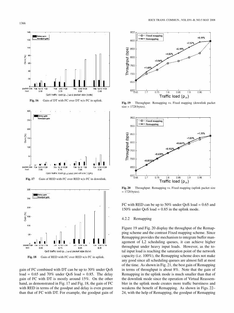
ment of the proposed FC scheme, Figs. 15–18 display theperformance gain of FC under different packet sizes andQoS loads in terms of the average goodput and the averagedelay. In the case the uplink mode (Fig. 16), the goodput
1366IEICE TRANS. COMMUN., VOL.E91–B, NO.5 MAY 2008
Fig. 16 Gain of DT with FC over DT w/o FC in uplink.
Fig. 17 Gain of RED with FC over RED w/o FC in downlink.
Fig. 18 Gain of RED with FC over RED w/o FC in uplink.
gain of FC combined with DT can be up to 30% under QoSload = 0.65 and 70% under QoS load = 0.85. The delaygain of FC with DT is mostly around 15%. On the otherhand, as demonstrated in Fig. 17 and Fig. 18, the gain of FCwith RED in terms of the goodput and delay is even greaterthan that of FC with DT. For example, the goodput gain of
Fig. 19 Throughput: Remapping vs. Fixed mapping (downlink packetsize = 1728 bytes).
Fig. 20 Throughput: Remapping vs. Fixed mapping (uplink packet size= 1728 bytes).
FC with RED can be up to 50% under QoS load = 0.65 and150% under QoS load = 0.85 in the uplink mode.
4.2.2 Remapping
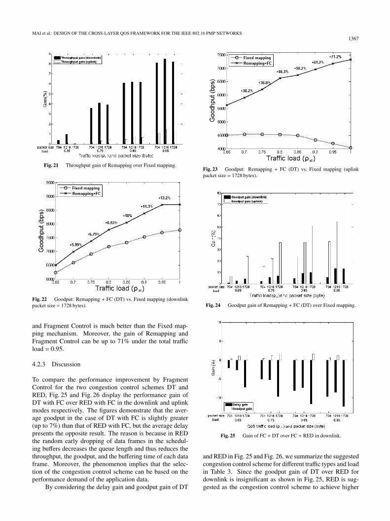
Figure 19 and Fig. 20 display the throughput of the Remap-ping scheme and the contrast Fixed mapping scheme. SinceRemapping provides the mechanism to integrate buffer man-agement of L2 scheduling queues, it can achieve higherthroughput under heavy input loads. However, as the to-tal input load is reaching the saturation point of the networkcapacity (i.e. 100%), the Remapping scheme does not makeany good since all scheduling queues are almost full at mostof the time. As shown in Fig. 21, the best gain of Remappingin terms of throughput is about 8%. Note that the gain ofRemapping in the uplink mode is much smaller than that ofthe downlink mode since the operation of Virtual Reassem-bler in the uplink mode creates more traffic burstiness andweakens the benefit of Remapping. As shown in Figs. 22–24, with the help of Remapping, the goodput of Remapping
MAI et al.: DESIGN OF THE CROSS-LAYER QOS FRAMEWORK FOR THE IEEE 802.16 PMP NETWORKS1367
Fig. 21 Throughput gain of Remapping over Fixed mapping.
Fig. 22 Goodput: Remapping + FC (DT) vs. Fixed mapping (downlinkpacket size = 1728 bytes).
and Fragment Control is much better than the Fixed map-ping mechanism. Moreover, the gain of Remapping andFragment Control can be up to 71% under the total trafficload = 0.95.
4.2.3 Discussion
To compare the performance improvement by FragmentControl for the two congestion control schemes DT andRED, Fig. 25 and Fig. 26 display the performance gain ofDT with FC over RED with FC in the downlink and uplinkmodes respectively. The figures demonstrate that the aver-age goodput in the case of DT with FC is slightly greater(up to 7%) than that of RED with FC, but the average delaypresents the opposite result. The reason is because in REDthe random early dropping of data frames in the schedul-ing buffers decreases the queue length and thus reduces thethroughput, the goodput, and the buffering time of each dataframe. Moreover, the phenomenon implies that the selec-tion of the congestion control scheme can be based on theperformance demand of the application data.
By considering the delay gain and goodput gain of DT
Fig. 23 Goodput: Remapping + FC (DT) vs. Fixed mapping (uplinkpacket size = 1728 bytes).
Fig. 24 Goodput gain of Remapping + FC (DT) over Fixed mapping.
Fig. 25 Gain of FC + DT over FC + RED in downlink.
and RED in Fig. 25 and Fig. 26, we summarize the suggestedcongestion control scheme for different traffic types and loadin Table 3. Since the goodput gain of DT over RED fordownlink is insignificant as shown in Fig. 25, RED is sug-gested as the congestion control scheme to achieve higher
1368IEICE TRANS. COMMUN., VOL.E91–B, NO.5 MAY 2008
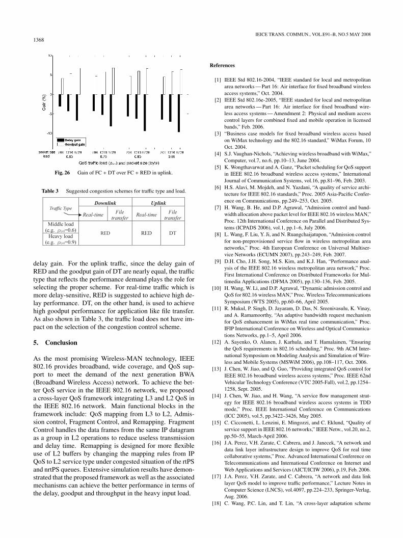
Fig. 26 Gain of FC + DT over FC + RED in uplink.
Table 3 Suggested congestion schemes for traffic type and load.
delay gain. For the uplink traffic, since the delay gain ofRED and the goodput gain of DT are nearly equal, the traffictype that reflects the performance demand plays the role forselecting the proper scheme. For real-time traffic which ismore delay-sensitive, RED is suggested to achieve high de-lay performance. DT, on the other hand, is used to achievehigh goodput performance for application like file transfer.As also shown in Table 3, the traffic load does not have im-pact on the selection of the congestion control scheme.
5. Conclusion
As the most promising Wireless-MAN technology, IEEE802.16 provides broadband, wide coverage, and QoS sup-port to meet the demand of the next generation BWA(Broadband Wireless Access) network. To achieve the bet-ter QoS service in the IEEE 802.16 network, we proposeda cross-layer QoS framework integrating L3 and L2 QoS inthe IEEE 802.16 network. Main functional blocks in theframework include: QoS mapping from L3 to L2, Admis-sion control, Fragment Control, and Remapping. FragmentControl handles the data frames from the same IP datagramas a group in L2 operations to reduce useless transmissionand delay time. Remapping is designed for more flexibleuse of L2 buffers by changing the mapping rules from IPQoS to L2 service type under congested situation of the rtPSand nrtPS queues. Extensive simulation results have demon-strated that the proposed framework as well as the associatedmechanisms can achieve the better performance in terms ofthe delay, goodput and throughput in the heavy input load.
References
[1] IEEE Std 802.16-2004, “IEEE standard for local and metropolitanarea networks — Part 16: Air interface for fixed broadband wirelessaccess systems,” Oct. 2004.
[2] IEEE Std 802.16e-2005, “IEEE standard for local and metropolitanarea networks — Part 16: Air interface for fixed broadband wire-less access systems — Amendment 2: Physical and medium accesscontrol layers for combined fixed and mobile operation in licensedbands,” Feb. 2006.
[3] “Business case models for fixed broadband wireless access basedon WiMax technology and the 802.16 standard,” WiMax Forum, 10Oct. 2004.
[4] S.J. Vaughan-Nichols, “Achieving wireless broadband with WiMax,”Computer, vol.7, no.6, pp.10–13, June 2004.
[5] K. Wongthavarwat and A. Ganz, “Packet scheduling for QoS supportin IEEE 802.16 broadband wireless access systems,” InternationalJournal of Communication Systems, vol.16, pp.81–96, Feb. 2003.
[6] H.S. Alavi, M. Mojdeh, and N. Yazdani, “A quality of service archi-tecture for IEEE 802.16 standards,” Proc. 2005 Asia-Pacific Confer-ence on Communications, pp.249–253, Oct. 2005.
[7] H. Wang, B. He, and D.P. Agrawal, “Admission control and band-width allocation above packet level for IEEE 802.16 wireless MAN,”Proc. 12th International Conference on Parallel and Distributed Sys-tems (ICPADS 2006), vol.1, pp.1–6, July 2006.
[8] L. Wang, F. Liu, Y. Ji, and N. Ruangchaijatupon, “Admission controlfor non-preprovisioned service flow in wireless metropolitan areanetworks,” Proc. 4th European Conference on Universal Multiser-vice Networks (ECUMN 2007), pp.243–249, Feb. 2007.
[9] D.H. Cho, J.H. Song, M.S. Kim, and K.J. Han, “Performance anal-ysis of the IEEE 802.16 wireless metropolitan area network,” Proc.First International Conference on Distributed Frameworks for Mul-timedia Applications (DFMA 2005), pp.130–136, Feb. 2005.
[10] H. Wang, W. Li, and D.P. Agrawal, “Dynamic admission control andQoS for 802.16 wireless MAN,” Proc. Wireless TelecommunicationsSymposium (WTS 2005), pp.60–66, April 2005.
[11] R. Mukul, P. Singh, D. Jayaram, D. Das, N. Sreenivasulu, K. Vinay,and A. Ramamoorthy, “An adaptive bandwidth request mechanismfor QoS enhancement in WiMax real time communication,” Proc.IFIP International Conference on Wireless and Optical Communica-tions Networks, pp.1–5, April 2006.
[12] A. Sayenko, O. Alanen, J. Karhula, and T. Hamalainen, “Ensuringthe QoS requirements in 802.16 scheduling,” Proc. 9th ACM Inter-national Symposium on Modeling Analysis and Simulation of Wire-less and Mobile Systems (MSWiM 2006), pp.108–117, Oct. 2006.
[13] J. Chen, W. Jiao, and Q. Guo, “Providing integrated QoS control forIEEE 802.16 broadband wireless access systems,” Proc. IEEE 62ndVehicular Technology Conference (VTC 2005-Fall), vol.2, pp.1254–1258, Sept. 2005.
[14] J. Chen, W. Jiao, and H. Wang, “A service flow management strat-egy for IEEE 802.16 broadband wireless access systems in TDDmode,” Proc. IEEE International Conference on Communications(ICC 2005), vol.5, pp.3422–3426, May 2005.
[15] C. Cicconetti, L. Lenzini, E. Mingozzi, and C. Eklund, “Quality ofservice support in IEEE 802.16 networks,” IEEE Netw., vol.20, no.2,pp.50–55, March-April 2006.
[16] J.A. Perez, V.H. Zarate, C. Cabrera, and J. Janecek, “A network anddata link layer infrastructure design to improve QoS for real timecollaborative systems,” Proc. Advanced International Conference onTelecommunications and International Conference on Internet andWeb Applications and Services (AICT/ICIW 2006), p.19, Feb. 2006.
[17] J.A. Perez, V.H. Zarate, and C. Cabrera, “A network and data linklayer QoS model to improve traffic performance,” Lecture Notes inComputer Science (LNCS), vol.4097, pp.224–233, Springer-Verlag,Aug. 2006.
[18] C. Wang, P.C. Lin, and T. Lin, “A cross-layer adaptation scheme
MAI et al.: DESIGN OF THE CROSS-LAYER QOS FRAMEWORK FOR THE IEEE 802.16 PMP NETWORKS1369
for improving IEEE 802.11e QoS by learning,” IEEE Trans. NeuralNetw., vol.17, no.6, pp.1661–1665, Nov. 2006.
[19] C. Wang, T. Lin, and J.L. Chen, “A cross-layer adaptive algorithmfor multimedia QoS fairness in WLAN environments using neu-ral networks,” IET Communications, vol.1, no.5, pp.858–865, Oct.2007.
[20] H. Jiang, W. Zhuang, and X. Shen, “Cross-layer design for resourceallocation in 3G wireless networks and beyond,” IEEE Commun.Mag., vol.43, no.12, pp.120–126, Dec. 2005.
[21] I. Gutierrez, F. Bader, J. Pijoan, and S.B. Slimane, “Adaptive re-source management for a MC-CDMA system with mixed QoSclasses using a cross layer strategy,” Proc. IEEE 65th VehicularTechnology Conference (VTC 2007-Spring), pp.3036–3040, April2007.
[22] N. Anastacio, F. Merca, O. Cabral, and F.J. Velez, “QoS metrics forcross-layer design and network planning for B3G systems,” Proc.IEEE International Symposium on Wireless Communications Sys-tems (ISWCS 2006), pp.592–596, Sept. 2006.
[23] R. Braden, D. Clark, and S. Shenker, “Integrated services in the In-ternet architecture: An overview,” IETF RFC 1633, June 1994.
[24] J. Wroclawski, “The use of RSVP with IETF integrated services,”IETF RFC 2210, Sept. 1997.
[25] S. Blake, D. Black, M. Carlson, E. Davies, Z. Wang, and W. Weiss,“An architecture for differentiated services,” IETF RFC 2475, Dec.1998.
Yi-Ting Mai received his B.S. degree inDepartment of Science Education from NationalHualien University of Education, Hualien, Tai-wan, in 1998 and M.S. degrees in Department ofInformation Management from Chaoyang Uni-versity of Technology, Taichung, Taiwan, in2004. He is currently a Ph.D. student in theDepartment of Computer Science and Informa-tion Engineering, National Chi Nan University(NCNU), Puli, Taiwan. His current researchtopics include wireless networks, QoS, and mul-
timedia network protocols.
Chun-Chuan Yang received his B.S. degreein computer and information science from Na-tional Chiao-Tung University, Taiwan, in 1990and Ph.D. degree in computer science from Na-tional Taiwan University in 1996. He joined theDepartment of Computer Science and Informa-tion Engineering, National Chi-Nan University(NCNU), Puli, Taiwan, as an Assistant Profes-sor in 1998. Since February 2008, he has beena Full Professor. His research area of interestsincludes multimedia network protocols, multi-
media synchronization control, and multimedia applications.
Yu-Hsuan Lin received his B.S. degree inDepartment of Information Management fromNation Taichung Instituted of Technology, Tai-wan, in 2004 and M.S. degree in computer sci-ence from National Chi Nan University, Puli,Taiwan, in 2006. His current research topic in-cludes 802.16 MAC QoS protocols.


