Embed Size (px)
Citation preview

Design of Timber Buildings for Deconstruction and Reuse —Three methods and five case studies Y l v a S a n d i n 1 , E l i z a b e t h S h o t t o n 2 , M a r l e n e C r a m e r 3 , K a r i n S a n d b e r g 1 ,
S t J o h n W a l s h 2 , J a n i n a Ö s t l i n g 4 , C a r m e n C r i s t e s c u 1 , V i o l e t a G o n z á l e z -A l e g r e 5 , G u i l l e r m o Í ñ i g u e z - G o n z á l e z 5 , D a n i e l F . L l a n a 5 , A n d e r s C a r l s s o n 6 , C a i t r í o n a U í C h ú l á i n 7 , N i c o l a J a c k s o n 8 , M a n u e l G a r c í a B a r b e r o 9 , A n d r e s Z a b a l a M e j i a 1
1 RISE Research Institutes of Sweden 2 University College Dublin 3 Edinburgh Napier University 4 IsoTimber Holding AB 5 Universidad Politécnica de Madrid 6 Derome 7 National University of Ireland Galway 8 Robertson Timber Engineering and Offsite Solutions Scotland 9 Klimark and Nova Domus Hábitat April 2022 RISE report 2022:52; ISBN 978-91-89561-92-2
METHOD TO ADAPT AN EXISTING DESIGN
INDICATOR SYSTEM BASED ON ISO 20887
A DFDR DESIGN DECISION MATRIX
NEW DESIGNS REFLECTIONS ON CONNECTIONS
GUIDELINES FOR DECONSTRUCTION AND REUSE

2 / 116

3 / 116
Table of contents
1. Introduction 8
1.1. Background 8
1.2. Aim 12
1.3. Terms and definitions 13
1.4. Overview 15
2. Research methodology 16
2.1. Research in three directions 16
2.2. Developing a method to adapt an existing design – researcher focus 17
2.3. Developing an indicator system based on ISO 20887 – industry focus 18
2.4. Developing a DfDR design decision matrix - designer focus 19
2.5. General methods 21
2.6. Overview 21
3. Results and discussions 23
3.1. Methods to optimize the design of a timber structure for deconstruction and reuse 23
3.2. Case studies – presentation of objects 38
3.3. New design strategies based on advantages and disadvantages of current designs 42
3.4. Report on connections 63
3.5. Guidelines for deconstruction and reuse 79
4. Conclusions 100
4.1. What methods can be adopted to optimize a primary design to deconstruction and reuse? 100
4.2. What new designs can be suggested? 101
4.3. What can be said on timber connections in relation to deconstruction and reuse? 103
4.4. How can guidelines for deconstruction and reuse be formulated? 104
4.5. Limitations to conclusions 107
4.6. Strengths of this study 107
5. Future work 108
6. References 112
Appendix A Design for deconstruction and reuse: Case study Villa Anneberg Appendix B Design for deconstruction and reuse: Case study Everett Grand Appendix C Design for deconstruction and reuse: Case study Villa Forshälla Sund Appendix D Design for deconstruction and reuse: An Irish suburban semi-detached dwelling Appendix E Design for Deconstruction and Reuse: Case Study Cuenca Village

4 / 116
Foreword
This report is a publication within the InFutUReWood project - Innovative Design for the Future – Use and Reuse of Wood (Building) Components. The project has seven work packages:
• WP 1 Coordination and management, led by Karin Sandberg, RISE, Sweden • WP 2 Design of timber structures for the future, led by Ylva Sandin, RISE, Sweden • WP 3 Product design using recovered timber, led by Annette Harte NUI Galway, Ireland • WP 4 Inventory, deconstruction and quality of recovered wood, led by Mark Hughes, Aalto
University, Finland • WP 5 Properties of the recovered wood, led by Daniel Ridley-Ellis, Napier University, UK • WP 6 Environmental and economic assessment of design for recycling in building
construction, led by Michael Risse, TUM, Germany • WP 7 Dissemination and engagement, led by Carmen Cristescu, RISE, Sweden
The work reported on here was conducted within Work Package 2 and was a collaboration between participants from Sweden, UK, Ireland, and Spain. Academic parts involved were RISE, UCD, Napier and UPM. NUI Galway contributed to case studies. Industry parts that took active part in work reported on here are Derome, IsoTimber, Robertson, Klimark, OSS and TMF.
The work includes case studies carried out by five different teams in the four countries. The studies were executed in succession. A method and report structure was developed for the first case (Villa Anneberg). The study, previously published as a standalone report (Sandin et. al. 2021) is included here as Appendix A. The following four studies were based on the same method and report structure, but adjustments were made where needed to fit the specific aims of each study. The fifth study deviates partly from the others as it concerns a new structural system while the others develop improvements within an existing design. The case studies are reported on in Appendix A, B, C, D and E. Appendix D has also been published as a standalone report (Walsh & Shotton 2021). Each team is responsible for their report/Appendix. Apart from case studies, an indicator system was developed by RISE with input from all others, and a design decision matrix was developed by UCD.
Authors and contributions Ylva Sandin Elizabeth Shotton Marlene Cramer Karin Sandberg St John Walsh Violeta González-Alegre Janina Östling Carmen Cristescu Guillermo Íñiguez-González Daniel F. Llana Anders Carlsson Caitríona Uí Chúláin Nicola Jackson Manuel García Barbero Andres Zabala Mejia
Ylva Sandin led WP 2, where this work was conducted. She led the first case study, the one on Villa Anneberg (appendix A) and developed the method used, later interpreted and used in the

5 / 116
subsequent case studies to an extent found appropriate by the case study leaders. Sandin elaborated a template for case study reports and coordinated the case studies. She contributed to the case studies on Everett Grand (Appendix B) and Villa Forshälla Sund (Appendix C). Sandin also led the development of an indicator system to assess deconstructability and reusability of buildings, reported on in section 2.3. She supervised master student Andres Zabala in his work on the system. Sandin created the outline/structure of this report and coordinated work assigned to others, as presented below. She was responsible for sections: 1.2 on aim, chapter 2 except 2.4 on the topic of methodology, 3.1 except 3.1.3 on methods developed, 3.2 presentation of cases, 4.1 on methods, 4.5-4.6 and 5. She revised and expanded this report in different stages and was responsible for preparing interim and final versions of the document including editing.
Elizabeth Shotton supervised the Master Thesis work of St John Walsh, including the development of a design support tool - the design decision matrix reported on in section 2.4. The Master Thesis work also included a study on Irish timber building designs. Shotton participated in the case study on an Irish suburban semi-detached dwelling, the Cygnum Reflect 140 house (Appendix D). She developed and executed the course Irish Timber and Sustainability at UCD School of Architecture, Planning and Environmental Policy, from which results were used to inspire the other authors and contributors and which are reported on in section 3.5. Shotton was responsible for sections: 2.4 on methodology for the design decision matrix and 3.5 and 4.4 on guidelines for deconstruction and reuse. She revised section 3.3 in the end stage with special focus on terminology. Shotton reviewed the report in interim and final versions.
Marlene Cramer led the case study on Everett Grand (Appendix B) and participated in the case study on Villa Forshälla Sund (Appendix C). She was responsible for the terminology section (section 1.3) which is based on a terminology list she developed for the InFUtUReWood project in collaboration with Carmen Cristescu. Cramer was also responsible for the sections 3.3 and 4.2 that discusses new designs. She revised and expanded the background section (section 1.1) and the section on connections (3.4). Cramer reviewed the report in interim and final versions.
Karin Sandberg initiated and led the InFutUReWood project. She participated in the case studies on Villa Anneberg, Everett Grand and Villa Forshälla Sund. Sandberg reviewed this report in interim stage.
St John Walsh led the case study on the Cygnum Reflect 140 house, an Irish suburban semi-detached dwelling (Appendix D). He carried out a Master Thesis work where he developed the design decision matrix described in sections 2.4 and 3.1.3, based in parts on a study on Irish timber buildings. Walsh was responsible for section 3.1.3. He reviewed this report in interim stage.
Violeta González-Alegre led the case study on Cuenca Village (Appendix E). She was responsible for section 3.4 on connections and reviewed this report in interim stage.
Janina Östling led the case study on Villa Forshälla Sund (Appendix C). She secured that data and personal resources were available at IsoTimber to facilitate the execution of the study. Östling reviewed the report in interim stage (section 3.3 also in final stage).
Carmen Cristescu was responsible for section 1.1 Background. She participated in the case study on Villa Forshälla Sund and led WP 7 Dissemination and engagement. She reviewed the report in interim stage.

6 / 116
Guillermo Íñiguez-González participated in the case study on Cuenca Village (Appendix E). He supervised Violeta González-Alegre and Daniel F. Llana and reviewed this report in interim stage.
Daniel F. Llana participated in the case study on Cuenca Village (Appendix E) and reviewed this report in interim stage.
Anders Carlsson participated in the case study on the Villa Anneberg (Appendix A), contributed all data on the design of the building and secured personal resources at Derome and a visit to the factory to facilitate the study.
Caitríona Uí Chúláin contributed to the development on new design solutions in the Villa Anneberg case study (Appendix A). She made the design detail drawings presented in section 3.4.3 based on current details provided by Derome.
Nicola Jackson participated in the case study on the Everett Grand, contributed data on design of the building, developed a Deconstruction Plan and shared it to be used as template for others. She reviewed this report at interim stage.
Manuel García Barbero initiated the Cuenca Village case study (Appendix E), was responsible for the design and development of the Cuenca Village project within Klimark and Nova Domus Hábitat and contributed all data on the project.
Andres Zabala Mejia developed, within his Master Thesis work at Linköping University, the indicator system that can be used to calculate a Rebuilding Index and that is accounted for in section 2.3, based on an early draft provided by RISE.
Project InFutUReWood is supported under the umbrella of ERA-NET Cofund ForestValue by Vinnova – Sweden´s Innovation Agency, Formas, Swedish Energy Agencythe Forestry Commissioners for the UK, the Department of Agriculture, Food and the Marine for Ireland, the Ministry of the Environment for Finland, the Federal Ministry of Food and Agriculture through the Agency for Renewable Resources for Germany, the Ministry of Science, Innovation and Universities for Spain, the Ministry of Education, Science and Sport for Slovenia. ForestValue has received funding from the European Union's Horizon 2020 research and innovation programme under grant agreement N° 773324.
The research and academia partners of InFutUReWood are RISE (Sweden), Edinburgh Napier University (UK), National University of Ireland Galway (Ireland), University College Dublin (Ireland), Universidad Politécnica de Madrid (Spain), University of Ljubljana (Slovenia), Aalto University Helsinki (Finland), and Technical University Munich (Germany). The industry partners are Kiruna Municipality Technical Service, Swedish Wood, Derome, Isotimber, Offsite Solutions Scotland, Robertson Timber Engineering, Hegarty Demolition, SIP Energy, Connaught Timber, The Federation of the Finnish Woodworking Industries, Jelovica, The Swedish Federation of Wood and Furniture Industry, Balcas Timber, Stora Enso, Klimark + Nova Domus Hábitat, and Brenner Planungsgesellschaft.

7 / 116
SUMMARY
There is a need for a shift towards circular economy in the construction sector and design philosophies as Design for Deconstruction and Reuse (DfDR) and Design for Adaptability (DfA) are being developed as means to design out waste and enhance resource efficiency. However, applying these philosophies is not yet common practice. The amount of DfDR/A timber buildings described in literature is limited.
This study aims at increasing and spreading knowledge on DfDR/A for timber buildings. It has four goals: 1) To suggest methods to apply DfDR/A. 2) To suggest new design solutions. 3) To collect experiences on connections in relation to DfDR. 4) To suggest how guidelines for deconstruction and reuse can be formulated.
The study presents three methods that all proved valuable in applying DfDR/A: one discussion-based method to improve an already existing timber building design, one indicator system to assess the DfDR/A potential of building designs, and one matrix to guide design decisions.
We used the first method to conduct five case studies in four European countries. The studied designs were judged to be well or relatively well adapted for deconstruction and reuse already today. The fact that the studied buildings are all offsite manufactured and of modular composition benefits the deconstruction process, partly because construction and deconstruction are similar processes so that the knowledge and infrastructure that companies have can be directly transferred to enable deconstruction and reuse. Where large modules can be recovered, the time and energy needed for deconstruction as well as the risk for damage will be reduced. Disadvantages to deconstruction and reuse identified were typically linked to the complexity of building modules and that individual components are not independent. This was reflected as irreversible or hidden connections, inaccessible services, interconnected layers of the structural modules and many different component sizes. One of the case study buildings, designed with mass timber panels, excelled in the simplicity and reduction of number of steps required for maximum material recovery.
New designs suggested included making fasteners more accessible to deconstruction, avoiding letting sensitive materials as plastic foils and particle boards pass continuously over joints between elements, and (for cases where standard units are not already used) standardizing elements. One case suggested using solid wood components instead of engineered wood products to achieve durability. The study showed that simple changes in design can lead to an augmented reuse potential. Some of the new design solutions generated will be taken into production by the participating manufacturers.
Insights on connections included recognizing the fact that the use of reversible screwed connections is not sufficient to ensure deconstructability and that although nailed or glued connections severely complicate reuse of components, they might be accepted within elements in case reuse on element level is the target.
Guidelines for deconstruction and reuse were developed in all case studies. Taken as a group of studies, there are advantageous additions proposed to earlier guidance documents. Despite being based on the same source, the different plans suggested varied substantially. There was a noteworthy difference between manufacturers’ in-house plans to those proposed by architects, engineers, or researchers, which speaks to the uncertainty regarding the appropriate structure and format.

8 / 116
1. Introduction
1.1. Background
1.1.1. Timber in the construction sector – from sustainability to circularity
Circular Economy is a priority of the European Union’s economic policy, and this was reiterated in the latest Action Plan for the Circular Economy (EC 2021) that includes proposals for actions to be carried out in the EU in the coming years. The sustainable product policy framework emphasises the need to turn the linear “take-make-dispose” economy to a truly circular economy, based on the following principles: reduction in energy and resource use; the retention of value in the economy; waste prevention; the designing out of waste and of harmful substances and pollution; keeping products and materials in use and in closed loops; protection of human health; promotion of consumer benefits; and regenerating natural systems; and the full integration of sustainable circular system thinking in all activities including policies, products, production processes and business models.
The construction sector has a major environmental impact, with 25% to 30% of the EU’s waste and 35% of global energy consumption resulting from the building and construction sector (United Nations Environment Programme 2020).There are several ways to decrease this impact, such as circular flow, which requires a change in the way we design and construct buildings. Already in 2011, the Roadmap to a Resource Efficient Europe (EC 2011) proposed a strategy to promote the sustainable use of wood in construction, since wood can be a sustainable building material that stores carbon. More recent strategies, such as the European Green Deal (EC 2019) and the UK’s Committee on Climate Change (2018) Biomass in a Low-Carbon Economy, also emphasise the increased use of timber as a construction material. One of the outcomes of these strategies is an increase in the net carbon storage potential of buildings, which Hildebrandt et al. (2017) estimated could amount to about 46 million tonnes CO2-eqvivalents per year by 2030. The circularity aspect of building with timber, however, has rarely been the focus of research. A recent review by Norouzi et al. (2021) shows that in the past five years, researchers paid close attention mostly to “sustainability”, “energy efficiency”, “life cycle assessment”, “renewable energy”, and “recycling”.
In the first report produced by WP2, Design for deconstruction and reuse of timber structures–state of the art review, we argued that timber used as structural building material deserves a similar place and a similar type of planning throughout the lifecycle as all fossil, non-renewable and abiotic building materials (Cristescu et al. 2020). We also showed recent case studies that calculated that the need of wood would soon outgrow the available timber quantities in Europe, making the reuse of timber a critical factor in meeting future demand.
Chen et al. (2022) identified the challenges and stakeholders linked to building circularity that are most often discussed in literature and summarised their findings in a Circular construction implementation framework. The authors show that different circularity strategies have to be implemented in different life-cycle phases of a building and different stakeholders are involved in each phase.

9 / 116
Chen et al. (2022) showed the multitude of challenges associated with circular buildings. WP 2 of the InFutUReWood project focuses mostly on the design phase, while other work packages address the manufacturing (WP 3 and WP5) and end of life phase (WP 4) of timber products.
1.1.2. Design philosophies for circular construction
Up to 80% of a product’s environmental impact is decided by its design (CEAP 2021), and for building construction, the planning and design phases are crucial because these phases determine the usability, adaptability, and reusability. Design is thus a key-issue of circular economy in the construction sector in general, and particularly in timber construction. Timber structures, if properly designed, could allow for much more flexibility in use and enable more successful disassembly for the recapture of materials for a second use in comparison to some other types of building structures which use ‘wet’ construction materials such as concrete (Bertino et al. 2021).
Within the design phase, a variety of strategies, that target different aspects of circularity, can be adopted. Pongiglione & Calderini (2016) reviewed sustainable structural design according to strategies such as durability, adaptability, and reusability, including the role that sustainable structural design plays in Green Building rating systems and building codes, concluding that the achievement of these goals cannot be reduced to a single factor, but rather needs to be understood as a network of interacting factors. Already in 2010, the Estidama’s Pearl Villa rating system was rewarding the following, indicating the complexity of factors involved: Design for Materials Reduction; Design for flexibility and adaptability; Design for disassembly; Modular flooring systems; Design for durability; Building reuse; Material reuse; Regional materials; Recycled materials; Rapidly renewable materials; Reused or certified timber (Estidama 2010). More recently, ISO 20887 -Sustainability in buildings and civil engineering works. Design for disassembly and adaptability. Principles, requirements and guidance summarised design principles that facilitate adaptability and disassembly. Design for disassembly that targets reuse with minimal intervention, or, as we coin it throughout this report, Design for Deconstruction and Reuse (DfDR), is an important circularity strategy that requires minimal material- and energy inputs after materials are recovered (Bertin et al. 2020).
Pomponi and Moncaster (2017) described that the existing literature on circular economy has been mostly focusing on products with a shorter life span than buildings, and that buildings present further challenges, due to their longevity and complexity. From the perspective of Brand’s six layers of shear (Brand 1995), the InFutUReWood project focuses on the structure, which according to Brand has the longest life span, apart from the site, and is the hardest to change. According to Bertin et al. (2020), the building structure uses large amounts of material and energy amongst building components. But the life span of the structure is often much shorter than it could be, and Pomponi and Moncaster raised the question why many buildings reach their end of life after only 30 to 40 years. A survey among demolition contractors, conducted in WP3 of the InFutUReWood project in 5 partner countries, revealed that the building condition is often not the reason for demolition, but rather the need to change the use of the site (Harte et al. Unpublished). If the structure could be moved and reused on a different site instead, large material savings and environmental benefits are expected. WP 2 therefore focuses on DfDR of the timber structure of buildings.

10 / 116
1.1.3. Methods and practical examples can help remove thresholds to DfDR
The dismantling of timber structures and their reuse or reassembly are understood to be phases to be introduced in the construction value chain, but questions such as how to increase the recapture rate of undamaged timber during a disassembly and how to retain the timber’s value for direct reuse rather than recycling require further research. Akinade et al. (2020) identified 26 barriers that currently make design for deconstruction in buildings more difficult and summarised them in 5 categories:
• Lack of effective design for deconstruction tools • Lack of adequate information in building design • Lack of stringent legislation for design for deconstruction • Lack of large enough market for recovered components • Difficulty in developing a business case for DfD
The most important of these barriers that are within the scope of WP2 of the InFutUReWood project, as identified so far, are “Lack of effective design for deconstruction tools” and “Lack of adequate information in building design”. Within the first category, the authors described that architects and designers lack efficient DfD tools that simulate the deconstruction process and help with the identification of reusable materials. Chen et al. (2022) found that, in current literature, many challenges of circular building design are addressed using BIM, for example storing information in material passports, conducting LCA, or quantifying waste materials at the end of life. They do point out that the building design and material choice have a large impact on both waste generation and environmental impact, two indicators that can be used to evaluate designs, but their literature overview does not mention any tools that help with developing DfDR design solutions. Finch (2019) described that existing DfDR tools show various shortcomings, and no widely used tool has been established yet. Many design factors that facilitate deconstruction can only be judged subjectively, and the measurement-side of circularity remains a challenge.
There is a need for guidance on how designers can address various challenges in new building designs, as well as a model for how to adapt design to deconstruction and reuse. There is also a need to show how ISO 20887 (2020) can be interpreted and used when developing and accessing designs for timber buildings with respect to DfDR.
Akinade et al. (2020), under “Lack of adequate information in building design”, further described problems like the difficulty to identify materials that can be reused, and the lack of information on how buildings can be disassembled. The authors emphasised that this information needs to be made available from the building’s design phase and should be documented in building manuals and BIM. Chen et al. (2022) also highlighted a lack of understanding which building parts show potential for being deconstructed.
The deconstruction- and reuse potential of building components and materials is also characterised in various studies, but often the literature on this topic is quite broad. Iacovidou and Purnell (2016) summarised existing literature, which shows that various studies target whole buildings and various different materials (as shown in Table 1.1). Solid timber is often mentioned as having a high reuse potential, but a differentiation between different building components and use situations is not made. Different studies also often have different goals and means of assessing deconstructability and reuse potential.

11 / 116
Table 1.1 Overview of literature on the deconstruction and reuse potential of different building components (selected studies that included timber materials). Literature as identified by Iacovidou and Purnell (2016)
Study Materials/ Components Method/ goal
Thormark (2000) Timber structure Concrete Clay bricks and roof tiles
Case study Practical re-construction Environmental impact assessment (LCA)
Sassi (2004) 60 building methods and products Literature research Rating, according to different deconstructability and reusability criteria
WRAP (2008) 33 common reclaimed materials (UK)
Reclaimed materials supplier data Rating of cost and availability; Guidance on reuse
Gorgolewski and Ergun (2013)
All components of a detached house with timber structure (Canada)
Case study Quantification of materials
Nakajima (2015) All components of 3 detached houses with timber or steel structure (Japan)
Case study Practical deconstruction Identification of barriers
Webster, Gumpertz, and Costello (2015)
Structural materials: Timber Steel Masonry Concrete
Conclusions from practical experience Design principles for structures
When targeting the reuse of timber structures specifically, it would be helpful to identify which building materials and components can be reused and which factors have an influence on the reuse potential. In addition, deconstruction information needs to be available from the design phase over the building’s life. It should be explored how this information can be stored and updated. We believe that this can be achieved with case studies that study the design of various timber building systems to identify barriers to reuse, similar to the one by Chisholm (2012). ISO 20887 (2020) also suggested the use of case studies for knowledge sharing. Case studies should be carried out for different timber building systems and within different regional contexts.
Studies that have a narrow scope regarding the design strategy (e.g. DfDR), the material (e.g. timber) and the building layer (e.g. structure) offer the chance to broaden the scope in terms of methods and goals. A comprehensive study could span all common DfDR themes that literature is currently concerned with, as identified by Kanters (2018): (1) General design and construction principles, (2) specific materials’ potential for DfD, (3) DfD throughout the design process, (4) tools for DfD, (5) existing building stock potential, and (6) barriers and drivers for DfD (represented in Figure 1.1).

12 / 116
Figure 1.1 Categories mentioned in literature as being important in design for deconstruction, according to Kanters (2018)
1.2. Aim
1.2.1. Overall purpose
The overall purpose of this work is to augment sustainability in building and construction by increasing and spreading knowledge on design for deconstruction and reuse.
1.2.2. Research questions
The overall question that we seek to answer is: “How can timber buildings be designed to facilitate deconstruction and reuse?”
More specifically, we try to answer:
• What method/-s can be adopted to optimize a primary design for deconstruction and reuse? (Q1)
• What new designs can be suggested? (Q2)
• What can be said on timber connections in relation to deconstruction and reuse? (Q3)
• How can guidelines for deconstruction and reuse be formulated? (Q4) The study includes aspects of designing timber buildings to facilitate adaptability, though the main focus is on deconstruction and reuse.
1.2.3. Cooperation across borders
The work has been carried out by teams in Sweden, Ireland, UK and Spain. Apart from answering our research questions, an important aim has been to create activities that give us both common experiences across national borders and depth in knowledge within each team. Activities are created that strive to build the network and collaboration and facilitate the sharing of experiences and knowledge.

13 / 116
1.2.4. Limitations and assumptions
We focus on residential timber buildings in general, and the load-bearing structure of these buildings in particular. Further study of other building types would be useful but are beyond the scope of this project. Studies of wood members for non-structural purposes (flooring, doors, windows, etc.) and how they can be recovered for reuse are also excluded from the scope of this study.
The study concerns technological issues, not economic issues. In some case studies, estimates of time and financial implications were undertaken by manufacturers involved but are not reported on in detail in the report.
This study does not include environmental assessments like LCA, though an LCA study is underway for the Villa Anneberg study, which will form part of a future report from Work Package 6 of the InFutUReWood project. This works assumption that reuse of building members is resource efficient and has a positive environmental impact which will be at least partially addressed in the WP6 report.
Case studies carried out within this work principally focus on the impact of Design for Deconstruction and Reuse (DfDR) strategies. Designing for Adaptability (DfA), an important vehicle to reducing the environmental impact of construction, is considered in some of the case studies.
The study suggests improved designs for connections. Some of these require physical testing to assure the viability of the connection as well as the deconstruction method proposed. Although this was planned for some case studies the restriction to lab spaces during the pandemic resulted in the exclusion of these tests.
1.2.5. Stakeholders
Case studies and development of tools to assist designers and manufacturers were undertaken in consultation with a variety of stakeholders including our industrial partners (manufacturers, architects, demolition contractors, sawmills) as well as input from design professionals (architects and engineers) and graduate architecture students. The results of this work are expected to be of interest to manufacturers, clients, property managers, architects, engineers, students, and researchers.
1.3. Terms and definitions
1.3.1. General terms
• Adaptability. Ability to be changed or modified to make suitable for a particular purpose, with minimal material flows within the built environment. The concept of adaptability can be broken down into a few simple strategies, such as flexibility, convertibility, and expandability. (Russel and Moffatt 2001, ISO 6707-1: 2017, ISO 20887:2020).
• Deconstruction. The systematic dismantling and removal of a structure or its parts, in the reverse order of construction, with the intent of repurposing, reusing, recycling, or salvaging as many of the materials, products, components, assemblies, or modules as possible. (Sparandara et al. 2019, Fannie Mae 2020).
• DfA. Design for Adaptability. Design strategy which allows for alterations with a minimum of material flows initiated to support changes in needs and requirements. The building's

14 / 116
structural frame has to be able to cope with layout changes. This implies a structure that permits cheap refurbishment and reinforcement. It also assumes the open spaces can be partitioned in an arbitrary way to provide flexibility. Definition based on definition of Adaptability and on Mouilek (2009).
• DfDR. Design for Deconstruction and Reuse. Deconstruction refers to the dismantling of a building in such a manner that its component parts can be re-used. Reuse refers to the use of reclaimed materials for their original purpose, as opposed to recycling into a different product. (Morgan & Stevenson 2005).
• Disassembly. See deconstruction.
• Element. A generic term describing any building component or assembly (e.g. wall element).
• Module. 3-dimensional assembly.
• Panel. A generic term describing a planar element. Panels can be assemblies, typically manufactured offsite, which may or may not have a structural as well as an enclosure function. Panel can also mean a planar element of engineered wood or a board product, e.g. OSB or plasterboard panel. (Gibb and Pendlebury 2013)
• Recycling. Any recovery operation by which waste materials are reprocessed into products, materials, or substances whether for the original or other purposes. It includes the reprocessing of organic material but does not include energy recovery and the reprocessing into materials that are to be used as fuels or for backfilling operations. (EC 2008).
• Reuse. Any operation by which products or components that are not waste are used again, with minimal re-processing, i.e. checking, cleaning and repairing (including surface treatments, such as repainting, recoating etc.). Reuse can include repurposing. (EC 2008).
1.3.2. Building Terms
• Baseplate: see Bottom rail • Batten: small section size timber attached at regular intervals to the primary structure (walls,
ceilings, roofs) to support finishes. • Beam: long span member, carrying loads acting perpendicular to its longitudinal direction.
Beams often carry loads from joists. • Bottom rail: bottom horizontal member in stud framed wall. • Column: vertical structural member supporting a beam (also referred to as a post). • Floor cassette: see floor panel. • Floor panel: a prefabricated floor assembly of joists and subfloor. • Headbinder: horizontal timber members attached to and overlapping the top of wall panels
to bind them into a single unit • Heavy timber structure: here used for a structure built up from either mass timber or large
solid timber sections. • I-joist: prefabricated element with two parts - web and flange. The web is inserted between
a top and bottom flange, creating the “I” shape. The flange can be made from laminated veneer lumber or solid wood. The web is typically made from plywood, laminated veneer lumber, or oriented strand board.
• Joist: large section timber element used in framed floors. • Light timber structure: here used for a structure built up from small timber sections,
comprising of studs, insulation, boards etc. as in Figure 1.2.

15 / 116
• Mass timber: engineered wood products as glulam, cross-laminated timber or laminated veneer lumber.
• Massive timber: see Mass timber. • OSB: Oriented strand board panels used for subflooring and exterior wall sheathing for
lateral stiffness. • Roof cassette: see roof panel. • Roof Panel: a prefabricated roof assembly of rafters and sheathing. • Sheathing: board material (traditionally OSB but can be plywood or solid wood) attached to
framed wall assemblies to provide lateral stiffness • Sill plate: see Sole plate • Sole plate: timber member anchored to foundation or floor assembly on which wall panels
are erected • Stick frame: framing using small section timber as opposed to heavy timber post (column)
and beam • Stud: vertical framing member of wall, typically spaced 600mm on centre • Timber I-beam: see I-joist. • Top rail: top horizontal member in stud framed wall • Vapour barrier (vapour control layer): film or foil sheet material attached to internal wall
surface to control the movement and condensation of water vapour • Wall panel: a prefabricated planar wall assembly.
Figure 1.2 Building terms – Light timber frame wall panel layers for the purpose of terminology. Note that differences in building systems exist between manufacturers.
1.4. Overview
In chapter 2, we present the research methodology used to develop three methods to optimize or adapt a design to deconstruction and reuse, methods that will provide answer to the first research question (given in chapter 1.2.2).
In chapter 3.1, we present the three methods developed, one of these being a case study method to use in this project.

16 / 116
In chapter 3.2- 3.5 we present and discuss results from applying the case study method. These results allow us to answer research questions 2-4 (given in chapter 1.2.2). Chapter 3.3 presents and discusses new design strategies, chapter 3.4 considers knowledge gained on connections, and chapter 3.5 reviews experiences made on guidelines for deconstruction and reuse.
In chapter 4, we summarise our findings by answering our research questions.
In chapter 5, we suggest further work.
2. Research methodology
In this chapter, we present the research methodology used to develop three methods:
• A case study method to adapt an existing design for deconstruction and reuse, • An indicator system to assess the reuse potential of buildings and • A design decision tool to give designers guidance during the design process.
The methods resulting from this work are described in chapter 3.1. The case study method was applied in a series of case studies, the results of which are presented in chapter 3.2- 3.5.
2.1. Research in three directions
Although some methods for answering our first research question (Q1) were found in the literature, existing guidance documents either lacked sufficient specificity (with guidance that can be easily applied to any project regardless of scale, complexity, or construction type) or were found too complex. Also, the purpose of building knowledge and cooperation within the project group, and the need to understand whether there are wood-specific considerations to make, aroused a need to develop a new method for optimising the design of timber structures for deconstruction and reuse. A practical and bottom-up way of working was needed, where personal understanding on how to optimize a design for deconstruction and reuse was built up under way. The idea arose to construct an indicator system for assessing the reuse potential of timber buildings. The assessment tool would serve as a method to adapt a design, as indicators rendering low grades would show design characteristics that would need to be improved. An optimal design would be a design reaching the highest possible level in the assessment.
A draft of a tool based on important aspects to think of in DfDR and DfA found in literature was created. It was then presented to a group of stakeholders and discussed in a workshop. (Sandin & Sandberg 2021). In this workshop and during its preparation, different stakeholders expressed different needs: researchers wanted a case study method, industry wanted an indicator system and architects wanted a design decision tool.
Researchers within the project needed a method to examine specific, existing designs representing different structural timber systems to learn about new design concepts, research needs on the topic of connections, and illustrations of how disassembly guidelines could be formulated. Finding such a method was crucial to answering our research questions.

17 / 116
Industry liked the idea of creating an indicator system. This would provide them with a means to show the sustainability of their products and to compete, which in turn could stimulate the development of systems adapted for reuse.
Architects pointed out that for them, a tool that could guide them within their ongoing design process would be valuable. An architect would not design a building, assess it and then re-design it but would rather get guidance throughout the whole design process from start to end.
Consequently, within this research, a decision was made to continue the work in three directions: 1. In the development of a method to adapt existing designs, to be applied in case studies. 2. In the development of an indicator system based on ISO 20887. 3. In the development of a design decision matrix, based on ISO 20887 and other sources.
2.2. Developing a method to adapt an existing design – researcher focus
To meet the researchers demands, a method was developed to adapt an existing timber building design for deconstruction and reuse. That is, a method to examine if a current design meets DfDR criteria and if necessary, modify the design to meet these criteria. (Criteria include that design should enable deconstruction with simple readily available tools and minimal damage to components, lead to a minimum of reconditioning and repair and minimize waste and risks to personal safety.) The new design should also be such that it can be produced within an economically sustainable business and should not have larger environmental impact than the current design. Designing for adaptability could also be investigated.
The method development consisted of four parts: finding a sample (case) for which the feasibility of the method is assessed, feasibility assessment, development (forming/buildout), and validation. These parts were partly iterative; they did not follow a strict chronological order.
Finding a sample (case)
To find a timber building design for which the feasibility of the method was to be tested we turned to the industry partners in the InFutUReWood project. The building concept Villa Anneberg from manufacturer Derome was chosen because:
• It represents a commonly used and widely spread timber building concept that if optimized for reuse would have an impact on the environment. (The concept being a two-storey dwelling with light timber frame elements produced off site.)
• Derome were willing to take active part in the work, give access to data and permission to spread results.
• Derome offered to participate with important key competencies: research manager, structural engineer, technical manager, and marketing department participated. The technical manager had personal experience from deconstruction and reuse as he had deconstructed and reconstructed a Derome building, which he lives in.
Feasibility
A draft for a method was developed. To judge its feasibility for the Villa Anneberg case, interviews with researchers and industry within the InFutUReWood project consortium were conducted. It was concluded that the method was promising and that it could be carried out within the project limits,

18 / 116
with resources from Derome to be provided. At an early stage, some testing of deconstruction and reuse in laboratory was discussed and considered infeasible given the scope of the project.
Development
It was decided that the current and improved designs should be analysed by life cycle assessment (LCA) and life cycle cost analysis (LCC) within Work Package 6 of the InFutUReWood project. However, as these analyses are time-consuming, it became clear that results will be reached too late for the time limits of this study.
As a pragmatic way to confirm that a modified design is reasonable regarding the use of natural resources, a decision was made to include an estimate of the amount of wood reusable for both the current and the improved designs.
This is not a measure of environmental impact and should not be interpreted as one. The measure is still judged interesting here, as it can be used to help understanding how much less virgin wood could be used in construction if primary designs of buildings were adapted for reuse.
Methods used were interviews, structured work meetings, studies and analysis of drawings and documents from Derome, a field study at the factory with photo documentation, structured meetings with staff at Derome and design work carried out in co-operation with Work Package 3 of the InFutUReWood project.
Validation
The method was used to carry out the first case study and proved to deliver a design adapted for deconstruction and reuse as the modified Villa Anneberg meets the DfDR criteria adopted, is judged to be reasonable in economic terms, and augments the potential to reuse wood (Sandin et. al. 2021). However, no objective and measurable validation from laboratory tests could be reached as resources were found insufficient for such studies.
The further validation of the method was done by applying it to four additional cases, which are presented as part of this report, and which led to improved designs adapted for deconstruction and reuse.
The method developed is presented in chapter 3.1.1.
2.3. Developing an indicator system based on ISO 20887 – industry focus
Recognising the desire from industry to illustrate the reuse potential of their building systems, the work on the indicator system commenced. Creating an indicator system to assess the potential for deconstruction and reuse of a building design, allows to quantify this potential. Such a tool also makes it possible (as pointed out earlier) to define an “optimized” design that reaches the highest possible grade in an assessment. The creation of the tool was carried out together with stakeholders from industry: timber building manufacturers, constructors, architects and engineers and the processes involved are described in Sandin & Sandberg (2021) and Zabala (2021). A summary of the working process is made here.

19 / 116
Feasibility A feasibility assessment was done for a draft of the tool during the workshop with stakeholders described in section 2.1. Samples used where the Villa Anneberg building from Derome and a student project (Sandin & Sandberg 2021).
Development It was decided that the tool was to be based on the ISO 20887 standard that had just been published. This would provide an accepted and verified base for the tool. The following development phase included a benchmark study, a questionnaire to stakeholders, a close study of the ISO 20887 and the construction of a tool based on the principles of that standard. The tool includes aspects on DfA as well as DfDR. This phase led to a tool presented by Zabala (2021).
Validation The tool was validated by assessing a series of building designs to check if any indicators cause problems in the assessment situation and to see that results are reasonable. The assessments were carried out by the researcher together with people with deep knowledge of the designs assessed. These were either people from industry or researchers. A questionnaire was sent out to persons having attended the assessments to get their views on the tool and the assessment process. Both utility (ability to provide relevant results) and usability (ease of use) were evaluated. General methods used to develop the tool were literature studies, workshops, interviews, and questionnaires. A field study of the ongoing deconstruction of a temporary market hall (Östermalmshallen) in Stockholm was also carried out and the owner was interviewed. The tool is presented in chapter 3.1.2.
2.4. Developing a DfDR design decision matrix - designer focus
The creation of a qualitative tool to guide design decisions was carried out to provide a third method to develop a design adapted to DfDR and DfA, suitable for designers. This was deemed as necessary based on a 2008 survey of UK architectural practices by Osmani & Glass, which found that only about 2% of practices designed for disassembly as a common practice. The work was carried out as a Master Thesis work (Walsh 2022) within the frame of the InFutUReWood project.
Feasibility
Once the initial structure of the tool was developed, discussions were held between the researchers and three professional bodies: the Royal Institute of British Architects (RIBA), the Institution of Structural Engineers (IStructE) and the Royal Institute of the Architects of Ireland (RIAI). Feedback was very positive about the structure and the potential impact such a tool could have on the profession if made freely available, though there were questions as to whether it should be strictly timber-based. There was an offer to have the tool vetted by members of the institution to provide detailed feedback which is currently underway.
Development
The tool was developed as an Excel spreadsheet using the Royal Institute of British Architects (RIBA) Plan of Work, which outlines the work stages in a design project, as a base structure. It is a document that architects, engineers, and project managers would frequently use as a guide to Stage Outcomes;

20 / 116
Core Tasks; Core Statutory Processes; Procurement Route; and Information Exchange across 7 defined stages in building design and construction (Figure 2.1). It is envisaged that the principles of DfA and DfDR form part of this document in the future, much as the Design for Manufacture and Assembly (DfMA) Overlay was added to this central document in 2016.
Figure 2.1 RIBA Plan of Work 2020 (RIBA 2021)
Strategies and tactics specific to timber construction were identified in the literature on DfDR and DfA as well as being supplemented with the researchers own experience from architectural practice. These were then organized into the appropriate work stage (horizontal categories) and under one of the seven DfDR principles identified in the ISO 20887 (2020).
Validation
The tool was tested on a timber design project with graduate architecture students at UCD in spring 2021. The project given to the students was to redesign the same Cygnum case study building used in the case study presented in Appendix D, with a timber construction method of their choosing. The matrix proved successful in helping to focus their studies to achieve very specific outcomes, based on their selection of principles and the affiliated strategies and tactics (Figure 2.2). Less expected was their tendency to reference the coordinates of the strategy from the matrix (B11, D34) rather than identify it to a work stage or DfDR principle. This may be due to their lack of experience with work stages.

21 / 116
Figure 2.2 Identifying strategies from the DfDR Matrix in a student project (Lichtblau 2021)
The tool was also validated within a case study on the Reflect 140 house from Cygnum (Walsh & Shotton 2020) and was found to successfully guide the process of adapting the design to DfDR and DfA principles. The case study also served to develop the tool further in terms of further specific tactics as well as adding a notes column to record how each tactic was realised, much as was done by the student example in Figure 2.2. General methods used to develop the tool were literature studies, interviews, surveys (ongoing), course development and supervision of students. The tool is presented in chapter 3.1.3.
2.5. General methods
The work was carried out with literature search and literature analyses, interviews, workshops/structured meetings, field studies, photo documentation, analysis of drawings, design work (drawing, estimation of dimensions), the development of courses and supervision of students.
2.6. Overview
Figure 2.3 presents a graphical overview of the methodology of this study.

22 / 116
Figure 2.3 Methodology, overview
New design solutions (answering Q2) Reflections on connections (answering Q3) Guidelines for deconstruction and reuse (answering Q4)
Case 1 Case 2
Case 3
Case 4 Case 5
A method to adapt an existing design (case study method) researcher focus
An indicator system based on ISO 20887 industry focus
A DfDR design decision matrix designer focus
WS: Discussing a method to optimize primary design
Different stakeholder needs => three methods developed to answer Q1

23 / 116
3. Results and discussions
3.1. Methods to optimize the design of a timber structure for deconstruction and reuse
Here we present the three methods developed in the project to provide us with design solutions adapted for future deconstruction and/or adaptability. First, we present the method to analyse an existing design that was developed with research needs in focus (case study method). Then, we present the indicator system developed to assess the reuse potential of a building design that was developed with industry needs in focus. Last, we present the design decision tool, developed to guide architects in design decisions throughout the whole design process, from idea to handover of the building.
3.1.1. A method to adapt an existing design, and its application to five cases
In this section, we first present the different steps of the method, then describe the separate steps in more depth. To illustrate how the method can be applied, examples and experiences from using the method in five case studies (for which the objects are presented in chapter 3.2) are presented.
The method involves analysing a current design and its strengths and weaknesses and modifying it to be better adapted for deconstruction and reuse. The outcome from using the method is a building design adapted for future deconstruction. 1 The work is carried out in four steps (Figure 3.1).
Step 0. Defining a scenario to design for
Step 1. Analysis of existing design
1.1 Description of the building and how it is assembled
1.2 Simulation of deconstruction and reassembly as well as identification of
strengths and weaknesses
1.3 Identification of areas to improve
1.4 Selection of areas to improve
1.5 Calculation of the amount of wood that can be reused with today's design
Step 2. Modified design
2.1 Design work
2.2 Calculation of the amount of wood that can be reused with modified design
Step 3. Comparison existing - modified design
Step 4. Guidelines for deconstruction and reuse
Figure 3.1 Steps in the case study method
1 Adapted in the sence that consideration has been taken to deconstruction so that it can be carried out without causing too much damage to parts, the deconstruction process has been judged reasonable with respect to tools, time and costs, the life span of products are chosen to enable a second life, parts can be mended, stored and reassembled.

24 / 116
Step 0. Defining a scenario to design for
Figure 3.2 Three principally different scenarios for future reuse: moving a whole building (left) or dismantling, moving and rebuilding (middle), or deconstructing to individual elements for reuse (right). Adapting the design for deconstruction and reuse would mean different things for these scenarios. (Photos, left to right: Kiruna municipality, Derome, S. J. Walsh)
Before any analysis can take place, the scenario(-s) for which the design is to be adapted needs to be described. The scenario envisaged will influence all the future judgements and decisions. For example, the design of a building needs to be adapted in different ways to the three scenarios "the whole house is to be moved", "the house is to be taken apart, moved and reassembled" or “the house is to be disassembled into individual timber members to be reused” (Figure 3.2). For the first scenario, it would be important that the house could be lifted and transported in its integrity which would make the design of the connections to the ground important, as well as measures and weights of the whole building. For the second scenario, designing reversible wall to wall and wall to floor connections would be important as well as designing robust elements of a size that is practical to manoeuvre. The final scenario requires a detailed consideration of connections of framing members, how simple they are to remove and how much damage occurs.
Scenarios applied in case studies
For three of the case studies on which the method was applied (Villa Anneberg, Villa Forshälla Sund and Everett Grand), a future scenario was assumed where the building is to be taken apart into its original elements (as delivered from the factory), moved, and reassembled to form an identical building on a new site after having served during a first life of some decades (50 years). It is assumed that the new site is in a region with similar environmental conditions. These three current designs are produced off-site and delivered to the building site as planar elements.
One can argue that this is a very limited scenario and that a higher degree of flexibility could have been asked for. However, it was considered of interest to explore if building designs can meet the demands that come with this scenario. Such designs would be of interest for manufacturer’s owning their buildings and renting them to end users. Manufacturers would then be interested in keeping

25 / 116
the parts undamaged and reusable after a first life. Also, six cases came to our knowledge where buildings were reused in this way recently, suggesting that the scenario is relevant. 2
A broader scenario was chosen in two case studies (Cygnum Reflect 140 and Cuenca Village). After 50 years, the buildings were assumed to be deconstructed to discrete material components to be either reused in new construction, recycled, or treated as waste. The latter scenario was important to study within the project, as any building would ultimately have to be deconstructed into its separate elements and knowledge of design considerations that come from that scenario needs to be developed. These two cases, as well as the Everett Grand case, also considered aspects of adaptability. A scenario was envisaged for the first 50 years, where it was assumed that the buildings needed to be adaptable in layout to satisfy different uses and user needs.
Step 1. Analysis of existing design
The next step in the method aims at analysing strengths and weaknesses in the existing design with respect to the envisaged future reuse scenario/-s.
First, a description is made of the building system and how it is assembled based on available drawings, descriptions, and oral information (step 1.1 in Figure 3.1). The main steps in an assumed deconstruction and reuse process are defined.
Then, the assumed process is analysed in detail as well as strengths and weaknesses that the existing design has regarding deconstruction and reuse (step 1.2 in Figure 3.1). For the different steps in the process, the following aspects are examined:
• Tools needed for deconstruction. • Damage that may occur to components and materials during deconstruction. • Need for reconditioning, repair, and health and safety controls. • Foreseen problems with transport or intermediate storage. • Foreseen waste. • Risks regarding personal safety. • Risks to the environment.
Any other relevant aspects that come up are also discussed. This analysis is preferably done in a meeting where all relevant competences are represented, such as industry, assembly team/construction firm, architect, structural engineer, and researcher. It is especially valuable that people with experience from deconstruction and reuse participate. However, these people can be hard to find as deconstruction is not yet an established field. The analysis/discussions are documented in a spreadsheet, created to structure the data.
After this, the recorded data are examined, and the system's weaknesses and strengths can be summarised. Areas for improvement can be identified (step 1.3 in Figure 3.1). Note that identifying strengths of a design is as important as identifying weaknesses. It might well be found that a building design can be dismantled and reused in its current configuration when it comes to technical properties. Obstacles to reuse might have more to do with economy.
2 The buildings were all located in Sweden and were of different types: a temporary market hall that was moved and rebuilt as a padel hall, student dwellings with a temporary building permit moved to be dwellings in another location, an apartment house moved to become a hotel, an office building moved and rebuilt as office building and two smaller pavilions.

26 / 116
Based on the possible areas for improvement, a choice of the most promising improvements is made (step 1.4 in Figure 3.1).
Finally, an estimation is made of the amount of wood that is reusable in the building (step 1.5 in Figure 3.1). The total amount of wood in an existing design is known to the manufacturer or designer. The amount of wood that can be reused with the current design is not known but can be estimated, based on the results of the discussions described above, where possible damages and waste from deconstruction are identified.
Experiences from case studies
In this study, as the method was applied to case studies, the analyses of strengths and weaknesses regarding deconstruction and reuse were based on judgements (discussions and analyses of step 1.2). Results depend on the competencies and experiences of the people participating.
A means to get objective data for this step would be to complement the theoretical analysis with studies of actual, practical deconstruction and reassembly work. This would confirm that the foreseen problems, but no additional problems, occur and that estimated reusable amounts of wood are reusable. Such studies can be carried in full scale or in laboratory. Within this research project, resources did not allow for that.
Even though the analysis of foreseen problems are informed assumptions, our opinion is that the method can provide credible results. In several cases studied, manufacturers were actively participating as partners in the InFutUReWood project, and the analysis of the designs were carried out in meetings with employees from these companies. People with long and detailed knowledge of the production and construction of the studied buildings were present. In one study (Villa Anneberg) the study also had access to experiences of practical deconstruction and reuse challenges (and absence of challenges), as a person participated who has bought, deconstructed, and reassembled a house much like the one studied.
A general experience was that these meetings were found rewarding and thought-provoking. Participants expressed that it was satisfying to start thinking of circularity and design in this very concrete, practical way. The structured discussions led to the existing design being seen with new eyes, which gave raise to new ideas on different possible ways of doing things.
Results might be influenced by the local context: local building traditions, markets, and regulations. In this study, the reuse potential of I-joists was judged differently in separate cases. In the Reflect 140 case, the assessment was made that it will not be interesting to reuse the light beams from the building after some decades of use as their value will be too low in relation to their quality. In the Villa Forshälla Sund case and the Everett Grand, light beams were judged to be reusable as part of the roof or floor modules. This assumption was based on experience transmitted from the manufacturer Masonite Beams who have reused 25-year-old I-joists (from another manufacturer) in a project (Appendix C). Different judgements might follow from different judgements of the retained economic value of aged beams. The value can be suspected to be different on different markets. Deconstructing buildings that were built 50 years ago would give us clues to the actual quality and value of used light beams but would of course concern products as they were produced fifty years ago. To find out the condition of today’s products after decades of use we have either to wait or to perform accelerated ageing tests.

27 / 116
The method can be applied to existing designs with different levels of data/documentation available. In this study, the method was applied on four buildings that are commercially available today, and one new concept for a load bearing timber structure. For commercially available designs, a lot of documentation and knowledge were available to support the analysis. For the less applied system, there was a reference system that could be used to identify current strengths and weaknesses, as the new system studied was based on a traditional structural type known from vernacular architecture.
An interesting and important result from this step was that several structures were judged to be highly deconstructable and reusable for the envisaged scenarios. The technical challenges were found to be surmountable, which implies that if economic incentives were created, reuse could be an alternative to demolition for many buildings already today.
Another practical result from this step was that non-prescribed fasteners were identified as obstacles to reuse. The problem with extra fasteners causing problems when separating parts is known also from literature (Chisholm 2012). Here, the experiences came from the Villa Anneberg study, where a participant had identified risks when deconstructing the roof of the house he now lives in. After having undone the screw connections roof truss to wall, the trusses were lifted with a crane. As they were also connected with nails, unknown to the disassembly team, trusses were stuck and could have caused risks to the deconstruction team as the nails suddenly yielded.
The proportion of wood that is reusable in existing buildings was estimated to be rather large for the assumed scenario where buildings are to be disassembled to their original parts, moved, and reassembled to identical buildings. For that scenario, the only waste produced is the one caused by damage. For a scenario where the parts of the building are assumed to be remanufactured for the new use in an unknown function, the amount of material that is not reused directly will be larger.
Note that waste produced in deconstruction and reuse were estimated and that estimations were made by different working groups for the different case studies. Therefore, one might be careful when comparing these figures to judge if a design is better (more reusable) than another. On the other hand, the teams working have been in continuous contact with each other and the first study served as a template for the others. It can therefore be assumed that the order of magnitude of the values is correct as well as the trend that the proportion of wood reusable is tightly linked to the scenario.
Step 2. Modified design
The next step in the method aims at improving the design, if found necessary, in a way that retains the strengths and solves the weaknesses. Improvements might be minor or radical and appropriate design methods are chosen accordingly. For the modified design, the amount of wood reusable is estimated in the same way as it was done for the original design.
Experiences from case studies
The case studies involved different types of design work, ranging from the change of details to the application of a new structural system in a specific geographical context.
For the Villa Anneberg study, new solutions for connections were searched in order to improve the reuse potential. Design methods needed were work meetings, estimating dimensions based on experiences, drafting and drawing. The modified solutions were judged by researchers and industry to meet the demands from building regulations. Laboratory tests will be needed to verify that the

28 / 116
suggested new details behave as assumed. Especially, new floor-to-floor connections should be tested regarding acoustic properties, which could not be done within this study.
In the other end of the scale, the Cuenca Village study developed a new building concept, to be applied on a specific site. Design work included analysis of traditional post-and-beam building methods and analysis of the site context, where aspects as the proximity to certain sawmills and the use of local material were included. Also, a deconstruction of a traditional post-and-beam building was studied on site to identify strengths and weaknesses in the design.
Step 3. Comparison existing - modified design
In this step, a comparison of the original design and the modified design is carried out to confirm that the modified design is an improvement with respect to reuse. As pointed out in chapter 2.2, objective measures could be retrieved from life cycle analyses and life cycle cost analyses, but within this project a simpler measure was needed. The proportion of wood in the building estimated to be reusable was calculated, a measure that is not strictly objective. To get objective data, real life deconstructions would have to be carried out and the waste recorded.
Experiences from case studies
It was found for all cases within this project, that the proportion of wood reusable augmented by modifying the design. For a scenario where parts are to be reused in buildings identical to the original, the proportions of wood reusable in the load bearing structure augmented from a range of 83 %- 97 % for current designs to a range of 86-100 % for modified designs (Table 3.1). These estimations are based on assumptions accounted for in chapter 3.3.4, which also contains detailed results of this step for all case studies. For a scenario where the building is to be deconstructed into its discrete materials, the proportions of wood reusable in the load bearing structure augmented from a range of 41 %-67 % for current designs, to 67 % - 94% for modified designs.
Table 3.1 Percentage of wood (solid wood or wood-based material) judged reusable organised by scenario assumed
Scenario Proportion of wood judged reusable - original design
Proportion of wood judged reusable - modified design
After 50 years, deconstructed, transported, and reassembled into identical building in region with same snow and wind loads
Villa Anneberg 83 % 86 % Everett Grand 94 % 98 % Villa Forshälla Sund 97 % 100 %
After 50 years, disassembled into its discrete materials.
Reflect 140 House (solid timber)
41 % 67 %
Cuenca Village for post-and-beam structure/ for wall, floor and roof panels
67 % / - % 94 % / 86 %

29 / 116
Step 4. Guidelines for deconstruction and reuse
In the last step, the knowledge built up during the previous steps are summarised into a guide for future end users/owners who want to reuse the building.
Experiences from case studies
The experiences drawn from case studies on this topic are devoted to a separate chapter (see 3.5).
3.1.2. An indicator system based on ISO 20887
Here we present the indicator system based on ISO 20887 developed within the project, that can be used to assess and improve a design with respect to DfA and DfDR. For a more complete account, see Zabala (2021).
The purpose of the tool is to measure the suitability of a load bearing structure for adaptability, deconstruction, and reuse. The result from using the tool is a grade, the ReBuilding Index. For an assessment leading to a high ReBuilding Index, the design can be said to meet demands for adaptability, deconstruction, and reuse. A low ReBuilding Index will inform the person carrying out the assessment on characteristics that could be improved.
The tool structure and assessment process
The tool was created in Excel. Apart from the assessment part (the actual tool) there is a page where data on the assessed building is reported (the project brief), pages where results are presented and an appendix with guidelines.
The assessment part (hereinafter referred to as the tool) is built around principles (important things to think of), retrieved from ISO 20887. For each principle several strategies have been formulated and these constitute the indicators that are assessed and graded for a specific building design. These grades are weighed and summed up to the ReBuilding Index. The tool is structured into in four levels (L1-L4), Figure 3.3. We will now look at the tool from a bottom-up perspective, starting with the lowest level (L4 in Figure 3.3). Figure 3.4 illustrates one of these strategies (strategy S.3.4c) and its grading possibilities. The figure shows that if the disassembly of connections is judged to lead to extensive damage to the components in the structure, the design will achieve 0 points in the assessment for this strategy. If the disassembly process is judged lead to minor damage to components, the design will achieve 0.5 points and if no damage is envisaged it will achieve 1 point.

30 / 116
ReBuilding Index (L1)
Category (L2) Principle (L3) Strategy (L4)
ReBu
ildin
g In
dex
1.0 Adaptability 1.1 Versatility (ISO20887 – Sec. 5.2.2) S.1.1 a – b
1.2 Convertibility (ISO20887 – Sec. 5.2.3) S.1.2 a – c
1.3 Expandability (ISO20887 – Sec. 5.2.4) S.1.3 a – c
2.0 Construction Design
2.1 Simplicity (ISO20887 – Sec. 5.3.6) S. 2.1 a-b
2.2 Standardization (ISO20887 – Sec. 5.3.7) S. 2.2 a-d
2.3 Accessibility (ISO20887 – Sec. 5.3.2) S. 2.3 a-c
2.4 Independence (ISO20887 – Sec. 5.3.3) S. 2.4 a-b
2.5 Durability (ISO20887 – Sec. 4.3.2) S. 2.5 a
3.0 Disassembly Design
3.1 Safety (ISO20887 – Sec. 5.3.8) S. 3.1 a-b
3.2 Deconstruction process (Sec. 5.3.8) S 3.2 a-c
3.3 Finishes (ISO20887 – Sec. 5.3.4) S. 3.3 a
3.4 Connections (ISO20887 – Sec. 5.3.2/5.3.3) S. 3.4 a-g
4.0 Circularity 4.1 Reusability (ISO20887 – Sec. 5.3.5) S. 4.1
4.2 Refurbishability (ISO20887 – Sec. 5.3.5) S. 4.2
4.3 Remanufacturability (ISO20887 – Sec. 5.3.5) S. 4.3
4.4 Recyclability (ISO20887 – Sec. 5.3.5) S. 4.4
4.5 Reclaimed material (ISO20887 – Sec. 5.3.5) S. 4.5
4.6 CE Market (ISO20887 – Sec. 5.3.5) S. 4-6
5.0 Documentation 5.1 General design documentation (ISO20887 – Sec. 6.1)
S. 5.1 a-d
5.2 Construction documentation (ISO20887 – Sec. 6.1) S 5.2 a-b
5.3 Disassembly documentation (ISO20887 – Sec. 6.2) S. 5.3 a -c
5.4 Material and manufacturers information (ISO20887 – Sec. 6.3)
S. 5.4 a – c
5.5 Documentation handling and transference
(ISO20887 – Sec. 6.5 & 6.6) S. 5.5 a-b
Figure 3.3 The assessment tool levels
S.3.4.c - The disassembly of connections within the structural system should not produce damage to its components.
0.0: Separation leads to extensive damage to components. 0.5: Separation leads to minor damage to components. 1.0: Separation leads to no damage to components.
Figure 3.4 Example of strategy to grade at the lowest level of the tool (L4).
At the next level (L3 in Figure 3.3), strategies are grouped into principles and the tool sums up the grades from the previous assessment to a total score for the principle. Each principle is derived from a specific section in ISO 20887 and the tool gives a reference to this. Figure 3.5 illustrates the strategies that make up the principle “3.4 Connections”. For the example in Figure 3.5, the score at principle level is summed up to 4 points.

31 / 116
As all principles do not have the same number of strategies, a mean value score is also calculated by the tool (not shown in Figure 3.3). The principle “Connections” in Figure 3.5 has seven strategies. Therefore, the mean value score achieved for the design in the example is 0.6 (4 divided by 7).
3.4 Connections (ISO20887 - Sec. 5.3.2/5.3.3) 0 0.5 1 S-T Total
S.3.4.a The connections within the structural system should be defined as standard details.
0.0: The connections are not standardized 0.5: The connections are company standard 1.0: The connections are industry standard
x 1
4
S.3.4.b The connections within the structural system should be exposed and leave space for disassembly.
0.0: The accessibility to connections is low 0.5: The accessibility to connections is relatively good 1.0: There is full accessibility to connections
x 0.5
S.3.4.c Separation of connections in the structural system should not cause damage to the connected components.
0.0: Separation will cause extensive damage to components 0.5: Separation will cause minor damage to components 1.0: Separation will cause no damage to components
x 0.5
S.3.4.d Deconstruction should not take a significant amount of time.
0.0: Deconstruction is performed in days. 0.5: Deconstruction is performed in hours. 1.0: Deconstruction is performed in minutes.
x 0
S.3.4.e Deconstruction should require simple tools.
0.0: Deconstruction requires heavy construction equipment. 0.5: Deconstruction requires power tools. 1.0: Deconstruction requires manual tools.
x 0.5
S.3.4.f - The connections within the structural system should be reversible and reusable.
0.0: Connections are NOT reversible, NOT reusable. 0.5: Connections are reversible but NOT reusable 1.0: Connections are reversible and reusable
x 0.5
S.3.4.g - Complete documentation of connections detailing.
0.0: Drawings and specifications for assembly and disassembly of connections DO NOT exist. 0.5: Drawings and specifications for assembly of connections exist, but NOT for disassembly 1.0: Drawings and specifications for BOTH assembly and disassembly of connections exist.
x 1
Figure 3.5 An example showing the grading of principle “3.4 Connections.”
At the next level (L2 in Figure 3.3), principles are grouped into categories. Figure 3.6 shows how the category “Disassembly design” constitutes of the principles “Safety”, “Deconstruction process”, “Finishes” and “Connections”. The tool calculates a score at category level by summing up the mean value scores at principle level and multiplying the sum with 100. In the example, the design has achieved a score of 73 in this category (Figure 3.6).
Category
Principle
Principle Score
Number of
strategies
Principle mean value
Total score (sum of principle mean value divided by number of
principles x 100)
3.0 Disassembly
Design
3.1 Safety (ISO20887 - Sec. 5.3.7) 1.5 2 0.8
73 3.2 Deconstruction process (ISO20887 - Sec. 5.3.7) 1.5 3 0.5 3.3 Finishes (ISO20887 - Sec. 5.3.4) 1.0 1 1.0 3.4 Connections (ISO20887 - Sec. 5.3.2/5.3.3) 4.0 7 0.6
Figure 3.6 An example of scoring at category level (L2) within the category “Disassembly design”. The assessed design has achieved grades at strategy level,- that have been summed up at principle level. The mean value grades are now calculated and from these, the total score is calculated.

32 / 116
At the highest level (L1 in Figure 3.3), the ReBuilding Index is calculated by summing up the scores from each category, after having multiplied them with weight factors. In the current version of the tool, the weight factor is equal in all five categories (0.2).
Figure 3.7 shows an example of results from an assessment where all strategies, principles and categories are included and a ReBuilding Index of 58 was achieved. Results from categories are also shown in a spider chart (Figure 3.8).
DfD/A Category
DfD/A Principle
Principle
Score
Principle
mean value score
Total Score
Weight Factor
1.0 Adaptability
1.1 Versatility (ISO20887 - Sec. 5.2.2) 1.0 0.5
54 0.2 1.2 Convertibility (ISO20887 - Sec. 5.2.3) 2.0 0.7
1.3 Expandability (ISO20887 - Sec. 5.2.4) 1.0 0.4
2.0 Construction Design
2.1 Simplicity (ISO20887 - Sec. 5.3.6) 1.0 0.5
62 0.2
2.2 Standardization (ISO20887 - Sec. 5.3.7) 2.5 0.7 2.3 Accessibility (ISO20887 - Sec. 5.3.2) 2.5 0.9 2.4 Independence (ISO20887 - Sec. 5.3.3) 1.0 0.5 2.5 Durability (ISO20887 - Sec. 4.3.2) 0.5 0.5
3.0 Disassembly Design
3.1 Safety (ISO20887 - Sec. 5.3.7) 1.5 0.8
73 0.2 3.2 Deconstruction process (Sec. 5.3.7) 1.5 0.5 3.3 Finishes (ISO20887 - Sec. 5.3.4) 1.0 1.0 3.4 Connections (ISO20887 - Sec. 5.3.2/5.3.3) 4.0 0.6
4.0 Circularity
4.1 Reusability (ISO20887 - Sec. 5.3.5) 0.5 0.5
42 0.2
4.2 Refurbishability (ISO20887 - Sec. 5.3.5) 0.5 0.5 4.3 Remanufacturability (ISO20887 - Sec. 5.3.5) 0.5 0.5 4.4 Recyclability (ISO20887 - Sec. 5.3.5) 1.0 1.0 4.5 Reclaimed material (ISO20887 - Sec. 5.3.5) 0.0 0.0 4.6 CE Market (ISO20887 - Sec. 5.3.5) 0.0 0.0
5.0 Documentation
5.1 General design documentation (ISO20887 - Sec. 6.1) 4.0 1.0
58 0.2
5.2 Construction documentation (ISO20887 - Sec. 6.1) 2.0 1.0 5.3 Disassembly documentation (ISO20887 - Sec. 6.2) 0.0 0.0 5.4 Material and manufacturers information (ISO20887 - Sec. 6.3) 1.0 0.4 5.5 Documentation handling and transference (ISO20887 - Sec. 6.5 & 6.6) 1.0 0.5
ReBuilding Index 58
Figure 3.7 Results, example

33 / 116
Figure 3.8 Results, example
3.1.3. A design decision matrix Here we describe the design decision matrix developed within the project, the reasons for its development and structure, and its anticipated use in a design process. A more thorough account for the method is made in Walsh (2022). The purpose of the tool is to guide designers through a design process in decisions that influence the future adaptability, deconstructability and reusability of a building.
Review of current literature & design philosophy
In a survey of 100 leading UK architectural practices by Osmani & Glass, it was found that only about 2% of practices designed for disassembly as a common practice (2008). This analysis suggests that information and tools for designing for disassembly and reuse must be developed and made more accessible if it is to become part of the everyday design in architectural practice. While many authors have discussed the main strategies and tactics for design for disassembly and reuse in isolation (Webster et al., 2005, Crowther, 1999, Guy & Ciarimboli, n.d. Chini et al., 2002), there have been limited attempts to link the theoretical work to practical case studies.
Chisholm (2012) has attempted to address this lack of practical guidance through a study and discussion of more specific aspects of detailing. In this case study, a timber frame multistorey dwelling was examined and in particular, a typical floor-wall junction, to investigate potential for disassembly. Though the study represents an interesting examination of a detail through the lens of design for disassembly & reuse, it is limited to one junction which would have been developed in the detail design phase. For DfDR to work in practical terms, to achieve a true circularity, we believe that various strategies are required across the design project at each work phase from Project Planning through to Construction and Handover. Additionally, Chisholm largely refers to life cycle assessment, which though important, does not aid a designer in the practical aspects of the design process (Chisholm, 2012).
The Royal Institute of British Architects (RIBA), in their role of governing the practice of architecture in the UK, have developed guidance on the stages of design, similar in structure to many other national architectural accrediting bodies, such as the Royal Institute of Architects of Ireland (RIAI). In an effort to develop more practical guidance for the architectural profession, the Scottish Ecological Design Association (SEDA) have mapped strategies to these RIBA stages in their guidance document on Design and detailing for deconstruction (Morgan & Stevenson 2005). However, the strategies outlined are broad and the document is reliant on designers and architects seeking the information, rather than simply using a modified RIBA work stage document. The RIBA published a Sustainability

34 / 116
Guide to the Plan of Work 2013 (Halliday et al., 2019), prepared by the GAIA Group, an interdisciplinary practice of architects, planners and researchers focused on sustainable design strategies, processes, and technologies for the built environment. Though it refers to designing for disassembly, like the SEDA publication it fails to offer sufficient detailed guidance to practitioners.
Our review of current literature has highlighted that there is a lack of specific, detailed, and accessible design guidance or tools to enable architects and engineers to successfully design for disassembly and reuse. The lack of specificity in these well-meaning guidance documents may be a result of attempting to provide guidance to any form of building and all types of construction. As the scale and type of construction used on a project will have significant implications for how to design for disassembly at each work stage, guidance has been reduced to generalisations that can be easily, though not effectively, applied to any project. It appears clear from this review that a more tailored approach, specific to either the scale of construction or the primary structural system used, or both, could provide substantially better guidance to architects and engineers. To this end the InFutUReWood project has focused on buildings where timber is the primary structural unit, which will have implications for the direction and specificity of design guidance documents or tools, based on a variety of structural timber construction types.
The Design Matrix: practical implementation of DfDR principles
A key factor which will impact the ability of practitioners to implement DfDR is the human resources required. Architects and engineers are under time pressure with many projects so a simple tool must be developed that can be used to provide information on design at any stage in the work process.
Due to economic and time constraints on professionals, such as engineers and architects, it is important that any guidance document or a design tool intended to support Design for Disassembly and Reuse is both accessible and easily implementable. Any tool developed also needs to consider the costs of such a strategy as, for this approach to be successful, the client must be supportive of such innovations. From a client’s perspective it should be as cost neutral as possible given the potential lack of return. Equally, any tool should also cover not only the design for future disassembly but also how salvaged materials might be incorporated into a design with the aim of reducing the construction budget and / or improving a sustainability rating.
A tool has been developed to enable architects to both easily implement the DfDR principles, strategies and tactics in their work as well as learning the skills of practice.
Tool format Several different formats were considered. Key factors considered when choosing the format were as follows.
• Widely available: niche file types would limit the uptake of the tool • Easy to use: Complex functionality may alienate or inhibit use. • Simple to manipulate: Agency of the user was important to allow for professional integration
and sharing. • Expandable: As the knowledge base of DfDR expands, so should the tool. • Free: A format which is supported by open-source software will allow the widest range of
users to access the files. • Likely longevity of the format: A pervasive form will more likely be used in the future than a
niche use.

35 / 116
Structure: RIBA Plan of Work A Design Matrix is proposed to address the limitations identified in the previous guidance documents, using the RIBA work plan template (Figure 3.9) as an underlying structure, as this was the most valuable attribute to both the SEDA and RIBA documents. Several project work plans were considered, from a variety of national professional institutes, however the 2020 RIBA Workplan was chosen as this represents a widely accepted international standard and provides for modern procurement methods such as design and build. Practitioners will likely be familiar with this structure which will improve the accessibility of the tool.
Figure 3.9 RIBA Plan of Work 2020 (RIBA 2021). (Figure 2.1 repeated)
Key factors in selecting the RIBA Plan of Work are as follows. • Internationally recognized • Addresses a wide range of procurement routes • Considers commencement of the project and post-handover responsibilities
The ISO 20887: Principles, Strategies and Tactics The aim of the matrix is to enable a design team easily to assess what decisions to take at each stage, to enable the recapture and reuse of timber at demolition as well as to add value to timber components and structures. The common elements of the work stages (outcomes) coupled with the guidance from research on DfDR, classified as principles, strategies, and tactics, have been interrogated regarding their applicability for timber construction and collated into a matrix in an Excel Spreadsheet format (Figure 3.10).

36 / 116
Figure 3.10 UCD DfDR Decision Matrix – partial view (Walsh 2022)
Strategies and Tactics A review of Design for Disassembly & Reuse literature was undertaken to identify principles and strategies for the different RIBA work stages. In current research, the definition of strategies and principles are often interchangeable. In a research paper on DfDR, the list provided by Dingley contains both broad and very specific points.
The following have been used to structure the tool
• Principles – Overarching approach with many applications, DfDR is unlikely to be successful unless the principles being achieved e.g., Standardization, Simplicity
• Strategies - A Plan of Action undertaken to achieve principles and outcomes e.g., Use commonly available timber elements,
• Tactics – An action to achieve a specific strategy i.e., the implementation of a strategy e.g., Avoid non-orthogonal plans to avoid large variations in standard elements.
Principles Using the RIBA work stages as the horizontal organisation, the primary structure under which strategies and tactics are identified are the seven ISO 20887 Design for disassembly and reuse principles. The ISO was chosen as it is an internationally recognized standard and the principles developed summarise many of the principles generated in the literature. As the ISO develops, the matrix will develop with this standard, thereby ensuring the relevance of the tool.
The intention was to provide clearer guidance for implementation of DfDR principles in practice at each stage of the design process. Thus, the matrix incorporates a different range of strategies and tactics appropriate to consider in each respective RIBA work stage (horizontal tabs). These are linked to DfDR principles (vertical tabs) from the ISO 20887 and are also integrated into information exchanges defined at each stage by the RIBA, with specific design strategies and tactics combined with complimentary design tasks.
The expandable matrix is formed from principles, strategies, and tactics linked to each RIBA work stage. Each expansion offers an increased level of detail on the potential design decisions at each

37 / 116
stage of the process. A column for notes is included beside each tactic to allow for the tracking of actions across a project timeline.
In conjunction with discussions with craftsmen and demolition contractors these principles and strategies were assessed from the perspective of timber construction to establish what methods might easily enable disassembly and future reuse of timber. This assessment has highlighted that simple traditional techniques, such as pre-forming holes, might ensure fixings can be removed easily following use with limited damage to the material, while not increasing the cost of construction prohibitively.
Using the Decision Matrix
The ISO 20887 principles are listed vertically below the horizontal work stages in a set of rows in the Decision Matrix. Each principle may be selectively expanded by pressing the ‘+’ button in the left-most part of the application window to reveal the respective strategies which will help fulfil the principle. This enables a user to choose the appropriate principle at the outset of each stage and to quickly assess and implement those most relevant for the project work stage (Figure 3.11).
Figure 3.11 Expansion of Simplicity Principle in Matrix (Walsh 2022)
The strategy columns can be further expanded by pressing the ‘+’ button above the top-most row to reveal some suggested tactics that can be used for each strategy (Figure 3.12). Once tactics are implemented, these can be noted in the adjacent column to help users track actions across a projects timeline and assess their impact.

38 / 116
Figure 3.12 Expansion of Simplicity Principle to Tactics and Notes (Walsh 2022)
The DfDR Decision Matrix was trialled with graduate architecture students in spring 2021. Students used the tool effectively to pinpoint strategies and tactics to inform the development of their design studies, though they showed less comprehension of the RIBA work stages than initially predicted. The tool is currently being vetted by professional architects via the two professional bodies for architects, the RIBA and the RIAI, who were consulted during its development.
3.2. Case studies – presentation of objects
Here, we present the buildings analysed in case studies. The detailed case study reports can be found in Appendix A to E.
3.2.1. Villa Anneberg, Sweden (off-site, light timber frame)
Figure 3.13 Villa Anneberg Case study name Villa Anneberg (Figure 3.13) Type of building Detached 2-storey residential building intended for a single family,
produced by Derome, Sweden. Catalogue/concept building.

39 / 116
Location Sweden Type of load bearing structure Light timber frame with concrete ground slab. Off-site production
where planar elements produced off-site are roof trusses, external load bearing wall elements, floor cassettes. Non-loadbearing walls are built on site. The building is raised on a concrete slab cast on site.
Assumed future scenario that the design is meant to be adapted for
After 50 years, the building is assumed to be deconstructed into its original planar elements, transported to another site in the same geographical region (having the same wind and snow loads) and to be reassembled to an identical building.
Aspects studied: design for adaptability , design for deconstruction and reuse or both
DfDR
Study reported in Appendix A and Sandin et al. (2021)
3.2.2. Everett Grand, UK (off-site, light timber frame)
Figure 3.14 Everett Grand, Image: Robertson Timber Engineering Case study name Everett Grand (Figure 3.14) Type of building Detached, 2 storey residential building, produced by Robertson
Timber Engineering. Catalogue/concept building. Location UK
Type of load bearing structure Light timber frame with concrete ground slab. Offsite manufactured: 2D open panels, floor cassettes with timber I-beams, trussed rafter roof.
Assumed future scenario that the design is meant to be adapted for
After 50 years, the building is assumed to be deconstructed into planar elements, transported to another site in the same geographical region (having the same wind and snow loads) and to be reassembled to an identical building. During the first service life, the building layout can be adapted to different uses and needs.
Aspects studied: design for adaptability, design for deconstruction and reuse or both
DfA and DfDR
Study reported in Appendix B

40 / 116
3.2.3. Villa Forshälla Sund, Sweden (off-site, mass timber panels)
Figure 3.15 Villa Forshälla Sund Case study name Villa Forshälla Sund (Figure 3.15) Type of building Detached 2-storey residential building intended for a single family.
Bespoke building. IsoTimber acts as Developer and delivers wall elements of their own production.
Location Sweden Type of load bearing structure Mass timber structure (IsoTimber + CLT elements) on a ground
frame (glulam beams and solid timber joists placed on glulam columns and concrete piles). Intermediate floor and interior walls: CLT. Roof: roofing boards and battens on timber I-beams.
Assumed future scenario that the design is meant to be adapted for
After 50 years, the building is assumed to be deconstructed into its original elements, transported to another site in the same geographical region (having the same wind and snow loads) and to be reassembled to an identical building
Aspects studied: design for adaptability, design for deconstruction and reuse or both
DfDR
Study reported in Appendix C
3.2.4. Cygnum Reflect 140 House, Ireland (off site/on site, light timber frame)
Figure 3.16 Cygnum Reflect 140 House, Photo: Cygnum Timber Frame Case study name Cygnum Reflect 140 House (Figure 3.16) Type of building Semi-Detached 2-storey residential building intended for 2
families. Houses are designed and partially prefabricated by Cygnum for specific projects using standardised prefabricated wall assemblies (Reflect 140)
Location Ireland Type of load bearing structure Light timber frame with concrete ground slab, timber I-beam
intermediate floor, load bearing external and internal walls and

41 / 116
prefabricated roof trusses. External loading-bearing walls, floor panels and roof trusses are built off-site while remainder is constructed on-site.
Assumed future scenario that the design is meant to be adapted for
The scenario assumed is that after 50 years the building will be disassembled into its discrete material components to be reused in new construction, recycled, or treated as waste. During the first service life, the building layout can be adapted to different uses and needs.
Aspects studied: design for adaptability, design for deconstruction and reuse or both
DfA and DfDR
Study reported in Appendix D and Walsh & Shotton (2021)
3.2.5. Cuenca Village, Spain (off-site, post-and-beam structure from solid timber, light timber frame walls, floors and roof panels)
Figure 3.17 Cuenca Village Case study name Cuenca Village (Figure 3.17) Type of building Terrace two-storey residential building intended for a single
family. Designed for symmetric row repetition. Bespoke residential project tailored for the site. Concept developed by Klimark.
Location Cuenca, Spain Type of load bearing structure Post-and-beam sawn timber structure with a framed secondary
load-bearing structure of wall, floors and roof panels. All structural elements are produced off-site. The Post-and-Beam elements are assembled on-site using carpentry connections. Panels are manufactured at the factory and set up on-site on the Post-and-Beam system with carpentry connections and mechanical fasteners.
Assumed future scenario that the design is meant to be adapted for
After 50 years, the building is assumed to be deconstructed -on-site (in panels, beams and post elements) and transported to the factory, for industrial disassembly in raw materials or for reuse in a new building. During the first service life, the building layout can be adapted to different uses and needs.
Aspects studied: design for adaptability, design for deconstruction and reuse or both DfA and DfDR
Study reported in Appendix E

42 / 116
3.3. New design strategies based on advantages and disadvantages of current designs
3.3.1. Advantages and disadvantages of current design
In this section we discuss the advantages and disadvantages of the current timber building structures with respect to DfDR and DfA, as identified in five case studies. Results referred to are found in Appendix A (Villa Anneberg), Appendix B (Everett Grand), Appendix C (Villa Forshälla Sund), Appendix D (Cygnum Reflect 140 House), Appendix E (Cuenca Village).
We will start by showing some general advantages observed in all studies. Then we analyse some advantages and disadvantages that were found to vary with design concept and assumed reuse scenario. We also suggest how advantages and disadvantages can be connected to and illustrate the following ISO 20887 design principles and considerations3:
• Disassembly principles o General o Ease of access to components and services o Independence
General Reversible connections
o Avoidance of unnecessary treatments and finishes o Supporting re-use (circular economy) business models o Simplicity o Standardization o Safety of disassembly
• Adaptability principles o Versatility o Convertibility o Expandability
• Design strategies o Durability considerations
Characteristics common to most case study buildings
The first case study identified a number of advantages and disadvantages for the Villa Anneberg design (Appendix A, chapter 3.3). Analysing the subsequent case studies, it can be concluded that despite differences in design and building systems, as all of the studied buildings have timber-based elements manufactured offsite, these properties apply to most case study buildings.
Advantages include: • Industrially produced, large elements (Standardization)
The structure is designed to optimize efficient production, transport, and assembly. Timber-based elements are light-weight. Deconstruction is facilitated by the fact that elements can be extracted as
3 An advantage/disadvantage might fit under several principles/considerations but here we connect an advantage to one principle/consideration only. Therefore, alternative associations are possible.

43 / 116
a whole, even where they are not intended to be used in their entirety again. Where they are disassembled into components, this can be done on the ground or in a factory environment, which speeds up the deconstruction process and makes further disassembly easier and assures that the components are not affected by weather conditions.
• Knowledge and logistics (Supporting re-use (circular economy) business models) Knowledge and logistics for efficient and safe transport and assembly are already in place. All deconstruction operations are comparable to current construction processes, and all facilities, tools and knowledge can be transferred easily to the deconstruction operations. The current business model could be expanded to include deconstruction, possible remanufacturing and retrofit, and reuse. Where it is not intended by the manufacturers to carry out these operations themselves, their knowledge can be included in the deconstruction information, which is further discussed in chapter 3.5.
• Planned lifting (Safety of disassembly) Where lifting holes are already in place, deconstruction can be carried out fast and efficiently. In some places, additional bracing and/ or lifting loops and hooks will be needed, but these positions are known from the assembly process (Figure 3.18). It might be possible to leave lifting loops in the assembled building, to facilitate the deconstruction process further. (Even if a future deconstruction firm would judge old loops unreliable, their presence would efficiently show where to attach new loops.)
Figure 3.18 Lifting of a wall panel; Villa Forshälla Sund case study. Planned lifting solutions that are known at the deconstruction stage are an advantage to DfDR. (Photo: IsoTimber)
• Few and common tools needed (Simplicity) Deconstruction requires only common tools, such as drill, saw and crowbar, which should already be available to the company or any demolition company. As the elements are large, a crane will be needed for lifting, but this is also part of the current construction process. Some special or additional tools for reversing connections or lifting wall elements might be needed, but this needs to be explored in an actual deconstruction process.
• Separation of services (Independence/General) Mechanical and electrical services can be accessed and altered before or after deconstruction. They are not integrated into the structural system. In two of the case studies, the Cygnum Reflect 140 House and the Everett Grand, the location of the services is addressed as a disadvantage, when services are not organised and centralised to facilitate alterations.

44 / 116
• Separability (Independence/Reversible connections) As opposed to cast or welded connections in concrete and steel structures, most connections in timber buildings can be interpreted as reversible. Carpentry joints and screwed connections are usually beneficial, but nailed connections can often be detached with a sabre saw. Depending on reuse scenario, leaving metal in elements might or might not be acceptable. The advantages and disadvantages of different connection types are discussed further in chapter 3.4.
Disadvantages include: • Hidden, sequentially constructed joints and irreversible connections
(Independence/Reversible connections) The disassembly of screw connections in Villa Anneberg is obstructed because several connections are hidden by boards (OSB, plasterboards or panel boards). Nailed joints in the Everett Grand and the Cygnum Reflect 140 House need to be sawn apart, a process that potentially bears some risk to safety and condition of the timber. In case nail guns are used, nails are very difficult to remove. This results in the ends of timber members being cut off for expediency and, if not, there will be considerable time to remove them and will leave honeycombing of stud and joist ends, limiting reusability. Villa Forshälla Sund did not have this disadvantage (connections were found both accessible and assumed to be reversible).
• Controlled temporary storing (Supporting re-use (circular economy) business models) The building parts are wood based and therefore temporary storing needs to be done with special care to ensure reusability and avoid problems with deformation and decay that could be caused by high levels of moisture under longer periods of time. This might include monitoring temperature and relative humidity for parts stored under plastic covers outside. For most parts, moisture protection is sufficiently achieved by storing them off the ground and under roof. Deconstruction should not take much longer than construction and elements are not assumed to normally be stored for a long time before reuse. Should retrofit or repair of some elements be needed however, or should unforeseen circumstances reuse otherwise, storing facilities are required.
• Weather protection (Supporting re-use (circular economy) business models) The deconstructed parts are sensitive to moisture. If deconstruction turns out to be a slower process than construction, the risk of moisture damage due to rain increases. Deconstruction might involve a need for specially adapted weather protection solutions.
• Miscellaneous fixings (Simplicity) Fixings that were not prescribed by the nailing schedule but have been added by the assembly teams may be present in completed buildings. Such fixings can be difficult to detect and remove in a deconstruction process. More importantly, health and safety risks could arise in deconstruction due to unprescribed fasteners. Reasons for adding additional fixings could be seen as necessary to keep an element in place while connecting it or be required to tighten a joint.
Advantages and disadvantages by building system and strategy for deconstruction
Studying the cases, we identified some distinguishing characteristics that we find relevant for design for deconstruction: number of deconstruction steps, deconstruction damage, complexity, unknown or short service life, recertification of assemblies to building regulations, value of recovered elements and size of recovered elements. Here we will discuss how the different case study buildings differ in these aspects.
The case study buildings come with two different basic approaches: systems with light timber structures and systems with heavy timber structures. Villa Anneberg, Everett Grand and Cygnum Reflect 140 House have light timber structures while Villa Forshälla Sund and Cuenca Village have

45 / 116
heavy timber structures. The differences in the build-up influence the advantages and disadvantages observed in the case studies.
The reuse of the elements is not only governed by the structure, but also by the deconstruction strategy. One strategy could be to reuse the recovered assemblies, another one involves the deconstruction of the assemblies and the reuse of their components. The Villa Anneberg, Everett Grand and the Villa Forshälla Sund based their assumptions on the reuse of assemblies, while the Cygnum Reflect 140 House assumed full disassembly and reuse of components. It is worth noting that, ultimately, all deconstruction strategies will result in disassembling assemblies into individual components.
The advantages and disadvantages discussed below fall into the categories: light timber/assembly recovery, light timber/component recovery, heavy timber/assembly recovery. We do not discuss the category heavy timber/component recovery, as the Cuenca Village study representing this, does not analyse the advantages and disadvantages of the existing traditional building system in depth. In figures below, “assembly recovery” is short for “light timber/assembly recovery, “component recovery” is short for “light timber/component recovery” and “heavy timber” is short for “heavy timber/assembly recovery”. Number of deconstruction steps (Simplicity)
In the Villa Anneberg and Everett Grand, it is assumed that deconstructing and reusing floor cassettes, load bearing wall elements and the roof structure poses no foreseen problems. In some cases, these assemblies can even stay assembled to a higher degree than in the original construction, with fewer deconstruction steps, so that reconstruction might be even quicker and less complicated. Generally, one would assume that fewer deconstruction steps also limit the potential for introducing damage to the materials and reduce time needed.
In the Cygnum Reflect 140, where individual components are recovered, additional deconstruction steps are needed which require time and energy. At the same time, the percentage of reusable elements is smaller (see chapter 3.3.4). It seems that generally this deconstruction scenario has a higher risk of introducing damage when de-connecting individual components.
The studied heavy timber system, Villa Forshälla Sund, has an advantage over the light timber frame systems, as it comprises fewer materials and layers. Even when disassembling the panels into components, the number of deconstruction steps is limited and less prone to damaging components.
• Number of deconstruction steps + Assembly recovery - Component recovery + Heavy timber
Dealing with deconstruction damage (Supporting re-use (circular economy) business models)
The assumed deconstruction damage and how well it can be repaired varies largely between case studies. In the case of the Villa Forshälla Sund nearly no damage is assumed, and it was observed that minor damage could easily be fixed on site. The building system in this case does not contain some of the components that are most susceptible to damage, like vapour control layer (VCL), which is an advantage. The same advantage might be observed in other mass timber building systems. In case of the Everett Grand, it is assumed that only the plasterboard and sole plates are damaged and are simply replaced. In the Villa Anneberg, more damage to the floor cassettes and some damage to
46 / 116
exterior walls is foreseen. This damage would require either repair on-site or the deconstruction of assemblies for repair, which would lead to more waste. In all three cases, and perhaps in designs that target the recovery of assemblies in general, not all components can easily be repaired or exchanged, should deconstruction cause unforeseen damage. Instead, assemblies will have to be deconstructed and repaired (potentially in a factory) before reuse. This would cause delays in the re-construction and would lead to longer storage times for recovered elements. To avoid delays, replacement elements could be manufactured in the factory and delivered to the new construction site in time with the recovered elements, but this is only feasible if manufacturing of the replacement elements is part of business-as-usual. This would be the case if only a limited number of different element configurations is being produced and the same prefabricated elements are being used in several house types (see “complexity” below).
In the Cygnum Reflect 140 House the recovered components often suffer damage due to nails, but it is assumed that the damaged parts can be cut off and the remaining timber reused. In deconstructions that target component reuse, a small percentage of most elements becomes waste, while the remaining material can be reused. An advantage of this deconstruction strategy is that all components that are damaged beyond repair (whether foreseen or unforeseen) can be recycled or discarded without greater implications for the reuse of other components.
• Dealing with deconstruction damage - Assembly recovery + Component recovery + Heavy timber
Complexity (Simplicity)
“Complexity” of building elements refers to: 1) the number of layers and materials, and 2) the amount of element configurations, with different dimensions, connections and materials present in various elements of the same type.
In light timber frame houses, Villa Anneberg, Everett Grand and Cygnum Reflect 140 House , wall panels consist of many different layers. From the internal face to the outside: plasterboard, service battens, VCL, studs and insulation, OSB, breather membrane and cladding. In the Cygnum Reflect 140 House , where component reuse is targeted, it is assumed that these layers can be separated from one another, but most materials besides the solid timber become waste in this process. In the Villa Anneberg case and the Everett Grand case it is assumed that all layers can be reused because the assemblies remain intact. However, should some layers, for example the VCL, need inspection or replacement, these layers are not always accessible, so assemblies may need to be deconstructed for repair. It is likely that even more layers may become damaged in this process. A similar problem would occur if regulations for the thermal performance, moisture control or fire ratings change within the first building life span, so that assemblies require a retrofit. These problems are, however, not further explored in the case studies which focus on the reuse of assemblies, as it is assumed that the different layers do not suffer damage (other than damage occurring during deconstruction) and that assemblies do not need retrofit.
The Villa Forshälla Sund uses few materials in prefabricated elements. External wall panels are the most complex assembly, consisting of cross-laminated timber CLT and two layers of IsoTimber. The prefabricated IsoTimber consist of a solid frame of studs that encapsulate posts with air channels, and this assembly is covered by plywood sheets that are glued to both sides. Hence, IsoTimber is load bearing and insulating system with no extra insulation needed, nor any airtight membrane on the inside or wind barrier on the outside. Since wall panels are primarily solid wood, they are very robust

47 / 116
and unlikely to be damaged. Potential changes to the panel build-up can be incorporated in a factory after deconstruction. For example, services run in milled-in channels between the CLT and IsoTimber, so that their position within a wall panel can be changed by disassembling the panel and milling new channels. Retrofit could be done by adding layers to the outside of panels or exchanging layers.
Overall, the problem of complexity due to the number of layers seems to mostly depend on the independence of the layers, but also the materials used. It seems to be an advantage to design layers specifically to be independent of each other or deconstructable, even where assembly reuse is targeted.
The influence on reuse potential due to number of panel configurations is illustrated by the Everett Grand and Cygnum Reflect 140 House case studies. Wall panels and floor cassettes in both studies come in many different configurations and sizes and are highly specific to the house type and their position within the building, limiting their reuse options. This problem is also connected to the question of adaptability, as for example more complex and less universal room layouts do not allow for adaptable uses.
In the case of the Cygnum Reflect 140 House, where components are reused, the complexity of the individual elements is reflected in the different dimensions of the timber that is recovered. Not all of the recovered lengths are deemed suitable for reuse.
In general, one could imagine that with this deconstruction strategy most building elements could be reused in some way, even if not for their original purpose. Nearly all solid timber could be reused in mass timber products, but small lengths of less than 1.5 m might not be economical even for this reuse option (Bergsagel et al. 2021).
In the Villa Forshälla Sund, elements of the same type, for example all external walls, are built in the same way throughout the whole building and do not come in different configurations.
• Complexity ± Assembly recovery ± Component recovery + Heavy timber
Unknown or short service life of some components (Design strategies/Durability considerations)
Some components might have a shorter service life than the timber structure and might need to be replaced. This becomes a problem for layers that are attached to the structural components, that might have a shorter service life than the timber structure or might suffer more deconstruction damage. Examples include the VCL and gypsum plasterboard. The plasterboard is assumed to be easily removed in the Everett Grand or covered with an additional layer of plaster in the Villa Anneberg. When internal layers, such as the VCL, need to be replaced, both case studies highlight that assemblies would need to be diverted to the factory and disassembled further.
The Cygnum Reflect 140 House case study assumes that I-joists and OSB have reached their intended lifespan after 50 years and will not be reused. The Villa Anneberg, Everett Grand and Villa Forshälla Sund studies however assume that I-joists within assemblies can be reused.
This problem is much less pronounced in the studied heavy timber building, where nearly all layers within assemblies are made from solid timber and have a similar life expectancy.

48 / 116
In any case, the problem of durability might not be the actual service life of components, but the uncertainty around it or the manufacturer’s warranties. Real data on long-term performance of different materials and negotiations for extended warranties might extend the life span of some components. Timber components will still need to be verified before they can be reused.
• Unknown or short service life of some components - Assembly recovery + Component recovery + Heavy timber
Verification according to building regulations (Design strategies/Durability considerations)
The question of verification and the responsibility of assuring performance came up in all case studies, even though technical aspects of reuse were the main focus. The Villa Anneberg and Everett Grand studies with scenarios which target the reuse of whole assemblies, pointed out that large parts of the structure will not be visible for inspection after disassembly. Studs, insulation and vapour barrier are hidden behind boards. Especially in the Villa Anneberg, where plasterboard is assumed to stay in place, visual inspection of the structure is not possible. This case study proposes inspection of the structure before disassembly via measuring moisture content, thermography and resistance drilling. It also assumes that undamaged parts do not need to be re-assessed to determine their mechanical properties.
The other case studies do mostly not discuss the problem of verification besides visual inspection of recovered elements and assume that components which are not obviously damaged can be reused. All studies mention that this assumption needs to be verified.
Discussing this topic in detail is out of scope of this report, but it should be mentioned that recovered timber components likely need to be verified in an assessment similar to the structural grading of new timber. Where the building elements are separated, a full visual assessment as well as acoustic measurements and potentially other grading approaches could be used. However, grading protocols for recovered timber do not yet exist, but new approaches for grading recovered timber are explored in work package 5 of the InFutUReWood project. The outcome of a structural assessment would need to assure that the components are fit for their original purpose. It could alternatively assign design values that are usable for a new structural design. This would mean a more complex assessment is required, or timber properties need to be estimated very conservatively. The latter approach would limit the reuse potential.
Methods for assessing and verifying assemblies after deconstruction are not yet verified either, so companies might initially need to test the properties of recovered assemblies and establish a protocol for the assessment of their properties by testing the proposed methods in practice. This does not only include the structural properties of assemblies, but also thermal and fire properties, as well as the effectiveness of treatments, for which regulations might have changed. On the other hand, the structural assessment of the structure would most likely be simpler than a timber grading protocol, with only two possible outcomes: “fit” or “unfit” for a known purpose. Such an assessment would mostly focus on unplanned damage to the structure and risk of decay.
• Verification according to building regulations ± Assembly recovery ± Component recovery Irrespective of building system
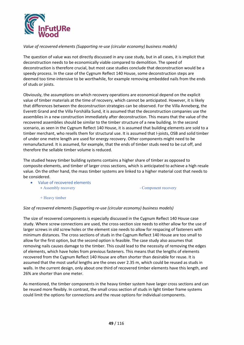
49 / 116
Value of recovered elements (Supporting re-use (circular economy) business models)
The question of value was not directly discussed in any case study, but in all cases, it is implicit that deconstruction needs to be economically viable compared to demolition. The speed of deconstruction is therefore crucial, but most case studies conclude that deconstruction would be a speedy process. In the case of the Cygnum Reflect 140 House, some deconstruction steps are deemed too time-intensive to be worthwhile, for example removing embedded nails from the ends of studs or joists.
Obviously, the assumptions on which recovery operations are economical depend on the explicit value of timber materials at the time of recovery, which cannot be anticipated. However, it is likely that differences between the deconstruction strategies can be observed. For the Villa Anneberg, the Everett Grand and the Villa Forshälla Sund, it is assumed that the deconstruction companies use the assemblies in a new construction immediately after deconstruction. This means that the value of the recovered assemblies should be similar to the timber structure of a new building. In the second scenario, as seen in the Cygnum Reflect 140 House, it is assumed that building elements are sold to a timber merchant, who resells them for structural use. It is assumed that I-joists, OSB and solid timber of under one metre length are used for energy recovery. Other components might need to be remanufactured. It is assumed, for example, that the ends of timber studs need to be cut off, and therefore the sellable timber volume is reduced.
The studied heavy timber building systems contains a higher share of timber as opposed to composite elements, and timber of larger cross sections, which is anticipated to achieve a high resale value. On the other hand, the mass timber systems are linked to a higher material cost that needs to be considered.
• Value of recovered elements + Assembly recovery - Component recovery + Heavy timber
Size of recovered elements (Supporting re-use (circular economy) business models)
The size of recovered components is especially discussed in the Cygnum Reflect 140 House case study. Where screw connections are used, the cross-section size needs to either allow for the use of larger screws in old screw holes or the element size needs to allow for respacing of fasteners with minimum distances. The cross sections of studs in the Cygnum Reflect 140 House are too small to allow for the first option, but the second option is feasible. The case study also assumes that removing nails causes damage to the timber. This could lead to the necessity of removing the edges of elements, which have holes from previous fasteners. This means that the lengths of elements recovered from the Cygnum Reflect 140 House are often shorter than desirable for reuse. It is assumed that the most useful lengths are the ones over 2.35 m, which could be reused as studs in walls. In the current design, only about one third of recovered timber elements have this length, and 26% are shorter than one meter.
As mentioned, the timber components in the heavy timber system have larger cross sections and can be reused more flexibly. In contrast, the small cross section of studs in light timber frame systems could limit the options for connections and the reuse options for individual components.

50 / 116
To summarise, the pros and cons of different designs with respect to a number of characteristics that we found important are compiled in Table 3.2. These are applicable to the cases studied but might be generalised to some extent.
Table 3.2 Summary of advantages and disadvantages regarding different characteristics, grouped by building system
Assembly recovery
Component recovery
Heavy timber
Number of deconstruction steps
+ - +
Dealing with damage
- + +
Complexity ± ± +
Unknown/short service life
- + +
Verification ±
Irrespective of building system
±
±
Irrespective of building system
Value of recovered elements
+ - +
3.3.2. General Improvements
Following the analysis of step 1, new design strategies were developed that address the disadvantages of the current designs.
First, some general measures that improve options for deconstruction and reuse are presented. Even though these measures are not necessarily related to the design, they were discussed in most case studies and are therefore considered important.
Treating buildings as an asset (Supporting re-use (circular economy) business models)
Deconstruction and reuse proved to be feasible to some degree in all case studies. Still, even buildings that require little improvement to be fit for deconstruction and reuse are not built with this goal in mind. It was proposed that companies need to adapt their business models to include adaptations, renovations, deconstructions and re-constructions in a building’s lifetime. Elements need to be manufactured with the goal to use them for a long time and more than one use-cycle. This is already the case for some elements, such as the IsoTimber elements inside wall panels of the Villa Forshälla Sund. The manufacturer of this component highlights the possibility to reuse the

51 / 116
elements and actively encourages their customers to do so. This thinking and the collaboration between component and building manufacturers is crucial to circular use of building components.
Houses as a whole also need to be considered as assets. They need to be built for accommodating generations of tenants and adapting to their different needs. Agreements for user responsibilities, for the alteration and maintenance of components, as well as for their eventual take-back by manufacturers need to be in place. Building manufacturers could either retain ownership of the building structure or agree on a “right of first refusal” clause with the relevant local authority that approves constructions and demolitions. If in this way buildings, assemblies and materials are treated as assets that can be reused to generate revenue, several of the following challenges would be solved as a logical consequence.
Measures to avoid not prescribed fasteners (Safety of disassembly)
This problem was identified in the Villa Anneberg case study, as it could draw from the experience of a previous deconstruction. Following this, other case studies also assumed that it is likely that assembly teams use additional fasteners that will not be consistent with the initial design. Measures to avoid fasteners that have not been prescribed in the design should therefore be taken. This would reduce time as well as health and safety risks during deconstruction. Joint details or their assembly may need to be improved, so that extra fasteners are not needed (or perceived to be needed). For example, in the Villa Anneberg angle brackets for roof trusses could be pre-assembled in the factory, where only planned fasteners are used. This should eliminate the need for extra nails, as roof trusses won’t need to be fixed while the brackets are mounted.
Alternatively, clearer installation instructions for construction teams might eliminate the use of extra fasteners. For example, in the Villa Anneberg, it might be sufficient to state clearly in assembly instructions that angle brackets must be mounted before the roof trusses are placed on the walls. Gregor Adam, Contracts Manager at Robertson Homes, interviewed in the Everett Grand case study, thinks that a protocol for the use of additional fasteners during erection needs to be in place in order to enable their deconstruction. This protocol should include a) the notion that additional fasteners are not to be used without a valid reason and b) that fasteners outside of the nailing schedule need to be marked and protocoled in as-built drawings. If the protocol is briefed to the workforce before erection and monitored on site, unprescribed fasteners would be known and would not pose a problem during deconstruction.
In addition, deconstruction instructions should be worked out and include information on how to check for extra nails and how to deconstruct connections.
Readability (Safety of disassembly)
Elements need to be marked to be able to track their specifications and history, which is addressed in the deconstruction instructions (see 3.5). This applies to components such as solid wood and panel products, as well as assemblies such as wall panels and floor cassettes. Non-timber products need to be traceable as well.
It was also suggested that screw and nail heads should be marked with spray paint in order to make it easier to find them during a deconstruction process. Studs and nogging could be marked on the OSB covering wall panels.

52 / 116
Verify reusability in practical study (Design strategies/Durability considerations)
It has been assumed in all case studies that it is technically possible to deconstruct and reassemble components and planar elements. Practical studies, where elements are deconstructed and reassembled, are needed to verify the assumptions.
The following questions have arisen that require further studies:
• Can old vapour barriers be reused, and can they be kept intact during a deconstruction process?
• Are screw connections reversible in practice? Will screws break or be unable to turn? Can elements be screwed a second time, or will this be prevented by presence of old holes or left-in screws?
It needs to be tested and verified whether reclaimed elements still show sufficient properties for reuse, which potentially requires a large testing regime before reuse as business-as-usual is possible. On-site visual assessment and non-destructive testing can then be used to verify the properties of timber components. Additional output control might still be needed when this phase is reached.
For solid wood components, a protocol for assessing their structural properties needs to be introduced, because properties might change during the service life of the building. A grading protocol for reclaimed timber is being developed within the InFutUReWood project, which could be used for this purpose. For assemblies, the testing and verification needs to be done on whole recovered assemblies. Properties of engineered wood products and non-timber components need to be verified as well.
An additional question arises for the treatment of timber with preservatives, which is required in structural timber elements in the UK and Ireland. It needs to be verified that the treatment is still effective after the first service life and throughout the reuse period. Otherwise, treatment procedures for recovered elements inside assemblies need to be developed. Or, better yet, in an agreement with insurance providers, it needs to be agreed that the timber is sufficiently protected from decay by design and moisture protection only. This would also avoid the use of chemicals and improve recycling options for timber after its useful life in buildings.
Instructions for weather protection and storage (Supporting re-use (circular economy) business models)
All case studies mention that timber elements need to be protected from moisture. Methods and instructions for weather protection during deconstruction should be developed to make sure that there is no risk for moisture damage.
Storage facilities might be needed, should timber elements need to be stored before re-construction.
Deconstruction and Reuse instructions (Supporting re-use (circular economy) business models)
Instructions for the deconstruction and reuse of components or assemblies is needed, as addressed by all case studies. Detailed requirements for these instructions are discussed in chapter 3.5.

53 / 116
3.3.3. Improved design strategies
In this section, we show how the design of timber structures could be improved to adapt timber structures to DfDR, and in some cases DfA. The design strategies are developed from the advantages and disadvantages in the five case studies. Here, they have been summarised under headings aligned with ISO 20887, as most new design details fit under one (or more) of the design principles in the standard. For each ISO 20887 design principle, examples from at least one of the case studies are given, that support the principle and show potential practical design changes.
Versatility, Convertibility and Expandability (DfA)
Some of the case studies addressed limitations of the design that were not strictly linked to deconstruction and reuse, but to the adaptability of structures. Designing for adaptability enhances the lifespan of buildings and can also impact DfDR potential. The size of rooms is linked to the length of wall panels, so is the variability in dimensions of recovered elements. When optimising the wall layout to use a minimum of panel variations, one can also incorporate layouts that allow flexible uses. The size of whole houses can be adapted by partly deconstructing or enlarging houses.
Everett Grand: Five bathrooms, which might not be required but cannot be used for any alternative use, are present in the original design. In the improved design, some of these bathrooms are made optional to increase the size of the bedrooms when they are omitted. This would allow space for a home-working station in case of a shared tenancy in which not all occupants can have a bedroom and an office. The different room layouts could be presented to prospective buyers with the option to omit up to three bathrooms.
Another option for a different tenancy scenario is also explored. The house is big enough so it can be transformed into two units, one on the ground floor and one on the first and second floor. The ground floor layout is adapted so that the hallway could be split into two and the bathroom could be transformed to accommodate a shower or bath.
The standardised wall lengths as discussed above also allow the partial deconstruction of the house to reduce its size. This would involve the removal of some wall panels and floor cassettes, which the company could take back and reuse. The reduced house is shown in Figure 3.19. Again, this option could be presented to prospective buyers and could be an important sales argument.
Figure 3.19 reduced Everett Grand

54 / 116
Cygnum Reflect 140 House: Room layouts are often inflexible and do not allow a modified use of houses. In the Cygnum Reflect 140 House, the roof space cannot be modified to accommodate use as inhabitable space because of the truss layout of the original design. In the modified design a cut truss roof allows for future inhabitation of the attic.
Figure 3.20 Changes in Truss- and room layouts that make the Cygnum Reflect 140 House more adaptable. Left: Current design. Right: Improved design.
The layout of the first floor is modified so that more usable space is available. The entrance door is moved to the side of the house, which brings it closer to the stairs and reduces the size of the hallway. The room layouts are standardised to enable a versatility of use, and plumbing services are vertically coordinated to allow for a reconsideration of use on the upper floor.
The floor cassettes are modified so that the joists have standardised lengths. The joist direction is changed, so that joists run from the party wall to the outer wall, which means that the house could be easily extended to the rear.
Cuenca Village: All internal partitions of the house are non-loadbearing and can easily be detached to transform the room layout. In addition, the whole building could be extended to the front and rear, but not to the sides where it meets other buildings.
Ease of access to components and services
Services need to be accessible and not connected to the structure, in order to alter them during the life of the building and detach them at the end of the building’s life.
Everett Grand: The services run in a dedicated service zone in the horizontal direction, but do not have a dedicated route in the vertical direction. In the improved design two service zones that run over all floors are introduced. One connects the garden and kitchen with the first-floor main bathroom and the other connects the ground floor bathroom, the potential first floor kitchen and the second-floor bathroom.
Cygnum Reflect 140 House: The services in the original design are installed by contractors, who position them as they see fit. They might drill or cut the OSB web of I-joists to lead the services through in the horizontal direction. The installation process is not controlled, and the position of

55 / 116
service runs will likely be unknown to anyone deconstructing the building. To make services more accessible, a service zone is introduced which connects the two bathrooms on both floors. The internal linings of the wall panels which contain service zones are detachable for increased accessibility.
Independence
Components that are independent can be altered or exchanged without affecting other components or materials.
Villa Anneberg: Connections between wall panels were redesigned to address the need for independence between layers in the composite assembly and to enhance access to the fastener.
These new design concepts are further discussed in chapter 3.4.
Cuenca Village: The internal lining and the services are independent of the structure. The internal finishes consist of a metal frame that contains services, so that they can be easily accessed and altered. Plasterboard is screwed onto the metal frame and not the timber structure.
Independence/ Reversible connections
The on-site assembly often uses nails to connect elements. Modern high-speed nail guns are an efficient tool, but the nailed connections generally regarded as not reversible. The same is true for glued or hidden connections.
Several new design strategies were developed for reversible connections and are discussed in chapter 3.4.
Standardization
The fact that current building systems often use prefabrication was highlighted as an advantage in several case studies.
Villa Anneberg and Villa Forshälla Sund: It is suggested to replace the roof trusses with prefabricated roof cassettes (Figure 3.21), members that are both loadbearing and insulating. Roof cassettes, unlike roof trusses, do not need temporary bracing during erection and deconstruction. The risk that assembly teams add superfluous fasteners is probably smaller for this type of structure than for roof trusses. After deconstruction, the entire cassette could be reused, once certified, and no boarding would go to waste. The cassettes are robust and easy to handle in deconstruction and transport, which should reduce time and energy consumption compared to handling roof boarding and roof trusses. In summary, time, waste, and risks should be reduced by building with roof cassettes. In the current design of the Everett Grand, it is assumed that the roof can be lifted off and reused as a whole. This is similar to today´s construction process and will reduce waste from the roof. For transport the roof might need to be sawn apart, but this damage can be mended upon re-construction. This could be an alternative solution for waste reduction in trussed rafter roofs.

56 / 116
Figure 3.21 Masonite Roof cassettes as proposed in the Villa Forshälla Sund case study. (Photo: Masonite Beams)
Everett Grand: It is suggested to include the external cladding in the prefabricated external wall assemblies. With the current design, the cladding is attached to the structure with steel wall ties, that need to be removed carefully during deconstruction. The process could be time consuming and leave damage to the timber. In addition, the masonry cladding cannot be reused and becomes waste. If the cladding was included in the wall panel assembly, it could be left in place during deconstruction and subsequently reused. Time and waste should be reduced by including the cladding in the wall panels.
Generally, in prefabricated building systems that aim to reuse entire assemblies, a high degree of prefabrication leads to less damage and therefore less waste. When disassembling the structure into components, still the extraction of large assemblies is beneficial, as these can be deconstructed on the ground or in a factory. Often the time and energy needed for deconstruction can be reduced as well. Prefabricated assemblies are beneficial for this reason and because the factory assembly is a very controlled process, so that fewer unknowns will hinder deconstruction. It seems evident that, where assemblies are to be reused, the time, effort and risk for damage is decreasing with increasing assembly size, which is linked to fewer deconstruction steps and less exposure of fragile components. Of course, the assembly size needs to be balanced with efficient transport and handling of the assemblies. The different components within assemblies should also be accessible or independent of one another, to still allow controls and repairs where needed.
Simplicity and Standardization
By simplicity we mean that elements are simple in their build and use the minimum number of materials, different connections and configurations. By our definition, standardization of components includes using a small set of standard dimensions. Automatically, assemblies made from these components are standardised as well. Parallelism means that elements which fulfil the same
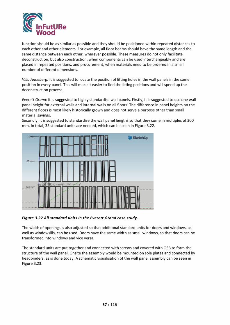
57 / 116
function should be as similar as possible and they should be positioned within repeated distances to each other and other elements. For example, all floor beams should have the same length and the same distance between each other, wherever possible. These measures do not only facilitate deconstruction, but also construction, when components can be used interchangeably and are placed in repeated positions, and procurement, when materials need to be ordered in a small number of different dimensions.
Villa Anneberg: It is suggested to locate the position of lifting holes in the wall panels in the same position in every panel. This will make it easier to find the lifting positions and will speed up the deconstruction process.
Everett Grand: It is suggested to highly standardise wall panels. Firstly, it is suggested to use one wall panel height for external walls and internal walls on all floors. The difference in panel heights on the different floors is most likely historically grown and does not serve a purpose other than small material savings. Secondly, it is suggested to standardise the wall panel lengths so that they come in multiples of 300 mm. In total, 35 standard units are needed, which can be seen in Figure 3.22.
Figure 3.22 All standard units in the Everett Grand case study.
The width of openings is also adjusted so that additional standard units for doors and windows, as well as windowsills, can be used. Doors have the same width as small windows, so that doors can be transformed into windows and vice versa.
The standard units are put together and connected with screws and covered with OSB to form the structure of the wall panel. Onsite the assembly would be mounted on sole plates and connected by headbinders, as is done today. A schematic visualisation of the wall panel assembly can be seen in Figure 3.23.

58 / 116
Figure 3.23 Panel assembly, example from the Everett Grand case study. Functional units are screwed together as shown by red arrows.
The units used in each wall panel should be documented and their function noted. After deconstruction, the wall panels could be disassembled into units again or modified by exchanging units, if needed. Otherwise, the standardised wall panels can be reused more easily, as the function and position of openings, additional studs and nogging is known. As the wall panel length is more uniform, panels fit together more easily and changes to the wall layout can be accommodated readily (see “Versatility, Convertibility and Expandability”).
Villa Forshälla Sund: The original design of this case study follows the principles of simplicity, standardization and parallelism. The IsoTimber elements of wall panels come in standard dimensions, which also dictate the possible dimensions of wall panels. Nearly all connections in the building are screwed and the same connections are repeated in similar elements. In addition, the walls and floor are made only from solid wood, with no additional insulation or membranes.
Cuenca Village: The design of wall panels, roof panels and floor cassettes follows the principles of parallelism and standardization to a very high degree. The build-up of all of these panels is extremely similar, with solid timber studs or joists that are connected with carpentry joists and clad with solid wood planks, as can be seen in Figure 3.24. The panels have a simple build, which does not use many different materials, only timber and insulation.
Figure 3.24 Roof Panels (1 and 2) and Floor panels (3 and 4) with very similar build in the Cuenca Village case study. Sleepers (Yellow), Studs/Joists (blue), Planks (red).

59 / 116
The components of the roof, walls and floors usually come in standardised dimensions that are typical for the respective part of the structure (Figure 3.25). This means a very small number of different timber components is needed for the manufacturing of the panels. When these components are recovered, they can easily be resold and reused, and their standardised dimensions would also facilitate remanufacturing of the components, for example into mass timber products like Glulam.
Figure 3.25 Roof Panels, Floor Panels and Wall Panels in their standard sizes, as used in the Cuenca Village case study.
It should be noted that the unusual shape of the house leads to some non-rectangular wall and roof panels, and therefore higher variability. Also, the non-standard window openings somewhat compromise the standardization of the wall panels.
Cygnum Reflect 140 House: The spatial layout and wall openings were redesigned, not simply to accommodate versatility and convertibility, but to reframe the structure to standardise to one length all joists and studs, to enhance recovery and reuse potential.
Design strategies/Durability considerations and Supporting re-use (circular economy) business models
More durable and robust materials with a longer life span can be reused more often and have a higher chance to be recovered damage-free.
Durability can also be achieved by protecting timber from adverse conditions. The deconstruction of a traditional farm building in Spain showed that better-protected timber members in the dwelling house could be recovered in a better condition than less protected timbers in the stable buildings. In modern timber structures the wood is usually protected from moisture and UV-light, which should increase its durability and diminish effects of ageing. This applies to all case study buildings.
Villa Forshälla Sund: The solid wood components of the current design are very robust. No short-lived or fragile components, such as plastic foils, are needed, since a diffusion-open construction with inherent insulation is used. This makes recovery and reuse of assemblies easier.
It is proposed, although not further explored, to protect the external glulam balcony from moisture and sunlight with a roof. This would potentially increase the life span of these components.
Reusability is the ability of components and assemblies to be reused in their original form after recovery. The reuse potential of different materials was judged differently between case studies and

60 / 116
has been addressed mostly in the Cygnum Reflect 140 House, where the assumptions about reusability were more conservative than in other case studies (see 3.3.4).
Cygnum Reflect 140 House: In the improved design, I-joists in the floor are replaced with solid timber joists. I-joists were identified as a component which cannot be reused, whereas solid wood joists have high reuse potential.
Timber studs under 1 metre length were judged not to be reusable, while lengths over 2.35 metres were judged to be best suited for reuse in studs. The design was improved to recover timber in longer lengths. It was considered to replace nails with wooden nails, to avoid honeycombing of the timber upon removal of the nails (see 3.4). This way, the ends of studs do not need to be removed and timber of longer length and higher reuse potential can be recovered.
It was also explored which implications the replacement of the concrete slab with a suspended timber ground floor would have. The concrete slab is not assumed to be reusable, whereas a timber floor is. The timber floor would also allow better access to ground-floor services.
3.3.4. Quantifying improvement: amount of wood that could be reused
Here, we show to what extent wood salvation could be improved with new design details, adapted to DfDR. The calculations are based on the amount of wood present in each case study building, and the estimations of percentage of waste for each building element or assembly. Note that every component that cannot be reused is regarded as “waste”, even though these timber elements could be recycled. The assumptions on which elements are damaged during deconstruction and consequently become waste differ between case studies, as they are largely based on the judgement of the different manufacturers rather than experience. The different assumptions on which the reuse quantifications for each case study are based, are shown in Table 3.3. Table 3.4 shows the percentage of timber in the structure that could be reused in the original and improved design. The numbers between original and improved design in each case study are suitable for direct comparison, while numbers between case studies cannot be readily compared due to the different underlying assumptions. The most important factor to influence the estimated amount of wood that would be reusable seems to be the deconstruction scenario. The case studies in which whole assemblies are to be reused in the same building show higher reuse percentages, but the reuse options for these kinds of components are very narrow. Should assemblies need to be adapted or remanufactured, the reuse percentage would decrease.

61 / 116
Table 3.3 Assumptions about waste in original and improved design Case study Assumptions about wastage
Original design Improved design
Villa Anneberg • Roof boarding and roof battens: 100 % waste. The boards will be damaged when ripped off from the trusses. • Exterior walls are judged to be reusable almost in their entirety. To account for some damage in handling, 0,15 m3 wood is assumed to go to waste. • Intermediate floor: 20 – 25 % of each floor cassette is judged to be wasted as joists and chipboard will suffer local damage when the chipboard is torn loose. • Sole plates: 100 % waste.
• Exterior walls do not suffer damage with new connection design. • Chipboard floor cover and floor joists do not suffer damage with new connection design.
Everett Grand • Roof boarding: 0-100 % waste. If roofing felt needs to be replaced, the tiling battens would need to be removed and would become waste. Since it is unclear whether the roofing felt has a life expectancy over 50 years, the waste percentage is taken as 50% for tiling battens. The exact tiling batten number cannot be seen in the design drawings and has been estimated. • Sole plates first floor and ground floor: 100% waste when sawing through nail connection.
• Sole plates can be reused when they are screwed to the floor.
Villa Forshälla Sund
• Roof boarding and roof battens: 100 % waste. The boards will be damaged when ripped off from the I-joists.
• Roof cassettes can be recovered as a whole.
Cygnum Reflect 140 house
• Solid timber under 1 metre length: 100% waste. • OSB: 100% waste. Panels cannot be recovered undamaged. • I-Joists: 100% waste. I-joists would not be reused after recovery per company guidance. • Studs: 8% waste. Nails would not be removed easily, so would result in the ends of structural members being cut off. Stud-ends would be reduced by 100 mm on each end. • Sole plates: 100% waste. See above. • Battens (tiling battens and service battens): 100% waste. Small
• Floor joists from solid wood would be reused. • Studs can be fully reused as wooden nails do not leave damage. • Less timber is recovered in lengths under 1 metre. • More timber is recovered in lengths over 2.35 metres. • Recovery rates are based on assumptions that all board (OSB) material is not reused and all solid timber under 1m is not reused • Sole plates: 100% waste. See
above. • Battens (tiling battens and service battens): 100% waste. Small cross

62 / 116
cross sections with frequent nails are not deemed to be useful for reuse.
sections with frequent nails are not deemed to be useful for reuse.
Cuenca Village • Post-and-Beam primary load-bearing structure: 33 % waste in the house structure. Waste percentage is higher depending on the previous use of the building, e. g. hayloft and hall: 55 % and 57 % waste respectively.
• Areas affected by carpentry joints are removed from all elements after recovery. This causes a cross-section reduction in all elements, with varying severity: • Primary load-bearing structure: 6 % waste. • Wall panels: around 14 % waste, including planks. • Floor panels: 6 % waste, including planks. • Roof panels: Around 20 % waste, including planks.
The amount of wood that could be reused increased in all case studies (Table 3.4). At the same time the quality of the building elements or assemblies increased in the Cygnum Reflect 140 House and the Everett Grand, opening up more reuse options. The improvements in the Villa Anneberg are also linked to time and cost savings in the original manufacturing.
Table 3.4 Percentage of wood or wood-based material that can be reused in original and improved design
Case study Percentage of reusable timber Original design Improved design
Villa Anneberg 83 % of all wood (solid or wood-based material)
86 % of all wood (solid or wood-based material)
Everett Grand 94 % of solid wood and potentially all OSB (3.51 m3), glulam (0.19 m3) and I-beams (81.57 running metres)
98 % of solid wood and potentially all OSB, glulam and I-beams Wall panels in standardised dimensions for flexible reuse
Villa Forshälla Sund 97 % 100 % Cygnum Reflect 140 House 41 % of total timber material is
reusable solid timber 67 % of total timber material is reusable solid timber
Cuenca Village 67 % of recovery in a Post-and-Beam (primary load-bearing structure) deconstructed to reuse
94 % of the Post-and-Beam (primary load-bearing structure) that can be compared to the traditional design. 86 % of wall, floor and roof panels (secondary load-bearing structure)
Overall, all building systems and case study buildings allow the recovery and reuse of a large amount of timber, even with the current design. The recovery and reuse of assemblies instead of individual components might be beneficial when solely looking at the amount of timber that can be recovered for reuse, but as shown earlier the reuse options for this deconstruction strategy are not as flexible.
The amount of wood recovered is evidently not an indicator for the reuse potential of timber elements that can be used on its own but is always linked to assumptions and the scenario. This system cannot be used to compare case studies. The ReBuilding Index, as discussed in chapter 3.1.2,

63 / 116
allows the comparison of reusability between case studies. It might also capture qualitative design improvements, such as reuse flexibility or deconstruction safety, and improvements which do not address wastage, but deconstruction speed, energy use or costs.
3.4. Report on connections
In this section, connection types occurring in case study buildings are first classified by type. Then, the different connections in each building are presented in more detail and connections considered for improvement are pointed out. After that, each case study is commented on. Finally, the reversibility of timber connections is discussed.
3.4.1. General types
Based on terminology from Blass (2010) and a general classification by Arriaga et al. (2015), the case studies use the following types of connection:
Carpentry joints
• Support joint • Notched support joint • Mortise-and-tenon joint • Rabbeted joint • Carpentry longitudinal splices
o Key splice o Jupiter-thunder splice
• Dovetail joints
Joints with mechanical fasteners
• Nails • Wood Nails • Dowels • Screws • Bolts • Coach-screws • Toothed ring connectors • Split rings • Nail plates • Proprietary or patented fasteners
Glued joints
After the life cycle of the timber structure, each connection kind has its advantages and disadvantages and has its own dismantling process described by Grantham (2002):
• Nails – most common type of connection requiring manual removal. This damages both the timber and nail.

64 / 116
• Screws – more easily removed than nails and less damage is caused to the screw. Manual Withdrawn screws could be re-used.
• Bolts – These form easily deconstructable connections with minimum damage to both the timber and the connector.
• Dowels and biscuits – used usually in combination with glue these joints are not easily taken apart. Dowels used for green oak framing may be drilled out for demounting the structure.
• Glued joints – a permanent connection that will cause damage to the wood if broken. Glued finger joints are generally as strong as the wood itself and may not need to be broken for re-use applications.
• Metal plate connectors – These come in various forms, but mostly commonly as munched metal plate connectors for the trussed rafter industry. Metal connectors are usually easily removed by hand.
The general deconstruction potential of different connection types has been described by Hradil (2014) and is summarised in Figure 3.26.
Figure 3.26 Possibilities of reusing timbers by connection type (Hradil, 2014)
In the case studies, the deconstruction potential of the different connection types was discussed with manufacturers. Connection types that were perceived as a disadvantage to DfDR were addressed in design changes and the outcomes are presented below. The general truth that screwed connections are suited for deconstruction while nailed or glued connections are more problematic was somewhat nuanced in the case studies. Even though screws were found deconstructable, there where situations where screwed connections needed to be changed (to make elements more independent and to avoid sequential connections). And even though using nails was found problematic for scenarios of component reuse, nailed connections were sometimes found acceptable if reuse of elements was the target. Glued connections were accepted within elements.
3.4.2. Connections in case studies
The different specific connections in the case study buildings are mapped and presented in more detail in Table 3.5. All the existing designs have connections with metal fasteners, predominantly screws and nails. Carpentry joints are used in the Cuenca Village case. Glued connections are present, mostly for floor covers (Villa Anneberg, Everett Grand and Cygnum Reflect 140 House) and in the Villa Forshälla Sund within the IsoTimber elements and between an oil-hardened plate and the

65 / 116
glulam foundation. Several connections were considered for improvement, and Table 3.5 also shows which connections that were improved within the case studies.
Table 3.5 Connections in Existing and Improved Designs
Case study Part Connection (position) Original technique Improved technique
Villa Anneberg
Roof Battens to roof-boarding Nailed Not considered for
improvement
Roof-boarding to roof truss Nailed Not considered for
improvement
Roof trusses Roof truss to exterior wall, first floor Angle bracket, Screwed Not considered for
improvement
Gables
Exterior wall first floor to intermediate floor Screwed Not considered for
improvement
Vertical corner joint Screwed Screwed
Attic floor/ ceilings
Battens to roof truss Nailed Not considered for improvement
Plasterboard to secondary spaced boarding Screwed Not considered for
improvement
Exterior wall, first floor
Exterior wall to intermediate floor (exterior)
Screwed Not considered for improvement
Floor to exterior wall (interior) Screwed Screwed, improved to be
more accessible
Wall panel to panel Screwed
Screwed, improved to be more accessible and to protect vapour barrier during deconstruction
Wall corner Screwed
Screwed, improved to be more accessible and to protect vapour barrier during deconstruction
Intermediate floors
Floor to floor Screwed, glued Screw-glued, improved to enable deconstruction without damage to particleboard
Exterior wall, ground floor
Exterior wall to intermediate floor (exterior)
Screwed Not considered for improvement
Exterior wall to baseplate on ground slab Screwed Not considered for
improvement
Wall panel to panel Screw connection
Screwed, improved to be more accessible and to protect vapour barrier during deconstruction
Wall corner Screw connection
Screwed, improved to be more accessible and to protect vapour barrier during deconstruction
Plate on ground incl. Sleeper Baseplate to slab Express nail Not considered for
improvement

66 / 116
Everett Grand
Roof Counter battens to trusses Nailed Not considered for
improvement
Tiling battens to counter battens Face nailed at each truss Not considered for
improvement
Roof trusses Truss clip to headbinder (wall panel)
Twisted nails Not considered for improvement
Roof truss to headbinder (wall panel)
Nailed (Skew fixed to every truss end)
Screwed
Gables Spandrel panel to panel Nailed (staggered) Screwed
Attic floor/ ceilings
Floor covering Glued Not considered for improvement
Plasterboard Screwed Not considered for improvement
External wall
External wall to intermediate floor
Nailed Screwed
Vertical joints between wall modules
Nailed (staggered) Screwed
Vertical corner joints between wall modules
Nailed (staggered) Screwed
Sole plate to wall panel (sole plate to bottom rail)
Nailed Screwed
OSB sheathing to studs Nailed Screwed
Intermediate floors
Supports of cassettes at external walls
Nailed Screwed
Longitudinal joints between cassettes
Hangers/ nailed Screwed
Plate on ground incl. Sleeper
Sole plate to foundation
Hammer Fixings or Hilti Nails
Screwed
Internal, loadbearing & non-loadbearing walls
Between panels and to external walls Nailed (staggered) Screwed
To floor joists Nailed Screwed
To trusses and ceiling joists Nailed Screwed
OSB sheathing to studs Nailed Screwed
Villa Forshälla Sund
Roof Roof boarding and battens Nailed Prefabricated roof
cassettes
Trusses to wall panels Angle brackets, screwed Roof cassettes screwed to external wall
Internal walls, first floor
Sole plate to floor panel Screwed Not considered for improvement
Wall to sole plate Screwed Not considered for improvement
Wall to wall (corner with stud) Screwed (from two sides) Not considered for
improvement

67 / 116
External walls, first floor
Wall to sole plate (sole plate is wall at ground floor)
Screwed (from outside) Sealant tape
Not considered for improvement
Wall to floor Angle brackets, screwed Not considered for improvement
Wall to wall (straight) Half-lap joint, screwed, (from two sides) Sealant tape
Not considered for improvement
Wall to wall (corner) Screwed (from outside) Sealant tape
Not considered for improvement
Intermediate floor
Floor panel to floor panel Half-lap joint, screwed Not considered for improvement
Floor panel to external wall Screwed Not considered for
improvement
Floor panel to internal wall (100 mm) Screwed Not considered for
improvement
Floor panel to internal wall (60 mm) Angle brackets, screwed Not considered for
improvement
External wall, ground floor
Sole plate to glulam Screwed Not considered for improvement
Wall to sole plate Screwed, Sealant tape
Not considered for improvement
Wall to wall (straight)
Half-lap joint, screwed (from two sides)
Sealant tape
Not considered for improvement
Wall to wall (corner) Screwed (from outside)
Sealant tape
Not considered for improvement
Internal walls, ground floor
Sole plate to glulam Screwed Not considered for improvement
Wall to sole plate Screwed Not considered for improvement
Wall to wall (corner with stud) Screwed (from two sides) Not considered for
improvement
Ground floor Floor cover and battens Screwed Not considered for
improvement
Floor joists to glulam frame Joist hanger, screwed Not considered for
improvement
Glulam foundation
Glulam beam to glulam beam (corner)
Angle brackets, screwed
Not considered for improvement
Glulam beam to glulam beam (double) Skew screwed Not considered for
improvement

68 / 116
Glulam post to glulam beam Angle brackets, screwed Not considered for
improvement
Glulam post to Glulam post (double)
Glued Supporting struts fastened with locking bolts
Not considered for improvement
Oil-hardened wood fibre board to glulam Nailed and glued Not considered for
improvement
Glulam post to post base Post anchor, screwed Not considered for improvement
Cygnum Reflect 140
Roof battens Battens to truss Nailed Screwed
Roof trusses Truss members Mending plates Wood Nails
Eave junction Truss to wall Nailed truss clip Screwed truss clip
Ceiling service cavity Battens to ceiling ties Nailed Screwed
Party walls Spandrel to party wall Screwed Not considered for improvement
External walls
Stud frame Nailed Wood Nails
OSB to Frame Nailed Screwed
Panel to Panel, Panel to Sole plate/Headbinder Nailed Screwed
Interior load bearing walls Stud frame Nailed Wood Nails
Interior non load bearing walls Stud frame Nailed Wood Nails
First floor I-joists OSB to Joists Glued and nailed Solid Timber Joists,
Screwed
Joist to noggin/top rail Nailed Solid Timber Joists, Wood Nails
Ground Floor joists
OSB to Joists N/A, Concrete slab Solid Timber Joists, Screwed
Joist to noggin/sole plate N/A, Concrete slab Solid Timber Joists, Wood Nails
Rising wall connection
Wall plate to concrete rising wall
72.5x112mm Rawlplug screw
Not considered for improvement
Cuenca Village
Load-bearing structure
Foundation to posts Simple support joint Mechanical fastener. Pillar base plate.
Beams to posts Carpentry joints (various) Carpentry joint, side dovetail (CNC)
Screwed
Rafters to beams Carpentry joints (various) Carpentry joint
Screwed
Rafters to ridges Carpentry joints (various) Carpentry joint. Dovetail.
Screwed
Wall panel Studs to sleepers Not applicable Screwed

69 / 116
Carpentry joint, dovetail, half section.
Planks to frame Not applicable Wooden nails
Floor panel Studs to sleepers
Not applicable Screwed
Not applicable Carpentry joint, dovetail, half section.
Planks to frame Not applicable Wooden nails
Roof panel Studs to sleepers Not applicable
Screwed
Carpentry joint, dovetail, half section.
Planks to frame Not applicable Wooden nails
Wall panel to load bearing structure
Wall panels to post Not applicable Screwed
Wall panels to beams Not applicable Carpentry joint, dovetail, half section
Screwed
Floor panel load bearing structure (Post-and Beam)
Floor panels to beams Not applicable
Carpentry joint, dovetail, half section
Screwed
Carpentry joint, support notched joint
Roof panels to load bearing structure (Post-and-Beam)
Roof panels to rafters Not applicable Carpentry joint, dovetail, half section
Screwed
Roof panels to rooftop Not applicable Screwed
3.4.3. Villa Anneberg
For Villa Anneberg, three new connections were developed within this study (Appendix A). Although deconstruction with current connections would not be impossible, it would cause damage to the building elements and thus require quite extensive repairs before reuse. The vapour barrier in the exterior walls would be damaged. This would lead to a need for repair of wall elements comprising taking off gypsum boards, OSB and vapour barrier and replacing them with new ones before reuse. Also, particle boards on top of floor cassettes would be damaged as the current connection floor-to-floor cassette is glued (and screwed). Within this study, better solutions could be achieved with minor changes in design, demanding no new technologies or dramatic changes in production.
Wall to wall connections were changed in the way the plastic vapour barrier is fitted in the elements. By folding the plastic differently, wall elements become more independent of each other and can be deconstructed without ripping apart the vapour barrier.
With existing design, the exterior wall panels are left incomplete during transport, Figure 3.27. A section of the internal OSB layer and internal batten and secondary insulation layer is omitted, to expose the structural posts for assembly on-site.

70 / 116
a b
c d
e f
Figure 3.27 Exterior wall element (a-b) and assembly detail (c-f) in current design of Villa Anneberg. Ends are left open to allow for screwing. (Photos: Derome)
The revised wall to wall connection is shown in Figure 3.28. The panel is now transported from the manufacturing facility complete with internal insulation, OSB and gypsum layers. The airtightness membrane is dressed in around the vertical batten, which makes wall panels more independent. The OSB and gypsum layers are finished short of the junction locally to allow access for structural fixing and sealing of membranes. The small gap in the OSB and gypsum layers is finished on-site.
Figure 3.28 Revised Villa Anneberg, wall to wall connection

71 / 116
The wall to floor connection is revised as well. In the current design, the internal plasterboard lining needs to be removed to uncover the screws in the connection of exterior walls to the soleplate on the floor. This would be feasible by either removing the plasterboard or cutting off a strip of plasterboard on the bottom, but both solutions are time- and energy consuming and require repair or replacement of the plasterboard. In the improved design, the connection is made accessible by finishing the plasterboard short off the floor and covering the gap with a removable skirting board (Figure 3.29).
Figure 3.29 Revised Villa Anneberg, wall to floor connection
To change the floor-to-floor connection and make it separable, each cassette needs to be built with one more joist than is the case today. There will be one joist on each side of the cassette with the new solution. The particle board can then overlap from one cassette to another without glue under the overlapping lip (Figure 3.30). The project members from industry and academy judged that the new solution is stiff enough not to cause movement that causes acoustic problems. This will have to be verified in laboratory studies out of the scope of this project.
Figure 3.30 Existing (a and b) and revised (c and d) Villa Anneberg floor-to-floor connection. Thin red lines mark the use of glue.
a b
c d

72 / 116
3.4.4. Everett Grand
The existing connections are not a big obstacle to deconstruction and reuse in the case study of Robertson Everett Grand (Appendix B). Even though most on-site connections are nailed, the manufacturers are confident that assemblies can be recovered and reused. Assemblies are expected to be sawn apart with a sabre saw. Of course, this method bears more uncertainties than loosening fasteners like screws, and it is unclear which share of recovered elements would suffer damage. If the operation is carried out carefully, it is assumed that 0% suffer damage, but deconstruction might require more time. A practical deconstruction study using the proposed methods is needed, but out of scope for this study.
It is therefore explored in the case study which implications the replacement of nails with screws would have. Especially the spacing and re-spacing options of screws instead of nails are investigated, to reveal how often elements could be reused without reusing screw holes. A study could be carried out to investigate whether placing screws in or close to old screw holes would influence connection strength. This would potentially allow more reuse cycles in the future, although in the case study building the re-spacing was not necessarily a limiting criterion for reuse, as at least 3 reuse cycles per element were deemed feasible.
The Contracts Manager at Robertson Homes was consulted on these changes on if he sees any negative implications for the on-site use of screws instead of nails. In his opinion, tools for placing nails and screws are equally fast and easy to handle, so that there would be no difference when changing practice.
The glued connection between the chipboard floor cover and the OSB floor deck was not regarded as a problem. The floor cassettes can be sawn apart with a sabre saw, leaving minimal damage that can be repaired with glue. The chipboard does not need to be removed from the floor cassettes in any case, otherwise both elements would suffer damage.
3.4.5. Villa Forshälla Sund
The analysis of Villa Forshälla Sund (Appendix C), states that the deconstruction process is likely to be understood intuitively and that the structure has several properties that makes it appropriate for deconstruction and reuse:
• the structure of the building contains few materials (there is no vapour barrier or other fragile materials present)
• wall and floor panels have a high stiffness and are dimensionally stable • all structural connections are fixed with screws (Figure 3.31) and foreseen to be easy to
disassemble • connections are of the same type throughout the building • connections are marked by construction tape and easy to read.
Practical experiences from the manufacturers factory show that screws can be undone and reused. The assumption of an easy disassembly process based on the screw fixings should also be verified in a long term, real case project though. Alternatively, screws can be cut off. In a practical deconstruction and reconstruction of an IsoTimber building, fasteners were cut by saw instead of being undone, due to time limits. This method of deconstruction proved to work well as no element

73 / 116
was damaged and the reconstruction was satisfactory (Appendix C). However, with this method screws are obviously destroyed.
In the current house design, roofing boards and roof battens are fixed with nails to I-joists. The roofing boards and battens are foreseen to be damaged during disassembly, while the I-joists are not (based on practical experience from a manufacturer of I-joists). A suggested modified design is to use roof cassettes instead and fix them with screws to the top edge of the external wall at assembly. Roof cassettes are expected to be disassembled without being damaged.
Figure 3.31 A screw connection in Villa Forshälla Sund (Image: IsoTimber)
3.4.6. Cygnum Reflect 140 House
There are some improvements on connections in the Cygnum Reflect 140 case study (Appendix D).
In this case study, timber components are targeted for reuse, which need to be free of metal fasteners at resale. Nails driven in with nail guns are difficult to remove, potentially leading to honeycombing of the timber, which would likely result in cutting the ends off joists and studs for expediency during the deconstruction process. This in turn would influence their length and reusability. Different alternative connection types are considered, and their advantages and disadvantages are summarised (Table 3.6). Screwed connections are easier to remove and would in most cases allow the reuse of joists and studs a second time, after which the ends would have to be cut off. Using wood nails (Figure 3.32) extends the number of times a joist or stud can be reused, as the substrate of the joist or stud will always be solid wood, free of holes. I-joists are switched to solid timber joists, that allow the use of wood nails (and have the additional benefit of being reusable). There are places in the assembly where the use of wood nails would make disassembly more difficult, as between wall panels or head binders, where screws are specified instead.

74 / 116
Table 3.6 Summary of Alternative Fixing Mechanisms and Reuse Strategies, Cygnum Reflect 140 House case study Option Assessment Option 1 Fill the hole in the bottom or top of the stud with wood filler of with a greater strength than the timber itself.
Pro No change to fixing methodology required Con Time taken to fill hole makes it time and cost ineffective
Option 2 Toenail the stud on second and / or first use.
Pro No need for remedial work to the stud Visible later when internal linings removed Con Not as standard a methodology as previous Two fixings required at each end
Option 3 Other alternative fixings may be brackets.
Pro Reusable fixings Visible to a deconstruction contractor Can be bolted connections or screwed Not limited to a small area around base of stud Con Expensive, resource inefficient Over engineered compared to the current nailed solution Not appropriate for small scale construction
Option 4 Wooden nails allow for elements to be quickly cut apart using a sabre saw.
Pro Quick installation Allows for disassembly using saw without risk of damage to blade Con Difficult to remove planar elements (e.g. OSB) from linear elements (studs), or head binders to top rails of walls Requires additional tool
Given these advantages and disadvantages of the different connection types, it was decided to change the fasteners in the following joints:
• Wall studs to rails: Wooden nails, nailing through the rails. • Wall panel to panel/ to soleplate/ to headbinder: Screws instead of nails. Wooden nails could
be used, but it seems easier to unscrew screws than to achieve a straight cut between panels with the sabre saw.
• Ceiling battens: Screws instead of nails. Evenly spaced wooden nails could be used, but sawing apart is deemed more time consuming than unscrewing.
• Roof truss, between truss members: Wooden nails instead of metal nails. • Floor joists to header joists/ to nogging: Wooden nails instead of metal nails. • OSB to floor joists/ to wall studs: Screws instead of nails. Wood nails would be difficult to saw
apart.
Also, the glue between deck and floor joists is suggested to be eliminated as it makes reuse of the joists more difficult.

75 / 116
The case study points out that existing techniques are not enough and there are some research needs listed below:
There is an outstanding question regarding the use of adhesives on subfloors, which is common industry practice. Glue is used to reduce squeaking, but the manufacturers involved in the case study believe it could be avoided. This requires more investigation.
In this case study, the authors have assumed that connections using wood nails can be easily sawn through with minimum loss of material, but trials are needed to confirm this.
Figure 3.32 Wooden nails proposed in Cygnum Reflect 140 case study, as well as Cuenca Village case study. (Image: M. Cramer).
It is assumed that the connections provided by wood nails will have longevity, but research is still ongoing into this topic.
It is also assumed using a new wood nail to make a connection in a stud or joist with old wood nails embedded is possible, but trials are needed to confirm this.
3.4.7. Cuenca Village
Cuenca Village (Appendix E), is a new design concept, based on traditional timber building systems. The connections between all the structural elements are conceptually innovative but technically not new. All carpentry connections are based on the mortise-and-tenon and dovetail carpentry connection but are not strictly the same. They are all designed specifically for this case study but using traditional and innovative techniques like carpentry joints cut by CNC or a mix of screws and wooden nails (Figure 3.32) that improves the assembly and disassembly process.
The carpentry connections are designed based on a mix between dovetail and mortise-and-tenon connection (Figure 3.33 and Figure 3.34) and are assured with coach screws. The innovative part of the joint is the assembly order. Following it, the easy disassembly of the whole structure is guaranteed.

76 / 116
Figure 3.33 Assembly order of post-and-beam structure, Cuenca Village case study.
Figure 3.34 Example of carpentry joint in Cuenca Village case study. Post-and-Beam structure (left) and detail of highlighted connection (right).
The wall, roof and floor panels follow a similar approach in connections and assembly. Connections between studs and sleepers are cut with CNC and secured with coach screws. The panels are assembled in the factory, complete with insulation and planking, which is nailed to the studs and rails with wooden nails (Figure 3.35).
Figure 3.35 Panel assembly in Cuenca Village case study. Left: Studs and sleepers are connected. Middle: Panel finished with wooden planks nailed to studs and sleepers with wood nails. Right: Detail of connection between studs and sleepers.
Wood nails can be a quantitative and qualitative improvement regarding reuse potential of the recovered timber. Planks are fixed to the frame with wooden nails, as it is supposed that planks fixed to the frame with metallic nails would suffer damage when removing nails. Using wooden nails, all

77 / 116
pieces can be sawn apart and wooden nails are supposed to remain in their place when disassembled, so all nail holes are filled.
The connection between the panels and the primary load-bearing structure is also a mix of mechanical fasteners and carpentry joints (Figure 3.36). The same connection type is used in all assemblies, and the screwed connections are assumed to be easily located and deconstructed.
Figure 3.36 Connection of Pre-assembled floor panels with primary loadbearing structure in Cuenca Village case study. Carpentry Joints are combined with coach screws.
Connections are the most useful techniques of this case study to facilitate disassembly, speeding up the process and improving the recovery percentage. Upon recovery of the timber components, however, the areas of carpentry joints are assumed to be removed, as they are highly specific.
Although there are a lot of new ideas in this case study, there are a lot of new questions about them. For example, how to guarantee the structural behaviour in the project phase, if joints are resistant enough to make an effective connection, the acoustic verification of all the building, especially connections, and the effect of age on the sawn timber.
3.4.8. Discussion on reversibility
A “reversible connection” is according to ISO 20887 “a connection that can be disconnected and/or disassembled for easy alterations and additions to structures”. A “reversible connection” can be seen as a relative term (because what is an “easy” alteration/addition is something relative). In a sense, most mechanical timber connections can be judged reversible, as most fasteners can either be removed or cut off with a saw. That being said, things can be done to increase the reversibility of timber connections, because the disassembled components or assemblies will suffer more or less damage and might contain more or less metal.
The amount of damage and metal content that can be accepted depends on the reuse target; to reuse assemblies or to reuse components. The case studies cover both these targets and have different approaches to improvement. In general, connections have been revised in the different case studies to make them more reversible in the meaning that:
1. Fasteners are more accessible. 2. Assemblies are more independent. 3. Reusability of elements is assured.

78 / 116
Reuse of assemblies
The Villa Anneberg, Everett Grand and Villa Forshälla Sund studies target the reuse of assemblies. The connections within assemblies were not considered for improvements. Consequently, glued connections within assemblies were retained and will not hinder the reuse of assemblies.
Connections between assemblies were in the Villa Anneberg case study improved to increase reversibility in all the three meanings pointed out above. Even though current connections were not considered to be irreversible, new design strategies were developed to improve the access to fasteners, avoid the overlap of the vapour control layer between wall panel assemblies, avoid the use of glue between floor cassettes and thus improve the reusability of the assemblies, as less damage is caused by deconstruction. Wall assemblies were judged reusable regardless of whether screws will be undone or cut with a saw, but improved floor cassettes need to be disassembled by undoing screws.
In both the Everett Grand and Villa Forshälla Sund studies, connections between assemblies were judged to be reversible enough with current design. In the Villa Forshälla Sund, most connections are screwed, and some are bolted. It is assumed that these connections can be undone and leave the assembly in a condition as good as new. It was observed in a practical deconstruction that the disassembly team preferred sawing between elements instead of unscrewing screws. This did not harm the assemblies and the reassembly was successful.
Manufacturers in the case of the Everett Grand were confident that nailed connections could be deconstructed in the same way: by sawing elements apart with a sabre saw. Screw connections were still regarded as safer to deconstruct, both for the disassembly team and for the timber, and it was concluded that no negative implications regarding assembly time or reuse potential of the structure would be caused by switching nails to screws.
Reuse of components
The Cygnum Reflect 140 house and Cuenca Village study target component reuse. In this case, fasteners should not remain inside components.
In the Cygnum Reflect 140 House case, nails were therefore identified as an adverse factor to reusability, since they need to be removed in a time-consuming process, which leaves damage to the timber. Nailed connections are therefore replaced with either screw connections or wooden nails, depending on the position of the joint. Wooden nails are mostly used where it is anticipated that components will be sawn apart with a sabre saw. In this process, wooden nails are also believed to be safer than metal nails.
The Cuenca Village case also uses screw connections and wooden nails, which in this case complement carpentry joints. Automated manufacturing processes allow to cut carpentry joints precisely, which ensures easy assembly and disassembly. The areas of carpentry joints are highly specific, however, and are assumed to be removed before the timber is reused. The planking on wall, floor and roof panels is connected with wooden nails, so that it can be sawn off and reused.

79 / 116
3.5. Guidelines for deconstruction and reuse
3.5.1. Introduction
Though considerable thought has been given to factors influencing the ease of disassembly that can be addressed in the design phase; from principles, material choices, connection types, procurement strategies and design team composition (Crowther 2005; Durmisevic 2006; Morgan & Stevenson 2005; Guy & Ciarimboli (n.d.); Durmisevic 2019), less consideration has been given to the question of how we ensure buildings are in fact disassembled in a manner consistent with these other strategies. There has certainly been research into the viability and potential structure that material passports might take to track materials being reused or recycled (Iacovidou et al. 2018; Honic et al. 2019), as well as research into how material banks, for facilitating the market for reused materials, might be structured, notably with reference to the use of 3D BIM technology (Cai & Waldmann 2019; Jayasinghe & Waldmann 2020; Durmisevic 2019). However, discussion on disassembly plans, which could govern how a building is to be decommissioned by a contractor to maximise the recovery rate of material that can be directly reused or recycled, has been given far less attention. The occasional references to it in the DfDR field (Durmisevic 2006; Halliday 2007) rarely explore how these should be developed, structured, or stored for future use. Two early DfDR manuals (Morgan & Stevenson 2005; Guy and Ciarimboli (n.d.)) are the exception, in that they clearly identified both the need for such a plan and postulated a potential structure for such a document (Table 3.7).
Guy & Ciarimboli drew heavily on the earlier Scottish Ecological Design Association (SEDA) document authored by Morgan & Stevenson (2005) resulting in a broad similarity between these two earliest manuals. There were four essential elements to what they felt would be an effective plan: a DfD strategy statement; an inventory of building elements; instructions for disassembly; and, critically, the identification of a permanent repository for future access. There were only minor variations on what might be included in the inventory of materials and the disassembly instructions. The more recent ISO 20887 (2020) largely echoed these earlier manuals, adding additional categories to the inventories, such as material characteristics (strength, toxicity), dimensions and quantity, though failed to recommend a strategy statement and offered less direction on disassembly instructions.
The most significant variation between the two early works was in the call by Morgan & Stevenson (2005) to have the plan continually revised at each handover, to keep the document relevant and up to date, a sentiment repeated in the ISO. This last issue is of critical importance, as not only do buildings evolve during their service lives, which may render as-built material inventories less than accurate, but construction cultures may change by the building’s end-of-life, potentially shifting the priorities of what is advantageous to salvage for reuse or recycling. Equally, one of the significant problems in storing such a document, much less keeping it updated, is that manuals for maintenance or safety and health are often misplaced or fail to be turned over to new owners. An institutional repository, such as a planning office, may be more future proof in this regard, but may not facilitate updating the plan at key junctures of the service life of the building. The inclusion in Table 3.7 of proposals from the waste sector (Zero Waste Scotland n.d.; FCRBE 2019; Deweerdt and Mertens 2020) in addition to Halliday (2007) and Melella et al. (2021), help to scope out a potential solution to this issue, by providing a view of demolition from a different vantage point.

80 / 116
Table 3.7 Review of Potential Elements in a Disassembly Plan
Proposed Sections / Actions for Disassembly Plan
Mor
gan
&
Stev
enso
n
Guy
&
Ciar
imbo
li (n
.d.)
Halli
day
(200
7)
Zero
Was
te
Scot
land
(n.d
.)
Dew
eerd
t and
M
erte
ns (2
020)
ISO
208
87
(202
0)
Mel
ella
et a
l. (2
021)
Statement of strategy for DfD X X X
Identify targets for reuse/recycling X X
List building elements X X X X X
Specifications, warranties, manufacturers X X X X
Include service life X X X
Identify best options (reuse, recycling, etc) X X X X X X
Material characteristics X X X
Material dimensions & quantities X X
Disassembly Instructions X X X
Up-to-date location plans X X X
Optimum technique for removal X X X X X
Equipment required, sequential processes, health and safety X X X X X
Categorising, recording and storing dismantled elements X X X
Pre-Disassembly Waste Audit X X X
Recording tool for actual waste and comparison with project targets X
Distribution of Disassembly Plan X X X X
Continual revisions, re-issue at each handover X X
Stored with legal deeds, H&S plans and Maintenance Plans X X X X
Halliday’s early Green Guide (2007) does not specifically recognise disassembly plans per se but acknowledges the need for the recovery of material playing a role in how a Decommissioning Plan is structured. Halliday notes that, among other things, such plans should explicitly encourage “maximum recycling, and therefore maintenance of materials and components in their highest value state to maximise opportunities for resale, reuse and recycling” and that prior to tendering of a demolition contract “an audit of materials that could be recycled” should be undertaken (2007). Also recommended is an explicit environmental policy statement in the plan that would include specific targets and incentives, which would ensure contractors address this in their bidding (Halliday 2007).
FCRBE (Facilitating the circulation of reclaimed building elements in Northwestern Europe), an Interreg-funded research project, developed a “pre-demolition audit method for reusable elements”, which begins to address Halliday’s recommendations (Deweerdt and Mertens 2020). As FCRBE noted in their earlier review of existing pre-demolition tools (2019), while there are as yet no requirements for such inventories in Europe, pre-demolition waste audits are increasingly common across Europe,

81 / 116
in an effort to better manage waste. Their 2019 review discussed a number of European initiatives to develop an audit and inventory tool, including Vade-mecum (2015), the Bellastock Resources Diagnostic (2014), the Brussels Environment’s Material Flow Inventory (2018) still in development at the date of their report, the GRO In Situ Inventory of Existent Construction Materials (2017), as well as the BAMB Reuse potential assessment tool (2019) and an earlier Building Material Salvage Assessment template by Brad Guy, author of the Seattle DfD Guide already discussed. Simply by stepping from the discipline of design into the realm of waste, the research on how one might develop and maintain a material inventory for a building expands substantially.
One of the few recent articles discussing disassembly plans (most are in the manufacturing sector, which is far more advanced on the topic than the construction sector), is Melella et al. (2021), who were trying to assess the carbon impact of the reuse of building materials, so did not directly address the question of quite what a disassembly plan looks like in practice. Nevertheless, they do raise the question of doing a pre-demolition audit of the building, echoed in articles from the waste sector. As an alternative to the front-loaded plans advocated by the DfDR manuals, they suggest that “preparation of a plan for disassembly and selective demolition” would occur at the end of the service-life of the building. This has some advantages as it avoids uncertainties of how long disassembly plans might survive in whatever repository they are placed, or their relevance due to changes in the building that have occurred or any future changes in construction culture. In defining the scope of such an audit Melella et al. (2021) drew on FCRBE study (Deweerdt and Mertens 2020) for guidelines on proper management of demolition waste and material inventory templates for their study of the environmental impact of disassembly in 2 case studies (Figure 3.37), which offer a useful structure to an as-built inventory during the commissioning stage, which could be updated in a later audit.
In addition to the comprehensive review of various audit templates, and the synthesis of this knowledge into a more precisely structured template, possibly the single greatest contribution from this field of research into waste management are the suggestions of setting specific project targets for material recapture, which would influence the tender process on demolition contracts, and offering a tool that not only describes the inventory of potential material to recover but a means to track the actual recovery rate during the process of deconstruction. It may be that these two elements can find their way into a front-loaded Disassembly Plan, the first within the strategy statement, and the second developed within the inventory structure used.

82 / 116
Figure 3.37 FCRBE Pre-Demolition Audit Form (Deweerdt & Mertens 2020)
3.5.2. UCD Student Case Studies
In spring 2021 architecture students in the UCD Master of Architecture programme, armed only with the guidance from the SEDA Design Guide (Morgan & Stevenson 2005), studied what a disassembly plan might look like for a standard 2 story semi-detached family residence in Ireland. As part of this study, they were allowed to choose the type of timber construction system to be used in the redesign (prefabricated 3D volumes or 2D planar elements, onsite platform frame or balloon frame, etc.). This ultimately influenced the structure of their disassembly plans, as they too had to decide to what level the buildings would be disassembled and reused, whether to a prefabricated element or

83 / 116
an individual structural member. Thus, proving the usefulness of the initial strategy description, as it will influence the structure of the remaining plan (Figure 3.38 and Figure 3.39). They were directed to focus only on the recovery of the timber structure.
Figure 3.38 Disassembly Diagrams for 2D planer elements (Lichtblau 2021)
Figure 3.39 Disassembly Diagrams for timber elements (Fjærvoll Saltvik & Ely 2021)
Being architecture students, they were by nature inclined to draw the disassembly plan, rather than rely on text-based descriptions of assembly/disassembly sequences or connection types and tools required, as illustrated in the previous images. In some cases (Figure 3.39) these diagrams not only included disassembly instructions, connections, and details of tools required, but imbedded diagrams of the number of workers required and the material inventory captured at each stage. Thus, not only doing away with text-based descriptions, but also spreadsheet-based inventories.
Although inventive, the ability to modify these plans for future (probable) changes to the building and its effective inventory of materials was limited. More effective, spreadsheet-based inventories were suggested in a few projects: for the recovery of prefabricated 2D planar elements for direct reuse (Figure 3.40), which focused its attention on the dimension and quantity of panels to be recovered; and for the recovery of individual timber members in a platform frame construction

84 / 116
(Figure 3.41), which identified quantity, dimensions, material characteristics (species, treatments) as well as the optimum recovery scenario (reuse, recycle or energy use).
Figure 3.40 Material Inventory for 2D planer elements (Lichtblau 2021)

85 / 116
Figure 3.41 Material Inventory of timber elements (McGrath & Bowler 2021)
Also apparent in the students’ proposals was the lack of understanding regarding the innate knowledge held by demolition contractors, who would not likely need specific instructions to take the finishes off first, or to disassemble the structure from the roof downward. Nor did they tackle the thorny issue of where these plans might be stored for 50 or more years, before they are required for the disassembly process. Nevertheless, their generous enthusiasm and creativity provided a series of alternative, albeit visually driven, templates to consider in tandem with the 2007 SEDA manual for the case studies undertaken by the InFutUReWood consortium. They also add to a growing body of inquiry into the nature and configuration of potential Disassembly Plans in the future.
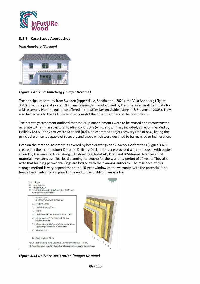
86 / 116
3.5.3. Case Study Approaches
Villa Anneberg (Sweden)
Figure 3.42 Villa Anneberg (Image: Derome)
The principal case study from Sweden (Appendix A, Sandin et al. 2021), the Villa Anneberg (Figure 3.42) which is a prefabricated 2D planar assembly manufactured by Derome, used as its template for a Disassembly Plan the guidance offered in the SEDA Design Guide (Morgan & Stevenson 2005). They also had access to the UCD student work as did the other members of the consortium.
Their strategy statement outlined that the 2D planar elements were to be reused and reconstructed on a site with similar structural loading conditions (wind, snow). They included, as recommended by Halliday (2007) and Zero Waste Scotland (n.d.), an estimated target recovery rate of 85%, listing the principal elements capable of recovery and those which were destined to be recycled or incineration.
Data on the material assembly is covered by both drawings and Delivery Declarations (Figure 3.43) created by the manufacturer Derome. Delivery Declarations are provided with the house, with copies stored by the manufacturer along with drawings (AutoCAD, DDS) and BIM-based data files (final material inventory, cut files, load planning for trucks) for the warranty period of 10 years. They also note that building permit drawings are lodged with the planning authority. The resilience of this storage method is very dependent on the 10-year window of the warranty, with the potential for a heavy loss of information prior to the end of the building’s service life.
Figure 3.43 Delivery Declaration (Image: Derome)
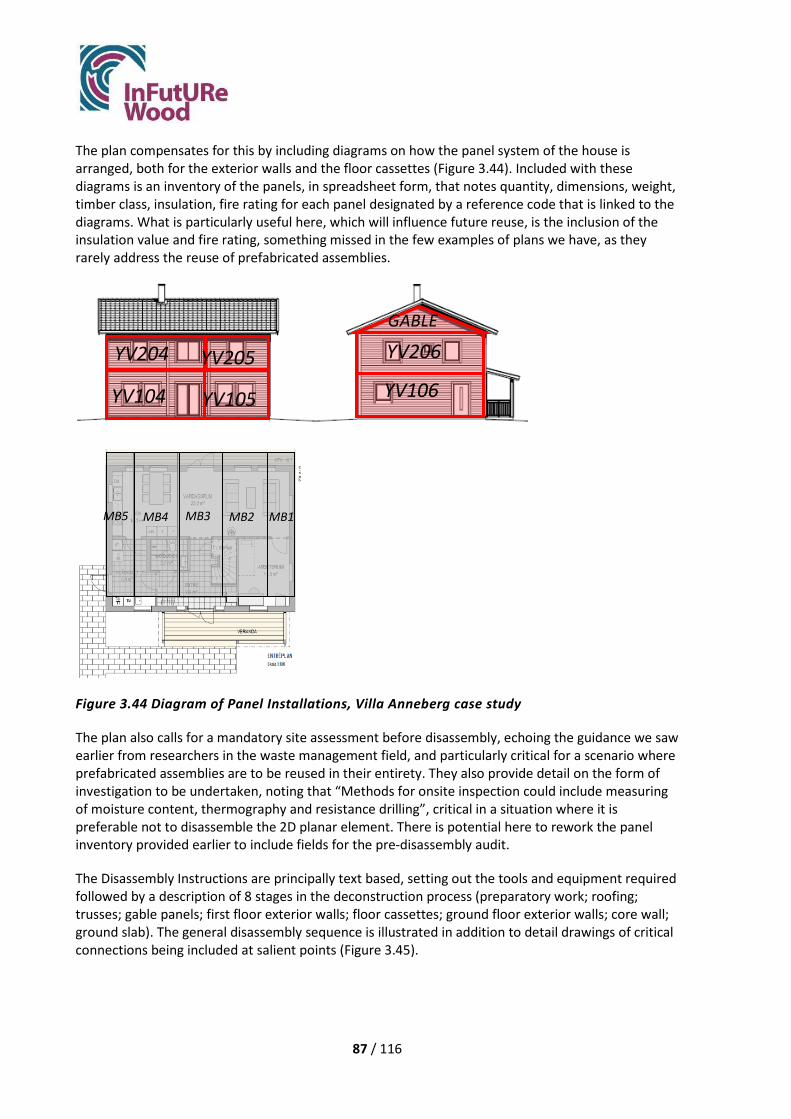
87 / 116
The plan compensates for this by including diagrams on how the panel system of the house is arranged, both for the exterior walls and the floor cassettes (Figure 3.44). Included with these diagrams is an inventory of the panels, in spreadsheet form, that notes quantity, dimensions, weight, timber class, insulation, fire rating for each panel designated by a reference code that is linked to the diagrams. What is particularly useful here, which will influence future reuse, is the inclusion of the insulation value and fire rating, something missed in the few examples of plans we have, as they rarely address the reuse of prefabricated assemblies.
Figure 3.44 Diagram of Panel Installations, Villa Anneberg case study
The plan also calls for a mandatory site assessment before disassembly, echoing the guidance we saw earlier from researchers in the waste management field, and particularly critical for a scenario where prefabricated assemblies are to be reused in their entirety. They also provide detail on the form of investigation to be undertaken, noting that “Methods for onsite inspection could include measuring of moisture content, thermography and resistance drilling”, critical in a situation where it is preferable not to disassemble the 2D planar element. There is potential here to rework the panel inventory provided earlier to include fields for the pre-disassembly audit.
The Disassembly Instructions are principally text based, setting out the tools and equipment required followed by a description of 8 stages in the deconstruction process (preparatory work; roofing; trusses; gable panels; first floor exterior walls; floor cassettes; ground floor exterior walls; core wall; ground slab). The general disassembly sequence is illustrated in addition to detail drawings of critical connections being included at salient points (Figure 3.45).
YV106
YV206 GABLE
YV104 YV105
YV204 YV205
MB2 MB1 MB3 MB4 MB5

88 / 116
Figure 3.45 Disassembly sequence diagram, Villa Anneberg case study
In principle, the Disassembly Instructions are clear and concise, both important points when the document is to be used by a contractor, as well as using the detail connection drawings very strategically. The overview of the 8-stage disassembly sequence is likely unnecessary, given the audience that will make use of this document, but is equally concise. They also include sections following this on security (safety), assessment of condition by an engineer following disassembly, storage protocols and reconditioning protocols, all valid additions to the outline described by Morgan & Stevenson (2005).
The question of where these documents are stored arises again at the end of the document, under Document Storage and Distribution. Here the date of the document creation is given, contact information for the manufacturer, and directions to have the plan updated as required by the owners. They also suggest that a copy of the document be stored with the permit drawings at the local authority. While the idea, postulated by Morgan & Stevenson (2005), that this plan should be updated as required makes sense, just how this is achieved by the owners is unclear. Nor has it been made clear in any research to date. The structure of the document needs to be considered from this perspective, perhaps allowing for a note column beside the disassembly instructions, or additional columns in the inventory for adjustments up to and including the final pre-deconstruction audit.

89 / 116
Everett Grand (Scotland, UK)
Figure 3.46 The Everett Grand single-family house
The UK team, led by Edinburgh Napier and supported by Robertson Timber Engineering Ltd, investigated one of Robertson’s single family house designs, the Everett Grand (Figure 3.46), a 2 story, prefabricated 2D open panel construction using light timber framing, which included prefabricated floor cassettes (Appendix B).
The team took quite a different approach to the structure of a Disassembly Plan, or Deconstruction Plan as they describe it, largely due to the involvement of Robertson Timber Engineering Ltd in its development, which is particularly informative to our discussion. The principal document of the plan is a master spreadsheet (Figure 3.47), which accommodates a wealth of information on the building panels. The spreadsheet is organised by deconstruction stages, under each of which are categories to describe:
• Component
• Deconstruction details
• Weight range of elements
• Proposed equipment required
• Risks to reuse
• Resource recovered
• Intended Re-use
• Value after recovery (Low, Medium, High)
• Recycling
This Deconstruction Plan spreadsheet is intended to be stored by the manufacturer, Robertson, and is linked to the BIM documentation developed and stored for the project. They have assumed that the deconstruction will be carried out by Robertson, as it is also expected that the manufacturer will retain ownership over the components, rather than selling them to the homeowner. The subsequent contract with the homeowners will require them to report any changes made to Robertson, to ensure the Deconstruction Plan is continually updated. The additional documents proposed to be linked to the Deconstruction Plan, beyond the data held in the BIM software, are:
• Original nailing schedule
• Design drawings of building and individual modules

90 / 116
• Guideline for pre-deconstruction inspection and survey
• Guideline for post-deconstruction inspection
• Guideline for factory assessment and repair
Figure 3.47 The Everett Grand Deconstruction Plan
The proposal offers several novel approaches to the creation of the Deconstruction Plan, as well as addressing many of the criteria raised in the waste sector. Foremost among these is the novel procurement strategy proposed, where the ownership resides with the manufacturer to better ensure the recapture of material for reuse or recycling. This is by no means a new idea, as advocates for the circular economy have been promoting just such a procurement structure, though to date progress has only been made in a limited manner, primarily in goods manufacturing rather than construction. A recent venture between ARUP and Tata Steel, in conjunction with Construction Innovation Hub’s Value Toolkit project and Network Rail to pilot the use of blockchain software to track materials through their lifecycle on a new rail station is also employing this strategy. Tata Steel will retain ownership of the material, which it will recover at the end of the building’s service life (citation). There is considerable logic to these types of procurement agreements if we are to successfully implement a circular economy. It addresses not only the recapture of material but the necessary reassessment / certification of its properties before reuse, solves many of the problems identified with creating a market for reused materials, and securely maintains and revises the necessary deconstruction documents.
The simplicity of the spreadsheet structure to capture most, though perhaps not all, information salient to the deconstruction process, is symptomatic of the manufacturer’s in-house knowledge base, which does not require a more elaborate document. Though it does not explicitly include a strategy statement, as described by many guides, the strategy is implicit in the structure of the spreadsheet, as are implied targets for recovery.

91 / 116
The plan also addresses the need, raised by researchers (Halliday 2007; FCRBE 2019; Deweerdt and Mertens 2020; Melella et al. 2021), for a pre-deconstruction audit, but extends this to deliberately include a post-deconstruction assessment. Though these documents are still under development, it does seem that the pragmatism and structure applied to the Deconstruction Plan could be equally applied here, to provide a sequence of linked spreadsheets to record this information in a systematic manner.
Villa Forshälla Sund (Sweden)
Figure 3.48 Villa Forshälla Sund (Photo: IsoTimber)
The Villa Forshälla Sund case study from Sweden (Figure 3.48), a single-family house, represents a departure from the other case studies which involved timber frame structures (both light and heavy frames). The Villa Forshälla Sund is constructed using mass timber frame wall panels, composed of CLT and the proprietary IsoTimber panels which avoid the use of multiple layers in the assembly for insulation and vapour control, thus facilitating both construction and deconstruction (Appendix C). As IsoTimber manufactures and delivers wall elements only, not the floor panels or roof panels, the IsoTimber Guide for Deconstruction focuses on the wall elements only. The overall purpose of the IsoTimber guide is to encourage reuse of the wall elements, in line with the company’s vision of enhancing a circular economy. As in the Cygnum Reflect 140 House case study, an actual Deconstruction document was developed to address both what information to provide and the format the document should take (Figure 3.49).
Figure 3.49 Illustration of the IsoTimber Guide for Deconstruction from the Villa Forshälla Sund case study

92 / 116
In the case of the IsoTimber Deconstruction Plan, it does not refer to the specifics of the Villa Forshälla Sund but is conceived as a general document that is to be supplemented by additional documents provided to the owner, some of which would be specific to each project. These additional documents include general documents such as:
• A Delivery specification, • an IsoTimber Technical Handbook, • an electronic building material declaration that defines the content of the wall panels, • a product sustainability assessment.
It would also include documents specific to the project:
• Assembly drawings and instructions, with specific technical details, which would include a 3D view with the panel’s weight and a loading plan for the transportation.
• A Material Specification, listing the dimensions and volumes in the delivery, that would include the names of suppliers of the complementary materials (Figure 3.50).
These documents, taken together with the generic IsoTimber Guide for Deconstruction, are to be provided to the owner, though the route by which it is successfully stored for the lifetime of the building is unclear.
Figure 3.50 Example of a customer specific Material Specification (in Swedish), a list of materials with dimensions and volumes. The manufacturer of all material is defined in the list. From the Villa Forshälla Sund case study.
The novelty of the plan proposed in the Villa Forshälla Sund case study is its generic format. Unlike the other case studies, where the elements of the plan were described and illustrated with project specific details, implying that it is drafted anew for each project, the generic IsoTimber Guide for Deconstruction has been developed to be reused on any project as well as for marketing. There is a benefit to this strategy for manufacturers as it provides a stable reusable guidance document that

93 / 116
can be supplemented with project specific documents. That it only deals with IsoTimber wall elements rather than the entire building assembly, may reduce its usefulness to a future deconstruction contractor depending on the comprehensiveness of the Assembly drawings and instructions document specific to the project. Nevertheless, it could provide an interesting format for the house manufacturers of the case study projects (Derome, Robertson, Cygnum) to consider in the future.
Cygnum Reflect 140 House (Ireland)
Figure 3.51 Cygnum Reflect 140 House
Timber construction is rare in Ireland, though the prefabricated timber housing share is growing. The team from University College Dublin selected a semi-detached project (Figure 3.51), representative of conventional house types in Ireland, manufactured by Cygnum Timber Frame to use as a case study. Though these were constructed using prefabricated wall panels and roof trusses, to expand the consortium’s case studies beyond prefabricated typologies it was reimagined in the new proposal as an onsite light timber platform frame construction. This allowed the team, with some guidance provided by Cygnum, to assess the issues involved in recovering timber elements rather than 2D panels for reuse (Appendix D).
The team relied heavily on the SEDA Design Guide to inform the development of their plan but developed a finer grain to the structure of the proposed document (below) than articulated by Morgan & Stevenson (2005). They also argue that the term ‘Disassembly Plan’ should be replaced with what they feel is a more accurate term: Disassembly Information Record or DIR:
Disassembly Information Record (DIR)
Contents 1. Record Storage Instructions 2. Project Details 3. Expected Reuse Scenario 4. Material Summary 5. Construction 6. Connections 7. Fixing Specification 8. Strategies for Adaptability, Disassembly & Reuse 9. Amendments to Disassembly Information 10. Appendix A: Architectural Drawings & Specification 11. Appendix B; Engineering / Fabrication Drawings 12. Appendix C: Warranties

94 / 116
13. Appendix D: Material Inventory As they explain, a ‘Disassembly Plan’ may only form a part of such a document, while the DIR could vary in complexity and scope relative to the size of the project. The team front ends the document storage directions (onsite, with deeds, and with local authority), which is both novel and likely more effective. It also offers an abbreviated summary of the volume of materials (Figure 3.52) early in the report, with the comprehensive and detailed material inventory at the end to keep the information concise and relevant. What is novel here is that the structure of the DIR anticipates changes occurring during the building’s service life by providing a means to record it, notably by hand.
Figure 3.52 Material Summary (Walsh & Shotton 2020)

95 / 116
The proposal that the DIR document is retained as a hard copy rather than a digital file, allowing for handwritten amendments, runs counter to contemporary DfDR research. This has increasingly been preoccupied by BIM-linked databases to underpin everything from material inventories, material passports, the marketing of reused materials, to the constructive details of buildings and related disassembly directions. Their rationale for a hardcopy approach relates to our inability to predict what form of digital technology, software or hardware, may exist in 50 years or more. There is a possible overconfidence of the BIM lobby in the longevity of their digital solutions, based on 2020 technology, being readable in 2070 or indeed in 2120. To remain accessible would require a digital repository for significant and increasing amounts of data, with a repeated transfer of data files to evolving platforms every 3-5 years. Archivists began struggling with this issue 20 years ago. It seems the circular economy community may not yet have come to grips with it. So, the proposition that the DIR would remain hardcopy, though initially counter intuitive, may be a very legitimate proposal.
The Irish team also assumed that knowledge of sequential disassembly is understood by demolition contractors thus an overly detailed description of the process was unnecessary. In a similar vein they argue for a concise report, both to ensure the compliance of the architect as well as reducing the burden on the contractor tasked with deconstructing the building. Thus, rather than having visually engaging diagrams of the disassembly sequence, they reduce this to an abbreviated description of the construction assembly (Figure 3.53) and a table outlining connection types and tools required (Figure 3.54) and an additional table with fastener specifications.
External Wall Panels TF200 Thermo 9mm OSB3 38x140mm C16 timber frame 90mm PIR insulation Foil Airtight membrane 44 x 46mm Service Cavity Airtight tapes and mastic Gerband
Internal Wall Panels (loadbearing and non-loadbearing)
38x89mm C16 timber frame 11mm OSB to racking walls on one or both sides; supplied with one side fitted for installation and services / insulation. 100mm Acoustic Insulation
Party Walls. 9mm OSB3 to cavity side of each frame Twin leaf 38x89mm C16 timber frames with cavity between 100mm acoustic insulation 15mm Plain (A) and 15mm fire (F) plasterboard
Party wall Spandrels. 9mm OSB3 to cavity side of each frame Twin leaf 38 x 89 C16 timber frames with cavity between 80mm Rigid PIR to bottom 400mm 15mm Plan (A) and 15mm fire (F) plasterboard
Upper floor 18mm OSB3 225mm x 45mm Solid Joists 100mm Acoustic Insulation FCM 750 airtight membrane for floor wall junctions
Trussed Roof Tiling battens Roofing felt breather membrane Cut Truss Roof, generally Rafters & Joists 140 x 38mm 400mm thermal insulation Vapour control foil 44x64mm service cavity
Figure 3.53 Construction Summary from Cygnum Reflect 140 case study

96 / 116
Beyond the full set of drawings enclosed in the Appendices, the only diagram provided in the plan deals with disassembly protocols for timber joined with wood nails, as the remainder is understood to be within the knowledge base of the contractor. This makes for a very lean DIR document, excluding the Appendices, which may have promise in being simpler to assemble, to revise and ultimately, for the contractor to read.
Part Junction Fixing Type No. or Centres
Tool Required
Roof Battens Battens / Truss Screwed
400 c/c Screw Gun
Roof Trusses Truss Members Wooden Nail -see description
at Connections
Sabre Saw
Eaves Junction Truss / Wall Plate Screwed w. Galv Truss Clip
8 no. / Truss clip
Screw Gun
Ceiling Service Cavity
Battens / Ceiling Ties Screwed
400 c/c Screw Gun
General Wall Panel Framing
Stud to Rail Connections Wooden Nail – see description
400 c/c Sabre Saw
Party Walls Spandrel / Party Wall Screwed 150 c/c Screw Gun External Wall Panels
OSB Sheathing / Stud Frame Screwed
150 c/c Screw Gun
External Wall Panel
Wall Panel / Wall Panel Screwed
150 c/c Screw Gun
External Wall Panels
Wall plate Screwed 400 c/c Screw Gun
Interior Load Bearing Walls
OSB / Stud Frame Screwed 150 c/c Screw Gun
Interior Non-Load Bearing walls
Stud to Plate Connections Wooden Nail - see description 400 c/c Sabre Saw
First Floor Deck
OSB Sheets / Solid Joists Screwed - See description below
150 c/c Screw Gun
Joist / Header Wooden Nail - see description Sabre Saw Rising Wall Connection
Wall Plate / Concrete rising wall
Screwed 600 c/c Screw Gun
Figure 3.54 Connection Summary from Cygnum Reflect 140 case study
A facet of this DIR document which, depending on the nature of the project, may not appear in every DIR, is the inclusion of a section outlining ‘Primary Strategies for Flexibility & Adaptability’. This is an important contribution, which is not adequately covered in the guidance to date, as the primary means to achieve sustainability in the construction sector is to maintain and adapt the building, rather than deconstructing it. It is possible that too much emphasis has been placed on developing successful deconstruction scenarios in recent literature, with insufficient weight given to designing for adaptability.

97 / 116
Cuenca Village (Spain)
Figure 3.55 The Cuenca Village Proposal
The case study undertaken in Spain by researchers from the Universidad Politécnica de Madrid and supported by industry partners Klimark + Nova Domus Hábitat was based on a new design proposal for terraced housing (Figure 3.55), based on traditional Spanish typologies. The proposal is a post-and-beam structure using timber joints and infilled with light timber framed wall, floor and roof panels using a combination of timber joints, timber nails and coach screws to fix the panels to the primary structure (Appendix E).
Though the Disassembly Plan primarily focused on the final step of recovery of raw materials, it also considered intermediate steps such as adapting the building during its use, or disassembly into panels and primary structural members to be reassembled elsewhere in the same configuration. Their elaboration of the disassembly sequence borrowed on the UCD student’s preference for graphic illustrations with graphic details on where to find all connections (Figure 3.56) over texted based descriptions, or indeed spreadsheets as the UK case study proposed. The plan was laid out as an 8-stage process, to recover the raw materials, though could be stopped at stage 7 if the building was to be reconstructed elsewhere:
1. Preparatory work: Installations, partitions coating layers (not addressed as case study examined only the timber elements)
2. Roof layers
3. Roof Panels
4. Wall Panels
5. Rafters
6. Floor Panels
7. Post-and-Beam structure
8. Panel disassembly off-site

98 / 116
Figure 3.56 The Cuenca Village disassembly sequence, stage 4
The proposal to disassemble the panels offsite, if required, carries many advantages with it for a more efficient recovery of materials. This process would be undertaken by Cuenca Sawmills, who would have originally produced the timber for the project. The authors propose making use of the spreadsheet developed on the case study, as a form of material inventory that could be used during the disassembly process. Although elaborate, it shares a level of pragmatism with the UK Robertson proposal and contains a number of useful fields that could enable monitoring of the recovery (Figure 3.57). In addition to material characteristics (species, dimensions) and quantities it has fields for Waste volume (m3); Volume recovered (m3); Recovery (%). These could prove invaluable during the recovery process and could be tied to recovery targets as suggested by Halliday (2007) and Zero Waste Scotland (n.d.).

99 / 116
Figure 3.57 The Cuenca Village Material Inventory
The proposal includes defining the tools required, storage instructions post-deconstruction, and that the plan should be deposited with the local Spanish Municipality as well as the building owner. The most novel contribution, however, is the consideration of how the material can be traced through multiple uses. Though much has been written concerning material passports, including the long-term viability of RFID tags (Iacovidou et al. 2018) or the trial use of Blockchain technology by Arup and Tata Steel, simple, workable long-term solutions remain elusive. The Spanish team propose that each timber element is marked, at the time it is first purpose-cut for the building in the sawmill, by the CNC equipment with sufficient information to assess its material characteristics at a later date (Figure 3.58). This appears to be a robust and simple manner to ensure traceability.
Figure 3.58 Information to be marked on each timber element in Cuenca Village case study

100 / 116
4. Conclusions
In this chapter, we conclude what we found and how we filled the identified knowledge gap by answering our research questions.
4.1. What methods can be adopted to optimize a primary design to deconstruction and reuse?
This study developed three methods that can be used to adapt or optimize a primary design with respect to deconstruction and reuse:
• The case study method. • An indicator system. • A design decision matrix.
The first two methods can be used when there is an existing design to assess and improve, while the third model is suitable to use from the start of a design process and through all its stages.
The first and third models are qualitative methods, while the second (the indicator system) results in a ReBuilding Index, reflecting the DfDR potential of the design. All models can include aspects of DfA. Due to time and resource limitations, these aspects were considered to a lesser degree within this study.
The case study method worked well and delivered the desired results. One of the most important findings was that at least two of the new designs that were developed together with industry, were found so valuable that they will be taken into the production process without delay (Figure 3.28, the Villa Anneberg study and the adjustment of the height of wall panels, the Everett Grand study).
The strength of the case study method is that it is intuitive and simple. It does not require special resources as third party or personnel trained in the use of a specific assessment method. (However, the manufacturers own expertise is crucial.) It provokes discussions that can be rewarding and generate new design solutions. The method could be completed with practical studies in laboratory or in actual construction and deconstruction, to confirm assumptions made within the analysis.
The indicator system is an assessment tool. The strength of the method is that it is quantitative, interprets and builds upon ISO 20887, and could be used for objective assessments from a third party. It can serve as a help to use the ISO standard and to work according to its guidelines in a structured way. It is our belief that the tool could stimulate companies to hire sustainability experts and have the sustainability and circularity questions on the agenda.
The design decision matrix guides the designer through a whole design process. The strength of the method includes that it is as much a material for learning as a design supporting tool and that the tool is based on the well-known and accepted document The Royal Institute of British Architects (RIBA) Plan of Work and is structured around the principles identified in the ISO 20887. RIBA has given positive feedback on the tool structure.

101 / 116
4.2. What new designs can be suggested?
The current study drew on a review of previous research in DfDR and DfA (Cristescu et al. 2020), which had established a range of principles and strategies later clarified in the 2020 ISO 20887. The study illustrates how the standard principles can be applied in practical design strategies for timber buildings. While the case study buildings are already relatively well positioned to be deconstructed to facilitate the reuse of the timber structure, alterations in strategic design details improved this potential. As the case studies were all, to varying degrees, manufactured offsite, this may have influenced the general compatibility with the principles of DfDR, due to their modular composition and prefabrication, which is consistent with the Standardization principle of DfDR/A. Modular construction and prefabrication not only reduces construction waste and improves quality due to factory controls, as well as reducing the time on site for assembly, it also holds potential benefits for the deconstruction because:
• Connection details are factory controlled, resulting in fewer unknown connections • Where large modules can be recovered, the time and energy needed for deconstruction as
well as damage will be reduced. • Construction and deconstruction are similar processes, so that the knowledge and
infrastructure that companies have can be directly transferred to enable the deconstruction of buildings.
There were disadvantages in the case study buildings identified that complicate deconstruction and reuse. These were typically linked to the complexity of building modules and that individual components are not independent. This is reflected in irreversible or hidden connections, inaccessible services, interconnected layers of the structural modules and a large number of different component sizes. New design strategies have been developed to maintain the advantages and address the disadvantages of the current designs. In addition, three case studies (Ireland, UK, Spain) addressed the ISO principle of Adaptability (DfA). The new design strategies are summarised below under the relevant ISO principles:
Disassemby Principles (DfDR)
• Independence /Reversible connections
By reversible connections we mean connections that allow the connected parts or elements to be disassembled without damaging the part or element. For light timber structures, concepts were developed that avoid letting sensitive materials as plastic foils and particle boards pass continuously over joints between elements. Two such solutions were developed in the Villa Anneberg study. Firstly, wall to wall connections were made more reversible by designing panels so that the sensitive plastic vapour barrier is not damaged during deconstruction. Secondly, floor-to-floor connections were altered so that a lip of particleboard stretching from one cassette to another is screwed instead of glued. The solution calls for an extra floor beam in each cassette, as one beam is needed on each side of the joint.
• Ease of access to components and services
For a light timber frame, a small and simple adjustment in the design of the floor-to wall-connection was suggested to make the main bottom fixing accessible for disassembly and reassembly without any significant damage to the wall. By simply finishing the OSB and gypsum layers short of the floor,

102 / 116
access is provided for structural fixing. A skirting board that can be removed and reused covers the gap. This concept was developed within the Villa Anneberg study.
In the Cygnum Reflect 140 House, hinged interior wall panels are proposed allow for access to services during life of building, minimising damage and repair to surfaces.
• Standardization
Although all studied buildings were largely offsite constructions, there were still ways to develop them further to augment the prefabrication level. New concepts included building with roof cassettes instead of roof boarding (this was suggested for the Villa Forshälla Sund case for example).
• Simplicity and Standardization
Aspects of simplicity can be considered in design by prescribing the use of few materials, mainly timber, as shown in the Cuenca Village and Villa Forshälla Sund studies. Prescribing the repetition of defined connection positions in all elements of the same type, as in the Villa Forshälla Sund case, is an example of how parallelism can be achieved.
For designs where standard units for wall panels are not already used, standardization in the sense of using few dimensions is an obvious development measure for a design, as this will make disassembled elements more interchangeable. This aspect is illustrated by both the Villa Forshälla sund case, where standardization is considered already in the original design, and in the Everett Grand study, where development of the current design towards standardisation is suggested and in the Cygnum Reflect 140 House, where through a readjustment in layout and framing, a standard joist length is achieved.
• Independence/General
Independent services in the internal frame structure are easily accessible and allow for alterations (Cuenca village).
• Design strategies/Durability considerations
Using durable, long-lived materials allows for various reuse cycles. One line of development to achieve durability includes using mostly heavy timber, as in the Villa Forshälla Sund and Cuenca Village cases. Also, the Cygnum Reflect 140 study suggests the use of solid wood components instead of engineered wood products using OSB. Another line of development when it comes to durability involves improving composite structures. Where assemblies are targeted for reuse, it is beneficial to use components with similar life spans within assemblies, as is currently the case in the Villa Forshälla Sund. New design concepts can include developing/finding components such as vapour barriers with a guaranteed life span of 100 years instead of 50 years.
Adaptability principles (DfA)
• Versatility, Convertibility and Expandability
Aspects of versatility (using buildings and spaces for different purposes), convertibility (changing spaces towards different needs) and expandability (de- or increase of building size) are important in design for adaptability and are also linked to design for deconstruction.

103 / 116
New strategies supporting these aspects and suggested in this study include designing spaces for different user groups with different requirements by making buildings partially deconstructable and designing to allow the removal of only some internal walls or one storey. Concrete examples include standardised wall dimensions, standardised opening dimensions and adapted room layouts to make partial deconstruction possible (in the Everett Grand study), making attic space usable due to changed truss layout, altering room sizes and layouts to provide versatile use, and altering floor joist direction to simplify expansion of the building (Cygnum Reflect 140 House study) and making internal walls removable (Cuenca village study).
4.3. What can be said on timber connections in relation to deconstruction and reuse?
The case study buildings have connections with mechanical fasteners, glued connections and (in one case) carpentry joints. Connections have been revised to:
• make fasteners more accessible, • assemblies more independent and to • assure reusability of elements.
Whether connections are judged to need improvements or not depends in part on the reuse target: if the target is to reuse assemblies or to reuse components.
Assembly reuse
For Villa Anneberg, the screwed connections in the current design were considered reversible per se, but improvements were still proposed:
• Wall to wall connections were improved by avoiding continuity of vapour barrier across element joint, making elements more independent and more reusable.
• Wall to floor connections were adjusted to make screws easier to find/more accessible. • Floor to floor connections were adjusted to avoid glue over the joint (glue was retained
within elements), making elements more independent and more reusable.
In the Everett Grand case, nailed connections were considered reversible. They could be cut with saw to disconnect elements, without damaging the assemblies or preventing their reuse. Still, alternatively, the study points out that nails could be replaced by screws without disadvantages to the manufacturer or the assembly team. This measure has benefits, as it might lead to a more controlled deconstruction regarding risks for damage of materials and risks for workers.
For Villa Forshälla Sund, the screwed connections were judged reversible, and no changes are needed. The current roof design with a boarding nailed to I-joists was suggested to be replaced by roof cassettes, screwed to walls.
Component reuse
For the Cygnum Reflect 140 House, nailed connections were judged to have poor reversibility, as nails leave damage to components. The study suggests either screws or wooden nails to be used, depending on position, as this will augment the reusability potential of the components. Glued

104 / 116
connections between deck and floor joists were deemed irreversible and the glue was suggested to be eliminated.
For the Cuenca Village building, carpentry connections combined with coach screws are suggested, to retain the positive properties observed in traditional building systems. These properties were confirmed by documenting the deconstruction of a vernacular building on site. Together with a specific assembly order developed for the building, these connections assure the reuse potential of the heavy timber components. Nailed connections normally used in floors were judged to have poor reversibility and the study suggests using wooden nails instead.
4.4. How can guidelines for deconstruction and reuse be formulated? Several things become apparent when comparing the proposed deconstruction plans in the case studies relative to the guidance found in the earlier SEDA document (Morgan & Stevenson 2005) and the more recent ISO 20887 (Table 4.1). First is the impact that prefabrication has on the plans proposed, not addressed in the two earlier published documents despite being an increasingly common form of construction. The impact is twofold: in the Everett Grand, Villa Anneberg and Villa Forshälla Sund case studies panel information rather than material data is supplied. In the first two of these cases there is a recommendation that the manufacturer retain the building information and disassembly plan, extended in the Everett Grand case to suggest the manufacturer also retain ownership of the assembly, which could strengthen the outlook for successful circularity.
The Cuenca Village and Cygnum Reflect 140 case studies, both premised on recovery of material rather than prefabricated assemblies, follow the structure of the previous publications more closely, for obvious reasons.
Four of the five case studies had some form of recommended targets for recovery, though they varied substantially in form from a stated target (%, Villa Anneberg); an anticipated value of recovery of elements either explicitly (Everett Grand) or implicitly (Cygnum Reflect 140) stated; to a spreadsheet that could be implemented to calculate actual recovery rates (Cuenca Village), which in its current form describes anticipated recovery targets. Both anticipated targets and a recording tool for recovery rates, in tandem with pre- and post-disassembly audits as advocated by Zero Waste Scotland (n.d.) and two case studies (Everett Grand, Villa Anneberg), are very useful additions to previous guidance. As with the other cases where panels are to be reused, the generic IsoTimber Guide for Deconstruction in the Villa Forshälla Sund case study also suggests a post-disassembly audit of the panels to ensure they meet current regulations.
Two case studies (Everett Grand, Cygnum Reflect 140) developed plans with concise, simple Information directed at a knowledgeable audience. The first was developed by the manufacturer, Robertson, on the assumption that they would retain ownership and all affiliated documentation, thus alleviating the need for more elaborate documentation beyond a spreadsheet linked to BIM. The second was developed to address only those aspects of the building that demolition contractors may not be familiar with and premised on the idea that the success of the documentation would be ensured by keeping its format concise and simple for the architects tasked with creating it. An interesting alternative to the project-specific plans of most case studies was the generic IsoTimber Guide for Deconstruction, developed as a document that could be handed out on any project to facilitate deconstruction when supplemented by project-specific documents. As a manufacturer-inspired version of a Deconstruction Plan, it excels in keeping the information simple enough to be applied to any project and reusable as part of their marketing.

105 / 116
Table 4.1 Review of Potential Elements in a Disassembly Plan from Case Studies
Proposed Sections / Actions for Disassembly Plan
X = Present in plan
/ = Mentioned in plan but not developed
* = Not in plan but present in supplementary documents
Mor
gan
&
Stev
enso
n IS
O 2
0887
(2
020)
Villa
Ann
eber
g (S
wed
en)
Ever
ett G
rand
Ro
bert
son
(UK)
Cu
enca
Vill
age
(Spa
in)
Cygn
um R
efle
ct
140
(Irel
and)
Vi
lla F
orsh
älla
Su
nd (S
wed
en)
Statement of strategy for DfD X X X X X X
Identify targets for reuse/recycling X X X /
Primary Strategies for Flexibility & Adaptability X
List building elements X X X X X X
Specifications, warranties, manufacturers information X X X / X *
Include service life X X / X /
Identify best options (reuse, recycling, etc) X X X X X /
Material characteristics X X X *
Material dimensions & quantities X X X
Panel Assembly X / X *
Panel characteristics (U-Value, Fire Rating) X
Panel Dimensions, Weight X X / *
Material Passport / X
Disassembly Instructions X X X X X
Up-to-date location plans X X X X X /
Optimum technique for removal X X X X X X X
Equipment required, sequential processes, health and safety X X X X X X X
Key Diagrams or details X X *
Categorising, recording, and storing dismantled elements X X / / X
Pre-Disassembly Audit X X
Post-Disassembly Audit X X X
Guidelines for Post-Disassembly Factory Repair X X
Recording tool for actual waste and comparison with project targets /
Distribution of Disassembly Plan X X X X X X
Continual revisions, re-issue at each handover X X / X X
Stored with legal deeds, H&S plans and Maintenance Plans X X X X X /
Stored with Local Authority X X X
Stored with Manufacturer 10yrs X
In terms of illustrated disassembly documents, diagrams of panel locations were included in the Villa Anneberg case study and intended to be provided as 3D diagrams in project specific documents recommended in Villa Forshälla Sund case study (Figure 4.1). This was an element not found in the Everett Grand study as the manufacturer in this case was presumed to be undertaking this work and would have access to the original drawings. Key detail connection drawings were included only in the Villa Anneberg, Cygnum Reflect 140 and Villa Forshälla Sund studies. Given the uncertainty around

106 / 116
who might disassemble the building in 50 or more years, identifying critical details and panel joints appears to be an appropriate safeguard.
Figure 4.1 3D-model of the building, CLT without/with IsoTimber with panel labels linking to documentation (Image: IsoTimber)
The Cygnum Reflect 140 case study also recommended a section outlining ‘Primary Strategies for Flexibility & Adaptability’. This is an important contribution, which is not adequately covered in the guidance to date, as the primary means to achieve sustainability in the construction sector is to maintain and adapt the building, rather than deconstructing it.
Taken as a group of studies, there are very advantageous additions proposed to earlier guidance documents:
• strategies for flexibility & adaptability • information on panels intended for reuse • targets for reuse • pre- and post-disassembly audits • a method to calculate actual recovery rates • key details / junctions illustrated.
Equally significant is the question of future technological changes in documentation formats explicitly (Cygnum Reflect 140) and implicitly (Cuenca Village) raised by these studies but not addressed in earlier guidance. Given the magnitude of change that has occurred in the last 50 years in design and construction practices, which would have relied solely on hard copy documents until about 30 years

107 / 116
ago and has only seen the general adoption of integrated BIM formats in the last decade, the question of how elaborate or simple a system of documentation to rely on is key. It is telling that in two case studies with close involvement of the manufacturer (Everett Grand, Villa Anneberg) did not address this question, as the documentation would remain in-house and presumably evolve with changes to digital platforms. In contrast, the Cuenca Village study proposed a material passport system that labelled individual pieces of timber with critical information, a very low-tech version in comparison the more technologically elaborate systems such as RFID (Iacovidou et al. 2018), blockchain (O’Grady and Hrivnak, 2021) or QR tags proposed in most research on the topic. There is a simplicity to this approach that will withstand inevitable changes to technology, which is echoed in the approach of the Cygnum Reflect 140 case study. This latter study goes farther in explicitly recognising the threat to a deconstruction plan that is tied too closely to current technologies in use, proposing a hardcopy document that can be easily amended by hand to reflect changes to a building during the service life of the building. This approach, though low-tech, is novel and addresses an issue that has not received sufficient attention within contemporary DfDR research.
4.5. Limitations to conclusions
Here, we highlight some limitations to the conclusions drawn.
Case studies are limited to 5 cases and all of them concern dwellings. For results to represent all timber building types, a larger number of cases representing a larger number of building types would be needed.
LCA & LCC could have shown reduction of environmental impact for existing and new design concepts. That is not done here.
The study is limited to technical aspects of design, not social acceptance, economic viability etc. Aspects that need further development are circular business models, readability and traceability of components and assemblies and verification of recovered components and assemblies. The new design concepts suggested in this study need to be tested in practice. This would include full scale disassembly and reassembly tests and (for some concepts) laboratory tests.
Both the indicator system and the design decision matrix suggested need to be developed further and the developed versions need to be validated
Design concepts developed in the different case studies are partly general, partly specific for the studied cases. A new wall to wall connection developed for one case might on the one hand be of general interest and show how a light timber frame can be made more reusable. On the other hand, the detailed solution might only be applicable to the studied building.
4.6. Strengths of this study
The study takes a systematic approach to understand how thresholds for design for deconstruction and reuse might be overcome. We turn both to the generic and the specific to develop knowledge. We have developed a set of general tools and we have gained knowledge through the study of specific cases.

108 / 116
The close collaboration between industry and academia throughout the study has enabled different perspectives to influence the discussions and solutions and has ensured that a practical economic reality is always present. The European context, with networking and building common knowledge across national borders has also contributed to a broad view on our questions.
The participants have developed a common, collective knowledge and understanding of DfDR and challenges implied to its application. Thus, as a collective we are equipped to go deeper in future studies with sharper focus.
5. Future work
In this chapter we suggest some areas for future research that were identified within this study.
Methods Some work remains to create final versions of the indicator system and the design decision matrix.
Indicator system The formulation of some of the principles and strategies will be revised to give less room for interpretation in the assessment situation. For some of them, examples and graphic descriptions can be added to illustrate how strategies can be rated. The updated strategies will be based on data collected in studies on real-life deconstruction and reuse processes. Work has started on four case studies where timber buildings are presently, or have recently been, deconstructed and reassembled. One example is shown in Figure 5.1. Experiences are collected on design aspects that obstruct or facilitate deconstruction and reuse. These experiences will be considered when adjusting the formulation of strategies in the indicator system. Obstacles to deconstruction and reuse should be punished with low grades in an assessment, while advantages should be awarded with high grades. The benefits of weighting factors need to be further investigated and a methodology for calculating them needs to be chosen. The possibility to choose a scenario/purpose to assess for will be further investigated.
The tool also needs to be tested for consistency. For example, it remains to verify that different assessors reach similar results for a specific design. The tool will be validated further by taking in views from experts on the importance of the chosen principles and by assessing many designs and confirming that results are reasonable and consistent.

109 / 116
Figure 5.1 Future work will include the study of deconstruction cases. One object that is presently studied is the previous temporary market hall at Östermalmstorg, Stockholm, Sweden. The building is owned by property developer and manager Wallenstam. Pictures show the hall in use (upper left) during deconstruction (upper right) and rebuilt as a padel hall in Mölnlycke, Sweden (below). (Photo above left and below: Ylva Sandin, above right: Andres Zabala Mejia)
Design decision matrix
Through consultation with practitioners, craftsmen and demolition contractors, the matrix will be refined further to ensure it performs as intended. It will be complimented by and developed to work

110 / 116
with the indicator system, which will enable designers to assess the final impact of their design, similar to building sustainability assessment methods such as BREEAM or LEED.
The DfDR Design Matrix will be further tested on prototypical designs developed using DfDR principles and tactics as outlined in the matrix, using various structural systems. The ambition is to increase the reversibility of traditional construction to maximise the quantity of timber components recovered for reuse. Following this prototype testing stage, the potential for a practical universal ‘material passport’ or ‘marker’ which will aid in the identification and tracking of the timber component or product will be developed.
New design concepts
The life span of assembled light timber panels, as well as recovered timber components, should be further studied, possibly with artificial aging tests. Methods for the verification of both assemblies and components will need to be developed.
Connections
Connections and their suitability for deconstruction and reuse should be studied further in terms of:
• Carrying capacity assessment. Numerical modelling (Finite Elements Models) and laboratory tests validation.
• Assembling and disassembling tests. Analysis of long-term behaviour and repeated reuse. • Economical study of different DfDR connections, manufacturing and assembly. • Assembling and disassembling time consumption analysis. • Analysis of alternative materials as compressed wood to steel solutions in order to improve
reversibility on connections.
Guidelines for deconstruction and reuse
In this study, there was a noteworthy difference between proposed Deconstruction Plans made by manufacturers to those proposed to be made by designers, which speaks to the uncertainty regarding guidance on the structure and format of these types of documents. Further research with stakeholders such as architects, engineers, contractors, manufacturers, professional bodies, and local building authorities is required to identify a coherent standard to govern such a document.
It seems probable that a document such as the Disassembly Information Record (DIR) as proposed in the Cygnum Reflect 140 House case study will ultimately become a standard, legally required, document in the future, much as Safety & Health or Maintenance manuals are currently. Three issues require further clarification, however.
Where should such a document be stored, whether with the building owner, the manufacturer or with a local authority? The last option is possibly the most future-proof in terms of access 50-100 years into the future.
Second is the structure of the document. Though manufacturers such as Robertson can confidently put together an abbreviated spreadsheet, knowing they will have in-house knowledge to rely on, if the company does not survive the service life of the building, this may prove inadequate. Unstudied in the current research is also the issue of the scale of the building, which could well influence the complexity of such a document. Ultimately there needs to be an agreed set of information that is provided regardless of authorship and perhaps ownership.

111 / 116
Finally, some serious consideration and further research needs to be undertaken in terms of the document format, that is whether it is digital or hard copy, and if digital what format will survive in a usable state for 50-100 years. Future technological advances are impossible to predict that far into the future, which suggests a simple low-tech solution may be preferable.
Business models and assessment methods
A possible obstacle to deconstruction and reuse is lack of commitment to the goal of recovering and reusing building parts. Next to design alterations, some changes in the attitude of businesses and consumers are required to tackle problems like adapting to circular business models and opening markets for recovered materials. In addition, some knowledge gaps need to be closed by conducting practical deconstruction studies and investigating assessment options for recovered materials’ structural properties.

112 / 116
6. References Akinade, O., Oyedele, L., Oyedele, A., Davila Delgado, J. M., Bilal, M., Akanbi, L., ... & Owolabi, H. (2020). Design for deconstruction using a circular economy approach: Barriers and strategies for improvement. Production Planning & Control, 31(10), 829-840.
Arriaga, F., Argüelles, R., Esteban, M., Iñiguez-González, G., Argüelles B., R. (2015). Estructuras de Madera. Uniones. [Timber Structures. Connections]. Asociación de Investigación Técnica de las Industrias de la Madera y Corcho (AITIM).
Bergsagel, D., Isaac, P., & Koeck, A. (2021). Feasibility Study Exploring Turning Reclaimed Timber into Structural Glulam. CIRCuIT research paper. https://simple-works.co.uk/reusing-waste-timber
Bertin, I., Mesnil, R., Jaeger, J. M., Feraille, A., & Le Roy, R. (2020). A BIM-based framework and databank for reusing load-bearing structural elements. Sustainability, 12(8), 3147.
Bertino, G., Kisser, J., Zeilinger, J., Langergraber, G., Fischer, T., & Österreicher, D. (2021). Fundamentals of building deconstruction as a circular economy strategy for the reuse of construction materials. Applied Sciences, 11(3), 939.
Blass H. J. (2010). Connections for timber structures. Karlsruhe Institute of Technology (KIT).
Boyer, R. H., Mellquist, A. C., Williander, M., Fallahi, S., Nyström, T., Linder, M., ... & Whalen, K. A. (2021). Three‐dimensional product circularity. Journal of Industrial Ecology.
Brand, Stewart. (1995). How Buildings Learn: What Happens after They’re Built. Penguin Books.
Cai, G., & Waldmann, D. (2019). A material and component bank to facilitate material recycling and component reuse for a sustainable construction: Concept and preliminary study. Clean Technologies and Environmental Policy, 21(10), 2015-2032.
Campbell, S. D. (2016). The planner's triangle revisited: sustainability and the evolution of a planning ideal that can't stand still. Journal of the American Planning Association, 82(4), 388-397.
Chen, Q., Feng, H., & de Soto, B. G. (2021). Revamping construction supply chain processes with circular economy strategies: A systematic literature review. Journal of Cleaner Production, 130240.
Chini, A. R., Schultmann, F., Crowther, P., Seemann, A., Rentz, O., Mueller, A. & Reinhold, M. 2002. Design for Deconstruction and Materials Reuse, CIB Publication 272. International Council for Research and Innovation in Building Construction, Miami, null.
Chisholm, S. (2012). Design for Deconstruction in UK Timber Framed Dwellings. PLEA2012 - 28th Conference. Lima, Perú.
Committee on Climate Change. (2018). Biomass in a Low-Carbon Economy.
Cristescu, C., Honfi, D., Sandberg, K., Sandin, Y., Shotton, E., Walsh, S. J., Cramer, M., Ridley-Ellis, D., Risse, M., Ivanica, R., Harte, A.M., Uí Chúláin, C., De Arana-Fernández, M., Llana, D.F., Íñiguez-González, G., García-Barbero, M., Nasiri, B., Hughes, M., Krofl, Ž. (2020). Design for deconstruction and reuse of timber structures–state of the art review.
Crowther, P. (2005). Design for disassembly–Themes and principles. Environment Design Guide, 1-7.
Crowther, P. (1999). Design for disassembly. BDP environment design guide.
Deweerdt, M. & Mertens, M. (2020). A guide for identifying the reuse potential of construction products, Working Draft version, 29 March 2020. FCRBE

113 / 116
Durmisevic, E. (2006). Transformable Building Structures Design for disassembly as a way to introduce sustainable engineering to building design & construction. Netherlands, Delft University of Technology. PhD.
Durmisevic, E. (2018). Reversible Building design guidelines. BAMB project report. University of Twente.
Durmisevic, E. (2019). Circular Economy in Construction: Design Strategies for Reversible Buildings. Netherlands, BAMB (Buildings as Material Banks).
EC (2008). Directive 2008/98/EC of the European Parliament and of the Council of 19 November 2008 on Waste and Repealing Certain Directives. The European Parliament and the Council of The European Union.
EC (2011). Roadmap to a Resource Efficient Europe. Communication from the Commission to the European Parliament, the Council, the European Economic and Social Committee and the Committee of the Regions.
EC (2019). Communication from the Commission: The European Green Deal.
EC (2021). New Circular Economy Action Plan - European Parliament resolution of 10 February 2021, Brussels.
Estidama (2010) Pearl Villa Rating system https://web.archive.org/web/20160420055528/http://estidama.upc.gov.ae/template/estidama/docs/PVRS%20Version%201.0.pdf
European standard (1994). Eurocode 5: Design of timber structures. Brussels, Belgium.
Fannie Mae. (2020). Multifamily Modular Construction Toolkit. https://multifamily.fanniemae.com/media/13576/display.
FCRBE. (2019). Review of existing pre-demolition tools, policies, resources for identifying, quantifying and organizing the reclamation of reusable elements. Facilitating the circulation of reclaimed building elements in Northwestern Europe, WPT2 / Action 1 / D.1.1., Interreg.
Finch, G. (2019). The Circular House: Designing timber-centric construction systems that facilitate viable structural and water-resistant material circularity in residential scale buildings. Research Proposal.
Fjærvoll Saltvik S., & Ely, J. (2021). DfDR Study. Unpublished work, carried out within the course Irish Timber & Sustainability under supervision of Elizabeth Shotton, UCD, School of Architecture, Planning and Environmental Policy.
Gibb, A. & Pendlebury, M. (Eds.) (2013). Glossary of Terms 2013. Buildoffsite.
Gorgolewski, M., and Deniz Ergun. (2013). Closed-Loop Materials Systems. SB13@Coventry Sustainable Building and Construction Conference, , 3-5 July Coventry University, UK.
Grantham, R. (2002). Deconstruction of Timber components. In Paper 13: Design for deconstruction - tools and practices. Design for Deconstruction and Materials Reuse, CIB Publication 272. Proceedings of the CIB task Group 39 – Deconstruction Meeting, Karlsruhe, Germany, April 2002. Guy, B. & N. Ciarimboli (n.d.). DfD Design for Disassembly in the Built Environment: A Guide to Closed-loop Design and Building. K. Hendrickson. Seattle, City of Seattle.
Halliday, S. (2007). Green Guide to the Architect’s Job Book. London, RIBA Publishing.

114 / 116
Halliday, S. & Atkins, R. (2019). Sustainability: RIBA Plan of Work 2013 Guide, Routledge.
Harte, A., Uí Chúláin, C., Nasiri, B., Hughes, M., F. Llana, D., Íñiguez-González, G., De Arana-Fernández, M., (Unpublished). Definition of Product Property Requirements. D3.1. InFutUReWood.
Herczeg, M., McKinnon, D., Milios, L., Bakas, I., Klaassens, E., Svatikova, K., & Widerberg, O. (2014). Resource efficiency in the building sector. Final report. Prepared for European Commission. ECORYS and Copenhagen Resource Institute, Rotterdam, the Netherlands.
Hildebrandt, J., Hagemann N. & Thrän, D. (2017). The contribution of wood-based construction materials for leveraging a low carbon building sector in Europe. Sustainable Cities and Society 34 (2017): 405-418.
Honic, M., et al. (2019). Improving the recycling potential of buildings through Material Passports (MP): An Austrian case study. Journal of Cleaner Production 217: 787-797.
Hradil, P. (2014). Timber re-using. Barriers and opportunities of structural elements re-use. Research report VTT-R-01363-14.
Iacovidou, E., & Purnell, P. (2016). Mining the physical infrastructure: Opportunities, barriers and interventions in promoting structural components reuse. Science of the Total Environment, 557, 791-807.
Iacovidou, E., Purnell, P., & Lim, M. K. (2018). The use of smart technologies in enabling construction components reuse: A viable method or a problem creating solution?. Journal of environmental management, 216, 214-223.
ISO 20887:2020, Sustainability in buildings and civil engineering works — Design for disassembly and adaptability — Principles, requirements and guidance, ISO- International standard Organization, First edition published 2020-01
ISO 6707-1. 2017. ‘BS ISO 6707-1:2017 Buildings and Civil Engineering Works. Vocabulary. General Terms.
Jayasinghe, L. B., & Waldmann, D. (2020). Development of a BIM-based web tool as a material and component bank for a sustainable construction industry. Sustainability, 12(5), 1766.
Jie, Q. K. (2016). Circular Buildings the Urban Living Lab Way: A Practical Facilitation Tool as Guidance for a Circular Building Process as Collaborative Ecosystem.
Kanters, J. (2018). Design for deconstruction in the design process: State of the art. Buildings, 8(11), 150.
Lichtblau, L. (2021). DFDR Study with prefabricated panels & „Brettstapel“. Irish timber & sustainability. Project 2 DfDR study. Unpublished work, carried out within the course Irish Timber & Sustainability under supervision of Elizabeth Shotton, UCD, School of Architecture, Planning and Environmental Policy.
Martino, G., Falotico, A., Buoninconti, L. (2019). Variable trim beams for restoration and rehabilitation. In the proceedings of the 5th International Conference on Structural Health Assessment on Timber Structures (SHATIS 2019). September 25-27. Guimarães, Portugal. 1002-1011
Mazur-Wierzbicka, E. (2021). Circular economy: advancement of European Union countries. Environmental Sciences Europe, 33(1), 1-15.
McGrath, L. & Bowler, A. (2021). Disassembly Plan and Inventory – Advanced Timber Frame House. Unpublished work, carried out within the course Irish Timber & Sustainability under supervision of Elizabeth Shotton, UCD, School of Architecture, Planning and Environmental Policy.

115 / 116
Melella, R., Di Ruocco, G., & Sorvillo, A. (2021). Circular Construction Process: Method for Developing a Selective, Low CO2eq Disassembly and Demolition Plan. Sustainability, 13(16), 8815.
Mouilek, S. S. M. (2009). Design for adaptability and deconstruction (DfAD) (Doctoral dissertation, Massachusetts Institute of Technology).
Morgan, C., & Stevenson, F. (2005). Design for Deconstruction-SEDA design guides for Scotland: No 1, published by the Scottish Executive and the Scottish Ecological Design Association.
Nakajima, S. (2014). Barriers for deconstruction and reuse/recycling of construction materials in Japan. Barriers for deconstruction and reuse/recycling of construction materials, CIB Publication 397.
Norouzi, M., Chàfer, M., Cabeza, L. F., Jiménez, L., & Boer, D. (2021). Circular economy in the building and construction sector: A scientific evolution analysis. Journal of Building Engineering, 44, 102704.
O’Grady, K. (Arup) & Hrivnak, J. (RIBA). (2021). Material passports using blockchain technology. Construction Innovation Hub. Interview with E. Shotton and S. J. Walsh.
Osmani, M., Glass, J., & Price, A. D. (2008). Architects’ perspectives on construction waste reduction by design. Waste management, 28(7), 1147-1158.
Pomponi, F., & Moncaster, A. (2017). Circular economy for the built environment: A research framework. Journal of cleaner production, 143, 710-718.
Pongiglione, M., & Calderini, C. (2016). Sustainable structural design: comprehensive literature review. Journal of Structural Engineering, 142(12), 04016139.
RIBA (2021). RIBA Plan of work. https://www.architecture.com/knowledge-and-resources/resources-landing-page/riba-plan-of-work. Last access 2022-01-12
Russel, P., & Moffatt, S. (2001). Assessing Buildings for Adaptability: Annex 31 Energy-Related Environmental Impact of Buildings. IEA.
Sandin, Y., Carlsson, A., Ui Chúláin, C., & Sandberg, K. (2021). Design for Deconstruction and Reuse: Case study Villa Anneberg. RISE Report 2021:96.
Sandin, Y. & Sandberg, K., (2021). Design for deconstruction and reuse of timber buildings - testing an assessment tool in a workshop, RISE Report 2021:50, ISBN 978-91-89385-40-5.
Sassi, P. (2004, September). Designing buildings to close the material resource loop. In Proceedings of the Institution of Civil Engineers-Engineering Sustainability (Vol. 157, No. 3, pp. 163-171). Thomas Telford Ltd.
Sparandara, L., Werner, M., Kaminsky, A., Finch, L., & Douglas, K. (2019). Accelerating the Circular Economy through Commercial Deconstruction and Reuse. Ellen MacArthur Foundation, Google. https://emf.thirdlight.com/link/v6gyhiosoqs7-s9k2oe/@/preview/1?o
Thormark, C. (2000). Environmental analysis of a building with reused building materials. International Journal of Low Energy & Sustainable Building, 1.
United Nations Environment Programme. (2020). 2020 Global Status Report for Buildings and Construction: Towards a Zero-Emission, Efficient and Resilient Buildings and Construction Sector.
Walsh, S. J., Shotton, E. (2021). Design for deconstruction and reuse: An Irish suburban semi-detached dwelling. Dublin: School of Architecture, Planning & Environmental Policy, University College Dublin. ISBN: 978-1-910963-53-1

116 / 116
Walsh, S.J., Shotton, E. (2020). Adding value to timber components through consideration of demolition and disassembly. In proceedings of the 16th World Conference on Timber Engineering (WCTE 2021). August 9-12. Santiago de Chile, Chile. EPFT0301. 9 p.
Walsh, St John. (2022). Design for Adaption, Disassembly and Reuse of Timber Framed Construction. MSc (Architecture) Dissertation. Dublin: School of Architecture, Planning & Environmental Policy, University College Dublin. In press.
Webster, M. D. & Costello, D. T. (2005). Designing structural systems for deconstruction: how to extend a new building’s useful life and prevent it from going to waste when the end finally comes. In Greenbuild conference, 2005. The US Green Building Council Atlanta, USA, 1-14.
WRAP (2008). Reclaimed building products guide.
Zabala Mejia, A. O. (2021). Developing a grading tool for sustainable design of structural systems in buildings.
Zero Waste Scotland (n.d.). Designing Out Construction Waste: A guide for project design teams. Stirling, Zero Waste Scotland.

Appendix A Design for deconstruction and reuse: Case study Villa Anneberg

Appendix A Design for deconstruction and reuse: Case study Villa Anneberg
Y lva Sandin 1 , Anders Ca r lsson 2 , Cai t r íona Uí Chúlá in 3 , Kar in Sandberg 1 1 R I S E R e s e a r c h I n s t i t u t e s o f S w e d e n
2 D e r o m e
3 N a t i o n a l U n i v e r s i t y o f I r e l a n d G a l w a y
November 2021 (revised April 2022)
Innovative Design for the Future – Use and Reuse of Wood Building Components

2
New Foreword, April 2022 This case study was first published as a standalone RISE report (RISE report 2021:96, ISBN 978‐91‐89385‐86‐3) in November 2021. It is here published a second time, as an appendix to Y. Sandin, E. Shotton, M. Cramer, K. Sandberg, S. J. Walsh, J. Östling, C. Cristescu, V. González-Alegre, G. Íñiguez-González, D. Llana, A. Carlsson, C. Uí Chúláin, N. Jackson, M. García Barbero, A. Zabala Mejia (2022): Design of Timber Buildings for Deconstruction and Reuse: Three methods and five case studies, RISE Report 2022:52, ISBN 978‐91‐89561‐92‐2. For this second publication, the front page has been adjusted and the Appendix 1 of this case study (page 54) has been formatted to be part of the document. When first published in November 2021, Appendix 1 was a separate spreadsheat in .csv‐format. In the original report, page 2 was a title page which is omitted in this version. The Table of contents has been formatted with other fonts than the original. No other changes have been done.
This first case study has served as a template to four more cases, and therefore the report structure as well as some of the general content is common to several case studies.
Thanks to Derome for the photo on the front page, showing roof trusses being mounted on a Derome building.
Foreword
This report is the first in a series of case study reports in the InFutURe Wood project (Innovative Design for the Future – Use and Reuse of Wood (Building) Components), Work Package 2.
The InFutUReWood project has seven work packages: WP 1 Coordination and management, led by Karin Sandberg, RISE, Sweden WP 2 Design of timber structures for the future, led by Ylva Sandin, RISE, Sweden WP 3 Product design using recovered timber, led by Annette Harte NUI Galway, Ireland WP 4 Inventory, deconstruction and quality of recovered wood, led by Mark Hughes, Aalto
University, Finland WP 5 Properties of the recovered wood, led by Daniel Ridley‐Ellis, Napier University, UK WP 6 Environmental and economic assessment of design for recycling in building
construction, led by Michael Risse, TUM, Germany WP 7 Dissemination and engagement, led by Carmen Cristescu, RISE, Sweden
This study was carried out by Ylva Sandin (developed the method, led the work on the case study and coordinated it with succeeding cases, wrote the report), Anders Carlsson (contributed with all information on the studied building, provided data on design, actively participated in meetings and interviews and secured resources from Derome), Caitríona Uí Chúláin (made design work on new connections, made the drawings of new connections and reviewed the report) Karin Sandberg (participated in meetings, reviewed the report and coordinated and led the InFutUReWood project). Design work in this study was also part of the works within WP 3. Drawings in this report are made by Caitríona Uí Chúlain and photos taken by Ylva Sandin, if not otherwise specified. This first case study has served as a template to the ones that follow which will all have similar outline and headlines.
InFutUReWood is supported under the umbrella of ERA‐NET Cofund ForestValue by Vinnova – Sweden’s Innovation Agency, Formas, Swedish Energy Agency, the Forestry Commissioners for the UK, the Department of Agriculture, Food and the Marine for Ireland, the Ministry of the Environment for Finland, the Federal Ministry of Food and Agriculture through the Agency for Renewable

3
Resources for Germany, the Ministry of Science, Innovation and Universities for Spain, the Ministry of Education, Science and Sport for Slovenia. This is supported under the umbrella of ERA‐NET Cofund ForestValue, and ForestValue has received funding from the European Union’s Horizon 2020 research and innovation programme under grant agreement N° 773324
The industry partners participate mostly with in‐kind. The research and academia project partners are RISE Research Institutes of Sweden (Sweden), Edinburgh Napier University (UK), National University of Ireland Galway (Ireland), University College Dublin (Ireland), Polytechnic University of Madrid (Spain), University of Ljubljana (Slovenia), Aalto University Helsinki (Finland), and Technical University Munich (Germany). The industry partners are Kiruna Municipality Technical Service, Swedish Wood, Derome, Isotimber, Offsite Solutions Scotland, Robertson Timber Engineering, Hegarty Demolition, SIP Energy, Connaught Timber, The Federation of the Finnish Woodworking Industries, Jelovica, The Swedish Federation of Wood and Furniture Industry, Balcas Timber, Stora Enso, Klimark + Nova domus Hábitat, and Brenner Planungsgesellschaft.
Special thanks to Mikael Öqvist, Jimi Leo and other staff at Derome who participated in the study and helped producing the underlying information.
4
Summary The building sector accounts for a large raw material consumption and waste production. One way of diminishing these would be to reuse buildings and building components to a higher degree and to facilitate that, buildings would need to be designed with that aspect in mind.
Work Package 2 of the InFutUReWood project investigates new ways to design timber‐based structures. This study investigates how new design concepts can be developed to make Villa Anneberg, a two‐storey light timber house from the Swedish manufacturer Derome, adapted for deconstruction and reuse. The objectives are:
To identify the inherent strengths and weaknesses of the current design of Villa Anneberg regarding deconstruction, rebuilding and reuse.
To show how the design could be improved with respect to future deconstruction and reuse and to estimate the amount of wood that could be reused in the future with the current and the improved designs.
To suggest guidelines for deconstruction and reuse. To test and develop a method for carrying out case studies, as the study is the first in a series
of case studies treating different structural systems.
The study is limited to the load bearing structure of the building. Focus is on reuse rather than recycling.
Methods used involve interviews, structured meetings, analyses of drawings and documents, photo documentation and design work.
A reuse scenario was assumed where the building will be deconstructed after a few decades into its separate parts. It will then be transported and reassembled to an identical building in the same geographical region.
It was found that the current design of Villa Anneberg is relatively well prepared for this scenario already. The building is designed for efficient transport and assembly and the process is judged to be reversible to a high degree. Many connectors are screwed, and the building can be deconstructed with common and simple tools. Several weaknesses were also identified.
Among these were joining techniques that are not reversible. Modified versions were developed for three joints. The new solutions were achieved with relatively small adjustments in design and within existing technology. One of the new connections was found so economically valuable to the manufacturer Derome, that it is likely to be taken into production soon. We estimated that the proportion of wood that is reusable would be higher for the modified Villa Anneberg than for the current. The proportion wood that is reusable in the load bearing structure with current design is estimated to 82,7 %. The proportion of wood that is reusable with the modified design is estimated to 86,4 %. These figures apply to the studied scenario.
Guidelines for deconstruction and reuse were suggested. The case study method was found efficient and ready to be used in further case studies.

5
Table of contents
1. Introduction 6
1.1. Background 6
1.2. Aim 6
1.3. Objective 7
1.4. Delimitations and assumptions 7
1.5. Target group 8
1.6. Terms and definitions 8
2. Method and implementation 9
2.1. Overview of steps 9
2.2. Step 0. Definition of scenario to design for 9
2.3. Step 1. Analysis of existing design 10
2.4. Step 2. Modified design 11
2.5. Step 3. Comparison existing ‐ modified design 11
2.6. Step 4. Guidelines for deconstruction and reuse 11
2.7. General methods 11
3. Results 12
3.1. Villa Anneberg: current design 12
3.2. Deconstruction process 19
3.3. Strengths and weaknesses regarding deconstruction and reuse 21
3.4. Potential for improvement 25
3.5. Selection of details to improve 29
3.6. Calculation of the amount of wood that can be reused with today's design 32
3.7. Modified design 33
3.8. Comparison current design ‐ modified design 36
3.9. Guidelines for deconstruction and reuse, Villa Anneberg 37
4. Discussion and conclusions 46
4.1. Conclusions 47
4.2. Quality of and limitations in findings 48
5. References 52
Appendix 1 54
Appendix 2 56

6
1. Introduction
1.1. Background
The building sector accounts for a large contribution of the world’s’ Green House Gas emissions, raw material consumption and waste production (EC 2020). One way of diminishing material consumption and waste production would be to reuse buildings and building components to a higher degree. To facilitate that, buildings would need to be designed with that aspect in mind. Today, difficulties can arise in deconstructing already manufactured buildings and reusing their parts. The difficulties have to do with things like joining techniques, sensitivity to damage and use of chemicals. Accounting for this is not standard design practice, in fact there are barriers to the application of design for deconstruction strategies (Cruz Rios, F., & Grau, D. 2020).
The InFutUReWood project is studying how to establish circularity for timber buildings. In Work Package 2, “Design of timber structures for the future”, new ways to design timber‐based structures are investigated. New design concepts are developed as well as a method to plan primary design to facilitate deconstruction rather than demolition. In Work Package 3, “Product design using recovered timber”, practical industry methods for design, construction, and deconstruction that will facilitate the reuse of timber building products are developed and potential new construction products using recovered timber are identified. The work reported on here was carried out mainly within these work packages.
A state‐of‐the‐art study carried out within InFutUReWood showed a knowledge gap in the published literature (Cristescu et. al. 2020). There is a lack of published knowledge on how wood‐based building frames are best designed for deconstruction and reuse. We found few practical examples illustrating advantages and obstacles to design for deconstruction and reuse of different types of existing timber buildings, possible design improvements, guidelines for deconstruction and reuse and general descriptions of methods to find new designs.
1.2. Aim
This case study is the first in a series that consider different types of wooden frame systems. The aim of the collected series is to:
Develop new design concepts adapted to design for deconstruction. Study how guidelines for deconstruction and reuse can be formulated. Develop a method to optimise a primary design for deconstruction and reuse.
In the case studies we examine the problems that can occur for a specific design and suggest how problems could be solved by modifying the design.
This first case study concerns a building design from the Swedish manufacturer Derome, the “Villa Anneberg”, which has a light timber frame, Figure 1.

7
Figure 1 Villa Anneberg, exterior. Image: Derome
1.3. Objective
The objective of the case study is to identify:
The inherent strengths of the current design of Villa Anneberg regarding deconstruction to facilitate rebuilding and reuse.
What weaknesses it has in the same respect. How the design could be improved with respect to future deconstruction and reuse. How much wood that could be reused in the future with the current design and how much
wood that could be reused after further development. By reuse we mean that a part / component is used for basically the same purpose as it was originally intended. (See also 1.5 Terminology.)
How guidelines for deconstruction and reuse could be formulated for this object.
Another objective of the study is to test and develop a method for carrying out case studies.
1.4. Delimitations and assumptions
The focus here is on the design of the load‐bearing structure, the frame. The design of the frame can depend on how installations are drawn, how the climate shell is designed and so on. Such parts may therefore also (to some extent) need to be considered in the analysis.
The study also focuses on solutions that can be considered in the design phase. We are looking for solutions that make building frames as well adapted for reuse as possible, while at the same time having a price and a design that means that the manufacturer has a sustainable business model. The fact that the building is "adapted for reuse" here means that the parts can be disassembled, transported, stored, and reassembled without losing (too much of) their function and economic value. (For example, by being damaged by disassembly and handling.) Much could probably also be said about other stages in a building’s life cycle that are not treated here, not least on the topic of demolition and deconstruction practices and methods.
It is assumed here that it is efficient from an environmental and resource point of view to design buildings so that in the future it is possible to deconstruct them and reuse their parts, i.e. to adopt a design philosophy sometimes referred to as Design for Deconstruction and Reuse, DfDR. The environmental impact from construction and real estate industry would perhaps decrease the most if
8
buildings were designed for adaptability. That is, if they were designed so that they could be adapted for new demands when necessary, kept in the place where they were originally erected. In practice, buildings must in many cases be taken down after a number of years of use, and to minimize the harmful environmental impact of this, we focus here on DfDR. Although important, design for adaptability is outside the scope of this work.
This study investigates technically possible design improvements with respect to DfDR. Costs and environmental impacts for different solutions are not examined. A separate study will be carried out, comparing the environmental impacts from different designs with life cycle assessments.
The study is in large parts quantitative rather than qualitative. For example, judgements of which work steps that can be considered difficult or time‐consuming in a deconstruction process are based on the participants own experiences. The study does not measure the time or energy it takes to perform different deconstruction actions.
1.5. Target group
The target group considered for this report is manufacturers of timber‐based building structures, architects and engineers designing such structures and researchers.
1.6. Terms and definitions
1.6.1. Terms
Deconstruction
The process of taking a building or structure, or portion thereof, apart with the intent of repurposing, reusing, recycling, or salvaging as many of the materials, products, components, assemblies, or modules as possible. (Off‐Site Construction Council, (n.d.)
The systematic dismantling and removal of a structure or its parts, in the reverse order of construction, for maximum value through the salvage and harvest of components, primarily for reuse in their original purpose and secondarily for recycling. (Sparandara et. al., n.d.)
Disassembly
Taking apart of an assembled product into constituent materials and/or components
Reuse
Any operation by which products or components that are not waste are used again for the same purpose for which they were initially designed. EC (2008)
Recycling
Any recovery operation by which waste materials are reprocessed into products, materials, or substances whether for the original, or other purposes. It includes the reprocessing of organic material but does not include energy recovery and the reprocessing into materials that are to be used as fuels or for backfilling operations. EC (2008)

9
1.6.2. Definitions
Ground floor and first floor
We adhere to traditions in large parts of Europe to call the floor on the ground the ground floor and the next floor up the first floor.
Improvement, improved solution
By improvement is understood a measure that leads to components retaining their functions and economic value to a greater degree in a future deconstruction process, or leads to a less time‐consuming or safer deconstruction process than can be reached with the current design. With improvements fewer damages will occur, less repair/ reconditioning will be required for the next use cycle, a larger proportion of the material can be reused, less time will be needed for deconstruction.
2. Method and implementation
This chapter presents the case study method. After an overview of the different steps, the separate steps and their implementation are explained.
2.1. Overview of steps
The method developed for this study has five steps, see Figure 2. The different steps are described in sections 2.2 – 2.6.
Step 0. Defining a scenario to design for
Step 1. Analysis of existing design
1.1 Description of the building and how it is assembled
1.2 Simulation of deconstruction and reassembly as well as identification of
strengths and weaknesses
1.3 Identification of areas to improve
1.4 Selection of areas to improve
1.5 Calculation of the amount of wood that can be reused with today's design
Step 2. Modified design
Step 3. Comparison existing - modified design
Step 4. Guidelines for deconstruction and reuse
Figure 2 The steps of the case study method
2.2. Step 0. Definition of scenario to design for
The future scenario that the design was evaluated and adapted for was defined as follows: After one service life (about fifty years), the building will be deconstructed into its original (planar) elements,

10
transported to another site in an area with the same wind and snow loads, and reassembled to an identical building.
2.3. Step 1. Analysis of existing design
First (step 1.1 in Figure 2), based on the supplier's drawings, descriptions and oral information, a description was made of the building system and how it is assembled in its original/first phase. The main steps in an assumed deconstruction process were also defined based on the knowledge that existed about the system and how it is assembled.
Then (step 1.2 in Figure 2), in a meeting with Derome's research and development manager, quality manager, structural engineer, marketing department and researcher Y. Sandin, the assumed deconstruction process was discussed in more detail as well as the strengths and weaknesses that the existing design has with regard to deconstruction and reuse. For the different steps in the process, aspects such as:
tools needed for deconstruction damage that may occur to components and materials during deconstruction need for reconditioning, repair, and controls foreseen problems with transport or intermediate storage foreseen waste risks with regards to personal safety risks to the environment
were discussed.
The discussions were documented with notes (Appendix 1). Appendix 1 contains a shortened, translated version, of the original notes that were taken in Swedish.
After this meeting, the recorded data were examined, and the system's weaknesses and strengths were summarized. Areas for improvement were highlighted (step 1.3 in Figure 2.).
Based on the possible areas for improvement, a choice of most promising improvement was made (step 1.4 in Figure 2). The choice was made based on meetings with researchers and Derome. One criterion in the selection process came from the fact that we decided to search for improvements within the existing light timber technique (and to not study how to build a Villa Anneberg with CLT for example). Another criterion followed from the fact that studies had to be limited to areas that can be examined without resource‐intensive studies such as large‐scale testing of whole elements.
Finally, an estimation was made of the amount of wood that would go to waste if the current design was to be deconstructed and reused (step 1.5 in Figure 2). The amount of wood in the load bearing structure of Villa Anneberg with its current design is known. The amount of wood that that can be reused with the current design is not known but can be estimated, based on the results from the discussions described above, where possible damages and waste from deconstruction were identified.

11
Including personal experiences on deconstruction and reuse
Mikael Öqvist, Derome’s quality manager, who participated in the discussions had especially valuable personal and practical experiences of deconstruction and reuse, as he has deconstructed and rebuilt and now lives in a Derome showhouse. He will be referred to as MÖ. The deconstructed building was not a Villa Anneberg design, but another Derome house design, with one storey. The building had been a showhouse for six years when it was deconstructed. The disassembled building was stored in an empty workshop for one year before the house was reassembled. MÖ refurbished the external walls, for two reasons. Firstly, he wanted to change the façade material from plaster to wood panel. It was assumed that the façade type had allowed water ingress or condensation, but it turned out that there was no moisture damage in the walls. Secondly, he wanted to improve the energy efficiency of the walls by adding insulation. Building regulations had changed and were more onerous since the building was first erected.
2.4. Step 2. Modified design
Modifications were discussed in meetings with Derome and researchers. Design studies were carried out to propose new design concepts and the results were presented in drawings and descriptions.
The amount of wood that can be reused with the modified design was then estimated.
Modifications were aiming to improve the design, in the sense suggested in section 1.6. Another criterion for modifications was that they should be applicable to the present production process. The smallest possible changes that still solves the problem of improving the design were studied here. A range of alternative, more dramatically different solutions might be added if the current production process was to be discarded. Here, the production process and the knowledge that Derome employees possess of that are considered as valuable resources.
2.5. Step 3. Comparison existing ‐ modified design
A comparison was made of the amount of easily accessible and reusable wood in current design and the corresponding amount in improved design.
(In parallel with this work and outside this study, a life cycle assessment and a life cycle cost assessment are carried out for the current and improved versions of Villa Anneberg. Results will be reported on in a separate study within the InFutUReWood project.)
2.6. Step 4. Guidelines for deconstruction and reuse
In Step 4, a structure for a deconstruction and reuse documentation for the improved Villa Anneberg was suggested, based on Morgan & Stevenson (2005).
2.7. General methods
The general methods used were interviews, structured meetings, analyses of drawings and documents, study trip to factory, photo documentation and design work (finding solutions in discussions, estimating dimensions, making drawings).

12
3. Results
In this chapter, we present the results. First, the current Villa Anneberg design is described and the assumed deconstruction process is explained (sections 3.1 and 3.2). Then, the strengths and weaknesses of the current design with respect to deconstruction and reuse are presented (section 3.3) and the potential for improvement is discussed (section 3.4). A selection of details to improve within this study is made (section 3.5) and the proportion of wood estimated to be reusable with current design is calculated (section 3.6). New solutions for the selected details are presented (section 3.7) and the current and modified designs are compared with respect to the proportion of wood estimated to be reusable (section 3.8). Finally, a suggestion is made for guidelines for deconstruction and reuse for the modified design (section 3.9).
3.1. Villa Anneberg: current design
Figure 3 Villa Anneberg. Image: Derome
The object of the case study is, as mentioned earlier, a concept house from Derome: Villa Anneberg (Figure 3). It is a two‐storey, single family residential building. The frame consists of prefabricated, insulated planar stick frame elements mounted on a concrete slab.
Vertical and horizontal loads are taken through the building as follows. Vertical loads on the roof are carried by roof trusses to the external front and rear elevation walls and further down to the foundation. Vertical loads on the intermediate floor are carried by floor cassettes to the front and rear external walls and to the core wall and further down to the foundation.
Horizontal loads perpendicular to the front and rear elevations are carried by the facade to the roof, the intermediate floor, and the foundation. The roof and floor carry the load to the gable side walls that takes it down to the foundation. Horizontal loads perpendicular to the gable walls are carried by the facade to the roof, the intermediate floor, and the foundation. Roof and intermediate floors take the loads to the front and rear external walls and core wall and further down to the foundation.
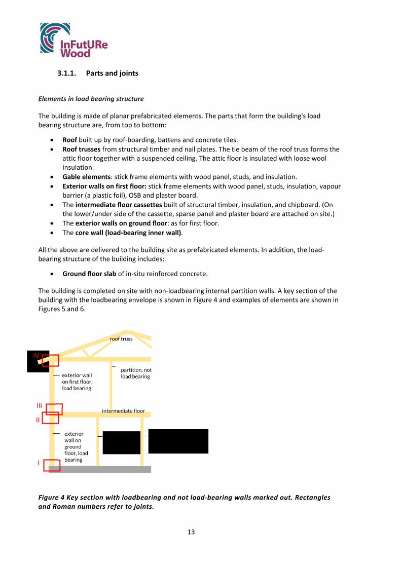
13
3.1.1. Parts and joints
Elements in load bearing structure
The building is made of planar prefabricated elements. The parts that form the building's load bearing structure are, from top to bottom:
Roof built up by roof‐boarding, battens and concrete tiles. Roof trusses from structural timber and nail plates. The tie beam of the roof truss forms the
attic floor together with a suspended ceiling. The attic floor is insulated with loose wool insulation.
Gable elements: stick frame elements with wood panel, studs, and insulation. Exterior walls on first floor: stick frame elements with wood panel, studs, insulation, vapour
barrier (a plastic foil), OSB and plaster board. The intermediate floor cassettes built of structural timber, insulation, and chipboard. (On
the lower/under side of the cassette, sparse panel and plaster board are attached on site.) The exterior walls on ground floor: as for first floor. The core wall (load‐bearing inner wall).
All the above are delivered to the building site as prefabricated elements. In addition, the load‐bearing structure of the building includes:
Ground floor slab of in‐situ reinforced concrete.
The building is completed on site with non‐loadbearing internal partition walls. A key section of the building with the loadbearing envelope is shown in Figure 4 and examples of elements are shown in Figures 5 and 6.
Figure 4 Key section with loadbearing and not load‐bearing walls marked out. Rectangles and Roman numbers refer to joints.
core wall, load bearing
partition, not load bearing
I
II
III
IV
partition, not load bearing
exterior wall on first floor, load bearing
exterior wall on ground floor, load bearing
roof truss
intermediate floor

14
Figure 5 Exterior wall elements. Image: Derome
Figure 6 Floor elements (cassettes).
Currently, for Villa Anneberg as for other buildings, the potential to deconstruct and reuse is not a design criterion. The design of the exterior wall panels aims to achieve energy efficiency, avoid thermal bridges, achieve moisture safety, and achieve sound‐absorption (Figure 7). To that end the wall is designed with:
• A three‐layer construction (having three layers of insulation). • The vapour barrier (plastic foil) placed inside the internal finishes of the wall. This is to
ensure that it will be continuous/unbroken and provide for maximum airtightness. Electric services can be installed without breaking the barrier.
• Continuous/unbroken outer insulation layer, to minimize thermal bridging. A weather/wind sheet membrane placed externally to the insulation insures moisture‐protection to the structural frame.
An external facade primarily weatherproofs the wall, but also provides some insulation to reduce any linear thermal bridging.
Figure 7 Wall design. Image: Derome
The wall panel is comprised of: 1 & 2. External timber cladding fixed to horizontal and vertical battens 3. Quilt insulation 4. Wind sheet membrane 5. Structural timber frame, quilt insulation between structural posts 6. Air‐tightness membrane (plastic foil) sealed using a synthetic isobutylene with isoprene sealant 7. Vertical internal battens with an additional insulation layer between the battens 8. OSB layer 9. Gypsum internal plaster finish taped and skimmed.

15
Joints
The dominant connection technique is screw connections. Some nail joints also occur. An overview of joints and joint techniques is given in Table 1.
Table 1 Overview of joints and joint techniques
Part Connection (position of) Technique
Roof Battens/roof‐boarding Nail connection Roof‐boarding/roof truss Nail connection
Roof trusses Roof truss/exterior wall, first floor Screw connection with angle bracket
Gables Exterior wall first floor/intermediate floor Screw connection Vertical corner joint Screw connection
Attic floor/ ceilings Secondary spaced boarding /roof truss Nail connection Gypsum plasterboard/ secondary spaced boarding
Screw connection
Exterior wall, first floor
Exterior wall/intermediate floor Screw connection Wall/wall Screw connection Wall/wall, corner Screw connection
Intermediate floors Floor/exterior wall Screw connection Floor/floor Screw glued connection
Exterior wall/ Screw connection Exterior wall, ground floor
Exterior wall/baseplate on ground slab Screw connection Wall/wall Screw connection Wall/wall, corner Screw connection
Plate on ground incl. Sleeper
Baseplate/slab Expander nail
The screw connections wall‐to‐floor are of the basic type shown in Figure 8 (I & III). Exterior wall elements on the first floor are screwed to a baseplate placed on the cassettes forming the intermediate floor. Likewise, the exterior wall elements on the ground floor are screwed to a baseplate on the ground slab.
Figure 8 Screw connections, principle. Roman figures refer to joint numbers in Figure 4. Image: Träguiden
I & III
II

16
Floor cassettes are screwed to exterior wall elements on the ground floor from the outside similarly to the principle shown in Figure 8 (II). The screw heads are covered by the wall element on the second floor when that is mounted on top.
Roof trusses are connected to the top plates of the exterior walls with screws and angle brackets (Figure 9).
Figure 9 Angle brackets connect roof trusses to walls. The photos show roof trusses being installed. In this specific case, the assembly team has mounted the angle brackets before mounting the roof truss. Images: Derome
The vertical joints where exterior wall elements meet are screwed together (Figure 10).
Figure 10 Section showing a wall‐to‐wall connection. Studs are screwed together.
To that end, part of the panels are left open during assembly (Figure 11).

17
Figure 11 Exterior wall panel lifted in place during assembly, ends are left open to allow for screwing. Image: Derome
The longitudinal joints between floor cassettes are screw‐glued (Figure 12).
Figure 12 Section showing a connection between two floor cassettes. The particle board on top of the left cassette is glued and screwed to the right cassette.
3.1.2. Presence of chemicals
The building is qualified according to the environmental assessment system “Svanen” (“Nordic Swan Ecolabel”), (Svanen 2021). There is one exception: the joint wall‐to‐wall does not qualify, as a tape containing butyl is used to make the connection airtight.
No wood is impregnated (neither pressure impregnated nor otherwise). The chipboard on top of the floor cassettes is of a moisture‐proof type (V313) but is not considered environmentally unfriendly – it passes the Nordic Swan Ecolabel.
3.1.3. Mechanical and electrical services and their connection to the load bearing structure
Installations for electricity, water and sanitation pass vertically primarily through non‐load‐bearing partition walls built on‐site and occasionally in exterior walls. In the horizontal direction, installations run along the beams in the cassettes. Water pipes that are narrow can also go across beams. Sometimes drainpipes can also be drawn across beams (unless too large holes would be needed). Exhaust air is the most used ventilation system for this building concept. The plant is located in shafts or in thick partitions. Ventilation shafts never go across beams due to their potentially large dimensions. Sometimes heat‐recovery systems are fitted to Derome houses with controlled exhaust ventilation and supply air. This requires a dual‐channel shaft system.

18
3.1.4. Assembly process for current design
The assembly process can be described as a conventional process from the bottom up (Figure 13), (compare Hemming 2012). A concrete slab is cast onto insulation on the ground level. On this, prefabricated elements are mounted by special assembly teams. The parts come as planar elements from the factory where they have been fitted with transport protection and packed and braced for safe transport. The components are weather protected while waiting for transport. At the construction site, the prefabricated parts are lifted from the transport vehicles with a crane for assembly on site. According to Derome, it takes one day to mount what is delivered from the factory on the cast slab and get the building to finished roof level. Usually, due to the short erection time, no special weather protection is used during assembly. The wood is not expected to have time to absorb harmful amounts of moisture during the hours it takes to have the roof in place.
After this first day of assembly it takes a week to get the building airtight. It takes in total 16‐20 weeks before the customer can move in, largely because of the process needed to dry out the concrete slab.
Roughly, the load bearing structure with its prefabricated elements is assembled in the following steps:
The ground floor slab is cast. Baseplates are mounted at the perimeter of the floor slab and core wall.
o Baseplates are anchored to concrete with expander nails. Exterior wall elements are lifted by crane from the truck and mounted to baseplates. Walls
are braced. o Walls are attached to the baseplates from the inside with a screw through a scantling
in the bottom edge and baseplate. (Compare principle in Figure 8.) o Wall elements are attached to each other in vertical joints with structural screws
through two studs, one from each element. The connection is made airtight. o Parts of elements that were left open to allow for screwing are closed (insulation,
studs and OSB are added). Core wall elements are lifted with a crane from the truck and mounted.
o Wall elements are attached to the base plate with screws. Floor cassettes are lifted by crane from the truck and placed on outer walls and core walls.
o The cassettes are screwed to external walls from the outside; obliquely downwards‐ inwards through the edge beam and the top plate. (Figure 8.)
o The cassettes are screwed to the core wall elements from the bottom up through top plates and edge beams.
Baseplates are mounted on floors all around. o Baseplates are screwed with one construction screw in the edge beam and one
construction screw in one of the load‐carrying beams. Exterior walls elements on first floor are assembled similarly to wall elements on ground
floor. Gable elements are lifted by crane from the truck and mounted on exterior walls.
o Gable elements are attached from the inside with construction screws through scantling and baseplate.
Roof trusses are lifted by crane from the truck and mounted on exterior walls. o Roof trusses are attached to top plates with angle brackets and screws. o Scaffold boards (ramps) are placed on ceiling joists.

19
The roof‐boarding comes in units consisting of several boards. Boards are nailed to the roof trusses. Two nails connect each board to a truss.
Battens and counter battens are nailed to the roof‐boarding. Concrete tiles are nailed to battens.
Figure 13 Assembly of a Villa Anneberg. Image: Christin Ljungqvist and Derome (bottom left)
3.2. Deconstruction process
A deconstruction process was formulated and assumed to be carried out in eight phases, Table 2. The note “Comment MÖ” below refers to personal reflections from Mikael Öqvist who has deconstructed and reassembled a Derome produced detached house and who took part in the discussions, as mentioned in section 2.3.

20
Table 2 Assumed deconstruction process for Villa Anneberg
Deconstruction step Description, what is done
1. Preparatory work Water and drainpipes are cut off at the bottom slab. Surface layers and internal partition walls are removed so that the structural frame is exposed. Comment MÖ: even surface layers can be reused, as parquet floors were reused in his case. The disassembly should therefore be done with appropriate caution. We discussed back and forth whether gypsum plasterboards must be separated from the load bearing walls. We concluded that it should be technically possible to keep them during deconstruction and reuse the whole assembled wall element with all its layers if plasterboards are protected during transport. The bathroom is demolished which is a big challenge. Comment MÖ: this was difficult. The tiles were heavy, and it was expensive to send material to landfill. Scaffolding is erected. Load bearing walls are braced.
2. Roof
Roof trusses and gable ends are temporarily braced. Concrete roof tiles are removed. The roof trusses are stripped back of battens, felt, and roof boarding. This is probably done with a crowbar and the material is removed for disposal as it will be damaged. Alternatively, the roof‐boarding could be sawn up into panels which could be reused or recycled. In that case, the short pieces left on the roof trusses are removed on site. Exterior walls are braced.
3. Roof trusses
The loose wool insulation in the attic is removed using a sludge suction truck. Installations/services in the attic are taken out. The suspended ceiling attached to the roof truss subframe is removed. The joint with screws and brackets connecting trusses to load‐bearing walls are disassembled or sawn apart. Loops are fastened to trusses. The trusses are lifted one by one with a crane. Comment MÖ: it should be possible to lift several roof trusses at the same time and possibly with their roof‐boarding left on, instead of lifting them one by one. That would be more efficient and risks with persons standing next to roof trusses would be lower, as would waste of roof‐boarding.
4. Gables Temporary braces are attached to the gables to create firmaments for lifting loops. The gables are lifted with a crane.

21
5. External walls, first floor
Disassembly of the vertical wall‐to‐wall connection is carried out in two steps. First, panel boards are removed to uncover the structural screw connections. Then, screws are unscrewed. Note: at the meeting, we did not discuss how to find the joints and how to identify the right panel boards to lift to expose screws. This information needs to be stated in a deconstruction documentation. Disassembly of the wall‐to‐floor junction is also carried out in two steps. 1) Screws must first be uncovered as they are not exposed but covered by gypsum plasterboards and OSB boards. Uncovering can be done by a) removing plasterboards and OSB boards entirely or b) by sawing a horizontal section 100‐200 mm above the floor level, removing plasterboard and OSB. This is possible at least in theory. 2) The screws that connect scantlings in the wall with the baseplates on the intermediate floor are unscrewed or cut off with a saw. Note: not prescribed connectors (nails) may occur. Exterior walls are then removed in the same format as they were installed. Loops are mounted and the elements are lifted by crane to transport vehicles. Comment MÖ: MÖ used the same loops that had originally been used for mounting the elements, as they were left in the walls. The building was 6 years old and the loops were in a good condition.
6. Intermediate floor cassettes
Any flooring (parquet/tiles/wood) or sound‐insulating layers that remains is removed for disposal. Disassembly of floor‐to‐floor cassette connection: The joints are located. Screws are unscrewed. The glued connection is disassembled by breaking the chipboard with a crowbar. Disassembly of floor‐to‐wall joint: The screws are now exposed and visible as the exterior wall on the first floor has been removed. Screws are unscrewed from the outside or sawn off. Loops are attached to floor cassettes and they are lifted by crane.
7. Exterior walls, ground floor
Process like that of first floor.
8. Slab An excavator chops the concrete slab to smaller pieces.
3.3. Strengths and weaknesses regarding deconstruction and reuse
The recorded knowledge and perceptions of the deconstruction process and reuse potential are presented in Appendix 1 (a slightly shortened, cleaned and translated version of the original Swedish version) and Appendix 2 (interpreted results restructured under the headings Strengths and Weaknesses for the different parts of the building).
In summary, the following strengths and weaknesses can be identified the current Villa Anneberg design with respect to deconstruction and reuse.

22
3.3.1. Strengths
Industrially produced, large elements with low weight developed for efficient assembly The structure is built up to optimize efficient production, transport, and assembly. The fact that elements are large and have low weight is beneficial for a rational deconstruction process.
As a general comment, MÖ stated that from his personal experience, deconstructing and reusing floor cassettes, load bearing wall elements and roof trusses poses no problems if you make an effort. (Contrarily, removing bathrooms required a lot of work in his case and lead to heavy waste that was expensive to dispose of. Solutions are not discussed further here as focus is on the load‐bearing wood‐based structure.)
Knowledge and logistics already at hand Knowledge and logistics are already in place for efficient and safe transport and assembly. The aspects of deconstruction and reuse can be worked into the business model if there are incentives to do so.
Detachable joints
Screw connections are used and are assumed to be demountable.
It might be possible to leave lifting loops in the assembled building. In the case of the deconstruction carried out by MÖ mentioned in section 2.3, wall elements were lifted in the same lifting loops that were used for the original erection, as they were left within the walls. This contributed to a fast and efficient process.
Few and common tools needed
Deconstruction can be done with a few common tools, as drill, saw and crowbar. As the elements are large, a crane will be needed for lifting. A potential for improvement exists, as it might be a good idea to develop a special tool for lifting wall elements – a tool that could be inserted to already existing holes intended for lifting loops.
Mechanical and electrical services are placed so that they are not expected to complicate
disassembly.
3.3.2. Weaknesses
Damages lead to material waste and time‐consuming restoration measures. The deconstruction of the exterior wall‐to wall‐joints and floor‐to‐floor joints will cause damage to the elements so that wall and floor elements will have to be repaired in a factory before reuse. Gypsum plaster boards and particleboards will be wasted in the process and will have to be replaced with new material. For the wall‐to‐wall connection, the problem is due to the fact that deconstruction will damage the vapour barrier (a plastic foil) so that it will have to be removed and replaced. The floor‐to‐floor cassette connections are glued and screwed. Disassembling the connection with a crowbar will damage the chipboard on top.
Hidden, sequentially constructed joints

23
The disassembly of screw connections in Villa Anneberg is made more difficult by the fact that several connections are hidden by boards (OSB, plasterboards or panel boards). This applies to the wall‐to‐floor joints for example, where you need to remove gypsum plasterboards to be able to disassemble the structural screw joint.
Unknown service life of vapour barrier The wall elements contain plastic vapour barriers. Their guaranteed service life is 50 years, which is shorter than the envisaged practical service life of the wooden frame. In practice, as the membrane is positioned between insulation layers in an environment protected from daylight and extreme temperatures, it is assumed here that the service life can exceed 50 years. In the following, we assume that a wall element can be reused after 50 years, with its original vapour barrier. This assumption will have to be verified.
Plaster boards are sensitive
Gypsum plasterboards are sensitive to damage. Lifting and transporting a wall element with plasterboards can lead to aesthetic problems (the paper layer may be wrinkled). This sensitivity is the reason why wall elements are originally mounted without the gypsum, which is added on‐site. Also, after decades of use, there will be holes in the walls caused by hanging of paintings et cetera. In this case study, we assume that wall elements will be deconstructed and reused with their original plasterboards left in place. After transport and reassembly on the new location, a new 6 mm thick plasterboard is assumed to be added to cover any superficial damage.
Disassembly of screw connections – feasible in practice? Screw connections are reversible in theory, but it would be good to have this assumption confirmed in practice. Studies should include or simulate screws that have been in use for several years and have been subjected to loads. Such investigations are out of the scope of this case study.
Not prescribed connectors complicate recovery and introduce risks
There may exist connectors (nails) in completed buildings that were not prescribed by Derome but have been added by the assembly teams. This was confirmed by MÖ, who has dismantled and rebuilt a Derome dwelling house. Such nails can be difficult to detect in a deconstruction process. It can also be difficult and time consuming to remove them. But more importantly, unprescribed nails could involve risks to workers in deconstruction. MÖ found that, when roof trusses were lifted with a crane, some trusses were stuck even though the structural screws connecting trusses to walls had been removed. Lifting the trusses until the nails gave way could potentially have been dangerous. Reasons for adding not prescribed nails could be (for example) a perceived need to keep an element in place while screwing the prescribed screws, or a need to tighten a joint.
Waste from roofs
The roof boarding will probably be damaged and all of it go to waste when boards are torn off with a crowbar. However, it might be possible to cut the boards off with a saw and reuse them in shorter lengths.
Verification of complex elements according to building regulations

24
The scenario envisaged includes reuse of whole elements. Large parts of the structure will not be visible for inspection after disassembly, as studs, insulation and vapour barrier are hidden behind boards.
Storing requires controlled climate As the building parts are wood based, temporary storing needs to be done in a controlled climate to avoid problems with biological growth. Protecting modular elements between constructs is a significant issue as covering/wrapping the units may cause condensation.
Need for weather protection The deconstructed parts are sensitive to moisture. If deconstruction turns out to be a slower process than assembly, the risk of damage due to rain is greater. The possible need for weather protection during deconstruction as well as appropriate methods are yet to be explored.
3.3.3. Several other questions followed from the analysis
Several questions that do not go under the categories strengths and weaknesses but still were considered as important if timber buildings are to be designed for reuse were noted during the discussions. Some of them will be mentioned here:
• How does the construction industry view future jobs in deconstruction, regarding safety and health? Can tasks such as disassembling with a jigsaw be solved in a good way or is there a risk of vibrations and "white fingers"? Can such work be attractive?
• Which houses are attractive enough / have qualities that make them likely to be moved? Do modern houses evoke such feelings that you take the trouble to move the house? Or is a competitive cost for a reconditioned house enough to incentivise a buyer?
• What quality do the parts of the building need to have? Should gypsum plasterboards be replaced with plywood, for example?
• What future material costs can be assumed? Today, labor costs of say SEK 500 / h are set against material costs x. But in the future, there will perhaps be a different relationship and a shortage of raw materials. What ratio is required for it to be profitable to reuse?
• Which standard dimensions should apply to wall and floor elements if standard dimensions are desired? The weather protection of the units during transport and storage could be a limiting factor but other considerations will also come into play.
• Who takes responsibility for the load‐bearing capacity of composite disassembled components such as wall elements and floor elements and how? That is, how do you verify the building regulations' requirements for stability, strength, and durability of used elements? Will we need updated building codes, that take reuse scenarios into account?
• Are light stick frame elements to be regarded as reusable in their composite form (as we have done here)? Or is it a problem that: 1) studs and their joints cannot be inspected visually 2) the plastic foil risks aging so that you want to replace it before reuse and installation in a building that will stand 50 ‐ 100 years?

25
3.4. Potential for improvement
Having focused mainly on the load bearing structure, and having aimed at changing weaknesses but retaining strengths, we identified the following potential areas for improvement of Villa Anneberg.
3.4.1. General
Measures to avoid not prescribed connectors
Measures to avoid not prescribed connectors could be worked out. This could potentially reduce time and energy consumption during disassembly and reduce personal risks.1 Joint details may need to be improved. Alternatively, clearer installation instructions for assembly teams might eliminate risks. This kind of improvement should be worked out together with assembly teams and be based on their experiences.
Taking the roof as an example, MÖ experienced a risk for workers while deconstructing roof trusses. When trusses were lifted with the crane after deconstruction of screw connections, trusses were held back by nails that were unknown to the deconstruction team. When nails suddenly yielded, trusses moved in an unexpected way. That could have been dangerous to the person standing next to the truss.
To minimize the risk that assembly teams add nails that are not prescribed, the screw connection roof truss to‐wall could be further developed: angle brackets could be pre‐assembled in the factory or an alternative design could be worked out for the screw connection. Alternatively, it might be sufficient to state clearly in assembly instructions that angle brackets must be mounted before the roof trusses are placed on the walls (as was the case in Figure 9). This should eliminate the need for extra nails, as roof trusses won’t need to be fixed while the brackets are mounted. Deconstruction instructions could be worked out and include information on how to check for extra nails connecting roof truss and wall before lifting. Instructions could also show alternative methods for deconstructing the roof, as lifting several or all roof trusses (with boarding in place) simultaneously instead of lifting one roof truss at a time. Similar processes are used in construction today and should be applicable in deconstruction. This would lead to less waste of roof‐boarding would reduce time spent on deconstruction as well as risks to workers.
Increase readability
Screw heads can be marked with spray paint to make it easier to find them during a deconstruction process. Painted screws then provide a lesser health and safety hazard.
1A similar problem was identified in a case study by Chisholm (2012). She stated that due to the two‐stage construction of the Sigma Home ‐ factory fix and site‐installation, the crossover between the two becomes important. In that case, the absence of fixing information on drawings resulted in confusion on site during construction and a lack of transparency regarding deconstruction. She suggested that measures should be taken to minimise fixings and reach a strategy for disassembly.

26
Verify reusability in practical study
It has been assumed here that it is technically possible to deconstruct and reassemble planar elements, complete with all their layers and materials (as boards, studs, insulation, vapour barriers and wind barriers). However, questions have arisen:
Whether you can rely on old vapor barriers and if they can be kept intact during a deconstruction process.
Whether screw connections are reversible in practice or if screws break, work will include poor ergonomics or screwing a second time will be prevented by the presence of old holes or old left‐in screws.
Practical studies, where elements are deconstructed and reassembled, are needed out to verify the reusability assumed.
Instructions for weather protection
Methods and instructions for weather protection during deconstruction (example, Figure 14) could be developed to make sure that there is no risk for moisture damage.
Figure 14 Weather protection. Methods and instructions for weatherproof deconstruction needs to be developed. Image: Andreas Videll, Derome
3.4.2. Roof and roof trusses
The building could be designed with roof cassettes; members that are both loadbearing and insulating (Figure 15). Roof cassettes, unlike roof trusses, do not need temporary bracing during erection and deconstruction. The risk that assembly teams add superfluous connectors is probably smaller for this type of structure than for roof trusses. After deconstruction, the entire cassette can be reused, and no boarding will go to waste. The cassettes are robust and easy to handle in deconstruction and transport, which should reduce time and energy consumption compared to handling roof boarding and roof trusses. In summary, time, waste, and risks should be reduced by building with roof cassettes.

27
Figure 15 Roof cassette, example. Image: Lättelement AB
3.4.3. Walls
Elements prepared for disassembly process
The time spent on disassembly would decrease if wall elements were more prepared for lifting in the deconstruction stage. Measures could be taken to make it easier for disassembly teams to know where to go and with which tool to lift.
The position of the holes intended for lifting loops should be the same for each element type and should also be specified in a deconstruction instruction, so that a future deconstruction team can easily find them. This is true today for rectangular wall elements, but holes in gable elements are drilled manually and their positions vary from one element to another. Also, lifting the gables would be easier and faster if special tool was manufactured, intended for lifting the gable in the holes of the original lifting loops. Alternatively, an existing, common tool might possibly be used and be specified in a deconstruction manual. This would have to be studied further.
It could be studied further if lifting loops used in primary construction (Figure 16) could systematically be left within in the walls, without causing problems such as gaps between wall and floor. The loops could be reused if deconstruction took place in a few years. If the loops have reached an age of several decades, it might be necessary to replace them but having the original ones in place should simplify the replacement.

28
Figure 16 Lifting loops like this might possibly be left in the mounted structure, but this would have to be studied.
Methods for reconditioning
Provided that wall elements can be reused with their original plasterboards left in place, methods to refurbish walls where the plasterboard has been wrinkled during deconstruction and transport could be developed. An existing technique for renovation projects, is to add a thin gypsum plasterboard to cover imperfections. Plasterboard finishes are routinely tapped and skimmed. Other techniques could be explored or developed. Maybe historic techniques using materials like linen textiles or paperboard could be taken as inspiration and starting point for such a development.
Methods for assessment of light timber elements
Strategies for verifying the demands of building regulations (as mechanical resistance and stability, safety in case of fire and hygiene, health, and the environment) for reused stick frame elements need to be developed.
Alternative frame principle
Alternatively, an entirely different type of wall construction could be used, that does not require a vapour barrier and/or does not make use of gypsum plasterboards. OSB boards that act as vapour barriers are available on the market and CLT elements could be used. To find the solution that would give the least environmental impact and best economical sustainability special studies would be needed.
3.4.4. Floors
Use floor cassettes
The concrete slab could be replaced with wood‐ based floor cassettes. The solution should be made moisture‐safe with devices for monitoring the climate in the ground and (possibly) controlled ventilation.

29
3.4.5. Connections
Connection roof truss‐to‐wall
This design of this connection and/or its assembly instructions could, as mentioned earlier, be further developed to minimize the risk that assembly teams put in nails during the primary assembly.
Connections wall‐to‐floor and wall‐to‐wall panel
The junctions “exterior wall‐to‐intermediate floor”, “exterior wall‐to‐ground slab” and “wall‐to‐wall panel” could all be developed to be more reversible. It would be preferable if they could be disassembled in one single step, using a minimum of time and energy. Today, deconstruction would have to be done in several steps as gypsum plaster boards need to be removed to expose the structural screws hidden behind.
Connection floor‐to‐floor cassette
This screw‐glued connection could be developed so that it can be dismantled without causing damage to chipboard or beams.
3.4.6. Other
The building could be built with bathroom modules. This is not an issue specific for the load bearing structure in focus here but worth mentioning as the bathrooms give a lot of waste today. Materials cannot be reused and getting rid of the waste is time consuming and expensive. Also, if the bathroom pods had a facility to close off inlets and outlets, this might reduce damage to the timber structure from wastewater after decommissioning of the building, as often there is a delay between occupancy and deconstruction.
Insulation boards could be used to replace loose wool insulation to isolate the attic. Getting rid of loose wool in a deconstruction situation would require a lot of transport as the loose wool is not compressed when taken out. However, this alternative solution is not only positive and the change in design is not obvious as using loose wool insulation is better from a health and safety aspect in the primary construction process. Blowing the loose wool out when erecting the building is done in 2‐3 hours and in a comfortable position for the worker. Working with boards means crawling on knees, is difficult and would take almost a week. Also, as boards have higher density, use of boards will probably lead to a higher amount of green‐house gases being produced in the primary construction.
3.5. Selection of details to improve
Based on what researchers and industry considered most promising and still feasible to study within the time and resource limits of the InFutUReWood project, three areas of improvements (three connections) were selected for further study: connection wall‐to floor, wall‐to‐wall panel junction and floor‐to‐floor cassette connection.
Beside what has previously been mentioned about the disadvantages of these details, a few more words will be said here on current designs and the motives for modifying them.

30
3.5.1. Connection wall‐to‐floor
The current connection exterior wall‐to floor is of the same type for both first and ground floor. Figure 17 illustrates the detail for the case exterior wall‐to intermediate floor. In discussions, we have assumed the current connection to be disengaged by unscrewing the structural screws after removal of gypsum plaster boards. Two methods to remove the gypsum to expose the screws were considered possible: 1) Either a horizontal cut is made in the plasterboard about a 100 mm above floor level, and the strip of plasterboard thus created is removed. The connection is then unscrewed. In reuse, reassembly includes patching up with a new strip of plasterboard and covering the wall on the inside with 6 mm gypsum plasterboard to cover damages. 2) Or the complete gypsum plasterboard is removed. In reuse, this is replaced with a new one.
Regardless of method chosen, having to remove the plasterboard is an important disadvantage as it will be time and energy consuming. Also, getting rid of the waste will be associated with costs.
Figure 17 Current wall‐to‐floor assembly. Left: Step 1. The gypsum layer is omitted to allow structural assembly. The airtightness layer is dressed under the horizontal floor batten. No sealant is used. Right: Step 2. When the panels are structurally connected to the base post, a gypsum finish is applied to the whole room. The finished floating floor is then fitted. NOTE: A section of the internal wall panel finish is also omitted during transport, which is also completed before applying the wall finishes. The diagrams are orientated left‐right from outside to inside.
3.5.2. Wall‐to‐wall panel junction
The motive for improving this connection is partly the same as for the one just mentioned: deconstruction must be done in sequences and waste will be produced. A problem that is specific for this connection is related to the scenario. The scenario we assess the design for includes reuse of entire wall elements and requires that the plastic vapour barriers in the panels are still intact after deconstruction. With current design, deconstruction will damage the vapour barriers. Figure 18 shows the connection with current assembly steps of the wall panel in‐situ. Studying the detail, discussions led to the assumption that future deconstruction of the joint might be done in two different ways: by unscrewing the structural screw connections or by cutting them off with a saw.2 In the first case, removal of gypsum, OSB, vertical battens, and internal insulation layer is necessary in
2 It was found during the previous disassembly and reassembly of the similar MÖ one‐story house, that it was more efficient to cut through the internal wall finishes and the structural screw connections than unscrewing the screws. All panels were diverted to the manufacturing facility where the gypsum, OSB, vertical battens, and internal insulation layer were removed to expose the air‐tightness membrane for replacement. Additionally, the original gypsum layer was discarded and replaced entirely at reconstruction of the building.

31
order to expose the screws. In the other case, gypsum and OSB will have to be removed before cutting.
Both methods will expose the air‐tightness membrane in the wall panels to damage. Also, the original gypsum layer will be destroyed. It will be necessary to divert the wall panels to a manufacturing facility to disassemble them and complete them with a new vapour barrier, internal insulation layer, battens and OSB. The gypsum plasterboard will be replaced entirely at reconstruction of the building.
Figure 18 Current wall panel assembly. Top left, step 1: For the assembly, the exterior wall panels are left incomplete during transport. A section of the internal OSB layer and internal batten and secondary insulation layer is omitted, to expose the structural posts for assembly on‐site. The airtightness membrane is dressed back on the internal face of the panel to allow access to main structure. The standard assembly practice consists of screwing the structural posts. Top right, step 2: The airtightness membrane is overlapped and sealed with a synthetic isobutylene with isoprene sealant. This sealant is not biodegradable. A vertical internal batten fixes the seal. Bottom left, step 3: The breach to the internal insulation layer can now be bridged. Bottom right, step 4: The OSB layer is completed. A gypsum finish is applied to whole room.
3.5.3. Floor‐to‐floor cassette connection
Figure 19 illustrates the connection assembly of the internal intermediate floor cassettes. Currently, the floor cassettes comprise a chipboard floor deck onto a joisted floor frame. An overlap of the deck is screwed and glued onto the adjacent deck, with a batten parallel with the main joist providing additional support to the deck. The cassettes are glued to comply with Swedish design standards to mitigate movement in the lightweight floor. Also, cassettes need to work together as a whole (to provide diaphragm action in the floor when carrying horizontal wind loads).
As a result of the glued connection, deconstruction will be difficult and disengaging the connection will damage both chipboard and joists significantly.

32
Figure 19 Existing floor to floor assembly. Left, step 1: Chipboard floor deck glued and nailed to structural edge joist, with additional 45 mm support to the deck. Right, step 2: Gypsum ceiling to battens.
3.6. Calculation of the amount of wood that can be reused with today's design
In the simulation of deconstruction and reuse, waste due to damage was discussed and estimated. The loss during disassembly for load‐bearing components was estimated as follows.
Roof boarding and roof battens: 100 % waste. The boards will be damaged when removed from the trusses. NOTE: these parts could be recycled. They might be used for producing chipboards for example. As it is out of the scope of this case study to examine possible recycling scenarios, the parts are here considered as waste, which a pessimistic assumption.
Roof trusses: 0% waste. The trusses are judged to be reusable in their entirety. Gables: 0% waste; they are judged reusable in their entirety. Exterior walls are judged to be reusable almost in their entirety. To account for some
damage in handling, 0,15 m3 wood is assumed to go to waste. Intermediate floor: 20 – 25 % of each floor cassette is judged to be wasted as joists and
chipboard will suffer local damage when the chipboard is torn loose. Baseplates: 100% waste.
It follows from the estimate, that 11 580 of the 14 000 kg wood in the load bearing structure could be reused with the current design.3 That is, 82,7 % (details, see Table 3).
3This study focuses on the load‐bearing structure of Villa Anneberg and does not account for reuse of other parts of the building. Still, it can be worth mentioning here that the interior non‐load‐bearing walls were judged to go to waste entirely in a future deconstruction. That is because surface layers/boards will be damaged and because studs are supposed have too low an economical value for it to be worthwhile to take them apart and sell them.

33
Table 3 Calculation of amount of wood that can be reused with current design Mass [kg] Estimated waste, roof boarding 1320 Estimated waste, roof battens 308 Estimated waste, floor cassettes, solid timber 176 Estimated waste, floor cassettes, chipboard 250 Estimated waste, wall studs 66 Estimated waste, baseplates 300 Total waste 2 420 Wood in the whole load bearing structure 14 000 Estimated mass of wood that can be reused: 14 000 – 2 420 = 11 580 Amount that can be reused: 11 580/14 000 = 0,827
3.7. Modified design
Designs were developed to meet our criteria for an improved solution. Improvements within the current production principles were sought. A solution like “replacing the light timber structure with a CLT structure” was not considered, neither replacing screws with bolts.
3.7.1. Modified connection wall‐to‐floor
Figure 20 illustrates the alternative assembly sequence that resulted from discussions between researchers and Derome. The inevitable damage and subsequent disposal of the gypsum wall finish, currently, is avoided by stopping the wall finishes short of the floor and introducing a timber skirting board. This timber board can be removed and reused. Alternatively, an additional 6 mm plaster finish to the internal walls for the secondary building will negate the need for a skirting board.
Figure 20 Revised wall to floor assembly. The diagrams are orientated left‐right from outside to inside. Left, step 1: The OSB and gypsum layers are now finished short of the floor to allow access for structural fixing. The airtightness layer is dressed under the horizontal floor batten, as before. Any breach of the airtightness membrane due to the unscrewing of the bottom structural fixing is deemed insignificant due to its location at several timber supports. Right, step 2: The finished floating floor is fitted. A timber skirting board, fixed to timber grounds, finishes the wall at the floor. The skirting board can be removed and reused. The

34
main bottom fixing is accessible for disassembly and reassembly without any significant damage to the wall.
3.7.2. Modified wall‐to‐wall panel junction
The next modification is judged by Derome to be such an improvement in several aspects, that it is likely to be integrated in production soon (within the coming months).
This study aimed to revise the vertical wall‐to‐wall detail to allow for reuse of whole, intact wall elements. With the modified design, the wall‐panels can be more substantially completed initially at the factory. They can be deconstructed and transported directly to the secondary site, for reassembly without any diversion for substantial repair. Figure 21 shows the sequence of assembly of the alternative connection. With the revised design, vapour barriers are not overlapping at the connection. Air tightness is achieved with an ordinary type of tape (does not require the use of butyl). The gypsum plasterboards are stopped short of the connection and are intended to be kept in the future deconstruction and reuse.
Deconstruction is assumed to be made by 1) finding the connection (can be seen from above) 2) taking off the strips of plasterboard and OSB 3) unscrewing the structural screws.
Figure 21 Revised Derome Villa Anneberg wall panel assembly. The diagrams are orientated top‐down from outside to inside. Top left, step 1: The panel is transported from the manufacturing facility complete with internal insulation, OSB and gypsum layers. The airtightness membrane is dressed in around the vertical batten. The batten size is increased to facilitate the structural fixing through to the main supports. Top right, step 2: The airtightness layers are sealed with a proprietary tape. (Butylband is not required). The OSB and gypsum layers are finished short of the junction locally to allow access for structural fixing and sealing of membranes. Bottom left, step 3: The small gap in the OSB and gypsum layers is repaired on‐site to a condition that matches the adjacent finishes.
3.7.3. Modified floor‐to‐floor cassette connection
The revised assembly design adds an additional edge joist for each cassette (Figure 22). Chipboards are glued to the joists, but the overlapping part of the chipboard is screwed without glue. It is
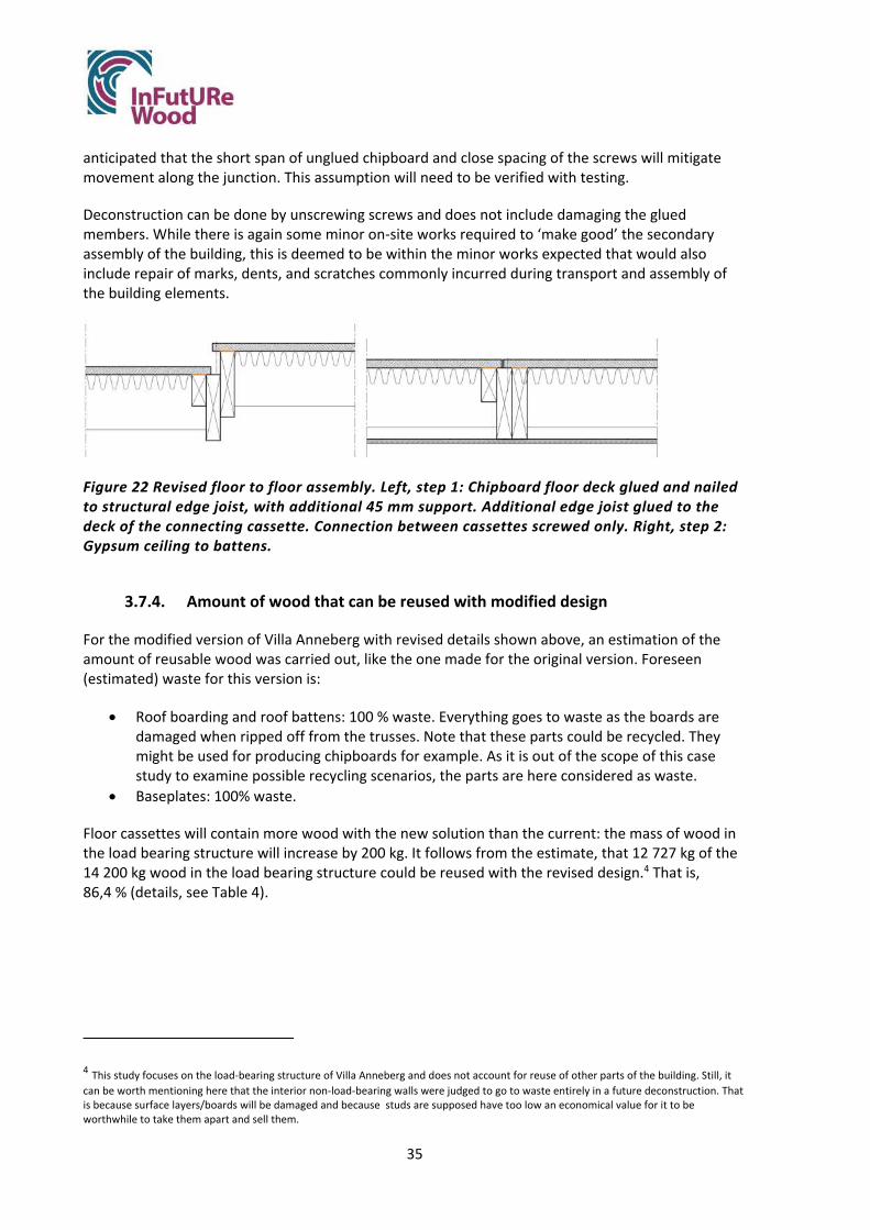
35
anticipated that the short span of unglued chipboard and close spacing of the screws will mitigate movement along the junction. This assumption will need to be verified with testing.
Deconstruction can be done by unscrewing screws and does not include damaging the glued members. While there is again some minor on‐site works required to ‘make good’ the secondary assembly of the building, this is deemed to be within the minor works expected that would also include repair of marks, dents, and scratches commonly incurred during transport and assembly of the building elements.
Figure 22 Revised floor to floor assembly. Left, step 1: Chipboard floor deck glued and nailed to structural edge joist, with additional 45 mm support. Additional edge joist glued to the deck of the connecting cassette. Connection between cassettes screwed only. Right, step 2: Gypsum ceiling to battens.
3.7.4. Amount of wood that can be reused with modified design
For the modified version of Villa Anneberg with revised details shown above, an estimation of the amount of reusable wood was carried out, like the one made for the original version. Foreseen (estimated) waste for this version is:
Roof boarding and roof battens: 100 % waste. Everything goes to waste as the boards are damaged when ripped off from the trusses. Note that these parts could be recycled. They might be used for producing chipboards for example. As it is out of the scope of this case study to examine possible recycling scenarios, the parts are here considered as waste.
Baseplates: 100% waste.
Floor cassettes will contain more wood with the new solution than the current: the mass of wood in the load bearing structure will increase by 200 kg. It follows from the estimate, that 12 727 kg of the 14 200 kg wood in the load bearing structure could be reused with the revised design.4 That is, 86,4 % (details, see Table 4).
4 This study focuses on the load‐bearing structure of Villa Anneberg and does not account for reuse of other parts of the building. Still, it can be worth mentioning here that the interior non‐load‐bearing walls were judged to go to waste entirely in a future deconstruction. That is because surface layers/boards will be damaged and because studs are supposed have too low an economical value for it to be worthwhile to take them apart and sell them.

36
Table 4 Calculation of amount of wood that can be reused with modified design Mass [kg] Estimated waste, roof boarding 1320 Estimated waste, roof battens 308 Estimated waste, baseplates 300 Total waste 1 928 Wood in the whole load bearing structure 14 200 Estimated mass of wood that can be reused: 14 200 – 1 928 = 12 272 Amount that can be reused: 12 272/14 200 = 0,864
3.8. Comparison current design ‐ modified design
The modified design leads to an increase in the amount of wood estimated to be accessible and reusable, compared to the current design. Note that the figures are based on estimations. Note also that the figures are based on the assumed reuse scenario.
The load bearing structure of the current design contains 14 000 kg wood, and the estimated reusable quantity is 11 580 kg. Thus 82,7 % of the wood can be reused today. The load bearing structure of the design with new connections contains 14 200 kg wood and the estimated recyclable quantity is 12 272 kg. Thus 86,4 % of the wood could be reused with the new design.
The figures show, that for each building another 692 kg of wood could be made available for reuse with a modified design. Let us see what this could mean on a larger scale.5
Derome could make up to 277 more tonnes of wood reusable per year. Derome today builds around 170 of Villa Anneberg buildings per year. With their other two‐storey models they build in total around 400 similar houses a year. Assuming all models use the same amount of wood (which is reasonable according to Derome), current Derome two‐storey designs use 5 600 tonnes of wood per year and 4 632 tonnes can be estimated to be reusable. New designs would use 5 680 tonnes of wood per year and 4 909 tonnes would be made reusable. The difference would be that 277 more tonnes of wood would be available for reuse per year if new design concepts were adopted.
Expanding the thought experiment to all buildings of this type in Sweden, up to 4 360 tonnes more wood could be available for reuse with modified designs. This estimation comes from the assumption (made by Anders Carlsson, Derome) that the Villa Anneberg production corresponds to 6% of the private market, which means that about 2 800 such buildings are erected per year in Sweden. In addition to these, similar houses are built in areas, about 3 500 per year. Other concepts than Villa Anneberg were not studied within this study, but if we play with the thought that all the around 6 300 buildings contain the same amount of wood and could augment the reuse potential in the same way, that would mean that 4 360 more tonnes of wood were made reusable (692 kg x 6 300 buildings).
Apart from the increased potential to reuse building elements, the modified Villa Anneberg design is most likely advantageous economically. The time needed for production in factory is estimated to be
5 Note that the scope of the study is narrow as only the load bearing structure is studied. Large quantities of materials are used in construction for less long‐lived parts as windows, doors and surface layers. The figures presented here could be related to (for example) the amount of surface materials replaced in refurbishments each year. Such analyses are beyond the limits of this work.

37
the same as for the current design, but a reduction of time at building site can be foreseen and is estimated to 5 minutes/ joint. The assembly on site is estimated to require less energy (50 W/joint).
Environmental and economic aspects of the original and modified designs are examined in a separate study within the InFutUReWood project (WP 6).
3.9. Guidelines for deconstruction and reuse, Villa Anneberg
In this chapter, we show what guidelines regarding deconstruction and reuse could look like for the revised Villa Anneberg design. This draft for guidelines is based on SEDA Design Guides for Scotland (Morgan & Stevenson 2005).
Statement of strategy for DfDR
Villa Anneberg is designed and assembled to enable a high degree of reuse of load‐bearing parts and climate shell. The design is adapted to allow for deconstruction of the building into its original planar elements and reconstruction of the building on a site with the same wind‐ and snow loads as the original building. For that scenario (where all building elements being are reused for their original purposes) approximately 85% of the weight of the timber in the load bearing structure can be reused.
Reusable parts are:
Roof tiles Roof trusses Exterior walls on ground floor and second floor Intermediate floor Core wall on ground floor
The parts may need to pass through the factory for reconditioning before reassembly.
Components that cannot easily be reused but can be recycled are:
Roof boarding Roof battens Roofing felt Ceilings (battens + plaster) Partitions (studs + plaster) Exterior supplementary boards
These should be sorted and divided into material‐unique fractions to enable either recycling of the material or incineration.
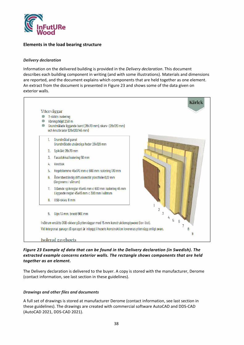
38
Elements in the load bearing structure
Delivery declaration
Information on the delivered building is provided in the Delivery declaration. This document describes each building component in writing (and with some illustrations). Materials and dimensions are reported, and the document explains which components that are held together as one element. An extract from the document is presented in Figure 23 and shows some of the data given on exterior walls.
Figure 23 Example of data that can be found in the Delivery declaration (in Swedish). The extracted example concerns exterior walls. The rectangle shows components that are held together as an element.
The Delivery declaration is delivered to the buyer. A copy is stored with the manufacturer, Derome (contact information, see last section in these guidelines).
Drawings and other files and documents
A full set of drawings is stored at manufacturer Derome (contact information, see last section in these guidelines). The drawings are created with commercial software AutoCAD and DDS‐CAD (AutoCAD 2021, DDS‐CAD 2021).

39
Building permit drawings are stored at the local municipality where the original building is erected.
Apart from drawings, the following files and documents describes the building and forms a BIM model (Building Information Model):
Purchase information and final quantity lists. Digital control files and files for managing cutting machines. Bill of quantity. Load planning document (showing how elements are fitted into trucks) for the original
assembly.
The files are created with DDS ‐CAD and Monitor (business system) commercial software.
All documents and files are stored at Derome at least ten years from the time of delivery to site (the warranty period).
Prior to deconstruction a desk study of the original design file and as‐built documentation should be carried out by a suitably qualified agent. Any variation from the design load or the as‐built drawings and health and safety and maintenance files should be noted.
Some elevations and layout plans are presented in Figures 24 and 25.
Figure 24 Elevations
Figure 25 Layout, ground floor (left) and first floor (right).
Definition of elements
The building frame consists of twelve exterior wall elements, five floor cassettes and core wall elements (Figure 26‐28). Quantities and performance of elements are given in Table 5.
The different elements are labeled to facilitate reassembly after deconstruction.

40
Figure 26 Exterior wall elements.
Figure 27 Exterior wall elements.
Figure 28 Floor cassettes.
Table 5 Quantities and performance of elements
Element type Label/Type number
Number of similar elements in building
Length [mm]
Depth (height) [mm]
Weight, one element [kg]
Performance declarations
Timber grade Insulation performance U [W/m2C]
Fire classification
Roof truss ‐ 10 9540 2106 84 C24 ‐ ‐ Gable element Gable 2 823 2106 308 C24 ‐ ‐
MB2 MB1 MB3 MB4 MB5
YV102 YV101
YV202 YV201
YV103
YV203
GABLE
YV106
YV206
GABLE
YV104 YV105
YV204 YV205

41
Exterior wall YV101 1 2503 439 C24 (C14 in 45 mm battens)
0,14 REI30
Exterior wall YV102 1 2503 1046 C24 0,14 REI30 Exterior wall YV103 1 8140 2503 1111 C24 0,14 REI30 Exterior wall YV104 1 2503 798 C24 0,14 REI30 Exterior wall YV105 1 2503 853 C24 0,14 REI30 Exterior wall YV106 1 8140 2503 1087 C24 0,14 REI30 Exterior wall YV201 1 2946 2503 429 C24 0,14 REI30 Exterior wall YV202 1 7146 2503 896 C24 0,14 REI30 Exterior wall YV203 1 8140 2503 1110 C24 0,14 REI30 Exterior wall YV204 1 5026 2503 744 C24 0,14 REI30 Exterior wall YV205 1 5066 2503 744 C24 0,14 REI30 Exterior wall YV206 1 8140 2503 1171 C24 0,14 REI30 Floor cassette MB 1 1 8140 1872 525 C24 ‐ ‐ Floor cassette MB 2 1 8140 2394 517 C24 ‐ ‐ Floor cassette MB 3 1 8140 2394 532 C24 ‐ ‐ Floor cassette MB 4 1 8140 2394 648 C24 ‐ ‐ Floor cassette MB 5 1 8140 1462 392 C24 ‐ ‐ Ground slab, reinforcement
581 C24 ‐ ‐
Ground slab,concrete
26820
Ground slab insulation, expanded plastic s100 s200
563 143
All elements in the loadbearing structure are judged to have a life span of 100 years.
Design loads
This building was designed for loads given in the building codes relevant at the time for construction.
On site assessments are mandatory
Prior to deconstruction, the building and its loadbearing structure should be assessed by visual inspection on site. This inspection is done to complement desktop studies of drawings and should be done by the person in charge of deconstruction and/or reuse.
This onsite and document inspections should also aim to evaluate the building's performance. Any variation to regulation from the initial build date should also be noted and addressed for the reconstruction phase. Changes in geometry, connections, supports, materials, and loads should be assessed. Special attention should be given to potential changes in load paths caused by new openings.
Methods for onsite inspection could include measuring of moisture content, thermography, and resistance drilling.

42
Disassembly instructions
Tools needed
Screwdriver Sabre saw with saw blade for wood and metal Circular saw Hammer Sledgehammer Crowbar Rope
Lifting and transporting facilities
Lifting loops Crane truck Truck Sludge suction truck for removing blown/loos insulation Excavator for chopping ground slab
Stages and activities
The recommended deconstruction process comprises eight stages (Figure 29): preparatory work (I), deconstruction of roof (II), roof trusses (III), gable panels (IV), exterior walls on first floor (V), floor cassettes (VI), exterior walls and core wall on ground floor (VII) and finally demolition of ground floor slab (VIII).
Figure 29 Deconstruction stages II‐VII. Not shown are stage I, preparatory work and stage VIII, demolition of concrete slab.
II
III
IV
V
VI
VII

43
I. Preparatory work
Surface layers and interior walls are removed to expose the main frame. Water pipes and wastewater pipes are disconnected. The bathroom is removed for disposal. Scaffolding is erected.
II. Roof
Roof structure, including trusses and gable are braced. Concrete roof tiles are removed. Battens nailed to the roof‐boarding are removed by crowbar. Roofing felt is stripped back for
disposal or recycling. Roof‐boarding is disconnected from roof trusses on site. Alternatively, roof‐boarding could
be sawn up to panels between trusses and the rest be left on roof trusses or torn off on site. Exterior walls on first floor are braced.
III. Roof trusses
The loose wool insulation in the attic is removed with a sludge suction truck. Any mechanical and electrical services in the attic are removed from the building. The suspended ceiling that is attached to the roof truss subframe is loosened. The joint with screws and brackets connecting trusses to load‐bearing walls are disassembled
or sawn apart. The connections roof to wall are checked for unprescribed nails. Loops are fastened to trusses. The trusses are lifted one by one with a crane. Lifting is done
carefully in case of unnoticed unprescribed nails. Alternatively, several roof trusses are lifted simultaneously with their roof‐boarding left on.
IV. Gables
Temporary battens are fastened to the gables to facilitate the connection of lifting loops. The gables are lifted with a crane.
V. Exterior walls, first floor
Figure 30 Wall‐to‐wall connection
To disassemble wall‐to‐wall connections (Figure 30), locate the connections from above. Remove exterior panel boards covering connections on the outside. Remove timber skirting boards. Remove strips of plasterboard and OSB covering connections on the inside by undoing
screws.
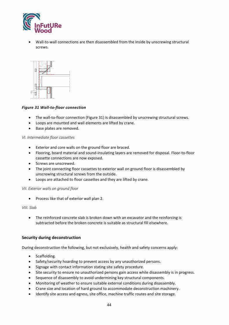
44
Wall‐to‐wall connections are then disassembled from the inside by unscrewing structural screws.
Figure 31 Wall‐to‐floor connection
The wall‐to‐floor connection (Figure 31) is disassembled by unscrewing structural screws. Loops are mounted and wall elements are lifted by crane. Base plates are removed.
VI. Intermediate floor cassettes
Exterior and core walls on the ground floor are braced. Flooring, board material and sound‐insulating layers are removed for disposal. Floor‐to‐floor
cassette connections are now exposed. Screws are unscrewed. The joint connecting floor cassettes to exterior wall on ground floor is disassembled by
unscrewing structural screws from the outside. Loops are attached to floor cassettes and they are lifted by crane.
VII. Exterior walls on ground floor
Process like that of exterior wall plan 2.
VIII. Slab
The reinforced concrete slab is broken down with an excavator and the reinforcing is subtracted before the broken concrete is suitable as structural fill elsewhere.
Security during deconstruction
During deconstruction the following, but not exclusively, health and safety concerns apply:
Scaffolding. Safety/security hoarding to prevent access by any unauthorized persons. Signage with contact information stating site safety procedure. Site security to ensure no unauthorized persons gain access while disassembly is in progress. Sequence of disassembly to avoid undermining key structural components. Monitoring of weather to ensure suitable external conditions during disassembly. Crane size and location of hard ground to accommodate deconstruction machinery. Identify site access and egress, site office, machine traffic routes and site storage.

45
Personal protective equipment through (safety shoes, goggles, hearing protection etc.). Valuation and identification of other risks for the building in question. Deterioration of
materials is a likely hazard with old and derelict buildings. Sufficient area to handle and pack the building parts in a way that means that they remain:
o Undamaged o Dry o Clean
Packaging /assembly. Transport of the building parts must be rational and safe. Traffic safety must not be compromised. Safety during loading and reconditioning must be considered.
Lifting aids for lifting the assembled components on a truck. Safe loading of truck and securing of load. Truck adapted for this type of transport. Building components must not be attached with additional or hidden attachments in
addition to those reported on assembly / disassembly documents. On‐site monitoring of building element connections for additional and potentially hazardous
fixings not included in the pre‐demolition report. This is to ensure that materials can be lifted clear of on‐site personnel, thus providing a safe disassembly practice.
Assessment of condition and performance
All elements must be assessed regarding damage by a structural engineer. For the assumed scenario (where all parts are reused to form a building identical to the original), additional strength and stiffness assessments are not mandatory for undamaged parts.
Storage
Roof tiles can be stored in outdoor climate if protected from dirt and damage.
Building elements can be stored outdoors for a limited time if they are protected from rain and snow. No exposure to rain or snow is allowed, not even for a few hours. Outdoor storage can only be allowed if elements are covered with plastic or are stored under roof. Elements should be monitored with respect to relative humidity. When plastic covers are used, measures must be taken to avoid condensation. With these conditions, roof trusses can be stored for a maximum time 10 days outdoors. Wall and floor elements can be stored for a maximum time of one week. It is possible to reach time limits of up to 1‐2 months in well controlled situations, with special precaution and close supervision.
When stored, all parts shall be well separated from the ground so that contamination caused by splashing is avoided.
Parts can also be stored indoors in unheated climate if monitored with respect to relative humidity. Precaution must always be taken to prevent moisture damage.
3.9.1. Reconditioning
The parts may need to pass through the factory for reconditioning before reassembly.

46
Wall elements are reconditioned after assembly on site by adding 6mm gypsum plaster boards on the inside of all elements.
Second assembly
Assembly is equal to original assembly. Instructions are found at Derome, se contact information below.
Document storage and distribution
Date of creation of this document
2021‐05‐21
This documentation is stored and managed by the owner of the building. When transferring the property, this documentation and the documents mentioned in it must be included in the sale. Any new owner must document and build on this documentation if the building is modified in such a way that it affects future dismantling and reuse.
This documentation could/should also be stored and managed by the local authorities, together with the building permit.
Contact information, manufacturer Derome
For further information, please contact manufacturer Derome.
Website: www.a‐hus.se, www.derome.se
Mail: [email protected]
Visit: Bjurumsvägen 14, Veddige, Sweden.
Health and safety and maintenance files
Health and safety and maintenance files should be prepared by the building contractor (overseeing agent) at each construction.
4. Discussion and conclusions
In this section, we discuss how well we reached the objective of the case study, to identify:
The inherent strengths of the current design of Villa Anneberg regarding deconstruction and reuse.
What weaknesses it has in the same respect. How the design could be improved with respect to future deconstruction and reuse.

47
How much wood that could be reused in the future with the current design and how much wood that could be reused after further development. By reuse we mean that a part / component is used for basically the same purpose as it was originally intended. (See also 1.5 Terminology.)
How guidelines for deconstruction and reuse could be formulated for this object.
And to test and develop a method for carrying out case studies.
4.1. Conclusions
The study filled a gap in the published knowledge on how timber buildings could be designed for deconstruction and reuse. We have identified advantages and obstacles to deconstruction and reuse of the current design of Villa Anneberg, showed how the design could be improved, how the improvement could be measured, how guidelines for deconstruction and reuse could be formulated and also, in general, a way to work to find new designs.
Strengths of the current design of Villa Anneberg regarding deconstruction and reuse
The current design of Villa Anneberg is relatively well prepared for disassembly already today. The building is designed for efficient transport and assembly and the process is judged to be reversible to a high degree. Many connectors are screwed, and the building can be deconstructed with common and simple tools. Mechanical and electrical services should not pose problems in deconstructing the structural frame.
Weaknesses of the current design of Villa Anneberg regarding deconstruction and reuse
The drawbacks in the current design are for example connections designed so that deconstruction causes damage to elements (which makes refurbishment before reuse mandatory), sequential connections that make deconstruction time consuming, the use of plasterboards that are sensitive to damage, use of plastic vapour barriers with unknown service life beyond 50 years and a risk that unprescribed connectors complicate deconstruction.
How the design could be improved with respect to deconstruction and reuse
New design concepts have been developed within the study as examples that illustrate what can be achieved. Three connections were modified to facilitate deconstruction and minimize the damage to elements caused by deconstruction. This change minimizes or eliminates the need for refurbishment of elements in factory prior to reuse.
These improvements were achieved with small adjustments in design and within existing technology. Other changes could also be envisaged, based on the identified strengths and weaknesses of the existing design.
Amount of wood that could be reused with the current design and with the improved design
The amount of wood that can be reused is relatively high already with the current design. More than 80 % of the wood could be reused with the scenario envisaged (deconstruction of the whole building and reuse of elements in an identical building). With the suggested new connections this figure would raise somewhat (from 82,7 % to 86,4 %).

48
How guidelines for deconstruction and reuse could be formulated for this object
Guidelines for deconstruction and reuse have been produced based on Morgan & Stevenson (2005) and include a mix of text, pictures and references to documents and files describing the design.
The case study method
The case study method was found to be simple and straight forward. The method led to focused discussions and new design solutions based on weaknesses and strengths in current design regarding DfDR. The method can be used more generally for assessing and improving other timber building structures.
4.2. Quality of and limitations in findings
In this section, we discuss the quality in our findings, the limitations in filling the identified gap in knowledge and the limits in generalization from the findings.
A single scenario studied
Within the frame of this work, one limited scenario for future reuse was studied. The design was assessed and improved for the scenario that the building will be taken apart to its original elements after several decades of use, and that the parts will be reused in an identical building in the future. Other scenarios could and should be studied too, as for example the scenario where the whole building is moved without deconstructing it (Figure 32). For that scenario, it is likely that there would be a different set of demands on the design. Assessing and modifying Villa Anneberg for that scenario would not necessarily lead to reversible wall‐to‐wall connections. More likely, there would be a need for a new ground structure and new connections wall‐to‐ground, to make the building easily detached and to produce less waste from the ground structure when the building is moved. The scenario might lead to a design where the concrete slab is replaced with a timber‐based floor.
Figure 32 Buildings can be moved in their entirety as an alternative to demolition. The photo shows a two‐storey timber building being moved in Kiruna. Image: Kiruna municipality
Consider design for adaptability and consider recycling
The study was limited to design for reuse. Equally, the design can be assessed to verify its potential to be adapted to new purposes in the future (that is, designed according to principles of Design for

49
Adaptability, DfA). Furthermore, we have not considered recycling. This study showed for example that the roof boarding will be wasted. If recycling was to be considered, roof boarding could have been considered as a material that can be used to produce particleboard. A ptoportion of wood could then be taken care of, than the around 85 percent that was found here.
Frame was studied: surfaces can be important
The load bearing structure was in focus here. Other studies could show how much of the surface materials that could be reused or recycled.
LCA and LCC should be studied
We focused here on technical design questions to solve to facilitate deconstruction and reuse. The study is also mainly qualitative. To get a picture of the environmental impact and costs with todays and improved designs, quantitative studies can be carried out, using life cycle analysis and life cycle cost analysis. (Such studies are in fact carried out in a separate part of the InFutUReWood project.)
Important key competences are represented, but assembly teams could contribute further
The study was carried out by industry and researchers in cooperation. In the analyses and discussions competences were represented to make sure that knowledge on production, logistics, structural engineering, customer needs and preferences was considered. One person participated who had deconstructed a Derome building, reassembled it and now lives in it.
It would have been preferable to have disassembly teams represented, but as buildings are not deconstructed in the envisaged way today there are no regular teams to include. Also, it would have strengthened the study and might have given new insights to have someone from an assembly team represented (even though Derome has good knowledge of the assembly process of the existing design).
This is a theoretical study: practical studies and verifications needed
The most obvious limitation of the study is that it is theoretical. Both strengths and weaknesses in design have been identified by discussions. New design concepts exist as drawings. No actual building has been built, deconstructed, moved, and rebuilt and no laboratory studies have been conducted.
To increase knowledge further, it should be verified with laboratory tests and field studies of ongoing deconstructions:
That the assumed stages in a deconstruction process are relevant in practice. This would need to be studied by following an actual deconstruction on site.
That whole/integral elements can be deconstructed and reused in practice: that damages are not more extensive than assumed here and that the fitting of a reassembled structure is satisfying.

50
That a vapour barrier, placed within a wall between insulation layers, has a sufficient life span for reuse in a second building. This would demand a special study, for example using accelerated aging methods in laboratory.
That the new design proposals work in practice. Especially, it should be confirmed that the
proposed new connection floor‐to‐floor meets demands regarding acoustics and vibrations.
That screws can be unscrewed with reasonable effort, time consumption and energy consumption. Preferably screw connections that have been subjected to loads for many years should be studied.
How time‐consuming it is to remove plasterboards and how much material you can expect to keep. There were, in our discussions, different opinions on this.
That original gypsum plasterboards can be kept through deconstruction and in reuse, if a new 6 mm thick plasterboard is added to cover superficial damage.
Studies on connections
Further studies on connections should be carried out to find new innovative techniques adapted for deconstruction and reuse. We discussed if some form of mortice and tenon joint be used to join floor and wall, but this question would need a separate study. Also, using bolts is an option that was not examined here.
As this is a case study, there are “natural” limits in generalization
The results concern Villa Anneberg. The new connections developed might not be interesting to all other manufacturers, as they have their own solutions.
Still, the specific can illustrate the general. For example, the fact found here that unprescribed connectors can be an obstacle in deconstruction can also be found in literature (see Chisholm 2012). Other general facts were illustrated by the specific case, as the sinsitivity of plastic vapour barriers and gypsum boards being sensitive to damage.
Case study method did not make systematic use of ISO 20887 – a general set of principles
To identify the flaws in the design of Villa Anneberg with respect to DfDR, we used the simple method of imagining the future deconstruction work and reuse and discussing the problems that can be foreseen. Aspects were considered such as tools needed for deconstruction, damage that may occur to components and materials during deconstruction, need for reconditioning, repair, and controls, foreseen problems with transport or intermediate storage, foreseen waste and risks.
Alternatively, the design could be assessed according to ISO 20887 Sustainability in buildings and civil engineering works — Design for disassembly and adaptability — Principles, requirements, and guidance. Chapter 5 of the standard deals with principles relevant for design for disassembly (Table 6).

51
Table 6 Principles relevant for design for disassembly according to ISO 20887
Section in ISO 20887 Short explanation/Portal section in ISO 20887
5.3.2 Ease of access to components and services
Allows for a material, component, or connector to be easily approached, with minimal damage.
5.3.3 Independence ISO 20887 5.3.3
Allows parts, components, modules, and systems to be removed or upgraded without affecting the performance of connected or adjacent systems)
5.3.3.2 Reversible connections
Reversible connections can be disconnected and/or disassembled for easy alterations and additions to structures.
5.3.4 Avoidance of unnecessary treatments and finishes
Choice of finishes can limit the options for reusing or recycling the substrate, particularly if potentially hazardous substances are included. To support disassembly, finishes that can prevent the substrate from being re‐used or recycled should be avoided. Finishes should serve a specific purpose, e.g. for fire and/or corrosion protection.
5.3.5 Supporting re‐use business models
General
This principle is concerned with supporting the market for re‐used, refurbished, remanufactured and recycled materials and products now and in the future, in support of circular economy business models
5.3.5.2 Reusability The ability of a material, product, component, or system to be used in its original form more than once and maintain its value and functional qualities to accommodate reapplication for the same or any purpose
5.3.5.3 Refurbishability The ability to restore the aesthetic and functional characteristic of a product, building or other constructed asset‐ to a condition suitable for continued use
5.3.5.4 Remanufacturability
The ability of a product to be disassembled and refabricated at the end of its useful life in a manner that provides restoration to a condition suitable for resale
5.3.5.6 Future recycling (recyclability)
Recyclability is the ability of component parts, materials, or both to be separated and reprocessed from products and systems and subsequently used as material input for the same or different use or function
5.3.6 Simplicity The quality of an assembly or system to be straightforward, easy to understand and meet performance requirements with the least amount of customization
5.3.7 Standardization Standardization is concerned with the use of common components, products, or processes to satisfy a multitude of requirements
5.3.8. Safety of disassembly
Requires a disassembly plan that is considered at the onset of design

52
An attempt to use the ISO 20887 was made but was interrupted as it was too time‐consuming for the time frame of this study. The attempt to assess parts or connections in the building lead to several questions and it became clear from the attempt that the standard needs to be interpreted.
Also, it would probably be necessary to choose which properties to assess. To evaluate five different main parts of the building and four connections with respect to the twelve properties of ISO 20887 listed in Table 4, more than a hundred considerations/decisions must be made.
To summarize, guidelines and aids that simplify an assessment are needed. To that end, an indicator system, a tool to assess the DfDR and DfA potential of buildings, was developed within InfutUReWood WP2 and is reported on separately (Sandin & Sandberg 2021, Zabala 2021).
5. References
Publications
Chisholm, S. (2012) Design for Deconstruction in UK Timber Framed Dwellings: The identification of design for deconstruction sensitive details, PLEA2012 ‐ 28th Conference, Opportunities, Limits & Needs Towards an environmentally responsible architecture Lima, Perú 7‐9 November 2012.
Cristescu, C., Honfi, D., Sandberg, K., Sandin, Y., Shotton, E., Walsh, S. J., Cramer, M., Ridley‐Ellis, D., Harte, A., Risse M., Ivanica R., De Arana‐Fernández, M., García Barbero, M., F. Llana, D., Íñiguez‐ González, G., Nasiri, B., Hughes, M., Krofl Ž. (2020). Design for deconstruction and reuse of timber structures–state of the art review. RISE report 2020:05.
Cruz Rios, F., & Grau, D. (2020). Circular Economy in the Built Environment: Designing, Deconstructing, and Leasing Reusable Products. Encyclopedia of Renewable and Sustainable Materials, January, 338–343.
EC (2008) Directive 2008/98/EC of the European Parliament and of the Council of 19 November 2008 on waste and repealing certain Directive
EC (2020) Circular Economy Action Plan: The European Green Deal, European Commission, DOI 10.2779/05068
Hemming K. (2012). Monteringsanvisningar för storelement och volymhus, Examensarbete för ingenjörsexamen, (In Swedish), Utbildningsprogrammet för byggnadsteknik, Vasa
ISO STANDARD ISO 20887:2020 Sustainability in buildings and civil engineering works ‐‐ Design for disassembly and adaptability ‐‐ Principles, requirements and guidance
Morgan, C., Stevenson F. (2005). Design for Deconstruction. SEDA Design Guides for Scotland : No 1 Offsite Construction Council (n.d.), Glossary of Off‐site Construction Terms, National Institute of Building Sciences, Washington
Sandin, Y., & Sandberg, K. (2021). Design for deconstruction and reuse of timber buildings ‐ testing an assessment tool in a workshop. RISE Report 2021:50

53
Sparandara, L., Werner, M. Kaminsky, A., Finch, L., Douglas, K. (n.d.) Accelerating the circular economy through commercial deconstruction and reuse, Ellen MacArthur Foundation
Zabala A. (2021). Developing a grading tool for sustainable design of structural systems in buildings.
Master’s thesis. Linköping University
Web sites
AutoCAD (2021). https://www.autodesk.com/products/autocad/overview (Last access 2021‐11‐03)
DDS‐CAD (2021). https://www.dds‐cad.net/ (Last access 2021‐11‐03)
Svanen (2021). (Nordic Swan Ecolabelled buildings) https://www.svanen.se/en/nordic‐swan‐ecolabelled‐buildings/ (Last access 2021‐10‐18)
Träguiden (2021). Förankring av element (Anchoring of elements), https://www.traguiden.se/planering/planera‐ett‐trabygge/byggsystem/lattbyggnadsteknik/lattbygg‐slutna‐element (Last access 2021‐10‐18)

54
Appendix 1
Notes taken during analysis of existing design, step 1 in a meeting at Derome, 29th October 2020 Present were:
Anders Carlsson, Research and Development manager, Derome Mikael Öqvist (MÖ), Quality manager, Derome Patricia Blomberg, Marketing department, Derome Anna Johansson, Marketing department, Derome Jimi Leo, Technical manager and structural engineer, Derome Ylva Sandin, Case study leader and leader of Work package 2 in InFutUReWood, RISE
Research Institutes of Sweden
The meeting was preceded by interviews carried out by Ylva Sandin with Anders Carlsson, to make a description of the building and to formulate an assumed deconstruction process. Sandin had also studied drawings and documents before this meeting. Follow‐up meetings were held with Ylva Sandin, Anders Carlsson and Mikael Öqvist to make estimations for the amount of wood that could be reused.
MÖ could refer to personal experiences made from deconstructing and rebuilding a Derome showhouse, the house he lives in. That building was not a Villa Anneberg, but another of Deromes buildings, a one‐storey building. MÖ:s specific experiences are referred to with "Comment MÖ" in the notes.

OVERALL GENERAL COMMENT, MÖ: Floor cassettes, wall elements and roof trusses: no problem to deconstruct and reuse if you make an effort. Though trusses were hard to get off.
GENERAL COMMENT MÖ, ON STORAGE: The deconstructed parts were stored for one year in a workshop.
Deconstruction
step/deconstructed part
Description, what is done during this step Tools that come
into use
Damage that may occur to components and
materials during disassembly and handling
Reuse potential Foreseen need for reconditioning, repair and controls Suitability of disassembled
components for
intermediate storage
Foreseeable waste Risks with regard to personal safety. (There may be a risk of
inhaling particles, risk of exposure to chemicals, risk of falling or
lifting too heavy, etc.).
Risks of
chemicals
contamina
ting soil or
air
PREPARATORY WORK Surface layers are torn out so that the frame is exposed. For example, parquet floors are removed and can be reused. We discussed back and forth whether plaster needs to be torn off or not. Technically possible to keep it in many places if you protect during transport. Bathroom is being demolished which is a big challenge. Difficult and heavy to remove the tiles and expensive to send to landfill. Water and drain pipes can be cut at the bottom plate.
COMMENT MÖ: Roof drainage, interior doors, washing machine etc. were all reused in his case.
COMMENT MÖ: All cables and pipes were cut off above concrete ground slab and wasted.
ROOF Barge boards are removed. Crowbar for tearing apart nailed connections.
Inspection regarding biological and mechanical damage. Storage in controlled climate possible.
COMMENT: Heavy rain when MÖ deconstructed. Workers needed to be equipped for rain.
None
Concrete roof tiles are removed. Tiles are sent down by hand.
Tiles may but doesn't have to be cracked or broken and/or worn out due to age.
Unbroken tiles can be reused if their lifespan is not reached. COMMENT: MÖ reused his tiles, that were 6 years old.
Need for: transport, washing, inspection with respect to cracks/damage, sorting and possibly storing. The costs for handling makes it not profitable to resuse them compared to buying new ones for a greater player.
Can be stored in outdoor climate. Fragile with respect to mechanical impact.
Depending on age 0 ‐ 100 % None
Battens with their nailed connections are torn off with crow bar. Roofing felt is torn off. Crowbar for tearing apart
Battens are destroyed as they are torn out with crow bar. Roofing felt is destroyed.
Comment MÖ: Battens could have been reused if coMÖected differently.
Inspection regarding biological and mechanical damage. Storage in controlled climate possible.
100 % of battens and roofing felt will be wasted.
None
Roof boarding could be sawn up to panels and the rest be left on roof trusses or torn off on site. But see below, more likely.
Saw. Crowbar. If cut by saw instead of torn with crow bar, boards would be less damaged but shorter
Boards of the length of the distance between roof trusses could have been retrieved if cut by saw instead of torn by crowbar.
Inspection regarding biological and mechanical damage. Storage in controlled climate possible.
Estimation 10 % waste (?) Roof trusses can fall over (become instable) when the boarding is taken of, if they are not properly braced.
None
Roof boarding is torn off from roof trusses on site. Crowbar Boards are broken. None Inspection regarding biological and mechanical damage. Storage in controlled climate possible.
100 % of the boarding is wasted. COMMENT: MÖ wasted all boards
Roof trusses can fall over (become instable) when the boarding is taken of, if they are not properly braced.
None
Roof trusses and gable ends are temporarily braced [for example by nailing cross braces to the upper frame].
Exterior walls are braced with steel braces to the floor.ROOF TRUSSES The loose wool insulation in the attic is sucked out with a sludge suction truck.
Installations/services in the attic are taken outThe suspended ceiling that is attached to the roof truss' subframe is loosenedThe joint with screws and brackets connecting trusses to load‐bearing walls are dissassembled or sawn apart. Drill or saw Drill holes. Screws might break and not come
out. They will then have to be sawn off.None
Loops are fastened to trusses. The trusses are lifted one by one with a crane. Loops. Crane. If roof trusses are lifted before all connections are dissassemled, they can be damaged, see column "Risks with regard to personal safety". Comment MÖ: 4 to 5 roof trusses were damaged due to the presence of extra nails still in when lifting.
Roof trusses can be reused in their present form, at least until reaching the foreseen service life.
Ocular inspection according to a special protocol should be carried out for each truss before reuse. Controls must include geographical data to check that snow and wind loads for example are not higher for the new location than for the original one. Inspection will also have to include an inventory of biological and mechanical damage. COMMENT MÖ: All roof‐boarding was removed from the roof trusses on site. There was no need for removing nails or for cleaning after the trusses had been lifted out. The damaged roof trusses were mended.
Storage in controlled climate possible.
0% This step included the project's biggest security risk when MÖ dismantled his house. The reason was un‐foreseen nails connecting trusses to the wall plates. When angle brackets and their screws had been dissassembled, the roof truss was stuck when the crane started to lift. When the nailed connection gave in, the roof truss unfastened at high speed, which entailed a safety risk for those standing next to it. Roof trusses were also damaged. A single nail can do great damage.
None
COMMENT MÖ: Could have lifted several roof trusses at the same time in a more efficient way. This was not further discussed in detail at the meeting: but it should be possible to lift the whole roof with all its trusses and boarding. That would be more efficient and risks for persons standing next to roof trusses would be avoided, as well as waste of boarding etc.
GABLES AND EXTERIOR WALL
ELEMENTS, FIRST FLOOR
Temporary lifting braces are fastened and loops are fastened to them. The gables are lifted with a crane. Loops. Crane. Gables can be reused in their present form. Inspection regarding biological and mechanical damage. Storage in controlled climate possible.
0% Nothing special. None
Dissassemly of vertical joints connecting one wall element to another. The vertical joints are covered by panel boards. Boards must first be removed to uncover the screwed connections. Then screws can be unscrewed. NOTE: At the work meeting, we did not talk about how to find the joints and the right boards to lift. This information needs to be stated in a recycling documentation. COMMENT MÖ: MÖ removed all plasterboards and threw them away. He thinks that he could have saved 70 % if he had wanted to. In the meetoing there were different opinions regarding how time consuming it is to remove plasterboards. MÖ said it could be done rather quickly.
Crowbar. Drill. Saw.
Panel boards may be damaged. Screws might break and not come out. They will then have to be sawn off.
Dissassembly of joint between wall element and intermediate floor. 1) Screws must first be uncovered as they are not exposed but covered by plaster boards and OSB boards. Uncovering can be done by A) Removing plaster boards and OSB boards entirely or B) By sawing a horizontal section 1‐2 dm above the floor, removing plaster board and OSB. This is posssible at least in theory. 2) The screws that connect scantlings in the wall with the sill plates on the intermediate floor are unscrewed or cut off with a saw. NOTE: Extra/not prescribed connectors (nails) may occur.
Drill. Saw. Plaster board is damaged. OSB board is damaged. Screws might break and not come out. They will then have to be sawn off.
Exterior walls are removed in the same format as they were installed. Loops are mounted and the elements are lifted by crane to transport vehicles. COMMENT: MÖ used the same loops that had originally been used for mounting the elements, as they were left in the walls.
Loops. Crane. The wall elements can be reused with their present measures and different layers if the damages on plaster boards and OSB can be mended. The question if the vapour barrier will be damaged came up but we did not come to any conclusion on this point.
If plaster boards are cut off horisontally, these parts will have to be mended. If plaster boards stay on as elements are lifted, the paper on them will be wrinkled. Plaster boards will have to be mended and covered withsomething that covers wrinkels, for example a thinner plaster board or putty. We dicussed historic building techniques ‐ finishing the walls with linen textiles or paper board ‐ as possible means to recondition walls. As for the other materials in the element, some inspection regarding biological and mechanical damage will be needed. COMMENT MÖ: MÖ refurbished the wall elements as he wanted to replace the plaster facade for a wooden facade and also wanted to make the building more energy efficient by adding insulation. So MÖ took all plasterboards and also all facade material off.
Storage in controlled climate possible.
We assumed during the discussion that the walls could technically be reused as they are, which would mean 0 % waste. But if plasterboards are thrown away we need a more nuanced measure here.
Nothing special None
INTERMEDIATE FLOOR
CASSETTE
The flooring / top floor (of parquet/tiles/wood), board material and sound‐insulating layer are torn off.
Disassembly of longitudinal joints connecting floor elements to each other. The joints are located. Screws are unscrewed. The glued connection is dissassembled by breaking the chipboard with a crow bar.
Drill. Crow bar. Screws might break and not come out. They will then have to be sawn off. Particleboards will be damaged. Load bearing beams/joists will probably be damaged to some degree either during deconstruction or during repair process in factory.
Disassembly of joint connecting floor cassettes to exterior wall on ground floor. Screws are exposed and visible as the exterior wall is now removed. Screws are unscrewed from the outside (from a scaffolding) or sawn off.
Drill. Screws might break and not come out. They will then have to be sawn off.
Loops are attached to floor cassettes and they are lifted by crane. Loops. Crane. Floor cassettes can be reused if the chipboard can be mended/filled in.
Cassettes will have to be taken to factory to be repaired. Repair of chipboard will be necessary. Load bearing beams/joists will probably need some mending.
Storage in controlled climate possible.
To be estiamted. Some waste due to damage will occur,
Nothing special
EXTERNAL WALLS, GROUND
FLOOR
Process similar to that of exterior wall on first floor
SLAB ON THE GROUND An excavator chops the concrete slab to smaller pieces.OTHER COMMENT MÖ: Tiles in bathroom represents a
big problem. Heavy. Double layers in MÖ:s house. 0.5 x 0.5 m is what you can lift. Expensive to get rid of waste.Derome: not economically possible to handle non loadbearing inner walls that are all built on site. COMMENT: MÖ did not reuse inner walls at all. Would have been possible if they would have beed prefabricated and connected differently to the structure according to MÖ.

Appendix 2
Strengths and weaknesses regarding deconstruction and reuse, thematized by building component. Strengths (properties to maintain) Weaknesses (properties to improve)
General remarks
Industrial production with prefabricated planar elements is an efficient process that can be reversed. The company has methods to work with packaging, loading and transport that is safe for people and safe for the products (does not harm them). They are used to thinking about the entire logistics chain. The process can be reversed; the company can sit down and think about it the other way around. Connections can be designed differently within the efficient industrial process; many of the connections might be more reversible using fittings. Long technical service life of most components.
Many metal connectors In practice, there can be more connectors than building instructions indicate. Extra nails are driven in during assembly. These can cause problem and even danger in deconstruction. Systems for weather protection have not developed for this building concept as it is not needed in primary construction. As wood and wood-based elements are sensitive to moisture and deconstruction might be more time consuming than construction, there might be a need for weather protection during deconstruction.
The different parts ROOF The roof-boarding comes in larger
sections so it should be possible to deconstruct it in sections, that could be reused. If no moisture damage has occurred, the roof boarding should be technically reusable.
The roof-boarding is nailed to the trusses and the battens are nailed to the roof-boarding. Disassembly by tearing them loose with a crowbar means that parts get damaged.
ROOF TRUSSES Can be lifted out in the same way as they are lifted in place. Easy to mount loops and lift with a crane.
The disassembly comprises several steps: removing tiles, battens, roof-boarding, extracting insulation and disassembly of roof trusses from external walls. If the building was designed with roof cassettes, disassembly could be done with fewer steps and be less time consuming. There is a risk that there are extra (not prescribed) nails in the structure. This can make disassembly time and energy consuming. Undetected nails might even cause danger if trusses are lifted while still being nailed to the walls.
The constructions are robust and can be reused as they are. They can withstand the removal of roof-boarding and angle brackets and the lifting and transportation to a new site.
It is probably possible to dismantle and lift all the roof trusses with roof-boarding in one single lift, as construction processes like that exist for new buildings.

57
GABLES Can be lifted out in the same way as they are mounted and can be reused as they are. For uninsulated attics, studs are visible for visual inspection.
In deconstruction, it might be difficult or impossible to find the original holes and attach lifting loops in the same way as they were attached during original assembly. Nailing new pieces of wood to the gables on the inside will probably be necessary to have somewhere to apply lifting loops in a way that is safe. If the attic is insulated and the insulation is covered with board material, the frame is hidden for ocular inspection.
EXTERIOR WALLS, FIRST FLOOR
It is technically possible to disassemble, remove, transport and reuse wall elements in the same shape as they were inserted, with the surface layers left in place. There is a hypothesis that original lifting loops can be left in the wall to be reused in deconstruction, but this has not been confirmed; it might be debatable.
If you want to disassemble and reuse entire elements as they are, it generally applies that some parts are not visible and therefore cannot be inspected visually after disassembly. In a stick frame with plasterboards, the plasterboards are sensitive. Aesthetic problems will arise if the plaster is wrinkled during disassembly and transport. The elements contain vapour barriers. The service life of these are shorter than that of the studs. Also, they depend on taped joints for their air tightness. One might have to replace vapour barriers after disassembly to guarantee their function. This means that the wall element must be dismantled, which will be time consuming and cause waste. There are question marks over disassembly of screw joints, especially if they have been in use for some years: is it feasible in practice to unscrew screws? It is probably time consuming.
INTERMEDIATE FLOORS
The cassettes can be removed and transported in the same format as they were mounted and with the chipboard left on top.
At least the chipboard on top will be damaged during disassembly, as the connection between cassettes are glued screw connections. After unscrewing screws, the joint will be torn apart with a crowbar. Damages should be repairable but is yet to study how to do it.
EXTERIOR WALLS, GROUND FLOOR
See exterior walls on first floor.


Appendix BDesign for deconstruction and reuse:Case study Everett Grand


1
Appendix B Design for deconstruction and reuse: Case study Everett Grand
Marlene Cramer 1 , N ico la Jackson 2 , Y lva Sandin 3
1 Edinburgh Napier University
2 Robertson Timber Engineering and Offsite Solutions Scotland
3 RISE Research Institutes of Sweden
Figure 1 Everett Grand ©Robertson Timber Engineering
April 2022
Innovative Design for the Future – Use and Reuse of Wood Building Components

2
FOREWORD This report is one in a series of five case study reports in the InFutUReWood project – Innovative Design for the Future – Use and Reuse of Wood (Building) Components. The first case (Sandin et. al 2021) served as a template, and therefore the report structure as well as some of the general content is common to this report and the first one. All five cases can be found as appendices to Y. Sandin, E. Shotton, M. Cramer, K. Sandberg, S. J. Walsh, J. Östling, C. Cristescu, V. González-Alegre, G. Íñiguez-González, D. Llana, A. Carlsson, C. Uí Chúláin, N. Jackson, M. García Barbero, A. Zabala Mejia (2022): Design of Timber Buildings for Deconstruction and Reuse: Three methods and five case studies. RISE Report 2022:52, ISBN 978-91-89561-92-2.
InFutUReWood is supported under the umbrella of ERA-NET and financed by funding agencies from each of the participating countries. The industry partners participate mostly with in-kind.
The research and academia project partners are RISE (Sweden), Edinburgh Napier University (UK), National University of Ireland Galway (Ireland), University College Dublin (Ireland), Polytechnic University of Madrid (Spain), University of Ljubljana (Slovenia), Aalto University Helsinki (Finland), and Technical University Munich (Germany).
The industry partners are Kiruna Municipality Technical Service, Swedish Wood, Derome, Isotimber, Offsite Solutions Scotland, Hegarty Demolition, Robertson Timber Engineering, SIP Energy, Connaught Timber, The Federation of the Finnish Woodworking Industries, Jelovica, The Swedish Federation of Wood and Furniture Industry, Balcas Timber, Stora Enso, Klimark + Nova domus Hábitat, and Brenner Planungsgesellschaft.
InFutUReWood is supported under the umbrella of ERA-NET Cofund ForestValue by Vinnova – Sweden’s Innovation Agency, Formas, Swedish Energy Agency, the Forestry Commissioners for the UK, the Department of Agriculture, Food and the Marine for Ireland, the Ministry of the Environment for Finland, the Federal Ministry of Food and Agriculture through the Agency for Renewable Resources for Germany, the Ministry of Science, Innovation and Universities for Spain, the Ministry of Education, Science and Sport for Slovenia. This is supported under the umbrella of ERA-NET Cofund ForestValue, and ForestValue has received funding from the European Union’s Horizon 2020 research and innovation programme under grant agreement N° 773324

3
Summary
Background: More than 80% of new built houses in Scotland use timber frame construction. This has been a development of the last twenty years, and before 2000 masonry construction was the predominant building technique for residential houses. Nonetheless, more than 25% of the UK’s wood waste comes from demolitions. In the future, when today’s buildings come to the end of their life, a considerable amount of wood will become available. Currently, wood waste is mostly chipped and incinerated for energy production, but if timber could be recovered in a good condition, it could be reused in buildings instead. Deconstructing buildings and reusing their parts instead of demolishing them is a circularity strategy that keeps timber in use for longer and has environmental benefits.
Aim and objectives: The case study aims to uncover advantages and disadvantages of contemporary UK timber houses with respect to deconstruction and reuse. We aim to address the disadvantages with new design concepts that can ultimately be generalised to facilitate design for deconstruction and reuse (DfDR) in other designs. It is hoped that this work will encourage the deconstruction of timber buildings instead of demolition and the reuse of timber building components.
Methods: The case study method involved a discussion between researchers and building manufacturers at Robertson Timber Engineering. We imagined how the deconstruction of the case study building would be conducted, which tools would be needed, which damage to the timber structure might occur and how assemblies could be reused in a new building. Advantages of the current design were analysed following the discussion and new design concepts that address the disadvantages were proposed. The amount of wood that is easily recoverable and reusable in both the current and the new design were calculated.
Results: The case study building could be deconstructed and its assemblies reused even with today’s design. It is assumed that around 95% of structural timber could be recovered damage free and reused in the same building type. Small design changes would facilitate deconstruction and open more reuse options, however. If nails were to be replaced with screws, deconstruction would be more controlled and safer. Assemblies could also be more standardised to allow for different reuse scenarios. With the different improvements, up to 98% of structural timber can be reused.
In addition, design changes to improve the adaptability of the building are proposed. Adaptable buildings are expected to have a longer lifespan and are hoped to be perceived as more desirable and preservable houses.
In addition to improving the building design, to enable deconstruction and reuse it is important to plan and communicate circularity goals and to adapt business models to circularity. A business model is suggested, in which the manufacturer retains ownership of the building assemblies and incorporates a reuse strategy in its business as usual. As part of this, recommendations for deconstruction instructions and an example deconstruction plan were developed.

4
Conclusion: Contemporary timber houses can be deconstructed and reused. Small design changes can improve the reuse potential of recovered assemblies, but they need to be part of a holistic design strategy and a circular business model to achieve maximum effects.

5
Content
1. Introduction 6
1.1. Background 6
1.2. Aim 6
1.3. Objective 7
1.4. Delimitations 7
1.5. Terms and definitions 8
2. Method and implementation 12
2.1. Overview of steps 12
2.2. Step 1. Analysis of existing design 12
2.3. Step 2. Modified design 13
2.4. Step 3. Comparison between existing and modified design 13
2.5. Step 4. Recycling documentation that can be linked to BIM 13
3. Results from ‘Step 1. Analysis of existing design’ 14
3.1. Description of the object with current design 14
3.2. Results from simulation of deconstruction and reassembly with identification of strengths and weaknesses (step 1.2) 21
3.3. Identification of areas to improve 28
3.4. Selection of areas to improve 31
3.5. Calculation of the amount of wood that can be recycled with today's design 31
4. Results ‘Step 2. Modified design’ 32
5. Results ‘Step 3. Comparison existing design - modified design 49
6. Results ‘Step 4. Reuse documentation that can be linked to BIM’ 50
7. Discussion and conclusions 52
8. References 56
List of appendices 58
Appendix 1 Meeting Notes - Deconstruction Analysis
Appendix 2 EC5 Calculations
Appendix 3 List of all functional units and unit width in cores (one core = 600 mm)
Appendix 4 Composition of wall panels from standard units, including new length of panels and optimisation suggestions for increased adaptability
Appendix 5 Deconstruction Plan

6
1. Introduction
1.1. Background
Around 83% of new houses in Scotland are built as timber frame construction (Structural Timber Association 2017). This has been a development of the last twenty years (besides a short surge of the construction technique in the 1970s and 80s), and before 2002 other construction methods were predominantly used in residential buildings (Palmer, n.d.). Nonetheless, more than 25% of the UK’s wood waste comes from demolitions and this resource is mostly chipped and used for energy production (Cramer and Ridley-Ellis 2020a). Buildings in the UK are often being demolished because they are in the wrong place at the wrong time, and not because the materials inside the building are faulty or too old (Cramer and Ridley-Ellis 2020b). One way of keeping wood in use for longer and decreasing the environmental impact of construction is to reuse buildings and building components to a higher degree. In order to facilitate this, buildings would need to be designed with that aspect in mind. Today, significant difficulties can arise in deconstructing already manufactured buildings and reusing their parts. The difficulties have to do with things like joining techniques, use of chemicals etc. There is a lack of published knowledge on how wood-based building frames are best designed for deconstruction and reuse.
InFutUReWood, Innovative Design for the Future - Use and Reuse of Wood (Building) Components, focuses on the structural reuse of timber. Within work package 2 of the project, we aim to optimise primary design to enhance resource efficiency in building deconstruction. In particular, we aim to answer the following research questions:
1. What new design concepts facilitate deconstruction? 2. How can connections be optimised? 3. How can guidelines for disassembly be formulated?
To answer these questions, we conducted five case studies in four of the partner countries. In this report, we describe the case study of an offsite constructed, light timber frame house in the UK.
Offsite Solutions Scotland (OSS) is a network of eight offsite timber manufacturing companies in Scotland. They work together with research institutes and Government to carry out collaborative research to drive forward the offsite industry to improve delivery, increase quality and reduce waste. Robertson Timber Engineering are a member of OSS.
1.2. Aim
This work aims ultimately at producing guidelines for the design of wooden building frames with respect to deconstruction and reuse. A case study has been conducted to examine the problems that can occur for a specific design and to suggest how the problems could be solved by modifying the design.

7
The case study is the third in a series that will consider different types of wooden frame systems. With a number of completed cases, it should be possible to identify common as well as and case-specific characteristics.
The object of this case study is a design concept from Robertson, the “Everett Grand”, which is a light timber frame construction with prefabricated open panels, Figure 2.
Figure 2 Everett Grand, exterior. ©Robertson Timber Engineering
1.3. Objective
To satisfy the above aim, the objectives of the case study were to identify:
• What strengths and weaknesses the design of the Everett Grand has, with regard to future deconstruction and reuse.
• How the design could be improved with respect to future deconstruction and reuse. • How much wood could be reused in the future with the current design and how
much wood could be reused after further development. By reuse we mean that a part / component is used for basically the same purpose as it was originally intended. (See also 1.5 Terms and Definitions.)
1.4. Delimitations
The study focuses on the design of the load-bearing structure i.e. the frame. The design of the frame can depend on how installations are drawn, how the climate shell is designed and so on. Such parts therefore may need to be taken into account in the analysis to some extent.

8
The case study focuses on solutions that can be considered in the design phase. We are looking for solutions that make building frames as well adapted for reuse as possible, while at the same time having a price and a design that means that the manufacturer has a sustainable business model. The fact that the building is "adapted for reuse" here means that the parts can be disassembled, transported, stored and reassembled without losing [much of] their function and economic value. (For example, by being damaged by disassembly and handling.)
It is assumed here that it is efficient from an environmental and resource point of view to design buildings so that in the future it is possible to deconstruct them and reuse their parts, i.e. to adopt a design philosophy sometimes referred to as Design for Deconstruction and Reuse, DfDR. The environmental impact from construction and real estate industry would perhaps decrease the most if buildings were designed for adaptability. That is, if they were designed so that they could be adapted for new demands when necessary, and kept in the place where they were originally erected. In practice, buildings must in many cases be taken down after a number of years of use, and to minimise the harmful environmental impact of this, we focus here on DfDR. Approaches for design for Adaptability are also discussed in this study, but are not the primary focus.
This study investigates technically possible design improvements with respect to DfDR. Costs and environmental impacts for different solutions are not examined.
The study is in large parts qualitative rather than quantitative. For example, judgements of which work steps that can be considered difficult or time-consuming in a deconstruction process are based on the judgement of timber frame manufacturers and joiners and their experience with the erection of the structure. The study does not test the feasibility, let alone measure the time or energy it takes to perform different deconstruction actions.
1.5. Terms and definitions
Adaptability Ability to be changed or modified to make suitable for a particular purpose, with minimal material flows. Within the built environment. The concept of adaptability can be broken down into a number of simple strategies, such as versatility, convertibility and expandability.
Assembly Set of components, attached to each other to form a functional unit. Can be 2-dimensional (planar), e.g. wall panels, floor cassettes or roof trusses, or 3-dimensional, e.g. modules, pods.

9
Building Information Modelling
BIM
Digital models that contain not only the building geometry, but are data-rich in terms of relations, physical attributes, time, costs and quantities. The result is a collaborative tool that can be used by the whole project team, clients and end users. BIM is used to generate and manage data throughout the entire life cycle of the building, from inception, design, through construction to demolition and recycling. Benefits include a significant reduction in risk through improved co-ordination, control and flow of information, improved accuracy of cost and programme planning, increased productivity, efficiency and predictability because of managing teams and data centrally and reduced rework on site.
Deconstruction
Disassembly
The systematic dismantling and removal of a structure or its parts, in the reverse order of construction, with the intent of repurposing, reusing, recycling, or salvaging as many of the materials, products, components, assemblies, or modules as possible.
Design for Deconstruction
Design for Disassembly
Design and construction strategy to facilitate future change and the eventual dismantlement (in part or whole) for recovery of systems, components and materials. Includes: 1) how building parts can be repaired or dismantled without breaking them 2) how the remaining lifetime of the dismantled parts can be utilised in new applications. The primary goal is to re-use the dismantled components: either reusing for the original purpose or for other purposes; whereas the secondary goal is to recycle.
First floor We adhere to traditions large parts of Europe to call the floor on the ground the ground floor and the next floor up the first floor.
Framed Building Building that relies wholly or mainly on a frame rather than on loadbearing walls for strength and stability.

10
Ground floor We adhere to traditions large parts of Europe to call the floor on the ground the ground floor.
Modular Composed of sets of standardised parts or independent units (modules) for easy construction or arrangement and adaptation or disassembly.
Offsite construction
The planning, design, fabrication and assembly of building modules at a location other than their final installed location to support the rapid and efficient construction of a permanent structure. Such building modules may be prefabricated at a different location and transported to the site or prefabricated on the construction site and then transported to their final location. Offsite construction is characterised by an integrated planning and supply chain optimisation strategy. Common alternative spellings for offsite are off-site or off site or it can be referred to as industrialised construction.
Open (Cell) Panel Timber Frame
Structural timber panels forming the inner load-bearing leaf of the cavity wall which are manufactured in factory conditions, brought to the site and fixed together to form a rigid load-bearing superstructure. These consist of timber studs and beams, stiffened on one side with wood-based panels, such as oriented strand board. The lining of the second side of the building component, and the application of insulation and other materials, usually happens onsite. Open cell timber frame is currently the conventional form of timber frame in the UK and is often just referred to as Timber Frame.

11
Reclamation
Reclaiming
Collection of products, components or materials with the intention of reuse or recycling and avoiding waste. Synonym: salvage.
Remanufacturing A series of industrial processes in a factory environment that return a used product to at least its original performance with a warranty that is equivalent to or better than that of the newly manufactured product. The manufacturing effort involves dismantling the product, the restoration, replacement and recombination of components —with as few as possible new parts, and testing of the individual parts and whole product to ensure that it is within its original design specifications.
Renovation Modification and improvements to an existing building in order to bring it up to an acceptable condition.
Repurpose Reclamation of an object or assembly to a productive condition corresponding with a use alternative to the previous use with minimal material intervention.
Reuse Any operation by which products or components that are not waste are used again, with minimal re-processing, i.e. checking, cleaning and repairing (including surface treatments, such as repainting, recoating etc.). Reuse can include repurposing.
Semi-detached house
House sharing one wall with another house.
Single family house
House not sharing any wall with another house. Synonym: detached house.

12
2. Method and implementation
2.1. Overview of steps
The method used for the case study has four steps, see Figure 3. The different steps are described in sections 2.2 – 2.5.
Figure 3 The steps of the case study method
Step 1. Existing design
1.1 Description of the building and its assembly
1.2 Simulation of deconstruction and reassembly as well as identification of
strengths and weaknesses
1.3 Identification of areas to improve
1.4 Selection of areas to improve
1.5 Calculation of the amount of wood that can be reused with today's design
Step 2. Modified design
Step 3. Comparison between existing and modified design
Step 4. Reuse documentation that can be linked to BIM
2.2. Step 1. Analysis of existing design
First (step 1.1 in Figure 3), based on the supplier's drawings, descriptions and oral information, a description was made of the building system and how it is assembled in its original/first phase. The predicted main steps in a deconstruction process were also defined based on the knowledge that existed about the system and its assembly.
Then (step 1.2 in Figure 3), in an online meeting with Robertson’s Managing Director and Technical Manager, the assumed deconstruction process was discussed in more detail, as well as strengths and weaknesses the existing design has with regard to deconstruction and reuse. For the different steps in the process, various aspects were discussed, such as:
• tools needed for deconstruction • damage that may occur to components and materials during deconstruction

13
• need for reconditioning, repair and controls • foreseen waste • risks with regard to personal safety • risks to the environment
The discussions were documented with notes (Appendix 1).
After this meeting, the data were examined, the system's weaknesses and strengths were summarised and areas for improvement were highlighted (Figure 3, step 1.3). Based on this, we made a choice on which areas showed the highest potential for improvement to take these areas forward to step 2 (Figure 3, step 1.4). Finally, an estimation was made of the amount of wood that would go to waste if the current design was to be deconstructed and reused (Figure 3, step 1.5).
2.3. Step 2. Modified design
Areas that were selected in step 1.4 were improved according to suggestions made in a meeting with Robertson and representatives from WP2 of the InFutUReWood project. In this meeting, it was concluded that few changes needed to be made to increase the deconstruction potential of the discussed house type. Therefore, the scope of this step was widened to include design for adaptability
2.4. Step 3. Comparison between existing and modified design
In step 3, a comparison is be made of the "easily accessible and reusable amount of wood with current design" and the "easily accessible and reusable amount of wood with improved design".
The amount of wood in an Everett Grand with current design is known. An estimation can be made of the amount of wood that can be reused with the current design, based on the results from step 1 (where possible damages and waste from deconstruction were identified). Equally, an estimation can be made of the amount of wood that can be reused with an improved design, based on the findings from step 2.
Some design changes lead to non-quantifiable improvements. The qualitative reuse and refurbishing options for both designs, as well as potential challenges beyond the scope of this study, will also be discussed.
2.5. Step 4. Recycling documentation that can be linked to BIM
In Step 4, we suggest a way to make “deconstruction and reuse manual” and examine how it can be linked to BIM. Problems such as damage of deconstructed building assemblies and time-consuming disassembly work were identified in step 1. Some of these could be prevented with instructions on how best to deconstruct and reuse the parts of the building.

14
3. Results from ‘Step 1. Analysis of existing design’
3.1. Description of the object with current design
Figure 4 Everett Grand, the object of the case study. ©Robertson Timber Engineering
The object of the case study is, as mentioned, a house from Robertson, Everett Grand, Figure 4. It is a three-storey, single-family residential building with five bedrooms and five bathrooms. A single-storey room with a pitched roof (referred to as the garden room) is located at the back of the building and a garage with a flat roof extends to the front. The frame consists of prefabricated planar wall panels mounted on a concrete slab. Intermediate floors are made from prefabricated cassettes containing timber I-joists, covered with a 15 mm OSB deck. The roof consists of trussed rafters that open for two pre-assembled dormer windows in the front.
Vertical loads on the roof are carried by roof trusses to the external walls of the long sides via the wall studs. The vertical loads on the intermediate floor are carried by floor cassettes to the external walls of the long sides and to the loadbearing internal walls and then down to the foundation.
Horizontal loads perpendicular to the long side are carried by the external walls to the roof, the intermediate floor and the foundation. The roof and floor carry the load to the gables, which transfer the load to the foundation. Horizontal loads perpendicular to the gables are carried by the external walls to the roof, the intermediate floor and the foundation. Roof and intermediate floors take the loads to the external walls on the long sides and loadbearing internal wall and further down to the foundation.

15
3.1.1. Parts and joints
Parts of the building
The building is made of planar prefabricated assemblies, including 2D wall panels and floor cassettes. Examples of the prefabricated assemblies can be seen in Figure 5 and Figure 6.
Figure 5 Roof trusses being lifted into position as one piece
Figure 6 Wall panel being lifted into position
The sectional drawings in Figure 7 show the structure of the Everett Grand.
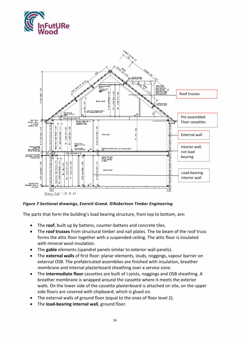
16
Figure 7 Sectional drawings, Everett Grand. ©Robertson Timber Engineering
The parts that form the building's load bearing structure, from top to bottom, are:
• The roof, built up by battens, counter-battens and concrete tiles. • The roof trusses from structural timber and nail plates. The tie beam of the roof truss
forms the attic floor together with a suspended ceiling. The attic floor is insulated with mineral wool insulation.
• The gable elements (spandrel panels similar to exterior wall panels). • The external walls of first floor: planar elements, studs, noggings, vapour barrier on
external OSB. The prefabricated assemblies are finished with insulation, breather membrane and internal plasterboard sheathing over a service zone.
• The intermediate floor cassettes are built of I-joists, noggings and OSB sheathing. A breather membrane is wrapped around the cassette where it meets the exterior walls. On the lower side of the cassette plasterboard is attached on site, on the upper side floors are covered with chipboard, which is glued on.
• The external walls of ground floor (equal to the ones of floor level 2). • The load-bearing internal wall, ground floor.
Load-bearing interior wall
Interior wall, not load bearing
External wall
Roof trusses
Pre-assembled Floor cassettes

17
All the above are delivered to the building site as partly prefabricated assemblies and are finished onsite.
In addition, the load-bearing structure of the building includes:
• Slab on ground, built on site from concrete.
The building is completed on site with interior walls that are not part of the load bearing structure.
Joints
The dominant connection technique are mechanical fasteners in the form of nails. Hangers, which are fixed to the joists using nails, are occasionally used between floor joists. An overview of joints and fastener types is given in Table 1.
Table 1 Overview of joints and joint techniques Part Connection (position
of) Technique
ROOF Counter battens to trusses
Nail connection (2no. every 600mm)
Tiling Battens to Counter Battens
Face nailed at each truss
ROOF TRUSSES Truss clip to headbinder (wall panel floor 1)
Twisted nails
Roof truss to head binder (wall panel)
Nailed connection (2no. skew fixed to every truss end)
GABLES Spandrel panel to panel
Nail connection (2no. per every 400mm (staggered))
ATTIC FLOOR/ CEILINGS
Floor covering Glued
Plasterboard
Screw connection (300mm c/c’s (note 150mm c/c’s if nails used))
EXTERNAL WALL, FIRST FLOOR
External wall/intermediate floor
Nailed (2 per joist and intersection)
Vertical joints between wall panels
Nailed (Each stud face @ 600mm c/c’s (staggered)
Vertical corner joints between wall panels Nailed as above
Sole plate to wall panel (sole plate to bottom rail)
Nailed (2 every 600 mm)

18
OSB sheathing to studs
Nailed, minimum 50mm centres
INTERMEDIATE FLOORS
Supports of cassettes at external walls
Nailed (2 per joist and intersection)
Longitudinal joints between cassettes Hangers/ Nailed
EXTERIOR WALL, GROUND FLOOR
See exterior wall first floor
PLATE ON GROUND INCL. SLEEPER
Sole plate to foundation
100mm hammer fixings or 72mm hilti nails
INTERNAL, LOADBEARING & NON-LOADBEARING WALLS
Between panels and to external walls
Nailed (Each stud face @ 600mm c/c’s (staggered))
To floor joists Nailed (2no. between each stud face)
To trusses and ceiling joists
Nailed (2no. between each stud face)
OSB sheathing to studs
Nailed, minimum 50mm centres
The connection between wall panels and floor cassettes is shown in Figure 8 below. The type of connection is representative for other connections between assemblies.
Figure 8 Panel to floor deck nailing exploded view. ©Robertson Timber Engineering

19
3.1.2. Presence of chemicals
Chemicals are found in the form of preservatives and glues. All timber at the risk of moisture contact is treated with preservatives. This includes the timber in soleplates, external wall studs and the roof structure. The chipboard is glued on top of the floor cassettes using non-toxic expansion glue.
3.1.3. Mechanical and electrical services and their connection to the load bearing structure
As found in the interview with Robertson, the mechanical and electrical services are not expected to complicate disassembly. Wall panels include a 50 mm service zone, directly under the plasterboard. In the floor cassettes, services run between the joists and occasionally through holes in the joists. That means that services in walls and ceilings can be easily accessed after removing the plasterboard sheathing from walls and ceilings.
3.1.4. Assembly process for original construction
The assembly process can be described as a conventional process from the bottom up. According to Robertson, it takes one day to mount the assemblies delivered from the factory on the cast slab and get the building under roof. Special weather protection is only used when panels have to be stored onsite during assembly, but normally the wood is not expected to have time to absorb harmful amounts of moisture during the hours it takes to make the building weather tight. Roughly, the load bearing structure with its prefabricated assemblies is assembled in the following steps:
1. The ground slab is cast 2. The roof is pre-assembled on the slab from pre-fabricated trussed rafters, gable ladders,
spandrel panels, purlins and temporary bracing 3. The roof is lifted as a whole and set aside 4. Soleplates are mounted on the slab for external and internal walls to mark the positions
of wall panels.
• Soleplates are anchored to concrete with 100mm hammer fixings or 72mm hilti nails
5. Exterior wall panels of the ground floor are installed. Wall assemblies come as planar, open panels from the factory, where they have been fitted with transport protection.
• Panels are lifted by crane from the truck and mounted against soleplates. Walls are temporarily braced.
• Bottom rail of the wall panel is nailed to the soleplate from the inside. • Wall panels are attached to each other in vertical joints and in corners with nails,
nailed through two studs, one from each panel. • Headbinders are nailed on top of the panels, so that they form a continuous element
over individual panels.

20
• Holding-down straps are fixed to the outside of wall panels with nails. • When all external walls are standing, the breather membrane is folded over panel
boundaries and stapled to the external sheathing.
6. Internal wall panels (loadbearing and non-loadbearing) are lifted with a crane from the truck and mounted.
• Erection in the same way as external walls
7. Floor cassettes come fully pre-assembled and are lifted by crane from the truck and placed on outer walls and loadbearing walls.
• The cassettes are nailed to the headbinders of external walls from the outside, obliquely downwards inwards through the edge beam and the top plate. (Figure 8)
• Cassettes are connected with nails through the headbinders
8. Soleplates are mounted on floors according to first-floor wall layout.
• Soleplates are nailed through the floor cover to the floor joists (Figure 8)
9. Exterior wall panels (first floor) are lifted with a crane from the truck and mounted against soleplates. Walls are braced.
• Erection in the same way as ground-floor walls
10. Internal wall panels (first floor) are lifted with a crane from the truck and mounted against soleplates. Walls are braced.
• Erection in the same way as ground-floor walls
11. Pre-assembled roof structure is lifted by crane from the ground and mounted on exterior walls.
• Roof trusses are attached to top rails with clips and nails. • Tiling battens are nailed between trusses and spandrel holding-down straps are fixed. • Tilting fillets, eaves and ridge sarking boards, eaves soffit framing, fascia board and
soffit plywood are nailed on trusses and framing. • Roof felt is nailed to trusses. • Counter battens and space tile battens are nailed to trusses. • OSB is fixed in coombe and between trusses, where dormer windows need additional
support. • Prefabricated dormer windows are lifted into openings using a crane and screwed to
battens and support rafters. • Concrete tiles are nailed to battens. • Temporary lifting web is removed under trusses.

21
When the structure is completed, finishes need to be applied, which is referred to as “second fix”. Windows and doors are fixed in openings, if they were not included in the prefabricated panel. The external walls are finished with insulation and masonry cladding from the outside. All wall panels are closed up with plasterboard sheathing, after services have been installed. It takes approximately two weeks to finish the construction process with surface layers, installations and finishes.
3.2. Results from simulation of deconstruction and reassembly with identification of strengths and weaknesses (step 1.2)
3.2.1. Deconstruction process
The process of deconstructing the frame for reuse was assumed to be carried out as suggested by Table 2. The scenario the deconstruction steps are based on is outlined as follows: After 50 years in use the house needs to be moved a short distance from its original location due to increased flood risk. It is moved within the same municipality and the same snow- and wind loads apply. The house is then erected on the new site exactly as it was before, perhaps with some aesthetic changes. For the disassembly, this means that the building is deconstructed to a degree so parts can be transported on a lorry. Parts are further taken apart if the structure needs to be inspected for damage or degradation. It is assumed that during the service life the building regulations, including the energy performance of the external structures, remain the same.
Table 2 Assumed deconstruction process DECONSTRUCTION STEP
DESCRIPTION, WHAT IS DONE
1. PREPARATORY WORK Masonry cladding is removed in the same way it was built (block by block). It will be destroyed in the process. Stairs are removed. Flooring removed. “Second fix” removed. Windows and doors only need to be removed in case they are to be replaced (for aesthetic or energy related reasons), otherwise they can remain in the panels.
2. ROOF Tiles Heavy concrete tiles are removed and are likely to be damaged in the process. Concrete tiles might also have reached their design life after 50 years and may have degraded to the point they need replacement. Alternatively, if lighter tiling was used, it could stay in place, but tiling choices might also be subject to trends and there might be a need to replace it for aesthetic reasons, nonetheless.
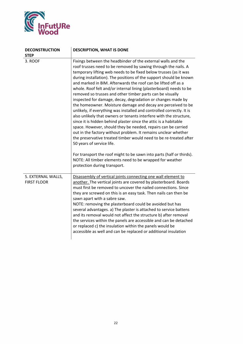
22
DECONSTRUCTION STEP
DESCRIPTION, WHAT IS DONE
3. ROOF Fixings between the headbinder of the external walls and the roof trusses need to be removed by sawing through the nails. A temporary lifting web needs to be fixed below trusses (as it was during installation). The positions of the support should be known and marked in BIM. Afterwards the roof can be lifted off as a whole. Roof felt and/or internal lining (plasterboard) needs to be removed so trusses and other timber parts can be visually inspected for damage, decay, degradation or changes made by the homeowner. Moisture damage and decay are perceived to be unlikely, if everything was installed and controlled correctly. It is also unlikely that owners or tenants interfere with the structure, since it is hidden behind plaster since the attic is a habitable space. However, should they be needed, repairs can be carried out in the factory without problem. It remains unclear whether the preservative treated timber would need to be re-treated after 50 years of service life. For transport the roof might to be sawn into parts (half or thirds). NOTE: All timber elements need to be wrapped for weather protection during transport.
5. EXTERNAL WALLS, FIRST FLOOR
Disassembly of vertical joints connecting one wall element to another. The vertical joints are covered by plasterboard. Boards must first be removed to uncover the nailed connections. Since they are screwed on this is an easy task. Then nails can then be sawn apart with a sabre saw. NOTE: removing the plasterboard could be avoided but has several advantages. a) The plaster is attached to service battens and its removal would not affect the structure b) after removal the services within the panels are accessible and can be detached or replaced c) the insulation within the panels would be accessible as well and can be replaced or additional insulation

23
DECONSTRUCTION STEP
DESCRIPTION, WHAT IS DONE
added d) the breather membrane would be accessible and could be replaced or repaired e) the plasterboard is the most moisture sensitive part of the wall panel and its removal (and exclusion from reuse) makes transport and storage less susceptible to moisture In bathrooms, where tiles are used, they need to be removed before access to the plasterboard is possible. If wetwall is used, it can be removed and reused later. Disassembly of joint between external wall panel and intermediate floor. Nailed connections between the sole plate and the floor cassette need to be sawn apart. The sole plate is likely not reusable afterwards. Exterior walls are removed in the same format as they were installed. Loops are mounted in existing holes and the panels are lifted by crane to transport vehicles. NOTE: The wall panels need to have marks for identification (QR codes?), preferably linked to BIM.
6. INTERMEDIATE FLOOR CASSETTES
Disassembly of longitudinal joints connecting floor panels to each other. The ceiling lining is removed from below and afterwards individual cassettes can be seen. Where they need to be separated (to extract transportable parts) the nailed connections are sawn apart with a sabre saw. The chipboard floor cover is glued on and cannot be removed. It is therefore also sawn apart between transport units and can be glued back together at the new site, using expansion glue. Disassembly of joint connecting floor cassettes to exterior wall ground floor. The nailed connections have to be sawn apart. The headbinder of the wall panels below could be damaged in the process. Loops are attached to floor cassettes (holed for their insertion are visible from below) and they are lifted by crane.
7. EXTERIOR AND LOADBEARING WALLS, GROUND FLOOR
Process similar to that of exterior wall on the first floor. Again, only the soleplates are likely to be damaged in the process.
8. SLAB An excavator chops the concrete slab to smaller pieces.

24
3.2.2. Analysis of deconstruction process
As described in section 2.2, different aspects of each step in the deconstruction process of Table 2 were discussed. This included: tools, damage that may occur to assemblies, need for reconditioning, repair and controls, foreseen waste, risks with regard to personal safety and risks to the environment. This way, the participants developed their knowledge and perceptions of the deconstruction process and potential to reuse the parts of the building. See Appendix 1 for notes.
3.2.3. Identifying strengths and weaknesses of existing design
The results of the analysis were restructured under the headings Strengths and Weaknesses for the different parts of the building, see Table 3. In summary, the following strengths and weaknesses can be identified with the current design with respect to deconstruction and reuse.
Strengths
• Industrially produced, large assemblies: • The structure is built up by large assemblies and can be deconstructed in a reversed
process resulting in even more finished/ larger modules. There are thus conditions for a relatively fast and rational deconstruction process with relatively few units.
• Low weight: • The assemblies are sufficiently light to be transported (a prerequisite for
prefabricating them). • Knowledge and logistics already at hand: • Knowledge and logistics are already in place for the prefabricated system with its
efficient transport and assembly methods; the aspect of deconstruction and reuse, as well as quality control and possible repair works, can be worked into the business model if there are incentives to do so.
• Lifting is planned: • Wall and floor panels have existing positions for lifting devices and can be lifted in
the same way as during the original erection. • Few, common tools needed: • Deconstruction can be done with a few common tools, as drill, saw and electric
screwdriver. As the assemblies are large, a crane will be needed for lifting. • Services and membranes accessible: • After the removal of the plasterboard, services and membranes (VCL and breather
membrane) are accessible and can be replaced or repaired.
Weaknesses
• Disassembly of nailed connections: • It is assumed that nailed connections can be sawn apart with minimal damage to the
parts they are connecting. In practice, it could be difficult to remove these

25
connectors without damaging the wood. The process could be more labour intensive than foreseen, especially if many unprescribed connectors exist.
• Limited flexibility: • The disassembly and reuse of components in the exact same house appears to be a
straightforward task. However, when it comes to reusing the components in a different house type, this might proof to be more challenging. Wall panels and floor cassettes come in many different configurations and sizes and are highly specific to the house type and their position within the building. In addition, room layouts are often not adaptable for different use scenarios.
• Need for weather protection: • The deconstructed parts are sensitive to moisture. If deconstruction is a slower
process than assembly, the risk of damage due to rain is greater in the deconstruction stage. It is assumed, however, that the deconstruction could be carried out in a matter of days, and it would be sufficient to use weather protection in a similar way as during transport of new assemblies.
• Not prescribed connectors: • There may very well exist connectors (nails) in completed buildings that were not
prescribed by the nailing schedule but have been added by the assembly teams. These “extra” nails can be difficult to detect in a deconstruction process and difficult and time consuming to remove.
• Verification according to building regulations of assemblies: • It is desirable to deconstruct and reuse entire wall and floor assemblies. These parts
can be visually assessed and occasionally tested in the factory environment, but it is unclear if this would satisfy insurance providers. Extensive testing of recovered assemblies might be needed before mass-reuse is possible.
• Storing requires controlled climate: • As the building parts are wood based, temporary storing needs to be done in a
controlled climate in order to avoid problems with decay and deformation. • Social acceptance: • It is unclear whether people would be willing to buy a house that has been moved
from another site and if they would be willing to spend the same amount of money for a used house.

26
Table 3 Analysis of strengths and weaknesses based on building component
Strengths (properties to maintain)
Weaknesses (properties to improve)
General remarks Industrial production with prefabricated panels is an efficient process that can be reversed. The company has methods to work with packaging, loading and transport that is safe for people and safe for the products. They are used to thinking about the entire logistics chain. The process can be reversed; the company can include the deconstruction process in their business as usual, including repair, retrofit and control as needed. Connections can be designed differently within the efficient industrial process; many of the connections might be more reversible using fittings. Long technical service life of most components.
Many metal connectors In practice, there can be more connectors than building instructions indicate. Extra nails are driven in during assembly. These can cause problem and even danger in deconstruction. The masonry façade needs to be removed before the timber structure can be deconstructed. Separating the outer leaf of brickwork from the wall ties without damaging the timber could be a complex process.
The different parts ROOF The roof is lifted onto the building
as a whole and can be removed in the same way. Only the roof tiles need to be removed before lifting, as they are made from heavy concrete. The tiles can likely not be reused. The fasteners that are removed are the ones between the headbinder of the first-floor walls and the roof trusses, the rest of the roof structure can stay assembled.
The connection between headbinder and roof trusses is nailed and needs to be sawn apart. This deconstruction method bears some uncertainties and potential safety risks.
27
EXTERIOR WALLS, FIRST FLOOR and GROUND FLOOR INTERNAL LOADBEARING WALLS
It is technically possible to disassemble, remove, transport and reuse wall panels in the same shape as they were inserted, with the surface layers left in place. It might however be an advantage to remove the internal plasterboard layer, for the following reasons: The service zone and breather membrane will be exposed, so that disconnection of services and damage assessment are facilitated The plasterboard is the most moisture sensitive part of the assembly and would need additional protection It is therefore assumed that the internal plasterboard is removed and the rest of the wall panel assembly extracted for reuse.
The assemblies contain vapour barriers. The expected service life of these is shorter than that of the studs. In addition, they depend on taped joints for their air tightness. Repairs to existing membranes can be carried out after extraction of the assemblies, but occasionally one might have to replace vapour barriers after disassembly in order to guarantee their function. For inspection of the studs, the internal breather membrane would need to be removed, but this only needs to be done in the following cases: Damage to the timber structure is suspected due to moisture or other indicators Insulation needs to be exchanged or additional insulation needs to be inserted The wall panels are mounted on sole plates that are nailed to the floor cover. The connection between wall panels and soleplates can be sawn apart, but the soleplates themselves are not likely to be recovered damage free.
INTERMEDIATE FLOORS
The cassettes can be removed and transported in the same format as they were mounted and with the chipboard left on top.
The chipboard cover needs to be sawn apart between cassettes, which would leave a small gap of 3 mm between floor covers after re-assembly. This can be repaired with expansion glue that is usually used for fixing the chipboard to the floor cassette. If the chipboard needs to be replaced for any reason, the glued connection between chipboard and floor cassettes is irreversible and a removal attempt would likely leave the floor cassettes damaged.

28
3.3. Identification of areas to improve
The identified weaknesses highlight features that can be improved with respect to disassembly and reuse, as well as adaptability, while the identified strengths highlight features that should be retained. From identified weaknesses and strengths, the following possible areas for improvement of the construction system can be formulated.
3.3.1. General
Prevent using extra connectors
Study how extra connectors could be made unnecessary. For unknown reasons, it happens that the assembly teams add nails that are not prescribed. Interviews should be conducted with assembly teams to find out why. Joint details may need to be improved and tested so as not to require extra attachments with nails. Clearer installation instructions may need to be developed.
The potential for improvement is that the time and energy consumption for disassembly is reduced and that personal risks are reduced.
3.3.2. Areas of improvement for deconstruction
Deconstruction instructions
Deconstruction instructions should be produced, similar to construction instructions of today, but in reverse order. The deconstruction plan should specify:
• Length, height and weight of assemblies • Order of assemblies to remove • How to remove assemblies and which tools are needed to loosen connections • Which layers of assemblies need to be removed before lifting, and what happens to
these layers afterwards • Where to apply bracing and lifting loops or hooks • Which controls to carry out before deconstruction and before reuse • How to check that there are no extra connectors connecting assemblies before lifting • How to protect deconstructed assemblies from weather and how to transport and
store them
Prepared disassembly process
The position of the holes intended for lifting loops can be standardised, so that a future deconstruction team can easily find them. Lifting loops could also be left in place after installation. The lifting positions should also be specified in deconstruction instructions.
Carry out a study on deconstruction and reassembly of assemblies

29
It has been assumed here that it is technically possible to deconstruct and reassemble planar wall panels and floor cassettes complete with all their layers and materials as sheathing, studs or joists, insulation and vapour- and wind barriers, by sawing apart nailed connections. However, questions have arisen whether you can dismount a building reliably and safely with a sabre saw, or if unforeseen problems would arise.
Even if nails were to be replaced with screws, practical experience for disassembly is invaluable. It has not been confirmed whether screws can be removed after years of service and whether all (or most) layers of planar assemblies can be kept intact and reused after disassembly. Plastic membranes could become degraded or damaged, and it is unclear whether membranes would need to be replaced routinely after the assemblie’s first service life. In addition, removing the masonry cladding could be more difficult than anticipated and the wall ties between the timber and the cladding could cause damage upon removal. It would take practical experiments in deconstruction and reassembly to answer these questions.
Develop assessment and reconditioning methods for assemblies
It is assumed that plasterboard is removed from walls and ceilings, so that timber elements can be visually inspected, services can be disconnected, and insulation can be retrofit if needed. It is, however, unclear how to assess whether timber elements are still fit for purpose after their first life. It is likely that an initial test period of recovered assemblies would be needed to develop reliable assessment strategies. The strategies should include a visual assessment guide to use before and after deconstruction, that allows to discern unsafe assemblies that need to be removed with additional care, as well as potentially unsafe assemblies that need to be further assessed and/ or retrofit in a factory environment. Besides visual assessment, mainly for fungal, insect and other visible damage, the inspection of recovered elements in assemblies could include measuring the moisture content and acoustic velocity, which is used to estimate the modulus of elasticity. Destructive testing of a percentage of recovered elements or assemblies would assess their compatibility with the design values.
Most of the timber in the external walls, roof structure and sole plates are treated with preservatives. It is unclear whether the treatment is still effective after the first life of the elements and whether re-treatment would be feasible. The treatment is currently required by insurance providers, even though timber elements in modern buildings should be sufficiently protected from moisture to be protected from insect and fungal attacks and preservative treatment is not required in other countries, like Sweden. Before deconstruction and reuse can become a widespread business practice for house builders, it would either need to be tested to determine if preservative treatment is still effective after years of service; a method for retreating whole assemblies needs to be developed; or a new agreement with insurance providers needs to be negotiated in which moisture protection serves as sufficient protection against biological degradation. The last option is arguably the most environmentally friendly and the cheapest solution.

30
Increase readability
Screw heads can be marked with spray paint in order to make it easier to find them during a deconstruction process and reduce time spent. Assemblies should be marked in alignment with the deconstruction plan (and BIM model) to assure all information relating to an assembly is available and the assembly can be reused efficiently.
Nailed connections between assemblies
Assemblies are connected with nails onsite. While these connections can likely be sawn apart, there might be connection methods that are safer and less uncertain in their disassembly. On-site nails could be replaced with screws, but these might require different lengths, diameters and spacing, which might not be compatible with the timber cross sections or design. The strength and failure behaviour of screws differ from nails, and it needs to be confirmed that screws are suitable as onsite fixings. Fixing screws on-site might also require more time or could meet lower approval by construction workers, who are used to using high-speed nail guns. All of these factors need investigation.
Floor cassette to chipboard connection (glued)
The chipboard cover is glued to the floor joists, which is necessary to avoid creaking. The floor cover can be sawn-apart and re-joint upon reassembly, but this deconstruction method bears safety-risks and uncertainties. Floor cassettes are sometimes connected with hangers (which are nailed to the joists) and sometimes nailed together in the current design. A method of connecting floor cassettes in a reversible manner could be used instead, to avoid the use of saws in the deconstruction process.
3.3.3. Areas of improvement for adaptability
Wall panel layouts
Wall panel lengths and wall panel configurations are not uniform, so much so that 75 different panels are used in the building. If wall lengths were designed to be multiples of 300 or 600 cm, wall panels could have more uniform dimensions. In addition, if different sections within wall panels could have lengths that are multiples of 300 or 600 cm and if these sections were detachable, the wall panels could be reconfigured to be reusable in various constellations.
Room layouts
The room layouts are relatively restricting and do not necessarily accommodate different aspects of modern living. It could be explored how rooms could be adapted for different uses and how the whole building could be redesigned to accommodate for different user scenarios, such as single-family, multiple-family (in two dwellings within the building) of multiple-tenant occupation.

31
Services
Services run in an easily accessible service zone under the plasterboard, which is an advantage. They could however be bundled in a central service cavity in the building which runs over all floors, which would make the installation of new services or the alteration of existing services even easier.
3.4. Selection of areas to improve
One design change that has the potential to significantly increase the deconstruction potential of the discussed design would be to replace nail fasteners with screws. As screws are in theory a reversible connection type, this means they can be removed with a limited level of damage therefore salvaging the majority of timber within the building. This option will also make the deconstruction process more controlled and safer, as it avoids the use of a sabre saw for deconstruction.
Improving the reuse potential of assemblies by making them uniform and therefore more flexible for different reuse scenarios is the second most impactful improvement. If assemblies can be recovered damage-free but are too specific to be reused in any other house type, their recovery might not be worth the effort. Trends and tastes in houses are likely to change within 50 years and recovered assemblies need to fit into new designs. It has therefore been attempted to make wall panels uniform, by dividing them into functional areas that can be joined with reversible connections in the factory and disassembled after recovery. At the same time, room layouts have been adapted to more uniform sizes and to serving variable needs. Specifically, the option to divide the house into two separate dwellings (ground floor and first plus second floor) has been introduced into the layout. Rooms have generally been made slightly bigger to allow for modern living needs, like working from home. Some bathrooms have been omitted in the layout plan, which leaves prospective buyers with the option to reduce the number of bathrooms by up to two.
3.5. Calculation of the amount of wood that can be recycled with today's design
In the simulation of deconstruction and reuse, waste due to damage with the current design was discussed. The loss during disassembly for the various components was estimated to be negligible for most parts, while soleplates are not assumed to be recoverable. The assumptions made for the different elements are shown in Table 4.
Table 4 Assumed wastage for different assemblies and components. Part Waste percentage Notes Roof boarding 0-100% The concrete roof tiles cannot be salvaged, but
after their removal the rest of the roof structure stays intact and can be reused. If roofing felt needs to be replaced, the tiling battens would need to be removed and would become waste. Since it is

32
Part Waste percentage Notes unclear whether the roofing felt has a life expectancy over 50 years, the waste percentage is taken as 50% for tiling battens. The exact tiling batten number cannot be seen in the design drawings and has been estimated.
Roof trusses 0% The roof structure is judged to be reusable as a whole. Gables 0%
Exterior walls, first and ground floor
0% Exterior walls are judged to be reusable in their entirety.
Soleplates first floor and ground floor
100% Wasted when sawing through nail connection.
Intermediate floor 0% The floor cassettes are judged to be reusable in their entirety. They will suffer minor local damage when the chipboard is sawn apart between cassettes. These are judged to be repairable when the cassettes are reassembled in a new building.
Slab 100% This does not contain timber
It follows from the estimate, that 16.56 out of 17.52 cubic metres of solid wood, along with potentially all OSB (3.51 m3), glulam (0.19 m3) and I-beams (81.57 running metres) in the building could be reused with the current design.
4. Results ‘Step 2. Modified design’
Nailed connections between assemblies
The replacement of nailed connections with screwed connections on site would lead to improved deconstructability, as connections can be reversed in a more predictable and safe way. This change in connections leads to several questions, which are answered below.
Would the replacement of nails with screws in connections that are fixed on-site change the assembly process in terms of speed, safety, costs and acceptance among the workforce?
Gregor Adam, Contracts Manager at Robertson Homes, thinks that modern, battery-powered tools for fixing screws are similar enough to the ones used for nails, so that the difference in the assembly (time and handling) would be minimal. He mentions that additional procurement costs for these tools could be an obstacle, however. It is also unclear whether the fasteners themselves have a significant difference in cost.
How does the spacing and size of screws relate to the one of nails?
When reassembling pre-used assemblies, can screws be used in or near old screw holes? How would this affect the strength of the connection?

33
Eurocode 5 (BS EN 1995-1-1:2004+A2:2014 2004) was used to calculate the size of screws that is required to replace nails (paslode) of 3.1 mm diameter and 75 mm length. The calculation is shown in Appendix 2. Firstly, the connection between two vertical timber members in single shear, as seen for example between studs of two wall panels, was examined (Figure 9). Secondly, the connection between two horizontal members in single shear, as for example between top rail and headbinder of wall panels, was examined (Figure 10).
Figure 9 Connection between two vertical timber members
Figure 10 Connection between two horizontal timber members
In the two connections above, nails can be replaced with screws of roughly the same diameter and length (di=3 to 3.45 mm, l=70 mm). It could be possible to reduce the screw diameter further, but, for simplicity, this screw choice is retained.
For assessing whether screws have to be placed in or near old screw holes when reassembling recovered assemblies, the minimum spacing for screws according to Eurocode 5 is analysed. No complications should arise when placing screws with minimum spacing to old screws or holes.
Wall panel studs of the smallest cross section (75 by 38 mm) have the least flexibility for re-spacing fasteners, but even these studs could be reused three times before reusing old holes is necessary. Assuming that one use cycle has 50 years, this would limit the life of these timber members to 200 years, an optimistic life span that might not be reached by typical building timber for other reasons.
It might sometimes be necessary to remove OSB panels, either to replace them, or, in the new design, when reconfigurating panels. The OSB to stud connection is therefore analysed as well.
Nails in this connection can be replaced with the same screws as above to meet the structural requirements. Attaching OSB requires more fasteners, however, and OSB could not de detached and reattached without using screws in or close to old screw holes.
Not all OSB will need to be removed from wall panels before reuse, and it might be a sensible approach to discard the OSB panels that have to be detached. Another option

34
would be to cut off the edges of the detached OSB to reuse it for covering smaller wall panels (spandrel panels or windowsills). On the other hand, the number of screws could be reduced in OSB panels, which do not contribute to the racking resistance of the building. This way some of the OSB panels would come with more re-spacing options for screws. Lastly, it might not be a problem to reuse the old screw holes and therefore the OSB. It would be useful to study the effect of reusing old screw holes on the connection strength and panel behaviour, also for other reuse scenarios and for solid wood and panel products.
Overall, replacing nails with screws poses no problems in theory, but contributes to facilitating deconstruction.
Wall panel layouts
Wall panels are divided into different functional units, which are 300 or multiples of 600 mm long. In the simplest case, wall panels could comprise of studs at 600 mm centres plus top- and bottom rail, and simple functional units of 600, 1200 and 1800 mm length are available. Additional functional unites are needed, as additional studs and nogging are needed for several reasons: As movement joists, to support perpendicular wall panels, to support floor cassettes above or as additional support near openings. The introduction of additional studs makes the required functional units more complicated and versatile.
In addition, timber elements in wall panels have a thickness of either 140mm (external walls), 89 mm (internal loadbearing walls) or 75mm (internal, non-loadbearing walls) and therefore some functional areas need to be manufactured in different thicknesses. Internal non-loadbearing walls also have nogging in all panels. In the current design, wall panels have slightly different heights depending on which floor they are located on, and whether they are internal or external panels, which is shown in Table 5. It is confirmed with the manufacturer, however, that wall panels in all floors can be of the same height.
Table 5 Height of different wall panels Wall height in mm Ground floor First Floor Second Floor External wall 2288 2378 Varies Internal, loadbearing wall 2288 - -
Internal, non-loadbearing wall 2301 2344 2357
An additional unit, referred to as Ecor, is introduced, which is 140 mm wide and 140 mm thick, matching the thickness of external wall panels. This unit can be added to external wall panels in corners of the building where two wall panels meet in a right angle. This assures that the internal walls, if they span the entire floor, can still be multiples of 600 mm in length (see Figure 11).

35
Figure 11 Function of unit "Ecor"
In total, 35 different functional units are needed, which are shown in Figure 12. An explanation of all functional units can be found in Appendix 3. Panels come in different widths and some units need to be repeated with 140, 89 and 75 mm thickness. Second floor external wall panels are spandrel panels, which are not considered in the improvements, as they cannot be manufactured from the same standard units due to their triangular shape. Panels with a special shape for the cathedral window (EX16GF and EX17GF) are disregarded as well.
Figure 12 All standard functional areas
Standard opening units can be doors or windows, and some might even be used as either. They come as 900 mm, 1648 mm or 2400 mm openings, so that units have a total width of 1200, 1800 and 3000 mm respectively. In some cases, glulam lintels support openings. At
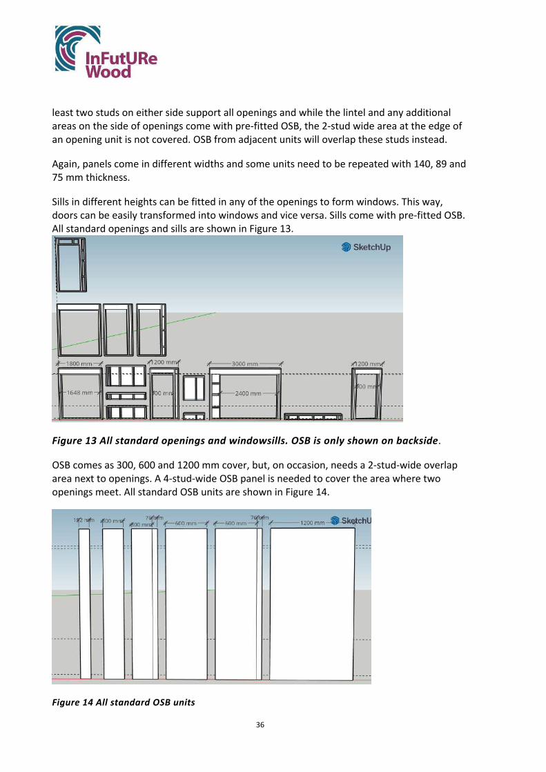
36
least two studs on either side support all openings and while the lintel and any additional areas on the side of openings come with pre-fitted OSB, the 2-stud wide area at the edge of an opening unit is not covered. OSB from adjacent units will overlap these studs instead.
Again, panels come in different widths and some units need to be repeated with 140, 89 and 75 mm thickness.
Sills in different heights can be fitted in any of the openings to form windows. This way, doors can be easily transformed into windows and vice versa. Sills come with pre-fitted OSB. All standard openings and sills are shown in Figure 13.
Figure 13 All standard openings and windowsills. OSB is only shown on backside.
OSB comes as 300, 600 and 1200 mm cover, but, on occasion, needs a 2-stud-wide overlap area next to openings. A 4-stud-wide OSB panel is needed to cover the area where two openings meet. All standard OSB units are shown in Figure 14.
Figure 14 All standard OSB units

37
The functional units (studs, top and bottom rail, lintels) are manufactured in the factory as usual and can be nailed. They are then joint in the factory into wall panels. This is done by connecting studs of different units with screws, so that they could be disassembled, should it be needed. OSB sheathing is attached in the factory too, sometimes overlapping more than one functional area, so that it would be beneficial to use screws in this connection too. The factory assembly is shown in Figure 15.
Figure 15 Panel assembly (example of EX1FF). Functional sections are screwed together as shown by red arrows. Note 2-stud-wide overlap of OSB next to window opening.
The finished wall panels resemble the original ones (Figure 16). To improve the standardisation further, it would be possible to adjust the length of individual panels as well to achieve the smallest possible number of different panel lengths. If the external walls were arranged symmetrically, it would be possible to remove or add sections to the house easily, which would further increase its adaptability. The composition of all wall panels from standard units and potential optimisations to wall panel configurations are shown in Appendix 4.
It would also be possible to limit the number of different wall thicknesses needed, by specifying loadbearing wall panels with 140 mm thickness to match external wall panels. This requires more material input, however, and it is out of the scope of this study to assess the environmental and financial impact of this option.

38
Figure 16 Original vs. improved wall panels (EX1FF, EX2FF and EX3FF) (OSB omitted in improved drawing outside openings)
On site, the wall panels are mounted on sole plates and connected with screws through studs from both sides. Headbinders, overlapping individual panels, are fixed on top (Figure 17). After fitting insulation and services, internal lining is fixed. Where non-standard OSB panels are needed around openings, these sections of the panels could entirely be finished in the factory. Figure 18 shows how the wall made up from the above panels would look inside the building.
Figure 17 Onsite assembly. Panels are screwed together and on soleplates and connected with headbinders as shown by red arrows. OSB in the back is fixed in the factory and internal lining could also be fixed in the front, where non-standard units are needed (windowsills, next to openings). Onsite, services and insulation as well as remaining internal lining are fitted.

39
Figure 18 Wall panels inside the building. (Soleplates and headbinders, second floor, roof and cathedral window of garden room not shown.)
The wall panels resemble the current design closely. If a standard stud length (governing the panel height) of 2212 mm is assumed, which is currently found in ground floor external and internal loadbearing panels, the following changes in the amount of wood in the house are calculated (Table 6).
Table 6 Amount of wood in wall panels in the current and new design Amount of wood in m3 Solid timber OSB Glulam
Current design 8.6 2.0 0.2 New design 8.1 2.0 0.6
The amount of solid wood is slightly lower in the new design, which is due to omitting several wall panels. The amount of glulam increases, as most openings are expected to have a glulam lintel. Detailed design calculations could prove that this is not always necessary, but even if it was, the amount of glulam with 0.6 m3 is reasonable.
Room layouts
The layout of the house is simplified to be rectangular (with an addition of the garden room on the ground floor), which makes the wall panels EX6GF, EX8GF, EX10GF, EX9FF and EX4SP as well as Floor cassette 1 redundant (see Figure 19 for example of the ground floor). The room layouts are changing with the new wall panel configurations, so that the walls come in standard lengths. The new room sizes are not always multiples of 600 mm, but are also governed by wall thickness and the position of the stairs, which was not changed (Figure 20).

40
Figure 19 original ground floor layout. Wall panels in orange rectangles are omitted thanks to new layout.
Figure 20 improved ground floor layout
The rooms are also adapted so that the dwelling could be split into two, for example if after years of occupation by a family the original owners want to only occupy the ground floor and

41
another family can occupy the first and second floor. For this scenario, the bathroom on the ground floor is enlarged to offer room for a bath or shower. It could further be merged with the utility room, should more space be required. The hallway is designed so that it would require only the addition of one wall, and the replacement of the window with a door, to become two hallways, one for each dwelling (Figure 21). The garage could be modified to become an additional room, when the door is transformed into a window. Additional considerations should be made, such as specifying wall panel IN3GF under the stairs and floor cassettes so that they meet criteria for party walls, alternatively, they could be retrofitted to meet these requirements. The existing garage wall (IL1GF and IL2GF), which would be between dwellings, is made from external wall panels and would not need retrofit.
Figure 21 Ground floor modification. A new party wall is built and a window is transformed into an entrance door. The hallway of the upstairs dwelling is marked in yellow and the rest of the ground floor would be one dwelling.
Alternatively, the ground floor could be modified as below (Figure 22), so that the whole hallway becomes part of the upper dwelling. The doors to the bathroom and lounge would need to be closed up and the two wall panels that become party walls (IN1GF and IL8GF) might also need retrofit to meet the changed requirements. The wall between the utility room and the bathroom would need to be removed and the position of the shower changed. The new entrance could be fitted into the garage door and the rest of the opening could become a window.

42
Figure 22 Alternative ground floor modification. Two doors are closed, a new entrance door is fitted instead of the garage door, an internal wall is removed and the shower is relocated. The hallway of the upstairs dwelling is marked in yellow.
The first floor layout sees changes towards standardised wall dimensions as well (compare Figure 23 and Figure 24). In addition, two bathrooms are omitted to allow more space in two bedrooms, for example for a home-working area in case of multiple occupation, when not all tenants can have a bedroom and separate office. The option of re-including one or both of the omitted bathrooms into the room layout could, however, be presented to prospective buyers.
In the scenario where the house is split into two dwellings, the two larger bedrooms would become kitchen and living room respectively, and since their doors are facing each other over the hallway, the living space could be easily linked by removing the doors from the frames (see Figure 24). Additional windows are introduced into the larger rooms, which would be needed in both these scenarios for additional light and ventilation. If the position of the stairs was adapted to suit standard wall lengths, room layouts could be even more flexible.
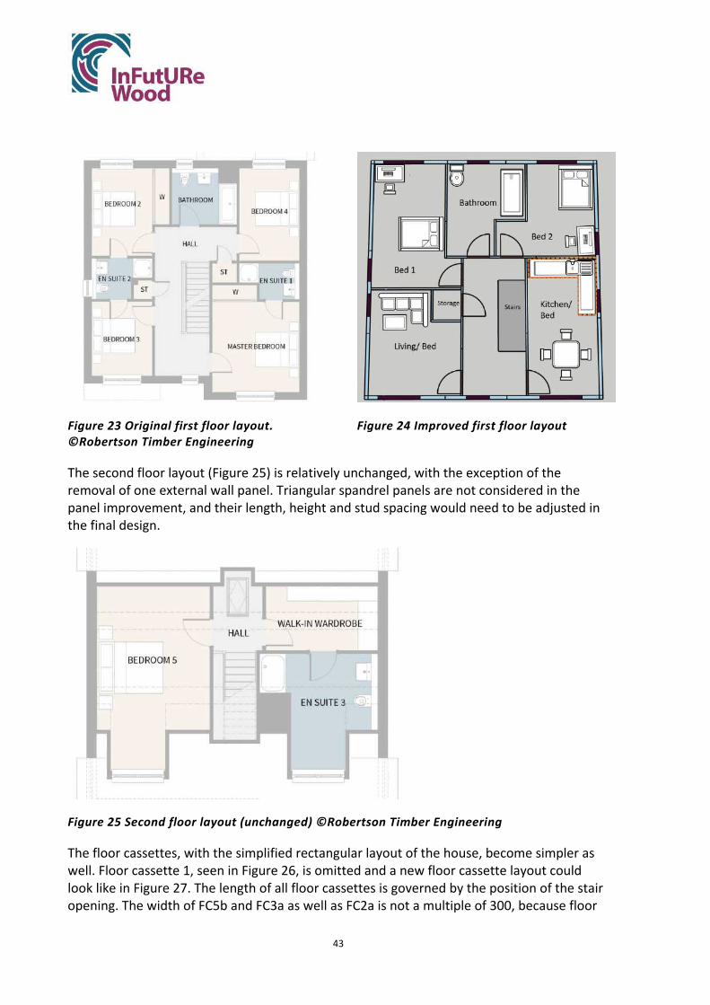
43
Figure 23 Original first floor layout. ©Robertson Timber Engineering
Figure 24 Improved first floor layout
The second floor layout (Figure 25) is relatively unchanged, with the exception of the removal of one external wall panel. Triangular spandrel panels are not considered in the panel improvement, and their length, height and stud spacing would need to be adjusted in the final design.
Figure 25 Second floor layout (unchanged) ©Robertson Timber Engineering
The floor cassettes, with the simplified rectangular layout of the house, become simpler as well. Floor cassette 1, seen in Figure 26, is omitted and a new floor cassette layout could look like in Figure 27. The length of all floor cassettes is governed by the position of the stair opening. The width of FC5b and FC3a as well as FC2a is not a multiple of 300, because floor

44
cassettes also need to cover the extra 140 mm external wall width on each side, which adds 280 mm total. Floor cassette 5 comes in three pieces in the current layout, so it was decided to keep it that way. Floor cassette 2 and 3 were divided into two pieces, so that floor cassettes are aligned and the layout can be easily modified.
Figure 26 Current floor cassette layout ©Robertson Timber Engineering
Figure 27 New floor cassette layout
Additional potential for adaptability
The house could be designed in an even more adaptable way, which would allow to reduce its size by removing rooms or floors. The company could take back the assemblies that were no longer needed. The reverse case would be possible as well. Customers could buy a smaller house that is extendable with rooms or floors being added, should they be needed. This more advanced design for adaptability requires more thought on wall lengths, floor cassette sizes and room layouts, so that several options for adding or removing walls could be included in the design. These options could be presented to the customer before sale and work as an additional sales argument and unique selling point.
One example of a possible modification to make the whole building adaptable is given below.
The size of the house could be reduced by about one third, by moving one side-wall inwards on all floors. The side-wall without the garden room has been chosen, since the garden room is the character-defining element of the house and should not be removed. Looking from the front of the house, the wall in question is the left side wall so we will refer to it as “left”. Figure 28 to Figure 30 show the modified house in comparison to the original floor layouts.

45
Figure 28 Whole house as smaller version vs. original size seen from the back. Floor layout shows original size. (Cathedral window of garden room and first floor “left” replacement wall not shown.)
Figure 29 Ground floor layout in smaller version. Floor layout shows original size. “Left” wall is moved inwards and some internal walls removed. (IL3GF under the stairs and cathedral window of garden room not shown.)

46
Figure 30 First Floor wall layout in smaller version vs original size. Some internal walls are removed. Ecor is added to the leftmost wall panels but the rest of the “left” replacement wall is not shown.
In this example, the floor cassettes FC5c, FC3b and FC2c, as well as the external wall panels EX2GF and EX11GF (on the ground floor) and EX3FF and EX7 FF (on the first floor) are removed. A new “left” wall is then added. The original “left” wall could be used, but this might need some changes to fulfil the new requirements. Some internal walls on both floors need to be removed as seen in Figure 29 and Figure 30 (IL6GF, IN1GF, IN2GF, IN7GF, IN8GF, both IN2FF, IN5FF, IN6FF, IN8FF (left), IN9FF (left) and IN10FF). This would also mean that the bathroom on the ground floor would be omitted. All removed assemblies could be reused, in case of the “left” external walls directly on site, or otherwise in other constructions. The company could include a modification and take-back scheme into their business model.
To enable these modifications some changes in the wall panel configurations are necessary, so that the leftmost wall panels of the “front” and “back” wall, as well as parallel internal walls, have a length of 3000 mm, so that they end in 140 mm distance to the edge of the floor cassettes FC5b, FC3a and FC2a (Figure 27). The 140 mm gap will then be filled with the unit Ecor of the replacement “left” wall. Panels in the “front”, “back”, and parallel walls need to be changed not only in length, but also in the position of openings. The specific changes required in this example are shown Figure 31.

47
Figure 31 Changes in wall panels. Front, back and internal wall change in length and position of openings.
On the first floor, the length of the leftmost external wall panels in the “front” and “back” wall is already 3000 mm, so that the change can be easily accommodated.
On the second floor the spandrel panels of the “left” wall need to be moved inwards, which can only be done after part of the roof structure (six trusses) is removed. It is assumed that the roof can be sawn apart where needed. One of the dormer windows needs to be taken out before the roof is cut apart and can be reused in another building. Gable ladders will need to be fitted on the new roof edge and trusses and purlins may need to be added for additional support. The roof truss layout is not covered in this report, but it would be helpful to line up one of the trusses with the end of the middle floor cassettes on the left side. Currently the roof truss in question is in 96mm distance to the cassette edge.
One wall on the second floor would likely need to be removed after downsizing the house, to keep the second-floor bedroom in a useful size. The wall in question (IN3SF and IN4SF) is shown in Figure 32.

48
Figure 32 Internal walls on second floor after downsizing. Wall panels marked with orange line will likely be removed.
Services
Services in the horizontal direction run in a service zone under the plasterboard of wall panels. This is easily accessible and can be altered after removing the internal lining. In the vertical direction, all services can run in two service zones. Service zone 1 is located in the wall right next to the stairs (panel IL2GF, IN15FF and IN4SF) and runs over all floors as seen in Figure 33 and Figure 34. Bathrooms on the ground floor and second floor as well as the utility room are conveniently located closely to this wall, which is in the same position on all floors. Should the first floor bedroom be converted into a kitchen, as suggested above, this service zone could supply the appliances there. In addition, services needed in the garage could be supplied from this zone.
On the ground floor, the kitchen appliances require an additional service zone in the external wall to the back (EX1FF), which is shown as service zone 2 in Figure 33 and Figure 34. This service zone could be extended to the first floor (EX2FF) and contain the services needed in the bathroom. In addition, a water tap in the garden can be supplied from this zone.

49
Figure 33 Service zones shown in the floor layouts of all floors. From left to right: Ground floor, first floor, second floor.
Figure 34 Vertical service zones shown in the building. (All other internal walls and floor cassettes are not shown.)
5. Results ‘Step 3. Comparison existing design - modified design
In the original design, around 94.5% of timber could be reused after deconstruction. In the improved design, this can be increased to 98.4% since the soleplates can be recovered damage-free, when they are screwed instead of nailed to the floor. The design was well suited for deconstruction even before the design changes, and the quantitative reuse improvement is not large.
Nonetheless, the design changes made are important, as they improve reuse options qualitatively. Firstly, the more flexible and adaptable layout allows a more versatile and therefore potentially longer initial use of the house. Secondly, the standardised units can be
50
reused in various design and different house types, while the original assemblies are highly specific and their reuse inflexible.
The amount of wood and wood products is nearly identical in both designs. The construction and deconstruction time should be nearly identical as well. Therefore, the costs for both designs should be very similar, but the improved design offers additional incentives:
• The panel heights on all floors have been adjusted to be identical, which facilitates production and procurement, as well as reuse. The manufacturer is planning on incorporating this change in their design.
• The improved design is adaptable during its lifetime, which can be an important feature and sales argument. This is also expected to extend the life span of the building.
• The flexible reuse of the improved assemblies guarantees the value of the recovered assemblies to the company.
6. Results ‘Step 4. Reuse documentation that can be linked to BIM’
A sample deconstruction plan has been developed and is shown in Appendix 5. It is assumed that the deconstruction is carried out by the building manufacturer, who has access to additional information and documents, which accompany the deconstruction plan. The documents linked to the deconstruction plan are:
• Original nailing schedule • Design drawings of building and individual assemblies • Guideline for pre-deconstruction inspection and survey (This document needs to be
written. It should include a survey to check the expected build with the existing build, instructions on how to check for extra connectors, instructions on how to assess the integrity of the timber structure in-situ)
• Guideline for post-deconstruction inspection (This document needs to be written. It should include a survey to check the expected assembly configuration with the actual configuration, instructions on how to check for damage or decay, instructions on repairs that can be carried out on-site, instructions on when to send assemblies to the factory for repair, guidance on how much remaining life expectancy assemblies and components need to have in order to be reused, instructions on how to deconstruct assemblies to recycle components on-site)
• Guideline for factory assessment and repair (This document needs to be written. It should include a survey to check the expected module configuration with the actual configuration, instructions on how to check for damage or decay in the factory, instructions on repairs that can be carried out in the factory, instructions on when to discard modules, instructions on how to deconstruct modules to recycle or reuse components)

51
The assemblie’s BIM models are also linked to the deconstruction plan and contain additional information about the dimensions and weight of the assemblies, the assemblie’s position within the building, the age of the assembly and components, the connections between assemblies and deconstruction instructions. The different functional units within wall panels could be explained here as well. The reasoning behind the use of additional studs, for example in movement joints, could be included, to facilitate understanding of panel configurations in the future.
Assemblies need to be marked so they can be identified, for example using QR codes or RFID tagging. Similarly, units within wall panels should be marked.
It might be worthwhile to create a collection of simplified design drawings, connection details and assembly descriptions (Assembly ID, components, dimensions, weight). In case the deconstruction operations are carried out by a contractor or by anyone besides the manufacturer, the design drawings and other documents might be hard to understand and it would take time to gather all relevant information from the different files. A summary document could also serve as an inventory.
The deconstruction instructions need to be updated, should changes to the structure be made. This includes adaptations as proposed in Chapter 4 under Additional potential for adaptability, as well as other alterations and renovations. It is assumed that the manufacturer retains ownership over the components and that a contract with the homeowners requires them to report any changes made. The contract could also restrict alterations to the structure. The initial inspection and survey would still be able to detect unreported changes.
To facilitate deconstruction, the as built drawings and any renovations/alterations to the building should be documented over the course of the buildings use. All relevant documents should reflect the intention to deconstruct the building at the end of its life and to reuse assemblies. Everyone involved in manufacturing of assemblies and construction of houses should be aware that assemblies are expected to have a life beyond their immediate application. New warranty agreements might need to be negotiated with external suppliers.
In addition, the construction guidelines should address the problem of unprescribed connectors. Gregor Adam, Contracts Manager at Robertson Homes, thinks that a protocol for the use of additional fasteners during erection needs to be in place in order to be able to manage their deconstruction. This protocol should include a) the notion that additional fasteners are not to be used without a valid reason and b) that fasteners outside of the nailing schedule need to be marked and protocoled. If the protocol is briefed to the workforce before erection and monitored on site, unprescribed fasteners would not pose a problem during deconstruction.

52
7. Discussion and conclusions
The existing design is relatively well prepared for deconstruction and reuse already. Even without design changes, up to 94.5% of the structure can be recovered for reuse. The main advantages of the building system are its offsite manufacturing, which makes assemblies highly precise and controlled, for example in the position of fasteners and lifting positions. The existing knowledge and infrastructure of the manufacturing company can easily be transferred to the deconstruction process, as it is very similar to the construction process.
Disadvantages of the existing design that were addressed in this study are the nailed connections and the high complexity of panels. In addition, the adaptability of the building to different functions was improved. With the design changes, a slightly higher percentage of wood can be recovered after deconstruction (98.4%), but more importantly the reuse options for assemblies become more flexible and the lifespan of the whole building might increase.
However, the problem of deconstruction and reuse is not only linked to the design of buildings and some additional questions came up during the study:
Who takes responsibility for the load-bearing capacity of composite disassembled components such as wall panels and floor cassettes and how? That is, how do you verify the building regulations' requirements for stability and durability of used assemblies?
If the same company who manufacturers the original parts is responsible for disassembly and reassembly of the new building, there is no question about the responsibility for the component’s function. The business model of the company could be extended, so that deconstruction is planned from the beginning and a take-back scheme for their products could be implemented. Over the use period of the building, the company could either retain ownership of the building parts and lease them to the occupants, or the company could agree on a “right of first refusal” (RoFR) contract. Such a contract would give the company the first right to entering a business transaction relating to the building, before the owner could offer the same transaction to a third party. This model could be used in different ways:
• The company could get the first right to buy the house, should the owner decide to sell it
• The owner could be required to offer renovation or alteration contracts to the company first, before looking for other contractors
• The council could give the company the first right to remove the building, should demolition be required.
Before reusing the recovered assemblies and components, the company would need to carry out an initial testing phase, to test their mechanical properties and assure their functionality. After this evaluation phase, an agreement with insurance providers for the reuse of assemblies can be reached. This business model would have several advantages:

53
• There is no question about who has the responsibility for the functionality of the assemblies, since only one party is involved from manufacturing to recovery, reuse and eventually end of life.
• The infrastructure and knowledge from manufacturing and assembly can be transferred easily to disassembly and reuse steps. If assemblies need to be inspected, repaired, or retrofitted, existing facilities can be used. BIM models do not need to be shared between parties and the knowledge about parts, connections and assembly history can be stored in the same place over the whole lifecycle.
• With the implementation of a take-back scheme or RoFR contract, there will be less uncertainty about the end of life of a building. The company will receive information about deconstruction projects, will have certainty about the costs for the take-back and there will be no competition with other deconstruction or demolition companies.
• The existing relationship between the company and the insurance providers will pose an advantage for the negotiation around the reuse of components.
Can tasks such as disassembling with a sabre saw be safe and controllable?
The deconstruction process and the waste that arises as a result are based on assumptions only. Practical tests need to be carried out to verify that the deconstruction can be carried out as planned and improvements to the deconstruction plan need to be made following the findings of practical deconstructions.
Which houses are attractive enough / have qualities that make them likely to be moved? Do modern houses evoke such feelings that you take the trouble to move or preserve them?
Houses are often demolished not because they are faulty, but because they are in the wrong place at the wrong time. But older houses, over 100 years, are not being demolished, since they are deemed preservable (Cramer and Ridley-Ellis 2020b). Modern UK houses on the other hand are seen as “too uniform and samey” by 36% of new home buyers (ZPG 2018) and only 12.5% of Londoners think they are “built with good design and modern living requirements in mind” (Airey, Scruton, and Wales 2018). The latter study highlights that there is a soft consensus of what makes a building beautiful, and that it is not at all impossible to build in this way. Biophilic design might also play a role in making new houses valued by their inhabitants, as this design concept involves improving the mental and physical health and mood of inhabitants by using natural materials and shapes, and creating a visual and sensory connection with nature (Ryan and Browning 2018). Many new houses lack the ability to provoke positive feelings in people and the design of new houses has to improve to create homes that will be valued and preserved by their occupants and neighbours. But the Everett Grand is built and equipped to high standards and has several features that are, according to a 2012 report by the Royal Institute of British Architects (Finlay et al. 2012), commonly valued by homeowners. This includes large windows and light rooms, spacious rooms (especially in the improved design) and a private garden.
The improved design ensures a longer life span of the building by being adaptable to different tenancy situations or changing requirements of the owners.

54
The user experience and experienced value of the building could be further improved by incorporating biophilic design. The design could for example use more natural and diverse materials as well as biomorphic forms and patterns in floors, walls, windows and/ or finishes; incorporate layered or dynamic lighting; and ensure comfortable room climate with slight variabilities in airflow and temperature (Ryan and Browning 2018). The façade should be designed to the same principles of “beauty” and biophilic design, as it affects the perception of everyone who sees the building. It should be of high quality and durability but also adaptable and customizable, as it reflects the personality of the owner to their neighbours. Of course, people’s living experience is not confined to the inside of their own house either, but largely impacted by their neighbourhood. The impression and perceived value of new-built homes therefore also needs to diagnose problems in housing developments.
Can developments, alongside houses, be improved to be more adaptable and preservable?
The case study building is part of a new housing development in the South of Glasgow with 70 plots. Sixteen different house types, all built by Robertson Timber Engineering, make up the development, which will be completed in 2022. The new homes are all single-family, 4- to 6-bedroom houses and cost between £365,000 and £465,000. This development is tailored to large, high-income families and unlikely to attract other demographics, such as young people, families without children, low-income families or elderly people. Furthermore, there is little communal space within the development. A green area and a play area serve as communal meeting spaces, but there is no room for commercial areas like shops and cafes. Of course, not every housing development can include a restaurant, hairdresser and grocery shop, but this is not the only development in the area that is missing such amenities and the closest shop and café is found in 1.4 km walking distance, outside the new housing developments. The concept of 20-minute neighbourhoods is highlighted as a development goal in Scotland’s Housing to 2040 roadmap (Scottish Government 2021a), which would address the problem that only 10-15% of new house buyers in the UK rate new-built houses to “have good facilities nearby” (ZPG 2018). The absence of commercial and communal spaces in new housing developments does not only make it harder for people to rely on climate-friendly methods for transport like walking and cycling, but also separates people’s homes from the rest of their life. If people have to leave their neighbourhood for everything from working over shopping to eating in a restaurant, they are unlikely to develop a sense of community, a connection with their neighbours or appreciation for their houses. It is also unlikely that someone would live in their neighbourhood for the rest of their life, as there is no opportunity to move into a smaller home in the same area (a problem that is addressed with the new adaptable design).
The abovementioned factors are likely a part of the negative bias against modern houses in the UK. People who have an emotional connection to the houses in their neighbourhood (which might be provoked by a beautiful design, but equally by positive memories and the experience of community) are probably more likely to preserve their houses and houses that surround them, and favour renovation over demolition.

55
Spaces that people want to live in are located close to amenities, are easily reached by a variety of transport modes, foster a community with mixed tenancy options and communal spaces, provokes positive feeling through design, incorporate natural green spaces, and are designed to be sustainable and lasting (Carmichael and Stern 2018). The Scottish Government highlights the importance of these aspects in the design of new housing developments in their Housing to 2040 vision (Scottish Government 2021b). Robertson is also involved in a positive example of a new neighbourhood being built. In the South of Inverness, Robertson and other building companies are building 67 new homes, a mix of houses and flats, as well as commercial spaces, including a restaurant, and a community square. In addition, the community has been involved to some degree in the planning and design of the space. Local high school pupils designed the art for the community space and had the chance to visit the construction site. An impression of the new development can be seen Figure 35. Building neighbourhoods with and for communities is a crucial aspect of building long-lasting, preservable houses and a challenge for the UK house-building industry.
Figure 35 New mixed housing development. ©Robertson
In summary, contemporary timber houses can be deconstructed and reused. Small design changes can improve the reuse potential of recovered assemblies. To achieve maximum effect, however, DfDR design changes need to be part of a holistic design strategy that focuses on the community’s need, which is embedded in the manufacturer’s circular business model.

56
8. References
Airey, Jack, Sir Roger Scruton, and Sir Robin Wales. 2018. ‘Building More, Building Beautiful How Design and Style Can Unlock the Housing Crisis’. Policy Exchange. https://policyexchange.org.uk/wp-content/uploads/2018/06/Building-More-Building-Beautiful.pdf.
BS EN 1995-1-1:2004+A2:2014. 2004. BS EN 1995-1 Eurocode 5: Design of Timber Structures. General. Common Rules and Rules for Buildings.
Carmichael, Lucy, and Daniel Stern. 2018. ‘Ten Characteristics of Places Where People Want to Live’. Royal Institute of British Architects.
Cramer, Marlene, and Daniel Ridley-Ellis. 2020a. ‘A Shed Resource: A Look at Timber Recycling in the UK’. In Timber 2020. London. https://www.infuturewood.info/wp-content/uploads/2020/11/Cramer-Timber2020-Wood-Recycling.pdf.
———. 2020b. ‘A Case Study of Timber Demolition Recycling in the UK’. In . Helsinki.
ETA Danmark. 2021. ‘European Technical Assessment ETA-20/0390 of 2021/06/01’. https://www.bea-group.com/fileadmin/user_upload/Meta-Menue/Downloads/de-pdf/ETA-20-0390_BeFix_screws.pdf.
Finlay, Stephen, Isabella Pereira, Ella Fryer-Smith, Anne Charlton, and Rebecca Roberts-Hughes. 2012. ‘The Way We Live Now: What People Need and Expect from Their Homes’. Royal Institute of British Architects. https://www.ipsos.com/sites/default/files/publication/1970-01/sri-riba-the-way-we-live-now-may-2012.pdf.
Palmer, Simon. n.d. ‘Sustainable Homes: Timber Frame Housing’. Sustainable Homes. https://docplayer.net/9665713-Sustainable-homes-timber-frame-housing.html.
Ryan, Catherine O., and William D. Browning. 2018. ‘Biophilic Design’. In Encyclopedia of Sustainability Science and Technology, edited by Robert A. Meyers, 1–44. New York, NY: Springer New York. https://doi.org/10.1007/978-1-4939-2493-6_1034-1.
Sandin, Y., Carlsson, A., Ui Chúláin, C., & Sandberg, K. (2021). Design for Deconstruction and Reuse: Case study Villa Anneberg. Retrieved from http://urn.kb.se/resolve?urn=urn:nbn:se:ri:diva-56832
Scottish Government. 2021a. ‘Housing to 2040 Roadmap’. https://www.gov.scot/publications/housing-2040-2/pages/5/.
———. 2021b. ‘Housing to 2040 Vision’. https://www.gov.scot/publications/housing-2040-vision-principles/pages/2/.

57
Structural Timber Association. 2017. ‘Annual Survey of UK Structural Timber Markets’. http://www.forestryscotland.com/media/370371/annual%20survey%20of%20uk%20structural%20timber%20markets%202016.pdf.
ZPG. 2018. ‘Insights into New Homes Buyers 2018’. https://advantage.zpg.co.uk/wp-content/uploads/2018/05/Insights-into-new-homes-buyers-2018.pdf.

58
List of appendices
Appendix B1 Meeting Notes - Deconstruction Analysis
Appendix B2 EC5 Calculations
Appendix B3 List of all functional units and unit width in cores (one core = 600 mm)
Appendix B4 Composition of wall panels from standard units, including new length of panels and optimisation suggestions for increased adaptability
Appendix B5 Deconstruction Plan

59
Appendix B1 Meeting Notes - Deconstruction Analysis
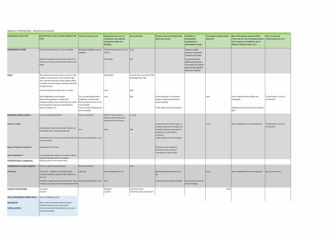
Appendix 1 Meeting Notes - Deconstruction Analysis
DECONSTRUCTION STEP DESCRIPTION, WHAT IS DONE DURING THIS
STEP
Tools that come into use Damage that may occur to
components and materials
during disassembly and
handling
Reuse potential Foreseen need for reconditioning,
repair and controls
Suitability of
disassembled
components for
intermediate storage
Foreseeable wastage (timber
elements)
Risks with regard to personal safety.
(There may be a risk of inhaling particles,
risk of exposure to chemicals, risk of
falling or lifting too heavy, etc.).
Risks of chemicals
contaminating soil or air
PREPARATORY WORK Remove flooring, staircase, external cladding All steps: Scaffolding, lorry for
transport
Components damaged and not
reused
none All parts: weather
protection wrappig for
transport and storage
Windows and doors only need to be removed if
they are not to be reused, else they remain in the
panel
No damage high For deconstruction,
additional protection is
not needed, as it will be a
matter of days that the
structure is exposed
ROOF Tiles need to be removed if they are heavy/ their
weight is not planned for. Concrete tiles might
have a low life expectancy. Roof cladding might
be subject to trend changes and might need to be
changed anyway.
Degradation Concrete tiles: none; Slate: high;
lightweight tiles: high
Dormer windows to be taken out as a whole none high
Saw: sawing through nails in
headbinder, sawing in half/
thirds (transport of parts up to
4.5m possible)
none high Visual inspection: rot, (moisture)
damage, unexpected alterations;
repair acordingly
none safety inspection before lifting, risk
manageable
Treated timber: no risk to
environment
Crane: Lift after lifting web has
been reinstalled
Timber might need to be retreated Lifting points should be known/included in
BIM
EXTERNAL WALLS, FLOOR 2 Remove internal plasterboard Electric screwdriver Plaster is fixed to service
battens and its replacement
would not affect structure
no reuse
Panels 5-194 kg
Dissassembly of joint between wall element and
intermediate floor: sawing through nailssaw none high
visual inspection of studs (repair as
needed), replacement or addition of
insulation material, replacement or
patching of vcl and breather
membrane
none risks manageable, time consuming labour Treated timber: no risk to
environment
Lifting holes exist, a new loop or hook would need
to be fixed there
temporary lifting device, crane Timber might need to be retreated
Repair of Breather membrane? Replacement or patching Marking of panels needed to
determine order of removal/
reinstallation: include in BIMSerice installations? Are accessible after plaster is removed, could be
replaced if needed; same for insulation
INTERNAL WALLS, Loadbearing Same procedure as for external walls
INTERMEDIATE FLOOR CASSETTE Remove ceiling lining plasterboard Electric screwdriver none
40-600 kg Floor cover - chipboard: saw through where
cassettes need to be separated, glue together at
new site
saber saw minor damage (3mm cut) glued with expansion glue on new
site
none risks manageable, time consuming labour glue: no known risks
Cassettes/ cassette groups can be lifted off, holes
for loops exist, loops need to be temporarily fitted
temporary lifting device, crane none visual inspection (repair as needed) stack cassettes correctly
to avoid damage
SLAB ON THE GROUND sole plates damaged cannot be reused 100%
concrete crushed cannot be reused, but recycled
NON LOAD BEARING INNER WALLS Same as loadbearing walls
BATHROOM Tiles can be removed but will be damaged
Wetwall could be removed and reused
INSTALLATIONS Can be accessed after plasterboard is removed,
alterations possible
Roof (headbinders+trusses+gable
laders+bracing+battens+ sarking+felt+
insulation+ceiling covers, can be lifted as a whole
and transported in big pieces (depending on
distance, bridges etc.)

Appendix B2 EC5 Calculations General assumptions
• C16 timber with characteristic 5th percentile density ρk of 310 kg/m3
• Holes are not predrilled• Paslode tensile strength minimum 700 N/mm2
• Paslode head pull-through strength fhead,k=20.72 N/mm2 for average wood density 350 kg/m3
• Paslode withdrawal strength fax,k=10.33 N/mm2 for average wood density 350 kg/m3
• Paslode pointside penetration length tpen=75 mm – 4.7 mm = 70.3 mm• Paslode head diameter dh=6.5 mm• Paslode diameter d=3.1 mm
Connection between two vertical timber members, single-shear (e.g. wall panel to wall panel connection, Figure 36)
Figure 36 Connection between two vertical timber members Nails perpendicular to grain Member1= stud of wall panel Member2= stud of wall panel Row parallel to grain, but staggered nef=n 2 every 600 mm (2 every 400 mm in spandrel panels) t1=38mm t2=75 mm – 38 mm = 37 mm fh1k= fh2k= 0,082 ρk d -0,3 = 18.1 N/mm2 (characteristic embedment strength for both timber members) fu=700 N/mm2
My,Rk= 0.3 fu d2.6= 3978.87 Nmm Fax,Rk= unknown = 0𝛽𝛽 = 𝑓𝑓ℎ2𝑘𝑘
𝑓𝑓ℎ1𝑘𝑘 = 1
Which leads to screws with the following characteristics: n=1 defmin=3.1 mm (to match nail diameter) dimin=3.1/1.1 = 2.82 mm di= 3 – 3.45 mm = 3.23 mm (assumption from (ETA Danmark 2021)) def=3.55 mm d=5 mm (assumption from (ETA Danmark 2021)) l=70 mm (assumption from (ETA Danmark 2021))

t2=70 mm – 38 mm = 32 mm My,Rk= 0,15 ∙ 600 ∙ d2.6= 5909.69 Nmm (Equation from from (ETA Danmark 2021))
fh1k= fh2k= 0,082 ρk𝑑𝑑−0.3
2.5 𝑐𝑐𝑐𝑐𝑐𝑐2𝛼𝛼+𝑐𝑐𝑠𝑠𝑠𝑠2𝛼𝛼 = 15.69 N/mm2 (Equation from from (ETA Danmark 2021))
fixFax,Rk= unknown = 0 Table 7 Parameters of nails and screws to replace nails in the same connection
Parameter Nail Screw t1 38 mm t2 37 mm 32 mm fh1k= fh2k 18.1 N/mm2 15.69 N/mm2 β 1 My,Rk 3978.87 Nmm 5909.69 Nmm Fax,Rk 0
Figure 37 Equation 8.6 from Eurocode 5 for the calculation of the characteristic load-carrying capacity per shear plane per fastener Table 8 Fv,RK for nails and screws, calculated using equation 8.6 from Eurocode 5 (Figure 37) and the parameters in Table 7, minimum highlighted in bold In N/mm2 Nail Screw (a) 2132.61 2290.39 (b) 2076.49 1928.75 (c) 871.86 879.29 (d) 852.58 957.37 (e) 835.61 856.75 (f) 768.52 970.64
The characteristic load-carrying capacity per shear plane per fastener is bigger for the screw than for the nail (Table 8) and therefore the screw is adequate for replacement.

Connection between two horizontal timber members, single-shear (e.g. headbinder to top rail of panel, Figure 38)
Figure 38 Connection between two horizontal timber members ©Robertson Timber Engineering
Member 1= headbinder or bottom rail Member 2= top rail or soleplate Nails perpendicular to grain Row perpendicular to grain 2 every 600 mm t1, t2, fh1k, fh2k, fu, My,Rk, Fax,Rk, 𝛽𝛽 are the same as above and therefore the screw specifications are as above. Connection between a panel product (OSB) and a timber member, single-shear Member 1= OSB sheathing, 9 mm thickness Member 2= stud, headbinder, bottom rail of panel t= 9 mm t2= 75-9 mm = 66 mm Minimum spacing 50 m fhk = fh1k = (characteristic embedment strength since dh>2d) = 65 d -0,7 t0.1 = 36.38 N/mm2 fh2k= 0,082ρk d -0,3 = 18.1 N/mm2 = 0.50 fu=700 N/mm2 My,Rk= 0.3 fu d2.6= 3978.87 Nmm Fax,Rk= unknown = 0 Which leads to screws with the following characteristics: n=1 defmin=3.1 mm dimin=3.1/1.1 = 2.82 mm di= 3 – 3.45 mm = 3.23 mm (assumption from (ETA Danmark 2021)) def=3.55 mm d=5 mm (assumption from (ETA Danmark 2021)) l=70 mm (assumption from (ETA Danmark 2021)) t2=70 mm – 9 mm = 61 mm dhmin=11.5mm >2def fh1k =65 def-0,7 t0.1 = 33.36 N/mm2 My,Rk= 0,15 ∙ 600 ∙ d2.6= 5909.69 Nmm (assumption from (ETA Danmark 2021)) fh2k= = 15.69 N/mm2 (assumption from ETA Danmark 2021)

Fax,Rk= unknown = 0 Parameter Nail Screw t1 9 mm t2 66 mm 61 mm fh1k 36.38 N/mm2 33.36 N/mm2 fh2k 18.1 N/mm2 15.69 N/mm2 β 0.5 0.47 My,Rk 3978.87 Nmm 5909.69 Nmm Fax,Rk 0
In N/mm2 Nail Screw (a) 1015.00 1501.20 (b) 3704.01 3676.68 (c) 1361.09 1387.78 (d) 603.54 809.32 (e) 1496.64 1578.07 (f) 888.12 1176.49
For assessing whether screws have to be placed in or near old screw holes when reassembling recovered assemblies, the minimum spacing for screws according to Eurocode 5 is analysed (Figure 39). No complications should arise when placing screws with minimum spacing to old screws and holes.
Connection between two vertical timber members, e.g. studs in wall panels
α= 0°
a1= (5+7│cos α│) d = 60 mm
a2= 5d = 25 mm
a3t= (10+ 5 cos α) d = 75 mm
a3c= 10d = 50 mm
a4t= (5+5 sin α)d = 25 mm
a4c= 5d = 25 mm
Figure 39 Minimum spacing for screws in connection 1, following the parameters in Table 7
Studs of a 38 by 75 mm2 cross section (in non-loadbearing internal walls) could only have one screw at the same height, but studs with a 38 by 140 mm2 cross section (in external walls) could have a maximum of three.
Studs of 2212 mm length contain a maximum of 4 connections with 600 mm spacing (3.69). With a minimum distance to the edge a3 of 50mm and 75 mm on both sides respectively, screws can be placed on 2087 mm

length, with 60 mm lengthwise distance between a pair of screws, meaning that the first assembly requires 60 mm space per screw pair and every following re-assembly requires 120 mm of space.
This means that we can reuse the same stud, without reusing screw holes (2087 𝑚𝑚𝑚𝑚− 4 ∙ 60 𝑚𝑚𝑚𝑚) ÷ (4 ∙120 𝑚𝑚𝑚𝑚) = 3.85 times, which in reality means a maximum of 3 times. It is likely that studs are not reused more than three times and thus holes will not need to be reused.
A special case are spandrel panels, that can be much shorter and have a lengthwise nail spacing of 400 mm. The worst cases in terms of spacing flexibility is the stud lengths of 718 mm in panel EX5SP (after panel EX4SP is made redundant due to new wall layout). This would allow lengthwise re-spacing of 1.97 times (1 time in reality). Spandrel panels, as external panels, have a stud width of 140 mm, so that a screw can be placed at the same height in 25 mm distance to the old hole and the edge twice (Figure 40). In total, 5 reuse cycles are possible without reusing screw holes.
Figure 40 re-spacing of screwed connections in external wall panels of 38 by 140 mm2 cross section, schematic Connection between two horizontal timber members e.g. headbinder to top rail of panel α= 90° a1= (5+7│cos α│) d = 25 mm a2= 5d = 25 mm a3t= (10+ 5 cos α) d = 50 mm a3c= 10d = 50 mm a4t= (5+5 sin α)d = 50 mm a4c= 5d = 25 mm
Figure 41 Minimum spacing for screws in connection 2, following the parameters in Table 7
Soleplates and headbinders have minimum sections of 800*75 mm2 with two connections and 1201*75 mm2 with three connections. This leaves us with only lengthwise respacing options for both scenarios, but 6.5 and 13.68 possibilities for respacing respectively (calculated as above, Figure 41).

Connection between a panel product (OSB) and a timber member, single-shear
α= 90°
a1= 0.85 (5+7│cos α│) d = 21.25 mm
a2= 0.85 5d = 21.25 mm
a3t= (10+ 5 cos α) d = 50 mm
a3c= 10d = 50 mm
a4t= (5+5 sin α) d = 50 mm
a4c= 5d = 25 mm
Figure 42 Minimum spacing for screws in connection of OSB, following the parameters in Table 8.
OSB panels require connectors around the edge with a minimum spacing of 50 mm (Figure 42). A standard OSB panel of 597 by 2288 mm2 requires 12 fasteners on the short side (11.94) and 46 fasteners on the long side (45.76). Only one fastener can be used at the same height in studs and at the same width in top or bottom rail. Using the same approach as above, we get replacement options of 0.47 and 0.62 times respectively. This leads to the conclusion that neither on the short nor on the long side OSB could be detached from the panel and reattached without using screws in or close to old screw holes.

Appendix B3 List of all functional units and unit width in cores (one core = 600 mm)
Unit No. Unit Unit width in cores
E1 External wall, 1 core 1 E1a External wall, 1 core plus 1 stud 1
E2 External wall, 1 core plus 2 studs 1
E2a External wall, 1 core plus movement joist 1 E2b External wall, 1 core plus middle stud 1
E3 External wall, 1 core plus nogging 1
E4 External wall, half core 0.5
E5 External wall, half core plus middle stud 0.5
E6 External wall, half core plus 1 stud 0.5
E7 External wall, half core plus 2 studs 0.5
E7a External wall, half core plus 3 studs 0.5
E8 External wall, half core plus nogging 0.5
E9 External wall, 2 cores 2
E10 External wall, 3 cores 3 E11 Internal loadbearing wall, 1 core 1 E12 Internal loadbearing wall, 1 core plus middle stud 1 E13 Internal loadbearing wall, 1 core plus 1 stud 1 E14 Internal loadbearing wall, 1 core plus 2 studs 1 E15 Internal loadbearing wall, 1 core plus 4 studs 1 E16 Internal loadbearing wall, 1 core plus nogging 1 E17 Internal loadbearing wall, half core 0.5 E18 Internal loadbearing wall, half core plus nogging 0.5 E19 Internal loadbearing wall, half core plus 1 stud 0.5 E20 Internal loadbearing wall, 2 cores 2 E21 Internal loadbearing wall, 3 cores 3 E22 Internal non-loadbearing wall, 1 core 1 E23 Internal non-loadbearing wall, 1 core plus 1 stud 1 E24 Internal non-loadbearing wall, half core 0.5
E25 Internal non-loadbearing wall, half core plus 1 stud 0.5
E26 Internal non-loadbearing wall, 2 cores 2 E27 Internal non-loadbearing wall, 3 cores 3

Unit No. Unit Unit width in cores
E27a Internal non-loadbearing wall, 1 core plus nogging 1
E27b Internal non-loadbearing wall, 1 core plus middle stud 1
E27c Internal non-loadbearing wall, half core plus nogging 0.5
E28 Window 3 E29 Small window 2 E30 Large window 5 E31 Internal loadbearing door, 140 mm width 2 E31a Internal loadbearing large door 3 E31b Internal loadbearing door, 89 mm width 2 E31c Internal loadbearing door plus nogging 2 E32 Internal non-loadbearing door 2 E33 Window sill - E34 Window sill high - E35 Window sill low - E36 Small window sill 1.5 E37 Small window sill high 1.5 E38 Small window sill low 1.5 E39 Large window sill 4 E40 OSB, half core 0.5 E40a OSB, half core plus 2 stud widths 0.5 E41 OSB, 1 core 1 E43 OSB, 1 core plus 2 stud widths 1 E45 OSB, 2 cores 2 E47 OSB, 4 stud widths - Ecor Corner, 140 mm width and thickness -

Appendix B4 Composition of wall panels from standard units, including new length of panels and optimisation suggestions for increased adaptability
Panel number Units Sill OSB new length Optimisation
EX1GF E9 E4 E28 E4 E33 E41 E43 E40a 3600 (1800)
Add E3 from EX 19GF and move E4, E28, E4 to EX2GF
EX2GF E2 E2b E45 1340 (3600)
Add E4,E28,E4 from EX1GF
EX3GF Ecor E1 E2a E9 E9 E3 E45 E41 E45 E45 4200 (3740)
Move E3 from EX3GF to EX4GF
EX4GF E6 E6 E2a E10 E45 E41 E45 3000 (3600)
EX5GF E4 E2 E9 E45 E40 E41 2100
EX6GF Deleted
EX7GF E30 Ecor 3140
EX8GF Deleted
EX9GF E29 E29 E38 E47 2400
EX10GF Deleted
EX11GF Ecor E4 E30 E8 E39 E40a E40a 3600
EX12GF E2a E1 E2 E10 E45 E45 E45 3600 (2100) Move E9 and E6 from EX12GF to EX13GF EX13GF E6 E2 E9 E45 E41 E40 2100 (3600)
EX14GF E9 E2a E9 E2b E45 E41 E45 E41 3740
EX15GF E4 E4 E10 E9 E4 Ecor E45 E41 E45 E41 E40 3900
EX16GF Unchanged
EX17GF Unchanged
EX18GF E4 E30 E7 E5 E40a E43 3900
EX19GF E3 E30 E1 E43 E43 E45 4200 (3600) Move E3 to EX1GF
IL1GF E9 E2 E1 E45 E45 2400 (3000) Move E1 from IL2GF to IL1GF
IL2GF E1 E3 E9 E2b E45 E45 E41 3000 (2400)
IL3GF E1 E31 E4 E1 E43 E40a E41 2700
IL4GF Deleted
IL5GF E20 E16 E31c E45 E43 3000
IL6GF E13 E31a E17 E16 E41 E40a E40a E41 3300
IL7GF E20 E11 E13 E45 E45 2400
IL8GF E31b E20 E13 E43 E41 E40 3000
IN1GF E32 E22 1800
IN2GF E26 E22 E23 2400
IN3GF Special
EX1FF E2a E28 E4 E8 E7 E5 E34 E43 E43 E41 3600

Panel number Units Sill OSB new length Optimisation
EX2FF E1 E29 E2b E37 E43 E43 2400 (1800) Move E3 from EX2FF to EX3FF
EX3FF E1a E4 E28 E4 E34 E41 E40a E40a 3000 (3600)
EX4FF Ecor E1 E2a E9 E9 E45 E45 E45 3740
EX5FF E1 E29 E4 E29 E37 E41 E40a 3300
EX6FF E2a E9 E1 Ecor E45 E41 E40 2540
EX7FF E4 E28 E1 E4 E33 E40b E40b 3000
EX8FF E1a E29 E1a E38 E41 E43 E40a 2400
EX9FF Deleted
EX10FF E1a E3 E28 E6 E4 Ecor E35 E40 E43 E43 E40 3740
EX11FF E9 E6 E4 E9 E45 E41 E45 3000
EX12FF E29 E2b E1 E29 E37 E43 E43 3600
EX13FF E1 E2a E9 E4 Ecor E45 E45 E40 2840
IN1FF E26 E26 2400
IN2FF Deleted
IN3FF E26 1200
IN4FF E26 1200
IN5FF E32 E22 1800
IN6FF E32 E32 E27a E22 3600
IN7FF E22 E32 E24 E32 E24 3600
IN8FF E26 E25 1500
IN9FF E26 E26 2400
IN10FF E26 E26 E26 3600
IN11FF Deleted
IN12FF Deleted
IN13FF Deleted
IN14FF Deleted
IN15FF E26 E23 E23 E22 3000
IN16FF E32 E23 E22 2400
IN1SF E26 E32 2400
IN2SF E27b E24 E27c 1200
IN5SF E25 E27b 900
All other SF Unchanged

Appendix B5 Deconstruction Plan

Appendix B5 Deconstruction Plan
Contract name
Everett Grand Building typeDetached timber-frame
houseUpdated 10.9.21
Step Deconstruction detailsWeight range of
elementsProposed equipment required Risks to reuse
Resource recovered
Intended re-use
Value after recovery
Recycling
1 Remove furnishing, wall attachments, bathroom installations, visible services like fire alarms etc., stairs
Stair, furniture
Stairs could be reused in another
building. Furniture could
be reused.
Medium
Timber, small electronic
devices, cables, tiles
2Remove plasterboard on walls and ceilings (unscrew screws).
Detach services inside panels. Remove floor finishes (depending on type).
16.5 to 22 kg (plasterboard) Electric screwdriver, crowbar, claw hammer, sabre saw Damage to floor finish Floor finish (timber)Floor finish in
another buildingMedium
Plasterboard, possibly carpet, tiles, chipboard
or linoleum flooring
3
Inspect structure. Ensure that structure is safe and built as expected. Note and mark any damage or decay. Note and mark any unreported connectors. Update deconstruction
information should the structure differ from design drawings. NOTE: Refer to inspection guidance.
Torch, screwdriver, measuring tape, portable moisture meter, portable computer, spray paint, calculator, metal detector?
n/a
4
Use sabre saw at nailed connections. Use electric screwdriver at screwed connections. Locate lifting points, insert lifting straps. Secure doors before lifting. NOTE: For position,
number and type of connections, refer to nailing schedule. For position of lifting points, refer to design drawings and BIM
model.
7.8 to 145.2 kg plus doors Sabre saw, electric screwdriverIncorrect BIM data or access to information.
Timber framed panels
Rebuild house in new location / reconfigure
layout
Medium
5 Remove brickwork. Ensure that timber kit is not damaged in the process.
Scaffolding, hydraulic breaker Low Brick fragments
6
Remove eaves soffit framing, fascia board, soffit ventilators, soffit plywood and bootends. Remove tilting fillets, eaves and ridge sarking boards (where applicable) and sheet with roof
sarking. Remove roof tiles.
Crowbar, Claw hammer, screwdriver, pliersPossibly reuse, if life-span is not
reached Low
Concrete tiles, uPVC boards
7Unscrew screws . Secure windows before lifting. NOTE: Refer
to manufacturer's instructions for type and position of connections and lifting points.
Electric screwdriver, Crane Dormer windowsRebuild house in
new locationHigh
8
Fix temporary bracing. Remove holding down straps. Saw apart trusses and panel headbinder. Secure windows before lifting. NOTE: For position, number and type of connections, refer to nailing schedule. For position of temporary bracing,
lifting points and holding down straps, refer to design drawings and BIM model.
Around 2990 kg Torch, Crowbar, Screwdriver, Sabre saw, Pliers, CraneMoisture damage.
Incorrect BIM data or access to information.
RoofRebuild house in
new locationHigh
Possibly roofing felt, timber
9
Fix temporary bracing. Use sabre saw at nailed connections. Use electric screwdriver at screwed connections. Locate lifting points, insert lifting straps. Secure doors before lifting. NOTE: For position, number and type of connections, refer to nailing schedule. For position of temporary bracing and lifting points,
refer to design drawings and BIM model.
143.0 to 278.8 kg plus doorsRebuild house in
new locationHigh
Possibly insulation, timber
10
Fix temporary bracing. Remove holding down straps. Use sabre saw at nailed connections. Use electric screwdriver at
screwed connections. Locate lifting points, insert lifting straps. Secure windows before lifting. NOTE: For position, number
and type of connections, refer to nailing schedule. For position of temporary bracing, lifting points and holding down straps,
refer to design drawings and BIM model.
122.0 to 425.7 kg plus windowsRebuild house in
new locationHigh
Possibly insulation,
timber, OSB, Membranes,
Windows
Deconstruction Plan
Component
First floor internal load-bearing wall panels
First floor external wall panels
Roof structure
Internal non-load bearing walls
Roof finish
Second fix
Internal finishes
External facade
Inspection
Dormer windows
Headbinder could suffer deconstruction damage.
Moisture damage. Incorrect BIM data or access to information.
Crane - sized to loads, max lifting radius and environment, sabre saw, Electric screwdriver
Timber framed panels
DRAFT PLAN ONLY - NOT FOR USE ON SITE

Appendix B5 Deconstruction Plan
11
Locate individual cassettes from below. Saw apart individual cassettes. Locate lifting points, insert lifting straps. NOTE: For
position, number and type of connections, refer to nailing schedule. For cassette layout and position of lifting points,
refer to design drawings and BIM model.
individual cassettes: Around 106 to 310 kg
Sabre saw, CraneMoisture damage.
Incorrect BIM data or access to information.
Floor cassettesRebuild house in
new locationHigh
Possibly insulation,
timber, OSB, Membranes
12
Fix temporary bracing. Remove holding down straps. Saw apart trusses and panel headbinder. NOTE: For position,
number and type of connections, refer to nailing schedule. For position of temporary bracing, lifting points and holding down
straps, refer to design drawings and BIM model.
Around 310 kg Crowbar, screwdriver, Sabre saw, craneMoisture damage.
Incorrect BIM data or access to information.
RoofRebuild house in
new locationHigh
Possibly roofing felt, timber
13
Fix temporary bracing. Use sabre saw at nailed connections. Use electric screwdriver at screwed connections. Locate lifting points, insert lifting straps. Secure doors before lifting. NOTE: For position, number and type of connections, refer to nailing schedule. For position of temporary bracing and lifting points,
refer to design drawings and BIM model.
143.0 to 278.8 kg plus doors HighPossibly
insulation, timber, OSB
14
Fix temporary bracing. Remove holding down straps. Use sabre saw at nailed connections. Use electric screwdriver at
screwed connections. Locate lifting points, insert lifting straps. Secure windows and doors before lifting. NOTE: For position, number and type of connections, refer to nailing schedule. For position of temporary bracing, lifting points and holding down
straps, refer to design drawings and BIM model.
122.0 to 425.7 kg plus doors and windows
High
Possibly insulation,
timber, OSB, Membranes,
Windows, Doors
15 If screwed, unscrew. If nailed, remove using crowbar. 1 to 8.5 kg Electric screwdriver, Crowbar Deconstruction damage Soleplates (timber)
Solplates could be reused if they
are recovered damage-free
Medium Timber
16 Demolish foundation Excavator, Skid steer Concrete rubble Low Concrete
17
Check components against inventory. Inspect all deconstructed elements for damage. Check if the intended
lifespan is reached or close to being reached. NOTE: Refer to inventory. For intended life-span and age, refer to BIM model.
For inspection instructions refer to post-deconstruction instructions.
Calculator, Portable Computer
a) For intact modules: Stack modules and wrap for protection during transport/storage. Update BIM model. Reuse in new
location.Stapler, Screwdriver, Portable computer, Lorry
Special case: Roof. Inspect roofing felt for damage or aging defects. Remove tiling battens and felt as necessary. Update BIM model. Saw apart roof structure as needed for transport.
Wrap for protection during transport and storage.
Stapler, Screwdriver, Sabre saw, Portable computer, Lorry
b) For slightly damaged modules: Repair on site or note and mark for repair on new site. Order materials to new site as required. Divert damaged components to recycling. Stack modules and wrap for protection during transport/storage.
Update BIM model.
Stapler, Screwdriver, Electric screwdriver, Nail gun, Portable computer, Lorry
c) For damaged elements: Divert modules for factory control.Not whether modules should be repaired, components
exchanged or modules disassembled for recycling. Update BIM model.
Screwdriver, portable computer, lorry
First floor cassettes
Ground floor load-bearing internal wall panels
Ground floor external wall panels
Soleplates
Concrete slab
Inspection
Garden room roof
Rebuild house in new location
Sabre saw, Electric screwdriver, Crane
Headbinder could suffer deconstruction damage.
Moisture damage. Incorrect BIM data or access to information.
Timber framed panels
DRAFT PLAN ONLY - NOT FOR USE ON SITE


Appendix CDesign for deconstruction and reuse:Case study Villa Forshälla Sund


Appendix C Design for deconstruction and reuse: Case study Villa Forshälla Sund
J an ina Ös t l ing 1 , Carm en Cr i s tescu 2 , Mar len e Cramer 3 , Y lva Sandin 2 , Kar in Sandberg 2 1 I s o T i m b e r H o l d i n g A B 2 R I S E R e s e a r c h I n s t i t u t e s o f S w e d e n 3 E d i n b u r g h N a p i e r U n i v e r s i t y
April 2022
Innovative Design for the Future – Use and Reuse of Wood Building Components

2
Foreword
This report is one in a series of case study reports in the InFutURe Wood project - Innovative Design for the Future – Use and Reuse of Wood (Building) Components. The first case (Sandin et. al 2021) served as a template, and therefore the report structure as well as some of the general content is common to this report and the first one. All five cases can be found as appendices to Y. Sandin, E. Shotton, M. Cramer, K. Sandberg, S. J. Walsh, J. Östling, C. Cristescu, V. González-Alegre, G. Íñiguez-González, D. Llana, A. Carlsson, C. Uí Chúláin, N. Jackson, M. García Barbero, A. Zabala Mejia (2022): Design of Timber Buildings for Deconstruction and Reuse: Three methods and five case studies. RISE Report 2022:52, ISBN 978-91-89561-92-2.
InFutUReWood is supported under the umbrella of ERA-NET and financed by funding agencies from each of the participating countries. The industry partners participate mostly with in-kind. The research and academia project partners are RISE (Sweden), Edinburgh Napier University (UK), National University of Ireland Galway (Ireland), University College Dublin (Ireland), Polytechnic University of Madrid (Spain), University of Ljubljana (Slovenia), Aalto University Helsinki (Finland), and Technical University Munich (Germany). The industry partners are Kiruna Municipality Technical Service, Swedish Wood, Derome, Isotimber, Offsite Solutions Scotland, Hegarty Demolition, SIP Energy, Connaught Timber, The Federation of the Finnish Woodworking Industries, Jelovica, The Swedish Federation of Wood and Furniture Industry, Balcas Timber, Stora Enso, Klimark + Nova domus Hábitat and Brenner Planungsgesellschaft.
The authors, and the project, want to dedicate special thanks to Erik Persson and Matilda Lindblom. It is very appreciated and valuable that you share your fantastic Villa Forshälla Sund and allow us to study and present it in this report. Thanks for the photos as well!
Thanks go also to the contractor Gustab AB, that allowed to share the construction drawings of the foundation and the ground floor, and of course, assembled the building. The photos from your assembly are very useful for the readers understanding, thanks!
Last, but not the least, thanks go to Marja Sidén, Johan Holm, César Puás and Håvard Jegerstedt at IsoTimber for participating in the deconstruction analysis and reviewing the report in the case study and Johan Hervall for valuable feedback on the report.
InFutUReWood is supported under the umbrella of ERA-NET Cofund ForestValue by Vinnova – Sweden’s Innovation Agency, Formas, Swedish Energy Agency, the Forestry Commissioners for the UK, the Department of Agriculture, Food and the Marine for Ireland, the Ministry of the Environment for Finland, the Federal Ministry of Food and Agriculture through the Agency for Renewable Resources for Germany, the Ministry of Science, Innovation and Universities for Spain, the Ministry of Education, Science and Sport for Slovenia. This is supported under the umbrella of ERA-NET Cofund ForestValue, and ForestValue has received funding from the European Union’s Horizon 2020 research and innovation programme under grant agreement N° 773324

3
Summary With the objective of reducing the carbon footprint on our planet, buildings constructed today should be designed with a long lifespan, considering how its properties and actions affect the environment, and shall strive to work for a long-term cycle and be part of a circular process. The project aimed to develop a method on how to evaluate a building’s suitability for deconstruction and reuse. A theoretical ‘case study’ method was decided upon and tested at a predefined scenario, to deconstruct the building in 50 years on and rebuild it in the same area. This case studied Villa Forshälla Sund, Sweden, a typical residential family home. The results are summarized below.
Strengths identified of the IsoTimber load bearing structure in the case study; - The prefabricated external wall elements are dimensionally stable - All structure connections are fixed together with screws and are easy to disassemble - An intuitive deconstruction that resembles the efficient construction process - The load bearing roof structure is assumed to be reusable - The structure contains few materials and is structurally sound, with no fragile materials - Lifting solutions are defined - No special tools are required
One disadvantage with the design was observed in the aspect of deconstruction The top layer of the roof construction is likely to be damaged at deconstruction. This weakness was addressed with a modified design, suggesting a roof cassette construction.
Estimated amount of wood that could be reused in the defined scenario A measure on how well the design of a building suits deconstruction and reuse was suggested by calculating the amount of load bearing wood that could be reused. With current design of Villa Forshälla Sund this proportion reached 96,5 % and the modified design 100 %.
Construction documentation that can be linked to BIM The documentation used during the construction stage became valuable in a process of deconstruction and reuse. Such as, structure function, material data, dimensions, and assembly instructions. Production drawings along with digital 3D-models where all wall elements are ID marked for quick and easy assembly.
IsoTimber Guide for Deconstruction Due to the findings observed in this case study, an immediate action was taken to create an IsoTimber Guide for Deconstruction with the purpose of facilitating a structure reuse.
Conclusion The case study method was found to be a crude but useful way to analyze the design of a building in terms of deconstruction and reuse, identifying both strengths and weaknesses. The case study found that the IsoTimber structure is designed for deconstruction and reuse. The walls studied, IsoTimber elements combined with CLT, can easily be disassembled into individual elements for reuse. There is no need to change the wall design, nor to improve the connections. Looking to the whole building, roof cassettes was suggested as an improvement.

4
Table of contents
1. Introduction 5
1.1. Background 5
1.2. Aim 5
1.3. Objectives 6
1.4. Delimitations 6
1.5. Target group 7
1.6. Terms and definitions 7
2. Method and implementation 8
2.1. Overview of steps 8
2.2. Step 0. Definition of scenario to design for 8
2.3. Step 1. Analysis of existing design 8
2.4. Step 2. Modified design 9
2.5. Step 3. Comparison existing - modified design 10
2.6. Step 4. Reuse documentation that can be linked to BIM 10
3. Results 11
3.1. Results: Step 1. Analysis of existing design 11
3.2. Results: Step 2. Modified design 40
3.3. Results: Step 3. Comparison existing – modified design 40
3.4. Results: Step 4. Reuse documentation that can be linked to BIM 41
4. Discussion and conclusions 44
4.1. Evaluation of the case study method 44
4.2. Conclusion about the strengths and the weakness of Villa Forshälla Sund 44
4.3. Thoughts about the IsoTimber Guide for Deconstruction 45
4.4. Quality of and limitations in findings 45
5. References 46
Appendix C1 IsoTimber Guide for Deconstruction

5
1. Introduction
1.1. Background
Society experiences a lack of housing, now and in the foreseeable future. At the same time the building sector accounts for a large contribution of society’s Green House Gas emissions, raw material consumption and waste production. One way of diminishing this environmental impact would be to reuse buildings and building components to a higher degree. To facilitate that, buildings would need to be designed with that aspect in mind. Today, significant difficulties can arise in deconstructing already manufactured buildings and reusing their parts. The difficulties have to do with things like joining techniques, sensitivity to damage and use of chemicals.
The InFutUReWood project is studying how to establish circularity for timber buildings. There is a lack of published knowledge on how wood-based building frames are best designed for deconstruction and reuse. In Work Package 2, “Design of timber structures for the future”, new ways to design timber-based structures are investigated. New design concepts are developed as well as a model to plan primary design to facilitate deconstruction rather than demolition.
A state-of-the-art study showed a knowledge gap in the published literature (Cristescu et. al. 2020). There is a lack of practical examples of the existing advantages and obstacles to design for deconstruction and reuse of different types of timber buildings, examples showing how designs could be improved, how guidelines for deconstruction and reuse could be formulated and also, in general, descriptions of ways to work to find new designs.
1.2. Aim
This case study is one in a series that considers different types of timber structures. The aim of the collected series is to:
• identify or develop new design concepts adapted to design for deconstruction • identify or develop a model to plan primary design to facilitate deconstruction rather
than demolition.
The project examines the problems that can occur for a specific design and suggests how problems could be solved by modifying the design if needed.
This specific case study concerns the building “Villa Forshälla Sund”, a residential building that was designed by Erik Persson and Matilda Lindblom, with a massive timber structure manufactured by IsoTimber, Sweden (Figure 1-1). This report is based on the same format, and partly the same information, as presented in the first case study report, Villa Anneberg, (Sandin et. al. 2021).

6
Figure 1-1 Villa Forshälla Sund, exterior. Illustration: Erik Persson, Matilda Lindblom.
1.3. Objectives
The objectives of the case study are to identify:
• The inherent strengths and weaknesses of the current design of Villa Forshälla Sund regards to deconstruction and reuse.
• How the design could be improved with respect to future deconstruction and reuse. • How much wood that could be reused, i.e. used for the same purpose as was
originally intended, in the future with the current and the improved design. • How guidelines for deconstruction and reuse could be formulated.
Another objective of the study is to develop and test a method for carrying out case studies.
1.4. Delimitations
The study focuses on the design of the load bearing structure, the frame.
Further, it focuses on solutions that can be considered in the design phase. We are aiming for improvements that make the building structure as well adapted for reuse as possible. The phrasing "adapted for reuse" here means that the parts can be deconstructed, transported, stored and reassembled without losing [much of] their function and economic value.
It is assumed to be efficient from an environmental and resource point of view to design buildings that can be deconstructed and their parts reused, i.e. to adopt a design philosophy referred to as Design for Deconstruction and Reuse, DfDR. The environmental impact from construction and real estate industry would also decrease if buildings were designed for adaptability, i.e. designed to be adapted and meet new demands when necessary. Although important, design for adaptability is outside the scope of this work.
This study investigates technically possible design improvements with respect to DfDR. Costs and environmental impacts for different solutions are not examined.

7
1.5. Target group
The target group considered for this report is manufacturers of timber-based building structures, architects and engineers designing such structures and researchers, as well as contractors and consultants.
1.6. Terms and definitions
Deconstruction The systematic dismantling and removal of a structure or its parts, in the reverse order of construction, with the intent of repurposing, reusing, recycling, or salvaging as many of the materials, products, components, assemblies, or modules as possible. (Sparandara et al. 2019, Fannie Mae 2020)
Disassembly While some authors make a distinction between "disassembly" and "deconstruction", here these two words are used interchangeably.
Element An IsoTimber element is a planar wall element as delivered to construction site. Typically of floor height and 6-8 meters width.
An element is constructed by several panels.
Ground floor and first floor
We adhere to traditions in large parts of Europe to call the floor on the ground the ground floor and the next floor up the first floor.
Improvement, improved solution
Improvement is a measure that leads to components retaining their functions and economic value to a greater degree in a future deconstruction, or that leads to a less time-consuming or safer deconstruction process than can be reached with the current design. With improvements fewer damages will occur, less repair/reconditioning will be required for the next use cycle, a larger proportion of the material can be reused and less deconstruction time.
Panel An IsoTimber panel is a timber panel of typical size 1200 x 2430 mm and thickness 60, 100 or 150 mm. The panel is both load bearing and insulating.
Recycling
Any recovery operation by which waste materials are reprocessed into products, materials or substances whether for the original or other purposes. It includes the reprocessing of organic material but does not include energy recovery and the reprocessing into materials that are to be used as fuels or for backfilling operations. (EC 2008)
Reuse
Any operation by which products or components that are not waste are used again for the same purpose for which they were conceived. (EC 2008)

8
2. Method and implementation
This chapter presents the case study method, which is based on another study, the Villa Anneberg (Sandin et. al. 2021).
2.1. Overview of steps
The method developed for this study has five steps, see Figure 2-1 and sections 2.2-2.6.
Step 0. Defining a scenario to design for
Step 1. Analysis of existing design
1.1 Description of the building and how it is assembled
1.2 Simulation of deconstruction and reassembly as well as identification of
strengths and weaknesses
1.3 Identification of areas to improve
1.4 Selection of areas to improve
1.5 Calculation of the amount of wood that can be reused with today's design
Step 2. Modified design
Step 3. Comparison existing - modified design
Step 4. Reuse documentation that can be linked to BIM
Figure 2-1 The steps of the case study method.
2.2. Step 0. Definition of scenario to design for
The future scenario that the design was evaluated and adapted for was defined as follows: After one service life (about 50 years), the building will be deconstructed into its original (planar) elements, transported to another site in an area with the same wind and snow loads, and reassembled to an identical building.
2.3. Step 1. Analysis of existing design
The analysis of existing design was made as described below. The possible deconstruction of the Villa Forshälla Sund was discussed between structural engineers, production manager, CEO, sustainable manager and researchers in the project.
2.3.1. Description of the building and how it is assembled
Customer specific assembly drawings and instructions, with technical details for Villa Forshälla Sund, were used as basic information.

9
2.3.2. Simulation of deconstruction and reassembly
This step, as well as the next one, was carried out in three meetings/workshops with several competences present from the manufacturer and research. Notes were taken.
The main steps in an assumed deconstruction process are first identified, based on knowledge of the system and how it is assembled the first time. The assumed deconstruction process is discussed in detail. Advantages and disadvantages of the existing design regarding deconstruction and reuse/recycling are identified and described. The following aspects were considered in the assumed deconstruction process:
• tools needed for deconstruction • damage that may occur to components and materials during deconstruction • need for reconditioning, repair and controls • foreseen problems with transport or intermediate storage • foreseen waste • risks with regard to personal safety • risks to the environment
2.3.3. Identification of strengths and weaknesses regarding deconstruction & reuse
See description in previous step.
2.3.4. Identification of areas to improve
In the simulation of deconstruction possible disadvantages were identified and noted. Improvements were suggested.
2.3.5. Selection of areas to improve
Only one area of design improvement was identified within the scope of this case study, this idea of improvement was further investigated.
2.3.6. Calculation of the amount of wood that can be reused with today’s design
The amount of wood in the object, in volume (m3), was calculated. Then an estimation was made of the amount of wood that can be reused. The causes for parts being damaged, or for some other reason not being reused according to the analysis 2.3.2 above, is described.
2.4. Step 2. Modified design
Since only one area of design improvement was identified within the scope of this case study, to change the current design of roof decking fixed with nails to the I-joists, to a roofing cassettes system fixed directly to the walls, this idea was further investigated by interviewing

10
a manufacturer to verify it. The amount of wood that can be reused with the modified design was then estimated.
2.5. Step 3. Comparison existing - modified design
A comparison was made of the amount of wood that can be reused in current design and the corresponding amount in the improved design.
2.6. Step 4. Reuse documentation that can be linked to BIM Provoked by the project, based on a better understanding after the detailed deconstruction discussion in this case study, an IsoTimber Guide for Deconstruction was developed. In the guidelines useful documentation was identified for an efficient deconstruction process.

11
3. Results
3.1. Results: Step 1. Analysis of existing design
3.1.1. Description of the building and how it is assembled
The detached house in this study is built on a hillside in the south-western part of Sweden and is named “Villa Forshälla Sund” (Figure 3-1). It is a one family residential 2-floor building of 188 m2 with a massive timber structure manufactured by the Swedish industrial partner IsoTimber. The building was designed by Erik Persson and Matilda Lindblom. The case study building is a one-off project, but similar construction techniques are used in other building types.
Figure 3-1 Villa Forshälla Sund.

12
Parts and joints
Load bearing parts of the structure
The parts that form the building's load bearing structure are, from top to bottom (Figure 3-2):
• Roof construction: built on site by roofing boards nailed to roof battens on top of roof structure (I-joist) and filled with cellulose insulation. The weather shield was roofing felt.
• Interior wall elements on first floor: prefabricated CLT elements. Some have load bearing function, some only stabilizing. Fixed together with screws.
• External wall elements on first floor: prefabricated wall elements of IsoTimber combined with CLT. The CLT had an interior visual quality in some rooms. Fixed together with screws.
• Floor elements intermediate floor: prefabricated CLT elements, fixed together with screws, no glue.
• Interior wall elements on ground floor: as for first floor. • External wall elements on ground floor: as for first floor. • Ground floor: framed with glulam beams and solid timber joists. • Foundation of glulam: columns made of glulam on concrete piles.
The above parts were delivered to the construction site as prefabricated elements, except the roof that was delivered as material and built on site. In addition, the load bearing foundation and ground floor was delivered and assembled by the local Swedish contractor Gustab AB on site. The CLT elements were manufactured by Stora Enso, the glulam by Moelven, the cellulose insulation by iCell and the screws by Würth.
Figure 3-2. Cross section of the building: external walls of IsoTimber elements combined with CLT, interior wall elements of CLT, intermediate floor of CLT, roof with I-joists and ground of a frame of glulam beams with solid timber joists.

13
Connections between wall/roof by angle brackets of dimension 90x105x105 mm.
Roof construction
The roof was built on site. The load bearing part is composed of I-joists (Figure 3-3, Figure 3-4), manufactured by Masonite Beams. Those were resting on the external wall and were secured by angle brackets (Figure 3-3). Plywood sheets were nailed at the short ends of the roof trusses (Figure 3-4), forming a cavity for the insulation, while a vapour control layer was fastened underneath and a breather membrane on top of the I-joists. Roofing boards were nailed to roof battens on top of the roof structure (I-joist) and the uppermost layer, the weather shield, was made of roofing felt. The roof cavity was filled with loose cellulose fibre insulation. The ceiling was constructed with battens and plasterboard.
Figure 3-3 Load bearing I-joists by Masonite Beam in the roof construction at the building site. A plywood sheet (12 mm) was nailed at the end of the I-joists to support the fibre insulation to stay in place sideways. To the right is a technical detail describing the connection between the I-joists and the exterior wall on the first floor, with dimensions and placement of angle brackets specified.
Figure 3-4 Dimensions of the I-joists in the roof described in a typical drawing detail.

14
Interior wall elements on first floor The interior walls on first floor (Figure 3-6) consist of prefabricated CLT elements. Some have a load bearing function, while most are stabilizing. A sole plate for the interior wall is assembled according to specific instructions (Figure 3-5) and plans (Figure 3-7). The wall panels are all fastened by screws at the sole plate and to each other or to the external wall elements (Figure 3-18).
Figure 3-5 Technical detail describing the assembly of the sole plate for the interior wall elements.
Figure 3-6 The interior walls are made of CLT.
Figure 3-7 Clipping from the assembly instruction of the interior wall element sole plate at first floor.

15
CLT element 100 mm + IsoTimber element 250 mm U-value 0,24 W/m2K
External wall elements on first floor
IsoTimber is a unique timber wall system, that is load bearing and insulated by air channels. No extra insulation is needed, nor any airtight membrane (plastic foil) on the inside or wind barrier on the outside. The prefabricated IsoTimber panels, which form part of the wall elements in the case study building, (Figure 3-8.b) have a simple design. A solid frame of studs encapsulates posts with air channels, and this assembly is covered by plywood sheets that are glued to both sides. Standard IsoTimber panels have dimensions 1200 x 2430 mm, with a thickness of 60, 100 or 150 mm. External wall elements of the Villa Forshälla Sund (Figure 3-9) contain these IsoTimber panels, with customised door and window openings.
The prefabricated external wall elements are constructed with IsoTimber panels (250 mm thick) combined with CLT (100 mm thick) (Figure 3-8). The CLT is facing the interior side and has a surface of ‘visual quality’ in some rooms. The wall elements meet in a half-lap joint (Figure 3-10). This method stabilizes the wall and makes it easier to form a straight wall at the construction site. Furthermore, it reduces the risk of air leakage (i.e. heat loss) through the wall joints. In addition, all joints in the building are covered with construction tape after assembly, with the purpose of preventing air leakage. Though, visible joints are covered by sealants for a more appealing expression interior.
(a)
(b)
Figure 3-8. a) Cross-section of a prefabricated external wall comprised of, from top to bottom: a CLT element (100 mm) and two IsoTimber panels (150+100 mm). It is produced at the IsoTimber factory in Östersund, Sweden. b) detail with a composition of IsoTimber panel. IsoTimber was awarded patent No. 6812412 in Japan.

16
Figure 3-9. The wall elements are prefabricated by assembling at least two layers of IsoTimber panels, depending on desired U-value. Wooden facade panel can be assembled in the factory, see photo, however the facade of Villa Forshälla Sund was assembled on site.
Figure 3-10 The wall elements meet in a half-lap joint (top view).
The external wall elements at first floor are assembled following the order given in the assembly instruction provided by the manufacturer IsoTimber (Figure 3-11). There is no separate sole plate mounted at first floor. The CLT-part of the external wall at ground floor, combined with the intermediate CLT floor element, act as sole plate for the external wall at first floor (Figure 3-13). Technical details are provided for all kinds of joints in the building, see example in Figure 3-12. Dimension of screws, angle brackets and their placement are described in these instructions. For an IsoTimber wall element, at standard ceiling height, typically 12 screws are used per vertical wall joint, and 5 screws per 2 meters at the sole plate.

17
Figure 3-11 Assembly instruction of the external wall elements on first floor. In this case the assembly order is defined by YV-01 to YV-13 (external wall elements), and IV-01 to IV-07 (interior wall elements). The physical elements are labelled with YV-01, YV-02 and so on.
Figure 3-12 Detailed assembly instruction for the external wall elements describing the connection at the corners.
Figure 3-13 Detailed assembly instruction for the external wall on first floor, the intermediate CLT floor element and the external wall at ground floor.
EXPLANATIONS Order of assembly: YV-01 to YV-13 IV-01 to IV-07 Intermediate floor Sill on the intermediate floor YV-14 to YV-22 IV-08 to IV-13 Assembly screws, angle brackets, construction tape, are included in the delivery

18
Floor elements at intermediate floor
The intermediate floor was made of 5 pieces of CLT elements (200 mm) (Figure 3-14, Figure 3-16). The joints between the floor elements are half-lap joints (Figure 3-15). No glue is needed in the joints since the CLT elements are sufficiently heavy. The technical detail provides the screw dimension. The intermediate floor elements are resting on the CLT-part of the external wall at ground level (Figure 3-13) and are fastened to it by screws (Figure 3-17). The bottom of the CLT floor element has visual quality.
Figure 3-14 (left) The CLT floor element at the intermediate floor is visible as well as the external wall element at first floor. The wall elements are secured by temporary supporting struts during assembly for safety reasons.
Figure 3-15 Technical detail how to connect the half-lap joints of the CLT floor elements.
Figure 3-16 (below) Part of the assembly instruction of the intermediate floor.

19
Interior wall elements on ground floor
The interior walls on ground floor were prefabricated CLT elements. Some have a load bearing function, while most are stabilizing. They are all fixed by screws in the same way as on first floor (Figure 3-18). Though there is an extra anchoring at the intermediate floor as described below (Figure 3-17).
Figure 3-17 The interior wall elements at ground floor are secured at the intermediate floor by screws through the CLT floor element (sideview, left and top view, right).
Figure 3-18 The interior wall elements at ground floor are secured at the external wall elements by screws as described in the technical detail (top view).

20
External wall elements on ground floor
Prefabricated wall elements, constructed in the same way as of the first floor with IsoTimber (250 mm) combined with CLT (100 mm) (Figure 3-8), were assembled at ground floor. However, at ground floor a dedicated sole plate (45 x 95 mm) was fixed by screws (Figure 3-19, Figure 3-20 and Figure 3-23).
Figure 3-19 Clipping from the assembly instruction for the sole plate at ground floor.
Figure 3-20 Detail of the assembly instruction for the sole plate at ground floor.

21
Ground floor
The ground floor is framed with glulam beams (Figure 3-21). Solid timber joists are fastened by screws and angle brackets (Figure 3-22). A second layer of solid timber joists are mounted in a perpendicular direction below it and a wind barrier attached underneath. Finally, a wood panel (22 mm) is attached to the bottom. The top layer of the ground floor is a wooden floor (30 mm) fastened to battens with screws. The floor cavity of the ground floor is filled with loose cellulose insulation. An overview of the ground floor construction is seen in Figure 3-23.
Figure 3-21 The structure of glulam at the ground floor.
Figure 3-22 Clipping from the assembly instruction for the solid timber joists at ground floor.

22
Figure 3-23 Construction overview of the ground floor.

23
Foundation of glulam
The house is located on a sloping hillside. Figure 3-24 shows an overview of the foundation, of glulam columns sitting on top of concrete foundations, and defines the assembly instruction for the foundation. Locking bolts at supporting struts are also holding the columns (Figure 3-25, Figure 3-26). The columns are made of two pieces of glulam glued together (Figure 3-26). An oil hardened wood fibre board (protecting the wood columns in case of water), is fixed with nails and glued to the end of the glulam column. The column is placed in a post base, which is fastened by screws to a concrete foundation that is anchored in the ground.
Figure 3-24 Schematic overview of the foundation of glulam columns on top of concrete foundations.
Figure 3-25 (above) Glulam columns on concrete foundations.
Figure 3-26 (right) Post base fixed by screws to the concrete foundations, forming the support for the glulam columns.

Presence of chemicals
The most common IsoTimber wall is 300 mm thick and contains ~99 % wood (weight percentage). The remaining 1 % comes from the weight of screws, construction tape and glue. The content of the wall panels of IsoTimber is fully described in an electronic building material declaration eBVD1 (C-556748467901-2). The glue used in the manufacturing process is the urea-formaldehyde resin, adhesive 1206, combined with the hardener 2545. The plywood is based on a Phenol-formaldehyde resin. The product was assessed by the Swedish Byggvarubedömningen2 in criteria based on chemical content, life cycle and social responsibility at the supplier level. The product obtained an overall judgement of Recommended (highest level) (BVB ID 136559). Documents are available in Swedish only. The CLT elements were delivered by Stora Enso. The elements are manufactured with PUR.
Electrical services and their connection to the load bearing structure
The electrical wiring was installed between the CLT and the IsoTimber. Figure 3-27 illustrates the layout of the conduits within the CLT and the holes where the electrical wires are emerging into the room, see also Figure 3-28. The conduits are milled at the CLT factory by a CNC reading those drawings. Services such as water, sanitation and ventilation were not investigated here.
Figure 3-27 The electrical wiring was installed between the layer of CLT and IsoTimber. The figure demonstrates a drawing for the corresponding hole taking in the CLT for the wiring.
1 https://byggmaterialindustrierna.se/byggvarudeklaration-ebvd1-0/ 2 https://byggvarubedomningen.se/in-english/

25
Figure 3-28 Electrical wiring extended through the external wall.
Figure 3-29 Wall elements are delivered in a stack, secured to each other for safety.
Assembly process for current design
Detailed assembly instructions are provided by the manufacturer IsoTimber, see an example in Figure 3-11. The foundation and the ground floor with the sole plate mounted, were already in place at the delivery of the prefabricated wall elements. The parts come as planar elements from the factory where they have been secured to each other (Figure 3-29), and the transportation vehicle, for a safe transport. The wall elements are loaded, inside the factory, to a closed transportation. Preferably, the delivery is just in time for assembly and no weather protection is needed. If necessary, the wall elements can be weather protected from factory.
At the construction site, the prefabricated elements are craned into position. Lifting solutions are in place from factory, for external wall elements (Figure 3-30), for interior wall elements (Figure 3-31) and intermediate floor elements (Figure 3-32). Supporting struts for stabilizing the wall elements are used at assembly for safety (Figure 3-14). Scaffolding is necessary for a safe work environment (Figure 3-33). Screws are included in the delivery and by specification in the assembly instructions it is clear what dimensions to use and where to place the connectors. In the case of Villa Forshälla Sund it took the contractor Gustab AB two days to assemble the walls and the roof. Usually, no special weather protection is used during assembly, but the wood is not expected to have time to absorb harmful amounts of moisture during the hours it takes to have the roof in place.

Figure 3-30 Lifting eye is fixed with screws and a webbing sling is used to lift the external wall elements.
Figure 3-31 Lifting screw and hook, connected to a webbing sling, are used to lift the interior CLT elements. Lifting screws are installed in a notch at the top of the element from factory, and those remain in the element.
Figure 3-32 Dowel and lifting sling is installed at the CLT factory and by connecting a webbing sling the CLT floor element can be lifted to its position.
Figure 3-33 Scaffolding (by Layher in the case study), is necessary for a safe work environment.

27
3.1.2. Simulation of deconstruction and reassembly
The possible deconstruction of the Villa Forshälla Sund was discussed between structural engineers, production manager, CEO, sustainable manager and researchers in the project. A deconstruction process was formulated and assumed to be carried out in 30 steps, Table 1. The external parts of the building, such as the balcony, were excluded from the case study since they were not defined to be within the scope of the project.
The deconstruction process is basically a reversed assembly process. Useful information is hence found in the assembly instructions: the order of assembly, the weight of elements etc. If even more detailed data is required, the manufacturing specifications could provide information of value, see example in Figure 3-45.
Experience of relocating screws at the manufacturing process
Reassembly was considered in the analysis. Basically, all recovered wooden parts from the load bearing structure are assumed to be able to reuse and to be assembled as in the original building. The screws might have to be relocated a few centimetres from their previous holes to be effective, and followingly the old screw holes covered with tape to ensure air tightness. This is based on the experience from the manufacture of IsoTimber elements. It happens that a screw does not work effectively. Then it is undone, relocated and fastened again next to the previous hole without problem. The functionality of undoing and reusing screws has been demonstrated at the manufacturing stage.
A practical case of deconstruction and reassembly of an IsoTimber pavilion
In a practical deconstruction and reconstruction of a small Isotimber building, connectors were cut by saw instead of being undone, due to time limits. The joints of the wall panels were not overlapping and therefore skew screwed in the case of the pavilion. This method of deconstruction proved to work well as no panels were damaged and the reconstruction was satisfactory. See photos from the process (Figure 3-34 to Figure 3-43). However, with this method the screws are obviously destroyed and could not be reused. All wall elements were of the same dimensions in the original pavilion, with a floor plan suitable for a student housing or a holiday pavilion. In the second building they were relocated, to place the windows and the door to be better suited for the new location and the building’s new function, a music studio.
In the case study of Villa Forshälla Sund it is assumed that a deconstruction will be planned and well prepared, why all screws are foreseen to be undone and reused.

28
Photos from the assembly of the first building, pavilion Magnolia by Pål Ross.
Figure 3-34 Floor plan of the pavilion Figure 3-35 The three floor cassettes are mounted. Magnolia by architect Pål Ross.
Figure 3-36 Assembly of IsoTimber wall panels. Figure 3-37 The panels are skew screwed.
Figure 3-38 Bathroom module arrives. Figure 3-39 Roof cassette lifted in place.

29
(a) (b) (c)
(d) (e)
Figure 3-40 (a-e) Interior and exterior of the pavilion when finished.
Photos from the deconstruction of the first building (approx. half year after first assembly).
(a) (b) (c)
(d) (e)
Figure 3-41 (a-e) Connections between the roof and wall panels were cut by a tiger saw due to time limit. Roof cassettes, wall panels and lastly the floor cassettes were lifted off to transport.

30
Photos from the assembly of the second building (approx. half year after deconstruction).
Figure 3-42 The building was reassembled at a new location, with a new floor plan. Since all wall panels had the same dimensions, they were easy to relocate to facilitate the new function of the building and the surroundings.
Photos of the second building when finished, a music studio.
Figure 3-43 Exterior and interior of the second building after being reconstructed

31
Experience of wall elements damaged in transportation and their repair
Based on a previous experience from a contractor, elements can be repaired should they be damaged. A wall element fell by mistake when unloading the transport at the construction site (with no injuries luckily) and was damaged slightly at the lower part. It could easily be repaired at the construction site. Another incident took place when a wall element fell during transport by a forklift truck in the factory (no photos available). The fall caused the panels in the wall element to somewhat separate from each other. In repair, the panels were separated completely from each other and reassembled again. New screws were used, no other new material or repair was needed.
(a) (b)
Figure 3-44 (a-b) An incident while unloading a transportation caused a minor damage to an IsoTimber wall element. The element was repaired at the construction site by knocking the lower stud and plywood sheet back in place and was used as intended. Note, the plywood is not load bearing.

32
Table 1 Assumed deconstruction process for Villa Forshälla Sund with required tools.
ASSUMED DECONSTRUCTION PROCESS – STEP BY STEP
*At all deconstruction steps, the following tools are useful: screwdriver, crowbar, indoor ladder, hand trolley.
Deconstruction step Activity Tools required*
PREPATORY
WORK
0 Be well prepared by planning the logistics of the deconstruction process. Know exactly in which storage place (temporarily or long term) to put each part of the building. The most efficient process is probably to load the elements directly to a transportation truck if possible. Even small things, such as preparing buckets/boxes for sorting screws and angle brackets for a more efficient reuse. Weather protection should be available if needed, both for the recovered building material and the building itself during the process.
Buckets for sorting screws and angle brackets. Labelled where to go at reuse.
1 Interior
Disassemble fixed furnishing (e.g. kitchen, closets, fireplace, chimney etc).
-
2 Disassemble surface layers (ceiling, wall, floor). These layers are attached by the user of the building and different connection techniques and materials are to be expected. Familiarise yourself with the materials and connectors present. Assess potential risks and reuse or recycling options for the recovered materials.
-
3 The electrical wiring is installed on the back of the CLT (between the IsoTimber and CLT). Unscrew the socket and extract the electrical wires through the socket hole, or keep the wiring as is for reuse.
Ensure to use a licensed electrician.
4 Disassemble the remaining building services ('VVS') incl toilets, water taps etc.
Ensure to use a licensed plumber.
5 Remove the loose cellulose insulation in the roof (vacuum out). Truck to handle the insulation
6 Remove ceiling battens and vapour control layer underneath the I-joists.
-
7 Exterior
Disassemble the outdoor staircase, balcony, handrails and glulam.
Scaffolding
Wrench, Socket wrench
8 If needed, remove the wooden façade panel, fascia and furring strips of the façade panel.
Scaffolding

33
9 Disassemble windowsills, roof drainage, chimney and chimney plate by reversed installing process.
Scaffolding
10 If in good condition, leave windows in place. If in bad condition, disassemble the windows. Large windows sections might be disassembled anyhow, disregarding whether they will be reused or not, if considered easier in transportation.
Scaffolding
Suction cups and window air cushions.
ROOF 11 Tear off the glued roofing felt. Scaffolding
12 Break loose the roofing boards. Scaffolding
13 Break loose the roof battens from the roof I-joists and the plywood sheets from the edges. Remove the wind protection membrane on top of the I-joists.
Scaffolding
14 Unscrew the roof structure (I-joists by Masonite Beams) connected by angle brackets. Lift down by crane.
Scaffolding
Truck with crane
INTERIOR WALL ELEMENTS, FIRST FLOOR
15 The interior walls of CLT elements on first floor are fixed by screws to a sole plate and to each other. Some of the walls are load bearing, others are only stabilizing. Secure the elements with supporting struts while working. Unscrew the elements and lift them to the ground by crane. Lifting screws are installed in a notch at the top of the element from factory. Use a hook and webbing sling suitable to the lifting screw and considering the weight of the element.
Supporting struts
Hook and webbing sling
Truck with crane
Transport truck
16 Unscrew the interior wall sole plate (45 x 45 mm). -
EXTERNAL WALL ELEMENTS, FIRST FLOOR
17 IsoTimber (250 mm) + CLT (100 mm). Tear off the construction tape covering the wall elements. Secure the elements with supporting struts. Fasten webbing sling in the lifting eye at the top of the element. Unscrew the angle brackets and screws and successively lift down the elements to the ground.
Scaffolding
Supporting struts
Webbing sling
Truck with crane
Transport truck
FLOOR ELEMENTS, INTER-MEDIATE FLOOR
18 Disassemble the staircase that was built on site by pieces of CLT. -
19 Intermediate floor elements (5 pcs) of CLT (200 mm). The elements connect with half-lap joints that are fixed with screws, not glued. The dowel and lifting sling in a hole remain from the assembly. Attach webbing slings to the element, unscrew them and lift them down.
Scaffolding
Webbing sling
Truck with crane
Transport truck

34
INTERIOR WALL ELEMENTS, GROUND FLOOR
20 Interior wall elements of CLT (60 mm) are anchored in the same way as at the first floor. Unscrew those elements and lift them by the same procedure as for the interior wall elements at the first floor.
Supporting struts
Hook and webbing sling
Truck with crane
Transport truck
21 Unscrew the interior wall sole plate (45 x 45 mm). -
EXTERNAL WALL ELEMENTS, GROUND FLOOR
22 IsoTimber (250 mm) + CLT (100 mm), visual quality on the inside. These wall elements are anchored in the neighbouring wall elements and a sole plate in the same way as at the first floor, though the sole plates are constructed in different ways (compare Figure 3-13 and Figure 3-20). Unscrew the elements and lift them by the same procedure as for the external wall elements at the first floor.
Scaffolding
Supporting struts
Webbing sling
Truck with crane
Transport truck
23 Unscrew the wall sole plate (45 x 95 mm). -
GROUND FLOOR
24 Remove the wood panel (22 mm) at the bottom of the ground floor.
-
25 Remove the loose cellulose insulation at the ground floor (vacuum out) by making a hole in the wind barrier.
Truck to handle the insulation
26 Break loose the furring strips (28x70 cc600 mm). Tear off the wind barrier.
-
27 Unscrew the wooden floor (30 mm) and the underlying battens (21 x 120 mm).
-
28 Unscrew the solid timber joists (45x220 mm, C24, cc400-600 mm) fastened by angled brackets to the glulam structure, as well as the beams (45x95 cc 600 mm).
-
29 Unscrew and separate the structure of glulam (double 115x495 mm, double 115x270 mm, single 115x495 mm) and corresponding angle brackets.
FOUNDATION 30 Undo the locking bolts of the supporting struts between the glulam columns and disassemble them. The 17 columns of glulam (2 x 140x270 mm glued) should be unscrewed from their respective post base and lifted down. Unscrew all post bases and remove the concrete piles from ground.
Wrench, Socket wrench
Demolition hammer or excavator with demolition hammer tool.

35
Figure 3-45 This is a drawing/instruction for manufacturing the external wall element identified as YV-15. Dimensions are specified and the total weight of the element is given (1700 kg). All elements manufactured in the IsoTimber-factory follow such a specification.

36
3.1.3. Identification of strengths and weaknesses regarding deconstruction & reuse
The following strengths and weaknesses were identified for the current Villa Forshälla Sund design with respect to deconstruction and reuse regarding the load bearing wood structure.
STRENGHTS
The prefabricated external wall elements are dimensionally stable The IsoTimber panels are massive and structurally sound building panels. Since they are assembled offset to each other, laterally and horizontally, they form very dimensionally stable wall elements. In this specific building, the dimensional stability is increased further by the CLT element in the external wall. During all their service life the massive IsoTimber panels are fixed together with screws, forming a very stable structure, where no major movement can occur within, or in relation to a neighbouring IsoTimber panel. The prefabricated wall elements are manufactured with millimetre precision, so even slight deformations would complicate reassembly. However, because elements are so dimensionally stable, they ought to be easy to reassemble. This rigid construction is assumed to be reusable to 100 %.
All structure connections are fixed together with screws and are easy to disassemble
All connections in the load bearing structure are fixed together with screws and are foreseen easy to undo. This assumption should preferably be verified in a long term, real case project. For now, it relies on the following reasoning: - In the production it happens occasionally that a screw does not work effectively.
Then it is undone, relocated and fastened again. The functionality has been demonstrated.
- The wall elements are ‘built in’, hence not exposed to direct UV-light and are exposed to normal moisture conditions only. No large expansion variations in the timber are expected due to humidity, i.e. no extra strain on the screws.
An intuitive deconstruction that resembles the efficient construction process
A clear and efficient assembly process is defined and documented for the building. Since the deconstruction is a reversed assembly process, this available knowledge and specifications are considered strengths during deconstruction and reassembly. Further can loading plans and safe transport procedures be reused.
The joints between the wall elements are easy to read, marked by construction tape, and since the connections are of the same type throughout the building, the deconstruction is intuitive.
The load bearing roof structure is assumed to be reusable As described in the deconstruction analysis, the roofing boards and roof battens are foreseen to be damaged and not to be reused. However, the roof structure of I-joist type is assumed to be reused. This assumption is based on the experience of the manufacturer Masonite Beams. They have practically demonstrated to reuse I-joists

37
of age 25 years from another manufacturer in their office building. They also assume that the angle brackets can be undone and that the I-joists can be reused again.
The structure contains few materials and is structurally sound, with no fragile materials The intermediate floor is made of massive wooden CLT elements and assumed easy to disassemble. The interior wall elements are also made of CLT. External wall elements of CLT and IsoTimber panels are similarly structurally sound and easy to disassemble. There is no risk of destroying any vapor barrier in the external wall during the deconstruction process, since no vapour barrier, or other delicate material, is used. It is a diffusion open construction. The ground floor and foundation are made from solid timber and glulam, which are robust materials as well. Based on the experience of two incidents, where one wall element fell while unloading the transport and the other while transported by a forklift truck, the elements can be repaired and reused even though should they be damaged.
Lifting solutions are defined
Lifting solutions exist from the assembly (Figure 3-30, Figure 3-31, Figure 3-32). Even though new webbing slings and hooks must be obtained at the time of deconstruction, it is an advantage that lifting solutions are already defined. Besides, the lifting screws at the interior wall elements and the dowel and sling solution in the floor elements remain from the assembly.
No special tools are needed
Scaffolding and transportation is obviously needed at the deconstruction, as for all buildings. Additionally, a crane is needed to lift the large wall elements. Beside that there are no unique tools needed at the deconstruction, only commonly available ones.
WEAKNESSES The top layer of the roof construction is likely to be damaged during deconstruction
In the current house design the roofing boards and the roof battens are fixed together with nails to the roof structure of I-joists type. The roofing boards and battens are therefore foreseen to be damaged during disassembly, while the I-joists are not, as described above. Note that the damaged material could, and should if feasible, be reused in shorter lengths, or otherwise recycled.

38
3.1.4. Identification of areas to improve
The focus in this case study was on the load bearing structure of the building. Hence, the deconstruction of the building was analysed (Table 1) from that perspective only, and it was suggested that the roof should be improved. It was identified that the roofing boards and the roof battens were nailed to the I-joists at the roof and will most likely be damaged during the deconstruction. All other parts of the load bearing structures were identified as being designed for deconstruction already.
The exterior parts of the building, such as the balcony (Figure 3-46), were excluded from the case study since they were not defined to be within the scope of the project. A roof above this section would better protect the wood and provide a longer material life cycle for this part though. Figure 3-46 Architecture of the balcony.
3.1.5. Selection of areas to improve
Only one area of improvement was identified within the scope of the study and was selected, the roof structure.
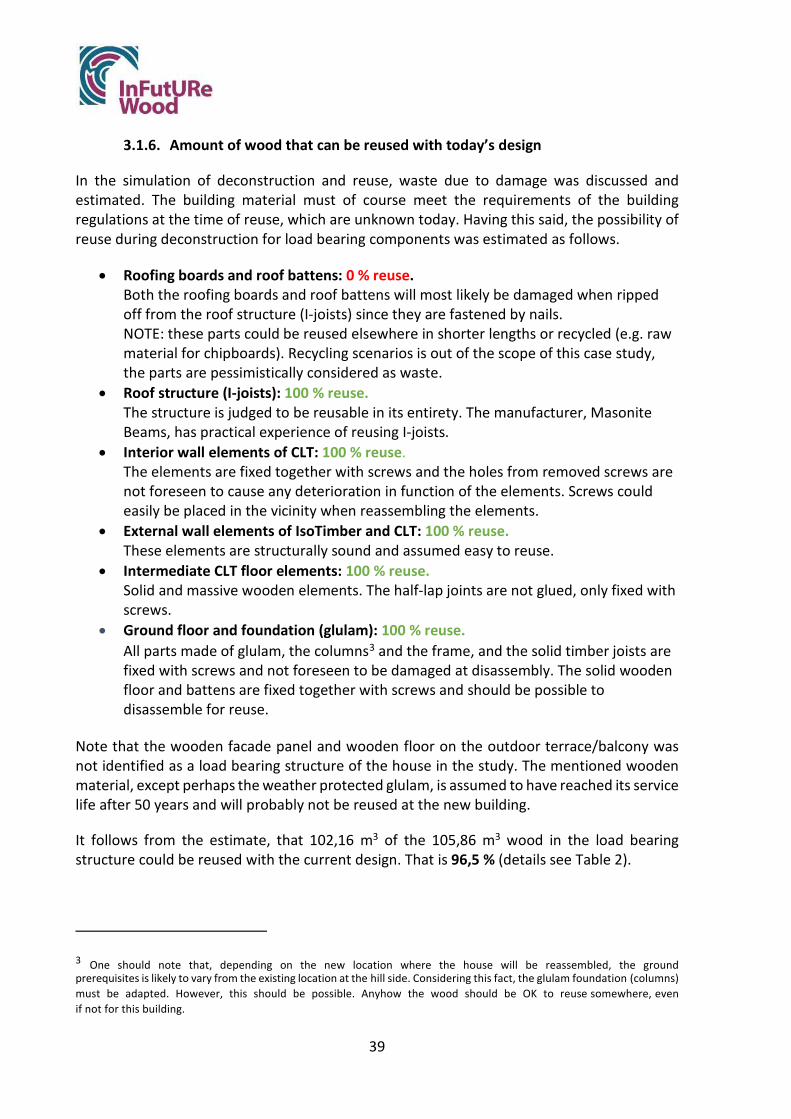
39
3.1.6. Amount of wood that can be reused with today’s design
In the simulation of deconstruction and reuse, waste due to damage was discussed and estimated. The building material must of course meet the requirements of the building regulations at the time of reuse, which are unknown today. Having this said, the possibility of reuse during deconstruction for load bearing components was estimated as follows.
• Roofing boards and roof battens: 0 % reuse.Both the roofing boards and roof battens will most likely be damaged when rippedoff from the roof structure (I-joists) since they are fastened by nails.NOTE: these parts could be reused elsewhere in shorter lengths or recycled (e.g. rawmaterial for chipboards). Recycling scenarios is out of the scope of this case study,the parts are pessimistically considered as waste.
• Roof structure (I-joists): 100 % reuse.The structure is judged to be reusable in its entirety. The manufacturer, MasoniteBeams, has practical experience of reusing I-joists.
• Interior wall elements of CLT: 100 % reuse.The elements are fixed together with screws and the holes from removed screws arenot foreseen to cause any deterioration in function of the elements. Screws couldeasily be placed in the vicinity when reassembling the elements.
• External wall elements of IsoTimber and CLT: 100 % reuse.These elements are structurally sound and assumed easy to reuse.
• Intermediate CLT floor elements: 100 % reuse.Solid and massive wooden elements. The half-lap joints are not glued, only fixed withscrews.
• Ground floor and foundation (glulam): 100 % reuse.All parts made of glulam, the columns3 and the frame, and the solid timber joists arefixed with screws and not foreseen to be damaged at disassembly. The solid woodenfloor and battens are fixed together with screws and should be possible todisassemble for reuse.
Note that the wooden facade panel and wooden floor on the outdoor terrace/balcony was not identified as a load bearing structure of the house in the study. The mentioned wooden material, except perhaps the weather protected glulam, is assumed to have reached its service life after 50 years and will probably not be reused at the new building.
It follows from the estimate, that 102,16 m3 of the 105,86 m3 wood in the load bearing structure could be reused with the current design. That is 96,5 % (details see Table 2).
3 One should note that, depending on the new location where the house will be reassembled, the ground prerequisites is likely to vary from the existing location at the hill side. Considering this fact, the glulam foundation (columns) must be adapted. However, this should be possible. Anyhow the wood should be OK to reuse somewhere, even if not for this building.

40
Table 2 Calculation of amount of wood assumed to be reused with current design.
Load bearing wood structure Volume wood [m3] Volume wood to be reused [m3]
Roofing boards 3,20 0 Roof battens on top of the roof structure 0,50 0 Roof structure (Masonite Beams I-joists) 2,40 2,40 CLT (floor elements and part of wall elements) 42,70 42,70 IsoTimber 50,7 m3 where ~80% (volume) is wood 40,56 40,56 Wooden floor 2,90 2,90 Ground floor and foundation (glulam) 13,60 13,60
Total: 105,86 m3 102,16 m3 or 96,5 %
3.2. Results: Step 2. Modified design
In the analysis, the top layer of the roof was identified as difficult to reuse. The building is suggested to be designed with roof cassettes instead, that are both load bearing and insulating (Figure 3-47). Standard solutions of roof cassettes are fixed with screws to the top edge of the external wall at assembly and expected to be unscrewed at the deconstruction without being damaged. Hence, they can be reused at the new building. The cassettes are structurally sound and easy to handle in deconstruction and transport, which should reduce time and energy consumption compared to handling roof boarding and roof trusses. In summary, time, waste and risks should be reduced by building with roof cassettes.
If assuming the building was constructed with roof cassettes in the modified design, all load bearing wooden structures could be reused, 100 %.
Figure 3-47 Photo of roof cassettes from Masonite Beams.
3.3. Results: Step 3. Comparison existing – modified design
If assuming the building was constructed with roof cassettes in the modified design, all load bearing wooden structures could be reused, 100 %, as compared to 96,5 % with current design.

41
3.4. Results: Step 4. Reuse documentation that can be linked to BIM
The documents listed below are available and provided to the customer today and were identified to be of value at the time of deconstruction:
General product information
- A Delivery specification informs e.g. about general functionality and delivery conditions.
- The IsoTimber Technical Handbook describes e.g. construction details and wall properties.
- eBVD, electronic building material declaration, defines the content of the wall elements, with details on each of the materials used.
- A product assessment, (Byggvarubedömningen) based on sustainability requirements.
Customer specific information
- Assembly drawings and instructions, with specific technical details. It includes a 3D view with the element’s weight and a loading plan for the transportation.
- Material Specification, listing the dimensions and volumes in the delivery, including the names of suppliers of the materials.
The listed documents alltogether provide detailed information about the structure regarding: function, material, specification and assembly instructions. It is recommended to keep this information safe at all times, as it is valuable at the deconstruction and reassembly process. Even more detailed information is stored at IsoTimber if needed, the manufacturing drawings, see Figure 3-45.
The 3D-model of the structure of the building (Figure 3-48), with the wall elements ID marked, is an example of information that could facilitate future deconstruction and reuse.

42
Figure 3-48- 3D-model of the building, CLT without/with IsoTimber.

43
Today Vision
3.4.1. IsoTimber Guide for Deconstruction
An immediate action taken after the analysis performed in this case study, was to write an IsoTimber Guide for Deconstruction (Figure 3-49, see Appendix C1). Knowledge and awareness obtained in the discussions during the analysis was summarized in the guide. It should be noted that IsoTimber manufactures and delivers wall elements only, i.e. parts of the house structure, and not key ready houses. Hence, the IsoTimber Guide for Deconstruction focuses on the wall elements only.
Figure 3-49 Illustration of the IsoTimber Guide for Deconstruction.
The guide will be of practical value to customers at the time of deconstruction, but also serve as valuable marketing information to new customers. The overall purpose of the guide is to encourage reuse of the wall elements, in line with the company’s vision of enhancing a circular economy (Figure 3-50).
Figure 3-50 The IsoTimber idea of enhancing a circular economy, by cascading the material and developing ways to complete the circle. Keeping the raw material in a longer service life by reusing the wall panels is a first step. The company works to complete the circle and get the material back to nature by substituting the adhesive to be biobased and 100 % fossil free.

44
4. Discussion and conclusions
4.1. Evaluation of the case study method
The case study method was found to be a crude but useful way to analyse the design of a building in terms of deconstruction and reuse, identifying both strengths and weaknesses. By focusing on the part being difficult to deconstruct or to reuse, the team tried to find a modified design to solve the problem. In this case study a solution was found immediately, with a technical solution already being available on the market. However, even if a solution was not to be found immediately, raising the awareness of the problem could speed up finding a better future design anyhow. Finally, in step 4, the need of a guide for deconstruction was identified. Based on the raised awareness and knowledge of important DfDR aspects to consider that we gathered from the analysis, an IsoTimber Guide for Deconstruction was established. The case study method could bring direct DfDR improvements to a building and result in other valuable outcomes such as improved documentation.
4.2. Conclusion about the strengths and the weakness of Villa Forshälla Sund
Considering the defined scenario, of deconstructing the Villa Forshälla Sund in 50 years on and reassemble it again at a new location within the same region, with the same requirements (e.g. wind and snow loads), we found that the building is already well prepared for deconstruction and reuse of planar elements. In particular, the following advantages of the design were identified:
Strengths:
- The prefabricated external wall elements are dimensionally stable - All structure connections are fixed together with screws and are easy to disassemble - An intuitive deconstruction that resembles the efficient construction process - The load bearing roof structure is assumed to be reusable - The structure contains few materials and is structurally sound, with no fragile materials - Lifting solutions are defined - No special tools are required One disadvantage of the design was observed: The top layer of the roof construction is likely to be damaged at deconstruction. This weakness was addressed with a modified design.
Modified design
The roof construction that is built on site today was exchanged for roof cassettes in the modified design. The prefabricated cassettes are fixed to the external walls by screws and can be detached and reused in their entirety.

45
Measure of the suitability for deconstruction and reuse
In an attempt to providing a measure on how well the design of a building suits deconstruction and reuse, the project suggested to calculate the amount of wood that could be reused for the defined scenario. For the current design of the building, the proportion of wood possible to reuse reached 96,5 %. When considering the suggested modified design, with roof cassettes, the proportion increased to 100 % reuse of the load bearing structure of wood.
Conclusion
In conclusion, the case study identified the structure of IsoTimber as already being designed for deconstruction and reuse. The walls of the building in the case study, IsoTimber elements combined with CLT, can easily be disassembled into individual elements that can be reused. There is no need to change anything in the wall design, nor to improve the connections.
Looking to the whole building it was suggested to use roof cassettes, for example as demonstrated by Masonite Beams AB.
4.3. Thoughts about the IsoTimber Guide for Deconstruction
The project inspired the IsoTimber manufacturer to establish a guide for deconstruction (Appendix C1). This will be of practical value to customers at the time of deconstruction, but also serve as valuable marketing information for new customers. The overall purpose of the guide is to facilitate a structure reuse, in line with the company’s vision of enhancing a circular economy.
4.4. Quality of and limitations in findings
This study was limited to a single scenario case. Many more scenarios can be suggested for reusing the building material. Since the service life of a building is expected to be very long, it is difficult today to guess what will be the most likely scenario of using the material in the future. Reuse in a second building with the same design, reuse of parts (e.g. wall panels) in a second building with different design, reuse of parts for a completely different purpose, material recycling to a different product, etc. The building was not analysed from the perspective of Design for adaptability, nor the aspect of Design for recycling.
This being a theoretical study, it should preferably be confirmed in a practical field study.
The team performing the analysis in this study came from various competence areas, such as: structural engineers, production manager, CEO, sustainable manager, researchers in wooden construction. However, it could have been useful to include someone from the assembly team and an architect in the discussions for valuable reasoning.

46
Suggested future investigations
There were some questions raised during the discussions in the case study analysis that the team suggests being further investigated.
• For a better understanding, an LCC (life cycle cost) and an LCA (life cycle analysis) should be calculated and considered for the building as well.
• Verify that the screws are easy to undo from an old building, subjected to real loads, that is constructed with prefabricated wall elements/panels. In the same field study, evaluate if the wall elements/panels are as easy to reassemble as assumed.
• Study not only the load bearing structure of a building, but also the surface finishes and installations of all types of materials. This will be an important contribution to improve the future environment and climate.
• Study the building from the perspective of Design for Adaptability, as this is an
important aspect to prolong the material service life. Further, from the perspective of recycling, since all parts of the building will come to an end of service life at some point.
5. References
Cristescu, C., Honfi, D., Sandberg, K., Sandin, Y., Shotton, E., Walsh, S. J., Cramer, M., Ridley-Ellis, D., Risse, M., Ivanica, R., Harte, A.M., Uí Chúláin, C., De Arana-Fernández, M., Llana, D.F., Íñiguez-González, G., García-Barbero, M., Nasiri, B., Hughes, M., Krofl, Ž. (2020). Design for deconstruction and reuse of timber structures–state of the art review.
EC. (2008). Directive 2008/98/EC of the European Parliament and of the Council of 19 November 2008 on Waste and Repealing Certain Directives. The European Parliament and the Council of The European Union. https://eur-lex.europa.eu/legal-content/EN/TXT/?uri=CELEX:32008L0098.
Fannie Mae. (2020). Multifamily Modular Construction Toolkit. https://multifamily.fanniemae.com/media/13576/display.
Sandin, Y., Carlsson, A., Ui Chúláin, C., & Sandberg, K. (2021). Design for Deconstruction and Reuse: Case study Villa Anneberg. RISE Report 2021:96.
Sparandara, Lauren, Mike Werner, Amanda Kaminsky, Libby Finch, and Kelly Douglas. (2019). Accelerating the Circular Economy through Commercial Deconstruction and Reuse. Ellen MacArthur Foundation, Google. https://www.ellenmacarthurfoundation.org/assets/downloads/google-deconstruction-and-reuse.pdf.

_ _ _ _ _ _ _ _ _ _ _ _ _ _ _ _ _ _ _ _ _ _ _ _ _ _ _ _ _ _ _ _ _ _ _ _ _ _ _ _ _ _ _ _ _ _ _ _ _ _ _ _ _ _ _ _ _ _ _ _ _ _ _ _ _ _ _ _ _ _ _ _ _ _ _ _ _ _ _ _ _ _ _ _ _ _I N F O - 1 0 3 - 0 1 I s o T i m b e r G u i d e f o r D e c o n s t r u c t i o n ( U p d a t e d O c t 1 5 , 2 0 2 1 ) P a g e 1 | 10
IsoTimber Holding AB (Org. No. 556748-4679), Address: Ställverksvägen 1, SE-831 52 Östersund, Sweden, Phone. +46 (0)63 431 31, E-mail. [email protected], www.isotimber.se
Today Vision
IsoTimber Guide for Deconstruction
Purpose of the document
This document is provided to customers at the delivery of an IsoTimber structure [1]. It contains information about the timber wall that is valuable to know when deconstructing the building. The overall aim is to encourage the reuse of IsoTimber walls, in line with IsoTimber’s goal of enforcing a circular economy, see Fig.1. The information provided here is partly based on the principles defined in the SEDA Design Guides [2].
Fig.1: The IsoTimber idea of enhancing a circular economy, by cascading the material and
developing ways to complete the circle. Keeping the raw material in a longer service life
by reusing the wall panels is a first step. The company works to complete the circle and
get the material back to nature by substituting the adhesive to be biobased and 100 %
fossil free.
Strategy for reuse
The IsoTimber panels are designed for a long service life, estimated to last more than a hundred years, and for reuse either as full size wall elements as delivered, see Fig.2, or by separating them as individual panels, see Fig.3, and resuse them in a new wall with a different technical or architectural design. However, since it is difficult today to define the actual service life of the adhesive used in the elements, see page 7, a reuse in form of elements might be most likely. The prefabricated wall elements are assembled by screws at the first building site, hence easy to deconstruct.
Note! At each time of reuse, national building regulations specific to each country
at that moment in time must be followed and the properties of the wall
panels/elements must be verified that they comply requested limit values of the
regulations at the time.
Fig.2: IsoTimber wall element. Fig.3: IsoTimber panels.
Appendix C1

_ _ _ _ _ _ _ _ _ _ _ _ _ _ _ _ _ _ _ _ _ _ _ _ _ _ _ _ _ _ _ _ _ _ _ _ _ _ _ _ _ _ _ _ _ _ _ _ _ _ _ _ _ _ _ _ _ _ _ _ _ _ _ _ _ _ _ _ _ _ _ _ _ _ _ _ _ _ _ _ _ _ _ _ _ _ I N F O - 1 0 3 - 0 1 I s o T i m b e r G u i d e f o r D e c o n s t r u c t i o n ( U p d a t e d O c t 1 5 , 2 0 2 1 ) P a g e 2 | 10
IsoTimber Holding AB (Org. No. 556748-4679), Address: Ställverksvägen 1, SE-831 52 Östersund, Sweden, Phone. +46 (0)63 431 31, E-mail. [email protected], www.isotimber.se
Delivery specification IsoTimber Technical Handbook
eBVD
BVB
List of information to keep safe
General product information is provided to the customer at the delivery of the house framework;
- A Delivery specification [3] informs e g about general functionality and delivery conditions.
- The IsoTimber Technical Handbook [1] describes e g construction details and wall properties.
- eBVD, electronic building material declaration [4] defines the content
of the wall panels, with details on the material used.
- A product assessment, BVB (Byggvarubedömningen), based on sustainability requirements [5].
Additionally, the following customer specific information regarding the customer’s specific structure is provided;
- Assembly drawings and instructions, with specific technical details, see example in Fig.4. It includes a 3D view with the panel’s weight and a loading plan for the transportation.
- Material Specification, listing the dimensions and volumes in the
delivery, including the names of suppliers of the complementary materials, see example in Fig.5.
The listed documents alltogether provide detailed information about the structure regarding: function, material and instructions on how to assembly it. It is recommended to keep this information safe at all times, as it is valuable at the deconstruction and reassembly process.
Even more detailed information is stored at IsoTimber if needed, the manufacturing drawings, see example in Fig.6.

_ _ _ _ _ _ _ _ _ _ _ _ _ _ _ _ _ _ _ _ _ _ _ _ _ _ _ _ _ _ _ _ _ _ _ _ _ _ _ _ _ _ _ _ _ _ _ _ _ _ _ _ _ _ _ _ _ _ _ _ _ _ _ _ _ _ _ _ _ _ _ _ _ _ _ _ _ _ _ _ _ _ _ _ _ _ I N F O - 1 0 3 - 0 1 I s o T i m b e r G u i d e f o r D e c o n s t r u c t i o n ( U p d a t e d O c t 1 5 , 2 0 2 1 ) P a g e 3 | 10
IsoTimber Holding AB (Org. No. 556748-4679), Address: Ställverksvägen 1, SE-831 52 Östersund, Sweden, Phone. +46 (0)63 431 31, E-mail. [email protected], www.isotimber.se
Fig.4: Example, part of assembly instructions of external wall
elements on first floor. In this case the assembly order is defined by
YV-01 to YV-13 (external wall elements), and IV-01 to IV-07 (interior
wall elements). The physical elements are labelled with YV-01, YV-02
and so on.
Fig.5: Example of a customer specific Material Specification (in Swedish), a list of materials with
dimensions and volumes. The manufacturer of all material is defined in the list.
Fig.6: This is a drawing/instruction for manufacturing the external wall element
identified as YV-15. Dimensions are specified and the total weight of the element is
given (1700 kg). All elements manufactured in the IsoTimber-factory follow such
specification.

_ _ _ _ _ _ _ _ _ _ _ _ _ _ _ _ _ _ _ _ _ _ _ _ _ _ _ _ _ _ _ _ _ _ _ _ _ _ _ _ _ _ _ _ _ _ _ _ _ _ _ _ _ _ _ _ _ _ _ _ _ _ _ _ _ _ _ _ _ _ _ _ _ _ _ _ _ _ _ _ _ _ _ _ _ _ I N F O - 1 0 3 - 0 1 I s o T i m b e r G u i d e f o r D e c o n s t r u c t i o n ( U p d a t e d O c t 1 5 , 2 0 2 1 ) P a g e 4 | 10
IsoTimber Holding AB (Org. No. 556748-4679), Address: Ställverksvägen 1, SE-831 52 Östersund, Sweden, Phone. +46 (0)63 431 31, E-mail. [email protected], www.isotimber.se
Fig.7: Typical corner in an IsoTimber wall.
Fig.9: Typical
connection
between the
IsoTimber panel
and the roof
construction.
Fig.10: Typical
connection of
IsoTimber at the
foundation and
the sill.
Side view Top view
Fig.8: Typical IsoTimber panel joint.
Fig.11: Two examples of intermediate floor solutions combined with IsoTimber walls. To the left: CLT (cross laminated timber)
panels. To the right: a suspended solution.
Description of typical connections in a house framework with IsoTimber elements
All deliveries from IsoTimber are customized, i.e. the information mentioned above should preferably be at hand when planning the decontruction of the building. However, many connections are the same, such typical connections are described in Fig. 7 - 11.

_ _ _ _ _ _ _ _ _ _ _ _ _ _ _ _ _ _ _ _ _ _ _ _ _ _ _ _ _ _ _ _ _ _ _ _ _ _ _ _ _ _ _ _ _ _ _ _ _ _ _ _ _ _ _ _ _ _ _ _ _ _ _ _ _ _ _ _ _ _ _ _ _ _ _ _ _ _ _ _ _ _ _ _ _ _ I N F O - 1 0 3 - 0 1 I s o T i m b e r G u i d e f o r D e c o n s t r u c t i o n ( U p d a t e d O c t 1 5 , 2 0 2 1 ) P a g e 5 | 10
IsoTimber Holding AB (Org. No. 556748-4679), Address: Ställverksvägen 1, SE-831 52 Östersund, Sweden, Phone. +46 (0)63 431 31, E-mail. [email protected], www.isotimber.se
Prepatory work
Decide how to reuse the structure, as IsoTimber wall elements or as panels (please read the important information on page 7). Plan the deconstruction process with that purpose of reuse in mind.
Each specific IsoTimber building has it’s own specific dimensions of wall elements, connections and screws. This must be considered and preferably the information should be retrieved from the documents mentioned in the List of information to keep safe.
All element weights are stated in the Assembly drawings and instructions. However, if the documentation of the specific element cannot be found, the dimensions of the elements must be measured. A density of ~420 kg/m3 could be used to estimate the element weight. Add an extra margin for precaution.
The deconstruction process is basically a reversed assembly process, that is why the Assembly drawings and instructions are useful information to have. They specify in which order the elements are mounted.
Be well prepared by planning the logistics of the deconstruction process by planning exactly in which storage place (temporarily or long term) to place each part of the building, not only the structure described here. The most efficient process is probably to load the elements directly to a transportation truck if possible. An appropriate location for the crane must be found and a good position for the truck(s).
Prepare even small things, such as defining buckets/boxes for sorting screws and angle brackets for a more efficient reuse.
Weather protection should be available if needed, both for the recovered building material and the building itself during the process.
Make sure all tools and manpower needed for the deconstruction are available, and transportation booked if needed.

_ _ _ _ _ _ _ _ _ _ _ _ _ _ _ _ _ _ _ _ _ _ _ _ _ _ _ _ _ _ _ _ _ _ _ _ _ _ _ _ _ _ _ _ _ _ _ _ _ _ _ _ _ _ _ _ _ _ _ _ _ _ _ _ _ _ _ _ _ _ _ _ _ _ _ _ _ _ _ _ _ _ _ _ _ _ I N F O - 1 0 3 - 0 1 I s o T i m b e r G u i d e f o r D e c o n s t r u c t i o n ( U p d a t e d O c t 1 5 , 2 0 2 1 ) P a g e 6 | 10
IsoTimber Holding AB (Org. No. 556748-4679), Address: Ställverksvägen 1, SE-831 52 Östersund, Sweden, Phone. +46 (0)63 431 31, E-mail. [email protected], www.isotimber.se
Fig.12: Scaffolding might be
needed depending on the height
of the building.
Fig.13: A crane with sufficient lifting
capacity must be in place. Make sure
to plan for its moving radius and
stability on the ground.
Fig.14: Truck for transportation and lifting sling
of appropriate lifting capacity, both for lifting
packages and individual elements.
Fig.15: Supporting struts must
be available when starting the
deconstruction process.
Fig.16: An electric
screwdriver is a must have,
all elements are fixed together
by screws.
Tools suggested for the deconstruction of IsoTimber elements
Please be reminded that this instruction focuses on deconstructing wall elements only. Other tools are needed for removing the remaining building parts.
Tools suggested: scaffolding, crane, truck, lifting sling, supporting struts, electric screwdriver and as listed below:
Club hammer Ladder Marker pen Knife Drill

_ _ _ _ _ _ _ _ _ _ _ _ _ _ _ _ _ _ _ _ _ _ _ _ _ _ _ _ _ _ _ _ _ _ _ _ _ _ _ _ _ _ _ _ _ _ _ _ _ _ _ _ _ _ _ _ _ _ _ _ _ _ _ _ _ _ _ _ _ _ _ _ _ _ _ _ _ _ _ _ _ _ _ _ _ _ I N F O - 1 0 3 - 0 1 I s o T i m b e r G u i d e f o r D e c o n s t r u c t i o n ( U p d a t e d O c t 1 5 , 2 0 2 1 ) P a g e 7 | 10
IsoTimber Holding AB (Org. No. 556748-4679), Address: Ställverksvägen 1, SE-831 52 Östersund, Sweden, Phone. +46 (0)63 431 31, E-mail. [email protected], www.isotimber.se
Instructions on how to deconstruct the IsoTimber structure
The IsoTimbers walls are expected to have a very long service life, a hundred years or more. This is in case of normal humidity conditions and the elements being protected from UV radiation by a façade material. The actual service life of the adhesive used in production cannot be defined though for this long timespan. On the other hand, the adhesive does not have a load bearing function in the wall element, the wall panels are assembled and held by screws. The main function of the adhesive is supporting the structure at the manufacturing and assembly process. Therefore, the functionality of the adhesive should be investigated at the time of deconstruction in case the plan is to reuse the individual panels from the wall. In case the idea is to reuse wall elements, it shouldn’t
be necessary.
Jugde the condition of existing windows and doors. If they are in good condition, they can be kept in the wall elements if the elements will be reused as is. A façade panel is probably difficult to keep. It is likely to be damaged while lifting the elements.
The original IsoTimber building was assembled by screws. It is expected that those screws can be unscrewed, and probably reused, at the time of deconstruction. As described above, no major movements can take place in the elements, why this assumption can be made.
The IsoTimber walls can be combined with a variety of construction solutions for the roofing, intermediate floor and foundation. All with specific connections. Hence this instruction describes the deconstruction concerning the IsoTimber elements and panels alone. The deconstruction of the other building parts should be planned as carefully.
No particular precautions need to be taken when deconstructing an IsoTimber wall with aspect of implications for health or environment. Safety aspects, such as securing the wall elements during deconstruction with supporting struts, should be carefully planned though and performed accordingly.

_ _ _ _ _ _ _ _ _ _ _ _ _ _ _ _ _ _ _ _ _ _ _ _ _ _ _ _ _ _ _ _ _ _ _ _ _ _ _ _ _ _ _ _ _ _ _ _ _ _ _ _ _ _ _ _ _ _ _ _ _ _ _ _ _ _ _ _ _ _ _ _ _ _ _ _ _ _ _ _ _ _ _ _ _ _ I N F O - 1 0 3 - 0 1 I s o T i m b e r G u i d e f o r D e c o n s t r u c t i o n ( U p d a t e d O c t 1 5 , 2 0 2 1 ) P a g e 8 | 10
IsoTimber Holding AB (Org. No. 556748-4679), Address: Ställverksvägen 1, SE-831 52 Östersund, Sweden, Phone. +46 (0)63 431 31, E-mail. [email protected], www.isotimber.se
Deconstruction step Instructions Tools
0 Prepatory work Make sure the prepatory work listed above is completed.
When performing the steps below, it is presumed that all other necessary building parts are removed, with the wall elements all clear.
Sharp mind
1 Secure the elements
Secure the elements with supporting struts, to make sure there is no risk of any element falling during the deconstruction process.
Supporting struts Electric screwdriver
2 Prepare lifting the elements
Fasten lifting slings in window openings (if windows are removed). Knock out the wooden rod from the previous hole used to lift the element (figure). In case previous holes and openings are not available, new holes must be drilled. Be careful to consider an even weight distribution in that case. Fasten lifting slings in the panels. Tear off the construction tape from the element joints (combustible waste). Remove any angle brackets potentially left at the top of the elements remaining from the roof fastenings.
Ladder Club hammer Drill Lifting sling Knife Electric screwdriver
3 Unscrew and lift down elements
Successively, in the order defined by the reversed Assembly drawing and instructions, unscrew each element from the sole plate (5 screws per 2 meters) and the joints of the neighbouring elements (typically 12 screws). Both exterior and interior. Scaffolding and ladder are used if needed. After securing the sling to the crane, unscrew the supporting struts, and lift the element down to a truck or to ground. Make sure the elements at ground are secured at all times.
Scaffolding Ladder Crane Truck Electric screwdriver

_ _ _ _ _ _ _ _ _ _ _ _ _ _ _ _ _ _ _ _ _ _ _ _ _ _ _ _ _ _ _ _ _ _ _ _ _ _ _ _ _ _ _ _ _ _ _ _ _ _ _ _ _ _ _ _ _ _ _ _ _ _ _ _ _ _ _ _ _ _ _ _ _ _ _ _ _ _ _ _ _ _ _ _ _ _ I N F O - 1 0 3 - 0 1 I s o T i m b e r G u i d e f o r D e c o n s t r u c t i o n ( U p d a t e d O c t 1 5 , 2 0 2 1 ) P a g e 9 | 10
IsoTimber Holding AB (Org. No. 556748-4679), Address: Ställverksvägen 1, SE-831 52 Östersund, Sweden, Phone. +46 (0)63 431 31, E-mail. [email protected], www.isotimber.se
A guide value of 20 minutes per element is estimated for assembling the IsoTimber element, this serves as the best estimation also for the deconstruction time.
4 Labelling for reassembly
In case the elements will be reused, please identify each element according to the Assembly drawing and instructions and make sure the individual identification label is still visible, or relabel if not. This makes the reassembly process easier.
Marker pen
5 Remove the sill Unscrew the sole plate (reuse if not damaged), and remove the sole plate gasket (combustible waste). Electric screwdriver
6 Multi storey building
Repeat step 1 to 5 above in case of a multistorey building.
The intermediate floor structure is removed before step 1 in that case, and rememeber to remove any potential fastenings left at the top or side of the wall elements before lifting them off.
7 Transportation At delivery the wall elements are loaded standing on the transportation, in packages of 3–5 elements secured to each other (figure). Normally the maximum weight of such package is restricted to approx. 5 tonnes. That could be a guideline also for the deconstruction. Preferably the loading plan could be reused. If the elements are not lifted directly to a transportation, they should be placed on a dry flat surface on the ground, and secured to each other. Please note to make sure the elements are secured for any weather impact, such as strong winds for example.
Truck
8 Store, reuse or recycle
Store the element weather protected until reuse, reconditioned or recycled.
The sole plate and screws must also be weather protected if to be reused. Recycle as wood/metal otherwise.

_ _ _ _ _ _ _ _ _ _ _ _ _ _ _ _ _ _ _ _ _ _ _ _ _ _ _ _ _ _ _ _ _ _ _ _ _ _ _ _ _ _ _ _ _ _ _ _ _ _ _ _ _ _ _ _ _ _ _ _ _ _ _ _ _ _ _ _ _ _ _ _ _ _ _ _ _ _ _ _ _ _ _ _ _ _ I N F O - 1 0 3 - 0 1 I s o T i m b e r G u i d e f o r D e c o n s t r u c t i o n ( U p d a t e d O c t 1 5 , 2 0 2 1 ) P a g e 10 | 10
IsoTimber Holding AB (Org. No. 556748-4679), Address: Ställverksvägen 1, SE-831 52 Östersund, Sweden, Phone. +46 (0)63 431 31, E-mail. [email protected], www.isotimber.se
Reassembly – the second building
At each time of reuse, current building regulations must be followed and the properties of the wall elements or panels must be verified as requested by regulations at the time. After an approved visual inspection there might be requirements on certain qualities such as load capacity, acoustics, moisture etc, that have to be verified by testing and/or assessed by a third party body.
Help pursuing the basic idea of circular economy
In case it is decided, for some reason, that the wall panels will not be reused, IsoTimber kindly urge them being recycled instead. For example by grounding the elements down and use the material in wooden fibre boards. To follow the concept of circular economy and keep the material in a service life as long as possible in order to keep the carbon storaged meanwhile.
References
Ref Document Comment [1] INFO-012 IsoTimber stomsystem Teknikhandbok Technical handbook describing the IsoTimber construction method. In Swedish only. [2] SEDA Design Guides for Scotland: No 1 Guidelines considering important aspects of how to ‘Design for Deconstruction’ DfD. [3] INFO-005 Leveransdeklaration - IsoTimber väggelement Delivery specification, info about general function and delivery conditions. In Swedish only. [4] eBVD (ID No. C-556748467901-2) Electronic building material declaration that defines the content of the wall panels.
See https://byggmaterialindustrierna.se/byggvarudeklaration-ebvd1-0/sok-ebvd-1-0/ [5] BVB (ID No. 136559) A product assessment, BVB (Byggvarubedömningen), based on sustainable requirements. See
https://byggvarubedomningen.com/
Appendix DDesign for deconstruction and reuse: An Irish suburban semi-detached dwelling


Appendix D Design for deconstruction and reuse: An Irish suburban semi-detached dwelling St John Walsh1, Elizabeth Shotton1
1 University College Dublin
Figure 1.1: Typical suburban semi-detached houses, exterior (Cygnum Timber Frame)
April 2022
Innovative Design for the Future – Use and Reuse of Wood Building Components

2
FOREWORD
This report is one in a series of case study reports in the InFutURe Wood project - Innovative Design for the Future – Use and Reuse of Wood (Building) Components. The first case (Sandin et. al 2021) served as a template, and therefore the report structure is common to this report and the first one. All five cases can be found as appendices to Y. Sandin, E. Shotton, M. Cramer, K. Sandberg, S. J. Walsh, J. Östling, C. Cristescu, V. González-Alegre, G. Íñiguez-González, D. Llana, A. Carlsson, C. Uí Chúláin, N. Jackson, M. García Barbero, A. Zabala Mejia (2022): Design of Timber Buildings for Deconstruction and Reuse: Three methods and five case studies. RISE Report 2022:52, ISBN 978-91-89561-92-2.
InFutUReWood is supported under the umbrella of ERA-NET and financed by funding agencies from each of the participating countries. The industry partners participate mostly with in-kind. The research and academia project partners are RISE (Sweden), Edinburgh Napier University (UK), National University of Ireland Galway (Ireland), University College Dublin (Ireland), Polytechnic University of Madrid (Spain), University of Ljubljana (Slovenia), Aalto University Helsinki (Finland), and Technical University Munich (Germany). The industry partners are Kiruna Municipality Technical Service, Swedish Wood, Derome, Isotimber, Offsite Solutions Scotland, Hegarty Demolition, SIP Energy, Connaught Timber, The Federation of the Finnish Woodworking Industries, Jelovica, The Swedish Federation of Wood and Furniture Industry, Balcas Timber, Stora Enso, Klimark + Nova domus Hábitat, and Brenner Planungsgesellschaft.
InFutUReWood is supported under the umbrella of ERA-NET Cofund ForestValue by Vinnova – Sweden’s Innovation Agency, Formas, Swedish Energy Agency, the Forestry Commissioners for the UK, the Department of Agriculture, Food and the Marine for Ireland, the Ministry of the Environment for Finland, the Federal Ministry of Food and Agriculture through the Agency for Renewable Resources for Germany, the Ministry of Science, Innovation and Universities for Spain, the Ministry of Education, Science and Sport for Slovenia. This is supported under the umbrella of ERA-NET Cofund ForestValue, and ForestValue has received funding from the European Union’s Horizon 2020 research and innovation programme under grant agreement N° 773324

3
SUMMARY
Background: Residential buildings in Ireland have long been constructed of load-bearing masonry with structural timber use limited to intermediate floor joists and roof structures. The growing phenomenon of timber platform framing in Ireland in the last 30 years has increased the share of this construction type to a current 27% of residential new builds primarily using prefabricated wall and floor panels. Despite this surge of interest in timber construction, recovered timber in Ireland is typically downcycling into wood chip-based products or for energy.
Aims and objectives: Given Ireland’s limited structural-grade timber stock, the ever-increasing share of timber use in residential construction will eventually put considerable pressure on timber supplies. The aim of this study was to evaluate a typical Irish semidetached house design, prefabricated by Cygnum Timber Frame, to identify the potential for reuse of primary material components in the current design and improve the recovery rate in a new design modified on the principles of Designing for Adaptability (DfA), to extend the service life of the building, and Designing for Disassembly and Reuse (DfDR) to maximise recapture and reuse potential.
Methods: Although the Cygnum design is constructed of prefabricated 2D wall and floor panels, so could have been analysed under a scenario of reusing these panels as other case studies did (UK, Sweden) our analysis considered the disassembly process from the perspective of the ultimate end-of-service life of the panels when they would be disassembled into material components. The construction system was analysed for how it would be disassembled, and the recovery rate of material calculated; any obstacles to disassembly were identified, which informed the new design proposal; and a similar assessment of recovery rates made for the new proposal. The modified design was compared to the original Cygnum design, both using a ground floor concrete slab, which was then altered to a timber-framed suspended ground floor assembly to assess the impact of this change.
Results: The original Cygnum design used I-joists with a glued and nailed subfloor, which was deemed unrecoverable as were all OSB sheathing. The recovery rate for solid timber elements greater than 1m, deemed the shortest length that would be reusable, was 41% of all timber material, while high value lengths greater than 2.35m were recaptured at a rate of 32.7% of solid timber (18.1% of all timber). In the modified design, which rationalised timber framing and made strategic use of wood nails and screws rather than nails, the recovery rate for solid timber elements greater than 1m was 60.1% of all timber material, while lengths greater than 2.35m were recaptured at a rate of 74% of solid timber (53% of all timber). When modified to include a timber framed ground floor these recovery rates increased to 62.5% solid timber over 1m to all timber material and 78% of all solid timber over 2.35m (56% of all timber).
Conclusions: Very limited interventions in the design including the strategic use of wood nails and screws, coupled with a rationalisation of the framing to minimise construction waste and the use of solid wood joists over I-joists, served to make the design far easier to disassemble with a view to maximising high-value timber for reuse.

4
TABLE OF CONTENTS
1 Introduction 5
1.1 Background 5
1.2 Aim 6
1.3 Objective 8
1.4 Limitations 9
1.5 Target group 9
1.6 Terms and definitions 9
2 Case study method 11
2.1 Overview of steps 11
2.2 Step 0. Definition of scenario to design for 11
2.3 Step 1: Analysis of existing design 11
2.4 Step 2. Modified design 13
2.5 Step 3. Comparison existing - modified design 13
2.6 Step 4. Reuse documentation that can be linked to BIM 13
3 RESULTS 14
3.1 Description of the current design 14 3.1.1 Parts and joints 16 3.1.2 Presence of chemicals 23 3.1.3 Mechanical and electrical services connections to the load bearing structure 24 3.1.4 Assembly process for current design 25
3.2 Deconstruction process 27
3.3 Advantages and Disadvantages 29
3.4 Potential for improvement 30
3.5 Selection of areas to improve within this study 30
3.6 Amount of wood that can be reused from the current design 30
3.7 Modified design 32 3.7.1 New design concept: Adaptability through to Reuse 32 3.7.2 Changing specification for increased reusability 35 3.7.3 Adjustment of fixing method to increase reuse potential 35 3.7.4 Amount of wood that can be reused with modified design 39 3.7.5 Comparison current design – modified design 40
3.8 Guidelines for deconstruction & reuse: Disassembly Information Record (DIR) 42
4 Discussion and conclusions 53
4.1 Improvements to Current Design 53
4.2 Limitations of Analysis 55
4.3 Conclusions 56
5 References 57

5
1 Introduction
1.1 Background
The building sector accounts for a large contribution of society’s Green House Gas emissions, raw material consumption and waste production. One way of diminishing this environmental impact would be to reuse buildings and building components to a higher degree.
The circular economy considers materials and products after-use value as important environmental and economic factors and a key tool to reduce global warming (Foundation, 2013). As such, buildings may be considered as material banks, as repositories for materials that could potentially be extracted for reuse or re purposing in the future (Debacker et al., 2016). As these building elements begin to replace primary resources extracted for construction, the need for primary resource use is reduced. Yet in Ireland, timber is largely considered a single use product in a linear economy (Figure 1.2 and 1.3), with considerable amounts of material incinerated for energy following demolition (Figure 1.4) and thus increasing the emission of carbon into the atmosphere (Llana et al., 2020).
Figure 1.2 and 1.3: Mixed skip with significant timber content and (1.3) wood waste before processing at Thornton Recycling facilities (Walsh, n.d.)
The percentage of housing constructed with timber frame in Ireland has increased significantly over the past two decades. Prior to 1990, less than 1% of annual residential construction was undertaken using timber frame; however, by 2002, timber frame housing accounted for approximately 15% of the annual Irish housing output in Ireland (TFHC). This increased to almost 25% by 2004. In 2019, 5500 houses were built using timber frames (ITFMA, 2020) which represents 27% of Irish new houses (CSO, 2020).

6
Figure 1.4: Amount of Wood Waste in Ireland per Annum & End Use (Llana et al., 2020)
The InFutUReWood project is studying how to establish circularity for timber buildings. There is a lack of published knowledge on how wood-based building frames are best designed for deconstruction and reuse. In Work Package 2, “Design of timber structures for the future”, new ways to design timber-based structures are investigated. New design concepts are developed as well as a model to plan primary design to facilitate deconstruction rather than demolition.
1.2 Aim
The aim of this study is to show how timber structures could be designed to be adapted for deconstruction and reuse. The study is one in a series that consider different types of timber-based structures.
This case study concerns a building design from the Irish manufacturer, Cygnum Timber Frame (Figure 1.1). The building consists of a pair of two-storey platform frame semi-detached houses largely constructed offsite as 2D panels. External wall panels are load bearing timber with a non-loading bearing brick outer leaf. Internal load bearing timber walls are found at ground floor only. OSB boards provide racking resistance to walls and floors. Service cavities are formed with timber battens on the walls and ceilings. The floor structure is formed with I-Joists with OSB subflooring. The roof is constructed of prefabricated timber roof trusses. The current timber volume encapsulated is approximately 15.1 m³.
Much construction is not undertaken at an industrial scale but in fact, at a smaller domestic scale or as one-off constructions. Rather than the industrialized off-site construction method of the existing structure, our case study will aim to examine this structure when considered as an onsite stick-build construction. The rationale for this is to provide more diversity in the case studies in the report, as both Sweden and the UK were examining similar prefabricated 2D panel systems. The ambition was to provide a counterpoint, where prefabricated systems could be compared to onsite framing systems (Figure 1.5). In doing so, we hope to address the opportunities and challenges that face this part of the timber construction industry in implementing circular economy principles.

7
Figure 1.5: Different levels of Timber construction (top: timber frame, middle: panel system, bottom: volumetric system) (Walsh & Sandin, 2020)

8
Based on a more adaptable layout, the redesigned onsite construction is anticipated to have a longer lifespan, with the intention that the building would be disassembled into individual timber elements at the end of its service life through careful consideration of joints and connections (Figure 1.6). To maximize potential reuse, these elements are kept as close to their original factory sizes as possible.
Figure 1.6: Example of Design for Disassembly (DfD) connections (AY Architects)
1.3 Objective
The objective of the case study is to identify:
● What advantages of the current prefabricated design has regarding future deconstruction and reuse.
● What disadvantages the current prefabricated design has regarding future deconstruction and reuse.
● Whether recovery and reuse are improved on a hypothetical onsite light timber frame construction of a similar configuration, and the reasons for this.
● How the spatial design and its constructive details could be improved to maximise future recovery of materials and their reuse in the onsite construction scenario.
● The magnitude of the improvement gained by modifying the design spatially and in terms of construction detail. We will estimate how much wood that could be reused (as opposed to

9
recycled) in the future from the current design and how much wood that could be reused after these design modifications. Reuse means that a part / component is used for basically the same purpose as it was originally intended. (See also 1.5 Terms and Definitions)
● What the appropriate form a plan for deconstruction and reuse should be for a building of this type.
1.4 Limitations
The focus of this case study will be on the design of the load-bearing structure, the timber frame and associated panels used for lateral stability. Future analysis is required regarding the potential for reuse of non-load bearing elements in the structure.
Over time, as the requirement for insulation has increased, the typical stud depth has also increased (90 mm to 140 mm). The structural depth for walls in the case study is taken as 140 mm however, some construction may still be undertaken using 90 mm studs.
As mentioned above, the current design of the house is a platform framed structure using prefabricated 2D panels. As other case studies are looking at this construction method, our analysis will consider this as an onsite stick-built platform frame construction. This method will be relevant to non-industrialised construction, which could include domestic extensions, one-off dwellings, and non-residential buildings, thus offering increased scope to its relevance to practitioners. As such, we do not envisage that the panels will be reused in our analysis of the current prefabricated assembly. Instead, components are envisioned to be disassembled at the end of use into their constituent parts i.e., stud, rail, sheet. These elements may be reused for the same purpose.
The case study is also not limited to the future reuse of the structural elements, but also rethinks the design by making it more adaptable during the first use phase to extend its potential service life. Thus, the current study encompasses both Design for Disassembly and Reuse (DfDR) as well as Design for Adaptability (DfA).
1.5 Target group
The target group considered for this report are manufacturers of timber-based building structures, architects and engineers and researchers.
1.6 Terms and definitions
Design for Adaptability (DfA)
Ability to be changed or modified to make suitable for a particular purpose. (ISO 6707-1:2017, 3.7.3.79)
Deconstruction
The process of taking a building or structure, or portion thereof, apart with the intent of repurposing, reusing, recycling, or salvaging as many of the materials, products, components, assemblies, or modules as possible. (Off-Site Construction Council)

10
The systematic dismantling and removal of a structure or its parts, in the reverse order of construction, for maximum value through the salvage and harvest of components, primarily for reuse in their original purpose and secondarily for recycling. (Ellen Macarthur Foundation 2019)
Disassembly
Non‑destructive taking apart of an assembled product into constituent materials and/or components (BS 8001 2017, ISO 8887-2 2009.)
Reuse
Any operation by which products or components that are not waste are used again for the same purpose for which they were conceived. (EC 2008)
Recycling
Any recovery operation by which waste materials are reprocessed into products, materials, or substances whether for the original or other purposes. It includes the reprocessing of organic material but does not include energy recovery and the reprocessing into materials that are to be used as fuels or for backfilling operations. (EC 2008)
Ground floor and first floor
We adhere to traditions large parts of Europe to call the floor on the ground the ground floor and the next floor up the first floor.
Improvement, improved solution
By improvement is understood a measure that leads to components retaining their functions and economic value to a greater degree in a future deconstruction process or leads to a less time-consuming or safer deconstruction process than can be reached with the current design. With improvements fewer damages will occur, less repair/ reconditioning will be required for the next use cycle, a larger proportion of the material can be reused, less time will be needed for deconstruction.
Party Wall
A wall shared between two houses, found in semi-detached or terraced housing.
Semi-detached
A semi-detached house shares one wall with another house.
11
2 Case study method
As noted above, this case study is one in a series, where all cases are carried out using a common method. This chapter presents the case study method. After an overview of the different steps, the separate steps and their implementation are explained.
2.1 Overview of steps
The method developed for this study has five steps, see Figure 2. The different steps are described in sections 2.2 – 2.6.
Figure 2.1: The steps of the case study method (Sandin et al., 2021)
2.2 Step 0. Definition of scenario to design for
The future scenario that the design was evaluated and adapted for was defined as follows: After one service life (about fifty years), the building will be deconstructed into its original elements (studs, sheets, battens etc.), transported to a merchant or another facility and reused in construction. This scenario results in a greater flexibility in how the recovered material is used as it is not so limited by local design factors or the original design.
2.3 Step 1: Analysis of existing design
Step 1.1: Information was collected from drawings, pictures, and interviews from Cygnum Timber Frame, including: building type, parts, connections, presence of chemicals, mechanical and electrical
Step 0. Defining a scenario to design for
Step 1. Analysis of existing design
1.1 Description of the building and how it is assembled
1.2 Simulation of deconstruction and reassembly as well as identification of
strengths and weaknesses
1.3 Identification of areas to improve
1.4 Selection of areas to improve
1.5 Calculation of the amount of wood that can be reused with today's design
Step 2. Modified design
Step 3. Comparison existing - modified design

12
services and their connection to the load bearing structure and the assembly process. Based on the supplier’s drawings from Cygnum Timber Frame, descriptions and discussions with the manufacturer, a description was made of the building system and how it is assembled in its original/first phase. The main steps in an assumed deconstruction process were also defined based on the knowledge that existed about the system and how it is assembled.
Step 1.2: This step, as well as Step 1.3, was carried out in a meeting with the UCD research group and an industry representative from Cygnum. The main steps in an assumed deconstruction process were first identified, based on knowledge of the system and how it is assembled the first time.
UCD research team discussed the assumed deconstruction process in detail, drawing on their experience as architects, with input from Cygnum engineers. The advantages and disadvantages of the existing design regarding deconstruction and reuse were identified. Aspects of the deconstruction process that were considered included:
• tools needed for deconstruction
• damage that may occur to components and materials during deconstruction
• need for reconditioning, repair, and controls
• foreseen waste
• risks regarding personal safety
Step 1.3: Areas for improvement were identified in current prefabricated system and were used to inform the hypothetical redesign as an onsite construction.
Step 1.4: Based on the possible areas for improvement, a choice of the most practical improvements were identified based on current Irish construction practice. Choices were based on meetings with UCD researchers with occasional input from Cygnum. Research was undertaken in alternative connection systems. As full-scale or lab-scale testing of connections [for time, ease of assembly and disassembly, and structural tests) was not possible due to the Covid-19 pandemic, assumptions regarding the ease of assembly or disassembly were made based on practical site experience of the researchers (both architects with professional experience) in addition to some input, specifically in the case of wood nails, from the manufacturer (Lignoloc) and a joinery firm that had used these systems (Cascade Joinery). Structural testing data for wood nails is available from Lignoloc.
Step 1.5: An estimation was made of the amount of wood that would go to waste if the current prefabricated design was to be completely deconstructed and the material (rather than the panels) reused. The amount of wood in the load bearing structure of the current prefabricated assembly was provided by Cygnum and confirmed with a BIM model created by UCD researchers. The amount of wood that that could be recovered for reuse (not recycling) was estimated by UCD researchers based on the following assumptions:
• Solid timber under 1m would not be reused • OSB panels would not be recovered undamaged, so should be used for energy generation or
other use • I-Joists would not be reused after recovery (based on Cygnum guidance) so would be
recycled or downcycled for energy generation • Nails would not be removed easily, so would result in the ends of structural members being
cut off
13
These assumptions, which differ from case studies that assumed the reuse of entire panel assemblies, had an impact on the recovery rate for both the existing design as well as the proposed design to be constructed onsite.
2.4 Step 2. Modified design
The existing design has been examined and modified to address weaknesses in the original design, when considered for deconstruction into individual timber members.
• Redesign of the building layout and construction to increase longevity of the building use through adaptability (DfA) and flexibility
• Redesign of the building layout and construction to improve efficiency of wood use, minimize onsite waste during construction and improving reusability of elements at end-of-life
• Evaluating potential for reuse using Eurocodes to examine different connection types
• Use of a 3D Development of a BIM model to establish benefits of changes, and provide a baseline for a disassembly inventory/plan
The amount of wood that can be reused with the new design concept is calculated in the same way as for the original design.
2.5 Step 3. Comparison existing - modified design
A comparison is made of the amount of wood easily accessible and reusable for the original design and the new design. Calculation procedure for both existing and modified design:
A. The amount of timber in the building in m3 (A) is calculated.
B. A description is made of causes for parts being damaged (or for some other reason not being reused) (according to assumptions in Step 1.5 above).
C. An estimation is made of the amount of timber withheld from reuse (B).
D. The amount of timber made available for reuse (C) is calculated: C = A - B, or "Reusable amount of timber" = "The amount of timber" - "The amount of wood that is currently withheld from reuse".
Comparisons are made between total timber in each design, the amount of total timber estimated to be recovered and the total timber greater than 2.35m in length that is recovered. This length was chosen it allows for use as a stud in a wall panel achieving at least 2400 mm floor to ceiling height once top and bottom rails are included, thus timber of this length or greater has the best reuse potential.
2.6 Step 4. Reuse documentation that can be linked to BIM
A structure for a deconstruction and reuse documentation for the improved design is developed, building on previous work by Morgan & Stevenson (2005), connected to BIM documentation of materials and products in the building.

14
3 RESULTS
3.1 Description of the current design
The object of the case study is a prefabricated semi-detached timber frame house by Cygnum (123.5m2 per house or 247m2 for both houses). Established in 1996 Cygnum is one of the leading manufacturers of timber frame solutions and engineered timber structures in the UK and Ireland.
The two houses, which share a common part wall, are arranged over two floors. The living room, kitchen, utility, and toilet are located at ground floor level while at first floor, three bedrooms, a family bathroom, wardrobe, and general storage are located (Figure 3.1).
Figure 3.1: Ground Floor (left) and First Floor plans of semi-detached houses (blue highlights water and plumbing) (Cygnum)
The house is entered from the front and an entrance hall runs along the side wall of the house to provide access to the ground floor accommodation and stairway. The living room is positioned towards the street with the kitchen / dining space opening to the garden at the rear. A small toilet opens off the entrance hallway. The high proportion of the ground floor plan, almost 25%, given over to circulation (hallway and stair) is noteworthy.
The walls at first floor level do not match the layout at ground floor. The primary wall of the bathroom at first floor is located over the likely position of the kitchen and therefore service runs are rationalised here. It does however result in the ground floor toilet being misaligned.
The span of the roof trusses as well as the principal I-Joists run from front to back, making the front and rear walls the principal loadbearing walls.

15
Figure 3.2: Elevations Front and Rear (top left), Side (top right) and Sections (bottom) (Cygnum)

16
3.1.1 Parts and joints
Elements in load bearing structure
The external wall panels are load bearing, transferring the load of the roof and intermediate floor to the foundations. Internally there are several loadbearing walls at ground floor, which run parallel to the front wall, that provide further support for the first-floor joists and bracing, in addition to the double framed party wall to runs from the concrete on grade to the underside of the roof. The internal walls, largely located in the centre of the plan, are arranged to allow for trimming joists around the staircase. The engineered roof truss structure spans from the front to the rear walls and there are no load bearing internal walls at first floor level. Oriented Strand boards (OSB3) are fixed to walls and joists to provide racking resistance
All exterior walls panels, I-joist floor panels and roof trusses are delivered to the building site as prefabricated elements. The external wall elements are supplied as enclosed units with the insulation and vapour control layer fitted in advance. The truss elements are typically provided by a sub-contractor of the manufacturer, and therefore have limited off site fitting undertaken prior to installation. The building is completed on site with internal and external finishes. The parts that form the building's load bearing structure (Figure 3.3) are, from top to bottom:
• Roofing is composed of slates nailed to battens that are nailed to roof trusses below, which transfer wind and snow loading to the roof truss below
• Roof trusses are fabricated from small section structural timber and nail plates. The tie beams of truss form the ceiling structure of first floor, with battens forming a service cavity.
• Exterior gable wall panels (see exterior walls first floor, no service cavity)
• Party Walls within roof space (see party walls first floor)
• Exterior walls on first floor are composite wall panel elements which include 38 x 140 mm studs, insulation, vapour control layer and OSB3 facings. A service cavity is also fitted to the panels. OSB Sheathing boards act against racking of these frames (see Panel Composition).
• Party Walls on first floor are both structural and fire resisting. These are double 38 x 89mm stud walls clad with OSB3 on each side of the frame. These elements come pre-clad with plasterboard to ensure their fire integrity (see Panel Composition).
• First-floor panels built of I-joists and sheathed in OSB3. There is no service cavity at ground floor ceiling level (see Panel Composition).
• Exterior walls on ground floor (see exterior walls first floor)
• Party Walls on ground floor (see party walls first floor)
• Interior loadbearing walls on ground floor composed of 38 x 89mm timber frame elements and fitted with OSB3 on one side, with the other completed on site once fixed in place and services run as necessary (see Panel Composition).
• Concrete foundation walls and in-situ concrete slab at ground floor, with blockwork walls.

17
Figure 3.3: BIM model of existing Cygnum semi-detached house timber framing (Walsh 2021)
The cast-in-situ concrete and masonry units that form the foundation and ground floor slab act as a base to which the prefabricated elements are anchored. A timber sole plate is anchored at the centre line of the exterior wall upstand to which the prefabricated timber wall panels are nailed (Figure 3.4). The lower upstand is sized to receive the on-site brick façade which is tied back to the wall panels. The interior load bearing wall details have a similar upstand connection (Figure 3.5).
Figure 3.4: Exterior Wall foundation detail with sole plate (left), soleplate anchor (right) (Cygnum)

18
Figure 3.5: Internal ground floor loadbearing wall (left) and party wall (right) (Cygnum)
Panel Composition
Items supplied by Cygnum Timber Frame are listed in the following table and are primarily load bearing prefabricated planar elements. Though most components are fabricated off-site, certain items, such as foundation works, internal finishes, external finishes including walls and roofing, and acoustic insulation are fitted on-site.
Table 3.1 Overview of panel assemblies -
External Wall Panels
- TF200 Thermo - 9mm OSB3 - 38x140mm c16 timber frame - 90mm PIR insulation (factory fitted) - Foil Airtight membrane (factory fitted) - 44 x 46mm Service Cavity (Factory Fitted) - Airtight tapes and mastic Gerband (Supply & Site fit)
Figure 3.6: Typical External Stud Wall Panel (Cygnum)

19
Internal Wall Panels (loadbearing and non-loadbearing)
- 38x89mm C16 timber frame - 11mm OSB to racking walls on one or both sides; supplied with
one side fitted for installation and services / insulation. - 100mm Acoustic Insulation (supply only)
Party Walls
- 9mm OSB3 to cavity side of each frame - Twin leaf 38x89mm C16 timber frames with cavity between - 100mm acoustic insulation (factory fit) - 15mm Plain (A) and 15mm fire (F) plasterboard (factory fit)
Party wall Spandrels
- 9mm OSB3 to cavity side of each frame - Twin leaf 38 x 89 C16 timber frames with cavity between - 80mm Rigid PIR to bottom 400mm (factory fit) - 15mm Plan (A) and 15mm fire (F) plasterboard (factory fit)
First floor panels
- 18mm OSB3 - 300mm I-Joists - 100mm Acoustic Insulation (Supply only) - FCM 750 airtight membrane for floor wall junctions (factory fit)
Figure 3.7: Typical Floor Panel (Cygnum)
Trussed Roof
- Tiling battens (site fit) - Roofing felt breather membrane (site fit) - Prefabricated roof trusses with timber infill as required - 400mm thermal insulation (supply only) - Vapour control foil (supply only) - 44x64mm service cavity (supply only)

20
Joints
The typical connection techniques used are screwed and nailed connections. The following table provides an overview of the joints and the manner of their connections, followed by a detailed description of key joints and connections. Details in bold will be discussed at further length below. Table 3.2 Overview of joints and joint techniques
Part Junction Connection / Fixing
Roof Battens Battens / Truss Nailed
Roof Trusses Fink Truss Members Mending Plates
Eaves Junction Truss / Wall Plate Nailed Truss Clip
Ceiling Service Cavity Battens / Ceiling Ties Nailed
Party Walls Spandrel / Party Wall Screwed
Rising Wall Connection Wall Plate / Concrete rising wall 72.5x112mm Rawlplug Screw
External Wall Panels OSB / Stud Frame Nailed
External Wall Panels Wall plate Nailed
External Wall Panels Panel to Panel Nailed
Interior Load Bearing Walls OSB / Stud Frame Nailed
Interior Non-Load Bearing walls OSB / Stud Frame Nailed
First Floor I Joists Noggins / Walls Nailed
First Floor I Joists OSB Subfloor Glued and nailed
Detail 1: Roof / Truss (Eaves) Junction & Truss Member Connection
The roof structure is composed of timber framed Fink trusses manufactured off site and craned into place on site at 400mm on centre. The configuration of Fink trusses does not allow for inhabitation of the roof space without significant structural modifications. The small section (38 x 89mm) timber members are aligned in-plane and are connected using mending plates. Nailed truss clips connect each roof truss to the head binder of the external walls, while bracing is nailed across the trusses to provide lateral stability (Figure 3.8).

21
Figure 3.8: Truss connection detail to head binder (A) with nailed connector plate (B). Truss members connected with mending plates (C)
Detail 3: Wall Panel Vertical Junction
The bottom rail of panels is connected to sole plate with nails at a minimum of one per stud bay. An additional fixing is required either side of a window opening greater than 2 m wide. Panel to panel connections are toe-nailed at maximum 300 mm centres vertically, then sealed with tape (Figure
3.9). Figure 3.9: Wall panel to panel connection (blue are membranes) Detail 4: External Leaf / Internal Leaf (Wall Tie)
Metal wall tie straps are used to connect the external timber frame wall panels and the outer masonry leaf. These are securely fixed to timber studs and header joists at specified centres. The ends of the stainless-steel wall ties are fully embedded in the mortar joints (Figure 3.10).
A
B
C
Panel A Panel B
Service cavity
interior
exterior

22
Figure 3.10: Brick outer leaf tied to timber framed wall panels at studs and headers
Detail 5: Floor OSB / Joist Connection
Floor cassettes are manufactured offsite and craned in on site. All ends and edges of OSB subflooring, other than tongued and grooved, are fully supported on joists or noggings. All short edge joints are staggered. OSB subflooring is glued to joists and nailed to joists at 150 mm centres.
Floor panels are erected by crane with operatives manoeuvring the panel into place, supported by the exterior and interior loadbearing walls. Junctions between the floor panels are secured to the neighbouring panel by oversailing the decking onto the last joist of previous floor cassette and nailing with 2.8x50mm treated nails @ 150mm c/c (Figure 3.11).
Figure 3.11: Floor panel to panel connection (red is glue line, OSB nailed to each joist)
Panel A Panel B

23
Detail 6: Floor Joist Wall Connection
Floor Panels are secured to the head binders by nailing from the external side with 3.1x90mm treated nails @300mm c/c and at every joist (400mm c/c) from the internal side.
Figure 3.12: Floor panel to wall panel connection: toenail joist header to head binder (A) and toenail joist chord to head binder (B)
Cygnum Timber Frame undertook a review of replacing nails with screw connections in all wall connections, but from a site ease and speed of erection viewpoint it was decided to continue with nailed fixings. Some elements (such as restraining straps for brick work connections) use nails specifically, as a strong enough screw would necessitate a larger section of timber. The Cygnum analysis did not consider ease of deconstruction. However, they agreed that a timber frame dwelling could more easily disassembled using screws.
3.1.2 Presence of chemicals
The required standards for timber frame in Ireland state that structural elements should be preservative treated structural timber using a high pressure / vacuum process (I.S. EN 15228:2009). The preservative used is Protim E406. This process involves the immersion of the timber in a closed cylinder of preservative under pressure, and the excess removed with a vacuum (Woodspec, 2020).
Glue is used in the floors between the joists and OSB panels to reduce the risk of squeaking and increase stability during transport. Cygnum noted that glue use on floor decks is not essential.
A B

24
3.1.3 Mechanical and electrical services connections to the load bearing structure
The current design utilises a concrete slab at ground floor level. Pop-ups for the wastes and incoming services are cast into this element. Electric cabling is left loose in stud walls to allow for movement should a wire be drilled inadvertently.
The current design allows for a service cavity at ceiling level at the first-floor ceiling as well as within exterior wall panels to avoid damage to the vapour barrier. Service cavities are absent from the ground floor ceiling level, where services can run between I-joists. Cygnum note that while pre-drilling could be undertaken at production, service routes through the joists in this case are cored out on site by the follow-on trades as they need them. Joist supplier guides are issued which provide information on allowable drilling to the main contractor (Figure 3.13).
Figure 3.13: Allowable locations and dimensions of service holes in I-joists (James Jones & Sons)

25
Installations for water and sanitation are only partially rationalised in current plans to ensure a direct vertical run of services between the kitchen and bathroom on the first floor through the service cavity of a rear wall panel (see Figure 3.1), with the ground level washroom and utility room in an unrelated location that requires additional service runs through and under the concrete ground floor slab.
3.1.4 Assembly process for current design
Platform frame construction is the most common form of domestic timber construction. Every level is erected as a separate operation, with the ceiling of one floor providing the erection platform for the next. Panels are sized so they can be either handled by operatives or with the help of a crane. (Woodspec, 2020)
Most elements of the current design are prefabricated in the factory setting, including wall panels, floor panels and roof trusses, and transported to site for assembly. The remainder of the building is site assembled, including ground floor slabs and internal/external finishes.
● Foundations
o Trenches are excavated for the foundations and ground levels reduced for the slab.
o The foundations are poured, and rising walls of blockwork formed.
o The hardcore and sand blinding is laid with an excavator and flatted. This is followed by the insulation, which is laid by hand, turned up at the edges to eliminate cold bridging.
o A plastic separation layer is placed between the insulation and structural slab. The structural concrete slab is poured and acts as a subfloor.
● Ground Floor Walls
o Sole plate is fixed to rising walls with Rawlplug screws. The centres of these fixings vary from 150 mm to 600 mm, depending on the engineering requirements. The fixings are positioned in the centre point of the upstand.
o External wall panels, party wall panels and internal wall panels come to site fully enclosed. These are erected by crane with operatives manoeuvring the panel into place on the ground or on the first-floor platform after the first-floor joists have been installed. The bottom rail of the panels is fixed with nails to the sole plate at a minimum of one per stud bay. An additional fixing is required either side of a window opening greater than 2 m wide.
o The panels, once erected, are fixed together at junctions using nails at maximum 300 mm centres vertically.
o A head binder is fixed with nails to the top of the panels to tie together the wall assemblies.
o Externally, the breather membrane is stapled to the timber frame panels at 150 mm centres with stainless steel staples.

26
● First Floor Structure
o The I-joists are pre-cut with OSB subflooring glued and nailed to the joists and delivered to site as composite floor panels.
o Floor panels are erected by crane with operatives manoeuvring the panel into place, supported by the exterior and interior loadbearing walls. Panels are secured to head binder by nailing from the external side with 3.1mm x 90mm treated nails at 300mm on centre and at every joist at 400mm on centre from the internal side.
o Junctions between the floor panels are secured to the neighbouring panel by oversailing the decking onto the last joist of previous floor cassette and nailing with 2.8mm x 50mm treated nails at 150mm on centre.
o The foil backed vapor control layer (VCL) from wall panels below taped to FCM 750 airtight membrane for floor wall junctions.
o Sole plate is nailed at the wall locations at 600mm on centre.
● First Floor Walls
o Same sequence as ground floor walls
● Roof
• Engineered trusses are fabricated off site and installed independently.
• The engineered trusses are connected to the wall plates with a truss clip which is nailed to the wall panel head binder and truss top rail.
• Longitudinal (binder) and diagonal bracing provide rigidity.
• Insulation is placed at ceiling level and the roof space is fully ventilated via the eaves.
• A roofing breather membrane is stapled on top of the truss, followed by battens.
• Insulation is site fitted (friction fit) between and over the ceiling from above.
• Slates are fixed with clout nails to the battens below.
• Service cavity is formed by fixing battens with nails to the ceiling joists.
● Services and Internal Finishes
• Electrical and plumbing service lines are installed within service cavities formed by battens in the exterior wall panels.
• Finished flooring is installed.
• The inner layer of plasterboard is added onsite, using drywall screws, skimmed, and painted. Plasterboard is screwed to the ceiling, either directly to I-joists on the ground floor ceiling or via service batten on the first-floor ceiling, and to the battens on the exterior wall panels and directly on the internal walls. Skirting boards, conceal the joint between the plasterboard and finished floor, are fixed with dabs of adhesive followed by mechanical fixings.

27
● External Finishes
• External leaf wall ties are nailed to the panels on site to align with the studwork behind the sheathing. They are at 450 mm vertical centres to align with mortar joints.
• External masonry leaf is erected. This masonry outer leaf is a 100 mm concrete blockwork in a runner bond and sand cement mortar.
• The truss ends overhang the final external wall surface to create an eaves. The eaves soffit is formed with a right-angled boxing made of treated softwood timber nailed to the rafter ends.
• PVC fascia and soffit are fixed with PVC headed nails.
3.2 Deconstruction process
The current deconstruction would potentially result in the prefabricated wall, floor and roof components being recovered in the reverse sequence to the assembly for a second use. While in other case studies involving 2D panel systems (Sweden, UK) the intention would be for these large panels to be reused directly in their current form on another construction project, in this case study we are examining the recapture rate if the panels are disassembled. This provides an estimate of the ultimate recovery rate for similar systems, following their second reuse as panels, and provides a reference point to a study of onsite light timber platform framing construction.
Stage 1
Non-structural elements removed.
● Internal applied elements: Kitchens, skirtings, doors, architraves would be removed first, many of which would be wood, or wood based. It is not possible to say exactly how these elements are fixed as it can vary significantly. Given the high turnover of these elements during the lifecycle of the building they may lack consistency in how they are fixed. Any process would begin with an investigation of the fixing method. Then an appropriate removal method would be undertaken. Kitchen units, doors and frames will be screwed in place. Architraves and skirtings will be glued or nailed which would be levered off. Note: A window may be removed at this stage to enable the removal of internal fixtures. (See note on windows in Stage 3).
● Electrical Services: Second fix items such as light fittings, sockets, switches, are screwed to metal junction boxes. These can be unscrewed.
● Floor Linings: The floor linings are installed or changed by the tenant. Common finishes include carpet, timber flooring, tiling. Laminate timber floors can be floating and are easily removed by hand. Carpet however may have a glued cushion layer beneath which can make removal difficult. Tiles will be fixed with an adhesive and grout. Removal of the surface finish may be straightforward however the fixing substrata of adhesive will be very difficult to remove.

28
● Mechanical Services: second fix elements may be left till next stage for convenience as the services running to them may still be live and require a plumber and to facilitate disassembly. This may be to water down dusty environments or clean equipment or removed items.
Stage 2
● Internal Wall lining: Plasterboard is screwed into place then skim coated with plaster. It would not be possible to easily locate all screws and therefore the internal plaster board lining is removed by being cut away using a claw hammer and saw.
● Roof insulation: The insulation friction fitted over and between the truss are removed.
● Mechanical services: First and second fix elements such as radiators, taps, hot and cold water and heating are removed.
● Electrical Services: Any second fix elements such as wiring and data cables. A certain proportion of first and second fix elements may be retained till late in the process to facilitate disassembly. This may be to charge or power tools.
Stage 3
● Roof tiles: These are attached with clout nails to battens. They are removed along with ancillary rainwater goods, fascia and soffit using a claw hammer. External roof battens, nailed through the breather membrane to the roof trusses are removed at this stage also using a claw hammer or pry bar.
● External Wall finishes: Typically, a rendered blockwork or brickwork outer leaf. When bonded with a sand cement render it will be difficult to remove and will be take down with a pneumatic hammer.
● Doors and windows: Depending on the installation, the doors and windows are removed before or after the external lining is removed. The galvanised straps which connect these elements to the timber frame inner leaf are screwed.
● Sills: These can be aluminium or masonry and are removed with the external lining. Aluminium sills will be screwed in place can be unscrewed while a concrete sill will be removed along with the masonry outer leaf.
● Membranes: All external membranes, attached with stainless steel staples, are removed by being ripped from the face of the panels or roof. The staples that remain can either be hammered into the surface or removed with some pliers. Vapour control layers which are part of the original prefabricated units remain in place. The membranes will not be reusable.
Stage 4
● Roof structure: Following removal of the tiles and roof membrane, the roof is ready to be removed. Internal bracing which has been nailed within the attic space is removed using a claw hammer. If the nails in the truss clips are not possible to be removed, the clips would be cut out. The trusses may be lifted as one or individually.
● First floor walls: The framed panels are sequentially removed from the first-floor platform. Removing nails at 300 mm centres vertically where possible, temporary works may be required to take these elements apart, such as bracing ties. If nails cannot be removed, then a vertical saw cut will be required. A straight cut may be difficult to achieve which will lead to

29
post deconstruction treatment. The wall panels may lever the nails in bottom plate out due to their weight. These panels would then be dropped to ground level for final disassembly.
● First Floor Panels: As the OSB tongue and groove sheets are glued, the construction must be cut apart using a sabre saw. The floor panels are removed by crane in whole elements therefore the screw fixings between the sheets and the joists will remain in place. The panel will be cut away from the ring joist. Neither OSB or I-joists will be reused.
● The ground floor walls are removed in a similar manner to the first floor.
● Sole plates which are screwed to the rising wall are removed from the concrete structure by unscrewing.
Stage 5
● Concrete substructure: Removed with an excavator.
3.3 Advantages and Disadvantages
Advantages for DfDR in the current design.
• Potential to reuse structural wall panels if they can be removed without damage. Roof trusses can also be reused if undamaged. Cygnum advises against using I-joists floor panels for a second use.
• The current assembly takes place off site, however much of the work is still undertaken by hand. This results in large planar elements which might be fully disassembled or reused.
• The current design utilises materials efficiently, with full sized elements such as OSB sheathing and flooring, joists, and studs, all used to maximise economy.
• Engineered trusses may be reused if the truss clip is located at a low enough level.
Potential Obstacles to DfDR in the current design.
• Service runs are not organised to enable replacement/maintenance. Otherwise, joists may be either notched or cored to allow for passage of services.
• Large panelised system means reuse of composite panel would be highly specific.
• Current general layout plan leads to high variability of unit lengths of structural members.
• Highly engineered layout results in limited scope of potential uses. For example, roof structure difficult to adapt for conversion of roof and difficult to expand.
• Some elements such as studs are too narrow to allow for screw fixing in certain locations.
• First floor formed of I-joists are unlikely to be reusable due to low material quality and potential degradation of joists.
• T&G flooring difficult to remove individually due to glued joints.
• Floor cassettes nailed very frequently making disassembly without damage difficult.

30
• Locating nail joints between wall panels maybe difficult, and removal may be difficult. This could result in saw cutting the joints which could damage the studs.
In addition to the obstacles to DfDR, the configuration of spaces in the current design makes adaptive use during the service-life of the building difficult.
3.4 Potential for improvement
A summary of potential Improvements to the current design are as follows.
• Reconfiguration of plan to: allow for greater adaptability to extend service life and; utilize full factory-sized timber to alleviate construction waste.
• Services centralised: as part of the reconfiguration of the layout
• Select more robust materials with greater longevity to increase opportunity for reuse, such as solid joists rather than OSB I-Joists.
• Utilize wood nails and/or screw connections in timber frame to allow for ease of cutting or removal.
• Roof structure connection: Truss clip location could be reconsidered to allow for sacrificial area enabling reuse of the engineered trusses.
• Locally removable internal lining to allow for adaptability of services to extend lifespan and reduce waste.
• Omit glue between deck and floor joists.
• Prepare Material Inventory & Disassembly Plan
3.5 Selection of areas to improve within this study
The selected areas of the design to be improved are as follows.
• Reconfiguration of plan to: allow for greater adaptability to extend service life; and utilize full factory-sized timber to alleviate construction waste.
• Services centralised: as part of the reconfiguration of the layout
• Select more robust materials with greater longevity to increase opportunity for reuse, such as solid joists rather than OSB I-Joists.
• Utilize wood nails and/or screw connections to allow for ease of cutting or removal.
• Omit glue between deck and floor joists.
• Prepare Material Inventory & Disassembly Plan
3.6 Amount of wood that can be reused from the current design
The following assumptions have been made in calculating the amount of timber available for reuse from the current design (for one house only):

31
• Lengths of less than 1 metre have been omitted: though it may be possible to reuse these elements, they will likely have a high proportion of penetrations per linear meter and therefore their reuse is less likely.
• OSB or elements which contain OSB have been omitted. OSB is formed with high amounts of glue and recycled product. Further investigation is required into the warranty of the glue’s properties beyond the initial product life.
• External and internal battens have been omitted. Due to the small section sizes and the penetrations every 400 mm approximately, the value of these elements would be limited. The sole plate is not considered for reuse as it will have a high number of fixings per linear meter and potentially weathered.
• Reduced Length of Solid Timber: To reduce the risk of nails remaining in elements removed or of honeycombing at element ends, it is assumed that 100 mm would be removed from both ends of each timber element.
• The minimum reusable length of timber has been defined as 2350 mm as this length is allows for use as stud in a wall panel achieving at least 2400 mm floor to ceiling height. (38 mm + 2350 mm + 38 mm).
The current design has approximately 16 m³ of timber (solid timber, I-joists, and wood-based structural panels) in the structure of one house of the semi-detached pair of houses. It is estimated that 6.6 m³ or 41.2% of this timber could be reused (Chart 3.1). However, as there is an assumption that the ends of each element may be removed to eliminate nails (up to 100 mm at each end), this may limit the options for reuse. For example, a stud of 2450 may be reduced to 2250 making It less likely to be reused as a stud.
16,00
8,87
6,56
2,90
0,000
2,000
4,000
6,000
8,000
10,000
12,000
14,000
16,000
18,000
Total Timber in Structure Sum of Solid Timber* Solid Timber over 1m Solid Timber over 2.35m
M3
of T
imbe
r
Chart 3.1 Quantity of Structural Timber in Cygnum Design - One House only

32
3.7 Modified design
3.7.1 New design concept: Adaptability through to Reuse
With the aim of adding to the lifespan of the proposed structure, the internal configuration of the space has been considered to increase the flexibility and adaptability of the space as well as the efficiency.
DfA: Efficiency, Adaptability and Flexibility
Floor Layout Changes (Figure 3.14):
● Entrance Location: The primary entrance to the house is relocated to the side. Though an option for a front entrance may be maintained, the new location eliminates the need for a long entrance corridor. This provides an opportunity for a future study or single bedroom at ground floor level (dotted in plan).
● Centralisation of Services: The new layout positions the bathrooms above each other at ground and first floor (highlighted in blue). The services are therefore centralised which would allow for a greater amount of flexibility later and simplify disassembly / deconstruction. The linings to these areas are designed to be removable allowing even more accessibility to services.
● First Floor Layout: The first-floor layout is reconfigured to provide three double bedrooms. The opportunity to install a stair to the attic is maintained at landing level (see below note on cut truss roof).
● Roof Structure: Cut truss roof will allow for greater adaptability into the future (Figure 3.15). This will provide more opportunity for storage and scope for the addition of another room. The pitch of the roof could also be adjusted to allow greater scope for change.
● Joist Span Direction: The joist layout at first floor level has been reconfigured to utilise standard full-length solid joists where possible. The joists span from party wall to side wall which would allow the accommodation to be extended without the need for a down stand beam at the rear.
● Removable linings: Certain internal walls are designed to allow for access to electrical and mechanical services using hinged internal wall panels (Figure 3.16).
To facilitate a meaningful comparison of recovery rates to the original design, the ground floor structure is assumed to be a concrete slab with masonry upstands as per the original design. However, in an optimum scenario the ground floor would be framed as a suspended timber floor. This suspended structure would allow for access from above to mechanical, electrical, and plumbing services that would be run underneath through insulated pipework and loose cabling.
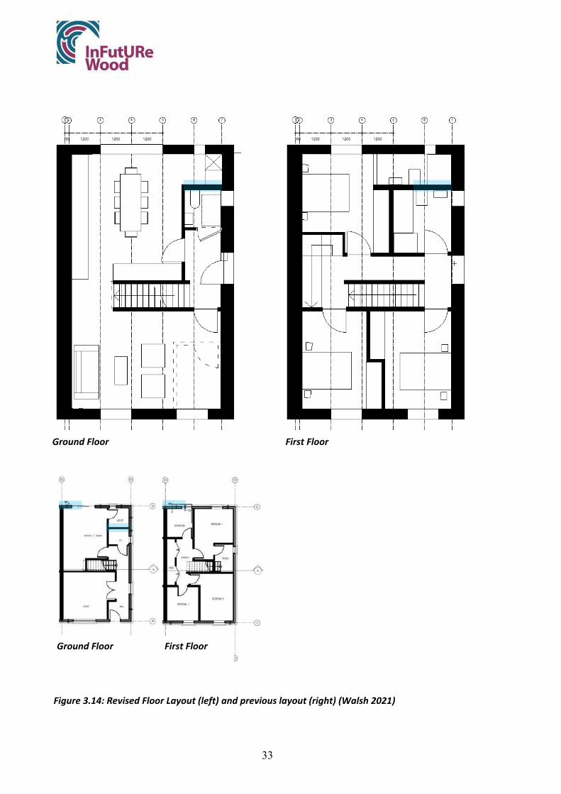
33
Figure 3.14: Revised Floor Layout (left) and previous layout (right) (Walsh 2021)
Ground Floor First Floor
Ground Floor First Floor

34
Figure 3.15: Revised Section layout with framed roof allowing future occupation (Walsh 2021)
Figure 3.16: Revised Section with hinged wall panels to facilitate service maintenance and changes (Walsh 2021)
Usable Attic Space

35
3.7.2 Changing specification for increased reusability
It is not envisaged the I-joists would be reusable in the future, given the material quality. There is also limited research on the longevity of the glues used. Therefore, the proposal includes the use of solid joists instead which will be more reusable in the future. The capital cost of this may prove a challenge to implementing the change.
The change from I-Joists to solid joists increased the overall volume of timber in the house. A 4.8m length of 225 x 75mm joist has a volume of 0.081 m³. By comparison, a 38 x 300mm I-Joist of similar length and dimensions has a volume of 0.034 m³. This equates to almost 2.4 times the quantity of timber. Some positive and potentially negative implications of this decision are as follows:
Benefits
● Avoid use of adhesives and chemicals in building products
● Higher rate of recovery and reuse
● More reusable timber in the building
● Higher quality product with less likelihood of failure
Challenges
● Larger sections of virgin timber required, unless adequate sources of second-use timber are found
● Greater capital cost may impact on the choice of timber frame as a construction method
● Larger self-weight on walls and foundations
3.7.3 Adjustment of fixing method to increase reuse potential
Eurocode sizing
Currently a timber stud is fixed to a bottom rail using nail connections. For a 140 mm external wall stud, three nail fixings are required while for an 89 mm internal stud, two fixings. The nails used are 3.1 mm wide, with a penetration depth in the stud of 8d (IS EN 1995-1-1:2004/clause 8.3.2.7). Cygnum uses a nail size of 3.1 x 90mm both for primary framing as well as panel to panel connections.
Screw Fixings to 140 mm Dimensioned Stud
The feasibility of using screws instead of nails using guidance from IS EN 1995-1-1:2004 was analysed (Figure 3.17). A comparable size to the current nails used by Cygnum would be a 4.2 x 80mm self-tapping screw. The use of a 4.2 mm screw would technically allow for 6 penetrations to be made across the depth of a 140mm stud (Table 3.3), suggesting that a stud may be reused twice if the holes are used only once. Screws of any larger diameter (5.5, 6.3mm) may be problematic, as the spacing required for two sets of fixings is larger than the given width. Equally, fixing a screw of larger dimension to the short dimension of the stud (38mm) is also problematic. The section size would have to increase by 6 mm to use a 5.5 mm screw and by 12.4 mm to use a 6.3 mm screw, which argues against the use of larger screws for either the first or second use.

36
The 140mm stud depth is standard for external loadbearing walls in Ireland. The standard 89mm stud depth, a typical size used in Irish timber framing for interior walls fastened with 2 rather than 3 nails or screws, would not accommodate a second set of screw attachments using a 4.2mm screw.
Figure 3.17: Section 8 guidance on axially loaded screws (IS EN 1995-1-1:2004)
Screw Size First Use Second Use Total Spacing required
Diameter mm 4.2
Spacing to Edge
Spacing between Screws
Spacing between screws Spacing to
Edge Length mm 80 a2 a2cg a2cg a2cg a2cg a2cg a2 mm Stud Depth 140mm (4d)
Screw 1 to 2 (5d)
Screw 2 to 3 (5d)
Screw 3 to 4 (5d)
Screw 4 to 5 (5d)
Screw 5 to 6 (5d) (4d)
3 screws 16.8 21 21 16.8 75.6
6 screws 16.8 21 21 21 21 21 16.8 138.6 Stud Width 38mm (4d) (4d) 1 screws 16.8 16.8 33.6
This analysis of the implications of Eurocode on the ability to reuse timber elements in this application highlighted some issues. Though numerically there is room for six equally spaced screws in a 38 x 140mm stud, the layout of this suggests that the first set would have to be carefully set out to enable a second series of screws if they were attached from the rail into the end grain as is typically done (Figure 3.18a & b). If an operative is to reuse an existing stud using the technique described above, the previous holes will be obscured by the respective rail to which it is to be fixed. It will therefore not be possible, or at least very difficult, to know exactly where the hole from the previous penetration is on the underside of the stud and consequently, the distance required for any new fixings. This careful locating of screws would be difficult to achieve on site, unless the studs were toenailed to the rails which would make the attachment points visible. Likewise, if one were to
Table 3.3 Spacing of Screws in 38 x 140 mm stud on first and second use

37
propose locating larger screws in previous 4.2mm screw locations, the difficulty is in locating them precisely, unless the toenail method is used.
Figure 3.18a & b: First and second (red) use screw locations in 140mm stud (Shotton 2021)
Several strategies to overcome these problems with connections in reuse scenarios were discussed by the team and are summarized in Table 3.4. The logic and ease of using wood nails in the project appeared to have the most promise and was further analyzed.
Table 3.4 Summary of Alternative Fixing Mechanisms and Reuse Strategies
Option 1
Fill the hole in the bottom or top of the stud with wood filler of with a greater strength than the timber itself.
Pro No change to fixing methodology required
Con Time taken to fill hole makes it time and cost ineffective
Option 2
Toenail the stud on second and / or first use.
Pro No need for remedial work to the stud Visible later when internal linings removed
Con Not as standard a methodology as previous Two fixings required at each end
Option 3
Other alternative fixings may be brackets.
Pro Reusable fixings Visible to a deconstruction contractor Can be bolted connections or screwed Not limited to a small area around base of stud
a. First screws equally spaced
b. First screws unequally spaced

38
Con Expensive, resource inefficient Over engineered compared to the current nailed solution Not appropriate for small scale construction
Option 4
Wooden nails allow for elements to be quickly cut apart using a sabre saw.
Pro Quick installation Allows for disassembly using saw without risk of damage to blade
Con Difficult to remove planar elements (eg. OSB) from linear elements (studs), or head binders to top rails of walls Requires additional tool
Wood Nails
Figure 3.19: Wood nail cartridge for wood nail gun (Lignoloc)
The utilisation of wood nails (Figure 3.19) to replace metal nails or screws requires greater investigation both in structural terms (embedment strength) and ease of disassembly through lab-scale prototype studies, which was not possible during the Covid-19 pandemic. However, wood nails have the potential to improve the recoverability and reuse of timber studs, joists, and rails by eliminating the difficulty of locating the second fixings relative to previous holes made in the timber.
The benefits of using wood nails to replace metal nails or screws in primary framing would include:
● No residual metallic nails or screws in the timber
● Honeycombing of timber ends due to fixings no longer an issue
● Simpler demolition as no need to locate screws
Potential challenges to the use of wooden nails include:
● Expense of purchasing additional technology to screw and/or nail guns
● Not appropriate for all connections, with a self-tapping screw easier to remove in some conditions
● If no disassembly information record is available, the fixing may not be evident to those deconstructing the building.
For linear elements such as studs and joists, the removal would be straightforward as a sabre saw can be used at the joint to sever studs from the rails. Typically, a timber frame wall panel is constructed by nailing through the top or bottom rail to the studs. This unit is then sheathed to

39
provide rigidity. The major benefits are the absence of screws and/or nails residing in the wood after recovery and the lack of holes that remain following removal of screws and/or nails. This last issue is a distinct advantage, as the studs and rails would effectively be solid wood composites, with the wood nails remaining in place, thus allowing for multiple reuses and reattachments.
Connections between Panels
The option of using timber nails to join panels were discussed. Though there is a simplicity to this option, the issue with sawing panels apart may be the straightness of the cut achieved if using a sabre saw. Given the screws can be easily used for this task, it seems unnecessary to do this.
Ceiling Battens
The option of using a packer to space the fixing of two elements may be possible for removal of these with a saw (if using wooden nails), however this is a time-consuming process. Screws are more appropriate for disassembly.
Roof Truss This may be quite a suitable location for the use of wood nails which could be face applied to a connection between two elements
Sub Flooring & Wall Sheathing
As noted above, planar elements will be difficult to remove when fixed with wood screws as the nail welds to the internal faces of the penetration. In this case, a screwed or metal nail connection would be best. Therefore, wood nails may be best used in assembly the main timber frame elements (stud to rail), joists (joists to headers), and rafter member connections.
3.7.4 Amount of wood that can be reused with modified design
The following assumptions have been made in calculating the amount of timber available for reuse from the modified design (for one house only):
● Lengths of less than 1 metre have been omitted: though it may be possible to reuse these elements, they will likely have a high proportion of penetrations per linear meter and therefore their reuse is less likely.
● OSB or elements which contain OSB have been omitted: OSB is formed with high amounts of glue and recycled product. Further investigation is required into the warranty of the glue’s properties beyond the initial product life.
● External and internal Battens have been omitted: Due to the small section sizes and the penetrations every 400 mm approximately, the value of these elements would be limited. The sole plate is not considered for reuse as it will have a high number of fixings per linear meter and potentially weathered.

40
● 2350 mm is taken as a minimum length as this allows for use as stud in a wall panel achieving at least 2400 mm floor to ceiling height. (38 mm + 2350 mm + 38 mm).
● Wood nails have been used in the primary construction of walls, floors, and roof trusses
The proposed design has approximately 18.05 m³ of timber in the structure (Chart 3.2). It is estimated that 10.84 m³ (60%) of this timber that is over 1m in length could be reused. Through the use of wood nails, many of these elements can be extracted in their factory dimension, without need for trimming, resulting in a recovery rate of 74% for solid timber material in lengths of over 2.35m.
3.7.5 Comparison current design – modified design
The modified design has a small increase (2.05m³) in all timber material when compared to the existing Cygnum structure (Chart 3.3). This is a result of the adjustments to the layout of the interior spaces and solid joists at first floor level. For comparison purposes the ground floor in the modified design was still modelled as a concrete slab on grade.
The re-design has led to the following differences:
● Moderate increase (12.8%) in the volume of timber products in the structure
● Increase of 46% in the amount of solid timber used
● Significant increase in the material volumes of solid reusable (>1m) timber material recovered (60% vs 41%)
● A shallower rate of material loss is seen across material lengths
● A greater quantity of longer lengths of timber (>2350mm) can be reused from the proposed design (74% of solid timber in design)
This analysis highlights that a different factor needs to be considered when evaluating the material extracted from a structure. Though the overall volume of timber recoverable from the modified design exceeds the existing design (71.7% vs 55%), what becomes apparent in breaking this
18,05
12,95
10,849,56
0,00
2,00
4,00
6,00
8,00
10,00
12,00
14,00
16,00
18,00
20,00
Total Timber in Structure Sum of Solid Timber* Solid Timber over 1m Solid Timber over 2.35m
M3
of T
imbe
r
Chart 3.2 Quantity of Structural Timber in Modified Design - One House only

41
down further by recoverable length is that the quality of the extracted material is significantly higher in the modified design. This is due to the greater quantity of elements of a length more than 2350 mm, which increases its reusability in the marketplace. When coupled with the use of wood nails in the main frame, which ensures that the substrate can received additional nails in a second use, this gives the modified design not only considerably higher recovery rate but recovers over 3 times as much material with the greatest reuse value of 2350 mm length or greater (Chart 3.4).
This analysis was based on retaining the concrete ground floor slab in the modified design, to ensure comparability of timber quantities and recovery rates to the original Cygnum design. Ideally a modified design would be constructed with a timber-framed floor structure at ground level, to eliminate the use of cast-in-situ concrete and facilitate access to services under the ground floor. When this alternative scenario is modelled in BIM the quantity of wood-based products in the design increases by nearly 40.9% from the existing Cygnum design and 24.9% from the modified design, with the percentage of recoverable solid timber over 2.35m increasing slightly to 78% of all solid timber from the previous 74% for the modified design with concrete slab (Chart 3.5).
16,00
8,87
6,56
2,90
18,05
12,95
10,849,56
0,00
2,00
4,00
6,00
8,00
10,00
12,00
14,00
16,00
18,00
20,00
Total Timber in Structure Sum of Solid Timber* Solid Timber over 1m Solid Timber over 2.35m
M3
of T
imbe
r
Chart 3.3 Quantity of Structural Timber in Cygnum vs Modified Design One House only
Existing Proposed
460
138
0 50 100 150 200 250 300 350 400 450 500
Proposed
Existing
Chart 3.4 Quantity of Timber Elements over 2.35m in Existing vs Modified Designs

42
3.8 Guidelines for deconstruction & reuse: Disassembly Information Record (DIR)
An attempt has been made to generate this document from first principles taking into account the work practices of Architects, who would be responsible for generating such a document, though reference has been made to the disassembly plan guidelines prepared by SEDA (Morgan and Stevenson 2005).
Document Name
Rather than a ‘Disassembly Plan’, this document may be more appropriately titled a ‘Disassembly Information Record’ (DIR). This is because information key to a ‘Disassembly Plan’ would be only a part of this document and depending on the scheme, the plan would vary in complexity and scope. In this case, only key information is provided as the build is not considered complex or of a scale.
Material Record
To enable a user quickly to establish the amount and nature of the reusable products in the building, a condensed material inventory or record has been created. This sets out the key information (Quantity, Type, Length, Number, Species etc.) This would be adapted depending on the project. This exists within the main report, with a full inventory of materials provided in an Appendix.
Expertise
The general contractor undertaking amendments or the disassembly contractor removing the whole structure, are assumed to be experts in construction and to have a familiarity with typical construction methods. Knowledge of sequential disassembly is assumed, and an overly detailed description is considered unnecessary. The construction drawings and specification documents will
16,00
8,87
6,56
2,90
22,54
16,25
14,0912,68
0,002,004,006,008,00
10,0012,0014,0016,0018,0020,0022,0024,00
Total Timber in Structure Sum of Solid Timber* Solid Timber over 1m Solid Timber over 2.35m
M3
of T
imbe
r
Chart 3.5 Quantity of Structural Timber in Cygnum vs Modified Design with timber-framed ground floor
One House only
Existing Proposed
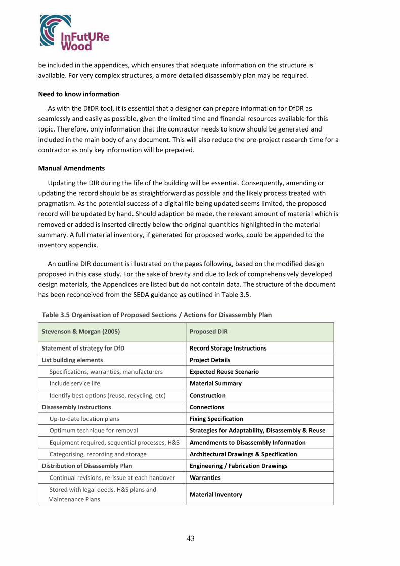
43
be included in the appendices, which ensures that adequate information on the structure is available. For very complex structures, a more detailed disassembly plan may be required.
Need to know information
As with the DfDR tool, it is essential that a designer can prepare information for DfDR as seamlessly and easily as possible, given the limited time and financial resources available for this topic. Therefore, only information that the contractor needs to know should be generated and included in the main body of any document. This will also reduce the pre-project research time for a contractor as only key information will be prepared.
Manual Amendments
Updating the DIR during the life of the building will be essential. Consequently, amending or updating the record should be as straightforward as possible and the likely process treated with pragmatism. As the potential success of a digital file being updated seems limited, the proposed record will be updated by hand. Should adaption be made, the relevant amount of material which is removed or added is inserted directly below the original quantities highlighted in the material summary. A full material inventory, if generated for proposed works, could be appended to the inventory appendix.
An outline DIR document is illustrated on the pages following, based on the modified design proposed in this case study. For the sake of brevity and due to lack of comprehensively developed design materials, the Appendices are listed but do not contain data. The structure of the document has been reconceived from the SEDA guidance as outlined in Table 3.5.
Table 3.5 Organisation of Proposed Sections / Actions for Disassembly Plan
Stevenson & Morgan (2005) Proposed DIR
Statement of strategy for DfD Record Storage Instructions
List building elements Project Details
Specifications, warranties, manufacturers Expected Reuse Scenario
Include service life Material Summary
Identify best options (reuse, recycling, etc) Construction
Disassembly Instructions Connections
Up-to-date location plans Fixing Specification
Optimum technique for removal Strategies for Adaptability, Disassembly & Reuse
Equipment required, sequential processes, H&S Amendments to Disassembly Information
Categorising, recording and storage Architectural Drawings & Specification
Distribution of Disassembly Plan Engineering / Fabrication Drawings
Continual revisions, re-issue at each handover Warranties
Stored with legal deeds, H&S plans and Maintenance Plans
Material Inventory

44
Disassembly Information Record (DIR) Project: Timber Frame Dwelling House Location: Richview, Clonskeagh, Dublin 4
Amendments to Disassembly Information If making changes to the structure, please undertake the following tasks if making relevant amendments to the building following the production of this disassembly plan.
● Append drawings and specification of works as built to this document in the appendix
● Adjust the material inventory in Section 2 with any materials removed or added.
● Ensure that the document is updated in all locations listed in Section 1.
CONTENTS
Record Storage Instructions 1
Project Details 1
Expected Reuse Scenario 2
Material Summary 3
Construction 4
Connections 6
Fixing Specification 7
General Screw
Soleplate Anchors
Wooden Nail
Strategies for Adaptability, Disassembly & Reuse 9
Use of Wood Screws at Stud Rail Junctions
Amendments to Disassembly Information 10
Appendix A: Architectural Drawings & Specification XX
Appendix B: Engineering / Fabrication Drawings XX
Appendix C: Warranties XX
Appendix D: Material Inventory XX

45
Record Storage Instructions This document must be stored at the following locations and all updated at amendments.
• On site, in a secure location, with the Safety File • With the building deeds • Local Councils Database
Project Details Location: Richview, Clonskeagh, Dublin 4
Description: Semi-detached Single-family dwelling
Site Description: Brown field site
Date of Completion: September 2023
Architect: St. John Walsh
Engineer: 123 Engineers
Main Contractor: Acme Construction
Timbe Frame Supplier: 123 Timber Frame
Truss Supplier: TrussRus

46
Expected Reuse Scenario After one service life (about 50 years +), the building panels will be deconstructed into its original elements (studs, sheets, battens etc.), transported to a merchant or another site and reused in construction for the same or similar purpose. The connections have been designed to allow for the decomposition of the planar components (Roof Truss, Wall Panels, Floor Panels) into their constituent elements (studs, rafters etc.). Where possible, these elements may be extracted in their factory dimensions and therefore allow for direct reuse.
Disassembly Plan Information The expected disassembly sequence is Reverse Assembly, from the roof down to foundations. A crane or hoist will be required to remove the roof trusses and first floor wall panels to ground level for disassembly into their elements.
● Crane Required: max panel weight 800kg.
● Common hand tools required: Screw gun, Sabre Saw, Hammer
● Temporary works: Scaffold and temporary works will be required
● Specialist Disassembly Requirements; None
See information below on Construction and Connections.
Important; A detailed health and safety plan, with method statements for temporary works, for the disassembly of the structure must be prepared by the general or disassembly contractor prior to undertaking work on the structure as per the Health & Safety legislation at that time.
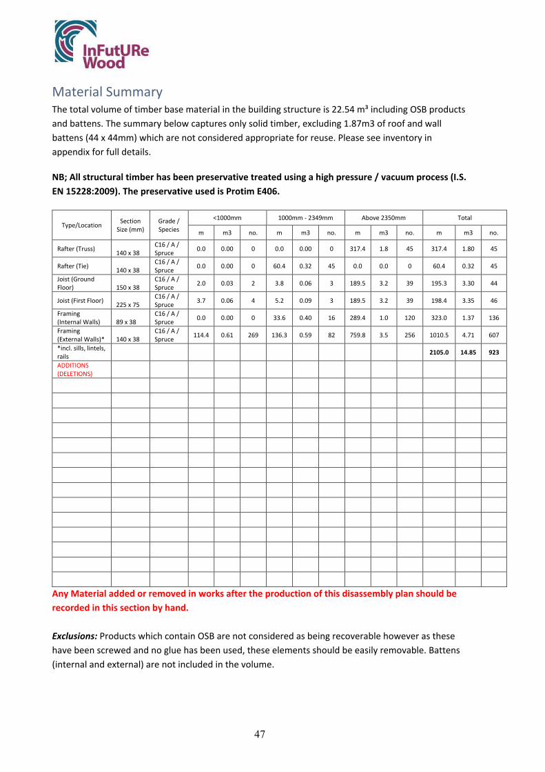
47
Material Summary The total volume of timber base material in the building structure is 22.54 m³ including OSB products and battens. The summary below captures only solid timber, excluding 1.87m3 of roof and wall battens (44 x 44mm) which are not considered appropriate for reuse. Please see inventory in appendix for full details.
NB; All structural timber has been preservative treated using a high pressure / vacuum process (I.S. EN 15228:2009). The preservative used is Protim E406.
Type/Location Section Size (mm)
Grade / Species
<1000mm 1000mm - 2349mm Above 2350mm Total
m m3 no. m m3 no. m m3 no. m m3 no.
Rafter (Truss) 140 x 38 C16 / A / Spruce 0.0 0.00 0 0.0 0.00 0 317.4 1.8 45 317.4 1.80 45
Rafter (Tie) 140 x 38 C16 / A / Spruce 0.0 0.00 0 60.4 0.32 45 0.0 0.0 0 60.4 0.32 45
Joist (Ground Floor) 150 x 38
C16 / A / Spruce 2.0 0.03 2 3.8 0.06 3 189.5 3.2 39 195.3 3.30 44
Joist (First Floor) 225 x 75 C16 / A / Spruce 3.7 0.06 4 5.2 0.09 3 189.5 3.2 39 198.4 3.35 46
Framing (Internal Walls) 89 x 38
C16 / A / Spruce 0.0 0.00 0 33.6 0.40 16 289.4 1.0 120 323.0 1.37 136
Framing (External Walls)* 140 x 38
C16 / A / Spruce 114.4 0.61 269 136.3 0.59 82 759.8 3.5 256 1010.5 4.71 607
*incl. sills, lintels, rails
2105.0 14.85 923
ADDITIONS (DELETIONS)
Any Material added or removed in works after the production of this disassembly plan should be recorded in this section by hand. Exclusions: Products which contain OSB are not considered as being recoverable however as these have been screwed and no glue has been used, these elements should be easily removable. Battens (internal and external) are not included in the volume.

48
Construction The building uses construction techniques typical with the time (2021). Where specific tactics have been used for DfDR they have been noted below in section. Drawings are available in the appendix.
External Walls TF200 Thermo 9mm OSB3 38x140mm c16 timber frame 90mm PIR insulation Foil Airtight membrane 44 x 46mm Service Cavity Airtight tapes and mastic Gerband
Internal Walls (loadbearing and non-loadbearing)
38x89mm C16 timber frame 11mm OSB to racking walls on one or both sides; supplied with one side fitted for installation and services / insulation. 100mm Acoustic Insulation
Party Walls 9mm OSB3 to cavity side of each frame Twin leaf 38x89mm C16 timber frames with cavity between 100mm acoustic insulation 15mm Plain (A) and 15mm fire (F) plasterboard
Party wall Spandrels 9mm OSB3 to cavity side of each frame Twin leaf 38 x 89 C16 timber frames with cavity between 80mm Rigid PIR to bottom 400mm 15mm Plan (A) and 15mm fire (F) plasterboard
Upper floor 18mm OSB3 225mm x 45mm Solid Joists 100mm Acoustic Insulation FCM 750 airtight membrane for floor wall junctions
Trussed Roof Tiling battens Roofing felt breather membrane Cut Truss Roof, generally Rafters & Joists 140 x 38mm 400mm thermal insulation Vapour control foil 44x64mm service cavity
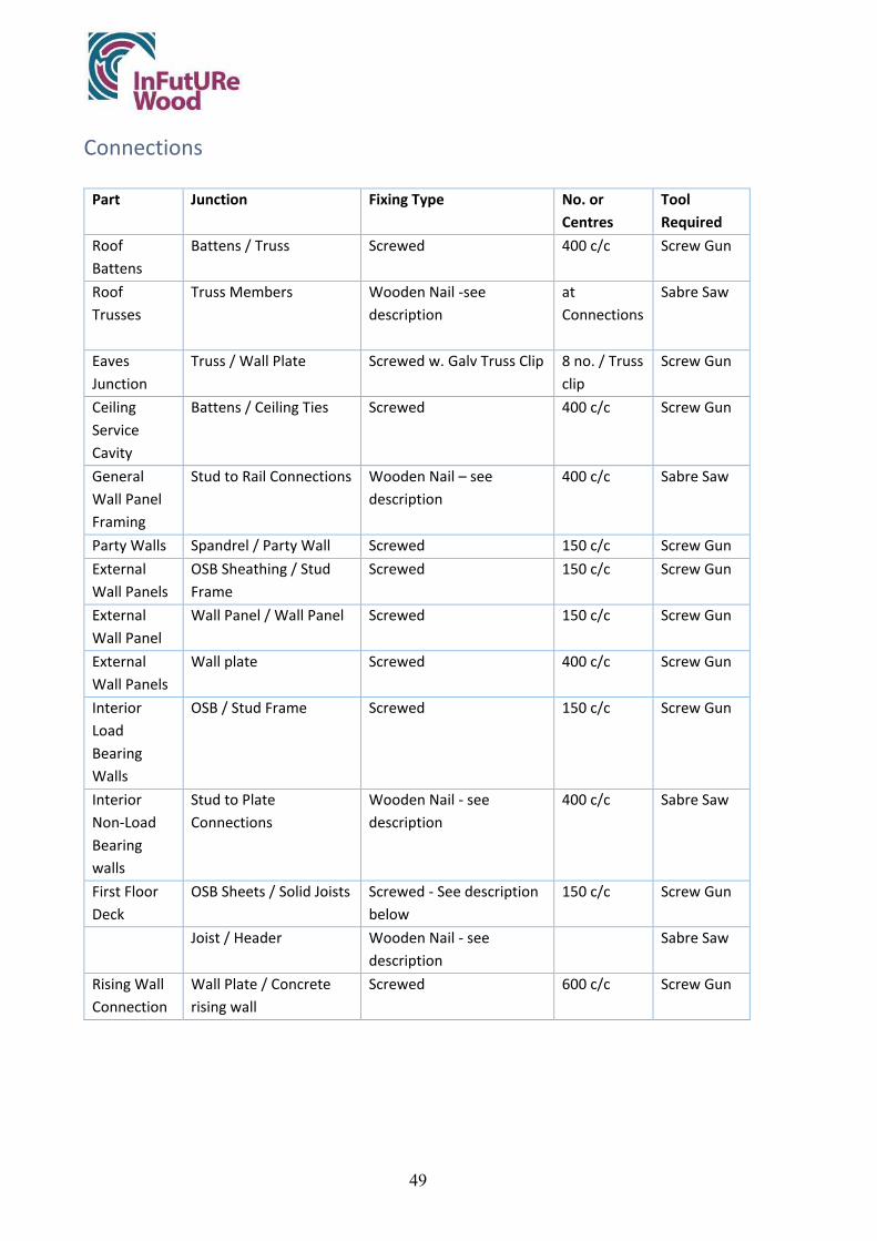
49
Connections
Part Junction Fixing Type No. or Centres
Tool Required
Roof Battens
Battens / Truss Screwed
400 c/c Screw Gun
Roof Trusses
Truss Members Wooden Nail -see description
at Connections
Sabre Saw
Eaves Junction
Truss / Wall Plate Screwed w. Galv Truss Clip
8 no. / Truss clip
Screw Gun
Ceiling Service Cavity
Battens / Ceiling Ties Screwed
400 c/c Screw Gun
General Wall Panel Framing
Stud to Rail Connections Wooden Nail – see description
400 c/c Sabre Saw
Party Walls Spandrel / Party Wall Screwed 150 c/c Screw Gun External Wall Panels
OSB Sheathing / Stud Frame
Screwed
150 c/c Screw Gun
External Wall Panel
Wall Panel / Wall Panel Screwed
150 c/c Screw Gun
External Wall Panels
Wall plate Screwed 400 c/c Screw Gun
Interior Load Bearing Walls
OSB / Stud Frame Screwed 150 c/c Screw Gun
Interior Non-Load Bearing walls
Stud to Plate Connections
Wooden Nail - see description
400 c/c Sabre Saw
First Floor Deck
OSB Sheets / Solid Joists Screwed - See description below
150 c/c Screw Gun
Joist / Header Wooden Nail - see description
Sabre Saw
Rising Wall Connection
Wall Plate / Concrete rising wall
Screwed 600 c/c Screw Gun

50
Fixing Specification
General Screw
Producer Würth
EAN XXX
Würth-No. 0123 42 70
Thread diameter d1 4.2 mm
Length total Ls 80 mm
Head diameter dk 8.1 mm
Soleplate Anchors Producer Rawl Plug WHO Screw
EAN XXX
Thread diameter d1 7.5 mm
Length total Ls 112 mm
Head diameter dk 10 mm
Partial thread length LgT
BIT size T
Wooden Nail Producer LIGNOLOC
EAN XXX
LIGNOLOC-No. XXX
Material Compressed beech wood
Thread diameter d1 4.7 mm
Length total Ls 90 mm
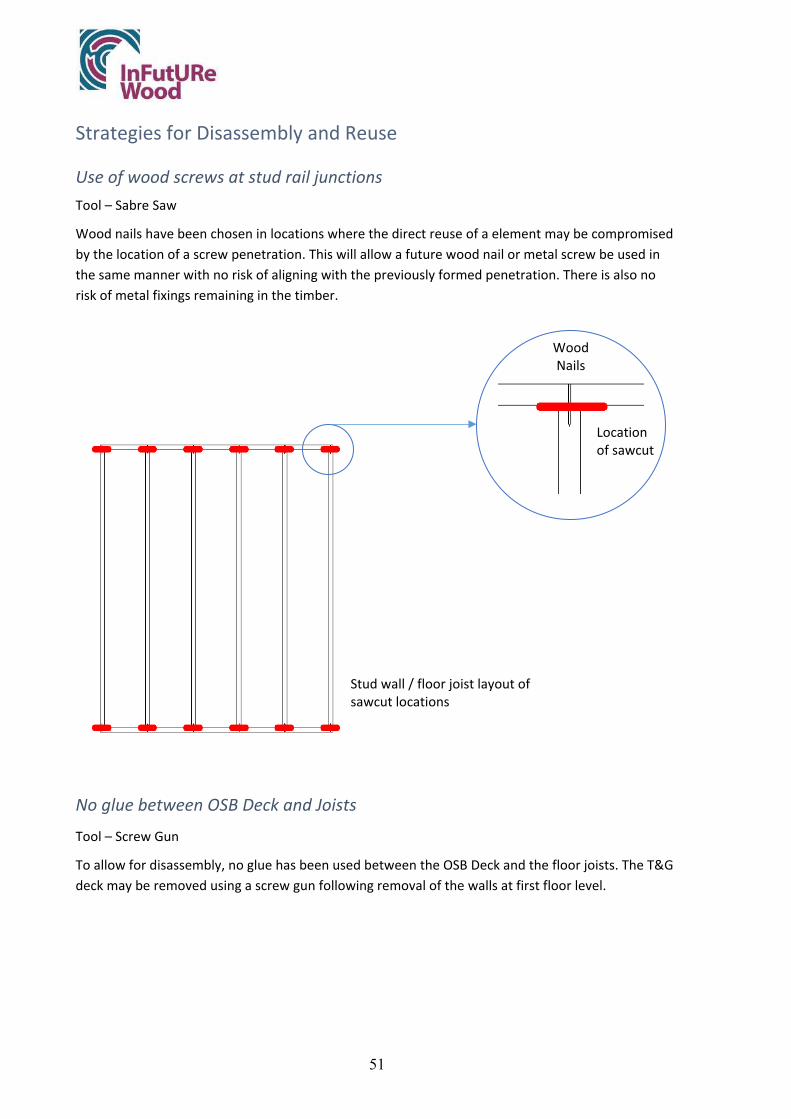
51
Strategies for Disassembly and Reuse
Use of wood screws at stud rail junctions Tool – Sabre Saw
Wood nails have been chosen in locations where the direct reuse of a element may be compromised by the location of a screw penetration. This will allow a future wood nail or metal screw be used in the same manner with no risk of aligning with the previously formed penetration. There is also no risk of metal fixings remaining in the timber.
No glue between OSB Deck and Joists
Tool – Screw Gun
To allow for disassembly, no glue has been used between the OSB Deck and the floor joists. The T&G deck may be removed using a screw gun following removal of the walls at first floor level.
Location of sawcut
Wood Nails
Stud wall / floor joist layout of sawcut locations

52
Primary strategies for Flexibility & Adaptability
Joists to rear span from party wall to side wall to enable extension to the rear.
● Circulation allows for division of front room for office purposes.
● Refer to material inventory at the outset of disassembly.
● High quality drill bits should be used when deconstructing this structure to avoid damage to screw heads. The drill should be set to screw mode.
Appendix A: Architectural Drawings
Appendix B: Engineering / Fabrication Drawings
Appendix C: Warranties
Appendix D: Expanded Material Inventory

53
4 Discussion and conclusions
Residential buildings in Ireland have long been constructed of load-bearing masonry with structural timber use limited to intermediate floor joists and roof structures. Less than 1% of residential construction was built using a timber load-bearing structure prior to 1990. The growing phenomenon of timber platform framing in Ireland in the last 30 years has increased the share of this construction type to a current 27% of residential new builds (CSO 2020), mostly using prefabricated 2D wall and floor panels. Despite this surge of interest in timber construction, presumably on environmental grounds, the current predominant end use of timber being recovered from all buildings is downcycling into wood chip-based products or incineration for energy rather than reuse.
Given Ireland’s modest, albeit growing, forestry cover and therefore limited structural-grade timber stock, this ever-increasing share of timber use in residential construction has already begun to put considerable pressure on timber supplies. Hence the need to reconsider the fate of structural timber coming out of current and future building stock, as an alternative supply for this growing timber market in Ireland. Our ambition in the current case study was to identify the potential for reuse in the current design and improve the recovery rate in a new design modified on the principles of DfA, to extend the service life of the building, and DfDR to maximise recapture and reuse potential.
4.1 Improvements to Current Design
Though the team had more than one prefabricated timber-framed house design to choose from, the Reflect 140 Semi-detached houses by Cygnum Timber Frame were considered emblematic of a standard mid-sized house type in Ireland, so held the most potential for reconsideration. Although the Cygnum design is constructed of prefabricated 2D wall and floor panels, so could have been analysed under a scenario of reusing these panels as other case studies did (UK, Sweden) our analysis considered the disassembly process from the perspective of the ultimate end-of-service life of the panels when they would be disassembled into material components.
There are distinct advantages to the current design in being prefabricated, as factory assembly generally produces less construction waste and significantly speeds up onsite construction time. There is also potential to reuse the wall panels and roof trusses a second time as-built, as is suggested in the UK and Swedish case studies, though Cygnum recommends against reusing floor panels due to the uncertainty of the service life of I-joists.
There were, nevertheless, several potential obstacles to the recapture of timber for a second use identified, principal among them the use of nails, driven in by nail guns, which are extremely difficult to remove. This would result in damage at panel-to-panel connections during deconstruction and inevitably lead to the discarding of the last 100mm of studs or joists to remove embedded nails, leaving lengths less viable for reuse. Equally problematic was the glue used in securing subfloor OSB to joists, effectively rendering them impossible to separate for reuse. The layout of the current design also resulted in not only a lack of long-term adaptability, particularly apparent in the choice of roof truss which restricted use of the attic space, which limited the service life of the building. The layout also resulted in a high degree of variability in the lengths of structural timber used, particularly in floor joists, which would limit the market available for their reuse.

54
The modified design addressed these obstacles through the application of principles for DfA and DfDR. The layout of the house was reconfigured on DfA principles to increase the efficiency of floor area use; allow for adaptability in use including occupation of the attic space using a cut-timber roof system; organised plumbing services for more effective use and simplified maintenance; and proposed a system of hinged wall panels to facilitate the maintenance and replacement of services.
The improved, more adaptable planning also served DfDR principles by rationalizing the joist layout to achieve standardized, full-length sizes use to minimise waste; replacing I-joists with solid timber joists that could be reused on recovery coupled with the elimination of the glue used in the subfloor assembly; and replacing nails with a combination of wood nails and screws to facilitate disassembly and ensure that joists and studs are recovered undamaged at full length to maximise their reuse potential. Though wood nails would be inappropriate in many connections, as they could make disassembly more complex, the impact of their strategic use in joist, stud, and rafter connections, where they are easily sawed, could be substantial to the ultimate reuse value of these elements as they would remain effectively solid wood composites without the difficult honeycombing at their ends which would otherwise occur.
The resulting estimated ultimate recovery rates from the original Cygnum design to the modified design speak to the efficacy of these limited changes to the project (Chart 4.1). This is further improved when the ground floor concrete slab of the original design is replaced with a timber-framed suspended floor. This not only increases the amount of solid timber recoverable from the design, but also simplifies access to services running under the floor joists. The rationalisation of the framing, specification of solid timber joists and the use of wood nails considerably improve the amount of solid timber recovered from a house of the same floor area as the original Cygnum design.
There is clearly an opportunity here to maximise the use of solid timber, and its long-term carbon storage potential, in a design modified to extend a building’s service life through adaptability with a final recapture of high value timber (>2.35m) at remarkable rate of 78% of total solid timber used for structural purposes.
0,002,004,006,008,00
10,0012,0014,0016,0018,0020,0022,0024,00
Total Timber in Structure Sum of Solid Timber* Solid Timber over 1m Solid Timber over 2.35m
M3
of T
imbe
r
Chart 4.1 Recovery Rates of Structural Timber in Cygnum vs Modified Design and Modified Design with timber-framed ground floor
One House only
Existing Proposed with Framed Ground Floor Proposed

55
Deconstruction Plan
The Disassembly Information Record (DIR) proposed builds on previous guidance from SEDA (Stevenson & Morgan 2007) but clarifies the ordering of information and expands the strategy statement to highlight DfA strategies for flexibility and adaptation, a crucial element to circularity. It also offers a degree of flexibility in ordering the document, to attend to the peculiarities of each project, and creates a simple and concise main document that addresses both the time constraints of the architect preparing the document as well as the prior knowledge of the contractor.
Critically, the DIR is considered as a hardcopy document, rather than a digital document linked to the BIM documentation that underpins the Material Inventory. This is a conscious departure from current research trends that exploit current and evolving digital technologies. The rationale for this is the inability to predict future digital technological trends in 50 years or more, when the building may be disassembled. By keeping the document hardcopy, the inevitable necessity of storing and updating digitally formatted data every few years is removed. This format also allows for handwritten amendments to be made by owners when the building is adapted or changed during its service life, with no need to access specialist models, software, and hardware.
Case Study method
The case study method, as defined for this project, provides a useful structure to follow in analysing a pre-existing design for potential improvements in DfDR. It did not specifically address DfA principles, which our team considered critical, so it was evolved to accommodate these issues. Also, the case study method only addresses a protocol for assessing a pre-existing design. To support decision making on a new design the Decision Matrix, developed as part of this study, holds more promise to educate designers on first principals of both DfA and DfDR and define specific strategies and tactics to use. The indicator system, also developed on this project, helps to assess the success of the design strategies used from the Decision Matrix.
The comprehensiveness of the analysis and overall success of using this case study method is very dependent on the team composition. Our team of architects approached the analysis from an architectural perspective, with guidance regarding spans and sizing drawn from the Eurocodes. We had the opportunity to consult with Cygnum engineers on their design, to better understand its construction and potential for reuse. However, having an engineer on our team for the modified designs would have been useful for a more comprehensive and accurate assessment. Viability of proposed improvements was likewise influenced by the knowledge base of the assessors, both in terms of construction and deconstruction methods, and would be facilitated by the engagement of a demolition contractor for specialist expertise, which was unavailable.
4.2 Limitations of Analysis
The digital modelling of both the original Cygnum house and the two proposals in BIM allowed for a reasonably accurate capture of a material inventory of structural wood-based products for comparison. However, the solid timber designated as longer than 2.35m was measured as 2.347m and above, to address minor modelling errors. Blocking within floor framing was not modelled for

56
any of BIM models, so represents an undercount of solid timber under 1m in length. None of the models were fully developed for internal and external finishes, so the proposal for hinged interior wall panels to allow for service access was not fully resolved to account for fire-ratings or material type. This would require further research and development, so these panels have not been included in the material inventory.
The recapture rate of 72.1% for all timber-based materials remains an undercount, as many timber-based materials in a building are not structural (flooring, windows, doors, skirting boards) or have, for simplicity, not been included in the current analysis (stairs). Many of these items, particularly doors, windows, and flooring, if undamaged and of solid timber, already find markets in the architectural salvage trade. However, there is a lack of reliable research on how much these elements could account for as a proportion of the timber encapsulated in a house.
The service life of products, such as I-joists and OSB, has been insufficiently documented or, perhaps, researched. This led Cygnum to the conclusion that I-joists would not have second use, and for our team to decide the same for OSB sheathing and subfloors. It maybe that these products could be reused, if carefully disassemble, but it requires evidence from manufacturers to prove this.
The premise behind using wood nails for stud wall assemblies, joist framing and roof framing was to avoid the honeycombing that occurs in these structural members which reduce their reuse value. Due to constraints in using lab facilities during the pandemic of 2020-21, lab tests to determine the ease of cutting these joints easily and fixing them together a second time using wood nails were not undertaken.
4.3 Conclusions
The use of careful analysis to identify obstacles to disassembly and posit solutions has delivered a similarly scaled semi-detached house that encapsulates a greater amount of timber, improving the carbon storage potential of the building. Through careful planning with a view to adaptability, rationalisation of framing and of service runs, and the strategic use of wood nails and screws, a design was developed that facilitates a far greater recapture rate (74%) of solid timber in sizes that are viable for reuse.
There were several issues which became clear during this analysis. First is that a careful reorganization of a plan to allow for adaptable living spaces can be coupled with a similar rationalisation of framing to minimise construction waste and maximise recovery lengths for reuse. Second is the value of a broader team of specialists, including contractors, engaging at an early stage of a design proposal, to better understand and address the difficulties that may be encountered on disassembly. Third, that a clearer, more objective measure of reuse potential is required, as measuring the cubic volume of material, or the weight, offers little guidance on how much material would truly be viable for reuse in construction. In our study we selected 2.35m as a definition of the minimum high value length for a solid timber element, based on conventional floor to ceiling heights in Ireland. This is not to suggest that shorter elements could not be reused, rather than recycled, but are far less likely to find a viable market. This measure would vary by country and by construction type.

57
Finally, it became apparent that there is a need to consider the entire life cycle of a building, to its final disassembly into individual material components, even for prefabricated panel assemblies. Looking across the case studies it becomes apparent that recovery rates for houses built of factory assembled floor and wall panels can be very high for a second use given appropriate connection details between panels. But how easily the panels can be disassembled into material components is necessary to consider as well, to ensure that we capitalise on recovery rates further into the future, which the current case study goes some way to address.
5 References
CSO. 2020. Available: https://www.cso.ie/en/index.html. [Accessed].
DEBACKER, W. & MANSHOVEN, S. 2016. Synthesis of the state-of-the-art. BAMB.
FOUNDATION, E. M. 2013. Towards the circular economy. Journal of Industrial Ecology, 2, 23-44.
ITFMA. 2020. RE: "Irish Timber Frame Manufacturers Association (ITFMA)” Type to WALSH, A.-S. J.
I.S. EN 1995-1-1:2004 & A1: 2008 & A2: 2014 & AC: 2006. EUROCODE 5: DESIGN OF TIMBER STRUCTURES – PART 1-1: GENERAL – COMMON RULES AND RULES FOR BUILDINGS. Dublin, National Standards Authority of Ireland.
I.S. EN 15228:2009. STRUCTURAL TIMBER - STRUCTURAL TIMBER PRESERVATIVE TREATED AGAINST BIOLOGICAL ATTACK. Dublin, National Standards Authority of Ireland.
LLANA, D., ET AL. 2020. InFutUReWood project 18CENForestValue1 – Step 1: Timber Products from Demolition and Current Reuse Report.
MORGAN, C. & STEVENSON, F. 2005. Design and detailing for deconstruction. Scotland Environmental Design Association, SEDA Design Guides for Scotland.
TFHC “timber frame housing 2002 consortium – Housing.gov.ie.”
WOODSPEC. 2020. Design Guidance [Online]. Available: http://www.woodspec.ie/docs/Woodspec%20Final%20-%20Section%20A.pdf [Accessed].


Appendix EDesign for Deconstruction and Reuse:Case Study Cuenca Village


Appendix E Design for Deconstruction and Reuse: Case Study Cuenca Village
V io leta Go nzález-A legre 1 , Manuel Garc ía B arbero 2 , Danie l F. L lana 1 , Gui l lermo Íñ iguez-Go nzález 1
1 Timber Construction Research Group (Universidad Politécnica de Madrid)
2 Klimark + Nova Domus Hábitat
April 2022
Innovative Design for the Future – Use and Reuse of Wood Building Components

Table of contents
1. Introduction 2
2. Methodology 3
2.1. General description 3
2.2. Background 4
2.3. Cuenca Village 4
2.4. Amount of potential reclaimed timber 5
2.5. Guidelines for DfA & DfDR 5
3. Results 6
3.1. Background 6 3.1.1. Post-and-Beam system in traditional timber construction 6 3.1.2. Post-and-Beam system in Klimark + Nova Domus Hábitat`s designs 8 3.1.3. Deconstruction process of a traditional Post-and-Beam system 9
3.2. Cuenca Village 13 3.2.1. Design concept 13 3.2.2. Composition and location 15 3.2.3. Primary load-bearing structure 19 3.2.4. Secondary load-bearing structure 24 3.2.5. Summary of connections 39 3.2.6. Other building details 39 3.2.7. Adaptability and deconstruction plan 40 3.2.8. Industrial deconstruction and recycling possibilities 45 3.2.9. Reconditioning, storage and reassembly 46
3.3. Amount of potential reclaimed timber 46
3.4. Guidelines for DfA &DfDR 54 3.4.1. Introduction 54 3.4.2. Obstacles and advantages to DfA 55 3.4.3. Obstacles and advantages to DfDR 55 3.4.4. In-situ and off-site demolition 55 3.4.4. Labelling and specifications 56 3.4.5. Tools and resources for demolition 57 3.4.6. Demolition manuals 57
4. Conclusions 58
References 62
Appendix 63

1
Foreword
This report is one in a series of case study reports in the InFutURe Wood project – Innovative Design for the Future – Use and Reuse of Wood (Building) Components. All five cases can be found as appendices to Y. Sandin, E. Shotton, M. Cramer, K. Sandberg, S. J. Walsh, J. Östling, C. Cristescu, V. González-Alegre, G. Íñiguez-González, D. Llana, A. Carlsson, C. Uí Chúláin, N. Jackson, M. García Barbero, A. Zabala Mejia (2022): Design of Timber Buildings for Deconstruction and Reuse: Three methods and five case studies. RISE Report 2022:52, ISBN 978-91-89561-92-2.
InFutUReWood is supported under the umbrella of ERA-NET and financed by funding agencies from each of the participating countries. The industry partners participate mostly with in-kind. The research and academia project partners are RISE (Sweden), Edinburgh Napier University (UK), National University of Ireland Galway (Ireland), University College Dublin (Ireland), Polytechnic University of Madrid (Spain), University of Ljubljana (Slovenia), Aalto University Helsinki (Finland), and Technical University Munich (Germany).The industry partners are Kiruna Municipality Technical Service, Swedish Wood, Derome, Isotimber, Offsite Solutions Scotland, Hegarty Demolition, Robertson Timber Engineering, SIP Energy, Connaught Timber, The Federation of the Finnish Woodworking Industries, Jelovica, The Swedish Federation of Wood and Furniture Industry, Balcas Timber, Stora Enso, Klimark + Nova domus Hábitat, and Brenner Planungsgesellschaft.
Authors from UPM would like to thank Mr. Manuel García Barbero from Klimark + Nova Domus Hábitat for his ideas and helpful technical assistance in the definition of the case study.
We would also like to thank our national funder, the Ministry of Science and Innovation for the funding, administrative reference PCI2019-103544:
Ministerio de Ciencia, Innovación y Universidades, España. Plan Estatal de Investigación Científica y Técnica y de Innovación 2017-2020, Programa Estatal de I+D+i Orientada a los Retos de la Sociedad, Proyectos de I+D+i «Programación Conjunta Internacional», convocatoria 2019. Título del proyecto: Diseño innovador para el futuro - uso y reutilización de componentes de edificación de madera. Referencia Administrativa: PCI2019-103544.
Project InFutUReWood is supported under the umbrella of ERA-NET Cofund ForestValue by Vinnova – Sweden´s Innovation Agency, Formas, Swedish Energy Agencythe Forestry Commissioners for the UK, the Department of Agriculture, Food and the Marine for Ireland, the Ministry of the Environment for Finland, the Federal Ministry of Food and Agriculture through the Agency for Renewable Resources for Germany, the Ministry of Science, Innovation and Universities for Spain, the Ministry of Education, Science and Sport for Slovenia. ForestValue has received funding from the European Union's Horizon 2020 research and innovation programme under grant agreement N° 773324.

2
1. Introduction
The aim of this work is to analyze traditional existing structures and to improve current and future designs, focused in principles of adaptability and reusability. This case study, based in Spanish’ experiences, is one in a series that considers different types of timber based structures, and within the InFutUReWood` project`s activities.
Cuenca Village case study analyzes the traditional timber Post-and-Beam building system focusing in aspects of circular economy and cascading, in order to improve current designs in building systems that facilitate deconstruction, reuse and recycling, rather than demolition. A general approach is shown in Figure 1.1.1.
Figure 1.1.1: Traditional timber Post-and-Beam system, current design in concrete and new
design focused in deconstruction, reuse and recycling
The specific objectives of the case study are:
• Identify advantages and disadvantages of a traditional Post-and-Beam system regarding future deconstruction and reuse
• Improve design based in Post-and-Beam system combined with other systems • Promote local resources and materials in order to reduce the carbon footprint and
valorise rural areas • Estimate the quantity (m3 / kg) and quality (section sizes) of timber that could be
reclaimed and reused in traditional and modern systems

3
2. Methodology
This case study, as previously mentioned, is one in a series, and all of them carried out using an established methodology described in following sections. All study cases are analysed in similar steps, but they have such variations in basic design concepts (building system used) and different assumptions of deconstruction and reuse, that is not possible to compare the results in the same way in any case.
This case study, based on traditional Post-and-Beam structural system, improves the new design concept using light framed systems as secondary structure, using some elements of the existing system and its strengths, to create a whole new combined system.
2.1. General description
The methodology proposed has four main steps:
Step 1. Background
• Traditional timber construction based on Post-and-Beam system • Description and analysis of a real deconstruction and reassembly process of
traditional Post-and-Beam in Mendiola, Álava • Identification and selection of areas to improve • Amount of wood that could be reclaimed and reused • Design criteria for the future designs • Defining a scenario to design for
Step 2. Cuenca Village Case Study
• Cuenca Village new design concept • Composition of the building and symmetric row repetition • Primary load-bearing structure. Post-and-Beam system. Posts, beams, ridges and
rafters • Secondary load-bearing structure. Framed system. Wall, floor and roof panels • Report on connections • Adaptability of the new design • Assumed deconstruction of the new design • Reconditioning, storage and reassembly • Industrial deconstruction and recycling possibilities • Amount of potential reclaimed timber
Step 3. Amount of potential reclaimed timber
• Advantages and disadvantages to DfA • Advantages and disadvantages to DfDR • Amount of reclaimed timber that could be reused in both systems

4
Step 4. Guidelines for Deconstruction and Reuse
• Assumed demolition process and steps • Tools needed and security during the process • Graphic documentation • Storage and reassembly
2.2. Background
This case study and the whole new design concept are based on a traditional Post-and-Beam load-bearing structure. This step is based on oral information, some bibliographic references on traditional timber building in Spain and the long experience of Mr. Manuel García Barbero, from Klimark + Nova Domus Hábitat, designing and building with this typology of load-bearing structure.
Timber Construction Research Group (UPM) and Klimark + Nova Domus Hábitat have been collaborating in this idea and developing all documents and models together by meetings between lecturers and researchers from UPM (Mrs. Violeta González-Alegre B.E. (Building) MSc., Mr. Daniel F. Llana B.E. (Agronomy), MSc., Ph.D. and Mr. Guillermo Íñiguez-González B.E. (Forestry), MSc., Ph.D.) and Mr. Manuel García Barbero (Architect and carpenter from Klimark 1 and Nova Domus Hábitat 2).
To obtain reliable and useful results for the new design concept, an existing geographic location and an industrial disassembly scenario were selected.
Furthermore, a real deconstruction of a traditional Post-and-Beam 200-year house in Mendiola, Álava (Spain) was recorded phase by phase by the UPM researchers. All details of recovering timber and selection for reuse and recycling were carefully registered.
2.3. Cuenca Village
The new design was discussed in further meetings with UPM`s researchers and Klimark + Nova Domus Habitat’s staff. The main architectural concept was defined by Mr. Manuel
1 Klimark is an architectural and engineering group that has been steadily working in real executive projects like the first CLT building with Stora Enso CLT elements in Spain, as well as in research and development of building technologies and methods with organisations like AIDIMA. www.klimark.com
2 Nova Domus Hábitat was founded as a building company by some of the members of Klimark. The company offers its developed building system and solutions to their clients. As a result of that experience, it develops and applies many innovations in timber building, especially in compositing timber with other structural materials as glass, steel and massive materials reaching further levels of performance in static values, fire resistance, thermal and acoustic behaviour of their projects. www.novadomusHábitat.com

5
García Barbero and the details and processes were defined by researchers guided by Mr. Manuel García Barbero, as well, who presented sketches and short descriptions.
The amount of wood that should be used in new design and the estimation of timber elements that could be recovered was calculated based on experience and the constructive details made using CADCAM software and parametric drawing. Tables and data are extracted from the theoretical model of the building with all its features but in the real case of construction of this building, amount of wood and life of materials can vary from the estimation that has been made in this document.
At this point of the study, all the structural and non-structural elements that compose the building including an approach to DfDR, DfA and the recycling process to recover all the raw materials are also analyzed.
Connections, joints and presence of chemicals are described in this document as well.
At the end of this section, the amount of wood that can be recovered in case of reconstruction, reusing or recycling the whole systems and singular elements as well is estimated.
2.4. Amount of potential reclaimed timber
Following different methods a quantitative and qualitative estimation of potential reclaimed timber between traditional Post-and-Beam and new building design is carried out, despite of their major differences.
The new design combines for the load-bearing structure two systems: traditional Post-and-Beam for main structure and Light- Frame for walls, floors and roof.
2.5. Guidelines for DfA & DfDR
In this fourth step is proposed a structure for the deconstruction and reuse documentation for this case study with data and graphic documentation about tools needed, security issues and storage and reassembly information.
Guidelines for deconstruction and reuse are applied to Cuenca Village deconstruction but will not be excluding other systems or documents.
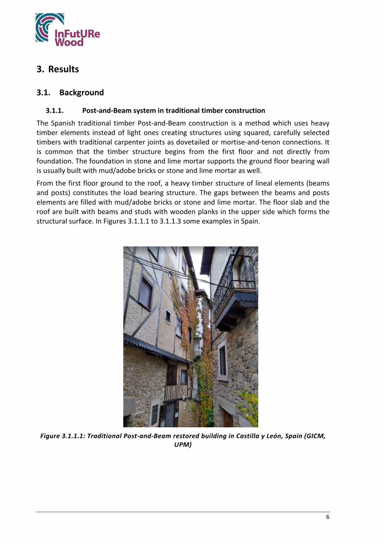
6
3. Results
3.1. Background
3.1.1. Post-and-Beam system in traditional timber construction
The Spanish traditional timber Post-and-Beam construction is a method which uses heavy timber elements instead of light ones creating structures using squared, carefully selected timbers with traditional carpenter joints as dovetailed or mortise-and-tenon connections. It is common that the timber structure begins from the first floor and not directly from foundation. The foundation in stone and lime mortar supports the ground floor bearing wall is usually built with mud/adobe bricks or stone and lime mortar as well.
From the first floor ground to the roof, a heavy timber structure of lineal elements (beams and posts) constitutes the load bearing structure. The gaps between the beams and posts elements are filled with mud/adobe bricks or stone and lime mortar. The floor slab and the roof are built with beams and studs with wooden planks in the upper side which forms the structural surface. In Figures 3.1.1.1 to 3.1.1.3 some examples in Spain.
Figure 3.1.1.1: Traditional Post-and-Beam restored building in Castilla y León, Spain (GICM,
UPM)

7
Figure 3.1.1.2: Façade wood coating (and not coated) of Post-and-Beam buildings in Castilla
y León, Spain (GICM, UPM)
Figure 3.1.1.3: Traditional Post-and-Beam building in Castilla y León, Spain (GICM, UPM)

8
3.1.2. Post-and-Beam system in Klimark + Nova Domus Hábitat`s designs
As it is shown in Figures 3.1.2.1 and 3.1.2.2, traditional and Klimark + Nova Domus Hábitat systems use bricks/stone elements for solving the space between structural elements of the primary load-bearing structure. The use of wet construction in any part of the building structure restricts the possibilities of a late disassembly or reuse of some elements.
Using adobe walls, the structure cannot be recovered to the maximum. There is a fundamental advantage that lies in the fact that the facilities and all the elements outside the supporting structure are not integrated within the walls or general structural system. In any case, they run through a self-supporting cladding, so the dismantling of the installations or partitions are not applicable in this case study. Only the study of the reuse of the general structure is contemplated.
Figure 3.1.2.1: Load-Bearing system of a house in Barahona, Castilla y León, Spain (Klimark +
Nova Domus Hábitat)
Figure 3.1.2.2: Mud-walls filling the gap between the Load-Bearing structure elements
(Klimark + Nova Domus Hábitat)

9
There is no chemical presence and the only metallic fixings that exist are the nails and the coach-screws.
3.1.3. Deconstruction process of a traditional Post-and-Beam system
- Introduction:
A deconstruction of a traditional Post-and-Beam 200-year house in Mendiola (Spain) is presented.
This building was composed by load-bearing masonry walls in the four facades and Post-and-Beam oak timber structure in the rest of the building (Fig. 3.1.3.1 and 3.1.3.2). The building area was 566 m2 divided in three different spaces, which influence the timber condition: a house, a hayloft and a common hall entrance. As expected, better materials were used and treated carefully in the houses than in the other two spaces. Therefore, timber condition was better in the house than in the hayloft.
The deconstruction process was followed on-site. After deconstruction, timber was selected for different end-uses.
Figure 3.1.3.1: Post-and-beam house with masonry façades (GICM, UPM)
Figure 3.1.3.2: Post-and-beam structure (GICM, UPM)

10
The first step in deconstruction process was to remove the floor planks (Figure 3.1.3.3). In the house, floor planks are usually in good condition, but not in places like haylofts or animal buildings. Floor planks were removed using a pick-axe.
Figure 3.1.3.3: Oak floor planks (GICM, UPM)
As the building was not originally designed for deconstruction, no specific tools are needed for deconstruction. All kinds of posts, beams, purlins… were carefully removed using a forest crane in order to save as much timber as possible (Figure 3.1.3.4 and 3.1.3.5), while tiles and masonry walls were considered debris.
Figure 3.1.3.4: Saving piece by piece of timber (GICM, UPM)

11
Figure 3.1.3.5: Post-and-Beam and masonry walls during deconstruction (GICM, UPM)
Timber was selected during recovering process by the crane operator by condition, shape and dimensions in different piles for reusing, recycling and firewood. As the demolition was in a rural area, no problems regarding store space were found.
- Analysis of deconstruction procedure:
From the deconstruction study, advantages and disadvantages of the traditional building system regarding deconstruction and reuse/recycling were identified. These are described below and are used as a basis for developing the design criteria which will be used for the new design.
Advantages:
• Load bearing heavy timber structure allows recovering a big volume of timber
• Metal-free easily separable carpentry joints
• Load-bearing structure and building compartmentation are absolutely independent from each other
• Hidden steel connections are not commonly used (excepts nails)
• The structure is simple and logic
• Doors and windows can be easily disassembled and recovered if desired
Disadvantages:
• Wet construction is hard to deconstruct in a clean and tidy way and very hard to reuse in a high percentage
• All coating interior and exterior are hardly removable due to be wet constructed
• It is hard to recover installations that goes beneath the wet-constructed elements

12
• Since the pillars and beams are surrounded by adobe or mud, they must go through a complicated process that consumes many resources to be used. Slab and roof elements can be easily reused
• Even carpentry joints are free of metals, floors were fixed to beams using nails. Rusty nails break inside the timber during deconstruction and to remove them is time consuming
- Amount of recovered timber in existing structure`s demolition:
Table 3.1.5.1 summarizes the volume of timber in the building calculated in the three different spaces and the recovered timber (Figure 3.1.5.1). You can see the timber volume in the building in the first column with a total of 32.37 m3. This is only structural timber, floor planks and roof planks are not included here. The second column is the timber recovered, and finally the percentage of recovered timber. As you can see more timber was recovered from the house (67%) than from the other spaces (45 and 43%). In total 54% of timber in the building was recovered.
Table 3.1.5.1: Volume of timber and recovered timber
Part of the building Volume in the
building Volume recovered Percentage of recovered timber
m³ m³ % House 14.53 9.78 67 Hayloft 12.83 5.72 45
Hall 5.01 2.13 43 Total 32.37 17.63 54
In conclusion, using the traditional Post-and-Beam system, the percentage of recovered timber varies from 43 to 67%, depending on how was treated the property.
Figure 3.1.5.1: Recovered timber (GICM, UPM)

13
3.2. Cuenca Village
3.2.1. Design concept
The design criteria used as a basis for the design of Cuenca Village model are, mainly, the next points:
Sustainability criteria:
• “Zero mile” high grade materials. (Zero Mile means that all materials come from local sources)
• Salzmann pine (Pinus nigra subsp. salzmannii (Dunal) Franco), main local species
• Trend to minimize the quantity of adhesive
Construction criteria:
• Sawn timber structure elements
• Wood-to-wood traditional connections
• Based on traditional Post-and-Beam system
• Factory manufactured. Quick and easy in-situ assembly
Disassembling criteria:
• Industrial deconstruction to raw materials
• Avoid steel-nails in connections as possible
• Standard panels designed to be moved without removing any piece (wall, floor and roof frames)
• Choice of material and construction systems that allows easier disassembling
The building type object of the case study is a timber frame two-storey residential building intended for a single family.
The house is arranged over two floors. At the ground floor level are located the living room and the kitchen together, a work-office and a toilet, while at first floor are located three bedroom, a family bathroom and a wardrobe room.
In Figure 3.2.1.1, ground floor level is shown:

14
Figure 3.2.1.1: Ground floor level
In Figure 3.2.1.2, first floor level is shown:
Figure 3.2.1.2: First floor level
The house is entered from the front through a door opened in the centre-right of the front façade. There is a square-shaped entrance hall to provide independent access to the office and to the family house itself. At the first look it is seen the living-room with an integrated kitchen and the staircase. Through the living-room window there is an access to the private backyard. Going upstairs there is a hallway which provides access to the three bedroom and the family bathroom.
The most of the partitions of the first floor do not match the layout at ground floor. It allows the structure systems lays on the external panels and the Post-and-Beam load-bearing system explained later.
For designing the building’s constructive and structural systems is it considered the floor distribution The aim of this case study series is not only to deconstruct and recycle as much as it is possible so is the adaptability over the lifetime of the building and the idea that the partitions should not be a problem for de structural behaviour they are designed to be in gypsum board (or similar) and steel frame never as a part of the load-bearing structure.

15
The supposed foundation will be a standard one made in reinforced concrete distributed as a slab with some punctual reinforcements placed where the posts will be.
3.2.2. Composition and location
Cuenca, Castilla-La Mancha, is chosen as the perfect context location. There is a local sawmill using wood from the surrounding forest and implies an implementation of improvements to reduce the carbon footprint.
The intention of choosing a location like this does not lie solely in the supply of the material. It is wanted to ensure that the adaptability process that may suffer the house as well as the final disassembly are carried out in the same place: the local sawmill. It is supposed that later, also the sawmill, it supplies the material that can be reused, which it is supposed to be the largest part, in the same way that it would supply new wood to repose the damaged elements during the adaptability/deconstruction processes. In Table 3.2.2.1 it is shown some forestry data about Cuenca.
Working directly with the company that supplies the material and not only with third parts, ensures that the responsibility and the intention to reuse the structural timber does not depend only on the designer technician.
Table 3.2.2.1: Cuenca, Castilla-La Mancha, Spain. Forest data of interest Total area of the province 17,141 km² Forested area 7,013.44 km² (41 %) Public forest area 5,290 km² Main wood species Salzmann pine Forest management certification PEFC. FSC Distance from sawmill to building place 1.5 km
The Cuenca Village case study is made with passive criteria so that in addition to being able to adapt to the previous certificates, it is also possible to have high energy efficiency with materials practically zero mile.
The assumed future scenario that the design is meant to be adapted for:
For the first life cycle the building can modify its distribution due to the main Post-and-Beam structure and detachable wall and floor panels. All panels are adjustable to new locations at the Post-and-Beam main structure.
After 50 years, the building is assumed to be deconstructed in-situ (in panels, beams and post elements) and transported to the industrial facilities, for the total disassembling in raw materials and to reuse them in a new building.
The aim of this case study and the proposed design is to focus in the lower area of the schema shown in Figure 3.2.2.1.

16
Figure 3.2.2.1: Lifecycle diagram
The exact location for the planned urbanization will be shown in the following figures 3.2.2.2 and 3.2.2.3:
Figure 3.2.2.2: Assumed location in Cuenca city, Spain (Google maps)
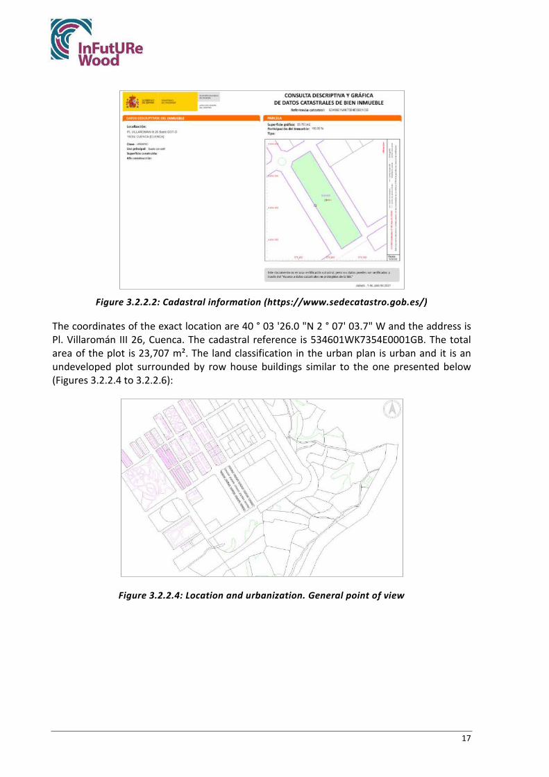
17
Figure 3.2.2.2: Cadastral information (https://www.sedecatastro.gob.es/)
The coordinates of the exact location are 40 ° 03 '26.0 "N 2 ° 07' 03.7" W and the address is Pl. Villaromán III 26, Cuenca. The cadastral reference is 534601WK7354E0001GB. The total area of the plot is 23,707 m². The land classification in the urban plan is urban and it is an undeveloped plot surrounded by row house buildings similar to the one presented below (Figures 3.2.2.4 to 3.2.2.6):
Figure 3.2.2.4: Location and urbanization. General point of view

18
Figure 3.2.2.5: Location and urbanization on perspective
Figure 3.2.2.6: Location and urbanization, row repetition
The volumes that are shown in previous figures are translated to this continuous structure shown in Figures 3.2.2.7 and 3.2.2.8:
Figure 3.2.2.7: Building schema. From load bearing structure to the building I

19
Figure 3.2.2.8: Building schema. From load bearing structure to the building II
3.2.3. Primary load-bearing structure
Primary load-bearing structure of the building is executed in Salzmann pine sawn timber cut with numeric control machine and connected with wooden connections based on traditional timber connections like dovetails, mortise-and-tenon, etc. That works as the skeleton for the panel secondary structure as it is shown in Figure 3.2.3.1.
The local timber is processed in autoclave with a treatment that avoids dimensional instability. Processing timber this way avoids the internal dimensional issues that timber suffers while drying and facilitates assembly.
Figure 3.2.3.1: Post-and-Beam, primary load-bearing structure

20
All cross sections and timber volumes are detailed in the following Table 3.2.3.1 and coloured reference in Figure 3.2.3.2:
Table 3.2.3.1: Post-and-Beam Cross-sections and volumes
Name Species Cross-
section Total
length Total
volume Colour in figures
mm² m m³ Post Salzmann Pine 200x200 52.91 2.07
Beam Salzmann Pine 200x240 87.03 3.92 Ridges and main
rafters Salzmann Pine 200x300 25.52 1.84
Rafters Salzmann Pine 200x300 28.66 1.52 Total 194.13 8.98
Figure 3.2.3.2: Post-and-Beam elements by colour
The primary load-bearing structure (Post-and-Beam) will be assembled following this schema (Figure 3.2.3.3):
Figure 3.2.3.3: Post-and-Beam building schema
4. Rafters 3. Ridges 2. Beams 1. Posts

21
All connections are designed to be easily assembled and disassembled. Carpenter joints secured with steel coach-screws that only work as a fixer and not as the main support of the connection. Next, after the detail of the location of the joints (Figure 3.2.3.4), the details of the connections of all the elements are shown separately. It is shown disassembled with wood texture to be able to see the dimensions and cuts of each piece and, in the right, the joint is completely assembled with transparencies so that the joined surfaces are seen (Figures 3.2.3.5 to 3.2.3.11).
Figure 3.2.3.4: Details on primary load-bearing structure
Figure 3.2.3.5: Detail A: Wood Connection between posts and beam. Corner

22
Figure 3.2.3.6: Detail B.1: Wood Connection between posts and beam. Central
Figure 3.2.3.7: Detail B.2: Wood Connection between posts and beam. Central
Figure 3.2.3.8: Detail C: Wood Connection between posts and beam. Central

23
Figure 3.2.3.9: Detail D: Wood Connection between beams and ridges. Corner
Figure 3.2.3.10: Detail E: Wood Connection between beams and ridges. Corner
Figure 3.2.3.11: Detail F: Wood Connection between a post and three ridges. Central

24
3.2.4. Secondary load-bearing structure
All panels (secondary load-bearing structure) are built in the same criteria and order. It is described in the first point (Wall Panels) but it is extensive for all panel system.
- Wall panels:
All panels can be assembled and disassembled in-situ in its complete form.
Cellulose is insufflating inside the wall panels at the industrial facilities to guarantee insulation requirements for Passivhaus standards. Also it allows a 100% recovery of the aisle material when disassembly.
All wooden connections and elements are cut with numeric control preformed and assembled at the factory for an easy assembly.
The enclosure system of the panels is made with standard planks of sawn timber. The standard dimension used is 125x2500x20 mm³.
The bottom piece is used as a sleeper under the gutter and is made of durable wood or pine itself, properly treated to prevent soil moisture from rising.
All frame pieces are connected with Steel coach screws (3 by connection between stud and sleeper). The planks are connected to the frame with wooden nails that avoid lateral movements.
Wooden nails Lignoloc (Beck, Mauerkirchen, Austria) to replace steel-nails are put in the planks for solving joints between the frame and the planks. This ensures the disassembly process by cutting wooden nails saving all planks completely and grants the timber element does not lose section. When cut, a part of the nail remains in each piece without tearing. The planks can be completely reused as there is no need to damage it in the disassembly process. Wooden nails are shown in Figure 3.2.4.1:
Figure 3.2.4.1: Wooden nails (Image: Marlene Cramer).
In a general perspective, the building schema of the wall panels is shown in Figure 3.2.4.2 and 3.2.4.3:

25
Figure 3.2.4.2: Wall panel schema
Figure 3.2.4.3: Wall panel in Post-and-Beam
All cross sections and timber volumes are detailed in the following Table 3.2.4.1 and coloured reference in Figure 3.2.4.4 and 3.2.4.5 and assembly process Figure 3.2.4.6 and 3.2.4.7:
Table 3.2.4.1: Wall panel Cross-sections and volumes
Name Species Cross-section Total length Total volume
Colour in figures mm² m m³
Sleepers Salzmann Pine 50x200 590.00 5.82
Studs
Name Species Planks dimension Total length Total volume
Colour in figures mm3 m m³
Planks Salzmann Pine 125x2500x20 316.42 6.96

26
Figure 3.2.4.4: Wall panel elements identified by colour
Figure 3.2.4.5: Wall panel frame and planks
Figure 3.2.4.6: elements in wall panel frame

27
Figure 3.2.4.7: wall panel connections between studs and sleepers. Coach screws.
It is shown in Figure 3.2.4.8 the assembly with primary load-bearing structure (Post-and-Beam)
Figure 3.2.4.8: Assembly process of wall panels in the primary load-bearing structure
All connections are designed to be easily assembled and disassembled. Carpenter joints secured with steel coach-screws that only work as a fixer and not as the main support of the connection. Next, after the detail of the location of the joints (Figure 3.2.4.9), the details of the connections of all the elements are shown separately. It is shown disassembled with wood texture to be able to see the dimensions and cuts of each piece and, in the right, the joint is completely assembled with transparencies so that the joined surfaces are seen (Figures 3.2.4.10 to 3.2.4.12).

28
Figure 3.2.4.9: Location of the details
Figure 3.2.4.10: Detail G: Connection between wall panels and Post-and-Beam. Roof
Figure 3.2.4.11: Detail H.1: Connection between wall panels and Post-and-Beam. 1st Floor
Figure 3.2.4.12: Detail H.2: Connection between wall panels and Post-and-Beam. 1st Floor
H
G

29
- Floor panels:
It is executed with the same criteria and assembly order than the wall panel. The difference between the other cassette systems is the connection with the primary load-bearing Post-and-Beam structure but the panel itself is built in the same order. The studs and sleepers are connected with steel coach screws and planks are connected to the framed structure with wooden nails with the same properties and dimension than the wooden nails of wall panels as it is shown in Figures 3.2.4.13 and 3.2.4.14:
Figure 3.2.4.13: Floor panels general schema
Figure 3.2.4.14: Floor panels assembled on primary load-bearing structure

30
All cross sections and timber volumes are detailed in the following Table 3.2.4.2 and coloured reference in Figure 3.2.4.15 and 3.2.4.16:
Table 3.2.4.2: Floor panel cross-sections and volumes
Name Species Cross-section Total length Total volume
Colour in figures mm² m m³
Sleepers Salzmann Pine 50x200 213.50 2.14 Studs
Name Species Plank dimension Total area Total volume
Colour in figures mm³ m² m³
Planks Salzmann Pine 125x2500x20 127.03 2.80
Figure 3.2.4.15: Floor panel elements by colour
Figure 3.2.4.16: Floor panel elements, assembly
All connections are designed to be easily assembled and disassembled. Carpenter joints secured with steel coach-screws that only work as a fixer and not as the main support of the connection. The details of the connections of all the elements are shown separately. It is shown disassembled with wood texture to be able to see the dimensions and cuts of each piece and, in the right, the joint is completely assembled with transparencies so that the joined surfaces are seen (Figures 3.2.4.17 to 3.2.4.19).

31
Figure 3.2.4.17: Wooden frame of floor panels. Studs and sleepers
Figure 3.2.4.18: Floor-frame elements
Figure 3.2.4.19: Connection between floor-studs and sleepers
The following figures shown the assembly of floor panels with primary load-bearing structure (Figures 3.2.4.20 to 3.2.4.24)

32
Figure 3.2.4.20: Assembly of floor panels in primary load bearing structure
Figure 3.2.4.21: Floor panels and primary load-bearing structure
Figure 3.2.4.22: Floor panels and primary load-bearing structure

33
Figure 3.2.4.23: Floor panels and primary load-bearing structure
Figure 3.2.4.24: Floor panels and primary load-bearing structure
- Roof panels:
They are executed with the same criteria and assembly order than wall panels and floor panels. The main difference between the other cassette systems is the connection with the primary load-bearing Post-and-Beam structure but the panel itself is built in the same order. The studs and sleepers are connected with steel coach screws and planks are connected to the framed structure with wooden nails with the same properties and dimension than the wooden nails of wall and floor panels. Figures 3.2.4.25 and 3.2.4.26 shows the general composition of panels and roof panels assembled in the primary load bearing structure.

34
Figure 3.2.4.25: Roof panel structure
Figure 3.2.4.26: Roof panel and primary load-bearing structure
All cross sections and timber volumes are detailed in the following Table 3.2.4.3 and coloured reference in Figure 3.2.4.27 and 3.2.4.28:

35
Table 3.2.4.3: Roof panel cross-sections and volumes
Name Species Cross section Total length Total volume
Colour in figures mm² m m³
Sleepers Salzmann Pine 50x200 284.36 2.84
Studs
Name Species Plank dimension Total area Total volume
Colour in figures mm³ m² m³
Planks Salzmann Pine 125x2500x20 142.71 3.14
Figure 3.2.4.27: Roof panel elements in colour
Figure 3.2.4.28: Roof panel composition
All connections are designed to be easily assembled and disassembled. Carpenter joints secured with steel coach-screws that only work as a fixer and not as the main support of the connection. The details of the connections of all the elements are shown separately. It is shown disassembled with wood texture to be able to see the dimensions and cuts of each piece and, in the right, the joint is completely assembled with transparencies so that the joined surfaces are seen (Figures 3.2.4.29 to 3.2.4.31).

36
Figure 3.2.4.29: Details of roof panels
Figure 3.2.4.30: Detail on connection of the elements of the roof panels
Figure 3.2.4.31: All elements and connection of the roof panel frame
The assembly process with primary load-bearing structure (Figs. 3.2.4.32 to 3.2.4.37)

37
Figure 3.2.4.32: Roof panel connection to primary load-bearing structure
Figure 3.2.4.33: Roof panel connection to primary load-bearing structure
Figure 3.2.4.34: Roof panel connection to primary load-bearing structure

38
Figure 3.2.4.35: Roof panel connection to primary load-bearing structure
Figure 3.2.4.36: Roof panel connection to primary load-bearing structure
Figure 3.2.4.37: Roof panel connection to primary load-bearing structure

39
3.2.5. Summary of connections
In Table 3.2.5.1 it is shown the summary of connections used in Cuenca Village design:
Table 3.2.5.1: Summary of connections Location Connection name Connection type
Load-bearing structure
Foundation to posts Mechanical fastener. Pillar base plate
Beams to posts Carpenter joint, side dovetail (cnc)
Ensured with 2 coach screws
Rafters to beams Carpenter joint
Ensured with 2 coach screws
Rafters to ridges Carpenter joint. Dovetail
Ensured with 2 coach screws
Wall panel Studs to sleepers
Coach screws Carpenter join, dovetail, half section
Planks to frame Wooden nails
Floor panel Studs to sleepers
Coach screws Carpenter join, dovetail, half section
Planks to frame Wooden nails
Roof panel Studs to sleepers
Coach screws Carpenter join, dovetail, half section
Planks to frame Wooden nails
Wall panel to load-bearing structure
Wall-panels to post Screws (to ensure connection)
Wall-panels to beams Carpenter joint, dovetail, half section Coach screws to ensure connection
Floor panel load-bearing structure (Post-and-
Beam) Floor-panels to beams
Carpenter joint, dovetail, half section Coach screws to ensure connection
Carpenter joint support notched joint Roof panels to load-
bearing structure (Post-and-Beam)
Roof-panels to rafters Carpenter joint, dovetail, half section Coach screws to ensure connection
Roof-panels to Ridge Screws (to ensure connection)
3.2.6. Other building details
All partitions, installations and coating layers are not a part of the load bearing structure and are not embedded in any structural element.
All interior partitions walls are designed to not to interfere in the structure to ease the adaptability and expandability process, made in steel frame and gypsum plasterboard are installed over the floor panels not being in any case embedded in any structural element.
Coating internal layers are made in gypsum plasterboard screwed on a self-supporting galvanized-steel frame. All installations (electric, water…) are embedded in this metallic and gypsum frame.

40
Façade exterior layer is executed with a cork layer by Amorim Company sticked to a variable pressure waterproofing foil following the next schema of installation in Figure 3.2.6.1:
Figure 3.2.6.1: Amorin’s cork façade (Amorin Company catalogue)
Any of this partitions, installations and coating layers are studied on this study case that is focused only on the timber load-bearing structure.
3.2.7. Adaptability and deconstruction plan
Solution presented is fully adaptable for two of its facades, the front and the back, due to the type of urbanization it is taken as reference.
A deconstruction plan proposed for the solution considered could include the following steps and elements:
1. Preparatory works: installations, partitions coating layers.
All installations are disconnected (Electrical, water and drain, windows, internal partitions… etc. This step is the same as the conventional deconstruction and demolition process of a standard building. This case study is not focused on this step but all the next ones. All the elements are built in dry construction and the partitions are not part of the load-bearing system so they should be disassembled easily and should not affect the structure.
2. Roof layers: roof tiles are disassembled and then the wooden strips. All insulations layers and waterproof/continuous clamping pressure foils are also removed in this steps. All elements are preserved and stored according to manufacturer’s instructions. Guarantee assumptions submitted to manufacturer’s guide of use.

41
3. Roof panels: as the roof upper surface is clean and there is not any false ceiling or installations behind the roof panels. The first step will be to remove the coach screws which connect the roof panels with the primary load-bearing structure. The screws are easily found in the structure by locating the outgoing parts of the frame. (First picture below).
After removing all coach screws, the roof panels are lifted and prepared to be carried to the processing factory and to be industrially dismantled off-site.

42
4. Wall panels: as the whole façade`s surface is clean both sides and there is not any partitions or installations behind the panels, the first step will be to remove the coach screws which connect the roof panels with the primary load-bearing structure. The screws are easily found in the structure by locating the outgoing parts of the frame. (First picture below).
After removing all coach screws, the wall panels are lifted and prepared to be carried to the processing factory and to be industrially dismantled off-site.

43
5. Rafters: as all roof and wall panels are removed. To continue the disassembly process, the rafters can difficult the access to other structure parts so they should be removed lifting and storing them.
The process should be to secure them with the crave and then to remove the coach screws installed to ensure the fixation to the Ridge and beams. Then, to lift them and store.
6. Floor panels: when the first floor upper surface is clean and there is not any false ceiling or installations behind the panels, the first step will be to remove the coach screws which connect the roof panels with the primary load-bearing structure. The screws are easily found in the structure by locating the outgoing parts of the frame. (First picture below).
After removing all coach screws, the floor panels are lifted and prepared to be carried to the processing factory and to be industrially dismantled off-site.

44
7. Post-and-Beam elements: the last step in-situ will be to disassembly the primary load-bearing structure. All beam and posts should be ensured with a crave.
The Ridges are removed from the top, then the beams are removed from the exterior sides of the building and, at last, the posts.

45
3.2.8. Industrial deconstruction and recycling possibilities
- Disassembly off-site plan: just in case of recycling all materials of the structure.
All panels stored in the factory will be dismantled in the same way.
First, the planks will recovered after sawing all wooden nails. Then the cellulose will be recovered 100 % to use it for any other uses.
Also the pieces of the structure will be separated removing all screws between studs and sleepers to finish the total disassembly to ray materials.
Deconstruction carried out off-site is a key point for this constructive system to be efficient and offers a series of advantages cited in section 3.4.1, guidelines for deconstruction.

46
3.2.9. Reconditioning, storage and reassembly
During the demolition process some elements can be damaged and should be replaced for new ones so all assembly and demolition plans must be accompanied by graphic information of the complete coded pieces in case any part, coach-screws, etc. should be replaced especially the pieces that are the smallest section, those can be the ones that give problems.
All pieces are dimensioned using standard sections and lengths so the reassembly process and the replacements, in its case, should be easy to
3.3. Amount of potential reclaimed timber
Looking on the life cycle of all the structural timber used in this building it is estimated this quantity of wood that could be reused or recycled in other timber applications (Figure 3.3.1):
Figure 3.3.1: Lifecycle schema with percentages of timber reuse
Those numbers come from the quantity of timber used and the quantity of timber that can be reused. As all cross sections are standard sized and not dimensioned specifically, the recovery capability is very high.
To assembly the same structure in any other place as many times as possible has the higher percentage of recovery but the number of times that the coach screws can be placed in the same position is limited due to the properties of the material itself.
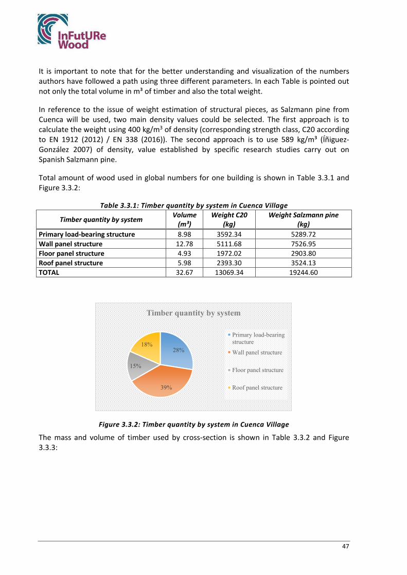
47
It is important to note that for the better understanding and visualization of the numbers authors have followed a path using three different parameters. In each Table is pointed out not only the total volume in m³ of timber and also the total weight.
In reference to the issue of weight estimation of structural pieces, as Salzmann pine from Cuenca will be used, two main density values could be selected. The first approach is to calculate the weight using 400 kg/m3 of density (corresponding strength class, C20 according to EN 1912 (2012) / EN 338 (2016)). The second approach is to use 589 kg/m³ (Íñiguez-González 2007) of density, value established by specific research studies carry out on Spanish Salzmann pine.
Total amount of wood used in global numbers for one building is shown in Table 3.3.1 and Figure 3.3.2:
Table 3.3.1: Timber quantity by system in Cuenca Village
Timber quantity by system Volume (m³)
Weight C20 (kg)
Weight Salzmann pine (kg)
Primary load-bearing structure 8.98 3592.34 5289.72 Wall panel structure 12.78 5111.68 7526.95 Floor panel structure 4.93 1972.02 2903.80 Roof panel structure 5.98 2393.30 3524.13 TOTAL 32.67 13069.34 19244.60
Figure 3.3.2: Timber quantity by system in Cuenca Village
The mass and volume of timber used by cross-section is shown in Table 3.3.2 and Figure 3.3.3:
28%
39%
15%
18%
Timber quantity by system
Primary load-bearingstructure
Wall panel structure
Floor panel structure
Roof panel structure

48
Table 3.3.2: Timber quantity in Cuenca Village by cross-section
Timber quantity by cross-section Volume (m³)
Weight C20 (kg)
Weight Salzmann pine (kg)
200x200 mm² 2.07 827.86 1219.02 200x240 mm² 3.92 1566.73 2307.01 200x300 mm² 2.99 1197.75 1763.68 50x200 mm² 10.80 4318.59 6359.12 20x125 mm2 12.90 5158.42 7595.77 TOTAL 32.67 13069.34 19244.60
Figure 3.3.3: Timber quantity by cross-section
The method that has been followed to calculate the amount of wood that can be reused and recycled in other projects has been carried out following the process explained below based on the construction system itself. This method is named Carpentry Joints Timber Loss method.
By having a model in CADCAM it is easy to obtain all the volume data piece by piece and it is easier to work with them. Following steps are:
• The total gross volume of the piece is taken out. • The total waste volume of the carpenter joints is taken out. Most of the joints are
based on the dovetail and the mortise-and-tenon. The carpenter joints means that sections are reduced.
• The real total installed volume is calculated after discounting the gaps generated to make the carpentry joints. All carpentry joints implies a reduction of the original cross-section.
• To this total real volume, both globally and for each piece, the volume occupied by the carpentry joint is discounted, which will generally be very close to the volume removed from the complete piece to do so previously.
• It is estimated that any of the wooden nails supposes not any loss of timber that can be recovered due to after cutting nails keep inside the beams. As all steel coach screws are placed in carpentry connections, for the number estimation all holes and pieces derived from the coach-screws installation are included on the volume of timber wasted this study subtracts from the global amount of timber.
6%12%
9%
33%
40%
Timber quantity by cross-section
200x200 mm²
200x240 mm²
200x300 mm²
50x200 mm²
Plank: 125x2500x20 mm³

49
The following data are derived from this Carpentry Joints Timber Loss method called forward CJTL, and it is shown from Tables 3.3.3 and 3.3.4:
Table 3.3.3: Timber quantity recovered by system (CJTL method)
Timber quantity recovered Volume (m³)
Weight C20 (kg)
Weight Salzmann pine (kg)
Primary load-bearing structure 8.46 3385.53 4985.19 Wall panel structure 11.01 4403.62 6484.33 Floor panel structure 4.65 1858.76 2737.03 Roof panel structure 4.79 1915.93 2821.21 TOTAL 28.91 11563.84 17027.75
Table 3.3.4: Timber quantity recovered by cross-section (CJTL method) Timber quantity recovered by cross-section
Volume (m³)
Weight C20 (kg)
Weight Salzmann pine (kg)
200x200 mm² 2.02 809.08 1191.37 200x240 mm² 3.66 1462.53 2153.58 200x300 mm² 2.78 1113.92 1640.24 50x200 mm² 10.38 4150.56 6111.71 20x125 mm2 10.07 4027.75 5930.86 TOTAL 28.91 11563.84 17027.75
The wasted timber is referred in following Tables 3.3.5 to 3.3.6:
Table 3.3.5: Timber quantity wasted by system (CJTL method)
Timber quantity wasted Volume (m³)
Weight C20 (kg)
Weight Salzmann pine (kg)
Primary load-bearing structure 0.52 206.81 304.53 Wall panel structure 1.77 708.06 1042.62 Floor panel structure 0.28 113.26 166.78 Roof panel structure 1.19 477.37 702.92 TOTAL 3.76 1505.50 2216.85
Table 3.3.6: Timber quantity wasted by cross-section (CJTL method) Timber quantity wasted by cross-section
Volume (m³)
Weight C20 (kg)
Weight Salzmann pine (kg)
200x200 mm² 0.05 18.78 27.65 200x240 mm² 0.26 104.20 153.44 200x300 mm² 0.21 83.83 123.44 50x200 mm² 0.42 168.02 247.41 20x125 mm2 2.83 1130.67 1664.91 TOTAL 3.76 1505.50 2216.85
So with this data and the method explained above those are de percentages of timber recovery in Cuenca Village Tables 3.3.7 and 3.3.8, figures 3.3.4 and 3.3.5:

50
Table 3.3.7: Percentage of timber used, wasted and recovered by system (CJTL method) Timber quantity % Used Wasted Recovered Primary load-bearing structure 100.00% 5.76% 94.24% Wall panel structure 100.00% 13.85% 86.15% Floor panel structure 100.00% 5.74% 94.26% Roof panel structure 100.00% 19.95% 80.05% TOTAL 100.00% 11.52% 88.48%
Figure 3.3.4: Percentage of timber used, wasted and recovered by system (CJTL method)
Table 3.3.8: Percentage of timber used, wasted and recovered by cross-section (CJTL method) Timber quantity % by cross-section Used Wasted Recovered 200x200 mm² 100.00% 2.27% 97.73% 200x240 mm² 100.00% 6.65% 93.35% 200x300 mm² 100.00% 7.00% 93.00% 50x200 mm² 100.00% 3.89% 96.11% 20x125 mm2 100.00% 21.92% 78.08% TOTAL 100.00% 11.52% 88.48%
Figure 3.3.5: Wasted and recovered timber in Cuenca Village (CJTL method)
5,76%13,85%
5,74%
19,95%11,52%
94,24%86,15%
94,26%
80,05%88,48%
Primary load-bearingstructure
Wall panel structure Floor panel structure Roof panel structure TOTAL
Recovered timber quantity by system
Wasted Recovered
12%
88%
Timber quantity by cross-section
Wasted
Recovered

51
From this percentage to the real number of standard pieces they are got after recovery process is shown in Table 3.3.9:
Table 3.3.9: Quantity recovery translated to standard pieces (CJTL method)
Recovery lengths and units Total length (m)
Standard length
(m)
Elements with standard length
(m) 200x200 mm² 50.57 3.00 16.86 200x240 mm² 76.17 4.00 19.04 200x300 mm² 46.41 4.00 11.60 50x200 mm² 1037.64 2.00 518.82 20x125 mm2 4027.75 2.00 2013.87
For the primary load-bearing structure, percentage derived from discounting the volume of all carpentry connections and joints (CJTL) is used and 94.24 % is obtained, far away from results obtained in Mendiola`s demolition, 67 %. Results shown in Table 3.3.10:
Table 3.3.10: Mendiola`s recovery post-and-beam percentage and Cuenca Village CJTL recovery percentage
Mendiola recovery percentage 67.00 %
Cuenca Village primary load-bearing structure (Post-and-Beam) recovery percentage 94.24 %
In order to estimate the maximum proportion of wood that could be reused in the secondary load bearing structure, estimations from Sandin et al. (2021) were used. In that study, just above 85 % of the wood in the light timber structure was estimated to be reusable. The estimation was based on the scenario that the original building will be deconstructed and reassembled into an identical building in a new location with the same wind and snow loads.
If in Sandin et al. (2021) would be disassembled the cassettes to use the raw materials for a different structure than reassembling the original one, as this is the case of Cuenca Village, much more waste will be generated. Despite the Sandin et al. (2021) is a reassembly study case, while Cuenca Village is not, the percentage of recovery (85%) reported by Sanding will be applied to the light-frame part of the structure from Cuenca Village. Using that figure for the here proposed new system thus means assuming that walls and timber will be reused in a building identical to the original one. For a scenario where the parts are used for other purposes, there will be much more waste as walls and floors need to be tailored to fit other spans. To make an estimation of that waste is not possible without knowing how the parts will be used.
When working with different types of building systems, as it is the case of this series of case studies, the methodology to estimate a correct number can vary significantly from one to the other. In order to have a comparison between the methods used in the different case studies, as an example, methodology of Villa Anneberg case study presented in Sandin et al. (2021) is analysed and used.
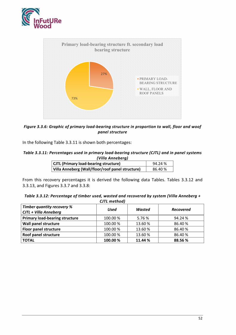
52
Figure 3.3.6: Graphic of primary load-bearing structure in proportion to wall, floor and woof panel structure
In the following Table 3.3.11 is shown both percentages:
Table 3.3.11: Percentages used in primary load-bearing structure (CJTL) and in panel systems (Villa Anneberg)
CJTL (Primary load-bearing structure) 94.24 % Villa Anneberg (Wall/floor/roof panel structure) 86.40 %
From this recovery percentages it is derived the following data Tables. Tables 3.3.12 and 3.3.13, and Figures 3.3.7 and 3.3.8:
Table 3.3.12: Percentage of timber used, wasted and recovered by system (Villa Anneberg + CJTL method)
Timber quantity recovery % CJTL + Villa Anneberg Used Wasted Recovered
Primary load-bearing structure 100.00 % 5.76 % 94.24 % Wall panel structure 100.00 % 13.60 % 86.40 % Floor panel structure 100.00 % 13.60 % 86.40 % Roof panel structure 100.00 % 13.60 % 86.40 % TOTAL 100.00 % 11.44 % 88.56 %
27%
73%
Primary load-bearing structure ft. secondary load bearing structure
PRIMARY LOAD-BEARING STRUCTURE
WALL, FLOOR ANDROOF PANELS

53
Figure 3.3.7: Percentage of timber used, wasted and recovered by system (Villa Anneberg + CJTL method)
Table 3.3.13: Timber quantity used, wasted and recovered by cross-section Timber quantity % by cross-section CJTL + Villa Anneberg Used Wasted Recovered
200x200 mm² 100.00% 2.27% 97.73% 200x240 mm² 100.00% 6.65% 93.35% 200x300 mm² 100.00% 7.00% 93.00% 50x200 mm² 100.00% 13.60% 86.40% 20x125 mm2 100.00% 13.60% 86.40% TOTAL 100.00% 11.44% 88.56%
Figure 3.3.8: Wasted and recovered timber in Cuenca Village (Villa Anneberg + CJTL method)
The volume and mass of timber recovered by system following Villa Anneberg + CJTS method is shown in Tables 3.3.14, 3.3.15 and 3.3.16:
Table 3.3.14: Quantity of timber recovered by system (Villa Anneberg + CJTL method) Timber quantity recovered. CJTL + Villa Anneberg
Volume (m³)
Weight C20 (kg)
Weight Salzmann Pine (kg)
Primary load-bearing structure 8.46 3385.53 4985.19 Wall panel structure 11.04 4416.49 6503.28 Floor panel structure 4.26 1703.83 2508.89
5,76%13,60% 13,60% 13,60% 11,44%
94,24%86,40% 86,40% 86,40% 88,56%
Primary load-bearingstructure
Wall panel structure Floor panel structure Roof panel structure TOTAL
Recovered timber quantity by system
Wasted Recovered
11%
89%
Timber quantity by cross-section
Wasted
Recovered

54
Roof panel structure 5.17 2067.81 3044.85 TOTAL 28.93 11573.65 17042.21
Table 3.3.15: Timber quantity recovered by cross-section (Villa Anneberg + CJTL method) Timber quantity by cross-section CJTL + Villa Anneberg Volume (m³) Weight C20
(kg) Weight Salzmann Pine
(kg) 200x200 mm² 2.02 809.08 1191.37 200x240 mm² 3.66 1462.53 2153.58 200x300 mm² 2.78 1113.92 1640.24 50x200 mm² 9.33 3731.26 5494.28 20x125 mm2 11.14 4456.87 6562.74 TOTAL 28.93 11573.65 17042.21
Table 3.3.16: Quantity recovery translated to standard pieces (Villa Anneberg + CJTL method)
Recovery lengths and units CJTL + Villa Anneberg
Total length (m)
Standard length
(m)
Elements with standard length
(m) 200x200 mm² 50.57 3.00 16.86 200x240 mm² 76.17 4.00 19.04 200x300 mm² 46.41 4.00 11.60 50x200 mm² 932.81 2.00 466.41 20x125 mm2 4456.87 2.00 2228.44
The resultant total numbers of both methods are very similar; being 88.48 % of recovery using the CJTL method and 88.56 % in Villa Anneberg + CJTL mixed method, respectively.
3.4. Guidelines for DfA &DfDR
3.4.1. Introduction
This case study has been carried out in limited conditions and it proposes some draft ideas in order to project in a specific construction system with focusing on to be dismantle it completely and achieve the maximum volume of recovered wood. For this, many details that are proposed must be subjected to theoretical study and mechanical resistance tests to verify the correct functioning of the system locally and globally.
Both the connections and the global operation of the stability can be affected by the changes made at the theoretical and design level, so this system in principle can work on paper but when built it can offer dimensioning problems, breaks and other issues.
Especially, it would be of interest to solve how should dimensional stability be treated for carpenter joints and when building with large dimensions.
The treatment applied to the Salzmann pine in the Cuenca local sawmill reduces the dimensional instability of sawn timber in large cross-sections and long lengths like the ones used in Cuenca Village, but it does not eliminate the risk. The carpenter connections that are implementing are complex and make each piece of the structure fit like a wooden puzzle into the next piece and leaving small gaps, which is what this system would allow to work properly, between 1 and 2 mm, does not guarantee that the system could be completely reassembled without adjusting the heads of the pieces properly.

55
Connections supposes in this case study one of the keys to success or failure of the system. So, for example, in case of rebuilding the house in another place and wanting to put the lag screws at the same point, perhaps it would be worth adding thicker coach-screws so that it continues to take wood when installing it.
When calculating such complex carpentry joints, it is important to detail that it is assumed that the section is working in its entirety and not with the recesses made or with useful sections.
3.4.2. Obstacles and advantages to DfA
Obstacles:
• The main Post-and-Beam structure make the storey number and distribution condition the adaptability on the first structural pattern
• Panels are standard modulated for their locations. The wall between adjoined buildings are not the same as the façade panels due to assembling method
• Using massive timber instead of Glued Laminated timber (Glulam) or Engineered Wood Products (EWP) will result in dimensional stability issues
Advantages:
• The crossover between framed wood construction and the Post-and-Beam system supposes benefitting from both systems advantages
• Using wood-to-wood connections and steel connections ensures the disassembling and enables an easier assembling
3.4.3. Obstacles and advantages to DfDR
Advantages:
• Post-and-beam traditional system is built with bricks or mud-wall/adobe and timber frame and precludes deconstruction and pre-industrialization
• Light frame construction hinders adaptability due to the fact that the main structure is formed by the distribution panels
• Wooden nails and wood-to-wood connections makes the disassembling easier and allows the reuse of all the materials
• This system is designed for industrial deconstruction, with the intention of speeding up the disassembling work in-situ
3.4.4. In-situ and off-site demolition
In this case study, to carry out the guidelines to be able to adapt the house without reaching complete disassembly, it will simply be enough to consult the part of the general deconstruction plan that is of interest. This case study is mainly focused on reaching the final step of recovery of raw materials. As noted in previous sections, following cases are considered:
• Interior or exterior adaptability of the building

56
• Disassembly for later reassembly in another place with exactly the same distribution • Complete disassembly to recover raw materials
The entire building demolition process is designed so that most of the disassembly is done off-site. This represents huge advantages in terms of speed and recovery of the maximum amount of wood as it is possible.
Advantages of off-site demolition:
• Speed • Clean and undisturbed work area • Independence of meteorological agents • Qualified workforce • More security • More appropriate technical equipment • Fully controlled process • Higher material recovery
3.4.4. Labelling and specifications
It is proposed in this case study to use the codification and weight as shown in following Table 3.4.4.1 All pieces must be labelled properly and should have a clearly reference on it. They should be pantographed with CNC machines when cut. This should guarantee the traceability of each piece in case there are some more other houses.
The label should contain the next information:
Table 3.4.4.1: Information in each recovered piece Project/batch No Piece reference Output date Nominal dimensions Species Provenance Reference of position in manuals Other information: treatment, …
In this case study, it is proposed that reuse and disassembly industrial process will take place in the Cuenca’s demolition industrial facility close to the actual sawmill.
Industry will register each piece since it comes from its own facilities and also all the exits and entries of raw material. In this way, the recovery and correct traceability of each piece will be facilitated.
All the points where there are coach-screws are easily recognizable on the model once all the outer and inner layers that do not belong to the structure have been lifted. This will greatly facilitate the disassembly of each part. However, everything will be incorporated into a hardware plan that must be included in the exploded drawings and the home disassembly manual.

57
3.4.5. Tools and resources for demolition
- Tools:
• Screwdriver • Tiger saw with saw blade for wood • Hammer • Rope
- Lifting and transporting facilities
• Lifting loops • Crane truck • Truck • Sludge suction truck for removing blown/loos insulation • Excavator for chopping ground slab
3.4.6. Demolition manuals
All the information must be available and kept together with the final execution project in the municipal registry (in Spain it is mandatory to register all projects). The owner/final user of the building must have a copy that should be attached to the building’s user manual (mandatory in Spain). All info must be perfectly legible. It is proposed to contain the following data:
• Steps for demolition with graphic details on where to find all connections. • Tools that are needed (coded) • All weights, labels and an interpretation of all elements • All elements manufacturing plans all measured. In the disassembly phase, some
elements can be irretrievably damaged • Foundation requirements for a new assemblage of the same structure • All Coach screws and requirements listed • Storage recommendations and security requirements
All cross-sections used are designed to be standard-sized and easily locatable in the geographical area. This detail ensures that all elements which are partially or totally damaged can be replaced and re-machined relatively quickly.
Is proposed the sawmill itself to supply the wood and assembles the building in first instance. If competitive, referring to the economic aspect, it would be an important optimization point of the process if the sawmill was also the one to dismantle it.
58
4. Conclusions
The traditional timber construction in Spain from the 18th century to the beginning of the 20th century has been executed mainly with Post-and-Beam construction system for housing and residential, using large cross-sections and species, generally pine and oak, and filling the gaps with bricks (stone, adobe ...). The best materials were commonly used in the houses rather than in other-uses buildings, and also treated more carefully in the first ones.
A demolition of a traditional timber building was attended and documented in Mendiola, Álava, Spain (a building dated from the 19th century, built 200 hundred years ago approx.) with Post-and-Beam main structure. It was concluded that depending on the use that is given to each area of the building, it can be possible to reuse more or less timber. For example, timber recovery from the living area can be reused in a higher proportion than from the hayloft or cowshed areas.
Most of the floor planks in the house were recoverable, although some of them are difficult to place on the current market due to the species with which they were executed. E.g. oak is more valuable than pine.
In the traditional Post-and-Beam system, the gaps in the façade are filled with block systems and this hinders the process of recovering the structure.
The recovery of structural timber from the Mendiola building varied from 43-45 % in the hayloft and cowshed areas up to 67 % in the housing area.
Based on the information obtained from the analysis of the traditional Post-and-Beam system, a series of design principles are developed on which the building object of this case study is based. The main new design concepts are: “0 mile” source materials, traditional carpenter joints, dry construction, ease of disassembling and industrial deconstruction in a specialized off-site materials recovery facility. The city of Cuenca is chosen as the best location because has its own local pine (Salzmann pine) sawmill, as main advantage.
This case study is focused on the recovery of raw materials instead of trying to rebuilt the same building in any other place or reuse the same constructive elements like the complete panels or frames. It is based on recycle raw materials.
This Cuenca Village case study is developed facilitating interior flexibility of distribution and it is adapted so that none of the interior partitions and horizontal subdivisions of the house are part of the load-bearing structure of the house.
The improvements made in this case study are mainly based on improving the disassembly possibilities of the system by replacing the adobe walls with a kind of timber light-frame panels on the roof, on the walls and on the floors. This improvement guarantees the proper pre-industrialization and prefabrication of the entire building as well as the correct disassembly without damaging the main structure.
The entire construction of the system is based on a pre-industrialized and prefabricated system with complete elements. All the complete panels already assembled with the

59
complete insulation are taken to the construction work directly and all the elements of the primary load-bearing Post-and-Beam structure are mechanized with numerical control in such a way that the installation is facilitated and the on-site construction processes are shortened.
Even though it is a continuous row repetition urbanization, the structure of each private house is independent from the contiguous ones and this enhances the possibility of independent disassembly and assembly house by house.
By replacing the standard steel nails with wooden nails, it is achieved a much greater reuse of all the elements of the structure because all nails can be cut at the time of disassembling and avoid unnecessary damage and loss of section in all the elements.
The deconstruction plan is the inverse of the assembly plan in general lines and that endows flexibility to the documentation management.
Total volume of timber in Cuenca Village structure is 32.67 m³ (0.210 m³ of timber / m² of building) of which 8.98 m³ (0.058 m³ / m²) are from primary load-bearing structure (Post-and-Beam) and 23.69 m³ (0.152 m³ / m²) are from secondary load-bearing structure (wall, floor and roof panels). Percentages of timber are in Figure 4.1:
Figure 4.1: Timber quantity by primary and secondary load-bearing structure
Following the methodology indicated in section 3.2.11 of Carpentry Joint Timber Loss (CJTL), 28.91 m³ from the total building are recovered, being 8.76 m³ from the primary load-bearing structure (94.24 %). This is shown in Figure 4.2:
Figure 4.2: Timber recovery percentage from primary load-bearing structure
27%
73%
Timber quantity by system
Primary load-bearingstructure
6%
94%
Timber quantity recovered from primary load-bearing structure
Wasted
Recovered

60
For secondary load-bearing structure (wall, floor and roof panels) and using CJTL methodology, 28.91 m³ from the total building are recovered, being 20.45 m³ from the secondary load-bearing structure (86.32%). This is shown in Figure 4.3:
Figure 4.3: Timber recovery percentage from secondary load-bearing structure (wall, floor and roof panels)
The total volume of timber recovered amounts to 28.91 m³ what supposes an 88.48 % of timber recovery. This is shown in Figure 4.4:
Figure 4.4: Timber recovery percentage from timber structure in Cuenca Village CJTL
For comparing results with another case study developed under the InFutUReWood project WP2, Villa Anneberg from Sweden is used. The timber recovery percentage is 86.40 %. Villa Anneberg is a light frame timber structure in a total reassembly scenario of the same building, and this recovery percentage is only applied to the secondary load-bearing structure of Cuenca Village which is similar to a light frame building system but in an industrial deconstruction scenario.
Using the recovery percentage of Villa Anneberg, from a total volume of 23.69 m³, are recovered 20.47 m³ from secondary load-bearing structure.
Combining both methods, CJTL for the primary load-bearing structure and Villa Anneberg for the secondary load-bearing structure the total percentage of timber recovered amounts to 88.56 % what means a volume recovered of 28.93 m³.
Both percentages are very similar, in Figure 4.5 is shown a graphic of both methods.
14%
86%
Timber quantity recovered from secondary load-bearing structure
Wasted
Recovered
12%
88%
Timber quantity recovery CJTL
Wasted
Recovered

61
Figure 4.5: Both recovery methods, CJTL and CJTL + Villa Anneberg method percentages
The timber recovery improvements quantified from Cuenca Village can be compared to Mendiola’s house recovery percentage of 67 % and are compared to the Post-and-Beam primary load-bearing structure due to both are similar building systems. From Cuenca Village, the primary load-bearing structure recovery percentage is 94.24 % and contrasting with Mendiola’s house percentage. The recovery and waste percentages are shown in Figure 4.6:
Figure 4.6: Recovery percentages in Cuenca Village and in Mendiola’s house.
The guidelines for deconstruction have been defined for a correct disassembling to recover as much timber as possible.
11,52% 11,44%
88,48% 88,56%
CJTL recovery timber method CJTL + Villa Anneberg recovery timbermethod
Comparing CJTL and mixed method
Wasted Recovered
33,00%
5,76%
67,00%
94,24%
Mendiola Cuenca Village
Post-and-Beam recovery percentages of Cuenca Village and Mendiola's Deconstruction
Wasted Recovered

62
References
European standard (1994) Eurocode 5: Design of timber structure. Brussels, Belgium.
European standard (2012) EN 1912. Structural Timber - Strength classes - Assignment of visual grades and species. European Committee of Standardization (CEN), Brussels, Belgium.
European standard (2016) EN 338. Structural timber - Strength classes. European Committee of Standardization (CEN), Brussels, Belgium.
Íñiguez-González, G. (2007) Clasificación mediante técnicas no destructivas y evaluación de las propiedades mecánicas de la madera aserrada de coníferas de gran escuadría para uso estructural [Grading by non destructive techniques and assessment of the mechanical properties of large cross section coniferous sawn timber for structural use]. Ph.D. Thesis, UPM, Madrid, Spain. http://oa.upm.es/415/.
ISO standard (2020) ISO 20887. Sustainability in buildings and civil engineering works - Design for disassembly and adaptability - Principles, requirements and guidance.
Llana, D. F. (2020) Deconstruction and selection of a 200-year timber building in Spain. https://www.infuturewood.info/demolition-of-a-200-year-timber-building-in-spain/ (Accessed 2021-06-26).
Sandin, Y., Carlsson, A., Uí Chúláin, C. (2021) Design for deconstruction and reuse: Case study Villa Anneberg. InFutUReWood project. WG2.
Zabala A. (2021) Developing a grading tool for sustainable design of structural systems in buildings. Master’s thesis. Linköping University.

63
Appendix
In following table is shown the characteristics of all timber elements of the main structure:
Group Element Species No. elements
Width Height Length Total length
Panel area
Total panel area
Total raw
volume
Total volume
Wasted volume
Volume recovered Recovery
Recovery weights Dmean C20. UNE EN 338:2016
Recovery weights Local den. Iñiguez-González, 2007
Dmean C20 UNE EN
338:2016
weight used
timber
weight wasted timber
weight recovered
timber
Local den Salzmann
pine Iñiguez,
2007
weight used
timber
weight wasted timber
weight recovered
timber
mm mm mm m m² m² m³ m³ m³ m³ % kg/m³ kg kg kg kg/m³ kg kg kg Load Bearing Structure Post-and-Beam Posts Salzmann pine 2 200.00 200.00 4768.61 9.54 0.00 0.00 0.38 0.37 0.008 0.3651 97.80% 400.00 149.31 3.29 146.02 589.00 219.86 4.84 215.02
Load Bearing Structure Post-and-Beam Posts Salzmann pine 4 200.00 200.00 5753.61 23.01 0.00 0.00 0.92 0.90 0.023 0.8740 97.41% 400.00 358.92 9.31 349.61 589.00 528.51 13.71 514.81
Load Bearing Structure Post-and-Beam Posts Salzmann pine 2 200.00 200.00 6749.74 13.50 0.00 0.00 0.54 0.53 0.011 0.5187 97.99% 400.00 211.73 4.26 207.46 589.00 311.77 6.28 305.49
Load Bearing Structure Post-and-Beam Posts Salzmann pine 1 200.00 200.00 6863.63 6.86 0.00 0.00 0.27 0.27 0.005 0.2649 98.22% 400.00 107.90 1.92 105.98 589.00 158.88 2.83 156.05
TOTAL POSTS 2.07 0.05 2.0227 97.73% 400.00 827.86 18.78 809.08 589.00 1219.02 27.65 1191.37 Load Bearing Structure Post-and-Beam Beam Salzmann pine 12 200.00 240.00 4215.00 50.58 0.00 0.00 2.43 2.22 0.208 2.0110 90.61% 400.00 887.78 83.36 804.42 589.00 1307.25 122.75 1184.50
Load Bearing Structure Post-and-Beam Beam Salzmann pine 4 200.00 240.00 9111.92 36.45 0.00 0.00 1.75 1.70 0.052 1.6453 96.93% 400.00 678.96 20.84 658.11 589.00 999.76 30.69 969.07
TOTAL BEAMS 3.92 0.26 3.6563 93.35% 400.00 1566.73 104.20 1462.53 589.00 2307.01 153.44 2153.58 Load Bearing Structure Post-and-Beam Rafters Salzmann pine 4 200.00 221.05 271.61 1.09 0.00 0.00 0.05 0.02 0.002 0.0139 86.89% 400.00 6.38 0.84 5.54 589.00 9.39 1.23 8.16
Load Bearing Structure Post-and-Beam Rafters Salzmann pine 4 200.00 300.00 2388.57 9.55 0.00 0.00 0.57 0.50 0.071 0.4313 85.87% 400.00 200.91 28.40 172.51 589.00 295.83 41.81 254.02
Load Bearing Structure Post-and-Beam Rafters Salzmann pine 4 200.00 300.00 4505.53 18.02 0.00 0.00 1.08 1.00 0.081 0.9191 91.89% 400.00 400.09 32.44 367.65 589.00 589.13 47.77 541.36
TOTAL RIDGE BEAM 1.52 0.15 1.3643 89.85% 400.00 607.37 61.67 545.70 589.00 894.36 90.81 803.54 Load Bearing Structure Post-and-Beam Ridges Salzmann pine 2 200.00 300.00 6517.41 13.03 0.00 0.00 0.78 0.74 0.039 0.7044 94.77% 400.00 297.30 15.54 281.76 589.00 437.77 22.88 414.89
Load Bearing Structure Post-and-Beam Ridges Salzmann pine 1 200.00 300.00 12487.51 12.49 0.00 0.00 0.75 0.73 0.017 0.7161 97.74% 400.00 293.08 6.62 286.45 589.00 431.56 9.75 421.80
TOTAL ROOFTOP BEAM 1.48 0.06 1.4205 96.25% 400.00 590.38 22.16 568.22 589.00 869.33 32.63 836.70
TOTAL LOAD BEARING POST-AND-BEAM STRUCTURE 8.98 0.52 8.4638 94.24% 400.00 3592.34 206.81 3385.53 589.00 5289.72 304.53 4985.19
WallPanels WallPanel Studs and Sleepers Salzmann pine 1 50.00 50.00 50.00 0.05 0.00 0.00 0.00 0.00 0.000 0.0001 100.00% 400.00 0.05 0.00 0.05 589.00 0.07 0.00 0.07 WallPanels WallPanel Studs and Sleepers Salzmann pine 2 50.00 200.00 2350.00 4.70 0.00 0.00 0.05 0.05 0.000 0.0470 100.00% 400.00 18.80 0.00 18.80 589.00 27.68 0.00 27.68 WallPanels WallPanel Studs and Sleepers Salzmann pine 1 50.00 200.00 2950.00 2.95 0.00 0.00 0.03 0.03 0.000 0.0295 100.00% 400.00 11.80 0.00 11.80 589.00 17.38 0.00 17.38 WallPanels WallPanel Studs and Sleepers Salzmann pine 7 200.00 50.00 160.00 1.12 0.00 0.00 0.01 0.01 0.000 0.0112 100.00% 400.00 4.48 0.00 4.48 589.00 6.60 0.00 6.60 WallPanels WallPanel Studs and Sleepers Salzmann pine 1 200.00 50.00 165.27 0.17 0.00 0.00 0.00 0.00 0.000 0.0014 92.58% 400.00 0.62 0.05 0.57 589.00 0.91 0.07 0.84 WallPanels WallPanel Studs and Sleepers Salzmann pine 1 200.00 50.00 260.13 0.26 0.00 0.00 0.00 0.00 0.000 0.0024 95.41% 400.00 0.99 0.05 0.95 589.00 1.46 0.07 1.40 WallPanels WallPanel Studs and Sleepers Salzmann pine 1 200.00 50.00 315.00 0.32 0.00 0.00 0.00 0.00 0.000 0.0032 100.00% 400.00 1.26 0.00 1.26 589.00 1.86 0.00 1.86
WallPanels WallPanel Studs and Sleepers Salzmann pine 3 200.00 50.00 365.00 1.10 0.00 0.00 0.01 0.01 0.000 0.0110 100.00% 400.00 4.38 0.00 4.38 589.00 6.45 0.00 6.45
WallPanels WallPanel Studs and Sleepers Salzmann pine 3 200.00 50.00 415.00 1.25 0.00 0.00 0.01 0.01 0.000 0.0125 100.00% 400.00 4.98 0.00 4.98 589.00 7.33 0.00 7.33 WallPanels WallPanel Studs and Sleepers Salzmann pine 2 200.00 50.00 430.00 0.86 0.00 0.00 0.01 0.01 0.000 0.0086 100.00% 400.00 3.44 0.00 3.44 589.00 5.07 0.00 5.07 WallPanels WallPanel Studs and Sleepers Salzmann pine 1 200.00 50.00 437.09 0.44 0.00 0.00 0.00 0.00 0.000 0.0041 97.32% 400.00 1.70 0.05 1.66 589.00 2.51 0.07 2.44 WallPanels WallPanel Studs and Sleepers Salzmann pine 2 200.00 50.00 450.00 0.90 0.00 0.00 0.01 0.01 0.000 0.0090 100.00% 400.00 3.60 0.00 3.60 589.00 5.30 0.00 5.30 WallPanels WallPanel Studs and Sleepers Salzmann pine 10 200.00 50.00 500.00 5.00 0.00 0.00 0.05 0.05 0.000 0.0500 100.00% 400.00 20.00 0.00 20.00 589.00 29.45 0.00 29.45 WallPanels WallPanel Studs and Sleepers Salzmann pine 1 200.00 50.00 518.10 0.52 0.00 0.00 0.01 0.01 0.000 0.0051 98.89% 400.00 2.05 0.02 2.03 589.00 3.02 0.03 2.98 WallPanels WallPanel Studs and Sleepers Salzmann pine 1 200.00 50.00 524.28 0.52 0.00 0.00 0.01 0.01 0.000 0.0050 97.77% 400.00 2.05 0.05 2.01 589.00 3.02 0.07 2.95 WallPanels WallPanel Studs and Sleepers Salzmann pine 13 200.00 50.00 550.00 7.15 0.00 0.00 0.07 0.07 0.000 0.0715 100.00% 400.00 28.60 0.00 28.60 589.00 42.11 0.00 42.11 WallPanels WallPanel Studs and Sleepers Salzmann pine 2 200.00 50.00 565.00 1.13 0.00 0.00 0.01 0.01 0.001 0.0093 90.29% 400.00 4.12 0.40 3.72 589.00 6.07 0.59 5.48 WallPanels WallPanel Studs and Sleepers Salzmann pine 1 200.00 50.00 575.56 0.58 0.00 0.00 0.01 0.01 0.000 0.0055 97.98% 400.00 2.26 0.05 2.21 589.00 3.32 0.07 3.26

64
Group Element Species No. elements
Width Height Length Total length
Panel area
Total panel area
Total raw
volume
Total volume
Wasted volume
Volume recovered Recovery
Recovery weights Dmean C20. UNE EN 338:2016
Recovery weights Local den. Iñiguez-González, 2007
Dmean C20 UNE EN
338:2016
weight used
timber
weight wasted timber
weight recovered
timber
Local den Salzmann
pine Iñiguez,
2007
weight used
timber
weight wasted timber
weight recovered
timber
mm mm mm m m² m² m³ m³ m³ m³ % kg/m³ kg kg kg kg/m³ kg kg kg WallPanels WallPanel Studs and Sleepers Salzmann pine 1 200.00 50.00 643.65 0.64 0.00 0.00 0.01 0.01 0.000 0.0063 99.11% 400.00 2.55 0.02 2.53 589.00 3.76 0.03 3.72 WallPanels WallPanel Studs and Sleepers Salzmann pine 1 200.00 50.00 681.81 0.68 0.00 0.00 0.01 0.01 0.000 0.0067 99.16% 400.00 2.70 0.02 2.68 589.00 3.98 0.03 3.95 WallPanels WallPanel Studs and Sleepers Salzmann pine 1 200.00 50.00 700.00 0.70 0.00 0.00 0.01 0.01 0.001 0.0060 92.31% 400.00 2.60 0.20 2.40 589.00 3.83 0.29 3.53 WallPanels WallPanel Studs and Sleepers Salzmann pine 1 200.00 50.00 835.76 0.84 0.00 0.00 0.01 0.01 0.000 0.0082 99.31% 400.00 3.32 0.02 3.30 589.00 4.89 0.03 4.86 WallPanels WallPanel Studs and Sleepers Salzmann pine 21 200.00 50.00 850.00 17.85 0.00 0.00 0.18 0.18 0.000 0.1785 100.00% 400.00 71.40 0.00 71.40 589.00 105.14 0.00 105.14 WallPanels WallPanel Studs and Sleepers Salzmann pine 5 200.00 50.00 950.00 4.75 0.00 0.00 0.05 0.05 0.000 0.0475 100.00% 400.00 19.00 0.00 19.00 589.00 27.98 0.00 27.98 WallPanels WallPanel Studs and Sleepers Salzmann pine 1 200.00 50.00 972.72 0.97 0.00 0.00 0.01 0.01 0.000 0.0096 99.41% 400.00 3.87 0.02 3.85 589.00 5.70 0.03 5.66 WallPanels WallPanel Studs and Sleepers Salzmann pine 4 200.00 50.00 1050.00 4.20 0.00 0.00 0.04 0.04 0.000 0.0420 100.00% 400.00 16.80 0.00 16.80 589.00 24.74 0.00 24.74 WallPanels WallPanel Studs and Sleepers Salzmann pine 1 200.00 50.00 1109.69 1.11 0.00 0.00 0.01 0.01 0.000 0.0110 99.48% 400.00 4.42 0.02 4.39 589.00 6.50 0.03 6.47 WallPanels WallPanel Studs and Sleepers Salzmann pine 6 200.00 50.00 1150.00 6.90 0.00 0.00 0.07 0.07 0.000 0.0690 100.00% 400.00 27.60 0.00 27.60 589.00 40.64 0.00 40.64 WallPanels WallPanel Studs and Sleepers Salzmann pine 1 200.00 50.00 1343.81 1.34 0.00 0.00 0.01 0.01 0.000 0.0133 99.57% 400.00 5.35 0.02 5.33 589.00 7.88 0.03 7.85 WallPanels WallPanel Studs and Sleepers Salzmann pine 1 200.00 50.00 1406.39 1.41 0.00 0.00 0.01 0.01 0.000 0.0139 99.59% 400.00 5.60 0.02 5.58 589.00 8.25 0.03 8.22 WallPanels WallPanel Studs and Sleepers Salzmann pine 4 200.00 50.00 1689.87 6.76 0.00 0.00 0.07 0.07 0.000 0.0671 99.66% 400.00 26.95 0.09 26.86 589.00 39.68 0.13 39.54 WallPanels WallPanel Studs and Sleepers Salzmann pine 3 200.00 50.00 1750.00 5.25 0.00 0.00 0.05 0.05 0.000 0.0525 100.00% 400.00 21.00 0.00 21.00 589.00 30.92 0.00 30.92 WallPanels WallPanel Studs and Sleepers Salzmann pine 3 200.00 50.00 1806.43 5.42 0.00 0.00 0.05 0.05 0.000 0.0535 99.36% 400.00 21.54 0.14 21.40 589.00 31.72 0.20 31.52 WallPanels WallPanel Studs and Sleepers Salzmann pine 1 200.00 50.00 1815.42 1.82 0.00 0.00 0.02 0.02 0.000 0.0180 99.68% 400.00 7.24 0.02 7.22 589.00 10.66 0.03 10.63 WallPanels WallPanel Studs and Sleepers Salzmann pine 3 200.00 50.00 1963.80 5.89 0.00 0.00 0.06 0.06 0.000 0.0586 99.71% 400.00 23.50 0.07 23.43 589.00 34.60 0.10 34.50 WallPanels WallPanel Studs and Sleepers Salzmann pine 4 200.00 50.00 2026.83 8.11 0.00 0.00 0.08 0.07 0.006 0.0687 91.76% 400.00 29.96 2.47 27.49 589.00 44.12 3.63 40.48 WallPanels WallPanel Studs and Sleepers Salzmann pine 1 200.00 50.00 2030.00 2.03 0.00 0.00 0.02 0.02 0.000 0.0203 100.00% 400.00 8.12 0.00 8.12 589.00 11.96 0.00 11.96 WallPanels WallPanel Studs and Sleepers Salzmann pine 1 200.00 50.00 2080.00 2.08 0.00 0.00 0.02 0.02 0.000 0.0208 100.00% 400.00 8.32 0.00 8.32 589.00 12.25 0.00 12.25 WallPanels WallPanel Studs and Sleepers Salzmann pine 3 200.00 50.00 2100.76 6.30 0.00 0.00 0.06 0.06 0.000 0.0627 99.73% 400.00 25.14 0.07 25.07 589.00 37.02 0.10 36.92 WallPanels WallPanel Studs and Sleepers Salzmann pine 2 200.00 50.00 2130.00 4.26 0.00 0.00 0.04 0.04 0.000 0.0426 100.00% 400.00 17.04 0.00 17.04 589.00 25.09 0.00 25.09 WallPanels WallPanel Studs and Sleepers Salzmann pine 1 200.00 50.00 2180.00 2.18 0.00 0.00 0.02 0.02 0.001 0.0203 96.44% 400.00 8.42 0.30 8.12 589.00 12.40 0.44 11.96 WallPanels WallPanel Studs and Sleepers Salzmann pine 2 200.00 50.00 2200.00 4.40 0.00 0.00 0.04 0.04 0.000 0.0433 99.14% 400.00 17.45 0.15 17.30 589.00 25.70 0.22 25.47 WallPanels WallPanel Studs and Sleepers Salzmann pine 3 200.00 50.00 2237.72 6.71 0.00 0.00 0.07 0.07 0.000 0.0668 99.74% 400.00 26.78 0.07 26.72 589.00 39.44 0.10 39.34 WallPanels WallPanel Studs and Sleepers Salzmann pine 6 200.00 50.00 2350.00 14.10 0.00 0.00 0.14 0.14 0.000 0.1410 100.00% 400.00 56.40 0.00 56.40 589.00 83.05 0.00 83.05 WallPanels WallPanel Studs and Sleepers Salzmann pine 3 200.00 50.00 2374.69 7.12 0.00 0.00 0.07 0.07 0.000 0.0709 99.76% 400.00 28.43 0.07 28.36 589.00 41.86 0.10 41.76 WallPanels WallPanel Studs and Sleepers Salzmann pine 1 200.00 50.00 2500.00 2.50 0.00 0.00 0.03 0.02 0.001 0.0240 97.96% 400.00 9.80 0.20 9.60 589.00 14.43 0.29 14.14 WallPanels WallPanel Studs and Sleepers Salzmann pine 1 200.00 50.00 2523.07 2.52 0.00 0.00 0.03 0.03 0.000 0.0251 99.77% 400.00 10.07 0.02 10.05 589.00 14.83 0.03 14.79 WallPanels WallPanel Studs and Sleepers Salzmann pine 40 200.00 50.00 2610.00 104.40 0.00 0.00 1.04 1.04 0.000 1.0440 100.00% 400.00 417.60 0.00 417.60 589.00 614.92 0.00 614.92 WallPanels WallPanel Studs and Sleepers Salzmann pine 4 200.00 50.00 2617.80 10.47 0.00 0.00 0.10 0.10 0.000 0.1043 99.78% 400.00 41.79 0.09 41.70 589.00 61.54 0.13 61.41 WallPanels WallPanel Studs and Sleepers Salzmann pine 4 200.00 50.00 2674.87 10.70 0.00 0.00 0.11 0.11 0.000 0.1065 99.79% 400.00 42.71 0.09 42.62 589.00 62.89 0.13 62.75 WallPanels WallPanel Studs and Sleepers Salzmann pine 4 200.00 50.00 2711.65 10.85 0.00 0.00 0.11 0.10 0.006 0.0965 94.14% 400.00 40.99 2.40 38.59 589.00 60.35 3.53 56.82 WallPanels WallPanel Studs and Sleepers Salzmann pine 1 200.00 50.00 2800.42 2.80 0.00 0.00 0.03 0.03 0.000 0.0279 99.80% 400.00 11.18 0.02 11.16 589.00 16.46 0.03 16.43 WallPanels WallPanel Studs and Sleepers Salzmann pine 16 200.00 50.00 2810.00 44.96 0.00 0.00 0.45 0.43 0.024 0.4016 94.36% 400.00 170.24 9.60 160.64 589.00 250.68 14.14 236.54 WallPanels WallPanel Studs and Sleepers Salzmann pine 1 200.00 50.00 2937.38 2.94 0.00 0.00 0.03 0.03 0.000 0.0293 99.81% 400.00 11.73 0.02 11.70 589.00 17.27 0.03 17.23 WallPanels WallPanel Studs and Sleepers Salzmann pine 3 200.00 50.00 2948.80 8.85 0.00 0.00 0.09 0.09 0.000 0.0881 99.81% 400.00 35.32 0.07 35.25 589.00 52.00 0.10 51.90 WallPanels WallPanel Studs and Sleepers Salzmann pine 3 200.00 50.00 2950.00 8.85 0.00 0.00 0.09 0.09 0.000 0.0885 100.00% 400.00 35.40 0.00 35.40 589.00 52.13 0.00 52.13 WallPanels WallPanel Studs and Sleepers Salzmann pine 4 200.00 50.00 3011.83 12.05 0.00 0.00 0.12 0.11 0.006 0.1081 94.60% 400.00 45.72 2.47 43.25 589.00 67.32 3.63 63.69 WallPanels WallPanel Studs and Sleepers Salzmann pine 1 200.00 50.00 3037.30 3.04 0.00 0.00 0.03 0.03 0.000 0.0301 99.62% 400.00 12.10 0.05 12.06 589.00 17.82 0.07 17.76 WallPanels WallPanel Studs and Sleepers Salzmann pine 2 200.00 50.00 3085.76 6.17 0.00 0.00 0.06 0.06 0.000 0.0615 99.81% 400.00 24.64 0.05 24.59 589.00 36.28 0.07 36.22 WallPanels WallPanel Studs and Sleepers Salzmann pine 2 200.00 50.00 3222.72 6.45 0.00 0.00 0.06 0.06 0.000 0.0642 99.82% 400.00 25.74 0.05 25.69 589.00 37.90 0.07 37.83 WallPanels WallPanel Studs and Sleepers Salzmann pine 2 200.00 50.00 3359.69 6.72 0.00 0.00 0.07 0.07 0.000 0.0670 99.83% 400.00 26.83 0.05 26.79 589.00 39.51 0.07 39.44 WallPanels WallPanel Studs and Sleepers Salzmann pine 1 200.00 50.00 3508.07 3.51 0.00 0.00 0.04 0.04 0.000 0.0350 99.84% 400.00 14.01 0.02 13.99 589.00 20.63 0.03 20.60 WallPanels WallPanel Studs and Sleepers Salzmann pine 4 200.00 50.00 3602.80 14.41 0.00 0.00 0.14 0.14 0.000 0.1437 99.84% 400.00 57.55 0.09 57.46 589.00 84.75 0.13 84.61 WallPanels WallPanel Studs and Sleepers Salzmann pine 4 200.00 50.00 3696.65 14.79 0.00 0.00 0.15 0.14 0.006 0.1359 95.77% 400.00 56.75 2.40 54.35 589.00 83.56 3.53 80.03 WallPanels WallPanel Studs and Sleepers Salzmann pine 8 200.00 50.00 4115.00 32.92 0.00 0.00 0.33 0.33 0.002 0.3252 99.39% 400.00 130.88 0.80 130.08 589.00 192.72 1.18 191.54 WallPanels WallPanel Studs and Sleepers Salzmann pine 22 200.00 50.00 4215.00 92.73 0.00 0.00 0.93 0.91 0.022 0.8833 97.57% 400.00 362.12 8.80 353.32 589.00 533.22 12.96 520.26 WallPanels WallPanel Studs and Sleepers Salzmann pine 8 200.00 50.00 4320.85 34.57 0.00 0.00 0.35 0.34 0.002 0.3409 99.30% 400.00 137.31 0.96 136.35 589.00 202.19 1.41 200.78
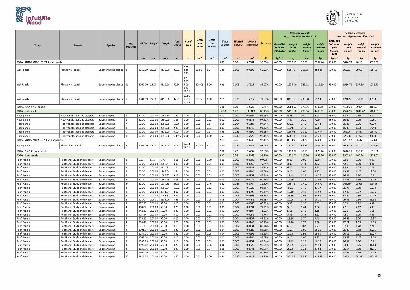
65
Group Element Species No. elements
Width Height Length Total length
Panel area
Total panel area
Total raw
volume
Total volume
Wasted volume
Volume recovered Recovery
Recovery weights Dmean C20. UNE EN 338:2016
Recovery weights Local den. Iñiguez-González, 2007
Dmean C20 UNE EN
338:2016
weight used
timber
weight wasted timber
weight recovered
timber
Local den Salzmann
pine Iñiguez,
2007
weight used
timber
weight wasted timber
weight recovered
timber
mm mm mm m m² m² m³ m³ m³ m³ % kg/m³ kg kg kg kg/m³ kg kg kg TOTAL STUDS AND SLEEPERS wall panels 5.82 0.08 5.7361 98.59% 400.00 2327.15 32.70 2294.46 589.00 3426.73 48.15 3378.59
WallPanels Planks wall panel Salzmann pine planks 8 2719.09 20.00 4115.00 32.92 9.26 8.38 6.39
66.56 1.97 1.46 0.505 0.9595 65.52% 400.00 585.76 201.95 383.81 589.00 862.53 297.37 565.16
WallPanels Planks wall panel Salzmann pine planks 16 2760.00 22.00 4115.00 65.84
8.77 9.53 5.09 8.23 11.36
154.09 4.00 3.39 0.608 2.7822 82.07% 400.00 1356.00 243.12 1112.89 589.00 1996.72 357.99 1638.73
WallPanels Planks wall panel Salzmann pine planks 8 3704.09 22.00 4115.00 32.92 10.95 13.31 10.32
95.77 2.68 2.11 0.576 1.5312 72.67% 400.00 842.76 230.30 612.46 589.00 1240.96 339.11 901.85
TOTAL PLANK wall panels 6.96 1.69 5.2729 75.75% 400.00 2784.53 675.36 2109.16 589.00 4100.21 994.47 3105.74
TOTAL wall panels 12.78 1.77 11.0090 86.15% 400.00 5111.68 708.06 4403.62 589.00 7526.95 1042.62 6484.33
Floor panels FloorPanel Studs and sleepers Salzmann pine 1 50.00 200.00 1269.50 1.27 0.00 0.00 0.01 0.01 0.001 0.0107 91.45% 400.00 4.68 0.40 4.28 589.00 6.89 0.59 6.30 Floor panels FloorPanel Studs and sleepers Salzmann pine 1 50.00 200.00 1850.00 1.85 0.00 0.00 0.02 0.02 0.001 0.0175 97.22% 400.00 7.20 0.20 7.00 589.00 10.60 0.29 10.31 Floor panels FloorPanel Studs and sleepers Salzmann pine 7 50.00 200.00 2365.00 16.56 0.00 0.00 0.17 0.16 0.004 0.1586 97.84% 400.00 64.82 1.40 63.42 589.00 95.45 2.06 93.39 Floor panels FloorPanel Studs and sleepers Salzmann pine 1 50.00 200.00 2795.50 2.80 0.00 0.00 0.03 0.03 0.002 0.0245 93.32% 400.00 10.48 0.70 9.78 589.00 15.43 1.03 14.40 Floor panels FloorPanel Studs and sleepers Salzmann pine 9 50.00 200.00 4115.00 37.04 0.00 0.00 0.37 0.35 0.025 0.3199 92.68% 400.00 138.04 10.10 127.94 589.00 203.26 14.87 188.39 Floor panels FloorPanel Studs and sleepers Salzmann pine 38 50.00 200.00 4215.00 160.17 0.00 0.00 1.60 1.57 0.030 1.5422 98.11% 400.00 628.78 11.90 616.88 589.00 925.88 17.52 908.36 TOTAL STUDS AND SLEEPERS floor panels 2.14 0.06 2.0733 97.11% 400.00 854.00 24.70 829.30 589.00 1257.52 36.37 1221.14
Floor panels Planks floor panel Salzmann pine planks 8 4165.00 22.00 4115.00 32.92 17.14 12.11 127.05 3.02 2.80 0.221 2.5737 92.08% 400.00 1118.02 88.56 1029.46 589.00 1646.29 130.41 1515.88
TOTAL PLANKS floor panels 2.80 0.22 2.5737 92.08% 400.00 1118.02 88.56 1029.46 589.00 1646.29 130.41 1515.88
TOTAL floor panels 4.93 0.28 4.6469 94.26% 400.00 1972.02 113.26 1858.76 589.00 2903.80 166.78 2737.03
Roof Panels RoofPanel Studs and sleepers Salzmann pine 1 6.61 6.56 6.78 0.01 0.00 0.00 0.00 0.00 0.000 0.0000 0.00% 400.00 0.00 0.00 0.00 589.00 0.00 0.00 0.00 Roof Panels RoofPanel Studs and sleepers Salzmann pine 2 50.00 200.00 475.54 0.95 0.00 0.00 0.01 0.01 0.002 0.0058 75.74% 400.00 3.06 0.74 2.32 589.00 4.51 1.09 3.41 Roof Panels RoofPanel Studs and sleepers Salzmann pine 2 50.00 200.00 871.79 1.74 0.00 0.00 0.02 0.02 0.002 0.0131 85.74% 400.00 6.10 0.87 5.23 589.00 8.99 1.28 7.71 Roof Panels RoofPanel Studs and sleepers Salzmann pine 2 50.00 200.00 1268.04 2.54 0.00 0.00 0.03 0.02 0.002 0.0204 89.08% 400.00 9.15 1.00 8.15 589.00 13.47 1.47 12.00 Roof Panels RoofPanel Studs and sleepers Salzmann pine 2 50.00 200.00 1588.85 3.18 0.00 0.00 0.03 0.03 0.003 0.0257 89.34% 400.00 11.49 1.22 10.26 589.00 16.91 1.80 15.11 Roof Panels RoofPanel Studs and sleepers Salzmann pine 2 50.00 200.00 1664.29 3.33 0.00 0.00 0.03 0.03 0.003 0.0277 90.76% 400.00 12.19 1.13 11.06 589.00 17.95 1.66 16.29 Roof Panels RoofPanel Studs and sleepers Salzmann pine 24 50.00 200.00 1914.58 45.95 0.00 0.00 0.46 0.42 0.043 0.3744 89.80% 400.00 166.78 17.02 149.77 589.00 245.59 25.06 220.53 Roof Panels RoofPanel Studs and sleepers Salzmann pine 4 50.00 200.00 3005.54 12.02 0.00 0.00 0.12 0.11 0.009 0.1029 92.25% 400.00 44.63 3.46 41.17 589.00 65.72 5.09 60.63 Roof Panels RoofPanel Studs and sleepers Salzmann pine 1 50.00 200.00 3071.54 3.07 0.00 0.00 0.03 0.03 0.000 0.0298 98.49% 400.00 12.10 0.18 11.92 589.00 17.82 0.27 17.55 Roof Panels RoofPanel Studs and sleepers Salzmann pine 2 50.00 200.00 3443.11 6.89 0.00 0.00 0.07 0.06 0.005 0.0591 92.34% 400.00 25.59 1.96 23.63 589.00 37.67 2.89 34.79 Roof Panels RoofPanel Studs and sleepers Salzmann pine 2 50.00 206.11 2631.06 5.26 0.00 0.00 0.05 0.05 0.004 0.0455 91.28% 400.00 19.95 1.74 18.21 589.00 29.38 2.56 26.82 Roof Panels RoofPanel Studs and sleepers Salzmann pine 4 327.27 200.00 50.00 0.20 0.00 0.00 0.01 0.01 0.003 0.0066 66.82% 400.00 3.93 1.30 2.63 589.00 5.79 1.92 3.87 Roof Panels RoofPanel Studs and sleepers Salzmann pine 4 408.87 200.00 50.00 0.20 0.00 0.00 0.02 0.01 0.004 0.0091 71.71% 400.00 5.10 1.44 3.66 589.00 7.51 2.12 5.38 Roof Panels RoofPanel Studs and sleepers Salzmann pine 4 442.21 200.00 50.00 0.20 0.00 0.00 0.02 0.01 0.004 0.0104 73.91% 400.00 5.61 1.46 4.15 589.00 8.26 2.16 6.11 Roof Panels RoofPanel Studs and sleepers Salzmann pine 2 475.54 200.00 50.00 0.10 0.00 0.00 0.01 0.01 0.002 0.0058 75.74% 400.00 3.06 0.74 2.32 589.00 4.51 1.09 3.41 Roof Panels RoofPanel Studs and sleepers Salzmann pine 4 805.12 200.00 50.00 0.20 0.00 0.00 0.03 0.03 0.004 0.0237 84.81% 400.00 11.18 1.70 9.49 589.00 16.47 2.50 13.97 Roof Panels RoofPanel Studs and sleepers Salzmann pine 4 838.46 200.00 50.00 0.20 0.00 0.00 0.03 0.03 0.004 0.0249 85.29% 400.00 11.70 1.72 9.98 589.00 17.22 2.53 14.69 Roof Panels RoofPanel Studs and sleepers Salzmann pine 2 871.79 200.00 50.00 0.10 0.00 0.00 0.02 0.02 0.002 0.0131 85.74% 400.00 6.10 0.87 5.23 589.00 8.99 1.28 7.71 Roof Panels RoofPanel Studs and sleepers Salzmann pine 4 1201.37 200.00 50.00 0.20 0.00 0.00 0.05 0.04 0.005 0.0383 88.68% 400.00 17.27 1.95 15.31 589.00 25.43 2.88 22.55 Roof Panels RoofPanel Studs and sleepers Salzmann pine 4 1234.71 200.00 50.00 0.20 0.00 0.00 0.05 0.04 0.005 0.0395 88.89% 400.00 17.78 1.98 15.80 589.00 26.18 2.91 23.27 Roof Panels RoofPanel Studs and sleepers Salzmann pine 2 1268.04 200.00 50.00 0.10 0.00 0.00 0.03 0.02 0.002 0.0204 89.08% 400.00 9.15 1.00 8.15 589.00 13.47 1.47 12.00 Roof Panels RoofPanel Studs and sleepers Salzmann pine 2 1588.85 200.00 50.00 0.10 0.00 0.00 0.03 0.03 0.003 0.0257 89.34% 400.00 11.49 1.22 10.26 589.00 16.91 1.80 15.11 Roof Panels RoofPanel Studs and sleepers Salzmann pine 4 1597.62 200.00 50.00 0.20 0.00 0.00 0.06 0.06 0.006 0.0529 90.54% 400.00 23.35 2.21 21.14 589.00 34.39 3.25 31.13 Roof Panels RoofPanel Studs and sleepers Salzmann pine 4 1630.96 200.00 50.00 0.20 0.00 0.00 0.07 0.06 0.006 0.0541 90.65% 400.00 23.86 2.23 21.63 589.00 35.14 3.29 31.85 Roof Panels RoofPanel Studs and sleepers Salzmann pine 2 1664.29 200.00 50.00 0.10 0.00 0.00 0.03 0.03 0.003 0.0277 90.76% 400.00 12.19 1.13 11.06 589.00 17.95 1.66 16.29 Roof Panels RoofPanel Studs and sleepers Salzmann pine 52 1914.58 200.00 50.00 2.60 0.00 0.00 1.00 0.90 0.092 0.8112 89.80% 400.00 361.36 36.87 324.49 589.00 532.11 54.29 477.82

66
Group Element Species No. elements
Width Height Length Total length
Panel area
Total panel area
Total raw
volume
Total volume
Wasted volume
Volume recovered Recovery
Recovery weights Dmean C20. UNE EN 338:2016
Recovery weights Local den. Iñiguez-González, 2007
Dmean C20 UNE EN
338:2016
weight used
timber
weight wasted timber
weight recovered
timber
Local den Salzmann
pine Iñiguez,
2007
weight used
timber
weight wasted timber
weight recovered
timber
mm mm mm m m² m² m³ m³ m³ m³ % kg/m³ kg kg kg kg/m³ kg kg kg Roof Panels RoofPanel Studs and sleepers Salzmann pine 4 2178.40 200.00 50.00 0.20 0.00 0.00 0.09 0.08 0.007 0.0734 91.43% 400.00 32.10 2.75 29.35 589.00 47.27 4.05 43.22 Roof Panels RoofPanel Studs and sleepers Salzmann pine 4 2441.11 200.00 50.00 0.20 0.00 0.00 0.10 0.09 0.008 0.0821 91.32% 400.00 35.94 3.12 32.82 589.00 52.92 4.59 48.33 Roof Panels RoofPanel Studs and sleepers Salzmann pine 10 2631.06 206.11 50.00 0.50 0.00 0.00 0.27 0.25 0.022 0.2277 91.28% 400.00 99.76 8.70 91.06 589.00 146.90 12.81 134.09 Roof Panels RoofPanel Studs and sleepers Salzmann pine 4 3005.54 200.00 50.00 0.20 0.00 0.00 0.12 0.11 0.009 0.1029 92.25% 400.00 44.63 3.46 41.17 589.00 65.72 5.09 60.63 Roof Panels RoofPanel Studs and sleepers Salzmann pine 2 3443.11 200.00 50.00 0.10 0.00 0.00 0.07 0.06 0.005 0.0591 92.34% 400.00 25.59 1.96 23.63 589.00 37.67 2.89 34.79 Roof Panels RoofPanel Studs and sleepers Salzmann pine 4 4295.36 200.00 50.00 0.20 0.00 0.00 0.17 0.16 0.009 0.1544 94.66% 400.00 65.24 3.49 61.75 589.00 96.06 5.13 90.93 TOTAL STUDS roof panels 2.84 0.28 2.5670 90.27% 400.00 1137.43 110.62 1026.81 589.00 1674.87 162.89 1511.98 Roof Panels Planks roof panels Salzmann pine planks 8 1814.58 22.00 2116.96 16.94 2.11 16.89 0.68 0.37 0.306 0.0649 17.51% 400.00 148.19 122.25 25.94 589.00 218.21 180.01 38.20 Roof Panels Planks roof panels Salzmann pine planks 8 1814.58 22.00 2940.98 23.53 5.34 42.69 0.94 0.94 0.000 0.9393 100.00% 400.00 375.70 0.00 375.70 589.00 553.22 0.00 553.22 Roof Panels Planks roof panels Salzmann pine planks 8 1814.58 22.00 3409.90 27.28 4.46 35.66 1.09 0.78 0.306 0.4778 60.99% 400.00 313.36 122.25 191.11 589.00 461.42 180.01 281.41 Roof Panels Planks roof panels Salzmann pine planks 8 1814.58 22.00 4233.92 33.87 5.95 47.62 1.35 1.05 0.306 0.7409 70.80% 400.00 418.62 122.25 296.38 589.00 616.42 180.01 436.41 TOTAL PLANKS roof panels 3.14 0.92 2.2228 70.80% 400.00 1255.87 366.74 889.13 589.00 1849.26 540.03 1309.24 TOTAL roof panels 5.98 1.19 4.7898 80.05% 400.00 2393.30 477.37 1915.93 589.00 3524.13 702.92 2821.21
TOTAL 32.67 3.76 28.91 88.48% 400.00 13069.34 1505.50 11563.84 589.00 19244.60 2216.85 17027.75


