Embed Size (px)
Citation preview

Designing for Shared Cognitionin Air Traffic Management
M. M. (Rene) VAN PAASSEN a,1, Clark BORST a, Rolf KLOMP a, Max MULDER a,Pim VAN LEEUWEN b, and Martijn MOOIJ c
aFaculty of Aerospace Engineering, Delft University of Technology (TU Delft), 2629 HSDelft, The Netherlands
bNational Aerospace Laboratory NLR, Amsterdam, The NetherlandscThales Research and Technology Netherlands, Human Factors and Cognition Team,
Delft, The Netherlands
Abstract. It is to be expected that the task of an air traffic controller will changewith the introduction of four-dimensional (space and time) trajectories for aircraft,as can be seen in ongoing developments in ATM systems in Europe (SESAR) andthe US (NextGen). It is clear that higher levels of automation will need to be de-veloped to support the management of four-dimensional trajectories, but a definiteconcept on a distribution of the roles of automation and human users has not yetbeen well defined. This paper presents one approach to the design of a shared rep-resentation for 4D trajectory management. The design is based on the CognitiveSystems Engineering framework and by using a formative approach in the analysisof the work domain, a step-wise refinement in the planning and execution of 4Dtrajectories is proposed. The design is described in three Abstraction Hierarchies,one for each phase in the refinement. The ultimate goal is to design a shared rep-resentation that underlies both the design of the human-machine interface and therationale that guides the automation. It is foreseen that such a shared representationwill greatly benefit the shared cognition in ATM and allows shifting back and forthacross various levels of automation. A preliminary version of a joint cognitive sys-tem for 4D trajectory management has been developed and will be introduced inthis paper. Further work will focus on the refinement of the shared representationby means of human-in-the-loop experiments.
Keywords. Ergonomics, interfaces, automation, Air Traffic Management
Introduction
Currently, air traffic controllers (ATCo’s) perform a sector-based, tactical form of control.They are responsible for planning and managing traffic within their assigned airspace,often with little help from automated tools [1]. In the coming decades, the task of anair traffic controller is predicted to undergo a large transformation. The pull for transfor-mation comes from the increasing demands which are placed on the air traffic manage-ment (ATM)-system [2,3,4]. A push is provided by technological advances on the air-
1Corresponding Author: M.M. van Paassen, Associate Professor, Faculty of Aerospace Engineering, DelftUniversity of Technology (TU Delft), 2629 HS Delft, The Netherlands; E-mail: [email protected].

and ground side of the ATM-system, which make a new form of air traffic control (ATC)possible [5,6]. This is expected to result in a situation where aircraft four-dimensional(4D, i.e., space and time) trajectories stored in automated support tools form the basisfor the ATCo’s work [7,8,9,10].
The explicit use of a 4D definition of the aircraft trajectory (4DT) as a shared rep-resentation between air and ground segments is a fundamental difference between cur-rent practice and future air traffic management. In SESAR, this 4DT has been defined asa Reference Business Trajectory (RBT). Supported by a communications network, theSystem Wide Information Management (SWIM), the information on the 4DT is to beshared such that all parties involved have access to relevant and the most up-to-date flightinformation.
Given that the stakes are high, and that the ATM work domain inevitably has toomany unforeseen situations to create a fully automated solution (i.e., the work domaincan be characterized as “open”, [11]), human users will have to remain involved in thesystem. The future air traffic controller will not, as he or she is doing currently, providehands-on instructions to the aircraft, in essence creating the aircraft’s 4D trajectory in realtime. Rather, controllers will work on (refining) a definition of the aircraft 4D trajectory,using automated tools to visualize and represent this trajectory. Future or modernizedaircraft will have the capability to receive this 4D trajectory update on the flight deck,and implement their flight according to this trajectory with a high degree of precision.
Although considerable research has been devoted to exploring this future approachto air traffic control with 4D trajectory support [12,13,14,15,16], a definite concept ona distribution of the roles of automation and human users has not yet been defined. It isclear that higher levels of automation will need to be developed, but the ‘central role’of the human operator is not well defined yet. Many other complex socio-technical do-mains have shown that the introduction of higher levels of automation often introducenew problems, problems that are often harder to resolve than those intended to be solvedin the first place [17]. Increasing the level of automation is not good or bad in itself,but with more automation greater coordination between people and technology will berequired[18]. Breakdowns in coordination may result in humans having difficulty get-ting the automation to do what they want and, conversely, a poor understanding of theway automation works[19]. To mitigate breakdowns in coordination between human andautomated agents, it is imperative to create new tools for coordination so as to makeautomated systems ‘team players’.
This paper explores one possible design approach for facilitating a successfulhuman-automation collaboration in a future 4DT-based ATM system. In the SESARWP-E project ‘C-SHARE’ a Cognitive Systems Engineering (CSE) approach is adopted[11,20,21]. CSE starts from an analysis of the work domain, identifying goals and func-tions in this work domain, and in a design, it is possible to start top-down, initially inde-pendent of the chosen solutions for the system. The ultimate goal of the project is to finda “common ground” or shared representation for manipulating 4DTs that can be used todevelop the automated tools as well as the human-machine interfaces. It is foreseen that ashared representation of automation and humans will greatly benefit the shared cognitionin ATM.
The paper outlines a step-wise approach to the definition and refinement of 4DTs,discusses some of the implications of 4DTs on automation and display design and intro-duces a preliminary version of a ‘joint cognitive system’ for ATM.

1. The structure and function of airspace
The re-engineering of the air traffic management system is a design process, which willbe approached here following the paradigm of Cognitive Systems Engineering (CSE).That means that the first step in CSE, the Work Domain Analysis (WDA), will be startedin a top-down fashion. Part of the WDA will reflect the constraints innate in the workdomain itself, for example the fact that aircraft need to have sufficient clearance fromterrain and other aircraft (separation). However, other functions in the WDA are influ-enced by the design choices, both for the current system and for the envisaged new ATMsystems.
1.1. Work domain analysis
The work domain analysis will be done by constructing an Abstraction Hierarchy (AH)[19]. In constructing an AH for a new domain, the main challenge is to select the properchoice for the abstract functions in this domain. In process technology and energy gen-eration systems, where CSE originated, the abstract functions that describe the energyand mass balances in a system form an appropriate choice [11]. In the description of asingle vehicle, the WDA at this level focuses on locomotion and on (potential and ki-netic) energy balances [22]. For the case of ATM, the principal functions at this level areproposed to be identified as locomotion, localization, communication, separation, and aprinciple we refer to as “travel space”.
Locomotion is a function of the moving elements in the ATM, realized by flight foraircraft, and drifting for weather. Localization is the function that determines the positionof these moving elements, either on-board, by the navigation system, or on the ground,by the ATM surveillance systems. Communication supports localization and decisionmaking in the system by sharing intentions, plans, and localization results. Separation isthe principal means for safety in the ATM system: at all times a proper clearance to otheraircraft, terrain and hazardous weather must be maintained.
The identification of travel space as a separate functionality in this analysis warrantsadditional explanation. We define travel space as the function offered by the air andinfrastructure to the moving elements in the ATM system – the aircraft – to implementtheir locomotion. Other elements in the system, such as weather, terrain and includingother aircraft, affect the possibility to use the available airspace in certain ways [23,24].That is, for a given aircraft fixed (terrain) and moving (other aircraft, weather) obstacleslimit the maneuvering possibilities for that aircraft both in space and time. Travel spaceis by definition four-dimensional, and the way its constraints can be managed stands atthe heart of (current and future) ATM.
1.2. Travel space function constraints
Identifying the possibilities for travel as a function in our analysis enables us to use arepresentation of the effect of the total of 4D trajectories in our design of new ATM sys-tems. Many constraints in this function are unavoidable; removing them would requireremoving terrain or other traffic. However, the solutions chosen for our ATM system,such as the communication and navigation systems, the legal infrastructure and the wayin which we plan and coordinate trajectories, affect the shape and characteristics of thetravel space function.

Communication limitations. Current ATM mainly uses voice communication. Toenable efficient use of this communication channel which is limited in bandwidth – onthe other hand, it is extremely flexible – the actors taking part in this communicationneed to have agreed on extensive background information. This makes it possible to onlyuse pre-defined and published way points and discrete altitude levels for defining tracks.The use of digital data-link communications means that the use of airspace can becomemore flexible.
Navigation systems. Traditionally, limitations of navigation systems provided con-straints on where flight was possible. In the early days of commercial aviation, railroadsand other landmarks formed the basis for the air structure. Later, radio navigation aids,such as the four-course radio range, VOR and NDB beacons largely determined the useof airspace. The navigation aids thus determined which parts of the airspace are usableas travel space, and how these can be used. Much of this restriction has been removed asaircraft are increasingly able to perform Area Navigation (RNAV), meaning that flightcan be performed independently from the location of (ground) navigation beacons.
Legal infrastructure. A further constraint on the locomotion is provided by the ad-ministrative organization of airspace. The (current) division in airspace sectors imposesrestrictions on the paths of aircraft, basically because the handling and the transition ofan aircraft from one sector to another requires a buffer zone between the sectors, andeffort from the controllers and pilots. Aircraft trajectories are effectively constrained totransitions between sectors with more or less perpendicular angle to the sector bound-aries. Short paths through sectors, such as the perpendicular traversal of narrow sectors,or passing through a corner of a sector, are difficult to manage and therefore uncommon.
Planning and coordination. Currently, the control of the traffic within an airspacesector is normally the job of a single ATCo, or of a small team of two to five. Support bytools is fairly limited, and the extent to which a 4D trajectory is known ahead of time isvery limited. This forces an ATCo to impose additional structure on the use of airspace.
The technological advances in navigation systems and communications foreseen inSESAR and NextGen can remove part of the constraints on the travel space function,opening the way for more economical, and shorter – direct – routes.
2. Operational concept
2.1. Overview
This paper sketches an operational concept for the future ATM system that largely usesthe functionality foreseen in the ATM master plan [2]. In particular, the functionalitiesprovided by 4D trajectory management and information-exchange with a SWIM systemare combined in a concept that assumes a central role for the human actors in the system.
A step-wise refinement of the 4D aircraft trajectories is proposed. Given the centralrole reserved for the human actors in this process, to enable them to contribute in defin-ing 4D trajectories, proper support for visualizing, evaluating and modifying these tra-jectories is required. Also, the amount of work involved in defining 4DTs for all aircraftusing the ATM system is expected to be very large, so human users have to be supportedby automated systems in this task.
Task division between humans and automation is often approached as an ‘allocationproblem’; either the human actor or the automation is selected for a task. Prime examples

for this can be found within the aircraft themselves; the task of stabilizing the aircraft isnormally allocated to the autopilot, and the navigation along a trajectory is performed bya combination of autopilot and Flight Management System.
The first guiding principles in task allocation have been laid out in what is nowknown as Fitts’ list [25]. In this concept, part of the tasks in the foreseen ATM conceptare indeed assigned with these principles, such as the tactical monitoring for deviationbetween actual flights and the agreed 4D trajectories. However, other tasks are foreseen tobe performed jointly by automation and humans, and some tasks can be done in parallelby automation and humans.
In most complex systems, however, many tasks are too ill-defined to be handled byautomation. Such ‘fuzzy’ tasks are typically assigned to human operators. To supportoperators in those cases, a proper visualization of the problem space can help. Examplesof such visualizations are the Ecological InterfaceDesign for the example process systemDURESS [26], or, more recently, visualizations for airborne traffic avoidance [27,28],and 4D trajectory manipulations on the flight deck [29,30] can be seen as automationsupport, where algorithms are used to visualize the work domain constraints in such away that operators can implement appropriate control strategies. This leads to a task thatcan be performed jointly by automation and humans. The resulting cognition can be seenas a joint effort of the automation, and in particular the visualization of the problem, andthe human user [31].
Within the SESAR overall operational concept, several stages in the refinement of4D trajectories are foreseen. The design presented in this paper focuses on three stages:(i) Short-term planning, performed 24 to 12 hours in advance of the flight; (ii) Pre-tacticalplanning, conducted several hours to 30 minutes in advance of the flight, and (iii) aTactical monitoring phase (30 minutes to now). In contrast, the full SESAR design startswith seasonal planning. A summary of the foreseen phases is given in Figure 1. Theinteraction foreseen in these three phases between users, their display and support toolsand automated agents is discussed in the following subsections.
2.2. Short-term planning
Short-term planning – termed short-term here to correspond with SESAR terminology –takes place approximately 24 to 12 hours in advance. This phase starts with an inventoryof intended flights, initially designed as the shortest and most economical route to thedestination. A visualization will be used to show the use of airspace, including “hot
(a) short-term planning (b) pre-tactical planning (c) tactical monitoring
Figure 1. Summary of the stages in refinement and implementation of 4DTs. Only for the tactical controlthe actual aircraft flight data is used (radar symbol). For the pre-tactical and tactical control, assistance fromautomated agents is foreseen.

spots”, with high concentration of traffic. The human planners use this representation tocreate a global structuring of the airspace (e.g., restricting the number of flights in certainareas, reserving altitudes for certain headings, making sure that there is ‘spare’ airspaceto handle unforeseen disturbances or to re-structure the flows to be able to handle achange in runway at an airport, etc.). The function of the automation in this stage ismainly to provide visualization and identification of hot-spots.
The result of this stage is a planned airspace ‘structure’, i.e., the travel space willbe partly pre-allocated. NextGen flow corridors [4] might be an example of this. The4D trajectories are then modified by automated algorithms to conform to this structureresulting in an indirect de-confliction (e.g., to adhere to capacity limits defined for theairspace), but overlapping conflicts that may exist between the 4D trajectories are notidentified or resolved, since the actual 4D trajectories are not yet sufficiently defined toperform this step.
Part of the work domain analysis is given in the Abstraction Hierarchy in Figure 2.The work domain analysis describes the functionality and constraints of the work do-main, in this case of Air Traffic Management. An Abstraction Hierarchy describes oneand the same system or work domain at different levels of abstraction [19]. The top levelis the functional purpose level, containing the goals identified for the system. The ab-stract function level describes the basic principles and processes in the work domain thatenable the realization of these goals. In this case, the basic mechanisms at work are ob-struction (e.g. by weather) and allocation of space. The generalized function level furtherspecified this in terms of “systems solutions”. Normally, an AH has two further – moredetailed – levels, that are not yet specified for this study [32].
The product that comes out of the short-term planning step is a “structure” for thetravel space; choices are made to reduce traffic at places where large volumes of trafficare expected, and additional capacity is reserved where needed, for example as a contin-gency for weather phenomena. This planned structure should achieve the goals identifiedat the top level in the AH.
Figure 2. Short-term planning stage, top three levels of Abstraction Hierarchy.

2.3. Pre-tactical planning
This takes place from several hours up to approximately half an hour in advance of cur-rent time. Using adjustments to the 4D path, and taking into account aircraft performanceand weather, the 4DTs are further defined to be “in principle” conflict free. The adjust-ments to 4DTs can be performed by human operators and automated agents in parallel.A proper visualization of the travel space functions are used as a template for the cog-nitive process; human operators can use this visualization to directly perceive the effectsof path and speed manipulation. It also serves as a shared memory, offering a workspaceto automation and human agents alike. The result of this stage is that the 4DTs are de-conflicted and in accordance with the airspace structure defined in the previous step.
Part of the work domain analysis for this stage is given in Figure 3. The airspacestructure generated in the previous stage is now a generalized function. It defines a roughplan for the generation and modification of trajectories for individual flights, and it actsas an additional constraint in this analysis, imposing limits on flights but providing anoverall means to simplify the planning process, analogous to the way the current airwaystructure is used to shape air traffic. Observing the needed separation, possible obstruc-tion by terrain, weather, etc. and the geometric constraints of each flight’s path, this stageresults in refined definitions for the 4DTs.
2.4. Tactical monitoring
At this stage the planned 4DTs of the different flights are conflict free. However, inthe execution of flights, small deviations from these planned trajectories are expected tobe unavoidable. Automated agents monitor the execution of the trajectories and providelimited solutions (e.g., speed and minor path adjustments) to keep the flights conflict-
Figure 3. Pre-tactical planning stage, top three levels of Abstraction Hierarchy.

free. The visualization now serves to inform the human users of the progress of the flightsand of the actions of the automated monitoring agents. The situation awareness thus builtup permits the human user to perform the higher – system – level monitoring, and tointervene when unforeseen circumstances make this necessary.
Part of the work domain analysis for this stage is given in Figure 4. At this stage,the physical function level will be formed by the functionality related to the aircraft andphysical devices in the ATM system. While the previous stages mainly involved planningflights (first globally, resulting in the travel space structure, then in more detail), the resultfrom this stage are the actual flights. Real-time communication therefore becomes animportant function at this stage.
2.5. Joint cognitive representation
The three stages differ in their nature of the joint cognition by human users and oper-ation. In the short-term planning, the contribution by the automation is mainly the vi-sualization. The human users are primarily responsible for the planning result. In thepre-tactical planning, the automation and human users contribute on a more or less equalbasis. The visualization serves here as the representation of the commonly used (space)resources. The tactical monitoring situation most closely resembles current high levelsof automation, with a large contribution of automated agents, utilizing a probabilisticroad-map method, to the final solution.
The work domain analysis, which in current approaches to Ecological Interface De-sign (EID) serves as an input to the display design process only, will in this project C-SHARE be used for both the design of the automation and the displays. That is, the con-straints on the 4D trajectories as identified in the WDA are transformed into a represen-tation that underlies both the design of the human-machine interface as well as ground-and air-automated tools.
Figure 4. Final tactical monitoring stage, top three levels of the Abstraction Hierarchy.

By virtue of being based on a ‘shared’ representation, the results of the work doneby automated tools will be compatible with the human’s representation of the work do-main, and can be visualized in a human-centric fashion. With automation and humansworking on a shared cognitive representation, this also allows shifting back and forthacross various levels of automation, from fully manual control to fully automated control,and in principle also supports the transition between SESAR’s unmanaged and managedairspace.
3. Implications for display design
In CSE, the analysis of the work domain is a primary input for the actual design of thedisplay. However, the design of a display presentation is still a creative step, the WDAdoes not result in a “recipe” for how the display is to be created, it only provides guidancein determining what functions should somehow be made visible in the display [30]. Thefollowing first inventory of the important elements, and the way theymight be visualized,is given here:
Short term For the short-term planning of the travel space structure, obstruc-tion and space allocation are considered primary functions at the abstract functionlevel (Figure 2). The product of this stage should be the travel space structure forthe next day, indicating how airspace will be allocated for flights, and where dis-ruptions are expected and thus buffers are reserved. The input to this work is the setof flight plans as filed by airline companies. Important aspects of the visualizationwill be the obstruction, by weather cells, terrain, or temporary restricted airspace.A global visualization of the traffic flow (not per 4D trajectory, but as a whole),and a visualization of the means to modify this flow by structuring the travel spaceis needed.
Pre-tactical Pre-tactical planning should result in initial conflict-free 4DTs.The visualization should show the travel space structure created in the previousstep. Since the planning is done in parallel by automated agents and human users,communication between the agents and humans on the ongoing work, and allo-cation of (space) resources is important (Figure 3). The result is mainly the pathgeometry of the 4DTs. At this stage, the constraints by the aircraft performancecapabilities, and the separation should be visible. An important feature of the dis-play is the visualization of the relation between the possible modifications to the4DTs and the effect on separation and performance.
Tactical In the tactical planning, much of the actual work should be per-formed by automated agents. Flights that are operating on or near the 4DT de-fined in the previous stage can be monitored automatically. The visualization forthe human user should enable checking of conformance to the 4DT at a glance. Atthis stage the detection of anomalies is important. Since the actual implementationdepends on real-time communication, an indication of communication health forall flights should be given (Figure 4). Handling flights with problems, that need tobe diverted from their route, needs a visualization of separation from other flightsand of buffer zones that can be used to safely divert the flight.

4. Travel space representation
As a starting point, an initial prototype for a shared representation has been designedfor the task of re-planning an RBT during the tactical monitoring phase (Figure 5). Re-planning is necessary in case one or more inherent (other traffic, weather, ...) or inten-tional (restricted airspace, procedures, ...) constraints, active on the aircraft RBT, cannotbe met due to any number unforeseen events.
The prototype is based on the principles of CSE and EID [11], and built upon on theresults of a more elaboratedWDA for the tactical monitoring phase (Figure 4). It aims atvisualizing the underlying relationships and constraints of the work domain, linking low-level functions (primarily the 4DT descriptions) and information to the more abstracthigher levels of the AH (primarily separation and timeliness). The constraints inherent tothe task of RBT re-planning are identified from the AH of the tactical phase; separation,obstruction, communication and travel. Any resulting RBT which abides to this set ofconstraints forms part of a so called ‘safe field of travel’.
For the initial travel space representation in Figure 5, the task of re-planning thehorizontal route of an RBT is considered. More specific, an attempt is made to visualizethe safe field of travel when introducing a new 4D-waypoint in a certain segment of theRBT. A similar representation has been designed for re-planning a 4D trajectory on theflight deck [29,30], however, here also the separation from other dynamic obstacles (theother airspace users) had to be taken into account.
In Figure 6(a) the basic composition of the travel space representation is shown. Air-craft AC1 is flying along a pre-agreed RBT towards a certain metering fix (point FIX) at
Figure 5. Prototype of the travel space representation.
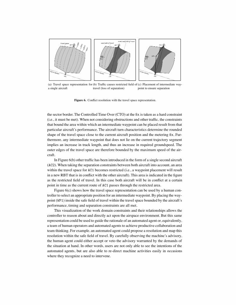
(a) Travel space representation fora single aircraft
(b) Traffic causes restricted field oftravel (loss of separation)
(c) Placement of intermediate way-point to ensure separation
Figure 6. Conflict resolution with the travel space representation.
the sector border. The Controlled Time Over (CTO) at the fix is taken as a hard constraint(i.e., it must be met). When not considering obstructions and other traffic, the constraintsthat bound the area within which an intermediate waypoint can be placed result from thatparticular aircraft’s performance. The aircraft turn characteristics determine the roundedshape of the travel space close to the current aircraft position and the metering fix. Fur-thermore, any intermediate waypoint that does not lie on the current trajectory segmentimplies an increase in track length, and thus an increase in required groundspeed. Theouter edges of the travel space are therefore bounded by the maximum speed of the air-craft.
In Figure 6(b) other traffic has been introduced in the form of a single second aircraft(AC2). When taking the separation constraints between both aircraft into account, an areawithin the travel space for AC1 becomes restricted (i.e., a waypoint placement will resultin a new RBT that is in conflict with the other aircraft). This area is indicated in the figureas the restricted field of travel. In this case both aircraft will be in conflict at a certainpoint in time as the current route of AC1 passes through the restricted area.
Figure 6(c) shows how the travel space representation can be used by a human con-troller to select an appropriate position for an intermediate waypoint. By placing the way-point (WP1) inside the safe field of travel within the travel space bounded by the aircraft’sperformance, timing and separation constraints are all met.
This visualization of the work domain constraints and their relationships allows thecontroller to reason about and directly act upon the airspace environment. But this samerepresentation could be used to guide the rationale of an automated agent or, equivalently,a team of human operators and automated agents to achieve productive collaboration andteam thinking. For example, an automated agent could propose a resolution and map thisresolution within the safe field of travel. By carefully observing the machine’s advisory,the human agent could either accept or veto the advisory warranted by the demands ofthe situation at hand. In other words, users are not only able to see the intentions of theautomated agents, but are also able to re-direct machine activities easily in occasionswhere they recognize a need to intervene.

5. Discussion
The largest change for an ATCo will be to step away from hands-on modification ofaircraft trajectories to implement the desired traffic flow in real time, to an operation inwhich traffic is planned in detail beforehand. For individual flights, it has proven possibleto implement, monitor and manipulate 4D trajectories, usually in the context of all otheraircraft being controlled traditionally. The case when all aircraft are to be controlledbased on their 4DT means a tremendous step, and a real-time visualization of how alltrajectories will evolve in time is a tremendous challenge for display designers. Whereasdimensionality of the control problem explodes, the visualization and display techniquesremain limited by, among others, clutter issues, and physical constraints like screen sizeand resolution.
The main outcome of the project will be a representation for the tactical and strate-gic manipulation of 4D trajectories. This framework for ‘joint cognition’ can act as abasis for designing both the automation support and human-machine interfaces, in theair and on the ground, from one and the same perspective. It is very likely that during thedevelopment and testing of prototypes, the Work Domain Analysis will need to be aug-mented and/or partly changed. Several human-in-the-loop experiments are foreseen thatwill show to be crucial in converging the design and analysis iterations to a representationof 4DT management that can indeed be used for both automation and human-machineinterface design.
6. Conclusions and future work
This paper outlines a possible approach for the creation of the new work domain in AirTraffic Management. The envisaged future situation in SESAR and NextGen, in whichaircraft will be able to fly four-dimensional (space and time) trajectories, requires plan-ning, monitoring, and if necessary modification of these trajectories. The approach pro-posed in this paper is based on Cognitive Systems Engineering, and assumes three suc-cessive steps in the refining and final implementation of the four-dimensional trajectories.Automation support comes in the form of visualization of the constraints in the planningphase, and collaborating agents in the execution phase. An initial Work Domain Analysishas been done for these three phases, and critical functions for each of the phases havebeen identified. A preliminary prototype for one of these phases, the Tactical monitoringphase, has been presented and discussed. Further work will focus on the refinement ofthe WDA, the creation of actual interfaces and the evaluation of the design.
Acknowledgment
The authors acknowledge the inspiration from EUROCONTROL and the SESAR JointUndertaking. The work was co-financed by EUROCONTROL on behalf of the SESARJoint Undertaking in the context of SESAR Work Package E (project C-SHARE: JointATM Cognition through Shared Representations). This work reflects only the authors’views and EUROCONTROL is not liable for any use that may bemade of the informationcontained herein.

References
[1] E. A. P. B. Oprins and M. Schuver, “Competentiegericht opleiden en beoordelen bij LVNL in Dutch:Competence based training and assessment at LVNL,” HUFAG nieuwsbrief, no. 6, pp. 2–4, 2003.
[2] O. Dlugi, T. Astheimer, C. Baldoni, J. M. Bara, R. Brown, R. Cato, G. O’Connell, M. Standar, J. Stenson,and G. Tauss, “The ATM target concept,” www.eurocontrol.int/sesar/gallery/content/public/docs/DLM-0612-001-02-00.pdf, SESAR Consortium, Toulouse, France, Deliverable 3 DLM-0612-001-02-00,2007.
[3] O. Dlugi, T. Astheimer, C. Baldoni, R. Brown, R. Cato, M. Erb, D. Hilton,G. O’Connell, A. Sohn, and J. Stenson, “The ATM deployment sequence,”www.eurocontrol.int/sesar/gallery/content/public/docs/DLM-0706-001-02-00.pdf, SESAR Consor-tium, Toulouse, France, Deliverable 4 DLM-0706-001-02-00, 2008.
[4] Anon., “Concept of operations for the next generation air transportation system. version 2.0.”www.jpdo.gov/library/NextGen v2.0.pdf, Joint Planning and Development Office, Report, 2007.
[5] R. A. Slattery, “Examination of Possible Future Terminal Area Procedures,” AIAA Guidance, Naviga-tion, and Control Conference, San Diego, California, July 29-31 1996.
[6] M. G. Ballin, J. M. Hoekstra, D. J. Wing, and G. W. Lohr, “NASA Langley and NLR research of dis-tributed air/ground traffic management,” AIAA’s Aircraft Technology, Integration and Operations 2002Technical, Los Angeles, California, USA, October 1-3 2002.
[7] M. J. Whiteley and I. Wilson, “Phare advanced tools problem solver,”www.eurocontrol.int/phare/gallery/content/public/documents/98-70-18-v8 ps.pdf, Eurocontrol, Brus-sels, Belgium, Final Report PHARE/EEC/PAT-6.5/FR; 1.0, DOC 98-70-18, August 1999.
[8] P. G. A. M. Jorna, D. Pavet, M. Van Blanken, and I. Pichancourt, “PHARE ground human ma-chine interface (GHMI) project,” www.eurocontrol.int/phare/gallery/content/public/documents/99-70-02ghmi.pdf, Eurocontrol, Brussels, Belgium, Summary Report PHARE/NLR/GHMI-7/FR/1.0, DOC99-70-02, August 1999.
[9] W. W. M. Heesbeen, J. M. Hoekstra, and M. S. V. Valenti Clari, “Traffic manager, traffic simulationfor validation of future ATM concepts,” AIAA Modeling and Simulation Technologies Conference andExhibit, Austin, Texas, USA, August 11-14 2003.
[10] T. Prevot, P. U. Lee, N. Smith, and E. A. Palmer, “ATC technologies for controller-managed and au-tonomous flight operations,” in AIAA Guidance, Navigation and Control Conference, San Francisco,California, USA, San Francisco, (CA), August 15-18 2005.
[11] K. J. Vicente and J. Rasmussen, “Ecological Interface Design: Theoretical Foundations,” IEEE Trans-actions on Systems, Man, and Cybernetics, vol. 22, no. 4, pp. 589–606, 1992.
[12] D. Lindgren and A. Torne, “4d trajectory management decision support,” FOI, Swedish Defense Agency,Linkoping, Tech. Rep. FOI-R–2405–SE, January 2008.
[13] R. Weber and C. Eva, “Subliminal atc utilizing 4d trajectory negotiation,” in 7th ICNS Conference.Herndon (VA): IEEE, 2007, pp. 1–9.
[14] M. Jackson, “Role of avionics in trajectory-based operations,” Aerospace and Electronic Systems Mag-azine, IEEE, vol. 25, no. 7, pp. 12 –19, 2010.
[15] S. Landry, “Human centered design in the air traffic control system,” Journal of IntelligentManufacturing, vol. 22, pp. 65–72, 2011, 10.1007/s10845-009-0278-6. [Online]. Available:http://dx.doi.org/10.1007/s10845-009-0278-6
[16] D. McNally and C. Gong, “Concept and laboratory analysis of trajectory-based automation for separa-tion assurance,” in AIAA-MST-2006, AIAA. Keystone, CO: AIAA, August 2006, pp. 1–17.
[17] A. M. Bisantz, “Ironies of automation,” Automatica, vol. 19, pp. 775 –779, 1983.[18] K. Christoffersen and D. D. Woods, “How to make automated systems team players,” in Advances in
Human Performance and Cognitive Engineering Research, 2nd ed., E. Salas, Ed. Elsevier Science Ltd,2002, vol. 2, ch. 1, pp. 1–12.
[19] J. Rasmussen, Information processing and human-machine interaction: an approach to cognitive engi-neering. New York: North-Holland, 1986.
[20] ——, “Ecological interface design for reliable human-machine systems,” International Journal of Avia-tion Psychology, vol. 9, no. 3, pp. 203–223, 1999.
[21] C. Borst, M. Mulder, M. M. Van Paassen, and J. A. Mulder, “Design and Simulator Evaluation of anEcological Synthetic Vision Display,” Journal of Guidance, Control & Dynamics, vol. 33, no. 5, pp.1577–1591, 2010.

[22] F. M. Heylen, S. B. J. Van Dam, M. Mulder, and M. M. Van Paassen, “Design of a Vertical SeparationAssistance Display,” Proceedings of the AIAA Guidance, Navigation and Control Conference, Honolulu(HI), USA, August 18-21, no. AIAA 2008-6969, 2008.
[23] M. M. Van Paassen, “Functions of space and travellers,” Proceedings of the XVIII European AnnualConference on Human Decision Making and Manual Control, Loughborough (UK), pp. 268–274, 1999.
[24] J. J. Gibson and L. E. Crooks, “A Theoretical Field Analysis of Automobile Driving,” The AmericanJournal of Psychology, vol. 51, no. 3, pp. 453–471, 1938.
[25] P. M. Fitts, “Human engineering for an effective air-navigation and traffic-control system,” Ohio StateUniversity Research Foundation, Technical Report, 1951.
[26] K. J. Vicente and J. Rasmussen, “The Ecology of Human-Machine Systems II: Mediating “Direct-Perception” in Complex Work Domains,” Ecological Psychology, vol. 2, no. 3, pp. 207–249, 1990.
[27] S. B. J. Van Dam, M. Mulder, and M. M. Van Paassen, “Ecological Interface Design of a TacticalAirborne Separation Assistance Tool,” IEEE Transactions on Systems, Man & Cybernetics, Part A,vol. 38, no. 6, pp. 1221–1233, 2008.
[28] J. Ellerbroek, S. B. J. Visser, M. van Dam, M. Mulder, and M. M. Van Paassen, “Design of an AirborneThree-Dimensional Separation Assistance Display,” IEEE Transactions on Systems, Man &Cybernetics,Part A, vol. 41, no. 5, pp. 863–875, 2011.
[29] M. Mulder, R. Winterberg, M. M. Van Paassen, and M. Mulder, “Direct Manipulation Interfaces forIn-Flight Four-Dimensional Navigation,” International Journal of Aviation Psychology, vol. 20, no. 3,pp. 249–268, 2010.
[30] B. J. A. Van Marwijk, C. Borst, M. Mulder, M. Mulder, and M. M. Van Paassen, “Supporting 4D Tra-jectory Revisions on the Flight Deck: Design of a Human-Machine Interface,” International Journal onAviation Psychology, vol. 21, no. 1, pp. 35–61, 2011.
[31] M. M. Van Paassen, M. Mulder, and S. B. J. Van Dam, “Cognitive Work Analysis for Vehicle Locomo-tion – Aircraft Short-Term Trajectory Planning,” Proceedings of the Nineth IFAC/IFIP/IFORS/IEA Sym-posium on Analysis, Design and Evaluation of Man-Machine Systems, Atlanta (GA), USA, September7-9, 2004.
[32] A. M. Bisantz and K. J. Vicente, “Making the abstraction hierarchy concrete,” Int. J. Human-ComputerStudies, vol. 40, pp. 83 –117, 1994.