Embed Size (px)
Citation preview
286
Copyright © 2010, IGI Global, distributing in print or electronic forms without written permission of IGI Global is prohibited.
Chapter 16Developing and Customizing
Federated ERP SystemsDaniel Lübke
Leibniz Universität Hannover, Germany
Jorge Marx GómezUniversity Oldenburg, Germany
AbstrAct
Small and Medium Enterprises (SMEs) are the most important drivers in many economies. Due to their flexibility and willingness to innovate they can stand up to larger industry players. However, SMEs – as every other company – need to further reduce costs and optimize their business in order to stay competi-tive. Larger enterprises utilize ERP systems and other IT support for reducing costs and time in their business processes. SMEs lack behind because the introduction and maintenance of ERP systems are too expensive, the return on investment is achieved too late and the associated financial risks are too high. However, SMEs would like to have IT support for their business. The research behind the Feder-ated ERP System (FERP) addresses the problems SMEs face with conventional ERP systems and offers reasonable and scalable IT support. This is done by decomposing the whole business logic of the ERP system into Web services, which are linked at run-time. The service composition is realized by a work-flow system that is also responsible for creating and managing the user interfaces and the data-flow. By integrating only the Web services that are needed (possibly from third parties) the cost is reduced and the functionality can be scaled to the actual needs. However, not only a technical solution is needed but also the development process must be tailored towards SMEs. Small companies cannot afford highly-skilled staff and often do not have defined business processes.
287
Developing and Customizing Federated ERP Systems
introduction
The business world is rapidly moving and Small-to-Medium Size Enterprises (SMEs) are competing within this vibrant marketplace with their flexibility and ability to innovate. They are an important part of the economy. For example, according to the IfM Bonn (2008) SMEs in Ger-many account for 38.3% of the overall turnover and employ 70.6% of all employees nationwide. In order to operate efficiently, SMEs need enterprise software, like ERP systems, for managing their business operations efficiently. However, ERP systems impose high costs due to their expensive purchase, customizing costs and re-customizing costs whenever business processes are changed. Thus, business process changes that are neces-sary to stay competitive become more costly as before.
This inevitably leads to the question how to make ERP systems better suited to SMEs in order to make them more competitive in the long run. The answer to this question is decomposed into two parts. The first part is a new architecture for such systems that can be introduced, operated, and maintained cheaper. The second part is en-gaged with the question on how to come to (new) requirements for the ERP system based on the business processes. A system that can be flexibly changed is worthless if no one knows what the desired result is.
Within this chapter we introduce the Feder-ated ERP System as a new architecture for ERP systems that are especially suited to SMEs. We describe the overall architectural ideas as well as our implementation. In the second part we present a technique for deriving and discovering business processes from textual scenarios – so called use cases known from the software engi-neering domain.
federAted erp systeMs
problem Addressed
An ERP system is a standard software system which provides functionality to integrate and automate the business practices associated with the operation or production aspects of a company. The integration is based on a common data model for all system components and extents to more than one enterprise sector (see Robey et al., 2002; Rautenstrauch et al., 2003).
However, there are some disadvantages as-sociated with conventional ERP systems. The main ones are:
• In most cases not all of the installed com-ponents are needed,
• high-end computer hardware is required to run the system, and
• customization of ERP systems is very ex-pensive because product specific know-how of experts is necessary.
Due to the expensive process of installation and maintenance only large enterprises can afford complex ERP systems, which provide business logic for all sectors of the functional enterprise organization. Contrary to these aspects, FERP systems allow the separation of local and remote functions whereby no local resources are wasted for unnecessary components. Furthermore, single components are executable on small computers and due to decreasing complexity of the local system installation and maintenance costs sub-side, too.
reference Architecture
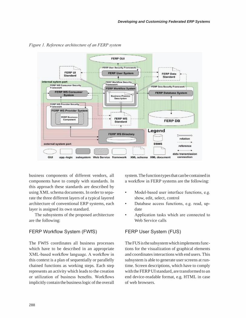
Figure 1 gives an overview of the reference ar-chitecture of a Web Service-based FERP system. The architecture consists of several subsystems, which are interconnected. Because one of the main objective of an FERP system is to integrate
Developing and Customizing Federated ERP Systems
288
business components of different vendors, all components have to comply with standards. In this approach these standards are described by using XML schema documents. In order to sepa-rate the three different layers of a typical layered architecture of conventional ERP systems, each layer is assigned its own standard.
The subsystems of the proposed architecture are the following:
FERP Workflow System (FWfS)
The FWfS coordinates all business processes which have to be described in an appropriate XML-based workflow language. A workflow in this context is a plan of sequentially or parallelly chained functions as working steps. Each step represents an activity which leads to the creation or utilization of business benefits. Workflows implicitly contain the business logic of the overall
system. The function types that can be contained in a workflow in FERP systems are the following:
• Model-based user interface functions, e.g. show, edit, select, control
• Database access functions, e.g. read, up-date
• Application tasks which are connected to Web Service calls
FERP User System (FUS)
The FUS is the subsystem which implements func-tions for the visualization of graphical elements and coordinates interactions with end users. This subsystem is able to generate user screens at run-time. Screen descriptions, which have to comply with the FERP UI standard, are transformed to an end device-readable format, e.g. HTML in case of web browsers.
Figure 1. Reference architecture of an FERP system
289
Developing and Customizing Federated ERP Systems
FERP Database System (FDS)
The FDS is the subsystem which implements functions for the communication with the FERP database. This subsystem is able to interpret XML structures which comply with the FERP data standard. The interface differentiates between two kinds of requests. Database update requests contain object oriented representations of business entities as XML trees. Database read requests contain X-Path or X-Query expressions specifying portions of data to be extracted. In both cases the request parameters have to be transformed into different types of request statements that vary depending on the type of database management system (DBMS) that is used. Assuming the use of a relational DBMS (RDBMS), the underlying data model also has to comply with the FERP data standard, which means that the corresponding table structure has to reflect the XML-Schema specifications respectively. The java.net project hyperjaxb21 provides a solution to generate SQL statements on the basis of XML schema defini-tions. Another solution is the application of native XML databases or XML-enabled RDBMS.
FERP Web Service Consumer System (FWCS)
The business logic of FERP systems is encap-sulated in so called FERP business components which are wrapped in a Web Service. The FWCS is the subsystem that provides the functionality for the invocation of Web Services. All possible types of FERP Web Services are specified by the FERP WS standard. This standard contains XML schema definitions that describe Web Service op-erations as well as input and output messages. A Web Service references these types in its WSDL description. Furthermore this subsystem is able to search for Web Services, which are defined by a unique identifier. This way it is possible that dif-ferent Web Service providers implement the same business component type as Web Service. Beside
the implementation of Web Service invocation and search functionality this subsystem is respon-sible for the interpretation and consideration of non-functional parameters. Examples for those parameters are security policies, payment polices, and Quality of Service (QoS) requirements on the part of Web Service consumers.
FERP Web Service Provider System (FWPS)
The FWPS is the subsystem which implements functions for the provision of Web Services which comply with the FERP WS Standard. The subsys-tem includes a Web Server which is responsible for the interpretation of incoming and outgoing HTTP requests which in turn encapsulate SOAP requests. The subsystem provides business components of the FERP system as Web Services.
A connection to the FERP Web Service Di-rectory allows the publication of Web Services. Furthermore this subsystem is responsible for the negotiation of common communication policies such as e.g. security protocols or usage fees with the requesting client.
FERP Web Service Directory (FWD)
The FWD provides an interface for the publica-tion and the searching of FERP Web Services based on the UDDI standard. The structure of this registry leans on the FERP WS standard. In this standard Web Services are assigned to cat-egories mirroring the predetermined functional organization of enterprises.
prototype development
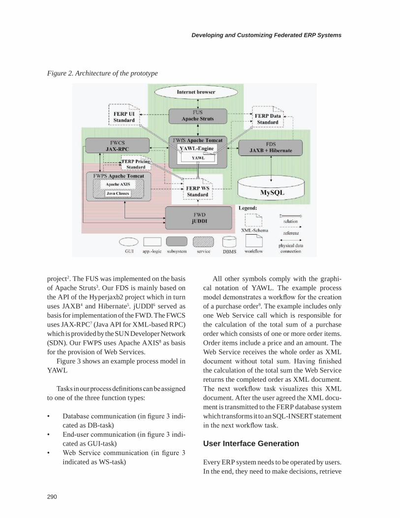
The following paragraph briefly describes a first implementation of the proposed reference archi-tecture which is based on open source software components. Figure 2 shows the architecture of our prototype. For the implementation of the FWfS we chose the workflow engine of the YAWL
Developing and Customizing Federated ERP Systems
290
project2. The FUS was implemented on the basis of Apache Struts3. Our FDS is mainly based on the API of the Hyperjaxb2 project which in turn uses JAXB4 and Hibernate5. jUDDI6 served as basis for implementation of the FWD. The FWCS uses JAX-RPC7 (Java API for XML-based RPC) which is provided by the SUN Developer Network (SDN). Our FWPS uses Apache AXIS8 as basis for the provision of Web Services.
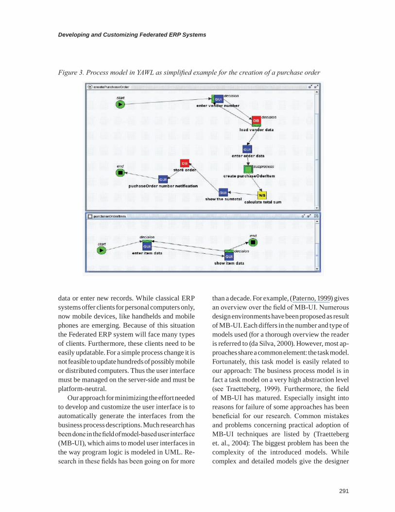
Figure 3 shows an example process model in YAWL
Tasks in our process definitions can be assigned to one of the three function types:
• Database communication (in figure 3 indi-cated as DB-task)
• End-user communication (in figure 3 indi-cated as GUI-task)
• Web Service communication (in figure 3 indicated as WS-task)
All other symbols comply with the graphi-cal notation of YAWL. The example process model demonstrates a workflow for the creation of a purchase order9. The example includes only one Web Service call which is responsible for the calculation of the total sum of a purchase order which consists of one or more order items. Order items include a price and an amount. The Web Service receives the whole order as XML document without total sum. Having finished the calculation of the total sum the Web Service returns the completed order as XML document. The next workflow task visualizes this XML document. After the user agreed the XML docu-ment is transmitted to the FERP database system which transforms it to an SQL-INSERT statement in the next workflow task.
user interface generation
Every ERP system needs to be operated by users. In the end, they need to make decisions, retrieve
Figure 2. Architecture of the prototype
291
Developing and Customizing Federated ERP Systems
data or enter new records. While classical ERP systems offer clients for personal computers only, now mobile devices, like handhelds and mobile phones are emerging. Because of this situation the Federated ERP system will face many types of clients. Furthermore, these clients need to be easily updatable. For a simple process change it is not feasible to update hundreds of possibly mobile or distributed computers. Thus the user interface must be managed on the server-side and must be platform-neutral.
Our approach for minimizing the effort needed to develop and customize the user interface is to automatically generate the interfaces from the business process descriptions. Much research has been done in the field of model-based user interface (MB-UI), which aims to model user interfaces in the way program logic is modeled in UML. Re-search in these fields has been going on for more
than a decade. For example, (Paterno, 1999) gives an overview over the field of MB-UI. Numerous design environments have been proposed as result of MB-UI. Each differs in the number and type of models used (for a thorough overview the reader is referred to (da Silva, 2000). However, most ap-proaches share a common element: the task model. Fortunately, this task model is easily related to our approach: The business process model is in fact a task model on a very high abstraction level (see Traetteberg, 1999). Furthermore, the field of MB-UI has matured. Especially insight into reasons for failure of some approaches has been beneficial for our research. Common mistakes and problems concerning practical adoption of MB-UI techniques are listed by (Traetteberg et. al., 2004): The biggest problem has been the complexity of the introduced models. While complex and detailed models give the designer
Figure 3. Process model in YAWL as simplified example for the creation of a purchase order
Developing and Customizing Federated ERP Systems
292
the best level of control, such models are difficult to learn, time-consuming to design and hard to maintain. Therefore, our approach particularly strives to reduce the inherent complexity. This is especially important for being useful for the targeted, non-expert audience.
Because we assume the business process to be already modeled, the user interface is expressed by stereotyping business functions. Four stereotypes have been introduced:
• Selection: The user shall select data from a collection of possible choices. For example: Select product from a catalogue.
• Edit: The user shall edit some information object from the data model. For example, edit order.
• Control: The user wants to explicitly in-voke some action. This is used to model navigational decisions. For example, “Accept order”.
• User: The user has to do something by himself, e.g. planning, comparing, etc.
These four actions can be attached to a busi-ness function and are visualized by small icons on the left-hand side. The annotated business processes are downloaded by the client software, which generates user interfaces from these models and sends the data and user decisions back to the server. This way, the user interface can be edited
simply by installing new business process models on the server.
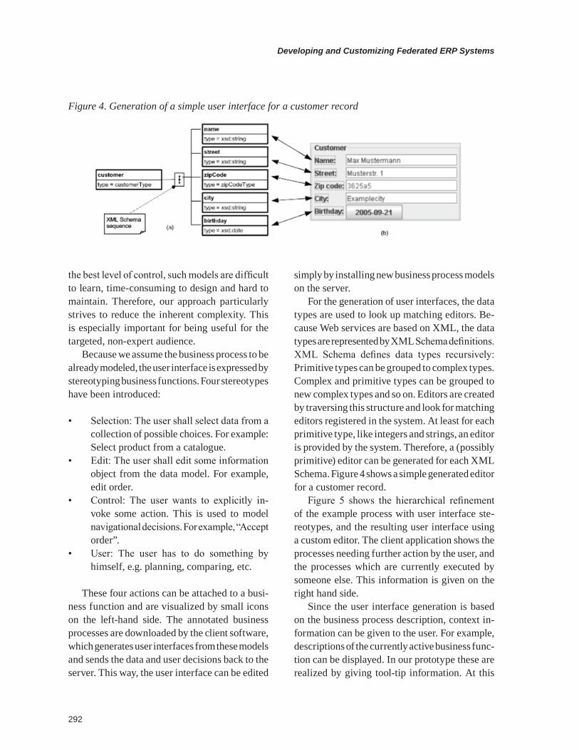
For the generation of user interfaces, the data types are used to look up matching editors. Be-cause Web services are based on XML, the data types are represented by XML Schema definitions. XML Schema defines data types recursively: Primitive types can be grouped to complex types. Complex and primitive types can be grouped to new complex types and so on. Editors are created by traversing this structure and look for matching editors registered in the system. At least for each primitive type, like integers and strings, an editor is provided by the system. Therefore, a (possibly primitive) editor can be generated for each XML Schema. Figure 4 shows a simple generated editor for a customer record.
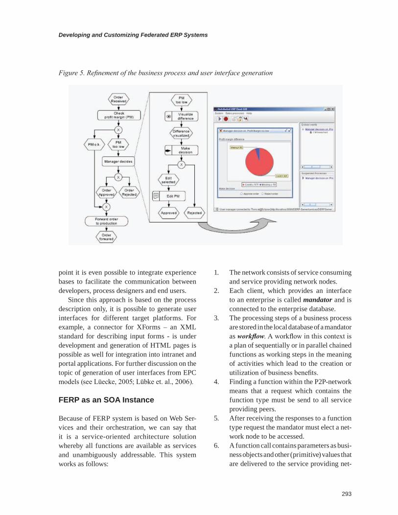
Figure 5 shows the hierarchical refinement of the example process with user interface ste-reotypes, and the resulting user interface using a custom editor. The client application shows the processes needing further action by the user, and the processes which are currently executed by someone else. This information is given on the right hand side.
Since the user interface generation is based on the business process description, context in-formation can be given to the user. For example, descriptions of the currently active business func-tion can be displayed. In our prototype these are realized by giving tool-tip information. At this
Figure 4. Generation of a simple user interface for a customer record
293
Developing and Customizing Federated ERP Systems
point it is even possible to integrate experience bases to facilitate the communication between developers, process designers and end users.
Since this approach is based on the process description only, it is possible to generate user interfaces for different target platforms. For example, a connector for XForms – an XML standard for describing input forms - is under development and generation of HTML pages is possible as well for integration into intranet and portal applications. For further discussion on the topic of generation of user interfaces from EPC models (see Lüecke, 2005; Lübke et. al., 2006).
ferp as an soA instance
Because of FERP system is based on Web Ser-vices and their orchestration, we can say that it is a service-oriented architecture solution whereby all functions are available as services and unambiguously addressable. This system works as follows:
1. The network consists of service consuming and service providing network nodes.
2. Each client, which provides an interface to an enterprise is called mandator and is connected to the enterprise database.
3. The processing steps of a business process are stored in the local database of a mandator as workflow. A workflow in this context is a plan of sequentially or in parallel chained functions as working steps in the meaning of activities which lead to the creation or utilization of business benefits.
4. Finding a function within the P2P-network means that a request which contains the function type must be send to all service providing peers.
5. After receiving the responses to a function type request the mandator must elect a net-work node to be accessed.
6. A function call contains parameters as busi-ness objects and other (primitive) values that are delivered to the service providing net-
Figure 5. Refinement of the business process and user interface generation
Developing and Customizing Federated ERP Systems
294
work node. A business object in this context is a snapshot of the enterprise database at a particular time in a standardized format. Function calls can contain other function calls.
7. A function returns a list of either directly modified business objects or independent values that are necessary for subsequent business object updates (e.g. intermediate data).
8. Returned business objects must be syn-chronized with the local database of the mandator.
business process ModeLing in the ferp context
The FERP system is targeted at SMEs. This poses some additional challenges besides the already outlined technical problems. Especially the gathering of requirements - and as their most important part business processes – has to be per-formed before any implementation of an (F)ERP system can start.
However, in most SMEs the business processes are not defined explicitly, but the organization as a whole has tacit knowledge of the activities that are to be performed and the order in which they have to be performed. But even if SMEs have documented business processes, these de-scriptions are typically not suited for software development or customization because technical details are missing.
Therefore, the knowledge of process partici-pants needs to be externalized into documented business processes that are suited to be the basis for software development and customization projects because they lack sufficient detail.
Within the FERP context, we propose a light-weight approach to elicitate the business processes and to generate explicit models from there. These
explicit business process models can be used to pre-generate and develop the workflows in FERP systems that are the technical representation of the business.
The technique is constrained for this particular context as following:
• Easy to use: The technique must easy to use because SME employees usually do not have extensive technical knowledge and no time for learning complex techniques.
• Easy to understand: When discussing results it is important that all stakeholders can par-ticipate and contribute. Therefore, the same restrictions apply to understanding as they do to usage.
• Lightweight: The technique must quickly save time for associated employees. Not much effort may be spend as this would pose undue costs and would hinder flexibility.
• Offer basis for later development: The results must be usable by the customization team later on. The smoother this transition is the better.
use cases as the basis
We use a use case-based approach for interview-ing the users and stakeholders in SMEs and documenting the results.
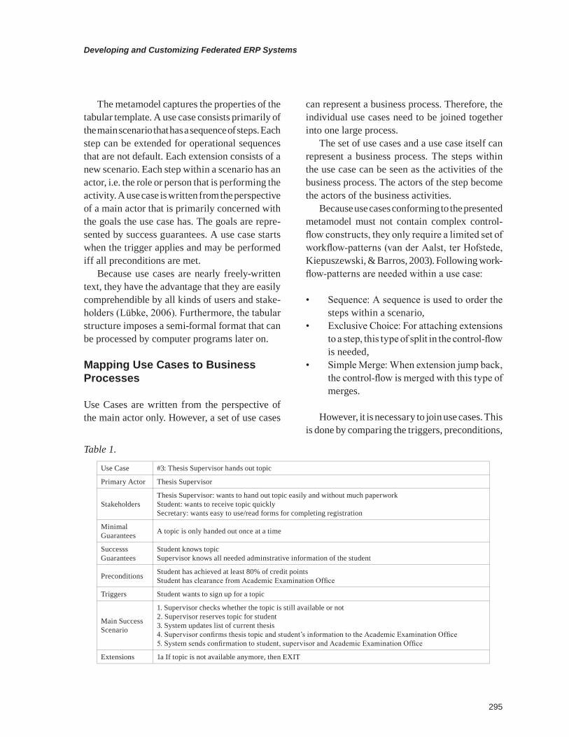
Use Cases (Cockburn, 2005) are a technique from the Requirements Engineering community. They represent possible scenarios from the point of view of a single main actor. The most common form for documenting use cases are tables as il-lustrated in table 1:
The table contains additional information like preconditions and success conditions that express goals and constraints from the business and software point of view that are associated with the use case.
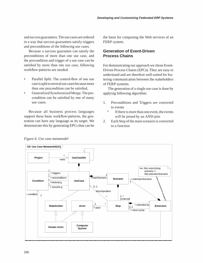
For our approach, we assume the use cases to conform to the meta-model as illustrated in figure 6.
295
Developing and Customizing Federated ERP Systems
The metamodel captures the properties of the tabular template. A use case consists primarily of the main scenario that has a sequence of steps. Each step can be extended for operational sequences that are not default. Each extension consists of a new scenario. Each step within a scenario has an actor, i.e. the role or person that is performing the activity. A use case is written from the perspective of a main actor that is primarily concerned with the goals the use case has. The goals are repre-sented by success guarantees. A use case starts when the trigger applies and may be performed iff all preconditions are met.
Because use cases are nearly freely-written text, they have the advantage that they are easily comprehendible by all kinds of users and stake-holders (Lübke, 2006). Furthermore, the tabular structure imposes a semi-formal format that can be processed by computer programs later on.
Mapping use cases to business processes
Use Cases are written from the perspective of the main actor only. However, a set of use cases
can represent a business process. Therefore, the individual use cases need to be joined together into one large process.
The set of use cases and a use case itself can represent a business process. The steps within the use case can be seen as the activities of the business process. The actors of the step become the actors of the business activities.
Because use cases conforming to the presented metamodel must not contain complex control-flow constructs, they only require a limited set of workflow-patterns (van der Aalst, ter Hofstede, Kiepuszewski, & Barros, 2003). Following work-flow-patterns are needed within a use case:
• Sequence: A sequence is used to order the steps within a scenario,
• Exclusive Choice: For attaching extensions to a step, this type of split in the control-flow is needed,
• Simple Merge: When extension jump back, the control-flow is merged with this type of merges.
However, it is necessary to join use cases. This is done by comparing the triggers, preconditions,
Use Case #3: Thesis Supervisor hands out topic
Primary Actor Thesis Supervisor
StakeholdersThesis Supervisor: wants to hand out topic easily and without much paperworkStudent: wants to receive topic quicklySecretary: wants easy to use/read forms for completing registration
Minimal Guarantees A topic is only handed out once at a time
Successs Guarantees
Student knows topicSupervisor knows all needed adminstrative information of the student
Preconditions Student has achieved at least 80% of credit pointsStudent has clearance from Academic Examination Office
Triggers Student wants to sign up for a topic
Main Success Scenario
1. Supervisor checks whether the topic is still available or not2. Supervisor reserves topic for student3. System updates list of current thesis4. Supervisor confirms thesis topic and student’s information to the Academic Examination Office5. System sends confirmation to student, supervisor and Academic Examination Office
Extensions 1a If topic is not available anymore, then EXIT
Table 1.
Developing and Customizing Federated ERP Systems
296
and success guarantees. The use cases are ordered in a way that success guarantees satisfy triggers and preconditions of the following use cases.
Because a success guarantee can satisfy the preconditions of more than one use case, and the precondition and trigger of a use case can be satisfied by more than one use case, following workflow-patterns are needed:
• Parallel Split: The control-flow of one use case is split to several use cases because more than one precondition can be satisfied,
• Generalized Synchronized Merge: The pre-condition can be satisfied by one of many use cases.
Because all business process languages support these basic workflow-patterns, the gen-eration can have any language as its target. We demonstrate this by generating EPCs that can be
the basis for composing the Web services of an FERP system.
generation of event-driven process chains
For demonstrating our approach we chose Event-Driven Process Chains (EPCs). They are easy to understand and are therefore well-suited for fos-tering communication between the stakeholders of FERP systems.
The generation of a single use case is done by applying following algorithm:
1. Preconditions and Triggers are converted to events
° If there is more than one event, the events will be joined by an AND-join
2. Each Step of the main scenario is converted to a function
Figure 6. Use case metamodel
cd: use case Metamodel (uc)
condition usecasescenario
stakeholder Actor
human Actor computer system
step extension
*+ triggers
*+ preconditions
*+minimal g.
*+ success g
1+mainScenario
*
0..1
decomposition
1..*{ordered}
*+ extended by
0..1+ return jump
+ extensionScenario1
*1+ actor
1+ condition
usecasesetproject*
+sets
inv: this.returnJump. scenario != this.extensionScenario
297
Developing and Customizing Federated ERP Systems
° Connected with simple okay-events3. Success guarantees are converted to end-
events° If there is more than one event, an AND-
split is introduced4. Extensions are introduced with an XOR-
split° The extension condition becomes an
event5. The extension scenario is converted like the
main scenario° Extensions of extensions are handled
recursively6. Return jumps are realized with an XOR-
join° The join is introduced before the function
that is the jump target
This algorithm is applied to every use case. In the following step, the use cases have to be joined. Depending on different needs, several join strategies are available:
• Large EPC: Generates a single, large EPC model from all use cases.
• Short EPC: Generates an EPC that has a function for each use case. The details of the use case are discarded and not displayed. This type of model is well-suited for discuss-ing the ordering of use cases and the global control-flow.
• Short EPC with hierarchical refinement: EPCs allow function to be detailed in other EPCs. This approach combines the advantages of the first two approaches by generating a short EPC and placing a more detailed EPC for the use case behind every function.
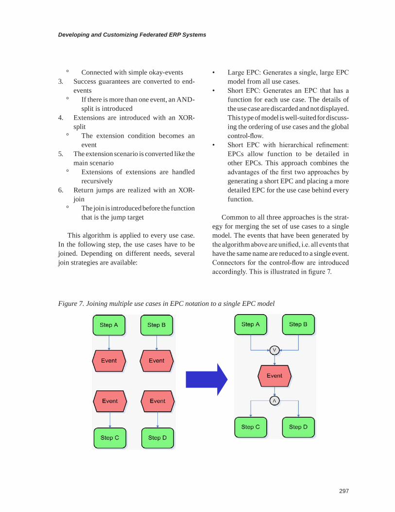
Common to all three approaches is the strat-egy for merging the set of use cases to a single model. The events that have been generated by the algorithm above are unified, i.e. all events that have the same name are reduced to a single event. Connectors for the control-flow are introduced accordingly. This is illustrated in figure 7.
Figure 7. Joining multiple use cases in EPC notation to a single EPC model
Developing and Customizing Federated ERP Systems
298
Advantages of the Use Case-Centered Approach
By using textual use cases, it is possible to docu-ment and discover business processes. Due to the use of plain, semi-formal text, they can be used by all involved stakeholders. These stakeholders do not need to learn a new notation nor do they have difficulties while interpreting and validat-ing the documented parts of business processes. Use Cases can guide interviews with isolated stakeholders. The generation generates a global view by combining the use cases to a large busi-ness process model. The business process model is the foundation for later ongoing development. It can be readily used by developers. Therefore, our approach satisfies the constraints outlined above nicely.
concLusion And outLook
Within this chapter we have presented the FERP architecture as an architecture for ERP systems that are well-suited for SMEs; such systems can be flexibly altered, and are comparably cheap to install and maintain. However, in order to know what to change and what to install, business pro-cesses need to be defined first. Within SMEs such processes need to be documented because usually no explicit business process documentation exists. We proposed a use case-centered approach for elicitating the business processes in a way that is comprehensibly by non-tech-savvy people.
With the combination of these two parts, SMEs can introduce and maintain their ERP systems and can stay competitive in the market.
While the FERP architecture was developed for addressing requirements of SMEs, the architecture may be suitable for larger companies as well. The assessment to what extend the architecture can scale will be part of our future work.
references
Cockburn, A. (2005). Writing Effective Use Cases. Amsterdam: Addison-Wesley Longman.
da Silva, P. P. (2002). User Interface Declara-tive Models and Development Environments: A Survey. In Palanque & Patern o (Eds.), DSV-IS, volume 1946 of Lecture Notes in Computer Sci-ence (pp. 207–226). London: Springer.
IfM Bonn (2008). Schlüsselzahlen Deutschland (Key Indicators Germany). Retrieved December 28, 2008, from http://www.ifm-bonn.org/index.php?id=99, 2008-12-28.
Lübke, D., Lüecke, T., Schneider, K., & Marx Gómez, J. (2006). Using Event-Driven Process Chains for Model-Driven Development of Busi-ness Applications. In Nüttgens & Mendling (Eds.), Proceedings of the XML4BPM 2006.
Lübke, D. (2006). Transformation of Use Cases to EPC Models. In M. Nüttgens, F. Rump, & J. Mendling (Eds.), Proceedings of the EPK 2006. CEUR Proceedings Vol 224. http://ftp.informa-tik.rwth-aachen.de/Publications/CEUR-WS/Vol-224/.
Lüecke, T. (2005). Development of a Concept for Creating and Managing User Interfaces bound to Business Processes. Master’s Thesis, Leibniz Universität Hannover, Germany.
Paterno, F. (1999). Model-Based Design and Evaluation of Interactive Applications. London, United Kingdom: Springer-Verlag.
Rautenstrauch, C., & Schulze, T. (2003). Infor-matik für Wirtschaftswissenschaftler und Wirt-schaftsinformatiker, Berlin.
Robey, D., Ross, J., & and Boudreau, M. (2002). Learning to implement enterprise systems: An exploratory study of the dialectics of change. Journal of Management Information Systems, 19(1), 17-46.
299
Developing and Customizing Federated ERP Systems
Trætteberg, H. (1999). Modelling Work. Workflow and Task Modelling. In Vanderdonckt, & Puerta (Eds.), CADUI (pp. 275-280). Kluwer.
Trætteberg, H., Molina, P. J., & Nunes, N. J. (2004). Making model-based UI design practical: usable and open methods and tools. In Vanderdonckt, Nunes, & Rich (Eds.), Intelligent User Interfaces (pp. 376–377). ACM.
van der Aalst, W., ter Hofstede, A.H.M., Kie-puszewski, B., & Barros, A. P. (n.d.). Workflow Patterns. Journal of Distributed and Parallel Databases, 3(14), 5-51.
endnotes
1 Hyperjaxb2 – relational persistence for JAXB objects: https://hyperjaxb2.dev.java.net/ (last visit October 2006)
2 http://yawlfoundation.org/ 3 http://sturts.apache.org/4 http://jaxp.dev.java.net/5 http://www.hibernate.org/ 6 http://ws.apache.org/juddi/7 http://java.sun.com/webservices/jaxrpc/ 8 http://ws.apache.org/axis/ 9 In order to improve understandability the
process was simplified. Changes of entered data and order items are not supported.
This work was previously published in the Journal of Enterprise Information Systems, vol. 5, issue 3, edited by A. Gunaseka-ran, pp. 45-59, copyright 2009 by IGI Publishing (an imprint of IGI Global).