Embed Size (px)
Citation preview
DEVELOPMENT OF AN INNOVATIVE MODULAR STEEL TRUSS SYSTEM
by
Sirou Zhuo
B.Eng., Fujian Agriculture and Forestry University, 2015
A THESIS SUBMITTED IN PARTIAL FULFILLMENT OF
THE REQUIREMENTS FOR THE DEGREE OF
MASTER OF APPLIED SCIENCE
in
THE FACULTY OF GRADUATE AND POSTDOCTORAL STUDIES
(Civil Engineering)
THE UNIVERSITY OF BRITISH COLUMBIA
(Vancouver)
April 2018
© Sirou Zhuo, 2018
ii
Abstract
This thesis proposes an innovative and economical modular steel truss system (MSTS), using
modular steel floor system (MSFS) and modular buckling restrained braced truss moment frame
(MBRBTMF). The proposed MSTS can be fabricated offsite and then shipped and assembled on
site, saving construction time and fabrication expense. This specially designed floor system,
MSFS, consists of space trusses and precast concrete slab toppings, and to fully utilize the spaces
within the floors, the mechanical, electrical and plumbing (MEP) systems are pre-installed within.
The proposed floor system was optimized for both gravity and lateral loads, using a robust
structural optimization method conducted in conjunction with the Matlab and OpenSees. Space
trusses are utilized to provide sufficient stiffness to support gravity, eliminate vertical deflection
and transfer lateral force without significantly increasing floor depth. The buckling restrained
braces (BRBs) in MBRBTMF are employed as energy dissipation components, allowing the
structures to be repaired efficiently after earthquakes. The seismic performances of a MSTS
structure and conventional structures with MSFS were systematically analyzed with OpenSees.
The results show that the proposed modular system is highly efficient in resisting gravity and
lateral loads, and can be used efficiently for modular constructions worldwide.
iii
Lay Summary
The key purpose of this thesis is to develop an innovative and economical modular steel truss
system (MSTS) for building structure. This MSTS consists of modular steel floor system (MSFS)
and modular buckling restrained braced truss moment frame (MBRBTMF). The proposed MSTS
can be fabricated offsite and then shipped and assembled on site, reducing fabrication errors and
saving construction expense.
Detailed design of MSFS and MBRBTMF were conducted, and the optimal design was presented.
The seismic behaviors of MSTS and conventional building structures using MSFS were studied,
and the results show that the proposed modular steel system, MSTS, is highly efficient, and can be
used effectively for modular applications.
iv
Preface
Part of this thesis has been accepted in conference proceedings as detailed below.
1. Chapter 3: Yang TY, Zhuo SR, Li YJ. (2018). “Seismic Behavior and Design of Innovative
Modular Steel Floor System”, Key Engineering Materials, Vol. 763, pp. 287-294.
The author of this thesis was responsible for the literature review, model development, data
processing, and presentation of results. The manuscripts were drafted by the author of the thesis
and revised based on comments by Professor T.Y. Yang at the University of British Columbia.
v
Table of Contents
Abstract .......................................................................................................................................... ii
Lay Summary ............................................................................................................................... iii
Preface ........................................................................................................................................... iv
Table of Contents ...........................................................................................................................v
List of Tables ................................................................................................................................ ix
List of Figures ............................................................................................................................... xi
List of Symbols .............................................................................................................................xv
List of Abbreviations ................................................................................................................ xvii
Acknowledgements .................................................................................................................. xviii
Dedication ................................................................................................................................... xix
Chapter 1: Introduction ................................................................................................................1
1.1 Modular Construction ..................................................................................................... 1
1.2 Review of Floor System.................................................................................................. 3
1.2.1 Concrete Floor System ................................................................................................ 4
1.2.2 Steel Floor Systems..................................................................................................... 5
1.2.3 Emerging Floor Systems ............................................................................................. 7
1.3 Seismic Force Resistance System (SFRS) .................................................................... 11
1.3.1 Steel Moment Resisting Frame (SMRF)................................................................... 11
1.3.2 Steel Plate Shear Wall (SPSW)................................................................................. 12
1.3.3 Steel Braced Frame (SBF) ........................................................................................ 13
1.4 Modular Steel Truss System (MSTS) ........................................................................... 16
vi
1.4.1 Modular Steel Floor System (MSFS) ....................................................................... 16
1.4.2 Modular Buckling Restrained Braced Truss Moment Frame (MBRBTMF) ........... 19
1.5 Research Scope ............................................................................................................. 21
1.6 Thesis Outline ............................................................................................................... 22
Chapter 2: Design and Optimization of Modular Steel Floor System ....................................25
2.1 Prototype Design ........................................................................................................... 25
2.1.1 Preliminary Floor Design .......................................................................................... 25
2.1.2 Connector Design...................................................................................................... 27
2.2 Structural Design .......................................................................................................... 31
2.3 Design Check ................................................................................................................ 32
2.3.1 Load Combination .................................................................................................... 33
2.3.2 Capacity Check ......................................................................................................... 33
2.3.3 Determination of Deflection ..................................................................................... 34
2.4 Structural Optimization ................................................................................................. 35
2.4.1 Optimization Method ................................................................................................ 35
2.4.2 Space Truss Floor System (STFS) ............................................................................ 38
2.4.3 Space Truss with W-beam Floor System (STWFS) ................................................. 40
2.5 Parameter Study ............................................................................................................ 43
2.6 Floor Vibration.............................................................................................................. 46
Chapter 3: Seismic Design of Modular Steel Truss System .....................................................50
3.1 Performance-Based Plastic Design (PBPD) Procedure ................................................ 51
3.2 Seismic Design of MBRBTMF .................................................................................... 53
3.2.1 Drift and Base Shear Calculation .............................................................................. 53
vii
3.2.2 BRB Design .............................................................................................................. 53
3.2.3 Truss Design ............................................................................................................. 55
3.2.4 Column Design ......................................................................................................... 56
3.3 Application of Modular Steel Truss System (MSTS) ................................................... 57
3.3.1 Hazard Analysis ........................................................................................................ 57
3.3.2 Structural Design and Modelling .............................................................................. 60
3.3.3 Ground Motion Selection .......................................................................................... 62
3.3.4 Structural Performance ............................................................................................. 64
Chapter 4: Application of Modular Steel Floor Systems in Conventional Structural Systems
........................................................................................................................................................67
4.1 Application of MSFS in 3-Story BRBF Building ......................................................... 67
4.1.1 Structural Design and Modelling .............................................................................. 67
4.1.2 Hazard Analysis ........................................................................................................ 70
4.1.3 Ground Motion Scaling............................................................................................. 73
4.1.4 Comparison Results .................................................................................................. 75
4.2 Application of MSFS in 12-Story BRBF Building ....................................................... 77
4.2.1 Building Design and Modelling ................................................................................ 78
4.2.2 Ground Motion Scaling............................................................................................. 81
4.2.3 Comparison Results .................................................................................................. 87
4.3 Simplified Model for Seismic Analysis ........................................................................ 89
4.3.1 Simplified Model of BRBF Building with MSFS .................................................... 89
4.3.2 Simplified Model of BRKBTMF Building with MSFS ........................................... 90
Chapter 5: Summary and Conclusions ......................................................................................94

viii
Bibliography .................................................................................................................................96
Appendix .....................................................................................................................................101
Appendix A ............................................................................................................................. 101
ix
List of Tables
Table 2.1 Typical floor gravity and seismic loads ........................................................................ 32
Table 2.2 Load combination ......................................................................................................... 33
Table 2.3 STFS design parameters ............................................................................................... 39
Table 2.4 The STWFS Design parameters ................................................................................... 41
Table 2.5 A detailed parameter study of STFS ............................................................................. 43
Table 2.6 Optimal results for STFS .............................................................................................. 44
Table 2.7 A detailed parameter study of STWFS ......................................................................... 45
Table 2.8 The optimal results for STWFS .................................................................................... 45
Table 2.9 The natural frequency of the floor systems .................................................................. 49
Table 3.1 Site class information, Berkley ..................................................................................... 59
Table 3.2 Design parameters ......................................................................................................... 60
Table 3.3 MBRBTMF design summary ....................................................................................... 61
Table 3.4 Selected ground motion ................................................................................................ 63
Table 4.1 3-Story building design details ..................................................................................... 68
Table 4.2 Site class information, Vancouver ................................................................................ 70
Table 4.3 Seismic hazard values, Vancouver ............................................................................... 70
Table 4.4 Values of the design spectrum, Vancouver .................................................................. 71
Table 4.5 Structural comparison: 3-Story building....................................................................... 74
Table 4.6 Scaled ground motions: 3-story building ...................................................................... 75
Table 4.7 12-Story building design details: equivalent concrete floor ......................................... 79
Table 4.8 12-Story building design details: conventional steel floor ........................................... 79
x
Table 4.9 12-Story building design details: STWFS .................................................................... 80
Table 4.10 Structural period: 12-story building ............................................................................ 82
Table 4.11 Scaled crustal ground motions: 12-story building ...................................................... 84
Table 4.12 Scaled subcrustal ground motions: 12-story building................................................. 85
Table 4.13 Scaled subduction ground motions: 12-story building ............................................... 86
Table 4.14 Structural components design ..................................................................................... 91
Table 4.15 Frame design ............................................................................................................... 92
xi
List of Figures
Figure 1.1 Material of the 100 tallest completed buildings, per decade ......................................... 1
Figure 1.2 Tall buildings 150 meters (492 ft) or taller completed up until 2017: described by type
of structural material ....................................................................................................................... 1
Figure 1.3 Little Hero ..................................................................................................................... 2
Figure 1.4 T30A Tower Hotel ........................................................................................................ 2
Figure 1.5 Steel framing floor systems ........................................................................................... 6
Figure 1.6 The shallow flat soffit precast concrete floor systems .................................................. 8
Figure 1.7 The Girder-slab system.................................................................................................. 9
Figure 1.8 The Deltabeam system .................................................................................................. 9
Figure 1.9 The Cobiax floor system ............................................................................................. 10
Figure 1.10 The Versa floor .......................................................................................................... 11
Figure 1.11 Steel moment resisting frame (SMRF) ...................................................................... 12
Figure 1.12 Steel plate shear wall (SPSW) ................................................................................... 13
Figure 1.13 Steel braced frames (SBFs) ....................................................................................... 14
Figure 1.14 The proposed modular steel floor system (MSFS) .................................................... 19
Figure 1.15 Modular buckling restrained braced truss moment frame (MBRBTMF) ................. 20
Figure 2.1 The proposed steel floor system (MSFS) module unit ................................................ 25
Figure 2.2 Space truss connector .................................................................................................. 27
Figure 2.3 The proposed innovative honeycomb cast steel connector ......................................... 29
Figure 2.4 The proposed structural system connector .................................................................. 31
Figure 2.5 The genetic algorithm approach .................................................................................. 36
xii
Figure 2.6 The structural optimization procedure ......................................................................... 37
Figure 2.7 The proposed space truss floor system (STFS) ........................................................... 38
Figure 2.8 The optimal space truss floor system (STFS).............................................................. 40
Figure 2.9 The proposed space truss with w-beam floor system (STWFS) ................................. 40
Figure 2.10 The optimal space truss with w-beam floor system (STWFS) .................................. 42
Figure 2.11 The relationship of depth to the deflection ratio ....................................................... 42
Figure 2.12 The parameter study of STWFS ................................................................................ 46
Figure 2.13 The recommended peak acceleration for the human comfort for vibrations due to
human activities ............................................................................................................................ 47
Figure 2.14 The mode shapes of the floor .................................................................................... 49
Figure 3.1 MSTS concept ............................................................................................................. 50
Figure 3.2 PBPD concept .............................................................................................................. 51
Figure 3.3 Structural geometry ..................................................................................................... 54
Figure 3.4 BRB Calibration .......................................................................................................... 55
Figure 3.5 Truss sample design .................................................................................................... 55
Figure 3.6 Free body diagram of column tree............................................................................... 56
Figure 3.7 The Pacific Ring of Fire .............................................................................................. 58
Figure 3.8 Cascadia region ........................................................................................................... 59
Figure 3.9 Design hazard spectrum, Berkeley .............................................................................. 60
Figure 3.10 The prototype MSTS building model ........................................................................ 62
Figure 3.11 Response spectrum of scaled ground motions: MBRBTMF building ...................... 63
Figure 3.12 Median peak inter-story drift ratio ............................................................................ 64
Figure 3.13 Median peak story acceleration ................................................................................. 64
xiii
Figure 3.14 IDA curve for the prototype MSTS building ............................................................ 65
Figure 3.15 Collapse fragility curves for the prototype MSTS building ...................................... 66
Figure 4.1 An isometric view of the 3-story building ................................................................... 68
Figure 4.2 Prototype 3-story building model ................................................................................ 69
Figure 4.3. Design hazard spectrum ............................................................................................. 71
Figure 4.4 Total hazard spectrum ................................................................................................. 72
Figure 4.5 Hazard according to the seismic sources ..................................................................... 73
Figure 4.6 Response spectrum of scaled ground motions: 3-story building ................................. 74
Figure 4.7 Median peak inter-story drift ratio .............................................................................. 76
Figure 4.8 Median peak story acceleration ................................................................................... 76
Figure 4.9 Roof drift time history curve: 3-story building ........................................................... 76
Figure 4.10 BRB behavior: 3-story building ................................................................................ 77
Figure 4.11 An isometric view of the 12-story building ............................................................... 78
Figure 4.12 Prototype 12-story building model ............................................................................ 81
Figure 4.13 Ground motion scaling .............................................................................................. 83
Figure 4.14 Median peak inter-story drift ratio ............................................................................ 87
Figure 4.15 Median peak story acceleration ................................................................................. 87
Figure 4.16 Roof drift time history curve: 12-story building ....................................................... 87
Figure 4.17. Median inter-story drift responses for different seismic sources ............................. 88
Figure 4.18. Median inter-story drift responses for different seismic sources ............................. 88
Figure 4.19 Median peak inter-story drift ratio ............................................................................ 90
Figure 4.20 Median peak story acceleration ................................................................................. 90
Figure 4.21 The prototype building description ........................................................................... 91

xiv
Figure 4.22 Peak median inter-story drift ratio ............................................................................. 92
Figure 4.23 Peak median story acceleration ................................................................................. 93

xv
List of Symbols
𝐴: area
𝐴1: area of top and chord chords
𝐴2: area of web truss chords
𝐴𝑔: gross area
𝐴𝑛𝑒: effective net area reduced for shear lag
𝐴𝑛𝑒𝑡: effective net area for tension
𝐴𝑛𝑒𝑠: effective net area for shear rupture
𝐶𝑟: factor compressive resistance of a member or a component
𝐷: dead load
𝐸: earthquake load
𝐹𝑢: specified minimum tensile strength
𝐹𝑦: specified minimum yield stress
𝐹(𝑇): site coefficient for spectral acceleration
𝑓𝑛: natural frequency
𝑔: gravity
𝐻: central height of space truss system
𝐿: live load
𝑀: magnitude
𝑀𝑝: plastic moment resistance
𝑀𝑟: factored moment resistance of a member or a component
xvi
𝑀𝑦: yield moment resistance
�̅�60: average standard penetration resistance
𝑛: parameter for compression resistance
𝑅1: external radius of top and bottom chords
𝑟1: inside radius of top and bottom chords
𝑆: elastic section modulus of a steel section
𝑆1: spacing along length
𝑆2: spacing along width
𝑆𝑢: soil undrained shear strength
𝑆𝑎(𝑇): 5% damped spectral response acceleration for a period of 𝑇
𝑆(𝑇): design spectral response acceleration for a period of 𝑇
𝑇: fundamental period
𝑇𝑟: factored tensile resistance of a member of a component
�̅�𝑆30: average shear wave velocity
𝑍: plastic section modulus of a steel section
𝛼: displacement demand-capacity ratio
𝛽: force demand-capacity ratio
Δ: deflection
𝜆: non-dimensional slenderness parameter in column formula
∅: resistance factor
xvii
List of Abbreviations
ADVE: average drift of vertical element
AP: annual probability
BRBF: buckling restrained braced frame
BRKBTMF: buckling restrained knee braced truss moment frame
DBE: design based earthquake
FEM: finite element model
MBRBTMF: modular buckling restrained braced truss movement frame
MCE: maximum considered earthquake
MDD: maximum diaphragm deflection
MEP: mechanical, electrical and plumbing
MSTS: modular steel truss system
MSFS: modular steel floor system
RT: return period
STFS: space truss floor system
STWFS: space truss with w-beam floor system
TR: period range
TRS: scenario-specific period range
OWSJ: open web steel joists
PGA: peak ground acceleration
UHS: uniform hazard spectrum

xviii
Acknowledgements
This work is funded by Canadian Institute of Steel Construction (CISC).
Firstly, I would like to sincerely thank my supervisor Professor T. Y. Yang for his patient
instruction, insightful inspiration, kindly encouragement through my MASc program. His
knowledge, passion, diligence and devotion extended a broader scope for my study. This work
could not have been completed without his generous support. My deep gratitude is also extended
to Prof. Lin-hai Han from Department of Civil Engineering of Tsinghua University for reviewing
my thesis and providing invaluable advice.
Furthermore, I wish to thank Dr. Dorian Tung, Yuanjie Li and Lisa Tobber for guiding on different
projects and help with my studies. Many thanks to my friends and associates, Yuxin Pan,
Hongzhou Zhang, Xinwen Zhang and Yingying Wang for their encouragement and support.
Above all, I would like to thank my parents, for their continual and unconditional love and support
for my education and life choice.

xix
Dedication
To my parents.
1
Chapter 1: Introduction
1.1 Modular Construction
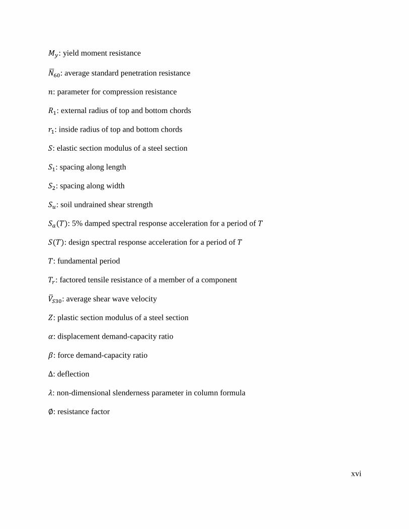
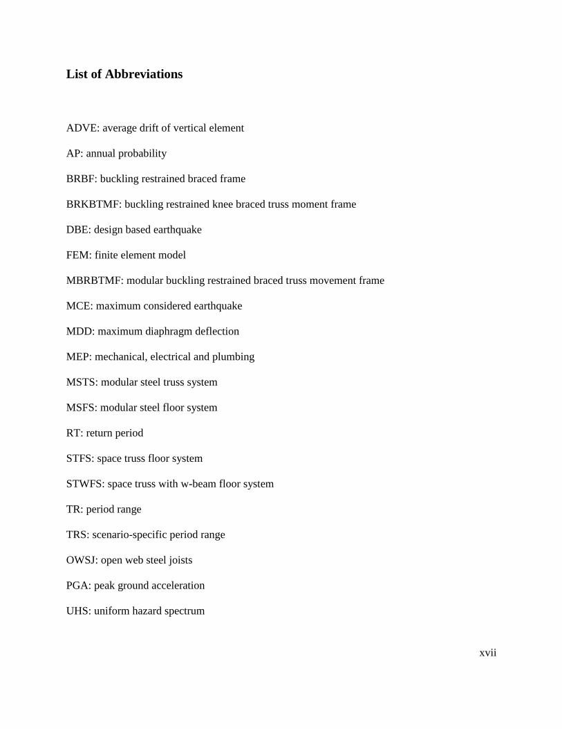
Concrete is employed to construct a great number of buildings throughout North America. The
Council on Tall Building and Urban Habitat (CTBUH)’s database (Council on Tall Buildings and
Urban Habitat, 2017) reveals that, over the last five decades, steel market shares have declined
significantly, while those for concrete and composite material have simultaneously increased (as
demonstrated in Figure 1.1 and Figure 1.2). This is mostly due to the lack of an efficient steel
construction method.
Figure 1.1 Material of the 100 tallest completed
buildings, per decade
Figure 1.2 Tall buildings 150 meters (492 ft) or
taller completed up until 2017: described by type of
structural material
With an increasing demand for high quality control and construction speed, modular constructions
are becoming increasing popular. Modular construction is a novel industrialized method in which
most of the structural elements can be pre-fabricated in factories prior to their on-site assembly.
This method is widely used for structures worldwide, some of the applications are described below.
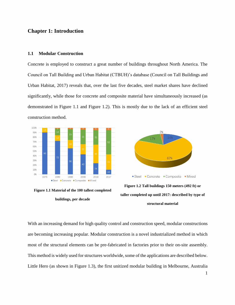
Little Hero (as shown in Figure 1.3), the first unitized modular building in Melbourne, Australia
2
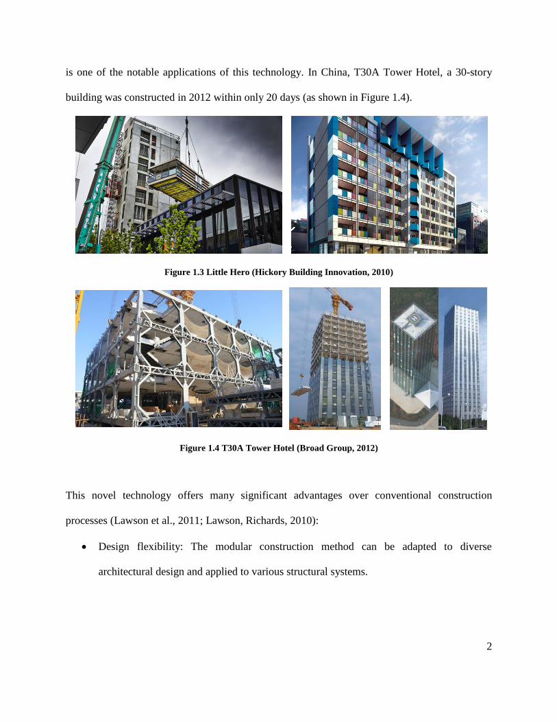
is one of the notable applications of this technology. In China, T30A Tower Hotel, a 30-story
building was constructed in 2012 within only 20 days (as shown in Figure 1.4).
Figure 1.3 Little Hero (Hickory Building Innovation, 2010)
Figure 1.4 T30A Tower Hotel (Broad Group, 2012)
This novel technology offers many significant advantages over conventional construction
processes (Lawson et al., 2011; Lawson, Richards, 2010):
• Design flexibility: The modular construction method can be adapted to diverse
architectural design and applied to various structural systems.
3
• Manufactural quantity improvement: Compared to on-site construction, the modular
construction method has better quality control and assurance. Its intricate and elaborate
details are pre-fabricated, while minimizing construction errors.
• Construction time reduction: With the factory performed prefabrication of its structural
elements, on-site construction time is significantly shortened. Also, on-site and off-site
construction work is able to proceed simultaneously. This greatly reduces construction
time, directly translating to construction savings.
• Site condition independence: Site disturbance such as weather and traffic are lessened,
since most the structural components are fabricated off-site, lowering both construction
time and budget.
• Less material waste: The modules can be disassembled and relocated for a variety of
purposes, reducing the demand for raw material and minimizing new demand expenditures.
Overall, the modular construction method provides various merits, compared with traditional
structural constructions. However, the seismic performance of modular buildings under severe
earthquake shaking may differ significantly from regular structures. Thus, an innovative modular
steel truss system (MSTS) consists of both gravity system and seismic force resisting system were
introduced and developed in this thesis.
1.2 Review of Floor System
The floor system, as the gravity system, is a significant component of building constructions. It
not only supports the gravity load, but also connects the lateral load resisting systems. Over the
years, several floor systems have been developed and applied in high-rise structures. The most
4
common floor systems use cast-in-place concrete, precast concrete, steel and several other
emerging floor system materials and methods.
1.2.1 Concrete Floor System
Over the last few decades, concrete floor systems have been commonly used in the building
industry. Designers can select from a wide variety of concrete floor systems for practical
applications, including cast-in-place and precast concrete floor systems.
Cast-in-place concrete floor systems have been widely used in both residential and commercial
applications. These systems are design flexible, and can be applied to a variety of architectural
plan. The main advantage of this floor creating system is its continuity of structural system, where
such frames as the lateral force resisting system can be implemented. Structural elements and floor
system can be cast monolithically, and hence, connectors are not required between beams and
columns as they are in most structural systems. Concrete floor systems are known to have good
sound and temperature insulation, as well as providing clear surface and fire resistance. These
systems are also durable and easy to maintain. Despite their advantages, the main disadvantage of
cast-in-place concrete floor systems which is their requirement of a long, on-site curing period and
the messy construction environment. The construction is also greatly affected by weather
conditions. More importantly, a significant degree of labour is required to construct and
deconstruct the formwork for concrete construction, resulting in increased cost.
Precast concrete floor systems are also commonly used in various types of constructions, since
these systems provide high manufacture quality control and accuracy. The industry produces
5
standardized precast slabs, which offers a distinct advantage in construction cost and time.
Compared with cast-in-place concrete floor systems, precast systems reduce the time required to
set up the formworks and on-site concrete construction. The main drawback is the additional depth
needed for the mechanical equipment employed. Furthermore, caulk joints may need to be
established between the precast slabs for waterproofing, hence increasing maintenance cost.
Although precast concrete floor systems are less affected by weather elements, proper care and
maintenance are required for transportation to prevent damage of the precast concrete units. The
heavy weight of the concrete slabs also escalates transportation costs and necessitates large crane
capacities. Precast concrete hollow-core slabs are frequently employed in many applications as
load-bearing floors and roofs (Girhammar, Pajari, 2008). One common type of shallow precast
concrete floor is composed of precast prestressed hollow-core planks supported on the lower flange
of the structural beams (Hegger et al., 2009). There are several advantages to precast hollow-core
floor systems, including light weight, cost saving, high-quality control, fire and sound resistance,
excellent deflection and vibrational characteristics. However, the conventional hollow-core floor
systems possess laminations of a low span-to-depth ratio and less building design flexibility.
1.2.2 Steel Floor Systems
Steel trusses are commonly utilized in parallel to form steel floor systems. These floor systems
provide an open web for mechanical systems, hence eliminating unnecessary waste of space. These
systems consist of main steel framing with composite slab toppings. The open web steel joists
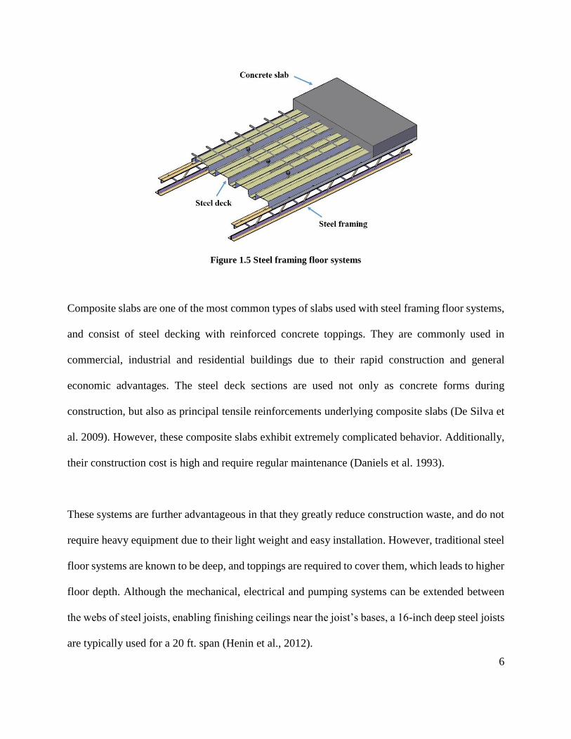
(OWSJ) used as the main steel framing, illustrated in Figure 1.5, have been used extensively in
industrial and structural applications.
6
Figure 1.5 Steel framing floor systems
Composite slabs are one of the most common types of slabs used with steel framing floor systems,
and consist of steel decking with reinforced concrete toppings. They are commonly used in
commercial, industrial and residential buildings due to their rapid construction and general
economic advantages. The steel deck sections are used not only as concrete forms during
construction, but also as principal tensile reinforcements underlying composite slabs (De Silva et
al. 2009). However, these composite slabs exhibit extremely complicated behavior. Additionally,
their construction cost is high and require regular maintenance (Daniels et al. 1993).
These systems are further advantageous in that they greatly reduce construction waste, and do not
require heavy equipment due to their light weight and easy installation. However, traditional steel
floor systems are known to be deep, and toppings are required to cover them, which leads to higher
floor depth. Although the mechanical, electrical and pumping systems can be extended between
the webs of steel joists, enabling finishing ceilings near the joist’s bases, a 16-inch deep steel joists
are typically used for a 20 ft. span (Henin et al., 2012).
7
1.2.3 Emerging Floor Systems
In addition to the traditional floor systems presented above, numerous new floor systems have
been developed, including the shallow flat soffit precast concrete floor system, Girder-slab system,
Deltabeam system, Cobiax system, and Versa floor, are introduced in this section.
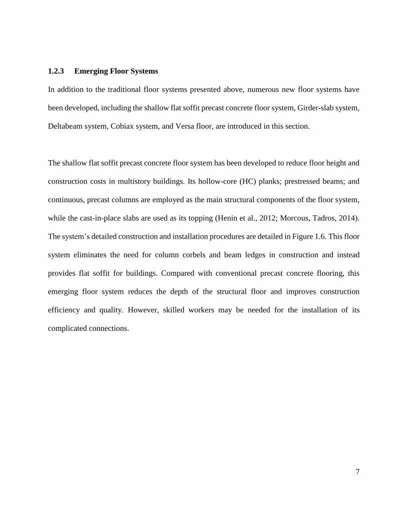
The shallow flat soffit precast concrete floor system has been developed to reduce floor height and
construction costs in multistory buildings. Its hollow-core (HC) planks; prestressed beams; and
continuous, precast columns are employed as the main structural components of the floor system,
while the cast-in-place slabs are used as its topping (Henin et al., 2012; Morcous, Tadros, 2014).
The system’s detailed construction and installation procedures are detailed in Figure 1.6. This floor
system eliminates the need for column corbels and beam ledges in construction and instead
provides flat soffit for buildings. Compared with conventional precast concrete flooring, this
emerging floor system reduces the depth of the structural floor and improves construction
efficiency and quality. However, skilled workers may be needed for the installation of its
complicated connections.
8
a) Construction sequence (Morcous,
Tadros, 2014)
b) Installation of HC-beam connection
reinforcement (Henin et al., 2012)
Figure 1.6 The shallow flat soffit precast concrete floor systems
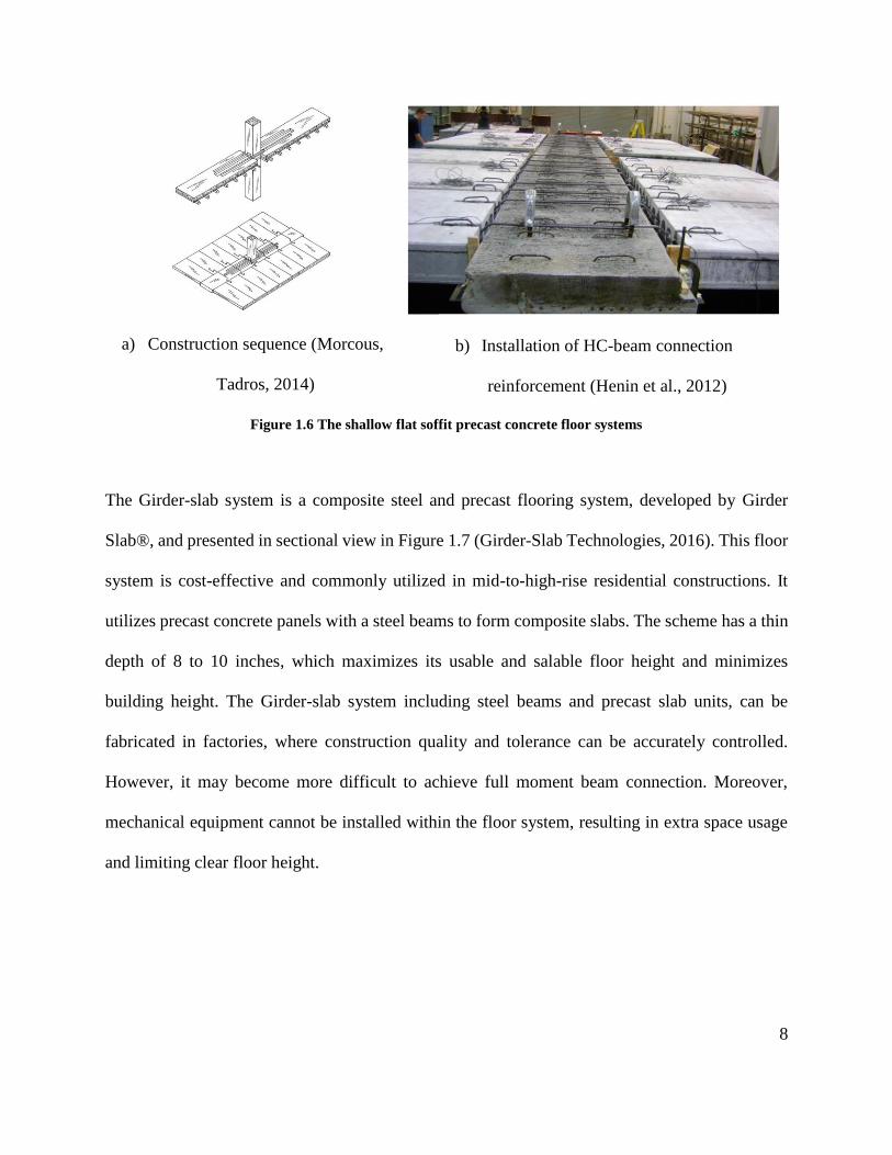
The Girder-slab system is a composite steel and precast flooring system, developed by Girder
Slab®, and presented in sectional view in Figure 1.7 (Girder-Slab Technologies, 2016). This floor
system is cost-effective and commonly utilized in mid-to-high-rise residential constructions. It
utilizes precast concrete panels with a steel beams to form composite slabs. The scheme has a thin
depth of 8 to 10 inches, which maximizes its usable and salable floor height and minimizes
building height. The Girder-slab system including steel beams and precast slab units, can be
fabricated in factories, where construction quality and tolerance can be accurately controlled.
However, it may become more difficult to achieve full moment beam connection. Moreover,
mechanical equipment cannot be installed within the floor system, resulting in extra space usage
and limiting clear floor height.
9
Figure 1.7 The Girder-slab system (Girder-Slab Technologies, 2016)
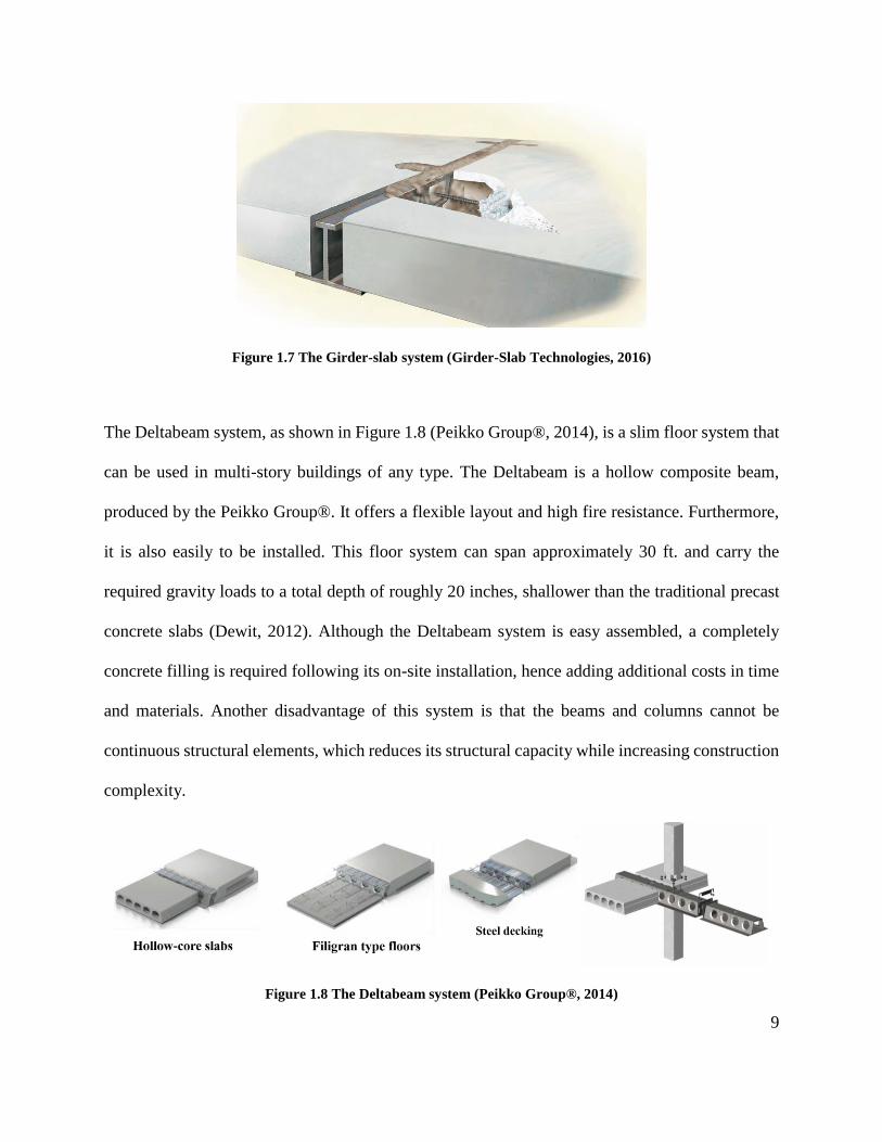
The Deltabeam system, as shown in Figure 1.8 (Peikko Group®, 2014), is a slim floor system that
can be used in multi-story buildings of any type. The Deltabeam is a hollow composite beam,
produced by the Peikko Group®. It offers a flexible layout and high fire resistance. Furthermore,
it is also easily to be installed. This floor system can span approximately 30 ft. and carry the
required gravity loads to a total depth of roughly 20 inches, shallower than the traditional precast
concrete slabs (Dewit, 2012). Although the Deltabeam system is easy assembled, a completely
concrete filling is required following its on-site installation, hence adding additional costs in time
and materials. Another disadvantage of this system is that the beams and columns cannot be
continuous structural elements, which reduces its structural capacity while increasing construction
complexity.
Figure 1.8 The Deltabeam system (Peikko Group®, 2014)
10
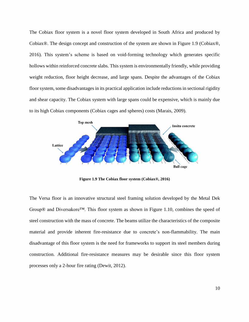
The Cobiax floor system is a novel floor system developed in South Africa and produced by
Cobiax®. The design concept and construction of the system are shown in Figure 1.9 (Cobiax®,
2016). This system’s scheme is based on void-forming technology which generates specific
hollows within reinforced concrete slabs. This system is environmentally friendly, while providing
weight reduction, floor height decrease, and large spans. Despite the advantages of the Cobiax
floor system, some disadvantages in its practical application include reductions in sectional rigidity
and shear capacity. The Cobiax system with large spans could be expensive, which is mainly due
to its high Cobiax components (Cobiax cages and spheres) costs (Marais, 2009).
Figure 1.9 The Cobiax floor system (Cobiax®, 2016)
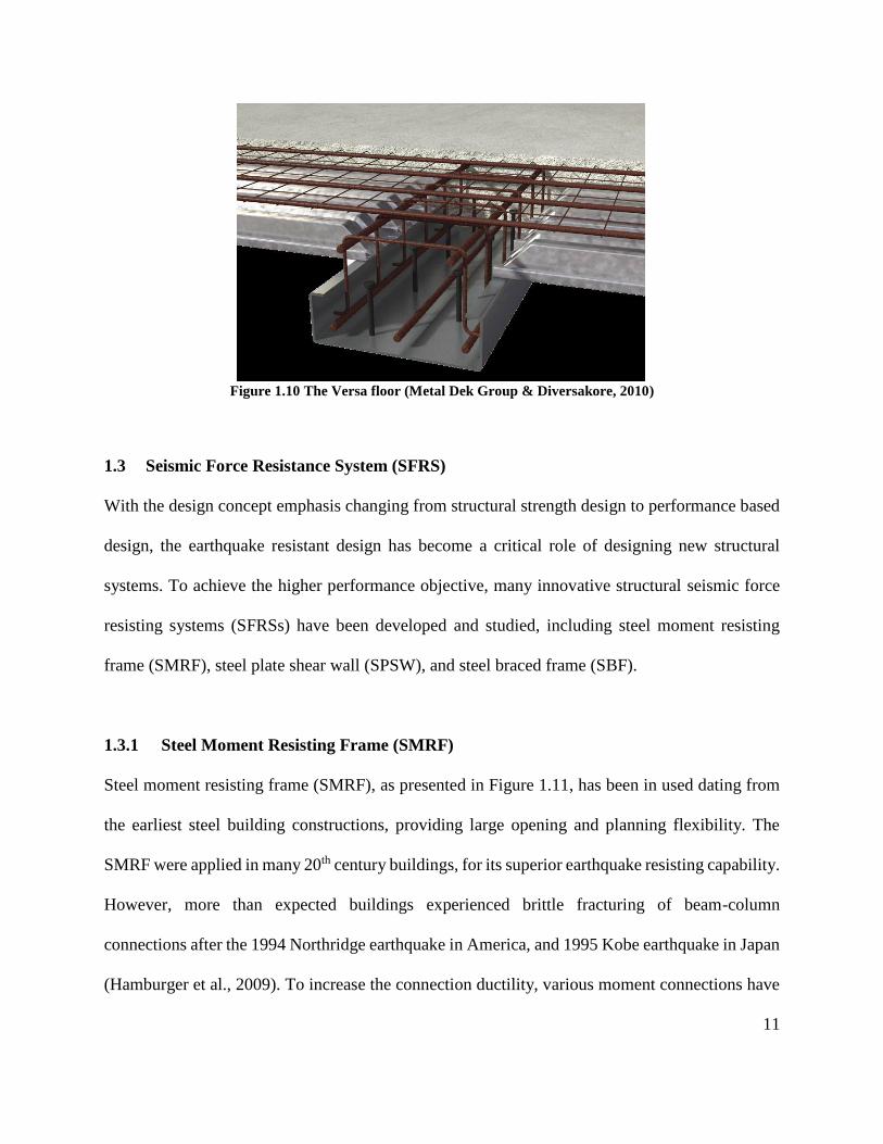
The Versa floor is an innovative structural steel framing solution developed by the Metal Dek
Group® and Diversakore™. This floor system as shown in Figure 1.10, combines the speed of
steel construction with the mass of concrete. The beams utilize the characteristics of the composite
material and provide inherent fire-resistance due to concrete’s non-flammability. The main
disadvantage of this floor system is the need for frameworks to support its steel members during
construction. Additional fire-resistance measures may be desirable since this floor system
processes only a 2-hour fire rating (Dewit, 2012).
11
Figure 1.10 The Versa floor (Metal Dek Group & Diversakore, 2010)
1.3 Seismic Force Resistance System (SFRS)
With the design concept emphasis changing from structural strength design to performance based
design, the earthquake resistant design has become a critical role of designing new structural
systems. To achieve the higher performance objective, many innovative structural seismic force
resisting systems (SFRSs) have been developed and studied, including steel moment resisting
frame (SMRF), steel plate shear wall (SPSW), and steel braced frame (SBF).
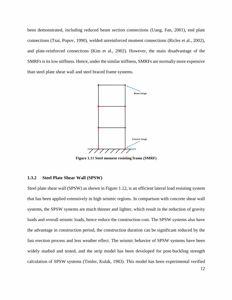
1.3.1 Steel Moment Resisting Frame (SMRF)
Steel moment resisting frame (SMRF), as presented in Figure 1.11, has been in used dating from
the earliest steel building constructions, providing large opening and planning flexibility. The
SMRF were applied in many 20th century buildings, for its superior earthquake resisting capability.
However, more than expected buildings experienced brittle fracturing of beam-column
connections after the 1994 Northridge earthquake in America, and 1995 Kobe earthquake in Japan
(Hamburger et al., 2009). To increase the connection ductility, various moment connections have
12
been demonstrated, including reduced beam section connections (Uang, Fan, 2001), end plate
connections (Tsai, Popov, 1990), welded unreinforced moment connections (Ricles et al., 2002),
and plate-reinforced connections (Kim et al., 2002). However, the main disadvantage of the
SMRFs is its low stiffness. Hence, under the similar stiffness, SMRFs are normally more expensive
than steel plate shear wall and steel braced frame systems.
Figure 1.11 Steel moment resisting frame (SMRF)
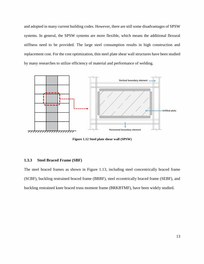
1.3.2 Steel Plate Shear Wall (SPSW)
Steel plate shear wall (SPSW) as shown in Figure 1.12, is an efficient lateral load resisting system
that has been applied extensively in high seismic regions. In comparison with concrete shear wall
systems, the SPSW systems are much thinner and lighter, which result in the reduction of gravity
loads and overall seismic loads, hence reduce the construction cost. The SPSW systems also have
the advantage in construction period, the construction duration can be significant reduced by the
fast erection process and less weather effect. The seismic behavior of SPSW systems have been
widely studied and tested, and the strip model has been developed for post-buckling strength
calculation of SPSW systems (Timler, Kulak, 1983). This model has been experimental verified
13
and adopted in many current building codes. However, there are still some disadvantages of SPSW
systems. In general, the SPSW systems are more flexible, which means the additional flexural
stiffness need to be provided. The large steel consumption results in high construction and
replacement cost. For the cost optimization, thin steel plate shear wall structures have been studied
by many researches to utilize efficiency of material and performance of welding.
Figure 1.12 Steel plate shear wall (SPSW)
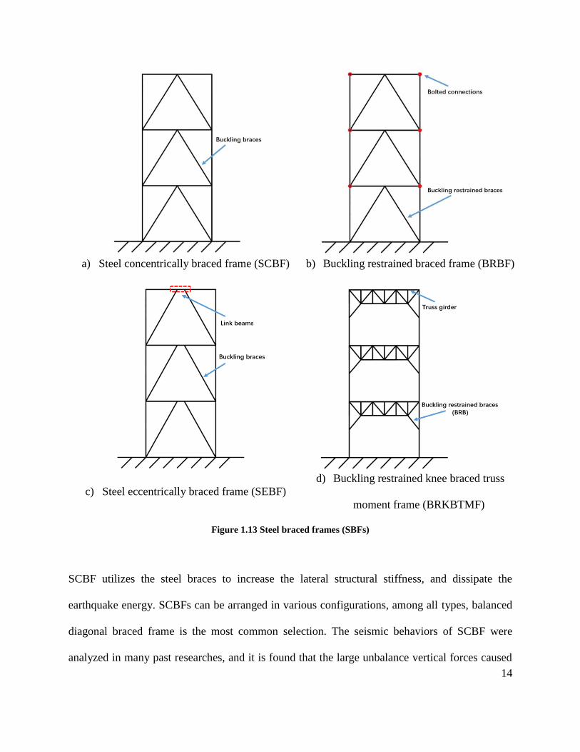
1.3.3 Steel Braced Frame (SBF)
The steel braced frames as shown in Figure 1.13, including steel concentrically braced frame
(SCBF), buckling restrained braced frame (BRBF), steel eccentrically braced frame (SEBF), and
buckling restrained knee braced truss moment frame (BRKBTMF), have been widely studied.
14
a) Steel concentrically braced frame (SCBF) b) Buckling restrained braced frame (BRBF)
c) Steel eccentrically braced frame (SEBF)
d) Buckling restrained knee braced truss
moment frame (BRKBTMF)
Figure 1.13 Steel braced frames (SBFs)
SCBF utilizes the steel braces to increase the lateral structural stiffness, and dissipate the
earthquake energy. SCBFs can be arranged in various configurations, among all types, balanced
diagonal braced frame is the most common selection. The seismic behaviors of SCBF were
analyzed in many past researches, and it is found that the large unbalance vertical forces caused
15
by brace buckling. To solve this disadvantage, conventional steel braces are replaced by buckling
restrained braces (BRBs) in BRBF, and first studied in a North America project (Clark et al., 1999).
The experimental results showed high energy dissipation performance of this structural system.
SEBF is a relatively new SFRS, proposed by Popov (Popov, Engelhardt, 1988). SEBF combines
the features of SMRF and SCBF, while minimizing the disadvantages of both systems. The SEBFs
can be classified as shear-controlled or flexural controlled SEBF, according to the link length. The
shear-controlled links are favorable with its excellent behavior, while the flexural-controlled links
are preferred for its large openings.
To achieve the higher performance objective, an innovative steel SFRS, buckling restrained knee
braced truss moment frame (BRKBTMF) was initiated by (Leelataviwat et al., 2012) and further
studied by (Yang et al., 2015; Yang et al., 2013). The buckling restrained braces (BRBs) are
utilized in the BRKBTMF, as the structural fuses to dissipate energy under severe seismic
loadings, providing a robust and resilient structural system towards future earthquakes. More
importantly, the structural fuses can be easily and efficiently construction using bolted or pinned
connections, and can be more easily replaced after earthquakes. The detailed parameter study of
optimization of the BRBKTMF has been conducted, and the results show that the optimal BRB
inclinations are either horizontal or connecting directly to the end of the columns. In conclusion,
the SBFs provide high performance without adding significant structural weight. However, the
SBFs are not favorable by architectures for its opening limitations.
Although the extensively numerical and experimental studies of SRFSs have been conducted over
past decades, there are relatively less researches about modular applications of SRFSs. In addition,
16
most SFRFs are analyzed as two-dimensional models, without considering the combination of
floor system and SFRFs.
1.4 Modular Steel Truss System (MSTS)
Based on the literature review, this thesis proposes an innovative and economical modular steel
truss system (MSTS), utilizing modular steel floor system (MSFS) in section 1.4.1, and modular
buckling restrained braced truss moment frame (MBRBTMF) in section 1.4.2. The designed
MSTS is targeted to be effective and efficient in resisting both gravity and seismic loads.
1.4.1 Modular Steel Floor System (MSFS)
Floor system design is influenced by spanning requirements and the loads to be supported.
Depending on the variety of floor system employed, the structural strength requires controlling for
during the design procedure according to the design standards. Additionally, the maximum
deflection of the floor system as defined in NBCC 2015 Table 9.4.3.1 (National Research Council
of Canada, 2015). For the system’s structural members, including floor beams, joists, and decking,
under all cases of supported ceilings, the maximum allowable deflection is that of span/360, and
dead loads need not be considered when computing deflections. For load combinations, the
deflection limitation criterion is defined as span/240. Thickness is another crucial factor to be
considered. For concrete floor systems, concrete thickness is a primary design decision. In
residential constructions, nominal 8-inch-thick concrete slabs are readily available, while for office
buildings, concrete thickness is usually around 10 inches. For the design of residential and
commercial concrete floor system, several requirements are defined by the floor class, as listed in
ACI 302.1R-15 (American Concrete Institute, 2015). The guide identifies the various classes of
17
concrete floors in use, along with their design details, site preparation, and concrete and related
material types.
The previous described lack of an efficient steel system curtails the growth and development of
the steel constructions. Also, due to the greater number of floors within buildings, the floor systems
have a significant impact on construction costs and structural height. This makes the choice of
floor system essential, particularly as floor system depth. Traditional steel floor systems are deep,
and the space within the floors is not fully utilized, but wasted. Therefore, it is practical for both
designers and engineers to increase construction efficiency while minimizing floor depth. More
importantly, with increasing trends in steel high-rise structures worldwide, developing a more
efficient floor for modular steel constructions is becoming a crucial criterion in maximizing usable
space within constructions. As well, in the interest of achieving the steel industry’s required
environmental and sustainable developmental objectives, it is essential that steel floor systems be
constructed more efficiently and create fewer carbon footprints. Also, reducing floor depth would
save usable space, allowing for additional floors while maintaining building’s structural height. In
this thesis, a novel MSFS has been developed to resolve above mentioned issues. To fully utilize
the space within floors, the mechanical, electrical and plumbing (MEP) systems are designed to fit
within thinner floor depths. Also, the specially designed MEP systems are pre-installed within the
proposed floor system.
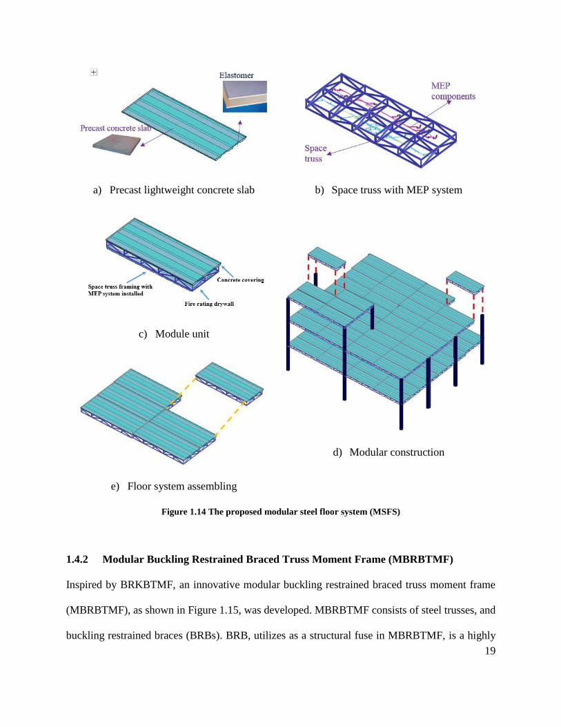
The design concept of the proposed MSFS is illustrated in Figure 1.14. This modular steel floor is
comprised of a structural truss framing system and sandwich non-structural components, as shown
respectively in Figure 1.14a and Figure 1.14b, which can significantly minimize the floor depth of

18
a multi-story steel structure, hence increasing its saleable space. These floor moduli can be used
as part of modular constructions in practical projects and improve the efficiency of conventional
steel structures. The modular floor system can be shipped to sites as individual units (Figure 1.14c)
and then assembled on-site (Figure 1.14d and Figure 1.14e). To facilitate the transportation of
modular units, the dimensions of each floor module will be limited to 20 by 8 ft., which are easily
stacked and transported using conventional semi-trailer (18-wheeler) trucks.
19
a) Precast lightweight concrete slab
b) Space truss with MEP system
c) Module unit
d) Modular construction
e) Floor system assembling
Figure 1.14 The proposed modular steel floor system (MSFS)
1.4.2 Modular Buckling Restrained Braced Truss Moment Frame (MBRBTMF)
Inspired by BRKBTMF, an innovative modular buckling restrained braced truss moment frame
(MBRBTMF), as shown in Figure 1.15, was developed. MBRBTMF consists of steel trusses, and
buckling restrained braces (BRBs). BRB, utilizes as a structural fuse in MBRBTMF, is a highly
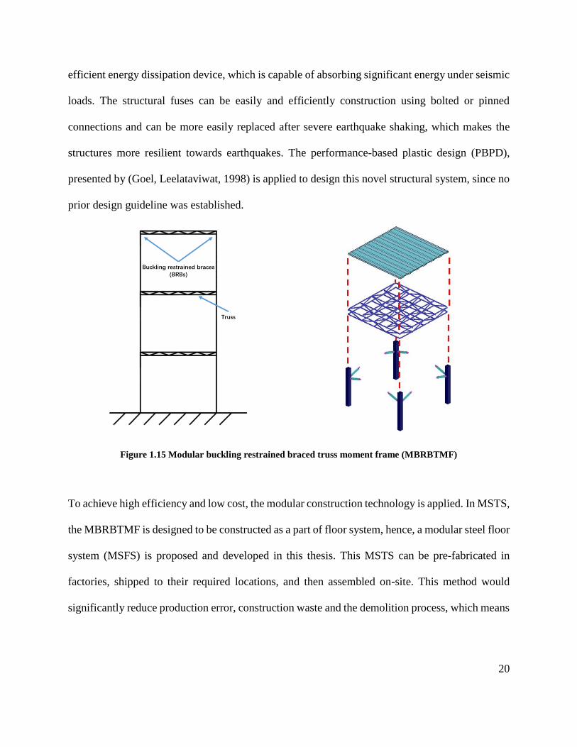
20
efficient energy dissipation device, which is capable of absorbing significant energy under seismic
loads. The structural fuses can be easily and efficiently construction using bolted or pinned
connections and can be more easily replaced after severe earthquake shaking, which makes the
structures more resilient towards earthquakes. The performance-based plastic design (PBPD),
presented by (Goel, Leelataviwat, 1998) is applied to design this novel structural system, since no
prior design guideline was established.
Figure 1.15 Modular buckling restrained braced truss moment frame (MBRBTMF)
To achieve high efficiency and low cost, the modular construction technology is applied. In MSTS,
the MBRBTMF is designed to be constructed as a part of floor system, hence, a modular steel floor
system (MSFS) is proposed and developed in this thesis. This MSTS can be pre-fabricated in
factories, shipped to their required locations, and then assembled on-site. This method would
significantly reduce production error, construction waste and the demolition process, which means
21
less labour, lower costs, and less installation and construction time. In addition, MBRBTMF offers
large opening, which is favorable by architectures.
1.5 Research Scope
This study aims to develop an efficient and economically viable modular steel floor system that
can be employed worldwide in steel constructions. This would be achieved through
• Providing a preliminary study of previous floor systems and SFRS studies, and then
proposing an initial prototype design. Detailed connector designs between modulus floor
units will be carefully considered, while ensuring easy construction and installation
methods.
• Developing a finite element model of the designed MSFS using OpenSees (Pacific
Earthquake Engineering Research (PEER) Center, 2005). Once the model is completed, an
optimization algorithm will be developed to optimize the geometry of the floor system in
interest of achieving optimal structural efficiency and material usage. Since the
optimization process requires an iterative procedure, a programming script will also be
developed through the Matlab (The Mathworks, 1998).
• Designing a prototype MBRBTMF system using the PBPD method, a detail design
procedure will be presented. Conducting a detailed nonlinear dynamic analysis of both
proposed MSTS and conventional structures using MSFS, to confirm the structural
efficiency and safety under gravity and seismic loads.
• Upon completion of the prototype design, structural optimization and analytical simulation,
a detailed assessment regarding construction cost and time will be conducted and compared
with concrete and steel floor systems in conventional structures.
22
1.6 Thesis Outline
The conceptual and structural design and seismic performance of proposed modular steel floor
system will be discussed in the following chapters:
• Chapter 2 Design and Optimization of Modular Steel Floor System: A preliminary
study of the modular steel floor system and connector designs is provided. At the end of
the chapter, an initial structural design of proposed modular steel floor system is presented.
For the connector design, the common connectors for space trusses were used, while an
innovative concept of honeycomb connector for structural components was proposed. The
proposed modular steel floor system was designed using NBCC 2015 (National Research
Council of Canada, 2015), CSA S16-14 (Canadian Institute of Steel Construction, 2014)
and the AISC steel manual (American Institute of Steel Construction, 2013). The detailed
optimization process was conducted to identify the optimal design which uses the least
amount of structural material, yet satisfied both strength and deflection limits. Robust
structural optimization was conducted using the OpenSees and Matlab programs. A
parameter study of the proposed modular steel floor system and a comparison of the
modular steel floor, conventional concrete, and steel floor systems were performed. The
deflection, natural frequency and mode shape of the proposed modular steel floor system
were also analyzed. The serviceability of the floor system under excitation was additionally
studied.
• Chapter 3 Seismic Design of Modular Steel Truss System: The designed modular steel
truss system (MSTS) consists of both gravity and seismic force resisting system. Upon the
23
completion of MSFS, as the main gravity system, an innovative modular buckling
restrained braced truss moment frame (MBRBTMF) was designed using the performance-
based plastic design (PBPD) procedure. The PBPD method uses energy-based plastic
design approach to satisfy both strength and story drift limitations. The buckling restrained
braces (BRBs) were utilized as the structural fuses. The MBRBTMF is targeted to be
applied for different hazard levels, without redesign the floor system. A detailed design
procedure of MBRBTMF is presented. A prototype 4-story modular steel truss system
(MSTS) building was designed. The hazard analysis was conducted for the construction
site, and the ground motions were selected and scaled to the target spectrum. The nonlinear
analysis was used to quantify the design procedure and the seismic performance of
designed modular system. The incremental dynamic analysis was also conducted to
provide the collapse assessment of the prototype building.
• Chapter 4 Application of Modular Steel Floor Systems in Conventional Structural
Systems: To promote the use of modular steel floor systems (MSFSs) for different
applications, the performances of structures with conventional SFRSs and MSFSs were
studied. The prototype buckling restrained braced frame (BRBF) and buckling restrained
knee braced truss moment frame (BRKBTMF) buildings, using MSFS, were designed
following PBPD procedure and modelled. A design spectrum was developed, and the
ground motions used in the analysis were selected and scaled. Time history analyses of
structures are conducted through the OpenSees program to study their seismic
performance, and the comparison results of the prototype buildings with the proposed
modular steel floor, conventional concrete floor, and steel floor systems are presented. The
24
construction cost is displayed to provide a visual idea of the advantages of the proposed
modular steel floor system. To reduce computational complexity, the study of simplified
model with rigid diaphragm was also conducted.
• Chapter 5 Summary and Conclusions: A detailed summary of the research results and
conclusions for the proposed modular steel building is provided.
25
Chapter 2: Design and Optimization of Modular Steel Floor System
Based on the literature review, this thesis proposes an innovative modular steel truss system
(MSTS), consisting of both gravity and seismic force resisting systems. The modular steel floor
system (MSFS), as the main gravity system, was designed and optimized in this thesis. During the
prototype design of the MSFS, many parameters, such as the dimensions of the modular unit,
structural layouts, and connectors, must be considered and evaluated. The initial design of the
proposed modular floor system is determined during this phase.
2.1 Prototype Design
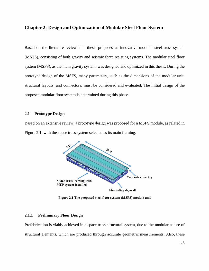
Based on an extensive review, a prototype design was proposed for a MSFS module, as related in
Figure 2.1, with the space truss system selected as its main framing.
Figure 2.1 The proposed steel floor system (MSFS) module unit
2.1.1 Preliminary Floor Design
Prefabrication is viably achieved in a space truss structural system, due to the modular nature of
structural elements, which are produced through accurate geometric measurements. Also, these
26
structural systems might be further extended or disassembled and reinstalled. This provides higher
quality control, less on-site labor usage, and creates less environmental pollution. The dimension
for each MSFS modular unit will be limited to 20 by 8 ft., which can be easily transported using
conventional trucks.
The proposed MSFS has multiple layers. The top layer one consists of a concrete covering and
acts as the foundation for the floor above it. If required, non-structural components such as carpets
or tiles can be superimposed largely for additional decorative purposes. The use of the concrete
covering serves many advantages, including fire and sound insulation and added stiffness and
strength for deflection and load control. Beneath this covering, is a series of specially designed
steel space trusses. These trusses are the main structural framing for the proposed modular floor
systems. The trusses are designed to be easily connected and provide sufficient stiffness for large
span. The space between the steel trusses can produce that required for the mechanical, electrical
and plumbing (MEP) systems, and the MEP system is pre-installed within the proposed modular
unit.
To reduce construction time and cost, the space truss internal to each modular unit should contain
continuous chord member. The connectors between the modular units would be applied for quick
and easy installation and assembling. Lastly, a fire rating drywall will be added as the final layer.
This will be the finishing stratum of the ceiling for the proceeding floor system. To ensure
transportability, the light bulbs will not be pre-installed in the factory, but light wiring will be
installed inside within modular steel floor system. The proposed floor system will be designed to
27
provide sufficient stiffness to minimize deflection under the loads, with a minimum 2-hour
fireproof rating and 20-dB noise reduction.
2.1.2 Connector Design
A significant advantage to steel construction is that most structural members can be designed and
fabricated in a factory and then quickly assembled on site. However, connectors are usually created
uniquely to suit diverse projects, increasing construction cost and time. An efficient way to
improve the efficiency of connector construction is to have a flexibly designed connector, which
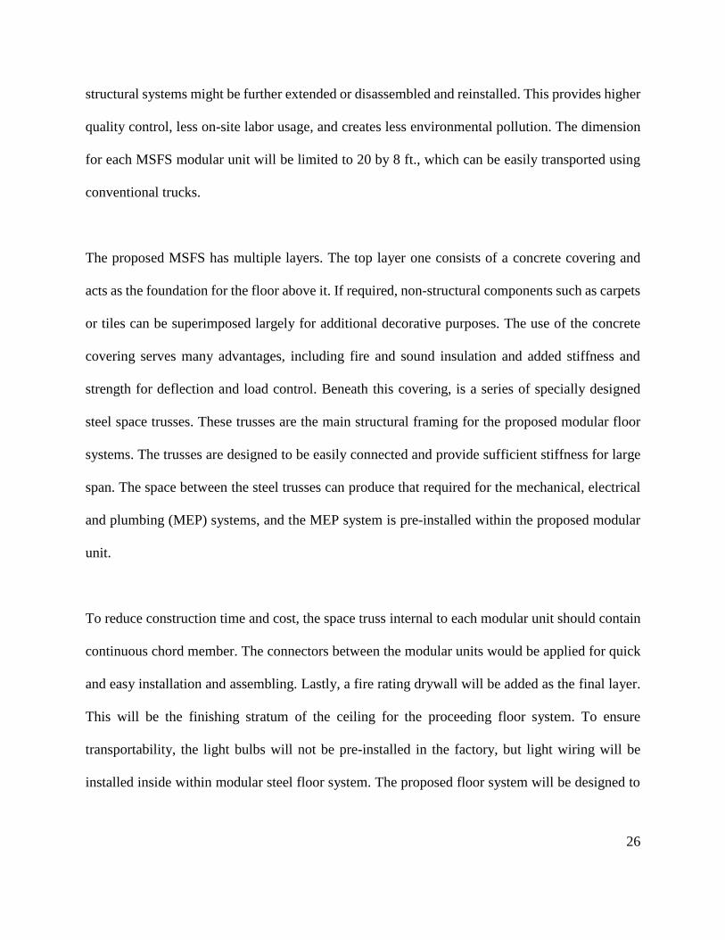
can be modified to any shape or size to fit current architecture demands. The multi angle
connectors as shown in Figure 2.2 are used for space trusses, and a concept of honeycomb steel
connector for structural elements is proposed.
Figure 2.2 Space truss connector
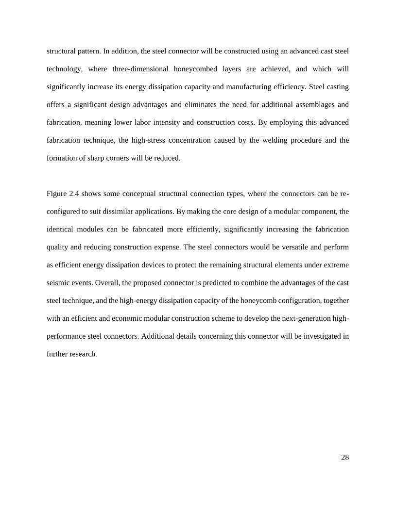
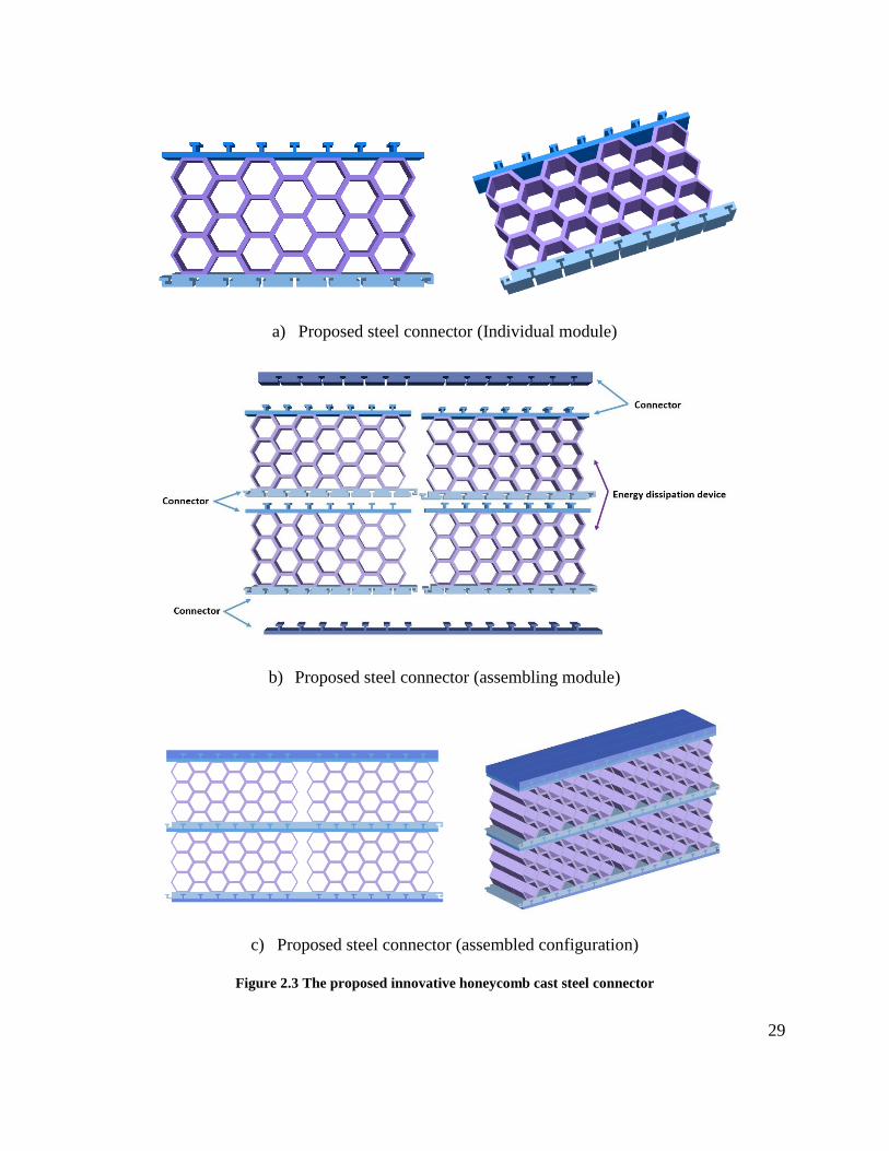
A concept of prototype honeycomb cast steel connector is shown in Figure 2.3, which utilizes the
advantages of the natural honeycomb configuration as its seismic energy dissipation device (Figure
2.3a). This connector has more developed redundancy, and greater mechanical properties and
stiffness, by taking extraordinary advantages of the natural honeycomb configuration as its interior
28
structural pattern. In addition, the steel connector will be constructed using an advanced cast steel
technology, where three-dimensional honeycombed layers are achieved, and which will
significantly increase its energy dissipation capacity and manufacturing efficiency. Steel casting
offers a significant design advantages and eliminates the need for additional assemblages and
fabrication, meaning lower labor intensity and construction costs. By employing this advanced
fabrication technique, the high-stress concentration caused by the welding procedure and the
formation of sharp corners will be reduced.
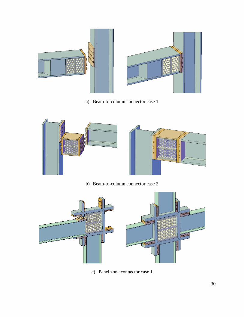
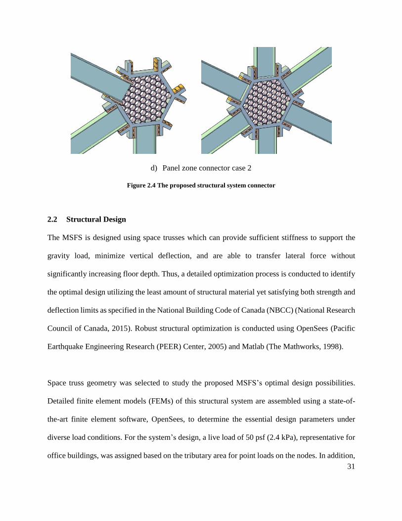
Figure 2.4 shows some conceptual structural connection types, where the connectors can be re-
configured to suit dissimilar applications. By making the core design of a modular component, the
identical modules can be fabricated more efficiently, significantly increasing the fabrication
quality and reducing construction expense. The steel connectors would be versatile and perform
as efficient energy dissipation devices to protect the remaining structural elements under extreme
seismic events. Overall, the proposed connector is predicted to combine the advantages of the cast
steel technique, and the high-energy dissipation capacity of the honeycomb configuration, together
with an efficient and economic modular construction scheme to develop the next-generation high-
performance steel connectors. Additional details concerning this connector will be investigated in
further research.
29
a) Proposed steel connector (Individual module)
b) Proposed steel connector (assembling module)
c) Proposed steel connector (assembled configuration)
Figure 2.3 The proposed innovative honeycomb cast steel connector
30
a) Beam-to-column connector case 1
b) Beam-to-column connector case 2
c) Panel zone connector case 1
31
d) Panel zone connector case 2
Figure 2.4 The proposed structural system connector
2.2 Structural Design
The MSFS is designed using space trusses which can provide sufficient stiffness to support the
gravity load, minimize vertical deflection, and are able to transfer lateral force without
significantly increasing floor depth. Thus, a detailed optimization process is conducted to identify
the optimal design utilizing the least amount of structural material yet satisfying both strength and
deflection limits as specified in the National Building Code of Canada (NBCC) (National Research
Council of Canada, 2015). Robust structural optimization is conducted using OpenSees (Pacific
Earthquake Engineering Research (PEER) Center, 2005) and Matlab (The Mathworks, 1998).
Space truss geometry was selected to study the proposed MSFS’s optimal design possibilities.
Detailed finite element models (FEMs) of this structural system are assembled using a state-of-
the-art finite element software, OpenSees, to determine the essential design parameters under
diverse load conditions. For the system’s design, a live load of 50 psf (2.4 kPa), representative for
office buildings, was assigned based on the tributary area for point loads on the nodes. In addition,
32
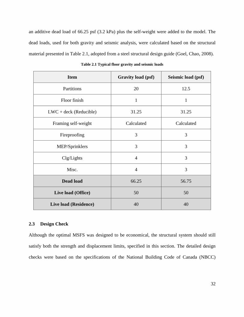
an additive dead load of 66.25 psf (3.2 kPa) plus the self-weight were added to the model. The
dead loads, used for both gravity and seismic analysis, were calculated based on the structural
material presented in Table 2.1, adopted from a steel structural design guide (Goel, Chao, 2008).
Table 2.1 Typical floor gravity and seismic loads
Item Gravity load (psf) Seismic load (psf)
Partitions 20 12.5
Floor finish 1 1
LWC + deck (Reducible) 31.25 31.25
Framing self-weight Calculated Calculated
Fireproofing 3 3
MEP/Sprinklers 3 3
Clg/Lights 4 3
Misc. 4 3
Dead load 66.25 56.75
Live load (Office) 50 50
Live load (Residence) 40 40
2.3 Design Check
Although the optimal MSFS was designed to be economical, the structural system should still
satisfy both the strength and displacement limits, specified in this section. The detailed design
checks were based on the specifications of the National Building Code of Canada (NBCC)
33
(National Research Council of Canada, 2015) and CSA S16-14 (Canadian Institute of Steel
Construction, 2014), are listed below.
2.3.1 Load Combination
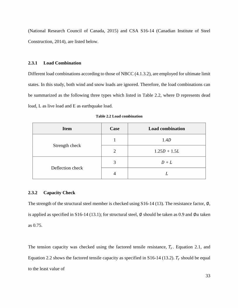
Different load combinations according to those of NBCC (4.1.3.2), are employed for ultimate limit
states. In this study, both wind and snow loads are ignored. Therefore, the load combinations can
be summarized as the following three types which listed in Table 2.2, where D represents dead
load, L as live load and E as earthquake load.
Table 2.2 Load combination
Item Case Load combination
Strength check
1 1.4𝐷
2 1.25𝐷 + 1.5𝐿
Deflection check
3 𝐷 + 𝐿
4 𝐿
2.3.2 Capacity Check
The strength of the structural steel member is checked using S16-14 (13). The resistance factor, ∅,
is applied as specified in S16-14 (13.1); for structural steel, ∅ should be taken as 0.9 and ∅𝑢 taken
as 0.75.
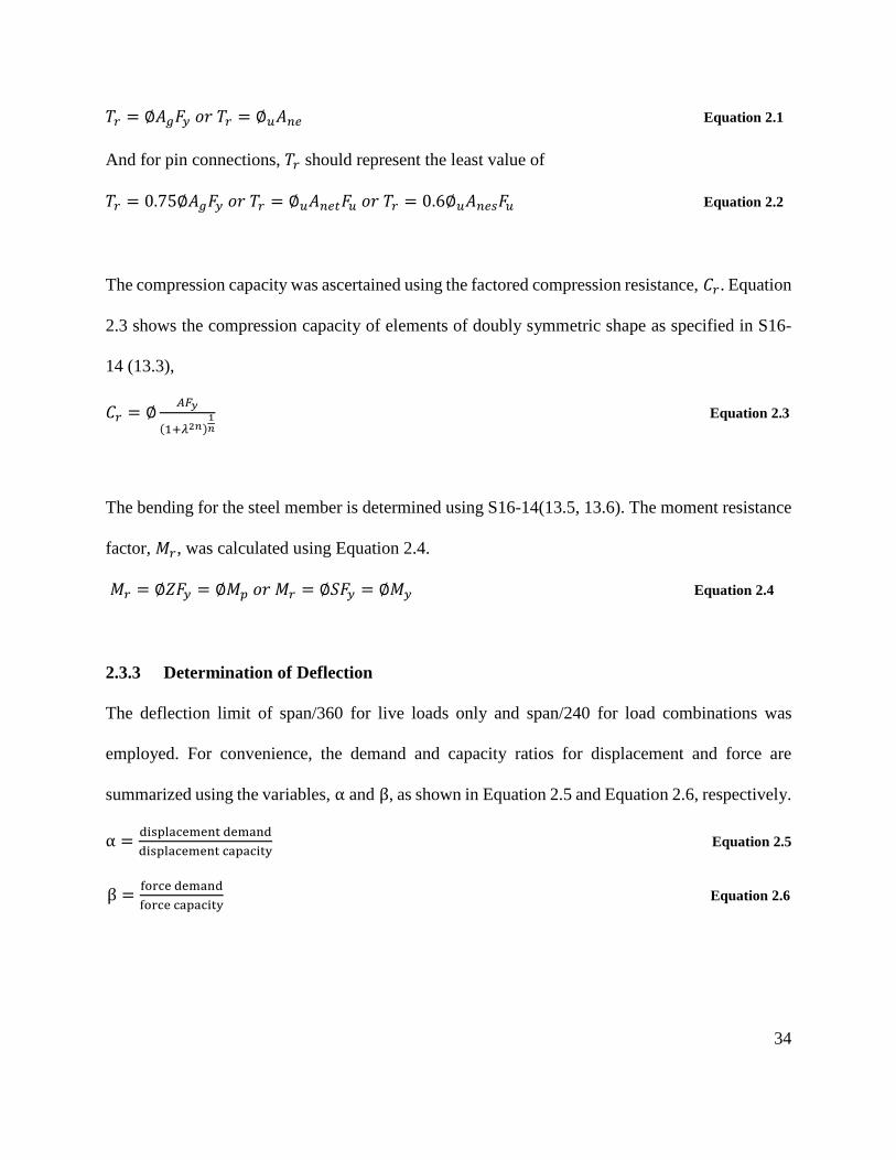
The tension capacity was checked using the factored tensile resistance, 𝑇𝑟 . Equation 2.1, and
Equation 2.2 shows the factored tensile capacity as specified in S16-14 (13.2). 𝑇𝑟 should be equal
to the least value of
34
𝑇𝑟 = ∅𝐴𝑔𝐹𝑦 𝑜𝑟 𝑇𝑟 = ∅𝑢𝐴𝑛𝑒 Equation 2.1
And for pin connections, 𝑇𝑟 should represent the least value of
𝑇𝑟 = 0.75∅𝐴𝑔𝐹𝑦 𝑜𝑟 𝑇𝑟 = ∅𝑢𝐴𝑛𝑒𝑡𝐹𝑢 𝑜𝑟 𝑇𝑟 = 0.6∅𝑢𝐴𝑛𝑒𝑠𝐹𝑢 Equation 2.2
The compression capacity was ascertained using the factored compression resistance, 𝐶𝑟. Equation
2.3 shows the compression capacity of elements of doubly symmetric shape as specified in S16-
14 (13.3),
𝐶𝑟 = ∅𝐴𝐹𝑦
(1+𝜆2𝑛)1𝑛
Equation 2.3
The bending for the steel member is determined using S16-14(13.5, 13.6). The moment resistance
factor, 𝑀𝑟, was calculated using Equation 2.4.
𝑀𝑟 = ∅𝑍𝐹𝑦 = ∅𝑀𝑝 𝑜𝑟 𝑀𝑟 = ∅𝑆𝐹𝑦 = ∅𝑀𝑦 Equation 2.4
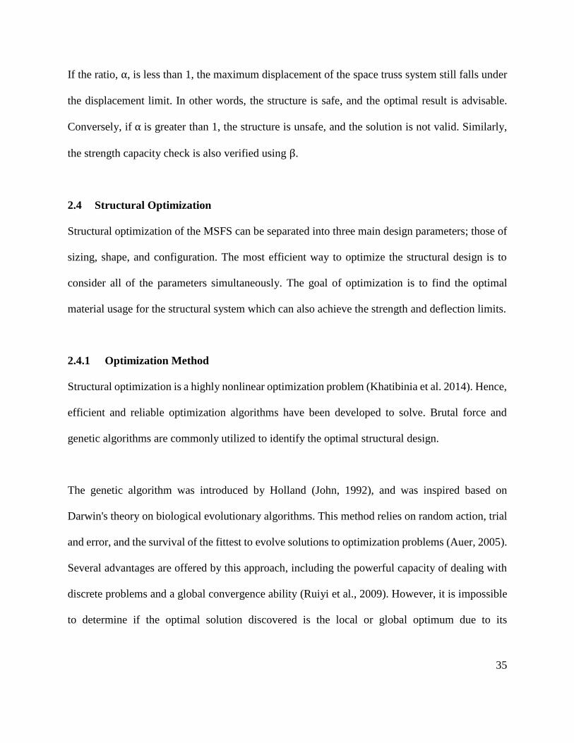
2.3.3 Determination of Deflection
The deflection limit of span/360 for live loads only and span/240 for load combinations was
employed. For convenience, the demand and capacity ratios for displacement and force are
summarized using the variables, α and β, as shown in Equation 2.5 and Equation 2.6, respectively.
α =displacement demand
displacement capacity Equation 2.5
β =force demand
force capacity Equation 2.6
35
If the ratio, α, is less than 1, the maximum displacement of the space truss system still falls under
the displacement limit. In other words, the structure is safe, and the optimal result is advisable.
Conversely, if α is greater than 1, the structure is unsafe, and the solution is not valid. Similarly,
the strength capacity check is also verified using β.
2.4 Structural Optimization
Structural optimization of the MSFS can be separated into three main design parameters; those of
sizing, shape, and configuration. The most efficient way to optimize the structural design is to
consider all of the parameters simultaneously. The goal of optimization is to find the optimal
material usage for the structural system which can also achieve the strength and deflection limits.
2.4.1 Optimization Method
Structural optimization is a highly nonlinear optimization problem (Khatibinia et al. 2014). Hence,
efficient and reliable optimization algorithms have been developed to solve. Brutal force and
genetic algorithms are commonly utilized to identify the optimal structural design.
The genetic algorithm was introduced by Holland (John, 1992), and was inspired based on
Darwin's theory on biological evolutionary algorithms. This method relies on random action, trial
and error, and the survival of the fittest to evolve solutions to optimization problems (Auer, 2005).
Several advantages are offered by this approach, including the powerful capacity of dealing with
discrete problems and a global convergence ability (Ruiyi et al., 2009). However, it is impossible
to determine if the optimal solution discovered is the local or global optimum due to its
36
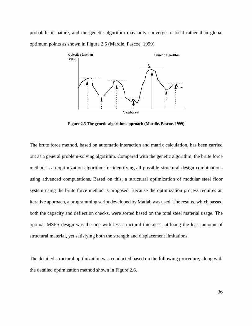
probabilistic nature, and the genetic algorithm may only converge to local rather than global
optimum points as shown in Figure 2.5 (Mardle, Pascoe, 1999).
Figure 2.5 The genetic algorithm approach (Mardle, Pascoe, 1999)
The brute force method, based on automatic interaction and matrix calculation, has been carried
out as a general problem-solving algorithm. Compared with the genetic algorithm, the brute force
method is an optimization algorithm for identifying all possible structural design combinations
using advanced computations. Based on this, a structural optimization of modular steel floor
system using the brute force method is proposed. Because the optimization process requires an
iterative approach, a programming script developed by Matlab was used. The results, which passed
both the capacity and deflection checks, were sorted based on the total steel material usage. The
optimal MSFS design was the one with less structural thickness, utilizing the least amount of
structural material, yet satisfying both the strength and displacement limitations.
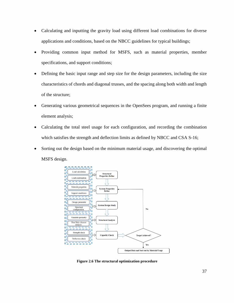
The detailed structural optimization was conducted based on the following procedure, along with
the detailed optimization method shown in Figure 2.6.
37
• Calculating and inputting the gravity load using different load combinations for diverse
applications and conditions, based on the NBCC guidelines for typical buildings;
• Providing common input method for MSFS, such as material properties, member
specifications, and support conditions;
• Defining the basic input range and step size for the design parameters, including the size
characteristics of chords and diagonal trusses, and the spacing along both width and length
of the structure;
• Generating various geometrical sequences in the OpenSees program, and running a finite
element analysis;
• Calculating the total steel usage for each configuration, and recording the combination
which satisfies the strength and deflection limits as defined by NBCC and CSA S-16;
• Sorting out the design based on the minimum material usage, and discovering the optimal
MSFS design.
Figure 2.6 The structural optimization procedure
38
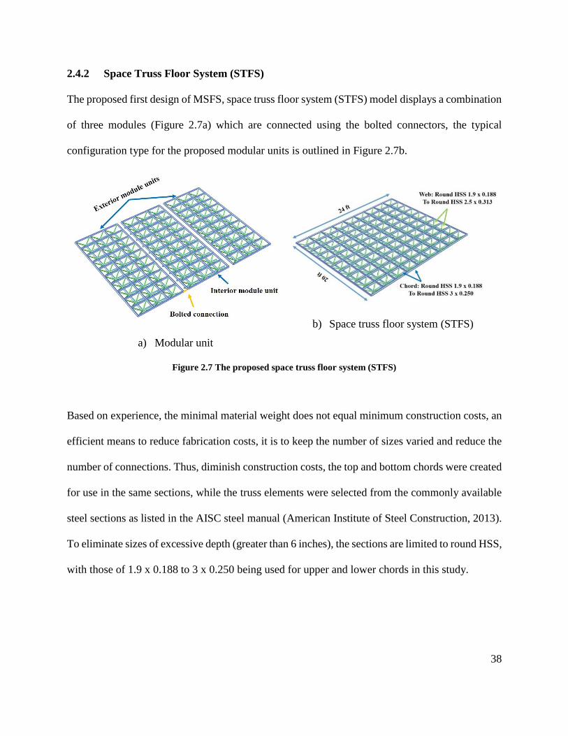
2.4.2 Space Truss Floor System (STFS)
The proposed first design of MSFS, space truss floor system (STFS) model displays a combination
of three modules (Figure 2.7a) which are connected using the bolted connectors, the typical
configuration type for the proposed modular units is outlined in Figure 2.7b.
a) Modular unit
b) Space truss floor system (STFS)
Figure 2.7 The proposed space truss floor system (STFS)
Based on experience, the minimal material weight does not equal minimum construction costs, an
efficient means to reduce fabrication costs, it is to keep the number of sizes varied and reduce the
number of connections. Thus, diminish construction costs, the top and bottom chords were created
for use in the same sections, while the truss elements were selected from the commonly available
steel sections as listed in the AISC steel manual (American Institute of Steel Construction, 2013).
To eliminate sizes of excessive depth (greater than 6 inches), the sections are limited to round HSS,
with those of 1.9 x 0.188 to 3 x 0.250 being used for upper and lower chords in this study.
39
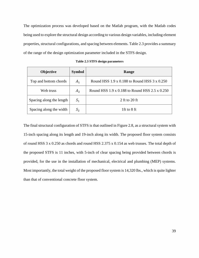
The optimization process was developed based on the Matlab program, with the Matlab codes
being used to explore the structural design according to various design variables, including element
properties, structural configurations, and spacing between elements. Table 2.3 provides a summary
of the range of the design optimization parameter included in the STFS design.
Table 2.3 STFS design parameters
Objective Symbol Range
Top and bottom chords 𝐴1 Round HSS 1.9 x 0.188 to Round HSS 3 x 0.250
Web truss 𝐴2 Round HSS 1.9 x 0.188 to Round HSS 2.5 x 0.250
Spacing along the length 𝑆1 2 ft to 20 ft
Spacing along the width 𝑆2 1ft to 8 ft
The final structural configuration of STFS is that outlined in Figure 2.8, as a structural system with
15-inch spacing along its length and 19-inch along its width. The proposed floor system consists
of round HSS 3 x 0.250 as chords and round HSS 2.375 x 0.154 as web trusses. The total depth of
the proposed STFS is 11 inches, with 5-inch of clear spacing being provided between chords is
provided, for the use in the installation of mechanical, electrical and plumbing (MEP) systems.
Most importantly, the total weight of the proposed floor system is 14,320 lbs., which is quite lighter
than that of conventional concrete floor system.
40
a) Plan view
b) Optimal space truss floor system (STFS)
Figure 2.8 The optimal space truss floor system (STFS)
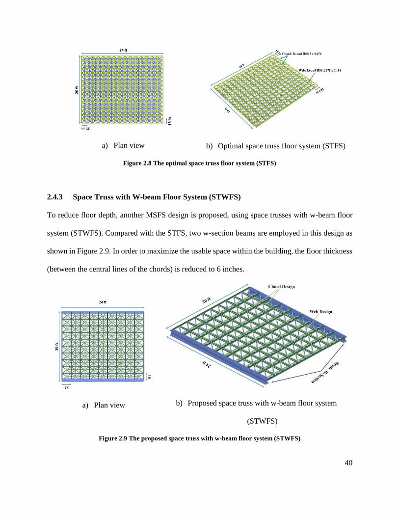
2.4.3 Space Truss with W-beam Floor System (STWFS)
To reduce floor depth, another MSFS design is proposed, using space trusses with w-beam floor
system (STWFS). Compared with the STFS, two w-section beams are employed in this design as
shown in Figure 2.9. In order to maximize the usable space within the building, the floor thickness
(between the central lines of the chords) is reduced to 6 inches.
a) Plan view
b) Proposed space truss with w-beam floor system
(STWFS)
Figure 2.9 The proposed space truss with w-beam floor system (STWFS)
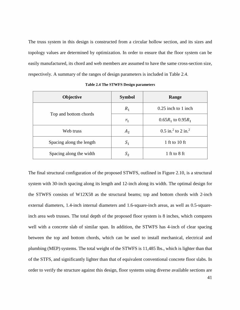
41
The truss system in this design is constructed from a circular hollow section, and its sizes and
topology values are determined by optimization. In order to ensure that the floor system can be
easily manufactured, its chord and web members are assumed to have the same cross-section size,
respectively. A summary of the ranges of design parameters is included in Table 2.4.
Table 2.4 The STWFS Design parameters
Objective Symbol Range
Top and bottom chords
𝑅1 0.25 inch to 1 inch
𝑟1 0.65𝑅1 to 0.95𝑅1
Web truss 𝐴2 0.5 in.2 to 2 in.2
Spacing along the length 𝑆1 1 ft to 10 ft
Spacing along the width 𝑆2 1 ft to 8 ft
The final structural configuration of the proposed STWFS, outlined in Figure 2.10, is a structural
system with 30-inch spacing along its length and 12-inch along its width. The optimal design for
the STWFS consists of W12X58 as the structural beams; top and bottom chords with 2-inch
external diameters, 1.4-inch internal diameters and 1.6-square-inch areas, as well as 0.5-square-
inch area web trusses. The total depth of the proposed floor system is 8 inches, which compares
well with a concrete slab of similar span. In addition, the STWFS has 4-inch of clear spacing
between the top and bottom chords, which can be used to install mechanical, electrical and
plumbing (MEP) systems. The total weight of the STWFS is 11,485 lbs., which is lighter than that
of the STFS, and significantly lighter than that of equivalent conventional concrete floor slabs. In
order to verify the structure against this design, floor systems using diverse available sections are
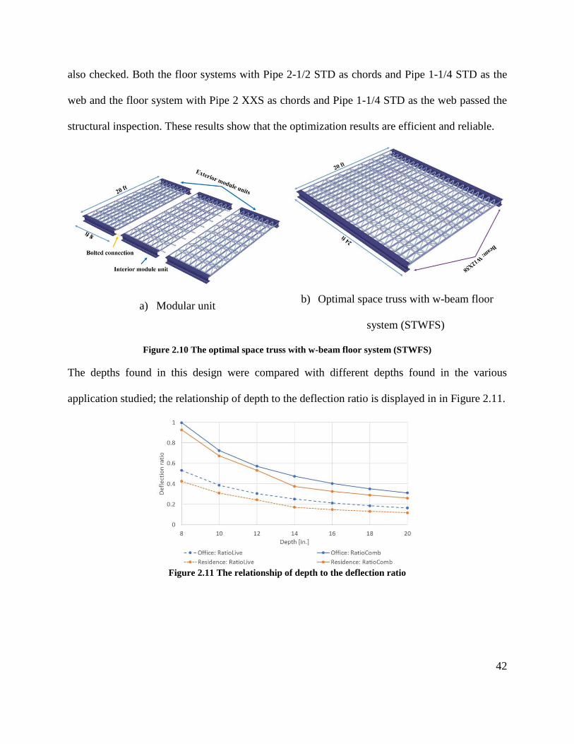
42
also checked. Both the floor systems with Pipe 2-1/2 STD as chords and Pipe 1-1/4 STD as the
web and the floor system with Pipe 2 XXS as chords and Pipe 1-1/4 STD as the web passed the
structural inspection. These results show that the optimization results are efficient and reliable.
a) Modular unit
b) Optimal space truss with w-beam floor
system (STWFS)
Figure 2.10 The optimal space truss with w-beam floor system (STWFS)
The depths found in this design were compared with different depths found in the various
application studied; the relationship of depth to the deflection ratio is displayed in in Figure 2.11.
Figure 2.11 The relationship of depth to the deflection ratio
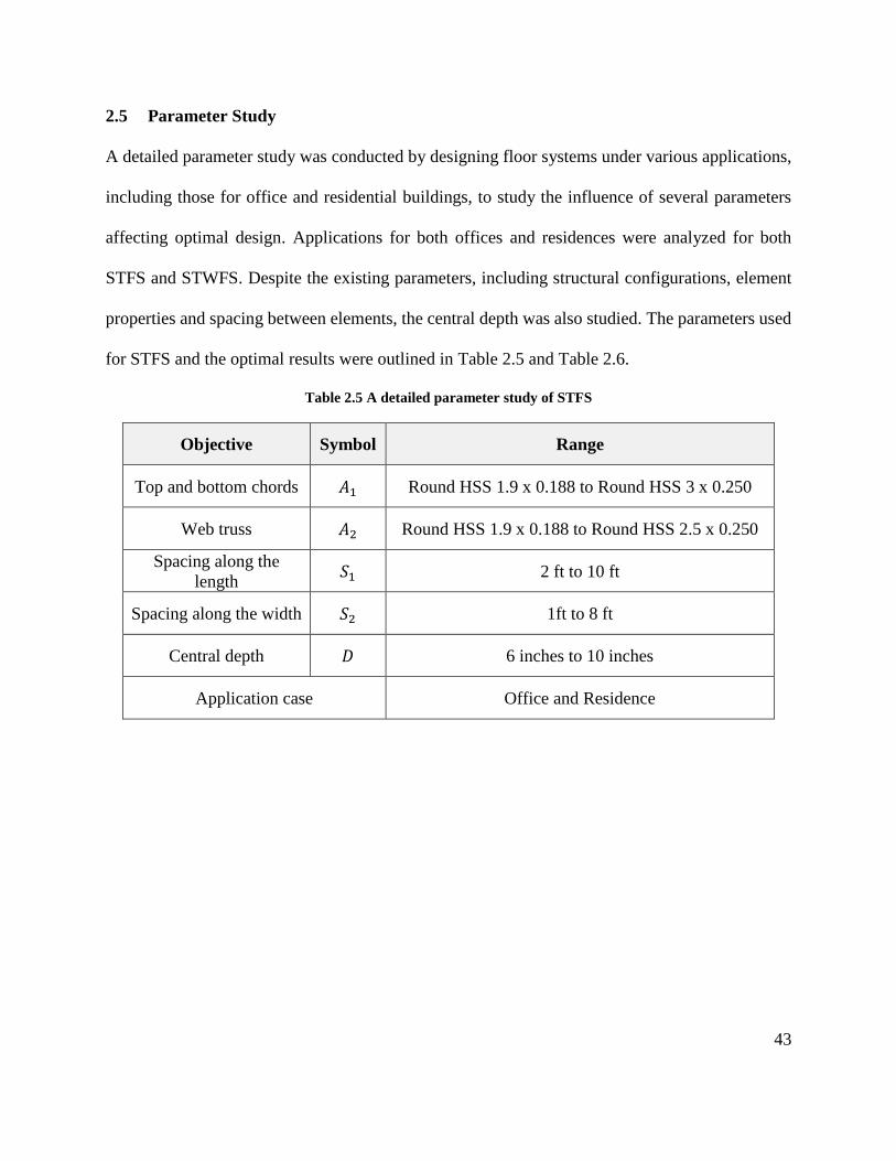
43
2.5 Parameter Study
A detailed parameter study was conducted by designing floor systems under various applications,
including those for office and residential buildings, to study the influence of several parameters
affecting optimal design. Applications for both offices and residences were analyzed for both
STFS and STWFS. Despite the existing parameters, including structural configurations, element
properties and spacing between elements, the central depth was also studied. The parameters used
for STFS and the optimal results were outlined in Table 2.5 and Table 2.6.
Table 2.5 A detailed parameter study of STFS
Objective Symbol Range
Top and bottom chords 𝐴1 Round HSS 1.9 x 0.188 to Round HSS 3 x 0.250
Web truss 𝐴2 Round HSS 1.9 x 0.188 to Round HSS 2.5 x 0.250
Spacing along the
length 𝑆1 2 ft to 10 ft
Spacing along the width 𝑆2 1ft to 8 ft
Central depth 𝐷 6 inches to 10 inches
Application case Office and Residence
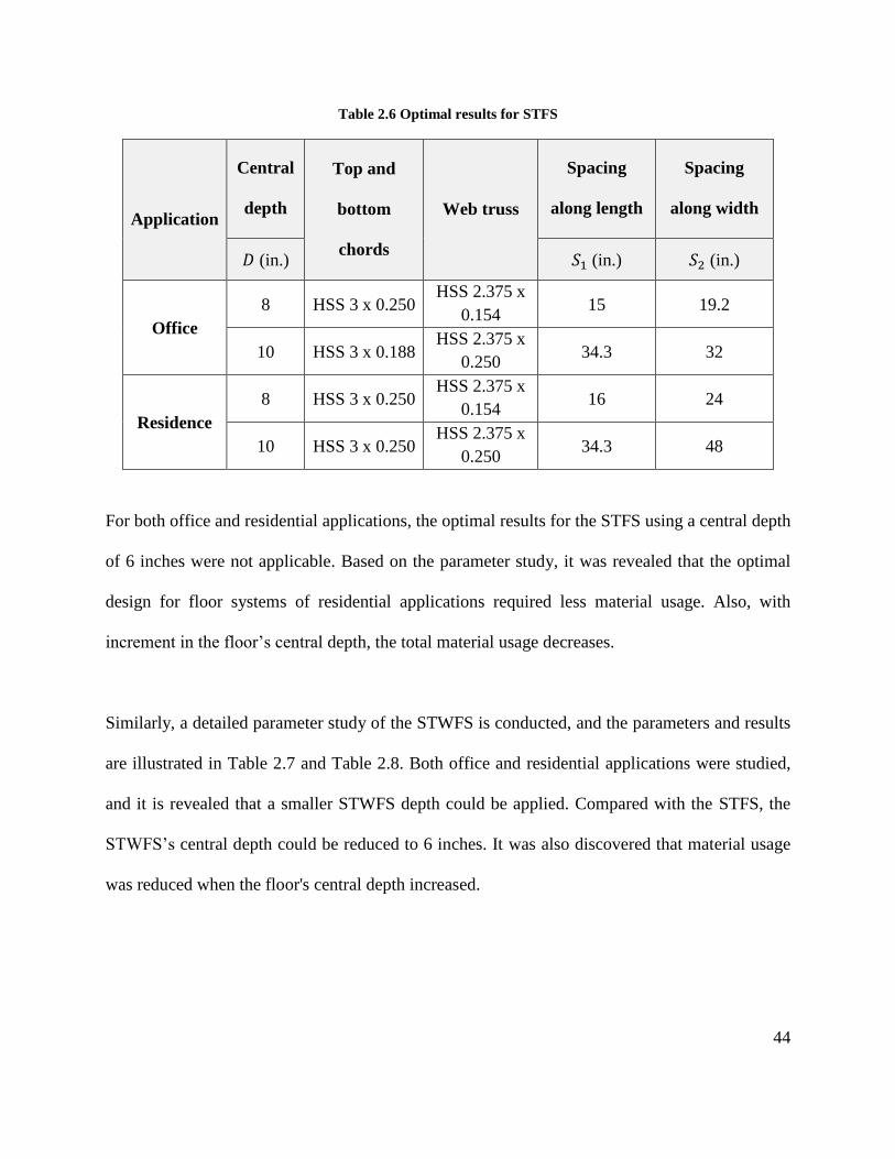
44
Table 2.6 Optimal results for STFS
Application
Central
depth
Top and
bottom
chords
Web truss
Spacing
along length
Spacing
along width
𝐷 (in.) 𝑆1 (in.) 𝑆2 (in.)
Office
8 HSS 3 x 0.250 HSS 2.375 x
0.154 15 19.2
10 HSS 3 x 0.188 HSS 2.375 x
0.250 34.3 32
Residence
8 HSS 3 x 0.250 HSS 2.375 x
0.154 16 24
10 HSS 3 x 0.250 HSS 2.375 x
0.250 34.3 48
For both office and residential applications, the optimal results for the STFS using a central depth
of 6 inches were not applicable. Based on the parameter study, it was revealed that the optimal
design for floor systems of residential applications required less material usage. Also, with
increment in the floor’s central depth, the total material usage decreases.
Similarly, a detailed parameter study of the STWFS is conducted, and the parameters and results
are illustrated in Table 2.7 and Table 2.8. Both office and residential applications were studied,
and it is revealed that a smaller STWFS depth could be applied. Compared with the STFS, the
STWFS’s central depth could be reduced to 6 inches. It was also discovered that material usage
was reduced when the floor's central depth increased.
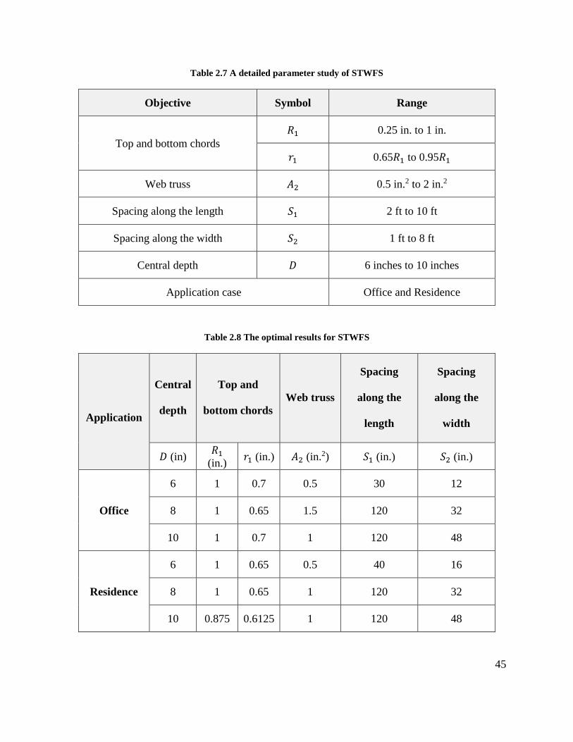
45
Table 2.7 A detailed parameter study of STWFS
Objective Symbol Range
Top and bottom chords
𝑅1 0.25 in. to 1 in.
𝑟1 0.65𝑅1 to 0.95𝑅1
Web truss 𝐴2 0.5 in.2 to 2 in.2
Spacing along the length 𝑆1 2 ft to 10 ft
Spacing along the width 𝑆2 1 ft to 8 ft
Central depth 𝐷 6 inches to 10 inches
Application case Office and Residence
Table 2.8 The optimal results for STWFS
Application
Central
depth
Top and
bottom chords
Web truss
Spacing
along the
length
Spacing
along the
width
𝐷 (in) 𝑅1
(in.) 𝑟1 (in.) 𝐴2 (in.2) 𝑆1 (in.) 𝑆2 (in.)
Office
6 1 0.7 0.5 30 12
8 1 0.65 1.5 120 32
10 1 0.7 1 120 48
Residence
6 1 0.65 0.5 40 16
8 1 0.65 1 120 32
10 0.875 0.6125 1 120 48
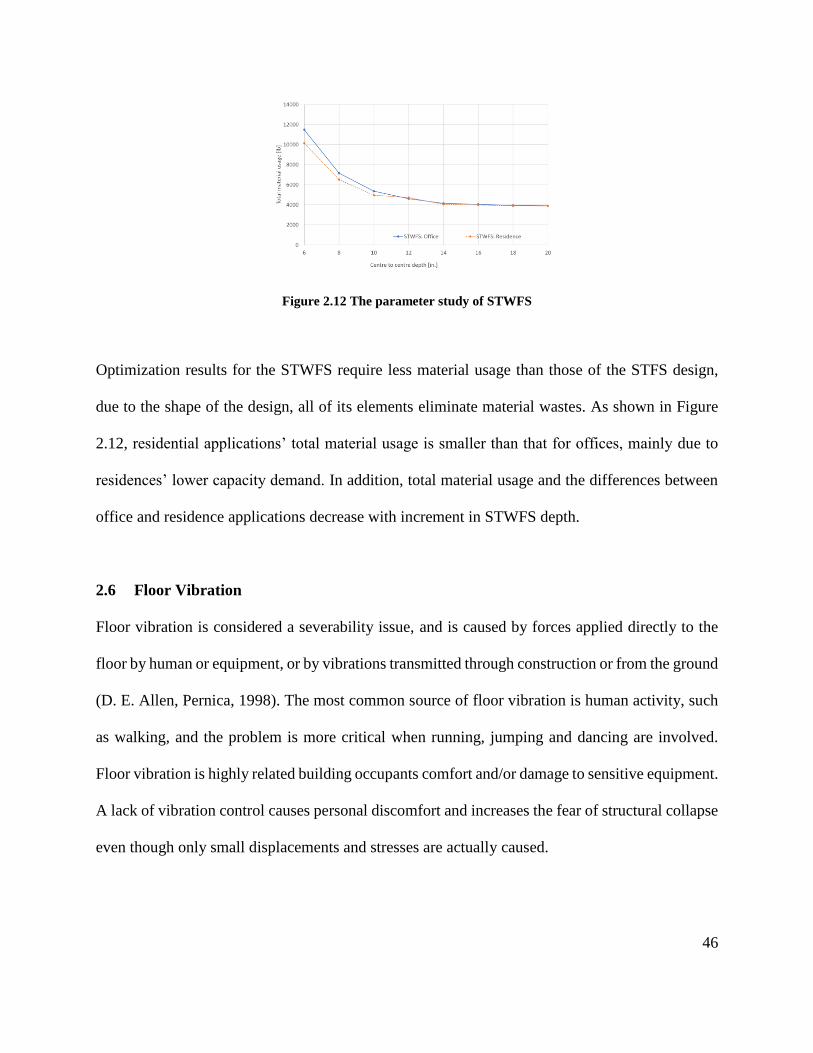
46
Figure 2.12 The parameter study of STWFS
Optimization results for the STWFS require less material usage than those of the STFS design,
due to the shape of the design, all of its elements eliminate material wastes. As shown in Figure
2.12, residential applications’ total material usage is smaller than that for offices, mainly due to
residences’ lower capacity demand. In addition, total material usage and the differences between
office and residence applications decrease with increment in STWFS depth.
2.6 Floor Vibration
Floor vibration is considered a severability issue, and is caused by forces applied directly to the
floor by human or equipment, or by vibrations transmitted through construction or from the ground
(D. E. Allen, Pernica, 1998). The most common source of floor vibration is human activity, such
as walking, and the problem is more critical when running, jumping and dancing are involved.
Floor vibration is highly related building occupants comfort and/or damage to sensitive equipment.
A lack of vibration control causes personal discomfort and increases the fear of structural collapse
even though only small displacements and stresses are actually caused.
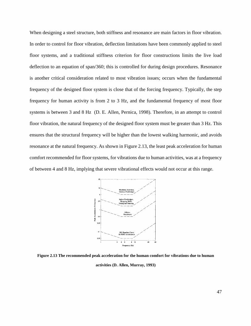
47
When designing a steel structure, both stiffness and resonance are main factors in floor vibration.
In order to control for floor vibration, deflection limitations have been commonly applied to steel
floor systems, and a traditional stiffness criterion for floor constructions limits the live load
deflection to an equation of span/360; this is controlled for during design procedures. Resonance
is another critical consideration related to most vibration issues; occurs when the fundamental
frequency of the designed floor system is close that of the forcing frequency. Typically, the step
frequency for human activity is from 2 to 3 Hz, and the fundamental frequency of most floor
systems is between 3 and 8 Hz (D. E. Allen, Pernica, 1998). Therefore, in an attempt to control
floor vibration, the natural frequency of the designed floor system must be greater than 3 Hz. This
ensures that the structural frequency will be higher than the lowest walking harmonic, and avoids
resonance at the natural frequency. As shown in Figure 2.13, the least peak acceleration for human
comfort recommended for floor systems, for vibrations due to human activities, was at a frequency
of between 4 and 8 Hz, implying that severe vibrational effects would not occur at this range.
Figure 2.13 The recommended peak acceleration for the human comfort for vibrations due to human
activities (D. Allen, Murray, 1993)
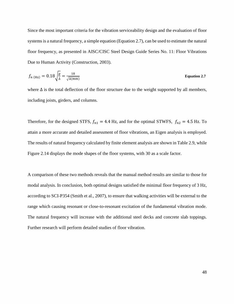
48
Since the most important criteria for the vibration serviceability design and the evaluation of floor
systems is a natural frequency, a simple equation (Equation 2.7), can be used to estimate the natural
floor frequency, as presented in AISC/CISC Steel Design Guide Series No. 11: Floor Vibrations
Due to Human Activity (Construction, 2003).
𝑓𝑛 (Hz) = 0.18√𝑔
∆=
18
√∆(mm) Equation 2.7
where ∆ is the total deflection of the floor structure due to the weight supported by all members,
including joists, girders, and columns.
Therefore, for the designed STFS, 𝑓𝑛1 = 4.4 Hz, and for the optimal STWFS, 𝑓𝑛2 = 4.5 Hz. To
attain a more accurate and detailed assessment of floor vibrations, an Eigen analysis is employed.
The results of natural frequency calculated by finite element analysis are shown in Table 2.9, while
Figure 2.14 displays the mode shapes of the floor systems, with 30 as a scale factor.
A comparison of these two methods reveals that the manual method results are similar to those for
modal analysis. In conclusion, both optimal designs satisfied the minimal floor frequency of 3 Hz,
according to SCI-P354 (Smith et al., 2007), to ensure that walking activities will be external to the
range which causing resonant or close-to-resonant excitation of the fundamental vibration mode.
The natural frequency will increase with the additional steel decks and concrete slab toppings.
Further research will perform detailed studies of floor vibration.
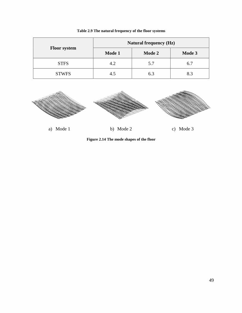
49
Table 2.9 The natural frequency of the floor systems
Floor system Natural frequency (Hz)
Mode 1 Mode 2 Mode 3
STFS 4.2 5.7 6.7
STWFS 4.5 6.3 8.3
a) Mode 1 b) Mode 2 c) Mode 3
Figure 2.14 The mode shapes of the floor
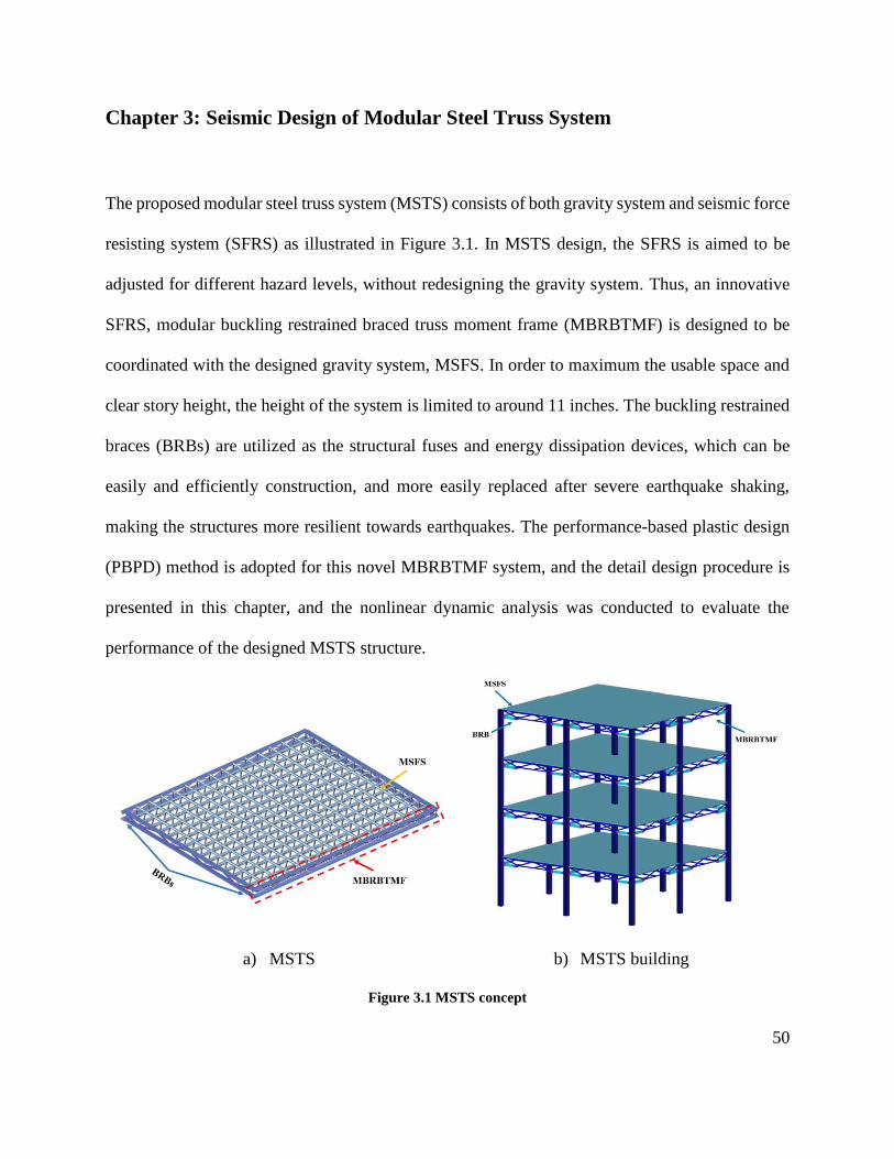
50
Chapter 3: Seismic Design of Modular Steel Truss System
The proposed modular steel truss system (MSTS) consists of both gravity system and seismic force
resisting system (SFRS) as illustrated in Figure 3.1. In MSTS design, the SFRS is aimed to be
adjusted for different hazard levels, without redesigning the gravity system. Thus, an innovative
SFRS, modular buckling restrained braced truss moment frame (MBRBTMF) is designed to be
coordinated with the designed gravity system, MSFS. In order to maximum the usable space and
clear story height, the height of the system is limited to around 11 inches. The buckling restrained
braces (BRBs) are utilized as the structural fuses and energy dissipation devices, which can be
easily and efficiently construction, and more easily replaced after severe earthquake shaking,
making the structures more resilient towards earthquakes. The performance-based plastic design
(PBPD) method is adopted for this novel MBRBTMF system, and the detail design procedure is
presented in this chapter, and the nonlinear dynamic analysis was conducted to evaluate the
performance of the designed MSTS structure.
a) MSTS b) MSTS building
Figure 3.1 MSTS concept
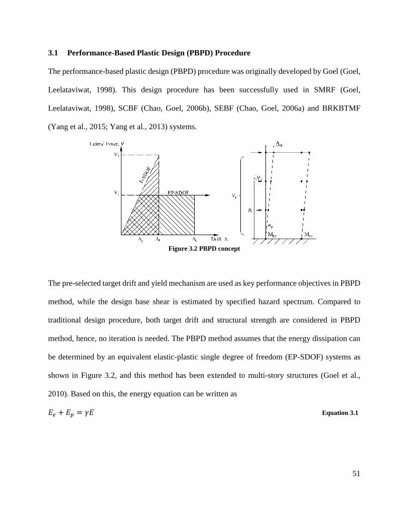
51
3.1 Performance-Based Plastic Design (PBPD) Procedure
The performance-based plastic design (PBPD) procedure was originally developed by Goel (Goel,
Leelataviwat, 1998). This design procedure has been successfully used in SMRF (Goel,
Leelataviwat, 1998), SCBF (Chao, Goel, 2006b), SEBF (Chao, Goel, 2006a) and BRKBTMF
(Yang et al., 2015; Yang et al., 2013) systems.
Figure 3.2 PBPD concept
The pre-selected target drift and yield mechanism are used as key performance objectives in PBPD
method, while the design base shear is estimated by specified hazard spectrum. Compared to
traditional design procedure, both target drift and structural strength are considered in PBPD
method, hence, no iteration is needed. The PBPD method assumes that the energy dissipation can
be determined by an equivalent elastic-plastic single degree of freedom (EP-SDOF) systems as
shown in Figure 3.2, and this method has been extended to multi-story structures (Goel et al.,
2010). Based on this, the energy equation can be written as
𝐸𝑒 + 𝐸𝑝 = 𝛾𝐸 Equation 3.1
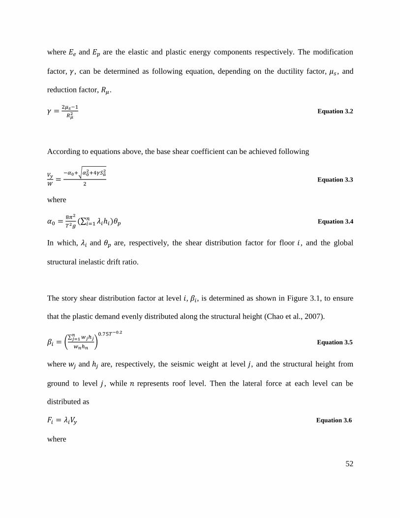
52
where 𝐸𝑒 and 𝐸𝑝 are the elastic and plastic energy components respectively. The modification
factor, 𝛾, can be determined as following equation, depending on the ductility factor, 𝜇𝑠 , and
reduction factor, 𝑅𝜇.
𝛾 =2𝜇𝑠−1
𝑅𝜇2 Equation 3.2
According to equations above, the base shear coefficient can be achieved following
𝑉𝑦
𝑊=
−𝛼0+√𝛼02+4𝛾𝑆𝑎
2
2 Equation 3.3
where
𝛼0 =8𝜋2
𝑇2𝑔(∑ 𝜆𝑖ℎ𝑖)𝜃𝑝
𝑛𝑖=1 Equation 3.4
In which, 𝜆𝑖 and 𝜃𝑝 are, respectively, the shear distribution factor for floor 𝑖 , and the global
structural inelastic drift ratio.
The story shear distribution factor at level 𝑖, 𝛽𝑖, is determined as shown in Figure 3.1, to ensure
that the plastic demand evenly distributed along the structural height (Chao et al., 2007).
𝛽𝑖 = (∑ 𝑤𝑗ℎ𝑗
𝑛𝑗=1
𝑤𝑛ℎ𝑛)
0.75𝑇−0.2
Equation 3.5
where 𝑤𝑗 and ℎ𝑗 are, respectively, the seismic weight at level 𝑗, and the structural height from
ground to level 𝑗 , while 𝑛 represents roof level. Then the lateral force at each level can be
distributed as
𝐹𝑖 = 𝜆𝑖𝑉𝑦 Equation 3.6
where
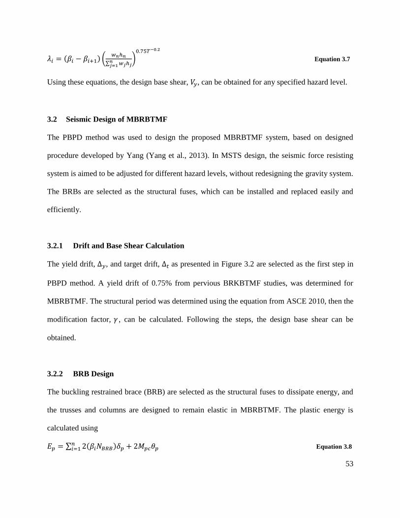
53
𝜆𝑖 = (𝛽𝑖 − 𝛽𝑖+1) (𝑤𝑛ℎ𝑛
∑ 𝑤𝑗ℎ𝑗𝑛𝑗=1
)0.75𝑇−0.2
Equation 3.7
Using these equations, the design base shear, 𝑉𝑦, can be obtained for any specified hazard level.
3.2 Seismic Design of MBRBTMF
The PBPD method was used to design the proposed MBRBTMF system, based on designed
procedure developed by Yang (Yang et al., 2013). In MSTS design, the seismic force resisting
system is aimed to be adjusted for different hazard levels, without redesigning the gravity system.
The BRBs are selected as the structural fuses, which can be installed and replaced easily and
efficiently.
3.2.1 Drift and Base Shear Calculation
The yield drift, Δ𝑦, and target drift, Δ𝑡 as presented in Figure 3.2 are selected as the first step in
PBPD method. A yield drift of 0.75% from pervious BRKBTMF studies, was determined for
MBRBTMF. The structural period was determined using the equation from ASCE 2010, then the
modification factor, 𝛾 , can be calculated. Following the steps, the design base shear can be
obtained.
3.2.2 BRB Design
The buckling restrained brace (BRB) are selected as the structural fuses to dissipate energy, and
the trusses and columns are designed to remain elastic in MBRBTMF. The plastic energy is
calculated using
𝐸𝑝 = ∑ 2(𝛽𝑖𝑁𝐵𝑅𝐵)𝛿𝑝 + 2𝑀𝑝𝑐𝜃𝑝𝑛𝑖=1 Equation 3.8
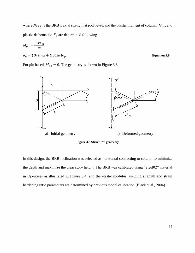
54
where 𝑁𝐵𝑅𝐵 is the BRB’s axial strength at roof level, and the plastic moment of column, 𝑀𝑝𝑐, and
plastic deformation 𝛿𝑝 are determined following
𝑀𝑝𝑐 =1.1𝑉ℎ𝑐1
4𝑁
𝛿𝑝 = (𝐷0𝑠𝑖𝑛𝛼 + 𝑙1𝑐𝑜𝑠𝛼)𝜃𝑝 Equation 3.9
For pin based, 𝑀𝑝𝑐 = 0. The geometry is shown in Figure 3.3.
a) Initial geometry b) Deformed geometry
Figure 3.3 Structural geometry
In this design, the BRB inclination was selected as horizontal connecting to column to minimize
the depth and maximize the clear story height. The BRB was calibrated using “Steel02” material
in OpenSees as illustrated in Figure 3.4, and the elastic modulus, yielding strength and strain
hardening ratio parameters are determined by previous model calibration (Black et al., 2004).
55
Figure 3.4 BRB Calibration
3.2.3 Truss Design
The truss span and depth was determined based on the dimension of MFSF, thus, the spans were
designed as 20 by 24ft., while the central depth is limited as 8 inches. The truss sample under
gravity and BRB forces is shown in Figure 3.5. The trusses are assumed to be perfectly pinned to
the columns.
Figure 3.5 Truss sample design
The maximum BBRB forces are calculated following
𝑃𝐵𝑅𝐵+ = 𝜔𝑅𝑦𝑃𝑦
𝑃𝐵𝑅𝐵− = 𝜔𝛽𝑅𝑦𝑃𝑦 Equation 3.10
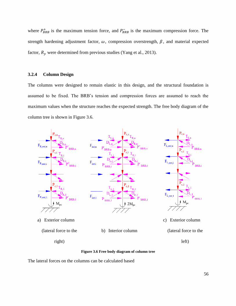
56
where 𝑃𝐵𝑅𝐵+ is the maximum tension force, and 𝑃𝐵𝑅𝐵
− is the maximum compression force. The
strength hardening adjustment factor, 𝜔 , compression overstrength, 𝛽 , and material expected
factor, 𝑅𝑦 were determined from previous studies (Yang et al., 2013).
3.2.4 Column Design
The columns were designed to remain elastic in this design, and the structural foundation is
assumed to be fixed. The BRB’s tension and compression forces are assumed to reach the
maximum values when the structure reaches the expected strength. The free body diagram of the
column tree is shown in Figure 3.6.
a) Exterior column
(lateral force to the
right)
b) Interior column
c) Exterior column
(lateral force to the
left)
Figure 3.6 Free body diagram of column tree
The lateral forces on the columns can be calculated based
57
𝐹𝑒𝑥𝑡,𝑅,𝑖 = 𝛼𝑖 ∑ (𝑇𝑅,𝑗−𝐷𝑅,𝑗𝑠𝑖𝑛𝜑)ℎ𝑖−∑ (𝑃𝐵𝑅𝐵,𝑖
+ )(ℎ𝑖−𝐷)+𝑀𝑝𝑐𝑛𝑖=1
𝑛𝑖=1
∑ 𝛼𝑖ℎ𝑖𝑛𝑖=1
𝐹𝑒𝑥𝑡,𝐿,𝑖 = 𝛼𝑖 ∑ (𝑇𝐿,𝑗−𝐷𝐿,𝑗𝑠𝑖𝑛𝜑)ℎ𝑖−∑ (𝑃𝐵𝑅𝐵,𝑖
− )(ℎ𝑖−𝐷)+𝑀𝑝𝑐𝑛𝑖=1
𝑛𝑖=1
∑ 𝛼𝑖ℎ𝑖𝑛𝑖=1
𝐹𝑒𝑥𝑡,𝑅,𝑖 = 𝐹𝑒𝑥𝑡,𝑅,𝑖 + 𝐹𝑒𝑥𝑡,𝐿,𝑖 Equation 3.11
where the distribution factor, 𝛼𝑖 is determined following
𝛼𝑖 =(𝛽𝑖−𝛽𝑖+1)
∑ (𝑛𝑖=1 𝛽𝑖−𝛽𝑖+1)
Equation 3.12
3.3 Application of Modular Steel Truss System (MSTS)
Following the PBPD procedure, the structural components of the prototype 4-story MSTS building
were designed. To coordinate with the gravity system, the seismic force resisting systems with 11-
inch total depth, were designed as frames along the length and width, respectively. To ensure that
the performance of the proposed modular steel truss system (MSTS) as shown in Figure 3.1a, a
detailed nonlinear dynamic analysis was conducted. The prototype 4-story building located in
Berkeley, California, was designed and modelled to confirm the applicability of the designed
systems.
3.3.1 Hazard Analysis
A hazard analysis is usually employed as the first step in determining and analyzing the degree of
risk. The seismicity of the structural site and hazard spectrum are studied for the prototype
structures. Berkeley, is located in the “Pacific Ring of Fire” as shown in Figure 3.7, a seismically
active zone belt surrounding the Pacific Ocean. The movements and collisions of tectonic plates
results in this region result in strain energy, finally causing earthquakes.

58
Figure 3.7 The Pacific Ring of Fire (U.S. Geological Survey, 2017)
Cascadia region is the Pacific Northwest region of North American, and one of the most
tectonically complex regions in the world. It is well known that convergent boundaries occur where
two plates slide toward one another, and that this movement will cause either a subduction zone
or continental collision. Specifically, a portion of the Pacific Plate along with the small Juan de
Fuca Plate is being subducted beneath the North American Plate, as shown in Figure 3.8. These
plate movements and collisions eventually result in a concentration of earthquakes. Hence, more
than 100 earthquakes of magnitude 5 or greater have occurred during the past 70 years. Based on
the United States Geological Survey (USGS) research, the Cascadia Subduction Zone (CSZ) has
suffered magnitude 9.0 and greater earthquakes in the past, and the potential is high for such largest
earthquakes to occur again in the future.
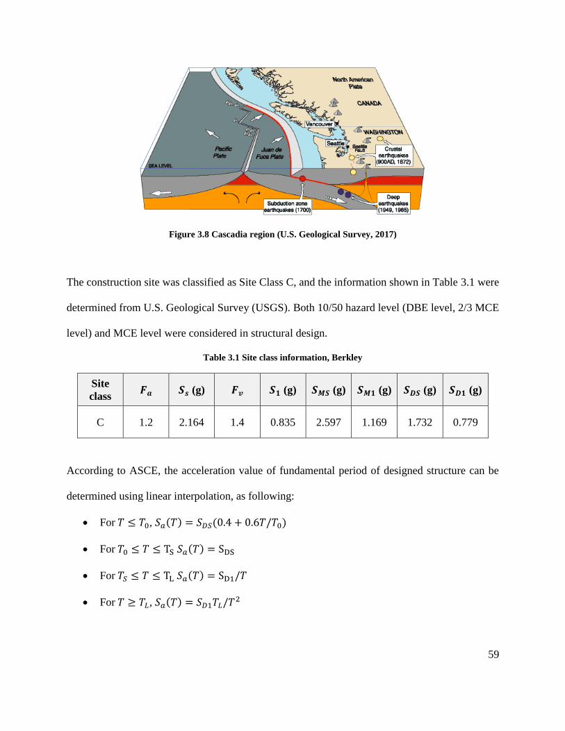
59
Figure 3.8 Cascadia region (U.S. Geological Survey, 2017)
The construction site was classified as Site Class C, and the information shown in Table 3.1 were
determined from U.S. Geological Survey (USGS). Both 10/50 hazard level (DBE level, 2/3 MCE
level) and MCE level were considered in structural design.
Table 3.1 Site class information, Berkley
Site
class 𝑭𝒂 𝑺𝒔 (g) 𝑭𝒗 𝑺𝟏 (g) 𝑺𝑴𝑺 (g) 𝑺𝑴𝟏 (g) 𝑺𝑫𝑺 (g) 𝑺𝑫𝟏 (g)
C 1.2 2.164 1.4 0.835 2.597 1.169 1.732 0.779
According to ASCE, the acceleration value of fundamental period of designed structure can be
determined using linear interpolation, as following:
• For 𝑇 ≤ 𝑇0, 𝑆𝑎(𝑇) = 𝑆𝐷𝑆(0.4 + 0.6𝑇/𝑇0)
• For 𝑇0 ≤ 𝑇 ≤ TS 𝑆𝑎(𝑇) = SDS
• For 𝑇𝑆 ≤ 𝑇 ≤ TL 𝑆𝑎(𝑇) = SD1/𝑇
• For 𝑇 ≥ 𝑇𝐿, 𝑆𝑎(𝑇) = 𝑆𝐷1𝑇𝐿/𝑇2
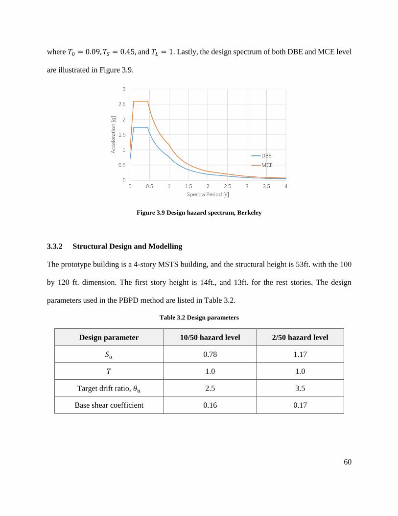
60
where 𝑇0 = 0.09, 𝑇𝑆 = 0.45, and 𝑇𝐿 = 1. Lastly, the design spectrum of both DBE and MCE level
are illustrated in Figure 3.9.
Figure 3.9 Design hazard spectrum, Berkeley
3.3.2 Structural Design and Modelling
The prototype building is a 4-story MSTS building, and the structural height is 53ft. with the 100
by 120 ft. dimension. The first story height is 14ft., and 13ft. for the rest stories. The design
parameters used in the PBPD method are listed in Table 3.2.
Table 3.2 Design parameters
Design parameter 10/50 hazard level 2/50 hazard level
𝑆𝑎 0.78 1.17
𝑇 1.0 1.0
Target drift ratio, 𝜃𝑢 2.5 3.5
Base shear coefficient 0.16 0.17
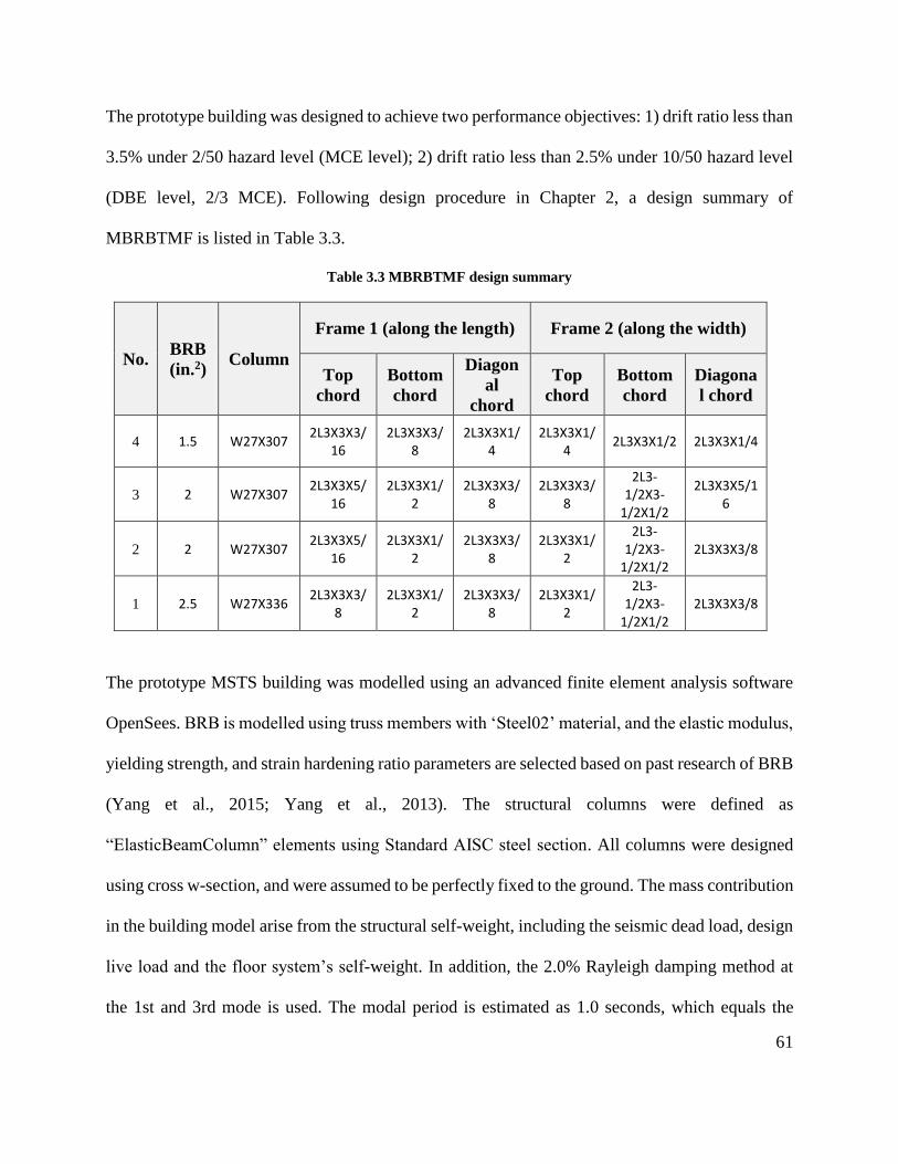
61
The prototype building was designed to achieve two performance objectives: 1) drift ratio less than
3.5% under 2/50 hazard level (MCE level); 2) drift ratio less than 2.5% under 10/50 hazard level
(DBE level, 2/3 MCE). Following design procedure in Chapter 2, a design summary of
MBRBTMF is listed in Table 3.3.
Table 3.3 MBRBTMF design summary
No. BRB
(in.2) Column
Frame 1 (along the length) Frame 2 (along the width)
Top
chord
Bottom
chord
Diagon
al
chord
Top
chord
Bottom
chord
Diagona
l chord
4 1.5 W27X307 2L3X3X3/
16 2L3X3X3/
8 2L3X3X1/
4
2L3X3X1/4
2L3X3X1/2 2L3X3X1/4
3 2 W27X307 2L3X3X5/
16 2L3X3X1/
2 2L3X3X3/
8 2L3X3X3/
8
2L3-1/2X3-
1/2X1/2
2L3X3X5/16
2 2 W27X307 2L3X3X5/
16 2L3X3X1/
2 2L3X3X3/
8 2L3X3X1/
2
2L3-1/2X3-
1/2X1/2 2L3X3X3/8
1 2.5 W27X336 2L3X3X3/
8 2L3X3X1/
2 2L3X3X3/
8 2L3X3X1/
2
2L3-1/2X3-
1/2X1/2 2L3X3X3/8
The prototype MSTS building was modelled using an advanced finite element analysis software
OpenSees. BRB is modelled using truss members with ‘Steel02’ material, and the elastic modulus,
yielding strength, and strain hardening ratio parameters are selected based on past research of BRB
(Yang et al., 2015; Yang et al., 2013). The structural columns were defined as
“ElasticBeamColumn” elements using Standard AISC steel section. All columns were designed
using cross w-section, and were assumed to be perfectly fixed to the ground. The mass contribution
in the building model arise from the structural self-weight, including the seismic dead load, design
live load and the floor system’s self-weight. In addition, the 2.0% Rayleigh damping method at
the 1st and 3rd mode is used. The modal period is estimated as 1.0 seconds, which equals the
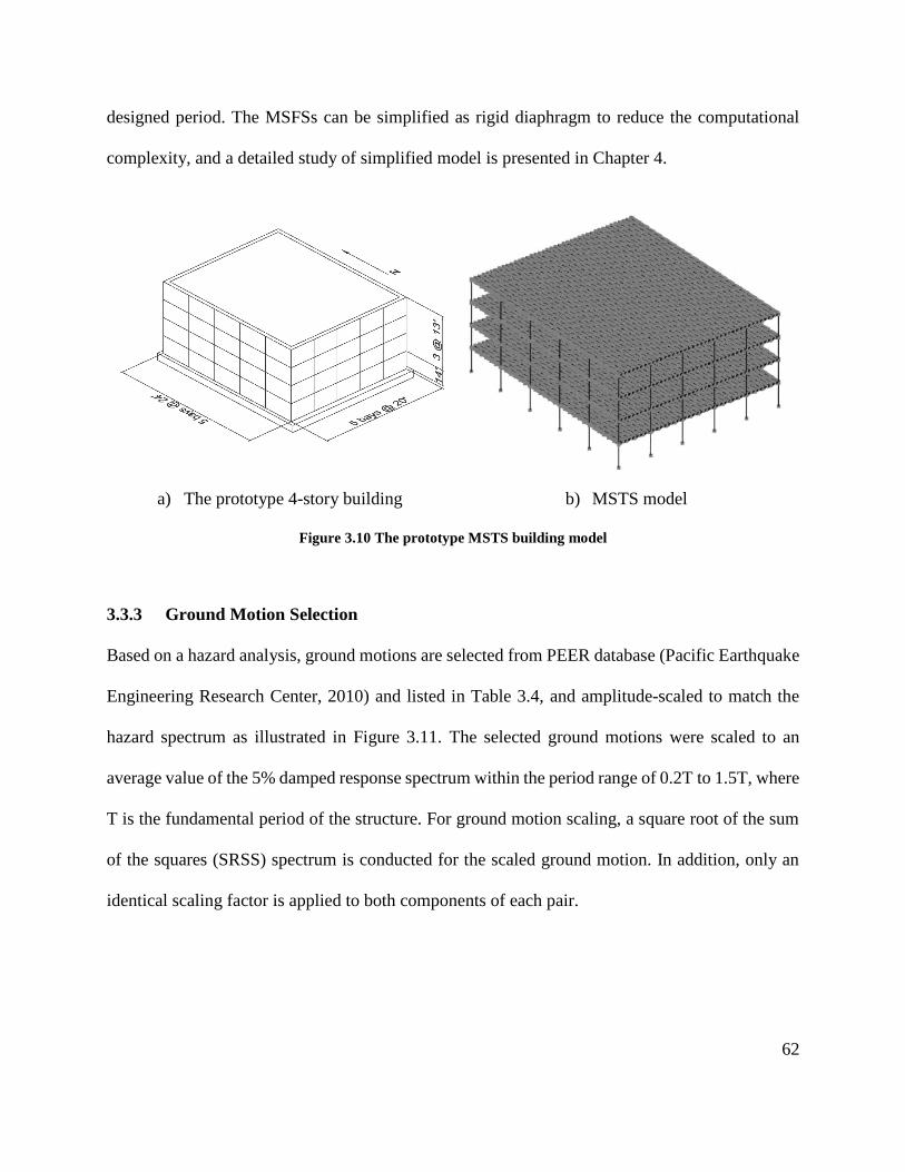
62
designed period. The MSFSs can be simplified as rigid diaphragm to reduce the computational
complexity, and a detailed study of simplified model is presented in Chapter 4.
a) The prototype 4-story building b) MSTS model
Figure 3.10 The prototype MSTS building model
3.3.3 Ground Motion Selection
Based on a hazard analysis, ground motions are selected from PEER database (Pacific Earthquake
Engineering Research Center, 2010) and listed in Table 3.4, and amplitude-scaled to match the
hazard spectrum as illustrated in Figure 3.11. The selected ground motions were scaled to an
average value of the 5% damped response spectrum within the period range of 0.2T to 1.5T, where
T is the fundamental period of the structure. For ground motion scaling, a square root of the sum
of the squares (SRSS) spectrum is conducted for the scaled ground motion. In addition, only an
identical scaling factor is applied to both components of each pair.
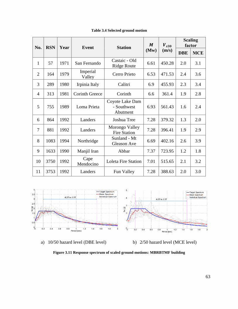
63
Table 3.4 Selected ground motion
No. RSN Year Event Station 𝑴
(Mw)
𝑽𝒔𝟑𝟎
(m/s)
Scaling
factor
DBE MCE
1 57 1971 San Fernando Castaic - Old
Ridge Route 6.61 450.28 2.0 3.1
2 164 1979 Imperial
Valley Cerro Prieto 6.53 471.53 2.4 3.6
3 289 1980 Irpinia Italy Calitri 6.9 455.93 2.3 3.4
4 313 1981 Corinth Greece Corinth 6.6 361.4 1.9 2.8
5 755 1989 Loma Prieta
Coyote Lake Dam
- Southwest
Abutment
6.93 561.43 1.6 2.4
6 864 1992 Landers Joshua Tree 7.28 379.32 1.3 2.0
7 881 1992 Landers Morongo Valley
Fire Station 7.28 396.41 1.9 2.9
8 1083 1994 Northridge Sunland - Mt
Gleason Ave 6.69 402.16 2.6 3.9
9 1633 1990 Manjil Iran Abbar 7.37 723.95 1.2 1.8
10 3750 1992 Cape
Mendocino Loleta Fire Station 7.01 515.65 2.1 3.2
11 3753 1992 Landers Fun Valley 7.28 388.63 2.0 3.0
a) 10/50 hazard level (DBE level) b) 2/50 hazard level (MCE level)
Figure 3.11 Response spectrum of scaled ground motions: MBRBTMF building
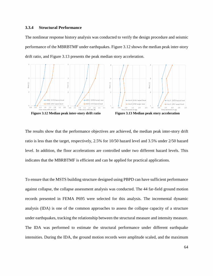
64
3.3.4 Structural Performance
The nonlinear response history analysis was conducted to verify the design procedure and seismic
performance of the MBRBTMF under earthquakes. Figure 3.12 shows the median peak inter-story
drift ratio, and Figure 3.13 presents the peak median story acceleration.
Figure 3.12 Median peak inter-story drift ratio Figure 3.13 Median peak story acceleration
The results show that the performance objectives are achieved, the median peak inter-story drift
ratio is less than the target, respectively, 2.5% for 10/50 hazard level and 3.5% under 2/50 hazard
level. In addition, the floor accelerations are controlled under two different hazard levels. This
indicates that the MBRBTMF is efficient and can be applied for practical applications.
To ensure that the MSTS building structure designed using PBPD can have sufficient performance
against collapse, the collapse assessment analysis was conducted. The 44 far-field ground motion
records presented in FEMA P695 were selected for this analysis. The incremental dynamic
analysis (IDA) is one of the common approaches to assess the collapse capacity of a structure
under earthquakes, tracking the relationship between the structural measure and intensity measure.
The IDA was performed to estimate the structural performance under different earthquake
intensities. During the IDA, the ground motion records were amplitude scaled, and the maximum
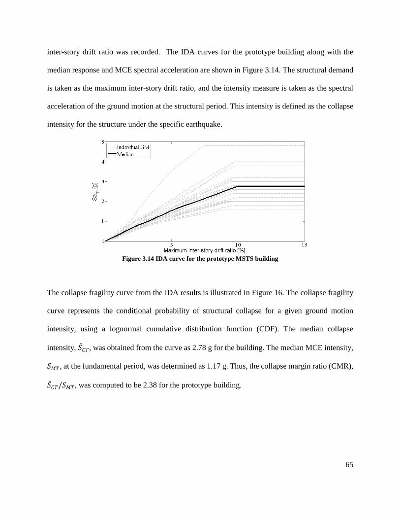
65
inter-story drift ratio was recorded. The IDA curves for the prototype building along with the
median response and MCE spectral acceleration are shown in Figure 3.14. The structural demand
is taken as the maximum inter-story drift ratio, and the intensity measure is taken as the spectral
acceleration of the ground motion at the structural period. This intensity is defined as the collapse
intensity for the structure under the specific earthquake.
Figure 3.14 IDA curve for the prototype MSTS building
The collapse fragility curve from the IDA results is illustrated in Figure 16. The collapse fragility
curve represents the conditional probability of structural collapse for a given ground motion
intensity, using a lognormal cumulative distribution function (CDF). The median collapse
intensity, �̂�𝐶𝑇, was obtained from the curve as 2.78 g for the building. The median MCE intensity,
𝑆𝑀𝑇, at the fundamental period, was determined as 1.17 g. Thus, the collapse margin ratio (CMR),
�̂�𝐶𝑇/𝑆𝑀𝑇, was computed to be 2.38 for the prototype building.
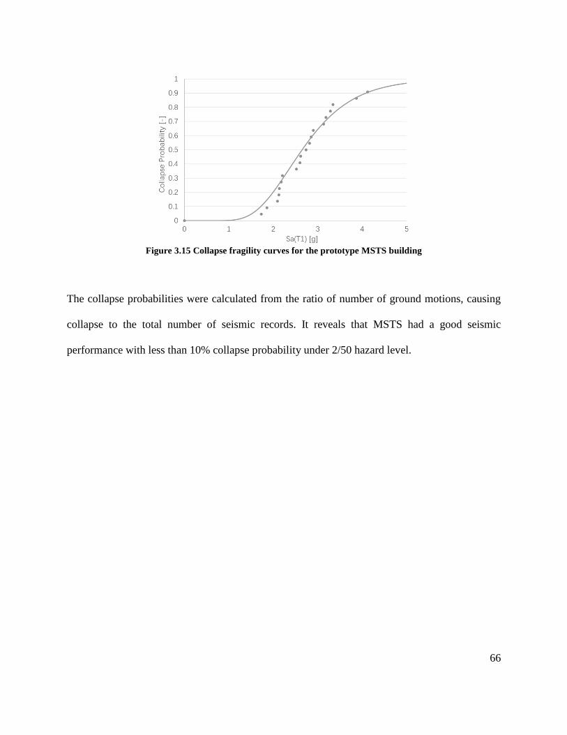
66
Figure 3.15 Collapse fragility curves for the prototype MSTS building
The collapse probabilities were calculated from the ratio of number of ground motions, causing
collapse to the total number of seismic records. It reveals that MSTS had a good seismic
performance with less than 10% collapse probability under 2/50 hazard level.
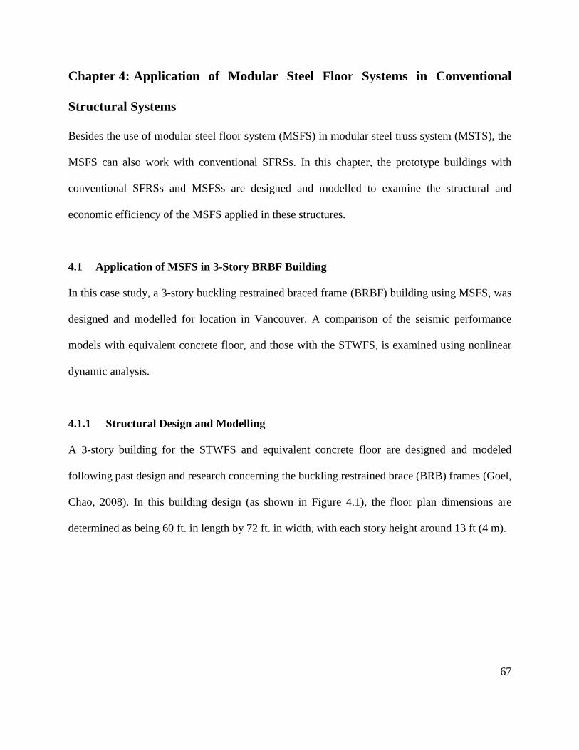
67
Chapter 4: Application of Modular Steel Floor Systems in Conventional
Structural Systems
Besides the use of modular steel floor system (MSFS) in modular steel truss system (MSTS), the
MSFS can also work with conventional SFRSs. In this chapter, the prototype buildings with
conventional SFRSs and MSFSs are designed and modelled to examine the structural and
economic efficiency of the MSFS applied in these structures.
4.1 Application of MSFS in 3-Story BRBF Building
In this case study, a 3-story buckling restrained braced frame (BRBF) building using MSFS, was
designed and modelled for location in Vancouver. A comparison of the seismic performance
models with equivalent concrete floor, and those with the STWFS, is examined using nonlinear
dynamic analysis.
4.1.1 Structural Design and Modelling
A 3-story building for the STWFS and equivalent concrete floor are designed and modeled
following past design and research concerning the buckling restrained brace (BRB) frames (Goel,
Chao, 2008). In this building design (as shown in Figure 4.1), the floor plan dimensions are
determined as being 60 ft. in length by 72 ft. in width, with each story height around 13 ft (4 m).
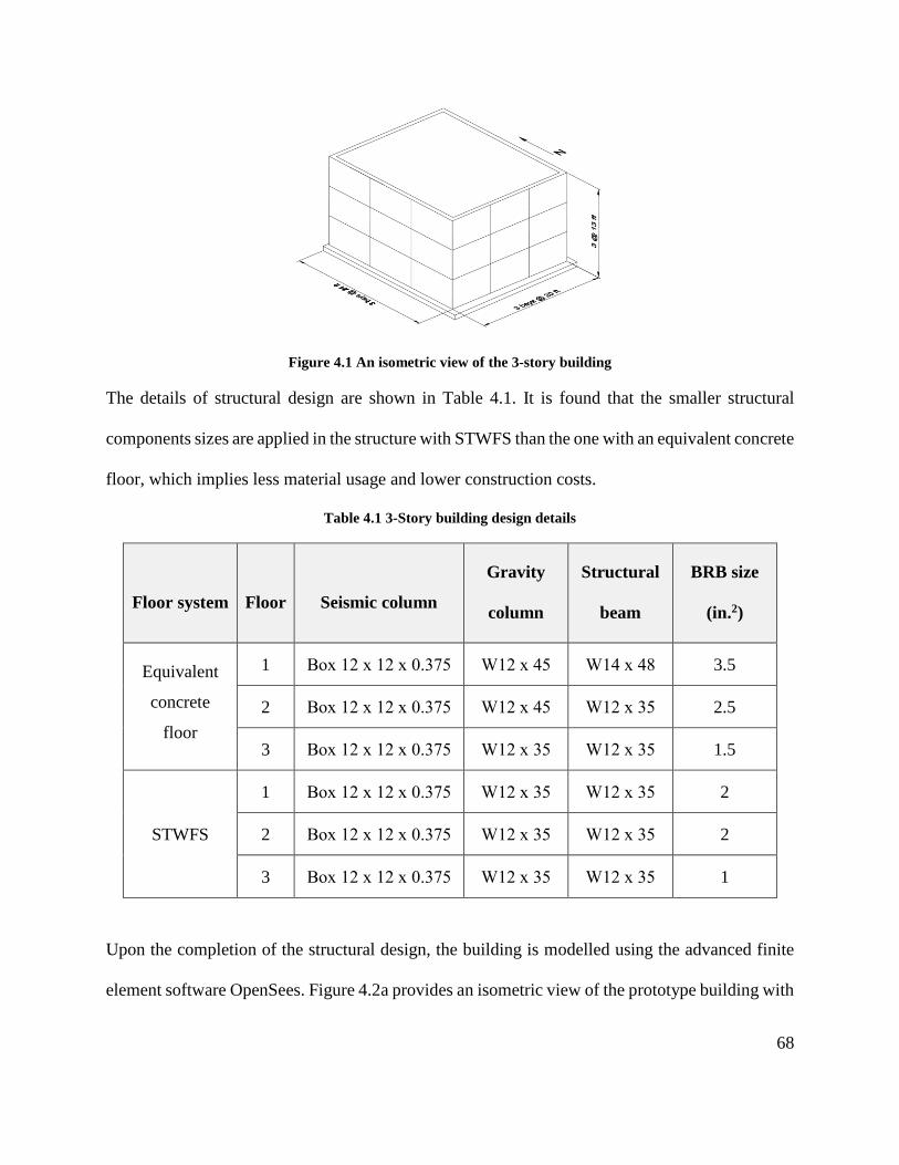
68
Figure 4.1 An isometric view of the 3-story building
The details of structural design are shown in Table 4.1. It is found that the smaller structural
components sizes are applied in the structure with STWFS than the one with an equivalent concrete
floor, which implies less material usage and lower construction costs.
Table 4.1 3-Story building design details
Floor system Floor Seismic column
Gravity
column
Structural
beam
BRB size
(in.2)
Equivalent
concrete
floor
1 Box 12 x 12 x 0.375 W12 x 45 W14 x 48 3.5
2 Box 12 x 12 x 0.375 W12 x 45 W12 x 35 2.5
3 Box 12 x 12 x 0.375 W12 x 35 W12 x 35 1.5
STWFS
1 Box 12 x 12 x 0.375 W12 x 35 W12 x 35 2
2 Box 12 x 12 x 0.375 W12 x 35 W12 x 35 2
3 Box 12 x 12 x 0.375 W12 x 35 W12 x 35 1
Upon the completion of the structural design, the building is modelled using the advanced finite
element software OpenSees. Figure 4.2a provides an isometric view of the prototype building with
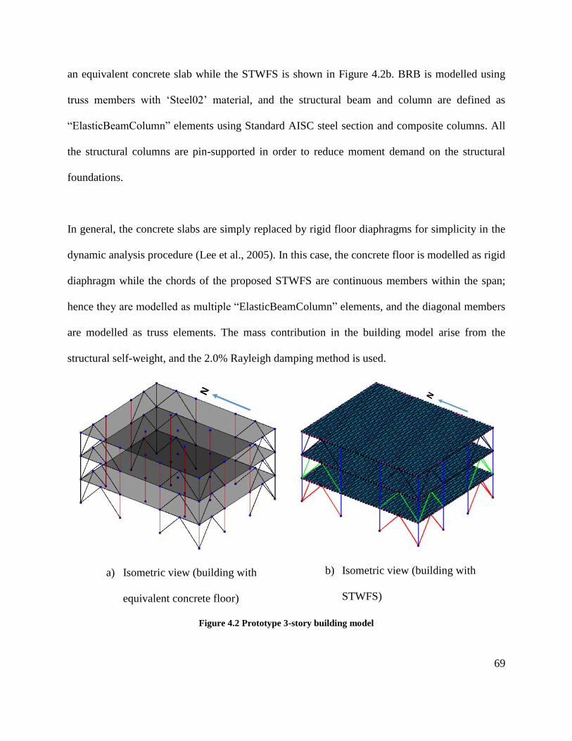
69
an equivalent concrete slab while the STWFS is shown in Figure 4.2b. BRB is modelled using
truss members with ‘Steel02’ material, and the structural beam and column are defined as
“ElasticBeamColumn” elements using Standard AISC steel section and composite columns. All
the structural columns are pin-supported in order to reduce moment demand on the structural
foundations.
In general, the concrete slabs are simply replaced by rigid floor diaphragms for simplicity in the
dynamic analysis procedure (Lee et al., 2005). In this case, the concrete floor is modelled as rigid
diaphragm while the chords of the proposed STWFS are continuous members within the span;
hence they are modelled as multiple “ElasticBeamColumn” elements, and the diagonal members
are modelled as truss elements. The mass contribution in the building model arise from the
structural self-weight, and the 2.0% Rayleigh damping method is used.
a) Isometric view (building with
equivalent concrete floor)
b) Isometric view (building with
STWFS)
Figure 4.2 Prototype 3-story building model
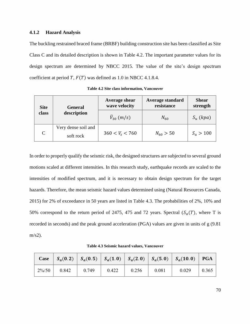
70
4.1.2 Hazard Analysis
The buckling restrained braced frame (BRBF) building construction site has been classified as Site
Class C and its detailed description is shown in Table 4.2. The important parameter values for its
design spectrum are determined by NBCC 2015. The value of the site’s design spectrum
coefficient at period 𝑇, 𝐹(𝑇) was defined as 1.0 in NBCC 4.1.8.4.
Table 4.2 Site class information, Vancouver
Site
class
General
description
Average shear
wave velocity
Average standard
resistance
Shear
strength
�̅�30 (𝑚/𝑠) 𝑁60 𝑆𝑢 (𝑘𝑝𝑎)
C
Very dense soil and
soft rock 360 < 𝑉𝑠 < 760 𝑁60 > 50 𝑆𝑢 > 100
In order to properly qualify the seismic risk, the designed structures are subjected to several ground
motions scaled at different intensities. In this research study, earthquake records are scaled to the
intensities of modified spectrum, and it is necessary to obtain design spectrum for the target
hazards. Therefore, the mean seismic hazard values determined using (Natural Resources Canada,
2015) for 2% of exceedance in 50 years are listed in Table 4.3. The probabilities of 2%, 10% and
50% correspond to the return period of 2475, 475 and 72 years. Spectral (𝑆𝑎(𝑇), where T is
recorded in seconds) and the peak ground acceleration (PGA) values are given in units of g (9.81
m/s2).
Table 4.3 Seismic hazard values, Vancouver
Case 𝑺𝒂(𝟎. 𝟐) 𝑺𝒂(𝟎. 𝟓) 𝑺𝒂(𝟏. 𝟎) 𝑺𝒂(𝟐. 𝟎) 𝑺𝒂(𝟓. 𝟎) 𝑺𝒂(𝟏𝟎. 𝟎) PGA
2%/50 0.842 0.749 0.422 0.256 0.081 0.029 0.365
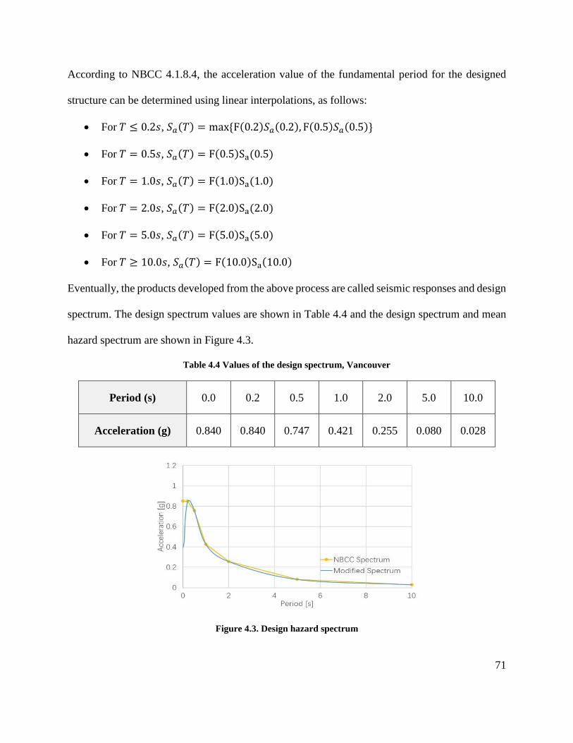
71
According to NBCC 4.1.8.4, the acceleration value of the fundamental period for the designed
structure can be determined using linear interpolations, as follows:
• For 𝑇 ≤ 0.2𝑠, 𝑆𝑎(𝑇) = max {F(0.2)𝑆𝑎(0.2), F(0.5)𝑆𝑎(0.5)}
• For 𝑇 = 0.5𝑠, 𝑆𝑎(𝑇) = F(0.5)Sa(0.5)
• For 𝑇 = 1.0𝑠, 𝑆𝑎(𝑇) = F(1.0)Sa(1.0)
• For 𝑇 = 2.0𝑠, 𝑆𝑎(𝑇) = F(2.0)Sa(2.0)
• For 𝑇 = 5.0𝑠, 𝑆𝑎(𝑇) = F(5.0)Sa(5.0)
• For 𝑇 ≥ 10.0𝑠, 𝑆𝑎(𝑇) = F(10.0)Sa(10.0)
Eventually, the products developed from the above process are called seismic responses and design
spectrum. The design spectrum values are shown in Table 4.4 and the design spectrum and mean
hazard spectrum are shown in Figure 4.3.
Table 4.4 Values of the design spectrum, Vancouver
Period (s) 0.0 0.2 0.5 1.0 2.0 5.0 10.0
Acceleration (g) 0.840 0.840 0.747 0.421 0.255 0.080 0.028
Figure 4.3. Design hazard spectrum
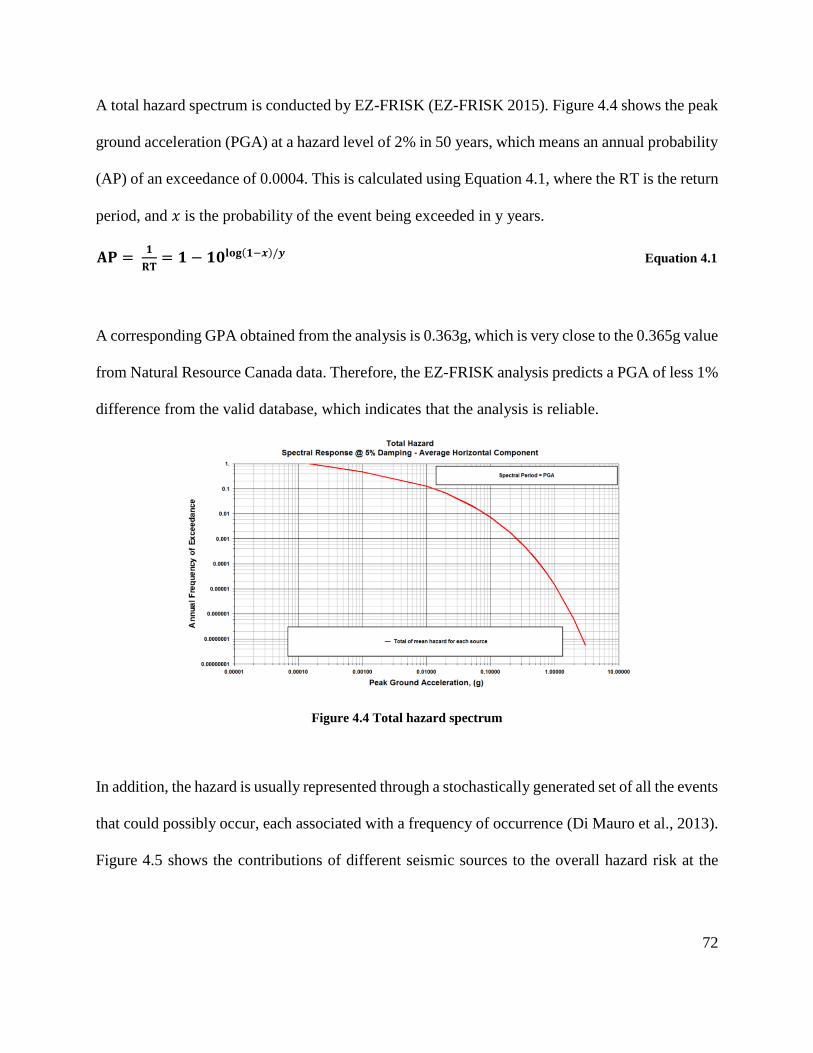
72
A total hazard spectrum is conducted by EZ-FRISK (EZ-FRISK 2015). Figure 4.4 shows the peak
ground acceleration (PGA) at a hazard level of 2% in 50 years, which means an annual probability
(AP) of an exceedance of 0.0004. This is calculated using Equation 4.1, where the RT is the return
period, and 𝑥 is the probability of the event being exceeded in y years.
𝐀𝐏 = 𝟏
𝐑𝐓= 𝟏 − 𝟏𝟎𝐥𝐨𝐠(𝟏−𝒙)/𝒚 Equation 4.1
A corresponding GPA obtained from the analysis is 0.363g, which is very close to the 0.365g value
from Natural Resource Canada data. Therefore, the EZ-FRISK analysis predicts a PGA of less 1%
difference from the valid database, which indicates that the analysis is reliable.
Figure 4.4 Total hazard spectrum
In addition, the hazard is usually represented through a stochastically generated set of all the events
that could possibly occur, each associated with a frequency of occurrence (Di Mauro et al., 2013).
Figure 4.5 shows the contributions of different seismic sources to the overall hazard risk at the
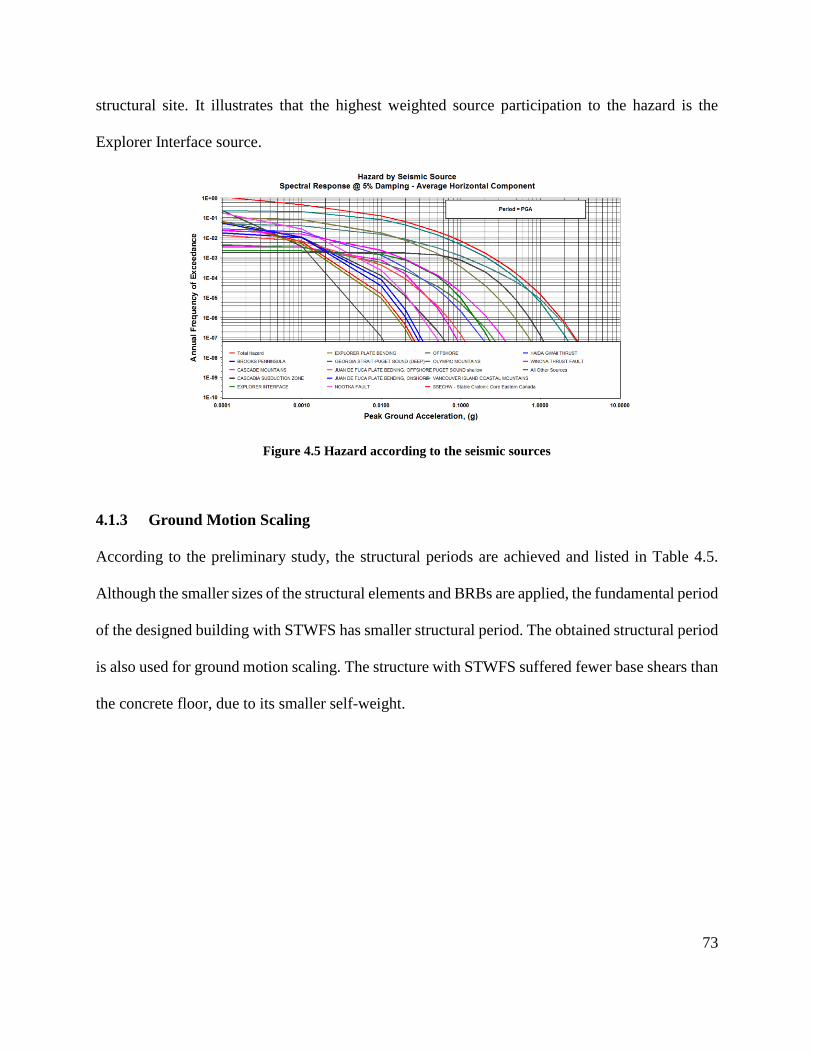
73
structural site. It illustrates that the highest weighted source participation to the hazard is the
Explorer Interface source.
Figure 4.5 Hazard according to the seismic sources
4.1.3 Ground Motion Scaling
According to the preliminary study, the structural periods are achieved and listed in Table 4.5.
Although the smaller sizes of the structural elements and BRBs are applied, the fundamental period
of the designed building with STWFS has smaller structural period. The obtained structural period
is also used for ground motion scaling. The structure with STWFS suffered fewer base shears than
the concrete floor, due to its smaller self-weight.
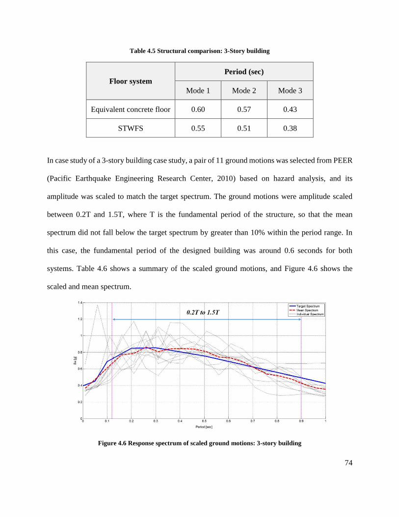
74
Table 4.5 Structural comparison: 3-Story building
Floor system
Period (sec)
Mode 1 Mode 2 Mode 3
Equivalent concrete floor 0.60 0.57 0.43
STWFS 0.55 0.51 0.38
In case study of a 3-story building case study, a pair of 11 ground motions was selected from PEER
(Pacific Earthquake Engineering Research Center, 2010) based on hazard analysis, and its
amplitude was scaled to match the target spectrum. The ground motions were amplitude scaled
between 0.2T and 1.5T, where T is the fundamental period of the structure, so that the mean
spectrum did not fall below the target spectrum by greater than 10% within the period range. In
this case, the fundamental period of the designed building was around 0.6 seconds for both
systems. Table 4.6 shows a summary of the scaled ground motions, and Figure 4.6 shows the
scaled and mean spectrum.
Figure 4.6 Response spectrum of scaled ground motions: 3-story building
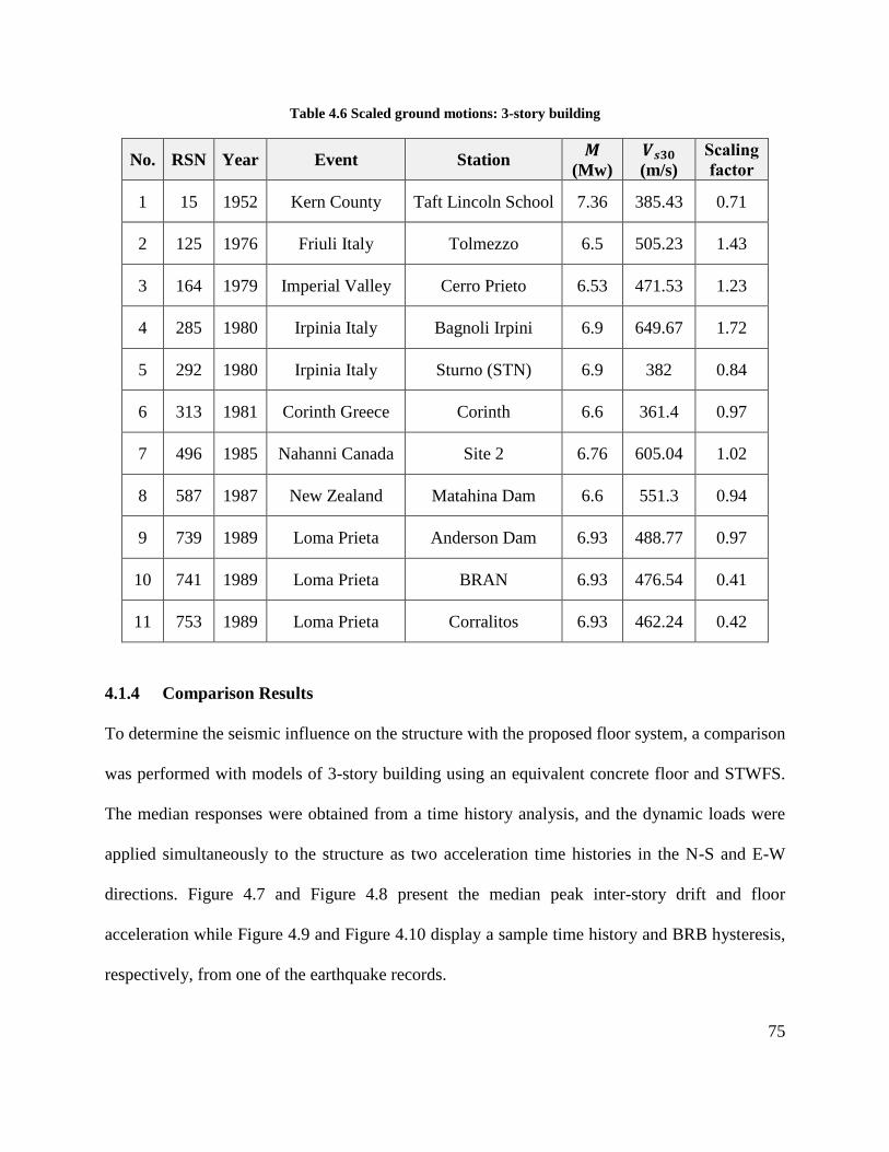
75
Table 4.6 Scaled ground motions: 3-story building
No. RSN Year Event Station 𝑴
(Mw)
𝑽𝒔𝟑𝟎
(m/s)
Scaling
factor
1 15 1952 Kern County Taft Lincoln School 7.36 385.43 0.71
2 125 1976 Friuli Italy Tolmezzo 6.5 505.23 1.43
3 164 1979 Imperial Valley Cerro Prieto 6.53 471.53 1.23
4 285 1980 Irpinia Italy Bagnoli Irpini 6.9 649.67 1.72
5 292 1980 Irpinia Italy Sturno (STN) 6.9 382 0.84
6 313 1981 Corinth Greece Corinth 6.6 361.4 0.97
7 496 1985 Nahanni Canada Site 2 6.76 605.04 1.02
8 587 1987 New Zealand Matahina Dam 6.6 551.3 0.94
9 739 1989 Loma Prieta Anderson Dam 6.93 488.77 0.97
10 741 1989 Loma Prieta BRAN 6.93 476.54 0.41
11 753 1989 Loma Prieta Corralitos 6.93 462.24 0.42
4.1.4 Comparison Results
To determine the seismic influence on the structure with the proposed floor system, a comparison
was performed with models of 3-story building using an equivalent concrete floor and STWFS.
The median responses were obtained from a time history analysis, and the dynamic loads were
applied simultaneously to the structure as two acceleration time histories in the N-S and E-W
directions. Figure 4.7 and Figure 4.8 present the median peak inter-story drift and floor
acceleration while Figure 4.9 and Figure 4.10 display a sample time history and BRB hysteresis,
respectively, from one of the earthquake records.
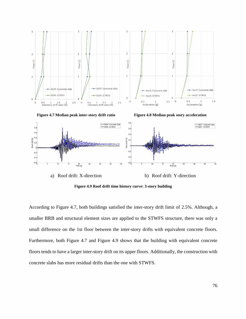
76
Figure 4.7 Median peak inter-story drift ratio Figure 4.8 Median peak story acceleration
a) Roof drift: X-direction b) Roof drift: Y-direction
Figure 4.9 Roof drift time history curve: 3-story building
According to Figure 4.7, both buildings satisfied the inter-story drift limit of 2.5%. Although, a
smaller BRB and structural element sizes are applied to the STWFS structure, there was only a
small difference on the 1st floor between the inter-story drifts with equivalent concrete floors.
Furthermore, both Figure 4.7 and Figure 4.9 shows that the building with equivalent concrete
floors tends to have a larger inter-story drift on its upper floors. Additionally, the construction with
concrete slabs has more residual drifts than the one with STWFS.
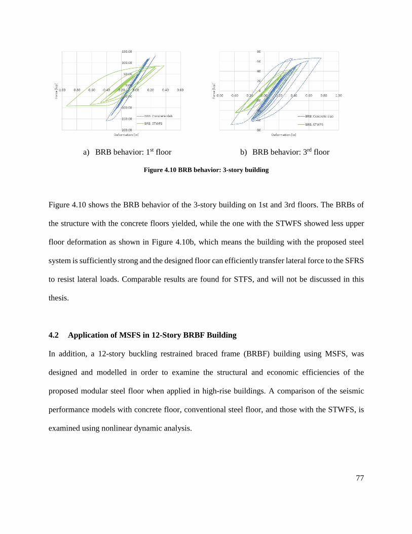
77
a) BRB behavior: 1st floor b) BRB behavior: 3rd floor
Figure 4.10 BRB behavior: 3-story building
Figure 4.10 shows the BRB behavior of the 3-story building on 1st and 3rd floors. The BRBs of
the structure with the concrete floors yielded, while the one with the STWFS showed less upper
floor deformation as shown in Figure 4.10b, which means the building with the proposed steel
system is sufficiently strong and the designed floor can efficiently transfer lateral force to the SFRS
to resist lateral loads. Comparable results are found for STFS, and will not be discussed in this
thesis.
4.2 Application of MSFS in 12-Story BRBF Building
In addition, a 12-story buckling restrained braced frame (BRBF) building using MSFS, was
designed and modelled in order to examine the structural and economic efficiencies of the
proposed modular steel floor when applied in high-rise buildings. A comparison of the seismic
performance models with concrete floor, conventional steel floor, and those with the STWFS, is
examined using nonlinear dynamic analysis.
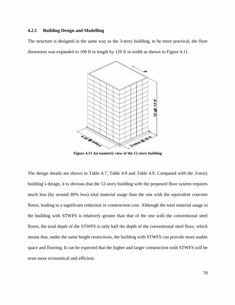
78
4.2.1 Building Design and Modelling
The structure is designed in the same way as the 3-story building, to be more practical, the floor
dimension was expanded to 100 ft in length by 120 ft in width as shown in Figure 4.11.
Figure 4.11 An isometric view of the 12-story building
The design details are shown in Table 4.7, Table 4.8 and Table 4.9. Compared with the 3-story
building’s design, it is obvious that the 12-story building with the proposed floor system requires
much less (by around 40% less) total material usage than the one with the equivalent concrete
floors, leading to a significant reduction in construction cost. Although the total material usage in
the building with STWFS is relatively greater than that of the one with the conventional steel
floors, the total depth of the STWFS is only half the depth of the conventional steel floor, which
means that, under the same height restrictions, the building with STWFS can provide more usable
space and flooring. It can be expected that the higher and larger construction with STWFS will be
even more economical and efficient.
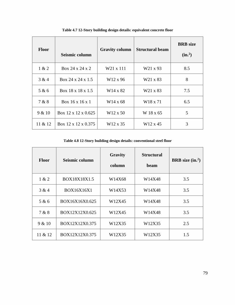
79
Table 4.7 12-Story building design details: equivalent concrete floor
Floor
Seismic column
Gravity column Structural beam
BRB size
(in.2)
1 & 2 Box 24 x 24 x 2 W21 x 111 W21 x 93 8.5
3 & 4 Box 24 x 24 x 1.5 W12 x 96 W21 x 83 8
5 & 6 Box 18 x 18 x 1.5 W14 x 82 W21 x 83 7.5
7 & 8 Box 16 x 16 x 1 W14 x 68 W18 x 71 6.5
9 & 10 Box 12 x 12 x 0.625 W12 x 50 W 18 x 65 5
11 & 12 Box 12 x 12 x 0.375 W12 x 35 W12 x 45 3
Table 4.8 12-Story building design details: conventional steel floor
Floor Seismic column
Gravity
column
Structural
beam
BRB size (in.2)
1 & 2 BOX18X18X1.5 W14X68 W14X48 3.5
3 & 4 BOX16X16X1 W14X53 W14X48 3.5
5 & 6 BOX16X16X0.625 W12X45 W14X48 3.5
7 & 8 BOX12X12X0.625 W12X45 W14X48 3.5
9 & 10 BOX12X12X0.375 W12X35 W12X35 2.5
11 & 12 BOX12X12X0.375 W12X35 W12X35 1.5
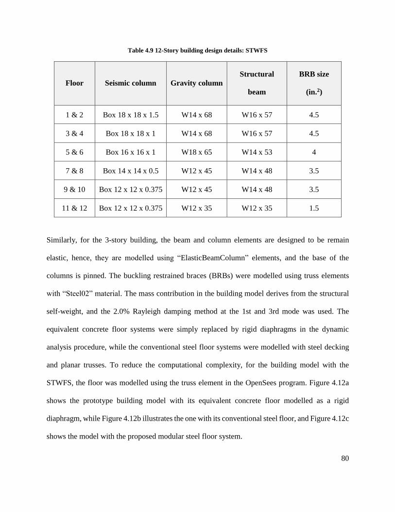
80
Table 4.9 12-Story building design details: STWFS
Floor Seismic column Gravity column
Structural
beam
BRB size
(in.2)
1 & 2 Box 18 x 18 x 1.5 W14 x 68 W16 x 57 4.5
3 & 4 Box 18 x 18 x 1 W14 x 68 W16 x 57 4.5
5 & 6 Box 16 x 16 x 1 W18 x 65 W14 x 53 4
7 & 8 Box 14 x 14 x 0.5 W12 x 45 W14 x 48 3.5
9 & 10 Box 12 x 12 x 0.375 W12 x 45 W14 x 48 3.5
11 & 12 Box 12 x 12 x 0.375 W12 x 35 W12 x 35 1.5
Similarly, for the 3-story building, the beam and column elements are designed to be remain
elastic, hence, they are modelled using “ElasticBeamColumn” elements, and the base of the
columns is pinned. The buckling restrained braces (BRBs) were modelled using truss elements
with “Steel02” material. The mass contribution in the building model derives from the structural
self-weight, and the 2.0% Rayleigh damping method at the 1st and 3rd mode was used. The
equivalent concrete floor systems were simply replaced by rigid diaphragms in the dynamic
analysis procedure, while the conventional steel floor systems were modelled with steel decking
and planar trusses. To reduce the computational complexity, for the building model with the
STWFS, the floor was modelled using the truss element in the OpenSees program. Figure 4.12a
shows the prototype building model with its equivalent concrete floor modelled as a rigid
diaphragm, while Figure 4.12b illustrates the one with its conventional steel floor, and Figure 4.12c
shows the model with the proposed modular steel floor system.
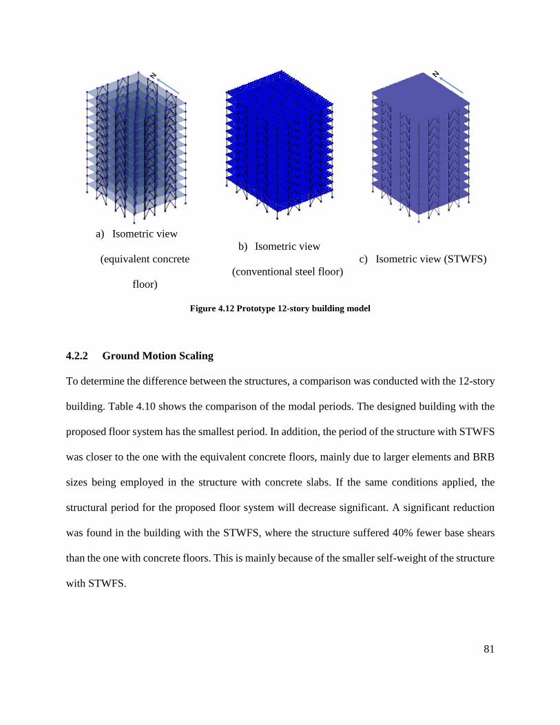
81
a) Isometric view
(equivalent concrete
floor)
b) Isometric view
(conventional steel floor)
c) Isometric view (STWFS)
Figure 4.12 Prototype 12-story building model
4.2.2 Ground Motion Scaling
To determine the difference between the structures, a comparison was conducted with the 12-story
building. Table 4.10 shows the comparison of the modal periods. The designed building with the
proposed floor system has the smallest period. In addition, the period of the structure with STWFS
was closer to the one with the equivalent concrete floors, mainly due to larger elements and BRB
sizes being employed in the structure with concrete slabs. If the same conditions applied, the
structural period for the proposed floor system will decrease significant. A significant reduction
was found in the building with the STWFS, where the structure suffered 40% fewer base shears
than the one with concrete floors. This is mainly because of the smaller self-weight of the structure
with STWFS.
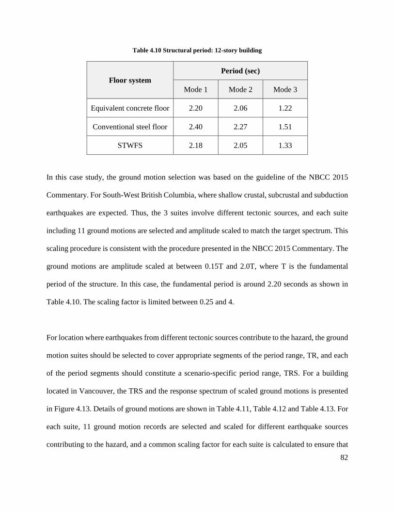
82
Table 4.10 Structural period: 12-story building
Floor system
Period (sec)
Mode 1 Mode 2 Mode 3
Equivalent concrete floor 2.20 2.06 1.22
Conventional steel floor 2.40 2.27 1.51
STWFS 2.18 2.05 1.33
In this case study, the ground motion selection was based on the guideline of the NBCC 2015
Commentary. For South-West British Columbia, where shallow crustal, subcrustal and subduction
earthquakes are expected. Thus, the 3 suites involve different tectonic sources, and each suite
including 11 ground motions are selected and amplitude scaled to match the target spectrum. This
scaling procedure is consistent with the procedure presented in the NBCC 2015 Commentary. The
ground motions are amplitude scaled at between 0.15T and 2.0T, where T is the fundamental
period of the structure. In this case, the fundamental period is around 2.20 seconds as shown in
Table 4.10. The scaling factor is limited between 0.25 and 4.
For location where earthquakes from different tectonic sources contribute to the hazard, the ground
motion suites should be selected to cover appropriate segments of the period range, TR, and each
of the period segments should constitute a scenario-specific period range, TRS. For a building
located in Vancouver, the TRS and the response spectrum of scaled ground motions is presented
in Figure 4.13. Details of ground motions are shown in Table 4.11, Table 4.12 and Table 4.13. For
each suite, 11 ground motion records are selected and scaled for different earthquake sources
contributing to the hazard, and a common scaling factor for each suite is calculated to ensure that
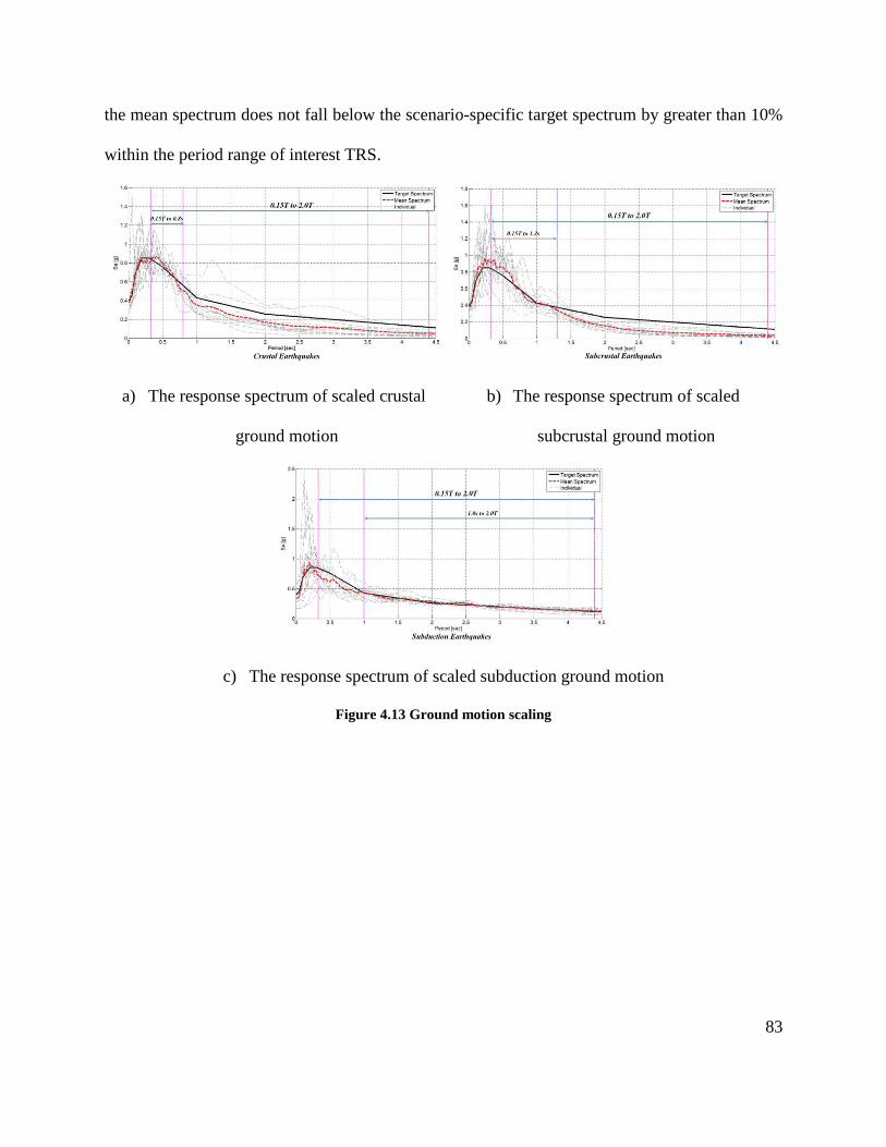
83
the mean spectrum does not fall below the scenario-specific target spectrum by greater than 10%
within the period range of interest TRS.
a) The response spectrum of scaled crustal
ground motion
b) The response spectrum of scaled
subcrustal ground motion
c) The response spectrum of scaled subduction ground motion
Figure 4.13 Ground motion scaling
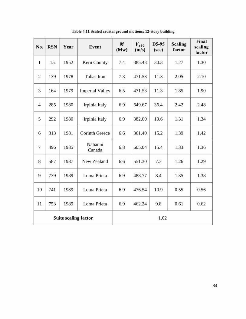
84
Table 4.11 Scaled crustal ground motions: 12-story building
No. RSN Year Event 𝑴
(Mw)
𝑽𝒔𝟑𝟎
(m/s)
D5-95
(sec)
Scaling
factor
Final
scaling
factor
1 15 1952 Kern County 7.4 385.43 30.3 1.27 1.30
2 139 1978 Tabas Iran 7.3 471.53 11.3 2.05 2.10
3 164 1979 Imperial Valley 6.5 471.53 11.3 1.85 1.90
4 285 1980 Irpinia Italy 6.9 649.67 36.4 2.42 2.48
5 292 1980 Irpinia Italy 6.9 382.00 19.6 1.31 1.34
6 313 1981 Corinth Greece 6.6 361.40 15.2 1.39 1.42
7 496 1985 Nahanni
Canada 6.8 605.04 15.4 1.33 1.36
8 587 1987 New Zealand 6.6 551.30 7.3 1.26 1.29
9 739 1989 Loma Prieta 6.9 488.77 8.4 1.35 1.38
10 741 1989 Loma Prieta 6.9 476.54 10.9 0.55 0.56
11 753 1989 Loma Prieta 6.9 462.24 9.8 0.61 0.62
Suite scaling factor 1.02
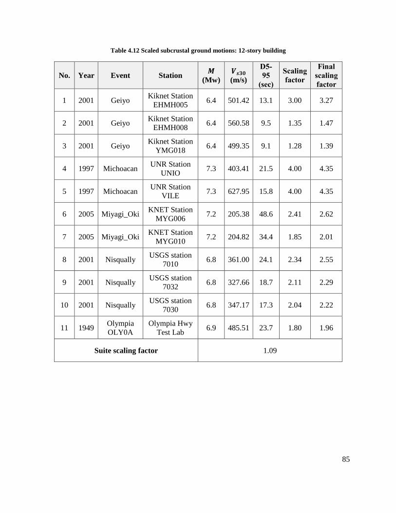
85
Table 4.12 Scaled subcrustal ground motions: 12-story building
No. Year Event Station 𝑴
(Mw)
𝑽𝒔𝟑𝟎
(m/s)
D5-
95
(sec)
Scaling
factor
Final
scaling
factor
1 2001 Geiyo Kiknet Station
EHMH005 6.4 501.42 13.1 3.00 3.27
2 2001 Geiyo Kiknet Station
EHMH008 6.4 560.58 9.5 1.35 1.47
3 2001 Geiyo Kiknet Station
YMG018 6.4 499.35 9.1 1.28 1.39
4 1997 Michoacan UNR Station
UNIO 7.3 403.41 21.5 4.00 4.35
5 1997 Michoacan UNR Station
VILE 7.3 627.95 15.8 4.00 4.35
6 2005 Miyagi_Oki KNET Station
MYG006 7.2 205.38 48.6 2.41 2.62
7 2005 Miyagi_Oki KNET Station
MYG010 7.2 204.82 34.4 1.85 2.01
8 2001 Nisqually USGS station
7010 6.8 361.00 24.1 2.34 2.55
9 2001 Nisqually USGS station
7032 6.8 327.66 18.7 2.11 2.29
10 2001 Nisqually USGS station
7030 6.8 347.17 17.3 2.04 2.22
11 1949 Olympia
OLY0A
Olympia Hwy
Test Lab 6.9 485.51 23.7 1.80 1.96
Suite scaling factor 1.09
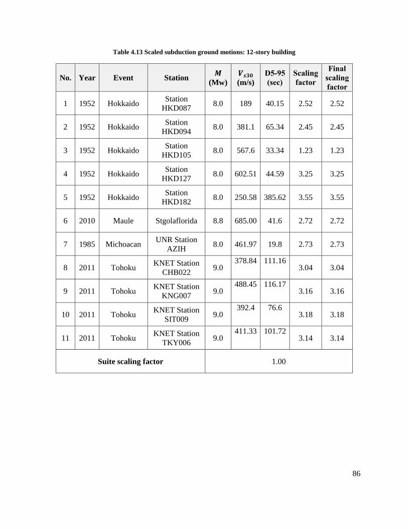
86
Table 4.13 Scaled subduction ground motions: 12-story building
No. Year Event Station 𝑴
(Mw)
𝑽𝒔𝟑𝟎
(m/s)
D5-95
(sec)
Scaling
factor
Final
scaling
factor
1 1952 Hokkaido Station
HKD087 8.0 189 40.15 2.52 2.52
2 1952 Hokkaido Station
HKD094 8.0 381.1 65.34 2.45 2.45
3 1952 Hokkaido Station
HKD105 8.0 567.6 33.34 1.23 1.23
4 1952 Hokkaido Station
HKD127 8.0 602.51 44.59 3.25 3.25
5 1952 Hokkaido Station
HKD182 8.0 250.58 385.62 3.55 3.55
6 2010 Maule Stgolaflorida 8.8 685.00 41.6 2.72 2.72
7 1985 Michoacan UNR Station
AZIH 8.0 461.97 19.8 2.73 2.73
8 2011 Tohoku KNET Station
CHB022 9.0
378.84 111.16 3.04 3.04
9 2011 Tohoku KNET Station
KNG007 9.0
488.45 116.17 3.16 3.16
10 2011 Tohoku KNET Station
SIT009 9.0
392.4 76.6 3.18 3.18
11 2011 Tohoku KNET Station
TKY006 9.0
411.33 101.72 3.14 3.14
Suite scaling factor 1.00
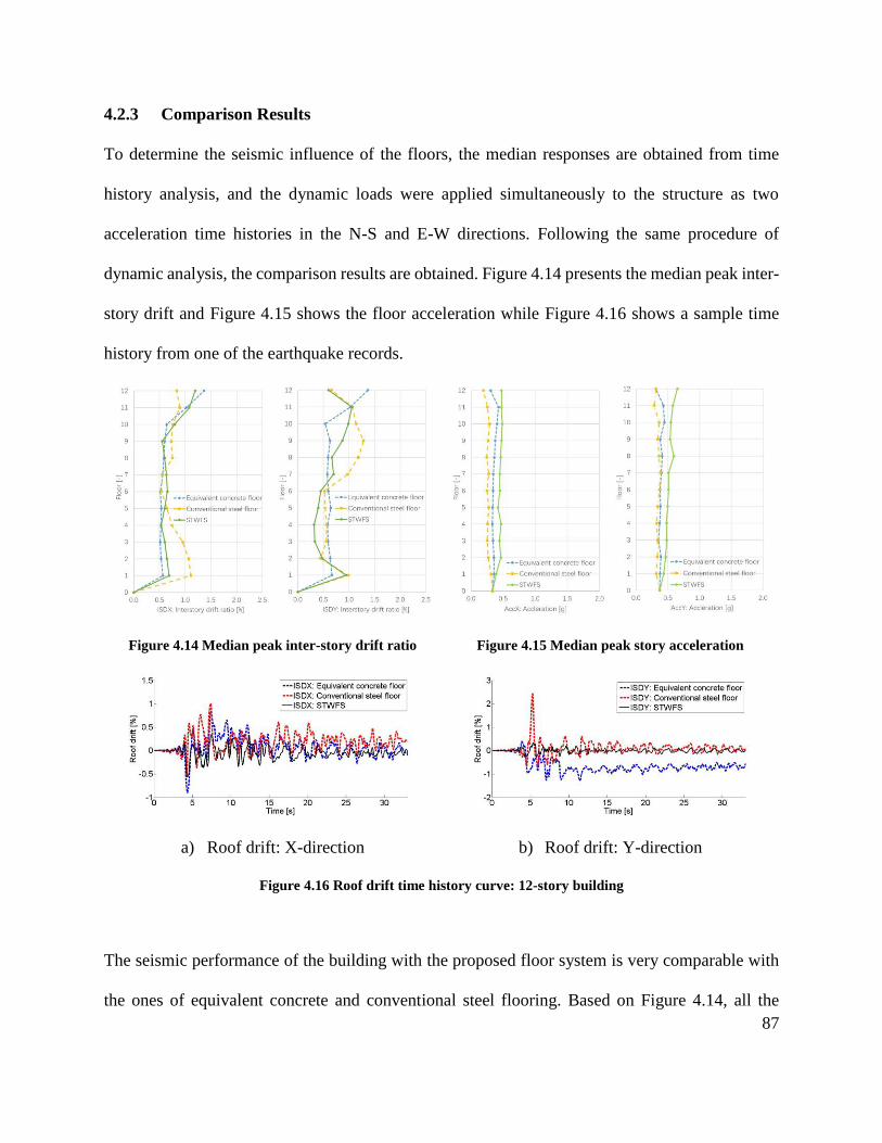
87
4.2.3 Comparison Results
To determine the seismic influence of the floors, the median responses are obtained from time
history analysis, and the dynamic loads were applied simultaneously to the structure as two
acceleration time histories in the N-S and E-W directions. Following the same procedure of
dynamic analysis, the comparison results are obtained. Figure 4.14 presents the median peak inter-
story drift and Figure 4.15 shows the floor acceleration while Figure 4.16 shows a sample time
history from one of the earthquake records.
Figure 4.14 Median peak inter-story drift ratio Figure 4.15 Median peak story acceleration
a) Roof drift: X-direction b) Roof drift: Y-direction
Figure 4.16 Roof drift time history curve: 12-story building
The seismic performance of the building with the proposed floor system is very comparable with
the ones of equivalent concrete and conventional steel flooring. Based on Figure 4.14, all the
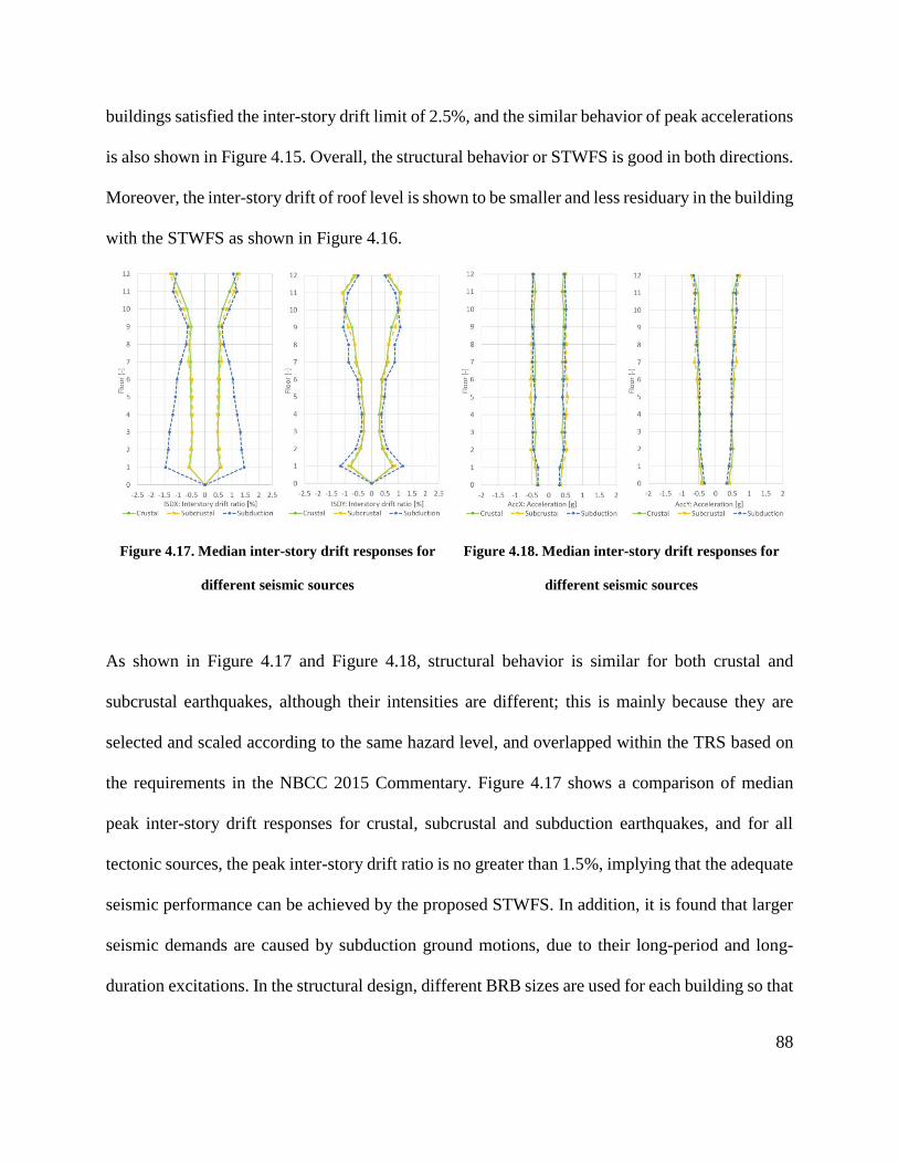
88
buildings satisfied the inter-story drift limit of 2.5%, and the similar behavior of peak accelerations
is also shown in Figure 4.15. Overall, the structural behavior or STWFS is good in both directions.
Moreover, the inter-story drift of roof level is shown to be smaller and less residuary in the building
with the STWFS as shown in Figure 4.16.
Figure 4.17. Median inter-story drift responses for
different seismic sources
Figure 4.18. Median inter-story drift responses for
different seismic sources
As shown in Figure 4.17 and Figure 4.18, structural behavior is similar for both crustal and
subcrustal earthquakes, although their intensities are different; this is mainly because they are
selected and scaled according to the same hazard level, and overlapped within the TRS based on
the requirements in the NBCC 2015 Commentary. Figure 4.17 shows a comparison of median
peak inter-story drift responses for crustal, subcrustal and subduction earthquakes, and for all
tectonic sources, the peak inter-story drift ratio is no greater than 1.5%, implying that the adequate
seismic performance can be achieved by the proposed STWFS. In addition, it is found that larger
seismic demands are caused by subduction ground motions, due to their long-period and long-
duration excitations. In the structural design, different BRB sizes are used for each building so that
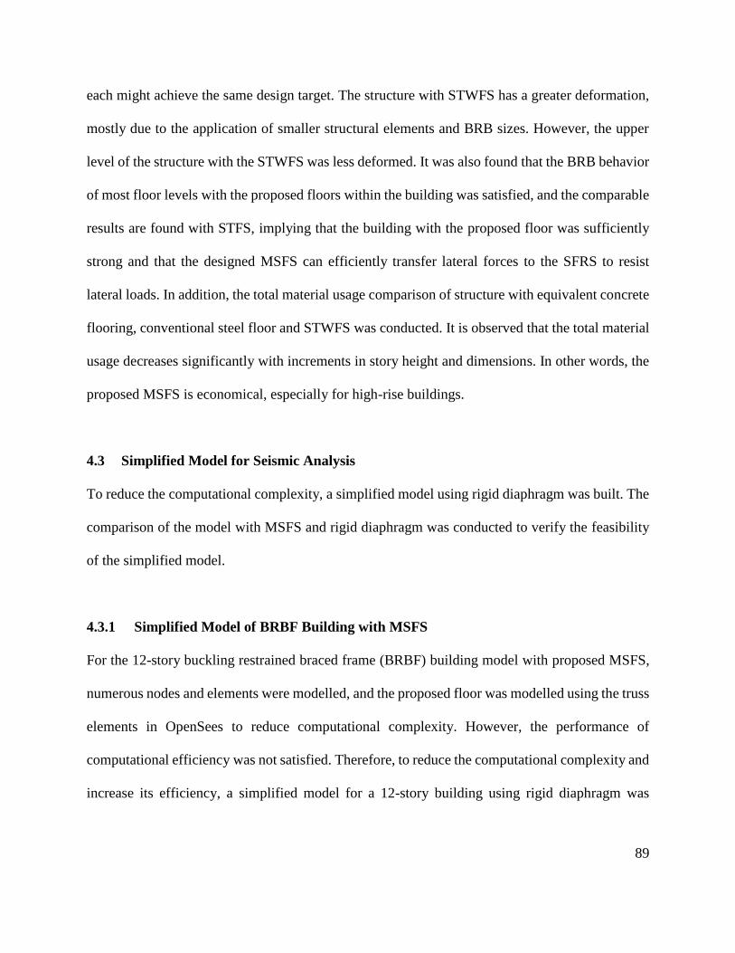
89
each might achieve the same design target. The structure with STWFS has a greater deformation,
mostly due to the application of smaller structural elements and BRB sizes. However, the upper
level of the structure with the STWFS was less deformed. It was also found that the BRB behavior
of most floor levels with the proposed floors within the building was satisfied, and the comparable
results are found with STFS, implying that the building with the proposed floor was sufficiently
strong and that the designed MSFS can efficiently transfer lateral forces to the SFRS to resist
lateral loads. In addition, the total material usage comparison of structure with equivalent concrete
flooring, conventional steel floor and STWFS was conducted. It is observed that the total material
usage decreases significantly with increments in story height and dimensions. In other words, the
proposed MSFS is economical, especially for high-rise buildings.
4.3 Simplified Model for Seismic Analysis
To reduce the computational complexity, a simplified model using rigid diaphragm was built. The
comparison of the model with MSFS and rigid diaphragm was conducted to verify the feasibility
of the simplified model.
4.3.1 Simplified Model of BRBF Building with MSFS
For the 12-story buckling restrained braced frame (BRBF) building model with proposed MSFS,
numerous nodes and elements were modelled, and the proposed floor was modelled using the truss
elements in OpenSees to reduce computational complexity. However, the performance of
computational efficiency was not satisfied. Therefore, to reduce the computational complexity and
increase its efficiency, a simplified model for a 12-story building using rigid diaphragm was
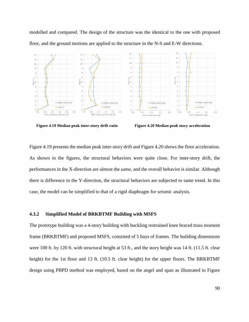
90
modelled and compared. The design of the structure was the identical to the one with proposed
floor, and the ground motions are applied to the structure in the N-S and E-W directions.
Figure 4.19 Median peak inter-story drift ratio Figure 4.20 Median peak story acceleration
Figure 4.19 presents the median peak inter-story drift and Figure 4.20 shows the floor acceleration.
As shown in the figures, the structural behaviors were quite close. For inter-story drift, the
performances in the X-direction are almost the same, and the overall behavior is similar. Although
there is difference in the Y-direction, the structural behaviors are subjected to same trend. In this
case, the model can be simplified to that of a rigid diaphragm for seismic analysis.
4.3.2 Simplified Model of BRKBTMF Building with MSFS
The prototype building was a 4-story building with buckling restrained knee braced truss moment
frame (BRKBTMF) and proposed MSFS, consisted of 5 bays of frames. The building dimensions
were 100 ft. by 120 ft. with structural height at 53 ft., and the story height was 14 ft. (11.5 ft. clear
height) for the 1st floor and 13 ft. (10.5 ft. clear height) for the upper floors. The BRKBTMF
design using PBPD method was employed, based on the angel and span as illustrated in Figure
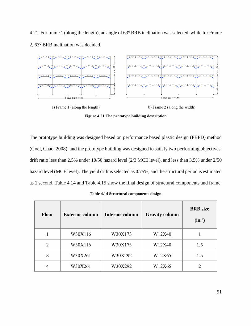
91
4.21. For frame 1 (along the length), an angle of 63⁰ BRB inclination was selected, while for Frame
2, 63⁰ BRB inclination was decided.
a) Frame 1 (along the length) b) Frame 2 (along the width)
Figure 4.21 The prototype building description
The prototype building was designed based on performance based plastic design (PBPD) method
(Goel, Chao, 2008), and the prototype building was designed to satisfy two performing objectives,
drift ratio less than 2.5% under 10/50 hazard level (2/3 MCE level), and less than 3.5% under 2/50
hazard level (MCE level). The yield drift is selected as 0.75%, and the structural period is estimated
as 1 second. Table 4.14 and Table 4.15 show the final design of structural components and frame.
Table 4.14 Structural components design
Floor Exterior column Interior column Gravity column
BRB size
(in.2)
1 W30X116 W30X173 W12X40 1
2 W30X116 W30X173 W12X40 1.5
3 W30X261 W30X292 W12X65 1.5
4 W30X261 W30X292 W12X65 2
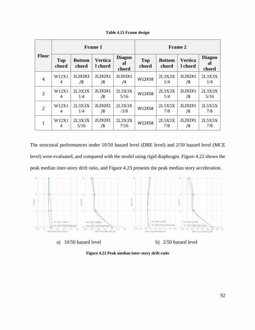
92
Table 4.15 Frame design
Floor
Frame 1 Frame 2
Top
chord
Bottom
chord
Vertica
l chord
Diagon
al
chord
Top
chord
Bottom
chord
Vertica
l chord
Diagon
al
chord
4 W12X1
4
2L2X2X3/8
2L2X2X1/8
2L3X3X1/4
W12X58 2L3X3X
1/4
2L2X2X1/8
2L3X3X
1/4
3 W12X1
4
2L3X3X
1/4
2L2X2X1/8
2L3X3X
5/16 W12X58
2L3X3X
1/4
2L2X2X1/8
2L3X3X
5/16
2 W12X1
4
2L3X3X
1/4
2L2X2X1/8
2L3X3X
/3/8 W12X58
2L5X5X
7/8
2L2X2X1/8
2L5X5X
7/8
1 W12X1
4
2L3X3X
5/16
2L2X2X1/8
2L3X3X
7/16 W12X58
2L5X5X
7/8
2L2X2X1/8
2L5X5X
7/8
The structural performances under 10/50 hazard level (DBE level) and 2/50 hazard level (MCE
level) were evaluated, and compared with the model using rigid diaphragm. Figure 4.22 shows the
peak median inter-story drift ratio, and Figure 4.23 presents the peak median story acceleration.
a) 10/50 hazard level b) 2/50 hazard level
Figure 4.22 Peak median inter-story drift ratio
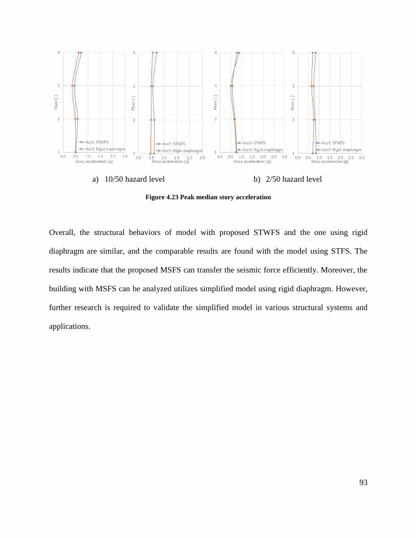
93
a) 10/50 hazard level b) 2/50 hazard level
Figure 4.23 Peak median story acceleration
Overall, the structural behaviors of model with proposed STWFS and the one using rigid
diaphragm are similar, and the comparable results are found with the model using STFS. The
results indicate that the proposed MSFS can transfer the seismic force efficiently. Moreover, the
building with MSFS can be analyzed utilizes simplified model using rigid diaphragm. However,
further research is required to validate the simplified model in various structural systems and
applications.
94
Chapter 5: Summary and Conclusions
In this study, an economical and innovative modular steel truss system (MSTS) is introduced and
developed for modular constructions. The MSTS consists of modular steel floor system (MSFS)
and modular buckling restrained braced truss moment frame (MBRBTMF). Two types of MSFS,
including the space truss floor system (STFS) and space truss with w-beam floor system (STWFS),
were designed and optimized. The specially designed space trusses are utilized in the floor system
to provide sufficient stiffness to support gravity, eliminate vertical deflection and transfer lateral
force without significantly increasing floor depth. The MBRBTMF was designed following the
performance based plastic design (PBPD) method. To promote the use of the introduced system,
the design and optimization procedure was presented.
The optimal design of the STFS is a structural system with a 15-inch spacing along its length and
19-inch spacing along its width. The STFS consists of round HSS 3 x 0.250 as top and bottom
chords, and round HSS 2.375 x 0.154 as web trusses. The total depth of the proposed floor system
is 11 inches, and a 5-inch clear spacing between the top and bottom chord is provided. In addition,
the optimization results for STWFS showed that an optimal configuration of a 6-inch height (centre
line of elements) was the structural system, with 30-inch spacing along its length and 12-inch
spacing along its width. The proposed floor system consists of W12X58 as the structural beam,
top and bottom chords with 2-inch external diameters, 1.4-inch internal diameters and 1.6-square-
inch areas, as well as the 0.5-square-inch area web trusses. The total floor depth is 8 inches, which
is very comparable with the conventional concrete slabs, and this creates a 4-inch gap to allow
mechanical, electrical and plumbing (MEP) systems to pass through. To be more practical, the
95
floor system using the available section is also checked, and these results show that the
optimization results are efficient and reliable.
The information on structure and site condition were introduced, and a prototype 4-story MSTS
building was designed and modelled. The MBRBTMFS, as the seismic force resisting frame, was
designed following the PBPD procedure. The buckling restrained braces (BRBs) were selected as
the structural fuses and energy dissipation devices, where the rest structural components were
designed to remain elastic. The structure was modelled in an advanced finite element analysis
software OpenSees. The hazard analysis was conducted, and ground motions were selected and
amplitude scaled to match the target spectrum. The results showed that the MBRBTMF is efficient
and the seismic performance of the prototype building is excellent. The structures with
conventional SFRS were also designed, and it was found that the building with the proposed floor
system, requires less material usage for both its structural elements and BRBs, which means less
construction costs. In addition, more usable space height can be provided by the designed floor,
and it can be expected that higher and larger construction with the proposed floors would be even
more economical and efficient. The seismic performances of various floors were studied, and the
results of the analyses reveal that the structure with the proposed floor has satisfied seismic
performance. This implies that the building with the designed STFS is sufficiently strong and that
the proposed floor can efficient transfer lateral force to the different SFRSs to resist lateral loads.
In conclusion, the proposed MSTS shows a promising performance for practical applications.
96
Bibliography
Allen, D., & Murray, T. (1993). Design criterion for vibrations due to walking. Engineering
Journal, 30(4), 117-129.
Allen, D. E., & Pernica, G. (1998). Control of floor vibration: Institute for Research in
Construction, National Research Council of Canada.
American Concrete Institute. (2015). ACI 302.1R-15: Guide for Concrete Floor and Slab
Construction.
American Institute of Steel Construction. (2013). AISC Shapes Database V14.1: American
Institute of Steel Construction.
Auer, B. J. (2005). Size and shape optimization of frame and truss structures through evolutionary
methods.
Black, C. J., Makris, N., & Aiken, I. D. (2004). Component testing, seismic evaluation and
characterization of buckling-restrained braces. Journal of Structural Engineering, 130(6),
880-894.
Broad Group. (2012). T30A Tower Hotel.
Canadian Institute of Steel Construction. (2014). CSA-S16-14: design of steel structures Canadian
Standards Association, Mississauga, Ontario, Canada.
Chao, S.-H., & Goel, S. C. (2006a). Performance-based seismic design of eccentrically braced
frames using target drift and yield mechanism as performance criteria. ENGINEERING
JOURNAL-AMERICAN INSTITUTE OF STEEL CONSTRUCTION INC, 43(3), 173-200.
Chao, S.-H., & Goel, S. C. (2006b). A seismic design method for steel concentric braced frames
for enhanced performance. Paper presented at the 4th International Conference on
Earthquake Engineering.
97
Chao, S.-H., Goel, S. C., & Lee, S.-S. (2007). A seismic design lateral force distribution based on
inelastic state of structures. Earthquake Spectra, 23(3), 547-569.
Clark, P., Aiken, I., Kasai, K., Ko, E., & Kimura, I. (1999). Design procedures for buildings
incorporating hysteretic damping devices. Paper presented at the Proceedings 68th annual
convention.
Cobiax®. (2016). Cobiax® Lightweight concrete slabs. from www.cobiax.com/home
Construction, A. I. o. S. (2003). AISC/CISC Steel Design Guide Series No. 11: Floor Vibrations
Due to Human Activity.
Council on Tall Buildings and Urban Habitat, C. (2017). The Global Tall Building Database of the
CTBUH. from http://www.skyscrapercenter.com/
Dewit, N. (2012). A Composite Structural Steel and Prestressed Concrete Beam for Building Floor
Systems.
Di Mauro, M., McLean, L., Guha-Sapir, D., Wirtz, A., Eichner, J., & Dilley, M. (2013). Risk
Information Issues and Needs: An Overview. Paper presented at the Geneva, Switzerland.
http://www. wmo. int/pages/prog/drr/projects/Thematic/HazardRisk/2013-10-TC-Prog-
FP-Meeting/documents/Doc.
Girder-Slab Technologies, L. (2016). The GIRDER-SLAB® System Design Guide v3.3. from
www.girder-slab.com/
Girhammar, U. A., & Pajari, M. (2008). Tests and analysis on shear strength of composite slabs of
hollow core units and concrete topping. Construction and Building Materials, 22(8), 1708-
1722.
Goel, S. C., & Chao, S.-H. (2008). Performance-based plastic design: earthquake-resistant steel
structures: International Code Council.
98
Goel, S. C., & Leelataviwat, S. (1998). Seismic design by plastic method. Engineering Structures,
20(4-6), 465-471.
Goel, S. C., Liao, W. C., Reza Bayat, M., & Chao, S. H. (2010). Performance‐based plastic
design (PBPD) method for earthquake‐resistant structures: an overview. The structural
design of tall and special buildings, 19(1‐2), 115-137.
Hamburger, R. O., Krawinkler, H., Malley, J. O., & Adan Scott, M. (2009). Seismic design of steel
special moment frames. NEHRP Seismic Design Technical Brief(2).
Hegger, J., Roggendorf, T., & Kerkeni, N. (2009). Shear capacity of prestressed hollow core slabs
in slim floor constructions. Engineering Structures, 31(2), 551-559.
Henin, E., Morcous, G., & Tadros, M. K. (2012). Shallow Flat Soffit Precast Concrete Floor
System. Practice Periodical on Structural Design and Construction, 18(2), 101-110.
Hickory Building Innovation. (2010). Little Hero.
John, H. (1992). Holland, Adaptation in Natural and Artificial Systems: An Introductory Analysis
with Applications to Biology, Control and Artificial Intelligence: MIT Press, Cambridge,
MA.
Kim, T., Whittaker, A., Gilani, A., Bertero, V., & Takhirov, S. (2002). Experimental evaluation of
plate-reinforced steel moment-resisting connections. Journal of Structural Engineering,
128(4), 483-491.
Lawson, R. M., Ogden, R. G., & Bergin, R. (2011). Application of modular construction in high-
rise buildings. Journal of architectural engineering, 18(2), 148-154.
Lawson, R. M., & Richards, J. (2010). Modular design for high-rise buildings. Proceedings of the
Institution of Civil Engineers-Structures and Buildings, 163(3), 151-164.
99
Lee, D.-G., Ahn, S.-K., & Kim, D.-K. (2005). Efficient seismic analysis of building structure
including floor slab. Engineering Structures, 27(5), 675-684.
Leelataviwat, S., Goel, S., Rai, D., Liao, W., Bayat, M., Chao, S., & Stojadinovic, B. (2012). A
Collaborative Research Program on Performance-Based Design of Innovative Structural
Systems for Earthquake Resistance: An Overview. Paper presented at the 15th World
Conference on Earthquake Engineering (15 WCEE), Lisbon, Portugal. 本人為通訊作者.
Marais, C. C. (2009). Design adjustment factors and the economical application of concrete flat-
slabs with internal spherical voids in South Africa. University of Pretoria.
Mardle, S., & Pascoe, S. (1999). An overview of genetic algorithms for the solution of optimisation
problems. Computers in Higher Education Economics Review, 13(1), 16-20.
Metal Dek Group & Diversakore. (2010). Vibration Performance of Composite Steel Frame-and-
Dek Floor System. from http://www.diversakore.com/
Morcous, G., & Tadros, M. (2014). Shallow flat soffit precast concrete floor system: Google
Patents.
National Research Council of Canada. (2015). National Building Code of Canada. Ottawa, ON.
Natural Resources Canada. (2015). Natural Resources Canada, .
Pacific Earthquake Engineering Research (PEER) Center. (2005). OpenSees command language
manual. 264.
Pacific Earthquake Engineering Research Center, P. (2010). Ground motion database. from Univ.
of California, Berkeley
Peikko Group®. (2014). DELTABEAM® Slim Floor Structures, Technical Manual. from
www.peikko.com/
100
Popov, E. P., & Engelhardt, M. D. (1988). Seismic eccentrically braced frames. Journal of
Constructional Steel Research, 10, 321-354.
Ricles, J. M., Mao, C., Lu, L.-W., & Fisher, J. W. (2002). Inelastic cyclic testing of welded
unreinforced moment connections. Journal of Structural Engineering, 128(4), 429-440.
Ruiyi, S., Liangjin, G., & Zijie, F. (2009). Truss topology optimization using genetic algorithm
with individual identification. Paper presented at the Proceedings of the world congress on
engineering.
Smith, A., Hicks, S., & Devine, P. (2007). SCI P354: Design of Floors for Vibration: A New
Approach: The Steel Construction Institute, Silwood Park, Ascot, Berkshire, UK.
The Mathworks. (1998). Guide, MATLAB User’s. Inc., Natick, MA, 5, 333.
Timler, P. A., & Kulak, G. L. (1983). Experimental study of steel plate shear walls.
Tsai, K.-C., & Popov, E. P. (1990). Cyclic behavior of end-plate moment connections. Journal of
Structural Engineering, 116(11), 2917-2930.
U.S. Geological Survey, U. (2017). U.S. Geological Survey, USGS.
Uang, C.-M., & Fan, C.-C. (2001). Cyclic stability criteria for steel moment connections with
reduced beam section. Journal of Structural Engineering, 127(9), 1021-1027.
Yang, T., Li, Y., & Goel, S. C. (2015). Seismic Performance Evaluation of Long-Span
Conventional Moment Frames and Buckling-Restrained Knee-Braced Truss Moment
Frames. Journal of Structural Engineering, 142(1), 04015081.
Yang, T., Li, Y., & Leelataviwat, S. (2013). Performance-based design and optimization of
buckling restrained knee braced truss moment frame. Journal of Performance of
Constructed Facilities, 28(6), A4014007.
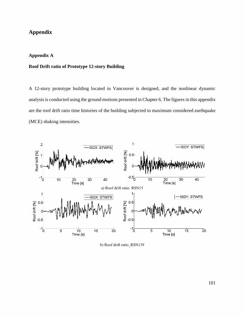
101
Appendix
Appendix A
Roof Drift ratio of Prototype 12-story Building
A 12-story prototype building located in Vancouver is designed, and the nonlinear dynamic
analysis is conducted using the ground motions presented in Chapter 6. The figures in this appendix
are the roof drift ratio time histories of the building subjected to maximum considered earthquake
(MCE) shaking intensities.
a) Roof drift ratio_RSN15
b) Roof drift ratio_RSN139
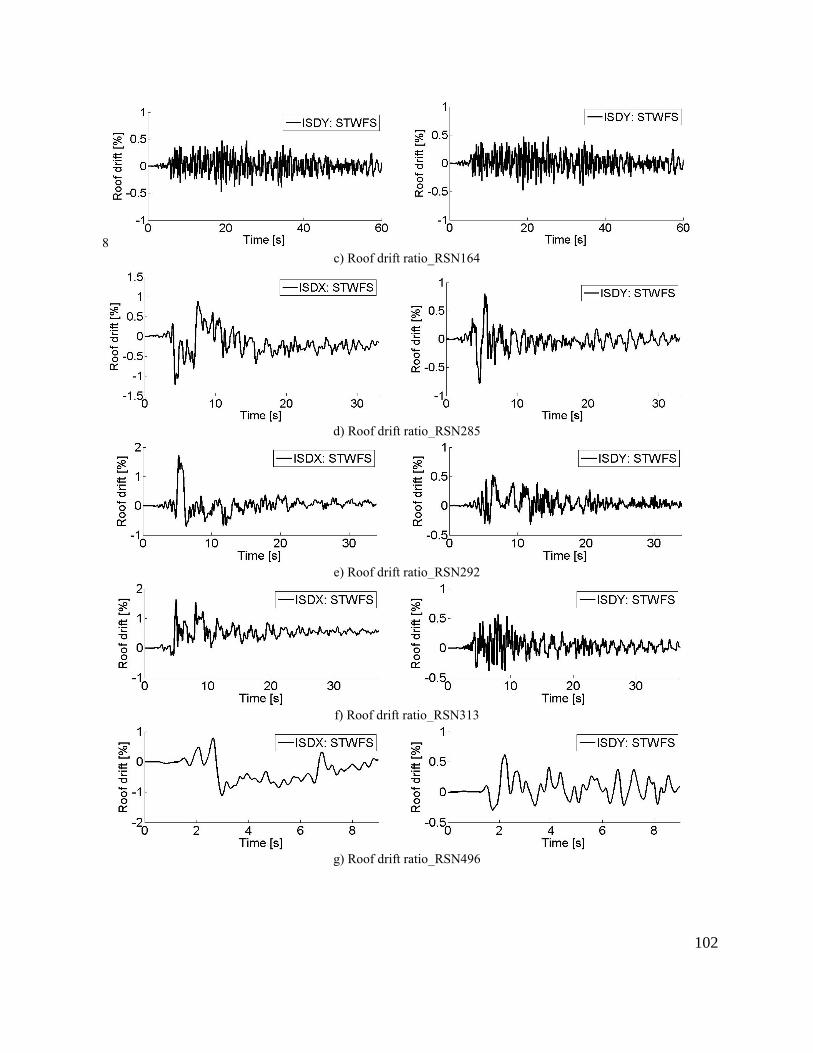
102
8
c) Roof drift ratio_RSN164
d) Roof drift ratio_RSN285
e) Roof drift ratio_RSN292
f) Roof drift ratio_RSN313
g) Roof drift ratio_RSN496
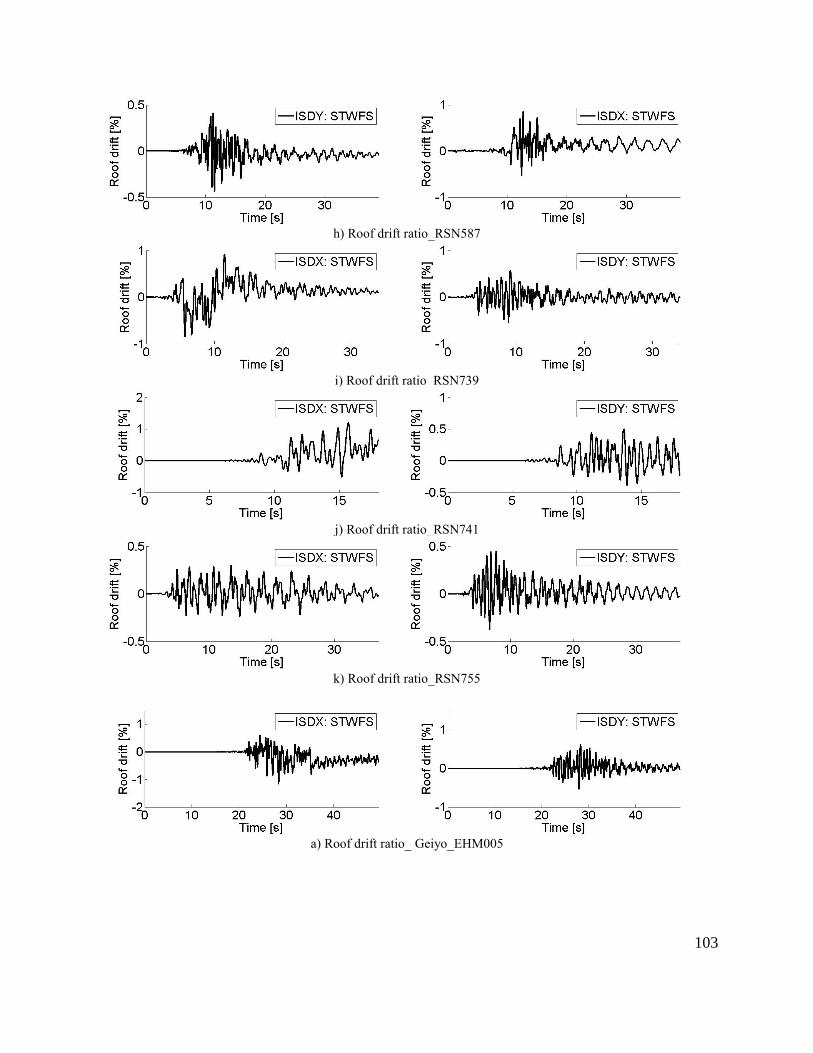
103
h) Roof drift ratio_RSN587
i) Roof drift ratio_RSN739
j) Roof drift ratio_RSN741
k) Roof drift ratio_RSN755
a) Roof drift ratio_ Geiyo_EHM005
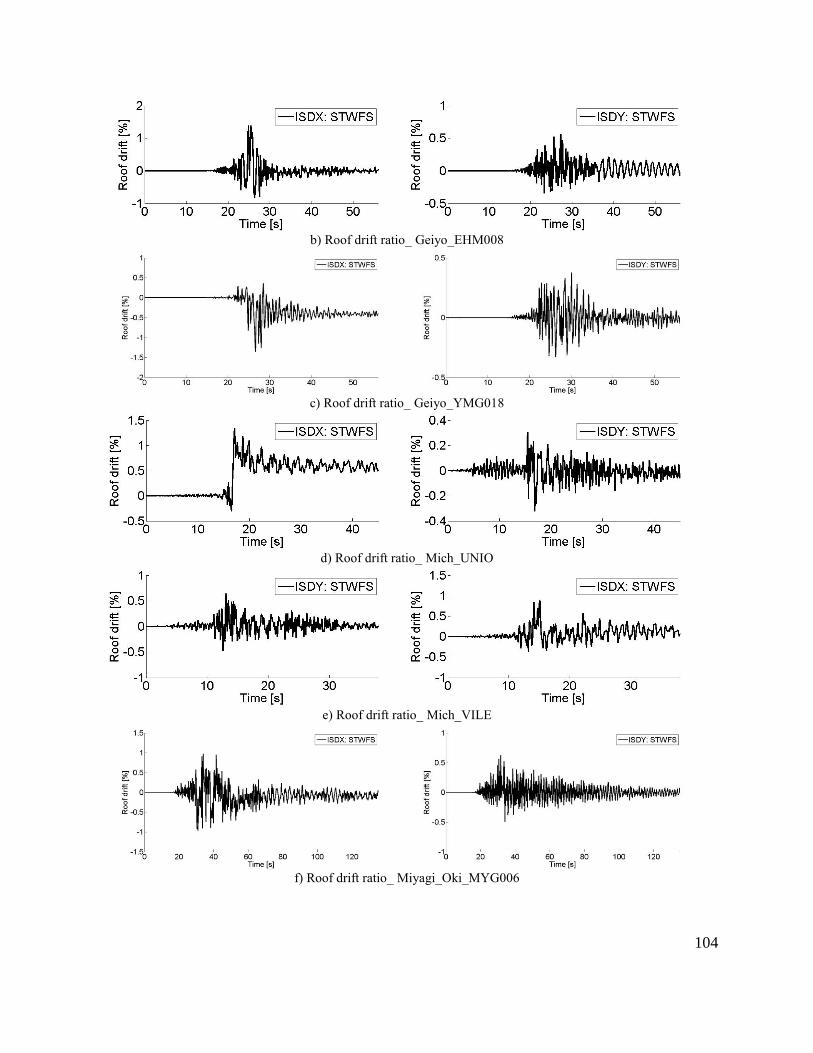
104
b) Roof drift ratio_ Geiyo_EHM008
c) Roof drift ratio_ Geiyo_YMG018
d) Roof drift ratio_ Mich_UNIO
e) Roof drift ratio_ Mich_VILE
f) Roof drift ratio_ Miyagi_Oki_MYG006
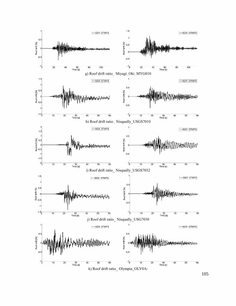
105
g) Roof drift ratio_ Miyagi_Oki_MYG010
h) Roof drift ratio_ Nisqually_USGS7010
i) Roof drift ratio_ Nisqually_USGS7032
j) Roof drift ratio_ Nisqually_USG7030
k) Roof drift ratio_ Olympia_OLY0A-
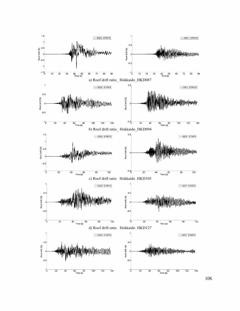
106
a) Roof drift ratio_ Hokkaido_HKD087
b) Roof drift ratio_ Hokkaido_HKD094
c) Roof drift ratio_ Hokkaido_HKD105
d) Roof drift ratio_ Hokkaido_HKD127
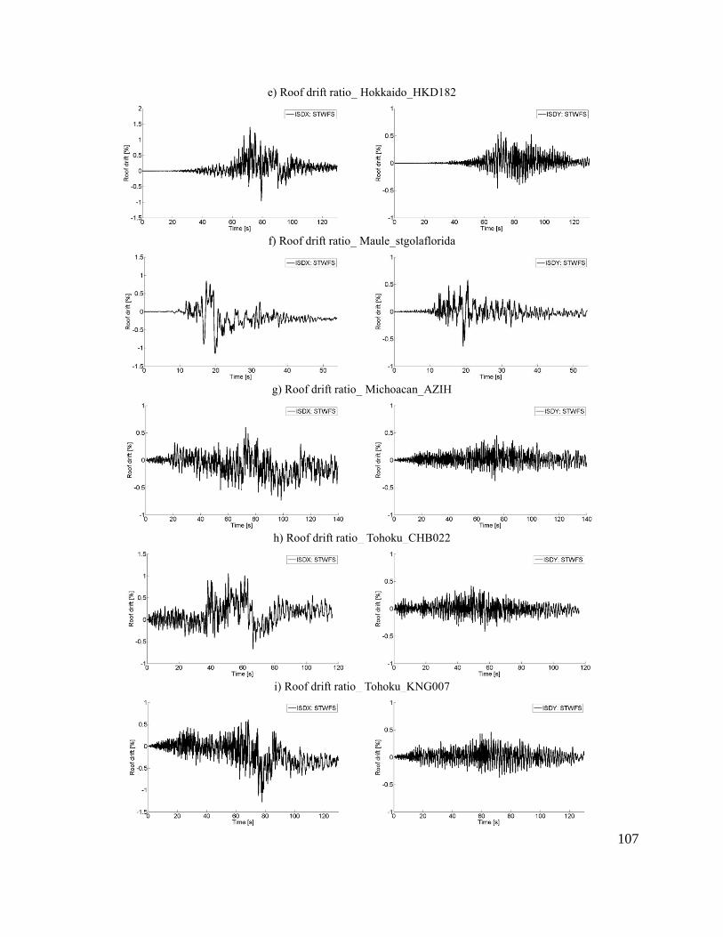
107
e) Roof drift ratio_ Hokkaido_HKD182
f) Roof drift ratio_ Maule_stgolaflorida
g) Roof drift ratio_ Michoacan_AZIH
h) Roof drift ratio_ Tohoku_CHB022
i) Roof drift ratio_ Tohoku_KNG007
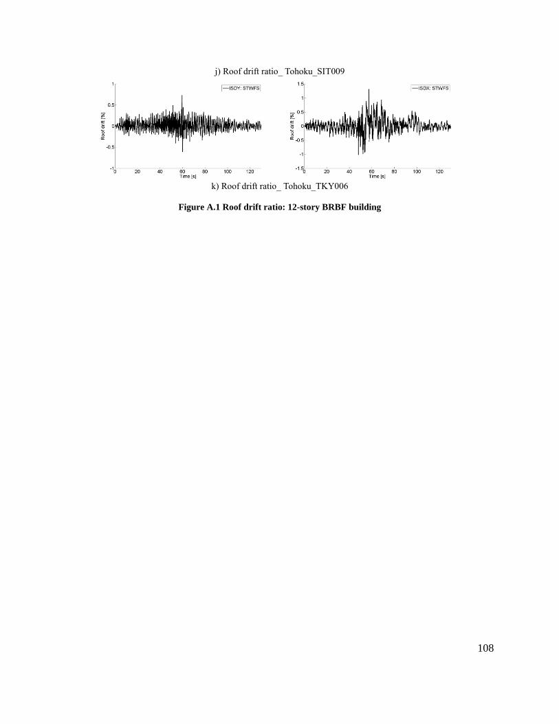
108
j) Roof drift ratio_ Tohoku_SIT009
k) Roof drift ratio_ Tohoku_TKY006
Figure A.1 Roof drift ratio: 12-story BRBF building


