Embed Size (px)
Citation preview

M. Romero, J. Ma. Rincón, A. Acosta. Development of mica glass-ceramic glazes Journal of the American Ceramic Society, 87 (2004) 5, 819-823; DOI: 10.1111/j.1551-2916.2004.00819.x
Development of mica glass-ceramic glazes
Maximina Romeroa, Jesús Ma. Rincóna, Anselmo Acostab
a Instituto Eduardo Torroja de Ciencias de la Construcción, Laboratory of Glass-ceramic
Materials, CSIC, Madrid, 28033, Madrid, Spain.
b Universidad de Castilla-La Mancha, Facultad de CC. Químicas, Dpto. Mineralogía Aplicada,
Ciudad Real, 13071, Spain.
Abstract
The effect of iron content on crystallization of a mica glaze as coating for fast firing stoneware
substrates has been investigated. Measurements by differential thermal analysis (DTA)
combined with X-ray diffraction (XRD) and scanning electron microscopy (SEM) have shown
the development of preferential crystal orientation in the mica glass-ceramic glaze. By com-
parison with amorphous and partly crystalline glazes, an enhancement of the mechanical
properties of coatings with aligned and interlocked crystals of mica has been observed.
1. Introduction
Glass-ceramics, which are polycrystalline materials comprised of crystalline and glassy phases,
have become established in a wide range of technical and technological applications.1 The glass-
ceramic process involves the controlled devitrification of a glass to provide a homogeneous
microcrystalline structure. To achieving this, it has usually been necessary to include a
nucleating agent, such as TiO2 or Fe2O3, in the glass that will provide the nuclei for subsequent
crystal growth or influence the structural reorganization in the glass in such a manner that many
crystals grow in the glass.1,2

M. Romero, J. Ma. Rincón, A. Acosta. Development of mica glass-ceramic glazes Journal of the American Ceramic Society, 87 (2004) 5, 819-823; DOI: 10.1111/j.1551-2916.2004.00819.x
Since their development in the 1950s, mica-containing glass-ceramics have attracted much
attention because of their unique properties.3
Mica glass-ceramics, in particular of the
phlogopite system, are high-quality electrical insulators and show high resistance to thermal
shock and machinability, due to the layered atomic structure of the sheet silicates which causes
a basal cleavage along the (001) planes of the plate-shaped mica crystals.4–6
In this sense,
several works have been conducted in the last years to establish the crystallization kinetics,7
to
obtain oriented mica glass-ceramics by extrusion8,9
and to enhance the mechanical properties of
mica glasses and glass-ceramics.10,11
However, to our knowledge, no previous work has been
published regarding the development of mica glass-ceramic glazes.
Glazed ceramic tile is the most common building material for floor and wall covering in
Mediterranean countries. Glazed tile is produced from frits, which are mixed with water and
organic additives to yield glaze slips. These slips are applied to the surface of green tile, and
after a drying step, they are subjected to a single-or double-firing process. There are a wide
variety of frits, which have different characteristics such as fusibility, viscosity, gloss, and
opacity.
The main objective of the present study is to develop a mica glass-ceramic glaze from a high
fusibility commercial frit, which originally shows an amorphous character. For this purpose, an
iron-containing glassy frit will be used as a precursor of crystallization.
2. Experimental Procedure
The compositions of the frits used for this study are given in Table I. Frit HIGHF is a high
fusibility glassy frit (supplied by Fritta S.L., Castellón, Spain), whereas frit IGF is an iron glassy
frit obtained from an iron-rich waste originated by a Spanish granite plant. The granite waste,
which was supplied as a dried mud coming from the sawing processing of granite blocks, was
melted in air at 1450°C for1hin silica–alumina crucibles. The fluid melt was quenched by
pouring into water to obtain a glassy frit. No visible corrosion or chemical attack of the silica–
alumina crucible by the melt was observed. Chemical compositions of frits were measured by
wet chemistry using inductively coupled plasma emission spectroscopy (ICP).
M. Romero, J. Ma. Rincón, A. Acosta. Development of mica glass-ceramic glazes Journal of the American Ceramic Society, 87 (2004) 5, 819-823; DOI: 10.1111/j.1551-2916.2004.00819.x
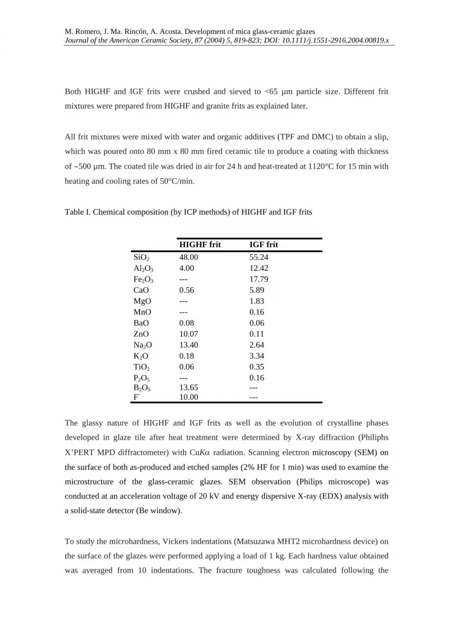
Both HIGHF and IGF frits were crushed and sieved to <65 µm particle size. Different frit
mixtures were prepared from HIGHF and granite frits as explained later.
All frit mixtures were mixed with water and organic additives (TPF and DMC) to obtain a slip,
which was poured onto 80 mm x 80 mm fired ceramic tile to produce a coating with thickness
of ∼500 µm. The coated tile was dried in air for 24 h and heat-treated at 1120°C for 15 min with
heating and cooling rates of 50°C/min.
Table I. Chemical composition (by ICP methods) of HIGHF and IGF frits
HIGHF frit IGF frit SiO2 48.00 55.24 Al2O3 4.00 12.42 Fe2O3
--- 17.79 CaO 0.56 5.89 MgO --- 1.83 MnO --- 0.16 BaO 0.08 0.06 ZnO 10.07 0.11 Na2O 13.40 2.64 K2O 0.18 3.34 TiO2 0.06 0.35 P2O5 B2O5 F-
--- 13.65 10.00
0.16 --- ---
The glassy nature of HIGHF and IGF frits as well as the evolution of crystalline phases
developed in glaze tile after heat treatment were determined by X-ray diffraction (Philiphs
X’PERT MPD diffractometer) with CuKα radiation. Scanning electron microscopy (SEM) on
the surface of both as-produced and etched samples (2% HF for 1 min) was used to examine the
microstructure of the glass-ceramic glazes. SEM observation (Philips microscope) was
conducted at an acceleration voltage of 20 kV and energy dispersive X-ray (EDX) analysis with
a solid-state detector (Be window).
To study the microhardness, Vickers indentations (Matsuzawa MHT2 microhardness device) on
the surface of the glazes were performed applying a load of 1 kg. Each hardness value obtained
was averaged from 10 indentations. The fracture toughness was calculated following the

M. Romero, J. Ma. Rincón, A. Acosta. Development of mica glass-ceramic glazes Journal of the American Ceramic Society, 87 (2004) 5, 819-823; DOI: 10.1111/j.1551-2916.2004.00819.x
equation of Evans and Charles12:
KIC=0.16Hva1/2(a/c)-3/2 (1)
where Hv is the Vickers microhardness, a is the half-diagonal of the indentation, and c is the
half-distance between the opposite crack tips.
2. Results and Discussion
Table I shows the chemical analysis by ICP of HIGHF and IGF frits. In this table, Fe2O3
represents the total amount of FeO + Fe2O3 in the IGF frit. The major components in the
HIGHF frit are SiO2,B2O3,Na2O, and ZnO, whereas the IGF frit is mainly composed of
SiO2,Fe2O3, and Al2O3.
Table II gives the different mixtures prepared from diopside and granite frits. The iron content
of those mixtures is also shown in Table II. As noted, the Fe2O3 content ranges from 0 wt% in
mixture A, which is composed of only the HIGHF frit, to near 16% for mixture F, which is
prepared mainly from the IGF frit (90 wt%).
Table II. Original frits mixtures prepared from HIGHF and IGF frits
Frit mixture HIGHF frit (wt. %)
IGF frit (wt. %)
Fe2O3 content (wt. %)
A 100 0 0.00 B 90 10 1.78 C 70 30 5.34 D 50 50 8.89 E 30 70 12.45 F 10 90 16.01
The frit mixtures were applied over ceramic tile substrates as explained earlier. After cooling at
room temperature, glaze tile showed a homogeneous and glossy surface. Glaze defects as
bubbles or crazing were not detectable.

M. Romero, J. Ma. Rincón, A. Acosta. Development of mica glass-ceramic glazes Journal of the American Ceramic Society, 87 (2004) 5, 819-823; DOI: 10.1111/j.1551-2916.2004.00819.x
Figure 1 shows the X-ray spectra collected on the surface of glaze tile. The XRD pattern of
sample A (Fig. 1(A)), which is prepared without addition of granite frit, shows that the HIGHF
frit gives rise to an amorphous glaze. Nevertheless, the DTA curve recorded from a powder
sample of the HIGHF frit (Fig. 2) shows its ability to crystallize, with two exothermic peaks at
720° and 950°C, respectively. This curve is similar to typical DTA curves of mica glasses
reported in the literature,13,14
in which XRD was used to determine that the exothermic peak at
the lower temperature (720°C in the HIGHF frit) corresponds to the crystallization of norbergite
(Mg3SiO4F2) whereas the second DTA peak (950°Cin the HIGHF frit) is due to
fluorophlogopite (KMg3AlSi3O10F2) precipitation. This means that although the HIGHF frit is
adequate to lead a mica glass-ceramic glaze, the fast cooling rate (50°C/min) does not allow
crystal growth during the manufacturing process, because an iron-containing frit has been used
as a precursor of crystallization to give rise to a glass-ceramic glaze without additional change
in the process conditions.
Fig. 1. X-ray spectra collected on the surface of glaze tiles ( = franklinite (ZnFe2O4); = hematite (Fe2O3); (hkl) = biotite reflections).
The XRD pattern of glazes B and C (Figs. 1(B,C)), which are prepared with additions of 10%
and 30% of the IGF frit, respectively, shows a diffractogram without crystallization peaks.
However, the background in glazes B and C is lower than in glaze A, indicating either that
glazes B and C are still amorphous, a structural change in the glass structure has taken place, or
both glazes are partially crystallized with a percentage of crystalline phase lower than the
detection limit of the XRD system (2% of crystalline phase). SEM confirmed the last
F
E
D
CBA
(020
)(0
20)
(003
)
(11
-3)
(11
-3)
(11
-3)
(004
)(1
31)
(131
)(1
3 -3
)
(204
)
(060
)
(204
)
(060
)
(13
-5)
(13
-6)
(007
)

M. RoJourn
suppo
IGF
dispe
and s
the E
conte
identi
SiO2
is dow
Fig. 2
Fig. 3IGF f
50
aa
omero, J. Ma. nal of the Ame
osition. Figu
frit. The sam
ersed on the g
size, compris
EDX analyses
ent when co
ified as the z
and Al2O3
wn to the ana
2. DTA curv
3. SEM micrfrit: (a) gener
00 µm
Rincón, A. Aerican Cerami
ure 3 shows t
mple is main
glaze surface
se by small c
s conducted
ompared with
zinc ferrite d
contents; th
alytical resol
e recorded fr
rographs on tral view of th
301.2
1.4
1.6
1.8
2.0
2.2
2.4
2.6
2.8
DTA
(µV
/mg)
Acosta. Develoic Society, 87
the microstru
nly amorpho
e (Fig. 3(a)).
crystals whos
on glaze C.
h the averag
denominated
his is a conse
lution of the
rom a powde
the surface ohe surface an
00 500
Tg = 5
opment of mic(2004) 5, 819
ucture of glaz
ous, but sma
These cryst
se average si
As noted, sm
ge composit
franklinite (
equence of th
SEM/EDX s
er sample of
of glass-ceramnd (b) crystal
0 700Temperatu
13ºC
Tp1 = 72
ca glass-ceram-823; DOI: 10
ze C prepare
all crystallin
talline region
ize is 0.5 µm
mall crystals
tion; thus th
(ZnFe2O4). E
he small size
system (1 µm
HIGHF frit.
mic glaze C pls of franklin
900ure (°C)
20ºC Tp2
3 µm
b
mic glazes 0.1111/j.1551
ed with addit
e regions ar
ns, which sho
m (Fig. 3(b)).
show greate
his crystallin
EDX analysi
e of franklini
m).
prepared witnite (ZnFe2O
1100
= 950ºC
1-2916.2004.0
tion of 30%
re homogene
ow irregular
. Table III co
er Fe2O3 and
ne phase cou
is also show
ite crystals, w
th addition oO4).
00819.x
of the
eously
shape
ollects
d ZnO
uld be
s high
which
f 30% of thee

M. Romero, J. Ma. Rincón, A. Acosta. Development of mica glass-ceramic glazes Journal of the American Ceramic Society, 87 (2004) 5, 819-823; DOI: 10.1111/j.1551-2916.2004.00819.x
Franklinite crystallization begins to be detected by XRD in the diffractogram recorded on the
surface of glaze D (Fig. 1(D)), which has been prepared with addition of 50% of the IGF frit.
SEM observations on this glaze are presented in Fig. 4. The surface of the glaze shows a high
degree of crystallinity (Fig. 4(a)) and a new phase, comprising crystals with hexagonal and
rectangular habit, starts to crystallize together with franklinite phase (Figs. 4(b,c)). EDX
analyses have shown that there are not significant differences in the chemical compositions of
both types of crystals; thus, hexagonal and rectangular crystals correspond only to a crystalline
phase belonging to the mica group. The general formula to describe the chemical compositions
of micas is X2Y4-6Z8O20(OH,F)4 where X is K, Na, or Ca, Y is mainly Al, Mg, or Fe, and Z is
mainly Si or Al but perhaps also Fe3+
and Ti. The micas can be subdivided into di-octahedral
and tri-octahedral classes in which the number of Y ions is 4 and 6, respectively. The cell
parameters of micas are influenced by the various ionic substitutions; thus, di-octahedral and tri-
octahedral micas can in general be distinguished by the position of the 060 reflection in the
XRD pattern. For the former d060 ∼1.50 Å and for the latter d060 ∼ 1.53–1.55 Å.15
This
reflection appears at 1.527 Å in glaze D (Fig. 1(D)); therefore, mica crystals observed belong to
the tri-octahedral class. The common micas in this class are phlogopite, biotite, zinnwaldite, and
lepidolite. The two latter are characterized by the presence of Li as a constituent in category Y;
hence, mica crystals precipitated in glaze D are phlogopite or biotite.
Table III. Chemical composition of C glaze and crystalline phase as analyzed by EDX
spectrometry.
SiO2 Al2O3 Fe2O3 CaO MgO ZnO Na2O K2O F-
Average 58.00 10.44 8.67 3.35 1.89 3.30 2.28 5.64 6.43 Small crystals 42.34 10.43 28.84 2.00 2.43 8.64 2.15 3.17 ---
Phlogopite and biotite are members of a continuous chemical and structural series whose
compositions fall within the field outlined by four end members—phlogopite, annite, eastonite,
and siderophyllite as can be seen in Fig. 5. The term biotite denotes an iron-rich mica which is
arbitrarily differentiated from phlogopite by the Mg:Fe ratio. Therefore, Mg:Fe > 2:1 in
phlogopite, whereas Mg:Fe < 2:1 in biotite. Table IV collects the average chemical composition
of the mica crystals in glaze D. As noted, Mg:Fe < 2:1, and hence mica phase should be
identified as biotite, K(Mg,Fe2+
)3(Al,Fe3+
)3O10(OH,F)2.

M. RoJourn
Fig. 4of IG
Fig. 5to be
80
aa
omero, J. Ma. nal of the Ame
4. SEM micrGF frit.
5. Phlogopitewhere Mg :
K
K
0 µm
Rincón, A. Aerican Cerami
rographs on t
e-biotite comFe = 2 : 1 (r
AnnK2Fe6[Si6Al2O
PhlogK2Mg6[Si6Al
5
ac
Acosta. Develoic Society, 87
the surface o
mpositional freference 15)
niteO20](OH, F)4
gopite2O20](OH, F)
P
5 µm
opment of mic(2004) 5, 819
of D glass-ce
fields; the div)
)4
Biotites
Phlogopites
ca glass-ceram-823; DOI: 10
eramic glaze
vision betwe
SideK2Fe5Al[Si
EaK2Mg5Al[Si
10 µm
b
mic glazes 0.1111/j.1551
e prepared w
een them is a
erophyllitei5Al3O20](OH
astonitei5Al3O20](OH
1-2916.2004.0
with addition
arbitrarily ch
H, F)4
H, F)4
00819.x
of a 50%
hosen

M. Romero, J. Ma. Rincón, A. Acosta. Development of mica glass-ceramic glazes Journal of the American Ceramic Society, 87 (2004) 5, 819-823; DOI: 10.1111/j.1551-2916.2004.00819.x
Table IV. Average chemical composition of mica crystals as analyzed by EDX spectrometry.
SiO2 Al2O3 Fe2O3 CaO MgO ZnO K2O F-
42.32 10.95 32.21 2.78 2.06 1.96 4.97 2.76
As for hexagonal and tabular habits found in SEM observations (Figs. 4(b,c)), they are owing to
the spatial orientation of biotite crystals with respect to glaze surface, as shown in Fig. 6, so that
hexagonal habit corresponds to crystals with the (001) basal plane parallel to the glaze surface
while biotite crystals with the (001) plane perpendicular to the glaze surface show rectangular
habit.
Fig. 6. Schematic representation of the different planes in a biotite crystal.
The effect of iron ions on the crystallization of biotite phase can be established by comparing
the XRD patterns of glazes D, E, and F (Figs. 1(D–F)), with 8.89%, 12.45%, and 16.01%,
respectively, of iron content expressed as Fe2O3. In the XRD pattern of glaze D several
reflection peaks from different mica planes are observed. With increasing iron content up to
12.45% (glaze E) the crystallization of biotite also increases and whereas the (003) reflection
peak disappears an increasing of the other reflections, specially the (020), (131), and (204)
planes, is observed. Finally, an increase in the content up to 16.01% (glaze F) leads to a spatial
orientation of biotite crystals with respect to the glaze surface and the XRD pattern exhibits
predominantly reflections from (001) planes. Peaks referring to (131) planes, which are
perpendicular or nearly perpendicular to the (001) plane, are also detected. On the other hand,
hematite crystallizes instead of franklinite in glaze F. This change in the oxidation state of iron
ions with the iron content has been previously detected by the authors in former investigations
on the effect of iron oxide content in the crystallization of glass-ceramic glazes.16
Figure 7
shows biotite crystals and hematite regions observed by SEM on the surface of glaze F. As
noted, hematite crystallizes as globular crystals whose average size is 0.15 µm.
0010-1 0 -1-1 2
2-2 1221
112

M. RoJourn
Fig. 7frit; (K(M
Figur
witho
increa
crysta
The s
interl
branc
3
b
omero, J. Ma. nal of the Ame
7. SEM micr a) gen
Mg,Fe2+)3(Al,
re 8 shows
out addition
ased in glaz
allize, and e
significant im
locking and
ching and ev
3 µm
b
Rincón, A. Aerican Cerami
rographs on neral view Fe3+)3O10(OH
the evolutio
of iron frit,
zes B and D
enhanced in
mprovement
alignment of
en blunting o
Acosta. Develoic Society, 87
the surface of the
H,F)2) crysta
on of toughn
shows a frac
D (1.0 and 1
glaze F (2.1
t of the mec
f mica plates
of microcrac
30 µm
aa
opment of mic(2004) 5, 819
of F glass-csurface, b
als.
ness versus F
cture toughne
.2 MPa m1/2
MPa m) w
chanical prop
s, which can
cking.10,17
ca glass-ceram-823; DOI: 10
eramic glazeb) hematit
Fe2O3 conte
ess of 0.9 M2, respective
where biotite
perties of gl
efficiently d
5 µm
ac
mic glazes 0.1111/j.1551
e prepared wte (Fe2O3)
ent in mica
MPa m1/2
. Thi
ely), in whic
is the main
laze F result
deflect crack
m
1-2916.2004.0
with additioncrystals
glazes. Gla
is value is sl
ch biotite sta
crystalline p
ts from both
k propagation
00819.x
n of a 90% oand c) b
aze A,
lightly
arts to
phase.
h high
n with
of IGF biotite

M. Romero, J. Ma. Rincón, A. Acosta. Development of mica glass-ceramic glazes Journal of the American Ceramic Society, 87 (2004) 5, 819-823; DOI: 10.1111/j.1551-2916.2004.00819.x
Fig. 8. Evolution of toughness versus Fe2O3 content in mica glazes
IV. Conclusion
The ability of an iron-containing frit as a precursor of mica crystallization in the production of
glass-ceramic glazes has been established. SEM observations on the surface of glass-ceramic
glazes have shown the presence of mica crystals with hexagonal and rectangular habits. The
position of the 060 reflection in the XRD pattern (1.527 Å in glaze D), along with the absence
of Li as a constituent, has allowed identification of this crystalline phase as biotite.
The effect of iron ions on the crystallization of biotite phase has been determined by comparison
of the XRD patterns of different glazes. Increasing iron content up to 16.01% (glaze F) leads to
a spatial orientation of biotite crystals with respect to the glaze surface, and the XRD pattern
exhibits predominantly reflections from (001) planes.
The development of preferential crystal orientation in the mica glass-ceramic glaze, together
with a high interlocking of crystals, has resulted in the improvement of mechanical properties.
Thus, the value of fracture toughness of biotite glass-ceramic glaze F is 2.3 times greater than
that of glaze A, which shows an amorphous behavior.
Acknowledgment
The authors are greatly thankful to Fritta S.L. (Castellón, Spain).The experimental assistance of
Mrs. P. Díaz (IETcc, Spain), Mr. C. Rivera (UC-LM, Spain) and Mr. A. Luna (UC-LM, Spain)
is gratefully appreciated.
0 4 8 12 16 20
0.5
1.0
1.5
2.0
2.5
KIC
(MPa
m1/
2 )
Fe2O3 (wt. %)
A
B D
F

M. Romero, J. Ma. Rincón, A. Acosta. Development of mica glass-ceramic glazes Journal of the American Ceramic Society, 87 (2004) 5, 819-823; DOI: 10.1111/j.1551-2916.2004.00819.x
References
1 G. Partridge, “An overview of glass ceramics. Part 1. Development and principal bulk applications”, Glass. Technol., 35 [3] 116-127 (1994). 2 J. Ma. Rincón, “Principles of nucleation and controlled crystallization of glasses”, Polym-Plast. Technol. Eng., 31 [3-4] 309-357 (1992). 3 S. N. Lungu and D. Popescu-Has, “StudiIGFsIGFCercetarIGFde Chimie”, Edited by Academia Republica Populara Romana, III pp. 225 (1955). 4 D. G. Grossman, “Machinable glass-ceramic based on tetrasilic mica”, J. Am. Ceram. Soc., 55 [9] 446-449 (1972). 5 W. Holand, W. Vogel, W. H. Mortier, P. H. Duvigneaud, G. Naessens and E. Plumat, “A new type of phlogopite crystals in machinable glass-ceramics”. Glass. Technol., 24 [6] 318-322 (1983). 6 T. Uno, T. Kasuga and S. Nakajima, “High-strength mica-containing glass-ceramics”, J. Am. Ceram. Soc., 74 [12] 3139-3141 (1991). 7 K. Cheng, J. Wan and K. Liang, “Differential thermal analysis on the crystallization kinetics of K2O-B2O3-MgO-Al2O3-SiO2-TiO2-F glass”, J. Am. Ceram. Soc., 82 [5] 1212-1216 (1999). 8 S. Habelitz, G. Carl and C. Rüssel, “Oriented mica glass-ceramic by extrusion and subsequent heat treatment”, Glastech. Ver. Glass Sci. Technol., 70 [3] 86-92 (1997). 9 T. Höche, S. Habelits and I. I. Khodos, “Origin of unusual fluorophlogopite morphology in mica glass-ceramics of the system SiO2- Al2O3-MgO-K2O-Na2O-F2”, J. Cryst. Growth, 192 185-195 (1998). 10 S. Habelitz, G. Carl, C. Rüssel, S. Thiel, J. D. Schnapp, A. Jordanov and H. Knake, “Mechanical properties of oriented glass-ceramics”, J. Non-Cryst. Solids, 220 291-298 (1997). 11 K. Cheng, J. Wan and K. Liang, “Enhanced mechanical properties of oriented mica glass-ceramics”, Mat. Lett., 39 350-353 (1999). 12 I. J. Colm, in “Ceramic Hardness” Plenum Press, New York, 1990. 13 K. Cheng, J. Wan and K. Liang, “Effect of fluorine source on crystallization of R2O-MgO-Al2O3-B2O3-SiO2-F (R = K+, Na+) glasses”, Mat. Sci. and Eng., A271 167-171 (1999). 14 K. Cheng, J. Wan and K. Liang, “Crystallization of R2O-MgO-Al2O3-B2O3-SiO2-F (R = K+, Na+) glasses with different fluorine source”, Mat. Lett., 47 1-6 (2001). 15 “An introduction to the rock forming minerals”, edited by W. A. Deer, R. A. Howie and J. Zussman, Longman Group, London, 1978. 16 M. Romero, J. Ma. Rincón and A. Acosta, “Effect of iron oxide content on the crystallization of a diopside glass-ceramic glaze”, J. Eur .Ceram. Soc., (in press). 17 P. W. McMillan, Glass Ceramics, 2nd edn., Academic Press, London, 1979.


