Embed Size (px)
Citation preview
Development of Next Generation OpticalEnginesConcept Design and Validation by Numerical MethodsMaster’s thesis in Applied Mechanics
KRISTOFFER CLASENANDERS DAHL
Department of Applied MechanicsCHALMERS UNIVERSITY OF TECHNOLOGYGoteborg, Sweden 2016


MASTER’S THESIS IN APPLIED MECHANICS
Development of Next Generation Optical Engines
Concept Design and Validation by Numerical Methods
KRISTOFFER CLASENANDERS DAHL
Department of Applied MechanicsDivision of Combustion
CHALMERS UNIVERSITY OF TECHNOLOGY
Goteborg, Sweden 2016
Development of Next Generation Optical EnginesConcept Design and Validation by Numerical MethodsKRISTOFFER CLASENANDERS DAHL
© KRISTOFFER CLASEN, ANDERS DAHL, 2016
Master’s thesis 2016:61ISSN 1652-8557Department of Applied MechanicsDivision of CombustionChalmers University of TechnologySE-412 96 GoteborgSwedenTelephone: +46 (0)31-772 1000
Cover:Rendering of DROE engine concept. Created by Clasen, Dahl and rendered in Autodesk Inventor 2016
Chalmers ReproserviceGoteborg, Sweden 2016
Development of Next Generation Optical EnginesConcept Design and Validation by Numerical MethodsMaster’s thesis in Applied MechanicsKRISTOFFER CLASENANDERS DAHLDepartment of Applied MechanicsDivision of CombustionChalmers University of Technology
Abstract
Optical engines are used as research and development tools to study the combustion inside internal combustionengines. Conventional optical engines uses an extended piston in order to be able to observe the combustionchamber from below, through the piston. This extended piston, or Bowditch piston, limits the load and speedin which the engine can operate due to its geometrically weak design and considerable mass. This masterthesis proposes a design for a new type of optical engine that has significantly higher mechanical performancecompared to conventional optical engines. The new design may provide an engine speed increase of up to 100%.
Optical engines are often single cylinder internal combustion engines, fitted with transparent parts providingoptical access to the combustion chamber. Using the optical access, various processes taking place in thecombustion chamber may be studied optically which becomes more and more important in today’s advancedengines, some of which are direct injected. The optical engine can be fitted with a transparent liner providingoptical access from the side of the combustion chamber, together with the Bowditch piston providing access frombelow. These pistons are known for their high weight and low stiffness, frequently limiting engine speeds andcylinder pressures to low or moderate. For a standard optical engine with car engine specifications, maximumspeeds can be around 2500 RPM. By summer 2014 Anders Dahl and Kristoffer Clasen came up with the ideaof how to replace the Bowditch piston in an optical engine. By reconfiguring the conrod and crankshaft, opticalaccess was achieved from beneath the piston rather than inside, making the piston shorter, lighter and thereforestronger. The reconfiguration also resulted in higher force absorption, which is a key feature since increasingengine speed drastically increases the piston acceleration and hence the reaction forces.
The concept was consumed by Bohus Automotive AB and a master thesis in collaboration with the divisionof combustion at Chalmers was initiated. The work was divided in two parts; development and validationof the piston, and development of an engine comprising the piston. The aim of the piston validation was todetermine a first estimate of the mechanical performance. A piston design was created using the CAD-softwareInventor and an iterative approach. When the design had matured it was analysed by FEM with regard tostress, using the commercial FE-software Ansys Workbench Mechanical. Parallel to the piston an engine designwas developed using the same software and iterative approach. The aim of the engine development was toestablish a suitable engine layout comprising the piston concept. Without an engine, the piston has no use.Much of the engine was created using engineering intuition to be able to create a whole engine design within theproject time, and the engine will need its own verification in the future. The piston analyses showed promisingresults, indicating a performance increase of up to 100% in engine speed compared to the Bowditch design.Likewise, a successful engine with a compact design was established that fulfilled the demands on ease of useand accessibility.
A few simplifications and assumptions have been implemented in the analyses, and more work is needed in thefuture to verify other components such as crankshaft and conrods. The transparent parts have been excludedfrom the analyses since they would inevitably limit the performance. Normally the transparent liner would bethe first component to break. There is however a configuration option of the new engine that excludes thetransparent liner which would allow much higher loads than usual.
Keywords: Optical Engine, Bowditch, Combustion Analyses
i

ii
Preface
This is a master thesis conducted at the Division of Combustion, Department of Applied Mechanincs, Chalmers.It is a work aimed to develop an optical engine concept into a mature engine design. The concept, which wasoriginally invented by Anders Dahl and Kristoffer Clasen in summer 2014 was consumed by Bohus AutomotiveAB and this project was initiated in collaboration with the Division of Combustion at Chalmers.
Acknowledgements
We would like to thank our examiner Professor Ingemar Denbratt for giving us permission to have this subjectfor our thesis and providing us with a good work environment at the department of Combustion.
We would like to express our sincere gratitude towards our first supervisor Ph.D. student Anders Johansson.Without him, this thesis would never have been initiated.
Thank you our second supervisor Ph.D. student Erik Svenning for showing an interest in the project andoffering help.
A big thanks to the staff of the department of Combustion which has supported us by making us feel at homein the offices and especially Ph.D. Alf Magnusson for his high spirits and good advice.
At Volvo Cars Group we received help from Hakan Sandstrom in form of drawings of engine parts and ConnyNyden provided us with cylinder pressure traces. Goran Josefsson provided us with feedback and a vision ofthe possibilities with our engine. Thank you all.
We received financial support from Innovationskontor Vast in order to produce a scaled 3D-printed model ofthe engine concept. They have shown a great interest in this project and they have our sincere thanks.
We also received funding from Almi Foretagspartner enabling us to apply for a patent of our design and forthis we are very grateful.
iii

iv

Abbreviations & Definitions
DROE - Dual Rod Optical EngineIC - Internal CombustionConrod - Connecting RodVEP - Volvo Engine PetrolCAD - Computer-Aided DesignCAD - Crank Angle Degree (in context)FE - Finite ElementFEM - Finite Element MethodBDC - Bottom Dead Center, 180° crank angleTDC - Top Dead Center, 0° crank angleCompression height - Vertical distance between piston pin center and top of piston
v

vi
Contents
Abstract i
Preface iii
Acknowledgements iii
Abbreviations & Definitions v
Contents vii
1 Introduction 11.1 Background . . . . . . . . . . . . . . . . . . . . . . . . . . . . . . . . . . . . . . . . . . . . . . . . . 11.2 Aim of the Project . . . . . . . . . . . . . . . . . . . . . . . . . . . . . . . . . . . . . . . . . . . . . 21.3 Method . . . . . . . . . . . . . . . . . . . . . . . . . . . . . . . . . . . . . . . . . . . . . . . . . . . 21.4 Limitations . . . . . . . . . . . . . . . . . . . . . . . . . . . . . . . . . . . . . . . . . . . . . . . . . 3
2 Concept 4
3 Piston Development 63.1 Engine Properties . . . . . . . . . . . . . . . . . . . . . . . . . . . . . . . . . . . . . . . . . . . . . 63.1.1 Dimensions . . . . . . . . . . . . . . . . . . . . . . . . . . . . . . . . . . . . . . . . . . . . . . . . 63.1.2 Cylinder Pressure . . . . . . . . . . . . . . . . . . . . . . . . . . . . . . . . . . . . . . . . . . . . 73.1.3 Cartesian coordinate system . . . . . . . . . . . . . . . . . . . . . . . . . . . . . . . . . . . . . . 83.2 Piston Forces . . . . . . . . . . . . . . . . . . . . . . . . . . . . . . . . . . . . . . . . . . . . . . . . 83.2.1 Motion . . . . . . . . . . . . . . . . . . . . . . . . . . . . . . . . . . . . . . . . . . . . . . . . . . 83.2.2 Equilibrium . . . . . . . . . . . . . . . . . . . . . . . . . . . . . . . . . . . . . . . . . . . . . . . . 103.2.3 Simplifications . . . . . . . . . . . . . . . . . . . . . . . . . . . . . . . . . . . . . . . . . . . . . . 103.3 Benchmark . . . . . . . . . . . . . . . . . . . . . . . . . . . . . . . . . . . . . . . . . . . . . . . . . 103.3.1 Benchmark piston . . . . . . . . . . . . . . . . . . . . . . . . . . . . . . . . . . . . . . . . . . . . 103.3.2 Changing Benchmark Crown . . . . . . . . . . . . . . . . . . . . . . . . . . . . . . . . . . . . . . 113.3.3 Benchmark Analysis Setup . . . . . . . . . . . . . . . . . . . . . . . . . . . . . . . . . . . . . . . 113.4 Design Improvement . . . . . . . . . . . . . . . . . . . . . . . . . . . . . . . . . . . . . . . . . . . . 133.4.1 Initial Concept, AA-piston . . . . . . . . . . . . . . . . . . . . . . . . . . . . . . . . . . . . . . . 133.4.2 FE-analysis of the AA-Piston . . . . . . . . . . . . . . . . . . . . . . . . . . . . . . . . . . . . . . 133.4.3 Design Iterations AA-EC . . . . . . . . . . . . . . . . . . . . . . . . . . . . . . . . . . . . . . . . 143.5 FE-iterations and Validation . . . . . . . . . . . . . . . . . . . . . . . . . . . . . . . . . . . . . . . 143.5.1 Iteration 1 - EB . . . . . . . . . . . . . . . . . . . . . . . . . . . . . . . . . . . . . . . . . . . . . 143.5.2 Iteration 2 - GB . . . . . . . . . . . . . . . . . . . . . . . . . . . . . . . . . . . . . . . . . . . . . 153.5.3 Iteration 3 - GD . . . . . . . . . . . . . . . . . . . . . . . . . . . . . . . . . . . . . . . . . . . . . 15
4 Engine Development 174.1 Requirements and Goals . . . . . . . . . . . . . . . . . . . . . . . . . . . . . . . . . . . . . . . . . . 174.2 Design Hierarchy . . . . . . . . . . . . . . . . . . . . . . . . . . . . . . . . . . . . . . . . . . . . . . 184.3 Limitations . . . . . . . . . . . . . . . . . . . . . . . . . . . . . . . . . . . . . . . . . . . . . . . . . 184.4 Concept Generation . . . . . . . . . . . . . . . . . . . . . . . . . . . . . . . . . . . . . . . . . . . . 194.4.1 DRSC, Dual Rod Single Crank . . . . . . . . . . . . . . . . . . . . . . . . . . . . . . . . . . . . . 204.4.2 DRDC-W, Dual Rod Dual Crank - Wet . . . . . . . . . . . . . . . . . . . . . . . . . . . . . . . . 204.4.3 DRDC-D, Dual Rod Dual Crank - Dry . . . . . . . . . . . . . . . . . . . . . . . . . . . . . . . . 204.4.4 Base concept . . . . . . . . . . . . . . . . . . . . . . . . . . . . . . . . . . . . . . . . . . . . . . . 214.5 Component Design . . . . . . . . . . . . . . . . . . . . . . . . . . . . . . . . . . . . . . . . . . . . . 214.5.1 Iterative Design and Parametrized Models . . . . . . . . . . . . . . . . . . . . . . . . . . . . . . . 214.6 Engine Iteration 1 . . . . . . . . . . . . . . . . . . . . . . . . . . . . . . . . . . . . . . . . . . . . . 214.6.1 Crank Case . . . . . . . . . . . . . . . . . . . . . . . . . . . . . . . . . . . . . . . . . . . . . . . . 224.6.2 Crankshafts and Synchronization . . . . . . . . . . . . . . . . . . . . . . . . . . . . . . . . . . . . 22
vii
4.6.3 Cylinder . . . . . . . . . . . . . . . . . . . . . . . . . . . . . . . . . . . . . . . . . . . . . . . . . . 224.7 Engine Iteration 2 . . . . . . . . . . . . . . . . . . . . . . . . . . . . . . . . . . . . . . . . . . . . . 224.7.1 Crank Case . . . . . . . . . . . . . . . . . . . . . . . . . . . . . . . . . . . . . . . . . . . . . . . . 234.7.2 Crankshafts and Synchronization . . . . . . . . . . . . . . . . . . . . . . . . . . . . . . . . . . . . 234.8 Engine Iteration 3 . . . . . . . . . . . . . . . . . . . . . . . . . . . . . . . . . . . . . . . . . . . . . 244.8.1 Crank Case . . . . . . . . . . . . . . . . . . . . . . . . . . . . . . . . . . . . . . . . . . . . . . . . 244.8.2 Cylinder . . . . . . . . . . . . . . . . . . . . . . . . . . . . . . . . . . . . . . . . . . . . . . . . . . 254.8.3 Lift System . . . . . . . . . . . . . . . . . . . . . . . . . . . . . . . . . . . . . . . . . . . . . . . . 254.8.4 Cylinder Head . . . . . . . . . . . . . . . . . . . . . . . . . . . . . . . . . . . . . . . . . . . . . . 264.8.5 Cam Drive . . . . . . . . . . . . . . . . . . . . . . . . . . . . . . . . . . . . . . . . . . . . . . . . 264.9 Engine Iteration 4 . . . . . . . . . . . . . . . . . . . . . . . . . . . . . . . . . . . . . . . . . . . . . 274.9.1 Shaft Layout . . . . . . . . . . . . . . . . . . . . . . . . . . . . . . . . . . . . . . . . . . . . . . . 274.9.2 Crank Case . . . . . . . . . . . . . . . . . . . . . . . . . . . . . . . . . . . . . . . . . . . . . . . . 274.9.3 Cylinder and Lift System . . . . . . . . . . . . . . . . . . . . . . . . . . . . . . . . . . . . . . . . 284.9.4 Balance Shafts . . . . . . . . . . . . . . . . . . . . . . . . . . . . . . . . . . . . . . . . . . . . . . 29
5 Results 315.1 Benchmark . . . . . . . . . . . . . . . . . . . . . . . . . . . . . . . . . . . . . . . . . . . . . . . . . 315.2 Stress Analysis of AA-piston . . . . . . . . . . . . . . . . . . . . . . . . . . . . . . . . . . . . . . . 325.3 Piston Design Iterations . . . . . . . . . . . . . . . . . . . . . . . . . . . . . . . . . . . . . . . . . . 335.4 FE-iterations of the Piston . . . . . . . . . . . . . . . . . . . . . . . . . . . . . . . . . . . . . . . . 355.4.1 Iteration 1 - EB . . . . . . . . . . . . . . . . . . . . . . . . . . . . . . . . . . . . . . . . . . . . . 355.4.2 Iteration 2 - GB . . . . . . . . . . . . . . . . . . . . . . . . . . . . . . . . . . . . . . . . . . . . . 385.4.3 Iteration 3 - GD . . . . . . . . . . . . . . . . . . . . . . . . . . . . . . . . . . . . . . . . . . . . . 405.4.4 GF-metal piston . . . . . . . . . . . . . . . . . . . . . . . . . . . . . . . . . . . . . . . . . . . . . 445.5 The Dual Rod Optical Engine Concept . . . . . . . . . . . . . . . . . . . . . . . . . . . . . . . . . 46
6 Discussion 506.1 Piston . . . . . . . . . . . . . . . . . . . . . . . . . . . . . . . . . . . . . . . . . . . . . . . . . . . . 506.1.1 Design . . . . . . . . . . . . . . . . . . . . . . . . . . . . . . . . . . . . . . . . . . . . . . . . . . . 506.1.2 Performance . . . . . . . . . . . . . . . . . . . . . . . . . . . . . . . . . . . . . . . . . . . . . . . 506.1.3 Piston Pin Problematics . . . . . . . . . . . . . . . . . . . . . . . . . . . . . . . . . . . . . . . . . 516.1.4 Other Limiting Elements . . . . . . . . . . . . . . . . . . . . . . . . . . . . . . . . . . . . . . . . 516.2 Engine . . . . . . . . . . . . . . . . . . . . . . . . . . . . . . . . . . . . . . . . . . . . . . . . . . . . 526.2.1 Shaft Layout Problematics . . . . . . . . . . . . . . . . . . . . . . . . . . . . . . . . . . . . . . . 526.2.2 Lift System Problematics . . . . . . . . . . . . . . . . . . . . . . . . . . . . . . . . . . . . . . . . 536.2.3 Future Work on Engine . . . . . . . . . . . . . . . . . . . . . . . . . . . . . . . . . . . . . . . . . 53
References 54
A Piston Forces IA.1 Motion . . . . . . . . . . . . . . . . . . . . . . . . . . . . . . . . . . . . . . . . . . . . . . . . . . . . IA.2 Force Equilibrium . . . . . . . . . . . . . . . . . . . . . . . . . . . . . . . . . . . . . . . . . . . . . IVA.2.1 Conrod Inertia . . . . . . . . . . . . . . . . . . . . . . . . . . . . . . . . . . . . . . . . . . . . . . IVA.2.2 Total Force . . . . . . . . . . . . . . . . . . . . . . . . . . . . . . . . . . . . . . . . . . . . . . . . V
B Material data VII
C Boundary Conditions IXC.1 Benchmark . . . . . . . . . . . . . . . . . . . . . . . . . . . . . . . . . . . . . . . . . . . . . . . . . IXC.2 Piston AA . . . . . . . . . . . . . . . . . . . . . . . . . . . . . . . . . . . . . . . . . . . . . . . . . . IXC.3 Stiffness comparison . . . . . . . . . . . . . . . . . . . . . . . . . . . . . . . . . . . . . . . . . . . . XC.4 Iteration 1 and 2 - EB and GB . . . . . . . . . . . . . . . . . . . . . . . . . . . . . . . . . . . . . . XIC.5 Iteration 3 - GD . . . . . . . . . . . . . . . . . . . . . . . . . . . . . . . . . . . . . . . . . . . . . . XII
D Design Improvement AA - EC XIIID.1 B-series . . . . . . . . . . . . . . . . . . . . . . . . . . . . . . . . . . . . . . . . . . . . . . . . . . . XIII
viii

D.2 D-series . . . . . . . . . . . . . . . . . . . . . . . . . . . . . . . . . . . . . . . . . . . . . . . . . . . XIVD.3 E-series . . . . . . . . . . . . . . . . . . . . . . . . . . . . . . . . . . . . . . . . . . . . . . . . . . . XV
E Design Changes G-series Pistons XVII
F Concept Comparison XIX
ix

x
1 Introduction
The internal combustion engine (IC-engine) is without doubt one of the most important propulsion systems inexistence. However, today’s need for more efficient and less polluting engines sets higher demands than ever onthe IC-engine development. Even though electrical vehicles are emerging, the IC-engine is still to be reckonedin the future of transportation. This master thesis is dedicated to the initial development and validation of aresearch tool that may help improve the IC-engine further.
1.1 Background
Optical combustion engines are research and development tools for IC-engines. An optical combustion engineis normally a single cylinder four stroke petrol- or diesel engine, with a cylinder displacement that resemblesone cylinder in a multi-cylinder engine. The engine is mounted in a test cell with various equipment to controland record the combustion. An electric motor is connected directly to the crankshaft and controls the enginespeed and monitors torque output. The fuel system is equipped with a weighing scale to monitor the fuelconsumption and different emission measuring devices are used to record different particles in the exhaust.However, optical engines are mostly used to observe different phenomena inside the combustion chamber. Someexamples are PIV (Particle Image Velocimetry), which is used to track the motion of injected particles insidethe cylinder, and different laser scattering techniques which are used to observe for example soot particlesand fuel concentrations. The different techniques often relies on a laser to be fired through what is called theengine’s optical access and a camera to record lit areas or scattered light. The optical access point is usually asegment of transparent material in direct connection with the combustion chamber.
The current optical engines available are often based upon a design consisting of a Bowditch-piston, as can beseen in Figure 1.1. The Bowditch-piston is an elongated piston with an extension bolted on top of a standardpiston that provides optical access from below the combustion chamber through a transparent window in thepiston roof. A stationary 45° tilted mirror is inserted into an oval side opening of the piston extension, whichtransfer the image to the side of the engine. The extended piston is usually combined with a transparent lineror a transparent segment of the liner that provides optical access from the side of the combustion chamber. Thecombination of a transparent piston and liner provides a three dimensional view of the combustion chamber.The transparent components are often made of fused silica (synthetic quartz glass) or clear sapphire due totheir abilities to transfer light in an relevant spectrum, their mechanical properties and heat resistance.
Optical engine research may be divided in two types, independent research and development validation. Forindependent research purposes the optical engine only has to provide the performance and conditions neededfor the specific study. The research may even be adapted to the limitations of the engine. However, when usingan optical engine for engine development and validation purposes the optical engine should resemble the fullmetal engine it is based upon. If the optical engine do not correspond to the metal engine, the behaviour inthe combustion chamber will be different. Compression ratio, heat conductivity, geometry, engine speed andpressure capacity are such properties that may alter the outcome of the study. At this stage the problemswith the current optical engines arise. The piston extension reduces the piston stiffness, thus altering thecompression ratio. The transparent components have significantly less heat conductivity than metal. The massof the piston extension, which may add 2 kg or more to the total mass of the piston assembly, increases theinertia forces by an excessive margin thus limiting the engine speed. Difficulties with heat can be managedusing different ways of cooling. The compression ratio can be compensated for. The inertia forces however cannot be decreased without changing the design. The mass can only be decreased to a certain limit. Beyond thelimit the extension becomes so weak that it can not be operated. The Bowditch-piston may therefore be thelimiting element in an optical engine, only allowing speeds and loads to low or moderate, thus limiting therange of the studies that may be conducted.
Today the demands on engines are higher than ever, with substantial power density increase and downsizing,low emissions and low fuel consumption. Combustion techniques are getting more and more advanced. Theadvantages of an optical engine that could provide such performance, where the old ones fail, that allowsresearchers and developers to view the whole engine speed and load spectrum should not be underestimated.
During summer 2014 Anders Dahl and Kristoffer Clasen came up with a new concept of an optical piston that
1
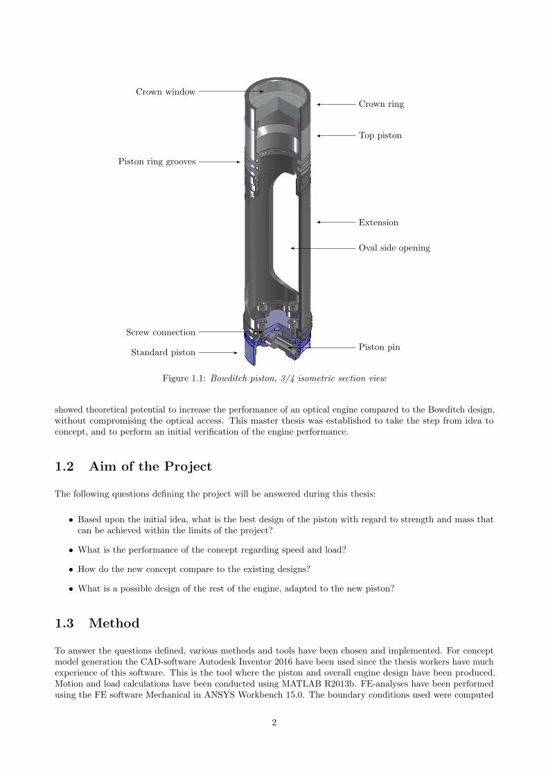
Crown ring
Top piston
Extension
Oval side opening
Piston pin
Crown window
Piston ring grooves
Screw connection
Standard piston
Figure 1.1: Bowditch piston, 3/4 isometric section view
showed theoretical potential to increase the performance of an optical engine compared to the Bowditch design,without compromising the optical access. This master thesis was established to take the step from idea toconcept, and to perform an initial verification of the engine performance.
1.2 Aim of the Project
The following questions defining the project will be answered during this thesis:
• Based upon the initial idea, what is the best design of the piston with regard to strength and mass thatcan be achieved within the limits of the project?
• What is the performance of the concept regarding speed and load?
• How do the new concept compare to the existing designs?
• What is a possible design of the rest of the engine, adapted to the new piston?
1.3 Method
To answer the questions defined, various methods and tools have been chosen and implemented. For conceptmodel generation the CAD-software Autodesk Inventor 2016 have been used since the thesis workers have muchexperience of this software. This is the tool where the piston and overall engine design have been produced.Motion and load calculations have been conducted using MATLAB R2013b. FE-analyses have been performedusing the FE software Mechanical in ANSYS Workbench 15.0. The boundary conditions used were computed
2
in MATLAB and exported to an Excel worksheet and then copied into ANSYS. The piston and engine designhave been created using an iterative approach, meaning that the designs have been improved in iterations.Much of the engine design have been accomplished by the use of the experience of the two master studentsinvolved in this project.
1.4 Limitations
This project is a master thesis work and is limited to 2x800 working hours. The engine concept model developedis only to be a 3D virtual design and not a physical model. It is important to note that the final enginedesign is to be a mere concept, not an actual production ready blueprint. The results obtained are limited tothe precision of the computations and may differ from possible physical tests. Due to the time limit only afew chosen loading cases thought to be of most importance have been implemented in the FE-analyses. Thechosen Bowditch-piston for comparison was assumed to serve as a representative design for Bowditch-pistonsin general. Unknown better designs may possibly be in existence. The thesis work aims to evaluate only thepiston performance. Other engine limitations, such as glass strength, heat or measuring equipment limitationswas not considered.
3
2 Concept
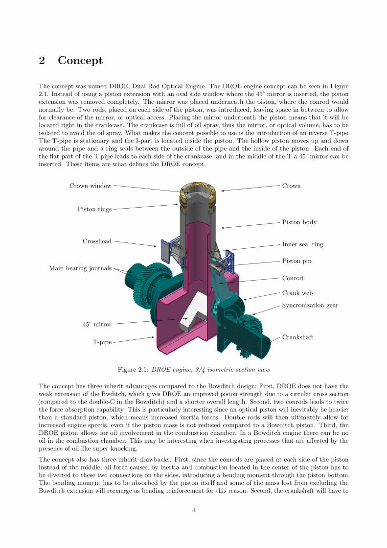
The concept was named DROE, Dual Rod Optical Engine. The DROE engine concept can be seen in Figure2.1. Instead of using a piston extension with an oval side window where the 45° mirror is inserted, the pistonextension was removed completely. The mirror was placed underneath the piston, where the conrod wouldnormally be. Two rods, placed on each side of the piston, was introduced, leaving space in between to allowfor clearance of the mirror, or optical access. Placing the mirror underneath the piston means that it will belocated right in the crankcase. The crankcase is full of oil spray, thus the mirror, or optical volume, has to beisolated to avoid the oil spray. What makes the concept possible to use is the introduction of an inverse T-pipe.The T-pipe is stationary and the I-part is located inside the piston. The hollow piston moves up and downaround the pipe and a ring seals between the outside of the pipe and the inside of the piston. Each end ofthe flat part of the T-pipe leads to each side of the crankcase, and in the middle of the T a 45° mirror can beinserted. These items are what defines the DROE concept.
Crown
Piston body
Inner seal ring
Piston pin
Conrod
Crank web
Syncronization gear
Crankshaft
Crown window
Piston rings
Crosshead
Main bearing journals
45° mirror
T-pipe
Figure 2.1: DROE engine, 3/4 isometric section view
The concept has three inherit advantages compared to the Bowditch design; First, DROE does not have theweak extension of the Bwditch, which gives DROE an improved piston strength due to a circular cross section(compared to the double-C in the Bowditch) and a shorter overall length. Second, two conrods leads to twicethe force absorption capability. This is particularly interesting since an optical piston will inevitably be heavierthan a standard piston, which means increased inertia forces. Double rods will then ultimately allow forincreased engine speeds, even if the piston mass is not reduced compared to a Bowditch piston. Third, theDROE piston allows for oil involvement in the combustion chamber. In a Bowditch engine there can be nooil in the combustion chamber. This may be interesting when investigating processes that are affected by thepresence of oil like super knocking.
The concept also has three inherit drawbacks. First, since the conrods are placed at each side of the pistoninstead of the middle, all force caused by inertia and combustion located in the center of the piston has tobe diverted to these two connections on the sides, introducing a bending moment through the piston bottom.The bending moment has to be absorbed by the piston itself and some of the mass lost from excluding theBowditch extension will reemerge as bending reinforcement for this reason. Second, the crankshaft will have to
4

be redesigned. Two options are possible, either using extra long conrods allowing for the T-pipe to be placedbetween piston and crankshaft, or split the crankshaft in two and place the T-pipe in between the crankshafts,as can be seen in Figure 2.1. Splitting the crankshaft will weaken it. However, the crankshaft can be heavilyreinforced without compromising engine performance since rotational mass is not a concern in a rig-operatedresearch engine. Third, the optical volume has to be isolated from the crankcase. If there is a leak, oil willintrude and may cover the mirror and piston glass. This will inevitably affect the results. The axial seal ringbetween T-pipe and piston will probably be critical since it is a kinematic seal difficult to make fully leak proof.
5
3 Piston Development
The mechanical properties of the DROE piston will in the end determine the engine performance. Therefore,the major analysis and validation work have been focused on the piston to achieve best possible outcome withinthe limits of this thesis. This chapter will cover the piston work, carried out in the following steps:
• Establishing fundamental engine design parameters, such as stroke and bore.
• Derivation of the piston forces, later used as boundary conditions for the various analyses.
• Establishing a benchmark using FE strength analysis, using a conventional optical piston design.
• Iterative DROE piston development, where the work have been further divided as:
– Initial FEM stress analysis of the first DROE concept piston.
– Major iterative piston development using stiffness comparison.
– Minor iterative piston improvement and validation, using thorough FE strength analysis.
3.1 Engine Properties
For the optical engine to take shape it had to be defined by fundamental dimensions. It was chosen to use thecurrent VEP (Volvo Engine Petrol) platform as a role model for the engine and piston design. This was a choicemade of the project group for tactical reasons. The Volvo engine platform is highly relevant for developmentpurposes, the dimensions were accessible and Volvo could provide engine data such as cylinder pressure.
3.1.1 Dimensions
The dimensions of the VEP can be seen in Table 3.1.
Table 3.1: Properties of the chosen engine reference, VEP.
Property Dimension [mm]Cylinder bore (D) 82Stroke (2 · r) 93.2Conrod length (l) 142.6Main bearing diameter 60Conrod bearing diameter/Length 50 / 24Piston Pin diameter/ length 21 / 54Piston Pin offset 0.5
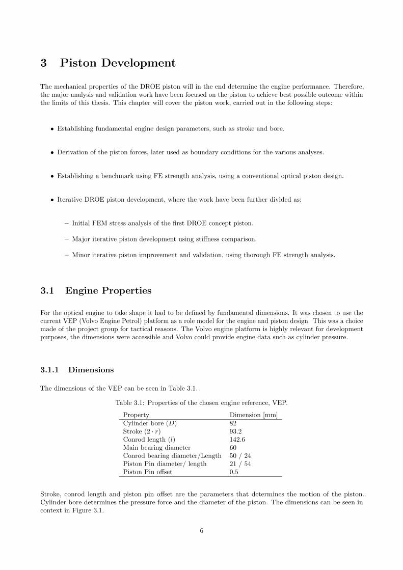
Stroke, conrod length and piston pin offset are the parameters that determines the motion of the piston.Cylinder bore determines the pressure force and the diameter of the piston. The dimensions can be seen incontext in Figure 3.1.
6
y
z
r
l
α
β
Pin offset
Piston Pin
Crank Pin
Crankshaft
Figure 3.1: Crank Rod Slider mechanism
3.1.2 Cylinder Pressure
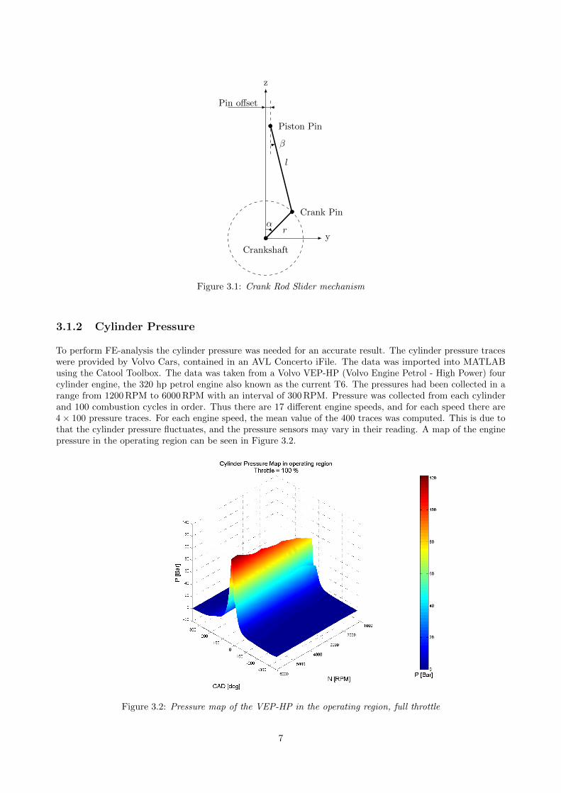
To perform FE-analysis the cylinder pressure was needed for an accurate result. The cylinder pressure traceswere provided by Volvo Cars, contained in an AVL Concerto iFile. The data was imported into MATLABusing the Catool Toolbox. The data was taken from a Volvo VEP-HP (Volvo Engine Petrol - High Power) fourcylinder engine, the 320 hp petrol engine also known as the current T6. The pressures had been collected in arange from 1200 RPM to 6000 RPM with an interval of 300 RPM. Pressure was collected from each cylinderand 100 combustion cycles in order. Thus there are 17 different engine speeds, and for each speed there are4× 100 pressure traces. For each engine speed, the mean value of the 400 traces was computed. This is due tothat the cylinder pressure fluctuates, and the pressure sensors may vary in their reading. A map of the enginepressure in the operating region can be seen in Figure 3.2.
Figure 3.2: Pressure map of the VEP-HP in the operating region, full throttle
7
3.1.3 Cartesian coordinate system
A global cartesian coordinate system was introduced to the engine to define forces and parts. It was chosen toplace the Z-axis in the piston center axis, X-axis in the center of the crankshaft pointing to the front of theengine and the Y-axis pointing to the right side of the engine, as could be seen in Figure 3.1.
3.2 Piston Forces
The forces acting on the piston have been derived from the chosen engine properties. The derived forces havebeen used as boundary conditions for the FE-analysis performed on the piston. The procedure of deriving theforces are covered in the following sections.
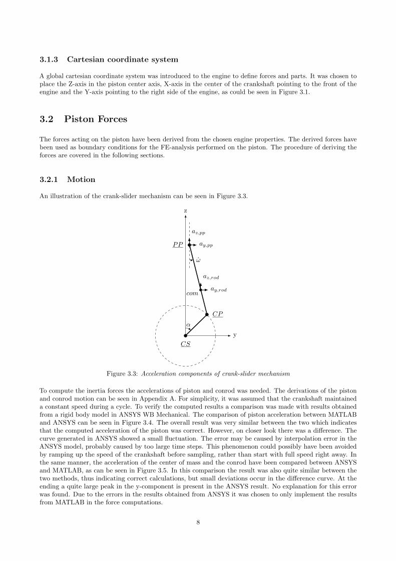
3.2.1 Motion
An illustration of the crank-slider mechanism can be seen in Figure 3.3.
y
z
α
ω
comay,rod
az,rod
ay,pp
az,pp
PP
CP
CS
Figure 3.3: Acceleration components of crank-slider mechanism
To compute the inertia forces the accelerations of piston and conrod was needed. The derivations of the pistonand conrod motion can be seen in Appendix A. For simplicity, it was assumed that the crankshaft maintaineda constant speed during a cycle. To verify the computed results a comparison was made with results obtainedfrom a rigid body model in ANSYS WB Mechanical. The comparison of piston acceleration between MATLABand ANSYS can be seen in Figure 3.4. The overall result was very similar between the two which indicatesthat the computed acceleration of the piston was correct. However, on closer look there was a difference. Thecurve generated in ANSYS showed a small fluctuation. The error may be caused by interpolation error in theANSYS model, probably caused by too large time steps. This phenomenon could possibly have been avoidedby ramping up the speed of the crankshaft before sampling, rather than start with full speed right away. Inthe same manner, the acceleration of the center of mass and the conrod have been compared between ANSYSand MATLAB, as can be seen in Figure 3.5. In this comparison the result was also quite similar between thetwo methods, thus indicating correct calculations, but small deviations occur in the difference curve. At theending a quite large peak in the y-component is present in the ANSYS result. No explanation for this errorwas found. Due to the errors in the results obtained from ANSYS it was chosen to only implement the resultsfrom MATLAB in the force computations.
8
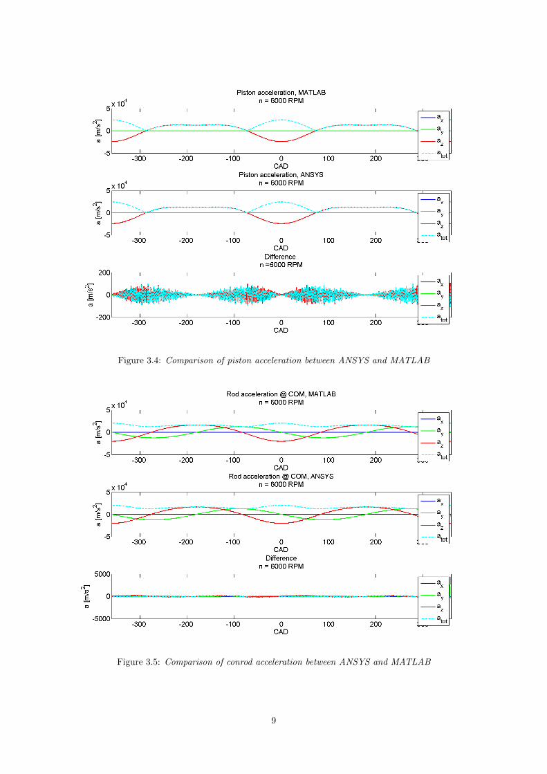
Figure 3.4: Comparison of piston acceleration between ANSYS and MATLAB
Figure 3.5: Comparison of conrod acceleration between ANSYS and MATLAB
9
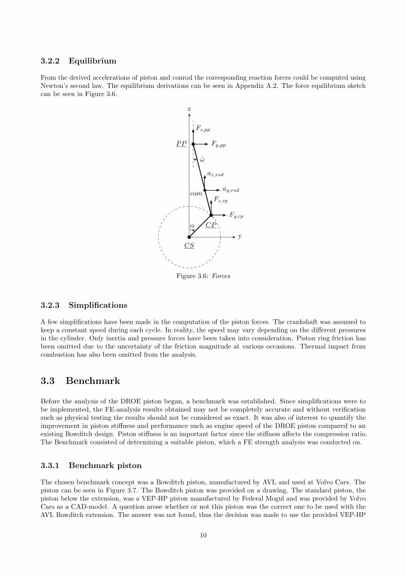
3.2.2 Equilibrium
From the derived accelerations of piston and conrod the corresponding reaction forces could be computed usingNewton’s second law. The equilibrium derivations can be seen in Appendix A.2. The force equilibrium sketchcan be seen in Figure 3.6.
y
z
α
ω
comay,rod
az,rod
Fy,pp
Fz,pp
Fy,cp
Fz,cp
PP
CP
CS
Figure 3.6: Forces
3.2.3 Simplifications
A few simplifications have been made in the computation of the piston forces. The crankshaft was assumed tokeep a constant speed during each cycle. In reality, the speed may vary depending on the different pressuresin the cylinder. Only inertia and pressure forces have been taken into consideration. Piston ring friction hasbeen omitted due to the uncertainty of the friction magnitude at various occasions. Thermal impact fromcombustion has also been omitted from the analysis.
3.3 Benchmark
Before the analysis of the DROE piston began, a benchmark was established. Since simplifications were tobe implemented, the FE-analysis results obtained may not be completely accurate and without verificationsuch as physical testing the results should not be considered as exact. It was also of interest to quantify theimprovement in piston stiffness and performance such as engine speed of the DROE piston compared to anexisting Bowditch design. Piston stiffness is an important factor since the stiffness affects the compression ratio.The Benchmark consisted of determining a suitable piston, which a FE strength analysis was conducted on.
3.3.1 Benchmark piston
The chosen benchmark concept was a Bowditch piston, manufactured by AVL and used at Volvo Cars. Thepiston can be seen in Figure 3.7. The Bowditch piston was provided on a drawing. The standard piston, thepiston below the extension, was a VEP-HP piston manufactured by Federal Mogul and was provided by VolvoCars as a CAD-model. A question arose whether or not this piston was the correct one to be used with theAVL Bowditch extension. The answer was not found, thus the decision was made to use the provided VEP-HP
10
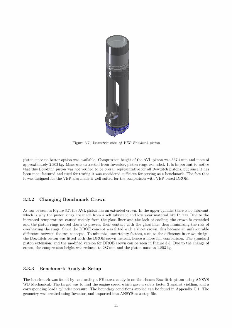
Figure 3.7: Isometric view of VEP Bowditch piston
piston since no better option was available. Compression height of the AVL piston was 367.4 mm and mass ofapproximately 2.303 kg. Mass was extracted from Inventor, piston rings excluded. It is important to noticethat this Bowditch piston was not verified to be overall representative for all Bowditch pistons, but since it hasbeen manufactured and used for testing it was considered sufficient for serving as a benchmark. The fact thatit was designed for the VEP also made it well suited for the comparison with VEP based DROE.
3.3.2 Changing Benchmark Crown
As can be seen in Figure 3.7, the AVL piston has an extended crown. In the upper cylinder there is no lubricant,which is why the piston rings are made from a self lubricant and low wear material like PTFE. Due to theincreased temperatures caused mainly from the glass liner and the lack of cooling, the crown is extendedand the piston rings moved down to prevent their contact with the glass liner thus minimizing the risk ofoverheating the rings. Since the DROE concept was fitted with a short crown, this became an unfavourabledifference between the two concepts. To minimize uncertainty factors, such as the difference in crown design,the Bowditch piston was fitted with the DROE crown instead, hence a more fair comparison. The standardpiston extension, and the modified version for DROE crown can be seen in Figure 3.8. Due to the change ofcrown, the compression height was reduced to 287 mm and the piston mass to 1.853 kg.
3.3.3 Benchmark Analysis Setup
The benchmark was found by conducting a FE stress analysis on the chosen Bowditch piston using ANSYSWB Mechanical. The target was to find the engine speed which gave a safety factor 2 against yielding, and acorresponding load/ cylinder pressure. The boundary conditions applied can be found in Appendix C.1. Thegeometry was created using Inventor, and imported into ANSYS as a step-file.
11
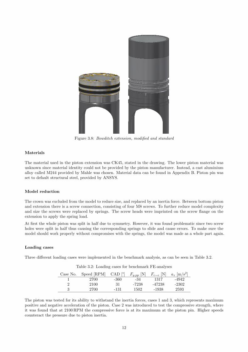
Figure 3.8: Bowditch extension, modified and standard
Materials
The material used in the piston extension was CK45, stated in the drawing. The lower piston material wasunknown since material identity could not be provided by the piston manufacturer. Instead, a cast aluminiumalloy called M244 provided by Mahle was chosen. Material data can be found in Appendix B. Piston pin wasset to default structural steel, provided by ANSYS.
Model reduction
The crown was excluded from the model to reduce size, and replaced by an inertia force. Between bottom pistonand extension there is a screw connection, consisting of four M8 screws. To further reduce model complexityand size the screws were replaced by springs. The screw heads were imprinted on the screw flange on theextension to apply the spring load.
At first the whole piston was split in half due to symmetry. However, it was found problematic since two screwholes were split in half thus causing the corresponding springs to slide and cause errors. To make sure themodel should work properly without compromises with the springs, the model was made as a whole part again.
Loading cases
Three different loading cases were implemented in the benchmark analysis, as can be seen in Table 3.2.
Table 3.2: Loading cases for benchmark FE-analyses
Case No. Speed [RPM] CAD [°] Fy,pp [N] Fc−e [N] az [m/s2]1 2700 -360 -34 1317 -49422 2100 31 -7238 -47238 -23023 2700 -131 1502 -1938 2593
The piston was tested for its ability to withstand the inertia forces, cases 1 and 3, which represents maximumpositive and negative acceleration of the piston. Case 2 was introduced to test the compressive strength, whereit was found that at 2100 RPM the compressive force is at its maximum at the piston pin. Higher speedscounteract the pressure due to piston inertia.
12
3.4 Design Improvement
In this section the piston design improvement process will be covered. First, the initial concept called AA wasanalysed. Using the results from AA, the major design improvement process was conducted, using an iterativeapproach with a simplified FE-analysis as feedback.
3.4.1 Initial Concept, AA-piston
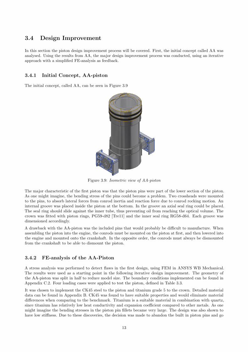
The initial concept, called AA, can be seen in Figure 3.9
Figure 3.9: Isometric view of AA-piston
The major characteristic of the first piston was that the piston pins were part of the lower section of the piston.As one might imagine, the bending stress of the pins could become a problem. Two crossheads were mountedto the pins, to absorb lateral forces from conrod inertia and reaction force due to conrod rocking motion. Aninternal groove was placed inside the piston at the bottom. In the groove an axial seal ring could be placed.The seal ring should slide against the inner tube, thus preventing oil from reaching the optical volume. Thecrown was fitted with piston rings, PG59-d82 [Tre11] and the inner seal ring RG58-d64. Each groove wasdimensioned accordingly.
A drawback with the AA-piston was the included pins that would probably be difficult to manufacture. Whenassembling the piston into the engine, the conrods must be mounted on the piston at first, and then lowered intothe engine and mounted onto the crankshaft. In the opposite order, the conrods must always be dismountedfrom the crankshaft to be able to dismount the piston.
3.4.2 FE-analysis of the AA-Piston
A stress analysis was performed to detect flaws in the first design, using FEM in ANSYS WB Mechanical.The results were used as a starting point in the following iterative design improvement. The geometry ofthe AA-piston was split in half to reduce model size. The boundary conditions implemented can be found inAppendix C.2. Four loading cases were applied to test the piston, defined in Table 3.3.
It was chosen to implement the CK45 steel to the piston and titanium grade 5 to the crown. Detailed materialdata can be found in Appendix B. CK45 was found to have suitable properties and would eliminate materialdifferences when comparing to the benchmark. Titanium is a suitable material in combination with quartz,since titanium has relatively low heat conductivity and expansion coefficient compared to other metals. As onemight imagine the bending stresses in the piston pin fillets became very large. The design was also shown tohave low stiffness. Due to these discoveries, the decision was made to abandon the built in piston pins and go
13
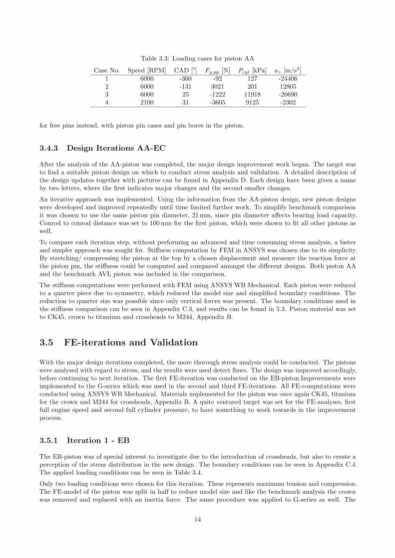
Table 3.3: Loading cases for piston AA
Case No. Speed [RPM] CAD [°] Fy,pp [N] Pcyl [kPa] az [m/s2]1 6000 -360 -92 127 -244062 6000 -131 3021 201 128053 6000 25 -1222 11918 -206904 2100 31 -3605 9125 -2302
for free pins instead, with piston pin cases and pin bores in the piston.
3.4.3 Design Iterations AA-EC
After the analysis of the AA-piston was completed, the major design improvement work began. The target wasto find a suitable piston design on which to conduct stress analysis and validation. A detailed description ofthe design updates together with pictures can be found in Appendix D. Each design have been given a nameby two letters, where the first indicates major changes and the second smaller changes.
An iterative approach was implemented. Using the information from the AA-piston design, new piston designswere developed and improved repeatedly until time limited further work. To simplify benchmark comparisonit was chosen to use the same piston pin diameter, 21 mm, since pin diameter affects bearing load capacity.Conrod to conrod distance was set to 100 mm for the first piston, which were shown to fit all other pistons aswell.
To compare each iteration step, without performing an advanced and time consuming stress analysis, a fasterand simpler approach was sought for. Stiffness computation by FEM in ANSYS was chosen due to its simplicity.By stretching/ compressing the piston at the top by a chosen displacement and measure the reaction force atthe piston pin, the stiffness could be computed and compared amongst the different designs. Both piston AAand the benchmark AVL piston was included in the comparison.
The stiffness computations were performed with FEM using ANSYS WB Mechanical. Each piston were reducedto a quarter piece due to symmetry, which reduced the model size and simplified boundary conditions. Thereduction to quarter size was possible since only vertical forces was present. The boundary conditions used inthe stiffness comparison can be seen in Appendix C.3, and results can be found in 5.3. Piston material was setto CK45, crown to titanium and crossheads to M244, Appendix B.
3.5 FE-iterations and Validation
With the major design iterations completed, the more thorough stress analysis could be conducted. The pistonswere analysed with regard to stress, and the results were used detect flaws. The design was improved accordingly,before continuing to next iteration. The first FE-iteration was conducted on the EB-piston.Improvements wereimplemented to the G-series which was used in the second and third FE-iterations. All FE-computations wereconducted using ANSYS WB Mechanical. Materials implemented for the piston was once again CK45, titaniumfor the crown and M244 for crossheads, Appendix B. A quite ventured target was set for the FE-analyses, firstfull engine speed and second full cylinder pressure, to have something to work towards in the improvementprocess.
3.5.1 Iteration 1 - EB
The EB-piston was of special interest to investigate due to the introduction of crossheads, but also to create aperception of the stress distribution in the new design. The boundary conditions can be seen in Appendix C.4.The applied loading conditions can be seen in Table 3.4.
Only two loading conditions were chosen for this iteration. These represents maximum tension and compression.The FE-model of the piston was split in half to reduce model size and like the benchmark analysis the crownwas removed and replaced with an inertia force. The same procedure was applied to G-series as well. The
14
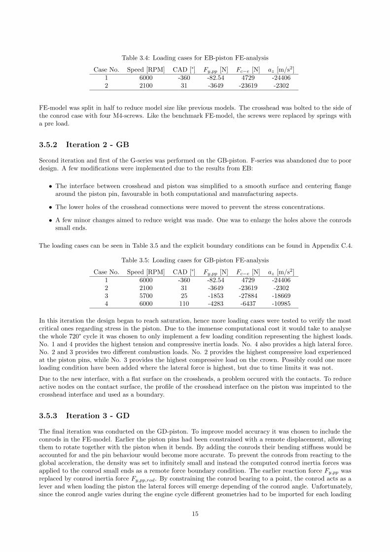
Table 3.4: Loading cases for EB-piston FE-analysis
Case No. Speed [RPM] CAD [°] Fy,pp [N] Fc−e [N] az [m/s2]1 6000 -360 -82.54 4729 -244062 2100 31 -3649 -23619 -2302
FE-model was split in half to reduce model size like previous models. The crosshead was bolted to the side ofthe conrod case with four M4-screws. Like the benchmark FE-model, the screws were replaced by springs witha pre load.
3.5.2 Iteration 2 - GB
Second iteration and first of the G-series was performed on the GB-piston. F-series was abandoned due to poordesign. A few modifications were implemented due to the results from EB:
• The interface between crosshead and piston was simplified to a smooth surface and centering flangearound the piston pin, favourable in both computational and manufacturing aspects.
• The lower holes of the crosshead connections were moved to prevent the stress concentrations.
• A few minor changes aimed to reduce weight was made. One was to enlarge the holes above the conrodssmall ends.
The loading cases can be seen in Table 3.5 and the explicit boundary conditions can be found in Appendix C.4.
Table 3.5: Loading cases for GB-piston FE-analysis
Case No. Speed [RPM] CAD [°] Fy,pp [N] Fc−e [N] az [m/s2]1 6000 -360 -82.54 4729 -244062 2100 31 -3649 -23619 -23023 5700 25 -1853 -27884 -186694 6000 110 -4283 -6437 -10985
In this iteration the design began to reach saturation, hence more loading cases were tested to verify the mostcritical ones regarding stress in the piston. Due to the immense computational cost it would take to analysethe whole 720° cycle it was chosen to only implement a few loading condition representing the highest loads.No. 1 and 4 provides the highest tension and compressive inertia loads. No. 4 also provides a high lateral force.No. 2 and 3 provides two different combustion loads. No. 2 provides the highest compressive load experiencedat the piston pins, while No. 3 provides the highest compressive load on the crown. Possibly could one moreloading condition have been added where the lateral force is highest, but due to time limits it was not.
Due to the new interface, with a flat surface on the crossheads, a problem occured with the contacts. To reduceactive nodes on the contact surface, the profile of the crosshead interface on the piston was imprinted to thecrosshead interface and used as a boundary.
3.5.3 Iteration 3 - GD
The final iteration was conducted on the GD-piston. To improve model accuracy it was chosen to include theconrods in the FE-model. Earlier the piston pins had been constrained with a remote displacement, allowingthem to rotate together with the piston when it bends. By adding the conrods their bending stiffness would beaccounted for and the pin behaviour would become more accurate. To prevent the conrods from reacting to theglobal acceleration, the density was set to infinitely small and instead the computed conrod inertia forces wasapplied to the conrod small ends as a remote force boundary condition. The earlier reaction force Fy,pp wasreplaced by conrod inertia force Fy,pp,rod. By constraining the conrod bearing to a point, the conrod acts as alever and when loading the piston the lateral forces will emerge depending of the conrod angle. Unfortunately,since the conrod angle varies during the engine cycle different geometries had to be imported for each loading
15
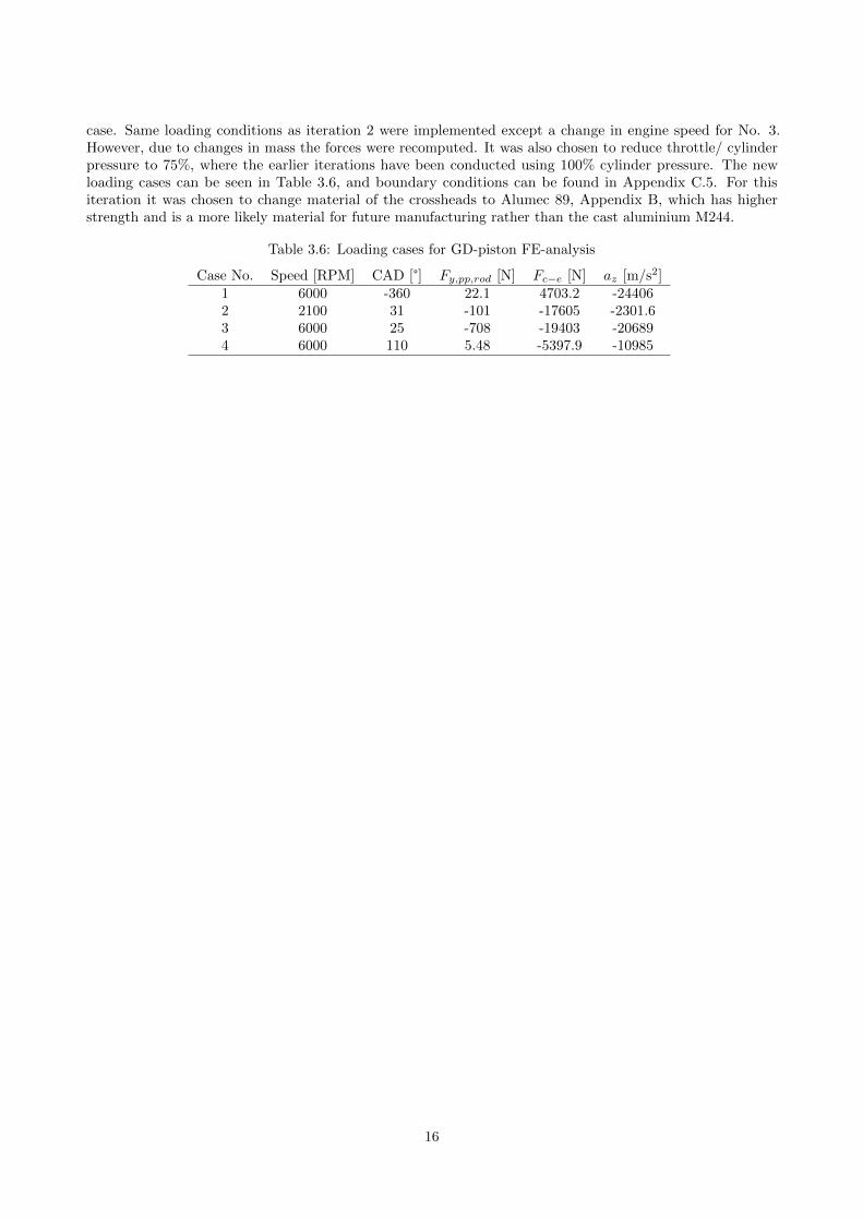
case. Same loading conditions as iteration 2 were implemented except a change in engine speed for No. 3.However, due to changes in mass the forces were recomputed. It was also chosen to reduce throttle/ cylinderpressure to 75%, where the earlier iterations have been conducted using 100% cylinder pressure. The newloading cases can be seen in Table 3.6, and boundary conditions can be found in Appendix C.5. For thisiteration it was chosen to change material of the crossheads to Alumec 89, Appendix B, which has higherstrength and is a more likely material for future manufacturing rather than the cast aluminium M244.
Table 3.6: Loading cases for GD-piston FE-analysis
Case No. Speed [RPM] CAD [°] Fy,pp,rod [N] Fc−e [N] az [m/s2]1 6000 -360 22.1 4703.2 -244062 2100 31 -101 -17605 -2301.63 6000 25 -708 -19403 -206894 6000 110 5.48 -5397.9 -10985
16
4 Engine Development
The DROE piston concept can offer even more than increased performance in terms of load and speed.Not only can it provide better optical access to the combustion chamber but also be more user friendlyregarding manufacturing, assembly and disassembly. This chapter describes the engine concept which serves todemonstrate the DROE piston’s possibility to improve the optical engine as a research tool.
4.1 Requirements and Goals
Several requirements and goals were set up for the engine design. These requirements are listed and explainedin the sections below.
• Optical access through piston head and cylinder liner.
• Compatible interfaces to conventional test rig equipment.
• Design for maintenance and cleaning.
• Fully balanced.
• Design for assembly, disassembly and manufacturing.
Optical access through piston head and cylinder liner
Different types of measurement techniques require different optical access. Most methods require optical accessfrom both the cylinder liner and piston crown. Optical parts are brittle and sensitive to heat gradients andvibrations. They also affect the combustion process in different ways compared to the metal parts of a realengine. The cost, risk of failure and deviation from a real engine is hence increased as more components aremade from transparent material and it is therefore desirable to minimize the number of optical components.This can be done by having a modular cylinder assembly with easily replaced parts and only use the opticalaccess which is needed. For this thesis however, it is desirable to maximize the optical access in order todemonstrate the capabilities and range of the engine concept.
Compatible interfaces to conventional test rig equipment
A new test rig is a major investment for any engine researcher but the engine itself is just a part of this cost.Equipment for emission measurement, fuel systems, engine dynamometer, air supply, cooling and temperaturemeasurement are examples of test rig equipment which exist in any engine lab. By designing the first DROE towork with existing test rig equipment from the start it will be easier to install a prototype in an existing celland validate the design in the future.
Design for maintenance and cleaning
Since the optical engine has transparent parts in contact with the combustion, and these parts optical capabilitiesare of great importance when running tests, they need to be cleaned regularly. This task is one of the mosttime consuming when a researcher is performing experiments. It is therefore common to have some sort ofsystem to quickly open the engine without the need to disassemble it. This is either done by lowering the topcylinder or by lifting the cylinder head. The elongated part of a Bowditch piston often allows for the cylinderto be lowered but the relatively short dual rod piston requires the cylinder head to be lifted or removed.
17
Fully balanced
The optical elements of a test rig are all sensitive to vibrations. Cameras and lasers can be mounted separatelyfrom the engine itself but it is still important for the object of study, the combustion chamber, to be relativelyfree of vibrations. In order for a single cylinder engine to run without vibrations it needs to be balanced. Themost common way to balance the engine forces is with balance shafts, which are separate rotating shafts withoffset center of mass timed to cancel out the forces from the engines reciprocating masses.
Design for disassembly and manufacturing
A research engine will be subject to many modifications and adjustments during its lifetime. It is thereforeimportant to have disassembly and manufacturing in mind when designing it [Ull03]. It is far too common withequipment which is either too complex by nature or too complex by design to repair or manufacture in smallermachine shops. It is desirable for the DROE to be designed in such a way as to allow for some repairs andmodifications by the end user if they so choose to.
4.2 Design Hierarchy
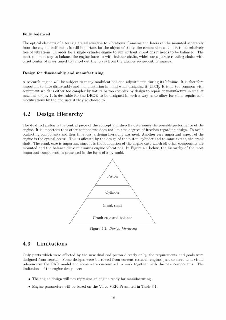
The dual rod piston is the central piece of the concept and directly determines the possible performance of theengine. It is important that other components does not limit its degrees of freedom regarding design. To avoidconflicting components and thus time loss, a design hierarchy was used. Another very important aspect of theengine is the optical access. This is affected by the design of the piston, cylinder and to some extent, the crankshaft. The crank case is important since it is the foundation of the engine onto which all other components aremounted and the balance drive minimizes engine vibrations. In Figure 4.1 below, the hierarchy of the mostimportant components is presented in the form of a pyramid.
Crank case and balance
Crank shaft
Cylinder
Piston
Figure 4.1: Design hierarchy
4.3 Limitations
Only parts which were affected by the new dual rod piston directly or by the requirements and goals weredesigned from scratch. Some designs were borrowed from current research engines just to serve as a visualreference in the CAD model and some were customized to work together with the new components. Thelimitations of the engine design are:
• The engine design will not represent an engine ready for manufacturing.
• Engine parameters will be based on the Volvo VEP. Presented in Table 3.1.
18
• No strength calculations will be done for the transparent parts.
• Stiffness calculations will only be done to critical components with unproven design.
• Design for disassembly and manufacturing will only be evaluated based on previous experience.
The engine design will not represent an engine ready for manufacturing
Since there is a certain time limit, an engine concept ready for production is difficult to achieve, especiallyconsidering that most of the parts are unproven designs. Focus will instead be put on achieving a base designwhich explores all major design difficulties.
Engine parameters based on the Volvo VEP
By using interfaces from an existing engine in production it is possible to re-use some existing parts. Sinceoptical engines most often are used by engine manufacturers or researchers in cooperation with an enginemanufacturer to improve engine design, parts for research engines are often available. Because of existingcontacts at Volvo, the engine will be based on the Volvo VEP.
No strength calculations will be done for the transparent parts
The transparent parts of an optical engine are exposed to many different stresses due to temperature andpressure fluctuations. The temperature difference of the inside and outside of the cylinder is considerable andcauses thermal stresses in the material. The different thermal expansion rates of the transparent material andits surrounding parts are very different and also causes stresses to the material. The work of determining allstresses and dimensioning the transparent parts are hence complicated. The transparent parts are thereforeexcluded from the design process in this thesis. However, the transparent components will eventually needdimensioning and validation. Parts of similar dimensions as are already in use will however be included in themodel.
Design for disassembly and manufacturing will only be evaluated based on previous experience
Determining and grading a design in respect to disassembly and manufacturing can be very time consuming.Especially when the design includes as many components as there are in an engine. Because of the significantmanufacturing experience of the students in this project it is deemed accurate enough to examine the designfrom a manufacturing and assembly point of view and to eliminate unnecessary complexity based on experience.
4.4 Concept Generation
In order to implement the dual rod piston in an optical engine and fully utilize its advantages, the possible waysof implementation needed to be defined and evaluated. After several brainstorming meetings with involvedparties, three different base concepts were constructed with CAD.
• DRSC (Dual Rod Single Crank)
• DRDC-W (Dual Rod Dual Crank - Wet)
• DRDC-D (Dual Rod Dual Crank - Dry)
19
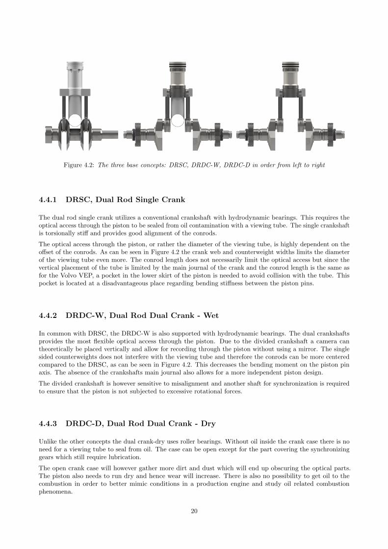
Figure 4.2: The three base concepts: DRSC, DRDC-W, DRDC-D in order from left to right
4.4.1 DRSC, Dual Rod Single Crank
The dual rod single crank utilizes a conventional crankshaft with hydrodynamic bearings. This requires theoptical access through the piston to be sealed from oil contamination with a viewing tube. The single crankshaftis torsionally stiff and provides good alignment of the conrods.
The optical access through the piston, or rather the diameter of the viewing tube, is highly dependent on theoffset of the conrods. As can be seen in Figure 4.2 the crank web and counterweight widths limits the diameterof the viewing tube even more. The conrod length does not necessarily limit the optical access but since thevertical placement of the tube is limited by the main journal of the crank and the conrod length is the same asfor the Volvo VEP, a pocket in the lower skirt of the piston is needed to avoid collision with the tube. Thispocket is located at a disadvantageous place regarding bending stiffness between the piston pins.
4.4.2 DRDC-W, Dual Rod Dual Crank - Wet
In common with DRSC, the DRDC-W is also supported with hydrodynamic bearings. The dual crankshaftsprovides the most flexible optical access through the piston. Due to the divided crankshaft a camera cantheoretically be placed vertically and allow for recording through the piston without using a mirror. The singlesided counterweights does not interfere with the viewing tube and therefore the conrods can be more centeredcompared to the DRSC, as can be seen in Figure 4.2. This decreases the bending moment on the piston pinaxis. The absence of the crankshafts main journal also allows for a more independent piston design.
The divided crankshaft is however sensitive to misalignment and another shaft for synchronization is requiredto ensure that the piston is not subjected to excessive rotational forces.
4.4.3 DRDC-D, Dual Rod Dual Crank - Dry
Unlike the other concepts the dual crank-dry uses roller bearings. Without oil inside the crank case there is noneed for a viewing tube to seal from oil. The case can be open except for the part covering the synchronizinggears which still require lubrication.
The open crank case will however gather more dirt and dust which will end up obscuring the optical parts.The piston also needs to run dry and hence wear will increase. There is also no possibility to get oil to thecombustion in order to better mimic conditions in a production engine and study oil related combustionphenomena.
20
4.4.4 Base concept
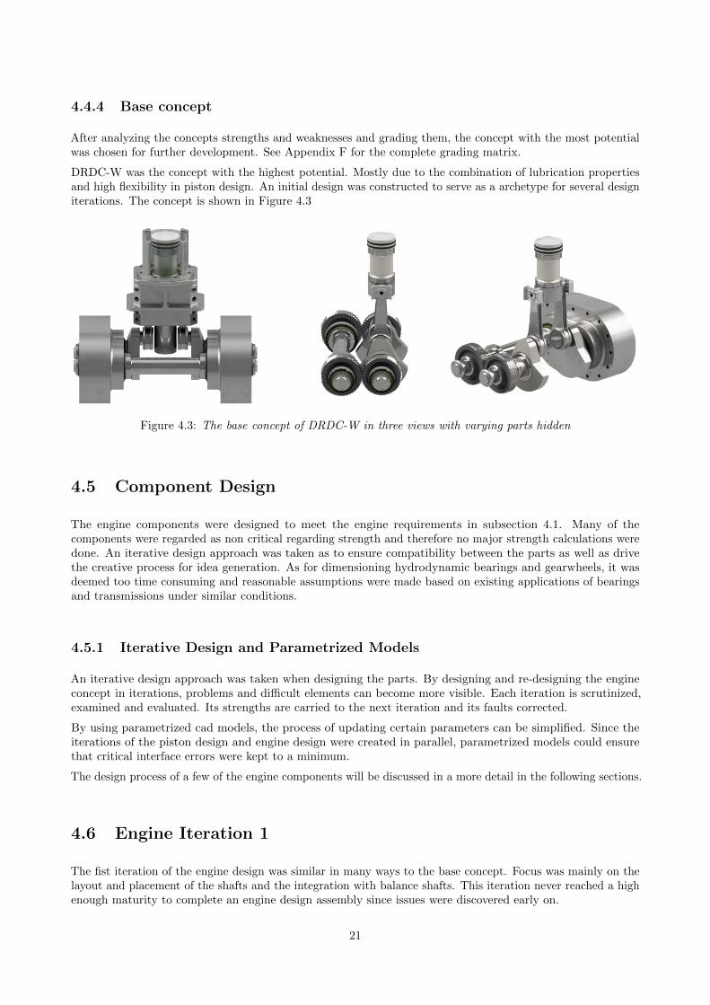
After analyzing the concepts strengths and weaknesses and grading them, the concept with the most potentialwas chosen for further development. See Appendix F for the complete grading matrix.
DRDC-W was the concept with the highest potential. Mostly due to the combination of lubrication propertiesand high flexibility in piston design. An initial design was constructed to serve as a archetype for several designiterations. The concept is shown in Figure 4.3
Figure 4.3: The base concept of DRDC-W in three views with varying parts hidden
4.5 Component Design
The engine components were designed to meet the engine requirements in subsection 4.1. Many of thecomponents were regarded as non critical regarding strength and therefore no major strength calculations weredone. An iterative design approach was taken as to ensure compatibility between the parts as well as drivethe creative process for idea generation. As for dimensioning hydrodynamic bearings and gearwheels, it wasdeemed too time consuming and reasonable assumptions were made based on existing applications of bearingsand transmissions under similar conditions.
4.5.1 Iterative Design and Parametrized Models
An iterative design approach was taken when designing the parts. By designing and re-designing the engineconcept in iterations, problems and difficult elements can become more visible. Each iteration is scrutinized,examined and evaluated. Its strengths are carried to the next iteration and its faults corrected.
By using parametrized cad models, the process of updating certain parameters can be simplified. Since theiterations of the piston design and engine design were created in parallel, parametrized models could ensurethat critical interface errors were kept to a minimum.
The design process of a few of the engine components will be discussed in a more detail in the following sections.
4.6 Engine Iteration 1
The fist iteration of the engine design was similar in many ways to the base concept. Focus was mainly on thelayout and placement of the shafts and the integration with balance shafts. This iteration never reached a highenough maturity to complete an engine design assembly since issues were discovered early on.
21
4.6.1 Crank Case
The first case iteration incorporated the balance shafts in the synchronization gear drive. The design can beseen to the left in Figure 4.8. Crank shafts, balance shafts, gears and the sync shaft were all built into separatemodules which could be fastened in the crank case. It was noted early on that these modules could become tooheavy and complex to meet the requirements for simplified manufacturing and disassembly and the conceptwas abandoned for a better design opportunity.
4.6.2 Crankshafts and Synchronization
This design also used tapered roller bearings for all shafts. Since the crank shafts and sync shaft needed to be ofa certain diameter to ensure high bending stiffness, and the reference speed of bearings are highly dependent onthe diameter, the bearings required for these shafts could not meet the speed requirement [SKF12] of 6000 RPMin their current state.
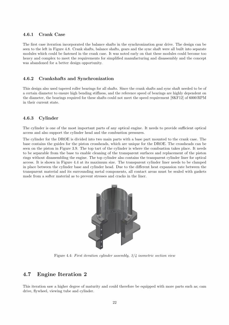
4.6.3 Cylinder
The cylinder is one of the most important parts of any optical engine. It needs to provide sufficient opticalaccess and also support the cylinder head and the combustion pressures.
The cylinder for the DROE is divided into two main parts with a base part mounted to the crank case. Thebase contains the guides for the piston crossheads, which are unique for the DROE. The crossheads can beseen on the piston in Figure 3.9. The top tart of the cylinder is where the combustion takes place. It needsto be separable from the base to enable cleaning of the transparent surfaces and replacement of the pistonrings without disassembling the engine. The top cylinder also contains the transparent cylinder liner for opticalaccess. It is shown in Figure 4.4 at its maximum size. The transparent cylinder liner needs to be clampedin place between the cylinder base and cylinder head. Due to the different heat expansion rate between thetransparent material and its surrounding metal components, all contact areas must be sealed with gasketsmade from a softer material as to prevent stresses and cracks in the liner.
Figure 4.4: First iteration cylinder assembly, 3/4 isometric section view
4.7 Engine Iteration 2
This iteration saw a higher degree of maturity and could therefore be equipped with more parts such as; camdrive, flywheel, viewing tube and cylinder.
22
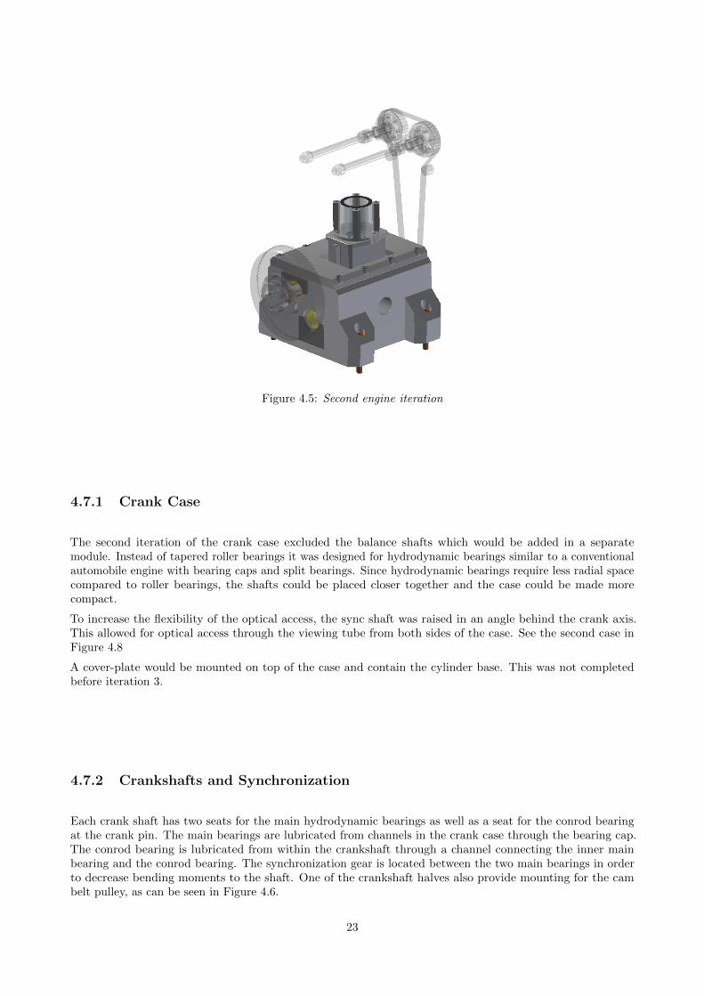
Figure 4.5: Second engine iteration
4.7.1 Crank Case
The second iteration of the crank case excluded the balance shafts which would be added in a separatemodule. Instead of tapered roller bearings it was designed for hydrodynamic bearings similar to a conventionalautomobile engine with bearing caps and split bearings. Since hydrodynamic bearings require less radial spacecompared to roller bearings, the shafts could be placed closer together and the case could be made morecompact.
To increase the flexibility of the optical access, the sync shaft was raised in an angle behind the crank axis.This allowed for optical access through the viewing tube from both sides of the case. See the second case inFigure 4.8
A cover-plate would be mounted on top of the case and contain the cylinder base. This was not completedbefore iteration 3.
4.7.2 Crankshafts and Synchronization
Each crank shaft has two seats for the main hydrodynamic bearings as well as a seat for the conrod bearingat the crank pin. The main bearings are lubricated from channels in the crank case through the bearing cap.The conrod bearing is lubricated from within the crankshaft through a channel connecting the inner mainbearing and the conrod bearing. The synchronization gear is located between the two main bearings in orderto decrease bending moments to the shaft. One of the crankshaft halves also provide mounting for the cambelt pulley, as can be seen in Figure 4.6.
23
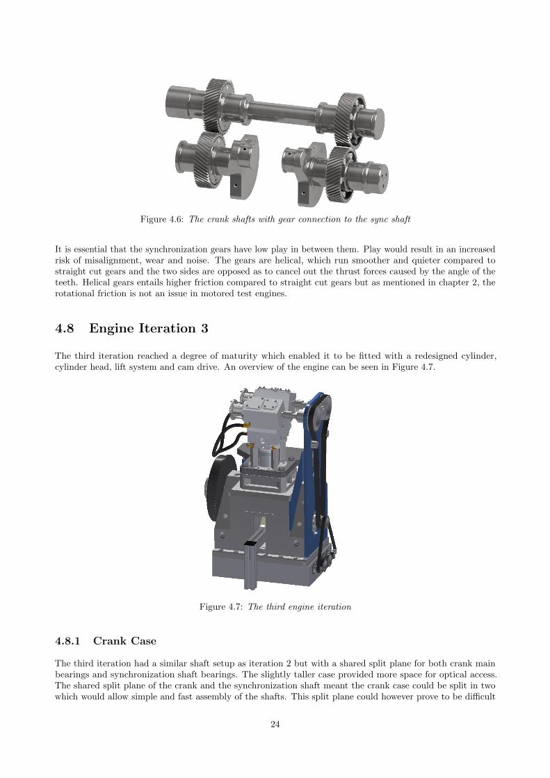
Figure 4.6: The crank shafts with gear connection to the sync shaft
It is essential that the synchronization gears have low play in between them. Play would result in an increasedrisk of misalignment, wear and noise. The gears are helical, which run smoother and quieter compared tostraight cut gears and the two sides are opposed as to cancel out the thrust forces caused by the angle of theteeth. Helical gears entails higher friction compared to straight cut gears but as mentioned in chapter 2, therotational friction is not an issue in motored test engines.
4.8 Engine Iteration 3
The third iteration reached a degree of maturity which enabled it to be fitted with a redesigned cylinder,cylinder head, lift system and cam drive. An overview of the engine can be seen in Figure 4.7.
Figure 4.7: The third engine iteration
4.8.1 Crank Case
The third iteration had a similar shaft setup as iteration 2 but with a shared split plane for both crank mainbearings and synchronization shaft bearings. The slightly taller case provided more space for optical access.The shared split plane of the crank and the synchronization shaft meant the crank case could be split in twowhich would allow simple and fast assembly of the shafts. This split plane could however prove to be difficult
24
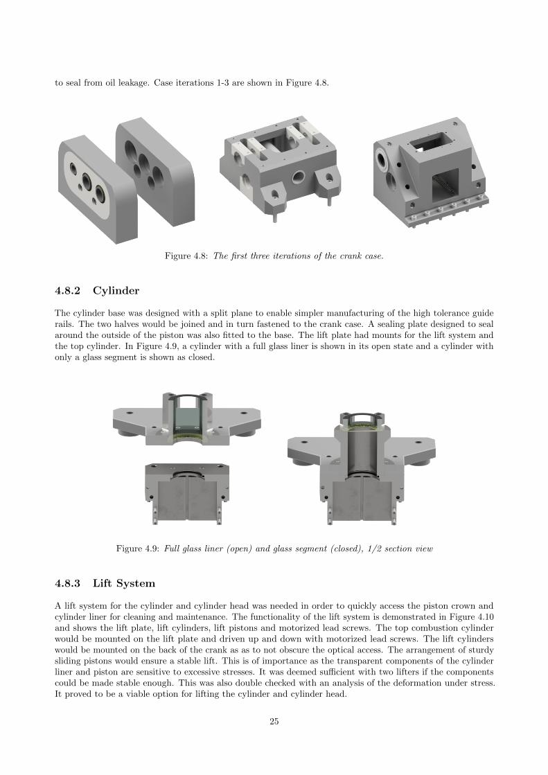
to seal from oil leakage. Case iterations 1-3 are shown in Figure 4.8.
Figure 4.8: The first three iterations of the crank case.
4.8.2 Cylinder
The cylinder base was designed with a split plane to enable simpler manufacturing of the high tolerance guiderails. The two halves would be joined and in turn fastened to the crank case. A sealing plate designed to sealaround the outside of the piston was also fitted to the base. The lift plate had mounts for the lift system andthe top cylinder. In Figure 4.9, a cylinder with a full glass liner is shown in its open state and a cylinder withonly a glass segment is shown as closed.
Figure 4.9: Full glass liner (open) and glass segment (closed), 1/2 section view
4.8.3 Lift System
A lift system for the cylinder and cylinder head was needed in order to quickly access the piston crown andcylinder liner for cleaning and maintenance. The functionality of the lift system is demonstrated in Figure 4.10and shows the lift plate, lift cylinders, lift pistons and motorized lead screws. The top combustion cylinderwould be mounted on the lift plate and driven up and down with motorized lead screws. The lift cylinderswould be mounted on the back of the crank as as to not obscure the optical access. The arrangement of sturdysliding pistons would ensure a stable lift. This is of importance as the transparent components of the cylinderliner and piston are sensitive to excessive stresses. It was deemed sufficient with two lifters if the componentscould be made stable enough. This was also double checked with an analysis of the deformation under stress.It proved to be a viable option for lifting the cylinder and cylinder head.
25
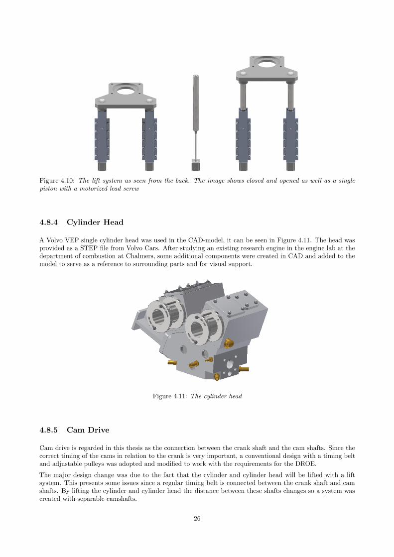
Figure 4.10: The lift system as seen from the back. The image shows closed and opened as well as a singlepiston with a motorized lead screw
4.8.4 Cylinder Head
A Volvo VEP single cylinder head was used in the CAD-model, it can be seen in Figure 4.11. The head wasprovided as a STEP file from Volvo Cars. After studying an existing research engine in the engine lab at thedepartment of combustion at Chalmers, some additional components were created in CAD and added to themodel to serve as a reference to surrounding parts and for visual support.
Figure 4.11: The cylinder head
4.8.5 Cam Drive
Cam drive is regarded in this thesis as the connection between the crank shaft and the cam shafts. Since thecorrect timing of the cams in relation to the crank is very important, a conventional design with a timing beltand adjustable pulleys was adopted and modified to work with the requirements for the DROE.
The major design change was due to the fact that the cylinder and cylinder head will be lifted with a liftsystem. This presents some issues since a regular timing belt is connected between the crank shaft and camshafts. By lifting the cylinder and cylinder head the distance between these shafts changes so a system wascreated with separable camshafts.
26
4.9 Engine Iteration 4
After exploring many different solutions in previous iterations and finalizing the piston design a fourth engineconcept could be generated. A new possible arrangement for the crank and synchronization shaft was discoveredand used. The fourth engine iteration was to be the last within this thesis. It reached a high degree of maturitybut still requires work to be ready for the prototype stage. A 1/2 scale 3D printed model of the fourth iterationwas created for demonstration purposes.
4.9.1 Shaft Layout
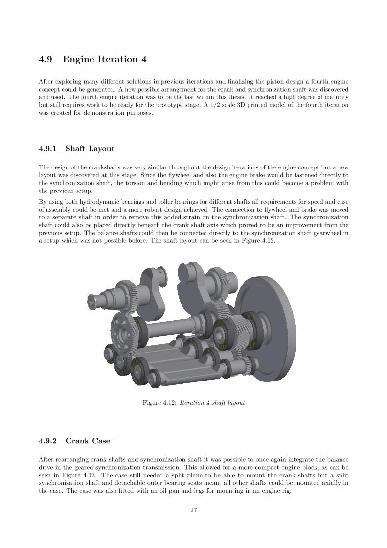
The design of the crankshafts was very similar throughout the design iterations of the engine concept but a newlayout was discovered at this stage. Since the flywheel and also the engine brake would be fastened directly tothe synchronization shaft, the torsion and bending which might arise from this could become a problem withthe previous setup.
By using both hydrodynamic bearings and roller bearings for different shafts all requirements for speed and easeof assembly could be met and a more robust design achieved. The connection to flywheel and brake was movedto a separate shaft in order to remove this added strain on the synchronization shaft. The synchronizationshaft could also be placed directly beneath the crank shaft axis which proved to be an improvement from theprevious setup. The balance shafts could then be connected directly to the synchronization shaft gearwheel ina setup which was not possible before. The shaft layout can be seen in Figure 4.12.
Figure 4.12: Iteration 4 shaft layout
4.9.2 Crank Case
After rearranging crank shafts and synchronization shaft it was possible to once again integrate the balancedrive in the geared synchronization transmission. This allowed for a more compact engine block, as can beseen in Figure 4.13. The case still needed a split plane to be able to mount the crank shafts but a splitsynchronization shaft and detachable outer bearing seats meant all other shafts could be mounted axially inthe case. The case was also fitted with an oil pan and legs for mounting in an engine rig.
27
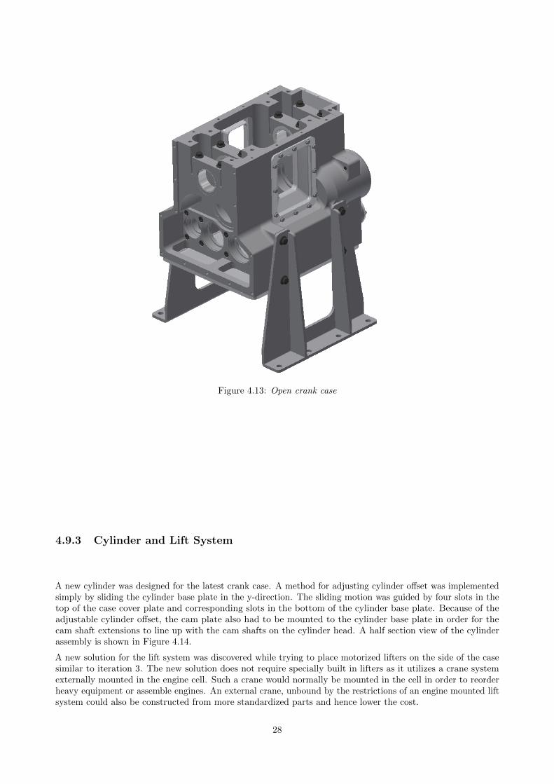
Figure 4.13: Open crank case
4.9.3 Cylinder and Lift System
A new cylinder was designed for the latest crank case. A method for adjusting cylinder offset was implementedsimply by sliding the cylinder base plate in the y-direction. The sliding motion was guided by four slots in thetop of the case cover plate and corresponding slots in the bottom of the cylinder base plate. Because of theadjustable cylinder offset, the cam plate also had to be mounted to the cylinder base plate in order for thecam shaft extensions to line up with the cam shafts on the cylinder head. A half section view of the cylinderassembly is shown in Figure 4.14.
A new solution for the lift system was discovered while trying to place motorized lifters on the side of the casesimilar to iteration 3. The new solution does not require specially built in lifters as it utilizes a crane systemexternally mounted in the engine cell. Such a crane would normally be mounted in the cell in order to reorderheavy equipment or assemble engines. An external crane, unbound by the restrictions of an engine mounted liftsystem could also be constructed from more standardized parts and hence lower the cost.
28
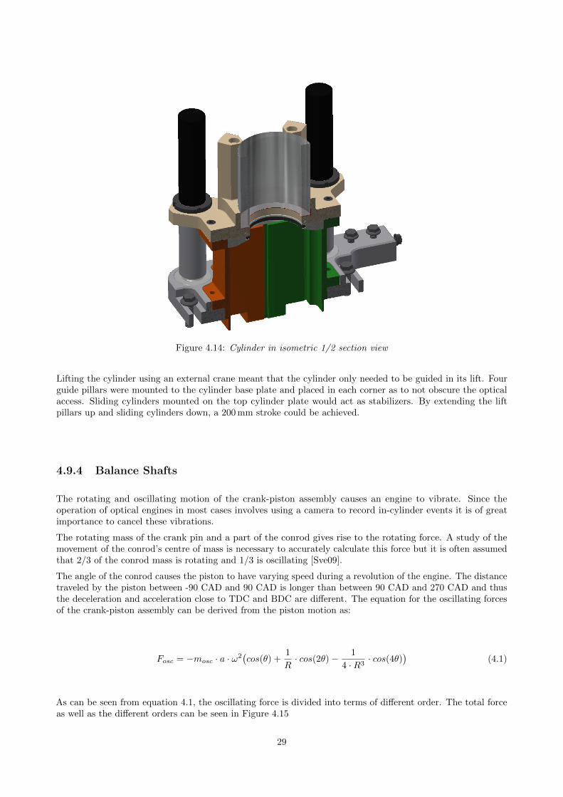
Figure 4.14: Cylinder in isometric 1/2 section view
Lifting the cylinder using an external crane meant that the cylinder only needed to be guided in its lift. Fourguide pillars were mounted to the cylinder base plate and placed in each corner as to not obscure the opticalaccess. Sliding cylinders mounted on the top cylinder plate would act as stabilizers. By extending the liftpillars up and sliding cylinders down, a 200 mm stroke could be achieved.
4.9.4 Balance Shafts
The rotating and oscillating motion of the crank-piston assembly causes an engine to vibrate. Since theoperation of optical engines in most cases involves using a camera to record in-cylinder events it is of greatimportance to cancel these vibrations.
The rotating mass of the crank pin and a part of the conrod gives rise to the rotating force. A study of themovement of the conrod’s centre of mass is necessary to accurately calculate this force but it is often assumedthat 2/3 of the conrod mass is rotating and 1/3 is oscillating [Sve09].
The angle of the conrod causes the piston to have varying speed during a revolution of the engine. The distancetraveled by the piston between -90 CAD and 90 CAD is longer than between 90 CAD and 270 CAD and thusthe deceleration and acceleration close to TDC and BDC are different. The equation for the oscillating forcesof the crank-piston assembly can be derived from the piston motion as:
Fosc = −mosc · a · ω2(cos(θ) +
1
R· cos(2θ)− 1
4 ·R3· cos(4θ)
)(4.1)
As can be seen from equation 4.1, the oscillating force is divided into terms of different order. The total forceas well as the different orders can be seen in Figure 4.15
29
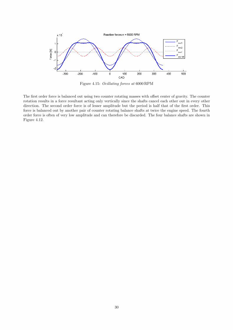
Figure 4.15: Ocillating forces at 6000 RPM
The first order force is balanced out using two counter rotating masses with offset center of gravity. The counterrotation results in a force resultant acting only vertically since the shafts cancel each other out in every otherdirection. The second order force is of lesser amplitude but the period is half that of the first order. Thisforce is balanced out by another pair of counter rotating balance shafts at twice the engine speed. The fourthorder force is often of very low amplitude and can therefore be discarded. The four balance shafts are shown inFigure 4.12.
30
5 Results
In this chapter the results from the work is presented. First the piston results will be presented and second theengine design.
5.1 Benchmark
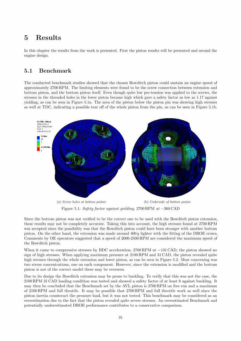
The conducted benchmark studies showed that the chosen Bowditch piston could sustain an engine speed ofapproximately 2700 RPM. The limiting elements were found to be the screw connection between extension andbottom piston, and the bottom piston itself. Even though quite low pre-tension was applied to the screws, thestresses in the threaded holes in the lower piston became high which gave a safety factor as low as 1.17 againstyielding, as can be seen in Figure 5.1a. The area of the piston below the piston pin was showing high stressesas well at TDC, indicating a possible tear off of the whole piston from the pin, as can be seen in Figure 5.1b.
(a) Screw holes at bottom piston (b) Underside of bottom piston
Figure 5.1: Safety factor against yielding, 2700 RPM at −360 CAD
Since the bottom piston was not verified to be the correct one to be used with the Bowditch piston extension,these results may not be completely accurate. Taking this into account, the high stresses found at 2700 RPMwas accepted since the possibility was that the Bowditch piston could have been stronger with another bottompiston. On the other hand, the extension was made around 400 g lighter with the fitting of the DROE crown.Comments by OE operators suggested that a speed of 2000-2500 RPM are considered the maximum speed ofthe Bowditch piston.
When it came to compressive stresses by BDC acceleration, 2700 RPM at −131 CAD, the piston showed nosign of high stresses. When applying maximum pressure at 2100 RPM and 31 CAD, the piston revealed quitehigh stresses through the whole extension and lower piston, as can be seen in Figure 5.2. Most concerning wastwo stress concentrations, one on each component. However, since the extension is modified and the bottompiston is not of the correct model these may be overseen.
Due to its design the Bowditch extension may be prone to buckling. To verify that this was not the case, the2100 RPM 31 CAD loading condition was tested and showed a safety factor of at least 8 against buckling. Itmay then be concluded that the Benchmark set by the AVL piston is 2700 RPM on free run and a maximumof 2100 RPM and full throttle. It may be possible that 2700 RPM and full throttle work as well since thepiston inertia counteract the pressure load, but it was not tested. This benchmark may be considered as anoverestimation due to the fact that the piston revealed quite severe stresses. An overestimated Benchmark andpotentially underestimated DROE performance contributes to a conservative comparison.
31
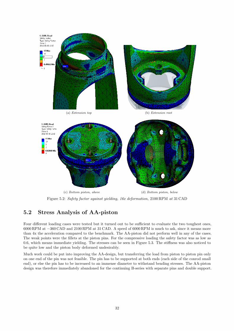
(a) Extension top (b) Extension root
(c) Bottom piston, above (d) Bottom piston, below
Figure 5.2: Safety factor against yielding, 16x deformation, 2100 RPM at 31 CAD
5.2 Stress Analysis of AA-piston
Four different loading cases were tested but it turned out to be sufficient to evaluate the two toughest ones,6000 RPM at −360 CAD and 2100 RPM at 31 CAD. A speed of 6000 RPM is much to ask, since it means morethan 4x the acceleration compared to the benchmark. The AA-piston did not perform well in any of the cases.The weak points were the fillets at the piston pins. For the compressive loading the safety factor was as low as0.6, which means immediate yielding. The stresses can be seen in Figure 5.3. The stiffness was also noticed tobe quite low and the piston body deformed undesirably.
Much work could be put into improving the AA-design, but transferring the load from piston to piston pin onlyon one end of the pin was not feasible. The pin has to be supported at both ends (each side of the conrod smallend), or else the pin has to be increased to an immense diameter to withstand bending stresses. The AA-pistondesign was therefore immediately abandoned for the continuing B-series with separate pins and double support.
32
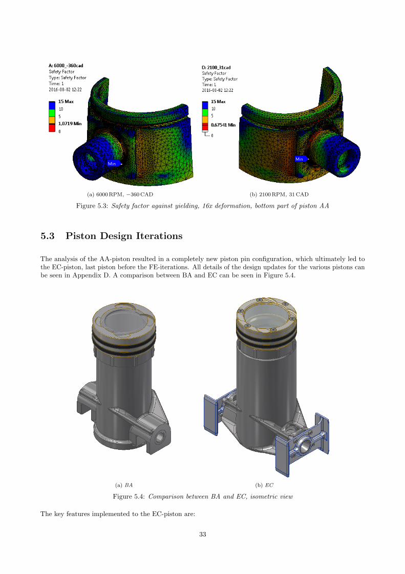
(a) 6000 RPM, −360 CAD (b) 2100 RPM, 31 CAD
Figure 5.3: Safety factor against yielding, 16x deformation, bottom part of piston AA
5.3 Piston Design Iterations
The analysis of the AA-piston resulted in a completely new piston pin configuration, which ultimately led tothe EC-piston, last piston before the FE-iterations. All details of the design updates for the various pistons canbe seen in Appendix D. A comparison between BA and EC can be seen in Figure 5.4.
(a) BA (b) EC
Figure 5.4: Comparison between BA and EC, isometric view
The key features implemented to the EC-piston are:
33
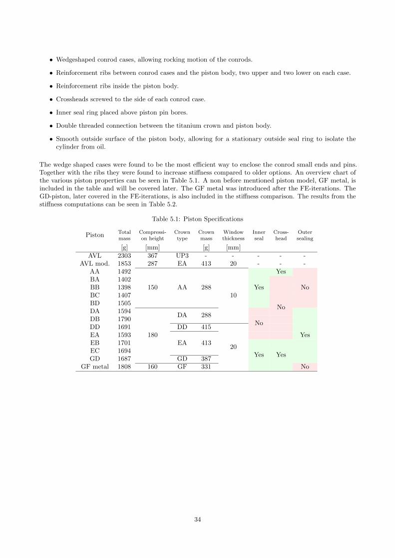
• Wedgeshaped conrod cases, allowing rocking motion of the conrods.
• Reinforcement ribs between conrod cases and the piston body, two upper and two lower on each case.
• Reinforcement ribs inside the piston body.
• Crossheads screwed to the side of each conrod case.
• Inner seal ring placed above piston pin bores.
• Double threaded connection between the titanium crown and piston body.
• Smooth outside surface of the piston body, allowing for a stationary outside seal ring to isolate thecylinder from oil.
The wedge shaped cases were found to be the most efficient way to enclose the conrod small ends and pins.Together with the ribs they were found to increase stiffness compared to older options. An overview chart ofthe various piston properties can be seen in Table 5.1. A non before mentioned piston model, GF metal, isincluded in the table and will be covered later. The GF metal was introduced after the FE-iterations. TheGD-piston, later covered in the FE-iterations, is also included in the stiffness comparison. The results from thestiffness computations can be seen in Table 5.2.
Table 5.1: Piston Specifications
Piston Totalmass
Compressi-on height
Crowntype
Crownmass
Windowthickness
Innerseal
Cross-head
Outersealing
[g] [mm] [g] [mm]AVL 2303 367 UP3 - - - - -
AVL mod. 1853 287 EA 413 20 - - -AA 1492
150 AA 28810
YesBA 1402BB 1398BC 1407BD 1505
Yes No
DA 1594
180
DB 1790DA 288
DD 1691 DD 415EA 1593
EA 413
No
No
EB 1701EC 1694GD 1687 GD 387
Yes
GF metal 1808 160 GF 331
20Yes Yes
No
34
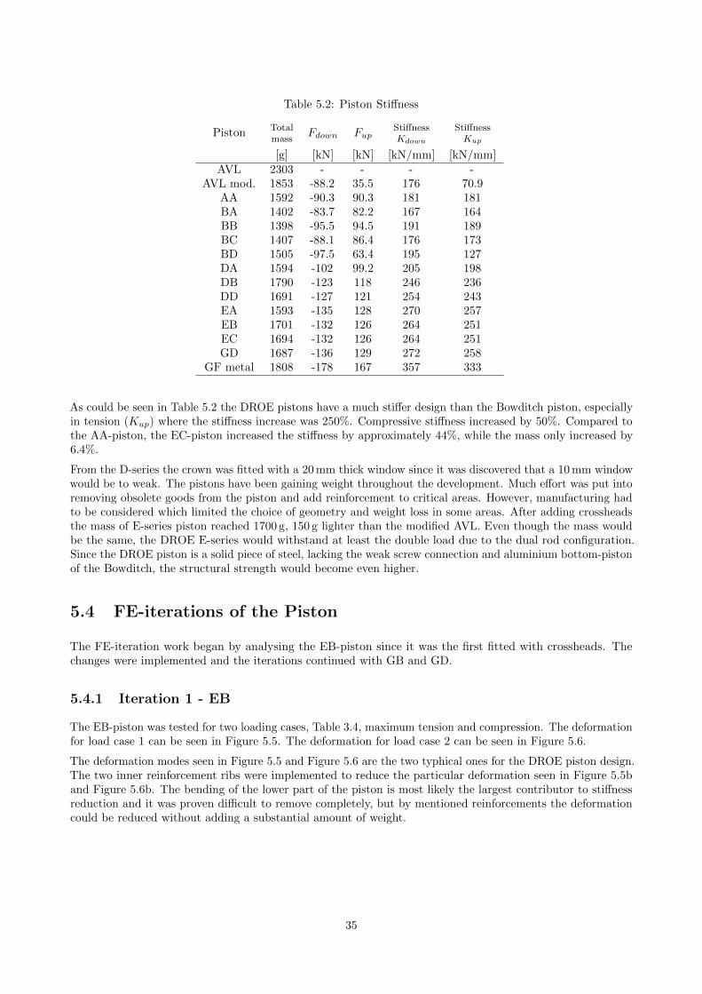
Table 5.2: Piston Stiffness
Piston Totalmass
Fdown FupStiffnessKdown
StiffnessKup
[g] [kN] [kN] [kN/mm] [kN/mm]AVL 2303 - - - -
AVL mod. 1853 -88.2 35.5 176 70.9AA 1592 -90.3 90.3 181 181BA 1402 -83.7 82.2 167 164BB 1398 -95.5 94.5 191 189BC 1407 -88.1 86.4 176 173BD 1505 -97.5 63.4 195 127DA 1594 -102 99.2 205 198DB 1790 -123 118 246 236DD 1691 -127 121 254 243EA 1593 -135 128 270 257EB 1701 -132 126 264 251EC 1694 -132 126 264 251GD 1687 -136 129 272 258
GF metal 1808 -178 167 357 333
As could be seen in Table 5.2 the DROE pistons have a much stiffer design than the Bowditch piston, especiallyin tension (Kup) where the stiffness increase was 250%. Compressive stiffness increased by 50%. Compared tothe AA-piston, the EC-piston increased the stiffness by approximately 44%, while the mass only increased by6.4%.
From the D-series the crown was fitted with a 20 mm thick window since it was discovered that a 10 mm windowwould be to weak. The pistons have been gaining weight throughout the development. Much effort was put intoremoving obsolete goods from the piston and add reinforcement to critical areas. However, manufacturing hadto be considered which limited the choice of geometry and weight loss in some areas. After adding crossheadsthe mass of E-series piston reached 1700 g, 150 g lighter than the modified AVL. Even though the mass wouldbe the same, the DROE E-series would withstand at least the double load due to the dual rod configuration.Since the DROE piston is a solid piece of steel, lacking the weak screw connection and aluminium bottom-pistonof the Bowditch, the structural strength would become even higher.
5.4 FE-iterations of the Piston
The FE-iteration work began by analysing the EB-piston since it was the first fitted with crossheads. Thechanges were implemented and the iterations continued with GB and GD.
5.4.1 Iteration 1 - EB
The EB-piston was tested for two loading cases, Table 3.4, maximum tension and compression. The deformationfor load case 1 can be seen in Figure 5.5. The deformation for load case 2 can be seen in Figure 5.6.
The deformation modes seen in Figure 5.5 and Figure 5.6 are the two typhical ones for the DROE piston design.The two inner reinforcement ribs were implemented to reduce the particular deformation seen in Figure 5.5band Figure 5.6b. The bending of the lower part of the piston is most likely the largest contributor to stiffnessreduction and it was proven difficult to remove completely, but by mentioned reinforcements the deformationcould be reduced without adding a substantial amount of weight.
35
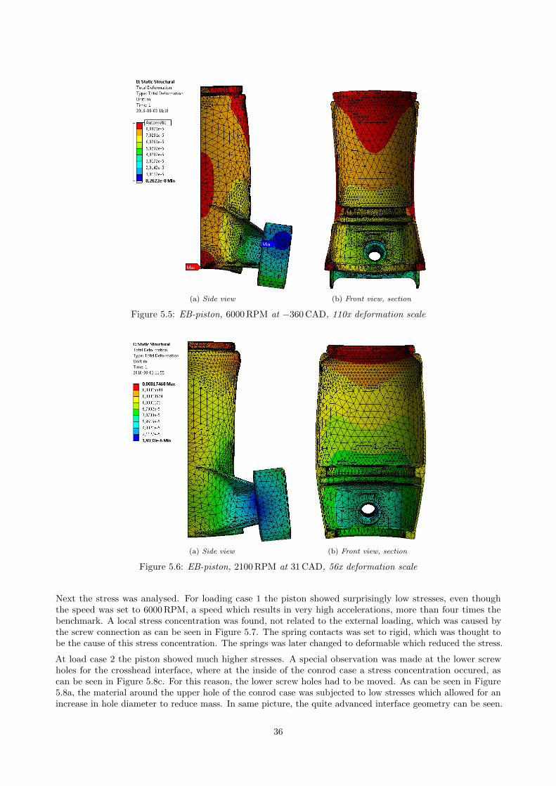
(a) Side view (b) Front view, section
Figure 5.5: EB-piston, 6000 RPM at −360 CAD, 110x deformation scale
(a) Side view (b) Front view, section
Figure 5.6: EB-piston, 2100 RPM at 31 CAD, 56x deformation scale
Next the stress was analysed. For loading case 1 the piston showed surprisingly low stresses, even thoughthe speed was set to 6000 RPM, a speed which results in very high accelerations, more than four times thebenchmark. A local stress concentration was found, not related to the external loading, which was caused bythe screw connection as can be seen in Figure 5.7. The spring contacts was set to rigid, which was thought tobe the cause of this stress concentration. The springs was later changed to deformable which reduced the stress.
At load case 2 the piston showed much higher stresses. A special observation was made at the lower screwholes for the crosshead interface, where at the inside of the conrod case a stress concentration occured, ascan be seen in Figure 5.8c. For this reason, the lower screw holes had to be moved. As can be seen in Figure5.8a, the material around the upper hole of the conrod case was subjected to low stresses which allowed for anincrease in hole diameter to reduce mass. In same picture, the quite advanced interface geometry can be seen.
36
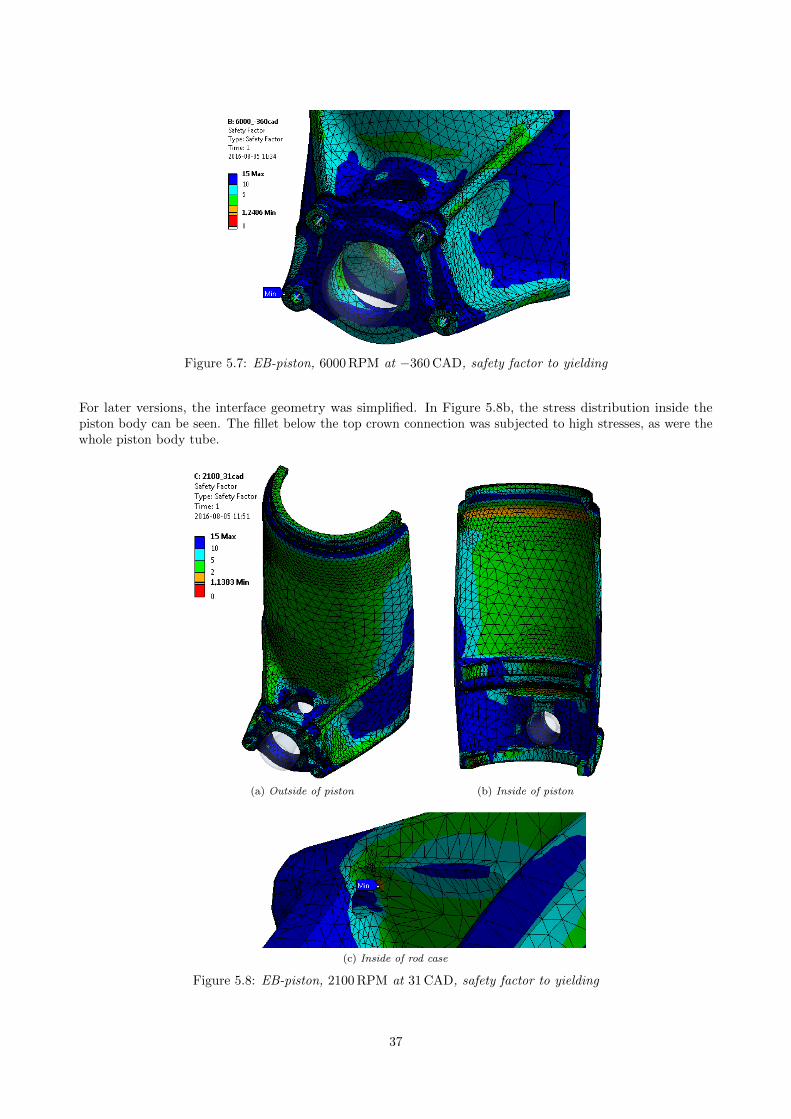
Figure 5.7: EB-piston, 6000 RPM at −360 CAD, safety factor to yielding
For later versions, the interface geometry was simplified. In Figure 5.8b, the stress distribution inside thepiston body can be seen. The fillet below the top crown connection was subjected to high stresses, as were thewhole piston body tube.
(a) Outside of piston (b) Inside of piston
(c) Inside of rod case
Figure 5.8: EB-piston, 2100 RPM at 31 CAD, safety factor to yielding
37
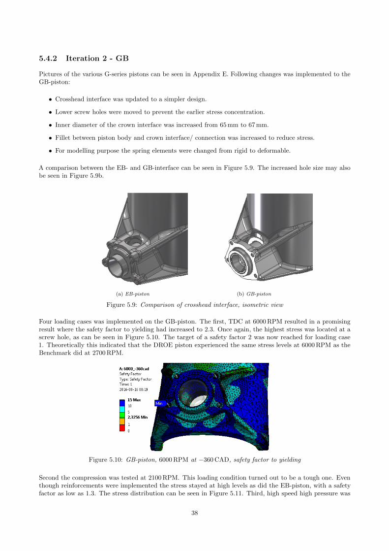
5.4.2 Iteration 2 - GB
Pictures of the various G-series pistons can be seen in Appendix E. Following changes was implemented to theGB-piston:
• Crosshead interface was updated to a simpler design.
• Lower screw holes were moved to prevent the earlier stress concentration.
• Inner diameter of the crown interface was increased from 65 mm to 67 mm.
• Fillet between piston body and crown interface/ connection was increased to reduce stress.
• For modelling purpose the spring elements were changed from rigid to deformable.
A comparison between the EB- and GB-interface can be seen in Figure 5.9. The increased hole size may alsobe seen in Figure 5.9b.
(a) EB-piston (b) GB-piston
Figure 5.9: Comparison of crosshead interface, isometric view
Four loading cases was implemented on the GB-piston. The first, TDC at 6000 RPM resulted in a promisingresult where the safety factor to yielding had increased to 2.3. Once again, the highest stress was located at ascrew hole, as can be seen in Figure 5.10. The target of a safety factor 2 was now reached for loading case1. Theoretically this indicated that the DROE piston experienced the same stress levels at 6000 RPM as theBenchmark did at 2700 RPM.
Figure 5.10: GB-piston, 6000 RPM at −360 CAD, safety factor to yielding
Second the compression was tested at 2100 RPM. This loading condition turned out to be a tough one. Eventhough reinforcements were implemented the stress stayed at high levels as did the EB-piston, with a safetyfactor as low as 1.3. The stress distribution can be seen in Figure 5.11. Third, high speed high pressure was
38
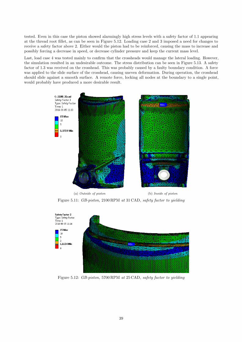
tested. Even in this case the piston showed alarmingly high stress levels with a safety factor of 1.1 appearingat the thread root fillet, as can be seen in Figure 5.12. Loading case 2 and 3 imposed a need for changes toreceive a safety factor above 2. Either would the piston had to be reinforced, causing the mass to increase andpossibly forcing a decrease in speed, or decrease cylinder pressure and keep the current mass level.
Last, load case 4 was tested mainly to confirm that the crossheads would manage the lateral loading. However,the simulation resulted in an undesirable outcome. The stress distribution can be seen in Figure 5.13. A safetyfactor of 1.3 was received on the crosshead. This was probably caused by a faulty boundary condition. A forcewas applied to the slide surface of the crosshead, causing uneven deformation. During operation, the crossheadshould slide against a smooth surface. A remote force, locking all nodes at the boundary to a single point,would probably have produced a more desirable result.
(a) Outside of piston (b) Inside of piston
Figure 5.11: GB-piston, 2100 RPM at 31 CAD, safety factor to yielding
Figure 5.12: GB-piston, 5700 RPM at 25 CAD, safety factor to yielding
39
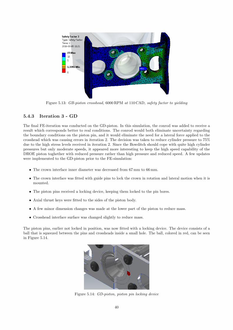
Figure 5.13: GB-piston crosshead, 6000 RPM at 110 CAD, safety factor to yielding
5.4.3 Iteration 3 - GD
The final FE-iteration was conducted on the GD-piston. In this simulation, the conrod was added to receive aresult which corresponds better to real conditions. The conrod would both eliminate uncertainty regardingthe boundary conditions on the piston pin, and it would eliminate the need for a lateral force applied to thecrosshead which was causing errors in iteration 2. The decision was taken to reduce cylinder pressure to 75%due to the high stress levels received in iteration 2. Since the Bowditch should cope with quite high cylinderpressures but only moderate speeds, it appeared more interesting to keep the high speed capability of theDROE piston toghether with reduced pressure rather than high pressure and reduced speed. A few updateswere implemented to the GD-piston prior to the FE-simulation:
• The crown interface inner diameter was decreased from 67 mm to 66 mm.
• The crown interface was fitted with guide pins to lock the crown in rotation and lateral motion when it ismounted.
• The piston pins received a locking device, keeping them locked to the pin bores.
• Axial thrust keys were fitted to the sides of the piston body.
• A few minor dimension changes was made at the lower part of the piston to reduce mass.
• Crosshead interface surface was changed slightly to reduce mass.
The piston pins, earlier not locked in position, was now fitted with a locking device. The device consists of aball that is squeezed between the pins and crossheads inside a small hole. The ball, colored in red, can be seenin Figure 5.14.
Figure 5.14: GD-piston, piston pin locking device
40
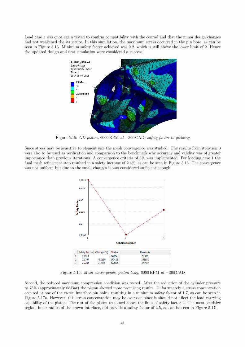
Load case 1 was once again tested to confirm compatibility with the conrod and that the minor design changeshad not weakened the structure. In this simulation, the maximum stress occurred in the pin bore, as can beseen in Figure 5.15. Minimum safety factor achieved was 2.2, which is still above the lower limit of 2. Hencethe updated design and first simulation were considered a success.
Figure 5.15: GD-piston, 6000 RPM at −360 CAD, safety factor to yielding
Since stress may be sensitive to element size the mesh convergence was studied. The results from iteration 3were also to be used as verification and comparison to the benchmark why accuracy and validity was of greaterimportance than previous iterations. A convergence criteria of 5% was implemented. For loading case 1 thefinal mesh refinement step resulted in a safety increase of 2.4%, as can be seen in Figure 5.16. The convergencewas not uniform but due to the small changes it was considered sufficient enough.
Figure 5.16: Mesh convergence, piston body, 6000 RPM at −360 CAD
Second, the reduced maximum compression condition was tested. After the reduction of the cylinder pressureto 75% (approximately 68 Bar) the piston showed more promising results. Unfortunately a stress concentrationoccured at one of the crown interface pin holes, resulting in a minimum safety factor of 1.7, as can be seen inFigure 5.17a. However, this stress concentration may be overseen since it should not affect the load carryingcapability of the piston. The rest of the piston remained above the limit of safety factor 2. The most sensitiveregion, inner radius of the crown interface, did provide a safety factor of 2.5, as can be seen in Figure 5.17c.
41
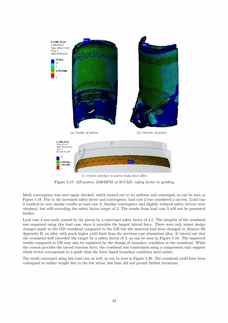
(a) Inside of piston (b) Outside of piston
(c) Crown interface to piston body inner fillet
Figure 5.17: GD-piston, 2100 RPM at 31 CAD, safety factor to yielding
Mesh convergence was once again checked, which turned out to be uniform and converged, as can be seen inFigure 5.18. Due to the increased safety factor and convergence, load case 2 was considered a success. Load case3 resulted in very similar results as load case 2. Similar convergence and slightly reduced safety factors wereobtained, but still exceeding the safety factor target of 2. The results from load case 3 will not be presentedfurther.
Load case 4 was easily passed by the piston by a converged safety factor of 3.2. The integrity of the crossheadwas examined using this load case, since it provides the largest lateral force. There were only minor designchanges made to the GD crosshead compared to the GB but the material had been changed to Alumec 89,Appendix B, an alloy with much higher yield limit than the previous cast aluminium alloy. It turned out thatthe crosshead well exceeded the target by a safety factor of 5, as can be seen in Figure 5.19. The improvedresults compared to GB may also be explained by the change of boundary condition at the crosshead. Whilethe conrod provides the lateral reaction force, the crosshead was constrained using a compression only supportwhich better corresponds to a guide than the force based boundary condition used earlier.
The result converged using this load case as well, as can be seen in Figure 5.20. The crosshead could have beenredesigned to reduce weight due to the low stress, but time did not permit further iterations.
42
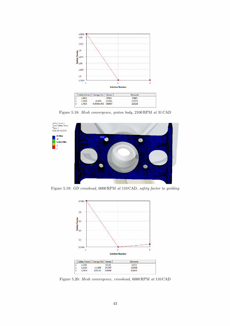
Figure 5.18: Mesh convergence, piston body, 2100 RPM at 31 CAD
Figure 5.19: GD crosshead, 6000 RPM at 110 CAD, safety factor to yielding
Figure 5.20: Mesh convergence, crosshead, 6000 RPM at 110 CAD
43
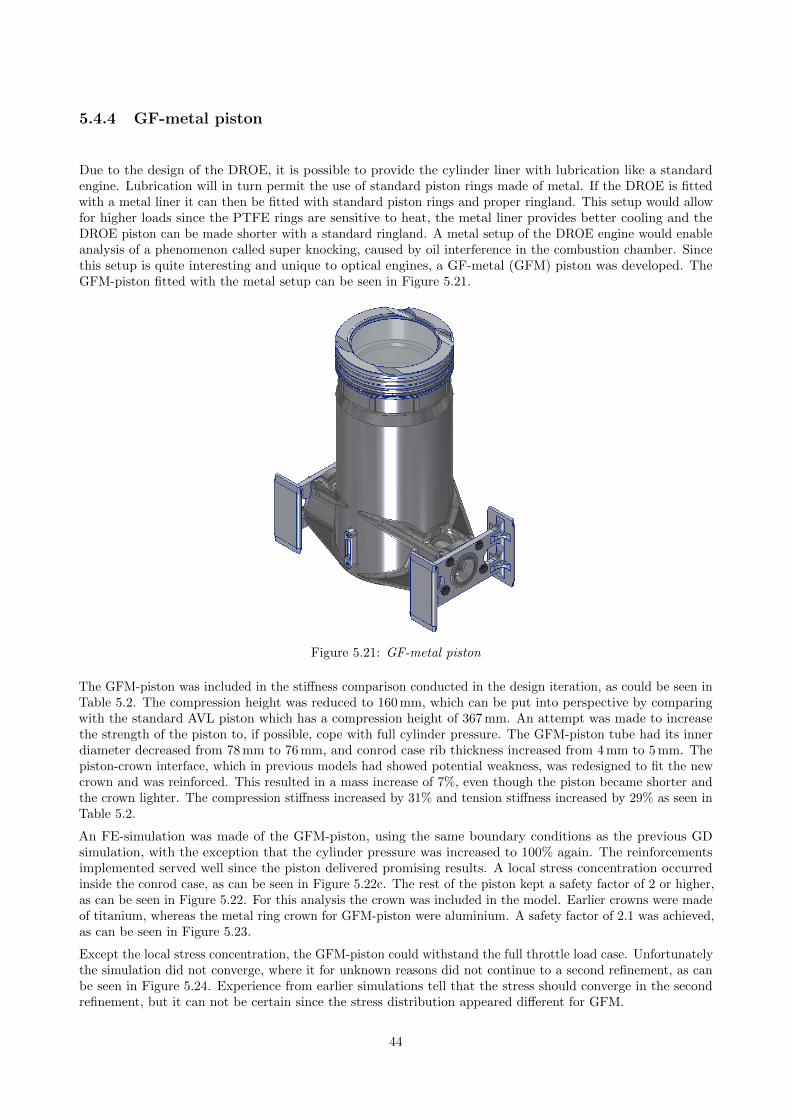
5.4.4 GF-metal piston
Due to the design of the DROE, it is possible to provide the cylinder liner with lubrication like a standardengine. Lubrication will in turn permit the use of standard piston rings made of metal. If the DROE is fittedwith a metal liner it can then be fitted with standard piston rings and proper ringland. This setup would allowfor higher loads since the PTFE rings are sensitive to heat, the metal liner provides better cooling and theDROE piston can be made shorter with a standard ringland. A metal setup of the DROE engine would enableanalysis of a phenomenon called super knocking, caused by oil interference in the combustion chamber. Sincethis setup is quite interesting and unique to optical engines, a GF-metal (GFM) piston was developed. TheGFM-piston fitted with the metal setup can be seen in Figure 5.21.
Figure 5.21: GF-metal piston
The GFM-piston was included in the stiffness comparison conducted in the design iteration, as could be seen inTable 5.2. The compression height was reduced to 160 mm, which can be put into perspective by comparingwith the standard AVL piston which has a compression height of 367 mm. An attempt was made to increasethe strength of the piston to, if possible, cope with full cylinder pressure. The GFM-piston tube had its innerdiameter decreased from 78 mm to 76 mm, and conrod case rib thickness increased from 4 mm to 5 mm. Thepiston-crown interface, which in previous models had showed potential weakness, was redesigned to fit the newcrown and was reinforced. This resulted in a mass increase of 7%, even though the piston became shorter andthe crown lighter. The compression stiffness increased by 31% and tension stiffness increased by 29% as seen inTable 5.2.
An FE-simulation was made of the GFM-piston, using the same boundary conditions as the previous GDsimulation, with the exception that the cylinder pressure was increased to 100% again. The reinforcementsimplemented served well since the piston delivered promising results. A local stress concentration occurredinside the conrod case, as can be seen in Figure 5.22c. The rest of the piston kept a safety factor of 2 or higher,as can be seen in Figure 5.22. For this analysis the crown was included in the model. Earlier crowns were madeof titanium, whereas the metal ring crown for GFM-piston were aluminium. A safety factor of 2.1 was achieved,as can be seen in Figure 5.23.
Except the local stress concentration, the GFM-piston could withstand the full throttle load case. Unfortunatelythe simulation did not converge, where it for unknown reasons did not continue to a second refinement, as canbe seen in Figure 5.24. Experience from earlier simulations tell that the stress should converge in the secondrefinement, but it can not be certain since the stress distribution appeared different for GFM.
44
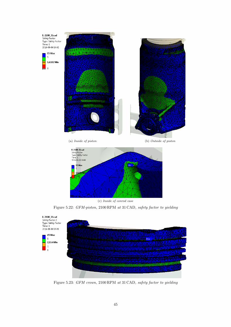
(a) Inside of piston (b) Outside of piston
(c) Inside of conrod case
Figure 5.22: GFM-piston, 2100 RPM at 31 CAD, safety factor to yielding
Figure 5.23: GFM crown, 2100 RPM at 31 CAD, safety factor to yielding
45
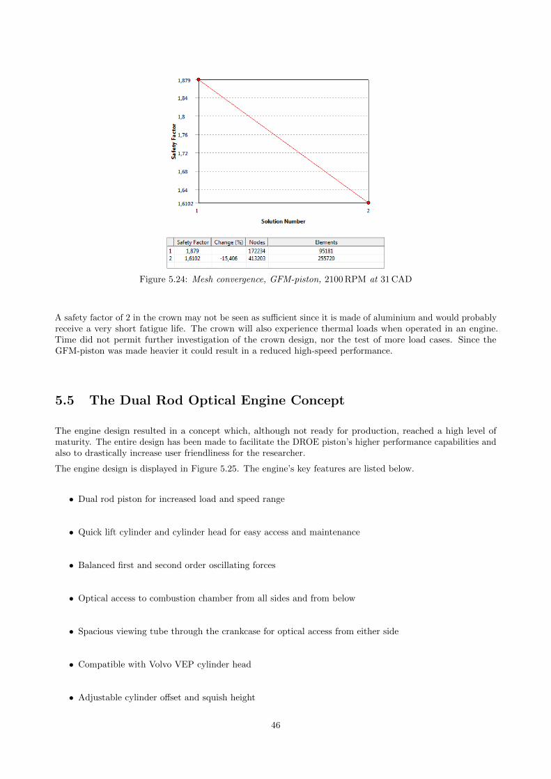
Figure 5.24: Mesh convergence, GFM-piston, 2100 RPM at 31 CAD
A safety factor of 2 in the crown may not be seen as sufficient since it is made of aluminium and would probablyreceive a very short fatigue life. The crown will also experience thermal loads when operated in an engine.Time did not permit further investigation of the crown design, nor the test of more load cases. Since theGFM-piston was made heavier it could result in a reduced high-speed performance.
5.5 The Dual Rod Optical Engine Concept
The engine design resulted in a concept which, although not ready for production, reached a high level ofmaturity. The entire design has been made to facilitate the DROE piston’s higher performance capabilities andalso to drastically increase user friendliness for the researcher.
The engine design is displayed in Figure 5.25. The engine’s key features are listed below.
• Dual rod piston for increased load and speed range
• Quick lift cylinder and cylinder head for easy access and maintenance
• Balanced first and second order oscillating forces
• Optical access to combustion chamber from all sides and from below
• Spacious viewing tube through the crankcase for optical access from either side
• Compatible with Volvo VEP cylinder head
• Adjustable cylinder offset and squish height
46
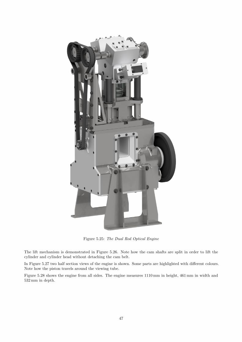
Figure 5.25: The Dual Rod Optical Engine
The lift mechanism is demonstrated in Figure 5.26. Note how the cam shafts are split in order to lift thecylinder and cylinder head without detaching the cam belt.
In Figure 5.27 two half section views of the engine is shown. Some parts are highlighted with different colours.Note how the piston travels around the viewing tube.
Figure 5.28 shows the engine from all sides. The engine measures 1110 mm in height, 461 mm in width and532 mm in depth.
47
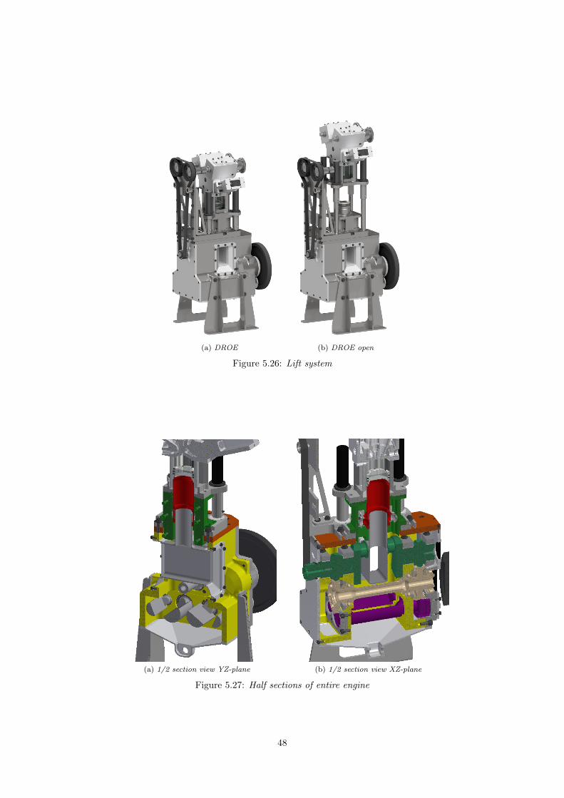
(a) DROE (b) DROE open
Figure 5.26: Lift system
(a) 1/2 section view YZ-plane (b) 1/2 section view XZ-plane
Figure 5.27: Half sections of entire engine
48
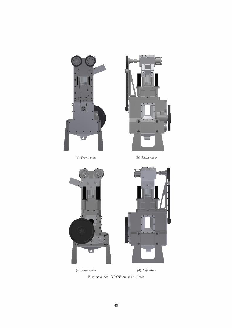
(a) Front view (b) Right view
(c) Back view (d) Left view
Figure 5.28: DROE in side views
49
6 Discussion
In this chapter the results are discussed and related to the aims of the project. The engine performance wassuccessfully quantified using the chosen methods, considering implemented limitations. The design is still inan early stage of development and will need more work before put into production and tested physically, butthe results received indicates that full engine speed and full pressure is within reach using the DROE design,provided that other limiting factors such as transparent components can be designed to withstand the addedstress.
6.1 Piston
The DROE piston development had a long journey from the AA-concept to the GD version. Various alternativeswere investigated and many designs tested were found to be dead ends, like C-series and F-series which wereabandoned and not covered in this report. In the end a promising design was established showing great potentialin stiffness and strength.
6.1.1 Design
The goal was to find a suitable design providing as high stiffness and strength to weight ratio as possible. It wassoon discovered that loose piston pins comprised by pin cases, reinforced by external ribs, gave the best resultsamongst the different options. Combined with a quite thin piston body tube, internally reinforced by ribs atthe connection points to the external ribs gave a substantial stiffness increase compared to the Bowditch pistonand the AA concept. This design was proven as the best option that could be established during the project.
6.1.2 Performance
By conducting a FE-analysis of the piston, the performance could be determined. The stress levels was themeasure that were used to determine the performance. A safety factor of 2 against yielding was chosen as thelower limit. The reduction of cylinder pressure to 75% combined with reinforcements at the final FE-iteration,resulted in that the GD-piston exceeded the safety factor 2 limit. On one hand, it is a promising result thatthe DROE piston may withstand speeds of 6000 RPM. However, some precautions must be taken. The pistonis dynamically loaded and will be subject to fatigue. In fatigue terms, 50% of the yield limit will probablynot provide a suitable fatigue life. A fatigue life computation is needed in the future if such high stresses arepresent. Only a few loading conditions were tested, where the conditions producing highest forces were chosen.To receive a more accurate stress analysis, the whole 720° engine cycle should be tested to find the higheststress amplitudes. Time and computational power did not permit a test of a whole engine cycle.
More factors that has been omitted are material impurity and surface finish. A manufactured component willnot have a perfect surface, resulting in stress concentrations and higher stresses. This will have to be accountedfor in the future. These problems can be minimised by putting high demands on the manufacturing. Highfinish is possible on this kind of pistons since they are only produced in very small numbers at high costs.A different choice of material would also be possible, which could double the safety factor quite easy. Aftertreatment like hardening and shot peening would also be possible, depending on how much resources that aresuitable and how high performance that is demanded. No matter how much force the piston can withstand, itall has to be absorbed by rods and crankshaft. The force absorption capability of conrods and crankshafts havebeen omitted in this thesis, and these will have to be investigated further to verify that the same speeds as thepiston will manage is possible.
The benchmark was established at 2700 RPM and full pressure, even though these figures are an overestimationof the current benchmark piston performance. Unfortunately the DROE piston could not meet the full pressurecondition, but only 75% to exceed safety factor 2. The decision was taken to focus on high speed instead. The6000 RPM mark was passed for the DROE, which in conservative terms means an engine speed increase of over100%. Later analyses conducted on the GFM-piston showed that full pressure could also be met with morework on the piston design.
50
Most work was put into iterating the design. After each completed loading case the design was updated andtested again. More loading cases, using various speeds, in the analysis of both benchmark and DROE wouldhave been of interest to implement to try to receive a more specific comparison. It was however proven difficultto compare the two pistons types since they have very different design and elements limiting the performance.The screw connection in the Bowditch piston was the cause of many errors and limited the performance, ratherthan the structural stresses.
To conclude, taking the mentioned reservations into account, the load limit of the DROE piston was achievedat 6000 RPM and 75% cylinder pressure. A 100% speed increase and 25% pressure reduction was established,compared to the Benchmark.
6.1.3 Piston Pin Problematics
A few special observation regarding the piston pins were made during the simulations which may cause problemsto the design. The two piston pins are made much shorter than those of a standard piston. This means thatthe projected area becomes smaller and the contact pressure increases for a given load. The pin connectionload transferring capability would therefore be reduced which contradicts the statement that dual rods meansdouble the load. This problem will however be overseen for the following reasons:
• Rod small end width is basically the same as standard rods, which means that contact pressure in rodsmall end will be similar as a standard rod for a given load.
• The pin bore in the DROE piston is reamed through steel. Compared to a standard piston which normallyis made of aluminium, the DROE piston can withstand higher loads in the connection between pistonand pin.
• While piston pins are normally semi-floating, it is meant that the pin will be stationary in the DROEpiston which would reduce wear in the pin bore.
• The DROE engine will not have the same service duration as a standard engine. Even though the wearwould be greater than normal, it should not cause a problem. Components are replaced regularly to fitnew engine configurations.
A second problem occurred, caused by the bending of the bottom of the piston. When the piston is loaded itslower section bends which introduces a rotation, or bending, to the piston pins, which are then transferredto the connecting rods. This bending may very well be the cause of conrod buckling and therefore failure, orat least it could result in fatal small end bearing wear. To minimize the bending, the conrods are to be keptas close to the center of the piston as possible. At the same time, the piston pins are to be kept as long aspossible to minimize contact pressure, without interfering with the optical access inside the piston. The pistonpin diameter may be increased to increase projected contact are, to reduce contact pressure, but only to acertain limit since the conrod small ends have to be enlarged as will the conrod housings at the piston sides. Apossible solution to these problems would be to remove the piston pins and replace them with ball joints, ascan be seen in Figure 6.1. The ball joint would provide a combination of large projected contact area at a lowdiameter, compared to the length of the piston pin. At the same time, the induced bending in the conrodscaused by the piston pin connection, possibly causing them to buckle during high compressible loads, would beeliminated. The ball joint connection may seem as a controversial suggestion, but it has been tested by Hondaon a standard piston configuration with promising results [Kaw+09]. Introduced to the DROE piston, it couldsimplify manufacturing, reduce weight and increase piston to conrod connection strength. Time did not permitfurther investigation.
6.1.4 Other Limiting Elements
As stated before, the established performance figures comes with several assumptions. The most criticalassumption is probably the transparent components and their ability to match the piston performance. Morework will have to be put into the transparent parts if the DROE piston is to be used. The glass liner isprobably the most sensitive component why the metal-ring piston configuration may be the most interesting to
51
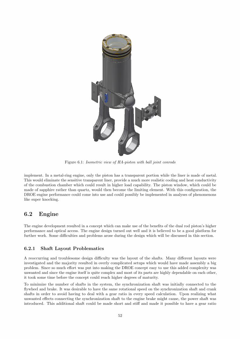
Figure 6.1: Isometric view of HA-piston with ball joint conrods
implement. In a metal-ring engine, only the piston has a transparent portion while the liner is made of metal.This would eliminate the sensitive transparent liner, provide a much more realistic cooling and heat conductivityof the combustion chamber which could result in higher load capability. The piston window, which could bemade of sapphire rather than quartz, would then become the limiting element. With this configuration, theDROE engine performance could come into use and could possibly be implemented in analyses of phenomenonslike super knocking.
6.2 Engine
The engine development resulted in a concept which can make use of the benefits of the dual rod piston’s higherperformance and optical access. The engine design turned out well and it is believed to be a good platform forfurther work. Some difficulties and problems arose during the design which will be discussed in this section.
6.2.1 Shaft Layout Problematics
A reoccurring and troublesome design difficulty was the layout of the shafts. Many different layouts wereinvestigated and the majority resulted in overly complicated setups which would have made assembly a bigproblem. Since so much effort was put into making the DROE concept easy to use this added complexity wasunwanted and since the engine itself is quite complex and most of its parts are highly dependable on each other,it took some time before the concept could reach higher degrees of maturity.
To minimize the number of shafts in the system, the synchronization shaft was initially connected to theflywheel and brake. It was desirable to have the same rotational speed on the synchronization shaft and crankshafts in order to avoid having to deal with a gear ratio in every speed calculation. Upon realizing whatunwanted effects connecting the synchronization shaft to the engine brake might cause, the power shaft wasintroduced. This additional shaft could be made short and stiff and made it possible to have a gear ratio
52
between crank and sync. With a bigger gearwheel on the synchronization shaft it could be placed directlyunderneath the crank axis without interfering with the optical access and also reach far enough to connectto the balance drive. The power shaft also had the added benefit of giving the engine output shaft the samerotational direction as the crank.
6.2.2 Lift System Problematics
Having four guiding pillars for the lift system means there are some redundancy as only three are needed tosecure the cylinder’s degrees of freedom. Some issues has also surfaced regarding the placement of the liftpillars. It could become a problem with access to the cylinder. A solution would be to make space inside thecase for the pillars to slide into. This would enable the pillars to be fastened to the top cylinder plate frombelow and three pillars could be used since the third would not obscure the optical access to the cylinder.
6.2.3 Future Work on Engine
As mentioned, some parts of the engine design needs verification in form of FE-analysis to determine theirstrength and estimated lifetime. The most crucial components are the shafts, gears and bearing seats. Thecylinder lift system also needs further development as there are some questions about its function. The mainissue is with the four lift pillars which might limit the physical access to the cylinder and piston.
Some further work also needs to be done on adding external components such as engine brake, intake/exhaust,fuel line, cooling system and oil supply to the model. Almost all external components can affect the opticaland physical access to the engine. Due to the lift system all components connected to the cylinder head needto be connected with either flexible hoses or quick release mechanisms. The engine design will undoubtedlyundergo major changes before a prototype is built.
The transparent components may become a major limiting factor of the engine’s performance. An in depthstudy of the strength of the transparent components needs to be done and a design which not limits theperformance of the piston has to be found. Some concepts, such as the all metal cylinder has already beendeveloped.
As it stands, there are some ideas surrounding a cylinder with smaller transparent segments which need to beexplored. More experience regarding actual research and engine testing is believed to be required in order tocomplete this design as the requirement for optical access through the cylinder liner is highly dependent on theexperiment being done.
53
References
[ASM16] ASM. Titanium Ti-6Al-4V (Grade 5), Annealed. Technical data sheet. 2016. url: http://asm.matweb.com/search/SpecificMaterial.asp?bassnum=MTP641 (visited on 04/25/2016).
[Cor08] Corning Incorporated, ed. HPFS® Fused Silica Standard Grade. Technical data sheet. Oct. 2008.[Jap03] M. Japp. “Formelsamling i mekanik”. 2003.[Kaw+09] M. Kawaguchi et al. Weight Reduction of Reciprocating Parts with a Spherical Joint Piston. SAE
International 9-2009-01-0196 (Jan. 2009).[MAH12] MAHLE GmbH (Ed.), ed. Pistons and engine testing. Version 1. Vieweg+ Teubner Verlag &
Springer Fachmedien Wiesbaden GmbH, 2012. Chap. 4.2 Aluminum materials, p. 67.[Met15] Metal Ravne. Steel CK45 (Mat.No. 1.1191, DIN Ck45, AISI 1045). Technical data sheet. 2015.
url: http://www.metalravne.com/steelselector/steels/CK45.html (visited on 05/01/2016).[SKF12] SKF. Rolling bearings. PUB BU/P1 10000 EN. SKF Group, Oct. 2012, p. 830.[Sve09] I. D. ( by Sven Andersson 2011. “Lecture Notes, Piston Engine Mechanics”. 2009.[Tre11] Trelleborg Sealing Solutions. GLYD RING® RG58/ PG59. EPHE025 02. June 2011.[UDD11] UDDEHOLM. Alumec 89. Technical data sheet. June 2011. url: http://www.uddeholm.com/
files/PB_alumec_english.pdf (visited on 04/25/2016).[Ull03] D. G. Ullman. The Mechanical Design Process. Vol. 3. Mechanical Engineering. 1221 Avenue of the
Americas, New York, NY 10020: McGraw-Hill, 2003.
54
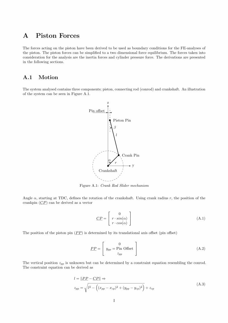
A Piston Forces
The forces acting on the piston have been derived to be used as boundary conditions for the FE-analyses ofthe piston. The piston forces can be simplified to a two dimensional force equilibrium. The forces taken intoconsideration for the analysis are the inertia forces and cylinder pressure force. The derivations are presentedin the following sections.
A.1 Motion
The system analysed contains three components; piston, connecting rod (conrod) and crankshaft. An illustrationof the system can be seen in Figure A.1.
y
z
r
l
α
β
Pin offset
Piston Pin
Crank Pin
Crankshaft
Figure A.1: Crank Rod Slider mechanism
Angle α, starting at TDC, defines the rotation of the crankshaft. Using crank radius r, the position of thecrankpin (CP ) can be derived as a vector
CP =
0r · sin(α)r · cos(α)
(A.1)
The position of the piston pin (PP ) is determined by its translational axis offset (pin offset)
PP =
0ypp = Pin Offset
zpp
(A.2)
The vertical position zpp is unknown but can be determined by a constraint equation resembling the conrod.The constraint equation can be derived as
l = ‖PP − CP‖ ⇒
zpp =
√l2 −
((xpp − xcp)2 + (ypp − ycp)2
)+ zcp
(A.3)
I
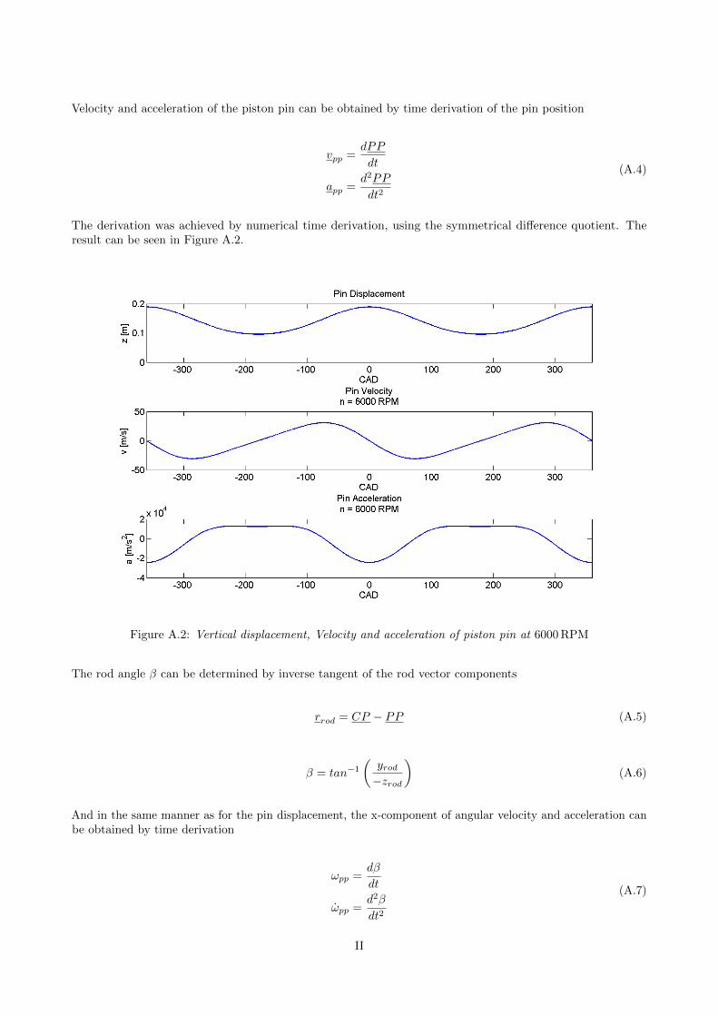
Velocity and acceleration of the piston pin can be obtained by time derivation of the pin position
vpp =dPP
dt
app =d2PP
dt2
(A.4)
The derivation was achieved by numerical time derivation, using the symmetrical difference quotient. Theresult can be seen in Figure A.2.
Figure A.2: Vertical displacement, Velocity and acceleration of piston pin at 6000 RPM
The rod angle β can be determined by inverse tangent of the rod vector components
rrod = CP − PP (A.5)
β = tan−1
(yrod−zrod
)(A.6)
And in the same manner as for the pin displacement, the x-component of angular velocity and acceleration canbe obtained by time derivation
ωpp =dβ
dt
ωpp =d2β
dt2
(A.7)
II
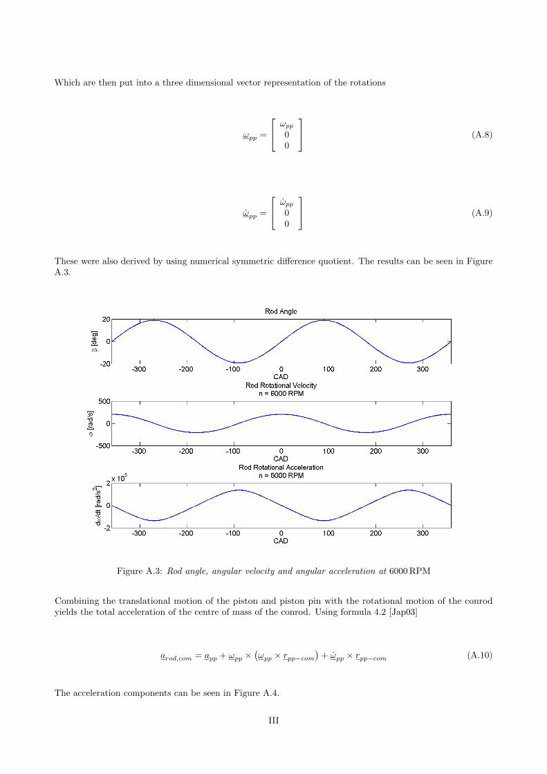
Which are then put into a three dimensional vector representation of the rotations
ωpp =
ωpp
00
(A.8)
ωpp =
ωpp
00
(A.9)
These were also derived by using numerical symmetric difference quotient. The results can be seen in FigureA.3.
Figure A.3: Rod angle, angular velocity and angular acceleration at 6000 RPM
Combining the translational motion of the piston and piston pin with the rotational motion of the conrodyields the total acceleration of the centre of mass of the conrod. Using formula 4.2 [Jap03]
arod,com = app + ωpp ×(ωpp × rpp−com
)+ ωpp × rpp−com (A.10)
The acceleration components can be seen in Figure A.4.
III
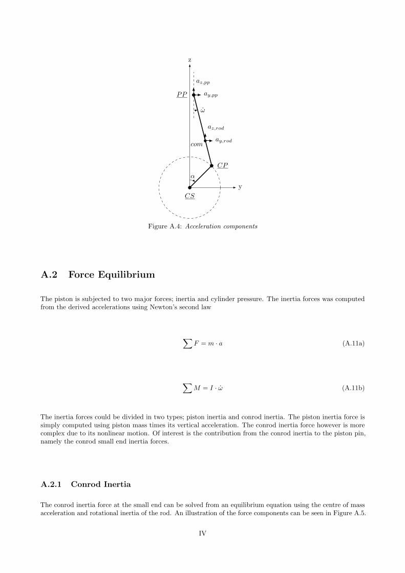
y
z
α
ω
comay,rod
az,rod
ay,pp
az,pp
PP
CP
CS
Figure A.4: Acceleration components
A.2 Force Equilibrium
The piston is subjected to two major forces; inertia and cylinder pressure. The inertia forces was computedfrom the derived accelerations using Newton’s second law
∑F = m · a (A.11a)
∑M = I · ω (A.11b)
The inertia forces could be divided in two types; piston inertia and conrod inertia. The piston inertia force issimply computed using piston mass times its vertical acceleration. The conrod inertia force however is morecomplex due to its nonlinear motion. Of interest is the contribution from the conrod inertia to the piston pin,namely the conrod small end inertia forces.
A.2.1 Conrod Inertia
The conrod inertia force at the small end can be solved from an equilibrium equation using the centre of massacceleration and rotational inertia of the rod. An illustration of the force components can be seen in Figure A.5.
IV
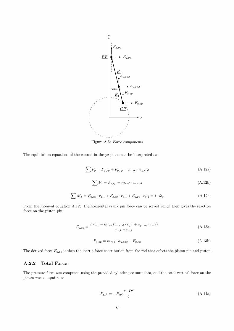
y
z
comay,rod
az,rod
Fy,pp
Fz,pp
Fy,cp
Fz,cp
R2
R1
PP
CP
Figure A.5: Force components
The equilibrium equations of the conrod in the yz-plane can be interpreted as
∑Fy = Fy,pp + Fy,cp = mrod · ay,rod (A.12a)
∑Fz = Fz,cp = mrod · az,rod (A.12b)
∑Mx = Fy,cp · rz,1 + Fz,cp · ry,1 + Fy,pp · rz,2 = I · ωx (A.12c)
From the moment equation A.12c, the horizontal crank pin force can be solved which then gives the reactionforce on the piston pin
Fy,cp =I · ωx −mrod (az,rod · ry,1 + ay,rod · rz,2)
rz,1 − rz,2(A.13a)
Fy,pp = mrod · ay,rod − Fy,cp (A.13b)
The derived force Fy,pp is then the inertia force contribution from the rod that affects the piston pin and piston.
A.2.2 Total Force
The pressure force was computed using the provided cylinder pressure data, and the total vertical force on thepiston was computed as
Fz,P = −Pcylπ ·D2
4(A.14a)
V

Fz,piston = Fz,P +mpiston · az,piston (A.14b)
Due to the conrod angle β, the vertical inertia and pressure forces introduces a horizontal normal force againstthe cylinder wall, which is added to the conrod small end inertia force.
Fy,normal = Fz,piston · tan(β) (A.15a)
Fy,piston = Fy,normal + Fy,pp (A.15b)
The force Fpiston is then the total force acting on the piston pin.
VI
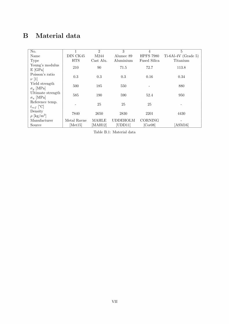
B Material data
No. 1 2 3 4 5Name DIN CK45 M244 Alumec 89 HPFS 7980 Ti-6Al-4V (Grade 5)Type HTS Cast Alu. Aluminium Fused Silica TitaniumYoung’s modulusE [GPa]
210 90 71.5 72.7 113.8
Poisson’s ratioν [1]
0.3 0.3 0.3 0.16 0.34
Yield strengthσy [MPa]
500 185 550 - 880
Ultimate strengthσu [MPa]
585 190 590 52.4 950
Reference temp.tref [°C]
- 25 25 25 -
Densityρ [kg/m3]
7840 2650 2830 2201 4430
Manufacturer Metal Ravne MAHLE UDDEHOLM CORNING -Source [Met15] [MAH12] [UDD11] [Cor08] [ASM16]
Table B.1: Material data
VII

VIII
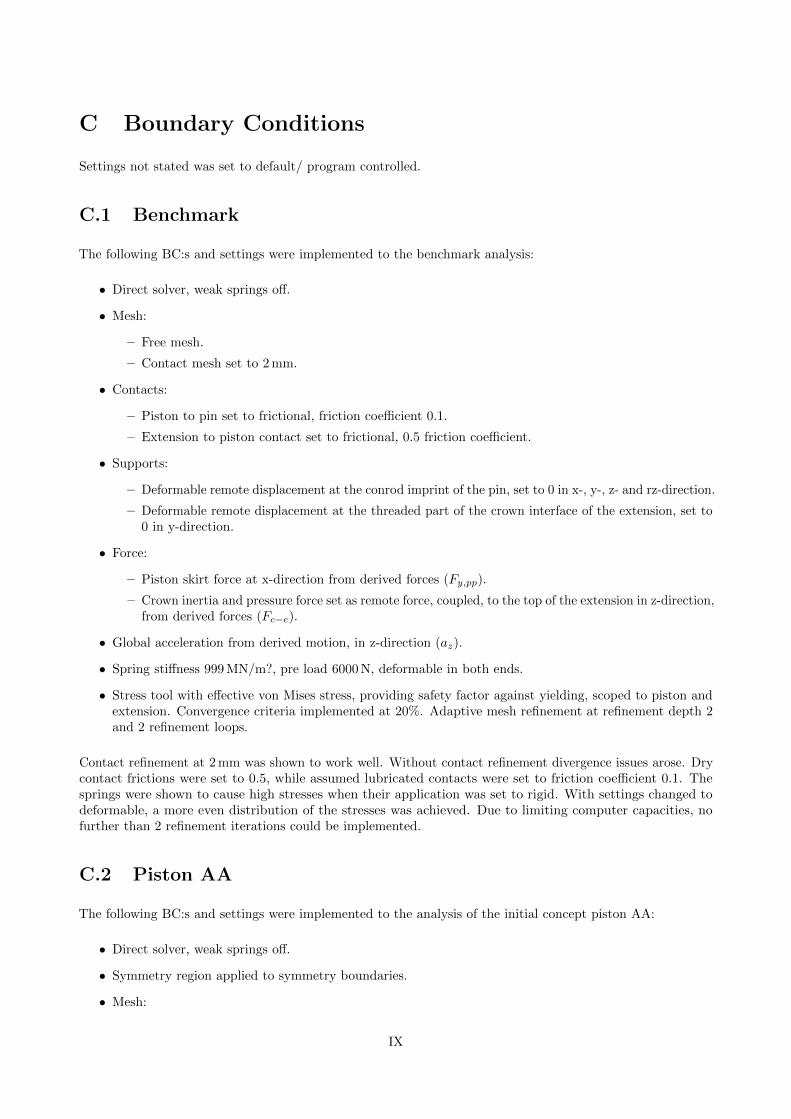
C Boundary Conditions
Settings not stated was set to default/ program controlled.
C.1 Benchmark
The following BC:s and settings were implemented to the benchmark analysis:
• Direct solver, weak springs off.
• Mesh:
– Free mesh.
– Contact mesh set to 2 mm.
• Contacts:
– Piston to pin set to frictional, friction coefficient 0.1.
– Extension to piston contact set to frictional, 0.5 friction coefficient.
• Supports:
– Deformable remote displacement at the conrod imprint of the pin, set to 0 in x-, y-, z- and rz-direction.
– Deformable remote displacement at the threaded part of the crown interface of the extension, set to0 in y-direction.
• Force:
– Piston skirt force at x-direction from derived forces (Fy,pp).
– Crown inertia and pressure force set as remote force, coupled, to the top of the extension in z-direction,from derived forces (Fc−e).
• Global acceleration from derived motion, in z-direction (az).
• Spring stiffness 999 MN/m?, pre load 6000 N, deformable in both ends.
• Stress tool with effective von Mises stress, providing safety factor against yielding, scoped to piston andextension. Convergence criteria implemented at 20%. Adaptive mesh refinement at refinement depth 2and 2 refinement loops.
Contact refinement at 2 mm was shown to work well. Without contact refinement divergence issues arose. Drycontact frictions were set to 0.5, while assumed lubricated contacts were set to friction coefficient 0.1. Thesprings were shown to cause high stresses when their application was set to rigid. With settings changed todeformable, a more even distribution of the stresses was achieved. Due to limiting computer capacities, nofurther than 2 refinement iterations could be implemented.
C.2 Piston AA
The following BC:s and settings were implemented to the analysis of the initial concept piston AA:
• Direct solver, weak springs off.
• Symmetry region applied to symmetry boundaries.
• Mesh:
IX
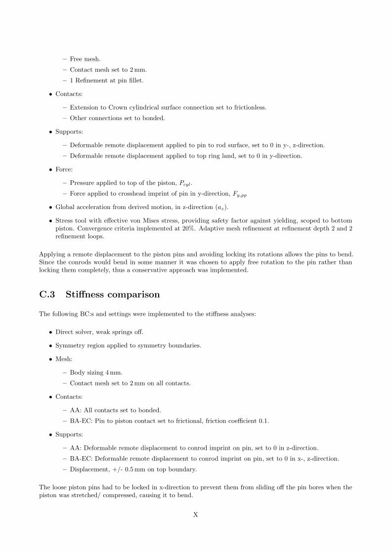
– Free mesh.
– Contact mesh set to 2 mm.
– 1 Refinement at pin fillet.
• Contacts:
– Extension to Crown cylindrical surface connection set to frictionless.
– Other connections set to bonded.
• Supports:
– Deformable remote displacement applied to pin to rod surface, set to 0 in y-, z-direction.
– Deformable remote displacement applied to top ring land, set to 0 in y-direction.
• Force:
– Pressure applied to top of the piston, Pcyl.
– Force applied to crosshead imprint of pin in y-direction, Fy,pp
• Global acceleration from derived motion, in z-direction (az).
• Stress tool with effective von Mises stress, providing safety factor against yielding, scoped to bottompiston. Convergence criteria implemented at 20%. Adaptive mesh refinement at refinement depth 2 and 2refinement loops.
Applying a remote displacement to the piston pins and avoiding locking its rotations allows the pins to bend.Since the conrods would bend in some manner it was chosen to apply free rotation to the pin rather thanlocking them completely, thus a conservative approach was implemented.
C.3 Stiffness comparison
The following BC:s and settings were implemented to the stiffness analyses:
• Direct solver, weak springs off.
• Symmetry region applied to symmetry boundaries.
• Mesh:
– Body sizing 4 mm.
– Contact mesh set to 2 mm on all contacts.
• Contacts:
– AA: All contacts set to bonded.
– BA-EC: Pin to piston contact set to frictional, friction coefficient 0.1.
• Supports:
– AA: Deformable remote displacement to conrod imprint on pin, set to 0 in z-direction.
– BA-EC: Deformable remote displacement to conrod imprint on pin, set to 0 in x-, z-direction.
– Displacement, +/- 0.5 mm on top boundary.
The loose piston pins had to be locked in x-direction to prevent them from sliding off the pin bores when thepiston was stretched/ compressed, causing it to bend.
X
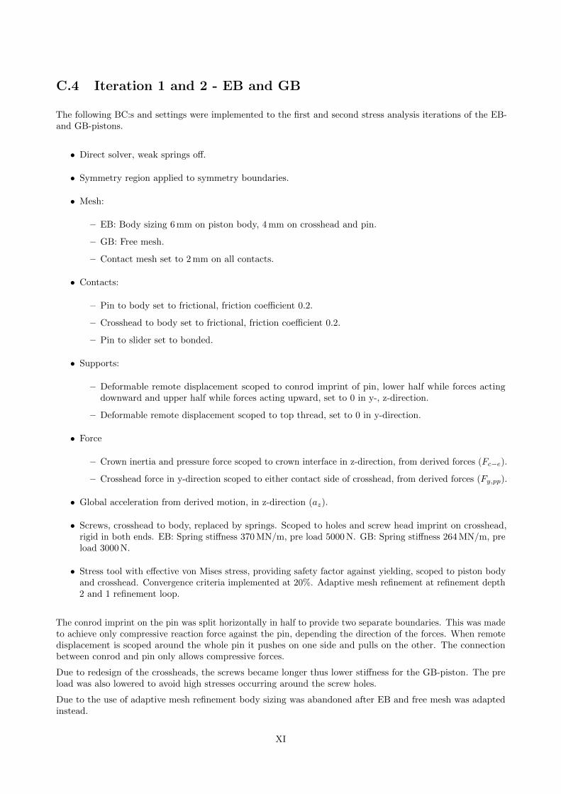
C.4 Iteration 1 and 2 - EB and GB
The following BC:s and settings were implemented to the first and second stress analysis iterations of the EB-and GB-pistons.
• Direct solver, weak springs off.
• Symmetry region applied to symmetry boundaries.
• Mesh:
– EB: Body sizing 6 mm on piston body, 4 mm on crosshead and pin.
– GB: Free mesh.
– Contact mesh set to 2 mm on all contacts.
• Contacts:
– Pin to body set to frictional, friction coefficient 0.2.
– Crosshead to body set to frictional, friction coefficient 0.2.
– Pin to slider set to bonded.
• Supports:
– Deformable remote displacement scoped to conrod imprint of pin, lower half while forces actingdownward and upper half while forces acting upward, set to 0 in y-, z-direction.
– Deformable remote displacement scoped to top thread, set to 0 in y-direction.
• Force
– Crown inertia and pressure force scoped to crown interface in z-direction, from derived forces (Fc−e).
– Crosshead force in y-direction scoped to either contact side of crosshead, from derived forces (Fy,pp).
• Global acceleration from derived motion, in z-direction (az).
• Screws, crosshead to body, replaced by springs. Scoped to holes and screw head imprint on crosshead,rigid in both ends. EB: Spring stiffness 370 MN/m, pre load 5000 N. GB: Spring stiffness 264 MN/m, preload 3000 N.
• Stress tool with effective von Mises stress, providing safety factor against yielding, scoped to piston bodyand crosshead. Convergence criteria implemented at 20%. Adaptive mesh refinement at refinement depth2 and 1 refinement loop.
The conrod imprint on the pin was split horizontally in half to provide two separate boundaries. This was madeto achieve only compressive reaction force against the pin, depending the direction of the forces. When remotedisplacement is scoped around the whole pin it pushes on one side and pulls on the other. The connectionbetween conrod and pin only allows compressive forces.
Due to redesign of the crossheads, the screws became longer thus lower stiffness for the GB-piston. The preload was also lowered to avoid high stresses occurring around the screw holes.
Due to the use of adaptive mesh refinement body sizing was abandoned after EB and free mesh was adaptedinstead.
XI

C.5 Iteration 3 - GD
The following BC:s and settings were implemented to the third stress analysis iteration of the GD-piston.
• Direct solver, weak springs off.
• Symmetry region applied to symmetry boundaries.
• Mesh:
– Free mesh.
– Contact mesh set to 2 mm on all contacts.
• Contacts:
– Conrod to pin set to frictional, friction coeff. 0.1 (assumed lubricated).
– Conrod to body set to frictional, friction coeff. 0.1 (assumed lubricated).
– Pin to body set to frictional, friction coeff. 0.5 (assumed dry).
– Pin-Ball-Body set to bonded.
– Crosshead to body set to frictional, friction coefficient 0.5 (assumed dry).
• Supports:
– Coupled remote displacement scoped to conrod bearing, set to 0 in y-, x-, z-direction.
– Deformable remote displacement scoped to top thread, set to 0 in y-direction.
– Compression only support scoped to compression side of crosshead.
• Force
– Crown inertia and pressure force scoped to crown interface in z-direction, from derived forces (Fc−e).
– Conrod small end inertia force, scoped to conrod small end, in y-direction, from derived forces(Fy,pp,rod).
• Global acceleration from derived motion, in z-direction (az).
• Screws, crosshead to body, replaced by springs. Scoped to holes and screw head imprint on crosshead,deformable in both ends. Spring stiffness 264 MN/m, pre load 3000 N.
• Stress tool with effective von Mises stress, providing safety factor against yielding, scoped to piston bodyand crosshead. Convergence criteria implemented at 10%. Adaptive mesh refinement at refinement depth3 and 2 refinement loop.
XII
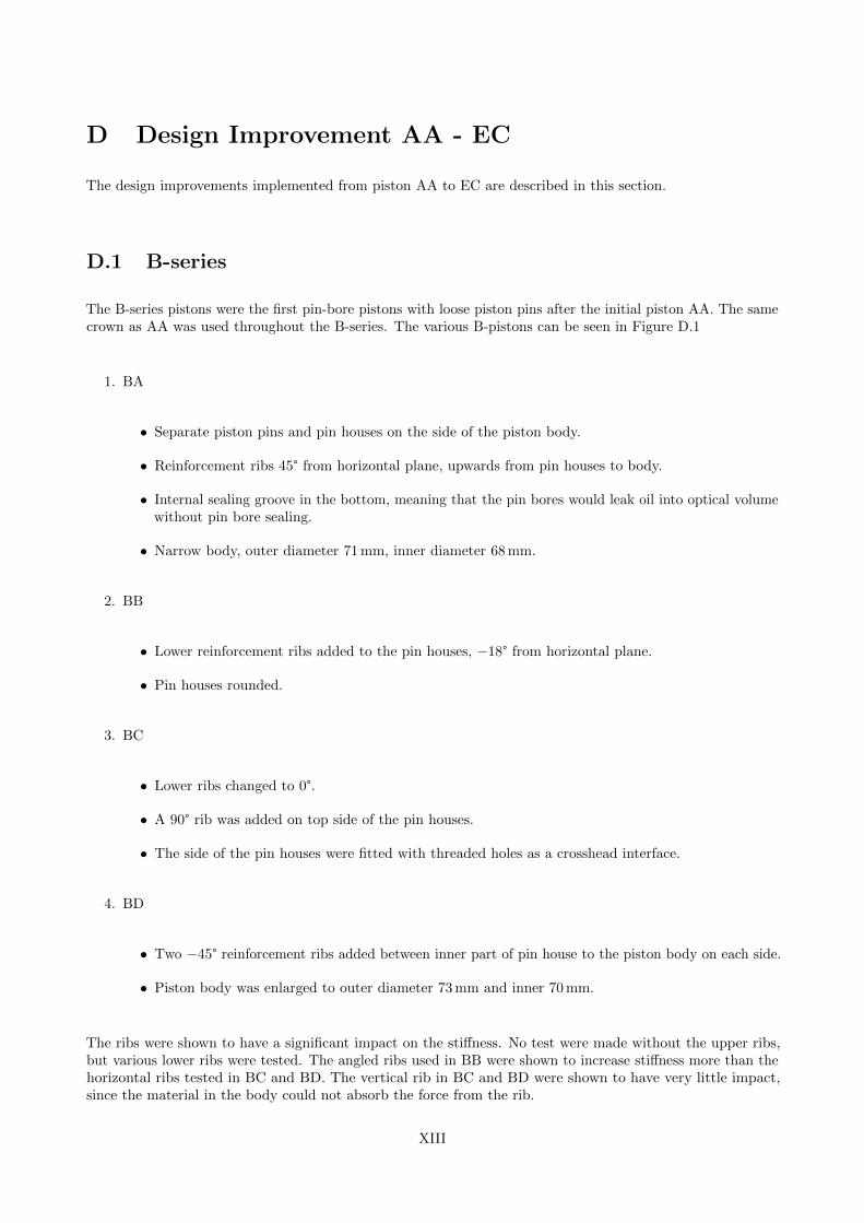
D Design Improvement AA - EC
The design improvements implemented from piston AA to EC are described in this section.
D.1 B-series
The B-series pistons were the first pin-bore pistons with loose piston pins after the initial piston AA. The samecrown as AA was used throughout the B-series. The various B-pistons can be seen in Figure D.1
1. BA
• Separate piston pins and pin houses on the side of the piston body.
• Reinforcement ribs 45° from horizontal plane, upwards from pin houses to body.
• Internal sealing groove in the bottom, meaning that the pin bores would leak oil into optical volumewithout pin bore sealing.
• Narrow body, outer diameter 71 mm, inner diameter 68 mm.
2. BB
• Lower reinforcement ribs added to the pin houses, −18° from horizontal plane.
• Pin houses rounded.
3. BC
• Lower ribs changed to 0°.
• A 90° rib was added on top side of the pin houses.
• The side of the pin houses were fitted with threaded holes as a crosshead interface.
4. BD
• Two −45° reinforcement ribs added between inner part of pin house to the piston body on each side.
• Piston body was enlarged to outer diameter 73 mm and inner 70 mm.
The ribs were shown to have a significant impact on the stiffness. No test were made without the upper ribs,but various lower ribs were tested. The angled ribs used in BB were shown to increase stiffness more than thehorizontal ribs tested in BC and BD. The vertical rib in BC and BD were shown to have very little impact,since the material in the body could not absorb the force from the rib.
XIII
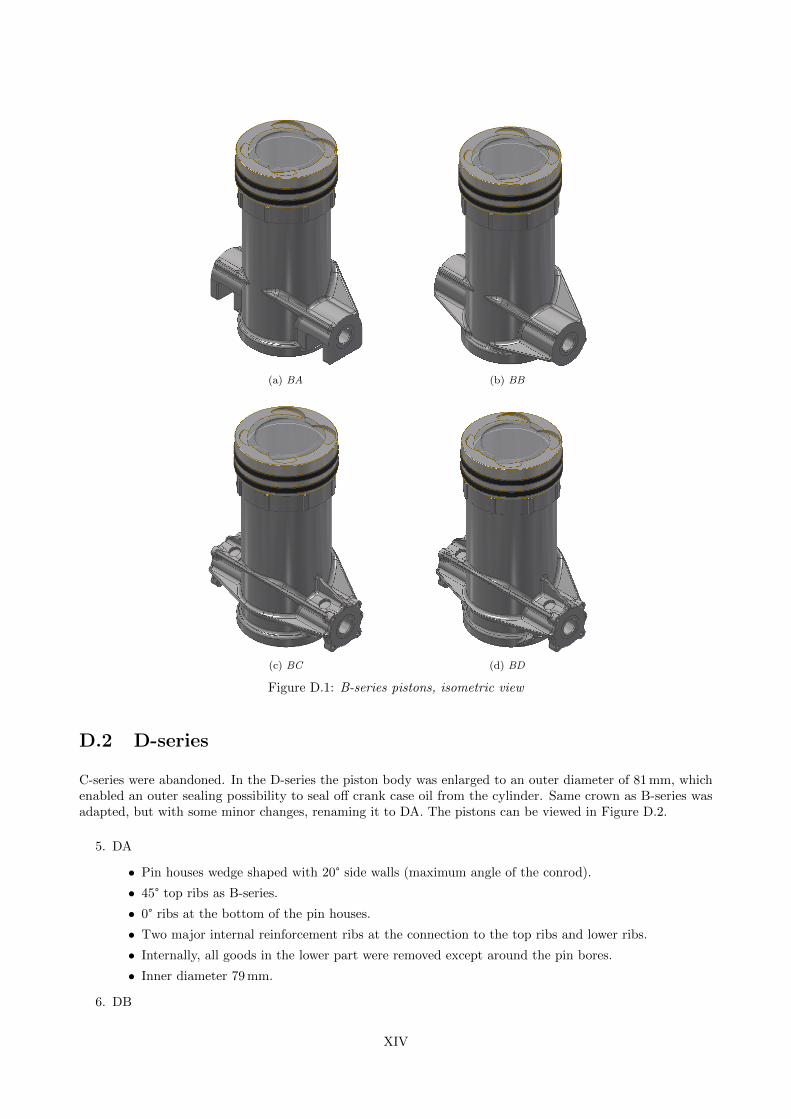
(a) BA (b) BB
(c) BC (d) BD
Figure D.1: B-series pistons, isometric view
D.2 D-series
C-series were abandoned. In the D-series the piston body was enlarged to an outer diameter of 81 mm, whichenabled an outer sealing possibility to seal off crank case oil from the cylinder. Same crown as B-series wasadapted, but with some minor changes, renaming it to DA. The pistons can be viewed in Figure D.2.
5. DA
• Pin houses wedge shaped with 20° side walls (maximum angle of the conrod).
• 45° top ribs as B-series.
• 0° ribs at the bottom of the pin houses.
• Two major internal reinforcement ribs at the connection to the top ribs and lower ribs.
• Internally, all goods in the lower part were removed except around the pin bores.
• Inner diameter 79 mm.
6. DB
XIV
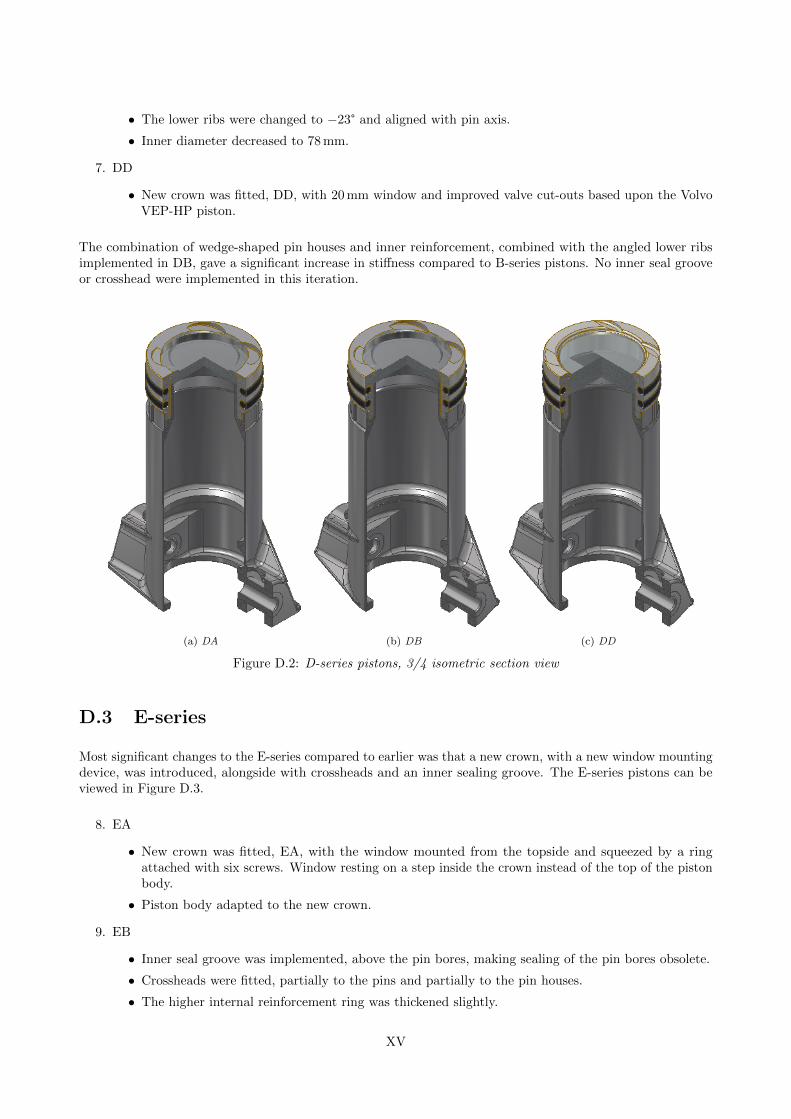
• The lower ribs were changed to −23° and aligned with pin axis.
• Inner diameter decreased to 78 mm.
7. DD
• New crown was fitted, DD, with 20 mm window and improved valve cut-outs based upon the VolvoVEP-HP piston.
The combination of wedge-shaped pin houses and inner reinforcement, combined with the angled lower ribsimplemented in DB, gave a significant increase in stiffness compared to B-series pistons. No inner seal grooveor crosshead were implemented in this iteration.
(a) DA (b) DB (c) DD
Figure D.2: D-series pistons, 3/4 isometric section view
D.3 E-series
Most significant changes to the E-series compared to earlier was that a new crown, with a new window mountingdevice, was introduced, alongside with crossheads and an inner sealing groove. The E-series pistons can beviewed in Figure D.3.
8. EA
• New crown was fitted, EA, with the window mounted from the topside and squeezed by a ringattached with six screws. Window resting on a step inside the crown instead of the top of the pistonbody.
• Piston body adapted to the new crown.
9. EB
• Inner seal groove was implemented, above the pin bores, making sealing of the pin bores obsolete.
• Crossheads were fitted, partially to the pins and partially to the pin houses.
• The higher internal reinforcement ring was thickened slightly.
XV
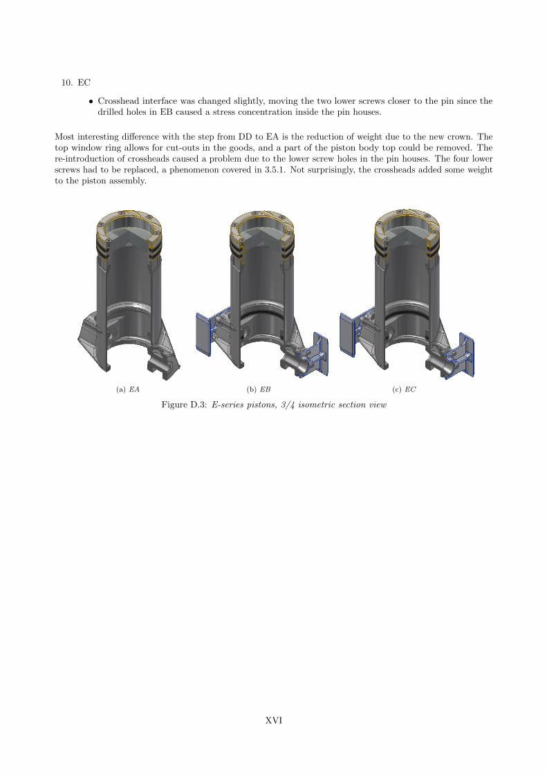
10. EC
• Crosshead interface was changed slightly, moving the two lower screws closer to the pin since thedrilled holes in EB caused a stress concentration inside the pin houses.
Most interesting difference with the step from DD to EA is the reduction of weight due to the new crown. Thetop window ring allows for cut-outs in the goods, and a part of the piston body top could be removed. There-introduction of crossheads caused a problem due to the lower screw holes in the pin houses. The four lowerscrews had to be replaced, a phenomenon covered in 3.5.1. Not surprisingly, the crossheads added some weightto the piston assembly.
(a) EA (b) EB (c) EC
Figure D.3: E-series pistons, 3/4 isometric section view
XVI
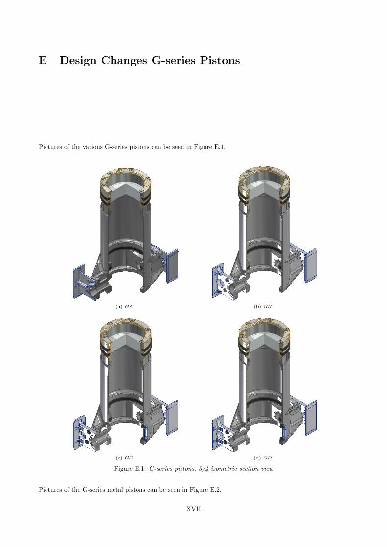
E Design Changes G-series Pistons
Pictures of the various G-series pistons can be seen in Figure E.1.
(a) GA (b) GB
(c) GC (d) GD
Figure E.1: G-series pistons, 3/4 isometric section view
Pictures of the G-series metal pistons can be seen in Figure E.2.
XVII
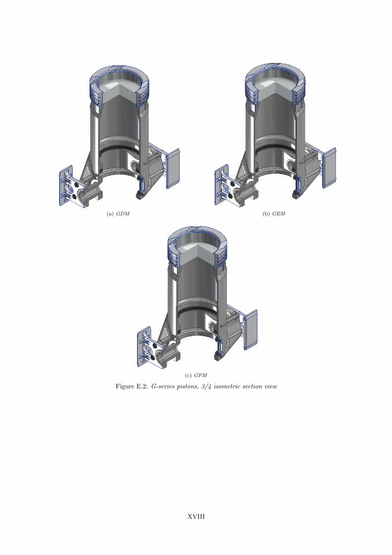
(a) GDM (b) GEM
(c) GFM
Figure E.2: G-series pistons, 3/4 isometric section view
XVIII
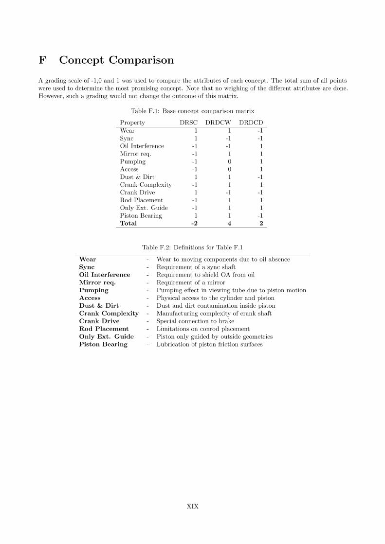
F Concept Comparison
A grading scale of -1,0 and 1 was used to compare the attributes of each concept. The total sum of all pointswere used to determine the most promising concept. Note that no weighing of the different attributes are done.However, such a grading would not change the outcome of this matrix.
Table F.1: Base concept comparison matrix
Property DRSC DRDCW DRDCDWear 1 1 -1Sync 1 -1 -1Oil Interference -1 -1 1Mirror req. -1 1 1Pumping -1 0 1Access -1 0 1Dust & Dirt 1 1 -1Crank Complexity -1 1 1Crank Drive 1 -1 -1Rod Placement -1 1 1Only Ext. Guide -1 1 1Piston Bearing 1 1 -1Total -2 4 2
Table F.2: Definitions for Table F.1
Wear - Wear to moving components due to oil absenceSync - Requirement of a sync shaftOil Interference - Requirement to shield OA from oilMirror req. - Requirement of a mirrorPumping - Pumping effect in viewing tube due to piston motionAccess - Physical access to the cylinder and pistonDust & Dirt - Dust and dirt contamination inside pistonCrank Complexity - Manufacturing complexity of crank shaftCrank Drive - Special connection to brakeRod Placement - Limitations on conrod placementOnly Ext. Guide - Piston only guided by outside geometriesPiston Bearing - Lubrication of piston friction surfaces
XIX