Embed Size (px)
Citation preview

Diesel Mechanic: Module OSS
- Mining Qualifications Authority - All rights reserved
Created : 01 February 2003
Revised : March 2015
Owner : Learnership Department
First Published : March 2003
Revision No: 002
TRG 9
Page 1 of 83
DIESEL MECHANIC
CODE: OSS
REPAIR A STEERING
SYSTEM
Diesel Mechanic: Module OSS
- Mining Qualifications Authority - All rights reserved
Created : 01 February 2003
Revised : March 2015
Owner : Learnership Department
First Published : March 2003
Revision No: 002
TRG 9
Page 2 of 83
INDEX The following elements are contained in this learning guide:
TOPIC PAGE NUMBER
Index 2
Module Objective and Additional resources 3
HIAC 4 - 5
Repair a steering system 6
Practice 7
Diesel Mechanic: Module OSS
- Mining Qualifications Authority - All rights reserved
Created : 01 February 2003
Revised : March 2015
Owner : Learnership Department
First Published : March 2003
Revision No: 002
TRG 9
Page 3 of 83
OBJECTIVE What you must do 1. Identify the different types of steering units. 2. Dismantle, clean and assemble the ball and nut steering unit. 3. Adjust and centralise the steering. 4. Adjust the front wheel alignment. 5. Complete a Condition Report on the steering unit. What you will be given 1. The steering geometry for: a) Camber b) Caster c) Toe-in d) Kingpin inclination (KPI) How well you must do it 1. The different types of steering units must be correctly identified. 2. There must not be any damage to any fasteners. 3. There must not be any damage to any equipment. 4. All the adjustments on the steering unit must comply with the limits specified in the
Workshop Manual. 5. The wheel alignment must be adjusted to specifications. 6. Excessive toe-in and toe-out must be filled in. 7. The condition report must be filled in. ADDITIONAL RESOURCES 1. Your Instructor. 2. Workshop Manual for the vehicle.
Diesel Mechanic: Module OSS
- Mining Qualifications Authority - All rights reserved
Created : 01 February 2003
Revised : March 2015
Owner : Learnership Department
First Published : March 2003
Revision No: 002
TRG 9
Page 4 of 83
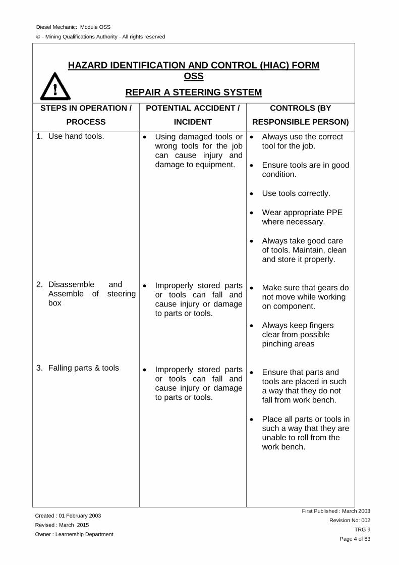
HAZARD IDENTIFICATION AND CONTROL (HIAC) FORM OSS
REPAIR A STEERING SYSTEM
STEPS IN OPERATION /
PROCESS
POTENTIAL ACCIDENT /
INCIDENT
CONTROLS (BY
RESPONSIBLE PERSON)
1. Use hand tools. 2. Disassemble and
Assemble of steering box
3. Falling parts & tools
Using damaged tools or wrong tools for the job can cause injury and damage to equipment.
Improperly stored parts or tools can fall and cause injury or damage to parts or tools.
Improperly stored parts or tools can fall and cause injury or damage to parts or tools.
Always use the correct tool for the job.
Ensure tools are in good condition.
Use tools correctly.
Wear appropriate PPE where necessary.
Always take good care of tools. Maintain, clean and store it properly.
Make sure that gears do not move while working on component.
Always keep fingers clear from possible pinching areas
Ensure that parts and tools are placed in such a way that they do not fall from work bench.
Place all parts or tools in such a way that they are unable to roll from the work bench.
Diesel Mechanic: Module OSS
- Mining Qualifications Authority - All rights reserved
Created : 01 February 2003
Revised : March 2015
Owner : Learnership Department
First Published : March 2003
Revision No: 002
TRG 9
Page 5 of 83
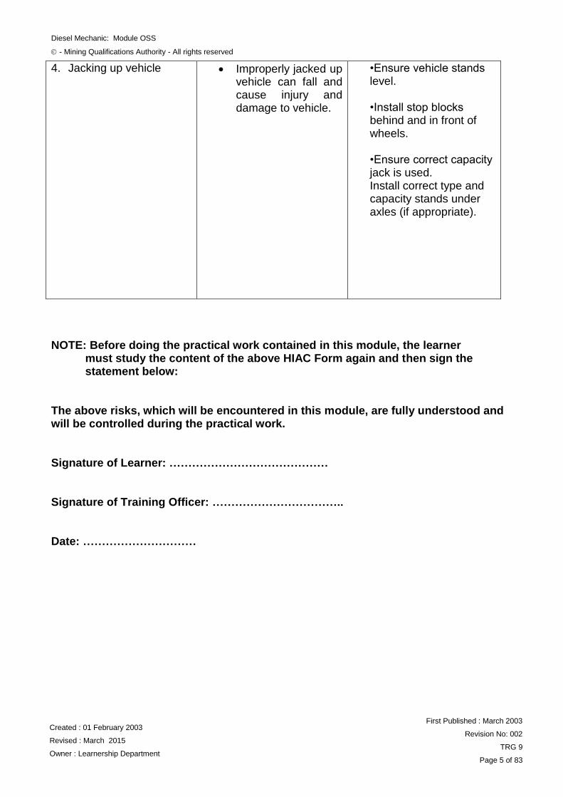
4. Jacking up vehicle
Improperly jacked up vehicle can fall and cause injury and damage to vehicle.
•Ensure vehicle stands level. •Install stop blocks behind and in front of wheels. •Ensure correct capacity jack is used. Install correct type and capacity stands under axles (if appropriate).
NOTE: Before doing the practical work contained in this module, the learner must study the content of the above HIAC Form again and then sign the statement below: The above risks, which will be encountered in this module, are fully understood and will be controlled during the practical work. Signature of Learner: …………………………………… Signature of Training Officer: …………………………….. Date: …………………………
Diesel Mechanic: Module OSS
- Mining Qualifications Authority - All rights reserved
Created : 01 February 2003
Revised : March 2015
Owner : Learnership Department
First Published : March 2003
Revision No: 002
TRG 9
Page 6 of 83
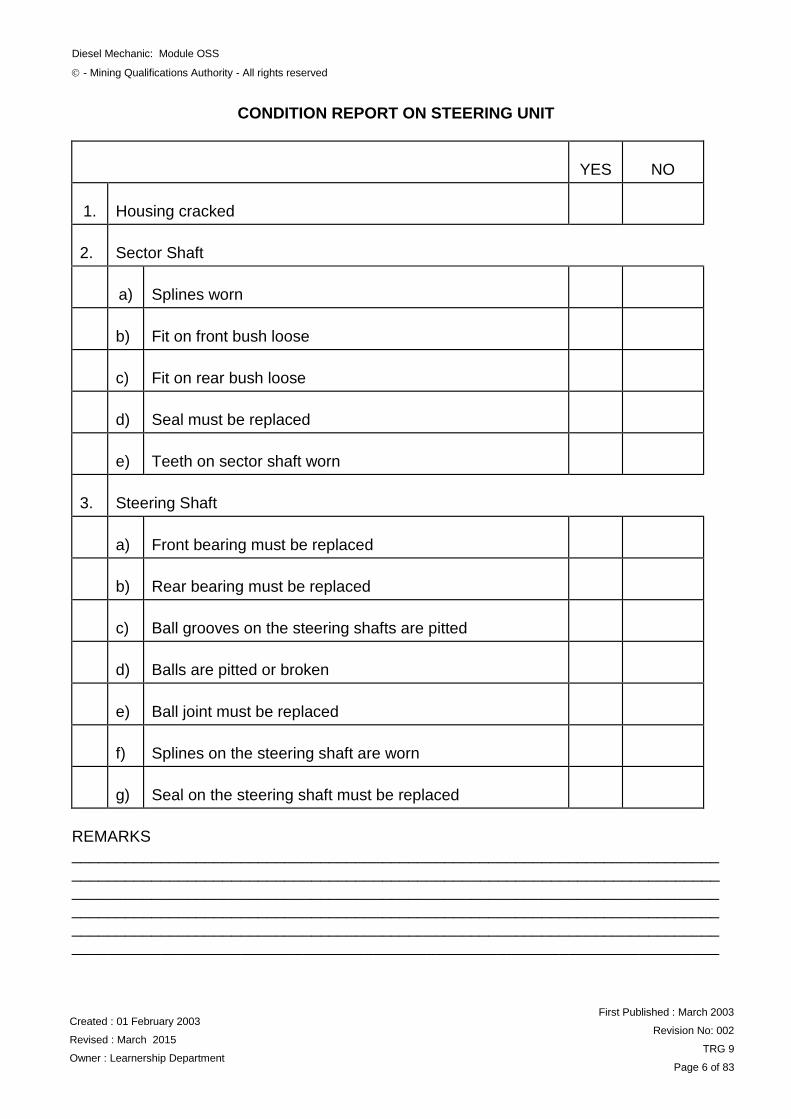
CONDITION REPORT ON STEERING UNIT
YES
NO
1.
Housing cracked
2.
Sector Shaft
a)
Splines worn
b)
Fit on front bush loose
c)
Fit on rear bush loose
d)
Seal must be replaced
e)
Teeth on sector shaft worn
3.
Steering Shaft
a)
Front bearing must be replaced
b)
Rear bearing must be replaced
c)
Ball grooves on the steering shafts are pitted
d)
Balls are pitted or broken
e)
Ball joint must be replaced
f)
Splines on the steering shaft are worn
g)
Seal on the steering shaft must be replaced
REMARKS _________________________________________________________________________ __________________________________________________________________________________________________________________________________________________ _________________________________________________________________________ _________________________________________________________________________ _________________________________________________________________________
Diesel Mechanic: Module OSS
- Mining Qualifications Authority - All rights reserved
Created : 01 February 2003
Revised : March 2015
Owner : Learnership Department
First Published : March 2003
Revision No: 002
TRG 9
Page 7 of 83
REPAIR A STEERING SYSTEM
ITEM / TASK: Introduction
DESCRIPTION:
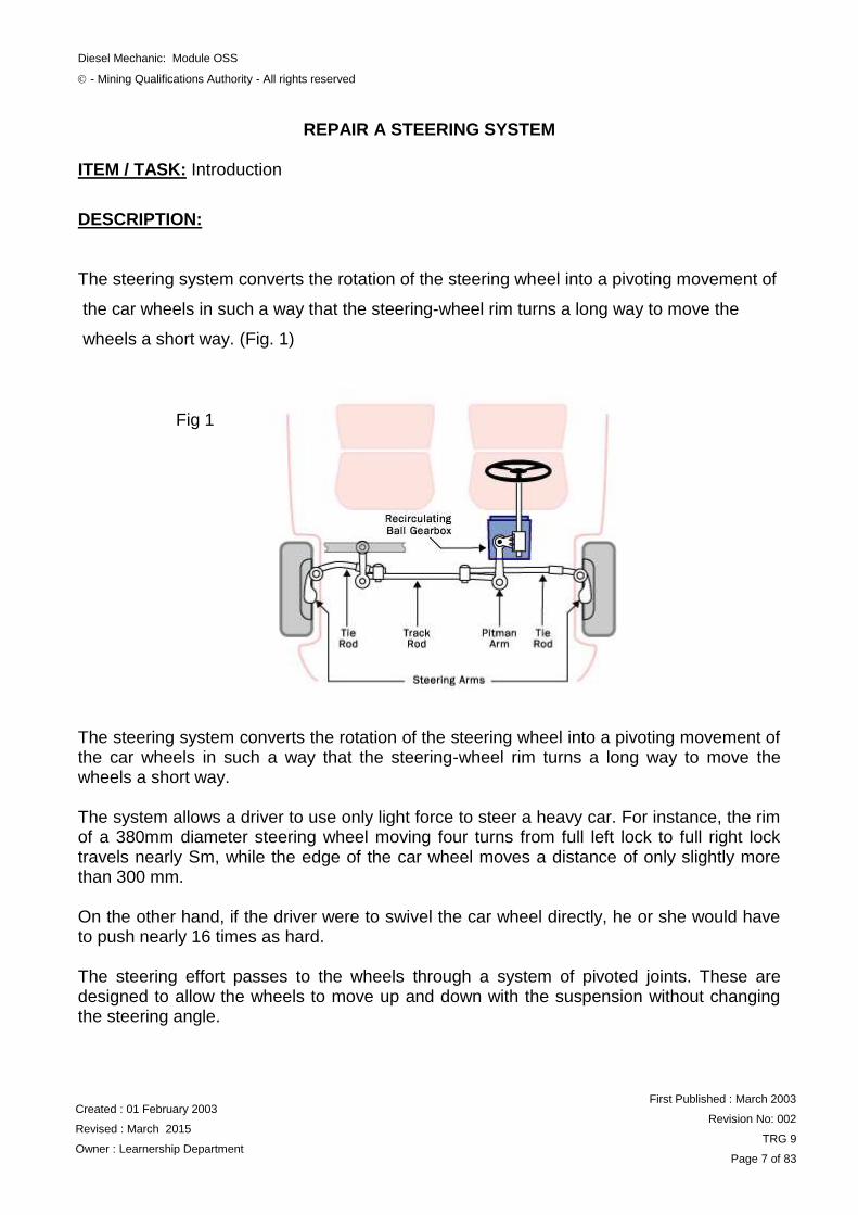
The steering system converts the rotation of the steering wheel into a pivoting movement of
the car wheels in such a way that the steering-wheel rim turns a long way to move the
wheels a short way. (Fig. 1)
The steering system converts the rotation of the steering wheel into a pivoting movement of the car wheels in such a way that the steering-wheel rim turns a long way to move the wheels a short way. The system allows a driver to use only light force to steer a heavy car. For instance, the rim of a 380mm diameter steering wheel moving four turns from full left lock to full right lock travels nearly Sm, while the edge of the car wheel moves a distance of only slightly more than 300 mm. On the other hand, if the driver were to swivel the car wheel directly, he or she would have to push nearly 16 times as hard. The steering effort passes to the wheels through a system of pivoted joints. These are designed to allow the wheels to move up and down with the suspension without changing the steering angle.
Fig 1
Diesel Mechanic: Module OSS
- Mining Qualifications Authority - All rights reserved
Created : 01 February 2003
Revised : March 2015
Owner : Learnership Department
First Published : March 2003
Revision No: 002
TRG 9
Page 8 of 83
The joints also ensure that, when cornering, the inner front wheel — which has to travel round a tighter curve than the outer one — becomes more sharply angled. Over the past two decades, a variety of different steering mechanisms have been used by vehicle manufacturers, the two main systems being the steering box (also known as worm-and-sector) and the rack and pinion. There have been many varieties of the steering-box system but these have gradually disappeared in favour of the reticulating-ball type. Modern car manufacturers clearly prefer the rack- and-pinion system. On large cars, either system may be power assisted to reduce further the effort needed to move it, especially when the car is moving slowly.
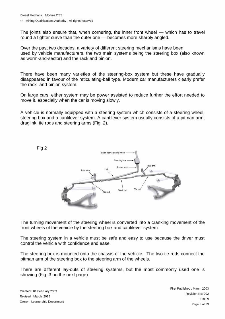
A vehicle is normally equipped with a steering system which consists of a steering wheel, steering box and a cantilever system. A cantilever system usually consists of a pitman arm, draglink, tie rods and steering arms (Fig. 2). The turning movement of the steering wheel is converted into a cranking movement of the front wheels of the vehicle by the steering box and cantilever system. The steering system in a vehicle must be safe and easy to use because the driver must control the vehicle with confidence and ease. The steering box is mounted onto the chassis of the vehicle. The two tie rods connect the pitman arm of the steering box to the steering arm of the wheels. There are different lay-outs of steering systems, but the most commonly used one is showing (Fig. 3 on the next page)
Fig 2
Diesel Mechanic: Module OSS
- Mining Qualifications Authority - All rights reserved
Created : 01 February 2003
Revised : March 2015
Owner : Learnership Department
First Published : March 2003
Revision No: 002
TRG 9
Page 9 of 83
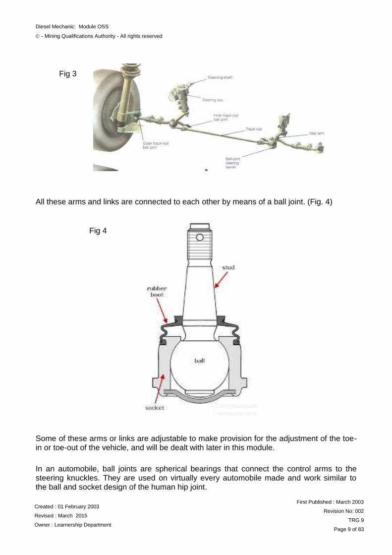
All these arms and links are connected to each other by means of a ball joint. (Fig. 4)
Some of these arms or links are adjustable to make provision for the adjustment of the toe-in or toe-out of the vehicle, and will be dealt with later in this module.
In an automobile, ball joints are spherical bearings that connect the control arms to the steering knuckles. They are used on virtually every automobile made and work similar to the ball and socket design of the human hip joint.
Fig 3
Fig 4
Diesel Mechanic: Module OSS
- Mining Qualifications Authority - All rights reserved
Created : 01 February 2003
Revised : March 2015
Owner : Learnership Department
First Published : March 2003
Revision No: 002
TRG 9
Page 10 of 83
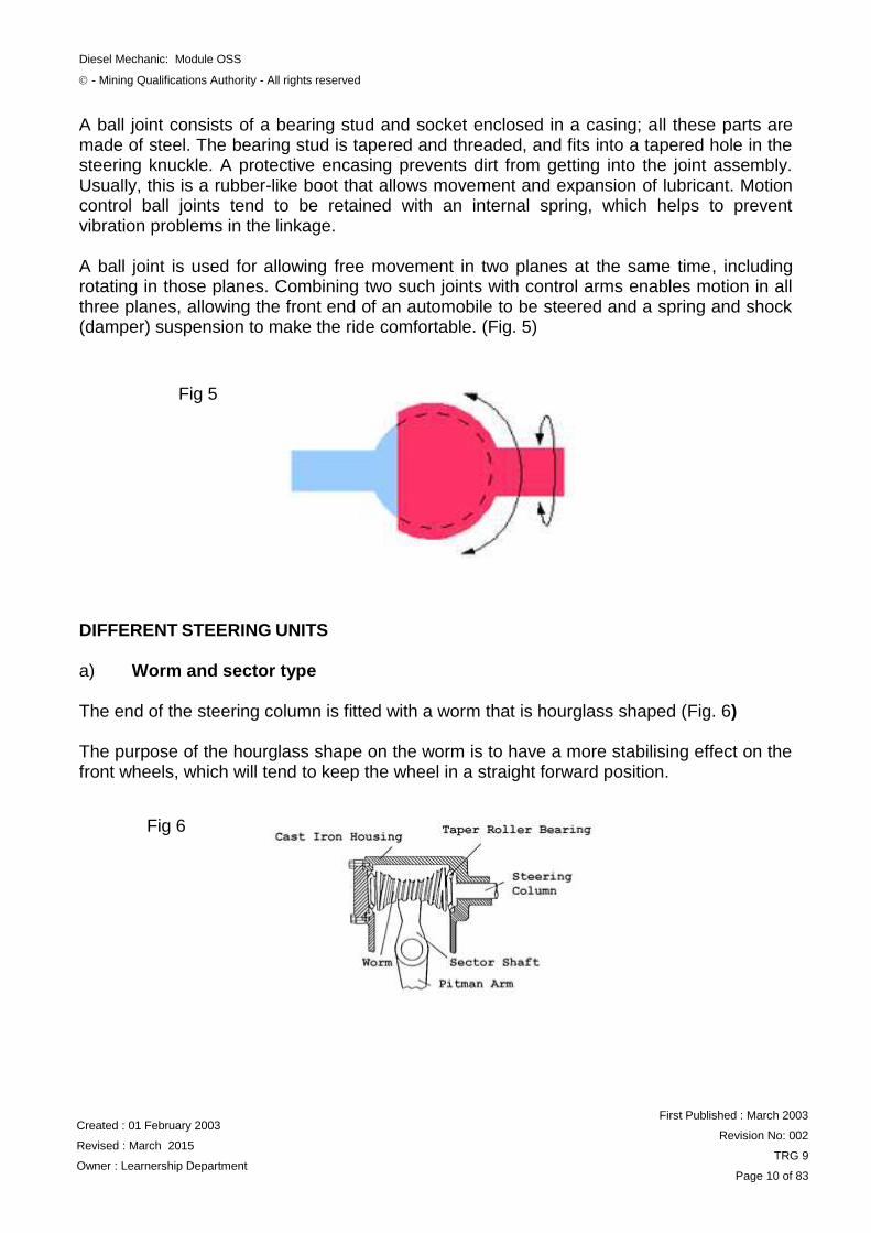
A ball joint consists of a bearing stud and socket enclosed in a casing; all these parts are made of steel. The bearing stud is tapered and threaded, and fits into a tapered hole in the steering knuckle. A protective encasing prevents dirt from getting into the joint assembly. Usually, this is a rubber-like boot that allows movement and expansion of lubricant. Motion control ball joints tend to be retained with an internal spring, which helps to prevent vibration problems in the linkage. A ball joint is used for allowing free movement in two planes at the same time, including rotating in those planes. Combining two such joints with control arms enables motion in all three planes, allowing the front end of an automobile to be steered and a spring and shock (damper) suspension to make the ride comfortable. (Fig. 5)
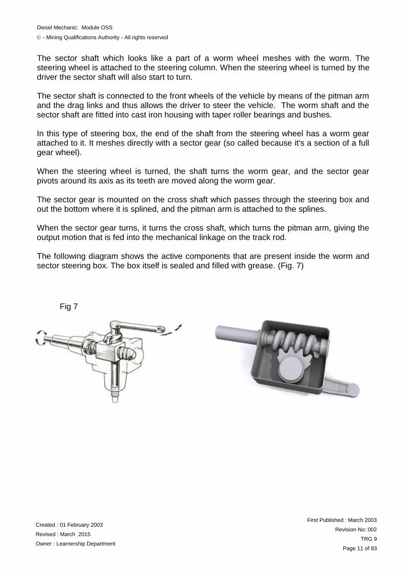
DIFFERENT STEERING UNITS a) Worm and sector type The end of the steering column is fitted with a worm that is hourglass shaped (Fig. 6) The purpose of the hourglass shape on the worm is to have a more stabilising effect on the front wheels, which will tend to keep the wheel in a straight forward position.
Fig 5
Fig 6
Diesel Mechanic: Module OSS
- Mining Qualifications Authority - All rights reserved
Created : 01 February 2003
Revised : March 2015
Owner : Learnership Department
First Published : March 2003
Revision No: 002
TRG 9
Page 11 of 83
The sector shaft which looks like a part of a worm wheel meshes with the worm. The steering wheel is attached to the steering column. When the steering wheel is turned by the driver the sector shaft will also start to turn. The sector shaft is connected to the front wheels of the vehicle by means of the pitman arm and the drag links and thus allows the driver to steer the vehicle. The worm shaft and the sector shaft are fitted into cast iron housing with taper roller bearings and bushes.
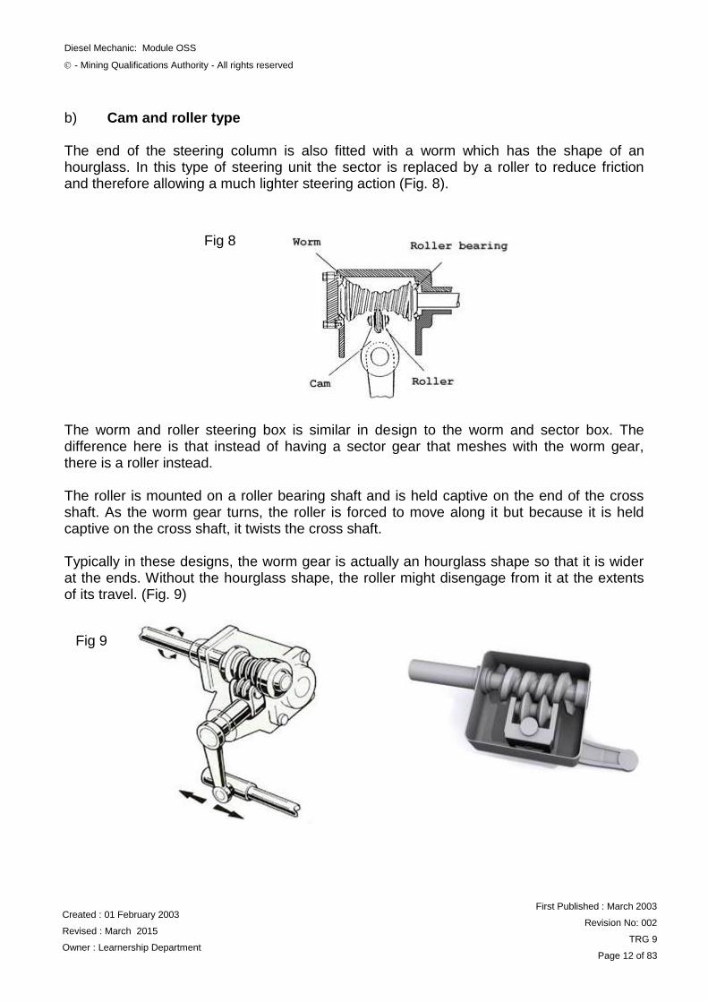
In this type of steering box, the end of the shaft from the steering wheel has a worm gear attached to it. It meshes directly with a sector gear (so called because it's a section of a full gear wheel). When the steering wheel is turned, the shaft turns the worm gear, and the sector gear pivots around its axis as its teeth are moved along the worm gear. The sector gear is mounted on the cross shaft which passes through the steering box and out the bottom where it is splined, and the pitman arm is attached to the splines. When the sector gear turns, it turns the cross shaft, which turns the pitman arm, giving the output motion that is fed into the mechanical linkage on the track rod. The following diagram shows the active components that are present inside the worm and sector steering box. The box itself is sealed and filled with grease. (Fig. 7)
Fig 7
Diesel Mechanic: Module OSS
- Mining Qualifications Authority - All rights reserved
Created : 01 February 2003
Revised : March 2015
Owner : Learnership Department
First Published : March 2003
Revision No: 002
TRG 9
Page 12 of 83
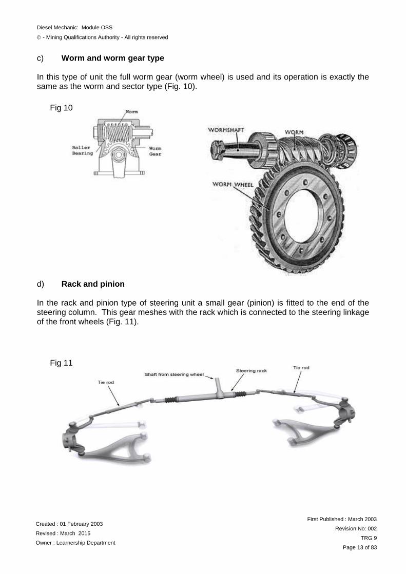
b) Cam and roller type The end of the steering column is also fitted with a worm which has the shape of an hourglass. In this type of steering unit the sector is replaced by a roller to reduce friction and therefore allowing a much lighter steering action (Fig. 8).
The worm and roller steering box is similar in design to the worm and sector box. The difference here is that instead of having a sector gear that meshes with the worm gear, there is a roller instead. The roller is mounted on a roller bearing shaft and is held captive on the end of the cross shaft. As the worm gear turns, the roller is forced to move along it but because it is held captive on the cross shaft, it twists the cross shaft. Typically in these designs, the worm gear is actually an hourglass shape so that it is wider at the ends. Without the hourglass shape, the roller might disengage from it at the extents of its travel. (Fig. 9)
Fig 8
Fig 9
Diesel Mechanic: Module OSS
- Mining Qualifications Authority - All rights reserved
Created : 01 February 2003
Revised : March 2015
Owner : Learnership Department
First Published : March 2003
Revision No: 002
TRG 9
Page 13 of 83
c) Worm and worm gear type In this type of unit the full worm gear (worm wheel) is used and its operation is exactly the same as the worm and sector type (Fig. 10). d) Rack and pinion In the rack and pinion type of steering unit a small gear (pinion) is fitted to the end of the steering column. This gear meshes with the rack which is connected to the steering linkage of the front wheels (Fig. 11).
Fig 10
Fig 11
Diesel Mechanic: Module OSS
- Mining Qualifications Authority - All rights reserved
Created : 01 February 2003
Revised : March 2015
Owner : Learnership Department
First Published : March 2003
Revision No: 002
TRG 9
Page 14 of 83
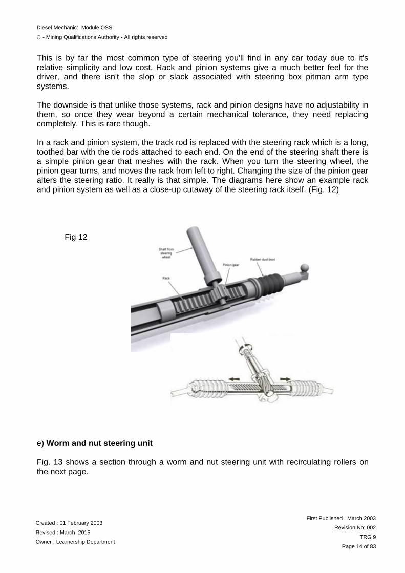
This is by far the most common type of steering you'll find in any car today due to it's relative simplicity and low cost. Rack and pinion systems give a much better feel for the driver, and there isn't the slop or slack associated with steering box pitman arm type systems. The downside is that unlike those systems, rack and pinion designs have no adjustability in them, so once they wear beyond a certain mechanical tolerance, they need replacing completely. This is rare though. In a rack and pinion system, the track rod is replaced with the steering rack which is a long, toothed bar with the tie rods attached to each end. On the end of the steering shaft there is a simple pinion gear that meshes with the rack. When you turn the steering wheel, the pinion gear turns, and moves the rack from left to right. Changing the size of the pinion gear alters the steering ratio. It really is that simple. The diagrams here show an example rack and pinion system as well as a close-up cutaway of the steering rack itself. (Fig. 12)
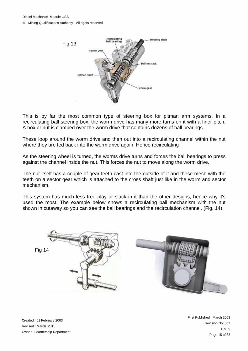
e) Worm and nut steering unit Fig. 13 shows a section through a worm and nut steering unit with recirculating rollers on the next page.
Fig 12
Diesel Mechanic: Module OSS
- Mining Qualifications Authority - All rights reserved
Created : 01 February 2003
Revised : March 2015
Owner : Learnership Department
First Published : March 2003
Revision No: 002
TRG 9
Page 15 of 83
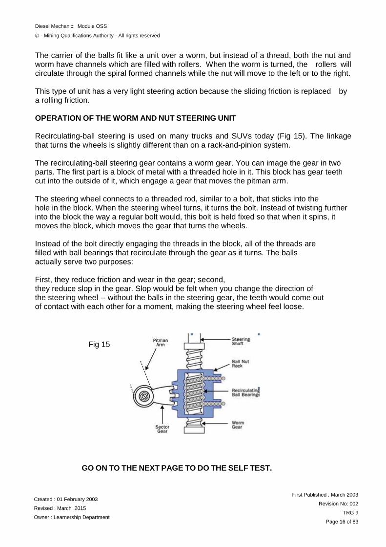
This is by far the most common type of steering box for pitman arm systems. In a recirculating ball steering box, the worm drive has many more turns on it with a finer pitch. A box or nut is clamped over the worm drive that contains dozens of ball bearings. These loop around the worm drive and then out into a recirculating channel within the nut where they are fed back into the worm drive again. Hence recirculating As the steering wheel is turned, the worms drive turns and forces the ball bearings to press against the channel inside the nut. This forces the nut to move along the worm drive. The nut itself has a couple of gear teeth cast into the outside of it and these mesh with the teeth on a sector gear which is attached to the cross shaft just like in the worm and sector mechanism. This system has much less free play or slack in it than the other designs, hence why it's used the most. The example below shows a recirculating ball mechanism with the nut shown in cutaway so you can see the ball bearings and the recirculation channel. (Fig. 14)
Fig 13
Fig 14
Diesel Mechanic: Module OSS
- Mining Qualifications Authority - All rights reserved
Created : 01 February 2003
Revised : March 2015
Owner : Learnership Department
First Published : March 2003
Revision No: 002
TRG 9
Page 16 of 83
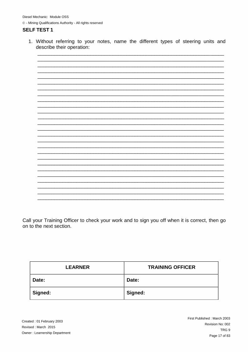
The carrier of the balls fit like a unit over a worm, but instead of a thread, both the nut and worm have channels which are filled with rollers. When the worm is turned, the rollers will circulate through the spiral formed channels while the nut will move to the left or to the right. This type of unit has a very light steering action because the sliding friction is replaced by a rolling friction. OPERATION OF THE WORM AND NUT STEERING UNIT Recirculating-ball steering is used on many trucks and SUVs today (Fig 15). The linkage that turns the wheels is slightly different than on a rack-and-pinion system. The recirculating-ball steering gear contains a worm gear. You can image the gear in two parts. The first part is a block of metal with a threaded hole in it. This block has gear teeth cut into the outside of it, which engage a gear that moves the pitman arm. The steering wheel connects to a threaded rod, similar to a bolt, that sticks into the hole in the block. When the steering wheel turns, it turns the bolt. Instead of twisting further into the block the way a regular bolt would, this bolt is held fixed so that when it spins, it moves the block, which moves the gear that turns the wheels. Instead of the bolt directly engaging the threads in the block, all of the threads are filled with ball bearings that recirculate through the gear as it turns. The balls actually serve two purposes: First, they reduce friction and wear in the gear; second, they reduce slop in the gear. Slop would be felt when you change the direction of the steering wheel -- without the balls in the steering gear, the teeth would come out of contact with each other for a moment, making the steering wheel feel loose.
GO ON TO THE NEXT PAGE TO DO THE SELF TEST.
Fig 15
Diesel Mechanic: Module OSS
- Mining Qualifications Authority - All rights reserved
Created : 01 February 2003
Revised : March 2015
Owner : Learnership Department
First Published : March 2003
Revision No: 002
TRG 9
Page 17 of 83
SELF TEST 1
1. Without referring to your notes, name the different types of steering units and describe their operation: ___________________________________________________________________ ___________________________________________________________________ ___________________________________________________________________ ______________________________________________________________________________________________________________________________________ ___________________________________________________________________ ___________________________________________________________________ ___________________________________________________________________
___________________________________________________________________ ___________________________________________________________________ ___________________________________________________________________
___________________________________________________________________ ___________________________________________________________________
___________________________________________________________________ ___________________________________________________________________
___________________________________________________________________ ___________________________________________________________________
___________________________________________________________________ ___________________________________________________________________ ___________________________________________________________________ ___________________________________________________________________ ___________________________________________________________________ ___________________________________________________________________ ___________________________________________________________________ ___________________________________________________________________ ___________________________________________________________________
Call your Training Officer to check your work and to sign you off when it is correct, then go on to the next section.
LEARNER
TRAINING OFFICER
Date:
Date:
Signed:
Signed:
Diesel Mechanic: Module OSS
- Mining Qualifications Authority - All rights reserved
Created : 01 February 2003
Revised : March 2015
Owner : Learnership Department
First Published : March 2003
Revision No: 002
TRG 9
Page 18 of 83
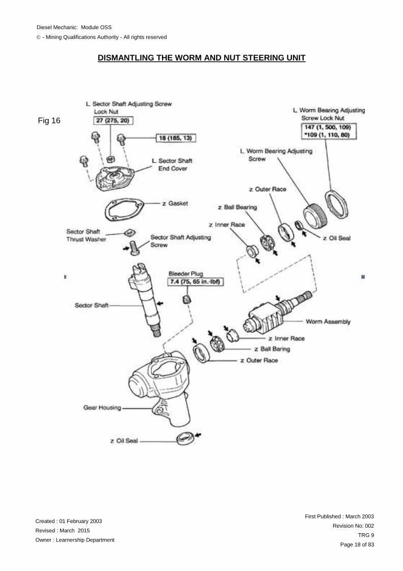
DISMANTLING THE WORM AND NUT STEERING UNIT
Fig 16
Diesel Mechanic: Module OSS
- Mining Qualifications Authority - All rights reserved
Created : 01 February 2003
Revised : March 2015
Owner : Learnership Department
First Published : March 2003
Revision No: 002
TRG 9
Page 19 of 83
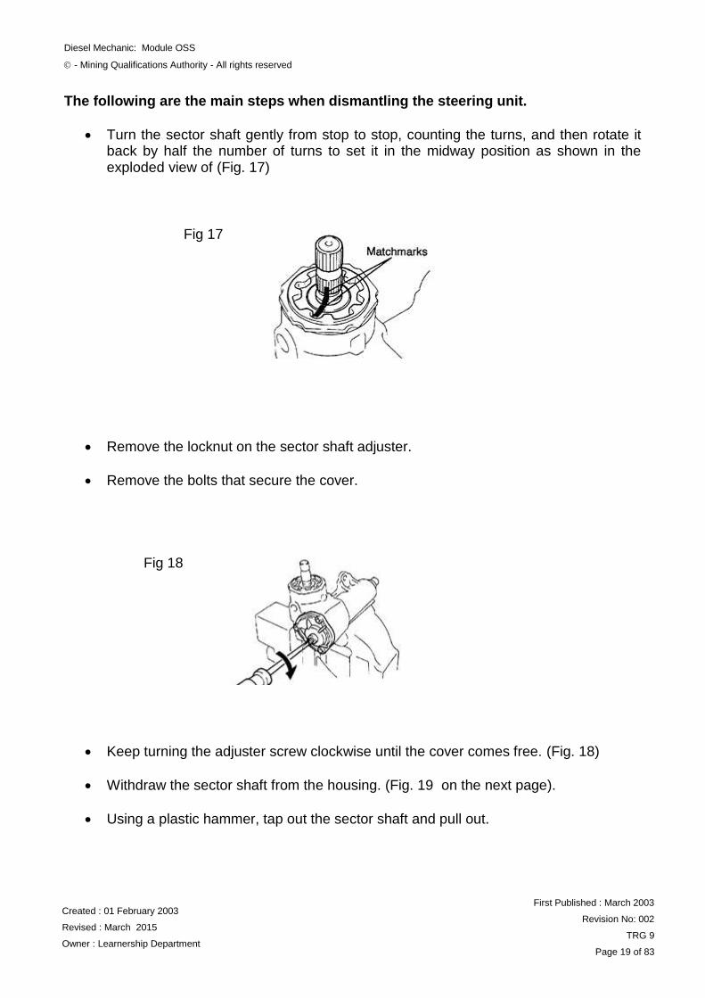
The following are the main steps when dismantling the steering unit.
Turn the sector shaft gently from stop to stop, counting the turns, and then rotate it back by half the number of turns to set it in the midway position as shown in the exploded view of (Fig. 17)
Remove the locknut on the sector shaft adjuster.
Remove the bolts that secure the cover.
Keep turning the adjuster screw clockwise until the cover comes free. (Fig. 18)
Withdraw the sector shaft from the housing. (Fig. 19 on the next page).
Using a plastic hammer, tap out the sector shaft and pull out.
Fig 17
Fig 18
Diesel Mechanic: Module OSS
- Mining Qualifications Authority - All rights reserved
Created : 01 February 2003
Revised : March 2015
Owner : Learnership Department
First Published : March 2003
Revision No: 002
TRG 9
Page 20 of 83
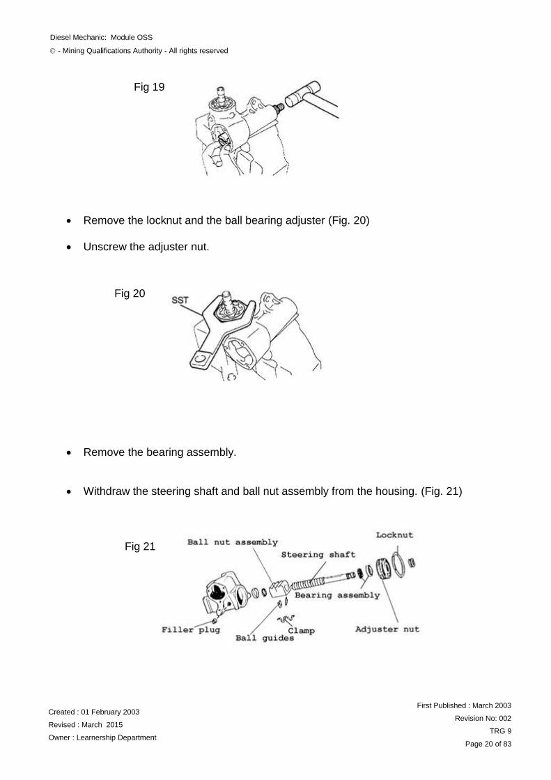
Remove the locknut and the ball bearing adjuster (Fig. 20)
Unscrew the adjuster nut.
Remove the bearing assembly.
Withdraw the steering shaft and ball nut assembly from the housing. (Fig. 21)
Fig 19
Fig 20
Fig 21
Diesel Mechanic: Module OSS
- Mining Qualifications Authority - All rights reserved
Created : 01 February 2003
Revised : March 2015
Owner : Learnership Department
First Published : March 2003
Revision No: 002
TRG 9
Page 21 of 83
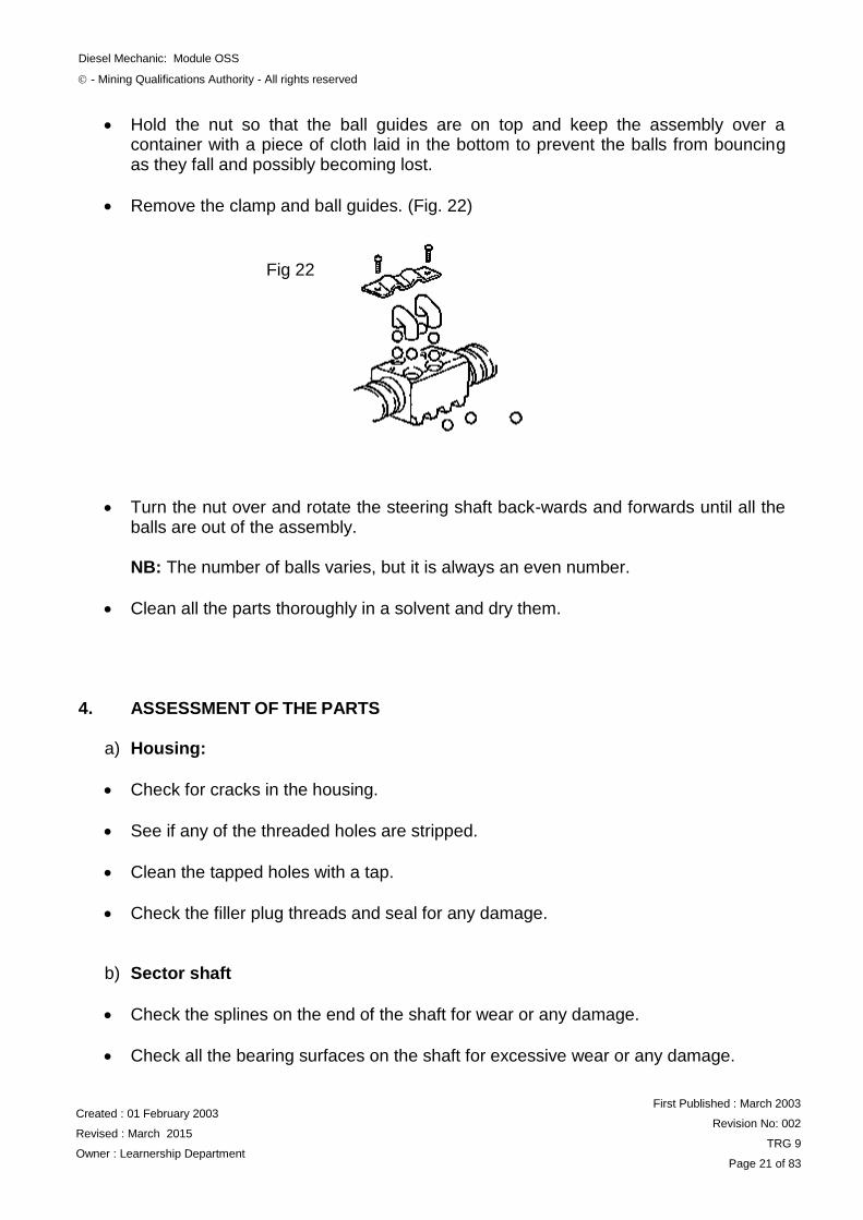
Hold the nut so that the ball guides are on top and keep the assembly over a container with a piece of cloth laid in the bottom to prevent the balls from bouncing as they fall and possibly becoming lost.
Remove the clamp and ball guides. (Fig. 22)
Turn the nut over and rotate the steering shaft back-wards and forwards until all the balls are out of the assembly.
NB: The number of balls varies, but it is always an even number.
Clean all the parts thoroughly in a solvent and dry them. 4. ASSESSMENT OF THE PARTS
a) Housing:
Check for cracks in the housing.
See if any of the threaded holes are stripped.
Clean the tapped holes with a tap.
Check the filler plug threads and seal for any damage.
b) Sector shaft
Check the splines on the end of the shaft for wear or any damage.
Check all the bearing surfaces on the shaft for excessive wear or any damage.
Fig 22
Diesel Mechanic: Module OSS
- Mining Qualifications Authority - All rights reserved
Created : 01 February 2003
Revised : March 2015
Owner : Learnership Department
First Published : March 2003
Revision No: 002
TRG 9
Page 22 of 83
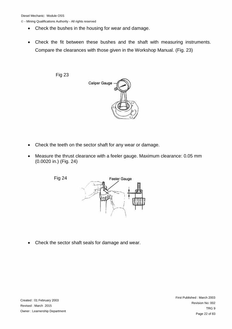
Check the bushes in the housing for wear and damage.
Check the fit between these bushes and the shaft with measuring instruments.
Compare the clearances with those given in the Workshop Manual. (Fig. 23)
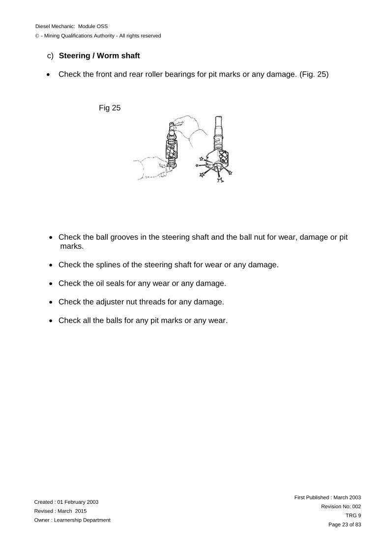
Check the teeth on the sector shaft for any wear or damage.
Measure the thrust clearance with a feeler gauge. Maximum clearance: 0.05 mm (0.0020 in.) (Fig. 24)
Check the sector shaft seals for damage and wear.
Fig 23
Fig 24
Diesel Mechanic: Module OSS
- Mining Qualifications Authority - All rights reserved
Created : 01 February 2003
Revised : March 2015
Owner : Learnership Department
First Published : March 2003
Revision No: 002
TRG 9
Page 23 of 83
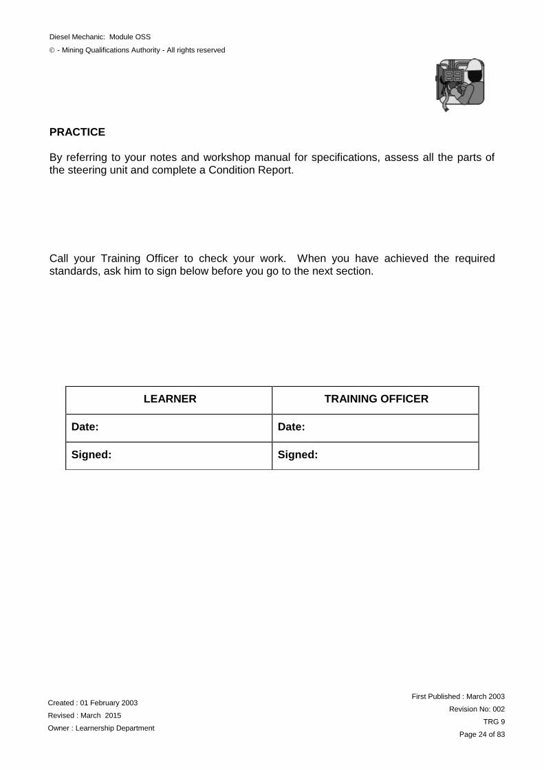
c) Steering / Worm shaft
Check the front and rear roller bearings for pit marks or any damage. (Fig. 25)
Check the ball grooves in the steering shaft and the ball nut for wear, damage or pit marks.
Check the splines of the steering shaft for wear or any damage.
Check the oil seals for any wear or any damage.
Check the adjuster nut threads for any damage.
Check all the balls for any pit marks or any wear.
Fig 25
Diesel Mechanic: Module OSS
- Mining Qualifications Authority - All rights reserved
Created : 01 February 2003
Revised : March 2015
Owner : Learnership Department
First Published : March 2003
Revision No: 002
TRG 9
Page 24 of 83
PRACTICE By referring to your notes and workshop manual for specifications, assess all the parts of the steering unit and complete a Condition Report. Call your Training Officer to check your work. When you have achieved the required standards, ask him to sign below before you go to the next section.
LEARNER
TRAINING OFFICER
Date:
Date:
Signed:
Signed:
Diesel Mechanic: Module OSS
- Mining Qualifications Authority - All rights reserved
Created : 01 February 2003
Revised : March 2015
Owner : Learnership Department
First Published : March 2003
Revision No: 002
TRG 9
Page 25 of 83
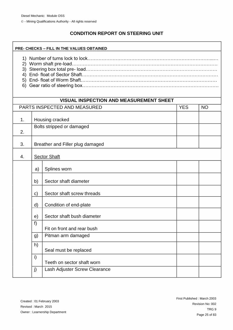
CONDITION REPORT ON STEERING UNIT
PRE- CHECKS – FILL IN THE VALUES OBTAINED
1) Number of turns lock to lock……………………………………………………………………...… 2) Worm shaft pre-load………………………………………………………………………………… 3) Steering box total pre- load………………………………………………………………………… 4) End- float of Sector Shaft…………………………………………………………………………… 5) End- float of Worm Shaft…………………………………………………………………………… 6) Gear ratio of steering box……………………………………………………………………………
VISUAL INSPECTION AND MEASUREMENT SHEET
PARTS INSPECTED AND MEASURED YES NO
1.
Housing cracked
2.
Bolts stripped or damaged
3.
Breather and Filler plug damaged
4.
Sector Shaft
a)
Splines worn
b)
Sector shaft diameter
c)
Sector shaft screw threads
d)
Condition of end-plate
e)
Sector shaft bush diameter
f) Fit on front and rear bush
g) Pitman arm damaged
h) Seal must be replaced
i) Teeth on sector shaft worn
j) Lash Adjuster Screw Clearance
Diesel Mechanic: Module OSS
- Mining Qualifications Authority - All rights reserved
Created : 01 February 2003
Revised : March 2015
Owner : Learnership Department
First Published : March 2003
Revision No: 002
TRG 9
Page 26 of 83
CONDITION REPORT ON STEERING UNIT (continues)
PARTS INSPECTED AND MEASURED YES NO 3.
Steering Shaft
a)
Front bearing must be replaced
b)
Condition of worm and nut
c)
Rear bearing must be replaced
d)
Ball grooves on the steering shafts are pitted
e)
Balls are pitted or broken
f)
Splines on the steering shaft are worn
g)
Condition of ball guide plates and securing screws
h)
Seal on the steering shaft must be replaced
REMARKS _______________________________________________________________________________________________________________________________________________________________________________________________________________________________________________________________________________________________________________________________________________________________________________________________________________________________________________________________________________________________________________________________ _______________________________________________________________________________________________________________________________________________________________________________________________________________________________________________________________________________________________________________________________________________________________________________________________________________________________________________________________________________________________________________________________
Diesel Mechanic: Module OSS
- Mining Qualifications Authority - All rights reserved
Created : 01 February 2003
Revised : March 2015
Owner : Learnership Department
First Published : March 2003
Revision No: 002
TRG 9
Page 27 of 83
ASSEMBLING THE STEERING UNIT
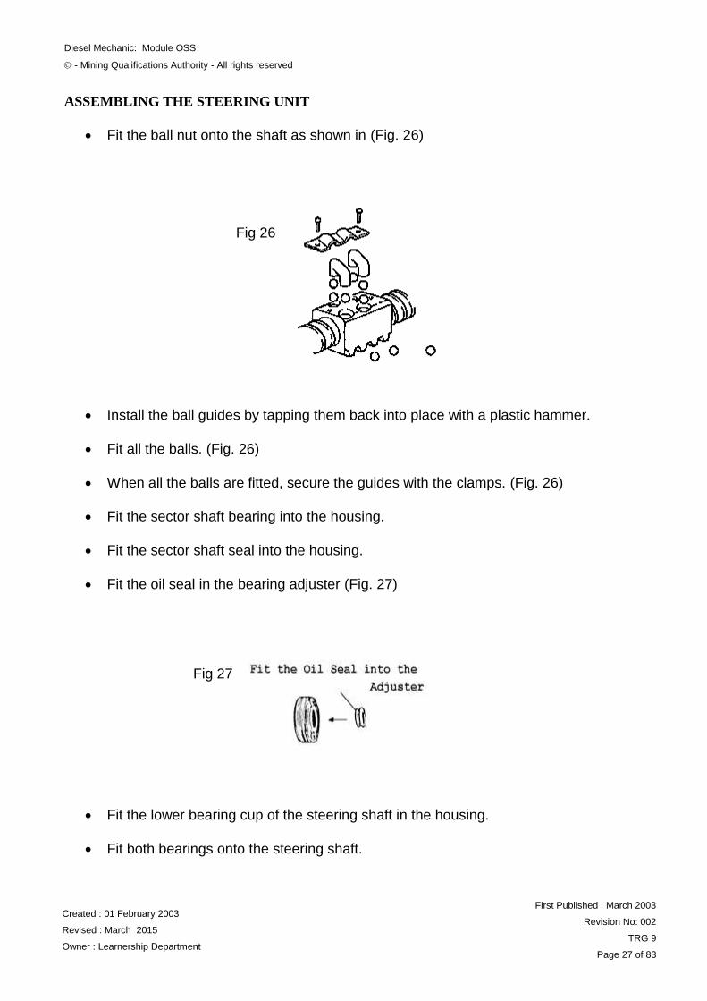
Fit the ball nut onto the shaft as shown in (Fig. 26)
Install the ball guides by tapping them back into place with a plastic hammer.
Fit all the balls. (Fig. 26)
When all the balls are fitted, secure the guides with the clamps. (Fig. 26)
Fit the sector shaft bearing into the housing.
Fit the sector shaft seal into the housing.
Fit the oil seal in the bearing adjuster (Fig. 27)
Fit the lower bearing cup of the steering shaft in the housing.
Fit both bearings onto the steering shaft.
Fig 26
Fig 27
Diesel Mechanic: Module OSS
- Mining Qualifications Authority - All rights reserved
Created : 01 February 2003
Revised : March 2015
Owner : Learnership Department
First Published : March 2003
Revision No: 002
TRG 9
Page 28 of 83
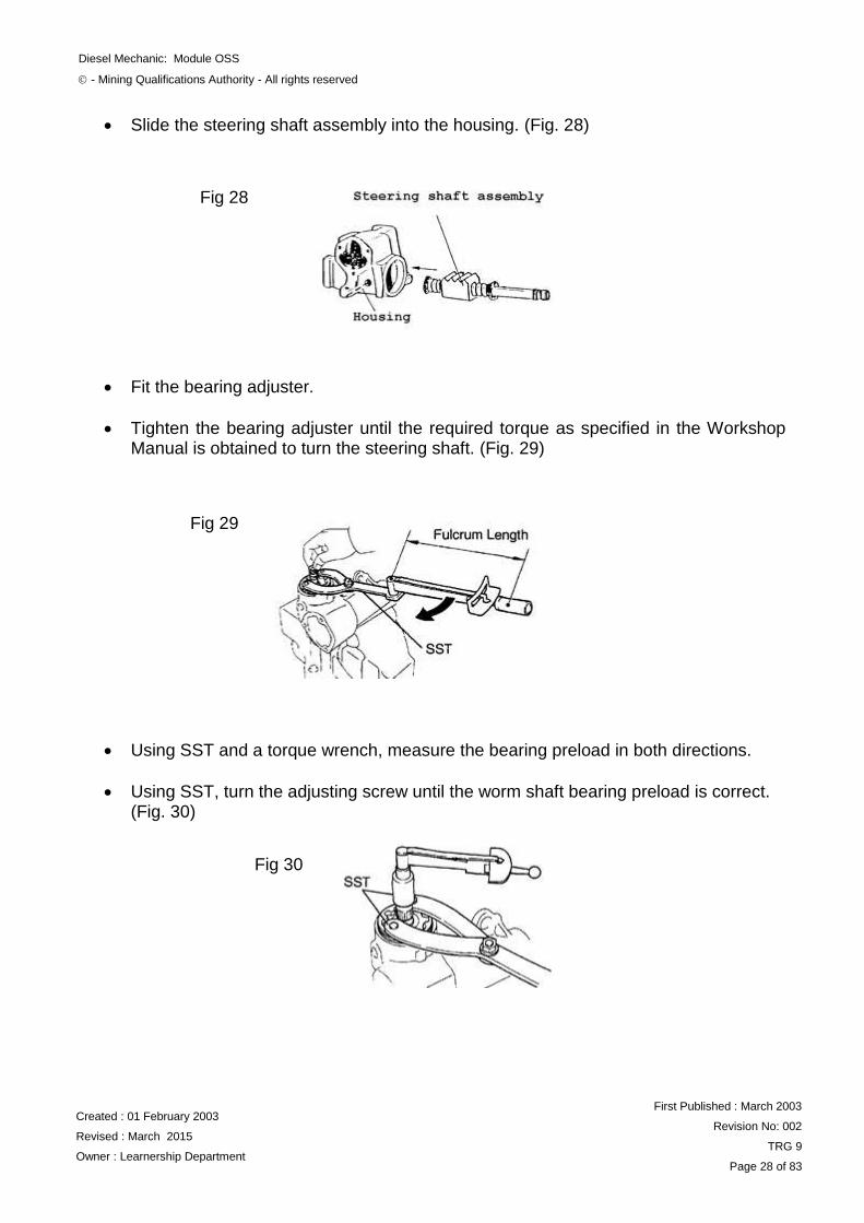
Slide the steering shaft assembly into the housing. (Fig. 28)
Fit the bearing adjuster.
Tighten the bearing adjuster until the required torque as specified in the Workshop Manual is obtained to turn the steering shaft. (Fig. 29)
Using SST and a torque wrench, measure the bearing preload in both directions.
Using SST, turn the adjusting screw until the worm shaft bearing preload is correct. (Fig. 30)
Fig 28
Fig 29
Fig 30
Diesel Mechanic: Module OSS
- Mining Qualifications Authority - All rights reserved
Created : 01 February 2003
Revised : March 2015
Owner : Learnership Department
First Published : March 2003
Revision No: 002
TRG 9
Page 29 of 83
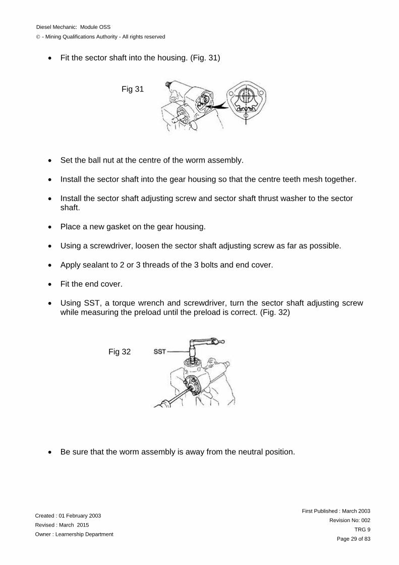
Fit the sector shaft into the housing. (Fig. 31)
Set the ball nut at the centre of the worm assembly.
Install the sector shaft into the gear housing so that the centre teeth mesh together.
Install the sector shaft adjusting screw and sector shaft thrust washer to the sector shaft.
Place a new gasket on the gear housing.
Using a screwdriver, loosen the sector shaft adjusting screw as far as possible.
Apply sealant to 2 or 3 threads of the 3 bolts and end cover.
Fit the end cover.
Using SST, a torque wrench and screwdriver, turn the sector shaft adjusting screw while measuring the preload until the preload is correct. (Fig. 32)
Be sure that the worm assembly is away from the neutral position.
Fig 31
Fig 32
Diesel Mechanic: Module OSS
- Mining Qualifications Authority - All rights reserved
Created : 01 February 2003
Revised : March 2015
Owner : Learnership Department
First Published : March 2003
Revision No: 002
TRG 9
Page 30 of 83
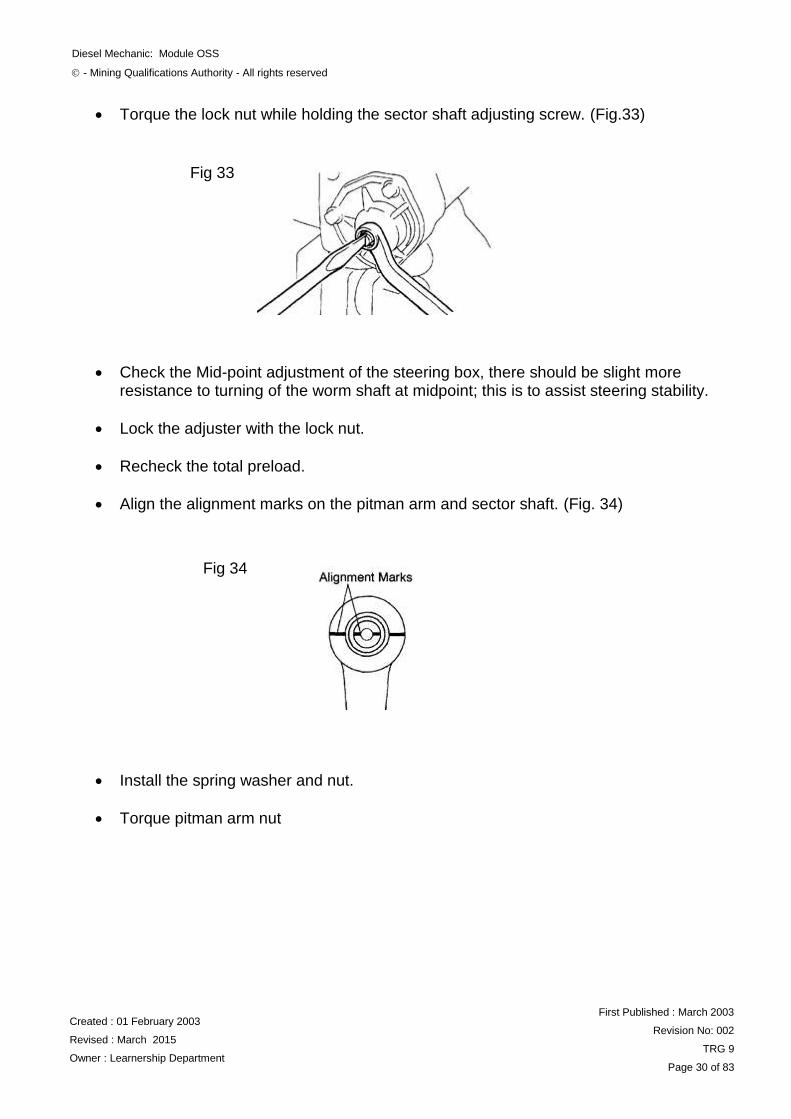
Torque the lock nut while holding the sector shaft adjusting screw. (Fig.33)
Check the Mid-point adjustment of the steering box, there should be slight more resistance to turning of the worm shaft at midpoint; this is to assist steering stability.
Lock the adjuster with the lock nut.
Recheck the total preload.
Align the alignment marks on the pitman arm and sector shaft. (Fig. 34)
Install the spring washer and nut.
Torque pitman arm nut
Fig 33
Fig 34

Diesel Mechanic: Module OSS
- Mining Qualifications Authority - All rights reserved
Created : 01 February 2003
Revised : March 2015
Owner : Learnership Department
First Published : March 2003
Revision No: 002
TRG 9
Page 31 of 83
PRACTICE By referring to your notes and workshop manual, dismantle and assemble the steering unit. Call your Training Officer to check your work and ask him to sign you off when it is correct, then go on to the next section.
LEARNER
TRAINING OFFICER
Date:
Date:
Signed:
Signed:
Diesel Mechanic: Module OSS
- Mining Qualifications Authority - All rights reserved
Created : 01 February 2003
Revised : March 2015
Owner : Learnership Department
First Published : March 2003
Revision No: 002
TRG 9
Page 32 of 83
WHEEL ALIGNMENT
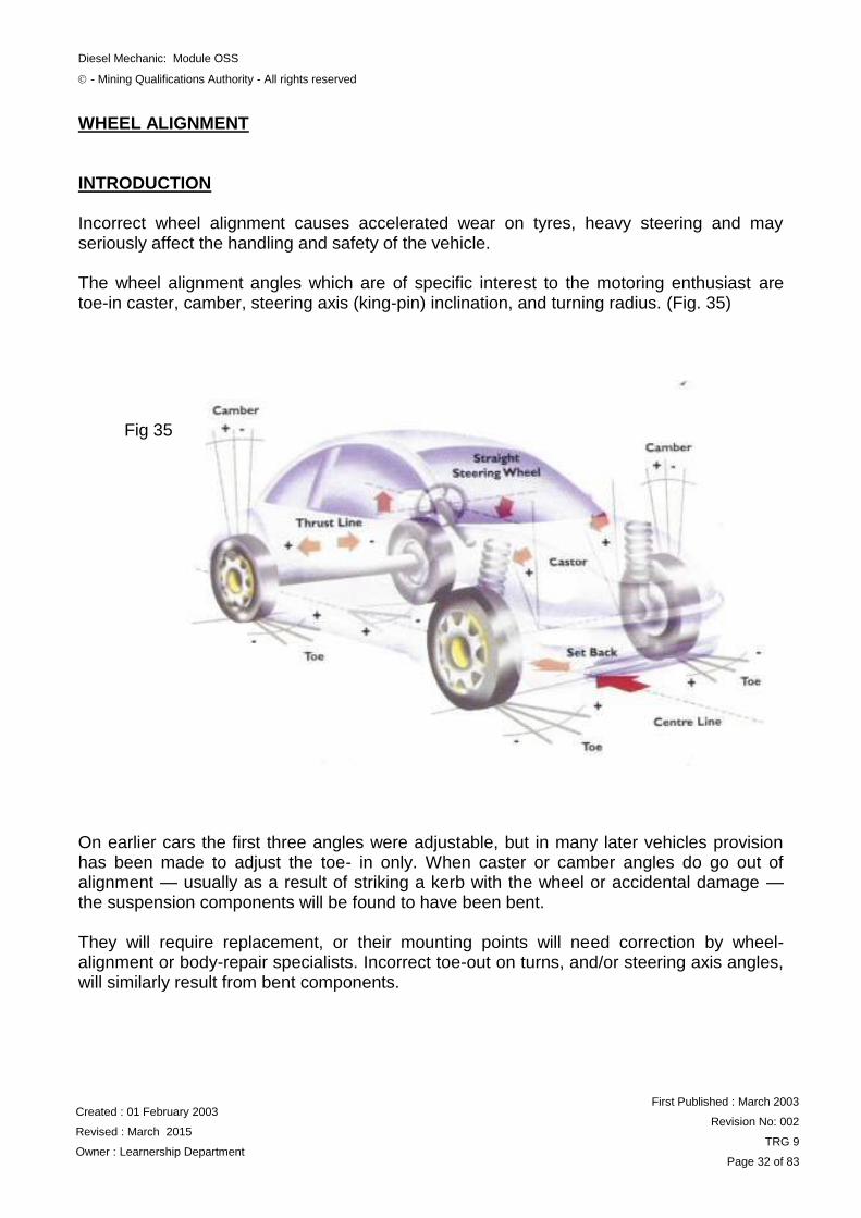
INTRODUCTION Incorrect wheel alignment causes accelerated wear on tyres, heavy steering and may seriously affect the handling and safety of the vehicle. The wheel alignment angles which are of specific interest to the motoring enthusiast are toe-in caster, camber, steering axis (king-pin) inclination, and turning radius. (Fig. 35) On earlier cars the first three angles were adjustable, but in many later vehicles provision has been made to adjust the toe- in only. When caster or camber angles do go out of alignment — usually as a result of striking a kerb with the wheel or accidental damage — the suspension components will be found to have been bent. They will require replacement, or their mounting points will need correction by wheel-alignment or body-repair specialists. Incorrect toe-out on turns, and/or steering axis angles, will similarly result from bent components.
Fig 35
Diesel Mechanic: Module OSS
- Mining Qualifications Authority - All rights reserved
Created : 01 February 2003
Revised : March 2015
Owner : Learnership Department
First Published : March 2003
Revision No: 002
TRG 9
Page 33 of 83
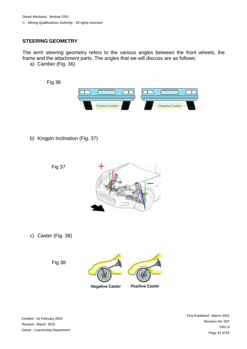
STEERING GEOMETRY The term steering geometry refers to the various angles between the front wheels, the frame and the attachment parts. The angles that we will discuss are as follows:
a) Camber (Fig. 36)
b) Kingpin Inclination (Fig. 37)
c) Caster (Fig. 38)
Fig 36
Fig 37
Fig 38
Diesel Mechanic: Module OSS
- Mining Qualifications Authority - All rights reserved
Created : 01 February 2003
Revised : March 2015
Owner : Learnership Department
First Published : March 2003
Revision No: 002
TRG 9
Page 34 of 83
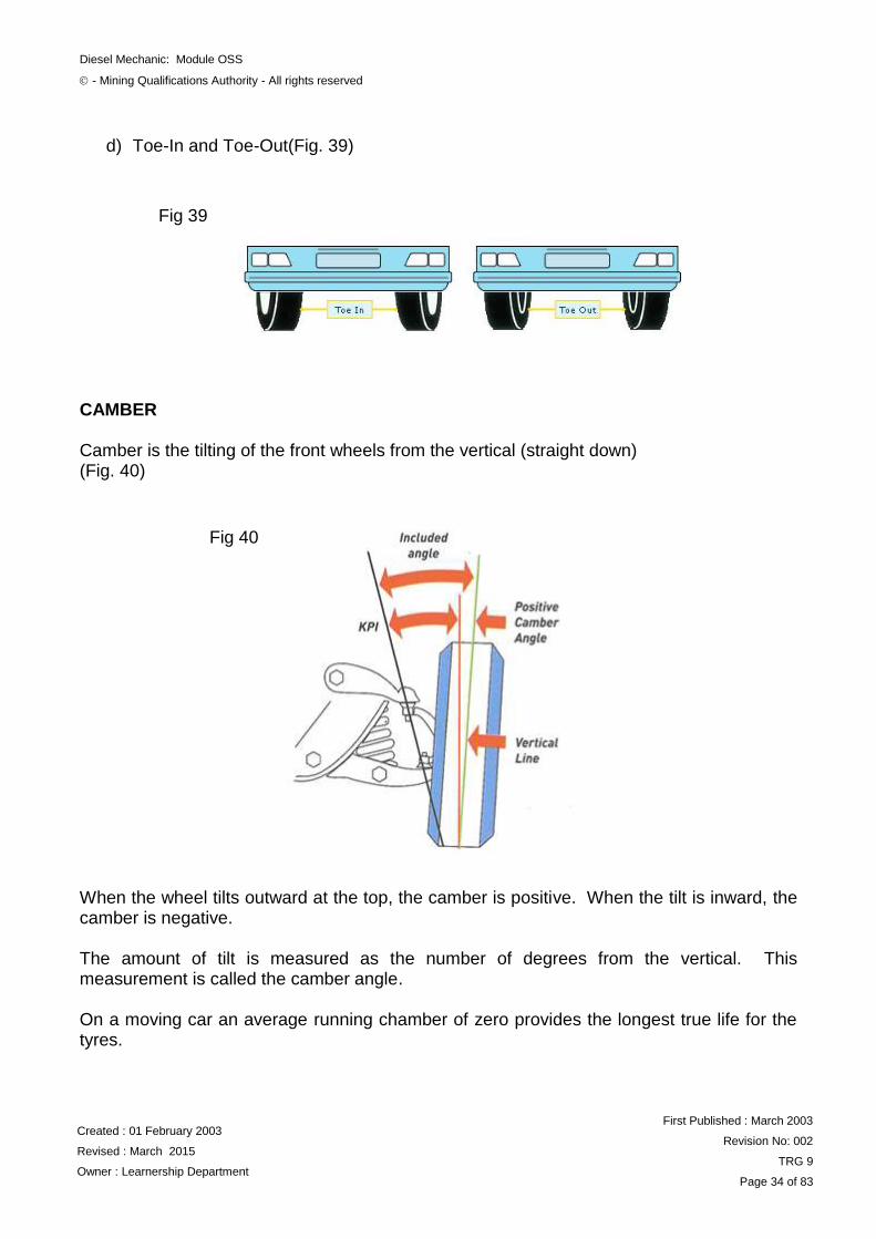
d) Toe-In and Toe-Out(Fig. 39) CAMBER Camber is the tilting of the front wheels from the vertical (straight down) (Fig. 40)
When the wheel tilts outward at the top, the camber is positive. When the tilt is inward, the camber is negative. The amount of tilt is measured as the number of degrees from the vertical. This measurement is called the camber angle. On a moving car an average running chamber of zero provides the longest true life for the tyres.
Fig 39
Fig 40
Diesel Mechanic: Module OSS
- Mining Qualifications Authority - All rights reserved
Created : 01 February 2003
Revised : March 2015
Owner : Learnership Department
First Published : March 2003
Revision No: 002
TRG 9
Page 35 of 83
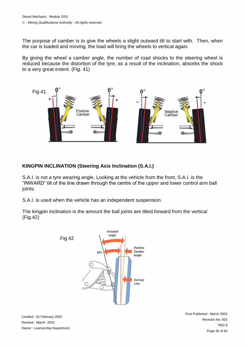
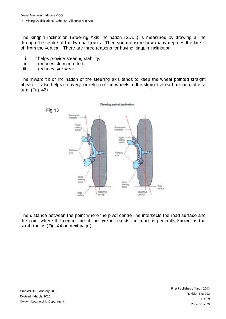
The purpose of camber is to give the wheels a slight outward tilt to start with. Then, when the car is loaded and moving, the load will bring the wheels to vertical again. By giving the wheel a camber angle, the number of road shocks to the steering wheel is reduced because the distortion of the tyre, as a result of the inclination, absorbs the shock to a very great extent. (Fig. 41) KINGPIN INCLINATION (Steering Axis Inclination (S.A.I.)
S.A.I. is not a tyre wearing angle. Looking at the vehicle from the front, S.A.I. is the “INWARD” tilt of the line drawn through the centre of the upper and lower control arm ball joints. S.A.I. is used when the vehicle has an independent suspension.
The kingpin inclination is the amount the ball joints are tilted forward from the vertical (Fig.42)
Fig 41
Fig 42
Diesel Mechanic: Module OSS
- Mining Qualifications Authority - All rights reserved
Created : 01 February 2003
Revised : March 2015
Owner : Learnership Department
First Published : March 2003
Revision No: 002
TRG 9
Page 36 of 83
The kingpin inclination (Steering Axis Inclination (S.A.I.) is measured by drawing a line through the centre of the two ball joints. Then you measure how many degrees the line is off from the vertical. There are three reasons for having kingpin inclination:
i. It helps provide steering stability. ii. It reduces steering effort. iii. It reduces tyre wear.
The inward tilt or inclination of the steering axis tends to keep the wheel pointed straight ahead. It also helps recovery, or return of the wheels to the straight-ahead position, after a turn. (Fig. 43)
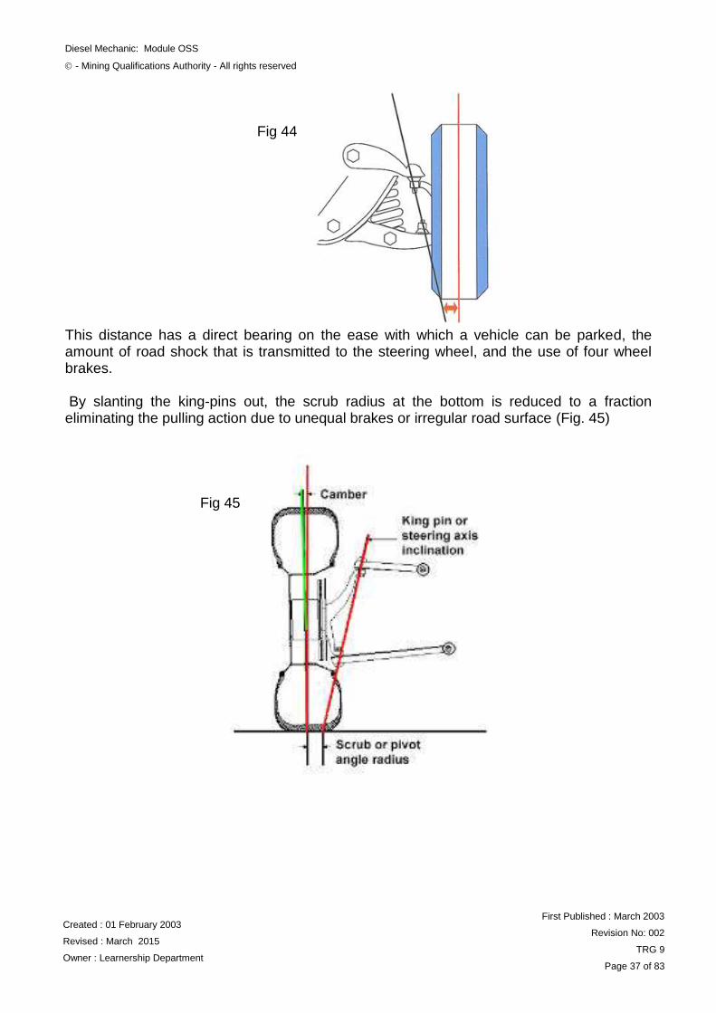
The distance between the point where the pivot centre line intersects the road surface and the point where the centre line of the tyre intersects the road, is generally known as the scrub radius (Fig. 44 on next page).
Fig 43
Diesel Mechanic: Module OSS
- Mining Qualifications Authority - All rights reserved
Created : 01 February 2003
Revised : March 2015
Owner : Learnership Department
First Published : March 2003
Revision No: 002
TRG 9
Page 37 of 83
This distance has a direct bearing on the ease with which a vehicle can be parked, the amount of road shock that is transmitted to the steering wheel, and the use of four wheel brakes. By slanting the king-pins out, the scrub radius at the bottom is reduced to a fraction eliminating the pulling action due to unequal brakes or irregular road surface (Fig. 45)
Fig 44
Fig 45
Diesel Mechanic: Module OSS
- Mining Qualifications Authority - All rights reserved
Created : 01 February 2003
Revised : March 2015
Owner : Learnership Department
First Published : March 2003
Revision No: 002
TRG 9
Page 38 of 83
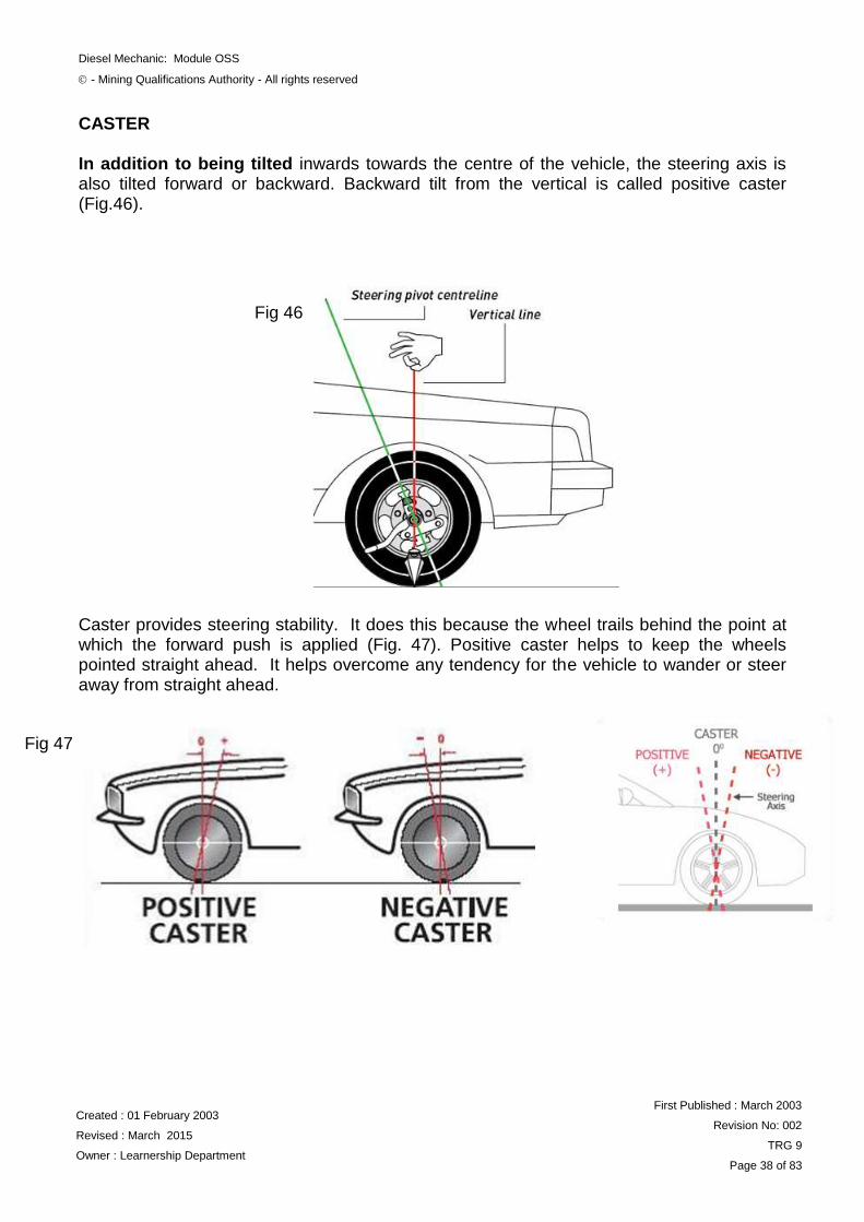
CASTER In addition to being tilted inwards towards the centre of the vehicle, the steering axis is also tilted forward or backward. Backward tilt from the vertical is called positive caster (Fig.46). Caster provides steering stability. It does this because the wheel trails behind the point at which the forward push is applied (Fig. 47). Positive caster helps to keep the wheels pointed straight ahead. It helps overcome any tendency for the vehicle to wander or steer away from straight ahead.
Fig 46
Fig 47
Diesel Mechanic: Module OSS
- Mining Qualifications Authority - All rights reserved
Created : 01 February 2003
Revised : March 2015
Owner : Learnership Department
First Published : March 2003
Revision No: 002
TRG 9
Page 39 of 83
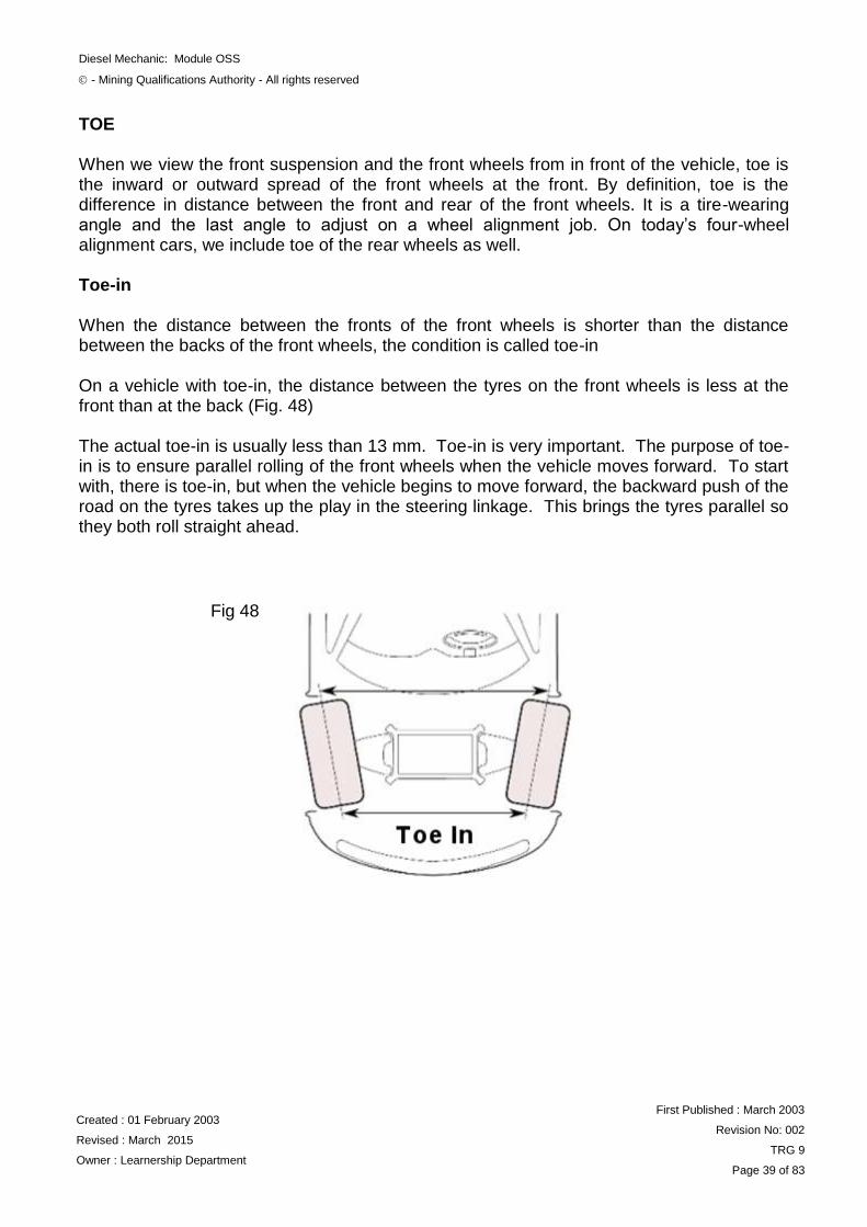
TOE When we view the front suspension and the front wheels from in front of the vehicle, toe is the inward or outward spread of the front wheels at the front. By definition, toe is the difference in distance between the front and rear of the front wheels. It is a tire-wearing angle and the last angle to adjust on a wheel alignment job. On today‟s four-wheel alignment cars, we include toe of the rear wheels as well. Toe-in When the distance between the fronts of the front wheels is shorter than the distance between the backs of the front wheels, the condition is called toe-in On a vehicle with toe-in, the distance between the tyres on the front wheels is less at the front than at the back (Fig. 48) The actual toe-in is usually less than 13 mm. Toe-in is very important. The purpose of toe-in is to ensure parallel rolling of the front wheels when the vehicle moves forward. To start with, there is toe-in, but when the vehicle begins to move forward, the backward push of the road on the tyres takes up the play in the steering linkage. This brings the tyres parallel so they both roll straight ahead.
Fig 48
Diesel Mechanic: Module OSS
- Mining Qualifications Authority - All rights reserved
Created : 01 February 2003
Revised : March 2015
Owner : Learnership Department
First Published : March 2003
Revision No: 002
TRG 9
Page 40 of 83
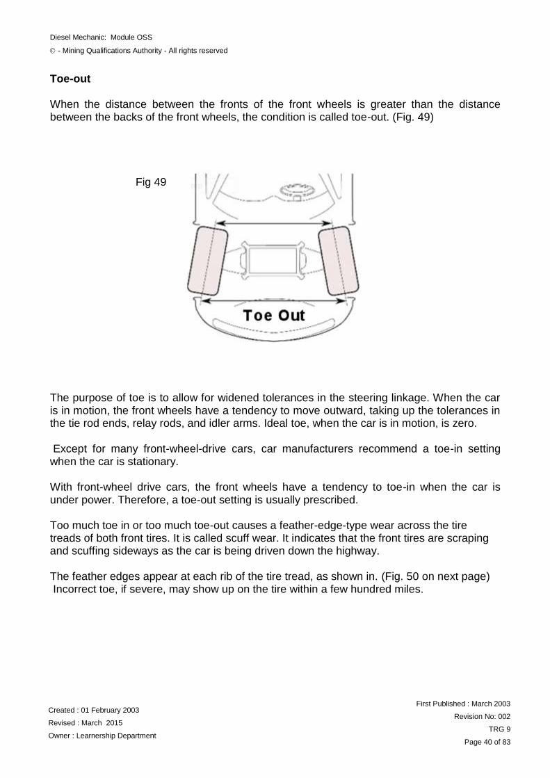
Toe-out When the distance between the fronts of the front wheels is greater than the distance between the backs of the front wheels, the condition is called toe-out. (Fig. 49) The purpose of toe is to allow for widened tolerances in the steering linkage. When the car is in motion, the front wheels have a tendency to move outward, taking up the tolerances in the tie rod ends, relay rods, and idler arms. Ideal toe, when the car is in motion, is zero. Except for many front-wheel-drive cars, car manufacturers recommend a toe-in setting when the car is stationary. With front-wheel drive cars, the front wheels have a tendency to toe-in when the car is under power. Therefore, a toe-out setting is usually prescribed. Too much toe in or too much toe-out causes a feather-edge-type wear across the tire treads of both front tires. It is called scuff wear. It indicates that the front tires are scraping and scuffing sideways as the car is being driven down the highway. The feather edges appear at each rib of the tire tread, as shown in. (Fig. 50 on next page) Incorrect toe, if severe, may show up on the tire within a few hundred miles.
Fig 49
Diesel Mechanic: Module OSS
- Mining Qualifications Authority - All rights reserved
Created : 01 February 2003
Revised : March 2015
Owner : Learnership Department
First Published : March 2003
Revision No: 002
TRG 9
Page 41 of 83
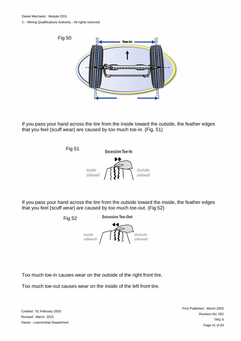
If you pass your hand across the tire from the inside toward the outside, the feather edges that you feel (scuff wear) are caused by too much toe-in. (Fig. 51) If you pass your hand across the tire from the outside toward the inside, the feather edges that you feel (scuff wear) are caused by too much toe-out. (Fig 52) Too much toe-in causes wear on the outside of the right front tire. Too much toe-out causes wear on the inside of the left front tire.
Fig 50
Fig 51
Fig 52
Diesel Mechanic: Module OSS
- Mining Qualifications Authority - All rights reserved
Created : 01 February 2003
Revised : March 2015
Owner : Learnership Department
First Published : March 2003
Revision No: 002
TRG 9
Page 42 of 83
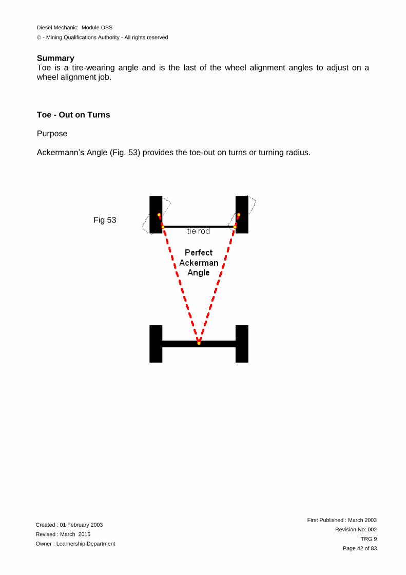
Summary Toe is a tire-wearing angle and is the last of the wheel alignment angles to adjust on a wheel alignment job. Toe - Out on Turns Purpose
Ackermann‟s Angle (Fig. 53) provides the toe-out on turns or turning radius.
Fig 53
Diesel Mechanic: Module OSS
- Mining Qualifications Authority - All rights reserved
Created : 01 February 2003
Revised : March 2015
Owner : Learnership Department
First Published : March 2003
Revision No: 002
TRG 9
Page 43 of 83
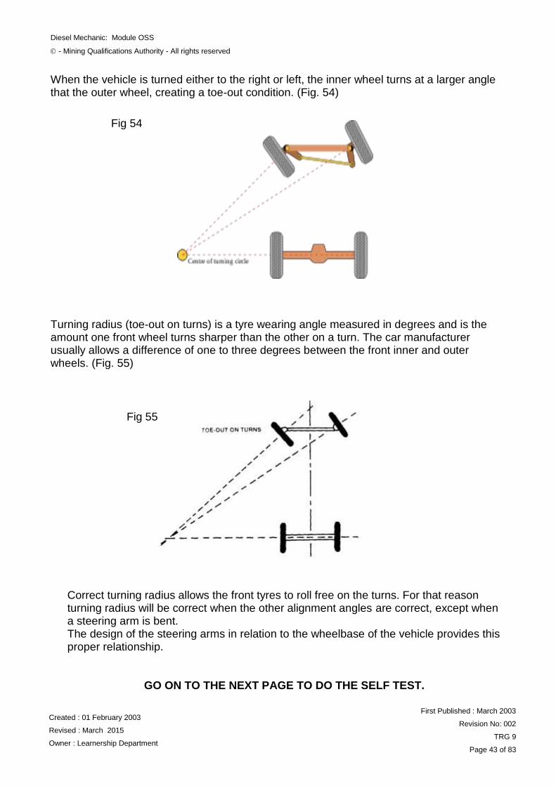
When the vehicle is turned either to the right or left, the inner wheel turns at a larger angle that the outer wheel, creating a toe-out condition. (Fig. 54)
Turning radius (toe-out on turns) is a tyre wearing angle measured in degrees and is the amount one front wheel turns sharper than the other on a turn. The car manufacturer usually allows a difference of one to three degrees between the front inner and outer wheels. (Fig. 55)
Correct turning radius allows the front tyres to roll free on the turns. For that reason turning radius will be correct when the other alignment angles are correct, except when a steering arm is bent. The design of the steering arms in relation to the wheelbase of the vehicle provides this proper relationship.
GO ON TO THE NEXT PAGE TO DO THE SELF TEST.
Fig 54
Fig 55
Diesel Mechanic: Module OSS
- Mining Qualifications Authority - All rights reserved
Created : 01 February 2003
Revised : March 2015
Owner : Learnership Department
First Published : March 2003
Revision No: 002
TRG 9
Page 44 of 83
SELF TEST 2 Without referring to your notes, state the purpose of the following:
a) Camber ___________________________________________________________________ ___________________________________________________________________ ___________________________________________________________________ ___________________________________________________________________
b) Kingpin Inclination ___________________________________________________________________ ___________________________________________________________________ ___________________________________________________________________ ___________________________________________________________________
c) Caster
___________________________________________________________________ ___________________________________________________________________ ___________________________________________________________________ ___________________________________________________________________
d) Toe-In
___________________________________________________________________ ___________________________________________________________________ ___________________________________________________________________ ___________________________________________________________________
e) Toe-out ___________________________________________________________________ ___________________________________________________________________ ___________________________________________________________________ ___________________________________________________________________
f) Toe-out on turns ___________________________________________________________________ ___________________________________________________________________ ___________________________________________________________________ ___________________________________________________________________
Diesel Mechanic: Module OSS
- Mining Qualifications Authority - All rights reserved
Created : 01 February 2003
Revised : March 2015
Owner : Learnership Department
First Published : March 2003
Revision No: 002
TRG 9
Page 45 of 83
Call your Training Officer to check your work and ask him to sign you off when it is correct, then go on to the next section.
LEARNER
TRAINING OFFICER
Date:
Date:
Signed:
Signed:
Diesel Mechanic: Module OSS
- Mining Qualifications Authority - All rights reserved
Created : 01 February 2003
Revised : March 2015
Owner : Learnership Department
First Published : March 2003
Revision No: 002
TRG 9
Page 46 of 83
PRE-ALIGNMENT VISUAL INSPECTION Before the actual adjusting of the vehicle alignment takes place, the vehicle must be visually inspected. Bear in mind that the information which the driver has given may be a valuable aid in making the proper diagnosis and in repairing the vehicle. Works area: Works area must be level and free of any obstructions
Standard kerb mass: (see specs)
a) Vehicle must not have any load on
b) Standard mass includes the battery, full fuel tank, etc.
Brakes:
Check vehicle brakes for correct operation (Need to be applied when taking measurements)
Diesel Mechanic: Module OSS
- Mining Qualifications Authority - All rights reserved
Created : 01 February 2003
Revised : March 2015
Owner : Learnership Department
First Published : March 2003
Revision No: 002
TRG 9
Page 47 of 83
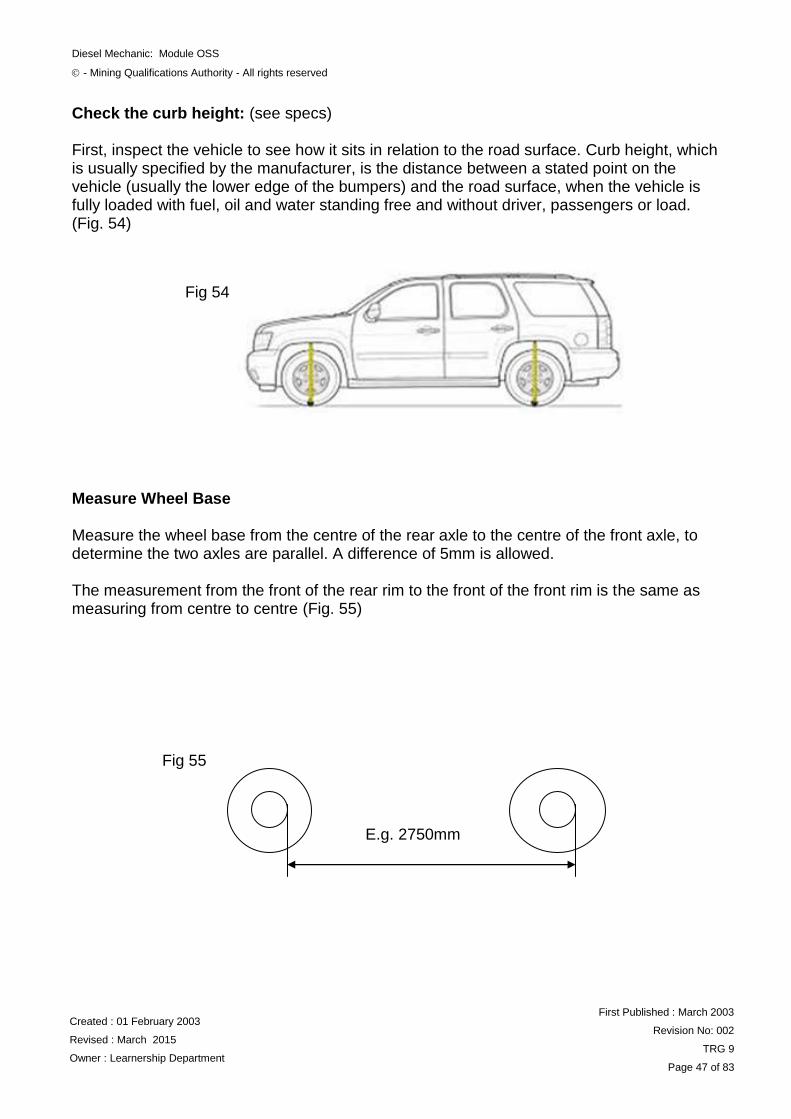
Check the curb height: (see specs) First, inspect the vehicle to see how it sits in relation to the road surface. Curb height, which is usually specified by the manufacturer, is the distance between a stated point on the vehicle (usually the lower edge of the bumpers) and the road surface, when the vehicle is fully loaded with fuel, oil and water standing free and without driver, passengers or load. (Fig. 54)
Measure Wheel Base Measure the wheel base from the centre of the rear axle to the centre of the front axle, to determine the two axles are parallel. A difference of 5mm is allowed. The measurement from the front of the rear rim to the front of the front rim is the same as measuring from centre to centre (Fig. 55)
Fig 54
E.g. 2750mm
Fig 55
Diesel Mechanic: Module OSS
- Mining Qualifications Authority - All rights reserved
Created : 01 February 2003
Revised : March 2015
Owner : Learnership Department
First Published : March 2003
Revision No: 002
TRG 9
Page 48 of 83
Wheels and Tyres
Check that all tyre pressures conform to specifications (Inflate to desire pressure is needed). Wrong tyre pressures-particularly pressures that are too low - lead to rapid tread wear or even total tyre failure, and can affect handling.
Because tyre pressure increases rapidly when the tyres get hot during running, always check pressures when the tyres are cold, before the car has been driven.
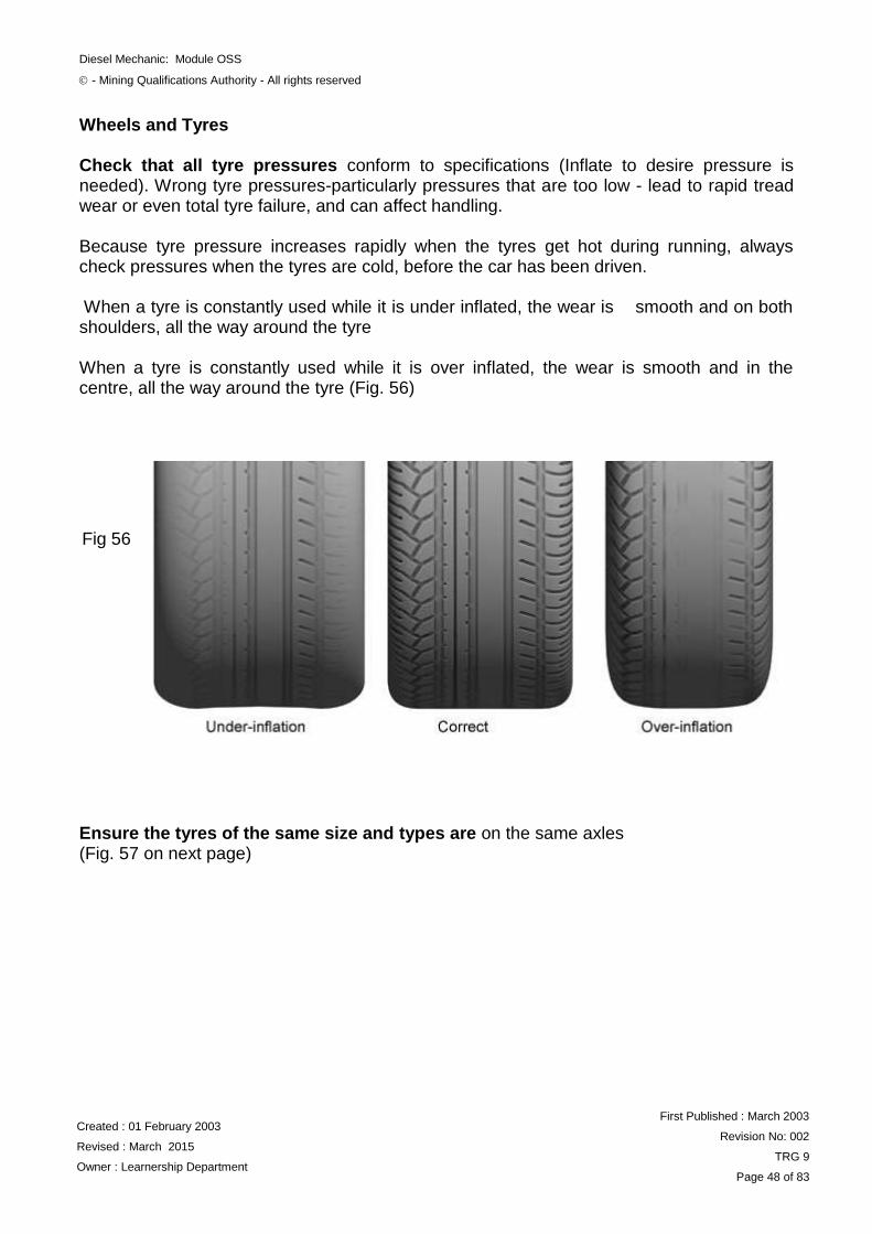
When a tyre is constantly used while it is under inflated, the wear is smooth and on both shoulders, all the way around the tyre
When a tyre is constantly used while it is over inflated, the wear is smooth and in the centre, all the way around the tyre (Fig. 56)
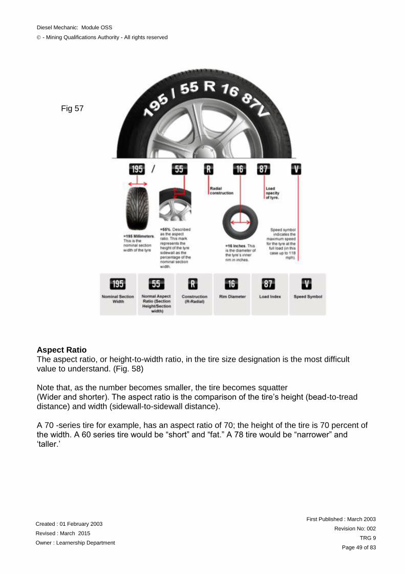
Ensure the tyres of the same size and types are on the same axles (Fig. 57 on next page)
Fig 56
Diesel Mechanic: Module OSS
- Mining Qualifications Authority - All rights reserved
Created : 01 February 2003
Revised : March 2015
Owner : Learnership Department
First Published : March 2003
Revision No: 002
TRG 9
Page 49 of 83
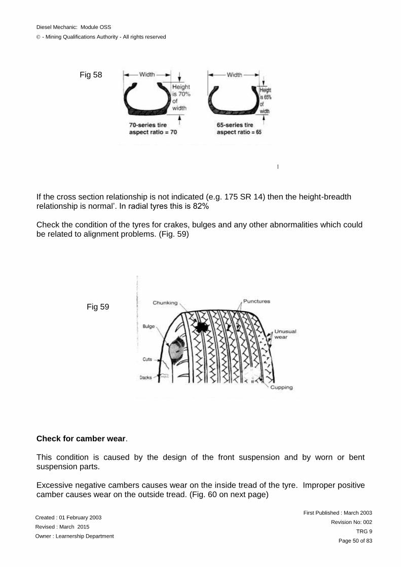
Aspect Ratio The aspect ratio, or height-to-width ratio, in the tire size designation is the most difficult value to understand. (Fig. 58) Note that, as the number becomes smaller, the tire becomes squatter (Wider and shorter). The aspect ratio is the comparison of the tire‟s height (bead-to-tread distance) and width (sidewall-to-sidewall distance). A 70 -series tire for example, has an aspect ratio of 70; the height of the tire is 70 percent of the width. A 60 series tire would be “short” and “fat.” A 78 tire would be “narrower” and „taller.‟
Fig 57
Diesel Mechanic: Module OSS
- Mining Qualifications Authority - All rights reserved
Created : 01 February 2003
Revised : March 2015
Owner : Learnership Department
First Published : March 2003
Revision No: 002
TRG 9
Page 50 of 83
If the cross section relationship is not indicated (e.g. 175 SR 14) then the height-breadth relationship is normal‟. In radial tyres this is 82% Check the condition of the tyres for crakes, bulges and any other abnormalities which could be related to alignment problems. (Fig. 59)
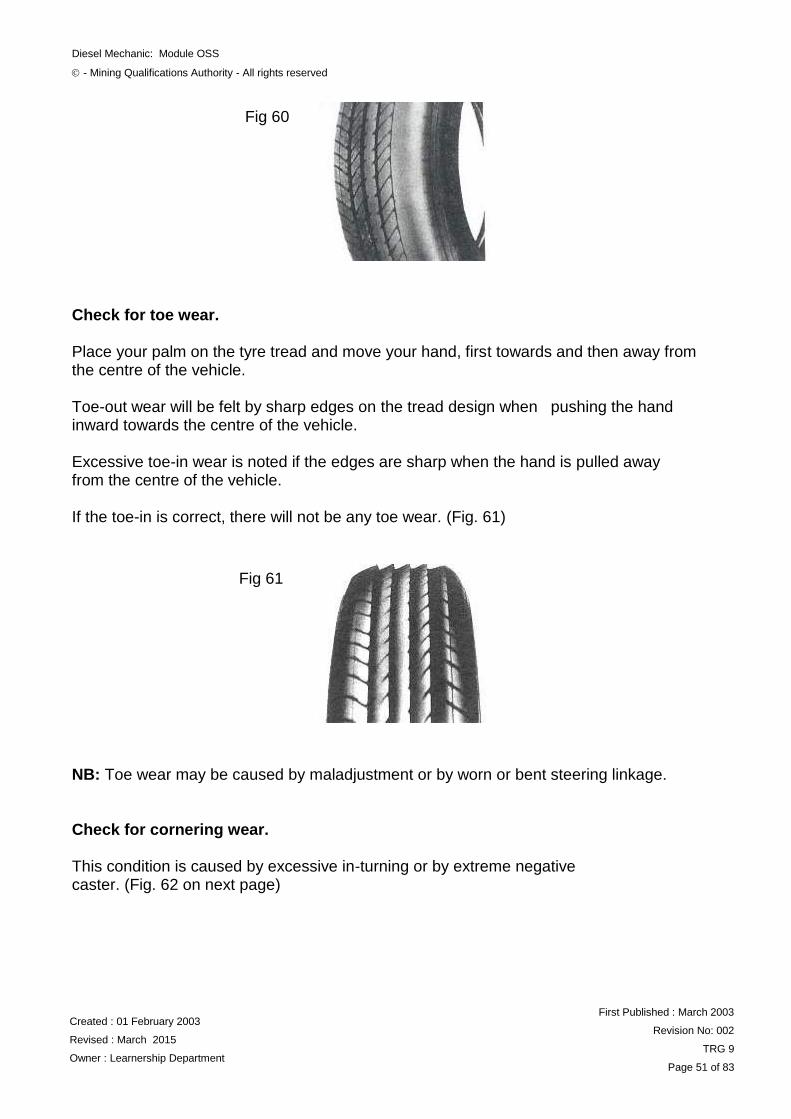
Check for camber wear. This condition is caused by the design of the front suspension and by worn or bent suspension parts. Excessive negative cambers causes wear on the inside tread of the tyre. Improper positive camber causes wear on the outside tread. (Fig. 60 on next page)
Fig 58
Fig 59
Diesel Mechanic: Module OSS
- Mining Qualifications Authority - All rights reserved
Created : 01 February 2003
Revised : March 2015
Owner : Learnership Department
First Published : March 2003
Revision No: 002
TRG 9
Page 51 of 83
Check for toe wear.
Place your palm on the tyre tread and move your hand, first towards and then away from the centre of the vehicle. Toe-out wear will be felt by sharp edges on the tread design when pushing the hand inward towards the centre of the vehicle. Excessive toe-in wear is noted if the edges are sharp when the hand is pulled away from the centre of the vehicle. If the toe-in is correct, there will not be any toe wear. (Fig. 61)
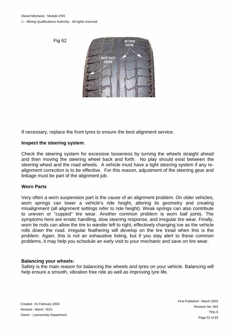
NB: Toe wear may be caused by maladjustment or by worn or bent steering linkage. Check for cornering wear. This condition is caused by excessive in-turning or by extreme negative caster. (Fig. 62 on next page)
Fig 60
Fig 61
Diesel Mechanic: Module OSS
- Mining Qualifications Authority - All rights reserved
Created : 01 February 2003
Revised : March 2015
Owner : Learnership Department
First Published : March 2003
Revision No: 002
TRG 9
Page 52 of 83
If necessary, replace the front tyres to ensure the best alignment service. Inspect the steering system. Check the steering system for excessive looseness by turning the wheels straight ahead and then moving the steering wheel back and forth. No play should exist between the steering wheel and the road wheels. A vehicle must have a tight steering system if any re-alignment correction is to be effective. For this reason, adjustment of the steering gear and linkage must be part of the alignment job. Worn Parts Very often a worn suspension part is the cause of an alignment problem. On older vehicles, worn springs can lower a vehicle's ride height, altering its geometry and creating misalignment (all alignment settings refer to ride height). Weak springs can also contribute to uneven or "cupped" tire wear. Another common problem is worn ball joints. The symptoms here are erratic handling, slow steering response, and irregular tire wear. Finally, worn tie rods can allow the tire to wander left to right, effectively changing toe as the vehicle rolls down the road. Irregular feathering will develop on the tire tread when this is the problem. Again, this is not an exhaustive listing, but if you stay alert to these common problems, it may help you schedule an early visit to your mechanic and save on tire wear.
Balancing your wheels: Safety is the main reason for balancing the wheels and tyres on your vehicle. Balancing will help ensure a smooth, vibration free ride as well as improving tyre life.
Fig 62
Diesel Mechanic: Module OSS
- Mining Qualifications Authority - All rights reserved
Created : 01 February 2003
Revised : March 2015
Owner : Learnership Department
First Published : March 2003
Revision No: 002
TRG 9
Page 53 of 83
When the wheels on your car have an imbalance, the most notable effect is that the steering wheel moves up and down in your hands or the seat vibrates. This can be extremely frustrating and especially tiring on a long trip, which may result in the driver's judgment being impaired. In a mishap, a vibration that is excessive may result in some suspension damage if the cause of the vibration is not corrected for a long period of time. As the tyre and wheel assembly is vibrating, the contact pressure of the tyre on the road varies, which can cause irregular wear and will in turn, result in premature tyre removal. The wheels should be balanced when new tyres are fitted, any time that the tyre is removed from the rim and at regular intervals to take into account any variation in tyre balance from irregular wear
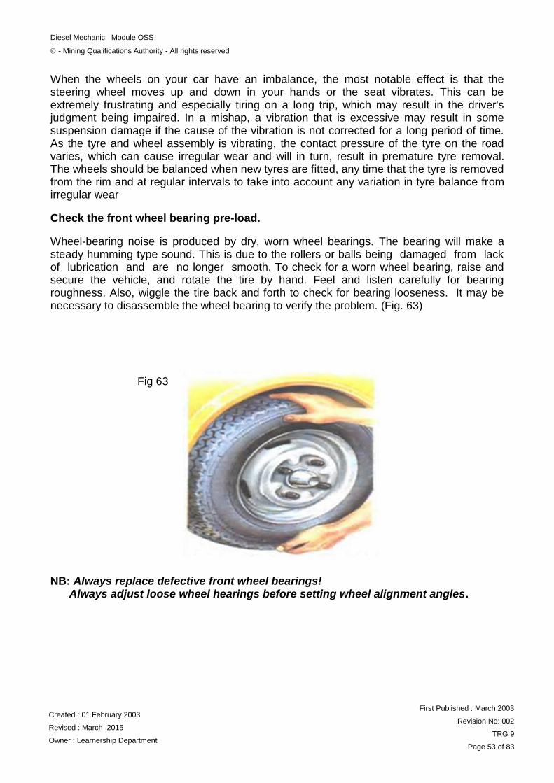
Check the front wheel bearing pre-load.
Wheel-bearing noise is produced by dry, worn wheel bearings. The bearing will make a steady humming type sound. This is due to the rollers or balls being damaged from lack of lubrication and are no longer smooth. To check for a worn wheel bearing, raise and secure the vehicle, and rotate the tire by hand. Feel and listen carefully for bearing roughness. Also, wiggle the tire back and forth to check for bearing looseness. It may be necessary to disassemble the wheel bearing to verify the problem. (Fig. 63)
NB: Always replace defective front wheel bearings! Always adjust loose wheel hearings before setting wheel alignment angles.
Fig 63
Diesel Mechanic: Module OSS
- Mining Qualifications Authority - All rights reserved
Created : 01 February 2003
Revised : March 2015
Owner : Learnership Department
First Published : March 2003
Revision No: 002
TRG 9
Page 54 of 83
WHEEL BEARINGS
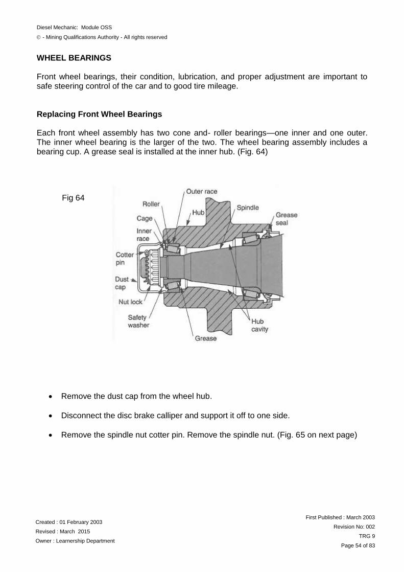
Front wheel bearings, their condition, lubrication, and proper adjustment are important to safe steering control of the car and to good tire mileage. Replacing Front Wheel Bearings Each front wheel assembly has two cone and- roller bearings—one inner and one outer. The inner wheel bearing is the larger of the two. The wheel bearing assembly includes a bearing cup. A grease seal is installed at the inner hub. (Fig. 64)
Remove the dust cap from the wheel hub.
Disconnect the disc brake calliper and support it off to one side.
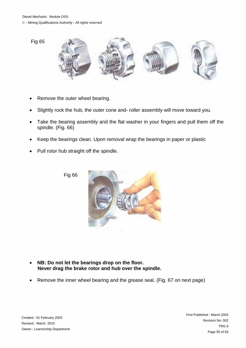
Remove the spindle nut cotter pin. Remove the spindle nut. (Fig. 65 on next page)
Fig 64
Diesel Mechanic: Module OSS
- Mining Qualifications Authority - All rights reserved
Created : 01 February 2003
Revised : March 2015
Owner : Learnership Department
First Published : March 2003
Revision No: 002
TRG 9
Page 55 of 83
Remove the outer wheel bearing.
Slightly rock the hub, the outer cone and- roller assembly will move toward you.
Take the bearing assembly and the flat washer in your fingers and pull them off the spindle. (Fig. 66)
Keep the bearings clean. Upon removal wrap the bearings in paper or plastic
Pull rotor hub straight off the spindle.
NB: Do not let the bearings drop on the floor. Never drag the brake rotor and hub over the spindle.
Remove the inner wheel bearing and the grease seal. (Fig. 67 on next page)
Fig 65
Fig 66
Diesel Mechanic: Module OSS
- Mining Qualifications Authority - All rights reserved
Created : 01 February 2003
Revised : March 2015
Owner : Learnership Department
First Published : March 2003
Revision No: 002
TRG 9
Page 56 of 83
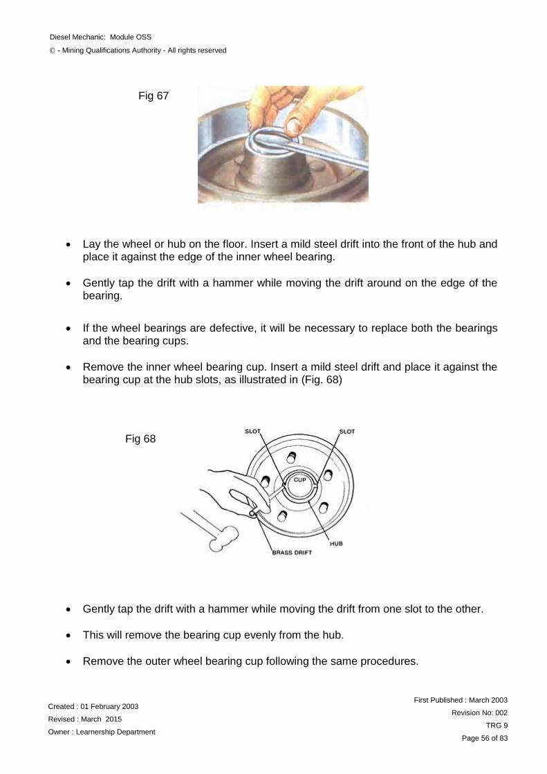
Lay the wheel or hub on the floor. Insert a mild steel drift into the front of the hub and place it against the edge of the inner wheel bearing.
Gently tap the drift with a hammer while moving the drift around on the edge of the bearing.
If the wheel bearings are defective, it will be necessary to replace both the bearings and the bearing cups.
Remove the inner wheel bearing cup. Insert a mild steel drift and place it against the bearing cup at the hub slots, as illustrated in (Fig. 68)
Gently tap the drift with a hammer while moving the drift from one slot to the other.
This will remove the bearing cup evenly from the hub.
Remove the outer wheel bearing cup following the same procedures.
Fig 67
Fig 68
Diesel Mechanic: Module OSS
- Mining Qualifications Authority - All rights reserved
Created : 01 February 2003
Revised : March 2015
Owner : Learnership Department
First Published : March 2003
Revision No: 002
TRG 9
Page 57 of 83
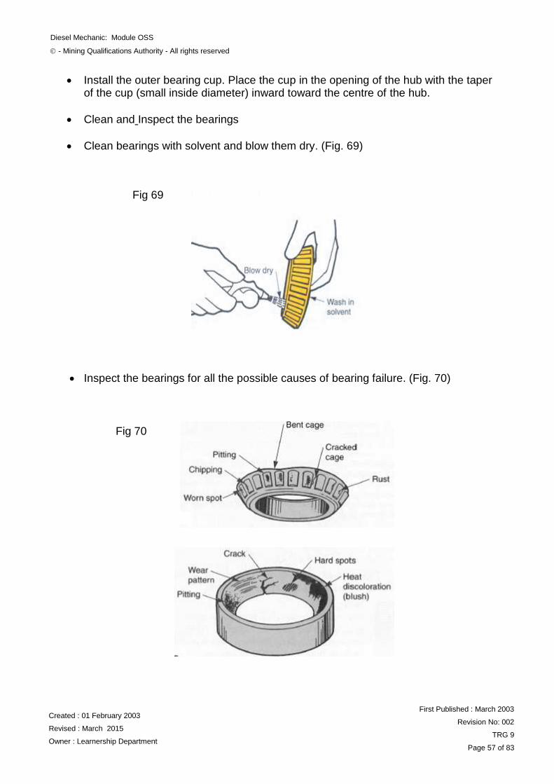
Install the outer bearing cup. Place the cup in the opening of the hub with the taper of the cup (small inside diameter) inward toward the centre of the hub.
Clean and Inspect the bearings
Clean bearings with solvent and blow them dry. (Fig. 69)
Inspect the bearings for all the possible causes of bearing failure. (Fig. 70)
Fig 69
Fig 70
Diesel Mechanic: Module OSS
- Mining Qualifications Authority - All rights reserved
Created : 01 February 2003
Revised : March 2015
Owner : Learnership Department
First Published : March 2003
Revision No: 002
TRG 9
Page 58 of 83
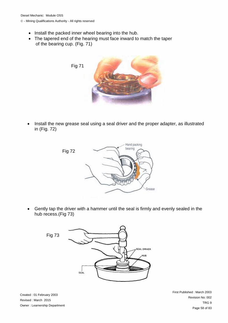
Install the packed inner wheel bearing into the hub.
The tapered end of the hearing must face inward to match the taper of the bearing cup. (Fig. 71)
Install the new grease seal using a seal driver and the proper adapter, as illustrated in (Fig. 72)
Gently tap the driver with a hammer until the seal is firmly and evenly sealed in the hub recess.(Fig 73)
Fig 71
Fig 72
Fig 73
Diesel Mechanic: Module OSS
- Mining Qualifications Authority - All rights reserved
Created : 01 February 2003
Revised : March 2015
Owner : Learnership Department
First Published : March 2003
Revision No: 002
TRG 9
Page 59 of 83
Install the wheel or rotor and hub assembly on the spindle.
Insert the outer wheel bearing into the hub.
Be sure the tapered end of the hearing is facing inward toward the centre of the hub.
NB: Be sure to keep the bearings free from dirt. The most common cause of bearing failure is dirt. Wheel bearings may be packed by hand or by a bearing packer. Apply a thin coat of wheel bearing lubricant to the inside of the hub and to the bearing cups.
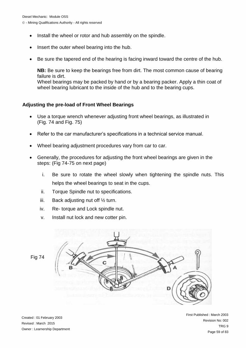
Adjusting the pre-load of Front Wheel Bearings
Use a torque wrench whenever adjusting front wheel bearings, as illustrated in (Fig. 74 and Fig. 75)
Refer to the car manufacturer‟s specifications in a technical service manual.
Wheel bearing adjustment procedures vary from car to car.
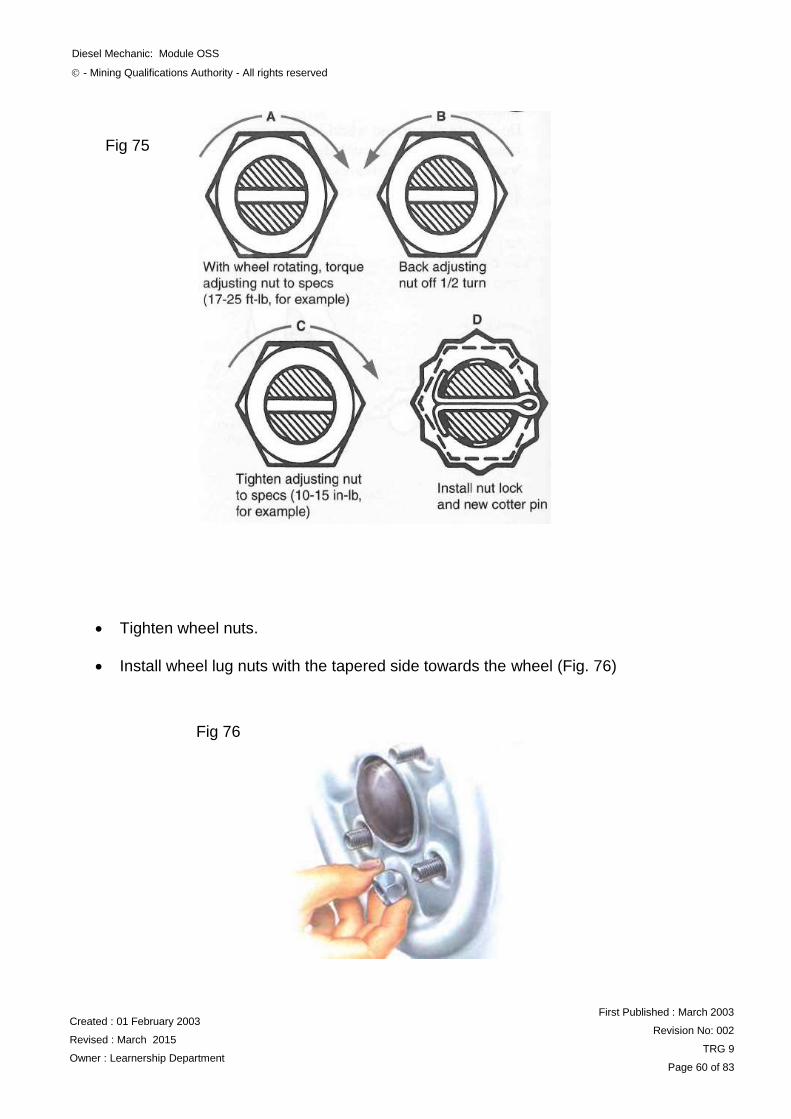
Generally, the procedures for adjusting the front wheel bearings are given in the steps: (Fig 74-75 on next page)
i. Be sure to rotate the wheel slowly when tightening the spindle nuts. This
helps the wheel bearings to seat in the cups.
ii. Torque Spindle nut to specifications.
iii. Back adjusting nut off ½ turn.
iv. Re- torque and Lock spindle nut.
v. Install nut lock and new cotter pin.
Fig 74
Diesel Mechanic: Module OSS
- Mining Qualifications Authority - All rights reserved
Created : 01 February 2003
Revised : March 2015
Owner : Learnership Department
First Published : March 2003
Revision No: 002
TRG 9
Page 60 of 83
Tighten wheel nuts.
Install wheel lug nuts with the tapered side towards the wheel (Fig. 76)
Fig 75
Fig 76
Diesel Mechanic: Module OSS
- Mining Qualifications Authority - All rights reserved
Created : 01 February 2003
Revised : March 2015
Owner : Learnership Department
First Published : March 2003
Revision No: 002
TRG 9
Page 61 of 83
Tighten the wheel lug nuts following a staggered, crisscross tightening sequence.
Never over tighten the wheel lug nuts, always use a torque wrench to tighten the nuts to the specified torque
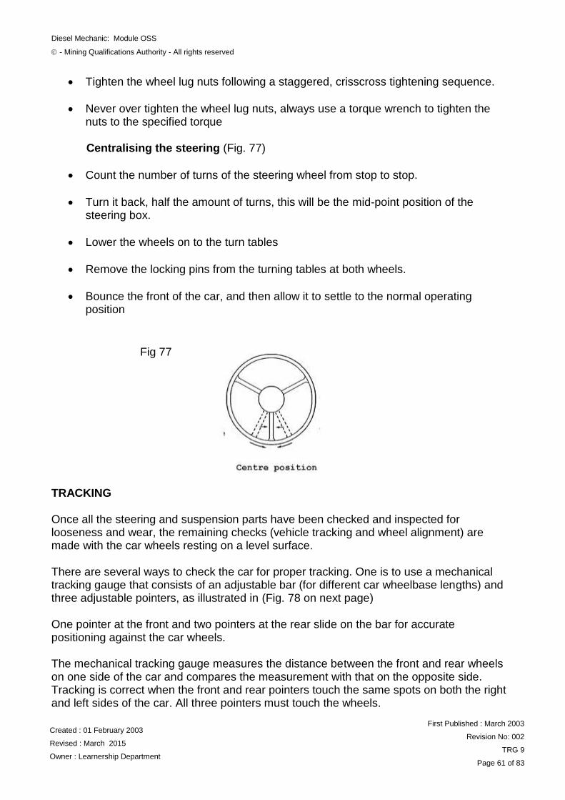
Centralising the steering (Fig. 77)
Count the number of turns of the steering wheel from stop to stop.
Turn it back, half the amount of turns, this will be the mid-point position of the steering box.
Lower the wheels on to the turn tables
Remove the locking pins from the turning tables at both wheels.
Bounce the front of the car, and then allow it to settle to the normal operating position
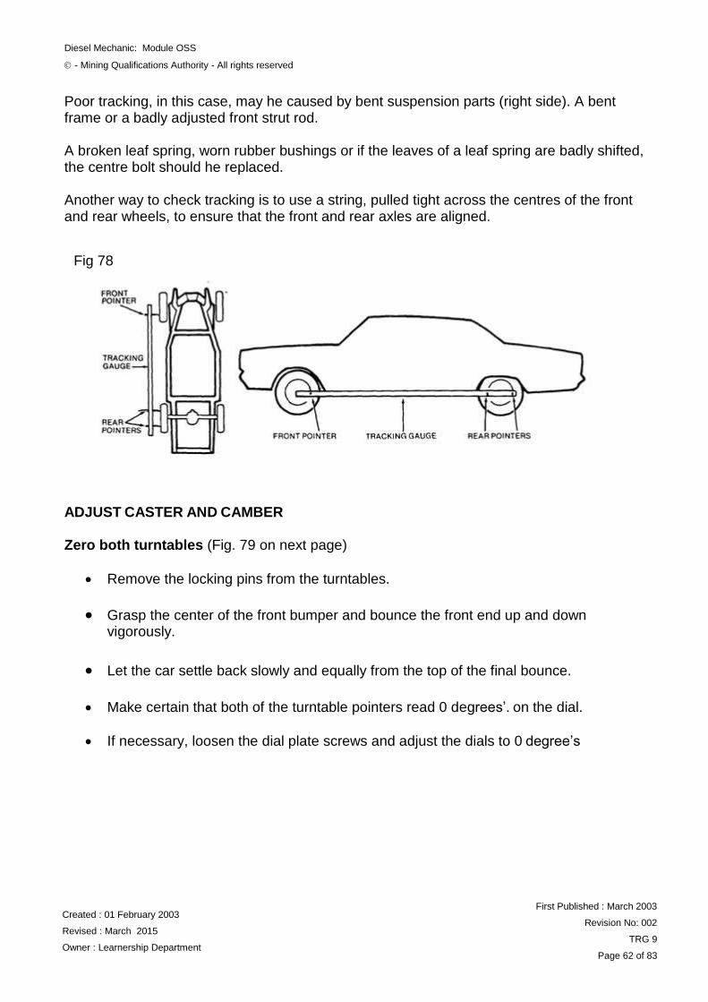
(Fig. 75) TRACKING Once all the steering and suspension parts have been checked and inspected for looseness and wear, the remaining checks (vehicle tracking and wheel alignment) are made with the car wheels resting on a level surface. There are several ways to check the car for proper tracking. One is to use a mechanical tracking gauge that consists of an adjustable bar (for different car wheelbase lengths) and three adjustable pointers, as illustrated in (Fig. 78 on next page)
One pointer at the front and two pointers at the rear slide on the bar for accurate positioning against the car wheels. The mechanical tracking gauge measures the distance between the front and rear wheels on one side of the car and compares the measurement with that on the opposite side. Tracking is correct when the front and rear pointers touch the same spots on both the right and left sides of the car. All three pointers must touch the wheels.
Fig 77
Diesel Mechanic: Module OSS
- Mining Qualifications Authority - All rights reserved
Created : 01 February 2003
Revised : March 2015
Owner : Learnership Department
First Published : March 2003
Revision No: 002
TRG 9
Page 62 of 83
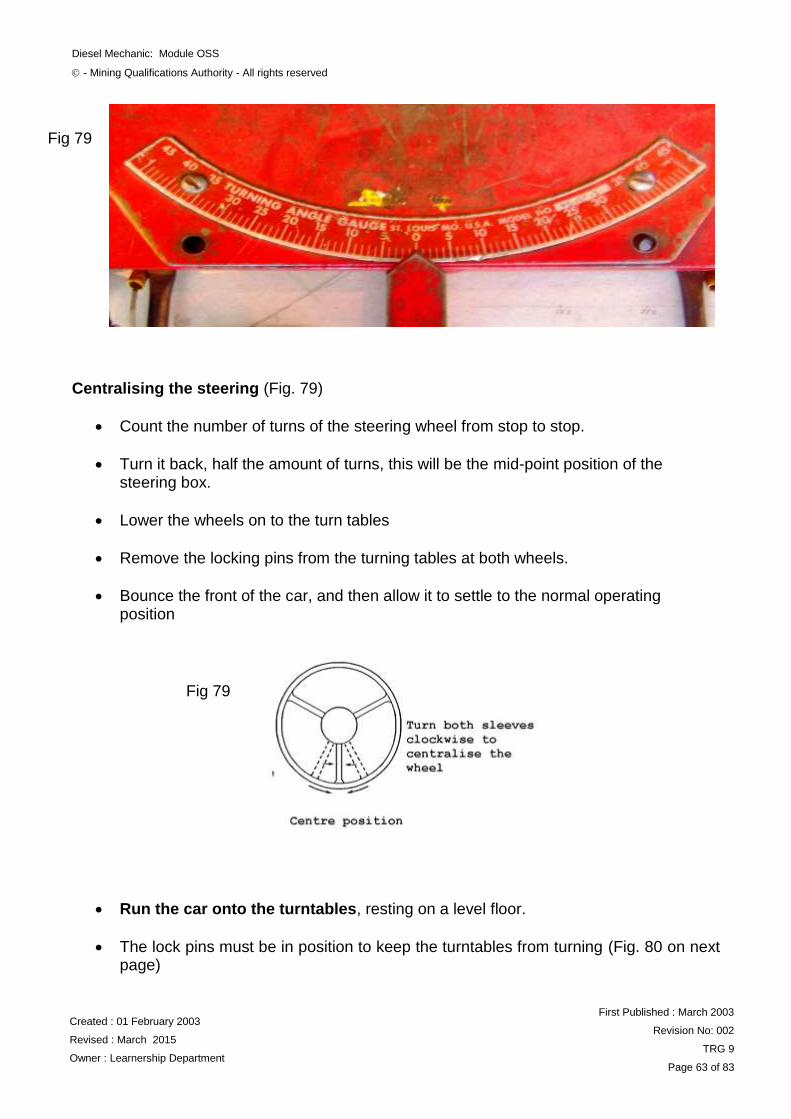
Poor tracking, in this case, may he caused by bent suspension parts (right side). A bent frame or a badly adjusted front strut rod. A broken leaf spring, worn rubber bushings or if the leaves of a leaf spring are badly shifted, the centre bolt should he replaced. Another way to check tracking is to use a string, pulled tight across the centres of the front and rear wheels, to ensure that the front and rear axles are aligned. ADJUST CASTER AND CAMBER Zero both turntables (Fig. 79 on next page)
Remove the locking pins from the turntables.
Grasp the center of the front bumper and bounce the front end up and down vigorously.
Let the car settle back slowly and equally from the top of the final bounce.
Make certain that both of the turntable pointers read 0 degrees‟. on the dial.
If necessary, loosen the dial plate screws and adjust the dials to 0 degree‟s
Fig 78
Diesel Mechanic: Module OSS
- Mining Qualifications Authority - All rights reserved
Created : 01 February 2003
Revised : March 2015
Owner : Learnership Department
First Published : March 2003
Revision No: 002
TRG 9
Page 63 of 83
Centralising the steering (Fig. 79)
Count the number of turns of the steering wheel from stop to stop.
Turn it back, half the amount of turns, this will be the mid-point position of the steering box.
Lower the wheels on to the turn tables
Remove the locking pins from the turning tables at both wheels.
Bounce the front of the car, and then allow it to settle to the normal operating position
Run the car onto the turntables, resting on a level floor.
The lock pins must be in position to keep the turntables from turning (Fig. 80 on next page)
Fig 79
Fig 79
Diesel Mechanic: Module OSS
- Mining Qualifications Authority - All rights reserved
Created : 01 February 2003
Revised : March 2015
Owner : Learnership Department
First Published : March 2003
Revision No: 002
TRG 9
Page 64 of 83
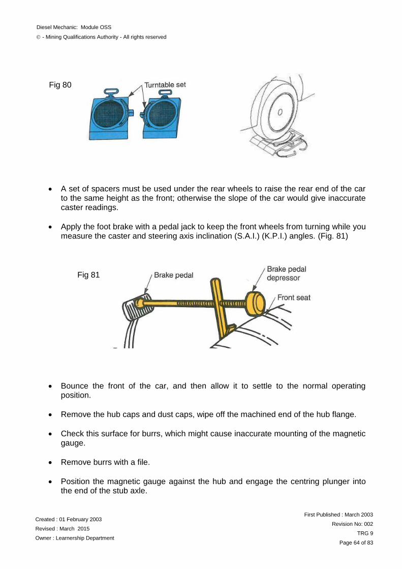
A set of spacers must be used under the rear wheels to raise the rear end of the car to the same height as the front; otherwise the slope of the car would give inaccurate caster readings.
Apply the foot brake with a pedal jack to keep the front wheels from turning while you measure the caster and steering axis inclination (S.A.I.) (K.P.I.) angles. (Fig. 81)
Bounce the front of the car, and then allow it to settle to the normal operating position.
Remove the hub caps and dust caps, wipe off the machined end of the hub flange.
Check this surface for burrs, which might cause inaccurate mounting of the magnetic gauge.
Remove burrs with a file.
Position the magnetic gauge against the hub and engage the centring plunger into the end of the stub axle.
Fig 80
Fig 81
Diesel Mechanic: Module OSS
- Mining Qualifications Authority - All rights reserved
Created : 01 February 2003
Revised : March 2015
Owner : Learnership Department
First Published : March 2003
Revision No: 002
TRG 9
Page 65 of 83
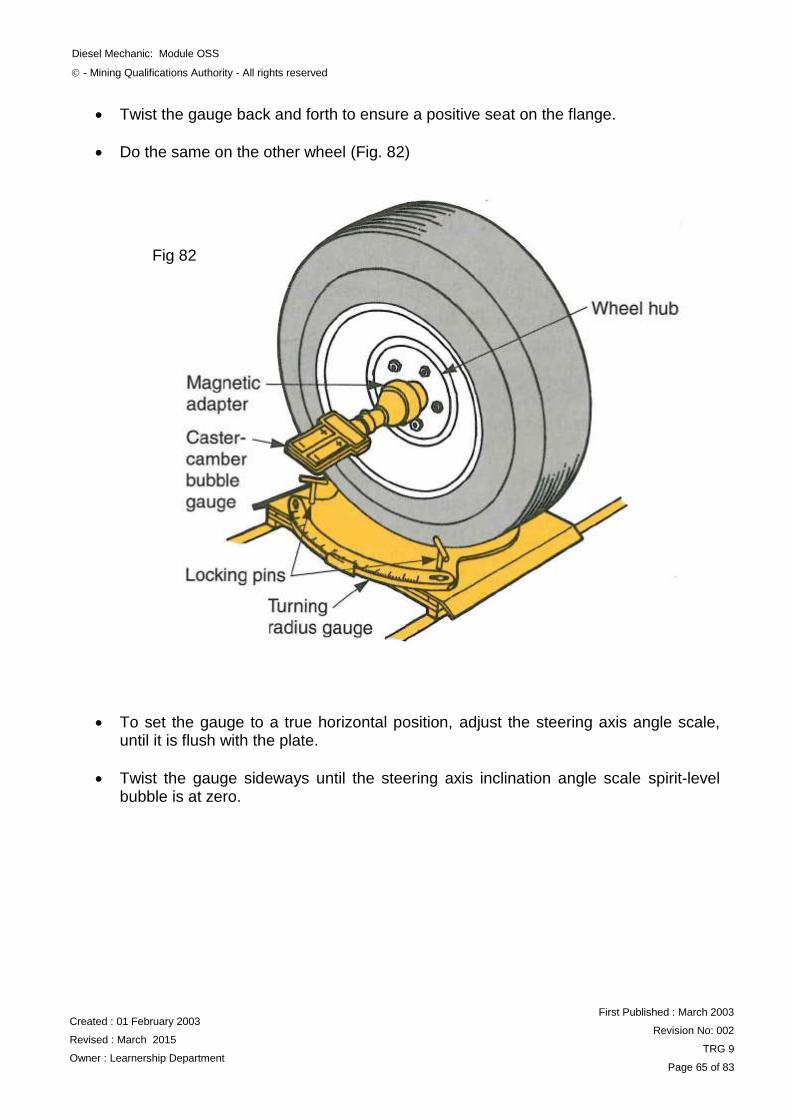
Twist the gauge back and forth to ensure a positive seat on the flange.
Do the same on the other wheel (Fig. 82)
To set the gauge to a true horizontal position, adjust the steering axis angle scale, until it is flush with the plate.
Twist the gauge sideways until the steering axis inclination angle scale spirit-level bubble is at zero.
Fig 82
Diesel Mechanic: Module OSS
- Mining Qualifications Authority - All rights reserved
Created : 01 February 2003
Revised : March 2015
Owner : Learnership Department
First Published : March 2003
Revision No: 002
TRG 9
Page 66 of 83
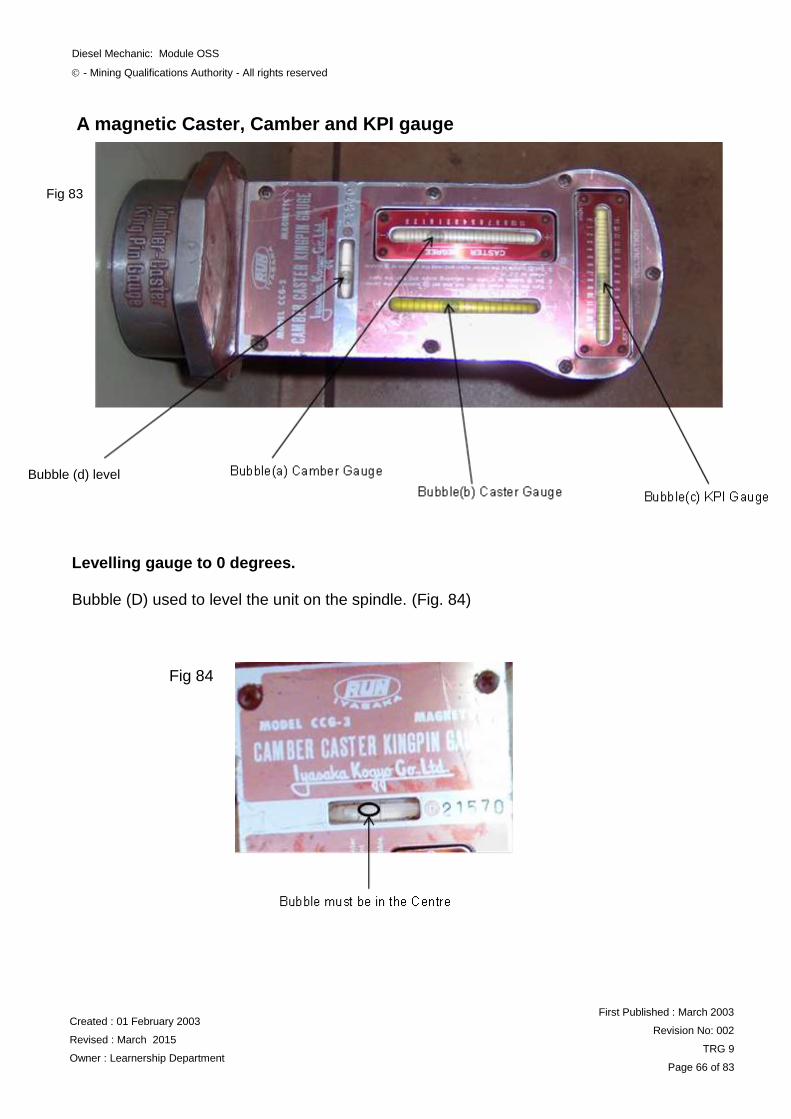
A magnetic Caster, Camber and KPI gauge
Levelling gauge to 0 degrees. Bubble (D) used to level the unit on the spindle. (Fig. 84)
Fig 84
Fig 83
g Gaugeb Bubble (d) level
Diesel Mechanic: Module OSS
- Mining Qualifications Authority - All rights reserved
Created : 01 February 2003
Revised : March 2015
Owner : Learnership Department
First Published : March 2003
Revision No: 002
TRG 9
Page 67 of 83
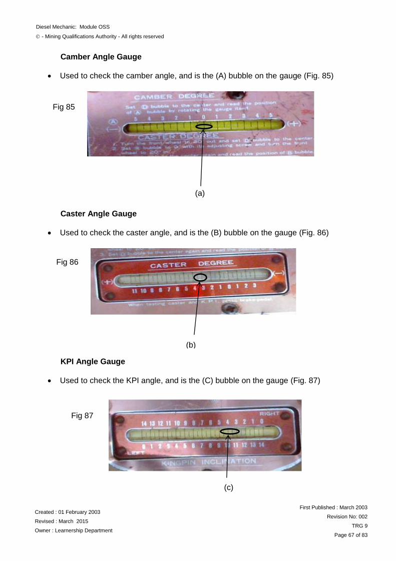
Camber Angle Gauge
Used to check the camber angle, and is the (A) bubble on the gauge (Fig. 85)
Caster Angle Gauge
Used to check the caster angle, and is the (B) bubble on the gauge (Fig. 86)
KPI Angle Gauge
Used to check the KPI angle, and is the (C) bubble on the gauge (Fig. 87)
(a)
Fig 85
(b)
Fig 86
(c)
Fig 87
Diesel Mechanic: Module OSS
- Mining Qualifications Authority - All rights reserved
Created : 01 February 2003
Revised : March 2015
Owner : Learnership Department
First Published : March 2003
Revision No: 002
TRG 9
Page 68 of 83
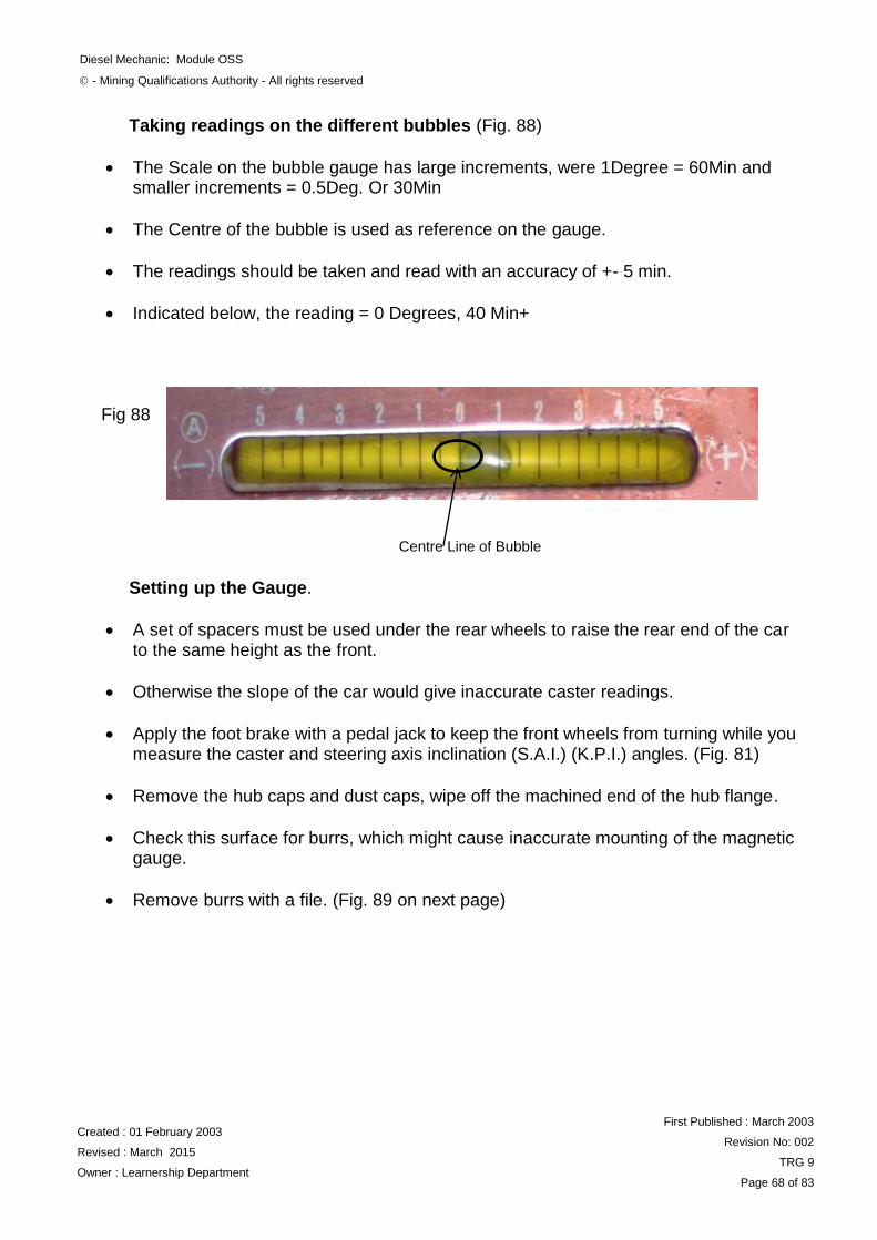
Taking readings on the different bubbles (Fig. 88)
The Scale on the bubble gauge has large increments, were 1Degree = 60Min and smaller increments = 0.5Deg. Or 30Min
The Centre of the bubble is used as reference on the gauge.
The readings should be taken and read with an accuracy of +- 5 min.
Indicated below, the reading = 0 Degrees, 40 Min+
Setting up the Gauge.
A set of spacers must be used under the rear wheels to raise the rear end of the car to the same height as the front.
Otherwise the slope of the car would give inaccurate caster readings.
Apply the foot brake with a pedal jack to keep the front wheels from turning while you measure the caster and steering axis inclination (S.A.I.) (K.P.I.) angles. (Fig. 81)
Remove the hub caps and dust caps, wipe off the machined end of the hub flange.
Check this surface for burrs, which might cause inaccurate mounting of the magnetic gauge.
Remove burrs with a file. (Fig. 89 on next page)
Centre Line of Bubble
Fig 88
Diesel Mechanic: Module OSS
- Mining Qualifications Authority - All rights reserved
Created : 01 February 2003
Revised : March 2015
Owner : Learnership Department
First Published : March 2003
Revision No: 002
TRG 9
Page 69 of 83
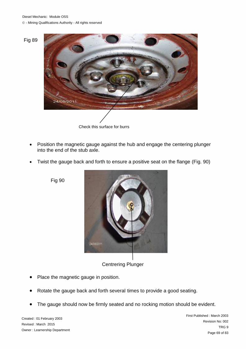
Position the magnetic gauge against the hub and engage the centering plunger into the end of the stub axle.
Twist the gauge back and forth to ensure a positive seat on the flange (Fig. 90)
Place the magnetic gauge in position.
Rotate the gauge back and forth several times to provide a good seating.
The gauge should now be firmly seated and no rocking motion should be evident.
Check this surface for burrs
Fig 89
Centrering Plunger
Fig 90
Diesel Mechanic: Module OSS
- Mining Qualifications Authority - All rights reserved
Created : 01 February 2003
Revised : March 2015
Owner : Learnership Department
First Published : March 2003
Revision No: 002
TRG 9
Page 70 of 83
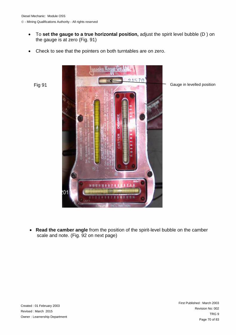
To set the gauge to a true horizontal position, adjust the spirit level bubble (D ) on the gauge is at zero (Fig. 91)
Check to see that the pointers on both turntables are on zero.
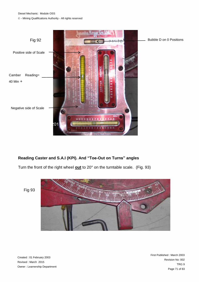
Read the camber angle from the position of the spirit-level bubble on the camber scale and note. (Fig. 92 on next page)
Gauge in levelled position
Fig 91
Diesel Mechanic: Module OSS
- Mining Qualifications Authority - All rights reserved
Created : 01 February 2003
Revised : March 2015
Owner : Learnership Department
First Published : March 2003
Revision No: 002
TRG 9
Page 71 of 83
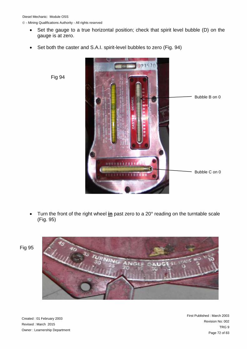
Reading Caster and S.A.I (KPI). And “Toe-Out on Turns” angles Turn the front of the right wheel out to 20° on the turntable scale. (Fig. 93)
Bubble D on 0 Positions
Positive side of Scale
Camber Reading=
40 Min +
Negative side of Scale
Fig 92
Fig 93
Diesel Mechanic: Module OSS
- Mining Qualifications Authority - All rights reserved
Created : 01 February 2003
Revised : March 2015
Owner : Learnership Department
First Published : March 2003
Revision No: 002
TRG 9
Page 72 of 83
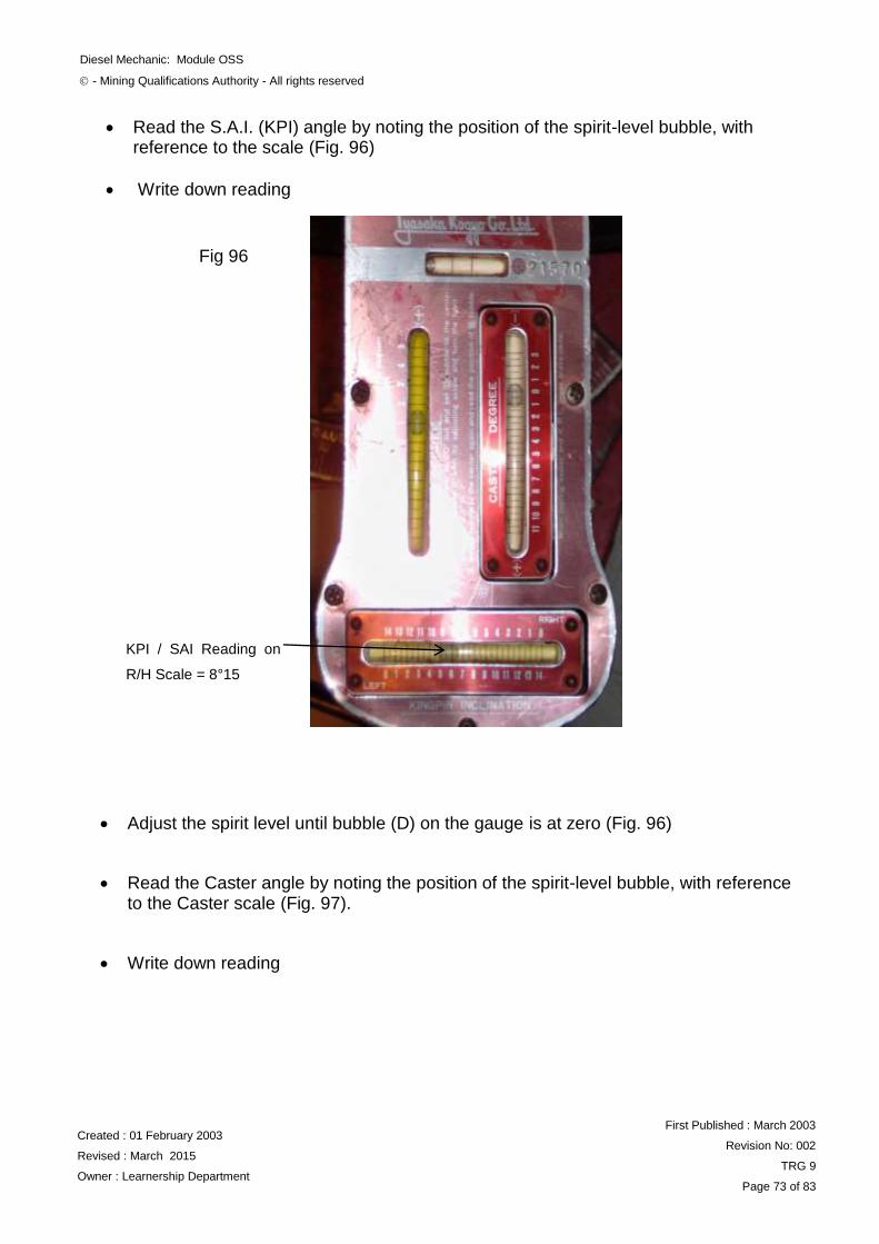
Set the gauge to a true horizontal position; check that spirit level bubble (D) on the gauge is at zero.
Set both the caster and S.A.I. spirit-level bubbles to zero (Fig. 94)
Turn the front of the right wheel in past zero to a 20° reading on the turntable scale (Fig. 95)
Bubble B on 0
Bubble C on 0
Fig 94
Fig 95
Diesel Mechanic: Module OSS
- Mining Qualifications Authority - All rights reserved
Created : 01 February 2003
Revised : March 2015
Owner : Learnership Department
First Published : March 2003
Revision No: 002
TRG 9
Page 73 of 83
Read the S.A.I. (KPI) angle by noting the position of the spirit-level bubble, with reference to the scale (Fig. 96)
Write down reading
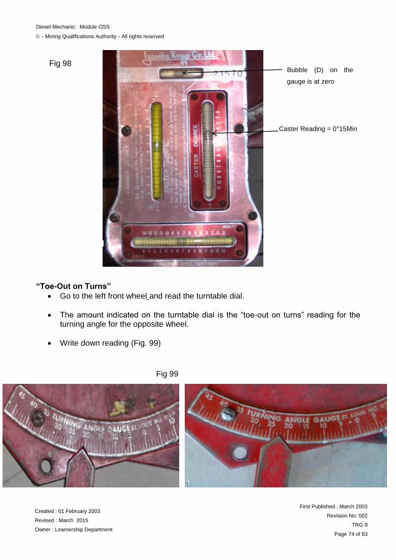
Adjust the spirit level until bubble (D) on the gauge is at zero (Fig. 96)
Read the Caster angle by noting the position of the spirit-level bubble, with reference to the Caster scale (Fig. 97).
Write down reading
KPI / SAI Reading on
R/H Scale = 8°15
Fig 96
Diesel Mechanic: Module OSS
- Mining Qualifications Authority - All rights reserved
Created : 01 February 2003
Revised : March 2015
Owner : Learnership Department
First Published : March 2003
Revision No: 002
TRG 9
Page 74 of 83
“Toe-Out on Turns”
Go to the left front wheel and read the turntable dial.
The amount indicated on the turntable dial is the “toe-out on turns” reading for the turning angle for the opposite wheel.
Write down reading (Fig. 99)
Bubble (D) on the
gauge is at zero
Caster Reading = 0°15Min
Fig 98
Fig 99
Diesel Mechanic: Module OSS
- Mining Qualifications Authority - All rights reserved
Created : 01 February 2003
Revised : March 2015
Owner : Learnership Department
First Published : March 2003
Revision No: 002
TRG 9
Page 75 of 83
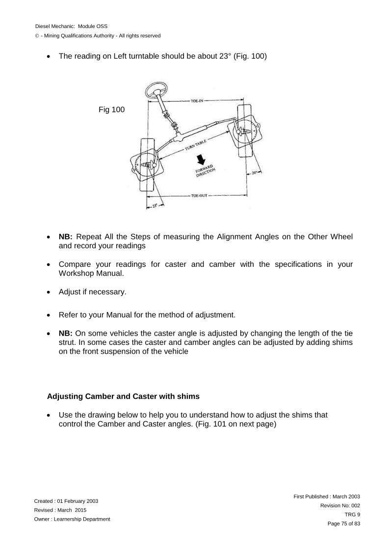
The reading on Left turntable should be about 23° (Fig. 100)
NB: Repeat All the Steps of measuring the Alignment Angles on the Other Wheel and record your readings
Compare your readings for caster and camber with the specifications in your Workshop Manual.
Adjust if necessary.
Refer to your Manual for the method of adjustment.
NB: On some vehicles the caster angle is adjusted by changing the length of the tie strut. In some cases the caster and camber angles can be adjusted by adding shims on the front suspension of the vehicle
Adjusting Camber and Caster with shims
Use the drawing below to help you to understand how to adjust the shims that control the Camber and Caster angles. (Fig. 101 on next page)
Fig 100
Diesel Mechanic: Module OSS
- Mining Qualifications Authority - All rights reserved
Created : 01 February 2003
Revised : March 2015
Owner : Learnership Department
First Published : March 2003
Revision No: 002
TRG 9
Page 76 of 83
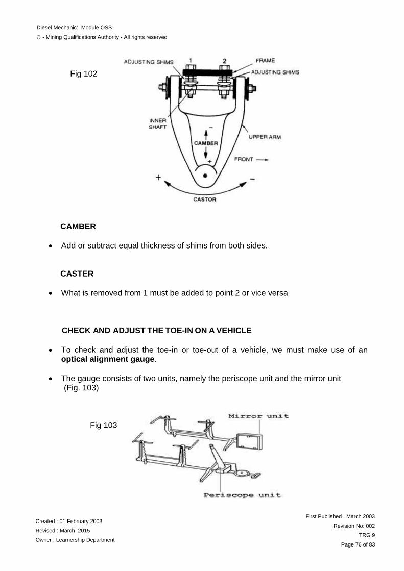
CAMBER
Add or subtract equal thickness of shims from both sides.
CASTER
What is removed from 1 must be added to point 2 or vice versa
CHECK AND ADJUST THE TOE-IN ON A VEHICLE
To check and adjust the toe-in or toe-out of a vehicle, we must make use of an optical alignment gauge.
The gauge consists of two units, namely the periscope unit and the mirror unit (Fig. 103)
(Fig. 99)
Fig 102
Fig 103
Diesel Mechanic: Module OSS
- Mining Qualifications Authority - All rights reserved
Created : 01 February 2003
Revised : March 2015
Owner : Learnership Department
First Published : March 2003
Revision No: 002
TRG 9
Page 77 of 83
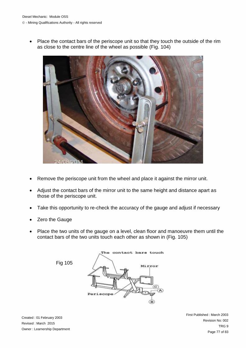
Place the contact bars of the periscope unit so that they touch the outside of the rim as close to the centre line of the wheel as possible (Fig. 104)
(Fig. 100)
Remove the periscope unit from the wheel and place it against the mirror unit.
Adjust the contact bars of the mirror unit to the same height and distance apart as those of the periscope unit.
Take this opportunity to re-check the accuracy of the gauge and adjust if necessary
Zero the Gauge
Place the two units of the gauge on a level, clean floor and manoeuvre them until the contact bars of the two units touch each other as shown in (Fig. 105)
(Fig. 107)
Fig 105
Diesel Mechanic: Module OSS
- Mining Qualifications Authority - All rights reserved
Created : 01 February 2003
Revised : March 2015
Owner : Learnership Department
First Published : March 2003
Revision No: 002
TRG 9
Page 78 of 83
Adjust the mirror and the periscope until the reflection of the target plate C can be seen in the mirror through the periscope (Fig. 106)
Sighting through the periscope, move pointer A until the image reflects the hairline in the centre of the triangle between the vertical lines (Fig. 107)
Fig 106
Fig 107
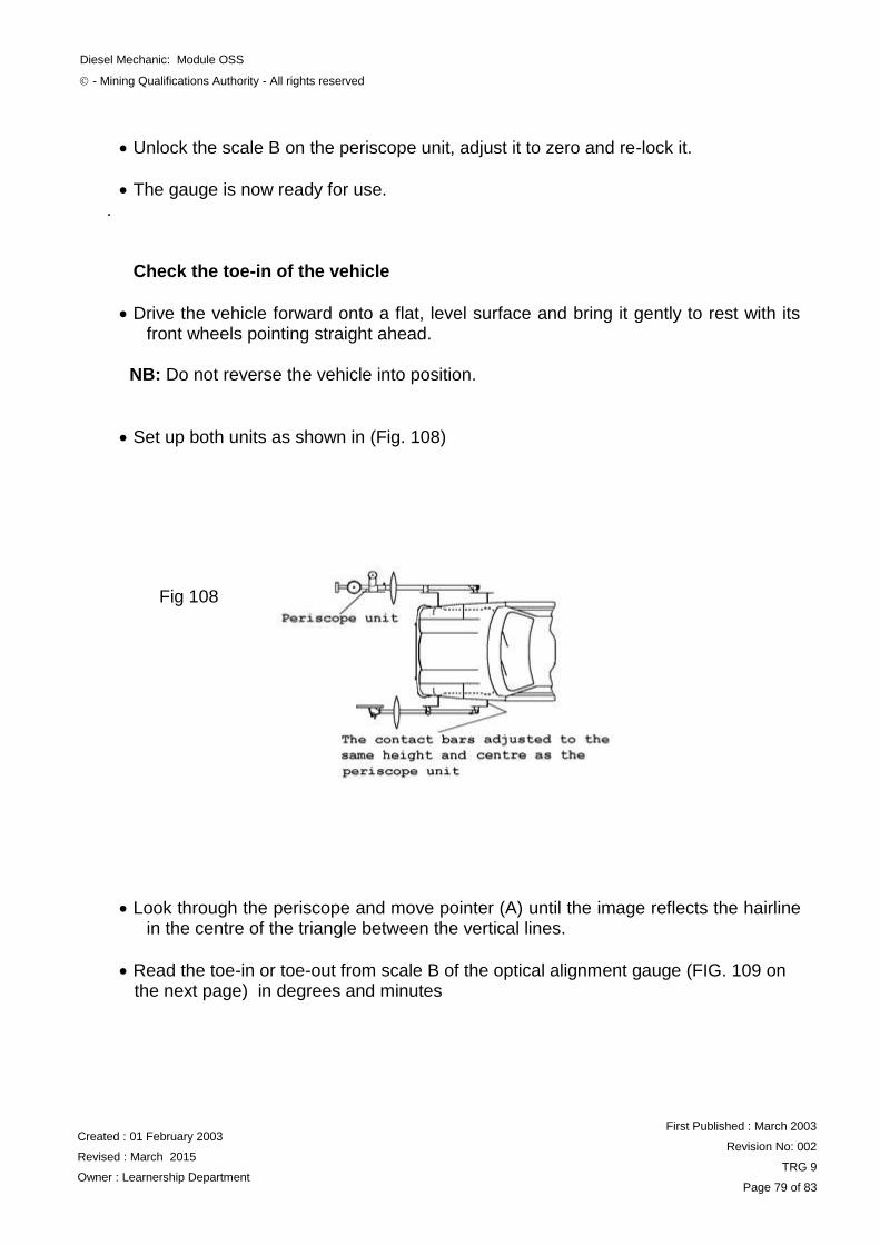
Diesel Mechanic: Module OSS
- Mining Qualifications Authority - All rights reserved
Created : 01 February 2003
Revised : March 2015
Owner : Learnership Department
First Published : March 2003
Revision No: 002
TRG 9
Page 79 of 83
Unlock the scale B on the periscope unit, adjust it to zero and re-lock it.
The gauge is now ready for use. .
Check the toe-in of the vehicle
Drive the vehicle forward onto a flat, level surface and bring it gently to rest with its front wheels pointing straight ahead.
NB: Do not reverse the vehicle into position.
Set up both units as shown in (Fig. 108)
Look through the periscope and move pointer (A) until the image reflects the hairline in the centre of the triangle between the vertical lines.
Read the toe-in or toe-out from scale B of the optical alignment gauge (FIG. 109 on the next page) in degrees and minutes
Fig 108
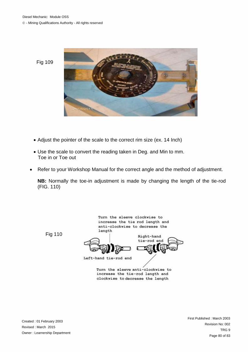
Diesel Mechanic: Module OSS
- Mining Qualifications Authority - All rights reserved
Created : 01 February 2003
Revised : March 2015
Owner : Learnership Department
First Published : March 2003
Revision No: 002
TRG 9
Page 80 of 83
(FIG. 106)
Adjust the pointer of the scale to the correct rim size (ex. 14 Inch)
Use the scale to convert the reading taken in Deg. and Min to mm. Toe in or Toe out
Refer to your Workshop Manual for the correct angle and the method of adjustment.
NB: Normally the toe-in adjustment is made by changing the length of the tie-rod (FIG. 110)
Fig 109
Fig 110
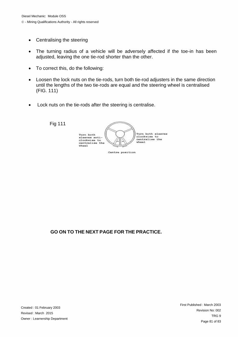
Diesel Mechanic: Module OSS
- Mining Qualifications Authority - All rights reserved
Created : 01 February 2003
Revised : March 2015
Owner : Learnership Department
First Published : March 2003
Revision No: 002
TRG 9
Page 81 of 83
Centralising the steering
The turning radius of a vehicle will be adversely affected if the toe-in has been adjusted, leaving the one tie-rod shorter than the other.
To correct this, do the following:
Loosen the lock nuts on the tie-rods, turn both tie-rod adjusters in the same direction until the lengths of the two tie-rods are equal and the steering wheel is centralised (FIG. 111)
Lock nuts on the tie-rods after the steering is centralise.
GO ON TO THE NEXT PAGE FOR THE PRACTICE.
Fig 111
Diesel Mechanic: Module OSS
- Mining Qualifications Authority - All rights reserved
Created : 01 February 2003
Revised : March 2015
Owner : Learnership Department
First Published : March 2003
Revision No: 002
TRG 9
Page 82 of 83
PRACTICE By referring to your notes and the workshop manual, check and adjust the caster, camber angles and toe of a vehicle. Call your Training Officer to check your work and ask him to sign you off when it is correct, then go on to the next section.
REMEMBER ALWAYS WORK SAFE
Once you have passed the entire self-
tests and practices, you are now at
liberty to request a Formative
Assessment from you Assessor
LEARNER
TRAINING OFFICER
Date:
Date:
Signed:
Signed:


![[Ramamurti Shankar] Principles of Quantum Mechanic(BookFi.org)](https://img.pdfslide.net/doc/110x75/636024bfabda3a4d4d03688e/ramamurti-shankar-principles-of-quantum-mechanicbookfiorg.jpg)


