Embed Size (px)
Citation preview

POLYMERTESTING
Polymer Testing 27 (2008) 581–590
ARTICLE IN PRESS
0142-9418/$ - see
doi:10.1016/j.po
�Correspondifax: +913222 2
E-mail addre
www.elsevier.com/locate/polytest
Material Properties
Direct fluorination of UHMWPE fiber and preparationof fluorinated and non-fluorinated fiber composites
with LDPE matrix
J. Maitya, C. Jacoba,�, C.K. Dasa, S. Alamb, R.P. Singhc
aMaterials Science Centre, Indian Institute of Technology, Kharagpur 721302, IndiabDMSRDE, Kanpur, India
cUniversity of Lucknow, Lucknow 226007, India
Received 21 January 2008; accepted 7 March 2008
Abstract
In this study, the surface of ultra-high-molecular-weight polyethylene (UHMWPE) fiber used as reinforcement in low-
density polyethylene (LDPE)/UHMWPE fiber composites was modified by direct fluorination using elemental fluorine,
(10% F2+90% He) mixture, at 25 1C. A polymer composite based on LDPE/UHMWPE fibers was prepared. We studied
the influence of surface treatment of the fibers on properties of the composite. The fibers were first used as received, and
then were used after fluorine (direct fluorination) treatment of their surface. Stress–strain behavior of the prepared samples
was measured. Thermal properties and the trans-crystallization of the matrix over the fibers were observed. The
crystallization of the matrix on the fiber surface was followed by scanning electron microscopy and by differential scanning
calorimeter (DSC) analysis. The structure of the interface was then observed by X-ray diffraction. Surface energy was
determined by contact angle measurement and it indicates that the wetting properties of the fluorinated fiber composites
were improved.
r 2008 Elsevier Ltd. All rights reserved.
Keywords: Direct fluorination; Short-fiber composites; Surface treatments; Scanning electron microscopy (SEM); Fiber/matrix bond
1. Introduction
High-performance fiber composites with a poly-meric matrix have been developed as innovativematerials for future air and spacecraft technologiesas well as conventional machinery design andconstruction. These materials increasingly replaceclassic construction materials such as steel and
front matter r 2008 Elsevier Ltd. All rights reserved
lymertesting.2008.03.001
ng author. Tel.: +913222 283 964;
55 303.
ss: [email protected] (C. Jacob).
aluminum, particularly when a high ratio ofmechanical properties to density is required. Fortechnical purposes, thermosets are mainly used asmatrix materials. However, the application ofthermoplastics promises a number of advantagesbecause manufacturing (and technology) is simple.Thermoplastic composites are superior with respectto impact strength, surface quality, and storagecapability [1]. Nowadays, due to ecological con-siderations and limitations on recycling of usedpolymeric materials, it is necessary either to producecomposites that can be biologically degraded by
.

ARTICLE IN PRESSJ. Maity et al. / Polymer Testing 27 (2008) 581–590582
micro-organisms or to develop fiber-reinforcedmaterials consisting of fibers and matrix withidentical chemical structure (one-polymer-compo-site). Such composites can be easily recycled by amelting process, e.g. by extrusion or injectionmolding, and can be used in a second application.
Ultra-high-molecular-weight polyethylene (UH-MWPE) fibers currently represent synthetic fiberswhose mechanical performance (specific modulusand strength) is among the most interesting on themarket. They are used successfully in many fieldsbecause of their properties, such as biocompatibil-ity, hydrophobic nature, chemical resistance andelectric insulation. However, low melting point andpoor fire resistance restricts their field of use.Moreover, use of these fibers as reinforcing materialin composite applications is basically impossiblebecause of their non-polar chemical nature whichmakes strong interactions with most polymericmatrices impossible. So, insertion of polyethylenefibers (PEFs) does not allow optimal transmissionof interfacial stresses of one fiber on another, andthis limits the application. Nevertheless, some testswere carried out to use these high-performancefibers as reinforcement in composite materials,mainly in thermosetting matrices of the epoxy type,by treating the fiber surface by plasma or a suitablechemical treatment [2,3]. Some studies were alsoundertaken by Devaux et al. [4,5], where thechemical similarity of structure between fiber andsurrounding matrix is exploited, i.e. the extremesurface of the UHMWPE fibers whose meltingpoint is higher than that of the matrix (polyethy-lene) melts, and co-crystallization occurs. This co-crystallization results in the appearance of atranscrystalline interphase, which improves theadhesion between the two materials present.
Reinforcing a common polyethylene with PEFsleads to a strong and stiff single polymer composite[6]. Lacroix et al. [7] studied the TC of UHMWPEfibers/HDPE composites, and found that the sur-face crystallization UHMWPE fibers act as nuclea-tion centers for the high-density PE matrix, whichmight result from epitaxial crystallization. Aftercrystallization from the melt, a TC layer was foundhaving lamellar crystals grown perpendicular to thefiber axis, which was independent of air-cooling, orisothermal crystallization conditions. Vaisman et al.[8] reported that UHMWPE fibers treated byphotochemical bromination, resulting in a higherconcentration of crystallization nuclei, generated adenser TC layer with higher specific radial orienta-
tion with respect to the fiber axis compared with theuntreated fiber. HDPE [9] is often used as thematrix, while the fiber reinforcements are usually ofthe same type of polymer [10–12], i.e. PE fibers.He and Porter [13] reported that, aided by thesimilarity between the HDPE matrix and high-modulus PE fiber, a higher PE fiber fraction in thecomposites increased the nucleation density. Theisothermal crystallization of a single PE compositewith 50wt% fiber fraction showed dual-step crystal-lization. The ultra-high-modulus PE fiber exhibitedvery good nucleation ability toward linear high-density polyethylene (LHDPE) [14]. Also, whenrecycled short GF was used with new PE matrix, theresidual matrix could recrystallize [15].
However, contact of this kind of fiber with amatrix of a similar chemical nature may beimproved by modifying the interfacial physico-chemical interactions. We have established [16] thata PE matrix, whose melting temperature is clearlyless than that of the fiber, can be processed withoutcausing significant damage to the fiber. Surfacemodification is a well-established method forenhancing the performance of polymeric materialsin a number of applications. A particularly effectiveapproach to surface modification is direct fluorina-tion, i.e. the treatment of a polymer surface withgaseous fluorine or a fluorine gas mixture. Due tothe relatively weak F–F and strong C–F bonds,fluorination can proceed spontaneously at practi-cally acceptable rates at ambient temperatureswithout the need for any initiation [17]. Moreover,a suitable surface treatment of the reinforcingmaterial may have a positive effect on adhesion byeliminating the existing weak boundary layer and byincreasing the surface contact between the twocomponents. In addition, such a chemical treatmentincreases the surface energy of the fiber and, thus,favors wetting by the liquid matrix. Kazanci et al.[18] studied extensively single-polymer compositesbased on UHMWPE fibers in a PE matrix withdifferent types of PE and a range of length andorientation of the fibers.
The present study has been driven by the idea thata specifically selected surface treatment of the PEfiber can generate a double effect, in which thepolarity of the fiber surface is increased. Theidentical chemical nature and crystalline morphol-ogy of the constituents in this composite systemresult in their mutual compatibility at the interface.This generates, in addition to a relatively goodinterfacial adhesion, a unique fiber/matrix interface,

ARTICLE IN PRESS
Table 1
Composition of the composites
Sample name Wt% of non-
fluorinated PE fiber
Wt% of
fluorinated PE
fiber
LDP0 0.00 –
LDP1 2.50 –
LDP2 5.00 –
LDP3 7.50 –
LDP5 15.0 –
LDP1F – 2.50
LDP2F – 5.00
LDP3F – 7.50
LDP5F – 15.0
J. Maity et al. / Polymer Testing 27 (2008) 581–590 583
in which the matrix crystallizes preferentially on thefiber surface. It has been hypothesized that surfacefluorination of the PE fiber can implant polarmoieties on the fiber surface which serves toenhance matrix nucleation and transcrystallization,and improve the mechanical properties of thesystem.
2. Experimental details
2.1. Materials
The UHMWPE fiber used in this experimentas a reinforcing agent was Spectra-900 (Alliedsignal). The matrix was low-density polyethylene(LDPE) [MFI (190 1C/2.16 kg) ¼ 30 g/10min, den-sity 0.918 gm/cm3] from IPCL, India.
2.2. Direct fluorination of fiber
Surface fluorination of UHMWPE fibers wasdone in a fluorination system fabricated in ourlaboratory. The fiber was treated with (10%F2+90% He) mixture in closed vessels at a totalmixture pressure of 95.59 kPa and a temperature of25 1C. The sample was placed inside the reactionchamber and treated for 2 h.
2.3. Preparation of composites by solution-casting
method
The composites were prepared by dissolving theLDPE in toluene at 100 1C with continuous stirring.After dissolving the polyethylene a clear solutionwas obtained. To this clear solution, chopped(approximately 5mm length) UHMWPE fibers(both non-fluorinated and fluorinated fibers) wereused in different batches to make the composites.The fibers were added and stirred to distribute thefibers homogeneously. After drying, the materialwas molded in a hot press at 120 1C under a pressureof 15 tons to obtain a sheet. The formulations of thecomposites are given in Table 1.
2.4. Mechanical testing
From the molded sheet, dumb-bell-shaped sam-ples were prepared in general accordance with ISO527 (length: 40mm, width: 4mm, thickness: 41mmbut o2mm). Tensile testing of the composites wasperformed at room temperature with a computer-ized universal testing machine [Hounsfield H25KS
Universal Testing Machine (UTM)] at a speed of5mm/min.
2.5. Thermal study
A Pyris Diamond TG/DTA (Perkin ElmerInstruments) was used for thermal stability analysisof the virgin matrix and the composites. Theprepared samples were scanned between 50 and650 1C under air atmosphere at a heating rate of10 1C/min. Values for onset (Ti) and 90% (T90%)degradation temperature of the samples weredetermined.
Non-isothermal crystallization and melting beha-vior of the composites and virgin matrix werestudied by a NETZSCH differential scanningcalorimeter (DSC) (Model no. NETZSCH DSC200PC) under Nitrogen atmosphere. About 4–5mgof sample was heated from �50 to 170 1C and thencooled at a rate of 10 1C/min.
2.6. X-ray diffraction (XRD) study
XRD of the samples was carried out by an X-raydiffractometer (Model no: PW 1710 X-ray diffract-ometer) with Cu-target (l ¼ 1.5418 A) and Ni-filterin the range 0–701 (2y). The percentage of crystal-linity (Xc) of the sample was then calculated fromthe analysis of the XRD plot using the followingequation:
X c ¼I c
I c þ Ia� 100 (1)
where Ic and Ia are the regions under the crystallineand amorphous peaks, respectively.

ARTICLE IN PRESS
Fig. 1. Mechanical properties of the virgin matrix [LDP0] and
the composites.
Table 2
Mechanical properties of the prepared samples
Sample name TS (MPa) Modulus (MPa) EB (%)
LDP0 8.77 210 90.40
LDP1 10.42 265 20.17
LDP2 10.80 290 16.46
LDP3 11.33 310 16.05
LDP5 10.00 248 20.31
LDP1F 13.66 366 11.60
LDP2F 16.32 458 8.21
LDP3F 21.16 584 8.06
LDP5F 28.72 737 4.25
J. Maity et al. / Polymer Testing 27 (2008) 581–590584
2.7. Scanning electron microscope (SEM) study
SEM photographs were taken of the fracturezone in the samples used for tensile tests. Thefractured (after tensile testing) samples (composites)were gold coated and their morphology observedusing a SEM Model no. JEOL JSM 5800 scanningmicroscope.
2.8. IR study
For structural analysis, IR study of the fibers andcomposites was undertaken using a Thermo Nico-let, NEXUS 870 FTIR spectrophotometer. TheIR-spectrum was taken in the frequency range4000–500 cm�1.
2.9. Contact angle measurement
Surface tension (surface free energy) of polymerswas tested by contact angle measurements at 24.5 1Cusing a dynamic contact angle-measuring instru-ment (Model no. DCAT II). The single liquidmethod using distilled water (surface tension72.75mN/m) and N,N-dimethylformamide (surfacetension 37.30mN/m) as reference liquids wasemployed. The surface energy (g) of the polymerswas obtained from a combination of the dispersion(gs
d) and polar (gsnd) components of the surface
tension (see Eq. (2)).
g ¼ gds þ gnds (2)
3. Results and discussion
3.1. Mechanical properties
It is clear from Fig. 1 and Table 2 that themechanical properties (Tensile strength (TS), mod-ulus) improved with fiber loading. TS and modulusfor non-fluorinated fiber composites increase up to10% fiber loading and then decrease. However, forfluorinated fiber composites both TS and modulusincrease up to 15% fiber loading. The maximumincrement of TS and modulus for non-fluorinatedfiber composites for 10% fiber loading are �1.4times and 1.6 times, respectively. In the case offluorinated fiber composites, the increments are�2.7 times and 3.3 times for 10% fiber loading, and3.3 times and 3.5 times for 15% fiber loading. Fromthis table, it is also observed that whilst fluorinatedfiber composites show higher TS and modulus they
have lower EB. One reason for increased modulusand strength may be improved fiber–matrix adhe-sion and improved stress transfer through matrix tothe fiber. Another reason for improvement ofmechanical properties may be because, after fluor-ination (see Fig. 2), the fiber surface becomes rough.The increase in surface roughness after the treat-ment might be desirable for improved mechanicalinterlocking and increased bondable surface area.
3.2. Thermal analysis
3.2.1. Differential scanning calorimetry studies
(DSC)
Melting and crystallization behavior of LDPEand composites was studied. Fig. 3 shows melting(Fig. 3a) and crystallization (Fig. 3b) of LDPE andthe composites. The DSC scan of the LDPE matrixshows a single melting peak with peak maximum

ARTICLE IN PRESS
Fig. 2. SEM micrograph of the fiber (left) before and (right) after fluorination.
Fig. 3. (a) Melting endotherm of the virgin matrix [LDP0] and
the composites. (b) DSC (cooling) plot of the virgin matrix
[LDP0] and the composites.
J. Maity et al. / Polymer Testing 27 (2008) 581–590 585
temperature at 108 1C. In the case of composites,two distinct endothermic peaks appeared. The firstpeak is due to LDPE and the second peak at highertemperature is due to PEF. It was also observed thatposition of the peak shifts towards higher tempera-ture and shift is higher for fluorinated fibercomposites. From the DSC analysis, it can also bestated that the two peaks for composite samplesindicate that two distinct phases, i.e. the matrix andfiber, are not miscible but the fiber acts as areinforcing agent. A marked increase of crystal-lization peak temperature can be observed whenfibers are incorporated in the polymer matrix, andthis increment is more significant when fibers arechemically treated.
3.2.1.1. The effect of fiber content and fiber surface
modification. The thermal properties such as crys-tallization temperature (Tc), melting temperature(Tm), and enthalpy of fusion (DHm) obtained fromDSC studies are summarized in Table 3. It is clearfrom Fig. 3 and Table 3 that addition of fiber toLDPE results in an increase in Xc and Tc of theLDPE matrix. This can be explained as due to thenucleating ability of fiber for the crystallization ofLDPE. As the amount of added fiber increases, Tc isalso found to increase. Tc and enthalpy of crystal-lization (DHc) of the LDPE phase increase onaddition of fiber, indicating that fibers accelerate thecrystallization process. Tc and heat of crystallizationof the LDPE phase are further increased by additionof chemically treated fibers, which favors thecrystallization process. Crystallinity was estimatedfrom the DSC curves by calculating the ratio ofmeasured DHm to DHm
0 of a 100% crystallinepolyethylene (245.3 J/g) and was found to beindependent of fiber content [19]. DSC measure-ments show that addition of non-fluorinated fibers
ARTICLE IN PRESS
Table 3
Thermal properties (Tm, DHm, Tc, DHc) from DSC analysis
Sample name Tm (1C) DHm (J/g) Tc (1C) DHc (J/g) Crystallinity (%)
DSC XRD
LDP0 108 63.21 87.5 65.15 25.76 50.06
LDP1 108, 145 62.40 88, 117.5 61.17 26.07 51.21
LDP2 109, 145 61.33 87, 118 61.45 26.25 52.09
LDP3 108, 147.5 59.82 87, 118 59.60 26.21 53.29
LDP5 110, 147.5 55.63 87.5, 118.5 58.74 26.08 47.48
LDP1F 110, 145.5 61.90 89, 119 59.60 25.86 50.60
LDP2F 110.5, 147 60.79 89, 119 58.77 26.02 51.84
LDP3F 111.5, 148 59.91 89, 119 54.53 26.25 54.83
LDP5F 111, 150 54.50 90.5, 118.5 50.79 25.55 49.53
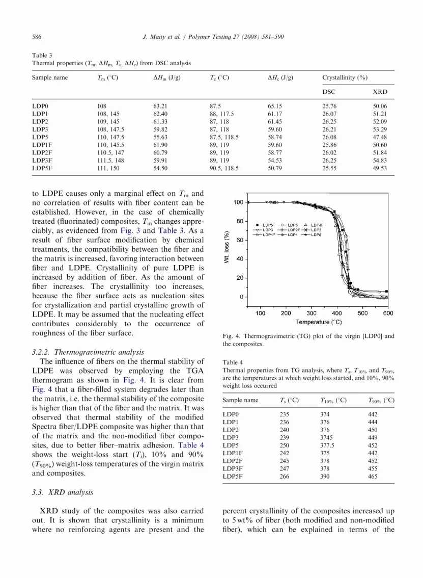
Fig. 4. Thermogravimetric (TG) plot of the virgin [LDP0] and
the composites.
Table 4
Thermal properties from TG analysis, where Ts, T10% and T90%
are the temperatures at which weight loss started, and 10%, 90%
weight loss occurred
Sample name Ts (1C) T10% (1C) T90% (1C)
LDP0 235 374 442
LDP1 236 376 444
LDP2 240 376 450
LDP3 239 3745 449
LDP5 250 377.5 452
LDP1F 242 375 442
LDP2F 245 378 452
LDP3F 247 378 455
LDP5F 266 390 465
J. Maity et al. / Polymer Testing 27 (2008) 581–590586
to LDPE causes only a marginal effect on Tm andno correlation of results with fiber content can beestablished. However, in the case of chemicallytreated (fluorinated) composites, Tm changes appre-ciably, as evidenced from Fig. 3 and Table 3. As aresult of fiber surface modification by chemicaltreatments, the compatibility between the fiber andthe matrix is increased, favoring interaction betweenfiber and LDPE. Crystallinity of pure LDPE isincreased by addition of fiber. As the amount offiber increases. The crystallinity too increases,because the fiber surface acts as nucleation sitesfor crystallization and partial crystalline growth ofLDPE. It may be assumed that the nucleating effectcontributes considerably to the occurrence ofroughness of the fiber surface.
3.2.2. Thermogravimetric analysis
The influence of fibers on the thermal stability ofLDPE was observed by employing the TGAthermogram as shown in Fig. 4. It is clear fromFig. 4 that a fiber-filled system degrades later thanthe matrix, i.e. the thermal stability of the compositeis higher than that of the fiber and the matrix. It wasobserved that thermal stability of the modifiedSpectra fiber/LDPE composite was higher than thatof the matrix and the non-modified fiber compo-sites, due to better fiber–matrix adhesion. Table 4shows the weight-loss start (Ti), 10% and 90%(T90%) weight-loss temperatures of the virgin matrixand composites.
3.3. XRD analysis
XRD study of the composites was also carriedout. It is shown that crystallinity is a minimumwhere no reinforcing agents are present and the
percent crystallinity of the composites increased upto 5wt% of fiber (both modified and non-modifiedfiber), which can be explained in terms of the

ARTICLE IN PRESS
Fig. 5. XRD plot of the virgin [LDP0] and the non-modified
[LDP1, LDP2, LDP3 and LDP5] and the modified fiber
composites [LDP1F, LDP2F, LDP3F and LDP5F].
J. Maity et al. / Polymer Testing 27 (2008) 581–590 587
enhanced mobility of LDPE macromolecularchains, leading to better alignment of the crystallattices. As concentration of the fiber increasedfurther, the fiber started to act as a restriction sitefor the LDPE segments, obstructing them fromobtaining a highly ordered spherulite structure, andthus, the percentage crystallinity again decreased.Crystallinity is higher in fluorinated fiber compo-sites compared to the non-fluorinated fiber compo-sites. This behavior is expected from thestress–strain behavior of the composite system.The XRD plots are given in Fig. 5, and thecrystallinity obtained by both methods are givenin Table 3. In both cases, crystallinity reaches amaximum value for the sample containing 7.5%fiber.
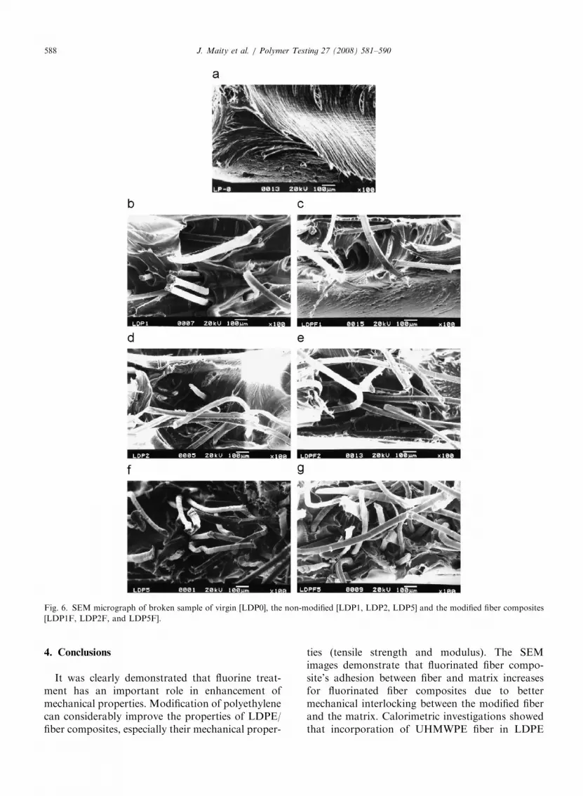
3.4. SEM analysis
SEM images of the fractured surface of thecontrol (LP0) and composites (LDP1, LDP2,LDP5, LDPF1, LDPF2, LDPF5) are shown inFig. 6. It is clear from the figure that there is ahomogeneous distribution of fibers in the PEmatrix. The homogeneous dispersion of filler inthe polymer matrix is one of the conditions for acomposite to show good mechanical strengthreinforcement, because inhomogeneities can leadto structural defects in the composite material. Fig.6a shows the fracture surface of the pure sample.Fig. 6(b, d and f) is the micrograph of the non-fluorinated PEF reinforced composite (LDP1,LDP2, LDP5), where the fibers are randomlyoriented and pulled out from the matrix dueto poor adhesion between the fiber and thematrix, resulting is poor thermal as well as dynamicmechanical stability of the composite. In the caseof fluorinated fiber reinforced composite(LDPF1, LDPF2, LDPF5) Fig. 6(c, e and g), fibersare broken and not pulled out, which is anindication of good adhesion between the fiber andthe matrix.
3.5. IR Study
As shown in Fig. 7 giving the IR spectra ofcomposites and base matrix, the absorption peaks at�2920 and �2848 cm�1 were attributed to methy-lene non-symmetry stretching vibration and methy-lene symmetry stretching vibration, respectively.The absorptions at �1463 and �719 cm�1 wereattributed to methylene non-symmetry changing
angle vibration and methylene swing in planevibration, respectively. In the case of fluorinatedfiber composites, a broad peak appears at1190 cm�1, which is due to the absorption of C–Fbond. Kharitonov et al. [17] observed that the bandat 1000–1300 cm�1 is well known for C–F absorp-tion. In addition, the formation of CQO bond wasindicated by the appearance of a band between 1600and 1900 cm�1. The appearance of CQO groupinto the polymer backbone occurred during thefluorination process because a very small amount ofoxygen (present as an impurity) is sufficient forintroduction of carbonyl groups. The band at�1885 cm�1 can be attributed to the carbonylvibration in a –COF group.
3.6. Contact angle analysis
The contact angle decreased greatly after mod-ification, suggesting that the introduction ofsome polar group into the fiber backbone. Due tothe introduction of polar moieties, adhesion proper-ties, such as wettability, of the fluorinated fiberimproved significantly. Table 5a shows the resultof surface energy value of the fiber before andafter fluorination. The surface energy of virginmatrix and the prepared composites are shownin Table 5b. The increasing values of SE forfluorinated fiber composites indicate that the wet-ting properties of fluorinated fiber compositesimproved.
ARTICLE IN PRESS
Fig. 6. SEM micrograph of broken sample of virgin [LDP0], the non-modified [LDP1, LDP2, LDP5] and the modified fiber composites
[LDP1F, LDP2F, and LDP5F].
J. Maity et al. / Polymer Testing 27 (2008) 581–590588
4. Conclusions
It was clearly demonstrated that fluorine treat-ment has an important role in enhancement ofmechanical properties. Modification of polyethylenecan considerably improve the properties of LDPE/fiber composites, especially their mechanical proper-
ties (tensile strength and modulus). The SEMimages demonstrate that fluorinated fiber compo-site’s adhesion between fiber and matrix increasesfor fluorinated fiber composites due to bettermechanical interlocking between the modified fiberand the matrix. Calorimetric investigations showedthat incorporation of UHMWPE fiber in LDPE

ARTICLE IN PRESS
Fig. 7. FTIR spectrum of virgin matrix [LDP0] and the
composites [LDP1, LDP1F, LDP5, LDP5F].
Table 5a
Surface energy of the fiber (PE [NF]) before and (PE [F]) after
fluorination
Sample
name
Contact angle gsd
(mJ/m2)
gsnd
(mJ/m2)
gsd+gs
nd
(mJ/m2)
ywater yDMF
PE[NF] 84.43 56.63 36.83 2.63 39.46
PE[F] 51.96 46.95 32.46 15.04 47.50
Table 5b
Surface energy of the virgin matrix and the prepared samples
Sample name gsd (mJ/m2) gs
nd (mJ/m2) gsd+gs
nd (mJ/m2)
LDP0 19.24 5.42 24.66
LDP1 19.20 5.50 24.70
LDP2 19.16 5.53 24.69
LDP3 19.19 5.51 24.71
LDP5 18.99 5.60 24.59
LDP1F 21.18 8.58 29.76
LDP2F 20.75 10.02 30.77
LDP3F 20.33 11.87 32.20
LDP5F 20.43 13.73 34.16
J. Maity et al. / Polymer Testing 27 (2008) 581–590 589
caused an apparent increase in crystallizationtemperature (Tc) and percentage of crystallinity.These effects can be attributed to the fact that thesurfaces of polyethylene (UHMWPE) fiber act asnucleating sites for crystallization of the polymer.From the viewpoint of application, fluorinated fibercomposites have higher TS, higher modulus and
lower elongation at break value, in addition to thehighest surface energy. Thus, it can be concludedthat surface modification of polyethylene fibersleads to improved adhesion with the LDPE matrixand, hence, an improvement in properties of thepolyethylene fibers–LDPE composites.
Acknowledgment
The authors are thankful to the Defense ResearchDevelopment Organization, Govt. of India, forgiving financial support to carry out this researchwork at the Indian Institute of Technology,Kharagpur.
References
[1] D. Bettge, G. Hinrichsen, Continuous manufacturing of
composites of high performance polyethylene fibers, Com-
pos. Sci. Technol. 47 (2) (1993) 131.
[2] N.H. Ladizesky, I.M. Ward, The adhesion behaviour of high
modulus polyethylene fibers following plasma and chemical
treatment, J. Mater. Sci. 24 (10) (1989) 3763.
[3] B. Tissington, G. Pollard, I.M. Ward, A study of the effects
of oxygen plasma treatment on the adhesion behaviour of
polyethylene fibers, Compos. Sci. Technol. 44 (3) (1992) 185.
[4] E. Devaux, C. Caze0, Composites of UHMW polyethylene
fibers in a LD polyethylene matrix. I. Processing conditions,
Compos. Sci. Technol. 59 (3) (1999) 459.
[5] E. Devaux, C. Caze0, Composites of ultra-high-molecular-
weight polyethylene fibers in a low-density polyethylene
matrix. II. Fiber/matrix adhesion, Compos. Sci. Technol. 59
(6) (1999) 879.
[6] F.V. Lacroix, M. Werwer, K. Schulte, Solution impregna-
tion of polyethylene fiber/polyethylene matrix composites,
Composites Part A 29 (4) (1998) 371.
[7] F.V. Lacroix, J. Loos, K. Schulte, Morphological investiga-
tions of polyethylene fiber reinforced polyethylene, Polymer
40 (4) (1999) 843.
[8] L. Vaisman, M.F. Gonzalez, G. Marom, Transcrystallinity
in brominated UHMWPE fiber reinforced HDPE compo-
sites: morphology and dielectric properties, Polymer 44 (4)
(2003) 1229.
[9] A. Pegoretti, M. Ashkar, C. Migliaresi, Relaxation processes
in polyethylene fiber-reinforced polyethylene composites,
Compos. Sci. Technol. 60 (8) (2000) 1181.
[10] A. Flores, A. Poeppel, C. Riekel, Evidence of a transcrystal-
line interphase in fiber PE homocomposites as revealed by
microdiffraction experiments using synchrotron radiation,
J. Macro. Sci. Phys. B 40 (5) (2001) 749.
[11] T. Stern, A. Teishev, G. Marom, Composites of polyethy-
lene reinforced with chopped polyethylene fibers: effect of
transcrystalline interphase, Compos. Sci. Technol. 57 (8)
(1997) 1009.
[12] A. Ajji, A. Aitkadi, A. Rochette, Polyethylene ultra high
modulus polyethylene short fibers composites, J. Compos.
Mater. 26 (1) (1992) 121.

ARTICLE IN PRESSJ. Maity et al. / Polymer Testing 27 (2008) 581–590590
[13] T.B. He, R.S. Porter, Melt transcrystallization of polyethy-
lene on high modulus polyethylene fibers, J. Appl. Polym.
Sci. 35 (7) (1988) 1945.
[14] H. Ishida, P. Bussi, Surface-induced crystallization in
ultrahighmodulus polyethylene fiber reinforced polyethylene
composites, Macromolecules 24 (12) (1991) 3569.
[15] N.E. Zafeiropoulos, P.C. Varelidis, C.D. Papaspyrides,
Characterisation of LDPE residual matrix deposited on
glass fibres by a dissolution reprecipitation recycling process,
Compos. Part A 30 (7) (1999) 831.
[16] J. Maity, C. Jacob, C.K. Das, S. Alam, R.P. Singh,
Homocomposites of chopped fluorinated polyethylene fiber
with low density polyethylene matrix, Mater. Sci. Eng. Part-
A 479 (1–2) (2008) 125.
[17] A.P. Kharitonov, R. Taege, G. Ferrier, V.V. Teplyakov,
D.A. Syrtsova, G.H. Koops, Direct fluorination-useful tool
to enhance commercial properties of polymer articles,
J. Fluorine Chem. 126 (2) (2005) 251.
[18] M. Kazanci, D. Cohn, G. Marom, Elastic and viscoelastic
behaviour of wound polyethylene fiber reinforced polyolefin
composites, J. Mater. Sci. 36 (12) (2001) 2845.
[19] J. Brandrup, E.H. Immergut, E.A. Grulke (Eds.), Polymer
Handbook, fourth ed, Wiley, New York, 1999.


