Embed Size (px)
Citation preview
International Journal of Applied Engineering Research ISSN 0973-4562 Volume 3 Number 11 (2008) pp. 1523–1534 © Research India Publications http://www.ripublication.com/ijaer.htm
Distinction Between Transient and Permanent Faults
Using Wavelet Transform
M. Sushama1, G. Tulasi Ram Das2 and A.Jaya Laxmi
1Associate professor, Department of Electrical and Electronics Engg., JNTU College of Engineering, Hyderabad, Andhra Pradesh, India.
E-mail: [email protected], [email protected] 2 Professor, Department of EEE, JNTU College of Engineering,
Hyderabad, Andhra Pradesh, India
Abstract
This paper presents a new technique for transient and permanent fault
identification in adaptive reclosure by using the fault generated high frequency current transients. A specifically designed transient and permanent fault identification unit is used to capture high frequency current noise generated by the fault arc. Wavelet transform is used to distinguish between the transient and permanent fault by ensuring the presence of secondary arc. Keywords: Wavelet transform, Transient fault, Permanent fault, Adaptive reclosure, Secondary arc, Circuit Breaker(CB).
Introduction Auto re-closure schemes as applied to EHV systems have, by offering benefits such as maintaining system stability and synchronism, been a major cause of a substantial improvement in the continuity of supply. It is, however, well known that the present auto re-closure practice employing a fixed prescribed dead time can pose problems. In the case of transient faults, for example, a re-strike of a fault due to insufficient time for the fault path to de-ionise fully can threaten system stability and reliability and, in case of a permanent fault, a second shock to the system can cause irreparable damage to expensive equipment. By W J Laycock C Eng, MIEE, Member IEEE “Adaptive Re-closure of HV Overhead Lines” IEEE transactions 1996 Rolls-Royce Industrial Power Group, Reyrolle Protection, Hebburn Tyne and Wear, NE31 lTZ, United Kingdom. Ideally the reclosing is only activated when the transient fault occurs and the dead time of auto re-closure should be set in such a way that a re-strike of a fault due to the incompletion of deionization can be avoided. To do so, distinguishing between transient and permanent becomes vital important. For this a specifically
1524 M. Sushama, G. Tulasi Ram Das and A.Jaya Laxmi
designed transient and permanent fault identification unit is used to capture high frequency current noise generated by the fault arc. Then wavelet transform is used to distinguish between the transient and permanent fault by ensuring the presence of secondary arc and the fault sustain time for a transient fault can be determined.
Wavelet Transform The wavelet transform is a mathematical tool, much like a Fourier transform in analyzing time localized stationary signal, which decomposes a signal into different scales with different levels of resolution by expanding a single prototype function. Wavelet transform provides a local representation (i.e. both time and frequency) of a given signal. Hence it is suitable for analyzing a signal where time- frequency resolution is needed such as power quality disturbances, where the characterizing each type of disturbances is different. More importantly, WT possesses variable windows so that the higher frequency components can be analyzed employing finer windows to attain more detailed information and the lower ones are analyzed using wider windows to get a comparable approximation by Charles K .Chui, " Wavelets: A Mathematical Tool for Signal Analysis", SIAM, Philadelphia, 1997. Hence Wavelet has advantages over traditional Fourier Transfor in analyzing accurately the power system transient phenomena where signals contain low power frequency and transient such as discontinuities, sags and sharp spikes.
Circuit Description Two 735 kV parallel lines, 200 km long, transmit 3000 MW of power from a generation station (12 generators of 350 MVA) to an equivalent network having a short circuit level of 20 GVA. The generation plant is simulated with a simplified synchronous machine. The machine is connected to the transmission network through a 13.8 kV/ 735 kV Delta-Wye step-up transformer. The transmission line is double circuit line feeding 500MW loads. Four circuit breakers are placed in the double circuit line two at each end of the transmission lines. As long transmission line has considered, the line models are distributed parameter lines. The lines are assumed to be transposed and their parameters R, L, C /km are specified in positive- and zero-sequence components. Study of System Faults The great majority of faults on overhead transmission lines are transitory in nature. They disappear if the line is de-energized for a short duration in order to permit the arc to be extinguished. After the arc has become sufficiently deionise, the line may be reenergized and put back into use. Lightning is the commonest cause of faults on overhead lines and most faults caused by lightning are transitory. In addition some faults due to other causes, such as swinging wires and temporary contacts with foreign objects are transitory.
A small percentage of the faults on overhead transmission lines are permanent for example those due to breakage of conductors or poles by aircrafts, floods, earthquakes
Distinction Between Transient and Permanent Faults 1525
or bombs. Rapid reclosure on a permanent fault is more determined to stability than no reclosure or long delayed reclosure.
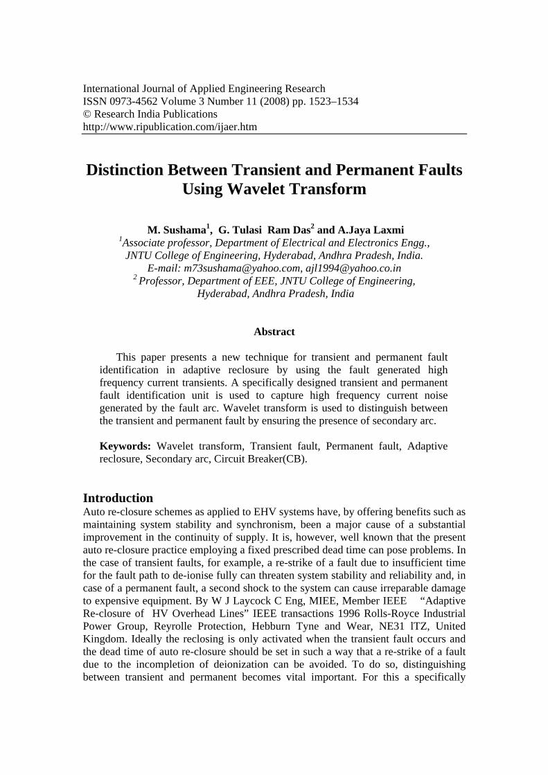
Figure 1: Voltage waveform of transient fault.
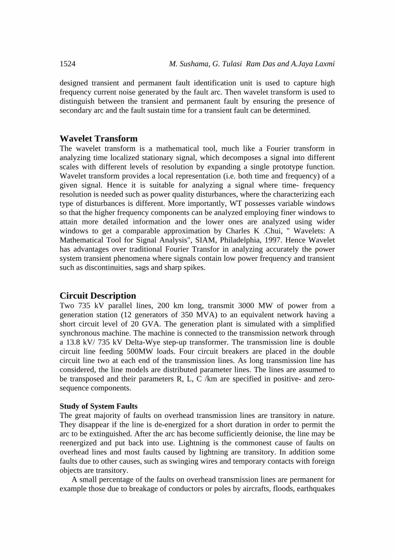
Figure 2: Voltage waveform of permanent fault.
The figure 1 and 2 shows the simulated voltage waveforms for a single phase-to-
ground fault with single pole tripping for a transient fault involving secondary arcing and a permanent fault (with high impedance)respectively. The former phenomenon arises due to coupling with healthy phases even after the primary arc has ceased and has a characteristic waveform presents the typical secondary.
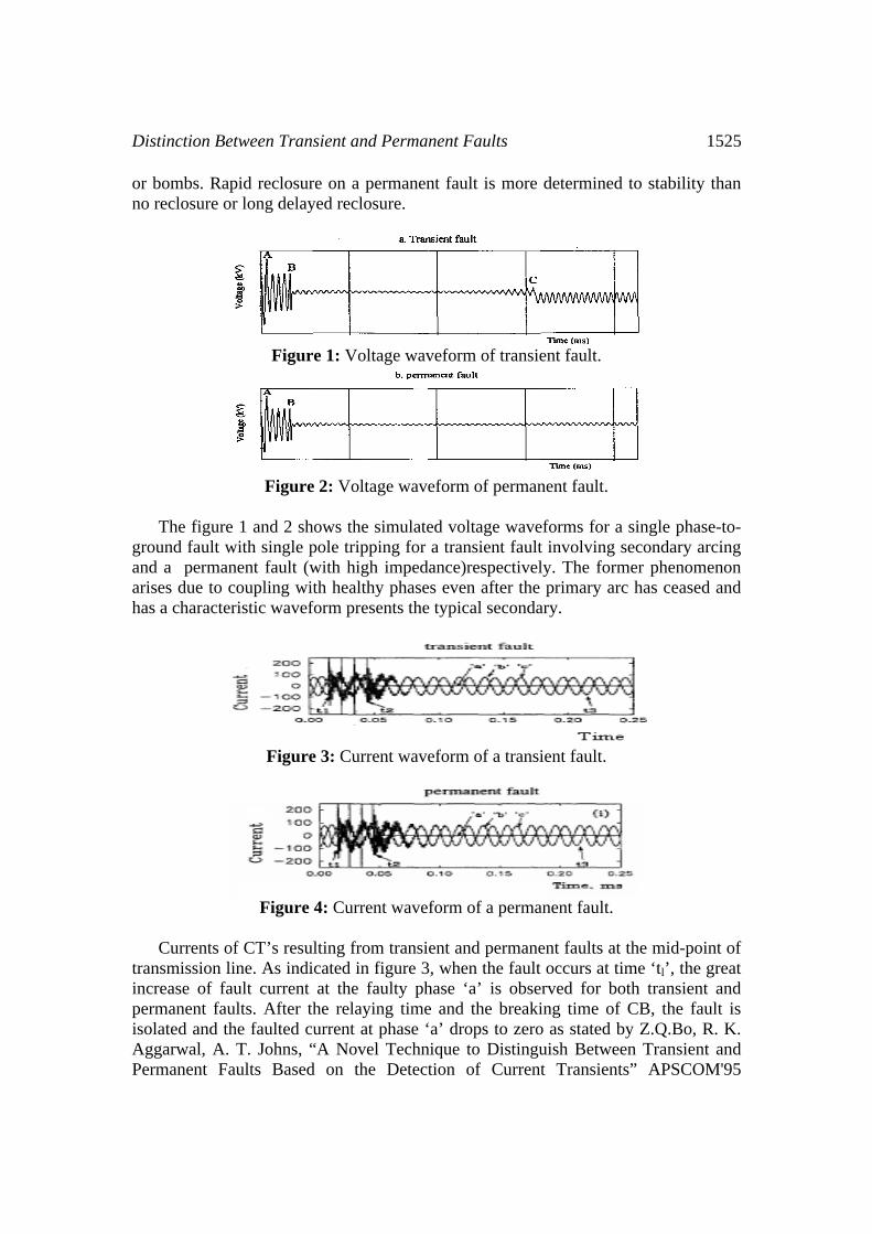
Figure 3: Current waveform of a transient fault.
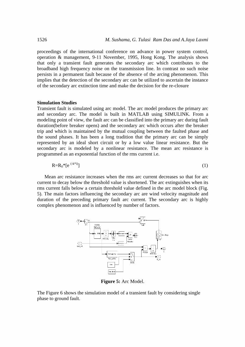
Figure 4: Current waveform of a permanent fault.
Currents of CT’s resulting from transient and permanent faults at the mid-point of
transmission line. As indicated in figure 3, when the fault occurs at time ‘tl’, the great increase of fault current at the faulty phase ‘a’ is observed for both transient and permanent faults. After the relaying time and the breaking time of CB, the fault is isolated and the faulted current at phase ‘a’ drops to zero as stated by Z.Q.Bo, R. K. Aggarwal, A. T. Johns, “A Novel Technique to Distinguish Between Transient and Permanent Faults Based on the Detection of Current Transients” APSCOM'95
1526 M. Sushama, G. Tulasi Ram Das and A.Jaya Laxmi
proceedings of the international conference on advance in power system control, operation & management, 9-11 November, 1995, Hong Kong. The analysis shows that only a transient fault generates the secondary arc which contributes to the broadband high frequency noise on the transmission line. In contrast no such noise persists in a permanent fault because of the absence of the arcing phenomenon. This implies that the detection of the secondary arc can be utilized to ascertain the instance of the secondary arc extinction time and make the decision for the re-closure
Simulation Studies Transient fault is simulated using arc model. The arc model produces the primary arc and secondary arc. The model is built in MATLAB using SIMULINK. From a modeling point of view, the fault arc can be classified into the primary arc during fault duration(before breaker opens) and the secondary arc which occurs after the breaker trip and which is maintained by the mutual coupling between the faulted phase and the sound phases. It has been a long tradition that the primary arc can be simply represented by an ideal short circuit or by a low value linear resistance. But the secondary arc is modeled by a nonlinear resistance. The mean arc resistance is programmed as an exponential function of the rms current i.e.
R=R0*[e (-k*i)] (1)
Mean arc resistance increases when the rms arc current decreases so that for arc current to decay below the threshold value is shortened. The arc extinguishes when its rms current falls below a certain threshold value defined in the arc model block (Fig. 5). The main factors influencing the secondary arc are wind velocity magnitude and duration of the preceding primary fault arc current. The secondary arc is highly complex phenomenon and is influenced by number of factors.
Figure 5: Arc Model.
The Figure 6 shows the simulation model of a transient fault by considering single phase to ground fault.
Distinction Between Transient and Permanent Faults 1527
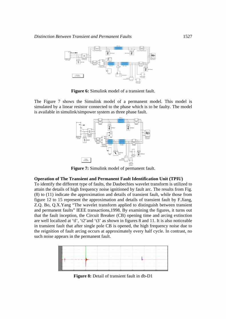
Figure 6: Simulink model of a transient fault.
The Figure 7 shows the Simulink model of a permanent model. This model is simulated by a linear resistor connected to the phase which is to be faulty. The model is available in simulink/simpower system as three phase fault.
Figure 7: Simulink model of permanent fault.
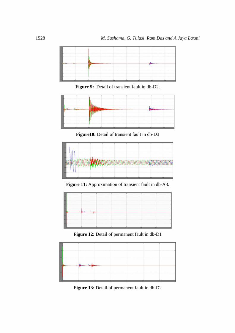
Operation of The Transient and Permanent Fault Identification Unit (TPIU) To identify the different type of faults, the Daubechies wavelet transform is utilized to attain the details of high frequency noise ignitioned by fault arc. The results from Fig. (8) to (11) indicate the approximation and details of transient fault, while those from figure 12 to 15 represent the approximation and details of transient fault by F.Jiang, Z.Q. Bo, Q.X.Yang “The wavelet transform applied to distinguish between transient and permanent faults” IEEE transactions,1998. By examining the figures, it turns out that the fault inception, the Circuit Breaker (CB) opening time and arcing extinction are well localized at ‘tl’, ‘t2’and ‘t3’ as shown in figures 8 and 11. It is also noticeable in transient fault that after single pole CB is opened, the high frequency noise due to the reignition of fault arcing occurs at approximately every half cycle. In contrast, no such noise appears in the permanent fault.
Figure 8: Detail of transient fault in db-D1
1528 M. Sushama, G. Tulasi Ram Das and A.Jaya Laxmi
Figure 9: Detail of transient fault in db-D2.
Figure10: Detail of transient fault in db-D3
Figure 11: Approximation of transient fault in db-A3.
Figure 12: Detail of permanent fault in db-D1
Figure 13: Detail of permanent fault in db-D2
Distinction Between Transient and Permanent Faults 1529
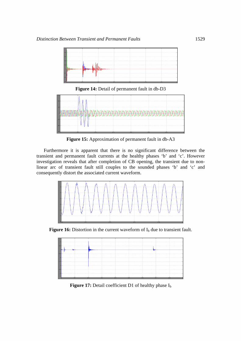
Figure 14: Detail of permanent fault in db-D3
Figure 15: Approximation of permanent fault in db-A3
Furthermore it is apparent that there is no significant difference between the transient and permanent fault currents at the healthy phases ‘b’ and ‘c’. However investigation reveals that after completion of CB opening, the transient due to non-linear arc of transient fault still couples to the sounded phases ‘b’ and ‘c’ and consequently distort the associated current waveform.
Figure 16: Distortion in the current waveform of Ib due to transient fault.
Figure 17: Detail coefficient D1 of healthy phase Ib
1530 M. Sushama, G. Tulasi Ram Das and A.Jaya Laxmi
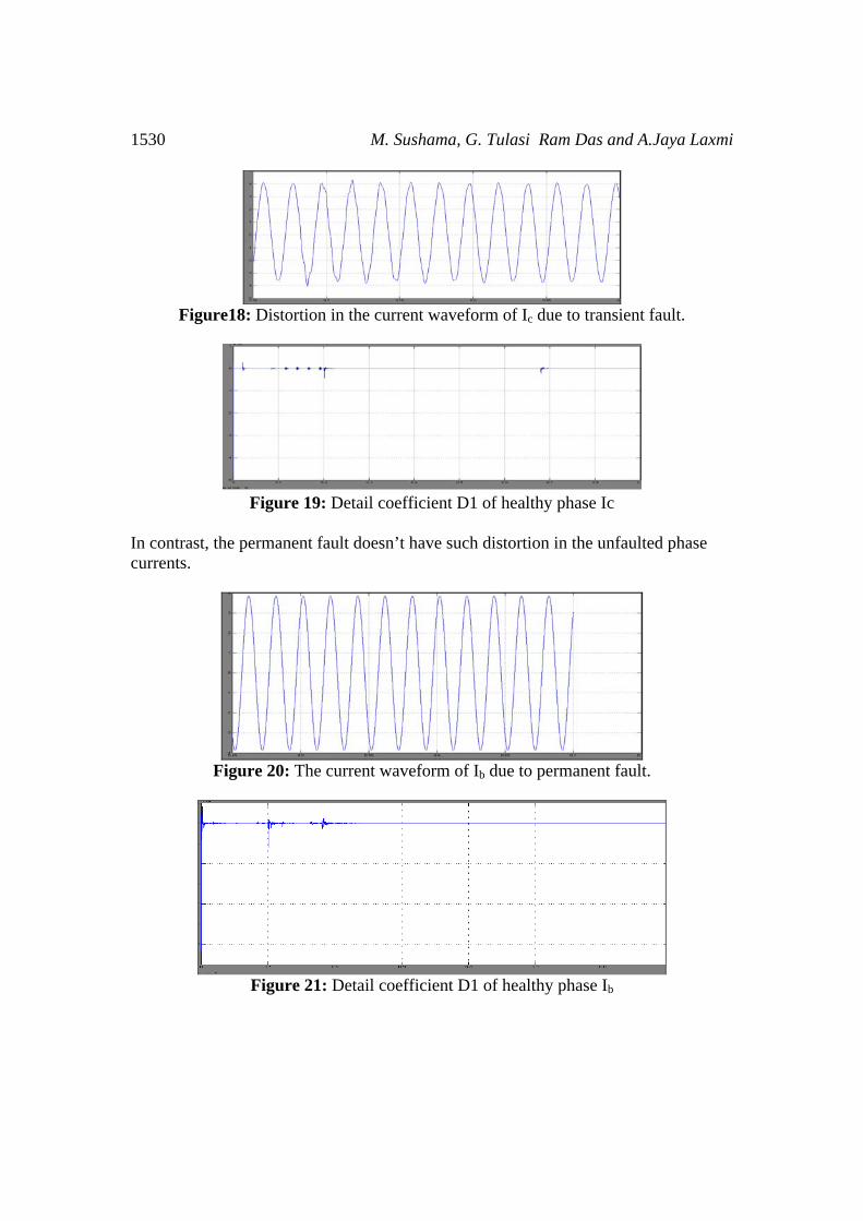
Figure18: Distortion in the current waveform of Ic due to transient fault.
Figure 19: Detail coefficient D1 of healthy phase Ic
In contrast, the permanent fault doesn’t have such distortion in the unfaulted phase currents.
Figure 20: The current waveform of Ib due to permanent fault.
Figure 21: Detail coefficient D1 of healthy phase Ib
Distinction Between Transient and Permanent Faults 1531
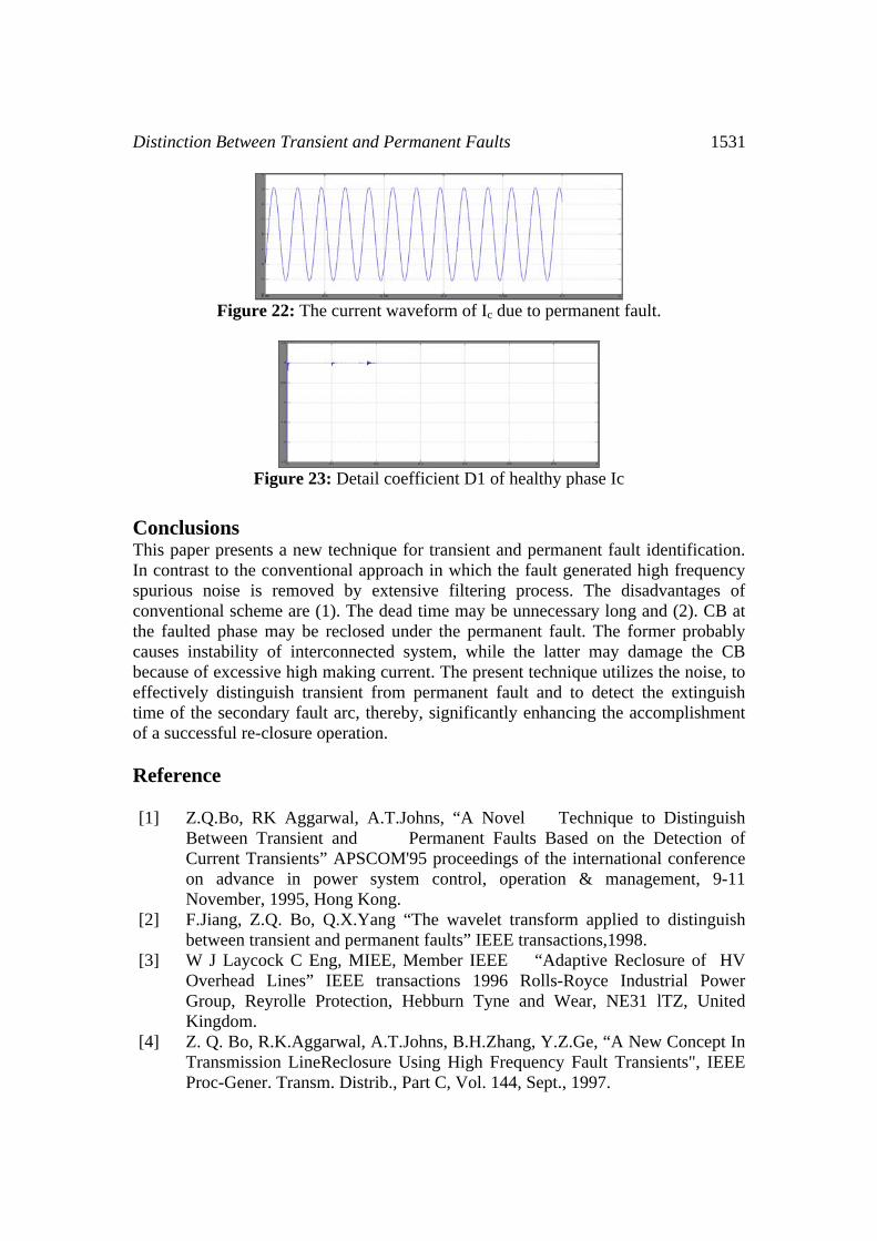
Figure 22: The current waveform of Ic due to permanent fault.
Figure 23: Detail coefficient D1 of healthy phase Ic
Conclusions This paper presents a new technique for transient and permanent fault identification. In contrast to the conventional approach in which the fault generated high frequency spurious noise is removed by extensive filtering process. The disadvantages of conventional scheme are (1). The dead time may be unnecessary long and (2). CB at the faulted phase may be reclosed under the permanent fault. The former probably causes instability of interconnected system, while the latter may damage the CB because of excessive high making current. The present technique utilizes the noise, to effectively distinguish transient from permanent fault and to detect the extinguish time of the secondary fault arc, thereby, significantly enhancing the accomplishment of a successful re-closure operation. Reference [1] Z.Q.Bo, RK Aggarwal, A.T.Johns, “A Novel Technique to Distinguish
Between Transient and Permanent Faults Based on the Detection of Current Transients” APSCOM'95 proceedings of the international conference on advance in power system control, operation & management, 9-11 November, 1995, Hong Kong.
[2] F.Jiang, Z.Q. Bo, Q.X.Yang “The wavelet transform applied to distinguish between transient and permanent faults” IEEE transactions,1998.
[3] W J Laycock C Eng, MIEE, Member IEEE “Adaptive Reclosure of HV Overhead Lines” IEEE transactions 1996 Rolls-Royce Industrial Power Group, Reyrolle Protection, Hebburn Tyne and Wear, NE31 lTZ, United Kingdom.
[4] Z. Q. Bo, R.K.Aggarwal, A.T.Johns, B.H.Zhang, Y.Z.Ge, “A New Concept In Transmission LineReclosure Using High Frequency Fault Transients", IEEE Proc-Gener. Transm. Distrib., Part C, Vol. 144, Sept., 1997.
1532 M. Sushama, G. Tulasi Ram Das and A.Jaya Laxmi
[5] C.H.Kim, S.P. Ahn, R.K. Aggarwal, A.T. Johns “A novel concept in adaptive single pole auto-reclosure as applied to high voltage transmission systems.” APSCOM’2000 Proceedings of the 5th International Conference on Advances in Power System Control, Operation and Management, APSCOM 2000, Hong Kong, October 2000.
[6] Charles K .Chui, " Wavelets: A Mathematical Tool For Signal Analysis", SIAM, Philadelphia, 1997.
[7] Z Q Bo, A T Johns, "Transient Based Protection - A New Concept in Power System Protection", IPST'97, International Conference on Power System Transients, University of Washington, Seattle, Washington, USA, June 22-26, 1997
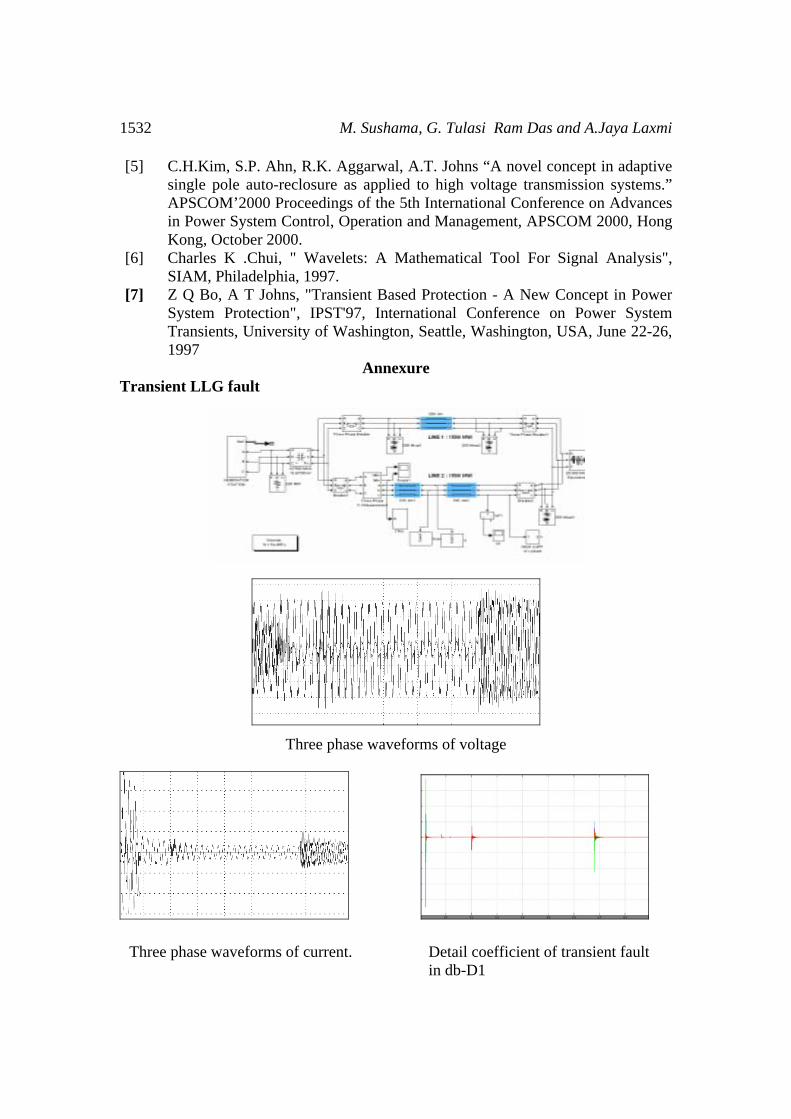
Annexure Transient LLG fault
Three phase waveforms of voltage
Three phase waveforms of current. Detail coefficient of transient fault in db-D1
Distinction Between Transient and Permanent Faults 1533
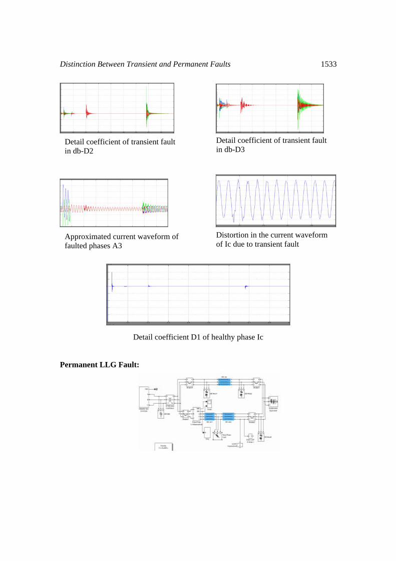
Detail coefficient D1 of healthy phase Ic
Permanent LLG Fault:
Detail coefficient of transient fault in db-D2
Detail coefficient of transient fault in db-D3
Approximated current waveform of faulted phases A3
Distortion in the current waveform of Ic due to transient fault
1534 M. Sushama, G. Tulasi Ram Das and A.Jaya Laxmi
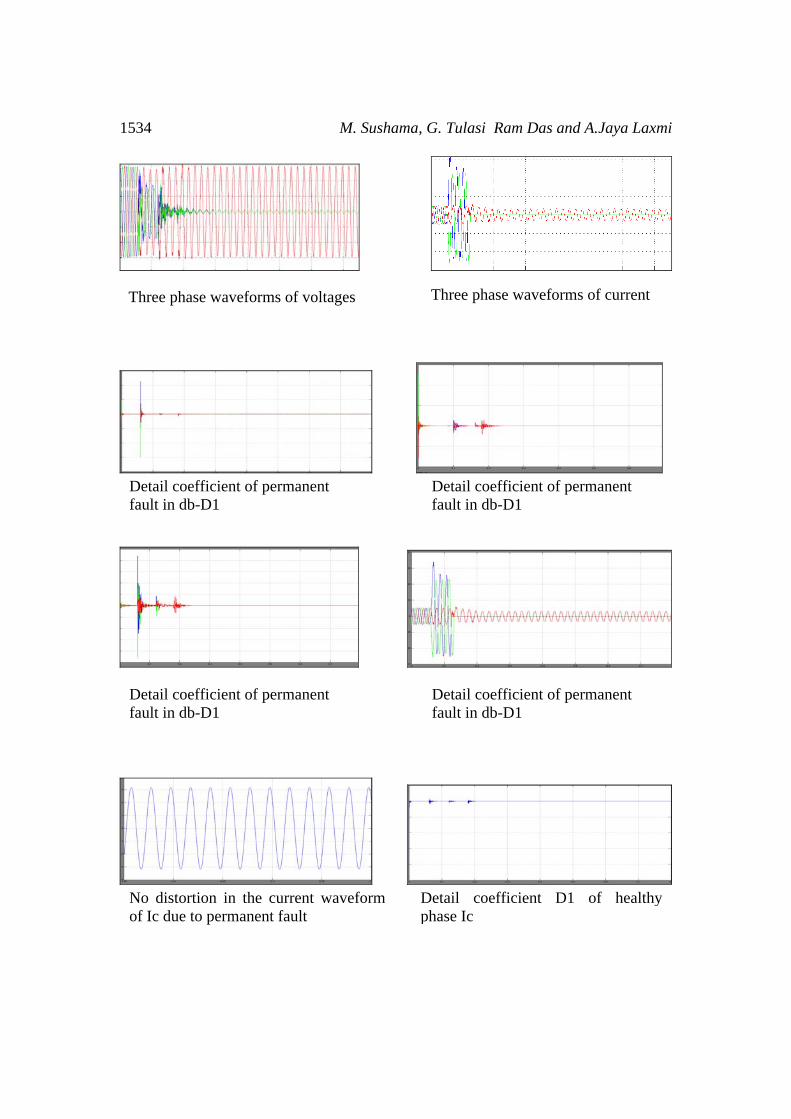
Three phase waveforms of voltages Three phase waveforms of current
Detail coefficient of permanent fault in db-D1
Detail coefficient of permanent fault in db-D1
Detail coefficient of permanent fault in db-D1
Detail coefficient of permanent fault in db-D1
No distortion in the current waveform of Ic due to permanent fault
Detail coefficient D1 of healthy phase Ic


