Embed Size (px)
Citation preview

Distributed Control-Oriented Modeling of ThermoacousticDynamics in a Duct
Prashant G. Mehta, Marios C. Soteriou, and Andrzej Banaszuk
Abstract— In this paper, we consider the problem of control-oriented modeling of the thermoacoustic dynamics of ducted,premixed bluffbody stabilized combustion. We make a simpli-fying assumption of ignoring the vortex dynamics, but retainthe effects of burning and fuel actuation. The thermoacousticmodel arises as an interconnection of acoustics and heat-release submodels. For acoustics, we model the effects of meanreacting flow and for heat-release, we model the effects ofdistributed flame and fuel dynamics. We carry out a control-oriented analysis of the resulting coupled thermoacousticmodel that highlights the important role of density ratio inobtaining combustion instability.
I. INTRODUCTION
Flameholder stabilized premixed combustion in a ducthas been a subject of extensive research in the past becauseit is a generic geometry of relevance to a number of powergeneration devices such as gas turbines and rockets. Theeffective operation of these devices is often plagued bythermoacoustic instabilities that arise due to a positivefeedback coupling of the duct acoustic modes with theunsteady heat released due to combustion [1], [2]. Recentcontrol-oriented modeling works in this area [2], [3], [4]have, for the most part, considered simplified, lumpedrepresentation of the combustion process and ignored fluiddynamics arising both as a consequence of exothermicityas well as vortex effects; see recent review in ref. [1]. Theprimary reason for ignoring the reacting fluid dynamics isthe relative difficulty of modeling - in a reduced orderfashion - these effects. Another feature of these earlierstudies is that they typically consider the combustion regionto be compact with respect to the acoustic wavelength - thisis based upon low Mach number, small flamelength, and lowacoustic frequency assumption.
In this paper, we build upon our recent work on meanflame response in [5] to obtain linear distributed acousticand heat-release submodels that incorporate some of thereacting flow effects. We use the heat-release submodel tostudy the response of heat-release to distributed (acoustic)velocity perturbations. Such a response with only flame dy-namics has been studied for lumped velocity perturbationsin [6], [4], [7] and for distributed modal perturbation inthe recent paper of [8]. Unlike these papers however, weincorporate the effects of exothermicity (density ratio) as
P. G. Mehta is with United Technologies Research Center East Hartford,CT 06108 [email protected]
M. C. Soteriou is with United Technologies Research Center EastHartford, CT 06108 [email protected]
A. Banaszuk is with United Technologies Research Center East Hart-ford, CT 06108 [email protected]
Fig. 1. Schematic of the physical problem.
well as fuel perturbations. We also use the acoustic and heat-release submodels to carry out a control-oriented analysisof the coupled thermoacoustic problem.
The outline of this paper is as follows. In Section II,we briefly present the physical problem. In Section III, wedescribe the equations for distributed acoustics, and in Sec-tion IV, we build upon our work in [5] to derive a distributedmodel for flame/fuel dynamics and resulting heat release.In Section V, we employ the Galerkin procedure to obtaina finite-dimensional model for the coupled thermoacousticproblem and in section VI, we carry out a control-orientedanalysis of this model. Finally, we draw some conclusionsin Section VII.
II. PROBLEM STATEMENT
We consider the 2D physical problem of premixedcombustion stabilized by a single rectangular bluff bodyflameholder of height h in a channel of height H (seeFigure 1 for a schematic). Fuel is introduced at the trailingedge x = L1, where it mixes with the incoming air toyield a uniform reactants mixture (see [9] for details onfuel injection). The Mach number is low and both reactants(of density ρu) and products (of density ρb) are assumed tobehave as ideal gases. On account of the low Mach number,we assume that the density jump arises entirely becauseof the temperature difference between the reactants andthe products. Premixed combustion is modeled using twoflamesheets anchored to the two lips of the flameholder. Forfluid dynamics, we retain the exothermic effects of burningbut neglect vortical effects and the effect of geometricalexpansion downstream of the bluffbody assuming a constantinflow of reactants with velocity U0 (see [5], [10] for detailson mean combustion models). Acoustics is introduced asperturbation to the reacting flow model and is described inthe section below.

III. ACOUSTICS
The acoustics describe compressible effects of the flowthat arise as perturbation of the mean reacting flow solutionobtained with the mean combustion model of [5]. We startwith the inviscid transport equations following the approachof [2], [9]
∂ρ
∂t+ ∇ · (uρ) = 0 (1)
ρ∂u
∂t+ ρu · ∇u = −∇p − η (2)
ρ∂e
∂t+ ρu · ∇e = −p∇ · u + q. (3)
In (2), η models the impact of turbulent noise. By assumingideal gas, and substituting e = 1
γ−1pρ
(γ denoting the ratioof specific heats) into (3) and applying (1) we obtain
∂p
∂t+ γp∇ · u + u · ∇p = (γ − 1)q. (4)
Next, we use the decomposition
u = U + u, p = P + p,
ρ = ρ0 + ρ, q = Q + q, (5)
to obtain the energy equation for acoustics
∂p
∂t+ (U · ∇)p + ∇P · u + γP (∇ · u) + γ(∇ · U)p
+ γp(∇ · u) + (u · ∇)p = (γ − 1)q, (6)
where, as a matter of notation, we have dropped the hats onthe perturbation variables. Denoting speed of sound c2 =γPρ0
, and using the continuity equation for the hydrodynamicmean U , we obtain
∂p
∂t+ (U · ∇)p + ∇P · u + γµST δ(x − xf )p
+ ρ0c2(∇ · u) + (u · ∇)p + γp(∇ · u) = (γ − 1)q,
(7)
where xf denotes the mean flame location and the meanhydrodynamic pressure due to flow is given by
∇P = −ρ0(U · ∇)U. (8)
The momentum equation for the acoustics is given by
ρ0
[
∂u
∂t+ (U · ∇)u + (u · ∇)U + u · u
]
= −∇p − η, (9)
where, we have neglected additional terms involving ρ
on the left hand side because of the low Mach numberassumption. For the purpose of this study, we write u =(u, v) and assume longitudinal acoustics with
v ≈ 0,∂
∂y= 0, (10)
an assumption that leads to two scalar equations (describingacoustics) in two unknowns (p, u) that - after ignoring the
nonlinear terms - yields
∂p∂t
+ U ∂p∂x
+ γµST δ(x − xf )p
−[
ρ0U∂U∂x
]
u + ρ0c2 ∂u
∂x
= (γ − 1)q,
ρ0∂u
∂t+ ρ0
∂(Uu)
∂x= −
∂p
∂x− ηu, (11)
where ηu denotes the u co-ordinate of turbulent noise - wedrop the subscript u subsequently. We require mean flowand flame solutions to determine the coefficients of theacoustics model (11). For this, we use the reduced ordermean models derived in [5] to obtain mean axial flow
U(x, y) =
U0 x ∈ [0, L1]U0 + 2α(x − L1) x ∈ [L1, LT ]
, (12)
where α =µS0
T
H, µ = (ρu
ρb− 1), and S0
T = ST [Y 0f ] is
the flame speed (evaluated as a function of local fuel massfraction [10]) for the uniformly premixed mean flow. Themean flame location xf = (ξ(y), y) for the upper flame isobtained as the solution of G-equation [5]
(
S0T + 2α(
H
2− y)
)
∂ξ
∂y= U0 + 2α(ξ − L1),
ξ(x = L1, y =h
2) = 0, (13)
whose solution (valid for y ∈ [h2 , H
2 ]) is given by
ξ(y) = L1 +U0
2α
y − h2
b − y, (14)
where b = H2
(
1 + 1µ
)
. The solution for the lower flameis obtained as a symmetric reflection (about y = 0) ofthe upper flame solution. The length of the combustiondomain over which the flame exists is obtained from theflame solution (14) by substituting y = H
2 to obtain
L =U0
S0T
[
H
2−
h
2
]
. (15)
Finally, the acoustic boundary conditions are assumed to bechoked-choked at the combustor inlet and exit, i.e.,
u(x = 0, t) = u(x = LT , t) = 0. (16)
IV. HEAT-RELEASE
After [5], we begin with a model for flame dynamics- written here for the upper flame - in the presence oflongitudinal acoustic velocity perturbation
∂ξ
∂t+ (ST + 2α(
H
2− y))
∂ξ
∂y= U0 + 2α(ξ − L1) + u,
ξ(x = L1, y =h
2) = 0, (17)
where ST = S0T + S
′
T yf , the second term represents theeffect of fuel perturbation yf at the flame - S′
T = dST
dYf[Y 0
f ]is the derivative of the flame speed function evaluated atits nominal uniformly premixed fuel mass fraction Y 0
f . The
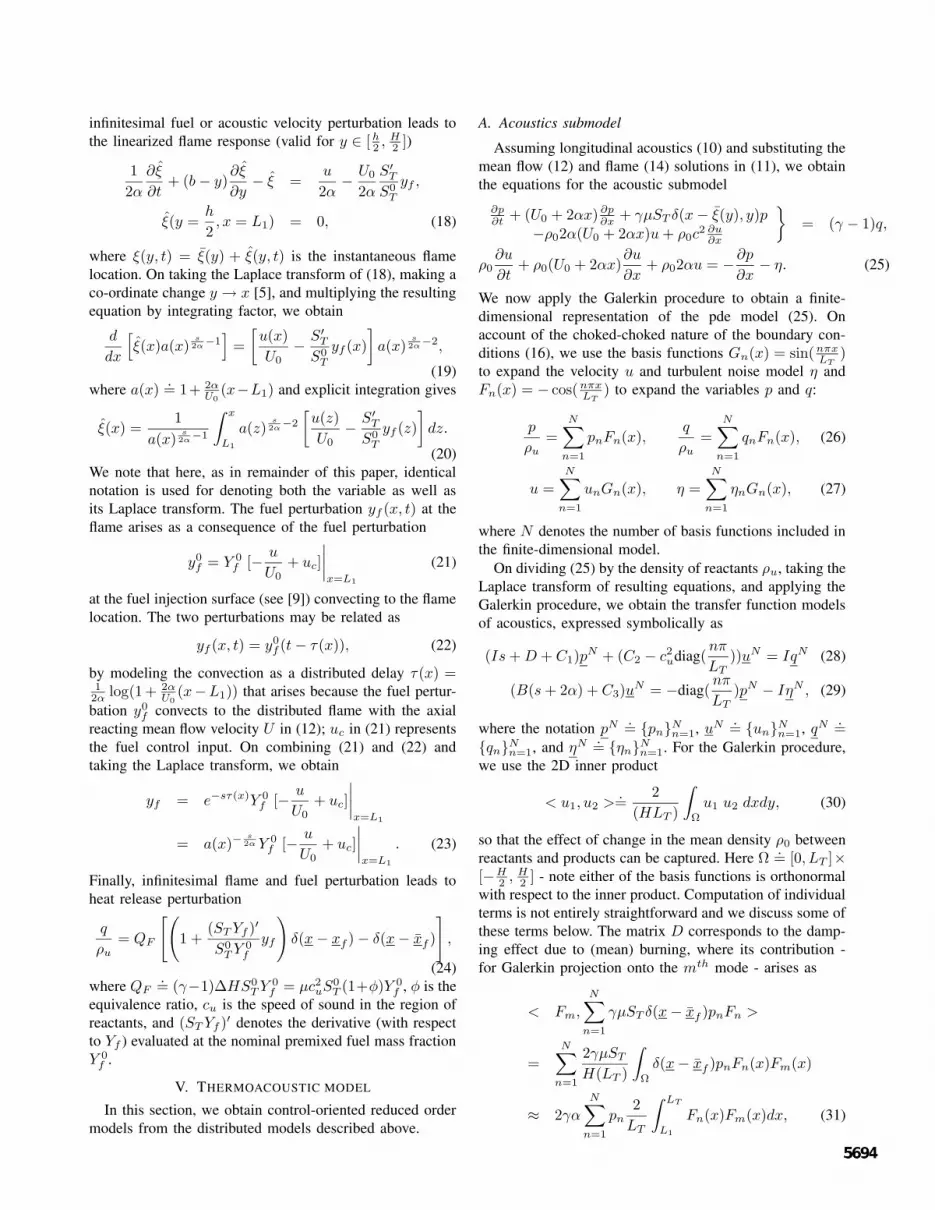
infinitesimal fuel or acoustic velocity perturbation leads tothe linearized flame response (valid for y ∈ [h
2 , H2 ])
1
2α
∂ξ
∂t+ (b − y)
∂ξ
∂y− ξ =
u
2α−
U0
2α
S′
T
S0T
yf ,
ξ(y =h
2, x = L1) = 0, (18)
where ξ(y, t) = ξ(y) + ξ(y, t) is the instantaneous flamelocation. On taking the Laplace transform of (18), making aco-ordinate change y → x [5], and multiplying the resultingequation by integrating factor, we obtain
d
dx
[
ξ(x)a(x)s2α
−1]
=
[
u(x)
U0−
S′
T
S0T
yf (x)
]
a(x)s2α
−2,
(19)where a(x)
.= 1+ 2α
U0
(x−L1) and explicit integration gives
ξ(x) =1
a(x)s2α
−1
∫ x
L1
a(z)s2α
−2
[
u(z)
U0−
S′
T
S0T
yf (z)
]
dz.
(20)We note that here, as in remainder of this paper, identicalnotation is used for denoting both the variable as well asits Laplace transform. The fuel perturbation yf (x, t) at theflame arises as a consequence of the fuel perturbation
y0f = Y 0
f [−u
U0+ uc]
∣
∣
∣
∣
x=L1
(21)
at the fuel injection surface (see [9]) convecting to the flamelocation. The two perturbations may be related as
yf (x, t) = y0f (t − τ(x)), (22)
by modeling the convection as a distributed delay τ(x) =12α
log(1 + 2αU0
(x−L1)) that arises because the fuel pertur-bation y0
f convects to the distributed flame with the axialreacting mean flow velocity U in (12); uc in (21) representsthe fuel control input. On combining (21) and (22) andtaking the Laplace transform, we obtain
yf = e−sτ(x)Y 0f [−
u
U0+ uc]
∣
∣
∣
∣
x=L1
= a(x)−s2α Y 0
f [−u
U0+ uc]
∣
∣
∣
∣
x=L1
. (23)
Finally, infinitesimal flame and fuel perturbation leads toheat release perturbation
q
ρu
= QF
[(
1 +(ST Yf )′
S0T Y 0
f
yf
)
δ(x − xf ) − δ(x − xf )
]
,
(24)where QF
.= (γ−1)∆HS0
T Y 0f = µc2
uS0T (1+φ)Y 0
f , φ is theequivalence ratio, cu is the speed of sound in the region ofreactants, and (ST Yf )′ denotes the derivative (with respectto Yf ) evaluated at the nominal premixed fuel mass fractionY 0
f .
V. THERMOACOUSTIC MODEL
In this section, we obtain control-oriented reduced ordermodels from the distributed models described above.
A. Acoustics submodel
Assuming longitudinal acoustics (10) and substituting themean flow (12) and flame (14) solutions in (11), we obtainthe equations for the acoustic submodel
∂p∂t
+ (U0 + 2αx) ∂p∂x
+ γµST δ(x − ξ(y), y)p−ρ02α(U0 + 2αx)u + ρ0c
2 ∂u∂x
= (γ − 1)q,
ρ0∂u
∂t+ ρ0(U0 + 2αx)
∂u
∂x+ ρ02αu = −
∂p
∂x− η. (25)
We now apply the Galerkin procedure to obtain a finite-dimensional representation of the pde model (25). Onaccount of the choked-choked nature of the boundary con-ditions (16), we use the basis functions Gn(x) = sin(nπx
LT)
to expand the velocity u and turbulent noise model η andFn(x) = − cos(nπx
LT) to expand the variables p and q:
p
ρu
=
N∑
n=1
pnFn(x),q
ρu
=
N∑
n=1
qnFn(x), (26)
u =
N∑
n=1
unGn(x), η =
N∑
n=1
ηnGn(x), (27)
where N denotes the number of basis functions included inthe finite-dimensional model.
On dividing (25) by the density of reactants ρu, taking theLaplace transform of resulting equations, and applying theGalerkin procedure, we obtain the transfer function modelsof acoustics, expressed symbolically as
(Is + D + C1)pN + (C2 − c2
udiag(nπ
LT
))uN = IqN (28)
(B(s + 2α) + C3)uN = −diag(
nπ
LT
)pN − IηN , (29)
where the notation pN .= pn
Nn=1, uN .
= unNn=1, qN .
=qn
Nn=1, and ηN .
= ηnNn=1. For the Galerkin procedure,
we use the 2D inner product
< u1, u2 >.=
2
(HLT )
∫
Ω
u1 u2 dxdy, (30)
so that the effect of change in the mean density ρ0 betweenreactants and products can be captured. Here Ω
.= [0, LT ]×
[−H2 , H
2 ] - note either of the basis functions is orthonormalwith respect to the inner product. Computation of individualterms is not entirely straightforward and we discuss some ofthese terms below. The matrix D corresponds to the damp-ing effect due to (mean) burning, where its contribution -for Galerkin projection onto the mth mode - arises as
< Fm,
N∑
n=1
γµST δ(x − xf )pnFn >
=
N∑
n=1
2γµST
H(LT )
∫
Ω
δ(x − xf )pnFn(x)Fm(x)
≈ 2γα
N∑
n=1
pn
2
LT
∫ LT
L1
Fn(x)Fm(x)dx, (31)

where if L1 = 0, then this term further simplifies to 2γαpm
and the matrix D = 2γαI; I denotes the size N identitymatrix. The terms C1 and C3 capture the convective effectof exothermic mean flow and C2 the effect of mean pressureon acoustics. Finally, the term B is quite important incapturing the increase in the natural frequency associatedwith burning (because of increase in the speed of thesound in the burning region). Its contribution - for Galerkinprojection onto the mth mode - arises as
< Gm,
N∑
n=1
(s + 2α)ρ0
ρu
unGn >
=N∑
n=1
2(s + 2α)
H(LT )
∫
Ω
(1 − νXProd)Gn(x)Gm(x)
= (s + 2α)
[
δmn −2ν
H(LT )
∫ LT
L1
2Y(x)GnGmdx
]
,
(32)
where ν.= (1− 1
1+µ), Xprod is a characteristic function that
is defined to take values 1 in the region of products and 0 inthe region of reactants, and Y(x) is the y co-ordinate of themean flame. Substituting (29) into (28), we may eliminatethe co-ordinate uN and obtain a coupled oscillators modelfor the acoustics in pressure co-ordinate.
pN = Apn(s)ηN + Apq(s)qN . (33)
In order to obtain the forcing term on account of unsteadyheat release (expressed in co-ordinate qN ), we consider theformula for heat release perturbation (24).
B. Heat-release submodel
On projecting the heat release perturbation on to the mth
mode, we obtain
qm = g1
∫
Ω
(δ(x − xf ) − δ(x − xf ))Fm
+ g2
∫
Ω
δ(x − xf )yfFm
≈ g1
∫ LT
L1
d
dx(Fmξ)dx + g2
∫ LT
L1
yfFmdx,
= g1(−1)m−1ξ(LT ) + g2
∫ LT
L1
yfFmdx, (34)
where g1 = 4QF
HLTand g2 =
(ST Yf )′
S0
TY 0
f
g1. The heat releaseresponse thus decomposes in to two parts: part 1) arisingbecause of flame response, and part 2) arising because ofupstream fuel perturbation as it is felt downstream at the(nominally fixed) flame. Using (23), the fuel perturbationat the flame
yf = a(x)−s2α Y 0
f
[
−N∑
n=1
Gn(L1)un
U0+ uc
]
, (35)
where Gn = sin(nπxLT
), is easily obtained and gives the heatrelease response for part 2 - we denote the resulting transfer
function matrix from uN → qN as Af ,2qu . For obtaining the
part 1 of the response, we use the flame solution (20) forthe linearized flame dynamics
ξ(LT ) =
N∑
n=1
a(LT )1− s
2αun
U0
∫ LT
L1
a(z)s2α
−2Gn(z)dz
+ a(LT )−s2α
(
S′
T
S0T
)
Y 0f
N∑
n=1
un
U0Gn(L1)L, (36)
where the first term corresponds to flame response en-tirely due to acoustics and the second term to the flameresponse on account of fuel perturbation (effect on flamespeed) - the corresponding transfer function matrices fromuN → qN are denoted as Aqu and A
f ,1qu respectively. Since
a(LT )−s2α = exp−
s2α
log(a(LT )), the response Af ,1qu arises as
an effective delay. We note that the delay character is byno means apriori apparent as the heat-release response forthis path arises due to acoustics→fuel→convection →flamedynamics→heat-release chain of effects. We show in thefollowing section that at high frequencies, this is the portionof the heat release response that dominates and likelyexplains why delay models of heat release models are sopopular in literature. Similar considerations apply in ob-taining the transfer function matrix - denoted symbolicallyas Aquc
- from the fuel input uc → qN , the heat releasemodal coefficients. We thus obtain the heat release modelexpressed symbolically as
qN = Aqu(s)uN + Afqu(s)uN + Aquc
(s)uc, (37)
where Afqu(s) = A
f ,1qu (s) + A
f ,2qu (s), the combined heat
release response because of fuel perturbations arising dueto acoustics. The individual transfer function matrix entriesare obtained using (34)-(36).
C. Coupled model
Using the finite-dimensional models derived above, weconstruct a coupled thermoacoustic model as a feedbackinterconnection of (33) and (37). In this paper, we aremainly interested in stability characteristics and forcedexcitation of the primary thermoacoustic mode. For thispurpose, the acoustic model is forced by (turbulent) noisefurther modeled by specifying
η1 = 1 (38)
in (29).Table I tabulates the numerical values of non-dimensional
problem parameters for which the model was constructed.The speed of sound cu in (28) is specified by its values inthe unburnt reactants. The effect of increase in the speedof sound (because of temperature effect) on raising theacoustic modal frequencies is captured by the equivalentmean density change as described by term B in (29)presented in Section V-A. The control problem is to modifythe coupled dynamics of the thermoacoustic loop by fuelmanipulation - term involving uc in (37).
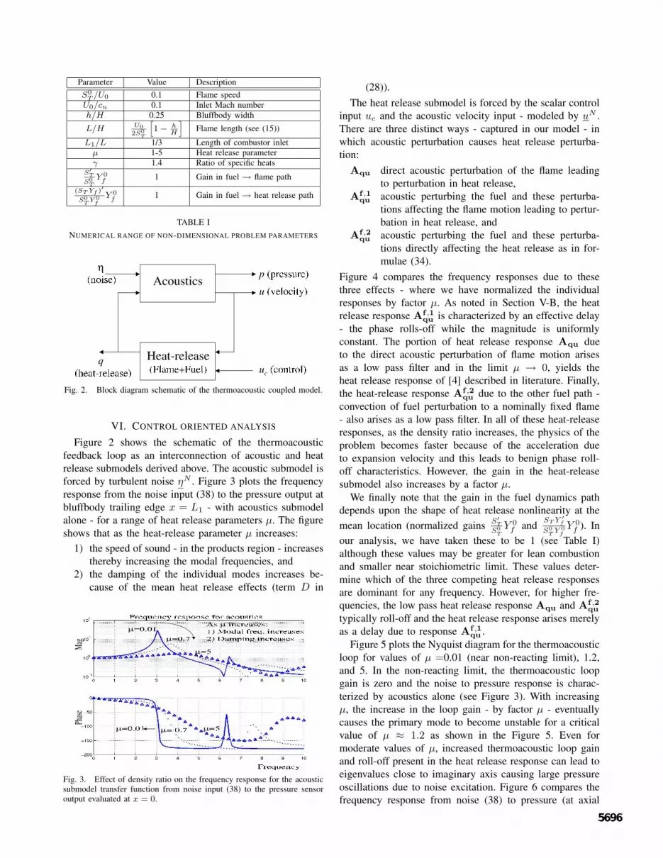
Parameter Value DescriptionS0
T /U0 0.1 Flame speedU0/cu 0.1 Inlet Mach numberh/H 0.25 Bluffbody width
L/H U0
2S0
T
[
1 −hH
]
Flame length (see (15))
L1/L 1/3 Length of combustor inletµ 1-5 Heat release parameterγ 1.4 Ratio of specific heats
S′
T
S0
T
Y 0f
1 Gain in fuel → flame path(ST Yf )′
S0
TY 0
f
Y 0f
1 Gain in fuel → heat release path
TABLE INUMERICAL RANGE OF NON-DIMENSIONAL PROBLEM PARAMETERS
Fig. 2. Block diagram schematic of the thermoacoustic coupled model.
VI. CONTROL ORIENTED ANALYSIS
Figure 2 shows the schematic of the thermoacousticfeedback loop as an interconnection of acoustic and heatrelease submodels derived above. The acoustic submodel isforced by turbulent noise ηN . Figure 3 plots the frequencyresponse from the noise input (38) to the pressure output atbluffbody trailing edge x = L1 - with acoustics submodelalone - for a range of heat release parameters µ. The figureshows that as the heat-release parameter µ increases:
1) the speed of sound - in the products region - increasesthereby increasing the modal frequencies, and
2) the damping of the individual modes increases be-cause of the mean heat release effects (term D in
Fig. 3. Effect of density ratio on the frequency response for the acousticsubmodel transfer function from noise input (38) to the pressure sensoroutput evaluated at x = 0.
(28)).The heat release submodel is forced by the scalar control
input uc and the acoustic velocity input - modeled by uN .There are three distinct ways - captured in our model - inwhich acoustic perturbation causes heat release perturba-tion:
Aqu direct acoustic perturbation of the flame leadingto perturbation in heat release,
Af ,1qu acoustic perturbing the fuel and these perturba-
tions affecting the flame motion leading to pertur-bation in heat release, and
Af ,2qu acoustic perturbing the fuel and these perturba-
tions directly affecting the heat release as in for-mulae (34).
Figure 4 compares the frequency responses due to thesethree effects - where we have normalized the individualresponses by factor µ. As noted in Section V-B, the heatrelease response A
f ,1qu is characterized by an effective delay
- the phase rolls-off while the magnitude is uniformlyconstant. The portion of heat release response Aqu dueto the direct acoustic perturbation of flame motion arisesas a low pass filter and in the limit µ → 0, yields theheat release response of [4] described in literature. Finally,the heat-release response A
f ,2qu due to the other fuel path -
convection of fuel perturbation to a nominally fixed flame- also arises as a low pass filter. In all of these heat-releaseresponses, as the density ratio increases, the physics of theproblem becomes faster because of the acceleration dueto expansion velocity and this leads to benign phase roll-off characteristics. However, the gain in the heat-releasesubmodel also increases by a factor µ.
We finally note that the gain in the fuel dynamics pathdepends upon the shape of heat release nonlinearity at themean location (normalized gains S′
T
S0
T
Y 0f and
ST Y ′
f
S0
TY 0
f
Y 0f ). In
our analysis, we have taken these to be 1 (see Table I)although these values may be greater for lean combustionand smaller near stoichiometric limit. These values deter-mine which of the three competing heat release responsesare dominant for any frequency. However, for higher fre-quencies, the low pass heat release response Aqu and A
f ,2qu
typically roll-off and the heat release response arises merelyas a delay due to response A
f ,1qu .
Figure 5 plots the Nyquist diagram for the thermoacousticloop for values of µ =0.01 (near non-reacting limit), 1.2,and 5. In the non-reacting limit, the thermoacoustic loopgain is zero and the noise to pressure response is charac-terized by acoustics alone (see Figure 3). With increasingµ, the increase in the loop gain - by factor µ - eventuallycauses the primary mode to become unstable for a criticalvalue of µ ≈ 1.2 as shown in the Figure 5. Even formoderate values of µ, increased thermoacoustic loop gainand roll-off present in the heat release response can lead toeigenvalues close to imaginary axis causing large pressureoscillations due to noise excitation. Figure 6 compares thefrequency response from noise (38) to pressure (at axial

Fig. 4. Effect of density ratio on the frequency response for (a) Aqu(s), (b) Af ,1qu (s), (c) A
f ,2qu (s), and (d) the cumulative Aqu + A
f ,1qu + A
f ,2qu (s)
heat release transfer functions from acoustic velocity input (uN (1) = 1) to the heat release output qN (1).
Fig. 5. Effect of density ratio on the Nyquist diagram
Fig. 6. Effect of the unsteady heat release feedback on the frequencyresponse from noise input (38) to the pressure sensor output evaluated atx = 0 (µ = 1).
location x = L1) with and with out unsteady heat releasefor a stable µ = 1 case. The damped characteristics ofacoustic submodel (because of mean heat release effects)together with delay induced roll-off present in the heat-release feedback leads to a peaksplitting in the responseto noise for the coupled model as shown in the figure.
VII. CONCLUSIONS
In this paper, we studied the distributed linear dynamicsof a coupled thermoacoustic problem. We showed that the
density ratio parameter µ is very important in determin-ing the magnitude and phase characteristics of both theacoustics (mean effects) and unsteady heat-release blocks.As the parameter µ increases, 1) the damping of theindividual acoustic mode increases, 2) the acoustic modalfrequency increases (due to increase in speed of sound), 3)the bandwidth of heat release response increases (physicsof the problem becoming faster) and 4) the thermoacousticloop gain increases. We also constructed a coupled ther-moacoustic model that exhibits an instability as the densityratio parameter is increased beyond a critical value.
VIII. ACKNOWLEDGEMENTS
Supported by AFOSR grant F49620-01-C-0021. The au-thors also acknowledge our useful conversations with Dr.Jesper Oppelstrup.
REFERENCES
[1] S. Candel, “Combustion dynamics and control: progress and chal-lenges,” Procs. of Combustion Institute, vol. 29, pp. 1–28, 2002.
[2] A. M. Annaswamy, M. Fleifil, J. P. Hathout, and A. Ghoniem,“Impact of linear coupling on the design of active controllers forthermoacoustic instability,” Combustion Science and Technology, vol.128, pp. 131–180, 1997.
[3] A. Dowling, “Nonlinear self-excited oscillations of a ducted flame,”Journal of Fluid Mechanics, vol. 346, pp. 271–290, 1997.
[4] ——, “A kinematical model of ducted flame,” Journal of FluidMechanics, vol. 394, pp. 51–72, 1999.
[5] P. G. Mehta, M. Soteriou, and A. Banaszuk, “Reduced ordermodelling of premixed flame dynamics in bluffbody combustors,”Submitted to Combustion and Flame, 2003.
[6] M. Fleifil, A. Annaswamy, Z. Ghoniem, and A. Ghoniem, “Responseof laminar premixed flame to flow oscillations: a kinematical modeland thermoacoustic instability results,” Combustion and Flame, vol.106, pp. 487–510, 1996.
[7] S. Ducruix, D. Durox, and S. Candel, “Theoretical and experimentaldetermination of the transfer function of a laminar premixed flame,”Proc. Combust. Inst., vol. 28, pp. 765–773, 2000.
[8] T. Schuller, D. Durox, and S. Candel, “A unified model for theprediction of laminar flame transfer functions: comparisons betweenconical and v-flame dynamics,” Combustion and Flame, vol. 134, pp.21–34, 2003.
[9] A. Banaszuk, G. Hagen, P. Mehta, and J. Oppelstrup, “A linear modelfor control of combustion instabilities on annular domain,” Procs. ofIEEE CDC, 2003.
[10] P. G. Mehta, A. Banaszuk, and M. Soteriou, “Fuel control of a ductedbluffbody flame,” Procs. of IEEE CDC, 2003.


