Embed Size (px)
Citation preview
instructables
DIY 2.1 Class AB Hi-Fi Audio Amplifier - Under $5
by vishalj.svp
Step 1: Selecting IC for Amplifier
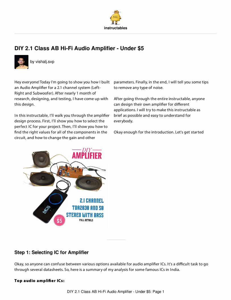
Hey everyone! Today I'm going to show you how I builtan Audio Ampli er for a 2.1 channel system (Left-Right and Subwoofer). After nearly 1 month ofresearch, designing, and testing, I have come up withthis design.
In this instructable, I’ll walk you through the ampli erdesign process. First, I’ll show you how to select theperfect IC for your project. Then, I’ll show you how to
nd the right values for all of the components in thecircuit, and how to change the gain and other
parameters. Finally, in the end, I will tell you some tipsto remove any type of noise.
After going through the entire instructable, anyonecan design their own ampli er for di erentapplications. I will try to make this instructable asbrief as possible and easy to understand foreverybody.
Okay enough for the introduction. Let's get started
Okay, so anyone can confuse between various options available for audio ampli er ICs. It's a di cult task to gothrough several datasheets. So, here is a summary of my analysis for some famous ICs in India.
To p a udio a m pli e r ICs :To p a udio a m pli e r ICs :
DIY 2.1 Class AB Hi-Fi Audio Amplifier - Under $5: Page 1
1. T DA729 4 1. T DA729 4 Datasheet
100V - 100W DMOS audio ampli er with muteShort circuit protectionCan provide 200W in parallel
2. LM 38 8 6 2. LM 38 8 6 Datasheet
High-Performance 68W Audio Power Ampli er w/MuteWide Supply Range 20V - 94VSignal-to-Noise Ratio ≥ 92dBBest Sound quality
3. L A4 4 4 0 /CD4 4 4 0 3. L A4 4 4 0 /CD4 4 4 0 Datasheet
Built-in 2 Channels (Dual) Enabling Use in Stereo and Bridge Ampli er Applications.Dual : 6 W × 2 (typ.) ; Bridge : 19 W (typ.)Minimum Number of External Parts Required
4 . T DA20 504 . T DA20 50 Datasheet
32 W hi- audio ampli erWide-range supply voltage, up to 50 VCheap and easy to replace
5. T DA20 305. T DA20 30 Datasheet
14 W hi- audio ampli erWide-range supply voltage, up to 36 VCheap and easy to replaceCan be bridged for more power
While selecting an IC, consider your expectation from the Ampli er and purpose of your project. If you want a highwattage ampli er with the best in class sound quality then go for TDA7294 or LM3886. But, if you just want to drivea 5W, 10W or 20W speaker than, 4rd and 5th option are best for you. You can also consider LA4440 if you want asimpler circuit (both left and right channel in a single IC).
Generally, you should pick an ampli er that can deliver power equal to twice the speaker’s power rating. This meansthat a speaker with an impedance of 8 ohms and a rating of 5 watts will require an ampli er that can produce 10watts into an 8-ohm load. For a stereo pair of speakers, the ampli er should be rated at 10 watts per channel into 8ohms.
Want to learn more about Ampli ers, click here
DIY 2.1 Class AB Hi-Fi Audio Amplifier - Under $5: Page 2
Step 2: Parts and Tools
1. LM72942. LM38863. TDA20504. TDA20305. LA4440
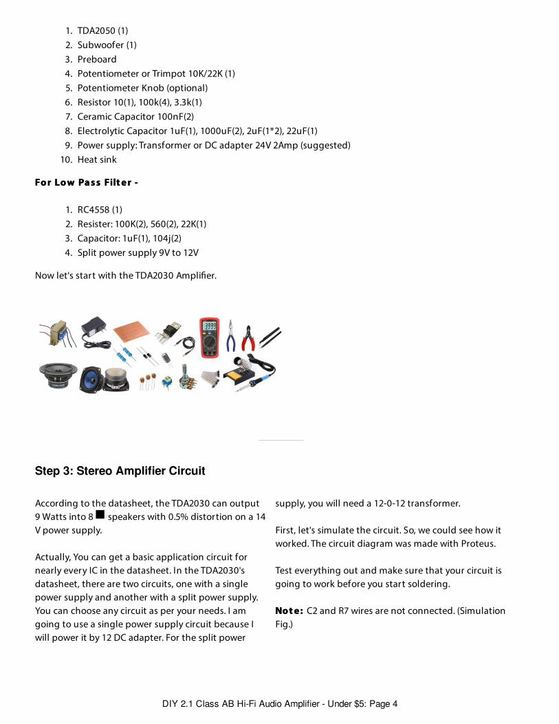
I want to drive two 5W speakers for Left and Right channels which I extracted from an old CRT TV. So, TDA2030 isbest for me but, you can choose TDA2050 for building Left and Right channels too.
To o ls -To o ls -
1. Multimeter2. Soldering station3. Hot glue gun4. Pliers5. Cutter6. Shrink tubing
Fo r T DA20 30 St e re o Am pli e r ( Le f t + Rig ht ) -Fo r T DA20 30 St e re o Am pli e r ( Le f t + Rig ht ) -
1. TDA2030 (2)2. Speakers (2)3. Preboard4. 3.5mm stereo jack5. 1N4007 Diode (2*2)6. Potentiometer or Trimpot 10K/22K (2)7. Potentiometer Knob (optional)8. Resistor 10(1*2), 100k(4*2), 3.7k(1*2)9. Ceramic Capacitor 100nF(2*2)
10. Electrolytic Capacitor 1uF(1*2), 100uF(1*2), 2uF(1*2), 22uF(1*2), 2200uF(1*2)11. Power supply: Transformer or DC adapter 12V 2Amp(min)12. Heat sink (2)
Fo r T DA20 50 Subw o o f e r -Fo r T DA20 50 Subw o o f e r -
1 2 3 45
DIY 2.1 Class AB Hi-Fi Audio Amplifier - Under $5: Page 3
Step 3: Stereo Amplifier Circuit
1. TDA2050 (1)2. Subwoofer (1)3. Preboard4. Potentiometer or Trimpot 10K/22K (1)5. Potentiometer Knob (optional)6. Resistor 10(1), 100k(4), 3.3k(1)7. Ceramic Capacitor 100nF(2)8. Electrolytic Capacitor 1uF(1), 1000uF(2), 2uF(1*2), 22uF(1)9. Power supply: Transformer or DC adapter 24V 2Amp (suggested)
10. Heat sink
Fo r Lo w Pa s s Filt e r -Fo r Lo w Pa s s Filt e r -
1. RC4558 (1)2. Resister: 100K(2), 560(2), 22K(1)3. Capacitor: 1uF(1), 104j(2)4. Split power supply 9V to 12V
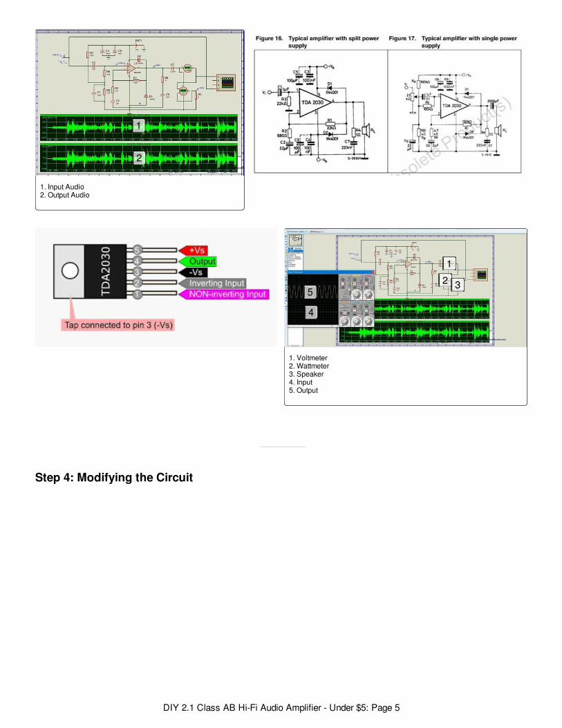
Now let's start with the TDA2030 Ampli er.
According to the datasheet, the TDA2030 can output9 Watts into 8 speakers with 0.5% distortion on a 14V power supply.
Actually, You can get a basic application circuit fornearly every IC in the datasheet. In the TDA2030'sdatasheet, there are two circuits, one with a singlepower supply and another with a split power supply.You can choose any circuit as per your needs. I amgoing to use a single power supply circuit because Iwill power it by 12 DC adapter. For the split power
supply, you will need a 12-0-12 transformer.
First, let's simulate the circuit. So, we could see how itworked. The circuit diagram was made with Proteus.
Test everything out and make sure that your circuit isgoing to work before you start soldering.
No t e : No t e : C2 and R7 wires are not connected. (SimulationFig.)
DIY 2.1 Class AB Hi-Fi Audio Amplifier - Under $5: Page 4
Step 4: Modifying the Circuit
1. Input Audio2. Output Audio
1. Voltmeter2. Wattmeter3. Speaker4. Input5. Output
1
2
1
2 3
4
5
DIY 2.1 Class AB Hi-Fi Audio Amplifier - Under $5: Page 5
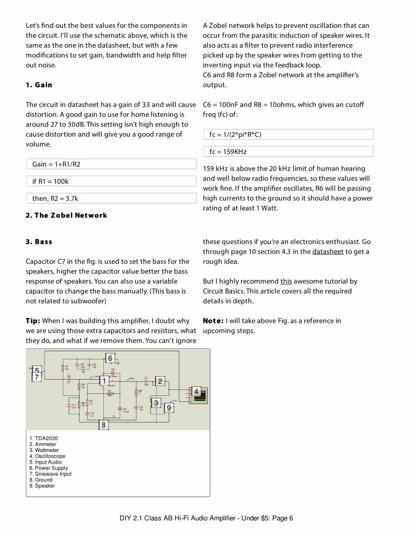
Let’s nd out the best values for the components inthe circuit. I’ll use the schematic above, which is thesame as the one in the datasheet, but with a fewmodi cations to set gain, bandwidth and help lterout noise.
1. G a in1. G a in
The circuit in datasheet has a gain of 33 and will causedistortion. A good gain to use for home listening isaround 27 to 30dB. This setting isn’t high enough tocause distortion and will give you a good range ofvolume.
Gain = 1+R1/R2
if R1 = 100k
then, R2 = 3.7k
2. T he Z o be l Ne t w o rk2. T he Z o be l Ne t w o rk
A Zobel network helps to prevent oscillation that canoccur from the parasitic induction of speaker wires. Italso acts as a lter to prevent radio interferencepicked up by the speaker wires from getting to theinverting input via the feedback loop.C6 and R8 form a Zobel network at the ampli er’soutput.
C6 = 100nF and R8 = 10ohms, which gives an cutofreq (fc) of :
fc = 1/(2*pi*R*C)
fc = 159KHz
159 kHz is above the 20 kHz limit of human hearingand well below radio frequencies, so these values willwork ne. If the ampli er oscillates, R6 will be passinghigh currents to the ground so it should have a powerrating of at least 1 Watt.
3. B a s s3. B a s s
Capacitor C7 in the g. is used to set the bass for thespeakers, higher the capacitor value better the bassresponse of speakers. You can also use a variablecapacitor to change the bass manually. (This bass isnot related to subwoofer)
T ip:T ip: When I was building this ampli er, I doubt whywe are using those extra capacitors and resistors, whatthey do, and what if we remove them. You can't ignore
these questions if you're an electronics enthusiast. Gothrough page 10 section 4.3 in the datasheet to get arough idea.
But I highly recommend this awesome tutorial byCircuit Basics. This article covers all the requireddetails in depth.
No t e :No t e : I will take above Fig. as a reference inupcoming steps.
1. TDA20302. Ammeter3. Wattmeter 4. Oscilloscope 5. Input Audio6. Power Supply7. Sinewave Input 8. Ground9. Speaker
1 2
3
4
5
6
7
8
9
DIY 2.1 Class AB Hi-Fi Audio Amplifier - Under $5: Page 6
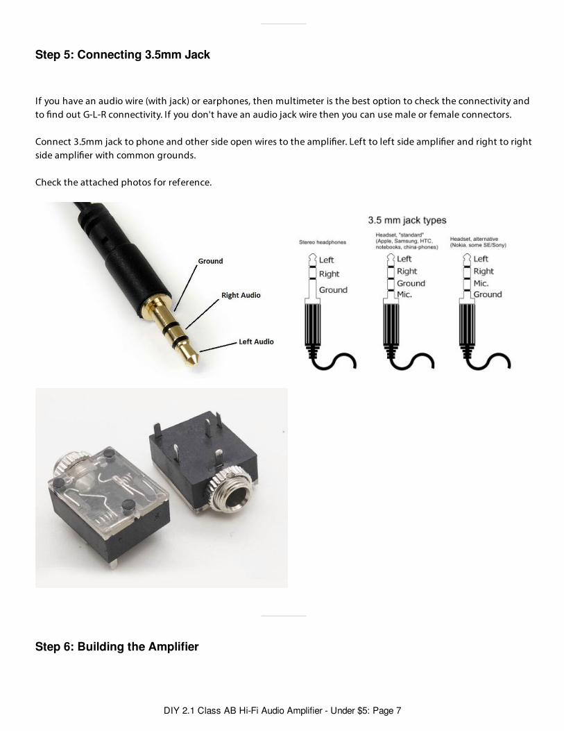
Step 5: Connecting 3.5mm Jack
Step 6: Building the Amplifier
If you have an audio wire (with jack) or earphones, then multimeter is the best option to check the connectivity andto nd out G-L-R connectivity. If you don't have an audio jack wire then you can use male or female connectors.
Connect 3.5mm jack to phone and other side open wires to the ampli er. Left to left side ampli er and right to rightside ampli er with common grounds.
Check the attached photos for reference.
DIY 2.1 Class AB Hi-Fi Audio Amplifier - Under $5: Page 7
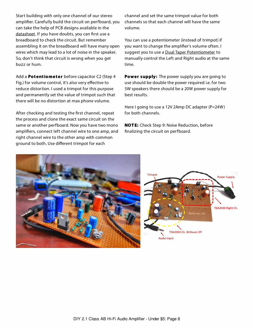
Start building with only one channel of our stereoampli er. Carefully build the circuit on perfboard, youcan take the help of PCB designs available in thedatasheet. If you have doubts, you can rst use abreadboard to check the circuit. But rememberassembling it on the breadboard will have many openwires which may lead to a lot of noise in the speaker.So, don't think that circuit is wrong when you getbuzz or hum.
Add a Po t e nt io m e t e r Po t e nt io m e t e r before capacitor C2 (Step 4Fig.) for volume control, it's also very e ective toreduce distortion. I used a trimpot for this purposeand permanently set the value of trimpot such thatthere will be no distortion at max phone volume.
After checking and testing the rst channel, repeatthe process and clone the exact same circuit on thesame or another perfboard. Now you have two monoampli ers, connect left channel wire to one amp, andright channel wire to the other amp with commonground to both. Use di erent trimpot for each
channel and set the same trimpot value for bothchannels so that each channel will have the samevolume.
You can use a potentiometer (instead of trimpot) ifyou want to change the ampli er's volume often. Isuggest you to use a Dual Taper Potentiometer tomanually control the Left and Right audio at the sametime.
Po w e r s upply : Po w e r s upply : The power supply you are going touse should be double the power required i.e. for two5W speakers there should be a 20W power supply forbest results.
Here I going to use a 12V 2Amp DC adapter (P=24W )for both channels.
NO T E:NO T E: Check Step 9: Noise Reduction, beforenalizing the circuit on perfboard.
DIY 2.1 Class AB Hi-Fi Audio Amplifier - Under $5: Page 8
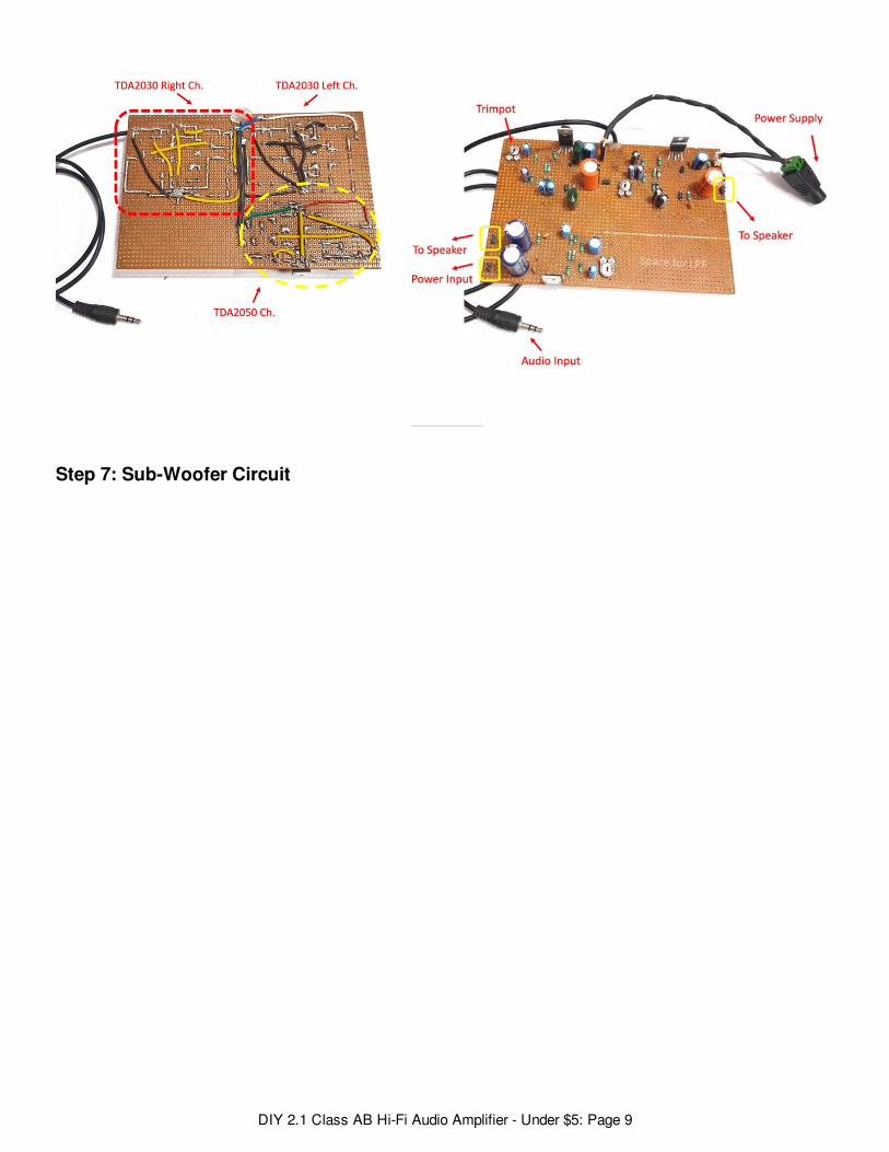
Step 7: Sub-Woofer Circuit
DIY 2.1 Class AB Hi-Fi Audio Amplifier - Under $5: Page 9
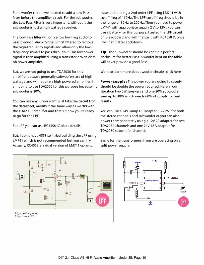
For a woofer circuit, we needed to add a Low Passlter before the ampli er circuit. For the subwoofer,
the Low Pass Filter is very important, without it thesubwoofer is just a high wattage speaker.
The Low Pass lter will only allow low freq audio topass through. Audio Signal is rst ltered to removethe high-frequency signals and allow only the low-frequency signals to pass through it. This low powersignal is then ampli ed using a transistor driven classAB power ampli er.
But, we are not going to use TDA2030 for thisampli er because generally subwoofers are of highwattage and will require a high powered ampli er. Iam going to use TDA2050 for this purpose because mysubwoofer is 20W.
You can use any IC you want, just take the circuit fromthe datasheet, modify it the same way as we did withthe TDA2030 ampli er and that's it now you're readyto go for the LPF.
For LPF you can use RC4558 IC. More details
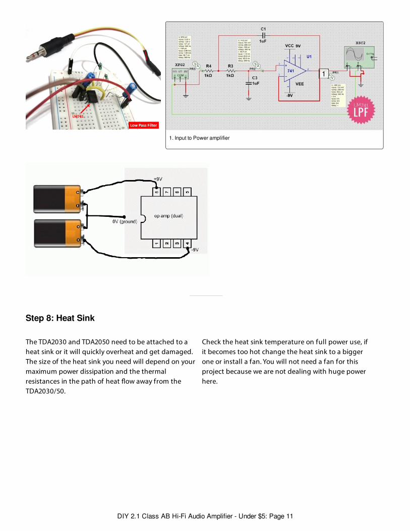
But, I don't have 4558 so I tried building the LPF usingLM741 which is not recommended but you can try.Actually, RC4558 is a dual version of LM741 op-amp.
I started building a 2nd order LPF using LM741 withcuto freq of 160Hz, The LPF cuto freq should be inthe range of 80Hz to 200Hz. Then you need to powerLM741 with appropriate supply (5V to 12V), you canuse a battery for this purpose. I tested the LPF circuiton Breadboard and will nalize it with RC4558 IC onceI will get it after Lockdown.
T ip:T ip: The subwoofer should be kept in a perfectenclosure for better Bass. A woofer kept on the tablewill never provide a good Bass.
Want to learn more about woofer circuits, click here
Po w e r s upply :Po w e r s upply : The power you are going to supplyshould be double the power required. Here in oursituation two 5W speakers and one 20W subwoofersum up to 30W which needs 60W of supply for bestresults.
You can use a 24V 3Amp DC adapter (P=72W ) for boththe stereo channels and subwoofer or you can alsopower them separately using a 12V 2A adapter for twoTDA2030 channels and one 24V 1.5A adapter forTDA2050 subwoofer channel.
Same for the transformers if you are operating on asplit power supply.
1. Ignore this ground2. Input from LPF
1
2
DIY 2.1 Class AB Hi-Fi Audio Amplifier - Under $5: Page 10
Step 8: Heat Sink
1. Input to Power amplifier
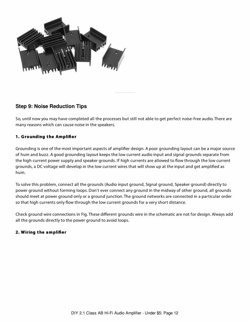
The TDA2030 and TDA2050 need to be attached to aheat sink or it will quickly overheat and get damaged.The size of the heat sink you need will depend on yourmaximum power dissipation and the thermalresistances in the path of heat ow away from theTDA2030/50.
Check the heat sink temperature on full power use, ifit becomes too hot change the heat sink to a biggerone or install a fan. You will not need a fan for thisproject because we are not dealing with huge powerhere.
1
DIY 2.1 Class AB Hi-Fi Audio Amplifier - Under $5: Page 11
Step 9: Noise Reduction Tips
So, until now you may have completed all the processes but still not able to get perfect noise-free audio. There aremany reasons which can cause noise in the speakers.
1. G ro unding t he Am pli e r1. G ro unding t he Am pli e r
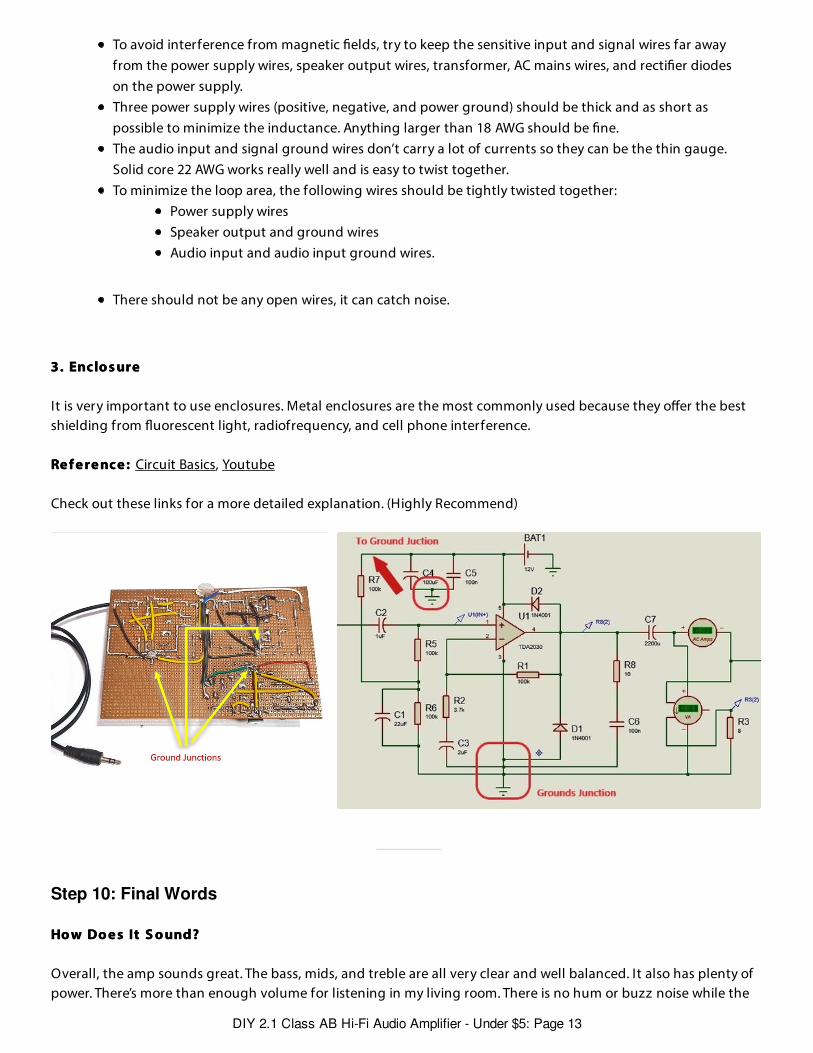
Grounding is one of the most important aspects of ampli er design. A poor grounding layout can be a major sourceof hum and buzz. A good grounding layout keeps the low current audio input and signal grounds separate fromthe high current power supply and speaker grounds. If high currents are allowed to ow through the low currentgrounds, a DC voltage will develop in the low current wires that will show up at the input and get ampli ed ashum.
To solve this problem, connect all the grounds (Audio input ground, Signal ground, Speaker ground) directly topower ground without forming loops. Don't ever connect any ground in the midway of other ground, all groundsshould meet at power ground only or a ground junction. The ground networks are connected in a particular orderso that high currents only ow through the low current grounds for a very short distance.
Check ground wire connections in Fig. These di erent grounds wire in the schematic are not for design. Always addall the grounds directly to the power ground to avoid loops.
2. W iring t he a m pli e r 2. W iring t he a m pli e r
DIY 2.1 Class AB Hi-Fi Audio Amplifier - Under $5: Page 12
Step 10: Final Words
To avoid interference from magnetic elds, try to keep the sensitive input and signal wires far awayfrom the power supply wires, speaker output wires, transformer, AC mains wires, and recti er diodeson the power supply.Three power supply wires (positive, negative, and power ground) should be thick and as short aspossible to minimize the inductance. Anything larger than 18 AWG should be ne.The audio input and signal ground wires don’t carry a lot of currents so they can be the thin gauge.Solid core 22 AWG works really well and is easy to twist together.To minimize the loop area, the following wires should be tightly twisted together:
Power supply wiresSpeaker output and ground wiresAudio input and audio input ground wires.
There should not be any open wires, it can catch noise.
3. Enclo s ure3. Enclo s ure
It is very important to use enclosures. Metal enclosures are the most commonly used because they o er the bestshielding from uorescent light, radiofrequency, and cell phone interference.
Re f e re nce : Re f e re nce : Circuit Basics, Youtube
Check out these links for a more detailed explanation. (Highly Recommend)
Ho w Do e s It S o und?Ho w Do e s It S o und?
Overall, the amp sounds great. The bass, mids, and treble are all very clear and well balanced. It also has plenty ofpower. There’s more than enough volume for listening in my living room. There is no hum or buzz noise while the
DIY 2.1 Class AB Hi-Fi Audio Amplifier - Under $5: Page 13
amp is plugged into the source (there can be surrounding noise when the audio jack is not plugged in thephone/laptop, So don't worry it's normal).
While the sound quality of the TDA2030 may not be up to par like TDA7394 or other, But is good to start with.
But there is no obstacle to create something better. This circuit is easy to modify, If you want you can also
Add a Bluetooth module.You can replace the power source with 12V (or higher) battery.You can add ON/OFF LED if you want.Add a music reactive LED strip or an LED array. (I will publish this soon)Can integrate Google Assistant using Raspberry Pi.
And then let your creativity ow!!
This is my rst instructable so don't forget to provide your valuable Feedback.
Follow me up for more projects like these in the future.
Have fun, Stay creative :D
- Vis ha l- Vis ha l
DIY 2.1 Class AB Hi-Fi Audio Amplifier - Under $5: Page 14


