Embed Size (px)
Citation preview
DLR-IB-RM-OP-2021-214 ViESTac: A Multimodal VR Evaluation Suite for Novel Tactile Devices Masterarbeit
Premankur Banerjee


Technische Universitat Munchen
Chair of Media Technology
Prof. Dr.-Ing. Eckehard Steinbach
Master Thesis
ViESTac: A Multimodal VR Evaluation Suitefor Novel Tactile Devices
Author: Premankur BanerjeeMatriculation Number: 03722403Address: Schrofelhofstraße 22, WG-02, Raum-05
81375 MunchenAdvisor: Dr.-Ing Thomas Hulin
Dr. Harsimran SinghProf. Dr.-Ing Eckehard Steinbach
Begin: 17.05.2021End: 01.12.2021

With my signature below, I assert that the work in this thesis has been composed by myselfindependently and no source materials or aids other than those mentioned in the thesishave been used.
Munchen, December 1, 2021
Place, Date Signature
This work is licensed under the Creative Commons Attribution 3.0 Germany License. Toview a copy of the license, visit http://creativecommons.org/licenses/by/3.0/de
Or
Send a letter to Creative Commons, 171 Second Street, Suite 300, San Francisco, California94105, USA.
Munchen, December 1, 2021
Place, Date Signature

Acknowledgements
First and foremost, I would like to extend my sincere gratitude to Prof. Dr.-Ing. EckehardSteinbach for supervising this thesis in addition to being highly supportive and involvedduring the entire journey.
I am extremely grateful to my supervisor Dr.-Ing. Thomas Hulin and co-supervisor Dr.Harsimran Singh, for providing me with the opportunity to pursue a thesis at the DeutschesZentrum fur Luft und Raumfahrt (DLR). They have devoted a lot of time, effort and werealways available to help whenever I ran into problems. They have been very friendly andalways kept me motivated to accomplish a great work. This thesis would not have beenpossible without their guidance, advice and supervision. It has been an absolute pleasureworking with them.
I would like to thank Dr. Bernhard Weber and Dr. Evelyn Muschter, the Human Factorsexperts involved in this master thesis project, for their valuable insights to experimentalpsychological research and for their help in formulating the evaluation study conducted. Ihighly appreciate the support from Dr. Bernhard Weber for conducting advanced statisticalanalyses of the results of the study.
Last but not the least, I would like to express my gratification to my parents for theirunconditional love, support, daily dose of motivation and their eagerness to know moreabout my work. A big shoutout to Michael Rothammer, Luis Perez Marcilla and LuisWiedmann for their valuable discussions, support in evaluation study, company duringlunch and coffee, and much more. I am very much indebted to my friends in Munich fortheir attempt at making my life a lot easier during this entire project.
This master thesis was carried out at the Institute of Robotics and Mechatronics, DLR. Itwas funded by the German Research Foundation (DFG, Deutsche Forschungsgemeinschaft)as part of Germany’s Excellence Strategy – EXC 2050/1 – Project ID 390696704 – Clusterof Excellence “Centre for Tactile Internet with Human-in-the-Loop” (CeTI) of TechnischeUniversitat Dresden.
i

Abstract
Virtual Reality (VR) applications designed for the purpose of testing or evaluating tactiledevices are strongly predisposed to the respective device display capabilities, and are de-veloped across multiple software platforms. This thesis presents “ViESTac”, a multimodalVR evaluation suite for evaluating and comparing novel tactile devices. To account for thewide variety of existing devices and their tactile capabilities and idiosyncrasies, an extensiveliterature review was conducted to determine the requirements for such a suite. ViESTaccontains two virtual environments, one for simulating different tactile properties of virtualobjects like stiffness, macro-roughness, fine-roughness, temperature, friction, and the otherfor supporting positioning accuracy in standard tasks in VR or teleoperation (such as pick-and-place, peg-in-hole, etc). ViESTac also allows easy integration of tactile devices, andcan support popular, unobtrusive hand tracking systems such as the Leap Motion con-troller. The potentiality of this VR suite has been exemplified through an evaluation studyinvolving two tactile devices – FingerTac and FerroVibe – and thirteen participants. Taskson discriminating contact point orientation, texture, stiffness were carried out in additionto object positioning. Results showed that participants could almost immaculately distin-guish between the different conditions tested for the tactile properties, with little variance.Tactile guidance for positioning tasks was found to be moderately helpful as comparedto the complexity of the tasks. Furthermore, both devices were compared on grounds oftrajectory lengths, completion times and overall helpfulness. Collectively, these served asa testament to the working of ViESTac.
iii
Kurzfassung
Virtual Reality (VR) Anwendungen, die zum Testen oder Bewerten taktiler Gerate entwi-ckelt werden, sind in hohem Maße von den jeweiligen Fahigkeiten der Gerate abhangig undwerden auf mehreren Softwareplattformen entwickelt. In diesem Beitrag wird “ViESTac”vorgestellt, eine multimodale VR Evaluierungssuite zur Evaluierung und zum Vergleichneuartiger taktiler Gerate. Um der großen Vielfalt an bestehenden Geraten und ihren tak-tilen Fahigkeiten und Eigenheiten zu berucksichtigen, wurde eine umfangreiche Literatur-recherche durchgefuhrt, um die Anforderungen an eine solche Suite zu ermitteln. ViESTacenthalt zwei virtuelle Umgebungen, eine zur Simulation verschiedener taktiler Eigenschaf-ten virtueller Objekte wie Steifigkeit, Makrorauheit, Feinrauheit, Temperatur und Reibung,und die andere zur Unterstutzung der Positionierungsgenauigkeit bei Standard-VR oder Te-leoperationsaufgaben (wie Pick-and-Place, Peg-in-Hole usw.). Die Suite ermoglicht die ein-fache Integration von taktilen Geraten und unterstutzt gangige, unauffallige HandtrackingSysteme wie den Leap Motion Controller. Das Potenzial dieser VR Suite wurde durch eineEvaluierungsstudie mit zwei taktilen Geraten – FingerTac und FerroVibe – und dreizehnTeilnehmern illustriert. Es wurden Aufgaben zur Unterscheidung von Kontaktpunktaus-richtung, Textur und Steifigkeit sowie Objektpositionierung durchgefuhrt. Die Ergebnissezeigten, dass die Teilnehmer die verschiedenen Bedingungen, die fur die taktilen Eigen-schaften getestet wurden, fast fehlerfrei und mit geringer Varianz unterscheiden konnten.Daruber hinaus wurden beide Gerate miteinander verglichen, wodurch die Funktionsweisevon ViESTac belegt werden konnte.
iv
Contents
1 Introduction 11.1 Motivation . . . . . . . . . . . . . . . . . . . . . . . . . . . . . . . . . . . . 11.2 Contributions . . . . . . . . . . . . . . . . . . . . . . . . . . . . . . . . . . 21.3 Outline . . . . . . . . . . . . . . . . . . . . . . . . . . . . . . . . . . . . . . 2
2 Background and Relevant Work 52.1 Haptics . . . . . . . . . . . . . . . . . . . . . . . . . . . . . . . . . . . . . 5
2.1.1 Kinesthetic Feedback . . . . . . . . . . . . . . . . . . . . . . . . . . 62.1.2 Tactile Feedback . . . . . . . . . . . . . . . . . . . . . . . . . . . . 6
2.2 Classification of Multimodal Haptic Devices . . . . . . . . . . . . . . . . . 62.2.1 Handheld Haptic Controllers . . . . . . . . . . . . . . . . . . . . . . 72.2.2 Fingertip Wearable Haptic Devices . . . . . . . . . . . . . . . . . . 9
2.3 Existing Virtual Environments . . . . . . . . . . . . . . . . . . . . . . . . . 14
3 Hardware and Software Description 193.1 FingerTac . . . . . . . . . . . . . . . . . . . . . . . . . . . . . . . . . . . . 193.2 FerroVibe . . . . . . . . . . . . . . . . . . . . . . . . . . . . . . . . . . . . 213.3 Integrating the Tactile Devices . . . . . . . . . . . . . . . . . . . . . . . . . 24
3.3.1 Virtual Environment Software . . . . . . . . . . . . . . . . . . . . . 243.3.2 Hand Tracking . . . . . . . . . . . . . . . . . . . . . . . . . . . . . 25
4 Virtual Scenarios 274.1 Discriminating Tactile Properties . . . . . . . . . . . . . . . . . . . . . . . 28
4.1.1 Contact Angle Discrimination . . . . . . . . . . . . . . . . . . . . . 284.1.2 Texture Discrimination . . . . . . . . . . . . . . . . . . . . . . . . . 314.1.3 Stiffness Discrimination . . . . . . . . . . . . . . . . . . . . . . . . 344.1.4 Shape Detection . . . . . . . . . . . . . . . . . . . . . . . . . . . . . 364.1.5 Friction and Temperature . . . . . . . . . . . . . . . . . . . . . . . 38
4.2 Object Positioning . . . . . . . . . . . . . . . . . . . . . . . . . . . . . . . 394.2.1 Vibration Modes . . . . . . . . . . . . . . . . . . . . . . . . . . . . 424.2.2 Vibration Patterns . . . . . . . . . . . . . . . . . . . . . . . . . . . 434.2.3 A 3-DoF Tactile Guidance . . . . . . . . . . . . . . . . . . . . . . . 45
v
CONTENTS vi
4.2.4 Additional Virtual Scenarios . . . . . . . . . . . . . . . . . . . . . . 48
5 Evaluation Study 515.1 Sample . . . . . . . . . . . . . . . . . . . . . . . . . . . . . . . . . . . . . . 525.2 Task 1: Contact Angle Discrimination . . . . . . . . . . . . . . . . . . . . 52
5.2.1 Task Description and Setup . . . . . . . . . . . . . . . . . . . . . . 525.2.2 Procedure . . . . . . . . . . . . . . . . . . . . . . . . . . . . . . . . 535.2.3 Results and Discussion . . . . . . . . . . . . . . . . . . . . . . . . . 53
5.3 Task 2: Texture Discrimination . . . . . . . . . . . . . . . . . . . . . . . . 555.3.1 Task Description and Setup . . . . . . . . . . . . . . . . . . . . . . 555.3.2 Procedure . . . . . . . . . . . . . . . . . . . . . . . . . . . . . . . . 555.3.3 Results and Discussion . . . . . . . . . . . . . . . . . . . . . . . . . 56
5.4 Task 3: Stiffness Discrimination . . . . . . . . . . . . . . . . . . . . . . . . 585.4.1 Task Description and Setup . . . . . . . . . . . . . . . . . . . . . . 585.4.2 Procedure . . . . . . . . . . . . . . . . . . . . . . . . . . . . . . . . 595.4.3 Results and Discussion . . . . . . . . . . . . . . . . . . . . . . . . . 59
5.5 Task 4: Object Positioning . . . . . . . . . . . . . . . . . . . . . . . . . . . 615.5.1 Task Description and Setup . . . . . . . . . . . . . . . . . . . . . . 615.5.2 Procedure . . . . . . . . . . . . . . . . . . . . . . . . . . . . . . . . 625.5.3 Results and Discussion . . . . . . . . . . . . . . . . . . . . . . . . . 63
5.6 Comparison of Tactile Devices . . . . . . . . . . . . . . . . . . . . . . . . . 665.7 Learning Experiences . . . . . . . . . . . . . . . . . . . . . . . . . . . . . . 67
6 Conclusion and Future Work 716.1 Conclusion . . . . . . . . . . . . . . . . . . . . . . . . . . . . . . . . . . . . 716.2 Future Work . . . . . . . . . . . . . . . . . . . . . . . . . . . . . . . . . . . 72
Appendix 73
List of Figures 80
List of Tables 82
Bibliography 83
List of Abbreviations
ANOVA Analysis of Variance
AR Augmented Reality
CI Confidence Interval
COM Communication
DCB Data or Device Control Block
DoF Degree of Freedom
ENM External Neodymium Magnet
ERM Eccentric Rotating Mass
HIP Haptic Interaction Point
HMD Head Mounted Display
JND Just Noticeable Difference
LED Light-emitting Diode
LRA Linear Resonant Actuator
MR Mixed Reality
NMEF Neodymium Magnet Enclosed in Ferro-fluid
ODE Open Dynamics Engine
PWM Pulse Width Modulation
SD Standard Deviation
USB Universal Serial Bus
VE Virtual Environment
VR Virtual Reality
vii

Chapter 1
Introduction
Human task performance in Virtual Reality (VR) or teleoperation systems is limited dueto long task completion time [1], [2], [3], inaccurate trajectories [4], [5], or excessive forceto objects in remote environments [6], [7], [8]. Most of present day multi-modal human-machine interfaces predominantly include visual and auditory cues [9], [10], [11], [12].Haptic interfaces aim to address these limitations by incorporating the sense of touchinto these interfaces [13], [14]. They provide an additional mode of feedback from virtualor remote environments that assist in improving critical performance aspects in VR orteleoperation systems.
1.1 Motivation
Tactile interactions and interfaces have gained vast popularity among researchers over thepast decade. A multitude of tactile devices have been developed, each exhibiting variousactuation techniques as well as possessing the capability to display one or more tactileproperties. Numerous studies have been conducted investigating different tactile devicesthrough a variety of tasks and experimental methodologies. Most of them feature a VRenvironment in which the devices are tested and validated through extensive user studies.Typically, each such study focuses on one particular haptic device only, or a few experimentsor task executions in a virtual scenario.
The experiments in such virtual environments or the environments itself, in most cases,are tailored to the respective device display capabilities. The details of such virtual envi-ronments are often unclear, making them difficult to reuse or recreate. The software usedfor designing VR environments or hardware for hand tracking also vary greatly, whichcan affect user performance and immersiveness during interactions with such tactile de-vices. Furthermore, since the applications (e.g. entertainment, rehabilitation or surgery),the tasks (e.g. pick-and-place or tracking), the experimental methodologies and apparatus
CHAPTER 1. INTRODUCTION 2
vary for almost every study conducted in this field, it is difficult to ascertain the overalleffectiveness of tactile feedback devices. For example, a tactile device only capable of dis-playing temperature changes will not be tested in a virtual scenario which is designed toevaluate stiffness properties.
The aforementioned reasons necessitates researchers to create their own virtual environ-ment to investigate the display properties of a new device in design. Therefore, virtualenvironments which can efficiently and fairly evaluate or compare several different tactiledevices being developed throughout the world, are to the best of my knowledge non-existent. Altogether, these grounds serve as a basis to motivate the need for a generic,multimodal VR suite that I designed, implemented and evaluated in this thesis.
1.2 Contributions
This thesis presents a first attempt at a generic multimodal virtual reality simulation whichhas the potential to serve as a benchmark for evaluating and comparing tactile devices.The scope of work to achieve this goal can be summarized as follows:
1. VR Suite – Conceptualization and implementation of a virtual reality scenario withsuitable collision detection. Such a simulation package designed in CHAI3D [15] cansimply be installed and be made to run on any platform.
2. Tactile Device Integration – Setting up of functional demonstrators (installationof drivers, mechanical and electrical component preparation) and integrability oftactile devices in the virtual scenario mentioned above.
3. Hand Tracking – Integration of a common finger position estimation method basedon a hand tracking system. One of the most common hand tracking systems, the LeapMotion controller [16] is used, which can be operated independently or in associationwith popular Head Mounted Displays (HMDs).
4. Tactile Patterns – Integration and testing of different tactile patterns suited to therespective tasks in the virtual environment, using available tactile devices.
5. Evaluation Study – An evaluation study that serves as a proof-of-concept of theentire VR suite. It also validates the device display properties, the different tactilepatterns integrated and the assumptions supporting such a virtual environment.
1.3 Outline
This thesis is organized into six chapters. Chapter 2 provides the necessary backgroundfor understanding the motivation and contents of this thesis. It starts with a brief history
CHAPTER 1. INTRODUCTION 3
of haptics, different feedback categories, and then it goes on to describe an overview of theexisting handheld and fingertip wearable tactile devices in the literature, followed by therespective virtual environments they are tested and evaluated in.
Chapter 3 presents a system description of the tactile devices used in conducting thisthesis, followed by the simulation software and how the connections between hardware andsoftware were established. It also explains the hand tracking devices used for testing andthe evaluation study.
The approach towards designing the virtual environment mentioned priorly is highlightedin Chapter 4, with mathematical details, algorithmic description and illustrations support-ing the framework of the virtual scenarios. Conducted evaluation study with participantdetails, task description, procedure, and results are contained in Chapter 5.
Finally, Chapter 6 concludes the thesis, thereby discussing the limitations and possibleextensions of this work that might be taken up in the future.

Chapter 2
Background and Relevant Work
In this chapter, a background of haptic feedback along with various handheld and wearabletactile devices developed in the scientific community has been abridged. It then goes onto discuss the respective virtual environments that were designed to evaluate the devicesdiscussed formerly.
2.1 Haptics
The word Haptics comes from the Greek word Haptikos, which means ‘to be able to come incontact with’ [17]. Haptic communication is a branch of non-verbal communication, whereinformation is conveyed through touch and proprioception. Haptic technologies recreate thesense of touch by rendering appropriate forces, vibrations and motions. Haptic rendering,in addition to audio and visual feedback, aggrandizes user immersion and performance invirtual or mixed environments, thereby enhancing human-computer interactions [18].
Haptic feedback is already integrated in various aspects of our daily lives ranging fromsmartphones [19], [20] and gaming controllers [21], [22], to driving [23], [24] and non-touchkiosks [25], and is expanding further as researchers continue to innovate novel interactionmethods and devices. This added sense of touch assists and improves teleoperation ofrobots, especially in highly sensitive environments [26], [27]. Study of how humans interactthrough touch is important in human-robot interaction as well, wherein a robot learns tointeract with humans based on human emotion [28], for example. A number of methodsand algorithms have been developed to deliver rich, realistic haptic sensations over digitalmedia. Psychological and psychophysical studies exhibit the fact that the human hapticperception system consists of two components which are separate but complementary toeach other. The two kinds of perception are Kinesthetic and Tactile [29], [30] – details ofwhich are discussed in the following subsections.
CHAPTER 2. BACKGROUND AND RELEVANT WORK 6
2.1.1 Kinesthetic Feedback
Kinesthetic feedback refers to high amplitude but low frequency force feedback signalswhich are typically felt from sensors and mechanical linkages in muscles, joints, and ten-dons. Kinesthetic sensation includes force sensation (normal and shear contact force, grav-itational force, inertial force), torque sensation (twist and bend), kinesthetic stiffness (forceto displacement ratio), and proprioception or movement sensation. Haptic interfaces de-livering kinesthetic feedback considerably improves immersion and task performances inVR or teleoperation tasks [31], [32]. In some cases, variations in kinesthetic stimulationconvey spatial information necessary to perform a task. For instance, forces acting on theend-effector of a robot can be displayed to the operator, to make interactions more realis-tic and to enable the operator to intuitively control forces in the distant environment [33].Such feedback is even more helpful for applications where human presence is implausibleor perilous [34].
2.1.2 Tactile Feedback
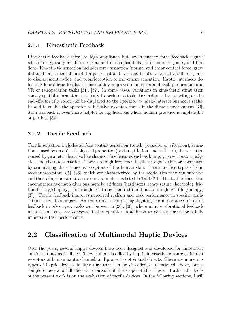
Tactile sensation includes surface contact sensation (touch, pressure, or vibration), sensa-tion caused by an object’s physical properties (texture, friction, and stiffness), the sensationcaused by geometric features like shape or fine features such as bump, groove, contour, edgeetc., and thermal sensation. These are high frequency feedback signals that are perceivedby stimulating the cutaneous receptors of the human skin. There are five types of skinmechanoreceptors [35], [36], which are characterized by the modalities they can subserveand their adaption rate to an external stimulus, as listed in Table 2.1. The tactile dimensionencompasses five main divisions namely, stiffness (hard/soft), temperature (hot/cold), fric-tion (sticky/slippery), fine roughness (rough/smooth) and macro roughness (flat/bumpy)[37]. Tactile feedback improves perceived realism and task performance in specific appli-cations, e.g. telesurgery. An impressive example highlighting the importance of tactilefeedback in telesurgery tasks can be seen in [26], [38], where minute vibrational feedbackin precision tasks are conveyed to the operator in addition to contact forces for a fullyimmersive task performance.
2.2 Classification of Multimodal Haptic Devices
Over the years, several haptic devices have been designed and developed for kinestheticand/or cutaneous feedback. They can be classified by haptic interaction gestures, differentreceptors of human haptic channel, and properties of virtual objects. There are numeroustypes of haptic devices in literature that can be classified as mentioned above, but acomplete review of all devices is outside of the scope of this thesis. Rather the focusof the present work is on the evaluation of tactile devices. In the following sections, I will
CHAPTER 2. BACKGROUND AND RELEVANT WORK 7
Table 2.1: Types of Skin Receptors [36]
Receptor Sensation Adaptation Rate
Meissner Corpuscle Fine Touch, Flutter, Movement Fast
Merkel’s Disk Touch, Pressure Slow
Pacinian Corpuscle Vibration Fast
Ruffini Corpuscle Skin stretch Slow
Free Nerve Ending Pain, Temperature Variable
therefore provide a brief overview of handheld and fingertip wearable devices based on theirability to convey different tactile properties of virtual objects.
2.2.1 Handheld Haptic Controllers
Handheld haptic devices have gained quite some attention in recent years. In contrast toseveral grounded devices, these offer significantly larger workspace, thus enabling large-scale body movement. For commercial VR devices such as Oculus Rift, HTC Vive, etc.,handheld controllers, which provide vibrational feedback, are the primary interaction inter-faces. Researchers have extended this concept to provide haptic feedback through handhelddevices.
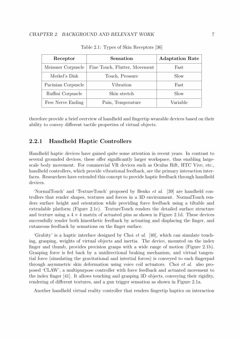
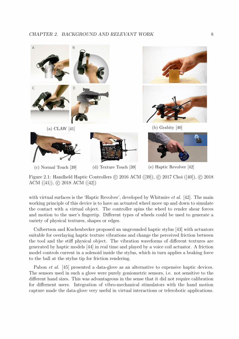
‘NormalTouch’ and ‘TextureTouch’ proposed by Benko et al. [39] are handheld con-trollers that render shapes, textures and forces in a 3D environment. NormalTouch ren-ders surface height and orientation while providing force feedback using a tiltable andextrudable platform (Figure 2.1c). TextureTouch renders the detailed surface structureand texture using a 4× 4 matrix of actuated pins as shown in Figure 2.1d. These devicessuccessfully render both kinesthetic feedback by actuating and displacing the finger, andcutaneous feedback by sensations on the finger surface.
‘Grabity’ is a haptic interface designed by Choi et al. [40], which can simulate touch-ing, grasping, weights of virtual objects and inertia. The device, mounted on the indexfinger and thumb, provides precision grasps with a wide range of motion (Figure 2.1b).Grasping force is fed back by a unidirectional braking mechanism, and virtual tangen-tial force (simulating the gravitational and intertial forces) is conveyed to each fingerpadthrough asymmetric skin deformation using voice coil actuators. Choi et al. also pro-posed ‘CLAW’, a multipurpose controller with force feedback and actuated movement tothe index finger [41]. It allows touching and grasping 3D objects, conveying their rigidity,rendering of different textures, and a gun trigger sensation as shown in Figure 2.1a.
Another handheld virtual reality controller that renders fingertip haptics on interaction
CHAPTER 2. BACKGROUND AND RELEVANT WORK 8
(a) CLAW [41] (b) Grabity [40]
(c) Normal Touch [39] (d) Texture Touch [39] (e) Haptic Revolver [42]
Figure 2.1: Handheld Haptic Controllers c⃝ 2016 ACM ([39]), c⃝ 2017 Choi ([40]), c⃝ 2018ACM ([41]), c⃝ 2018 ACM ([42])
with virtual surfaces is the ‘Haptic Revolver’, developed by Whitmire et al. [42]. The mainworking principle of this device is to have an actuated wheel move up and down to simulatethe contact with a virtual object. The controller spins the wheel to render shear forcesand motion to the user’s fingertip. Different types of wheels could be used to generate avariety of physical textures, shapes or edges.
Culbertson and Kuchenbecker proposed an ungrounded haptic stylus [43] with actuatorssuitable for overlaying haptic texture vibrations and change the perceived friction betweenthe tool and the stiff physical object. The vibration waveforms of different textures aregenerated by haptic models [44] in real time and played by a voice coil actuator. A frictionmodel controls current in a solenoid inside the stylus, which in turn applies a braking forceto the ball at the stylus tip for friction rendering.
Pabon et al. [45] presented a data-glove as an alternative to expensive haptic devices.The sensors used in such a glove were purely goniometric sensors, i.e. not sensitive to thedifferent hand sizes. This was advantageous in the sense that it did not require calibrationfor differnent users. Integration of vibro-mechanical stimulators with the hand motioncapture made the data-glove very useful in virtual interactions or telerobotic applications.
CHAPTER 2. BACKGROUND AND RELEVANT WORK 9
A novel approach to deliver button effects in Augmented Reality (AR) using air-jet displayswas developed by Kim et al. [46]. The force profile from real physical interactions wasrecreated through a pneumatic array, which gave users haptic feedback while interactingwith buttons in an AR environment.
2.2.2 Fingertip Wearable Haptic Devices
The disadvantages of handheld devices are that they often limit hand postures duringinteractions with virtual objects. Wearable devices on the other hand, support differenthand postures and therefore can subserve more natural interaction experiences. This sec-tion provides a brief overview of the different finger-wearable tactile devices that have beendeveloped so far, and which are relevant for this thesis.
One of the first fingernail-mounted tactile displays ‘SmartFinger’, which comprises of aphoto-detector, fingernail sensor and a voice coil actuator, is capable of displaying virtual2D shapes and textures encoded as vibrations, was developed in [47]. Minamizawa etal. proposed a wearable haptic display – ‘Gravity Grabber’ [48]. The device exploits thefact that deformation of fingerpads due to the weight of an object can generate a virtualweight sensation even in the absence of proprioceptive sensations on the wrist and arm.The mechanism designed to reproduce fingerpad deformation employed a pair of motorsand a belt. Vertical stress on fingerpads was generated by rotating the pair of motors inopposite directions, whereas shearing stress was produced by rotating the motors in thesame direction. Users wearing this device successfully perceived the grip force, gravity,and inertia of a virtual object. In their paper, Kim et al. [49] proposed SaLT, a wearabletactile display based on piezoelectric ultrasonic actuator array with a temporal resolutionof 20 Hz and a spatial resolution of 1.5 mm. The system is capable of providing varioustypes of tactile sensations, especially roughness and planar textures, with less latency andlower unwanted sounds in the structural response.
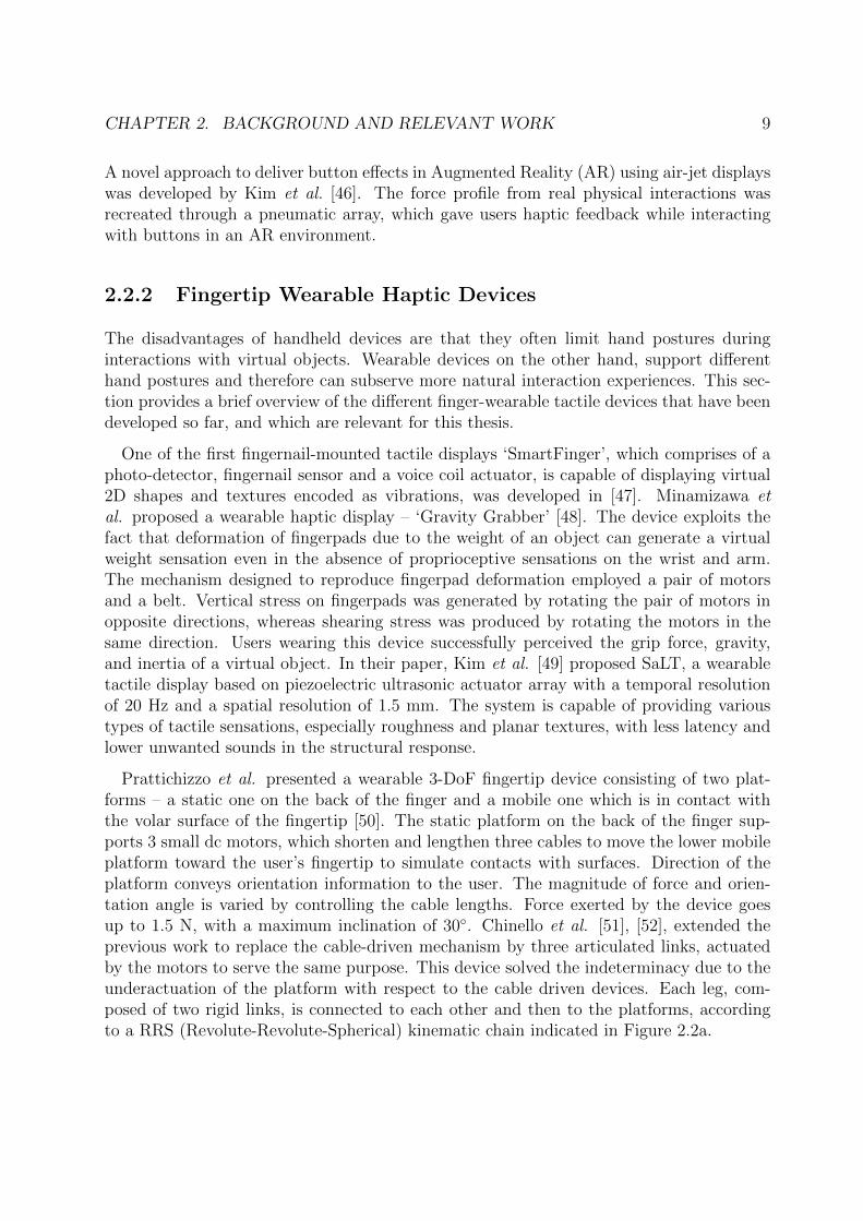
Prattichizzo et al. presented a wearable 3-DoF fingertip device consisting of two plat-forms – a static one on the back of the finger and a mobile one which is in contact withthe volar surface of the fingertip [50]. The static platform on the back of the finger sup-ports 3 small dc motors, which shorten and lengthen three cables to move the lower mobileplatform toward the user’s fingertip to simulate contacts with surfaces. Direction of theplatform conveys orientation information to the user. The magnitude of force and orien-tation angle is varied by controlling the cable lengths. Force exerted by the device goesup to 1.5 N, with a maximum inclination of 30◦. Chinello et al. [51], [52], extended theprevious work to replace the cable-driven mechanism by three articulated links, actuatedby the motors to serve the same purpose. This device solved the indeterminacy due to theunderactuation of the platform with respect to the cable driven devices. Each leg, com-posed of two rigid links, is connected to each other and then to the platforms, accordingto a RRS (Revolute-Revolute-Spherical) kinematic chain indicated in Figure 2.2a.
CHAPTER 2. BACKGROUND AND RELEVANT WORK 10
Pacchierotti et al. proposed a wearable device called hRing [53]. It is a 2 DoF cutaneousdevice that comprises of servo motors which move a belt that is kept in contact withthe user’s skin. Movement of this belt provides normal and shear forces to the skin. Itspositioning on the proximal finger phalanx improves the capability of this device to beused together with unobtrusive hand tracking systems, such as the Leap Motion controllerand the Kinectsensor. A cost-effective, wireless, and wearable haptic device was developedin [54] to substitute stiffness of virtual objects by vibrotactile cues (Figure 2.4b). Thestiffness change is perceived by users as a change of vibration force strength by varying thevibration intensities while tapping virtual objects modeled as virtual springs.
(a) 3RRS Wearable Device [51] (b) 3-DoF Fingertip Device [55]
Figure 2.2: Fingertip wearable tactile devices with parallel mechanical linkages c⃝ 2016IEEE (left), c⃝ 2017 IEEE (right)
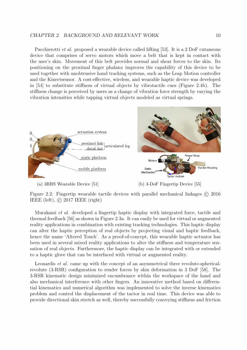
Murakami et al. developed a fingertip haptic display with integrated force, tactile andthermal feedback [56] as shown in Figure 2.3a. It can easily be used for virtual or augmentedreality applications in combination with existing tracking technologies. This haptic displaycan alter the haptic perception of real objects by projecting visual and haptic feedback,hence the name ‘Altered Touch’. As a proof-of-concept, this wearable haptic actuator hasbeen used in several mixed reality applications to alter the stiffness and temperature sen-sation of real objects. Furthermore, the haptic display can be integrated with or extendedto a haptic glove that can be interfaced with virtual or augmented reality.
Leonardis et al. came up with the concept of an asymmetrical three revolute-spherical-revolute (3-RSR) configuration to render forces by skin deformation in 3 DoF [58]. The3-RSR kinematic design minimized encumbrance within the workspace of the hand andalso mechanical interference with other fingers. An innovative method based on differen-tial kinematics and numerical algorithm was implemented to solve the inverse kinematicsproblem and control the displacement of the tactor in real time. This device was able toprovide directional skin stretch as well, thereby successfully conveying stiffness and friction
CHAPTER 2. BACKGROUND AND RELEVANT WORK 11
(a) Altered Touch [56] (b) Fabric-based Display [57]
Figure 2.3: Fingertip wearable fabric-based tactile devices c⃝ 2017 Murakami (left), c⃝2017 IEEE (right)
of objects in a virtual environment. In [55], Schorr and Okamura presented a fingertiptactile device for virtual object manipulation and exploration (Figure 2.2b). Using a skindeformation mechanism, differences in weights of virtual objects could be perceived withthe device. It also exploited such a mechanism to render objects with varying frictionand stiffness, providing a more compelling haptic experience appropriate for virtual objectmanipulations.
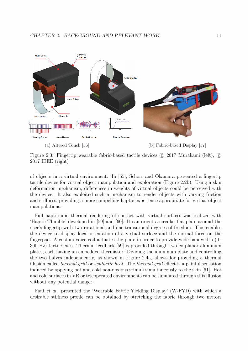
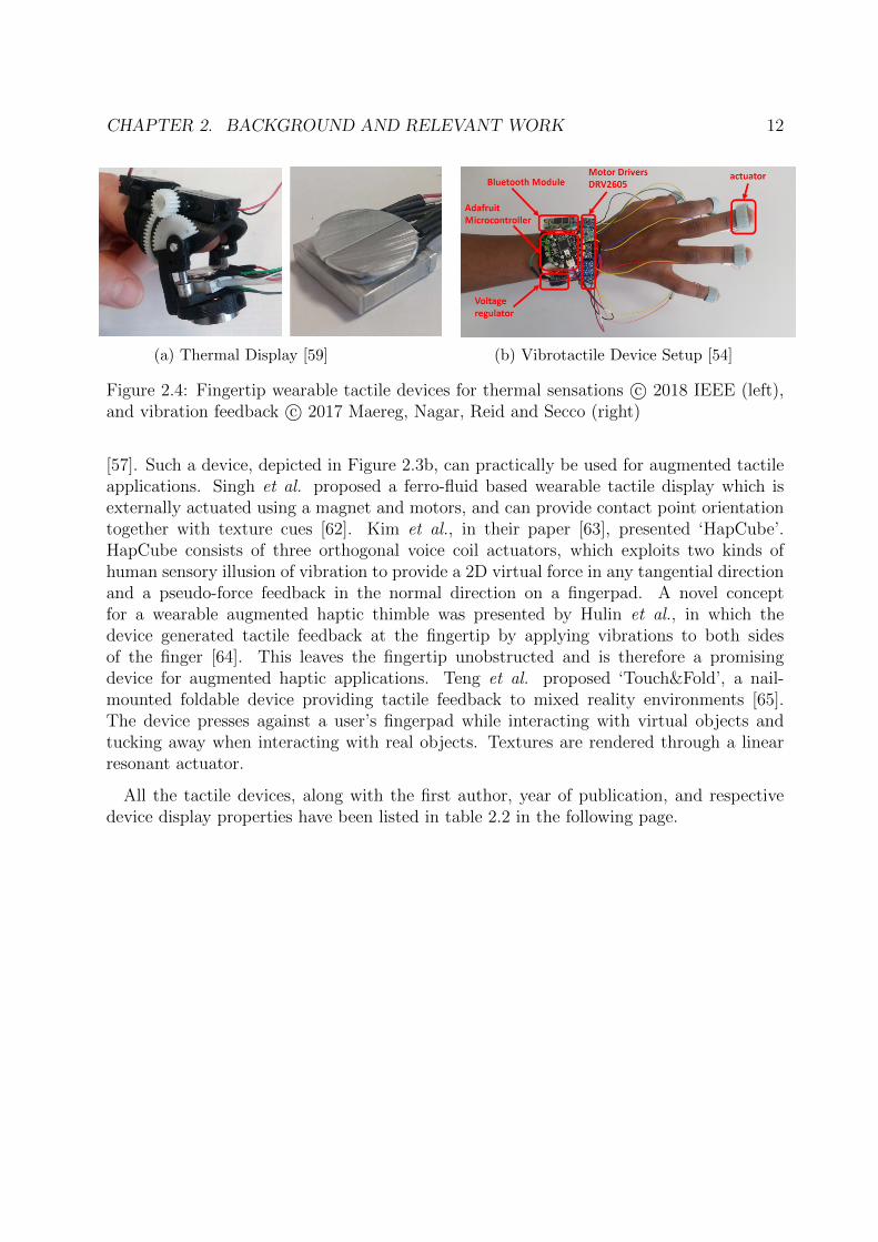
Full haptic and thermal rendering of contact with virtual surfaces was realized with‘Haptic Thimble’ developed in [59] and [60]. It can orient a circular flat plate around theuser’s fingertip with two rotational and one transitional degrees of freedom. This enablesthe device to display local orientation of a virtual surface and the normal force on thefingerpad. A custom voice coil actuates the plate in order to provide wide-bandwidth (0–300 Hz) tactile cues. Thermal feedback [59] is provided through two co-planar aluminumplates, each having an embedded thermistor. Dividing the aluminum plate and controllingthe two halves independently, as shown in Figure 2.4a, allows for providing a thermalillusion called thermal grill or synthetic heat. The thermal grill effect is a painful sensationinduced by applying hot and cold non-noxious stimuli simultaneously to the skin [61]. Hotand cold surfaces in VR or teleoperated environments can be simulated through this illusionwithout any potential danger.
Fani et al. presented the ‘Wearable Fabric Yielding Display’ (W-FYD) with which adesirable stiffness profile can be obtained by stretching the fabric through two motors
CHAPTER 2. BACKGROUND AND RELEVANT WORK 12
(a) Thermal Display [59] (b) Vibrotactile Device Setup [54]
Figure 2.4: Fingertip wearable tactile devices for thermal sensations c⃝ 2018 IEEE (left),and vibration feedback c⃝ 2017 Maereg, Nagar, Reid and Secco (right)
[57]. Such a device, depicted in Figure 2.3b, can practically be used for augmented tactileapplications. Singh et al. proposed a ferro-fluid based wearable tactile display which isexternally actuated using a magnet and motors, and can provide contact point orientationtogether with texture cues [62]. Kim et al., in their paper [63], presented ‘HapCube’.HapCube consists of three orthogonal voice coil actuators, which exploits two kinds ofhuman sensory illusion of vibration to provide a 2D virtual force in any tangential directionand a pseudo-force feedback in the normal direction on a fingerpad. A novel conceptfor a wearable augmented haptic thimble was presented by Hulin et al., in which thedevice generated tactile feedback at the fingertip by applying vibrations to both sidesof the finger [64]. This leaves the fingertip unobstructed and is therefore a promisingdevice for augmented haptic applications. Teng et al. proposed ‘Touch&Fold’, a nail-mounted foldable device providing tactile feedback to mixed reality environments [65].The device presses against a user’s fingerpad while interacting with virtual objects andtucking away when interacting with real objects. Textures are rendered through a linearresonant actuator.
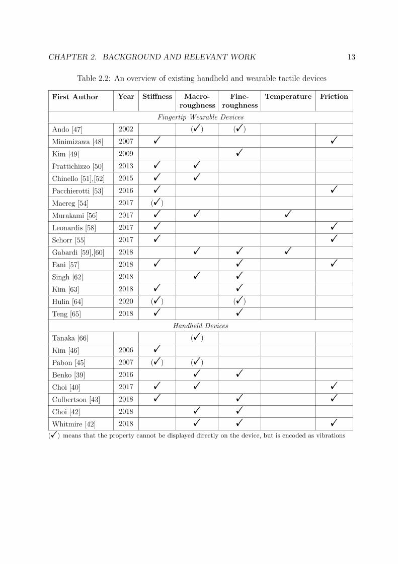
All the tactile devices, along with the first author, year of publication, and respectivedevice display properties have been listed in table 2.2 in the following page.
CHAPTER 2. BACKGROUND AND RELEVANT WORK 13
Table 2.2: An overview of existing handheld and wearable tactile devices
First Author Year Stiffness Macro-roughness
Fine-roughness
Temperature Friction
Fingertip Wearable Devices
Ando [47] 2002 (!) (!)
Minimizawa [48] 2007 ! !
Kim [49] 2009 !
Prattichizzo [50] 2013 ! !
Chinello [51],[52] 2015 ! !
Pacchierotti [53] 2016 ! !
Maereg [54] 2017 (!)
Murakami [56] 2017 ! ! !
Leonardis [58] 2017 ! !
Schorr [55] 2017 ! !
Gabardi [59],[60] 2018 ! ! !
Fani [57] 2018 ! ! !
Singh [62] 2018 ! !
Kim [63] 2018 ! !
Hulin [64] 2020 (!) (!)
Teng [65] 2018 ! !
Handheld Devices
Tanaka [66] (!)
Kim [46] 2006 !
Pabon [45] 2007 (!) (!)
Benko [39] 2016 ! !
Choi [40] 2017 ! ! !
Culbertson [43] 2018 ! ! !
Choi [42] 2018 ! !
Whitmire [42] 2018 ! ! !
(!) means that the property cannot be displayed directly on the device, but is encoded as vibrations
CHAPTER 2. BACKGROUND AND RELEVANT WORK 14
2.3 Existing Virtual Environments
To evaluate and validate some of the tactile devices discussed previously, some researchersconducted subjective studies by designing appropriate tasks in virtual environments. Theyalso designed VR applications which might be suited for the respective tactile devices. Thissection discusses some of those virtual tasks, the environments that they were designed in,as well as the tracking mechanisms employed for those tactile devices.
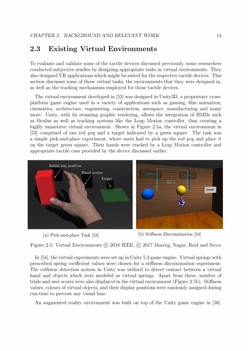
The virtual environment developed in [53] was designed in Unity3D, a proprietary cross-platform game engine used in a variety of applications such as gaming, film animation,cinematics, architecture, engineering, construction, aerospace, manufacturing and manymore. Unity, with its stunning graphic rendering, allows the integration of HMDs suchas Oculus as well as tracking systems like the Leap Motion controller, thus creating ahighly immersive virtual environment. Shown in Figure 2.5a, the virtual environment in[53] comprised of one red peg and a target indicated by a green square. The task wasa simple pick-and-place experiment, where users had to pick up the red peg and place iton the target green square. Their hands were tracked by a Leap Motion controller andappropriate tactile cues provided by the device discussed earlier.
(a) Pick-and-place Task [53] (b) Stiffness Discrimination [54]
Figure 2.5: Virtual Environments c⃝ 2016 IEEE, c⃝ 2017 Maereg, Nagar, Reid and Secco
In [54], the virtual experiments were set up in Unity 5.3 game engine. Virtual springs withprescribed spring coefficient values were chosen for a stiffness discrimination experiment.The collision detection system in Unity was utilized to detect contact between a virtualhand and objects which were modeled as virtual springs. Apart from these, number oftrials and user scores were also displayed in the virtual environment (Figure 2.5b). Stiffnessvalues, colours of virtual objects, and their display positions were randomly assigned duringrun-time to prevent any visual bias.
An augmented reality environment was built on top of the Unity game engine in [56].
CHAPTER 2. BACKGROUND AND RELEVANT WORK 15
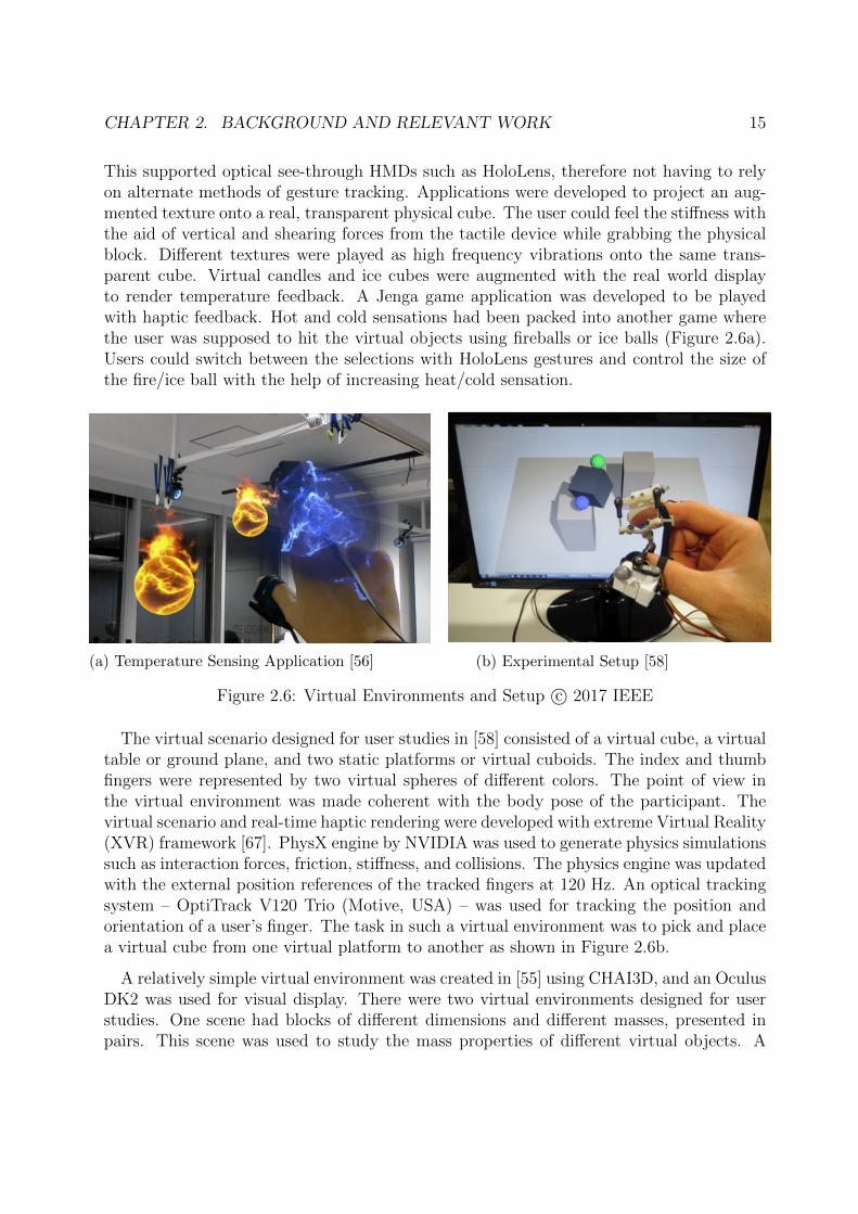
This supported optical see-through HMDs such as HoloLens, therefore not having to relyon alternate methods of gesture tracking. Applications were developed to project an aug-mented texture onto a real, transparent physical cube. The user could feel the stiffness withthe aid of vertical and shearing forces from the tactile device while grabbing the physicalblock. Different textures were played as high frequency vibrations onto the same trans-parent cube. Virtual candles and ice cubes were augmented with the real world displayto render temperature feedback. A Jenga game application was developed to be playedwith haptic feedback. Hot and cold sensations had been packed into another game wherethe user was supposed to hit the virtual objects using fireballs or ice balls (Figure 2.6a).Users could switch between the selections with HoloLens gestures and control the size ofthe fire/ice ball with the help of increasing heat/cold sensation.
(a) Temperature Sensing Application [56] (b) Experimental Setup [58]
Figure 2.6: Virtual Environments and Setup c⃝ 2017 IEEE
The virtual scenario designed for user studies in [58] consisted of a virtual cube, a virtualtable or ground plane, and two static platforms or virtual cuboids. The index and thumbfingers were represented by two virtual spheres of different colors. The point of view inthe virtual environment was made coherent with the body pose of the participant. Thevirtual scenario and real-time haptic rendering were developed with extreme Virtual Reality(XVR) framework [67]. PhysX engine by NVIDIA was used to generate physics simulationssuch as interaction forces, friction, stiffness, and collisions. The physics engine was updatedwith the external position references of the tracked fingers at 120 Hz. An optical trackingsystem – OptiTrack V120 Trio (Motive, USA) – was used for tracking the position andorientation of a user’s finger. The task in such a virtual environment was to pick and placea virtual cube from one virtual platform to another as shown in Figure 2.6b.
A relatively simple virtual environment was created in [55] using CHAI3D, and an OculusDK2 was used for visual display. There were two virtual environments designed for userstudies. One scene had blocks of different dimensions and different masses, presented inpairs. This scene was used to study the mass properties of different virtual objects. A
CHAPTER 2. BACKGROUND AND RELEVANT WORK 16
second virtual environment consisting of two small blocks on a table was used to studydifferent physical properties of objects. Both blocks had the same size and shape, but haddifferent colours to make them easily distinguishable. Each pair of blocks presented tothe participants had matching physical properties except any one of the following – mass,stiffness or friction coefficient.
A HoloLens 2, with built-in depth cameras on the headset for tracking was used to displayMR application scenarios in [65]. The system could also be paired with alternative trackingsystems, such as the proximity sensors or optical motion capture. All MR scenarios weredeveloped in Unity3D and displayed using appropriate MR headsets. Applications includedon-body interfaces, a MR furniture editor for haptic transitions between real and virtual,and multi-finger haptic feedback to interact with virtual knobs and buttons. The proposeddevice was also used to add haptic feedback to the existing HoloLens Mixed Reality toolkit(MRTK). The first user study conducted was in an MR environment that included oneinteractive object at a time among five MR objects – a hard surface, a soft surface, abutton with a spring mechanism, a low-frequency texture, and a high-frequency texture.The second user study involved performing a physical repair task by following instructionsdepicted in mixed reality by touching an MR interface while wearing the tactile device.The Unity3D application provided a simple MR interactive guide with repair instructions,which could be browsed haptically using the device.
Visual and haptic rendering in [39] was performed in Unity3D v-5.3.2. Oculus RiftDK2 HMD was used for VR rendering, which was tracked by its own camera. Eachhandheld tactile device had unique retro-reflective markers to distinguish them in VR andwere tracked via the OptiTrack V120:Trio tracking system. The OptiTrack system wascalibrated to the same coordinate system as the Oculus Rift so as to avoid re-calibration.A number of VR scenarios were implemented to test the devices. A variety of rigid anddeformable 3D objects, such as simple shapes as well as 3D models of cars, animals, etc,were rendered in one scene. Rigid body physics simulation experiments were performedin another scenario, where users could use force sensing and feedback to flick a virtualball across a table. In evaluation studies, two types of targeting tasks – pointing andtracing task – were used to assess how accurately visual stimuli could be matched withhaptic sensations. In a third task, users explored the shape of virtual objects using each ofthe controllers to rate the level of fidelity of haptic shape rendering each of the interfacesprovided.
Virtual scenarios in [55] were designed in CHAI3D. CHAI3D integration for Open Dy-namics Engine (ODE) was used for physical interactions. An Oculus VR headset was usedfor display of virtual scenarios and OptiTrack, in combination with a magnetic encoder,was used to track the position and orientation of the thumb and the index fingers as shownin Figure 2.7b. One virtual scenario consisted of three blocks of varying masses that hadto be sorted in ascending order. The other scenario had blocks of different dimensions anda cylinder, with varying masses, which users could freely explore. Unity 2017 software wasused for rendering the VR environment in [41], and display and tracking was provided via
CHAPTER 2. BACKGROUND AND RELEVANT WORK 17
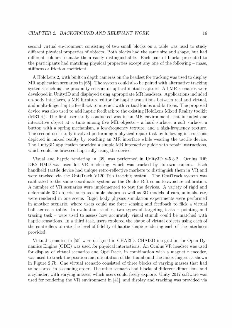
HTC Vive headset. Researchers in this paper presented a ‘Haptic Playground’, which wasa virtual scene comprising of a number of individual sections exhibiting different hapticqualities. The scenario had soft objects, rigid objects, buttons of different stiffnesses, im-movable objects with texture qualities, and a gun for recoil sensation through the hapticdevice. Evaluation studies were conducted to assess different modes of the haptic device- grabbing vs touching. The virtual scenarios used for such studies consisted of a whiteobject that needed to be grabbed and aligned with a target position marked by red, and ascene where users had to just push a red circular button.
(a) VR Application [42] (b) Experimental Setup [55]
Figure 2.7: Virtual Environments and Setup c⃝ 2017 IEEE
In [42], a python middleware layer handled device communication, visualization, logging,and communication with the VR application. The virtual environment was built in Unity3D game engine. For user studies conducted to evaluate device properties, a virtual scenariohad a horizontal surface implemented, across which users had to slide their fingers. Anotherstudy involved users tracing a path on a surface in a different scene. VR applicationsdeveloped for the device were - a card table demo (Figure 2.7a) to render different textures,a painting and sculpting demo to render shapes and sense force applied, and a keyboarddemo to render edges and shapes.
In summary, it can be seen that a wearable or handheld tactile device that is capableof displaying all the five different tactile properties of virtual objects does not exist. Nordoes a virtual environment exist for the evaluation of these devices that can also be usedto validate the display capabilities of another device or compare with another device.Thus, the subsequent chapters discuss the experimental setup of available hardware, handtracking and virtual environment components which can be assembled together to overcomethese problems addressed up until now.

Chapter 3
Hardware and Software Description
A detailed description of the design and working principle of the tactile devices used in thisthesis is provided in this chapter. It also explains the connections made and the softwarefor designing virtual environments. The process for integrating the tactile devices in avirtual environment along with suitable hand tracking devices is provided thenceforth.
3.1 FingerTac
The FingerTac is a wearable tactile device capable of generating tactile feedback at thedistal pad of a fingertip by applying vibrations simultaneously at both sides of the fin-ger [64]. The vibrational stimuli are applied on both sides at the same frequency. It isa 1-DoF tactile device that allows interactions with real and virtual objects at the sametime. This is made possible by keeping the fingerpad free and devoid of any obstructions.The vibrations from the tactile device are perceived in this area of the fingerpad.
The factors of design that were considered while designing the FingerTac were unob-trusive shape, low inertia and high wearable comfort. Ensuring an unobtrusive shape wasimportant as interactions with real world objects was to be sustained. Therefore, the de-vice needed to be kinematically compatible with human hand movements. To minimize theoverall bulkiness of the wearable device, overall mass needed to be reduced and distributingthe mass of each component was necessary to allow free movements of the hand. Highermass components were to be placed near the centre of the fingers or on stronger parts ofthe body. Finally, the device was to be made comfortable and easy to wear. High contactpressure and sharp edges were to be avoided, whereas simultaneously accounting for a widerange of finger sizes.
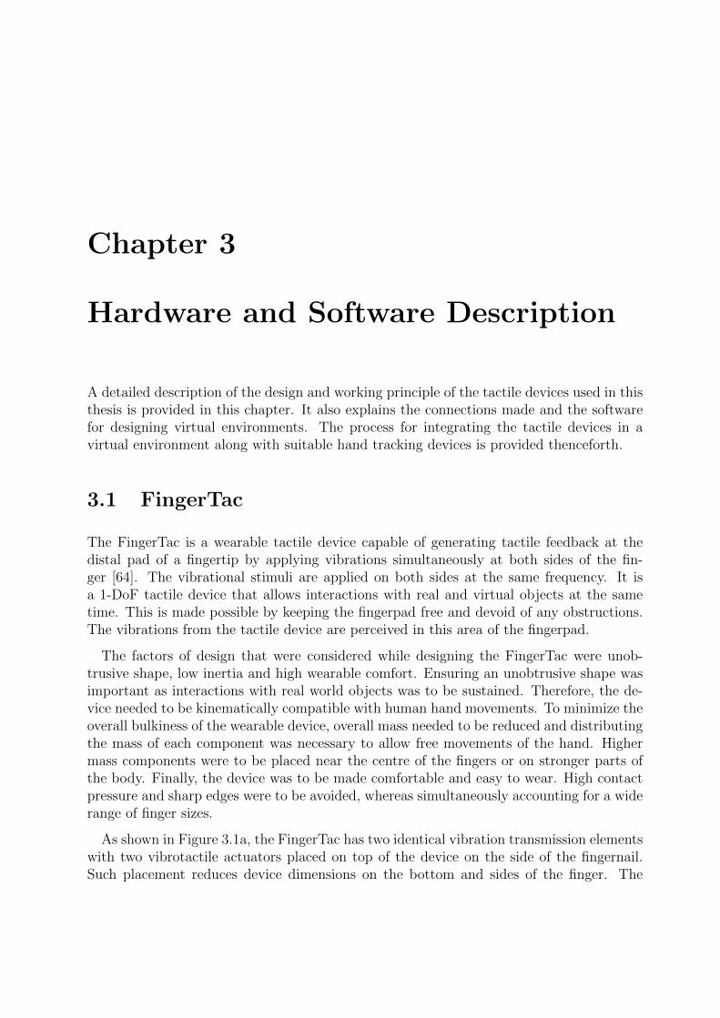
As shown in Figure 3.1a, the FingerTac has two identical vibration transmission elementswith two vibrotactile actuators placed on top of the device on the side of the fingernail.Such placement reduces device dimensions on the bottom and sides of the finger. The
CHAPTER 3. HARDWARE AND SOFTWARE DESCRIPTION 20
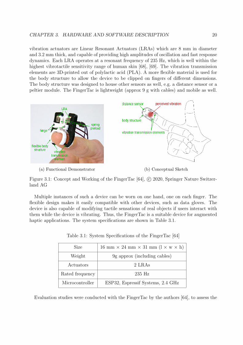
vibration actuators are Linear Resonant Actuators (LRAs) which are 8 mm in diameterand 3.2 mm thick, and capable of providing high amplitudes of oscillation and fast responsedynamics. Each LRA operates at a resonant frequency of 235 Hz, which is well within thehighest vibrotactile sensitivity range of human skin [68], [69]. The vibration transmissionelements are 3D-printed out of polylactic acid (PLA). A more flexible material is used forthe body structure to allow the device to be clipped on fingers of different dimensions.The body structure was designed to house other sensors as well, e.g. a distance sensor or apeltier module. The FingerTac is lightweight (approx 9 g with cables) and mobile as well.
(a) Functional Demonstrator (b) Conceptual Sketch
Figure 3.1: Concept and Working of the FingerTac [64], c⃝ 2020, Springer Nature Switzer-land AG
Multiple instances of such a device can be worn on one hand, one on each finger. Theflexible design makes it easily compatible with other devices, such as data gloves. Thedevice is also capable of modifying tactile sensations of real objects if users interact withthem while the device is vibrating. Thus, the FingerTac is a suitable device for augmentedhaptic applications. The system specifications are shown in Table 3.1.
Table 3.1: System Specifications of the FingerTac [64]
Size 16 mm × 24 mm × 31 mm (l × w × h)
Weight 9g approx (including cables)
Actuators 2 LRAs
Rated frequency 235 Hz
Microcontroller ESP32, Espressif Systems, 2.4 GHz
Evaluation studies were conducted with the FingerTac by the authors [64], to assess the
CHAPTER 3. HARDWARE AND SOFTWARE DESCRIPTION 21
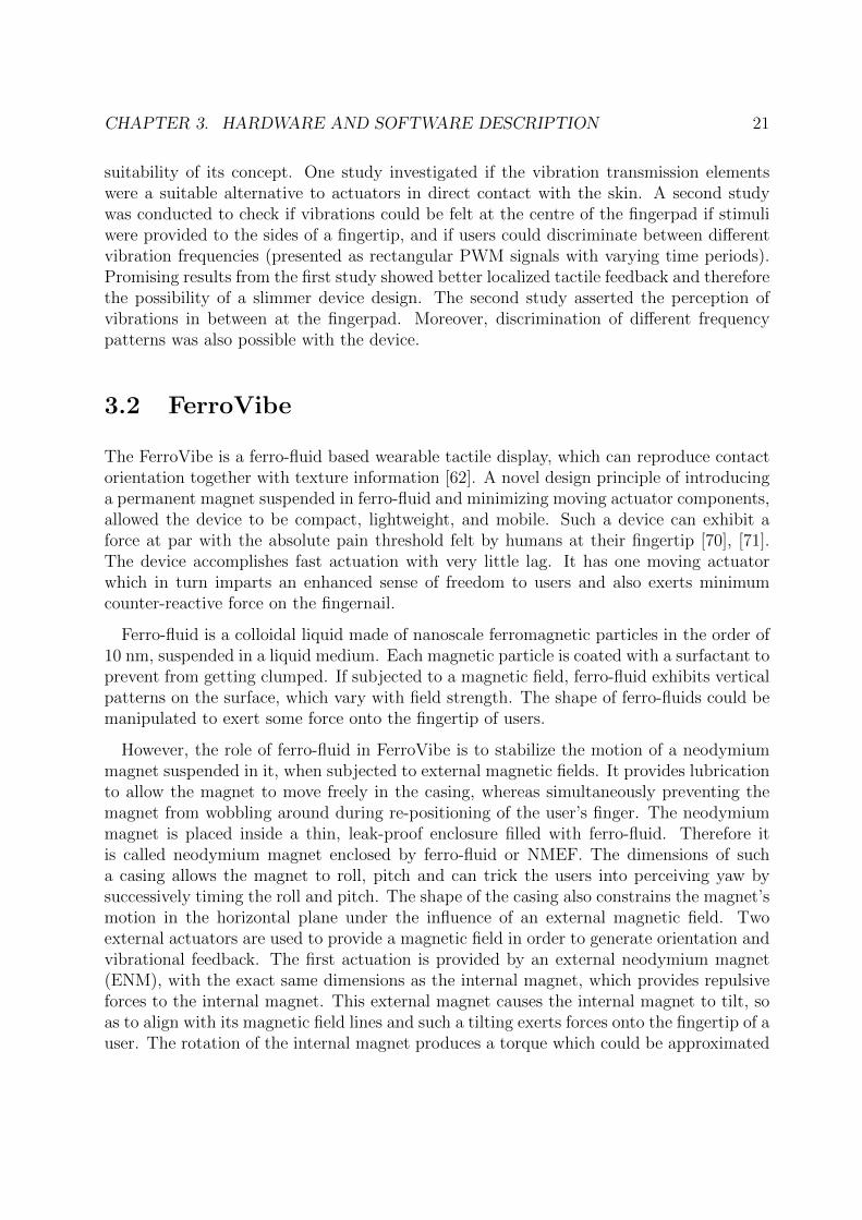
suitability of its concept. One study investigated if the vibration transmission elementswere a suitable alternative to actuators in direct contact with the skin. A second studywas conducted to check if vibrations could be felt at the centre of the fingerpad if stimuliwere provided to the sides of a fingertip, and if users could discriminate between differentvibration frequencies (presented as rectangular PWM signals with varying time periods).Promising results from the first study showed better localized tactile feedback and thereforethe possibility of a slimmer device design. The second study asserted the perception ofvibrations in between at the fingerpad. Moreover, discrimination of different frequencypatterns was also possible with the device.
3.2 FerroVibe
The FerroVibe is a ferro-fluid based wearable tactile display, which can reproduce contactorientation together with texture information [62]. A novel design principle of introducinga permanent magnet suspended in ferro-fluid and minimizing moving actuator components,allowed the device to be compact, lightweight, and mobile. Such a device can exhibit aforce at par with the absolute pain threshold felt by humans at their fingertip [70], [71].The device accomplishes fast actuation with very little lag. It has one moving actuatorwhich in turn imparts an enhanced sense of freedom to users and also exerts minimumcounter-reactive force on the fingernail.
Ferro-fluid is a colloidal liquid made of nanoscale ferromagnetic particles in the order of10 nm, suspended in a liquid medium. Each magnetic particle is coated with a surfactant toprevent from getting clumped. If subjected to a magnetic field, ferro-fluid exhibits verticalpatterns on the surface, which vary with field strength. The shape of ferro-fluids could bemanipulated to exert some force onto the fingertip of users.
However, the role of ferro-fluid in FerroVibe is to stabilize the motion of a neodymiummagnet suspended in it, when subjected to external magnetic fields. It provides lubricationto allow the magnet to move freely in the casing, whereas simultaneously preventing themagnet from wobbling around during re-positioning of the user’s finger. The neodymiummagnet is placed inside a thin, leak-proof enclosure filled with ferro-fluid. Therefore itis called neodymium magnet enclosed by ferro-fluid or NMEF. The dimensions of sucha casing allows the magnet to roll, pitch and can trick the users into perceiving yaw bysuccessively timing the roll and pitch. The shape of the casing also constrains the magnet’smotion in the horizontal plane under the influence of an external magnetic field. Twoexternal actuators are used to provide a magnetic field in order to generate orientation andvibrational feedback. The first actuation is provided by an external neodymium magnet(ENM), with the exact same dimensions as the internal magnet, which provides repulsiveforces to the internal magnet. This external magnet causes the internal magnet to tilt, soas to align with its magnetic field lines and such a tilting exerts forces onto the fingertip of auser. The rotation of the internal magnet produces a torque which could be approximated
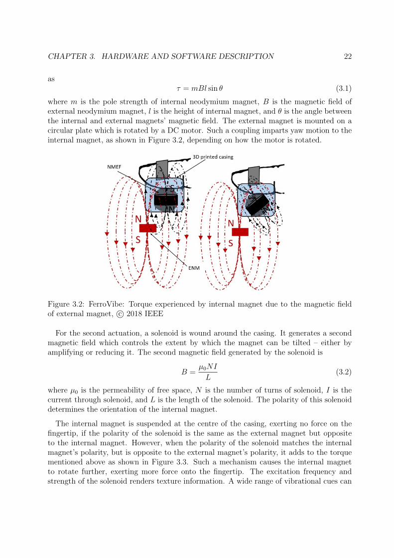
CHAPTER 3. HARDWARE AND SOFTWARE DESCRIPTION 22
asτ = mBl sin θ (3.1)
where m is the pole strength of internal neodymium magnet, B is the magnetic field ofexternal neodymium magnet, l is the height of internal magnet, and θ is the angle betweenthe internal and external magnets’ magnetic field. The external magnet is mounted on acircular plate which is rotated by a DC motor. Such a coupling imparts yaw motion to theinternal magnet, as shown in Figure 3.2, depending on how the motor is rotated.
Figure 3.2: FerroVibe: Torque experienced by internal magnet due to the magnetic fieldof external magnet, c⃝ 2018 IEEE
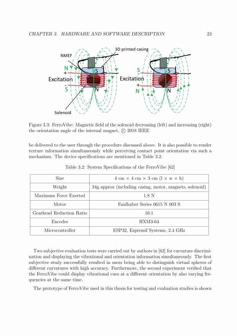
For the second actuation, a solenoid is wound around the casing. It generates a secondmagnetic field which controls the extent by which the magnet can be tilted – either byamplifying or reducing it. The second magnetic field generated by the solenoid is
B =µ0NI
L(3.2)
where µ0 is the permeability of free space, N is the number of turns of solenoid, I is thecurrent through solenoid, and L is the length of the solenoid. The polarity of this solenoiddetermines the orientation of the internal magnet.
The internal magnet is suspended at the centre of the casing, exerting no force on thefingertip, if the polarity of the solenoid is the same as the external magnet but oppositeto the internal magnet. However, when the polarity of the solenoid matches the internalmagnet’s polarity, but is opposite to the external magnet’s polarity, it adds to the torquementioned above as shown in Figure 3.3. Such a mechanism causes the internal magnetto rotate further, exerting more force onto the fingertip. The excitation frequency andstrength of the solenoid renders texture information. A wide range of vibrational cues can
CHAPTER 3. HARDWARE AND SOFTWARE DESCRIPTION 23
Figure 3.3: FerroVibe: Magnetic field of the solenoid decreasing (left) and increasing (right)the orientation angle of the internal magnet, c⃝ 2018 IEEE
be delivered to the user through the procedure discussed above. It is also possible to rendertexture information simultaneously while perceiving contact point orientation via such amechanism. The device specifications are mentioned in Table 3.2.
Table 3.2: System Specifications of the FerroVibe [62]
Size 4 cm × 4 cm × 3 cm (l × w × h)
Weight 34g approx (including casing, motor, magnets, solenoid)
Maximum Force Exerted 1.8 N
Motor Faulhaber Series 0615 N 003 S
Gearhead Reduction Ratio 16:1
Encoder HXM3-64
Microcontroller ESP32, Espressif Systems, 2.4 GHz
Two subjective evaluation tests were carried out by authors in [62] for curvature discrimi-nation and displaying the vibrational and orientation information simultaneously. The firstsubjective study successfully resulted in users being able to distinguish virtual spheres ofdifferent curvatures with high accuracy. Furthermore, the second experiment verified thatthe FerroVibe could display vibrational cues at a different orientation by also varying fre-quencies at the same time.
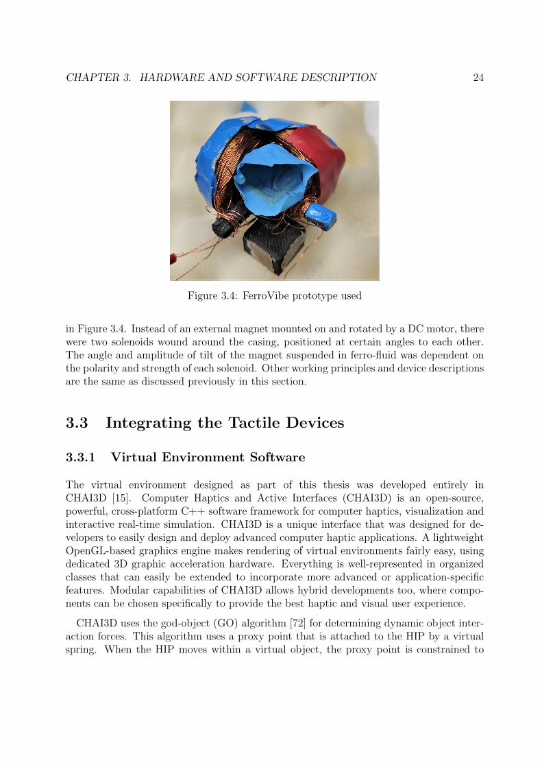
The prototype of FerroVibe used in this thesis for testing and evaluation studies is shown
CHAPTER 3. HARDWARE AND SOFTWARE DESCRIPTION 24
Figure 3.4: FerroVibe prototype used
in Figure 3.4. Instead of an external magnet mounted on and rotated by a DC motor, therewere two solenoids wound around the casing, positioned at certain angles to each other.The angle and amplitude of tilt of the magnet suspended in ferro-fluid was dependent onthe polarity and strength of each solenoid. Other working principles and device descriptionsare the same as discussed previously in this section.
3.3 Integrating the Tactile Devices
3.3.1 Virtual Environment Software
The virtual environment designed as part of this thesis was developed entirely inCHAI3D [15]. Computer Haptics and Active Interfaces (CHAI3D) is an open-source,powerful, cross-platform C++ software framework for computer haptics, visualization andinteractive real-time simulation. CHAI3D is a unique interface that was designed for de-velopers to easily design and deploy advanced computer haptic applications. A lightweightOpenGL-based graphics engine makes rendering of virtual environments fairly easy, usingdedicated 3D graphic acceleration hardware. Everything is well-represented in organizedclasses that can easily be extended to incorporate more advanced or application-specificfeatures. Modular capabilities of CHAI3D allows hybrid developments too, where compo-nents can be chosen specifically to provide the best haptic and visual user experience.
CHAI3D uses the god-object (GO) algorithm [72] for determining dynamic object inter-action forces. This algorithm uses a proxy point that is attached to the HIP by a virtualspring. When the HIP moves within a virtual object, the proxy point is constrained to
CHAPTER 3. HARDWARE AND SOFTWARE DESCRIPTION 25
the object surface, stretching the spring and this determines a virtual interaction force,according to Hooke’s law. CHAI3D provides support for a variety of commercially avail-able three-, six- and seven-degree-of-freedom haptic devices, and custom haptic devices aswell. It houses wrappers for the ODE and GEL dynamics engines, making it possible tosimulate rigid and deformable bodies, as well as various physics simulations in real time.Moreover, it is possible to combine CHAI3D with third party libraries including graphicsor dynamic engines. CHAI3D based applications have gained popularity all around theworld in segments such as medical, automotive, entertainment, aerospace and industrialrobotics.
In the scope of this thesis, a serial communication for data exchange between CHAI3Dand the respective device microcontrollers for FingerTac and FerroVibe was established.Each device could be connected to the PC through a USB serial link or via Bluetooth.The communication in either case was established by indicating the COM numbers for therespective ports. This is something which changes on different PCs and platforms, andmight need changing when connecting the devices and running such a virtual environment.A separate C++ class was added to the project, which took care of opening and closinga connection, configuring the DCB structure or the control settings for communication,and finally writing as well as reading data to and from the serial port respectively. Theserial communication was made to run at a baud rate of 115200 or 115200 bits/s. Suitabledata from the simulations running in CHAI3D was written onto the serial communicationlink and sent to the microcontroller, which executed the program flashed onto it based onthe new input. It is necessary to have the required device driver software installed on thelocal PC to ensure proper execution of both the tactile devices. Based on the input to themicrocontroller program, the tactile devices would then output appropriate vibrations orprovide desirable feedback.
3.3.2 Hand Tracking
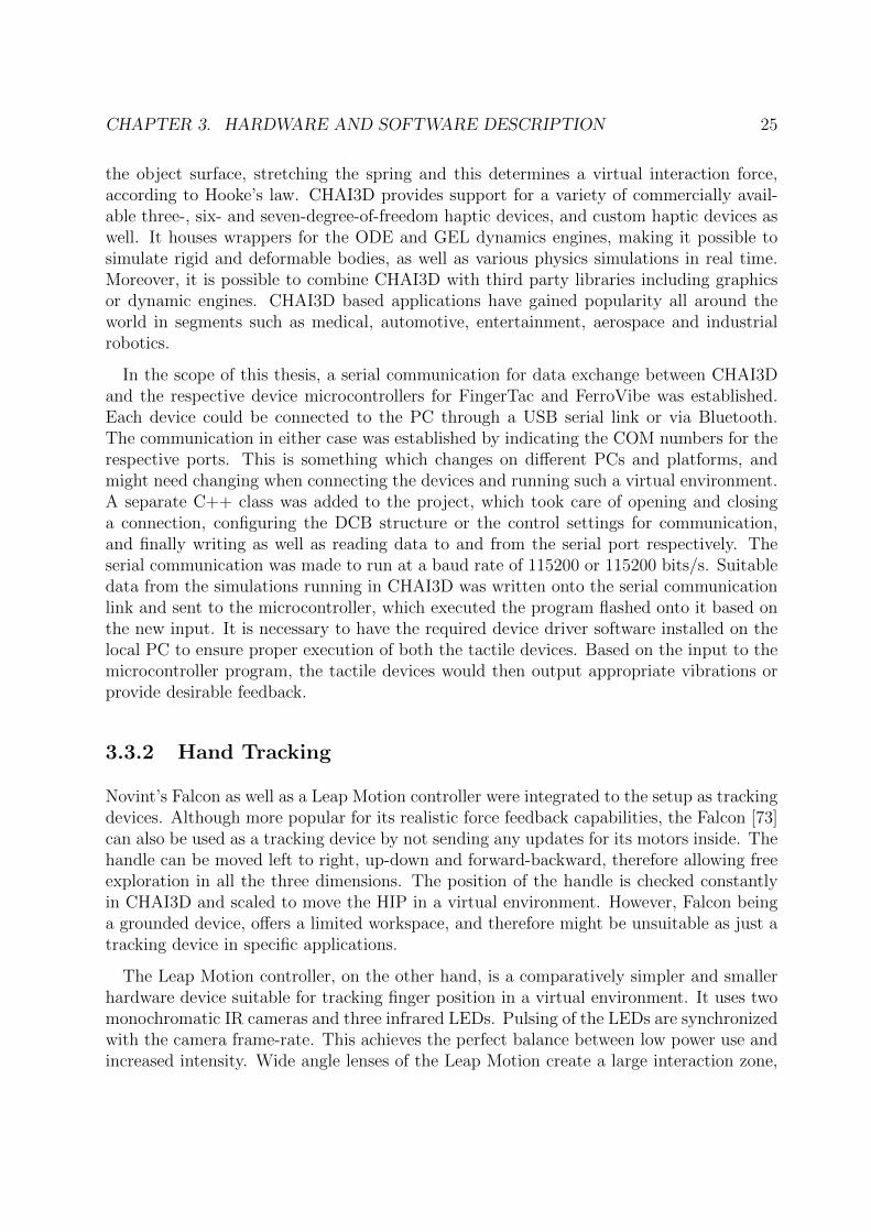
Novint’s Falcon as well as a Leap Motion controller were integrated to the setup as trackingdevices. Although more popular for its realistic force feedback capabilities, the Falcon [73]can also be used as a tracking device by not sending any updates for its motors inside. Thehandle can be moved left to right, up-down and forward-backward, therefore allowing freeexploration in all the three dimensions. The position of the handle is checked constantlyin CHAI3D and scaled to move the HIP in a virtual environment. However, Falcon beinga grounded device, offers a limited workspace, and therefore might be unsuitable as just atracking device in specific applications.
The Leap Motion controller, on the other hand, is a comparatively simpler and smallerhardware device suitable for tracking finger position in a virtual environment. It uses twomonochromatic IR cameras and three infrared LEDs. Pulsing of the LEDs are synchronizedwith the camera frame-rate. This achieves the perfect balance between low power use andincreased intensity. Wide angle lenses of the Leap Motion create a large interaction zone,
CHAPTER 3. HARDWARE AND SOFTWARE DESCRIPTION 26
thereby offering a larger workspace. It observes a hemispherical area up to a distance ofapproximately 1 metre with an accuracy up to 0.01 millimetres [16]. The data takes theform of a grayscale stereo image of the near-infrared light spectrum, separated into the leftand right cameras. Once the image data is streamed, advanced algorithms are applied tothe raw sensor data. The Leap Motion software does image processing by analyzing theraw image data and reconstructing a 3D representation out of it. Filtering techniques areapplied to extract tracking information such as fingers, and to ensure smooth temporalcoherence of the data. The whole system overview is shown in Figure 3.5.
Figure 3.5: System Overview
The entire setup discussed in this chapter is used in the following chapters for designingand testing the virtual environments designed as a part of this thesis. Furthermore, Iconducted subjective studies with these devices in the virtual environments using theseconnections and a similar setup.
Chapter 4
Virtual Scenarios
Two separate virtual environments were designed as a part of the thesis. The virtual en-vironments and respective tasks were chosen after a thorough literature survey of variousexisting virtual scenarios used for evaluating haptic devices or employed in robot teleop-eration. A general motivation supporting both the virtual environments is tactile percep-tuality. Tactile feedback is only helpful if variations in vibration intensity or frequencycan be accurately perceived by humans. Psychophysical studies investigate the relationbetween physical stimulation by a device and the perceived stimulus intensity [74]. Ideally,the relationship should be linear [75]. The ability to maintain a linear relationship betweenperceived and physical stimuli serves as a basic evaluation dimension of any tactile device.The three main classifications involved in multimodal haptic interaction can be attributedto
1. different properties of virtual objects [37], [76],
2. multiple gestures for haptic interaction [77],
3. receptors of the human skin [35], [36].
Since this thesis focuses on wearable and handheld tactile devices, the first virtual en-vironment and all its scenarios were designed keeping the different tactile properties inmind. Hence, it was aimed at discriminating different tactile properties of virtual objects.The second virtual environment was more inspired by standard tasks in teleoperation andVR for rehabilitation [78], [79], and therefore, focused on object positioning tasks. Insummary, both the virtual environments together anchor the evaluation of perception andperformance of any tactile device with standard methods or tasks, respectively.
CHAPTER 4. VIRTUAL SCENARIOS 28
4.1 Discriminating Tactile Properties
The tactile dimensions can be broadly classified into five categories – stiffness, macro-roughness, fine roughness, temperature and friction [37]. Ideally, a good tactile deviceshould be able to successfully render all these properties to be a versatile tool. For VRapplications as well as teleoperation scenarios, these qualities are important to increaseperceived realism. There does not exist a single wearable tactile device in literature thatcan convey all these tactile properties simultaneously. However, the scenarios discussedbelow are designed so that they can universally be used to evaluate or compare differenttactile devices that are capable of displaying one or more tactile properties of virtualobjects. This environment allows for validating all the tactile properties virtual objectsmay be expected to possess.
4.1.1 Contact Angle Discrimination
Some tactile devices have the capability to display orientation information of virtual ob-jects. Additionally, such an information provided by tactile devices may also suggest howa user’s finger (or the Haptic Interaction Point (HIP) in virtual environments) comes incontact with certain virtual objects. Examples of orientation information from virtualenvironments may be bumps or grooves on a flat surface, or the direction in which theHIP interacts with different virtual objects. These can be broadly classified under macro-roughness.
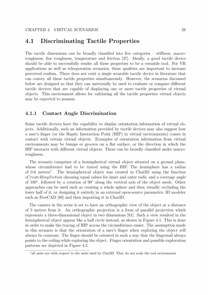
The scenario comprises of a hemispherical virtual object situated on a ground plane,whose circumference had to be traced using the HIP. The hemisphere has a radiusof 0.6 metres1. The hemispherical object was created in Chai3D using the functioncCreateRingSection choosing equal values for inner and outer radii, and a coverage angleof 180◦, followed by a rotation of 90◦ along the vertical axis of the object mesh. Otherapproaches can be used such as creating a whole sphere and then visually occluding thelower half of it, or designing it entirely in an external open-source parametric 3D modelersuch as FreeCAD [80] and then importing it in Chai3D.
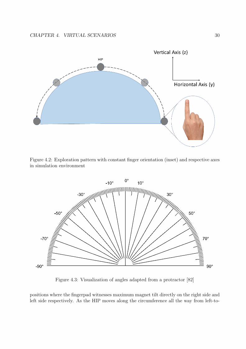
The camera in the scene is set to have an orthographic view of the object at a distanceof 5 metres from it. An orthographic projection is a form of parallel projection whichrepresents a three-dimensional object in two dimensions [81]. Such a view resulted in thehemispherical object appear like a half circle instead, as shown in Figure 4.1. This is donein order to make the tracing of HIP across the circumference easier. The assumption madein this scenario is that the orientation of a user’s finger when exploring the object willalways be constant. The finger should be oriented in such a way that the fingernail alwayspoints to the ceiling while exploring the object. Finger orientation and possible explorationpatterns are depicted in Figure 4.2.
1all units are with respect to the units used by Chai3D. They do not scale the real environment
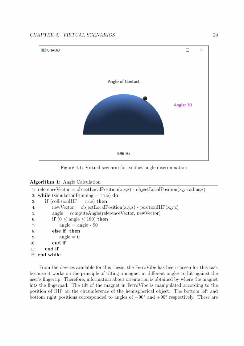
CHAPTER 4. VIRTUAL SCENARIOS 29
Figure 4.1: Virtual scenario for contact angle discrimination
Algorithm 1: Angle Calculation
1: referenceVector = objectLocalPosition(x,y,z) - objectLocalPosition(x,y-radius,z)2: while (simulationRunning = true) do3: if (collisionHIP = true) then4: newVector = objectLocalPosition(x,y,z) - positionHIP(x,y,z)5: angle = computeAngle(referenceVector, newVector)6: if (0 ≤ angle ≤ 180) then7: angle = angle - 908: else if then9: angle = 010: end if11: end if12: end while
From the devices available for this thesis, the FerroVibe has been chosen for this taskbecause it works on the principle of tilting a magnet at different angles to hit against theuser’s fingertip. Therefore, information about orientation is obtained by where the magnethits the fingerpad. The tilt of the magnet in FerroVibe is manipulated according to theposition of HIP on the circumference of the hemispherical object. The bottom left andbottom right positions corresponded to angles of −90◦ and +90◦ respectively. These are
CHAPTER 4. VIRTUAL SCENARIOS 30
Figure 4.2: Exploration pattern with constant finger orientation (inset) and respective axesin simulation environment
Figure 4.3: Visualization of angles adapted from a protractor [82]
positions where the fingerpad witnesses maximum magnet tilt directly on the right side andleft side respectively. As the HIP moves along the circumference all the way from left-to-
CHAPTER 4. VIRTUAL SCENARIOS 31
right, the magnet hitting the fingerpad gradually rotates and changes its orientation underthe finger from right-to-left, while always maintaining the same magnitude of tilt and viceversa. The angles across the hemispherical surface are indicated in Figure 4.3. At 0◦, themagnet hits the fingerpad towards the front. Such a perception is crucial for contact anglediscrimination during an evaluation study. The procedure for angle calculation is shownin Algorithm 1. The function computeAngle computes the angle between two vectors as
θ = cos−1
(a · b|a||b|
)(4.1)
where θ is the angle, a is the reference vector and b is the new vector (see Algorithm 1).
4.1.2 Texture Discrimination
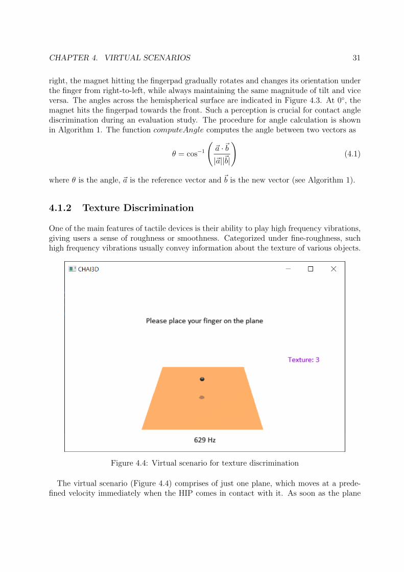
One of the main features of tactile devices is their ability to play high frequency vibrations,giving users a sense of roughness or smoothness. Categorized under fine-roughness, suchhigh frequency vibrations usually convey information about the texture of various objects.
Figure 4.4: Virtual scenario for texture discrimination
The virtual scenario (Figure 4.4) comprises of just one plane, which moves at a prede-fined velocity immediately when the HIP comes in contact with it. As soon as the plane
CHAPTER 4. VIRTUAL SCENARIOS 32
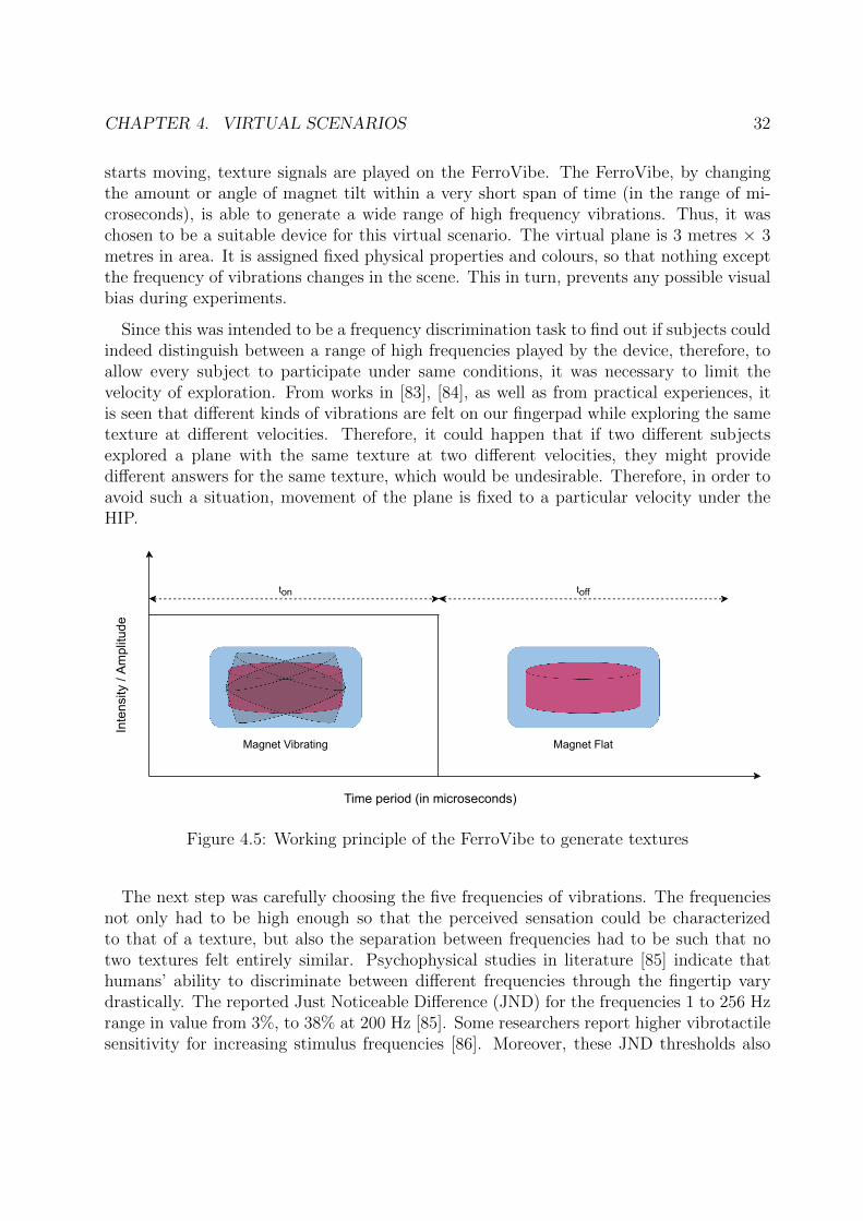
starts moving, texture signals are played on the FerroVibe. The FerroVibe, by changingthe amount or angle of magnet tilt within a very short span of time (in the range of mi-croseconds), is able to generate a wide range of high frequency vibrations. Thus, it waschosen to be a suitable device for this virtual scenario. The virtual plane is 3 metres × 3metres in area. It is assigned fixed physical properties and colours, so that nothing exceptthe frequency of vibrations changes in the scene. This in turn, prevents any possible visualbias during experiments.
Since this was intended to be a frequency discrimination task to find out if subjects couldindeed distinguish between a range of high frequencies played by the device, therefore, toallow every subject to participate under same conditions, it was necessary to limit thevelocity of exploration. From works in [83], [84], as well as from practical experiences, itis seen that different kinds of vibrations are felt on our fingerpad while exploring the sametexture at different velocities. Therefore, it could happen that if two different subjectsexplored a plane with the same texture at two different velocities, they might providedifferent answers for the same texture, which would be undesirable. Therefore, in order toavoid such a situation, movement of the plane is fixed to a particular velocity under theHIP.
Magnet Vibrating Magnet Flat
ton toff
Inte
nsity
/ Am
plitu
de
Time period (in microseconds)
Figure 4.5: Working principle of the FerroVibe to generate textures
The next step was carefully choosing the five frequencies of vibrations. The frequenciesnot only had to be high enough so that the perceived sensation could be characterizedto that of a texture, but also the separation between frequencies had to be such that notwo textures felt entirely similar. Psychophysical studies in literature [85] indicate thathumans’ ability to discriminate between different frequencies through the fingertip varydrastically. The reported Just Noticeable Difference (JND) for the frequencies 1 to 256 Hzrange in value from 3%, to 38% at 200 Hz [85]. Some researchers report higher vibrotactilesensitivity for increasing stimulus frequencies [86]. Moreover, these JND thresholds also
CHAPTER 4. VIRTUAL SCENARIOS 33
vary due to a lot of other factors such as age or different tactile devices in use [87], [88].
The texture signals produced in the dedicated task are at frequencies 500 Hz, 333.33 Hz,250 Hz, 200 Hz, and 166.67 Hz. Although they may appear to be unevenly distributed,these correspond to vibration time periods of 2000, 3000, 4000, 5000 and 6000 microsecondsrespectively. These values allows for a uniform ordered distribution in the time domain,whereas also maintaining a distinct perceptual difference. There are multiple ways togenerate texture signals in the FerroVibe, but the approach followed in this case is similarto that of a PWM distribution. The magnet inside FerroVibe changes its magnitude of tiltwithin half the time period assigned to it, and continues to remain flat for the remaininghalf of the time period, as shown in Figure 4.5.
(a) Bamboo (b) Cork
(c) Aluminum (d) Felt
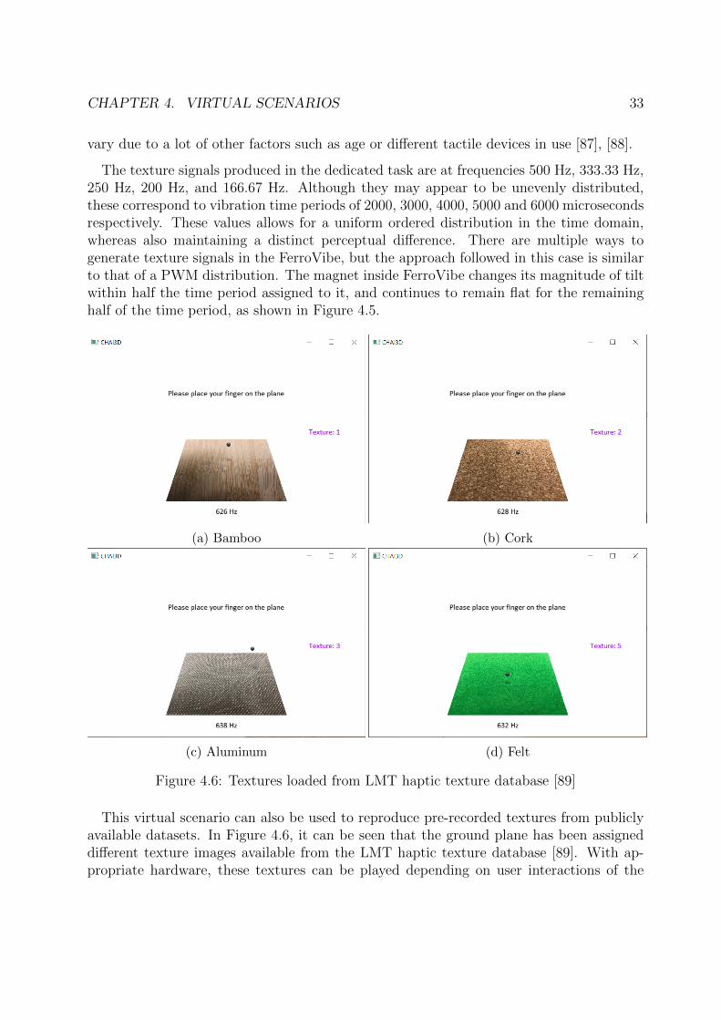
Figure 4.6: Textures loaded from LMT haptic texture database [89]
This virtual scenario can also be used to reproduce pre-recorded textures from publiclyavailable datasets. In Figure 4.6, it can be seen that the ground plane has been assigneddifferent texture images available from the LMT haptic texture database [89]. With ap-propriate hardware, these textures can be played depending on user interactions of the
CHAPTER 4. VIRTUAL SCENARIOS 34
virtual plane. However, the FerroVibe prototype being used was open-loop controlled, i.e.the output did not influence the input or vibration state of the device in any way. Therewere also no sensors at the end-effector to measure the actual frequency of vibrations per-ceived at the fingertip of users. Moreover, there was also the drawback of external factorssuch as different finger dimensions of different users and therefore a consequent differencein pressure applied on the place where the magnet moved to give feedback. This couldalso lead to a different perception and these could only be taken into consideration in aclosed-loop control system. Therefore, such real world texture data was not tested in theevaluation study conducted as part of this thesis.
4.1.3 Stiffness Discrimination
Stiffness of an object is defined as the resistance of the object to deformation by an appliedforce. It is one of the most studied properties of an object. Stiffness property is helpful fordiscrimination, identification and manipulation of objects [90]. Some studies [91] show thatstiffness discrimination is significantly better while tapping than by pressing or squeezing[92]. The designed virtual scenario for stiffness discrimination is therefore laid on theunderlying assumption that object stiffnesses are going to be explored while tapping. Sucha tapping process does not need measurements of velocity or acceleration across the objectsurface, and suitable information can be conveyed through devices only worn on one finger.Due to the respective device design of the FerroVibe and FingerTac, neither of them canstimulate stiffness information by deforming or by applying a normal force to the fingerpad.Therefore, the stiffness information from this scenario is encoded as vibrations and playedon the respective devices.
Various works so far use a multitude of approaches to encode and display stiffness [93].Some researchers have reproduced stiffness by varying amplitude (intensity) of vibrationsthrough a vibrotactile device, whereas others have varied just the frequency of vibrations[54], [94]. A combination of a wide range of intensities and frequencies has also beenemployed to produce stiffness information [95]. In [54], the authors investigated stiffnessdiscrimination by modulating PWM signals. Since the FingerTac has an LRA to generatevibrations, the operation frequency is fixed. However, PWM duty cycles can be changed.Hence, stiffness encoding for this virtual scenario is done by modulating PWM duty cycles.Through an evaluation study, it was attested that the FingerTac can encode stiffness asdesired. With other tactile devices, other approaches may of course be used with or withoutencoding, depending on device display capabilities.
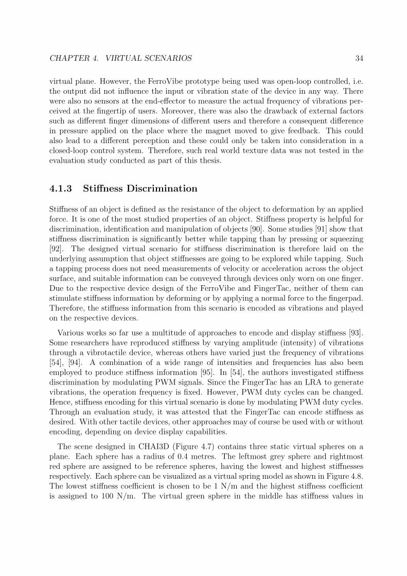
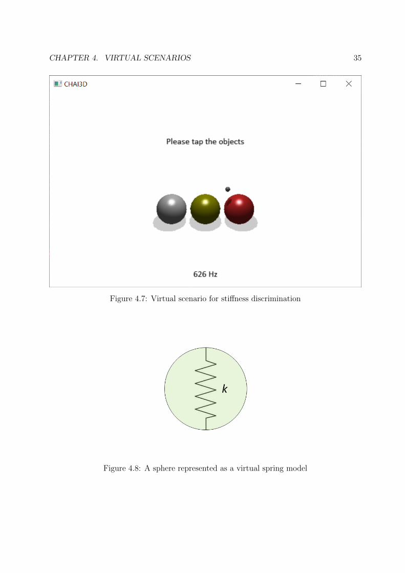
The scene designed in CHAI3D (Figure 4.7) contains three static virtual spheres on aplane. Each sphere has a radius of 0.4 metres. The leftmost grey sphere and rightmostred sphere are assigned to be reference spheres, having the lowest and highest stiffnessesrespectively. Each sphere can be visualized as a virtual spring model as shown in Figure 4.8.The lowest stiffness coefficient is chosen to be 1 N/m and the highest stiffness coefficientis assigned to 100 N/m. The virtual green sphere in the middle has stiffness values in
CHAPTER 4. VIRTUAL SCENARIOS 35
Figure 4.7: Virtual scenario for stiffness discrimination
Figure 4.8: A sphere represented as a virtual spring model
CHAPTER 4. VIRTUAL SCENARIOS 36
between 1 to 100 N/m, but as multiples of 10. Keyboard functionalities are implementedto randomly assign a stiffness value to the green sphere in the middle. Apart from thecolors and stiffness, all other physical properties of each sphere is left unchanged. Thestiffness coefficient is converted into OFF time for PWM vibration signals whereas theON duration is kept fixed. Besides these, there is also an option to change the stiffnesscoefficient of the red virtual sphere by using the up (↑) and down (↓) arrow keys. This wasuseful for the stiffness matching task or magnitude production task discussed later duringthe evaluation study.
4.1.4 Shape Detection
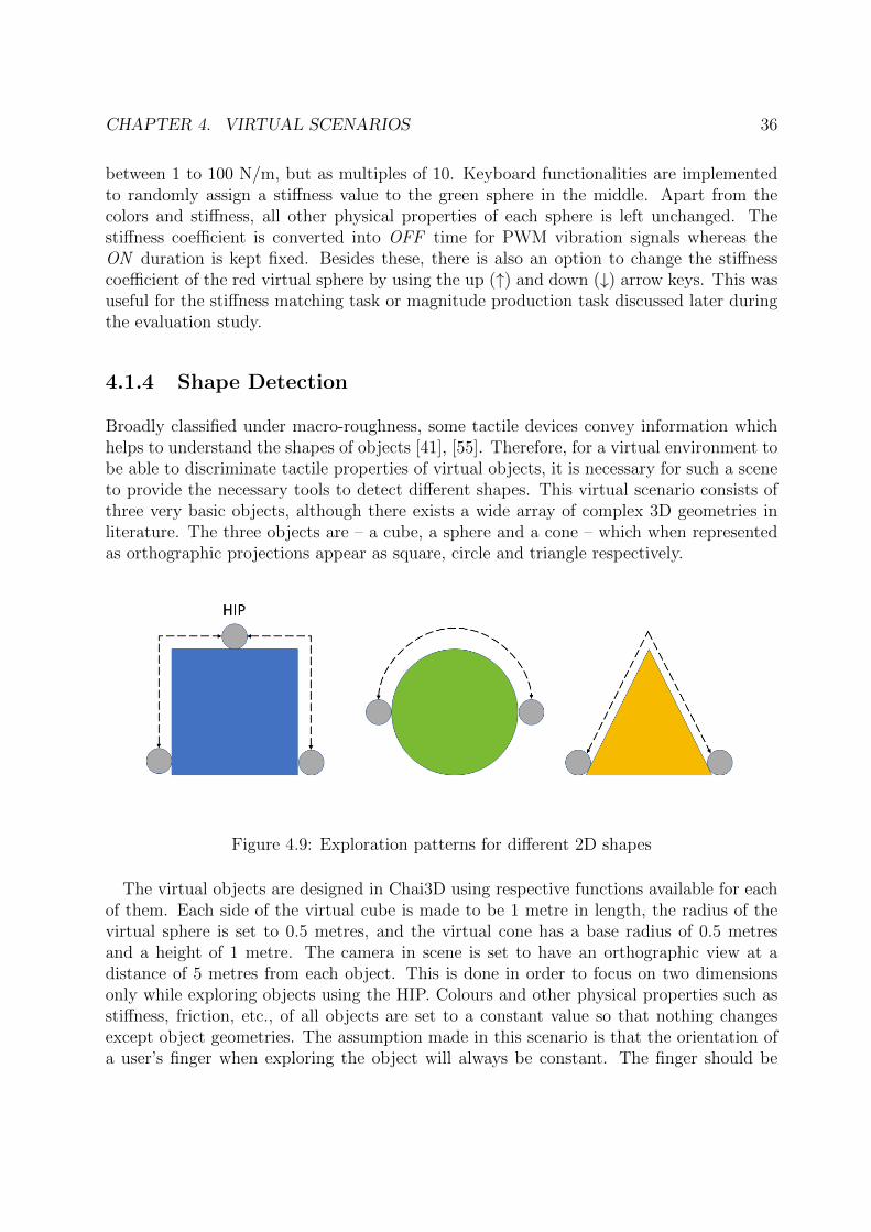
Broadly classified under macro-roughness, some tactile devices convey information whichhelps to understand the shapes of objects [41], [55]. Therefore, for a virtual environment tobe able to discriminate tactile properties of virtual objects, it is necessary for such a sceneto provide the necessary tools to detect different shapes. This virtual scenario consists ofthree very basic objects, although there exists a wide array of complex 3D geometries inliterature. The three objects are – a cube, a sphere and a cone – which when representedas orthographic projections appear as square, circle and triangle respectively.
Figure 4.9: Exploration patterns for different 2D shapes
The virtual objects are designed in Chai3D using respective functions available for eachof them. Each side of the virtual cube is made to be 1 metre in length, the radius of thevirtual sphere is set to 0.5 metres, and the virtual cone has a base radius of 0.5 metresand a height of 1 metre. The camera in scene is set to have an orthographic view at adistance of 5 metres from each object. This is done in order to focus on two dimensionsonly while exploring objects using the HIP. Colours and other physical properties such asstiffness, friction, etc., of all objects are set to a constant value so that nothing changesexcept object geometries. The assumption made in this scenario is that the orientation ofa user’s finger when exploring the object will always be constant. The finger should be
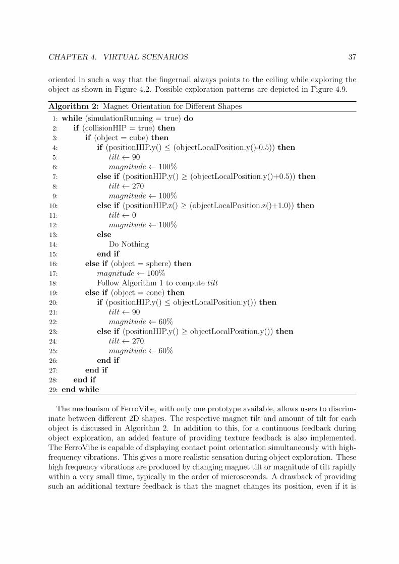
CHAPTER 4. VIRTUAL SCENARIOS 37
oriented in such a way that the fingernail always points to the ceiling while exploring theobject as shown in Figure 4.2. Possible exploration patterns are depicted in Figure 4.9.
Algorithm 2: Magnet Orientation for Different Shapes
1: while (simulationRunning = true) do2: if (collisionHIP = true) then3: if (object = cube) then4: if (positionHIP.y() ≤ (objectLocalPosition.y()-0.5)) then5: tilt← 906: magnitude← 100%7: else if (positionHIP.y() ≥ (objectLocalPosition.y()+0.5)) then8: tilt← 2709: magnitude← 100%10: else if (positionHIP.z() ≥ (objectLocalPosition.z()+1.0)) then11: tilt← 012: magnitude← 100%13: else14: Do Nothing15: end if16: else if (object = sphere) then17: magnitude← 100%18: Follow Algorithm 1 to compute tilt19: else if (object = cone) then20: if (positionHIP.y() ≤ objectLocalPosition.y()) then21: tilt← 9022: magnitude← 60%23: else if (positionHIP.y() ≥ objectLocalPosition.y()) then24: tilt← 27025: magnitude← 60%26: end if27: end if28: end if29: end while
The mechanism of FerroVibe, with only one prototype available, allows users to discrim-inate between different 2D shapes. The respective magnet tilt and amount of tilt for eachobject is discussed in Algorithm 2. In addition to this, for a continuous feedback duringobject exploration, an added feature of providing texture feedback is also implemented.The FerroVibe is capable of displaying contact point orientation simultaneously with high-frequency vibrations. This gives a more realistic sensation during object exploration. Thesehigh frequency vibrations are produced by changing magnet tilt or magnitude of tilt rapidlywithin a very small time, typically in the order of microseconds. A drawback of providingsuch an additional texture feedback is that the magnet changes its position, even if it is
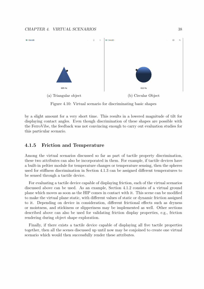
CHAPTER 4. VIRTUAL SCENARIOS 38
(a) Triangular object (b) Circular Object
Figure 4.10: Virtual scenario for discriminating basic shapes
by a slight amount for a very short time. This results in a lowered magnitude of tilt fordisplaying contact angles. Even though discrimination of these shapes are possible withthe FerroVibe, the feedback was not convincing enough to carry out evaluation studies forthis particular scenario.
4.1.5 Friction and Temperature
Among the virtual scenarios discussed so far as part of tactile property discrimination,these two attributes can also be incorporated in them. For example, if tactile devices havea built-in peltier module for temperature changes or temperature sensing, then the spheresused for stiffness discrimination in Section 4.1.3 can be assigned different temperatures tobe sensed through a tactile device.
For evaluating a tactile device capable of displaying friction, each of the virtual scenariosdiscussed above can be used. As an example, Section 4.1.2 consists of a virtual groundplane which moves as soon as the HIP comes in contact with it. This scene can be modifiedto make the virtual plane static, with different values of static or dynamic friction assignedto it. Depending on device in consideration, different frictional effects such as drynessor moistness, and stickiness or slipperiness may be implemented as well. Other sectionsdescribed above can also be used for validating friction display properties, e.g., frictionrendering during object shape exploration.
Finally, if there exists a tactile device capable of displaying all five tactile propertiestogether, then all the scenes discussed up until now may be conjoined to create one virtualscenario which would then successfully render these attributes.
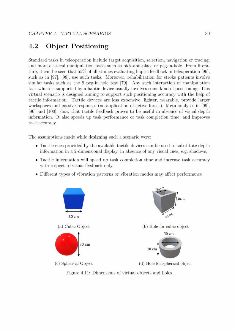
CHAPTER 4. VIRTUAL SCENARIOS 39
4.2 Object Positioning
Standard tasks in teleoperation include target acquisition, selection, navigation or tracing,and more classical manipulation tasks such as pick-and-place or peg-in-hole. From litera-ture, it can be seen that 55% of all studies evaluating haptic feedback in teleoperation [96],such as in [97], [98], use such tasks. Moreover, rehabilitation for stroke patients involvesimilar tasks such as the 9 peg-in-hole test [79]. Any such interaction or manipulationtask which is supported by a haptic device usually involves some kind of positioning. Thisvirtual scenario is designed aiming to support such positioning accuracy with the help oftactile information. Tactile devices are less expensive, lighter, wearable, provide largerworkspaces and passive responses (no application of active forces). Meta-analyses in [99],[96] and [100], show that tactile feedback proves to be useful in absence of visual depthinformation. It also speeds up task performance or task completion time, and improvestask accuracy.
The assumptions made while designing such a scenario were:
• Tactile cues provided by the available tactile devices can be used to substitute depthinformation in a 2-dimensional display, in absence of any visual cues, e.g. shadows,
• Tactile information will speed up task completion time and increase task accuracywith respect to visual feedback only,
• Different types of vibration patterns or vibration modes may affect performance
(a) Cubic Object (b) Hole for cubic object
(c) Spherical Object (d) Hole for spherical object
Figure 4.11: Dimensions of virtual objects and holes
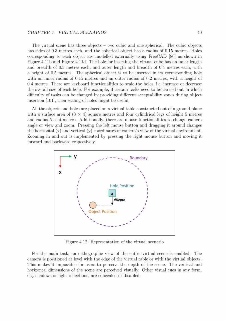
CHAPTER 4. VIRTUAL SCENARIOS 40
The virtual scene has three objects – two cubic and one spherical. The cubic objectshas sides of 0.3 metres each, and the spherical object has a radius of 0.15 metres. Holescorresponding to each object are modelled externally using FreeCAD [80] as shown inFigure 4.11b and Figure 4.11d. The hole for inserting the virtual cube has an inner lengthand breadth of 0.3 metres each, and outer length and breadth of 0.4 metres each, witha height of 0.5 metres. The spherical object is to be inserted in its corresponding holewith an inner radius of 0.15 metres and an outer radius of 0.2 metres, with a height of0.4 metres. There are keyboard functionalities to scale the holes, i.e. increase or decreasethe overall size of each hole. For example, if certain tasks need to be carried out in whichdifficulty of tasks can be changed by providing different acceptability zones during objectinsertion [101], then scaling of holes might be useful.
All the objects and holes are placed on a virtual table constructed out of a ground planewith a surface area of (3 × 4) square metres and four cylindrical legs of height 5 metresand radius 5 centimetres. Additionally, there are mouse functionalities to change cameraangle or view and zoom. Pressing the left mouse button and dragging it around changesthe horizontal (x) and vertical (y) coordinates of camera’s view of the virtual environment.Zooming in and out is implemented by pressing the right mouse button and moving itforward and backward respectively.
Figure 4.12: Representation of the virtual scenario
For the main task, an orthographic view of the entire virtual scene is enabled. Thecamera is positioned at level with the edge of the virtual table or with the virtual objects.This makes it impossible for users to perceive the depth of the scene. The vertical andhorizontal dimensions of the scene are perceived visually. Other visual cues in any form,e.g. shadows or light reflections, are concealed or disabled.
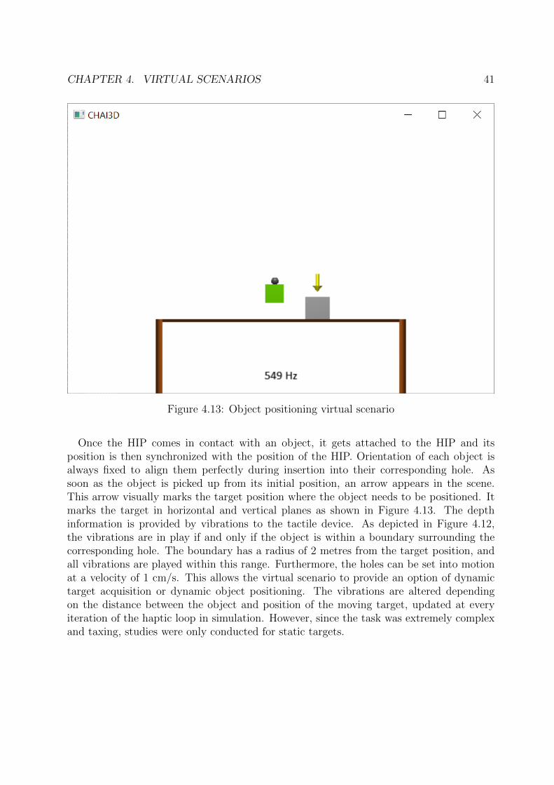
CHAPTER 4. VIRTUAL SCENARIOS 41
Figure 4.13: Object positioning virtual scenario
Once the HIP comes in contact with an object, it gets attached to the HIP and itsposition is then synchronized with the position of the HIP. Orientation of each object isalways fixed to align them perfectly during insertion into their corresponding hole. Assoon as the object is picked up from its initial position, an arrow appears in the scene.This arrow visually marks the target position where the object needs to be positioned. Itmarks the target in horizontal and vertical planes as shown in Figure 4.13. The depthinformation is provided by vibrations to the tactile device. As depicted in Figure 4.12,the vibrations are in play if and only if the object is within a boundary surrounding thecorresponding hole. The boundary has a radius of 2 metres from the target position, andall vibrations are played within this range. Furthermore, the holes can be set into motionat a velocity of 1 cm/s. This allows the virtual scenario to provide an option of dynamictarget acquisition or dynamic object positioning. The vibrations are altered dependingon the distance between the object and position of the moving target, updated at everyiteration of the haptic loop in simulation. However, since the task was extremely complexand taxing, studies were only conducted for static targets.
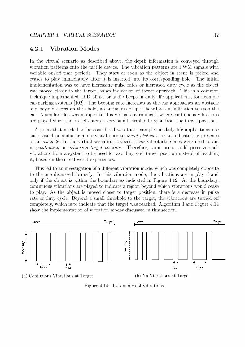
CHAPTER 4. VIRTUAL SCENARIOS 42
4.2.1 Vibration Modes
In the virtual scenario as described above, the depth information is conveyed throughvibration patterns onto the tactile device. The vibration patterns are PWM signals withvariable on/off time periods. They start as soon as the object in scene is picked andceases to play immediately after it is inserted into its corresponding hole. The initialimplementation was to have increasing pulse rates or increased duty cycle as the objectwas moved closer to the target, as an indication of target approach. This is a commontechnique implemented LED blinks or audio beeps in daily life applications, for examplecar-parking systems [102]. The beeping rate increases as the car approaches an obstacleand beyond a certain threshold, a continuous beep is heard as an indication to stop thecar. A similar idea was mapped to this virtual environment, where continuous vibrationsare played when the object enters a very small threshold region from the target position.
A point that needed to be considered was that examples in daily life applications usesuch visual or audio or audio-visual cues to avoid obstacles or to indicate the presenceof an obstacle. In the virtual scenario, however, these vibrotactile cues were used to aidin positioning or achieving target position. Therefore, some users could perceive suchvibrations from a system to be used for avoiding said target position instead of reachingit, based on their real-world experiences.
This led to an investigation of a different vibration mode, which was completely oppositeto the one discussed formerly. In this vibration mode, the vibrations are in play if andonly if the object is within the boundary as indicated in Figure 4.12. At the boundary,continuous vibrations are played to indicate a region beyond which vibrations would ceaseto play. As the object is moved closer to target position, there is a decrease in pulserate or duty cycle. Beyond a small threshold to the target, the vibrations are turned offcompletely, which is to indicate that the target was reached. Algorithm 3 and Figure 4.14show the implementation of vibration modes discussed in this section.
(a) Continuous Vibrations at Target (b) No Vibrations at Target
Figure 4.14: Two modes of vibrations
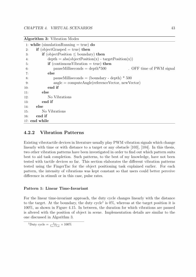
CHAPTER 4. VIRTUAL SCENARIOS 43
Algorithm 3: Vibration Modes
1: while (simulationRunning = true) do2: if (objectGrasped = true) then3: if (objectPosition ≤ boundary) then4: depth = abs(objectPosition(x) - targetPosition(x))5: if (continuousVibration = true) then6: pauseMilliseconds = depth*500 ▷ OFF time of PWM signal7: else8: pauseMilliseconds = (boundary - depth) * 5009: angle = computeAngle(referenceVector, newVector)10: end if11: else12: No Vibrations13: end if14: else15: No Vibrations16: end if17: end while
4.2.2 Vibration Patterns
Existing vibrotactile devices in literature usually play PWM vibration signals which changelinearly with time or with distance to a target or any obstacle [103], [104]. In this thesis,two other vibration patterns have been investigated in order to find out which pattern suitsbest to aid task completion. Such patterns, to the best of my knowledge, have not beentested with tactile devices so far. This section elaborates the different vibration patternstested using the FingerTac for the object positioning task explained earlier. For eachpattern, the intensity of vibrations was kept constant so that users could better perceivedifference in stimuli or in this case, pulse rates.
Pattern 1: Linear Time-Invariant
For the linear time-invariant approach, the duty cycle changes linearly with the distanceto the target. At the boundary, the duty cycle1 is 0%, whereas at the target position it is100%, as shown in Figure 4.15. In between, the duration for which vibrations are pausedis altered with the position of object in scene. Implementation details are similar to theone discussed in Algorithm 3.
1Duty cycle = tonton+toff
× 100%
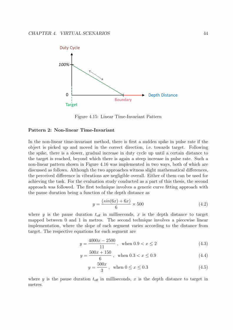
CHAPTER 4. VIRTUAL SCENARIOS 44
Figure 4.15: Linear Time-Invariant Pattern
Pattern 2: Non-linear Time-Invariant
In the non-linear time-invariant method, there is first a sudden spike in pulse rate if theobject is picked up and moved in the correct direction, i.e. towards target. Followingthe spike, there is a slower, gradual increase in duty cycle up until a certain distance tothe target is reached, beyond which there is again a steep increase in pulse rate. Such anon-linear pattern shown in Figure 4.16 was implemented in two ways, both of which arediscussed as follows. Although the two approaches witness slight mathematical differences,the perceived difference in vibrations are negligible overall. Either of them can be used forachieving the task. For the evaluation study conducted as a part of this thesis, the secondapproach was followed. The first technique involves a generic curve fitting approach withthe pause duration being a function of the depth distance as
y =(sin(6x) + 6x)
6× 500 (4.2)
where y is the pause duration toff in milliseconds, x is the depth distance to targetmapped between 0 and 1 in metres. The second technique involves a piecewise linearimplementation, where the slope of each segment varies according to the distance fromtarget. The respective equations for each segment are
y =4000x− 2500
11, when 0.9 < x ≤ 2 (4.3)
y =500x+ 150
6, when 0.3 < x ≤ 0.9 (4.4)
y =500x
3, when 0 ≤ x ≤ 0.3 (4.5)
where y is the pause duration toff in milliseconds, x is the depth distance to target inmetres.
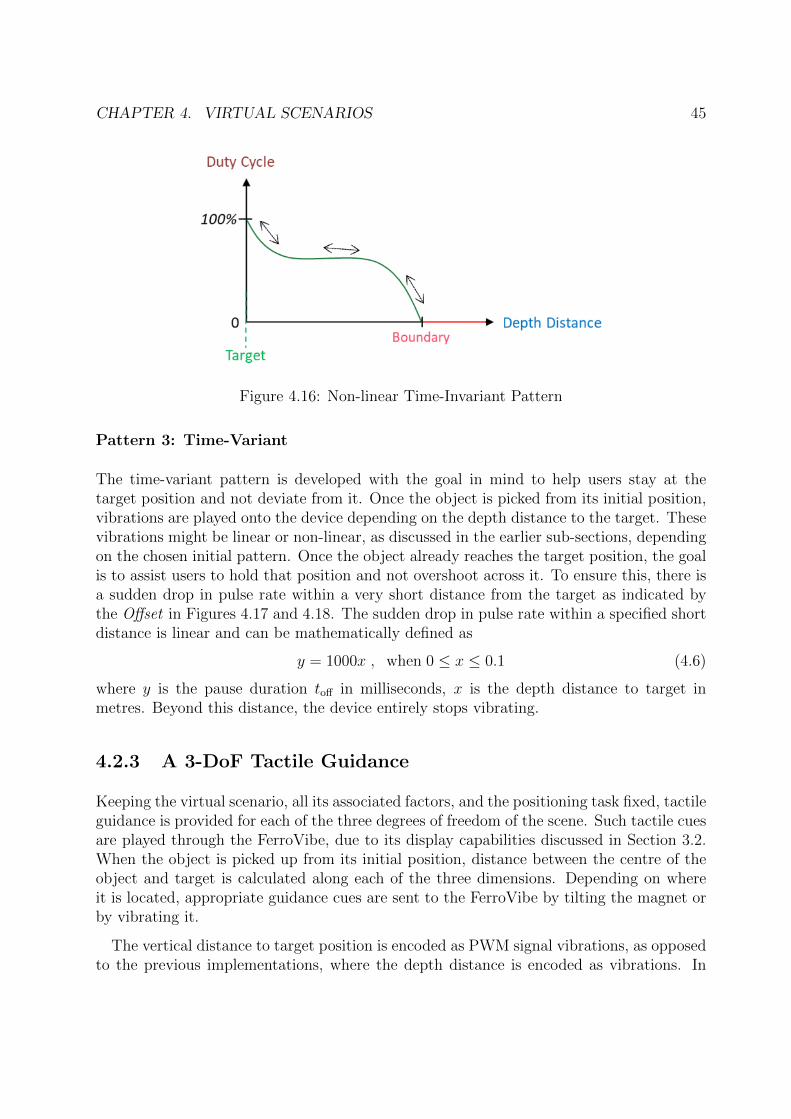
CHAPTER 4. VIRTUAL SCENARIOS 45
Figure 4.16: Non-linear Time-Invariant Pattern
Pattern 3: Time-Variant
The time-variant pattern is developed with the goal in mind to help users stay at thetarget position and not deviate from it. Once the object is picked from its initial position,vibrations are played onto the device depending on the depth distance to the target. Thesevibrations might be linear or non-linear, as discussed in the earlier sub-sections, dependingon the chosen initial pattern. Once the object already reaches the target position, the goalis to assist users to hold that position and not overshoot across it. To ensure this, there isa sudden drop in pulse rate within a very short distance from the target as indicated bythe Offset in Figures 4.17 and 4.18. The sudden drop in pulse rate within a specified shortdistance is linear and can be mathematically defined as
y = 1000x , when 0 ≤ x ≤ 0.1 (4.6)
where y is the pause duration toff in milliseconds, x is the depth distance to target inmetres. Beyond this distance, the device entirely stops vibrating.
4.2.3 A 3-DoF Tactile Guidance
Keeping the virtual scenario, all its associated factors, and the positioning task fixed, tactileguidance is provided for each of the three degrees of freedom of the scene. Such tactile cuesare played through the FerroVibe, due to its display capabilities discussed in Section 3.2.When the object is picked up from its initial position, distance between the centre of theobject and target is calculated along each of the three dimensions. Depending on whereit is located, appropriate guidance cues are sent to the FerroVibe by tilting the magnet orby vibrating it.
The vertical distance to target position is encoded as PWM signal vibrations, as opposedto the previous implementations, where the depth distance is encoded as vibrations. In
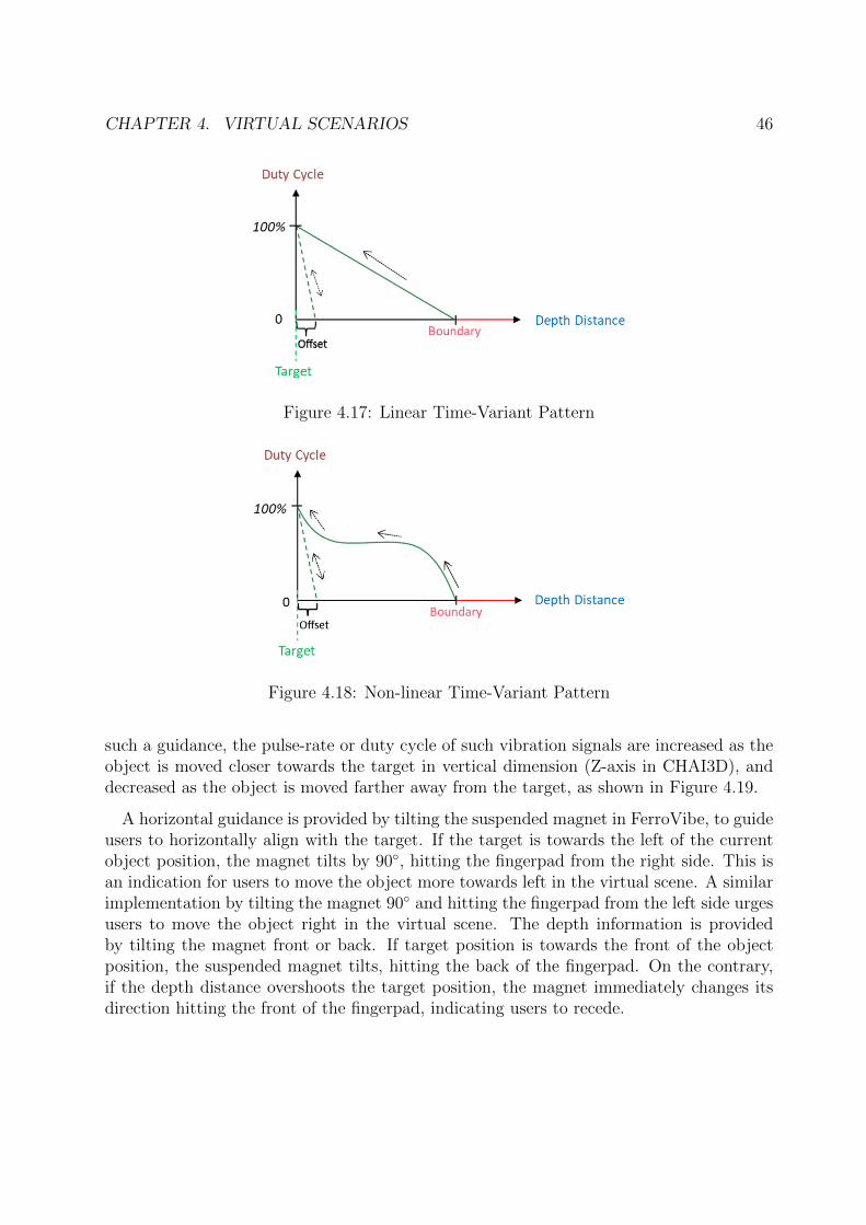
CHAPTER 4. VIRTUAL SCENARIOS 46
Figure 4.17: Linear Time-Variant Pattern
Figure 4.18: Non-linear Time-Variant Pattern
such a guidance, the pulse-rate or duty cycle of such vibration signals are increased as theobject is moved closer towards the target in vertical dimension (Z-axis in CHAI3D), anddecreased as the object is moved farther away from the target, as shown in Figure 4.19.
A horizontal guidance is provided by tilting the suspended magnet in FerroVibe, to guideusers to horizontally align with the target. If the target is towards the left of the currentobject position, the magnet tilts by 90◦, hitting the fingerpad from the right side. This isan indication for users to move the object more towards left in the virtual scene. A similarimplementation by tilting the magnet 90◦ and hitting the fingerpad from the left side urgesusers to move the object right in the virtual scene. The depth information is providedby tilting the magnet front or back. If target position is towards the front of the objectposition, the suspended magnet tilts, hitting the back of the fingerpad. On the contrary,if the depth distance overshoots the target position, the magnet immediately changes itsdirection hitting the front of the fingerpad, indicating users to recede.
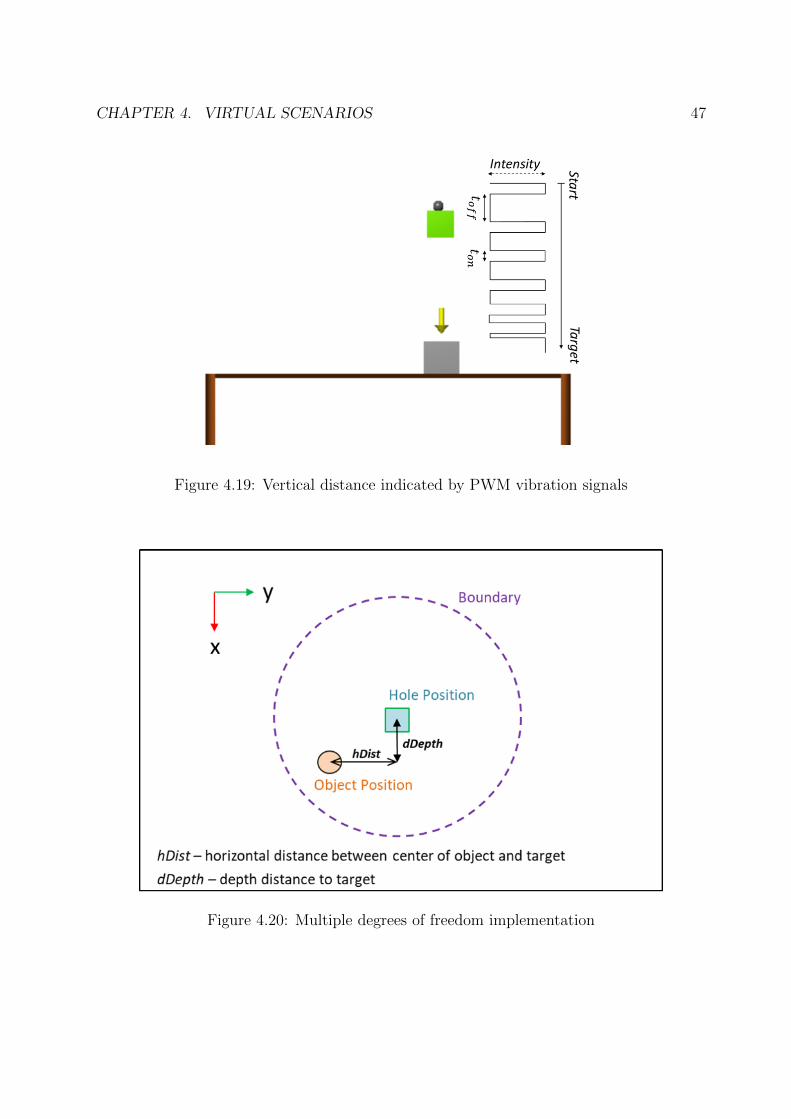
CHAPTER 4. VIRTUAL SCENARIOS 47
Figure 4.19: Vertical distance indicated by PWM vibration signals
Figure 4.20: Multiple degrees of freedom implementation
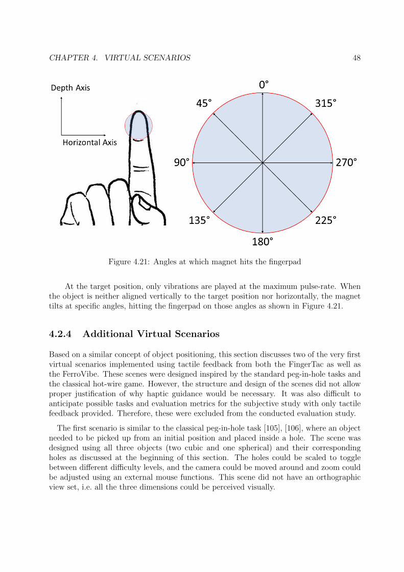
CHAPTER 4. VIRTUAL SCENARIOS 48
Figure 4.21: Angles at which magnet hits the fingerpad
At the target position, only vibrations are played at the maximum pulse-rate. Whenthe object is neither aligned vertically to the target position nor horizontally, the magnettilts at specific angles, hitting the fingerpad on those angles as shown in Figure 4.21.
4.2.4 Additional Virtual Scenarios
Based on a similar concept of object positioning, this section discusses two of the very firstvirtual scenarios implemented using tactile feedback from both the FingerTac as well asthe FerroVibe. These scenes were designed inspired by the standard peg-in-hole tasks andthe classical hot-wire game. However, the structure and design of the scenes did not allowproper justification of why haptic guidance would be necessary. It was also difficult toanticipate possible tasks and evaluation metrics for the subjective study with only tactilefeedback provided. Therefore, these were excluded from the conducted evaluation study.
The first scenario is similar to the classical peg-in-hole task [105], [106], where an objectneeded to be picked up from an initial position and placed inside a hole. The scene wasdesigned using all three objects (two cubic and one spherical) and their correspondingholes as discussed at the beginning of this section. The holes could be scaled to togglebetween different difficulty levels, and the camera could be moved around and zoom couldbe adjusted using an external mouse functions. This scene did not have an orthographicview set, i.e. all the three dimensions could be perceived visually.
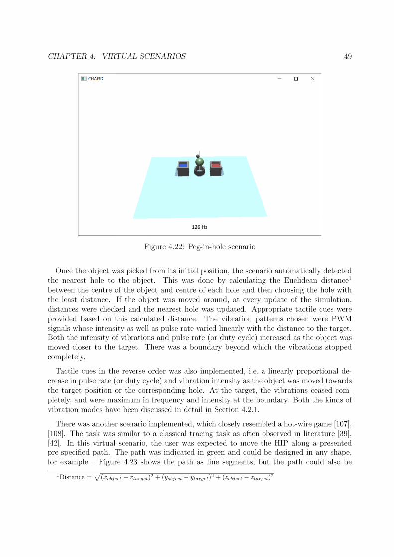
CHAPTER 4. VIRTUAL SCENARIOS 49
Figure 4.22: Peg-in-hole scenario
Once the object was picked from its initial position, the scenario automatically detectedthe nearest hole to the object. This was done by calculating the Euclidean distance1
between the centre of the object and centre of each hole and then choosing the hole withthe least distance. If the object was moved around, at every update of the simulation,distances were checked and the nearest hole was updated. Appropriate tactile cues wereprovided based on this calculated distance. The vibration patterns chosen were PWMsignals whose intensity as well as pulse rate varied linearly with the distance to the target.Both the intensity of vibrations and pulse rate (or duty cycle) increased as the object wasmoved closer to the target. There was a boundary beyond which the vibrations stoppedcompletely.
Tactile cues in the reverse order was also implemented, i.e. a linearly proportional de-crease in pulse rate (or duty cycle) and vibration intensity as the object was moved towardsthe target position or the corresponding hole. At the target, the vibrations ceased com-pletely, and were maximum in frequency and intensity at the boundary. Both the kinds ofvibration modes have been discussed in detail in Section 4.2.1.
There was another scenario implemented, which closely resembled a hot-wire game [107],[108]. The task was similar to a classical tracing task as often observed in literature [39],[42]. In this virtual scenario, the user was expected to move the HIP along a presentedpre-specified path. The path was indicated in green and could be designed in any shape,for example – Figure 4.23 shows the path as line segments, but the path could also be
1Distance =√(xobject − xtarget)2 + (yobject − ytarget)2 + (zobject − ztarget)2
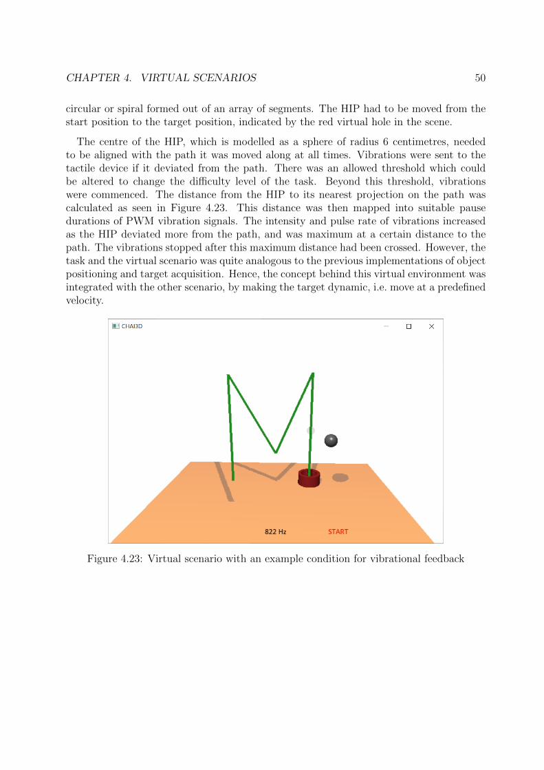
CHAPTER 4. VIRTUAL SCENARIOS 50
circular or spiral formed out of an array of segments. The HIP had to be moved from thestart position to the target position, indicated by the red virtual hole in the scene.
The centre of the HIP, which is modelled as a sphere of radius 6 centimetres, neededto be aligned with the path it was moved along at all times. Vibrations were sent to thetactile device if it deviated from the path. There was an allowed threshold which couldbe altered to change the difficulty level of the task. Beyond this threshold, vibrationswere commenced. The distance from the HIP to its nearest projection on the path wascalculated as seen in Figure 4.23. This distance was then mapped into suitable pausedurations of PWM vibration signals. The intensity and pulse rate of vibrations increasedas the HIP deviated more from the path, and was maximum at a certain distance to thepath. The vibrations stopped after this maximum distance had been crossed. However, thetask and the virtual scenario was quite analogous to the previous implementations of objectpositioning and target acquisition. Hence, the concept behind this virtual environment wasintegrated with the other scenario, by making the target dynamic, i.e. move at a predefinedvelocity.
Figure 4.23: Virtual scenario with an example condition for vibrational feedback
Chapter 5
Evaluation Study
In order to corroborate the assumptions behind such a virtual suite, multiple tasks wereconducted using the FingerTac and FerroVibe with N = 13 subjects each. This studynot only served as a proof-of-concept for the virtual suite itself, but also validated therespective device display capabilities.
At first, some tasks were conducted to check if subjects could successfully distinguish thedifferent orientations or points of contact on a hemispherical surface based on the magnettilt of the FerroVibe. The texture display capabilities of FerroVibe were then investigatedin a second task, where subjects were asked to rate the differences in texture smoothness orroughness on a Likert-type scale. Furthermore, random textures were played on the deviceto check if subjects could recognize the frequencies they were being played at. A third tasktested if participants could distinguish between different stiffness values, corresponding todifferent PWM duty cycles, of objects based on vibrotactile feedback only. As an additionaltask, they were also asked to change the stiffness of one of the objects and try to matchthe stiffness of another. These studies were conducted initially so that subjects could havean idea and familiarize themselves with the devices.
For the relatively challenging Positioning scenario, tasks were carried out to attest theunderlying assumption that depth information in a 3D environment can be replaced by vi-brotactile cues. Different vibration patterns were tried out to choose the best suited one forsuch an application. With the FerroVibe, additional directional guidance for the remainingdegrees of freedom were provided using magnet tilt in combination with vibrations.
The procedure, setup and results1 of the entire evaluation study are discussed in thefollowing sections, along with their appropriate discussions. Finally, this chapter concludeswith some personal remarks and takeaways from the conducted evaluation study.
1I acknowledge and highly appreciate the support received from Dr. Bernhard Weber for the advancedstatistical analyses conducted from the results of the evaluation study in this chapter
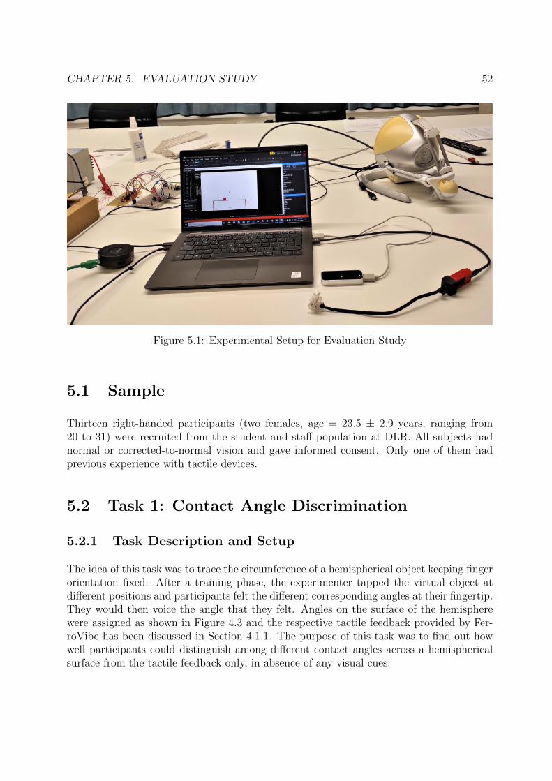
CHAPTER 5. EVALUATION STUDY 52
Figure 5.1: Experimental Setup for Evaluation Study
5.1 Sample
Thirteen right-handed participants (two females, age = 23.5 ± 2.9 years, ranging from20 to 31) were recruited from the student and staff population at DLR. All subjects hadnormal or corrected-to-normal vision and gave informed consent. Only one of them hadprevious experience with tactile devices.
5.2 Task 1: Contact Angle Discrimination
5.2.1 Task Description and Setup
The idea of this task was to trace the circumference of a hemispherical object keeping fingerorientation fixed. After a training phase, the experimenter tapped the virtual object atdifferent positions and participants felt the different corresponding angles at their fingertip.They would then voice the angle that they felt. Angles on the surface of the hemispherewere assigned as shown in Figure 4.3 and the respective tactile feedback provided by Fer-roVibe has been discussed in Section 4.1.1. The purpose of this task was to find out howwell participants could distinguish among different contact angles across a hemisphericalsurface from the tactile feedback only, in absence of any visual cues.
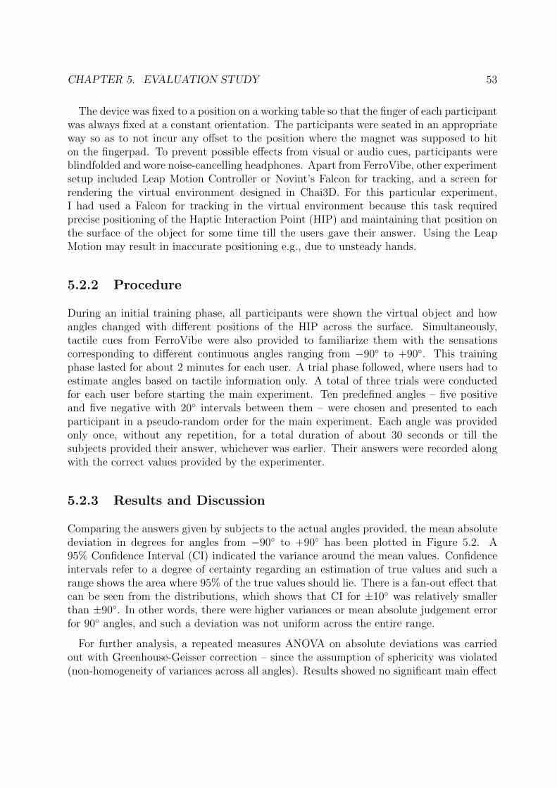
CHAPTER 5. EVALUATION STUDY 53
The device was fixed to a position on a working table so that the finger of each participantwas always fixed at a constant orientation. The participants were seated in an appropriateway so as to not incur any offset to the position where the magnet was supposed to hiton the fingerpad. To prevent possible effects from visual or audio cues, participants wereblindfolded and wore noise-cancelling headphones. Apart from FerroVibe, other experimentsetup included Leap Motion Controller or Novint’s Falcon for tracking, and a screen forrendering the virtual environment designed in Chai3D. For this particular experiment,I had used a Falcon for tracking in the virtual environment because this task requiredprecise positioning of the Haptic Interaction Point (HIP) and maintaining that position onthe surface of the object for some time till the users gave their answer. Using the LeapMotion may result in inaccurate positioning e.g., due to unsteady hands.
5.2.2 Procedure
During an initial training phase, all participants were shown the virtual object and howangles changed with different positions of the HIP across the surface. Simultaneously,tactile cues from FerroVibe were also provided to familiarize them with the sensationscorresponding to different continuous angles ranging from −90◦ to +90◦. This trainingphase lasted for about 2 minutes for each user. A trial phase followed, where users had toestimate angles based on tactile information only. A total of three trials were conductedfor each user before starting the main experiment. Ten predefined angles – five positiveand five negative with 20◦ intervals between them – were chosen and presented to eachparticipant in a pseudo-random order for the main experiment. Each angle was providedonly once, without any repetition, for a total duration of about 30 seconds or till thesubjects provided their answer, whichever was earlier. Their answers were recorded alongwith the correct values provided by the experimenter.
5.2.3 Results and Discussion
Comparing the answers given by subjects to the actual angles provided, the mean absolutedeviation in degrees for angles from −90◦ to +90◦ has been plotted in Figure 5.2. A95% Confidence Interval (CI) indicated the variance around the mean values. Confidenceintervals refer to a degree of certainty regarding an estimation of true values and such arange shows the area where 95% of the true values should lie. There is a fan-out effect thatcan be seen from the distributions, which shows that CI for ±10◦ was relatively smallerthan ±90◦. In other words, there were higher variances or mean absolute judgement errorfor 90◦ angles, and such a deviation was not uniform across the entire range.
For further analysis, a repeated measures ANOVA on absolute deviations was carriedout with Greenhouse-Geisser correction – since the assumption of sphericity was violated(non-homogeneity of variances across all angles). Results showed no significant main effect
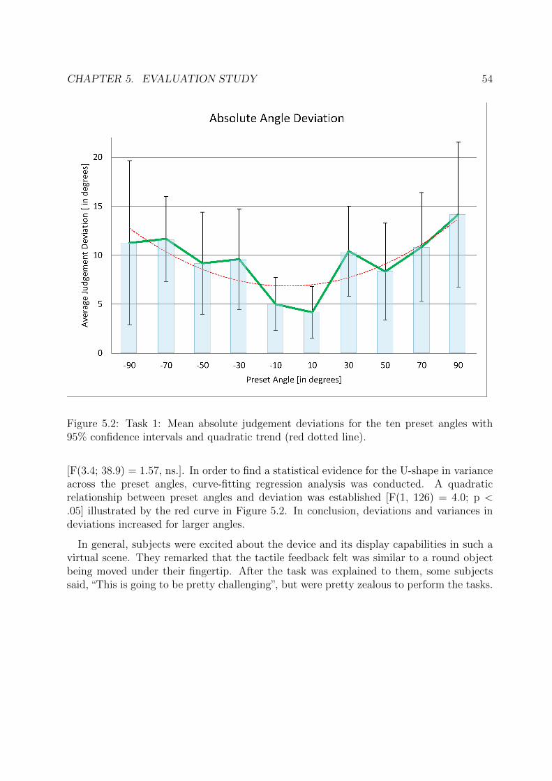
CHAPTER 5. EVALUATION STUDY 54
Figure 5.2: Task 1: Mean absolute judgement deviations for the ten preset angles with95% confidence intervals and quadratic trend (red dotted line).
[F(3.4; 38.9) = 1.57, ns.]. In order to find a statistical evidence for the U-shape in varianceacross the preset angles, curve-fitting regression analysis was conducted. A quadraticrelationship between preset angles and deviation was established [F(1, 126) = 4.0; p <.05] illustrated by the red curve in Figure 5.2. In conclusion, deviations and variances indeviations increased for larger angles.
In general, subjects were excited about the device and its display capabilities in such avirtual scene. They remarked that the tactile feedback felt was similar to a round objectbeing moved under their fingertip. After the task was explained to them, some subjectssaid, “This is going to be pretty challenging”, but were pretty zealous to perform the tasks.
CHAPTER 5. EVALUATION STUDY 55
5.3 Task 2: Texture Discrimination
5.3.1 Task Description and Setup
In this task, participants were asked to touch a virtual ground plane presented on thescreen. As soon as the HIP came in contact with the plane, the plane started to move ata constant velocity under the HIP, and textures at different frequencies were played viaFerroVibe. Five texture frequencies were chosen at 500 Hz, 333.33 Hz, 250 Hz, 200 Hz,and 166.67 Hz, which correspond to vibration time periods of 2000 ms, 3000 ms, 4000 ms,5000 ms and 6000 ms respectively.
This task was divided into two parts. For the first sub-task, subjects had to rate howsmooth or rough a particular texture felt in comparison to another. In the second sub-task,subjects had to indicate the frequency of a particular texture being played out of five pre-defined frequencies. Participants were insisted to wear noise-cancelling headphones so asto not be influenced by any auditory cues from the vibrations. A Leap Motion Controllerwas used for tracking in the virtual environment, and a screen for rendering the scenariodesigned in Chai3D.
5.3.2 Procedure
At first, textures with lowest and highest frequencies corresponding to 166.67 Hz and 500Hz respectively were played to give participants an idea about the reference range whichthey would be adhering to during the task. The signal with a frequency of 166.67 Hz wastermed to be the roughest texture and the one with 500 Hz was labelled as the smoothest.During the main experiment, two textures were played sequentially for five consecutivetimes. Order of the textures presented to each participant was varied systematically, butthe textures were predefined. After every trial, each participant was asked, “How muchsmoother or rougher did the second texture feel as compared to the first one?”. Theiranswers were recorded on a 7-point Likert-type scale, with 1 being much smoother, 4 beingsame and 7 being much rougher. This sub-task had no training phase except for thereference texture signals which were played to each participant for about 60 seconds beforethe task began.
In the training phase for the second sub-task, all five texture signals were played initiallyand subjects were shown the frequency at which each signal was played at. Each subjecthad up to 3 minutes to familiarize themselves with all the frequencies. A trial phasefollowed, where one random texture was played by the experimenter and participants hadto note down the frequency of that texture. For the main experiment, five such trials wereconducted where each texture was played at least once for consistency, but presented toeach participant in a different order. Participants were not made aware of the fact that
CHAPTER 5. EVALUATION STUDY 56
each texture would be played exactly once. After the experiment, the experimenter noteddown correct answers beside the answers noted by the participants.
5.3.3 Results and Discussion
Results of the first sub-task, where subjects were asked to compare two textures and givea rating on the difference felt in smoothness or roughness, are shown in Figure 5.3.
Figure 5.3: Average smoothness/roughness ratings for five comparisons with 95% CI
It shows the mean ratings together with the 95% confidence intervals around the meanvalues. From the results, it is evident that most subjects perceived a similar texture(indicated by a rating of 4), when same textures were played consecutively with very smallvariance. They could also clearly compare smoothness and roughness of the two extremefrequencies provided, again with comparably little variance.
A repeated measures ANOVA was performed on the ratings with Greenhouse-Geissercorrections and a significant main effect of comparison categories was found [F(2.24; 26.84)= 25.29; p <0.001]. As a next step, post-hoc comparisons with Bonferroni correction(taking into consideration the inflation of α values through multiple comparisons) wereconducted. Pairwise comparison between the different categories revealed highly significantmean differences between 166.67 Hz vs 250Hz (p < 0.001) as well as 500 vs 250Hz (p <
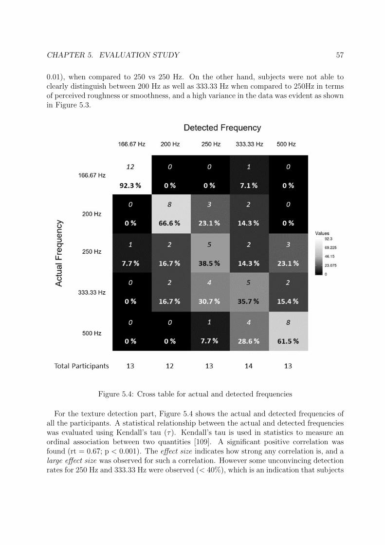
CHAPTER 5. EVALUATION STUDY 57
0.01), when compared to 250 vs 250 Hz. On the other hand, subjects were not able toclearly distinguish between 200 Hz as well as 333.33 Hz when compared to 250Hz in termsof perceived roughness or smoothness, and a high variance in the data was evident as shownin Figure 5.3.
Figure 5.4: Cross table for actual and detected frequencies
For the texture detection part, Figure 5.4 shows the actual and detected frequencies ofall the participants. A statistical relationship between the actual and detected frequencieswas evaluated using Kendall’s tau (τ). Kendall’s tau is used in statistics to measure anordinal association between two quantities [109]. A significant positive correlation wasfound (rt = 0.67; p < 0.001). The effect size indicates how strong any correlation is, and alarge effect size was observed for such a correlation. However some unconvincing detectionrates for 250 Hz and 333.33 Hz were observed (< 40%), which is an indication that subjects
CHAPTER 5. EVALUATION STUDY 58
confused these two frequencies quite a lot.
In general, subjects remarked that they were a bit confused about discriminating theexact frequencies in the range of 200 Hz to 333.33 Hz, even though no two textures feltexactly the same to them. Some even avowed that their fingertip felt a bit numb after thefirst half of the experiment due to constant vibrations provided from the FerroVibe.
5.4 Task 3: Stiffness Discrimination
5.4.1 Task Description and Setup
Participants were presented with three different static virtual objects. The objects haddifferent stiffness levels as discussed in detail in Section 4.1.3. The task of each participantwas to explore the objects by tapping on them. Stiffness of each object was encoded asvibration patterns of varying pulse rates or duty cycles. The participants could explorethe objects for an unlimited amount of time. No visual cues about the stiffness of objects– such as deformation when tapped or pressed – was provided. They were asked to judgethe stiffness of objects solely based on tactile cues.
On a scale of “1” to “10”, the leftmost reference object had a minimum stiffness of 1N/m or “1” and the rightmost object had a maximum stiffness of 100 N/m or “10”. Theseserved as reference values of stiffnesses. The participants had to explore the objects bytapping and rate the stiffness of the object in between on a scale of 1 to 10. Therefore, thistask was identified as a “Magnitude Estimation” task. As an additional task, subjects wereasked to change the stiffness of the rightmost reference object using the up and down arrowkeys until it matched the stiffness of the middle object. During this additional “MagnitudeProduction” task, the time for matching stiffness and the changes in stiffness as made byeach participant was recorded in a file. As soon as recording of data started, the leftmostreference object was made to disappear from the scene and only the objects to be matchedwere shown, along with appropriate text messages.
The stiffness values between 1 and 10 were presented at random, and the order wassystematically varied for each participant. This study was performed using the FingerTacworn by participants on their index finger. A Leap Motion Controller was used for trackingthe finger in the virtual environment, and a screen for rendering the virtual scenario. Noise-cancelling headphones were worn by all participants to occlude any bias to their answersfrom vibrational audio-cues.
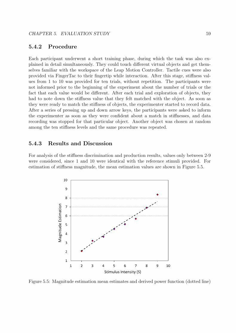
CHAPTER 5. EVALUATION STUDY 59
5.4.2 Procedure
Each participant underwent a short training phase, during which the task was also ex-plained in detail simultaneously. They could touch different virtual objects and get them-selves familiar with the workspace of the Leap Motion Controller. Tactile cues were alsoprovided via FingerTac to their fingertip while interaction. After this stage, stiffness val-ues from 1 to 10 was provided for ten trials, without repetition. The participants werenot informed prior to the beginning of the experiment about the number of trials or thefact that each value would be different. After each trial and exploration of objects, theyhad to note down the stiffness value that they felt matched with the object. As soon asthey were ready to match the stiffness of objects, the experimenter started to record data.After a series of pressing up and down arrow keys, the participants were asked to informthe experimenter as soon as they were confident about a match in stiffnesses, and datarecording was stopped for that particular object. Another object was chosen at randomamong the ten stiffness levels and the same procedure was repeated.
5.4.3 Results and Discussion
For analysis of the stiffness discrimination and production results, values only between 2-9were considered, since 1 and 10 were identical with the reference stimuli provided. Forestimation of stiffness magnitude, the mean estimation values are shown in Figure 5.5.
Figure 5.5: Magnitude estimation mean estimates and derived power function (dotted line)
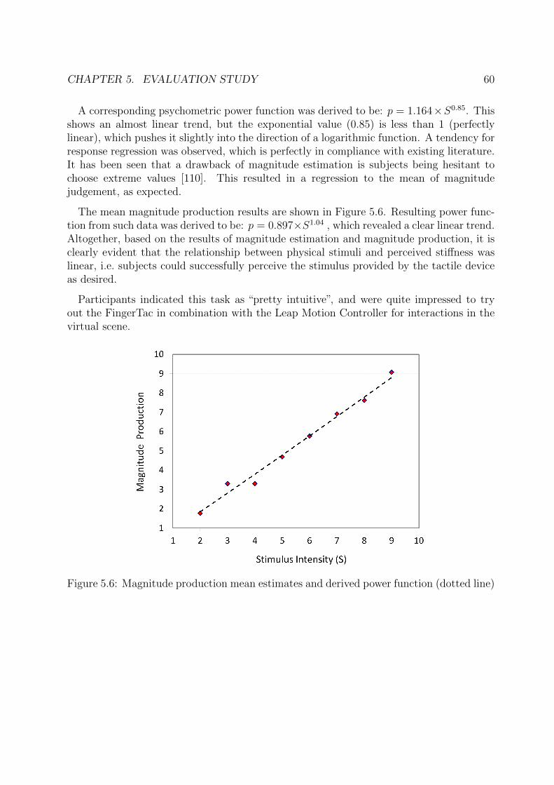
CHAPTER 5. EVALUATION STUDY 60
A corresponding psychometric power function was derived to be: p = 1.164×S0.85. Thisshows an almost linear trend, but the exponential value (0.85) is less than 1 (perfectlylinear), which pushes it slightly into the direction of a logarithmic function. A tendency forresponse regression was observed, which is perfectly in compliance with existing literature.It has been seen that a drawback of magnitude estimation is subjects being hesitant tochoose extreme values [110]. This resulted in a regression to the mean of magnitudejudgement, as expected.
The mean magnitude production results are shown in Figure 5.6. Resulting power func-tion from such data was derived to be: p = 0.897×S1.04 , which revealed a clear linear trend.Altogether, based on the results of magnitude estimation and magnitude production, it isclearly evident that the relationship between physical stimuli and perceived stiffness waslinear, i.e. subjects could successfully perceive the stimulus provided by the tactile deviceas desired.
Participants indicated this task as “pretty intuitive”, and were quite impressed to tryout the FingerTac in combination with the Leap Motion Controller for interactions in thevirtual scene.
Figure 5.6: Magnitude production mean estimates and derived power function (dotted line)
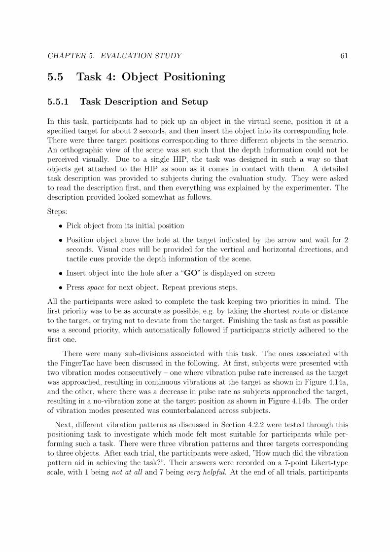
CHAPTER 5. EVALUATION STUDY 61
5.5 Task 4: Object Positioning
5.5.1 Task Description and Setup
In this task, participants had to pick up an object in the virtual scene, position it at aspecified target for about 2 seconds, and then insert the object into its corresponding hole.There were three target positions corresponding to three different objects in the scenario.An orthographic view of the scene was set such that the depth information could not beperceived visually. Due to a single HIP, the task was designed in such a way so thatobjects get attached to the HIP as soon as it comes in contact with them. A detailedtask description was provided to subjects during the evaluation study. They were askedto read the description first, and then everything was explained by the experimenter. Thedescription provided looked somewhat as follows.
Steps:
• Pick object from its initial position
• Position object above the hole at the target indicated by the arrow and wait for 2seconds. Visual cues will be provided for the vertical and horizontal directions, andtactile cues provide the depth information of the scene.
• Insert object into the hole after a “GO” is displayed on screen
• Press space for next object. Repeat previous steps.
All the participants were asked to complete the task keeping two priorities in mind. Thefirst priority was to be as accurate as possible, e.g. by taking the shortest route or distanceto the target, or trying not to deviate from the target. Finishing the task as fast as possiblewas a second priority, which automatically followed if participants strictly adhered to thefirst one.
There were many sub-divisions associated with this task. The ones associated withthe FingerTac have been discussed in the following. At first, subjects were presented withtwo vibration modes consecutively – one where vibration pulse rate increased as the targetwas approached, resulting in continuous vibrations at the target as shown in Figure 4.14a,and the other, where there was a decrease in pulse rate as subjects approached the target,resulting in a no-vibration zone at the target position as shown in Figure 4.14b. The orderof vibration modes presented was counterbalanced across subjects.
Next, different vibration patterns as discussed in Section 4.2.2 were tested through thispositioning task to investigate which mode felt most suitable for participants while per-forming such a task. There were three vibration patterns and three targets correspondingto three objects. After each trial, the participants were asked, ”How much did the vibrationpattern aid in achieving the task?”. Their answers were recorded on a 7-point Likert-typescale, with 1 being not at all and 7 being very helpful. At the end of all trials, participants
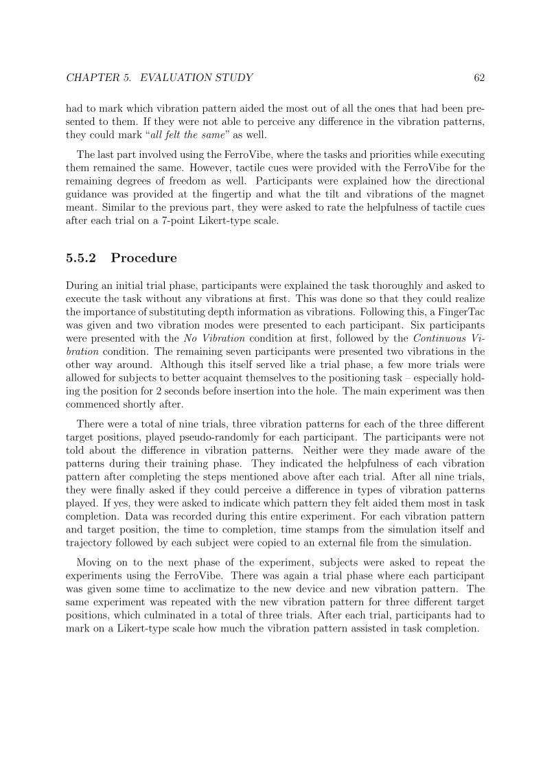
CHAPTER 5. EVALUATION STUDY 62
had to mark which vibration pattern aided the most out of all the ones that had been pre-sented to them. If they were not able to perceive any difference in the vibration patterns,they could mark “all felt the same” as well.
The last part involved using the FerroVibe, where the tasks and priorities while executingthem remained the same. However, tactile cues were provided with the FerroVibe for theremaining degrees of freedom as well. Participants were explained how the directionalguidance was provided at the fingertip and what the tilt and vibrations of the magnetmeant. Similar to the previous part, they were asked to rate the helpfulness of tactile cuesafter each trial on a 7-point Likert-type scale.
5.5.2 Procedure
During an initial trial phase, participants were explained the task thoroughly and asked toexecute the task without any vibrations at first. This was done so that they could realizethe importance of substituting depth information as vibrations. Following this, a FingerTacwas given and two vibration modes were presented to each participant. Six participantswere presented with the No Vibration condition at first, followed by the Continuous Vi-bration condition. The remaining seven participants were presented two vibrations in theother way around. Although this itself served like a trial phase, a few more trials wereallowed for subjects to better acquaint themselves to the positioning task – especially hold-ing the position for 2 seconds before insertion into the hole. The main experiment was thencommenced shortly after.
There were a total of nine trials, three vibration patterns for each of the three differenttarget positions, played pseudo-randomly for each participant. The participants were nottold about the difference in vibration patterns. Neither were they made aware of thepatterns during their training phase. They indicated the helpfulness of each vibrationpattern after completing the steps mentioned above after each trial. After all nine trials,they were finally asked if they could perceive a difference in types of vibration patternsplayed. If yes, they were asked to indicate which pattern they felt aided them most in taskcompletion. Data was recorded during this entire experiment. For each vibration patternand target position, the time to completion, time stamps from the simulation itself andtrajectory followed by each subject were copied to an external file from the simulation.
Moving on to the next phase of the experiment, subjects were asked to repeat theexperiments using the FerroVibe. There was again a trial phase where each participantwas given some time to acclimatize to the new device and new vibration pattern. Thesame experiment was repeated with the new vibration pattern for three different targetpositions, which culminated in a total of three trials. After each trial, participants had tomark on a Likert-type scale how much the vibration pattern assisted in task completion.
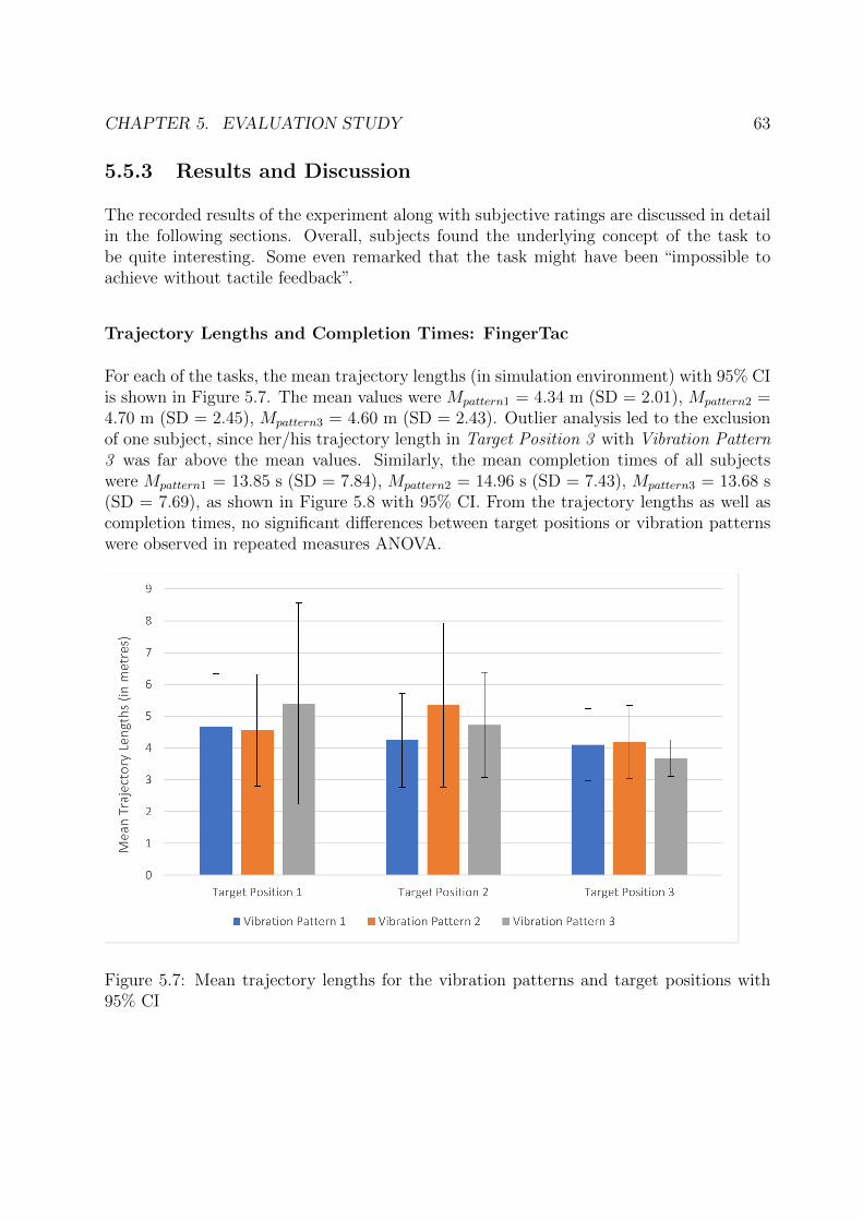
CHAPTER 5. EVALUATION STUDY 63
5.5.3 Results and Discussion
The recorded results of the experiment along with subjective ratings are discussed in detailin the following sections. Overall, subjects found the underlying concept of the task tobe quite interesting. Some even remarked that the task might have been “impossible toachieve without tactile feedback”.
Trajectory Lengths and Completion Times: FingerTac
For each of the tasks, the mean trajectory lengths (in simulation environment) with 95% CIis shown in Figure 5.7. The mean values were Mpattern1 = 4.34 m (SD = 2.01), Mpattern2 =4.70 m (SD = 2.45), Mpattern3 = 4.60 m (SD = 2.43). Outlier analysis led to the exclusionof one subject, since her/his trajectory length in Target Position 3 with Vibration Pattern3 was far above the mean values. Similarly, the mean completion times of all subjectswere Mpattern1 = 13.85 s (SD = 7.84), Mpattern2 = 14.96 s (SD = 7.43), Mpattern3 = 13.68 s(SD = 7.69), as shown in Figure 5.8 with 95% CI. From the trajectory lengths as well ascompletion times, no significant differences between target positions or vibration patternswere observed in repeated measures ANOVA.
Figure 5.7: Mean trajectory lengths for the vibration patterns and target positions with95% CI
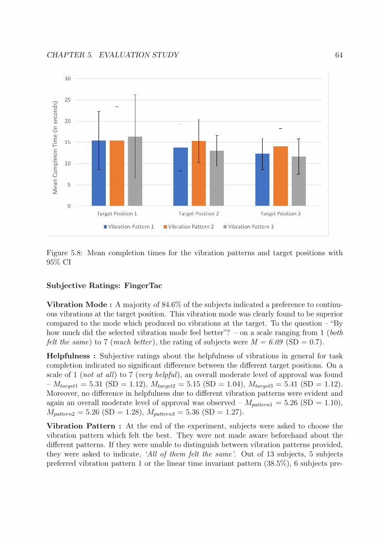
CHAPTER 5. EVALUATION STUDY 64
Figure 5.8: Mean completion times for the vibration patterns and target positions with95% CI
Subjective Ratings: FingerTac
Vibration Mode : A majority of 84.6% of the subjects indicated a preference to continu-ous vibrations at the target position. This vibration mode was clearly found to be superiorcompared to the mode which produced no vibrations at the target. To the question – “Byhow much did the selected vibration mode feel better”? – on a scale ranging from 1 (bothfelt the same) to 7 (much better), the rating of subjects were M = 6.09 (SD = 0.7).
Helpfulness : Subjective ratings about the helpfulness of vibrations in general for taskcompletion indicated no significant difference between the different target positions. On ascale of 1 (not at all) to 7 (very helpful), an overall moderate level of approval was found– Mtarget1 = 5.31 (SD = 1.12), Mtarget2 = 5.15 (SD = 1.04), Mtarget3 = 5.41 (SD = 1.12).Moreover, no difference in helpfulness due to different vibration patterns were evident andagain an overall moderate level of approval was observed – Mpattern1 = 5.26 (SD = 1.10),Mpattern2 = 5.26 (SD = 1.28), Mpattern3 = 5.36 (SD = 1.27).
Vibration Pattern : At the end of the experiment, subjects were asked to choose thevibration pattern which felt the best. They were not made aware beforehand about thedifferent patterns. If they were unable to distinguish between vibration patterns provided,they were asked to indicate, ‘All of them felt the same’. Out of 13 subjects, 5 subjectspreferred vibration pattern 1 or the linear time invariant pattern (38.5%), 6 subjects pre-
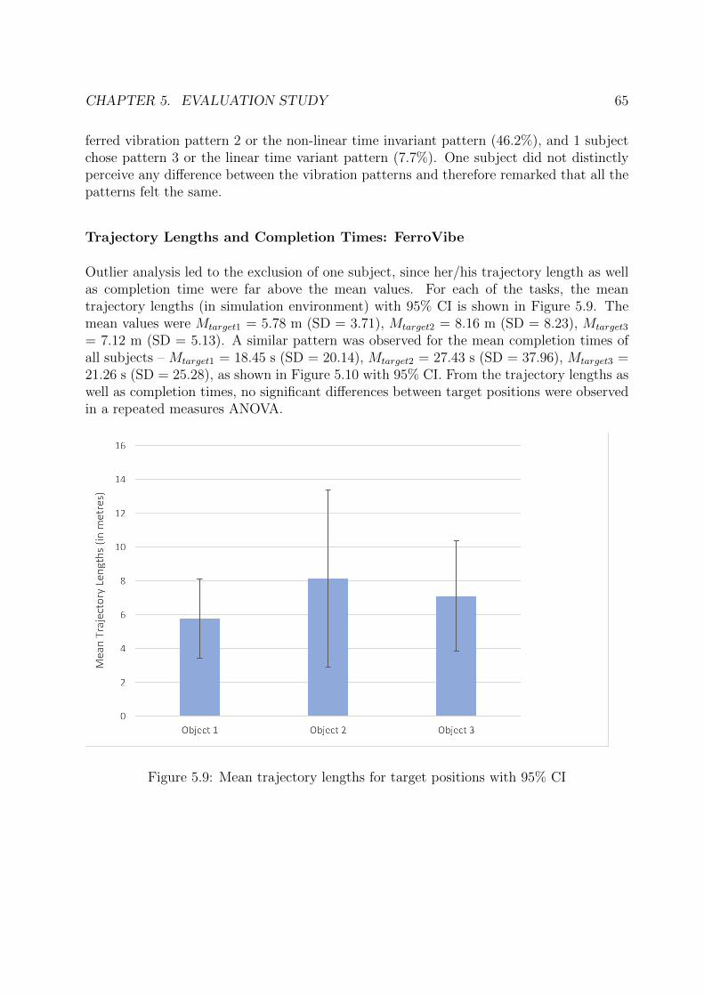
CHAPTER 5. EVALUATION STUDY 65
ferred vibration pattern 2 or the non-linear time invariant pattern (46.2%), and 1 subjectchose pattern 3 or the linear time variant pattern (7.7%). One subject did not distinctlyperceive any difference between the vibration patterns and therefore remarked that all thepatterns felt the same.
Trajectory Lengths and Completion Times: FerroVibe
Outlier analysis led to the exclusion of one subject, since her/his trajectory length as wellas completion time were far above the mean values. For each of the tasks, the meantrajectory lengths (in simulation environment) with 95% CI is shown in Figure 5.9. Themean values were Mtarget1 = 5.78 m (SD = 3.71), Mtarget2 = 8.16 m (SD = 8.23), Mtarget3
= 7.12 m (SD = 5.13). A similar pattern was observed for the mean completion times ofall subjects – Mtarget1 = 18.45 s (SD = 20.14), Mtarget2 = 27.43 s (SD = 37.96), Mtarget3 =21.26 s (SD = 25.28), as shown in Figure 5.10 with 95% CI. From the trajectory lengths aswell as completion times, no significant differences between target positions were observedin a repeated measures ANOVA.
Figure 5.9: Mean trajectory lengths for target positions with 95% CI
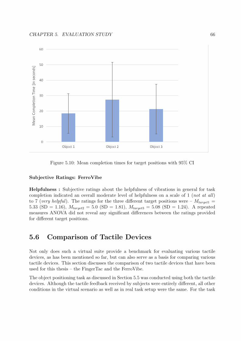
CHAPTER 5. EVALUATION STUDY 66
Figure 5.10: Mean completion times for target positions with 95% CI
Subjective Ratings: FerroVibe
Helpfulness : Subjective ratings about the helpfulness of vibrations in general for taskcompletion indicated an overall moderate level of helpfulness on a scale of 1 (not at all)to 7 (very helpful). The ratings for the three different target positions were – Mtarget1 =5.33 (SD = 1.16), Mtarget2 = 5.0 (SD = 1.81), Mtarget3 = 5.08 (SD = 1.24). A repeatedmeasures ANOVA did not reveal any significant differences between the ratings providedfor different target positions.
5.6 Comparison of Tactile Devices
Not only does such a virtual suite provide a benchmark for evaluating various tactiledevices, as has been mentioned so far, but can also serve as a basis for comparing varioustactile devices. This section discusses the comparison of two tactile devices that have beenused for this thesis – the FingerTac and the FerroVibe.
The object positioning task as discussed in Section 5.5 was conducted using both the tactiledevices. Although the tactile feedback received by subjects were entirely different, all otherconditions in the virtual scenario as well as in real task setup were the same. For the task
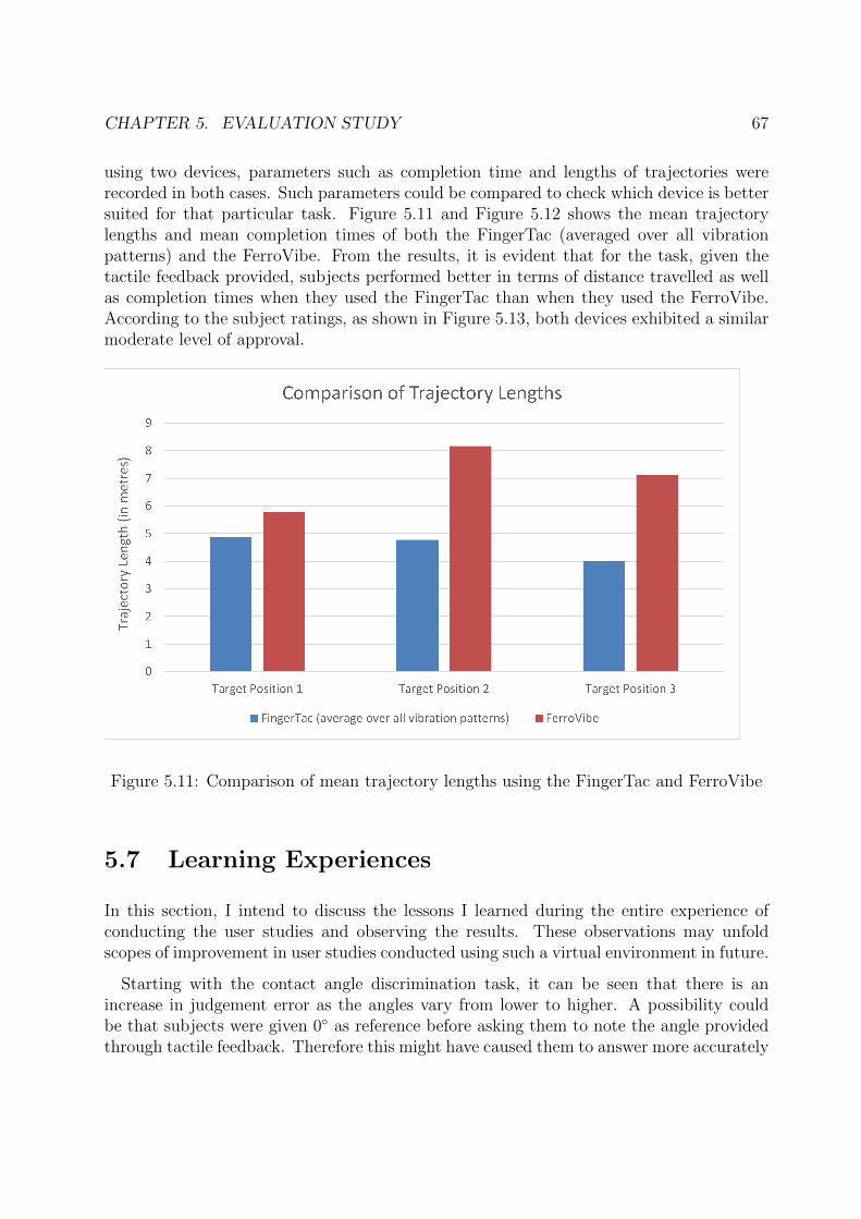
CHAPTER 5. EVALUATION STUDY 67
using two devices, parameters such as completion time and lengths of trajectories wererecorded in both cases. Such parameters could be compared to check which device is bettersuited for that particular task. Figure 5.11 and Figure 5.12 shows the mean trajectorylengths and mean completion times of both the FingerTac (averaged over all vibrationpatterns) and the FerroVibe. From the results, it is evident that for the task, given thetactile feedback provided, subjects performed better in terms of distance travelled as wellas completion times when they used the FingerTac than when they used the FerroVibe.According to the subject ratings, as shown in Figure 5.13, both devices exhibited a similarmoderate level of approval.
Figure 5.11: Comparison of mean trajectory lengths using the FingerTac and FerroVibe
5.7 Learning Experiences
In this section, I intend to discuss the lessons I learned during the entire experience ofconducting the user studies and observing the results. These observations may unfoldscopes of improvement in user studies conducted using such a virtual environment in future.
Starting with the contact angle discrimination task, it can be seen that there is anincrease in judgement error as the angles vary from lower to higher. A possibility couldbe that subjects were given 0◦ as reference before asking them to note the angle providedthrough tactile feedback. Therefore this might have caused them to answer more accurately
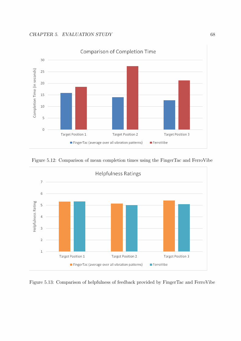
CHAPTER 5. EVALUATION STUDY 68
Figure 5.12: Comparison of mean completion times using the FingerTac and FerroVibe
Figure 5.13: Comparison of helpfulness of feedback provided by FingerTac and FerroVibe
CHAPTER 5. EVALUATION STUDY 69
for lower angles. If the extreme ± 90◦ angles were provided additionally as reference,then the chances of higher angles being accurate might have been more. For the texturediscrimination task, subjects could have been explicitly asked to use two different fingersfor the two sub-tasks. This could have let to better perception of frequencies in case certainsubjects felt slight numbness at their fingertip after the first sub-task.
Finally, in the object positioning task, subjects could have been mentioned or askedabout the different vibration patterns as was done in case of the vibration modes beforethe start of the series of tasks. This might have led to subjects having a more conscious anddistinct perception of the different vibration patterns. The task conducted with FerroVibecould have been designed a bit differently, since the tactile feedback was provided in threedegrees of freedom. Especially for comparison of the two devices in this virtual scenario,both the devices should have been tested under the same conditions, i.e. changing PWMvibration patterns along the depth of the scene. This might have led to a fairer comparisonof the two devices. Furthermore, the order of devices used during these tasks was notcounterbalanced across subjects, which likely resulted in learning effects. Hence, a directstatistical comparison of both devices was not appropriate under the given circumstances.

Chapter 6
Conclusion and Future Work
This chapter wraps up the thesis by summarizing the important contributions and obser-vations made throughout. Followed by the conclusions, ideas and scopes are presented forpossible extensions and improvement of this work in future.
6.1 Conclusion
The thesis discusses the design and development of a generic virtual reality suite ViESTac,dedicated primarily for the purpose of assessing and comparing tactile devices. A thoroughbackground survey of existing tactile devices and virtual reality applications developed byresearchers in literature so far has been discussed, thereby highlighting the requisite andmotivation supporting this thesis. Two virtual reality applications and each individualscenario of the two environments have been discussed elaborately, specifying exact compo-nents and their dimensions in detail. This makes it possible for any researcher to recreatethese virtual environments easily and tune it to their necessities. Furthermore, the tasksin each virtual environment have been chosen such that there is no underlying bias to aparticular tactile device display capabilities. This makes it generic for any tactile device.
As a proof-of-concept, two distinct novel tactile devices – FingerTac and FerroVibe – havebeen integrated into this virtual suite and tested extensively. Evaluation studies conductedwith 13 participants indicate that using the FerroVibe and this virtual suite, users candifferentiate between a wide range of contact point orientations of virtual objects in scenequite accurately with moderately less variance. The FerroVibe can also display differenttexture frequencies assigned to ground planes in a virtual scenario. These frequencies areeasily distinguishable if they are chosen at larger intervals, and less so if chosen at smallerintervals. It has further been established that these devices can successfully encode stiffnessinformation in terms of PWM vibration signals. The studies also demonstrated that tactilefeedback from these devices can be used to substitute visual depth information in virtual
CHAPTER 6. CONCLUSION AND FUTURE WORK 72
scenes, thereby supporting positioning in standard pick-and-place, peg-in-hole or tracingtasks. Therefore, the working of tactile devices can be validated through such a VR suite.Finally, two tactile devices under similar task environments and providing similar feedback,can be compared for performance accuracy, performance time, wearability comfort, tactileperception, and so on.
The virtual environments presented in this VR suite can be easily used by anyone havinglittle or no experience with VR and tactile devices. There are prospects of improvementand further extension, which are discussed in the following section.
6.2 Future Work
There are a number of grounds on which this virtual reality suite may be extended orimproved. They are listed as follows:
• Additional Scenarios: for tactile devices capable of stimulating additional proper-ties, e.g., fluid sensations, some additional scenarios may be designed, which containfluid interactions. Some extra scenes could be added which simulate suitable virtualobjects, like fire or ice, to render temperature properties, and so on.
• HMD Display: currently, the virtual reality simulation is only visualized on ascreen. There are a number of head mounted displays such as the Occulus or HTCVive, which may be integrated to visualize the simulation wearing those. It may leadto a more immersive experience. In-built tracking could be used for tracking handsand estimating finger position and orientation, or using a Leap Motion controllerattached to the HMDs.
• Multi-point Interaction: the virtual environment designed as a part of this thesisconsists of only one HIP, which represents the tactile device worn on one finger. Thiscan be extended to replace the single HIP with multiple HIPs which could representtactile devices worn on two or more fingers. In general, a virtual hand avatar can bedesigned in CHAI3D for better visual interaction [111].
• Aesthetics and Audio: overall aesthetics of each of the scenario may be improvedto increase perceived realism. Suitable backgrounds can be added to each of thescenes, with matching audio for task descriptions and added effects. All of thesecan be integrated to increase user immersiveness into a single, phenomenal virtualenvironment.
Overall, it can be deduced that ViESTac provides a propitious solution towards a firstapproach at creating a generic multimodal VR suite for tactile devices. Future workssuggested indicate improvements for increased realism and user immersion, which wouldfurther promote extensive usability in research and development.
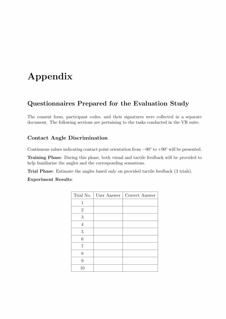
Appendix
Questionnaires Prepared for the Evaluation Study
The consent form, participant codes, and their signatures were collected in a separatedocument. The following sections are pertaining to the tasks conducted in the VR suite.
Contact Angle Discrimination
Continuous values indicating contact point orientation from−90◦ to +90◦ will be presented.
Training Phase: During this phase, both visual and tactile feedback will be provided tohelp familiarize the angles and the corresponding sensations.
Trial Phase: Estimate the angles based only on provided tactile feedback (3 trials).
Experiment Results:
Trial No. User Answer Correct Answer
1
2
3
4
5
6
7
8
9
10
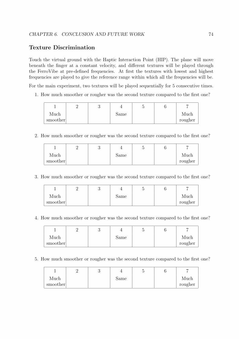
CHAPTER 6. CONCLUSION AND FUTURE WORK 74
Texture Discrimination
Touch the virtual ground with the Haptic Interaction Point (HIP). The plane will movebeneath the finger at a constant velocity, and different textures will be played throughthe FerroVibe at pre-defined frequencies. At first the textures with lowest and highestfrequencies are played to give the reference range within which all the frequencies will be.
For the main experiment, two textures will be played sequentially for 5 consecutive times.
1. How much smoother or rougher was the second texture compared to the first one?
1 2 3 4 5 6 7
Muchsmoother
Same Muchrougher
2. How much smoother or rougher was the second texture compared to the first one?
1 2 3 4 5 6 7
Muchsmoother
Same Muchrougher
3. How much smoother or rougher was the second texture compared to the first one?
1 2 3 4 5 6 7
Muchsmoother
Same Muchrougher
4. How much smoother or rougher was the second texture compared to the first one?
1 2 3 4 5 6 7
Muchsmoother
Same Muchrougher
5. How much smoother or rougher was the second texture compared to the first one?
1 2 3 4 5 6 7
Muchsmoother
Same Muchrougher
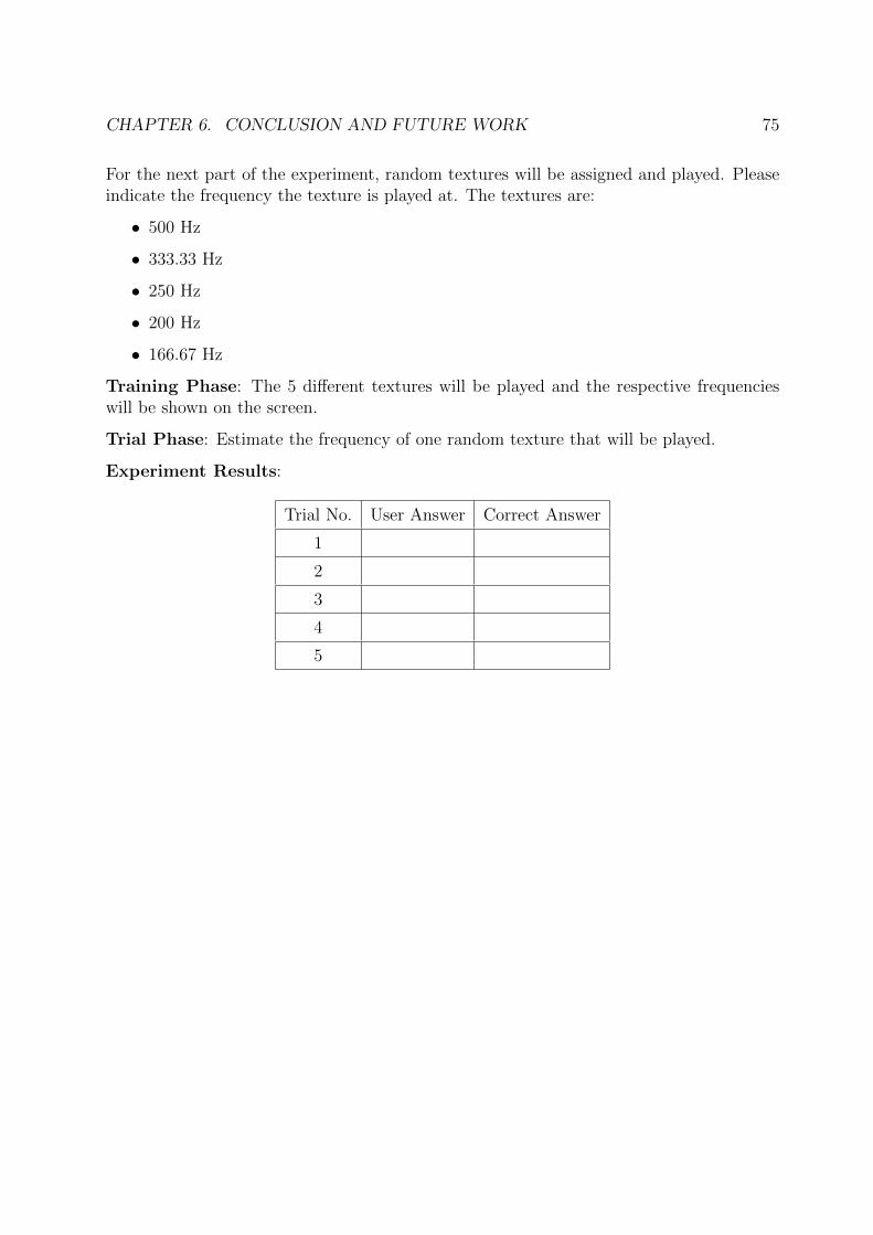
CHAPTER 6. CONCLUSION AND FUTURE WORK 75
For the next part of the experiment, random textures will be assigned and played. Pleaseindicate the frequency the texture is played at. The textures are:
• 500 Hz
• 333.33 Hz
• 250 Hz
• 200 Hz
• 166.67 Hz
Training Phase: The 5 different textures will be played and the respective frequencieswill be shown on the screen.
Trial Phase: Estimate the frequency of one random texture that will be played.
Experiment Results:
Trial No. User Answer Correct Answer
1
2
3
4
5
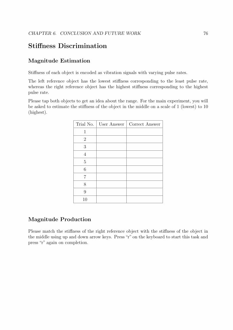
CHAPTER 6. CONCLUSION AND FUTURE WORK 76
Stiffness Discrimination
Magnitude Estimation
Stiffness of each object is encoded as vibration signals with varying pulse rates.
The left reference object has the lowest stiffness corresponding to the least pulse rate,whereas the right reference object has the highest stiffness corresponding to the highestpulse rate.
Please tap both objects to get an idea about the range. For the main experiment, you willbe asked to estimate the stiffness of the object in the middle on a scale of 1 (lowest) to 10(highest).
Trial No. User Answer Correct Answer
1
2
3
4
5
6
7
8
9
10
Magnitude Production
Please match the stiffness of the right reference object with the stiffness of the object inthe middle using up and down arrow keys. Press “r” on the keyboard to start this task andpress “r” again on completion.
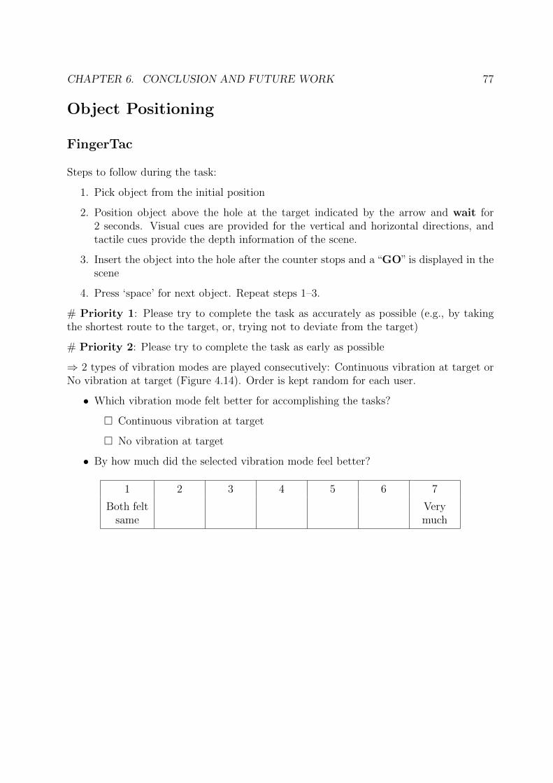
CHAPTER 6. CONCLUSION AND FUTURE WORK 77
Object Positioning
FingerTac
Steps to follow during the task:
1. Pick object from the initial position
2. Position object above the hole at the target indicated by the arrow and wait for2 seconds. Visual cues are provided for the vertical and horizontal directions, andtactile cues provide the depth information of the scene.
3. Insert the object into the hole after the counter stops and a “GO” is displayed in thescene
4. Press ‘space’ for next object. Repeat steps 1–3.
# Priority 1: Please try to complete the task as accurately as possible (e.g., by takingthe shortest route to the target, or, trying not to deviate from the target)
# Priority 2: Please try to complete the task as early as possible
⇒ 2 types of vibration modes are played consecutively: Continuous vibration at target orNo vibration at target (Figure 4.14). Order is kept random for each user.
• Which vibration mode felt better for accomplishing the tasks?
□ Continuous vibration at target
□ No vibration at target
• By how much did the selected vibration mode feel better?
1 2 3 4 5 6 7
Both feltsame
Verymuch
CHAPTER 6. CONCLUSION AND FUTURE WORK 78
⇒ The same task is now repeated for 3 different vibration patterns. The vibration patternswill be explained by the experimenter (Section 4.2.2) supported by pictures. (Figures 4.15,Figure 4.16 and Figure 4.17)
Training Phase: Please execute the task with two objects for getting familiarized beforebeginning the experiment.
Experiment Results: Please mark the helpfulness of tactile feedback after executingeach task.
1. Target Position: Vibration Pattern:
How helpful was the vibration pattern in achieving the task?
1 2 3 4 5 6 7
Not atall
Verymuch
2. Target Position: Vibration Pattern:
How helpful was the vibration pattern in achieving the task?
1 2 3 4 5 6 7
Not atall
Verymuch
Repeat for 9 times in total
General Question:
Which pattern aided the most in achieving the task?
□ Pattern 1 (Linear Time Invariant)
□ Pattern 2 (Non-linear Time Invariant)
□ Pattern 3 (Linear Time Variant)
□ All of them felt the same
CHAPTER 6. CONCLUSION AND FUTURE WORK 79
FerroVibe
Steps to follow during the task:
1. Pick object from the initial position
2. Position object above the hole at the target indicated by the arrow and wait for2 seconds. Visual cues are provided for the vertical and horizontal directions, andtactile cues provide the depth information of the scene.
3. Insert the object into the hole after the counter stops and a “GO” is displayed in thescene
4. Press ‘space’ for next object. Repeat steps 1–3.
# Priority 1: Please try to complete the task as accurately as possible (e.g., by takingthe shortest route to the target, or, trying not to deviate from the target)
# Priority 2: Please try to complete the task as early as possible
For this task, directional guidance will be provided by magnet tilt for horizontal (left/right)and depth (front/back) dimensions, in addition to pulse width modulated vibration signalsfor vertical (up/down) dimension. If the target is towards the front, you will feel themagnet pushing your fingertip from the back and vice versa (depth). If the target istowards the left, you will feel the magnet pushing your fingertip from the right and viceversa (horizontal) (Figure 4.20). Finally, the vertical distance to the target is encoded asvibrations, i.e. increasing pulse rates as the target is approached (Figure 4.19).
Experiment Results: Please mark the helpfulness of tactile feedback after executingeach task.
1. Target Position: Vibration Pattern:
How helpful was the vibration pattern in achieving the task?
1 2 3 4 5 6 7
Not atall
Verymuch
Repeat for 3 times in total
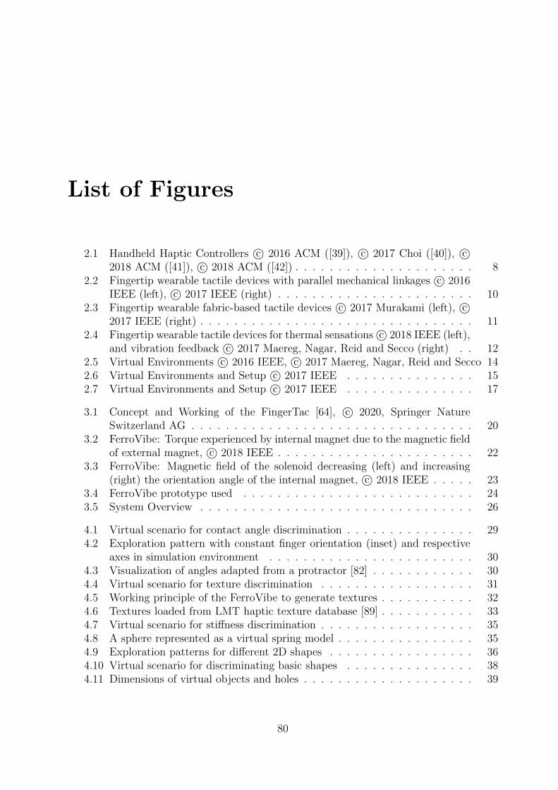
List of Figures
2.1 Handheld Haptic Controllers c⃝ 2016 ACM ([39]), c⃝ 2017 Choi ([40]), c⃝2018 ACM ([41]), c⃝ 2018 ACM ([42]) . . . . . . . . . . . . . . . . . . . . . 8
2.2 Fingertip wearable tactile devices with parallel mechanical linkages c⃝ 2016IEEE (left), c⃝ 2017 IEEE (right) . . . . . . . . . . . . . . . . . . . . . . . 10
2.3 Fingertip wearable fabric-based tactile devices c⃝ 2017 Murakami (left), c⃝2017 IEEE (right) . . . . . . . . . . . . . . . . . . . . . . . . . . . . . . . . 11
2.4 Fingertip wearable tactile devices for thermal sensations c⃝ 2018 IEEE (left),and vibration feedback c⃝ 2017 Maereg, Nagar, Reid and Secco (right) . . 12
2.5 Virtual Environments c⃝ 2016 IEEE, c⃝ 2017 Maereg, Nagar, Reid and Secco 142.6 Virtual Environments and Setup c⃝ 2017 IEEE . . . . . . . . . . . . . . . 152.7 Virtual Environments and Setup c⃝ 2017 IEEE . . . . . . . . . . . . . . . 17
3.1 Concept and Working of the FingerTac [64], c⃝ 2020, Springer NatureSwitzerland AG . . . . . . . . . . . . . . . . . . . . . . . . . . . . . . . . . 20
3.2 FerroVibe: Torque experienced by internal magnet due to the magnetic fieldof external magnet, c⃝ 2018 IEEE . . . . . . . . . . . . . . . . . . . . . . . 22
3.3 FerroVibe: Magnetic field of the solenoid decreasing (left) and increasing(right) the orientation angle of the internal magnet, c⃝ 2018 IEEE . . . . . 23
3.4 FerroVibe prototype used . . . . . . . . . . . . . . . . . . . . . . . . . . . 243.5 System Overview . . . . . . . . . . . . . . . . . . . . . . . . . . . . . . . . 26
4.1 Virtual scenario for contact angle discrimination . . . . . . . . . . . . . . . 294.2 Exploration pattern with constant finger orientation (inset) and respective
axes in simulation environment . . . . . . . . . . . . . . . . . . . . . . . . 304.3 Visualization of angles adapted from a protractor [82] . . . . . . . . . . . . 304.4 Virtual scenario for texture discrimination . . . . . . . . . . . . . . . . . . 314.5 Working principle of the FerroVibe to generate textures . . . . . . . . . . . 324.6 Textures loaded from LMT haptic texture database [89] . . . . . . . . . . . 334.7 Virtual scenario for stiffness discrimination . . . . . . . . . . . . . . . . . . 354.8 A sphere represented as a virtual spring model . . . . . . . . . . . . . . . . 354.9 Exploration patterns for different 2D shapes . . . . . . . . . . . . . . . . . 364.10 Virtual scenario for discriminating basic shapes . . . . . . . . . . . . . . . 384.11 Dimensions of virtual objects and holes . . . . . . . . . . . . . . . . . . . . 39
80
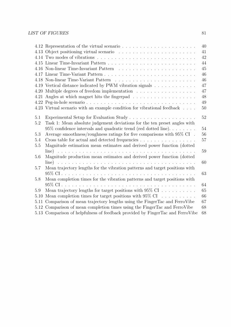
LIST OF FIGURES 81
4.12 Representation of the virtual scenario . . . . . . . . . . . . . . . . . . . . . 404.13 Object positioning virtual scenario . . . . . . . . . . . . . . . . . . . . . . 414.14 Two modes of vibrations . . . . . . . . . . . . . . . . . . . . . . . . . . . . 424.15 Linear Time-Invariant Pattern . . . . . . . . . . . . . . . . . . . . . . . . . 444.16 Non-linear Time-Invariant Pattern . . . . . . . . . . . . . . . . . . . . . . 454.17 Linear Time-Variant Pattern . . . . . . . . . . . . . . . . . . . . . . . . . . 464.18 Non-linear Time-Variant Pattern . . . . . . . . . . . . . . . . . . . . . . . 464.19 Vertical distance indicated by PWM vibration signals . . . . . . . . . . . . 474.20 Multiple degrees of freedom implementation . . . . . . . . . . . . . . . . . 474.21 Angles at which magnet hits the fingerpad . . . . . . . . . . . . . . . . . . 484.22 Peg-in-hole scenario . . . . . . . . . . . . . . . . . . . . . . . . . . . . . . . 494.23 Virtual scenario with an example condition for vibrational feedback . . . . 50
5.1 Experimental Setup for Evaluation Study . . . . . . . . . . . . . . . . . . . 525.2 Task 1: Mean absolute judgement deviations for the ten preset angles with
95% confidence intervals and quadratic trend (red dotted line). . . . . . . . 545.3 Average smoothness/roughness ratings for five comparisons with 95% CI . 565.4 Cross table for actual and detected frequencies . . . . . . . . . . . . . . . . 575.5 Magnitude estimation mean estimates and derived power function (dotted
line) . . . . . . . . . . . . . . . . . . . . . . . . . . . . . . . . . . . . . . . 595.6 Magnitude production mean estimates and derived power function (dotted
line) . . . . . . . . . . . . . . . . . . . . . . . . . . . . . . . . . . . . . . . 605.7 Mean trajectory lengths for the vibration patterns and target positions with
95% CI . . . . . . . . . . . . . . . . . . . . . . . . . . . . . . . . . . . . . . 635.8 Mean completion times for the vibration patterns and target positions with
95% CI . . . . . . . . . . . . . . . . . . . . . . . . . . . . . . . . . . . . . . 645.9 Mean trajectory lengths for target positions with 95% CI . . . . . . . . . . 655.10 Mean completion times for target positions with 95% CI . . . . . . . . . . 665.11 Comparison of mean trajectory lengths using the FingerTac and FerroVibe 675.12 Comparison of mean completion times using the FingerTac and FerroVibe 685.13 Comparison of helpfulness of feedback provided by FingerTac and FerroVibe 68
List of Tables
2.1 Types of Skin Receptors [36] . . . . . . . . . . . . . . . . . . . . . . . . . . 72.2 An overview of existing handheld and wearable tactile devices . . . . . . . 13
3.1 System Specifications of the FingerTac [64] . . . . . . . . . . . . . . . . . . 203.2 System Specifications of the FerroVibe [62] . . . . . . . . . . . . . . . . . . 23
82
Bibliography
[1] Lena Geiger, Michael Popp, Berthold Faerber, Jordi Artigas, and Philipp Kremer.The influence of telemanipulation-systems on fine motor performance. In 2010 ThirdInternational Conference on Advances in Computer-Human Interactions, pages 44–49, 2010.
[2] B.J. Unger, A. Nicolaidis, P.J. Berkelman, A. Thompson, S. Lederman, R.L. Klatzky,and R.L. Hollis. Virtual peg-in-hole performance using a 6-dof magnetic levitationhaptic device: comparison with real forces and with visual guidance alone. In Proceed-ings 10th Symposium on Haptic Interfaces for Virtual Environment and TeleoperatorSystems. HAPTICS 2002, pages 263–270, 2002.
[3] Prateek Dwivedi, David Cline, Joe Cecil, and Ronak Etemadpour. Manual assemblytraining in virtual environments. 07 2018.
[4] Colin Ware and Ravin Balakrishnan. Reaching for objects in vr displays: Lag andframe rate. ACM Trans. Comput.-Hum. Interact., 1(4):331a356, dec 1994.
[5] M.J. Massimino, T.B. Sheridan, and J.B. Roseborough. One handed tracking in sixdegrees of freedom. In Conference Proceedings., IEEE International Conference onSystems, Man and Cybernetics, pages 498–503 vol.2, 1989.
[6] Marwan Radi and Verena Nitsch. Telepresence in industrial applications: Implemen-tation issues for assembly tasks. Presence, 19(5):415–429, 2010.
[7] M. Tavakoli, R. V. Patel, and M. Moallem. Haptic feedback and sensory substitu-tion during telemanipulated suturing. In In Proceedings of the IEEE World HapticsConference, pages 543–544, 2005.
[8] Rafael Aracil, Martin Buss, Salvador Cobos, Manuel Ferre, Sandra Hirche, MartinKuschel, and Angelika Peer. The Human Role in Telerobotics, volume 31, pages11–24. 10 2007.
[9] Jacob Rosen, Blake Hannaford, and Richard M. Satava. Surgical robotics : systems,applications and visions. 2011.
83
BIBLIOGRAPHY 84
[10] Xiaoli Yang, Qing Chen, D.C. Petriu, and E.M. Petriu. Internet-based teleoperationof a robot manipulator for education. In The 3rd IEEE International Workshop onHaptic, Audio and Visual Environments and Their Applications, pages 7–11, 2004.
[11] K. Kawamura and M. Iskarous. Trends in service robots for the disabled and theelderly. In Proceedings of IEEE/RSJ International Conference on Intelligent Robotsand Systems (IROS’94), volume 3, pages 1647–1654 vol.3, 1994.
[12] M. Utsumi, T. Hirabayashi, and M. Yoshie. Development for teleoperation underwa-ter grasping system in unclear environment. In Proceedings of the 2002 InterntionalSymposium on Underwater Technology (Cat. No.02EX556), pages 349–353, 2002.
[13] Oleg Gerovich, Panadda Marayong, and Allison Okamura. The effect of visual andhaptic feedback on computer-assisted needle insertion. Computer aided surgery :official journal of the International Society for Computer Aided Surgery, 9:243–9, 022004.
[14] Eva-Lotta Sallnas and Shumin Zhai. Collaboration meets fitts’ law: Passing virtualobjects with and without haptic force feedback. 01 2003.
[15] Francois Conti, Federico Barbagli, Dan Morris, and Christopher Sewell. CHAI: Anopen-source library for the rapid development of haptic scenes. In IEEE WorldHaptics Conference (WHC), volume 38, 2005.
[16] https://www.ultraleap.com/tracking/. Accessed: 2021-11-24.
[17] https://en.wikipedia.org/wiki/Haptic_technology. Accessed: 2021-11-23.
[18] K. Salisbury, D. Brock, T. Massie, N. Swarup, and C. Zilles. Haptic rendering: pro-gramming touch interaction with virtual objects. In SI3D ’95: Symp. on Interactive3D graphics, pages 123–130, Monterey, California, United States, 1995.
[19] Ernesto Granado, Flavio Quizhpi, Julio Zambrano, and William Colmenares. Remoteexperimentation using a smartphone application with haptic feedback. In 2016 IEEEGlobal Engineering Education Conference (EDUCON), pages 240–247, 2016.
[20] F. J. Gonzalez-Canete, J. L. Lopez Rodriguez, P. M. Galdon, and A. Diaz-Estrella.Improvements in the learnability of smartphone haptic interfaces for visually impairedusers. PLOS ONE, 14(11):1–21, 11 2019.
[21] Tobias Hermann., Andreas Burkard., and Stefan Radicke. Virtual reality controllerwith directed haptic feedback to increase immersion. In Proceedings of the 15th In-ternational Joint Conference on Computer Vision, Imaging and Computer GraphicsTheory and Applications - HUCAPP,, pages 203–210. INSTICC, SciTePress, 2020.
[22] Ping-Hsuan Han, Yang-Sheng Chen, Kai-Ti Yang, Wei-Shu Chuan, Yu-Tong Chang,Tin-Ming Yang, Jia-Yan Lin, Kong-Chang Lee, Chiao-En Hsieh, Lai-Chung Lee,Chien-Hsing Chou, and Yi-Ping Hung. Boes: Attachable haptics bits on gaming
BIBLIOGRAPHY 85
controller for designing interactive gameplay. In SIGGRAPH Asia 2017 VR Show-case, SA ’17, New York, NY, USA, 2017. Association for Computing Machinery.
[23] Yoren Gaffary and Anatole Lecuyer. The use of haptic and tactile information in thecar to improve driving safety: A review of current technologies. Frontiers in ICT,5:5, 2018.
[24] Dagmar Kern and Bastian Pfleging. Supporting interaction through haptic feedbackin automotive user interfaces. Interactions, 20(2):16a21, mar 2013.
[25] Orestis Georgiou, Hannah Limerick, Loıc Corenthy, Mark Perry, Mykola Maksy-menko, Sam Frish, Jorg Muller, Myroslav Bachynskyi, and Jin Ryong Kim. Mid-airhaptic interfaces for interactive digital signage and kiosks. In Extended Abstracts ofthe 2019 CHI Conference on Human Factors in Computing Systems, CHI EA ’19,page 1a9, New York, NY, USA, 2019. Association for Computing Machinery.
[26] Rainer Konietschke, Ulrich Hagn, Mathias Nickl, Stefan Jorg, Andreas Tobergte,Georg Passig, Ulrich Seibold, Luc Le-Tien, Bernhard Kubler, Martin Groger, FlorianFrohlich, Christian Rink, Alin Albu-Schaffer, Markus Grebenstein, Tobias Ortmaier,and Gerd Hirzinger. The dlr mirosurge - a robotic system for surgery. In 2009 IEEEInternational Conference on Robotics and Automation, pages 1589–1590, 2009.
[27] Aude Bolopion, Guillaume Millet, Cecile Pacoret, and Stephane Regnier. Hapticfeedback in teleoperation in micro- and nanoworlds. Reviews of Human Factors andErgonomics, 9(1):57–93, 2013.
[28] Alexis E. Block and Katherine J. Kuchenbecker. Softness, warmth, and respon-siveness improve robot hugs. International Journal of Social Robotics, 11(1):49–64,October 2018.
[29] Vera Zasulich Perez Ariza and Mauricio Santıs-Chaves. Interfaces Hapticas: SistemasCinestesicos vs. Sistemas Tactiles. Revista EIA, pages 13 – 29, 12 2016.
[30] Shantonu Biswas and Yon Visell. Haptic perception, mechanics, and material tech-nologies for virtual reality. Advanced Functional Materials, 31(39):2008186, 2021.
[31] Michael E. Abbott, Joshua D. Fajardo, H.W. Lim, and Hannah S. Stuart. Kines-thetic feedback improves grasp performance in cable-driven prostheses. In 2021 IEEEInternational Conference on Robotics and Automation (ICRA), pages 10551–10557,2021.
[32] Marco Aggravi, Daniel A. L. Estima, Alexandre Krupa, Sarthak Misra, and Clau-dio Pacchierotti. Haptic teleoperation of flexible needles combining 3d ultrasoundguidance and needle tip force feedback. IEEE Robotics and Automation Letters,6(3):4859–4866, 2021.
[33] Thomas Hulin, Michael Panzirsch, Harsimran Singh, Andre Coelho, Ribin Balachan-dran, Aaron Pereira, Bernhard M. Weber, Nicolai Bechtel, Cornelia Riecke, Bern-
BIBLIOGRAPHY 86
hard Brunner, Neal Y. Lii, Julian Klodmann, Anja Hellings, Katharina Hagmann,Gabriel Quere, Adrian S. Bauer, Marek Sierotowicz, Roberto Lampariello, Jorn Vo-gel, Alexander Dietrich, Daniel Leidner, Christian Ott, Gerd Hirzinger, and AlinAlbu-Schaffer. Model-augmented haptic telemanipulation: Concept, retrospectiveoverview, and current use cases. Frontiers in Robotics and AI, 8:76, 2021.
[34] Sandra Hirche and Martin Buss. Human-oriented control for haptic teleoperation.Proceedings of the IEEE, 100(3):623–647, 2012.
[35] Joseph Feher. 4.3 - cutaneous sensory systems. In Joseph Feher, editor, QuantitativeHuman Physiology (Second Edition), pages 389–399. Academic Press, Boston, secondedition edition, 2012.
[36] David L. Felten, M. Kerry O’Banion, and Mary Summo Maida. 9 - peripheral nervoussystem. In David L. Felten, M. Kerry O’Banion, and Mary Summo Maida, editors,Netter’s Atlas of Neuroscience (Third Edition), pages 153–231. Elsevier, Philadel-phia, third edition edition, 2016.
[37] Shogo Okamoto, Hikaru Nagano, and Yoji Yamada. Psychophysical dimensions oftactile perception of textures. IEEE Transactions on Haptics, 6(1):81–93, 2013.
[38] Katherine J. Kuchenbecker, Jamie Gewirtz, William McMahan, Dorsey Standish,Paul Martin, Jonathan Bohren, Pierre J. Mendoza, and David I. Lee. Verrotouch:High-frequency acceleration feedback for telerobotic surgery. In Astrid M. L. Kap-pers, Jan B. F. van Erp, Wouter M. Bergmann Tiest, and Frans C. T. van der Helm,editors, Haptics: Generating and Perceiving Tangible Sensations, pages 189–196,Berlin, Heidelberg, 2010. Springer Berlin Heidelberg.
[39] Hrvoje Benko, Christian Holz, Mike Sinclair, and Eyal Ofek. Normaltouch and tex-turetouch: High-fidelity 3d haptic shape rendering on handheld virtual reality con-trollers. In Proceedings of the 29th Annual Symposium on User Interface Softwareand Technology, UIST ’16, page 717a728, New York, NY, USA, 2016. Association forComputing Machinery.
[40] Inrak Choi, Heather Culbertson, Mark R. Miller, Alex Olwal, and Sean Follmer. Gra-bity: A wearable haptic interface for simulating weight and grasping in virtual reality.In Proceedings of the 30th Annual ACM Symposium on User Interface Software andTechnology, UIST ’17, page 119a130, New York, NY, USA, 2017. Association forComputing Machinery.
[41] Inrak Choi, Eyal Ofek, Hrvoje Benko, Mike Sinclair, and Christian Holz. CLAW: AMultifunctional Handheld Haptic Controller for Grasping, Touching, and Triggeringin Virtual Reality, page 1a13. Association for Computing Machinery, New York, NY,USA, 2018.
[42] Eric Whitmire, Hrvoje Benko, Christian Holz, Eyal Ofek, and Mike Sinclair. HapticRevolver: Touch, Shear, Texture, and Shape Rendering on a Reconfigurable Virtual
BIBLIOGRAPHY 87
Reality Controller, page 1a12. Association for Computing Machinery, New York, NY,USA, 2018.
[43] Heather Culbertson and Katherine J. Kuchenbecker. Ungrounded haptic augmentedreality system for displaying roughness and friction. IEEE/ASME Transactions onMechatronics, 22(4):1839–1849, 2017.
[44] Heather Culbertson and Katherine J. Kuchenbecker. Importance of matching physi-cal friction, hardness, and texture in creating realistic haptic virtual surfaces. IEEETransactions on Haptics, 10(1):63–74, 2017.
[45] Silvia Pabon, Edoardo Sotgiu, Rosario Leonardi, Cristina Brancolini, Otniel Portillo-Rodrıguez, Antonio Frisoli, and Massimo Bergamasco. A data-glove with vibro-tactilestimulators for virtual social interaction and rehabilitation. 2007.
[46] Yeongmi Kim, Sehun Kim, Taejin Ha, Ian Oakley, Woontack Woo, and Jeha Ryu.Air-jet button effects in ar. In Proceedings of the 16th International Conference onAdvances in Artificial Reality and Tele-Existence, ICAT’06, page 384a391, Berlin,Heidelberg, 2006. Springer-Verlag.
[47] Hideyuki Ando, Takeshi Miki, Masahiko Inami, and Taro Maeda. The nail-mountedtactile display for the behavior modeling. In ACM SIGGRAPH 2002 ConferenceAbstracts and Applications, SIGGRAPH ’02, page 264, New York, NY, USA, 2002.Association for Computing Machinery.
[48] K. Minamizawa, Souichiro Fukamachi, Hiroyuki Kajimoto, Naoki Kawakami, andSusumu Tachi. Gravity grabber: wearable haptic display to present virtual masssensation. In SIGGRAPH ’07, 2007.
[49] Seung-Chan Kim, Chong-Hui Kim, Gi-Hun Yang, Tae-Heon Yang, Byung-Kil Han,Sung-Chul Kang, and Dong-Soo Kwon. Small and lightweight tactile display(salt)and its application. In World Haptics 2009 - Third Joint EuroHaptics conference andSymposium on Haptic Interfaces for Virtual Environment and Teleoperator Systems,pages 69–74, 2009.
[50] Domenico Prattichizzo, Francesco Chinello, Claudio Pacchierotti, and MonicaMalvezzi. Towards wearability in fingertip haptics: a 3-dof wearable device for cuta-neous force feedback. IEEE Trans. on Haptics, 6(4):506–516, 2013.
[51] Francesco Chinello, Monica Malvezzi, Claudio Pacchierotti, and Domenico Prat-tichizzo. Design and development of a 3rrs wearable fingertip cutaneous device. In2015 IEEE International Conference on Advanced Intelligent Mechatronics (AIM),pages 293–298, 2015.
[52] Francesco Chinello, Claudio Pacchierotti, Monica Malvezzi, and Domenico Prat-tichizzo. A three revolute-revolute-spherical wearable fingertip cutaneous device forstiffness rendering. IEEE Transactions on Haptics, 11(1):39–50, 2018.
BIBLIOGRAPHY 88
[53] Claudio Pacchierotti, Gionata Salvietti, Irfan Hussain, Leonardo Meli, and DomenicoPrattichizzo. The hRing: A wearable haptic device to avoid occlusions in handtracking. In IEEE Haptics Symp., pages 134–139. IEEE, 2016.
[54] Andualem Tadesse Maereg, Atulya Nagar, David Reid, and Emanuele L. Secco. Wear-able vibrotactile haptic device for stiffness discrimination during virtual interactions.Frontiers in Robotics and AI, 4:42, 2017.
[55] Samuel B. Schorr and Allison M Okamura. Fingertip tactile devices for virtual ob-ject manipulation and exploration. In CHI Conf. on Human Factors in ComputingSystems, pages 3115–3119, 2017.
[56] Takaki Murakami, Tanner Person, Charith Lasantha Fernando, and Kouta Mi-namizawa. Altered touch: Miniature haptic display with force, thermal and tactilefeedback for augmented haptics. In ACM SIGGRAPH 2017 Emerging Technologies,SIGGRAPH ’17, New York, NY, USA, 2017. Association for Computing Machinery.
[57] Simone Fani, Simone Ciotti, Edoardo Battaglia, Alessandro Moscatelli, and MatteoBianchi. W-FYD: A wearable fabric-based display for haptic multi-cue delivery andtactile augmented reality. IEEE Trans. on Haptics, 11(2):304–316, 2017.
[58] Daniele Leonardis, Massimiliano Solazzi, Ilaria Bortone, and Antonio Frisoli. A 3-rsr haptic wearable device for rendering fingertip contact forces. IEEE Trans. onHaptics, 10(3):305–316, 2016.
[59] Massimiliano Gabardi, Daniele De Leonardis, Massimiliano Solazzi, and AntonioFrisoli. Development of a miniaturized thermal module designed for integration in awearable haptic device. 2018 IEEE Haptics Symposium (HAPTICS), pages 100–105,2018.
[60] Massimiliano Gabardi, Massimiliano Solazzi, Daniele Leonardis, and Antonio Frisoli.A new wearable fingertip haptic interface for the rendering of virtual shapes andsurface features. In IEEE Haptics Symp., pages 140–146, 2016.
[61] Didier Bouhassira, Delphine Kern, Jean Rouaud, Emilie Pelle-Lancien, and FrancoiseMorain. Investigation of the paradoxical painful sensation (‘illusion of pain’) producedby a thermal grill. Pain, 114:160–7, 04 2005.
[62] Harsimran Singh, Bhivraj Suthar, Syed Zain Mehdi, and Jee-Hwan Ryu. Ferro-fluidbased portable fingertip haptic display and its preliminary experimental evaluation.In IEEE Haptics Symp., pages 14–19, 2018.
[63] Hwan Kim, HyeonBeom Yi, Hyein Lee, and Woohun Lee. HapCube: A WearableTactile Device to Provide Tangential and Normal Pseudo-Force Feedback on a Fin-gertip, pages 1–13. Association for Computing Machinery, New York, NY, USA,2018.
BIBLIOGRAPHY 89
[64] Thomas Hulin, Michael Rothammer, Isabel Tannert, Suraj Subramanyam Giri,Benedikt Pleintinger, Harsimran Singh, Bernhard Weber, and Christian Ott. Finger-Tac – a wearable tactile thimble for mobile haptic augmented reality applications. InProceedings of the International Conference on Human-Computer Interaction (HCIInternational), 2020.
[65] Shan-Yuan Teng, Pengyu Li, Romain Nith, Joshua Fonseca, and Pedro Lopes.Touch&Fold: A Foldable Haptic Actuator for Rendering Touch in Mixed Reality.Association for Computing Machinery, New York, NY, USA, 2021.
[66] Yutaka Tanaka, Hisayuki Yamauchi, and Kenichi Amemiya. Wearable haptic displayfor immersive virtual environment. Proceedings of the JFPS International Symposiumon Fluid Power, 2002(5-2):309–314, 2002.
[67] Marcello Carrozzino, Franco Tecchia, Sandro Bacinelli, Carlo Cappelletti, and Mas-simo Bergamasco. Lowering the development time of multimodal interactive appli-cation: The real-life experience of the xvr project. In Proceedings of the 2005 ACMSIGCHI International Conference on Advances in Computer Entertainment Technol-ogy, ACE ’05, page 270a273, New York, NY, USA, 2005. Association for ComputingMachinery.
[68] Martin Rothenberg, Ronald T. Verrillo, Stephen A. Zahorian, Michael L. Brachman,and Stanley J. Bolanowski. Vibrotactile frequency for encoding a speech parameter.The Journal of the Acoustical Society of America, 62 4:1003–12, 1977.
[69] Carl E. Sherrick. A scale for rate of tactual vibration. The Journal of the AcousticalSociety of America, 78(1):78–83, 1985.
[70] Anna Bauer, Julia Hagenburger, Tina Plank, Volker Busch, and Mark W. Greenlee.Mechanical pain thresholds and the rubber hand illusion. Frontiers in Psychology,9:712, 2018.
[71] Flavia Mancini, Armando Bauleo, Jonathan Cole, Fausta Lui, Carlo A. Porro, PatrickHaggard, and Gian Domenico Iannetti. Whole-body mapping of spatial acuity forpain and touch. Annals of Neurology, 75(6):917–924, 2014.
[72] William S. Harwin and N. Melder. Improved haptic rendering for multi-finger ma-nipulation using friction cone based god-objects. 2002.
[73] https://hapticshouse.com/. Accessed: 2021-11-24.
[74] S Lederman and Roberta Klatzky. Haptic perception: A tutorial. Attention, percep-tion psychophysics, 71:1439–59, 10 2009.
[75] Laura Armstrong and Lawrence Marks. Haptic perception of linear extent. PerceptionPsychophysics, 61:1211–1226, 08 1999.
[76] S. J. Lederman and R. L. Klatzky. Haptic perception: A tutorial. Attention, Per-ception, & Psychophysics, 71(7):1439–1459, 2009.
BIBLIOGRAPHY 90
[77] Susan J Lederman and Roberta L Klatzky. Hand movements: A window into hapticobject recognition. Cognitive Psychology, 19(3):342–368, 1987.
[78] Firas Abi-Farrajl, Bernd Henze, Alexander Werner, Michael Panzirsch, Christian Ott,and Maximo A Roa. Humanoid teleoperation using task-relevant haptic feedback. In2018 IEEE/RSJ International Conference on Intelligent Robots and Systems (IROS),pages 5010–5017, 2018.
[79] Peter Feys, Ilse Lamers, Gordon Francis, Ralph Benedict, Glenn Phillips, NicholasLaRocca, Lynn D Hudson, Richard Rudick, and Multiple Sclerosis Outcome Assess-ments Consortium. The nine-hole peg test as a manual dexterity performance mea-sure for multiple sclerosis. Multiple Sclerosis Journal, 23(5):711–720, 2017. PMID:28206826.
[80] https://www.freecadweb.org/. Accessed: 2021-11-24.
[81] Patrick Maynard. Drawing Distinctions: The Varieties of Graphic Expression. Cor-nell University Press, 2018.
[82] https://www.tes.com/teaching-resource/protractors-with-no-numbers-11672388.Accessed: 2021-11-22.
[83] Charles M. Greenspon, Kristine R. McLellan, Justin D. Lieber, and Sliman J. Bens-maia. Effect of scanning speed on texture-elicited vibrations. Journal of the RoyalSociety Interface, 17, 2020.
[84] Heather Culbertson and Katherine J. Kuchenbecker. Should haptic texture vibrationsrespond to user force and speed? In 2015 IEEE World Haptics Conference (WHC),pages 106–112, 2015.
[85] Helena Pongrac. Vibrotactile perception: examining the coding of vibrations and thejust noticeable difference under various conditions. Multimedia Systems, 13(4):297–307, 2008.
[86] Genevieve D. Goff. Differential discrimination of frequency of cutaneous mechanicalvibration. Journal of Experimental Psychology, 74(2, Pt.1):294–299, 1967.
[87] Meg Stuart, Bulent Turman, Jacqueline Shaw, Natalie Walsh, and Vincent Nguyen.Effects of aging on vibration detection thresholds at various body regions. BMCgeriatrics, 3:1, 02 2003.
[88] Shu-Chen Li, Malina Jordanova, and Ulman Lindenberger. From good senses to goodsense: A link between tactile information processing and intelligence. Intelligence,26(2):99–122, 1998.
[89] Matti Strese, Clemens Schuwerk, Albert Iepure, and Eckehard Steinbach. Multi-modal feature-based surface material classification. IEEE Transactions on Haptics,10(2):226–239, 2017.
BIBLIOGRAPHY 91
[90] Netta Gurari, Katherine J. Kuchenbecker, and Allison M. Okamura. Stiffness dis-crimination with visual and proprioceptive cues. In World Haptics 2009 - ThirdJoint EuroHaptics conference and Symposium on Haptic Interfaces for Virtual En-vironment and Teleoperator Systems, pages 121–126, 2009.
[91] Giulia Paggetti, Burak Cizmeci, Cem Dillioglugil, and Eckehard Steinbach. Onthe discrimination of stiffness during pressing and pinching of virtual springs. In2014 IEEE International Symposium on Haptic, Audio and Visual Environmentsand Games (HAVE) Proceedings, pages 94–99, 2014.
[92] Franziska Freyberger and Berthold Faerber. Compliance discrimination of deformableobjects by squeezing with one and two fingers. Proc. EuroHaptics, 01 2006.
[93] Takahiro Kawabe. Mid-air action contributes to pseudo-haptic stiffness effects. IEEETransactions on Haptics, 13(1):18–24, 2020.
[94] Francesca Sorgini, Luca Massari, Jessica D’Abbraccio, Eduardo Palermo, AriannaMenciassi, Petar Petrovic, Alberto Mazzoni, Maria Carrozza, Fiona Newell, andCalogero Oddo. Neuromorphic Vibrotactile Stimulation of Fingertips for EncodingObject Stiffness in Telepresence Sensory Substitution and Augmentation Applica-tions. Sensors, 18(1):261, January 2018.
[95] Patrick G Sagastegui Alva, Silvia Muceli, Seyed Farokh Atashzar, Lucie William,and Dario Farina. Wearable multichannel haptic device for encoding proprioceptionin the upper limb. Journal of neural engineering, 2020.
[96] Bernhard Weber and Clara Eichberger. The benefits of haptic feedback in telesurgeryand other teleoperation systems: A meta-analysis. 08 2015.
[97] Camilo Tejeiro, Cara E. Stepp, Mark Malhotra, Eric Rombokas, and Yoky Matsuoka.Comparison of remote pressure and vibrotactile feedback for prosthetic hand control.In 2012 4th IEEE RAS EMBS International Conference on Biomedical Robotics andBiomechatronics (BioRob), pages 521–525, 2012.
[98] Dao M. Vo, Judy M. Vance, and Mervyn G. Marasinghe. Assessment of haptics-based interaction for assembly tasks in virtual reality. In World Haptics 2009 -Third Joint EuroHaptics conference and Symposium on Haptic Interfaces for VirtualEnvironment and Teleoperator Systems, pages 494–499, 2009.
[99] Verena Nitsch and Berthold Farber. A meta-analysis of the effects of haptic interfaceson task performance with teleoperation systems. IEEE Transactions on Haptics,6(4):387–398, 2013.
[100] Bernhard Weber and Sonja Schneider. The effects of force feedback on surgical taskperformance: A meta-analytical integration. volume 8619, 06 2014.
BIBLIOGRAPHY 92
[101] J. Aleotti, S. Caselli, and M. Reggiani. Evaluation of virtual fixtures for a robotprogramming by demonstration interface. IEEE Transactions on Systems, Man, andCybernetics - Part A: Systems and Humans, 35(4):536–545, 2005.
[102] Sanaa Alfatihi, Soukaina Chihab, and Yassine Salih Alj. Intelligent parking system forcar parking guidance and damage notification. In 2013 4th International Conferenceon Intelligent Systems, Modelling and Simulation, pages 24–29, 2013.
[103] Tal Oron-Gilad, Joshua L. Downs, Richard D. Gilson, and Peter A. Hancock. Vibro-tactile guidance cues for target acquisition. IEEE Transactions on Systems, Man,and Cybernetics, Part C (Applications and Reviews), 37(5):993–1004, 2007.
[104] Simon Schatzle and Bernhard Weber. Towards vibrotactile direction and distanceinformation for virtual reality and workstations for blind people. 08 2015.
[105] B.J. Unger, A. Nicolaidis, P.J. Berkelman, A. Thompson, R.L. Klatzky, and R.L.Hollis. Comparison of 3-d haptic peg-in-hole tasks in real and virtual environments.In Proceedings 2001 IEEE/RSJ International Conference on Intelligent Robots andSystems. Expanding the Societal Role of Robotics in the the Next Millennium (Cat.No.01CH37180), volume 3, pages 1751–1756 vol.3, 2001.
[106] Carlos Perez-del Pulgar, Jan Smisek, Victor Munoz-Martinez, and Andre Schiele.Haptic guidance to solve the peg-in-hole task based on learning from demonstration.01 2015.
[107] Simone Kager, Asif Hussain, Adele Cherpin, Alejandro Melendez-Calderon, At-sushi Takagi, Satoshi Endo, Etienne Burdet, Sandra Hirche, Marcelo H. Ang, andDomenico Campolo. The effect of skill level matching in dyadic interaction on learn-ing of a tracing task. In 2019 IEEE 16th International Conference on RehabilitationRobotics (ICORR), pages 824–829, 2019.
[108] Tobias Hermann., Andreas Burkard., and Stefan Radicke. Virtual reality controllerwith directed haptic feedback to increase immersion. In Proceedings of the 15th In-ternational Joint Conference on Computer Vision, Imaging and Computer GraphicsTheory and Applications - HUCAPP,, pages 203–210. INSTICC, SciTePress, 2020.
[109] M. G. Kendall. A New Measure of Rank Correlation. Biometrika, 30(1-2):81–93, 061938.
[110] George A. Gescheider. Psychophysics: The Fundamentals. International series ofmonographs on physics. Lawrence Erlbaum Associates, Mahwah, New Jersey, 1997.
[111] Edoardo Battaglia and Ann Majewicz Fey. chand: Visualizing hands in chai3d. In2021 IEEE World Haptics Conference (WHC), pages 354–354, 2021.


