Embed Size (px)
Citation preview

Doorcontrols
PHONE 877-671-7011FAX 800-248-1460www.allegion.com/us 4/15 0094262
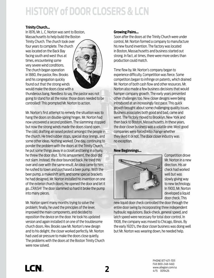
Trinity Church…In 1876, Mr. L. C. Norton was sent to Boston, Massachusetts to help build the Boston Trinity Church. The church took over four years to complete. The church was located on the Back Bay facing south and west thus at times, encountering some very severe wind conditions. The church began operation in 1880, the pastor, Rev. Brooks and his congregation quickly found out that the strong winds would make the doors close with a thunderous bang. Needless to say, the pastor was not going to stand for all the noise; those doors needed to be controlled! This prompted Mr. Norton to action.
Mr. Norton’s first attempt to remedy the situation was to hang the doors on double-spring hinges. Mr. Norton had now uncovered a second problem. The slamming stopped but now the strong winds made the doors stand open. The cold, drafting air raised protest amongst the people in the church. He tried rubber stops, special door linings, and some other ideas. Nothing worked. One day, continuing to ponder the problem with the doors at the Trinity Church, he put some things away in a closet and being in a hurry, he threw the door shut. To his amazement, the door did not slam. Instead, the door bounced back. He tried this over and over with the same result. An idea came to him; he rushed to town and purchased a beer pump. With the beer pump, a makeshift arm, and some special brackets he had designed, Mr. Norton installed his invention on one of the exterior church doors. He opened the door and let it go…CRASH! The door slammed so hard it broke the pump into many pieces.
Mr. Norton spent many months trying to solve the problem; finally, he used the principles of the lever, improved the main components, and decided to reposition the device on the door. He took his updated version and again installed it on one of the troublesome church doors. Rev. Brooks saw Mr. Norton’s new design and to his delight, the closer worked perfectly. Mr. Norton had used air pressure to make the doors close quietly. The problems with the doors at the Boston Trinity Church were now solved.
Growing Pains…Soon after the doors at the Trinity Church were under control, Mr. Norton formed a company to manufacture his new found invention. The factory was located in Boston, Massachusetts and business started out strong. In fact, at times, there were more orders than production could match.
Time flew by. Mr. Norton’s company began to experience difficulty. Competition was fierce. Some competitors began to infringe on patents, which drained Mr. Norton of both cash flow and other resources. Mr. Norton also made a few business decisions that would hamper company growth. The early years presented other challenges too. New closer designs were being introduced at an increasingly fast pace. This quick growth brought about some challenging quality issues. Business associates both good and bad, came and went. The factory moved to Brooklyn, New York and then back to Boston, Massachusetts. In these years, the door closer business was a volatile one. Most good companies were forced into change whether they liked it or not. The door closer industry was no exception.
New Beginnings…Competition drove Mr. Norton in a new direction. His air check had worked well but was slowly giving way to new technology. In 1900, Mr. Norton developed a liquid door check. This
new liquid door check controlled the door through the entire door swing by incorporating three independent hydraulic regulations. Back-check, general speed, and latch speed were necessary for total door control. In 1908, the company was moved to Chicago, Illinois. By the early 1920’s, the door closer business was doing well but Mr. Norton was wearing down, he needed help.
HISTORY of DOOR CLOSERS & LCN

PHONE 877-671-7011FAX 800-248-1460www.allegion.com/us 4/15 0094263
In 1925, Mr. L. C. Norton teamed with Mr. D. R. Lasier and formed the Norton-Lasier Company. The business was located at 466 West Superior Street in Chicago, Illinois. Norton & Lasier knew that if their company was to survive, they must build a far superior product at a very fair price. They called their improved door closer an LCN. After a few years, Mr. Norton left the business to Mr. Lasier and moved to California. During the years of 1926 through 1948, under the leadership of Mr. D. R. Lasier, LCN manufactured and shipped high-quality traditional style closers all over the world. Many of these closers are still in use today. In 1949, the factory moved to Princeton, Illinois. In 1958,
LCN introduced the heavy-duty 4010/4110 series closer. Schlage Lock Company purchased LCN in 1959. In 1974,
Ingersoll-Rand purchased Schlage Lock Company (and LCN). Today, LCN offers a complete line of door control products including heavy-duty hydraulic closers, power operators, fire/life safety closer/holders, high security closers & more.
The model numbers may have changed but the passion, quality, and excitement will always remain. Cast iron, forged steel arms, double heat treating, powder coat finishes, all-weather fluid, and 10 million cycles are just a few of the features and benefits that LCN offers in producing the finest door closers in the world!
1851 – Lewis C. Norton born May 5th in New Hampshire.1880 – First door closer installed at Boston Trinity Church.1881 – Manufacturing begins at Boston plant.1900 – Mr. Norton introduces a liquid door check.1908 – Company moves to Chicago.1917 – David R. Lasier joins company as timekeeper.1925 – Norton-Lasier Company begins operation.1929 – L. C. Norton moves to California. D. R. Lasier
heads up company.1930 – Norton-Lasier Company produces wooden riding
toys to cope with the Great Depression.1937 – L. C. Norton passes away on November 4th.1942 – Norton-Lasier Company produces hydraulic
aircraft fittings for the war effort.1948 – Norton-Lasier Company officially changes name
to LCN.1958 – LCN introduces the 4010/4110 series door closer.1959 – LCN sold to Schlage Lock Company.1972 – LCN introduces Sentronic line of fire/life safety
holder/closers.1973 – LCN introduces the 4040 series door closer.1974 – Schlage Lock (and LCN) sold to Ingersoll-Rand.1978 – LCN introduces Equalizer units.1980 – Production on traditional series ends.1981 – LCN introduces the 1460 series door closer.1981 – LCN introduces AutoEqualizer™ units.1985 – LCN introduces the 1070 series door closer.1993 – LCN introduces the powder coat finish.1995 – LCN introduces Electric Operator units.1996 – LCN introduces the 1520 series door closer.1998 – LCN introduces the 1370 series door closer.2006 – LCN introduces the new 4030 series door
closer to replace the 1520 closer series.2006 – LCN introduces the new Senior, Astro and
Middle Swing Digital Control Box.2007 – LCN introduces the new Tri-Volt Magnets.2007 – LCN introduces the new 4040XP.2007 – LCN introduces the new 1260 Series.2013 – In December of 2013, the Security Technologies
division of Ingersoll Rand became its own publicly traded company called Allegion.

PHONE 877-671-7011FAX 800-248-1460www.allegion.com/us 4/15 0094264
TABLE OF CONTENTSGENERAL INFORMATION History of Door Closers & LCN...............................................2-3 Table of Contents .........................................................................4 Finishes ............................................................................................ 5 Warranty .........................................................................................6 Door Closer Specialists .................................................................7 Specifications ..........................................................................8-10 ANSI Cross Reference ............................................................ 11-13 Materials ........................................................................................ 14 Proper Door Control ....................................................................15 Mechanical Considerations ................................................16-21 Glossary of Abbreviations ........................................................22 Glossary of Terms ................................................................. 23-31
4000 SERIES SURFACE MOUNTED CLOSERS Product Selection Guide .......................................................... 1-2 4010 Series .................................................................................3-6 4010T Series ...............................................................................7-11 4020 Series .............................................................................13-16 4020T Series ............................................................................17-21 4030 Series ...........................................................................23-30 4030T Series ..........................................................................31-36 4040XP Series...................................................................... 37-45 4040XPT Series ................................................................... 47-53 4110 Series ..............................................................................55-59 4110T Series ........................................................................... 61-65 4000T Series ........................................................................ 67-70
1000 SERIES SURFACE MOUNTED CLOSERS Product Selection Guide .......................................................... 1-2 1260 Series ................................................................................ 3-10 1460 Series ................................................................................11-18 1460T Series ...........................................................................19-25
CONCEALED CLOSERS SERIES Product Selection Guide .......................................................... 1-2 2010 Series ..................................................................................3-6 2030 Series .................................................................................7-11 3030 Series ..............................................................................13-16 3130 Series .............................................................................. 17-20 5010 Series .............................................................................. 21-24 5030 Series ............................................................................25-28 6030 Series ........................................................................... 29-32
FIRE/LIFE SAFETY CLOSER/HOLDERS SERIES Product Selection Guide .......................................................... 1-3 SEM Series..................................................................................5-12 3130SE Series ..........................................................................13-16 4040SE Series ........................................................................17-22 2310ME Series .......................................................................23-26 4310ME Series .........................................................................27-31 4410ME Series .......................................................................33-37 4310 HSA Series ...................................................................39-42 4410 HSA Series .................................................................. 43-46 SEH Series ..............................................................................47-50
HIGH SECURITY CLOSERS SERIES Product Selection Guide .......................................................... 1-2 2210 Series ..................................................................................3-6 4210 Series ................................................................................ 7-10 4210T Series .............................................................................11-14 4510 Series ...............................................................................15-18 4510T Series ........................................................................... 19-22
AUTOMATIC OPERATORS Product Selection Guide ..........................................................1-5 Pneumatic Powered Systems .............................................. 7-9 2610 Series ................................................................................11-14 4810 Series...............................................................................15-18 4820 Series ............................................................................. 19-22 4840 Series ............................................................................23-27 7900 Series Control Boxes ...............................................28-33 900 Series Compressors...........................................................34 Electrohydraulic Powered Systems ................................35-37 4630/4640 Electrohydraulic Series .................................... 38 Electrohydraulic Powered Systems ......................................39 4630 Series .............................................................................41-45 4640 Series ............................................................................ 47-51 Electromechanical Powered Systems .......................... 53-57 Benchmark Unique Features ................................................. 59 9130 Series ............................................................................. 61-65 9140 Series ...............................................................................67-71 9150 Series .............................................................................. 73-77 Senior Swing Unique Features ...............................................79 2810 Series ............................................................................. 81-86 2850 Series ............................................................................87-92 2860 Series ........................................................................... 93-98 9530 Series ..........................................................................99-103 9540 Series........................................................................105-109 9550 Series ............................................................................111-116 9560 Series...........................................................................117-122 Actuators & Accessories ................................................. 123-133 Sensors & Accessories .....................................................134-139
1250 & 1450 SERIES SURFACE MOUNTED CLOSERS Product Selection Guide ..........................................................1-2 1250 Series ................................................................................ 3-10 1450 Series ................................................................................11-18
4050 SERIES SURFACE MOUNTED CLOSERS Product Selection Guide ..........................................................1-2 4050 Series ...............................................................................3-12
LCN121 West Railroad Avenue P.O. Box 100 Princeton, IL 61356-0100
For SSC Representative contact information, please visit www.allegion.com/us and click "Contact Us"
To view or download an electronic copy, visit www.allegion.com/us.LCN reserves the right to change the informationcontained in this catalog without notice.

PHONE 877-671-7011FAX 800-248-1460www.allegion.com/us 4/15 0094265
FINISHESSTANDARD POWDER COAT FINISHES LCN powder coating provides superior protection against the effects of weather conditions and is an environmentally friendly process. The high quality, chip resistant finish is far superior to any previously offered. Corrosion resistance surpasses 100 hours salt spray testing (four times the industry standard). Non-metallic components also provide the same high resistance to the effects of the elements. All LCN products must be shipped with a finish.
LCN STANDARD FINISHES (CLOSEST BHMA EqUIvALENT):
OPTIONAL PLATED FINISHES Visible components such as metal covers, arms, fasteners, and finish plates are plated to match the selected finish. Surface mounted tracks are powder coated to compliment the plated finish. Hidden assemblies such as cylinders, tracks, and mounting plates are supplied with a powder coated finish. Plated finishes require handing of closers.
LCN PLATED FINISHES: US 3 Bright Brass (BHMA 632)US 4 Satin Brass (BHMA 633)US 10 Satin Bronze (BHMA 639)US 10B Oxidized Satin Bronze (BHMA 641)US 15 Satin Nickel (BHMA 646)US 26 Bright Chrome (BHMA 651)US 26D Satin Chrome (BHMA 652)
SPECIAL RUST INHIBITING (SRI) PROCESS For installations where a higher level of protection against weather conditions, or the effects of a potentially corrosive atmosphere is required, LCN offers a special rust inhibiting (SRI) process. Ferrous metal components receive an SRI pretreatment and a standard powder coat finish of your choice, or a custom powder coat finish for a nominal additional cost. Closers treated with the SRI process exceed the 100 hour protection level available with standard LCN powder coated finishes. For details, contact your local SSC representative or the LCN factory.
STANDARD ANODIZED FINISHES LCN Senior Swing & Benchmark electromechanical power operators are offered with an anodized finish. Anodizing is an electrochemical process that thickens and toughens the protective oxide on aluminum metal.
LCN ANODIZED FINISHES: Aluminum ANCLR (BHMA 628)Dark Bronze ANDKBRZ (BHMA 710)
OPTIONAL CUSTOM POWDER COAT FINISHES LCN offers custom powder coating to provide a custom appearance and all the corrosion resistance of standard powder coat finishes at a nominal additional cost. LCN uses the RAL numbering system for the 150+ custom colors available. Contact your local SSC representative for a brochure showing the available custom colors. Note: Custom powder coat finishes require a metal cover.
ALUM ALUMINUM (BHMA 689)
DKBRZ DARK BRONZE (BHMA 695)
STAT STATUARY BRONZE (BHMA 690)
LTBRZ LIGHT BRONZE (BHMA 691)
BLK BLACK (BHMA 693)
BRASS BRASS (BHMA 696)

PHONE 877-671-7011FAX 800-248-1460www.allegion.com/us 4/15 0094266
Term: The limited warranty period for Products is as stated in the Product Table above. The “Commencement Date” for a limited warranty period shall be the date of Company’s delivery to the original purchaser of the Products. Proof of Product purchase may be required by Company to confirm the Commencement Date.
What Company will do: Company may require proof of Product purchase in order to provide coverage under this limited warranty. As Company’s only responsibility and user’s only remedy under this limited warranty, Company will furnish a replacement Product upon receipt and confirmation by Company, in its sole opinion, that the Product has, in fact, failed due to a manufacturing defect under normal use and maintenance. In the event a replacement Product cannot be provided, Company will either provide a suitable replacement Product or a refund in the amount of the original purchase price.
What is not covered: The following costs, expenses, and damages are not covered by the provisions of this limited warranty: (i) labor costs including, but not limited to, such costs as removal and installation of Product; (ii) shipping and freight expenses required to return Product to Company; (iii) failures, defects, or damage caused by any third party product or service; (iv) any other incidental, consequential, indirect, special and/or punitive damages, whether based on contract, warranty, tort (including, but not limited to, strict liability or negligence), patent infringement, or otherwise, even if advised of the possibility of such damages.
The provisions of this limited warranty do not apply to Product that is: (i) not the proper size for the application for which the Product is used; (ii) not installed in accordance with Company’s published Product installation instructions; (iii) installed with improper parts and/or incorrect parts (NOTE: It is recommended that Product be installed with LCN fasteners provided with Product); (iv) improperly stored, maintained, or operated; (v) modified, repaired, or altered in Company’s sole opinion, in any manner, without the express written consent of Company; (vi) used for purposes for which the Product is not designed or intended; (vii) subjected to misuse, abuse, negligence, or accident; or (vii) subjected to improper temperature, humidity, or other environmental conditions.
Note: 900/7900 Series compressors are not manufactured by Company and are excluded from coverage under this limited warranty. For more information, parts, or repairs concerning the compressors, contact the compressor manufacturer directly at (269) 926-6171.
Additional Terms: This limited warranty is in lieu of all other warranties, express or implied. Company does not authorize any person to create for it any obligation or liability in connection with Product. Company’s maximum liability hereunder is limited to the original purchase price of the Product. No action arising out any claimed breach of this limited warranty by Company may be brought by the user more than one (1) year after the cause of action has arisen.
How local law applies: This limited warranty gives you specific legal rights, and you may also have other rights as permitted by law. Some local laws do not allow limitations on how long an implied warranty lasts or the exclusions or limitation of incidental or consequential damages so the limitations or exclusions provided herein may not apply to you.
Program and Warranty Claims: All Product claimed to be defective under this limited warranty shall be sent to: LCN, Warranty and Replacement Department, 121 West Railroad Avenue, P.O. Box 100, Princeton, Illinois USA 61356-0100. For information, contact Customer Care at (877) 671-7011.
LCN Limited Warranty
Subject to the terms and conditions of this limited warranty, Schlage Lock Company, LLC (the “Company’) extends a limited warranty against defects in material and workmanship for its LCN branded product(s) identified in the Product Table below (“Products”) as installed in the original location.
This limited warranty applies to Products purchased on or after March 3, 2014.
Product Table
4000 Series 30 Years
1460 Series 30 Years
1260 Series 20 Years
Concealed, High Security (except 2210DPS) 15Years
Automatic Operators; SE, ME, HSA, SEH Series; SEM Magnets; 2210 DPS (includes both electronic and mechanical components)
2 Years

PHONE 877-671-7011FAX 800-248-1460www.allegion.com/us 4/15 0094267
DOOR CLOSER SPECIALISTSSince its founding in 1926, LCN has specialized in solving door control problems through the use of high quality, innovative door control products. By adhering to high standards of performance, LCN has earned a leadership role within the industry and is committed to meeting door control challenges of the future. With representatives located throughout the world, LCN provides the products and services necessary to solve your door control problems.
Materials LCN is committed to providing the best door closers in the world. In addition to the mechanical advantages derived from proven designs, much of the durability of the closer and arm system is related to the materials used in their manufacturing.
10 Million Cycles Why do some hardware professionalsclaim that LCN stands for “LastCloser Needed?” LCN closers wereput through grueling independentcycle tests and have exceeded 10million cycles.
Forged Steel Arms The closing power and control generated within LCN closers is transferred to the door through forged steel arms. Forged steel arms have greater strength, better appearance and less bulk.
Chrome Silicon Many closer manufacturers use less expensive oil-tempered springs, but LCN engineers know that such a spring loses up to 20% of its power after a few thousand cycles.
Heat-Treated LCN steel pinions have larger, stronger teeth and are double heat-treated for the greatest possible strength on the shaft. Heat-treating makes the pinion harder, better able to resist wear after years of service and results in less stress on the cylinder.
Special Templates When a standard door closer won’t do the job, there is only one proven, reliable source for special solutions — LCN. With over 3,000 special templates on file, LCN can provide a door control solution for one-of-a-kind doors such as vault, balanced, over-sized and arch doors.
Hydraulic Fluid LCN uses a special formula hydraulic fluid with special lubrication properties to keep closer components working smoothly. This unique all-weather hydraulic fluid eliminates the need for seasonal adjustments.
Customer Service At a time when machines are picking up more and more customer calls, real people are answering the phones at LCN. Every member of our customer service staff is trained and qualified to assist you with orders, closer selection and special applications.
The LCN formula for success

PHONE 877-671-7011FAX 800-248-1460www.allegion.com/us 4/15 0094268
SPECIFICATIONSPART 1 - GENERAL1.1 qUALITY ASSURANCEA. Reference Standards 1. American National Standards Institute
(ANSI/BHMA): A117.1 Providing Accessibility and Usability
for Physically Handicapped People A156.10 For Power Operated Pedestrian Doors A156.4 Door Controls - Closers A156.15 Life Safety Closer Holder Release
Devices A156.18 Materials and Finishes A156.19 Power Assist and Low Energy Power
Operated Doors 2. Americans with Disabilities Act (ADA) 3. American Society for Testing and Material (ASTM):
Specification B117-9 Method of Finish Corrosion Testing 4. Underwriters Laboratory (UL): 228 Door Closers-Holders UL10C Standard Positive Pressure Fire
Test of Door Assemblies UL10B Standard for Fire Test of Door Assemblies 5. National Fire Protection Association (NFPA): No. 80 Fire Doors and Windows No. 101 Life Safety Code
B. Source quality Control 1. Obtain each kind of hardware (latch and lock sets,
hinges, closers, etc.) from only one manufacturer, although several may be indicated as offering products complying with requirements.
2. All products shall meet grade 1 or the highest level of cycle test requirements of the applicable ANSI/BHMA standard.
C. Supplier qualifications 1. Supplier must be a recognized builders hardware
supplier who has been furnishing hardware in the projects vicinity for a period of not less than two years.
2. Supplier must be or employ an experienced hard ware consultant who is available, at reasonable times during the course of the work, for consultation about the project’s hardware requirements, to Owner, Architect, and Contractor.
D. Fire-rated Openings 1. Provide hardware for fire rated openings in compliance
with NFPA Standard No. 80, NFPA Standard No. 101, and local building codes.
2. [Manual hold-open arm function not allowed.] Provide hardware which has been tested and listed by UL for types and sizes of doors required and complies with the requirements of door and frame labels.
PART 2 - PRODUCTS2.3 MATERIALS AND FABRICATIONA. General 1. Closers shall be installed to allow door swing as shown
on plans. Doors swinging into exit corridors should provide for corridor clear width as required by codes.
2.8 CLOSERS AND DOOR CONTROL DEvICESA. General All closers shall be as manufactured by LCN CLOSERS,
Princeton, Illinois, USA, and shall have the following features: 1. [Applies to 4010, 4020, 4110, 4210, 4510, 5010
Series only.]All manual door closers shall be certified to exceed 15 million (15,000,000) full load operating cycles by a recognized independent testing laboratory.
2. All manual closers shall carry a manufacturers ten (10) year warranty.
3. All closers with electrical or pneumatic components shall carry a manufacturers two (2) year warranty. [Items 4 through 12 apply to closer cylinder, items 13 through 16 apply to closer arms.]
4. Fully hydraulic, rack and pinion action with high strength cast iron cylinders and one piece forged steel pistons.
5. Fluid of a type requiring no seasonal adjustments. 6. [Delete for 1460, 1260, 3030, 3130 and 4030
Series.] Pinion shaft minimum diameter of 11/16". 7. Hydraulic regulation controlled by tamper-proof, non-
critical screw valves, adjustable with a hex wrench. 8. Separate adjustments for backcheck, general speed, and
latch speed. 9. [Applies to 1260, 1460, 4010, 4020, 4040XP, 4110,
4210, 4510, 5010 Series.]Where detailed on double lever arm closers, provide a delayed action feature to delay closing up to one minute from maximum opening to approximately 75º.
10. Backcheck shall be properly located for protection of the door, frame, and applied hardware.
11. [Applies to 2210, 4110, 4210, 4210T, 4510, and 4510T Series only.] Where detailed, provide advanced variable backcheck to start backcheck function at approximately 45º.
12. Include high efficiency, low friction full compliment pinion bearings.
13. [Delete for 1260, 1460, 6030 Series.] Forged steel main arms.
14. [Applies to 4110, 4210, 4510 Series and all EDA and CUSH arms.] Forged steel main and forearms.
15. [Applies to all single lever arm (track type) closers.] Where detailed, provide a quiet, low friction track and roller assembly and provisions for an optional bumper assembly to assist backcheck and/or hold-open clip.
16. [Applies to all double lever arm closers, except EDA or CUSH arms.] Reversible shoe to increase latching power of the closer.

PHONE 877-671-7011FAX 800-248-1460www.allegion.com/us 4/15 0094269
SPECIFICATIONSB. Size of Closers 1. Sized in accordance with ANSI/BHMA Standard A156.4
as shown in the applicable TABLE OF SIZES listed in the current LCN General Catalog.
2. Closing power of non-sized cylinders shall be adjustable over a range of sizes;[Applies to 1261, 1461, 1460T, 4011, 4021, 4040SE, 4040XP, 4040XPT, 4041DEL, 4111, 4211, 4511, 4631, 4642, 4811, 4822, 4841, 4031, 4031T Cylinders.]
C. Barrier Free Manual Closers 1. All closers for openings that must meet the minimum
requirements of the ADA act, in lieu of ANSI/BHMA Standard A156.4, shall be sized in accordance with the applicable REDUCED OPENING FORCE table in the current LCN General Catalog.
2. All size 1 manual closers shall provide or be adjustable to provide less than 5 pounds opening force on a 36" door leaf and delay closing time in accordance with the ADA requirements.
D. Combination Door Closers and Holders 1. Provide closer/holders designed to hold the door in the
open position under normal usage and to release and automatically close the door under fire conditions. Closer will include an integral electro magnetic holder mechanism designed for use with UL listed fire detectors, provided with normally closed switching contacts.
2. [Applies to all ME models.] Where detailed, multi-point closer/holders shall incorporate a hold-open bypass feature from 0º up to either 80º or 140º.
3. [Applies to 4310 ME only.] Where detailed, multi-point closer/holders shall provide a swing-free function with a no-drift feature.
E. High Security Closers 1. Provide closers designed to resist vandalism and
tampering. 2. All exposed fasteners shall be TORX machine screws
with a security pin. 3. All closer adjustments shall be shielded by the cover
or finish plate, after installation. 4. Arm and, where furnished, high security roller assembly
shall be designed to prevent disassembly. 5. [4210 and 4510 Series only.] All surface mounted high
security closers shall include a cast iron cylinder certified by an independent testing laboratory to exceed ten million (10,000,000) operating cycles, heavy gauge metal covers with four mounting screws and double lever arms manufactured to prevent disassembly.
6. [4210T and 4510T Series only.] All surface mounted high security closers shall include a cast iron cylinder certified by an independent testing laboratory to exceed ten million (10,000,000) operating cycles, heavy gauge metal covers with four mounting screws, heavy duty arm with special security roller, and a heavy gauge high security track designed to eject foreign objects.
7. [2210 and 2210 DPS only.] All concealed high security closers shall include a cast iron cylinder certified by an independent testing laboratory to exceed ten million (10,000,000) operating cycles, 3/8” steel mounting plate, heavy duty arm with special security roller, and a heavy gauge high security track designed to eject foreign objects.
8. [2210 DPS only.] A built-in door position switch shall be optional with concealed closers.
F. Automatic Operators 1. Where low kinetic energy, as defined by ANSI/BHMA
Standard 156.19, automatic operators are indicated for doors required to be accessible to the disabled. Provide pneumatic, electrohydraulic or electromechanical [2610, 2810, 2850, 2860, 4630, 4640, 4810, 4820, 4840, 9130, 9140, 9150, 9530, 9540, 9550, 9560 Series] operators complying with the ADA for opening force and time to close standards.
2. Full closing force shall be provided when the power or assist cycle ends [2610, 2810, 2850, 2860, 4630, 4640, 4810, 4820, 4840, 9130, 9140, 9150, 9530, 9540, 9550, 9560 Series].
3. [2610, 4810, 4820, 4840] Locate power unit and pneumatic exhaust away from door to minimize noise and vibration in pedestrian areas.
4. All automatic operator systems shall include the following features and functions.
a) Provisions for separate conduits to carry high and low voltage wiring in compliance with the National Electrical Code, section 725-31.
b) The operator will be designed to prevent damage to the mechanism if the system is actuated while the door is latched or if the door is forced closed during the opening cycle.
c) All covers, mounting plates and arm systems shall be powder coated and successfully pass a minimum of 100 hours testing as outlined in ANSI/BHMA Standard A156.18 [2610, 4630, 4640, 4810, 4820, 4840 Series].
-Or-
d) Electromechanical automatic operators shall be standard anodized either in aluminum or dark bronze. Custom anodized finishes and custom paint are available and can be specified. [2810, 2850, 2860, 9130, 9140, 9150, 9530, 9540, 9550, 9560 Series]
e) UL listed for use on labeled doors f) [4630, 4640, 4810, 4820, 4840 Series] shall
be non-handed with spring power over a range of at least four sizes either 1 through 4 or 2 through 5.
-Or-
g) [2810, 2850, 2860, 9130, 9140, 9150, 9530, 9540, 9550, 9560, Series] are handed and feature a spring return.

PHONE 877-671-7011FAX 800-248-1460www.allegion.com/us 4/15 00942610
SPECIFICATIONSPART 3 - EXECUTION3.1 INSTALLATIONA. General 1. Installation shall be in accordance with the templates
and installation instructions packaged with the closers at the time of manufacture.
2. Installation shall be made with fasteners packaged with the closer by the manufacturer.
3. All electrical connections shall be made in accordance with the manufacturers recommendations.
4. Clean installed closer to remove dirt, debris, and marks incidental to installation work.
5. Installation instructions and templates are to be turned over to the Owners representative upon completion of the installation work.
6. Factory trained representative will be available for job site inspection of major projects upon completion of the hardware installation work.
3.2 ADJUSTMENTA. Adjustment 1. Install and regulate all closers in accordance with the
installation instructions packaged with the closers at the time of manufacture.
2. If unfamiliar with LCN products furnished, consult factory representative prior to installation for assistance.
h) Provisions in the control box or module shall provide control {inputs and outputs} for; electric strike delay, auxiliary contact, sequential operations, fire alarm systems, actuators, swing side sensors, stop side sensors. [2610, 4630, 4640, 4810, 4820, 4840, 9130, 9140, 9150 Series]
5. [4630, 4640 Series] All electrohydraulic automatic operators shall include the following features or functions:
a) Second Chance Feature: When an obstruction or resistance to the opening swing is encountered the operator will pause at that point, then attempt to continue opening the door. If the obstruction or resistance remains, the operator will again pause the door.
b) Easily accessible main power and maintain hold-open switches will be provided on the operator.
c) An electronically controlled clutch to provide adjustable opening force.
d) A microprocessor to control all motor and clutch functions.
e) An on-board power supply capable of delivering both 12V and 24V outputs up to a maximum of 1.0 ampere combined load.
f) All input and output power wiring shall be protected by a resettable circuit breaker.
-Or-
5. All electromechanical automatic operators shall include the following features of functions:
a) Maximum 8-1/2 lbs of manual opening force [9130, 9140, 9150 Series].
b) Maximum 15 lbs of manual opening force [2810, 2850, 2860, 9530, 9540, 9550, 9560 Series].
c) Bottom loaded header for easy access to controls [2810, 2850, 2860, 9550, 9560 Series].
d) Power Boost, which adds an additional 25 lbs of closing force at latch [2810, 2850, 2860, 9130, 9140, 9150, 9530, 9540, 9550, 9560 Series].
e) Self contained automatic operators in a cast aluminum housing and a forged steel arm [2810, 2850, 2860, 9130, 9140, 9150, 9530, 9540, 9550, 9560 Series].
2.12 HARDWARE FINISHESA. Finish 1. All closers with powder coat finishes shall exceed a
minimum 100 hour salt spray test, as described in ANSI/BHMA Standard A156.4 and ASTM B117.
2. All closers detailed with plated finishes shall include plated covers (or finish plates), arms, and visible fasteners.
3. All electromechanical automatic operators supplied with anodized finishes.
4. All closers must be shipped with a finish.

PHONE 877-671-7011FAX 800-248-1460www.allegion.com/us 4/15 00942611
C02011 HINGE SIDE 4031 X X X X X4040XP X X X X X
1260 X X X X X X1460 X X X X X X4010 X X X X X X4510 X X X X X X X
C02021 PARALLEL 4031 X X X X X X4040XP X X X X X X
1260 X X X X X X X1460 X X X X X X X4110 X X X X X X X X4210 X X X X X X X X
C02031 BRACKET 4040XP X X X X X4010 X X X X X X
C02041 TOP JAMB 4031 X X X X X4040XP X X X X X
1260 X X X X X X1460 X X X X X X4020 X X X X X X
C02051 HINGE SIDE HOLD OPEN 4031 X X X X X4040XP X X X X X
1260 X X X X X X1460 X X X X X X4010 X X X X X X
C02061 PARALLEL HOLD OPEN 4031 X X X X X XX X X X X X
1260 X X X X X X X1460 X X X X X X X4110 X X X X X X X X4210 X X X X X X X X
C02071 BRACKET HOLD OPEN 4010 X X X X X X4040XP X X X X X
C02081 TOP JAMP HOLD OPEN 4031 X X X X X4040XP X X X X X
1260 X X X X X X1460 X X X X X X4020 X X X X X X
C02091 HINGE SIDE FUSIBLE LINK 4010 X X X X X XC02101 PARALLEL FUSIBLE LINK 4110 X X X X X X XC02111 BRACKET FUSIBLE LINK 4010 X X X X X XC02121 TOP JAMP FUSIBLE LINK 4020 X X X X X XC02171 HINGE SIDE TELEPHONE BOOTH 4010TEL X
4110TEL XC02211 HINGE SIDE TRACK 1460T X X X X X
4010T X X X X X4031T X X X X X
4040XPT X X X X X4510T X X X X X X
C02221 HINGE SIDE HOLD OPEN TRACK 1460T X X X X X4010T X X X X X4031T X X X X X
4040XPT X X X X X
ANSI CROSS REFERENCE
ANSI N
UMBER
LCN C
LOSER
MOUNTING
PT-4H
PT-4J
PT-4A
PT-4D
PT-4F
PT-4G
PT-4C
Note: All closers listed in this section are certified grade 1 = 1,500,000 cycles, PT4A = 15% adjustable closing force, PT4B = 35% adjustable closing force, PT4C = 50% adjustable closing force, PT4D = adjustable hydraulic backcheck, PT4F = delayed action, PT4G = built-in factory dead stop (Cush-N-Stop), PT4H = spring power adjustable over a range of sizes, PT4J = backcheck position advanced 15 degrees.
ANSI FUNCTION NUMBER TO LCN PRODUCT
SURFACE MOUNTED ANSI Standard A156.4-2000
PT-4B

PHONE 877-671-7011FAX 800-248-1460www.allegion.com/us 4/15 00942612
Note: All closers listed in this section are certified grade 1 = 1,500,000 cycles, PT4A = 15% adjustable closing force, PT4B = 35% adjustable closing force, PT4C = 50% adjustable closing force, PT4D = adjustable hydraulic backcheck, PT4F = delayed action, PT4G = built-in factory dead stop (Cush-N-Stop), PT4H = spring power adjustable over a range of sizes, PT4J = backcheck position advanced 15 degrees.
ANSI CROSS REFERENCE
4031T X X X X X4040XPT X X X X X
4510T X X X X X XC02221 HINGE SIDE HOLD OPEN TRACK 1460T X X X X X
4010T X X X X X4031T X X X X X
4040XPT X X X X XC02231 STOP FACE TRACK 1460T X X X X X
4031T X X X X X4040XPT X X X X X
4110T X X X X X4210T X X X X X X
C02241 STOP FACE HOLD OPEN TRACK 1460T X X X X X4031T X X X X X
4040XPT X X X X X4110T X X X X X
C02251 TOP JAMB TRACK 1460T X X X X X4000T X X X X X4020T X X X X X4031T X X X X X
4040XPT X X X X XC02261 TOP JAMB HOLD OPEN TRACK 1460T X X X X X
4020T X X X X X4031T X X X X X
4040XPT X X X X XC02271 TOP JAMB PUSH SIDE FLUSH
FRAME TRACK4031T X X X X X
C02281 TOP JAMB PUSH SIDE FLUSH FRAME HOLD OPEN TRACK
4031T X X X X X
C03011 HINGE SIDE 1260 X X X X X XC03021 PARALLEL 1260 X X X X X X XC03041 TOP JAMB 1260 X X X X X XC03051 HINGE SIDE HOLD OPEN 1260 X X X X X XC03061 PARALLEL HOLD OPEN 1260 X X X X X X XC03081 TOP JAMB HOLD OPEN 1260 X X X X X X
ANSI N
UMBER
LCN C
LOSER
MOUNTING
PT-4H
PT-4J
PT-4A
PT-4D
PT-4F
PT-4G
PT-4C
ANSI FUNCTION NUMBER TO LCN PRODUCT
SURFACE MOUNTED ANSI Standard A156.4-2000
PT-4B
C04011 CONCEALED IN DOOR REG 3030 X XHO 3030H X X
C04031 CONCEALED IN DOOR STANDARD 3130 XHO 3130H X
ANSI N
UMBER
ARM
LCN C
LOSER
MOUNTING
PT-4A
ANSI FUNCTION NUMBER TO LCN PRODUCT
CONCEALED IN DOOR ANSI Standard A156.4-2000
PT-4D
Note: All closers listed in this section are certified grade 1 = 1,500,000 cycles. PT4A = 15% adjustable closing force, PT4D = adjustable hydraulic backcheck.

PHONE 877-671-7011FAX 800-248-1460www.allegion.com/us 4/15 00942613
Note: All closers listed in this section are certified grade 1 = 1,500,000 cycles.PT8A = door under control from 7 degrees of maximum door opening to close, PT8B = hold-open between 85 and 180 degrees, PT8D = 50% adjustable PT8E = single acting, 165 degrees of opening, double acting 165 degrees of opening either way, PT8F = adjustable hydraulic backcheck, PT8J = delayed action, PT8L = 35% adjustable closing force.
ANSI CROSS REFERENCE
C05011 BUTT HINGE REG 5010 X X X X X X X5030 X X X X X X
C05021 PIVOT REG 5010 X X X X X X5030 X X X X X
C05031 BUTT HINGE STANDARD 2010 X X X X X2030 X X X X X2210 X X X X X
2210 DPS X X X X XC05041 PIVOT STANDARD 2010 X X X X
2030 X X X X2210 X X X X
2210 DPS X X X XC05071 PIVOT STANDARD 2010 X X X X
2030 X X X XC05081 PIVOT STANDARD 6030 X X X XC05091 BUTT HINGE HO 5010 X X X X X X X
5030 X X X X X X
ANSI N
UMBER
ARM
LCN C
LOSER
MOUNTING
PT-8A
PT-8D
PT-8J
ANSI FUNCTION NUMBER TO LCN PRODUCT
OvERHEAD CONCEALED ANSI Standard A156.4-2000
PT-8B
PT-8F
PT-8E
PT-8L
C00011 WALL N/A 7830, 7840, 7850WALL N/A 1960, 1970, 1980
C00021 FLOOR N/A 7820C00191 HINGE SIDE STANDARD 4040SE X X X
4040SEL X X XC00231 STOP FACE STANDARD 4040SE X X X
4040SEL X X XC00311 TOP JAMB REG 4410HSA X X
4410ME X XC00351 HINGE SIDE STANDARD 4310HSA X X
4310ME X XC00371 HINGE SIDE SF 4310ME X XC00391 TOP JAMB DE 4310HSA X X
4310ME X XC00471 HINGE SIDE REG 4040SEH XC00511 PUSH SIDE REG 4040SEH XC00611 CONCEALED STANDARD 3130SE X X
3130SEL X XC00651 CONCEALED STANDARD 2310ME X X
ANSI N
UMBER
ARM
LCN C
LOSER
MOUNTING
PT4D
PT4PANSI FUNCTION NUMBER TO LCN PRODUCT LIFE SAFETY CLOSER/ HOLDER RELEASE DEvICE ANSI Standard A156.15-2001
PT4N
Note: Options are; PT4D = adjustable hydraulic backcheck, PT4N = adjustable spring power, and PT4P = adjustable hold-open intensity.

PHONE 877-671-7011FAX 800-248-1460www.allegion.com/us 4/1514
MATERIALSLCN is committed to providing the best door closers in the
world. In addition to the mechanical advantages derived
from proven designs, much of the durability of the closer
and arm system is directly related to the materials used in
their manufacturing.
Precision machined cast iron cylinders and forged steel pistons work together because of the compatibility
of their basic elements. Heat-treated pinions and pistons spread the load over a large gear tooth system
to better handle the wear and stress of millions of
operating cycles. Upper and lower full compliment pinion
bearings provide the support and load capacity required
by the design of the closer. All weather fluid eliminates
the need for seasonal adjustments.
Forged steel main arms are superior to stamped steel
arms used on closers where price is the primary concern.
Specially designed shoe and elbow joints provide
maintenance free service. A state-of-the-art, powder coat process delivers a high quality, corrosion resistant
finish on all metal parts in popular architectural finishes.
LCN always uses the best materials available to provide
the exceptional value and long service life that you, our
customer, have every right to expect.

PHONE 877-671-7011FAX 800-248-1460www.allegion.com/us 4/15 00942615
PROPER DOOR CONTROLToday practically every door in modern commercial, industrial, and institutional buildings is opened by the person passing through and closed by a mechanical door closer which should keep the door under orderly control at all times. The power to close the door is generated by the springs inside the closer. Regulated hydraulic circuits control the speed of the doors closing swing. Ideal door “conduct” is illustrated and described in the diagram below. It can be achieved by equipping each door with the appropriate LCN door closer.
Perfect door operation…The aim of mechanical control.
This diagram shows the main part or stages in correct door operation, whether under manual or mechanical control or a combination of the two.
(1) On the opening swing, the door closers function is to let the door open easily, except at the end of the swing where backcheck is applied.
(2) Backcheck is a feature that cushions the opening swing to prevent the door from slamming into the stop. Special closers designed for potentially abusive applications begin the backcheck function much earlier (2A) such as LCN’s advanced variable backcheck (AVB).
(3) Through the long closing arc, a uniform, reasonable (main) speed should be maintained.
(4) The latching arc allows the door to close quietly and firmly.
Opening the door builds up the power, which later closes the door.As a controlled door is opened, the spring of the closer is compressed which builds up the power to close the door. Normally, more opening force would be required as spring compression increases. However, as an LCN closer changes it’s arm geometry while the door opens, it increases the door leverage. This offsets the spring compression, resulting in greater ease in opening the door.
In opening, more leverage for the person.The changing arm geometry gives increased leverage over the door to overcome the growing power of the spring allowing one to pass through the door easily.
In closing, more leverage for the closer.When the person releases the door and the closer takes over, spring power is applied through the arm system to close the door. Because the spring has been compressed, its power is very high. As the door closes the spring expands, providing the power to close the door.
Special closers for reduced opening force.The 1990 Americans with Disabilities Act (ADA) and ANSI Standard A117.1 describe maximum opening force limitations for certain non-fire rated doors. The last page of each closer section in the catalog includes a section titled REDUCED OPENING FORCE CLOSERS. This section lists closers in that specific series that will comply with a maximum opening force based on the width of the door.
Any manual door closer, including those certified by BHMA to conform to ANSI Standard A156.4, that is selected, installed, and adjusted based on ADA or other reduced opening force requirements may not provide sufficient power to reliably close and latch the door.
Refer to AUTOMATIC OPERATORS section for information on electric, pneumatic and electromechanical systems that meet reduced opening force requirements without affecting closer power.

PHONE 877-671-7011FAX 800-248-1460www.allegion.com/us 4/15 00942616
MECHANICAL CONSIDERATIONSHOW TO SELECT A DOOR CLOSER
CONCEALED OR SURFACE MOUNTED CLOSERS?Door closers are available in two styles - concealed or
surface mounted. In choosing a closer style for a
parti cu lar application, consideration should be given to the
type of door being controlled, frame conditions, aesthetic
requirements, and control features needed. Information
contained in the following material can
serve as a guide in selecting the style and model of
closer to meet specific requirements.
IF CONCEALED, WHERE?Closers concealed in the head frame over the door are
out of sight and entirely out of the pedestrians way.
They cannot be harmed by scrub water, cleaning
chemicals or floor dirt, and are protected from airborne
contaminants, like dust. They are easy to reach for
regulation without removing any parts. Closers for
frame sections as thin as 1-3/4˝ (44 mm) are available.
Closers located within the door itself are also hidden and
protected but recommended for interior doors only.
CONCEALED IN FRAME
CONCEALED IN 1-3/4” TUBE
CONCEALED IN DOOR
SURFACE MOUNTED CLOSERS – LOCATION?Closer location is subject to the considerations of
practicality and appearance. Good taste usually decrees
that closers on doors along a corridor be located on the
room side of the door so they are out of the line of sight
from the corridor. Closers should be placed on the inside
of exterior doors for appearance and to shelter them
from the elements.
WHERE ARE HEAvY DUTY CLOSERS REqUIRED?Heavy duty closers should always be used in these places:
1) Schools or public buildings where heavy or abusive
usage is expected.
2) Exterior doors.
3) Doors subject to draft, winds, or air pressure
differentials.
4) High frequency doors such as those on department
stores, malls, or mixed use tenancies.
HINGE (PULL) SIDE MOUNT
TOP JAMB (PUSH SIDE) MOUNT
PARALLEL ARM (PUSH SIDE) MOUNT

PHONE 877-671-7011FAX 800-248-1460www.allegion.com/us 4/15 00942617
MECHANICAL CONSIDERATIONSWHICH ARM SYSTEM?Double lever arm closers can provide control under difficult conditions for either interior or exterior doors.
A parallel arm system is a type of double lever arm where the main arm is parallel to the face of the closed door.
Available double lever arms:
Single lever arm (track) closers may be used on interior or sheltered exterior doors. The hold-open function in a
single lever arm system is provided by either the track or the cylinder assembly. Available single lever arms:
HOLD-OPEN (H)
FUSIBLE LINK (FL)
EXTRA DUTY (EDA) HOLD-OPEN EXTRA DUTY (HEDA)
STANDARD (STD) DOUBLE EGRESS (DE)
STANDARD ADJUSTABLE (STD)SWING-FREE (SF)
SPRING CUSH (SCUSH) SPRING HOLD-OPEN CUSH (SHCUSH)
REGULAR (REG)
HOLD-OPEN CUSH-N-STOP (HCUSH)
CUSH-N-STOP (CUSH)
3077CNS 3049CNS
PHONE 877-671-7011FAX 800-248-1460www.allegion.com/us 4/15 00942618
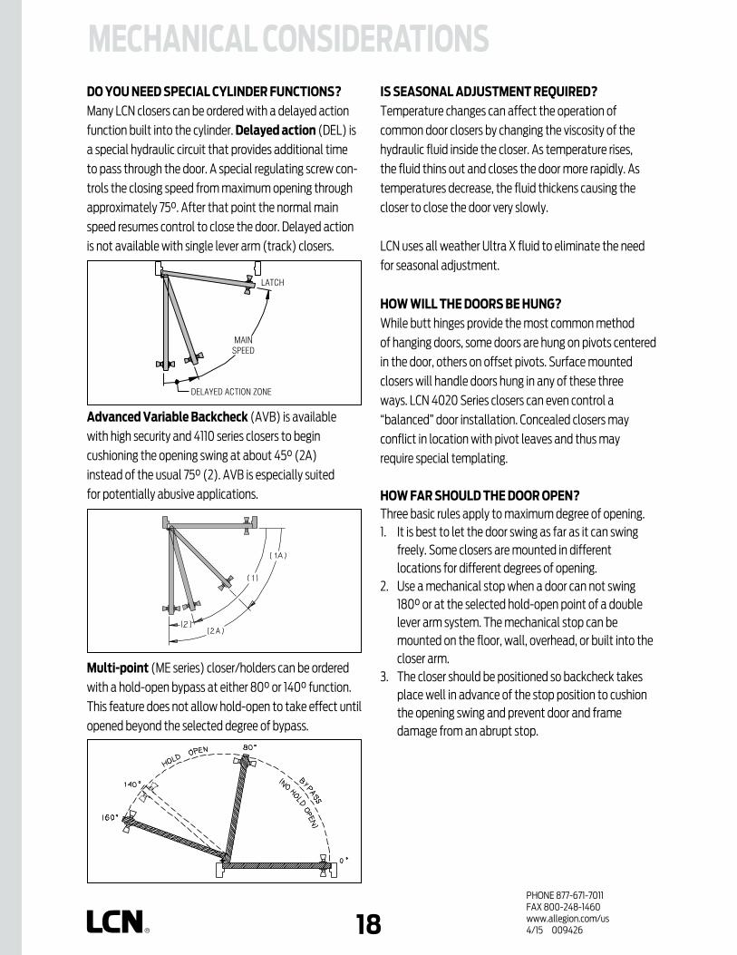
DO YOU NEED SPECIAL CYLINDER FUNCTIONS?Many LCN closers can be ordered with a delayed action
func tion built into the cylinder. Delayed action (DEL) is
a special hydraulic circuit that provides additional time
to pass through the door. A special regulating screw con-
trols the closing speed from maxi mum opening through
approximately 75°. After that point the normal main
speed resumes control to close the door. Delayed action
is not available with single lever arm (track) closers.
Advanced variable Backcheck (AVB) is available
with high security and 4110 series closers to begin
cushioning the opening swing at about 45° (2A)
instead of the usual 75° (2). AVB is especially suited
for potentially abusive applications.
Multi-point (ME series) closer/holders can be ordered
with a hold-open bypass at either 80° or 140° function.
This feature does not allow hold-open to take effect until
opened beyond the selected degree of bypass.
IS SEASONAL ADJUSTMENT REqUIRED?Temperature changes can affect the operation of
common door closers by changing the viscosity of the
hydraulic fluid inside the closer. As temperature rises,
the fluid thins out and closes the door more rapidly. As
temperatures decrease, the fluid thickens causing the
closer to close the door very slowly.
LCN uses all weather Ultra X fluid to eliminate the need
for seasonal adjustment.
HOW WILL THE DOORS BE HUNG?While butt hinges provide the most common method
of hanging doors, some doors are hung on pivots centered
in the door, others on offset pivots. Surface mounted
closers will handle doors hung in any of these three
ways. LCN 4020 Series closers can even control a
“balanced” door installation. Concealed closers may
conflict in location with pivot leaves and thus may
require special templating.
HOW FAR SHOULD THE DOOR OPEN?Three basic rules apply to maximum degree of opening.1. It is best to let the door swing as far as it can swing
freely. Some closers are mounted in different locations for different degrees of opening.
2. Use a mechanical stop when a door can not swing 180° or at the selected hold-open point of a double lever arm system. The mechanical stop can be mounted on the floor, wall, overhead, or built into the closer arm.
3. The closer should be positioned so backcheck takes place well in advance of the stop position to cushion the opening swing and prevent door and frame damage from an abrupt stop.
MECHANICAL CONSIDERATIONS

PHONE 877-671-7011FAX 800-248-1460www.allegion.com/us 4/15 00942619
MECHANICAL CONSIDERATIONSDOOR DIMENSIONS?The width of the door is the main consideration in determining the correct closer size. Size here refers to the minimum spring power and hence the closing force, generated by the closer. In the catalog, the interior and exterior TABLE OF SIZES for each closer are set up for ranges of door width and assume normal operating conditions. If a door is of exceptional height, weight, special construction, or if drafts and air pressure differ entials exist, increased closer power should be considered.
Door thickness may be a factor. A concealed-in-the-door closer should not be used in a hollow metal door less than 1-1/2˝ (38 mm) thick or a wood door under 1-3/4˝ (44 mm). Exceptionally thick doors can affect hinge and pivot centers to the extent that closer functions and geometry are also affected.
The depth of the doors top rail is important to nearly every closer installation. Narrow top rails may require plates to successfully mount the closer. An insufficient top rail in flush, hollow, or composite filled doors may make concealed-in-the-door installations impractical.
HAND OF A DOOR?Some door closers are handed. When approaching a door
from the push side, if hinged on the left, it is a left hand
door; if hinged on the right, it is a right hand door.
For purposes of handing door closers, right hand reverse
bevel and left hand are identical. Also, left hand reverse
bevel and right hand are identical.
WILL A STANDARD CLOSER AND TEMPLATE MEET YOUR NEEDS?Occasionally the physical limitations of the selected
closer may not provide the desired functions or degree
of opening. Standard templated locations may interfere
with other applied hardware. In these situations, contact
the LCN Applications Engineering Department for
assistance. Customized installation templates or pro ducts
may be available to solve an unusual application.
DOOR TOP RAIL

PHONE 877-671-7011FAX 800-248-1460www.allegion.com/us 4/15 00942620
Specialized brackets, adapters, and parallel arm shoes
are available to simplify the installation of closers
with a variety of frame and door conditions. The most
commonly used are listed with each closer. Consult
LCN for assistance if you are not sure.
MECHANICAL CONSIDERATIONSWHY USE PLATES, BRACKETS, ADAPTERS AND OTHER SPECIAL PIECES?A drop plate is now commonly used to drop (lower)
closers to meet special conditions or adapt a closer to
door or frame surfaces that are not adequate for normal
mounting patterns.
WHAT FASTENERS SHOULD BE USED?LCN closers are shipped with a wood and machine screw
pack or Self-Reaming and Tapping screws (SRT) unless
other fasteners are ordered. These screw packs are
suitable for wood or properly reinforced hollow metal
frames and metal or solid core wood doors. For wood door
applications, LCN recommends the use of wood screws.
For selected closers, metric machine screws are available
in lieu of UNC/UNF machine screws.
When attaching closers to hollow core doors, optional
THRU BOLTS (TB) are recommended to minimize
crushing or squeezing the door. Thru bolting can also
provide a very strong mechanical connection for
potentially abusive applications. Because the TB barrel
extends completely through the door, the door thickness
must be specified when ordering if it is other than 1-3/4˝
(44 mm). TB’s are only available for 1/4-20 machine
screws.
For high security applications, TORX machine screws
are available with most closers. These are standard for
all exposed fasteners with high security closers. TORX
fasteners feature a hex lobular drive with a security pin in
the center. They can only be installed or removed with a
special set of bits that are available from LCN.
DROP PLATE
CUSH SHOE SUPPORT
BLADE STOP SPACER
EDA ARM
TORX

PHONE 877-671-7011FAX 800-248-1460www.allegion.com/us 4/15 00942621
MECHANICAL CONSIDERATIONSWHAT FINISH IS DESIRED?LCN powder coating provides superior protection
against the effects of weather conditions and is an
environmentally friendly process. The high quality, chip
resistant finish is far superior to any previously offered.
Corrosion resistance surpasses 100 hours salt spray
testing (four times the industry standard). Non-metallic
components also provide the same high resistance to the
effects of the elements. All LCN products must be shipped
with a finish.
LCN offers custom finishing services to complement
special installations. This provides a custom appearance
and all the corrosion resistance inherent in the standard
powder coated finishes. It is recommended that the
customer submit a physical sample of desired custom
finish with the closer order. Custom powder coat finishes
are available at additional cost. A metal cover must be
ordered when custom powder coat finishes are desired.
With some exceptions, visible components such as
covers, arms, fasteners, and finish plates are available in
plated finishes. Tracks are painted to complement the
plated finish. Hidden assemblies such as cylinders and
mounting plates are supplied with a powder coated
finish. Plated finishes are available at additional cost.
For installations where a higher level of protection
against weathering is required, LCN offers a special rust
inhibiting (SRI) process at an additional cost. Metal
components receive an SRI pretreatment and a standard
or custom powder coat finish. The SRI process with a
powder coat finish exceeds the protection level available
with powder coated parts. SRI can not be ordered with
plated or anodized finishes. All closers must be shipped
with a finish.
INSTALLATION PROCESS?Before installation of the door closer;
Review the installation instructions provided with the
door closer.
Verify the desired installation and template with
the hardware schedule. Review other applied door
hardware for possible interference.
Verify that the frame attachments and door hinges or
pivots are securely installed.
Verify that the door is hung properly and operates
smoothly through it’s entire range of opening.
Misalignment, sagging or other conditions that
prevent free movement of the door must be corrected
prior to installation of the door closer.
LCN recommends < 1/4 lbf to open the door before
installing closers for ADA applications.
Check latching mechanisms for proper operation
and release.
Verify that the door and frame have specified
reinforcements.
Verify that all required tools are available.
Complete the installation by;
Follow the installation instructions and use fasteners
provided with the closer.
Using the template provided with the closer, layout,
drill and tap (for metal screws) the required mounting
holes. Be sure to use the proper size drill bit and tap to
ensure maximum holding power by the screws.
For closers with adjustable spring power, adjust the
cylinder spring power based on the width of the door
as described in the installation instructions.
The hydraulic back check, main speed and latch speed
regulation adjustments of the door closer have been
adjusted at the factory to meet normal installation
conditions. If further adjustments are required to the
hydraulic regulation, follow the directions included
with the installation instructions.
Lightly wipe the cover and arm surfaces with a soft,
clean, dry cloth to remove any dirt or smudges that
occurred during the installation.

PHONE 877-671-7011FAX 800-248-1460www.allegion.com/us 4/15 00942622
Arm OptionsSTD - Standard ArmREG - Regular ArmRw/PA - Regular Arm with Parallel Arm ShoeR/62A - Regular Arm with Auxiliary Parallel Arm ShoeH - Hold Open ArmHw/PA - Hold Open Arm with Parallel
Arm ShoeLONG - Long ArmXLONG - Extra Long ArmHLONG - Hold Open Long ArmEDA - Extra Duty ArmEDAw/62G - Extra Duty Arm with Thick Hub ShoeHEDA - Hold Open Extra Duty ArmHEDAw/62G - Hold Open Extra Duty Arm
w/ Thick Hub ShoeCUSH - Cush -n- Stop ArmHCUSH - Hold Open Cush -n- Stop ArmSCUSH(SCNS) - Spring Cush -n- Stop ArmSHCUSH(SHCNS) - Spring Hold Open
Cush -n- Stop ArmSF - Swing Free ArmDE - Double Egress ArmFL - Fusible Link Arm
Control Box Options SC - Standard Control Box
Cylinder OptionsSTD - Standard CylinderDEL(DA) - Delayed Action CylinderAVB - Advanced Variable Backcheck B80 - Bypass 80 Degree ME CylinderB140 - Bypass 140 Degree ME CylinderTEL - Telephone Cylinder
Cover OptionSTD - Standard Plastic CoverMC - Metal CoverFC - Full CoverCL - Cover LengthDS1 - Designer Series Cover
Track OptionsSTD - Standard TrackHO - Hold Open TrackBUMPER - Track with BumperHBUMPER - Hold Open Track with Bumper
Fastener Pack OptionsWMS - Wood & Machine ScrewsTBWMS - Thru-Bolt, Wood & Machine ScrewsSRT - Self Reaming & Tapping ScrewsTBSRT - Thru-Bolt, Self Reaming & Tapping ScrewsTORX - ‘TORX’ Machine ScrewsTBTRX - Thru-Bolt, ‘Torx’ Machine Screws
Motor Gearbox OptionsSF - Standard Force Motor Gearbox
Powder Coat FinishesAL - Aluminum DKBRZ - Dark BronzeSTAT - Statuary BronzeLTBRZ - Light BronzeBLK - BlackBRASS - Brass
Miscellaneous TermsELR - Extra Long RodSRI - Special Rust InhibitorSE - Single Point ElectronicME - Multi-Point ElectronicPAH - Parallel Arm HolderHSA - Hold Open / Scanner ActivatedES - Electric Strike Relay (Control Boxes)S - Sequential (Control Boxes)RF - Radio FrequencyTJ - Top JambPA - Parallel ArmG - Flush CeilingT - TrackDPS - Door Position SwitchLR - Long RodST - Special TemplateRH - Right HandLH - Left HandHL - Header LengthDD - Double Door HeaderPOS - Positive Mechanical StopBKY - Panic Breakaway StopXP - Extra Protection
GLOSSARY OF ABBREvIATIONS

PHONE 877-671-7011FAX 800-248-1460www.allegion.com/us 4/15 00942623
GLOSSARY OF TERMS
A-B
ARCH TOP DOOR – Any door with an arched top rail.
ARMATURE EXTENSION – Standard metal extensions available for SEM magnets where the armature does not reach the magnet. Available in 1/2", 3/4", 1", 2", 4" or a kit including all sizes.
AUTOEqUALIZER™ – An LCN specific term for an electric or a pneumatic power operator. System is low-energy & carries a two-year warranty.
AUTOMATIC OPERATOR – A term used to describe a type of automated opening system.
AUXILIARY DOOR STOP – Hardware designed and installed to limit the swing of a door.
BBACKCHECK – Hydraulic circuit designed to cushion the doors opening swing at about 75°. Standard on all LCN closers.
AADA – Americans with Disabilities Act.
ADvANCED vARIABLE BACKCHECK CYLINDER (AvB) – Optional cylinder that starts backcheck at about 45° (2A) instead of the normal 75°(2).
ANODIZED – An electrochemical process that thickens and toughens the protective oxide on aluminum metal.
ANSI – American National Standards Institute publishes standards for commercial hardware. A156.4 is the basic door closer standard.
APPLIED STOP – Surface mounted stop attached to a cased opening frame.
FRAME DEPTHFRAMEFACE
RABBET
TOP RAIL OF DOOR
HINGESIDEFRAMEREVEAL
HINGE
DOOR THICKNESS
PANEL ORGLASS LITE
REVEAL
SOFFIT
STOP
STOP HEIGHT
RABBET
FRAMEFACE
INCREASE
BACKCHECK BACKCHECKREGULATING SCREW
SOFTER
PULL SIDE PUSH SIDE
AvB CYLINDER
FIRMER

PHONE 877-671-7011FAX 800-248-1460www.allegion.com/us 4/15 00942624
BACKCHECK SELECTOR vALvE – Valve used to provide proper backcheck location for 4040XP parallel arm mounting.
BLADE STOP – Narrow frame stop that will not accept a parallel arm shoe.
BLADE STOP SPACER – Spacer lowers a parallel arm 1/2˝ so the arm will clear a blade stop.
BLOW-OPEN – A type of control box that is used for a smoke evacuation system. Can be used with or without a normal power operator system.
BRIGHT METALLIC – Custom powder coat finish, which resembles that of US26 or US26D plated finish.
BYPASS CYLINDER – ME cylinder that will not hold-open within a specified range of door swing.
CCASED OPENING – Frame section without stops.
CAST IRON – Material used in producing high quality door closers.
CLEARANCE – Distance from a PA SHOE to the push side of door or distance from the pull side of door to the wall on 90° installations.
GLOSSARY OF TERMSB-
C CLOSING FORCE – Energy generated by a closer to close and latch the door.
CONTROL BOX, Standard, 9100 SERIES – Microprocessor door control without Power Boost or built in power supply.
CONTROL BOX, 2800, 9500 SERIES – Microprocessor door control, includes adjustment for opening, closing & backcheck speeds. Features Push ‘N Go & Power Boost.
CONTROL BOX, 7900 SERIES – Heavy duty, surface mounted control box that contains one or two electrically controlled pneumatic circuits.
CONTROLLER ASSEMBLY – Digital control suite used in the LCN electric power operator. Includes adjustments for opening force and opening speed.
CONCEALED IN DOOR – Closer with cylinder concealed in the top rail of the door with either an exposed or concealed arm.
CUSH SHOE SUPPORT – Support provides fifth screw anchorage of CUSH shoes on frames with narrow push side reveals.
CUSH-N-STOP ARMS (CUSH) – Extra duty, parallel arm that includes a stop in the CUSH shoe.
CUSTOM POWDER COAT (RAL) – An optional powder coat finish. Currently, LCN offers a wide selection for special powder coat finishes. LCN uses a European color standard, referred to as an RAL #, to differentiate between finishes.
CUTOUT – Preparation of the top rail of a door or frame for concealment of the closer, arm or track.
80° BYPASS CYLINDER ILLUSTRATED
CLEARANCE DOOR
WALL
Turn in clockwise for PA mount.
CUSH SHOE SUPPORT
CUSH-N-STOP ARM
SIDE
1 03
1
4041
BACKCHECK SELECTOR vALvE
BLADE STOP SPACER
PHONE 877-671-7011FAX 800-248-1460www.allegion.com/us 4/15 00942625
GLOSSARY OF TERMS
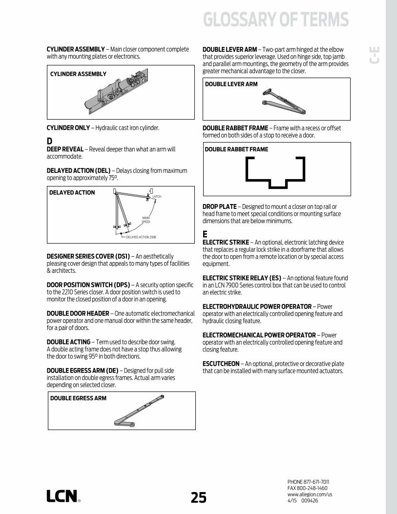
C-EDOUBLE LEvER ARM – Two-part arm hinged at the elbow
that provides superior leverage. Used on hinge side, top jamb and parallel arm mountings, the geometry of the arm provides greater mechanical advantage to the closer.
DOUBLE RABBET FRAME – Frame with a recess or offset formed on both sides of a stop to receive a door.
DROP PLATE – Designed to mount a closer on top rail or head frame to meet special conditions or mounting surface dimensions that are below minimums.
EELECTRIC STRIKE – An optional, electronic latching device that replaces a regular lock strike in a doorframe that allows the door to open from a remote location or by special access equipment.
ELECTRIC STRIKE RELAY (ES) – An optional feature found in an LCN 7900 Series control box that can be used to control an electric strike.
ELECTROHYDRAULIC POWER OPERATOR – Power operator with an electrically controlled opening feature and hydraulic closing feature.
ELECTROMECHANICAL POWER OPERATOR – Power operator with an electrically controlled opening feature and closing feature.
ESCUTCHEON – An optional, protective or decorative plate that can be installed with many surface mounted actuators.
CYLINDER ASSEMBLY – Main closer component complete with any mounting plates or electronics.
CYLINDER ONLY – Hydraulic cast iron cylinder.
DDEEP REvEAL – Reveal deeper than what an arm will accommodate.
DELAYED ACTION (DEL) – Delays closing from maximum opening to approximately 75°.
DESIGNER SERIES COvER (DS1) – An aesthetically pleasing cover design that appeals to many types of facilities & architects.
DOOR POSITION SWITCH (DPS) – A security option specific to the 2210 Series closer. A door position switch is used to monitor the closed position of a door in an opening.
DOUBLE DOOR HEADER – One automatic electromechanical power operator and one manual door within the same header, for a pair of doors.
DOUBLE ACTING – Term used to describe door swing. A double acting frame does not have a stop thus allowing the door to swing 95° in both directions.
DOUBLE EGRESS ARM (DE) – Designed for pull side installation on double egress frames. Actual arm varies depending on selected closer.
DELAYED ACTION
DOUBLE LEvER ARM
DOUBLE EGRESS ARM
SIDE
1 03
1
4041
DOUBLE RABBET FRAME
CYLINDER ASSEMBLY

PHONE 877-671-7011FAX 800-248-1460www.allegion.com/us 4/15 00942626
GLOSSARY OF TERMSE-
H EXTRA DUTY ARM (EDA) – Double lever arm with both main and forearm made of solid forged steel for extra strength.
EXTRA LONG ARM (XLONG) – 4040XP Series double lever arm for exceptionally deep reveals or other special applications.
F(LCN®) FAST™ POWER ADJUST – A green dial located on the end of the spring tube on selected heavy duty closers. Designed to help installers accurately adjust the closer power to match the conditions of the entrance.
FIFTH SCREW – Mounting screw farthest from the door on a parallel arm shoe.
FIFTH SCREW SPACER – Supports PA shoe mounted on frame stop.
FINISH PLATE – Decorative plate applied to overhead concealed closer to conceal closer mounting plate and screws.
FIRE SHIELD – 22-gage steel liner mounts in the track mortise of the door’s top rail for 20 minute labeled wood doors.
FLUSH CEILING – Condition when the ceiling is at the same height as the top of the frame.
FLUSH PANEL ADAPTER – Adapter provides PA shoe mounting surface when door and frame are flush.
FOREARM – Arm part that connects main arm to the shoe attachments in a double lever arm system.
FRAME DEPTH – Face to face dimension of the frame.
FRAME FACE – Exposed part of frame parallel to face of the wall.
FULL COMPLIMENT BEARINGS – Low friction, high load needle bearings found in all LCN closers.
FULL COvER (FC) – Cover that encloses cylinder assembly except for shaft/arm attachment.
FUSIBLE LINK ARM (FL) – Releases hold-open function when exposed to high temperatures. 135°F and 165°F available.
HHAND – Direction of a doors’ swing, either right or left.
HANDED – Closer or part designed for ONLY right or left swinging doors.
HEAD FRAME – Member of the frame above the door.
LCN® FAST™ POWER ADJUST
FLUSH CEILING
FLUSHPANELADAPTER
FRAME FACE
FUSIBLE LINK ARM
HAND
EXTRA-DUTY ARM

PHONE 877-671-7011FAX 800-248-1460www.allegion.com/us 4/15 00942627
GLOSSARY OF TERMS
H-MJ
JAMB – The vertical member that forms the sides of a door frame. There is a hinge side jamb and a strike side jamb.
LLABELED DOOR – Conforms to all applicable codes, requirements, and procedures governing fire rated doors and bears the manufacturer’s identification label.
LATCH SPEED – Separate adjustment to control the last few degrees of the door’s closing swing.
LOCK STILE – Vertical member of a door prepared for installation of a lock.
LONG ARM (LONG) – Extended arm for deep reveals or other special applications.
LOW ENERGY OPERATOR – A type of automated opener used on a door that should take approximately 5 seconds to open to 90°. Low Energy operators do not require safety devices or guide rails. Conforms to ANSI A156.19.
MMAIN ARM – Connects to the cylinder in a double lever arm system.
MAIN SPEED – Separate adjustment to control closing swing of the door to within a few degrees of latch.
MAXIMUM OPENING – Furthest degree of door opening.
METAL COvER (MC) – Stamped metal cover required for optional plated finishes and custom powder coat finishes. Standard cover with High Security Series closers.
MOTOR CLUTCH – The geared assembly in an LCN electric power operator. Once activated, the motor clutch drives the door open.
MOTOR GEARBOX – Electromechanical drive unit.
HEADER – Aluminum enclosure for motor gearbox & controller.
HINGE SIDE – Face of door and frame on which the hinge pivot point is located.
HINGE SIDE MOUNT – Mounting with the closer cylinder on the hinge side of the door top rail.
HINGE SIDE REvEAL – Depth measured from the frame face to the pull side of the door face.
HINGE STILE – Vertical member of a door prepared for installation of hinges.
HOLD-OPEN ARM (H) – Double lever arm that provides hold-open function that is either adjustable at elbow or shoe.
HOLD-OPEN CLIP – Located in track to provide hold-open function for single lever arms.
HOLD-OPEN CUSH (HCUSH) – Parallel arm that features solid forged steel main arm and forearm with stop in soffit shoe. Uses control handle to select hold-open function.
HOLD-OPEN LONG ARM (HLONG) – Hold-open arm extended by a long head and tube for deep reveals.
HOLD-OPEN TRACK (HO) – Track with hold-open clip installed.
HOLD-OPEN TRACK with BUMPER (HBUMPER) – Track with hold-open clip and bumper assembly installed.
HOLDER SCANNER-ACTIvATED (HSA) – Electrically controlled closer/holder with built-in scanner.
HYDRAULIC FLUID – Fluid metered by valve system to control door.
IINDEPENDENT PAIR – Two automatic doors that function separately.
HINGE (PULL)SIDE MOUNT
HINGE SIDE REvEAL
LATCH SPEED LATCH SPEED REGULATION
MAIN SPEED MAIN SPEED REGULATION

PHONE 877-671-7011FAX 800-248-1460www.allegion.com/us 4/15 00942628
GLOSSARY OF TERMSM
-P PANIC BREAKAWAY STOP – An optional safety device that permits egress on in-swinging exterior doors by allowing them to swing out in case of an emergency. Used with overhead concealed, center pivoted in-swinging doors.
PARALLEL ARM – A push side mounted double lever arm system where main arm is parallel to the door when in the closed position.
PARALLEL ARM HOLDER (PAH) – An item usually used on the inactive leaf of a pair of doors for hold-open where the active leaf has a closer installed.
PINION – Transfers rotary motion of the arm system to the piston. Also provides attachment of arms to closer.
PISTON – One of the internal pieces of a door closer. The piston is moved by the rotating pinion, which in turn compresses the spring.
POSITIvE MECHANICAL STOP – Door stop for overhead concealed, center pivoted out swinging doors.
PNEUMATIC – This type of LCN Automatic Operator is driven by an air source. The air source can be built into the control box or provided separately within the building.
POWER BOOST – Provides additional closing force to ensure latching.
POWER OPERATOR – A term used to describe a type of automated opening system. Refer to “Automatic Operators”.
POWDER COAT – A standard finishing process that provides a very durable, corrosion resistant covering to the majority of products that LCN offers. An LCN powder coat finish offers over four times the ANSI salt spray test of 25 hours.
PULL SIDE – Hinge side of door.
MORTISE – Material removed from frame and/or top rail of door.
MOUNTING/FINISH PLATE – Plate with exposed mounting screws and finish applied.
MULTI-POINT HOLD-OPEN (ME) – Infinite hold-open points from 0° up to maximum opening.
NNO DESTRUCT FEATURE – A feature specific to the motor clutch assembly portion of an LCN electric power operator. This feature does not allow the user to back drive the motor, which could cause damage to the unit.
NON-HANDED – Closer or part designed for both right and left hand swinging doors.
NON-SIZED – Cylinder assembly with spring power adjustable over a range of sizes.
OOPENING FORCE – Force required to open the door against the closers spring power.
OvERHEAD CONCEALED – Closer with cylinder concealed in head frame and either a concealed or exposed arm.
PPA SHOE ADAPTER – Adapter provides horizontal mounting for PA shoe on a flush door and frame.
PA SHOE – Attaches the forearm to the soffit for a parallel arm system.
PACKING NUT – A threaded part that holds the pinion in place. Usually, the LCN model number and date of manufacture are stamped into this part. The date of manufacture is important because the owner can determine if the cylinder is in or out of warranty.
PA SHOEADAPTER
PARALLEL ARM MOUNT
SIDE
1 03
1
4041
PULL SIDE/PUSH SIDE
SIDE
1 03
1
4041
PACKING NUT
Model#
Shift Made
Week of the Year Manufactured
Year Manufactured

PHONE 877-671-7011FAX 800-248-1460www.allegion.com/us 4/15 00942629
GLOSSARY OF TERMS
P-SS
SELF-REAMING and TAPPING SCREW (SRT) – Philips head screw with self-reaming and self-tapping capability used in mounting installations.
SECOND CHANCE FEATURE – A feature that allows the Automatic Operator two attempts at opening the door. If resistance is encountered on the first attempt, the operator will pause and then try a second time. This feature is standard on the LCN electric automatic operators.
SEM – SEM is short for ‘single-point electronic magnet’. An actual product number is required when ordering.
SENTRONIC – A general term for the fire/life safety products that are offered by LCN.
SEqUENCE – An option to the LCN series of automatic operators. This option allows a pair of vestibule doors to open one after the other.
SHOE – Attaches forearm to frame or door face in a double lever arm system.
SIMULTANEOUS PAIR – Two automatic doors that open at the same time.
SINGLE POINT HOLD-OPEN (SE) – Electrically controlled hold-open using a special track and single lever arm.
SINGLE LEvER (STANDARD) ARM (STD) – Directly connects cylinder and track/roller assembly on the door or frame.
SINGLE RABBET FRAME – Frame with a recess or offset formed on one side of a stop to receive a door.
SIZED – A closer with a specific closer power for proper door applications.
SLIDER – This part is used in conjunction with a track roller in a Sentronic track assembly.
PUSH SIDE – Face of door on stop side of frame.
PUSH ‘N GO – Provides power opening after partial (5°) manual opening of door.
qqUICK FIX PLATE™ – Retrofit mounting plate for the LCN 1260 closer used for closer replacement in push/pull applications.
RRABBET – Recess or offset formed in the face to receive a door.
RADIO FREqUENCY (RF) – A method of actuating LCN Automatic Operators. A RF transmitter signals a RF receiver to open a door.
REGULAR ARM – A double lever, non hold-open arm.
REGULATING SCREW – Valve that adjusts flow of hydraulic fluid within cylinder to control door closing speed.
REvEAL – Depth measured from the frame face to the door face.
ROD & SHOE – Part of forearm that provides adjustable length feature for double lever arms.
REGULAR ARM
SIDE
1 03
1
4041
REGULATING SCREW DELAY REGULATING SCREW
REvEAL
ROD & SHOE
SINGLE LEvER ARM
SIDE
1 03
1
4041
SELF-REAMING and TAPPING SCREW
SINGLE RABBET
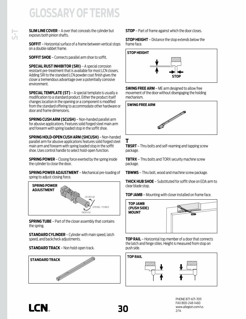
PHONE 877-671-7011FAX 800-248-1460www.allegion.com/us 2/1430
GLOSSARY OF TERMSS-
T SLIM LINE COvER – A over that conceals the cylinder but exposes both pinion shafts.
SOFFIT – Horizontal surface of a frame between vertical stops on a double rabbet frame.
SOFFIT SHOE – Connects parallel arm shoe to soffit.
SPECIAL RUST INHIBITOR (SRI) – A special corrosion resistant pre-treatment that is available for most LCN closers. Adding SRI to the standard LCN powder coat finish gives the closer a tremendous advantage over a potentially corrosive environment.
SPECIAL TEMPLATE (ST) – A special template is usually a modification to a standard product. Either the product itself changes location in the opening or a component is modified from the standard offering to accommodate other hardware or door and frame dimensions.
SPRING CUSH ARM (SCUSH) – Non-handed parallel arm for abusive applications. Features solid forged steel main arm and forearm with spring loaded stop in the soffit shoe.
SPRING HOLD-OPEN CUSH ARM (SHCUSH) – Non-handed parallel arm for abusive applications features solid forged steel main arm and forearm with spring loaded stop in the soffit shoe. Uses control handle to select hold-open function.
SPRING POWER – Closing force exerted by the spring inside the cylinder to close the door.
SPRING POWER ADJUSTMENT – Mechanical pre-loading of spring to adjust closing force.
SPRING TUBE – Part of the closer assembly that contains the spring.
STANDARD CYLINDER – Cylinder with main speed, latch speed, and backcheck adjustments.
STANDARD TRACK – Non hold-open track.
STOP – Part of frame against which the door closes.
STOP HEIGHT – Distance the stop extends below the frame face.
SWING FREE ARM – ME arm designed to allow free movement of the door without disengaging the holding mechanism.
TTBSRT – Thru bolts and self-reaming and tapping screw package.
TBTRX – Thru bolts and TORX security machine screw package.
TBWMS – Thru bolt, wood and machine screw package.
THICK HUB SHOE – Substituted for soffit shoe on EDA arm to clear blade stop.
TOP JAMB – Mounting with closer installed on frame face.
TOP RAIL – Horizontal top member of a door that connects the latch and hinge stiles. Height is measured from stop on push side.
TOP RAIL
SWING FREE ARM
STOP HEIGHT
STOP
STANDARD TRACK
TOP JAMB(PUSH SIDE)MOUNT
SPRING POWER ADJUSTMENT
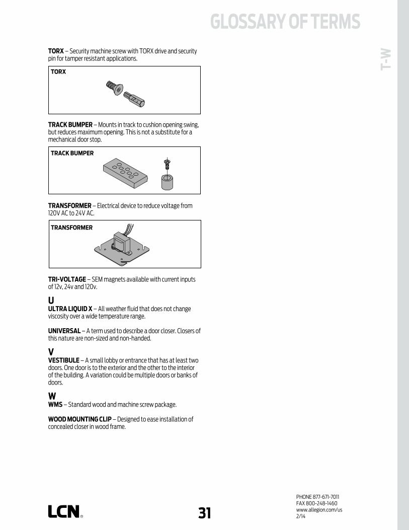
PHONE 877-671-7011FAX 800-248-1460www.allegion.com/us 2/1431
GLOSSARY OF TERMS
T-WTORX – Security machine screw with TORX drive and security
pin for tamper resistant applications.
TRACK BUMPER – Mounts in track to cushion opening swing, but reduces maximum opening. This is not a substitute for a mechanical door stop.
TRANSFORMER – Electrical device to reduce voltage from 120V AC to 24V AC.
TRI-vOLTAGE – SEM magnets available with current inputs of 12v, 24v and 120v.
UULTRA LIqUID X – All weather fluid that does not change viscosity over a wide temperature range.
UNIvERSAL – A term used to describe a door closer. Closers of this nature are non-sized and non-handed.
vvESTIBULE – A small lobby or entrance that has at least two doors. One door is to the exterior and the other to the interior of the building. A variation could be multiple doors or banks of doors.
WWMS – Standard wood and machine screw package.
WOOD MOUNTING CLIP – Designed to ease installation of concealed closer in wood frame.
TORX
TRACK BUMPER
TRANSFORMER

PHONE 877-671-7011FAX 800-248-1460www.allegion.com/us 4/15 00942632
Notes

1PHONE 877-671-7011FAX 800-248-1460www.allegion.com/us 4/15 009426
Product coMPArISoNThis chart shows a basic comparison of 4000 Series closers.Refer to the specific closer chapter for complete details.
4000 SErIES SurFAcE MouNtEd cLoSErS
* INDICATES HIGH SECURITY CLOSER. REFER TO THAT SECTION OF THE CATALOG.
EXtErIor door
doubLE LEvEr ArM
4020 4040XP 4110 4210* 4030
PuSH SIdEMouNtEd
PuLL SIdEMouNtEd
doubLE LEvEr ArM
4020 4040XP4110 4210*
PuLL SIdEMouNtEd
INtErIor door
Product SELEctIoN GuIdESurface mounted 4000 Series LCN closers feature a modern design engineered for each application, easy installation, and superior performance. This guide is based on the desired mounting of the closer.
PuSH SIdEMouNtEd
doubLE LEvEr ArM
4010 4040XP 4510*
SINGLE LEvEr ArM
4110t 4040XP 4210t*
doubLE LEvEr ArM
4020 4030 4040XP 4510*
SINGLE LEvEr ArM
4000t 4010t 4020t 4510t*4040XPt 4030t
Closer available with less than 5.0 lbs. opening force on 36" door. ** Maximum opening/hold-open point with standard template. See individual closer series for
degrees of opening per installation. *** Advanced Variable Backcheck. **** Delay Action for 4040XP Requires standard 4041 cylinder.
AVAILABLE NOT AVAILABLE
4010
CLOSERSERIES
4010T
4020
4020T
4030
PLASTIC
METAL
HINGE (PULL)
SIDE
TOP JAMB (PULL
)
TOP JAMB (PUSH)
4030T
PARALLEL A
RM
STOP FACE
MOUNTING COVER CYLINDER
180°
180°
140° 140° 140°
180°
180°
140°
180° 110° 100° 100°
140°
100°
120°
STANDARD (S
INGLE)
REGULA
R (DOUBLE)
HOLD-O
PEN
FUSIB
LE LI
NK
EDA/HEDA
CUSH/HCUSH
SCUSH/SHCUSH
180° 180°
**ARM FUNCTIONFINISH
NON-HANDED
NON-SIZED
ACCESSIBILI
TY
DELAYED ACTIO
N****
AVB***
4040XP 180° 110°110°120°120°
4040XPT
4110
4110T
4000T
DOUBLE EGRESS
110°
110°
120°
180° 180° 110° 110°
100°
90°
POWDER COAT
PLATED
100°

2PHONE 877-671-7011FAX 800-248-1460www.allegion.com/us 4/15 009426
APPLIcAtIoNS n For aluminum, hollow metal, or wood swinging doors and frames. n Can be used with hinge or pivot mounted door. n Adapter plates and other installation accessories available for
unusual conditions.
FEAturES coMMoN to 4000 SErIES n Each closer (except 4040XP, 4040XPT, 4030, 4030T) is designed
for a specific mounting; hinge side, top jamb, or parallel arm. 4040XP closer with regular or hold-open arm mounts hinge side or top jamb. 4030 and 4040 regular parallel arm closers include 62PA SHOE required to parallel arm mount either regular or hold-open arm.
n Handed for right or left swinging doors, except 4000T, 4030, 4030T, 4040XP and 4040XPT.
n Closers to meet ADA reduced opening force requirements except 4000T.
n Adjustable hydraulic backcheck cushions opening swing prior to 90°. n Separate regulation of general closing speed and latching speed. n Joints in regular arm and shoe adapt to uneven trim. n Reversible shoe to boost latching power on double lever arms. n Available in a wide range of standard or optional custom powder
coat finishes to blend with door and frame. n Plated finishes available to accent door and frame. n Not designed for exterior mounting or exposed to elements.
dESIGN ASSIStANcELCN has been providing reliable solutions to unique door control problems for over 85 years. Design and specification assistance are only a phone call away.
Contact LCN for assistance or technical information at 877-671-7011 or FAX 800-248-1460 (order Entry), Fax 815-879-1495 for Product Support.
WArrANtY 30 year limited warranty. See General Information Section for complete warranty details.
SPEcIFIcAtIoNS Refer to ”SPECIFICATIONS” section for suggested architectural specifications.
MAtErIALS n High strength cast iron cylinder. n Forged steel main arms. n One piece forged steel piston. n double heat treated pinion. n All weather fluid eliminates seasonal adjustments temperatures
ranging from 120° F (49° C) to -30°F. (-35° C). n High efficiency, full complement, low friction bearings. n Tamper resistant regulating screws. n Full rack and pinion hydraulic action. n Quiet, low friction track and roller combination for all single lever
arm closers.
FINISHES n Available in seven standard or optional custom powder
coat finishes to blend with door and frame.
4000 SErIES SurFAcE MouNtEd cLoSErS n LCN’s powder coat finishes surpass 100 hours of salt spray which
is over four times the ANSI standard for corrosion resistance. n For installations where a higher level of corrosive resistance is
required, LCN offers an optional special rust inhibiting (SRI) pre-treatment. Closers that combine the exclusive LCN powder coat finish and the SRI pre-treatment exceed the ANSI standard for corrosion resistance even further.
n Plated finishes are available as an option to accent door and frame. (SRI not available with plated finishes).
LIStINGS & APProvALSUL listed for self-closing doors without hold-open under "SWINGING DOOR CLOSERS"(GVEV) file R1943.Tested and certified under ANSI Standard A156.4 Grade One. Consult factory for details.Consult factory for other listings such as; cUL, California State Fire Marshal, Bureau of Standards and Appeals.
PoSItIvE PrESSurE LCN closers have been certified for three hours by UL to be in compliance with UBC 7.2 (1997) and UL 10C. Contact LCN for specific details on door closer fire ratings.
FAStENErS4010, 4010T, 4020, 4020T, 4040XP, 4040XPT, 4110, 4110T Series closers are shipped with: A standard SELF-REAMING and TAPPING SCREW (SRT) pack that contains Philips head SRT screws to install the closer. 4000T series closers are shipped with: A standard WOOD and MACHINE SCREW (WMS) pack that contains Philips head wood and machine screws to install the closer. 4030, 4030T series closers are shipped with: A standard WOOD and SELF-TAPPING MACHINE SCREW (WMS) pack that contains Phillips head wood and self-tapping machine screws to install the closer.Standard LCN thru bolts (TB) can be installed on 1-3/4˝ (44 mm) thick doors with 1/4-20 machine screws. Optional thru bolt (TB) sizes are available for 1-5/8˝ (41 mm) or 1-3/8˝ (35 mm) door thickness, but this must be specified when ordering.
Notes:1. For Thru Bolts, specify door thickness if other than 1-3/4˝ (44mm),
represented in diagram as dimension "X".2. Phillips head, metric machine screws are available, please specify.3. LCN recommends the use of wood screws, available in optional WMS screw packs,
for wood door applications.
MAINtENANcE Closers mounted according to LCN installation instructions require no periodic maintenance or adjustments.
Drill 25/64˝ forsteel doorsorDrill 3/8˝for wood doors

2 3PHONE 877-671-7011FAX 800-248-1460www.allegion.com/us 4/15 009426
Standard 4010 Series closer is shipped with regular arm, standard plastic cover, and self reaming and tapping screws. See 4010 Series page 5 for options.
Size 6 (4016) cylinder for interior doors to 5´0˝ and exterior doors to 4´0˝.
Non-sized cylinder (4011) adjustable for interior doors to 4´6˝ and exterior doors to 3´6˝.
Closer mounts hinge side, specify right or left swinging door.
4011 cylinder meets ADA requirements. See 4010 Series page 6.
Standard or optional custom powder coat finish.
Optional plated finish on metal cover, arm and fasteners.
Optional SRI primer for installations in corrosive conditions is available with powder coat finish only.
The 4010 Series is UL and cUL listed with regular or fusible link arms for self-closing doors.
Tested and certified under ANSI Standard A156.4, grade one.
the 4010 is LcN’s best performing
heavy duty closer designed
specifically for institutional
and other rugged high traffic
applications.
n Cast Iron n Forged Steel Main Arm n Double Heat Treated Steel Pinion n All Weather Fluid n LCN Patented Green Dial n UL & cUL Listed n Peel-n-Stick Templates for Fast
and Accurate Installations
4010 SErIES HINGE (PuLL) SIdE MouNt
The 4010 Series includes theLcN® "Green dial"
Spring Force Indicator
Closer available with less than 5.0 lbs. opening force on 36˝ door. ** Maximum opening/hold-open point with standard template. *** Advanced Variable Backcheck.
AVAILABLE NOT AVAILABLE
FEAt
urES
NON-HANDED
NON-SIZED
ACCESSIBILI
TY
DELAYED ACTIO
N
AVB***
PLASTIC
METAL
HINGE (PULL)
SIDE
TOP JAMB (PULL
)
TOP JAMB (PUSH)
STANDARD (S
INGLE)
REGULA
R (DOUBLE)
HOLD-O
PEN
FUSIB
LE LI
NK
EDA/HEDA
CUSH/HCUSH
SCUSH/SHCUSH
DOUBLE EGRESS
PARALLEL A
RM
STOP FACE
POWDER COAT
PLATED
140° 140° 140°
MOUNTING COVER CYLINDER **ARM FUNCTIONFINISH

4PHONE 877-671-7011FAX 800-248-1460www.allegion.com/us 4/15 009426
HINGE (PuLL) SIdE MouNtING
MAXIMuM oPENINGCan be templated for 100°,
A = 5-15/16˝ (151 mm)B = 11-15/16˝ (303 mm)
or 140°. A = 4-3/16˝ (106 mm)B = 10-3/16˝ (259 mm)
Hold-open points up to maximum opening with hold-open arm.
Arm clearance above door. Regular arm requires
C = 1-1/16˝ (27 mm).Hold-open arm requires
C = 1-3/8˝ (35 mm).Fusible link arm requires
C = 1-5/8˝ (41 mm).
4010 SErIES
n butt Hinges should not exceed 5˝ (127 mm) in width.
n Auxiliary Stop is recommended at hold-open point or where a door cannot swing 140°.
n reveal should not exceed 3/4˝ (19 mm). Should not exceed 1/8˝ (3 mm) for Fusible link arm.
n top rail less than 3-3/4˝ (95 mm) requires PLATE, 4010-18. Plate requires 2˝ (51 mm) minimum.
n clearance of 2-1/4˝ (57 mm) behind door required for 90° installation.
n delayed Action Add suffix “DEL” to selected cylinder. Not available with 4016 cylinder. Delays closing from maximum opening to approximately 70°. Delay time adjustable up to approximately 1 minute.
Mou
NtIN
G dE
tAIL
S
options n Size 6 or non-sized cylinder. n Delayed action cylinder. n Hold-open or fusible link arm. n Metal cover.
Special templates Customized installation templates or products may be available to solve unusual applications. Contact LCN Product Support for assistance.
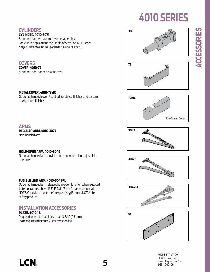
4 5PHONE 877-671-7011FAX 800-248-1460www.allegion.com/us 4/15 009426
4010 SErIES cYLINdErScYLINdEr, 4010-3071 Standard, handed cast iron cylinder assembly. For various applications see “Table of Sizes” on 4010 Series page 6. Available in size 1 (Adjustable 1-5) or size 6.
covErScovEr, 4010-72 Standard, non-handed plastic cover.
MEtAL covEr, 4010-72McOptional, handed cover. Required for plated finishes and custom powder coat finishes.
ArMSrEGuLAr ArM, 4010-3077Non-handed arm.
HoLd-oPEN ArM, 4010-3049Optional, handed arm provides hold-open function, adjustable at elbow.
FuSIbLE LINK ArM, 4010-3049FL Optional, handed arm releases hold-open function when exposed to temperatures above 165° F. 1/8” (3 mm) maximum reveal. NOTE: Check local codes before specifying FL arms. NOT A life safety product!
INStALLAtIoN AccESSorIESPLAtE, 4010-18Required where top rail is less than 3-3/4” (95 mm). Plate requires minimum 2” (51 mm) top rail.
72
3077
72Mc
3071
3049
3049FL
AccE
SSor
IES
18
Right Hand Shown

6PHONE 877-671-7011FAX 800-248-1460www.allegion.com/us 4/15 009426
*4011
*4011
EXtErIor (and vEStIbuLE) door WIdtH
24"610mm
30"762mm
36"914mm
42"1067mm
INtErIor door WIdtH
48"1219mm
24"610mm
34"864mm
38"965mm
48"1219mm
54"1372mm
60"1524mm
4016
4016
size 2 size 3 size 4 size 5 size 6
* Adjustable Size 1 thru 5.
rEducEd oPENING ForcE 4010 cLoSErScAutIoN ! Any manual door closer, including those certified by BHMA to conform to ANSI Standard A156.4, that is selected, installed and adjusted based on ADA or other reduced opening force requirements may not provide sufficient power to reliably close and latch a door.
Refer to AUTOMATIC OPERATORS section for information on systems that meet reduced opening force requirements without affecting closing power.
MinimumDoor Width
MinimumDoor Width
4010 SErIES or
dErI
NG IN
ForM
AtIo
N
Indicates recommended range of door width for closer size.
tAbLE oF SIZES Select closer based on width of door.The spring power of non-sized 4011 cylinder is adjustable from size 1 through size 5 and is shipped set to size 3. Sized 4010 Series cylinders available in size 6. Delayed action not available with 4016 cylinder.
HoW-to-ordEr4010 SErIES cLoSErS1. SELEct cYLINdEr SIZE 4011 (adjustable from size 1 to 5) 4016 (DEL not available)2. SPEcIFY HANd RH LH 3. SELEct FINISH Standard Powder Coat __________
Aluminum, Dark Bronze, Statuary, Light Bronze, Black, Brass.
cLoSEr oPtIoNScYLINdEr Delayed Action (DEL)covEr Metal (MC)ArM Hold-Open (H) Fusible Link, 165°F (FL)FINISH Custom Powder Coat (RAL) ___________
(handed metal cover required) Plated Finish, US ___________
(handed metal cover required) SRI primer (use with powder coat
finishes only)ScrEW PAcK TB* & SRT Screw (TBSRT) Wood & Machine Screw (WMS) TB*, Wood & Machine Screw (TBWMS) TORX Machine Screw (TORX) TB* & TORX Machine Screw (TBTRX)
* Specify door thickness if other than 1-3/4".INStALLAtIoN AccESSorIES Plate, 4010-18SPEcIAL tEMPLAtE ST- _________
door WIdtH 36˝ 42˝ 48˝
8.5* lbs. 4011 4011 4011
5.0* lbs. 4011 4011 4011
* Maximum opening force.
closer will be shipped with: - STANDARD COVER,- REGULAR ARM,- SELF REAMING and TAPPING SCREWS, unless options listed below are selected.

6 7PHONE 877-671-7011FAX 800-248-1460www.allegion.com/us 4/15 009426
4010t SErIES
Closer available with less than 5.0 lbs. Opening force @ 36" ** Maximum opening/hold-open point with standard template. *** Advanced Variable Backcheck
AVAILABLE NOT AVAILABLE
FEAt
urES
n Standard 4010T Series closer is shipped with standard arm, standard track, track roller, standard plastic cover, and self reaming and tapping screws. See 4010T Series pages 9 & 10 for options.
n Sized cylinders for interior doors to 4´0˝.
n Closer mounts hinge side, specify right or left swinging door.
n Standard or optional custom powder coat finish.
n Optional plated finish on metal cover, arm and fasteners.
n Optional SRI primer for installations in corrosive conditions is available with powder coat only.
n 4010T-DE available for double egress frames. See 4010T Series page 9.
n The 4010T Series is UL and cUL listed with a standard track for self-closing doors.
n Tested and certified under ANSI Standard A156.4, grade one.
the 4010t is LcN’s best performing
heavy duty track closer designed
specifically for interior doors in
institutional and other rugged high
traffic applications.
n Cast Iron n Forged Steel Arm n Double Heat Treated Steel Pinion n All Weather Fluid n UL & cUL Listed n Peel-n-Stick Templates for Fast and
Accurate Installations
180° 120°
PLASTIC
METAL
HINGE (PULL)
SIDE
TOP JAMB (PULL
)
TOP JAMB (PUSH)
STANDARD (S
INGLE)
REGULA
R (DOUBLE)
HOLD-O
PEN
FUSIB
LE LI
NK
EDA/HEDA
CUSH/HCUSH
SCUSH/SHCUSH
DOUBLE EGRESS
PARALLEL A
RM
STOP FACE
MOUNTING COVER CYLINDER **ARM FUNCTIONFINISH
NON-HANDED
NON-SIZED
ACCESSIBILI
TY
DELAYED ACTIO
N
AVB***
POWDER COAT
PLATED
100°
HINGE (PuLL) SIdE MouNt

8PHONE 877-671-7011FAX 800-248-1460www.allegion.com/us 4/15 009426
HINGE (PuLL) SIdE MouNtING
MAXIMuM oPENINGTemplating allows 180° with standard arm, limited to 120° when optional bumper is installed.
Consult factory if door will be held open at 180°.
Hold-open points at , 90°, 95°, 100°, 105°, 110° or 120°, depending on the clip location in track.
Please note that many track style door closers are capable of allowing 180° of door swing. Be aware that the majority of track style closers are at their weakest closing force in the 180 – 130° range. Consult factory for applications where door must swing 180°.
4010t SErIES
n butt Hinges should not exceed 5˝ (127 mm) in width.
n Auxiliary Stop is recommended at hold-open point or where a door cannot swing 180°. Note: optional track bumper assembly assists backcheck in cushioning the opening swing of the door. It is not intended to replace an auxiliary stop.
n reveal should not exceed 1/8˝ (3 mm) for standard arm. Should not exceed 3-5/16˝ (84 mm) for double egress arm.
n top rail less than 3-3/4˝ (95 mm) requires PLATE, 4010T-18. Note: Plate requires 2" (51 mm) minimum.
n Head Frame requires 1-1/2˝ (38 mm) minimum.
n clearance of 2-1/4˝ (57 mm) behind door required for 90° or 180° installation.
Mou
NtIN
G dE
tAIL
S
options n Standard track with bumper,
hold-open track, hold-open track with bumper.
n Double egress arm. n Metal cover.
Special templates Customized installation templates or products may be available to solve unusual applications. Contact LCN Product Support for assistance.

8 9PHONE 877-671-7011FAX 800-248-1460www.allegion.com/us 4/15 009426
cYLINdErScYLINdEr, 4010t-3071Standard, handed cast iron cylinder assembly.For various applications see “Table of Sizes” on 4010T Series page 11. Available in sizes 1, 3, & 4.
covErScovEr, 4010t-72 Standard, non-handed plastic cover.
MEtAL covEr, 4010t-72McOptional, handed cover. Required for plated finishes and custom powder coat finishes.
ArMSStANdArd ArM, 4010t-3077t Handed arm.Arm does not include track roller.
doubLE EGrESS ArM, 4010t-3077dE Optional, handed arm for double egress doors and frames.Arm does not include track roller. Maximum reveal is 3 5/16" (84mm).
trAcKSStANdArd trAcK, 4010t-3038Standard, non hold-open, non-handed track.Will accept hold-open clip and/or bumper assembly.
StANdArd trAcK with buMPEr, 4010t-3038bOptional non hold-open, non-handed track with bumper assembly installed. Will accept hold-open clip.
HoLd-oPEN trAcK, 4010t-3038HOptional, non-handed track with hold-open clip installed.Will accept bumper assembly.
HoLd-oPEN trAcK with buMPEr, 4010t-3038HbOptional, non-handed track with hold-open clip and bumper assembly installed.
3077t
3077dE
30383038b3038H3038Hb
72Mc
72
3071
4010t SErIES
AccE
SSor
IES
Right Hand Shown

10PHONE 877-671-7011FAX 800-248-1460www.allegion.com/us 4/15 009426
3034
INStALLAtIoN AccESSorIESPLAtE, 4010t-18Required where top rail is less than 3-3/4˝ (95 mm). Plate requires minimum 2˝ (51 mm) top rail.
trAcK buMPEr, 4010t-169Mounts in track to assist backcheck, does not replace auxiliary stop.Limits maximum opening.Consists of bumper, bumper post, and mounting screw.
HoLd-oPEN cLIP, 4010t-3054Mounts in track to provide hold-open function.Hold-open point controlled by clip location.Consists of clip and mounting screws.
trAcK roLLEr, 4010t-3034Quiet, low friction roller assembly.Shoulder dimension "X" = 1/16˝ (2mm).
3054
169
18
4010t SErIES Ac
cESS
orIE
S

10 11PHONE 877-671-7011FAX 800-248-1460www.allegion.com/us 4/15 009426
4010t SErIES
ordE
rING
INFo
rMAt
IoN
4013t
INtErIor door WIdtH
26"660mm
34"864mm
38"965mm
48"1219mm
4014t
size 1 size 3 size 4
MinimumDoor Width
Indicates recommended range of door width for closer size.
** Note: Using this closer on double-egress doors and frames requires the closer to be ordered with a “DE” suffix (i.e., 4014T DE). Standard “DE” option will accommodate pull side reveals up to 3-5/16˝. For deeper reveals, consult factory.
tAbLE oF SIZES Select closer based on width of door.Sized 4010T Series cylinders available in size 1, 3 or 4. Closing power of all 4010T Series closers may be increased 15%.
HoW-to-ordEr 4010t SErIES cLoSErS1. SPEcIFY cYLINdEr SIZE 4011T (ADA) 4013T 4014T2. SPEcIFY HANd RH LH 3. SPEcIFY FINISH Standard Powder Coat __________
Aluminum, Dark Bronze, Statuary, Light Bronze, Black, Brass.
cLoSEr oPtIoNScovEr Metal (MC)ArM Double Egress (DE)**trAcK Regular with Bumper (BUMPER) Hold-Open (HO) Hold-Open with Bumper (HBUMPER)FINISH Custom Powder Coat (RAL) ___________
(handed metal cover required) Plated Finish, US ______________
(handed metal cover required) SRI primer (use with powder coat
finishes only)ScrEW PAcK TB* & SRT Screw (TBSRT) Wood & Machine Screw (WMS) TB*, Wood & Machine Screw (TBWMS) TORX Machine Screw (TORX) TB* & TORX Machine Screw (TBTRX)
* Specify door thickness if other than 1-3/4˝.
INStALLAtIoN AccESSorY Plate, 4010T-18SPEcIAL tEMPLAtE ST- _________
closer will be shipped with:- STANDARD COVER,- STANDARD ARM,- TRACK ROLLER,- STANDARD TRACK,- SELF-REAMING and TAPPING SCREWS, unless options listed below are selected.
rEducEd oPENING ForcE 4010t cLoSErScAutIoN ! Any manual door closer, including those certified by BHMA to conform to ANSI Standard A156.4, that is selected, installed and adjusted based on ADA or other reduced opening force requirements may not provide sufficient power to reliably close and latch a door.
Refer to AUTOMATIC OPERATORS section for information on systems that meet reduced opening force requirements without effecting closing power.
door WIdtH 36" 42" 48"
8.5* lbs. N/A N/A N/A
5.0* lbs. 4011T 4011T 4011T
* Maximum opening force.

12PHONE 877-671-7011FAX 800-248-1460www.allegion.com/us 4/15 009426
Notes

12 13PHONE 877-671-7011FAX 800-248-1460www.allegion.com/us 4/15 009426
the 4020 is LcN’s best performing
heavy duty closer designed specifically
for institutional and other rugged high
traffic applications.
n Cast Iron n Forged Steel Main Arm n Double Heat Treated Steel Pinion n All Weather Fluid n LCN Patented Green Dial n UL & cUL Listed n Peel-n-Stick Templates for Fast and
Accurate Installations
toP JAMb (PuSH SIdE) MouNt
The 4020 Series includes theLcN® "Green dial"
Spring Force Indicator
4020 SErIES
Closer available with less than 5.0 lbs. opening force on 36˝ door. ** Maximum opening/hold-open point with standard template. *** Advanced Variable Backcheck.
AVAILABLE NOT AVAILABLE
FEAt
urES
180° 140° 140°
PLASTIC
METAL
HINGE (PULL)
SIDE
TOP JAMB (PULL
)
TOP JAMB (PUSH)
STANDARD (S
INGLE)
REGULA
R (DOUBLE)
HOLD-O
PEN
FUSIB
LE LI
NK
EDA/HEDA
CUSH/HCUSH
SCUSH/SHCUSH
PARALLEL A
RM
STOP FACE
MOUNTING COVER CYLINDER **ARM FUNCTIONFINISH
NON-HANDED
NON-SIZED
ACCESSIBILI
TY
DELAYED ACTIO
N
AVB***
POWDER COAT
PLATED
DOUBLE EGRESS
n Standard 4020 Series closer is shipped with regular arm, standard plastic cover, and self reaming and tapping screws. See 4020 Series page 15 for options.
n Size 6 cylinder for interior doors to 5´0˝ and exterior doors to 4´0˝.
n Non-sized cylinder (4021) adjustable for interior doors to 4´6˝ and exterior doors to 3´6˝.
n Closer mounts top jamb (push side), specify right or left swinging door.
n 4021 cylinder meets ADA requirements. See 4020 Series page 16.
n Standard or optional custom powder coat finish.
n Optional plated finish on metal cover, arm and fasteners.
n Optional SRI primer for installations in corrosive conditions is available with powder coat only.
n The 4020 Series is UL and cUL listed with regular or fusible link arms for self-closing doors.
n Tested and certified under ANSI Standard A156.4, grade one.

14PHONE 877-671-7011FAX 800-248-1460www.allegion.com/us 4/15 009426
n butt Hinges should not exceed 5˝ (127 mm) in width.
n Auxiliary Stop is recommended at hold-open point or where the door cannot swing 180°.
n reveal of 2-9/16˝ (65 mm) allows 180° opening with regular arm. 4-13/16˝ (122 mm) allows up to 140° opening with regular arm. 8˝ (203 mm) allows up to 140° opening with LONG ARM where standard rod and shoe is replaced with optional long rod and shoe (4020-79LR).
n Head Frame less than 3-7/16˝ (87 mm) requires PLATE, 4020-18 Use PLATE, 4020-18G for flush ceiling condition. Either plate requires 1-3/4˝ (44 mm) minimum.
n top rail requires minimum 1-1/2˝ (38 mm). Closer on 4020-18 plate requires 2˝ (51 mm) minimum. Closer on 4020-18G plate requires 2-3/4˝ (70 mm) minimum.
n delayed Action Add suffix “DEL” to selected cylinder. Not available with 4026 cylinder. Delays closing from maximum opening to approximately 75°. Delay time adjustable up to approximately 1 minute.
toP JAMb (PuSH SIdE) MouNtING
MAXIMuM oPENINGCan be templated for100°,
A = 6" (152 mm) B = 12 3/8" (314 mm)
140°,A = 4" (102 mm)B = 10 3/8" (264 mm)
or 180°.A = 2" (51 mm)B = 8 3/8" (213 mm)
Hold-open points up to maximum opening or 140°, whichever is less, for hold-open or fusible link arm.
For hold-open beyond 140°, use 4110 Series closer.
4020 SErIES M
ouNt
ING
dEtA
ILS
options n Size 6 or non-sized cylinder. n Delayed action cylinder. n Hold-open, or fusible link arm. n Metal cover.
Special templates Customized installation templates or products may be available to solve unusual applications. Contact LCN Product Support for assistance.

14 15PHONE 877-671-7011FAX 800-248-1460www.allegion.com/us 4/15 009426
cYLINdErScYLINdEr, 4020-3071 Standard, handed cast iron cylinder assembly.For various applications see “Table of Sizes” on 4020 Series page 16.
covErScovEr, 4020-72 Standard, handed plastic cover.
MEtAL covEr, 4020-72McOptional, handed cover. Required for plated finishes and custom powder coat finishes.
ArMSrEGuLAr ArM, 4020-3077 Non-handed arm.
LoNG ArM, 4020-3077LOptional non-handed arm includes 4020-79LR for deep reveals.(see page 14 for allowable reveals)
HoLd-oPEN ArM, 4020-3049Optional, handed arm provides hold-open function, adjustable at elbow. 5-3/4˝ (146 mm) maximum reveal, 140° hold open.
FuSIbLE LINK ArM, 4020-3049FL Optional, handed arm releases hold-open function, adjustable at shoe, when exposed to temperatures above 165° F.3-7/8˝ (98 mm) maximum reveal.NOTE: Check local codes before specifing FL arms. NOT A life safety product!
INStALLAtIoN AccESSorIESPLAtE, 4020-18 Required where head frame is less than 3-7/16˝ (87 mm). Plate requires minimum 1-3/4˝ (44 mm) minimum headframe and 2˝ (51 mm) top rail.3-7/8˝ (98 mm) maximum reveal.
PLAtE, 4020-18GFor flush ceiling condition.Plate requires minimum 1-3/4˝ (44 mm) minimum headframe and 2-3/4˝ (70 mm) top rail.
72Mc
18
18G
3049
3049FL
3071
72
79Lr
Left Hand Shown
Left Hand Shown
4020 SErIES
AccE
SSor
IES
3077

16PHONE 877-671-7011FAX 800-248-1460www.allegion.com/us 4/15 009426
size 3 size 4 size 5 size 6*4021
EXtErIor (and vEStIbuLE) door WIdtH
24"610mm
30"762mm
36"914mm
42"1067mm
48"1219mm
4026
rEducEd oPENING ForcE 4020 cLoSErScAutIoN ! Any manual door closer, including those certified by BHMA to conform to ANSI Standard A156.4, that is selected, installed and adjusted based on ADA or other reduced opening force requirements may not provide sufficient power to reliably close and latch a door.
Refer to AUTOMATIC OPERATORS section for information on systems that meet reduced opening force requirements without effecting closing power.
MinimumDoor Width
tAbLE oF SIZES Select closer based on width of door.The spring power of non-sized 4021 cylinder is adjustable from size 1 through size 5 and is shipped set to size 3. Sized 4020 Series cylinders available in size 6. Delayed action not available with 4026 cylinder.
*4021
INtErIor door WIdtH
24"610mm
34"864mm
38"965mm
48"1219mm
54"1372mm
60"1524mm
4026
size 2 size 3 size 4 size 5 size 6
* Adjustable Size 1 thru 5.
MinimumDoor Width
Indicates recommended range of door width for closer size.
HoW-to-ordEr4020 SErIES cLoSErS1. SELEct cYLINdEr SIZE 4021 (adjustable from size 1 to 5) 4026 (DEL not available)2. SPEcIFY HANd RH LH 3. SELEct FINISH Standard Powder Coat __________
Aluminum, Dark Bronze, Statuary, Light Bronze, Black, Brass.
cLoSEr oPtIoNScYLINdEr Delayed Action ( DEL)covEr Metal (MC)ArM Hold-Open (H) Fusible Link, 165°F (FL)FINISH Custom Powder Coat (RAL) __________
(handed metal cover required) Plated Finish, US _____________
(handed metal cover required) SRI primer (use with powder coat
finishes only)ScrEW PAcK TB* & SRT Screw (TBSRT) Wood & Machine Screw (WMS) TB*, Wood & Machine Screw (TBWMS) TORX Machine Screw (TORX) TB* & TORX Machine Screw (TBTRX)
* Specify door thickness if other than 1-3/4”. INStALLAtIoN AccESSorIES Plate, 4020-18 Plate, 4020-18GSPEcIAL tEMPLAtE ST- _________
door WIdtH 36" 42" 48"
8.5* lbs. 4021 4021 4021
5.0* lbs. 4021 4021 4021
* Maximum opening force.
closer will be shipped with: - STANDARD COVER,- REGULAR ARM,- SELF REAMING and TAPPING SCREWS, unless options listed below are selected.
4020 SErIES or
dErI
NG IN
ForM
AtIo
N
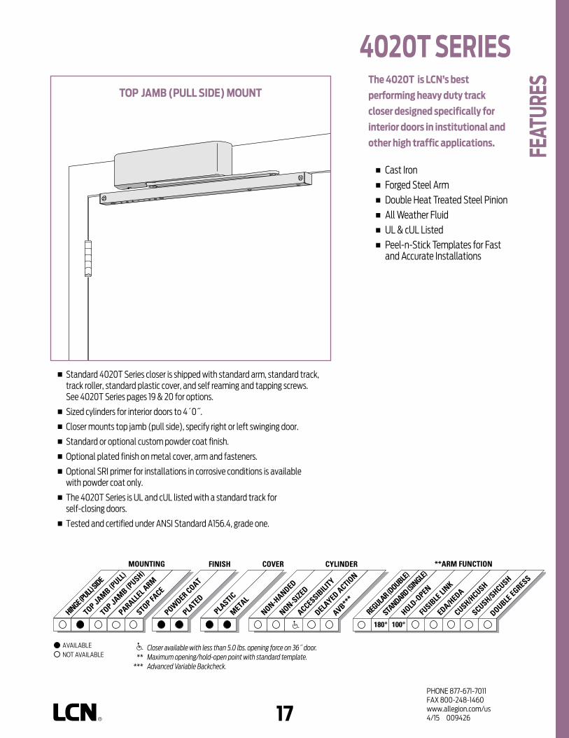
16 17PHONE 877-671-7011FAX 800-248-1460www.allegion.com/us 4/15 009426
n Standard 4020T Series closer is shipped with standard arm, standard track, track roller, standard plastic cover, and self reaming and tapping screws. See 4020T Series pages 19 & 20 for options.
n Sized cylinders for interior doors to 4´0˝.
n Closer mounts top jamb (pull side), specify right or left swinging door.
n Standard or optional custom powder coat finish.
n Optional plated finish on metal cover, arm and fasteners.
n Optional SRI primer for installations in corrosive conditions is available with powder coat only.
n The 4020T Series is UL and cUL listed with a standard track for self-closing doors.
n Tested and certified under ANSI Standard A156.4, grade one.
the 4020t is LcN’s best
performing heavy duty track
closer designed specifically for
interior doors in institutional and
other high traffic applications.
n Cast Iron n Forged Steel Arm n Double Heat Treated Steel Pinion n All Weather Fluid n UL & cUL Listed n Peel-n-Stick Templates for Fast
and Accurate Installations
toP JAMb (PuLL SIdE) MouNt
Closer available with less than 5.0 lbs. opening force on 36˝ door. ** Maximum opening/hold-open point with standard template. *** Advanced Variable Backcheck.
AVAILABLE NOT AVAILABLE
4020t SErIES
FEAt
urES
100°180°
PLASTIC
METAL
HINGE (PULL)
SIDE
TOP JAMB (PULL
)
TOP JAMB (PUSH)
STANDARD (S
INGLE)
REGULA
R (DOUBLE)
HOLD-O
PEN
FUSIB
LE LI
NK
EDA/HEDA
CUSH/HCUSH
SCUSH/SHCUSH
PARALLEL A
RM
STOP FACE
MOUNTING COVER CYLINDER **ARM FUNCTIONFINISH
NON-HANDED
NON-SIZED
ACCESSIBILI
TY
DELAYED ACTIO
N
AVB***
POWDER COAT
PLATED
DOUBLE EGRESS

18PHONE 877-671-7011FAX 800-248-1460www.allegion.com/us 4/15 009426
toP JAMb (PuLL SIdE) MouNtING
MAXIMuM oPENINGTemplating allows 180° with standard track arm, limited to 100° with optional bumper installed.
Consult factory if door will be held open at 180°.
Hold-open points at 80°, 85°, 90°, 95°, or 100° with hold-open tracks.
Please note that many track style door closers are capable of allowing 180° of door swing. Be aware that the majority of track style closers are at their weakest closing force in the 180° – 130° range. Consult factory for applications where door must swing 180°.
n butt Hinges should not exceed 5˝ (127 mm) in width.
n Auxiliary Stop is recommended at hold-open point or where a door cannot swing 180°. Optional track bumper assembly assists backcheck in cushioning the opening swing of the door. It is not intended to replace an auxiliary stop.
n reveal should not exceed 1/8˝ (3 mm).
n Head Frame less than 3-7/8˝ (98 mm), requires PLATE, 4020T-18. Plate requires 1-3/4˝ (44 mm) minimum.
n clearance of 1-1/2˝ (38 mm) behind door required for 90° or 180° installation.
4020t SErIES M
ouNt
ING
dEtA
ILS
options n Standard track with bumper,
hold-open track, hold-open track with bumper.
n Metal cover.
Special templates Customized installation templates or products may be available to solve unusual applications. Contact LCN Product Support for assistance.
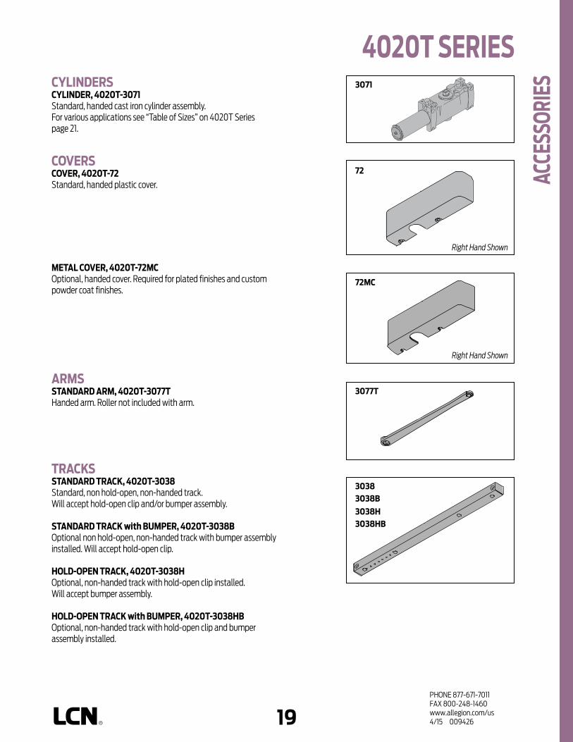
18 19PHONE 877-671-7011FAX 800-248-1460www.allegion.com/us 4/15 009426
cYLINdErScYLINdEr, 4020t-3071 Standard, handed cast iron cylinder assembly. For various applications see “Table of Sizes” on 4020T Series page 21.
covErScovEr, 4020t-72 Standard, handed plastic cover.
MEtAL covEr, 4020t-72McOptional, handed cover. Required for plated finishes and custom powder coat finishes.
ArMSStANdArd ArM, 4020t-3077t Handed arm. Roller not included with arm.
trAcKSStANdArd trAcK, 4020t-3038 Standard, non hold-open, non-handed track.Will accept hold-open clip and/or bumper assembly.
StANdArd trAcK with buMPEr, 4020t-3038b Optional non hold-open, non-handed track with bumper assembly installed. Will accept hold-open clip.
HoLd-oPEN trAcK, 4020t-3038HOptional, non-handed track with hold-open clip installed. Will accept bumper assembly.
HoLd-oPEN trAcK with buMPEr, 4020t-3038Hb Optional, non-handed track with hold-open clip and bumper assembly installed.
72
3038b
72Mc
3077t
3038
3038Hb3038H
3071
4020t SErIES
AccE
SSor
IES
Right Hand Shown
Right Hand Shown

20PHONE 877-671-7011FAX 800-248-1460www.allegion.com/us 4/15 009426
INStALLAtIoN AccESSorIESPLAtE, 4020t-18Required where head frame is less than 3-7/8” (98 mm). Plate requires minimum 1-3/4” (44 mm) frame face.
trAcK buMPEr, 4020t-169Mounts in track to assist backcheck, not replace auxiliary stop.Limits maximum opening. Consists of bumper, bumper post, and mounting screw.
HoLd-oPEN cLIP, 4020t-3054Mounts in track to provide hold-open function.Hold-open point controlled by clip location.Consists of clip and mounting screws.
trAcK roLLEr, 4020t-3034Quiet, low friction roller assembly.Shoulder dimension "X"= 1/16˝ (2mm).
18
169
3054
3034
4020t SErIES Ac
cESS
orIE
S

20 21PHONE 877-671-7011FAX 800-248-1460www.allegion.com/us 4/15 009426
4020t SErIES
ordE
rING
INFo
rMAt
IoN
4023t
INtErIor door WIdtH
26"660mm
34"864mm
38"965mm
48"1219mm
4024t
size 1 size 3 size 4
MinimumDoor Width
Indicates recommended range of door width for closer size.
tAbLE oF SIZES Select closer based on width of door.4020T Series cylinders available in size 1, 3 or 4. Closing power of all 4020T Series closers may be increased 15%.Specify next higher size closer where strong drafts exist.
HoW-to-ordEr4020t SErIES cLoSErS
1. SELEct cYLINdEr SIZE 4021T (ADA) 4023T 4024T2. SPEcIFY HANd RH LH 3. SPEcIFY FINISH Standard Powder Coat __________
Aluminum, Dark Bronze, Statuary, Light Bronze, Black, Brass.
cLoSEr oPtIoNScovEr Metal (MC)
FINISH Custom Powder Coat (RAL) __________
(handed metal cover required) Plated Finish, US _____________
(handed metal cover required) SRI primer (use with powder coat
finishes only)trAcK Standard with Bumper (BUMPER) Hold-Open (HO) Hold-Open with Bumper (HBUMPER)ScrEW PAcK TB* & SRT Screw (TBSRT) Wood & Machine Screw (WMS) TB*, Wood & Machine Screw (TBWMS) TORX Machine Screw (TORX) TB* & TORX Machine Screw (TBTRX)
* Specify door thickness if other than 1-3/4". INStALLAtIoN AccESSorY Plate, 4020T-18SPEcIAL tEMPLAtE ST- _________
closer will be shipped with:- STANDARD COVER,- STANDARD ARM,- TRACK ROLLER,- STANDARD TRACK,- SELF-REAMING and TAPPING SCREWS, unless options listed below are selected.

22PHONE 877-671-7011FAX 800-248-1460www.allegion.com/us 4/15 009426
Notes

22 23PHONE 877-671-7011FAX 800-248-1460www.allegion.com/us 4/15 009426
n Standard new 4030 Series closer is shipped with forged regular arm, metal cover and wood/self-tapping machine screw pack. See 4030 Series pages 28 & 29 for options.
n Non-sized (1-4) 4031 cylinder for exterior doors to 36” (914 mm) and interior doors to 48” (1219 mm).
n Closer mounts hinge side, top jamb, and parallel arm, on either right or left swinging doors.
n Closer meets ADA requirements. See 4030 Series page 30.
n Standard or optional custom powder coat finish.
n Optional plated finish on metal cover, arm and fasteners.
n Optional SRI primer for installations in corrosive conditions is available with powder coat only.
n The 4030 Series is UL and cUL listed for Self-closing doors without hold-open.
n Tested and certified under ANSI Standard A156.4, grade one.
the 4031 is a cast iron, universal
closer designed specifically
for doors in moderate traffic
conditions. this versatile closer
compliments the rest of the heavy
duty 4000 Series and offers the
choice of three mountings and
multiple arm options.
n Cast Iron n Forged Steel Main Arm n Heat Treated Steel Pinion n All Weather Fluid n UL & cUL Listed
cLoSEr MouNtS*HINGE (PuLL) SIdE
toP JAMb (PuSH SIdE)PArALLEL (PuSH SIdE)
*HINGE (pull) side mount shown
Closer available with less than 5.0 lbs. opening force on 36˝ door. ** Maximum opening/hold-open point with standard template. See individual
closer series for degrees of opening per installation. *** Advanced Variable Backcheck
AVAILABLE NOT AVAILABLE
4030 SErIES
FEAt
urES
DOUBLE EGRESS

24PHONE 877-671-7011FAX 800-248-1460www.allegion.com/us 4/15 009426
HINGE (PuLL) SIdE MouNtING
MAXIMuM oPENINGCan be templated for 180°. Hold-open points up to maximum opening with hold-open arm.
n butt Hinges should not exceed 5˝ (127 mm) in width.
n Auxiliary Stop is recommended at hold-open point or where a door cannot swing 180°.
n reveal should not exceed 3/16˝ (5 mm) for regular arm or 3/16˝ (5 mm) for hold-open arm.
n top rail requires 2-7/8˝ (73 mm) minimum.
n clearance of 1-3/4˝ (44 mm), behind door required for installation.
4030 SErIES M
ouNt
ING
dEtA
ILS
options n Hold-open arm.
Special templates Customized installation templates or products may be available to solve unusual applications. Contact LCN Product Support for assistance.

24 25PHONE 877-671-7011FAX 800-248-1460www.allegion.com/us 4/15 009426
toP JAMb (PuSH SIdE) MouNtING
MAXIMuM oPENINGCan be templated for 180°.
Hold-open points up to maximum opening with hold-open arm.
n butt Hinges should not exceed 5˝ (127 mm) in width.
n Auxiliary Stop is recommended at hold-open point or where the door cannot swing 180°.
n reveal up to 3-1/2˝ (89 mm) allows 180° opening. Reveal up to 7-1/2” (191 mm) with long arm allows for 140° opening.
n top rail requires 1-1/2˝ (38 mm) minimum from stop.
n Head Frame less than 2-1/4˝ (57 mm) requires PLATE, 4030-18TJ. Plate requires 1-1/2˝ (38 mm) minimum.
options n Hold-open arm.
n Long arm.
n Long Hold-open arm.
Special templates Customized installation templates or products may be available to solve unusual applications. Contact LCN Product Support for assistance.
4030 SErIES
Mou
NtIN
G dE
tAIL
S
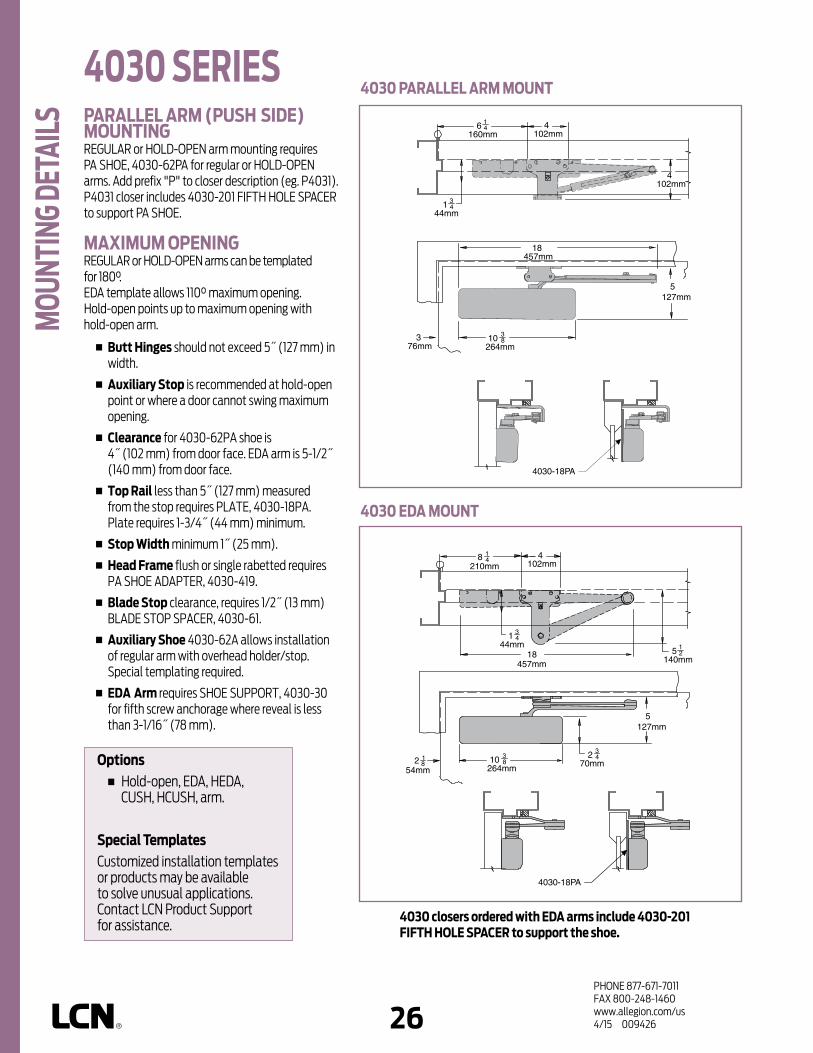
26PHONE 877-671-7011FAX 800-248-1460www.allegion.com/us 4/15 009426
PArALLEL ArM (PuSH SIdE) MouNtINGREGULAR or HOLD-OPEN arm mounting requires PA SHOE, 4030-62PA for regular or HOLD-OPEN arms. Add prefix "P" to closer description (eg. P4031). P4031 closer includes 4030-201 FIFTH HOLE SPACER to support PA SHOE.
MAXIMuM oPENINGREGULAR or HOLD-OPEN arms can be templated for 180°.EDA template allows 110° maximum opening.Hold-open points up to maximum opening with hold-open arm.
n butt Hinges should not exceed 5˝ (127 mm) in width.
n Auxiliary Stop is recommended at hold-open point or where a door cannot swing maximum opening.
n clearance for 4030-62PA shoe is 4˝ (102 mm) from door face. EDA arm is 5-1/2˝ (140 mm) from door face.
n top rail less than 5˝ (127 mm) measured from the stop requires PLATE, 4030-18PA. Plate requires 1-3/4˝ (44 mm) minimum.
n Stop Width minimum 1˝ (25 mm).
n Head Frame flush or single rabetted requires PA SHOE ADAPTER, 4030-419.
n blade Stop clearance, requires 1/2˝ (13 mm) BLADE STOP SPACER, 4030-61.
n Auxiliary Shoe 4030-62A allows installation of regular arm with overhead holder/stop. Special templating required.
n EdA Arm requires SHOE SUPPORT, 4030-30 for fifth screw anchorage where reveal is less than 3-1/16˝ (78 mm).
4030 EdA MouNt
4030 PArALLEL ArM MouNt
4030 closers ordered with EdA arms include 4030-201 FIFtH HoLE SPAcEr to support the shoe.
4030 SErIES M
ouNt
ING
dEtA
ILS
options n Hold-open, EDA, HEDA,
CUSH, HCUSH, arm.
Special templates Customized installation templates or products may be available to solve unusual applications. Contact LCN Product Support for assistance.

26 27PHONE 877-671-7011FAX 800-248-1460www.allegion.com/us 4/15 009426
clearance for CUSH or SPRING CUSH shoe is 5-1/2˝ (140 mm) from door face.
Head Frame flush or rabetted requires CUSH FLUSH PANEL ADAPTER, 4030-419.
cuSH or SPrING cuSH ArM requires SHOE SUPPORT, 4030-30 for fifth screw anchorage where reveal is less than 3-1/16˝ (78 mm).
4030 cuSH MouNt
4030 SPrING cuSH MouNt
cuSH-N-StoP or SPrING cuSH MouNtING4031 closers ordered with CUSH or SPRING CUSH arms include 4030-201 FIFTH HOLE SPACER to support the shoe.
MAXIMuM oPENINGCUSH and SPRING CUSH arms can be templated for maximum opening/hold-open point at85°,
A = 3-5/8˝ (92 mm)B = 9-3/4˝ (248 mm)
90°,A = 3˝ (76 mm)B = 9-1/8˝ (232 mm)
or 100°*. A = 1-7/8˝ (48 mm)B = 8˝ (203 mm)
*100° mounting will not work with swing clear hinges.
Spring Cush hold-open points are approximately 5° less than templated stop point.
4030 SErIES
Mou
NtIN
G dE
tAIL
S

28PHONE 877-671-7011FAX 800-248-1460www.allegion.com/us 4/15 009426
cYLINdErScYLINdEr, 4031-3071Standard, non-handed cast iron cylinder assembly.
ArMSrEGuLAr ArM, 4030-3077Non-handed arm mounts hinge side or top jamb. P4031 closer includes PA SHOE, 4030-62PA is required for parallel arm mounting.
LIGHt dutY ArM, 4030-3077LdOptional non-handed stamped arm mounts hinge side, top jamb or parallel arm (62PA required).
PA SHoE, 4030-62PARequired for parallel arm mounting.
LoNG ArM, 4030-3077L Optional non-handed arm includes LONG ROD AND SHOE, 4030-79LR for top jamb mount with deep reveals.
HoLd-oPEN ArM, 4030-3049Optional, non-handed arm mounts hinge side, top jamb or parallel arm (62PA required). Hold-open adjustable at shoe.
LoNG HoLd-oPEN ArM, 4030-3049LOptional non-handed arm includes LONG HEAD AND TUBE, 4030-3048L for top jamb mount with deep reveals.
EXtrA dutY ArM, 4030-3077EdAOptional, non-handed parallel arm features solid forged steel main and forearm for potentially abusive installations.
HoLd-oPEN EdA ArM, 4030-3049EdA Optional handed arm, provides hold-open function adjustable at shoe.
cuSH-N-StoP® ArM, 4030-3077cNSOptional, non-handed parallel arm features solid forged steel main arm and forearm with stop in soffit shoe.
HoLd-oPEN cuSH ArM, 4030-3049cNSOptional non-handed arm, provides hold-open function with templated stop/hold-open points. Handle controls hold-open function.
SPrING cuSH ArM,4030-3077ScNSOptional, non-handed parallel arm for abusive applications features solid forged steel main arm and forearm with spring loaded stop in the soffit shoe.
SPrING HcuSH ArM, 4030-3049ScNSOptional, non-handed parallel arm for abusive applications features solid forged steel main arm and forearm with spring loaded stop in the soffit shoe. Handle controls hold-open function.
79Lr
3077
3077Ld
3049
3077EdA 3049EdA
3049cNS
3077ScNS
3049ScNS
3077cNS
62PA
3071
4030 SErIES Ac
cESS
orIE
S
3048L

28 29PHONE 877-671-7011FAX 800-248-1460www.allegion.com/us 4/15 009426
1520 track
1520t-721520-72
1460t-72ec1070-72
72Mc
30
62A
419
covErScovEr, 4030-72Mc Non-handed metal cover.
INStALLAtIoN AccESSorIESPLAtE, 4030-18tJ Required for top jamb mounting where head frame is less than 2-1/4˝ (57 mm) or flush ceiling condition exists. Plate requires 1-1/2˝ (38 mm) minimum.
PLAtE, 4030-18PA Required for parallel arm mounting where top rail is less than 5˝ (127 mm), measured from the stop. Plate requires 1-3/4˝ (44 mm) minimum.
cuSH SHoE SuPPort, 4030-30 Provide anchorage for fifth screw used with CUSH arms where reveal is less than 3-1/16˝ (78 mm).
bLAdE StoP SPAcEr, 4030-61 Lowers parallel arm shoe to clear 1/2˝ (13 mm) blade stop.
AuXILIArY SHoE, 4030-62A requires a top rail of 7˝ (178 mm). Optional shoe replaces -62PA for parallel arm mounting of regular arm with some overhead holder/stop. Consult factory.
PA FLuSH PANEL AdAPtEr, 4030-419 Provides horizontal mounting surface for PA or CUSH shoe on single rabetted or flush frame.
18tJ
18PA
61
4030 SErIES
AccE
SSor
IES

30PHONE 877-671-7011FAX 800-248-1460www.allegion.com/us 4/15 009426
HoW-to-ordEr4030 SErIES cLoSErS1. SELEct FINISH Standard Powder Coat __________
Aluminum, Dark Bronze, Statuary, Light Bronze, Black, Brass.
cLoSEr oPtIoNSFINISH Custom Powder Coat (RAL) ___________ Plated Finish, US ______________ SRI primer (use with powder coat
finishes only)ArM Regular w/62PA (Rw/PA) Regular w/62A (R/62A) Long (LONG) Hold-Open (H) Hold-Open w/62PA (Hw/PA) Long Hold-Open (HLONG) Light Duty (LD) Light Duty w/62A (LD/62A) Light Duty w/62PA (LD/PA) Light Duty Long (LDL) EDA HEDA (specify right or left hand) Cush-N-Stop (CUSH) HCush-N-Stop (HCUSH) Spring Cush (SCUSH) Spring HCush (SHCUSH)oPtIoNAL ScrEW PAcKS TB*, Wood & Machine Screw (TBWMS)
* Specify door thickness if other than 1-3/4˝.
INStALLAtIoN AccESSorIES Plate, 4030-18TJ Plate, 4030-18PA CUSH Shoe Support, 4030-30 Blade Stop Spacer, 4030-61 Auxiliary Shoe, 4030-62A PA Flush Panel Adapter, 4030-419SPEcIAL tEMPLAtE ST- ________
closer will be shipped with:- STANDARD CYLINDER,- STANDARD METAL COVER,- REGULAR ARM,- WOOD and SELF-TAPPING MACHINE
SCREW PACK unless options listed below are selected.
size 3 size 44031
4031
EXtErIor (and vEStIbuLE) door WIdtH
26"660mm
30"762mm
36"914mm
INtErIor door WIdtH
26"660mm
34"864mm
38"965mm
48"1219mm
size 2 size 3 size 4
rEducEd oPENING ForcE 4030 cLoSErScAutIoN ! Any manual door closer, including those certified by BHMA to conform to ANSI Standard A156.4, that is selected, installed and adjusted based on ADA or other reduced opening force requirements may not provide sufficient power to reliably close and latch a door.
Refer to AUTOMATIC OPERATORS section for information on systems that meet reduced opening force requirements without effecting closing power.
MinimumDoor Width
MinimumDoor Width
Indicates recommended range of door width for closer size.
tAbLE oF SIZES Non-sized 4031 cylinder is adjustable from sizes 1 to 4 and is shipped set to size 3.
door WIdtH 36" 42" 48"
8.5* lbs. 4031 4031 4031
5.0* lbs. 4031 4031 4031
* Maximum opening force.
4030 SErIES or
dErI
NG IN
ForM
AtIo
N

30 31PHONE 877-671-7011FAX 800-248-1460www.allegion.com/us 4/15 009426
cLoSEr MouNtS*HINGE (PuLL) SIdE
toP JAMb (PuLL SIdE)StoP FAcE (PuSH SIdE)
*HINGE (pull) side mount shown
n Standard 4031T Series closer is shipped with a standard arm, metal cover, a standard track and wood/self-tapping machine screw pack. See 4030T Series page 35 for options.
n Non-sized 4031T cylinder for interior doors to 38˝ (965 mm).
n Closer mounts pull side on door, pull side on frame and push side on door, on either right or left swinging doors.
n Standard or optional custom powder coat finish.
n Optional plated finish on metal cover, arm and fasteners.
n Optional SRI primer for installations in corrosive conditions is available with powder coat only.
n The 4030 Series is UL and cUL listed for Self-closing doors without hold-open.
n Tested and certified under ANSI Standard A156.4, grade one.
the 4031t is a single lever (track)
arm, surface mounted closer
designed for interior use on
narrow head frames and top rails.
the choice of three mountings
and ease of installation offer a
versatile solution to door control
in moderate traffic applications.
the 4030t compliments the
heavy duty 4000 Series.
n Cast Iron n Heat Treated Steel Pinion n All Weather Fluid n UL & cUL Listed
AVAILABLE NOT AVAILABLE
4030t SErIES
FEAt
urES
Closer available with less than 5.0 lbs. opening force on 36˝ door. ** Maximum opening/hold-open point with standard template. See individual
closer series for degrees of opening per installation. *** Advanced Variable Backcheck.
DOUBLE EGRESS
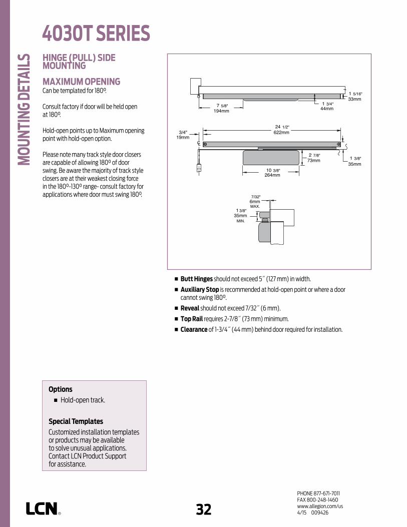
32PHONE 877-671-7011FAX 800-248-1460www.allegion.com/us 4/15 009426
HINGE (PuLL) SIdE MouNtING
MAXIMuM oPENINGCan be templated for 180°.
Consult factory if door will be held open at 180°. Hold-open points up to Maximum opening point with hold-open option.
Please note many track style door closers are capable of allowing 180° of door swing. Be aware the majority of track style closers are at their weakest closing force in the 180°-130° range- consult factory for applications where door must swing 180°.
n butt Hinges should not exceed 5˝ (127 mm) in width.
n Auxiliary Stop is recommended at hold-open point or where a door cannot swing 180°.
n reveal should not exceed 7/32˝ (6 mm).
n top rail requires 2-7/8˝ (73 mm) minimum.
n clearance of 1-3/4˝ (44 mm) behind door required for installation.
622mm24 1/2"
264mm10 3/8"
CL19mm
3/4"
35mm1 3/8"
6mmMAX.
7/32"
35mm1 3/8"
MIN.
194mm7 5/8" 44mm
1 3/4"33mm1 5/16"
73mm2 7/8"
4030t SErIES M
ouNt
ING
dEtA
ILS
options n Hold-open track.
Special templates Customized installation templates or products may be available to solve unusual applications. Contact LCN Product Support for assistance.

32 33PHONE 877-671-7011FAX 800-248-1460www.allegion.com/us 4/15 009426
toP JAMb (PuLL SIdE) MouNtING
MAXIMuM oPENINGCan be templated for 180°.
Consult factory if door will be held open at 180°. Hold-open points up to maximum opening with hold-open option.
Please note many track style door closers are capable of allowing 180° of door swing. Be aware the majority of track style closers are at their weakest closing force in the 180°-130° range- consult factory for applications where an exterior or large/heavy door must swing 180°.
n butt Hinges should not exceed 5˝ (127 mm) in width.
n Auxiliary Stop is recommended at hold-open point or where the door cannot swing 180°.
n reveal should not exceed 1/8˝ (3 mm).
n top rail requires 1˝ (25 mm) minimum.
n Head Frame requires 2-7/8˝ (73 mm) minimum.
CL
264mm10 3/8"
19mm3/4"
622mm24 1/2"
3mmMAX.
1/8"
25mm1"
MIN.
100mm4" 44mm
1 3/4"32mm1 5/16"
81mm3 1/4"
25mm1"
4030t SErIES
options n Hold-open track.
Special templates Customized installation templates or products may be available to solve unusual applications. Contact LCN Product Support for assistance.
Mou
NtIN
G dE
tAIL
S

34PHONE 877-671-7011FAX 800-248-1460www.allegion.com/us 4/15 009426
StoP FAcE (PuSH SIdE) MouNtING
MAXIMuM oPENINGCan be templated for 110°.
Hold-open points up to maximum opening with hold-open option.
Please note that many track style door closers are capable of allowing 180° of door swing. Be aware that the majority of track style closers are at their weakest closing force in the 180° – 130° range. Consult factory for applications where door must swing 180°.
n butt Hinges should not exceed 5˝ (127 mm) in width.
n Auxiliary Stop is recommended at hold-open point or where the door cannot swing 110°.
n reveal should not exceed 1-3/4˝ (44 mm).
n top rail requires 4-1/8˝ (105 mm) minimum measured from the stop.
n Head Frame minimum 1-1/4˝ (32 mm).
295mm11
1
5/8"
32mm1/4"
CL
CL
38mm1 1/2"
32mm1 1/4"
MIN.
622mm24 1/2"
25mm1"
33mm1 5/16"
44mm1 3/4"
105mm4 1/8"
4030t SErIES M
ouNt
ING
dEtA
ILS
options n Hold-open track.
Special templates Customized installation templates or products may be available to solve unusual applications. Contact LCN Product Support for assistance.

34 35PHONE 877-671-7011FAX 800-248-1460www.allegion.com/us 4/15 009426
cYLINdErScYLINdEr, 4031t-3071 Standard, non-handed cast iron cylinder assembly.
covErScovEr, 4030t-72Mc Non-handed metal cover.
ArMSStANdArd ArM, 4030t-3077tNon-handed single lever arm mounts hinge side, top jamb or stop face. Track roller included with arm.
StANdArd trAcK, 4030t-3038Standard, non hold-open, non-handed track mounts on either side of the door. Will accept hold-open clip.
HoLd-oPEN trAcK, 4030t-3038HOptional non-handed hold-open track mounts on either side of the door. Comes with 4030T-3054 Hold-open clip.
HoLd-oPEN cLIP, 4030t-3054Mounts in track to provide hold-open function. Hold-open point controlled by clip location.
1520 track
1520t-721520-72
1460t-72ec1070-72
1520 track
1520t-721520-72
1460t-72ec1070-72
72Mc
3071
3077t
30383038H
3054
4030t SErIES
AccE
SSor
IES

36PHONE 877-671-7011FAX 800-248-1460www.allegion.com/us 4/15 009426
* Maximum opening force .
HoW-to-ordEr4030t SErIES cLoSErS1. SELEct FINISH Standard Powder Coat __________
Aluminum, Dark Bronze, Statuary, Light Bronze, Black, Brass.
cLoSEr oPtIoNStrAcK Hold-open (H)FINISH Custom Powder Coat (RAL) ___________ Plated Finish, US ___________ SRI primer (use with powder coat
finishes only)ScrEW PAcK TB*, Wood & Machine Screws (TBWMS)
closer will be shipped with:- STANDARD CYLINDER,- STANDARD METAL COVER,- STANDARD TRACK,- STANDARD ARM ,- TRACK ROLLER,- WOOD and SELF-TAPPING MACHINE
SCREW PACK unless options listed below are selected.
rEducEd oPENING ForcE 4030t cLoSErScAutIoN ! Any manual door closer, including those certified by BHMA to conform to ANSI Standard A156.4, that is selected, installed and adjusted based on ADA or other reduced opening force requirements may not provide sufficient power to reliably close and latch a door.
Refer to AUTOMATIC OPERATORS section for information on systems that meet reduced opening force requirements without effecting closing power.
Indicates recommended range of door width for closer size.
tAbLE oF SIZES Non-sized 4031T cylinder is adjustable from sizes 1 to 3 and is shipped set to size 3.
door WIdtH 36" 42" 48"
8.5* lbs. N/A N/A N/A
5.0* lbs. 4031T 4031T 4031T
4030t SErIES or
dErI
NG IN
ForM
AtIo
N
4031t
INtErIor door WIdtH
26"660mm
34"864mm
38"965mm
size 2 size 3
MinimumDoor Width

36 37PHONE 877-671-7011FAX 800-248-1460www.allegion.com/us 4/15 009426
n Standard 4040XP Series closer shipped with regular arm, standard plastic cover, and self reaming and tapping screws.
n Non-sized cylinder is adjustable for interior doors to 5’0” and exterior doors to 4’0”.
n Closer mounts hinge side, top jamb, and parallel arm on either right or left swinging doors.
n Closers to meet ADA requirements.
n Standard or optional custom powder coat finish.
n Optional plated finish on cover, arm, and fasteners.
n Optional SRI primer for installations in corrosive conditions. (Available with powder coat finishes only.)
n UL and cUL listed for self-closing doors without hold-open.
n Tested and certified under ANSI Standard A156.4, grade one.
the 4040XP is LcN’s
most durable and flexible
heavy duty closer designed for
institutional and other demanding
high traffic applications.
n Cast Iron n Forged Steel Arm n Double Heat Treated Steel Pinion n All Weather Fluid n Non-Handed n LCN Patented Green Dial n Peel-n-Stick Templates for Fast and
Accurate Installation n UL & cUL Listed n 3/4˝ Journal Diameter Pinion n Full Compliment Bearing
cLoSEr MouNtS*HINGE (PuLL) SIdE
toP JAMb (PuSH SIdE)PArALLEL ArM (PuSH SIdE)
*HINGE (pull) side mount shown
AVAILABLE NOT AVAILABLE
4040XP SErIES
FEAt
urES
The 4040XP Series includes theLcN® "Green dial"
Spring Force Indicator
Closer available with less than 5.0 lbs. opening force on 36˝ door. ** Maximum opening/hold-open point with standard template. *** Advanced Variable Backcheck. **** Delayed Action Closer incorporates standard 4041 Delay Cylinder.
PLASTIC
METAL
HINGE (P
ULL) S
IDE
TOP JAMB (PULL
)
TOP JAMB (PUSH)
PARALLEL A
RM
STOP FACE
MOUNTING COVER
180° 180° 180° 110°110°
STANDARD (S
INGLE)
REGULA
R (DOUBLE)
HOLD-O
PEN
FUSIB
LE LI
NK
EDA/HEDA
CUSH/HCUSH
SCUSH/SHCUSH
DOUBLE EGRESS
*ARM FUNCTIONFINISH CYLINDER
NON-HANDED
NON-SIZED
ACCESSIBILI
TY
DELAYED ACTION
AVB**POW
DER COAT
PLATED

38PHONE 877-671-7011FAX 800-248-1460www.allegion.com/us 4/15 009426
HINGE (PuLL) SIdE MouNtING
MAXIMuM oPENINGTemplating allows up to 120°.
Hold-open points 90° up to 120° with hold-open arm.
n butt Hinges should not exceed 5” (127 mm) in width.
n Auxiliary Stop is recommended at hold-open point or where a door cannot swing beyond 120°.
n reveal should not exceed 3/4” (19 mm) for regular arm or hold-open arm.
n top rail less than 3-3/4” (95 mm) requires PLATE, 4040XP-18. Plate requires 2” (51 mm) minimum.
n clearance of 2-3/8” (60 mm) behind door required for 90° installation.
n *delayed Action Incorporates standard 4041 cylinder, without XP cylinder. Delays closing from 120° to 70°. Delay time adjustable up to approximately 1 minute.
4040XP SErIES M
ouNt
ING
dEtA
ILS
options n 4041 Delayed action cylinder*. n Hold-open arm. n Metal cover.
Special templates Customized installation templates or products may be available to solve unusual applications. Contact LCN Product Support for assistance.

38 39PHONE 877-671-7011FAX 800-248-1460www.allegion.com/us 4/15 009426
toP JAMb (PuSH SIdE) MouNtING
MAXIMuM oPENINGTemplating allows up to 120°.
Hold-open points 85° up to 120° with hold-open arm.
n butt Hinges should not exceed 5˝ (127 mm) in width.
n Auxiliary Stop is recommended at hold-open point or where a door cannot swing beyond 120°.
n reveal of 2-9/16” (65 mm) allows 120° opening for REGULAR ARM or standard Hold-open ARM. 4-13/16” (122 mm) allows up to 120° opening with LONG ARM where standard rod and shoe is replaced with optional LONG ROD AND SHOE 4040XP-79LR. Use H-LONG ARM with LONG HEAD AND TUBE, 4040XP-78HL for hold-open. 8” (203 mm) allows up to 120° opening with EXTRA LONG ARM where standard rod and shoe is replaced with optional EXTRA LONG ROD AND SHOE, 4040XP-79ELR.
n top rail requires 1-1/4˝ (32 mm) minimum. 2-1/4˝ (57 mm) minimum with closer on PLATE, 4040XP-18TJ. 3˝ (76 mm) minimum with closer on PLATE, 4040XP-18G.
n Head Frame less than 3-1/2” (89 mm) requires PLATE, 4040XP-18TJ. With flush ceiling, use PLATE, 4040XP-18G. Either plate requires 1-3/4” (44 mm) minimum.
n *delayed Action Incorporates standard 4041 cylinder, without XP cylinder. Delays closing from 120° to 70°. Delay time adjustable up to approximately 1 minute.
4040XP SErIES
options n 4041 Delayed action cylinder*. n Hold-open arm. n Metal cover.
Customized installation templates or products may be available to solve unusual applications. Contact LCN Product Support for assistance.
Mou
NtIN
G dE
tAIL
S

40PHONE 877-671-7011FAX 800-248-1460www.allegion.com/us 4/15 009426
PArALLEL ArM (PuSH SIdE) MouNtINGOptional mounting requires PA SHOE, 4040XP-62PA for regular or HOLD-OPEN arms. Add prefix "P" to closer description (eg. P4040XP). P4040XP closer includes 4040XP-201 FIFTH HOLE SPACER to support PA SHOE.
MAXIMuM oPENING180° opening/hold-open points with all except CUSH arms.
110° opening/hold-open with CUSH arms.
n butt Hinges should not exceed 5” (127 mm) in width.
n Auxiliary Stop is recommended at hold-open point, where the door cannot swing 180°, or where CUSH-N-STOP arm is not used.
n clearance for 4040XP-62PA shoe is 4” (102 mm) from door face. EDA shoe projects 5-1/2” (140 mm) from door face. CUSH shoe projects 6” (152 mm) from door face.
n top rail less than 5-3/8” (137 mm) measured from the stop requires PLATE, 4040XP-18PA. Plate requires 2” (51 mm) minimum from the stop.
n Head Frame flush or rabetted requires PA SHOE ADAPTER, 4040XP-419.
n Stop Width minimum 1” (25 mm). CUSH arm requires minimum 1-1/2” (38 mm).
n blade Stop clearance requires 1/2˝ (13mm) BLADE STOP SPACER, 4040XP-61.
n *delayed Action Incorporates standard 4041 cylinder, without XP cylinder. Delays closing from 120° to 70°. Delay time adjustable up to approximately 1 minute.
4040XP SErIES M
ouNt
ING
dEtA
ILS
options n 4041 Delayed action cylinder*. n Hold-open, EDA, HEDA, CUSH,
HCUSH, SPRING CUSH or SPRING HCUSH arm.
n Metal cover.
Special templates Customized installation templates or products may be available to solve unusual applications. Contact LCN Product Support for assistance.

40 41PHONE 877-671-7011FAX 800-248-1460www.allegion.com/us 4/15 009426
Mounting details are the same
as 4040XP Series rEGuLAr or
HoLd-oPEN except as listed below.
4040XP Series closers ordered with
EdA or cuSH arms include 4040XP-
201 FIFtH HoLE SPAcEr to support
the shoe.
MAXIMuM oPENINGEDA arm can be templated for points at: 110°,
A = 6-3/8” (162 mm)B = 7-3/4” (197 mm)
or 180°.A = 2-7/8” (73 mm)B = 4-1/4” (108 mm)
Hold-open points up to maximum opening with HEDA arm.
CUSH arms can be templated for opening/hold-open point at:85°,
A = 7-15/16” (202 mm)B = 9-1/8” (232 mm)
90°,A = 7-3/16” (183 mm)B = 8-1/2” (216 mm)
100°, A = 6-1/16” (154 mm)B = 7-1/4” (184 mm)
or 110°.A = 5-1/16” (129 mm)B = 6-3/8” (162 mm)
Spring Cush dead stop points are approximately 5 ̊more than templated stop point. Hold open at templated stop points.
n clearance for 4040XP-62EDA is 5-1/2” (140 mm) from door face. 6” (152 mm) for CUSH.
n Head Frame flush or rabetted requires CUSH FLUSH PANEL ADAPTER, 4040XP-419.
n cuSH ArM requires SHOE SUPPORT, 4040XP-30 for fifth screw anchorage for narrow frames.
n *delayed Action Incorporates standard 4041 cylinder, without XP cylinder. Delays closing from maximum opening to ; 115˚ with 180˚ template, 95˚ with 110˚ template, 85˚ with 100˚ template, 75˚ with 90˚ template. Delay time adjustable up to approximately 1 minute.
4040XP SErIES
Mou
NtIN
G dE
tAIL
S4040XP SErIES EdA MouNt
4040XP SErIES cuSH MouNt

42PHONE 877-671-7011FAX 800-248-1460www.allegion.com/us 4/15 009426
cYLINdErScYLINdEr, 4040XP-3071 Heavy duty, non-handed cast iron cylinder assembly.cYLINdEr, 4041-3071 dEL Cylinder used for delayed action options.
covErScovEr, 4040XP-72 Standard, non-handed plastic cover.MEtAL covEr, 4040XP-72Mc Optional, handed cover. Required for plated finishes and custom powder coat finishes.
ArMSrEGuLAr ArM, 4040XP-3077 Non-handed arm mounts pull side or top jamb with shallow reveal. P4041 closer includes PA SHOE, 4040XP-62PA required for parallel arm mounting.PA SHoE, 4040XP-62PA Required for parallel arm mounting.LoNG ArM, 4040XP-3077L Optional non-handed arm includes LONG ROD AND SHOE, 4040XP-79LR for top jamb mount.EXtrA LoNG ArM, 4040XP-3077ELr Optional non-handed arm includes EXTRA LONG ROD AND SHOE, 4040XP-79ELR for top jamb mount with deep reveal. HoLd-oPEN ArM, 4040XP-3049 Optional, non-handed arm mounts pull side or top jamb with shallow reveal, hold-open adjustable shoe. 4040XP closer includes 4040XP-62PA shoe required for parallel arm mounting.LoNG HoLd-oPEN ArM, 4040XP-3049L Optional non-handed arm includes LONG HEAD AND TUBE, 4040XP-3048L for top jamb mount.EXtrA dutY ArM, 4040XP-3077EdA Non-handed parallel arm features forged, solid steel main and forearm for potentially abusive installations.HoLd-oPEN EXtrA dutY ArM, 4040XP-3049EdA Handed parallel arm features forged, solid steel main and forearm for potentially abusive installations. Hold-open function is adjusted at the shoe. EXtrA dutY ArM WItH 62G, 4040XP-3077EdA/62G Non-handed parallel arm features forged, solid steel main and forearm for potentially abusive installations. 62G shoe provides additional blade stop clearance.HoLd-oPEN EXtrA dutY ArM WItH 62G, 4040XP-3049EdA/62G Handed parallel arm features forged, solid steel main and forearm for potentially abusive installations. 62G shoe provides additional blade stop clearance. Hold-open function is adjusted at the shoe.
4040XP SErIES Ac
cESS
orIE
S
72Mc72
79ELr
3048L 3049
4040XP-3071
79Lr 62PA
3077
3049EdA3077EdA
3049EdA/62G3077EdA/62G
4041-3071 dEL

42 43PHONE 877-671-7011FAX 800-248-1460www.allegion.com/us 4/15 009426
ArMS coNt.cuSH-N-StoP® ArM, 4040XP-3077cNSOptional, non-handed parallel arm features solid forged steel main arm and forearm with stop in soffit shoe.
HcuSH ArM, 4040XP-3049cNS Optional, non-handed hold-open function with templated stop/hold-open points. Handle controls hold-open function.
SPrING cuSH ArM, 4040XP-3077ScNS Optional, non-handed parallel arm for abusive applications features solid forged steel main arm and forearm with spring loaded stop in the soffit shoe.
SPrING HcuSH ArM, 4040XP-3049ScNS Optional, non-handed parallel arm for abusive applications features solid forged steel main arm and forearm with spring loaded stop in the soffit shoe. Handle controls hold-open function.
INStALLAtIoN AccESSorIESPLAtE, 4040XP-18 Required for hinge side mount where top rail is less than 3-3/4” (95 mm). Plate requires minimum 2” (51 mm) minimum top rail.
PLAtE, 4040XP-18G Locates top jamb mounted closer flush with top of head frame face in flush ceiling condition. Plate requires 1-3/4” (44 mm) minimum head frame.
PLAtE, 4040XP-18tJ Centers top jamb mounted closer vertically on head frame where face is less than 3-1/2” (89 mm). Plate requires 1-3/4” (44 mm) minimum head frame.
PLAtE, 4040XP-18PA Required for parallel arm mounting where top rail is less than 5-1/2” (140 mm), measured from the stop. Plate requires 2” (51 mm) minimum top rail.
4040XP SErIES
AccE
SSor
IES
18G 18tJ
18PA
3077cNS
3049cNS
3077ScNS
3049ScNS
18

44PHONE 877-671-7011FAX 800-248-1460www.allegion.com/us 4/15 009426
INStALLAtIoN AccESSorIES coNt.cuSH SHoE SuPPort, 4040XP-30Provides anchorage for fifth screw used with CUSH arms, where reveal is less than 3-1/16” (78 mm).
bLAdE StoP SPAcEr, 4040XP-61Required to lower parallel arm shoe to clear 1/2” (13 mm) blade stop.
PA FLuSH PANEL AdAPtEr, 4040XP-419Provides horizontal mounting surface for parallel arm shoe on single rabetted or flush frame.
AuXILIArY SHoE, 4040XP-62A Requires a top rail of 7” (178 mm). Optional shoe replaces -62PA for parallel arm mounting of regular arm with overhead holder/stop.
4040XP SErIES Ac
cESS
orIE
S 30
62A
419
61
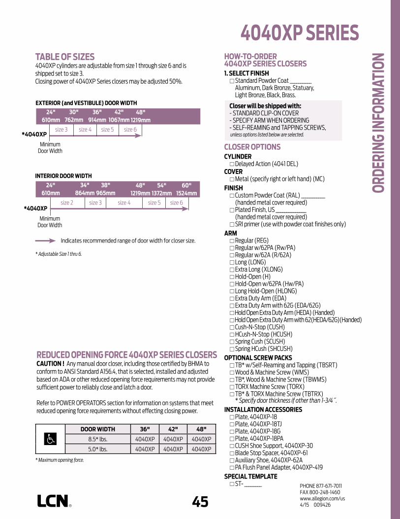
44 45PHONE 877-671-7011FAX 800-248-1460www.allegion.com/us 4/15 009426
4040XP SErIES
ordE
rING
INFo
rMAt
IoN
size 3 size 4 size 5 size 6*4040XP
*4040XP
EXtErIor (and vEStIbuLE) door WIdtH
24"610mm
30"762mm
36"914mm
42"1067mm
INtErIor door WIdtH
48"1219mm
24"610mm
34"864mm
38"965mm
48"1219mm
54"1372mm
60"1524mm
size 2 size 3 size 4 size 5 size 6
rEducEd oPENING ForcE 4040XP SErIES cLoSErScAutIoN ! Any manual door closer, including those certified by BHMA to conform to ANSI Standard A156.4, that is selected, installed and adjusted based on ADA or other reduced opening force requirements may not provide sufficient power to reliably close and latch a door.
Refer to POWER OPERATORS section for information on systems that meet reduced opening force requirements without effecting closing power.
MinimumDoor Width
MinimumDoor Width
Indicates recommended range of door width for closer size.
* Adjustable Size 1 thru 6.
tAbLE oF SIZES 4040XP cylinders are adjustable from size 1 through size 6 and is shipped set to size 3.Closing power of 4040XP Series closers may be adjusted 50%.
HoW-to-ordEr4040XP SErIES cLoSErS1. SELEct FINISH Standard Powder Coat __________
Aluminum, Dark Bronze, Statuary, Light Bronze, Black, Brass.
cLoSEr oPtIoNScYLINdEr Delayed Action (4041 DEL)covEr Metal (specify right or left hand) (MC)FINISH Custom Powder Coat (RAL) ___________
(handed metal cover required) Plated Finish, US ______________
(handed metal cover required) SRI primer (use with powder coat finishes only)ArM Regular (REG) Regular w/62PA (Rw/PA) Regular w/62A (R/62A) Long (LONG) Extra Long (XLONG) Hold-Open (H) Hold-Open w/62PA (Hw/PA) Long Hold-Open (HLONG) Extra Duty Arm (EDA) Extra Duty Arm with 62G (EDA/62G) Hold Open Extra Duty Arm (HEDA) (Handed) Hold Open Extra Duty Arm with 62(HEDA/62G)(Handed) Cush-N-Stop (CUSH) HCush-N-Stop (HCUSH) Spring Cush (SCUSH) Spring HCush (SHCUSH)oPtIoNAL ScrEW PAcKS TB* w/Self-Reaming and Tapping (TBSRT) Wood & Machine Screw (WMS) TB*, Wood & Machine Screw (TBWMS) TORX Machine Screw (TORX) TB* & TORX Machine Screw (TBTRX)
* Specify door thickness if other than 1-3/4˝.INStALLAtIoN AccESSorIES Plate, 4040XP-18 Plate, 4040XP-18TJ Plate, 4040XP-18G Plate, 4040XP-18PA CUSH Shoe Support, 4040XP-30 Blade Stop Spacer, 4040XP-61 Auxiliary Shoe, 4040XP-62A PA Flush Panel Adapter, 4040XP-419SPEcIAL tEMPLAtE ST- ________
door WIdtH 36" 42" 48"
8.5* lbs. 4040XP 4040XP 4040XP
5.0* lbs. 4040XP 4040XP 4040XP
* Maximum opening force.
closer will be shipped with: - STANDARD CLIP-ON COVER- SPECIFY ARM WHEN ORDERING- SELF-REAMING and TAPPING SCREWS, unless options listed below are selected.

46PHONE 877-671-7011FAX 800-248-1460www.allegion.com/us 4/15 009426
Notes

46 47PHONE 877-671-7011FAX 800-248-1460www.allegion.com/us 4/15 009426
n Standard 4040XPT Series closer is shipped with standard arm, standard track, track roller, standard plastic cover, and self reaming and tapping screws. See 4040XPT Series pages 51 & 52 for options.
n Non-sized cylinders for interior doors to 4´0˝.
n Closer mounts pull side on door, pull side top jamb or push side on door.
n Standard or optional custom powder coat finish.
n Optional plated finish on metal cover, arm and fasteners.
n Optional SRI primer for installations in corrosive conditions is available with powder coat only.
n Consult factory for double egress applications.
n Optional designer series metal cover.
n The 4040XPT Series is UL and cUL listed with a standard track for self-closing doors.
n Tested and certified under ANSI Standard A156.4, grade one.
the 4040XPt is LcN’s most flexible
heavy duty track closer designed
specifically for interior doors in
institutional and other rugged high
traffic applications.
n Cast Iron n Forged Steel Arm n Double Heat Treated Steel Pinion n All Weather Fluid n Non-Handed n UL & cUL Listed n 3/4˝ Journal n 5/8˝ Bearing n Peel-n-Stick Templates for Fast
and Accurate Installations n LCN Patented Green Dial
4040XPt SErIES cLoSEr MouNtS
HINGE (PuLL) SIdE (Shown)toP JAMb (PuLL SIdE)
StoP FAcE (PuSH SIdE)
FEAt
urES
AVAILABLE NOT AVAILABLE
The 4040XPT Series includes theLcN® "Green dial"
Spring Force Indicator
Closer available with less than 5.0 lbs. opening force on 36˝ door. ** Maximum opening/hold-open point with standard template. *** Delayed Action Closer incorporates standard 4041 Delay Cylinder.
PLASTIC
METAL
HINGE (PULL)
SIDE
TOP JAMB (PULL
)
TOP JAMB (PUSH)
PARALLEL A
RM
STOP FACE
MOUNTING COVER
110°120°
STANDARD (S
INGLE)
REGULA
R (DOUBLE)
HOLD-O
PEN
FUSIB
LE LI
NK
EDA/HEDA
CUSH/HCUSH
SCUSH/SHCUSH
**ARM FUNCTION
DOUBLE EGRESS
FINISH CYLINDER
NON-HANDED
NON-SIZED
ACCESSIBILI
TY
DELAYED ACTIO
N
AVB***
XPPOWDER COAT
PLATED

48PHONE 877-671-7011FAX 800-248-1460www.allegion.com/us 4/15 009426
HINGE (PuLL) SIdE MouNtING
MAXIMuM oPENINGTemplating allows 120° with standard arm, limited to 110° when optional bumper is installed.
Hold-open points at 85°, 90°, 95°, 100°, 105°, or 110°, depending on the clip location in track.
Please note that many track style door closers are capable of allowing 180° of door swing. Be aware that the majority of track style closers are at their weakest closing force in the 180° – 130° range. Consult factory for applications where door must swing 180°.
n butt Hinges should not exceed 5˝ (127 mm) in width.
n Auxiliary Stop is recommended at hold-open point or where a door cannot swing 120°. Optional track bumper assembly assists backcheck in cushioning the opening swing of the door. It is not intended to replace an auxiliary stop.
n reveal should not exceed 1/8˝ (3 mm) for standard arm.
n top rail less than 3-3/4˝ (95 mm) requires PLATE, 4040XPT-18. Plate requires 1-13/16˝ (44 mm) minimum.
n Head Frame requires 1-1/4˝ (32 mm) minimum.
n clearance of 2-1/4˝ (57 mm) behind door required for 90° installation.
4040XPT-18
4040XPt SErIES M
ouNt
ING
dEtA
ILS
options n Standard track with bumper,
hold-open track, hold-open track with bumper.
n Metal cover. n ST required for double egress
applications. Consult factory.
Special templates Customized installation templates or products may be available to solve unusual applications. Contact LCN Product Support for assistance.
4040XPT-18

48 49PHONE 877-671-7011FAX 800-248-1460www.allegion.com/us 4/15 009426
toP JAMb (PuLL SIdE) MouNtING
MAXIMuM oPENINGTemplating allows 180° with standard track arm, limited to 110° with optional bumper installed.
Consult factory if door will be held open at 180°.
Hold-open points at 85°, 90°, 95°, 100°, 105° or 110° with hold-open tracks.
Please note that many track style door closers are capable of allowing 180° of door swing. Be aware that the majority of track style closers are at their weakest closing force in the 180° – 130° range. Consult factory for applications where an exterior or large/heavy door must swing 180°.
4040XPt SErIES
n butt Hinges should not exceed 5˝ (127 mm) in width.
n Auxiliary Stop is recommended at hold-open point or where a door cannot swing 180°. Optional track bumper assembly assists backcheck in cushioning the opening swing of the door. It is not intended to replace an auxiliary stop.
n reveal should not exceed 1/8˝ (3 mm).
n Head Frame less than 3-7/8˝ (98 mm), requires PLATE, 4040XPT-18TJ. Plate requires 1-3/4˝ (44 mm) minimum.
n clearance of 1-1/4˝ (32 mm) behind door required for 180° installation.
4040XPT-18TJ
options n Standard track with bumper,
hold-open track, hold-open track with bumper.
n Metal cover.
Special templates Customized installation templates or products may be available to solve unusual applications. Contact LCN Product Support for assistance.
Mou
NtIN
G dE
tAIL
S
4040XPT-18TJ

50PHONE 877-671-7011FAX 800-248-1460www.allegion.com/us 4/15 009426
StoP FAcE (PuSH SIdE) MouNtING
MAXIMuM oPENINGTemplating allows 120° with standard track arm, limited to 110° with optional bumper tracks.
Hold-open points at 85°, 90°, 95°, 100°, 105° or 110° with hold-open tracks.
Please note that many track style door closers are capable of allowing 180° of door swing. Be aware that the majority of track style closers are at their weakest closing force in the 180° – 130° range. Consult factory for applications where door must swing 180°.
n butt Hinges should not exceed 5˝ (127 mm) in width.
n Auxiliary Stop is recommended at hold-open point or where a door cannot swing 120°. Optional track bumper assembly assists backcheck in cushioning the opening swing of the door. It is not intended to replace an auxiliary stop.
n clearance projects 2-1/4˝ (57 mm) from face of door.
n top rail less than 5-1/4˝ (133 mm) measured from the stop, requires PLATE, 4040XPT-18. Plate requires 3-1/2” (89 mm) minimum.
n Stop Width minimum 1-1/4˝ (32 mm).
options n Standard track with bumper,
hold-open track, hold-open track with bumper.
n Metal cover.
Special templates Customized installation templates or products may be available to solve unusual applications. Contact LCN Product Support for assistance.
4040XPt SErIES M
ouNt
ING
dEtA
ILS

50 51PHONE 877-671-7011FAX 800-248-1460www.allegion.com/us 4/15 009426
cYLINdErScYLINdEr, 4040XPt-3071 Standard, non-handed cast iron cylinder assembly.
covErScovEr, 4040XPt-72 Standard, non-handed plastic clip-on cover.
MEtAL covEr, 4040XPt-72McOptional, handed cover. Required for plated finishes and custom powder coat finishes.
ArMSStANdArd ArM, 4040XPt-3077t Non-handed arm.Arm does not include track roller.
doubLE EGrESS ArM, 4040XPt-3077dE Optional, handed arm for double egress doors and frames. Arm does not include track roller. Maximum reveal is 2-11/16˝ (68mm).
trAcKSStANdArd trAcK, 4040XPt-3038Standard, non hold-open, non-handed track.Will accept hold-open clip and/or bumper assembly.
StANdArd trAcK with buMPEr, 4040XPt-3038bOptional non hold-open, non-handed track with bumper assembly installed. Will accept hold-open clip.
HoLd-oPEN trAcK, 4040XPt-3038HOptional, non-handed track with hold-open clip installed.Will accept bumper assembly.
HoLd-oPEN trAcK with buMPEr, 4040XPt-3038HbOptional, non-handed track with hold-open clip and bumper assembly installed.
4040XPt SErIES
AccE
SSor
IES
3077t
3077tdE
3038
72Mc
72
3038b3038H3038Hb
3071
Left Hand Shown

52PHONE 877-671-7011FAX 800-248-1460www.allegion.com/us 4/15 009426
3034
INStALLAtIoN AccESSorIESPLAtE, 4040XPt-18Required for pull side (door mount) installations where top rail is less than 3-3/4˝ (95 mm).Plate requires minimum 1-3/4˝ (44 mm) top rail.Required for push side (door mount) installations where top rail is less than 5-1/4˝ (133 mm) measured from the stop. Plate requires minimum 3-1/2˝ (89 mm) top rail.
PLAtE, 4040XPt-18tJRequired for pull side top jamb installations where head frame is less than 3-7/8˝ (98 mm). Plate requires minimum 1-3/4˝ (44 mm) head frame.
trAcK buMPEr, 4040XPt-169Mounts in track to assist backcheck, does not replace auxiliary stop. Limits maximum opening. Consists of bumper, bumper post, and mounting screw.
HoLd-oPEN cLIP, 4040XPt-3054Mounts in track to provide hold-open function.Hold-open point controlled by clip location.Consists of clip and mounting screws.
trAcK roLLEr, 4040XPt-3034Quiet, low friction roller assembly.Shoulder dimension "X" = 1/8˝ (3mm).
3054
169
18tJ
4040XPt SErIES Ac
cESS
orIE
S 18

52 53PHONE 877-671-7011FAX 800-248-1460www.allegion.com/us 4/15 009426
HoW-to-ordEr 4040XPt SErIES cLoSErS1. SELEct FINISH Standard Powder Coat __________
Aluminum, Dark Bronze, Statuary, Light Bronze, Black, Brass.
cLoSEr oPtIoNScovEr Metal (specify right or left hand) (MC)FINISH Custom Powder Coat (RAL) ___________
(handed metal cover required) Plated Finish, US ___________
(handed metal cover required) SRI primer (use with powder coat
finishes only)trAcK Regular with Bumper (BUMPER) Hold-Open (HO) Hold-Open with Bumper (HBUMPER)SPEcIFY ScrEW PAcK TB* w/Self-Reaming and Tapping Screws
(TBSRT) Wood & Machine Screw (WMS) TB*, Wood & Machine Screw (TBWMS) TORX Machine Screw (TORX) TB* & TORX Machine Screw (TBTORX)
* Specify door thickness if other than 1-3/4˝INStALLAtIoN AccESSorY Plate, 4040XPT-18 Plate, 4040XPT-18TJSPEcIAL tEMPLAtE ST- _________
closer will be shipped with:- STANDARD COVER, - STANDARD ARM,- TRACK ROLLER,- STANDARD TRACK,- SELF-REAMING and TAPPING SCREWS, unless options listed below are selected. Indicates recommended range of door width for closer size.
tAbLE oF SIZES Non-Sized 4040XPT cylinder is adjustable from sizes 1 thru 4 and isshipped set to size 3.
4040XPt
INtErIor door WIdtH
26"660mm
34"864mm
38"965mm
48"1219mm
size 2 size 3 size 4
MinimumDoor Width
4040XPt SErIES
ordE
rING
INFo
rMAt
IoN
* Maximum opening force.
rEducEd oPENING ForcE 4040XPt cLoSErScAutIoN ! Any manual door closer, including those certified by BHMA to conform to ANSI Standard A156.4, that is selected, installed and adjusted based on ADA or other reduced opening force requirements may not provide sufficient power to reliably close and latch a door.
Refer to POWER OPERATORS section for information on systems that meet reduced opening force requirements without effecting closing power.
door WIdtH 36" 42" 48"
8.5* lbs. N/A N/A N/A
5.0* lbs. 4040XPT 4040XPT 4040XPT

54PHONE 877-671-7011FAX 800-248-1460www.allegion.com/us 4/15 009426
Notes
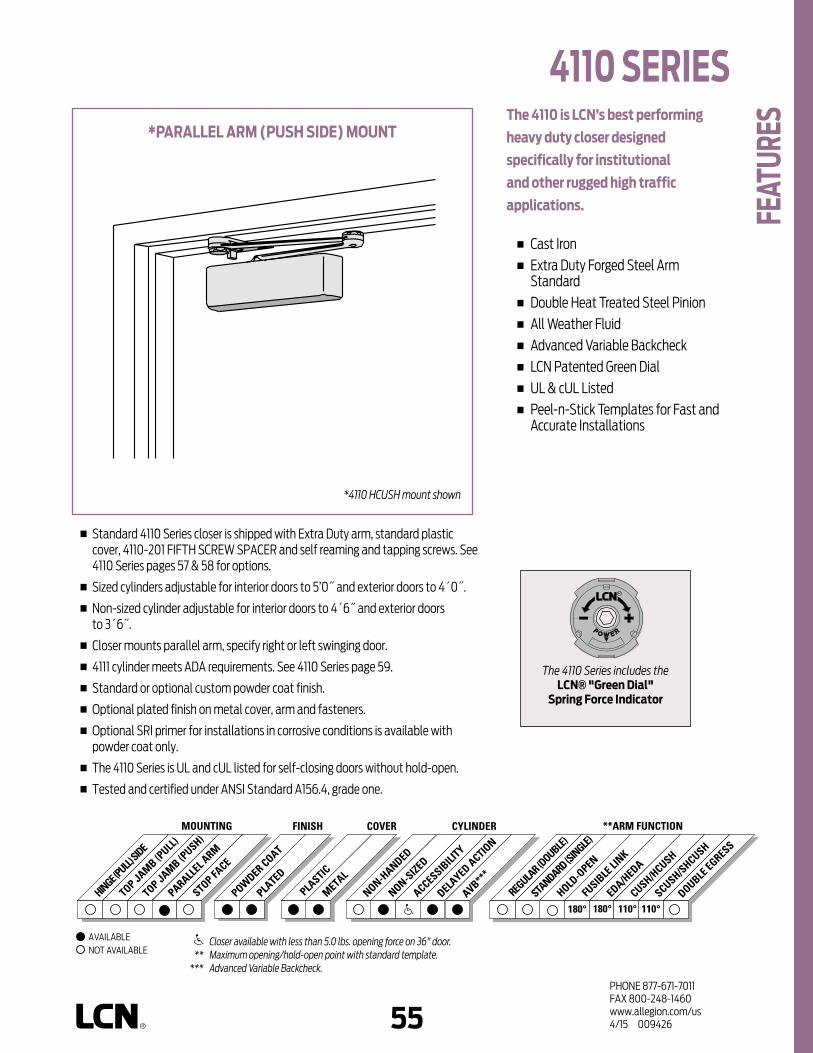
54 55PHONE 877-671-7011FAX 800-248-1460www.allegion.com/us 4/15 009426
n Standard 4110 Series closer is shipped with Extra Duty arm, standard plastic cover, 4110-201 FIFTH SCREW SPACER and self reaming and tapping screws. See 4110 Series pages 57 & 58 for options.
n Sized cylinders adjustable for interior doors to 5’0˝ and exterior doors to 4´0˝.
n Non-sized cylinder adjustable for interior doors to 4´6˝ and exterior doors to 3´6˝.
n Closer mounts parallel arm, specify right or left swinging door.
n 4111 cylinder meets ADA requirements. See 4110 Series page 59.
n Standard or optional custom powder coat finish.
n Optional plated finish on metal cover, arm and fasteners.
n Optional SRI primer for installations in corrosive conditions is available with powder coat only.
n The 4110 Series is UL and cUL listed for self-closing doors without hold-open.
n Tested and certified under ANSI Standard A156.4, grade one.
the 4110 is LcN’s best performing
heavy duty closer designed
specifically for institutional
and other rugged high traffic
applications.
n Cast Iron n Extra Duty Forged Steel Arm
Standard n Double Heat Treated Steel Pinion n All Weather Fluid n Advanced Variable Backcheck n LCN Patented Green Dial n UL & cUL Listed n Peel-n-Stick Templates for Fast and
Accurate Installations
*PArALLEL ArM (PuSH SIdE) MouNt
*4110 HCUSH mount shown
Closer available with less than 5.0 lbs. opening force on 36" door. ** Maximum opening/hold-open point with standard template. *** Advanced Variable Backcheck.
AVAILABLE NOT AVAILABLE
4110 SErIES
FEAt
urES
The 4110 Series includes theLcN® "Green dial"
Spring Force Indicator
180° 110° 110°180°
PLASTIC
METAL
HINGE (PULL)
SIDE
TOP JAMB (PULL
)
TOP JAMB (PUSH)
STANDARD (S
INGLE)
REGULA
R (DOUBLE)
HOLD-O
PEN
FUSIB
LE LI
NK
EDA/HEDA
CUSH/HCUSH
SCUSH/SHCUSH
PARALLEL A
RM
STOP FACE
MOUNTING COVER CYLINDER **ARM FUNCTIONFINISH
NON-HANDED
NON-SIZED
ACCESSIBILI
TY
DELAYED ACTIO
N
AVB***
POWDER COAT
PLATED
DOUBLE EGRESS

56PHONE 877-671-7011FAX 800-248-1460www.allegion.com/us 4/15 009426
n butt Hinges should not exceed 5˝ (127 mm) in width.
n Auxiliary Stop is recommended at hold-open point, where a door cannot swing 180°, or where CUSH-N-STOP arm is not used.
n clearance for EDA, or CUSH shoe is 5-1/2˝ (140 mm) from door face.
n top rail less than 5-1/8˝ (130 mm) measured from stop requires PLATE, 4110-18. Plate requires 2˝ (51 mm) minimum measured from the stop.
n Stop Width minimum 1˝ (25 mm).
n Head Frame flush or rabetted requires CUSH FLUSH PANEL ADAPTER, 4110-419.
n reveal less than 2-3/4˝ (70 mm), use CUSH SHOE SUPPORT, 4110-30 with CUSH arms.
n blade Stop Spacer, 4110-61 required to clear 1/2˝ (13 mm) blade stop.
n cush Arm requires CUSH SHOE SUPPORT, 4110-30 for fifth screw anchorage with CUSH arms.
n delayed Action Add suffix “DEL” to selected cylinder (eg. 4111 DEL). Not available with 4116 cylinder. Delays closing from maximum opening to approximately 70°. Delay time adjustable up to approximately 1 minute.
n Advanced variable backcheck cylinder starts backcheck at approximately 45° instead of the normal 75°. Add suffix “AVB” to selected cylinder.
*
*5-11/16˝ (144 mm) For Fusible Link Arm Applications
PArALLEL ArM (PuSH SIdE) MouNtING
MAXIMuM oPENINGEDA or Fusible Link arm can be templated for100°,
A = 5-15/16˝ (151 mm) B = 7-1/4˝ (184 mm)
140°, A = 4-7/16” (113 mm) B = 5-3/4˝ (146 mm)
or 180°. A = 2-15/16˝ (75 mm) B = 4-1/4˝ (108 mm)
Hold-open points up to maximum opening with HEDA or Fusible Link arm.
CUSH arm can be templated for maximum opening at85°,
A = 8-5/16˝ (211 mm) B = 9-5/8˝ (244 mm)
90°, A = 7-11/16˝ (195 mm) B = 9˝ (229 mm)
100°, A = 6-7/16˝ (164 mm) B = 7-3/4˝ (197 mm)
or 110°. A = 5-9/16˝ (141 mm) B = 6-7/8˝ (175 mm)
Hold-open point at maximum opening with HCUSH arm. Spring Cush hold-open points are approximately 5˚ less than templated stop point.
4110 SErIES M
ouNt
ING
dEtA
ILS
options n Size 6 or non-sized cylinder. n Delayed Action and/or Advanced
Variable Backcheck cylinder. n HEDA, CUSH, HCUSH, SPRING
CUSH, SPRING HCUSH or Fusible Link arm.
n Metal cover.
Special templates Customized installation templates or products may be available to solve unusual applications. Contact LCN Product Support for assistance.

56 57PHONE 877-671-7011FAX 800-248-1460www.allegion.com/us 4/15 009426
cYLINdErScYLINdEr, 4110-3071 Standard, handed cast iron cylinder assembly.For various applications see “Table of Sizes” on 4110 Series page 59.
covErScovEr, 4110-72 Standard, non-handed plastic cover.
MEtAL covEr, 4110-72Mc Optional, handed cover. Required for plated finishes and custom powder coat finishes.
ArMSEXtrA dutY ArM, 4110-3077EdA, 4110-3077EdAGNon-handed parallel arm features forged, solid steel main and forearm for potentially abusive installations.Optional 4110-62G thick hub shoe for blade stop clearance.
HoLd-oPEN ArM 4110-3049EdAOptional handed arm provides hold-open function, adjustable at shoe.
FuSIbLE LINK ArM, 4110-3049FL Optional, handed arm releases hold-open function adjustable at shoe when exposed to temperatures above 165° F.NOTE: Check local codes before specifing FL arms. NOT A life safety product!
cuSH-N-StoP ArM, 4110-3077cNS Non-handed parallel arm features solid forged steel main arm and forearm with built-in stop in soffit shoe.
72
3077
72Mc
3049
3077EdAG
Left Hand Shown
3077cNS
3049FL 62FL
3071
4110 SErIES
AccE
SSor
IES

58PHONE 877-671-7011FAX 800-248-1460www.allegion.com/us 4/15 009426
H-cuSH ArM 4110-3049cNSNon-handed arm provides hold-open function with templated stop/hold-open points. Handle controls hold-open function.
SPrING cuSH ArM, 4110-3077ScNSOptional, non-handed parallel arm for abusive applications features solid forged steel main arm and forearm with spring loaded stop in the soffit shoe.
SPrING H-cuSH ArM, 4110-3049ScNSOptional, non-handed parallel arm for abusive applications features solid forged steel main arm and forearm with spring loaded stop in the soffit shoe. Handle controls hold-open function.
INStALLAtIoN AccESSorIESPLAtE, 4110-18Required for push side mount where top rail is less than 5-1/8˝ (130 mm), measured from the stop. Plate requires minimum 2˝ (51 mm) minimum top rail. Plate also used with CUSH Arm installations.
cuSH SHoE SuPPort, 4110-30 Provides anchorage for fifth screw used with CUSH arm, where reveal is less than 3-1/16˝ (78 mm).
bLAdE StoP SPAcEr, 4110-61 Lowers parallel arm shoe to clear 1/2˝ (13 mm) blade stop
PA FLuSH PANEL AdAPtEr, 4110-419 Provides horizontal mounting surface for CUSH shoe on single rabetted or flush frame.
18
30
3049cNS
3077ScNS
3049ScNS
61
4110 SErIES Ac
cESS
orIE
S
419

58 59PHONE 877-671-7011FAX 800-248-1460www.allegion.com/us 4/15 009426
* Adjustable Size 1 thru 5
size 3 size 4 size 5 size 6*4111
*4111
EXtErIor (and vEStIbuLE) door WIdtH
28"711mm
30"762mm
36"914mm
42"1067mm
INtErIor door WIdtH
48"1219mm
28"711mm
34"864mm
38"965mm
48"1219mm
54"1372mm
60"1524mm
4116
4116
size 2 size 3 size 4 size 5 size 6
rEducEd oPENING ForcE 4110 cLoSErScAutIoN ! Any manual door closer, including those certified by BHMA to conform to ANSI Standard A156.4, that is selected, installed and adjusted based on ADA or other reduced opening force requirements may not provide sufficient power to reliably close and latch a door.
Refer to AUTOMATIC OPERATORS section for information on systems that meet reduced opening force requirements without effecting closing power.
MinimumDoor Width
MinimumDoor Width
Indicates recommended range of door width for closer size.
* Adjustable Size 1 thru 5.
tAbLE oF SIZES Select closer based on width of door.The spring power of non-sized 4111 cylinder is adjustable from size 1 through size 5 and is shipped set to size 3.Sized 4116 series cylinders 6.Delayed action not available with 4116 cylinderH - CUSH and SPRING H-CUSH arm not available with 4116 cylinder.
HoW-to-ordEr4110 SErIES cLoSErS1. SELEct cYLINdEr SIZE 4111 (adjustable from size 1 to 5) 4116 (DEL, SHCUSH or HCUSH arm not available)2. SPEcIFY HANd RH LH3. SELEct FINISH Standard Powder Coat __________
Aluminum, Dark Bronze, Statuary, Light Bronze, Black, Brass.
4110 cLoSEr oPtIoNScYLINdEr Delayed Action (DEL) (not available with 4116) Advanced Variable Backcheck (AVB)covEr Metal (MC)FINISH Custom Powder Coat (RAL) ___________
(handed metal cover required) Plated Finish, US ______________
(handed metal cover required) SRI primer (use with powder coat finishes only)SPEcIFY ArM Hold-Open Extra Duty (HEDA) Fusible Link,165° F (FL) Cush-N-Stop (CUSH) H-Cush-N-Stop (n/a with 4116 cylinder) (HCUSH) Spring Cush (SCUSH) Spring H-Cush (n/a with 4116 cylinder) (SHCUSH) Extra Duty (EDA) H-Extra Duty (HEDA)ScrEW PAcK TB*, Self-Reaming & Tapping (TBSRT) Wood & Machine Screw (WMS) TB*, Wood & Machine Screw (TBWMS) TORX Machine Screw (TORX) TB* & TORX Machine Screw (TBTRX
* Specify door thickness if other than 1-3/4”.INStALLAtIoN AccESSorIES Plate, 4110-18 CUSH Shoe Support, 4110-30 Blade Stop Spacer, 4110-61 PA Flush Panel Adapter, 4110-419SPEcIAL tEMPLAtE ST- _________
door WIdtH 36" 42" 48"
8.5* lbs. 4111 4111 4111
5.0* lbs. 4111 4111 4111
* Maximum opening force.
closer will be shipped with: - STANDARD COVER,- FIFTH SCREW SPACER,- EDA ARM,- SELF-REAMING and TAPPING SCREWS
unless options listed below are selected.
4110 SErIES
ordE
rING
INFo
rMAt
IoN

60PHONE 877-671-7011FAX 800-248-1460www.allegion.com/us 4/15 009426
Notes

60 61PHONE 877-671-7011FAX 800-248-1460www.allegion.com/us 4/15 009426
n Standard 4110T Series closer is shipped with standard arm, standard track, track roller, standard plastic cover and self reaming and tapping screws. See 4110T Series pages 63 & 64 for options.
n Sized cylinders for interior doors to 4´0˝.
n Closer mounts stop face side, specify right or left swinging door.
n Standard or optional custom powder coat finish.
n Optional plated finish on metal cover, arm and fasteners.
n Optional SRI primer for installations in corrosive conditions is available with powder coat only.
n The 4110T Series is UL and cUL listed with a standard track for self-closing doors.
n Tested and certified under ANSI Standard A156.4, grade one.
the 4110t is LcN’s best performing
heavy duty track closer designed
specifically for interior doors in
institutional and other high traffic
applications.
n Cast Iron n Forged Steel Main Arm n Double Heat Treated Steel Pinion n All Weather Fluid n UL & cUL Listed n Peel-n-Stick Templates for Fast and
Accurate Installations
StoP FAcE (PuSH SIdE) MouNt
4110t SErIES
FEAt
urES
AVAILABLE NOT AVAILABLE
Closer available with less than 5.0 lbs. opening force on 36˝ door. ** Maximum opening/hold-open point with standard template. *** Advanced Variable Backcheck.
HINGE (PULL)
SIDE
TOP JAMB (PULL
)
TOP JAMB (PUSH)
PARALLEL A
RM
STOP FACE
MOUNTING
110° 100°
PLASTIC
METAL
STANDARD (S
INGLE)
REGULA
R (DOUBLE)
HOLD-O
PEN
FUSIB
LE LI
NK
EDA/HEDA
CUSH/HCUSH
SCUSH/SHCUSH
COVER CYLINDER **ARM FUNCTIONFINISH
NON-HANDED
NON-SIZED
ACCESSIBILI
TY
DELAYED ACTIO
N
AVB***
POWDER COAT
PLATED
DOUBLE EGRESS

62PHONE 877-671-7011FAX 800-248-1460www.allegion.com/us 4/15 009426
StoP FAcE (PuSH SIdE) MouNtING
MAXIMuM oPENINGTemplating allows 110° with standard track arm, limited to 100° with optional bumper tracks.
Hold-open points at 85°, 90°, 95°, or 100° with hold-open tracks.
Please note that many track style door closers are capable of allowing 180° of door swing. Be aware that the majority of track style closers are at their weakest closing force in the 180° – 130° range. Consult factory for applications where door must swing 180°.
n butt Hinges should not exceed 5˝ (127 mm) in width.
n Auxiliary Stop is recommended at hold-open point or where a door cannot swing 110°. Optional track bumper assembly assists backcheck in cushioning the opening swing of the door. It is not intended to replace an auxiliary stop.
n clearance projects 2-1/4˝ (57 mm) from face of door.
n top rail less than 5-1/4˝ (133 mm) measured from stop, requires PLATE, 4110T-18. Plate requires 2-1/4˝ (57 mm) minimum.
n Stop Width minimum 1-1/4˝ (32 mm).
4110t SErIES M
ouNt
ING
dEtA
ILS
options n Standard track with bumper,
hold-open track, hold-open track with bumper.
n Metal cover.
Special templates Customized installation templates or products may be available to solve unusual applications. Contact LCN Product Support for assistance.

62 63PHONE 877-671-7011FAX 800-248-1460www.allegion.com/us 4/15 009426
cYLINdErScYLINdEr, 4110t-3071 Standard, handed cast iron cylinder assembly. For various applications see “Table of Sizes” on 4110T Series page 65.
covErScovEr, 4110t-72 Standard, non-handed plastic cover.
MEtAL covEr, 4110t-72McOptional, handed cover. Required for plated finishes and custom powder coat finishes.
ArMStANdArd ArM, 4110t-3077tHanded arm. Roller not included with arm.
trAcKSStANdArd trAcK, 4110t-3038Standard, non hold-open, non-handed track.Will accept hold-open clip and/or bumper assembly.
StANdArd trAcK with buMPEr, 4110t-3038b Optional non hold-open, non-handed track with bumper assembly installed. Will accept hold-open clip.
HoLd-oPEN trAcK, 4110t-3038HOptional, non-handed track with hold-open clip installed.Will accept bumper assembly.
HoLd-oPEN trAcK with buMPEr, 4110t-3038HbOptional, non-handed track with hold-open clip and bumper assembly installed.
4110t SErIES
AccE
SSor
IES
Left Hand Shown
3077t
3038
72Mc
72
3038b3038H3038Hb
3071

64PHONE 877-671-7011FAX 800-248-1460www.allegion.com/us 4/15 009426
3034
INStALLAtIoN AccESSorIESPLAtE, 4110t-18Required where top rail, when measured from the stop, is less than 5-1/4˝ (133 mm). Plate requires minimum 2-1/4˝ (57 mm) minimum top rail.
trAcK buMPEr, 4110t-169Mounts in track to assist backcheck, not replace auxiliary stop.Limits maximum opening. Consists of bumper, bumper post, and mounting screw.
HoLd-oPEN cLIP, 4110t-3054Mounts in track to provide hold-open function.Hold-open point controlled by clip location.Consists of clip and mounting screws.
trAcK roLLEr, 4110t-3034Quiet, low friction roller assembly.Shoulder dimension "X" = 1/16" (2 mm).
3054
169
18
4110t SErIES Ac
cESS
orIE
S

64 65PHONE 877-671-7011FAX 800-248-1460www.allegion.com/us 4/15 009426
HoW-to-ordEr 4110t SErIES cLoSErS1. SELEct cYLINdEr SIZE 4111T (ADA) 4113T 4114T2. SPEcIFY HANd RH LH 3. SELEct FINISH Standard Powder Coat __________
Aluminum, Dark Bronze, Statuary, Light Bronze, Black, Brass.
cLoSEr oPtIoNScovEr Metal (MC)FINISH Custom Powder Coat (RAL)__________
(handed metal cover required) Plated Finish, US _____________
(handed metal cover required) SRI primer (use with powder coat
finishes only)SPEcIFY trAcK Standard with Bumper (BUMPER) Hold-Open (HO) Hold-Open with Bumper (HBUMPER)SPEcIFY ScrEW PAcK TB* w/Self-Reaming and Tapping
(TBSRT) Wood & Machine Screw (WMS) TB*, Wood & Machine Screw (TBWMS) TORX Machine Screw (TORX) TB* & TORX Machine Screw (TBTRX)
* Specify door thickness if other than 1-3/4”.INStALLAtIoN AccESSorIES Plate, 4110T-18SPEcIAL tEMPLAtE ST- _________
closer will be shipped with: - STANDARD COVER,- STANDARD ARM,- TRACK ROLLER,- STANDARD TRACK,- SELF-REAMING and TAPPING SCREWS unless options listed below are selected.
4110t SErIES
ordE
rING
INFo
rMAt
IoN
4113t
INtErIor door WIdtH
26"660mm
34"864mm
38"965mm
48"1219mm
4114t
size 1 size 3 size 4
MinimumDoor Width
Indicates recommended range of door width for closer size.
tAbLE oF SIZES Select closer based on width of door.Sized 4110T series cylinders available in size 1, 3 or 4. Closing power of all 4110T Series closers may be increased 15%.Specify next higher size closer where strong drafts exist.
rEducEd oPENING ForcE 4110t cLoSErScAutIoN ! Any manual door closer, including those certified by BHMA to conform to ANSI Standard A156.4, that is selected, installed and adjusted based on ADA or other reduced opening force requirements may not provide sufficient power to reliably close and latch a door.
Refer to POWER OPERATORS section for information on systems that meet reduced opening force requirements without effecting closing power.
door WIdtH 36" 42" 48"
8.5* lbs. N/A N/A N/A
5.0* lbs. 4111T 4111T 4111T
* Maximum opening force.

66PHONE 877-671-7011FAX 800-248-1460www.allegion.com/us 4/15 009426
Notes

66 67PHONE 877-671-7011FAX 800-248-1460www.allegion.com/us 4/15 009426
n 4000T Series closer is shipped with standard arm, standard track, track roller, standard plastic cover, and wood and machine screw pack. See 4000T Series page 69 for options.
n Sized cylinders for interior fire/smoke barrier doors to 4´0˝.
n Closer mounts in a wall pocket, hinge side, on either right or left hand door.
n Standard or optional custom powder coat finish.
n Optional plated finish on metal cover, arm and fasteners.
n Optional SRI primer for installations in corrosive conditions is available with powder coat only.
n The 4000T Series is UL and cUL listed with a standard arm for self-closing doors.
n Tested and certified under ANSI Standard A156.4, grade one.
the 4000t is a heavy duty closer
to reliably control fire and smoke
barrier doors with maximum
swing of 90°. designed for use
with an SEM 7850 wall magnet.
n Cast Iron n Forged Steel Arm n Double Heat Treated Steel Pinion n All Weather Fluid n UL & cUL Listed
WALL PocKEt MouNt
4000t SErIES
FEAt
urES
** Maximum opening/hold-open point with standard template. *** Advanced Variable Backcheck.
AVAILABLE NOT AVAILABLE
90°
PLASTIC
METAL
HINGE (PULL)
SIDE
TOP JAMB (PULL
)
TOP JAMB (PUSH)
STANDARD (S
INGLE)
REGULA
R (DOUBLE)
HOLD-O
PEN
FUSIB
LE LI
NK
EDA/HEDA
CUSH/HCUSH
SCUSH/SHCUSH
PARALLEL A
RM
STOP FACE
MOUNTING COVER CYLINDER **ARM FUNCTIONFINISH
NON-HANDED
NON-SIZED
ACCESSIBILI
TY
DELAYED ACTIO
N
AVB***
POWDER COAT
PLATED
DOUBLE EGRESS

68PHONE 877-671-7011FAX 800-248-1460www.allegion.com/us 4/15 009426
WALL PocKEt MouNtINGCylinder mounts on wall.Track mounts on hinge side of door.
MAXIMuM oPENINGTemplating allows 90° only.Hold-open point 90° with magnet.
dimension 1 is the distance from the centerline of the closer shaft to the centerline of the hinge or pivot. For pocket pivot or total door hinge,9-1/2˝ (241 mm).For butt hinge 8˝ (203 mm).For center pivot 10˝ (254 mm).dimension 2 is the distance from the centerline of the pivot or hinge to the cylinder mounting surface.For pocket pivot 4-1/2˝ (114 mm).For total door hinge 3-7/8˝ (98mm)For butt hinge 2-7/8˝ (73 mm).For center pivot 4-1/2˝ (114 mm).dimension 3 is the distance from the centerline of the pivot or hinge to end of the track.For pocket pivot or total door hinge,3-7/8˝ (98mm).For butt hinge 2-3/8˝ (60mm).For center pivot 4-5/8˝ (117mm).
n butt Hinges, Pocket Pivot, Total Door Hinge or Center Pivot are door mounting options.
n butt Hinges should not exceed 5˝ (127 mm).
n Pocket depth, See above table for distance required between door and closer mounting location. This dimension is measured from the cylinder mounting surface to the pull side face of the door at 90°.
n Wall Magnet SEM 7850 is recommended. Use of other magnets may require special construction to alter the depth of the pocket at the magnet location. See Fire Life Safety Section.
options n Metal cover.
Special templates Customized installation templates or products may be available to solve unusual applications. Contact LCN Product Support for assistance.
4000t SErIES M
ouNt
ING
dEtA
ILS

68 69PHONE 877-671-7011FAX 800-248-1460www.allegion.com/us 4/15 009426
cYLINdErScYLINdEr, 4000t-3071 Standard, non-handed cast iron cylinder assembly.
covErScovEr, 4000t-72 Standard, non-handed plastic cover.
MEtAL covEr, 4000t-72Mc Optional, handed cover. Required for plated and custom powder coat finishes.
ArMStANdArd ArM, 4000t-3077t Non-handed arm.
trAcKStANdArd trAcK, 4000t-3038 Standard, non hold-open, non-handed track. Will not accept hold-open clip or bumper assembly.
trAcK roLLEr, 4000t-3034Quiet, low friction roller assembly.Shoulder Dimension "X"= 1/8˝ (3 mm).
72
3038
72Mc
3077t
3034
3071
Right Hand Shown
4000t SErIES
AccE
SSor
IES

70PHONE 877-671-7011FAX 800-248-1460www.allegion.com/us 4/15 009426
4000t SErIES or
dErI
NG IN
ForM
AtIo
N HoW-to-ordEr4000t SErIES cLoSErS
1. SELEct cYLINdEr SIZE 4003T 4004T2. SELEct FINISH Standard Powder Coat __________
Aluminum, Dark Bronze, Statuary, Light Bronze, Black, Brass.
cLoSEr oPtIoNScovEr Metal (MC)FINISH Custom Powder Coat (RAL)__________
(handed metal cover required) Plated Finish, US _____________
(handed metal cover required) SRI primer (use with powder coat
finishes only)ScrEW PAcK TB*, Wood & Machine Screw (TBWMS) TORX Machine Screw (TORX) TB* & TORX Machine Screw (TBTRX)
* Specify door thickness if other than 1-3/4”.SPEcIAL tEMPLAtE ST- _________
closer will be shipped with: - STANDARD COVER,- STANDARD ARM,- TRACK ROLLER,- STANDARD TRACK,- WOOD and MACHINE SCREW PACK
unless options listed below are selected.
4003t
INtErIor door WIdtH
28"711mm
34"864mm
38"965mm
42"1067mm
48"1219mm
4004t
size 3 size 4
MinimumDoor Width
Indicates recommended range of door width for closer size.
tAbLE oF SIZES Select closer based on width of door.4000T Series cylinders available in size 3 or 4. Closing power of 4000T Series closers is not adjustable.

PHONE 877-671-7011FAX 800-248-1460www.allegion.com/us 4/15 009426
1000 SERIES SURFACE MOUNTED CLOSERSPRODUCT SELECTION GUIDESurface mounted 1000 Series LCN closers feature a modern slim line design for easy installation on narrow head frames and top rails. This guide is based on the desired mounting of the closer. NOTE: For parallel mounts order “P” version to also receive PA Shoe.
PRODUCT COMPARISONThis chart shows a basic comparison of LCN 1000 Series closers. Refer to the specific closer chapter for complete details.
SINGLELEVER ARM
1460T
INTERIOR DOOR
DOUBLELEVER ARM
12601460
DOUBLELEVER ARM
12601460
DOUBLELEVER ARM
12601460
DOUBLELEVER ARM
12601460
EXTERIOR DOOR
1
SINGLELEVER ARM
1460T
PULL SIDEMOUNTED
PULL SIDEMOUNTED
PUSH SIDEMOUNTED
PUSH SIDEMOUNTED
PLASTIC
METAL
COVER
DESIGNER SERIES
*ARM FUNCTION
HEAVY DUTY
HOLD-O
PEN
STANDARD (S
INGLE)
REGULA
R (DOUBLE)
EDA/HEDA
CUSH/HCUSH
SCUSH/SHCUSH
180
AVAILABLE
NOT AVAILABLE
NON-HANDED
NON-SIZED
ACCESSIBILI
TY
CYLINDER
DELAYED ACTIO
N
POWDER COAT
PLATED
FINISH
100
STOP FACE
PARALLEL A
RM
MOUNTING
1260
HINGE (PULL)
SIDE
TOP JAMB (PULL
)
TOP JAMB (PUSH)
1460
1460T D
D 180 180 180
115180
180 110
110 100 100
120 110
Closer available with less than 5.0 lbs. opening force on 36" door. * Maximum opening/hold-open point with standard template. See individual closer series for degrees
of opening per installation. D = For designer series only.

PHONE 877-671-7011FAX 800-248-1460www.allegion.com/us 4/15 0094262
APPLICATIONSn For aluminum, hollow metal, or wood swinging doors and frames. n Can be used with hinge or pivot mounted door.n Mounts on 1-3/4˝ transom without adapter plates.n Adapter plates and other installation accessories available for
unusual conditions.
FEATURES COMMON TO 1000 SERIESn 1000 series closers mount three ways. Closers with regular or
hold-open arm mount hinge side or top jamb. Parallel arm, closers include - 62PA SHOE required for parallel arm mount. 1460T mounts hinge side, top jamb (pull side) and stop face.
n Non-handed for right and left swinging doors.n Closers to meet ADA reduced opening force requirements.n Adjustable hydraulic backcheck cushions opening swing prior to
90°. n Separate regulation of general closing speed and latching speed.n Joints in arm and shoe adapt to uneven trim.n Reversible shoe to boost latching power on double lever arms.
DESIGN ASSISTANCELCN has been providing reliable solutions to unique door control problems for over 85 years. Design and specification assistance are only a phone call away.Contact LCN for assistance or technical information at 877-671-7011 or FAX 800-248-1460 (Order Entry), Fax 815-879-1495 for Product Support.
WARRANTY30 year limited warranty (1460 Series) and 20 year limited warranty (1260 Series). See General Information Section for complete warranty details.
SPECIFICATIONSRefer to ”SPECIFICATIONS” section for suggested architectural specifications.
MATERIALSn High strength cast iron cylinder.n Forged steel main arm for all EDA, Cush, 1460HD and
1460T Arms.n One piece forged steel piston.n Heat treated pinion.n All weather fluid eliminates seasonal adjustments. n High efficiency, full complement, low friction bearings.n Tamper resistant regulating screws.n Full rack and pinion hydraulic action.n Quiet, low friction track and roller combination for all single lever
arm closers.
FINISHESn Available in six standard or a wide selection of optional custom
powder coat finishes to blend with door and frame.n LCN’s powder coat finish surpasses 100 hours of salt spray which is
1000 SERIES SURFACE MOUNTED CLOSERS over four times the ANSI standard for corrosion resistance.
n For installations where a higher level of corrosion resistance is required, LCN offers an optional special rust inhibiting (SRI) pre-treatment. Closers that combine the exclusive LCN powder coat finish and the SRI pre-treatment exceed the ANSI standard for corrosion resistance even further.
n Plated finishes are available as an option to accent door and frame for the 1460 Series closers.
LISTINGS & APPROVALSUL listed for self-closing doors without hold-open under ”SWINGING DOOR CLOSERS” (GVEV) file R 1943. Tested and certified under ANSI Standard A156.4 grade one. Consult factory for details.Consult factory for other listings such as; cUL, California State Fire Marshal, Bureau of Standards and Appeals.
POSITIVE PRESSURE LCN closers have been certified for three hours by UL to be in compliance with UBC 7-2 (1997) and UL 10 C. Contact LCN for specific details on door closer fire ratings.
FASTENERS1260, 1460, 1460T series closers are shipped with: A standard SELF-REAMING and TAPPING SCREW (SRT) pack that contains Philips head SRT screws to install the closer. Standard LCN thru bolts (TB) can be installed on 1-3/4” (44 mm) thick doors with 1/4-20 machine screws. Optional thru bolt (TB) sizes are available for 1-5/8” (41 mm) or 1-3/8” (35 mm) door thickness, but this must be specified when ordering.
Note 1: For Thru Bolts, specify door thickness if other than 1-3/4˝ (44 mm). Represented in diagram as dimension "X".
Note 2: Phillips head, metric machine screws are available, please specify.
Note 3: LCN recommends the use of wood screws in wood door applications.
MAINTENANCEClosers mounted according to LCN installation instructions require no periodic maintenance or adjustments.
Drill 25/64˝ forsteel doorsorDrill 3/8˝for wood doors

PHONE 877-671-7011FAX 800-248-1460www.allegion.com/us 4/15 009426
n Standard 1260 Series closer shipped with regular arm, a shaft cover, and self reaming and tapping screws. See 1260 Series Pages 8-9 for options.
n Non-sized (1-5) cylinder is adjustable for interior doors to 4´6˝ and exterior doors to 3´6˝.
n Closer mounts hinge side, top jamb and parallel arm on either right or left swinging doors.
n Mounts to most common commercial footprint (3/4˝ x 9-1/16˝).
n Closer meets ADA requirements. See 1260 Series page 10.
n Optional Quick Fix™ bracket kit.
n Standard or optional custom powder coat finish.
n Optional SRI primer for installations in corrosive conditions. (Available with powder coat finishes only).
n Optional Slim Line cover.
n Tested and certified under ANSI Standard A156.4, grade one.
The 1260 is a light to medium duty
cast iron closer designed to fit into
the most common commercial foot
print. The 1260 is adjustable for spring
sizes 1-5. The 1260 also features a
complete line of regular and extra duty
arms, LCN’s peel-n-stick installation
templates, a convenient spring adjust
pointer, and an optional Quick Fix™
bracket kit.
n Cast Iron n All weather fluid n Non-handed n Peel-n-stick templates for fast and
accurate installation n UL and cUL listed
FEAT
URES
1260 SERIES
PLASTIC
METAL
COVER
DESIGNER SERIES
*ARM FUNCTION
HEAVY DUTY
HOLD-O
PEN
STANDARD (S
INGLE)
REGULA
R (DOUBLE)
EDA/HEDA
CUSH/HCUSH
SCUSH/SHCUSH
180° 180° 120° 110° 110°
NON-HANDED
NON-SIZED
ACCESSIBILI
TY
CYLINDER
DELAYED ACTIO
N
POWDER COAT
PLATED
FINISH
PARALLEL A
RM
MOUNTING
STOP FACE
HINGE (PULL)
SIDE
TOP JAMB (PULL
)
TOP JAMB (PUSH)
3
CLOSER MOUNTS*HINGE (PULL) SIDE
TOP JAMB (PUSH SIDE)PARALLEL ARM (PUSH SIDE)
*HINGE (pull) side mount shown
Closeravailablewithlessthan5.0lbs.openingforceon36˝door. * Maximum opening/hold-open point with standard template.
AVAILABLE
NOT AVAILABLE

PHONE 877-671-7011FAX 800-248-1460www.allegion.com/us 4/15 009426
Options n Hold-open arm. n Slim Line cover (SLIM).
Special TemplatesCustomized installation templates or products may be available to solve unusual applications. Contact LCN Product Support for assistance.
HINGE (PULL) SIDE MOUNTING
MAXIMUM OPENINGTo 100°
A = 6-9/16˝ (167 mm)B = 12-7/16˝ (316 mm)
or 101° to 120°A = 5-9/16˝ (141 mm)B = 11-7/16˝ (291 mm)
or *121° to 180°A = 3-1/16˝ (78 mm)B = 8-15/16˝ (227 mm)
Hold-open points up to maximum opening with hold-open arm.
*Frame and trim permitting.
1260 SERIES
n Butt Hinges should not exceed 5˝ (127 mm) in width.
n Auxiliary Stop is recommended at hold-open point or where a door cannot swing 180°.
n Reveal should not exceed 3/4˝ (19 mm) for regular arm or 1/2˝ (13 mm) for hold-open arm.
n Top Rail less than 2-1/2˝ (64 mm) requires PLATE, 1260-18.
n Clearance of 2-7/8˝ (73 mm) behind door required for installation.
1260-18
12305 mm
2 11/1668 mm
1 1/432 mm
3 3/886 mm
252 mm
A2 7/8
73 mm
B
CL
9 15/16
2 ½64 mm
4
MOU
NTIN
G DE
TAIL
S
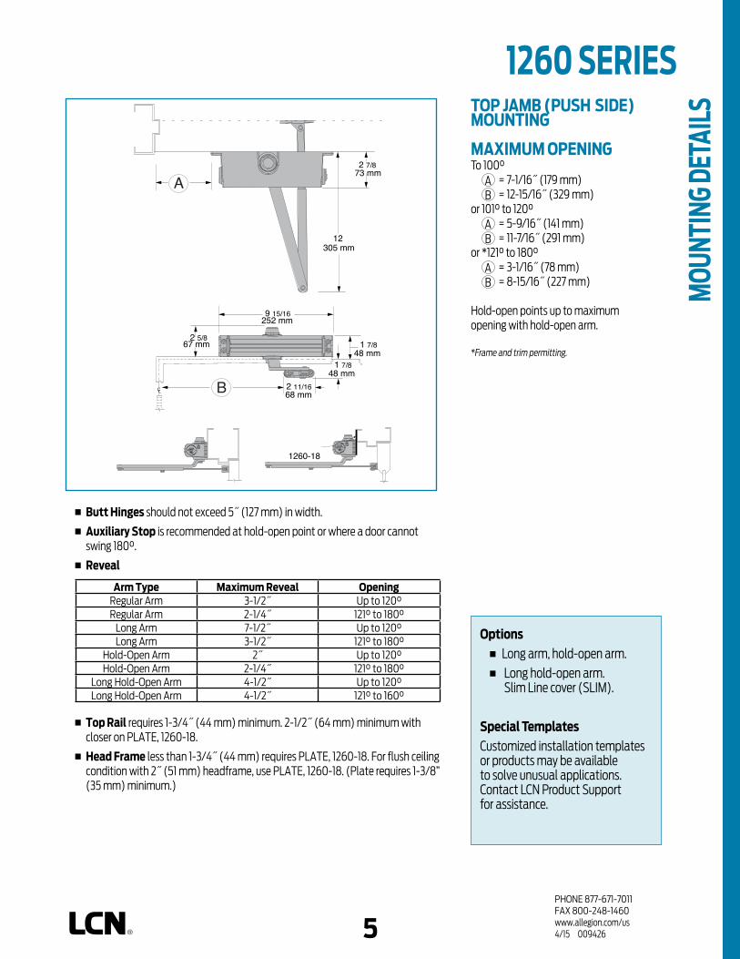
PHONE 877-671-7011FAX 800-248-1460www.allegion.com/us 4/15 009426
1260 SERIES TOP JAMB (PUSH SIDE) MOUNTING
MAXIMUM OPENINGTo 100°
A = 7-1/16˝ (179 mm)B = 12-15/16˝ (329 mm)
or 101° to 120°A = 5-9/16˝ (141 mm)B = 11-7/16˝ (291 mm)
or *121° to 180°A = 3-1/16˝ (78 mm)B = 8-15/16˝ (227 mm)
Hold-open points up to maximum opening with hold-open arm.
*Frame and trim permitting.
n Butt Hinges should not exceed 5˝ (127 mm) in width.
n Auxiliary Stop is recommended at hold-open point or where a door cannot swing 180°.
n Reveal
Arm Type Maximum Reveal OpeningRegular Arm 3-1/2˝ Up to 120°Regular Arm 2-1/4˝ 121° to 180°
Long Arm 7-1/2˝ Up to 120°Long Arm 3-1/2˝ 121° to 180°
Hold-Open Arm 2˝ Up to 120°Hold-Open Arm 2-1/4˝ 121° to 180°
Long Hold-Open Arm 4-1/2˝ Up to 120°Long Hold-Open Arm 4-1/2˝ 121° to 160°
n Top Rail requires 1-3/4˝ (44 mm) minimum. 2-1/2˝ (64 mm) minimum with closer on PLATE, 1260-18.
n Head Frame less than 1-3/4˝ (44 mm) requires PLATE, 1260-18. For flush ceiling condition with 2˝ (51 mm) headframe, use PLATE, 1260-18. (Plate requires 1-3/8” (35 mm) minimum.)
67 mm
1 7/848 mm
LC
2 5/8
1260-18
12305 mm
2 11/1668 mm
252 mm
A
B
2 7/873 mm
1 7/848 mm
9 15/16
5
Options n Long arm, hold-open arm. n Long hold-open arm.
Slim Line cover (SLIM).
Special TemplatesCustomized installation templates or products may be available to solve unusual applications. Contact LCN Product Support for assistance.
MOU
NTIN
G DE
TAIL
S
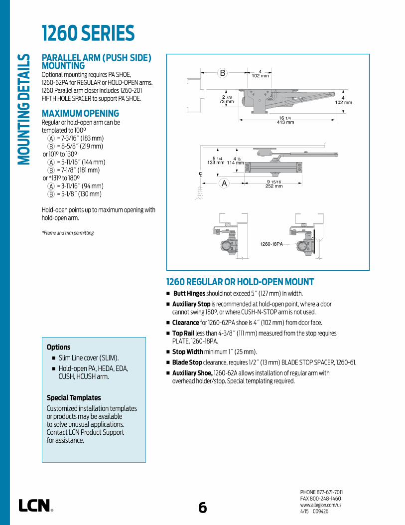
PHONE 877-671-7011FAX 800-248-1460www.allegion.com/us 4/15 009426
1260 SERIES PARALLEL ARM (PUSH SIDE) MOUNTINGOptional mounting requires PA SHOE, 1260-62PA for REGULAR or HOLD-OPEN arms. 1260 Parallel arm closer includes 1260-201 FIFTH HOLE SPACER to support PA SHOE.
MAXIMUM OPENINGRegular or hold-open arm can be templated to 100°
A = 7-3/16˝ (183 mm)B = 8-5/8˝ (219 mm)
or 101° to 130°A = 5-11/16˝ (144 mm)B = 7-1/8˝ (181 mm)
or *131° to 180°A = 3-11/16˝ (94 mm)B = 5-1/8˝ (130 mm)
Hold-open points up to maximum opening with hold-open arm.
*Frame and trim permitting.
1260 REGULAR OR HOLD-OPEN MOUNTn Butt Hinges should not exceed 5˝ (127 mm) in width.
n Auxiliary Stop is recommended at hold-open point, where a door cannot swing 180°, or where CUSH-N-STOP arm is not used.
n Clearance for 1260-62PA shoe is 4˝ (102 mm) from door face.
n Top Rail less than 4-3/8˝ (111 mm) measured from the stop requires PLATE, 1260-18PA.
n Stop Width minimum 1˝ (25 mm).
n Blade Stop clearance, requires 1/2˝ (13 mm) BLADE STOP SPACER, 1260-61.
n Auxiliary Shoe, 1260-62A allows installation of regular arm with overhead holder/stop. Special templating required.
LC
133 mm5 1/4
1260-18PA
252 mm
B
A
4102 mm
16 1/4413 mm
4102 mm
2 7/873 mm
9 15/16
114 mm4 ½
6
MOU
NTIN
G DE
TAIL
S
Options n Slim Line cover (SLIM). n Hold-open PA, HEDA, EDA,
CUSH, HCUSH arm.
Special TemplatesCustomized installation templates or products may be available to solve unusual applications. Contact LCN Product Support for assistance.

PHONE 877-671-7011FAX 800-248-1460www.allegion.com/us 4/15 009426
n Clearance for 1260-62EDA or CUSH shoe is 5-1/2˝ (140 mm) from door face.
n Head Frame flush or rabbeted requires CUSH FLUSH PANEL ADAPTER, 1260-419.
n EDA or CUSH ARM requires SHOE SUPPORT, 1260-30 for fifth screw anchorage where reveal is less than 3-1/16˝ (78 mm).
1260 SERIES 1260 EDA MOUNT
1260 CUSH MOUNT
LC
133 mm5 1/4
1260-18PA
EDA
9 15/16252 mm
B
A
16406 mm
4102 mm
2 7/873 mm
5 1/2140 mm
114 mm4 ½
LC
Cush
133 mm5 1/4
B
A
16406 mm
4102 mm
2 7/873 mm
5 1/2140 mm
114 mm4 ½
9 15/16252 mm
1260-18PA
1260 EDA OR CUSH-N-STOP MOUNTING1260 closers ordered with EDA, CUSH or SPRING CUSH arms include 1260-201 FIFTH HOLE SPACER to support the shoe.
MAXIMUM OPENINGEDA template allows 120°. Hold-open point up to maximum opening.90°,
A = 4-13/16˝ (122 mm)B = 9-1/2˝ (241 mm)
or 120°,A = 3-5/16˝ (84 mm)B = 8˝ (203 mm)
CUSH arms can be templated for maximum opening/hold-open point at85°,
A = 5-5/16˝ (135 mm)B = 10” (254 mm)
90°,A = 4-11/16˝ (119 mm)B = 9-3/8˝ (238 mm)
100°, A = 3-9/16˝ (90 mm)B = 8-1/4˝ (210 mm)
or 110°. A = 2-13/16˝ (71 mm)B = 7-1/2˝ (191 mm)
76
MOU
NTIN
G DE
TAIL
S
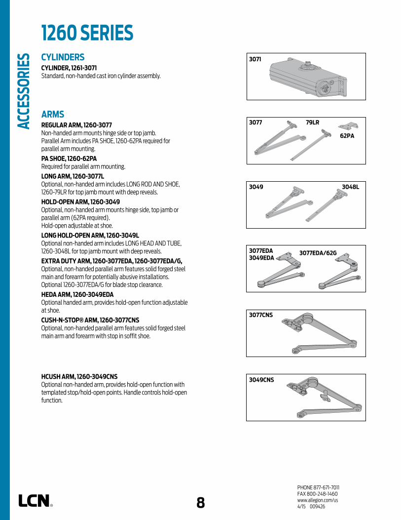
PHONE 877-671-7011FAX 800-248-1460www.allegion.com/us 4/15 009426
1260 SERIES AC
CESS
ORIE
S CYLINDERSCYLINDER, 1261-3071Standard, non-handed cast iron cylinder assembly.
ARMSREGULAR ARM, 1260-3077Non-handed arm mounts hinge side or top jamb. Parallel Arm includes PA SHOE, 1260-62PA required for parallel arm mounting.
PA SHOE, 1260-62PARequired for parallel arm mounting.
LONG ARM, 1260-3077L Optional, non-handed arm includes LONG ROD AND SHOE, 1260-79LR for top jamb mount with deep reveals.
HOLD-OPEN ARM, 1260-3049Optional, non-handed arm mounts hinge side, top jamb or parallel arm (62PA required). Hold-open adjustable at shoe.
LONG HOLD-OPEN ARM, 1260-3049LOptional non-handed arm includes LONG HEAD AND TUBE, 1260-3048L for top jamb mount with deep reveals.
EXTRA DUTY ARM, 1260-3077EDA, 1260-3077EDA/G, Optional, non-handed parallel arm features solid forged steel main and forearm for potentially abusive installations. Optional 1260-3077EDA/G for blade stop clearance.
HEDA ARM, 1260-3049EDA Optional handed arm, provides hold-open function adjustable at shoe.
CUSH-N-STOP® ARM, 1260-3077CNSOptional, non-handed parallel arm features solid forged steel main arm and forearm with stop in soffit shoe.
HCUSH ARM, 1260-3049CNSOptional non-handed arm, provides hold-open function with templated stop/hold-open points. Handle controls hold-open function.
3071
3048L3049
3049CNS
3077CNS
8
79LR3077
62PA
3077EDA 3049EDA
3077EDA/62G

PHONE 877-671-7011FAX 800-248-1460www.allegion.com/us 4/15 009426
1260 SERIES 72
30
62A
18 18PA
18QF
9
COVERCOVER, 1260-72 Optional, non-handed, slim line plastic cover.
INSTALLATION ACCESSORIESPLATE, 1260-18Required for hinge side mount where top rail is less than 2-1/2˝ (64 mm). Required for top jamb mounting where head frame is less than 1-3/4˝ (44 mm) or flush ceiling condition exists.Plate requires minimum 1-1/2˝ (38 mm) minimum top rail or 1-1/4˝ (32 mm) head frame.
PLATE, 1260-18PARequired for parallel arm mounting where top rail is less than 4-3/8˝ (111 mm), measured from the stop.Plate requires 1-3/4˝ (44 mm) minimum top rail.
QUICK FIX™ BRACKET KIT, 1260-18QF Optional kit includes retro-fit mounting plates for closer cylinder and shoe. Useful in applications when previously drilled holes are damaged.
CUSH SHOE SUPPORT, 1260-30 Provide anchorage for fifth screw used with CUSH arms where reveal is less than 3-1/16˝ (78 mm).
BLADE STOP SPACER, 1260-61 Lowers parallel arm shoe to clear 1/2˝ (13 mm) blade stop.
AUXILIARY SHOE, 1260-62A Requires a top rail of 7˝ (178 mm). Optional shoe replaces -62PA for parallel arm mounting of regular arm with overhead holder/stop.
PA FLUSH PANEL ADAPTER, 1260-419 Provides horizontal mounting surface for PA, EDA or CUSH shoe on single rabbeted or flush frame.
419
61
ACCE
SSOR
IES

PHONE 877-671-7011FAX 800-248-1460www.allegion.com/us 4/15 009426
Indicates recommended range of door width for closer size.
TABLE OF SIZES Select closer based on width of door.The spring power of a 1261 cylinder is field adjustable from size 1 through size 5 and is shipped adjusted to size 3.
DOOR WIDTH 36" 42" 48"
8.5* lbs. 1261 1261 1261
5.0* lbs. 1261 1261 1261
REDUCED OPENING FORCE 1260 CLOSERSCAUTION ! Any manual door closer, including those certified by BHMA to conform to ANSI Standard A156.4, that is selected, installed and adjusted based on ADA or other reduced opening force requirements may not provide sufficient power to reliably close and latch a door.
Refer to POWER OPERATORS section for information on systems that meet reduced opening force requirements without affecting closing power.
* Maximum opening force.
1260 SERIES
size 3 size 4 size 5 *1261
EXTERIOR (and VESTIBULE) DOOR WIDTH
size 2 size 3 size 4 size 5 *1261
10
Minimum Door
Width
Minimum Door
Width
HOW-TO-ORDER1260 SERIES CLOSERS
1. SELECT FINISH Standard Powder Coat __________
Aluminum, Dark Bronze, Statuary, Light Bronze, Black, Brass.
CLOSER OPTIONSCOVER Slim line cover (SLIM)
FINISH Custom Powder Coat (RAL) ___________ SRI primer (for use with powder coat finishes only)
ARM Regular w/62PA (Rw/PA) Long (LONG) Regular w/62A (R/62A) Hold-Open (H) Hold-Open w/62PA (Hw/PA) Long Hold-Open (HLONG) EDA (optional -62G) HEDA (specify right or left hand),
(optional -62G) Cush-N-Stop (CUSH) HCush (HCUSH)
OPTIONAL SCREW PACKS TB* w/Self-Reaming and Tapping Screws (TBSRT) Wood & Machine Screw (WMS) TB*, Wood & Machine Screw (TBWMS) TORX Machine Screw (TORX) TB* & TORX Machine Screw (TBTORX)
* Specify door thickness if other than 1-3/4”.
SPECIAL TEMPLATE ST- _________
INSTALLATION ACCESSORIES Plate, 1260-18 Plate, 1260-18PA CUSH Shoe Support, 1260-30 Blade Stop Spacer, 1260-61 Auxiliary Shoe, 1260-62A PA Flush Panel Adapter, 1260-419 Quick Fix™ Bracket Kit, 1260-18QF
* Adjustable Size 1 thru 5
ORDE
RING
INFO
RMAT
ION
24"610mm
30"762mm
36"914mm
42"1067mm
INTERIOR DOOR WIDTH
24"610mm
34"864mm
38"965mm
48"1219mm
54"1372mm
Closer will be shipped with: - STANDARD CYLINDER, - REGULAR ARM, - SELF-REAMING and TAPPING SCREWS, unless options listed below are selected.

PHONE 877-671-7011FAX 800-248-1460www.allegion.com/us 10/14
n Standard 1460 series closer shipped with regular arm, a slim line plastic cover, and self reaming and tapping screws. See 1460 Series Pages 16 & 17 for options.
n Multiple cover options include; Standard (Slim line), Full and Designer Series.
n Non-sized (1-6) cylinder is adjustable for interior doors to 5´0˝ and exterior doors to 4´0˝.
n Closer mounts hinge side, top jamb and parallel arm on either right or left swinging doors.
n Closer meets ADA requirements. See 1460 Series page 18.
n Standard or optional custom powder coat finish.
n Optional plated finish on Designer Series metal cover, arm and fasteners. (Available with powder coat finishes only.)
n Optional SRI primer for installations in corrosive conditions.
n Tested and certified under ANSI Standard A156.4, grade one.
Designed for maximum versatility,
the 1460, available with multiple
cover options, can be used for
both commercial and institutional
applications. This fully universal
closer offers a wide variety of
options and fast and accurate
installation.
n Cast Iron n All weather fluid n Non-handed n Peel-n-stick templates for fast and
accurate installation n UL and cUL listed n LCN patented green dial
1460 SERIES
PLASTIC
METAL
COVER
DESIGNER SERIES
*ARM FUNCTION
HEAVY DUTY
HOLD-O
PEN
STANDARD (S
INGLE)
REGULA
R (DOUBLE)
EDA/HEDA
CUSH/HCUSH
SCUSH/SHCUSH
180 180 180 110 100 100
NON-HANDED
NON-SIZED
ACCESSIBILI
TY
CYLINDER
DELAYED ACTIO
N
POWDER COAT
PLATED
FINISH
DPARALL
EL ARM
MOUNTING
STOP FACE
HINGE (
PULL) SIDE
TOP JAMB (PULL
)
TOP JAMB (PUSH)
11
CLOSER MOUNTS*HINGE (PULL) SIDE
TOP JAMB (PUSH SIDE)PARALLEL ARM (PUSH SIDE)
*HINGE (pull) side mount shown
10
FEAT
URES
Closer available with less than 5.0 lbs. opening force on 36" door. * Maximum opening/hold-open point with standard template. D = For designer series only.
AVAILABLE NOT AVAILABLE
The 1460 Series includes theLCN® "Green Dial"
Spring Force Indicator
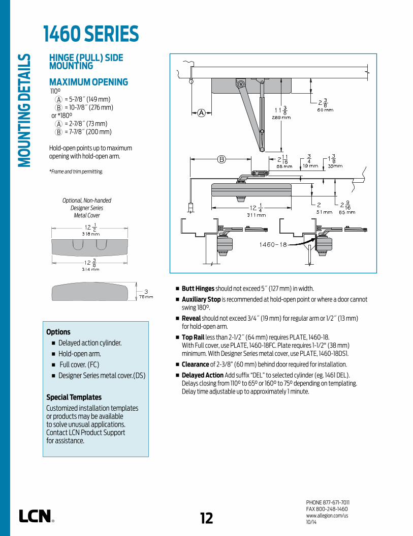
PHONE 877-671-7011FAX 800-248-1460www.allegion.com/us 10/14
Options n Delayed action cylinder. n Hold-open arm.
n Full cover. (FC)
n Designer Series metal cover.(DS)
Special TemplatesCustomized installation templates or products may be available to solve unusual applications. Contact LCN Product Support for assistance.
HINGE (PULL) SIDE MOUNTING
MAXIMUM OPENING 110°
A = 5-7/8˝ (149 mm)B = 10-7/8˝ (276 mm)
or *180°A = 2-7/8˝ (73 mm)B = 7-7/8˝ (200 mm)
Hold-open points up to maximum opening with hold-open arm.
*Frame and trim permitting.
1460 SERIES
n Butt Hinges should not exceed 5˝ (127 mm) in width.
n Auxiliary Stop is recommended at hold-open point or where a door cannot swing 180°.
n Reveal should not exceed 3/4˝ (19 mm) for regular arm or 1/2˝ (13 mm) for hold-open arm.
n Top Rail less than 2-1/2˝ (64 mm) requires PLATE, 1460-18. With Full cover, use PLATE, 1460-18FC. Plate requires 1-1/2" (38 mm) minimum. With Designer Series metal cover, use PLATE, 1460-18DS1.
n Clearance of 2-3/8” (60 mm) behind door required for installation.
n Delayed Action Add suffix “DEL” to selected cylinder (eg. 1461 DEL). Delays closing from 110° to 65° or 160° to 75° depending on templating. Delay time adjustable up to approximately 1 minute.
12
Optional, Non-handed Designer Series
Metal Cover
MOU
NTIN
G DE
TAIL
S

PHONE 877-671-7011FAX 800-248-1460www.allegion.com/us 11/14
1460 SERIES TOP JAMB (PUSH SIDE) MOUNTING
MAXIMUM OPENING110°
A = 6-3/4˝ (169 mm)B = 11-1/4˝ (286 mm)
180°A = 3˝ (76 mm)B = 7-1/2˝ (191 mm)
Hold-open points up to maximum opening with hold-open arm.
n Butt Hinges should not exceed 5˝ (127 mm) in width.
n Auxiliary Stop is recommended at hold-open point or where a door cannot swing 180°.
n Reveal
Arm Type Reveal Max. OpeningRegular Arm 4-7/8" Up to 140°Regular Arm 3-1/2" Up to 180°
Long Arm 7" Up to 140°Hold Open Arm 2-1/2" Up to 180°
Long Hold-Open Arm 4-7/8" Up to 140°
n Top Rail requires 1-7/8˝ (48 mm) minimum. 2-3/4˝ (70 mm) minimum with closer on PLATE, 1460-18.
n Head Frame less than 1-3/4˝ (44 mm) requires PLATE, 1460-18. For flush ceiling condition with 2˝ (51 mm) headframe, use PLATE, 1460-18.
n Delayed Action Add suffix “DEL” to selected cylinder (eg. 1460 DEL). Delays closing from 110° to 75° or 180° to 95° depending on templating. Delay time adjustable up to approximately 1 minute.
Options n Delayed action cylinder. n Long arm, hold-open arm,
long hold-open arm. n Full cover. (FC) n Designer Series metal cover. (DS)
Special TemplatesCustomized installation templates or products may be available to solve unusual applications. Contact LCN Product Support for assistance.
13
1460 - 18
Optional, Non-handed Designer Series
Metal Cover
MOU
NTIN
G DE
TAIL
S

PHONE 877-671-7011FAX 800-248-1460www.allegion.com/us 4/15 009426
PARALLEL ARM (PUSH SIDE) MOUNTINGOptional mounting requires PA SHOE, 1460-62PA for REGULAR or HOLD-OPEN arms. Add prefix "P" to closer description (e.g. P1460). P1460 closer includes 1460-201 FIFTH HOLE SPACER to support PA SHOE.
MAXIMUM OPENINGRegular or hold-open arm can be templated for 100°
A = 4-1/4˝ (108 mm)B = 9-1/4˝ (235 mm)
or 180°.A = 1-3/4˝ (44 mm)B = 6-3/4˝ (171 mm)
Hold-open points up to maximum opening with hold-open arm.
1460 REGULAR OR HOLD-OPEN MOUNTn Butt Hinges should not exceed 5˝ (127 mm) in width.
n Auxiliary Stop is recommended at hold-open point, where a door cannot swing 180°, or where CUSH-N-STOP arm is not used.
n Clearance for 1460-62PA shoe is 4˝ (102 mm) from door face.
n Top Rail less than 4-3/8˝ (111 mm) measured from the stop requires PLATE, 1460-18PA. With Full cover, use PLATE, 1460-18PAFC. Plate requires 1-3/4˝ (44 mm) minimum. Plate requires 1-1/4˝ (32 mm) minimum. With Designer Series metal cover, use PLATE, 1460-18PADS1.
n Head Frame flush or single rabbeted requires PA SHOE ADAPTER, 1460-418.
n Stop Width minimum 1˝ (25 mm).
n Blade Stop clearance, requires 1/2˝ (13 mm) BLADE STOP SPACER, 1460-61.
n Auxiliary Shoe, 1460-62A allows installation of regular arm with overhead holder/stop. Special templating required.
n Delayed Action Add suffix “DEL” to selected cylinder (eg. P1460 DEL). Delays closing from maximum opening to approximately 75°. Delay time adjustable up to approximately 1 minute.
14
1460 - 18PA
1460 SERIES M
OUNT
ING
DETA
ILS
Options n Delayed action cylinder. n Hold-open, EDA, HEDA, CUSH,
HCUSH, SPRING CUSH, or SPRING HCUSH arms.
n Full cover. (FC) n Designer Series metal cover.
(DS)
Special TemplatesCustomized installation templates or products may be available to solve unusual applications. Contact LCN Product Support for assistance.

PHONE 877-671-7011FAX 800-248-1460www.allegion.com/us 4/15 009426
n Spring CUSH hold open points are approximately 5° less than dead stop point.
n Clearance for 1460-62EDA or CUSH shoe is 5-1/2˝ (140 mm) from door face.
n Head Frame flush or rabbeted requires PA FLUSH PANEL ADAPTER, 1460-419.
n EDA or CUSH ARM requires SHOE SUPPORT, 1460-30 for fifth screw anchorage where reveal is less than 3-1/16˝ (78 mm).
1460 EDA MOUNT
1460 CUSH MOUNT
1460 EDA OR CUSH-N-STOP MOUNTING1460 closers ordered with EDA, CUSH or SPRING CUSH arms include 1460-201 FIFTH HOLE SPACER to support the shoe.
MAXIMUM OPENINGEDA template allows 110°.Hold-open point up to maximum opening.
CUSH arms can be templated for maximum opening/hold-open point at85°,
A = 2-3/8˝ (60 mm)B = 9-9/16˝ (243 mm)
90°,A = 1-5/8˝ (41 mm)B = 9-1/16˝ (230 mm)
or 100°. A = 5/8˝ (16 mm)B = 8-1/16˝ (205 mm)
15
1460 - 18PA
1460 - 18PA
14
1460 SERIES
MOU
NTIN
G DE
TAIL
S

PHONE 877-671-7011FAX 800-248-1460www.allegion.com/us 11/14
1460 SERIES CYLINDERSCYLINDER, 1461-3071Standard, non-handed cast iron cylinder assembly.
ARMSREGULAR ARM, 1460-3077Non-handed arm mounts hinge side or top jamb. P1460 closer includes PA SHOE, 1460-62PA required for parallel arm mounting.
PA SHOE, 1460-62PARequired for parallel arm mounting.
LONG ARM, 1460-3077L Optional, non-handed arm includes LONG ROD AND SHOE, 1460-79LR for top jamb mount with deep reveals.
HEAVY DUTY REGULAR ARM 1460-3077HDOptional, heavy duty, forged, non-handed arm, mounts hinge side, top jamb or parallel arm.
HEAVY DUTY LONG ARM 1460-3077HDLOptional, heavy duty, forged, non-handed arm. Includes long rod and shoe, 1460-79LR for top jamb mounts with deep reveals.
HOLD-OPEN ARM, 1460-3049Optional, non-handed arm mounts hinge side, top jamb or parallel arm (62PA required). Hold-open adjustable at shoe.
LONG HOLD-OPEN ARM, 1460-3049LOptional non-handed arm includes LONG HEAD AND TUBE, 1460-3048L for top jamb mount with deep reveals.
EXTRA DUTY ARM, 1460-3077EDA, 1460-3077EDA/62GOptional, non-handed parallel arm features solid forged steel main and forearm for potentially abusive installations. Optional 1460-3077EDA/62G for blade stop clearance.
HEDA ARM, 1460-3049EDA Optional handed arm, provides hold-open function adjustable at shoe.
CUSH-N-STOP® ARM, 1460-3077CNSOptional, non-handed parallel arm features solid forged steel main arm and forearm with stop in soffit shoe.
HCUSH ARM, 1460-3049CNSOptional non-handed arm, provides hold-open function with templated stop/hold-open points. Handle controls hold-open function.
SPRING CUSH ARM,1460-3077SCNSOptional, non-handed parallel arm for abusive applications features solid forged steel main arm and forearm with spring loaded stop in the soffit shoe.
SPRING HCUSH ARM, 1460-3049SCNSOptional, non-handed parallel arm for abusive applications features solid forged steel main arm and forearm with spring loaded stop in the soffit shoe. Handle controls hold-open function.
79LR3077
3071
3077HD
3049
3077EDA3049EDA
3077EDA/62G
3077SCNS
3049SCNS
3077CNS
16
62PAACCE
SSOR
IES
3049L
3049CNS
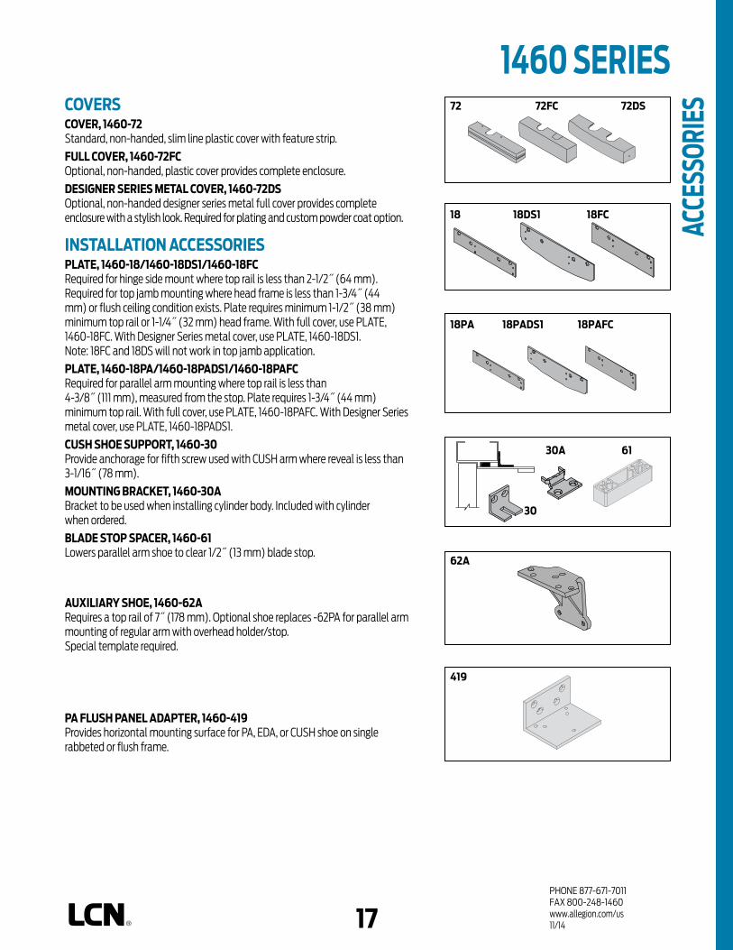
PHONE 877-671-7011FAX 800-248-1460www.allegion.com/us 11/14
1460 SERIES 72 72FC 72DS
30A
30
62A
419
18 18FC18DS1
18PA 18PADS1 18PAFC
17
COVERSCOVER, 1460-72 Standard, non-handed, slim line plastic cover with feature strip.
FULL COVER, 1460-72FC Optional, non-handed, plastic cover provides complete enclosure.
DESIGNER SERIES METAL COVER, 1460-72DSOptional, non-handed designer series metal full cover provides complete enclosure with a stylish look. Required for plating and custom powder coat option.
INSTALLATION ACCESSORIESPLATE, 1460-18/1460-18DS1/1460-18FCRequired for hinge side mount where top rail is less than 2-1/2˝ (64 mm). Required for top jamb mounting where head frame is less than 1-3/4˝ (44 mm) or flush ceiling condition exists. Plate requires minimum 1-1/2˝ (38 mm) minimum top rail or 1-1/4˝ (32 mm) head frame. With full cover, use PLATE, 1460-18FC. With Designer Series metal cover, use PLATE, 1460-18DS1.Note: 18FC and 18DS will not work in top jamb application.
PLATE, 1460-18PA/1460-18PADS1/1460-18PAFC Required for parallel arm mounting where top rail is less than 4-3/8˝ (111 mm), measured from the stop. Plate requires 1-3/4˝ (44 mm) minimum top rail. With full cover, use PLATE, 1460-18PAFC. With Designer Series metal cover, use PLATE, 1460-18PADS1.
CUSH SHOE SUPPORT, 1460-30 Provide anchorage for fifth screw used with CUSH arm where reveal is less than 3-1/16˝ (78 mm).
MOUNTING BRACKET, 1460-30A Bracket to be used when installing cylinder body. Included with cylinder when ordered.
BLADE STOP SPACER, 1460-61 Lowers parallel arm shoe to clear 1/2˝ (13 mm) blade stop.
AUXILIARY SHOE, 1460-62A Requires a top rail of 7˝ (178 mm). Optional shoe replaces -62PA for parallel arm mounting of regular arm with overhead holder/stop.Special template required.
PA FLUSH PANEL ADAPTER, 1460-419 Provides horizontal mounting surface for PA, EDA, or CUSH shoe on single rabbeted or flush frame.
61
ACCE
SSOR
IES

PHONE 877-671-7011FAX 800-248-1460www.allegion.com/us 4/15 009426
size 2 size 3 size 4 size 5 size 6*1461
Minimum Door
Width
Indicates recommended range of door width for closer size.
TABLE OF SIZESSelect closer based on width of door.The spring power of a 1461 cylinder is field adjustable from size 1 through size 6 and is shipped adjusted to size 3.
REDUCED OPENING FORCE 1460 CLOSERSCAUTION ! Any manual door closer, including those certified by BHMA to conform to ANSI Standard A156.4, that is selected, installed and adjusted based on ADA or other reduced opening force requirements may not provide sufficient power to reliably close and latch a door.
Refer to POWER OPERATORS section for information on systems that meet reduced opening force requirements without affecting closing power.
1460 SERIES OR
DERI
NG IN
FORM
ATIO
N
size 3 size 4 size 5 size 6*1461
EXTERIOR (and VESTIBULE) DOOR WIDTH
24"610mm
30"762mm
36"914mm
42"1067mm
INTERIOR DOOR WIDTH
48"1219mm
24"610mm
34"610mm
38"965mm
48"1219mm
54"1372mm
60"1524mm
18
Minimum Door
Width
HOW TO ORDER 1460 SERIES CLOSERS1. SELECT FINISH Standard Powder Coat __________
Aluminum, Dark Bronze, Statuary, Light Bronze, Black, Brass.
CLOSER OPTIONSCYLINDER Delayed Action (DEL)COVER Full cover (FC) Designer series cover (DS)FINISH Custom Powder Coat (RAL) ___________
(DS cover required) Plated Finish, US ___________
(DS cover required) SRI primer (for use with powder coat finishes only)ARM Regular w/62PA (Rw/PA) Long (LONG) Regular w/62A (Rw/62A) Hold-Open (H) Hold-Open w/62PA (Hw/PA) Long Hold-Open (HLONG) Heavy Duty (HD) Heavy Duty w/62A (HD/62A) Heavy Duty w/62PA (HD/PA) Heavy Duty Long (HDL) EDA (optional -62G) HEDA (specify right or left hand), (optional -62G) Cush-N-Stop (CUSH) HCush (HCUSH) Spring Cush (SCUSH) Spring HCush (SHCUSH)OPTIONAL SCREW PACKS TB* w/Self-Reaming and Tapping Screws (TBSRT) Wood & Machine Screw (WMS) TB*, Wood & Machine Screw (TBWMS) TORX Machine Screw (TORX) TB* & TORX Machine Screw (TBTORX)
* Specify door thickness if other than 1-3/4˝.SPECIAL TEMPLATE ST- _________INSTALLATION ACCESSORIES Plate, 1460-18 Plate, 1460-18DS Plate, 1460-18FC Plate, 1460-18PA Plate, 1460-18PADS Plate, 1460-18PAFC CUSH Shoe Support, 1460-30 Blade Stop Spacer, 1460-61 Auxiliary Shoe, 1460-62A PA Flush Panel Adapter, 1460-419
* Adjustable Size 1 thru 6
DOOR WIDTH 36" 42" 48"
8.5* lbs. 1461 1461 1461
5.0* lbs. 1461 1461 1461
* Maximum opening force.
Closer will be shipped with: - STANDARD CYLINDER, - STANDARD COVER, - REGULAR ARM, - SELF-REAMING and TAPPING SCREWS, unless options listed below are selected.

PHONE 877-671-7011FAX 800-248-1460www.allegion.com/us 10/14
n Standard 1460T series closer shipped with a standard arm, a slim line plastic cover, a standard track, a track roller, and self reaming and tapping screws. See 1460T Series page 23 & 24 for options.
n Multiple cover options include; Standard (Slim line), Full and Designer Series.
n Non-sized (2-4) cylinders adjustable for interior doors to 4´0˝.
n Non-handed closer mounts hinge side, top jamb (pull side), and stop face on either right or left swinging doors.
n Standard or optional custom powder coat finish.
n Optional plated finish on Designer Series metal cover, arm and fasteners. (Available with powder coat finishes only).
n Optional SRI primer for installations in corrosive conditions.
n Tested and certified under ANSI Standard A156.4, grade one.
The 1460T is a fully universal
slim line, single lever (track) arm
closer designed for interior use on
narrow headframes and top rails.
The modern styling and small
projection make it an excellent
choice for interior doors.
n Cast Iron n All weather fluid n Non-handed n UL and cUL listed
1460T SERIES
PLASTIC
METAL
COVER
DESIGNER SERIES
*ARM FUNCTION
HEAVY DUTY
HOLD-O
PEN
STANDARD (S
INGLE)
REGULA
R (DOUBLE)
EDA/HEDA
CUSH/HCUSH
SCUSH/SHCUSH
NON-HANDED
NON-SIZED
ACCESSIBILI
TY
CYLINDER
DELAYED ACTIO
N
POWDER COAT
PLATED
FINISH
115D
PARALLEL A
RM
MOUNTING
STOP FACE
HINGE (
PULL) SIDE
TOP JAMB (PULL
)
TOP JAMB (PUSH)
180
1918
CLOSER MOUNTS*HINGE (PULL) SIDE
TOP JAMB (PULL SIDE)STOP FACE (PUSH SIDE)
*HINGE (pull) side mount shown
FEAT
URES
* Maximum opening/hold-open point with standard template. Hinge side mount D = For designer series only.
AVAILABLE NOT AVAILABLE

PHONE 877-671-7011FAX 800-248-1460www.allegion.com/us 4/15 009426
Options n Regular track with bumper. n Hold-open track. n Hold-open track with bumper. n Full cover. (FC) n Designer Series metal cover.
(DS)
Special Templates Customized installation templates or products may be available to solve unusual applications. Contact LCN Product Support for assistance.
HINGE (PULL) SIDE MOUNTING
MAXIMUM OPENINGTemplating allows up to 180°, trim and frame permitting, limited to 115° when optional bumper is installed.
Consult factory if door will be held open at 180°.
Hold-open points at 85°, 90°, 95°, 100°, 110° or 115° with hold-open tracks.Please note that many track style door closers are capable of allowing 180° of door swing. Be aware that the majority of track style closers are at their weakest closing force in the 180°-130° range. Consult factory for applications where an exterior or large/heavy door must swing 180°.
n Butt Hinges should not exceed 5˝ (127 mm) in width.
n Auxiliary Stop is recommended where a door cannot swing 180°. Optional track bumper assembly assists backcheck in cushioning the opening swing of the door. It is not intended to replace an auxiliary stop.
n Reveal should not exceed 1/8˝ (3 mm).
n Top Rail less than 2-1/2˝ (64 mm) requires PLATE, 1460T-18. Plate requires 1-1/2˝ (38 mm) minimum. With Full cover, use PLATE, 1460T-18FC. With Designer Series metal cover, use PLATE, 1460T-18DS.
n Clearance of 2-3/8˝ (60 mm) behind door required for installation.
20
Optional, Non-handed Designer Series
Metal Cover
1460T SERIES M
OUNT
ING
DETA
ILS
1460T - 18

PHONE 877-671-7011FAX 800-248-1460www.allegion.com/us 4/15 009426
Options n Regular track with bumper. n Hold-open track. n Hold-open track with bumper. n Full cover. (FC) n Designer Series metal cover. (DS)
Special Templates Customized installation templates or products may be available to solve unusual applications. Contact LCN Product Support for assistance.
1460T SERIES TOP JAMB (PULL SIDE) MOUNTING
MAXIMUM OPENINGTemplating allows up to 180°, limited to 115° when optional bumper is installed.
Consult factory if door will be held open at 180°.
Hold-open points at 85°, 90°, 95°, 100°, 110° or 115° with hold-open tracks.
Please note that many track style door closers are capable of allowing 180° of door swing. Be aware that the majority of track style closers are at their weakest closing force in the 180° – 130° range. Consult factory for applications where an exterior or large/heavy door must swing 180°.
n Butt Hinges should not exceed 5˝ (127 mm) in width.
n Auxiliary Stop is recommended where a door cannot swing 180°. Track bumper assembly assists backcheck in cushioning the opening swing of the door. It is not intended to replace an auxiliary stop.
n Head Frame less than 2-3/4˝ (70 mm) requires PLATE, 1460T-18. Plate requires 1-3/4˝ (44 mm) minimum. With full cover, use PLATE, 1460T-18FC. With Designer Series metal cover, use PLATE, 1460T-18DS.
n Reveal (hinge side) should not exceed 1/8˝ (3 mm).
n Top Rail minimum 1-1/4˝ (32 mm).
n Clearance 1-1/4˝ (32 mm) behind door for installations.
21
Optional, Non-handed Designer Series
Metal Cover
MOU
NTIN
G DE
TAIL
S

PHONE 877-671-7011FAX 800-248-1460www.allegion.com/us 4/15 009426
1460T SERIES STOP FACE (PUSH SIDE) MOUNTING
MAXIMUM OPENINGTemplating allows 110°, limited to 100° when optional bumper is installed.
Hold-open points at 85°, 90°, 95°, or 100° with hold-open tracks.
n Butt Hinges should not exceed 5˝ (127 mm) in width.
n Auxiliary Stop is recommended where a door cannot swing 110°. Track bumper assembly assists backcheck in cushioning the opening swing of the door. It is not intended to replace an auxiliary stop.
n Clearance 1460T projects 2-3/8˝ (60 mm) from door face.
n Top Rail less than 4˝ (102 mm) measured from the stop face requires PLATE, 1460T-18PA. Plate requires 1-1/2˝ (38 mm) minimum. With Full cover, use PLATE, 1460T-18PAFC. With Designer Series metal cover, use PLATE, 1460T-18PADS.
n Stop Width minimum 1-1/4˝ (32 mm).
22
1460T - 18PA
Optional, Non-handed Designer Series
Metal Cover
MOU
NTIN
G DE
TAIL
S
Options n Regular track with bumper. n Hold-open track. n Hold-open track with bumper. n Full cover. (FC) n Designer Series metal cover. (DS)
Special Templates Customized installation templates or products may be available to solve unusual applications. Contact LCN Product Support for assistance.

PHONE 877-671-7011FAX 800-248-1460www.allegion.com/us 11/14
1460T SERIES CYLINDERSCYLINDER, 1460T-3071 Standard, non-handed cast iron cylinder assembly. For various applications see “Table of Sizes” on 1460T Series.
MOUNTING BRACKET, 1460T-30ABracket to be used when installing cylinder body. Included with cylinder when ordered.
COVERSCOVER, 1460T-72 Standard, non-handed, slim line plastic cover with feature strip.
FULL COVER, 1460T-72FC Optional, non-handed, plastic cover provides complete enclosure.
DESIGNER METAL COVER, 1460T-72DSOptional, non-handed designer series metal full cover provides complete enclosure with a stylish look. Required for plating option and custom powder coat finishes.
ARMSTANDARD ARM, 1460T-3077T Non-handed single lever arm mounts hinge side, top jamb, or stop face. Track roller not included with arm.
TRACKSSTANDARD TRACK, 1460T-3038Standard, non hold-open, non-handed track mounts on either side of the door. Will accept hold-open clip and/or bumper assembly.
STANDARD TRACK with BUMPER, 1460T-3038BOptional, non hold-open, non-handed track with bumper mounts on either side of the door. Will accept hold-open clip.
HOLD-OPEN TRACK, 1460T-3038HOptional, non-handed hold-open track mounts on either side of the door. Will accept bumper assembly.
HOLD-OPEN TRACK with BUMPER, 1460T-3038HBOptional, non-handed hold-open track with bumper mounts on either side of the door.
3077T
30383038B3038H3038HB
1460T-30A
3071
22 23
MOU
NTIN
G DE
TAIL
S
72DS72 72FC

PHONE 877-671-7011FAX 800-248-1460www.allegion.com/us 4/15 009426
1460T SERIES AC
CESS
ORIE
S INSTALLATION ACCESSORIESPLATE, 1460T-18,1460T-18DS,1460T-18FCRequired for hinge side mount where top rail is less than 2-1/2˝ (64 mm). Required for top jamb mount when head frame is less than 2-3/4˝ (70 mm). Plate requires minimum 1-1/2˝ (38 mm) top rail or 1-3/4˝ (44 mm) head frame minimum. With Full cover, use PLATE, 1460T-18FC. With Designer Series metal cover, use PLATE, 1460T-18DS1.
PLATE, 1460T-18PA,1460T-18PADS,1460T-18PAFC Required for stop face mounting where top rail is less than 4˝ (102 mm), measured from the stop.Plate requires 1-1/2˝ (38 mm) minimum top rail.With Full cover, use PLATE, 1460T-18PAFC.With Designer Series metal cover, use PLATE, 1460T-18PADS1.
TRACK BUMPER, 1460T-169Mounts in track to assist backcheck, does not replace auxiliary stop. Limits maximum opening. Consists of bumper, bumper post, and mounting screw.
HOLD-OPEN CLIP, 1460T-3054Mounts in track to provide hold-open function.Hold-open point controlled by clip location.
TRACK ROLLER, 1460T-3034Quiet, low friction roller assembly.Shoulder dimension “X” = 1/8˝ (3 mm).
3054
3034
18
18PA
169
18FC18DS
18PAFC18PADS
24

PHONE 877-671-7011FAX 800-248-1460www.allegion.com/us 11/14
1460T SERIES
Indicates recommended range of door width for closer size.
TABLE OF SIZESSelect closer based on width of door. The spring power of a 1460T cylinder is adjustable from size 2 to size 4 and is shipped adjusted to size 3. The closing power of 1460T series cylinders may be increased 50%. The spring power of a 1461T cylinder is adjustable from size 1 to size 2 and is shipped adjusted to size 1.
HOW-TO-ORDER1460T SERIES CLOSERS1. SELECT CYLINDER SIZE 1461T 1460T (adjustable from size 2 to 4)
2. SPECIFY FINISH Standard Powder Coat __________
Aluminum, Dark Bronze, Statuary, Light Bronze, Black, Brass.
CLOSER OPTIONSCOVER
Full cover (FC) Designer Series metal cover (DS)
FINISH Custom Powder Coat (RAL) ___________
(DS cover required) Plated Finish, US ___________
(DS cover required) SRI primer (for use with powder coat
finishes only)
TRACK Standard with Bumper (BUMPER) Hold-Open (H) Hold-Open with Bumper (HBUMPER)
SCREW PACK TB* w/Self-Reaming and Tapping Screws
(TBSRT) Wood & Machine Screw (WMS) TB*, Wood & Machine Screw (TBWMS) TORX Machine Screw (TORX) TB* & TORX Machine Screw (TBTRX)
* Specify door thickness if other than 1-3/4˝.
SPECIAL TEMPLATE ST- _________
INSTALLATION ACCESSORIES Plate, 1460T-18 Plate, 1460T-18DS1 Plate, 1460T-18FC Plate, 1460T-18PA Plate, 1460T-18PADS1 Plate, 1460T-18PAFC
INTERIOR DOOR WIDTH
26"660mm
34"864mm
38"965mm
48"1219mm
size 2 size 3 size 4 *1460T
* Adjustable Size 2 thru 4
Minimum Door
Width
INTERIOR DOOR WIDTH
26"660mm
34"864mm
38"965mm
48"1219mm
size 2 size 3 size 4*1461T
* Adjustable Size 1 thru 2
Minimum Door
Width
25
ORDE
RING
INFO
RMAT
ION
Closer will be shipped with: - STANDARD COVER,- STANDARD ARM,- STANDARD TRACK,- TRACK ROLLER,- SELF-REAMING and TAPPING SCREWS unless options listed below are selected.
REDUCED OPENING FORCE 1460T CLOSERSCAUTION ! Any manual door closer, including those certified by BHMA to conform to ANSI Standard A156.4, that is selected, installed and adjusted based on ADA or other reduced opening force requirements may not provide sufficient power to reliably close and latch a door.
Refer to POWER OPERATORS section for information on systems that meet reduced opening force requirements without affecting closing power.
DOOR WIDTH 36" 42" 48"
8.5* lbs. N/A N/A N/A
5.0* lbs. 1461T 1461T 1461T
* Maximum opening force.

PHONE 877-671-7011FAX 800-248-1460www.allegion.com/us 4/15 00942626
Notes

1PHONE 877-671-7011FAX 800-248-1460www.allegion.com/us 4/15 009426
DOUBLELEVER ARM
5010
SINGLELEVER ARM
2010 2210**
DOUBLELEVER ARM
5030
SINGLELEVER ARM
2030 6030
DOUBLELEVER ARM
3030
SINGLELEVER ARM
3130***
PRODUCT COMPARISONThis chart shows a basic comparison of LCN concealed closers. Refer to the specific closer chapter for complete details.
CONCEALED CLOSER SERIES
IN FR
AME
IN 1-
3/4˝ T
UBE
IN DOOR
POWDER COAT
PLATED
CONCEALEDMOUNTING FINISH
CLOSERSERIES2010
2030
CONCEALED
EXPOSED
ARM
ACCESSIBILI
TY
CYLINDER *ARM FUNCTION
DELAYED ACTIO
N
REGULAR (D
OUBLE)
STANDARD (SIN
GLE)
180°
180°
HANDED
SIZED
110°
110°
3030
3130 140°
180°
180°5010
6030
5030
95°
180°
100°
100°
95°
100°
140°
HOLD-O
PEN
** INDICATES HIGH SECURITY CLOSER, DOOR POSITION SWITCH OPTIONAL. REFER TO HIGH SECURITY SECTION OF THE CATALOG. *** INDICATES FIRE LIFE SAFETY OPTION AVAILABLE WITH HOLD OPEN CAPABILITY. REFER TO FIRE LIFE SAFETY SECTION.
INTERIOR DOOR
CONCEALEDIN FRAME
CONCEALED INMIN. 1-3/4˝ TUBE FRAME
CONCEALEDIN DOOR
DOUBLELEVER ARM
5010
CONCEALEDIN FRAME
SINGLELEVER ARM
2010 2210**
DOUBLELEVER ARM
5030
EXTERIOR DOOR
PRODUCT SELECTION GUIDEThe concealed LCN closers feature a modern design for concealment in either the head frame or top rail of the door. This guide is based on the desired mounting of the closer.
CONCEALED INMIN. 1-3/4˝ TUBE FRAME
SINGLELEVER ARM
2030 6030
Closeravailablewithlessthan5.0lbs.openingforceon36˝door. * Maximumopening/hold-openpointwithstandardtemplate.Seeindividualcloserseriesfor
degreesofopeningperinstallation.
AVAILABLE NOT AVAILABLE

PHONE 877-671-7011FAX 800-248-1460www.allegion.com/us 4/15 0094262
APPLICATIONSn For aluminum, hollow metal, or wood doors and frames. n Can be used with hinge or pivot mounted door.n Closers for 4˝ or minimum 1-3/4˝ head frame or 4˝ top rail.n Mounting clips for wood frames and other installation accessories
available for unusual conditions.n For concealed in door closers consult factory for installations with pivots.
FEATURES COMMON TO CONCEALED CLOSERSn Mountings for head frame or door top rail. n Handed for right or left swinging doors. (except 6030) n Closers to meet ADA reduced opening force requirements.n Adjustable hydraulic backcheck cushions opening swing prior to 90°.n Separate regulation of general closing speed and latching speed. n Joints in arm and shoe adapt to uneven trim. (for double lever arms)
DESIGN ASSISTANCELCN has been providing reliable solutions to unique door control problems for over 85 years. Design and specification assistance are only a phone call away.Contact LCN for assistance or technical information at 877-671-7011 or FAX 800-248-1460 (order entry), Fax 815-879-1495 for Application Engineering.
WARRANTY15 year limited warranty. See General Information Section for complete warranty details.
SPECIFICATIONSRefer to ”SPECIFICATIONS”section for suggested architectural specifications.
MATERIALS(Closers concealed in the door or frame)
n High strength cast iron cylinder.n Forged steel main arms (except 6030). n One piece forged steel piston.n All weather fluid in overhead concealed models eliminates seasonal
adjustments. From 120°F to -30°F.n High efficiency, full compliment, low friction bearings.n Tamper resistant regulating screws.n Full rack and pinion hydraulic action. n Quiet, low friction track and roller combination for all single lever
(standard) arm closers.
CONCEALED CLOSER SERIESFINISHES
n Available in six standard or a wide selection of optional custom powder coat finishes to blend with door and frame.
n LCN’s powder coat finishes surpass 100 hours of salt spray which is over four times the ANSI standard for corrosion resistance.
n For installations where a higher level of corrosive resistance is required, LCN offers an optional special rust inhibiting (SRI) pre-treatment. Closers that combine the exclusive LCN powder coat finish and the SRI pre-treatment exceed the ANSI standard for corrosion resistance even further.
n Plated finishes are available as an option to accent door and frame.
LISTINGS & APPROVALSUL listed for self-closing doors without hold-open under "SWINGING DOOR CLOSERS" (GVEV) file R 1943.
Tested and certified under ANSI Standard A156.4. Consult factory for details.
Consult factory for other listings such as; cUL, California State Fire Marshal, Bureau of Standards and Appeals.
POSITIVE PRESSURE LCN closers have been certified for three hours by UL to be in compliance with UBC 7.2 (1997) and UL 10 C. Contact LCN for specific details on door closer fire ratings.
FASTENERSStandard WOOD and MACHINE SCREW (WMS) pack contains phillips head wood and machine screws to install the closer. TORX machine screws are available for some closers.
Note 1: Phillips head, metric machine screws are available, please specify.
MAINTENANCEClosers mounted according to LCN installation instructions require no periodic maintenance or adjustments.

PHONE 877-671-7011FAX 800-248-1460www.allegion.com/us 4/15 0094262 3
n Standard 2010 Series closer shipped with standard arm, standard track, metal finish plate and wood and machine screw pack. See 2010 Series page 5 for options.
n Sized cylinders for interior doors to 5´0˝ and exterior doors to 4´0˝.
n Handed for right or left swinging doors.
n For aluminum, hollow metal, or wood, doors and frames.
n Aluminum frame requires minimum 4˝ x 4˝ (102 mm) tube.
n Closers to meet ADA requirements. See 2010 Series page 6.
n Standard or optional custom powder coat finish.
n Optional plated finish on arm, fasteners and finish plate.
n Optional SRI primer for installations in corrosive conditions. (Available with powder coat finishes only.)
The concealed 2010 Series is a heavy
duty closer designed to provide
complete concealment. The single
lever arm and roller assembly provide
smooth, quiet door control and the
choice of finishes and track functions
meet virtually all architectural
requirements.
The2010SeriesisUL&cULlistedfor
self-closingdoorswithouthold-open.
TestedandcertifiedunderANSIStandard
A156.4,gradeone.
2010 SERIES
IN FR
AME
IN 1-
3/4˝ T
UBE
IN DOOR
POWDER COAT
PLATED
CONCEALEDMOUNTING FINISH
CONCEALED
EXPOSED
ARM
ACCESSIBILI
TY
CYLINDER *ARM FUNCTION
DELAYED ACTIO
N
REGULAR (D
OUBLE)
STANDARD (SIN
GLE)
HANDED
SIZEDHOLD
-OPEN
180° 110°
AVAILABLE NOT AVAILABLE
FEAT
URESCONCEALED (IN FRAME) MOUNTING
Closeravailablewithlessthan5.0lbs.openingforceon36˝door. * Maximumopening/hold-openpointwithstandardtemplate.Seeindividualcloserseriesfor
degreesofopeningperinstallation.

PHONE 877-671-7011FAX 800-248-1460www.allegion.com/us 4/15 0094264
CONCEALED MOUNTINGFor interior or exterior doors. Single acting cylinder in head frame. Concealed arm and track in door top rail.
MAXIMUM OPENINGButt hinge template allows 180°, trim permitting. Limited to 110° when optional bumper is installed.Adjustable hold-open points from 85° to 110°, with hold-open track.
Offset pivot template allows 110°, trim permitting. Limited to 95° when optional bumper is installed.Adjustable hold-open points from 75° to 95°, with hold-open track.
Center pivot template allows 120°, trim permitting. Limited to 95° when optional bumper is installed.Adjustable hold-open points from 75° to 95°, with hold-open track.
2010 SERIES
n Butt Hinges should not exceed 5˝ (127 mm) in width.
n Auxiliary Stop is recommended where a door cannot swing 180°. Optional track bumper assembly assists backcheck in cushioning the opening swing of the door. It is not intended to replace an auxiliary stop.
n Top Rail 1-3/8˝ (35 mm) mortise required. With Fire Shield, 1-13/32˝ (36 mm) mortise required. 5/16˝ (8 mm) cutout required at top of the door, stop face only.
n Door Thickness 1-3/4˝ (44 mm) minimum.
n Hollow Metal Frame Consult factory for installation instructions.
Options n Standard track with Bumper. n Hold-open track. n Hold-open track with Bumper. n Fire Shield.
Special Templates Customized installation templates or products may be available to solve unusual applications. Contact LCN Product Support for assistance.
MOU
NTIN
G DE
TAIL
S

PHONE 877-671-7011FAX 800-248-1460www.allegion.com/us 4/15 0094264 5
2010 SERIES CYLINDERSCYLINDER, 2010-3071 Standard, handed, cast iron cylinder assembly with mounting plate. For various applications see “Table of Sizes” on 2010 Series page 6.
ARMSTANDARD ARM, 2010-3077T Handed arm. Track roller not included with arm.
TRACKSSTANDARD TRACK, 2010-3038Standard, non hold-open, non-handed track. Will accept hold-open clip and/or bumper assembly.
STANDARD TRACK with BUMPER, 2010-3038BOptional, non hold-open, non-handed track with bumper. Will accept hold-open clip.
HOLD-OPEN TRACK, 2010-3038HOptional, non-handed hold-open track. Will accept bumper assembly.
HOLD-OPEN TRACK with BUMPER, 2010-3038HBOptional, non-handed hold-open track with bumper.
INSTALLATION ACCESSORIESFIRE SHIELD, 2010-420 22 gauge steel liner mounts in the track mortise of the door’s top rail for 20 minute labeled wood doors.
TRACK BUMPER, 2010-169Mounts in track to assist backcheck. Limits maximum opening. Consists of bumper, bumper post, and mounting screw. NOTE: Track bumper does not replace auxiliary stop.
HOLD-OPEN CLIP, 2010-3054Mounts in track to provide hold-open function.Hold-open point controlled by clip location.
TRACK ROLLER, 2010-3034Quiet, low friction roller assembly.Shoulder dimension "X" = 1/16˝ (2mm).
3077T
3071
420
3034
169
3054
3038
3038H3038HB
3038B
ACCE
SSOR
IES

PHONE 877-671-7011FAX 800-248-1460www.allegion.com/us 4/15 0094266
2013
2010 SERIES
Indicates recommended range of door width for closer size.
REDUCED OPENING FORCE 2010 CLOSERSCAUTION ! Any manual door closer, including those certified by BHMA to conform to ANSI Standard A156.4, that is selected, installed and adjusted based on ADA or other reduced opening force requirements may not provide sufficient power to reliably close and latch a door.
Refer to POWER OPERATORS section for information on systems that meet reduced opening force requirements without affecting closing power.
TABLE OF SIZESSelect closer based on width of door.2010 Series cylinders available in size 1, 3, 4, 5, or 6. Closing power of all 2010 Series closers may be increased 15%. Specify next higher size closer where strong drafts exist.
size 3 size 4 size 5 size 6
2014
2013
EXTERIOR (and VESTIBULE) DOOR WIDTH
28"711mm
30"762mm
36"914mm
42"1067mm
2015
INTERIOR DOOR WIDTH
48"1219mm
2016
HOW-TO-ORDER2010 SERIES CLOSERS1. SELECT CYLINDER SIZE 2011 (ADA) 2013 2014 2015 2016
2. SPECIFY HAND RH LH
3. SPECIFY FINISH Standard Powder Coat __________
Aluminum, Dark Bronze, Statuary, Light Bronze, Black, Brass.
CLOSER OPTIONSTRACK Standard with Bumper (BUMPER) Hold-open (H) Hold-open with Bumper (HBUMPER)
FINISHES Custom Powder Coat (RAL)_____________ Plated Finish, US ______________ SRI primer (use with powder coat
finishes only)
SCREW PACK TORX Machine Screw (TORX)
INSTALLATION ACCESSORIES Fire Shield, 2010-420
SPECIAL TEMPLATE ST- _________
size 3 size 4 size 5 size 6
2014
28"711mm
38"965mm
48"1219mm
2015
54"1372mm
2016
60"1524mm
34"864mm
MinimumDoor Width
MinimumDoor WidthOR
DERI
NG IN
FORM
ATIO
N
DOOR WIDTH 36" 42" 48"
8.5* lbs. 2014 2014 2015
5.0* lbs. 2011 2011 2013
* Maximum opening force.
Closer will be shipped with: - FINISH PLATE,- TRACK ARM,- TRACK ROLLER,- STANDARD TRACK,- WOOD and MACHINE SCREW PACK,unlessoptionslistedbelowareselected.

PHONE 877-671-7011FAX 800-248-1460www.allegion.com/us 4/15 0094266 7
n Standard 2030 Series closer shipped with standard arm, standard track, mounting/finish plate, and wood and machine screw pack. See 2030 Series page 9 & 10 for options.
n Sized cylinders for interior doors to 4´6˝ and exterior doors to 3´6˝.
n Handed for right or left swinging doors.
n Aluminum frame requires minimum 1-3/4˝ (44 mm) x 4˝ (102 mm) tube.
n Closers to meet ADA requirements. See 2030 Series page 11.
n Standard or optional custom powder coat finish.
n Optional plated finish on arm, fasteners and finish plate.
n Optional SRI primer for installations in corrosive conditions. (Available with powder coat finishes only.)
The concealed 2030 Series PACER®
is a heavy duty closer designed to
fit in a narrow, minimum 1-3/4˝
aluminum transom. The single
lever arm and roller assembly
provide smooth, quiet door control
and the choice of finishes and
track functions meet virtually all
architectural requirements.
The2030SeriesisUL&cULlistedfor
self-closingdoors,withouthold-open.
TestandcertifiedunderANSIStandard
A156.4,gradeone.
2030 SERIES
POWDER COAT
PLATED
CONCEALEDMOUNTING FINISH
CONCEALED
EXPOSED
ARM
ACCESSIBILI
TY
CYLINDER *ARM FUNCTION
DELAYED ACTIO
N
REGULAR (D
OUBLE)
STANDARD (SIN
GLE)
HANDED
SIZED
110°
HOLD-O
PEN
180°
IN FR
AME
IN 1-
3/4˝ T
UBE
IN DOOR
AVAILABLE NOT AVAILABLE
CONCEALED (IN 1-3/4˝ TUBE) MOUNTING
FEAT
URES
Closeravailablewithlessthan5.0lbs.openingforceon36"door. * Maximumopening/hold-openpointwithstandardtemplate.Seeindividualcloserseriesfor
degreesofopeningperinstallation.
AVAILABLE NOT AVAILABLE

PHONE 877-671-7011FAX 800-248-1460www.allegion.com/us 4/15 0094268
CONCEALED MOUNTINGFor interior or exterior doors.Single acting cylinder in head frame.Concealed arm and track in door top rail.
MAXIMUM OPENINGButt hinge template allows 180°, trim permitting. Limited to 110° when optional bumper is installed.Adjustable hold-open points from 85° to 110°, with hold-open track.
Consult factory if door will be held open at 180°.
Offset pivot template allows 115°, trim permitting. Limited to 95° when optional bumper is installed.Hold-open point from 85°, with hold-open track.
Center pivot template allows 120°, trim permitting. Limited to 100° when optional bumper is installed.Adjustable hold-open points from 85° to 100°, with hold-open track.
2030 SERIES
n Butt Hinges should not exceed 5˝ (127 mm) in width.
n Auxiliary Stop is recommended where a door cannot swing 180°. Optional track bumper assembly assists backcheck in cushioning the opening swing of the door. It is not intended to replace an auxiliary stop.
n Top Rail 1-3/8˝ (35 mm) mortise required. With Fire Shield, 1-13/32˝ (36 mm) mortise required. 5/16˝ (8 mm) cutout required at top of the door, stop face only.
n Door Thickness 1-3/4˝ (44 mm) minimum.
n Hollow Metal Frame Consult factory for installation instructions.
n Wood Frame installation simplified by WOOD MOUNTING CLIP SET 2030-416 for center pivoted or 2030-417 for offset pivoted and butt hung installations. Consult factory for preparation details.
MOU
NTIN
G DE
TAIL
S
Options n Standard track with Bumper. n Hold-open track. n Hold-open track with Bumper. n Fire Shield.
Special Templates Customized installation templates or products may be available to solve unusual applications. Contact LCN Product Support for assistance.

PHONE 877-671-7011FAX 800-248-1460www.allegion.com/us 4/15 0094268 9
2030 SERIES CYLINDERSCYLINDER, 2030-3071 Standard, handed, cast iron cylinder assembly with mounting plate. For various applications see “Table of Sizes” on 2030 Series page 11.
ARMSTANDARD ARM, 2030-3077THanded arm. Track roller not included with arm.
TRACKSSTANDARD TRACK, 2030-3038Standard, non hold-open, non-handed track. Will accept hold-open clip and/or bumper assembly.
STANDARD TRACK with BUMPER, 2030-3038BOptional, non hold-open, non-handed track with bumper. Will accept hold-open clip.
HOLD-OPEN TRACK, 2030-3038HOptional, non-handed hold-open track. Will accept bumper assembly.
HOLD-OPEN TRACK with BUMPER, 2030-3038HBOptional, non-handed hold-open track with bumper.
3077T
3038
3038H3038HB
3038B
3071
ACCE
SSOR
IES

PHONE 877-671-7011FAX 800-248-1460www.allegion.com/us 4/15 00942610
2030 SERIES INSTALLATION ACCESSORIESFIRE SHIELD, 2030-420 22 gauge steel liner mounts in the track mortise of the door’s top rail for 20 minute labeled wood doors.
WOOD MOUNTING CLIP SET, 2030-416 Simplifies mounting center pivoted 2030 closer in wood frame. Includes latch stile clip, hinge stile clip, and cover. For use with Ives Series center pivots. Consult factory for special template.
WOOD MOUNTING CLIP SET, 2030-417 Simplifies mounting offset pivoted or butt hung 2030 closer in wood frame. Includes two clips. For use with offset pivots. Consult factory for special template.
TRACK BUMPER, 2030-169Mounts in track to assist backcheck. Limits maximum opening. Consists of bumper, bumper post, and mounting screw. NOTE: Track bumper does not replace auxiliary stop.
HOLD-OPEN CLIP, 2030-3054Mounts in track to provide hold-open function.Hold-open point controlled by clip location.
TRACK ROLLER, 2030-3034Quiet, low friction roller assembly.Shoulder dimension "X" = 1/16˝ (2mm).
420
169
3054
416
417
3034
ACCE
SSOR
IES

PHONE 877-671-7011FAX 800-248-1460www.allegion.com/us 4/15 00942610 11
size 3 size 4 size 5
Indicates recommended range of door width for closer size.
REDUCED OPENING FORCE 2030 CLOSERSCAUTION ! Any manual door closer, including those certified by BHMA to conform to ANSI Standard A156.4, that is selected, installed and adjusted based on ADA or other reduced opening force requirements may not provide sufficient power to reliably close and latch a door.
Refer to POWER OPERATORS section for information on systems that meet reduced opening force requirements without affecting closing power.
TABLE OF SIZES Select closer based on width of door.2030 Series cylinders available in size 1, 2, 3, 4, or 5. Closing power of all 2030 Series closers may be increased 35%. Specify next higher size closer where strong drafts exist.
20342033
EXTERIOR (and VESTIBULE) DOOR WIDTH
28"711mm
30"762mm
36"914mm
42"1067mm
2035
2030 SERIES
size 2 size 3 size 4 size 5
2033
2032
INTERIOR DOOR WIDTH
28"711mm
34"864mm
38"965mm
48"1219mm
2034
54"1372mm
2035
HOW-TO-ORDER2030 SERIES CLOSERS1. SELECT CYLINDER SIZE 2031(ADA) 2032 2033 2034 2035
2. SPECIFY HAND RH LH
3. SPECIFY FINISH Standard Powder Coat __________
Aluminum, Dark Bronze, Statuary, Light Bronze, Black, Brass.
CLOSER OPTIONSTRACK Standard with Bumper (BUMPER) Hold-open (H) Hold-open with Bumper (HBUMPER)
FINISHES Custom Powder Coat (RAL)___________ Plated Finish, US ______________ SRI primer (use with powder coat
finishes only)
SCREW PACK TORX Machine Screw (TORX)
INSTALLATION ACCESSORIES Fire Shield, 2030-420 Wood Clip Set, 2030-416 Wood Clip Set, 2030-417
SPECIAL TEMPLATE ST- _________
MinimumDoor Width
MinimumDoor Width OR
DERI
NG IN
FORM
ATIO
N
DOOR WIDTH 36" 42" 48"
8.5* lbs. 2033 2033 2034
5.0* lbs. 2031 2032 2032
* Maximum opening force.
Closer will be shipped with: - FINISH PLATE,- TRACK ARM,- TRACK ROLLER,- STANDARD TRACK,- WOOD and MACHINE SCREW PACK,unlessoptionslistedbelowareselected.

PHONE 877-671-7011FAX 800-248-1460www.allegion.com/us 4/15 00942612
Notes

PHONE 877-671-7011FAX 800-248-1460www.allegion.com/us 4/15 00942612 13
n Standard 3030 Series closer shipped with regular arm and wood and machine screw pack. See 3030 Series page 15 for options.
n Sized cylinders for interior doors to 4´0˝.
n Handed for right or left swinging doors.
n Closers to meet ADA requirements. See 3030 Series page 16 .
n Standard or optional custom powder coat finish.
n Optional plated finish on arm and fasteners.
n Optional SRI primer for installations in corrosive conditions. (Available with powder coat finishes only.)
n Consult factory for installations with pivots.
The concealed 3030 Series is designed
to mount in a 1-3/4˝ interior door. The
double lever arm provides superior
door control and the choice of finishes
and
arm functions meet virtually all
architectural requirements.
The3030SeriesisULandcULlistedwith
regulararmforself-closingdoors.Tested
andcertifiedunderANSIStandardA156.4,
gradeone.
3030 SERIES
POWDER COAT
PLATED
CONCEALEDMOUNTING FINISH
CONCEALED
EXPOSED
ARM
ACCESSIBILI
TY
CYLINDER *ARM FUNCTION
DELAYED ACTIO
N
REGULAR (D
OUBLE)
STANDARD (SIN
GLE)
HANDED
SIZED
140°
HOLD-O
PEN
180°IN
FRAME
IN 1-
3/4˝ T
UBE
IN DOOR
AVAILABLE NOT AVAILABLE
CONCEALED (IN DOOR) MOUNTING
ACCE
SSOR
IES
Closeravailablewithlessthan5.0lbs.openingforceon36"door. * Maximumopening/hold-openpointwithstandardtemplate.Seeindividualcloserseriesfor
degreesofopeningperinstallation.
AVAILABLE NOT AVAILABLE

PHONE 877-671-7011FAX 800-248-1460www.allegion.com/us 4/15 00942614
CONCEALED MOUNTINGFor interior doors.Single acting cylinder in top rail of door.Exposed arm on hinge side of door.
MAXIMUM OPENINGCan be templated for 110°,
A = 3-5/8˝ (92 mm)B = 10-1/4˝ (260 mm)
130°, A = 2-5/8˝ (67 mm) B = 9-1/4˝ (235 mm)
or 180°, A = 1-5/8˝ (41 mm) B = 8-1/4˝ (210 mm)
trim permitting.
Hold-open points up to maximum opening or 140°, whichever is less, with hold-open arm.
Arm clearance above door C =1-1/4˝ (32 mm) minimum.
3030 SERIES
n Butt Hinges should not exceed 5” (127 mm) in width.
n Auxiliary Stop is recommended at hold-open point or where a door cannot swing 180°.
n Top Rail minimum 4˝ (102 mm) required.
n Door Thickness 1-3/4˝ (44 mm) minimum. Please consult the door manufacturer to assure that the door integrity and warranty is maintained after installing the 3030 Series door closer in a 1-3/4˝ thick wood door.
MOU
NTIN
G DE
TAIL
S
Options n Hold-open arm.
n Consult factory for installations with pivots.
Special Templates Customized installation templates or products may be available to solve unusual applications. Contact LCN Product Support for assistance.

PHONE 877-671-7011FAX 800-248-1460www.allegion.com/us 4/15 00942614 15
3030 SERIES CYLINDERSCYLINDER, 3030-3071 Standard, handed, cast iron cylinder assembly with mounting plate. For various applications see “Table of Sizes” on 3030 Series page 16.
ARMSREGULAR ARM, 3030-3077 Non-handed arm.
HOLD-OPEN ARM, 3030-3049 Optional, handed arm provides hold-open function, adjustable at elbow.
3077
3071
3049
ACCE
SSOR
IES

PHONE 877-671-7011FAX 800-248-1460www.allegion.com/us 4/15 00942616
size 2 size 3 size 4
3033
3032
3034
HOW-TO-ORDER3030 SERIES CLOSERS1. SELECT CYLINDER SIZE 3031 (ADA) 3032 3033 3034
2. SPECIFY HAND RH LH
3. SPECIFY FINISH Standard Powder Coat __________
Aluminum, Dark Bronze, Statuary, Light Bronze, Black, Brass.
CLOSER OPTIONSARM Hold-open (H)
FINISHES Custom Powder Coat (RAL)___________ Plated Finish, US ______________ SRI primer (use with powder coat
finishes only)
SCREW PACK TORX Machine Screw (TORX)
SPECIAL TEMPLATE ST- _________
REDUCED OPENING FORCE 3030 CLOSERSCAUTION ! Any manual door closer, including those certified by BHMA to conform to ANSI Standard A156.4, that is selected, installed and adjusted based on ADA or other reduced opening force requirements may not provide sufficient power to reliably close and latch a door.
Refer to POWER OPERATORS section for information on systems that meet reduced opening force requirements without affecting closing power.
TABLE OF SIZES Select closer based on width of door.3030 Series cylinders available in size 1, 2, 3, or 4. Closing power of all 3030 Series closers may be increased 15%.
3030 SERIES
24"610mm
34"864mm
38"965mm
48"1219mm
MinimumDoor WidthOR
DERI
NG IN
FORM
ATIO
N
INTERIOR DOOR WIDTH
DOOR WIDTH 36" 42" 48"
8.5* lbs. N/A N/A N/A
5.0* lbs. 3031 3031 3032
* Maximum opening force.
Indicates recommended range of door width for closer size.
Closer will be shipped with: - REGULAR ARM,- WOOD and MACHINE SCREW PACK,unlessoptionslistedbelowareselected.

PHONE 877-671-7011FAX 800-248-1460www.allegion.com/us 4/15 00942616 17
n Standard 3130 Series closer shipped with standard arm, standard track and wood and machine screw pack. See 3130 Series page 19 for options.
n Sized cylinders for interior doors to 3´2˝.
n Handed for right or left swinging doors.
n Closers to meet ADA requirements. See 3130 Series page 20.
n Standard or optional custom powder coated finish.
n Optional plated finish on arm and fasteners.
n Optional SRI primer for installations in corrosive conditions. (Available with powder coat finishes only.)
n Consult factory for installation with pivots.
The concealed 3130 Series is designed
to mount in a 1-3/4˝ interior door.
The single lever arm and roller
assembly provides complete
concealment and the choice of finishes
and track functions meet virtually all
architectural requirements.
The3130SeriesisULandcULlisted
withouthold-openforself-closingdoors.
TestedandcertifiedunderANSIStandard
A156.4,gradeone.
3130 SERIES
POWDER COAT
PLATED
CONCEALEDMOUNTING FINISH
CONCEALED
EXPOSED
ARM
ACCESSIBILI
TY
CYLINDER *ARM FUNCTION
DELAYED ACTIO
N
REGULAR (D
OUBLE)
STANDARD (SIN
GLE)
HANDED
SIZED
100°
HOLD-O
PEN
140°IN
FRAME
IN 1-
3/4˝ T
UBE
IN DOOR
AVAILABLE NOT AVAILABLE
CONCEALED (IN DOOR) MOUNTING
FEAT
URES
Closeravailablewithlessthan5.0lbs.openingforceon36˝door. * Maximumopening/hold-openpointwithstandardtemplate.Seeindividualcloserseriesfor
degreesofopeningperinstallation.
AVAILABLE NOT AVAILABLE

PHONE 877-671-7011FAX 800-248-1460www.allegion.com/us 4/15 00942618
CONCEALED MOUNTINGFor interior doors.Single acting cylinder and standard arm in top rail of door.Concealed track in head frame.
MAXIMUM OPENINGTemplating allows 140°, trim permitting. 100° with optional bumper installed.
Adjustable hold-open points from 85° to 100°, with hold-open track.
3130 SERIES
n Butt Hinges should not exceed 5˝ (127 mm) in width.
n Auxiliary Stop is recommended at hold-open point or where a door cannot swing 140°. Optional track bumper assembly assists backcheck in cushioning the opening swing of the door. It is not intended to replace an auxiliary stop.
n Top Rail minimum 4˝ (102 mm) required.
n Door Thickness 1-3/4˝ (44 mm) minimum. Please consult the door manufacturer to assure that the door integrity and warranty is maintained after installing the 3130 Series door closer in a 1-3/4˝ thick wood door.
n Door Width 2´2˝ (660 mm) minimum.
MOU
NTIN
G DE
TAIL
S
Options n Standard track with Bumper.
n Hold-open track.
n Hold-open track with Bumper.
n Consult factory for installations with pivots.
Special Templates Customized installation templates or products may be available to solve unusual applications. Contact LCN Product Support for assistance.

PHONE 877-671-7011FAX 800-248-1460www.allegion.com/us 4/15 00942618 19
3130 SERIES CYLINDERSCYLINDER, 3130-3071 Standard, handed, cast iron cylinder assembly with mounting plate. For various applications see “Table of Sizes” on 3130 Series page 20.
ARMSSTANDARD ARM, 3130-3077T Handed arm. Track roller not included with arm.
TRACKSSTANDARD TRACK, 3130-3038Standard, non hold-open, non-handed track. Will accept hold-open clip and/or bumper assembly.
STANDARD TRACK with BUMPER, 3130-3038BOptional, non hold-open, non-handed track with bumper. Will accept hold-open clip.
HOLD-OPEN TRACK, 3130-3038HOptional, non-handed hold-open track. Will accept bumper assembly.
HOLD-OPEN TRACK with BUMPER, 3130-3038HBOptional, non-handed hold-open track with bumper.
INSTALLATION ACCESSORIESTRACK BUMPER, 3130-169Mounts in track to assist backcheck, does not replace auxiliary stop. Limits maximum opening.Consists of bumper, bumper post, and mounting screw.
HOLD-OPEN CLIP, 3130-3054Mounts in track to provide hold-open function.Hold-open point controlled by clip location.
TRACK ROLLER, 3130-3034Quiet, low friction roller assembly.Shoulder dimension “X” = 1/8˝ (2mm).
3077T
3071
169
3038
3038B3038H3038HB
3054
3034
FEAT
URES

PHONE 877-671-7011FAX 800-248-1460www.allegion.com/us 4/15 00942620
size 2 size 3
3133
3132
MinimumDoor Width
INTERIOR DOOR WIDTH
REDUCED OPENING FORCE 3130 CLOSERSCAUTION ! Any manual door closer, including those certified by BHMA to conform to ANSI Standard A156.4, that is selected, installed and adjusted based on ADA or other reduced opening force requirements may not provide sufficient power to reliably close and latch a door.
Refer to POWER OPERATORS section for information on systems that meet reduced opening force requirements without affecting closing power.
TABLE OF SIZES Select closer based on width of door.3130 Series cylinders available in size 1, 2, or 3. Closing power of 3130 Series closers is not adjustable.
3130 SERIES HOW-TO-ORDER3130 SERIES CLOSERS1. SELECT CYLINDER SIZE 3131 (ADA) 3132 3133
2. SPECIFY HAND RH LH
3. SPECIFY FINISH Standard Powder Coat __________
Aluminum, Dark Bronze, Statuary, Light Bronze, Black, Brass.
CLOSER OPTIONSTRACK Standard with Bumper (BUMPER) Hold-open (H) Hold-open with Bumper (HBUMPER)
FINISHES Custom Powder Coat (RAL)___________ Plated Finish, US ______________ SRI primer (use with powder coat
finishes only)
SCREW PACK TORX Machine Screw (TORX)
SPECIAL TEMPLATE ST- _________
26"660mm
34"864mm
38"965mm
ORDE
RING
INFO
RMAT
ION
DOOR WIDTH 36" 42" 48"
8.5* lbs. N/A N/A N/A
5.0* lbs. 3131 3131 3132
* Maximum opening force.
Indicates recommended range of door width for closer size.Closer will be shipped with: - FINISH PLATE,- TRACK ROLLER,- STANDARD TRACK,- WOOD and MACHINE SCREW PACK,unlessoptionslistedbelowareselected.

PHONE 877-671-7011FAX 800-248-1460www.allegion.com/us 4/15 00942620 21
n Standard 5010 Series closer shipped with regular arm, metal finish plate, and wood and machine screw pack. See 5010 Series page 23 for options.
n Sized cylinders for interior doors to 5´0˝ and exterior doors to 4´0˝.
n Handed for right or left swinging doors.
n For hollow metal or wood, door and frame.
n Aluminum frame requires minimum 4˝ (102 mm) x 4˝ tube.
n Closers to meet ADA requirements. See 5010 Series page 24.
n Standard or optional custom powder coat finish.
n Optional plated finish on finish plate, arm, and fasteners.
n Optional SRI primer for installations in corrosive conditions. (Available with powder coat finishes only.)
The concealed 5010 Series is a heavy
duty closer designed for institutional,
high traffic, or other applications
exposed to weather or abuse. The
double lever arm provides superior
door control and a choice of finishes,
cylinder functions, and arm functions
that meet virtually all architectural
requirements.
The5010SeriesisULandcULlistedwith
regulararmsforself-closingdoors.Tested
andcertifiedunderANSIStandardA156.4,
gradeone.
5010 SERIES
POWDER COAT
PLATED
CONCEALEDMOUNTING FINISH
CONCEALED
EXPOSED
ARM
ACCESSIBILI
TY
CYLINDER *ARM FUNCTION
DELAYED ACTIO
N
REGULAR (D
OUBLE)
STANDARD (SIN
GLE)
HANDED
SIZED
100°
HOLD-O
PEN
180°IN
FRAME
IN 1-
3/4˝ T
UBE
IN DOOR
AVAILABLE NOT AVAILABLE
CONCEALED (IN FRAME) MOUNTING
FEAT
URES
Closeravailablewithlessthan5.0lbs.openingforceon36"door. * Maximumopening/hold-openpointwithstandardtemplate.Seeindividualcloserseriesfor
degreesofopeningperinstallation.
AVAILABLE NOT AVAILABLE

PHONE 877-671-7011FAX 800-248-1460www.allegion.com/us 4/15 00942622
CONCEALED MOUNTINGFor interior or exterior doors.Single acting cylinder in head frame.Exposed arm on push side of door.
MAXIMUM OPENINGButt hung doors can be templated for 100°,
A = 10-3/16˝ (259 mm) B = 12” (305 mm)
or 180°,A = 5-1/2˝ (140 mm)B = 7-5/16˝ (186 mm)
trim permitting.
Hold-open points up to 100° only with hold-open arm.
Center pivot mounting restricts opening to 140°.
Offset pivot mounting allows up to 180°, trim permitting.
n Butt Hinges should not exceed 6˝ (152 mm) in width.
n Auxiliary Stop is recommended at hold-open point or where a door cannot swing 180°.
n Top Rail minimum 2-1/8˝ (54 mm) required.
n Delay Action Add suffix “DEL” to selected cylinder (eg. 5014 DEL). Not available with 5016 cylinder. Delays closing from maximum opening to approximately 70°. Delay time adjustable up to approximately 1 minute.
Options n Delayed action cylinder.
n Hold-open.
Special TemplatesCustomized installation templates or products may be available to solve unusual applications. Contact LCN Product Support for assistance.
5010 SERIES M
OUNT
ING
DETA
ILS

PHONE 877-671-7011FAX 800-248-1460www.allegion.com/us 4/15 00942622 23
CYLINDERSCYLINDER, 5010-3071 Standard, handed, cast iron cylinder assembly with mounting plate. For various applications see “Table of Sizes” on 5010 Series page 24.
ARMSREGULAR ARM, 5010-3077 Non-handed arm.
HOLD-OPEN ARM, 5010-3049 Optional, handed arm provides hold-open function for 100° Template, adjustment at elbow.
3077
3071
5010 SERIES
ACCE
SSOR
IES
3049

PHONE 877-671-7011FAX 800-248-1460www.allegion.com/us 4/15 00942624
size 2 size 3 size 4 size 5 size 6
5010 SERIES HOW-TO-ORDER5010 SERIES CLOSERS
1. SELECT CYLINDER SIZE 5011 (ADA) 5012 5013 5014 5015 5016 (DEL not available)
2. SPECIFY HAND RH LH
3. SPECIFY FINISH Standard Powder Coat __________
Aluminum, Dark Bronze, Statuary, Light Bronze, Black, Brass.
CLOSER OPTIONSCYLINDER FUNCTION Delayed Action (DEL)
ARM Hold-Open (H)
FINISHES Custom Powder Coat (RAL)__________ Plated Finish, US ______________ SRI primer (use with powder coat
finishes only)
SCREW PACK TORX Machine Screw (TORX)
SPECIAL TEMPLATE ST- _________REDUCED OPENING FORCE 5010 CLOSERS
CAUTION ! Any manual door closer, including those certified by BHMA to conform to ANSI Standard A156.4, that is selected, installed and adjusted based on ADA or other reduced opening force requirements may not provide sufficient power to reliably close and latch a door.
Refer to POWER OPERATORS section for information on systems that meet reduced opening force requirements without affecting closing power.
TABLE OF SIZESSelect closer based on width of door.Series cylinders available in size 1, 2, 3, 4, 5, or 6. Closing power of all 5010 Series closers may be increased 50%.Specify next higher size closer where strong drafts exist.Delayed action not available with 5016 cylinder.
size 3 size 4 size 5 size 6
5014
5013
EXTERIOR (and VESTIBULE) DOOR WIDTH
24"610mm
30"762mm
36"914mm
42"1067mm
5015
5014
5013
INTERIOR DOOR WIDTH24"
610mm38"
965mm48"
1219mm
5015
54"1372mm
5016
48"1219mm
60"1524mm
5016
34"864mm
5012
MinimumDoor Width
MinimumDoor Width
ORDE
RING
INFO
RMAT
ION
Indicates recommended range of door width for closer size.
DOOR WIDTH 36" 42" 48"
8.5* lbs. 5012 5013 5013
5.0* lbs. 5011 5011 5012
* Maximum opening force.
Closer will be shipped with: - FINISH PLATE,- REGULAR ARM,- WOOD and MACHINE SCREW PACK,unlessoptionslistedbelowareselected.

PHONE 877-671-7011FAX 800-248-1460www.allegion.com/us 4/15 00942624 25
n Standard 5030 Series closer shipped with regular arm, mounting/finish plate and wood and machine screw pack. See 5030 Series page 27 for options.
n Sized cylinders for interior doors to 5´0˝ and exterior doors to 4´0˝.
n Handed for right or left swinging doors.
n Aluminum frame requires minimum 1-3/4˝ (44 mm) x 4-1/2˝ (114 mm) tube.
n Closers to meet ADA requirements. See 5030 Series page 28.
n Standard or optional custom powder coat finish.
n Optional plated finish on arm, fasteners and mounting/finish plate.
n Optional SRI primer for installations in corrosive conditions. (Available with powder coat finishes only.)
The concealed 5030 Series PACER®
is a heavy duty closer designed to
fit in a narrow, minimum 1-3/4˝
aluminum transom. The double
lever arm provides superior door
control and the choice of finishes
and arm functions meet virtually
all architectural requirements.
The5030SeriesisULandcULlisted
withregulararmsforself-closing
doors.Testedandcertifiedunder
ANSIStandardA156.4,gradeone.
5030 SERIES
POWDER COAT
PLATED
CONCEALEDMOUNTING FINISH
CONCEALED
EXPOSED
ARM
ACCESSIBILI
TY
CYLINDER *ARM FUNCTION
DELAYED ACTIO
N
REGULAR (D
OUBLE)
STANDARD (SIN
GLE)
HANDED
SIZED
100°
HOLD-O
PEN
180°
IN FR
AME
IN 1-
3/4˝ T
UBE
IN DOOR
AVAILABLE NOT AVAILABLE
CONCEALED (IN 1-3/4” TUBE) MOUNTING
FEAT
URES
Closeravailablewithlessthan5.0lbs.openingforceon36˝door. * Maximumopening/hold-openpointwithstandardtemplate.Seeindividualcloserseriesfor
degreesofopeningperinstallation.
AVAILABLE NOT AVAILABLE
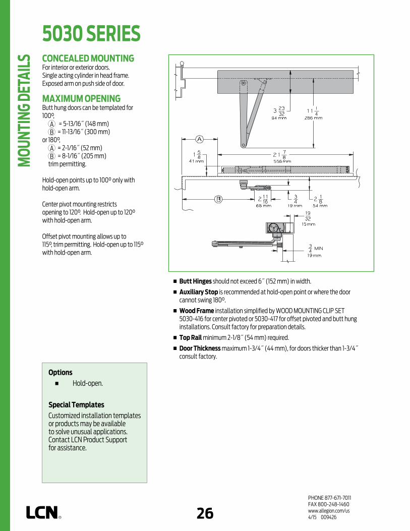
PHONE 877-671-7011FAX 800-248-1460www.allegion.com/us 4/15 00942626
CONCEALED MOUNTINGFor interior or exterior doors.Single acting cylinder in head frame.Exposed arm on push side of door.
MAXIMUM OPENINGButt hung doors can be templated for 100°,
A = 5-13/16˝ (148 mm) B = 11-13/16˝ (300 mm)
or 180°, A = 2-1/16˝ (52 mm) B = 8-1/16˝ (205 mm)
trim permitting.
Hold-open points up to 100° only with hold-open arm.
Center pivot mounting restricts opening to 120°. Hold-open up to 120° with hold-open arm.
Offset pivot mounting allows up to 115°, trim permitting. Hold-open up to 115° with hold-open arm.
n Butt Hinges should not exceed 6˝ (152 mm) in width.
n Auxiliary Stop is recommended at hold-open point or where the door cannot swing 180°.
n Wood Frame installation simplified by WOOD MOUNTING CLIP SET 5030-416 for center pivoted or 5030-417 for offset pivoted and butt hung installations. Consult factory for preparation details.
n Top Rail minimum 2-1/8˝ (54 mm) required.
n Door Thickness maximum 1-3/4˝ (44 mm), for doors thicker than 1-3/4˝ consult factory.
Options n Hold-open.
Special TemplatesCustomized installation templates or products may be available to solve unusual applications. Contact LCN Product Support for assistance.
5030 SERIES M
OUNT
ING
DETA
ILS

PHONE 877-671-7011FAX 800-248-1460www.allegion.com/us 4/15 00942626 27
CYLINDERSCYLINDER, 5030-3071 Standard, handed, cast iron cylinder assembly with mounting plate. For various applications see “Table of Sizes” on 5030 Series page 28.
ARMSREGULAR ARM, 5030-3077 Non-handed arm.
HOLD-OPEN ARM, 5030-3049 Optional, handed arm provides hold-open function for 100° template, adjustable at elbow.
INSTALLATION ACCESSORIESWOOD MOUNTING CLIP SET, 5030-416 Simplifies mounting center pivoted 5030 closer in wood frame. Includes latch stile clip, hinge stile clip, and cover. For use with Ives Series center pivots. Consult factory for special template.
WOOD MOUNTING CLIP SET, 5030-417 Simplifies mounting offset pivoted or butt hung 5030 closer in wood frame. Includes two clips. For use with offset pivots. Consult factory for special template.
3049
3077
3071
416
417
5030 SERIES
ACCE
SSOR
IES

PHONE 877-671-7011FAX 800-248-1460www.allegion.com/us 4/15 00942628
size 3 size 4 size 5 size 6
5034
5033
INTERIOR DOOR WIDTH
28"711mm
38"965mm
48"1219mm
5035
54"1372mm
5036
60"1524mm
34"864mm
HOW-TO-ORDER5030 SERIES CLOSERS
1. SELECT CYLINDER SIZE 5031 (ADA) 5033 5034 5035 5036
2. SPECIFY HAND RH LH
3. SPECIFY FINISH Standard Powder Coat __________
Aluminum, Dark Bronze, Statuary, Light Bronze, Black, Brass.
CLOSER OPTIONSARM Hold-Open (H)
FINISHES Custom Powder Coat (RAL) ___________ Plated Finish, US ______________ SRI Primer (use with powder coat
finishes only)
SCREW PACK TORX Machine Screw (TORX)
INSTALLATION ACCESSORIES Wood Clip Set, 5030-416 Wood Clip Set, 5030-417
SPECIAL TEMPLATE ST- _________
REDUCED OPENING FORCE 5030 CLOSERSCAUTION ! Any manual door closer, including those certified by BHMA to conform to ANSI Standard A156.4, that is selected, installed and adjusted based on ADA or other reduced opening force requirements may not provide sufficient power to reliably close and latch a door.
Refer to POWER OPERATORS section for information on systems that meet reduced opening force requirements without affecting closing power.
TABLE OF SIZES Select closer based on width of door.5030 Series cylinders available in size 1, 2, 3, 4, 5 or 6. Closing power of all 5030 Series closers may be increased 50%.Specify next higher size closer where strong drafts exist.
size 3 size 4 size 5 size 6
5034
5033
EXTERIOR (and VESTIBULE) DOOR WIDTH
28"711mm
30"762mm
36"914mm
42"1067mm
5035
48"1219mm
5036
MinimumDoor Width
MinimumDoor Width
5030 SERIES M
OUNT
ING
DETA
ILS
DOOR WIDTH 36" 42" 48"
8.5* lbs. 5033 5033 5033
5.0* lbs. 5031 5031 5033
* Maximum opening force.
Indicates recommended range of door width for closer size.
Note:Minimumdoorwidth28˝(711mm).
Closer will be shipped with: - REGULAR ARM,- WOOD and MACHINE SCREW PACK,unlessoptionslistedbelowareselected.

PHONE 877-671-7011FAX 800-248-1460www.allegion.com/us 4/15 00942628 29
n Standard 6030 Series closer shipped with standard arm, standard track with bumper, mounting/finish plate and wood and machine screw pack. See 6030 Series page 31 for options.
n Sized, double acting cylinders for interior doors to 4´6˝ and exterior doors to 3´6˝.
n Aluminum frame requires minimum 1-3/4˝ (44 mm) x 4˝ (102 mm) header.
n Closers to meet ADA requirements. See 6030 Series page 32.
n Adjustment of spring power and latch speed independent for either swing.
n Backcheck and general speed adjustment are common for both swings.
n Standard or optional custom powder coat finish.
n Optional plated finish on arm, fasteners and mounting/finish plate.
n Optional SRI primer for installations in corrosive conditions. (Available with powder coat finishes only.)
The concealed 6030 Series PACER®
is a heavy duty, double acting closer
designed to fit in a narrow, minimum
1-3/4˝ header. The single lever arm
and roller assembly provides smooth,
quiet door control and the choice
of finishes and track functions
meet virtually all architectural
requirements. Installation at left
illustrated with center pivot set (not
included).
The6030SeriesisULandcULlisted
forself-closingdoors,nonhold-open.
TestedandcertifiedunderANSIStandard
A156.4,gradeone.
POWDER COAT
PLATED
CONCEALEDMOUNTING FINISH
CONCEALED
EXPOSED
ARM
ACCESSIBILI
TY
CYLINDER *ARM FUNCTION
DELAYED ACTIO
N
REGULAR (D
OUBLE)
STANDARD (SIN
GLE)
HANDED
SIZED
95°
HOLD-O
PEN
95°IN
FRAME
IN 1-
3/4˝ T
UBE
IN DOOR
AVAILABLE NOT AVAILABLE
CONCEALED (IN 1-3/4” TUBE) MOUNTING
Double Acting Closer
6030 SERIES
FEAT
URES
Closeravailablewithlessthan5.0lbs.openingforceon36"door. * Maximumopening/hold-openpointwithstandardtemplate.Seeindividualcloser
seriesfordegreesofopeningperinstallation.
AVAILABLE NOT AVAILABLE

PHONE 877-671-7011FAX 800-248-1460www.allegion.com/us 4/15 00942630
CONCEALED MOUNTINGFor interior or exterior doors.Double acting cylinder in cased frame.Concealed arm and track in door top rail.Center pivots only.
MAXIMUM OPENINGCenter pivot template allows 95°.
Adjustable hold-open points from 85° to 95°, with hold-open track.
n Auxiliary Stop is recommended where a door cannot swing 95°.
n Center Pivot Set, must be used but ordered separately.
n Door Width 30˝ (762 mm) minimum with 1-3/4˝ (44 mm) pivot centers.
n Top Rail 1-7/16˝ (36 mm) mortise required. 3/8˝ (10 mm) cutout required at top of the door, both sides.
n Door Thickness 1-3/4˝ (44 mm) minimum.
n Centering Adjustment provided by eccentric in track roller with 3/4˝ (19 mm) adjustment to center a 36" (914 mm) door in the opening.
n Wood Frame installation simplified by WOOD MOUNTING CLIP SET, 6030-416. Consult product support for special template.
Options n Hold-open track with Bumper.
Special TemplatesCustomized installation templates or products may be available to solve unusual applications. Contact LCN Product Support for assistance.
6030 SERIES M
OUNT
ING
DETA
ILS

PHONE 877-671-7011FAX 800-248-1460www.allegion.com/us 4/15 00942630 31
CYLINDERSCYLINDER, 6030-3071 Standard, non-handed, cast iron cylinder assembly with mounting plate. For various applications see “Table of Sizes” on 6030 Series page 36.
ARMSTANDARD ARM, 6030-3077T Non-handed 5/16˝ (8 mm) thick arm.Track roller not included with arm.
TRACKSSTANDARD TRACK with BUMPER, 6030-3038BStandard, non hold-open, non-handed track with bumper. Will accept hold-open clip.
HOLD-OPEN TRACK with BUMPER, 6030-3038HBOptional, non-handed hold-open track with bumper.
INSTALLATION ACCESSORIESWOOD MOUNTING CLIP SET, 6030-416 Simplifies mounting closer in wood frame. Includes latch stile clip, hinge stile clip, and cover. For use with Ives Series center pivots. Consult factory for special template.
TRACK BUMPER, 6030-169Mounts in track to assist backcheck. Limits maximum opening. Consists of bumper, bumper post, and mounting screw. NOTE: Track bumper does not replace auxiliary stop.
HOLD-OPEN CLIP, 6030-3054Mounts in track to provide hold-open function.Hold-open point controlled by clip location.
TRACK ROLLER, 6030-3034Quiet, low friction roller assembly includes eccentric with 3/4˝ (19 mm) adjustment to center 36˝ (914 mm) door.
3077T
3071
3038B3038HB
416
169
3054
3034
6030 SERIES
ACCE
SSOR
IES
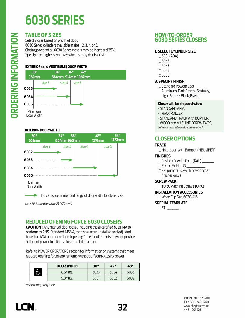
PHONE 877-671-7011FAX 800-248-1460www.allegion.com/us 4/15 00942632
HOW-TO-ORDER6030 SERIES CLOSERS
1. SELECT CYLINDER SIZE 6031 (ADA) 6032 6033 6034 6035
3. SPECIFY FINISH Standard Powder Coat __________
Aluminum, Dark Bronze, Statuary, Light Bronze, Black, Brass.
CLOSER OPTIONSTRACK Hold-open with Bumper (HBUMPER)
FINISHES Custom Powder Coat (RAL) _________ Plated Finish, US ______________ SRI primer (use with powder coat
finishes only)
SCREW PACK TORX Machine Screw (TORX)
INSTALLATION ACCESSORIES Wood Clip Set, 6030-416
SPECIAL TEMPLATE ST- _________
size 3 size 4 size 5
REDUCED OPENING FORCE 6030 CLOSERSCAUTION ! Any manual door closer, including those certified by BHMA to conform to ANSI Standard A156.4, that is selected, installed and adjusted based on ADA or other reduced opening force requirements may not provide sufficient power to reliably close and latch a door.
Refer to POWER OPERATORS section for information on systems that meet reduced opening force requirements without affecting closing power.
TABLE OF SIZES Select closer based on width of door.6030 Series cylinders available in size 1, 2, 3, 4, or 5. Closing power of all 6030 Series closers may be increased 35%.Specify next higher size closer where strong drafts exist.
6034
6033
EXTERIOR (and VESTIBULE) DOOR WIDTH
30"762mm
34"864mm
36"914mm
42"1067mm
6035
size 2 size 3 size 4 size 5
6034
6033
6032
INTERIOR DOOR WIDTH
30"762mm
38"965mm
48"1219mm
6035
54"1372mm
34"864mm
MinimumDoor Width
MinimumDoor Width
6030 SERIES OR
DERI
NG IN
FORM
ATIO
N
DOOR WIDTH 36" 42" 48"
8.5* lbs. 6033 6034 6035
5.0* lbs. 6031 6032 6032
* Maximum opening force.
Indicates recommended range of door width for closer size.
Note:Minimumdoorwidth28˝(711mm).
Closer will be shipped with: - STANDARD ARM,- TRACK ROLLER,- STANDARD TRACK with BUMPER,- WOOD and MACHINE SCREW PACK,unlessoptionslistedbelowareselected.

1PHONE 877-671-7011FAX 800-248-1460www.allegion.com/us 4/15 009426
PRODUCT COMPARISONThis chart shows a basic comparison of Sentronic closer/holders.Refer to the specific product chapter for complete details.
FIRE/LIFE SAFETY CLOSERS/HOLDERS SERIES
3130SE
CLOSERSERIES
4040SE
2310ME
4310ME
4410ME
4310HSA
4410HSA
PLASTIC
METAL
HINGE (P
ULL) SIDE
TOP JAMB (PUSH)
STOP FACE (P
USH)
REGULA
R (DOUBLE)
STANDARD (S
INGLE)
SWIN
G FREE
DOUBLE EGRESS
CONCEALED (F
RAME)
CONCEALED (D
OOR)
MOUNTING COVER CYLINDER *ARM FUNCTIONFINISH
NON-SIZED
HANDED
SIZEDSINGLE
POINT HOLD
-OPEN
MULTI-POINT H
OLD-OPEN
BYPASS 80/14
0
POWDER COAT
PLATED
SINGLE POINT
4040SE SEH**
PUSH SIDEMOUNTED
MULTI-POINT 4410ME
SINGLE POINT
4040SE SEH**
PULL SIDEMOUNTED
MULTI-POINT 4310ME
SINGLE POINT 3130SE
CONCEALED MOUNTING
MULTI POINT 2310ME
INTERIOR DOOR
PRODUCT SELECTION GUIDESENTRONIC® Series LCN closer/holders combine heavy duty closers with electrically controlled hold-open functions to control fire and smoke barrier doors. This guide is based on the desired mounting of the unit.
WALL SEM7830 SEM7840 SEM7850
PULL SIDE
4310 HSA
7800*** MAGNETS
FLOOR SEM7820
PUSH SIDE
4410 HSA
HIGH VOLUME TRAFFIC DOORS INTERIOR/EXTERIOR
* Maximum hold-open with standard template. See individual closer series for degrees of opening and hold-open per installation.
** See SEH section (cylinder not included).*** SEM 7800 Series are die cast.
AVAILABLE NOT AVAILABLE

2PHONE 877-671-7011FAX 800-248-1460www.allegion.com/us 4/15 009426
FIRE/LIFE SAFETY CLOSERS/HOLDERS SERIESLISTINGS AND APPROVALSSentronic closer/holders are listed by Underwriters Laboratories, Inc. in the following product categories under FIRE DOORS (GSNV), Combination Door Closers and Holders (GTIS) file R7050. SEM 7800 Series magnets are listed under Door Holders (GTPR) file R8327. Consult the factory for other listings, such as; cUL, Department of Labor and Industry of the Commonwealth of Pennsylvania, The Board of Standards and Appeals of the City of New York, Fire and Panic Safety Standards of the California State Fire Marshal.
HOLDING SOLENOIDS CURRENT DRAW
SE/ME24V AC/DC (+10% -15%) @ 90 mA max.120V AC/DC (+10% -15%) @ 30 mA max.
SEM (TRI-VOLT)12V DC (+10% -15%) @ 30 mA max.24V AC/DC (+10% -15%) @ 20 mA max.120V AC (+10% -15%) @ 20 mA max.
HSA24V AC/DC (+10% -15%) @ 120 mA max.
TRANSFORMER DATA120V AC 50-60 Hz (primary); 24V AC @ 400 mA max. (secondary)An LCN supplied transformer will power (recommended) 2 SE, 3 SE/ME, and 15 SEM.
ME WIRINGME “ON/OFF” switch assembly includes trim pot to adjust pull out force and fuse to protect solenoid.
SENTRONIC® CLOSER/HOLDERSAutomatic detection and containment of fire and smoke are the best ways to minimize danger to life and property. Patented Sentronic door closer/holders are designed to hold swinging doors open in normal use and release and automatically close the doors under fire conditions. Conforms to major building codes, life safety codes (eg. NFPA 101) and ANSI A156.15.
SINGLE POINT HOLD-OPEN (SE)SE Series offers adjustable single point hold-open function controlled by solenoid assembly located in the SE track.
MULTI-POINT HOLD-OPEN (ME)ME Series offers infinitely adjustable, multi-point hold-open function controlled by solenoid on the cylinder assembly.
HOLDER SCANNER ACTIVATED (HSA)Electronically controlled closer/ holder designed to provide easy passage for groups of pedestrians through high traffic doors. Best suited for high traffic emergency exit doors.
MAGNETS (SEM) - ELECTROMAGNETIC DOOR HOLDERSSEM Series magnets work with manual door closers to provide single point hold-open. Now available in new tri-voltage with 35 lbs. of holding force.
APPLICATIONSn For fire and smoke barrier doors.n Integrated into larger system.n Surface and concealed mountings. n Remote control hold-open function of executive and conference
area doors.n Adapter plates and other installation accessories available for
unusual conditions.
GENERAL NOTESNote 1: For installations where 120V AC input voltage is supplied, 120V/24V
transformer, 4040SE-3210, is required to reduce line voltage for 24V holding solenoid. Units are available in either 24V or 120V input, please specify.
Note 2: Transformer 4040SE-3210 mounted on cover plate to fit 4˝ (102 mm) x 4˝ x 2-1/8˝ (54 mm) junction box (by others).
Note 3: SE track quick-connector is required for 1/2˝ conduit.Note 4: SE test switch assembly includes fuse to protect solenoid. Works with
ionization, photoelectric and heat sensing detectors (by others).
SE WIRING DIAGRAM
CHASSIS GROUND
WIRING DIAGRAMINPUT VOLTAGE
24V AC/DCOR 120V AC/DC
(USUALLY FROMALARM PANEL
OR DETECTOR)
ME (2310) WIRING DIAGRAM
ME (4310, 4410) WIRING DIAGRAM (24V only)

2 3PHONE 877-671-7011FAX 800-248-1460www.allegion.com/us 4/15 009426
FIRE/LIFE SAFETY CLOSERS/HOLDERS SERIESHSA WIRINGHSA “On/Off” switch assembly includes trim pot to adjust hold-open time and fuse to protect solenoid.
FEATURES COMMON TO FIRE/LIFE SAFETY CLOSERSn 24V AC/DC or 120V AC input, please specify for SE or ME.n When current is interrupted, hold-open releases and door
closes.n Adjustable hydraulic backcheck cushions opening swing
prior to 90°.n Separate regulation of general closing speed and latching
speed.n Available in a wide range of powder coated finishes to blend
with door and frame. SEM magnets available in Aluminum and Dark Bronze only.
n Circuit automatically handles AC or DC input.n Can be pushed safely and easily out of hold-open.n Functions as a full rack and pinion door closer when hold-
open is not engaged or current is interrupted.n Works with ionization, photoelectric and heat sensing
detectors (by others).
WARRANTY2 year limited warranty. See General Information Section for complete warranty details.
SPECIFICATIONSRefer to “SPECIFICATIONS” section for suggested architectural specifications.
DESIGN ASSISTANCELCN has been providing reliable solutions to unique door control problems for over 85 years. Contact LCN for assistance or technical information at 877-671-7011 or FAX 800-248-1460 (order entry), Fax 815-879-1495 for Application Engineering.
MATERIALSn High strength cast iron cylinder.n Forged steel main arm.n One piece forged steel piston.n All weather fluid eliminates seasonal adjustments.n High efficiency, full complement, low friction bearings.n Tamper resistant regulating screws.n Quiet, low friction track and roller combination for all single lever
arm closers.
FINISHES n Available in six standard or a wide selection of optional custom powder
coat finishes to blend with door and frame.n LCN’s powder coat finishes surpass 100 hours of salt spray which is over
four times the ANSI standard for corrosion resistance.n Plated finishes are available as an option to accent door and frame.
MAINTENANCEClosers mounted according to LCN installation instructions require no periodic adjustments. Quarterly inspections are recommended. Refer to the installation instructions for complete, product specific details.
POSITIVE PRESSURE LCN closers have been certified for three hours by UL to be in compliance with UBC 7.2 (1997) and UL 10 C. Contact LCN for specific details on door closer fire ratings.
FASTENERSStandard WOOD and MACHINE SCREW (WMS) pack contains phillips head wood and machine screws to install the closer. Thru Bolts and/or TORX® machine screws are available for most closers. LCN thru bolts (TB) can be installed on 1-3/4˝ thick doors with either the 1/4-20 machine screws or optional TORX screws supplied with the closer. Optional sizes are available for 1-5/8˝ or 1-3/8˝ door thicknesses, but this must be specified when ordering.
Drill 25/64˝ forsteel doorsorDrill 3/8˝for wood doors
NOTE 1: For Thru Bolts, specify door thickness if other than 1-3/4˝ (44 mm).NOTE 2: Phillips head, metric machine screws are available on special order.
CONNECT GREEN WIRETO EARTH GROUND
CONNECT BLACKWIRES TO INPUTVOLTAGE LEADS
(POLARITY NOTIMPORTANT)
HSA WIRING DIAGRAM

4PHONE 877-671-7011FAX 800-248-1460www.allegion.com/us 4/15 009426
Notes

4 5PHONE 877-671-7011FAX 800-248-1460www.allegion.com/us 4/15 009426
SEM 7820 MAGNETDie Cast, Floor mounted.
SEM SERIES The Sentronic® SEM 7800 Series
are heavy duty, electrically
controlled door holding magnets.
Magnets are fail safe and hold
until the current is interrupted.
A manual door closer is used to
control and close the door. A
choice of floor, recessed wall, or
surface mounted wall magnets are
available.
All SEM Series magnets are UL listed
for smoke barrier or labeled fire doors.
Tested and certified under ANSI
Standard A156.15.
SEM FEATURESn Tri-voltage design with 35 lbs.
of holding force.n Now available armature extensions
from LCN (see page 11).
n SEM 7820 magnets are shipped with die cast housing, cover, armature(s) and WMS screw pack.
n Available in Aluminum and Dark Bronze finishes only.
n UL listed for smoke barrier or labeled fire doors.
SEM 7820
Total Projection = 6-3/4˝ (171 mm)
FEAT
URES

6PHONE 877-671-7011FAX 800-248-1460www.allegion.com/us 4/15 009426
SEM SERIES SEM FEATURES
n Tri-voltage design with 35 lbs. of holding force.
n Now available armature extensions from LCN (see page 11).
n SEM 7830 magnets are shipped with die cast housing, cover, armature and WMS screw pack.
n SEM 7830 available in Aluminum and Dark Bronze finishes only.
n Suitable for use in pocket door installations.
n UL listed for smoke barrier or labeled fire doors.
SEM 7830
Total Projection = 4-1/8˝ (105 mm) Dimensions apply for both SEM 7830
SEM 7830 MAGNETDie cast housing, Surface wall mounted.
FEAT
URES

6 7PHONE 877-671-7011FAX 800-248-1460www.allegion.com/us 4/15 009426
SEM SERIES SEM 7840 MAGNETDie cast housing, low profile recessed wall mount.2˝ (51 mm) x 4˝ (102 mm)x 1-1/2˝ (38 mm).NOTE: Outlet box not included.
SEM FEATURESn Tri-voltage design with 35 lbs.
of holding force.
n Now available armature extensions from LCN (see page 11).
n SEM 7840 magnets are shipped with die cast housing, cover, armature and WMS screw pack.
n SEM 7840 available in Aluminum and Dark Bronze finishes only.
n Suitable for use in pocket door installations.
n UL listed for smoke barrier or labeled fire doors.
SEM 7840
Total Projection = 2-5/8˝ (67 mm) Dimensions apply for both SEM 7840
FEAT
URES

8PHONE 877-671-7011FAX 800-248-1460www.allegion.com/us 4/15 009426
SEM 7850 MAGNETDie cast housing, standard profile recessed wall mount.2˝ (51 mm) x 4˝ (102 mm) x 1-1/2˝ (38 mm) NOTE: Outlet box not included.
SEM FEATURESn Tri-voltage design with 35 lbs. of
holding force.
n Now available armature extensions from LCN (see page 11).
n SEM 7850 available in Aluminum and Dark Bronze finishes only.
n Suitable for use in pocket door installations.
n UL listed for smoke barrier or labeled fire doors.
SEM 7850
Total Projection = 3-5/8˝ (92 mm) Dimensions apply for both SEM 7850
SEM SERIES FE
ATUR
ES

8 9PHONE 877-671-7011FAX 800-248-1460www.allegion.com/us 4/15 009426
ELECTRICAL SCHEMATIC
ELECTRICAL DATAHolding Force: 35 lbs. @ Nominal Input Voltage.Maximum Current Draw: .020A @ 24VAC/DC, 120VAC
.030A @ 12VDC
VOLTAGE INPUT
SEM SERIES
ELEC
TRIC
AL D
ATA

10PHONE 877-671-7011FAX 800-248-1460www.allegion.com/us 4/15 009426
516(floor)
516(wall)
825 828
72
268
MAGNETSFLOOR MAGNET, SEM7820-516Standard magnet coil.WALL MAGNET, SEM7830-516, SEM7840-516, SEM7850-516Standard magnet coil.
ARMATURESDOOR ARMATURE, SEM7820-825, SEM7830-825, SEM7840-825Standard, die cast low profile armature.DOOR ARMATURE, SEM7850-828 Standard, die cast armature.
COVERSTANDARD COVER, SEM7830-72, SEM7840-72, SEM7850-72Standard, die cast cover.
BOXWALL BOX, SEM7830-268Standard, die cast surface wall mount box.
SEM SERIES AC
CESS
ORIE
S

10 11PHONE 877-671-7011FAX 800-248-1460www.allegion.com/us 4/15 009426
NOTE: Using just the Coupler Assembly Kit (SEM7810-514) will create a 1-1/2˝ link. Extension Links are available in different lengths and can be combined together to achieve the desired length. Max. recommended length = 12˝
514
E050
E075
E100
E200
E400
517
EXTENSIONSCOUPLER ASSEMBLY KIT, SEM7810-514Coupler assembly is required for each door needing extension(s). Kit includes coupler link and ball pivot (alone serves as a 1-1/2˝ extension).
Extension, SEM7810-E050 Standard metal 1/2˝ extension.
Extension, SEM7810-E075 Standard metal 3/4˝ extension.
Extension, SEM7810-E100 Standard metal 1˝ extension.
Extension, SEM7810-E200 Standard metal 2˝ extension.
Extension, SEM7810-E400 Standard metal 4˝ extension.
EXTENSION KIT, SEM7810-517Extension kit includes: 10...........7810SEM-E050 10............7810SEM-E075 10............7810SEM-E100 5...........7810SEM-E200 20...............7810SEM-514
SEM SERIES
ACCE
SSOR
IES

12PHONE 877-671-7011FAX 800-248-1460www.allegion.com/us 4/15 009426
HOW-TO-ORDER SEM 7800 SERIES MAGNETS1. SELECT MAGNET SERIES SEM7820 SEM7830 SEM7840 SEM78502. SPECIFY FINISH Standard Powder Coat ______________
Aluminum, Dark Bronze.
HOW-TO-ORDER SEM 7810 EXTENSIONS1. SELECT EXTENSIONS SEM7810-514 (qty.) _______________ SEM7810-E050 (qty.) _______________ SEM7810-E075 (qty.) _______________ SEM7810-E100 (qty.) _______________ SEM7810-E200 (qty.) _______________ SEM7810-E400 (qty.) _______________ SEM7810-517 (qty.) _______________
SEM 7820
SEM 7840
SEM 7830
SEM 7850
SEM SERIES OR
DERI
NG IN
FORM
ATIO
N

12 13PHONE 877-671-7011FAX 800-248-1460www.allegion.com/us 4/15 009426
n Standard 3130SE Series closer shipped with a standard arm, 24V or 120V SE track (please specify), track roller, and wood and machine screw pack. See 3130SE Series page 15 for options.
n Sized cylinders for interior doors to 4´0˝.
n Functions as full rack and pinion door closer when hold-open is not engaged or current is interrupted.
n Handed for right or left swinging door.
n Interfaces with fire alarm systems.
n Standard or optional custom powder coated finish.
n Optional plated finish on arm and fasteners.
PLA
STIC
METAL
HINGE (P
ULL) SIDE
TOP JAMB (PUSH)
STOP FACE (P
USH)
SWIN
G FREE
DOUBLE EGRESS
CONCEALED (F
RAME)
CONCEALED (D
OOR)
MOUNTING COVER CYLINDER *ARM FUNCTIONFINISH
NON-SIZED
HANDED
SIZEDSINGLE
POINT HOLD
-OPEN
MULTI-POINT H
OLD-OPEN
BYPASS 80/14
0
POWDER COAT
PLATED
REGULA
R (DOUBLE)
STANDARD (S
INGLE)
* Maximum hold-open with standard template. See individual closer series for degrees of opening and hold-open per installation.
The 3130SE SENTRONIC® is a
concealed in the door, closer/
holder designed to provide single
point hold-open for fire and smoke
barrier doors. Door is held open
until current interruption releases
the holding mechanism and the
door closes. Single lever (track)
arm closer is specifically designed
for interior doors.
The 3130SE and SEL Series is UL listed
for metal smoke barrier or labeled
fire doors.
Door and frame manufacturer must
have preparation included in their UL
procedures. Tested and certified under
ANSI Standard A156.15. Conforms to life
safety code, NFPA 101.
CONCEALED (IN DOOR) MOUNTING
3130SE SERIES
FEAT
URES
AVAILABLE NOT AVAILABLE

14PHONE 877-671-7011FAX 800-248-1460www.allegion.com/us 4/15 009426
n Butt Hinges should not exceed 5˝ (127 mm) in width. Consult factory for pivot hung installations.
n Auxiliary Stop is recommended at hold-open point.
n Top Rail minimum 4˝ (102 mm).
n Door Thickness 1-3/4˝ (44 mm) minimum. Please consult the door manufacturer to assure that the door integrity and warranty is maintained after installing the 3130SE Series door closer in 1-3/4˝ (44 mm) thickness wood doors.
n Door Width 2´4˝ (711 mm) minimum for single door with SE. 2´8˝ (813 mm) minimum for door with SEL.
n Wiring Diagram
CONCEALED MOUNTINGFor interior smoke barrier and labeled fire doors.
MAXIMUM OPENINGTemplating allows 110°.
Hold-open points between 85° and 110° in approximately 3° increments.
SEL arm and track locate hold-open at 110°, 120° and 130°.
SE, SEL ELECTRICAL OPTIONSThese track assemblies require a single power circuit for the holding solenoid.SE or SEL holding solenoid is either 24V or 120V input, please specify.An optional 4040SE-3210 or 8310-824 TRANSFORMER reduces 120V AC line voltage to 24V AC.Circuitry accepts either AC or DC input.
SE WIRING DIAGRAM
3130SE SERIES M
OUNT
ING
DETA
ILS
Options n Long (SEL) track and arm. n 24V or 120V input, please
specify.
Special TemplatesCustomized installation templates or products may be available to solve unusual applications. Contact LCN Product Support for assistance.

14 15PHONE 877-671-7011FAX 800-248-1460www.allegion.com/us 4/15 009426
SE-3077T
2210dps-3071
3071CYLINDERSE CYLINDER, 3130SE-3071 Standard, handed cast iron cylinder assembly. For various applications see “Table of Sizes” on 3130SE Series page 16.
ARMSTANDARD ARM, 3130SE-3077T Handed arm. Arm adjustable to select hold-open point.
LONG ARM, 3130SEL-3077TOptional, handed, solid arm provides hold-open point from 110° to 130°, determined by track templating.Used with SEL TRACK 3130SEL-3038 only.
TRACKSSE TRACK, 3130SE-3038Standard, non-handed track.Circuitry accepts either AC or DC input.24V holding solenoid (24) or120V holding solenoid (120), please specify.
SEL TRACK, 3130SEL-3038Optional, long non-handed track.Used with LONG ARM, 3130SEL-3077T, only.Provides hold open point from 110° to 130°, determined by templating.Circuitry accepts either AC or DC input.24V holding solenoid (24) or120V holding solenoid (120), please specify.
SWITCHTEST SWITCH, 3130SE-3436
INSTALLATION ACCESSORIESCONDUIT QUICK-CONNECTOR, 3130SE-81Two piece connector for use with 1/2˝ conduit. See page 21 for illustration.
TRACK ROLLER, 3130SE-3034Quiet, low friction roller assembly.Shoulder dimension “X” = 1/8˝ (3 mm).
TRACK SLIDER, 3130SE-168Alloy metal slider for use in SE series tracks only.
TRANSFORMER, 4040SE-3210 Reduces line voltage from 120V to 24V AC.Mounted on plate for 4˝ (102 mm) x 4˝ x 2-1/8˝ (54 mm) junction box (by others).
SEL-3077T
3034
4040SE-3210
SEL-3038
CHASSIS GROUND
WIRING DIAGRAMINPUT VOLTAGE
24V AC/DCOR 120V AC/DC
(USUALLY FROMALARM PANEL
OR DETECTOR)
SE-3436
SE-3038
168
3130SE SERIES
ACCE
SSOR
IES
81

16PHONE 877-671-7011FAX 800-248-1460www.allegion.com/us 4/15 009426
TABLE OF SIZESSelect closer based on width of door. Sized 3130SE series cylinders available in size 3 or 4. Closing power of all 3130SE Series closers is not adjustable.
HOW-TO-ORDER 3130SE SERIES CLOSERS1. SELECT CYLINDER SIZE 3133SE 3134SE
2. SPECIFY HAND RH LH
3. SELECT TRACK SE SEL (requires long arm)
4. VOLTAGE 24V AC/DC 120V AC/DC
5. SPECIFY FINISH Standard Powder Coat __________
Aluminum, Dark Bronze, Statuary, Light Bronze, Black, Brass.
CLOSER OPTIONSARM Long Arm* (LONG)
* use with SEL track only
FINISH Custom Powder Coat (RAL) ___________ Plated Finish, US ___________
SCREW PACK TORX Machine Screw (TORX)
INSTALLATION ACCESSORIES Transformer, 4040SE-3210
SPECIAL TEMPLATE ST- _________
INTERIOR DOOR WIDTH
28"711mm
34"864mm
38"965mm
48"1219mm
size 3 size 4 3133SE
3134SE
MinimumDoor Width
for SE
3130SE SERIES OR
DERI
NG IN
FORM
ATIO
N
Closer will be shipped with:- STANDARD ARM,- TRACK ROLLER,- STANDARD TRACK,- WOOD & MACHINE SCREW PACK,unless options listed below are selected.
Indicates recommended range of door width for closer size.
NOTE: For SE, minimum door width 28˝ (711mm). For SEL, minimum door width 32˝ (813mm).

16 17PHONE 877-671-7011FAX 800-248-1460www.allegion.com/us 4/15 009426
n Standard 4040SE Series closer shipped with a standard arm, 24V or 120V (please specify) SE track, standard plastic clip-on cover, and wood and machine screw pack. SEL tracks are optional, see 4040SE Series pages 20 & 21 for options.
n Non-sized cylinders for interior doors to 4´0˝.
n Hold-open force is adjustable.
n Momentary on/off switch board assembly for testing door release also provides over-voltage protection. Field replaceable.
n Functions as a full rack and pinion closer when hold-open is not engaged or current is interrupted.
n Closer mounts on either push or pull side of the door.
n Non-handed for mounting on either right or left hand door.
n Concealed or surface wiring.
n Interfaces with alarm systems.
n Standard or optional custom powder coated finishes on cover and arm.
n Optional plated finishes.
The 4040SE SENTRONIC® is a
heavy duty, non-handed, non-
sized closer/holder designed to
provide single point hold-open
for fire and smoke barrier doors.
The door is held open until
current interruption releases the
holding mechanism and the door
closes. Single lever (track) arm
closer is specifically designed
for interior doors. Choice of
finishes, track functions, and
installation accessories meet
virtually all life safety requirements.
The 4040SE and SEL Series is UL and cUL
listed for smoke barrier or labeled fire
doors. Tested and certified under ANSI
Standard A156.15. Conforms to life safety
code, NFPA 101.
110 95
PLASTIC
METAL
HINGE (P
ULL) SIDE
TOP JAMB (PUSH)
STOP FACE (P
USH)
SWIN
G FREE
DOUBLE EGRESS
CONCEALED (F
RAME)
CONCEALED (D
OOR)
MOUNTING COVER CYLINDER *ARM FUNCTIONFINISH
NON-SIZED
HANDED
SIZEDSINGLE
POINT HOLD
-OPEN
MULTI-POINT H
OLD-OPEN
BYPASS 80/14
0
POWDER COAT
PLATED
REGULA
R (DOUBLE)
STANDARD (S
INGLE)
* Maximum hold-open with standard template. See individual closer series for degrees of opening and hold-open per installation.
HINGE (PULL) SIDE MOUNTING
4040SE SERIES
FEAT
URES
AVAILABLE NOT AVAILABLE

18PHONE 877-671-7011FAX 800-248-1460www.allegion.com/us 4/15 009426
n Butt Hinges should not exceed 5˝ (127 mm) in width.
n Swing Clear Hinges consult factory.
n Auxiliary Stop is recommended at hold-open point.
n Reveal should not exceed 1/8˝ (3 mm) for standard arm. Should not exceed 2-11/16˝ (68 mm) for double egress arm.
n Top Rail minimum 3-1/2˝ (89 mm). Installation with PLATE, 4040SE-18 requires SPECIAL TEMPLATE and 1-3/4˝ (44 mm) minimum top rail.
n Head Frame requires 2˝ (51 mm) minimum.
n Flush Ceiling with 2˝ (51 mm) head frame does not require special templating.
n Door Width 2´4˝ (711 mm) minimum for single door with SE. 4´8˝ (1422 mm) minimum for paired doors with SE.
n Clearance of 2-3/8˝ (60 mm) behind door required for 90° installation.
n Wiring Diagram See “FIRE/LIFE SAFETY” section page 19 for typical wiring and electrical diagram.
Options n Long (SEL) track. n Handed double egress arm for
reveal under 2-11/16˝ (67 mm). n Metal cover. n 24V or 120V input for SE or SEL,
please specify.
Special Templates Customized installation templates or products may be available to solve unusual applications. Contact LCN Product Support for assistance.
HINGE (PULL) SIDE MOUNTINGInformation applies to 4040 SE unless otherwise specified.
MAXIMUM OPENINGTemplating allows 110°.Hold-open points between 85° and 110° in approximately 3° increments.Pull side mounting on a double egress frame requires a handed double egress arm. Maximum hold-open to 95°. 2-11/16˝ (67 mm) maximum reveal on pull side.SEL track provides hold-open points between 90° and 120°‚ in approximately 3° increments.
SE, SEL ELECTRICAL OPTIONSThese track assemblies require a single power circuit for the holding solenoid.
SE or SEL holding solenoid is either 24V or 120V input, please specify.An optional 4040SE-3210 or 8310-824 TRANSFORMER reduces 120V AC line voltage to 24V AC.Circuitry accepts either AC or DC input.
4040SE SERIES M
OUNT
ING
DETA
ILS
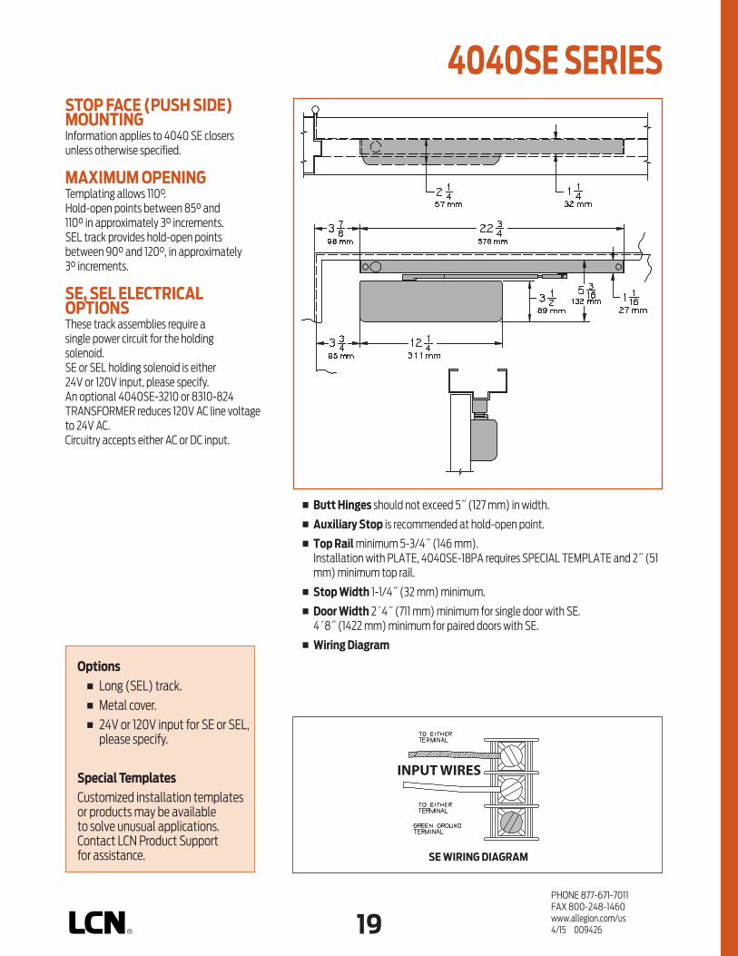
18 19PHONE 877-671-7011FAX 800-248-1460www.allegion.com/us 4/15 009426
STOP FACE (PUSH SIDE)MOUNTINGInformation applies to 4040 SE closers unless otherwise specified.
MAXIMUM OPENINGTemplating allows 110°.Hold-open points between 85° and 110° in approximately 3° increments.SEL track provides hold-open points between 90° and 120°‚ in approximately 3° increments.
SE, SEL ELECTRICAL OPTIONSThese track assemblies require a single power circuit for the holding solenoid.SE or SEL holding solenoid is either 24V or 120V input, please specify.An optional 4040SE-3210 or 8310-824 TRANSFORMER reduces 120V AC line voltage to 24V AC.Circuitry accepts either AC or DC input.
n Butt Hinges should not exceed 5˝ (127 mm) in width.
n Auxiliary Stop is recommended at hold-open point.
n Top Rail minimum 5-3/4˝ (146 mm). Installation with PLATE, 4040SE-18PA requires SPECIAL TEMPLATE and 2˝ (51 mm) minimum top rail.
n Stop Width 1-1/4˝ (32 mm) minimum.
n Door Width 2´4˝ (711 mm) minimum for single door with SE. 4´8˝ (1422 mm) minimum for paired doors with SE.
n Wiring Diagram
Options n Long (SEL) track. n Metal cover. n 24V or 120V input for SE or SEL,
please specify.
Special Templates Customized installation templates or products may be available to solve unusual applications. Contact LCN Product Support for assistance. SE WIRING DIAGRAM
4040SE SERIES
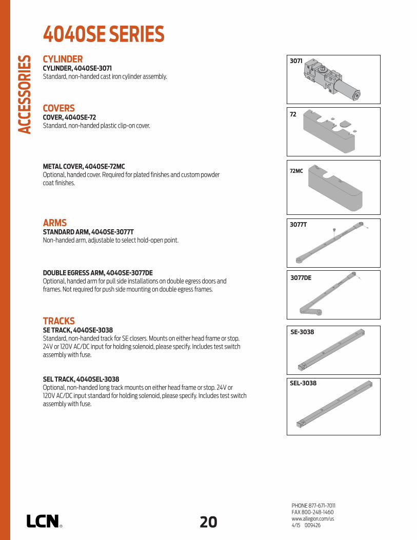
20PHONE 877-671-7011FAX 800-248-1460www.allegion.com/us 4/15 009426
CYLINDERCYLINDER, 4040SE-3071 Standard, non-handed cast iron cylinder assembly.
COVERSCOVER, 4040SE-72Standard, non-handed plastic clip-on cover.
METAL COVER, 4040SE-72MCOptional, handed cover. Required for plated finishes and custom powder coat finishes.
ARMSSTANDARD ARM, 4040SE-3077TNon-handed arm, adjustable to select hold-open point.
DOUBLE EGRESS ARM, 4040SE-3077DEOptional, handed arm for pull side installations on double egress doors and frames. Not required for push side mounting on double egress frames.
TRACKSSE TRACK, 4040SE-3038Standard, non-handed track for SE closers. Mounts on either head frame or stop. 24V or 120V AC/DC input for holding solenoid, please specify. Includes test switch assembly with fuse.
SEL TRACK, 4040SEL-3038Optional, non-handed long track mounts on either head frame or stop. 24V or 120V AC/DC input standard for holding solenoid, please specify. Includes test switch assembly with fuse.
72
2210dps-3071
3071
72MC
3077T
3077DE
SE-3038
SEL-3038
4040SE SERIES AC
CESS
ORIE
S

20 21PHONE 877-671-7011FAX 800-248-1460www.allegion.com/us 4/15 009426
SWITCHTEST SWITCH, 4040SE-3436
INSTALLATION ACCESSORIESPLATE, 4040SE-18Required where top rail is less than 3-1/2˝ (89 mm).Plate requires minimum 2˝ (51 mm) top rail.Plate installations require a SPECIAL TEMPLATE.
PLATE, 4040SE-18PARequired where top rail is less than 5-3/4˝ (146 mm).Plate requires minimum 2˝ (51 mm) top rail.Plate installations require a SPECIAL TEMPLATE.
CONDUIT QUICK-CONNECTOR, 4040SE-81Two piece connector for use with 1/2˝ conduit.
TRACK ROLLER, 4040SE-3034Quiet, low friction roller assembly.Shoulder dimension “X” = 1/8˝ (3 mm).
TRACK SLIDER, 4040SE-168Alloy metal slider for use in SE series tracks only.
TRANSFORMER, 4040SE-3210Reduces line voltage from 120V to 24V AC.Mounted on cover for 4˝ (102 mm) x 4˝ x 2-1/8˝ (54 mm) junction box (by others).
18
18PA
3034
168
81
4040SE-3210
CHASSIS GROUND
WIRING DIAGRAMINPUT VOLTAGE
24V AC/DCOR 120V AC/DC
(USUALLY FROMALARM PANEL
OR DETECTOR)
3436
4040SE SERIES
ACCE
SSOR
IES

22PHONE 877-671-7011FAX 800-248-1460www.allegion.com/us 4/15 009426
HOW-TO-ORDER4040SE SERIES CLOSERS1. SELECT TRACK SE SEL2. VOLTAGE 24V AC/DC 120V AC/DC3. SPECIFY FINISH Standard Powder Coat __________
Aluminum, Dark Bronze, Statuary, Light Bronze, Black, Brass.
CLOSER OPTIONSCOVER Metal (MC)
(please specify right or left hand)FINISHES Custom Powder Coat (RAL)
(handed metal cover required) Plated Finish, US ___________
(handed metal cover required)ARM Double Egress (DE)
(please specify right or left hand)SCREW PACK TB*, Wood & Machine Screw (TBWMS) TORX Machine Screw (TORX) TB* & TORX Machine Screw (TBTRX)
* Specify door thickness if other than 1-3/4”.INSTALLATION ACCESSORIES Plate, 4040SE-18 Plate, 4040SE-18PA Transformer, 4040SE-3210SPECIAL TEMPLATE ST- ________ (if required)
TABLE OF SIZES 4040SE series cylinders accommodate interior doors up to 48˝ (1219 mm) wide.Closing power of 4040SE Series closers is adjustable through a range of sizes up to size 4.
Minimum door widths:for SE on paired door, min. width 60˝ (1524 mm).for SE, minimum door width 28˝ (711 mm).for SEL, minimum door width 30˝ (762 mm).Details are listed on the MOUNTING DETAILS pages.
size 3 size 4
4040SE
INTERIOR DOOR WIDTH
28"711mm
34"864mm
38"965mm
48"1219mm
MinimumDoor Width for SE
4040SE SERIES OR
DERI
NG IN
FORM
ATIO
N
Closer will be shipped with:– STANDARD CYLINDER,– STANDARD CLIP-ON COVER,– STANDARD ARM,– STANDARD TRACK,– WOOD & MACHINE SCREW PACK,unless options listed below are selected.

22 23PHONE 877-671-7011FAX 800-248-1460www.allegion.com/us 4/15 009426
n Standard 2310ME Series closer shipped with either 24V or 120V cylinder (please specify), two piece metal finish plate, standard arm, track, and wood and machine screw pack. See 2310ME Series page 25 for options.
n Sized cylinders for interior doors to 4´0˝.
n Functions as full rack and pinion door closer when hold-open is not engaged or current is interrupted.
n Handed for right or left swinging door.
n Built-in “On/Off” switch controls hold-open function.
n Interfaces with fire alarm systems.
n Standard or optional custom powder coated finish.
n Optional plated finish on arm, fasteners and finish plate.
160°
PLASTIC
METAL
HINGE (P
ULL) SIDE
TOP JAMB (PUSH)
STOP FACE (P
USH)
SWIN
G FREE
DOUBLE EGRESS
CONCEALED (F
RAME)
CONCEALED (D
OOR)
MOUNTING COVER CYLINDER *ARM FUNCTIONFINISH
NON-SIZED
HANDED
SIZEDSINGLE
POINT HOLD
-OPEN
MULTI-POINT H
OLD-OPEN
BYPASS 80/14
0
POWDER COAT
PLATED
REGULA
R (DOUBLE)
STANDARD (S
INGLE)
The 2310ME SENTRONIC® is a
concealed heavy duty, electri cally
controlled closer/holder designed
to provide infinitely adjustable
hold-open for fire and smoke
barrier doors. Door is held open
until current interruption releases
mechanism and the door closes.
Single lever (track) arm closer is
specifically designed for interior
doors. Choice of finishes, cylinder
functions, and installation
accessories meet virtually all life
safety requirements.
The 2310ME Series is UL & cUL listed
for smoke barrier or labeled fire doors.
Tested and certified under ANSI
Standard A156.15. Conforms to life
safety code, NFPA 101.
CONCEALED (IN FRAME) MOUNTING
2310ME SERIES
FEAT
URES
* Maximum hold-open with standard template. See individual closer series for degrees of opening and hold-open per installation.
AVAILABLE NOT AVAILABLE

24PHONE 877-671-7011FAX 800-248-1460www.allegion.com/us 4/15 009426
n Butt Hinges should not exceed 5˝ (127 mm) in width.
n Top Rail 1-3/8˝ (35 mm) mortise required. 5/16˝ (8 mm) cutout required at top of door, stop face only.
n Door Thickness 1-3/4˝ (44 mm) minimum.
n Door Width 2´4˝ (711 mm) minimum.
n Hollow Metal Frame Requires minimum 4˝ (102 mm) x 4˝ frame. Consult factory or template for preparation details.
n Bypass (suffix “B80” or “B140”) eliminates hold-open function up to a specified point of door swing. B80 cylinder from 0° to 80°. B140 cylinder from 0° to 140°.
n Wiring Diagram
CONCEALED MOUNTINGFor interior smoke barrier and labeled fire doors.
MAXIMUM OPENINGTemplating allows 180° with hold-open points up to 160°.
CHASSIS GROUND
WIRING DIAGRAMINPUT VOLTAGE
24V AC/DCOR 120V AC/DC
(USUALLY FROMALARM PANEL
OR DETECTOR)
ME (2310) WIRING DIAGRAM
2310ME SERIES M
OUNT
ING
DETA
ILS
Options n Hold-open bypass. n 24V or 120 volt input, please
specify.
Special Templates Customized installation templates or products may be available to solve unusual applications. Contact LCN Product Support for assistance.

24 25PHONE 877-671-7011FAX 800-248-1460www.allegion.com/us 4/15 009426
3071
3038
CYLINDERME CYLINDER, 2310ME-3971 Standard, handed cast iron cylinder assembly. Specify 24V or 120V.
ME CYLINDER, 2310ME-3071 Standard, handed cylinder and mounting plate assembly.“On/Off” switch assembly controls the hold-open function.Circuitry accepts either AC or DC input. Specify 24V or 120V.
ARMSTANDARD ARM, 2310ME-3077T Handed arm.
TRACKSTANDARD TRACK, 2310ME-3038Standard, non-handed track.
SWITCHSWITCH, 2310ME-3351“On/Off” switch assembly provides continuous hold-open function. Available as 24V or 120V, please specify.
INSTALLATION ACCESSORIESFIRE SHIELD, 2310ME-420 22 gauge steel liner mounts in the track mortise of the door’s top rail for 20 minute labeled wood doors with hollow metal frames.
TRANSFORMER, 2310ME-3210 Reduces line voltage from 120V to 24V AC.Mounted on plate for 4˝ (102 mm) x 4˝ x 2-1/8˝ (54 mm) junction box (by others).
TRACK ROLLER, 2310ME-3034Quiet, low friction roller assembly.Shoulder dimension “X” = 1/16˝ (2 mm).
3077T
420
3210
CHASSIS GROUND
WIRING DIAGRAMINPUT VOLTAGE
24V AC/DCOR 120V AC/DC
(USUALLY FROMALARM PANEL
OR DETECTOR)
3971
3034
CHASSIS GROUND
WIRING DIAGRAMINPUT VOLTAGE
24V AC/DCOR 120V AC/DC
(USUALLY FROMALARM PANEL
OR DETECTOR)
3351
2310ME SERIES
ACCE
SSOR
IES

26PHONE 877-671-7011FAX 800-248-1460www.allegion.com/us 4/15 009426
size 4
TABLE OF SIZESClosing power of 2314ME Series closers may be increased 15%.
INTERIOR DOOR WIDTH
28"711mm
34"864mm
38"965mm
48"1219mm
2314
MinimumDoor Width
for SE
HOW-TO-ORDER 2310ME SERIES CLOSERS1. SPECIFY HAND RH LH2. VOLTAGE 24V AC/DC 120V AC/DC3. SPECIFY FINISH Standard Powder Coat __________
Aluminum, Dark Bronze, Statuary, Light Bronze, Black, Brass.
CLOSER OPTIONSCYLINDER FUNCTION Bypass 80° (B80) Bypass 140° (B140)FINISH Custom Powder Coat (RAL) ___________ Plated Finish, US ___________ SCREW PACK TORX Machine Screw (TORX)INSTALLATION ACCESSORIES Fire Shield, 2310ME-420 Transformer, 2310ME-3210SPECIAL TEMPLATE ST-_________
2310ME SERIES OR
DERI
NG IN
FORM
ATIO
N
Indicates recommended range of door width for closer size.Closer will be shipped with:– FINISH PLATES,– STANDARD ARM,– STANDARD TRACK,– TRACK ROLLER,– WOOD & MACHINE SCREW PACK,unless options listed below are selected.

26 27PHONE 877-671-7011FAX 800-248-1460www.allegion.com/us 4/15 009426
160 95
PLASTIC
METAL
HINGE (P
ULL) SIDE
TOP JAMB (PUSH)
STOP FACE (P
USH)
SWIN
G FREE
DOUBLE EGRESS
CONCEALED (F
RAME)
CONCEALED (D
OOR)
MOUNTING COVER CYLINDER *ARM FUNCTIONFINISH
NON-SIZED
HANDED
SIZEDSINGLE
POINT HOLD
-OPEN
MULTI-POINT H
OLD-OPEN
BYPASS 80/14
0
POWDER COAT
PLATED
REGULA
R (DOUBLE)
STANDARD (S
INGLE)
The 4310ME SENTRONIC® is a
heavy duty, electrically controlled
closer/holder designed to provide
infinitely adjustable hold-open for
fire and smoke barrier doors.
Door is held open until current
interruption releases mechanism
and the door closes. Single lever
(track) arm closer is specifically
designed for interior doors. Choice
of finishes, cylinder functions,
and installation accessories
meet virtually all life safety
requirements.
The 4310ME is UL listed for smoke
barrier or labeled fire doors. Tested and
certified under ANSI Standard A156.15.
Conforms to life safety code, NFPA 101.
An ME provides only the closer/holder
function.
n Standard 4310ME Series closer shipped with a 24V or 120V cylinder (please specify) on a mounting plate, metal cover, Swing-Free arm, track, track roller, and wood and machine screw pack. See 4310ME Series pages 29 & 30 for options.
n Sized cylinders for interior doors to 4´0˝.
n Functions as full rack and pinion door closer when hold-open is not engaged or current is interrupted with Swing-Free arm engaged.
n Handed for right or left swinging door.
n Concealed or exposed electrical connections.
n Built-in “On/Off” switch controls hold-open function.
n Swing-Free arm allows door to be moved without door closer resistance.
n Interfaces with fire alarm systems.
n Standard or optional custom powder coated finish.
n Optional plated finish on cover, arm, and fasteners.
HINGE (PULL) SIDE MOUNTING
4310ME SERIES
FEAT
URES
* Maximum hold-open with standard template. See individual closer series for degrees of opening and hold-open per installation.
AVAILABLE NOT AVAILABLE

28PHONE 877-671-7011FAX 800-248-1460www.allegion.com/us 4/15 009426
n Butt Hinges should not exceed 4-1/2˝ (114 mm) in width.
n Top Rail 1-1/16˝ (27 mm) minimum.
n Reveal should not exceed 1/8˝ (3 mm) for Swing-Free arm. Should not exceed 2-11/16˝ (68 mm) for double egress arm.
n Head Frame requires 2˝ (51 mm) minimum.
n Clearance of 1-1/4˝ (32 mm) behind door required for installation.
n Bypass (suffix “B80 or B140”) eliminates hold-open function up to a specified point of the doors swing. B80 cylinder from 0° to 80°. B140 cylinder from 0° to 140°.
n Wiring Diagram
HINGE (PULL) SIDE MOUNTINGInformation applies to ME closer.
MAXIMUM OPENINGTemplating allows 180° with hold-open points up to 160°.Optional double egress arm limited to 95°.Please note that many track style door closers are capable of allowing 180° of door swing. Be aware that the majority of track style closers are at their weakest closing force in the 180° – 130° range. Consult factory for applications where exterior or large/heavy door must swing 180°.
ME ELECTRICAL OPTIONSThese assemblies have a single electrical circuit with a choice of voltages. A separate TRANSFORMER, 4040SE-3210, can be used to reduce line voltage to 24V AC. Circuitry accepts either AC or DC input.Please specify 24V or 120V.
SOLENOID HOLDINGFORCE ADJUSTMENTPOTENTIOMETER (24V ONLY)
ME (4310, 4410) WIRING DIAGRAM
4310ME SERIES M
OUNT
ING
DETA
ILS
Options n Hold-open bypass. n Double egress arm. n 24V or 120 volt input,
please specify.
Special Templates Customized installation templates or products may be available to solve unusual applications. Contact LCN Product Support for assistance.

28 29PHONE 877-671-7011FAX 800-248-1460www.allegion.com/us 4/15 009426
3071
CHASSIS GROUND
WIRING DIAGRAMINPUT VOLTAGE
24V AC/DCOR 120V AC/DC
(USUALLY FROMALARM PANEL
OR DETECTOR)
3971CYLINDERME CYLINDER, 4310ME-3971 Standard, handed cast iron cylinder assembly. Please specify 24V or 120V.
ME CYLINDER, 4310ME-3071 Standard, handed cylinder and mounting plate assembly.“On/Off” switch assembly controls hold-open function.Circuitry accepts either AC or DC input.Please specify 24V or 120V.
COVERSCOVER, 4310ME-72MC Handed, metal cover.
ARMSSWING-FREE ARM, 4310ME-3077SFHanded arm.After door is placed in hold-open, secondary pivot point allows up to 160° swing without door closer resistance.
DOUBLE EGRESS ARM, 4310ME-3077DEOptional, handed arm for double egress doors and frames.2-11/16˝ (68 mm) maximum reveal.
TRACKTRACK, 4310ME-3038 Standard, non-handed track.
72MC
3077DE
3038
3077SF
4310ME SERIES
ACCE
SSOR
IES

30PHONE 877-671-7011FAX 800-248-1460www.allegion.com/us 4/15 009426
SWITCHSWITCH, 4310ME-3351“On/Off” switch assembly provides continuous hold-open function. Available as 24V or 120V, please specify.
INSTALLATION ACCESSORIESTRACK ROLLER, 4310ME-3034 Quiet, low friction roller assembly.Shoulder dimension “X” = 1/8˝ (3mm).
TRANSFORMER, 4310-3210 Reduces line voltage from 120V to 24V AC.Mounted on cover for 4˝ (102 mm) x 4˝ x 2-1/8˝ (54mm) junction box (by others).
ME WIRING HARNESS, 4310ME-3354Three wire harness with 6˝ (152 mm) leads for field wiring connections.
3210
CHASSIS GROUND
WIRING DIAGRAMINPUT VOLTAGE
24V AC/DCOR 120V AC/DC
(USUALLY FROMALARM PANEL
OR DETECTOR)
3354
3034
3351
24V 120V
4310ME SERIES AC
CESS
ORIE
S

30 31PHONE 877-671-7011FAX 800-248-1460www.allegion.com/us 4/15 009426
size 2 size 4 4314ME
MinimumDoor Width
TABLE OF SIZES Closing power of 4314ME Series closers may be increased 15%.
HOW-TO-ORDER 4310ME SERIES CLOSERS1. SPECIFY HAND RH LH2. VOLTAGE 24V AC/DC 120V AC/DC3. SPECIFY FINISH Standard Powder Coat __________
Aluminum, Dark Bronze, Statuary, Light Bronze, Black, Brass.
CLOSER OPTIONSCYLINDER FUNCTION Bypass 80° (B80) Bypass 140° (B140)ARM Double Egress (DE)FINISHES Custom Powder Coat (RAL) Plated Finish, US SCREW PACK TB*, Wood & Machine Screw (TBWMS) TORX Machine Screw (TORX) TB* & TORX Machine Screw (TBTRX)
*Specify door thickness if other than 1-3/4˝.INSTALLATION ACCESSORIES Transformer, 4310ME-3210SPECIAL TEMPLATE ST- _________
4310ME SERIES
ORDE
RING
INFO
RMAT
ION
INTERIOR DOOR WIDTH
26"660mm
34"864mm
38"965mm
48"1219mm
Indicates recommended range of door width for closer size.
Closer will be shipped with:– STANDARD COVER,– SWING-FREE (SF) ARM,– STANDARD TRACK,– TRACK ROLLER,– WOOD & MACHINE SCREW PACK,unless options listed below are selected.

32PHONE 877-671-7011FAX 800-248-1460www.allegion.com/us 4/15 009426
Notes

32 33PHONE 877-671-7011FAX 800-248-1460www.allegion.com/us 4/15 009426
150
PLASTIC
METAL
HINGE (P
ULL) SIDE
TOP JAMB (PUSH)
STOP FACE (P
USH)
SWIN
G FREE
DOUBLE EGRESS
CONCEALED (F
RAME)
CONCEALED (D
OOR)
MOUNTING COVER CYLINDER *ARM FUNCTIONFINISH
NON-SIZED
HANDED
SIZEDSINGLE
POINT HOLD
-OPEN
MULTI-POINT H
OLD-OPEN
BYPASS 80/14
0
POWDER COAT
PLATED
REGULA
R (DOUBLE)
STANDARD (S
INGLE)
The 4410ME SENTRONIC® is a
heavy duty, electrically controlled
closer/holder designed to provide
infinitely adjustable hold-open for
fire and smoke barrier doors.
Door is held open until current
interruption releases mechanism
and the door closes. Double lever
arm closer is specifically designed
for interior doors. Choice of finishes,
cylinder functions, and installation
accessories meet virtually all life
safety requirements.
The 4410ME Series is UL listed for smoke
barrier or labeled fire doors. Tested and
certified under ANSI Standard A156.15.
Conforms to life safety code, NFPA 101. An
ME provides only the closer/holder
function.n Standard 4410ME Series closer shipped with a 24V or 120V cylinder
(please specify) on a mounting plate, metal cover, regular arm, and wood and machine screw pack. See 4410ME Series pages 35 & 36 for options.
n Sized cylinder for interior doors to 4´0˝.
n Functions as full rack and pinion door closer when hold-open is not engaged or current is interrupted.
n Handed for right or left swinging door.
n Concealed or surface wiring.
n Built-in “On/Off” switch controls hold-open function.
n Interfaces with fire alarm systems.
n Standard or optional custom powder coat finish.
n Optional plated finish on cover, arm, and fasteners.
TOP JAMB (PUSH SIDE) MOUNTING
4410ME SERIES
* Maximum hold-open point with standard template. See individual closer series for degrees of opening and hold-open per installation.
AVAILABLE NOT AVAILABLE
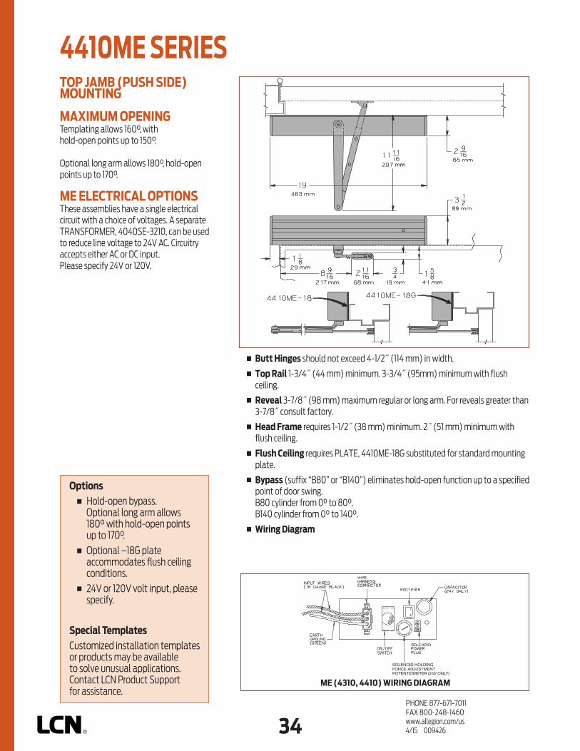
34PHONE 877-671-7011FAX 800-248-1460www.allegion.com/us 4/15 009426
n Butt Hinges should not exceed 4-1/2˝ (114 mm) in width.
n Top Rail 1-3/4˝ (44 mm) minimum. 3-3/4˝ (95mm) minimum with flush ceiling.
n Reveal 3-7/8˝ (98 mm) maximum regular or long arm. For reveals greater than 3-7/8˝ consult factory.
n Head Frame requires 1-1/2˝ (38 mm) minimum. 2˝ (51 mm) minimum with flush ceiling.
n Flush Ceiling requires PLATE, 4410ME-18G substituted for standard mounting plate.
n Bypass (suffix “B80” or “B140”) eliminates hold-open function up to a specified point of door swing. B80 cylinder from 0° to 80°. B140 cylinder from 0° to 140°.
n Wiring Diagram
TOP JAMB (PUSH SIDE) MOUNTING
MAXIMUM OPENINGTemplating allows 160°, with hold-open points up to 150°.
Optional long arm allows 180°, hold-open points up to 170°.
ME ELECTRICAL OPTIONSThese assemblies have a single electrical circuit with a choice of voltages. A separate TRANSFORMER, 4040SE-3210, can be used to reduce line voltage to 24V AC. Circuitry accepts either AC or DC input.Please specify 24V or 120V.
SOLENOID HOLDINGFORCE ADJUSTMENTPOTENTIOMETER (24V ONLY)
ME (4310, 4410) WIRING DIAGRAM
4410ME SERIES
Options n Hold-open bypass.
Optional long arm allows 180° with hold-open points up to 170°.
n Optional –18G plate accommodates flush ceiling conditions.
n 24V or 120V volt input, please specify.
Special Templates Customized installation templates or products may be available to solve unusual applications. Contact LCN Product Support for assistance.

34 35PHONE 877-671-7011FAX 800-248-1460www.allegion.com/us 4/15 009426
3071
CYLINDERME CYLINDER, 4414ME-3971 Standard, handed cast iron cylinder assembly. Please specify 24V or 120V.
ME CYLINDER, 4414ME-3071 Standard, handed cylinder and mounting plate assembly.“On/Off” switch assembly controls hold-open function.Circuitry accepts either AC or DC input.Please specify 24V or 120V.
COVERSCOVER, 4410ME-72MC Handed, metal cover.
ARMSREGULAR ARM, 4410ME-3077Non-handed arm. 3-7/8˝ (98 mm) maximum reveal.
LONG ARM, 4410ME-3077LOptional long ARM for increasing opening to 180°.3-7/8˝ (98 mm) maximum reveal.
72MC
3077L
3077
CHASSIS GROUND
WIRING DIAGRAMINPUT VOLTAGE
24V AC/DCOR 120V AC/DC
(USUALLY FROMALARM PANEL
OR DETECTOR)
3971
4410ME SERIES
ACCE
SSOR
IES

36PHONE 877-671-7011FAX 800-248-1460www.allegion.com/us 4/15 009426
SWITCHSWITCH, 4410ME-3351“On/Off” switch assembly provides continuous hold-open function. Available as 24V or 120V, please specify.
INSTALLATION ACCESSORIESMOUNTING PLATE, 4410ME-18 Standard mounting plate.
MOUNTING PLATE, 4410ME-18G Optional mounting plate substituted for standard plate on flush ceiling installations.
TRANSFORMER, 4410ME - 3210Reduces line voltage from 120V to 24V AC.Mounted on cover for 4˝ (102 mm) x 4˝ x 2-1/8˝ (54 mm) junction box (by others).
ME WIRING HARNESS, 4410ME-3354Three wire harness with 6˝ (152 mm) leads for field wiring connections.
18G
18
3210
3351
CHASSIS GROUND
WIRING DIAGRAMINPUT VOLTAGE
24V AC/DCOR 120V AC/DC
(USUALLY FROMALARM PANEL
OR DETECTOR)
3354
24V 120V
4410ME SERIES
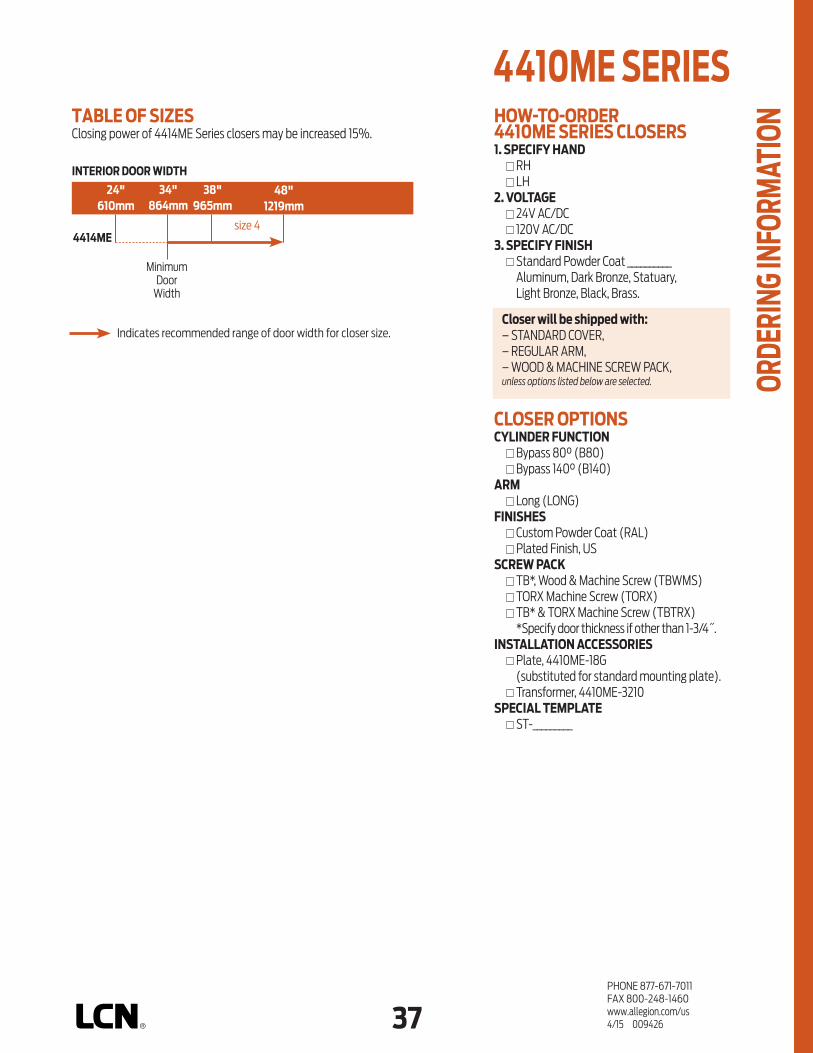
36 37PHONE 877-671-7011FAX 800-248-1460www.allegion.com/us 4/15 009426
HOW-TO-ORDER 4410ME SERIES CLOSERS1. SPECIFY HAND RH LH2. VOLTAGE 24V AC/DC 120V AC/DC3. SPECIFY FINISH Standard Powder Coat __________
Aluminum, Dark Bronze, Statuary, Light Bronze, Black, Brass.
CLOSER OPTIONSCYLINDER FUNCTION Bypass 80° (B80) Bypass 140° (B140)ARM Long (LONG)FINISHES Custom Powder Coat (RAL) Plated Finish, US SCREW PACK TB*, Wood & Machine Screw (TBWMS) TORX Machine Screw (TORX) TB* & TORX Machine Screw (TBTRX)
*Specify door thickness if other than 1-3/4˝.INSTALLATION ACCESSORIES Plate, 4410ME-18G
(substituted for standard mounting plate). Transformer, 4410ME-3210SPECIAL TEMPLATE ST- _________
INTERIOR DOOR WIDTH
24"610mm
34"864mm
38"965mm
48"1219mm
size 44414ME
MinimumDoor
Width
4410ME SERIES
ORDE
RING
INFO
RMAT
IONTABLE OF SIZES
Closing power of 4414ME Series closers may be increased 15%.
Indicates recommended range of door width for closer size.Closer will be shipped with:– STANDARD COVER,– REGULAR ARM,– WOOD & MACHINE SCREW PACK,unless options listed below are selected.

38PHONE 877-671-7011FAX 800-248-1460www.allegion.com/us 4/15 009426
Notes

38 39PHONE 877-671-7011FAX 800-248-1460www.allegion.com/us 4/15 009426
160° 9595°
PLASTIC
METAL
HINGE (P
ULL) SIDE
TOP JAMB (PUSH)
STOP FACE (P
USH)
SWIN
G FREE
DOUBLE EGRESS
CONCEALED (F
RAME)
CONCEALED (D
OOR)
MOUNTING COVER CYLINDER *ARM FUNCTIONFINISH
NON-SIZED
HANDED
SIZEDSINGLE
POINT HOLD
-OPEN
MULTI-POINT H
OLD-OPEN
BYPASS 80/14
0
POWDER COAT
PLATED
REGULA
R (DOUBLE)
STANDARD (S
INGLE)
* Maximum hold-open point with standard template. See individual closer series for degrees of opening and hold-open per installation.
AVAILABLE NOT AVAILABLE
The 4310HSA SENTRONIC® is an
electrically controlled closer/holder
designed to provide easy passage for
groups of pedestrians through high
traffic doors. Pedestrians, moving
through the doorway, trigger the
built-in scanner. When the door is
opened to 80° or more, the door is
electrically held open to minimize
wear and tear on applied door
hardware. After the last pedestrian
in a group passes through the
doorway, the system timer releases
the hold-open, closing the door
under control of the heavy duty
closer. Single lever (track) arm closer
is specifically designed for pull side
mounting. Choice of finishes and
accessories meet virtually all high
traffic installation requirements.
Tested and certified under ANSI Standard
A156.4 and A156.15. Conforms to life
safety code, NFPA 101.
n Standard 4310HSA series closer shipped with a 24V cylinder, standard cover, standard arm, non-handed track and wood & machine screw pack. See 4310HSA Series page 41 for options.
n HSA features a scanner activated hold-open function.
n Hold-open period is adjustable up to 30 seconds.
n Sized cylinders for interior doors to 4´0˝.
n Functions as full rack and pinion door closer when current is interrupted or continuous hold-open is not engaged.
n Handed for right or left swinging door.
n Concealed or surface wiring. 24V AC/DC input only. 120V AC input requires 4310HSA-3210 transformer.
n Built-in “On/Off” switch provides continuous hold-open function.
n Standard or optional custom powder coated finish.
n Optional plated finish on cover, arm and fasteners. (Available with powder coat finishes only).
HINGE (PULL) SIDE MOUNTING
4310 HSA SERIES
FEAT
URES

40PHONE 877-671-7011FAX 800-248-1460www.allegion.com/us 4/15 009426
HINGE (PULL) SIDE MOUNTING
MAXIMUM OPENINGTemplating allows 180°.Optional double egress arm limited to 95°.Infinite hold-open points from 80° up to 160°.
n Butt Hinges should not exceed 4-1/2˝ (114 mm) in width.
n Top Rail 1-1/16˝ (27 mm) minimum.
n Reveal should not exceed 1/8˝ (3 mm) for standard arm. Should not exceed 2-11/16˝ (68 mm) for double egress arm.
n Head Frame requires 2˝ (51 mm) minimum.
n Clearance 1-1/4˝ (32 mm) minimum.
n Wiring Diagram
4310 HSA SERIES M
OUNT
ING
DETA
ILS
CONNECT GREEN WIRETO EARTH GROUND
CONNECT BLACKWIRES TO INPUTVOLTAGE LEADS
(POLARITY NOTIMPORTANT)
HSA WIRING DIAGRAMOptions n Double egress arm. n 120 volt input requires
4310HSA-3210 transformer to change 120V AC to 24V AC.
Special Templates Customized installation templates or products may be available to solve unusual applications. Contact LCN Product Support for assistance.
4310HSA

40 41PHONE 877-671-7011FAX 800-248-1460www.allegion.com/us 4/15 009426
3071
3077DE
CYLINDERHSA CYLINDER, 4311HSA-3971 Standard, handed cast iron cylinder assembly. 24V AC/DC input only for holding solenoid.
HSA CYLINDER, 4311HSA-3071 Standard, handed cylinder and mounting plate assembly.Includes scanner module and system timer module.“On/Off” switch assembly provides continuous hold-open function.24V AC/DC input only for holding solenoid and electronics modules.
COVERSMETAL COVER, 4310HSA-72MC Handed , metal cover.
ARMSTANDARD ARM, 4310HSA--3077T Handed arm.
DOUBLE EGRESS ARM, 4310HSA--3077DE Optional, handed arm for double egress doors and frames.2 11/16” (67 mm) maximum reveal.
TRACKTRACK, 4310HSA-3038Standard, non-handed track.
SWITCHSWITCH, 4310HSA-3448“On/Off” switch assembly provides continuous hold-open function.
SCANNERSCANNER MODULE, 4310HSA-3428
INSTALLATION ACCESSORIESTRACK ROLLER, 4310HSA-3034 Quiet, low friction roller assembly.Shoulder dimension “X” = 1/8” (3 mm).
TRANSFORMER, 4310HSA-3210 Reduces line voltage from 120V to 24V AC.Mounted on plate for 4˝ (102 mm) x 4˝ x 2-1/8˝ (54 mm) junction box (by others).
3077TCHASSIS GROUND
WIRING DIAGRAMINPUT VOLTAGE
24V AC/DCOR 120V AC/DC
(USUALLY FROMALARM PANEL
OR DETECTOR)
3428
CHASSIS GROUND
WIRING DIAGRAMINPUT VOLTAGE
24V AC/DCOR 120V AC/DC
(USUALLY FROMALARM PANEL
OR DETECTOR)
3971
3034
3038
4310 HSA SERIES
ACCE
SSOR
IES
3210
72MC
3448
3351
3448

42PHONE 877-671-7011FAX 800-248-1460www.allegion.com/us 4/15 009426
TABLE OF SIZESClosing power of 4310HSA Series closers may be increased 15%.
HOW-TO-ORDER 4310 HSA SERIES CLOSERS1. SPECIFY HAND RH LH2. VOLTAGE 24V AC/DC3. SPECIFY FINISH Standard Powder Coat __________
Aluminum, Dark Bronze, Tan, Statuary, Light Bronze, Black, Brass.
CLOSER OPTIONSARM Double Egress (DE)FINISH Custom Powder Coat (RAL) ___________ Plated Finish, US ___________ SCREW PACK TB*, Wood & Machine Screw (TBWMS) TORX Machine Screw (TORX) TB* & TORX Machine Screw (TBTRX)
* Specify door thickness if other than 1-3/4˝.INSTALLATION ACCESSORIES Transformer, 4310HSA-3210SPECIAL TEMPLATE ST-_________ (if required)
4310 HSA SERIES OR
DERI
NG IN
FORM
ATIO
N
Closer will be shipped with:– 24 AC/DC HSA CYLINDERS,– METAL COVER,– STANDARD ARM,– STANDARD TRACK,– TRACK ROLLER,– WOOD & MACHINE SCREW PACK,unless options listed below are selected.
4310HSA
MinimumDoor Width
INTERIOR DOOR WIDTH
26"660mm
34"864mm
38"965mm
48"1219mm
Indicates recommended range of door width for closer size.

42 43PHONE 877-671-7011FAX 800-248-1460www.allegion.com/us 4/15 009426
150°
PLASTIC
METAL
HINGE (P
ULL) SIDE
TOP JAMB (PUSH)
STOP FACE (P
USH)
SWIN
G FREE
DOUBLE EGRESS
CONCEALED (F
RAME)
CONCEALED (D
OOR)
MOUNTING COVER CYLINDER *ARM FUNCTIONFINISH
NON-SIZED
HANDED
SIZEDSINGLE
POINT HOLD
-OPEN
MULTI-POINT H
OLD-OPEN
BYPASS 80/14
0
POWDER COAT
PLATED
REGULA
R (DOUBLE)
STANDARD (S
INGLE)
The 4410HSA SENTRONIC® is an
electrically controlled closer/holder
designed to provide easy passage for
groups of pedestrians through high
traffic doors. Pedestrians, moving
through the doorway, trigger the
built-in scanner. When the door is
opened to 80° or more, the door is
electrically held open to minimize
wear and tear on applied door
hardware. After the last pedestrian
in a group passes through the
doorway, the system timer releases
the hold-open, closing the door
under control of the heavy duty
closer. Double lever arm closer is
specifically designed for push side
mounting. Choice of finishes and
accessories meet virtually all high
traffic installation requirements.
Tested and certified under ANSI Standard A156.4
and A156.15. Conforms to life safety code, NFPA 101.
n Standard 4410HSA Series closer shipped with a 24V cylinder, standard cover, regular arm and wood & machine screw pack. See 4410HSA Series page 45 for options.
n HSA features a scanner activated hold-open function.
n Hold-open period is adjustable up to 30 seconds.
n Sized cylinders for interior doors to 4´6˝.
n Functions as full rack and pinion door closer when current is interrupted or continuous hold-open is not engaged.
n Handed for right or left swinging door.
n Concealed or surface wiring. 24V AC/DC input only. 120V AC input requires 4410HSA-3210 transformer or 8310-824.
n Built-in "On/Off" switch provides continuous hold-open function.
n Standard or optional custom powder coated finish.
n Optional plated finish on cover, arm and fasteners.
TOP JAMB (PUSH SIDE) MOUNTING
4410 HSA SERIES
* Maximum hold-open point with standard template. See individual closer series for degrees of opening and hold-open per installation.
AVAILABLE NOT AVAILABLE
FEAT
URES

44PHONE 877-671-7011FAX 800-248-1460www.allegion.com/us 4/15 009426
TOP JAMB (PUSH) SIDE MOUNTING
MAXIMUM OPENINGTemplating allows 160°.Infinite hold-open points from 80° up to 150°.Optional long arm allows 180°, hold-open points up to 170°.
n Butt Hinges should not exceed 4-1/2˝ (114 mm) in width.
n Top Rail 1-3/4˝ (44 mm) minimum. 3-3/4˝ (95 mm) minimum with flush ceiling.
n Head Frame requires 1-1/2˝ (38mm) minimum. 2˝ (51 mm) minimum with flush ceiling.
n Reveal 3-7/8” (98 mm) maximum for regular or long arm. For reveals greater than 3-7/8” consult factory.
n Wiring Diagram
4410 HSA SERIES M
OUNT
ING
DETA
ILS
CONNECT GREEN WIRETO EARTH GROUND
CONNECT BLACKWIRES TO INPUTVOLTAGE LEADS
(POLARITY NOTIMPORTANT)
HSA WIRING DIAGRAM
Options n Optional long arm allows
180° with hold-open points up to 170°.
n Optional –18G plate accommodates flush ceiling conditions.
n 120 volt input requires 4410HSA–3210 transformer to change 120V AC to 24V AC.
Special Templates Customized installation templates or products may be available to solve unusual applications. Contact LCN Product Support for assistance.
4410 HSA

44 45PHONE 877-671-7011FAX 800-248-1460www.allegion.com/us 4/15 009426
3071
3077
CYLINDERHSA CYLINDER, 4312HSA-3971 Standard, handed cast iron cylinder assembly. 24V AC/DC input only for holding solenoid.
HSA CYLINDER, 4312HSA-3071 Standard, handed cylinder and mounting plate assembly.Includes scanner module and system timer module.“On/Off” switch assembly provides continuous hold-open function.24V AC/DC input only for holding solenoid and electronics modules.
COVERSMETAL COVER, 4410HSA-72MC Handed, metal cover.
ARMREGULAR ARM, 4410HSA-3077Non-Handed Arm.3-7/8˝ (98 mm) maximum reveal.
LONG ARM, 4410HSA-3077L Optional arm for increased opening.3-7/8˝ (98 mm) maximum reveal.
SWITCHSWITCH, 4410HSA-3448“On/Off” switch assembly provides continuous hold-open function.
SCANNERSCANNER MODULE, 4410HSA-3428
INSTALLATION ACCESSORIESMOUNTING PLATE, 4410HSA-18 Standard mounting plate.
MOUNTING PLATE, 4410HSA-18G Optional mounting plate substituted on flush ceiling installations.
TRANSFORMER, 4410HSA-3210 Reduces line voltage from 120V to 24V AC.Mounted on plate for 4˝ (102 mm) x 4˝ x 2-1/8˝ (54 mm) junction box (by others).
72MC
CHASSIS GROUND
WIRING DIAGRAMINPUT VOLTAGE
24V AC/DCOR 120V AC/DC
(USUALLY FROMALARM PANEL
OR DETECTOR)
3428
CHASSIS GROUND
WIRING DIAGRAMINPUT VOLTAGE
24V AC/DCOR 120V AC/DC
(USUALLY FROMALARM PANEL
OR DETECTOR)
3971
18
3077L
4410 HSA SERIES
ACCE
SSOR
IES
3210
18G
3448
3351
3448

46PHONE 877-671-7011FAX 800-248-1460www.allegion.com/us 4/15 009426
TABLE OF SIZESClosing power of 4410HSA Series closers may be increased 15%.
HOW-TO-ORDER 4410 HSA SERIES CLOSERS1. SPECIFY HAND RH LH2. VOLTAGE 24V AC/DC3. SPECIFY FINISH Standard Powder Coat __________
Aluminum, Dark Bronze, Tan, Statuary, Light Bronze, Black, Brass.
CLOSER OPTIONSARM Long Arm (LONG)FINISH Custom Powder Coat (RAL) ___________ Plated Finish, US ___________ SCREW PACK TB*, Wood & Machine Screw (TBWMS) TORX Machine Screw (TORX) TB* & TORX Machine Screw (TBTRX)
* Specify door thickness if other than 1-3/4˝.INSTALLATION ACCESSORIES Plate, 4410HSA-18 Plate, 4410HSA-18G
(substituted for standard mounting plate) Transformer,4410HSA-3210SPECIAL TEMPLATE ST-_________ (if required)
4410 HSA SERIES OR
DERI
NG IN
FORM
ATIO
N
Closer will be shipped with:– 24 AC/DC HSA CYLINDERS,– METAL COVER,– REGULAR ARM,– WOOD & MACHINE SCREW PACK,unless options listed below are selected.
INTERIOR DOOR WIDTH
24"610mm
34"864mm
38"965mm
48"1219mm
4410HSA
MinimumDoor
Width
Indicates recommended range of door width for closer size.

46 47PHONE 877-671-7011FAX 800-248-1460www.allegion.com/us 4/15 009426
n Standard SEH Series is a door holder that must be installed in conjunction with an opposite side mounted, UL listed door closer.
n Standard SEH series holder shipped with a standard arm, 24V or 120V (please specify) SEH track and wood and machine screw pack.
n Hold-open force is adjustable.
n Momentary on/off switch board assembly for testing door release also provides over-voltage protection. Field replaceable.
n Non-handed for mounting on either right or left hand door.
n Concealed or surface wiring.
n Interfaces with alarm systems. Consult factory for full details.
n Standard or optional custom powder coated finishes on track and arm.
The SEH SENTRONIC® is a holder
designed to provide single point
hold-open for fire and smoke
barrier doors that must be used
with an opposite side mounted UL
listed door closer. The door is held
open until current interruption
releases the holding mechanism
and the door closes. Single
lever (track) arm is specifically
designed for interior doors. Choice
of finishes, track functions,
and installation accessories
meet virtually all life safety
requirements.
The SEH Series is UL listed for
smoke barrier or labeled fire doors.
cUL listed for self-closing doors
without hold-open. Tested and certified under
ANSI Standard A156.15. Conforms to life safety
code, NFPA 101.
100
PLASTIC
METAL
HINGE (P
ULL) SIDE
TOP JAMB (PUSH)
STOP FACE (P
USH)
SWIN
G FREE
DOUBLE EGRESS
CONCEALED (F
RAME)
CONCEALED (D
OOR)
MOUNTING COVER **CYLINDER *ARM FUNCTIONFINISH
NON-SIZED
HANDED
SIZEDSINGLE
POINT HOLD
-OPEN
MULTI-POINT H
OLD-OPEN
BYPASS 80 /
140
POWDER COAT
PLATED
REGULA
R (DOUBLE)
STANDARD (S
INGLE)
HINGE (PULL) SIDE MOUNTING
SEH SERIES
FEAT
URES
* Maximum hold-open with standard template. See individual closer series for degrees of opening and hold-open per installation.
** Cylinder sold separately.
AVAILABLE NOT AVAILABLE

48PHONE 877-671-7011FAX 800-248-1460www.allegion.com/us 4/15 009426
HINGE (PULL) SIDE MOUNT
STOP FACE (PUSH SIDE) MOUNT
HINGE (PULL) SIDE & STOP FACE (PUSH SIDE) MOUNTINGSInformation applies to SEH unless otherwise specified.
MAXIMUM OPENINGTemplating allows 100°.Hold-open points between 80° and 100° in approximately 3° increments.
SEH ELECTRICAL OPTIONSThese track assemblies require a single power circuit for the holding solenoid.SEH holding solenoid is either 24V or 120V input, please specify.An optional 4040SE-3210 TRANSFORMER or 8310-824 reduces 120V AC line voltage to 24V AC. Circuitry accepts either AC or DC input.
n Butt Hinges should not exceed 5˝ (127 mm) in width.
n Swing Clear Hinges consult factory.
n Auxiliary Stop is recommended at hold-open point.
n Reveal should not exceed 1/8˝ (3 mm) for standard arm.
n Head Frame requires 2˝ (51 mm) minimum.
n Stop Width 1-1/4˝ (32 mm) minimum.
n Flush Ceiling with 2˝ (51 mm) head frame does not require special templating.
n Door Width 2´4˝ (711 mm) minimum for single door with SEH. 4´8˝ (1422 mm) minimum for paired doors with SEH.
n Wiring Diagram See “FIRE/LIFE SAFETY” section page 19 for typical wiring and electrical diagram.
Options n 24V or 120V volt input for SEH,
please specify.
Special Templates Customized installation templates or products may be available to solve unusual applications. Contact LCN Product Support for assistance.
SEH SERIES M
OUNT
ING
DETA
ILS

48 49PHONE 877-671-7011FAX 800-248-1460www.allegion.com/us 4/15 009426
ARMSHOLDER ARM, SEH-3077TNon-handed arm can be combined with any 4040SE Series track to provide an electrically controlled hold-open function on either side of the door. All SEH type holders require a separate closer for fire or smoke barrier door applications.
TRACKSSE TRACK, SEH-3038Standard, non-handed track for SEH. Mounts on either head frame or stop. 24V or 120V AC/DC input for holding solenoid, please specify. Includes test switch assembly with fuse.
SWITCHTEST SWITCH, SEH-3436
INSTALLATION ACCESSORIESCONDUIT QUICK-CONNECTOR, SEH-81Two piece connector for use with 1/2˝ conduit.
TRACK ROLLER, SEH-3034Quiet, low friction roller assembly.Shoulder dimension “X” = 1/4˝ (6 mm).
TRACK SLIDER, SEH-168Alloy metal slider for use in SE series tracks only.
TRANSFORMER, 4040SE-3210Reduces line voltage from 120V to 24V AC.Mounted on cover for 4˝ (102 mm) x 4˝ x 2-1/8˝ (54 mm) junction box (by others).
3034
168
81
3210
CHASSIS GROUND
WIRING DIAGRAMINPUT VOLTAGE
24V AC/DCOR 120V AC/DC
(USUALLY FROMALARM PANEL
OR DETECTOR)
3436
3077T
3038
SEH SERIES
ACCE
SSOR
IES

50PHONE 877-671-7011FAX 800-248-1460www.allegion.com/us 4/15 009426
SEH SERIES OR
DERI
NG IN
FORM
ATIO
N HOW-TO-ORDER SEH SERIES 1. VOLTAGE 24V AC/DC 120V AC/DC2. SPECIFY FINISH Standard Powder Coat __________
Aluminum, Dark Bronze, Statuary, Light Bronze, Black, Brass.
CLOSER OPTIONSFINISHES Custom Powder Coat (RAL)
(handed metal cover required)SCREW PACK TB*, Wood & Machine Screw (TBWMS) TORX Machine Screw (TORX) TB* & TORX Machine Screw (TBTRX)
* Specify door thickness if other than 1-3/4˝.INSTALLATION ACCESSORIES Transformer, 4040SE-3210SPECIAL TEMPLATE ST- ________ (if required)
Closer will be shipped with:– STANDARD ARM,– STANDARD TRACK,– WOOD & MACHINE SCREW PACK,unless options listed below are selected.

1PHONE 877-671-7011FAX 800-248-1460www.allegion.com/us 4/15 009426
PLASTIC
METAL
COVER CYLINDER
180
180
180
140
110
110
180
EDA
STANDARD (S
INGLE)
CUSH/HCUSH
**ARM FUNCTIONFINISH
HANDED
NON-SIZED
SIZEDACCESSIB
ILITY
DELAYED ACTIO
N
2210
CLOSERSERIES
2210DPS
4210
4210T
4510
4510T
HINGE (P
ULL) S
IDE
PARALLEL A
RM (PUSH)
STOP FACE
CONCEALED (F
RAME)MOUNTING
POWDER COAT
PLATED
AVB***
DPS SWITCH
HIGH SECURITY CLOSERS SERIES
PRODUCT COMPARISONThis chart shows a basic comparison of LCN High Security closers.Refer to the specific closer chapter for complete details.
* Door position switch.
PRODUCT SELECTION GUIDEHigh Security LCN closers feature a vandal resistant design engineered for each application, easy installation, and superior performance. This guide is based on the desired mounting of the closer.
SINGLE LEVER ARM
2210 2210 DPS*
EXTERIOR DOOR
CONCEALED IN FRAME
PARALLEL ARM
4210
PUSH SIDEMOUNTED
DOUBLE LEVER ARM
4510
PULL SIDEMOUNTED
PARALLEL ARM
4210
PUSH SIDEMOUNTED
SINGLE LEVER ARM
4210T
DOUBLE LEVER ARM
4510
PULL SIDEMOUNTED
SINGLE LEVER ARM
4510T
SINGLE LEVER ARM
2210 2210 DPS*
INTERIOR DOOR
CONCEALED IN FRAME
Closeravailablewithlessthan5.0lbs.openingforceon36˝door. ** Maximumopeningwithstandardtemplate.Seeindividualcloserseriesfordegreesof
opening per installation. *** AdvancedVariableBackcheck.
AVAILABLE NOT AVAILABLE

PHONE 877-671-7011FAX 800-248-1460www.allegion.com/us 4/15 0094262
APPLICATIONSn For any concealed or surface mounted installation subject to
potential abuse or vandalism.n For correctional, aluminum, hollow metal, or wood doors and frames.n Can be used with hinge or pivot mounted door.n Adapter plates and other installation accessories available for
unusual conditions.
FEATURES COMMON TO HIGH SECURITY CLOSERSn Each closer is a vandal resistant design for a specific mounting;
hinge side, parallel arm, stop face, or concealed.n All high security closers are based on a cylinder certified to exceed
10,000,000 cycles in independent testing.n Handed for right or left swinging doors.n Closers to meet ADA reduced opening force requirements. n All closers furnished with TORX tamper resistant machine screws.n All surface mount closers include a heavy gauge steel cover with
four attachment points. n All closer adjustments are protected when installation is complete.n All track closers use a jam resistant track and tamper resistant
arm/roller assembly. n Adjustable hydraulic backcheck cushions opening swing prior to 90°. n Advanced variable backcheck (AVB) is available on all high
security closers.n Separate regulation of general closing speed and latching speed.
DESIGN ASSISTANCELCN has been providing reliable solutions to unique door control problems for over 85 years. Design and specification assistance are only a phone call away.
Contact LCN for assistance or technical information at 877-671-7011 or FAX 800-248-1460 (order entry), FAX 815-879-1495 for Technical Support.
WARRANTYHigh Security Series closers carry a 15 year limited warranty, except for the 2210DPS Series closer that carries a 2 year limited warranty. See General Information Section for complete warranty details.
MATERIALSn High strength cast iron cylinder. n Forged steel main arms and forearms. n One piece forged steel piston. n All weather fluid eliminates seasonal adjustments.n High efficiency, full compliment, low friction bearings. n Double heat treated pinions. n Tamper resistant regulating screws. n Full rack and pinion hydraulic action.n Quiet, low friction track and roller combination for all single lever
arm closers.
FINISHES n Available in six standard or a wide selection of optional custom
powder coat finishes to blend with door and frame.n LCN’s powder coat finishes surpass 100 hours of salt spray which
is over four times the ANSI standard for corrosion resistance.
n For installations where a higher level of corrosive resistance is required, LCN offers an optional special rust inhibiting (SRI) pre-treatment. Closers that combine the exclusive LCN powder coat finish and the SRI pre-treatment exceed the ANSI standard for corrosion resistance even further.
n Plated finishes are available as an option to accent door and frame.
LISTINGS & APPROVALSUL listed for self-closing doors without hold-open under ”SWINGING DOOR CLOSERS“(GVEV) file R 1943.Tested and certified under ANSI Standard A 156.4. Consult factory for details.Consult factory for other listings such as; ULC, California State Fire Marshal, Bureau of Standards and Appeals.
POSITIVE PRESSURE LCN closers have been certified for three hours by UL to be in compliance with UBC 7.2 (1997) and UL 10 C. Contact LCN for specific details on door closer fire ratings.
FASTENERSTORX MACHINE SCREW (TORX) pack contains tamper resistant machine screws to install the closer. Thru Bolts for TORX machine screws are available for all high security closers, except 2210 series. LCN thru bolts (TB) can be installed on 1-3/4˝ thick doors with the 1/4-20 TORX screws supplied with the closer. Optional sizes are available for 1-5/8˝ or 1-3/8˝ door thicknesses, but this must be specified when ordering.
Note1:ForThruBolts,specifydoorthicknessifotherthan1-3/4˝(44mm).
Special driver bits are required for installation or removal of TORX machine screws with a security pin as supplied with LCN High Security closers. All bits fit a 1/4˝ hex drive socket. For 1/4-20 screws use T-27, for #12 machine screws use T-25, for 10# machine screws use T20, for #8 (and undercut #10) machine screws use T15, and for #6 machine screws use T10. The specific bits required for installation are listed on the "HOW TO ORDER" page for each closer. Sold separately.
MAINTENANCEClosers mounted according to LCN installation instructions require no periodic maintenance or adjustments.
SPECIFICATIONSRefer to ”SPECIFICATIONS” section for suggested architectural specifications.
Drill 25/64˝ forsteel doorsorDrill 3/8˝for wood doors
HIGH SECURITY CLOSERS SERIES

PHONE 877-671-7011FAX 800-248-1460www.allegion.com/us 4/15 0094262 3
n Standard 2210 Series closer shipped with standard arm, security track (non hold-open), two piece metal cover plate, and TORX machine screw pack. For options see 2210 Series page 5.
n Sized cylinders for interior doors to 4´6˝ and exterior doors to 3´6˝.
n Concealed cylinder mounts in head frame, specify right or left swinging door.
n Optional Door Position Switch (DPS). Limited two year warranty.
n Standard or optional custom powder coat finish.
n Optional SRI primer for installations in corrosive conditions (excludes DPS option). (Available with powder coat finishes only).
n The 2210 Series is UL and cUL listed for self-closing doors, grade one.
n Tested and certified under ANSI A156.4.
The concealed 2210 Series, heavy
duty, high security track closer
features complete concealment
with special components to
minimize tampering and vandalism.
Forged steel, single lever arm
and heavy steel mounting plate
are designed for correctional,
vandal prone, institutional, and
other high traffic applications.
A choice of finishes and cylinder
functions meet correctional and
vandal resistant requirements.
PLASTIC
METAL
COVER CYLINDER
180
EDA
STANDARD (S
INGLE)
CUSH/HCUSH
*ARM FUNCTIONFINISH
HANDED
NON-SIZED
SIZEDACCESSIB
ILITY
DELAYED ACTIO
N
HINGE (PULL)
SIDE
PARALLEL A
RM (PUSH)
STOP FACE
CONCEALED (F
RAME)MOUNTING
POWDER COAT
PLATED
AVB**
DPS SWITCH
CONCEALED IN FRAME MOUNTING
DoorPositionSwitch(DPS)shown
2210 SERIES
FEAT
URES
* Maximumopeningwithstandardtemplate. ** AdvancedVariableBackcheck.
AVAILABLE NOT AVAILABLE

PHONE 877-671-7011FAX 800-248-1460www.allegion.com/us 4/15 0094264
CONCEALED MOUNTINGFor interior or exterior doors.Single acting cylinder in head frame.Concealed arm and track in top rail of door.
MAXIMUM OPENINGTemplating allows 180°.
Consult factory if door will be held open at 180°.
Pivot mounting door limits opening to 110° and increases minimum door width to 32”(813 mm). Consult factory.
Please note that many track style door closers are capable of allowing 180° of door swing.
Note:Trackstyleclosersareattheirweakestclosingforceat180°.Consultfactoryforapplicationswheredoormustswing180°.
Butt Hinges should not exceed 4-1/2˝ (114 mm) in width.
Auxiliary Stop is recommended where a door cannot swing 180°.
Top Rail 1-1/4˝ (32 mm) mortise required. 3/8˝ (10 mm) cutout required at top of door, stop face only.
Door Thickness 1-3/4˝ (44 mm) minimum.
Door Width 28˝ (711 mm) minimum.
Head Frame 5-3/4˝ (146 mm) wide and 4˝ (102 mm) high with 2-3/16˝ (56 mm) rabbet required. Consult factory if any dimension is less.
Steel Mounting Plate thickness 3/8˝ (10 mm).
Door Position Switch Optional, newly redesigned, field adjustable switch can interface with security and monitoring systems. Add suffix “DPS” to selected cylinder. Finish plates must be removed for access to adjustments. Provides normally open (N.O.) and normally closed (N.C.) circuit. A three wire connector harness with 84˝ (2134 mm), 16 AWG leads is furnished to simplify connection to field wiring. Single pole double throw (SPDT) contacts rated at 125/250 VAC at 10.1 amps maximum resistive load are standard.
Advanced Variable Backcheck cylinder starts backcheck at approximately 45° instead of the normal 75°. Add suffix “AVB” to selected cylinder (eg. 2213 DPS AVB).
2210 SERIES M
OUNT
ING
DETA
ILS
Options n Advanced Variable Backcheck
Cylinder. n Door Position Switch. n Test kit.
Special TemplatesCustomized installation templates or products may be available to solve unusual applications. Contact LCN Product Support for assistance.

PHONE 877-671-7011FAX 800-248-1460www.allegion.com/us 4/15 0094264 5
CYLINDERSCYLINDER, 2210-3071 Standard, handed cast iron cylinder assembly. For various applications see “Table of Sizes” on 2210 Series page 6.
ARMSTANDARD SECURITY ARM, 2210-3077THanded arm features solid forged steel and large cross section for potentially abusive installations.Special threaded attachment of track roller for extra security.Double slab arm/pinion attachment for maximum strength.Can only be used with high security track roller, 2210-3034.Roller is included with arm when 2210-3077T ordered separately.
TRACKSECURITY TRACK, 2210-3038 Non-handed, high security track.Hold-open function not available.Designed to eject foreign objects placed in track during either opening or closing motion.Requires track roller, 2210-3034.
SECURITY TRACK ROLLER, 2210-3034 Low friction track roller threads into 2210-3077T arm for extra strength and security. Can not be removed without disconnecting arm from closer.
FINISH PLATESLONG PLATE, 2210-11 Heavy gauge metal finish plate.Plate 2210-12 also required for complete enclosure.Six point TORX® mounting screws for extra security.Closer adjustments not accessible with finish plates installed.
SHORT PLATE, 2210-12 Heavy gauge metal finish plate.Plate 2210-11 also required for complete enclosure.Four point TORX® mounting screws for extra security.Closer adjustments not accessible with finish plates installed.
INSTALLATION ACCESSORIESTEST KIT, 2210-493Battery operated test kit designed to verify switch signal response point. Test kit can be used directly at door location.(used for 2210 DPS only)
3077T
2210dps-3071
3071
3038
3034
1112
493
2210 SERIES
ACCE
SSOR
IES

PHONE 877-671-7011FAX 800-248-1460www.allegion.com/us 4/15 0094266
size 3 size 4 size 5
TABLE OF SIZESSelect closer based on width of door.2210 Series cylinders available in size 3, 4, or 5. Spring power is set at the factory for size 3, 4, or 5, but is field adjustable (may be increased 50%).
2214(DPS)
2213(DPS)
EXTERIOR (and VESTIBULE) DOOR
28"711mm
30"762mm
36"914mm
42"1067mm
2215(DPS)
size 3 size 4 size 52213(DPS)
INTERIOR DOOR WIDTH
28"711mm
34"864mm
38"965mm
48"1219mm
2214(DPS)
54"1372mm
2215(DPS)
HOW-TO-ORDER 2210 SERIES CLOSERS1. SELECT CYLINDER SIZE 2213 2213 DPS 2214 2214 DPS 2215 2215 DPS
2. SPECIFY HAND RH LH
3. SPECIFY FINISH Standard Powder Coat __________
Aluminum, Dark Bronze, Statuary, Light Bronze, Black, Brass.
CLOSER OPTIONSCYLINDER Advanced Variable Backcheck (AVB)
FINISH Custom Powder Coat (RAL) ___________ Plated Finish, US ___________ SRI primer (excludes DPS) (use with powder
coat finishes only)
SPECIAL TEMPLATE ST- _________
NOTE:InstallationofthiscloserrequiresT-27,T-25andT-15driverbitsforTORXmachinescrewswithasecuritypin.Soldseparately.
MinimumDoor
Width
MinimumDoor
Width
2210 SERIES OR
DERI
NG IN
FORM
ATIO
N
Indicates recommended range of door width for closer size.
Note:Minimumdoorwidth28˝(711mm).
Closer will be shipped with:– TWO PIECE FINISH PLATE,– STANDARD SECURITY ARM,– SECURITY TRACK ROLLER,– SECURITY TRACK,– TORX MACHINE SCREW PACK,unlessoptionslistedbelowareselected.

PHONE 877-671-7011FAX 800-248-1460www.allegion.com/us 4/15 0094266 7
n Standard 4210 series closer shipped with EXTRA DUTY arm (non hold-open), metal security cover, and TORX Machine Screw pack. For options, see 4210 Series page 9.
n Sized cylinders for interior doors to 5´0˝ and exterior doors to 4´0˝.
n Non-sized cylinder adjustable for interior doors to 4´6˝ and exterior doors to 3´6˝.
n Closer mounts parallel arm, specify right or left swinging door.
n 4211 cylinder meets ADA requirements. See 4210 Series page 10.
n Standard or optional custom powder coat finish.
n Optional SRI primer for installations in corrosive conditions. (Available with powder coat finishes only).
n The 4210 Series is UL listed with EDA or CUSH arms for self-closing doors.
n Tested and certified under ANSI Standard A156.4, grade one.
The 4210 SMOOTHEE® Series
is a heavy duty, high security
closer with special components
to minimize tampering and
vandalism. Forged steel parallel
arms and heavy gauge metal
security covers are designed
for correctional, vandal prone,
institutional and other high
traffic applications. The closer
has passed 10 million cycles in
independent testing. A choice of
finishes and cylinder functions
meet correctional and vandal
resistant requirements.
PLA
STIC
METAL
COVER CYLINDER
110180
EDA
STANDARD (S
INGLE)
CUSH/HCUSH
*ARM FUNCTIONFINISH
HANDED
NON-SIZED
SIZEDACCESSIB
ILITY
DELAYED ACTIO
N
HINGE (PULL)
SIDE
PARALLEL A
RM (PUSH)
STOP FACE
CONCEALED (F
RAME)
MOUNTING
POWDER COAT
PLATED
AVB**
DPS SWITCH
PARALLEL ARM (PUSH SIDE) MOUNT
4210 SERIES
FEAT
URES
Closeravailablewithlessthan5.0lbs.openingforceon36˝door. * Maximumopeningwithstandardtemplate.Seeindividualcloserseriesfordegreesof
opening per installation. ** AdvancedVariableBackcheck.
AVAILABLE NOT AVAILABLE
The4211SeriesincludestheLCN® "Green Dial"
Spring Force Indicator

PHONE 877-671-7011FAX 800-248-1460www.allegion.com/us 4/15 0094268
n Butt Hinges should not exceed 5˝ (127 mm) in width.
n Auxiliary Stop is recommended where the door cannot swing 180° or where CUSH arms not used.
n Clearance for EDA or CUSH is 5-1/2˝ (140 mm) from push side of door.
n Top Rail less than 5-1/8˝ (130 mm) measured from stop, requires PLATE 4210-18. Plate requires 2˝ (51 mm) minimum top rail.
n Stop Width 2-3/4˝ (70 mm) recommended. Less than 1˝ (25mm), consult factory.
n Delay Action Add suffix “DEL” to selected cylinder (eg. 4211DEL). Not available with 4215 or 4216 cylinder. Delays closing from maximum opening to approximately 70°. Delays time adjustable up to approximately 1 minute.
n Advanced Variable Backcheck cylinder starts backcheck at approximately 45° instead of the normal 75°. Add suffix “AVB” to selected cylinder (eg. 4211 AVB).
PARALLEL ARM (PUSH SIDE) MOUNTING
MAXIMUM OPENINGEDA arm can be templated for 100°,
A = 5-15/16˝ (151 mm) B = 7-1/4˝ (184 mm)
140°,A = 4-7/16˝ (113 mm) B = 5-3/4˝ (146 mm)
or 180°. A = 2-15/16˝ (75 mm) B = 4-1/4˝ (108 mm)
CUSH arm can be templated for maximum opening at85°,
A = 8-5/16˝ (211 mm) B = 9-5/8˝ (244 mm)
90°,A = 7-11/16˝ (195 mm) B = 9˝ (229 mm)
100°, A = 6-7/16˝ (164 mm) B = 7-3/4˝ (197 mm)
or 110°. A = 5-9/16˝ (141 mm) B = 6-7/8˝ (175 mm)
Hold-open point at maximum opening with H-CUSH arm.
4210 SERIES M
OUNT
ING
DETA
ILS
Options n Sized or non-sized cylinder. n Delayed Action or Advanced
Variable Backcheck cylinder. n CUSH or H-CUSH arm.
Special Templates Customized installation templates or products may be available to solve unusual applications. Contact LCN Product Support for assistance.

PHONE 877-671-7011FAX 800-248-1460www.allegion.com/us 4/15 0094268 9
CYLINDERSCYLINDER, 4210-3071 Standard, handed cast iron cylinder assembly.For various applications see “Table of Sizes” on 4210 Series page 10.
COVERSECURITY COVER, 4210-72MC Standard, handed heavy gauge metal security cover.Four point mounting for extra security. Closer adjustments not accessible with cover installed.
ARMSEXTRA DUTY ARM, 4210-3077EDA Non-handed parallel arm features solid forged steel main arm and forearm for potentially abusive installations.Double slab arm/pinion attachment for maximum strength.
CUSH-N-STOP® (CUSH) ARM, 4210-3077CNSNon-handed parallel arm features solid forged steel main arm and forearm with built-in stop in soffit shoe.Double slab arm/pinion attachment for maximum strength.
HCUSH ARM, 4210-3049CNS Non-handed arm provides hold-open function with templated stop/hold-open points.Handle controls hold-open function.HCUSH arm not available with 4216 cylinder.Double slab arm/pinion attachment for maximum strength.
INSTALLATION ACCESSORIESPLATE, 4210-18, 4210-18CUSHRequired for push side mount where top rail is less than 5-1/8˝ (130 mm), measured from the stop. Plate requires 2” (51 mm) minimum top rail measured from the stop. Plate also used with Cush arm installations.
CUSH SHOE SUPPORT, 4210-30Provide anchorage for fifth screw used with CUSH arms where reveal is less than 3-1/16˝ (78mm).
BLADE STOP SPACER, 4210-61Lowers parallel arm shoe to clear 1/2˝ (13 mm) blade stop.
PA FLUSH PANEL ADAPTER, 4210-419Provides horizontal mounting surface for EDA or CUSH shoe on single rabetted or flush frame.
72MC
3071
3077CNS
3049CNS
1818CUSH
30 61
419
3077EDA
4210 SERIES
ACCE
SSOR
IES

PHONE 877-671-7011FAX 800-248-1460www.allegion.com/us 4/15 00942610
size 3 size 4 size 5 size 6*4211
EXTERIOR (and VESTIBULE) DOOR
28"711mm
30"762mm
36"914mm
42"1067mm
INTERIOR DOOR WIDTH
HOW-TO-ORDER 4210 SERIES CLOSERS1. SELECT CYLINDER SIZE 4211 (adjustable from size 1 to 5) 4216 (DEL or HCUSH arm not available)
2. SPECIFY HAND RH LH
3. SPECIFY FINISH Standard Powder Coat __________
Aluminum, Dark Bronze, Statuary, Light Bronze, Black, Brass.
CLOSER OPTIONSCYLINDER Delayed Action (DEL) Advanced Variable Backcheck (AVB)
FINISH Custom Powder Coat (RAL) ___________ Plated Finish, US ___________ SRI primer (use with powder coat
finishes only)ARMS Cush-N-Stop arm (CUSH) HCush-N-Stop arm (HCUSH)SCREW PACK TB* and TORX Machine Screw (TBTRX)
* Specify door thickness if other than 1-3/4”.INSTALLATION ACCESSORIES PLATE, 4210-18 PLATE, 4210-18CUSH
SPECIAL TEMPLATE ST- _________
NOTE:InstallationofthiscloserrequiresT-27andT-25 driverbitsforTORXmachinescrewswithasecuritypin. Soldseparately.
48"1219mm
24"610mm
34"864mm
38"965mm
48"1219mm
54"1372mm
60"1524mm
4216
size 2 size 3 size 4 size 5 size 6*4211
4216
*AdjustableSize1thru5
*AdjustableSize1thru5
MinimumDoor
Width
MinimumDoor
Width
4210 SERIES OR
DERI
NG IN
FORM
ATIO
N
REDUCED OPENING FORCE 4210 CLOSERSCAUTION ! Any manual door closer, including those certified by BHMA to conform to ANSI Standard A156.4, that is selected, installed and adjusted based on ADA or other reduced opening force requirements may not provide sufficient power to reliably close and latch a door.
Refer to POWER OPERATORS section for information on systems that meet reduced opening force requirements without affecting closing power.
DOOR WIDTH 36" 42" 48"
8.5* lbs. 4211 4211 4211
5.0* lbs. 4211 4211 4211
* Maximum opening force.
TABLE OF SIZESSelect closer based on width of door.The spring power of non-sized 4211 cylinder is adjustable from size 1 through size 5 and is shipped set to size 3. Sized 4210 Series cylinder available in size 6. Delayed action not available with 4216 cylinder.
Indicates recommended range of door width for closer size.
Closer will be shipped with:– SECURITY COVER,– EXTRA DUTY ARM,– TORX MACHINE SCREW PACK,unlessoptionslistedbelowareselected.

PHONE 877-671-7011FAX 800-248-1460www.allegion.com/us 4/15 00942610 11
n Standard 4210T Series closer shipped with standard arm, security track (non hold-open), metal security cover, and TORX Machine Screw pack. See 4210T Series page 13 for options.
n Sized cylinders for interior doors to 4´0˝.
n Closer mounts on push side of the door, track mounts to frame stop. Specify right or left swinging door.
n 4211T cylinder meets ADA requirements. See 4210T Series page 14.
n Standard or optional custom powder coat finish.
n Optional SRI primer for installations in corrosive conditions. (Available with powder coat finishes only).
n The 4210T Series is UL listed for self-closing doors.
n Tested and certified under ANSI Standard A156.4, grade one.
The 4210T SMOOTHEE® Series is a
heavy duty, high security track closer
with special components to minimize
tampering and vandalism. Forged
steel arms and heavy gauge metal
security covers are designed
for correctional, vandal prone,
institutional and other high traffic
interior applications. The closer
has passed 10 million cycles in
independent testing. A choice of
finishes and cylinder functions
meet correctional and vandal
resistant requirements.
PLA
STIC
METAL
COVER CYLINDER
110
EDA
STANDARD (S
INGLE)
CUSH/HCUSH
*ARM FUNCTIONFINISH
HANDED
NON-SIZED
SIZEDACCESSIB
ILITY
DELAYED ACTIO
N
HINGE (PULL)
SIDE
PARALLEL A
RM (PUSH)
STOP FACE
CONCEALED (F
RAME)
MOUNTING
POWDER COAT
PLATED
AVB**
DPS SWITCH
STOP FACE (PUSH SIDE) MOUNT
4210T SERIES
FEAT
URES
Closeravailablewithlessthan5.0lbs.openingforceon36˝door. * Maximumopeningwithstandardtemplate. ** AdvancedVariableBackcheck.
AVAILABLE NOT AVAILABLE
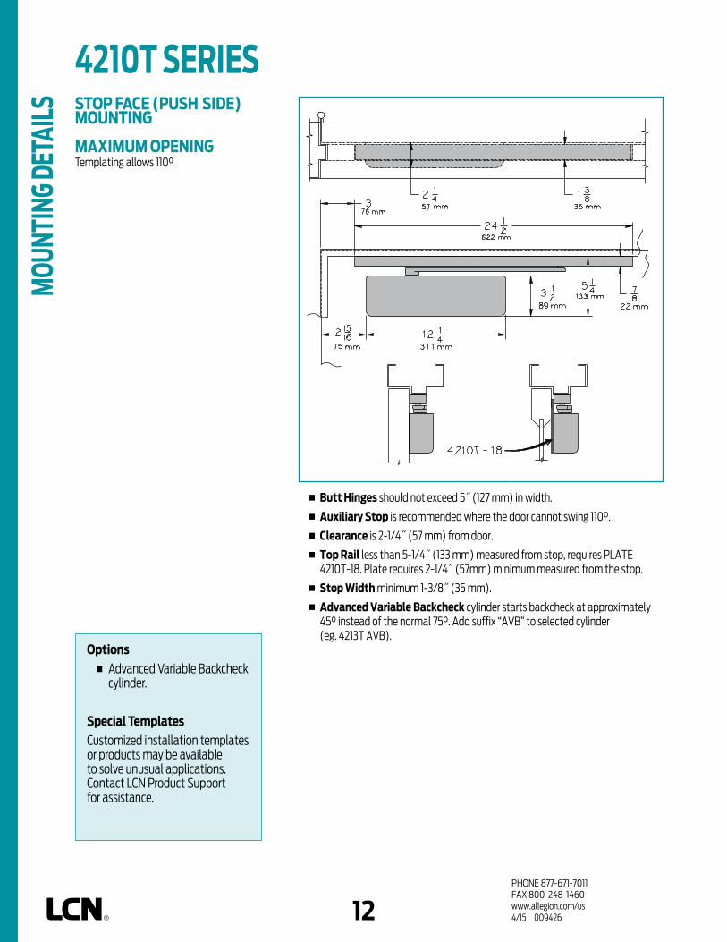
PHONE 877-671-7011FAX 800-248-1460www.allegion.com/us 4/15 00942612
STOP FACE (PUSH SIDE) MOUNTING
MAXIMUM OPENINGTemplating allows 110°.
n Butt Hinges should not exceed 5˝ (127 mm) in width.
n Auxiliary Stop is recommended where the door cannot swing 110°.
n Clearance is 2-1/4˝ (57 mm) from door.
n Top Rail less than 5-1/4˝ (133 mm) measured from stop, requires PLATE 4210T-18. Plate requires 2-1/4˝ (57mm) minimum measured from the stop.
n Stop Width minimum 1-3/8˝ (35 mm).
n Advanced Variable Backcheck cylinder starts backcheck at approximately 45° instead of the normal 75°. Add suffix “AVB” to selected cylinder (eg. 4213T AVB).
4210T SERIES M
OUNT
ING
DETA
ILS
Options n Advanced Variable Backcheck
cylinder.
Special Templates Customized installation templates or products may be available to solve unusual applications. Contact LCN Product Support for assistance.

PHONE 877-671-7011FAX 800-248-1460www.allegion.com/us 4/15 00942612 13
CYLINDERSCYLINDER, 4210T-3071 Standard, handed cast iron cylinder assembly. For various applications see “Table of Sizes” on 4210T Series page 14.
COVERSECURITY COVER, 4210T-72MC Handed, heavy gauge metal security cover.Four point TORX mounting for extra security. Closer adjustments not accessible with cover installed.
ARMSTANDARD SECURITY ARM, 4210T-3077T Handed arm closer features solid forged steel, large cross section arm. Special threaded attachment of track roller for extra security. Double slab arm/pinion attachment for maximum strength.Can only be used with high security track roller, 4210T-3034.
TRACKSECURITY TRACK, 4210T-3038 Non-handed, high security track.Designed to eject foreign objects placed in track during either opening or closing motion.Requires track roller, 4210T-3034.
SECURITY TRACK ROLLER, 4210T-3034Low friction track roller threads into 4210T-3077 arm for extra strength and security. Can not be removed without disconnecting arm from closer.
INSTALLATION ACCESSORIESPLATE, 4210T-18Required where top rail, when measured from the stop, is less than 5-1/4˝ (133 mm). Plate requires 2-1/4˝ (57 mm) minimum top rail measured from the stop.
3034
72MC
3077T
3038
18
2210dps-3071
3071
4210T SERIES
ACCE
SSOR
IES

PHONE 877-671-7011FAX 800-248-1460www.allegion.com/us 4/15 00942614
4214T
4211T
4213T
30"762mm
34"864mm
38"965mm
INTERIOR DOOR WIDTH
HOW-TO-ORDER 4210T SERIES CLOSERS1. SELECT CYLINDER SIZE 4211T (ADA) 4213T 4214T
2. SPECIFY HAND RH LH
3. SPECIFY FINISH Standard Powder Coat __________
Aluminum, Dark Bronze, Statuary, Light Bronze, Black, Brass.
CLOSER OPTIONSCYLINDER Advanced Variable Backcheck (AVB)
FINISH Custom Powder Coat (RAL) ___________ Plated Finish, US ___________ SRI primer (use with powder coat
finishes only)SCREW PACK TB* and TORX Machine Screw (TBTRX)
* Specify door thickness if other than 1-3/4”.INSTALLATION ACCESSORIES PLATE, 4210T-18
SPECIAL TEMPLATE ST- _________
NOTE:InstallationofthiscloserrequiresT-27andT-25 driverbitsforTORXmachinescrewswithasecuritypin. Soldseparately.
48"1219mm
MinimumDoor
Width
size 1 size 3 size 4
4210T SERIES OR
DERI
NG IN
FORM
ATIO
N TABLE OF SIZESSelect closer based on width of door.4210T series cylinders available in size 1, 3 or 4. Closing power of all 4210T Series closers may be increased 15%.
Indicates recommended range of door width for closer size.
Note:Minimumdoorwidth30"(762mm).
REDUCED OPENING FORCE 4210T CLOSERSCAUTION ! Any manual door closer, including those certified by BHMA to conform to ANSI Standard A156.4, that is selected, installed and adjusted based on ADA or other reduced opening force requirements may not provide sufficient power to reliably close and latch a door.
Refer to POWER OPERATORS section for information on systems that meet reduced opening force requirements without affecting closing power.
DOOR WIDTH 36" 42" 48"
8.5* lbs. 4213T 4213T 4213T
5.0* lbs. 4211T 4211T 4211T
* Maximum opening force.
Closer will be shipped with:– SECURITY COVER,– STANDARD SECURITY ARM,– SECURITY TRACK ROLLER,– SECURITY TRACK, – TORX MACHINE SCREW PACK,unlessoptionslistedbelowareselected.

PHONE 877-671-7011FAX 800-248-1460www.allegion.com/us 4/15 00942614 15
n Standard 4510 Series closer shipped with extra duty arm (non hold-open), metal security cover, and TORX Machine Screw pack. See 4510 Series page 17 for options.
n Sized cylinders for interior doors to 5´0˝ and exterior doors to 4´0˝.
n Non-sized cylinder adjustable for interior doors to 4´6˝ and exterior doors to 3´6˝.
n Closer mounts hinge side, specify right or left swinging door.
n 4511 cylinder meets ADA requirements. See 4510 Series page 18.
n Standard or optional custom powder coat finish.
n Optional SRI primer for installations in corrosive conditions. (Available with powder coat finishes only).
n The 4510 Series is UL listed for self-closing doors.
n Tested and certified under ANSI Standard A156.4, grade one.
The 4510 SMOOTHEE® Series is a
heavy duty, high security closer
with special components to
minimize tampering and
vandalism. Forged steel double
lever arms and heavy gauge
metal security covers are
designed for correctional, vandal
prone, institutional and other
high traffic applications. The
closer has passed 10 million
cycles in independent testing.
A choice of finishes and cylinder
functions meet correctional and
vandal resistant requirements.
PLA
STIC
METAL
COVER CYLINDER
140
EDA
STANDARD (S
INGLE)
CUSH/HCUSH
*ARM FUNCTIONFINISH
HANDED
NON-SIZED
SIZEDACCESSIB
ILITY
DELAYED ACTIO
N
HINGE (PULL)
SIDE
PARALLEL A
RM (PUSH)
STOP FACE
CONCEALED (F
RAME)MOUNTING
POWDER COAT
PLATED
AVB**
DPS SWITCH
HINGE (PULL) SIDE MOUNT
4510 SERIES
FEAT
URES
Closeravailablewithlessthan5.0lbs.openingforceon36˝door. * Maximumopeningwithstandardtemplate. ** AdvancedVariableBackcheck.
AVAILABLE NOT AVAILABLE
The4511SeriesincludestheLCN® "Green Dial"
Spring Force Indicator

PHONE 877-671-7011FAX 800-248-1460www.allegion.com/us 4/15 00942616
HINGE (PULL) SIDE MOUNTING
MAXIMUM OPENINGCan be templated for 140°.
A = 4-3/16” (106 mm)B = 9-7/8” (251 mm)
n Butt Hinges should not exceed 5˝ (127 mm) in width.
n Auxiliary Stop is recommended where a door cannot swing 140°.
n Reveal should not exceed 1/8˝ (3 mm).
n Top Rail less than 3-1/2˝ (89 mm), requires PLATE 4510-18. Plate requires 2˝ (51mm) minimum top rail.
n Head frame less than 1˝ (25 mm), consult factory.
n Clearance of 2-1/4˝ (57 mm) behind door required for installation.
n Arm Clearance above door 1-1/8˝ (29 mm) required.
n Delay Action Add suffix “DEL” to selected cylinder. Not available with 4516 cylinder. Delays closing from maximum opening to approximately 70°. Delay time adjustable up to approximately 1 minute.
n Advanced Variable Backcheck cylinder starts backcheck at approximately 45° instead of the normal 75°. Add suffix “AVB” to selected cylinder.
4510 SERIES
Options n Sized or non-sized cylinder. n Delayed action or Advanced
Variable Backcheck cylinder.
Special TemplatesCustomized installation templates or products may be available to solve unusual applications. Contact LCN Product Support for assistance.
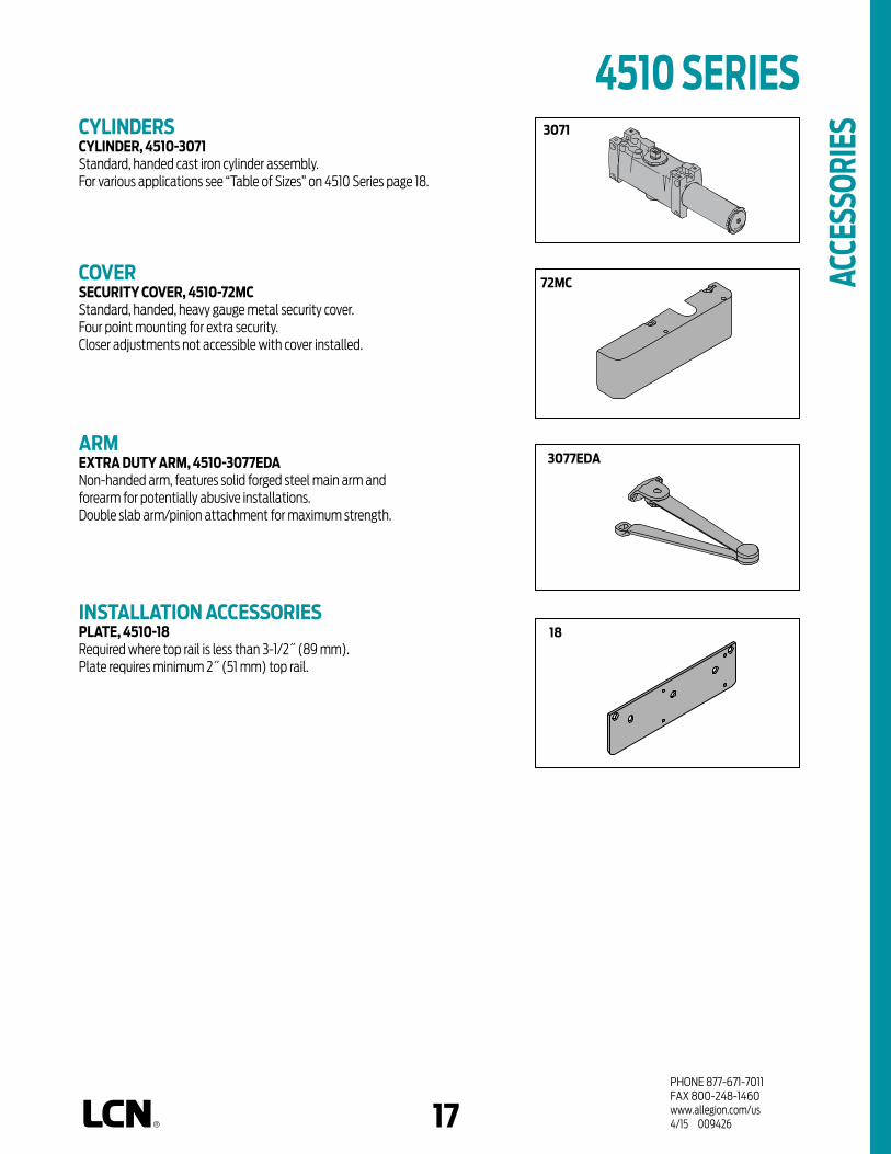
PHONE 877-671-7011FAX 800-248-1460www.allegion.com/us 4/15 00942616 17
CYLINDERSCYLINDER, 4510-3071 Standard, handed cast iron cylinder assembly.For various applications see “Table of Sizes” on 4510 Series page 18.
COVERSECURITY COVER, 4510-72MC Standard, handed, heavy gauge metal security cover.Four point mounting for extra security. Closer adjustments not accessible with cover installed.
ARMEXTRA DUTY ARM, 4510-3077EDA Non-handed arm, features solid forged steel main arm and forearm for potentially abusive installations.Double slab arm/pinion attachment for maximum strength.
INSTALLATION ACCESSORIESPLATE, 4510-18Required where top rail is less than 3-1/2˝ (89 mm). Plate requires minimum 2˝ (51 mm) top rail.
72MC
3077EDA
18
3071
ACCE
SSOR
IES
4510 SERIES

PHONE 877-671-7011FAX 800-248-1460www.allegion.com/us 4/15 00942618
HOW-TO-ORDER 4510 SERIES CLOSERS1. SELECT CYLINDER SIZE 4511 (adjustable from size 1 to 5) 4516 (DEL not available)
2. SPECIFY HAND RH LH
3. SPECIFY FINISH Standard Powder Coat __________
Aluminum, Dark Bronze, Statuary, Light Bronze, Black, Brass.
CLOSER OPTIONSCYLINDER Delayed Action (DEL) Advanced Variable Backcheck (AVB) FINISH Custom Powder Coat (RAL) ___________ Plated Finish, US ___________ SRI primer (use with powder coat
finishes only)SCREW PACK TB* and TORX Machine Screw (TBTRX)
* Specify door thickness if other than 1-3/4”.INSTALLATION ACCESSORIES PLATE, 4510-18
SPECIAL TEMPLATE ST- _________
NOTE:InstallationofthiscloserrequiresT-27andT-25 driverbitsforTORXmachinescrewswithasecuritypin. Soldseparately.
size 3 size 4 size 5 size 6*4511
EXTERIOR (and VESTIBULE) DOOR
24"610mm
30"762mm
36"914mm
42"1067mm
48"1219mm
4516
*AdjustableSize1thru5MinimumDoor
Width
INTERIOR DOOR WIDTH
24"610mm
34"864mm
38"965mm
48"1219mm
54"1372mm
60"1524mm
size 2 size 3 size 4 size 5 size 6*4511
4516
*AdjustableSize1thru5MinimumDoor
Width
ORDE
RING
INFO
RMAT
ION
REDUCED OPENING FORCE 4510 CLOSERSCAUTION ! Any manual door closer, including those certified by BHMA to conform to ANSI Standard A156.4, that is selected, installed and adjusted based on ADA or other reduced opening force requirements may not provide sufficient power to reliably close and latch a door.
Refer to POWER OPERATORS section for information on systems that meet reduced opening force requirements without affecting closing power.
DOOR WIDTH 36" 42" 48"
8.5* lbs. 4511 4511 4511
5.0* lbs. 4511 4511 4511
* Maximum opening force.
Closer will be shipped with:– SECURITY COVER,– EXTRA DUTY ARM,– TORX MACHINE SCREW PACK,unlessoptionslistedbelowareselected.
TABLE OF SIZESSelect closer based on width of door.The spring power of non-sized 4511 cylinder is adjustable from size 1 through size 5 and is shipped set to size 3. Sized 4510 Series cylinder available in size 6. Delayed action not available with 4516 cylinder.
Indicates recommended range of door width for closer size.
4510 SERIES

PHONE 877-671-7011FAX 800-248-1460www.allegion.com/us 4/15 00942618 19
Closeravailablewithlessthan5.0lbs.openingforceon36˝door. * Maximumopeningwithstandardtemplate. ** AdvancedVariableBackcheck.
n Standard 4510T Series closer shipped with standard arm, security track. (non hold-open), track roller, metal security cover, and TORX Machine Screw pack. See 4510T Series page 21 for options.
n Sized cylinders for interior doors to 4´0˝.
n Closer mounts hinge side, specify right or left swinging door.
n 4511T cylinder meets ADA requirements. See 4510T Series page 22.
n Standard or optional custom powder coat finish.
n Optional SRI primer for installations in corrosive conditions. (Available with powder coat finishes only).
n The 4510T Series is UL listed for self-closing doors.
n Tested and certified under ANSI Standard A156.4, grade one.
The 4510T SMOOTHEE® Series is a
heavy duty, high security track
closer with special components
to minimize tampering and
vandalism. Forged steel single
lever arm and heavy gauge metal
security cover are designed for
correctional, vandal prone,
institutional and other high traffic
interior applications. The closer
has passed 10 million cycles in
independent testing. A choice of
finishes and cylinder functions
meet correctional and vandal
resistant requirements.
PLA
STIC
METAL
COVER CYLINDER
180
EDA
STANDARD (S
INGLE)
CUSH/HCUSH
*ARM FUNCTIONFINISH
HANDED
NON-SIZED
SIZEDACCESSIB
ILITY
DELAYED ACTIO
N
HINGE (PULL)
SIDE
PARALLEL A
RM (PUSH)
STOP FACE
CONCEALED (F
RAME)
MOUNTING
POWDER COAT
PLATED
AVB**
DPS SWITCH
HINGE (PULL) SIDE MOUNT
4510T SERIES
FEAT
URES
AVAILABLE NOT AVAILABLE

PHONE 877-671-7011FAX 800-248-1460www.allegion.com/us 4/15 00942620
HINGE (PULL) SIDE MOUNTING
MAXIMUM OPENINGTemplating allows 180°.
Consult factory if door will be held open at 180°.
n Butt Hinges should not exceed 5˝ (127 mm) in width.
n Auxiliary Stop is recommended where a door cannot swing 180°.
n Reveal should not exceed 1/8˝ (3 mm).
n Top Rail less than 3-3/4˝ (95 mm), requires PLATE 4510T-18. Plate requires 2˝ (51 mm) minimum top rail.
n Head Frame minimum 2-1/8” (54 mm).
n Clearance of 2-1/4˝ (57 mm) behind door required for installation.
n Advanced Variable Backcheck cylinder starts backcheck at approximately 45° instead of the normal 75°. Add suffix “AVB” to selected cylinder (eg. 4513T AVB).
4510T SERIES
Options n Advanced Variable Backcheck
cylinder.
Special TemplatesCustomized installation templates or products may be available to solve unusual applications. Contact LCN Product Support for assistance.

PHONE 877-671-7011FAX 800-248-1460www.allegion.com/us 4/15 00942620 21
CYLINDERSCYLINDER, 4510T-3071 Standard, handed cast iron cylinder assembly.For various applications see “Table of Sizes” on 4510T Series page 22.
COVERSECURITY COVER, 4510T-72MC Handed, heavy gauge metal security cover.Four point TORX mounting for extra security. Closer adjustments not accessible with cover installed.
ARMSTANDARD SECURITY ARM, 4510T-3077T Handed arm features solid forged steel, large cross section arm.Special threaded attachment of track roller for potentially abusive installations.Double slab arm/pinion attachment for maximum strength.Can only be used with high security track roller, 4510T-3034.
TRACKSECURITY TRACK, 4510T-3038 Non-handed, high security track.Designed to eject foreign objects placed in track during either opening or closing motion.Requires track roller, 4510T-3034.
SECURITY TRACK ROLLER, 4510T-3034 Low friction track roller threads into 4510T-3077T arm for extra strength and security. Can not be removed without disconnecting arm from closer.
INSTALLATION ACCESSORIESPLATE, 4510T-18Required where top rail is less than 3 3/4” (95 mm). Plate requires minimum 2” (51 mm) top rail.
72MC
3071
3034
3077T
3038
18
4510T SERIES
ACCE
SSOR
IES

PHONE 877-671-7011FAX 800-248-1460www.allegion.com/us 4/15 00942622
4510T SERIES HOW-TO-ORDER 4510T SERIES CLOSERS1. SELECT CYLINDER SIZE 4511T (ADA) 4513T 4514T
2. SPECIFY HAND RH LH
3. SPECIFY FINISH Standard Powder Coat __________
Aluminum, Dark Bronze, Statuary, Light Bronze, Black, Brass.
CLOSER OPTIONSCYLINDER Advanced Variable Backcheck (AVB) FINISH Custom Powder Coat (RAL) ___________ Plated Finish, US ___________ SRI primer (use with powder coat
finishes only)SCREW PACK TB* and TORX Machine Screw (TBTRX)
* Specify door thickness if other than 1-3/4”.INSTALLATION ACCESSORIES PLATE, 4510T-18SPECIAL TEMPLATE ST- _________
NOTE:InstallationofthiscloserrequiresT-27andT-25 driverbitsforTORXmachinescrewswithasecuritypin.Soldseparately.
REDUCED OPENING FORCE 4510T CLOSERSCAUTION ! Any manual door closer, including those certified by BHMA to conform to ANSI Standard A156.4, that is selected, installed and adjusted based on ADA or other reduced opening force requirements may not provide sufficient power to reliably close and latch a door.
Refer to POWER OPERATORS section for information on systems that meet reduced opening force requirements without affecting closing power.
DOOR WIDTH 36" 42" 48"
8.5* lbs. 4513T 4513T 4513T
5.0* lbs. 4511T 4511T 4511T
* Maximum opening force.
Closer will be shipped with:– SECURITY COVER,– STANDARD SECURITY ARM,– SECURITY TRACK ROLLER,– SECURITY TRACK,– TORX MACHINE SCREW PACK,unlessoptionslistedbelowareselected.
4514T
4511T
4513T
26"660mm
34"864mm
38"965mm
INTERIOR DOOR WIDTH48"
1219mm
MinimumDoor
Width
size 1 size 3 size 4
TABLE OF SIZESSelect closer based on width of door.Sized 4510T Series cylinders available in size 1, 3 or 4. Closing power of all 4510T Series closers may be increased 15%.
Indicates recommended range of door width for closer size.

1PHONE 877-671-7011FAX 800-248-1460allegion.com/us4/15 009426
PRODUCT SELECTION GUIDELCN automatic operators are the proven standard in schools and health care facilities for over 20 years. They are easily retrofitted into existing doors and frames, as well as new construction. LCN low energy electrohydraulic and pneumatic automatic operators feature a heavy duty closer with a slow opening function. LCN’s electromechanical automatic operators utilizes a motor gearbox and control box to perform the opening and closing function.
2610 (PNEUMATIC)2810 (ELECTROMECHANICAL)2850 (ELECTROMECHANICAL)2860 (ELECTROMECHANICAL)
SURFACE MOUNTED PULL SIDE
4630 (ELECTROHYDRAULIC)4810 (PNEUMATIC)9130 (ELECTROMECHANICAL)9530 (ELECTROMECHANICAL)9550 (ELECTROMECHANICAL)9560 (ELECTROMECHANICAL)
SURFACE MOUNTED PUSH SIDE
4640 (ELECTROHYDRAULIC)4820 (PNEUMATIC)4840 (PNEUMATIC)9140 (ELECTROMECHANICAL)9150 (ELECTROMECHANICAL)9540 (ELECTROMECHANICAL)9550 (ELECTROMECHANICAL)9560 (ELECTROMECHANICAL)
LOW ENERGYPOWEREDSYSTEMS CONCEALED
MOUNTSURFACE MOUNTED
DOUBLE EGRESS
9550 (ELECTROMECHANICAL)9560 (ELECTROMECHANICAL)
AUTOMATIC OPERATORS

53PHONE 877-671-7011FAX 800-248-1460www.allegion.com/us 4/15 009426
ELECTROMECHANICAL POWERED SYSTEMSELECTROMECHANICAL AUTOMATIC OPERATORSLCN’s electromechanical products are designed primarily for automatic opening applications that occasionally require manual opening. A control box provides all electrical functions. These self-contained units are suitable for use on single leaf doors or pair of doors. These products combine all the control and power elements into a single operator package, only some actuators are required to complete the system.
n Surface mounted and overhead concealed mountings available.
n Available in two standard anodized finishes – Aluminum and Dark Bronze.
LOW ENERGY ELECTROMECHANICAL POWER OPERATORS
n Complies with ANSI 156.19.n Opening time from full close to backcheck is no faster than
3 seconds.n Less than 15 lbs of force to open door manually.
STANDARDS, LISTINGS & APPROVALS n UL listed for self-closing doors without hold open. UL 325.n Tested and certified under ANSI.n Low Energy Electromechanical Operators ANSI 156.19.n ADA Compliant.n Wiring is compliant with both UL 325 and the NEC.
Separation of high and low voltage.n Consult the factory for other listings.
WARRANTYn 2 year limited warranty. See General Information Section
for complete details.
MAINTENANCELow Energy Electromechanical Power Operators
n Operators mounted according to the LCN Installation instructions require no periodic maintenance or adjustments.
n Periodic visual inspections are recommended.n No service contracts.

PHONE 877-671-7011FAX 800-248-1460www.allegion.com/us 4/15 00942654
ELECTROMECHANICAL POWERED SYSTEMS
SINGLE DOOR SYSTEM (WIRELESS)n An Interior Door.n Guide rails or safety devices not required.n Free Swinging (or Dogged) Door.
How It WorksWireless actuators with receiver, powered by the transformer allows for easy installation. For automatic door operation, touching either actuator signals the receiver and power operator to open the door to 90 degrees. The door is held there until the system times out. Door closes via spring return. Door opening speed, closing speed and hold open time is adjustable on the control box. If not actuated, the power operator functions as a manual door.
120VInput
Low Voltage Wiring
RF Receiver
RF Actuator
RF Actuator
Automatic Operator
SINGLE DOOR SYSTEMS
VESTIBULE ENTRY SYSTEM (WIRED)n Exterior & Vestibule doors.n Sequential Operation.n Guide rails or safety devices not required.n Controlled Access, Free Egress.
How It WorksThis installation provides both accessibility and security for building occupants. It allows for the integration of multiple automatic operators, a card reader and electric strike. A sequencer allows sequential operation of the two automatic operators. Vestibule actuators allow single door ingress/egress from the vestibule as needed. If not actuated the power operator functions as a manual door.
Low Voltage Wiring
Wall Plate Actuator
Automatic Operator
Automatic Operator
Card Reader w/keypad as Exterior Actuator
Sequencer
Electric Strike
Low Voltage
Wall Plate Actuator
Wall Plate Actuator
Note: 120V AC Input required to both operators
120V Input
120V Input
VESTIBULE ENTRY OPERATION
BILL OF MATERIALSQty. Part No. Description1 9542 Automatic operator (RH)1 9531 Automatic operator (RH)3 8310-853 Wall Plate Actuators1 8310-849 Sequencer Other products from Von Duprin and Schlage Electronics
BILL OF MATERIALSQty. Part No. Description1 9531 Automatic Operator (RH)2 8310-3853WS Wireless Actuators1 8310-865 Wireless Receiver
This page illustrates examples of typical Electromechanical LCN systems. Please consult your local SSC
representative of LCN for assistance with specific installations and material requirements.

54 55PHONE 877-671-7011FAX 800-248-1460www.allegion.com/us 4/15 009426
ELECTROMECHANICAL POWERED SYSTEMSCONTROL BOX - 2800, 9500 SERIES
1. Control Box, 115VAC 60Hz, or 240 VAC 50/60 Hz
2. Seven Segment Display
3. Power Indicator
4. Factory Default Push Button
5. Model Identification Label
6. 6-Pin Connector for Master Motor
7. 3-Pin Connector for 3 Position Switch
8. Breakaway Jumper Cable
9. 2-Pin Connector for Breakaway Switch
10. Accessory Direct Connect Diagram
11. 6-Pin Connector for Companion Motor (supply only w/simultaneous pairs)
12. Value Adjustment Push Buttons
13. Setting Adjustment Menu
14. Function Adjustment Push Buttons
15. Closing Speed Adjustment Dial (Master)
16. Closing Speed Adjustment Dial (Companion)
17. 3-Pin Connector for AC power

PHONE 877-671-7011FAX 800-248-1460www.allegion.com/us 4/15 00942656
ELECTROMECHANICAL POWERED SYSTEMSSTANDARD CONTROL BOX - 9100 SERIES
24VDC -
24VDC +
Safety Sen
Safety GND
Common GND
N/O Strike Relay
N/C Strike Relay
Aux GND
Aux ACT
3 Way HO
3 Way GND
3 Way OFF
Main Act
Main Act
Electric Lock,
Electric Strike, etc.
N.O. or N.C.Depending on Device
Black DC-
Red DC+
ActivationDeviceN.O.
Dry ContactsRedBlackGreen
Activation DeviceN.O. Dry Contacts
Multiple activation devicesshould be connected in parallel
Control boxgrounding stud
For clarity, not allcomponents are shown
on the control box PC boardJ8, 10-positionControl Box Power Cable
J1, 6-positionMain Power Cable
J5, 2-positionMotor Power Cable
J3, 4-positionHall Effect Cable
Plug cables intothese receptacles
ConnectFail Safe to N/CFail Secure to N/O
Disabled whenoptional 3 positionswitch is inOff position
Optional3 Position
Switch

56 57PHONE 877-671-7011FAX 800-248-1460www.allegion.com/us 4/15 009426
ELECTROMECHANICAL POWERED SYSTEMSGENERAL ELECTRICAL DATA1. The 115/240 volt power supply must be a dedicated circuit from the main circuit breaker panel and must not be connected into a building
lighting system operating fluorescent lights.2. Location of conduits determined by mounting. See installation instructions for location.
2800, 9500, SERIESELECTRICAL DATA1. 120 VAC 60Hz input @ 2.5 amps (2800 and 7500 Series).2. 240 VAC 50/60 Hz @ 2.5 amps (2800, and 9500 Series).3. 24 V AC output @ 1.5 amps (protected by self-resetting thermal fuse).4. 24 V DC available with SO kit included.
9100, SERIESELECTRICAL DATA1. 120 VAC input @ 1 amp.2. 24 VDC output @ 2.5 amps.

PHONE 877-671-7011FAX 800-248-1460www.allegion.com/us 4/15 00942658
Notes

58 59PHONE 877-671-7011FAX 800-248-1460www.allegion.com/us 4/15 009426
BENCHMARK UNIQUE FEATURESOn-Board Power SupplyProvides 24V DC output to power card readers, manual actuators and other peripherals.
Electronic Circuit ProtectionFused input circuit protection and fused output protection for 24 VDC peripherals.
Visual Function IndicatorsThere are 2 LED s for installation and trouble shooting feedback. The motor LED will illuminate when the motor drive circuit energizes. This is when the operator is activated it will remain on only during the opening of the door and the power LED this will illuminate when power is applied to the board and remains illuminated as long as there is power applied to the board.
Programming ModeAllow tailoring of the following functions to meet specific site conditions:
n Power Boostn Opening Speedn Backcheck Speedn Hold Open Time Delayn Backcheck Positionn Closing Speedn Latch Positionn Push ‘N Gon Delayed Activation

PHONE 877-671-7011FAX 800-248-1460www.allegion.com/us 4/15 00942660
Notes

60 61PHONE 877-671-7011FAX 800-248-1460www.allegion.com/us 4/15 009426
STANDARD ANODIZED
FINISHHANDING
HANDED
NON-HANDED
COVER
METAL
ARM FUNCTION
STANDARD (S
INGLE
LEVER)
REGULAR (D
OUBLE LE
VER)
OFFSET PIVOT BUTT HIN
GE ARM
CENTER PIVOT ARM
DOUBLE EGRESS (P
USH/PULL)
MOUNTING
SURFACE M
OUNT SINGLE
DOOR
SURFACE M
OUNT SIMULTA
NEOUS PAIR
SURFACE M
OUNT INDEPENDENT PAIR
CONCEALED SIN
GLE DOOR
CONCEALED IN
DEPENDENT PAIR
CONCEALED SIM
ULTANEOUS PAIR
The 9130 BENCHMARK by LCN is an
electrically powered low-energy
operator. It provides easy access for
people with disabilities, or the elderly.
Designed primarily for automatic opening
applications that occasionally require
manual opening. The BENCHMARK is a
cost-effective solution for retrofitting
an activated or manual door.
n Push ‘N Go permits non-switch activation. n Microprocessor control box ensures
reliability and maintains customer settings.
n Power Boost allows for increased closing force near latch.
9130 Series is fully compliant with UL
325 and meets the provisions of ANSI
A156.19. The 9130 Series is UL listed
for fire-rated applications. The 9130
Series also meets the provisions of the
Americans with Disabilities Act.
n 9130 Series operator is shipped with motor gearbox, control box, mounting plate, standard arm, metal cover, standard track, wood and machine screws. Actuators available separately, see pages 122-137.
n Single interior door, surface mounted.
n ADA compliant.
n On/Off switch included as standard.
n Non-handed for either right or left swinging door.
n 27˝ cover is standard. 36” optional.
n All potentiometers clearly labeled with their functions.
n LED lights indicate power to control box and motor gearbox.
SINGLE DOOR, SURFACE MOUNT (PULL)OFFSET PIVOT/BUTT HINGE
AVAILABLE NOT AVAILABLE
9130 SERIES
FEAT
URES

PHONE 877-671-7011FAX 800-248-1460www.allegion.com/us 4/15 00942662
n Butt Hinges should not exceed 5˝ (127 mm) in width.
n Reveal should not exceed 1/8˝ (3 mm).
n Head Frame minimum 2˝ (51 mm).
n Top Rail minimum 2˝ (51 mm).
n Opening and Closing Time are variable by adjustments to the electronic control module located on the operator assembly. Maximum hold open time adjustable up to approximately 30 seconds.
n System Diagram see “AUTOMATIC OPERATORS” section pages 53 for typical system wiring and page 56 for electrical data.
TOP JAMB SINGLE DOOR (OFFSET/BUTT HINGE, CENTER PIVOT, PULL, STANDARD COVER) MOUNTING
TOP JAMB SINGLE DOOR (OFFSET/BUTT HINGE, CENTER PIVOT, PULL, FULL COVER) MOUNTING
MAXIMUM OPENINGTemplate allows 90 degree power opening and 90 degree manual opening.
PULL ARMASS'Y
OFFSET PIVOT
ORBUTT
HINGES
5/8" FROMTOP OF DOOR
DOORFRAME
4 3/4"121 MM
6" MIN.152 MM
OPERATOR
4 1/2"114 MM
27" OPERATOR
28 1/2" PULL CHANNEL
FROM TOP OF DOOROPENING TO CEILING
DOOR
5/8" FROMTOP OF DOOR
DOORFRAME
4 3/4"121 MM
6" MIN.152 MM
OPERATOR
4 1/2"114 MM
FROM TOP OF DOOROPENING TO CEILING
DOOR
PULL ARMASS'Y
OFFSET PIVOT
ORBUTT
HINGES
FULL LENGTH OPERATOR
28 1/2" PULL CHANNEL
Contact LCN Product Support for installation assistance.
9130 SERIESM
OUNT
ING
DETA
ILS

62 63PHONE 877-671-7011FAX 800-248-1460www.allegion.com/us 4/15 009426
MOTOR GEARBOXMOTOR GEARBOX ASSEMBLY, 9130-3454S Driving mechanism for operator. (Switch included). For 27˝ unit.
MOTOR GEARBOX ASSEMBLY (W/O SWITCH), 9130-3454 Driving mechanism for operator. (Switch not included). For full length unit (36˝).
BRACKETSMOUNTING BRACKET, 9130-3018 Standard mounting bracket.
SWITCH BRACKET – 29˝ CABLE, 9130-3351-1 Bracket used to locate switch at end of cover on full length unit.
SWITCH BRACKET – 41˝ CABLE, 9130-3351-2 Bracket used to locate switch at end of cover on full length unit.
CONTROL BOXESCONTROL BOX, (120v), 9130-3462 Electronic controlling device with power supply output and power boost feature for Benchmark.
COVERSMETAL COVER, 9130-72MC Standard, 27˝, non-handed, extruded aluminum cover.
FULL METAL COVER, 9130-72FC 36˝, non-handed, extruded aluminum cover.
COVER INSERT 9130-163 Used to cover operator shaft opening. (Includes 2 pieces).
COVER END CAP INSERT, 9130-163-1 Used to cover switch hole opening.
COVER END CAP, 9130-334 Black plastic end caps. (Includes 9130-163-1 cover and cap insert).
34543454S
3018
3351-13351-2
3462
72MC72FC
163
334
163-1
9130 SERIES
ACCE
SSOR
IES
Note (*334 includes 163-1)

PHONE 877-671-7011FAX 800-248-1460www.allegion.com/us 4/15 00942664
TRACKSSTANDARD TRACK, 9130-3038 Standard, non-handed track.
TRACK END CAP, 9130-73 Black plastic end caps.
ROLLER, 9130-3034Quiet low friction roller assembly.
ARMSSTANDARD ARM, 9130-3077T Non-handed arm. Track roller not included.
STANDARD ARM with 9130-3077PLCM Non-handed arm and standard non handed track.
3038733034
3077T
9130-3077PLCM
9130 SERIESAC
CESS
ORIE
S

64 65PHONE 877-671-7011FAX 800-248-1460www.allegion.com/us 4/15 009426
9131
DOOR WIDTH
30"762mm
48"1219mm
MinimumDoor
Width
9130 SERIES
ORDE
RING
INFO
RMAT
IONHOW-TO-ORDER
9130 SERIES OPERATORS1. SPECIFY FINISH Standard Anodized Finish __________
Aluminum or Dark Bronze.
OPERATOR OPTIONSCOVER 36˝ Full Cover.
Indicates recommended range of door width for operator.
NOTE: For All Benchmark Series. 30˝ minimum door width for 27˝ pull operator. 36˝ door width only for full length pull operator.
TABLE OF SIZES
Operator will be shipped with:- STANDARD MOTOR GEARBOX,- STANDARD CONTROL BOX,- MOUNTING BRACKET,- 27˝ METAL COVER,- STANDARD ARM (3077T),- STANDARD TRACK w/TRACK ROLLER,- WOOD and MACHINE SCREW PACKUnless options listed below are selected.

PHONE 877-671-7011FAX 800-248-1460www.allegion.com/us 4/15 00942666
Notes
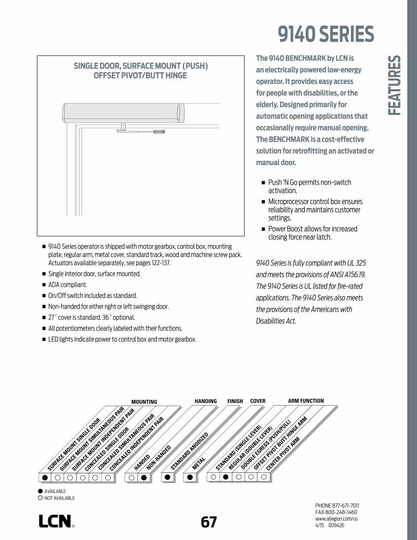
66 67PHONE 877-671-7011FAX 800-248-1460www.allegion.com/us 4/15 009426
STANDARD ANODIZED
FINISHHANDING
HANDED
NON-HANDED
COVER
METAL
ARM FUNCTION
STANDARD (S
INGLE
LEVER)
REGULAR (D
OUBLE LE
VER)
OFFSET PIVOT BUTT HIN
GE ARM
CENTER PIVOT ARM
DOUBLE EGRESS (P
USH/PULL)
MOUNTING
SURFACE M
OUNT SINGLE
DOOR
SURFACE M
OUNT SIMULTA
NEOUS PAIR
SURFACE M
OUNT INDEPENDENT PAIR
CONCEALED SIN
GLE DOOR
CONCEALED IN
DEPENDENT PAIR
CONCEALED SIM
ULTANEOUS PAIR
The 9140 BENCHMARK by LCN is
an electrically powered low-energy
operator. It provides easy access
for people with disabilities, or the
elderly. Designed primarily for
automatic opening applications that
occasionally require manual opening.
The BENCHMARK is a cost-effective
solution for retrofitting an activated or
manual door.
n Push ‘N Go permits non-switch activation.
n Microprocessor control box ensures reliability and maintains customer settings.
n Power Boost allows for increased closing force near latch.
9140 Series is fully compliant with UL 325
and meets the provisions of ANSI A156.19.
The 9140 Series is UL listed for fire-rated
applications. The 9140 Series also meets
the provisions of the Americans with
Disabilities Act.
n 9140 Series operator is shipped with motor gearbox, control box, mounting plate, regular arm, metal cover, standard track, wood and machine screw pack. Actuators available separately, see pages 122-137.
n Single interior door, surface mounted.
n ADA compliant.
n On/Off switch included as standard.
n Non-handed for either right or left swinging door.
n 27˝ cover is standard. 36˝ optional.
n All potentiometers clearly labeled with their functions.
n LED lights indicate power to control box and motor gearbox.
SINGLE DOOR, SURFACE MOUNT (PUSH)OFFSET PIVOT/BUTT HINGE
9140 SERIES
FEAT
URES
AVAILABLE NOT AVAILABLE

PHONE 877-671-7011FAX 800-248-1460www.allegion.com/us 4/15 00942668
n Butt Hinges should not exceed 5˝ (127 mm) in width.
n Reveal for push installations should not exceed 6˝ (152 mm) for REGULAR ARM and 9-3/4˝ (248 mm) for LONG ARM.
n Head Frame minimum 2˝ (51 mm).
n Top Rail minimum 2˝ (51 mm). Flush ceiling installation requires 5-1/4˝ (133 mm) minimum.
n Opening and Closing Time are variable by adjustments to the electronic control module located on the operator assembly. Maximum hold open time adjustable up to approximately 30 seconds.
n System Diagram see “AUTOMATIC OPERATORS” section pages 53 for typical system wiring and page 56 for electrical data.
PUSH ARMASS'Y
18 1/4" FROMEDGE OF DOOR
OFFSET PIVOT
ORBUTT
HINGES
27" OPERATOR
1 7/16" FROMTOP OF DOOR
DOORFRAME
4 3/4"121 MM
5 9/16" MIN.141 MM
OPERATOR
19 1/2" MAX.495 MM
4 1/2"114 MM
DOOR
PUSH ARMASS'Y
18 1/4" FROMEDGE OF DOOR
OFFSET PIVOT
ORBUTT
HINGES
1 7/16" FROMTOP OF DOOR
DOORFRAME
4 3/4"121 MM
5 9/16" MIN.141 MM
OPERATOR
19 1/2" MAX.495 MM
4 1/2"114 MM
FULL LENGTH OPERATOR
DOOR
TOP JAMB SINGLE DOOR (OFFSET/BUTT HINGE, CENTER PIVOT, PUSH, STANDARD COVER) MOUNTING
TOP JAMB SINGLE DOOR (OFFSET/BUTT HINGE, CENTER PIVOT, PUSH, FULL COVER) MOUNTING
MAXIMUM OPENINGTemplate allows 90 degree power opening and 90 degree manual opening.
Contact LCN Product Support for installation assistance.
9140 SERIESM
OUNT
ING
DETA
ILS

68 69PHONE 877-671-7011FAX 800-248-1460www.allegion.com/us 4/15 009426
MOTOR GEARBOXMOTOR GEARBOX ASSEMBLY, 9140-3454SDriving mechanism for operator. (Switch included.) For 27˝ unit.
MOTOR GEARBOX ASSEMBLY (W/O SWITCH), 9140-3454Driving mechanism for operator. (Switch not included.) For full length unit (36˝).
BRACKETSMOUNTING BRACKET, 9140-3018 Standard mounting bracket.
SWITCH BRACKET – 29˝ CABLE, 9140-3351-1 Bracket used to locate switch at end of cover on full length unit.
SWITCH BRACKET – 41˝ CABLE, 9140-3351-2 Bracket used to locate switch at end of cover on full length unit.
CONTROL BOXESCONTROL BOX, (120v), 9130-3462 Electronic controlling device with power supply output and power boost feature for Benchmark.
COVERSMETAL COVER, 9140-72MC Standard, 27˝, non-handed, extruded aluminum cover.
FULL METAL COVER, 9140-72FC 36˝ Full length, non-handed, extruded aluminum cover.
COVER INSERT 9140-163 Used to cover operator shaft opening. (Includes 2 pieces).
COVER END CAP INSERT, 9140-163-1 Used to cover switch hole opening.
COVER END CAP, 9140-334 Black plastic end caps. (Includes 9130-163-1 cover and cap insert).
34543454S
3018
3351-13351-2
3462
72MC72FC
163
334
9140 SERIES
ACCE
SSOR
IES
NOTE (*334 includes 163-1)
163-1

PHONE 877-671-7011FAX 800-248-1460www.allegion.com/us 4/15 00942670
ARMSREGULAR ARM, 9140-3077Non-handed arm.
LONG PUSH ARM, 9140-3077LNon-handed long arm.
ROD & SHOE, 9140-79Rod for use with regular arm.
LONG ROD & SHOE, 9140-79LRLong rod used with long arm, for deep reveals.
30773077L
79LR79
9140 SERIESAC
CESS
ORIE
S

70 71PHONE 877-671-7011FAX 800-248-1460www.allegion.com/us 4/15 009426
9140 SERIES
ORDE
RING
INFO
RMAT
IONHOW-TO-ORDER
9140 SERIES OPERATORS1. SPECIFY FINISH Standard Anodized Finish __________
Aluminum or Dark Bronze.
OPERATOR OPTIONSCOVER 36˝ Full CoverARM Long Arm (3077L)
(reveals 6˝ to 9-3/4˝)
Operator will be shipped with:- STANDARD MOTOR GEARBOX,- STANDARD CONTROL BOX,- MOUNTING BRACKET,- 27˝ METAL COVER,- STANDARD ARM (3077),- STANDARD TRACK w/TRACK ROLLER,- WOOD and MACHINE SCREW PACKUnless options listed below are selected.
9142
DOOR WIDTH
26"660mm
48"1219mm
MinimumDoor
Width
Indicates recommended range of door width for operator.
NOTE: For All Benchmark Series. 30˝ minimum door width for 27˝ pull operator. 36˝ door width only for full length pull operator.
TABLE OF SIZES
PHONE 877-671-7011FAX 800-248-1460www.allegion.com/us 4/15 00942672
Notes
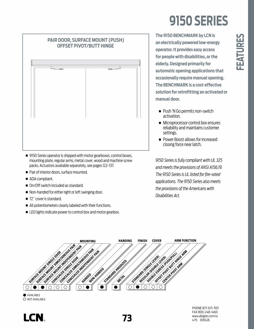
72 73PHONE 877-671-7011FAX 800-248-1460www.allegion.com/us 4/15 009426
STANDARD ANODIZED
FINISHHANDING
HANDED
NON-HANDED
COVER
METAL
ARM FUNCTION
STANDARD (S
INGLE
LEVER)
REGULAR (D
OUBLE LE
VER)
OFFSET PIVOT BUTT HIN
GE ARM
CENTER PIVOT ARM
DOUBLE EGRESS (P
USH/PULL)
MOUNTING
SURFACE M
OUNT SINGLE
DOOR
SURFACE M
OUNT SIMULTA
NEOUS PAIR
SURFACE M
OUNT INDEPENDENT PAIR
CONCEALED SIN
GLE DOOR
CONCEALED IN
DEPENDENT PAIR
CONCEALED SIM
ULTANEOUS PAIR
The 9150 BENCHMARK by LCN is
an electrically powered low-energy
operator. It provides easy access
for people with disabilities, or the
elderly. Designed primarily for
automatic opening applications that
occasionally require manual opening.
The BENCHMARK is a cost-effective
solution for retrofitting an activated or
manual door.
n Push ‘N Go permits non-switch activation.
n Microprocessor control box ensures reliability and maintains customer settings.
n Power Boost allows for increased closing force near latch.
9150 Series is fully compliant with UL 325
and meets the provisions of ANSI A156.19.
The 9150 Series is UL listed for fire-rated
applications. The 9150 Series also meets
the provisions of the Americans with
Disabilities Act.
n 9150 Series operator is shipped with motor gearboxes, control boxes, mounting plate, regular arms, metal cover, wood and machine screw packs. Actuators available separately, see pages 122-137.
n Pair of interior doors, surface mounted.
n ADA compliant.
n On/Off switch included as standard.
n Non-handed for either right or left swinging door.
n 72˝ cover is standard.
n All potentiometers clearly labeled with their functions.
n LED lights indicate power to control box and motor gearbox.
PAIR DOOR, SURFACE MOUNT (PUSH)OFFSET PIVOT/BUTT HINGE
9150 SERIES
FEAT
URES
AVAILABLE NOT AVAILABLE

PHONE 877-671-7011FAX 800-248-1460www.allegion.com/us 4/15 00942674
n Butt Hinges should not exceed 5˝ (127 mm) in width.
n Reveal for push installations should not exceed 6˝ (152 mm) for REGULAR ARM and 9-3/4˝ (248 mm) for LONG ARM.
Head Frame minimum 2˝ (51 mm).
n Top Rail minimum 2˝ (51 mm). Flush ceiling installation requires 5-1/4˝ (133 mm) minimum.
n Opening and Closing Time are variable by adjustments to the electronic control module located on the operator assembly. Maximum hold open time adjustable up to approximately 32 seconds.
n System Diagram see “AUTOMATIC OPERATORS” section pages 53 for typical system wiring and page 56 for electrical data.
18 1/4" FROMEDGE OF DOOR
OFFSET PIVOT
ORBUTT
HINGES
1 7/16" FROMTOP OF DOOR
DOORFRAME
4 3/4"121 MM
5 9/16" MIN.141 MM
OPERATOR
19 1/2" MAX.495 MM
4 1/2"114 MM
FULL LENGTH OPERATOR
18 1/4" FROMEDGE OF DOOR
OFFSET PIVOTORBUTT HINGES
PUSH ARMASS'Y
PUSH ARMASS'Y
DOOR
TOP JAMB, INDEPENDENT/SIMULTANEOUS PAIR (OFFSET PIVOT/BUTT HINGE, CENTER PIVOT, PUSH) MOUNTING
Determined by wiring method during installation.
MAXIMUM OPENINGTemplate allows 90 degree power opening and 90 degree manual opening.
Contact LCN Product Support for installation assistance.
9150 SERIESM
OUNT
ING
DETA
ILS

74 75PHONE 877-671-7011FAX 800-248-1460www.allegion.com/us 4/15 009426
MOTOR GEARBOXMOTOR GEARBOX ASSEMBLY, 9150-3454SDriving mechanism for operator. (Switch included).
BRACKETSMOUNTING BRACKET, 9150-3018 Standard mounting bracket.
SWITCH BRACKET - 51˝ CABLE, 9150-3351-3 Bracket used to locate switch at end of cover on full length unit.
CONTROL BOXESCONTROL BOX, (120v), 9150-3462 Electronic controlling device with power supply output and power boost feature for Benchmark.
COVERSMETAL COVER, 9150-72MC Standard, 72˝, non-handed, extruded aluminum cover.
COVER INSERT 9150-163 Used to cover operator shaft opening. (Includes 2 pieces).
COVER END CAP INSERT, 9150-163-1 Used to cover switch hole opening.
COVER END CAP, 9150-334 Black plastic end Caps. (Includes 9130-163-1 cover and cap insert).
3454S
3018
3462
72MC
163
334
163-1
9150 SERIES
ACCE
SSOR
IES
NOTE (*334 includes 163-1)
3351-3

PHONE 877-671-7011FAX 800-248-1460www.allegion.com/us 4/15 00942676
ARMSREGULAR ARM, 9150-3077Non-handed arm.
LONG ARM, 9150-3077LNon-handed long arm.
ROD & SHOE, 9150-79Rod for use with regular arm.
LONG ROD & SHOE, 9150-79LRLong rod used with long arm for deep reveal.
30773077L
79LR79
9150 SERIESAC
CESS
ORIE
S

76 77PHONE 877-671-7011FAX 800-248-1460www.allegion.com/us 4/15 009426
9150 SERIES
ORDE
RING
INFO
RMAT
IONHOW-TO-ORDER
9150 SERIES OPERATORS1. SPECIFY FINISH Standard Anodized Finish __________
Aluminum or Dark Bronze.
OPERATOR OPTIONSARM Long Arm (3077L)
(Reveals 6˝ to 9-3/4˝)
Operator will be shipped with:- STANDARD MOTOR GEARBOX (2 ea),- STANDARD CONTROL BOX (2 ea),- MOUNTING BRACKET (2 ea),- 72˝ METAL COVER,- STANDARD ARM (2 ea),- WOOD and MACHINE SCREW PACKUnless options listed below are selected.
9153
DOOR WIDTH
52"1321mm
96"
2438mm
MinimumDoor
Width
Indicates recommended range of door width for operator.
NOTE: For 9150 Benchmark Series. 72˝ door width only for full length push double door operator.
TABLE OF SIZES

PHONE 877-671-7011FAX 800-248-1460www.allegion.com/us 4/15 00942678
Notes

78 79PHONE 877-671-7011FAX 800-248-1460www.allegion.com/us 4/15 009426
SENIOR SWING UNIQUE FEATURESDigital Control SuiteProvides exceptionally precise control of a large range of built-in functions combined with superior durability and performance. Visual indications and digital readouts of all control function settings and activity make adjustments easy, fast and accurate.
Dual Independent Program MemoriesEach unit is pre-programmed to factory default settings. The installer can adjust the unit to meet the job site requirements. These field settings are locked into the computer’s memory. Any subsequent field adjustments replace the original field adjustments. The factory settings are always retained in memory and can be recalled to replace the field settings in just seconds, restoring the unit to its original programming.
On-Board DiagnosticsSophisticated built-in diagnostics program monitors the system microprocessor, power supplies, drive systems, actuators and safety circuits. Reduces the time required to make sure the installation is complete and correct.
On-Board Power SupplyProvides 24V AC output or 24V DC output with rectifier to power card readers, manual actuators and other peripherals.
Plug and Play SensorsMotion sensors and safety sensors feature a “plug and play” concept allowing fast and accurate wiring connections in only seconds.
Electronic Circuit ProtectionHigh voltage (primary AC input) is protected by replaceable fuse. Low voltage (secondary AC output) is protected by self-resetting fuses.
Visual Function IndicatorsLED Display allows direct observation of these inputs while in visual function indicator mode:
n Key switch- set to Auto, OFF or HOLDn Activate n DMSS approachn DMSS safetyn Bodyguardn Power Boost Disable
Programming ModeAllows tailoring the following functions to meet specific site conditions
n Opening Speedn Backcheck Speedn Backcheck Positionn Hold Open Delayn Latch Positionn Auto Reverse - Closingn Electric Lock Delayn Power Boostn Push N’ Gon Alternate Actionn Safety Slow/Stopn Slow Down Disable
Push ‘N GoAllows pedestrians to walk up to the door and push it open as if it were a manual door. After the door is manually opened approximately 5 degrees, the Push ‘N Go feature takes over and continues to open the door – slowly and automatically to the full open position. With Push ‘N Go, the door will stay fully open from one to 30 seconds, depending on the time delay chosen.
Auto ReverseA safety feature that reverses the direction of the door when it comes into contact with an object during either opening or closing.
Safety Slow/Stops FunctionOnce the door starts opening, any person or object entering the swing area will cause the door to go into a safety slow speed. This function can be set to allow for a short stop once a person or object is sensed.
Power BoostAdds an additional latching force to ensure secure latching in severe wind or stack conditions. Power Boost is also ideal for overcoming slowing obstacles such as electric strikes. Provides approximately 25 lbs. of total closing force.
MicroprocessorControl unit allows for quiet efficiency in operation. Combined with the all electromechanical unit, it eliminates unnecessary wear and prolongs the life of the unit.
Electric Lock DelayCauses a 1 second delay between activate signal and door opening to allow time for most electric locks to disengage before operator opens door.

PHONE 877-671-7011FAX 800-248-1460www.allegion.com/us 4/15 00942680
Notes

80 81PHONE 877-671-7011FAX 800-248-1460www.allegion.com/us 4/15 009426
STANDARD ANODIZED
FINISHHANDING
HANDED
NON-HANDED
COVER
METAL
ARM FUNCTION
STANDARD (S
INGLE
LEVER)
REGULAR (D
OUBLE LE
VER)
OFFSET PIVOT BUTT HIN
GE ARM
CENTER PIVOT ARM
DOUBLE EGRESS (P
USH/PULL)
MOUNTING
SURFACE M
OUNT SINGLE
DOOR
SURFACE M
OUNT SIMULTA
NEOUS PAIR
SURFACE M
OUNT INDEPENDENT PAIR
CONCEALED SIN
GLE DOOR
CONCEALED IN
DEPENDENT PAIR
CONCEALED SIM
ULTANEOUS PAIR
The 2810 SENIOR SWING by LCN is an
ADA door operator that is a two-in-one
swing door operator. SENIOR SWING
operator when activated, opens doors
automatically for wheelchair access,
yet allows for manual operation for
regular pedestrian traffic.
n Push ‘N Go permits non-switch activation.
n Power Boost provides additional latching force.
n Electromechanical unit with microprocessor control.
n Meets International Building Code requirements and ANSI A156.19.
n UL approved for fire doors.
2810 Series is fully compliant with
UL 325 & UL 1998 and meets the
provisions of ANSI A156.19. The 2810
Series is UL listed for fire-rated
applications. The 2810 Series also
meets the provisions of the Americans
with Disabilities Act.
n 2810 Series operator is shipped with motor gearbox, control box, arm, bottom pivot, header, and mounting hardware. Actuators available separately, see pages 122-137.
n Single door, overhead concealed.
n Meets ADA, requirements (power mode only).
n Handed product.
n 36˝ header length is standard, specify length 33˝ to 49˝ max.
n Double door header available up to 98˝, specify length 49˝ to 98˝ max. Consult factory regarding this option.
n Fixed (Positive) or breakaway stop available with center pivot arm.
n Adjustable hold open time of 1 to 32 seconds.
OPERATOR MOUNTS SINGLE DOOR, OVERHEAD CONCEALED
*CENTER PIVOTOFFSET PIVOT/BUTT HINGE
*CENTER PIVOT arm shown
2810 SERIES
FEAT
URES
AVAILABLE NOT AVAILABLE

PHONE 877-671-7011FAX 800-248-1460www.allegion.com/us 4/15 00942682
n Head Frame minimum 36˝ (L) x 5-3/4˝ (H) x 4-1/2˝ (W) (914 mm x 146 mm x 114 mm).
n Top Rail minimum 2˝ (51 mm).
n Opening & Closing Time are variable by adjustments to the electronic control box. Maximum hold open time adjustable up to approximately 32 seconds.
n Door Stop required for each door panel.
n System Diagram see “AUTOMATIC OPERATORS” section pages 53 for typical system wiring and page 56 for electrical data.
CONCEALED SINGLE DOOR (CENTER PIVOT, EMERGENCY BREAKAWAY, PULL) MOUNTINGMinimum header length 33˝ with applied stop by others and 36˝ with LCN fixed or breakaway stop.
CONCEALED SINGLE DOOR (CENTER PIVOT, FIXED STOP, PUSH) MOUNTINGMinimum header length 33˝ with applied stop by others and 36˝ with LCN fixed or breakaway stop.
MAXIMUM OPENINGTemplate allows 90 degree power opening and 90 degree manual opening.
4
1/2
" 114 MM
5
3/4
" 146 MM
SWING DIRECTION
3
3/4
" 95 MM
SWING OPERATOR
48" DOOR OPENING (MAX.)
3/16" 5 MM
1" 25 MM
INCOMING
EMERGENCY BREAKOUT
1/8" 3 MM
BREAKAWAYSTOP BREAKOUT DIRECTION
EXTERIOR
OUTGOING
3
3/4
" 95 MM
48" DOOR OPENING (MAX.)
1" 25 MM
3/16" 5 MM
SWING OPERATOR
4
1/2
" 114 MM
5
3/4
" 146 MM
SWING DIRECTION
EXTERIOR
FIXED STOP
1/8" 3 MM
Shown w/ 3-3/4˝ pivot
Shown w/ 3-3/4˝ pivot
Contact LCN Product Support for installation assistance.
2810 SERIESM
OUNT
ING
DETA
ILS

82 83PHONE 877-671-7011FAX 800-248-1460www.allegion.com/us 4/15 009426
n Head Frame minimum 33˝ (L) x 5-3/4˝ (H) x 4-1/2˝ (W) (838 mm x 146 mm x 114 mm).
n Top Rail minimum 2˝ (51 mm).
n Opening & Closing Time are variable by adjustments to the electronic control box. Maximum hold open time adjustable up to approximately 32 seconds.
n Door Stop required for each door panel.
n System Diagram see “AUTOMATIC OPERATORS” section pages 53 for typical system wiring and page 56 for electrical data.
CONCEALED SINGLE DOOR (OFFSET PIVOT OR BUTT HINGE, SLIDE ARM, PUSH) MOUNTINGMinimum header length 33˝. Installations require bottom pivot and two intermediate pivots.
MAXIMUM OPENINGTemplate allows 90 degree power opening and 90 degree manual opening.
SWINGOPERATOR
4 1/2"114 MM
5 3/4"146 MM
DOOR
SWINGDIRECTION
DOORFRAME
EXTERIOR
1/8"3 MM
SLIDE ARMASS'Y
CONCEALINGCHANNEL
3 3/4"95 MM
OUTGOING
10 1/2"257 MM
11"SLIDE
CHANNEL
SLIDE ARM ASS'YWITH SLIDE BLOCK
CONCEALINGCHANNEL
OFFSETPIVOTSorBUTTHINGES
Contact LCN Product Support for installation assistance.
2810 SERIES
MOU
NTIN
G DE
TAIL
S
Shown w/ 3-3/4˝ pivot

PHONE 877-671-7011FAX 800-248-1460www.allegion.com/us 4/15 00942684
MOTOR GEARBOXMOTOR GEARBOX – SENIOR SWING, 2810-3454Driving mechanism for operator. Provides maximum 15 lbs opening force. Handed.
MOUNTING BRACKETMOUNTING BRACKET – 3-3/4˝, 2810-375Motor gearbox mounting bracket for 3-3/4˝ offset pivot, butt hinge or center pivot with finger guard installations. Front bracket.
MOUNTING BRACKET – 2-3/4˝, 2810-275Motor gearbox mounting bracket for 2-3/4˝ center pivot installations. Front bracket.
REAR MOUNT BRACKET, 2810-3018Motor gearbox mounting bracket. Rear bracket.
CONTROL BOXESCONTROL BOX - SENIOR SWING, 2810-3462Electronic controlling device for Senior Swing.
HEADERSHEADER, 2810-3572HLStandard, mounting header. Single door, single operator. Specify length 33˝ to 49˝ maximum.
HEADER, 2810-3572DDStandard, mounting header. Double door, single operator. Specify length 49˝ to 98˝ maximum.
END CAPSHEADER END CAPS, 2810-334End cap with openings for wiring.
ARMSCENTER PIVOT ARM, 2810-3077CP (CENTER PIVOT INSTALLATIONS ONLY)Used with overhead concealed operators and center pivoted doors.
OFFSET PIVOT ARM, 2810-3077OP (OFFSET PIVOT OR BUTT HUNG INSTALLATIONS ONLY)Used with overhead concealed operators.
OFFSET PIVOT ARM ASSEMBLY COMPLETE 2810-3077 OPCM Offset arm with track and concealing channel. (Includes 3072 concealing channel, 168 slide channel and 3077OP offset pivot arm).
3454
375 275 3018
3462
3572HL
3572DD
334
3077OPCM
3077CP 3077OP
2810 SERIESAC
CESS
ORIE
S
3072168
3077OP
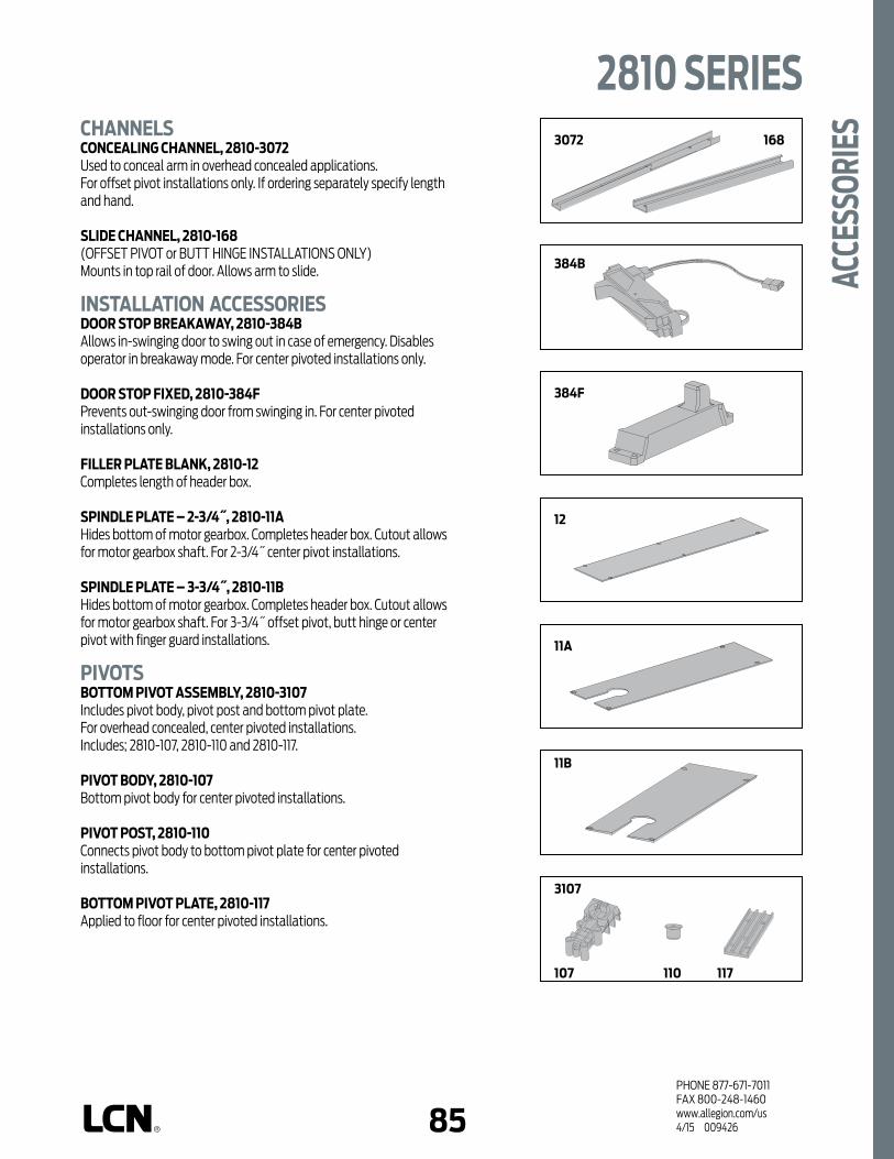
84 85PHONE 877-671-7011FAX 800-248-1460www.allegion.com/us 4/15 009426
CHANNELSCONCEALING CHANNEL, 2810-3072Used to conceal arm in overhead concealed applications. For offset pivot installations only. If ordering separately specify length and hand.
SLIDE CHANNEL, 2810-168 (OFFSET PIVOT or BUTT HINGE INSTALLATIONS ONLY)Mounts in top rail of door. Allows arm to slide.
INSTALLATION ACCESSORIESDOOR STOP BREAKAWAY, 2810-384BAllows in-swinging door to swing out in case of emergency. Disables operator in breakaway mode. For center pivoted installations only.
DOOR STOP FIXED, 2810-384FPrevents out-swinging door from swinging in. For center pivoted installations only.
FILLER PLATE BLANK, 2810-12Completes length of header box.
SPINDLE PLATE – 2-3/4˝, 2810-11AHides bottom of motor gearbox. Completes header box. Cutout allows for motor gearbox shaft. For 2-3/4˝ center pivot installations.
SPINDLE PLATE – 3-3/4˝, 2810-11BHides bottom of motor gearbox. Completes header box. Cutout allows for motor gearbox shaft. For 3-3/4˝ offset pivot, butt hinge or center pivot with finger guard installations.
PIVOTSBOTTOM PIVOT ASSEMBLY, 2810-3107Includes pivot body, pivot post and bottom pivot plate. For overhead concealed, center pivoted installations. Includes; 2810-107, 2810-110 and 2810-117.
PIVOT BODY, 2810-107Bottom pivot body for center pivoted installations.
PIVOT POST, 2810-110Connects pivot body to bottom pivot plate for center pivoted installations.
BOTTOM PIVOT PLATE, 2810-117Applied to floor for center pivoted installations.
384B
384F
12
11A
11B
107 110 117
3072 168
2810 SERIES
ACCE
SSOR
IES
3107

PHONE 877-671-7011FAX 800-248-1460www.allegion.com/us 4/15 00942686
HOW-TO-ORDER 2810 SERIES OPERATORS1. SELECT INSTALLATION TYPE 28112. SPECIFY ARM 3-3/4˝ (Offset pivoted) Arm (3077OP) 2-3/4˝ (Center pivoted) Arm (3077CP) 3-3/4˝ (Center pivoted) Arm (3077CP)3. SPECIFY HAND RH LH4. SPECIFY HEADER/LENGTH HL__ (Specify length 33˝ to 49˝ offset pivot) HL__ (Specify length 36˝ to 49˝ center pivot) DD__ (Specify length 49˝ to 98˝)5. SPECIFY FINISH Standard Anodized Finish ______________
Aluminum or Dark Bronze.
OPERATOR OPTIONSSTOPS* Positive Mechanical Stop (POS) Panic Breakaway Stop (BKY)
*Available with Center Pivoted installations only.
2810 SERIESOR
DERI
NG IN
FORM
ATIO
N
Operator will be shipped with:- MOTOR GEARBOX,- CONTROL BOX,- HEADER (at specified Length, 36˝ standard),- WOOD and MACHINE SCREW PACKUnless options listed below are selected.
2811
DOOR WIDTH
33"838mm
48"1219mm
MinimumDoor
Width
Indicates recommended range of door width for operator.
NOTE: For all Senior Swing Series. Single Door - Width per leaf 33˝ minimum, 48˝ maximum.
TABLE OF SIZES

86 87PHONE 877-671-7011FAX 800-248-1460www.allegion.com/us 4/15 009426
STANDARD ANODIZED
FINISHHANDING
HANDED*
NON-HANDED
COVER
METAL
ARM FUNCTION
STANDARD (S
INGLE
LEVER)
REGULAR (D
OUBLE LE
VER)
OFFSET PIVOT BUTT HIN
GE ARM
CENTER PIVOT ARM
DOUBLE EGRESS (P
USH/PULL)
MOUNTING
SURFACE M
OUNT SINGLE
DOOR
SURFACE M
OUNT SIMULTA
NEOUS PAIR
SURFACE M
OUNT INDEPENDENT PAIR
CONCEALED SIN
GLE DOOR
CONCEALED IN
DEPENDENT PAIR
CONCEALED SIM
ULTANEOUS PAIR
The 2850 SENIOR SWING by LCN is an
ADA door operator that is a two-in-one
swing door operator. SENIOR SWING
operator when activated, opens doors
automatically for wheelchair access,
yet allows for manual operation for
regular pedestrian traffic.
n Push ‘N Go permits non-switch activation.
n Power Boost provides additional latching force.
n Electromechanical unit with microprocessor control.
n Digital keypad for easy setup. n Meets International Building Code
requirements and ANSI A156.19. n UL approved for fire doors.
2850 Series is fully compliant with
UL 325 & UL 1998 and meets the
provisions of ANSI A156.19. The 2850
Series is UL listed for fire-rated
applications. The 2850 Series also
meets the provisions of the Americans
with Disabilities Act.
n 2850 Series operator is shipped with motor gearboxes, control box, arms, bottom pivot, header, and mounting hardware. Actuators available separately, see pages 122-137.
n Simultaneous pair, overhead concealed.
n Meets ADA, requirements (power mode only).
n Handed for double egress applications only.
n 72˝ header length is standard. Specify other length 52˝ to 98˝ max. Consult factory regarding this option.
n Optional fixed (POS) or breakaway stop (BKY) available (center pivot arm). Header lengths 70˝ to 98˝ max with either (POS) or (BKY) option.
n Adjustable hold time period of 1 to 32 seconds.
OPERATOR MOUNTS SIMULTANEOUS PAIR, OVERHEAD CONCEALED
*CENTER PIVOTOFFSET PIVOT/BUTT HINGE
*CENTER PIVOT arm shown
2850 SERIES
FEAT
URES
AVAILABLE NOT AVAILABLE
* For double egress only.

PHONE 877-671-7011FAX 800-248-1460www.allegion.com/us 4/15 00942688
n Head Frame minimum 52˝ (L) x 5-3/4˝ (H) x 4-1/2˝ (W) (1524 mm x 146 mm x 114 mm).
n Top Rail minimum 2˝ (51 mm).
n Opening & Closing Time are variable by adjustments to the electronic control box. Maximum hold open time adjustable up to approximately 32 seconds.
n Door Stop required for each door panel.
n System Diagram see “AUTOMATIC OPERATORS” section pages 53 for typical system wiring and page 56 for electrical data.
3
3/4
" 95 MM
8'-0" DOOR OPENING (MAX.)
SWING OPERATOR
4
1/2
" 114 MM
5
3/4
" 146 MM
SWING DIRECTION
EXTERIOR
INCOMING
INCOMING
3
3/4
" 95 MM
1" 25 MM
1" 25 MM
EXTERIOR
EMERGENCY BREAKAWAY
EMERGENCY BREAKAWAY
1/8" 3 MM
BREAKAWAYDIRECTION
BREAKAWAYSTOP
3
3/4
" 95 MM
8'-0" DOOR OPENING (MAX.)
SWING OPERATOR
4
1/2
" 114 MM
5
3/4
" 146 MM
SWING DIRECTION
EXTERIOR
3
3/4
" 95 MM
1" 25 MM
1" 25 MM
EXTERIOR
1/8" 3 MM
OUTGOING
OUTGOING
FIXED STOP
Shown w/ 3-3/4˝ pivot
Shown w/ 3-3/4˝ pivot
2850 SERIESM
OUNT
ING
DETA
ILS CONCEALED
SIMULTANEOUS PAIR (CENTER PIVOT, EMERGENCY BREAKAWAY, PULL) MOUNTINGMinimum header length 52˝ with applied stop by others and 70˝ with LCN fixed or breakaway stop.
CONCEALED SIMULTANEOUS PAIR (CENTER PIVOT, FIXED STOP, PUSH) MOUNTINGMinimum header length 52˝ with applied stop by others and 70˝ with LCN fixed or breakaway stop.
MAXIMUM OPENINGTemplate allows 90 degree power opening and 90 degree manual opening.
Contact LCN Product Support for installation assistance.

88 89PHONE 877-671-7011FAX 800-248-1460www.allegion.com/us 4/15 009426
n Head Frame minimum 52˝ (L) x 5-3/4˝ (H) x 4-1/2˝ (W) (1524 mm x 146 mm x 114 mm).
n Top Rail minimum 2˝ (51 mm).
n Opening & Closing Time are variable by adjustments to the electronic control box. Maximum hold open time adjustable up to approximately 32 seconds.
n Door Stop required for each door panel.
n System Diagram see “AUTOMATIC OPERATORS” section pages 53 for typical system wiring and page 56 for electrical data.
CONCEALED SIMULTANEOUS PAIR (OFFSET PIVOT/BUTT HINGE, PUSH) MOUNTINGOffset pivot installations require a bottom pivot and two intermediate pivots.
MAXIMUM OPENINGTemplate allows 90 degree power opening and 90 degree manual opening.
SWINGOPERATOR
4 1/2"114 MM
5 3/4"146 MM
SWINGDIRECTION
1/8"3 MM
OUTGOING OUTGOING
3 3/4"95 MM
10 1/2"267 MM
11"SLIDE
CHANNEL
OFFSETPIVOTSorBUTTHINGES
SLIDE ARM ASS'YWITH SLIDE BLOCK
EXTERIOR
CONCEALINGCHANNEL
DOOR
DOORFRAME
SLIDE ARMASS'Y
CONCEALINGCHANNEL
2850 SERIES
MOU
NTIN
G DE
TAIL
S
Contact LCN Product Support for installation assistance.

PHONE 877-671-7011FAX 800-248-1460www.allegion.com/us 4/15 00942690
MOTOR GEARBOXMOTOR GEARBOX – SENIOR SWING, 2850-3454Driving mechanism for operator. Provides maximum of 15 lbs opening force. Handed.
MOUNTING BRACKETMOUNTING BRACKET – 3-3/4˝, 2850-375Motor gearbox mounting bracket for 3-3/4˝ offset pivot, butt hinge or center pivot with finger guard installations. Front bracket.
MOUNTING BRACKET – 2-3/4˝, 2850-275Motor gearbox mounting bracket for 2-3/4˝ center pivot installations. Front bracket.
REAR MOUNT BRACKET, 2850-3018Motor gearbox mounting bracket. Rear bracket.
CONTROL BOXESCONTROL BOX – SENIOR SWING, 2850-3462Electronic controlling device for Senior Swing.
COMPANION CABLE, 2850-982Cable that allows one control box to run two motor gearboxes. For use with Senior Swing.
HEADERSHEADER, 2850-3572HLStandard, mounting header. Pair door, two operators. Specify length 52˝ to 98˝ maximum.
END CAPSHEADER END CAPS, 2850-334End cap with openings for wiring.
ARMSCENTER PIVOT ARM, 2850-3077CP (CENTER PIVOT INSTALLATIONS ONLY)Used with overhead concealed operators and center pivoted doors.
OFFSET PIVOT ARM, 2850-3077OP (OFFSET PIVOT OR BUTT HUNG INSTALLATIONS ONLY)Handed arm. Used with overhead concealed operators.
OFFSET PIVOT ARM ASSEMBLY COMPLETE, 2850-3077OPCM Offset arm with track and concealing channel. Includes 3072 Concealing Channel, 168 Slide Channel and 30770P offset pivot arm.
3454
375 275 3018
3462
982
3572HL
334
3077CP 3077OP
2850 SERIESAC
CESS
ORIE
S
30770PCM
168 3072 30770P

90 91PHONE 877-671-7011FAX 800-248-1460www.allegion.com/us 4/15 009426
CHANNELSCONCEALING CHANNEL, 2850-3072Used to conceal arm in overhead concealed applications. For offset pivot and butt hinges installations only. If ordering separately specify length and hand.
SLIDE CHANNEL, 2850-168 (OFFSET PIVOT or BUTT HINGE INSTALLATIONS ONLY)Mounts in top rail of door. Allows arm to slide.
INSTALLATION ACCESSORIESDOOR STOP BREAKAWAY, 2850-384BAllows in-swinging door to swing out in case of emergency. For center pivoted installations only.
DOOR STOP FIXED, 2850-384FPrevents out-swinging door from swinging in. For center pivoted installations only.
FILLER PLATE BLANK, 2850-12Completes length of header box.
SPINDLE PLATE – 2-3/4˝, 2850-11AHides bottom of motor gearbox. Completes header box. Cutout allows for motor gearbox shaft. For 2-3/4˝ center pivot hinge installations.
SPINDLE PLATE – 3-3/4˝, 2850-11BHides bottom of motor gearbox. Completes header box. Cutout allows for motor gearbox shaft. For 3-3/4˝ offset pivot, butt hinge or center pivot with finger guard installations.
PIVOTSBOTTOM PIVOT ASSEMBLY, 2850-3107Includes pivot body, pivot post and bottom pivot plate. For overhead concealed, center pivoted installations. Includes; 2850-107, 2850-110 and 2850-117.
PIVOT BODY, 2850-107Bottom pivot body for center pivoted installations.
PIVOT POST, 2850-110Connects pivot body to bottom pivot plate for center pivoted installations.
BOTTOM PIVOT PLATE, 2850-117Applied to floor for center pivoted installations.
384B
384F
12
11A
11B
3107
107 110 117
3072 168
2850 SERIES
ACCE
SSOR
IES

PHONE 877-671-7011FAX 800-248-1460www.allegion.com/us 4/15 00942692
HOW-TO-ORDER 2850 SERIES OPERATORS1. SELECT INSTALLATION TYPE 28532. SPECIFY ARMS 3-3/4˝ (Offset pivoted) Arm (3077OP) 2-3/4˝ (Center pivoted) Arm (3077CP) 3-3/4˝ (Center pivoted) Arm (3077CP)3. SPECIFY HAND (if double egress) RH LH4. SPECIFY HEADER/LENGTHS HL__ (Specify length 52˝ to 98˝)5. SPECIFY FINISH Standard Anodized Finish ______________
Aluminum or Dark Bronze.
OPERATOR OPTIONSSTOPS* Pair Positive Mechanical Stop (POS) Pair Panic Breakaway Stop (BKY)
*Available with Center Pivoted installations only.
Operator will be shipped with:- STANDARD MOTOR GEARBOX (1 LH & 1 RH),- STANDARD CONTROL BOX,- COMPANION CABLE,- HEADER (at specified length - 72˝ standard),- 2-3/4˝ PIVOT POINT,- WOOD and MACHINE SCREW PACKUnless options listed below are selected.
2850 SERIESOR
DERI
NG IN
FORM
ATIO
N
2853
COMBINED DOOR WIDTH
52"1524mm
96"2438mm
MinimumCombined
Door Width
Indicates recommended range of door width for operator.
NOTE: For all Senior Swing Series. Simultaneous Pair – Width per leaf 26" minimum to 48˝ maximum.
TABLE OF SIZES

92 93PHONE 877-671-7011FAX 800-248-1460www.allegion.com/us 4/15 009426
STANDARD ANODIZED
FINISHHANDING
HANDED*
NON-HANDED
COVER
METAL
ARM FUNCTION
STANDARD (S
INGLE
LEVER)
REGULAR (D
OUBLE LE
VER)
OFFSET PIVOT BUTT HIN
GE ARM
CENTER PIVOT ARM
DOUBLE EGRESS (P
USH/PULL)
MOUNTING
SURFACE M
OUNT SINGLE
DOOR
SURFACE M
OUNT SIMULTA
NEOUS PAIR
SURFACE M
OUNT INDEPENDENT PAIR
CONCEALED SIN
GLE DOOR
CONCEALED IN
DEPENDENT PAIR
CONCEALED SIM
ULTANEOUS PAIR
The 2860 SENIOR SWING by LCN is an
ADA door operator that is a two-in-one
swing door operator. SENIOR SWING
operator when activated, opens doors
automatically for wheelchair access,
yet allows for manual operation for
regular pedestrian traffic.
n Push ‘N Go permits non-switch activation.
n Power Boost provides additional latching force.
n Electromechanical unit with microprocessor control.
n Digital keypad for easy setup. n Meets International Building Code
requirements and ANSI A156.19. n UL approved for fire doors.
2860 Series is fully compliant with UL 325 &
UL 1998 and meets the provisions of ANSI
A156.19. The 2860 Series is UL listed for
fire-rated applications. The 2860 Series
also meets the provisions of the Americans
with Disabilities Act.
n 2860 Series operator is shipped with motor gearboxes, control boxes, bottom pivots, arms, header, and mounting hardware. Actuators available separately, see pages 122-137.
n Independent pair of doors, overhead concealed.
n Meets ADA, requirements (power mode only).
n Handed for double egress applications only.
n 72˝ header length is standard. Specify other length 65˝ to 98˝ max. Consult factory regarding this option.
n Optional fixed (POS) or breakaway stop (BKY) available (center pivot arm) - Header lengths 70˝ to 98˝ max with either (POS) or (BKY).
n Adjustable hold open time of 1 to 32 seconds.
OPERATOR MOUNTS INDEPENDENT PAIR, OVERHEAD CONCEALED
*CENTER PIVOTOFFSET PIVOT/BUTT HINGE
*CENTER PIVOT arm shown
2860 SERIES
FEAT
URES
AVAILABLE NOT AVAILABLE
* For double egress only.

PHONE 877-671-7011FAX 800-248-1460www.allegion.com/us 4/15 00942694
n Head Frame minimum 65˝ (L) x 5 3/4" (H) x 4 1/2" (W) (1651 mm x 146 mm x 114 mm).
n Top Rail minimum 2˝ (51 mm).
n Opening & Closing Time are variable by adjustments to the electronic control box. Maximum hold open time adjustable up to approximately 32 seconds.
n Door Stop required for each door panel.
n System Diagram see “AUTOMATIC OPERATORS” section pages 53 for typical system wiring and page 56 for electrical data.
CONCEALED INDEPENDENT PAIR (CENTER PIVOT, EMERGENCY BREAKAWAY, PULL) MOUNTINGMinimum header length 65˝ with applied stop by other and 70˝ with LCN Positive or Breakaway Stop.
CONCEALED INDEPENDENT PAIR (CENTER PIVOT, FIXED STOP, PUSH) MOUNTINGMinimum header length 65˝ with applied stop by others and 70˝ with LCN Positive or Breakaway Stop.
MAXIMUM OPENINGTemplate allows 90 degree power opening and 90 degree manual opening.
3
3/4
" 95 MM
8'-0" DOOR OPENING (MAX.)
SWING OPERATOR
4
1/2
" 114 MM
5
3/4
" 146 MM
SWING DIRECTION
EXTERIOR
INCOMING
INCOMING
3
3/4
" 95 MM
1" 25 MM
1" 25 MM
EXTERIOR
EMERGENCY BREAKAWAY
EMERGENCY BREAKAWAY
1/8" 3 MM
BREAKAWAYDIRECTION
BREAKAWAYSTOP
3
3/4
" 95 MM
8'-0" DOOR OPENING (MAX.)
SWING OPERATOR
4
1/2
" 114 MM
5
3/4
" 146 MM
SWING DIRECTION
EXTERIOR
3
3/4
" 95 MM
1" 25 MM
1" 25 MM
EXTERIOR
1/8" 3 MM
OUTGOING
OUTGOING
FIXED STOP
Shown w/ 3-3/4˝ pivot
Shown w/ 3-3/4˝ pivot
2860 SERIES
Contact LCN Product Support for installation assistance.

94 95PHONE 877-671-7011FAX 800-248-1460www.allegion.com/us 4/15 009426
n Head Frame minimum 65˝ (L) x 5-3/4˝ (H) x 4-1/2˝ (W) (1651 mm x 146 mm x 114 mm).
n Top Rail minimum 2˝ (51 mm).
n Opening & Closing Time are variable by adjustments to the electronic control box. Maximum hold open time adjustable up to approximately 32 seconds.
n Door Stop required for each door panel.
n System Diagram see “AUTOMATIC OPERATORS” section pages 53 for typical system wiring and page 56 for electrical data.
CONCEALED INDEPENDENT PAIR (OFFSET PIVOT/BUTT HINGE, PUSH) MOUNTINGOffset pivot installations require a bottom pivot and two intermediate pivots.
MAXIMUM OPENINGTemplate allows 90 degree power opening and 90 degree manual opening.
SWINGOPERATOR
4 1/2"114 MM
5 3/4"146 MM
SWINGDIRECTION
1/8"3 MM
OUTGOING OUTGOING
3 3/4"95 MM
10 1/2"267 MM
11"SLIDE
CHANNEL
OFFSETPIVOTSorBUTTHINGES
SLIDE ARM ASS'YWITH SLIDE BLOCK
EXTERIOR
CONCEALINGCHANNEL
DOOR
DOORFRAME
SLIDE ARMASS'Y
CONCEALINGCHANNEL
2860 SERIES
Contact LCN Product Support for installation assistance.

PHONE 877-671-7011FAX 800-248-1460www.allegion.com/us 4/15 00942696
MOTOR GEARBOXMOTOR GEARBOX – SENIOR SWING, 2860-3454Driving mechanism for operator. Provides maximum of 15 lbs opening force. Handed.
MOUNTING BRACKETMOUNTING BRACKET – 3-3/4˝, 2860-375Motor gearbox mounting bracket for 3-3/4˝ offset pivot, butt hinge or center pivot with finger guard installations. Front bracket.
MOUNTING BRACKET – 2-3/4˝, 2860-275Motor gearbox mounting bracket for 2-3/4˝ center pivot installations. Front bracket.
REAR MOUNT BRACKET, 2860-3018Motor gearbox mounting bracket. Rear bracket.
CONTROL BOXESCONTROL BOX – SENIOR SWING, 2860-3462Electronic controlling device for Senior Swing.
HEADERSHEADER, 2860-3572HLStandard, mounting header. Pair door, two operators. Specify length 65˝ to 98˝ maximum.
END CAPSHEADER END CAPS, 2860-334End cap with openings for wiring.
ARMSCENTER PIVOT ARM, 2860-3077CP (CENTER PIVOT INSTALLATIONS ONLY)Used with overhead concealed operators and center pivoted doors.
OFFSET PIVOT ARM, 2860-3077OP (OFFSET PIVOT OR BUTT HUNG INSTALLATIONS ONLY)Used with overhead concealed operators.
OFFSET PIVOT ARM ASSEMBLY COMPLETE, 2860-3077OPCM Offset arm with track and concealing channel. Includes 3072 Concealing Channel, 168 Slide Channel and 30770P offset pivot arm.
3454
375 275 3018
3462
3572HL
334
3077CP 3077OP
2860 SERIESAC
CESS
ORIE
S
30770PCM
168 3072 30770P

96 97PHONE 877-671-7011FAX 800-248-1460www.allegion.com/us 4/15 009426
CHANNELSCONCEALING CHANNEL, 2860-3072Used to conceal arm in overhead concealed applications. For offset pivot and butt hinge installations only. If ordering separately specify length and hand.
SLIDE CHANNEL, 2860-168 (OFFSET PIVOT or BUTT HINGE INSTALLATIONS ONLY)Mounts in top rail of door. Allows arm to slide.
INSTALLATION ACCESSORIESDOOR STOP BREAKAWAY, 2860-384BAllows in-swinging door to swing out in case of emergency. For center pivoted installations only.
DOOR STOP FIXED, 2860-384FPrevents out-swinging door from swinging in. For center pivoted installations only.
FILLER PLATE BLANK, 2860-12Completes length of header box.
SPINDLE PLATE – 2-3/4˝, 2860-11AHides bottom of motor gearbox. Completes header box. Cutout allows for motor gearbox shaft. For 2-3/4˝ center pivot hinge installations.
SPINDLE PLATE – 3-3/4˝, 2860-11BHides bottom of motor gearbox. Completes header box. Cutout allows for motor gearbox shaft. For 3-3/4˝ offset pivot/butt hinge or center pivot with finger guard installations.
PIVOTSBOTTOM PIVOT ASSEMBLY, 2860-3107Includes pivot body, pivot post and bottom pivot plate. For overhead concealed, center pivoted installations. Includes; 2860-107, 2860-110 and 2860-117.
PIVOT BODY, 2860-107Bottom pivot body for center pivoted installations.
PIVOT POST, 2860-110Connects pivot body to bottom pivot plate for center pivoted installations.
BOTTOM PIVOT PLATE, 2860-117Applied to floor for center pivoted installations.
384B
384F
12
11A
11B
107 110 117
3072 168
2860 SERIES
ACCE
SSOR
IES
3107

PHONE 877-671-7011FAX 800-248-1460www.allegion.com/us 4/15 00942698
HOW-TO-ORDER 2860 SERIES OPERATORS1. SELECT INSTALLATION TYPE 28632. SPECIFY ARMS Standard 3-3/4˝ (Offset pivoted) Arm (3077OP) Standard 2-3/4˝ (Center pivoted) Arm (3077CP) Standard 3-3/4˝ (Center pivoted) Arm (3077CP)3. SPECIFY HAND (only for double egress) RH LH4. SPECIFY HEADER/LENGTHS HL__ (Specify length 65˝ to 98˝)5. SPECIFY FINISH Standard Anodized Finish ______________
Aluminum or Dark Bronze.
OPERATOR OPTIONSSTOPS* Pair Positive Mechanical Stop (POS) Pair Panic Breakaway Stop (BKY)
*Available with Center Pivoted installations only.
Operator will be shipped with:- STANDARD MOTOR GEARBOX (1 LH & 1 RH),- STANDARD CONTROL BOX (2 ea),- HEADER (at specified length, 72˝ standard),- 2-3/4˝ PIVOT POINT,- WOOD and MACHINE SCREW PACKUnless options listed below are selected.
2860 SERIESOR
DERI
NG IN
FORM
ATIO
N
2863
DOOR WIDTH
65"1651mm
96"2438mm
MinimumDoor
Width
Indicates recommended range of door width for operator.
NOTE: For all Senior Swing Series. Independent Pair – Width per leaf 32-1/2˝ minimum to 48˝ maximum.
TABLE OF SIZES
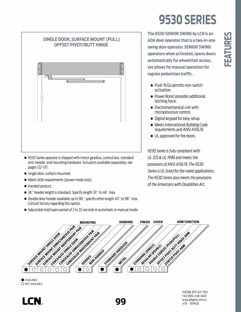
98 99PHONE 877-671-7011FAX 800-248-1460www.allegion.com/us 4/15 009426
STANDARD ANODIZED
FINISHHANDING
HANDED
NON-HANDED
COVER
METAL
ARM FUNCTION
STANDARD (S
INGLE
)
REGULAR (D
OUBLE)
OFFSET PIVOT BUTT HIN
GE ARM
CENTER PIVOT ARM
DOUBLE EGRESS (P
USH/PULL)
MOUNTING
SURFACE M
OUNT SINGLE
DOOR
SURFACE M
OUNT SIMULTA
NEOUS PAIR
SURFACE M
OUNT INDEPENDENT PAIR
CONCEALED SIN
GLE DOOR
CONCEALED IN
DEPENDENT PAIR
CONCEALED SIM
ULTANEOUS PAIR
The 9530 SENIOR SWING by LCN is an
ADA door operator that is a two-in-one
swing door operator. SENIOR SWING
operators when activated, opens doors
automatically for wheelchair access,
yet allows for manual operation for
regular pedestrian traffic.
n Push ‘N Go permits non-switch activation.
n Power Boost provides additional latching force.
n Electromechanical unit with microprocessor control.
n Digital keypad for easy setup. n Meets International Building Code
requirements and ANSI A156.19. n UL approved for fire doors.
9530 Series is fully compliant with
UL 325 & UL 1998 and meets the
provisions of ANSI A156.19. The 9530
Series is UL listed for fire-rated applications.
The 9530 Series also meets the provisions
of the Americans with Disabilities Act.
n 9530 Series operator is shipped with motor gearbox, control box, standard arm, header, and mounting hardware. Actuators available separately, see pages 122-137.
n Single door, surface mounted.
n Meets ADA requirements (power mode only).
n Handed product.
n 36˝ header length is standard. Specify length 33˝ to 48˝ max.
n Double door header available up to 98˝, specify other length 49˝ to 98˝ max. Consult factory regarding this option.
n Adjustable hold open period of 2 to 32 seconds in automatic or manual mode.
SINGLE DOOR, SURFACE MOUNT (PULL)OFFSET PIVOT/BUTT HINGE
9530 SERIES
FEAT
URES
AVAILABLE NOT AVAILABLE
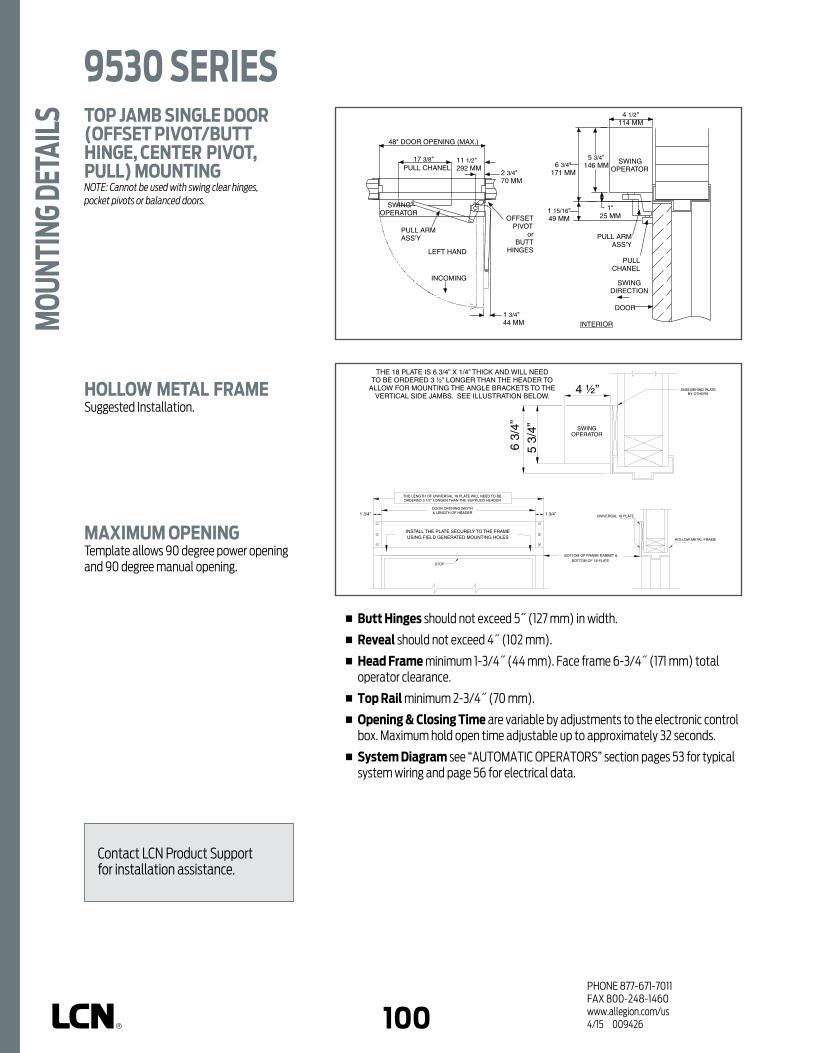
PHONE 877-671-7011FAX 800-248-1460www.allegion.com/us 4/15 009426100
n Butt Hinges should not exceed 5˝ (127 mm) in width.
n Reveal should not exceed 4˝ (102 mm).
n Head Frame minimum 1-3/4˝ (44 mm). Face frame 6-3/4˝ (171 mm) total operator clearance.
n Top Rail minimum 2-3/4˝ (70 mm).
n Opening & Closing Time are variable by adjustments to the electronic control box. Maximum hold open time adjustable up to approximately 32 seconds.
n System Diagram see “AUTOMATIC OPERATORS” section pages 53 for typical system wiring and page 56 for electrical data.
TOP JAMB SINGLE DOOR (OFFSET PIVOT/BUTT HINGE, CENTER PIVOT, PULL) MOUNTINGNOTE: Cannot be used with swing clear hinges, pocket pivots or balanced doors.
HOLLOW METAL FRAMESuggested Installation.
MAXIMUM OPENINGTemplate allows 90 degree power opening and 90 degree manual opening.
PULL ARM ASS'Y
OFFSET PIVOT
or BUTT
HINGES
2
3/4
" 70 MM
SWING OPERATOR
48" DOOR OPENING (MAX.)
INCOMING
LEFT HAND
PULL CHANEL
1
3/4
" 44 MM
SWING OPERATOR
4
1/2
" 114 MM
6
3/4
" 171 MM
5
3/4
" 146 MM
DOOR
SWING DIRECTION
INTERIOR
PULL CHANEL
PULL ARM ASS'Y
1 " 25 MM
1
15/16
" 49 MM
17
3/8
"
11
1/2
" 292 MM
9530 SERIESM
OUNT
ING
DETA
ILS
Contact LCN Product Support for installation assistance.

100 101PHONE 877-671-7011FAX 800-248-1460www.allegion.com/us 4/15 009426
MOTOR GEARBOXMOTOR GEARBOX – SENIOR SWING, 9530-3454Driving mechanism for operator. Provides maximum of 15 lbs opening force. Handed.
MOUNTING BRACKETMOUNTING BRACKET – 2-3/4˝, 9530-275Motor gearbox mounting bracket for 2-3/4˝ offset pivot or butt hinge installations. Front bracket.
REAR MOUNT BRACKET, 9530-3018Motor gearbox mounting bracket. Rear bracket.
ANGLED BRACKET, 9530-334-1Mounting bracket for surface applications. (Includes 2 mounting brackets).
CONTROL BOXESCONTROL BOX – SENIOR SWING, 9530-3462Electronic controlling device for Senior Swing.
HEADERSHEADER, 9530-3572HLStandard, mounting header. Single door, single operator. Specify length 33˝ to 48˝ maximum.
HEADER, 9530-3572DDStandard, mounting header. Double door, single operator. Specify length 49˝ to 98˝ maximum.
END CAPSHEADER END CAPS, 9530-334End cap with openings for wiring.
END DRESS PLATE, 9530-334-2Metal finish end cap.
3454
275 3018 334-1 (2)
3462
3572HL
3572DD
334 334-2
9530 SERIES
ACCE
SSOR
IES

PHONE 877-671-7011FAX 800-248-1460www.allegion.com/us 4/15 009426102
ARMSSTANDARD ARM ASSEMBLY, 9530-3077PLCMHanded arm. Track roller included. (Includes 3038, 3077T, 3034 & 73).
STANDARD ARM, 9530-3077THanded arm. Track roller not included.
TRACKSTRACK 9530-3038Standard non-handed track. (Includes 3034 & 73).
TRACK END CAP 9530-73Black plastic end caps.
ROLLER, 9530-3034Quiet low friction roller assembly.
INSTALLATION ACCESSORIESSPINDLE PLATE – 2-3/4˝, 9530-11AHides bottom of motor gearbox. Completes header box. Cutout allows for motor gearbox shaft. For 2-3/4˝ offset pivot or butt hinge installations.
FILLER PLATE BLANK, 9530-12Completes length of header box. (Specify Length).
MOUNTING PLATE, 9530-18Optional mounting plate for standard hollow metal door frames. Specify length 36-1/2˝ to 101-1/2˝ maximum, when angle brackets. Specify length 33˝ to 98˝ maximum when using end dress plates.NOTE: The length of a universal 18 plate will need to be ordered 3-1/2˝ longer than the
supplied header when using angle brackets.
3077PLCM
3077T
11A
73
12
18
9530 SERIESAC
CESS
ORIE
S
3077T
3038
3038 3034

102 103PHONE 877-671-7011FAX 800-248-1460www.allegion.com/us 4/15 009426
9530 SERIES
ORDE
RING
INFO
RMAT
IONHOW-TO-ORDER
9530 SERIES OPERATORS1. SPECIFY HAND RH LH2. SPECIFY HEADER/LENGTH HL __ (Specify length 33˝ to 48˝) DD __ (Specify length 49˝ to 98˝)3. SPECIFY FINISH Standard Anodized Finish __________
Aluminum or Dark Bronze.
OPERATOR OPTIONSMOUNTING PLATE Plate, ____ (Specify Length 33˝ to 101-1/2˝)
Operator will be shipped with:- STANDARD MOTOR GEARBOX,- STANDARD CONTROL BOX,- HEADER (at specified Length, 36˝ standard),- STANDARD ARM (3077T),- 2-3/4˝ PIVOT POINT,- STANDARD TRACK w/TRACK ROLLER,- MACHINE SCREW PACKUnless options listed below are selected.
9531
DOOR WIDTH
33"838mm
48"1219mm
MinimumDoor
Width
Indicates recommended range of door width for operator.
NOTE: For all Senior Swing Series. Single Door - Width per leaf 33˝ minimum, 48˝ maximum.
TABLE OF SIZES

PHONE 877-671-7011FAX 800-248-1460www.allegion.com/us 4/15 009426104
Notes

104 105PHONE 877-671-7011FAX 800-248-1460www.allegion.com/us 4/15 009426
STANDARD ANODIZED
FINISHHANDING
HANDED
NON-HANDED
COVER
METAL
ARM FUNCTION
STANDARD (S
INGLE
LEVER)
REGULAR (D
OUBLE LE
VER)
OFFSET PIVOT BUTT HIN
GE ARM
CENTER PIVOT ARM
DOUBLE EGRESS (P
USH/PULL)
MOUNTING
SURFACE M
OUNT SINGLE
DOOR
SURFACE M
OUNT SIMULTA
NEOUS PAIR
SURFACE M
OUNT INDEPENDENT PAIR
CONCEALED SIN
GLE DOOR
CONCEALED IN
DEPENDENT PAIR
CONCEALED SIM
ULTANEOUS PAIR
The 9540 SENIOR SWING by LCN is an
ADA door operator that is a two-in-one
swing door operator. SENIOR SWING
operators when activated, opens doors
automatically for wheelchair access,
yet allows for manual operation for
regular pedestrian traffic.
n Push ‘N Go permits non-switch activation.
n Power Boost provides additional latching force.
n Electromechanical unit with microprocessor control.
n Digital keypad for easy setup. n Meets International Building Code
requirements and ANSI A156.19. n UL approved for fire doors.
9540 Series is fully compliant with
UL 325 & UL 1998 and meets the
provisions of ANSI A156.19. The 9540
Series is UL listed for fire-rated
applications. The 9540 Series also
meets the provisions of the Americans
with Disabilities Act.
n 9540 Series operator is shipped with motor gearbox, control box, regular arm, header, and mounting hardware. Actuators available separately, see pages 122-137.
n Single door, surface mounted.
n Meets ADA requirements (power mode only).
n Handed product.
n 36˝ header length is standard. Specify length 33˝ to 48˝ max.
n Double door header available up to 98˝, specify other length 49˝ to 98˝ max. Consult factory regarding this option.
n Adjustable hold open period of 2 to 32 seconds in automatic or manual mode.
SINGLE DOOR, SURFACE MOUNT (PUSH)OFFSET PIVOT/BUTT HINGE
9540 SERIES
FEAT
URES
AVAILABLE NOT AVAILABLE

PHONE 877-671-7011FAX 800-248-1460www.allegion.com/us 4/15 009426106
n Butt Hinges should not exceed 5˝ (127 mm) in width.
n Reveal for push installations should not exceed 10˝ (254 mm) for REGULAR ARM and 20˝ (508 mm) for LONG ARM.
n Head Frame minimum 1-3/4˝ (44 mm). Face frame 6-3/4˝ (171 mm) total operator clearance.
n Top Rail minimum 2-3/4˝ (70 mm).
n Opening & Closing Time are variable by adjustments to the electronic control box. Maximum hold open time adjustable up to approximately 32 seconds.
n System Diagram see “AUTOMATIC OPERATORS” section pages 53 for typical system wiring and page 56 for electrical data.
TOP JAMB SINGLE DOOR (OFFSET PIVOT/BUTT HINGE, CENTER PIVOT, PUSH) MOUNTING
Consult factory for all balance door installations.
HOLLOW METAL FRAMESuggested Installation.
MAXIMUM OPENINGTemplate allows 90 degree power opening and 90 degree manual opening.
OUTGOING
PUSH ARM ASS'Y
17" From edge of door
OFFSET PIVOT
or BUTT
HINGES 2
3/4
" 70 MM
SWING OPERATOR
48" DOOR OPENING (MAX.)
RE
VE
AL
SWING OPERATOR
4
1/2
" 114 MM
6
3/4
" 171 MM
5
3/4
" 146 MM
1 " 25 MM
DOOR
SWING DIRECTION
DOOR FRAME
EXTERIOR
1
7/16
" From top of door
SECONDARY LINK
9540 SERIESM
OUNT
ING
DETA
ILS
Contact LCN Product Support for installation assistance.

106 107PHONE 877-671-7011FAX 800-248-1460www.allegion.com/us 4/15 009426
MOTOR GEARBOXMOTOR GEARBOX – SENIOR SWING, 9540-3454Driving mechanism for operator. Provides 15 lbs opening force. Handed.
MOUNTING BRACKETMOUNTING BRACKET – 2-3/4˝, 9540-275Motor gearbox mounting bracket for 2-3/4˝ offset pivot or butt hinge installations. Front bracket.
REAR MOUNT BRACKET, 9540-3018Motor gearbox mounting bracket. Rear bracket.
ANGLED BRACKET, 9540-334-1Mounting bracket for surface applications. (Includes 2 mounting brackets).
CONTROL BOXESCONTROL BOX – SENIOR SWING, 9540-3462Electronic controlling device for Senior Swing.
HEADERSHeader, 9540-3572HLStandard, mounting header. Single door, single operator. Specify length 33˝ to 48˝ maximum.
Header, 9540-3572DDStandard, mounting header. Double door, single operator. Specify length 49˝ to 98˝ maximum.
END CAPSHEADER END CAPS, 9540-334End cap with openings for wiring.
END DRESS PLATE, 9540-334-2Metal finish end cap.
3454
275 3018 334-1 (2)
3462
3572HL
3572DD
334 334-2
9540 SERIES
ACCE
SSOR
IES
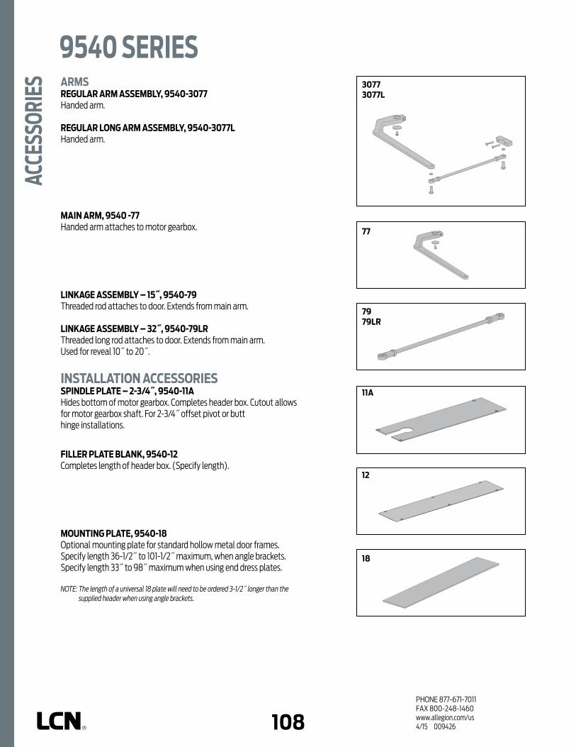
PHONE 877-671-7011FAX 800-248-1460www.allegion.com/us 4/15 009426108
ARMSREGULAR ARM ASSEMBLY, 9540-3077Handed arm.
REGULAR LONG ARM ASSEMBLY, 9540-3077LHanded arm.
MAIN ARM, 9540 -77Handed arm attaches to motor gearbox.
LINKAGE ASSEMBLY – 15˝, 9540-79Threaded rod attaches to door. Extends from main arm.
LINKAGE ASSEMBLY – 32˝, 9540-79LRThreaded long rod attaches to door. Extends from main arm.Used for reveal 10˝ to 20˝.
INSTALLATION ACCESSORIESSPINDLE PLATE – 2-3/4˝, 9540-11AHides bottom of motor gearbox. Completes header box. Cutout allows for motor gearbox shaft. For 2-3/4˝ offset pivot or butt hinge installations.
FILLER PLATE BLANK, 9540-12Completes length of header box. (Specify length).
MOUNTING PLATE, 9540-18Optional mounting plate for standard hollow metal door frames. Specify length 36-1/2˝ to 101-1/2˝ maximum, when angle brackets. Specify length 33˝ to 98˝ maximum when using end dress plates.
NOTE: The length of a universal 18 plate will need to be ordered 3-1/2˝ longer than the supplied header when using angle brackets.
30773077L
77
7979LR
11A
12
18
9540 SERIESAC
CESS
ORIE
S

108 109PHONE 877-671-7011FAX 800-248-1460www.allegion.com/us 4/15 009426
9540 SERIES
ORDE
RING
INFO
RMAT
IONHOW-TO-ORDER
9540 SERIES OPERATORS1. SPECIFY HAND RH LH2. SPECIFY HEADER/LENGTH HL __ (Specify length 33˝ to 48˝) DD __ (Specify length 49˝ to 98˝)3. SPECIFY FINISH Standard Anodized Finish __________
Aluminum or Dark Bronze.
OPERATOR OPTIONSMOUNTING PLATE Plate, ____ (Specify Length 33˝ to 101-1/2˝) ARM Long Arm (3077L)
Operator will be shipped with:- STANDARD MOTOR GEARBOX,- STANDARD CONTROL BOX,- HEADER (at specified length, 36˝ standard),- REGULAR ARM (3077),- 2-3/4˝ PIVOT POINT,- WOOD and MACHINE SCREW PACKUnless options listed below are selected.
9542
DOOR WIDTH
33"838mm
48"1219mm
MinimumDoor
Width
Indicates recommended range of door width for operator.
NOTE: For all Senior Swing Series. Single Door - Width per leaf 33˝ minimum, 48˝ maximum.
TABLE OF SIZES

PHONE 877-671-7011FAX 800-248-1460www.allegion.com/us 4/15 009426110
Notes

110 111PHONE 877-671-7011FAX 800-248-1460www.allegion.com/us 4/15 009426
STANDARD ANODIZED
FINISHHANDING
HANDED
NON-HANDED
COVER
METAL
ARM FUNCTION
STANDARD (S
INGLE
LEVER)
REGULAR (D
OUBLE LE
VER)
OFFSET PIVOT BUTT HIN
GE ARM
CENTER PIVOT ARM
DOUBLE EGRESS (P
USH/PULL)
MOUNTING
SURFACE M
OUNT SINGLE
DOOR
SURFACE M
OUNT SIMULTA
NEOUS PAIR
SURFACE M
OUNT INDEPENDENT PAIR
CONCEALED SIN
GLE DOOR
CONCEALED IN
DEPENDENT PAIR
CONCEALED SIM
ULTANEOUS PAIR
The 9550 SENIOR SWING by LCN is an
ADA door operator that is a two-in-one
swing door operator. SENIOR SWING
operators when activated, opens doors
automatically for wheelchair access,
yet allows for manual operation for
regular pedestrian traffic.
n Push ‘N Go permits non-switch activation.
n Power Boost provides additional latching force.
n Electromechanical unit with microprocessor control.
n Digital keypad for easy setup. n Meets International Building Code
requirements and ANSI A156.19. n UL approved for fire doors.
9550 Series is fully compliant with
UL 325 & UL 1998 and meets the
provisions of ANSI A156.19. The 9550
Series is UL listed for fire-rated
applications. The 9550 Series also
meets the provisions of the Americans
with Disabilities Act.
n 9550 Series operator is shipped with motor gearboxes, control box, arms, header, and mounting hardware. Actuators available separately, see pages 122-137.
n Simultaneous pair, surface mounted.
n Meets ADA requirements (power mode only).
n Handed product.
n Pull, Push or Double Egress applications available.
n 72˝ header length is standard. Specify other length 52" to 98" (Push). Specify other length 60" to 98" (Pull; Double Egress).
n Adjustable hold open period of 2 to 32 seconds in automatic or manual mode.
OPERATOR MOUNTS SIMULTANEOUS PAIR, SURFACE MOUNT
*PULL SIDEPUSH SIDE
DOUBLE EGRESS
*PULL SIDE mount shown
9550 SERIES
FEAT
URES
AVAILABLE NOT AVAILABLE

PHONE 877-671-7011FAX 800-248-1460www.allegion.com/us 4/15 009426112
n Butt Hinges should not exceed 5˝ (127 mm) in width.
n Reveal for push installations should not exceed 10˝ (254 mm) for REGULAR ARM and 20˝ (508 mm) for LONG ARM.
n Reveal for pull installations should not exceed 4˝ (102 mm).
n Reveal for double egress installations should not exceed 4˝ (102 mm).
n Head Frame minimum 1-3/4˝ (44 mm). Face frame 6-3/4˝ (171 mm) total operator clearance.
n Top Rail minimum 2-3/4˝ (70 mm).
n Opening & Closing Time are variable by adjustments to the electronic control box. Maximum hold open time adjustable up to approximately 32 seconds.
n System Diagram see “AUTOMATIC OPERATORS” section pages 53 for typical system wiring and page 56 for electrical data.
TOP JAMB SIMULTANEOUS PAIR (OFFSET PIVOT/BUTT HINGE, CENTER PIVOT, PUSH) MOUNTING
Consult factory for all balanced door installations.
TOP JAMB SIMULTANEOUS PAIR (OFFSET PIVOT/BUTT HINGE, CENTER PIVOT, PULL) MOUNTINGNOTE: Cannot be used with swing clear hinges, pocket pivots or balanced doors.
MAXIMUM OPENINGTemplate allows 90 degree power opening and 90 degree manual opening.
OUTGOING
PUSH ARM ASS'Y
17" From edge of door
OFFSET PIVOT or BUTT HINGES
2
3/4
" 70 MM
SWING OPERATOR
8'-0" DOOR OPENING (MAX.)
RE
VE
AL
OUTGOING
SWING OPERATOR
4
1/2
" 114 MM
6
3/4
" 171 MM
5
3/4
" 146 MM
1 " 25 MM
DOOR
SWING DIRECTION
DOOR FRAME
EXTERIOR
1
7/16
" From top of door
SECONDARY LINK
PULL ARM ASS'Y
OFFSET PIVOT
or BUTT
HINGES
2
3/4
" 70 MM
SWING OPERATOR
8'-0" DOOR OPENING (MAX.)
INCOMING
INCOMING
PULL CHANNEL
INTERIOR
17
3/8
" 441 MM
1
3/4
" 44 MM
11
1/2
" 291 MM
SWING OPERATOR
4
1/2
" 114 MM
6
3/4
" 171 MM
5
3/4
" 146 MM
1 " 25 MM
DOOR
SWING DIRECTION
PULL ARM ASS'Y
INTERIOR
PULL CHANNEL
1
1
5/16
" 49 MM
LCN 9550 SERIESM
OUNT
ING
DETA
ILS
Contact LCN Product Support for installation assistance.

112 113PHONE 877-671-7011FAX 800-248-1460www.allegion.com/us 4/15 009426
n Butt Hinges should not exceed 5˝ (127 mm) in width.
n Reveal for push installations should not exceed 10˝ (254 mm) for REGULAR ARM and 20˝ (508 mm) for LONG ARM.
n Reveal for pull installations should not exceed 4˝ (102 mm).
n Reveal for double egress installations should not exceed 4˝ (102 mm).
n Head Frame minimum 1-3/4˝ (44 mm). Face frame 6-3/4˝ (171 mm) total operator clearance.
n Top Rail minimum 2-3/4˝ (70 mm).
n Opening & Closing Time are variable by adjustments to the electronic control box. Maximum hold open time adjustable up to approximately 32 seconds.
n System Diagram see “AUTOMATIC OPERATORS” section pages 53 for typical system wiring and page 56 for electrical data.
TOP JAMB SIMULTANEOUS PAIR (RH DOUBLE EGRESS) MOUNTINGDouble egress applications with safety sensors require LCN 9560 series.NOTE: Cannot be used with swing clear hinges, pocket pivots or balanced door.
HOLLOW METAL FRAMESuggested Installation.
MAXIMUM OPENINGTemplate allows 90 degree power opening and 90 degree manual opening.
SWING OPERATOR
4
1/2
" 114 MM
INTERIOR
PUSH ARM ASS'Y
PULL ARM ASS'Y
SWING OPERATOR
SWING OPERATOR
48" DOOR OPENING (MAX.)
2 3/4
" 70 MM
48" DOOR OPENING (MAX.)
2
3/4
" 70 MM
1
3/4
" 44 MM
17" From edge of door
BUTT HINGES
11
1/2
" 292 MM
17
3/8
" PULL CHANNEL
SWING OPERATOR
4
1/2
" 114 MM
5
3/4
" 146 MM
5
3/
4
" 14
6 M
M
6
3/4
" 171 MM
SECONDARY LINK DOOR
FRAME
SWING DIRECTION
SWING DIRECTION
DOOR FRAME
DOOR
DOOR
1 " 25 MM
1
" 25 MM
2 3/
18"
FR
OM
BO
TTO
M
OF
DO
OR
STO
P
PULL ARM ASS'Y
PUSH ARM ASS'Y
1 15
/16"
FR
OM
TO
P O
F D
OO
R
PULL CHANNEL
BUTT HINGES
9550 SERIES
MOU
NTIN
G DE
TAIL
S
Contact LCN Product Support for installation assistance.

PHONE 877-671-7011FAX 800-248-1460www.allegion.com/us 4/15 009426114
MOTOR GEARBOXMOTOR GEARBOX – SENIOR SWING, 9550-3454Driving mechanism for operator. Provides 15 lbs opening force. Handed.
MOUNTING BRACKETSMOUNTING BRACKET – 2-3/4˝, 9550-275Motor gearbox mounting bracket for 2-3/4˝ offset pivot or butt hinge installations. Front bracket.
REAR MOUNT BRACKET, 9550-3018Motor gearbox mounting bracket. Rear bracket.
ANGLED BRACKET, 9550-334-1Mounting bracket for surface applications. (Includes 2 mounting brackets).
CONTROL BOXESCONTROL BOX – SENIOR SWING, 9550-3462Electronic controlling device for Senior Swing.
COMPANION CABLE, 9550-982Cable that allows one control box to run two motor gear boxes. Companion cable. For use with Senior Swing.
HEADERSHEADER, 9550-3572HLStandard, mounting header. Pair door, two operators. Specify other length 52" to 98" (Push). Specify other length 60" to 98" (Pull; Double Egress).
END CAPSHEADER ENDCAPS, 9550-334End cap with openings for wiring.
END DRESS PLATE, 9550-334-2Metal finish end cap.
3454
275 3018 334-1 (2)
3462
982
3572HL
334 334-2
9550 SERIESAC
CESS
ORIE
S

114 115PHONE 877-671-7011FAX 800-248-1460www.allegion.com/us 4/15 009426
ARMSSTANDARD ARM ASSEMBLY, 9550-3077PLCMHanded arm. (Includes 3077 regular arm assembly, 3038 track, and 3034 track roller).
REGULAR ARM ASSEMBLY, 9550-3077Handed arm. (Includes 77 main arm assembly and 79 linkage assembly).
REGULAR LONG ARM ASSEMBLY, 9550-3077LHanded arm. (Includes 77 main arm assembly and 79LR linkage assembly).
STANDARD ARM, 9550-3077THanded arm. Track roller not included.
MAIN ARM, 9550-77Handed arm attaches to motor gearbox.
LINKAGE ASSEMBLY – 15˝, 9550-79Threaded rod attaches to door. Extends from main arm.
LINKAGE ASSEMBLY – 32˝, 9550-79LRThreaded long rod attaches to door. Extends from main arm.Used for reveal 10˝ to 20˝.
TRACKSTRACK 9550-3038Standard non-handed track.
TRACK END CAP 9550-73Black plastic end caps.
ROLLER, 9550-3034Quiet low friction roller assembly.
INSTALLATION ACCESSORIESSPINDLE PLATE – 2-3/4˝, 9550-11AHides bottom of motor gearbox. Completes header box. Cutout allows for motor gearbox shaft. For 2-3/4˝ offset pivot or butt hinge installations.
FILLER PLATE BLANK, 9550-12Completes length of header box. (Specify length).
MOUNTING PLATE, 9550-18Optional mounting plate for standard hollow metal door frames. Specify length 55-1/2˝ to 101-1/2˝ maximum when using angle brackets. Specify length 52˝ to 98˝ maximum when using dress plates.NOTE: The length of a universal 18 plate will need to be ordered 3-1/2˝ longer than the supplied header when using angle brackets.
3077PLCM
30773077L
3077
77
79/79LR
3038
3077T 77
7979LR
11A 12
18
73
3034
9550 SERIES
ACCE
SSOR
IES
3038

PHONE 877-671-7011FAX 800-248-1460www.allegion.com/us 4/15 009426116
MinimumCombined
Door Width
HOW-TO-ORDER 9550 SERIES OPERATORS1. SPECIFY HAND RH LH2. SPECIFY HEADER / LENGTH HL__ (Specify length 52˝ to 98˝)
regular or long arm HL__ (Specify length 60˝ to 98˝)
for standard or DE arm3. SPECIFY FINISH Standard Anodized Finish ______________
Aluminum or Dark Bronze.
OPERATOR OPTIONSMOUNTING PLATE Plate, ____ (Specify Length 52˝ to 101-1/2˝) ARM Standard Arm (2 ea)
w/Standard Track (2 ea) Double Egress
Includes Standard Arm w/Track (1 ea) & Regular Arm (1 ea)
Long Arm (3077L)
Operator will be shipped with:- STANDARD MOTOR GEARBOX (SF) (2 ea),- STANDARD CONTROL BOX (SC),- METAL COVER (at specified length 72˝ standard),- REGULAR ARM (2 ea),- 2-3/4˝ PIVOT POINT,- MACHINE SCREW PACK
9550 SERIESOR
DERI
NG IN
FORM
ATIO
N
9550 (Push)
9550 (Pull;
Double Egress)
COMBINED DOOR WIDTH
52"1321mm
60"1524mm
98"2489mm
Indicates recommended range of door width for operator.
NOTE: For all Senior Swing Series. Simultaneous Pair – Width per leaf 30˝ minimum to 48˝ maximum.
TABLE OF SIZES

116 117PHONE 877-671-7011FAX 800-248-1460www.allegion.com/us 4/15 009426
STANDARD ANODIZED
FINISHHANDING
HANDED
NON-HANDED
COVER
METAL
ARM FUNCTION
STANDARD (S
INGLE
LEVER)
REGULAR (D
OUBLE LE
VER)
OFFSET PIVOT BUTT HIN
GE ARM
CENTER PIVOT ARM
DOUBLE EGRESS (P
USH/PULL)
MOUNTING
SURFACE M
OUNT SINGLE
DOOR
SURFACE M
OUNT SIMULTA
NEOUS PAIR
SURFACE M
OUNT INDEPENDENT PAIR
CONCEALED SIN
GLE DOOR
CONCEALED IN
DEPENDENT PAIR
CONCEALED SIM
ULTANEOUS PAIR
The 9560 SENIOR SWING by LCN is an
ADA door operator that is a two-in-one
swing door operator. SENIOR SWING
operators when activated, opens doors
automatically for wheelchair access, yet
allows for manual operation for regular
pedestrian traffic.
n Push ‘N Go permits non-switch activation.
n Power Boost provides additional latching force.
n Electromechanical unit with microprocessor control.
n Digital keypad for easy setup. n Meets International Building Code
requirements and ANSI A156.19. n UL approved for fire doors.
9560 Series is fully compliant with UL 325
& UL 1998 and meets the provisions of ANSI
A156.19. The 9560 Series is UL listed for
fire-rated applications. The 9560 Series also
meets the provisions of the Americans with
Disabilities Act.
n 9560 Series operator is shipped with motor gearboxes, control boxes, arms, header, and mounting hardware. Actuators available separately, see pages 122-137.
n Independent pair, surface mounted.
n Meets ADA requirements (power mode only).
n Handed product.
n Pull, Push or Double Egress applications available.
n 72˝ header length is standard. Specify other length 65˝ to 98˝.
n Adjustable hold open period of 2 to 32 seconds in automatic or manual mode.
OPERATOR MOUNTS INDEPENDENT PAIR, SURFACE MOUNT
*PULL SIDEPUSH SIDE
DOUBLE EGRESS
*PULL SIDE mount shown
9560 SERIES
FEAT
URES
AVAILABLE NOT AVAILABLE

PHONE 877-671-7011FAX 800-248-1460www.allegion.com/us 4/15 009426118
TOP JAMB INDEPENDENT PAIR (OFFSET PIVOT/BUTT HINGE, CENTER PIVOT, PUSH) MOUNTING
Consult factory for all balanced door installations.
TOP JAMB INDEPENDENT PAIR (OFFSET PIVOT/BUTT HINGE, CENTER PIVOT, PULL) MOUNTINGNOTE: Cannot be used with swing clear hinges, pocket pivots or balanced doors.
MAXIMUM OPENINGTemplate allows 90 degree power opening and 90 degree manual opening.
OUTGOING
PUSH ARM ASS'Y
17" From edge of door
OFFSET PIVOT or BUTT HINGES
2
3/4
" 70 MM
SWING OPERATOR
8'-0" DOOR OPENING (MAX.)
RE
VE
AL
OUTGOING
SWING OPERATOR
4
1/2
" 114 MM
6
3/4
" 171 MM
5
3/4
" 146 MM
1 " 25 MM
DOOR
SWING DIRECTION
DOOR FRAME
EXTERIOR
1
7/16
" From top of door
SECONDARY LINK
PULL ARM ASS'Y
OFFSET PIVOT
or BUTT
HINGES
2
3/4
" 70 MM
SWING OPERATOR
8'-0" DOOR OPENING (MAX.)
INCOMING
INCOMING
PULL CHANNEL
INTERIOR
17
3/8
" 441 MM
1
3/4
" 44 MM
11
1/2
" 291 MM
SWING OPERATOR
4
1/2
" 114 MM
6
3/4
" 171 MM
5
3/4
" 146 MM
1 " 25 MM
DOOR
SWING DIRECTION
PULL ARM ASS'Y
INTERIOR
PULL CHANNEL
1
1
5/16
" 49 MM
n Butt Hinges should not exceed 5˝ (127 mm) in width.
n Reveal for push installations should not exceed 10˝ (254 mm) for REGULAR ARM and 20˝ (508 mm) for LONG ARM.
n Reveal for pull installations should not exceed 4˝ (102 mm).
n Reveal for double egress installations should not exceed 4˝ (102 mm).
n Head Frame minimum 1-3/4˝ (44 mm). Face frame 6-3/4˝ (171 mm) total operator clearance.
n Top Rail minimum 2-3/4˝ (70 mm).
n Opening & Closing Time are variable by adjustments to the electronic control box. Maximum hold open time adjustable up to approximately 32 seconds.
n System Diagram see “AUTOMATIC OPERATORS” section pages 53 for typical system wiring and page 56 for electrical data.
9560 SERIESM
OUNT
ING
DETA
ILS
Contact LCN Product Support for assistance.

118 119PHONE 877-671-7011FAX 800-248-1460www.allegion.com/us 4/15 009426
n Butt Hinges should not exceed 5˝ (127 mm) in width.
n Reveal for push installations should not exceed 10˝ (254 mm) for REGULAR ARM and 20˝ (508 mm) for LONG ARM.
n Reveal for pull installations should not exceed 4˝ (102 mm).
n Reveal for double egress installations should not exceed 4˝ (102 mm).
n Head Frame minimum 1-3/4˝ (44 mm). Face frame 6-3/4˝ (171 mm) total operator clearance.
n Top Rail minimum 2-3/4˝ (70 mm).
n Opening & Closing Time are variable by adjustments to the electronic control box. Maximum hold open time adjustable up to approximately 32 seconds.
n System Diagram see “AUTOMATIC OPERATORS” section pages 53 for typical system wiring and page 56 for electrical data.
TOP JAMB INDEPENDENT PAIR (RH DOUBLE EGRESS) MOUNTING
NOTE: Cannot be used with swing clear hinges, pocket pivots or balanced doors.
HOLLOW METAL FRAMESuggested Installation.
MAXIMUM OPENINGTemplate allows 90 degree power opening and 90 degree manual opening.
SWING OPERATOR
4
1/2
" 114 MM
INTERIOR
PUSH ARM ASS'Y
PULL ARM ASS'Y
SWING OPERATOR
SWING OPERATOR
48" DOOR OPENING (MAX.)
2 3/4
" 70 MM
48" DOOR OPENING (MAX.)
2
3/4
" 70 MM
1
3/4
" 44 MM
17" From edge of door
BUTT HINGES
11
1/2
" 292 MM
17
3/8
" PULL CHANNEL
SWING OPERATOR
4
1/2
" 114 MM
5
3/4
" 146 MM
5
3/
4
" 14
6 M
M
6
3/4
" 171 MM
SECONDARY LINK DOOR
FRAME
SWING DIRECTION
SWING DIRECTION
DOOR FRAME
DOOR
DOOR
1 " 25 MM
1
" 25 MM
2 3/
18"
FR
OM
BO
TTO
M
OF
DO
OR
STO
P
PULL ARM ASS'Y
PUSH ARM ASS'Y
1 15
/16"
FR
OM
TO
P O
F D
OO
R
PULL CHANNEL
BUTT HINGES
Contact LCN Product Support for assistance.
9560 SERIES
MOU
NTIN
G DE
TAIL
S

PHONE 877-671-7011FAX 800-248-1460www.allegion.com/us 4/15 009426120
MOTOR GEARBOXMOTOR GEARBOX – SENIOR SWING, 9560-3454Driving mechanism for operator. Provides 15 lbs opening force. Handed.
MOUNTING BRACKETSMOUNTING BRACKET – 2-3/4˝, 9560-275Motor gearbox mounting bracket for 2-3/4˝ offset pivot or butt hinge installations. Front bracket.
REAR MOUNT BRACKET, 9560-3018Motor gearbox mounting bracket. Rear bracket.
ANGLED BRACKET, 9560-334-1Mounting bracket for surface applications. (Includes 2 mounting brackets).
CONTROL BOXESCONTROL BOX – SENIOR SWING, 9560-3462Electronic controlling device for Senior Swing.
HEADERSHEADER, 9560-3572HLStandard, mounting header. Pair door, two operators. Specify length 65˝ to 98˝ maximum.
END CAPSHEADER END CAPS, 9560-334End cap with openings for wiring.
END DRESS PLATE, 9560-334-2Metal finish end cap.
3454
275 3018 334-1
3462
3572HL
334 334-2
9560 SERIESAC
CESS
ORIE
S

120 121PHONE 877-671-7011FAX 800-248-1460www.allegion.com/us 4/15 009426
ARMSSTANDARD ARM ASSEMBLY, 9560-3077PLCMHanded arm. (Includes 3077 regular arm assembly, 3038 track, and 3034 track roller).
REGULAR ARM ASSEMBLY, 9560-3077Handed arm. (Includes 77 main arm and 79 linkage assembly).
REGULAR LONG ARM ASSEMBLY, 9560-3077LHanded arm. (Includes 77 main arm assembly and 79LR linkage assembly).
STANDARD ARM, 9560-3077THanded arm. Track roller not included.
MAIN ARM, 9560 -77Handed arm attaches to motor gearbox.
LINKAGE ASSEMBLY – 15˝, 9560-79Threaded rod attaches to door. Extends from main arm.
LINKAGE ASSEMBLY – 32˝, 9560-79LRThreaded long rod attaches to door. Extends from main arm.Used for reveal 10˝ to 20˝.
TRACKSTRACK 9560-3038Standard non-handed track.
TRACK END CAP 9560-73Black plastic end caps.
ROLLER, 9560-3034Quiet low friction roller assembly.
INSTALLATION ACCESSORIESSPINDLE PLATE – 2-3/4˝, 9560-11AHides bottom of motor gearbox. Completes header box. Cutout allows for motor gearbox shaft. For 2-3/4˝ offset pivot or butt hinge installations.
FILLER PLATE BLANK, 9560-12Completes length of header box. (Specify length).
MOUNTING PLATE, 9560-18Optional mounting plate for standard hollow metal door frames. Specify length 68-1/2˝ to 101-1/2˝ maximum when using angle brackets. Specify length 65˝ to 98˝ maximum when using dress plates. NOTE: The length of a universal 18 plate will need to be ordered 3-1/2˝ longer than the supplied header.
3077PLCM
30773077L
3077
77 7979LR
3038
3077T 77
7979LR
11A 12
18
73
9560 SERIES
ACCE
SSOR
IES
3038 3034

PHONE 877-671-7011FAX 800-248-1460www.allegion.com/us 4/15 009426122
HOW-TO-ORDER 9560 SERIES OPERATORS1. SPECIFY HAND RH LH2. SPECIFY HEADER / LENGTH HL__ (Specify length 65˝ to 98˝)
regular or long arm3. SPECIFY FINISH Standard Anodized Finish ______________
Aluminum or Dark Bronze
OPERATOR OPTIONSMOUNTING PLATE Plate, ____ (Specify Length 65˝ to 101-1/2˝) ARM Standard Arm (2 ea)
w/Standard Track (2 ea) Double Egress
Includes Standard Arm w/Track (1 ea) & Regular Arm (1 ea)
Long Arm (3077L)
Operator will be shipped with:- STANDARD MOTOR GEARBOX (SF) (2 ea),- STANDARD CONTROL BOX (SC),- METAL COVER (at specified length 72˝ standard),- REGULAR ARM (2 ea),- 2-3/4˝ PIVOT POINT,- MACHINE SCREW PACK
9560 SERIESOR
DERI
NG IN
FORM
ATIO
N
MinimumCombined
Door Width
9560
COMBINED DOOR WIDTH
65"1651mm
98"2489mm
Indicates recommended range of door width for operator.
NOTE: For all Senior Swing Series. Independent Pair – Width per leaf 30˝ minimum to 48˝ maximum.
TABLE OF SIZES

122 123PHONE 877-671-7011FAX 800-248-1460www.allegion.com/us 4/15 009426
AUTOMATIC OPERATOR ACTUATORS & ACCESSORIES8310 Series 4-1/2˝ Surface and Flush mounts
WALL MOUNTED ACTUATOR, 8310-856Hardwired low voltage actuator with round, stainless steel touch plate in 4-1/2˝ (114mm) diameter. Engraved blue filled handicap symbol conforms to most accessibility codes. Designed to mount in a flush or surface mount box (sold separately) in/on a vertical surface near the controlled door. Optional mounting in single gang electrical box (by others). Heavy industrial grade components provide vandal resistant mounting and weather resistant switch standard.
WALL MOUNTED ACTUATOR, 8310-856TSame as the 8310-856, with the added engraving of “Push to Open”.
FLUSH MOUNT BOX, 8310-868FRugged Plastic Box, 4-1/2˝ Round. Optional accessory - Can be used w/any 4-1/2˝ round actuator.
SURFACE MOUNT BOX, 8310-868SRugged Plastic Box, 4-1/2˝ Round. Optional accessory - Can be used w/any 4-1/2˝ round actuator.
WEATHER/TRIM RING, 8310-800Weather/Trim Ring, 4-1/2˝ Round. Optional accessory - Must be used w/any 4-1/2˝ round plastic mounting box.
TRANSMITTER, 8310-844Transmitter, Wireless, 1 Channel, 9v battery included. Use to convert standard wall mount actuator to wireless.Requires 8310-865 Receiver.
RECEIVER, 8310-865Receiver, Wireless, 1 Channel, w/Sequencing Feature. Used in conjunction w/ Wireless Actuators & Transmitter(s).
ESCUTCHEON, 8310-874Tapered stainless steel escutcheon covers the gap between the wall and the back of the wall plate actuators when mounted in electrical boxes (by others) to minimize cart damage or vandalism. Optional accessory - Can be used w/any 4-1/2˝ round actuator.
856T856
The actuators and accessories on the following pages are to be used with LCN automatic operators. When using actuators supplied by others, such as card readers, consult the factory.The desired function, traffic patterns and physical design of the opening will determine the type of actuators used. Generally, for two-way traffic, an actuator is required on both the interior and exterior side of the door. Each actuator is packaged with a decal to be applied to the controlled door. Scanners operate on 12V or 24V AC/DC and may be powered by the LCN electrohydraulic/electromechanical operators. The 7900 series control box requires separate power supply for scanners. Actuators provide normally open (N.O.) dry contacts.
868F 868S
800
844
865
874
ACTU
ATOR
S & A
CCES
SORI
ES

PHONE 877-671-7011FAX 800-248-1460www.allegion.com/us 4/15 009426124
FLUSH MOUNT KIT, 8310-3856WFActuator, 4-1/2˝ Round, Logo, WirelessIncludes 8310-856 Actuator, 8310-844 Transmitter,8310-868F Flush Box, 8310-800 Weather/Trim Ring.Requires 8310-865 Receiver (not part of kit).
SURFACE MOUNT KIT, 8310-3856WSActuator, 4-1/2˝ Round, Logo, Wireless,Includes 8310-856 Actuator, 8310-844 Transmitter,8310-868S Surface Box, 8310-800 Weather/Trim Ring.Requires 8310-865 Receiver (not part of kit).
FLUSH MOUNT KIT, 8310-3856TWFActuator, 4-1/2˝ Round, Logo, Text, Wireless,Includes 8310-856T Actuator, 8310-844 Transmitter,8310-868F Flush Box, 8310-800 Weather/Trim Ring.Requires 8310-865 Receiver (not part of kit).
SURFACE MOUNT KIT, 8310-3856TWSActuator, 4-1/2˝ Round, Logo, Text, Wireless,Includes 8310-856T Actuator, 8310-844 Transmitter,8310-868S Surface Box, 8310-800 Weather/Trim Ring. Requires 8310-865 Receiver (not part of kit).
SURFACE MOUNT KIT, 8310-3860TActuator Package, 4-1/2˝ Round,Includes 8310-856T (2) Wall Mount Actuator, 8310-868S Surface Mount Box.
NOTE: Weather/Trim Rings are sold separately.
SURFACE MOUNT KIT, 8310-3860TWActuator Package, 4-1/2˝ Round, Wireless, Includes 8310-856T (2) Wall Mount Actuator, 8310-868S (2) Surface Mount Box, 8310-800 (2) Weather/Trim Ring, 8310-844 (2) Transmitter, 8310-865 Receiver.
AUTOMATIC OPERATOR ACTUATORS & ACCESSORIES8310 Series 4-1/2˝ Surface and Flush mounts
3856WF
856800
868F
844
3856WS
856800
868S
844
3856TWF
856T
800
868F
844
3856TWS
856T
800
868S
844
3860T
856T(2) 868S(2)
3860TW 800(2)
865868S(2)856T(2)
ACTU
ATOR
S & A
CCES
SORI
ES
844 (2)

124 125PHONE 877-671-7011FAX 800-248-1460www.allegion.com/us 4/15 009426
AUTOMATIC OPERATOR ACTUATORS & ACCESSORIES8310 Series 6˝ Surface and Flush mounts
WALL MOUNTED ACTUATOR, 8310-852Hardwired low voltage actuator with round, stainless steel touch plate in 6˝ (152mm) diameter. Engraved blue filled handicap symbol conforms to most accessibility codes. Designed to mount in a flush or surface mount box (sold separately) in/on a vertical surface near the controlled door. Optional mounting in single gang electrical box (by others) or double gang box (4˝ x 4˝ by others). Heavy industrial grade components provide vandal resistant mounting and weather resistant switch standard.
WALL MOUNTED ACTUATOR, 8310-852TSame as the 8310-852, with the added engraving of “Push to Open”.
WALL MOUNTED ACTUATOR, 8310-852WPWireless, low profile, low voltage actuator with round, stainless steel touch plate in 6˝ (152mm) diameter. Engraved blue filled handicap symbol conforms to most accessibility codes. Surface mount box includes integral transmitter w/ battery and actuator switch. Heavy industrial grade components provide vandal resistant mounting and weather resistant switch standard. Requires 8310-865 Receiver.
WALL MOUNTED ACTUATOR, 8310-852TWPSame as the 8310-852WP, with the added engraving of “Push to Open”.
FLUSH MOUNT BOX, 8310-869FRugged Plastic Box, 6˝ Round. Optional accessory - Can be used w/ any 6˝ round actuator.
SURFACE MOUNT BOX, 8310-869SRugged Plastic Box, 6˝ Round. Optional accessory - Can be used w/ any 6˝ round actuator.
WEATHER/TRIM RING, 8310-802Plastic Weather/Trim Ring, 6˝ Round. Optional accessory - Can be used w/ any 6˝ round plastic mounting box.
TRANSMITTER, 8310-844Transmitter, Wireless, 1 Channel, 9v battery included.Use to convert standard wall mount actuator to wireless.Requires 8310-865 Receiver.
RECEIVER, 8310-865Receiver, Wireless, 1 Channel, w/ Sequencing FeatureUsed in conjunction w/ Wireless Actuators & Transmitter(s).
ESCUTCHEON, 8310-876Tapered stainless steel escutcheon covers the gap between the wall and the back of the wall plate actuators when mounted in electrical boxes (by others) to minimize cart damage or vandalism. Optional accessory - Can be used w/ any 6˝ round actuator.
852T852
852WP 852TWP
802
844
865
876
869F 869S
ACTU
ATOR
S & A
CCES
SORI
ES

PHONE 877-671-7011FAX 800-248-1460www.allegion.com/us 4/15 009426126
FLUSH MOUNT KIT, 8310-3852WF6˝ Round, Logo, Wireless, Includes 8310-852 Actuator, 8310-844 Transmitter, 8310-869F Flush Box, 8310-802 Weather/Trim Ring.Requires 8310-865 Receiver (not part of kit).
SURFACE MOUNT KIT, 8310-3852WS6˝ Round, Logo, Wireless, Includes 8310-852 Actuator, 8310-844 Transmitter, 8310-869S Surface Box, 8310-802 Weather/Trim Ring.Requires 8310-865 Receiver (not part of kit).
FLUSH MOUNT KIT, 8310-3852TWF6˝ Round, Logo, Text, Wireless,Includes 8310-852T Actuator, 8310-844 Transmitter, 8310-869F Flush Box, 8310-802 Weather/Trim Ring.Requires 8310-865 Receiver (not part of kit).
SURFACE MOUNT KIT, 8310-3852TWS6˝ Round, Logo, Text, Wireless,Includes 8310-852T Actuator, 8310-844 Transmitter, 8310-869S Surface Box, 8310-802 Weather/Trim Ring.Requires 8310-865 Receiver (not part of kit).
AUTOMATIC OPERATOR ACTUATORS & ACCESSORIES8310 Series 6˝ Surface and Flush mounts
3852WF
852 802
869F 844
3852WS
852802
869S844
3852TWF
852T 802869F 844
3852TWS
852T802
869S844
ACTU
ATOR
S & A
CCES
SORI
ES

126 127PHONE 877-671-7011FAX 800-248-1460www.allegion.com/us 4/15 009426
JAMB MOUNTED ACTUATOR, 8310-818Hardwired low voltage actuator with rectangular stainless steel touch plate. 1-1/2˝ (38mm) wide by 4-3/4˝ (121mm). Engraved blue filled handicap symbol conforms to most accessibility codes. Designed to mount in a frame cutout (template provided) projecting approximately 1/2˝ (12mm) from the frame. Optional mounting in surface or flush mount box (sold separately). Heavy industrial grade components provide vandal resistant mounting and weather resistant switch standard.
JAMB MOUNTED ACTUATOR, 8310-818TSame as the 8310-818, with the added engraving of “Push to Open”.
FLUSH MOUNT BOX, 8310-819FRugged Plastic Jamb Box, 1- 1/2˝ x 4-3/4˝ Rectangle, Optional accessory - Can be used w/ any 1-1/2˝ x 4-3/4˝ jamb mount actuator.
SURFACE MOUNT BOX, 8310-819SRugged Plastic Jamb Box, 1-1/2˝ x 4-3/4˝, Rectangle. Optional accessory - Can be used w/ any 1-1/2˝ x 4-3/4˝ jamb mount plastic mounting box.
TRANSMITTER, 8310-844JTransmitter, Wireless, 1 Channel, Jamb Mount, 3v battery included. Used to convert standard jamb mount actuator to wireless when used w/ 819F or 819S boxes. Requires 8310-865 Receiver (interior use only).
RECEIVER, 8310-865Receiver, Wireless, 1 Channel, w/ Sequencing FeatureUsed in conjunction w/ Wireless Actuators & Transmitter(s).
AUTOMATIC OPERATOR ACTUATORS & ACCESSORIES8310 Series 1-1/2˝ x 4-3/4˝ Surface and Flush mounts
818 818T
819S
844J
865
NOTE: LCN recommends for all jamb mount actuators be used on an interior installation only.
819F
ACTU
ATOR
S & A
CCES
SORI
ES

PHONE 877-671-7011FAX 800-248-1460www.allegion.com/us 4/15 009426128
ACTU
ATOR
S & A
CCES
SORI
ESAUTOMATIC OPERATOR ACTUATORS & ACCESSORIES8310 Series 1-1/2˝ x 4-3/4˝ Surface and Flush mounts
FLUSH MOUNT KIT, 8310-3818WFActuator, 1-1/2˝ x 4-3/4˝ Rectangle, Logo, Wireless Includes 8310-818 Actuator, 8310-844J Transmitter, 8310-819F Flush Box. Requires 8310-865 Receiver (not part of kit).
SURFACE MOUNT KIT, 8310-3818WSActuator, 1-1/2˝ x 4-3/4˝ Rectangle, Logo, Wireless Includes 8310-818 Actuator, 8310-844J Transmitter, 8310-819S Surface Box. Requires 8310-865 Receiver (not part of kit).
FLUSH MOUNT KIT, 8310-3818TWFActuator, 1-1/2˝ x 4-3/4˝ Rectangle, Logo, Wireless Includes 8310-818T Actuator, 8310-844J Transmitter, 8310-819F Flush Box. Requires 8310-865 Receiver (not part of kit).
SURFACE MOUNT KIT, 8310-3818TWSActuator, 1-1/2˝ x 4-3/4˝ Rectangle, Logo, Wireless Includes 8310-818T Actuator, 8310-844J Transmitter, 8310-819S Surface Box. Requires 8310-865 Receiver (not part of kit).
SURFACE MOUNT KIT, 8310-3822TActuator Package, 1-1/2˝ x 4-3/4˝, Jamb MountIncludes 8310-818T (2) Jamb Mount Actuator, 8310-819S (2) Surface Mount Box.
SURFACE MOUNT KIT, 8310-3822TWActuator Package, 1-1/2˝ x 4-3/4˝, Wireless, Jamb MountIncludes 8310-818T (2) Jamb Mount Actuator, 8310-819S (2) Surface Mount Box, 8310-844J (2) Jamb Mount Transmitter, 8310-865 Receiver.
3818WF
818
819F
844J
3818WS
818 819S
844J
3818TWF
3818TWS
3822T
818T(2) 819S(2)
3822TW
819S(2)
844J(2)
818T(2)
818T844J
819F
818T
844J
819S
NOTE: LCN recommends for all jamb mount actuators be used on an interior installation only.

128 129PHONE 877-671-7011FAX 800-248-1460www.allegion.com/us 4/15 009426
ACTU
ATOR
S & A
CCES
SORI
ES
AUTOMATIC OPERATOR ACTUATORS & ACCESSORIES8310 Series 4-3/4” Square Surface and Flush mounts
WALL MOUNTED ACTUATOR, 8310-853Hardwired low voltage actuator with stainless steel touch plate in 4-3/4˝ (121mm) square. Engraved blue filled handicap symbol conforms to most accessibility codes. Designed to mount in a flush or surface mount box (sold separately) in/on a vertical surface near the controlled door. Optional mounting in single gang electrical box (by others) or double gang box (4˝ x 4˝ by others) or on an 8310-866 bollard post. Heavy industrial grade components provide vandal resistant mounting and weather resistant switch standard.
WALL MOUNTED ACTUATOR, 8310-853TSame as the 8310-853, with the added engraving of “Push to Open”.
SURFACE MOUNTED ACTUATOR, 8310-853WPWireless, low profile, low voltage actuator with round, stainless steel touch plate in 4-3/4˝ (121mm) square. Engraved blue filled handicap symbol conforms to most accessibility codes. Surface mount box includes integral transmitter w/ battery and actuator switch. Heavy industrial grade components provide vandal resistant mounting and weather resistant switch standard. Requires 8310-865 Receiver.
SURFACE MOUNTED ACTUATOR, 8310-853TWPSame as the 8310-853WP, with the added engraving of “Push to Open”.
FLUSH MOUNT BOX, 8310-867FRugged Plastic Box, 4-3/4˝ Square. Optional accessory - Can be used w/ any 4-3/4˝ square actuator.
SURFACE MOUNT BOX, 8310-867SRugged Plastic Box, 4-3/4˝ Square. Optional accessory - Can be used w/ any 4-3/4˝ square actuator.
WEATHER/TRIM RING, 8310-801Plastic Weather Ring, 4-3/4˝ Square. Optional accessory - Can be used w/ any 4-3/4˝ square plastic mounting box.
TRANSMITTER, 8310-844Transmitter, Wireless, 1 Channel, 9v battery included. Use to convert standard wall mount actuator to wireless.Requires 8310-865 Receiver.
RECEIVER, 8310-865Receiver, Wireless, 1 Channel, w/ Sequencing FeatureUsed in conjunction w/ Wireless Actuators & Transmitter(s).
TOUCHLESS WALL MOUNTED ACTUATOR, 8310-813Hardwired low voltage actuator with plastic plate in 4-3/4˝ (121mm) square. Optional mounting in single gang electrical box (by others) or double gang box (4˝ x 4˝ by others).
853T853
853WP 853TWP
801
844
865
867F 867S
813

PHONE 877-671-7011FAX 800-248-1460www.allegion.com/us 4/15 009426130
ACTU
ATOR
S & A
CCES
SORI
ES FLUSH MOUNT KIT, 8310-3853WFActuator, 4-3/4˝ Square, Logo, WirelessIncludes 8310-853, 8310-844 Transmitter,8310-867F Flush Box, 8310-801 Weather/Trim Ring. Requires 8310-865 Receiver (not part of kit).
SURFACE MOUNT KIT, 8310-3853WSActuator, 4-3/4˝ Square, Logo, WirelessIncludes 8310-853, 8310-844 Transmitter,8310-867S Surface Box, 8310-801 Weather/Trim Ring.Requires 8310-865 Receiver (not part of kit).
FLUSH MOUNT KIT, 8310-3853TWFActuator, 4-3/4˝ Square, Logo, Text, Wireless,Includes 8310-853T, 8310-844 Transmitter,8310-867F Flush Box, 8310-801 Weather/Trim Ring.Requires 8310-865 Receiver (not part of kit).
SURFACE MOUNT KIT, 8310-3853TWSActuator, 4-3/4˝ Square, Logo, Text, WirelessIncludes 8310-853T, 8310-844 Transmitter,8310-867S Surface Box, 8310-801 Weather/Trim Ring.Requires 8310-865 Receiver (not part of kit).
SURFACE MOUNT KIT, 8310-3857TActuator Package, 4-3/4˝ SquareIncludes 8310-853T (2) Wall Mount Actuator, 8310-867S (2) Surface Mount Box.
NOTE: Weather/Trim Ring sold separately.
SURFACE MOUNT KIT, 8310-3857TWActuator Package, 4-3/4˝ SquareIncludes 8310-853T (2) Wall Mount Actuator, 8310-867S (2) Surface Mount Box, 8310-801 (2) Weather/Trim Ring, 8310-844 (2) Transmitter, 8310-865 Receiver.
AUTOMATIC OPERATOR ACTUATORS & ACCESSORIES8310 Series 4-3/4˝ Square Surface and Flush mounts
3853WF
853
801844
867F
3853WS
3853TWF
3853TWS
3857T
853T(2) 867S(2)
3857TW
865867S(2)
801(2)
844(2)
853T(2)
853
844
867S
853T
844
867F
853T
844
867S
801
801
801

130 131PHONE 877-671-7011FAX 800-248-1460www.allegion.com/us 4/15 009426
ACTU
ATOR
S & A
CCES
SORI
ESDUAL WALL MOUNTED ACTUATOR, 8310-855Hardwired low voltage actuator with dual rectangle, stainless steel touch plate in 4-3/4˝ (121mm) square. Engraved blue filled handicap symbol w/ text, conforms to most accessibility codes. Designed to mount in a flush or surface mount box (sold separately) in/on a vertical surface near the controlled door. Optional mounting in double gang box (4˝ x 4˝ by others) or on an 8310-866 bollard post. Heavy industrial grade components provide vandal resistant mounting and weather resistant switch standard.
FLUSH MOUNT BOX, 8310-867FRugged Plastic Box, 4-3/4˝ Square. Optional accessory - Can be used w/ any 4-3/4˝ square actuator.
SURFACE MOUNT BOX, 8310-867SRugged Plastic Box, 4-3/4˝ Square. Optional accessory - Can be used w/ any 4-3/4˝ square actuator.
WEATHER/TRIM RING, 8310-801Plastic Weather Ring, 4-3/4˝ Square. Optional accessory - Can be used w/ any 4-3/4˝ square plastic mounting box.
TRANSMITTER, 8310-844Transmitter, Wireless, 1 Channel, 9v battery included.Use to convert standard wall mount actuator to wireless.Requires 8310-865 Receiver.
RECEIVER, 8310-865Receiver, Wireless, 1 Channel, w/ Sequencing FeatureUsed in conjunction w/ Wireless Actuators & Transmitter(s).
AUTOMATIC OPERATOR ACTUATORS & ACCESSORIES8310 Series 4-3/4˝ Dual Square Surface and Flush mounts
BACKCHECKBACKCHECKBACKCHECKBACKCHECKBACKCHECKBACKCHECKBACKCHECK
855
801
844
865
867F 867S

PHONE 877-671-7011FAX 800-248-1460www.allegion.com/us 4/15 009426132
ACTU
ATOR
S & A
CCES
SORI
ES FULL LENGTH ACTUATOR (FLA), 8310-836THardwired low voltage actuator with stainless steel touch plate with 36˝ x 6˝ ac va on surface. Blue handicap symbol conforms with most accessibility codes. Added "PUSH TO OPEN" lettering for enhanced identification. Designed to meet California building codes and increase accessibility for wheelchair bound entrants. Can easily be mounted to any flat surface or a bollard post.
FULL LENGTH ACTUATOR (FLA), 8310-836TWSame as the 8310-836T with a built in wireless transmitter and 3v battery. Use in conjunction with 8310-865 Receiver (not included).
RECEIVER, 8310-865Receiver, Wireless, 1 Channel, w/Sequencing Feature. Used in conjunction w/ Wireless Actuators & Transmitter(s).
TRANSMITTER, 8310-844Transmitter, Wireless, 1 Channel, 9v Battery included. Used to convert standard actuators to wireless. Requires 8310-865 Receiver. Recommended for exterior application with 8310-836T.
FLA BOLLARD POST 8310-866FLAA powder coated steel 42˝ x 4˝ x 6˝: Bollard Post, mounting base pre prepped for the 8310-836T. Includes 8310-866 CAP, 2 mounting screws & spacer for installation.
FLA BOLLARD MOUNT KIT 8310-3836T36˝ x 6˝ Actuator with 8310-866FLA Bollard for wired applications.
FLA BOLLARD MOUNT 8310-3836TW36˝ x 6˝ Actuator with 8310-866FLA Bollard and 8310-844 wireless Transmitter. Transmitter requires 8310-865 Receiver (not included).
AUTOMATIC OPERATOR ACTUATORS & ACCESSORIES8310 Series 36˝ x 6˝ Full Length Actuators
865
8310-836T8310-836TW
844
844
866FLA
866FLA
866FLA
8310-836T
8310-836T
3836T
3836TW

132 133PHONE 877-671-7011FAX 800-248-1460www.allegion.com/us 4/15 009426
ACTU
ATOR
S & A
CCES
SORI
ES K
ITS
AUTOMATIC OPERATOR ACTUATORS & ACCESSORIES8310 Series 4-3/4˝ Dual Square Surface and Flush mounts
FLUSH MOUNT KIT, 8310-3855WFActuator, 4-3/4˝ Square, Logo, Text, Dual Vestibule, Wireless. Includes 8310-855 Actuator, 8310-844 Transmitter (2), 8310-867F Flush Box, 8310-801 Weather/Trim Ring. Requires 8310-865 Receiver (2) (not part of kit).
SURFACE MOUNT KIT, 8310-3855WSActuator, 4-3/4˝ Square, Logo, Text, Dual Vestibule, Wireless. Includes 8310-855 Actuator, 8310-844 Transmitter (2), 8310-867S Surface Box, 8310-801 Weather/Trim Ring. Requires 8310-865 Receiver (2) (not part of kit).
ACTUATOR, BOLLARD MOUNT, 8310-3853WB4-3/4˝ Square w/ Logo, Wireless actuator. Use w/ 8310-866 Bollard (not included) - Includes 8310- 853 actuator, 8310-844 Transmitter. Requires 8310-865 Receiver (not part of kit).
ACTUATOR, BOLLARD MOUNT, 8310-3853TWB4-3/4˝ Square w/ Logo, Text, Wireless actuator. Use w/ 8310-866 Bollard (not included) - Includes 8310- 853T actuator, 8310-844 Transmitter. Requires 8310-865 Receiver (not part of kit).
867F855
801
844(2)
3855WS
3855WF
867S855
801
844(2)
3853WB
3853TWB
853 844
853T 844

PHONE 877-671-7011FAX 800-248-1460www.allegion.com/us 4/15 009426134
DOOR MOUNT SAFETY SENSOR, 8310-804-1Contains one active sensor module to detect obstruction(s) on leading edge of door.
DOOR MOUNT SAFETY SENSOR, 8310-804-2Contains two active sensor modules to detect obstruction(s) on full face of door.
HEADER MOUNT ACTIVATION SENSOR, 8310-854Header Mount Activation Sensor, 'K' Band TechnologyUsed to detect objects either approaching or moving away from sensor. Uses standard 'one way' detection but additional detection can be programmed. Optional 8310-859 Handheld Remote Control can be used to program 8310-854 sensor from a distance.
HEADER MOUNT SAFETY SENSOR, 8310-877Header Mount Safety Sensor, 'Diffused Infrared' Technology. Used to detect obstructions during door open and door closed position. Nine selectable patterns. 8310-859 Handheld Remote Control required to program 8310-877 sensor from a distance. Includes 8310-846 Harness.
HEADER MOUNT SAFETY SENSOR SPACER, 8310-877SRequired when 8310-804-1 or 8310-804-2 Door Mount Safety Sensors are used w/ 8310-877 Header Mount Safety Sensor.
REMOTE CONTROL, HANDHELD, 8310-859Used to program 8310-877 Header Mount Safety Sensor or 8310-854 Header Mount Motion Sensor.
HARNESS, HEADER MOUNT, 8310-846Used w/ 8310-877 Header Mount Safety Sensor.
HARNESS, DOOR MOUNT , 8310-847Used w/ 8310-804-1 or 8310-804-2 Door Mount Safety Sensor (Used with Senior Swing only).
The sensors and accessories on the following pages are to be used only with LCN automatic operators. When using sensors supplied by others, consult the factory.The desired function, traffic patterns and physical design of the opening will determine the type of sensors used.
804-2
804-1
BACKCHECKBACKCHECKBACKCHECKBACKCHECKBACKCHECKBACKCHECKBACKCHECK854
877
877S
859
846 847
AUTOMATIC OPERATOR SENSORS & ACCESSORIES8310 Series
SENS
ORS &
ACC
ESSO
RIES

134 135PHONE 877-671-7011FAX 800-248-1460www.allegion.com/us 4/15 009426
SENS
ORS &
ACC
ESSO
RIES
KIT
S
AUTOMATIC OPERATOR SENSORS & ACCESSORIES8310 Series
SAFETY SENSOR PACKAGE, 8310-3881LActivation/Safety Sensor Package, Single DoorIncludes 8310-854 (2) Header Mount Activation Sensor, 8310-877 Header Mount Safety Sensor, 8310-877S Header Mount Spacer, 8310-804-2 Door Mount Safety Sensor (approach side), 8310-847 Harness. (Used with Senior Swing only).
SAFETY SENSOR PACKAGE, 8310-3881Activation/Safety Sensor Package, Single DoorIncludes 8310-854 (2) Header Mount Activation Sensor, 8310-877 Header Mount Safety Sensor,8310-877S Header Mount Spacer, 8310-847 Harness, 8310-804-2 (2) Door Mount Safety Sensor (approach/safety side) (Used with Senior Swing only).
SAFETY SENSOR PACKAGE, 8310-3883Activation/Safety Sensor Package, Low Energy Convenience, Single Door, Includes 8310-804-1 Door Mount Safety Sensor (approach side), 8310-805C Door Position Switch (Concealed), 8310-845 Programmable Relay Module (Used with Senior Swing only).
3881L
877 804-2
854(2)
3881
877
804-2(2)
845
3883
805C
804-1
877S847
877S847854(2)

PHONE 877-671-7011FAX 800-248-1460www.allegion.com/us 4/15 009426136
SENS
ORS &
ACC
ESSO
RIES
KIT
SAUTOMATIC OPERATOR SENSORS & ACCESSORIES8310 SeriesSAFETY SENSOR PACKAGE, 8310-3882LActivation/Safety Sensor Package, Double DoorIncludes 8310-854 (2) Header Mount Activation Sensor, 8310-877 Header Mount Safety Sensor, 8310-877S Header Mount Spacer, 8310-847 (2) Harness, 8310-804-2 (2) Door Mount Safety Sensor (approach side) (Used with Senior Swing only). NOTE: Not for use with Double Egress.
SAFETY SENSOR PACKAGE, 8310-3882Activation/Safety Sensor Package, Double DoorIncludes 8310-854 (2) Header Mount Sensor, 8310-877 Header Mount Sensor, 8310-877S Header Mount Spacer, 8310-847 (2) Harness, 8310-804-2 (4) Door Mount Safety Sensor (approach/safety side) (Used with Senior Swing only). NOTE: Not for use with Double Egress.
SAFETY SENSOR PACKAGE, 8310-3891Activation/Safety Sensor Package, Health Care I, Simultaneous Pair, Includes 8310-877 Header Mount Sensor, 8310-877S Header Mount Spacer, 8310-804-2 (4) Door Mount Sensor (approach/safety side), 8310-847 (2) Harness (Used with Senior Swing only). NOTE: Not for use with Double Egress.
SAFETY SENSOR PACKAGE, 8310-3892Activation/Safety Sensor Package, Health Care II, Independent Pair, Includes 8310-877 (2) Header Mount Sensor, 8310-877S (2) Header Mount Spacer, 8310-804-2 (4) Door Mount Sensor (approach/safety side), 8310-847 (2) Harness (Used with Senior Swing only).
3891
804-2(4)877
3882
804-2(4)
3892
877(2)804-2(4)
877
3882L 877
804-2(2)
877S847(2)
877S847(2)
877S847(2)
847(2)877S(S)
854(2)
854(2)

136 137PHONE 877-671-7011FAX 800-248-1460www.allegion.com/us 4/15 009426
ACCE
SSOR
IES
AUTOMATIC OPERATOR SENSORS & ACCESSORIES8310 Series
SWITCH, DOOR POSITION, SURFACE MOUNT, 8310-805Used when 8310-804-1 or 8310-804-2 Door Mounted Safety Sensor and 8310-845 Relay Module is installed in conjunction w/ either a electrohydraulic, pneumatic or Benchmark Automatic Operator. Disables approach side sensor when door is closed.
SWITCH, DOOR POSITION, CONCEALED, 8310-805CUsed when 8310-804-1 or 8310-804-2 Door Mounted Safety Sensor and 8310-845 Relay Module is installed in conjunction w/ either a electrohydraulic, pneumatic or Benchmark Automatic Operator. Disables approach side sensor when door is closed.
TRANSFORMER, 24V, HARDWIRED, 8310-824Optional accessory - Used to remotely power any 24v sensor/receiver. TRANSFORMER, 24V, PLUG IN, 8310-824POptional accessory - Used to remotely power any 24v sensor/receiver.
BRACKET, DROP CEILING, 8310-854ECAOptional bracket used w/ 8310-854 Header Mount Activation Sensor.
COVER, PROTECTIVE, 8310-854ERAOptional cover used w/ 8310-854 Header Mount Activation Sensor.
WIRELESS CONVERSION KIT, JAMB MOUNT, 3V, 8310-3803Converts standard jamb actuator to wireless version.Includes 8310-865 Receiver, 8310-844J (2) Jamb Mounted Transmitter - Requires 8310-819S or 8310-819F Jamb Box.
WIRELESS CONVERSION KIT, WALL MOUNT, 9V, 8310-3809Converts standard wall mount actuator to wireless version.Includes 8310-865 Receiver, 8310-844 (2) Wall Mount Transmitter. Requires Surface or Flush Box and Weather Ring.
SAFETY MODULE KIT, 8310-3889Used w/ 7901, 7902, 7981, 7982 Control Boxes.Includes 8310-3888 Safety Module Harness. Required when 8310-877 Header Mount Safety Sensor is used w/ Pneumatic Automatic Operators (2610, 4810, 4820 or 4840 Series).
HARNESS, SAFETY MODULE, SERVICE PART, 8310-3888Safety Module Harness for pneumatic control box.
805C
805
3889
BACKCHECKBACKCHECKBACKCHECKBACKCHECKBACKCHECKBACKCHECKBACKCHECK824
824P
BACKCHECKBACKCHECKBACKCHECKBACKCHECKBACKCHECKBACKCHECKBACKCHECK854ECA
854ERA
3803
865 844J(2)
3809
865 844(2)

PHONE 877-671-7011FAX 800-248-1460www.allegion.com/us 4/15 009426138
ACCE
SSOR
IES TRANSMITTER, WIRELESS, 8310-861
1 Channel, Handheld, 3v. Requires 8310-865 Receiver.
TRANSMITTER, WIRELESS, 8310-8622 Channel, Handheld, 3v. Requires 8310-865 Receiver.
TRANSMITTER, WIRELESS, 8310-8633 Channel, Handheld, 3v. Requires 8310-865 Receiver.
TRANSMITTER, WIRELESS, 8310-8644 Channel, Handheld, 3v. Requires 8310-865 Receiver.
BOLLARD POST, 8310-866A powder coated steel 42˝ x 4˝ x 6˝ Bollard Post, Mounting Base and 8310-866CAP. Actuator cut out accepts 8310-3853WB or 8310-3853TWB wireless actuators 4-3/4˝ square hard wired actuator.
BOLLARD POST, 8310-866CAPPlastic Cap, Protective Cover, Service Part for 8310-866 Bollard Post.
AUTOMATIC OPERATOR SENSORS & ACCESSORIES8310 Series
864
861 863
862
BACKCHECKBACKCHECKBACKCHECKBACKCHECKBACKCHECKBACKCHECKBACKCHECK
866
BACKCHECK
BACKCHECKBACKCHECKBACKCHECKBACKCHECKBACKCHECKBACKCHECK
866CAP
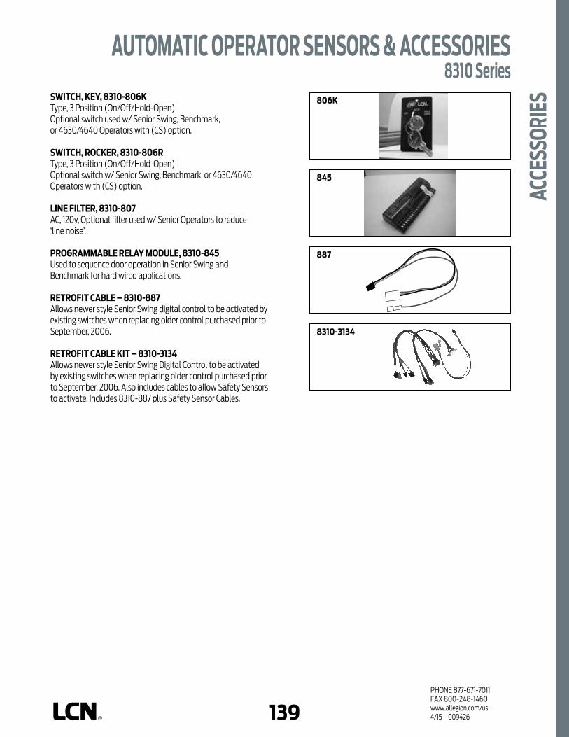
138 139PHONE 877-671-7011FAX 800-248-1460www.allegion.com/us 4/15 009426
ACC
ESSO
RIES
AUTOMATIC OPERATOR SENSORS & ACCESSORIES8310 Series
SWITCH, KEY, 8310-806KType, 3 Position (On/Off/Hold-Open)Optional switch used w/ Senior Swing, Benchmark, or 4630/4640 Operators with (CS) option.
SWITCH, ROCKER, 8310-806RType, 3 Position (On/Off/Hold-Open)Optional switch w/ Senior Swing, Benchmark, or 4630/4640 Operators with (CS) option.
LINE FILTER, 8310-807AC, 120v, Optional filter used w/ Senior Operators to reduce ‘line noise’.
PROGRAMMABLE RELAY MODULE, 8310-845 Used to sequence door operation in Senior Swing and Benchmark for hard wired applications.
RETROFIT CABLE – 8310-887 Allows newer style Senior Swing digital control to be activated by existing switches when replacing older control purchased prior to September, 2006.
RETROFIT CABLE KIT – 8310-3134Allows newer style Senior Swing Digital Control to be activated by existing switches when replacing older control purchased prior to September, 2006. Also includes cables to allow Safety Sensors to activate. Includes 8310-887 plus Safety Sensor Cables.
806K
887
845
8310-3134

PHONE 877-671-7011FAX 800-248-1460www.allegion.com/us 4/15 009426140
Notes

2PHONE 877-671-7011FAX 800-248-1460www.allegion.com/us 4/15 009426
STANDARD ANODIZED
FINISHHANDING
HANDED****
NON-HANDED
COVER
METAL
ARM FUNCTION
STANDARD (S
INGLE
LEVER)
REGULAR (D
OUBLE LE
VER)
OFFSET PIVOT ARM
CENTER PIVOT ARM
DOUBLE EGRESS (P
USH/PULL)
OPERATORSERIES
MOUNTING
SURFACE M
OUNT SINGLE
DOOR
SURFACE M
OUNT SIMULTA
NEOUS PAIR
SURFACE M
OUNT INDEPENDENT PAIR
CONCEALED SIN
GLE DOOR
CONCEALED IN
DEPENDENT PAIR
CONCEALED SIM
ULTANEOUS PAIR
2810
2850
2860
9130
9140
9150
9530
9540
9550
9560
TOP JA
MB (PULL
SIDE)
TOP JA
MB (PUSH SIDE)MOUNTING
PARALLEL A
RM
OPERATORSERIES2610
POWDER COAT
PLATED
PLASTIC
METAL
NON-HANDED
NON-SIZED
ACCESSIBILI
TY*
COVER CYLINDERFINISH
POWER
OPERATO
R
CONCEALED
4630
4640
4810
4820
4840
HOLD-O
PEN
STANDARD (S
INGLE)
REGULA
R (DOUBLE)
EXTRA DUTY ARM
*ARM FUNCTION
CUSH-N-S
TOP
SPRING CUSH
4630CS
4640CS
DPS SWITCH
PRODUCT COMPARISON - ELECTROHYDRAULIC/PNEUMATIC PRODUCT COMPARISONThis chart shows a basic features comparison of the LCN electrohydraulic and pneumatic power operator systems designed to provide easy access without sacrificing closing power. Refer to the specific closer chapter for complete details.
PRODUCT COMPARISON - ELECTROMECHANICAL PRODUCT COMPARISONThis chart shows a basic features comparison of the LCN electromechanical power operator systems designed to provide easy access without sacrificing closing power. Refer to the specific operator chapter for complete details.
AUTOMATIC OPERATORS
Meets ADA requirements (power mode). * See individual series for maximum manual opening. ** Switch provided for continuous Hold Open (4630 & 4640 only).
AVAILABLE NOT AVAILABLE
AVAILABLE NOT AVAILABLE
*** All electromechanical operators open to 90º. **** Handed for 2850 and 2860, double egress only.

2 3PHONE 877-671-7011FAX 800-248-1460www.allegion.com/us 4/15 009426
WHAT IS THE ADA?The ADA is a civil rights law, not a building code. This act is designed to provide protection for people with disabilities. The law is divided into four major titles that prohibit discrimination against the disabled in Employment, Title I, Public Services and Transportation Title II, Public Accommodations Title III, and Telecommunications Title IV. Title III concerns doors and door controls.
WHAT IS THE INTENT OF ADA, TITLE III?Essentially, owners of certain types of buildings must remove barriers and provide people with disabilities with access equal to, or similar to, that available to the general public. The deadline for compliance was January 26, 1992.The final rules implementing Title III were published in the Federal Register of July 26, 1991. To obtain a copy or ask questions, contact the U.S. DEPARTMENT OF JUSTICE. Technical information can be obtained from The U.S. ARCHITECTURAL AND TRANSPORTATION BARRIERS COMPLIANCE BOARD.
HOW DOES ADA AFFECT DOORS?The ADA defines an “accessible” opening which means, among other things, providing a door with a minimum 32" (813 mm) clear opening, easily manipulated handles, a maximum opening force, a minimum closing time, and capable of opening to at least 90°.ADA criteria, based on OPENING FORCE, are similar to American National Standards Institute (ANSI) Standard A117.1. This is different from ANSI Standard A156.4, which is based on CLOSING FORCE.
WHAT ARE THE OPENING FORCE LIMITS?DOOR TYPE OPENING FORCE
Fire Rated Note 1
Interior Non-Fire-Rated 5.0 lbs. (22.2 N)
Exterior Non-Fire-Rated “Reserved”
NOte 1: All fire rated doors should have the minimum opening force allowable by the appropriate administrative authority, typically the local Fire Marshal. Closing and latching a fire door takes precedence over ADA opening force limits.
HOW IS THE DOOR MEASURED?Two ADA criteria affect the door closer selection, adjustments, opening force, and time to close. Since the law does not clearly define the method of measurement, this is LCN’s recommendation.
1. On the push side of the door, locate a point at the center line of the push plate/lock trim or 34" (864 mm), from the hinge edge of the door, whichever is greater.
2. Mark the floor at a point where the push side of the doors’ latch stile is at 70°. Mark a second point where the push side is 3˝ (76 mm) from the latch.
3. Open the door so the latch is clear of the strike and the door is slightly off the stop.
4. Using a force gauge on the mark determined in Step #1, push the door open to the 70° mark established in Step #2. Observe the force readings. (Accuracy of the readings varies with the gauge quality.)
5. Adjust the closer spring power to meet the maximum opening force.
6. Hold the door at the 70° mark. Release the door and time the closing sweep between the two marks.
7. Adjust the closer main speed regulation valve to obtain a minimum 3 second “time to close”.
NOte: Delayed action closers are not necessary to meet the ADA 3 second “time to close” requirement but do offer additional time for people to pass through the door.
CAUTION ! Any manual door closer, including those certified by BHMA to conform to ANSI Standard 156.4, that is selected, installed, and adjusted based on ADA requirements
may not provide sufficient power to reliably close and latch a door. Auto Equalizer systems offer an alternate solution.
30"
(OR)
C/L OF TRIM
WHICHEVERIS GREATER
AUTOMATIC OPERATORS

4PHONE 877-671-7011FAX 800-248-1460www.allegion.com/us 4/15 009426
WHAT ARE THE CHOICES FOR ADA COMPLIANT DOOR CONTROLS?LCN offers both surface and concealed mountings for powered systems or manual closers.
POWERED SYSTEMSLCN Power Operator Systems offer easy access for the disabled and resolve the problem of obtaining reduced opening force while providing adequate closing force.
MANUAL CLOSERSManual closers rely on reduced spring power to meet opening force requirements. Four principle factors affect the performance of manual closers: 1. DOOR WIDTH:
A wider door provides more leverage for the user, thus reducing the opening force required.
2. SPRING POWER: Adjusting spring power to achieve a lower opening force also reduces the closing force available.
3. ARM SELECTION: The superior mechanical advantage of a regular arm system offers the user significantly lower average opening forces through the 70° measurement range compared to a standard arm (track type) closer. Regular arms also provide superior latching power.
4. ADDITIONAL FORCES Improperly hung doors, stiff latches, HVAC or environmental pressures, and other forces acting on the door require increasing the closer spring power to reliably close and latch a door which produces a corresponding increase in opening force.
INFORMATION SOURCESLCN CLOSERS PHONE 877-671-7011121 W. RAILROAD AVE. FAX 800-248-1460P.O. BOX 100 www.securitiestechnologies.ingersollrand.comPRINCETON, IL, USA 61356-0100
U.S. DEPARTMENT OF JUSTICE The Office of the Americans with Disabilities Act, Civil Rights Div., P.O. Box 66118, Washington, D.C. 20035-6118 (202) 514-0301
THE U.S. ARCHITECTURAL AND TRANSPORTATION BARRIERS COMPLIANCE BOARD1111 18th Street N.W., Suite 501, Washington, D.C. 20036 (800) 872-2253
AMERICAN NATIONAL STANDARDS INSTITUTE11 West 42nd Street, New York, N.Y. 10036 (212) 642-4900- ANSI A117.1 Providing Accessibility and Usability for Physically
Handicapped People- ANSI A156.4 for Door Controls - Closers- ANSI A156.19 Power Assist and Low Energy Power Operated Doors
ELECTROHYDRAULIC & PNEUMATIC FASTENERSStandard WOOD and MACHINE SCREW (WMS) pack contains phillips head wood and machine screws to install the closer. Thru Bolts (TB) and/or TORX® machine screws are available for all closers, except the 2610 series. LCN thru bolts can be installed on 1-3/4˝ thick doors with either the 1/4-20 machine screws or optional TORX security screws supplied with the closer. Optional sizes are available for 1-5/8˝ or 1-3/8˝ door thicknesses, but must be specified when ordering.
NOte 1: Phillips head, metric machine screws are available, please specify.
ELECTROMECHANICAL FASTENERSTypically installed 1/4 - 20 machine screw for aluminum/steel frames. Wood screws included for wood door mounting. Consult factory for additional information.
REGULAR ARM STANDARD ARM(TRACK TYPE)
ADA MEASUREMENT RANGE
EXT
MAX.
INT.
MAX.
OPENING FORCE (lbs.)
TYPICAL ARM POWER CURVE
• "RESERVED", TYPICALLY 8.6 POUNDS
DOOR OPENING ANGLE
10
9
8
7
6
5
4
3
2
1
00 10 20 30 40 50 60 70 80 90 100 110
REGULAR ARM STANDARD ARM
Drill 25/64˝ forsteel doorsorDrill 3/8˝for wood doors
AUTOMATIC OPERATORS

4 5PHONE 877-671-7011FAX 800-248-1460www.allegion.com/us 4/15 009426
COMMON SYSTEM FEATURESn Power opening plus full door control.n No guide rails or safety devices required due to low energy
design.n Adjustable opening force.n Adjustable closing power.n 4630 and 4810 operators meet ADA reduced manual opening
force requirements. n Electrohydraulic and pneumatic systems feature adjustable
backcheck that slows opening swing at about 70°.n Electromechanical systems feature electronic backcheck that
slows opening swing at about 70°.n Systems allow for separate adjustment of general closing
and latch speed.n Electrohydraulic and pneumatic systems are available in
six standard finishes or a wide selection of optional custom powder coat finishes to blend with door and frame.
n Electromechanical systems are available in two standard anodized finishes.
n UL & NEC compliant.n Compatible with most security and safety systems.n Capable of full integration with high security keypads and
card readers.n Wiring allows for sequential operation for vestibule
applications. Electromechanical systems require additional components.
n Modular design simplifies installation and maintenance.
WARRANTYn 2 year limited warranty. See General Information Section
for complete details.
MAINTENANCEn Operators mounted according to the LCN installation
instructions require no periodic maintenance or adjustments.n Periodic visual inspections are recommended.
LOW ENERGY OPERATORSThe basic design concept for all LCN power operator systems is door control of both the opening and closing motion of the door. Our designs allow the system to be easily retrofitted into existing doors and frames as well as new construction. A basic LCN electrohydraulic/pneumatic system consists of a power operator based on a heavy duty LCN 4040 Series door closer and peripheral actuators. Our electromechanical automatic operators utilize a motor gearbox and a control box to perform the opening and closing function. LCN offers a choice of either electrohydraulic, electromechanical or pneumatic low energy automatic operators.
AUTOMATIC OPERATORS
FEAT
URES
APPLICATIONSn Electrohydraulic and pneumatic systems are used primarily
for manual opening with available push button automatic opening.
n Electromechanical systems are used primarily for automatic openings.
n For dedicated handicap access.n Stand alone or integrated into larger multi-door systems.n Surface and concealed mountings.n Installation accessories available for unusual conditions.n CAUTION ! For exterior doors exceeding 3´0˝ wide by
7´0˝ tall, interior doors exceeding 4´0˝ wide by 8´0˝ tall, or any door exceeding 225 pounds, consult factory before specifying or installing LCN electrohydraulic or pneumatic automatic operators.
n CAUTION ! For exterior doors exceeding 4´0˝ wide by 7´0˝ tall, interior doors exceeding 4´0˝ wide by 8´0˝ tall, or any door exceeding 200 pounds, consult factory before specifying or installing LCN Electromechanical automatic operators.
A156.19 SYSTEM DESIGN PARAMETERS n Cycle test standard of 300,000 full load operating cycles.n Power opening plus full door control.n Open to backcheck no faster than 3 seconds.n Opening time to fully open is no faster than 4 seconds.n Remain fully open for at least 5 seconds.n Closing time from 90° to 10° is no faster than 3 seconds.n Less than 15 lb to stop doors motion.n Kinetic energy must not exceed 1.25 lb-ft.n In event of failure, less than 15 lb to release latch, less than
30 lb to put door in motion, less than 15 lb to fully open door system.

6PHONE 877-671-7011FAX 800-248-1460www.allegion.com/us 4/15 009426
Notes

6 7PHONE 877-671-7011FAX 800-248-1460www.allegion.com/us 4/15 009426
PNEUMATIC (AIR) POWERED SYSTEMSLCN Pneumatic Auto Equalizer systems use the power of pressurized air to do the work of automatically opening the door. These systems have exceeded 3 million full load automatic operating cycles; that’s 10 times the industry standard! A basic pneumatic system consists of an automatic operator to provide the door control, a control box that contains the valves and electrical timing circuits, actuators to start the system, and a compressed air source.
UNIQUE FEATURESn Multi-Door & Single-Door Solutions
The pneumatic automatic operators are ideal for multi-door applications because the cost per door leaf decreases significantly as the number of door leaves increase. A single control box may power up to two pairs of doors simultaneously making it a cost-effective solution for single or multi-door applications. This flexibility results in significant savings in material and installation costs.
n Quiet Operation Since the pneumatic automatic operators are powered by pressurized air, they are quiet, efficient, and very reliable. Flexible LCN pneumatic tubing is the only connection between the control box and the door frame. There is no need for high-voltage wiring at the door frame since all of the power for operation is generated by pressurized air located away from the door frame. (Note: special fittings are available so 3/16˝ metal tubing (by others) can be used in fire rated plenums).
n Pneumatically (Air) Powered All pneumatic automatic operators require a compressed air source. LCN’s pneumatic systems have the flexibility to run as an independent unit (7980 Series has a compressor built into the control box) or to run off an existing air supply (7900 Series has connections for utilizing existing air supply). Using a self-contained 7980 Series control box for single or double door leaf applications eliminates the need for an independent compressor. Existing building air compressors with a storage tank can be used to reduce the cost of multi-door systems and must utilize the 7900 Series control boxes.
n Easy Adjustment/Installation The air pressure and timing cycle are easily adjustable to meet the need of a specific installation. Because the control box can be located anywhere within 100 linear tubing feet from the controlled door for the 7900 Series or within 50 linear tubing feet for the 7980 Series, they can be placed in easily accessible locations. Convenient features such as sequential operation of vestibule doors are available.
n Multiple Mounting Configurations Available in three different mounting configurations: - Concealed in the frame (2610 Series).
- Top Jamb Surface Mounted on the pull side of the door (4810 Series).
- Top Jamb Surface Mounted on the push side of the door (4820 Series).
- Door Mounted, Parallel Arm on the push side of the door (4840 Series).
n Hazardous Location Use Since there is no high-voltage wiring at the door frame, pneumatically powered systems are ideal for use in hazardous areas. The control box, which contain the valves and electrical timing circuits, is remotely located outside the hazardous area.
n Blow-Open (Smoke Evacuations Systems) An auxiliary “blow-open” box is available and is controlled by the building smoke evacuation system to allow fresh air into the building. When activated, the normal pneumatic power operator functions are not available. The 7949 Series “blow-open” box works with or without the 7900 Series control boxes. (Limited to 50 linear foot of tubing).
STANDARDS, LISTINGS & APPROVALSn UL listed for self-closing doors without hold open under
“SWINGING DOOR CLOSERS (GVEV)” file R1943.n Tested and certified under ANSI Standard A156.19. Refer to
Section 2.1 and consult factory for details.n ANSI Standard A117.1, Section 4.13.13.n ADA law, Section 4.13.12.n UBC 7.2 (1997) for positive pressure plus UL 10B and
UL 10C listing.n Consult the factory for other listings such as: State or Local
Government Regulations.
WARRANTYn 2 year limited warranty. See General Information Section for
complete details.
MAINTENANCEn Operators mounted according to the LCN installation
instructions require no periodic maintenance or adjustments.n Periodic visual inspections are recommended.n Inspect and service filter assembly in 7900 Series control
boxes as required.n No service contracts.
PNEUMATIC POWERED SYSTEMS

8PHONE 877-671-7011FAX 800-248-1460www.allegion.com/us 4/15 009426
SINGLE INTERIOR DOOR SYSTEM (WIRED)
n Slow opening interior door leaf. n System may be expanded to include an additional
simultaneous door.n No guide rails or safety devices.
How It Works: A person requiring assistance triggersthe system using either actuator. The control box supplies pressurized air to the Auto Equalizer which opens the door slowly to 90˚, holds it for up to 30 seconds, then applies full spring power to reliably close and latch the door. If not actuated, the Auto Equalizer functions as a full featured door closer.
SINGLE INTERIOR DOOR SYSTEM (WIRELESS)
n Slow opening automatic door on door leaf. n Wireless actuators. n Stand alone system, no planned expansion. n No guide rails or safety devices.
How It Works: A person requiring assistance triggers the system using either actuator. The wireless transmitter in the actuator sends a signal to the wireless receiver which triggers the control box. The control box supplies pressurized air to the Auto Equalizer which slowly swings door to 90°, holds it for up to 30 seconds, then applies full spring power to reliably close and latch the door. If not actuated, the Auto Equalizer functions as a full featured door closer.
INTERIORACTUATOR
EXTERIORACTUATOR
RECEIVER
AUTO-EQUALIZERPNEUMATICTUBING(50' Max.)
120V ACINPUT
CONTROL BOX
BILL OF MATERIALSQty. Part No. Description1 4811 Auto Equalizer1 8310-856 Actuator (exterior) 1 8310-856 Actuator (interior) 1 7901 Control Box1 920 Compressor(as needed) 925 Tubing
BILL OF MATERIALSQty. Part No. Description1 4811 Auto Equalizer2 8310-3856WS Wireless Actuator1 8310-865 Wireless Receiver1 7981 Control Box(as needed) 925 Tubing
INTERIORACTUATOR
EXTERIORACTUATOR COMPRESSOR
CONTROL BOX
AUTO-EQUALIZERPNEUMATICTUBING(100' Max.)
12V DCWIRING
120V ACINPUT
PNEUMATICTUBING(500' Max.)
120V ACINPUT
Single Interior Door System
These pages illustrate examples of typical Pneumatic LCN systems. Please consult your local SSC
representative or LCN for assistance with specific installations and material requirements.
TYPICAL PNEUMATIC POWERED SYSTEMS

8 9PHONE 877-671-7011FAX 800-248-1460www.allegion.com/us 4/15 009426
ALTERNATE VESTIBULE DOOR SYSTEM (WIRED)
n Slow opening automatic doors with sequential operation for exterior and vestibule pairs of doors.
n No guide rails or safety devices.
How It Works: People requiring assistance press exterioractuator for entry. The exterior pair opens and after a short sequential delay the interior pair opens. As the system times out, first the exterior, then the interior doors close. Pressing the interior actuator reverses the process to exit the building. This allows passage through the vestibule without all doors open for the entire cycle. If a person stops in the vestibule and the system times out before they exit, pressing either vestibule actuator opens the appropriate doors. Compressor is sized for multiple systems. Sequential operation is not recommended with scanners or motion sensors. If not actuated, the Auto Equalizer functions as a full feature door closer.
VESTIBULE DOOR SYSTEM (WIRELESS)n Slow opening automatic doors with sequential operation
for single exterior and vestibule doors. n No guide rails or safety devices.
How It Works: People requiring assistance press exterioractuator for entry. The exterior door opens and after a short delay the interior door opens. When the system times out, first the exterior, then the interior door closes. Pressing the interior actuator reverses the process to exit the building. This allows passage through the vestibule without both doors open for the entire cycle. If a person stops in the vestibule and the system times out before they exit, pressing either vestibule actuator opens the appropriate door. Sequential operation is not recommended with scanners or motion sensors. If not actuated, the Auto Equalizer functions as a full featured door closer.
EXTERIORACTUATOR COMPRESSOR
CONTROL BOX12V DCWIRING
120V ACINPUT
120V ACINPUT
PNEUMATICTUBING(100' Max.)
INTERIORACTUATOR
AUTO-EQUALIZERA B
VESTIBULEACTUATORS
PNEUMATICTUBING(500' Max.)
BILL OF MATERIALSQty. Part No. Description2 4822 Auto Equalizer (exterior)2 4811 Auto Equalizer (interior)1 7902S Control Box with Sequencer Card1 922 Compressor4 8310-856 Actuator(as needed) 925 Tubing
INTERIORACTUATOR
EXTERIORACTUATOR
RF RECEIVER
CONTROL BOX
120V ACINPUT
LOW VOLTAGEPOWER ANDSIGNAL WIRING
PNEUMATICTUBING(50' Max.)
VESTIBULEACTUATORS
AUTO-EQUALIZER
A B
BILL OF MATERIALSQty. Part No. Description1 4822 Auto Equalizer (exterior)1 4811 Auto Equalizer (interior)1 7982S Control Box with Sequencer Card4 8310-3856WS RF Actuators2 8310-865 RF Receiver(as needed) 925 Tubing
TYPICAL PNEUMATIC POWERED SYSTEMS
10PHONE 877-671-7011FAX 800-248-1460www.allegion.com/us 4/15 009426
Notes

10 11PHONE 877-671-7011FAX 800-248-1460www.allegion.com/us 4/15 009426
POWDER COAT
PLATED
PLASTIC
METAL
NON-HANDED
NON-SIZED
ACCESSIBILI
TY*
COVER CYLINDERFINISH
POWER
OPERATO
R
TOP JA
MB (PULL
SIDE)
TOP JA
MB (PUSH SIDE)
MOUNTING
PARALLEL A
RM
CONCEALED
HOLD-O
PEN
DPS SWITCH
STANDARD (S
INGLE)
REGULA
R (DOUBLE)
EXTRA DUTY ARM
*ARM FUNCTION
CUSH-N-S
TOP
SPRING CUSH
The 2610 AUTO EQUALIZER™
is LCN’s pneumatically powered
MULTI-DOOR solution. This
low-energy power operator provides
easy access for people with
disabilities, or the elderly. Designed
primarily for manual opening
applications that occasionally require
automatic opening.
n Multi-Door Solution. n Utilizes a 10,000,000 Cycle Heavy
Duty Door Closer. n Quiet, Efficient & Reliable. n Requires Control Boxes with integral
compressor or control box using auxiliary air supply.
n Guard Rails/Safety Mats not required.
the 2610 Series is UL228 and meets the
provisions of ANSI Standard A117.1, A156.19
and the Americans with Disabilities Act.
n Ideal for multi-door applications since cost per door leaf decrease significantly as the number of door leaves increases.
n Standard 2610 Series closer shipped with single lever (standard) arm, mounting/finish plate, standard track and wood and machine screw pack. See 2610 Series page 13 for options.
n Meets ADA requirements (power mode).
n Sized cylinders for interior doors to 4´0˝ and exterior doors to 3´0˝.
n Handed for right or left swinging doors.
n Requires additional system components. See CONTROL BOX pages 27-29 and actuators & accessories, pages 122-137.
n Standard or optional custom powder coated finish.
n Optional plated finish on arm, fasteners, and mounting/finish plate.
n Optional Door Position Switch (DPS) that signals when the door has reached the open position.
CONCEALED (IN FRAME) MOUNTING
2610 SERIES
FEAT
URES
Meets ADA requirements (power mode). * See individual series for maximum manual opening.
AVAILABLE NOT AVAILABLE

12PHONE 877-671-7011FAX 800-248-1460www.allegion.com/us 4/15 009426
n Butt Hinges should not exceed 5˝ (127 mm) in width.
n Auxiliary Stop is recommended.
n Head Frame minimum 4˝ (102 mm) x 4˝ for hollow metal or aluminum tube construction.
n Top Rail 1-3/8˝ (35 mm) mortise required. 5/16˝ (8 mm) cutout required at top of the door, push side only.
n System Diagram See “AUTOMATIC OPERATORS” section pages 8-9 for typical system wiring, and pages 28-29 for electrical and pneumatic data for control boxes.
CONCEALED MOUNTING For interior or exterior doors.Single acting cylinder in head frame.Concealed arm and track in door top rail.
MAXIMUM OPENINGButt hinge template allows 90° power opening and 160° manual opening.
Please note that many track style door closers are capable of allowing 180° of door swing. Track style closers are at their weakest closing force at 180°. Consult factory for applications where exterior or large/heavy door must swing 180°.
Consult factory for all pivot mounted installations.
2610 SERIESM
OUNT
ING
DETA
ILS
Special TemplatesCustomized installation templates or products may be available to solve unusual applications. Contact LCN Product Support for assistance.

12 13PHONE 877-671-7011FAX 800-248-1460www.allegion.com/us 4/15 009426
3038
CYLINDERSCYLINDER ONLY, 2610-3971 Standard, handed, cast iron cylinder. NOte: For various applications see “table of Sizes” on 2610 Series page 14.
CYLINDER ONLY, 2610-3971 DPS Standard, handed, cast iron cylinder with door position switch which sends signal when door is closed. Picture not shown.
CYLINDER ASSEMBLY, 2610-3071 Standard, handed, cast iron cylinder and mounting plate. NOte: For various applications see “table of Sizes” on 2610 Series page 14.
CYLINDER ASSEMBLY, 2610-3071 DPS Standard, handed, cast iron cylinder, and mounting plate with door position switch which sends signal when door is closed.Picture not shown.
ARMS STANDARD ARM, 2610-3077THanded arm. Track roller not included with arm.
TRACKSTANDARD TRACK, 2610-3038Standard non-handed track.Will not accept hold open clip or bumper assembly.
INSTALLATION ACCESSORIESTRACK ROLLER, 2610-3034Quiet, low friction roller assembly.Shoulder dimension “X” = 1/16˝ (1 mm).
3077T
3034
3071
3971
2610 SERIES
ACCE
SSOR
IES

14PHONE 877-671-7011FAX 800-248-1460www.allegion.com/us 4/15 009426
2610 SERIESOR
DERI
NG IN
FORM
ATIO
N TABLE OF SIZESSelect closer based on width of door. Sized 2610 Series cylinders available in size 3 or 4.Closing power of all 2610 Series closers may be increased 15%.
HOW-TO-ORDER 2610 SERIES CLOSERS1. SELECT CYLINDER SIZE 2613 2613 DPS 2614 2614 DPS2. SPECIFY HAND RH LH3. SPECIFY FINISH Standard Powder Coat __________
Aluminum, Dark Bronze, Statuary, Light Bronze, Black, Brass.
CLOSER OPTIONSFINISH Custom Powder Coat (RAL) Plated Finish, US SCREW PACK Wood & Machine Screw (WMS)SPECIAL TEMPLATE ST-_________
EXTERIOR (and VESTIBULE) DOOR WIDTH
INTERIOR DOOR WIDTH
30"762mm
30"762mm
36"914mm
38"965mm
48"1219mm
size 4
size 3 size 4
2614
2613
2614
MinimumDoor Width
MinimumDoor Width
Closer will be shipped with:- STANDARD ARM,- TRACK ROLLER,- STANDARD TRACK,- WOOD & MACHINE SCREW PACK,unless options listed below are selected.
Indicates recommended range of door width for closer size.
NOte: Minimum door width 30" (762 mm).

14 15PHONE 877-671-7011FAX 800-248-1460www.allegion.com/us 4/15 009426
TOP JA
MB (PULL
SIDE)
TOP JA
MB (PUSH SIDE)
MOUNTING
PARALLEL A
RM
POWDER COAT
PLATED
PLASTIC
METAL
NON-HANDED
NON-SIZED
ACCESSIBILI
TY*
COVER CYLINDERFINISH
POWER
OPERATO
R
CONCEALED
HOLD-O
PEN
DPS SWITCH
STANDARD (S
INGLE)
REGULA
R (DOUBLE)
EXTRA DUTY ARM
*ARM FUNCTION
CUSH-N-S
TOP
SPRING CUSH
The 4810 AUTO EQUALIZER™ is
LCN’s pneumatically powered MULTI-
DOOR solution. This low-energy
automatic operator provides easy
access for people with disabilities,
or the elderly. Designed primarily
for manual opening applications
that occasionally require automatic
opening.
n Multi-Door Solution. n Utilizes a 10,000,000 Cycle Heavy
Duty Door Closer. n Quiet, Efficient & Reliable. n Requires Control Boxes with integral
compressor or control box using auxiliary air supply.
n Guard Rails/Safety Mats not required.
the 4810 Series is UL and cUL228 listed and
meets the provisions of ANSI Standards
A117.1, A156.19, and the Americans with
Disabilities Act.
n Ideal for multi-door applications since cost per door leaf decrease significantly as the number of door leaves increases.
n Standard, plate mounted 4810 Series closer shipped with single lever (standard) arm, metal cover, standard track, and wood and machine screw pack. See 4810 Series page 16 for options.
n Meets ADA requirements (power mode).
n Non-sized cylinders for interior doors to 4´0˝ and exterior doors to 3´0˝.
n Non-handed.
n Requires additional system components. See CONTROL BOX pages 27-29 and ACTUATORS & ACCESSORIES, pages 122-137.
n Standard or optional custom powder coated finish, end caps are black.
n Optional plated finish on cover, arm, and fasteners.
TOP JAMB (PULL SIDE) MOUNTING
4810 SERIES
FEAT
URES
Meets ADA requirements (power mode). * See individual series for maximum manual opening.
AVAILABLE NOT AVAILABLE

16PHONE 877-671-7011FAX 800-248-1460www.allegion.com/us 4/15 009426
n Butt Hinges should not exceed 5˝ (127 mm) in width.
n Auxiliary Stop is recommended.
n Reveal should not exceed 1/8˝ (3 mm).
n Head Frame minimum 2˝ (51 mm).
n Top Rail minimum 1-1/8˝ (29 mm).
n System Diagram See “AUTOMATIC OPERATORS” section pages 7-8 for typical system wiring, and pages 27-29 for electrical and pneumatic data for control boxes.
TOP JAMB (PULL SIDE) MOUNTING
MAXIMUM OPENINGTemplating allows 90° power opening and 170° manual opening.
Please note that many track style door closers are capable of allowing 180° of door swing. Track style closers are at their weakest closing force at 180°. Consult factory for applications where exterior or large/heavy door must swing 180°.
4810 SERIESM
OUNT
ING
DETA
ILS
Special TemplatesCustomized installation templates or products may be available to solve unusual applications. Contact LCN Product Support for assistance.

16 17PHONE 877-671-7011FAX 800-248-1460www.allegion.com/us 4/15 009426
72MC
CYLINDERSCYLINDER ONLY, 4811-3971 Standard, non-handed, cast iron cylinder.
CYLINDER ASSEMBLY, 4811-3071 Standard, non-handed, cast iron cylinder and mounting plate.
COVERSCOVER, 4810-72MC Standard, non-handed metal cover with black end caps.
TRACKSSTANDARD TRACK, 4810-3038 Standard non-handed track.Will not accept hold open clip or bumper assembly.
ARMSSTANDARD ARM, 4810-3077T Non-handed arm. Track roller not included with arm.
INSTALLATION ACCESSORIESTRACK ROLLER, 4810-3034Quiet low friction roller assembly.Shoulder dimension "X" = 1/8" (3mm).
3077T
3034
3038
3071
3971
4810 SERIES
ACCE
SSOR
IES

18PHONE 877-671-7011FAX 800-248-1460www.allegion.com/us 4/15 009426
4810 SERIESOR
DERI
NG IN
FORM
ATIO
N TABLE OF SIZESNon-sized 4810 Series cylinder is adjustable from size 1 through size 4 and is shipped set to size 3. Closing power of 4810 Series closers may be increased 50%.
HOW-TO-ORDER 4810 SERIES CLOSERS1. SPECIFY FINISH Standard Powder Coat __________
Aluminum, Dark Bronze, Statuary, Light Bronze, Black, Brass.
CLOSER OPTIONSFINISH Custom Powder Coat (RAL)-_________ Plated Finish, US-_________SCREW PACK TB*, Wood & Machine Screw (TBWMS)
*Specify door thickness if other than 1-3/4˝.SPECIAL TEMPLATE ST-_________
Closer will be shipped with:- STANDARD CYLINDER,- STANDARD METAL COVER,- STANDARD ARM,- TRACK ROLLER, - STANDARD TRACK,- WOOD and MACHINE SCREW PACK,unless options listed below are selected.
Indicates recommended range of door width for closer size.
NOte: Minimum door width 28" (711 mm).
EXTERIOR (and VESTIBULE) DOOR WIDTH
28"711mm
30"762mm
36"914mm
size 3 size 4 4811
MinimumDoor Width
INTERIOR DOOR WIDTH
28"711mm
38"965mm
34"864mm
48"1219mm
size 2 size 3 size 4 4811
MinimumDoor Width
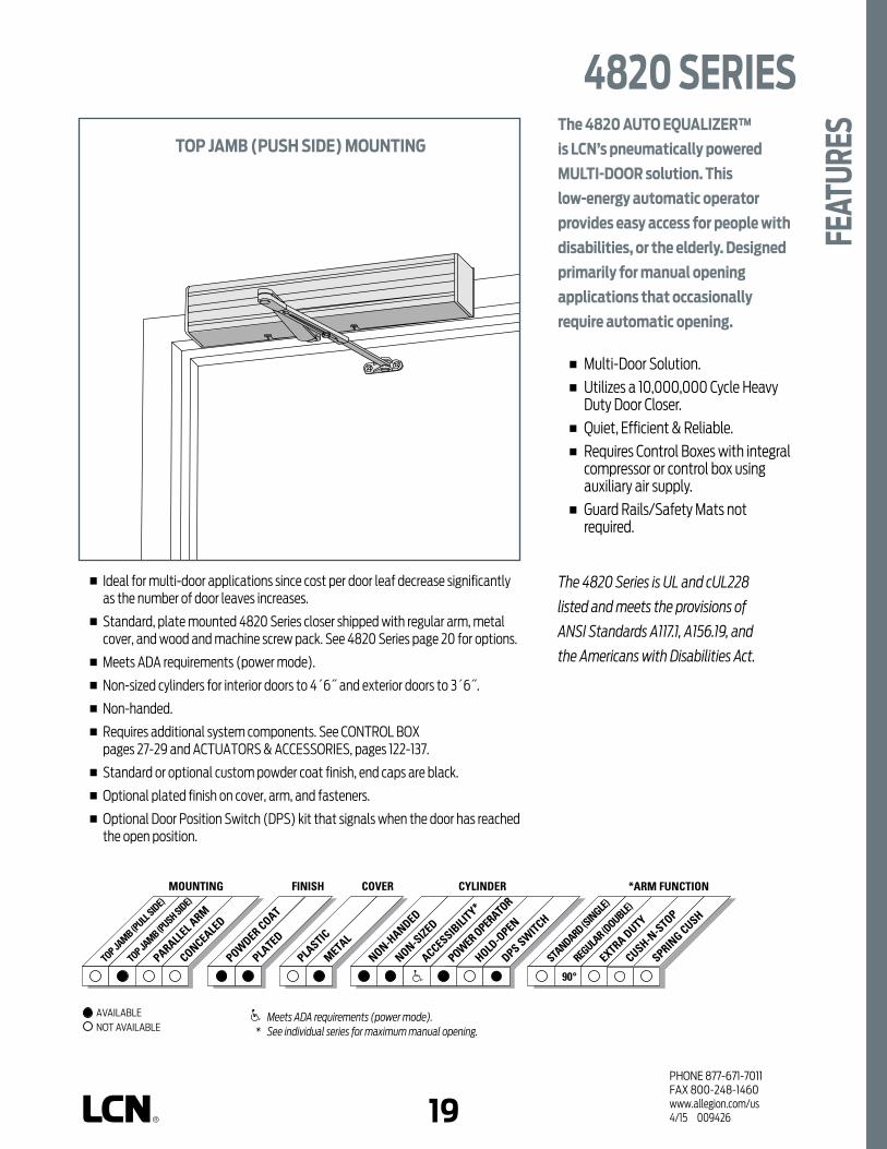
18 19PHONE 877-671-7011FAX 800-248-1460www.allegion.com/us 4/15 009426
TOP JA
MB (PULL
SIDE)
TOP JA
MB (PUSH SIDE)MOUNTING
PARALLEL A
RM
POWDER COAT
PLATED
PLASTIC
METAL
NON-HANDED
NON-SIZED
ACCESSIBILI
TY*
COVER CYLINDERFINISH
POWER
OPERATO
R
CONCEALED
HOLD-O
PEN
DPS SWITCH
STANDARD (S
INGLE)
REGULA
R (DOUBLE)
EXTRA DUTY
*ARM FUNCTION
CUSH-N-S
TOP
SPRING CUSH
The 4820 AUTO EQUALIZER™
is LCN’s pneumatically powered
MULTI-DOOR solution. This
low-energy automatic operator
provides easy access for people with
disabilities, or the elderly. Designed
primarily for manual opening
applications that occasionally
require automatic opening.
n Multi-Door Solution. n Utilizes a 10,000,000 Cycle Heavy
Duty Door Closer. n Quiet, Efficient & Reliable. n Requires Control Boxes with integral
compressor or control box using auxiliary air supply.
n Guard Rails/Safety Mats not required.
the 4820 Series is UL and cUL228
listed and meets the provisions of
ANSI Standards A117.1, A156.19, and
the Americans with Disabilities Act.
n Ideal for multi-door applications since cost per door leaf decrease significantly as the number of door leaves increases.
n Standard, plate mounted 4820 Series closer shipped with regular arm, metal cover, and wood and machine screw pack. See 4820 Series page 20 for options.
n Meets ADA requirements (power mode).
n Non-sized cylinders for interior doors to 4´6˝ and exterior doors to 3´6˝.
n Non-handed.
n Requires additional system components. See CONTROL BOX pages 27-29 and ACTUATORS & ACCESSORIES, pages 122-137.
n Standard or optional custom powder coat finish, end caps are black.
n Optional plated finish on cover, arm, and fasteners.
n Optional Door Position Switch (DPS) kit that signals when the door has reached the open position.
TOP JAMB (PUSH SIDE) MOUNTING
4820 SERIES
FEAT
URES
Meets ADA requirements (power mode). * See individual series for maximum manual opening.
AVAILABLE NOT AVAILABLE
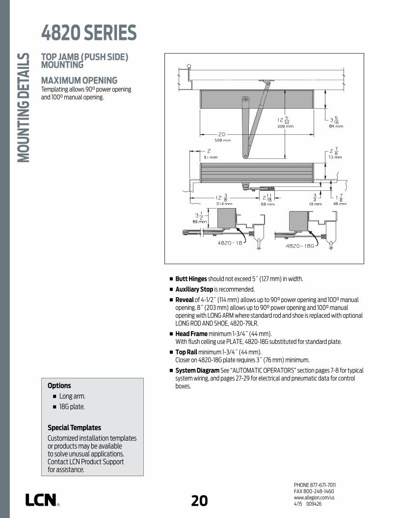
20PHONE 877-671-7011FAX 800-248-1460www.allegion.com/us 4/15 009426
n Butt Hinges should not exceed 5˝ (127 mm) in width.
n Auxiliary Stop is recommended.
n Reveal of 4-1/2˝ (114 mm) allows up to 90° power opening and 100° manual opening. 8˝ (203 mm) allows up to 90° power opening and 100° manual opening with LONG ARM where standard rod and shoe is replaced with optional LONG ROD AND SHOE, 4820-79LR.
n Head Frame minimum 1-3/4˝ (44 mm). With flush ceiling use PLATE, 4820-18G substituted for standard plate.
n Top Rail minimum 1-3/4˝ (44 mm). Closer on 4820-18G plate requires 3˝ (76 mm) minimum.
n System Diagram See “AUTOMATIC OPERATORS” section pages 7-8 for typical system wiring, and pages 27-29 for electrical and pneumatic data for control boxes.
TOP JAMB (PUSH SIDE) MOUNTING
MAXIMUM OPENINGTemplating allows 90° power opening and 100° manual opening.
4820 SERIESM
OUNT
ING
DETA
ILS
Options n Long arm. n 18G plate.
Special TemplatesCustomized installation templates or products may be available to solve unusual applications. Contact LCN Product Support for assistance.

20 21PHONE 877-671-7011FAX 800-248-1460www.allegion.com/us 4/15 009426
72MC
CYLINDERSCYLINDER ONLY, 4822-3971 Standard, non-handed, cast iron cylinder.
CYLINDER ASSEMBLY, 4822-3071 Standard, non-handed, cast iron cylinder. Includes; 4820-18 Mounting Plate or 4820-18G Mounting Plate (must specify).
COVERSCOVER, 4820-72MC Standard, non-handed metal cover with black end caps.
ARMSREGULAR ARM, 4820-3077 Non-handed arm.
LONG ARM, 4820-3077L Arm includes LONG ROD AND SHOE, 4820-79LR for deep reveals.
INSTALLATION ACCESSORIESPLATE, 4820-18 Standard mounting plate.Plate requires minimum 1-3/4˝ (44 mm) minimum head frame and 2˝ (51 mm) top rail.
PLATE, 4820-18G Replaces standard plate for flush ceiling condition.Plate requires minimum 1-3/4˝ (44 mm) minimum head frame and 3˝ (76 mm) top rail.
DOOR POSITION SWITCH KIT, 4820-3377 Provides feedback when the door reaches the fully opened position. Specifically RH or LH when ordering.
3077 79LR
18 18G
3071
3971
4820 SERIES
ACCE
SSOR
IES
3377

22PHONE 877-671-7011FAX 800-248-1460www.allegion.com/us 4/15 009426
4822
INTERIOR DOOR WIDTH
size 3 size 4 size 54822
EXTERIOR (and VESTIBULE) DOOR WIDTH
24"610mm
30"762mm
36"914mm
42"1067mm
24"610mm
34"864mm
38"965mm
48"1219mm
54"1372mm
size 2 size 3 size 4 size 5
MinimumDoor
Width
MinimumDoor
Width
4820 SERIESOR
DERI
NG IN
FORM
ATIO
N TABLE OF SIZESNon-sized 4820 Series cylinder is adjustable from size 2 through size 5 and is shipped set to size 3. Closing power of 4820 Series closers may be increased 50%.
HOW-TO-ORDER 4820 SERIES CLOSERS1. SPECIFY FINISH Standard Powder Coat __________
Aluminum, Dark Bronze, Statuary, Light Bronze, Black, Brass.
CLOSER OPTIONSFINISH Custom Powder Coat (RAL) Plated Finish, US ARM Long (LONG)SCREW PACK TB*, Wood & Machine Screw (TBWMS)
*Specify door thickness if other than 1-3/4˝.INSTALLATION ACCESSORIES Plate, 4820-18 Plate, 4820-18G Door Position Switch Kit, 4820-3377 LH Door Position Switch Kit, 4820-3377 RHSPECIAL TEMPLATE ST-_________
Closer will be shipped with:- STANDARD CYLINDER,- STANDARD METAL COVER,- REGULAR ARM,- WOOD and MACHINE SCREW PACK,unless options listed below are selected.
Indicates recommended range of door width for closer size.

22 23PHONE 877-671-7011FAX 800-248-1460www.allegion.com/us 4/15 009426
4840 (PUSH SIDE MOUNTED AUTO-EQUALIZER WITH 4040 EDA ARM)
POWDER COAT
PLATED
PLASTIC
METAL
NON-HANDED
NON-SIZED
ACCESSIBILI
TY*
COVER CYLINDERFINISH
POWER
OPERATO
R
TOP JA
MB (PULL
SIDE)
TOP JA
MB (PUSH SIDE)
MOUNTING
PARALLEL A
RM
CONCEALED
HOLD-O
PEN
DPS SWITCH
STANDARD (S
INGLE)
REGULA
R (DOUBLE)
EXTRA DUTY
*ARM FUNCTION
CUSH-N-S
TOP
SPRING CUSH
The 4840 AUTO EQUALIZER™ is
LCN’s pneumatically powered MULTI-
DOOR solution. This low-energy
automatic operator provides easy
access for people with disabilities,
or the elderly. Designed primarily
for manual opening applications
that occasionally require automatic
opening.
n Multi-Door Solution. n Utilizes a 10,000,000 Cycle Heavy
Duty Door Closer. n Quiet, Efficient & Reliable. n Requires Control Boxes with integral
compressor or control box using auxiliary air supply.
n Guard Rails/Safety Mats not required.
the 4840 Series is UL and cUL228
listed and meets the provisions of
ANSI Standards A117.1, A156.19, and
the Americans with Disabilities Act.
n Ideal for multi-door applications since cost per door leaf decrease significantly as the number of door leaves increases.
n Standard, plate mounted 4840 Series closer shipped with EXTRA DUTY arm, metal cover and a wood and machine screw pack. See 4840 Series page 24-25 for options.
n Meets ADA requirements (power mode).
n Installation requires use of either DOOR LOOP-459 or TRANSFER HINGE- 460, see page 25 in this section for details.
n Non-sized cylinders for interior doors to 4´6˝ and exterior doors to 3´6˝.
n Non-Handed.
n Requires additional system components. See CONTROL BOX pages 27-29 and ACTUATORS & ACCESSORIES, pages 122-137.
n Standard or optional custom powder coated finish, end caps are black.
n Optional plated finish on cover, arm, and fasteners.
4840 with eDA arm and 459 Door Loop
PARALLEL ARM (PUSH SIDE) MOUNTING
4840 SERIES
FEAT
URES
Meets ADA requirements (power mode). * See individual series for maximum manual opening.
AVAILABLE NOT AVAILABLE

24PHONE 877-671-7011FAX 800-248-1460www.allegion.com/us 4/15 009426
Butt Hinges should not exceed 5˝ (127 mm) in width.
n Auxiliary Stop is recommended when CUSH-N-STOP or SPRING CUSH arms are not used.
n Clearance for EDA or CUSH shoes is 5-1/2˝ (140 mm) from door face.
n Top Rail minimum 4-1/8˝ (105 mm). 6˝ minimum top rail for screw not to show in glass.
n Head Frame (flush) requires PA SHOE ADAPTER, 4840-419.
n Stop Width minimum 1˝ (25 mm).
n Blade Stop clearance requires 1/2˝ (13 mm) BLADE STOP SPACER, 4840-61.
n System Diagram See “AUTOMATIC OPERATORS” section pages 7-8 for typical system wiring, and pages 27-29 for electrical and pneumatic data for control boxes.
PARALLEL ARM (PUSH SIDE) MOUNTING
MAXIMUM OPENINGMaximum power opening is 90° with all arms.
Maximum manual opening is 105° with EDA or SPRING CUSH arms.
Maximum manual opening is 100° with CUSH-N-STOP arm.
NOte: For CUSH-N-StOP or SPRING CUSH arm installations with maximum opening less than listed above, consult factory for Special template.
4840 SERIESM
OUNT
ING
DETA
ILS
Options n CUSH or SPRING CUSH arms.
Special TemplatesCustomized installation templates or products may be available to solve unusual applications. Contact LCN Product Support for assistance.

24 25PHONE 877-671-7011FAX 800-248-1460www.allegion.com/us 4/15 009426
72MC
CYLINDERSCYLINDER ONLY, 4841-3971 Standard, non-handed, cast iron cylinder.
CYLINDER ASSEMBLY, 4841-3071 Standard, non-handed, cast iron cylinder and mounting plate.
COVERSCOVER, 4840-72MCStandard, non-handed metal cover with black end caps.
ARMSEXTRA DUTY ARM, 4840-3077EDA Standard, non-handed parallel arm features forged solid steel main arm and forearm for potentially abusive installations.
CUSH-N-STOP ARM, 4840-3077CNS Optional, non-handed parallel arm features forged solid steel main arm and forearm with stop in soffit shoe.
SPRING CUSH ARM, 4840-3077SCNS Optional, non-handed parallel arm for abusive applications features forged solid steel main arm and forearm with spring loaded stop in soffit shoe.
3077EDA
3077SCNS
3077CNS
3071
3971
4840 SERIES
ACCE
SSOR
IES

26PHONE 877-671-7011FAX 800-248-1460www.allegion.com/us 4/15 009426
INSTALLATION ACCESSORIESCUSH SHOE SUPPORT, 4840-30Provides anchorage for fifth screw used with EDA and CUSH arms, where reveal is less than 3-1/16˝ (78 mm).
BLADE STOP SPACER, 4840-61Required to lower parallel arm shoe to clear 1/2˝ (13 mm) blade stop.
PA FLUSH PANEL ADAPTER, 4840-419Provides horizontal mounting surface for parallel arm shoe on single rabbeted or flush frame.
DOOR LOOP KIT, 4840-459Surface mounted, flexible metal loop transfers pressurized air via pneumatic tubing from frame to closer end cap. Extra caps allow tubing to run on frame surface or concealed in the frame.
PNEUMATIC TRANSFER HINGE, 4840-460Transfers pressurized air via pneumatic tubing from frame to door leaf for fully concealed installations. Preparation of a raceway is required from the hinge stile of the door to the top rail for concealment of the pneumatic tubing within the door leaf.
6130
419
459
460
4840 SERIESAC
CESS
ORIE
S

26 27PHONE 877-671-7011FAX 800-248-1460www.allegion.com/us 4/15 009426
4840 SERIES
ORDE
RING
INFO
RMAT
ION
4841
INTERIOR DOOR WIDTH
size 3 size 4 size 54841
EXTERIOR (and VESTIBULE) DOOR WIDTH
24"610mm
30"762mm
36"914mm
42"1067mm
24"610mm
34"864mm
38"965mm
48"1219mm
54"1372mm
size 2 size 3 size 4 size 5
MinimumDoor
Width
MinimumDoor
Width
TABLE OF SIZESNon-sized 4841 cylinder is adjustable from size 1 through size 5 and is shipped set to size 3. Closing power of 4841 closers may be increased 50%.
HOW-TO-ORDER 4840 SERIES CLOSERS1. SPECIFY FINISH Standard Powder Coat __________
Aluminum, Dark Bronze, Statuary, Light Bronze, Black, Brass.
CLOSER OPTIONSFINISH Custom Powder Coat (RAL) _________________ Plated Finish, US_____________________________ARMS CUSH-N-STOP (CUSH) SPRING CUSH (SCUSH)SCREW PACK TB*, Wood & Machine Screw (TBWMS)
*Specify door thickness if other than 1-3/4˝.INSTALLATION ACCESSORIES Cush Shoe Support, 4840-30 Blade Stop Spacer, 4840-61 PA Flush Panel Adapter, 4840-419 Door Loop Kit, 4840-459 Pneumatic Transfer Hinge, 4840-460SPECIAL TEMPLATE ST-_________
Closer will be shipped with:- STANDARD CYLINDER,- STANDARD METAL COVER,- EXTRA DUTY ARM,- WOOD and MACHINE SCREW PACK,unless options listed below are selected.
Indicates recommended range of door width for closer size.
NOte: Minimum door width 24" (610 mm).

28PHONE 877-671-7011FAX 800-248-1460www.allegion.com/us 4/15 009426
7901 AND ES7901 CONTROL BOXFor single door applications or independent control of single door in multiple door systems. Two door leaves can be operated, if they are activated simultaneously. The single pneumatic circuit accepts Normally Open (N.O.) inputs from hardwired or RF (wireless) actuator/receiver combinations. The 7901 control box requires a separate compressor.
7902 AND ES7902 CONTROL BOXFor independent operation of two door or four door leaves, if pairs are actuated simultaneously. Two independent pneumatic circuits accept Normally Open (N.O.) inputs from hardwired or RF (wireless) actuator/receiver combinations. Sequential operation (add suffix “S”) is available for 7902. The 7902 control box requires a separate compressor.
CONTROL BOXESHeavy duty, surface mounted control box contains one or two electrically controlled pneumatic circuits. Air filtration, pneumatic regulation, and system timing is performed by the control box. 7980 Series control boxes also contain a built-in air pump to power the system. Each pneumatic circuit can be adjusted for a hold open time up to 30 seconds. Output air pressure can be adjusted to precisely tailor system to individual door requirements.
Pneumatic connections use standard barbed fittings and 925 tubing from the compressor to the control box to the operator. A package of barbed tee and butt connectors are supplied with each control box to simplify installations. Consult LCN for details.
Other than a semi-annual inspection of the air filter assembly and muffler, no periodic system maintenance is required.
* FILTER
TIMERADJUSTWHEEL
5 AMPFUSE ONLY
EARTHGROUND
AIR PRESSUREREGULATOR
KNOB
AIR PRESSUREGAUGE
MANUALOVERRIDE
INSTALL BOXWITH SIX TAPCONCONCRETE SCREWS - 3/16 x 1 1/4
DRILL 5/32 HOLE 1 1/4" DEEPWITH CARBIDE TIPPED CONCRETE BIT
A
* FILTER
TIMERADJUSTWHEEL
EARTHGROUND
AIR PRESSUREREGULATOR
KNOB
AIRPRESSURE
GAUGE
MANUALOVERRIDE
LED LED
A BA
7900 SERIES CONTROL BOXES

28 29PHONE 877-671-7011FAX 800-248-1460www.allegion.com/us 4/15 009426
7981 AND ES7981 CONTROL BOXSelf-contained control box/compressor combination for single door leaf applications. The single pneumatic circuit accepts Normally Open (N.O.) inputs from hardwired or RF (wireless) actuator/receiver combinations. The 7981 control box does not require a separate compressor.
7982 AND ES7982 CONTROL BOXSelf-contained control box/compressor combination for independent or simultaneous operation of two door leaves. Two independent pneumatic circuit accepts Normally Open (N.O.) inputs from hardwired or RF (wireless) actuator/receiver combinations. The 7982 control box does not require a separate compressor. Sequential operation (add suffix “S”) is available for 7982 control boxes.
AIRFILTER
A
AirFilter
7900 SERIES CONTROL BOXES

30PHONE 877-671-7011FAX 800-248-1460www.allegion.com/us 4/15 009426
7949 AND ES7949 CONTROL BOXAuxiliary “blow-open” box works with or without 7901 or 7902 and one or two Auto Equalizers. Controlled by smoke evacuation system, the 7949 open the door(s) to allow fresh air into the building. Normal Auto Equalizer functions are not available when “blow-open” box is activated.
OPTIONAL “ES” BOXESIdentical in function(s) to the basic box but includes an isolated (SPDT) relay with 1 set of Normally Open (N.O.) and Normally Closed (N.C.) contracts to control an electric strike. The LCN control box cannot power the strike. ES7949 has two sets of isolated (DPDT) contacts. Compressor size recommendations are based on normal usage for the number of operations listed. All LCN supplied auxiliary compressors include an automatic drain feature.
Install BoxwithtwotapconConcrete Screws 3/16 X 1 1/4".
Drill 5/32 Hole X 1 1/4 Deep.Use A Carbidetipped Drill
If Mounted On Masonary Surace.
EarthGround
Control Box MustBe Connected to
Earth Ground.
DANGER!Filter*
Air PressureRegulator
Caution:Locate this box in areasWhere the temperatures do notexceed 120°f or fall below 35°F.
A
CONTROL BOX INSTALLATION NOTES1. Locate a 7900 Series control box so no more than 100 linear feet of LCN 925 pneumatic tubing is required between the control
box and door. Maximum 50 linear feet for a 7980 and 7949 Series.
2. Locate a 7900/7980/7949 Series control box where the temperatures do not exceed 120°F or fall below 35°F.
3. 7901, 7902 and 7949 control box input 120V AC @ 1 amp. 7981 and 7982 control boxes input 120V AC @ 5 amp.
4. Output voltage is 12V DC @ 0.25 amp. max.
5. Air pressure input, 80 PSI minimum/100 PSI maximum, required for 7901, 7902 and 7949.
6. Regulated air output up to 80 PSI for Auto Equalizer.
7. Auto Equalizers require approximately 0.5 cfm airflow in heavy traffic.
8. All control boxes are 15˝ x 15˝ x 6˝.
7900 SERIES CONTROL BOXES
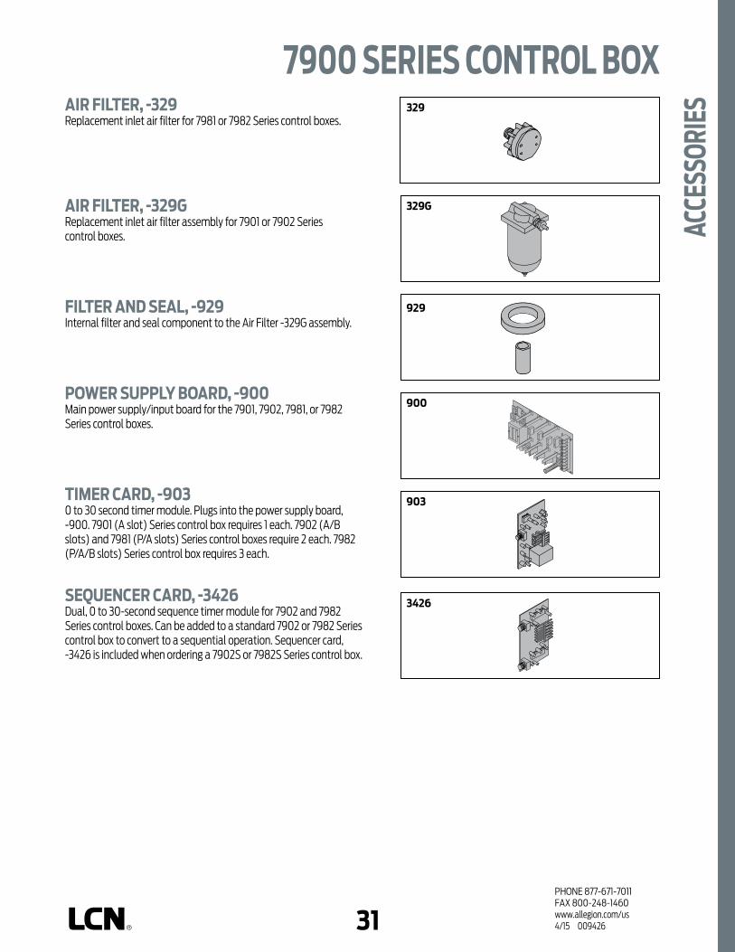
30 31PHONE 877-671-7011FAX 800-248-1460www.allegion.com/us 4/15 009426
3390A3390B3390C
941
942
941C
3299A
3299B
CAPACITOR
329AIR FILTER, -329Replacement inlet air filter for 7981 or 7982 Series control boxes.
AIR FILTER, -329G Replacement inlet air filter assembly for 7901 or 7902 Series control boxes.
FILTER AND SEAL, -929Internal filter and seal component to the Air Filter -329G assembly.
POWER SUPPLY BOARD, -900Main power supply/input board for the 7901, 7902, 7981, or 7982 Series control boxes.
TIMER CARD, -9030 to 30 second timer module. Plugs into the power supply board, -900. 7901 (A slot) Series control box requires 1 each. 7902 (A/B slots) and 7981 (P/A slots) Series control boxes require 2 each. 7982 (P/A/B slots) Series control box requires 3 each.
SEQUENCER CARD, -3426Dual, 0 to 30-second sequence timer module for 7902 and 7982 Series control boxes. Can be added to a standard 7902 or 7982 Series control box to convert to a sequential operation. Sequencer card, -3426 is included when ordering a 7902S or 7982S Series control box.
3390A3390B3390C
941
942
941C
3299A
3299B
CAPACITOR
329G
3390A3390B3390C
941
942
941C
3299A
3299B
CAPACITOR
9293390A3390B3390C
941
942
941C
3299A
3299B
CAPACITOR
900
3390A3390B3390C
941
942
941C
3299A
3299B
CAPACITOR
903
3390A3390B3390C
941
942
941C
3299A
3299B
CAPACITOR
3426
7900 SERIES CONTROL BOX
ACCE
SSOR
IES

32PHONE 877-671-7011FAX 800-248-1460www.allegion.com/us 4/15 009426
3390A3390B3390C
941
942
941C
3299A
3299B
CAPACITOR
941VALVE ASSEMBLY, -941Regulator valve assembly for 7901 Series control box.
VALVE ASSEMBLY, -942Regulator valve assembly for 7902 Series control box.
VALVE ASSEMBLY, -941CRegulator valve assembly for 7949 Series blow open control box.
SOLENOID VALVE ASSEMBLY, -3299AAir valve assembly for 7981 Series control box or the ‘A’ circuit valve assembly for the 7982 Series control box.
SOLENOID VALVE ASSEMBLY, -3299BAir valve assembly for the ‘B’ circuit in the 7982 Series control box.
RELAY PACKAGE ‘A’, -3390AES relay assembly for 7901 and 7981 Series control boxes or the ‘A’ circuit ES relay assembly in a 7902 or 7982 Series control boxes. Includes 390 relay, base, and wires. Can be added to standard 7901, 7902, 7981, or 7982 Series control boxes to convert to ES operation. Relay package, -3390A is included when ordering a 7901ES, 7902ES, 7981ES, or 7982ES Series control box.
RELAY PACKAGE ‘B’, -3390BES relay assembly for ‘B’ circuit in 7902 or 7982 Series control boxes. Includes –390 relay, base, and wires. Can be added to standard 7902 or 7982 Series control boxes to convert to ES operation. Relay package, -3390B is included when ordering a 7902ES or 7982ES Series control box.
RELAY PACKAGE ‘C’, -3390CES relay assembly in 7949 Series blow open control box. Includes –390C relay, base, and wires. Can be added to standard 7949 Series blow open control box to convert to ES operation. Relay package, -3390C is included when ordering a 7949ES Series control box.
3390A3390B3390C
941
942
941C
3299A
3299B
CAPACITOR
942
3390A3390B3390C
941
942
941C
3299A
3299B
CAPACITOR
941C
3390A3390B3390C
941
942
941C
3299A
3299B
CAPACITOR
3299A
3390A3390B3390C
941
942
941C
3299A
3299B
CAPACITOR
3299B
3390A3390B3390C
941
942
941C
3299A
3299B
CAPACITOR
3390A3390B3390C
7900 SERIES CONTROL BOXAC
CESS
ORIE
S
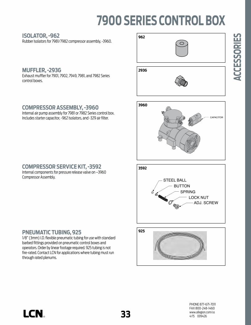
32 33PHONE 877-671-7011FAX 800-248-1460www.allegion.com/us 4/15 009426
ISOLATOR, -962Rubber Isolators for 7981/7982 compressor assembly, -3960.
MUFFLER, -293GExhaust muffler for 7901, 7902, 7949, 7981, and 7982 Series control boxes.
COMPRESSOR ASSEMBLY, -3960Internal air pump assembly for 7981 or 7982 Series control box. Includes starter capacitor, -962 Isolators, and -329 air filter.
COMPRESSOR SERVICE KIT, -3592Internal components for pressure release valve on –3960 Compressor Assembly.
PNEUMATIC TUBING, 925 1/8” (3mm) I.D. flexible pneumatic tubing for use with standard barbed fittings provided on pneumatic control boxes and operators. Order by linear footage required. 925 tubing is not fire-rated. Contact LCN for applications where tubing must run through rated plenums.
3390A3390B3390C
941
942
941C
3299A
3299B
CAPACITOR
39603390A3390B3390C
941
942
941C
3299A
3299B
CAPACITOR
3592
925
3390A3390B3390C
941
942
941C
3299A
3299B
CAPACITOR
962
3390A3390B3390C
941
942
941C
3299A
3299B
CAPACITOR
293G
7900 SERIES CONTROL BOX
ACCE
SSOR
IES

34PHONE 877-671-7011FAX 800-248-1460www.allegion.com/us 4/15 009426
900 SERIES COMPRESSORS
Compressor size recommendations are based on normal usage for the number of operators listed. All LCN supplied compressors include an automatic drain feature to periodically exhaust condensation from the pressure tank. Consider sound level, vibration, space requirements, condensation drainage, mounting, and placement of air lines when selecting compressor location. Provide adequate ventilation to avoid overheating the compressor. Compressors carry the compressor manufacturer's limited one year warranty. Contact LCN for details.
COMPRESSOR INSTALLATION NOTES 1. When usage is infrequent (less than two activations per
minute), use one size smaller compressor. 2. Locate compressor so less than 500 linear feet of LCN 925
tubing is required between compressor and control box. 3. Locate compressor where the temperatures do not exceed
120º F or fall below 35º F. 4. Projects requiring ASME certification of the pressure tank
require a 921 or larger compressor. 5. LCN 925 tubing or 3/16˝ metal tubing (by others) must be
used to maintain warranty. Contact LCN for details.
920 LCN does not manufacture the compressors listed.
For warranty information and service parts, contact
the compressor manufacturer.
920 (illustrated) Operators Up to 2 Auto Equalizers.Capacity 2 gallon pressure tank.Dimensions 23˝ long, 9˝ wide, 17˝ high.Electrical 115V AC 60 Hz, Single Phase.Amperage 6.0 in-rush, 4.0 continuous.Motor H.P. 0.17Acoustical 73 dba @ 3´, 68 dba @ 20´
921Operators Up to 4 Auto Equalizers.Capacity 12 gallon pressure tank.Dimensions 31˝ long, 14˝ wide, 21˝ high.Electrical 115V AC 60 Hz, Single Phase.Amperage 9.0 in-rush, 6.0 continuous.Motor H.P. 0.25Acoustical 78 dba @ 3´, 71 dba @ 20´
922Operators Up to 8 Auto Equalizers.Capacity 20 gallon pressure tank.Dimensions 33˝ long, 16˝ wide, 27˝ high.Electrical 115V AC, 60 Hz, Single Phase.Amperage 25.0 in-rush, 10.0 continuous or 230V AC, 60 Hz, Single Phase 19.0 in-rush, 5.0 continuous.Motor H.P. 0.50Acoustical 81 dba @ 3´, 73 dba @ 20´
923Operators Up to 20 Auto Equalizers.Capacity 30 gallon pressure tank.Dimensions 38˝ long, 23˝ wide, 30˝ high.Electrical 115V AC, 60 Hz, Single PhaseAmperage 85.0 in-rush, 22.0 continuous or 230V AC, 60 Hz, Single Phase 50.0 in-rush, 11.0 continuous.Motor H.P. 1.50Acoustical 83 dba @ 3´, 75 dba @ 20´

34 35PHONE 877-671-7011FAX 800-248-1460www.allegion.com/us 4/15 009426
ELECTROHYDRAULIC POWERED SYSTEMSELECTRIC AUTO EQUALIZERSThese Auto Equalizer products are an addition to the original pneumatic drive system. People moving through a door can use it as a normal rack & pinion door closer or, at the touch of a button, open the door automatically. An integrated digital control suite provides all electrical control functions. These self-contained units are suitable for use on single leaf doors or pair of doors where each leaf is equipped with an operator. The operator provides all the control and power elements into a single operator package, only some actuators are required to complete the system.
n Introduced in 1995.n Two surface mount models available. The 4630 mounts on the
pull side of the door and the 4640 Series mounts on the push side of the door.
n Integrates a modified heavy-duty 4040 Series cast iron cylinder.n 4600 Electric Operators are not approved for smoke evacuation
systems.
UNIQUE FEATURESn Digital Control Box
Provides exceptionally precise control of a large range of built-in functions combined with superior durability and performance. Visual indications and digital readouts of all control function settings and activity make adjustments easy, fast and accurate.
n Dual Independent Program Memories Each unit is pre-programmed to factory default settings. The installer can adjust the unit to meet the job site requirements. These field settings are locked into the computer’s memory. Any subsequent field adjustments replace the original field adjustments. The factory settings are always retained in memory and can be recalled to replace the field settings in just seconds, restoring the unit to it’s original programming.
n On-Board Diagnostics Sophisticated built-in diagnostics program monitors the system microprocessor, power supplies, drive system and actuators circuitry. Reduces the time required to make sure the installation is complete and correct.
n On-Board Power Supply Provides both 12V DC and 24V DC outputs to power card readers, manual actuators and other peripherals.
n “Plug & Play” Sensors Motion sensors and safety sensors feature a ‘plug and play’ concept allowing fast and accurate wiring connections in only seconds.
n “No Destruct” Drive System Specially designed motor and clutch assembly provide a ‘breakaway’ function that reduces the chance the operator will be damaged in an abusive application. If a vandal tries to force the door closed while it is trying to open, the clutch mechanism prevents damage. The door is never out of control because the heavy duty 4040 closer is always operable.
nElectronic Circuit Protection The high voltage input circuit is protected by a one amp slow blow fuse. The low voltage output circuits by self-resetting fuses.
n Visual Function Indicators LED’s allow direct observation of these inputs: - input power - fire alarm input - normal trigger (actuator) input - sequential trigger (actuator) input - hold open/alternate action (actuator) input - lockout timer - safety sensor (clear) input - safety sensor (active) input
n Programming Mode Allows tailoring the following functions to meet specific site conditions: - hold open time - 90° slow down time - one shot input [ON or OFF] - Exterior mode [ON or OFF] function to accommodate
momentary resistance, like wind gusts, during the opening swing.
- electric strike delay timer - electric strike 3 second power function [ON or OFF] - sequential trigger delay timer - alternate action timer - lockout timer
ELECTRIC AUTO EQUALIZER SYSTEMSn Originally introduced in 1995.n Exceeds proposed ANSI cycle test standard of 300,000 full
load automatic operating cycles. Integrated LCN 10 million cycle heavy duty 4040 door closer.
n Power operation plus full door control.n For all applications, single or multi-door projects.n Opening time to backcheck no faster than 3 seconds.n Opening time 4 seconds or more to fully open.n Must remain fully open for at least 5 seconds.n Closing time from 90° to 10° no faster than 3 seconds.n Less than 15 pounds-force to stop door’s motion.n Kinetic energy must not exceed 1.25 lbf-ft.n In event of failure; less than 15 lbf. to release latch, less than
30 lbf. to put door in motion, less than 15 lbf. to fully open door systems.
Continued on page 36

36PHONE 877-671-7011FAX 800-248-1460www.allegion.com/us 4/15 009426
STANDARDS, LISTINGS & APPROVALSn UL listed for self-closing doors without hold open under
“SWINGING DOOR CLOSERS (GVEV)” file R1943.n Tested and certified under ANSI Standard A156.19. Refer to
Section 2.1 and consult factory for details.n ANSI Standard A117.1, Section 4.13.13.n ADA law, Section 4.13.12.n UBC 7.2 (1997) for positive pressure plus UL 10B and
UL 10C listing.n Wiring is compliant with both UL 325 and the NEC.
Separation of high and low voltage.n Consult the factory for other listings such as; State and
Local Government regulations.n cUL Listed for Fire Rated Door Operators with Automatic Closers,
File No. (GUJY).
WARRANTYn 2 year limited warranty. See General Information Section for
complete details.
MAINTENANCEn Operators mounted according to the LCN installation
instructions require no periodic maintenance or adjustments.n Periodic visual inspections are recommended.n No service contracts.
ELECTROHYDRAULIC POWERED SYSTEMS

36 37PHONE 877-671-7011FAX 800-248-1460www.allegion.com/us 4/15 009426
SINGLE DOOR SYSTEM (WIRELESS)n An Interior Door.n No guide rails or safety devices.n Free Swinging (or Dogged) Door.
How It Works: Wireless RF actuators and receiver, powered by the Auto Equalizer simplify installation and minimize installation costs. For automatic door operation, touching either actuator signals the receiver and controller module to open the door to 90°. The door is held there until the system times out, then full spring power is applied to reliably close and latch the door. Door opening speed and hold open time are adjustable on the controller. Closing power and speed are adjustable on the cylinder assembly. If not actuated, the Auto Equalizer functions as a full featured door closer.
SINGLE DOOR SYSTEMSLow VoltageWiring
Auto-Equalizer
RF Receiver
120VInput
RF Actuator
RF Actuator
VESTIBULE ENTRY SYSTEM (WIRED)n Exterior & Vestibule doors.n Sequential Operation.n No guide rails or safety devices.n Controlled Access, Free Egress.
How It Works: This installation provides both accessibility and security for building occupants. The Auto Equalizer controller module provides both the power and coordination for card reader and electric strike applications. A built-in delay allows the strike to release before the door begins to open. Two interconnected Auto Equalizers provide sequential operation in both directions. Vestibule actuators allow single door ingress/egress from the vestibule as needed. NOte: An eL device requires a separate power supply. If not actuated, the Auto equalizer functions as a full featured door closer.
Vestibule Entry OperationLow Voltage
Wiring Auto-Equalizer
Auto-Equalizer
Card Readerw/keypad as
Exterior Actuator Note: 120V AC Inputrequired to both operators
Electric Strike
(mounted on push side)
(interior door)
(exterior door)
Interior Actuator
VestibuleActuator
VestibuleActuator
BILL OF MATERIALSQty. Part No. Description1 4642 Auto Equalizer (exterior)1 4631 Auto Equalizer (interior)3 8310-856 Wall Plate Actuators Other products from Von Duprin and Locknetics
BILL OF MATERIALSQty. Part No. Description1 4631 Auto Equalizer2 8310-3856WS Wireless Actuators1 8310-865 Wireless Receiver
This page illustrates examples of typical Electric LCN systems. Please consult your local SSC representative or
LCN for assistance with specific installations and material requirements.
ELECTROHYDRAULIC POWERED SYSTEMS

38PHONE 877-671-7011FAX 800-248-1460www.allegion.com/us 4/15 009426
DOOR CLOSER ASSEMBLY nBased on a heavy duty 4040, cast iron cylinder with
all-weather fluid for consistency and reliability.nRugged drive mechanism provides the connection to the
electric motor assembly.nFully adjustable, independent hydraulic regulation
controls the door to minimize the chance of damage to the door and frame assemblies.
ELECTRIC MOTOR/CLUTCH ASSEMBLYnHighly efficient motor combined with a custom designed
gear system provides exceptionally quiet and smooth operation.
nSpecial clutch transmits the power and provides a unique “breakaway” function that prevents damage to the operator, door and frame if a vandal forces the door closed during the powered opening swing.
DIGITAL CONTROLLER MODULEnDigital Control Suite.nDual Independent Program Memories.nOn Board Diagnostics.nVisual Function Indicators.nAdjustable Programming Modes.
FIELD WIRING
nInput power; 120V AC @ 1.5 amperes.nOn-board, low voltage power supply provides both
12V and 24V DC @ 1.0 ampere (maximum combined load) for LCN actuators, RF receivers, and electric strikes or magnetic locks.
nSlow blow and self-resetting fuses protect input and output power from voltage spikes.
nTerminal strips simplify field wiring.
nOn/Off Switch
nHold Open Switch
nSeparate conduits for high voltage power and low voltage power and signal wiring meet UL and National Electrical Code requirements.
1
34.14.2
4.3
4.4 2
3 2 4.x
4.1
4.2
4.3
4.4
1
3 2 4.x
4.1
4.2
4.3
4.4
1
3 2 4.x
4.1
4.2
4.3
4.4
1
3 2 4.x
4.1
4.2
4.3
4.4
13 2 4.x
4.1
4.2
4.3
4.4
1
3 2 4.x
4.1
4.2
4.3
4.4
13 2 4.x
4.1
4.2
4.3
4.4
13 2 4.x
4.1
4.2
4.3
4.4
1
4630/4640 ELECTROHYDRAULIC POWERED SYSTEMS

38 39PHONE 877-671-7011FAX 800-248-1460www.allegion.com/us 4/15 009426
LCN DIGITAL CONTROL BOX
LCN LOW VOLTAGE (CLASS 2 NEC) ELECTRICAL CONNECTIONSFIELD CONNECTION TERMINALS
12/24 VDC11 2 3 4 5 6 7 8 9 10 11 12 13 14 15 16 17 18 19 20 21 22 23 24
FUNCTION TERMINALActuator - Normal Input (N.O.) 16 & 17 or 18 & 19Actuator - Sequential Input (N.O.) 8 & 19Actuator - Alternate Action (N.O.) 15 & 17Actuator - Continuous (N.O.) 6 & 17Sequential Output 9Stop Side Safety (N.O.) 19 & 20Swing Side Safety (N.O.) 19 & 21Fire Alarm Contact (N.C.) 13 & 14 (Fire Shunt)Auxiliary Relay Contacts (5 amp max) 10 - Common 11 - N.O. 12 - N.C.E.S. Relay Contacts (5 amp max) 22 - Common 23 - N.O. 24 - N.C.12V DC & 24V DC Negative* 2, 4, 13, 17, & 1912V DC Positive* 5 & 724V DC Positive* 1 & 3
* NOte: 1 Amp max load between 12V and 24V DC outputs.
© ETAD.GFM
ROPPUS LACINHCET T
®
1-877-671-7011www.allegion.com/us
Allegion 2015
Opening Speed AdjustmentLimited to a minimum of 3 seconds to backcheck(approx. 70°)
Opening Force AdjustmentMaximum of 15 lb-f to stop door swing
Time DisplayDisplays numeric value relating to timing adjustments (16 = approx. 5 seconds)
Mode IndicatorIndicates programming mode currently being displayed
Up ButtonIncreases time or changes from OFF to ON when programming
Down ButtonDecreases time or changes from OFF to ON when programming
Mode ButtonAdvances through programming setups on Mode Indicator
Operating IndicatorsDisplays operating information about internal functions and external hardware
ELECTROHYDRAULIC POWERED SYSTEMS

40PHONE 877-671-7011FAX 800-248-1460www.allegion.com/us 4/15 009426
Notes

40 41PHONE 877-671-7011FAX 800-248-1460www.allegion.com/us 4/15 009426
TOP JA
MB (PULL
SIDE)
TOP JA
MB (PUSH SIDE)
MOUNTING
PARALLEL A
RM
POWDER COAT
PLATED
PLASTIC
METAL
NON-HANDED
NON-SIZED
ACCESSIBILI
TY*
COVER CYLINDERFINISH
POWER
OPERATO
R
CONCEALED
HOLD-O
PEN
DPS SWITCH
STANDARD (S
INGLE)
REGULA
R (DOUBLE)
EXTRA DUTY
*ARM FUNCTION
CUSH-N-S
TOP
SPRING CUSH
The 4630 AUTO EQUALIZER™ is LCN’s
SMART & RELIABLE electrically powered
low-energy power operator. It provides
easy access for people with disabilities,
or the elderly. Designed primarily for
manual opening applications that
occasionally required automatic opening.
n Digital Control Box. n Utilizes a 4040 Heavy Duty Door Closer. n On-Board Diagnostics. n On-Board Power Supply. n Factory-Default Memory. n Includes “No Destruct” Drive System. n Guard Rails or Safety Mats not required.
4630 Series is UL and cUL listed with standard
arm for self-closing doors and meets the
provisions of ANSI Standards A117.1, A156.19,
and the Americans with Disabilities Act.n Standard, top jamb (pull side) mounted 4630 Series closer shipped with single
lever (standard) arm, metal cover, standard track, and wood and machine screw pack. Actuators available separately, see pages 122-137.
n Meets ADA requirements (power mode).
n Non-sized cylinders for interior doors to 4´0˝ and exterior doors to 3´0˝.
n Non-handed for either right or left swinging door.
n 4630 has easily accessible switches to provide on/off and continuous hold open functions. 4630 with CS option provides concealed on/off power switch. Control module provides all timing and sequential door functions, electric strike controls and adjustments for opening speed and force.
n Standard or optional custom powder coated finish, end caps are black.
n Optional plated finish on cover, arm, and fasteners.
TOP JAMB (PULL SIDE) MOUNTING
4630 SERIES
FEAT
URES
Meets ADA requirements (power mode). * See individual series for maximum manual opening. ** Switch provided for continuous hold open (4630 only).
AVAILABLE NOT AVAILABLE

42PHONE 877-671-7011FAX 800-248-1460www.allegion.com/us 4/15 009426
n Butt Hinges should not exceed 5˝ (127 mm) in width.
n Auxiliary Stop is recommended.
n Reveal should not exceed 1/8˝ (3 mm).
n Head Frame minimum 2˝ (51 mm).
n Top Rail minimum 1-1/8˝ (29 mm).
n Opening Time and Force are variable by adjustments to the electronic control module located on the operator assembly. Maximum hold open time adjustable up to approxi mately five minutes.
n System Diagram See “AUTOMATIC OPERATORS” section pages 36 for typical system wiring and pages 37-38 for electrical data.
TOP JAMB (PULL SIDE) MOUNTING
MAXIMUM OPENINGTemplating allows 90° power opening and 170° manual opening.
Please note that many track style door closers are capable of allowing 180° of door swing. Track style closers are at their weakest closing force at 180°. Consult factory for applications where exterior or large/heavy door must swing 180°.
Consult factory for all pivot mounted installations.
4630 SERIESM
OUNT
ING
DETA
ILS
Special TemplatesCustomized installation templates or products may be available to solve unusual applications. Contact LCN Product Support for assistance.

42 43PHONE 877-671-7011FAX 800-248-1460www.allegion.com/us 4/15 009426
72MC
3071
3971CYLINDERSCYLINDER ONLY, 4631-3971 Standard, non-handed, cast iron cylinder. CYLINDER ASSEMBLY, 4631-3071 Standard, non-handed, cast iron cylinder and mounting plate. Includes; 4630-3454 Motor Clutch, 4630-3180 I/O Board Assembly and 4630-3462 Controller.
CYLINDER ASSEMBLY, 4631-3071CS Standard, non-handed, cast iron cylinder and mounting plate. Includes; 4630-3454 Motor Clutch, 4630-3180 I/O Board Assembly and 4630-3462 Controller. Same as a 4630-3071 assembly except on/off switch is concealed in endcap and no hold open switch is included. (Separate key switches suggested).
COVERSCOVER, 4630-72MC Standard, non-handed metal cover.
TRACKSSTANDARD TRACK, 4630-3038 Standard non-handed track.Will not accept hold open clip or bumper assembly.
ARMSSTANDARD ARM, 4630-3077T Non-handed arm. Track roller not included with arm.
INSTALLATION ACCESSORIESTRACK ROLLER, 4630-3034Quiet low friction roller assembly.Shoulder dimension "X" = 1/8˝ (3mm).
3077T
3034
3038
3071CS
4630 SERIES
ACCE
SSOR
IES

44PHONE 877-671-7011FAX 800-248-1460www.allegion.com/us 4/15 009426
INSTALLATION ACCESSORIESSWITCH END CAP, 4630-334End cap (black powder coat finish only) with cut outs for installing on/off and hold open switches.
BLANK END CAP, 4630-334-2Black powder coat only.
SWITCH END CAP, 4630-334CSEnd cap and switch (black powder coat only) for concealed switch option.
ON/OFF SWITCH ASSEMBLY, 4630-3179-1Black rocker switch. Plugs into high voltage PC board.
HOLD OPEN SWITCH ASSEMBLY, 4630-3179-2Black rocker switch. Field wired to low voltage PC board.
PC BOARD ASSEMBLY, 4630-3180High and low voltage PC boards connected to mounting bracket.
MOTOR/CLUTCH ASSEMBLY, 4630-3454A geared assembly in an LCN power operator that incorporates a “no destruct” feature.
CONTROL BOX ASSEMBLY, 4630-3462Digital controller with built-in 12/24 VDC power supply. Programming and timing functions are adjusted on controller.
AC POWER CABLE, 4630-3498-22 wire cable to connect 120 VAC from PC board assembly to controller.
RIBBON CABLE CONNECTOR, 4630-3498-116 wire ribbon cable connecting 1-24 pin terminal connectors to controller.
3179-13179-2
3180
3498-2
3498-1
3454
3462
4630 SERIESAC
CESS
ORIE
S 334334-2334CS
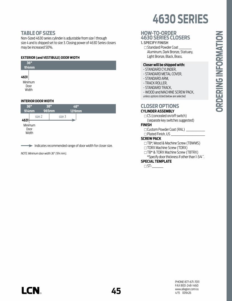
44 45PHONE 877-671-7011FAX 800-248-1460www.allegion.com/us 4/15 009426
4630 SERIES
ORDE
RING
INFO
RMAT
ION
4631
INTERIOR DOOR WIDTH
4631
EXTERIOR (and VESTIBULE) DOOR WIDTH
36"914mm
36"914mm
38"965mm
48"1219mm
size 2 size 3
MinimumDoor
Width
MinimumDoor
Width
TABLE OF SIZESNon-Sized 4630 series cylinder is adjustable from size 1 through size 4 and is shipped set to size 3. Closing power of 4630 Series closers may be increased 50%.
HOW-TO-ORDER 4630 SERIES CLOSERS1. SPECIFY FINISH Standard Powder Coat __________
Aluminum, Dark Bronze, Statuary, Light Bronze, Black, Brass.
CLOSER OPTIONSCYLINDER ASSEMBLY CS (concealed on/off switch)
(separate key switches suggested)FINISH Custom Powder Coat (RAL) _______________ Plated Finish, US ___________________________SCREW PACK TB*, Wood & Machine Screw (TBWMS) TORX Machine Screw (TORX) TB* & TORX Machine Screw (TBTRX)
*Specify door thickness if other than 1-3/4˝.SPECIAL TEMPLATE ST-_________
Closer will be shipped with:- STANDARD CYLINDER,- STANDARD METAL COVER,- STANDARD ARM,- TRACK ROLLER, - STANDARD TRACK,- WOOD and MACHINE SCREW PACK,unless options listed below are selected.
Indicates recommended range of door width for closer size.
NOte: Minimum door width 36" (914 mm).

46PHONE 877-671-7011FAX 800-248-1460www.allegion.com/us 4/15 009426
Notes

46 47PHONE 877-671-7011FAX 800-248-1460www.allegion.com/us 4/15 009426
TOP JA
MB (PULL
SIDE)
TOP JA
MB (PUSH SIDE)
MOUNTING
PARALLEL A
RM
POWDER COAT
PLATED
PLASTIC
METAL
NON-HANDED
NON-SIZED
ACCESSIBILI
TY*
COVER CYLINDERFINISH
POWER
OPERATO
R
CONCEALED
HOLD-O
PEN
DPS SWITCH
STANDARD (S
INGLE)
REGULA
R (DOUBLE)
EXTRA DUTY
*ARM FUNCTION
CUSH-N-S
TOP
SPRING CUSH
The 4640 AUTO EQUALIZER™
is LCN’s SMART & RELIABLE
electrically powered low-energy
power operator. It provides easy
access for people with disabilities,
or the elderly. Designed primarily
for manual opening applications
that occasionally require automatic
opening.
n NEW Digital Control Suite n Utilizes a 4040 Heavy Duty
Door Closer n On-Board Diagnostics n On-Board Power Supply n Factory-Default Memory n Includes “No Destruct” Drive System n Guard Rails or Safety Mats
not required
the 4640 Series is UL and cUL listed
with regular arm for self-closing doors
and meets the provisions of ANSI
Standards A117.1, A156.19, and the
Americans with Disabilities Act.
n Standard, top jamb (push side) mounted 4640 Series closer shipped with regular arm, metal cover, and wood and machine screw pack. Actuators available separately, see pages 122-137.
n Meets ADA, requirements (power mode).
n Non-sized cylinders for interior doors to 4´6˝ and exterior doors to 3´6˝.
n Non-handed for either right or left swinging door.
n 4640 has easily accessible switches to provide on/off and continuous hold open functions. 4640 with CS option provides concealed on/off power switch. Control module provides all timing and sequential door functions, electric strike controls and adjustments for opening speed and force.
n Standard or optional custom powder coated finish, end caps are black.
n Optional plated finish on cover, arm, and fasteners.
TOP JAMB (PUSH SIDE) MOUNTING
4640 shown
4640 SERIES
FEAT
URES
Meets ADA requirements (power mode). * See individual series for maximum manual opening. ** Switch provided for continuous hold open (4640 only).
AVAILABLE NOT AVAILABLE

48PHONE 877-671-7011FAX 800-248-1460www.allegion.com/us 4/15 009426
n Butt Hinges should not exceed 5˝ (127 mm) in width.
n Auxiliary Stop is recommended.
n Reveal of 4-1/2˝ (114 mm) allows up to 90° power opening and 100° manual opening. 8˝ (203 mm) allows up to 90° power opening and 100° manual opening with LONG ARM where standard rod and shoe is replaced with optional LONG ROD AND SHOE, 4640-79LR.
n Head Frame minimum 1-3/4˝ (44 mm). The standard mounting plate is also used to meet flush ceiling conditions.
n Top Rail minimum 1-3/4˝ (44 mm). Flush ceiling installation requires 3-3/4˝ (95 mm) minimum.
n Opening Time and Force are variable by adjustments to the electronic control module located on the operator assembly. Maximum hold open time adjustable up to approxi mately five minutes.
n System Diagram See “AUTOMATIC OPERATORS” section page 36 for typical system wiring and pages 37-38 for electrical data.
TOP JAMB (PUSH SIDE) MOUNTING
MAXIMUM OPENINGTemplating allows 90° power opening and 100° manual opening.
Consult factory for all pivot mounted installations.
Standard Mount Flush Ceiling Mount
4640 shown
4640 SERIESM
OUNT
ING
DETA
ILS
Options n Long arm.
Special TemplatesCustomized installation templates or products may be available to solve unusual applications. Contact LCN Product Support for assistance.

48 49PHONE 877-671-7011FAX 800-248-1460www.allegion.com/us 4/15 009426
CYLINDERSCYLINDER ONLY, 4642-3971 Standard, non-handed, cast iron cylinder.
CYLINDER ASSEMBLY, 4642-3071 Standard, non-handed, cast iron cylinder and mounting plate. Includes; 4640-3454 Motor Clutch, 4640-3180 I/O Board Assembly and 4640-3462 Controller.
CYLINDER ASSEMBLY, 4642-3071CS Standard, non-handed, cast iron cylinder and mounting plate. Includes; 4640-3454 Motor Clutch, 4640-3180 I/O Board Assembly and 4640-3462 Controller. Same as a 4640-3071 assembly except on/off switch is concealed in endcap and no hold open switch is included. (Separate key switches suggested).
COVERSCOVER, 4640-72MC Standard, non-handed metal cover.
ARMSREGULAR ARM, 4640-3077 Non-handed arm.
LONG ARM, 4640-3077L Arm includes LONG ROD AND SHOE, 4640-79LR for deep reveals.
ROD & SHOE, 4640-79Rod for use with regular arm.
LONG ROD & SHOE, 4640-79LRLong rod used for long arm with deep reveals.
79LR79
3071CS
4640 SERIES
ACCE
SSOR
IES
72MC
30773077L
3071
3971

50PHONE 877-671-7011FAX 800-248-1460www.allegion.com/us 4/15 009426
INSTALLATION ACCESSORIESSWITCH END CAP, 4640-334End cap (black powder finish coat only) with cut outs for installing on/off and hold open switches.
BLANK END CAP, 4640-334-2Black power coat only.
SWITCH END CAP, 4640-334CSEnd cap and switch (black powder coat only) for concealed switch option.
ON/OFF SWITCH ASSEMBLY, 4640-3179-1Black rocker switch. Plugs into high voltage PC board.
HOLD-OPEN SWITCH ASSEMBLY, 4640-3179-2Black rocker switch. Field wired to low voltage PC board.
PC BOARD ASSEMBLY, 4640-3180High and low voltage PC boards connected to mounting bracket.
MOTOR/CLUTCH ASSEMBLY, 4640-3454A geared assembly in an LCN power operator that incorporates a “no destruct” feature.
CONTROL BOX ASSEMBLY, 4640-3462Digital controller with built-in 12/24 VDC power supply. Programming and timing functions are adjusted on controller.
AC POWER CABLE, 4640-3498-22 wire cable to connect 120 VAC from PC board assembly to controller.
RIBBON CABLE CONNECTOR, 4640-3498-116 wire ribbon cable connecting 1-24 pin terminal connectors to controller.
3179-13179-2
3180
3498-2
3498-1
3454
3462
4640 SERIESAC
CESS
ORIE
S 334334-2334CS

50 51PHONE 877-671-7011FAX 800-248-1460www.allegion.com/us 4/15 009426
4640 SERIES
ORDE
RING
INFO
RMAT
ION
4642
INTERIOR DOOR WIDTH
4642
EXTERIOR (and VESTIBULE) DOOR WIDTH
36"914mm
38"965mm
48"1219mm
54"1372mm
size 3 size 4 size 5
MinimumDoor
Width
MinimumDoor
Width
TABLE OF SIZESNon-sized 4640 series cylinder is adjustable from size 2 through size 5 and is shipped set to size 3. Closing power of 4640 Series closers may be increased 50%.
HOW-TO-ORDER 4640 SERIES CLOSERS1. SPECIFY FINISH Standard Powder Coat __________
Aluminum, Dark Bronze, Statuary, Light Bronze, Black, Brass.
CLOSER OPTIONSCYLINDER ASSEMBLY CS (concealed on/off switch)
(separate key switches suggested)FINISH Custom Powder Coat (RAL) _______________ Plated Finish, US ___________________________ARM Long (LONG)SCREW PACK TB*, Wood & Machine Screw (TBWMS) TORX Machine Screw (TORX) TB* & TORX Machine Screw (TBTRX)
*Specify door thickness if other than 1-3/4˝.SPECIAL TEMPLATE ST-_________
Closer will be shipped with:- STANDARD CYLINDER,- STANDARD METAL COVER,- REGULAR ARM,- WOOD and MACHINE SCREW PACK,unless options listed below are selected.
Indicates recommended range of door width for closer size.
NOte: Minimum door width 36" (914 mm).
36"914mm
42"1067mm
size 5

52PHONE 877-671-7011FAX 800-248-1460www.allegion.com/us 4/15 009426
Notes

1PHONE 877-671-7011FAX 800-248-1460www.allegion.com/us 4/15 009426
n Standard holder shipped with wood and machine screw pack.
n Handed for right or left swinging doors.
n Standard or optional custom powder coat finish.
n Hold-open point adjustable at the soffit shoe.
n Optional plated finish on holder and fasteners.
n Optional SRI primer for installations in corrosive conditions.
The PAH 60 is recommended for use
on the inactive leaf of a pair of doors
where the active leaf has a door closer
installed.
MAXIMUM OPENINGHold-open points up to 180°.
PAH 60
n Butt Hinges should not exceed 5˝ (127 mm) in width.
n Auxiliary Stop recommended at hold-open point.
n Top Rail minimum 2˝ (51 mm).
n Rabbet Depth minimum 1-1/4˝ (32 mm).
HOW-TO-ORDERPAH 60 HOLDER1. SPECIFY HAND RH LH
2. SPECIFY FINISH Standard Powder Coat __________
Aluminum, Dark Bronze, Tan, Statuary, Light Bronze, Black, Brass.
OPTIONAL ARM FINISH Custom Powder Coat (RAL)__________ Plated Finish, US__________ SRI Primer
FEAT
URES
& O
RDER
ING
INFO
RMAT
ION

PHONE 877-671-7011FAX 800-248-1460www.allegion.com/us 4/15 0094262
Notes


Allegion (NYSE: ALLE) creates peace of mind by pioneering safety and security.
As a $2 billion provider of security solutions for homes and businesses, Allegion
employs more than 7,800 people and sells products in more than 120 countries
across the world. Allegion comprises 23 global brands, including strategic
brands CISA®, Interflex®, LCN®, Schlage® and Von Duprin®.
For more, visit www.allegion.com
About Allegion
© 2014 Allegion 009426, Rev. 4/15allegion.com/us


