Embed Size (px)
Citation preview
City, University of London Institutional Repository
Citation: Pierotti., M.J. (2005). Aircraft Maintenance Engineering : developing Aircraft Maintenance Programme using Reliability Centred Maintenance / MSG3 analysis and taking into consideration ETOPs and low utilisation. (Unpublished Doctoral thesis, City University London)
This is the accepted version of the paper.
This version of the publication may differ from the final published version.
Permanent repository link: https://openaccess.city.ac.uk/id/eprint/8461/
Link to published version:
Copyright: City Research Online aims to make research outputs of City, University of London available to a wider audience. Copyright and Moral Rights remain with the author(s) and/or copyright holders. URLs from City Research Online may be freely distributed and linked to.
Reuse: Copies of full items can be used for personal research or study, educational, or not-for-profit purposes without prior permission or charge. Provided that the authors, title and full bibliographic details are credited, a hyperlink and/or URL is given for the original metadata page and the content is not changed in any way.
City Research Online

City Research Online: http://openaccess.city.ac.uk/ [email protected]
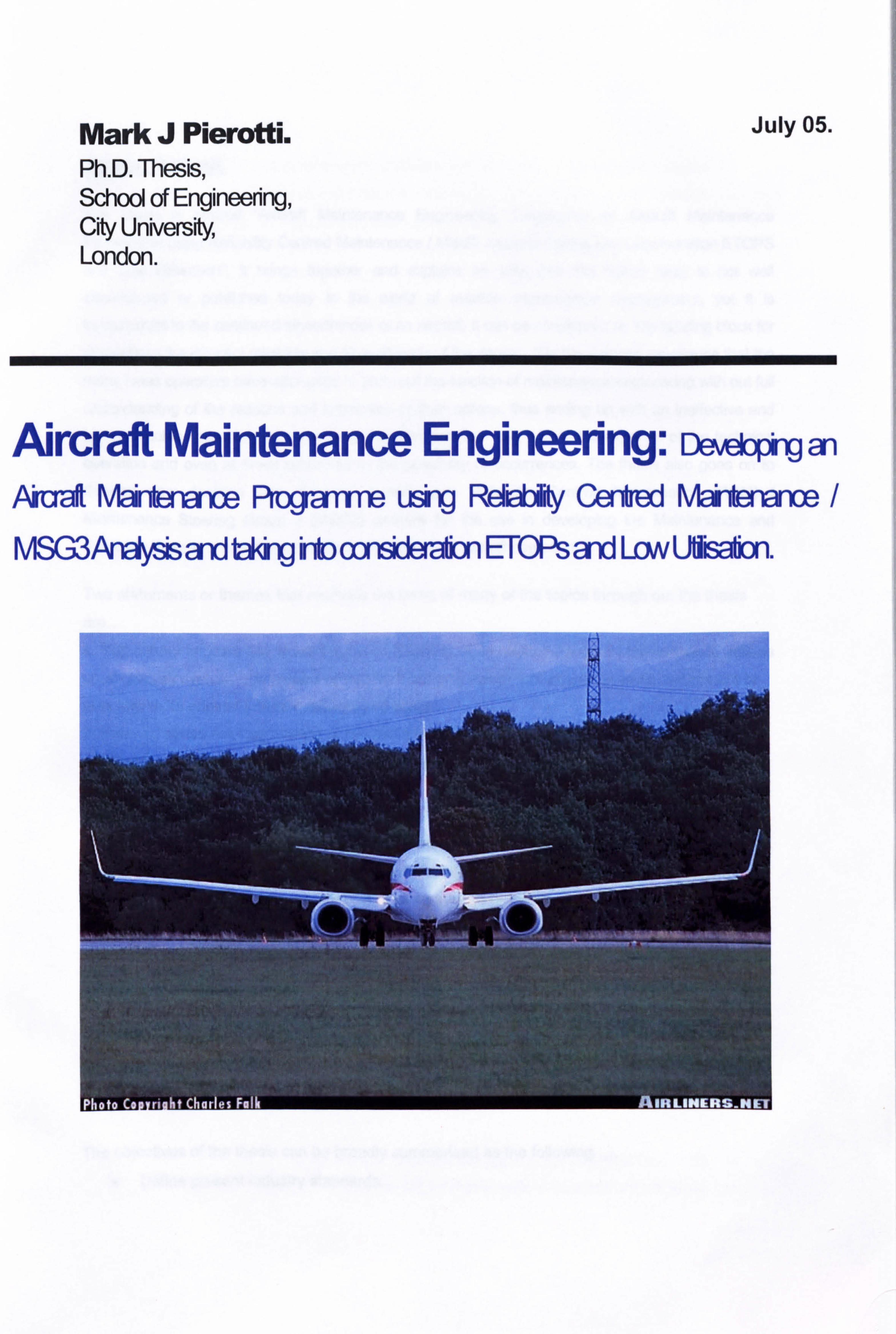
Mark J Pierotti. Ph. D. Thesis, School of Engineering, City University, London.
July 05.
Airc Maintenance Engineering: i)&ýw Aiued Mahbffaue Rugame u§-, g Rdd)k Cated Minbanance /
MSG3ArbVjs md d4ig hb oonsiderahon ETOPs and Low Ulisaý.

Text cut off in original
Thesis Abstract.
The thesis is entitled "Aircraft Maintenance Engineering: Developing an AJrcraft Maintenance Programme using Reliability Centred Maintenance / MSG3 Analysis Taking into Consideration ETOPS
and Low Utilisation", It brings together and explains an area that the author feels is not well documented or published today in the world of aviation maintenance management, yet it is fundamental to the continued airworthiness of an aircraft, it can be considered as the building block for
maintaining the inherent reliability and airworthiness of the design. It is the author's experience that too
many times operators have attempted to carry out the function of maintenance engineering with out full
understanding of the reasons and implication of their actions, thus ending up with an ineffective and non applicable collection of maintenance activities that can only add to the expense of the technical
operation and even at times contribute to the possibility of occurrences. The thesis also goes on to develop new decision tree diagrams based upon Reliability Centred Maintenance (RCM) / Maintenance Steering Group 3 (MSG3) analysis for the use in developing the Maintenance and Reliability Programme and incorporating new aspects of aircraft operation.
Two statements or themes that motivate the basis of many of the topics through out the thesis
are... 1. You cannot improve the airworthiness or reliability of an original design by maintenance actions on an aircraft system, component or structure but only return that aircraft system, component or structure to its original inherent reliability of design. 2. You can cause the degradation of the airworthiness or reliability of an original design by
maintenance actions on an aircraft system, component or structure.
These two statements are built upon early in the thesis in defining the Nature of Failure and then the RCM / MGS3 analysis process used for defining the scheduled maintenance tasks. This
process is reviewed in detail showing where it is most effective and at other time insufficient
requiring supplementing with life controls or even system redesign.
The thesis examines exactly what is the Aircraft Maintenance Programme and identifies that it is
the definition of scheduled maintenance tasks that are both effective & applicable in maintaining the inherent reliability of the aircraft and the on going development of the scheduled maintenance tasks through the Reliability Programme and the efficient management of accomplishment and
recording of the scheduled maintenance tasks. An area that the author considers as largely
misunderstood with in the industry of aircraft maintenance engineering.
The objectives of the thesis can be broadly summarised as the following
0 Define present industry standards.
" Identify & Define new original improvements to those standards.
" Identify new original standards for ETOPs & Low Utilisation issues.
" Identify & Define original effective management methods for the standards & their improvements.
While the original aspects of the thesis can be defines as...
1. New Enhancements to the RCM / MSG3 Process for Producin-q the Scheduled
Maintenance Tasks:
" Clarification of the Nature of Failure & RCM
" Insertion of the ETOPS Question to MSG3
" Identifying when life limitations are required on non damage tolerant structural items
" Adopting the ETOPs standards as normal practices for all aircraft
" New Low Utilisation assessment to MSG3
" An economic comparison of RCM / MSG3 Maintenance Programmes against non RCM MSG 3 defined Programmes
2. New Standards for Maintenance Engineering Planning:
" The Definition of Maintenance Engineering Planning
" Establishing a standard for Maintenance Engineering Planning
Establishing the critical link between Maintenance Engineering Planning & Human Factors
3. New Standards for conductino The Reliability Pro_qramme:
Establishing the essential need for Reliability Monitoring
Establishing a simple new standard for Reliability Monitoring incorporating ETOPs
standards Getting to the Root Cause of failures
Reassessment of the Maintenance Programme through Optimisation Studies
4. The Use of Maintenance Programme Control Software:
" New MPCS Assessment Standards
" New MPCS Selection Standards
" New MPCS Implementation Standards
5. New Standards for Management of a Simple Organisation:
0 Identifies the Regulatory Standard for a European JAA operator
* Defines a simple Organisation to meet the regulations
0 Defines what must be in place to meet the standards
In summary the Thesis fills the gap in the understanding and documenting of the Maintenance
Programme Process for Aircraft and brings the Engineering discipline into the 21st Century, by
defining and integrating existing standards and developing new standards as a single Maintenance Programme Process. Furthermore the theories and processes defined in the thesis
are very topical and have undergone careful practical application in the support of a wide and
narrow body fleet over the last 4 years. They have been extensively discussed with other industry
professionals and industry organizations such as ICAO and IATA and then also presented to a
major aircraft manufacturer and aircraft maintenance service provider for possible inclusion in
part into their standards. The thesis has been met with interest by all these parties.
The Proposal for Future Work can be surnmarised as three tasks. These are The author continues to attempt to formalise the new recommendation defined in the
thesis as industry standards working with ICAO, IATA, the Regulators, the Manufacturers
and Industry.
0 The author will plan to conduct a Maintenance Programme Optimisation study using the
method defined in the thesis section 6 for a fleet of five B737-NG's.
The author will continue to encourage other Industries out with aviation to adopt the
Maintenance Programme philosophy such as submarines, ships, military equipment and
even plants.

I herby give the City University Librarian permission to make single of multiple copies of text from this book as required.
ckrsvtýl
Mark J Pierotti.
Mark J Pierotti. Ph. D. Thesis, School of Engineering, City University, London.
July 2005.
A0 irc Maintenance Engineering: De. ý an Aiual kbriaro-m Roganm u§-U Rdb* Cated N/bi*ro-m MSMAruVds aid t*ng hb oonsiderAm ETOPs and Low Ulsabon.
TabbdCcrkwft 1. Thesis Introducbm Page4
2 REfiaIA[YCw*ed Mairftrrw. PagoT
21 M@irknanwAnEnjrwWReqkemenL Pag97
2.1.1 Maintenance Philosophies Before RCM. Page 7
2-2 AninkoduclionblhelheorydRCM. Pam 8
2.2.1 The Nature of Failure. Page 8
2.2.2 Failure Management through Scheduled Maintenance Tasks. Page 22
2.2.3 The P-F Interval. Page 24
2.2.4 RCM Analysis, the Process. Page 29
2.3 Application of RCM to produce an Aircraft Maintenance Programme. Page 52
2.3.1 Analysis of Systems. Page 52
2.3.2 Analysis of Structures. Page 63
2.3.3 The Zonal Programme. Page 98
3. The Maintenance Steerina Group. Page 122
3.1 MSG: An Industry Acceptance of RCM Analysis to Create an Aircraft Maintenance Page 122 Programme.
3.11.11 MSG: Addressing the Issue of Aircraft Scheduled Maintenance, Page 122
3.1.2 MSG I an Initial theory to create an Aircraft Maintenance Programme. Page 122
3.1.3 MSG 2 Improving the Initial theory and a step closer to RCM. Page 126
3.1 A MSG 3 application of RCM. Page 127
3.1.5 Further Development of the RCM theory and JAII 011 RCM Standard. Page 132
3.2 MSG 3 Analysis: Creation of A New Aircraft Maintenance Programme. Page 133
3.2.1 The Regulative Requirements under JAA and FAA for Aircraft Maintenance Programmes. Page 133
3.2.2 Air Transport Association of Amedca Guidelines For Producing a Maintenance Programme. Page 136
3.2.3 Application of MSG 3 to Produce A Maintenance Programme for A New Aircraft Utilizing the Page 136 MRB & the ISC.
3.2.4 The Production of the Operators Approved Maintenance Programme. Page 137
4. New Enhancements to the IVISG3 Process Including ETOPs. Page 148
4.1 Extended TWn Engine Operation. ETOPs. Page 148
4.1.1 ETOPs: An Introduction. Page M
4.1.2 ETOPs: Maintenance and Engineering Implications. Page 151
4.1.3 ETOPs Maintenance Philosophy, a New Standard for Ail Aircraft Maintenance Programmes. Page 152
4.2 Low Utilisation Implications for an Aircraft Maintenance Programme. Page 176
4.2.1 Low Utilisation: An introduction. Page 176
4.2.2 Low Utilisation: Maintenance Implications. Page 176
4.2.3 Low Utilisation Adjustments to the MSG3 Process. Page 179
4.3 An Economic Model for Comparison of MSG 3 Maintenance Programmes Versus Non MSG 3. Page 192
5. Maintenance Ennineerina Plannina. Page 198
5.1 Getting the Scheduled Maintenance Task Done. Page 200
5.1.1 Maintenance Planning. Page 201
5.1.2 Production Planning and Control. Page 210
5.1.3 Task Cards & the Maintenance Manual. Page 223
5.2 Non Routine Findings: The Results of Scheduled Maintenance. Page 227
5.2.1 Non Routine Findings: Classification. Page 227
5.2.2 Unscheduled Component Changes. Page 228
5.3 Human Factors Associated with Accomplishing the Maintenance Programme. Page 229
6 The Reliabilitv Prociramme: Rellabilitv Monitorincl and Develor)ment of the MSG3 Page 238 Maintenance Programme.
6.1 The Reliability Programme Is an Integral part of the MSG3 / RCM Maintenance Programme. Page 238
6.1.1 The Regulations and Requirements for Reliability Programmes. Page 239
6.1.2 Data Collection to Enable the Reliability Monitoring. Page 241
6.1.3 Methods of Reliability Monitoring. Page 242
6.1.4 ETOPs and Reliability Monitoring. Page 259
6.1.5 Getting to the Root Cause of the Failures or Findings. Page 265
6.2 Developing the Maintenance Programme Based on Scheduled Maintenance Findings and Reliability Page 271 Monitoring.
6.2.1 The Reliability Control Board (RCB): Objeclives, Functions and Processes. Page 277
6.2.2 The Maintenance Schedule Review Board (MSRB): Objectives, Functions and Processes. Page 262
6.2.3 Development of the Scheduled Maintenance Tasks using In operational data & Maintenance Page 268 Findings.
6.2.4 Scheduled Maintenance Programme Optimisation. Page 273
6.3 The Role of The Operating Crew In MSG3 Maintenance Programmes. Page 274
6.3.1 A Reminder of The RCM Dependency on Operating Crew Evident Failure Modes. Page 283
6.3.2 Flight Crew Training To Understand the MSG3 Philosophy. Page 283
6.3.3 Maintenance Crew Training To Understand the MSG3 Philosophy. Page 284
7 Maintenance Prouramme Control Software. Page 285
7.1 User Team selection and Preparation. Page 286
2
7.2 Software Assessment Page 287
7.3 Software Selection. Page 289
7A Software Implementation. Page 290
8 The Organisation and the Maintenance Programme. Page 298
8.1 The Maintenance and Engineering Division. Page 298
8.2 Maintenance Implications for The Requirements for an Air Operators Certificate: JAR OPS. Page 302
9 Thesis Conclusion. Page 310
10 Recommendation for Further Work. Page 316
11 Attachments. Page 318
12 Glossary. Page 319
13 Biblioaraphy. Page321
3
1. Thesis Introducdon.
The maintenance of aircraft is today a discipline and function that every operator must take very
seriously for two main reasons. Firstly it is the legal requirement of every aircraft operator to ensure the continued airworthiness of his aircraft, this is regulated extensively. Secondly the maintenance
of aircraft is one of the most cost consuming aspects of the operation of aircraft, not to manage the
maintenance of the aircraft in an efficient and cost effective manner will result in massive cost
excesses, eating away at the operators profits. The maintenance programme is the building block
ensuring the continued airworthiness of an aircraft. The maintenance programme defines what
scheduled maintenance tasks should be carried out and when those tasks should be carried out. It
is my opinion that the maintenance programme is much greater that what some operators realise today. Not only is it a collection of scheduled maintenance tasks with their respective intervals but
also a process and method of continued development and validation of those scheduled
maintenance tasks ensuring that all the tasks accomplished, do bring value to the ongoing
airworthiness of the aircraft. This on going monitoring process of the scheduled maintenance tasks
is referred to as the Reliability Programme. The Reliability Programme along with the Scheduled
Maintenance Tasks and with the processes and procedures involved in maintaining the
Programme together can be referred to as the Maintenance Programme.
The thesis start in earnest with section 2 where the nature of failure of structures and systems is
described and it is established why we need to carry out maintenance. The P-F interval is
described and establishes that by understanding the P-F interval we can start the process of
analysis defining maintenance tasks. This section continues to define and describes the process
called Reliability Centred Maintenance (RCM) better know in aircraft maintenance as Maintenance
Steering Group 3 (MSG3) philosophy. It explains that through a process of analysis of individual
components, systems and structures we can realise the full inherent reliability of design of those
components, systems and -structures through establishing effective and applicable scheduled
maintenance tasks. A series of decision diagrams is explained that will lead to task identification or indeed the need to redesign the system or structure. This section describes the design
philosophies of Safe Life, Fail Safe and DamageTolerant and how these design philosophies can
affect the maintenance actions to be carried out. It identifies that at times RCM / MSG3
maintenance tasks are at times insufficient and Life Limitations may have to be applied to structural items that are not damage tolerant whose failure if goes undetected can lead to catastrophic
functional failures.
The establishing and development of the Maintenance Steering Group (MSG) is described in
section 3. This describes where the aircraft manufacturers, regulators and later also the operators have establish MSG 1, MSG 2 and finally MSG 3 philosophies in an attempt to create an effective
and applicable collection of scheduled maintenance tasks-It identifies the regulations, both JAA
and FAA, and industry standards applicable to the establishment of an effective aircraft
maintenance programme and builds upon them to define an efficient method for an Airline or Operator to establish their own applicable Maintenance Programme.
4
Section 4 develops what is described in section 3 and introduces new procedures improving the
Maintenance Programme definition process, introducing the philosophies of Extended Twin Jet
Operations (ErOPs) maintenance standards as applicable to all aircraft and all operations. In
section 4 it is shown that ErOPs standards can easily be inserted into the RCM / MSG 3 process
as well as into to the every day maintenance standards of all aircraft establishing a more effective
maintenance programme. The section then also goes on to examine the custornisation of a
maintenance programme in particular to the Low Utilisation environment. Here it is described the importance of considering the operational context and utilisation of an aircraft and where
adjustments must be made to ensure that the maintenance programme is effective for a Low
Utilisation operation. The process of the RCM / MSG 3 decision diagram is adapted to review the
effects of the operational environment and of low utilisation. Section 4 also presents an economic comparison of Scheduled Maintenance Programmes established by RCM / MSG3 to those of non RCM / MSG 3 methods; it examines using a simple model the economic benefits from conducting
an MSG3 scheduled maintenance programme versus a non MSG3 programme and defines in
maintenance cost per operational flight hour for each of the maintenance programme types.
Having established the maintenance schedule tasks using the methods described in section 2,3
and 4 Section 5 defines how to plan, prepare, implement and manage the maintenance schedule. It
defines the need for short term, medium term, long term maintenance planning and also production
planning and control, describing effective and efficient ways to conduct the planning process. The
section goes on further to describe what non routine findings are and how they are important to the
maintenance programme process. This section also describes the effects of human factors and the
regulations related to them.
Section 6 deals with the Reliability Programme describing the essential need for this process in the
context of an RCM / MSG 3 Maintenance Programme. The section continually defines that with out
a simple reliability monitoring function in place the maintenance programme is incomplete. A simple
system is defined as well as a more complex system that will ensure that the maintenance
programme is effective and applicable. This section identifies regulation and industry standards
applicable to reliability monitoring and builds upon them defining new improvements to the present
standards. It defines methods for data gathering, for data reporting and areas where those involved
in the maintenance programme process need training, from flight crew to maintenance staff. Scheduled Maintenance Optimisation Process is described and defined as a new process for
reviewing and revising the Maintenance Programme through analysis again using the RCM / MSG
3 decision diagram.
Section 7 describes how Maintenance Programme Control Software (MPCS) can be utilised to
assist in effective Maintenance Programme control and management. This section identifies the Super User system for selection and implementation of a MPCS establishing a new industry
standard that will enable the best selection and most efficient implementation.
5
Section 8 identifies the regulations for an aircraft maintenance engineering organisation. It defines a
simple organisation and a more complex organisation that meets the required regulation and will be
effective in managing the Maintenance Programme of a fleet of aircraft.
Finally section 9 the conclusion, brings together and summarises all the original thought and
recommendations for new standards in each section of the thesis clarifying and substantiating their
value and section 10 describes recommendations for further work to be undertaken continuing the
spirit of the thesis in developing the Aircraft Maintenance Programme Process as a whole and for
other industries.
6
2. Reliabilitv Centred Maintenance.
2.1 Maintenance: An Engineering Requirement
2.1.1 Maintenance Philosophies before RCM.
The Second World War instigated a massive leap in the operational use of the airplane. It soon became apparent that the machines were required to be kept in a condition that allowed the aircraft
not only to carry out a successful mission once but to ensure that it could again repeatedly carry out
other missions and also as well to ensure the safety of the operating crew. The maintenance of the
machine therefore became an engineering discipline that required careful technical consideration.
When should the engine be taken off the aircraft?
When should the Nng control cables be replaced?
What maintenance tasks on the landing gear should be done?
Maintenance Engineering or Maintainability was not in the early days a prime consideration to the
design engineer or the manufacturer, but became one of the prime considerations to the owner and
operator, whose concern was to operate the machine to its best ability and to minimize its non
availability due to failures.
After the war and the role of the aircraft in the civilian world was diverted from flying military
missions to mass people transportation by profit seeking corporations, a new element of economics
now factored into the maintenance question.
How can I maintain my aircraft so that it meets the operational requirements, thus reducing the
probability of failure, in a cost effective manner?
The maintenance engineers of that time believed in a cause-and-effect relationship between
scheduled maintenance and operating reliability. This was based on the concept that mechanical
parts wear out and the reliability of any equipment is directly related to it's operating age. Following
on from this it was accepted that the more frequently the equipment was overhauled the less likely
the equipment would suffer mechanical failure. The only open question was at what time of
operating life should the scheduled maintenance take place to assure reliable operation? The DC 8
Manufacturers Recommended Maintenance Programme called for 339 components to be
overhauled at a hard time regardless of condition. This of course had spares holding implications
and aircraft downtime implication.
The FAA was looking closely at engine failure rates and discovered that the idea that by
overhauling an engine or a component increases its resistance to failure was flawed. The traditional hard time policies appeared to be ineffective at controlling failure rates. The FAA in the 1960's was frustrated that airlines could not control their component failure rate even by reducing their hard time overhaul intervals or by increasing their workscope of the overhaul task. The FAA went on to
7
address the problem by forming a task force consisting of representatives from the FAA and the
airlines, to investigate the capabilities of scheduled maintenance. The work of this group lead to a
FAA / Industry Reliability Programme, issued in November 1961. The introduction to that
programme stated....
The development of this programme is towards the control of reliability through an analysis
of the factors that effect reliability and provide a system of actions to improve low reliability levels
when they exist... in the past, a great deal of emphasis has been placed on the control of overhaul
periods to provide a satisfactory level of reliability. After careful study the Committee is convinced that reliability and overhaul time control are not necessarily directly associated topics, therefore
these subjects are dealt with separately.
The traditional concept that overhaul actions was an important factor in a component or systems failure rate was being challenged head on by this work group.
2.2 An introduction to the theory of RCM.
2.2.1 The Nature of Failure.
Some definitions of Failure
An unsatisfactory outcome or condition. Webster International 1998
An inability to function. Collins 2000
Break down or ceasing to function. Encarta 1999
All mechanical parts are subject to forces that will reduce its ability to perform its function.
These forces are wear, corrosion and fatigue. The experience of these forces ultimately will be the
cause of the part to no longer be able to achieve its intended function. The function of the part can
be defined as, (SAE JA101 I Aug 99), what the owner or user of a physical asset orsystern wants it
to do. The ceasing of the part to perform its required function is when the part can be classified as
failed. The role of scheduled maintenance is to identify prior to, and subsequently take action to
prevent through a maintenance action, the failure and more importantly the consequences of the
failure. This subject of scheduled maintenance will be dealt with in detail further at a later stage. A
failure consequence is, (SAE A 1011 Aug 99), the ways in which the effects of a failure mode or a
multiple failure matter. (Evidence of failure, impact on safety, the environment, operational
capability, direct and indirect repair costs). A Failure Mode is A single event, which causes a
Functional Failure, where a Functional Failure is a state in which a physical asset or system is
unable to perform a specific function to a desired level of performance (SAE JA 1011 Aug 99).
8
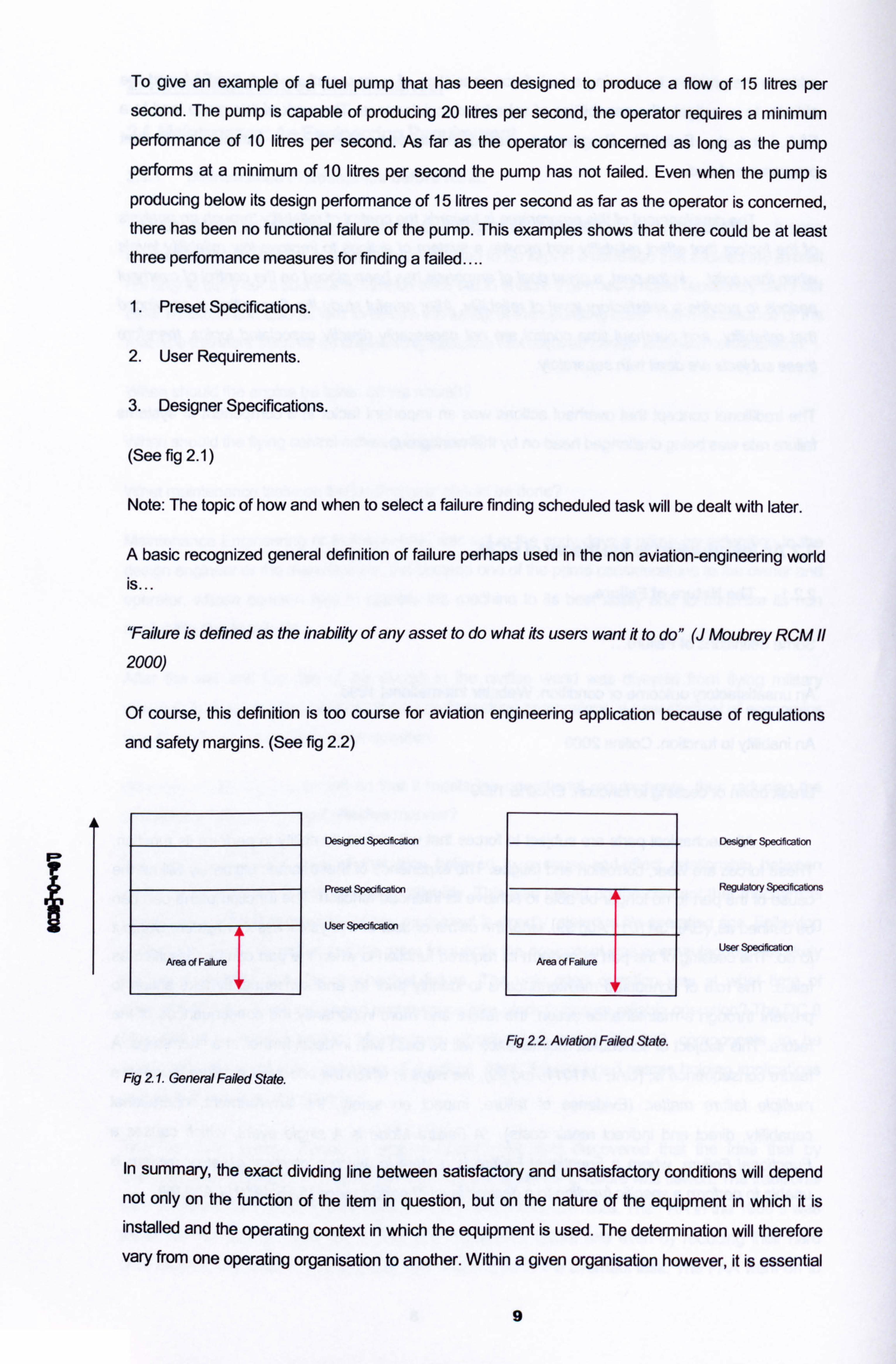
To give an example of a fuel pump that has been designed to produce a flow of 15 litres per
second. The pump is capable of producing 20 litres per second, the operator requires a minimum
performance of 10 litres per second. As far as the operator is concerned as long as the pump
performs at a minimum of 10 litres per second the pump has not failed. Even when the pump is
producing below its design performance of 15 litres per second as far as the operator is concerned, there has been no functional failure of the pump. This examples shows that there could be at least
three performance measures for finding a failed....
1. Preset Specifications.
2. User Requirements.
3. Designer Specifications.
(See fig 2.1)
Note: The topic of how and when to select a failure finding scheduled task will be dealt with later.
A basic recognized general definition of failure perhaps used in the non aviation-engineering world is...
"Failure is defined as the inability of any asset to do what its users want it to do" (J Moubrey RCM
2000)
Of course, this definition is too course for aviation engineering application because of regulations and safety margins. (See fig 2.2)
Area of Failure
Fig 2 1. General Failed State.
Designed Specification
Preset Specification
User Specificabon
Area of Failure
Fig 22 Aviation Failed State.
Desgm Speoficabon
RegUatory Specificabons
User Speaficabon
In summary, the exact dividing line between satisfactory and unsatisfactory conditions will depend not only on the function of the item in question, but on the nature of the equipment in which it is installed and the operating context in which the equipment is used. The determination will therefore vary from one operating organisation to another. Within a given organisation however, it is essential
9
that the boundaries between satisfactory and unsatisfactory condition be defined for each item in
clear and unmistakable terms. This means that the individual component failure effect must be
considered for failure implication on the complete function of the system.
Functional Failure and Potential Failure.
Functional Failure: "A state in which a physical asset or system is unable to perform a specific function to a desired level of performance" (SAE JA 1011 Aug 99).
A complete failure of a component or a system in so much that it ceases to function at all is a functional failure but so is the failure of that component or system to function to e required standard. To be able to define the functional failure we must understand the completely the workings and functions of the component or system and the implication that component or system has on other
components or systems. For example, the cabin conditioning and pressurisation system is to not
only create a comfortable temperature controlled environment for passengers inside the cabin, but
it is also to supply passengers with adequate air that will allow them to breathe. Functional failures
of components with in the system may not cause a functional failure of the complete system but
may raise the cabin temperature by a few degrees. It is very important that all the system functions
are understood so as the functional failures can be defined. (This is a very important aspect of RCM for determining failure-finding tasks when developing the scheduled maintenance programme
that will be discussed later).
Potential Failure: "An Identiffiable condition that indicates that a functional failure is either about to
occur oris in the process of occurTing"(SAEJAIOI I Aug 99).
Prior to a functional failure occurring, evidence of the imminent failure should be available. It should be possible to detect when a system or component is in this potential failing stage. Once a positive detection has been made of a component or system entering the potential failure stage, it can be
removed from service and replaced thus preventing the functional failure from occurring. The ability
to determine a potential or functional failure depends upon three factors...
A clear definition of the functions of the component or system.
0A clear definition of the conditions that constitute a functional failure.
0A clear definition of the conditions that indicate the imminence of the failure.
Failure Mode.
Failure Mode: "A single event, which causes a functional failure. "(SAE JA 1011 Aug 99).
The component and system function is understood and the functional failures have been identified.
It should then follow that the failure modes (cause of the failure) be recognized. For example, the
fuel distribution system's function is to transfer metered fuel from the wing tanks to the engines. A
10
functional failure could be fuel starvation to the engines, the failure mode is the fuel pump impeller
bearing has seized thus stopped pumping fuel. Understanding and recognizing the failure modes
assist us in rectifying the failure mode and restoring the function of the system.
Dealing with a failure mode when a functional failure has occurred is of course a reactive maintenance action. A proactive maintenance action would mean detecting the failure mode prior to a functional failure and dealing with it before a functional failure has occurred or when a potential failure is imminent. By identifying the failure modes prior to a functional failure you can identify
maintenance actions to rectify the failure mode or identify maintenance actions that will prevent the failure mode, but not all failure modes are preventable through proactive maintenance actions, some failure modes require re design, improved operating procedures or improved operator training.
An Example of Understanding Functional Failure and Failure Modes.
An Integrated drive generator (IDG) is responsible for generating three phase 115 / 200v, 4001-lz AC power to supply an aircraft electrical system. The IDG is cooled by oil flowing through the
component, if the oil flow is restricted or reduced, thus it looses its required cooling ability, the result will be an increase in IDG temperature, thus a functional failure of the IDG is imminent. By
understanding the function of the IDG and its cooling system a functional failure of the IDG due to temperature increase has been identified, due to loss of cooling oil and this is recognized as a failure mode. Then the design engineer can introduce an IDG temperature warning light or better
an oil pressure warning light to monitor the system and make evident to the operator to shut the
system down when a functional failure is imminent. This is failure mode prevention by design.
Equally a proactive maintenance action of frequent checking the IDG cooling oil level, ensuring a
sufficient quantity exists in the system and toping it up as required is a proactive maintenance
action to prevent a failure mode. Only by understanding the possible failure modes can a proactive
redesign or proactive maintenance action be identified to prevent failure modes from occurring.
Non-Deterioration Attributed Failure Modes.
The mistake often made in the maintenance engineering profession is that maintenance is
regarded as dealing with failure modes caused by deterioration of the system or component alone. Some other categories of failure modes often go missed. Such as human error induced failure
mode or design flaw induced failure mode. To be considered thoroughly and complete, all natures and categories of failure modes must be considered. By recognizing human error or design
induced failure modes the maintenance action may be quite different than if the failure mode is
attributed directly to deterioration or wear out. The topic of design induced failure modes will be dealt with when the RCM analysis of the failure is carried out and often redesign of the system is a recommendation or a requirement of the analysis to prevent the failure, but the human error aspect of failure is about many issues such as correct training, clear and correct procedures, the right working environment. AM of these issues will be explored further later in the thesis.
11
Root Cause of the Failure Mode.
While it is important that the reason for the failure mode is recognized at the "Root Cause", so an
appropriate maintenance action can be determined, this could mean that one would go on forever.
E. G.
Subject: Fuel Pump in a fuel delivery system.
Function : The fuel pump is to move fuel from the wing tanks to the engine fuel management
system at a constant pressure of 30 psi and a minimum flow of 9,000kg/h.
Functional Failure : Fuel supply to the engine is not sufficient to sustain constant ignition.
Failure Mode : The fuel pump has failed in supplying the correct fuel pressure due to an impeller
failure.
but we could go further... -
Failure Mode 2: The fuel pump impeller failure was due to the attaching nut braking off.
Failure Mode 3: The impeller attaching nut broke off due to the nut not being split pin locked at
manufacture.
Failure Mode 4: The split pin was not inserted at manufacturers because the assembly procedure
was not clear to the assembling production worker.
The "Root Cause" was Human Factors, unclear work procedures for the assembly staff member. But for the purposes of identifying a manageable maintenance task for an identifiable failure mode
we could stop at the first failure mode and as a reactive maintenance task replace the pump, or as
a proactive design task add a pressure monitoring light in line of the pump to indicate low pressure. By not getting to the root cause an incorrect maintenance action could be decided upon. For
example the failure mode analysis could of stopped at impeller attaching nut broke of, and the
maintenance action to be taken is to inspect the impeller attachment nut for security and
serviceability. While this will prevent the failure it does not address the root cause and costs time
and money to rectify a defect that can be stopped in total by an alternative action.
Reasons for failure modes will be examined in more detail later as this is a very important issue in
the continued development of the aircraft maintenance programme.
Consequence and Effects of Failure.
The failure effects describes what happens if the failure mode actually occurs, i. e. the consequence
of not preventing the failure mode. The consequence of failure can be anything from the modest
cost of replacing a component to the destruction of a system and subsequent loss of lives. Later we
12
will see that the consequence of failure determines the priority of the maintenance activity or design
improvement required to prevent its occurrence.
The more complex any piece of equipment is, the more ways in which it can fail. All failure
consequences can however be grouped in one of the following four categories...
0 Safety Consequence. Involving possible loss of equipment and its occupants.
9 Operational Consequence. Involves an indirect economic loss, such as a flight delay, as well
as the direct cost of repair.
0 Non Operational Consequence. Involves only the direct cost of repair.
0 Hidden Failure Consequence. No direct impact but increases the likelihood of multiple failure.
Safety Consequence.
Does the failure cause a loss of function or secondary damage that could have a direct effect on
operating safety?
Suppose the fuel line to the engine fuel control unit became disconnected and caused fuel to be
sprayed on the hot engine casing. This functional failure of the loss of engine thrust from fuel
starvation would not in its self cause threat to the aircraft loosing altitude as the other engines could
maintain forward thrust and altitude, but the secondary threat of an engine fire and possible
subsequent wing fire would cause a great threat to both the aircraft and passenger lives. In this
case the secondary effects are sufficient reasons to classify the failure as critical. A Critical Failure
is a failure that could have a direct effect on safety. The impact of the failure must be immediate if
the failure is to be considered direct that is the adverse effect must be one that will be felt before the
planned completion of the flight. Further more a critical failure must result from a single failure and
not as a result of a multiple failure, or some combination of this failure and another that has not yet
occurred. An important fact follows from this...
A ciffical failures will be evident to the operating crew. ff a failure has no evident resufts, it can
not by definflion have a direct effect on safety. (Reliability Centred Maintenance F. S. Nowlan
1978)
What this means is that a failure that goes unnoticed or does not cause the cessation or interruption of a planned flight, i. e. whose consequence of failure is not evident to the operating
crew or one that can be lived with without a threat of catastrophic results, can not be considered
critical.
Operational Consequence.
Does the failure have a direct adverse effect on operational capabilfty?
13
In this case consequences are economic. The implications of the failure are the costs of non
operation and the costs of repairing the failure mode. The failure of an inflation bottle for an escape
slide, i. e. the bottle pressure is below the acceptable minimum. This does not prevent the aircraft from being dispatched to complete a flight, but restricts the number of passengers able to fly on board. The cost of the failure is the loss of revenue by a reduction of potential passengers and the
cost of removing the slide and sending it for a bottle replacement.
Hidden Failure Consequence.
By definition hidden failures have no direct adverse effect (if they did they would not be hidden), but
if a hidden failure goes undetected it potentially could have catastrophic consequences. For
example the hydraulic pressure for the B737NG hydraulic flying controls is obtained by system A
and system B engine driven hydraulic pumps. The hydraulic pressure is maintained at around 3000ps! and if it drops below a pressure of 2000psi the standby hydraulic pump will start to
supplement the reduction in pressure. A failure of the standby hydraulic pump will not be evident to
the crew until the operation of the pump is required, so it is possible that the pump is in a failed
state but hidden to the operating crew. The consequence of any hidden functional failure is
increased exposure to the consequence of a multiple failure.
Failure Protective Devises.
Protective devices are increasingly being used in aircraft system design in an attempt to eliminate
or at least reduce the consequences of failure. Modem aircraft protective devises work in one of six different ways...
Aert Systems: to make the operating crew aware of an abnormal condition. These systems can be
used for hidden failures as well as potential evident failures. The Master Caution system will alert the operating crew to failures and potential failures of critical systems as soon as they are detected.
Hydraulic pressure low, fuel Pressure low, anti ice failure, equipment cooling failure, IRS failure will
all cause a Master Caution warnings. Some of these failures will be evident and some may be
hidden. While other alert systems will register failures but not annunciate them to the operating
crew as they are detected because these failures are not regarded as critical and will not affect the
normal operation of the aircraft. These failures can be brought to the attention of the maintenance
crew when the aircraft is on the ground through maintenance messages in the aircraft's central
computer system, that is interrogated by the receiving ground maintenance crew. The Built in Test
Equipment (BITE) systems are now on almost all individual avionics components as well as many
systems. The BITE will continuously initiate internal tests that will result in pass or fail light indication
on the aircraft central computer or on the individual component.
Shut down systems: These systems detect potential failures and to prevent them from becoming
failures shut the system down. For example the Auxiliary Power Unit (APU) start cycle include a
14
fuel flow and turbine exhaust gas temperature (TGT) monitoring system. If a certain fuel flow does
not result in a reduction in TGT, it means that ignition has not taken place, therefore the detection
system will stop the start cycle and shut down the engine operation, thus preventing a failure.
Relief systems: These systems, usually used in pneumatic or hydraulic systems, will monitor the
status of operation and enable a relief to take place when a failure mode has been reached. For
example the hydraulic system of the B737NG maintains hydraulic pressure at 3000psi. The fluid
reservoir experiences a head pressure of approximately 45psi to ensure positive feed to the
pumps. If the head pressure rises above 65psi a relief valve will open in the reservoir and vent the
excess pressure through a vent line and expelled overboard through a drain mast.
Standby systems: These systems will not normally be operative until the failure of the prime system has occurred. Usually only essential systems have standby systems. The electrical power system is an example of a standby system with multiple redundancy built in. The main power for supply the
main aircraft bus bars comes from AC generators, in the event of a generator failure or engine failure which will result in the generators failure to generate AC power, standby DC batteries will
supply inverted DC to AC power on line through a standby power control unit. The standby system
will now supply the essential electrical systems With AC power.
Redundancy by Design systems: Modem Airliners have most critical systems duplicated by
independent similar systems. For example the elevator of the B737NG is moved by two actuators. one actuator from the hydraulic system pressurized by engine number one driven pump and the
other actuator from the hydraulic system pressurized by engine number two. Both these systems
are similar in design but independent in function. The failure of system one will mean that system two will continue the operation of the elevator.
Detection and Extinguishing systems: These systems are typically fire detection and extinguishing
systems. Where a detector monitors temperature rise or air particle composition and activates an
extinguishing to put out a fire. Engine fire systems (temperature detection) and cargo fire systems (temperature and particle detection) are typical areas that would employ such systems.
The emergence of protective devices, protective systems and BITE has in irs self become a
subject of failure assessment. The successful function of these devices is essential and is
depended upon for safe operation of the aircraft. So a functional failure of a detection system may be a hidden failure and may allow for the possibility of a multiple failure.
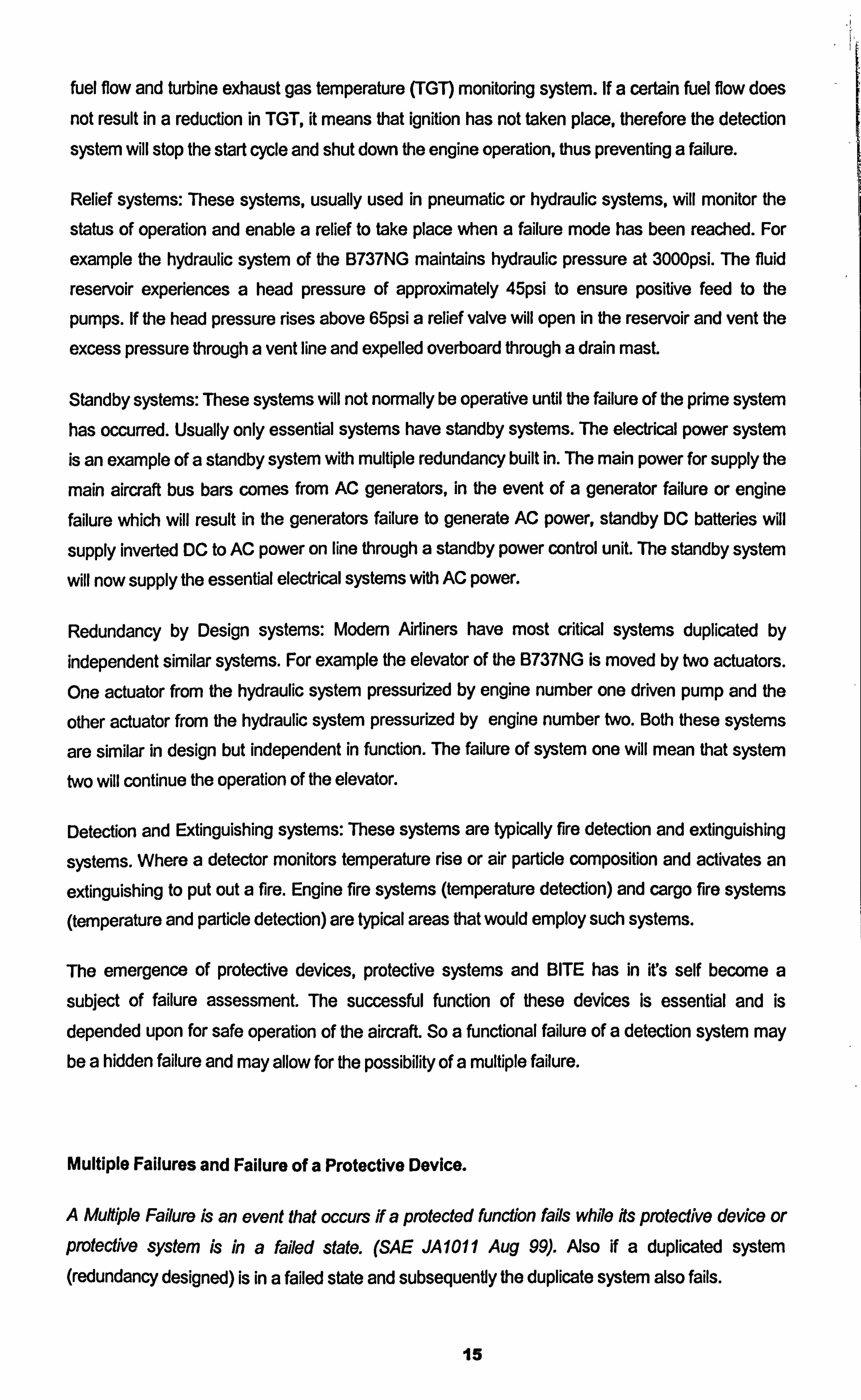
Multiple Failures and Failure of a Protective Device.
A MuMple Failure is an event that occurs if a protected function fails while its protective device or
Protective Systern is in a failed state. (SAE JAIOII Aug 99). Mso if a duplicated system (redundancy designed) is in a failed state and subsequently the duplicate system also fails.
15
Suppose systems A and B have a probability of surviving a2 hour flight 0.99 (99% chance of not failing, and a 11% chance of failing, which is a very high probability of failures rate), if system A and its protective device B( or duplicated system) are functioning in an aircraft at take off there are four
possible out comes...
0 System A survives and protective device B survives: P=0.99 x 0.99 = 0.9801
0 System A survives and protective device B fails: P=0.99 x 0.01 = 0.0099
0 System A fails and protective device B survives: P=0.01 x 0.99 = 0.0099
0 System A fails and protective device B fails: P=0.01 x 0.01 = 0.0001
This means there is a probability of 0.0001, that is once in 10,000 flights, that both system A and its
protective device B will fail at the same time. '
Take for example a Boeing 737NG aircraft with two CFM156-7B engines. The actual world wide fleet figures of utilisation is 111,1185,593 engine hours. The rate of in flight engine shut down (IFSD)
for that engine is 0.002 per 1,000 engine flight hours, (CFMI Fleet Highlights Jan 31 2002). This
equates to a single failure every 500,000 engine flight hours. So the P(engine failure) = 1/500,000
0.000002. P(engine survival) =1-0.000002 = 0.999998.
0 Engine 1 survives and engine 2 survives: P=0.999998 x 0.999998 = 0.999996000004
0 Engine 1 survives and engine 2 fails in flight: P=0.999998 x 0.000002 = 0.00000 1999996
0 Engine 1 fails in flight and engine 2 survives: P=0.000002 x 0.999998 = 0.00000 1999996
0 Engine I fails in flight and engine 2 fails in flight: P=0.000002 x 0.000002 = 0.000000000004
So while the probability of a single engine in-flight failure is 0.000001999996, equating to a single failure every 500,000 flight hours, a double in flight engine failure has a Probability of
0.000000000004. This equates to a double in-flight engine failure every 250,000,000,000 engine flight hours.
The Mean Time Between Failure (MTBF) is taken from a sample size and sample time. The
inverse of the MTBF, i. e. 1/MTBF is the probability of failure rate. For example if a hydraulic pump has a MTBF of 10,000 flight hours, that means 10,000 flight hours is the average utilisation of a
sample set of pumps. The probability that the pump will fail is P(failure) = 1/10,000 = 0.0001.
16
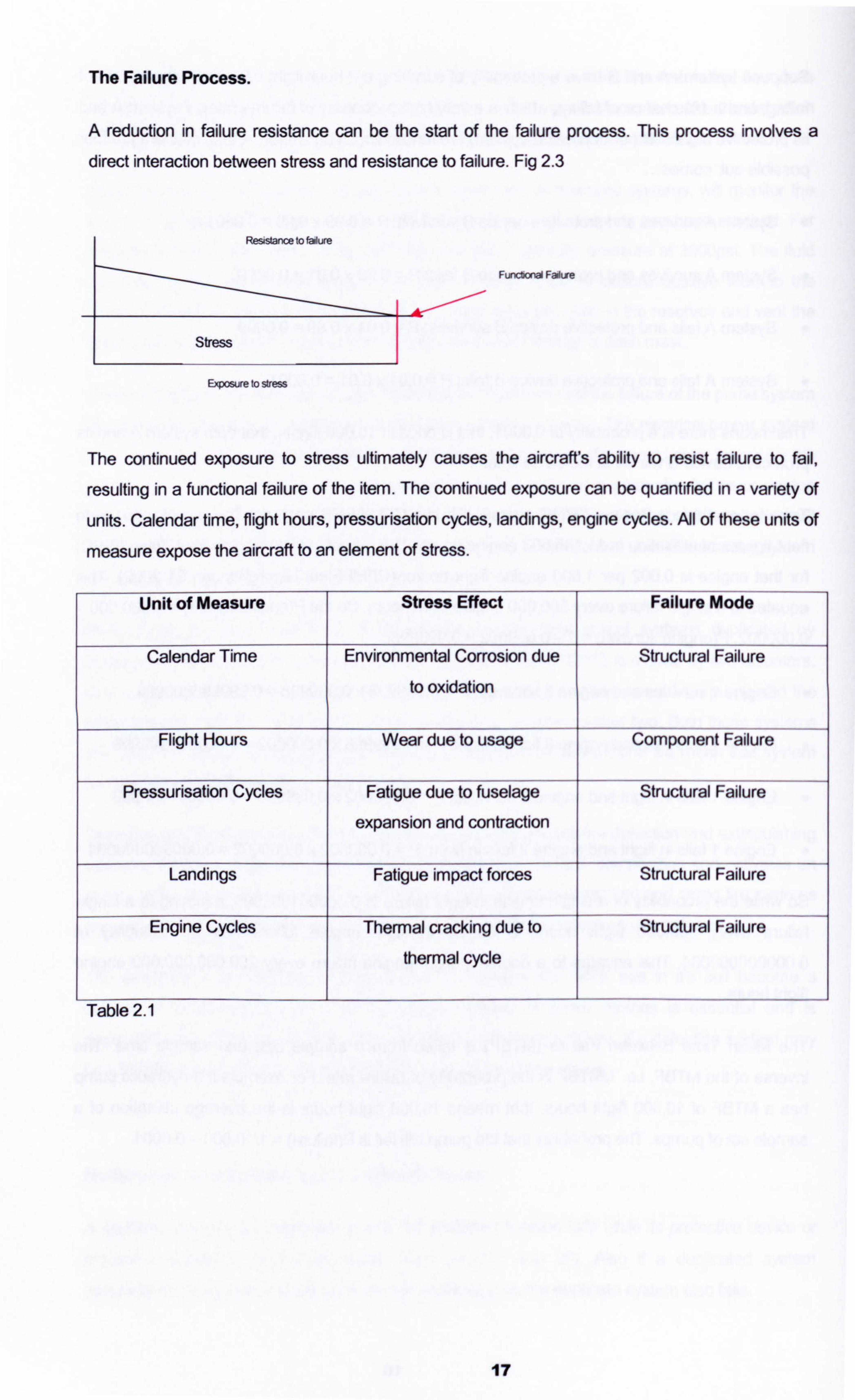
The Failure Process.
A reduction in failure resistance can be the start of the failure process. This process involves a
direct interaction between stress and resistance to failure. Fig 2.3
Resistance to ladure
Functonal Faitire
Evosure to Wm
The continued exposure to stress ultimately causes the aircraft's ability to resist failure to fail,
resulting in a functional failure of the item. The continued exposure can be quantified in a variety of
units. Calendar time, flight hours, pressurisation cycles, landings, engine cycles. AJI of these units of
measure expose the aircraft to an element of stress.
Unit of Measure Stress Effect Failure Mode
Calendar Time Environmental Corrosion due
to oxidation
Structural Failure
Flight Hours Wear due to usage Component Failure
Pressurisation Cycles Fatigue due to fuselage
expansion and contraction
Structural Failure
Landings Fatigue impact forces Structural Failure
Engine Cycles Thermal cracking due to
thermal cycle
Structural Failure
Table 2.1
17
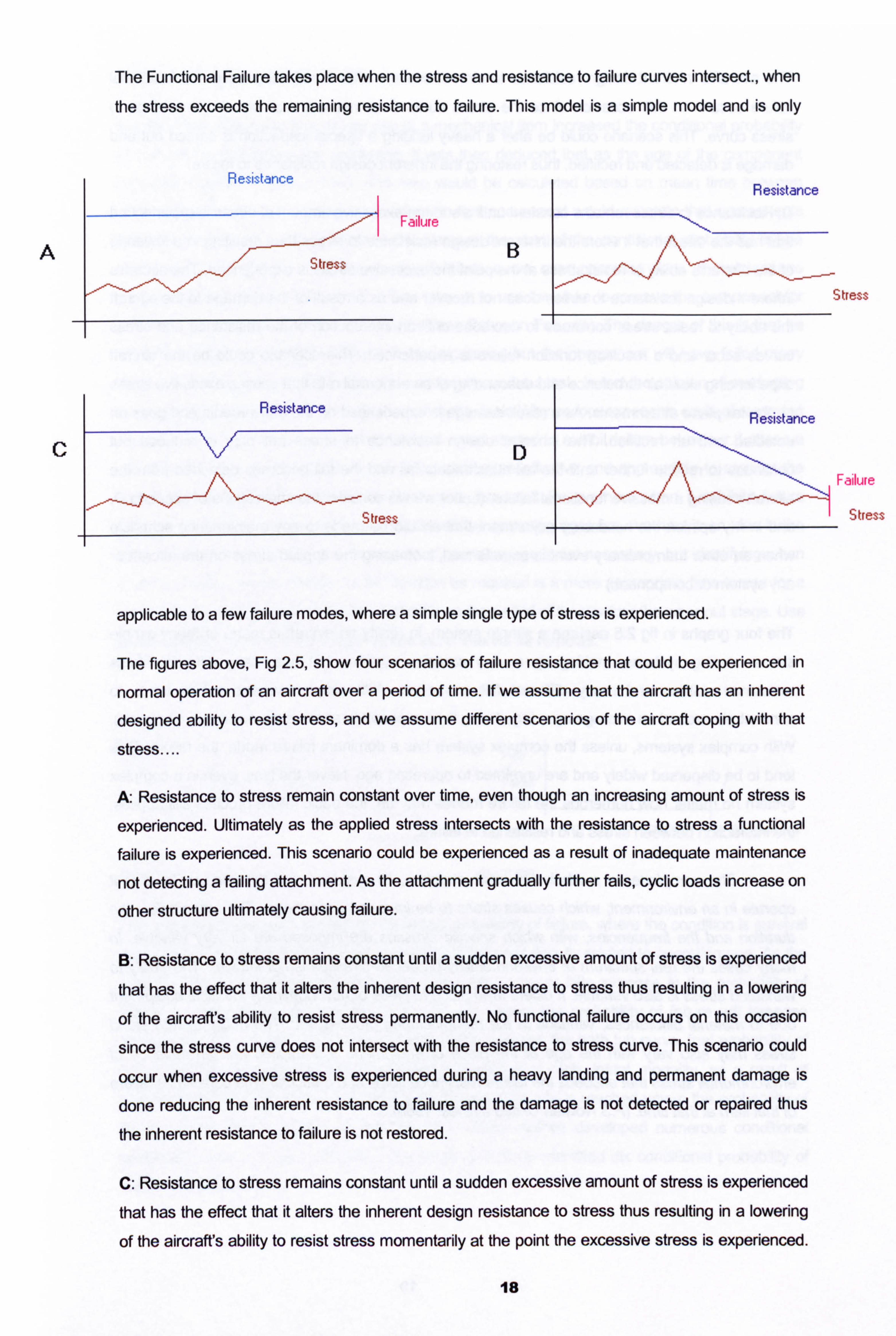
The Functional Failure takes place when the stress and resistance to failure curves intersect., when the stress exceeds the remaining resistance to failure. This model is a simple model and is only
Failure
A B
3 tress
C D -alluie
Stress
applicable to a few failure modes, where a simple single type of stress is experienced.
The figures above, Fig 2.5, show four scenarios of failure resistance that could be experienced in
normal operation of an aircraft over a period of time. If we assume that the aircraft has an inherent
designed ability to resist stress, and we assume different scenarios of the aircraft coping with that
stress....
A: Resistance to stress remain constant over time, even though an increasing amount of stress is
experienced. Ultimately as the applied stress intersects with the resistance to stress a functional
failure is experienced. This scenario could be experienced as a result of inadequate maintenance
not detecting a failing attachment. As the attachment gradually further fails, cyclic loads increase on
other structure ultimately causing failure.
B: Resistance to stress remains constant until a sudden excessive amount of stress is experienced
that has the effect that it alters the inherent design resistance to stress thus resulting in a lowering
of the aircraft's ability to resist stress permanently. No functional failure occurs on this occasion
since the stress curve does not intersect with the resistance to stress curve. This scenario could
occur when excessive stress is experienced during a heavy landing and permanent damage is
done reducing the inherent resistance to failure and the damage is not detected or repaired thus
the inherent resistance to failure is not restored.
C: Resistance to stress remains constant until a sudden excessive amount of stress is experienced
that has the effect that it alters the inherent design resistance to stress thus resulting in a lowering
of the aircraft's ability to resist stress momentarily at the point the excessive stress is experienced.
18
The aircrafts inherent design resistance to stress recovers after the event passes. No functional failure occurs on this occasion since the stress curve does not intersect with the resistance to
stress curve. This scenario could be after a heavy landing a special inspection is carried out and damage is detected and rectified, thus restoring the inherent design resistance to failure.
D: Resistance to stress remains constant until a sudden excessive amount of stress is experienced that has the effect that it alters the inherent design resistance to stress thus resulting in a lowering
of the aircrafts ability to resist stress at the point the excessive stress is experienced. The aircrafts inherent design resistance to stress does not recover and as a result of the damage to the aircraft the ability to resist stress continues to decrease until an intersection of the resistance and stress
curves occur and a resulting function failure is experienced. This scenario could be the aircraft
experiencing clear air turbulence and descending at an abnormal rate that causes excessive stress
on the tail plane attachments. As a result damage is experienced on the attachments and goes un detected and un rectified. The inherent design resistance to stress not only is reduced but
continues to reduce further until the tail attachments fail and the tail becomes detached from the
aircraft causing a massive functional failure. (Latter we will consider the implications of scenario D,
and in my opinion the necessary adjustment that should be made to any maintenance schedule
when an other than ordinary event is experienced, increasing the applied stress on the aircraft or
any system or component. )
The four graphs in fig 2.5 assume a simple system, in reality an aircraft is made of many simple
stress bearing systems, making up a very complex system, that has many different stress
resistance abilities and many different failure modes. With simple systems failure tends to
concentrate around an average age, (age being time exposed to stress such as time in operation). With complex systems, unless the complex system has a dominant failure mode, the failure ages tend to be dispersed widely and are unrelated to operating age. Never the less, even in a complex
system no matter how numerous the failure modes may be, the basic failure process still applies, the interaction between stress and resistance to failure.
The aeroplane as a whole, fts basic structure, fts systems, and the various items in ft
operate in an environment, which causes stress to be imposed upon them. The magnitudes, the
duration and the frequencies, with which specific stresses are imposed are all very vadable. In
many cases the real spectrum of environmentally produced stresses is not known. The abilfty to
withstand stress is also variable. It differs from piece to piece of new nominally identical equipment due to material differences, variation in the manufacturing process, etc. The abilfty to with stand
stress may also vary with the age of the piece of equipment. It is implied that an instance of
environmental stress that exceeds the failure resistance items at a particular time constitutes failure
of that itern at that time. (F. S Nowlan Unked aldines. 1960).
19
Failure and Operating Age.
It used to be understood that as the age of a mechanical item increased the conditional probability
of that component failing also increased. It was then deduced that as the age of the component increased towards a certain time, (this time would be calculated based on mean time between
failure rates), to remove & apply an overhaul to that component would reinstate that components
reliability & restore that component in the place at the start of the conditional probability failure
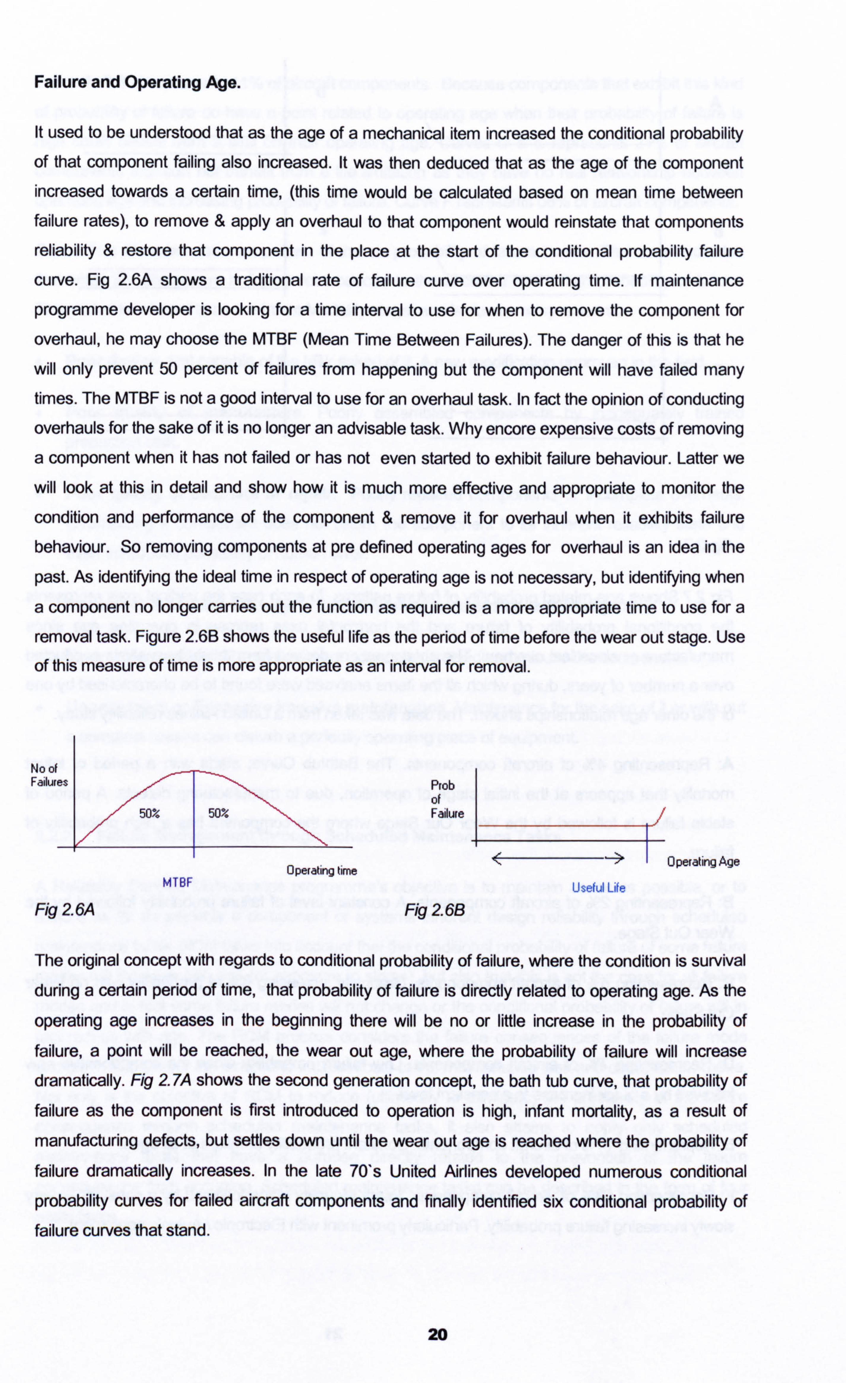
curve. Fig 2.6A shows a traditional rate of failure curve over operating time. If maintenance
programme developer is looking for a time interval to use for when to remove the component for
overhaul, he may choose the MTBF (Mean Time Between Failures). The danger of this is that he
will only prevent 50 percent of failures from happening but the component will have failed many times. The MTBF is not a good interval to use for an overhaul task. In fact the opinion of conducting
overhauls for the sake of it is no longer an advisable task. Why encore expensive costs of removing
a component when it has not failed or has not even started to exhibit failure behaviour. Latter we
will look at this in detail and show how it is much more effective and appropriate to monitor the
condition and performance of the component & remove it for overhaul when it exhibits failure
behaviour. So removing components at pre defined operating ages for overhaul is an idea in the
past. As identifying the ideal time in respect of operating age is not necessary, but identifying when
a component no longer carries out the function as required is a more appropriate time to use for a
removal task. Figure 2.613 shows the useful life as the period of time before the wear out stage. Use
of this measure of time is more appropriate as an interval for removal.
No of Failur Ptob
of Failure
OperatingAge
Useful Life
Fig 2 6A Fig 2 6B
The original concept with regards to conditional probability of failure, where the condition is survival
during a certain period of time, that probability of failure is directly related to operating age. As the
operating age increases in the beginning there will be no or little increase in the probability of
failure, a point will be reached, the wear out age, where the probability of failure will increase
dramatically. Fig 2.7A shows the second generation concept, the bath tub curve, that probability of
failure as the component is first introduced to operation is high, infant mortality, as a result of
manufacturing defects, but settles down until the wear out age is reached where the probability of
failure dramatically increases. In the late 70's United Airlines developed numerous conditional
probability curves for failed aircraft components and finally identified six conditional probability of failure curves that stand.
20
Operating time MTBF
AD
B
I
C
E
Fig 27
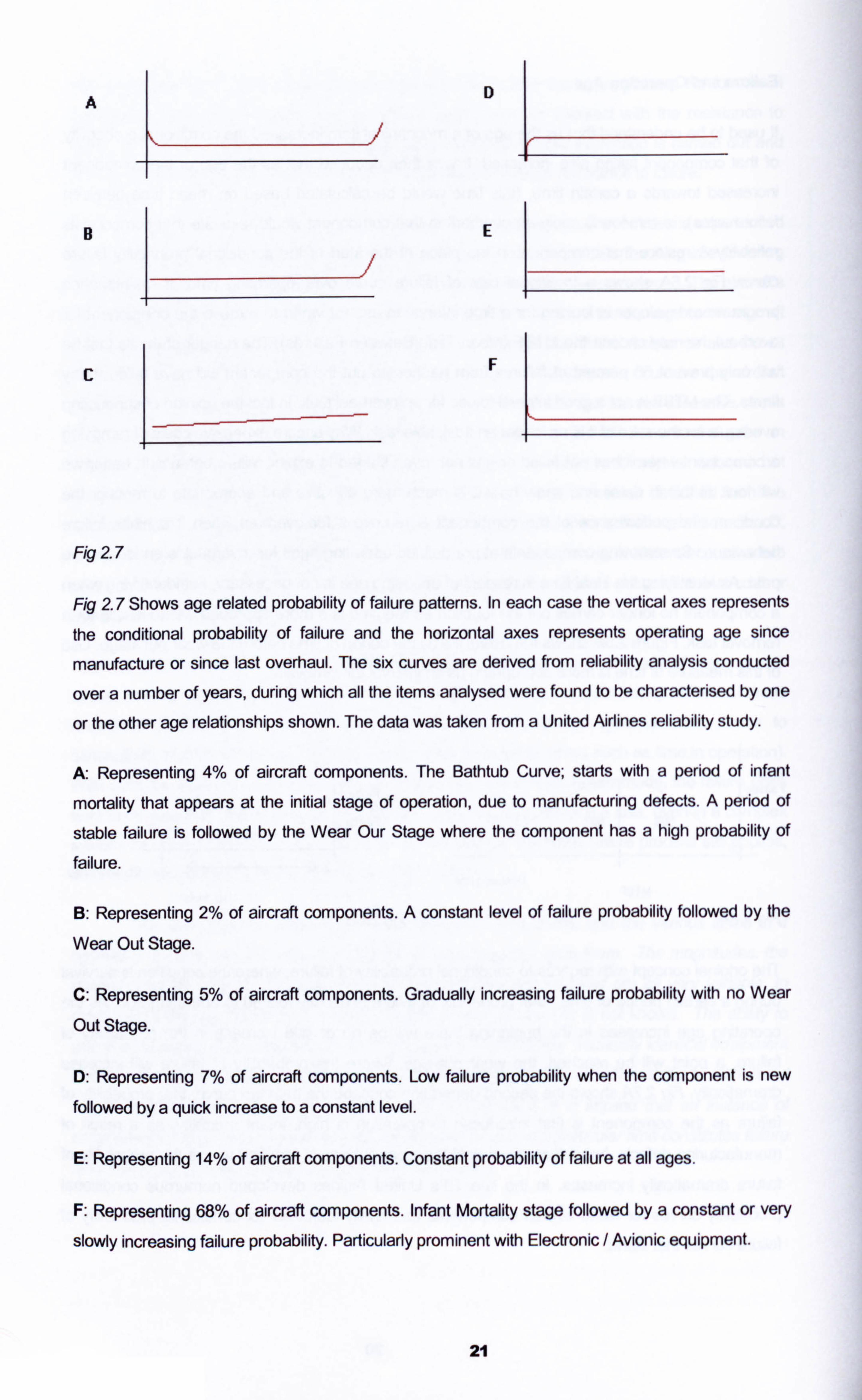
Fig 27 Shows age related probability of failure patterns. In each case the vertical axes represents
the conditional probability of failure and the horizontal axes represents operating age since
manufacture or since last overhaul. The six curves are derived from reliability analysis conducted
over a number of years, during which all the items analysed were found to be characterised by one
or the other age relationships shown. The data was taken from a United Airlines reliability study.
A Representing 4% of aircraft components. The Bathtub Curve; starts with a period of infant
mortality that appears at the initial stage of operation, due to manufacturing defects. A period of
stable failure is followed by the Wear Our Stage where the component has a high probability of
failure.
B: Representing 2% of aircraft components. A constant level of failure probability followed by the
Wear Out Stage.
C: Representing 5% of aircraft components. Gradually increasing failure probability with no Wear
Out Stage.
D: Representing 7% of aircraft components. Low failure probability when the component is new
followed by a quick increase to a constant level.
E: Representing 14% of aircraft components. Constant probability of failure at all ages.
F: Representing 68% of aircraft components. Infant Mortality stage followed by a constant or very
slowly increasing failure probability. Particularly prominent with Electronic / Avionic equipment.
21
Curve A, B&C represents 11 % of aircraft components. Because components that exhibit this kind
of probability of failure do have a point related to operating age when their probability of failure is
high could benefit from a limit on their operating age. Curves D&E represents 21% of aircraft components that can not benefit from a life limitation as they have no real relationship between
operating age and increasing probability of failure. Curve F represents 68% of aircraft components.
Curve F: Is the most common pattern of the six probability of failure curves. The curve indicates
that when the component is first or reintroduced to the aircraft it has a high probability of failure.
This period is referred to as the Infant Mortality stage, and is due to many reasons...
0 Poor design. Not capable of the task asked of it. A new modification unproven in the field.
0 Poor quality of manufacture. Poorly assembled components by inadequately trained
production staff.
Poor quality of overhaul or repair. Poorly repaired components or incomplete overhauls. Overhauling a component does not return the component to its inherent reliability state and
even introduces possibility of human error.
0 Incorrect installation. Damage to the component at installation or miss alignment.
0 Incorrect operation. The crew are not adequately trained and misuse the component.
0 Unnecessary or Excessive invasive maintenance. Maintenance for the sake of it or with out
a complete reason can disturb a perfectly operating piece of equipment.
2.2.2 Failure Management through Scheduled Maintenance Tasks.
A Reliability Centred Maintenance programme's objective is to maintain as far as possible, or to
restore as far as possible a component or systems inherent design reliability through scheduled
maintenance tasks. RCM takes into account that the conditional probability of failure of some failure
modes will increase with age (or exposure to stress), but also that this is not the case for all failure
modes and in fact some failure modes will not change or the conditional probability of failure will in
fact reduce with age. The RCM process considers the failure consequences of the failure mode
and also will consider the direct and indirect costs of the maintenance task and of the failure mode. Not only is the objective of RCM to reduce (ultimately to eliminate) the probability of the failure
consequence through scheduled maintenance tasks, it also attains to apply only scheduled
maintenance tasks, that have a purpose directly related to the prevention of the failure
consequences from occurring. Scheduled maintenance tasks can be described in the form of four
basic tasks
22
1. On Condition Tasks : (Predictive or Condition Monitoring). Used where a clearly defined
potential failure period (P-F period) exists for the failure mode under consideration. For
example a tyre inspection every day, the tyre stays installed if the wear is not to a certain limit,
and is removed if the wear is at or beyond a certain limit The survival of the tyre is based on the condition it passes the inspection.
2. Scheduled Discard Task : Used where a clearly defined age of increased conditional
probability of failure exists for the failure mode under consideration. For example the
passenger life jackets part number P0124W have a discard life of 10 years. The manufacturer has through studies shown that the useful life of the jackets, i. e. the period of time prior to when the wear out stage starts, is 10 years. After that the jackets have a high probability of failure
due to the perishing rubber components. The cost of removal, replacing & restoring the jackets
will cost more than purchasing a new jacket so the old jacket is discarded.
3. Scheduled Restoration Task : Used where a clearly defined age of increased conditional probability of failure exists for the failure mode under consideration and the restoration task
restores the components resistance to failure to a level that is tolerable. For example the main landing gear of a B737 built by Manesco, has a restoration life of 12 years or 15,000 cycles
which ever is sooner. Manesco have through studies shown that the gears useful life is at 12
years due to environmental effects or 15,000 cycles due to operating stress and the probability
of failure rises considerable at this point which is the start of the wear out stage. But by
restoration of the gear & its components the inherent reliability of the gear can be restored.
4. Failure Finding Task : Used where the task can confirm that all components covered by the failure mode under consideration, are functional. (Not used for evident failure modes. ) For
example a standby hydraulic pump that is not normally in use, is intentionally brought on line by
perhaps simulating a failure of the main pumps, (pulling their circuit breakers) the performance
of the standby pump is then monitored for correct function.
The selection of the scheduled maintenance task to be accomplished, consists of determining an
effective and applicable task. Applicability depends on the failure characteristics of the component
or system under investigation, this means the scheduled maintenance task can only be applicable if
it can detect a potential failure state, such as the end of the useful life or the beginning of the wear
out stage. The effectiveness of a task can only be apparent if the task results in the avoidance of the failure consequences.
Al scheduled maintenance tasks must meet the following criteria
In the case of an evident failure mode that has safety consequences, the task shall reduce the
probability of the failure mode to a level that is acceptable to the authorities, the manufacturer and the operator. If it is found that no scheduled maintenance task can be regarded as
applicable and effective to address this failure mode redesign of the system must take place. (here it can be seen that the process of RCM is not only to identify scheduled maintenance
23
tasks to address failure modes, but also to identify areas of the design that need to be re designed. )
In the case of hidden failure mode where the associated multiple failure has safety consequences, the task shall reduce the probability of the hidden failure mode to an extent which reduces the probability of the associated multiple failure to a level that is acceptable to the authorities, the manufacturer and the operator. (Again if no scheduled maintenance task
can be found applicable and effective re design must be considered. )
In the case of an evident failure mode that does not have safety consequences, the direct and in direct costs of doing the task shall be less that the direct and in direct costs of the failure
mode when measured over comparable periods of time.
In the case of a hidden failure mode where the associated multiple failures do not have safety
consequences, the direct and indirect costs of doing the task shall be less than the direct and indirect cost of the multiple failures plus the cost of repairing the hidden failure mode when
measured over a comparable period of time.
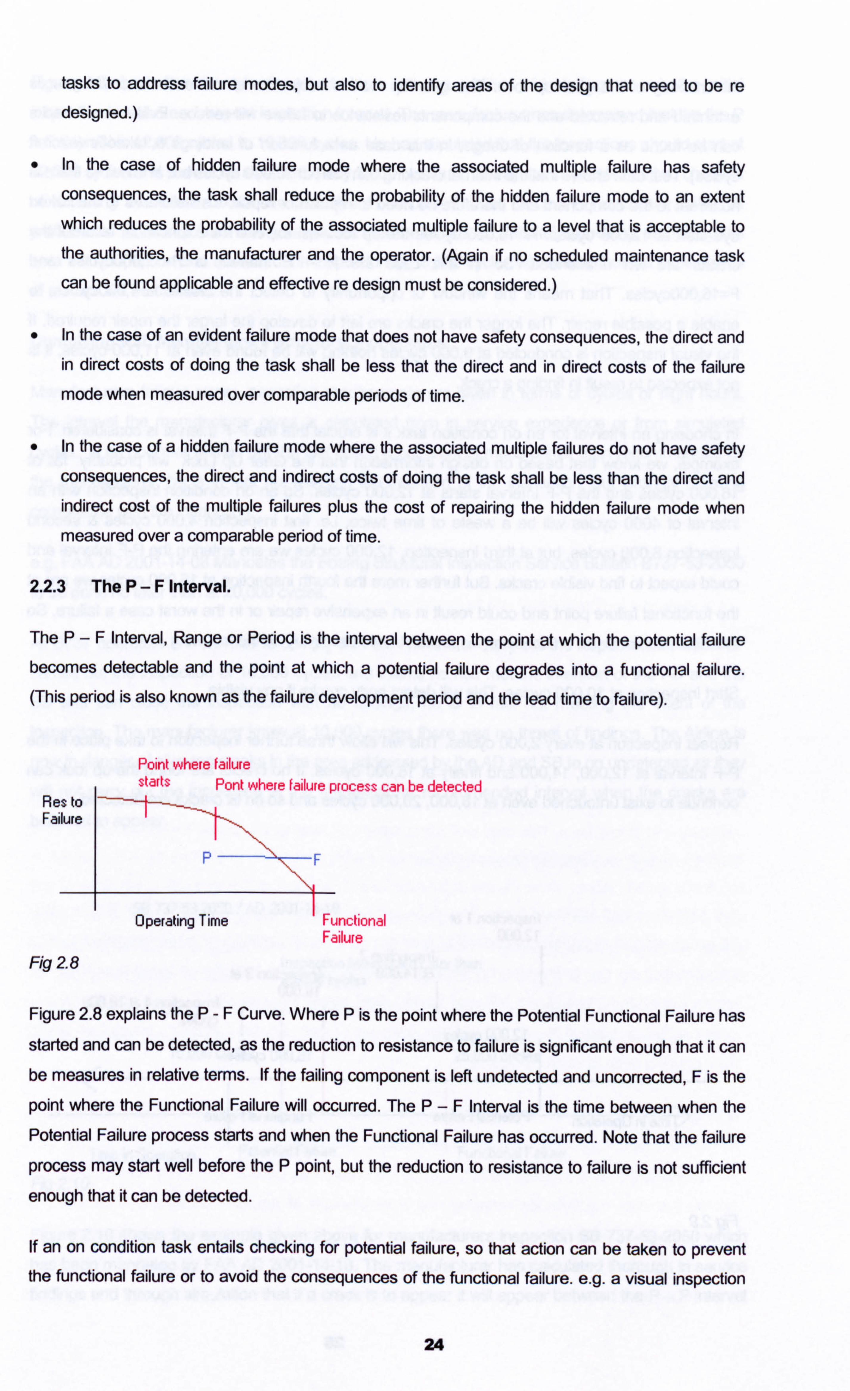
2.2.3 The P-F Interval.
The P-F Interval, Range or Period is the interval between the point at which the potential failure
becomes detectable and the point at which a potential failure degrades into a functional failure.
(This period is also known as the failure development period and the lead time to failure).
Point where failure starts Pont where failure process can be detected
Res to Failure
P- '--,
Operating Time Functional Failure
Fig 28
Figure 2.8 explains the P-F Curve. Where P is the point where the Potential Functional Failure has
started and can be detected, as the reduction to resistance to failure is significant enough that it can be measures in relative terms. If the failing component is left undetected and uncorrected, F is the
point where the Functional Failure will occurred. The P-F Interval is the time between when the Potential Failure process starts and when the Functional Failure has occurred. Note that the failure
process may start well before the P point, but the reduction to resistance to failure is not sufficient enough that it can be detected.
If an on condition task entails checking for potential failure, so that action can be taken to prevent the functional failure or to avoid the consequences of the functional failure. e. g. a visual inspection
24
for cracking of the gear up lock. The gear up lock is subject to stress each time the gear is
extended and retracted and the components resistance to failure will reduce. Evidence of cracks
can be found as a function of usage, in this case as a function of landings & takeoffs (aircraft
cycles). Test data shows that the internal cracking can start at 10,000 cycles but at this time there is
no threat to the component and therefore no need to replace or repair. Visible cracks to the naked
eye start at 12,000 cycles. At 16,000 cycles the up lock will experience a functional failure if the
cracks are left unattended. So in this case the P-F Interval is P=12,000cycles and
F=16,000cycles. That means the window of opportunity to detect the cracks is 4,000cycles, to
enable a possible repair. The longer the cracks are left to develop the larger the repair required. If
the visual inspection is conducted at 9,000 cycles nothing will be found even at 11,000 cycles, it is
not expected to result in finding a crack.
In choosing an interval for an on condition task it is crucial that the P-F Interval is considered. For
example, we know that based on design information that the Gear Up Lock will probably fail at
16,000 cycles and the P-F Interval starts at 12,000 cycles. So an on condition inspection with an
interval of 4000 cycles will be a waste of time twice, i. e. first inspection 4,000 cycles & second
inspection 8,000 cycles, but at third inspection, 12,000 cycles we are entering the P-F Interval and
could expect to find visible cracks. But further more the fourth inspection at 16,000 cycles we are at
the functional failure point and could result in an expensive repair or in the worst case a failure. So
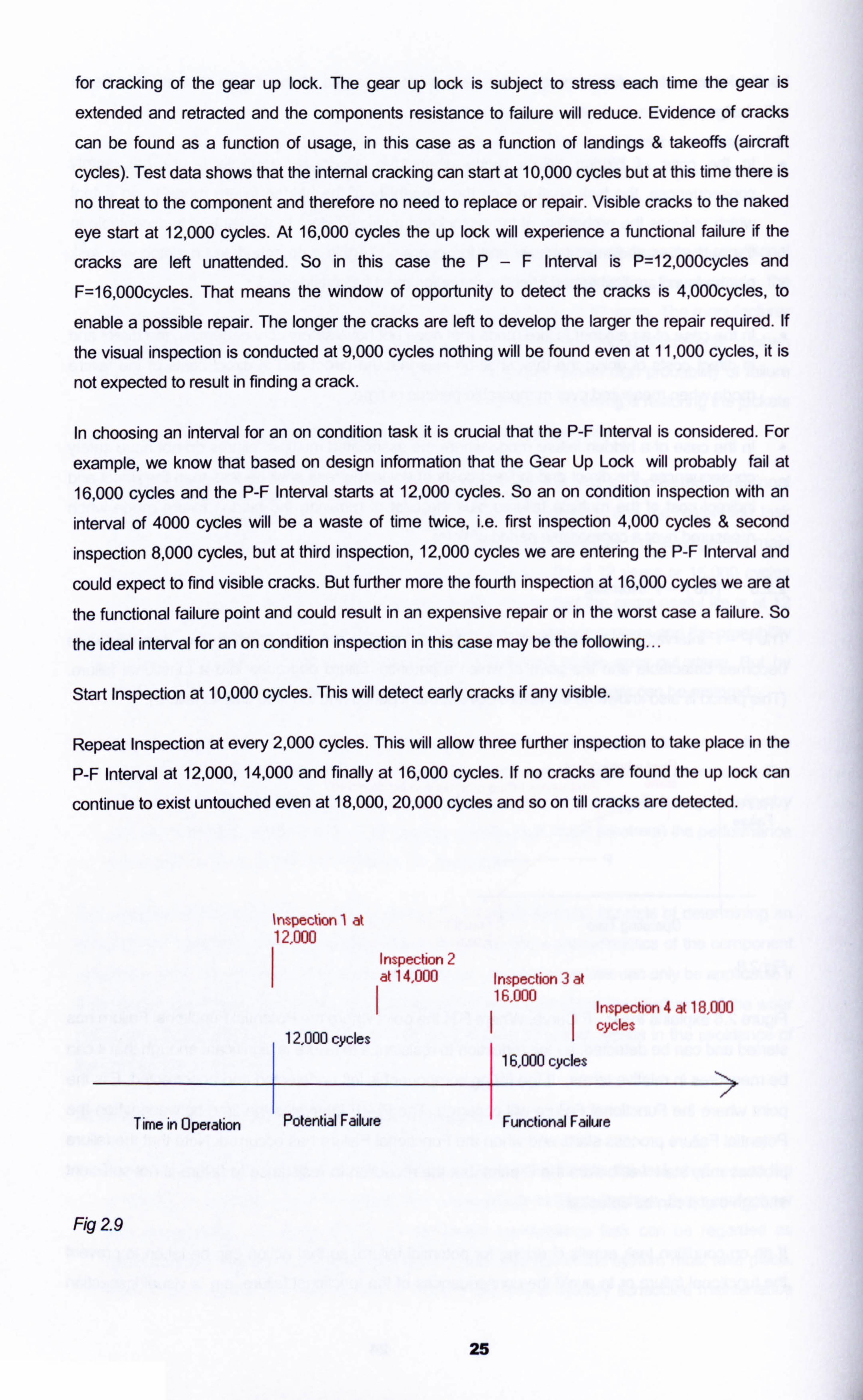
the ideal interval for an on condition inspection in this case may be the following...
Start Inspection at 10,000 cycles. This will detect early cracks if any visible.
Repeat Inspection at every 2,000 cycles. This will allow three further inspection to take place in the
P-F Interval at 12,000,14,000 and finally at 16,000 cycles. If no cracks are found the up lock can
continue to exist untouched even at 18,000,20,000 cycles and so on till cracks are detected.
ýnspedion 1 at 12,000
Inspection 2 at 14,000 Inspection 3 at
16,000 Inspection 4 at 18,000
12,000 cycles I cycles
1 16,000 cycles
Time in Operation Potential Failure ' Functional Failure
Fig 29
25
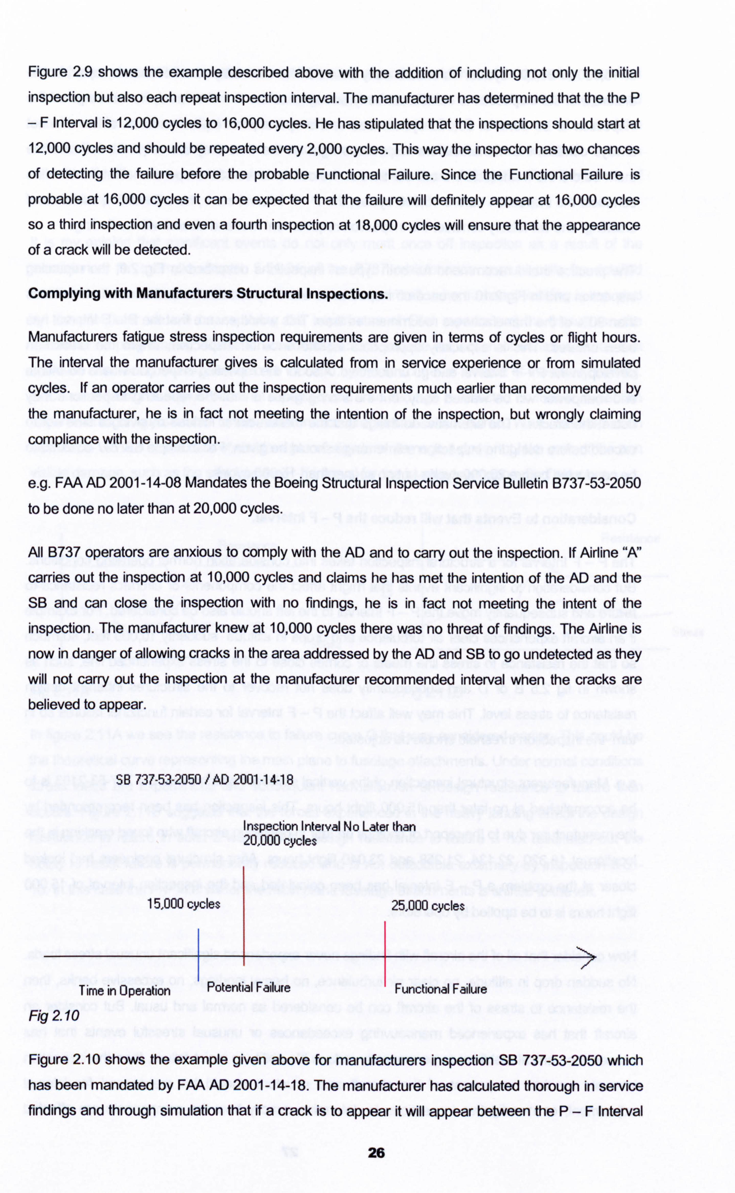
Figure 2.9 shows the example described above with the addition of including not only the initial inspection but also each repeat inspection interval. The manufacturer has determined that the the P
-F Interval is 12,000 cycles to 16,000 cycles. He has stipulated that the inspections should start at 12,000 cycles and should be repeated every 2,000 cycles. This way the inspector has two chances of detecting the failure before the probable Functional Failure. Since the Functional Failure is
probable at 16,000 cycles it can be expected that the failure will definitely appear at 16,000 cycles so a third inspection and even a fourth inspection at 18,000 cycles will ensure that the appearance of a crack will be detected.
Complying with Manufacturers Structural Inspections.
Manufacturers fatigue stress inspection requirements are given in terms of cycles or flight hours.
The interval the manufacturer gives is calculated from in service experience or from simulated
cycles. If an operator carries out the inspection requirements much earlier than recommended by
the manufacturer, he is in fact not meeting the intention of the inspection, but wrongly claiming
compliance with the inspection.
e. g. FAA AD 2001-14-08 Mandates the Boeing Structural Inspection Service Bulletin B737-53-2050
to be done no later than at 20,000 cycles.
All B737 operators are anxious to comply with the AD and to carry out the inspection. If Airline "N'
carries out the inspection at 10,000 cycles and claims he has met the intention of the AD and the
SIB and can close the inspection with no findings, he is in fact not meeting the intent of the
inspection. The manufacturer knew at 10,000 cycles there was no threat of findings. The Airline is
now in danger of allowing cracks in the area addressed by the AD and SIB to go undetected as they
will not carry out the inspection at the manufacturer recommended interval when the cracks are
believed to appear.
SB 737-53-2050 Y AD 2001 -14-18
Inspection Inteival No Latef than 20,000 cycles
15,000 cycles 1 25,000 cycles
Time in Operation Potential Failure ' Functional Failure
Ra 2 10
Figure 2.10 shows the example given above for manufacturers inspection SB 737-53-2050 which has been mandated by FAA AD 2001-14-18. The manufacturer has calculated thorough in service findings and through simulation that if a crack is to appear it will appear between the P-F Interval
26
of 15,000 to 25,000 cycles. To ensure early detection for the ability of an economic repair, but to
ensure that the inspecton is carried out early enough into the P-F Interval, he has required the
inspection to be done at 20,000 cycles. Due to the operational requirements an airline can not
always conduct the manufacturers inspections right on the time they are required, so schedule them before the manufacturers call out time at the convenience of the operation. But if the airline
conducts the inspection before 15,000 cycles, the P-F interval start , he will not find evidence of
cracking, and will falsely consider the inspection requirement met and closed with no findings.
The practice that I recommend for both type of inspections described in Fig 2.9, the repeating inspection and in Fig 2.10 the once off inspection is that they should not be first conducted at less
than 90% of the manufacturers recommended time. This would ensure that the P-F Interval has
been entered. This is especially appropriate for the once off inspection, where the crack can develop in the P-F Interval and go undetected. Also for the repeating inspection where downtime
and manpower will be wasted early, but the saving grace is that the repeating inspections may detect the cracks. The alternative to this is that the manufacturer instead of giving a time not to
exceed before doing the inspection a time range should be given. For example SB 737-53-2050 to
be conducted before 20,000 cycles but no sooner than 15,000 cycles.
Consideration to Events that will reduce the P-F Interval.
The P-F Interval for a structural inspection takes into consideration normal operating conditions. But consideration to significant events that might affect the components or aircrafts resistance to
failure and subsequently move the P-F Interval to the left should also be considered. For example if an aircraft experiences clear air turbulence and drops in altitude suddenly 10,000 feet, so much
so that the resistance to stress line meets or comes close to the stress experienced line, such as
shown in fig 2.5 B or D and subsequently does not recover to the structures inherent design
resistance to stress level. This may well affect the P-F Interval for certain functional failures so in
turn the inspection threshold should be adjusted.
e. g. Manufacturers structural inspection of the vertical stabiliser attachments SB 737-53-2103 is to
be accomplished at no later than 15,000 flight hours. This inspection has been recommended by
the manufacturer due to the report of findings on four in operation aircraft who found cracking In the
location at 18,320,22,134,21,258 and 23,040 flight hours. After structural engineers had looked
closer at the problem aP-F Interval has been calculated and the inspection interval of 15,000
flight hours is to be applied by operators.
Now consider that all of the aircraft with findings never experienced significant unusual stress loads.
No sudden drop in altitude, no clear air turbulence, no heavy landings, no excessive banks, then
the resistance to stress of the aircraft can be considered as normal and usual. But consider an
aircraft that has experienced manoeuvring exceedances or unusual stressful events that has
caused the vertical stabiliser to permanently reduce it's ability to resist failure, then the inspection
intervals for that component of the aircraft and structure should be reassessed for interval
adjustment, or investigative inspections to determine exactly how the components are affected
27
should take place. While excessive stressful events are often evident to the operating crew and often reported to the maintenance and engineering sections, these events should be logged and considered for structural effect and permanent movement of the P-F Intervals as a result of the events. But often the continuous minor exceedances go un noticed and un reported. Over an aircraft's life this can be considerable and can have an effect on shifting the P-F Intervals of certain components.
It is my opinion that significant events do not only merit once off inspection as a result of the
exccedance, for example chapter 5-51-01 of the B737 maintenance manual calls for detailed
additional structural inspections to be carried out on an aircraft when a heavy landing is reported by the pilot, flater we will be exploring the importance of Pilot reports and the impact on the
maintenance programme). These structural inspections include inspection of sensitive areas that
could be affected by the excessive force induced by the structure as a result of the heavy landing.
Once carried out this inspection is not repeated and if no damage is detected no further inspection
requirements or adjustments to the maintenance programme are required. While the inspection
detailed in 5-51 -01 takes care of visible signs of structural damage it does not take care of the non
visible damage, such as the affect on the P-F Interval for the involved components of structure.
C B
S tress
Fig 21 IA Fig 21 1B
In figure 2.11 A we see the resistance to failure curve C that was considered earlier. This could be
the theoretical curve representing the main plane to fuselage attachments. Under normal conditions
stress loads are experienced and subsequent normalisation of design resistance to failure then
occurs. Figure 2.11 B suggests that the forces experienced in the heavy landing affect the design
resistance to failure in such a way that the design resistance to failure is not reinstated but the
ability to resist failure is permanently reduced and is not detectable externally by inspection 5-51-
10. In this case the P-F Interval for the main plane fuselage attachments is shifted to the left.
28
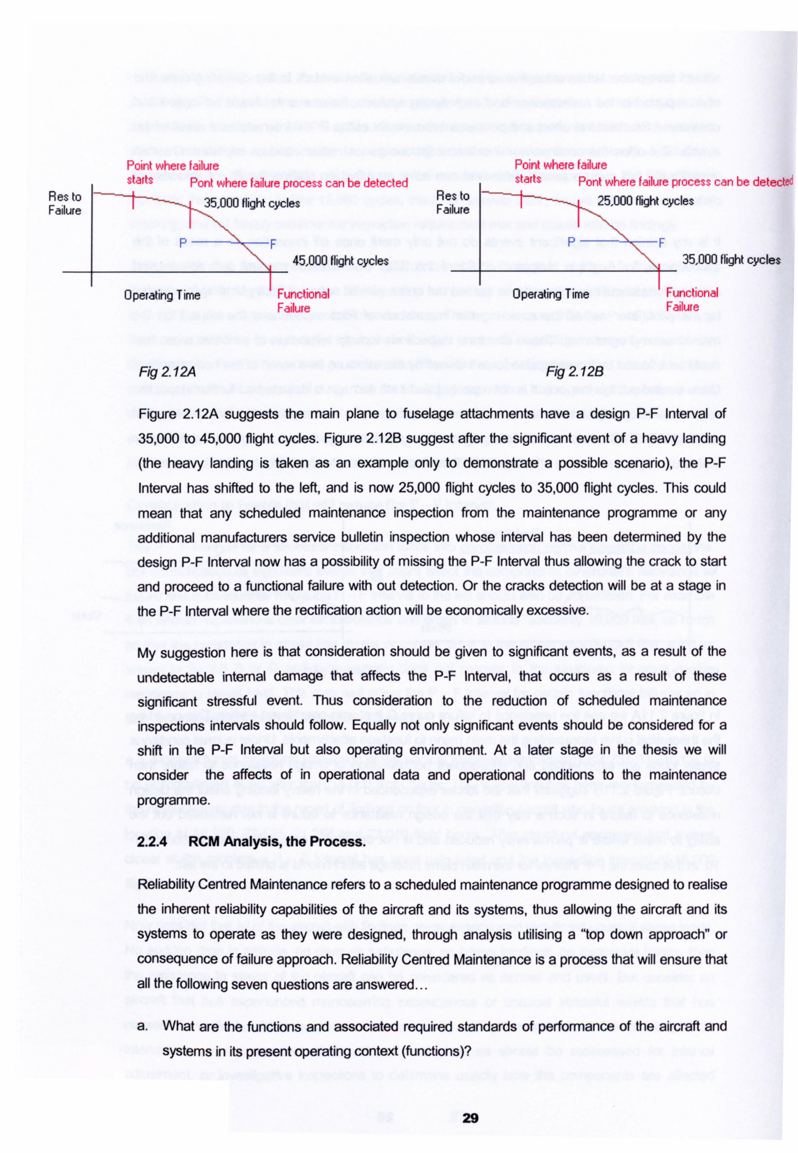
Point wheie failure Point where failure starts Pont where failure process can be detected starts Pont where failure process can be detected
Res to Res to 25,000 flight cycles Failure 5,000 flight cycles Failure
45,000 flight cycles F
35,000 flight cycles
Operating Time Functional Operating Time Functional Failure Failure
Fig 2 12A Fig 2.12B
Figure 2.12A suggests the main plane to fuselage attachments have a design P-F Interval of
35,000 to 45,000 flight cycles. Figure 2.12B suggest after the significant event of a heavy landing
(the heavy landing is taken as an example only to demonstrate a possible scenario), the P-F
Interval has shifted to the left, and is now 25,000 flight cycles to 35,000 flight cycles. This could
mean that any scheduled maintenance inspection from the maintenance programme or any
additional manufacturers service bulletin inspection whose interval has been determined by the
design P-F Interval now has a possibility of missing the P-F Interval thus allowing the crack to start
and proceed to a functional failure with out detection. Or the cracks detection will be at a stage in
the P-F Interval where the rectification action will be economically excessive.
My suggestion here is that consideration should be given to significant events, as a result of the
undetectable internal damage that affects the P-F Interval, that occurs as a result of these
significant stressful event. Thus consideration to the reduction of scheduled maintenance
inspections intervals should follow. Equally not only significant events should be considered for a
shift in the P-F Interval but also operating environment. At a later stage in the thesis we will
consider the affects of in operational data and operational conditions to the maintenance
programme.
2.2.4 RCM Analysis, the Process.
Reliability Centred Maintenance refers to a scheduled maintenance programme designed to realise the inherent reliability capabilities of the aircraft and its systems, thus allowing the aircraft and its
systems to operate as they were designed, through analysis utilising a "top down approach" or
consequence of failure approach. Reliability Centred Maintenance is a process that will ensure that
all the following seven questions are answered...
a. What are the functions and associated required standards of performance of the aircraft and
systems in its present operating context (functions)?
29
b. In what ways can it fail to fulfil its functions (failure modes)?
c. What causes each functional failure (mode)?
d. What happens when each failure occurs (failure effect)?
e. In what way does each failure matter (failure consequence)?
f. What should be done to predict or prevent each failure (proactive tasks and task intervals)?
g. What should be done if a suitable proactive task cannot be found (default actions)?
The process of evaluating failure consequence and maintenance tasks is facilitated by a decision
diagram technique. The first step is to decide on a level of analysis . If the level of analysis is too
high the analysis becomes too superficial, while if the level is too low the analysis can become
unmanageable and unintelligible.
(Note: The RCM philosophy described from now on is that recognised and described by the
ATA in the MSG-3 Revision 2001.1 document. Later in the thesis, chapter 3, the
development of the initial RCM philosophy to get to MSG-3 Revision 2001.1 will be
described).
Deciding Upon the Level to Conduct the Analysis.
When considering the failure modes of an aircraft gas turbine engine, a possible failure mode
would be a blocked fuel line. The fuel line is part of the fuel system , so it would be better and more
appropriate to address the fuel system as a system in its self rather than as an analysis of the
complete engine.
The aircraft lends itself to an almost obvious level with three major areas of divisions. These are the..
Aircraft Systems.
2. Aircraft Structure.
3. Aircraft Powerplant.
Each major division can be further partitioned into functional areas utilising the -Air Transports
Associations Specification 100 (ATA 100) System chapterisation and sub system chapterisation.
30
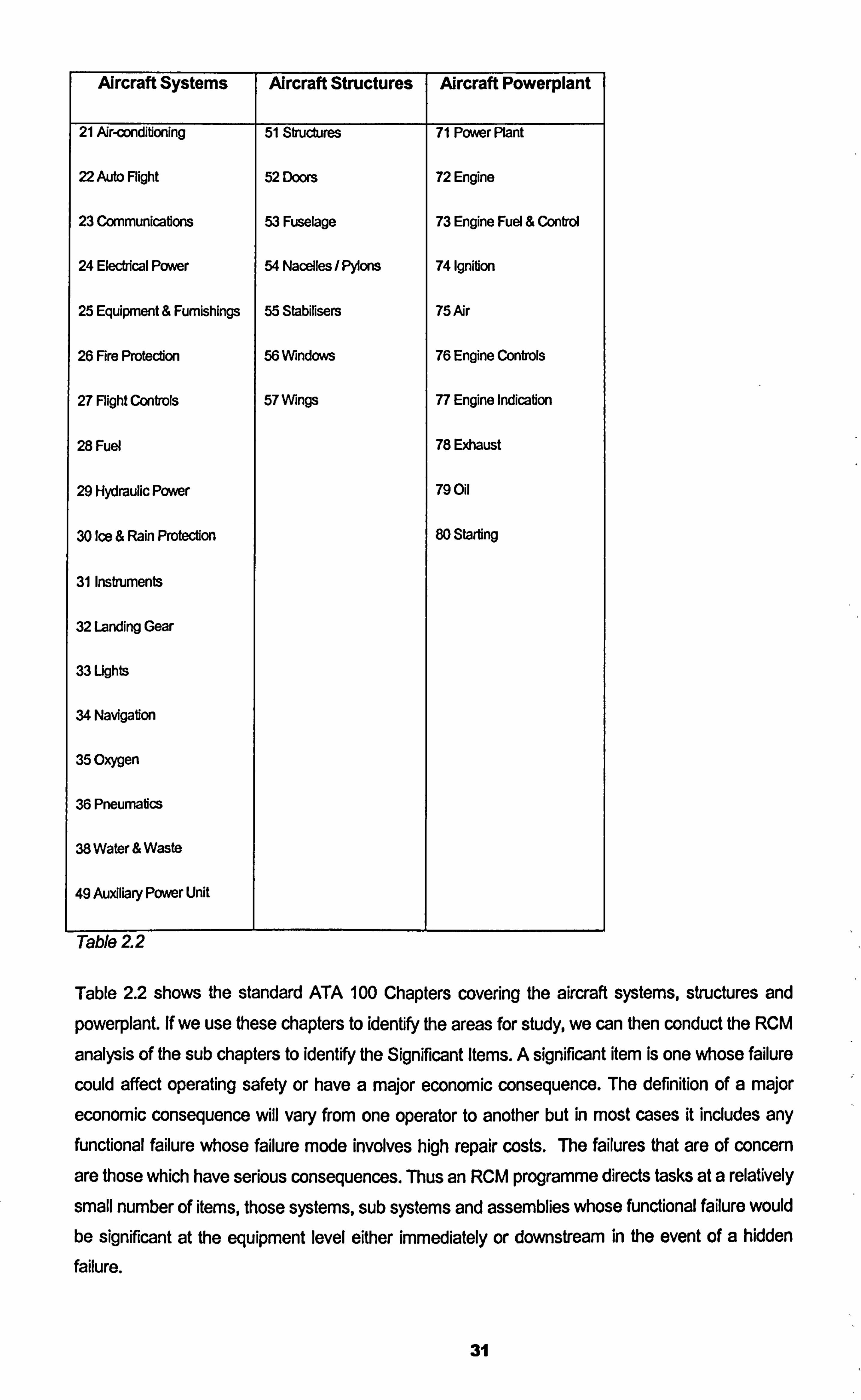
Aircraft Systems Aircraft Structures Aircraft Powerplant
21 Air-conditioning 51 Structures 71 Power Plant
22 Auto Flight 52 Doors 72 Engine
23 Communications 53 Fuselage 73 Engine Fuel & Control
24 Electrical Power 54 Nacelles / Pylons 74 Ignition
25 Equipment & Furnishings 55 Stabilisers 75 Air
26 Fire Protection 56Wndows 76 Engine Controls
27 Flight Controls 57 Wings 77 Engine Indication
28 Fuel 78 Exhaust
29 Hydraulic Power 79 Oil
30 Ice & Rain Protection 80 Starting
31 Instruments
32 Landing Gear
33 Lights
34 Navigation
35 Oxygen
36 Pneumatics
38 Water & Waste
49 Auxiliary Power Unit
Table 22
Table 2.2 shows the standard ATA 100 Chapters covering the aircraft systems, structures and
powerplant. If we use these chapters to identify the areas for study, we can then conduct the RCM
analysis of the sub chapters to identify the Significant Items. A significant item is one whose failure
could affect operating safety or have a major economic consequence. The definition of a major
economic consequence will vary from one operator to another but in most cases it includes any functional failure whose failure mode involves high repair costs. The failures that are of concern
are those which have serious consequences. Thus an RCM programme directs tasks at a relatively
small number of items, those systems, sub systems and assemblies whose functional failure would be significant at the equipment level either immediately or downstream in the event of a hidden
failure.
31
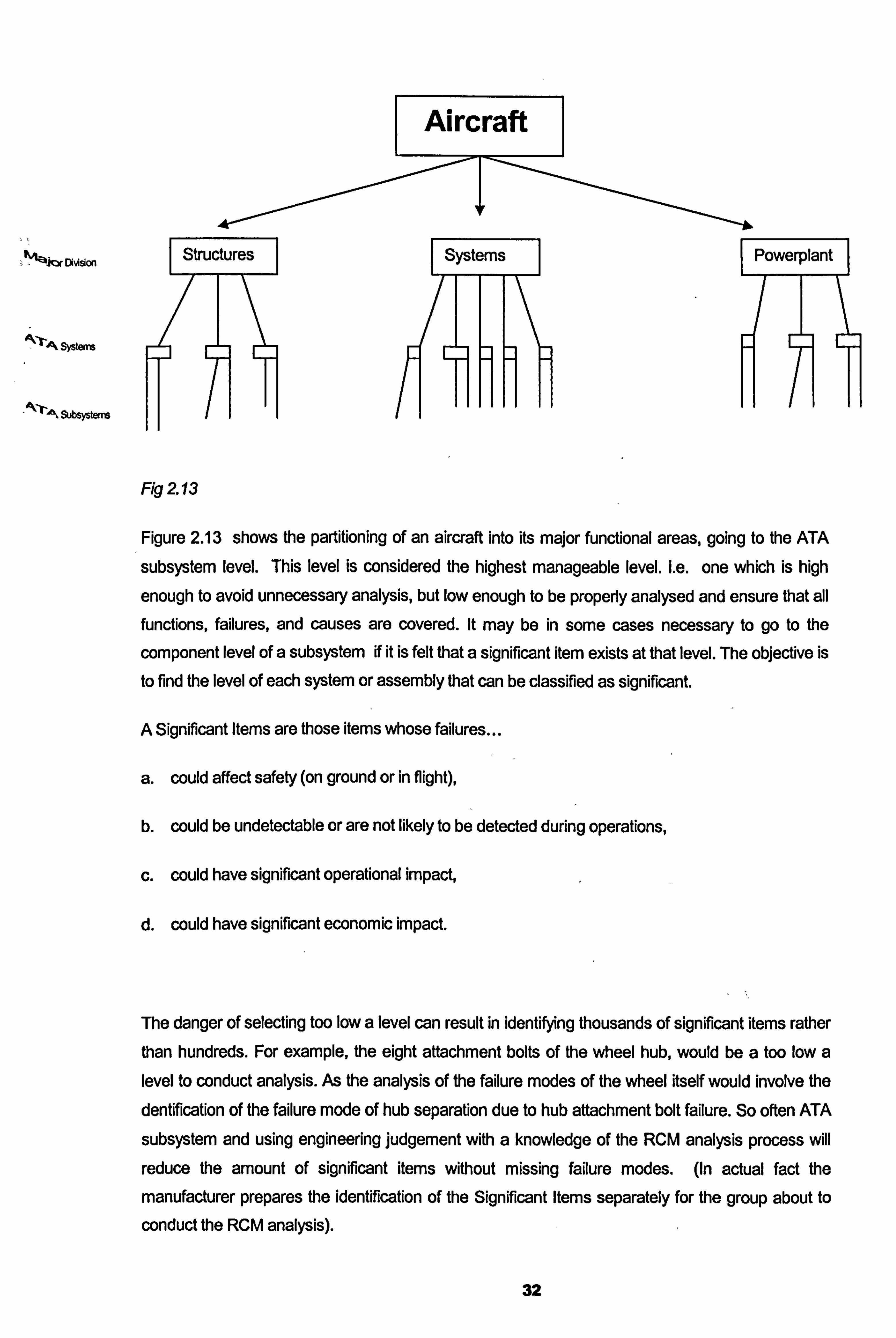
Aircraft
DhAsion rS-t-ructures
4--rA Syst.
Subsysten
Fig 2 13
I Powerplant I
Figure 2.13 shows the partitioning of an aircraft into its major functional areas, going to the ATA
subsystem level. This level is considered the highest manageable level. Le. one which is high
enough to avoid unnecessary analysis, but low enough to be properly analysed and ensure that all functions, failures, and causes are covered. It may be in some cases necessary to go to the
component level of a subsystem if it is felt that a significant item exists at that level. The objective is
to find the level of each system or assembly that can be classified as significant.
A Significant Items are those items whose failures
a. could affect safety (on ground or in flight),
b. could be undetectable or are not likely to be detected during operations,
c. could have significant operational impact,
d. could have significant economic impact.
The danger of selecting too low a level can result in identifying thousands of significant items rather than hundreds. For example, the eight attachment bolts of the wheel hub, would be a too low a level to conduct analysis. As the analysis of the failure modes of the wheel itself would involve the
dentification of the failure mode of hub separation due to hub attachment bolt failure. So often ATA
subsystem and using engineering judgement with a knowledge of the RCM analysis process will
reduce the amount of significant items without missing failure modes. (in actual fact the
manufacturer prepares the identification of the Significant Items separately for the group about to
conduct the RCM analysis).
32
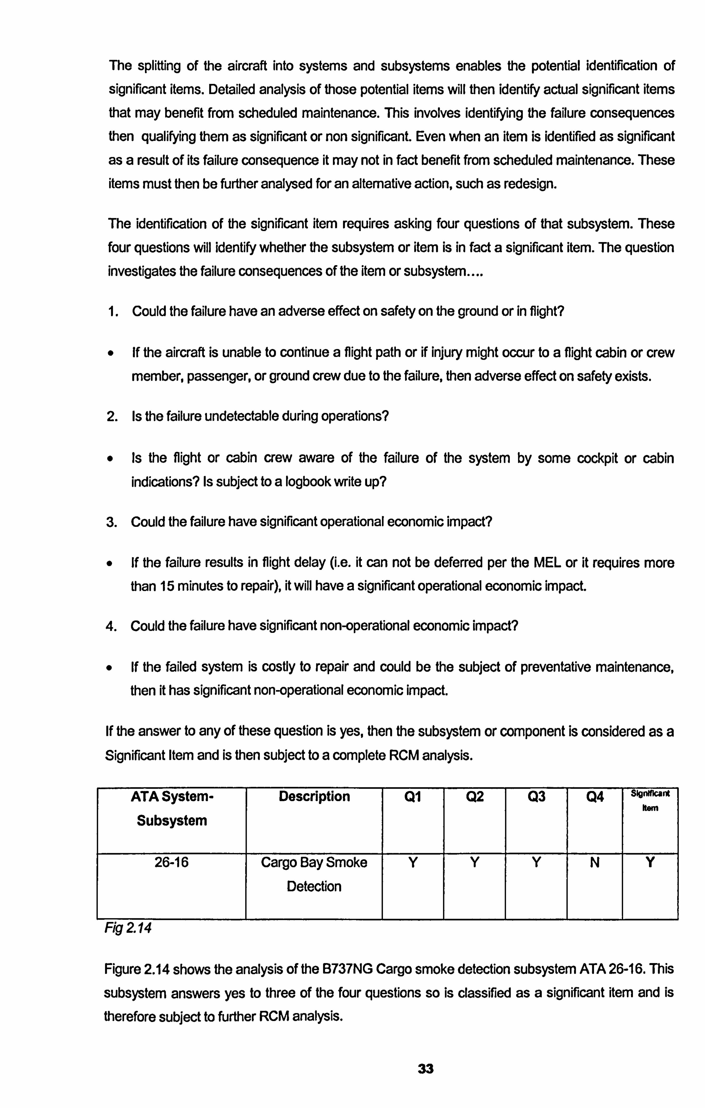
The splitting of the aircraft into systems and subsystems enables the potential identification of
significant items. Detailed analysis of those potential items will then identify actual significant items
that may benefit from scheduled maintenance. This involves identifying the failure consequences then qualifying them as significant or non significant. Even when an item is identified as significant
as a result of its failure consequence it may not in fact benefit from scheduled maintenance. These
items must then be further analysed for an alternative action, such as redesign.
The identification of the significant item requires asking four questions of that subsystem. These
four questions will identify whether the subsystem or item is in fact a significant item. The question investigates the failure consequences of the item or subsystem....
1. Could the failure have an adverse effect on safety on the ground or in flight?
If the aircraft is unable to continue a flight path or if injury might occur to a flight cabin or crew
member, passenger, or ground crew due to the failure, then adverse effect on safety exists.
2. Is the failure undetectable during operations?
Is the flight or cabin crew aware of the failure of the system by some cockpit or cabin indications? Is subject to a logbook write up?
3. Could the failure have significant operational economic impact?
If the failure results in flight delay (i. e. it can not be deferred per the MEL or it requires more than 15 minutes to repair), it will have a significant operational economic impact.
4. Could the failure have significant non-operational economic impact?
If the failed system is costly to repair and could be the subject of preventative maintenance, then it has significant non-operational economic impact.
If the answer to any of these question is yes, then the subsystem or component is considered as a Significant Item and is then subject to a complete RCM analysis.
ATA System- Description Ql Q2 Q3 Q4 slgnfflcant
Subsystem kem
26-16 Cargo Bay Smoke Y Y Y N Y
Detection
1-ig 2.14
Figure 2.14 shows the analysis of the B737NG Cargo smoke detection subsystem ATA 26-16. This
subsystem answers yes to three of the four questions so is classified as a significant item and is
therefore subject to further RCM analysis.
33
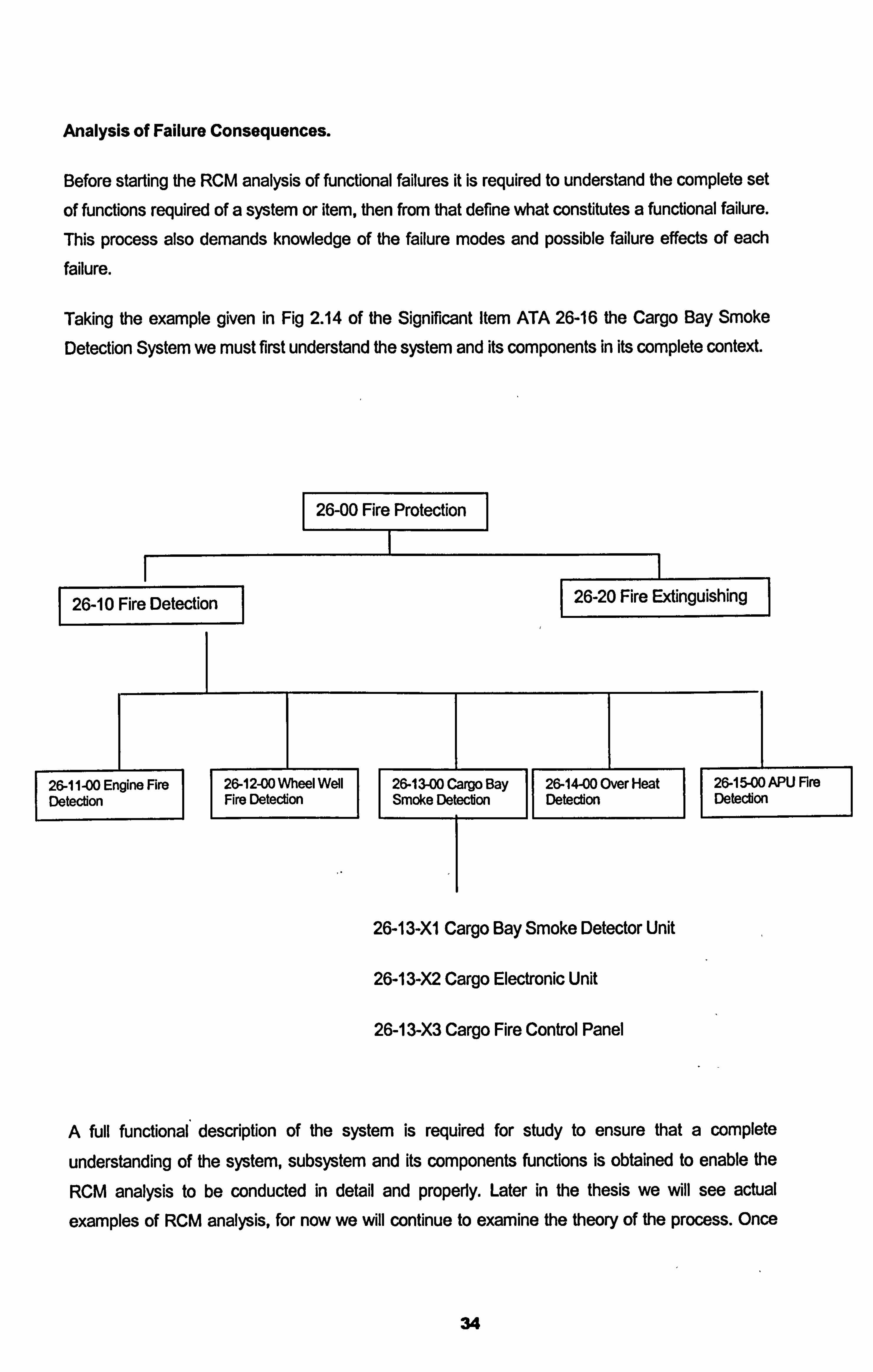
Analysis of Failure Consequences.
Before starting the RCM analysis of functional failures it is required to understand the complete set
of functions required of a system or item, then from that define what constitutes a functional failure.
This process also demands knowledge of the failure modes and possible failure effects of each failure.
Taking the example given in Fig 2.14 of the Significant Item ATA 26-16 the Cargo Bay Smoke
Detection System we must first understand the system and its components in its complete context.
26-00 Fire Protection
1 26-10 Fire Detectýioýn
26-11 -00 Engine Fire 26-12-00 Wheel Well Deteclion
II Fire Detedon
1 26-20 Fire Extinguishing I
26-13-00 Cargo Bay 26-14-00 Over Heat 26-15-00 APU Fire Smoke Detedon
II Detedon
II Detection
26-13-XI Cargo Bay Smoke Detector Unit
26-13-X2 Cargo Electronic Unit
26-13-X3 Cargo Fire Control Panel
A full functional description of the system is required for study to ensure that a complete
understanding of the system, subsystem and its components functions is obtained to enable the
RCM analysis to be conducted in detail and properly. Later in the thesis we will see actual
examples of RCM analysis, for now we will continue to examine the theory of the process. Once
34
each function of each system, subsystem and component has been defined, it is now possible to
evaluate the actual consequence of failure.
The aircraft has been divided then subdivide into systems & subsystems using the ATA 100
chapters & subchapters. Each subsystem has been subjected investigation to identify whether as
a result of their failure consequences, they can be identified as a Significant Item. Then for each
significant item the following must be identified...
1. Function(s) - the normal characteristics of an item.
2. Functional Failure(s) - Failure of an item to perform its intended function within specified limits.
3. Failure Effect(s) - what is the result of a functional failure
4. Failure Modes (Causes) - why the functional failure occurs
When listing the four items above, care should be taken to identify the functions of all protective devices. These include devises with the following functions:
a. to draw attention of the operating crew to abnormal conditions.
b. To shut down equipment in the event of a failure.
c. To eliminate or relieve abnormal conditions which follow a failure.
d. To take over from a function that has failed.
Using the RCM Decision Tree to Identify The Consequence Of Failure. Level 1.
The consequence of functional failure depends up on both the nature of the function and the nature
of the failure. Hence the importance of identifying and listing items 1 to 4 above. The RCM decision
tree has two levels of investigation. The first level evaluates each functional failure to determine the
Failure Effect Category.
Failure Effect Catewries.
0 Safety (Category 5)
0 Operational (Category 6)
* Economic (Category 7)
0 Hidden Safety (Category 8)
0 Hidden Non Safety (Category 9)
35
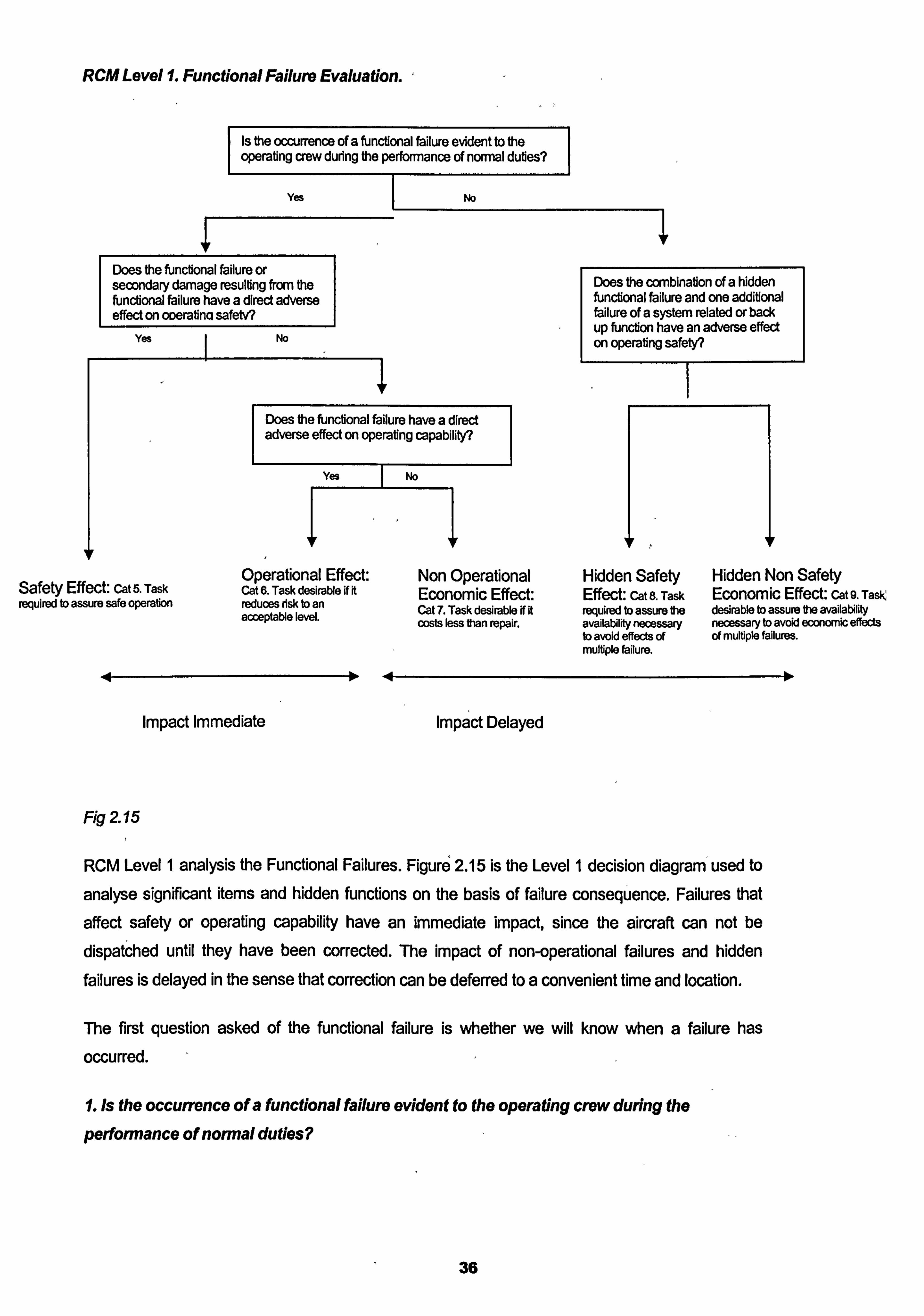
RCM Level 1. Functional Failure Evaluation. ý
Is the occurrence of a functional failure evident to the operating crew during the perforrnance of nomial duties?
Yes
Does the functional failure or secondary damage resulting from the functional failure have a direct adverse effect on oDeratina safetv?
Yes I No
No
Does the combination of a hidden functional failure and one additional failure of a system related or back up function have an adverse effect on operating safety?
Does the functional failure have a direct adverse effect on operating capability?
Yes I No
Operational Effect: Non Operational Hidden Safety Hidden Non Safety Safety Effect: Cat 5. Task Cat 6. Task desirable if it Economic Effect: Effect: cat 8. Task Economic Effect: cat 9. Task required to assure safe operation reduces risk to an
acceptable level. Cat 7. Task desirable ff it required to assure the desirable to assure the availability costs less than repair. availability necessary necessary to avoid economic effects
to avoid effects of of multiple failures.
404
multiple failure.
10
Impact Immediate Impact Delayed
Fig 2 15
RCM Level I analysis the Functional Failures. Figure 2.15 is the Level I decis! on diagram I used to
analyse significant items and hidden functions on the basis of failure consequence. Failures that
affect safety or operating capability have an immediate impact, since the aircraft can not be
dispatched until they have been corrected. The impact of non-operational failures and hidden
failures is delayed in the sense that correction can be deferred to a convenient time and location.
The first question asked of the functional failure is whether we will know when a failure has
occurred.
1. Is the occurrence of a functional failure evident to the operating crew during the
performance of normal duties?
36
This question must be asked of each function of the significant item under analysis. The loss of a function of an item may well be evident but any secondary functions that have been affected may
not be evident to the operating crew. The operating crew consist of qualified flight and cabin crew
personnel who are on duty. Remember earlier we said that any functional failure which has a direct
effect on operational capability will always be evident to the operating crew. If the loss of a function
is not evident, the loss of that function has no immediate impact. This means that if the answer to
the first question is no, then the failure could go undetected, that means scheduled maintenance to
try to identify a hidden functional failure is required. The scheduled maintenance task should not
necessarily be selected to attempt to prevent the failure of the hidden function but to detect the
failure to allow rectification of the failure to take place to prevent the possibility of a multiple failure.
(see + below). Any credit taken for flight crew checks for the detection of a failure must be
supported by conformation that the check is in the duties of the crew member detailed in the
Aircraft Flight Manual. If the answer to the question is yes, the functional failure will be evident to
the operating crew, then we need to analyse how serious are the consequences of the failure by
asking further questions.
Z Does the functional failure or secondary damage resulting from the functional failure
have a direct adverse effect on operating safety?
This question must be asked for each functional failure and for each failure mode. In most cases of
modern aircraft the answer is no except in a few exceptional cases such as engine failure. A yes
answer to this question means that preventative maintenance is mandatory and can be considered
effective only if it prevents all occurrences of this type of failure. This failure is categorised as Category 5 Evident Safety. If the answer to this question is no, the next consideration is economic.
4. Does the functional failure have a direct adverse effect on operational capability?
The consequences in this case may be interruption to the operation, reduced capability of the
aircraft, delay, and diversion or flight cancellation. In these cases scheduled maintenance is not
required for safety reasons but may be desirable for economic reasons. Thus if the answer to this
question is yes the scheduled maintenance task must be cost effective, that means less expensive that the failure consequences. A proactive maintenance task is only worth doing if it costs less over
a period of time that the cost of the operational consequence plus the cost of repairing the failures
which it is meant to prevent. A yes answer to this question is categorised as Category 6 Evident
Operational Economic. A no answer is categorised as Category 7 Evident Non Operational
Economic.
Non Evident Hidden Failures. Question 3 leads from a no answer to question I and deals with the hidden non evident failures.
37
I Does the combination of a hidden functional failure and one additional failure of a system
related or back up function have an adverse effect on operating safety?
If the answer to this question is no, the failure is then a hidden functional failure. As detailed earlier the issue with a hidden failure is the possibility of a multiple failure occurring. So to enable this issue
to be addressed the following question must be analysed., A no answer to this question is
categorlsed as Category 9 Hidden Non Safety Economic while a yes answer to this question is
categorised as Category 8 Hidden Safety.
Now we have the answer to the three questions of the level 1 analysis we can go to the second level to evaluate a possible maintenance task to address each failure possibility.
Using the RCIVI Decision Tree To Identify Scheduled Maintenance Tasks. Level 2.
Section 2.2.2 describes some of the aspects of the scheduled maintenance task....
The selection of the scheduled maintenance task to be accomplished consists of determining an
effective and applicable task. Applicability depends on the failure characteristics of the component
or system under investigation, this means the scheduled maintenance task can only be applicable if
it can detect a potential failure state, such as the end of the useful life or the beginning of the wear
out stage. The effectiveness of a task can only be apparent if the task results in the avoidance of the failure consequences.
The second level analyses the Failure Mode (Cause) and attempts to find a task that is both
applicable and effective in preventing the Failure Mode (Cause) from happening. This phase of RCM analysis involves a systematic study of each failure mode to determine whether one of the
four basic maintenance tasks will satisfy both the criteria for applicability and specific conditions for
effectiveness.
The Four Basic Maintenance Tasks.
I. On Condition Task 2. Scheduled Discard Task
3. Scheduled Restoration Task 4. Failure Finding Task
Depending upon the Failure Effect Category of the Level One analysis, the Level Two analysis will
change a little. The applicable and effective conditions for the scheduled maintenance task for the
different categories change...
Cat 5. Evident Safety Effect: The selection of a scheduled maintenance task is required to assure
safe operation. (See fig 2.16)
Cat 6. Evident Operational Effect: The selection of a scheduled maintenance task is desirable if it
reduces risk to an acceptable level. (See fig 2.17)
38
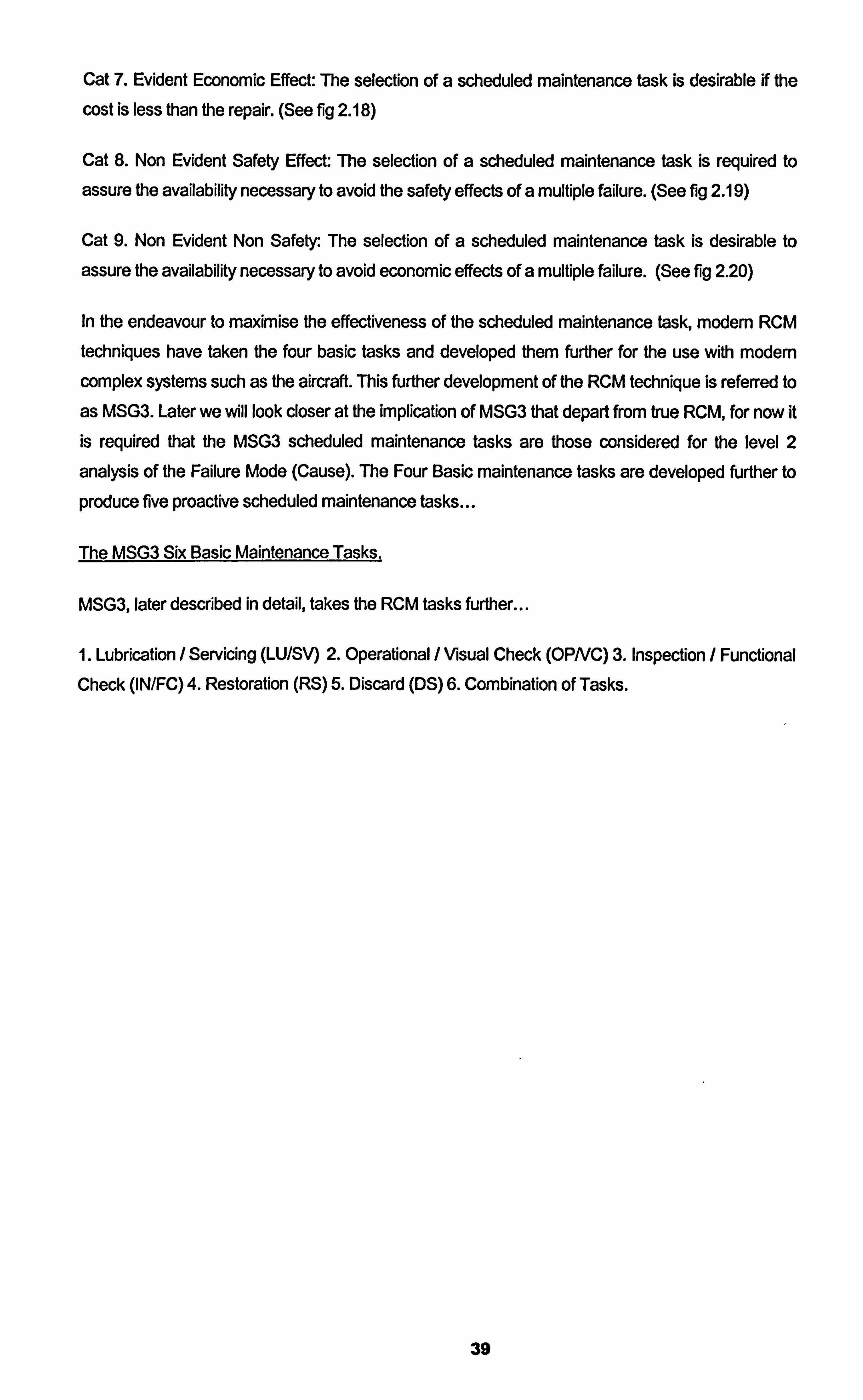
Cat 7. Evident Economic Effect: The selection of a scheduled maintenance task is desirable if the
cost is less than the repair. (See fig 2.18)
Cat 8. Non Evident Safety Effect: The selection of a scheduled maintenance task is required to
assure the availability necessary to avoid the safety effects of a multiple failure. (See fig 2.19)
Cat 9. Non Evident Non Safety: The selection of a scheduled maintenance task is desirable to
assure the availability necessary to avoid economic effects of a multiple failure. (See fig 2.20)
In the endeavour to maximise the effectiveness of the scheduled maintenance task, modem RCM techniques have taken the four basic tasks and developed them further for the use with modem complex systems such as the aircraft. This further development of the RCM technique is referred to
as MSG3. Later we will look closer at the implication of MSG3 that depart from true RCM, for now it is required that the MSG3 scheduled maintenance tasks are those considered for the level 2
analysis of the Failure Mode (Cause). The Four Basic maintenance tasks are developed further to
produce five proactive scheduled maintenance tasks...
The MSG3 Six Basic Maintenance Tasks.
MSG3, later described in detail, takes the RCM tasks further
1. Lubrication / Servicing (LU/SV) 2. Operational / Visual Check (OPNC) 3. Inspection / Functional
Check (IN/FC) 4. Restoration (RS) 5. Discard (DS) 6. Combination of Tasks.
39
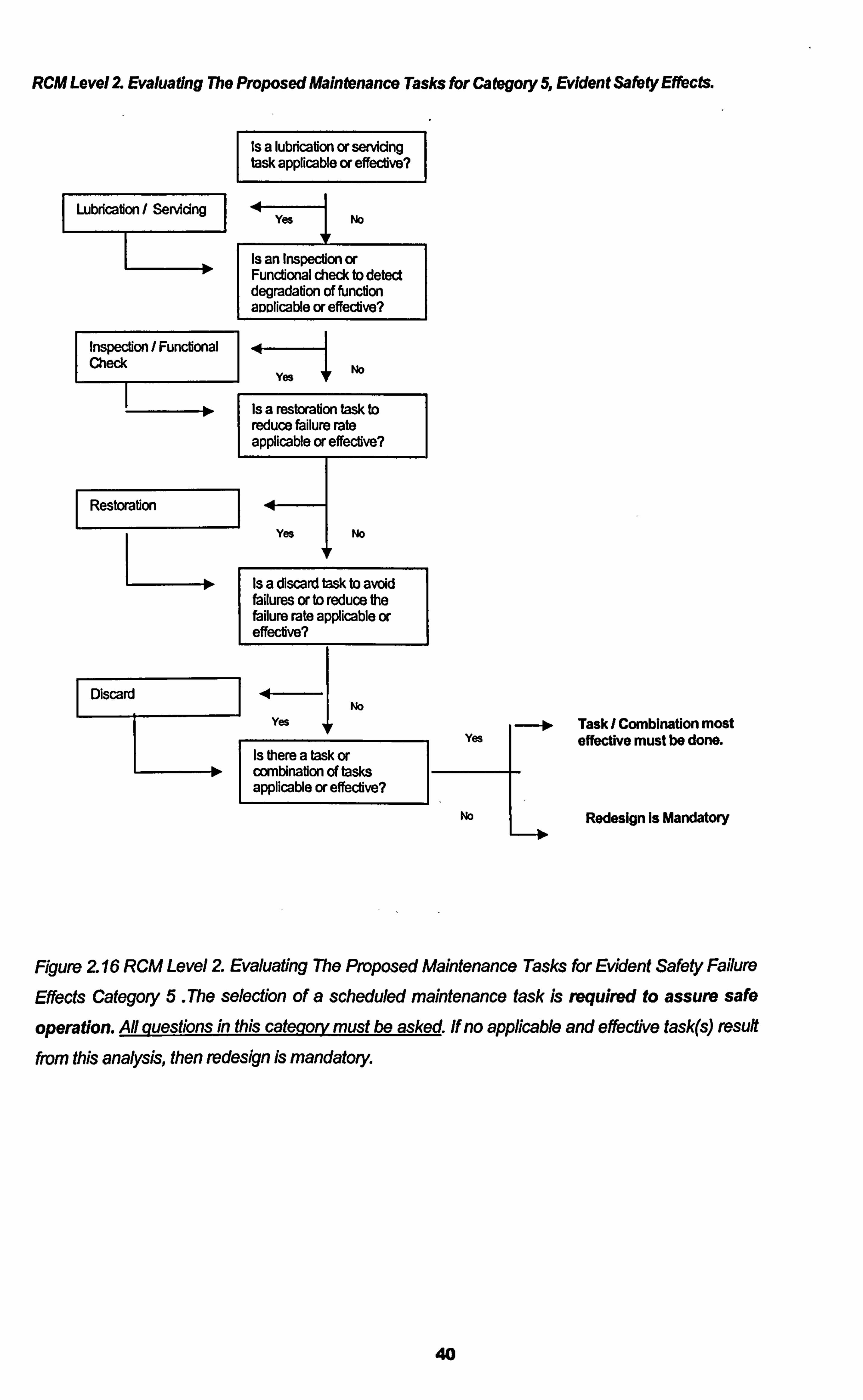
RCM Level Z Evaluating The Proposed Maintenance Tasks thr Category 5, Evident Safety Effects.
I Lubdcafion / Servidn
InspecHon 1 FuncHonal Check
1
l> 1
Restorabon
Is a lubricadon or servicing task applicable or effecUve?
]
Yes I No
Is an Inspection or Functional check to detect degradation of fUnction awlicable or effective?
Yes No
Is a restoradon Itask to reduce failure rate applicable or effecfive?
Yes I No
Is a discard task to avoid failures or to reduce the failure rate applicable or effeclive?
Discard No
Yes
I
Yes
Is there a task or combination of tasks applicable " effective?
No
Task I Combination most effective must be done.
Redesign is Mandatory
Figure 2 16 RCM Level 2 Evaluating The Proposed Maintenance Tasks for Evident Safety Failure
Effects Category 5 The selection of a scheduled maintenance task is required to assure safe
operation. A# questions in this caLe_q-o& must be asked. If no applicable and effective task(s) result from this analysis, then redesign is mandatory.
40
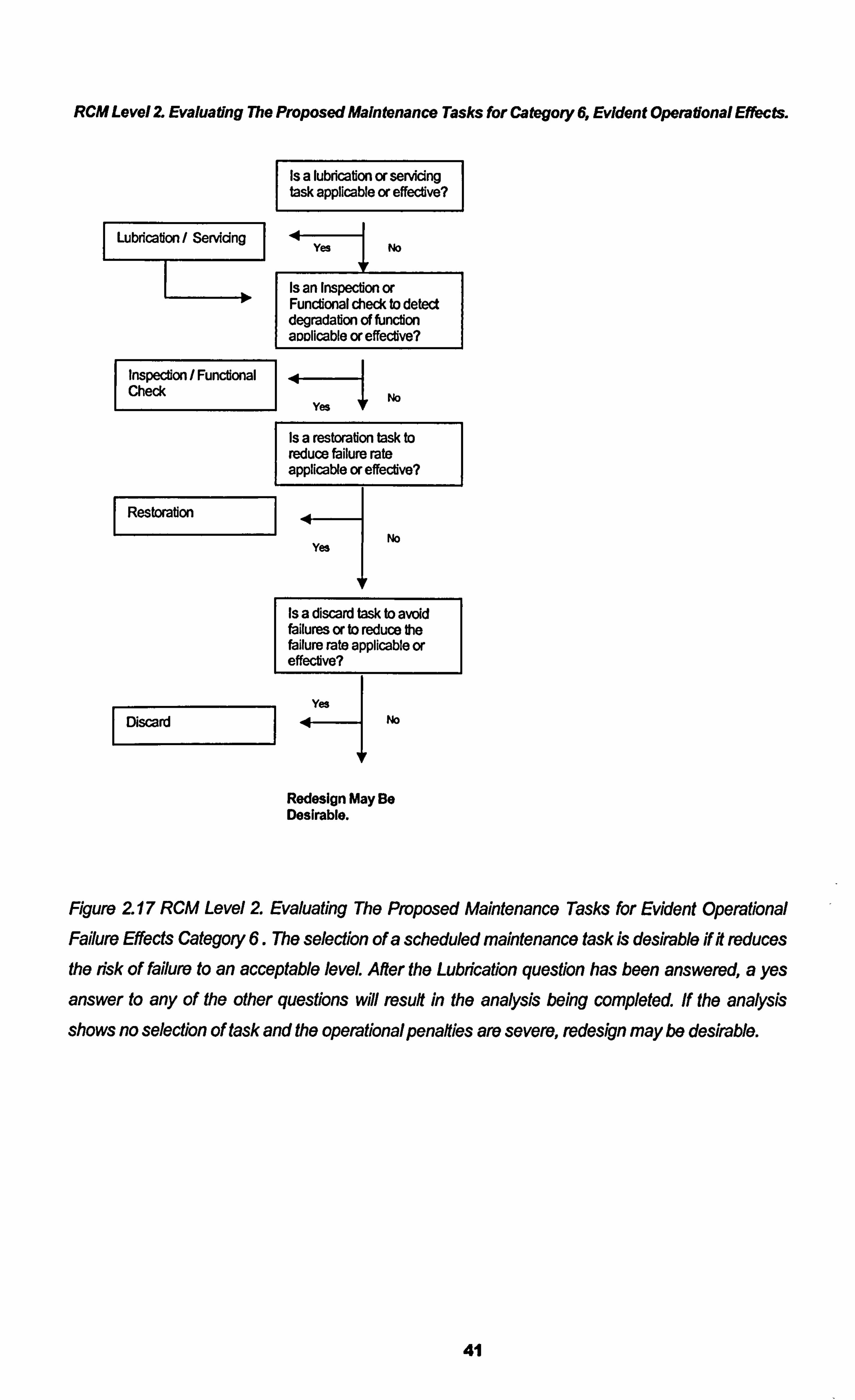
RCM Level Z Evaluating The Proposed Maintenance Tasks for Categoty 6, Evident Operational Effects.
I Lubdcabon/ S
Inspecton / Fundonal Check
I Restorabon
I Discard I
Is a lubrication or servicing task applicable or effecdve?
Yes I No
Is an Inspection or Functional check to detect degradation of function aDDlicable or effective?
-4- 1
Yes No
Is a restoration task to reduce failure rate applicable or effective?
. 44 No
Yes
V
Is a discard task to avoid failures or to reduce the failure rate applicable or effective?
Yes No
Redesign May Be Desirable.
Figure 2 17 RCM Level 2 Evaluating The Proposed Maintenance Tasks for Evident Operational
Failure Effects Category 6. The selection of a scheduled maintenance task is desirable if it reduces the risk of failure to an acceptable level. After the Lubrication question has been answered, a yes
answer to any of the other questions will result in the analysis being completed. if the analysis
shows no selection of task and the operational penaftles are severe, redesign may be desirable.
41
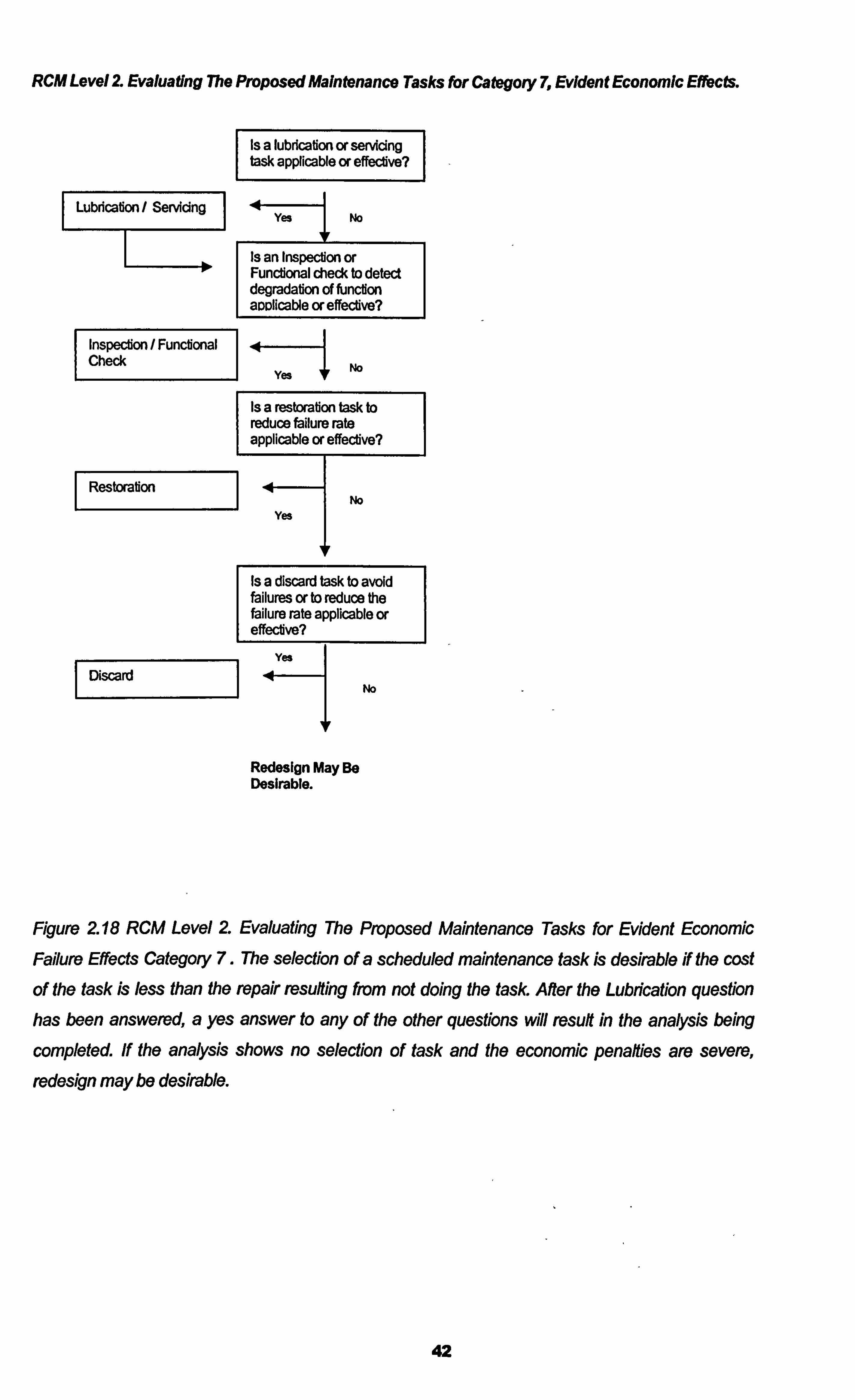
RCM Level Z Evaluating The Proposed Maintenance Tasks thr Category 7, Evident Economic Effects.
Is a lubricalion or servicing task applicable or effective?
Lubdcafion/ Servicin 4 Yes No
I Is an Inspection or 1-unctional check to detect degradation of function aDDlicable or effective?
InspecUon / Functional .41 Check
Yes No
Is a restoration task to reduce failure rate applicable or effective?
Restorabon .4 No
Yes
I Is a discard task to avoid failures or to reduce the failure rate applicable or effective?
I
I Discard No
Redesign May Be Desirable.
Figure 2 18 RCM Level 2 Evaluating The Proposed Maintenance Tasks for Evident Economic
Failure Effects Category 7. The selection of a scheduled maintenance task is desirable if the cost
of the task is less than the repair resulting from not doing the task After the Lubrication question has been answered, a yes answer to any of the other questions will result in the analysis being
completed If the analysis shows no selection of task and the economic penalties are severe,
redesign may be desirable.
42
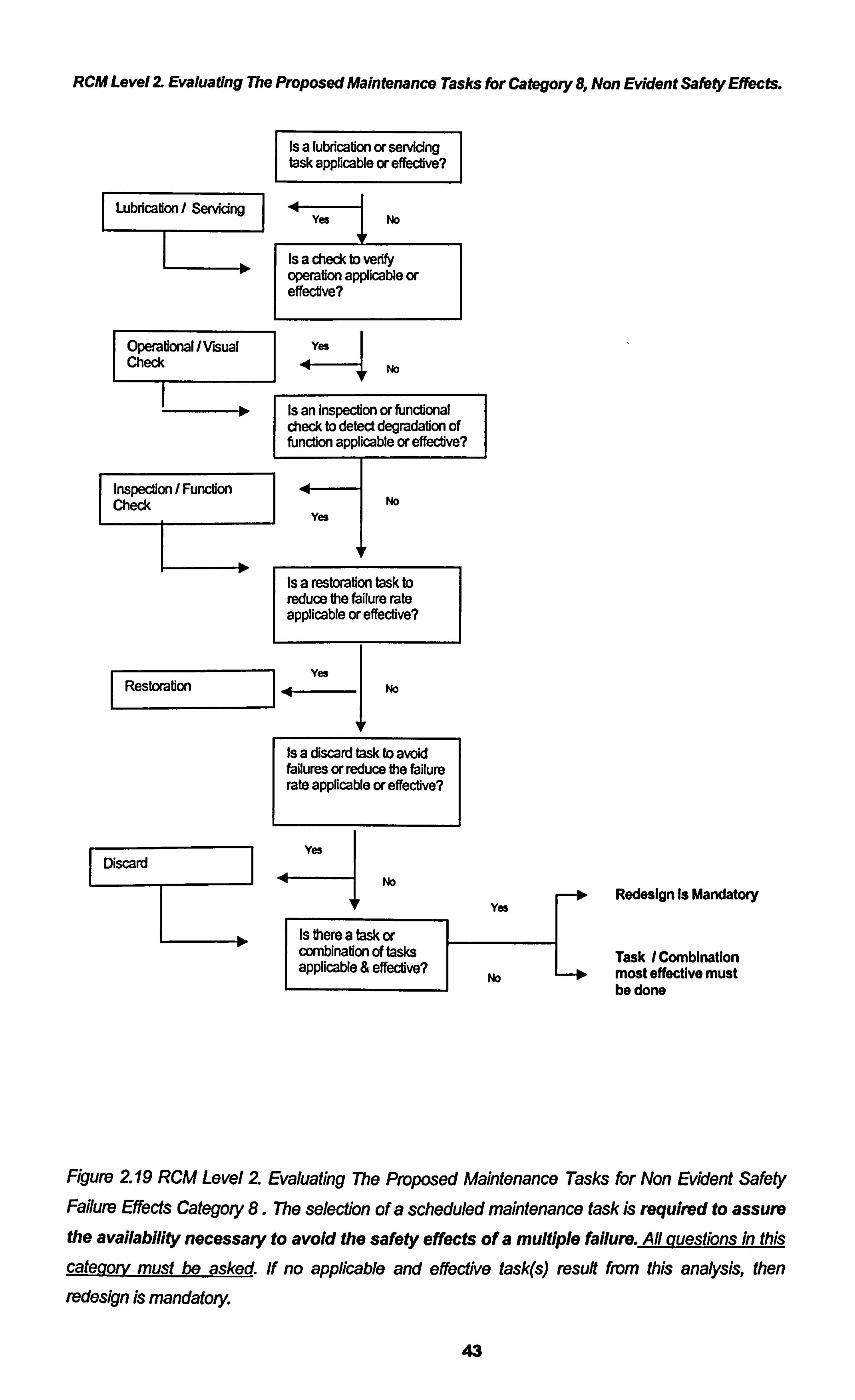
RCM Level 2 Evaluating The Proposed Maintenance Tasks for Category 8, Non Evident Safety Effects.
I Lubdcadon/
Operational I Visual Check
I lo,
I
Inspecdon / Funcdon Check
Is a lubdcabon or servicing task applicable or effective?
Yes I No
Is a check to verify operation applicable or effective?
Yes
No
Is an Inspection or functional check to detect degradation of function applicable or effective?
4 No
Yes
Is a restoration task to reduce the failure rate applicable or effective?
Yes Restorabon 41 No
Is a discard task to avoid failures or reduce the failure rate applicable or effective?
Yes Discard
No
IF Yes
Is there a task or combination of tasks applicable & effective?
No
Redesign Is Mandatory
Task /Combination most effective must be done
Figure 219 RCM Level 2 Evaluating The Proposed Maintenance Tasks for Non Evident Safety Failure Effects Category 8. The selection of a scheduled maintenance task is required to assure the availability necessary to avoid the safety effects of a multiple failure.
categg& must be asked If no applicable and effective task(s) result from this analysis, then
redesign is mandatory.
43
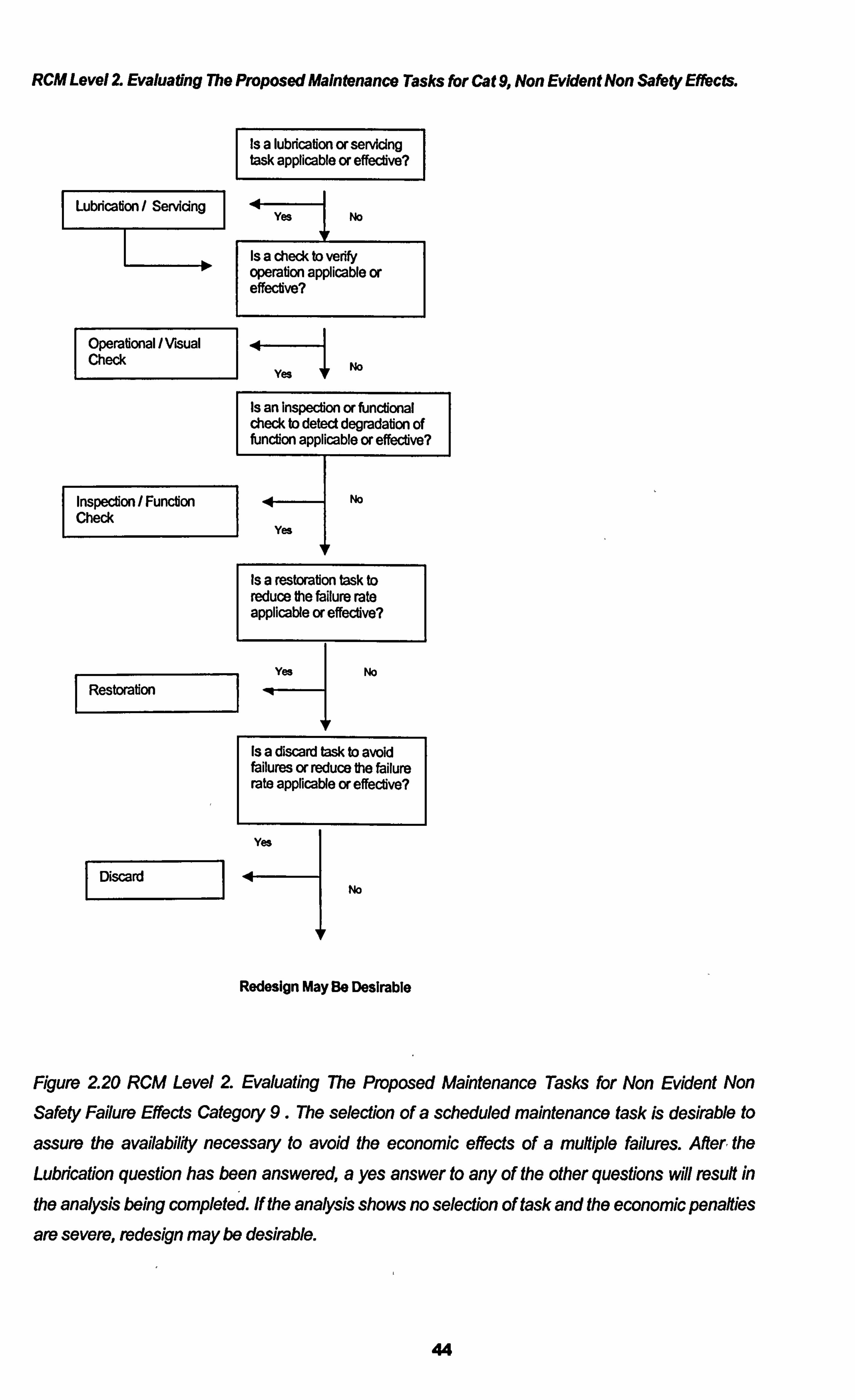
RCM Level 2 Evaluating The Proposed Maintenance Tasks for Cat 9, Non Evident Non Safety Effects.
Is a lubricafion or servicing task applicable or effective?
Lubdcation / Servidn yes No
IF
Is a check to vedfy operation applicable or effecdve?
Operational / Visual Check
Yes NO
Is an Inspection or functional check to detect degradation of fUnction applicable or effective?
Inspedon / Fundon No Check
I
Yes
Is a restorabon task to reduce the failure rate applicable or effective?
Restmfion Yes No
Is a discard task to avold failures or reduce the failure rate applicable or effecfive?
yes
Discard No
Redesign May Be Desirable
Figure 220 RCM Level 2 Evaluating 7he Proposed Maintenance Tasks for Non Evident Non
Safety Failure Effects Category 9. The selection of a scheduled maintenance task is desirable to
assure the availabiW necessary to avoid the economic effects of a multiple failures. After, the
Lubrication question has been answered, a yes answer to any of the other questions will result in
the analysis being completed. If the analysis shows no selection of task and the economic penalties
are severe, redesign may be desirable.
44
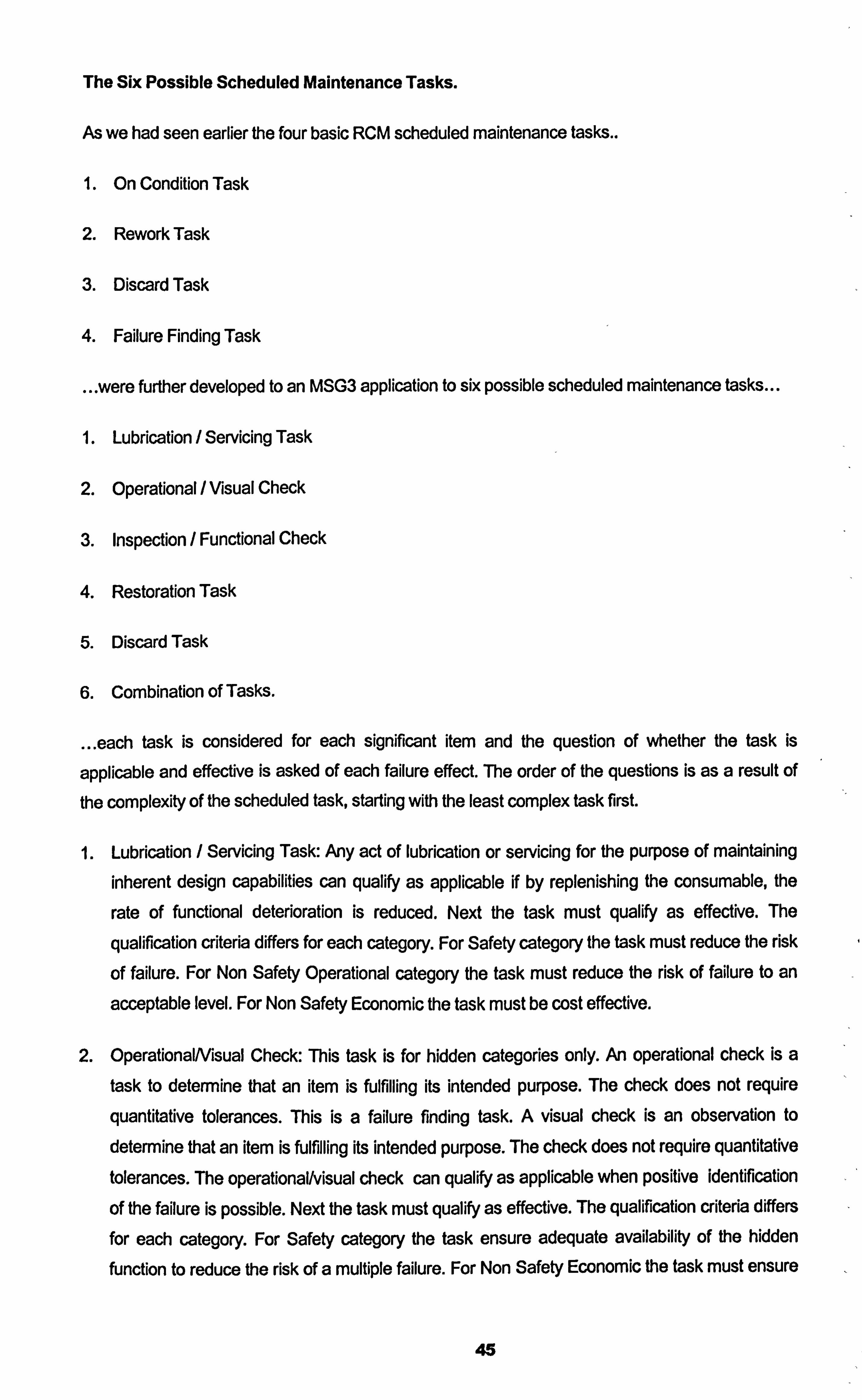
The Six Possible Scheduled Maintenance Tasks.
As we had seen earlier the four basic RCM scheduled maintenance tasks..
1. On Condition Task
2. Rework Task
3. Discard Task
4. Failure Finding Task
were further developed to an MSG3 application to six possible scheduled maintenance tasks
1. Lubrication / Servicing Task
2. Operational / Visual Check
3. Inspection / Functional Check
4. Restoration Task
5. Discard Task
6. Combination of Tasks.
... each task is considered for each significant item and the question of whether the task is
applicable and effective is asked of each failure effect. The order of the questions is as a result of
the complexity of the scheduled task, starting with the least complex task first.
1. Lubrication / Servicing Task: Any act of lubrication or servicing for the purpose of maintaining inherent design capabilities can qualify as applicable if by replenishing the consumable, the
rate of functional deterioration is reduced. Next the task must qualify as effective. The
qualification criteria differs for each category. For Safety category the task must reduce the risk
of failure. For Non Safety Operational category the task must reduce the risk of failure to an
acceptable level. For Non Safety Economic the task must be cost effective.
2. OperationalNisual Check: This task is for hidden categories only. An operational check is a task to determine that an item is fulfilling its intended purpose. The check does not require
quantitative tolerances. This is a failure finding task. A visual check is an observation to
determine that an item is fulfilling its intended purpose. The check does not require quantitative tolerances. The operational/visual check can qualify as applicable when positive identification
of the failure is possible. Next the task must qualify as effective. The qualification criteria differs
for each category. For Safety category the task ensure adequate availability of the hidden
function to reduce the risk of a multiple failure. For Non Safety Economic the task must ensure
45
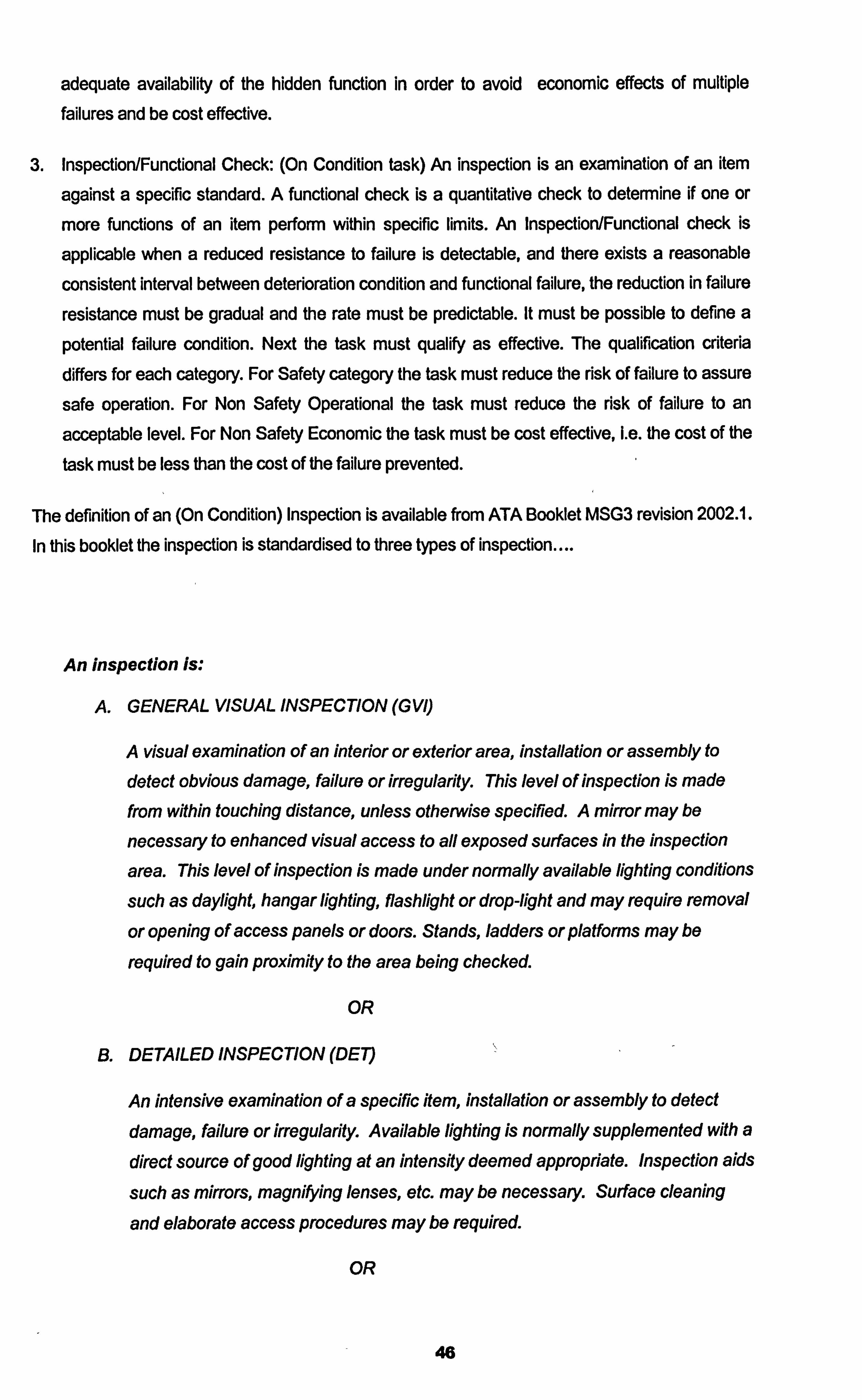
adequate availability of the hidden function in order to avoid economic effects of multiple failures and be cost effective.
3. Inspection/Functional Check: (On Condition task) An inspection is an examination of an item
against a specific standard. A functional check is a quantitative check to determine if one or
more functions of an item perform within specific limits. An Inspection/Functional check is
applicable when a reduced resistance to failure is detectable, and there exists a reasonable
consistent interval between deterioration condition and functional failure, the reduction in failure
resistance must be gradual and the rate must be predictable. It must be possible to define a
potential failure condition. Next the task must qualify as effective. The qualification criteria differs for each category. For Safety category the task must reduce the risk of failure to assure
safe operation. For Non Safety Operational the task must reduce the risk of failure to an
acceptable level. For Non Safety Economic the task must be cost effective, Le. the cost of the
task must be less than the cost of the failure prevented.
The definition of an (On Condition) Inspection is available from ATA Booklet MSG3 revision 2002.1.
In this booklet the inspection is standardised to three types of inspection....
An inspection is:
A. GENERAL VISUAL INSPECTION (GVI)
A visual examination of an interior or exterior area, installation or assembly to
detect obvious damage, failure or irregularity. This level of inspection is made from within touching distance, unless otherwise specified. A mirror may be
necessary to enhanced visual access to all exposed surfaces in the inspection
area. This level of inspection is made under normally available lighting conditions
such as daylight, hangar lighting, flashlight or drop-light and may require removal
or opening of access panels or doors. Stands, ladders or platforms may be
required to gain proximity to the area being checked.
OR
B. DETAILED INSPECTION (DE7)
An intensive examination of a specific item, installation or assembly to detect
damage, failure or irregularity. Available lighting is normally supplemented with a
direct source of good lighting at an intensity deemed appropriate. Inspection aids
such as mirrors, magnifying lenses, etc. may be necessary. Surface cleaning
and elaborate access procedures may be required.
OR
46
C. SPECIAL DETAILED INSPECTION (SDI)
An intensive examination of a specific item, installation, or assembly to detect
damage, failure or irregularity. The examination is likely to make extensive use of
specialized Inspection Techniques andlor equipment Intricate cleaning and
substantial access or disassembly procedure may be required.
4. Restoration Task: The work necessary to return the item to a specific standard. Since
restoration may vary from cleaning or replacement of single parts up to a complete
overhaul, the scope of each assigned restoration task has to be specified. A restoration task is applicable if the item shows functional degradation characteristics at an identifiable
age and a large proportion of units must survive to that age. There must be an identifiable
age at which there is a rapid increase in failure probability. It must be possible to restore the item to a specific standard of failure resistance. The qualification criteria differs for
each category. For Safety category the task must reduce the risk of failure to assure safe
operation. For Non Safety Operational category the task must reduce the risk of failure to
an acceptable level. For Non Safety Economic category the task must be cost effective, i. e. the cost of the task must be less than the cost of the failure prevented.
5. Discard Task: The removal of an item from service at a specified life limit. Discard task
are normally applied to so called single celled parts such as cartridges, canisters
cylinders, engine disks, safe life structural members etc. A discard task is applicable
when the item shows functional degradation characteristics at an identifiable age and a large proportion of units must survive to that age, Le. there must be an Identifiable age that at which there is a rapid increase in failure probability (for safety items all
components must survive to the scheduled removal time). In addition it should not be
possible or cost effective to restore that component to a condition of low failure probability
or the criteria for an on aircraft functional check or inspection can not be met. The
qualification criteria differs for each category. For Safety category a safe life limit must
reduce the risk of failure to assure safe operation. For Non Safety Operational category the task must reduce the risk of failure to an acceptable level. For Non Safety Economic
category the task must be cost effective, i. e. the cost of the task must be less than the
cost of the failure prevented.
6. Combination: This task is for safety categories only. Since this is a safety category
question and a task is require, all possible avenues must be analysed. To do this a review
of the task(s) that are applicable is necessary. From this review the most effective task(s)
must be selected.
47
MSG3 Scheduled Maintenance Task Development.
Original RCM techniques identified the four basic scheduled maintenance task. MSG3 applied that
logic further developing the four basic tasks into five tasks and a task combination. The scheduled
on condition task is a task to detect potential failures. Therefore the subject must manifest
symptoms of a failing period, the P-F range. The task must be capable of identifying physical
evidence of a reduced resistance to failure. The definition of the inspection interval is dependant on technical data from the design engineers or even better from in operation experience. As described
in previous section 2.2.2 on the scheduled maintenance task, the interval of the on condition task
must be sufficient enough to ensure detection of the potential failure in the P-F range before the
failure occurs. MSG3 logic developed the on condition task to Inspection or Function check. The
inspection task which can be either GVI, DIET or SDI as shown above, is to visually detect a
potential failure, while the function check is to measure and identified a potential failure in the
performance of a system or component. The MSG3 task description develops further the idea of the RCM on condition task understanding that specifics are required and identifies the difference
between the Visual and the functional checks. The scheduled failure finding task is a task to detect
non evident failures. Although such tasks are intended to locate functional failures rather than
potential failures, they can be viewed as a type of on condition maintenance, since the failure of a hidden function can be considered as a potential failure of a multiple system. The MSG3 task
description develops further the idea of the RCM failure finding task detailing it as an operational or
visual check to determine that the system or component is fulfilling its intended purpose. Lubrication
and servicing tasks were additions to the RCM scheduled maintenance tasks that took, into
consideration the needs of serviceable systems and components where a preventative
maintenance task such as replenishing the lubricant level when required can prevent functional
failures. It can also be considered in some respect as an on condition inspection task, if the level of lubricant is below 8 quarts you are in a potential failure range, and the rectification action to prevent the failure is to top up the lubricant level.
The Addition of the Lubrication and Servicing Task to the classical RCM tasks.
Considering closer the lubrication and servicing implications of a system or component. Failure due
to lubrication is associated with two types of failure modes. The first is due to the lack of lubricant
available, as a result of loss of the level of lubricant. The second failure mode is a failure of the
effectiveness of lubricant due to physical and chemical changes to'the properties of the lubricant,
such as oxidation, shearing of the oil molecules or degradation through contamination of the oil or
grease (such as moisture ingression).
The introduction of the servicing task was required to address the components and systems that
are subject to lubrication, in their own right rather than the task being a part of the on condition inspection for lubricant level or Discard task for lubricant replacement. The servicing task was
considered to be significant and important enough to merit ifs own designation. Even today modem RCM does not include the lubrication or servicing task as a task in their own right, but MSG3
48
philosophy does. At a latter stage in this document we will examine the differences in modem RCM
versus the aircraft application of the philosophy called MSG3.
Task Interval selection.
Once the scheduled maintenance task has been identified that meets both the applicable and
effective criteria, an interval has to be allocated to the task that is appropriate for the task based on
available known or calculated data or if that is not available good engineering judgment.
Normally for a new piece of equipment such as a new aircraft type, the component failure data is
not readily available. In these cases simulated data may be used but the in operational
performance of the subject must be carefully monitored to show the appropriateness of the chosen interval, or to justify an adjustment of the interval. This subject of in operation monitoring will be
studied in more detail at a later stage. If a similar system or component is used in other applications
or aircraft types then the in operation data for that installation can be possibly appropriate for use in
the new scenario. Again engineering judgement must be used. The environment that component or
system operates in could have an effect on its failure modes. A scheduled maintenance task should not be allocated a lesser interval than it merits just because
it is easy to access. Doing tasks more often than necessary increases the chance of maintenance
error or human induced error. This is especially true on invasive maintenance tasks when access
may be difficult or elaborate. Reliability issues with a component or system can at times be related to the hand of man as a result of continued disturbance. A good example of an invasive task is too
frequently entering the fuel tanks, rather than a single entry to carry out multiple tasks. Tank entry is
very invasive, panels & seals are disturbed, tight areas are accessed where delicate components
are located, easily bumped or disturbed.
Possible sources of Information available to assist in an appropriate task intervals are...
" Manufacturers tests and simulation's
" Manufacturers recommendation's
" In service experience of the subject
" In service experience of a similar subject
" Best Engineering judgment
The selected interval also depends upon the scheduled maintenance task e. g.
Lubrication / Servicing (Failure Prevention): The usage rate, the amount of consumable In the
container and the deterioration characteristics of the consumable.
Inspection / Function check (On condition task, Potential Failure Finding): Intervals are governed by
the P-F interval, so there should be a clearly defined Potential failure condition. The task interval
49
should be less than the shortest likely interval between the point at which the potential failure
becomes detectable and the point that which the item fails, but not so long that the potential failure
interval is nearing the end of the range and the resulting repair will not be economical or practical.
Restoration task intervals (Failure Avoidance): Depend upon useful life of the item under
consideration, where the conditional probability of failure increases significantly. A sufficiently large
proportion of the failures should occur after the selected interval.
Operational / Visual check (Failure Finding task): Intervals are governed by the consequence of the
multiple failure and the mean time between occurrences of the hidden failure. Consideration must be given also to the fact that the task itself may leave the hidden function in a failed state.
Task Interval Parameters
Earlier in section 2.2.1 we examined the variety of interval parameters or units of measures.
9 Calendar Time
0 Flight Hours
Flight Cycles/landings
Engine / APU hours / cycles
The most appropriate unit of measure or combination of units of measure should be determined.
This would become apparent after analysing the failure mode and determining its nature of failure
resulting from fatigue, wear, environmental or any other implications. Table 2.1 in section 2.2.1
details the available units of measure.
e. g. An Integrated Drive Generator (IDG) has been allocated after RCM analysis two Lubrication /
Servicing tasks. The first to check the lubricant level and the second to replace the lubricant in total
due to degradation of the lubricant. Now we have to identify the interval for both these tasks.
Scheduled Maintenance Task: Check IDG Lubricant Level. Manufacturers information
recommends that this is accomplished every 300 flight hours, as the IDG will on average loose
oil through the air vent at a rate of 0.0005 quarts per hour and through leakage of the main
shaft seal at a rate of 0.00 15 quarts per hour. The IDG sump is full when 2 quarts of oil are in
the sump and requires replenishing when it reaches1.25 quarts of oil for normal operation. This
means that the IDG can be expected to operate for 375 hours before any servicing is required. The 300 flight hours interval recommended by the manufacturer allows for a 75 hour margin. In
service operation of the same part number IDG on another engine shows that the loss of oil detailed by the manufacturer is on the high side and the data gathered by the airline suggest
50
that an interval of 400 flight hours is more appropriate and the task requirement is developed
not only to inspect and service the oil level as required, but to inspect and service the oil level
to ftill.
2. Scheduled Maintenance Task: Replace IDG Lubricant. The lubricant manufacturer has advised the IDG manufacturer that his oil in the environment of the IDG will maintain its chemical and
physical ability to cool and to lubricate for 3000 flight hours of usage. A scheduled
maintenance task is planned for to replace the lubricant at the manufacturers
recommendations of 3000 flight hours. As well as replacing the lubricant at this time, a sample
of the oil is sent to the laboratory for spectral analysis to determine how the oil differs from its
original specification. This analysis will describe how the operational time has affected the
ability of the oil to perform to the original specification. From these results the intervals can be
confirmed as effective and applicable or the interval can be escalated to a more appropriate interval.
So it can be seen from both the examples above that hours of utilisation are the most appropriate interval parameters. Calendar days would not be appropriate as a parked aircraft that is not flying
will not experience lubricant degradation and landings also is not a function of the oil usage or degradation. Equally the following example shows the appropriateness of other interval
parameters..
3. Scheduled Maintenance Task: Inspect Flap Attachment for Cracking. The RCM analysis has
identified this task as a significant item with aP-F interval, therefore an On Condition
inspection is called for. In this case the inspection has been identified as a Detailed Inspection
to be accomplished every 10,000 landings. This interval is in line with the manufacturers
calculation, simulations or in service experience with similar designs. Landings are selected as the appropriate parameter as it is the landing cycle that most stress is induced on that section
of the structure as flaps are used extensively for take off and landings and at those stages of flight the flaps are subject to significant aerodynamic forces.
Later in section 6 we will look closely at not only the importance of verifying that the scheduled
maintenance tasks selected through the RCM process are applicable and effective but also that the
intervals and parameters selected for the significant items are appropriate in the operating context
of the aircraft. This is done through In Operation Reliability Monitoring.
51
2.3 Application of RCIVI to produce an Aircraft Maintenance Programme.
Section 2 describes the Reliability Centred Maintenance analysis process as a process that considers a significant item from the perspective of the consequence of failure of that item, then examines further that item to determine an applicable & effective preventative maintenance task. In section 2.2.4 we identified three major areas for categorising the
complete aircraft, they were Systems, Engines and Structures. The RCIVI analysis process described so far can be applied directly to Systems and Engines identifying applicable and
effective scheduled maintenance tasks, but some difficulty appears in it's application in the
exact form when it comes to analysing Structures and structural significant items. We will
now look specifically at the application of RCM analysis to the three significant categories of Systems, Engines and then Structures. We will now consider the differences required in
approach to analysing each of the three significant categories.
2.3.1 Analysis of Systems.
The systems category includes all the components and systems required for operating the
aircraft except the power plant itself. Most systems are composed of numerous separate
assemblies or components, linked by electrical, mechanical or hydraulic lines. Even in new
aircraft a lot of the systems will not be brand new designs but will have seen active operation in a previous application. As a result of this the performance behaviour and
reliability will be predictable and known. RCM analysis of systems to produce a scheduled maintenance programme focuses on using the traditional decision trees as detailed in
section 2.2A onwards. This standard decision process focuses on the effects of failure
utilising the inherent reliability of the system design.
Below are some examples of the application of the standard system RCM analysis as detailed in section 2.2.4....
Analvsis of a Landina Gear Brake Assembiv.
The brake assembly for the main landing gear of the Boeing 737 Next Generation is
classified as a significant item because the primary function of the braking system is to
provide stopping capability after landing or during ground operations. Since a complete loss of the system would clearly have safety consequences, it is necessary to consider how the brake assembly contributes to the overall system function. The full braking
capacity of the system is rarely used and its effect is masked by the availability of reverse thrust from the engines as well as the brakes available on other wheels on the same gear bogie. As a result the pilot may not notice a reduction of capability of the braking system in
stopping the aircraft due to the reverse thrust and the multiple brake bogies. This means the item will have hidden functions as well.
52
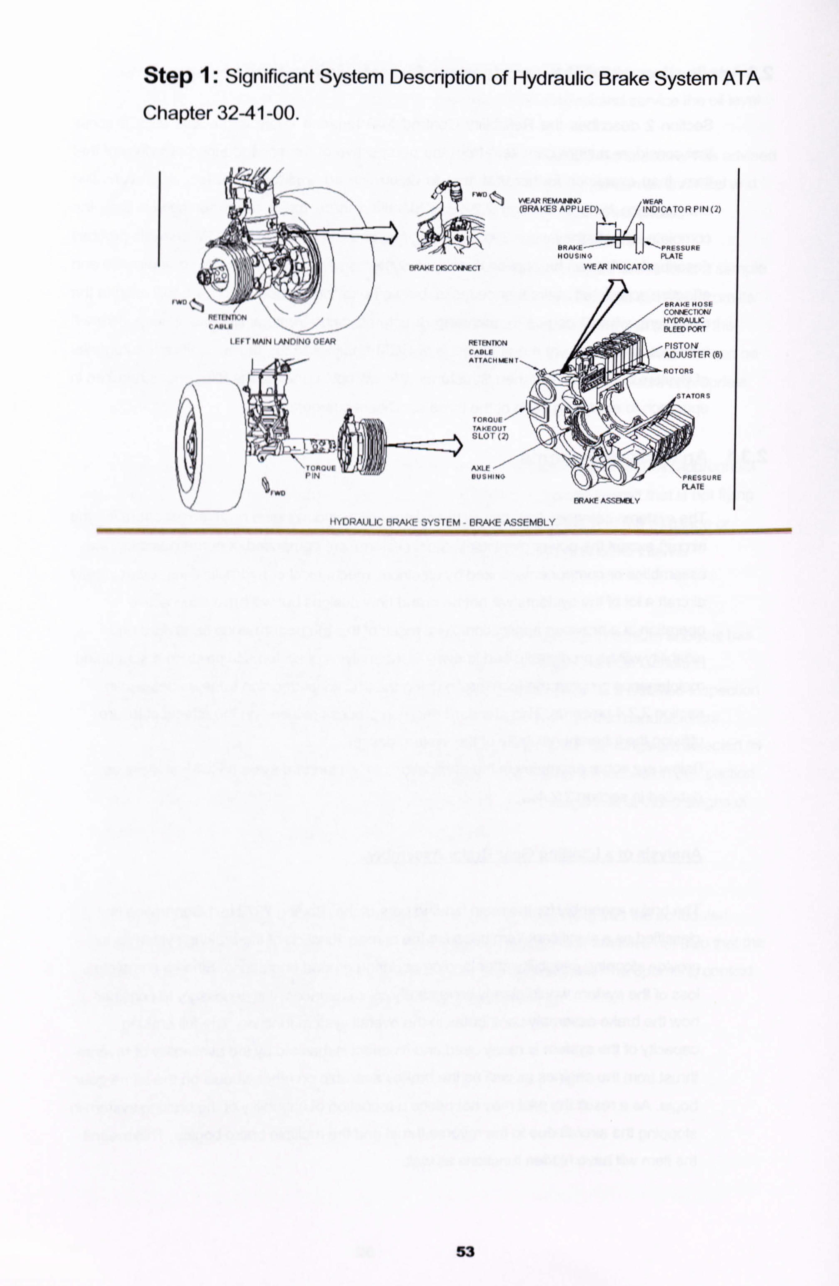
Step 1: Significant System Description of Hydraulic Brake System ATA
Chapter 3241 -00.
'wo
401M T R'.. WEM
(BRAKES APPU ED) INDICATOR PIN (2)
BRAýE---44ýýPRESSUEF PLATE
fWMF DISCONNI Cl WEAR INDICATOR
BRAkE H0- CO CTION/ HYDRAULIC DUEED PORT
ýETWION PISTONf CABLE AT TACH wN
ADJUSTER (6) r,
TAkEOUT SLOT 2)
AXLE
PLATE
13RAKE ASSFM3L Y
IIYORAULIC BRAkE SYSTEM - 13RAKE ASSEMBLY
53
I FFT MAIN IANDINO OFAR
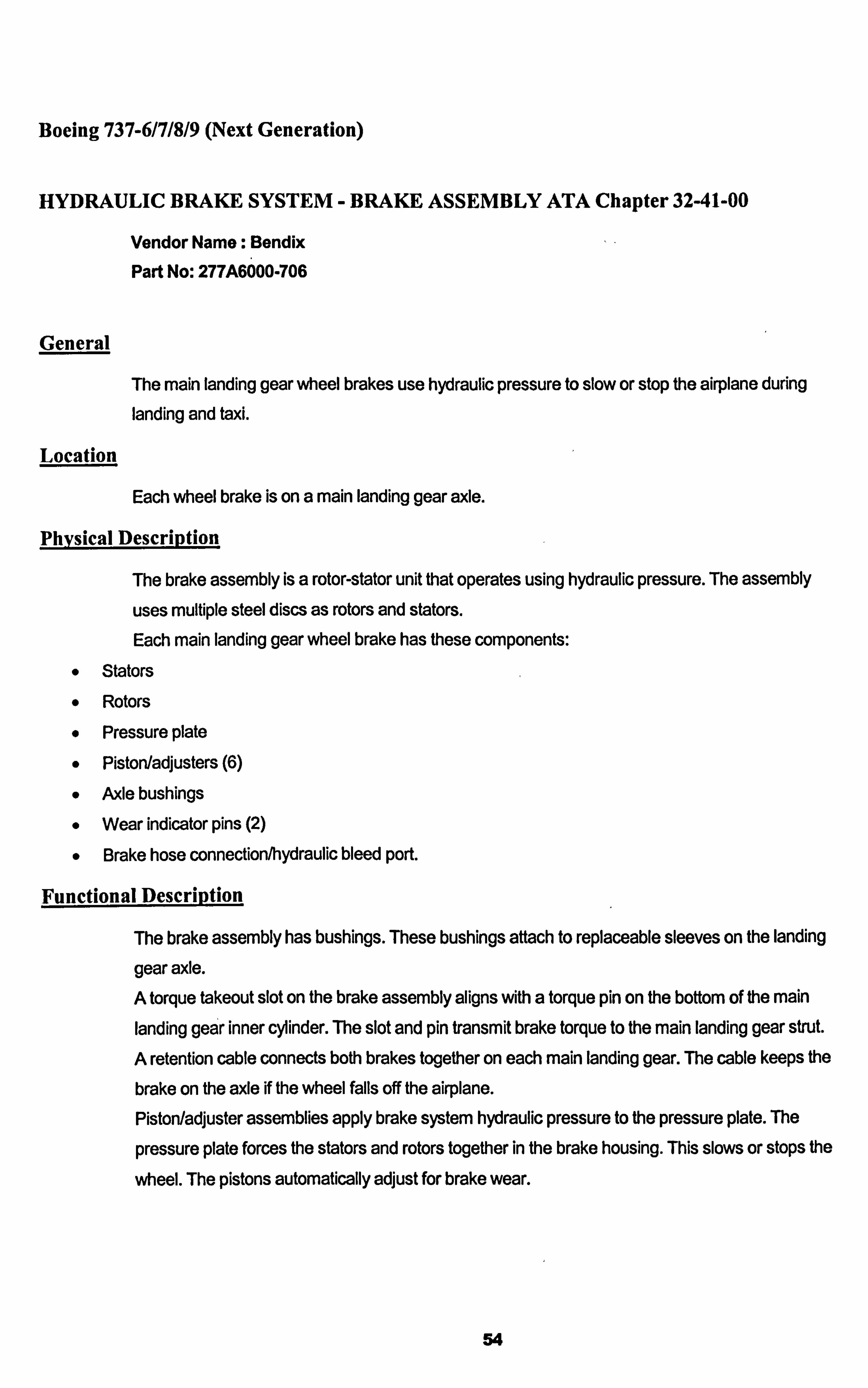
Boeing 737-6/7/8/9 (Next Generation)
HYDRAULIC BRAKE SYSTEM - BRAKE ASSEMBLY ATA Chapter 32-41-00
Vendor Name: Bendix
Part No: 277A6000-706
General
The main landing gear wheel brakes use hydraulic pressure to slow or stop the airplane during
landing and taxi.
Location
Each wheel brake is on a main landing gear axle.
Phvsical Description
The brake assembly is a rotor-stator unit that operates using hydraulic pressure. The assembly
uses multiple steel discs as rotors and stators. Each main landing gear wheel brake has these components:
0 Stators Rotors
Pressure plate Piston/adjusters (6)
Axle bushings
Wear indicator pins (2)
Brake hose connection/hydraulic bleed port.
Functional Description
The brake assembly has bushings. These bushings attach to replaceable sleeves on the landing
gear axle. A torque takeout slot on the brake assembly aligns with a torque pin on the bottom of the main landing gear inner cylinder. The slot and pin transmit brake torque to the main landing gear strut.
A retention cable connects both brakes together on each main landing gear. The cable keeps the
brake on the axle if the wheel falls off the airplane. Piston/adjuster assemblies apply brake system hydraulic pressure to the pressure plate. The
pressure plate forces the stators and rotors together in the brake housing. This slows or stops the
wheel. The pistons automatically adjust for brake wear.
54
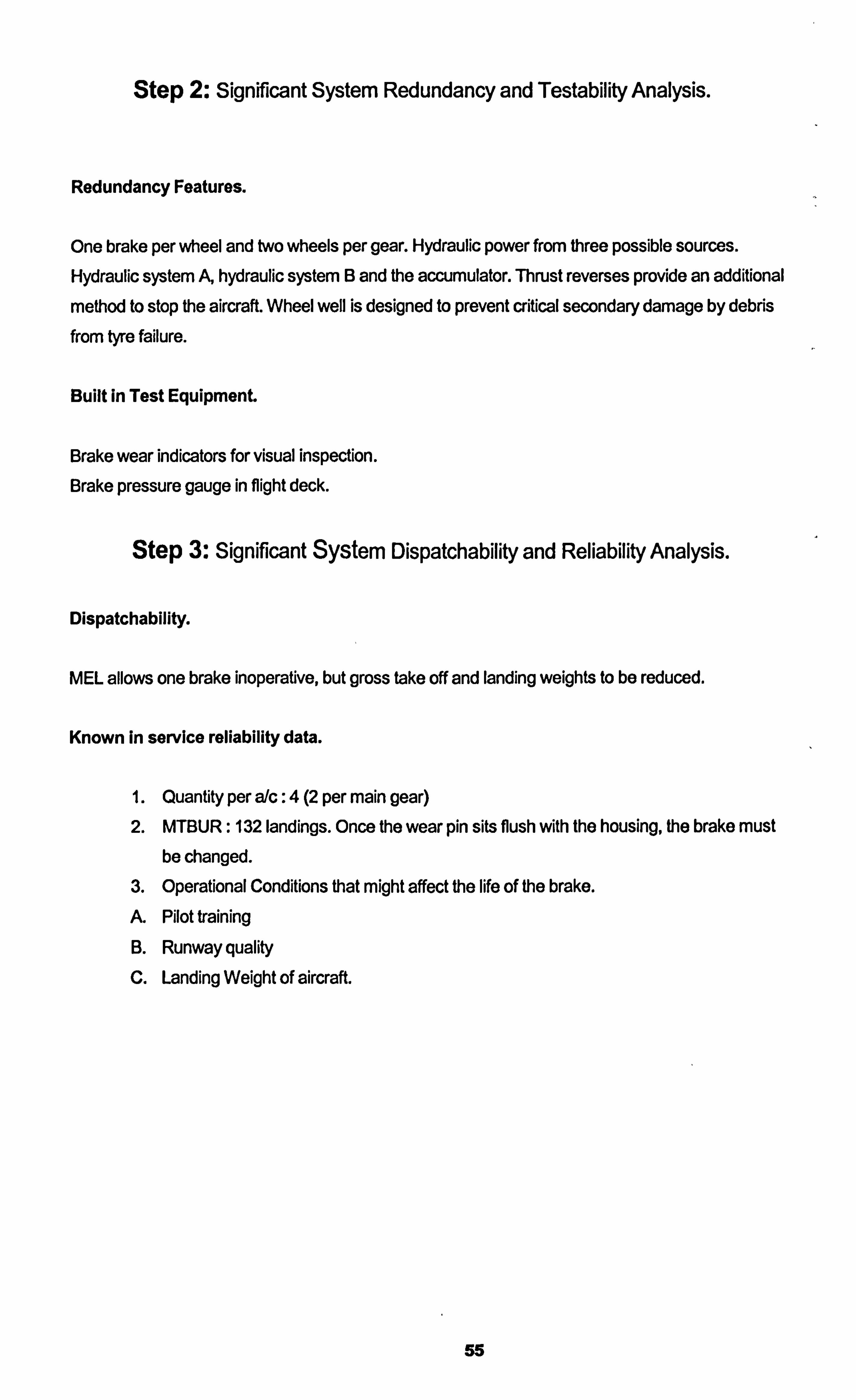
Step 2: Significant System Redundancy and Testability Analysis.
Redundancy Features.
One brake per wheel and two wheels per gear. Hydraulic power from three possible sources. Hydraulic system A, hydraulic system B and the accumulator. Thrust reverses provide an additional
method to stop the aircraft. Wheel well is designed to prevent critical secondary damage by debris
from tyre failure.
Built in Test Equipment.
Brake wear indicators for visual inspection.
Brake pressure gauge in flight deck.
Step 3: Significant SyStern Dispatchability and Reliability Analysis.
Dispatchability.
MEL allows one brake inoperative, but gross take off and landing weights to be reduced.
Known in service reliability data.
1. Quantity per a/c: 4 (2 per main gear) 2. MTBUR: 132 landings. Once the wear pin sits flush with the housing, the brake must
be changed. 3. Operational Conditions that might affect the life of the brake.
A. Pilot training
B. Runway quality C. Landing Weight of aircraft.
55
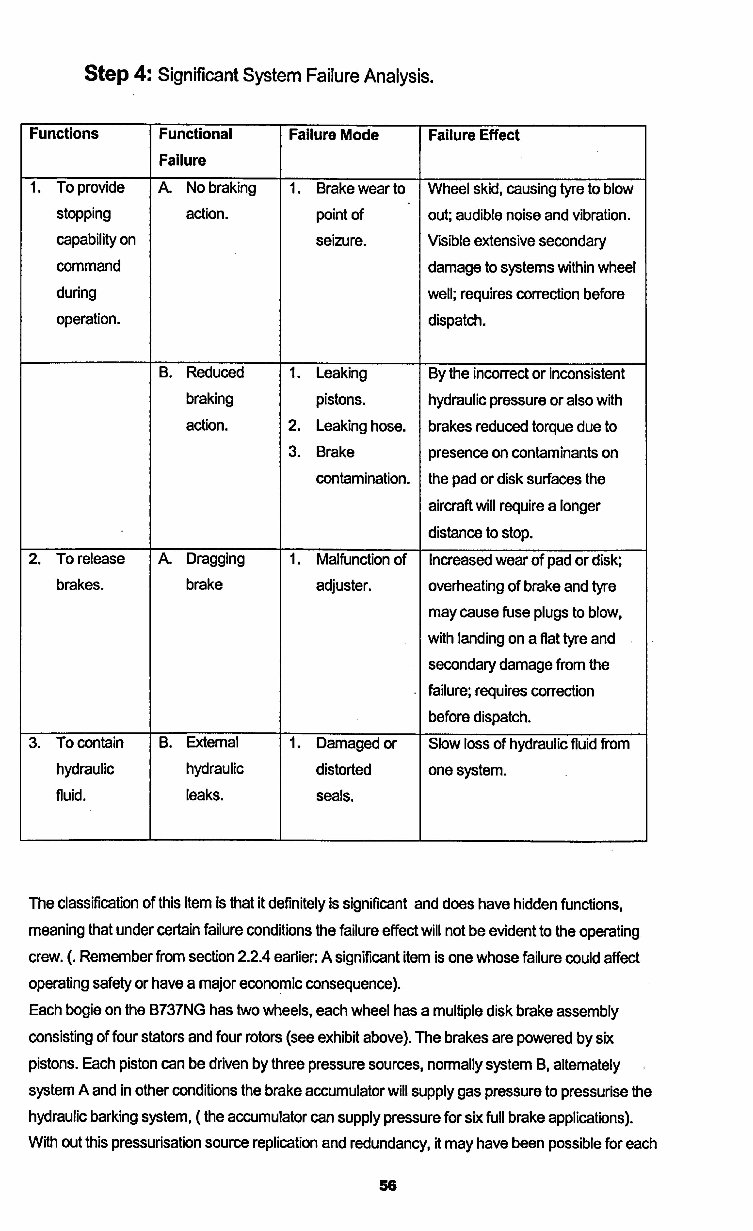
Step 4: Significant System Failure Analysis.
Functions Functional Failure Mode Failure Effect Failure
1 To provide A. No braking 1. Brake wear to Wheel skid, causing tyre to blow
stopping action. point of out; audible noise and vibration. capability on seizure. Visible extensive secondary command damage to systems within wheel during well; requires correction before
operation. dispatch.
B. Reduced 1. Leaking By the incorrect or inconsistent braking pistons. hydraulic pressure or also with action. 2. Leaking hose. brakes reduced torque due to
3. Brake presence on contaminants on contamination. the pad or disk surfaces the
aircraft will require a longer
distance to stop. 2. To release A. Dragging 1. Malfunction of Increased wear of pad or disk;
brakes. brake adjuster. overheating of brake and tyre
may cause fuse plugs to blow,
with landing on a flat tyre and secondary damage from the failure; requires correction before dispatch.
3. To contain B. External 1. Damaged or Slow loss of hydraulic fluid from hydraulic hydraulic distorted one system. fluid. leaks. seals.
The classification of this item is that it definitely is significant and does have hidden functions,
meaning that under certain failure conditions the failure effect will not be evident to the operating crew. (. Remember from section 2.2.4 earlier: A significant item is one whose failure could affect operating safety or have a major economic consequence). Each bogie on the B737NG has two wheels, each wheel has a multiple disk brake assembly consisting of four stators and four rotors (see exhibit above). The brakes are powered by six pistons. Each piston can be driven by three pressure sources, normally system B, alternately system A and in other conditions the brake accumulator will supply gas pressure to pressurise the hydraulic barking system, (the accumulator can supply pressure for six full brake applications). With out this pressurisation source replication and redundancy, it may have been possible for each
56
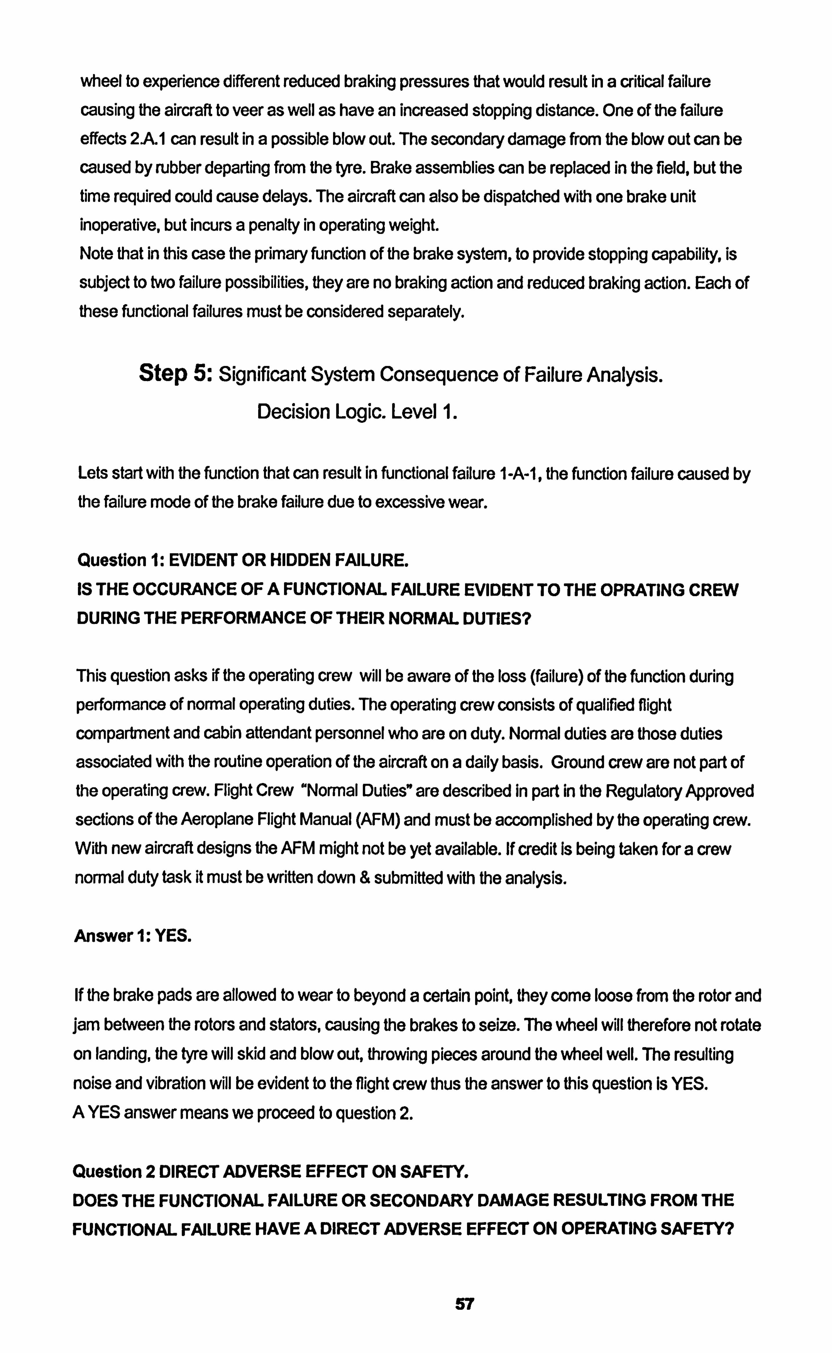
wheel to experience different reduced braking pressures that would result in a critical failure
causing the aircraft to veer as well as have an increased stopping distance. One of the failure
effects 2AII can result in a possible blow out. The secondary damage from the blow out can be
caused by rubber departing from the tyre. Brake assemblies can be replaced in the field, but the time required could cause delays. The aircraft can also be dispatched with one brake unit inoperative, but incurs a penalty in operating weight. Note that in this case the primary function of the brake system, to provide stopping capability, is
subject to two failure possibilities, they are no braking action and reduced braking action. Each of these functional failures must be considered separately.
Step 5: Significant System Consequence of Failure Analysis. Decision Logic. Level 1.
Lets start with the function that can result in functional failure 1 -A-1, the function failure caused by
the failure mode of the brake failure due to excessive wear.
Question 1: EVIDENT OR HIDDEN FAILURE.
IS THE OCCURANCE OF A FUNCTIONAL FAILURE EVIDENT TO THE OPRATING CREW DURING THE PERFORMANCE OF THEIR NORMAL DUTIES?
This question asks if the operating crew will be aware of the loss (failure) of the function during
performance of normal operating duties. The operating crew consists of qualified flight
compartment and cabin attendant personnel who are on duty. Normal duties are those duties
associated with the routine operation of the aircraft on a daily basis. Ground crew are not part of the operating crew. Flight Crew "Normal Duties" are described in part in the Regulatory Approved
sections of the Aeroplane Flight Manual (AFM) and must be accomplished by the operating crew. With new aircraft designs the AFM might not be yet available. If credit Is being taken for a crew
normal duty task it must be written down & submitted with the analysis.
Answerl: YES.
If the brake pads are allowed to wear to beyond a certain point, they come loose from the rotor and jam between the rotors and stators, causing the brakes to seize. The wheel will therefore not rotate
on landing, the tyre will skid and blow out, throwing pieces around the wheel well. The resulting
noise and vibration will be evident to the flight crew thus the answer to this question Is YES.
A YES answer means we proceed to question 2.
Question 2 DIRECT ADVERSE EFFECT ON SAFETY.
DOES THE FUNCTIONAL FAILURE OR SECONDARY DAMAGE RESULTING FROM THE
FUNCTIONAL FAILURE HAVE A DIRECT ADVERSE EFFECT ON OPERATING SAFETY?
57
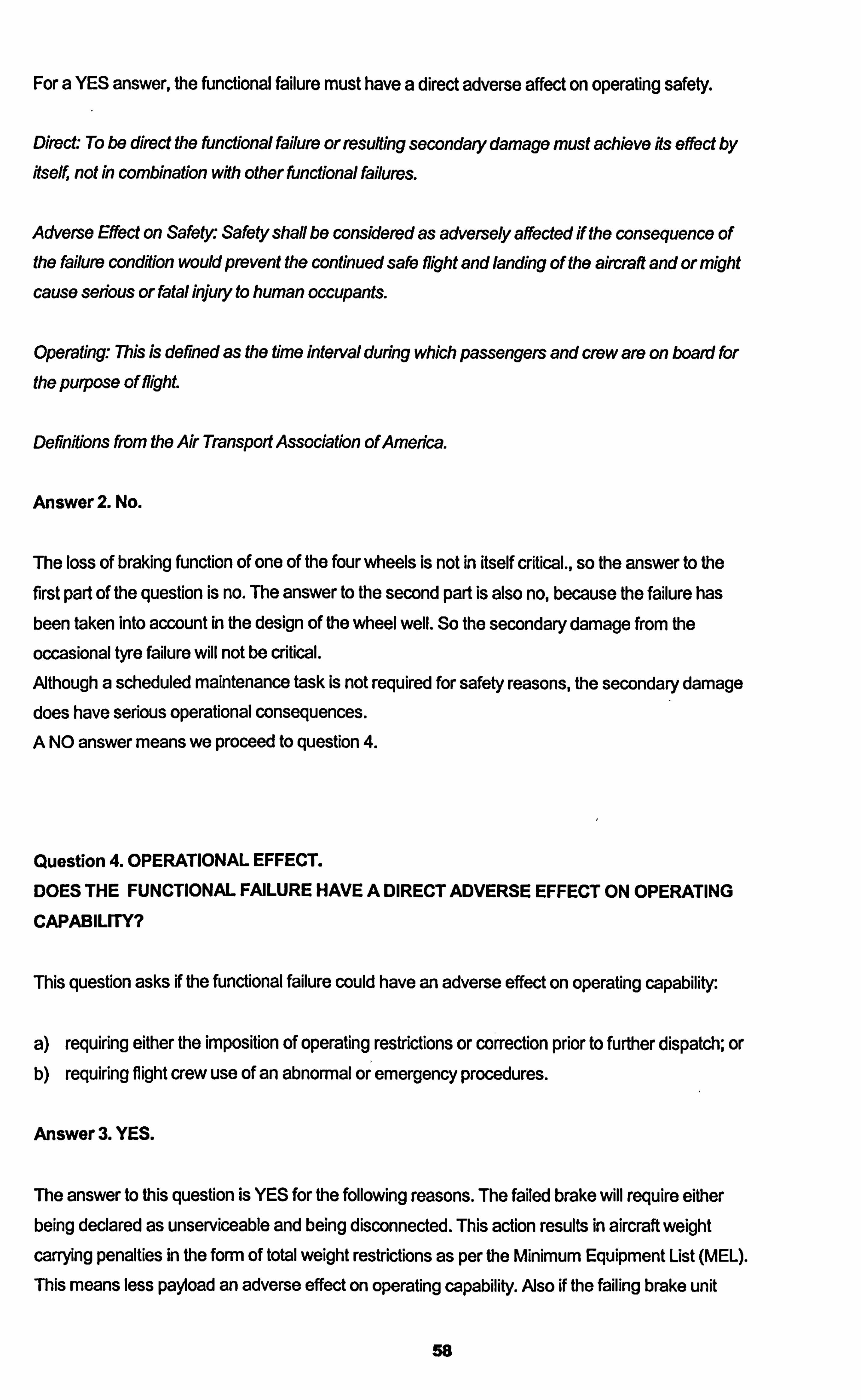
For a YES answer, the functional failure must have a direct adverse affect on operating safety.
Direct: To be direct the functional failure or resulting secondary damage must achieve fts effect by fiself, not in combination wfth other functional failures.
Adverse Effect on Safety: Safety shall be considered as adversely affected if the consequence of the failure condition would prevent the continued safe flight and landing of the aircraft and or might cause serious or fatal injury to human occupants.
Operating., This is defined as the time interval during which passengers and crew are on board for
the purpose of flight
Definflions from the Air Transport Association of America.
Answer 2. No.
The loss of braking function of one of the four wheels is not in itself critical., so the answer to the
first part of the question is no. The answer to the second part is also no, because the failure has
been taken into account in the design of the wheel well. So the secondary damage from the
occasional tyre failure will not be critical. Afthough a scheduled maintenance task is not required for safety reasons, the secondary damage
does have serious operational consequences. A NO answer means we proceed to question 4.
Question 4. OPERATIONAL EFFECT.
DOES THE FUNCTIONAL FAILURE HAVE A DIRECT ADVERSE EFFECT ON OPERATING
CAPABILrrY?
This question asks if the functional failure could have an adverse effect on operating capability:
a) requiring either the imposition of operating restrictions or correction prior to further dispatch; or
b) requiring flight crew use of an abnormal or emergency procedures.
Answer 3. YES.
The answer to this question is YES for the following reasons. The failed brake will require either being declared as unserviceable and being disconnected. This action results in aircraft weight carrying penalties in the form of total weight restrictions as per the Minimum Equipment List (MEL).
This means less payload an adverse effect on operating capability. AJso if the failing brake unit
58
results in a tyre burst, the result will be replacing the tyre. To do this take a spare tyre, equipment
and time. One of these variables may not be readily available and result in a delay or a flight
cancellation, again an adverse effect on operating capability.
We have now reached the end of Level 1 and find as a result of the last question, question 4, being
YES the failure effect analysed can be categorised as a Category 6 Evident Operational failure
effect.
Step 6: Significant System Scheduled Task Selection.
Decision Logic. Level 2.
Category 6 Operational Effects: A scheduled maintenance task is desirable if it reduces risk to an
acceptable level. The Level 2 task analysis must be now carried out. In this case we start by asking
about the affect of lubrication....
Question 6A: IS A LUBRICATION OR SERVICING TASK APPLICABLE & EFFECTIVE?
Answer: NO.
The brake unit has no facility or requirement for lubrication or servicing.
A NO answer means continuing to the next question
Question 613: IS AN INSPECTION OR FUNCTIONAL CHECK TO DETECT DEGRADATION OF
FUNCTION APPLICABLE & EFFECTIVE?
Answer: YES.
The brake unit has a wear indicator pin. The indicator pin will show when the brake pads have wom to a near or an actual unacceptable level that may result if further used, in seizing of the brake unit. So by inspecting the wear indicator pin at regular intervals a brake unit can be seen to be ready for
replacement due to brake pad wear. This meets the condition that for an on condition Inspection to
be applicable the subject must have a potential failure condition. Due to obtaining a YES answer there is no need to continue with the other questions
In this case a scheduled maintenance task, an inspection of the brake wear pin, has been the out
come of the Level 2 decision logic. The scheduled maintenance task can be said to be applicable
and effective on the following grounds (section 2.2.4 details the criteria for inspection ) ...
59
Applicable Criteria: Reduced resistance to failure must be detectable and a reasonably consistent interval between deterioration condition and functional failure. The case of the brake unit fits this
condition as the under normal operating conditions a brake will last for 521 landings on average
and the presence of the wear indicator pin will show when a brake unit nears the end of its life.
Effective Criteria - Safety: The task must reduce the risk of failure to assure safe operation. Again in
the case of the brake unit the wear indicator pin will show when the brake is approaching the end of its usable life. This will allow the aircraft to be dispatched with the knowledge that the brake will be
able to enable brake applications. The wear indicator pin will also show how worn the brake unit is.
On average the brake pin Will protrude out of the casing 1 mm for every 5 landings. Once the
yellow portion of the indicator shows the brake must be replaced, from this the dispatching engineer
can be confident that under normal conditions the brake unit will sustain the flight out and back at least.
Effectiveness Criteria - Operational: The task must reduce the risk of failure to an acceptable level.
Again as with the last paragraph, the wear pin will indicate approximately under normal conditions how long the brake unit can stay in service. This will allow an operational decision to be made. For
example if the aircraft has only 1 mm remaining on the wear pin, that means 5 landings and the
aircraft is scheduled for a7 sector flight, it would make operational sense to replace that brake now before departure from base to eliminate the possibility of a brake change away from base where there may be no facilities resulting in a delay.
Effectiveness Criteria - Economic: The task must be cost effective. Le. the cost of the task must be
less than the cost of the failure prevented. In this case to inspect the wear pin takes about 30
seconds per brake, to replace a seized brake will take about 2 man hours and the resulting repair due to over heating may cost thousands of pounds.
So after considering all the criteria for the inspection it can be said that a scheduled inspection of the wear indicator pin is applicable and effective in the case of resulting functional failure from the
failure mode of the brake unit wearing to the point of seizure.
Now we have verified the task, we need to next identify an appropriate interval to conduct the task,
(ref section 2.2.4).
Possible sources of Information available to assist in an appropriate task intervals are
Manufacturers tests and simulation's
Manufacturers recommendation's In service experience of the subject In service experience of a similar subject Best Engineering judgment
60
The selected interval also depends upon the scheduled maintenance task.
Inspection (On condition task, Potential Failure Finding): Intervals are governed by the P-F
interval, so there should be a clearly defined Potential failure condition. The task interval should be
less than the shortest likely interval between the point at which the potential failure becomes detectable and the point that which the item fails, but not so long that the potential failure interval is
nearing the end of the range and the resulting repair will not be economical or practical.
Taking all the above into consideration
" Manufacturers tests and simulation's
" Manufacturers recommendation's The manufacturers data shows that the MTBUR is 132 landings with the three standard deviations
79 landings being at the lower end and 185 at the higher end. This range of landings will capture 99% of failures.
" In service experience of the subject
" In service experience of a similar subject In service experience of Bendix part numbers on other aircraft, have an average life of around 150
landings some being removed as early as 60 landings. It can be seen that the pilots performance,
availability of thrust reversers and the runway conditions can play a big part In the life of the brake
unit.
* Best Engineering judgment
So taking all the available information into consideration, it can be summarised as follows...
The MTBUR being 132 with the lower three sigma 79 landings we could start the wear pin inspections at that time and repeat them every landing and expect to capture 99% of failing brake
units due to wear. The wear pin starts to show early before the brake unit wears to failure, so for
operational reasons the brake unit can be monitored at regular intervals easily thus the inspector
can anticipate the failure as the pin moves closer to the guides. The earliest brake removal to date
in service due to wear was at 60 landings.
The interval selection can be made at an initial inspection interval of 60 landings with confidence that all previously failed brakes due to wear would be captured, but in case of special conditions
perhaps dropping the interval to 50 landings will give a 16.6% safe region. But the inspection at 50
landings could show that the wear pin has sufficient protrusion not to call for the brake unit to be
replaced, but it may require changing before the next 50 landings and that would go un noticed if
the inspection was not carried out for another 50 landings. The options open here for the group
conducting the analysis are as follows ......
61
1. Adopt an initial inspection of the wear pin at 50 landings and repeat every subsequent 5
landings, and if the wear pin is flush it should be replaced. 2. Adopt the interval of 50 landings but recommend to modify the pin to show when the brake unit
would have less than 50 normal landings left and call for the brake unit change to carried out. 3. Adopt a lower interval of say every 15 landings and modify the wear pin with a coloured band
and call for the unit to be replaced when the coloured band is all that is showing. 4. As this is an easily accessible task allocate the task to the daily check and the task will be
conducted prior to every first flight of the day or more appropriately would be at the end of each flying day as this will give the technicians time to replace the brake unit if a potential failure
condition exists. (This approach brakes the rule of inspections should never be carried out because the access is easy, but is appropriate in this case! ).
These intervals and suggestions are appropriate for normal operation but in the case of abnormal
operation such as heavy and hard landings or landings with out thrust reverse the brake wear inspection should be called after every landing, as should many other relevant inspections.
After the detailed analysis my recommendation would be the following
Firstly the brake wear indicator pin should be modified with a coloured band to show 50 landings
remaining at normal wear rates. The inspection should then be at an interval of every 50 flights.
Since the prevention of the failure depends upon the indicator the rule should be that the brake unit
must be replaced once the wear pin is flush with the housing, but notice should be taken of the
yellow band position in relation to the housing and the inspector conducting the daily check should dispatch the aircraft with a condition, if the pin shows the yellow band level or lower to the housing,
that the unit should be re inspected every 5 flight, then the unit will be replaced once the wear pin is
flush. In fact a flush wear pin does not mean no landings are available, but as stated earlier 5
landings can still take place with that unit.
62
2.3.2 Analysis of Structures.
The analysis of the structure of the aircraft considers all the load carrying elements including not
only the basic airframe but also the fuselage, wings, tail assembly and a variety of other load
carrying assemblies and components:
" Engine nacelles and pylons.
" Flight control surfaces.
" Landing Gear legs and assemblies. Integral fuel tanks.
" The pressurized skin.
" Windows and doors.
" Bulkheads and decks.
An aircraft structure and its elements are subject to two classifications of loads and forces during
normal operation:
Ground Loads
Taxiing. Landing. Towing. Hoisting.
Air Loads
Flight Manoeuvres, Gusts.
The magnitude of the induced loads will be a function of the operating conditions such as:
" Runway condition.
" Weather and air quality.
" Pilot training.
" Operating procedures.
The two classifications of loads experienced by an aircraft can be further divided Into the following..
0 Surfaces forces: which act upon the surfaces of the structure e. g. aerodynamic and hydrostatic
pressure. Body forces: which act over the volume of the structure and are produced by gravitational and inertial effects.
Regulatory terminology for structural loading limits is as follows. Limit Load which is the maximum load the structure is expected to experience under normal operating conditions, the Proof Load
63
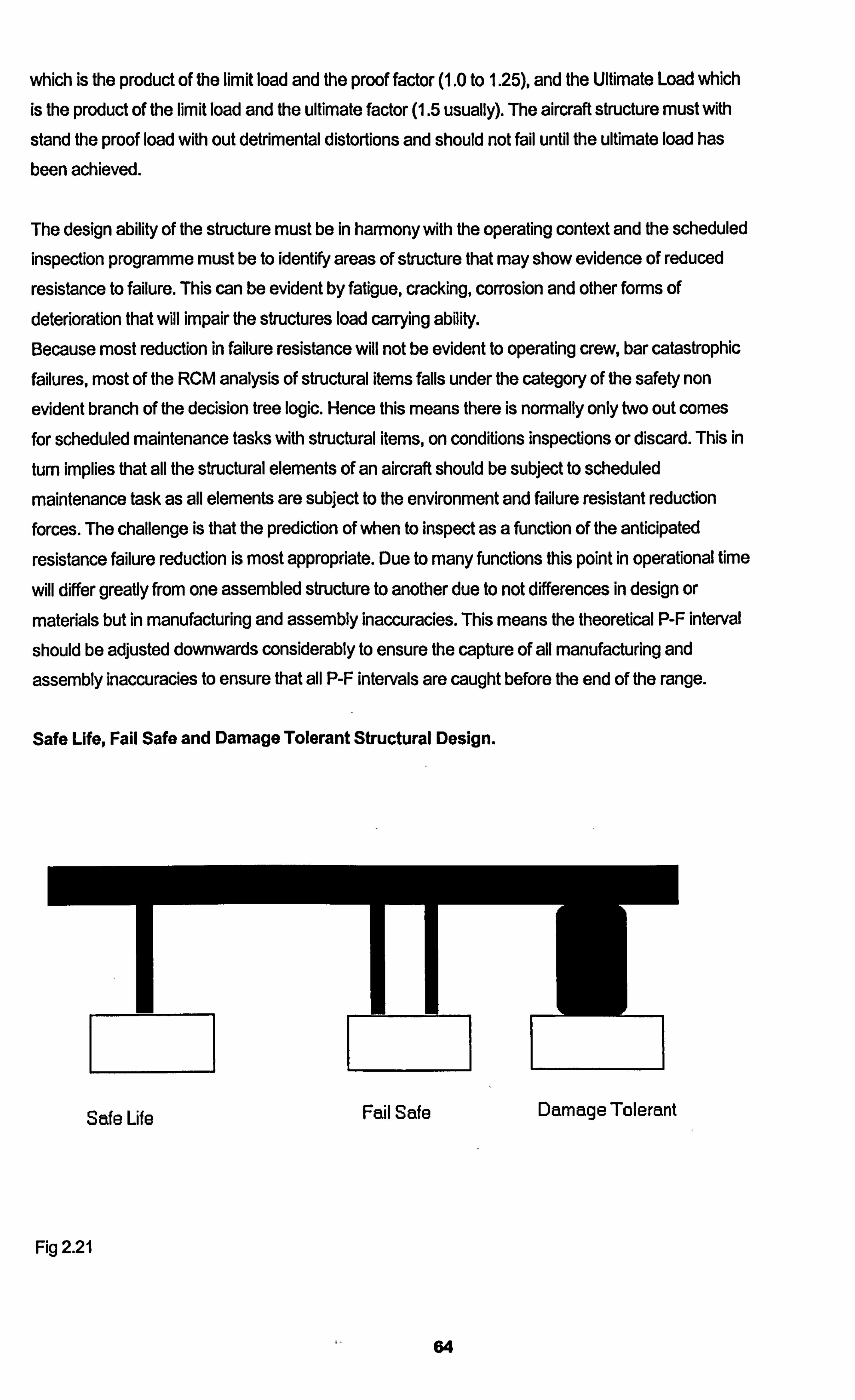
which is the product of the limit load and the proof factor (1.0 to 1.25), and the Ultimate Load which is the product of the limit load and the ultimate factor (1.5 usually). The aircraft structure must with
stand the proof load with out detrimental distortions and should not fail until the ultimate load has
been achieved.
The design ability of the structure must be in harmony with the operating context and the scheduled inspection programme must be to identify areas of structure that may show evidence of reduced
resistance to failure. This can be evident by fatigue, cracking, corrosion and other forms of deterioration that will impair the structures load carrying ability. Because most reduction in failure resistance will not be evident to operating crew, bar catastrophic failures, most of the RCM analysis of structural items falls under the category of the safety non
evident branch of the decision tree logic. Hence this means there is normally only two out comes for scheduled maintenance tasks with structural items, on conditions inspections or discard. This in
turn implies that all the structural elements of an aircraft should be subject to scheduled
maintenance task as all elements are subject to the environment and failure resistant reduction forces. The challenge is that the prediction of when to inspect as a function of the anticipated
resistance failure reduction is most appropriate. Due to many functions this point in operational time
will differ greatly from one assembled structure to another due to not differences in design or
materials but in manufacturing and assembly inaccuracies. This means the theoretical P-F interval
should be adjusted downwards considerably to ensure the capture of all manufacturing and
assembly inaccuracies to ensure that all P-F intervals are caught before the end of the range.
Safe Life, Fall Safe and Damage Tolerant Structural Design.
Safe Life Fail Safe Damage Tolerant
Fig 2.21
64
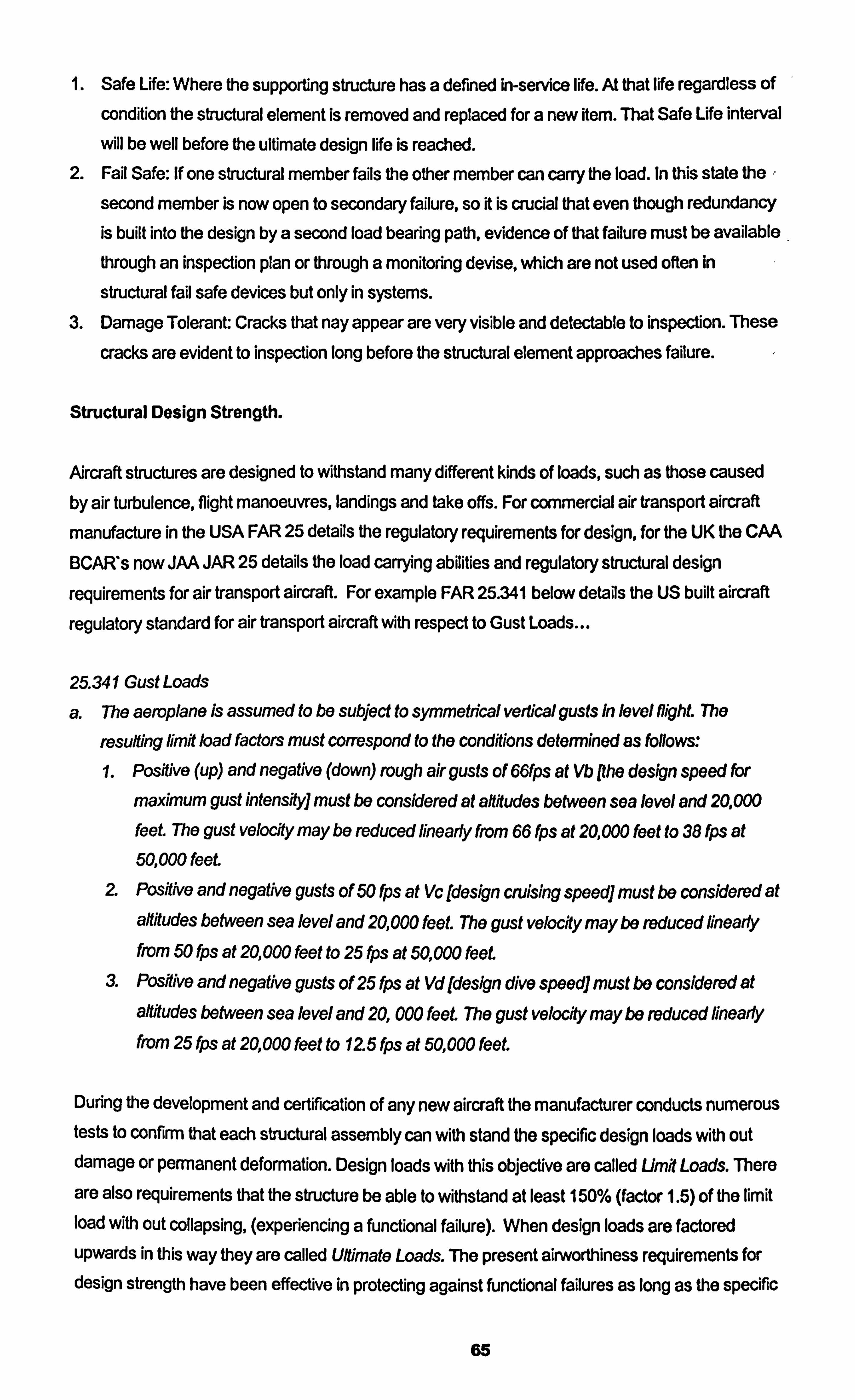
1. Safe Life: Where the supporting structure has a defined in-service life. At that life regardless Of
condition the structural element is removed and replaced for a new Rem. That Safe Life interval
will be well before the ultimate design life is reached. 2. Fail Safe: If one structural member fails the other member can carry the load. In this state the ,
second member is now open to secondary failure, so it is crucial that even though redundancy is built into the design by a second load bearing path, evidence of that failure must be available through an inspection plan or through a monitoring devise, which are not used often in
structural fail safe devices but only in systems. 3. Damage Tolerant: Cracks that nay appear are very visible and detectable to inspection. These
cracks are evident to inspection long before the structural element approaches failure.
Structural Design Strength.
Aircraft structures are designed to withstand many different kinds of loads, such as those caused by air turbulence, flight manoeuvres, landings and take offs. For commercial air transport aircraft
manufacture in the USA FAR 25 details the regulatory requirements for design, for the UK the CAA
BCAR's now JAA JAR 25 details the load carrying abilities and regulatory structural design
requirements for air transport aircraft. For example FAR 25.341 below details the US built aircraft
regulatory standard for air transport aircraft with respect to Gust Loads...
25.341 Gust Loads
a. The aeroplane is assumed to be subject to symmetrical vertical gusts In level ffighL The
resulting limit load factors must coffespond to the conditions determined as IbIlows:
1. Positive (up) and negative (down) rough air gusts of 661ps at Vb Phe design speed thr
maximum gust intensity] must be considered at aftitudes between sea level and 20,000 feeL The gust velocity may be reduced linearly from 66 fps at 20,000 feet to 38 fps at 50,000 feet
Z Posftive and negative gusts of 50 fps at Vc [design cruising speed] must be considered at afifludes between sea level and 20,000 feet The gust velocfty may be reduced linearly from 50 fps at 20,000 feet to 25 fps at 50,000 feet.
a Positive and negative gusts of 25 fps at Vd [design dive speed] must be considered at altitudes between sea level and 20,000 feet. The gust velocity may be reduced Anearty from 25 fps at 20,000 feet to 12.5 fps at 50,000 feet.
During the development and certification of any new aircraft the manufacturer conducts numerous tests to confirm that each structural assembly can with stand the specific design loads with out damage or permanent deformation. Design loads with this objective are called Um# Loads. There
are also requirements that the structure be able to withstand at least 150% (factor 1.5) of the limit load with out collapsing, (experiencing a functional failure). When design loads are factored
upwards in this way they are called UlUmate Loads. The present airworthiness requirements for design strength have been effective in protecting against functional failures as long as the specific
65
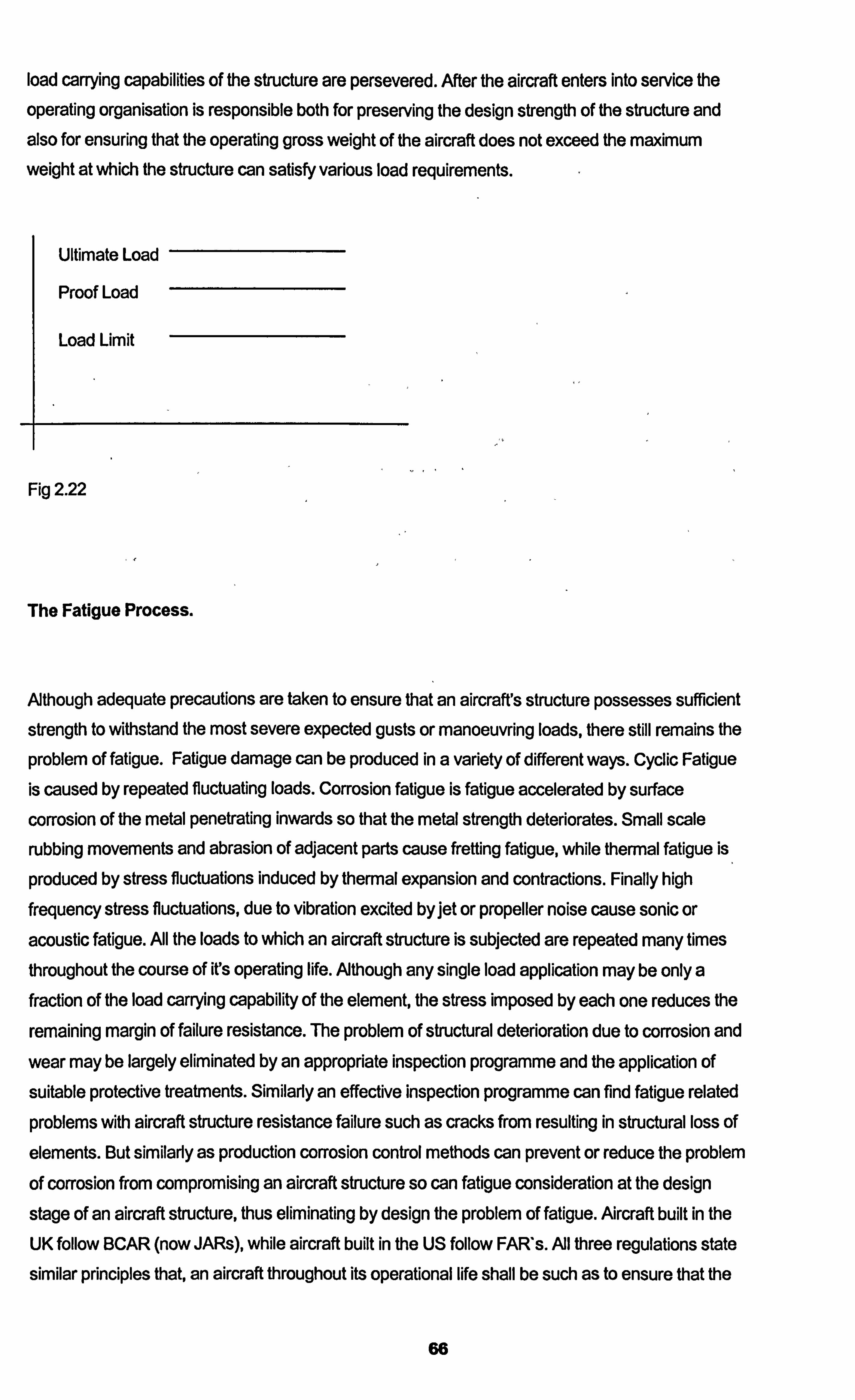
load carrying capabilities of the structure are persevered. After the aircraft enters into service the
operating organisation is responsible both for preserving the design strength of the structure and
also for ensuring that the operating gross weight of the aircraft does not exceed the maximum weight at which the structure can satisfy various load requirements.
Ultimate Load
Proof Load
Load Limit
Fig 2.22
The Fatigue Process.
Although adequate precautions are taken to ensure that an aircraft's structure possesses sufficient
strength to withstand the most severe expected gusts or manoeuvring loads, there still remains the
problem of fatigue. Fatigue damage can be produced in a variety of different ways. Cyclic Fatigue
is caused by repeated fluctuating loads. Corrosion fatigue is fatigue accelerated by surface
corrosion of the metal penetrating inwards so that the metal strength deteriorates. Small scale
rubbing movements and abrasion of adjacent parts cause fretting fatigue, while thermal fatigue is
produced by stress fluctuations induced by thermal expansion and contractions. Finally high
frequency stress fluctuations, due to vibration excited by jet or propeller noise cause sonic or
acoustic fatigue. All the loads to which an aircraft structure is subjected are repeated many times
throughout the course of ifs operating life. Although any single load application may be only a fraction of the load carrying capability of the element, the stress imposed by each one reduces the
remaining margin of failure resistance. The problem of structural deterioration due to corrosion and
wear may be largely eliminated by an appropriate inspection programme and the application of
suitable protective treatments. Similarly an effective inspection programme can find fatigue related
problems with aircraft structure resistance failure such as cracks from resulting in structural loss of
elements. But similarly as production corrosion control methods can prevent or reduce the problem
of corrosion from compromising an aircraft structure so can fatigue consideration at the design
stage of an aircraft structure, thus eliminating by design the problem of fatigue. Aircraft built in the
UK follow BCAR (now JARs), while aircraft built in the US follow FAR's. All three regulations state
similar principles that, an aircraft throughout its operational life shall be such as to ensure that the
66
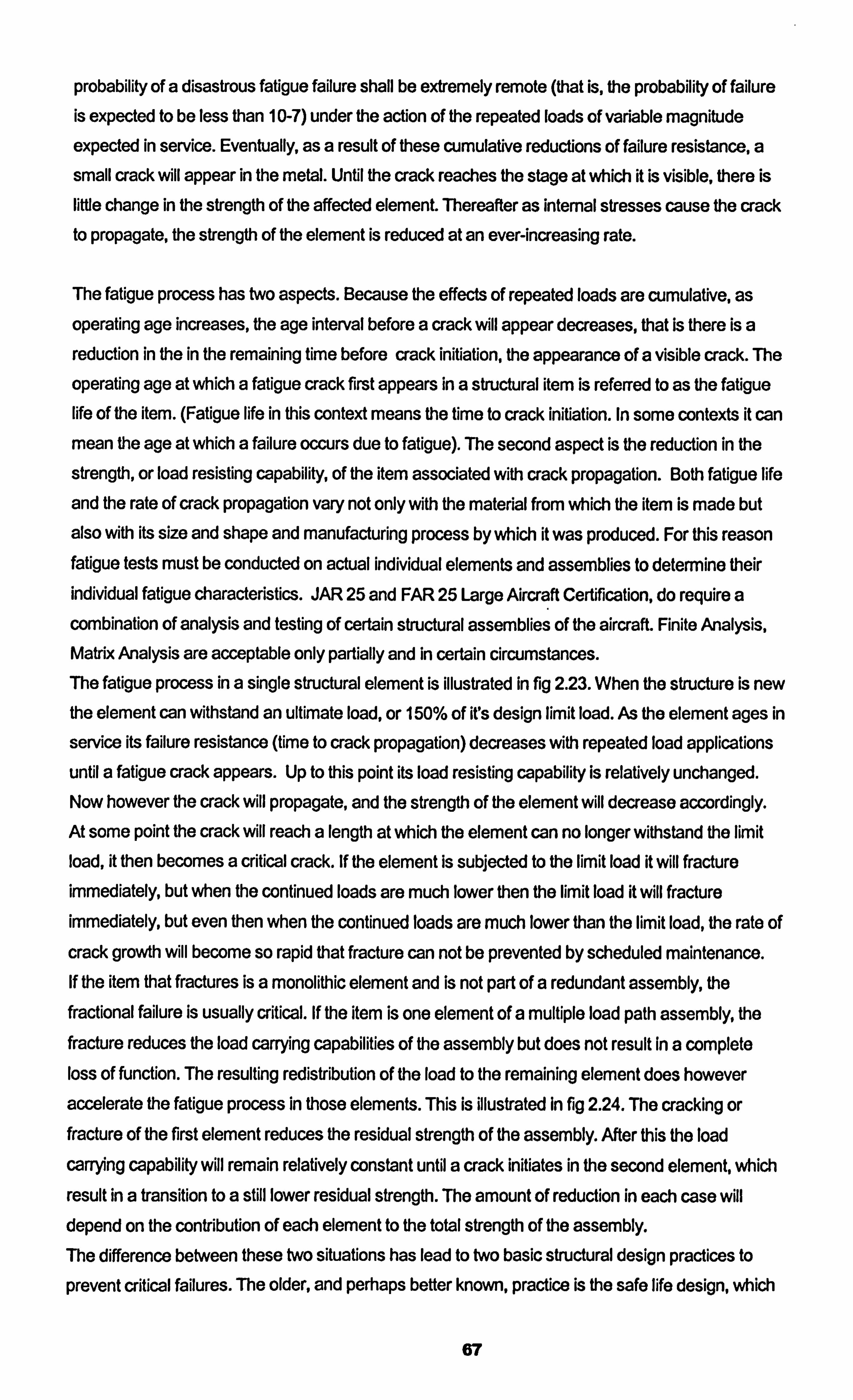
probability of a disastrous fatigue failure shall be extremely remote (that is, the probability of failure
is expected to be less than 10-7) under the action of the repeated loads of variable magnitude expected in service. Eventually, as a result of these cumulative reductions of failure resistance, a small crack will appear in the metal. Until the crack reaches the stage at which it is visible, there is
little change in the strength of the affected element. Thereafter as internal stresses cause the crack to propagate, the strength of the element is reduced at an ever-increasing rate.
The fatigue process has two aspects. Because the effects of repeated loads are cumulative, as
operating age increases, the age interval before a crack will appear decreases, that is there is a reduction in the in the remaining time before crack initiation, the appearance of a visible crack. The
operating age at which a fatigue crack first appears in a structural item is referred to as the fatigue life of the item. (Fatigue life in this context means the time to crack initiation. In some contexts it can mean the age at which a failure occurs due to fatigue). The second aspect is the reduction in the
strength, or load resisting capability, of the item associated with crack propagation. Both fatigue life
and the rate of crack propagation vary not only with the material from which the item is made but
also with its size and shape and manufacturing process by which it was produced. For this reason fatigue tests must be conducted on actual individual elements and assemblies to determine their individual fatigue characteristics. JAR 25 and FAR 25 Large Aircraft Certification, do require a combination of analysis and testing of certain structural assemblies of the aircraft. Finite Analysis, Matrix Analysis are acceptable only partially and in certain circumstances. The fatigue process in a single structural element is illustrated in fig 2.23. When the structure is new the element can withstand an ultimate load, or 150% of irs design limit load. As the element ages in
service its failure resistance (time to crack propagation) decreases with repeated load applications
until a fatigue crack appears. Up to this point its load resisting capability is relatively unchanged. Now however the crack will propagate, and the strength of the element will decrease accordingly. At some point the crack will reach a length at which the element can no longer withstand the limit
load, it then becomes a critical crack. If the element is subjected to the limit load it will fracture
immediately, but when the continued loads are much lower then the limit load it will fracture
immediately, but even then when the continued loads are much lower than the limit load, the rate of
crack growth will become so rapid that fracture can not be prevented by scheduled maintenance. If the item that fractures is a monolithic element and is not part of a redundant assembly, the fractional failure is usually critical. If the item is one element of a multiple load path assembly, the fracture reduces the load carrying capabilities of the assembly but does not result In a complete loss of function. The resulting redistribution of the load to the remaining element does however
accelerate the fatigue process in those elements. This is illustrated In fig 2.24. The cracking or fracture of the first element reduces the residual strength of the assembly. After this the load
carrying capability will remain relatively constant until a crack initiates in the second element, which
result in a transition to a still lower residual strength. The amount of reduction in each case will depend on the contribution of each element to the total strength of the assembly. The difference between these two situations has lead to two basic structural design practices to
prevent critical failures. The older, and perhaps better known, practice is the safe life design, which
67
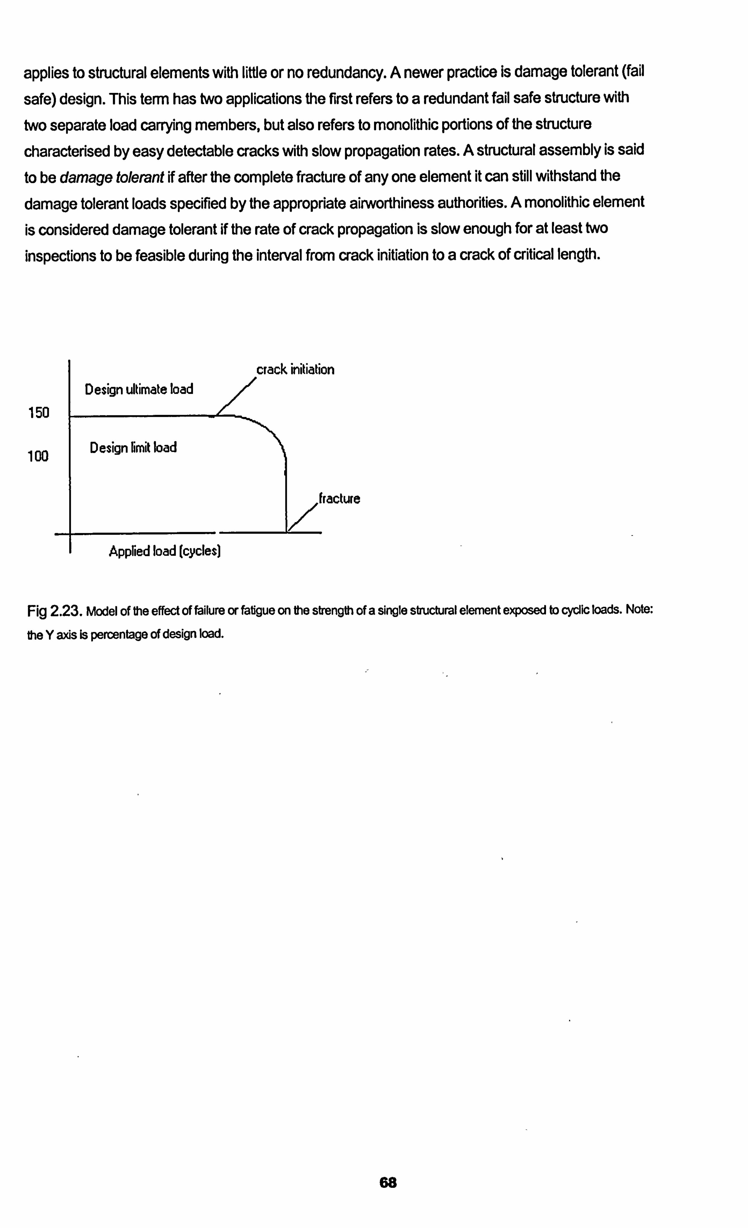
applies to structural elements with little or no redundancy. A newer practice is damage tolerant (fail
safe) design. This term has two applications the first refers to a redundant fail safe structure with two separate load carrying members, but also refers to monolithic portions of the structure characterised by easy detectable cracks with slow propagation rates. A structural assembly is said to be damage tolerant if after the complete fracture of any one element it can still withstand the
damage tolerant loads specified by the appropriate airworthiness authorities. A monolithic element is considered damage tolerant if the rate of crack propagation is slow enough for at least two
inspections to be feasible during the interval from crack initiation to a crack of critical length.
Design ultimate load
150
100 1 Design limit load
Appried load (cycles)
crack initiation
Fig 2.23. Model of the effect of failure or fatigue on the strength of a single structural element exposed to cyclic loads. Note:
the Y axis is percentage of design load.
68
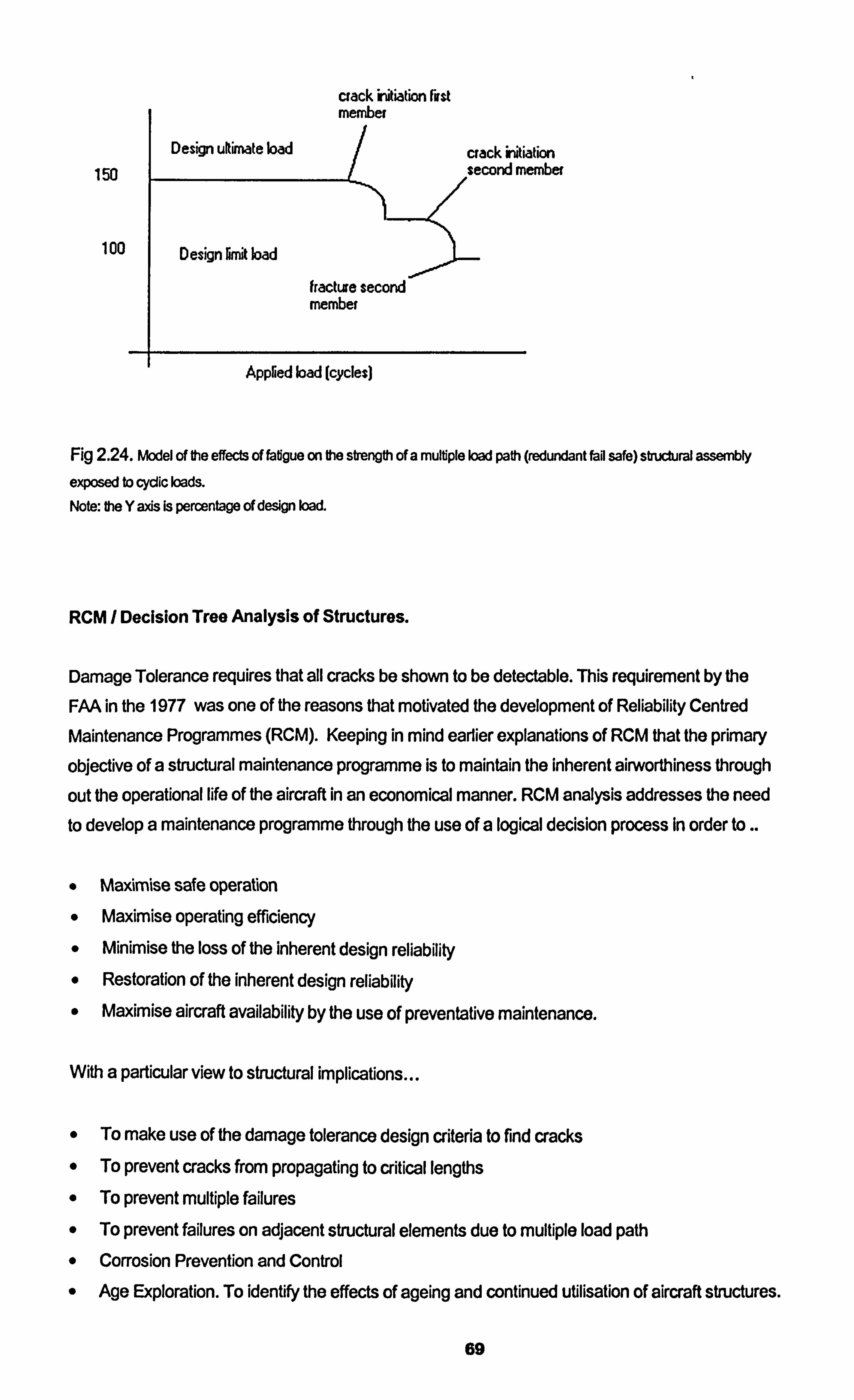
crack Wiation First member
50 Design ukimate load crack initiation
. second member
100 1 Design limit load
fractu e second member
Appried load (cycles)
Fig 2.24. Model of the effects of fatigue on the strength of a multiple load path (redundant fail safe) structural assembly
exposed to cyclic loads.
Note: the Y axis is percentage of design load.
RCM / Decision Tree Analysis of Structures.
Damage Tolerance requires that all cracks be shown to be detectable. This requirement by the
FAA in the 1977 was one of the reasons that motivated the development of Reliability Centred
Maintenance Programmes (RCM). Keeping in mind earlier explanations of RCM that the primary
objective of a structural maintenance programme is to maintain the inherent airworthiness through
out the operational life of the aircraft in an economical manner. RCM analysis addresses the need to develop a maintenance programme through the use of a logical decision process In order to..
MaAmise safe operation Maximise operating efficiency
0 Minimise the loss of the inherent design reliability Restoration of the inherent design reliability Maximise aircraft availability by the use of preventative maintenance.
With a particular view to structural implications
0 To make use of the damage tolerance design criteria to find cracks
" To prevent cracks from propagating to critical lengths
" To prevent multiple failures
" To prevent failures on adjacent structural elements due to multiple load path
" Corrosion Prevention and Control
" Age Exploration. To identify the effects of ageing and continued utilisation of aircraft structures.
69
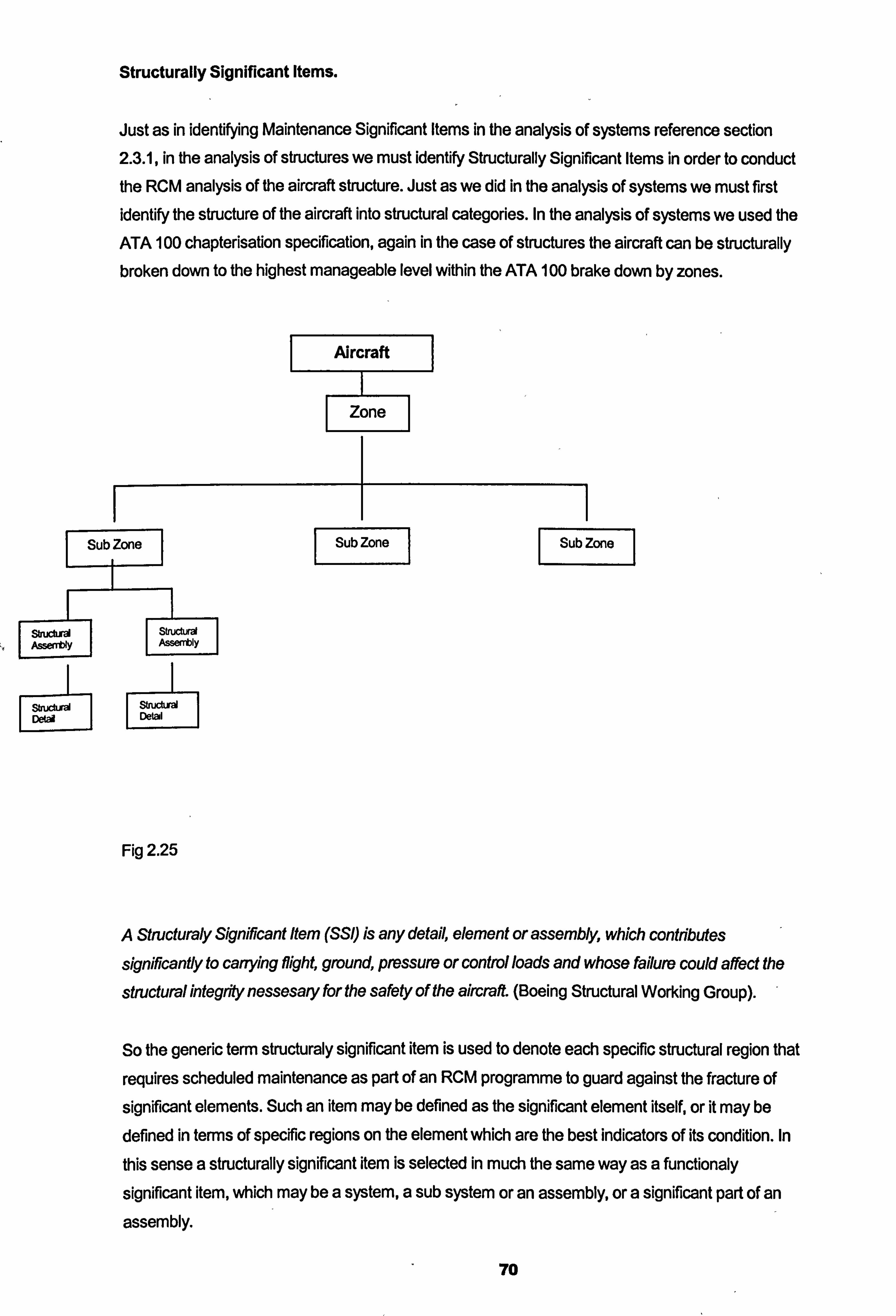
Structurally Significant Items.
Just as in identifying Maintenance Significant Items in the analysis of systems reference section 2.3.1, in the analysis of structures we must identify Structurally Significant Items in order to conduct the RCM analysis of the aircraft structure. Just as we did in the analysis of systems we must first
identify the structure of the aircraft into structural categories. In the analysis of systems we used the
ATA 100 chapterisation specification, again in the case of structures the aircraft can be structurally broken down to the highest manageable level within the ATA 100 brake down by zones.
Aircraft
Zone
1 Sub Zone 1
struchm Assently S
st. cvä Detal
I Sub Zon Sub Zone I
Fig 2.25
A Structuraly Significant Item (SSI) is any detail, element or assembly, which contlibutes
significantly to cary3dng flight, ground, pressure or control loads and whose failure could affect the
structural integ* nessesary for the safety of the aircraft. (Boeing Structural Working Group). "
So the generic term structuraly significant item is used to denote each specific structural region that
requires scheduled maintenance as part of an RCM programme to guard against the fracture of
significant elements. Such an item may be defined as the significant element itself, or it may be
defined in terms of specific regions on the element which are the best indicators of its condition. In
this sense a structurally significant item is selected in much the same way as a functionaly
significant item, which may be a system, a sub system or an assembly, or a significant part of an
assembly.
70
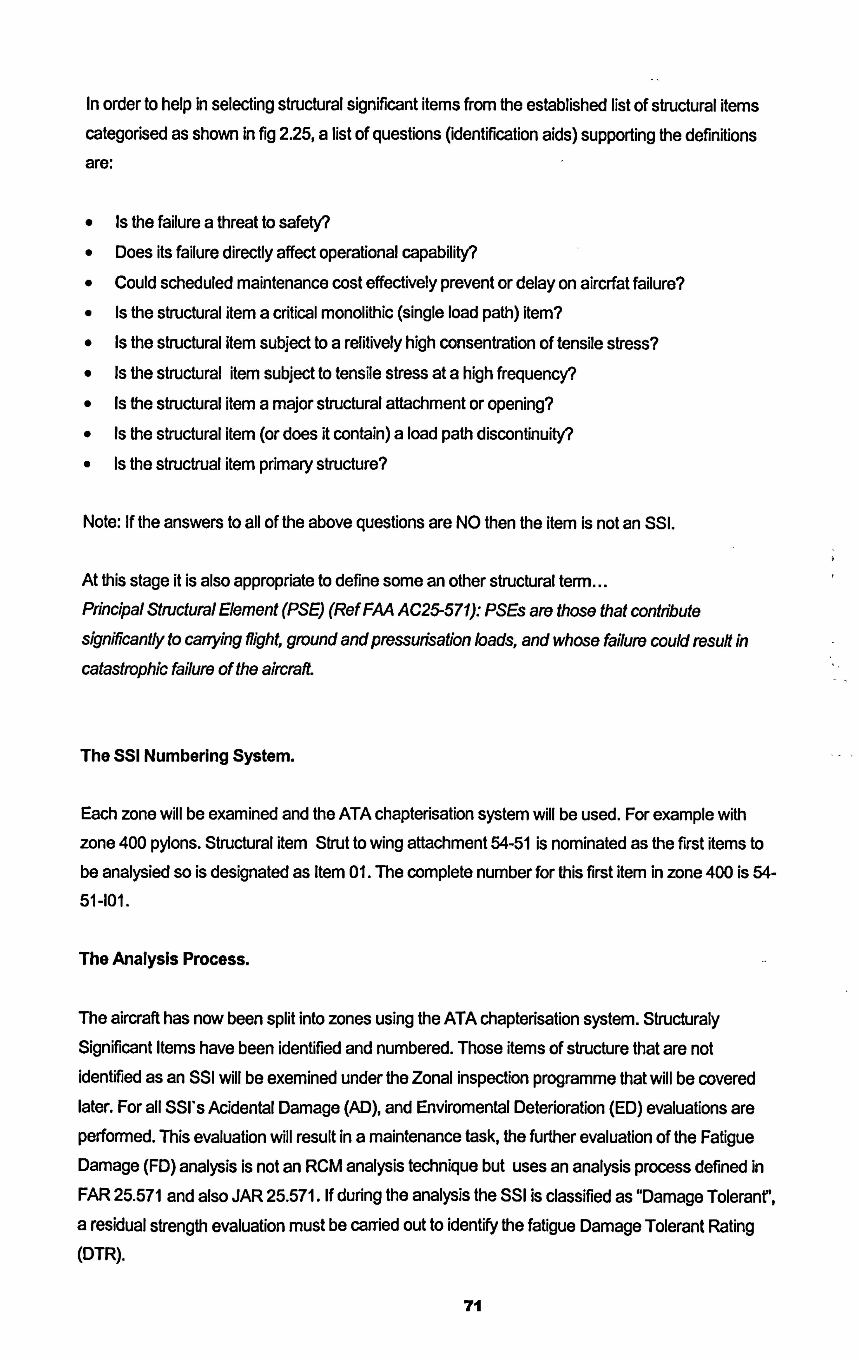
In order to help in selecting structural significant items from the established list of structural items
categorised as shown in fig 2.25, a list of questions (identification aids) supporting the definitions
are:
Is the failure a threat to safety? Does its failure directly affect operational capability? Could scheduled maintenance cost effectively prevent or delay on aircrfat failure?
Is the structural item a critical monolithic (single load path) item?
Is the structural item subject to a relitively high consentration of tensile stress? Is the structural item subject to tensile stress at a high frequency?
Is the structural item a major structural attachment or opening? Is the structural item (or does it contain) a load path discontinuity?
Is the structrual item primary structure?
Note: If the answers to all of the above questions are NO then the item is not an SSI.
At this stage it is also appropriate to define some an other structural term... Principal Structural Element (PSE) (Ref FAA A C25-571): PSEs are those that contribute significantly to canying, flight, ground and pressurisation loads, and whose failure could result in
catastrophic failure of the aircraft.
The SSI Numbering System.
Each zone will be examined and the ATA chapterisation system will be used. For example with zone 400 pylons. Structural item Strut to wing attachment 54-51 is nominated as the first items to be analysied so is designated as Item 01. The complete number for this first item in zone 400 is 54- 51-101.
The Analysis Process.
The aircraft has now been split into zones using the ATA chapterisation system. Structuraly Significant Items have been identified and numbered. Those items of structure that are not identified as an SSI will be exemined under the Zonal inspection programme that will be covered later. For all SSI's Acidental Damage (AD), and Enviromental Deterioration (ED) evaluations are performed. This evaluation will result in a maintenance task, the further evaluation of the Fatigue Damage (FD) analysis is not an RCM analysis technique but uses an analysis process defined in FAR 25.571 and also JAR 25.571. If during the analysis the SSI is classified as "Damage Tolerant',
a residual strength evaluation must be carried out to identify the fatigue Damage Tolerant Rating (DTR).
71
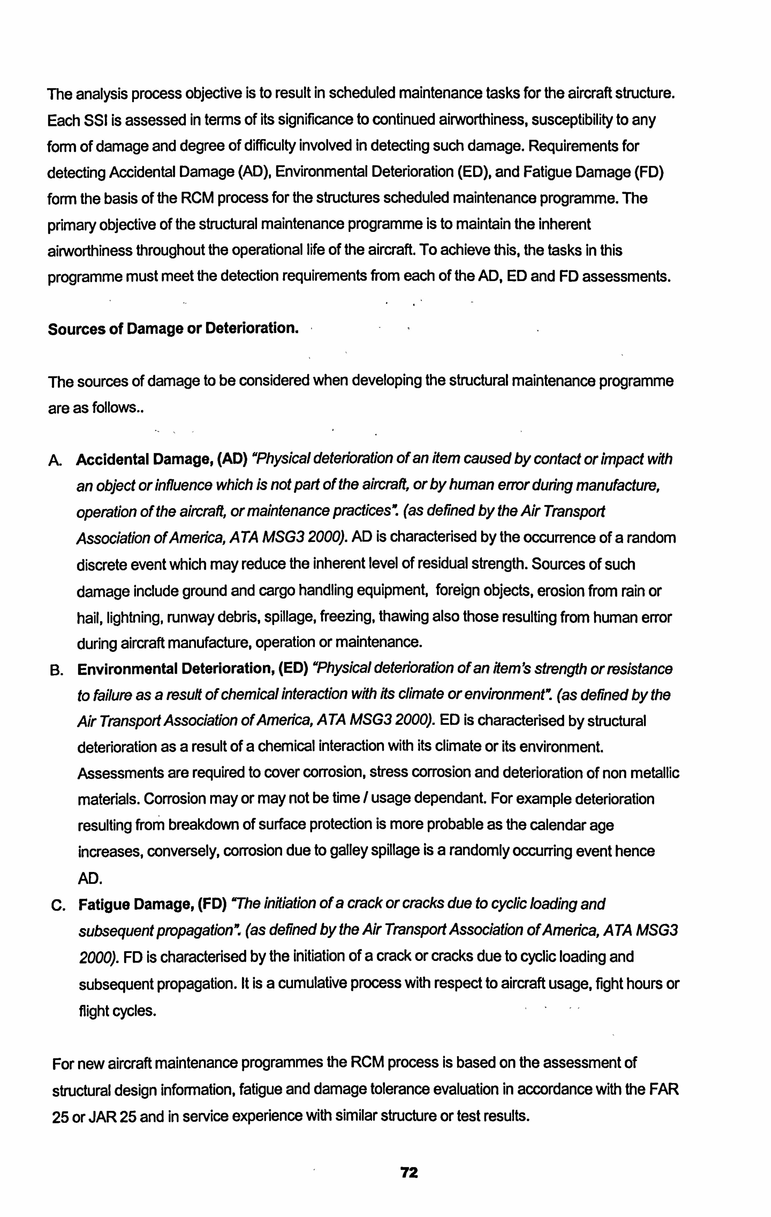
The analysis process objective is to result in scheduled maintenance tasks for the aircraft structure. Each SSI is assessed in terms of its significance to continued airworthiness, susceptibility to any form of damage and degree of difficulty involved in detecting such damage. Requirements for
detecting Accidental Damage (AD), Environmental Deterioration (ED), and Fatigue Damage (FD)
form the basis of the RCM process for the structures scheduled maintenance programme. The
primary objective of the structural maintenance programme is to maintain the inherent
airworthiness throughout the operational life of the aircraft. To achieve this, the tasks in this
programme must meet the detection requirements from each of the AD, ED and FD assessments.
Sources of Damage or Deterioration.
The sources of damage to be considered when developing the structural maintenance programme
are as follows..
A. Accidental Damage, (AD) "Physical deterioration of an item caused by contact or impact with
an object or influence which is not part of the aircraft, or by human error during manufacture,
operation of the aircraft, or maintenance practices ý (as defined by the Air Transport
Association ofAmerica, ATA MSG3 2000). AD is characterised by the occurrence of a random discrete event which may reduce the inherent level of residual strength. Sources of such damage include ground and cargo handling equipment, foreign objects, erosion from rain or hail, lightning, runway debris, spillage, freezing, thawing also those resulting from human error during aircraft manufacture, operation or maintenance.
B. Environmental Deterioration, (ED) "Physical deterioration of an item's strength or resistance to failure as a result of chemical interaction with its climate or environmentm (as defined by the
Air Transport Association of America, A TA MSG3 2000). ED is characterised by structural deterioration as a result of a chemical interaction with its climate or its environment. Assessments are required to cover corrosion, stress corrosion and deterioration of non metallic
materials. Corrosion may or may not be time / usage dependant. For example deterioration
resulting from breakdown of surface protection is more probable as the calendar age increases, conversely, corrosion due to galley spillage is a randomly occurring event hence
AD.
C. Fatigue Damage, (FD) 'The infliation of a crack or cracks due to cyclic loading and
subsequent propagation". (as derined by the Air Transport Association of America, ATA MSG3
2000). FD is characterised by the initiation of a crack or cracks due to cyclic loading and
subsequent propagation. It is a cumulative process with respect to aircraft usage, fight hours or flight cycles.
For new aircraft maintenance programmes the RCM process is based on the assessment of
structural design information, fatigue and damage tolerance evaluation in accordance with the FAR
25 or JAR 25 and in service experience with similar structure or test results.
72
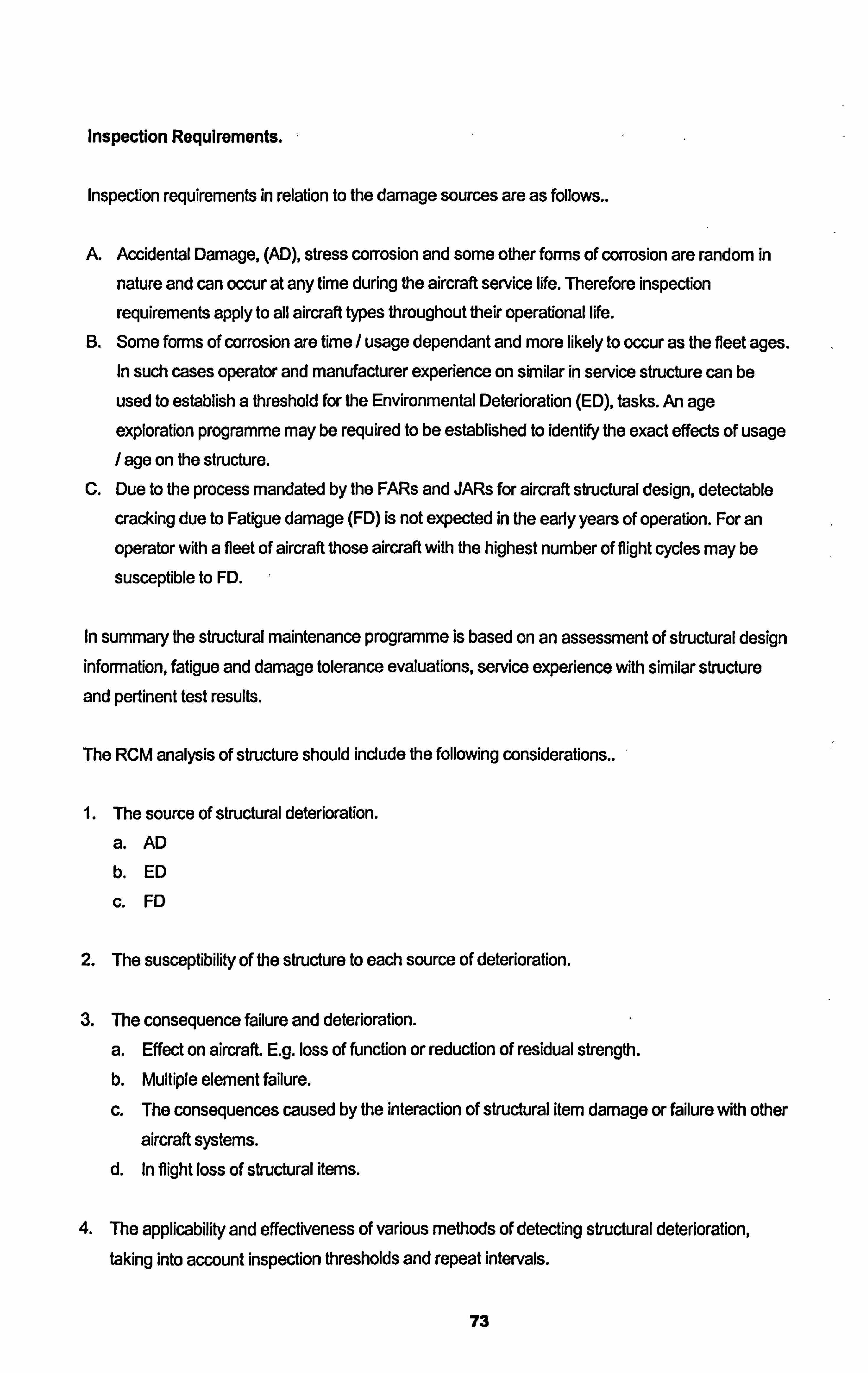
Inspection Requirements. :
Inspection requirements in relation to the damage sources are as follows..
A. Accidental Damage, (AD), stress corrosion and some other forms of corrosion are random in
nature and can occur at any time during the aircraft service life. Therefore inspection
requirements apply to all aircraft types throughout their operational life.
B. Some forms of corrosion are time / usage dependant and more likely to occur as the fleet ages. In such cases operator and manufacturer experience on similar in service structure can be
used to establish a threshold for the Environmental Deterioration (ED), tasks. An age
exploration programme may be required to be established to identify the exact effects of usage / age on the structure.
C. Due to the process mandated by the FARs and JARs for aircraft structural design, detectable
cracking due to Fatigue damage (FD) is not expected in the early years of operation. For an operator with a fleet of aircraft those aircraft with the highest number of flight cycles may be
susceptible to FID.
In summary the structural maintenance programme is based on an assessment of structural design information, fatigue and damage tolerance evaluations, service experience with similar structure
and pertinent test results.
The RCM analysis of structure should include the following considerations..
1. The source of structural deterioration.
AD
b. ED
c. FD
2. The susceptibility of the structure to each source of deterioration.
3. The consequence failure and deterioration.
a. Effect on aircraft. E. g. loss of function or reduction of residual strength. b. Multiple element failure.
c. The consequences caused by the interaction of structural item damage or failure with other
aircraft systems. d. In flight loss of structural items.
4. The applicability and effectiveness of various methods of detecting structural deterioration,
taking into account inspection thresholds and repeat intervals.
73
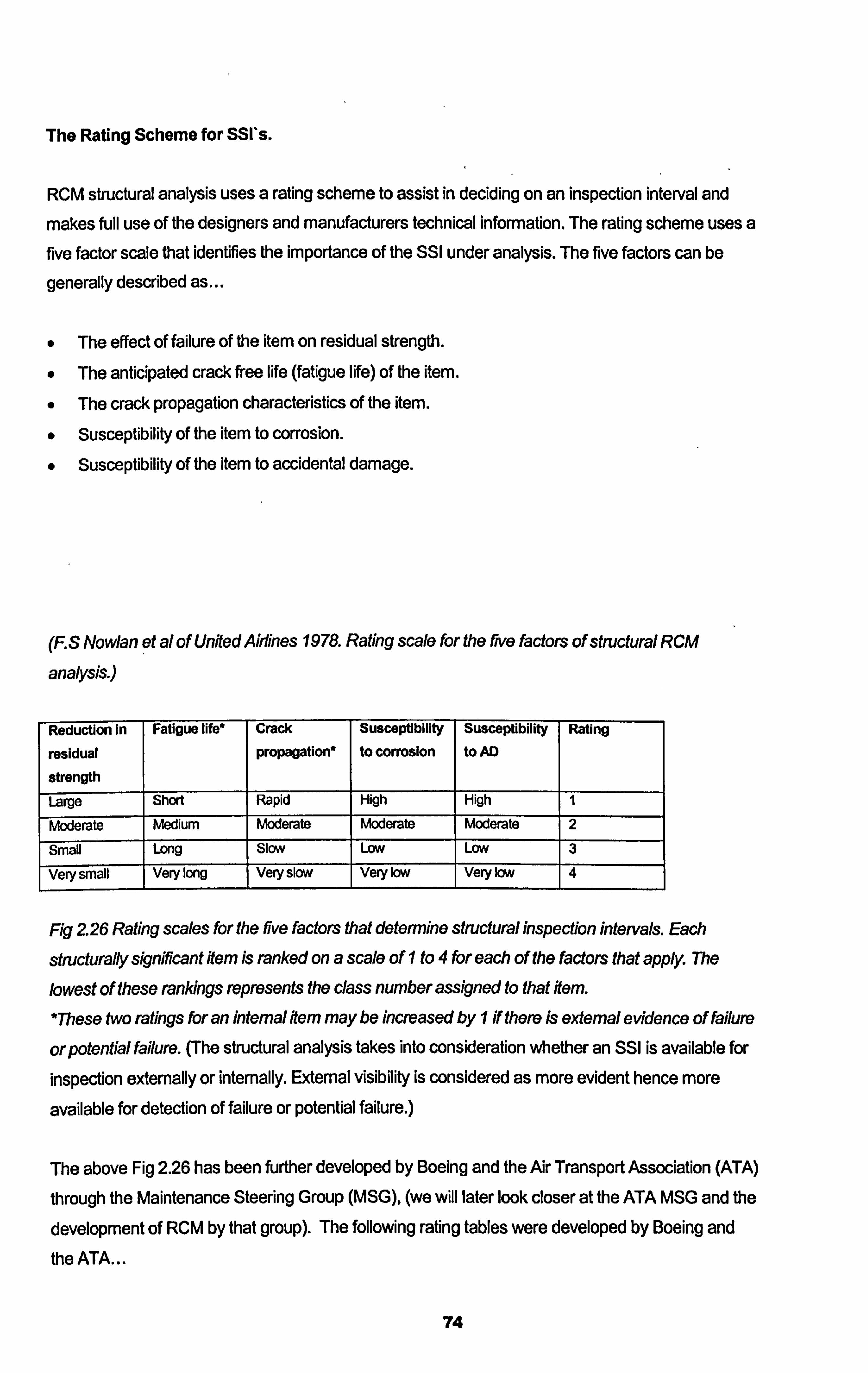
The Rating Scheme for SSI*s.
RCM structural analysis uses a rating scheme to assist in deciding on an inspection interval and
makes full use of the designers and manufacturers technical information. The rating scheme uses a five factor scale that identifies the importance of the SSI under analysis. The five factors can be
generally described as. --
0 The effect of failure of the item on residual strength. The anticipated crack free life (fatigue life) of the item.
The crack propagation characteristics of the item.
Susceptibility of the item to corrosion. Susceptibility of the item to accidental damage.
(F. S Nowlan et al of United Aldnes 1978. Rating scale for the rive factors of stnictural RCM
analysis. )
Reductionin
residual
strength
Fatigue IIW Crack
propagation*
Susceptibility
to corrosion
Susceptibility
to AD Rating
Large Short Rapid High High I
Moderate Medium Moderate Moderate Moderate 2
Small Long Slow LOW LOW 3
Very small Very long Very slow Very low Very low 4
Fig 2 26 Rating scales for the rive factors that determine structural inspection intervals. Each
structurally signifficant Hem is ranked on a scale of I to 4 for each of the factors that apply. The
lowest of these rankings represents the class number assigned to that ftem.
*These two ratings for an internal Item may be increased by I if there is external evidence of failure
orpotential failure. (The structural analysis takes into consideration whether an SSI is available for
inspection externally or internally. External visibility is considered as more evident hence more
available for detection of failure or potential failure. )
The above Fig 2.26 has been further developed by Boeing and the Air Transport Association (ATA)
through the Maintenance Steering Group (MSG), (we will later look closer at the ATA MSG and the
development of RCM by that group). The following rating tables were developed by Boeing and the ATA...
74
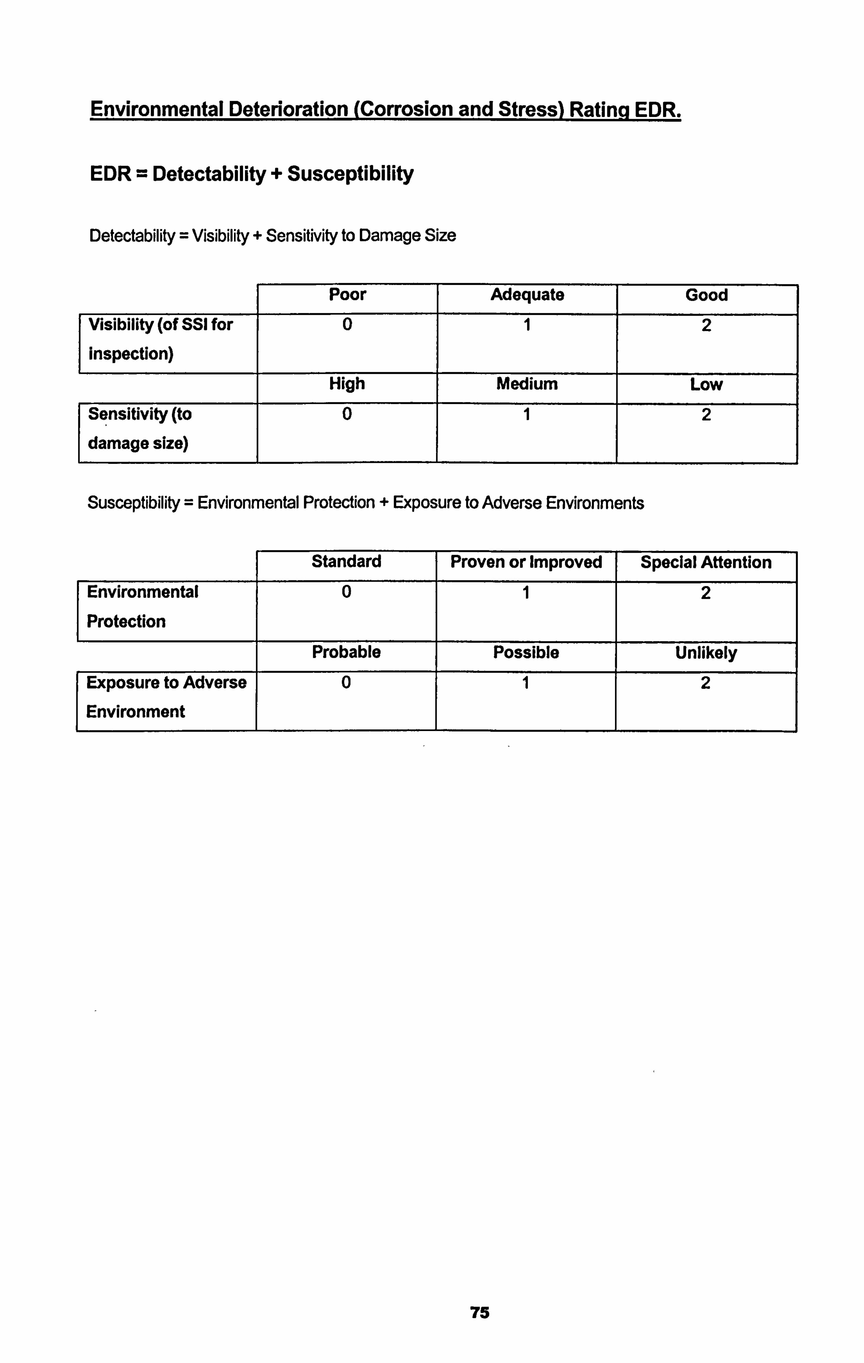
Environmental Deterioration (Corrosion and Stress) Ratinq EDR.
EDR = Detectability + Susceptibility
Detectability = Visibility + Sensitivity to Damage Size
Poor Adequate Good
Visibility (of SSI for
inspection)
0 1 2
High Medium Low
Sensitivity (to
damage size)
0 1 2
Susceptibility = Environmental Protection + Exposure to Adverse Environments
Standard Proven or Improved Special Attention
Environmental
Protection
0 2
Probable Possible Unlikely
Exposure to Adverse
Environment
0 1 2
75
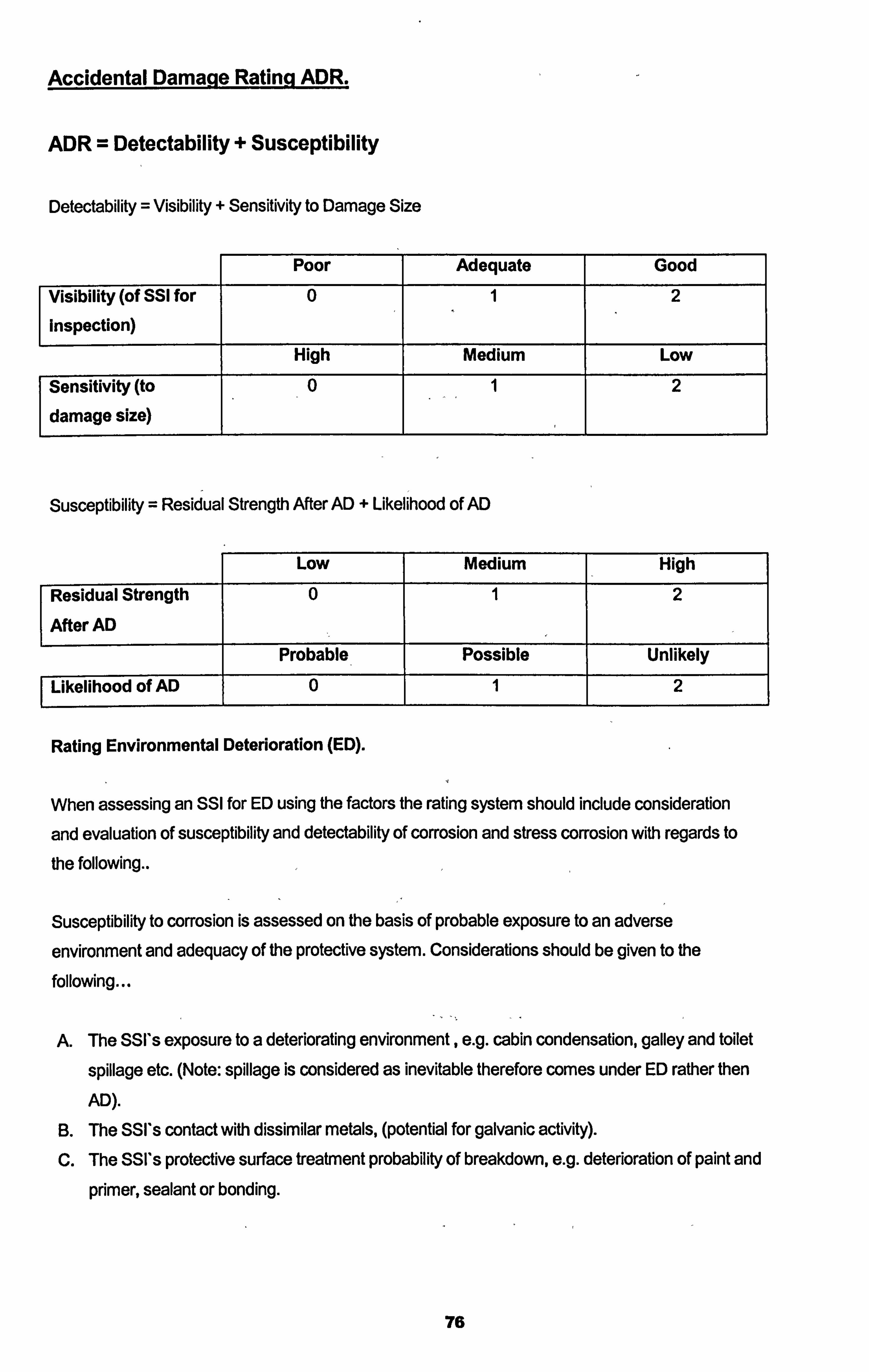
Accidental Damaqe Ratinq ADR.
ADR = Detectability + Susceptibility
Detectability = Visibility + Sensitivity to Damage Size
Poor Adequate Good
Visibility (of SSI for
Inspection)
0 1 2
High Medium Low
Sensitivity (to
damage size)
0 1 2
Susceptibility = Residual Strength After AD + Likelihood of AD
Low Medium High
Residual Strength
After AD
0 1 2
Probable Possible Unlikely
Likelihood of AD 0 1 2
Rating Environmental Deterioration (ED).
When assessing an SSI for ED using the factors the rating system should include consideration
and evaluation of susceptibility and detectability of corrosion and stress corrosion with regards to
the following..
Susceptibility to corrosion is assessed on the basis of probable exposure to an adverse
environment and adequacy of the protective system. Considerations should be given to the
following...
A. The SSI's exposure to a deteriorating environment, e. g. cabin condensation, galley and toilet
spillage etc. (Note: spillage is considered as inevitable therefore comes under ED rather then
AD).
B. The SSI's contact with dissimilar metals, (potential for galvanic activity). C. The SSI's protective surface treatment probability of breakdown, e. g. deterioration of paint and
primer, sealant or bonding.
76
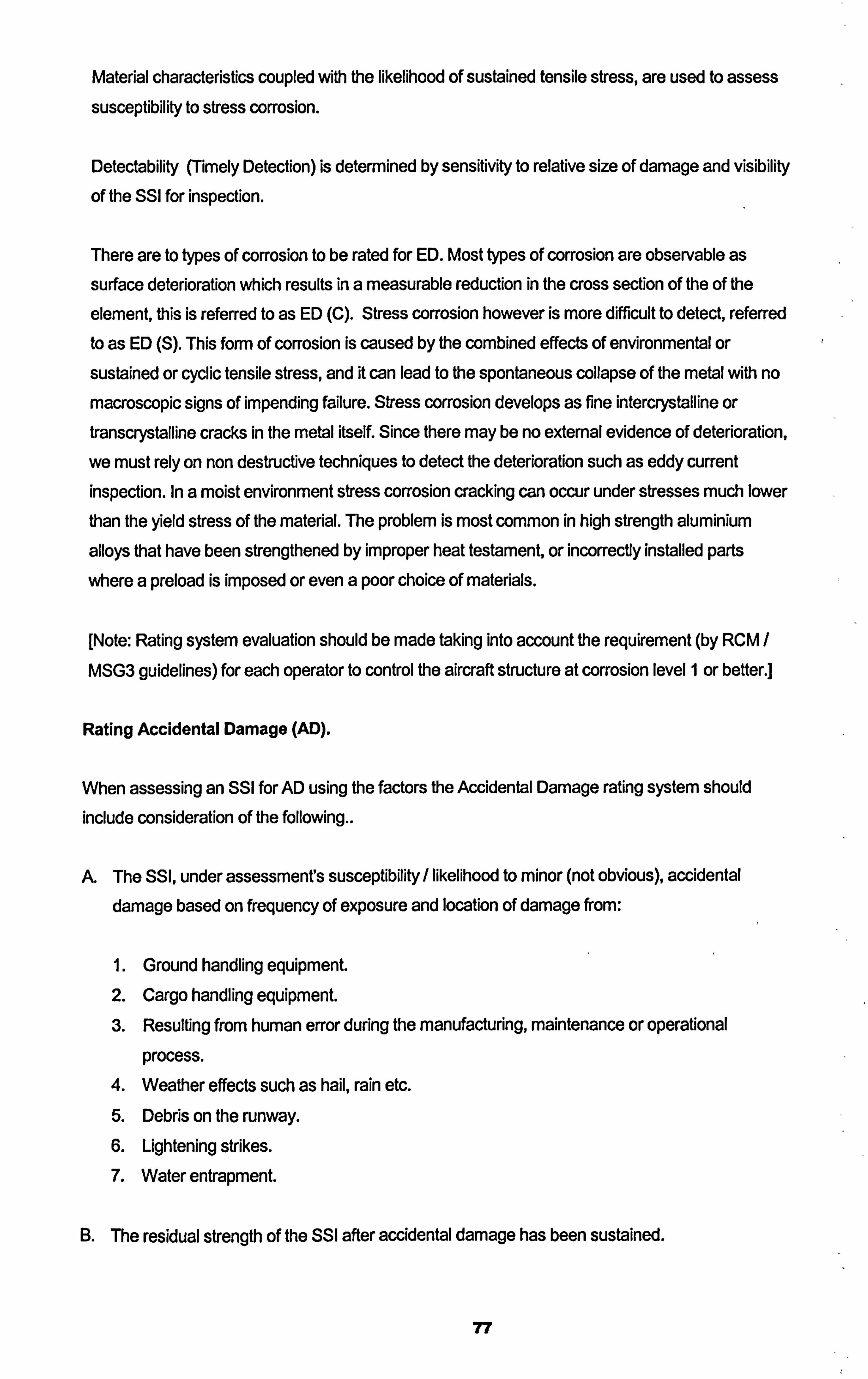
Material characteristics coupled with the likelihood of sustained tensile stress, are used to assess
susceptibility to stress corrosion.
Detectability (Timely Detection) is determined by sensitivity to relative size of damage and visibility
of the SSI for inspection.
There are to types of corrosion to be rated for ED. Most types of corrosion are observable as
surface deterioration which results in a measurable reduction in the cross section of the of the
element, this is referred to as ED (C). Stress corrosion however is more difficult to detect, referred to as ED (S). This form of corrosion is caused by the combined effects of environmental or
sustained or cyclic tensile stress, and it can lead to the spontaneous collapse of the metal with no
macroscopic signs of impending failure. Stress corrosion develops as fine intercrystalline or transcrystalline cracks in the metal itself. Since there may be no external evidence of deterioration,
we must rely on non destructive techniques to detect the deterioration such as eddy current inspection. In a moist environment stress corrosion cracking can occur under stresses much lower
than the yield stress of the material. The problem is most common in high strength aluminiurn
alloys that have been strengthened by improper heat testament, or incorrecty installed parts
where a preload is imposed or even a poor choice of materials.
[Note: Rating system evaluation should be made taking into account the requirement (by RCM /
MSG3 guidelines) for each operator to control the aircraft structure at corrosion level 1 or better. ]
Rating Accidental Damage (AD).
When assessing an SSI for AD using the factors the Accidental Damage rating system should include consideration of the following..
A. The SSI, under assessmenfs susceptibility/ likelihood to minor (not obvious), accidental damage based on frequency of exposure and location of damage from:
1. Ground handling equipment. 2. Cargo handling equipment. 3. Resulting from human error during the manufacturing, maintenance or operational
process. 4. Weather effects such as hail, rain etc. 5. Debris on the runway. 6. Lightening strikes. 7. Water entrapment.
B. The residual strength of the SSI after accidental damage has been sustained.
77
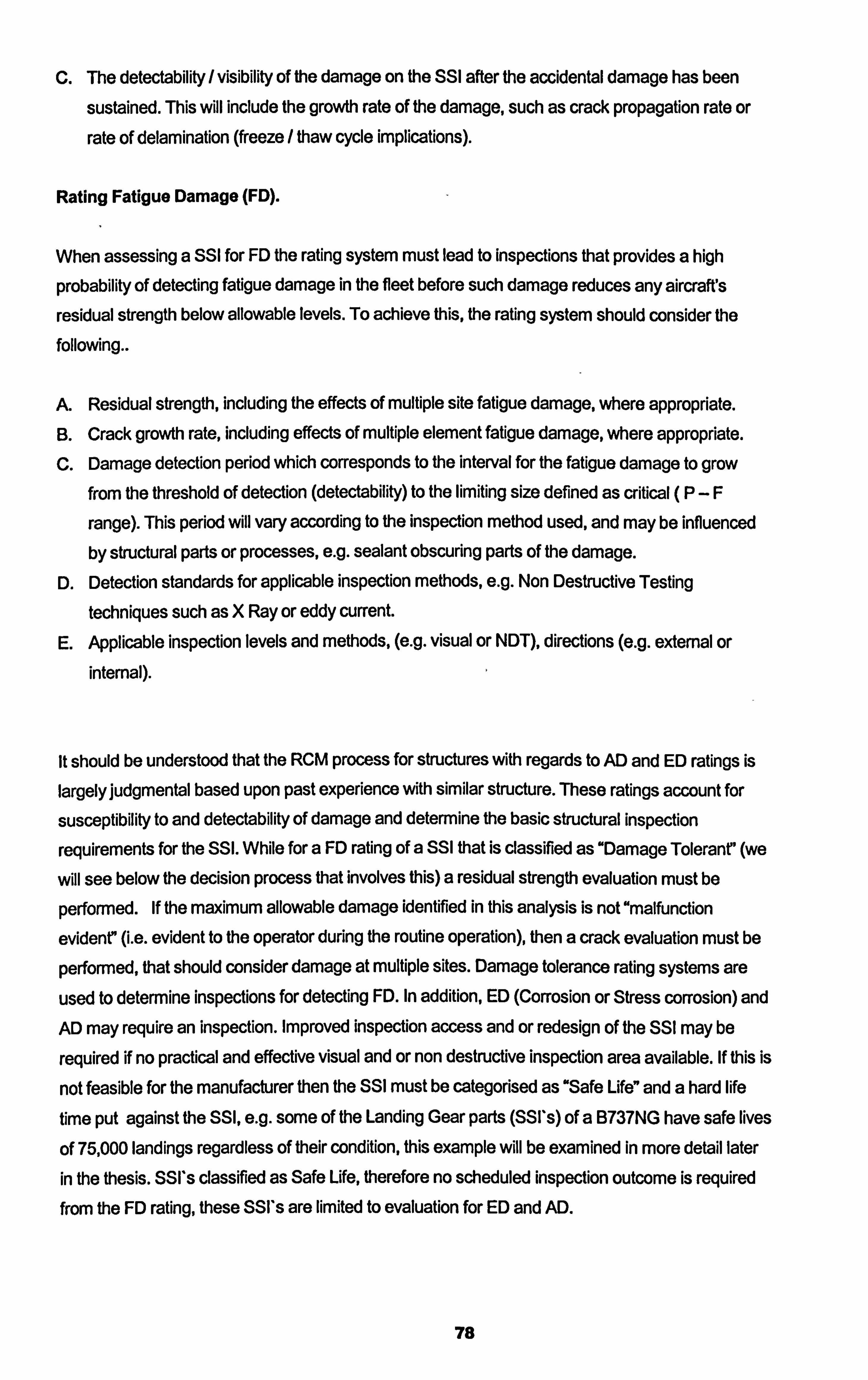
C. The detectability /visibility of the damage on the SSI after the accidental damage has been
sustained. This will include the growth rate of the damage, such as crack propagation rate or
rate of delamination (freeze / thaw cycle implications).
Rating Fatigue Damage (FD).
When assessing a SSI for FD the rating system must lead to inspections that provides a high
probability of detecting fatigue damage in the fleet before such damage reduces any aircraft's
residual strength below allowable levels. To achieve this, the rating system should consider the
folloWing..
A. Residual strength, including the effects of multiple site fatigue damage, where appropriate. B. Crack growth rate, including effects of multiple element fatigue damage, where appropriate. C. Damage detection period which corresponds to the interval for the fatigue damage to grow
from the threshold of detection (detectability) to the limiting size defined as critical (P-F
range). This period will vary according to the inspection method used, and may be influenced
by structural parts or processes, e. g. sealant obscuring parts of the damage.
D. Detection standards for applicable inspection methods, e. g. Non Destructive Testing
techniques such as X Ray or eddy current. E. Applicable inspection levels and methods, (e. g. visual or NDT), directions (e. g. external or
intemal).
It should be understood that the RCM process for structures with regards to AD and ED ratings is
largely judgmental based upon past experience with similar structure. These ratings account for
susceptibility to and delectability of damage and determine the basic structural inspection
requirements for the SSI. While for a FD rating of a SSI that is classified as "Damage Tolerant' (we
will see below the decision process that involves this) a residual strength evaluation must be
performed. If the maximum allowable damage identified in this analysis is not "malfunction
evident7 (i. e. evident to the operator during the routine operation), then a crack evaluation must be
performed, that should consider damage at multiple sites. Damage tolerance rating systems are
used to determine inspections for detecting FD. In addition, ED (Corrosion or Stress corrosion) and AD may require an inspection. Improved inspection access and or redesign of the SSI may be
required if no practical and effective visual and or non destructive inspection area available. If this is
not feasible for the manufacturer then the SSI must be categorised as "Safe Life" and a hard life
time put against the SSI, e. g. some of the Landing Gear parts (SSI*s) of a B737NG have safe lives
of 75,000 landings regardless of their condition, this example will be examined in more detail later
in the thesis. SSI's classified as Safe Life, therefore no scheduled inspection outcome is required from the FD rating, these SSI's are limited to evaluation for ED and AD.
78
For composite material the damage tolerance analytical approach closely parallels that for metallic SSI's requiring an ED rating and an AD rating. However because composite structure are designed to stop damage growth a damage tolerance calculation is not required. With the understanding that each operator the has the ability (in fact later we will look at the real requirement for this activity to be carried out) to adjust the Structural Maintenance Programme
once produced, in the areas of AD and ED tasks provided there is sufficient evidence that the tasks is redundant or superseded by company procedure. Later in the we will look at the in operational development of an operators maintenance programme where many RCM tasks are up for scrutiny as to their in operational applicability and effectively once operation experience and maintenance engineering statistics through reliability studies have been gathered. Just as with all RCM produced tasks, validation of the tasks in the particular operators environment and procedural context must take place where task interval adjustment, task deletion, or even new task addition. Until no in
operation data is available the RCM analysis produced maintenance schedule is the only relevant
schedule to be followed.
The rating scheme attempts to rate each SSI in terms of its susceptibility to damage and detectability once damaged. The structural maintenance tasks and intervals are developed to
enable timely detection of Accidental Damage (AD), Environmental Deterioration (ED C and S),
and Fatigue Damage (FD). The rating allocated to an SSI should be with consideration to other
ratings allocated to SSI*s in the similar inspection area, leading to greater emphasis to the most
critical SSI*s. Once the SSI has been rated for EDR(C), EDR(S), ADR and FDR, the lowest rating dictates the final rating for that SSI, thus dictates the frequency of the interval.
79
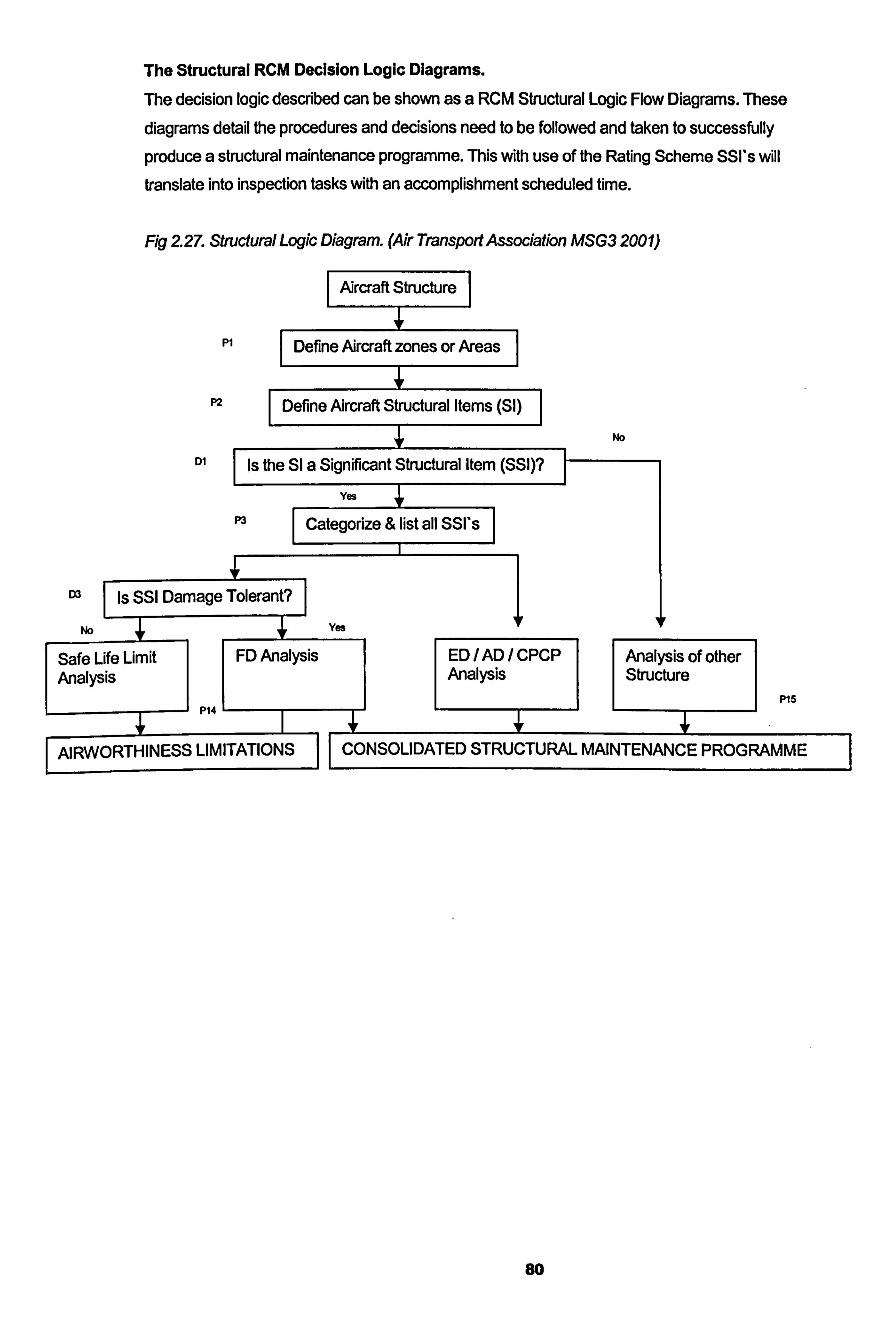
The Structural RCM Decision Logic Diagrams.
The decision logic described can be shown as a RCM Structural Logic Flow Diagrams. These
diagrams detail the procedures and decisions need to be followed and taken to successfully
produce a structural maintenance programme. This with use of the Rating Scheme SSI's will translate into inspection tasks with an accomplishment scheduled time.
Fig 2 27. Structural Logic Diagram. (Air Transport Association MSG3 200 1)
Aircraft Structure
PI I Define Aircraft zones or Areas
P2 I Define Aircraft Structural Items (SI)
No
DI Is the Sl a Significant Structural Item (SSI)?
Yes
P3 Categorize& list all SSI'sj
03 1 Is SSI Damage Tolerant?
No Yes
Safe Life Limit FD Analysis Analysis
I
P14
I AIRWORTHINESS LIMITATIONS I
ED/AD/CPCP Analysis of other Analysis Structure
P15
I CONSOLIDATED STRUCTURAL MAINTENANCE PROGRAMME I
80
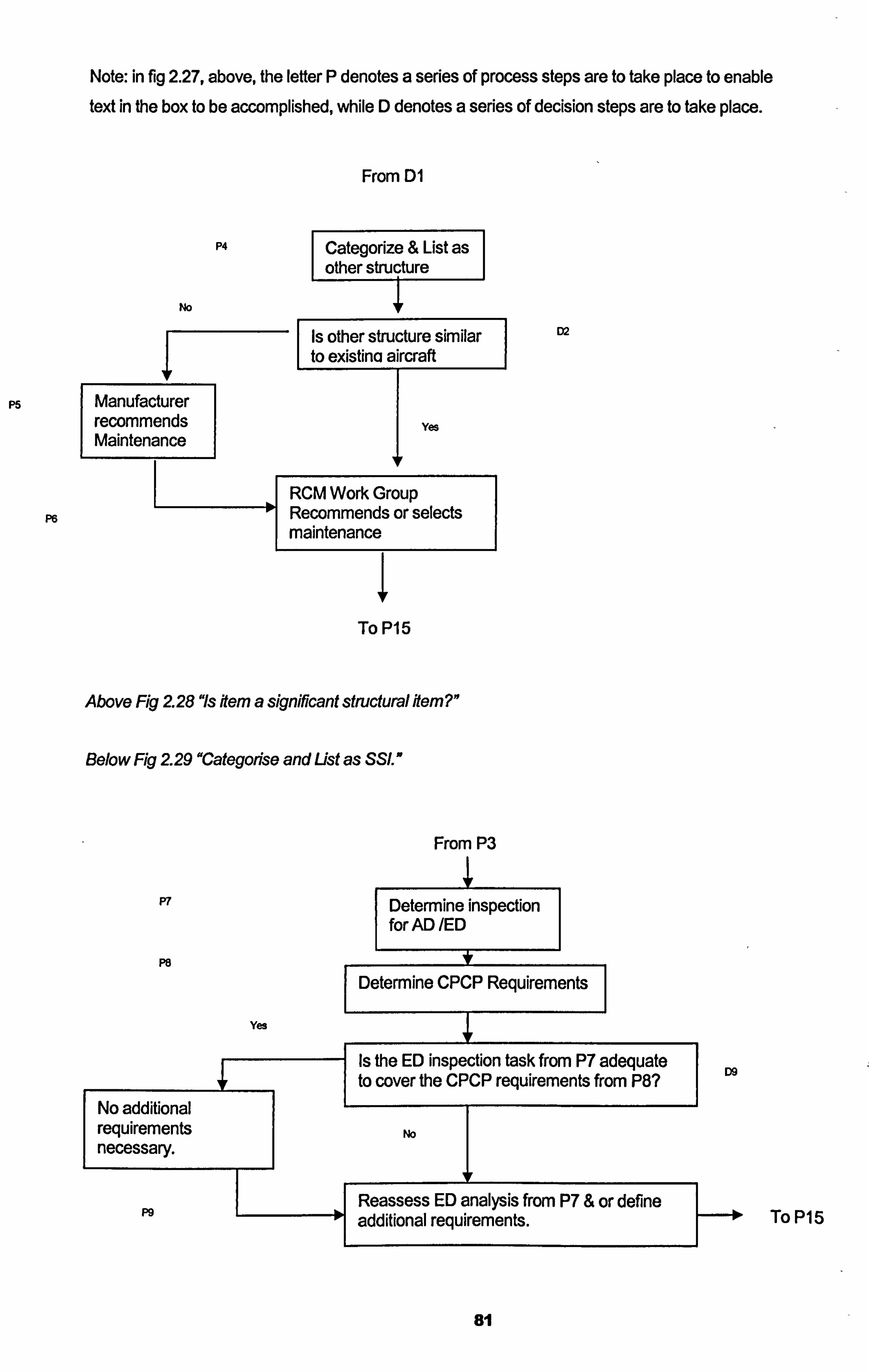
Note: in fig 2.27, above, the letter P denotes a series of process steps are to take place to enable text in the box to be accomplished, while D denotes a series of decision steps are to take place.
P4
No
From DI
Categorize & List as other structure
Is other structure similar to existino aircraft
P5 Manufacturer recommends yes Maintenance
II
RCM Work Group Recommends or selects maintenance
To P15
Above Fig 2 28 "Is item a significant structural item? "
Below Fig 229 "Categotise and List as SSI. "
D2
From P3 I
P7 Determine insp for AD /ED
PS [-Determine CPCP Requirements
Yes
Is e ED inspection task from P7 adequate D9
No additional
to cover the CPCP requirements from P8?
requirements No necessary.
IF
Reassess ED analysis from P7 & or define P9
-additional
requirements. ToP15
81
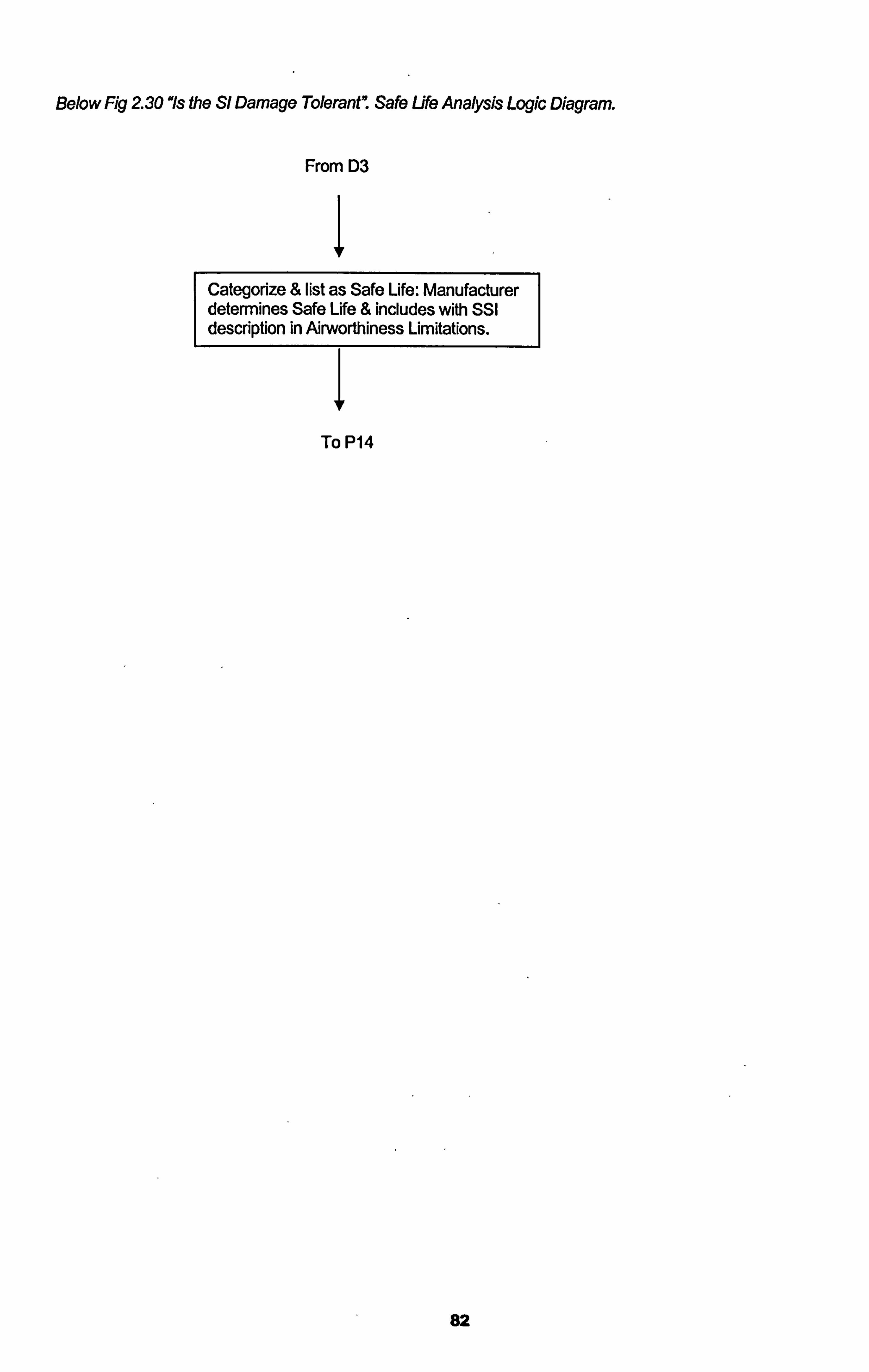
Below Fig 230 "Is the Sl Damage Tolerant" Safe Life Analysis Logic Diagram.
From D3
Categorize & list as Safe Life: Manufacturer determines Safe Life & includes with SSI description in Airworffiiness Limitations.
To P14
82
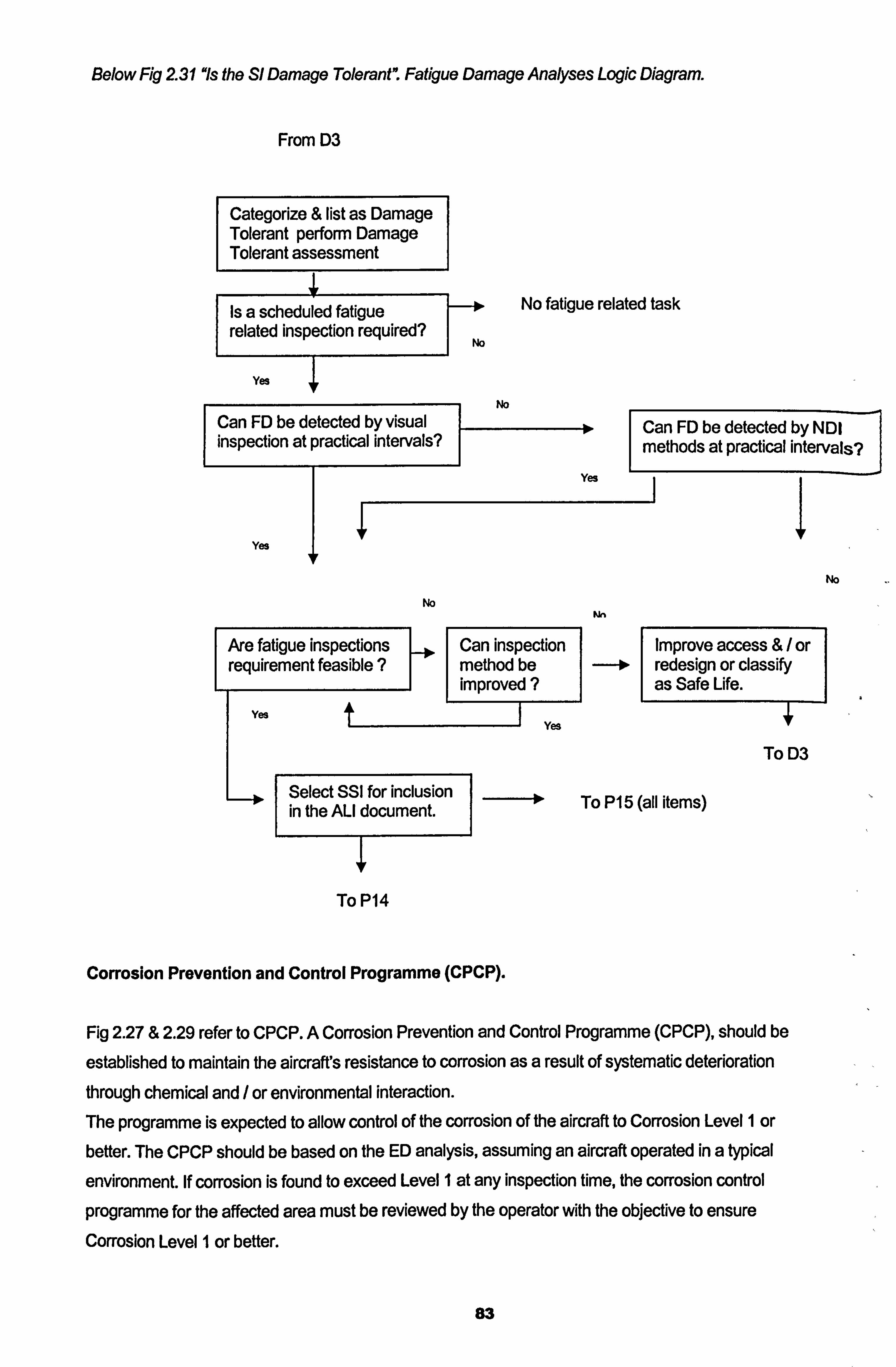
Below Fig 231 "is the Sl Damage Tolerant". Fatigue Damage Analyses Logic Diagram.
From D3
Categorize & list as Damage Tolerant perform Damage Tolerant assessment
No fatigue related task Is a scheduled fatigue related inspection required? N.
Yes +
Can FD be detected by visual 0 Can FD be detected by NDI inspection at practical intervals? methods at practical intervals?
Yes
Yes
No
No
Are fatigue inspections Can inspection Improve access &/ or requirement feasible ? method be 0 redesign or classify
improved ? as Safe Life. Yes
t
Yes
To D3
Select SSI for inclusion To P15 (all items) in the ALI document.
To P14
Corrosion Prevention and Control Programme (CPCP).
Fig 2.27 & 2.29 refer to CPCP. A Corrosion Prevention and Control Programme (CPCP), should be
established to maintain the aircrafts resistance to corrosion as a result of systematic deterioration
through chemical and / or environmental interaction. The programme is expected to allow control of the corrosion of the aircraft to Corrosion Level 1 or better. The CPCP should be based on the ED analysis, assuming an aircraft operated in a typical
environment. If corrosion is found to exceed Level I at any inspection time, the corrosion control programme for the affected area must be reviewed by the operator with the objective to ensure Corrosion Level I or befter.
83
[Corrosion Level 1: Corrosion damage that does not require structural reinforcement or
replacement. Or Corrosion occuning between successive inspections exceeds allowable limit but is
local and can be attributed to an event not typical of operator usage, e. g. mercuty spillage. ATA MSG3 2001]
Summansing the Flow Chart Process to Produce a Structural Maintenance Schedule.
Structural Logic Flow Charts 2.27 to 2.31 explain the method of developing the Structural
Maintenance Programme of tasks. Along with this process and the rating process to identify
intervals, the out come is a Structural Maintenance Schedule.
Fig 2.27 details the process for producing the initial structural maintenance programme and details
a series of processes (P 1, P2, P3 etc) and decision steps (D 1, D2, D3 etc) ....
P1 Process 1 splits the aircraft into manageable zones / areas to be assessed. P2 Process 2 defines the structural items to be assessed in each zone. D1 Decision I is to be made for each structural item defined in P2 and ask of each item if it is
significant. If so it is classed as a Structural Significant Item (SSI) subject to further analysis. See page 50 for definitions of what is significant.
P3 Process 3 is applied to those items in D3 that are classified as a SSI. This Process is further
detailed in decision flow chart fig 2.29 where the Accidental Damage AD and the Environmental Deterioration including CPCP, considerations are analysed and addressed. Process 4 is applied to those items in DI that are not classified as significant (SSI).
This process is applied to all structural items in all zones / areas until all structural items have been
categorised.
P7 and P8, Process 7 and Process 8 leading from P3 are to analyse the SSI forAD, ED and CPCP implications and requirements. Leading to D9 Decision 9 asking the question to address CPCP implications. If the ED tasks meets the CPCP requirements then no additional CPCP
task is required. P7, P8, P9 and D9 are repeated until all SSI's are analysed. Those items from DI that are not classified as a SSI undergo D2 and P4, P5 and P6, where the flow chart fig 2.28 is followed for each item, where the structure is compared to already known similar structure.
PI 0 Process 10 is applied to those SSI's that are not "Damage Tolerant7. This process is very important as it addresses those SSI's that require a life limitation applied to them. This process
can have significant cost implications as well as serious safety implications. SSI*s with a "Safe
Life! ' imposed are not subjected to further fatigue related scheduled inspections.
Al remaining SSI's are therefore damage tolerant. These SSI's are analysed in accordance
with flow chart fig 2.31 to determine the fatigue related inspection requirements. Here D4 to D8
84
and P1 I to P14 are processed to establish airworthiness limitations and scheduled structural
maintenance inspections. Here Non Destructive Inspection /Testing methods (NDI / NDT) may be employed where visual inspections are not appropriate or applicable.
85
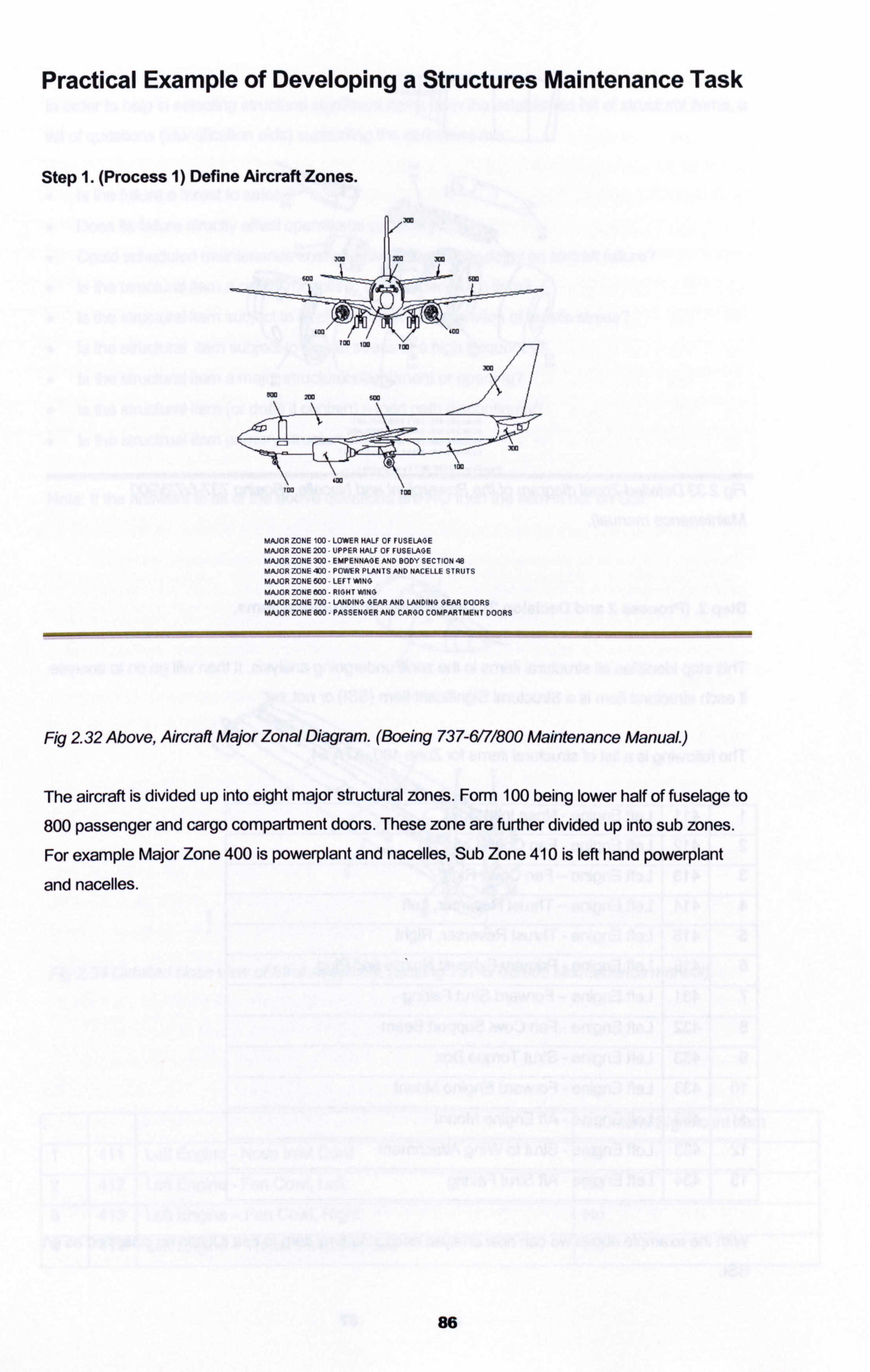
Practical Example of Developing a Structures Maintenance Task
Step 1. (Process 1) Define Aircraft Zones.
MAJOR ZONE 100 LOWER HALF OF FUSELAGE MAJORZONE200 UPPER HALF OF FUSELAGE MAJOR ZONE 300 EMPENNAGE AND BODY SECTION 48 MAJOR ZONE 4DO POWER PLANTS AND NACELLE STRUTS MAJORZONE600 LEFT*N0 MAJOR ZONE 500 -RIGHT WHO MAJOR ZONE 700 LANDING GEAR AND LANDING GEAR DOORS MAJOR ZONE 800 - PASSENGER AND CARGO COMPARTMENT DOORS
Fig 2.32 Above, Aircraft Major Zonal Diagram. (Boeing 737-6171800 Maintenance Manual. )
The aircraft is divided up into eight major structural zones. Form 100 being lower half of fuselage to
800 passenger and cargo compartment doors. These zone are further divided up into sub zones.
For example Major Zone 400 is powerplant and nacelles, Sub Zone 410 is left hand powerplant
and nacelles.
86
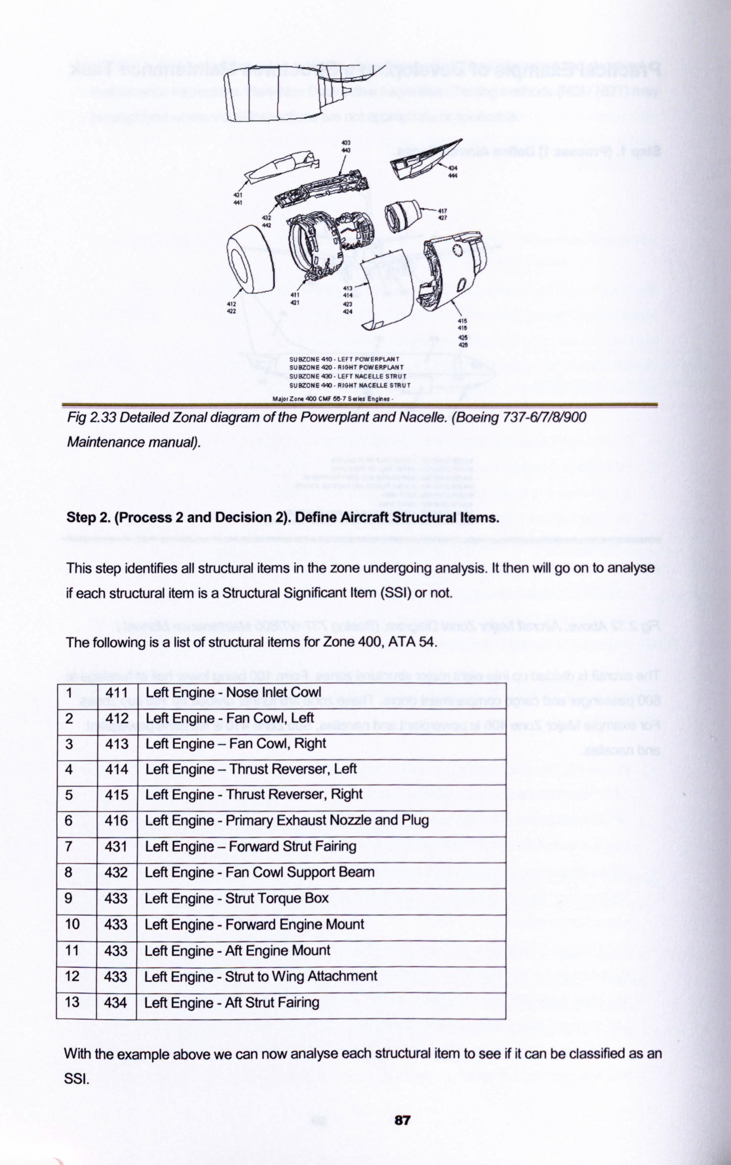
433 443
1114 444
432
43 411 414
412 41 423 422 424
4ýI 4.
425 420
SUM HE410. LEFTPCWERFL^NT SU0Z0HE420-RIGHTPOWERFILANT
SýBZONE430-LEFTNACELLESTRUT
SUE2ONE440 RIGHTNACELLESTRUT
M. j., Z.. 400 CMF 56 7S. i., Eýgi-
Fig 2.33 Detailed Zonal diagram of the Powerplant and Nacelle. (Boeing 737-617181900
Maintenance manual).
Step 2. (Process 2 and Decision 2). Define Aircraft Structural Items.
This step identifies all structural items in the zone undergoing analysis. It then will go on to analyse
if each structural item is a Structural Significant Item (SSI) or not.
The following is a list of structural items for Zone 400, ATA 54.
1 411 Left Engine - Nose Inlet Cowl
2 412 Left Engine - Fan Cowl, Left
3 413 Left Engine - Fan Cowl, Right
4 414 Left Engine - Thrust Reverser, Left
5 415 Left Engine - Thrust Reverser, Right
6 416 Left Engine - Primary Exhaust Nozzle and Plug
7 431 Left Engine - Forward Strut Fairing
8 432 Left Engine - Fan Cowl Support Beam
9 433 Left Engine - Strut Torque Box
10 433 Left Engine - Forward Engine Mount
11 433 Left Engine - Aft Engine Mount
12 433 Left Engine - Strut to Wing Attachment
13 434 Left Engine - Aft Strut Fairing
With the example above we can now analyse each structural item to see if it can be classified as an SSI.
87
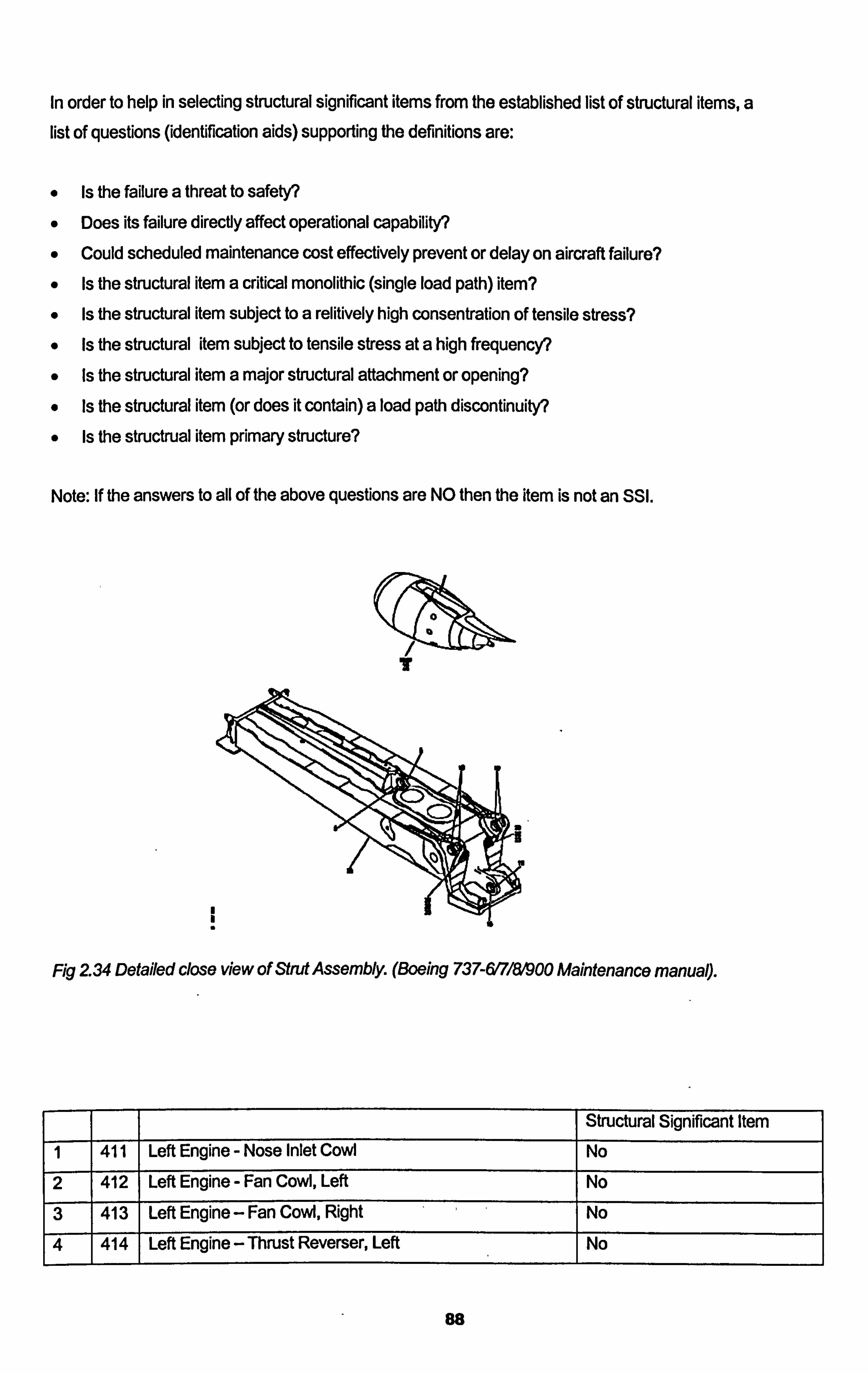
In order to help in selecting structural significant items from the established list of structural items, a list of questions (identification aids) supporting the definitions are:
" Is the failure a threat to safety?
" Does its failure directly affect operational capability?
" Could scheduled maintenance cost effectively prevent or delay on aircraft failure?
" Is the structural item a critical monolithic (single load path) item?
" Is the structural item subject to a relitively high consentration of tensile stress?
" Is the structural item subject to tensile stress at a high frequency?
" Is the structural item a major structural attachment or opening?
" Is the structural item (or does it contain) a load path discontinuity?
" Is the structrual item primary structure?
Note: If the answers to all of the above questions are NO then the item is not an SSI.
Fig 234 Detailed close view of Strut Assembly. (Boeing 737-617181900 Maintenance manual).
I Structural Significant Item
1 411 1 Left Engine - Nose Inlet Cowl No
2 412 Left Engine - Fan Cowl, Left No
3 413 Left Engine - Fan CoW, Right No
4 414 Left Engine - Thrust Reverser, Left No
88
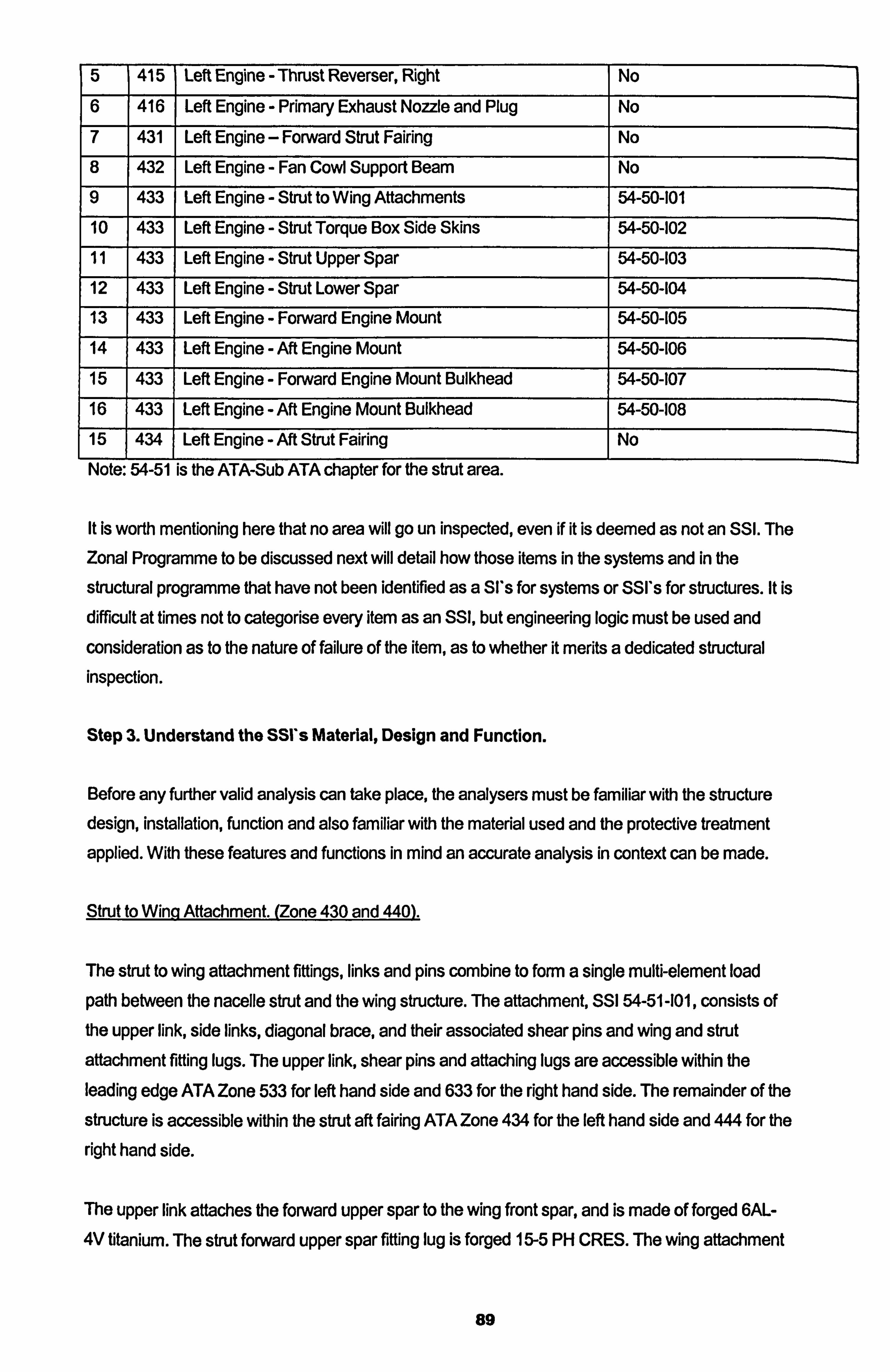
5 415 Left Engine - Thrust Reverser, Right No
6 416 Left Engine - Primary Exhaust Nozzle and Plug No
7 431 Left Engine - Forward Strut Fairing No
8 432 Left Engine - Fan Cowl Support Beam No
9 433 Left Engine - Strut to Wing Affachments 54-50-101
10 433 Left Engine - Strut Torque Box Side Skins 54-50-102
11 433 Left Engine - Strut Upper Spar 54-50-103
12 433 Left Engine - Strut Lower Spar 54-50-104
13 433 Left Engine - Forward Engine Mount 54-50-105
14 433 Left Engine - Aft Engine Mount 54-50-106
15 433 Left Engine - Forward Engine Mount Bulkhead 54-50-107
16 433 Left Engine - Aft Engine Mount Bulkhead 54-50-108
Left Engine - Aft Strut Fairing No
Note: 54-51 is the ATA-Sub ATA chapter for the strut area.
It is worth mentioning here that no area will go un inspected, even if it is deemed as not an SSI. The Zonal Programme to be discussed next will detail how those items in the systems and in the
structural programme that have not been identified as a SI's for systems or SSI's for structures. It is
difficult at times not to categorise every item as an SSI, but engineering logic must be used and
consideration as to the nature of failure of the item, as to whether it merits a dedicated structural inspection.
Stop 3. Understand the SSI's Material, Design and Function.
Before any further valid analysis can take place, the analysers must be familiar with the structure design, installation, function and also familiar with the material used and the protective treatment
applied. With these features and functions in mind an accurate analysis in context can be made.
Strut to Winq Affachment. (Zone 430 and 440).
The strut to wing attachment fiffings, links and pins combine to form a single multi-element load
path between the nacelle strut and the wing structure. The attachment, SSI 54-51 -101, consists of the upper link, side links, diagonal brace, and their associated shear pins and wing and strut
attachment fitting lugs. The upper link, shear pins and attaching lugs are accessible within the leading edge ATA Zone 533 for left hand side and 633 for the right hand side. The remainder of the
structure is accessible within the strut aft fairing ATA Zone 434 for the left hand side and 444 for the
right hand side.
The upper link attaches the forward upper spar to the wing front spar, and is made of forged 6AL-
4V titanium. The strut forward upper spar fifting lug is forged 15-5 PH CRES. The wing attachment
89
fiffing lug is 7050-T74 aluminium. The shear pin for both ends of the link are made of 15-5 PH
CRES.
The primary strut attachment lugs are integral parts of the strut aft upper spar fittings. These two forged Ti-6AL-4V fiffings attach the strut aft upper comers to the Tl-6AL-4V front spar fitting to the
wing. The shear pins for this attachment are made of 15-5 PH CRES.
The side links connect the strut aft bulkhead to the wing lower surface. They are made from 6AL-
4V titanium as are the strut attachment lugs which are integral to the strut aft upper spar fittings.
The wing attachment fittings are made of 7050-T74 aluminium. The shear pins for both ends of the
link are made of passive A286 CRES.
The diagonal brace attaches the strut lower spar at the aft bulkhead to the wing lower surface. It is
made of 7075-T73 aluminium with integral machined lugs on both ends. The strut diagonal brace..
fitting lugs are forged 15-5 PH CRES. The wing attachment fitting lugs are 7073-T74 aluminium. The shear pins for both ends of the diagonal brace are made of 15-5 PH CRES.
Strut To[gue Box (ATA Zones 432 and 442.433 and 443).
The strut is a closed end, stressed skin structural torque box. The strut design employs skin spar bulkhead / frame type construction with two spars and five bulkheads.
The Upper Spar SSI consists of chords of 6AL-4V beta annealed titanium and a web of 6AL-4V mill
annealed titanium, with the 15-5 PH CRIES forward upper spar fitting forming a tee shaped stiffener
along BL 0.0. The upper spar is made of a web of 2024-T851 aluminiurn with chords of 6AL-4V
titanium and 2024-T851 aluminiurn stiffeners.
The upper spar chords are spliced by the upper flange of the 6AL-4V titanium aft engine mount bulkhead and a spliced strip of 6AL-4V titanium.
The Side Skins SSI are made of 2024-T851 aluminiurn with hot bonded and riveted doublers of 2024-T851 aluminium. The triplers are riveted and fey surface sealed 2024-T851, while the bear
strap / tripler is 6AL-4V titanium, attached by the same method as the forward triplers. The fore-aft
stiffeners are 2024-T851 aluminium. The remaining stiffeners are 6AL-4V titanium.
The Lower Spar SSI is made of one piece chords of 15-5 PH CRIES and two 15-5 PH CRIES webs
spliced. The chord lower flanges are doubled by straps of 15-5 PH CRIES extending from the
forward engine mount bulkhead aft.
The forward engine mount bulkhead SSI is made from forged 6AL-4V mill annealed titanium with
press fit 15-5 PH CRIES bushings in the shear pin and ground support equipment pin holes.
Corrosion Protection.
Forward and Aft Engine Mount Assemblies.
90
AJI primary components of the forward engine mount assembly are manufactured from 15-5 PH CRES. The attachment bolts are nickel alloy 718. The primary components as well as the
attachment bolts of the aft engine mount assembly are manufactured from nickel alloy 718. These
materials are inherently corrosion resistant and for the environment in which they operate, require no further corrosion protection.
Strut Torque Box.
The engine strut structure consists of the following components.
Forged aluminium and titanium bulkheads
Extruded and forged aluminium frame elements. Titanium, aluminium and corrosion resistant steel spar webs. Extruded and forged titanium and corrosion resistant steel chords. Aluminium side skin vVith hot bonded doublers, mechanically fastened to frames, bulkheads
and chords. Corrosion resistant steel honey comb heat shield with titanium sheet fire wall. Forged corrosion resistant steel, aluminiurn and titanium fittings.
Nickel alloy 625 ducting and race ways.
* Adhesive bonded aluminium honeycomb pressure relief doors and aluminium sheet metal
access doors.
Aluminium details (except honeycomb core) which are also to be adhesive bonded are phosphoric anodized and primed with BSM 5-137 Type 1 corrosion inhibiting primer prior to bonding with BMS
5-137, Type 11. Bonded skins and doors are given a coat of BMS - 1079 type III primer and a coat
of BIVIS 10-60, type 11 enamel where exposed. Aluminium details that are not bonded or do not
contact steel or titanium are either boric sulphuric acid anodized (if bare) or Alodines (if clad) and
given one coat of BMS 10-11, type I primer. If aluminium contacts steel or titanium, two coats of
primer are used. AJI corrosion resistant steels details are passivated except where aluminium rivets
are installed, or another aluminiurn part contacts. In these areas they are given two coats of BMS
10-11, type I primer. Faying surfaces are sealed with BMS 5-95, BMS 5-26 or BMS 5-63. Sealant
depending upon surface temperature of the area. Drainage systems in low or sump areas have
been provided to prevent fluid collection. Sump area where drain holes could not be provided because of structural reasons are filled with moisture resistant potting compound to a level to
promote drainage.
91
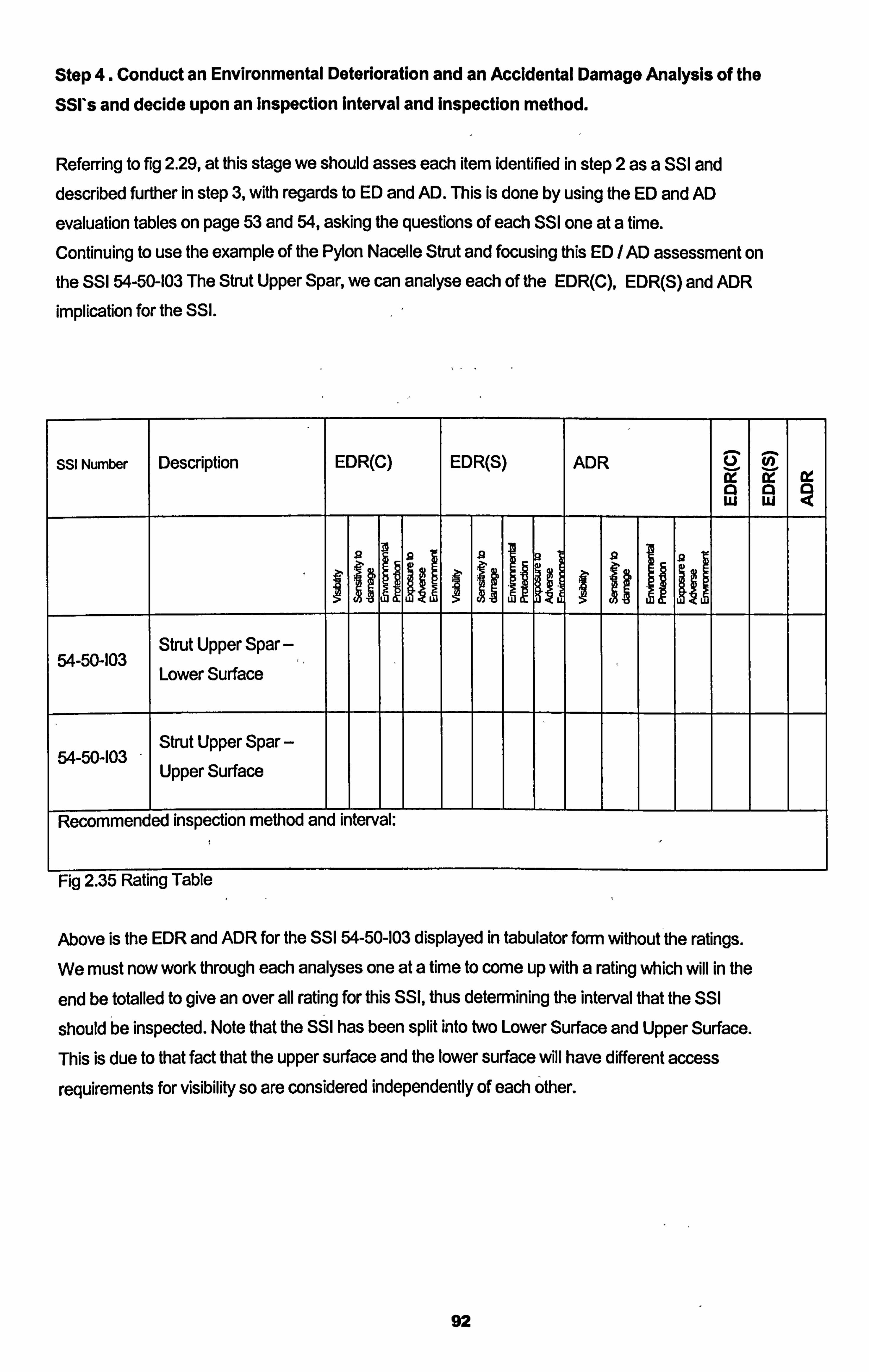
Step 4. Conduct an Environmental Deterioration and an Accidental Damage Analysis of the
SSI*s and decide upon an inspection interval and Inspection method.
Referring to fig 2.29, at this stage we should asses each item identified in step 2 as a SSI and described further in step 3, with regards to ED and AD. This is done by using the ED and AD
evaluation tables on page 53 and 54, asking the questions of each SSI one at a time.
Continuing to use the example of the Pylon Nacelle Strut and focusing this ED / AD assessment on the SSI 54-50-103 The Strut Upper Spar, we can analyse each of the EDR(C), EDR(S) and ADR
implication for the SSI.
SSI Number Description EDR(C) EDR(S) ADR Q 0 W W
ý, T
Strut Upper Spar - 54-50-103 Lower Surface
Strut Upper Spar - 54-50-103 Upper Surface
Recommended inspection method and interval:
Fig 2.35 Rating Table
Above is the EDR and ADR for the SSI 54-50-103 displayed in tabulator form without the ratings. We must now work through each analyses one at a time to come up with a rating which will in the
end be totalled to give an over all rating for this SSI, thus determining the interval that the SSI
should be inspected. Note that the SSI has been split into two Lower Surface and Upper Surface.
This is due to that fact that the upper surface and the lower surface will have different access
requirements for visibility so are considered independently of each other.
92
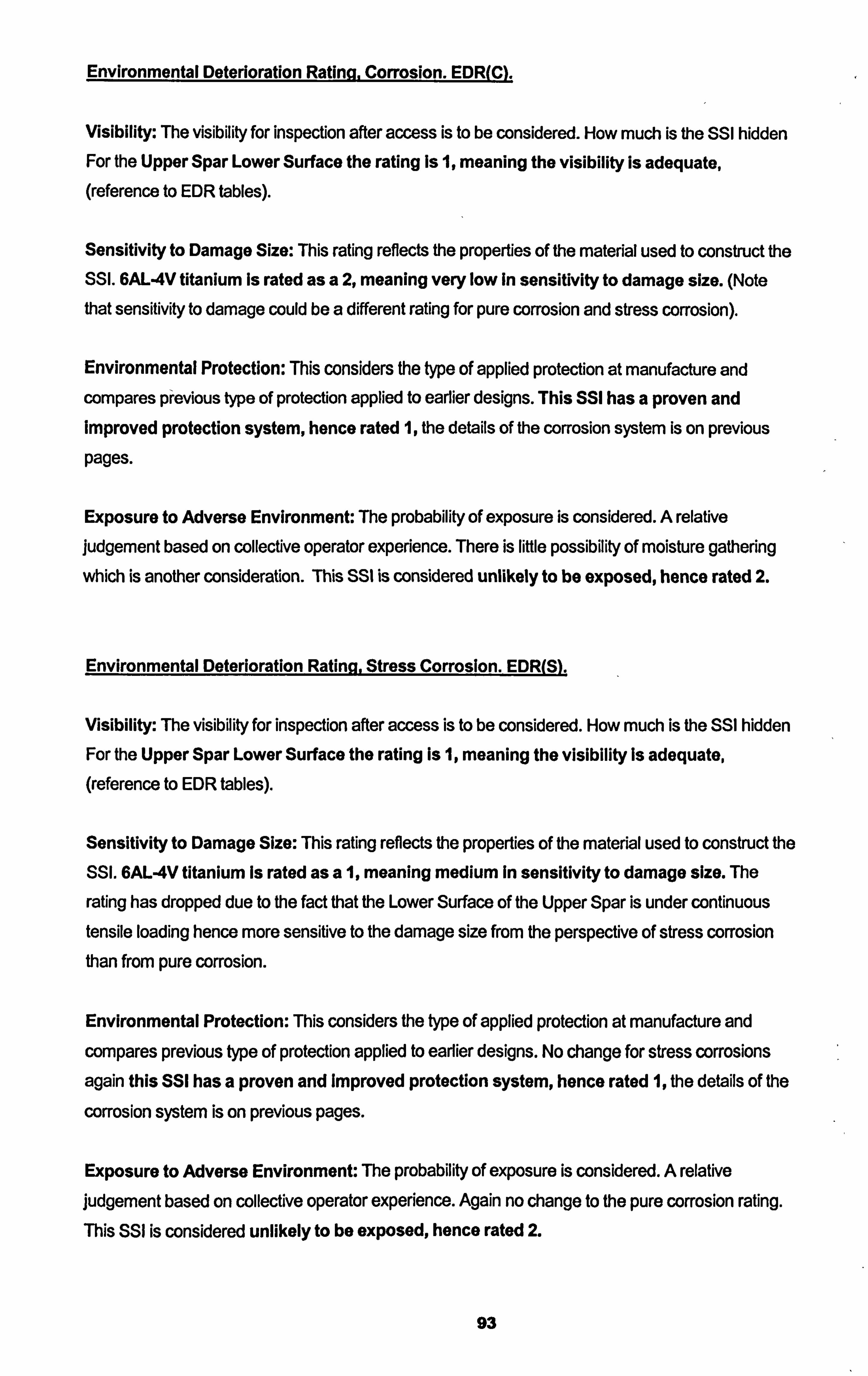
Environmental Deterioration Ratina. Corrosion. EDR(C).
Visibility: The visibility for inspection after access is to be considered. How much is the SSI hidden For the Upper Spar Lower Surface the rating is 1, meaning the visibility is adequate, (reference to EDR tables).
Sensitivity to Damage Size: This rating reflects the properties of the material used to construct the SSI. 6AL-4V titanium is rated as a 2, meaning very low In sensitivity to damage size. (Note that sensitivity to damage could be a different rating for pure corrosion and stress corrosion).
Environmental Protection: This considers the type of applied protection at manufacture and compares previous type of protection applied to earlier designs. This SSI has a proven and Improved protection system, hence rated 1, the details of the corrosion system is on previous pages.
Exposure to Adverse Environment: The probability of exposure is considered. A relative judgement based on collective operator experience. There is little possibility of moisture gathering which is another consideration. This SSI is considered unlikely to be exposed, hence rated 2.
Environmental Deterioration Ratina. Stress Corrosion. EDR(S).
Visibility: The visibility for inspection after access is to be considered. How much is the SSI hidden For the Upper Spar Lower Surface the rating Is 1, meaning the visibility is adequate, (reference to EDR tables).
Sensitivity to Damage Size: This rating reflects the properties of the material used to construct the SSI. 6AL-4V titanium Is rated as a 1, meaning medium In sensitivity to damage size. The
rating has dropped due to the fact that the Lower Surface of the Upper Spar is under continuous tensile loading hence more sensitive to the damage size from the perspective of stress corrosion than from pure corrosion.
Environmental Protection: This considers the type of applied protection at manufacture and
compares previous type of protection applied to earlier designs. No change for stress corrosions
again this SSI has a proven and Improved protection system, hence rated 1, the details of the
corrosion system is on previous pages.
Exposure to Adverse Environment: The probability of exposure is considered. A relative judgement based on collective operator experience. Again no change to the pure corrosion rating. This SSI is considered unlikely to be exposed, hence rated 2.
93
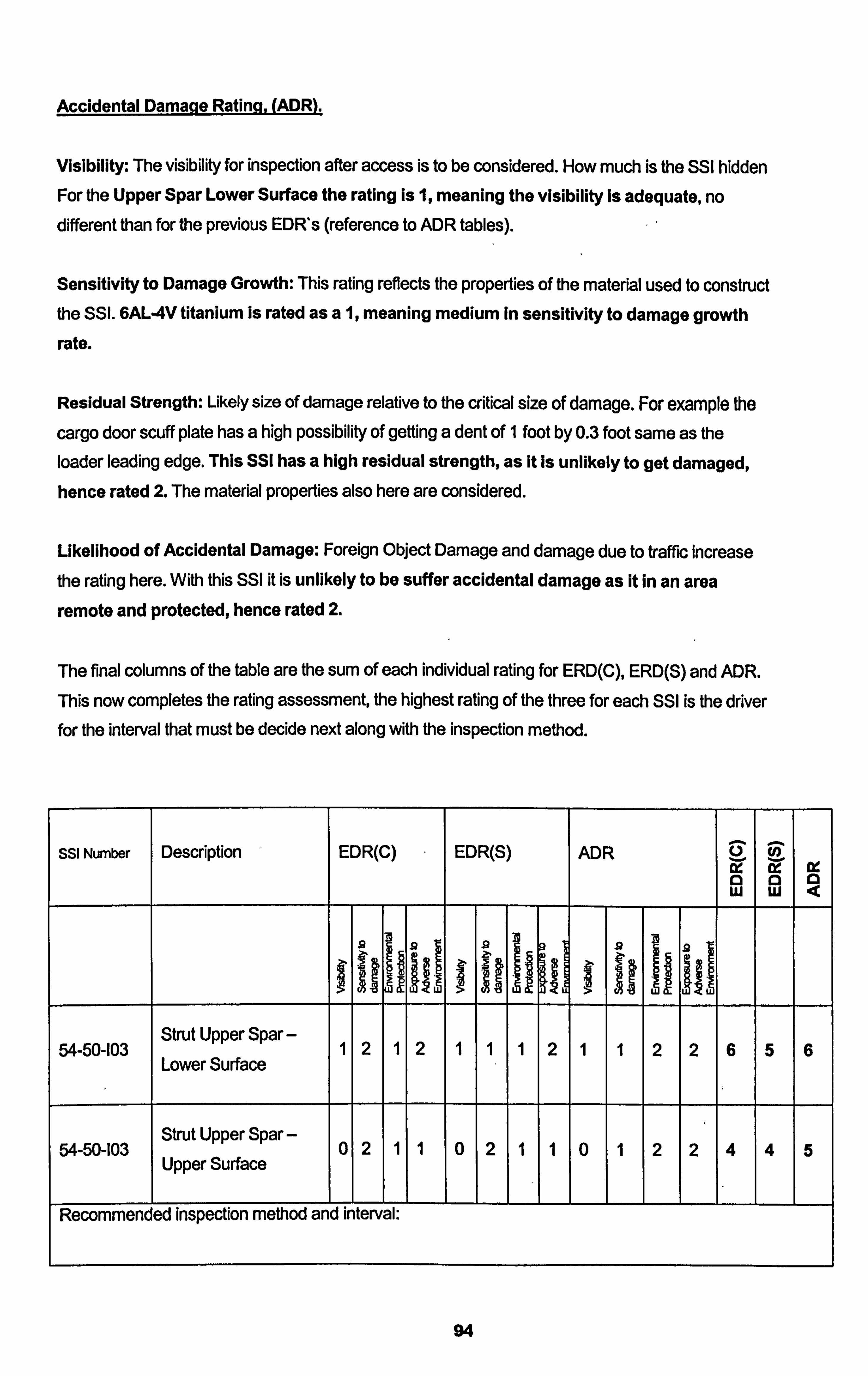
Accidental Damane Ratina. (ADR).
Visibility: The visibility for inspection after access is to be considered. How much is the SSI hidden For the Upper Spar Lower Surface the rating Is 1, meaning the visibility is adequate, no different than for the previous EDR's (reference to ADIR tables).
Sensitivity to Damage Growth: This rating reflects the properties of the material used to construct the SSI. 6AL-4V titanium Is rated as a 1, meaning medium In sensitivity to damage growth rate.
Residual Strength: Likely size of damage relative to the critical size of damage. For example the
cargo door scuff plate has a high possibility of getting a dent of 1 foot by 0.3 foot same as the loader leading edge. This SSI has a high residual strength, as it Is unlikely to get damaged,
hence rated 2. The material properties also here are considered.
Likelihood of Accidental Damage: Foreign Object Damage and damage due to traffic increase
the rating here. With this SSI it is unlikely to be suffer accidental damage as it in an area
remote and protected, hence rated 2.
The final columns of the table are the sum of each individual rating for ERID(C), ERD(S) and ADR.
This now completes the rating assessment, the highest rating of the three for each SSI is the driver for the interval that must be decide next along with the inspection method.
SSI Number Description EDR(C) EDR(S) ADR W a
Ix 0
Ex a
W III
Strut Upper Spar - 54-50-103 1 2 1 2 1 1 1 2 1 1 2 2 6 5 6 Lower Surface
Strut Upper Spar - 54-50-103 0 2 1 1 0 2 1 1 0 1 2 2 4 4 5 Upper Surface
Recommended inspection method and interval:
94
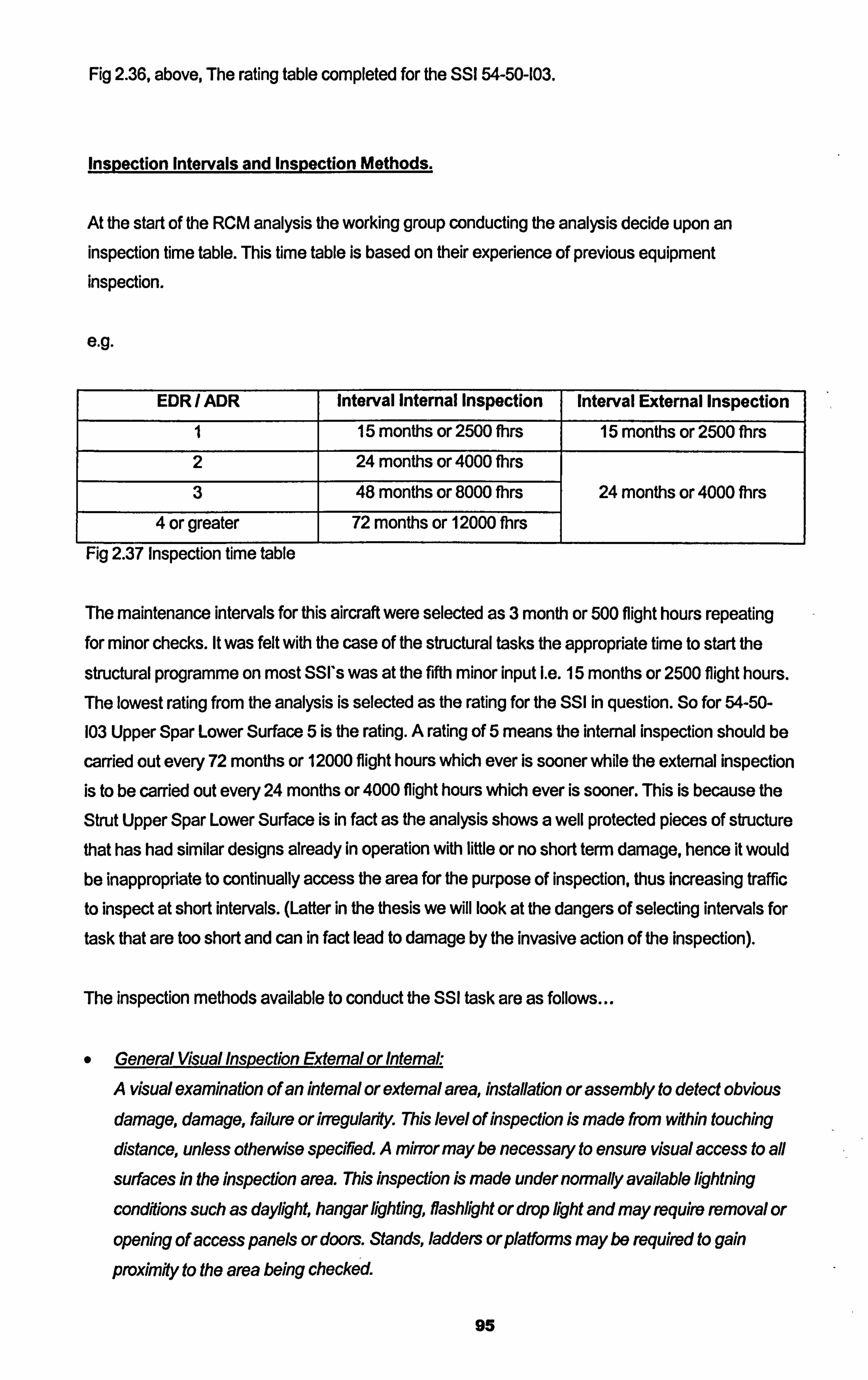
Fig 2.36, above, The rating table completed for the SSI 54-50-103.
Inspection Intervals and Inspection Methods.
At the start of the RCM analysis the working group conducting the analysis decide upon an inspection time table. This time table is based on their experience of previous equipment inspection.
e. g.
EDR / ADR Interval Internal Inspection Interval External Inspection
1 15 months or 2500 Mrs 15 months or 2500 fhrs
2 24 months or 4000 fhrs
3 48 months or 8000 fhrs 24 months or 4000 fhrs
4 or greater 72 months or 12000 fhrs
Fig 2.37 Inspection time table
The maintenance intervals for this aircraft were selected as 3 month or 500 flight hours repeating for minor checks. It was felt with the case of the structural tasks the appropriate time to start the
structural programme on most SSI's was at the fifth minor input I. e. 15 months or 2500 flight hours.
The lowest rating from the analysis is selected as the rating for the SSI in question. So for 54-50-
103 Upper Spar Lower Surface 5 is the rating. A rating of 5 means the internal inspection should be
carried out every 72 months or 12000 flight hours which ever is sooner while the external inspection
is to be carried out every 24 months or 4000 flight hours which ever is sooner. This is because the
Strut Upper Spar Lower Surface is in fact as the analysis shows a well protected pieces of structure that has had similar designs already in operation with little or no short term damage, hence it would be inappropriate to continually access the area for the purpose of inspection, thus increasing traffic
to inspect at short intervals. (Latter in the thesis we will look at the dangers of selecting intervals for
task that are too short and can in fact lead to damage by the invasive action of the inspection).
The inspection methods available to conduct the SSI task are as follows
e General Visual Inspection Extemal or Intemal.
A visual examination of an internal or extemal area, installation or assembly to detect obvious damage, damage, failure or irregularifty, This level of inspection is made from within touching
distance, unless otherwise specirted. A mirror may be necessary to ensure visual access to a#
surfaces in the inspection area. This inspection is made under normally available lightning
condilions such as daylight, hangar lighting, flashlight or drop light and may require removal or
opening of access panels or doors. Stands, ladders orplafforms may be required to gain
proximity to the area being checked.
95
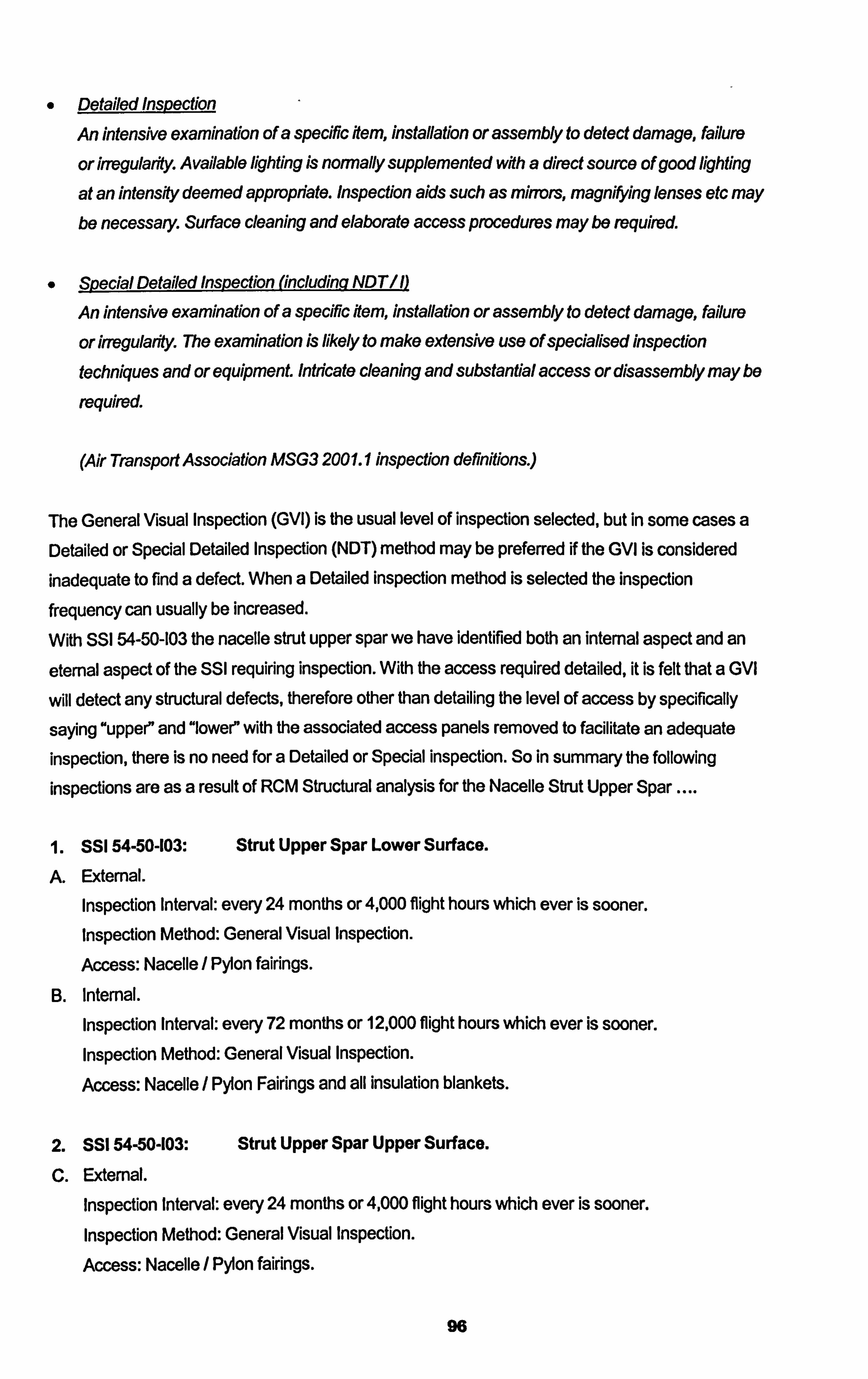
o Detailed Inspection
An intensive examination of a specific item, installation or assembly to detect damage, failure
or irregularfly. Available lighting is normally supplemented with a direct source of good lighting
at an intensity deemed appropriate. Inspection aids such as mirrors, magnifying lenses etc may be necessary. Surface cleaning and elaborate access procedures may be required.
9 SDecialDetailedinspection(includinqNDTIn
An intensive examination of a specific Item, installation or assembly to detect damage, failure
or irregularfly. The examination is likely to make extensive use of speciallsed inspection
techniques and or equipment Intricate cleaning and substantial access or disassembly may be
required.
(Air Transport Association MSG3 200 1.1 inspection definitions. )
The General Visual Inspection (GVI) is the usual level of inspection selected, but in some cases a Detailed or Special Detailed Inspection (NDT) method may be preferred if the GVI is considered inadequate to find a defect. When a Detailed inspection method is selected the inspection
frequency can usually be increased.
With SSI 54-50-103 the nacelle strut upper spar we have identified both an internal aspect and an
eternal aspect of the SSI requiring inspection. With the access required detailed, it is felt that a GVI
will detect any structural defects, therefore other than detailing the level of access by specifically
saying "upper" and "lower" with the associated access panels removed to facilitate an adequate inspection, there is no need for a Detailed or Special inspection. So in summary the following
inspections are as a result of RCM Structural analysis for the Nacelle Strut Upper Spar ....
SSI 54-50-103: Strut Upper Spar Lower Surface.
A. Extemal.
Inspection Interval: every 24 months or 4,000 flight hours which ever is sooner. Inspection Method: General Visual Inspection.
Access: Nacelle / Pyion fairings.
B. Intemal.
Inspection Interval: every 72 months or 12,000 flight hours which ever is sooner. Inspection Method: General Visual Inspection.
Access: Nacelle / Pylon Fairings and all insulation blankets.
2. SSI 54-50-103: Strut Upper Spar Upper Surface.
Extemal.
Inspection Interval: every 24 months or 4,000 flight hours which ever is sooner. Inspection Method: General Visual Inspection.
Access: Nacelle / Pylon fairings.
96
D. Internal.
Inspection Interval: every 72 months or 12,000 flight hours which ever is sooner. Inspection Method: General Visual Inspection.
Access: Nacelle / Pylon fairings and all insulation blankets.
Note: Though the upper surface score was one point less than the lower surface, both fell into
the same bracket of inspection intervals. Aso note that the distinction between the external and internal inspection is not only the fact that one looks at the external side of the strut but also the level of access. It can be then said that the detailed level of access can in fact define the scope
of inspection.
97

2.3.3 The Zonal Inspection Programme.
The RCM analysis process has so far concentrated on the scheduled maintenance tasks
generated by explicit consideration to failure consequences and the Inherent reliability
characteristics of each item. By this method alone many items both structural and system wise,
would go un inspected by the strength that they are not classified as Structural Significant Items or Maintenance Significant Items. To complete the RCM process described so far there should be a
supplemental programme including inspection tasks that consider the "left out"areas not addressed
with the effects of failure RCM process that considers the effects of failure. Because the remaining "left out"areas are not classified as "Significant"their inspection should be cost effective and un
complicated general area inspections. Non significant area inspections, known as Zonal
Inspections, complete the RCM Scheduled Maintenance programme in ensuring all systems,
structures and all areas of the aircraft do not go un inspected for their in service life.
GENERAL VISUAL INSPECTION (GVf)
A visual examination of an interior or exterior area, installation or assembly to
detect obvious damage, failure or irregularity. This level of inspection is made from within touching distance, unless otherwise specified. A mirror may be
necessary to enhanced visual access to all exposed surfaces in the inspection
area. This level of inspection is made under normally available lighting conditions
such as daylight, hangar lighting, flashlight or drop-light and may require removal or opening of access panels or doors. Stands, ladders or platforms may be
required to gain proximity to the area being checked.
Air Transport Association Maintenance Steering Group 3 2001.1
The Zonal Inspection Programme is based on a series of General Visual Inspections (GVI's as defined by the ATA MSG3). The Zonal inspections are based on a three dimensional identification
system used by the manufacturer to identify physical locations on the aircraft. The zones are
usually defined and bounded by bulkheads, significant areas, stringers, floor beams, skins etc. The
complete aircraft is split into zones and every part of the aircraft is located within a defined zone, as
shown previously in fig 2.32.
The Zonal GVI inspection is looking for deterioration of the original installation. This includes..
0 Corrosion * Cracks
Chafing
Evidence of leakage
98
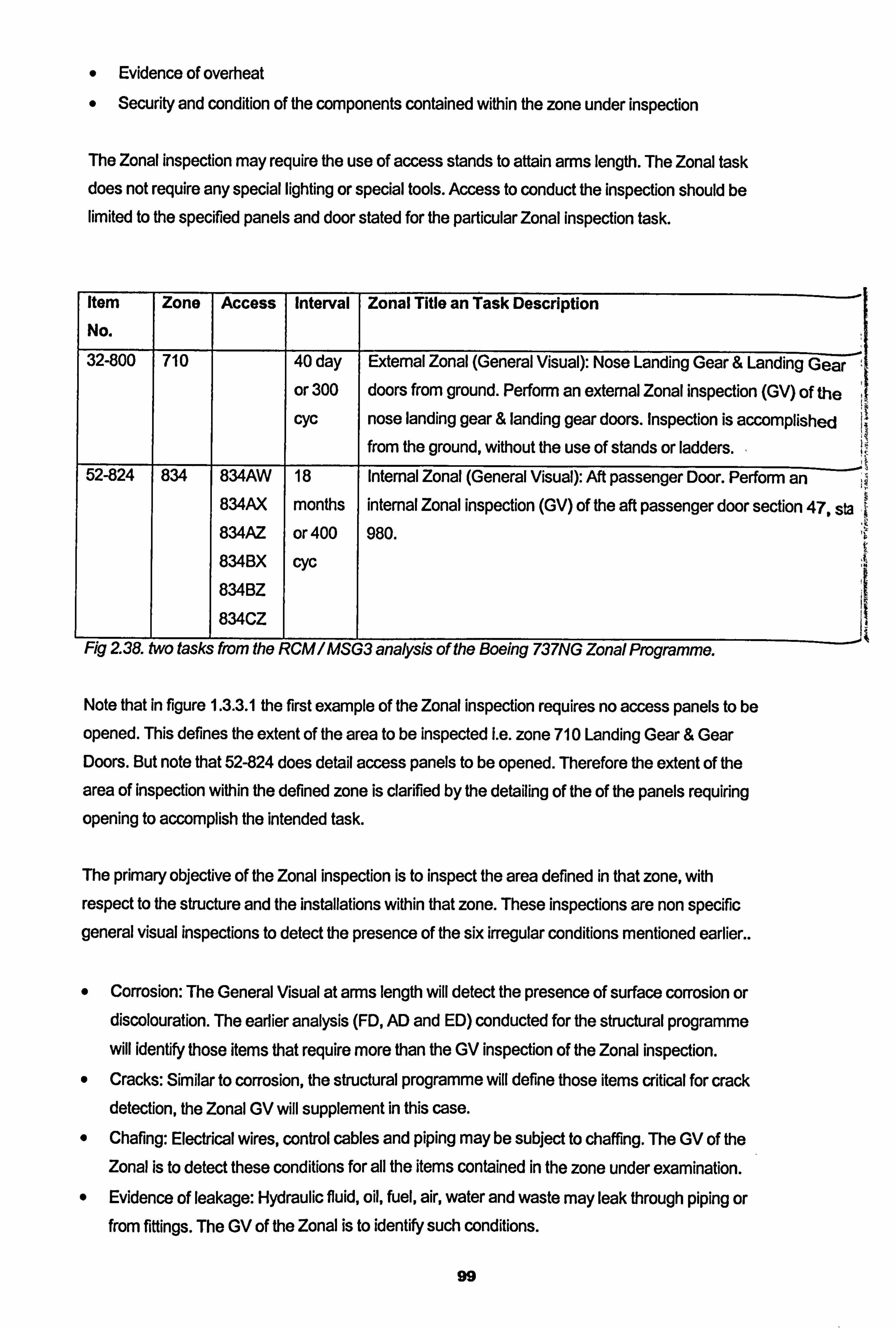
* Evidence of overheat Security and condition of the components contained within the zone under inspection
The Zonal inspection may require the use of access stands to attain arms length. The Zonal task does not require any special lighting or special tools. Access to conduct the inspection should be limited to the specified panels and door stated for the particular Zonal inspection task.
Item
No. Zone Access Interval Zonal Title an Task Description
32-800 710 40 day External Zonal (General Visual): Nose Landing Gear & Eanding G-ea-r-ý'-
or 300 doors from ground. Perform an external Zonal inspection (GV) of the CYC nose landing gear & landing gear doors. Inspection is accomplished
from the ground, without the use of stands or ladders. 52-824 834 834AW 18 Internal Zonal (General Visual): Aft passenger Door. Perform an
834AX months internal Zonal inspection (GV) of the aft passenger door section 47, sta 834AZ or 400 980. 834BX cyc 834BZ
834CZ
Fig 2 38. two tasks from the RCM / MSG3 analysis of the Boeing 73 7NG Zonal Programme.
Note that in figure 1.3-3.1 the first example of the Zonal inspection requires no access panels to be
opened. This defines the extent of the area to be inspected i. e. zone 710 Landing Gear & Gear Doors. But note that 52-824 does detail access panels to be opened. Therefore the extent of the
area of inspection within the defined zone is clarified by the detailing of the of the panels requiring opening to accomplish the intended task.
The primary objective of the Zonal inspection is to inspect the area defined in that zone, with respect to the structure and the installations within that zone. These inspections are non specific general visual inspections to detect the presence of the six irregular conditions mentioned earlier..
Corrosion: The General Visual at arms length will detect the presence of surface corrosion or discolouration. The earlier analysis (FD, AD and ED) conducted for the structural programme will identify those items that require more than the GV inspection of the Zonal inspection.
Cracks: Similar to corrosion, the structural programme will define those items critical for crack detection, the Zonal GV will supplement in this case. Chafing: Electrical wires, control cables and piping may be subject to chaffing. The GV of the Zonal is to detect these conditions for all the items contained in the zone under examination.
0 Evidence of leakage: Hydraulic fluid, oil, fuel, air, water and waste may leak through piping or from fittings. The GV of the Zonal is to identify such conditions.
99
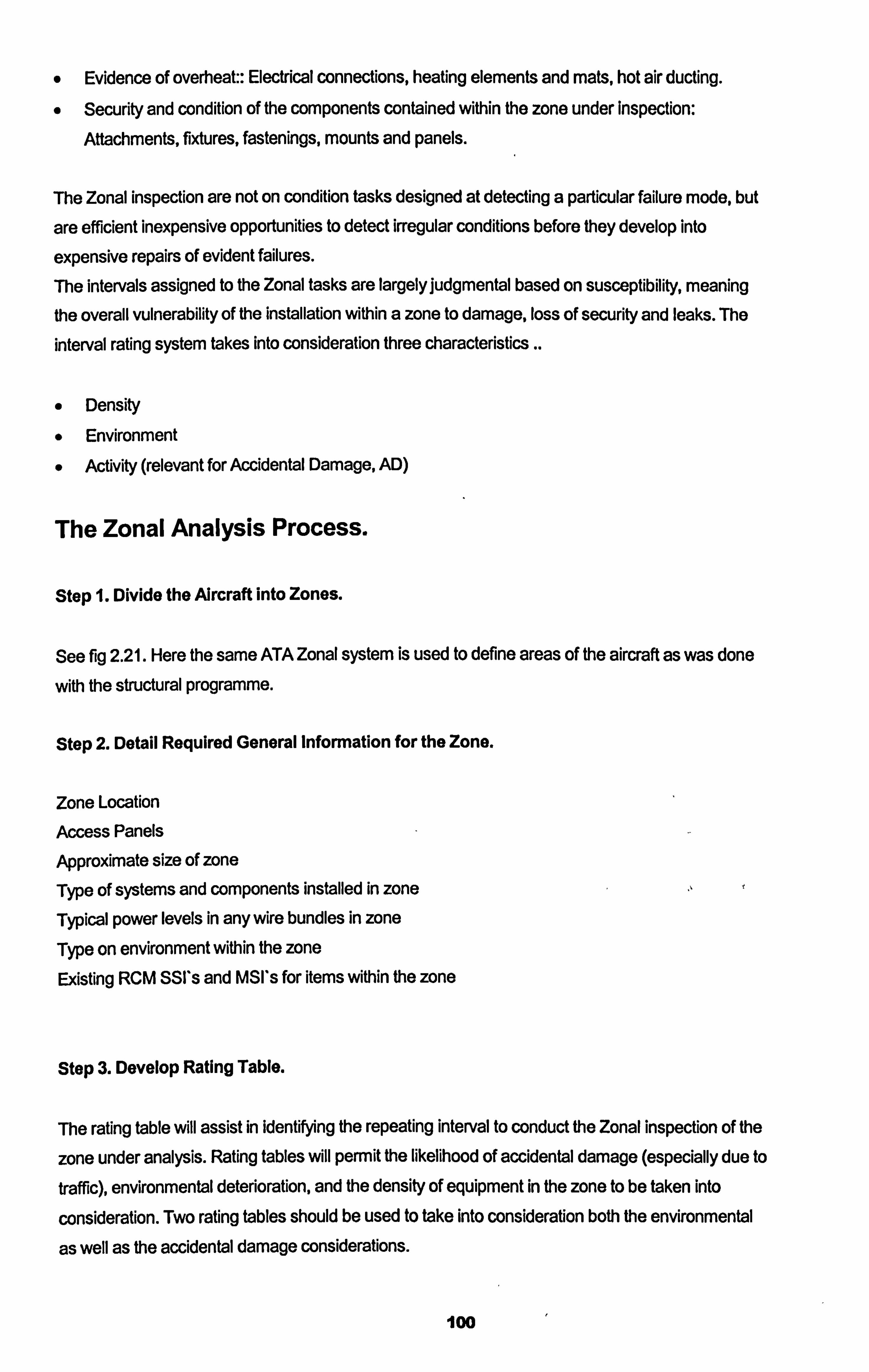
0 Evidence of overheat:: Electrical connections, heating elements and mats, hot air ducting.
0 Security and condition of the components contained within the zone under Inspection:
Attachments, fixtures, fastenings, mounts and panels.
The Zonal inspection are not on condition tasks designed at detecting a particular failure mode, but
are efficient inexpensive opportunities to detect irregular conditions before they develop into
expensive repairs of evident failures.
The intervals assigned to the Zonal tasks are largely judgmental based on susceptibility, meaning the overall vulnerability of the installation Within a zone to damage, loss of security and leaks. The
interval rating system takes into consideration three characteristics ..
Density
* Environment
o Activity (relevant for Accidental Damage, AD)
The Zonal Analysis Process.
Step 1. Divide the Alrcraft into Zones.
See fig 2.21. Here the same ATA Zonal system is used to define areas of the aircraft as was done
with the structural programme.
Stop 2. Detail Required General Information for the Zone.
Zone Location Access Panels
Approximate size of zone Type of systems and components installed in zone Typical power levels in any wire bundles in zone Type on environment within the zone Existing RCM SSI's and MSI's for items within the zone
Step 3. Develop Rating Table.
The rating table will assist in identifying the repeating interval to conduct the Zonal inspection of the
zone under analysis. Rating tables will permit the likelihood of accidental damage (especially due to
traffic), environmental deterioration, and the density of equipment in the zone to be taken into
consideration. Two rating tables should be used to take into consideration both the environmental
as well as the accidental damage considerations.
100
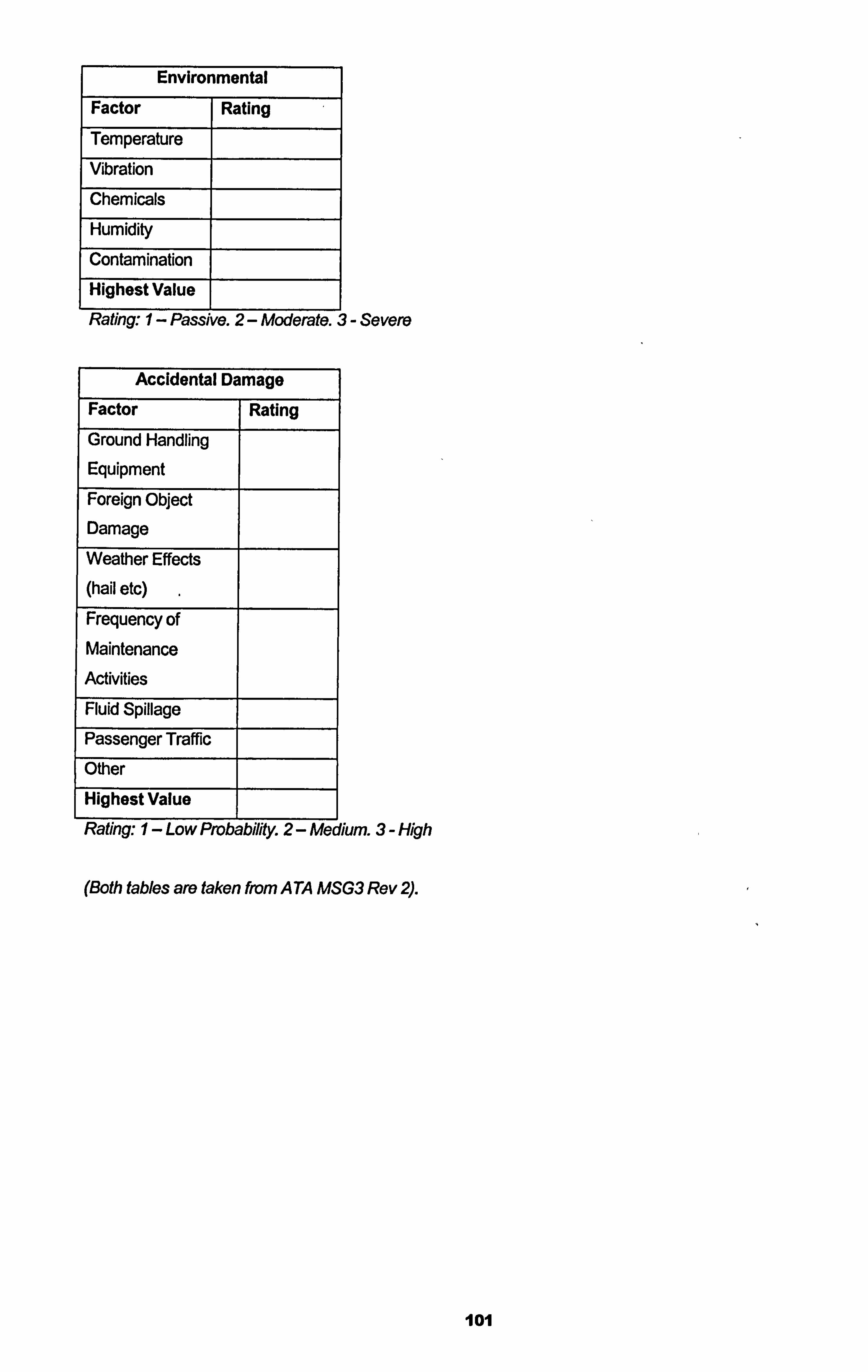
Environmental
Factor Rating
Temperature
Vibration
Chemicals
Humidity
Contamination
Highest Value
Rating: I- Passive. 2- Moderate. 3- Severe
Accidental Damage
Factor Rating
Ground Handling Equipment
Foreign Object Damage
Weather Effects (hail etc) Frequency of Maintenance
Activities
Fluid Spillage
Passenger Traffic
Other
Highest Value
Rating: I- Low Probability. 2- Medium. 3- High
(Both tables are taken from A TA MSG3 Rev 2).
101
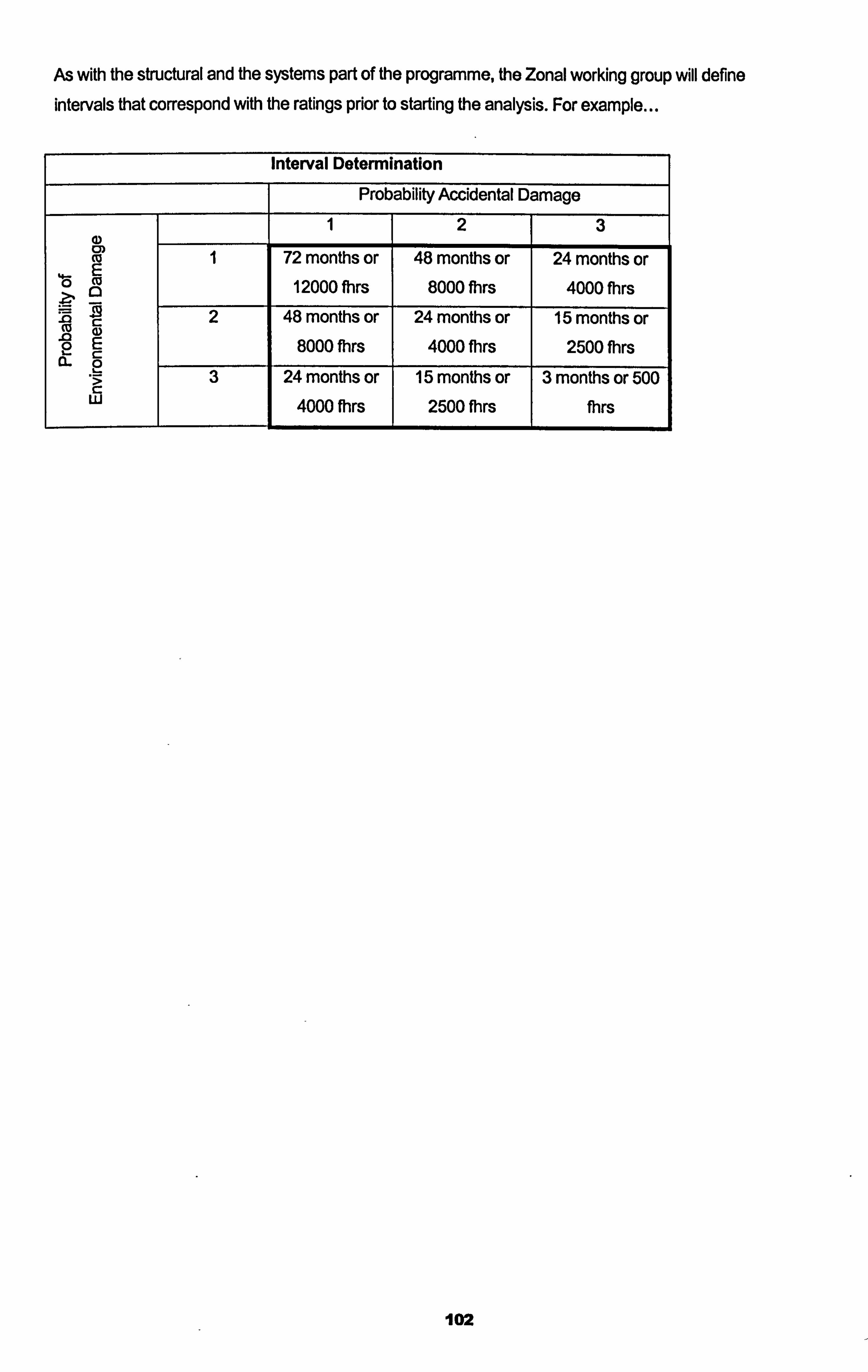
As with the structural and the systems part of the programme, the Zonal working group will define
intervals that correspond with the ratings prior to starting the analysis. For example...
Interval Determination
Probability Accidental Damage
2 3
Ca 1 72 months or 48 months or 24 months or E 46 Cu
a 12000 fhrs 8000 Mrs 4000 fhrs ZN C: 2 48 months or 24 months or 15 months or CU a) ý0 2E 8000 fhrs 4000 fhrs 2500 Mrs C: 2 .9 3 24 months or 15 months Or 3 months or 500 w 4000 fhrs 2500 fhrs thrs
102
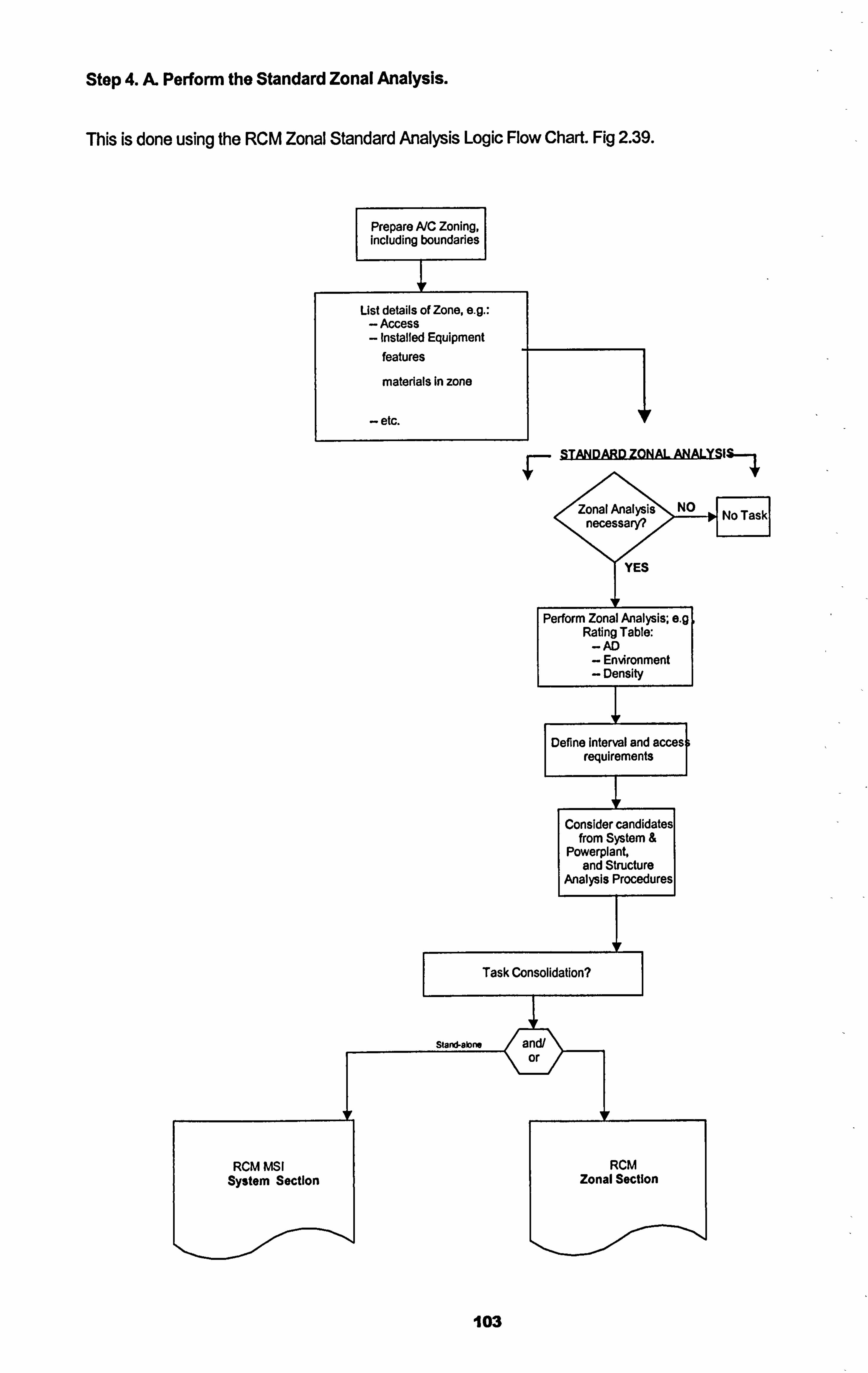
Stop 4. A- Perform the Standard Zonal Analysis.
This is done using the RCM Zonal Standard Analysis Logic Flow Chart. Fig 2.39.
Prepare A/C Zoning, including boundaries
List details of Zone, e. g.: - Access - Installed Equipment
features
materials In zone
- etc.
103
_I- STANDARD ZONAL ANALY IS--,
fig 239 A TA MSG3 Standard Zonal Analysis Flow Chart
Step 4. B. Perform the Enhanced Zonal Analysis.
After some consideration as to the scope of use of the Zonal programme by the Air transport Association of America Maintenance Steering Group (ATA MSG) it was proposed that the Zonal
programme be extended to address some topical issues that were arising at that time in the
operation of aircraft. The first was the integrity of electrical wires over time and the build up of combustible materials over the operating life of the aircraft. The enhanced Zonal analysis adds two
new aspects for the analysis and takes into consideration wiring as a "system" of its own requiring
at times detailed visual inspections to ensure wire integrity. This does not effect the fact that wire in
a zone is still subject to the GVI Zonal inspection, it will identify where wiring merits consideration as a detailed inspection in the system programme. This aspect of wire is not considered in the RCM
system analysis and was added to the RCM flow chart after the initial analysis were conducted. AJso the enhanced analysis includes consideration to the collection of combustible materials. Over
the life of an aircraft material that is not native gather in the comers of many parts of the aircraft,
such as lint, hair, dead skin, carpet fibres, even fuel vapours etc. These materials can be classified
as combustible and many aircraft fires can be said to have been assisted by the presence of these
materials. The Zonal analysis programme takes this aspect into consideration and includes
consideration to the gathering of such materials. So the enhanced dimensions to the Zonal tries to address both of these new aspects of wire as a
system in its own deserving the attentions at times of a detailed inspection in the system
programme as well as always considered in the GVI Zonal programme, also consideration to the build up of combustible material that if left un removed can be classified as a fire hazard. Fig 2.40
and 2.41 show the recognised analysis flow charts in use today.
The two new aspects of the enhanced Zonal analysis complete the objective of the Zonal
programme to detect an abnormal situation existing in a zone in its early period, and giving an
opportunity to rectify the situation and restore the zone to its normal situation.
104
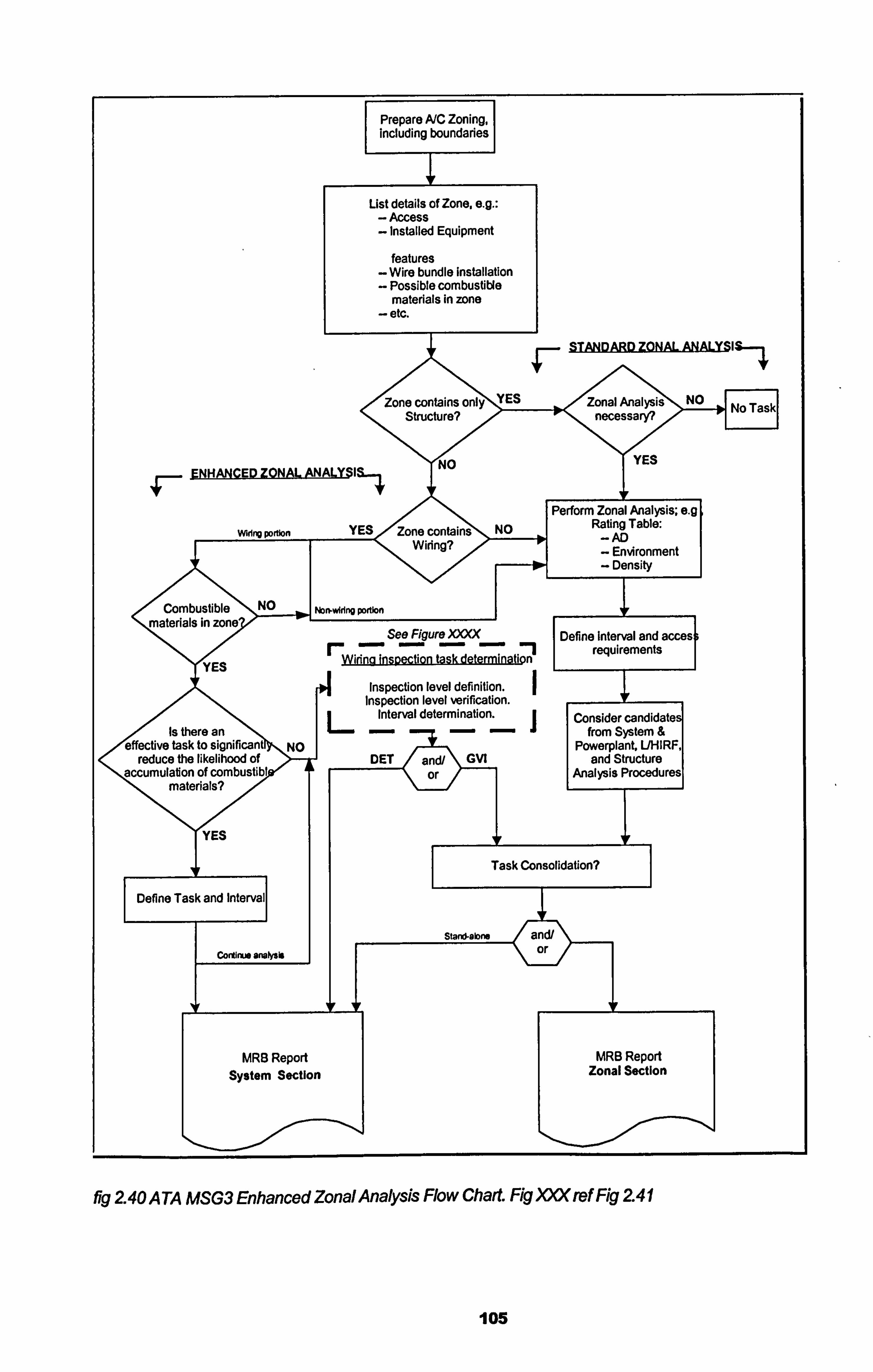
Prepare A/C Zoning, including boundaries
List details of Zone, e. g.: - Access - Installed Equipment
features
- Wire bundle Installation
- Possible combustible materials in zone
- etc.
STANDARD ZONAL ANALY IS-1
e contains onljýM Structure?
ENHANCED ZONAL ANALY IS.,
Zonal Analysi3>ý No necessary?
'0"'
YYES
Perform Zonal Analysis; e. g IE<Zon(e co ins NO Rating Table:
Vý - AD Wiring? - Environment - Density
/" Combustible NO Kba-vAdng portion materials In zone
See Figure X)= Define Interval and a requirements
YES Wiring Insoection task determinati n
s si
Inspection level definition. Inspection level verification.
Interval determination. Consider candida Is there
1
an from System &
10 active task to significant NO Powerplant, UHIF reduce ýft likelihood of DET ý and/ GVI and Structure cnulation of combustibl or Analysis Procedui I materials?
fI
Task Consolidation?
Define Task and
and/
Cono" snoisis or
MRB Report System Section
MRB Report Zonal Section
fig 240 A TA MSG3 Enhanced Zonal Analysis Flow Chart. Rg)= ref Fig 241
105
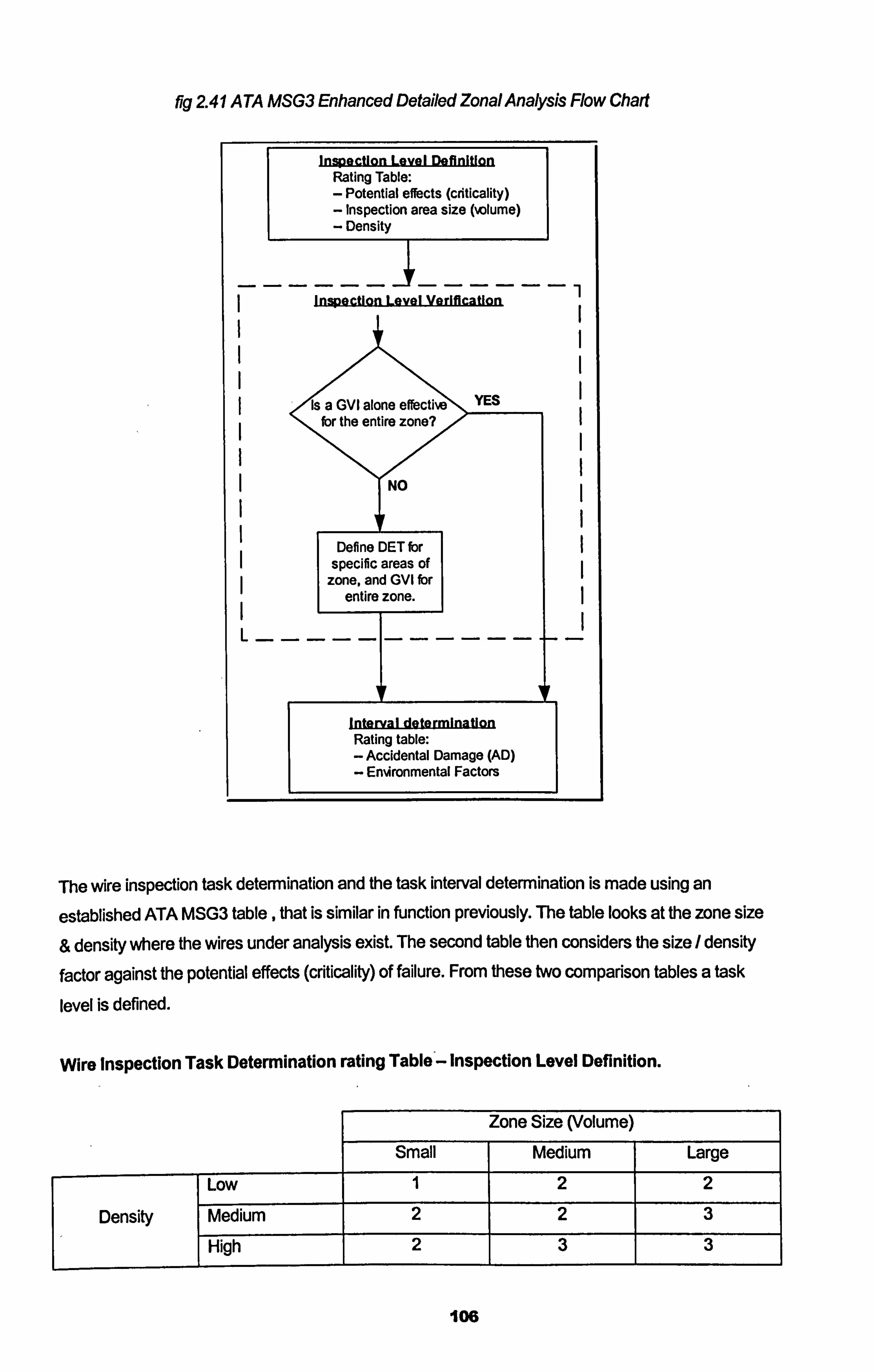
fic 241 A TA MSG3 Enhanced Detailed Zonal Analysis Flow Chart
Inspection Level Definition Rating Table: - Potential effects (criticality) - Inspection area size (%olume) - Density
------------- Inspection Level Verification
YES , "'is a GVI alone effective for the entire zone?
NO
Define DIRT fbr specific areas of
zone, and GVI for entire zone.
Interval determination Rating table:
- Accidental Damage (AD)
- En%4ronmental Factors
The wire inspection task determination and the task interval determination is made using an
established ATA MSG3 table, that is similar in function previously. The table looks at the zone size
& density where the wires under analysis exist. The second table then considers the size / density
factor against the potential effects (criticality) of failure. From these two comparison tables a task
level is defined.
Wire Inspection Task Determination rating Table - Inspection Level Definition.
Zone Size (Volume) Small Medium Large
Low 1 2 2
Density Medium 2 2 3 High 2 3 3
106
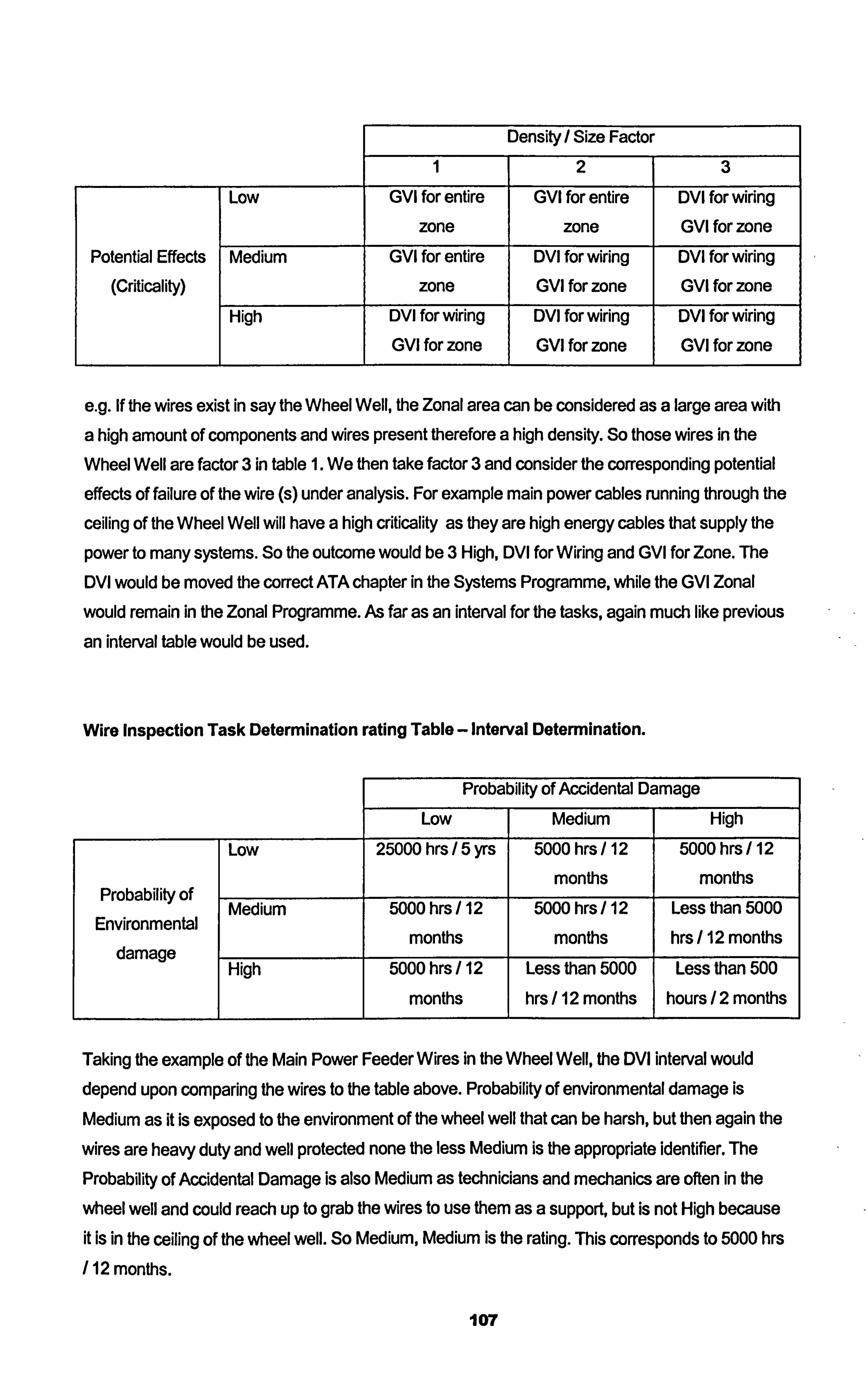
Density / Size Factor
2 3
LOW GVI for entire
zone
GVI for entire
zone
DVI for wiring GVI for zone
Potential Effects
(Criticality)
Medium GVI for entire
zone
DVI for wiring GVI for zone
DVI for wiring GVI for zone
High DVI for wiring GVI for zone
DVI for wiring GVI for zone
DVI for wiring GVI for zone
e. g. If the wires exist in say the Wheel Well, the Zonal area can be considered as a large area with
a high amount of components and wires present therefore a high density. So those wires in the
Wheel Well are factor 3 in table 1. We then take factor 3 and consider the corresponding potential
effects of failure of the wire (s) under analysis. For example main power cables running through the
ceiling of the Wheel Well will have a high criticality as they are high energy cables that supply the
power to many systems. So the outcome would be 3 High, DVI for Wiring and GVI for Zone. The
DVI would be moved the correct ATA chapter in the Systems Programme, while the GVI Zonal
would remain in the Zonal Programme. As far as an interval for the tasks, again much like previous
an interval table would be used.
Wire Inspection Task Determination rating Table - Interval Determination.
Probability of Accidental Damage
Low Medium High
LOW 25000 hrs 5 yrs 5000 hrs / 12 5000 hrs / 12
months months Probability of
Medium 5000 hrs 12 5000 hrs / 12 Less than 5000 Environmental
months months hrs 112 months damage
High 5000 hrs / 12 Less than 5000 Less than 500
months hrs / 12 months hours /2 months
Taking the example of the Main Power Feeder Wires in the Wheel Well, the DVI interval would depend upon comparing the wires to the table above. Probability of environmental damage is
Medium as it is exposed to the environment of the wheel well that can be harsh, but then again the
wires are heavy duty and well protected none the less Medium is the appropriate identifier. The
Probability of Accidental Damage is also Medium as technicians and mechanics are often in the
wheel well and could reach up to grab the wires to use them as a support, but is not High because
it is in the ceiling of the wheel well. So Medium, Medium is the rating. This corresponds to 5000 hrs
/ 12 months.
107
So the Wire Inspection Task is
DVI the Main Power Feeder Cables Passing Through the Ceiling of the Left and Right Wheel Well
every 5000 flight hours or 12 months which ever is sooner.
This means the Zonal programme analysis has been completed. Consideration to those areas that
may not have been inspected using the systems and structures analysis have now been examined. The new aspects of Wires being considered as systems in their own and given a detailed analysis in the Zonal programme addresses the possibility of early detection of faulty wiring thus maintaining the serviceability and airworthiness of the original wire installation. As well as the consideration to
the build up of combustible materials in the Zonal programme analysis therefore the threat of foreign material contributing to the fire threat may be minimised.
108
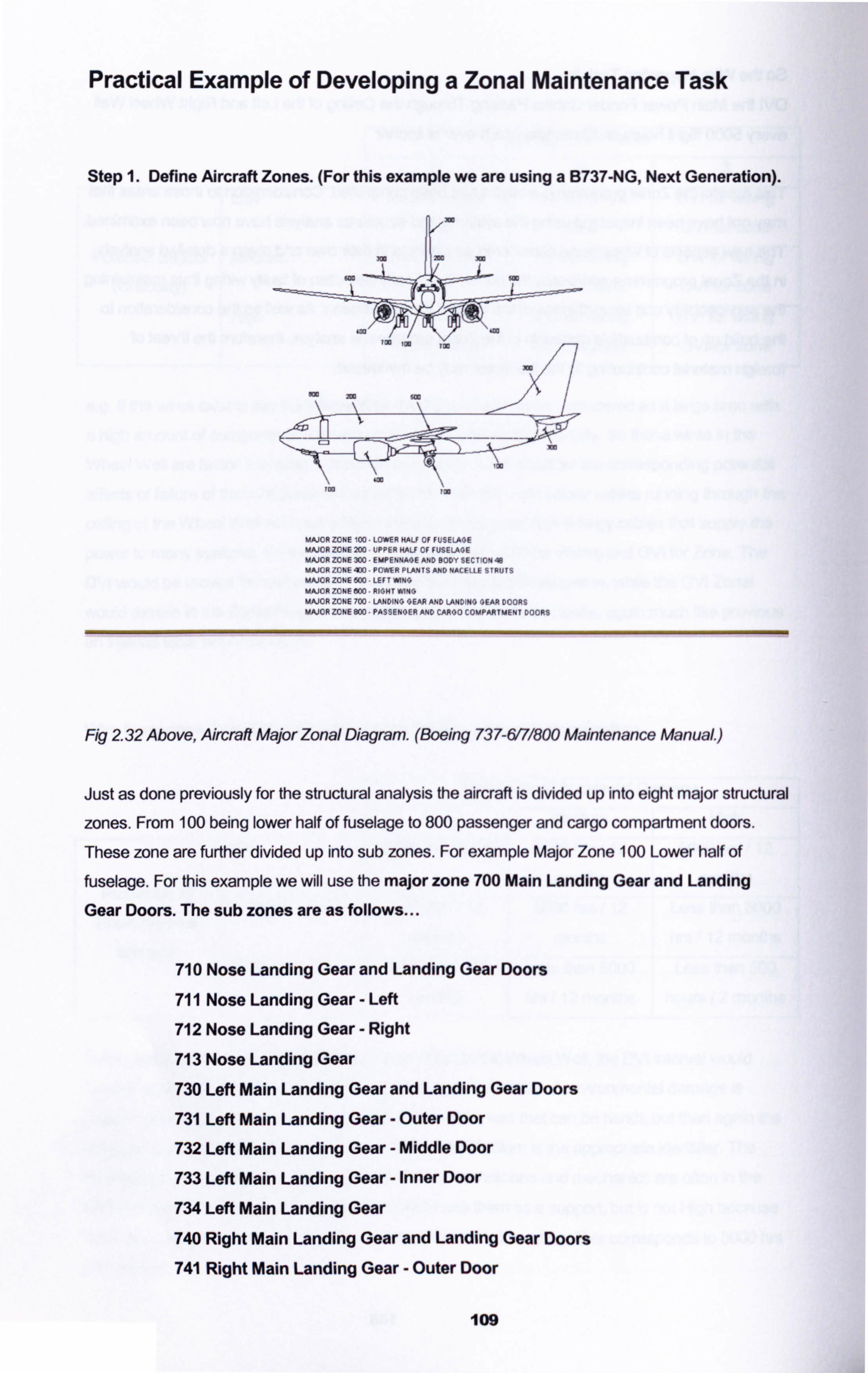
Practical Example of Developing a Zonal Maintenance Task
Step 1. Define Aircraft Zones. (For this example we are using a B737-NG, Next Generation).
MAJOR ZONE 100 LOWER K04LF OF FUSELAGE MAJOR ZONE 200 UPPER HALF OF FUSELAGE MAJOR ZONE 300 EMPENNAGE AND BODY SECTION 48 MAJOR ZONE 400 POWER PLANTS AND NACELLE STRUTS MAJORZONE500 LEFTWINO MAJOR ZONE 000 RIGHT WINO MAJOR ZONE 700 LANDING GEAR AND LANDING GEAR DOORS MAJOR ZONE BOO PASSENGER AND CARGO COMPARTMENT DOORS
Fig 232 Above, Aircraft Major Zonal Diagram. (Boeing 737-6171800 Maintenance Manua/. )
Just as done previously for the structural analysis the aircraft is divided up into eight major structural
zones. From 100 being lower half of fuselage to 800 passenger and cargo compartment doors.
These zone are further divided up into sub zones. For example Major Zone 100 Lower half of
fuselage. For this example we will use the major zone 700 Main Landing Gear and Landing
Gear Doors. The sub zones are as follows...
710 Nose Landing Gear and Landing Gear Doors
711 Nose Landing Gear - Left
712 Nose Landing Gear - Right
713 Nose Landing Gear
730 Left Main Landing Gear and Landing Gear Doors
731 Left Main Landing Gear - Outer Door
732 Left Main Landing Gear - Middle Door
733 Left Main Landing Gear - Inner Door
734 Left Main Landing Gear
740 Right Main Landing Gear and Landing Gear Doors
741 Right Main Landing Gear - Outer Door
109
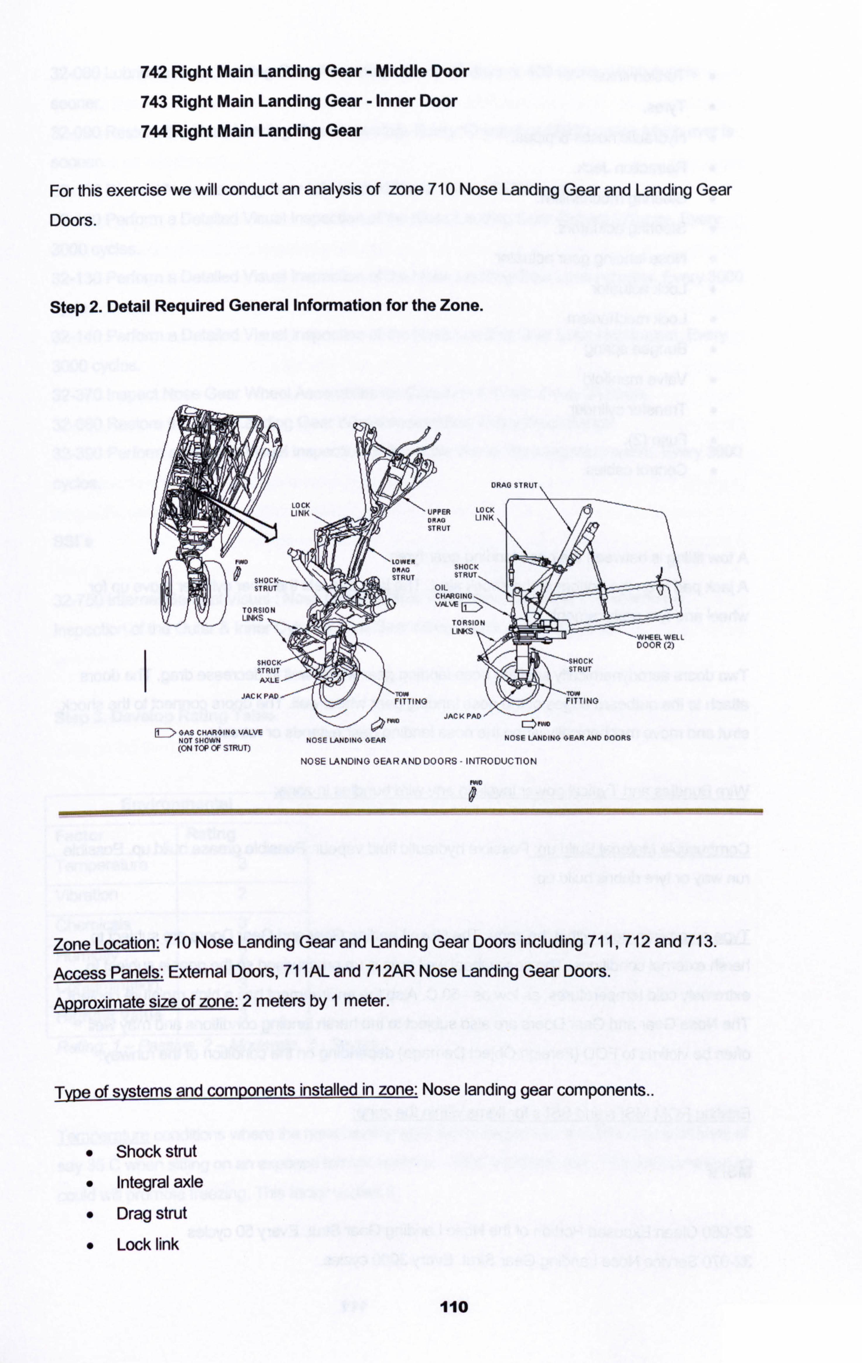
742 Right Main Landing Gear - Middle Door
743 Right Main Landing Gear - Inner Door
744 Right Main Landing Gear
For this exercise we will conduct an analysis of zone 710 Nose Landing Gear and Landing Gear
Doors.
Step 2. Detail Required General Information for the Zone.
ft-ID> OAS CHARGING VALVE
ONND c:: ) FM
NOT S140 N NOSE LANDING GEAR NOSE LANDING GEAR AND DOORS (ON TOP OF STRUT)
NOSE LA WING GEAR A ND DO 0 RS - INTRO DUCTI ON
IWO 0
Zone Location: 710 Nose Landing Gear and Landing Gear Doors including 711,712 and 713.
Access Panels: External Doors, 71 1AL and 712AR Nose Landing Gear Doors.
Approximate size of zone: 2 meters by 1 meter.
Type of syýtems and components installed in zone: Nose landing gear components..
Shock strut Integral axle Drag strut Lock link
110
" Torsion links.
" Tyres.
" Hydraulic hoses & pipes.
" Retraction Jack.
" Steering mechanism.
" Steering actuators.
" Nose landing gear actuator
" Lock actuator
" Lock mechanism
" Bungee spring
" Valve manifold
" Transfer cylinder
" Fuse (2).
" Control cables.
A tow fiffing is between the nose landing gear tyres.
A jack pad is on the bottom of the shock strut. The jack pad lets the inner Cylinder move up for
wheel and tyre replacement.
Two doors aerodynamically seal the nose landing gear wheel well to decrease drag. The doors
attach to the outboard edges of the nose landing gear wheel well. The doors connect to the shock
strut and move mechanically when the nose landing gear extends or retracts.
Wire Bundles and nVical gower levels in any mfire bundles in zone:
Combustible Material Build unLPossible hydraulic fluid vapour. Possible grease build up. Possible
run way or tyre debris build up.
IWe on environment within the zone: The Nose Landing Gear and Gear Doors are subject to harsh external conditions. The nose wheel well area is un pressurised so the gear is subject to
extremely cold temperatures, as low as -50 C. Also the environment has a high moisture content. The Nose Gear and Gear Doors are also subject to the harsh landing conditions and may well often be victims to FOD (Foreign Object Damage) depending on the condition of the runway.
Existing RCM MSI's and SSI's for items within the zone:
MSI's
32-060 Clean Exposed Portion of the Nose Landing Gear Strut. Every 50 cycles 32-070 Service Nose Landing Gear Strut. Every 3000 cycles.
III
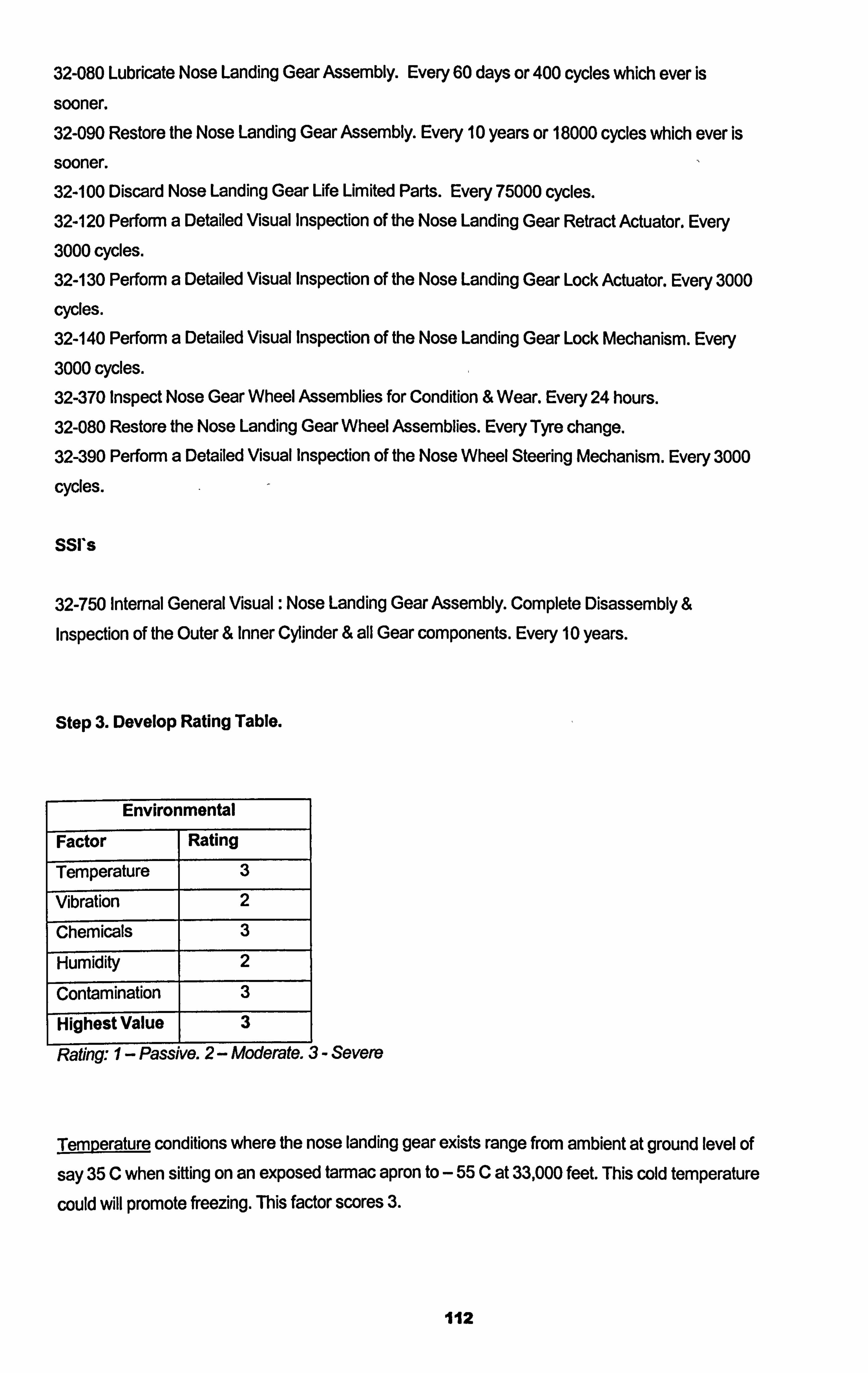
32-080 Lubricate Nose Landing Gear Assembly. Every 60 days or 400 cycles which ever is
sooner. 32-090 Restore the Nose Landing Gear Assembly. Every 10 years or 18000 cycles which ever is sooner. 32-100 Discard Nose Landing Gear Life Limited Parts. Every 75000 cycles. 32-120 Perform a Detailed Visual Inspection of the Nose Landing Gear Retract Actuator. Every 3000 cycles. 32-130 Perform a Detailed Visual Inspection of the Nose Landing Gear Lock Actuator. Every 3000
cycles. 32-140 Perform a Detailed Visual Inspection of the Nose Landing Gear Lock Mechanism. Every 3000 cycles. 32-370 Inspect Nose Gear Wheel Assemblies for Condition & Wear. Every 24 hours. 32-080 Restore the Nose Landing Gear Wheel Assemblies. Every Tyre change. 32-390 Perform a Detailed Visual Inspection of the Nose Wheel Steering Mechanism. Every 3000
cycles.
SSI*s
32-750 Internal General Visual : Nose Landing Gear Assembly. Complete Disassembly &
Inspection of the Outer & Inner Cyfinder & all Gear components. Every 10 years.
Step 3. Develop Rating Table.
Environmental
Factor Rating
Temperature 3
Vibration 2
Chemicals 3
Humidity 2
Contamination 3
Highest Value 3
Rating: I- Passive. 2- Moderate. 3- Severe
Temerature conditions where the nose landing gear exists range from ambient at ground level of
say 35 C when sifting on an exposed tarmac; apron to - 55 C at 33,000 feet. This cold temperature
could will promote freezing. This factor scores 3.
112
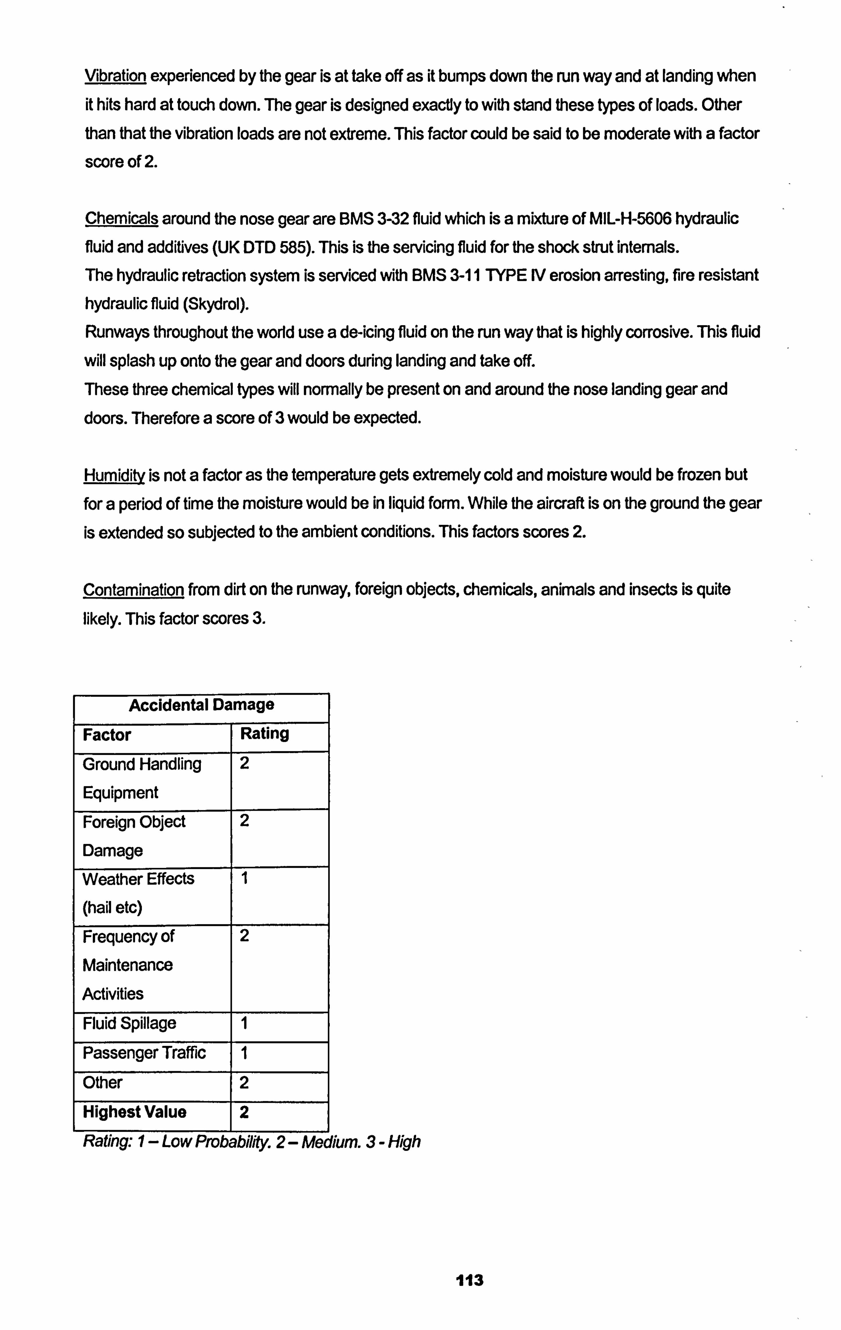
Vibration experienced by the gear is at take off as it bumps down the run way and at landing when it hits hard at touch down. The gear is designed exactly to with stand these types of loads. Other
than that the vibration loads are not extreme. This factor could be said to be moderate with a factor
score of 2.
Chemicals around the nose gear are BMS 3-32 fluid which is a mixture of MIL-H-5606 hydraulic
fluid and additives (UK DTD 585). This is the servicing fluid for the shock strut internals.
The hydraulic retraction system is serviced with BMS 3-11 TYPE IV erosion arresting, fire resistant hydraulic fluid (Skydrol). Runways throughout the world use a de-icing fluid on the run way that is highly corrosive. This fluid
will splash up onto the gear and doors during landing and take off. These three chemical types will normally be present on and around the nose landing gear and doors. Therefore a score of 3 would be expected.
Humidi is not a factor as the temperature gets extremely cold and moisture would be frozen but
for a period of time the moisture would be in liquid form. While the aircraft is on the ground the gear is extended so subjected to the ambient conditions. This factors scores 2.
Contamination from dirt on the runway, foreign objects, chemicals, animals and insects is quite likely. This factor scores 3.
Accidental Damage
Factor Rating
Ground Handling
Equipment
2
Foreign Object
Damage
2
Weather Effects
(hail etc)
1
Frequency of Maintenance
Activities
2
Fluid Spillage 1
Passenger Traffic 1
Other 2
Highest Value 2
Rating., 1- Low Probabifity. 2- Medium. 3- High
113
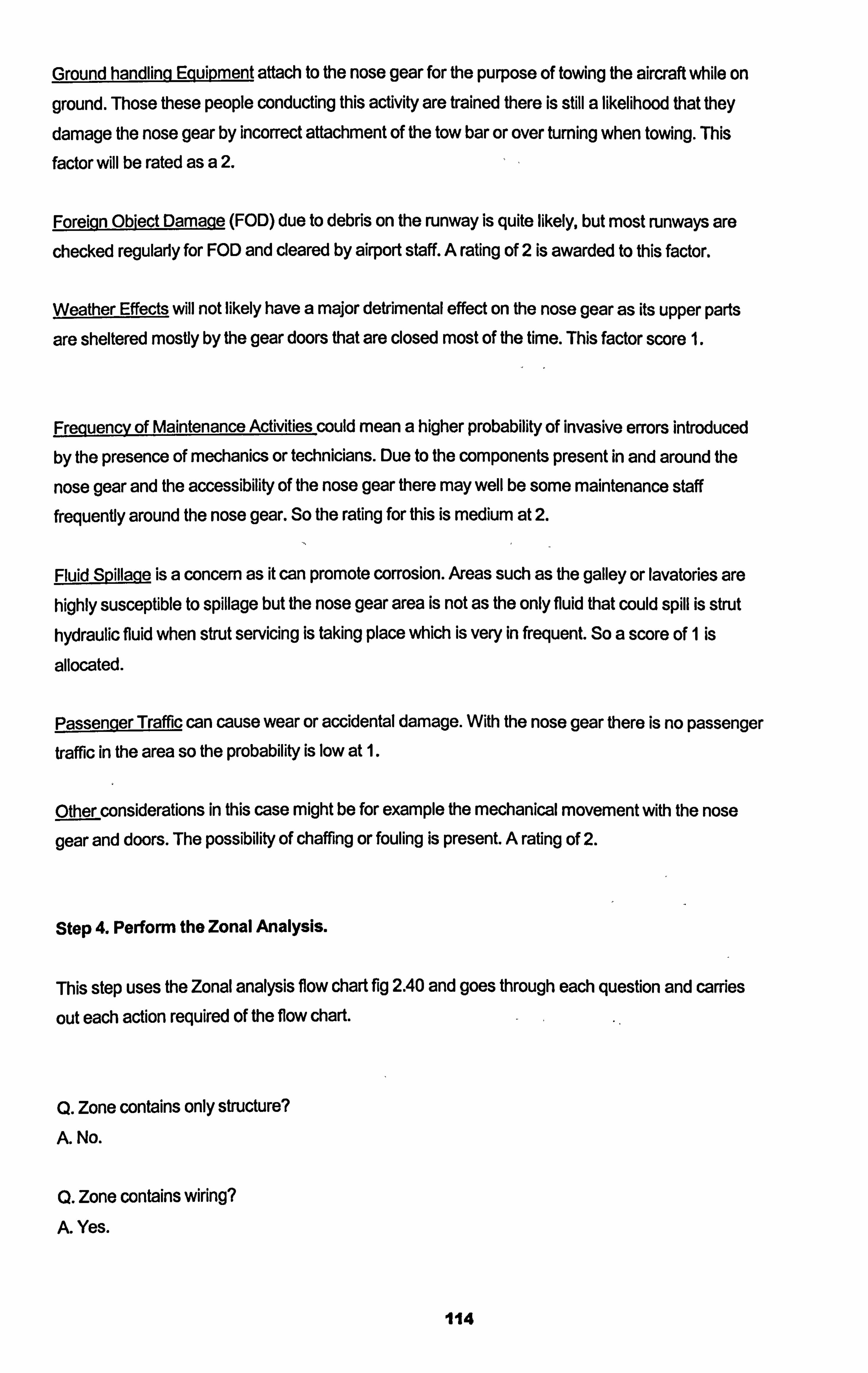
Ground handling Eguipmen attach to the nose gear for the purpose of towing the aircraft while on
ground. Those these people conducting this activity are trained there is still a likelihood that they
damage the nose gear by incorrect attachment of the tow bar or over turning when towing. This
factor will be rated as a 2.
Foreign Obiect Damage (FOD) due to debris on the runway is quite likely, but most runways are
checked regularly for FOD and cleared by airport staff. A rating of 2 is awarded to this factor.
Weather Effects will not likely have a major detrimental effect on the nose gear as its upper parts
are sheltered mostly by the gear doors that are closed most of the time. This factor score 1.
Freguengy of Maintenance Activities could mean a higher probability of invasive errors introduced
by the presence of mechanics or technicians. Due to the components present in and around the
nose gear and the accessibility of the nose gear there may well be some maintenance staff frequently around the nose gear. So the rating for this is medium at 2.
Fluid Spillage is a concern as it can promote corrosion. Areas such as the galley or lavatories are highly susceptible to spillage but the nose gear area is not as the only fluid that could spill is strut hydraulic fluid when strut servicing is taking place which is very in frequent. So a score of 1 is
allocated.
Passenger Traffi can cause wear or accidental damage. With the nose gear there is no passenger traffic in the area so the probability is low at 1.
pther considerations in this case might be for example the mechanical movement with the nose
gear and doors. The possibility of chaffing or fouling is present. A rating of 2.
Step 4. Perform the Zonal Analysis.
This step uses the Zonal analysis flow chart fig 2.40 and goes through each question and carries
out each action required of the flow chart.
Q. Zone contains only structure?
A. No.
Q. Zone contains wiring? A. Yes.
114
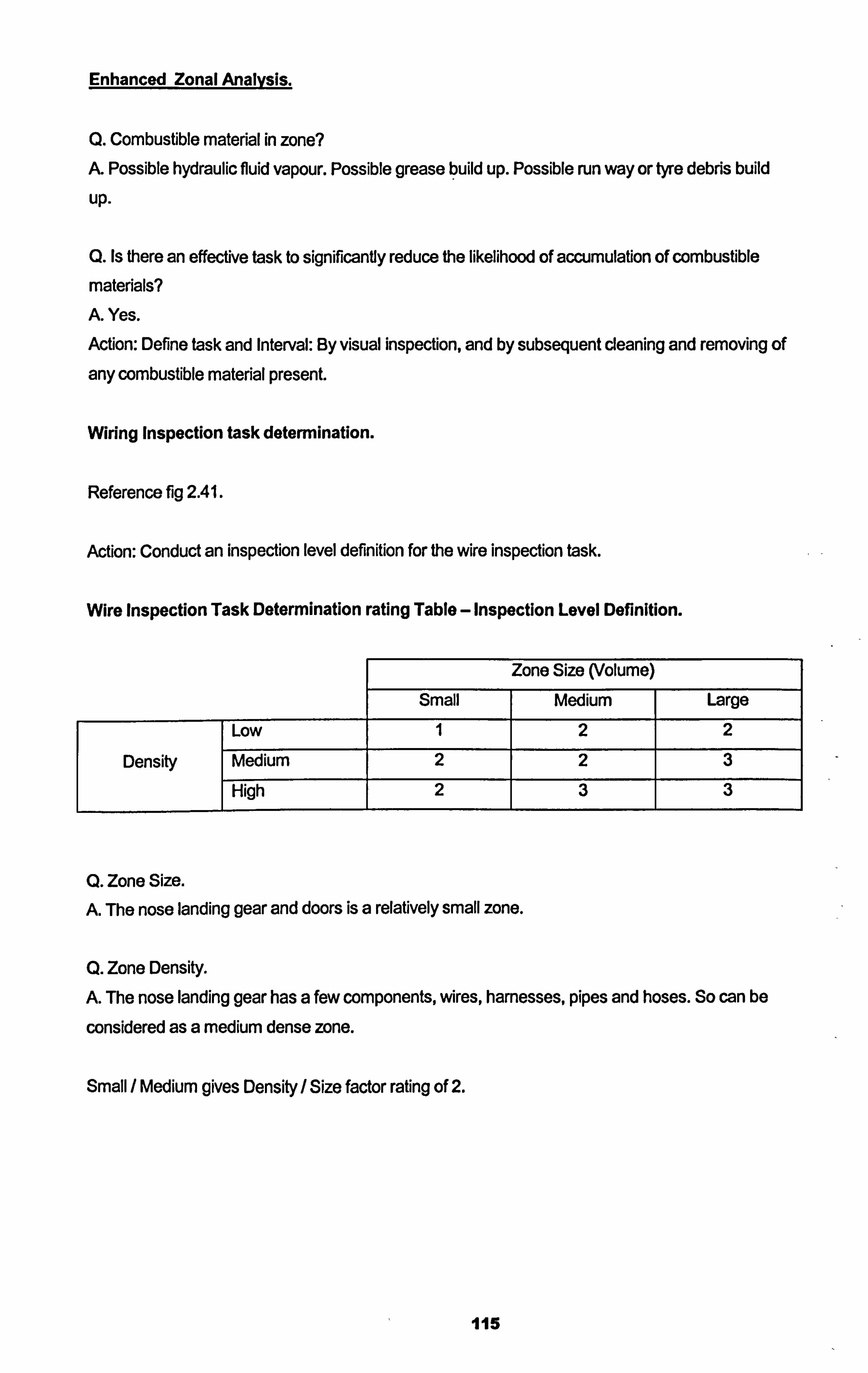
Enhanced Zonal Analysis.
Q. Combustible material in zone? A. Possible hydraulic fluid vapour. Possible grease build up. Possible run way or tyre debris build
up.
Q. Is there an effective task to significantly reduce the likelihood of accumulation of combustible materials? A. Yes.
Action: Define task and Interval: By visual inspection, and by subsequent cleaning and removing of
any combustible material present.
Wiring Inspection task determination.
Reference fig 2.41.
Action: Conduct an inspection level definition for the wire inspection task.
Wire Inspection Task Determination rating Table - Inspection Level Definition.
Zone Size (Volume) Small Medium Large
Low 1 2 2
Density Medium 2 2 3 High 2 3 3
Q. Zone Size. A. The nose landing gear and doors is a relatively small zone.
Q. Zone Density. A. The nose landing gear has a few components, Wres, harnesses, pipes and hoses. So can be
considered as a medium dense zone.
Small / Medium gives Density / Size factor rating of 2.
115
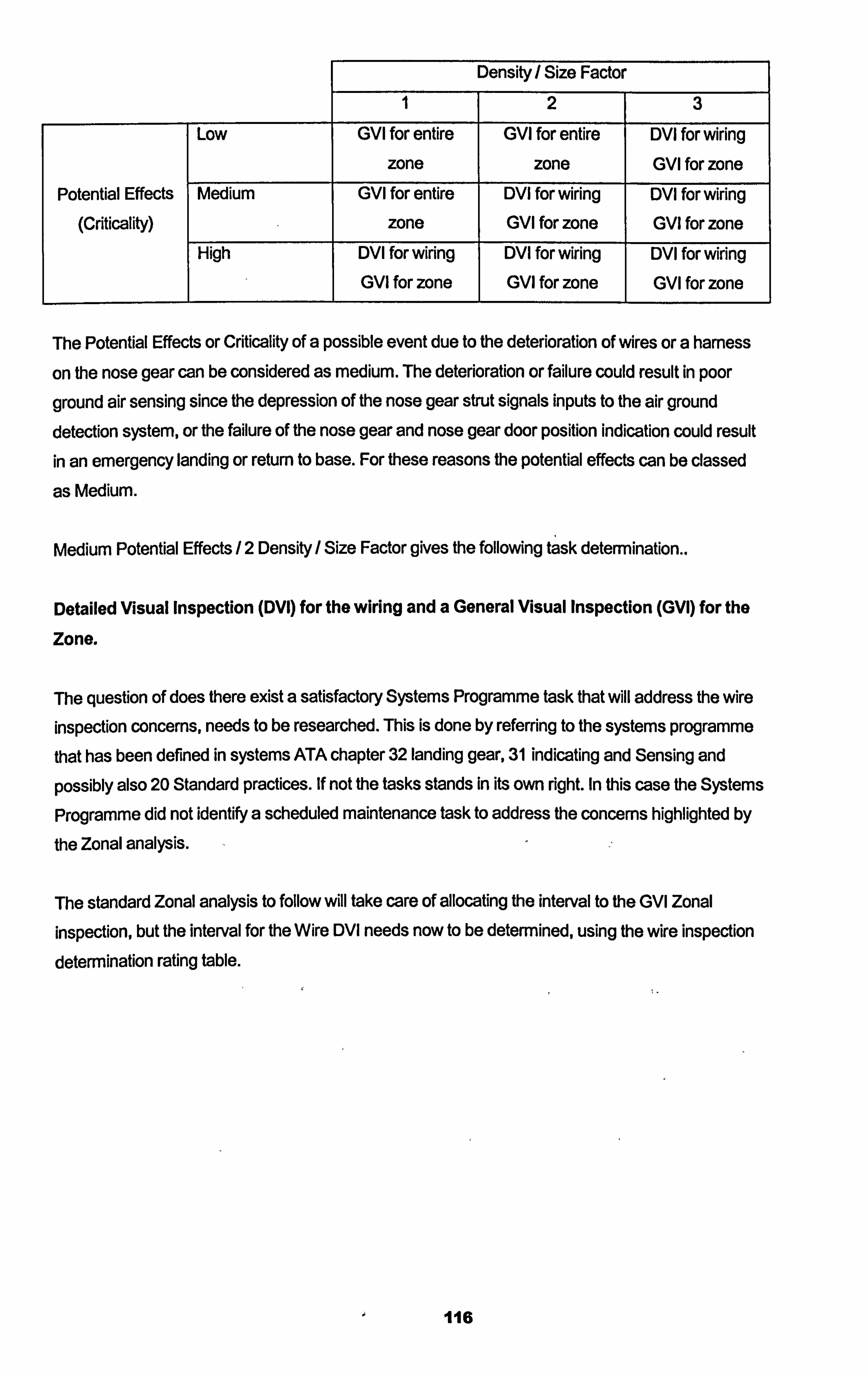
Density/ Size Factor
1 2 3
Low GVI for entire
zone
GVI for entire
zone
DVI for wiring GVI for zone
Potential Effects
(Criticality)
Medium GVI for entire
zone
DVI for wiring GVI for zone
DVI for wiring GVI for zone
High DVI for wiring GVI for zone
DVI for wiring GVI for zone
DVI for wiring GVI for zone
The Potential Effects or Criticality of a possible event due to the deterioration of wires or a harness
on the nose gear can be considered as medium. The deterioration or failure could result in poor
ground air sensing since the depression of the nose gear strut signals inputs to the air ground detection system, or the failure of the nose gear and nose gear door position indication could result in an emergency landing or return to base. For these reasons the potential effects can be classed
as Medium.
Medium Potential Effects /2 Density / Size Factor gives the following task determination..
Detailed Visual Inspection (DVI) for the wiring and a General Visual Inspection (GVQ for the
Zone.
The question of does there exist a satisfactory Systems Programme task that will address the wire inspection concerns, needs to be researched. This is done by referring to the systems programme that has been defined in systems ATA chapter 32 landing gear, 31 indicating and Sensing and
possibly also 20 Standard practices. If not the tasks stands in its own right. In this case the Systems
Programme did not identify a scheduled maintenance task to address the concerns highlighted by
the Zonal analysis. -2
The standard Zonal analysis to follow will take care of allocating the interval to the GVI Zonal
inspection, but the interval for the Wire DVI needs now to be determined, using the wire inspection
determination rating table.
116
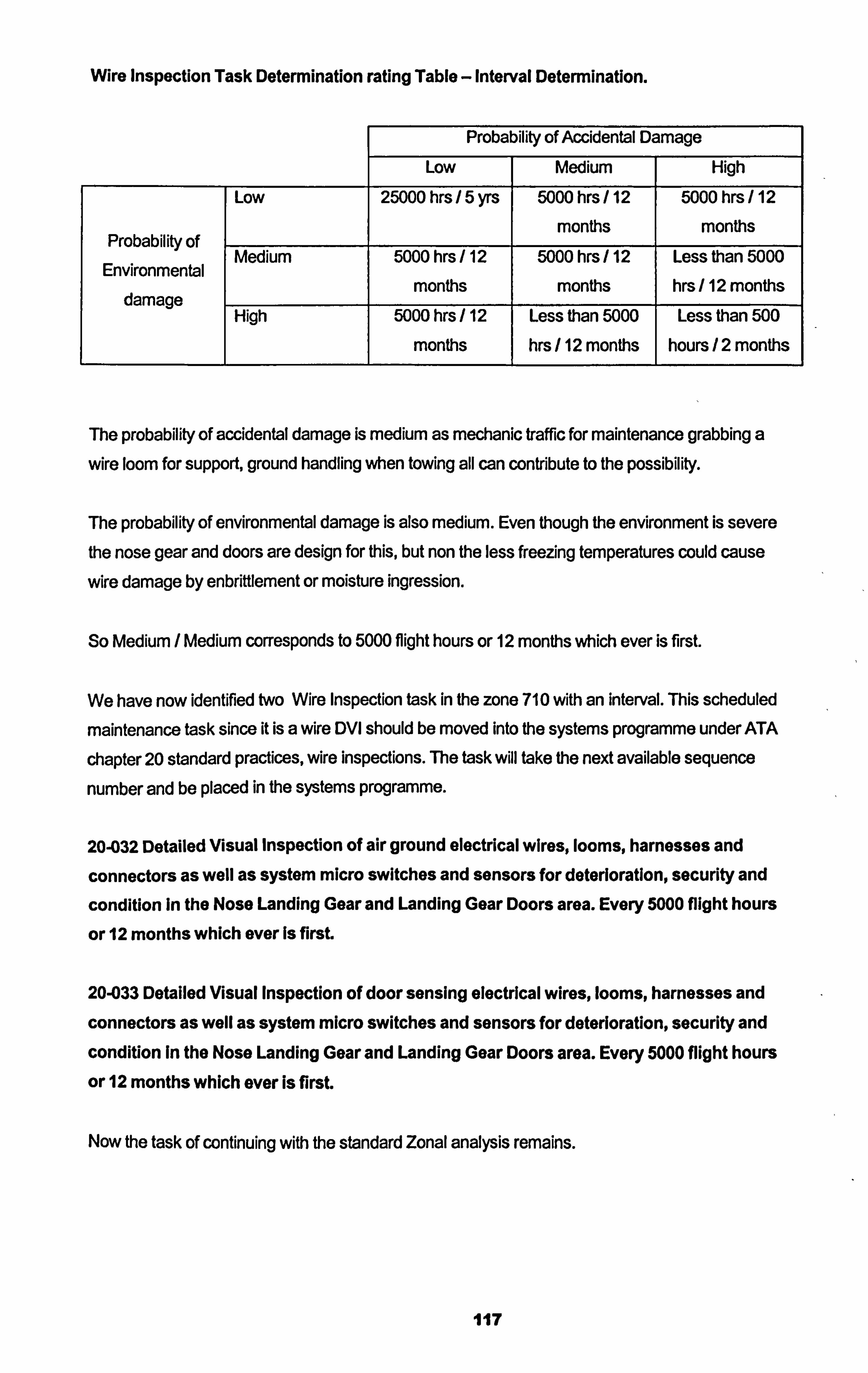
Wire Inspection Task Determination rating Table - Interval Determination.
Probability of Accidental Damage
LOW Medium High
Low 25000 hrs 5 yrs 5000 hrs / 12 5000 hrs / 12
months months Probability of
Medium 5000 hrs 12 5000 hrs / 12 Less than 5000 Environmental
months months hrs / 12 months damage High 5000 hrs / 12 Less than 5000 Less than 500
months hrs / 12 months hours /2 months
The probability of accidental damage is medium as mechanic traffic for maintenance grabbing a
wire loom for support, ground handling when towing all can contribute to the possibility.
The probability of environmental damage is also medium. Even though the environment is severe the nose gear and doors are design for this, but non the less freezing temperatures could cause
wire damage by enbrittlement or moisture ingression.
So Medium / Medium corresponds to 5000 flight hours or 12 months which ever is first.
We have now identified two Wire Inspection task in the zone 710 with an interval. This scheduled
maintenance task since it is a wire DVI should be moved into the systems programme under ATA
chapter 20 standard practices, wire inspections. The task will take the next available sequence
number and be placed in the systems programme.
20-032 Detailed Visual Inspection of air ground electrical wires, looms, harnesses and
connectors as well as system micro switches and sensors for deterioration, security and
condition In the Nose Landing Gear and Landing Gear Doors area. Every 5000 flight hours
or 12 months which ever Is first.
20-033 Detailed Visual Inspection of door sensing electrical wires, looms, harnesses and
connectors as well as system micro switches and sensors for deterioration, security and
condition In the Nose Landing Gear and Landing Gear Doors area. Every 5000 flight hours
or 12 months which ever is first.
Now the task of continuing with the standard Zonal analysis remains.
117
Standard Zonal Analyýis.
We have already recognised that a Zonal task is necessary, so we move on to the next question or
action.
Action: Perform Zonal analysis. E. g. rating table, AD / Environmental / Density.
This action was done at step 3, so we refer to the two tables. The first showing the highest value for Environmental as 3 and Accidental as 2. As a GVI Zonal is inexpensive to conduct and in this case the access is almost nothing. The GVI for the zone 710, Nose Landing Gear and Doors should be
less than 5000 flight hours / 12 months. Using airline experience and engineering judgement the following Zonal inspection could be adopted..
Z710-001 During Walk Round Inspection check the Nose Landing Gear and Doors for
damage and condition. Before Every Flight.
Z710-002 Nose Landing Gear and Doors Zonal GV1 Inspection. Every 6 months.
Note that the first inspection Z71 0-001 is not strictly a Zonal GVI but a walk round inspection before
flight. This type of inspection though not adhering strictly to the definition of the Zonal or the GVI,
within touching distance, non the less the walk round pre flight inspection is an effective way of on a
very regular basis establishing a general airworthiness condition before flight.
Note that the numbering convention used above is Z for Zonal, to identify the task as part of the
Zonal programme. 710 for the zone under inspection and 001 for the sequence of the task within that zone. Another convention can be used such as...
32 for Zonal ATA chapter and 800 for a sequence number that will not coincide with the systems
programme or the structures programme for that ATA chapter.
For example, the same inspection as above numbered as follows
32-801 During Walk Round Inspection check the Nose Landing Gear and Doors for damage
and condition. Before Every Flight.
32-802 Nose Landing Gear and Doors Zonal GVI Inspection. Every 6 months.
Ila
The Walk round Inspection.
Walk round inspection are general visual inspections from ground to detect any obvious external damage or defect such as a large dent from a bird strike, fluid leakage from control screw jacks or power control units, gear damage sustained from the last landing etc. The Walk round is an effective check to be carried out usually post flight and pre flight. The level of skill to carry out the
walk round inspection is of some debate. Often the flight crew conduct their walk round prior to
accepting an aircraft for flight. Often the releasing technician will conduct a walk round as part of his
departure checks. Though the walk round inspection is not strictly a Zonal GVI as the subject of inspection, e. g. underside of wing of a B747, is not within touching distance. This should be
considered when allocating a walk round inspection to address an item in the RCM analysis.
Event Orientated Inspections.
Special events that are not at all normal, such as lightning strikes or heavy landings. Merit special inspections that are not determined by RCM analysis. These inspection are as a result of a
significant event. These significant events should be anticipated, considered and the effective inspection tasks to ensure the continued airworthiness should be determined. Examples of Event
Orientated Inspections also known as Unscheduled Maintenance Checks are found in ATA Chapter 5 of the maintenance manual. The following are defined unscheduled maintenance cheks
with their respective ata chapter...
ql-. 05-51-01 HARD LANDING OR HIGH DRAGISIDE LOAD LANDING
05-51-04 SEVERE OR UNUSUAL TURBULENCE, STALL, BUFFET OR SPEEDS
MORE THAN DESIGN LIMITS
05-51-08 FLAP/SLAT DOWN OVERSPEED CONDITION
05-51-10 DRAGGED ENGINE NACELLEIENGINE SEIZUREITHRUST REVERSER
AND ATTACH POINTS DAMAGE
05-51-14 MERCURY SPILLAGE CONDITION
05-51-15 BRAKE SEIZURE CONDITION
05-51-16 FLAT SPOTTED TIRES
05-51-17 WHEEL BEARING FAILURE/DAMAGE CONDITION
05-51-18 BIRD/HAIL STRIKE CONDITION
05-51-19 LIGHTNING STRIKE CONDITION
05-51-22 HYDRAULIC FLUID REACTION WITH TITANIUM
05-51-24 CABIN OVERPRESSURE CONDITION
05-51-27 EXTREME DUST CONDITION
05-51-28 ICE OR SNOW CONDITION
05-51-31 VOLCANIC ASH CONDITION
05-51-32 TAIL STRIKE/SKID CONDITION
119
1? z 05-51-34 HOT AIR DUCT RUPTURE CONDITION
05-51-35 OVERWEIGHT LANDING
05-51-42 DAMAGE DUE TO ENGINE BLADE OUT
05-51-44 NACELLE/STRUT PRESSURE RELIEF DOORS OPEN CONDITION
05-51-47 LANDING-GEAR-DOWN OVERSPEED CONDITION
05-51-54 TIRE TREAD LOSS OR TIRE BURST
05-51-57 ACID SPILLAGE CONDITION
05-51-67 AIRFRAME VIBRATION CONDITION
05-51-80 CONDITIONED AIR PACK OUTLET DUCT SYSTEM FAILURE
05-51-81 CABIN DEPRESSURIZATION CONDITION
05-51-91 EXCESSIVE CABIN PRESSURE LEAKAGE
05-55 HIRF/LIGHTNING PROCEDURES
Though the unscheduled maintenance checks are not derived from RCM / MSG3 analysis they are
event orientated in as much as they are only carried out as a result of an unusual event occurring.
Summarisina RCM.
The use of RCM analysis is to attempt to define a scheduled maintenance programme of tasks that
maintain the inherent design reliability of a system or component through scheduled maintenance tasks. A systems, structural and a Zonal maintenance programme can be developed using RCM.
By considering the consequences or effects of failure before defining the scheduled maintenance
task, this means the focus is on applicable and effective maintenance tasks rather than carrying out
a task for the sake of it. RCM maintenance programmes remove the irrelevant maintenance task
and recognises that Maintenance tasks are invasive and can by their own action introduce further
or different problems. The decision to carry out a maintenance task should not be without close
analysis of the merit of that inspection.
RCM analysis allows in operational failures to occur at times but also goes looking for non evident
failures at intervals defined by engineering logic and historical failure data.
RCM analysis attempts to bring to maintenance task allocation a decision logic that minimises
scheduled maintenance tasks to a core few. It has standardised the maintenance task to 5 specific
maintenance actions,
General visual Inspection
Detailed Inspection
operational Check
Functional Check
120
Restoration
Over and above the RCM maintenance schedule it is recognised that special events require special inspections. Those events have been pre defined and so have the maintenance actions. RCM
decision tree analyses is the basis for MSG3 analyses which will be further discussed in the next
section.
121
3. The Maintenance Steerinq Group.
3.1 MSG: An Industry Acceptance of RCM Analysis to Create an Aircraft Maintenance
Programme.
3.1.1 MSG: Addressing the Issue of Aircraft Scheduled Maintenance.
The FAA became increasingly concerned by experience showing that it was not possible to control the failure rate of certain types of engines by any feasible changes in either the content or frequency of scheduled overhauls. As a result, in 1960 a task force was formed, consisting of
representatives from both the FAA and the airlines, to investigate the capabilities of preventative
maintenance.
The work group led to the establishment of the FAA Industry Reliability Pr ogramme. Two major discoveries resulted from the programme:
Scheduled overhauls have little effect on the overall reliability of a complex item unless the item has
a dominant failure mode.
Arline and manufacturer experience in developing scheduled maintenance programmes for new
aircraft has shown that more effective programmes can be developed through the use of a logic
decision process. This working together of the Regulators and the Operators'was the attempts of a Maintenance Steering Group (MSG) endeavouring to find a maintenance solution to ensure the
continued airworthiness of aircraft in an efficient logical manner.
3.1.2 MSG 1 an Initial theory to create an Aircraft Maintenance Programme.
During the advent of the introduction of the B747, representatives were invited by Boeing to attend
a series of meeting with the view to develop an effective and efficient maintenance programme. In
july 1968 this Maintenance Steering Group produced a handbook called "MSG-1 Maintenance
Evaluation and Programme Development' which included decision logic and inter airline
manufacturer procedures for developing a maintenance programme for the new B747. It was felt
that these guidelines in the MSG-1 Handbook would ensure maximum safety and reliability at the
lowest cost possible.
The MSG-1 philosophy utilised Overhaul and On Condition concepts. The objective of the MSG-1
Handbook was to permit the evaluation of a new aircraft design for maintainability and subsequent to the evaluation develop a maintenance programme which will be acceptable to the Regulatory
Authorities, the Operators and the Manufacturer.
MSG-1 for the first time called on the designers to consider maintenance and reliability. Three of the main objectives of the Handbook were...
122
1. To outline the otganisation and methods for providing akline in puts to the aircraft designer to
assure proper consideration for maintainability features during the design phase of new aircraft.
2 To outline the organisation, decision process and detailed procedures for determining the
scheduled maintenance requirements for new aircrA
a To outline the methods by which the airlines and Regulatory AuthotWes can operate together during the period of development of the airlines maintenance programmes for new aftraft.
(MSG-1 Boeing 1968)
It was this idea that all those with a vested interest in developing an effective maintenance
programme got together to decide on policy, direct the activities of the Working Group as well as to
be part of it. The Working Group made up of the Operators, Regulators and Manufacturers was
named the Maintenance Review Board. They would together build the maintenance programme
using the guidelines of the MSG-1 Handbook.
At this stage of MSG development it was already understood that the best reliability that could be
achieved by a system, component or structure belonging to an aircraft was the reliability of the
original design. No amount of maintenance could improve that level on inherent reliability. It was
also recognised that in operation experience played a large part in maintenance programme development after the initial programme was developed. MSG also recognised the requirement for
trained personnel and for standards and levels of inspection. The first standard inspection levels
defined by MSG-1 were as follows...
1. Servicing
2. Inspection
3. Repair
4. Testing
5. Calibration
6. Replacement
It was defined that only tasks that have a direct effect on meeting the stated objectives of the
maintenance programme are valid task for inclusion into the programme. Task that increase
maintenance costs without a corresponding increase in reliability protection are not advised in
IVISG-11.
123

The MSG-1 Handbook advised the development of the Scheduled Maintenance Programme using decision logic for the first time in the aircraft maintenance discipline. The decision logic started by
considering the consequence of failure and the potential effectiveness of scheduled maintenance tasks. In those cases when the failure consequences were purely economic, the guide lines lead to
consideration to the cost of the scheduled maintenance task and the value of the benefits resulting from accomplishing the task.
124
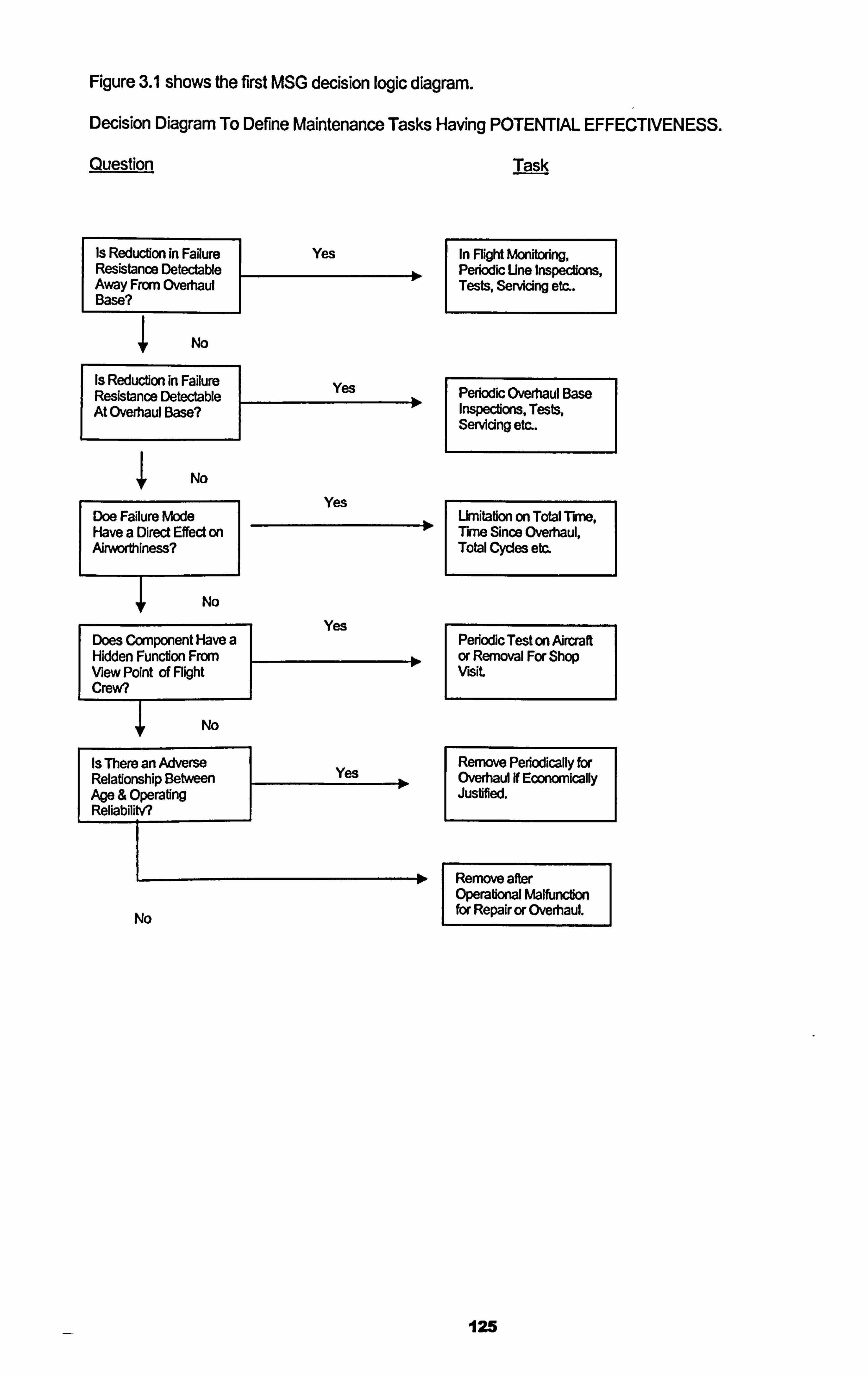
Figure 3.1 shows the first MSG decision logic diagram.
Decision Diagram To Define Maintenance Tasks Having POTENTIAL EFFECTIVENESS.
Question Task
Is Reduction In Failure Yes In Flight Monitoring, Resistance Detectable Periodic Une Inspections, Away From Overhaul Tests, Servicing etc.. Base?
I No
Is Reduction in Failure Yes Resistance Detectable Periodic Overhaul Base 1 At Overhaul Base? 0 Inspections, Tests,
Servicing etc..
No
Doe Failure Mode Have a Direct Effect on Airworthiness?
I No
Yes Urnitation an Total Thm, Time Since Overhaul, Total Cycles etc.
Yes Does Component Have a Hidden Function From 10 View Point of Flight Crew?
I No
I Is There an Adverse Relabonship BetNeen Age & Operafing ReliabilitV?
I Yes
No
Periodic Test on Aircraft or Removal For Shop visit
Rerrx)ve Periodically fbr Overhaul If Ecmwically Juslified.
Remove after Operational Malfunction for Repair or Overhaul.
125
The first introduction of decision logic diagrams through MSG-1 analysis, seen above started to
examine the reduction of failure resistance and started to ask the question of the consequences of the failures through analysis. Here we see for the first time the concepts of overhaul and on-
condition tasks being considered to attempt to maintain the inherent reliability of the original design.
What the B747 MSG-1 Handbook tries to attempt to give guidelines to accomplish the production of
a relevant and cost effective maintenance programme by bringing together the manufacturer and the operator who through a process an analysis develop a maintenance programme for a new
aircraft prior to introduction to service, acceptable to the FAA.
3.1.3 MSG 2 improving the Initial theory and a step closer to RCM.
Recognising the success of Boeing's MSG-1 "Maintenance Evaluation and Programme
Development' Handbook produced in 1968 for the new B747, in 1970 the Air transport Association
of America (ATA) recognising the benefits of such a process to its members and to aviation safety in general, decided to attempt to create a universal document that could be used not only for the
development of the B747 maintenance programme, but for the development of all new aircraft
maintenance programmes.
The ATA Reliability and Maintenance Subcommittee, taking the experience of the group that
developed MSG-1 guide lines produced a document called "Airline / Manufacturer Maintenance
Programme Planning Document MSG-2". This documents objectives were...
to present a means for developing a maintenance programme which will be acceptable to
Regulatory Authorities, the Operators and the Manufacturers. The maintenance programme data'
will be developed by co-ordination wfth specialists from the operators, the manufacturers and when feasible the regulatoty authorkies of the country of manufacture"
(A TA MSG-2 March 25th 19 70. )
MSG-2 recognised three general primary maintenance processes. These were..
1. Hard Time: A maximum interval for performing maintenance tasks. These intervals usually
applied to overhaul, but also apply to total life of parts or units.
2. On Condition: Repetitive inspections, or tests to determine the condition of units or systems or
portions of structure. 3. Condition Monitoring: For items that have neither hard time limits nor on condition maintenance
as their primary process. Condition Monitoring is accomplished by appropriate means available
126
to an operator for finding and resolving problem areas. These means range from notices of
unusual problems to specific analysis of unit performance.
MSG-2 continued to develop the three process further into five detailed scheduled maintenance
processes..
I- Servicing. 2. Inspection. 3. Testing. 4. Calibration.
5. Replacement.
It also continued to recognise the decision tree logic established in MSG-1 recognising that
Systems (including powerplant) and Structure required analysis in this way. It also partially introduced a new aspect to the process that was missing from MSG-1 and that was the definition of the interval that a scheduled maintenance task should be, but falls short of defining how the
intervals should be determined. MSG-2 also brought in to the analysis the new technologies of Aircraft Integrated Data Systems (AIDS) and Built in Test Equipment (BITE). Both these systems
give valuable performance data that can reflect the failure resistance reduction of systems and
components.
Aircraft that underwent MSG-2 analysis to develop their initial maintenance programme are
Lockheed Ll 011 Tristar,
McDonnell Douglas DC-10.
B737-200 (parts)
BAC Concord. *
A300. *
*The Association of European Airlines took MSG-2 and produced a document called the
European Maintenance Steering Group Guidelines (EMSG) in 1972. This document was
essentially MSG-2 with a few clarification.
3.1.4 MSG 3 application of RCM.
In early 1978 the US Department of Defence commissioned the services of two well known figures
in the commercial aviation sector who had been instrumental in the establishing scheduled maintenance programme development present day thinking. Both these experts were employed by United Airlines who at that time were using the MSG-2 philosophy with further developed
127
philosophies and ideas. F. Stanley Nowlan was at that time the Director, Maintenance Analysis for
United and Howard F. Heap Manager, Maintenance Programme Planning, both working for United
Airlines in San Francisco. Their commission was
Io explain and research the basic concepts, principles, definitions and applications of a logical
discipline for development of efficient scheduled (preventative) maintenance programmes for
complex equipment, and on going management of such programmes. Such programmes were
referred to as reflability-centred maintenance (RCM) programmes because they centred on
achieving the inherent safety and reliability capabilities of equipment at a minimum cost. (Nowlan and Heap RCM 1978).
The US Department of Defence intended the commissioned report to serve as a guide for the
maintenance of a verity of military equipment.
The final report issued in December 1978 further developed the existing MSG-2 philosophy. Where
MSG-2 was concerned primarily with the development of maintenance programmes prior to service for aircraft, RCM taking the basic philosophy built on it to a definite way of establishing not only initial intervals but also repeat intervals and also developed the methodology of packaging
scheduled maintenance tasks. An emphasis on the importance of in service data was identified in
RCM as central to the further development of the initial base-line maintenance programme. This
was established through in service failure and finding investigation resulting in the developing of the
initially established maintenance programme. MSG-2 mentioned nothing about the development
and appropriateness of the initially developed programme. RCM introduced more relevant analysis
of the structural tasks and introduced the concept of the Zonal programme. Both of these issues
were either very sketchily dealt with or not at all in MSG-2.
The RCM decision logic diagram itself differed from that used in MSG-2 in that it began with the
consequences of failure and then the analysis of the failure modes rather than the evaluation of
proposed maintenance tasks. RCM also recognised the existence of the four basic maintenance tasks instead of the three primary maintenance processes recognised in MSG-2.
1. On Condition Tasks : (Predictive or Condition Monitoring). Used where a clearly defined
potential failure period (P-F period) exists for the failure mode under consideration. For
example a tyre inspection every day, the tyre stays installed if the wear is not to a certain limit,
and is removed if the wear is at or beyond a certain limit. The survival of the tyre is based on the condition it passes the inspection.
2. Scheduled Discard Task : Used where a clearly defined age of increased conditional
probability of failure exists for the failure mode under consideration. For example the
passenger life jackets part number P01 24W have a discard life of 10 years. The manufacturer
128
has through studies shown that the useful life of the jackets, i. e. the period of time prior to when the wear out stage starts, is 10 years. After that the jackets have a high probability of failure
due to the perishing rubber components. The cost of removal, replacing & restoring the jackets
will cost more than purchasing a new jacket so the old jacket is discarded.
3. Scheduled Restoration Task : Used where a clearly defined age of increased conditional
probability of failure exists for the failure mode under consideration and the restoration task
restores the components resistance to failure to a level that is tolerable. For example the main landing gear of a B737 built by Manesco, has a restoration life of 12 years or 15,000 cycles
which ever is sooner. Manesco have through studies shown that the gears useful life is at 12
years due to environmental effects or 15,000 cycles due to operating stress and the probability
of failure rises considerable at this point which is the start of the wear out stage. But by
restoration of the gear & its components the inherent reliability of the gear can be restored.
4. Failure Finding Task : Used where the task can confirm that all components covered by the
failure mode under consideration, are functional. (Not used for evident failure modes. ) For
example a standby hydraulic pump that is not normally in use, is intentionally brought on line by
perhaps simulating a failure of the main pumps, (pulling their circuit breakers) the performance
of the standby pump is then monitored for correct function.
After the issue of the RCM Report in 1978, the ATA decided take on board the developed RCM
process improvements made to MSG-2 and issued the in 1980 the document titled "ATA MSG-3
Operator / manufacturer Scheduled Maintenance Programme Development7 . MSG-3 was not a departure from the MSG-2 philosophy but built on ten years of validated reliable aircraft operation.
Major Improvements of MSG-3 to MSG-2.
MSG-3 is a "top down" approach or consequence of failure approach. The consequence of failure was assigned one of two basic categories
1. Safety
ii. Economic
further sub classification were..
Category 5 Evident Safety Effects
Category 6 Evident Operational Effects
Category 7 Evident Economic Effects
Category 8 Hidden Function Safety Effects
129
Category 9 Hidden Function Non-Safety Effects
2. The structural deterioration process included the consideration to fatigue, accidental damage,
age exploration, and others.
3. The new damage tolerance rules for design mandated by FAR 25.571 were introduced to the
process.
4. MSG-3 was task oriented not maintenance process oriented as with MSG-2.
5. The MSG-3 process separated tasks applicable to hidden or evident failures. Hidden failures
were treated more thoroughly.
6. The effects of multiple failures were taken in to consideration.
7. MSG-3 made a clear separation between those tasks required for economic reasons from
those required for safe operation.
Aircraft that underwent MSG-3 analysis to develop their initial maintenance programme are
Boeing 757
Boeing 767
Airbus 310
A: irbus 320.
The ATA Maintenance Steering Group made up of manufacturers, operators and regulators,
continued to monitor the success of MSG-3 developed maintenance programmes for in service
aircraft and further improved the MSG process building on data received from the operators.
In 1988 the ATA issued MSG-3 Revision 1. Many administrative clarifications were made. The
main revision was the deletion of Crew Monitoring tasks. Those tasks in crew manuals that were
required to be carried out were deleted from the maintenance programme as the failures should be
identified by the crew in their daily operation of the aircraft. This point is very important as it is
effectively involving the flight crew in the detection of failures through crew procedures. It is for this
case important that flight crew understand their roles the continued airworthiness of the aircraft
through reporting failures and defects, this is not always realised by flight crew.
Aircraft that underwent MSG-3 Revisioni analysis to develop their initial maintenance programme
are
130
Boeing 777
McDonnell Douglas MD 11
Airbus 340
In 1993 resulting from the FAA AD 1990-25-05 guidelines on the Corrosion Prevention and Control - programme were added to the analysis logic. This resulted in the ATA issuing MSG-3 Revision 2 in late 1993. Aircraft whose scheduled maintenance programme was developed to the MSG-3 Revision 2 guidelines were considered as compliant with FAA AD 1990-25-05 by the nature of the CPCP tasks being considered into the structural programme.
Aircraft that underwent MSG-3 Revision2 analysis to develop their initial maintenance programme
are...
Boeing 737 New Generation Boeing 717
Airbus 330 Gulfstream GV
Bombardier Regional Jet (RJ)
Note. MSG-3 philosophy had now been adopted as the standard for not only leading aldiners but
was now also crossing over to the regidnaIjet and corporate jet world.
In 2001 MSGý3 Revision 2001.1 was issued by the ATA. This revision incorporated the enhanced Zonal analysis. (as detailed in chapter 2.3-3) where the gathering of combustible material was
considered and the importance of the serviceability of wire runs also was given special
consideration. Also detailing that a GVI was to be conducted at arms length using introducing a tactile dimension to the inspection and the use of a mirror when required.
Finally in existence today, MSG-3 Revision 2002.1 was issued. This revision introduced a dimension to examine non-metallic structure and emphasised the Importance of recording
assumptions and considering vendor recommendations.
In summary IVISG-3 enabled the development of scheduled maintenance programmes for aircraft that were effective, applicable and economically efficient. IVISG-3 moved on from the philosophy of
removing parts at scheduled intervals regardless of their condition to ensured safety and reliability to a philosophy of operational and visually check parts at scheduled intervals and allowing them to
continue in service if they meet airworthiness criteria. It is suggested by Boeing and the ATA that
maintenance costs as a result of MSG-3 have reduced by at least 30% over the last 20 years by
the industry adopting MSG-3 as a standard philosophy. By IVISG-3 calling for in service monitoring of reliability (touched on so far but this subject will be developed in chapter 4), has allowed for a more detailed understanding of the nature of failure of aircraft components and systems. The
131
disciplined process of the MSG-3 analysis has not only given the operators an effective
maintenance programme but feedback to the manufacturer where improvements can be identified
in the basic design of the aircraft and of the systems. Finally the process of MSG-3 brings together
all the main players of the industry at one time, the manufacturer, the operator, the regulator and
even the vendors, this process improves not only communication but the sharing of technical
information from different perspectives.
3.1.5 Further Development of the RCM / MSG-3 theory and JAI 011 RCM Standard.
Through out the late 1980's it was soon realised the benefits of the RCM / MSG-3 process in
producing scheduled maintenance programmes and as with many new technologies first started in
aviation other maintenance and engineering disciplines started to look closer at adopting the
methods of RCM / MSG-3- In 1991 John Moubray a non aviation maintenance engineering
specialist recognised the potential of RCM / MSG-3 and published the book "RCM Reliability
Centred Maintenance" Industdal Press Inc. ISBN 0-8331-3078-4. This book explained and adapted the methodology now used as standard in the aviation world to apply it universally to the
development of all maintenance scheduled for Plants, machinery, structures and systems. This
book took the principles established by Nowlan and Heap in 1978 and defined them in terms that
could be followed by any maintenance engineers for the use of developing a maintenance
programme. Soon after, the Society of Automotive Engineers of the America, SAE, accepted RCM
as the standard for developing maintenance programmes in all engineering context, issued SAE
Standard JA1 011 in 1999. This standard document established the recognised application of RCM
describing the minimum criteria that any process must comply with to be called RCM. The
document defined in the standard many of the terms and conditions for RCM analysis. It also followed the line of aviation in establishing a policy that the programme developed through RCM
analysis must be subject to continuous review as to the applicability and effectiveness of the initially
established programme through in service data analysis. This standard has been used for
establishing the initial maintenance programmes for Nuclear Reactors, Oil Rigs, Container Ships,
Manufacturing Factories and even Pipe Lines and continues to be the maintenance and
engineering standard for the development of scheduled maintenance programmes so much so that
any maintenance programme developed through non RCM methods is questioned as to ifs
effectiveness.
132
3.2 MSG 3 Analysis: Creation of A New Aircraft Maintenance
Programme.
3.2.1 The Regulative Requirements for AIrcraft Maintenance Programmes.
In order to get an Air Operators Certificate from a JAA state under JAR OPS 1 must be complied with. JAR OPS I requires a nominated person acceptable to the Authorities to be responsible for the Maintenance function. The nominated maintenance post holder will be responsible for
establishing the Maintenance Programme. JAR OPS 1, sub part M, 1.910 with regards to the Operators Aeroplane Maintenance Programme states the following...
JAR OPS 1, subpart M, 1.910.
a) An operator must ensure that the aeroplane is maintained in accordance with the operators
aeroplane maintenance programme. The programme must contain details including frequency,
of all maintenance required to be carried out. The programme will be required to include a
reliability programme when the Authorfty determines that such a refiabilfty programme s
necessary. (See AMC OPS 1.910(a))
b) An operators aeroplane maintenance programme and any subsequent amendment must be
approved by the authority. (See AMC OPS 1.91 O(b). )
Acceptable Means of Compliance AMC OPS 1.910(a).
1. The aeroplane maintenance programme should be managed and presented by the operator to
the Authority.
2 Where implementation of the content of an approved operator's aeroplane maintenance
programme is accomplishes by an appropriately approved JAR 145 Approved Maintenance
Organisation, it therefore follows that the JAR 145 Approved Organisation should have access to the relevant parts to the approved operators aeroplane maintenance programme when the
organisation is not the author. Implementation means preparation and planning of the
maintenance tasks in accordance wfth the approved maintenance programme.
3. The aeroplane should only be maintained to one approved operators maintenance
programme at a given point in time. Where an operator wishes to change from one programme to another approved programme, a transfer check / inspection may be needed to be
performed, as agreed with the Authorfly, in order to implement the change.
4. The operator's approved maintenance programme should contain a preface which will define
the maintenance programme contents, the inspection standards to be applied, permitted
variations to task frequencies and where applicable, any procedure to escalate check /
133
inspection intervals. Appendix 1 to AMC OPS 1.9 10 (a) & (b) provides detailed guidance on the
content of an approved operator's aeroplane maintenance programme.
5. Where an operator wishes to use an aeroplane with the initial operators maintenance
programme based upon the Maintenance Review Boards Report (MRBR) process, any
associated programme for the continuous surveillance of the reliability or heafth monftoring of the aeroplane should be considered as part of the aeroplane maintenance programme.
6. Where an aeroplane type has been subjected to the MRBR process, an operator should
normally develop the inflial aeroplane maintenance programme based upon the MRBR.
Z T77o documentation supporting the development of the operators maintenance programme s for aeroplane types subjected to the MRBR process should contain identification cross
reference to the MRBR tasks such that it is always possible to related such tasks to the current
approved operators maintenance programme. This does not prevent the approved operators
maintenance programme from being developed in the light of service experience to beyond the
MRBR recommendations but will show the relationship to such recommendations.
8. Some approved operators aeroplane maintenance programmes, not developed from the MRB
Process, utifise reliability programmes. Such reliability programmes should be considered as
part of the approved maintenance programme.
9. Reliability Programmes should be developed for aeruplane maintenance programmes based
. upon the MSG logic or those that include condition monitored components or that do not
contain overhaul periods for all significant system components.
10. Reliability programmes need not be developed for aeroplane maintenance programmes of
aeroplanes of 5700 kg and below or that do not contain overhaul time periods for all significant
system components.
1. The putpose of the reliability programme i's to ensure that aeroplane maintenance programme tasks are effective and their perlodicfty is adequate. ft therefore follows that the actions
resuffing from the reliability programme may be not only to escalate or delete maintenance tasks, but also to do escalate or add maintenance tasks, as necessaty.
12 A reliability programme provides as appropriate means Of monftoring the effectiveness of the
maintenance programme.
it can be seen through the JAA regulations that the maintenance programme is regarded as the
prime vehicle for ensuring the continued airworthiness of the aircraft and so entrusts the
responsibility of the maintenance programme with the operator on ever occasion even when the
maintenance tasks are contracted out to maintenance service providers. It is my opinion that the
134
definition of the maintenance programme and its application to attain specific objectives is not clear. The AMC's do not go far enough to elaborate on what is an acceptable maintenance programme,
while in the US the FARs define levels of maintenance programmes through the different levels of AOC, FAR 121,135 or 91 for private categories. The FAA Advisory Circular AC 120-16D goes on further to define what a maintenance programme is (this is a valiant effort by the FAA to define the
complete activities of the maintenance programme, but by removing the responsibility of the private operator, FAR 91, to meet the definitions in the AC I believe is s short fall of the intention of the
regulation. JAR OPS 2 (JAA equivalent to FAR 91, private category) is pending with the JAA. It is
my hope that the JAA go one step further than the FAA and mandate the maintenance programme requirements (maintenance schedule and reliability programme) for private operators. The depth of the maintenance programme will of course not be as far reaching as the airliner JAR OPS I AOC's. There fore what the FAA have done in my opinion needs to be also done by the JAA and a clear definition of the objectives of the maintenance programmes over and above the Maintenance
Schedule needs to be elaborated upon. Further more it is also my opinion that the FAR*s fall short (the JAR' s do not even start to address the issue) in negating the requirement for a maintenance
programme as opposed to an inspection programme (with out a reliability programme) to be in
place for private operators. It is the private operators that use the aircraft in a unique way that need the substantiating data from conducting a reliability programme to support the effectiveness of their
maintenance schedule as much if not more than a standard airline type operator. Section 3.2.4
starts to define what I believe is an accurate interpretation of what a maintenance programme is,
and what I believe is required to be in place if RCM / MSG3
By the maintenance programme being mandated in the JAR OPS subpart M rather than in the JAR
145 (JAR 145 is the regulations governing maintenance performed on aircraft, that with out JAR
145 approval an operator or maintenance service provider can not conduct maintenance activities
on a JAA state registered aircraft), the responsibility lies with the operator. The regulation also
embrace the RCIVI / MSG 3 maintenance philosophy by making reference on many occasions to
the MRBR process. It also recognises the need for continued monitoring of the maintenance
programme for effectiveness by also referring to the supporting reliability programme. The one
conflicting regulatory issue is AMC OPS 1.910(a) paragraph 10, where it removes the responsibility
of utilising a reliability programme W overhaul time periods for all significant system do not exist. It is
in my opinion required for all maintenance programmes that the reliability programme be in place for all maintenance programmes, perhaps by employing a very small method of periodic defect
analysis. I believe this might be an error in the regulations as it contradicts earlier paragraphs such
as paragraph 9 that recommends the use of reliability programmes for maintenance programmes developed through the MSG process. I think here the JAA are confusing MSG2 and MSG3
philosophies.
The development of reliability programmes in support of the maintenance programme will be a point of development later in the thesis.
135
3.2.2 Air Transport Association Guidelines For Producing a Maintenance Programme.
ATA MSG3 Operator / Manufacturer Scheduled Maintenance Development document issued and
revised by the Air Transport Association (ATA) is produced with the purpose to develop a proposal to assist Regulatory Agencies in establishing initial scheduled maintenance tasks and intervals for
new types of aircraft and or power plants. Though the JAA regulations do not directly refer to the
document they do in JAR OPS subpart M make many references to the procedures detailed within the ATA documents that are better known as MSG3 or the MRBR process. This document is a detailed step by step recommendation on the procedures to be taken to produce an MSG3
maintenance programme.
3.2.3 Application of MSG 3 to Produce A Maintenance Programme for A New Aircraft
Utilizing the MRB & the ISC.
FAA FAR 21, and JAA JAR 21 requires that one of the condition for a new Type Certificate being
issued to a manufacturer for a new aircraft type is that a report detailing the requirements for
continued airworthiness is issued. On modem aircraft this regulation is satisfied by the production of the MRBR utilising the MSG3 process through the MRB. FAR 121,135 and JAR OPS 1 requires that for an applicant to be granted an Air Operating Certificate (AOC), that a maintenance
programme must be in place and acceptable to the authorities.
Before the new aircraft manufacturer is ready to apply for the new type certificate invitations are
sent out to those operators that have already placed orders for the new type or those operators that
are considering to place an order. At the same time the manufacturing country regulatory
authorities are invited as are any other authorities of potential operating countries. Representatives
of those operators and authorities and also of the manufacturer and some component vendors will
meet and form the Maintenance Review Board. The MRB will then through many meetings apply the MSG3 philosophy to the new aircraft type using the exact process described in chapter 2.3
previously. The result from the MRB will be the MRBR the Maintenance Review Board Report. This
FAA / JAA / TC / other authorities approved report will be one of the required documents and
process for the issuance of a new type certificate under FAR 21 and JAR 21.
The MSG3 process recognising the need for on going monitoring of the effectiveness of the
maintenance programme, so the MRBR responsibilities for on going revision and monitoring is
taken on board by the ISC, the Industry Steering Committee. The ISC is very similar in construction to the MRBR in that it is usually held by the manufacturer, with members from the authorities, the
operators, the manufacturer and vendors. The appointed chairperson is normally from one of the
lead operators who take on the role of co-ordinating and chairing the meetings. The ISC main role is to ensure the development of the MRBR utilising in service data gathered by the operators and
the manufacturer. This task may involve the recognition of new scheduled maintenance task
requirements as a result on multiple in service failures or findings fed back to the manufacturer and
the ISC by the operators. It may also involve the escalation of scheduled maintenance tasks based
on no in operational findings or even de escalation. The whole point of the ISC is to continue the
136
RCM / MSG3 philosophy that the applicability and effectively of the scheduled maintenance
programme must be continually monitored to assure the on going airworthiness of the aircraft type.
The ISC may meet twice yearly at the manufacturers head quarters. It is the responsibility of the
manufacturer along with the ISC chairperson to present the revised MRBR to the authorities for
approval before the new revised MIRBR is issued to operators. A revision to the MIRBIR will result in the Manufacturers Planning Document being revised also.
3.2.4 The Operators Approved Maintenance Programme.
As JAR OPS subpart M 1.910 states that the Operator must ensure that the aircraft utilised under the operators JAR OPS approval and AOC must be maintained to an approved maintenance
programme. This requires the operator to produce a scheduled maintenance programme
applicable to the aircraft type they are operating and acceptable to the authorities issuing the AOC
and JAR OPS M approval.
The term "aircraft maintenance programme" is one of some of the most miss-understood words in
the maintenance of aircraft. The JAR's compound this misunderstanding by not clearly stating what
a maintenance programme should consist of, while the FAR's do go a little further to clarify the '
differences between a maintenance programme and an inspection programme through the issue of different levels of AOC's from FAR 121,135 and 91. For 121 and 135 a maintenance programme
should be applied by the operator but for 91, private category only an inspection programme needs to be applied. The term maintenance programme in my opinion means the complete system of identifying the scheduled maintenance tasks required to be carried out at certain intervals, a
method of documentation to carry out those tasks and a complete system of monitoring and feed
back to ensure the continued effectiveness and applicability of the scheduled maintenance tasks.
The document itself that details the scheduled maintenance tasks and the intervals to be followed
to accomplish those tasks is called the "Maintenance Scheduler (MS). The MS front introduction
pages details the rules and methods of complying with the Maintenance Programme. Once the MS
is accepted by the authorities and issued an approval by the authorities Is now refereed to as an AMS, approved maintenance schedule. Once approved the AMS is then subjected to approval at
every revision. The AMS forms the basis of the maintenance programme and of the operators JAR
OPS subpart M approval.
TvDical Components of a Maintenance Programme.
1. An Approved Maintenance Schedule, (AMS).
2. A Task Card set to carry out the AMS. 3. A system to control the AMS and issue the Task Card set. 4. A system to monitor the effectiveness of the AMS through defect monitoring, both pilot reports
and maintenance reports. (Reliability Programme). 5. A system to monitor the condition of components removed in service. (Reliability Programme).
137
6. A system to be able to revise the AMS due the Reliability Programme or manufacturers
recommendations.
Often operators stop at item I when identifying a Maintenance Programme, but as the JAA
regulations say in JAR OPS subpart M, perhaps contradicting them selves a little in different
paragraphs, but reference to AMC OPS 1.91 0(a) paragraph 9 states..
"Reflabilfty Programmes should be developed for aeroplane maintenance programmes based
upon MSG logic. _"
The MRB process is certainly an MSG logic programme, and the requirement of the RCM / MSG3
logic process to continuously monitor the in operational and maintenance findings is required to
support the tasks and intervals in the maintenan6e programme for applicability and effectiveness. For this reason the Reliability Programme is an integral part of the complete Maintenance
Programme. Later in the thesis we will review the different methods of conducting a Reliability
Programme, for now lets continue to look closer at the production of the AMS.
The AMS should normally be based upon the MRBR. In order to assist the operator with a better
technical clarification of the MRBR the manufacturer often issues the Maintenance Planning Data
(MPD). The MPD contains the MRBR but elaborates with reference to panels to be opened,
manhours estimated to carry out the MRBR tasks, maintenance manuals or task card references the detail the MSI or SSI task work steps details, work zones or area that the task falls in, further
information in support of the scheduled maintenance tasks. The MPD is contains the complete MRBR and is revised when ever the MRBR is revised but the MPD is also revised on its own. The
ISC often improve decide on the MPD revisions to improve clarifications Or scheduled maintenance task details. Often the MPD is the source base line document for the operators AMS.
While the MPD is adequate as a base line document, that details the complete RCM / MSG 3
manufacturers recommended scheduled maintenance tasks, it would be a Mistake to use it alone. In addition to the MPD there may be other scheduled tasks required for inclusion in the
Maintenance Programme that are not RCM / MSG 3 derived, such as...
Regulatory Tasks: Airworthiness Directives, Aircraft frequent weighing, Pressurised bottle
hydrostatic testing etc.
2. Company Special Tasks: Cabin Interior Inspections, In Flight Entertainment Inspections etc. 3. Non MRBR Manufactures Task: Service Bulletins, Service Letters or ETOPs tasks etc. 4. Reliability Derived Tasks: Tasks developed on other operator aircraft With similar equipment
etc. 5. Vendor Requirements: Special Vendor equipment installed maintenance tasks etc.
138
6. Environmental Considerations: Task to address the climate that the AOC holder will operate his aircraft in such as hot and humid, wet non paved run way landings, salt water air, freezing
conditions,, etc.
The AMS is in fact a living document that should be continuously developed to address issues derived from the on going Reliability Programme.
The section that follow is an example of a typical introduction to an Operators Maintenance Schedule. It describes not only the construction of the AMS but also the Maintenance Programme
process. The introduction of n AMS is essential to define and detail the purpose and methods of the
complete maintenance programme....
139
PART 1
DESCRIPTION OF
MAINTENANCE SCHEDULE
INTRODUCTION
The Maintenance Schedule described in this document applies to Operator X aircraft. This
schedule covers all scheduled maintenance tasks for the airplane and systems including
powerplant, required by the manufacturer and relevant authorities. Opertor X Engineering
Planning and Development are responsible for managing and coordinating the accomplishment
of the requirements in this schedule and for the necessary revision service to the Maintenance
Schedule.
MAINTENANCE SCHEDULE PROCESS
2. All scheduled maintenance tasks are controlled by a time interval. This interval can be in the
form of flight hours, flight cycles, landings, engine operating hours or cycles, APU operating
hours, or calendar times. Tasks will be allocated to packages (Monthly, A-check series, C-check
series), specified flights (Daily, Transit Night Stop ) or in conjunction with another scheduled
maintenance action, e. g., engine change. The interval is the requirement when the task must be
complied with. Allocating a task to a work package is for planning convenience only.
3. Component and engine restorations are controlled by a "life limited" and/or "on conditiolf'
process.
a. The life limited process is applied when components or engines are scheduled for
restoration or discard at a specified time or interval. Ilis includes replacement of life
limited parts at specified intervals.
b. The "on condition! ' process is applied when components or engines are monitored for
"conditiore'by periodically scheduled inspections or checks and/or by regular data
collection (such as the engine trend monitoring schedule). Component or engine
maintenance is required when the inspected item exceeds the "limits" specified in the
AMTvVCMM, or information based on Operator X reliability data.
Condition monitoring is a primary maintenance process to verify the fleet for
airworthiness and the effectiveness of the Maintenance Schedule. Condition
monitoring is a program of data collection and analysis in order to obtain information for the whole fleeL The results are used to control the Maintenance
Schedule, evaluate the continuity of airworthiness of the fleet and monitor the
performance of individual parts and systems.
SCOPE AND LIMITATIONS OF SCHEDULE
140
4. The Operator X Boeing 737-700IGW Maintenance Schedule is applicable for aircraft
operating In the range of 150 to 1,500 flight hours per year. Any aircraft operating outside
these limitations can not follow this Schedule without prior approval from the Opertor X
Authorities & Boeing.
5. This schedule is applicable only to the operators Boeing 737-NG, with CFM56-7B engines installed. Registration numbers are XX-XX, XX-XX, XX-XX.
6.1 While the basis for the schedule is the manufacturer's Maintenance Planning Data document ý
(MPD), all maintenance work performed on Operator X aircraft will be in compliance with and in reference to the following documents:
a. Aircraft Maintenance Manual
b. Engine Maintenance Manual
C. Structural Repair Manual
d. Component Maintenance Manual
e. Illustrated Parts Catalogue
f. Wiring Diagram Manual
g. Service Bulletins
h. Service Letters
i. Airworthincss Directivcs
Amendments
7. The basis for this schedule is the Boeing 737-NG MPD D626AOO I Revision 13 Dated Oct 02,
CFM56-7B Engine Shop Manual Revision 21 15Aug 02, all revisions to these documents
will be appraised & if applicable reflected in this schedule. Any possible amendment to the
Maintenance Schedule shall be discussed by the Operator X Schedule Review Board (MSRB).
The MSRB will sit three times a year to deliberate on possible Maintenance Schedule
amendments.
8. Amending the Maintenance Schedule is the responsibility of the Maintenance Engineering
Planning section.
9. Amendments to the Maintenance Schedule shall take place as a result of the following:
a. Issue or revision to any OEM's documentation.
b. Issue or revision to any appropriate FAA, CAA, DGAC, TC, GCAA or odier relevant
regulatory documentation.
C. Revisions or additions to Operator X company requirements.
d. The experience of Operator X.
141
10. Every revision and amendment must be presented to QAM or his deputy for acceptance; QAM
will then seek approval of the Operator X Authorties. Only then will Engineering Planning and Development make effective the changes and revise all issued Maintenance Schedules and
annotate each revision sheet. This process will take place at the MSRB. No revision shall take
effect until Operator X have granted approval.
Responsibilities
Opertor X Maintenance Engineering Planning (MEP) are the responsible section to ensure the
Maintenance Schedule is in effect at all times. MEP will monitor the effectiveness and
appropriateness of the schedule and will instigate the development of the schedule where felt
technically necessary. Any deviations from this Maintenance Schedule or accompanying documents are not allowed without prior approval from MEP. MEP will not agree to deviations
from this Schedule without prior approval from the QAM. MEP are also responsible for creating
and issuing the work documents in advance to aircraft maintenance (AM), which are required to
ensure the Maintenance Schedule tasks are called for compliance prior to exceedance of their
Maintenance Schedule interval.
12. All significant structural discrepancies found shall be reported to Boeing Commercial Airplanes
(BCA) on a Discrepant Structural Report form (see BBJ MPD D626AOO I, page B. 0-1 for form
copy). It is the responsibility of Operator X Maintenance Engineering Planning to ensure the
forms are submitted when required. Definition of corrosion levels 1 to 3, and guidelines to be
followed are referenced in D626A001.
Extension of Task Intervals
13. Short-term extension: In exceptional circumstances the Maintenance Schedule allows for
short-term extension of maintenance tasks. The maximum allowable extension of the tasks are
as follows:
a. Hours: 10% but not to exceed 50 hours
b. Landings: 10% but not to exceed 25 landings
C. Calendar: For intervals less than I year 10% but not to exceed I months
For intervals less than 2 years 10% but not to exceed 2 months
For intervals less than 3 years 10% but not to exceed 3 months.
Notes Extensions are not permitted to component mandatory life limitations, safety equipment or Certification Maintenance Requirements (CMRs as indicated in the task description).
CMR's Definition: As defined by FAA AC 25-19 a CMR is a required periodic task,
established during the design certification of the airplane as an operating limitation on the type
certificate. CMR tasks are identified also with an asterisk after the task number.
142
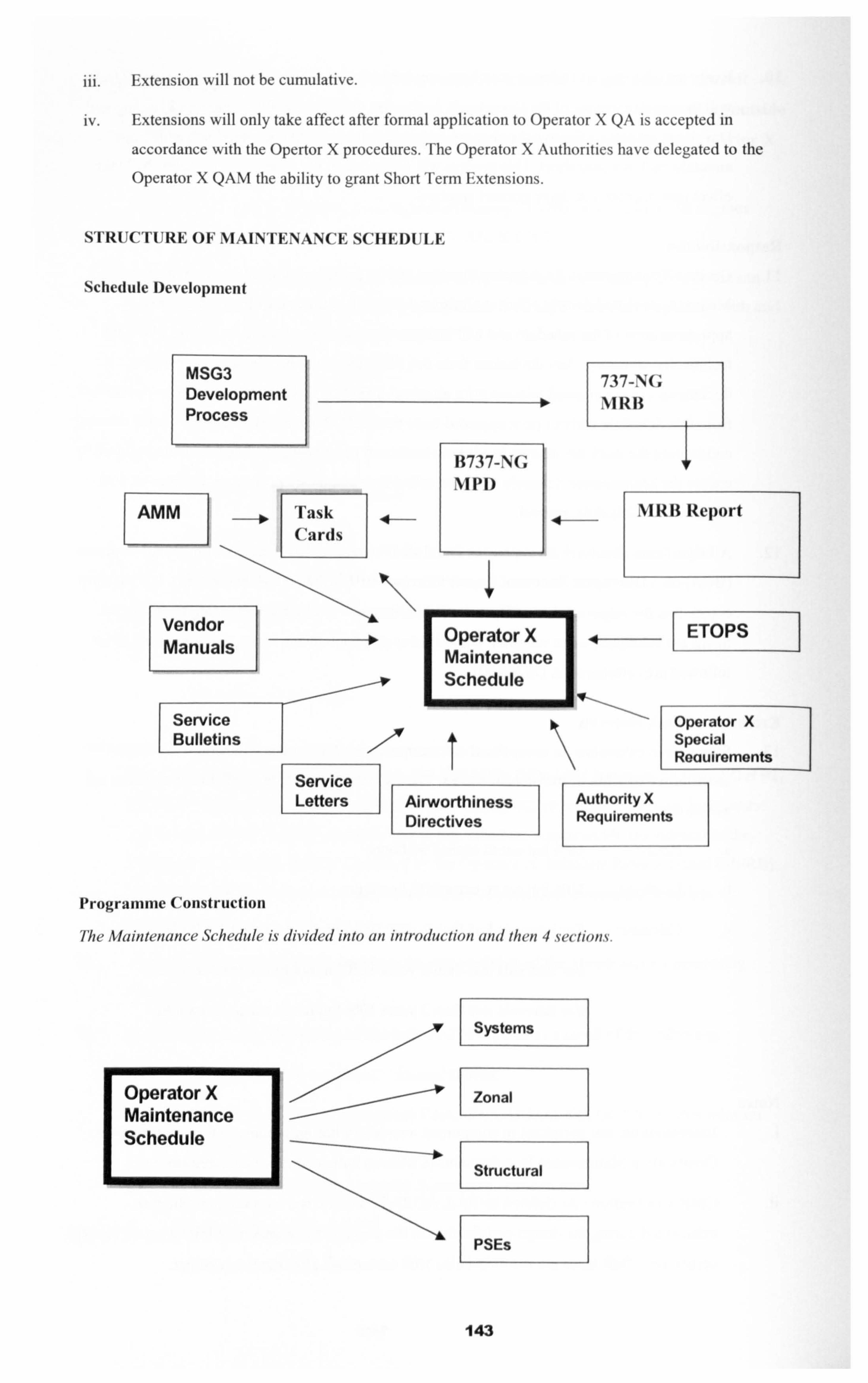
iii. Extension will not be cumulative.
iv. Extensions will only take affect after formal application to Operator X QA is accepted in
accordance with the Opertor X procedures. The Operator X Authorities have delegated to the
Operator X QAM the ability to grant Short Term Extensions.
STRUCTURE OF MAINTENANCE SCHEDULE
Schedule Development
MSG3 Development Process
AMM
737-N'(; NIRB
B737-N(; Ni P 1)
IVIRB Report
Vendor 70perator X Manuals t Mýainteunmance
ETOPS X x
S Sc I] chedule I
Service Operator X
Bulletins Special Reauirements
Service Letters Airworthiness Authority X
Directives Requirements
Programme Construction
Me Maintenance Schedule is divided into an introduction and then 4sections.
Operator X Maintenance Schedule
Systems
Zonal
Structural
PSEs
Systems I
143
14. Extended-Range Twin Operations Procedure (ETOPs): The Maintenance Schedule
development and construction takes into consideration ETOPs, as far as tasks are identified as
an ETOPs significant task, where applicable. The ETOPs-significant tasks will not normally be
scheduled for compliance at the same time on both engines or systems during line maintenance.
If through some occasional or nonroutine case, multiple actions on ETOPs-significant items do
occur, different technicians will perform the maintenance on the similar systems, and the work
will be inspected by different approved inspectors, or a verification of the system will be
accomplished. During minor and major maintenance, ETOPs-significant tasks will have
adequate certifiers and final function checks to satisfy the ETOPs requirements for system
integrity and therefore can be scheduled concurrently. The Amiri Flight ETOPS Manual
explains how Operator X meets the GCAA requirements. Note: ETOPS significant tasks are
identified as "ETOPs Similar System Maintenance TasVin the MS & Task Cards, while
ETOPs CMP additional tasks for ETOPs flights are identified as "CMP Task" in the MS & Task
Cards.
15. Definition of Line Maintenance: A package of scheduled maintenance tasks that do not require
extensive access or downtime. Daily, Transit, Night Stop, Daily Non Flying, & Day Non Flying
and the Monthly series are considered line maintenance.
16. Definition of Minor Maintenance: A package of scheduled maintenance tasks that may require
some extensive access or downtime. The A-check series is considered minor maintenance.
17. Definition of Major Maintenance: A package of scheduled maintenance tasks that do require
extensive access or downtime. The C-check series is considered major maintenance.
18. Work Packages: Operator X Engineering Planning and Development have allocated certain
points in time to accomplish groups of tasks at one input. Those inputs are referred to as work
packages. The work packages are assuming an annual utilization of 1500 flight hours & 400
flight cycles. If the utilization differs over time from the assumption the work packages will be
reallocated accordingly without excedance of the task interval. The work packages are as
follows:
a. , Daily: Prior to the first flight of the day in accordance with Task Card 050001.
Transit: During every Transit in accordance with Task Card 05000 1.
C. Night Stop : When the crew have left the a/c secured & unattended for a stop of 6 hours
or more in accordance with Task Card 050001.
d. Non Flying Tasks : These tasks have to be accomplished when the a/c is parked in a flight ready condition but has not flown for a certain period of time. Non Flying Daily
has to be done not to exceed 48 hrs elapsed of non flying & the 7 Day Non Flying has to
be done not to exceed 7 days elapsed of non flying. Both tasks are iaw Task Card
050001.
144
e. Monthly 1: Not to exceed every 2 calendar month or 300 flight hours in accordance with Task Card 0500M I
Monthly 2: Not to exceed every 2 calendar month or 300 flight hours in accordance with Task Card 050OM2.
E A-check: Not exceed every 6 calendar months or 750 flight hours, whichever is sooner, in accordance with Boeing Task Cards.
g. C-chcck: Not to exceed every 36 calendar months or 4,500 flight hours, whichever is
sooner, in accordance with Boeing Task Cards.
19. Though allocated to a work package the requirement for each individual task is dictated by the Maintenance Schedule task interval.
DESCRIPTION OF THE MAINTENANCE SCHEDULE CHAPTERS AND CODES
20. Systems. This chapter describes in order of ATA, the MSG 3 scheduled maintenance
requirements for the complete aircraft systems, to ensure system serviceability and integrity.
The tasks in this chapter ensure aircraft systems integrity by lubrication, functional checking,
operational check, inspection, checking and removal of components for restoration or for
discard.
21. Zonal. This chapter describes the Zonal programme of general visual (GV) inspection tasks and if required, physical check of the general condition and security of attachment of the accessible
systems and structural items in defined zones with the access defined for each task. This includes checks for degradation such as chafing of tubing, loose duct supports, wiring damage,
cable and pulley wear, fluid leaks, electrical bonding, general condition of fasteners, inadequate
drainage, and general corrosion, not covered in the MSG 3 analysis. The Zonal inspection is not intended as a quality assurance check after maintenance check for determining proper reassembly of components, structures or powerplants.
22. Structures. This chapter describes the scheduled maintenance tasks for the structural
maintenance programme. This programme is designed to provide timely detection and repair of
structural damage which may occur in the fleet during normal operation. Detection of corrosion,
stress corrosion, minor accidental damage and fatigue cracking by visual and NDT procedures- is
considered. The corrosion prevention and control programme (CPCP) is an integral part of the
structural progranune. All tasks in the structural programme require the application of the CPCP
basic task at the specific intervals (see MPD D626AOO I pages 8.0-8 and 9 for details of the
CPCP basic task). The objective of the CPCP programme is to control corrosion found on all
structures listed in the structural programme to Level I or better.
23. Reporting Results of the Structural Inspection: All significant structural discrepancies found
shall be reported to Boeing Commercial Airplanes (BCA) on a Discrepant Structural Report
form (see MPD D626AOO I page B. 0- 1 for form copy). It is the responsibility of Operator X
Maintenance Engineering Planning to ensure the forms are submitted when required. Definition
145
of corrosion levels I to 3 and guidelines to be followed are referenced in D626AOO I.
Maintenance Engineering Planning are also required to copy any reports raised to QA.
24. Definitions of inspection types.
a. The terms "check" and "inspect" are not intended to imply a level of skill required to
accomplish a task.
b. The phrase "... mechanical control path... " is used in describing certain scheduled
maintenance tasks. This is not intended to include cables, but only
components/assemblies required to initiate and terminate action.
C. "Intcmar' and "external" as used in the Zonal inspection tasks refer to the point from
which the inspection is accomplished in relation to the zone. "External" is also used for
inspections under panels with quick release fasteners. The Zonal tasks include visual
checks of electrical wiring, hydraulic tubing, water/wastc plumbing, pneumatic ducting,
components and fittings, brackets, and so on, associated with systems, as well as all
visible structures which are contained within the zone boundaries. The extent of the intended area is defined by the access listed. Whenever possible, the Zonal inspection
should be conducted within touching distance.
d. General visual: A visual examination of an interior or exterior area conducted within
arms legnth, installation or assembly to detect obvious damage, failure or irregularity.
This level of inspection is made under normal available lighting conditions such as daylight, hangar lighting, flashlight or drop light and may require removal or opening of
access panels or doors. Stands ladders or platforms may be required to gain proximity to
the areas being checked. Normal inspection aids are to be used as required.
Detailed inspection: An intensive visual examination of a specific structural area, system, installation or assembly to detect damage, failure or irregularity. Available lighting is
normally supplemented with a direct source of good lighting at an intensity deemed to be
appropriate by the inspector. Inspection aids may be used. Surface cleaning and elaborate
access procedures may be required.
Special detailed inspection: An intensive examination of specific items, installations or
assemblies to detect damage, failure or irregularity. The examination is likely to make
extensive use of specialised inspection techniques and/or equipment. Intricate cleaning
and substantial access or disassembly procedures may be required.
25. Task No.: A unique identifying number for each task in the Maintenance Schedule. This
number reflects directly the manufacturer's MPD Task No. where applicable. The first two
digits are the ATA chapter (41 for left, -02 for right, and -00 for tasks without left or right
positions). The last two digits allow for identifying multiple positions for a common task.
Operator X added tasks are identified by -XX The substantiating data for the addition of these
tasks will be held as part of the process.
146
26. AMTOSS (Aircraft Maintenance Task Oriented Support System): The first 6 digits denote
chapter-section-subject of the corresponding maintenance manual procedure to accomplish this
task. The seventh and eighth digits are function codes that identify the type of work required. For tasks without AMTOSS references the Task Card, if available, is entered here.
27. Interval: Task intervals are specified in terms of frequency and usage parameters such as flight hours, cycles and calendar time. "Note" refers to an explanation under the task description that
will clarify the interval.
CYC = aircraft flight cycles
HRS = aircraft flight hours
cycles.
YRS = years
LDG CNG = landing gear change
SHP VST = shop visit
Daily = Prior to the first flight of each day
flight
Arrival = After each aircraft arrival
APU CNG = APU change
AHR = APU hours ACY = APU
MOS = months
ENG CNG = engine change
LIFLIM = life limited
PD = Pre-dcparture - prior to every
Note: When there are two or more intervals for a task, which is due sooner must be followed.
28. Threshold: This refers to the interval that a task must first be carried out. A task with a threshold and a repeat interval is subject to inspection firstly at the threshold time and
subsequently at the repeat interval.
29. Zone: The zone identifies where the task is applicable on the aircraft. Zones are defined in
Section 3 of the B737-NG MPD.
30. Access: The access panels or door numbers required to be open to carry out the task.
31. Manhours: The manhour estimates are based on the time for skilled personnel to accomplish the task. These amounts do not include time for access or defueling or moving stands to get to
the task area.
32. Task Description: Description of the task to be perfonned. Applicability and interval notes are listed here to provide additional explanation. Also, if the task is an ETOPS-related task it will be
noted here.
33. Applicability: The task applicability to the Opertor aircraft and engines will be shown here.
147
4. New Enhancements to the MSG3 Process including ETOPs.
4.1 Extended Twin Engine Operation. ETOPs.
4.1.1 ETOPs: An Introduction.
Regulation in existence today from the US FAA and the European JAA limit two engine aircraft from flying further than 60 minutes, at one engine cruise speed, from an adequate alternate airport. This limitation resulted from failure data gathered over the years of mainly piston propeller and early jet engines. The intention of this regulation was to try to ensure an operating aircraft had adequate
ability to land at an appropriate airport (not any airport but an adequate airport) in the event of an
engine failure. This regulation contributed to the development of the three engined aircraft such as the Ll 011 Tristar, DC1 0, and the B727 that could legally transport passengers across the Atlantic,
Pacific and Caribbean routes. (It should be noted that pre ETOPs times, as early as 1977 the FAA
granted approval for operation of 75 minutes to some operators to meet routes in the Caribbean
Sea).
As the large gas turbine engine become more advanced and much more reliable, the
manufacturers and operators petitioned the regulators to review the regulation. The result was in
1985 the FAA issued Advisory Circular 120-45 (AC 120-45). AC120-45 was considered as a
method for exemption to the 60 minutes rule and detailed the requirements that an operator must
meet prior to application to their authority for exemption to the 60 minutes rule. In the first instances
the authorities would give extension of the 60 minute rule for 75 minutes and 120 minutes. Soon
after the issue of the FAA ACII 20-42 the UK CAA issued CAP 513, the French DGAC CTC 20 and Transport Canada TIP 6327, (later JAA Information Leaflet 20,11-20) all addressing the requirement to be met by an operator prior to application for extended twin engine operations further than 60
minutes, single engine cruise speed, from an adequate alternate airport. In existence today the
FAA recognise 75,120,180 and 207 minutes ETOPs approval, while the JAA recognise 90,120,
180 and 207 minute ETOPs approval categories.
AC 120-42 and the other regulatory authorities requirements, identified a two stage process for the
approval to operate ETOPs. The two stages are...
ErOPs Type Design Approval.
2. ETOPs Operational Approval.
The Operational Approval was split further into two distinct areas..
a. Operational conditions.
b. Maintenance and Engineering conditions.
148
ETOPs Type Design Approval.
During the type design approval process of a new aircraft the aircraft must meet Federal Aviation Regulation 21 for aircraft built in the US and Joint Aviation Regulation 21 for aircraft built in Europe. For ETOPs type design approval the manufacturer must show that the airframe and propulsion systems for a particular aircraft can achieve a sufficient high level of reliability. In some instances the manufacturer must receive ETOPs design approval from more than one regulatory agency. The "traditional method" of approval required aircraft to have conducted two years of in service operation and the engines to have flown between 50,000 to 250,000 flight hours. Type design
approval of an aircraft / engine combination is also contingent upon a sufficiently low World fleet in flight shut down (IFSD) rate. Two specific IFSD rates are in existence today with the FAA and the JAA, they are 0.05 in flight shut downs per 1000 engine hours minutes (I IFSD per 20,000 hours) for 120 ETOPs design approval and 0.02 in flight shut downs per 1000 engine hours minutes (1 IFSD per 50,000 hours) for 180 minutes ETOPs design approval.
Under the "traditional method" of ETOPs type design approval, if a manufacturer wished to design
a new two engine aircraft that was specifically for long range missions associated with ETOPs, there would have been a delay of up to one year of operation before the aircraft could be approved for ETOPs missions. This led Boeing to liaise with the FAA to seek an altemative method of getting ETOPs approval for the latest twin jet the B777. The method now referred to as Oeady" ErOPs type design approval, required the regulatory authority and the manufacturer to establish specific design
reviews and flight test conditions, (e. g. FAA Special Conditions 25-ANM-84 and JAA Certification Review Item, CRI, G-1)., that have to be satisfied during the basic certification testing of the aircraft. Many rigorous ground and flight tests are performed which replicate one or more years of actual in
service and maintenance cycles, thereby establishing a high degree of confidence that the desired
reliability levels would be realised in actual operational service. Successful completion of this
certification programme for the B777 has validated this approach as a viable alternative for future
aircraft designs to the "traditional" one or two years waiting before ETOPs Type Design Approval.
Some of the improvements to design of the modem jet liner required for ETOPs operation were for
example a hydraulic motor generator (HMG) had to be added to the B757 and B767 to provide a source of back up power in the event of a loss of power from both integrated drive generators (IDG's), or the loss of one IDG and the auxiliary power unit (APU). The B737 and MD80 series aircraft do not have the HMG's, for these aircraft it would be necessary that the APU is running during the entire ETOPs portion of the flight. The B777 was designed with four sources of electrical
power ( two from each engine) which satisfies the ETOPs requirement. Cargo fire extinguisher
systems and equipment cooling systems were also subject systems required for ETOPs design
approval.
After the Type Design Approval for ETOPs operation has been granted a note is added to the Aircraft Flight Manual (AFM) similar to the follomfing...
For "traditional" ETOPs approval method
149
The type design reliability and performance of this aircraft/ engine combination has been evaluated in accordance with FAA Advisory Circular 120-42(X) and found to be suitable for extended range
operations-when configured with Boeing Document D6)000(, 'Configuration Maintenance, and Procedure for Extended Range (ER) Operation" This finding does not constitute approval to
conduct extended range operations.
For "early' ETOPs approval method
The type design reliability and performance of this aircraft / engine combination has been evaluated in accordance with 25-ANM-84-FAA Special Conditions: "Extended Range Operations of the
Boeing )= series aircraft" dated XX XX , and found suitable for extended range ope t ons X)=. ra i
This finding does not constitute approval to conduct extended range operations.
ETOPs Operational Approval.
The "traditionar method for ETOPs Operational Approval requires that the operator shows the
regulatory agency..
a. The airline can operate the aircraft safely under conditions of ETOPs.
b. The airline can maintain and engineer the aircraft in the approved configuration at a high level
of reliability.
At the initiation of the ETOPs concept in 1985 it was considered prudent to require an airline to
operate the candidate engine / airframe combination for one year before being authorised to
conduct 120 minutes ETOPs flights, because ETOPs was not at that time considered a proven
concept. In 1988 when the maxim um diversion time was extended to 180 minutes, it was again
considered appropriate for the operator to conduct not only 12 months of reliably flying but also 12
months of 120 minutes ETOPs reliable flying. Prior to consideration for approval to operate at 180
minutes ETOPs flights. Again the conservatism was based on the fact that the concept was still in
its early stages. The Operator was expected to show the authority detailed information on the
maintenance and reliability processes and programmes as well as the flight operations and training
processes and programmes that the operator had been using for the past one years operation. Since the requirements for IETOPs are much more stringent in all these areas than for non ETOPs
operations, it would be expected that the operator would be able to show that their performance
was at least up to the standard required by ETOPs regulations. This approach would still be
satisfactory if an operator has sufficient domestic non ErOPs operational experience. If this is not the case and it was required that the operator gains ETOPs approval as quickly as possible, then
the Accelerated ErOPs Operational Approval Method can be applied.
150
The "accelerated" method for ETOPs Operational Approval was introduced as a new appendix to
the AC 120-42 entitled "Reduction of Airlines In-service Experience Prior to the Granting of an ETOPs Operational Approval". It was designated as Appendix 7 of both A 120-42 and JAA IL 20.
Appendix 7 identifies the requirements for an airline to begin service with up to 180 minutes ETOPs (or up to the type design approval limit for the engine / airframe combination) , when the
airline has established that the necessary ErOPs processes are in place, and that the processes are proven to be reliable. The accelerated ETOPs approval method allows an airline the flexibility to
use the aircraft on the most optimum routes from the start of initial operation with that aircraft.
The accelerated ETOPs operational approval appendix is a reflection of the willingness of the
aviation industry to examine data and retain only those requirements that add value to operational safety. An accelerated ETOPs operational approval requires a firm commitment by the operator to
establish and maintain the necessary practices and procedures and to maintain them throughout the life of the programme.
4.1.2 ETOPs: Maintenance and Engineering Implications.
FAA AC 12042 and JAA IL 20 identifies twelve specific maintenance and engineering activities that must take place supplementing the normal existing maintenance and engineering practices followed by an airline, for those wishing to apply for ETOPs operational approval. These fourteen
activities are design to ensure a more reliable technical operation is established and a monitoring
programme to ensure the more reliable technical operation is maintained.
1. ETOPS Maintenance Programme: A supplement to the existing approved programme.
Presently approved maintenance programmes (MSG2 or 3) for the engine / aircraft combination
must be supplemented by tasks identified in the AC 12042, IL 20 and the Configuration,
Maintenance and Procedures (CMP) manual approved by the authorities for the aircraft type.
These were task identified by non MSG methods that addressed concerns for ETOPs critical
systems. For example with the B737NG Engine Hydraulic quick disconnect lines should be
inspected every 500 flight hours, the engine fuel cross feed valve should be operationally checked
every 6000 flight hours, the APU fuel feed shut off valve should be restored every 30,000 flight
hours. These tasks should be added to the airlines maintenance programme and Identified in the
programme as ETOPs tasks.
2. ETOPs Training Programme: A supplement to the existing maintenance training programme for aircraft used in ETOPs operation.
Additional training is required for ETOPs maintenance personnel. The objective of this initial training
and subsequent refresher training is to ensure the seriousness of the ETOPs operation is
151
understood and that all the additional activities and considerations that must take place are known
by the technical staff that Will be involved in the ETOPs operation.
3. ETOPs Reliability Programme: A supplement to the existing Reliability Programme or a new
stand-alone programme.
An Event Oriented Reliability Programme is preferred for ETOPs operations, where ETOPs
problems are identified as they appear and prevented from occurring or developing further into
serious issues. Traditionally Reliability monitoring has been undertaken through statistical analysis
of defects or reports. The ETOPs requirement is an attempt to move those operating ETOPs away from those retrospective reactive reliability monitoring systems to a more proactive anticipatory
monitoring system. This subject will be discussed further later in the thesis (section 6) and
investigated in more detail as the more credible system for use with not only ETOPs operations but
for use with all MSG-3 developed Maintenance Programmes.
4. ETOPs Manual.
A chapter in the AAines Maintenance Organisation Exposition (MOE) or a stand-alone manual
describing the procedures and policies to be followed with in the Maintenance and Engineering
Division to meet the ETOPs requirements.
5. ETOPS Pre Departure Service Check: Performed prior to all ETOPs flights. Consists of
standard Maintenance Programme Transit check tasks with the addition of some specific ETOPs tasks deemed necessary for that type of aircraft by the manufacturer or by the
authorities.
Some examples of additional pre departure tasks are the inspection of the cargo fire containment
tape seals between side walls, inspection of the cargo door seal, both these tasks target the fire
containment capability in the event of a cargo bay fire. The inspection of the oil level from the sight
gauge and servicing to full prior to every ETOPs flight.
6. Oil Consumption Monitoring Programme: It is required that oil consumption rates of all engines, APU's included, are monitored not only for ETOPs flight but all flights.
The oil consumption should be observed and calculated for both the short term and long term to
recognise immediate excessive consumption and consumption trends. This involves checking the
oil levels prior to every flight and recording uplifts.
7. Engine Condition Monitoring Programme: ECM is to detect the detedoration of engines at an
eady stage.
ECM is to ensure that trends or exceedances are monitored and acted upon before they become
airworthiness issues resulting in failures or costly repairs.
152
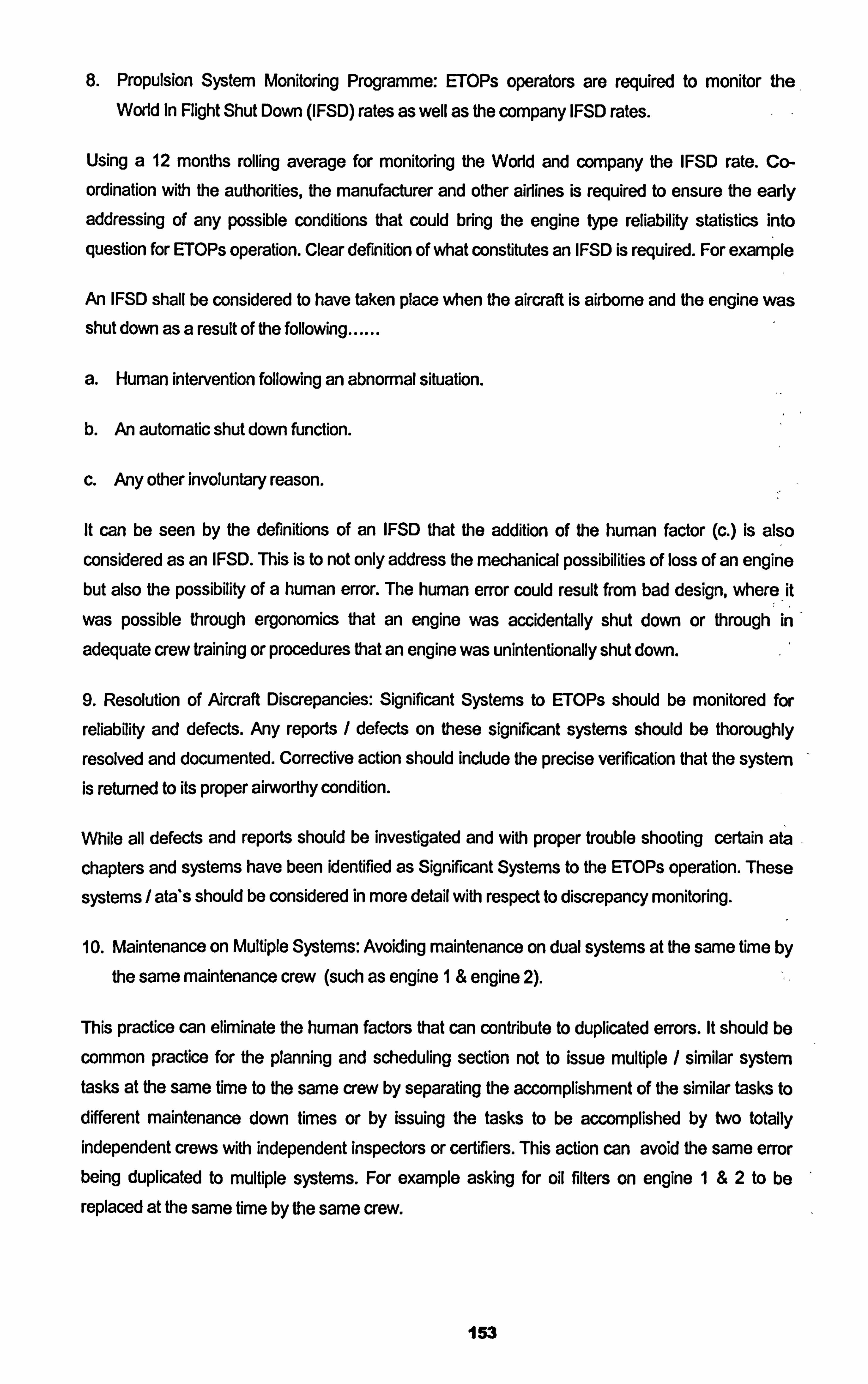
8. Propulsion System Monitoring Programme: ETOPs operators are required to monitor the World In Flight Shut Down (IFSD) rates as well as the company IFSD rates.
Using a 12 months rolling average for monitoring the World and company the IFSD rate. Co-
ordination with the authorities, the manufacturer and other airlines is required to ensure the early addressing of any possible conditions that could bring the engine type reliability statistics into
question for ETOPs operation. Clear definition of what constitutes an IFSD is required. For example
An IFSD shall be considered to have taken place when the aircraft is airborne and the engine was shut down as a result of the following ......
a. Human intervention follovVing an abnormal situation.
b. An automatic shut down function.
c. Any other involuntary reason.
It can be seen by the definitions of an IFSD that the addition of the human factor (c. ) is also considered as an IFSD. This is to not only address the mechanical possibilities of loss of an engine but also the possibility of a human error. The human error could result from bad design, where it
was possible through ergonomics that an engine was accidentally shut down or through in
adequate crew training or procedures that an engine was unintentionally shut down
9. Resolution of Aircraft Discrepancies: Significant Systems to ErOPs should be monitored for
reliability and defects. Any reports / defects on these significant systems should be thoroughly
resolved and documented. Corrective action should include the precise verification that the system is returned to its proper airworthy condition.
While all defects and reports should be investigated and with proper trouble shooting certain ata
chapters and systems have been identified as Significant Systems to the ETOPs operation. These
systems / ata*s should be considered in more detail with respect to discrepancy monitoring.
10. Maintenance on Multiple Systems: Avoiding maintenance on dual systems at the same time by
the same maintenance crew (such as engine I& engine 2).
This practice can eliminate the human factors that can contribute to duplicated errors. It should be
common practice for the planning and scheduling section not to issue multiple / similar system tasks at the same time to the same crew by separating the accomplishment of the similar tasks to different maintenance down times or by issuing the tasks to be accomplished by two totally independent crews with independent inspectors or certifiers. This action can avoid the same error being duplicated to multiple systems. For example asking for oil filters on engine I&2 to be
replaced at the same time by the same crew.
153
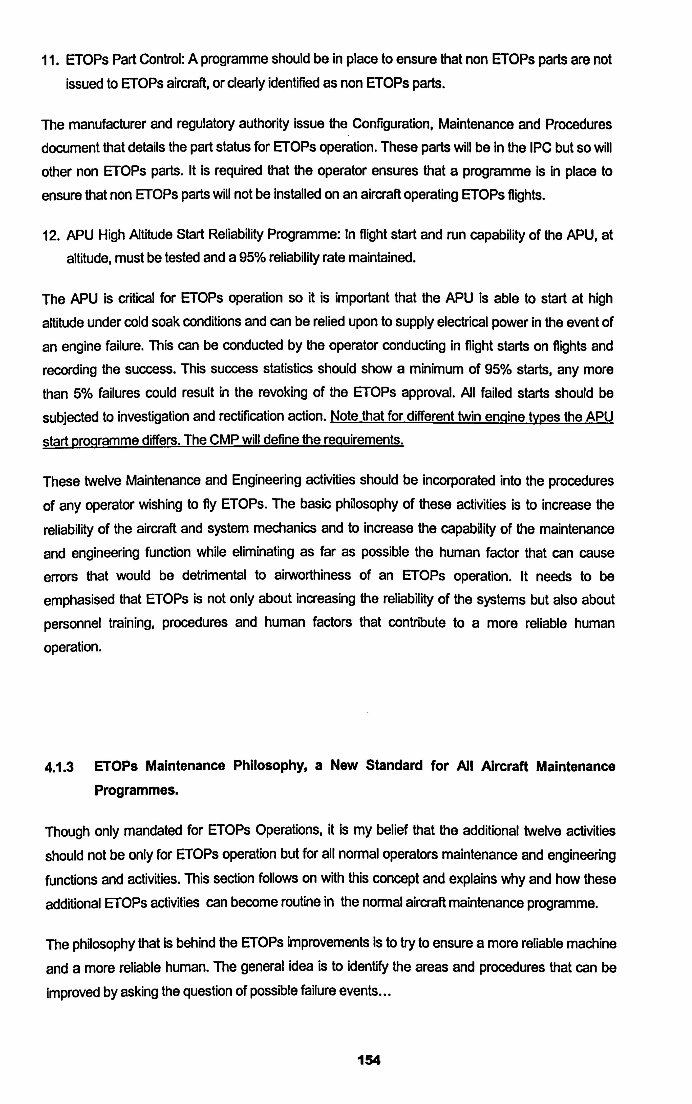
11. ErOPs; Part Control: A programme should be in place to ensure that non ETOPs parts are not issued to ETOPs aircraft, or clearly identified as non ETOPs parts.
The manufacturer and regulatory authority issue the Configuration, Maintenance and Procedures
document that details the part status for ETOPs operation. These parts will be in the IPC but so will
other non ErOPs; parts. It is required that the operator ensures that a programme is in place to
ensure that non ETOPs parts will not be installed on an aircraft operating ETOPs flights.
12. APU High Atitude Start Reliability Programme: In flight start and run capability of the APU, at
altitude, must be tested and a 95% reliability rate maintained.
The APU is critical for ETOPs operation so it is important that the APU is able to start at high
altitude under cold soak conditions and can be relied upon to supply electrical power in the event of
an engine failure. This can be conducted by the operator conducting in flight starts on flights and
recording the success. This success statistics should show a minimum of 95% starts, any more than 5% failures could result in the revoking of the ETOPs approval. All failed starts should be
subjected to investigation and rectification action. Note that for different twin enqine tvr)es the APU
start p gramme differs. The CMP will define the reguirements.
These twelve Maintenance and Engineering activities should be incorporated into the procedures
of any operator wishing to fly ETOPs. The basic philosophy of these activities is to increase the
reliability of the aircraft and system mechanics and to increase the capability of the maintenance
and engineering function while eliminating as far as possible the human factor that can cause
errors that would be detrimental to airworthiness of an ETOPs operation. It needs to be
emphasised that ETOPs is not only about increasing the reliability of the systems but also about
personnel training, procedures and human factors that contribute to a more reliable human
operation.
4.1.3 ETOPs Maintenance Philosophy, a New Standard for All Aircraft Maintenance
Programmes.
Though only mandated for ETOPs Operations, it is my belief that the additional twelve activities
should not be only for ETOPs operation but for all normal operators maintenance and engineering functions and activities. This section follows on with this concept and explains why and how these
additional ETOPs activities can become routine in the normal aircraft maintenance programme.
The philosophy that is behind the ETOPs improvements is to try to ensure a more reliable machine
and a more reliable human. The general idea is to identify the areas and procedures that can be
improved by asking the question of possible failure events...
154
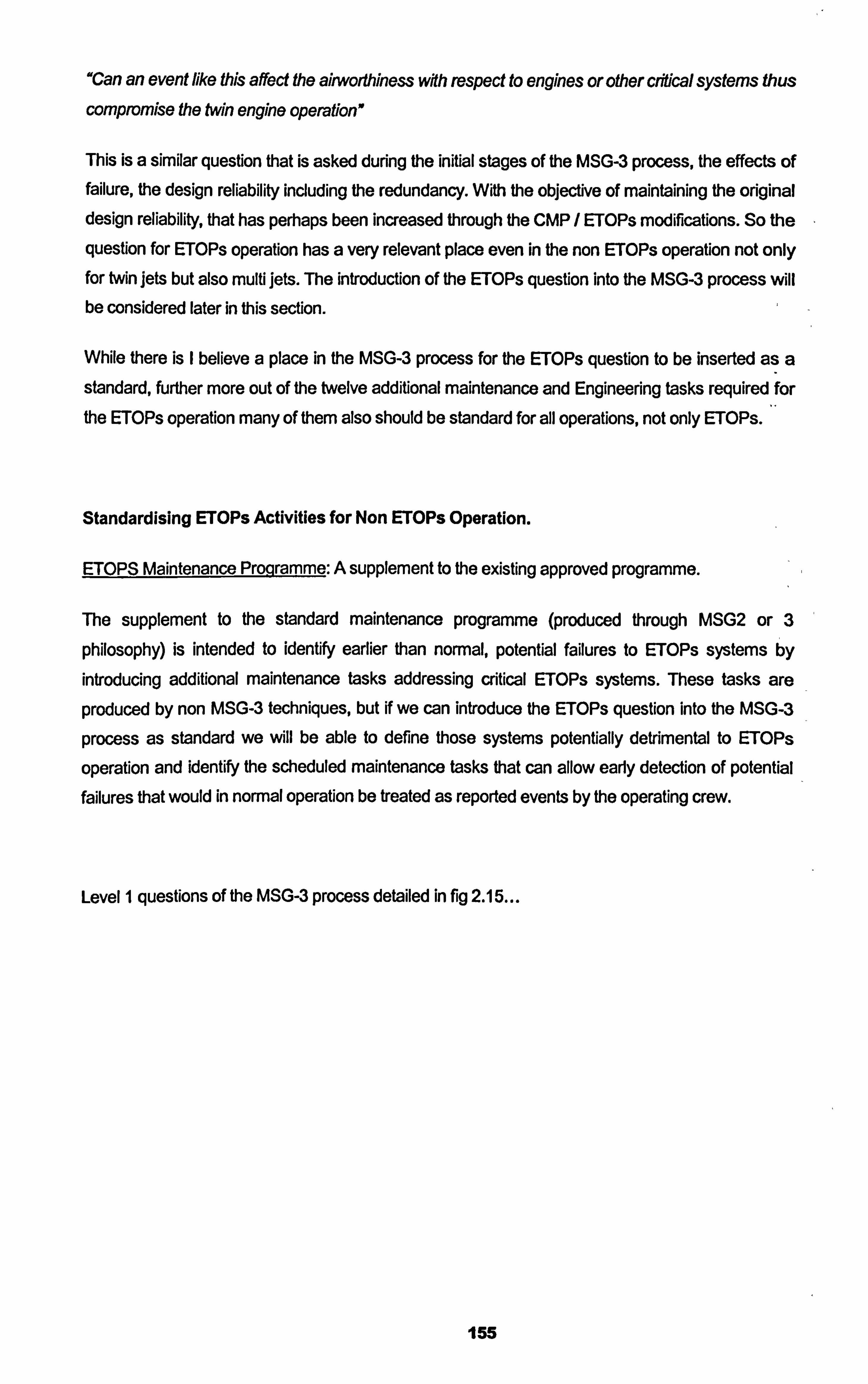
"Can an event like this affect the airworthiness wfth respect to engines or other chlical SYSterns thus
compromise the twin engine operation"
This is a similar question that is asked during the initial stages of the MSG-3 process, the effects of failure, the design reliability including the redundancy. With the objective of maintaining the original design reliability, that has perhaps been increased through the CMP / ETOPs modifications. So the
question for ETOPs operation has a very relevant place even in the non ETOPs operation not only for twin jets but also multi jets. The introduction of the ETOPs question into the MSG-3 process will be considered later in this section.
While there is I believe a place in the MSG-3 process for the ETOPs question to be inserted as a standard, further more out of the twelve additional maintenance and Engineering tasks required for
the ETOPs operation many of them also should be standard for all operations, not only ETOPs.
Standardising ETOPs Activities for Non ETOPs Operation.
ETOPS Maintenance Programme: A supplement to the existing approved programme.
The supplement to the standard maintenance programme (produced through MSG2 or 3
philosophy) is intended to identify earlier than normal, potential failures to ETOPs systems by
introducing additional maintenance tasks addressing critical ETOPs systems. These tasks are
produced by non MSG-3 techniques, but if we can introduce the ETOPs question into the MSG-3
process as standard we will be able to define those systems potentially detrimental to ETOPs
operation and identify the scheduled maintenance tasks that can allow early detection of potential failures that would in normal operation be treated as reported events by the operating crew.
Level I questions of the MSG-3 process detailed in fig 2.15
155
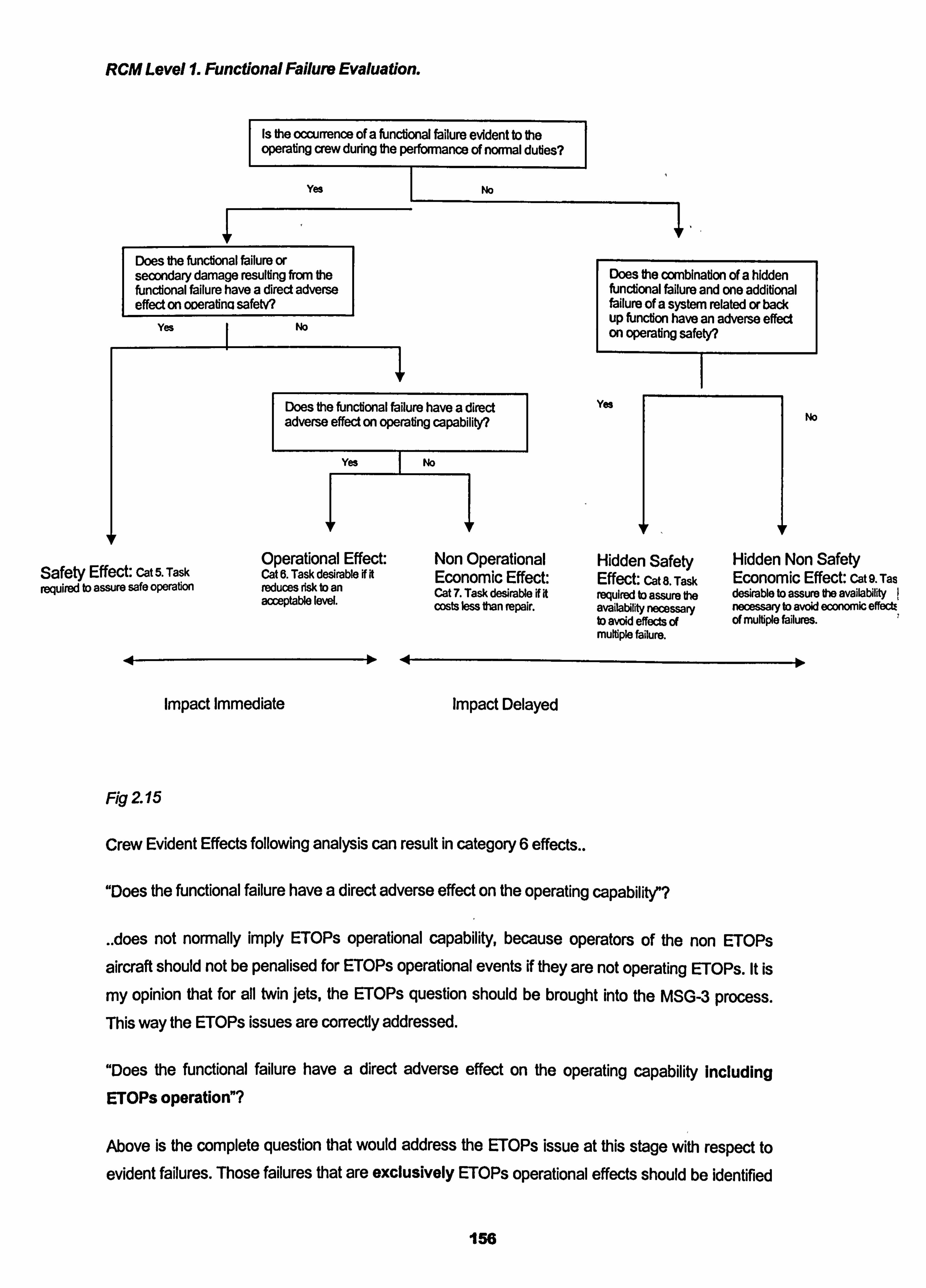
RCM Level 1. Functional Failure Evaluation.
Is the occurrence of a functional failure evident to the operating crew during the performance of normal duties?
Yes
Does the functional failure or secondary damage resulting from the functional failure have a direct adverse effect on oDeratina safetv?
Yes I No
No
Does the functional failure have a direct adverse effect on operating capability?
Yes
Safety Effect: Cat 5. Task required to assure safe operation
Operational Effect: Cat 6. Task desirable KI reduces risk tD an acceptable level.
Impact Immediate
Fig 2 15
No
Non Operational Economic Effect: Cat 7. Task desirable N ft wsts less than repair.
Impact Delayed
Crew Evident Effects following analysis can result in category 6 effects..
Does the combination of a hidden functional failure and one additional failure of a system related or back up function have an adverse effect on operating safety?
Yes No
Hidden Safety Hidden Non Safety Effect: cat 8. Task Economic Effect: cat 9. Tas required to assure ft desirable to assure ft availability availability necessary necessary to avoid economic effectE tD avoid effects of , of multiple failures. multiple failure.
"Does the functional failure have a direct adverse effect on the operating capability"?
Aoes not normally imply ETOPs operational capability, because operators of the non ETOPs
aircraft should not be penalised for ETOPs operational events if they are not operating ETOPs. It is
my opinion that for all twin jets, the ETOPs question should be brought into the IVISG-3 process. This way the ETOPs issues are correctly addressed.
"Does the functional failure have a direct adverse effect on the operating capability including ETOPs operation"?
Above is the complete question that would address the ETOPs issue at this stage with respect to
evident failures. Those failures that are exclusively ETOPs operational effects should be identified
156
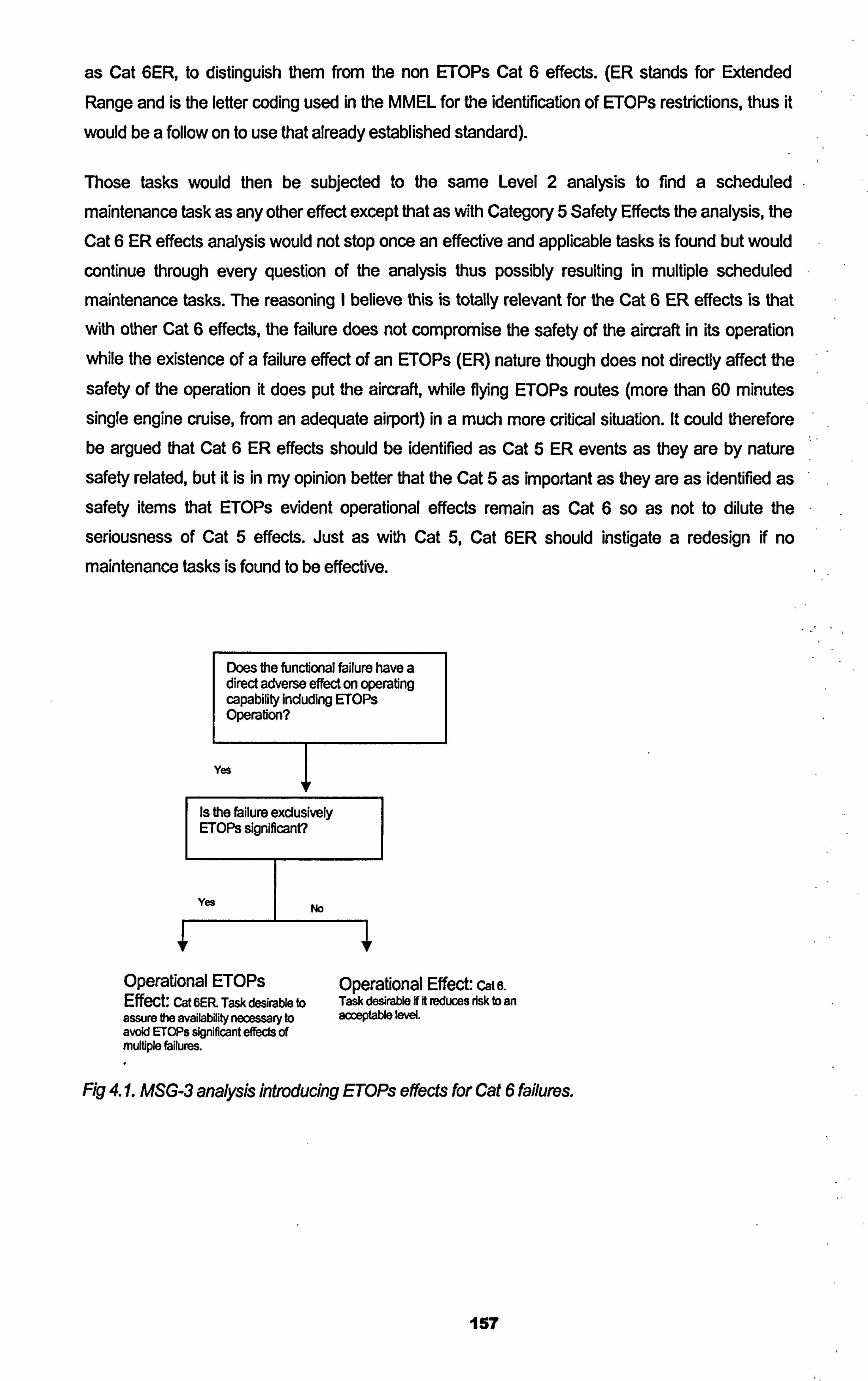
as Cat 6ER, to distinguish them from the non ETOPs Cat 6 effects. (ER stands for Extended
Range and is the letter coding used in the MMEL for the identification of ETOPS restrictions, thus it
would be a follow on to use that already established standard).
Those tasks would then be subjected to the same Level 2 analysis to find a scheduled
maintenance task as any other effect except that as with Category 5 Safety Effects the analysis, the
Cat 6 ER effects analysis would not stop once an effective and applicable tasks is found but would
continue through every question of the analysis thus possibly resulting in multiple scheduled
maintenance tasks. The reasoning I believe this is totally relevant for the Cat 6 ER effects is that
with other Cat 6 effects, the failure does not compromise the safety of the aircraft in its operation while the existence of a failure effect of an ETOPs (ER) nature though does not directly affect the
safety of the operation it does put the aircraft, while flying ETOPs routes (more than 60 minutes single engine cruise, from an adequate airport) in a much more critical situation. It could therefore be argued that Cat 6 ER effects should be identified as Cat 5 ER events as they are by nature safety related, but it is in my opinion better that the Cat 5 as important as they are as identified as safety items that ETOPs evident operational effects remain as Cat 6 so as not to dilute the
seriousness of Cat 5 effects. Just as with Cat 5, Cat 6ER should instigate a redesign if no maintenance tasks is found to be effective.
Does the functional failure have a direct adverse effect on operating capability including ErOPs Operation?
Yes
Is the Ulure exclusively ETOPs significant?
Yes I No
Operational ETOPs Effect: Cat 6ER Task desirable to assure the availability necessary to avoid IFTOPs significant effects of multiple failures.
Operational Effect: cat e. Task desirable if it reduces dsk to an acceptable level.
Ficy 4.1. MSG-3 analysis introducing ETOP: s effects for Cat 6 failures.
157
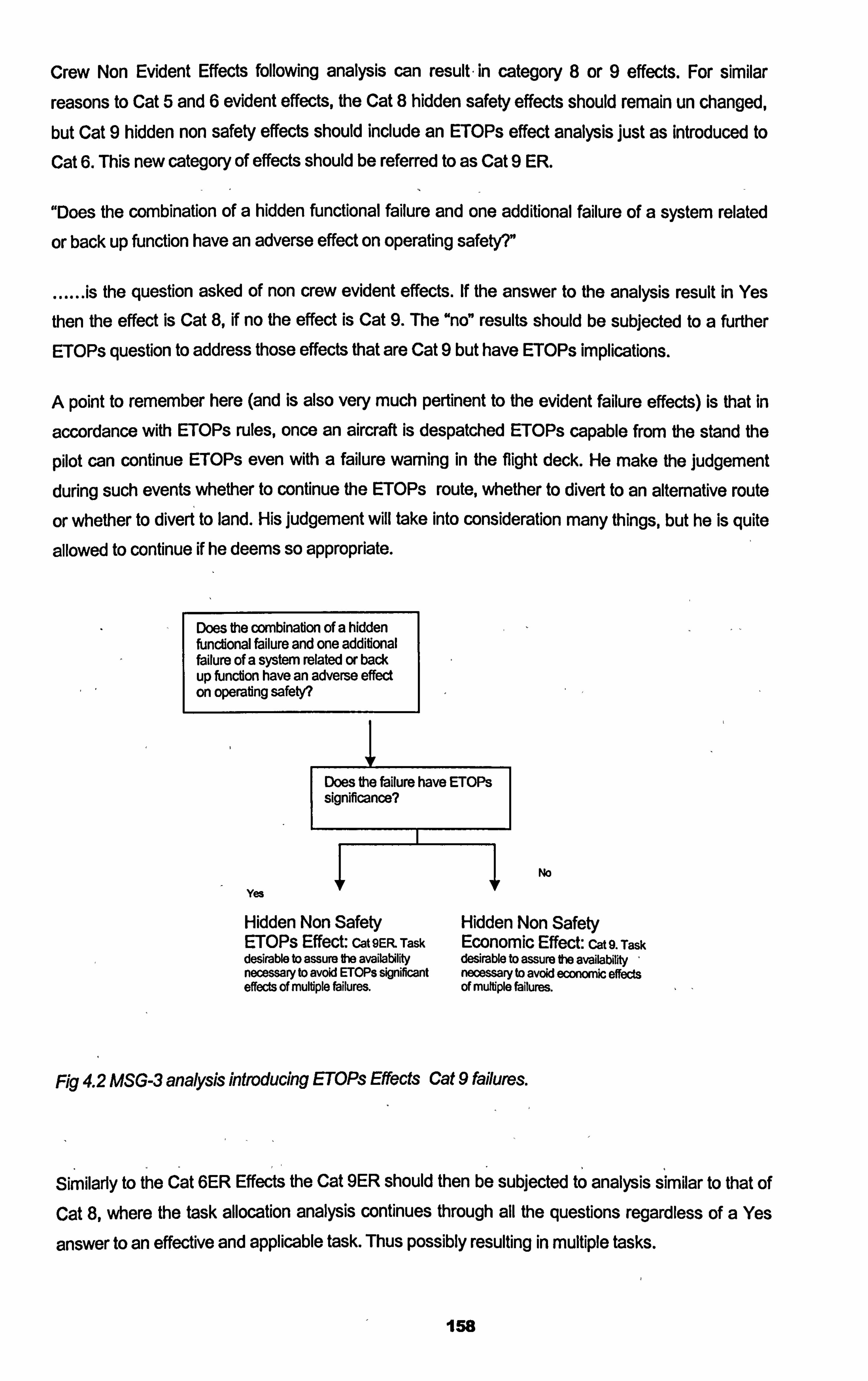
Crew Non Evident Effects following analysis can result - in category 8 or 9 effects. For similar
reasons to Cat 5 and 6 evident effects, the Cat 8 hidden safety effects should remain un changed, but Cat 9 hidden non safety effects should include an ETOPs effect analysis just as introduced to
Cat 6. This new category of effects should be referred to as Cat 9 ER.
"Does the combination of a hidden functional failure and one additional failure of a system related
or back up function have an adverse effect on operating safety? "
...... is the question asked of non crew evident effects. If the answer to the analysis result in Yes
then the effect is Cat 8, if no the effect is Cat 9. The "no" results should be subjected to a further
ETOPs question to address those effects that are Cat 9 but have ETOPs implications.
A point to remember here (and is also very much pertinent to the evident failure effects) is that in
accordance with ETOPs rules, once an aircraft is despatched ETOPs capable from the stand the
pilot can continue ETOPs even with a failure warning in the flight deck. He make the judgement
during such events whether to continue the ETOPs route, whether to divert to an alternative route
or whether to divert to land. His judgement will take into consideration many things, but he is quite
allowed to continue if he deems so appropriate.
Does the combination of a hidden functional failure and one additional failure of a system related or back up funciion have an adverse effect on operating safety?
Does the failure have ETOPs significance?
No
Yes
Hidden Non Safety Hidden Non Safety ErOPS Effect: Cat 9EF; L Task Economic Effect: cat 9. Task desirable to assure ft availability desirable to assure ft availability , necessary to avoid ErOPs significant necessary to avoid econwic effects effects of multiple failures. of multiple failures.
Fig 4.2 MSG-3 analysis introducing ETOPs Effects Cat 9 failures.
Similarly to the Cat 6ER Effects the Cat 9ER should then be subjected to analysis similar to that of Cat 8, where the task allocation analysis continues through all the questions regardless of a Yes
answer to an effective and applicable task. Thus possibly resulting in multiple tasks.
158
With the addition and identification of ETOPs Effects Cat 6ER and Cat 9ER failures, thus the
development of scheduled maintenance tasks applicable to ETOPs operation resulting from the
MSG-3 process, the introduction of these tasks can be considered as more relevant and consistent than other methods of task selection for ETOPs operation. Operators using the aircraft for non ErOPs operation of course need not include the ER tasks in their maintenance programme as they
are not subject to the higher criticality of the ETOPs systems inherent reliability, the standard MSG-
3 analysis (non ER task development) Will result in adequate task selection.
ETOPs Traininq Pro-qramme: Activity 2 in the ETOPs additional activities..
A supplement to the existing maintenance training programme for aircraft used in ErOPs
operation.
The emphasis here is to highlight to those in daily contact with the aircraft, who have airworthiness responsibilities from a maintenance and engineering stand point the ETOPs maintenance and engineering philosophy and the importance of the concept. It is my opinion that to start and stop
only with ETOPs implications is incomplete. The standard maintenance and engineering programme, (maintenance programme refers to the complete set of activities from routine
scheduled maintenance tasks to management and rectification of findings and modifications),
should be explained and imparted to all those directly involved with the aircraft airworthiness and
operational life cycle. It is not my experience today that the maintenance programme concept is
understood fully by maintenance staff and operational staff. The IETOPs training programme Vies to
heighten the level of awareness of the ETOPs maintenance programme, we should endeavour not
only to do this but also to ensure that the standard (non ETOPs) maintenance programme and intentions are understood universally.
For example....
The maintenance technician or engineer, does he / she understand why we conduct scheduled
maintenance and why we do the tasks we do, and why we do the tasks we do when we do them?
Do they understand the definitions of the scheduled tasks that we ask them to do or the implication
of the defect rectification that they do? The maintenance technician / engineer is the front line in
maintaining aircraft airworthiness. His actions directly affect the airworthiness of the aircraft in the
shortest period of time. His actions and recording of his action is critical to the maintenance and
engineering programme. We are only aware of the effectiveness of the maintenance programme through his feedback using the documentation that is included in the maintenance and engineering
programme. For example..
a. The correct carrying out of scheduled routine maintenance tasks that have been defined by the
MSG-3 process.
159
b. The correct rectification of findings resulting from the scheduled maintenance tasks and from
routine operation of the aircraft.
c. The correct interpretation of the pilot reports during the operation.
d. The correct reference to the manuals and documents that make up the maintenance
programme, such as the maintenance manual, fault isolation manual, the minimum equipment list.
e. The correct feedback and recording of findings and subsequent rectification action. The
maintenance technician / engineer goes through years of technical training, but does he also
get correct instruction on technical writing? The maintenance programme relies on the
maintenance technician / engineer for clear accurate recording of a finding or conditions and his subsequent actions in the non routine finding card, in the technical log and in any
occurrence reports. The whole system relies on this feedback and his conformation (or
otherwise) that the inherent reliability of the design is reintroduced after an event, allowing the
monitoring of the applicability and effectiveness of the maintenance programme.
it is my experience that the training programme in place for ErOPs explains the importance of the
role of the maintenance technician / engineer with respect to the complete maintenance and
engineering programme, but those that are not subject to this, I. e. non ErOPs operations perhaps
are not aware, thus creating quite a considerable hole in the maintenance and engineering
programme effectiveness. (Later in the thesis the importance of the feedback from the maintenance technician / engineer will be examined further and shown exactly where and how it impacts on the
maintenance and engineering programme).
In addition to the maintenance technician / engineer, do the flight crew understand their part in the
maintenance and engineering programme? How they are an integral part of the maintenance cycle. Remembering that MSG-3 level 1 asks the question "is the occurrence of a functional failure
evident to the operating crew during normal duties", without their recognition, feedback or
recording of failures or events, the MSG-3 concept is considerably handicapped. Recognising and
reporting on evident failures, liaising with the maintenance staff, using new modified systems
recently installed on their aircraft that are intended to increase the inherent reliability?
Finally also do the operational dispatch staff understand the performance capabilities of the aircraft
and when we might be asking the aircraft to operate in circumstances or environments that might
be demanding or detrimental?
While MSG-3 maintenance programme philosophy does feedback to, and is considered in part by,
the design engineers and the manufacturer, if the maintenance end engineering staff, the flight
crew and the operational staff are trained to understand the maintenance and engineering cycle of
the aircraft and their part in that cycle, this will add only to the maintainability and inherent reliability
of the aircraft. It is in my opinion essential that flight crew in particular undertake maintenance
160
engineering appreciation training to ensure their understanding of their role in the maintenance
programme cycle.
For example The MSG 3 analysis of the engine fire warning system resulted with no scheduled
maintenance task since it was in the crews procedures to conduct a test of the circuitry prior to
every engine start, confirming the correct warnings and lights come on. If the pilot does not report
when a fault occurs or an in correct sequence when conducting the test, the maintenance
programme will not get the pilots input reporting the occurrence. This will give the false information
that there is no problem with the system. This shows how the maintenance programme depends
upon Pilot Reports (PIREPs) to confirm the effectileness of the maintenance programme. Or when
the maintenance crew carry out visual inspections of the wing to body area for evidence of fluid
leaks, and they detect a fluid leak but do not report it in the defect report or the non routine card but
just go ahead and clean the leak. Then the maintenance programme is getting the wrong feedback
that the inspection is not detecting any faults and therefore needs no attention as far as fault
research or interval reduction is concerned.
Both these examples show the importance of correct reporting of findings and faults from the crew
and maintenance staff and its effect on the maintenance programme.
qa ETOPs Reliabili! y Programme: A sunglement to the existing Reliability Pro- ramme or a new st nd-
alone Qroqramme.
For ETOPs operation is it required that the operator conducts reliability monitoring. It is required
that Event Based Reliability Monitoring is employed rather than the regularly used Statistical Based
Monitoring Programme (JAA IL 20 & FAA AC120-42) . Later in the thesis this subject will be
explored in more detail., but essentially what IL20 and AC 120-42 is trying to establish is the
monitoring of the ETOPs Significant Events for recurrence. (ETOPs significant events are those
that effect ETOPs sensitive ata chapters that can have a detrimental effect on the ETOPs critical
systems). Recurrence means that a fault or defect occurs a second time after rectification action
has taken place, thus identifying either an issue with the rectification action taken, the
misunderstanding of the system, a faulty system or component or incorrect documentation
identifying the fault. It is my opinion that the Event Based (recurrence) monitoring is applicable not
only to the ETOPs operation but for all operations. The effectiveness of the statistical monitoring
programme using standard deviations to establish alert levels, is in my opinion questionable in its
retrospective ability, relying on a large data sample and focusing on the event alone regardless of how trivial or significant, rather than the event and subsequent corrective action for a particular
report. Later in the thesis (section 6) we will investigate the benefits of the event based system (adapted to all ata chapters not iust ETOPs chapters) versus the statistical based system for firstly
a small fleet of up to ten aircraft and then for a larger fleet of many more than ten aircraft. Aso we
will look at the essentialness of conducting reliability monitoring from IVISG-3 based programme, as they rely totally on the feedback and reporting of findings. The table below details those ata
161
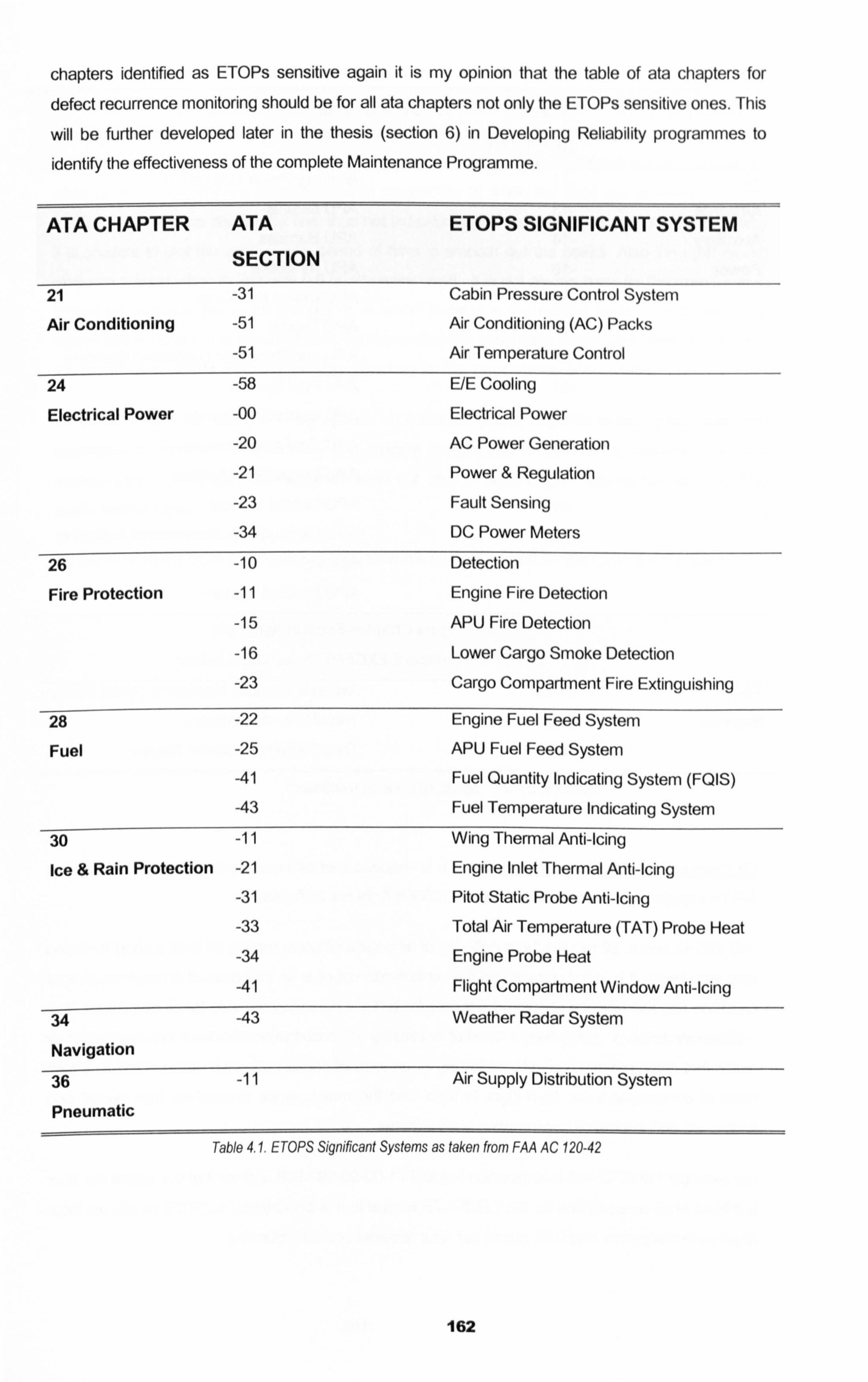
chapters identified as ETOPs sensitive again it is my opinion that the table of ata chapters for
defect recurrence monitoring should be for all ata chapters not only the ETOPs sensitive ones. This
will be further developed later in the thesis (section 6) in Developing Reliability programmes to
identify the effectiveness of the complete Maintenance Programme.
ATA CHAPTER ATA ETOPS SIGNIFICANT SYSTEM
SECTION 21 -31 Cabin Pressure Control System
Air Conditioning -51 Air Conditioning (AC) Packs
-51 Air Temperature Control
24 -58 E/E Cooling
Electrical Power -00 Electrical Power
-20 AC Power Generation
-21 Power & Regulation
-23 Fault Sensing
-34 DC Power Meters
26 -10 Detection
Fire Protection -11 Engine Fire Detection
-15 APU Fire Detection
-16 Lower Cargo Smoke Detection
-23 Cargo Compartment Fire Extinguishing
28
Fuel -22
-25
-41
-43
Engine Fuel Feed System
APU Fuel Feed System
Fuel Quantity Indicating System (FQIS)
Fuel Temperature Indicating System
30 -11 Wing Thermal Anti-Icing
Ice & Rain Protection -21 Engine Inlet Thermal Anti-Icing
-31 Pitot Static Probe Anti-Icing
-33 Total Air Temperature (TAT) Probe Heat
-34 Engine Probe Heat
-41 Flight Compartment Window Anti-Icing
34 -43 Weather Radar System
Navigation
36 -11 Air Supply Distribution System
Pneumatic
Table 4.1. ETOPS Significant Systems as taken from FAA AC 120-42
162
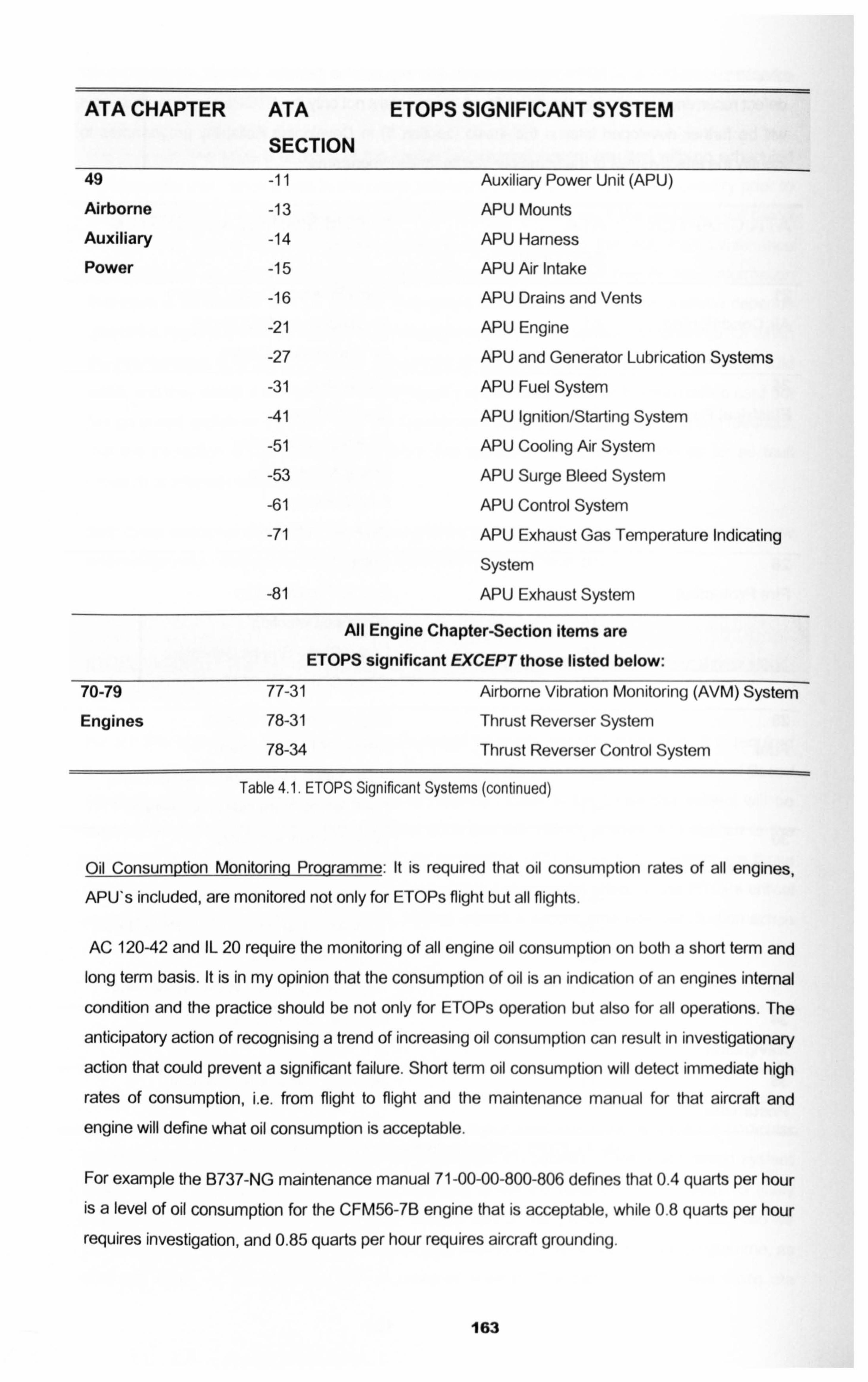
ATA CHAPTER ATA ETOPS SIGNIFICANT SYSTEM
SECTION
49 -11 Auxiliary Power Unit (APU)
Airborne -13 APU Mounts
Auxiliary -14 APU Harness
Power -15 APU Air Intake
-16 APU Drains and Vents
-21 APU Engine
-27 APU and Generator Lubrication Systems
-31 APU Fuel System
-41 APU Ignition/Starting System
-51 APU Cooling Air System
-53 APU Surge Bleed System
-61 APU Control System
-71 APU Exhaust Gas Temperature Indicating
System
-81 APU Exhaust System
All Engine Chapter-Section items are ETOPS significant EXCEPT those listed below:
70-79 77-31 Airborne Vibration Monitoring (AVM) System
Engines 78-31 Thrust Reverser System
78-34 Thrust Reverser Control System
Table 4.1. ETOPS Significant Systems (continued)
Oil Consumption Monitoring Programm : It is required that oil consumption rates of all engines,
APU's included, are monitored not only for ETOPs flight but all flights.
AC 120-42 and IL 20 require the monitoring of all engine oil consumption on both a short term and long term basis. It is in my opinion that the consumption of oil is an indication of an engines internal
condition and the practice should be not only for ETOPs operation but also for all operations. The
anticipatory action of recognising a trend of increasing oil consumption can result in investigationary
action that could prevent a significant failure. Short term oil consumption will detect immediate high
rates of consumption, i. e. from flight to flight and the maintenance manual for that aircraft and
engine will define what oil consumption is acceptable.
For example the B737-NG maintenance manual 71-00-00-800-806 defines that 0.4 quarts per hour
is a level of oil consumption for the CFM56-7B engine that is acceptable, while 0.8 quarts per hour
requires investigation, and 0.85 quarts per hour requires aircraft grounding.
163
When monitoring the oil consumption rate you must be careful to take into consideration the
accuracy of the recording of the oil uplift. e. g. the maintenance technician might not service the oil
until the level is below the sight gauge thus requiring perhaps two quarts to get the level up to the full level line, thus the oil consumption might appear to have jumped to a high level all of a sudden, while another maintenance technician might service the oil when the sight gauge shows mid way between the refill line and the full line, thus not indicating such a dramatic consumption. This is why it is prudent to plot the uplift over a period of time to smooth out the peaks. Nso the uplift record may say I quart when in fact only 0.5 quarts were used. It is not always easy for the maintenance technician to detail the exact amount of oil used to service the engine as no exact measuring
equipment is used in the servicing task. By separating the short term immediate consumption from
the longer term plotted consumption you can allow for the inaccuracies of recording.
Oil consumption monitoring is in my opinion an essential activity required to take place within the
maintenance programme to identify non evident events that could lead to failures. This way
maintenance actions can take place to avoid not only in flight engine failures but also resulting
costly engine repairs.
To follow is an example of a medium / long term consumption chart for the CFM56-7B engine.
164
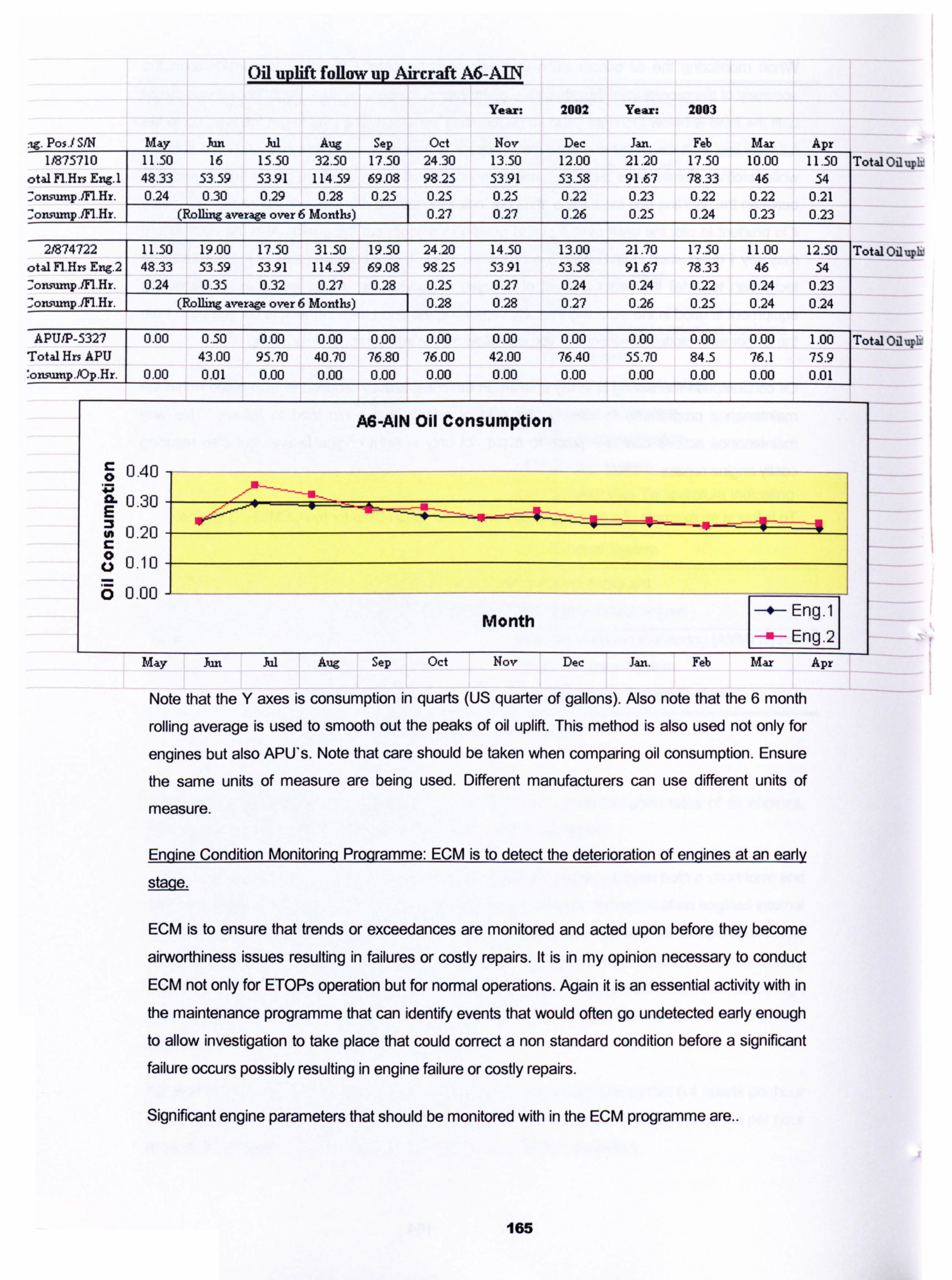
. lg. Pos. / SIN May Jun lia7571 ll 1
. 50 150 16
otal Fl. Hrs Eng. 1 833 L
53.59 Zonsmnp. M. Hr. 0ý Oý 4 0.24 0.30
2W4722 11.50 19.00 otal FI. Hrs Eng. 2 48.33 53.59 -ortsurnp. fn. Hr. 0.24 0.35 : onsump. M. Hr. (Rolling a
APU/P-5327 0.00 0.50 Total Hrs APU 43.00 : onsumi). /OP. Hr. 0.00 0.01
Oil uplift follow up Aircraft A6-AIIN
Year: 2002
Jul Aug Sep Oct Nov Dec 15.50 32.50 17.50 24.30 13.50 12.00 53.91 114.59 69.08 98.25 53.91 53.58 0.29 0.28 0.25 0.25 0.25 0.22
mae over 6 Months) 0.27 0.27 0.26
17.50 31.50 19.50 24.20 14.50 13.00 53.91 114.59 69.08 98.25 53.91 53.58 0.32 0.27 0.28 0.25 0.27 0.24
ge over 6 Months) 0.28 0.28 0.27
0.00 0.00 0.00 0.00 0.00 0.00 95.70 40.70 76.80 76.00 42.00 76.40 0.00 0.00 0.00 0.00 0.00 0.00
AS-AIN Oil Consumption
Year: 2003
Jan. Feb Mar Apr 21.20 17.50 10.00 11.50 Total Oil upIr 91.67 78.33 46 54 0.23 0.22 0.22 0.21 0.25 0.24 0.23 0.23
21.70 17.50 11.00 12.50 Total Oil upIr 91.67 78.33 46 54 0.24 0.22 0.24 0.23 0.26 0.25 0.24 0.24
0.00 0.00 0.00 1.00 Total Oil uph: 55.70 84.5 76.1 75.9 0.00 0.00 0.00 0.01
0.40
0.30 E 0.20
0 0.10
0 0.00
Month s Eng. 1
-a- Eng. 21 May Jun Jul Aug Sep Oct Nov Dec Jan. Feb Mar Apr
Note that the Y axes is consumption in quarts (US quarter of gallons). AJso note that the 6 month
rolling average is used to smooth out the peaks of oil uplift. This method is also used not only for
engines but also APU's. Note that care should be taken when comparing oil consumption. Ensure
the same units of measure are being used. Different manufacturers can use different units of
measure.
Engine Condition Monitoring Proqramme: ECM is to detect the deterioration of engines at an earl
ýiýe.
ECIVI is to ensure that trends or exceedances are monitored and acted upon before they become
airworthiness issues resulting in failures or costly repairs. It is in my opinion necessary to conduct ECM not only for ETOPs operation but for normal operations. Again it is an essential activity with in
the maintenance programme that can identify events that would often go undetected early enough to allow investigation to take place that could correct a non standard condition before a significant failure occurs possibly resulting in engine failure or costly repairs.
Significant engine parameters that should be monitored with in the ECM programme are..
165
Exhaust Gas Temperature EGT. A rise in EGT may well be identified by the flight crew, but only
usually if it is an exceedance, upward trend of increasing EGT can be identified by ECM and a
possible problem can be investigated prior to a failure occurrence. Short term EGT increases can be attributed to faulty crew actions or procedures as well as defective systems or components,
while medium or long-term trend increases can be the result of potential failures such as, engine fuel management faults, engine bleed air valve faults or just EGT probe faults.
Engine Low Pressure Fan Speed N 1. A fluctuation in NI again as with EGT may well be identified
by the crew if an exceedance takes place, but regular non exceedances; or upward trends will be
detected by ECM of this parameter. NI fluctuation could result from engine fuel management faults
or NI speed sensor faults.
Other parameters to be monitored are Engine High Pressure fan Speed N2, 'Fuel Flow, Oil
Temperature, Oil Pressure, Engine Vibration. By monitoring trends from these parameters an indication of the health of the engine internals can be determined and with investigation of noticed trend increases as opposed to one of fluctuations, maintenance actions can be planned ahead thus
preventing in operation failures or even expensive failure repairs.
ECM parameters can now a days be downloaded directly from the aircraft while in flight through
ACARS (Aircraft Communication and Reporting System) and transmitted through SATCOM
(Satellite Communication) to the ECM ground station, downloaded directly into a software
programme that will plot the parameters immediately live and show data and trends while the
aircraft flies.
The activity of ECM in my opinion should be carried out on all operations even if it is not the
ACARS method but a simple crew form filling in process while at cruise. (Automatic recording of
engine parameters has a large advantage over manual methods as it may not be possible due to
pilot work load and the criticality of the stage of flight to ask for take off and landing engine data to
be monitored by form filling). This way the non evident potential failure modes of the engine internals can be monitored before a resulting failure occurs.
Maintenance on Multiple Sygtems: Avoiding maintenance on dual systems at the same time by the
same maintenance crew (such as engine 1& engine 2). This practice can avoid the same wrong
process being accomplished on two essential ETOPs systems at the same time.
IDENTICAL MAINTENANCE ON SIMILAR SYSTEMS
Identical maintenance action to multiple similar elements in ETOPS significant systems
should not be undertaken nor should it be practiced on non ETOPs systems. Identical
maintenance action to multiple similar elements is defined as the same task (i. e., repair,
replacement, or disassembly) being performed on more than one of similar systems during
166
the same maintenance visit, and on the same component. Engine-driven components are
considered equivalent, consequently the replacement of such components in any combination
on both engines qualifies as an identical maintenance action. Examples of the above would include: removal of both engine oil filters or both chip detectors, and replacement of both
IDGs, EDPs, or replacement of the #1 IDG and the #2 EDP.
NOTE. Servicing of fluids and gases is not considered multiple maintenance action.
To aviod the situation occuring Scheduled Maintenance on multiple, similar systems should be scheduled by the Maintenance and Engineering Planning section so that tasks will be
performed during different check packages or different phases of phased checks.
Routine line checks should be staggered to prevent maintenance action from being performed
on both systems at the same time. If, through some non-routine cause or on a time when multiple actions do occur, the following should apply:
a. Different technicians / engineers will perform the maintenance on the similar
systems.
b. The work will be certified by an independent inspector; or
C. A verification of the systems (as will be detailed in the following section Resolution of Aircrfat Discrepencies) will be accomplished to ensure system integrity.
If the Maintenance and Engineering Planning section do schedule similar system
maintenance tasks or identify that an issued task could result in similar system maintenance, that task card should be marked as "Similar System Maintenance". It is then the responsibility
of the Maintenance Personnel to be aware that if he violates the similar system rule he must
comply with the conditions to ensure system integrity after the task is carried out. This also leads to the importance of correct and clear technical authorship detailing that the system
violated has undergone confirnation of system integrity through an appropraite and adiquate
maintenance manual test.
This issue of separating in time similar system maintenance tasks as a preference to same task at the same time but with different technicians and inspectors is an issue argued over many times. It is my opinion that whenever possible the separation of the tasks accomplishment to
ensure the similar system violation takes place at separate points in time with several operating
cycles and hours between the task accomplishment is a much preferred option than using separate
maintenance staff only, for the following reasons (using the engine oil filter change as an
example)....
Engine I oil filter is changed by technician number 1 and certified by inspector number 1,
while Engine 2 oil filter is changed by technician number 2 and inspected by inspector number 2.
The different crew works both engines on at the exact same time. This reduces largely the risk of the same error by the same technician and inspector being followed over on to both engines, but
167
the risk can be reduced further by conducting the tasks at different scheduled points in time
because, both technician number I and number 2 may consult each other on how to do the task
thus swapping errors. Technician number 1 and number 2 will refer to the exact same maintenance
manual procedure effective for that point in time, which may be wrong or unclear. Technician
number I and number 2 will use the exact same tools on the exact same day, which may be faulty
or if requiring calibration inaccurate. Technician number 1 and number 2 will use the material kits
preloaded on the same day probably from the same batch of receipts, which may contain the same defective material.
So by scheduling similar system maintenance tasks at the same point in time but by using different maintenance staff you are only removing the human factor contributing to the risk, but by
scheduling the tasks at different points in time and if any of the errors mentioned do occur you have
created a stagger in time where it is less probable that a failure induced by the errors mentioned do
occur at the exact same flight or point in time in the future, thus giving time to react to correct any
maintenance, tool or material error and reducing the risk of multiple failures at the same time on
similar systems.
It is my opinion that this ETOPs standard practice is the most relevant for use in all
standard aircraft maintenance practices when carrying out Line maintenance, whether ETOPs,
propeller, twin or four engine aircraft. The first step of making the maintenance staff aware of the
similar system maintenance by marking the task card "Similar System Maintenance" is the first
crucial step. To stop here would be an improvement by reducing the human factor risk element, but
to physically separate the tasks is reducing the risk that bit more. Some examples of how to
separate the similar system tasks is as follows...
B737-700 / CFM56-7B Maintenance Schedule.
Task 79-010-01 -00 Change Engine No I Oil Supply Filter.
Task 79-010-02-00 Change Engine No 2 Oil Supply Filter.
Both tasks have an interval of 12 months are would neatly fit into the 2A Check maintenance input.
It is easy for the Maintenance and Engineering Planning section to plan to accomplish both tasks
and all other tasks at the 2A 12 month maintenance input. But equally since the B737 maintenance
schedule also has a6 month IA Check maintenance input all the engine number I tasks could be
separated from the engine number 2 tasks and accomplished on the 1A check input and
subsequently repeated every 12 months on the 3A, 5A 7A etc, while the engine number 2 tasks
accomplished on the 2A, 4A, 6A etc. AJI that is lost is 6 months from the life of engine number one's tasks that need to be accomplished early to establish the stagger. A more complex example of
separating similar system tasks is...
168
Task 72- 010-01 -00 Inspect the Magnetic Chip Detectors (MCD) for evidence of debris build up on
engine No. 1.
Task 72- 010-02-00 Inspect the Magnetic Chip Detectors for evidence of debris build up on engine No. 2.
Both tasks have to be accomplished every 250 flight hours and are not aligned to any scheduled
maintenance input but are controlled as "out of phasd' and complied with just prior to, but as close to as possible, their due time on an opportunity basis. The adoption of the similar system
maintenance stagger in this case may result in the introduction of some additional co-ordination
and even perhaps some additional downtime, as the tasks interval does not lend itself to the easy
allocation of the task to a maintenance input, so they should be done on an opportunity basis,
perhaps on a night stop or during a daily check when they are close to falling due. The MCD
example is a very good task to look at. It is a simple task taking only 10 minutes to remove the
MCD that is very accessible through an access flap in the bottom of the engine cowl, remove the MCD inspect it, and reinstall it. The appeared trivial nature of such a task lends its self to
complacency. This task is a violation of a very significant engine system, the oil system, loss of oil through the incorrect installation would result in engine shut down and may not become apparent
until the aircraft is in flight.
There are at least three famous occasions when this simple task was incorrectly carried out on all the engines of an aircraft resulting in oil loss to both engines and in one occasion to the four
engines of a four engined aircraft. On a four engined aircraft it would be good practice to exercise
separation of the tasks in pairs of engines rather than for all engines. For example engine 1 and 3
could be accomplished together and engine 2 and 4. Thus at no time are both engines on the same
wing violated. The reason I propose going that step further than just identifying and using separate technicians is based largely on what has happened in the past with the MCD task. On one
occasion the MCD's were removed, sent to a laboratory for inspection, and new MCD's installed.
The MCD's have a single 0 ring seal on their shaft, it was the practice for many years that the
newly supplied MCD's were prepared by stores for the technician to immediately install, i. e. the o
rings were already fitted to the new MCD. On one occasion this process changed and the new
supplied MCD's did not have the o ring pre installed on the MCD shaft. The technician was not
aware of this new practice and did as he always did, remove four MCD's, take them to the stores for shipment to the lab, and get four back and immediately install them. Not having the o ring installed was not sufficient to show an oil leak during the engine motoring run, but on take off role
and after take off the oil loss was sufficient enough to give the flight crew four engine oil pressure
warnings which were substantial enough to cause four in-flight shut downs. My opinion here is that
even by having two inspectors or technicians carrying out the tasks on the different engines, this
error could have still occurred. But by separating the task in engine pairs, the pilot would have been
faced with only two engine IFSD's on this occasion. My point is that the human error aspect
contributing to the failures is only one of a few possibilities, by separating the tasks the other
contributing possibilities can have reduced risk.
169
For those who do not wish to incur the additional co-ordination and perhaps in some way the
additional cost of separating similar system tasks where either they are not following ETOPs
practices or are using the different technician and inspector procedure, I would encourage that they
re consider and perhaps compromise with the splitting of what I see as the four vital similar system tasks....
1. Fuel System violations: for example filter changes or fuel nozzle inspections.
2. Oil System violations: for example filter changes or MCD inspections.
3. Ignition System violations: for example plug changes or harness changes 4. Boroscope Inspections: This will involve internal inspection of the engine via some access hole
or through ignition plugs or fuel nozzles.
By at least avoiding similar system violation with regards to these four areas on line maintenance
activities I believe the risk of similar system concurrent failure will be largely reduced. On major
maintenance inputs it is difficult to avoid similar system violations, but in such cases adequate final
function tests should be carried out to ensure the revalidation of violated systems. This may in
some cases require full power engine runs or even a flight test.
Resolution of Aircraft Discregancies: Significant Systems to ETOPs should be monitored for
reliability and defects. Any reports / defects on these significant systems should be thoroughly
resolved and documented. Corrective action should include the precise verification that the system is returned to its proper airworthy condition or at least a precise detail of the maintenance tasks
carried out during the investigation of the report. This approach should not be conducted only for
ETOPs system events but for all systems.
The addressing of pilot reports or defects by maintenance staff involves a methodical investigation
process. Manufacturers produce a variety of troubleshooting aids on modem jet aircraft such as the
following...
Fault Codes identified in the aircraft management computer maintenance page. These fault codes
can be entered directly into the Fault Isolation Manual (FIM) where troubleshooting procedures will be detailed and if followed will result in the root cause of the symptom being discovered. Though
the FIM gives details of troubleshooting the maintenance procedures remain to be detailed in the
maintenance manual, MM. The MM is always the authoritative manual to detail non, routine
maintenance tasks.
On going system and component self test using Built in Test Equipment (BITE) for critical systems. These test often activated on the controlling system computer, can identify if the system or
computer is in a serviceable mode.
It is essential that the exact work steps taken are detailed in the maintenance documentation, either the Technical Log or the Non Routine Card. This will allow the complete defect history and action
170
taken to be saved to history for future reference or to assist in the study of ongoing problems. This
aspect of maintenance, i. e. correct and detailed action recording has been examined in "ETOPs
Training Programmd" paragraph e mentioned previously. The technical writing skills of the investigating technician / engineer is essential to effective root cause analysis of faults and defects.
An example of a Technical Log entry with rectification / resolution details is as follows
PREP 1. A defect resulting in repair / resolution confirmation.
Pilot Rei)ort:: Defect / SyrnDtom.
Automatic Direction Finding ADF 1 audio intermittent.
Rectification action 1:
CB on P1 8-1 cycled. Reports will be monitored further.
Rectification action 2:
ADF system audio test FIM TASK 34-57-00-810-806 referred to. AMM TASK 34-57-
00-730-801 p501 carried out audio test. Audio test found not satisfactory. FIM step F
captains flight inter phone speaker test carried out refer to AM 23-51 task 805. Capt
flight inter phone failed test, subsequent replacement of same inter phone carried out iaw AMM TASK 34-57-00-730-801 p5011 removal & AMM TASK 34-57-00-730-801
p5011 installation. Repair confirmation FIM 23-51 task 805 step G carried out
successfully. Defect rectified.
Rectification action 1 does not involve detailed trouble shooting and does not involve evidence of a
methodological approach. While Rectification action 2 not only clearly follows the FIM process detailing the exact methodological process carried out by the maintenance technician / engineer, it
also gives conformation of rectification and defect resolution at the end of the action details. This is
a good example of a well trouble shot and written defect action rectification.
PREP 2. A defect resulting in no confirming repair action.
Pilot Report: Defect / Soptom.
While on taxi after landing, rudder pedals does not move freely, requires more than
normal force to obtain same output.
171
Rectification action 1:
Rudder pedals inspected for obstacles, none found and rudder hinge lubricated.
Rectification action 2:
Rudder Does Not Move Freely - Fault Isolation task 27-21-00-810-807 referred to and step 7 c, Ia through to h rudder travel check carried out. All found normal, fault identified as intermittent. Defect cleared, will monitor for further occurrence.
Rectification action 1 does not tell you the troubleshooting process carried out and can not be used in future re arising of the symptom as assistance in the trouble shooting process. While
Rectification action 2 details the exact FIM reference and the subsequent steps carried out. Even
though the action does not result in exact resolution, this can be used in future to build upon if the
event re occurs. The second action is clear and uses a methodological process detailed well on the
maintenance documentation.
Pilot reports of discrepancies is one aspect of defect rectification, another aspect are defects found
during scheduled maintenance, i. e. the carrying out of the fault finding maintenance programme task. Remember that the point of carrying out the maintenance programme tasks is to detect
potential failures.
Maintenance Schedule Task 1.
Routine Task 53-110-00-00 General Visual Inspection of the Galley to Floor Attachment.
Resulting in the following..
Non Routine Card 1.
Corrosion found. Attachments placed in accordance with maintenance manual chapter 53.
Non Routine Card 2.
Corrosion found when carrying out Task Card 53-11 O-Oo-oo on Galley 4 attachment forward
inboard & forward outboard. FWd I/B attachment corrosion removed & found to be surface
corrosion, damage within limits reference SRM 53-25-00, no further action required. Fwd O/B attachment corrosion gone beyond limits in SRM 53-25-00. Attachment replaced law
AMM 53-25-20-200-800.
172
In an MSG-3 maintenance programme it is imperative that non routine findings are noted and considered in detail. The Non Routine Card is the vehicle for detailing what is found when conducting the routine task. Without clear and precise technical authorship it is not known if the findings should result in the reduction or increase of a maintenance tasks depth of inspection or interval of inspection. NRC 1 is a very bad example of little detail from what is a corrosion finding. From this it is not known the depth or significance of corrosion or even where the corrosion has
occurred. But from NRC 2a clear and exact detail of what was found and the subsequent investigation is detailed well. It gives us a good indication of what was found and where exactly it
was found. From NRC 2 we know that this task is doing its job and resulting in findings.
Maintenance Schedule Task 2.
Routine Task 24-100-00-00 Check Engine #1 Integrated Drive Generator Oil level & Service as Required.
Resulting in the following..
Non Routine Card 1.
I DG serviced to full mark law 24-13-21-21-600-801.
Non Routine Card 2.
Engine #1 IDG oil level checked law task 24-100-00-00 & found below"service line"on sight
gauge. 1.25 quarts of oil added law AMM 12-13-21-600-801.
NRC I tells us by implication that the task found the IDG low on oil so required servicing. It even
confirms that the technician used the correct procedure. But NRC 2 tells us much more and gives
us the oil required to service the IDG to full, 1.25 qts. This allows us to know that the oil
consumption of the IDG was not so much that it went below the minimum line, but only to the
service line. Also by knowing the oil uplift at this time, we can monitor next scheduled inspection
results to see if the next uplift is the same amount or less and then be able to calculate the
consumption over the hours flown sine the last check.
Both these examples of PIREPs and NRC*s show the importance of good technical authorship
when a technician or engineer is writing up a report or finding and their rectification action. It is not only imperative for an IVISG-3 based maintenance programme to get good clear detailed feedback, but it is also imperative for any maintenance process that maintenance actions and defect
173
rectification are carried out to approved procedures and detailed clearly and that findings are
confirmed found and confirmed rectified. Getting to the Root Cause of a defect is imperative to
finding the correct and appropriate resolution and good maintenance records can lead to the Maintenance Programme becoming more effective and applicable. This is not only applicable to an ETOPs operations but to every aspect of maintenance engineering. Of course the eloquent writing
of a technician does not guarantee that the root cause of the defect has been found and the correct
rectification action has been carried out, but what it does do is documents the action taken by the technician and allows for a clear record to be referred to later if the defect reoccurs. What will result in the root cause rectification of the defect is correct and adequate training of the technician on the
type or aircraft and its systems and also in the use of documents available to him to assist him in
his research and trouble shooting.
To resolve that a defect has been cleared it may be necessary to carry out a full function check of the system to ensure that the action taken by the technician has resulted in complete resolution of the defect. This will be detailed in the appropriate maintenance manual, but the technician may
wish to conduct full function tests of the system in the same environment that the defect occurred. This may not be possible on the ground. Most of the time any defect resolution can be confirmed by
full function checks on the ground, such as powered engine runs, hydraulic pressurisation tests and
so one, but for defects such as hydraulic pressurisation module freezing when the aircraft is at cold
soak, can not be confirmed rectified or reproduced on the ground. This type of defect rectification
requires resolution action confirmation by getting the same environment reproduced to see if the
fault is solved or reoccurs. Hence a verification flight would be required.
Many aspects are involved in the confinned resolution of defects rectification
1. Adequate technical training of the technician to enable understanding of the aircraft and
systems.
2. Adequate training for the technician in the use of the manuals available to assist him in his
trouble shooting.
3. Adequate training of the technician in how to conduct technical writing. Ensuring clear and
accurate referencing of maintenance activities and tasks.
4. Correct understanding of the technician on how to confirm that the maintenance action he has
conducted will result in confirmed resolution of the defect. His ability to understand when further
verification is required.
5. An adequate reliability and defect monitoring system paying attention to all PIREPs and NRC*s
assisting the technician in his trouble shooting and monitoring for further reporting on
subsequent operations.
174
Interchanqeabilitv of Components
Swapping components between ETOPS airplanes similar primary systems for troubleshooting
purposes (e. g., installing #1 Enigne Electronic Control Unit (EECU) in the #2 EECU location
to ascertain if a problem is with the #2 EECU or further up the system) is not recommended. In those cases where similar components are swapped, positive verification of system as described in the previouse section, is required for both systems.
175
4.2 Low Utilisation Implications for an Aircraft Maintenance Programme.
4.2.1 Low Utilisation: An Introduction.
When an aircraft manufacture decides to build a new aircraft type it is only after a lot of industry
research which will involve talking to operators on what size of aircraft they need, with what range, how many seats, and with what anticipated utilisation, where are the likely geographical locations,
what will the runways be like. Al these parameters combine to identify the role of the new aircraft. The anticipated role will influence all aspects of the design and certification process.
When an operator wishing to use the new aircraft for a role that is not consistent with the initial
conceptual role such as...
A Japanese airline used B747's for short range high passenger density flights, when the B747 was
conceptually designed for long haul flights.
An Indian airline took a A320 and operated it to remote landing strips that were not constructed with the same material as national airports.
A B737 was fitted with auxiliary fuel tanks to give it a range twice of its design range to conduct long
range flights while this aircraft was designed for short haul hops.
The scenario we will explore in this thesis is the use of airliners to conduct occasional in frequent
flights to almost any location in the world. The term Low Utilisation is used to describe such
operations, where it is a B747-400 flying once every 30 days or a B737-700 flying 800 flight hours
per year. This scenario is often seen in the Charter World where aircraft are utilised only in the
holiday season or in the Government or VIP world where the objective for the aircraft is to be ready
on call for occasional personal transportation of a person or family at short notice.
4.2.2 Low Utilisation: Maintenance Implications.
As touched on in section 2.2.1, the definitions of responsibility for the Private Category Operator
has not been defined in the JAKs. Pending JAR OPS 2 is suppose to be the regulatory vehicle that will define the requirements and will be available with in the next year, while the FAA FAR 91
defines for US registered aircraft the responsibilities for the private category operator. Very often the Low Utilisation operation is also private category. At the start of the IVIRB process some
assumptions are made by the board. These assumptions are normally predominantly operational
assumptions such as the following...
1. Operators average annual flight hour utilisation.
2. Operators average annual cycle utilisation.
176
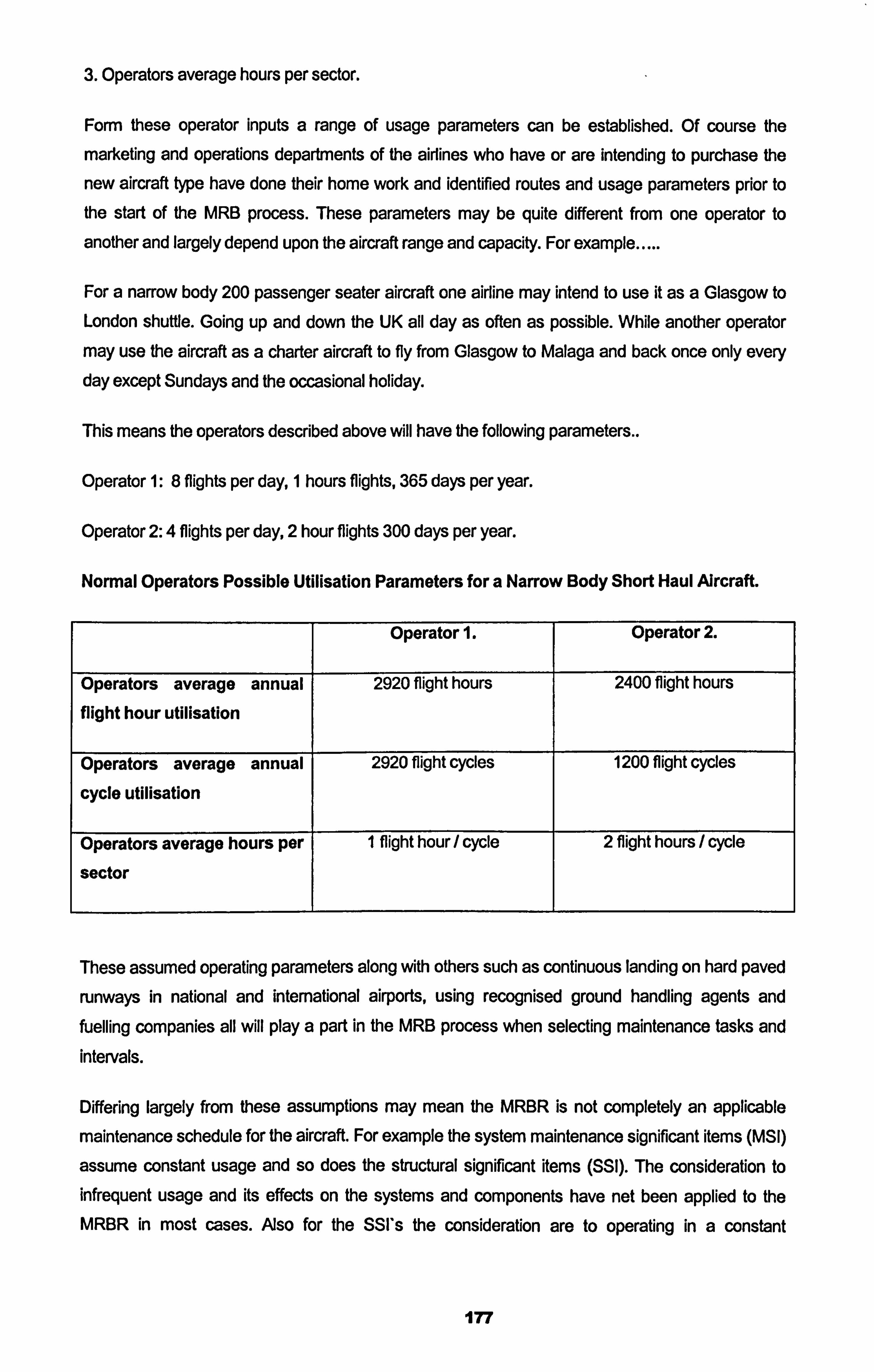
3. Operators average hours per sector.
Form these operator inputs a range of usage parameters can be established. Of course the
marketing and operations departments of the airlines who have or are intending to purchase the
new aircraft type have done their home work and identified routes and usage parameters prior to the start of the IVIRB process. These parameters may be quite different from one operator to
another and largely depend upon the aircraft range and capacity. For example.....
For a narrow body 200 passenger seater aircraft one airline may intend to use it as a Glasgow to London shuttle. Going up and down the UK all day as often as possible. While another operator may use the aircraft as a charter aircraft to fly from Glasgow to Malaga and back once only every day except Sundays and the occasional holiday.
This means the operators described above will have the following parameters..
Operator 1: 8 flights per day, 1 hours flights, 365 days per year.
Operator 2: 4 flights per day, 2 hour flights 300 days per year.
Normal Operators Possible Utilisation Parameters for a Narrow Body Short Haul Aircraft.
Operator 1. Operator 2.
Operators average annual 2920 flight hours 2400 flight hours
flight hour utilisation
Operators average annual 2920 flight cycles 1200 flight cycles
cycle utilisation
Operators average hours per I flight hour/ cycle 2 flight hours / cycle
sector
These assumed operating parameters along with others such as continuous landing on hard paved
runways in national and international airports, using recognised ground handling agents and fuelling companies all will play a part in the IVIRB process when selecting maintenance tasks and intervals.
Differing largely from these assumptions may mean the MRBR is not completely an applicable
maintenance schedule for the aircraft. For example the system maintenance significant items (MSI)
assume constant usage and so does the structural significant items (SSI). The consideration to infrequent usage and its effects on the systems and components have net been applied to the MRBR in most cases. Also for the SSI*s the consideration are to operating in a constant
177
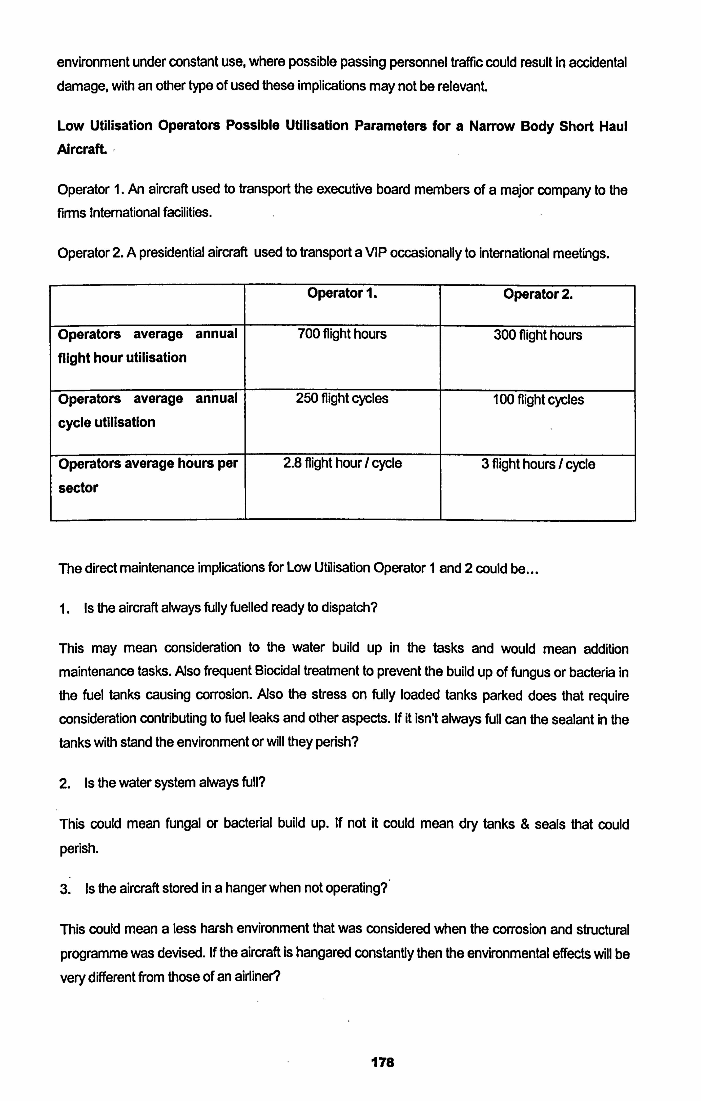
environment under constant use, where possible passing personnel traffic could result in accidental damage, with an other type of used these implications may not be relevant.
Low Utilisation Operators Possible Utilisation Parameters for a Narrow Body Short Haul
Aircraft. ,
Operator 1. An aircraft used to transport the executive board members of a major company to the firms International facilities.
Operator 2. A presidential aircraft used to transport a VIP occasionally to international meetings.
Operator 1. Operator 2.
Operators average annual 700 flight hours 300 flight hours
flight hour utilisation
Operators average annual 250 flight cycles 100 flight cycles
cycle utilisation
Operators average hours per 2.8 flight hour / cycle 3 flight hours / cycle
sector
The direct maintenance implications for Low Utilisation Operator 1 and 2 could be
1. Is the aircraft always fully fuelled ready to dispatch?
This may mean consideration to the water build up in the tasks and would mean addition maintenance tasks. Aso frequent Biocidal treatment to prevent the build up of fungus or bacteria in
the fuel tanks causing corrosion. Aso the stress on fully loaded tanks parked does that require
consideration contributing to fuel leaks and other aspects. If it isn't always full can the sealant in the
tanks with stand the environment or will they perish?
2. Is the water system always full?
This could mean fungal or bacterial build up. If not it could mean dry tanks & seals that could
perish.
3. Is the aircraft stored in a hanger when not operating? '
This could mean a less harsh environment that was considered when the corrosion and structural
programme was devised. If the aircraft is hangared constantly then the environmental effects will be
very different from those of an airliner?
178
4. Is the aircraft handled on the ground by specialist handlers or the same as those that airlines use?
This will largely affect the accidental damage ratings that are influenced by the banging and large
personnel traffic of international airline ground handling companies. Perhaps the handling agents of
such low utilisation companies are more careful and the personnel traffic is much less.
5. Many lubricating system require the system to be in operation to be able to lubricate?
By low utilisation the systems that are normally lubricated frequently are now not. The sumps will contain the oil while the bearings and seals will be open to the atmosphere of the system. Perhaps
some systems require more frequent lubricating or operational testing to get the oils flowing?
6. Is a MRBR task is to be done at 3000 flight hours? This may be 30 years for a low utilisation
aircraft, is this acceptable?
The MRB process will be looked at closer in the next section taking into' consideration the
adjustments of intervals if required, if a factor of calendar usage is a valid consideration for the
reduction or extension on task intervals. But what can be seen by considering the operating cycle
of the Low Utilisation aircraft is that conditions and environment can be very different from the
airliner, so to just adopt the airliner maintenance philosophy and maintenance schedule would not be correct, but to factor in the Low Utilisation implications of long periods of non usage, of specialist handling at special VIP terminals, of possible exposure of structure to a controlled environment, as
well as others would be a necessary requirement in my opinion. It is my opinion that any aircraft
operating out side the "normal" operating parameters of the intended design should be subjected to
a proper Low Utilisation Maintenance Implication review and this should start with the review of the
MRBR process and the MSG3 analysis.
4.2.3 Low Utillsation Adjustments to The MSG3 Process.
Boeing Document D626AOOI the Manufacturers Maintenance Planning Data, derived from the
MRBR, for the B737NG details that any operation less than 100 flight hours per months or 1200
flight hours per year should consider following a low utilisation maintenance programme. Other
Boeing and Airbus maintenance planning documents also give the operating parameters that were
assumed by the MRBR. It has been the practice in the past that when an operator wished to use an
aircraft for missions that do not meeting the operating parameters detailed in the MRBR / MPD to
adjust the maintenance schedule tasks from their usage based intervals to those of a calendar based interval. For example tasks with an interval of 5000 flight hours intervals, usage based,
would have been converted to 3 years intervals. The concept being assume a utilisation of 1000
flight hours per year it would be 5 years at the most for a 1000 flight hour per year low utilisation operation or even 10 years for a 500 flight hour low utilisation operation to meet the task interval
179
requirements. While normal operations were conducting the tasks at around 3 year or less
intervals.
This approach of simply converting scheduled maintenance task intervals from one usage
parameter to a calendar parameter, say from flight hours to years or months, is completely wrong
and completely contradicts the intention of the RCM / MSG3 process of deciding on effective and
applicable intervals to conduct scheduled maintenance tasks. What applicability at all does doing a
scheduled maintenance task that has come out of the RCM / MSG3 process to be accomplished
every 5000 flights hours at 3 years? The RCM / MSG3 process has identified that that Maintenance
Significant Item or Structural Significant Item (MSI or SSI), is a function of flight hour usage. imagine the low utilisation operator at 3 years has only flown 2000 flight hours and he is conducting
maintenance tasks for 5000 flight hours? All he achieves by doing so is the disturbance of stable
airworthy systems and components and introduces an activity that in itself can be destructive and invasive. it is my opinion that such Low Utilisation calculators that massively reduce the task
intervals, that have been applied in the past, are not appropriate and can not be classified as
applicable and effective maintenance tasks.
What I will achieve and attempt to describe in this section of the thesis is the possibility of two
methods, where the low utilisation implications of an operation can be taken into direct
consideration I the RCM / MSG3 process by the following...
Method 1. Where the airliner MRBR is taken as is and the low utilisation implications are applied to
the MRBR MSI*s and SSI's and adjustments made where appropriate. -
Method 2. Where the RCM / MSG3 process takes place all over again with the assumption
parameters detailed in the MRB hand Book, established from the very beginning that take into
consideration the low utilisation operation parameters.
The selection of which method is to be used may be based on a cost implication, but it is my
opinion when an aircraft is marketed for a low utilisation operation, method 2 should be applied, but
when the product is adapted for a low utilisation method 1 may suffice. It should be also realised that the out come of the RCM / IVISG3 process, the MRBR is only one part of the value of
conducting the IVIRB process, that other part is the think tank that is established where operators
and manufacturers and authorities get together to decide on maintenance policies for the whole
world, at what other times does this ever happen?
Looking closer at Method 1.
The B737-6001700/800 and CFM56-7B Maintenance Review Board Report was issued on 7th July
1997 and approved by the US Federal Aviation Administration (FAA), Transport Canada (TC) and the Joint Aviation Authorities (JAA). The report was produced using the Air Transport Association's
Maintenance Programme Development Document MSG3 Revision 2, dated 12 Sept 1993.
180
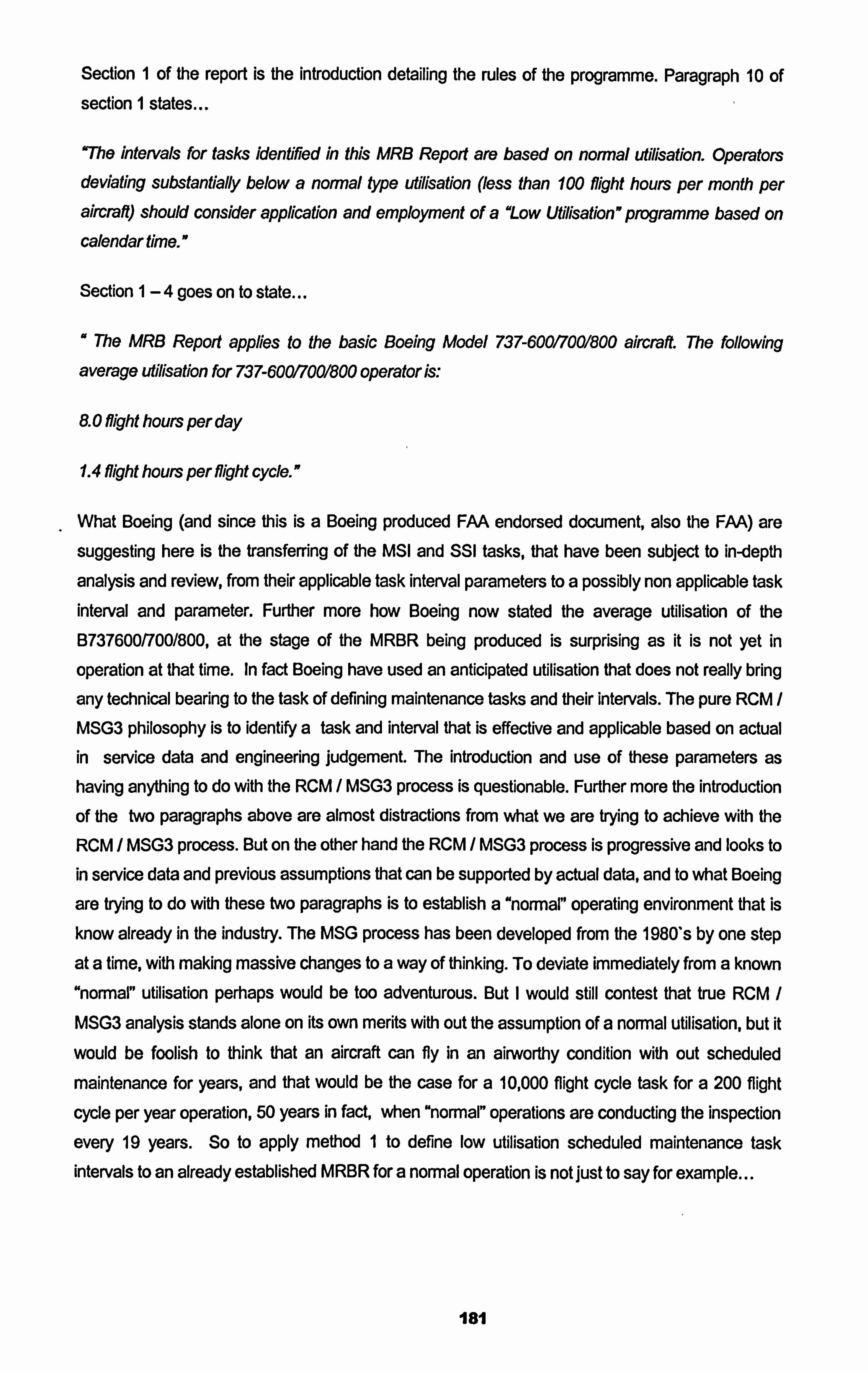
Section 1 of the report is the introduction detailing the rules of the programme. Paragraph 10 of section I states...
uThe intervals for tasks identified in this MRB Report are based on normal utilisation. Operators deviating substantially below a normal type utilisation (less than 100 flight hours per month per aircraft) should consider application and employment of a "Low Utillsation "programme based on calendar time. "
Section 1-4 goes on to state
" The MRB Report applies to the basic Boeing Model 737-60017001800 aircraft. The following
average utilisation for 737-60017001800 operator is.,
8.0 flight hours per day
1.4 flight hours per flight cycle. ff
What Boeing (and since this is a Boeing produced FAA endorsed document, also the FAA) are suggesting here is the transferring of the MSI and SSI tasks, that have been subject to in-depth
analysis and review, from their applicable task interval parameters to a possibly non applicable task interval and parameter. Further more how Boeing now stated the average utilisation of the B737600/700/800, at the stage of the MRBR being produced is surprising as it is not yet in
operation at that time. In fact Boeing have used an anticipated utilisation that does not really bring
any technical bearing to the task of defining maintenance tasks and their intervals. The pure RCM /
MSG3 philosophy is to identify a task and interval that is effective and applicable based on actual in service data and engineering judgement. The introduction and use of these parameters as having anything to do with the RCM / MSG3 process is questionable. Further more the introduction
of the two paragraphs above are almost distractions from what we are trying to achieve with the RCM / MSG3 process. But on the other hand the RCM / MSG3 process is progressive and looks to in service data and previous assumptions that can be supported by actual data, and to what Boeing
are trying to do with these two paragraphs is to establish a "normal" operating environment that is
know already in the industry. The MSG process has been developed from the 1980's by one step
at a time, with making massive changes to a way of thinking. To deviate immediately from a known
"normal" utilisation perhaps would be too adventurous. But I would still contest that true RCM /
MSG3 analysis stands alone on its own merits with out the assumption of a normal utilisation, but it
would be foolish to think that an aircraft can fly in an airworthy condition with out scheduled
maintenance for years, and that would be the case for a 10,000 flight cycle task for a 200 flight
cycle per year operation, 50 years in fact, when "normal" operations are conducting the inspection
every 19 years. So to apply method 1 to define low utilisation scheduled maintenance task intervals to an already established MRBR for a normal operation is not just to say for example...
181
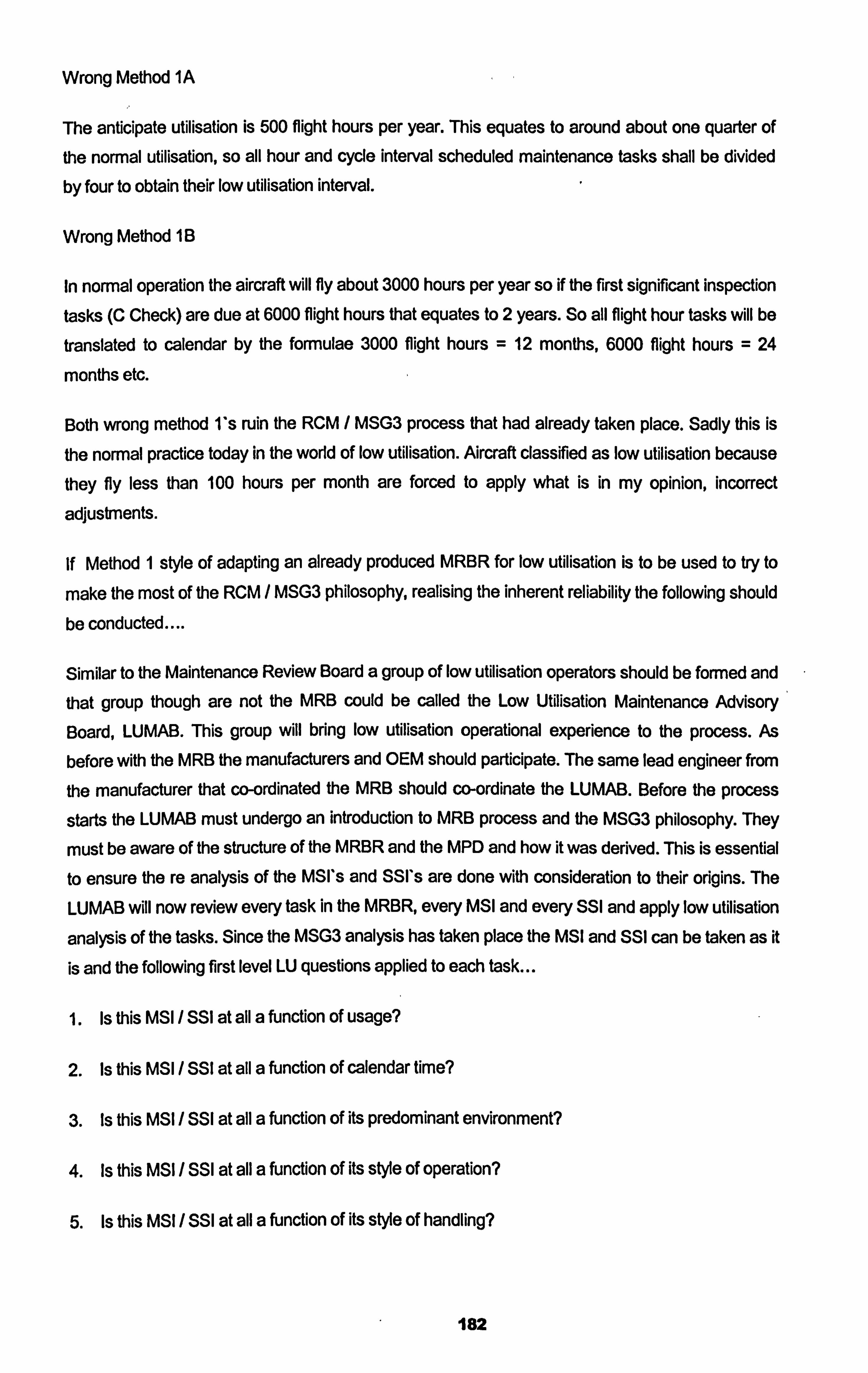
Wrong Method 1A
The anticipate utilisation is 500 flight hours per year. This equates to around about one quarter of the normal utilisation, so all hour and cycle interval scheduled maintenance tasks shall be divided
by four to obtain their low utilisation interval.
Wrong Method 1B
In normal operation the aircraft will fly about 3000 hours per year so if the first significant inspection
tasks (C Check) are due at 6000 flight hours that equates to 2 years. So all flight hour tasks will be
translated to calendar by the formulae 3000 flight hours = 12 months, 6000 flight hours = 24
months etc.
Both wrong method I's ruin the RCM I MSG3 process that had already taken place. Sadly this is
the normal practice today in the world of low utilisation. Aircraft classified as low utilisation because
they fly less than 100 hours per month are forced to apply what is in my opinion, incorrect
adjustments.
If Method I style of adapting an already produced MRBR for low utilisation is to be used to try to
make the most of the RCM / MSG3 philosophy, realising the inherent reliability the following should be conducted....
Similar to the Maintenance Review Board a group of low utilisation operators should be formed and that group though are not the MRB could be called the Low Utilisation Maintenance Advisory
Board, LUMAB. This group will bring low utilisation operational experience to the process. As
before with the MRB the manufacturers and OEM should participate. The same lead engineer from
the manufacturer that co-ordinated the MRB should co-ordinate the LUMAB. Before the process
starts the LUMAB must undergo an introduction to MRB process and the MSG3 philosophy. They
must be aware of the structure of the MRBR and the MPD and how it was derived. This is essential to ensure the re analysis of the MSI's and SSI's are done with consideration to their origins. The
LUMAB will now review every task in the MRBR, every MSI and every SSI and apply low utilisation
analysis of the tasks. Since the MSG3 analysis has taken place the MSI and SSI can be taken as it
is and the following first level LU questions applied to each task...
Is this MSI / SSI at ail a function of usage?
2. Is this MSI / SSI at all a function of calendar time?
3. Is this MSI / SSI at all a function of its predominant environment?
4. Is this MSI / SSI at all a function of its style of operation?
5. Is this MSI / SSI at all a function of its style of handling?
182
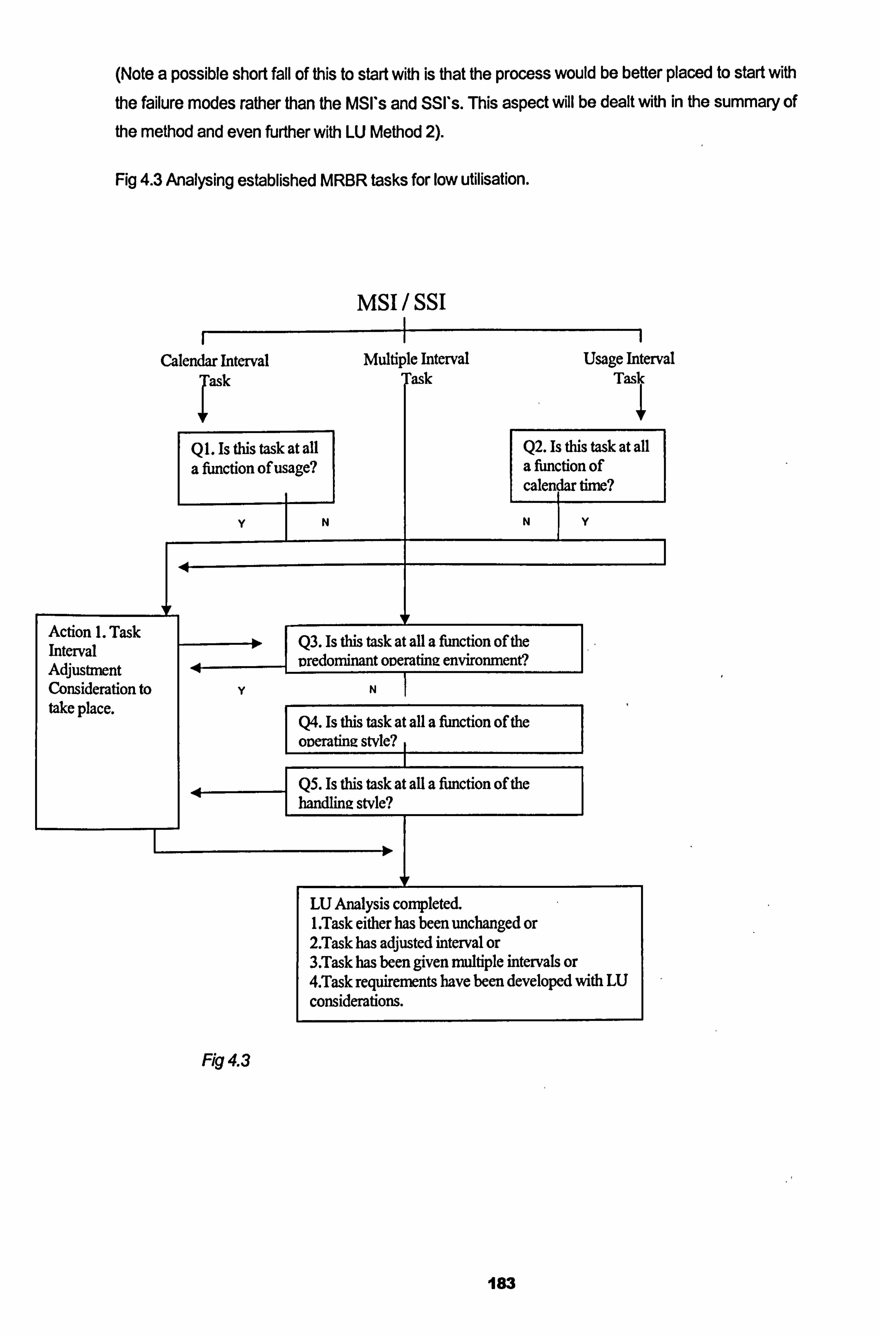
(Note a possible short fall of this to start with is that the process would be better placed to start with the failure modes rather than the MSI's and SSI*s. This aspect will be dealt with in the summary of the method and even further with LU Method 2).
Fig 4.3 Analysing established MRBR tasks for low utilisation.
msi Ssi
Calendar Interval Multiple Interval Usage Interval Tas Task
Q 1. Is Us task at all Q2. Is this task at all a fimction of usage? a fimction of
calendar tinie?
Action 1. Task 10 Q3. Is this task at all a function of the Interval
t
medominant weratiniz enviromnent? Adjusfinent Consideration to yN take place. Q4. Is this task at all a fimction of the I
oneratiniz stvle? ,
Q5. Is this task at all a fimction of the handline stvle?
I
LU Analysis completed. I. Task either has been unchanged or 2. Task has adjusted interval or 3. Task has been given multiple intervals or 4. Task requirements have been developed with LU considerations.
Fig 4.3
183
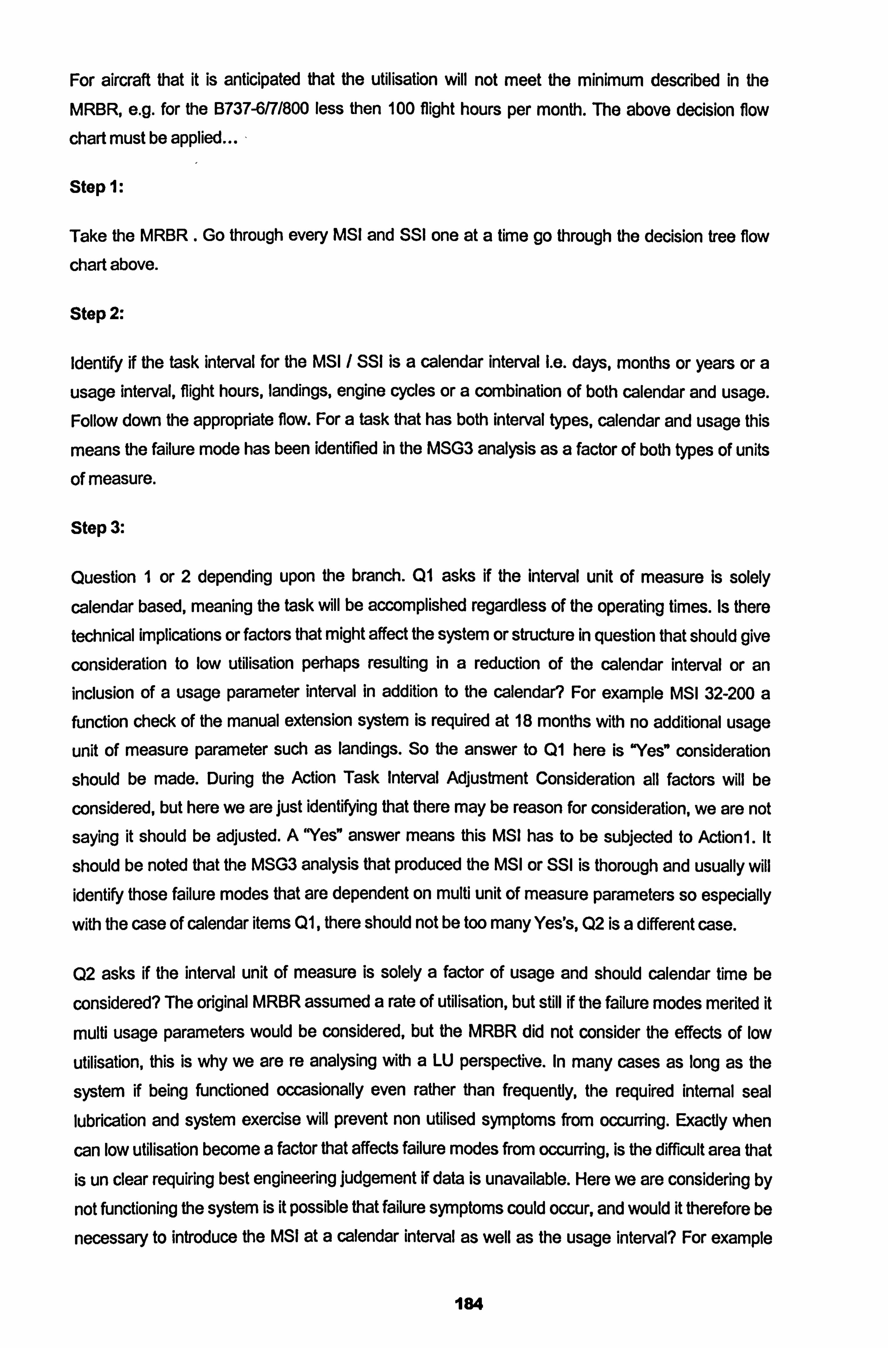
For aircraft that it is anticipated that the utilisation will not meet the minimum described in the
MRBR, e. g. for the B737-6/7/800 less then 100 flight hours per month. The above decision flow
chart must be applied... -
Stop 1:
Take the MRBR . Go through every MSI and SSI one at a time go through the decision tree flow
chartabove.
Step 2:
Identify if the task interval for the MSI / SSI is a calendar interval i. e. days, months or years or a
usage interval, flight hours, landings, engine cycles or a combination of both calendar and usage. Follow down the appropriate flow. For a task that has both interval types, calendar and usage this
means the failure mode has been identified in the MSG3 analysis as a factor of both types of units
of measure.
Stop 3:
Question I or 2 depending upon the branch. Q1 asks if the interval unit of measure is solely
calendar based, meaning the task will be accomplished regardless of the operating times. Is there
technical implications or factors that might affect the system or structure in question that should give
consideration to low utilisation perhaps resulting in a reduction of the calendar interval or an inclusion of a usage parameter interval in addition to the calendar? For example MSI 32-200 a function check of the manual extension system is required at 18 months with no additional usage
unit of measure parameter such as landings. So the answer to Q1 here is "Yee consideration
should be made. During the Action Task Interval Adjustment Consideration all factors will be
considered, but here we are just identifying that there may be reason for consideration, we are not
saying it should be adjusted. AYes" answer means this MSI has to be subjected to Actioni. It
should be noted that the MSG3 analysis that produced the MSI or SSI is thorough and usually will identify those failure modes that are dependent on multi unit of measure parameters so especially
with the case of calendar items Q1, there should not be too many Yes's, Q2 is a different case.
Q2 asks if the interval unit of measure is solely a factor of usage and should calendar time be
considered? The original MRBR assumed a rate of utilisation, but still N the failure modes merited it
multi usage parameters would be considered, but the MRBR did not consider the effects of low
utilisation, this is why we are re analysing with a LU perspective. In many cases as long as the
system if being functioned occasionally even rather than frequently, the required internal seal lubrication and system exercise will prevent non utilised symptoms from occurring. Exactly when
can low utilisation become a factor that affects failure modes from occurring, is the difficult area that
is un clear requiring best engineering judgement if data is unavailable. Here we are considering by
not functioning the system is it possible that failure symptoms could occur, and would it therefore be
necessary to introduce the MSI at a calendar interval as well as the usage interval? For example
184
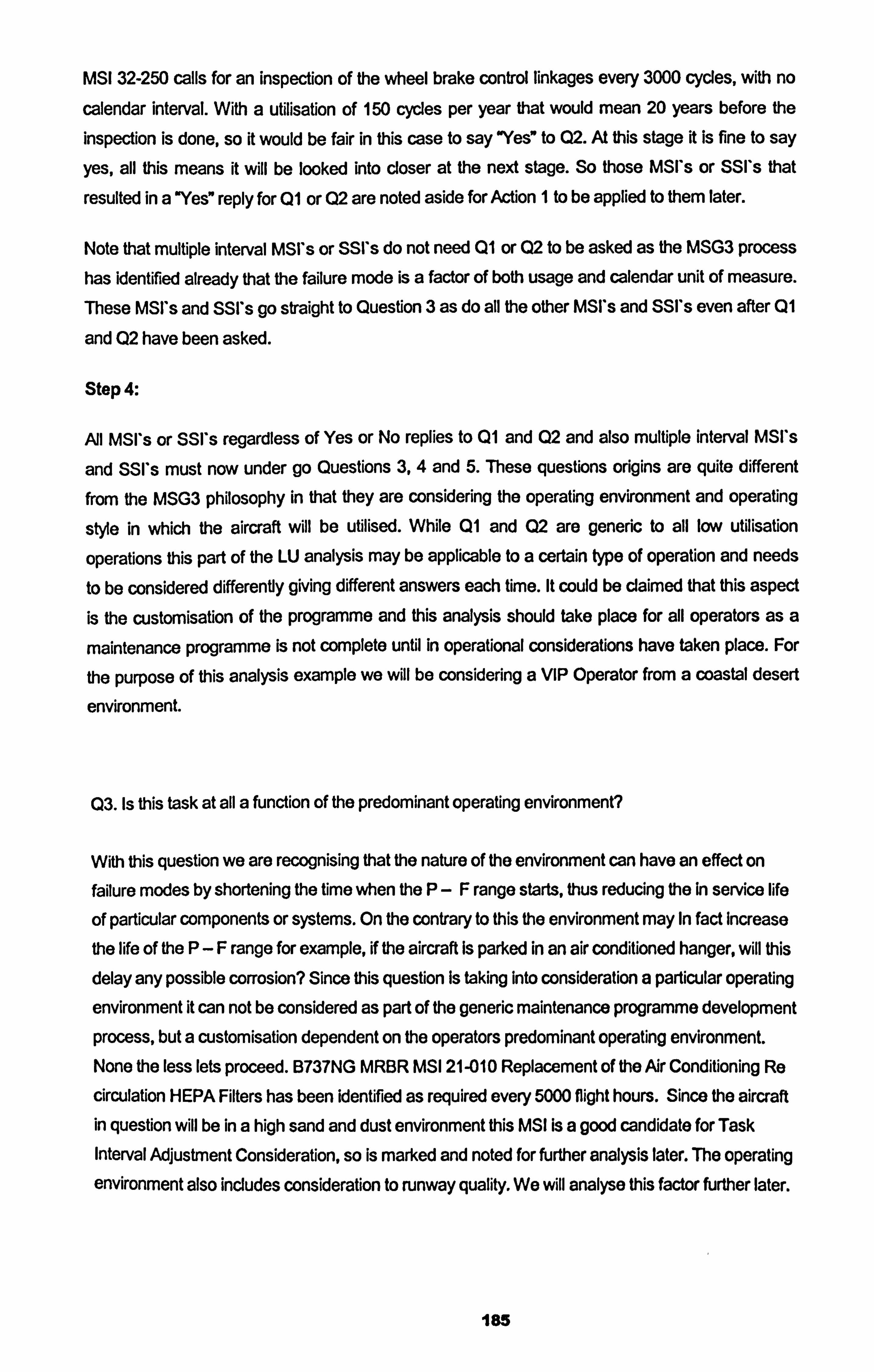
MSI 32-250 calls for an inspection of the wheel brake control linkages every 3000 cycles, with no
calendar interval. With a utilisation of 150 cycles per year that would mean 20 years before the
inspection is done, so it would be fair in this case to say "Yes7 to Q2. At this stage it is fine to say
yes, all this means it will be looked into closer at the next stage. So those MSI's or SSI's that
resulted in a "Yes" reply for Q1 or Q2 are noted aside for Action I to be applied to them later.
Note that multiple interval MSI's or SSI's do not need Q1 or Q2 to be asked as the MSG3 process has identified already that the failure mode is a factor of both usage and calendar unit of measure. These MSI's and SSI's go straight to Question 3 as do all the other MSI's and SSI's even after Q1
and Q2 have been asked.
Step 4:
AM MSI*s or SSI*s regardless of Yes or No replies to Q1 and Q2 and also multiple interval MSI's
and SSI's must now under go Questions 3,4 and 5. These questions origins are quite different
from the MSG3 philosophy in that they are considering the operating environment and operating
style in which the aircraft will be utilised. While Q1 and Q2 are generic to all low utilisation
operations this part of the LU analysis may be applicable to a certain type of operation and needs
to be considered differently giving different answers each time. It could be claimed that this aspect is the customisation of the programme and this analysis should take place for all operators as a
maintenance programme is not complete until in operational considerations have taken place. For
the purpose of this analysis example we will be considering a VIP Operator from a coastal desert
environment.
Q3. Is this task at all a function of the predominant operating environment?
With this question we are recognising that the nature of the environment can have an effect on failure modes by shortening the time when the P-F range starts, thus reducing the In service life
of particular components or systems. On the contrary to this the environment may In fact increase
the life of the P-F range for example, if the aircraft Is parked in an air conditioned hanger, will this delay any possible corrosion? Since this question Is taking into consideration a particular operating
environment it can not be considered as part of the generic maintenance programme development
process, but a customisation dependent on the operators predominant operating environment. None the less lets proceed. B737NG MRBR MSI 21-010 Replacement of the Air Conditioning Re
circulation HEPA Filters has been identified as required every 5000 flight hours. Since the aircraft in question will be in a high sand and dust environment this MSI is a good candidate for Task Interval Adjustment Consideration, so is marked and noted for further analysis later. The operating environment also incJudes consideration to runway quality. We will analyse this factor further later.
185
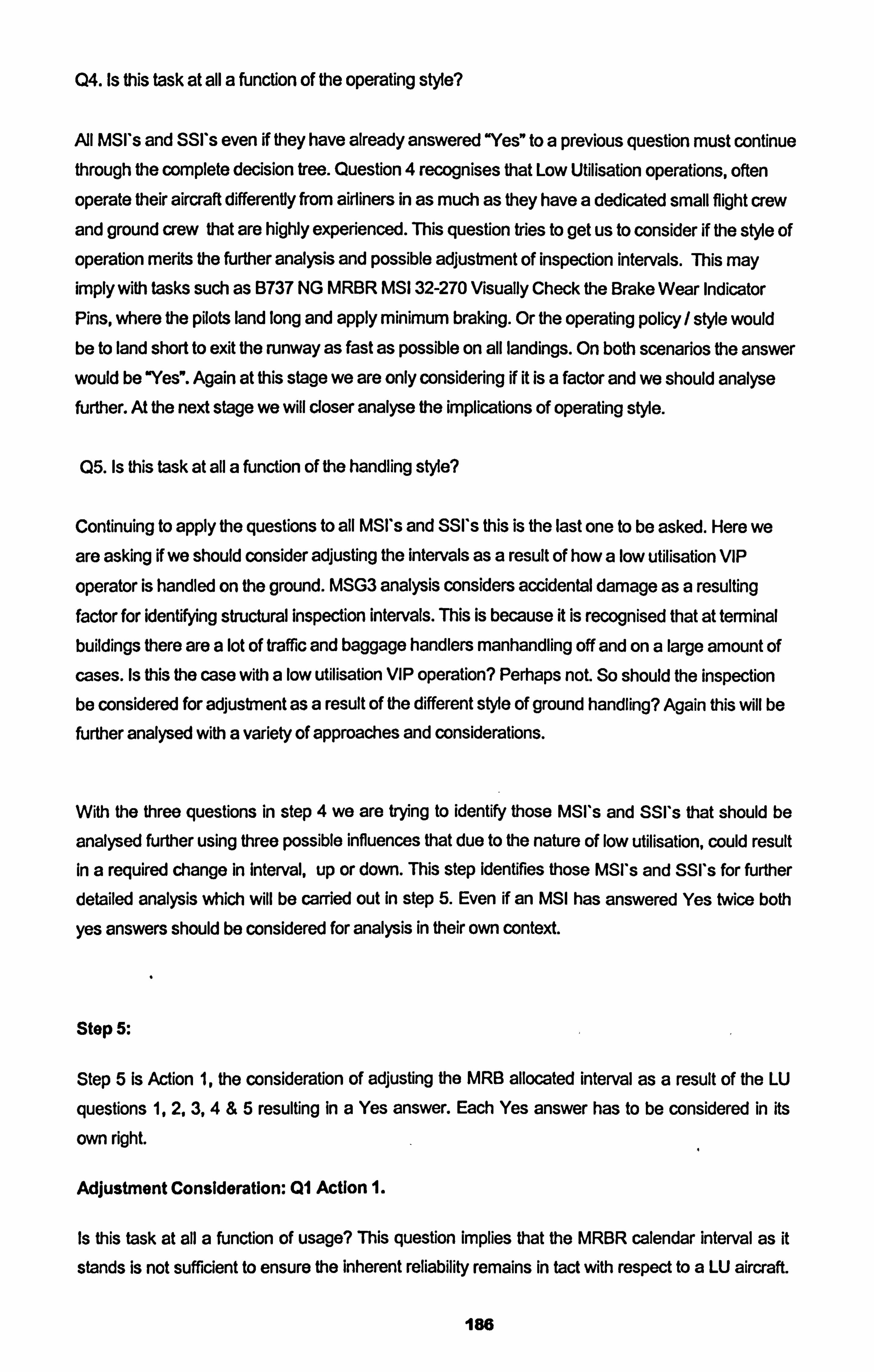
Q4. Is this task at all a function of the operating style?
All MSI's and SSI*s even if they have already answered "Yee to a previous question must continue through the complete decision tree. Question 4 recognises that Low Utilisation operations, often operate their aircraft differently from airliners in as much as they have a dedicated small flight crew and ground crew that are highly experienced. This question tries to get us to consider if the style of operation merits the further analysis and possible adjustment of inspection intervals. This may imply with tasks such as B737 NG MRBR MSI 32-270 Visually Check the Brake Wear Indicator Pins, where the pilots land long and apply minimum braking. Or the operating policy / style would be to land short to exit the runway as fast as possible on all landings. On both scenarios the answer would be "Yes". Again at this stage we are only considering if it is a factor and we should analyse further. At the next stage we will closer analyse the implications of operating style.
Q5. Is this task at all a function of the handling style?
Continuing to apply the questions to all MSI's and SSI's this is the last one to be asked. Here we are asking K we should consider adjusting the intervals as a result of how a low utilisation VIP
operator is handled on the ground. MSG3 analysis considers accidental damage as a resulting factor for identifying structural inspection intervals. This is because it is recognised that at terminal buildings there are a lot of traffic and baggage handlers manhandling off and on a large amount of cases. Is this the case with a low utilisation VIP operation? Perhaps not. So should the inspection be considered for adjustment as a result of the different style of ground handling? Again this will be further analysed with a variety of approaches and considerations.
With the three questions in step 4 we are trying to identify those MSI's and SSI's that should be
analysed further using three possible influences that due to the nature of low utilisation, could result In a required change in interval, up or down. This step identifies those MSI's and SSI*s for further detailed analysis which will be carried out in step 5. Even if an IVISI has answered Yes twice both
yes answers should be considered for analysis in their own context.
Stop 5:
Step 5 Is Action 1, the consideration of adjusting the MRB allocated interval as a result of the LU
questions 1,2,3,4 &5 resulting in a Yes answer. Each Yes answer has to be considered in its
own right.
Adjustment Consideration: Ql Action 1.
Is this task at all a function of usage? This question implies that the MRBR calendar interval as it
stands is not sufficient to ensure the inherent reliability remains in tact with respect to a LU aircraft.
186
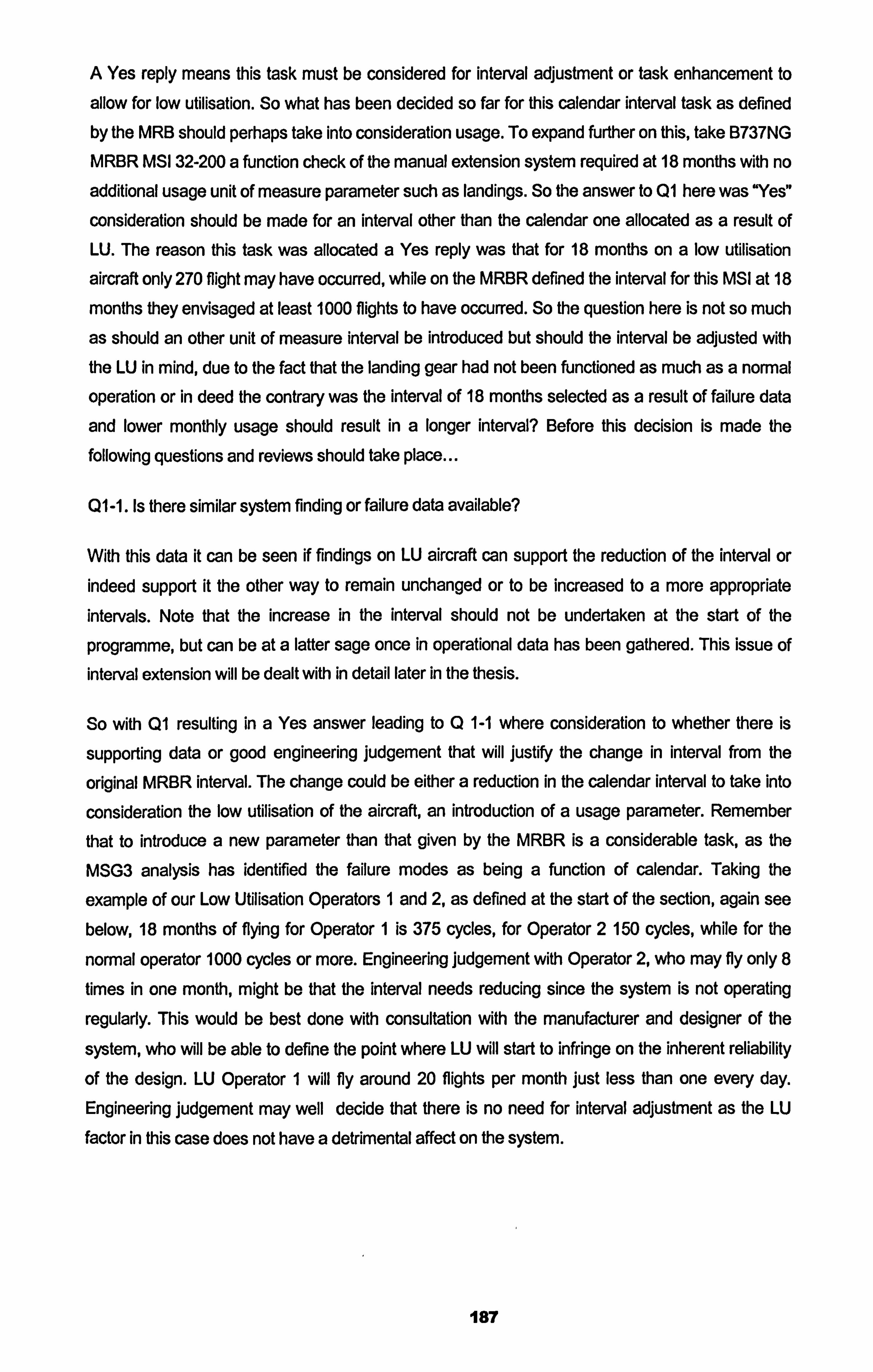
A Yes reply means this task must be considered for interval adjustment or task enhancement to
allow for low utilisation. So what has been decided so far for this calendar interval task as defined by the IVIRB should perhaps take into consideration usage. To expand further on this, take B737NG MRIBR IVISI 32-200 a function check of the manual extension system required at 18 months with no additional usage unit of measure parameter such as landings. So the answer to Q1 here was "Yes"
consideration should be made for an interval other than the calendar one allocated as a result of LU. The reason this task was allocated a Yes reply was that for 18 months on a low utilisation
aircraft only 270 flight may have occurred, while on the MRBR defined the interval for this MSI at 18
months they envisaged at least 1000 flights to have occurred. So the question here is not so much
as should an other unit of measure interval be introduced but should the interval be adjusted with the LU in mind, due to the fact that the landing gear had not been functioned as much as a normal operation or in deed the contrary was the interval of 18 months selected as a result of failure data
and lower monthly usage should result in a longer interval? Before this decision is made the following questions and reviews should take place...
QI -1. Is there similar system finding or failure data available?
With this data it can be seen if findings on LU aircraft can support the reduction of the interval or indeed support it the other way to remain unchanged or to be increased to a more appropriate intervals. Note that the increase in the interval should not be undertaken at the start of the
programme, but can be at a latter sage once in operational data has been gathered. This issue of interval extension will be dealt with in detail later in the thesis.
So with QI resulting in a Yes answer leading to Q 1-1 where consideration to whether there is
supporting data or good engineering judgement that will justify the change in interval from the
original MRBR interval. The change could be either a reduction in the calendar interval to take into
consideration the low utilisation of the aircraft, an introduction of a usage parameter. Remember
that to introduce a new parameter than that given by the MRBR is a considerable task, as the
MSG3 analysis has identified the failure modes as being a function of calendar. Taking the
example of our Low Utilisation Operators I and 2, as defined at the start of the section, again see below, 18 months of flying for Operator 1 is 375 cycles, for Operator 2 150 cycles, while for the
normal operator 1000 cycles or more. Engineering judgement with Operator 2, who may fly only 8
times in one month, might be that the interval needs reducing since the system is not operating
regularly. This would be best done with consultation with the manufacturer and designer of the
system, who will be able to define the point where LU will start to infringe on the inherent reliability
of the design. LU Operator 1 will fly around 20 flights per month just less than one every day.
Engineering judgement may well decide that there is no need for interval adjustment as the LU
factor in this case does not have a detrimental affect on the system.
187
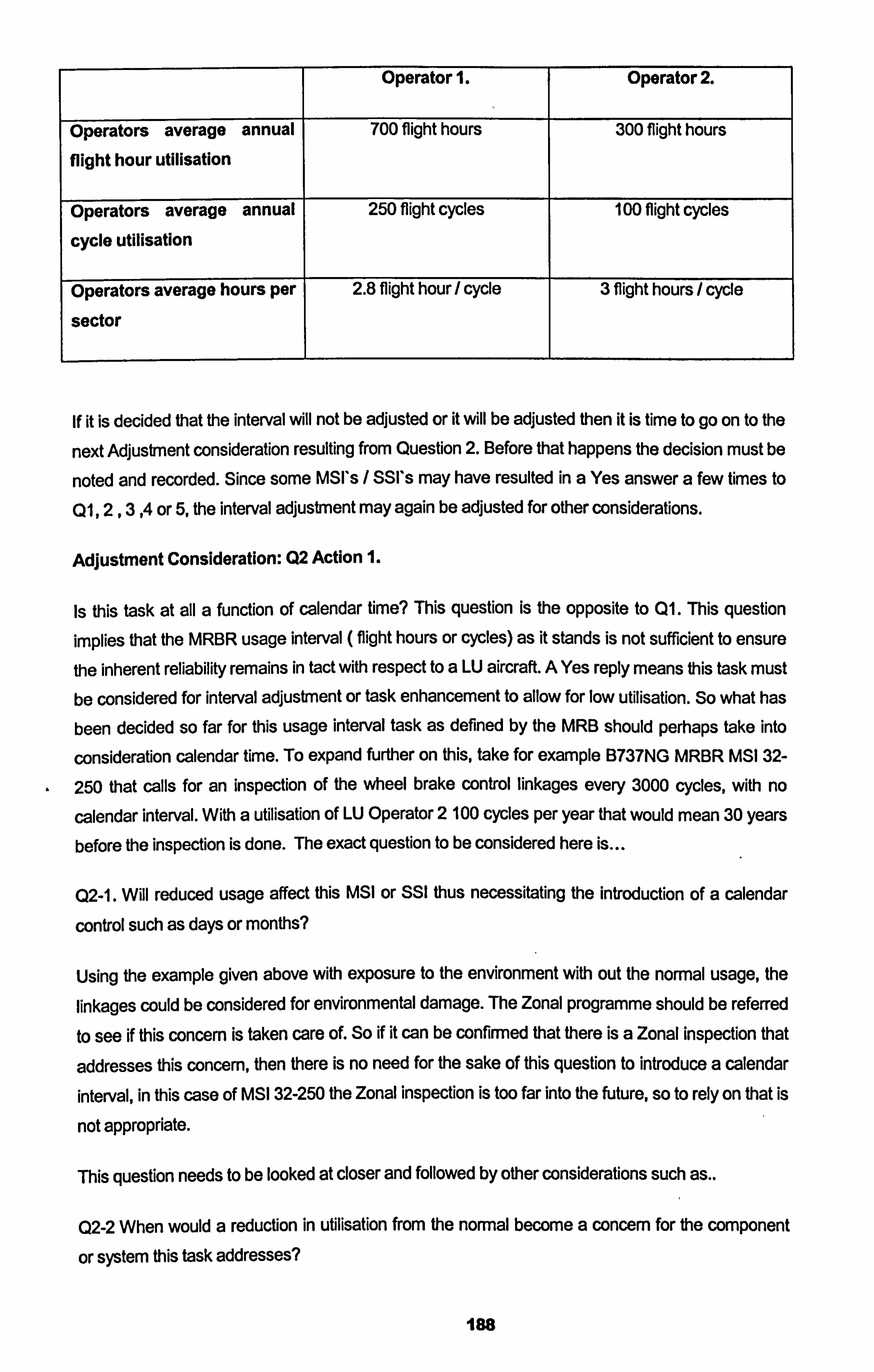
Operator 1. Operator 2.
Operators average annual 700 flight hours 300 flight hours
flight hour utilisation
Operators average annual 250 flight cycles 100 flight cycles
cycle utilisation
Operators average hours per 2.8 flight hour / cycle 3 flight hours / cycle
sector
If it is decided that the interval will not be adjusted or it will be adjusted then it is time to go on to the
next Adjustment consideration resulting from Question 2. Before that happens the decision must be
noted and recorded. Since some MSI's / SSI's may have resulted in a Yes answer a few times to
Q1,2,3,4 or 5, the interval adjustment may again be adjusted for other considerations.
Adjustment Consideration: Q2 Action 1.
Is this task at all a function of calendar time? This question is the opposite to Q1. This question
implies that the MRBR usage interval ( flight hours or cycles) as it stands is not sufficient to ensure
the inherent reliability remains in tact with respect to a LU aircraft. A Yes reply means this task must be considered for interval adjustment or task enhancement to allow for low utilisation. So what has
been decided so far for this usage interval task as defined by the MRB should perhaps take into
consideration calendar time. To expand further on this, take for example B737NG MRBR MS1 32-
250 that calls for an inspection of the wheel brake control linkages every 3000 cycles, with no
calendar interval. With a utilisation of LU Operator 2 100 cycles per year that would mean 30 years
before the inspection is done. The exact question to be considered here is
Q2-1. Will reduced usage affect this MSI or SSI thus necessitating the introduction of a calendar
control such as days or months?
Using the example given above with exposure to the environment with out the normal usage, the
linkages could be considered for environmental damage. The Zonal programme should be referred
to see if this concern is taken care of. So if it can be confirmed that there is a Zonal inspection that
addresses this concern, then there is no need for the sake of this question to introduce a calendar
interval, in this case of MSI 32-250 the Zonal inspection is too far into the future, so to rely on that is
not appropriate.
This question needs to be looked at closer and followed by other considerations such as..
Q2-2 When would a reduction in utilisation from the normal become a concern for the component
or system this task addresses?
les
Boeing define Low Utilisation as anything below 100 flight hours per month, which would be around just under 1 flight a day. Using engineering judgement would not in my opinion merit an interval
adjustment but question 2-2 begs to be asked. This leads to Q2-3 which is in my opinion a more
appropriate question...
Q2-3 Would the anticipated utilisation include long periods of non usage, if so should this be
considered for task interval adjustment?
Non usage or long periods on non usage of an aircraft is an area that is important to define. If an aircraft and its systems are operating regularly, say every two days, but are operating less then 100
flight hours per months are at less a risk than an aircraft that is operating only a few flights a month. There is Low Utilisation then there is Very Low Utilisation, the latter is an area that is of concern as the aircraft and systems are not being functioned and not being lubricated as intended. Aircraft
Maintenance Manual chapterlO deals with prolonged periods of parking. Identifying, 7 days, 10
days and 30 days as short periods of non operation times where preservation maintenance
activities must take place. The 7 days and 30 days tasks are minimal, but in my opinion no where is
the very low utilisation issue addressed adequately. Boeing classify less than 1200 flight hours per
year (100 per month) as low utilisation and less than 150 flight hours per year as very low
utilisation. They also limit the use of the Boeing Low Utilisation programme to aircraft operating no less than 150 hours per year. This is arguable as I believe that very low utilisation should be
considered not by hours of flight per year but by cycles of flights per year with restrictions on times
between flights. For example 1 flight every other day of one hours is an acceptable Low Utilisation
operation, totalling about 180 flights per year but only perhaps 200 flight hours per year. Boeing
gives a band of 150 to 1200 flight hours per year as a classification of low utilisation. It is my opinion that very low utilisation (periods of non operation) should be based on time between flights and flight per month rather than flight hours. For example, 1 flight of one hour every two days would
equate to 182 flights per year and 182 flight hours per year. When the aircraft is not flying it is
parked in a hanger, this is low utilisation but not very low utilisation.
So in summary, Q2 Action I leads to three questions to be asked of the MSI / SSI
Q2-11 Will reduced usage affect this MSI or SSI thus necessitating the introduction of a calendar
control such as days or months?
Q2-2 When would a reduction in utilisation from the normal become a concern for the component
or system this task addresses?
Q2-3 Would the anticipated utilisation include long periods of non usage, if so should this be
considered for task interval adjustment?
The out come of all these question will first determine if a change of interval is required then
secondly identify a more appropriate interval for the LU operation with regards to this MSI or SSI.
189
Adjustment Consideration: 03 Action 1.
We are now starting to examine the special implication of the operation other than actual low
utilisation, that could have influence on the scheduled maintenance programme tasks. These implications could be argued as non generic, but rather particular to a certain operating environment, so should be subjected not to a generic LU Maintenance Schedule but customised to
an operator depending upon the nature of the operation. Either way is acceptable but must be
considered before a maintenance programme is completed for an operator, but perhaps the
generic route would not be completely correct as it will allow those operators that do not apply the
special circumstances to their daily operation to take advantage of the interval adjustments when it
would not be appropriate for them to do so.
A Yes answer resulting from;
Is this task at all a function of the predominant operating environment?
Should then be examined for interval adjustment. The closer look at why the reply was Yes should then follow. An MRBR interval will be based on a normal operating environment for an Airliner. Taking Operator 2 as our example here, a VIP Government Operator flying the Head of State,
perhaps in a country where the environment is sandy and humid, but the aircraft is hangered most
of the time it is not operating in an air conditioned hanger. This aircraft will be definitely subjected to
a different operating environment that a northern European operator. What we are trying to determine here is there a need to adjust the interval as a result of the environment that the aircraft will operate?
This leads to
Q4-1 Is there similar system in operational data available for research?
Examination of similar system data for other aircraft that have been operated in the environment will give good guidelines as to the appropriateness of the adjustment. Perhaps the harsh sandy
environment would normally require the adjustment down of an interval for filter replacement for
example, but equally this would be cancelled out as a result of the aircraft being hanagered when not operating. Again the best way to determine the need for LU adjustment here is to examine historical data on system failures or especially on lab reports on filter efficiency after removal from
the aircraft. This subject will be looked at in detail later also when examining in operational data for
identifying the effectiveness of the maintenance programme and the necessary adjustments to task details or intervals.
190
Adjustment Consideration: Q4 Action 1.
A Yes reply to Question 4 Is this task at all a function of the operating style? Leads to adjustment
consideration which can be examined by the following question...
Q4-1 Who will fly the aircraft and how? This question tries to examine the need for LU adjustment resulting similarly from the previous
question Q3-1, (perhaps again a more custornised question than generic, but non the less
symptomatic of LU operations). It considers that fact that LU operations often have only a few core
pilots that are often experienced captains but now flying irregularly. The second consideration after the capability of the pilots is the standard operating procedures of the LU operator. Is it standard to
get off the run way as quickly as possible, to land short and stop as fats as possible? Is it standard to descend quickly? Al of these issues contribute to the need to adjust the interval.
Adjustment Consideration: Q5 Action 1.
A Yes reply to Question 5 Is this task at all a function of the handling style? Leads to adjustment
consideration which can be examined by the following question...
Q5-11 Who will normally conduct the ground handling when away from Base?
This question implies that the likelihood of AD (accidental damage) as defined in the MRBR is
much less likely due to the nature of the LU operation. Firstly the LU operator does not use the
international airports that are notorious of the AD possibilities and the LU operators does not carry
the same extend of cargo on normal operations as the MRBR normal aircraft, thus again reducing
the likelihood for AD. Usually the LU operator flies to regional rather than international airports so
the traffic is much less and often the LU operator uses VIP or corporate ground handling agencies
that undergo specialised training on handling LU VIP aircraft. So from this perspective adjustment
to most AD identified MRBR task intervals may well be appropriate.
Some MSI's or SSI's that were identified as requiring consideration for task interval adjustment leading from more than one of the LU questions must undergo consideration from all angles of the
Yes replies.
The previous Low Utilisation method describes on how to adjust an established airliner MRBR for
low utilisation implication, but another method was previously mentioned where the Low Utilisation
implications are considered not after the MRBR is produced but as an integral part of the MSG3
analysis process undertaken on the aircraft type in question. This would involve the complete integration of LU questions 1,2,3,4 and 5 detailed in figure 3.2, into the MSG3 process from the beginning. Since most airliners are built with a target market in mind with a specific utilisation range,
191
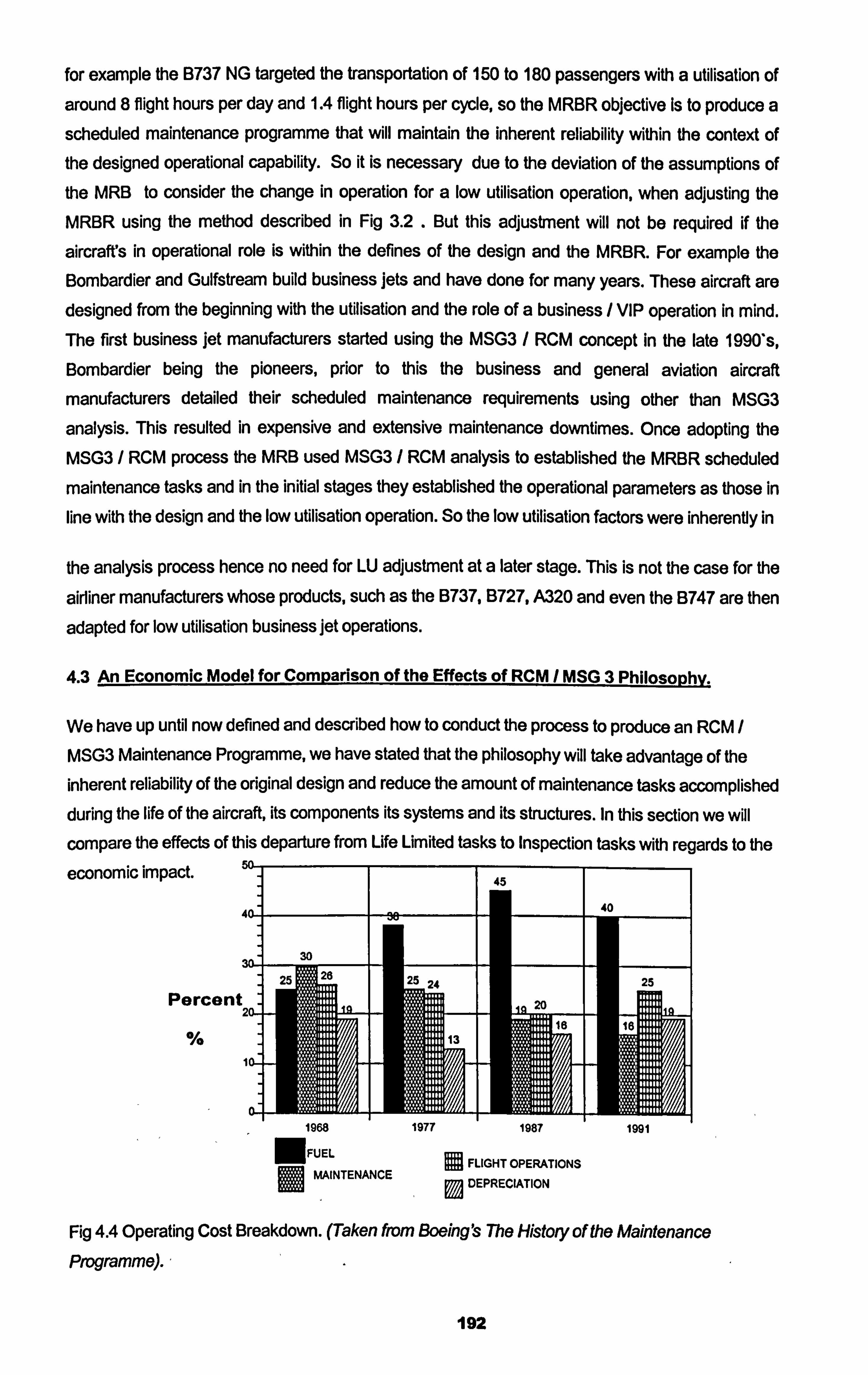
for example the B737 NG targeted the transportation of 150 to 180 passengers with a utilisation of
around 8 flight hours per day and 1.4 flight hours per cycle, so the MRBR objective Is to produce a
scheduled maintenance programme that will maintain the inherent reliability within the context of the designed operational capability. So it is necessary due to the deviation of the assumptions of the MRB to consider the change in operation for a low utilisation operation, when adjusting the MRBR using the method described in Fig 3.2 . But this adjustment will not be required if the
aircraft's in operational role is within the defines of the design and the MRBR. For example the Bombardier and Gulfstream build business jets and have done for many years. These aircraft are designed from the beginning with the utilisation and the role of a business / VIP operation in mind. The first business jet manufacturers started using the MSG3 / RCM concept in the late 1990's,
Bombardier being the pioneers, prior to this the business and general aviation aircraft
manufacturers detailed their scheduled maintenance requirements using other than MSG3
analysis. This resulted in expensive and extensive maintenance downtimes. Once adopting the
MSG3 / RCM process the MRB used MSG3 / RCM analysis to established the MRBR scheduled
maintenance tasks and in the initial stages they established the operational parameters as those in
line with the design and the low utilisation operation. So the low utilisation factors were inherently in
the analysis process hence no need for LU adjustment at a later stage. This is not the case for the
airliner manufacturers whose products, such as the B737, B727, A320 and even the B747 are then
adapted for low utilisation business jet operations.
4.3 An Economic Model for Comparison of the Effects of RCM / MSG 3 PhilosophV.
We have up until now defined and described how to conduct the process to produce an RCM /
MSG3 Maintenance Programme, we have stated that the philosophy will take advantage of the inherent reliability of the original design and reduce the amount of maintenance tasks accomplished during the life of the aircraft, its components its systems and its structures. In this section we will compare the effects of this departure from Life Limited tasks to Inspection tasks with regards to the
economic impact.
Percent
Fig 4.4 Operating Cost Breakdown. (Taken from Boeing ýs The History of the Maintenance
Programme).,
192
1968 1977 1987 1991 NFUEL
FLIGHT OPERATIONS Im MAINTENANCE DEPRECIATION
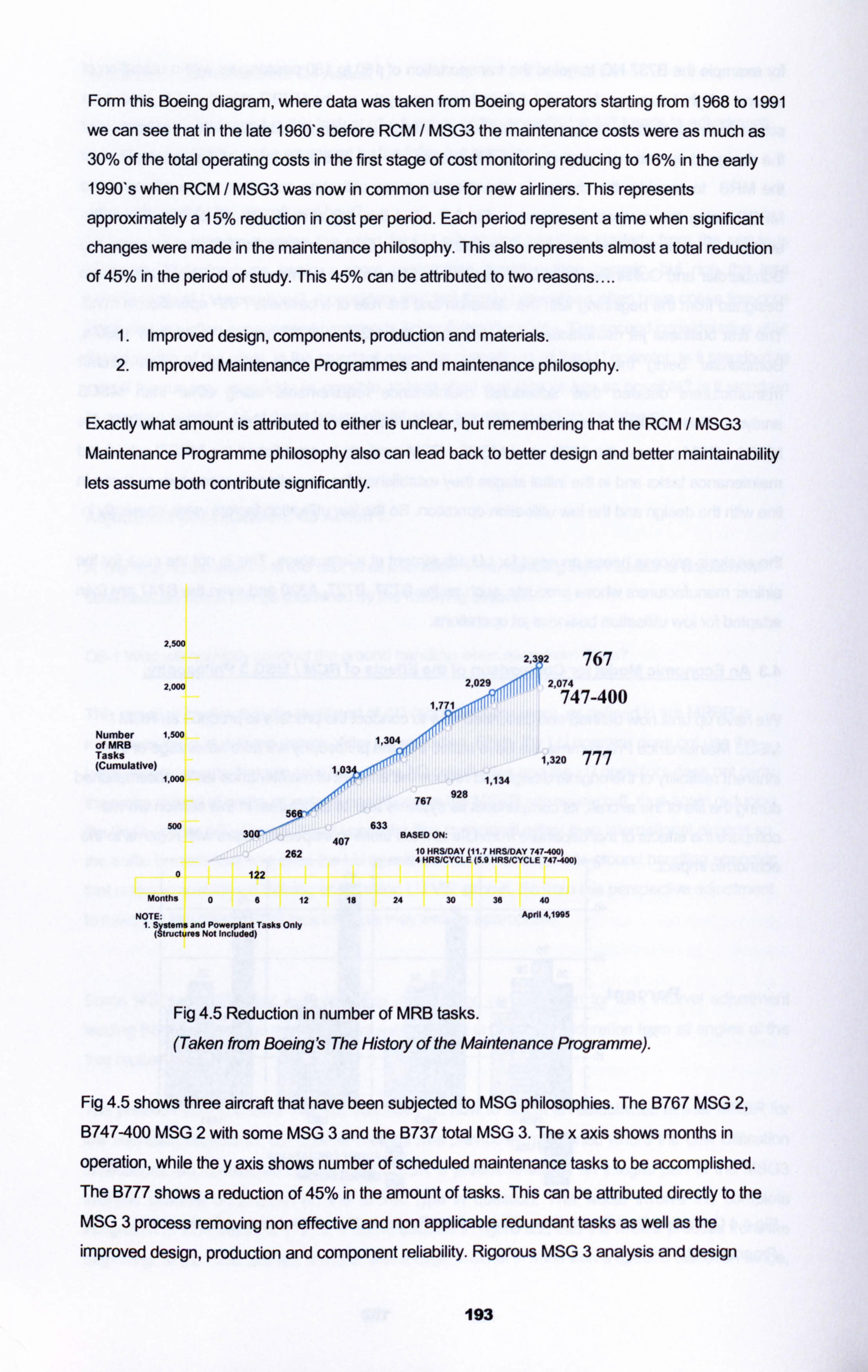
Form this Boeing diagram, where data was taken from Boeing operators starting from 1968 to 1991
we can see that in the late 1960's before RCM / MSG3 the maintenance costs were as much as 30% of the total operating costs in the first stage of cost monitoring reducing to 16% in the early 1990's when RCM / MSG3 was now in common use for new airliners. This represents
approximately a 15% reduction in cost per period. Each period represent a time when significant
changes were made in the maintenance philosophy. This also represents almost a total reduction
of 45% in the period of study. This 45% can be attributed to two reasons....
1. Improved design, components, production and materials. 2. Improved Maintenance Programmes and maintenance philosophy.
Exactly what amount is attributed to either is unclear, but remembering that the RCM / MSG3
Maintenance Programme philosophy also can lead back to better design and better maintainability lets assume both contribute significantly.
2,500
ýý3
2 767 2,000 2,029 2074
747-400
Number 1.5oo of MR8 1,304 Tasks I-c", 1,320 777 (Cumulative) 1,034-ý<" :
1,000 1,134
767 928
56 500
30(r- 407
633 BASED ON:
262 10 HRSIDAY 411.7 HRS/DAY 747400) 4 HRSICYCLE (5.9 HRSICYCLE 747400)
0 122
Months 06 12 is 24 30 35 40
NOTE: April 4,1995 I. S erns and Powerplant Tasks Only
(Cructures Not Includod)
Fig 4.5 Reduction in number of MRB tasks.
(Taken from Boeing's The History of the Maintenance Programme).
Fig 4.5 shows three aircraft that have been subjected to MSG philosophies. The B767 MSG 2,
B747-400 MSG 2 with some MSG 3 and the B737 total MSG 3. The x axis shows months in
operation, while the y axis shows number of scheduled maintenance tasks to be accomplished. The B777 shows a reduction of 45% in the amount of tasks. This can be attributed directly to the MSG 3 process removing non effective and non applicable redundant tasks as well as the improved design, production and component reliability. Rigorous MSG 3 analysis and design
193
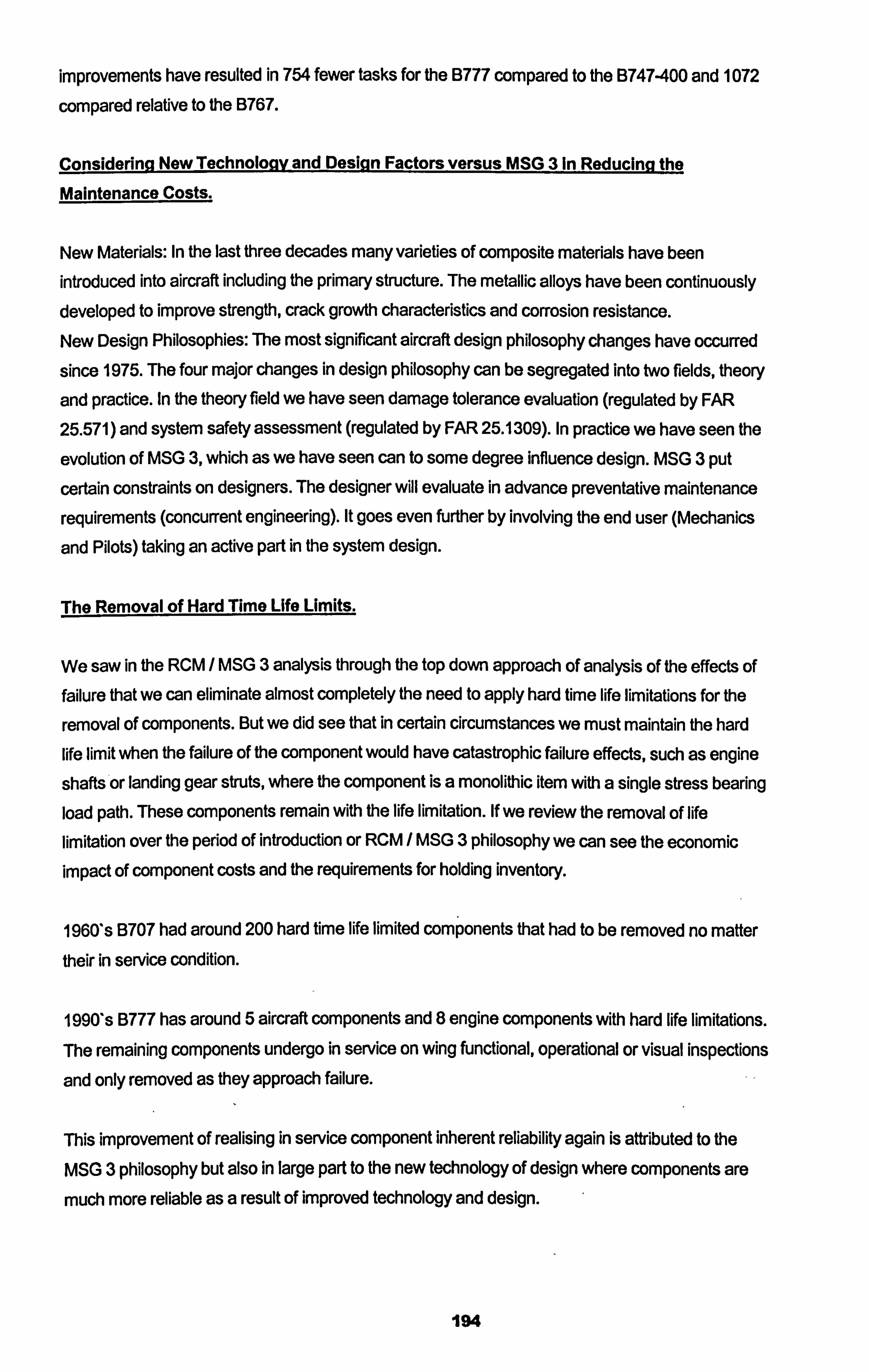
improvements have resulted in 754 fewer tasks for the B777 compared to the B747-400 and 1072
compared relative to the B767.
Considering New Technoloav and Design Factors versus MSG 3 in Reducing the
Maintenance Costs.
New Materials: In the last three decades many varieties of composite materials have been
introduced into aircraft including the primary structure. The metallic alloys have been continuously developed to improve strength, crack growth characteristics and corrosion resistance. New Design Philosophies: The most significant aircraft design philosophy changes have occurred
since 1975. The four major changes in design philosophy can be segregated into two fields, theory
and practice. In the theory field we have seen damage tolerance evaluation (regulated by FAR
25.571) and system safety assessment (regulated by FAR 25.1309). In practice we have seen the
evolution of MSG 3, which as we have seen can to some degree influence design. MSG 3 put
certain constraints on designers. The designer will evaluate in advance preventative maintenance
requirements (concurrent engineering). It goes even further by involving the end user (Mechanics
and Pilots) taking an active part in the system design.
The Removal of Hard Time Life Limits.
We saw in the RCM / MSG 3 analysis through the top down approach of analysis of the effects of failure that we can eliminate almost completely the need to apply hard time life limitations for the
removal of components. But we did see that in certain circumstances we must maintain the hard
life limit when the failure of the component would have catastrophic failure effects, such as engine
shafts or landing gear struts, where the component is a monolithic item with a single stress bearing
load path. These components remain with the life limitation. If we review the removal of life
limitation over the period of introduction or RCM / MSG 3 philosophy we can see the economic impact of component costs and the requirements for holding inventory.
1960's B707 had around 200 hard time life limited components that had to be removed no matter their in service condition.
1990's B777 has around 5 aircraft components and 8 engine components with hard life limitations.
The remaining components undergo in service on wing functional, operational or visual inspections
and only removed as they approach failure.
This improvement of realising in service component inherent reliability again is attributed to the
MSG 3 philosophy but also in large part to the new technology of design where components are
much more reliable as a result of improved technology and design.
194
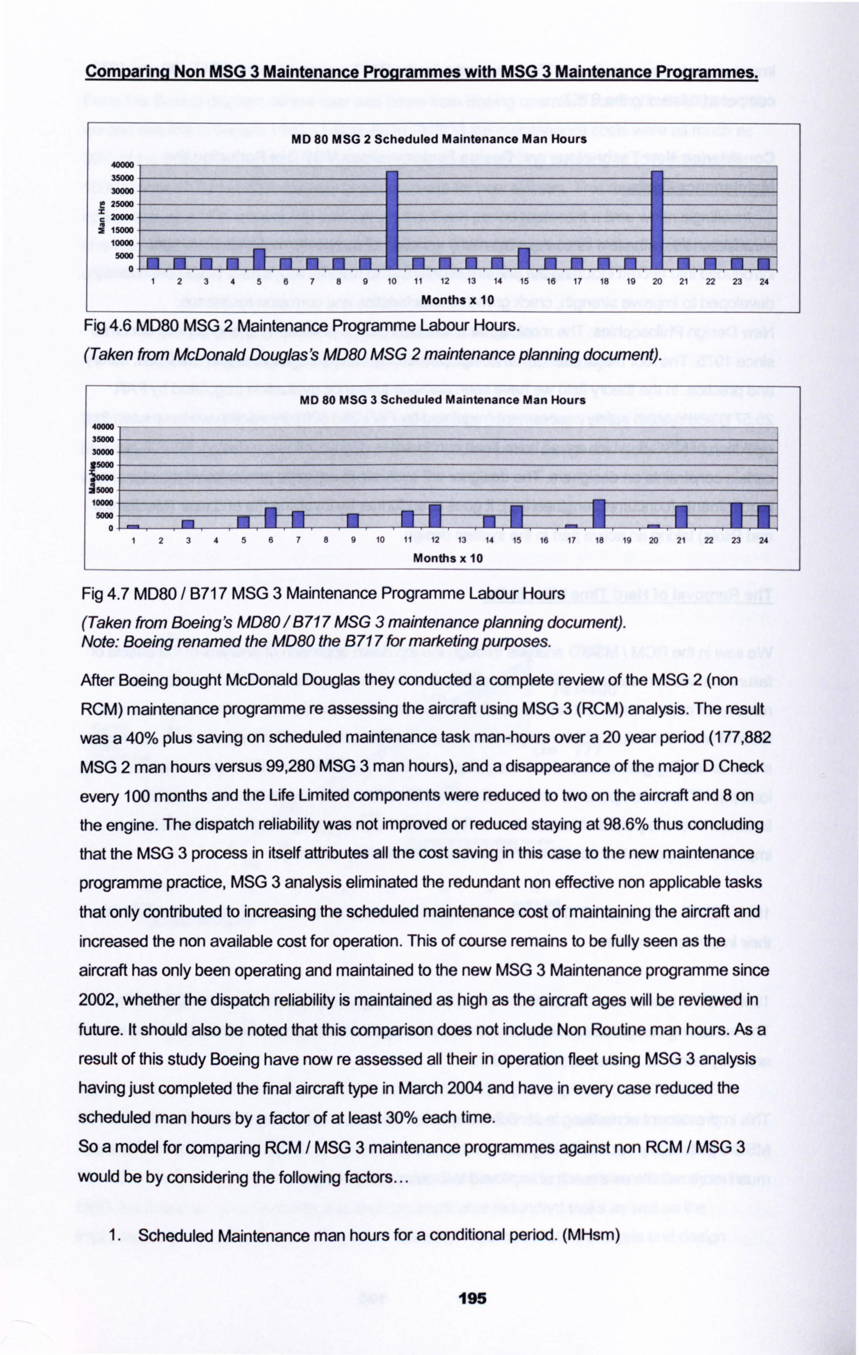
Comparina Non MSG 3 Maintenance Proarammes with MSG 3 Maintenance Prourammes.
MD 80 MSG 2 Scheduled Maintenance Man Hours
40000
35000
30000 25000 20000
15000 10000 5000
0
123456789101112131415161718192021222324
Months x 10
Fig 4.6 MD80 MSG 2 Maintenance Programme Labour Hours.
(Taken from McDonald Douglas's MD80 MSG 2 maintenance planning document).
MD 80 MSG 3 Scheduled Maintenance Man Hours
40000 35M 30M g5m
: 15000
10000 5000
0- 123456789101112131415161718192021222324
Months x 10
Fig 4.7 MD80 / B717 MSG 3 Maintenance Programme Labour Hours
(Taken from Boeing's MD80 / B717 MSG 3 maintenance planning document). Note: Boeing renamed the MD80 the B 717 for marketing purposes.
After Boeing bought McDonald Douglas they conducted a complete review of the MSG 2 (non
RCM) maintenance programme re assessing the aircraft using MSG 3 (RCM) analysis. The result
was a 40% plus saving on scheduled maintenance task man-hours over a 20 year period (177,882
MSG 2 man hours versus 99,280 MSG 3 man hours), and a disappearance of the major D Check
every 100 months and the Life Limited components were reduced to two on the aircraft and 8 on
the engine. The dispatch reliability was not improved or reduced staying at 98.6% thus concluding
that the MSG 3 process in itself attributes all the cost saving in this case to the new maintenance
programme practice, MSG 3 analysis eliminated the redundant non effective non applicable tasks
that only contributed to increasing the scheduled maintenance cost of maintaining the aircraft and increased the non available cost for operation. This of course remains to be fully seen as the
aircraft has only been operating and maintained to the new MSG 3 Maintenance programme since 2002, whether the dispatch reliability is maintained as high as the aircraft ages will be reviewed in
future. It should also be noted that this comparison does not include Non Routine man hours. As a
result of this study Boeing have now re assessed all their in operation fleet using MSG 3 analysis having just completed the final aircraft type in March 2004 and have in every case reduced the
scheduled man hours by a factor of at least 30% each time. So a model for comparing RCM / MSG 3 maintenance programmes against non RCM / MSG 3
would be by considering the following factors...
Scheduled Maintenance man hours for a conditional period. (MHsm)
195
2. Non Routine man hours generated from scheduled maintenance for a conditional period. (MHnr)
3. Life Limited components for a conditional period. (LL)
4. *Dispatch Reliability for a conditional period. (DR)
5. Aircraft non availability due to due to scheduled maintenance + non routine maintenance. (ACna)
*Note: DR =% of flights that depart within 15mins of scheduled departure time.
In figures 4.6 and 4.7 we are comparing only the scheduled maintenance man hours which is
an indicator of maintenance time reduction due exclusively to scheduled maintenance. To get
a more accurate model we should consider the following...
Total Maintenance Man hours for the Maintenance Life Cycle.
MHt = MHsm + MHnr (Note Maintenance Life Cycle would be the estimated in-service time for the aircraft).
.. to do this we would need to have a sample size of the aircraft type on a non MSG3 maintenance
programme to compare against a MSG3 same aircraft type sample. For now all we can do is
compare the theoretical MHsm as we do not have available the MHnr data but that could be
estimated as a ratio of SM. Below is for the MD 80 programmes in the figures above for a
scheduled maintenance life span of 20 years using only SM data from the available maintenance
programme....
x- MD 80 MSG 3 MHsm = 99,280
y- MD 80 Non MSG 3 MHsm 177,882
(Y-X)/y
(177,882 - 99,280) / 177,882 0.44
MSG 3 analysis can account for a 44% reduction In total scheduled
maintenance man hours. For no DR chance for a 20 year Period.
Assuming 4500 flight hours per year therefore 4500x2Oyrs = 90,000 flight hours for the 20 year
period. A standard model for comparing scheduled maintenance programmes in an operational
context could be the amount of scheduled maintenance man hours required for 1 hour of flight.
196
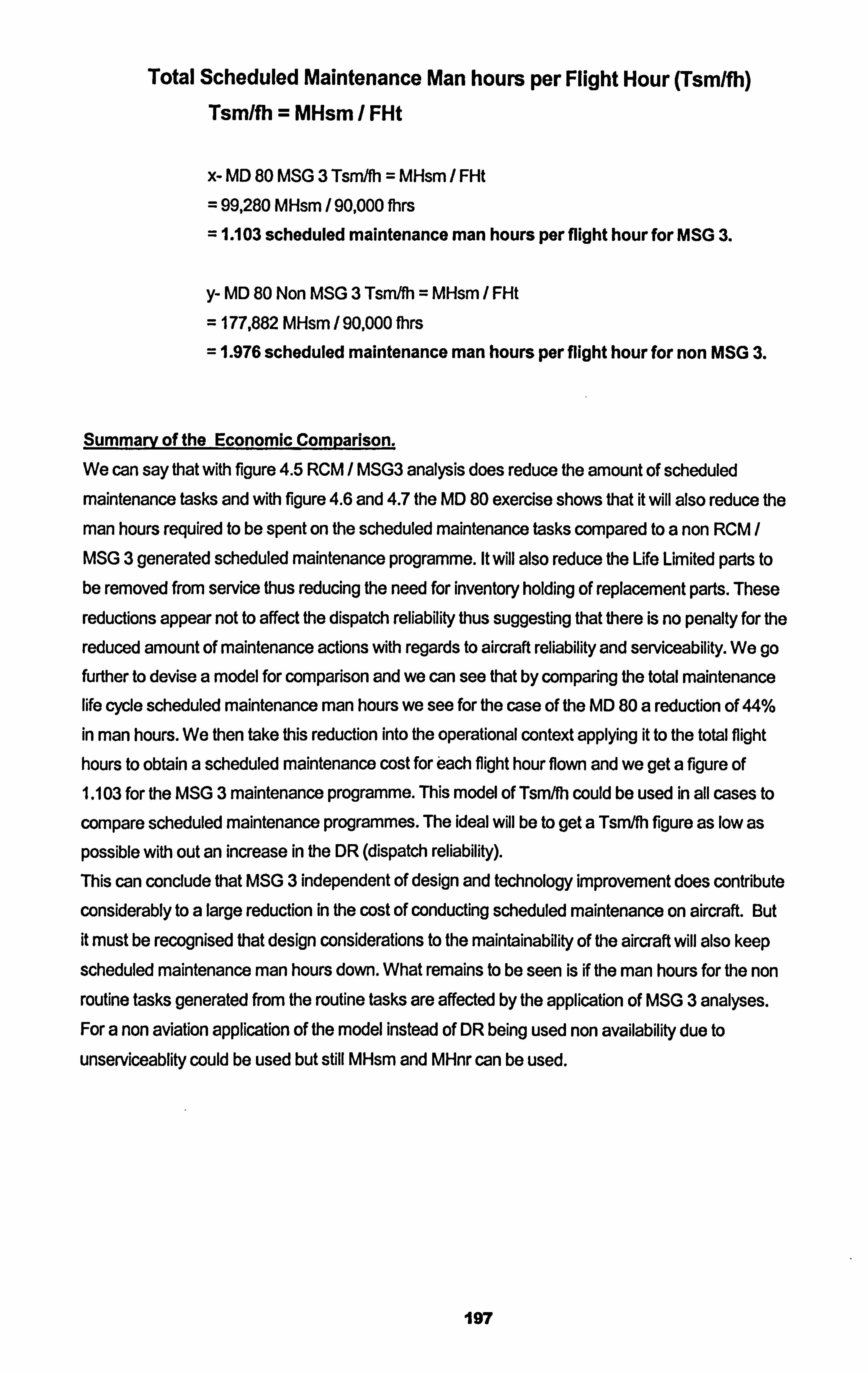
Total Scheduled Maintenance Man hours per Flight Hour (Tsm/fh) Tsm/fh = MHsm / FHt
x- MD 80 MSG 3 Tsmlfh = MHsm / FHt
99,280 MHsm / 90,000 fhrs 1.103 scheduled maintenance man hours per flight hour for MSG 3.
y- MD 80 Non MSG 3 Tsm/fh = MHsm / FHt
= 177,882 MHsm / 90,000 fhrs
= 1.976 scheduled maintenance man hours per flight hour for non MSG 3.
Summarv of the Economic Comparison.
We can say that with figure 4.5 RCM / MSG3 analysis does reduce the amount of scheduled maintenance tasks and with figure 4.6 and 4.7 the MD 80 exercise shows that it will also reduce the
man hours required to be spent on the scheduled maintenance tasks compared to a non RCM / MSG 3 generated scheduled maintenance programme. It will also reduce the Life Limited parts to be removed from service thus reducing the need for inventory holding of replacement parts. These
reductions appear not to affect the dispatch reliability thus suggesting that there is no penalty for the
reduced amount of maintenance actions with regards to aircraft reliability and serviceability. We go further to devise a model for comparison and we can see that by comparing the total maintenance life cycle scheduled maintenance man hours we see for the case of the MD 80 a reduction of 44% in man hours. We then take this reduction into the operational context applying it to the total flight hours to obtain a scheduled maintenance cost for each flight hour flown and we get a figure of 1.103 for the MSG 3 maintenance programme. This model of Tsm/fh could be used in all cases to
compare scheduled maintenance programmes. The ideal will be to get a Tsm/fh figure as low as
possible with out an increase in the DR (dispatch reliability). This can conclude that MSG 3 independent of design and technology improvement does contribute considerably to a large reduction in the cost of conducting scheduled maintenance on aircraft. But it must be recognised that design considerations to the maintainability of the aircraft will also keep
scheduled maintenance man hours down. What remains to be seen is if the man hours for the non routine tasks generated from the routine tasks are affected by the application of MSG 3 analyses. For a non aviation application of the model instead of DR being used non availability due to
unserviceablity could be used but still MHsm and MHnr can be used.
197
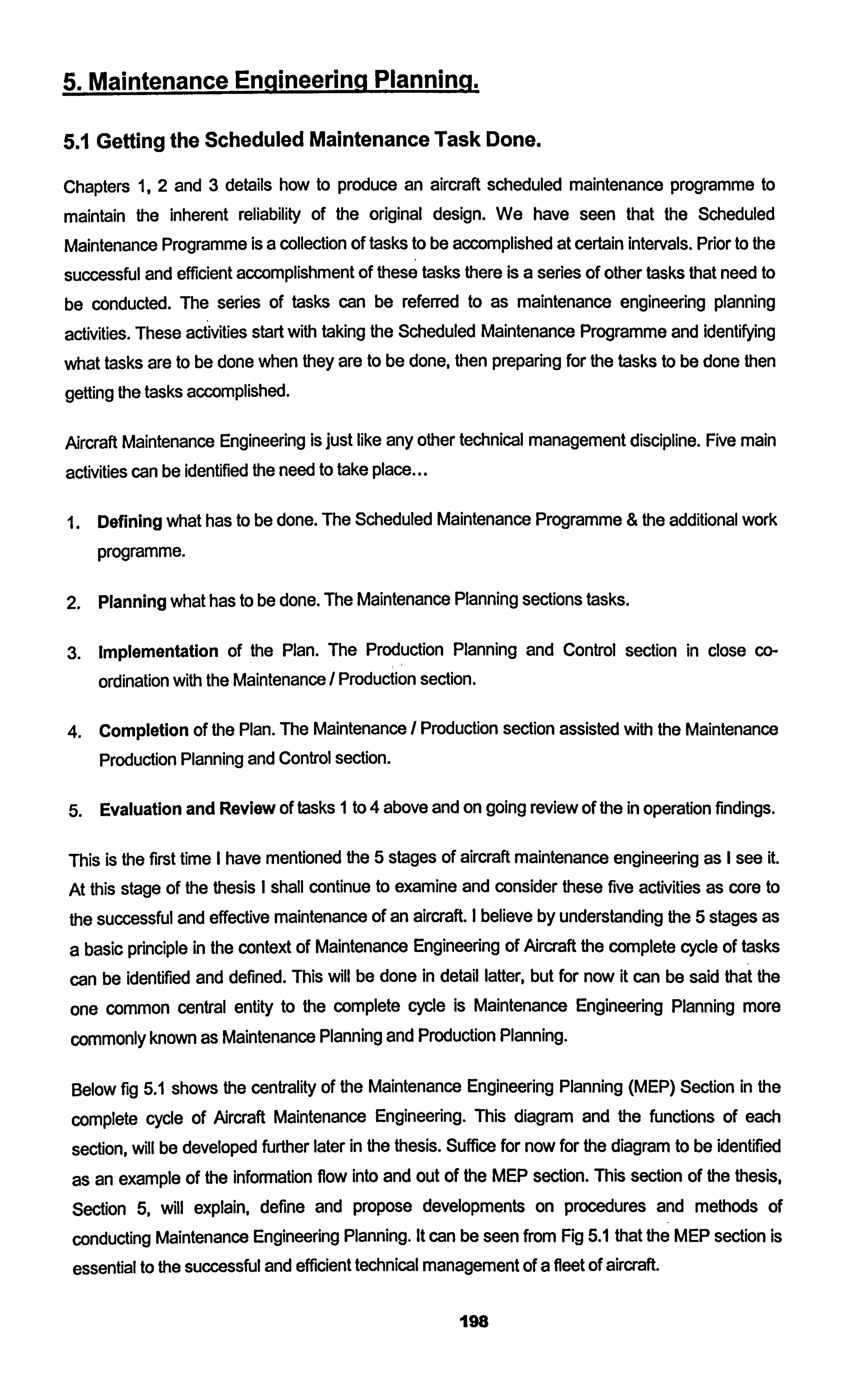
5. Maintenance Engineering Planning,
5.1 Getting the Scheduled Maintenance Task Done.
Chapters 1,2 and 3 details how to produce an aircraft scheduled maintenance programme to
maintain the inherent reliability of the original design. We have seen that the Scheduled
Maintenance Programme is a collection of tasks to be accomplished at certain intervals. Prior to the
successful and efficient accomplishment of these tasks there is a series of other tasks that need to
be conducted. The series of tasks can be referred to as maintenance engineering planning
activities. These activities start with taking the Scheduled Maintenance Programme and identifying
what tasks are to be done when they are to be done, then preparing for the tasks to be done then
getting the tasks accomplished.
Aircraft Maintenance Engineering is just like any other technical management discipline. Five main
activities can be identified the need to take place...
1. Defining what has to be done. The Scheduled Maintenance Programme & the additional work
programme.
2. Planning what has to be done. The Maintenance Planning sections tasks.
3. implementation of the Plan. The Production Planning and Control section in close co-
ordination with the Maintenance / Production section.
4. Completion of the Plan. The Maintenance / Production section assisted with the Maintenance
Production Planning and Control section.
5. Evaluation and Review of tasks 1 to 4 above and on going review of the in operation findings.
This is the first time I have mentioned the 5 stages of aircraft maintenance engineering as I see it.
At this stage of the thesis I shall continue to examine and consider these five activities as core to
the successful and effective maintenance of an aircraft. I believe by understanding the 5 stages as
a basic principle in the context of Maintenance Engineering of Aircraft the complete cycle of tasks
can be identified and defined. This will be done in detail latter, but for now it can be said that the
one common central entity to the complete cycle is Maintenance Engineering Planning more
commonly known as Maintenance Planning and Production Planning.
Below fig 5.1 shows the centrality of the Maintenance Engineering Planning (MEP) Section in the
complete cycle of Aircraft Maintenance Engineering. This diagram and the functions of each
section, will be developed further later in the thesis. Suffice for now for the diagram to be identified
as an example of the information flow into and out of the MEP section. This section of the thesis,
Section 5, will explain, define and propose developments on procedures and methods of
conducting Maintenance Engineering Planning. It can be seen from Fig 5.1 that the MEP section is
essential to the successful and efficient technical management of a fleet of aircraft.
198
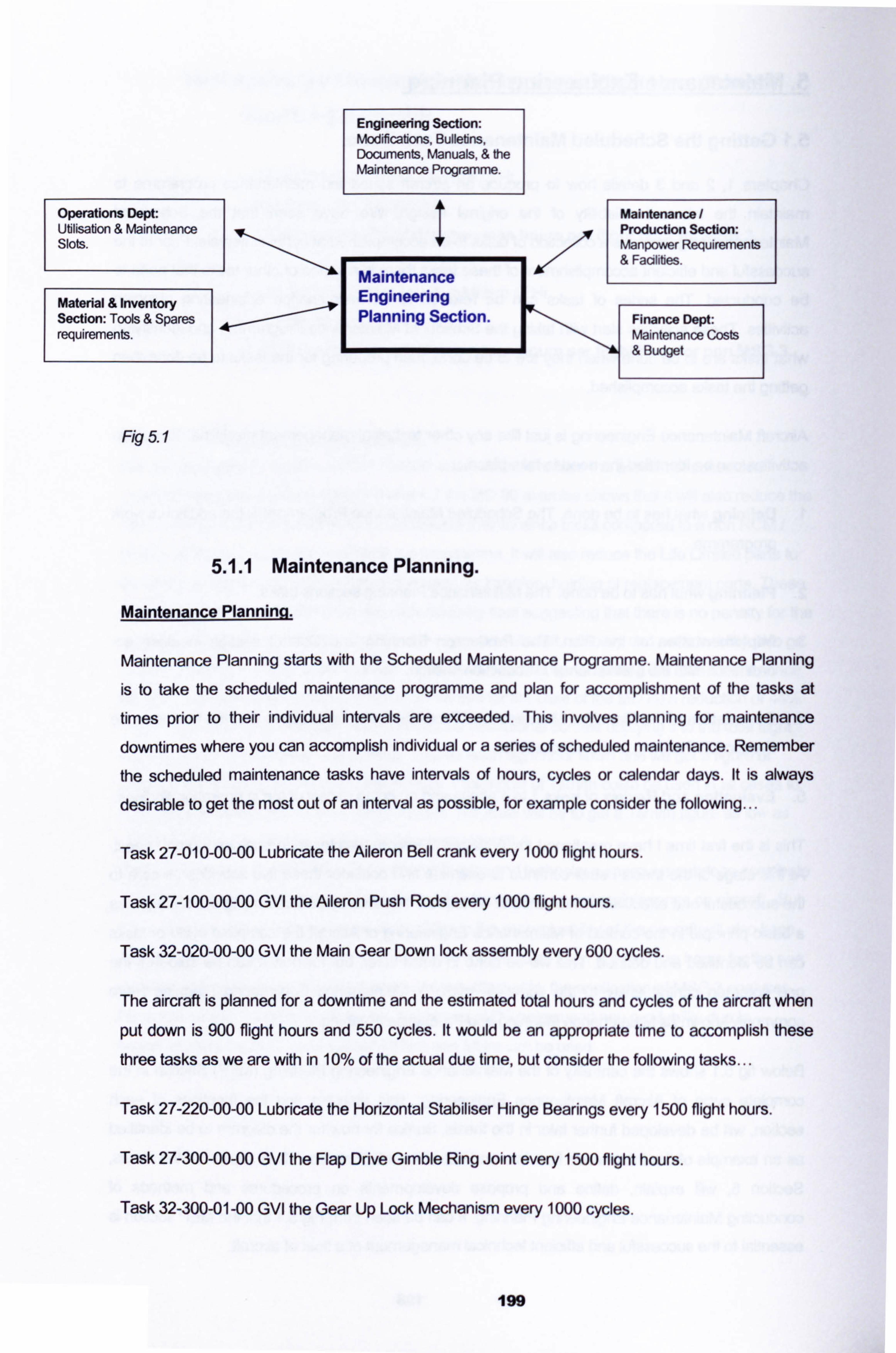
Operations Dept: Utilisation & Maintenance Slots.
Material & Inventory Section: Tools & Spares requirements.
Fig 5.1
5.1.1
Engineering Section: Modifications, Bulletins, Documents, Manuals, & the Maintenance Programme.
I
Maintenance Engineering Planning Section.
Maintenance Planning.
Maintenance Plannina.
Maintenance / Production Section: Manpower Requirements & Facilities.
Finance Dept: Maintenance Costs & Budget
Maintenance Planning starts with the Scheduled Maintenance Programme. Maintenance Planning
is to take the scheduled maintenance programme and plan for accomplishment of the tasks at
times prior to their individual intervals are exceeded. This involves planning for maintenance
downtimes where you can accomplish individual or a series of scheduled maintenance. Remember
the scheduled maintenance tasks have intervals of hours, cycles or calendar days. It is always
desirable to get the most out of an interval as possible, for example consider the following...
Task 27-010-00-00 Lubricate the Aileron Bell crank every 1000 flight hours.
Task 27-100-00-00 GVI the Aileron Push Rods every 1000 flight hours.
Task 32-020-00-00 GVI the Main Gear Down lock assembly every 600 cycles.
The aircraft is planned for a downtime and the estimated total hours and cycles of the aircraft when
put down is 900 flight hours and 550 cycles. It would be an appropriate time to accomplish these
three tasks as we are with in 10% of the actual due time, but consider the following tasks...
Task 27-220-00-00 Lubricate the Horizontal Stabiliser Hinge Bearings every 1500 flight hours.
Task 27-300-00-00 GVI the Flap Drive Gimble Ring Joint every 1500 flight hours.
Task 32-300-01 -00 GVI the Gear Up Lock Mechanism every 1000 cycles.
199
The planned down time detailed above would not be the appropriate time to accomplish the second
group of three tasks, in one case 40% of the task life remains., There is too much life remaining before they should be accomplished thus if accomplished the tasks would not be effective or
applicable.
With the Schedule Maintenance Programme consisting of hundreds of tasks it would not be
convenient for an airline to have its aircraft grounded every hundred flight hours or so it is not un
common for the Maintenance Planning section to group a series of tasks for accomplishment at the
same time for example. ---
Airline XYZ estimates a utilisation of 250 flight hours and 100 landings/cycles per month. The
following task grouping could be followed..
Monthly Check:: All tasks due at 250 flight hours, 100 landings/cycles and 30 days
1A Check:: Al task due at 750 flight hours, 300 landings/cycles and 90 days.
2A Check: : AJI tasks due at 1500 flight hours, 600 landings/cycles and 180 days.
This type of grouping is termed as block checks or letter checks where a series of like interval tasks
are grouped together and planned for their accomplishment at the same point in time, as close to
their due times as possible.
This is one of the essential skills for the Maintenance Planning section where with careful co-
ordination with the Operations section for aircraft availability and with the Maintenance section for
manpower availability and hanger space, an aircraft maintenance downtime can be planned that
disturbs the aircraft operational availability to the minimum while accomplishing the scheduled
maintenance programme tasks as close to their intervals as possible. This activity takes place on
three levels that will be explored in detail later, these levels are Long Term Maintenance Planning,
Medium Term Maintenance Planning and Short Term Maintenance Planning.
Back to the example above, Tasks that fall due between the groupings for example 900 flight hour
tasks or 400 landings tasks can either be accomplished on their own as and when they fall due or
can be grouped with the lesser check interval loosing the time remaining on them for the sake of
packaging. This task of packaging higher interval tasks with lower interval checks must be with
careful consideration as hinted upon with the example of a task being planned for With 40% of its
life remaining. (This subject will be discussed further within this section). In the letter check or block
check system each lesser check is normally complied with as part of the greater check. For
example...
The 2A Check will contain the 1A and the Monthly check tasks as it is a multiple of the lesser
checks. It was the practice in the past and remains still with some operators, to go as far as
replacing the intervals in the Scheduled Maintenance Programme with letters such as 1A, 2A etc.
This was even also the practice in the MPD that was produced by the Manufacturer. This in my
200
opinion is not good practice as it looses the actual interval identified during the MSG3 process which must always be considered when planning to accomplish a scheduled maintenance task. The tasks that are left to float and be accomplished on their own when they fall due are referred to
as Out Of Phase scheduled maintenance tasks, (OOP). These tasks are usually simple tasks that do not need substantial down time and can be done with out too much effort as they are not labour
or time intensive. If an OOP task is intensive it would normally be aligned to a schedule maintenance downtime package or permanently aligned to a letter check package that is
appropriate for its interval. AJso component lives such as oxygen bottle hydrostatic tests are left as OOP tasks as a component life is linked to a specific individual component that could be changed in the field at anytime as a result on an in operational failure or finding. Remember that the MSG3
process attempts to remove all life limitations on components preferring to introduce failure finding tasks that identify a need to remove a component rather than the unsubstantiated removal of a component.
The Maintenance Planner conducting the planning activity for a particular downtime, must have the following crucial task in place prior to at least four weeks before a minor down time (this depends
upon the size and extent of the input of course, four weeks is a good minimum guide for an input that has a significant level of work)....
1. The Scheduled Maintenance Routine Work Scope. Identifying significant tasks.
2. The Routine Work Documents required to accomplish the Work Scope.
3. The Additional Work Scope other than the Scheduled Maintenance tasks to be aligned at this
down time with the Work Scope. i. e. Service Bulletins, Airworthiness Directives, Component
Changes, etc. Identifying significant tasks.
4. The Additional Work Documents required to accomplish the Additional Work Scope.
5. The complete Work Scope material requirement, tools and parts. Shortages must be
identified at this time also.
6. The Work Scope man-hour and manpower requirement to accomplish the complete Work Scope. This includes the skills required, identifying where external assistance may be needed.
7. The total Work Scope required elapsed down time required to complete the complete Work Scope.
8. A point in the future, a Maintenance Slot, before the exccedance of any task intervals in the
work scope, where the aircraft is taken out of operation with the Operation Departments
agreement and the Maintenance Sections agreement.
A "minor" downtime can be considered as a traditional A Check taking anything from 40 man-hours with an elapsed time of 1 day to a 200 man-hour input with an elapsed time of 5 days. Referring
201
back to section 3.2.4, where the operator defines the classification of checks, along with the
approval of his authority The example given was..
15. Definition of Line Maintenance: A package of scheduled maintenance tasks that do not require
extensive access or downtime. Daily, Transit, Night Stop, Daily Non Flying, & Day Non Flying
and the Monthly series are considered line maintenance.
16. Definition of Minor Maintenance: A package of scheduled maintenance tasks that may require
some extensive access or downtime. The A-check series is considered minor maintenance.
17. Definition of Major Maintenance: A package of scheduled maintenance tasks that do require
extensive access or downtime. The C-check series is considered major maintenance.
With the 8 planning activities detailed above accomplished and in place the next planning
activity can take place, Production Planning. This subject will be discussed further in more detail after defintlion of the three Maintenance Planning time periods or the short, medium
and long term.
Short, Medium and Long Term Maintenance Planning.
So far we have spoken about the Planning roles of Maintenance Planning and Production
Planning. We identified these two areas as distinct areas in the discipline of Maintenance
Engineering Planning. It has been considered that in small organisations that these two planning disciplines are often conducted by a single section, this is often the case. What has not been
discussed so far is the third area of Long Tenn Planning or also called Master Planning.
The Maintenance Engineering Planning has three definable time frames. Two of the time frames
have been hinted at already by separating Production Planning from Maintenance Planning. Where
Production Planning is the short term implementation of the Maintenance Plan and Maintenance
Planning is the more medium term Planning time frame. In fact the three distinct time frames are as follows
1. Long Term Maintenance Planning: from 18 months to 6 years.
2. Medium Term Maintenance Planning: from 3 months to 18 months.
3. Short Term Maintenance Planning : from I day to 3 months.
202
Long Term Maintenance Planning. (18 months to 6 years. )
See attachment 1.
To be able to budget cash flow properly and effectively plan downtime and significant tasks Long
Term Planning must take place. Long Term Planning also referred to as Master Planning, looks into
the long term future at high level significant tasks such as Minor and Major Checks, Major
component changes, or Major modification programmes. The idea of Master Planning is to identify
all points in time for up to 6 years into the future a down time slot in the maintenance hanger and a
rough cost of what needs to be done. The staff in Long Term Planning must be aware of the
Maintenance Programme and be able to project due times based on operational estimations of
utilisation. They must also be aware of the major modification programmes the Development
Engineering section have in the pipe line, such as a Flap Retrofit Programme or an Interior Design
change. The Master Planning section should allocate down times into the future for these routine
checks or special projects. One other consideration for the Long Term Planning section is
significant material and tool availability and long term man power requirements. It is the Master
Planning section that define both man power requirements for the future as well as facility
requirements and can identify significant short falls or manpower excesses or facility requirements
such as insufficient maintenance hangarage.
Inaccurate Long Term Planning can result in the following
Insufficient maintenance slots identified versus the operational requirements: If a bottle neck of
maintenance is identified in the Long Term plan perhaps all falling due in the summer of 4 years
ahead, is not identified early, the maintenance falling due will disrupt the operation and could result
in massive loss of revenue due many aircraft not being available at the same time. It is Long Term
Planning tasks to identify and stagger conflicting inputs in the long term.
Insufficient skilled manpower: If a significant modification programme is not identified early as
requiring specialist skilled man power then come the time the activities are to be carried out the
staff will struggle with accomplishing the new tasks., AJso if an increase in man power requirements
or the opposite a reduction in man power availability due to training or retirements is not identified
early then the downtimes will have to be stretched.
Insufficient Maintenance Facilities: If due to many aircraft requiring their C Check accomplished at
the same time there is insufficient maintenance bays and maintenance access docking. If this is not identified years in advance there could be a terrible bottle neck and demand on resources. Long
Term Planning should identify this just like it should all other bottle necks or Maintenance
Engineering Section demands well in advance and allow for the Management to plan for
increasing in house capability or by preparing to contract out some of the excessive maintenance tasks. With out Long Term Planning these requirements will become apparent far too late.
203
The Long Term Maintenance Planning section must work closely with the Maintenance
Programmes Section to understand when the significant scheduled maintenance tasks are failing
due, also with the Material Planning section for tooling and spare requirements as it should also
with Development Engineering for identification of significant modification or Service Bulletin
requirements. Long Term Planning should be involved in the budgeting process for identifying long
term maintenance costs that require annual allocation of tasks (maintenance accruals).
Medium Term Maintenance Planning. (3 months to 18 months. )
See attachment 2.
In the medium term most of the hard work in planning is conducted. Identifying downtimes,
negotiating maintenance slots, building work scopes, co-ordinating requirements with other
sections. In this time period the theoretical inputs become actual inputs. This time frame is where detailed budgeting is also done. Conflicts in downtimes and work scopes should have been
identified in principle in the long term planning but in medium term planning the details of the
downtimes become more apparent. It is the Maintenance Planning sections responsibility to ensure
all scheduled maintenance and inspection and modification programmes are conducted before
they fall beyond their due times. This means the Medium Term Plan must consider the whole fleet,
the available manpower, the available facilities in more detail than the long term planning. During
this period of time the detailed work scope becomes more defined and all requirements to
accomplish the works copes become more apparent. As the end of the Medium Term period
approaches the Planning section should have almost completed the first stage of the work scope definition and have formed a rough work scope for the input. It is also the medium term planning's
responsibility to start the coronation with other section. Material and tooling, manpower, and facilities.
Short Term Maintenance Planning. (I day to 3 months. )
See attachment 3.
The Short Terrn Planning is the final phase before Production Planning and continues right up until
the day before the aircraft starts it's downtime. There is an overlap with Short Term Planning and Production Planning. During the short term planning phase the work scope is closed and the
downtime is defined and claimed with actual dates of start and finish. These dates are used by the
Operations Section to remove the aircraft from service. During this period Planning still continue to
liaise with Operations even thought he dates are defined in case an operational emergency calls for
the aircraft downtime to be changed. It may be a very difficult activity but Planning must keep in
mind at all times that the business they are in is air transport and if the need to change input dates
or to cut down on maintenance downtimes occurs they must try their best to assist. In Short Term
204
Planning the down time dates should be as close to the due date as possible of the work scope. The work scope due date should be driven by the significant check included in the work scope,
such as the C check. Other due tasks prior to the due date should normally be attempted to
accomplished out of phase. For example is the Work Scope consists of the IC Check due at 3000
flight hours, S13 737-27-1055 due at 3100 flight hours and IDG change due on 14 May 2003. It is
anticipated that using current utilisation the aircraft will be at 2950 flight hours on the 1 Sh May 2003,
so the downtime is planned to start on the Monday ISh May 2003. This way two important things
are achieved. 1. The maximum time in operation for the aircraft is achieved before the IC and the
work scope is due. 2. The input will start on the first day of the week then giving a clear run for the
five day input when manpower is best available and at its best productively. It is during the short term phase that the pre input meeting task place and the hand over of the work package takes
place from the Short Term Planning section to the Production Planning section. It is not unusual
also for some Operators to have a Line Maintenance Planning section. This is not unlike the
Production Planning section in that they only deal with line maintenance such as Weekly or Monthly
checks or Out of Phase tasks that have a repeating interval of a short period, or indeed any tasks
that are accomplishable in less than a turn around time. But care must be taken in Line
Maintenance Planning in that a contingency is available if during the Line Maintenance tasks a finding calls for a longer downtime than initially anticipated. This in fact is a consideration that need to be taken every time the Maintenance Planning section plan for a downtime of any sort, i. e. what if we have findings. This will be considered in more detail in the next section.
The Maintenance Plans shown above as Short Term, Medium Term and Long Term must be
published, controlled and available to all concerned in Operations, Maintenance Engineering,
Marketing, Materials, and Finance. These three plans form one of the basis of the operation with
regards to airworthiness and safety, management of manpower, equipment and facilities,
management of inventory, management of finances and budget and ultimately management of the
operation.
Modification and Service Bulletin Planning.
As the manufacture receives feed back from in service aircraft and from engineering studies
conducted by the manufacturer in testing or by computer simulation, the need to revise the original design of the aircraft may become apparent. Remembering that scheduled maintenance is to
restore the inherent reliability of the original design, Service Bulletins are to revise the original design or to address design imperfection that may cause airworthiness issues. The manufacturer
will inform the operators of these requirements through issuing Service Bulletins (SB's). The SB's
can call for modification to address changes to the original design or inspection SB's to look for
possible airworthiness issues. The operators will receive relevant SB's from the manufacturer only
applicable to the serial numbers of the aircraft type they operate. Normally aircraft in production and those in pre production will automatically be subjected to the modifications prior to delivery.
205
Example of a Modification SB..
SB 737-27-1053: Rudder Trim Actuator Replacement.
The SB will be received by the Operator and will describe in the SB the reasons why the SB has
been issued, will identify the SS as Alert, Recommended or Optional. Alert SB's are normally
addressing a condition that is safety or airworthy related. Often Alert SB's become later mandated by the regulatory authorities when they feel the subject is of a considerable airworthiness or safety level of importance. How each operator manages and plans for incorporation can change and vary depending upon Engineering Policy. The issuer of the SB, the Original Equipment Manufacturer,
(OEM) after classifying the SB as AJert, Recommended or Optional may go on to give a time frame
when the SB should be accomplished as well as planning information such as material required,
man-hours to accomplish the task, tooling required, and then will give the work steps on how to
accomplish the SB. In the case of SB 737-27-1053, the rudder trim actuator is recommended for
replacement introducing a new improved modified actuator with a different part number. The varied
operator approaches to managing the SB's usually start with a section in Engineering appraising
whether or not the SB should be accomplished. Some of the considerations for the appraising
engineer when deciding to recommend to the management for incorporation of the SB are as follows..
Company fleet data should be looked at to see if an issue exists within the company that the SB
addresses. Does this SB address a know problem that has been an issue with the fleet already?
Does the SB address an issue of importance to the company, safety or airworthiness?
Consideration as to fleet strategy should be made, for example will the aircraft type be in operation for some time?
investment pay back. By accomplishment of the SB will the fleet type become more reliable hence
less maintenance or is the resale value affected?., A return on investment calculation may be
devised. Both material cost, downtime cost and manpower cost should be considered.
Is the SB a warranty issue where the OEM will reimburse the time and material?
Once the appraising engineer of the operator has appraised the SB it will normally be sent to
Engineering Management for review. If the it is agreed upon to be accomplished it becomes a Modification Planning issue often the responsibility of the Maintenance Planning section, subject to
planning activities just like scheduled maintenance tasks i. e. material ordered, work documents
written, accomplishment planned. It is not unusual for operators to only accomplish Alert SB's or
only those that are concurrent with engineering policy for example cabin appearance or safety
related. Often those not concurrent with Company Engineering policy are filed and only referred to
in the future if an issue occurs later in time that the SB addresses.
206
Example of an Inspection SB..
SB 737-53-1128: Horizontal Stabiliser Attachment Inspection.
The OEM recommended this SB as a result of in service findings reported back to them of cracks found on two occasion. One at 50,000 flight cycles and one at 57,000 flight cycles. The
recommended inspection time frame is at a threshold 40,000 flight cycles repeating at every 10,000 flight cycles after. Operator Engineering policy may differ for inspection SB's as often these call for
a known manifested condition. The appraising engineer will submit his recommendations to the
engineering management in a similar way to how he did in with the Modification SB. Even though it is an inspection and not a modification, the planning section treat that task in a similar way. Once a final decision is made the Inspection SB will then be subjected to planning activities by the Maintenance Planning section.
It is my opinion that the Maintenance Planning section should review all open Service Bulletins
where the company engineering decision is to accomplish them, along with the engineering section responsible for appraising SB's and other relevant sections on at least a two monthly basis. This
will ensure that the Planning activities are co-ordinated with the relevant section, material section to follow up on tooling or part requirements, maintenance section to inform them of the approximate work involvement, and the engineering section responsible for writing the work documents. It is the Planning sections responsibility to ensure that the SB is accomplished, modification or inspection,
at an appropriate downtime prior to the compliance time frame allocated to it by the appraising
engineering section. To plan for a 100 man-hour modification on a light 2 day A check downtime
may not be appropriate. For those SB's that any one on the engineering management decision
team who review the S13 recommendations from the appraising engineer, disagree with the
accomplishment recommendation, those SB's should be discussed individually until a consensus
of decision is made. The Technical Director, or his delegate often the senior engineering manager,
will make the final decision when there is no concurrent agreement. The subject of engineering
policy on SB accomplishment should be made with careful consideration. Company guidelines for
the appraising engineer should be clear and considerate as should his recommendations. To make
a decision to do every SB that an OEM issues regardless, is in my opinion not a wise one. Just as
with scheduled maintenance SB tasks can be non effective or applicable and even invasive and
can be resulting from a reason that is not completely relevant to your particular fleet. Equally to
make a policy that only alert SB that have been mandated by the Authorities are to be
accomplished and no others, is also in my opinion not a wise decision. If an SB regardless of being
mandated address an important issue on safety or airworthiness careful consideration should be
given to its accomplishment with in an effective period of time also regardless of the OEM's
recommendations. Communication with the OEM and with the industry can help an operator in his decision to accomplish SB's. Just because an operator has not yet experienced an issue
addressed by an SB doesn't mean it should be recommended not for accomplishment.
207
5.1.2 Production Planning and Control.
After completion of the preparation tasks defined as Maintenance Planning, the next stage for a
well planned successful maintenance input is the Production Planning and Control phase. Production Planning is often conducted by the Maintenance Planning section, in small
organisations, after the Maintenance Planning phase, by the Maintenance section or as with larger
maintenance organisation by the Production Planning and Control section. How ever the distribution of tasks, the Production Planning function is essential to the success of the
maintenance input and to minimise the down time spent on the work scope, remember every hour
the aircraft is on maintenance is an hour of operational revenue lost. Production Planning and Control is taking the Work Scope produced by the Maintenance Planning section and subjecting the work scope to detailed planning activities ultimately resulting in the implementation of the work
scope.
Major Production Planning Activities
Task Sequencing: taking the work scope built by the Maintenance Planning section and splitting the tasks into common sequences of events. Eg
Seq 1: Pre Hanger Tasks.
Seq 2: Pre Power Off Tasks.
Seq 3: Cleaning & Access Tasks. (panel opening).
Seq 4: Inspections Tasks.
Seq 5: Lubrication & Servicing Tasks.
Seq 6: Pre Power On Tasks.
Seq 8: Power On tasks.
There can be many more or only a few of the above sequences when sequencing a work scope depending upon the size of the work scope. Task Sequencing, even in its most basic form, is
essential to an efficient maintenance input. In an A Check there may be as little as 30 task or as
many as 200 tasks, sequencing makes sense of all the work to be done and orders it in a logical
manner.
Production Plan: The Production Plan is a flow chart, also known as a Gantt Chart. This diagram
shows the activities and milestones of the work scope. This diagram can be completed using detailed planning software showing many activities in order of sequence, showing also a critical
path or it can be more simple showing only major miles stones and a few critical activities. If being
used to plan and control a maintenance input, firstly the Production Plan must be bought into by the
Production section, agreeing with the major activities and milestones and committing to achieving
208
them. During the input the Production Plan must be dynamic, and must change when required as the input progresses. If this dynamic aspect of the Production Plan is not their or the Production
section does not commit to meeting the Plan, the Production Plan becomes nothing more than a pretty picture that doesn't really reflect or mean anything to do with the progress of the input. This is
often the case. Common mistakes made with the Production Plan are...
It is too vague.
It is too detailed.
It is not achievable.
It is not based on credible past history.
It is not bought into by the Production Line Managers.
It is not dynamic and doesn't change as new information is known as the input progresses.
If all of the above do not occur and the Production Plan is a credible accepted plan by the
Production section, it can drive the input to a successful downtime, giving clarity of information as to
what has been done and what is still to be done. The sequencing of the tasks goes hand in hand
with the Production Plan and often the sequencing titles form the major mile stones of the input. A
very important mile stone that has not been mentioned so far is "Inspections Complete". A good
guide as to when inspection tasks should all be complete is prior to the completion of the first third
of the input. This is essential as to know where you stand with findings resulting from the fault
finding scheduled maintenance tasks in the work scope. It would not be production planning to
assume the scheduled maintenance would result in no findings. This leads to the author of the
Production Plan allowing in his plan for time to rectify defects. This can be difficult unless you have
a data base of past findings on the same type of aircraft with a similar operating role and similar
age and utilisation. Some rough guidelines for routine (scheduled tasks) versus non routine (findings resulting from schedule tasks) are as follows..
Aircraft Age of around 1.5 years with a normal utilisation:
I hour routine generates 0.5 hours of non routine. 1: 0.5.
Aircraft Age of around 3 years with a normal utilisation:
I hour routine generates 1 hour of non routine. 1: 1.
Aircraft Age of around 5 years with a normal utilisation:
I hour routine generates 2 hours of non routine. 1: 2.
209
This is not an industry standard but based upon my experience. The figures used by an operator
must be based upon historical data.
See attachment 4. (a simple Production Plan).
JAR 145, the Maintenance Regulation for JAA Sate Countries maintaining aircraft recently has
included a section on Human Factors for Maintenance where Production Planning has been
identified as required to take into consideration in the Production Plan the factors that can effect human performance such as , shift patterns, man power allocation and planned activities. This
aspect levitates the Production Plan from being a nice to have concept as it was in the past to a
required maintenance management tool. A good Production Plan will take into consideration not
only the flow of work sequence but also the loading of maintenance tasks to the available work force. This leads us to the next aspect of Production Planning, Man Power Planning.
Manpower Planning : taking the work scope from the Maintenance Planning section and planning
and producing a detailed man hour / manpower capacity plan. This includes comparing the
required man power for the work scope versus the available man power from the Production
section. A good Production Plan show a sequence of maintenance activities that is achievable with
the man power availability of the Production section. Shift manpower allocation, leave, sickness,
training should all be reflected in the Manpower Plan and that in turn should be considered in the
Production Plan. The occasion when the Production Plan shows that on day 2 that 30 man hours
on Avionics skill tasks is required for the first half of the day, when in fact only 20 man hours of Avionic man hours are available. This situation can occur in the initial phase of producing the
Production Plan and the plan then shows a short fall in the required manpower for that activity, the
resulting action should then be that the plan is adjusted to suit the available Production man power
or supplemental manpower is planned for that activity. If the available man power can not meet the
Production Plan, then it is incorrect to leave the plan unchanged. This puts unfair pressure on the
Production section. This is why JAR 145 is heading in the direction of mandating good Production
Planning as it can see a relationship with Human Factor events with inaccurate planning. Further
more a Production Plan should not be bought into by the Production section that also shows new
activities that training or experience is required.
Material Planning: this can be split into two areas, tools and equipment and parts and spares.
Tools and Eguipment: The Planner for the in put should know what tools and what equipment is
required to accomplish the work scope. This should be detailed in the work scope when the
Maintenance Planning section defines the task in the work scope. The Maintenance Planning
section should not include a task requiring tools or equipment that can not be provided in time for
the input. The Production Planning section should with draw tasks from the work scope when it is
confirmed that the tools or equipment will not be available in time when the Production Plan show
that the activity should take place. This is only capable if there is time remaining on the task, if not
the order for the tool or equipment should be raised to critical and the Production Plan changed to
reflect a reasonable time when it is forecasted that the tool will be available on site. It is important
210
that the Production Plan should not reflect an acUvity that requires tools when they are not
available, again this can result in Production pressure as they are unable to complete the tasks that
are planned. Not only does this apply to tooling but also to equipment. Hanger access platforms for
example, over head cranes and especially safety equipment. The Production Planning section should not be the first to identify a tooling need. Maintenance Planning know well in advance from
the Scheduled Maintenance Programme what task are to be done when. They are therefore in the
position to pre order tools or equipment long before the requirement for them occurs due to
scheduled maintenance requirements. Often Material Planning is a section in itself, with dedicated
staff who review the Scheduled Maintenance Programme for material requirements. The Material Planning section along with the Maintenance Planning section should work very closely. By the
time it comes to the Production Planning section no scheduled maintenance requirement should be
new to the Material section, all the Production Planning section do is tell the Material section when
exactly the material is required. For non Scheduled Maintenance requirements such as
modifications, Maintenance Planning section should have frequent modification co-ordination
meetings with the Material section identifying special tooling and material required to accomplish the mods. It is not unusual that a section in the Maintenance Planning section is dedicated to
master planning for major modification programmes and for major component replacements. Such
as landing gear changes or engine changes. These expenditures are so significant that it is worth
while to dedicate a section to co-ordinate the programmes attempting to align the major activities
with the closest and most appropriate down time. Small operators often do not have that luxury and the Maintenance Planning section carry out the Master Planning, Maintenance Planning and the
Production Planning activities.
Parts and Spares: The Maintenance Planning section producing the work scope should not only identify the tools and equipment required to accomplish the tasks but also a material pre load sheet detailing all the spares and parts required to accomplish the work scope. This includes the
components such as generators or fire extinguishers, the consumables such as seals o-rings or oils
and greases, the mod kits to accomplish modifications. The exact same rules apply to the parts
and spares that apply to the tools and equipment. Material Planning again should be planning for
the scheduled maintenance parts well in advance of the input, in fact the aircraft manufacturer will
provide for the operator a Recommended Spare Part List (RSPL). This is a list of parts and spares
required as a result of the scheduled maintenance programme provided by the manufacturer (MPD
/ MRBR) as well as a list of un scheduled parts that through the manufacturers experience may well be needed in the course of operating the aircraft. This list is available and adjustable depending
upon utilisation and service level. One thing to keep in mind is that the manufacturer will also offer to sell you the parts in the RSPL, so a little home work is a good idea, perhaps looking closely at the Minimum Equipment List when making material orders based upon the RSPL. Some operators
pool parts with other operators of the same type to minimise the inventory cost, or it may be
possible to loan components if required due to an unscheduled occurrence, but this is often a very expensive. The common pricing for a loan component is 11% per day of the cost of the component.
211
After 100 days you have paid for the component. This decision has to be taken with some risk
assessment., for example..
An Integrated Drive Generator (IDG) for a B737-NG is totally on condition and has no scheduled life. The IDG has an industry mean time between unscheduled removal (MTBUR) of 65,000 flight
hours. The cost of the IDG is around 250,000 US Dollars. In addition the B737-NG can be
dispatched with only one IDG operative according to the MEL for normal operations, but not for an ETOPs flight. An non ETOPs operator has no reason to buy an IDG according to the statistics.
Scenario.
1. The operator does not buy an IDG. If the unit fails he places an AOG (Aircraft on Ground) order
paying a premium of an extra 20% to get the unit on short notice if he can. He operates the
aircraft under the MEL until the replacement IDG is available. He is able to negotiate apart
exchange with his unserviceable IDG.
250,000 x 1.20 = 300,000 USD but gets back 150,000 for his u/s unit =a total cost of 200, OOOUSD.
By not planning for this unit replacement the operator is opening himself to risk. The risk of not
being able to get a unit, the risk of paying over the odds for the AOG unit, the risk of a second
failure while the first failure is un addressed and also the budget allocation may not be available for
such a large expenditure.
2. The operator buys a spare IDG at 250,000 USD and holds it in store. It sits there for 3 years
and is never called upon to be installed.
On great advantage of having the unit in stock is that your are prepared in the event of the IDG
failure and no disturbance to the operation will take place and no expensive AOG orders will be
required. Aso you are in a position to trade the units use and make the inventory work as a
capital investment for the owner. It can be offered for loan for AOG requirements at 1% per day. The period that you have it out on loan increases the risk of course, and also
consideration to the usage on the spare by another operator is of concern.
3. The operator does not buy a complete IDG unit, but along with an other operator pools the unit, both owning 50% of the spare and both being able to call upon the spare at any time due to
component failure. This is a good agreement as not only do you have access to a spare IDG
you pay only 50% of the cost of owning that IDG, of course you only actually own 50% of the
capital but you reduce your risk of requiring an IDG and not being able to get one massively. There is a remote possibility that both of the owners require the IDG at the same time, this
means some agreement needs to be made that in that case the cost of getting another IDG
must be bome by both parties, thus in that situation the benefits of pooling parts is often lost. A
consideration to an additional charge to the operator that actually uses the spare IDG should be made, perhaps an hourly cost over and above the 50% owner ship cost.
212
4. Another common method of meeting the requirement for a component when it is required due
to an unscheduled reason is by paying a subscription to a service provider who has an inventory of parts. He in effect becomes your available RSPL inventory. Often you are charged a subscription to have access to the inventory and a further charge when you use a part, often based on an hourly utilisation charge. For example
An operator of four B737-NGs does not want to spend the 12,000,000 USD on an RSPL Boeing recommend for a four aircraft fleet of B737's operating at 6,000 flight hours per year. Since he is a low cost start up airline he can not afford the capital expenditure. He equally can not risk the cancellation of a flight due to non availability of a spare as this will also cost
massively in lost revenue. The answer he goes for is to pay KLM a 40 B737-NG fleet operator
a subscription to have access to their inventory. In addition to the annual subscription based on an estimated flight hour utilisation an additional cost is charged per flight hour when a component is claimed. The unit removed from the low Cost Operator then goes into the inventory of KLM available for the KLM fleet or indeed any other operators in the subscription deal. There are of course a few conditions to the deal. Many major components are not included in this deal, such as engines or landing gear. The Low Cost operator must maintain their mod standards of their aircraft to that of KLM, which means accomplishing ETOPs mods and some other optional mods that perhaps the Low Cost Operator would have chosen not to do.
It is the responsibility of the Material Section along with the Finance section to calculate the best scenario for the operator. It be seen that to take a flight cancellation is a better business
decision than to hold an expensive part in stock on the presumption it may be needed.
Documentation Availability: The Maintenance Planning section define the work scope and
provide the task cards to accomplish the work scope. Often the task cards refer to maintenance
manuals or other controlled documents. The Production Planning should ensure that the
referenced documents required to accomplish the work scope are complete and readily available. This may mean identifying maintenance manual section required and printing them off or obtaining
referred to procedures. If this is not done it will result in the maintenance technician not having the
complete instructions to carry out the task, which is a situation that will either waste time or result in
the possible compromisation of the technician. This rule applies definitely to tasks in the work
scope, to those generated as non routine tasks during the work scope accomplishment it can also be argued that the Production Planning section also play an important role. This will be discussed
next.
Pro Input Meeting: It is the Production Planning section responsibility to call the pre input meeting
once all the Production Planning tasks are accomplished or at least on the way to being
accomplished. This should be done as soon after the Maintenance Planning section has handed
over the Work Scope and the Production Planning section has had time to review it and at least
213
start the Production Planning process. The pre input meeting should take place no later then two
weeks prior to an input for minor maintenance and three weeks for major maintenance. For Line
maintenance it can be as short as one week and be in a form of a pre input hand over for simple tasks. The Production Planning section should chair the meeting and invite representatives from
the following sections...
Production (maintenance) Section: To explain the work scope and the Production Plan including
the shift patterns, as they are the people who will accomplish the work scope. Liaison with Production must be constant and almost daily to ensure manpower is understood and available
and that the Production Plan is accepted. The work scope should be read through by the
supervisors that will be leading the individual trades during the input.
Material Section: To be able to present the material shortages and estimated expected dates.
Material section need also to know the shift patterns as they may be required to supply store
personnel.
Qua Lity section- They need to be aware of the work scope and input dates so as to scheduled any
audits or to review any procedures.
Development En-qineerinq Section: They are the section responsible for writing any Engineering
Orders for modifications or special inspection, they need to be aware of any special tasks being
accomplished. Also they need to be on stand by in case of any problems or findings requiring Engineering assistance. Also the Development Engineering section may well be responsible for
revising documents or manuals such as the MEL or AFM or AMM, for this reason they need to be
aware of any modification being accomplished.
Operations and Flight Crew sections: In the event that significant changes to the aircraft will be
made at an input, such as the installation of Satellite Communication (SATCOM), are to be made it
is important that the Operations section and the Flight Crew representatives are aware in order to
revise their manuals or to plan for training for the crew as required. The Flight Crew Fleet Manager
should be aware of any significant modification programme on his fleet long before Production
planning start their planning activities.
Production Control.
Though the Production Planning Engineer who has carried out all the Production Planning activities
prior to the input, effectively hands over the management of the maintenance input on the day the
input starts to the Production Line Manager (some times known as the Forman), it should not be
the end of his involvement. The Production Planning Engineers role now changes from that of a Planning Engineer to that of a Check Controller. The main duties here are assisting the Production
Line Manager in implementing a downtime that is in accordance or as close as possible to the
Production Plan. The Production Planning Engineer may have a team of check planner or also
called doc planners who assist the Production Crew with the following activities...
214
Non Routine Finding Planning: This involves the scheduling of the NRC's that arise as a result of the scheduled maintenance tasks. To ensure that the findings receive as much as scheduled tasks
with regards to task planning all the activities described above, task sequencing, production planning, manpower planning, material planning, documentation availability, all these planning tasks are as applicable for noun routine findings as they are for scheduled maintenance tasks. It
should be the Production Planning sections tasks to carry them out.
Task Sequencing: The Production Planning section should receive all NRC's raised as soon as they are raised, then identify where the NRC can be best addressed. For example does it require power on, does it require special conditions, what access does it need etc. Each NRC should be
prioritised with in the greater scheme of the complete check. It would be incorrect if as soon as the
routine task is completed the maintenance technician then goes onto the NRC*s that he generated. It is important to identify that the routine tasks should all be completed first, then the NRC's
addressed unless the NRC's is identified as requiring urgent special attention then it will be
sequenced to start immediately.
Production Planning: The master production plan should be referred to every day. The morning
meetings should have a routine agenda where reviewing the production plan versus where the
production is actual at should be one of the prime issues discussed. The Morning Input Production
Meeting Agenda should contain the following items..
1. Are we on target with the Production Plan?
2. What are the critical NRC's?
3. What are the material shortages?
4. How is the manpower?
The Production Meeting should be chaired by the Production Line Manager responsible for the
input, but the Production Planning section are key in this meeting and the relationship with the
Production Line Manager and the Production Planning Engineer (Check Controller) is one of information and support.
Production Plan: If the answer to 1. above is no then the reasons why the production is not in line
with the plan should be asked. If possible remedial action should be taken to get back on target or inevitably the plan should be changed. It is not the end of the world if the plan has to be changed as
many occurrences during the input will cause reason for the plan to possibly change. This is
especially true for findings. This is why it is important for the inspections to be completed as quickly
as possible or at a pre agreed milestone, so as the Production Line Manager and the Production
Planning Engineer know where the they stand with respect to the generation of NRC's. The Production Plan should reflect the NRC's as they are raised and should show milestones for NRC's or show adjustment of already defined milestones as required for example, if a structural crack is found and the NRC calls for NDT of the crack, this along with other NRC's requiring NDT
215
should appear in the Production Plan as a milestone, similarly if corrosion Is found In the pylon
resulting in major access being required, or if a hydraulic leak defect is found that prevents the
milestone for hydraulic power on from being achieved then the milestone needs to be adjusted
accordingly. The new activities associated with an NRC should appear in the Production Plan as NRC milestones or activities but just as not every routine task appears as an activity or a milestone
not every NRC should appear only the key significant NRC*s. It is the Production Planning
Engineers job to identify where the actual production progress is behind the plan and where discussion should be focused as to adjust the plan or the work methods to attempt not to delay the
final milestone of check completed. So it can be seen that with proper use and continuous update
of the Production Plan that the Plan during the execution of the check has six major roles..
1. Allows for comparison of actual progress with planned progress.
2. Alows for the inclusion of significant findings in the Production Plan.
3. Alows for the Production section to be aware of the next work to be accomplished.
4. Adlows for identification and following of critical task accomplishment (routine and non routine).
5. Alows management to more easily consider theoretical adjustments to Production to attempt
to meet milestones.
6. Enables an actual record of progress for future inputs.
Manpower Planning: The initial Production Plan assumed a man power availability. It is the
Production Planning Engineers task to ensure that the Production Line Manager has in fact
scheduled the agreed man power on each shift. If the Production actual progress is behind the
Production Plan the Production Planning Engineer should suggest the reallocation of man power or
supplementation of non planned man power (internal or external contracted man power) to enable the plan to get back on track. One of the reasons additional man power may be required is as a
result of the NRC*S. The rate of findings may be in excess of the estimated planned time for defect
rectification, thus either a compromise in mile stone adjustment or man power reallocation needs to
be made if supplemental manpower is not available. The value of this exercise is also for future
inputs. So it can be said that manpower planning during the check has three values..
1. To identify that the planned manpower is actually being used.
2. To identify and co-ordinate manpower requirement changes as a result of findings (NRC*s).
3. To keep a historical record for future planning of the man power requirements of tasks and
activities accomplished on the focus input.
Material Planning: This function is not really the role of the Production Planning section but is of
the Material Planning Section. Each input should have a material planner assigned to the input. it is
216
his task to progress the material requirements that occur during the input as a result of findings
(NRC's). One of the most important questions of the daily Production Meeting is what are the
material shortages, because with out the required material, spares or tools, the task can not be
addressed and rectified. It is not unusual that major milestones of a plan have had to adjusted due
to the non availability of a component. This issues goes back to that described in the first
explanation of material planning of what material to hold and what not and the risks associated with that decision. It may be an idea for the Production Planning staff assigned to the Check Controller for an input to conduct the material requisitioning as a result of Production raising NRC's. This
could an advantage in that the Production staff could be kept on the aircraft carrying out scheduled tasks while the Production Planning section carry out the material requisitioning and follow up with the material section. This may show a need for a skilled Production Planning staff member who is
capable of researching and identifying the material (and tooling) requirement to address an NRC, but just as Production Planning do this for routine they in theory should be capable for non routine. It is my opinion that this is a delicate subject and if managed correctly could result in improved
production man power availability to carry out on aircraft tasks. A few skilled material or production
planning researchers could take the NRC from the Maintenance Technician and carry out the
research and co-ordination required to identify what is required to address the particular NRC. This
would should be in my opinion finalised with feedback to the originating technician for conformation.
Documentation Availability: The last paragraph talked about how to maximise the Production
sections time on "on aircraft" tasks by enabling the Production Planning staff to take on some
administrative technical roles such as material research. Similarly I would like to expand that role by
including certain documentation research. It is the Production Planning sections role to supply all task cards, manuals and documents referred to in the complete work scope before the input starts,
similarly it should in my opinion be the Production Planning tasks to supply all the required manuals
or documents required by the Production section for the addressing of findings resulting in NRC's.
SRM, AMM, IPC or indeed drawing research can be done by Production Planning staff with the
necessary skills and training. Of course this should be finalised by the acceptance of the research document outcome by the originating Production technician. The reference should then be
attached to the relevant NRC. For example, a Maintenance technician raises a NRC as follows...
NRC Finding Details: Hydraulic Fluid Leaking from the Rudder Actuator over and above the
maintenance manual limits. Replace the actuator.
From this the Production Planning staff allocated to the maintenance input in my opinion should
carry out the following tasks...
1. Document Research: They refer to firstly the Aircraft Maintenance Manual (AMM) and find the
procedure for replacing the actuator. They then move on to the Illustrated Parts Catalogue
(IPC) and locate the subject component. This attached to the NRC.
2. Material Research: From the AMM and IPC they identify the spares including seals & lubricants, the tooling to carry out the replacement. Once reviewed and confirmed by the
217
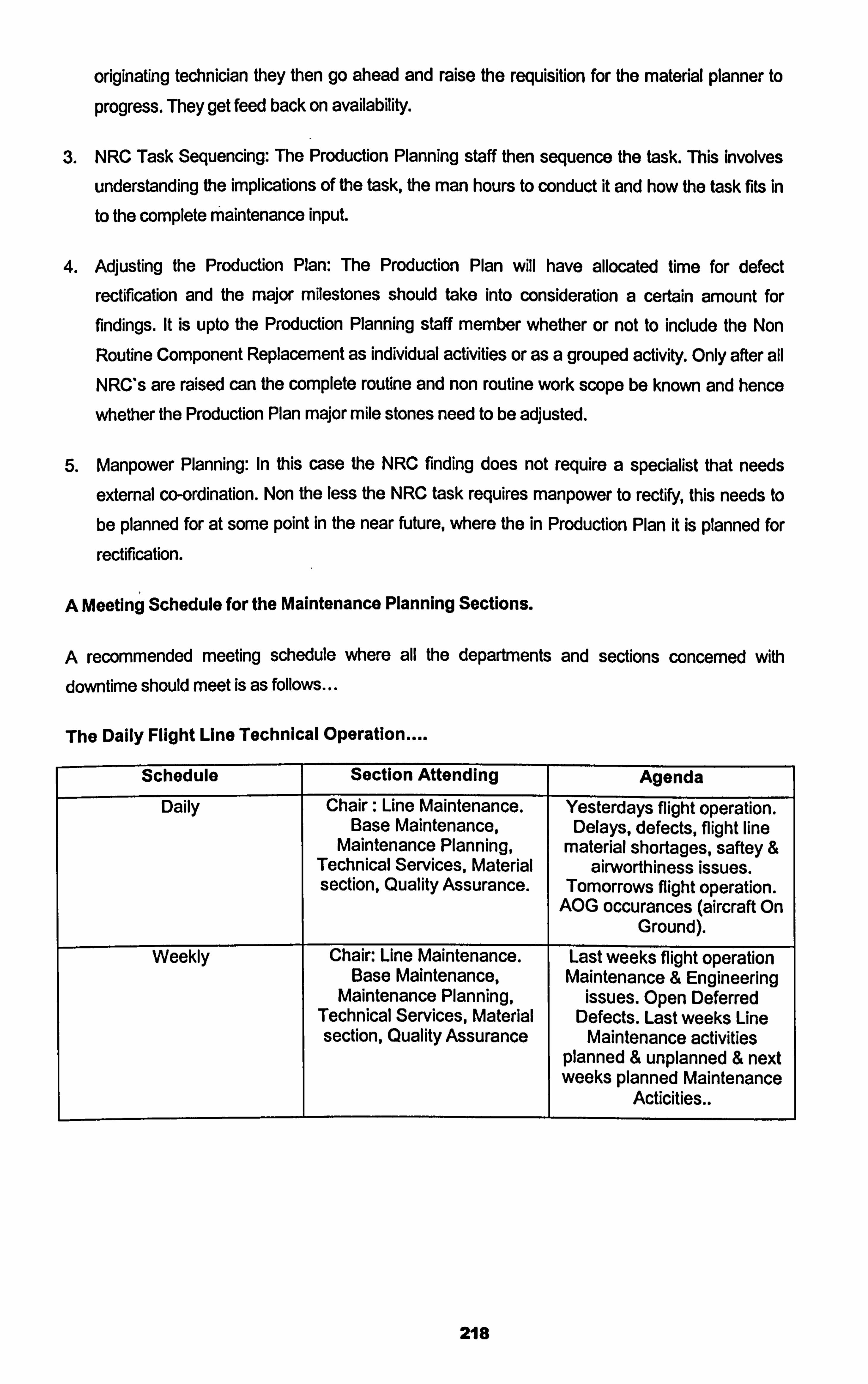
originating technician they then go ahead and raise the requisition for the material planner to
progress. They get feed back on availability.
3. NRC Task Sequencing: The Production Planning staff then sequence the task. This involves
understanding the implications of the task, the man hours to conduct it and how the task fits In
to the complete maintenance input.
4. Adjusting the Production Plan: The Production Plan will have allocated time for defect
rectification and the major milestones should take into consideration a certain amount for
findings. It is upto the Production Planning staff member whether or not to include the Non
Routine Component Replacement as individual activities or as a grouped activity. Only after all NRC's are raised can the complete routine and non routine work scope be known and hence
whether the Production Plan major mile stones need to be adjusted.
5. Manpower Planning: In this case the NRC finding does not require a specialist that needs
external co-ordination. Non the less the NRC task requires manpower to rectify, this needs to
be planned for at some point in the near future, where the in Production Plan it is planned for
rectification.
A Meeting Schedule for the Maintenance Planning Sections.
A recommended meeting schedule where all the departments and sections concerned with downtime should meet is as follows...
The Daily Flight Line Technical Operation
Schedule Section Attending Agenda
Daily Chair: Line Maintenance. Yesterdays flight operation. Base Maintenance, Delays, defects, flight line
Maintenance Planning, material shortages, saftey & Technical Services, Material airworthiness issues. section, Quality Assurance. Tomorrows flight operation.
AOG occurances (aircraft On Ground).
Weekly Chair: Line Maintenance. Last weeks flight operation Base Maintenance, Maintenance & Engineering
Maintenance Planning, issues. Open Deferred Technical Services, Material Defects. Last weeks Line section, Quality Assurance Maintenance activities
planned & unplanned & next weeks planned Maintenance
I Acticities..
218
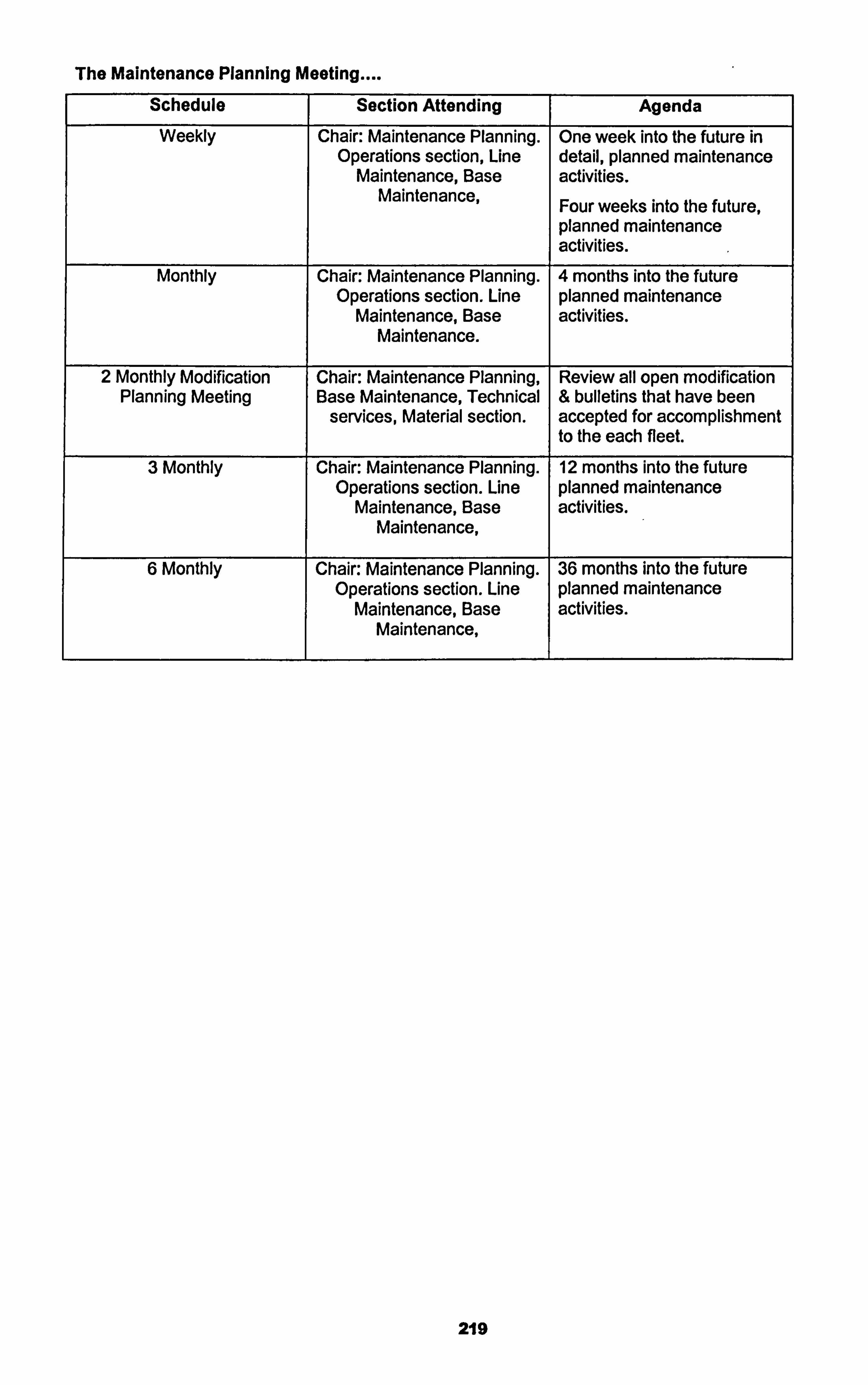
The Maintenance Planning Meeting
Schedule Section Attending Agenda
Weekly Chair: Maintenance Planning. One week into the future in Operations section, Line detail, planned maintenance
Maintenance, Base activities. Maintenance, Four weeks into the future,
planned maintenance activities.
Monthly Chair: Maintenance Planning. 4 months into the future Operations section. Line planned maintenance
Maintenance, Base activities. Maintenance.
2 Monthly Modification Chair: Maintenance Planning, Review all open modification Planning Meeting Base Maintenance, Technical & bulletins that have been
services, Material section. accepted for accomplishment to the each fleet.
3 Monthly Chair: Maintenance Planning. 12 months into the future Operations section. Line planned maintenance
Maintenance, Base activities. Maintenance,
6 Monthly Chair: Maintenance Planning. 36 months into the future Operations section. Line planned maintenance
Maintenance, Base activities. Maintenance,
219
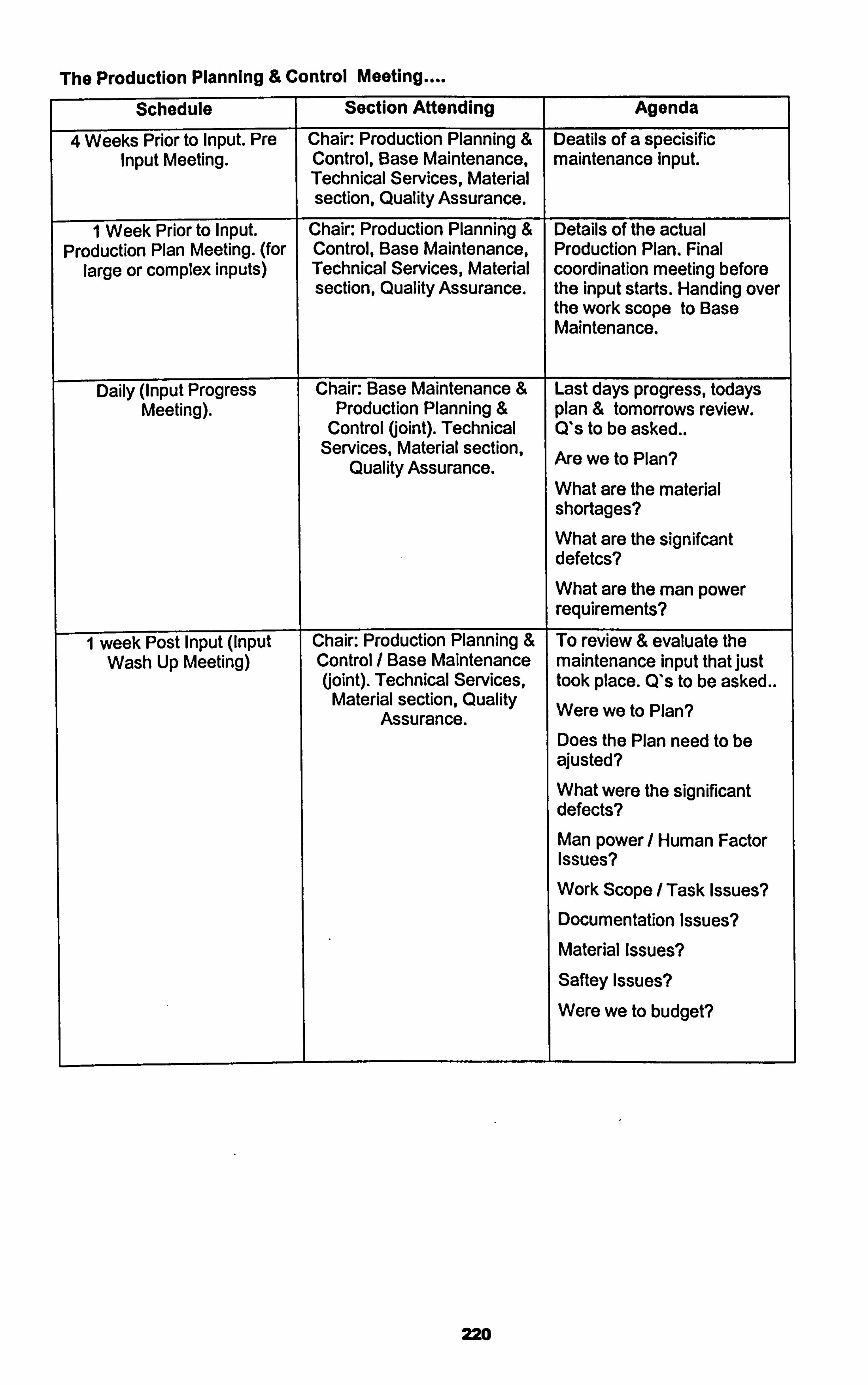
The Production Planning & Control Meeting
Schedule Section Attending Agenda
4 Weeks Prior to Input. Pre Chair: Production Planning & Deatils of a specisific Input Meeting. Control, Base Maintenance, maintenance input.
Technical Services, Material section, Quality Assurance.
1 Week Prior to Input. Chair: Production Planning & Details of the actual Production Plan Meeting. (for Control, Base Maintenance, Production Plan. Final
large or complex inputs) Technical Services, Material coordination meeting before section, Quality Assurance. the input starts. Handing over
the work scope to Base Maintenance.
Daily (input Progress Chair: Base Maintenance & Last days progress, todays Meeting). Production Planning & plan & tomorrows review.
Control (joint). Technical Q*s to be asked.. Services, Material section, Are we to Plan? Quality Assurance.
What are the material shortages? What are the signifcant defetes?
What are the man power requirements?
1 week Post Input (input Chair: Production Planning & To review & evaluate the Wash Up Meeting) Control / Base Maintenance maintenance input that just
(joint). Technical Services, took place. Q's to be asked.. Material section, Quality Were we to Plan? Assurance.
Does the Plan need to be ajusted? What were the significant defects?
Man power/ Human Factor Issues?
Work Scope / Task Issues? Documentation Issues? Material Issues?
Safteyissues?
Were we to budget?
220
5.1.3 Task Cards, Work Documents & The Maintenance Manual.
Scheduled Maintenance Tasks work instruction on how to accomplish the task will be detailed in a Routine Task Card, RTC. The scheduled maintenance task can originate from a variety from
sources, the majority being from the MRBR. Remember earlier in section 2.2.4 the MPD was introduced as a document produced by the manufacturer clarifying the MRBR in a more usable form. Most of the RTC tasks will originate from the MPD and be available as manufacturers task
cards that are available with the MPD from the manufacturer. Provided these task cards are not generic and are custornised to correspond to the configuration of the operators aircraft, these cards will detail totally acceptable work accomplishment instructions for the operator to follow to comply with the scheduled maintenance task. It is my opinion that not to use these cards and to re write the
cards into a company format should be decision taken with careful consideration. If the MPD task
card work details do differ from the operators configuration for example the aircraft has been
modified then the MPD task card should be revised to reflect the aircrafts actual configuration. For
example if MPD scheduled maintenance task 21 -010-00-01 calls for the replacement of the H EPA
Filter gaining access to the filter access through the forward cargo lining, when the aircraft has had
auxiliary fuel tanks installed in the forward cargo area blocking the access to the filter, the card
would not be applicable as it does not reflect the correct aircraft configuration, and should be
subject to revision perhaps replaced by a company written task cards rather then utilising the MPD
task card. Or another example could be MPD task 27-030-00-01 calls for lubrication of the Flap
Track Screw Jack and the MPD task card details the procedure to be followed identifying the
lubrication point at the top left hand of the screw jack main body, but screw jack installed has the
lubrication point at a different location, then the MPD task cards would not reflect the correct
configuration, then the MPD task card would need to be revised. The first example where the
auxiliary fuel tasks were installed after delivery by a modification company through an Supplemental Type Certificate STC, would possibly result in a differing configuration from those
reflected in the MPD task card set, since using the STC method the manufacturer of the aircraft Boeing, may well not be aware of the configuration change. But the second example of the flap
screwjack could of resulted from a modification SB from the manufacturer being accomplished on the flap screw jacks. In this case the manufacturer who issued the S13 should be aware through
operator feedback of all S13 accomplishment to ensure the relevant manufacturer supplied documents, in this case the MPD and task cards set, are subsequently revised, thus eliminating the
need for the operator to write his own task card. So it can be seen it is important to inform the
manufacturer of SB accomplishment for relevant revisions to the Manufacturer provided documents
such as the AMM, IPC and MPD task Card set. For those configuration changes that are not
originated by OEM SB's that have scheduled maintenance implications, the operator must consider
revision of the existing scheduled maintenance procedures by writing their own RCT. AJso for those tasks in the operators scheduled maintenance programme that do not originate from the MPD,
such as company added tasks or regulatory authority required tasks, must be included in the
maintenance programme with their own written RTC.
221
SB accomplishment whether it is a modification or an inspection should also have their own detailed work instruction. Often operators produce Engineering Orders, EO*s, to accomplish SB's.
These work instructions should reflect operators aircraft configuration and once accomplished trigger a series of events where the manufacturer is ultimately informed when he will then revised the relevant manufacturers supplied documents to reflect the new configuration. in the case of RTC's or EO*s both should reflect the relevant maintenance manual procedures to
conduct the tasks. In modem MSG3 aircraft the manufacturer supplying the MPD RTC has set up his aircraft maintenance manual and RTC systems so that the AMM is auto printed on the relevant RTC, thus eliminating the need to revise two procedures when a revision take place. This has only
started to be seen in the modem MSG 3 aircraft whose MRBR / MPD has been generated from the
most recent MSG 3 methodology, such as the B777, B737-NG & A330. In the past the philosophy
was that the RTC was for scheduled maintenance and the AMM was for defect rectification. This is
no longer the philosophy. The AMM previously regarded as a tool for defect rectification is now a document that details all maintenance procedures both scheduled tasks and defect rectification. The AMM now uses a standard called AMTOSS, aircraft maintenance task support system. The
AMTOSS number is a twelve digit AT code that leads to a specific section in the AMM. For
example/ with the B737-NG. -
AMM AMTOSS 27-41-71-700-801 Details the Horizontal Stabiliser Trim Motor Test.
This task though in the AMM is also a scheduled maintenance task. (Note: AMTOSS ending in 801
is standardised as a test procedure always. ). Task Card (RTC) 27-120-01 -00 is to conduct A Trim
Motor Test of the Horizontal Stabiliser. The RTC refers on the first line to the AMTOSS & the task
work details is a complete extract from the AMM. This means an operator has now an option to
continue to use the RTC's as has been the standard in the past or to use directly the AMM through
the AMTOSS reference. The latter being quite controversial as is has been industry standard in the
past to stage work steps on task cards enabling multi signatures for work step that culminate to
accomplish a scheduled maintenance task. It is my opinion that middle ground can be found
satisfying the need to stage complex work steps addressing Human Factor issues, while
eliminating the need to require a lengthy texts to be issued, stamped, returned and stored for future
reference. Provided a complete reference is made utilising the AMTOSS and those scheduled
maintenance tasks that are complex are identified, thus accommodated by multi step enabling, a
single line calling for the task accomplishment should suffice as the permanent record of the work
accomplished, eliminating the need to issue, stamp and return a multi page RTC. This method I
believe is clear, reduces waste and minimises on non required non-essential paper. Caution should be used as there are times the complete RTC may be the relevant vehicle to be used. See Attachment 7 for a Sign Off sheet that includes over 50 scheduled maintenance tasks, but
requires on 5 pages, while the RTC's for those 50 scheduled maintenance tasks would result in
150 pages. The choice can still be made to use the RTC as a referenced working document that is
recycled time again, or to use the AMM ATOSS directly. It is my opinion that depending upon the
circumstances wither is relevant for use. For example on the A Check the RTC's should be
222
available for work reference, as technicians may wish to take the complete procedure to the aircraft
as they conduct the task, as they should, but on a Line check where one technician is caring out 10
scheduled maintenance tasks the AMM AMTOSS directly on a Lap Top computer with a single
sign off sheet referring the AMTOSS is more relevant than a folder of RTC's. Remember both the
RTC and the AMTOSS are in effect the exact same procedure word for word. See Attachment 7 for
a sign off sheet that refers directly to the AMTOSS with out using the RTC. In the second example shown in Attachment 7 the RTC may need to be produced for reference if the operator has written his own RTC, since that procedure may not be in the AMM and will not have a relevant AMTOSS.
Though many criticise this system as opening the possibility of procedures not being followed, as if
each RTC work step needs to be signed off each work step procedure will be accurately followed,
while if it is just referred to, the temptation may be not to read each individual work step. This a valid issue and does need addressing through Human Factor training, but remember defect rectification
can be done in a technical log and is often a single sentence, for example what can be a bigger
defect rectification than an engine change ....
Engine CFM56-7B Serial No 1234 has been replaced by CFM56-7B Serial No 2345 law with AMM
72-00-02-000-801 -FOO & 72-00-02400-FOO.
The Technical log book entry and work step details for one of the most complex of tasks is shown
above. We must remember technicians and engineers are trained from the beginning to follow
referred to procedures always in aircraft maintenance. I must say that with the example I use though it is often the practice, I do believe that with such complex tasks it is relevant to give
extended work step details, but the principle remains, those complex scheduled maintenance tasks
can be identified in advance and catered for.
So in summary the AMM has undergone a massive change in philosophy and we as maintainers of
aircraft should task use of its new possibilities removing wastage and inefficiencies.
One of the observation I have made with the RTC and the new AMM, is that if you operate a mixed fleet type, e. g. B737-200, B747-800, since these aircraft are from differing periods of time and
subsequently differing MSG philosophies with their Maintenance Programmes and with the AMM's,
a case does exist for the operator to define his own inspection definitions and RTC's rather than
using the manufacturers products for scheduled maintenance.
For example.. The B737-200 MRBR is not the same revision of MSG as the B737-800 hence the inspection
definitions for structural and Zonal inspections are different. The general Visual Inspection of the
B737-800 calls for "within arms length" while the B737-200 does not. By issuing to the same technicians who will conduct the same type of scheduled maintenance on both types of aircraft there may be confusion. One type does not use AMM ATMOSS while the other does also adds to
the possible confusion. This may well justify what a lot of the big world operators do, that is write
223
completely their own Scheduled Maintenance Programmes using their own written RTC's referring
to their own company defined inspection definitions. This means they need a large department to
write their own RTC's completely for the sake of constant maintenance standards. This means the
operator will not take advantage of the progressions made in aircraft maintenance as his fleet
modemises. While this is definitely a Human Factor issue, in my opinion it can be over come with
good MSG3 training for technicians and engineers, who until now have not been trained or involved
with the new MSG3 concepts. I believe this is a flaw in our industry with our standard system of training maintenance technicians and inspection staff. This issue will be dealt with in detail in the
section 5.3 entitled Human Factors Associated with Accomplishing the Maintenance Programme.
224
5.2 Non Routine Findings: The Results of Scheduled Maintenance.
5.2.1 Non Routine Findings: Classification.
Remembering that the Scheduled maintenance tasks are mostly fault finding tasks. An effective maintenance programme when carried out will result in findings. These findings are referred to as Non Routine, the maintenance actions required to correct the findings are referred to as Non Routine Maintenance Tasks, (also as unscheduled maintenance tasks). It is normal that on during
a scheduled maintenance input the Non Routine Findings are detailed on a Non Routine Card,
NRC. So as a result of Routine Cards, RCs, NRCs are raised. A more detailed definition of the
NRCs are
Non Routine Findings are those findings resulting from carrying out Routine Maintenance Tasks, (Scheduled Maintenance), that indicate a reduction in the inherent reliability of the original design of the aircraft. These findings should be registered and detailed onto a Non Routine Card referring back to the Routine Task that detected them in the first place. On the NRC reference should be
made to the RC that detected them and a detail of the finding indicating exactly where the reduction in inherent reliability is and when relevant quantifying that reduction.
For example
Routine Task Card 57-200-00-01 is a Scheduled Maintenance Zonal Task that calls for a GVI of the Left Hand Wing Underside in board of the P&n.
Non Routine Task Card, NRC 100200 was raised as a result of the RC. Details entered on the NRC are as follows..
Finding: Ref RC 57-200-00-01 Slight surface corrosion was found in zone 510 underwing just inboard of Noll pyllon.
Rectification: Corrosion removed in accordance with SRM 57-10-00 and removed metal
measured using a DTI and found to be 1 thousands of an inch, within allowable damage tolerance
as detailed in SIRM 57-10-00 hence corrosion level 1. Bare metal re protected, primed & repainted law SIRM 57-10-01.
Other details required on the NRC will include categorising the ATA chapter 57, the man-hours to
conduct the rectification action, any parts used during the rectification action and the name and certification of the certifying technician or engineer.
Another example..
Routine Task Card 26-100-00-00 is a Scheduled Maintenance Operation Check Task that calls for
an Operation Check of the Fire and Overheat Detection System..
225
Non Routine Task Card, NRC 100201 was raised as a result of the RC. Details entered on the
NRC are as follows..
Finding: Ref RC 26-100-00-00 When conducting Fire Detection Overheat Ops check AMTOSS
26-10-00-710-801 the APU IN OP DET light remained on.
Rectification: Ref FIM 26-10 Task 801. Task 26-10-00-810-801 carried out. APU Fire Detection
Control Module BITE Test. APU Overheat Detector Element found defective. Removal carried out iaw AMTOSS 26-15-01-000-801, Replacement carried out law AMTOSS 26-15-01-400-801. RC
26-100-00-00 carried out again, system working normally.
Other details required on the N RC will include categorising the ATA chapter 26-10, the man-hours to conduct the rectification action, any parts used during the rectification action in this case part
number and serial number of the off and on detector and the batch number of the on detector, and the name and certification of the certifying technician or engineer.
it can be seen in both cases above that the result of conducting the failure finding scheduled routine
maintenance tasks that non routine unscheduled findings occurred. They were registered and a
NRC raised and rectification action was taken restoring the inherent reliability of the original design.
AM actions were detailed in the NRC and the NRC should be linked back to the RC. The important
issues here are that the maintenance programme that defined the scheduled maintenance task
worked, and the NRC details are comprehensive enough showing exactly what the technician /
engineer found and exactly what he did to rectify the findings referring back to the maintenance documentation available each time to guide him through the rectification process. The section
responsible for defining the maintenance programme should register the finding accordingly in a database for future reference to later support the maintenance programme tasks. In the case when the RC is carried out resulting in no findings then no NRC is raised. A continued of absence of findings may result in an interval escalation application of the task, conversely the continued
occurrence of findings could result in a more detailed examination of the reasons and perhaps
result in a interval de escalation of the task or further reliability studies.
5.2.2 Unscheduled Component Changes.
Example 2 above showed a NRC resulting in a component change. This component change can be classified as an Unscheduled Component change because the component was replaced as a
result of failing an operation check and not as a result of a planned removal. Another scenario
when an unscheduled component change can have been considered to have taken place is when
an in service defect, PIREP (Pilot Report) detailed in the Technical Log, result in finding a defective
component hence the component change takes place to rectify the occurrence. This is also an
unscheduled component change, but should be regarded as slightly different to that when a
226
component is replaced as a result of scheduled maintenance. The PREP resultant unscheduled
component change is when a component actually fails in the field evident to the flight crew hence at the end of ifs P-F range, while with the scheduled maintenance operational check resultant
unscheduled component change, the component can be considered to have not failed in the field
but failed an operational check hence starting to decline down the P-F range but not yet at the
end. Thus again the maintenance programme fault finding task has been effective. AM unscheduled
component changes should be reviewed and followed up. Conformation of the failed component
should take place through reviewing the shop report that returns with the unscheduled removed
component. This report will detail two important factors, a) whether the component did actually fail,
b) the root cause of failure.
Unscheduled removals of component should be tracked and with the help of the shop report component reliability tracking should be conducted. Mean Time Between Failures and Mean Time Between Unscheduled Removals should be recorded for components. If the MTBF and MTBUR
are followed and compared against the manufacturers data. this will indicate if there is an issue with this particular component or system that it exists as a part of.
A further question raised here with regards to the two scenarios of unscheduled component change are as follows...
When tracking unscheduled component replacements we can have two reasons for the component removal...
1. A component is replaced as a result of a PI REP, hence the component failed in the field, in
operation. 2. A component is replaced while on scheduled maintenance when an operational check is
carried out, but did not fail in the field.
With both scenarios the shop report (strip report) is reviewed on return of the component from the
repair shop. Both are confirmed the component required maintenance actions to return it to its
inherent reliability., but...
1. Should both removals be strictly classified as unscheduled removals? Since one was not really
a failure but a degradation of function while the other was an actual failure in the field?
2. Should both removals be classified if we are calculating MTBF, or one MTBF & the other MTBUR?
This subject will be considered further later in the thesis under the section of Component Reliability
Monitoring.
227
5.3 Human Factors Associated with Accomplishing the Maintenance
Programme.
What Is the definition of Human Factors?
Boeing Human factors Work Group:
OHuman Factors (HF) is a disciplined approach for incorporating human capabilities and limitations
into the design, operation and maintenance of technological systems"
US FAA Human Factors Process Overview Work Took
"Human factors is a multidisciplinary effort to generate and compile information about human
capabilities and limitations and apply that information to.
- Equipment
- Systems
- Software
- Facilities
- Procedures
- Jobs
- Environments
- Training
- Staffing
- Personnel management
to produce safe, comfortable, effective human performancew
JAA JAR 145.5:
"Human factors are principles that apply to aircraft design, certirication, training, operation and
maintenance that enable a safe interface between the human and other systems and components
giving proper consideration to human performance. "
"Human performance is the human capabilfties and limitations, which have an impact on the safety
and effidlency of aeronautical operations. 11
These three international definitions of Human Factors lean towards basically the same thing, that
is the understanding of human capabilities and performance with in the context of design, operation
and maintenance of the aircraft or indeed ancillary activities related to the design, operation and
maintenance of the aircraft.
228
Around 80% of all aircraft losses today are attributed to human error, the other 20% attributed to
mechanical failures. And it is envisaged by HF professionals as the mechanical design becomes
more expert and computerised human induced failures percentages will only increase.
Significant Human Factors Events.
Chicago 1979, DC 10.
The manufacturers detailed procedure for removing and installing an engine and a pyion was available in the aircraft maintenance manual. In that procedure it detailed that the engine first and then the pylon should be removed giving the exact part number of tooling, hoists and equipment the manufacturer approved to be used to accomplish the procedure. The airline was conducting a
programme of engine and pylon removals on the DC 10 fleet and had identified an alternative
procedure that cut on aircraft downtime and required man hours. This alternative procedure involve
removing both the pylon and the engine while attached to each other at the same time utilising a fork lift truck. He fork lift truck would be elevated to take the weight of the engine and pylon then the
attachments of the pylon to wing would be removed. Unknown to the airline that adopted this
alternative procedure they were inducing excessive strain to the attaching structural members. The
resultant weakening of the metal eventually manifested itself in the separation of the engine and
pylon one DC 10 during take off. The aircraft hence yawed massively out of control and crash landed on the ground.
The outcome of the investigation was that proper procedures were not followed resulting in the
accident.
Hawaii 1988, B737-200.
The B737-200 fleet were being subjected to an inspection programme that looked closely at the
aircraft external crown for evidence of defects. After the programme was carried out on one specific B737, the complete crown skin of the aircraft separated from the rest of the aircraft structure,
exposing the complete cabin interior. The two inspectors that carried out the programme on that
particular aircraft had 28 and 30 years respective maintenance experience.
The outcome of the investigation identified many issues, one being that the hanger where the
inspections were conducted was simply too dark and could of assisted in the inspectors not
noticing the cracks.
229
Miami 1983, L-1 011 Tristar.
The L-I 011 aircraft underwent regular engine oil system magnetic chip detector inspections, where
a technician would remove the magnetic chip detectors, install new detectors from stores and send the removed ones to the lab for checking. The normal procedure was that new o rings should also be taken from the store and installed on the new chip detectors prior to installation on the engine. on one occasion after carrying out the magnetic chip detector task and after aircraft take off all three engines lost engine oil. The pilot noticed the flight deck warnings and went around to carry out
an emergency landing. The third engine shut down seconds after the pilot managed to make that
emergency landing.
The outcome of the investigation was a new technician carried out the task for the first time but
failed to install new o rings on the newly installed chip detectors.
AM three examples of incidents resulted from Human Factors. The first showed the use of a non
standard procedure, the second inadequate equipment and environment, the third incorrect training
and incorrect procedure.
Human Factors and the Regulations In Aircraft Maintenance.
Identifying Human Factors as a significant contributing element to aircraft safety in maintenance
engineering the organisations and authorities started to revise their recommendations and
regulation to consider Human Factors...
ICAO added Annex 6, Chapter 8.
'rhe training programme established by the maintenance organisation shall include training in
knowledge and skills related to Human Performance, including co-ordination with other
maintenance personnel and flight crew. " .
"The design and application of the operators maintenance programme shag observe human factors
principles. "
The ATA added Specification 113 - Maintenance Human Factor Programme Guide Lines.
The JAA recognising that Human Factors needed to be taken into consideration in the
Maintenance Organisation started to formalise consideration to HF issues in Dec 1998 through the
set up of the JAA maintenance Human Factors Working Group. Which resulted in March 2003
publication of JAR 145 amendment 5. The JAA identified also in JAR 66 the need for HF training
and in JAR 145 amendment 5 the need to consider HF in almost all aspects of aircraft
maintenance.
230
As a result of Amendment 5 the following changes were recognised
JAR 145.47 The need for Production Planning. To assist in enabling the best possible preparation
prior to conducting aircraft maintenance.
JAR 145.60 Elaborated on Occurrence Reporting, to identify and document areas that need
attention noticed or detected by maintenance personnel.
JAR 145.45 c, The need for clear and correct maintenance data available at all times to
maintenance personnel.
The JAA Human factors Working Group went on in detail to recognised two distinct areas requiring to address HIF issues...
1. Organisational Issues: Those that can be addressed through an organisational rule change.
2. Training Issues: Those that can be addressed through dedicated HF training.
Three Criticality Levels were defined by the Work Group
Criticality 1: the most critical.
Criticality 2: moderately critical.
Criticality 3: the least critical.
Omanisational Issues
Criticality 1:
a. Design: Manufacturers documentation and Maintainability.
b. Fatigue: Working hours.
c. Safety Culture: Blame free for reporting purposes.
d. Inspection: Understanding what inspection methods are to be used.
e. Non Compliance with procedures: Developing alternative procedures or not following approved
methods.
f. Poor Planning of Tasks: Production Planning & Control.
231
g. Shifts / Handover: Clear communication methods.
h. Signing of Task not seen: Certify only the tasks you witness.
I. Shortage of Maintenance Staff: Adequate amount of Inspector and Technicians.
Criticality 2:
a. Technical Documentation: Access to and revision control.
b. Pressure: Turn around times and down times.
c. Tools and Equipment: Design, maintenance, accessibility and availability.
d. Work Place: Lighting, environment/climate, noise.
Criticality 3:
a. Computerisation: Appropriateness and adequacy of computerised systems.
Traininq Issues
Criticality 1:
a. Behaviour: Error provoking, alternative procedure culture.
b. Communication: Meetings and reporting.
c. Fatigue: Leave and tiredness.
d. Human Training: Leadership., team work.
Safety Culture:
Interruptions while performing tasks.
g. Poor Planning.
Criticality 2:
a. Technical documentation: Ability to use.
b. Pressure: How to manage ones own work.
232
Criticality 3:
a. Personal Performance: Health check ups.
b. Repetitive Tasks: Complacency.
c. Cultures: Possible intercultural issues.
Maintenance Resource Management.
In the 1990*s it was seen required by the FAA to issue an Advisory Circular to address the issue of Crew Resource Management, CRM, AC 120-51 D was issued explaining what the FAA regarded
as acceptable methods for the management of flight crew human resource issues. This AC was
seen as required to address those human factor issues that if managed properly could result in a
reduction in pilot error. Early in 2002 the FAA gave the same regard as they did to flight crew to
maintenance crew and produced a draft AC 120xxx to address the issues linked to Maintenance
Resource Management, MRM. This was the FAA starting to recognise in writing the importance of human factors in the realm of aircraft maintenance. The FAA AC though not mandated is a strong
recommendation and identifies areas that require an operator to look carefully at. Draft AC120xxx
approached MRM from the aspect of education of personnel to enable them to manage Human
Factor issues better. The draft AC started with guidelines for developing, implementing and
assessing a Maintenance Resource Management training programme. The AC identified MRM
training should focus on the following.....
Situation awareness
Communication
Team Work
Task Alocation
Decision Making
In more detail an effective MRM training programme would hope to impart four major aspects to
students...
1. Human Factors KnoWedge
a. Understanding the maintenance operation as a system. To often maintenance staff are not
completely aware of the complete system. By undergoing training that will make them
aware of where the reasons and implications of aircraft maintenance better practices will
be followed.
233
b. Identifying basic human factor issues. To some HF issues may be common sense but to
other they may not.
c. Recognising contributing causes to human factors. An error results always from a chain of
events, not just a single event.
2. Communication Skills.
a. Clear and accurate communication standard in every day maintenance activities is
essential to the elimination of errors.
b. Communication skills can assist in preventing an occurrence but also can assist in the
investigation of why an event occurred.
3. Team Work Skills.
a. By understanding the best way for a team to work together again errors can be reduced.
b. By establishing good practices as normal practices. Peer pressure will frown upon non
standard procedural usage.
4. Performance Management and Situation Awareness.
a. Worker Health and Safety.
b. Team situation awareness.
C. Leadership.
The above MRM programme recommendations recognised that every staff member involved in
aircraft maintenance must undergo MRM training. By educating the shop floor members of staff on the issues of Human Factors and MIRK errors can be reduced greatly. In addition to the training of
shop floor staff on MRM and HF, it is also essential that for an effective Human Factors programme to be addressed by a MRM training programme the system of maintenance management must
also be included.
Additional Elements to The MRM Programme applicable to the Maintenance Management
System
1. Senior management support.
The MRM programme and a commitment to the reduction of human errors must be clear in the
management philosophy for the senior management. They must be committed to MRM and HF issues. This commitment should be clear in their job descriptions as it should also be in the
234
job description of every maintenance employee. The senior management are responsible for
providing the correct resources, facility and equipment to address all MRM and HF issues. The
budget must allow for this.
2. Identification of a responsible manager.
Even though regulation require the appointment of a accountable manager with regards to the
technical operation, MRM and HF's requires a "Champion7 to manage the MRM programme. This manager should be part of the maintenance system management team, not a new post, it
should be a part of his task to monitor and manage the MRM programme. He should have both
the authority and means to enable an adequate and effective MRM programme. The obvious
manager for this task may be the Quality Manager or the Maintenance Manager, but it must be
someone with a commitment to MRIVI and someone who is trained in MRIVI and HF issues.
The addition of this task to a managers duties should not over load him and should be a daily
function of his management duties.
3. A defined error investigation procedure.
MRM recognises that HF errors will always occur. A good MRM programme attempts to
educate staff to attempt to reduce as far as possible the occurrences of HF errors. When a HF
error does occur the management of the situation and the subsequent investigation of the error to get to the root cause of the issue is essential. A pre defined clearly written procedure for
error investigation should exist. Trained members of staff should be prepared to carry out interviews and error investigation that will include correct approach, clearly documented and
consistent reports that state facts only. The resulting actions from an investigation is the
responsibility of the management. The investigators should be separate from the management
and as impartial as possible. An investigation should be conducted in a methodological way,
examining contributing factors, procedures, processes and should always involve feedback to
those involved. Contributing factors to the error could be,
a. Technician Based: Knowledge, skills, ability, personnel issues.
b. Local Factors: Environment, design, tooling, manuals, task, time pressures,
communication.
c. Supervision: Planning, organisation, delegating, instructing.
d. Organisation: Philosophies, norms, procedures, policies, labour relations.
4. A discipline policy that encourages participation in the process of MRM.
The occurrence of an incident is as a result of many small HF issues that fall un reported or un
noticed through the gaps of our daily work. It is good policy that staff are encouraged to report
even the smallest HF issue noticed or discovered by them. This can be encouraged through a
235
policy of Blame Free reporting or Anonymous reporting. By allovVing staff members to be free
from blame as a result of their proactive reporting of noticed incidents, them the culture of free
from the fear of reprisals will promote the reporting and subsequent elimination of FIF errors. Staff must be encouraged to report even the smallest incidents and they even should be
encouraged to suggest remedial action to resolve the issue. A policy of disciplining the reporter
of a HF event will only result in staff trying to hide or ignoring FIF issues that when go un
addressed could culminate in an occurrence.
5. Technical support and training.
The maintenance management system should support the IVIRM programme with at its
disposal a budget to train all shop floor staff, to conduct investigations, to enable rectification
action to take place, to put the MRIVI programme and HF training as a standard In the
development of all staff in the maintenance system.
Maintenance Error Decision Aid, (MEDA).
Boeing recognising the need for HF issues to be addressed and investigated properly started a
work group within the company that along with the airlines started to devise a methodology for HF
error investigation. Human Factor Physiologists, Industrial Engineers and Maintenance Technicians
/ Engineers from the airlines assisted Boeing in producing MEDA in 1995. The MEDA process was
a standardised process for investigating maintenance errors. Its main philosophy was that people do not make errors intentionally, but as a result of events happening an error occurred. The
process had six sections to it and the process was essentially driven by a pre defined from where
all details were documented and standardised.
Section 1. General Information.
Section 2. The Event.
Section I Maintenance Error Description.
Section 4. Contributing Factors.
Section 5. Error Prevention Strategies.
Section 6. Summary.
See Appendix B Boeing MEDA form Revision g.
Though only a few airlines and operators have adopted MEDA, it should be said the idea behind it
is completely in line with an effective MRM and HF programme, where a standard pre defined
process is used in a constructive defined manner to identify the issues and sub events that resulted
236

in the occurrence of a maintenance error. Not only does it involve those directly affected by the
event it also goes on to give recommendations as to the future prevention of the event from
occurring again. After that it is up to the management to accept or reject the recommendations. It is
my opinion that this process should serve as a model and it should be not only mandated through
regulations that such a system should be in place, that also the responsible MIRM programme manager should report all events to the Accountable Manager formally, and these reports and recommendations should be subject to Authority review from time to time, to ensure that the airline or maintainer is investigating errors, and taking adequate remedial action in the prevention of further errors.
237
6. The Reliability Programme: Reliability Monitoring and Development of the MSG3 Maintenance Proaramme.
6.1 Reliability Programme is an Integral part of the IVISG3 / RCM
Maintenance Programme.
To recap on the objectives of an MSG3 / RCM based Maintenance Programme, its objectives
are to maintain the inherent reliability of design through the accomplishment of scheduled
maintenance tasks. The methodology of defining the scheduled maintenance tasks is by using MSG3 decision tree logic, which starts with the question of V the MSI or SSI fails will it be
evident to the operating crew? It then goes on to examine the consequences of failure to assist in defining whether a scheduled maintenance task can be effective and applicable. Remember
also that one of the major differences in MSG3 / RCM and MSG1 and 2 is the elimination of life
limitations on components, allowing most components to enter their P-F range to be detected
by scheduled maintenance tasks and even to fail in service as the redundancy of design
prevents airworthiness compromises. For these reasons it is in my opinion essential that
detailed review of in-service failures and events must be carried out to substantiate the
effectiveness and applicability of the scheduled maintenance programme and of all
maintenance practices. This is accomplished through an established Reliability Programme
where Reliability Monitoring is carried out on the complete technical operation of the aircraft
ensuring all maintenance practices and procedures are effective and applicable in establishing the continued airworthiness of the aircraft or fleet. Without establishing a Reliability Programme
and conducting Reliability Monitoring I believe a massive gap exists in the maintenance
programme of the operator.
A Maintenance Program Is a Set of Rules and Practices for Managing Maintenance and Controlling and Developing the Scheduled Maintenance Program. The Reliability
Programme Is an Integral part of the Maintenance Programme that supports and verifies the
effectiveness and applicability of the scheduled maintenance tasks through monitoring the
in-service findings resulting from the technical operation of the fleet and maintenance
findings resulting from the scheduled maintenance tasks.
238
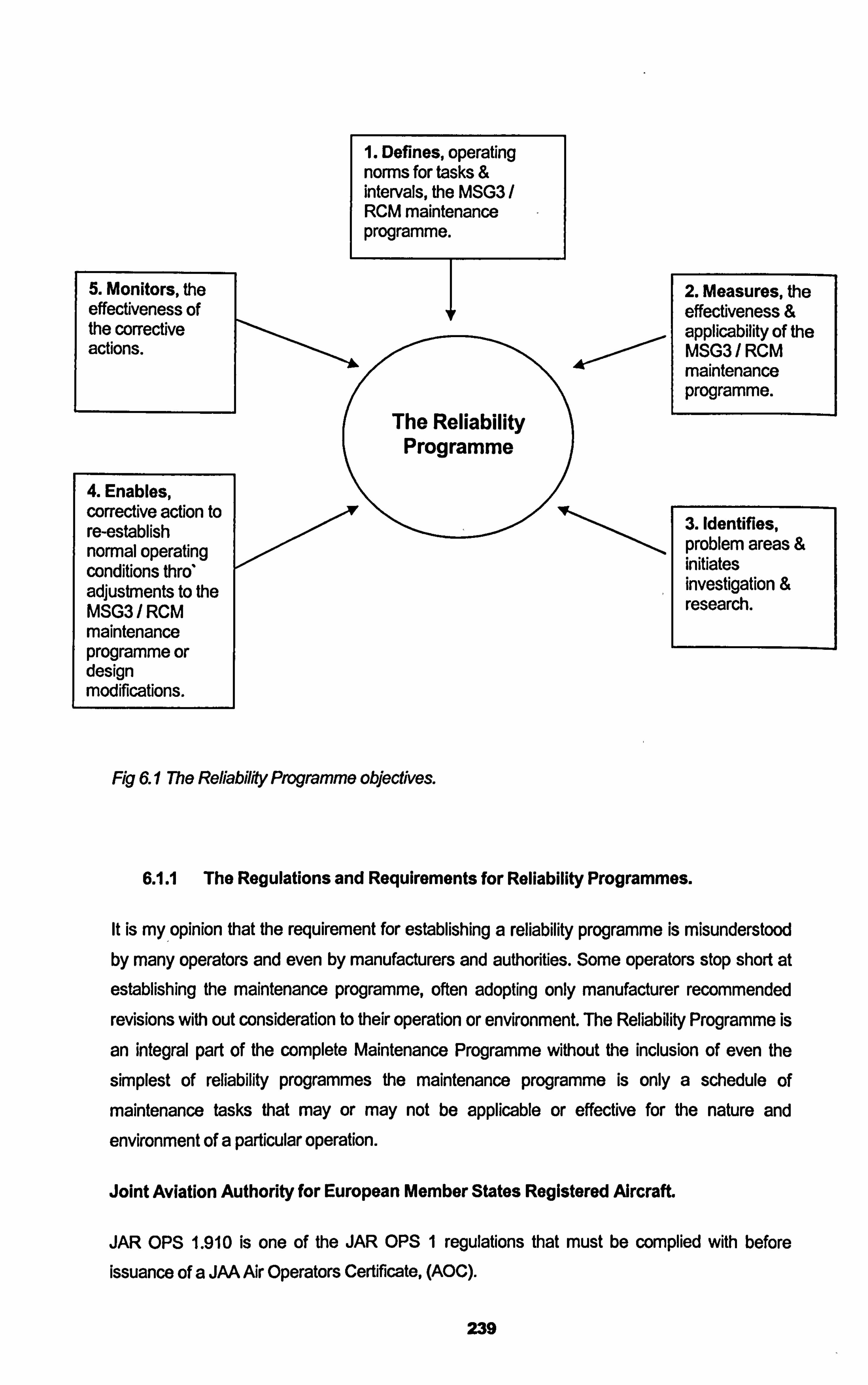
1. Defines, operating norms for tasks & intervals, the MSG3 RCM maintenance programme.
5. Monitors, the effectiveness of the corrective actions.
The Reliability Programme
4. Enables, corrective action to re-establish normal operating conditions thro* adjustments to the MSG3/RCM maintenance programme or design modifications.
Fig 6.1 The Refiabilfty Programme objectives.
2. Measures, the effectiveness & applicability of the MSG3/RCM maintenance programme. 4--ý
3. Identifies, problem areas & initiates investigation & research.
6.1.1 The Regulations and Requirements for Reliability Programmes.
It is my opinion that the requirement for establishing a reliability programme is misunderstood by many operators and even by manufacturers and authorities. Some operators stop short at
establishing the maintenance programme, often adopting only manufacturer recommended
revisions with out consideration to their operation or environment. The Reliability Programme is
an integral part of the complete Maintenance Programme without the inclusion of even the
simplest of reliability programmes the maintenance programme is only a schedule of
maintenance tasks that may or may not be applicable or effective for the nature and
environment of a particular operation.
Joint Aviation Authority for European Member States Registered Alrcraft.
JAR OPS 1.910 is one of the JAR OPS 1 regulations that must be complied with before
issuance of a JAA Air Operators Certificate, (AOC).
239
"An operator must ensure that the aeroplane is maintained in accordance with the operator's
aeroplane maintenance programme. The programme must contain details, including
frequency, of all maintenance required to be canied out. The programme will be required include a reflabifity programme when the A uthQ& determines that such a reflability programme is necessa
Acceptable Means of Compliance (AMC) 1.910 elaborates on that regulation to say that....
Where an operator wishes to use an aeroplane with the initial operatorýs aeroplane
maintenance programme based upon the Maintenance Review Board Report (MRBR)
process, any associated programme for the continuous surveillance of the reliability, or health
monitoring of the aeroplane should be considered as part of the aeroplane maintenance
programme. "
The AMC goes on to say more
lReflability programmes should be developed for aeroplane maintenance programmes based
upon MSG logic or those that include condition monitored components or that do not contain
overhaul time periods for a# significant system components. 11
The Federal Aviation Administration FAA for US Registered Aircraft.
FAR 121.373 is one of the Federal Airworthiness Regulations that an air operator (121.373 is
for commercial domestic & international operators, an identical FAR 135.431 exist for
commuter & charter operators) must comply with prior to issues of an AOC. This FAR is
concerned with "Continuing analysis and surveillance" (CASS).
"/-I Each certificate holder shall establish and maintain a system for the continuing analysis I C11 and surveillance of the performance and effectiveness of its inspection program and the
program covering other maintenance, preventive maintenance, and alterations and for the
correction of any deficiency in those programs, regardless of whether those programs are
carried out by the certificate holder or by another person. 0
The following Advisory Circulars go on to elaborate on acceptable methods to conduct the
CASS
AC 120-16D Air Carrier Maintenance Programmes chapter 9 out lines that an Aircraft
Maintenance Programme should contain a CASS programme to assess and ensure the
effectiveness of the Maintenance Programme, further more AC 120-17A Maintenance Control
by Reliability Methods dated 1978.
The FAA recommendations go much further than the JAA, who only give the AMC's detailed
above. But even though the FAA are more thorough with their advice I believe the regulations
240
are not upto date and do not take fully into considerations the rational behind MSG3 analysis. The ATA along with the FAA have produced a draft revision to AC 120-17A, pending at 120- 17B that deals considerably with the implications of MSG3 and the requirement for an adequate reliability programme. This draft revision brings the FAA AC better up to date dealing with reliability issues with the RCM / MSG3 maintenance programme but as of now this draft remains pending, leaving 120-17A an inadequate AC failing short of what really is
required.
6.1.2 Data Collection to Enable the Reliability Monitoring.
The Reliability Programme starts with the collection of relevant technical data. Data sources that feed into the Reliability Programme enabling reliability monitoring come from almost all aspect of the technical operation of the fleet.
a. Flight Operations.
Pilot Reports enable in service crew evident findings to be noted in the Technical Log. This includes system faults and discrepancies, flight deck warnings. Cabin Reports detail non airworthiness faults such as cabin appearance items. Flight hours and cycles, fuel and oil uplifts, ETOPs flights, Operational performance and parameters, Auto Land flights, Engine
condition parameter readings. Minimum Equipment List issues, delays and cancellations, journey reports, technical incidents.
b. Flight Line Maintenance Operations.
Component failures and removals, daily and line check maintenance accomplishment, deferred defects, Human Factor issues.
c. Base Maintenance Operations.
Routine check maintenance, Non Routine findings, Component removals, Human Factor
issues, Man hour and elapsed times,.
d. Production Planning and Control.
Maintenance Check schedules and downtimes, Time controlled parts, Airworthiness Directives
and Modification programmes.
e. Marketing.
Flight schedules, turn around times, destinations and routes.
f. Accounting.
241
Maintenance costs per flight hour, Maintenance costs per man hour, Maintenance costs per base input, Maintenance costs per aircraft.
g. Human Recourses.
Employee data, skills, qualifications, experience, training.
h. Material and Inventory.
Stores holdings and re order levels, rotable times between failures, consumable usage,
component receipts, shop reports, conformation of component failures, and component
modification compliances.
Capturing of this data is essential to an effective reliability programme, the source of data, the types
of data, the integrity of the data and the format of the data is all important. The data can be
gathered manually such as that in Technical Logs and Non Routine Cards or electronically such as
with downloads of engine condition data through the Airborne Communication Reporting System,
(ACARS). Transmitted to ground through the Satellite Communication system, (SATCOM). The
quality of the data is essential as garbage into the reliability programme will result in garbage out in
the reliability reports.
6.1.3 Methods for Reliability Monitoring.
a. Aircraft Reliability Monitoring.
The method of monitoring and reporting on aircraft or fleet at a high level is to give a general impression of how the technical operation is performing. This form of monitoring and reporting is a very rough indicator of performance reliability rather than an indicator of the maintenance
programme effectiveness and can not be used for specific maintenance programme
adjustments but can be used as a starting point for high level triggers. The sort of data
monitored at an aircraft or fleet level on a monthly basis are the following...
1. Number of aircraft in fleet.
2. Number of Aircraft in service.
3. Number of Operating Days.
4. Number of Days out of Operation.
i. On Scheduled Maintenance
ii. On Unscheduled Maintenance
242
5. Flying Hours & Cycles
1. Revenue
ii. Training
iii. Other
6. Daily Utilisation
7. Ave Flight Duration
8. Defect Rate for Aircraft.
9. Deferred Defects & MEL items raised.
10. Despatch Reliability.
1. Technical Delays
ii. Technical Cancellation
11. Incidents. (IFSDs, ATO, IFTAs, etc)
This kind of data is also of use for operational planning or for marketing. It is important that a high level review of such general performance data is taken on at least a monthly basis of the fleet as a whole. The more specific reliability monitoring methods contribute to the monitoring of the
maintenance programme effectiveness.
b. Systems Reliability Monitoring.
Pilot Reports (PIREPS) are recorded in the Technical Log. Each one of these reports relate to
a crew evident discrepancy that will fall in one of the ATA system chapters, for example air-
conditioning systems ATA chapter 21, fuel systems ATA chapter 28, navigation systems ATA
chapter 34, lighting systems ATA chapter 33 and so on. The ground technician or engineer that
meets the aircraft on arrival at the destination will review the technical log entries and trouble
shoot the discrepancies to try to rectify the occurrence. This will result in a rectification
maintenance action. The PIREP and resulting maintenance action should be logged firstly in
the technical log then into a data base of PIREPS back at the operators main base. The
monitoring of the data base is the responsibility of the Reliability Section. With modem day
computer programmes this is quite easy and the recurrence of defects in the same ATA
chapter or an unusually high rate of discrepancies with the same ATA chapter can be easily identified. Note that with this method we take the four digit ATA chapter. This chapterisation
system splits further the ATA chapterisation into sub systems
243
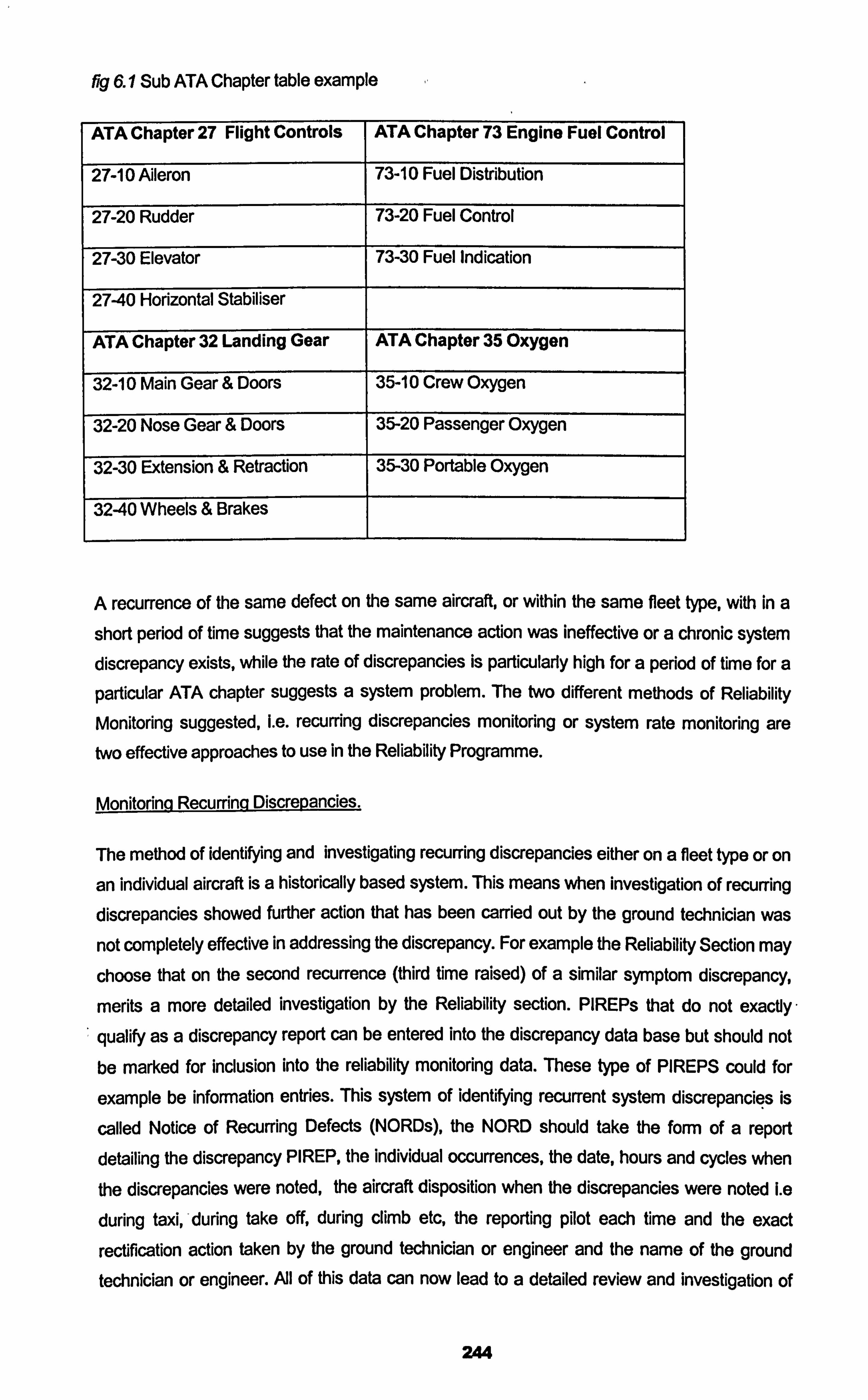
fig 6.1 Sub ATA Chapter table example
ATA Chapter 27 Flight Controls ATA Chapter 73 Engine Fuel Control
27-10 Aileron 73-10 Fuel Distribution
27-20 Rudder 73-20 Fuel Control
27-30 Elevator 73-30 Fuel Indication
27-40 Horizontal Stabiliser
ATA Chapter 32 Landing Gear ATA Chapter 35 Oxygen
32-10 Main Gear & Doors 35-10 Crew Oxygen
32-20 Nose Gear & Doors 35-20 Passenger Oxygen
32-30 Extension & Retraction 35-30 Portable Oxygen
32-40 Wheels & Brakes
A recurrence of the same defect on the same aircraft, or within the same fleet type, with in a
short period of time suggests that the maintenance action was ineffective or a chronic system discrepancy exists, while the rate of discrepancies is particularly high for a period of time for a
particular ATA chapter suggests a system problem. The two different methods of Reliability
Monitoring suggested, Le. recurring discrepancies monitoring or system rate monitoring are two effective approaches to use in the Reliability Programme.
Monitorinq Recurrinq Discrepancies.
The method of identifying and investigating recurring discrepancies either on a fleet type or on
an individual aircraft is a historically based system. This means when investigation of recurring discrepancies showed further action that has been carried out by the ground technician was
not completely effective in addressing the discrepancy. For example the Reliability Section may
choose that on the second recurrence (third time raised) of a similar symptom discrepancy,
merits a more detailed investigation by the Reliability section. PIREPs that do not exactly
qualify as a discrepancy report can be entered into the discrepancy data base but should not be marked for inclusion into the reliability monitoring data. These type of PIREPS could for
example be information entries. This system of identifying recurrent system discrepancies is
called Notice of Recurring Defects (NORDs), the NORD should take the form of a report detailing the discrepancy PIREP, the individual occurrences, the date, hours and cycles when the discrepancies were noted, the aircraft disposition when the discrepancies were noted Le
during taxi, -during take off, during climb etc, the reporting pilot each time and the exact
rectification action taken by the ground technician or engineer and the name of the ground technician or engineer. AJI of this data can now lead to a detailed review and investigation of
244
the occurrence. Care should be taken to detail word for word the details as they were entered in the technical log and care should be taken to ensure the ATA chapter allocation is correct. The period of time used to identify the recurring discrepancies should be considered carefully, for example three occurrences of a similar ATA chapter sub system discrepancy in 100 days
may not be appropriate for a high utilisation operation, perhaps a period of 50 hours or 10
cycles would be more appropriate. The resultant investigation of a NORD should take place
using a methodical process. Such question that should be asked during the research of the discrepancy are...
a. Was it the same pilot reporting the discrepancy each time. Did he follow correct standard
operating procedures. Sometimes misunderstanding of how a system works can result in
wrongly identifying a discrepancy. Or even language used by the reporting pilot, is the
PREP clear on what the discrepancy was?
b. Was it the same ground engineer that addressed and attempted to rectify the PREP. Did
he refer to correct procedures as detailed in the maintenance documentation?
Maintenance documentation on modem airliners such as the B737-NG gives detailed
trouble shooting steps to be followed in addressing a discrepancy, were these steps
correct followed in total? Often the temptation is to go straight to a maintenance task that
the ground technician is familiar with.
c. Was the environment that the PREP was reported the same each time? E. g. was the
defect related to a condition of flight? If the PREP was noticed at altitude could it be
related to temperature drop. At 30,000 feet the temperature can drop to minus 40 degrees
Celsius, this is referred to cold soak if the discrepancy is evident after a period of time at that temperature.
d. Had the system worked on previously, perhaps subject to a scheduled maintenance
action, or a modification?
All of these question can assist in the Reliability Engineer finding a reason for the recurring discrepancy. The Reliability Engineer may well have technical information that the ground technician does not have e. g. world fleet reports on the type issued by the manufacturer, or
similar discrepancies found on other aircraft with similar systems, this is when a good
computerised data base of PIREPs, discrepancies and maintenance actions can assist in
finding the root cause of a discrepancy. The whole objective of the Reliability Engineers
research is to determine the root cause of the failure. This can result in many forms from a training issue or a procedural issue to a component failure. If a component replacement was
carried out resulting from the PIREP, often the root cause can not be defined until a shop
report of the removed component is received back verifying the failure mode of the component, if any at all. Later we will identify the importance of component shop reports and the
importance of how to deal with "no fault found" (NFF) component shop reports.
245
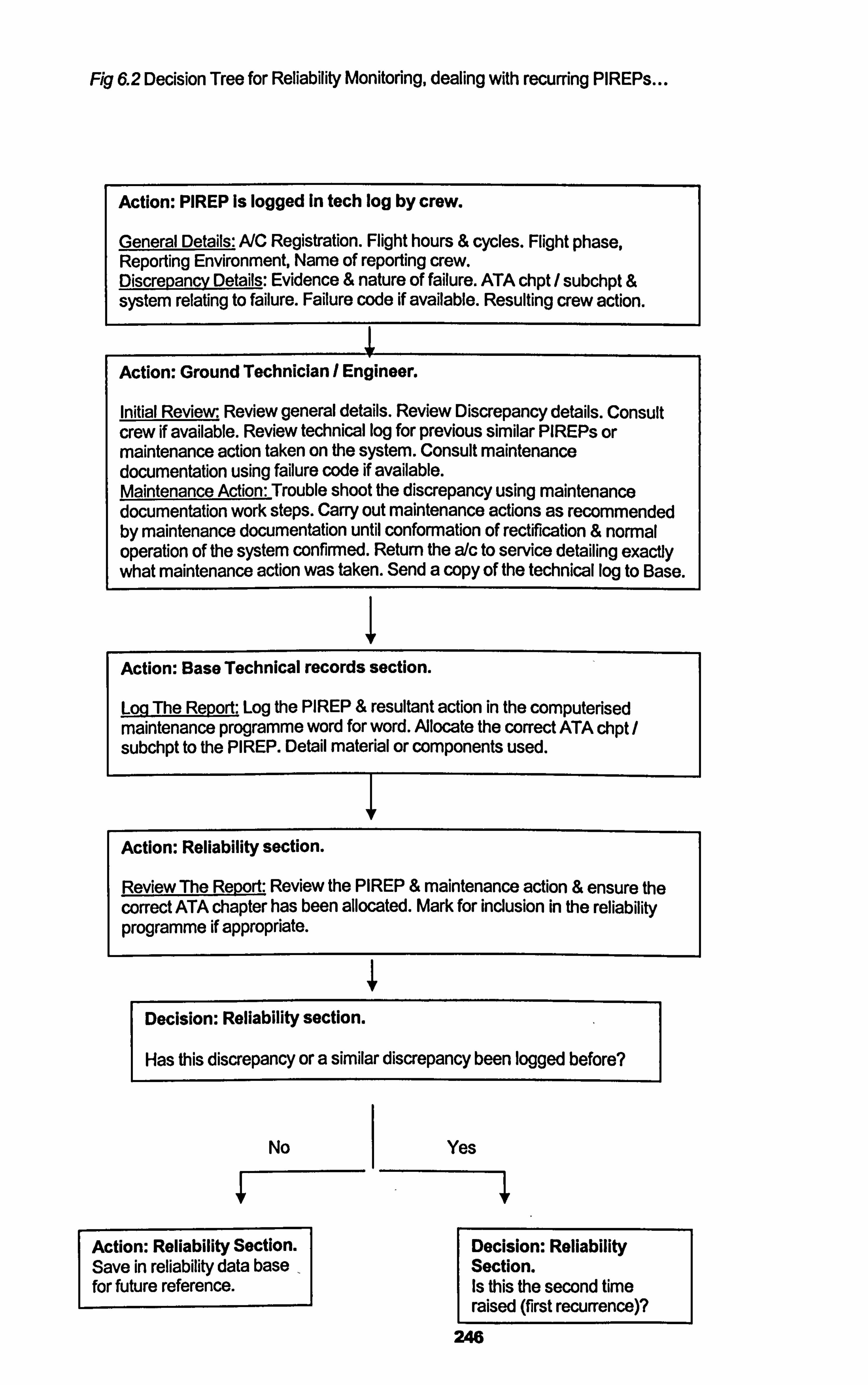
Fig 6.2 Decision Tree for Reliability Monitoring, dealing with recurring PIREPs
Action: PIREP is logged In tech log by crew.
General Details: A/C Registration. Flight hours & cycles. Flight phase, Reporting Environment, Name of reporting crew. Discrepancy Details: Evidence & nature of failure. ATA chpt / subchpt & system relating to failure. Failure code if available. Resulting crew action.
Action: Ground Technician / Engineer.
Initial Review. Review general details. Review Discrepancy details. Consult crew if available. Review technical log for previous similar PIREPs or maintenance action taken on the system. Consult maintenance documentation using failure code if available. Maintenance Action: Trouble shoot the discrepancy using maintenance documentation work steps. Carry out maintenance actions as recommended by maintenance documentation until conformation of rectification & normal operation of the system confirmed. Return the a/c to service detailing exactly what maintenance action was taken. Send a copy of the technical log to Base.
Action: Base Technical records section.
Log The Report: Log the PREP & resultant action in the compute ised maintenance programme word for word. Alocate the correct ATA chpt subchpt to the PREP. Detail material or components used.
Action: Reliability section.
Review The Report: Review the PIREP & maintenance action & ensure the correct ATA chapter has been allocated. Mark for inclusion in the reliability programme if appropriate.
Decision: Reliability section.
Has this discrepancy or a similar discrepancy been logged before?
No
Action: Reliability Section. Save in reliability data base for future reference.
Yes
Decision: Reliability Section. Is this Ule second time raised (first recurrence)?
246
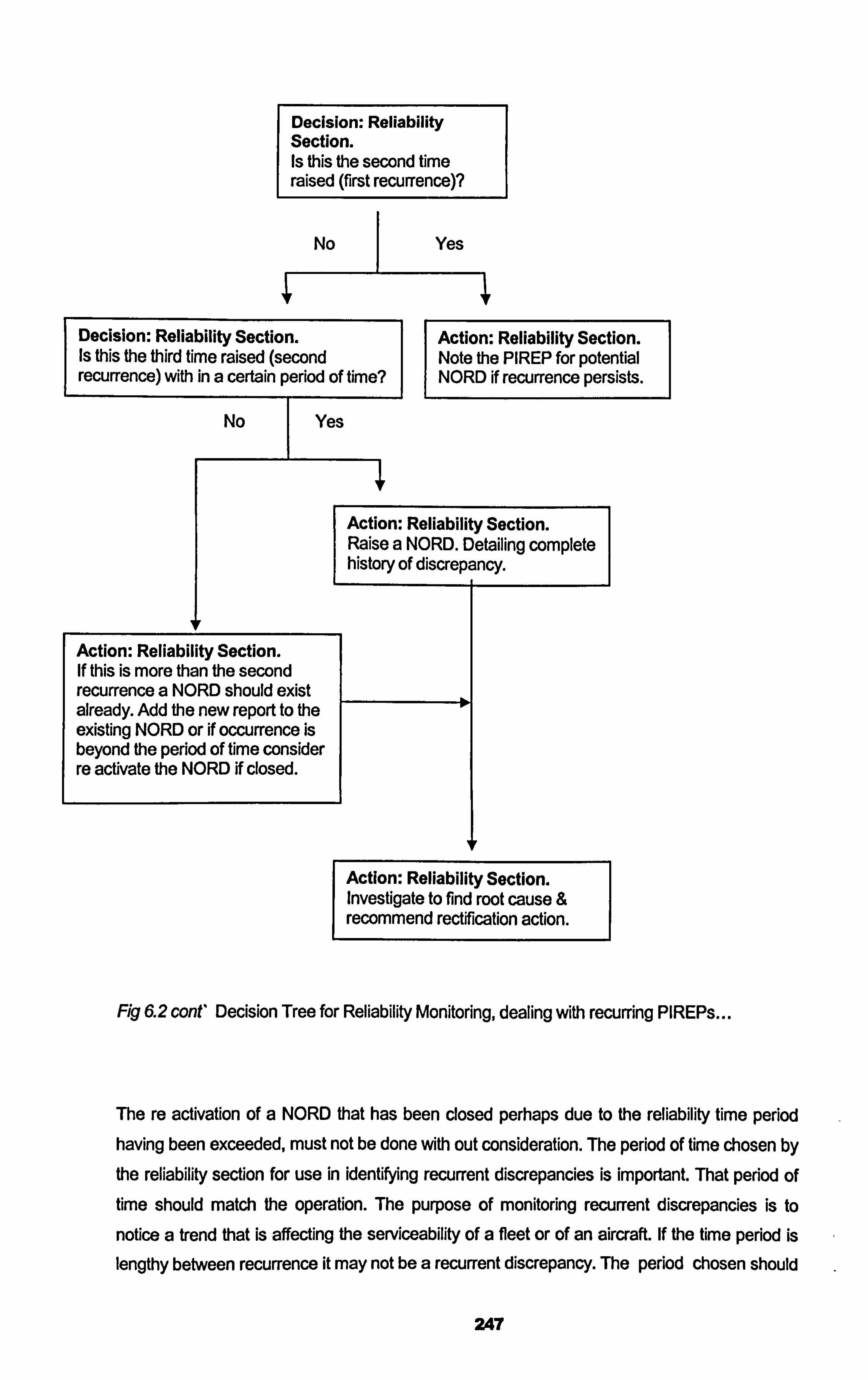
Decision: Reliability Section. Is this the second time raised (first recurrence)?
No Yes
Decision: Reliability Section. Action: Reliability Section. Is this the third time raised (second Note the PIREP for potential recurrence) with in a certain period of time? NORD if recurrence persists.
No I Yes
Action: Reliability Section. Raise a NORD. Detailing complete history of discrepancy.
Action: Reliability Section. If this is more than the second recurrence a NORD should exist already. Add the new report to the existing NORD or if occurrence is beyond the period of time consider re activate the NORD if closed.
Action: Reliability Section. Investigate to find root cause & recommend rectification action.
Fig 6.2 cont' Decision Tree for Reliability Monitoring, dealing with recurring PIREPs
The re activation of a NORD that has been closed perhaps due to the reliability time period having been exceeded, must not be done with out consideration. The period of time chosen by
the reliability section for use in identifying recurrent discrepancies is important. That period of time should match the operation. The purpose of monitoring recurrent discrepancies is to
notice a trend that is affecting the serviceability of a fleet or of an aircraft. If the time period is lengthy between recurrence it may not be a recurrent discrepancy. The period chosen should
247
be appropriate in its variable unit, such as for a landing system discrepancy perhaps a landings interval would be more appropriate than flight hours. There should be no fixed hard rule in the
opening of closed NORDs good engineering judgement should be used.
One important issue to understand is the recognition of fleet trends as apposed to individual
aircraft recurrent discrepancies. A recurrent discrepancy that has manifested it self on three different occasions with in the reliability time frame on the same aircraft is a candidate for a NORD. But a discrepancy that has appeared on three different aircraft is still a recurrent discrepancy and should be subjected to a NORD but the Investigation should take slightly different slant and direction. While many of the same reasons may have contributed to the NORD on different aircraft, such as wrong procedures, inadequate training, misunderstanding of the system by the operating crew etc, also the time frame for a fleet recurrent discrepancy
may well be different to that of an individual aircraft. Often a maintenance programme interval
or task adjustment is more appropriate to the fleet NORD than to the Individual aircraft NORD
as a fleet NORD suggest the issue is not symptomatic of an individual aircraft, while the individual aircraft NORD could be a chronic condition that has gone unaddressed. In both
cases the NORD system allows a recurring situation to be registered and examined in a
methodological way using exact historical data and utilising world fleet and manufacturers
published data. Operator conferences held by manufacturers are often a good way to find out about world issues to a type, and also enable a platform for operators of the world to share technical data on failures or discrepancies. At times commercial pressures on airlines and operators prevent this kind of data from being shared world wide, but the manufacturers should enable by becoming the vehicle for publishing the data, but again this could only be done if the
manufacturer is fed back the in operational data. It is my opinion in the interest of better
airworthiness and more efficient technical operations regional operators of similar types should pusli the manufacturers to enable the gathering and publishing of appropriate technical data in
a short efficient time frame, if they won't perhaps the operators should them selves cooperate.
Statistical Trend Analyýis.
While monitoring recurrence of discrepancies is one method to conduct reliability monitoring, the second method is a more statistical based method where PIREP data is gathered and trends are calculated for each ATA chapter, (while the NORD system goes to ATA sub chapter, trend analysis should not unless a specific system is targeted for monitoring, e. g. 23-
30 In-flight Entertainment, this subject may be of particular importance for a commercial
airline). After a period of data gathering alerts levels are calculated based upon the historical
sample size using standard deviation methods to establish thresholds where most of the discrepancies should fall in. When a chapter has a rate of discrepancies that falls out of the
calculated threshold that ATA chapter is said to be in alert and investigation and research into
why that alert has been triggered is conducted.
248
As normal the pilot make technical log entries specifying events or discrepancies, the
discrepancy is classified in to a relevant ATA chapter. The ground technician / engineer
addresses the PREP, carries out rectification maintenance action and re certifies the aircraft for further flight. Adl details are fed back to base where the data is entered into the
computerised maintenance programme. After all the data is gathered a "defect ratd" can be
established for a fleet and for an ATA chapter....
e. g. 20 PIREPs were raised across the B737 NG fleet in ATA chapter 21 air-conditioning, during a total flying period of 1000 flight hours and 400 landings for a particular month. The rate is therefore 20 for this example. Note it is standard to use Pl REPs per 1000 flight hours for the majorifty of ATA chapters and also it is standard to plot rates on a monthly basis, flight cycles or landings may be appropriate unit of measure for calculating for example ATA 32 landing gear systems.
After a period of data gathering, usually at least one year, standard deviation calculations of the
sample are used to determine PREP alert rates. Normally 2 standard deviations from the
mean rate per ATA chapter are used to capture a predicted 95% of future PIREPs. Those
rates falling above the alert rate (5 /2=2.5% of PIREPs) a trigger / alert will be activated that
will instigate the investigation focusing on a fleet type and a particular ATA chapter. This
method of statistical reliability monitoring has been the normal standard utilised in airlines for a long time, and is an easy way to monitor and identify fleet wide technical deviation from the
norm if you have a large fleet where hundreds of PIREPs are raised daily. Adjustment to alert rates should be made occasionally but care should be taken prior to alert rate adjustment, and consideration to season, operational changes, fleet changes and other variables that could influence the rate of PIREPs, e. g. to change the alert rate in the summer just before the holiday
season operation using the last 18 months of PREP data would be a mistake. PREP data is
seasonal, certain ATA chapters may well be affected by ground environment, precipitation, etc, the adjustment to an alert should be made only with consistent data that fairly represents a equal period of operating time.
It is my opinion that statistically based reliability monitoring such as PREP rates and alert
settings, is controversial in its effectiveness in supporting the Maintenance Programme. The
process of data gathering, entering into the computerised maintenance programme, and data
monitoring is good, but what does entering into the alert zone really mean? Is it worth getting
excited about and triggering a frenzy in the maintenance management board room, "we are in
alert in ATA 25 cabin interior". I feel it may miss lead and may miss appropriately apportion
reliability engineering time. Entering into the alert range is to be expected, the reasons for
entering into the alert range can be many for example, miss appointing ATA chapters to
PIREPs, or PIREPs with no real technical value getting in to the calculations, or a particular difficult period of operating time. The value it does have is that an unhealthy increasing trend
can be noticed by paying attention to monthly PREP rates, and if individual aircraft are
249
compared to the fleet rate a rouge aircraft can be noticed, these two benefits of statistical
analysis do not require alert calculation and setting.
E. g.
A fleet B737 NG ATA 24 PIREP rate has been increasing monthly for the last 4 months. The
trend was recognised by the Reliability Section and when looked at closer it can be seen as of last month 10 out of the fleet of 12 have also on an individual aircraft basis had experienced a PIREP rate increase every month. This lead to an investigation as to why and it was eventually found out that the B737-NG fleet were undergoing a electrical buss bar modification and as of
last month all the fleet of 12 bar 2 were complete. The modification programme should now be
looked at closer as being a potential reason for the increase in PIREPs and drop In reliability. The gathering of PREP data, calculating rates per fleet per ATA chapter did assist in firstly
identifying the trend and probably did assist in getting to the root cause of the discrepancies
causing the PREP rate to increase.
So it is my opinion that the value of statistical methods for reliability monitoring is good in that it
promotes data gathering and data classification and can be used in the recognition of discrepancy trends and hence instigating investigations, but as to the value of alert setting to
instigate investigations I am suspicious of its worth and feel it is perhaps creates a falls sense
of security when no alert has been triggered, yet our PIREP rate may be increasing fast on a
monthly basis, or we have had one massive failure in a system yet it receives the same merit
as a small non significant event as far as data pints go, or a false sense of alert that we are in
an alert range for an ATA but really all is in control or our alerts are just out of date. The other issue I have is when is it recommended to set rates and alerts, for a fleet of 12 aircraft or 100,
over a period of 12 months of 10,000 flight hours or 24 months of 50,000 flight hours? Should 2
or 3 standard deviations be used, how often should the alerts be adjusted? Should we use the
Normal, the Poisson or the Weibull distribution when calculating alerts? What is an expected
rate increase as aircraft and their systems age? After a modification programme has been
carried out should we start again gathering data? All of these questions lead me to be
suspicious of the use of alert setting in Reliability Monitoring.
c. Component Reliability Monitoring.
Component Reliability is the statistical measurement of a components performance expressed in usage hours or cycles. The objective of a. component reliability programme is to set
standards, evaluate performance, identify trends, take corrective action and continuously
monitor performance. Remember earlier we mentioned that MSG3 reduced massively the
amount of hard time lived components from as many as 130 to 4. This means that attention
must be paid to component failure data in support of the MSG3 maintenance Programme. The
main objectives can be described as follows...
250
1. To ensure the maintenance programme is effective and applicable with respect to
component failures.
2. To ensure optimal aircraft utilisation.
3. To reduce maintenance cost with respect to components.
The benefits that result from component reliability monitoring are as follows
1. The ability to identify poor component performance.
2. The gathering of data to assist in the determination of carr)(ing out component
modifications.
3. The identification of repetitive discrepancies related to component part no's or
particular rouge serial no's.
4. The ability to identify shop procedures that need improvements.
The sort of component data that is gathered and used in component reliability monitoring is..
1. Unscheduled component removals.
2. Confirmed component failures.
3. Non Confirmed component failures, No Fault Founds. (NFF).
4. Shop / Strip reports for components.
5. Time since new, time since over haul & time installed for removed components. (Time
flight hours, cycles & days)
6. Calculated Reliability Times. The four most commonly used reliability calculation for
components in the aviation industry are..
i. IVITBR: Mean Time Between Removals.
MTBR= (Fleet Flying Hours x QPA) / Total No of Removals.
I MTBUR: Mean Time Between Unscheduled Removals.
MTBUR= (Fleet Flying Hours x QPA) / Total No Unscheduled Removals.
ifl. URR: Unscheduled Removal Rate.
URR= (1000 x Total No Unscheduled Removals) / (Fleet Flight Hours x QPA)
251
[Note that URR= 1000 / MTBURI
iv. MTBF: Mean Time Between Failures.
MTBF= (Fleet Flying Hours x QPA) / Confirmed Failures
[Note QPA: Quantity Per Aircraft]
Comparing MTBF to MTBUR is a good indicator that can take the attention of a component
reliability programme as for each MTBUR more than MTBF the question should be asked why was that component removed yet was not confirmed a failure. To be able to do this the operator must track component shop reports confirming component failures, many operators do not review the
shop report in fact many do not even request it from the shop. It is good practice that all shop
reports are requested for NFF components and for expensive or critical components to give an
understanding of how the reliability of these components can be improved.
MTBUR versus MTBF.
Both MTBUR and MTBF have value in monitoring with in the component reliability programme. While MTBF is a truer indicator of component reliability MTBUR is an all-round indicator of
component reliability and operators trouble shooting success. MTBUR / MTBF the closer to I this
value is a good indication. The smaller the value tending away from I indicates an issue with the
components identified as the reason for a PREP or discrepancy.
e. g.
Cabin Pressure Controller Part No 26A432-1 ATA 21-30
QPA =2
Fleet Size: 50
Flight Hours for the Fleet for the year = 54,750
Unscheduled Removals for the year= 10
Confirmed Failures =8
MTBUR= (54,750 x 2) / 10
MTBUR= 10,950 hours.
MTBF= (54,750 x 2) /8
MTBF = 13,688 hours
MTBUR / MTBF = 10,950 / 13,688 = 0.78
252
0.78 is reasonably close to 1 indicating 78% of removed components thought to have failed, were
confirmed failed. 22% of the components cost the company a lot of time and money and did not
address the discrepancy. These 22% can be referred to as NFF (No Fault Found). NFF's cost the
operator millions of dollars each year. If the only detailed component review that an operator carries
out is to review the NFF's, that alone will contribute to the costs of maintenance. The reasons for a NFF component removal to address a discrepancy could be as follows..
1. In correct trouble shooting by the ground technician. He wrongly identifies the component
as the reason for the PREP.
2. In correct training. The ground technician or engineer addressing the PREP may have not been correctly or adequately trained, hence identifies the easy option, by removing the
component.
3. In correct manuals. Wrong or unclear maintenance manuals.
4. Incorrect procedures. Wrong or unclear company procedures or maintenance procedures.
5. A rogue component that shows intermittent random tendencies. Removal of that
component from service could cost the operator the price of a new component but also
save a lot on maintenance downtimes and man-hours.
There are three levels of components reliability monitoring that an operator can conduct.
Level 1. Operators track and report Unscheduled Removals. This indicates components that are
not performing to the performance standards expected.
Level 2. Operators track all kinds of removals, unscheduled, scheduled, convenience, modification
programmes etc.. ), once removed and in the shop the operator review the shop report for that
component to confirm those that have failed in service. The shop report is also referred to as the
tear down report or strip report.
Level 3. Operators carry out all that described in Level 1&2 but also go further to describe &
review in detail the shop reports, identifying not only confirmed failures but also internal conditions
of components. Those that are confirmed as failures, will trigger an investigation as to why the
component failed in service and research a solution to address the failure. If the failure is not
confirmed and the component is returned as No Fault Found "NFF", this also triggers a detailed
review of the originating discrepancy that resulted in the component removal. The intension of this
investigation is to get to the root cause of the discrepancy. Detailed Component Mapping may be
carried out with this level of component reliability monitoring. Alerts can be set much in the same
way as for systems statistical reliability monitoring, using standard deviation calculation of a sample
of historical data and plotting monthly component removal rates against the calculated alerts levels.
Also being able to compare operators rates to manufacturer or world rates assists in identifying is
there is an issues with the operating environment or the individual operators method and
253
procedures. If the individual operators component removal rate or MTBUR / MTBF Is vastly
different from others or the expected manufacturers MTBUR / MTBF an Investigation should be
triggered.
Component Mapping.
Component Mapping is a very high level method of tracking component reliability, it involves
identifying individual serial numbers and tracking their lives from manufacture to in-service
performance to removal reasons to shop reports. All aspects of the component life is recorded and tracked. Computerised maintenance programmes can ease this task but to carry out such a task if
you have a large fleet is quite an endeavour. Most operators with a good component reliability
programme in place would only conduct this level of investigation for very serious discrepancies for
large complex or expensive components, for example engines or auxiliary power units, or it may be
carried out for those components that have been identified as NFF. But a method for recognising
rogue serial numbers should be in place, a repeatedly removed component (same serial number)
must be identified and removed from the spares holding unless the root cause of its continued failing is found. This level of component reliability will definitely assist in getting to the root cause of
the failure but will cost a lot of time and resource to conduct. A balance is required using
component tracking for those components identified as critical to the operation or expensive to
replace. By solving a component reliability problem you will be saving the company potential
millions of dollars through eliminating time wastage in man-hours and aircraft non availability and
also in stores holdings to support the failures.
d. Engine Reliability Monitoring.
The engine is the single most expensive component installed on an aircraft and also probably the most important component with regards to airworthiness. Hence the engines deserve a detailed individual reliability monitoring programme that accomplishes four main objectives..
1. Maintains Engine Inherent Reliability & Airworthiness.
2. Maintains Acceptable Engine Perforrnance Standards.
3. Increases Engine Time on Wing.
4. Reduces Engine Associated Maintenance Costs.
A fifth objective also exists for Extended Twin Engine Operators
5. Enables Continued ETOPs Operation.
254
Four significant parameters that should be used for monitoring power plant reliability, ATA chapters 71 through to 80 are..
1. Inflight shutdowns per 1000 engine cydes or flight hours.
Firstly what constitutes an IFSD (Inflight shut down) should be defined for example..
An In Right Engine Shut Down shall be considered to have taken place when the aircraft is
airborne and the engine was shut down as a resuft of the following...
a. Human intervention following an abnormal situation.
b. An automatic shut down function.
c. Any other involuntaty reason.
Section 4.1.2 deals with IFSD's in the contexts of the ErOPS operation, but it is equally
pertinent for all operations not only for ErOPS. The objective of monitoring IFSD is recognising that the engine shut down is one of the most significant technical events that can happened to
an aircraft and therefore merits a heightened level of monitoring. IFSD can result from the loss
of inherent design reliability as a result of mechanical failure of one or many of all the complex
components and systems that contribute to the continued airworthiness operation of an engine. It can also result from human factors resulting from inappropriate ergonomic design of the crew controls or as a result of inappropriate crew procedures or practices. Remember that the
reliability programme endeavours to maintain or improve the inherent design reliability through
monitoring not only mechanical failures but human failures that contribute to technical events. Identifying an issue through reliability monitoring can result in changes to procedures as well as to maintenance actions. IFSD's for an operator can be compares to other similar type
operators or to previous rates with the same operator. An increase in the rates of IFSD should trigger of an investigation. This investigation should take many directions..
Mechanical investigation of the failed engines.
Procedural investigation of the crew.
Shop practices that overhaul the engine.
The resultant of the investigation could be..
Identification of a common failed part or system, thus a recommendation for a modification to the part or system.
Identification of an incorrect procedures followed by the operating crew or the ground crew.
Identification of an incorrect procedure followed by the engine shop.
255
Engine failures that do not qualify as an IFSD should not be included in the IFSD rate, but
should be investigated in the exact same manner as any IFSD. The reason they should not be
included is that if a particular operators rate does include other than IFSDs it can not be
compared to that of the world fleet as it will be to a different standard, also the objective of
tracking IFSDs is due to their shear importance and affect on the continued airworthiness of the
operation. For example an engine shut down during a maintenance ground run is significant
and must be subjected to a detailed investigation to get to the root cause of the failure, but it did
not happen in flight and the conditions of the shut down may well be different from that of that
in flight when the aircraft is conducting a standard revenue flight. It is also argued in some
respects that an engine failure during a test flight should also be excluded from the IFSD rates,
but it is my opinion that such a failure does constitute an IFSD as it meet the requirements in
the definition of an IFSD. Any definition of an IFSD adopted by an operator should be
accepted by the regulatory agencies that approves that particular operators Maintenance and Reliability Programme.
2. Unscheduled engine removal rates for 1000 engine cycles or flight hours.
An unscheduled engine removal can result from three evident sources.
1. A PREP raised as a result of an evident flight deck warning or non
standard occurrence that after trouble shooting results in declaring that
engine unserviceable resulting in the removal of the engine.
U. A scheduled maintenance tasks, such as a boroscope inspection, that detects engine internal deteriation beyond limits that results in declaring
that engine unserviceable resulting in the removal of the engine.
Engine Condition Monitoring (ECM), that detects either an adverse trend
tending towards an unserviceable condition or an engine parameter
exccedance. This normally leads to an internal boroscope and trouble
shooting that results in declaring that engine unserviceable resulting in
the removal of the engine.
Al of these reasons should be tracked and recorded as a rate. IFSDs resulting in engine
removals should also be included in this rate. By tracking the rate and comparing it to world
fleet rates and also to other fleet type rates should be part of the Reliability Programme. The
Reliability Programme can also then identify increasing trends in unscheduled engine removals
and just as with component tracking result in the identification of issues requiring addressing or
modification programmes requiring incorporation.
3. Pilot Reports (PIREPS) per 1000 engine cycles or flight hours.
This method has been described in the sections dealing with Monitoring Recurring
Discrepancies and Statistical Trend Analysis earlier in this section. With regards to engines the
256
-, ATA chapters 71 through to 80 are relevant. The same process as with other ATA chapters
should be adopted.
4. Delays or cancellations per 1000 engine cycles or flight hours.
Again earlier in this section we described the basic Reliability Programme monitoring fleet
performance on a high level. In the same way those delays or cancellations resulting from
engine discrepancies should be tracked. This will give an indication as to the trend of engine reliability.
Enqine Condition Monitoring. (ECM).
Engine Condition Monitoring, ECM, has come along way in the last few years with the introduction of Digital Flight Data Recorders (DFDR), Satellite Communications (SATCOM),
Aircraft Communication and Reporting Systems (ACARS). ECM records and plots in flight data
of the engine, Low Rotor Speed N1, High Rotor Speed N2, Exhaust Gas Temperature EGT,
Vibration Vib, Fuel Flow Wf, Throttle Lever Angel TLA, Inlet Pressure P2, Inlet Temperature
T2, in order to identify adverse tends of exceedances. The older methods required the flight
crew to manually complete forms while in flight at climb, cruise and descent and these forms
would then be submitted to the Power Plant engineering section for plotting and review. On
modem systems this is done automatically by the DFDR and automatically transmitted through SATCOM to a ground station, either the operator him self or a service provider such as the
engine manufacturer. Even today this data is live and can be monitored by the operator live on a computer as the aircraft makes it journey if the correct software and system is in place. ECM is a fantastic tool and in its present modem form can assist in the detection of engine internal
deterioration enabling the operator to anticipate and prevent engine failure and pull that engine off for repair before the failure occurs thus accomplishing two critical activities, firstly preventing the aircraft from entering a compromised airworthy condition and allowing the recognition of a failing engine enabling a resultant repair that will be less expensive than that of what could be if
the condition of the engine was allowed to deteriorate further. Most modem jet engines
supported by ECM are completely on condition, that means they have no life limit and for that
reason can remain on an aircraft until they fail, supported by a single scheduled maintenance task that may be a periodic internal boroscope. It is my opinion that to take advantage of the on
condition concept of the engine ECM must be undertaken even in its simplest form of the crew filling in forms. To not conduct ECM and leaving engine deterioration detection to crew
reporting evident failures through PIREPs or periodic boroscope inspections is incorrect and
will result in costly engine repair bills and possible IFSD rate increase. The cost of implementing ECM will out way massively any cost related engine repairs or failures.
257
ECM Advantages and Limitations.
Advantaqes.
Maintains safe engine operation and effective maintenance practices through the following..
0 Reduces unexpected problems and unscheduled maintenance by detecting abnormal trend shifts.
0 Chronological trending of engine parameters.
o Fuel Bum & EGT trends.
0 Rotor Speeds.
9 Oil Pressure & Temperature.
0 Engine Vibration.
0 Throttle stagger.
Limitations.
Unreliable in finding unrelated to engine aerodynamic and thermodynamic performance, such as
0 Bearing system problems.
0 Fuel contamination.
An oil consumption and monitoring programme can compensate for the short falls with ECM.
Monitoring oil consumption rates is also an effective Method for monitoring the engine
reliability. See section 4.1 for a detailed description. This method is inexpensive and can
contribute to the reliability programme in detecting trends tending towards a failure. ECM
including Oil Consumption Monitoring are mandated for ETOPs operation, it is my opinion that
both methods should also be mandated for normal operations as they lend them selves to not
only cost savings but also the detection of trends tending towards un airworthy conditions, that
can enable rectification action taken earlier prior to an evident failure. As well as oil
consumption oil quality monitoring methods can give indication of engine internal condition, through Magnetic Chip Detector (MCD) inspection, where a magnetic probe protrudes into the
oil sump or oil line. The magnetic probe will pick up any ferrous material. The MCD can be
inspected periodically for ferrous material build up, indicating bearing failure or other conditions
where metallic particles can separate from a component and end up in the oil. Spectral Oil
Analysis Process (SOAP) is another way of monitoring oil quality. An oil sample is taken from
the oil return line or oil sump. That sample is then examined for chemical content compared to
258
its specification. This process will do two things, it will first tell the condition of the oil comparing it to its expected chemical state, and it will also show contaminants in the oil resulting from internal engine or component failures. AM of these methods can be considered as engine condition monitoring and do have their part in the engine reliability programme.
6.1.4 ETOPs and Reliability Monitoring.
Section 4.1.1,4.1.2 and 4.1.3 describes the requirements with regards to ETOPs and Reliability Monitoring. The three mandated areas required for ETOPs operation with regards to
Reliability Monitoring are..
a. An Event Based Reliability Programme should be in place.
b. An ECM programme should be in place.
c. An Oil Consumption monitoring programme should be in place.
We saw in the ETOPs section that the issues for the Maintenance & Engineering section vvith
regards to ETOPs are..
e Propulsion System.
Maintenance Programme.
e Oil Consumption.
9 ECM.
9 MEL.
0 Resolution of Discrepancies.
* Training.
Those primarily addressed in the Reliability Programme are Oil Consumption, ECM and the
Resolution of discrepancies. It is in my mind that the best way to confirm the resolution of discrepancies is first of all by good training and dear procedures enabling the clear detailing of
resolution steps and referencing of maintenance manuals. The part the Reliability section plays is
through monitoring the recurrence of the discrepancy through the NORD system as described
previously in this section. The NORD method of Reliability Monitoring is an Event Orientated
method identify the recurrence of discrepancies and enables in a more detailed investigation of those discrepancies that are not rectiW.
259

6.1.5 Getting to the Root Cause of the Failures or Findings.,
The whole objective of the Reliability Programme is to support the existence of the Scheduled
Maintenance Programme by identifying and rectifying evident failures and validation of the
scheduled maintenance tasks and by enabling the establishment of what caused the In operational failures. Getting to the root cause of the failure will enable understanding of why it failed and how it
can be prevented in future. The process that takes place before the reliability section get their
hands on a PIREP can prevent NORDs form being raised. Good ground technician / engineer training and good practices of following the manuals is the start of getting to the root cause quickly, but with regards to reliability monitoring it is my opinion that a simple effective and robust reliability
monitoring system can consist of three basic elements...
1. Monitoring Recurrence of Discrepancies.
2. ECM.
3. Oil Consumption.
The NORD system of monitoring discrepancy recurrence ensure that PIREPs and in operational failures are correctly resolved, and if not a detailed investigation is triggered resulting in modification
recommendation or revision the the scheduled maintenance tasks. The ECM and the Oil
consumption monitoring system focuses on the most expensive and significant single component installed on the aircraft, the engine. While it would be desirable to review every shop report for
component condition, that could be expensive, but when a NORD is involved with a component
removal the shop report must be reviewed to assist with the investigation, focusing on component
shop reports that are reported as NFF's (No Fault Found). With these three systems in place and
good initial trouble shooting the root cause of all failures and discrepancies can be found quickly
and effectively. The resultant action take once the root cause of a discrepancy is known is the final
part of the Reliability Programme.
6.2 Developing the Maintenance . Programme Based on Scheduled Maintenance
Findings and Reliability Monitoring.
Remembering the Maintenance Programme consists of Scheduled Maintenance Tasks
developed through the RCM / MSG3 philosophy and a supporting Reliability Programme
monitoring in service events. Once the initial RCM / MSG3 Maintenance Schedule is produced
the Reliability Programme monitors the effectiveness and applicability of the tasks in review of the findings, occurrences and events reported through PIREPs, Technical Log entries, Non
Routine Cards and component shop reports. All of these monitored issues should be
catalogued and presented to those responsible for the maintenance management to review
and deliberate on resultant action. The Reliability section should periodically convene a
meeting where they present the data and propose corrective actions. This meeting and those
involved are referred to as the reliability Control Board, RCB.
260
6.2.1 The Reliability Control Board (RCB): Objectives, Functions and Processes.
Depending upon the fleet size and the depth of reliability conducted, the frequency of the RCB
meeting should be decided upon, for the RCB to be effective and efficient, this meeting should
not take place any longer than quarterly, every second month would be more effective if
possible. The RCB should have a terms of reference and the members of the RCB should be
specified. Those selected as members should be briefed or should undergo basic training in the philosophy of RCM / MSG3 and Reliability Monitoring and should have basic knowledge on the aircraft type..
The RCB Members.
Chair: The Reliability Section Senior Engineer responsible for the Fleet being studied
supported by the responsible Reliability Engineer.
Members: Development Engineers representing power plant, avionics, airframe and systems. Quality Assurance, Senior Maintenance Engineer for the fleet, Planning Engineer for the fleet,
Material & Inventory, C' rew Fleet Manager. The civil aviation authority can have a representative present if they wish.
The RCM objective is to present in a report with commentary description of the findings since the last RCB, meeting. The Reliability Report should detail all the monitored reliability parameters, the contents and depth of the parameters is decided upon by the Reliability Section at the out set of the process and accepted as adequate for the operation by the RCB
and the civil aviation authority of the operator. The reliability report should detail and present all monitored parameters clearly and the accompanying commentary should present to the RCB
all findings, identify all trends, identify issues requiring decisions and suggest resultant action to
address any issues. The RCB meeting should ensure that all involved in the technical
operation understand the technical disposition of the fleet in question and should be in
agreement with any resultant action to be taken such as modification programmes, fleet
campaigns and proposed scheduled maintenance changes. The scheduled maintenance changes do not take place at the RCB but may be identified as possibly required. The
scheduled maintenance changes proposals should be deliberated upon by another meeting, the Maintenance Schedule Review Board, MSRB.
6.2.2 The Maintenance Schedule Review Board (MSRB): Objectives, Functions and Processes.
Remembering that the Maintenance Schedule's (MS) whole objective in life is to maintain the
aircraft in an airworthy condition enabling the realisation of the inherent reliability of design with
consideration to the optimisation of in service time and cost. Revision to the MS must take
place to ensure that on going operational and environmental issues are addressed in the
Maintenance Schedule to ensure the continued establishment of the inherent reliability of
261
design of the aircraft. The Engineer responsible for the production and development of the
Maintenance Schedule for a particular aircraft should be expert in RCM / MSG3 philosophy
and ideally should be involved with the manufactures MRB and ISC. No MS change should take place with out prior acceptance by the MSRB. All proposed MS changes should be
documented and thoroughly researched for applicability and effectively, too many times tasks
are added to an operators MS that do not bring value to the continued airworthiness and
reliability of an aircraft and are often just knee jerk in effective reactions. It is sensible that the
MSRB sits at the same frequency as the manufacturers MPD is revised. The MS should be up to date with all relevant manufacturer MPD revisions, none the less, even the MPD revisions
should undergo investigation for applicability and effectively for the operators particular
operation and environment. It is a mistake to blindly accept any MPD revision into the
operators MS. Those selected as members of the MSRB should be briefed or should undergo basic training in the philosophy of RCM / MSG3 and should have basic knowledge on the
aircraft type..
The MSRB Members.
Chair: The Maintenance Programme Section Senior Engineer responsible for the Fleet being
studied supported by the responsible Maintenance Programmes Engineer.
Members: The fleet type Reliability Engineer, Development Engineers representing power
plant, avionics, airframe and systems. Quality Assurance, Senior Maintenance Engineer for the
fleet, Planning Engineer for the fleet, Material & Inventory. The civil aviation authority can have
a representative present if they wish.
The basic RCM / MSG3 rules should be applied continuing with the separation of System,
Zonal and Structural tasks. The inspection standards identified by the ATA 1 Manufacturer
should also be maintained. It is found sometimes that an operator develops their own inspection standards and definitions that may be related to their maintenance staffs
qualifications. This should be considered carefully as the standard defined by the ATA and
manufacturer may be used world wide and may be referenced to by the manufacturer in other documents such as the maintenance manual, to deviate from them may cause problems and a lot more work for maintenance staff who work on multiple types. Aso consideration should be
made to the resale ability of an aircraft that may be affected if the aircraft is maintained to a
standard that is peculiar to one operator only.
Once the proposed changes to the MS are presented, explained and justified to the MSRB a
vote should be taken. If all are in agreement the revision can be incorporated at the next issue
of the MS. Contested proposed changes to the MS will require further research or rejection for
incorporation to the MS. Care should be taken not to add tasks that do not directly contribute to
airworthiness, maintenance of the inherent reliability of design or may well be addressed by a
modification at a latter stage. Those tasks that may be temporary, or not confirmed as effective
and applicable can be issued for compliance as required but can stay out of the MS until
262
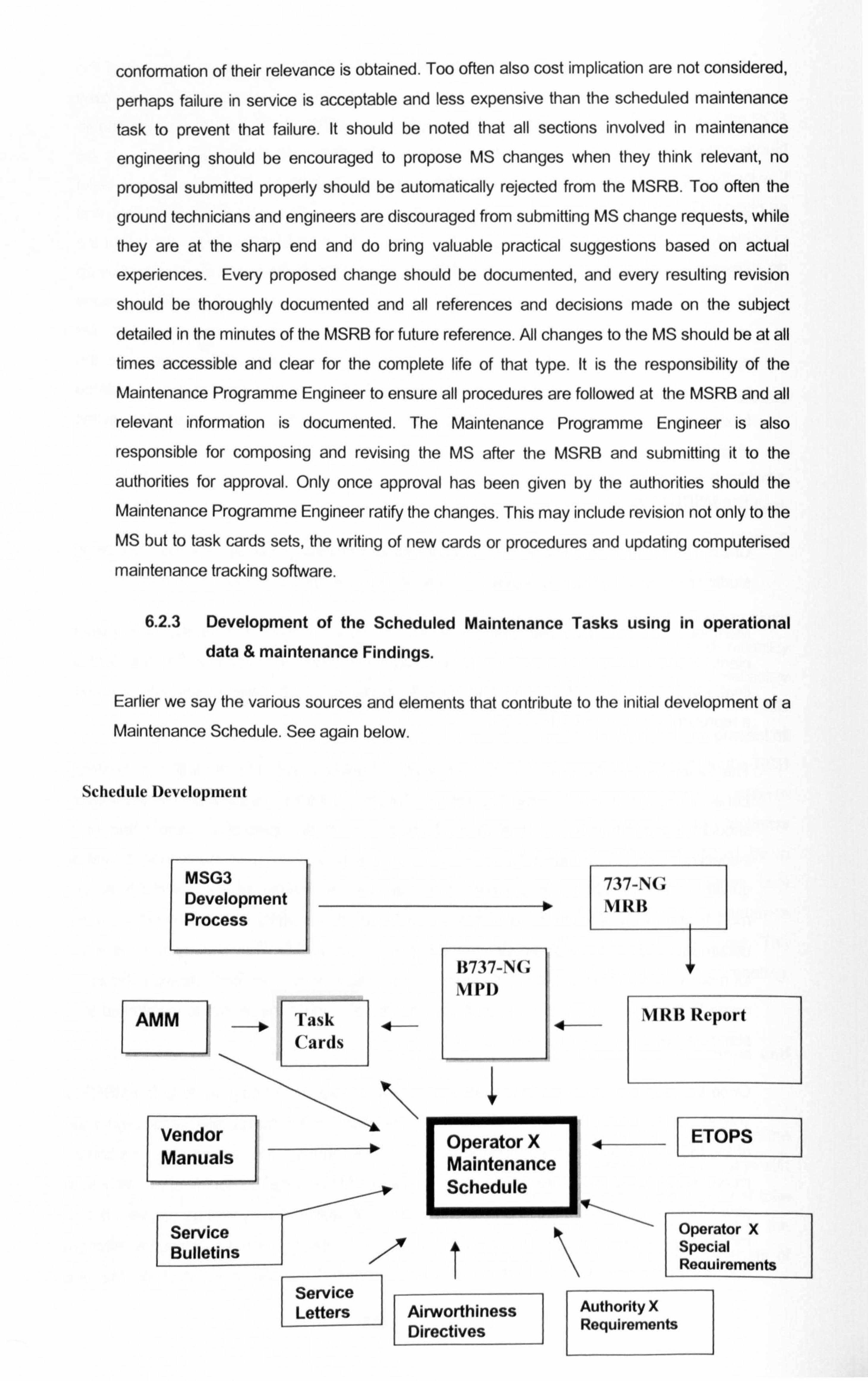
conformation of their relevance is obtained. Too often also cost implication are not considered,
perhaps failure in service is acceptable and less expensive than the scheduled maintenance
task to prevent that failure. It should be noted that all sections involved in maintenance
engineering should be encouraged to propose IVIS changes when they think relevant, no
proposal submitted properly should be automatically rejected from the MSRB. Too often the
ground technicians and engineers are discouraged from submitting IVIS change requests, while
they are at the sharp end and do bring valuable practical suggestions based on actual
experiences. Every proposed change should be documented, and every resulting revision
should be thoroughly documented and all references and decisions made on the subject
detailed in the minutes of the MSRB for future reference. All changes to the MS should be at all
times accessible and clear for the complete life of that type. It is the responsibility of the
Maintenance Programme Engineer to ensure all procedures are followed at the MSRB and all
relevant information is documented. The Maintenance Programme Engineer is also
responsible for composing and revising the MS after the MSRB and submitting it to the
authorities for approval. Only once approval has been given by the authorities should the
Maintenance Programme Engineer ratify the changes. This may include revision not only to the
MS but to task cards sets, the writing of new cards or procedures and updating computerised
maintenance tracking software.
6.2.3 Development of the Scheduled Maintenance Tasks using in operational data & maintenance Findings.
Earlier we say the various sources and elements that contribute to the initial development of a Maintenance Schedule. See again below.
Schedule Development
MSG3 737-N(; Development VIRII Process
11737-NG VIP[)
AMM 4 MR13 Report
L
Vendor Operator X4 Manuals Maintenance
Sc
Service
Schedule
Operator X Bulletins Special
Reauirements Service Letters Airworthin Authority X
IV s wo hiness
Direcýtives Requirements 0 hiness
Knowing what we know now we can determine that though this diagram is acceptable for the initial
development of the MS, it is missing the main contributor to the on going development of the MS,
the Reliability Programme. The MS along with the Reliability Programme can be referred to in total
as the Maintenance Programme. As we discussed earlier this may be a term misunderstood. Many
use the terms Maintenance Schedule and Maintenance Programme to mean the same. Other
identify the Reliability Programme as something separate from the Scheduled Maintenance
Programme. It is my strong belief, and I believe this has been shown on several occasions that with
out the Reliability Programme, the Scheduled Maintenance Programme is incomplete and can not be referred to as a Maintenance Programme. As we have defined earlier...
A Maintenance Program Is a Set of Rules and Practices for Managing Maintenance and Controlling and Developing the Scheduled Maintenance Program. The Reliability
Programme Is an Integral part of the Maintenance Programme that supports and verities the
effectiveness and applicability of the scheduled maintenance tasks through monitoring the
in-service findings resulting from the technical operation of the fleet and maintenance findings resulting from the scheduled maintenance tasks.
From this definition and what we have discussed so far we can see that the Reliability Programme
enables the development of the scheduled maintenance programme through the Maintenance
schedule Review Board as a result of two main aspects of reliability monitoring...
1. In Service Operational Findings, PIREPs.
2. On Maintenance Findings resulting from scheduled maintenance tasks, Non Routine Cards, NRC's.
The development of the Maintenance Schedule can go in two direction..
1. Increased scheduled task activity, (task addition or de-escalation).
ii. Decreased scheduled task activity, (task deletion or escalation).
1. Developing the Maintenance Schedule as a Result of Monitoring In Service Operational
Findings, PIREPs.
1. Scheduled Maintenance Task Addition or Interval Reduction (de-escalation).
Remembering firstly that the RCM / MSG3 philosophy recognises; crew evident failures and may
well through the decision logic tree allow in service failures to happens as a result of the inherent
reliability of the design. For this to be validated the crew evident findings must be reported and must be monitored PIREP reliability monitoring and tracking as detailed in earlier in this section. The two
detailed procedures for PIREP reliability monitoring described in this thesis was Recurrent
264
Discrepancy Monitoring and PIREP Statistical Trend Analysis (PIREP Rate tracking), sometime
using alert setting.
Monitoring Recurrent Discrepancies. (Ref section 5.1.3 b)
Once the recurrent discrepancy has been registered and the investigation started as to find the root
cause. If the resultant conclusion shows that the inclusion of a new scheduled maintenance task
could assist in addressing the root cause, perhaps through a failure finding task detecting
degradation early before failure or reduction of an interval of an existing scheduled maintenance task.
e. g. 1.
Recurrent Discrepancy: ATA 27-50 In Board Flap Screw Jack Failure.
Failure 1: 10,500 flight hours Shop Report confirm root cause oil loss.
Failure 2: 12,200 flight hours Shop Report confirm root cause oil loss.
Failure 3: 11,900 flight hours Shop Report confirm root cause oil loss.
NORD investigation finally results in recommending a new scheduled maintenance task of Servicing of the flap screw jack oil reservoir every 9,500 flight hours.
Note that the creation of a new MS task is not taken lightly. Prior to the final recommendation the
engineer carrying out the NORD investigation would consider in service failure implications,
component modification possibilities, component part number replacement possibilities, and possibly other alternatives in addressing the root cause. Cost would be a consideration taken into
the equation also, perhaps it is less expensive to allow the component to fail in service than to carry
out a modification programme or a new scheduled maintenance task. In this case the
recommendation is the introduction of a new MS task. The reliability engineer then raises a Maintenance Schedule Change Request and submits it to the Maintenance Programme Engineer
who puts it through he MSRB.
e. g. 2
Recurrent Discrepancy. ATA 79-35 Engine Oil Filter By Pass Light On.
Failure 1: 8,500 engine hours filter replaced found clogged.
Failure 2: 9,500 engine hours filter replaced found clogged.
Failure 3: 10,500 engine hours filter replaced found dogged.
265
NORD investigation finally results in recommending a the reduction of an interval of an existing
scheduled maintenance task 79-010-00-01 Engine Oil Filter Removal & Cleaning every 12,000
engine hours to 7,500 engine hours.
The reliability engineer then raises a Maintenance Schedule Change Request and submits it to the Maintenance Programme Engineer who puts it through he MSRB.
Example 1 shows how through Recurrent Discrepancy Reliability Monitoring (in that case also component shop report monitoring was used) new scheduled maintenance tasks can be identified,
and example 2 shows how existing scheduled maintenance tasks can be adjusted to address in
service findings. Both examples are examples of reliability monitoring methods resulting in the development of the scheduled maintenance programme.
Statistical Trend Analysis of PI REPs . (Ref section 6.1.3 b)
Statistical Trend Analysis of PIREPs involves the gathering of PREP data and logging it then
graphically presenting it monitoring the graphs for increasing trends or alerts.
e. g. 1.
ATA 33 Lights has had a steady PREP rate of between 50 to 100 (i. e. PIREPs per 1000 flight
hours) for the months of May though to August. During the months of September to April the rate has increased to 200 to 300 for the year 2003. The reliability engineering is notified of the rate increase through the trend monitoring of the graphical presentation of the PREP rates for ATA 33.
This triggers of an investigation. The investigation shows the rate increase is due to mostly the
replacement of cabin interior filaments due to in service failures. The resultant root cause is
believed to be increased usage of the cabin lights during the winter dark months of the year. This
conclusion was got at after comparing a three year cycle of seasonal information. The reliability
engineers recommendation was to ensure failed lights were reported and replaced by the reduction
of an existing scheduled maintenance task 33-010-00-00 OPC of the Cabin Interior Lights from the
present 36 months to 12 months, to be done just prior to the start of the winter season.
Example 1 shows how the procedure will work but is quite a controversial example in so much as it introduces a failure finding task to detect a failure that could be considered as totally random. Aso by conducting the OPC task can induce failures, can give a false feeling of all is ok as the next time
after the OPC the lights are operated they can fail, or if lights are replaced can introduce infant
mortality. The best solution to address this example is to train the cabin crew to keep alert to filament failures and to report cabin light failures immediately as they occur to the ground crew through the cabin defect log.
e. g.
ATA 52 Doors has had a steady PREP rate increase in the last 6 months. After research by the
reliability engineer noticed that six months ago was the start of the B737 ETOPs Operations across
266
the Atlantic. After review in detail of the PIREPs, noticing the PREP of "excessive door surround
noiser and after consultation with other B737 ETOPs operators it was concluded that the door seals
were freezing, becoming stiff and sealing badly causing air leakage and a resulting whistle from the
door surround. This all was caused by the prolonged operation at cold soak altitude resulting from
longer ETOPs flights. The investigating reliability engineer then consulted the MS noticed that there
was no scheduled lubrication of the door seals, hence completed a MS Change Form to include a
task every 12 months to lubricate the door surround seal with silicon gel to prevent freezing.
Example 2 shows the value in Reliability Monitoring with regards to in operational data, the
operation changed and this affected the serviceability of some of the aircraft systems, noticed by
the reliability engineer who after identifying the root cause recommended development of the MS
by inclusion of a new scheduled maintenance tasks to address the new failure mode. This example
also emphasises the importance of customising the operators MS to take into consideration the
operating condition.
ii. Scheduled Maintenance Task Deletion or Interval Increase (escalation).
In-service operational findings in them selves does not lend it self to task deletion or interval
escalation, but the absence of finding does. This method of Maintenance Development will be more
appropriately dealt with in the next paragraphs where the absence of in operational PIREPs can
assist in extending task intervals or deleting task intervals.
2.13eveloping the Maintenance Schedule as a Result of Monitoring On Maintenance Non
Routine Findings, NRC*s.
1. Scheduled Maintenance Task Addition or Interval Reduction (de-escalation).
During the accomplishment of routine scheduled maintenance tasks often the resultant is non
routine findings, as these findings are written up on a card they re referred to as Non Routine Cards
NRC's. It is critical that when NRC*s are raise on a scheduled maintenance input that the task
resulting in the finding is recorded against the NRC. Remember that the MSG3 failure finding task
is to detect and rectify discrepancies, so to discover scheduled maintenance tasks result in NRC*s
is nothing to be worried about provided the resultant NRC is repairable and not approaching too
close to the end of the P-F range Le. close to the point of failure. Again if a scheduled
maintenance task continuously detects NRC's that are repairable and rectifiable no further action
needs to be taken, but if the NRC does result in an expensive or complex repair, meaning the
inherent reliability of design was heavily compromised tending towards the end of the P-F range
then adjustment of the scheduled maintenance task may be required to enable the detection of the
potential failure earlier enabling a less expensive or less significant repair. This may in this case
result in the reduction of the scheduled maintenance task interval or the creation of a new failure
finding scheduled maintenance task.
267
e. g. 1
Schedule Maintenance Task 27-200-00-00 Function Check of the Back Lash of the Horizontal Screw Jack and Gimble at every 5000 flight hours. This task measures the wear in the screw jack
as a result of usage. Potential Failure of the screw jack would not be immediately evident to the
operating crew until the operating characteristics were affected. This task hopes to detect the wear of the screw jack gimble before it becomes evident to the operating crew. The screw jack gimble is
not expected to fail the check at the first check at 5000 flight hours, but in the last few checks NRC*s have been raised to replace the screw jack gimble at the second 5000 flight hours check, (i. e. 10,000 flight hours) and the resulting shop report scrapped the gimble as worn to far to
economically repair. The reliability engineer reviewing the NRC's detects that on the last 10 checks 3 gimbles resulted in this condition, with the same shop report. After detailed investigation. the Reliability Engineer recommended a decrease in the scheduled maintenance task to check the
gimble and screw jack for wear at an interval of 4000 flight hours, with the repeat second inspection
at 8000 flight hours. Indications of the investigation shows that the wear at that time will be sufficient to be detected by the scheduled maintenance task, an NRC being raised and the gimble being able to be repaired. The Reliability Engineer raises the MS Change form and submits it to the Maintenance Programme Engineer for deliberation at the MSRB.
This example shows how through careful monitoring of NRC's development of the scheduled
maintenance tasks can take place by task interval reduction. Of course the investigation and research that must take place before that conclusion is made must be complete and extensive. Questions that must be asked during the Reliability Engineers investigation will include review of other operators findings if available from the manufacturer, also manufacturers MTBUR and MTBF*s, service bulletin review to see if a modification exists that addresses the condition, review of other common systems for discrepancies that may implicate the screw jack and gimble leading
to the wear, and review of the task its self to see if the procedure is correct and the tooling used is
calibrated and accurate. Taking the same example another conclusion could be made that inclusion of a new task such as a lubrication task would prevent the failure. For example the Reliability Engineer may well recommend the development of the MS to include a lubrication task of the gimble and screw jack at intervals of 2500 flight hours if he can attribute the failure to the lack of lubricant leading to friction resulting in excessive gimble wear. In this case the Reliability Engineer
would raise an MS change request to include a new scheduled maintenance task to lubricate the Horizontal Screw Jack and Gimble at intervals of 2500 flight hours, maintaining the Back Lash
check at the initial 5000 flight hour interval. This resultant would be accompanied by on going
monitoring of the NRC's raised to see if the removal rate of the gimble would decrease as a result
of the lubrication addressing the root cause of the failure.
ii. Scheduled Maintenance Task Deletion or Interval Increase (escalation).
Reliability Monitoring through NRC review is not only to find deficiencies not addressed adequately through the scheduled maintenance programme but also to ensure the airworthiness of the aircraft
268
and its inherent reliability is maintained cost effectively. This may mean reduction in the amount of
maintenance initially thought to have been appropriate, i. e. the increase in task intervals or the
deletion of irrelevant tasks. If we remember in the initial stages of the thesis we detailed how the
RCM / MSG3 process started by the IVIRB deciding upon appropriate major intervals for packaging
scheduled maintenance tasks. This was done through the Policy and Procedures hand book, PPH.
Where the MRB would allocate periods in time where scheduled maintenance tasks would be
allocated appropriately...
1 month, 3 months, 12 months, 36 months etc....
100 flight hours, 500 flight hours, 1500 flight hours etc
IA Check, 2A Check, IC Check etc....
Theses intervals were ascertained through the best means available, through historical evidence of
similar systems and through best engineedng judgement. These intervals may well be proven to be
excessive and too frequent. This can be recognised through careful assessment of the scheduled
maintenance tasks as packages through reviewing the NRC*s raised at the particular scheduled
maintenance inputs. Absence of NRC's on the scheduled maintenance packages could suggest an increase in the scheduled maintenance interval. This activity should be an ongoing practice carried
out continuously by the reliability section. Equally it can work both ways, if the scheduled
maintenance packages are resulting in many significant NRC's so much so that it affects the
planned estimated input time then the reverse could be the solution, to reduce the scheduled
maintenance interval of the scheduled maintenance package. Escalation of a group of scheduled
maintenance tasks should only take place is sufficient scheduled maintenance tasks have been
carried out with no significant NRC*s raised against each task. Care should be taken to show that
the interval was accomplished or very close to. Evidence of no findings of 5000 flight tasks when the tasks were accomplished at 4000 flight hours is not evidence to support interval escalation.
269
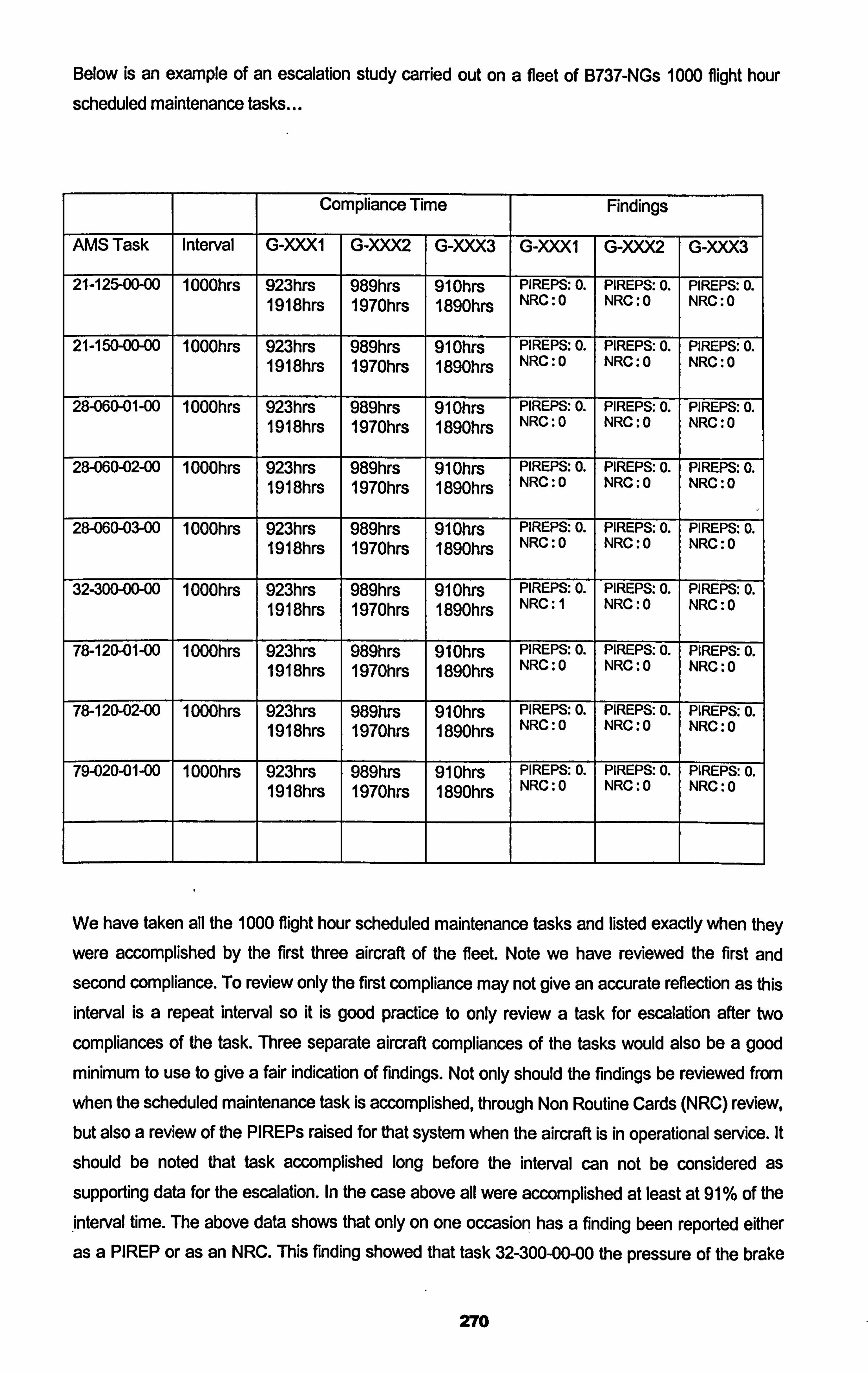
Below is an example of an escalation study carried out on a fleet of B737-NGs 1000 flight hour
scheduled maintenance tasks...
Compliance Time Findings
AMS Task Interval G-XXXI G-XXX2 G-XXX3 G-XXX1 G-XXX2 G-XXX3
21-125-00-00 1 000hrs 923hrs 989hrs 91 Ohrs PIREPS: 0. PIREPS: 0. PIREPS: 0. 1918hrs 1970hrs 1890hrs NRC: 0 NRC: 0 NRC: 0
21-150-00-00 1 000hrs 923hrs 989hrs 91 Ohrs PIREPS: 0. PIREPS: 0. PIREPS: 0. 1918hrs 1970hrs 1890hrs NRC: 0 NRC: 0 NRC: 0
28-060-01-00 1000hrs 923hrs 989hrs 91 Ohrs PIREPS: 0. PIREPS: 0. PIREPS: 0. 1918hrs 1970hrs 1890hrs NRC: 0 NRC: 0 NRC: 0
28-060-02-00 1 000hrs 923hrs 989hrs 91 Ohrs PIREPS: 0. PIREPS: 0. PIREPS: 0. 1918hrs 1970hrs 1890hrs NRC: 0 NRC. 0 NRC: 0
28-060-03-00 1 000hrs 923hrs 989hrs 91 Ohrs PIREPS: 0. PIREPS: 0. PIREPS-. 0. 1918hrs 1970hrs 1890hrs NRC: 0 NRC: 0 NRC: 0
32-300-00-00 1000hrs 923hrs 989hrs 91 Ohrs PIREPS: 0. PIREPS: 0. PIREPS: 0. 1918hrs 1970hrs 1890hrs NRC: 1 NRC: 0 NRC: 0
78-120-01-00 1000hrs 923hrs 989hrs 91 Ohrs PIREPS: 0. PIREPS: 0. PIREPS: 0. 1918hrs 1970hrs 1890hrs NRC: 0 NRC: 0 NRC -. 0
78-120-02-00 1 000hrs 923hrs 989hrs 91 Ohrs PIREPS: 0. PIREPS: 0. PIREPS: 0. 1918hrs 1970hrs 1890hrs NRC: 0 NRC: 0 NRC: 0
79-020-01-00 1 000hrs 923hrs 989hrs 91 Ohrs PIREPS: 0. PIREPS: 0. PIREPS: 0. 1918hrs 1970hrs 1890hrs NRC: 0 NRC: 0 NRC: 0
We have taken all the 1000 flight hour scheduled maintenance tasks and listed exactly when they
were accomplished by the first three aircraft of the fleet. Note we have reviewed the first and second compliance. To review only the first compliance may not give an accurate reflection as this interval is a repeat interval so it is good practice to only review a task for escalation after two
compliances of the task. Three separate aircraft compliances of the tasks would also be a good
minimum to use to give a fair indication of findings. Not only should the findings be reviewed from
when the scheduled maintenance task is accomplished, through Non Routine Cards (NRC) review, but also a review of the PIREPs raised for that system when the aircraft is in operational service. It
should be noted that task accomplished long before the interval can not be considered as
supporting data for the escalation. In the case above all were accomplished at least at 91 % of the
interval time. The above data shows that only on one occasion has a finding been reported either as a PREP or as an NRC. This finding showed that task 32-300-00-00 the pressure of the brake
270
accumulator was found low at the second repeat at 1918 flight hours on aircraft G-XXX1 and had to
be charged. So it can be deduced that on six separate scheduled inspection of this task one
resulted in a finding. This data displayed in the manner above could be used to substantiate an
escalation consideration of the 1000 flight hours tasks. The escalation amount should not be more than 10% to 15% of the original interval. In the case above an Maintenance Scheduled Change
request to escalate the 1000 flight hours tasks to 1150 flight hours could be made to the MSR13 and if accepted could then be applied for through an AMS revision to the approving authority along with the substantiating data as detailed above. It should be also noted that Certificated Maintenance
Requirements (CMF; Vs) as detailed in the MRBR are not candidates for escalation. The FAA identify some Maintenance Review Board Report tasks as single star tasks while the JAA can identify tasks as single or two start CMR tasks, the single CMR tasks are not allowed to be
candidates for escalation by either the JAA or FAA. Also careful consideration should be given to the origins of the MSG3 analysis of the tasks that are candidates for escalation...
Cat 6. Evident Operational Effect: The selection of a scheduled maintenance task is desirable if it
reduces risk to an acceptable level.
Cat 7. Evident Economic Effect: The selection of a scheduled maintenance task is desirable if the
cost is less than the repair.
Cat 8. Non Evident Safety Effect: The selection of a scheduled maintenance task is required to
assure the availability necessary to avoid the safety effects of a multiple failure.
Cat 9. Non Evident Non Safety: The selection of a scheduled maintenance task is desirable to
assure the availability necessary to avoid economic effects of a multiple failure.
Some opinions are that Cat 8 Non Evident Safety tasks should not be candidates for escalation. But it is my opinion that is they are identified and reviewed comprehensively, remembering that the
MSG3 process is not claimed to be exact, that they also can be considered for escalation.
The data above gives good technical justification based on actual findings resulting from the
compliance of the scheduled maintenance tasks for escalation, but it should be remembered that
task escalation can not take place with out the acceptance of the Maintenance Schedule Review
Board, MSRB and also with out the approval of the aviation authority that approve the complete
scheduled maintenance programme. Some aviation authorities may not accept the escalation if the
new proposed intervals deviate from the Manufacturers Planning Document with regards to the
new interval being greater than the MPD interval. This is also in my opinion not correct as the MPD
is only a base line starting document. The manufacturer will not change the MPD task intervals until
the world fleet return data to the manufacturer that suggest the intervals should be increased. This
is done through the Industry Steering Committee, ISC, for that aircraft type, see section 2 for the
construction of the ISC. This process can take a long time and the ISC will only escalate intervals
when the world fleet data suggests it can. An individual operator should be able to apply for
271
escalation regardless of the ISC adjusting the MPD interval provided it is done in the manner described above and supported by sound actual reliability data.
Deletion of a scheduled maintenance task is a serious issue and is not recommended unless a
very good technical reason can be given in support of the removal of the task. Even if the
scheduled maintenance task results in no NRC's and the reliability monitoring results in no PIREPs
raised, the deletion of a task should only take place when the task becomes not applicable due to a
modification of the system or the task is found to be completely irrelevant in maintaining the
inherent reliability of the system or component. Normally the MPD will remove the applicability of a
manufacturers recommended scheduled maintenance task when a Service Bulletin modification is
carried out, the removal from the MPD is sufficient support for the operator to remove the task from
their maintenance programme. For example task 27-140-02-00 calls for the replacement of the
wing flap drive transmition oil every 12 years. SB 737-27-1036 modifies the flap system by
replacing the old flap drives with new sealed units that the oil can not be replaced. In this case if SB
737-27-1036 is carried out the task 27-140-02-00 becomes irrelevant and not applicable and the
task can be removed from the operators maintenance programme. Another example is 25-200-00-
00 calls for the crew escape lanyards to be operationally checked every 12 years. It has been
discovered that by operationally checking the lanyards the rope and escape system are destroyed
as they are designed for one use only. This task was removed from the MPD and operators could
also remove it from their maintenance programmes. A final example is for category 7 MPD tasks.
Remember these are economic tasks that are there only to save money. It was suggested earlier in
the thesis that an operator should be able to consider the not incorporating cat 7 task if he so desires with out disagreement from his authorities and the MRBR / MPD should indicate this
accordingly. If the operator does not feel the economic benefit of performing the task he should be
permitted to remove these tasks. Most authorities will have trouble with this as they perhaps do not fully understand that the cat 7 tasks in the MRBR / MPD have no bearing on airworthiness safety but only economic Implications. It is my opinion that a manufacturer should highlight in the MPD the
reasoning for the inclusion of the cat 7 tasks and that they are there only for economic reasoning.
An operators should include these tasks if they feel they are of benefit but should continuously
monitor there effectiveness through PIREP monitoring and resultant NRC's from carrying out the
tasks. Deletion of these tasks should take place if the operator finds they bring no economic value
to there particular operation.
Though task escalation as an ongoing practice is recommended, I do suggest that great care is
taken in identifying candidates for escalation or deletion from the scheduled maintenance
programme. It is often a subject approached with too much enthusiasm and "escalation fever" can
result as well as with intrepid fear to deviate from the MRBR or MPD, both of these approaches are
incorrect. While it is the duty of the Maintenance Programme & Reliability Sections to ensure that
the Maintenance Programme is applicable, effective and appropriate with regards to maintaining
the inherent reliability in a cost effective manner, it is also their responsibility to ensure that careful
consideration is given to any candidate task before it proposed for escalation or deletion.
Correspondence with the manufacturer is recommended even through the ISC or directly prior to
272
task escalation, while they may not give their exact approval for the changes they may give reason
as to why the change may not be appropriate or indeed they may included it in the agenda for the
next ISC to deliberate on. Operator involvement in the ISC will give them a chance to drive the
tasks they have identified as candidates, and to benefit from the world fleet opinion. ISC
involvement is encourages.
6.2.4 Scheduled Maintenance Programme Task Optimisation.
So far we have described the development of the Maintenance Programme through initially the
MSG3 process and ongoing through reliability monitoring. This will ensure that the scheduled
maintenance tasks carried out on the aircraft detailed in the Maintenance Programme of the
operator, are appropriate, applicable and effective in maintaining the original design reliability of the
aircraft including any implication of modification carried out since delivery. None the less it is in my opinion recommended practice for an operator to conduct a complete review of their maintenance programme from time to time. Some aircraft such as business jets and general aviation aircraft do
not have a manufacturers recommended maintenance programme that is based upon MSG3
principles or indeed even MSG2. These aircraft and even aircraft with MSG3 developed
programmes can benefit largely from an optimisation review. A complete review of the scheduled
maintenance tasks should be carried out approximately every 3 years as an optimisation process to identify the applicability and effectiveness of the programme as a whole. It is too easy even with the
MSRB for scheduled maintenance tasks to enter into the maintenance programme, with all the
good intentions in the world that are found after time to be in effective. Continued inclusion of these
tasks at their intervals only inflates the maintenance programme resulting in increased expense
and increased invasive maintenance activity. As service experience is gained by the operator
through operation of their fleet, maintenance programme tasks are constantly updated and developed by addition, deletion and revision of tasks. This process can be controlled using the
methods described previously, but a periodic review of the programme as a whole can assist in
identifying task effectiveness and can assist in identifying candidate tasks for removal or revision
ensuring that the scheduled maintenance programme is maintaining the inherent reliability of the
aircraft in an appropriate and cost effective manner.
Below fig 6.3 is a simplified summary of the Maintenance Programme and Reliability process that
has been taken place continuously by the operator...
273
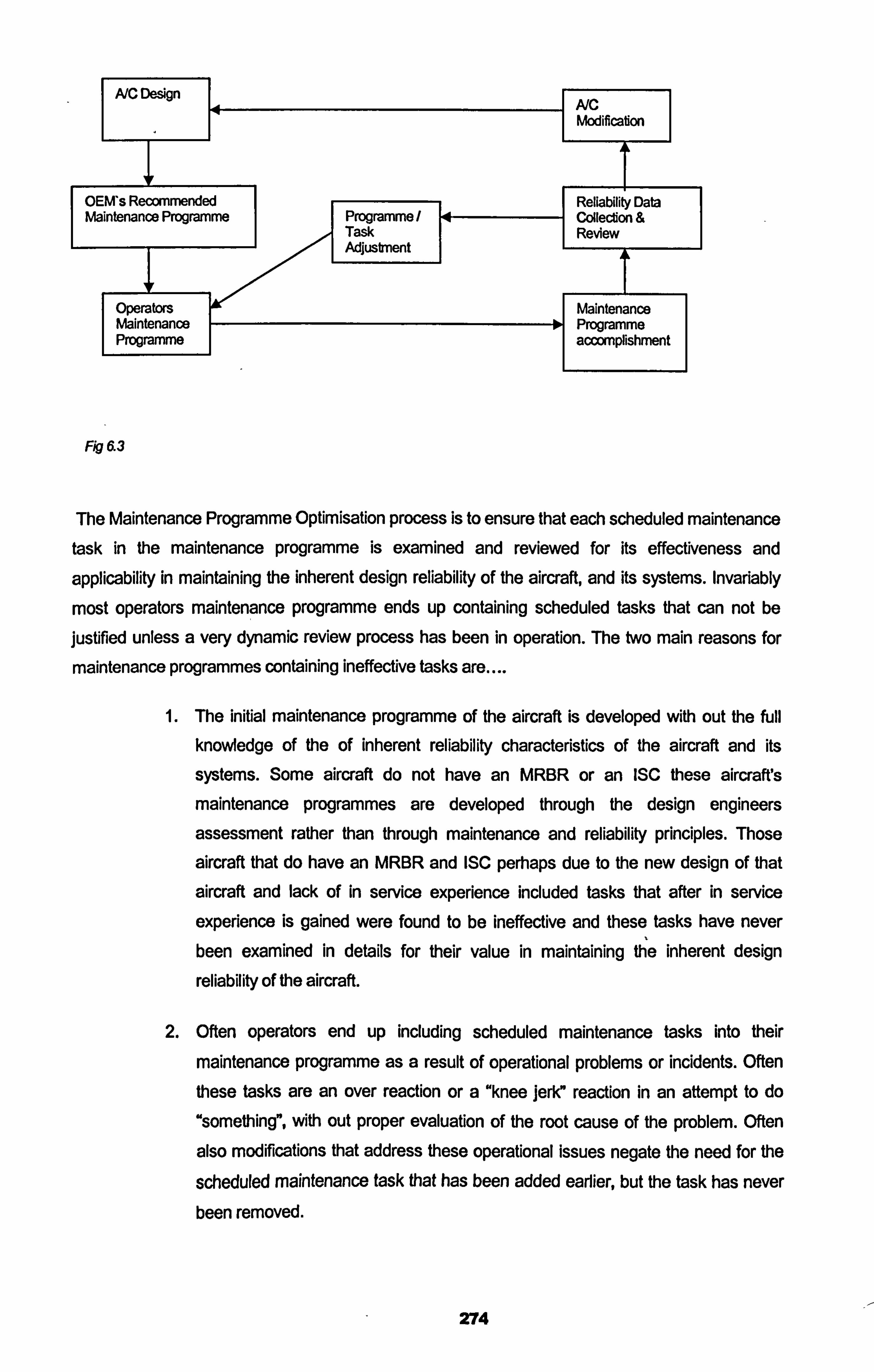
A/C Design A/C Modificabon
OEM's Recommended ta Maintenance Programme Programme
Task ee Adjustment A
Operators I Maintenance Maintenance lo Programme Programme I
accomplishment
Fig 63
The Maintenance Programme Optimisation process is to ensure that each scheduled maintenance task in the maintenance programme is examined and reviewed for its effectiveness and
applicability in maintaining the inherent design reliability of the aircraft, and its systems. Invariably
most operators maintenance programme ends up containing scheduled tasks that can not be
justified unless a very dynamic review process has been in operation. The two main reasons for
maintenance programmes containing ineffective tasks are....
1. The initial maintenance programme of the aircraft is developed with out the full knowledge of the of inherent reliability characteristics of the aircraft and its
systems. Some aircraft do not have an MRBR or an ISC these aircraft's
maintenance programmes are developed through the design engineers assessment rather than through maintenance and reliability principles. Those
aircraft that do have an MRBR and ISC perhaps due to the new design of that
aircraft and lack of in service experience included tasks that after in service
experience is gained were found to be ineffective and these tasks have never been examined in details for their value in maintaining tlýe inherent design
reliability of the aircraft.
2. Often operators end up including scheduled maintenance tasks into their
maintenance programme as a result of operational problems or incidents. Often
these tasks are an over reaction or a "knee jeW reaction in an attempt to do
"something", with out proper evaluation of the root cause of the problem. Often
also modifications that address these operational issues negate the need for the
scheduled maintenance task that has been added earlier, but the task has never been removed.
274
The basic underlining principle with the optimisation review is that every individual scheduled
maintenance task in the programme is subject to a critical review at a regular interval. The outcome
of the review will be to retain the task, delete the task, revise the task content or revise the task
interval. While the MSG3 analysis process starts with the system top down review approach, the
optimisation process starts with the task review approach. This approach may at first look appear to
be contradicting the MSG3 process with the respect that this process reviews the task itself, but in
fact it is building upon the MSG3 process recognising that the task exists and reviewing that task in
the light on now known actual in service experience. Remember for those tasks generated from the MSG3 analysis often there is no in service actual data available, the optimisation process validates those tasks developed from MSG3 or for those task generated from other processes, it reviews their effectiveness based upon actual findings and operation data. The process also take into
consideration any modifications that have been carried out to the aircraft or its systems changing the original design. The process may indeed recognise that additional maintenance tasks are
required, similar to that process described previously above.
The optimisation process should take each task and review in detail the task re analysing the task for applicability and effectiveness in maintaining the inherent reliability of the aircraft including
implication of any modification that has been carried out on the aircraft.
The Optimisation Process is similar to the MSG3 process in that it is a decision logic process....
Identify the Task / MSI for review.
Process 1. Task Tvpe Identification.
Process 1 identifies three task types. The process reviews all maintenance programme tasks and
attempts to categorise that task into one of the three types. The task type is defined through a
series of decision logic considerations. It essentially tries to define the Maintenance Programme
Task / MSI based upon the issue it address in its attempt to maintain the inherent reliability of the
aircraft or its systems.
Stop 1: Asses Airworthiness and Safety Implications. This part of the analysis attempts to
identify if the Task or MSI has been included into the Maintenance Programme to address an
airworthy or safety issue. This is done through a series of questions and consideration in a logical
flow. A Yes answer to any of these questions identifies that MSI / task as an Airworthiness / Safety
Task type.
Stop 2: Asses the Operational Implications. This part of the analysis attempts to identify if the
Task or MSI has been included into the Maintenance Programme to address an operational issue.
This is done through a series of questions and consideration in a logical flow. A Yes answer to any
of these questions identifies that MSI / task as an Operational Task type.
275
Stop 3: Asses the Economic and Customer Care Implications. This part of the analysis attempts to identify if the Task or MSI has been included into the Maintenance Programme to
address an economic or customer care issue. This is done through a series of questions and consideration in a logical flow. A Yes answer to any of these questions identifies that MSI / task as Economic / Customer Care Task type.
A MSI / task can be identified as more than one type. Depending upon the task type, further
analysis is to be carried out to identify if that task is applicable and effective in maintaining the inherent reliability of the original design taking into consideration any modifications that have been
carried out and any reliability data gathered during the in-service time of the aircraft.
Process 2. Task Review & Validation.
Process 2 ftirther reviews the Task / IVISI and scrutinises its validity for existing in the maintenance programme. Is the task still effective and applicable in maintaining the inherent reliability of the
aircraft or its systems? In-service reliability data is key to this process.
The Task / MSI is at the end of this process identified as a candidate for continued inclusion or for
removal from the maintenance programme.
Airworthiness I Safety Type Tasks. This part of the analysis attempts to identify if the Task or MSI continues to have validity in meeting the tasks original intentions of addressing a particular
airworthy or safety issue. This is done through a series of questions and consideration in a logical flow. Similar to Process 1. At the end of the process each Task / MSI is identified as a candidate for
either... 1. Interval escalation or task deletion or 2. To remain un revised or 3. Interval reduction. With AD's, CMffs, ALI's or Regulatory tasks, escalation or deletion is not permitted. Strong
engineering substantiation will be required if an operator wishes to escalate or delete these tasks,
only with their authorities authorisation.
Operational Type Tasks. This part of the analysis attempts to identify if the Task or MSI continues to have validity in meeting the tasks original intentions of addressing an operational issue. At the
end of the process each Task / MSI is identified as a candidate for either... 1. Interval escalation or task deletion or 2. To remain un revised or 3. Interval reduction.
Economic I Customer Care Type Tasks. This part of the analysis attempts to identify if the Task
or MSI continues to have validity in meeting the tasks original intentions of addressing an economic
or customer care issue. At the end of the process each Task I MSI is identified as a candidate for
either... 1. Interval escalation or task deletion or 2. To remain un revised or 3. Interval reduction.
Maintenance Programme Optimisation Decision Diagram's
276
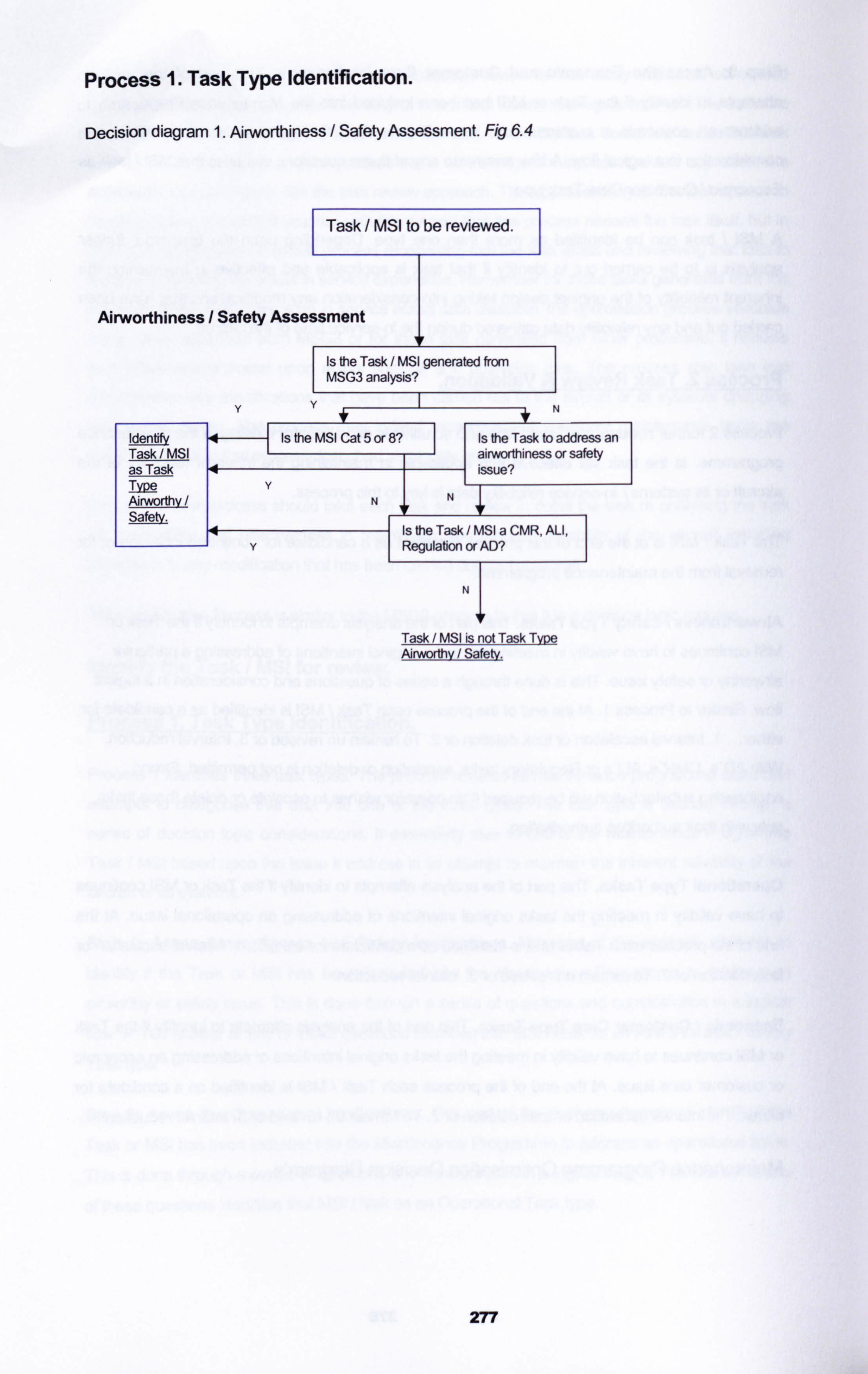
Process I. Task Type Identification.
Decision diagram 1. Airworthiness / Safety Assessment. Fig 6.4
Task / MSI to be reviewed.
Airworthiness / Safety Assessment
Is #1e Task / MS1 generated from IVISG3 analysis?
I
Identi 4 Is the MSI Cat 5 or 8? Is the Task to address an Task / MSI airworthiness or safety as Task 4 issuel Type Y Airworthv NNT Safety.
Is the Task / MSI a CMR, ALI, Y
4Regulabon
or AD?
I
Task / MSI is not Task T Airworthy / Safety.
277
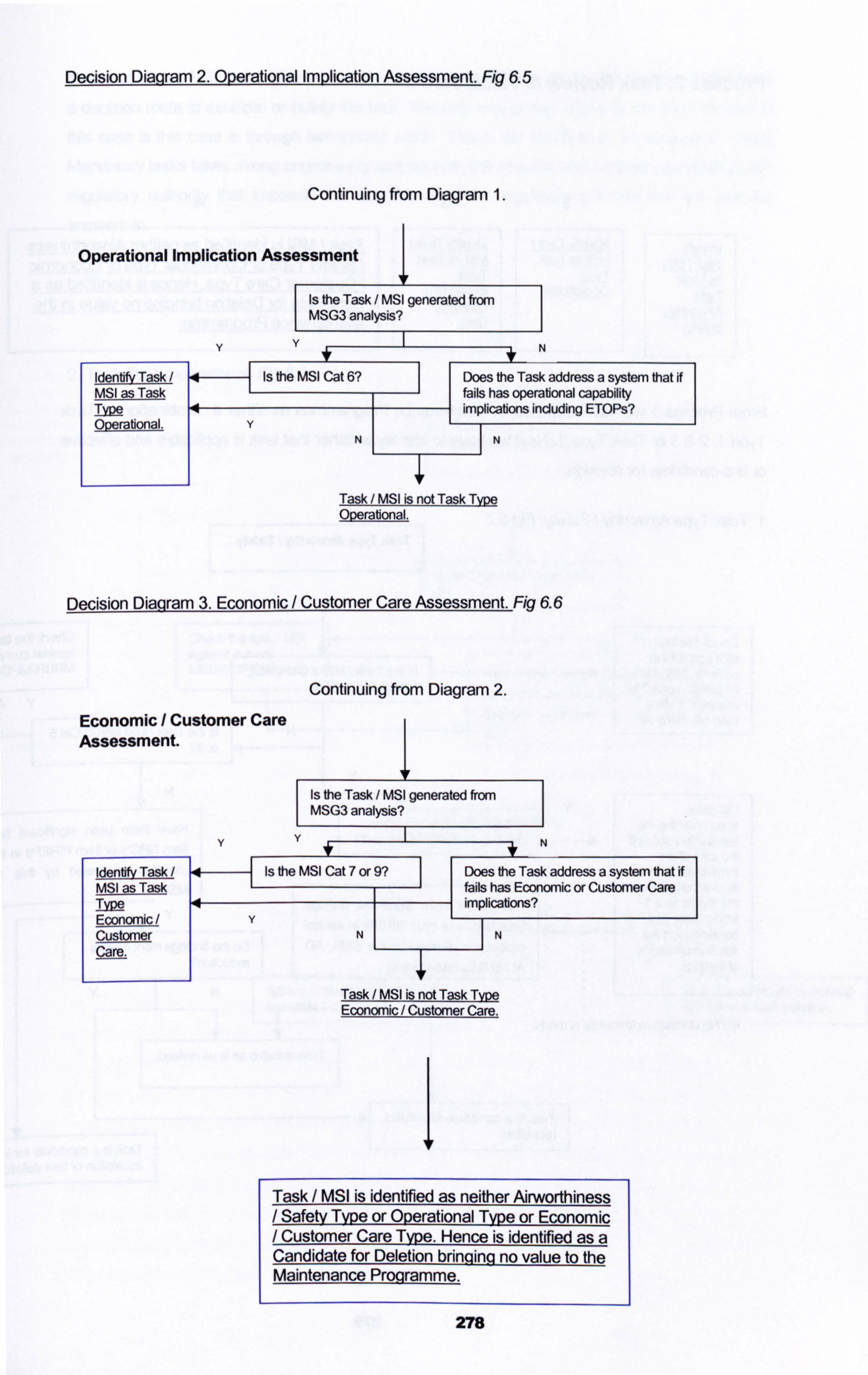
Decision Diaqram 2. Operational Implication Assessment. 6.5
Continuing from Diagram 1.
Operational Implication Assessment
Is the Task / MSI generated from I MSG3 analysis? I
YY f- I
--+ N
Idenbfv Task ýIs
the IMSI Cat 6 Does the Task address a system that if MSI as Task fails has operational capability Type 4ui phadhons including ETOPs? Operational. YI
Task / MSI is not Task ODerabonal.
Decision Diagram 3. Economic / Customer Care Assessment. Fig 6.6
Continuing from Diagram 2.
Economic / Customer Care Assessment.
Idenbfy Task MSI as Tas Type Economic Customer Care.
Is the Task / IVISI generated from IVISG3 analysis?
I
YY* T-
N
Is the IVISI Cat Does the Task address a system that ff fiails has Economic or Customer Care implications?
YNIN
Task / MSI is not Task Economic / Customer Care.
Task / MSI is identified as neither Airworthiness Safety Type or Ooerational Type or Economic Customer Care Type. Hence is identified as a
Candidate for Deletion brinqing no value to the Maintenance Programme.
278
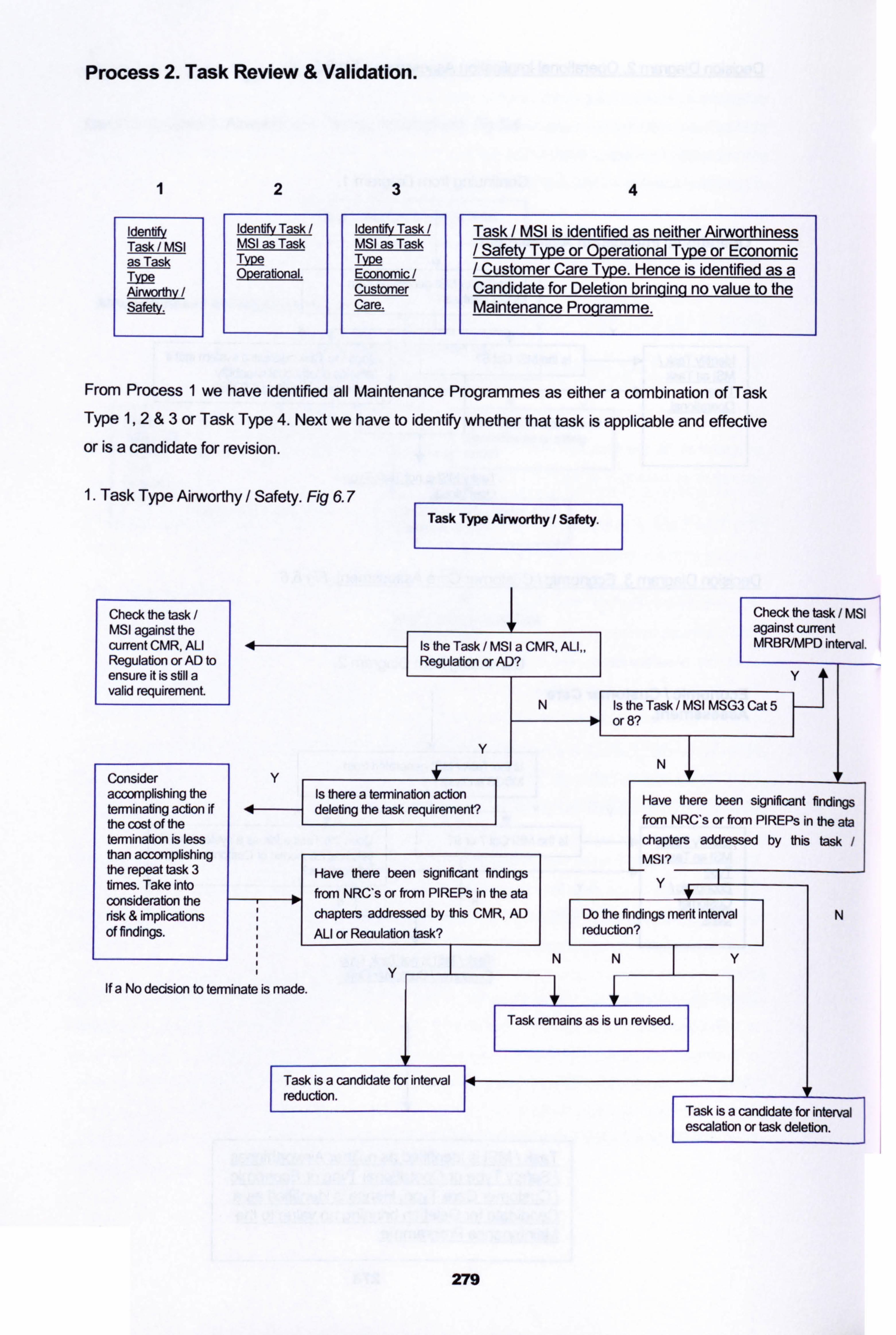
Process 2. Task Review & Validation.
1
Iden Idenfifv Task ldenbfv Task Task / MSI MSI as Task MSI as Task as Task Type Type Type Overabonal. Economic Airworthy Customer Safetv.
I f
Care.
4
Task / MSI is identified as neither Airworthiness Safetv Tvpe or Operational Tvpe or Economic Customer Care Tvpe. Hence is identified as a
Candidate for Deletion briming no value to the Maintenance Proqramme.
From Process 1 we have identified all Maintenance Programmes as either a combination of Task Type 1,2 &3 or Task Type 4. Next we have to identify whether that task is applicable and effective or is a candidate for revision.
1. Task Type Airworthy / Safety. Fig 6.7
Check the task / IVISI against the current CMR, ALI Regulation or AD to ensure it is still a valid requirement.
Consider y accomplishing the terminating action if 4 the cost of the termination is less than accomplishing the repeat task 3 times. Take into consideration the
Y
Is there a termination action deleting the task requirement?
Have there been significant findings
from NRC's or from PIREPs in the ata chapters addressed by this CMR, AD ALI or Reoulation task?
risk & implications of findings.
If a No decision to terminate is made. Y
Check the task / MSI against current MRBR/MPD intervaf.
y
Is the Task / MSI IVISG3 Cat 5 or 8?
1
N
Have there been significant findings from NRC's or from PIREPs in the ata chapters addressed by this task MSI?
y
Do the findings merit interval N ucb
I [=ction?
NN T- y
Task remains as is un revised.
Task is a candidate for interval reduction.
I
Task is a candidate for interval escalation or task deletion.
I Task Type Airworthy / Safety.
Is the Task / MSI a CMR, ALI,, Regulabon or AD?
I
N
279
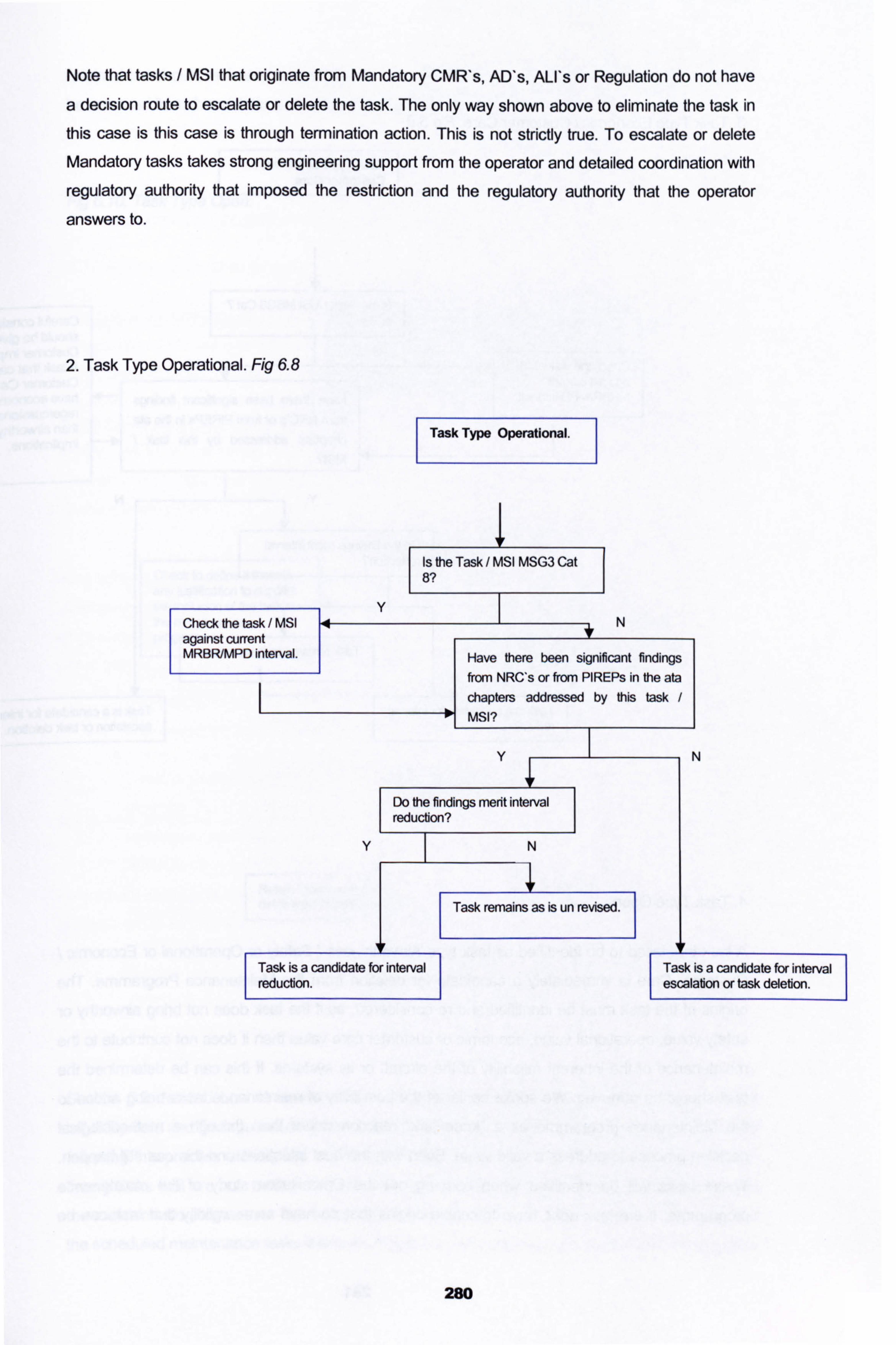
Note that tasks / MSI that originate from Mandatory CMR's, AD's, ALI's or Regulation do not have
a decision route to escalate or delete the task. The only way shown above to eliminate the task in
this case is this case is through termination action. This is not strictly true. To escalate or delete
Mandatory tasks takes strong engineering support from the operator and detailed coordination with
regulatory authority that imposed the restriction and the regulatory authority that the operator
answers to.
2. Task Type Operational. Fig 6.8
Check the task / MSI against current MRBR/MPD interval.
Task Type Operational.
Is the Task / MSI MSG3 Cat 8?
1
Y N
Have there been significant findings from NRC's or from PIREPs in the ata chapters addressed by this task MSI?
Y
Do Me findings merit interval reduction?
I
Y
Task is a candidate for interval reduction.
I
N
Task remains as is un revised.
280
N
Task is a candidate for interval escalation or task delebon.
I
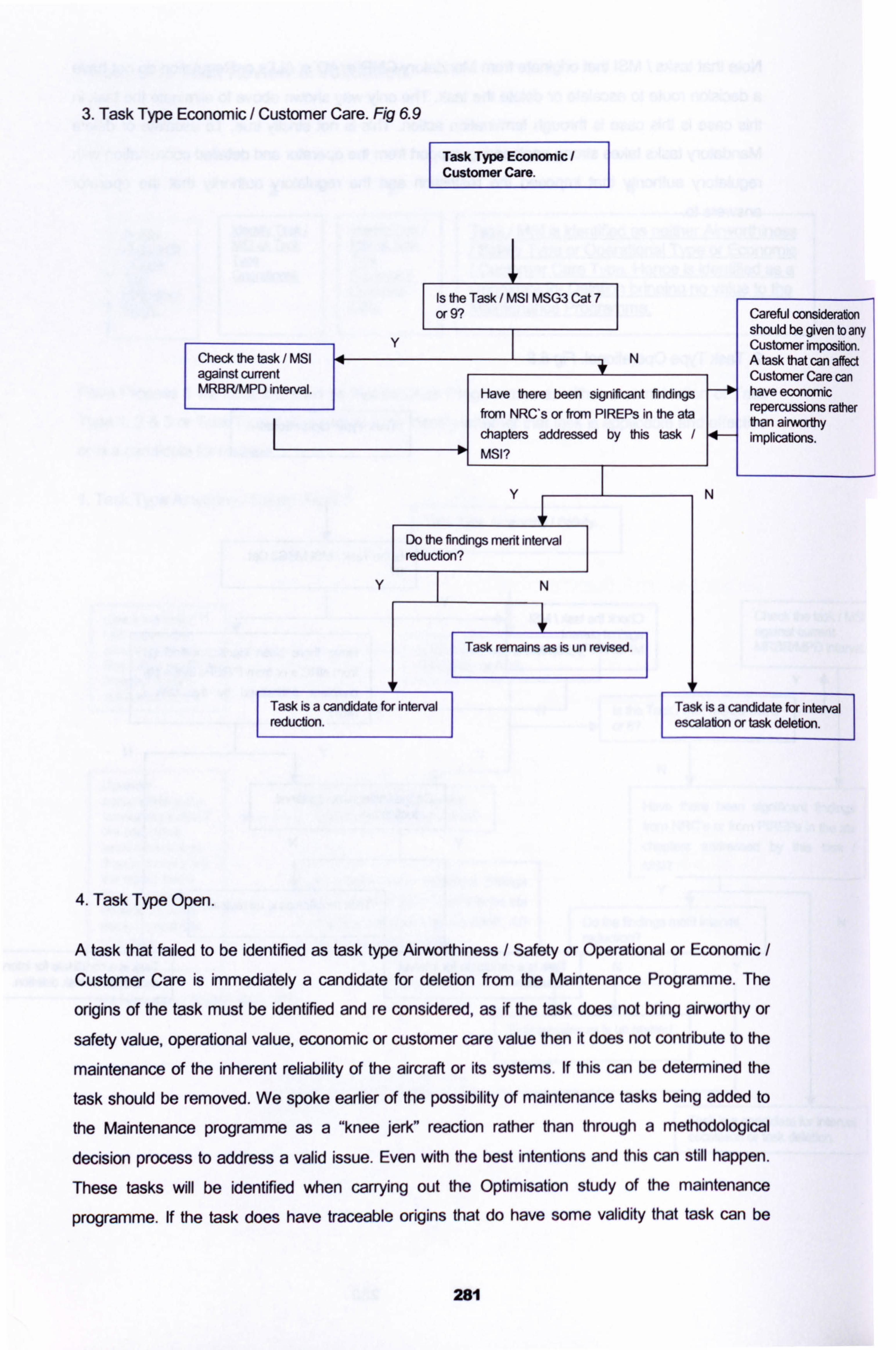
3. Task Type Economic / Customer Care. Fig 6.9
Task Type Economic Customer Care.
Check the task / MSI against current MRBR/MPD interval.
Task is a candidate for interval reduction.
I
4. Task Type Open.
N
Careful consideration should be given to any Customer imposition. A task that can affect Customer Care can have economic repercussions rather than airworthy implications.
Task is a candidate for interval escalation or task deletion.
I
A task that failed to be identified as task type Airworthiness / Safety or Operational or Economic /
Customer Care is immediately a candidate for deletion from the Maintenance Programme. The
origins of the task must be identified and re considered, as if the task does not bring airworthy or
safety value, operational value, economic or customer care value then it does not contribute to the
maintenance of the inherent reliability of the aircraft or its systems. If this can be determined the
task should be removed. We spoke earlier of the possibility of maintenance tasks being added to
the Maintenance programme as a "knee jerk" reaction rather than through a methodological
decision process to address a valid issue. Even with the best intentions and this can still happen.
These tasks will be identified when carrying out the Optimisation study of the maintenance
programme. If the task does have traceable origins that do have some validity that task can be
Is the Task / MSI MSG3 Cat 7 or 9?
1
Y N
Have there been significant findings from NRC*s or from PIREPs in the ata chapters addressed by this task MSI?
Y
Do the findings mrit interval reduction?
I
V N
Task remains as is un revised.
281
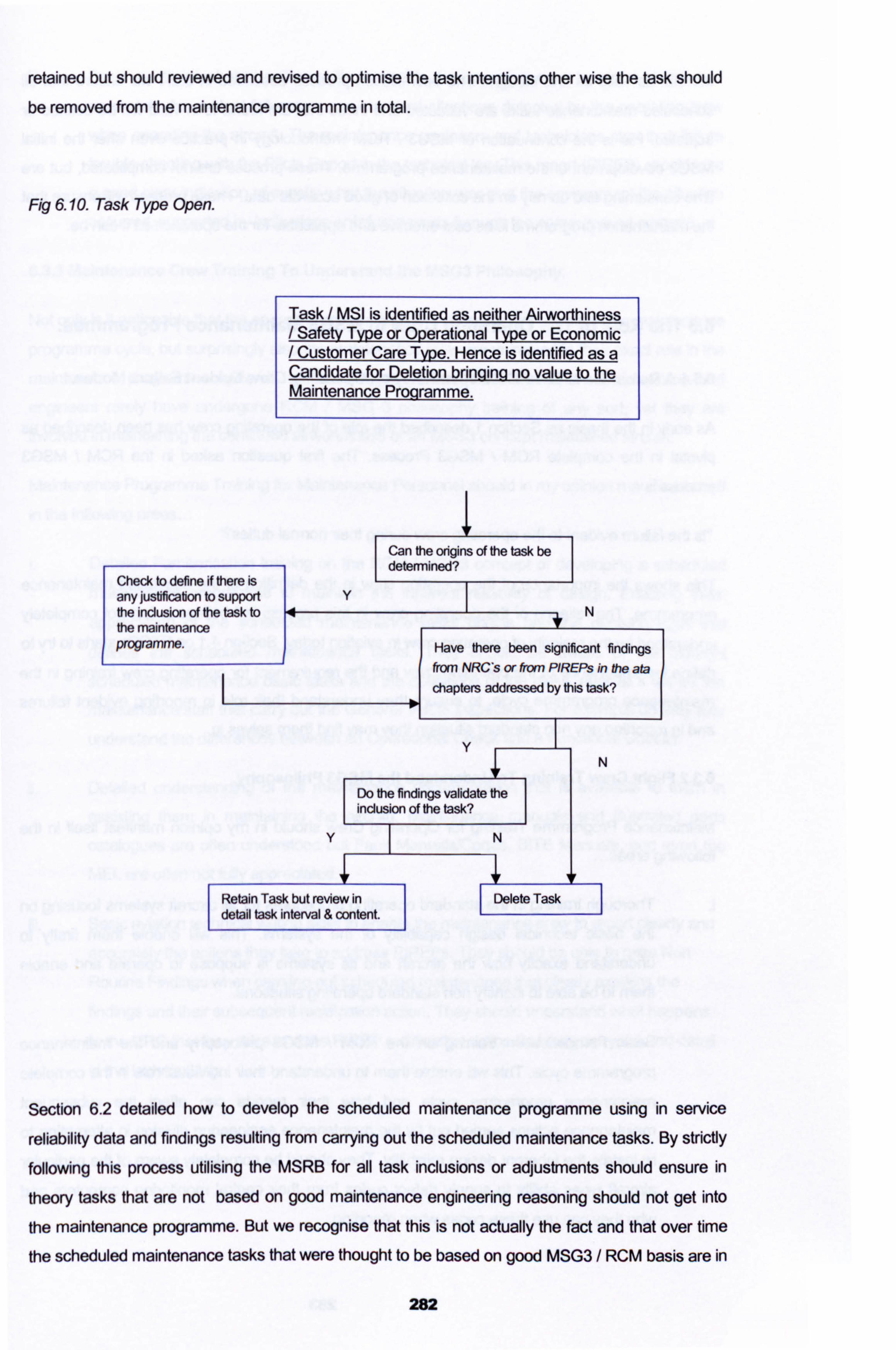
retained but should reviewed and revised to optimise the task intentions other wise the task should be removed from the maintenance programme in total.
Fig 6.10. Task Type Open.
Task / MSI is identified as neither Airworthiness / Safe! y Type or Operational Type or Economic / Customer Care Type. Hence is identified as a Candidate for Deletion brinqinq no value to the Maintenance Proqramme.
Can the origins of the task be deteffnined?
I
Check to define if there is any justification to support the inclusion of the task to the maintenance programme.
V N
Have there been significant findings from NRCs or from PIREPs in the ata chapters addressed by this task?
V
Do the findings validate e inclusion of the task?
yN
Retain Task but review in Delete Task detail task interval & oDntent.
N
Section 6.2 detailed how to develop the scheduled maintenance programme using in service
reliability data and findings resulting from carrying out the scheduled maintenance tasks. By strictly following this process utilising the MSRB for all task inclusions or adjustments should ensure in
theory tasks that are not based on good maintenance engineering reasoning should not get into
the maintenance programme. But we recognise that this is not actually the fact and that over time
the scheduled maintenance tasks that were thought to be based on good MSG3 / RCM basis are in
282
fact not as valid as first thought. The optimisation process described in 6.2.4 will ensure that all
scheduled maintenance tasks are validated and those that are found to in valid will be deleted or
adjusted. His is the continuation of MSG3 / RCM methodology in practice even after the initial
MSG3 development of the maintenance programme. These process are not complicated, but are time consuming and do rely on the collection of good accurate data. These process will ensure that
the maintenance programme is as cost effective and applicable for the operation as it can be.
6.3 The Role of The Operating Crew In MSG3 Maintenance Programmes.
6.3.1 A Reminder of The RCM Dependency on Operating Crew Evident Failure Modes.
As early in the thesis as Section 1 described the role of the operating crew has been described as pivotal in the complete RCM / MSG3 Process. The first question asked in the RCM / MSG3
processis
"is the failure evident to the operating crew during their nonnal dutiesr
This shows the importance of the operating crew in the definition of the scheduled maintenance programme. The reliance of the operating crew in this process is I believe a fact not completely understood by the majority of operating crew in aviation today. Section 4.1 on ETOPs starts to try to define the importance of the operating crew and the requirement for operating crew training in the
maintenance programme cycle, to ensure they understand their role in reporting evident failures
and in reporting any non standard situation they may find them selves in.
6.3.2 Flight Crew Training To Understand the MSG3 Philosophy.
Maintenance Programme Training for Operating Crew should in my opinion manifest itself in the following areas...
Thorough training in the standard operating procedures for all aircraft systems focusing on the basic technical design capability of the systems. This will enable them firstly to
understand exactly how the aircraft and its systems is suppose to operate and enable them to be able to identify non standard operating situations.
Basic Familiarisation training on the RCM / MSG3 philosophy and the'maintenance
programme cycle. This will enable them to understand their individual role in the complete
maintenance programme cycle and how their reports can affect the subsequent
maintenance actions carried out by the maintenance engineering division in attempting to
re instate the inherent design reliability. They should be completely aware of the particular aircraft types ability to supply defect codes from their central monitoring computers and who they can use these codes when reporting.
283
Basic aviation technical writing skills to enable the operating crew to report clearly and accurately the evident failures or non standard situations detected by the operating crew when operating the aircraft. The maintenance engineers and technicians start their failure trouble shooting with the Pilots Report in the technical log. This report (PIREP) should give a good clear indication of exactly what the situation was and the environment the situation occurred, supported by indications or failure reports through the computerised systems.
6.3.3 Maintenance Crew Training To Understand the MSG3 Philosophy.
Not only is it noticeable that the operating crew often fail to understand their role in the maintenance programme cycle, but surprisingly also the maintenance crew are untrained in their exact role in the
maintenance programme cycle. It has been my experience that maintenance technicians and engineers rarely have undergone RCM / MSG 3 philosophy training of any sort, yet they are involved in maintaining the continued airworthiness of an MSG3 concept maintained aircraft.
Maintenance Programme Training for Maintenance Personnel should in my opinion manifest its self in the following areas...
Detailed Familiarisation training on the RCM / MSG3 concept of developing a scheduled maintenance programme to maintain the inherent reliability of design. Enabling them
appreciation of the scheduled maintenance tasks origins and the decision logic that defines the scheduled maintenance tasks. They should be aware of the different
scheduled maintenance basic tasks and the definitions of the tasks, after all it will be the
maintenance staff that carry out the General Visual Inspections. For example do they fully
understand the differences between an Operational Check and a Functional Check?
Detailed understanding of the maintenance documentation that is available to them in
assisting them in maintaining the aircraft. Maintenance manuals and illustrated parts catalogues are often understood but Fault Manuals/Codes, BITE Manuals, and even the MEL are often not fully appreciated.
Basic aviation technical writing skills to enable the maintenance crew to report clearly and accurately the actions they take to address PIREPs. They should be able to raise Non
Routine Findings when carrying out scheduled maintenance that clearly explains the findings and their subsequent rectification action. They should understand what happens
to the NRC that they raise and the PIREP rectification action that they carry out and detail in the technical log.
284
7. Maintenance Programme Control Software.
The Maintenance Programme in its entirety has been defined in the previous 5 sections of the thesis. Starting with the development of the initial Scheduled Maintenance Task utilising the MRBR MSG3/RCM process, then custornising it for a particular operators environment, we then have the Operators Maintenance Schedule. Accomplishing the NIS with Task Cards and monitoring the MS with an on going Reliability Programme all constitutes the complete Maintenance Programme. This complete process is a complex series of controlled activities and can be accomplished and applied by utilising efficiently with a Maintenance Programme Control Software, MPCS. There are many MPCS available today in the Aviation world. Some
stand alone controlling only the MS, some included the Reliability Monitoring, some go much further in supporting all aspects of the technical operation of an aircraft or a fleet.
Maintenance Programme Control Software Modules in their complete form can be able to
control and monitor the following....
1. Fleet Operational Activities: Flight hours, Flight Cycles, Arrival Stations, Departure Stations, Fuel Burn, Flight Performance Data.
2. Scheduled Maintenance Task Control: Controlling all scheduled maintenance tasks with their intervals. Showing when they fall due and how much time is
remaining until they fall due.
3. Technical Records Management & Control: Stores all aircraft technical records detailing all installed components, fleet flight hours & cycles, fleet modiflcation status.
4. Task Card Control: Linking all task cards to the scheduled maintenance tasks or bulletin task, enabling task card printing for the controlled scheduled maintenance tasks.
5. Bulletin Control: Controlling all Service Bulletins, Airworthiness Directives and
other Bulletin types, modifications and inspections.
6. Reliability Monitoring & Defect Control: Carries out the complete Reliability
function from storing all PIREPs, setting alerts and notification of recurrent defects.
Also manages all defects raised as a result of scheduled maintenance tasks,
linking them to the scheduled maintenance task that resulted in the defect finding.
7. Manpower & Capacity Management: Controls manpower requirements
required to carry out the scheduled maintenance tasks & monitors manpower
availability.
285
8. Inventory & Material Management: Controlling all inventory material. Defining all
material requirements to accomplish the scheduled maintenance programme &
modification programme. Controlling the purchasing of material to support the technical operation.
Depending upon the operators requirements often the above eight aspects of an MPCS are
available as modules. A small operators may only require a few of the modules while a large airline
may require all modules detailed above and even many more such as a Flight Planning module, Crew Management Module or even a Financial Control Module. Modules 2 to 6 are essential in my
mind required to conduct proper and complete Maintenance Programme Management.
Before an operator decides upon the MPCS they wish to use to manage their maintenance
programme function, there are four definite phases they must undertake to ensure they purchase the correct MPCS for their particular operation. These are...
6.1 User Team Selection and Preparation.
6.2 Software Assessment.
6.3 Software Selection.
6.4 Soffivare Implementation.
These for phases must be carried out by a group of representatives from each section involved in
the management and accomplishment of the Maintenance Programme. Each section
representative or User, will be involved from the start to the completion of the project. Carrying out the four phases lead by a Project Manger whose task is to ensure all decisions, tasks, activities are
planned and made in a timely manner in coordination with all representative Users.
7.1 User Team Selection and Preparation.
The user team should be completely representative of the sections that intend to use the software.
A team member should be completely familiar with the procedures and processes followed by the
section he represents. He should understand the important functions and the less important
functions with in his section. The team member should understand that being in the team means
extra work and extra hours. It is often difficult for the User Team members to split their time
between their daily routine duties and their project demands, but unless the team members are 100% dedicated to the project the result will not be as good as it should be.
Once the User Team has been selected it should be clearly written down what is expected of the
team members and what deliverables they are required to produce. It should also be clear that the
286
Project Manager and selected team leaders do have authority to set deadlines and to distribute
action items with regards to the project for all User Team Members.
Summary of Written instructions required..
Clear job descriptions for each team member, including the team leaders and Project
Manager.
o Clear deliverables expected from each team member.
0 Clear reporting lines in the context of the project.
Once the User Team has been selected and written instructions are clear and accepted by the
team, it is now required that the User Team starts to prepare to assesses a number of software
available in the market. The Project Leaders have first before getting the User Team involved,
define the following...
0 What is the operators budget available for the software?
a What is the operators exact requirements?
What software is available in the market that meets the budget & the general
requirements?
Once the Project Leaders have identified the three issues above, the team can prepare for the
assessment.
7.2 Software Assessment.
Software assessment should take three phases.
Phase 1: The identification of appropriate software available in the market.
The Project Leaders should conduct the Phase 1 identification of available software in the market. This first search and find activity should select software that merits the review based upon the three
criteria detailed in 6.1 above. The Project Leaders should eliminate that software that does not
meet the criteria of operators budget and operators requirement. Too expensive software should be eliminated as should software that does not meet the requirements. Project Leaders should be
careful not to eliminate non aviation software at first glance often good aircraft maintenance
software was derived from plant maintenance software. Those left from the Project Leaders search
should be entitled to Phase 2 Initial Review. The Project Leaders should research software
available from the following source...
I. Aviation Magazines.
287
2. Aviation Trade Shows.
3. World Wide Web searches.
4. Word of mouth from other operators.
5. Any other sources available.
Phase 2: The initial review of the available software.
This is the first time when the User Team are brought in to review. The User Team should have
prepared with a matrix of major general section functions. This matrix should identify the major function that each section assessing the software are expected to carry out. A box should be
beside each function where the assessing User can score 0 to 3 rating the software for his
functions. 0 means it is not capable of the function while 3 means it is highly capable. Those
selected by the Project Leaders for Phase 2 can be assessed by the User Team through a variety
of methods..
1. Internet Presentation.
2. Software Provider Presentation.
3. Existing User Visit.
4. Any other method where the User Team can score the capabilities listed in the Phase 2
See attachment 5, Phase 2 Initial High Level Assessment Matrix: AssesmentDetailed. xls
Phase 3: Second Review. Detailed Assessment.
This is the second User Team review of the software that scored highest in the first User Team
review in Phase 2. This Phase takes the software that the Users wish to examine further for
possible selection. This time the User Group have to do much more preparation by developing a detailed functional review matrix for each user section. Each User should define every detailed
function carried out by his section in support of the Maintenance Programme, each function is
weighted 1 to I Weight 1 being desirable function weight 2 being required function weight and 3
being pssential function weight. Those functions that are mandatory required should be weighted 3
but identified as RED, meaning if the software is not capable it is rejected. The matrix should go on to have a box to score each function once assessed 0 to 5.0 meaning it is not capable, 5 meaning it is completely capable in all ways. 2,3, and 4 are levels of capability between as determined by
the assessing User.
288
See attachment 5, Phase 3 Detailed Assessment Review, Attachment 5: AssesmentDetailed. xls
This detailed assessment should take place at the operators base with the software presenter bring
along a copy of the product with good current usable data. This may involve requesting an existing
user to allow access to his data for review purposes. It should also be noted at this stage the
following information should be attempted to be received....
0 How many operators in the world are using this product?
0 How long has the product been in circulation?
0 How is the product supported?
0 How do the individual operator users now feel about the product?
The detailed assessment should take at least three days and each User Team member should be
given full ability to completely review all aspects of the detailed functions in the detailed matrix. The
assessment of the software should be conducted with good data that the User is familiar with, for
example if the operators fleet is mainly B737's it is ideal that B737 data is used for the assessment. If the software presenter is unable to provide good data then the assessment will not be of as high
value as could be. Aso if the software presenter is not familiar in detail with the software functions
in total again the assessment will not be of as value as it could be. Users should not settle for
explanations of how the software works, but should them selves carry out the function they are
assessing and see its capability first hand. Remarks are important at time against the each function. The assessing User should describe any issues he wishes positive or negative and note
them against the score in the matrix.
The IT section should be represented by a User Team member, he must carry out also a thorough
review and assessment from an IT perspective. Their appraisal is as important as the User function
assessment. IT considerations should be given to software platforms, programming language, data
integrity, hardware requirements and very importantly to legacy system data migration issues and
other system integration issues.
7.3 Software Selection.
Once the detailed assessment has been carried out satisfactorily the User Team Leaders should
ensure that the matrix has been completed correctly, all calculations are working correctly then he
should compile a summary of the total scores for management review with the detailed functional
scoring available for review by senior management.
See Attachment 5, Phase 3 Detailed Review Matrix with Executive summary & Score Comparison:
AssesmentDetailed. xls
289
The User Team have now conducted a detailed assessment of a number of software against many detailed functional issues. This is important for many reasons.
e The Users in the Team will be those responsible later for implementing the software.
The Users in the Team will be responsible for using the software in their daily duties once implemented.
These two points must be re iterated to the Users Team many times from the start of the project to
the finalisation of scores in the detailed assessment matrix.
Selection of the software will be ultimately a decision taken by the Senior Mangers for Maintenance Engineering and for Information Technology (IT). As company accountable managers they both will be responsible for the compete success of the software so before they select the software to be
purchased they must review the Users Teams assessment and even meet with the Team to
discuss any issues that will assist them in their decision. In theory you would think the top scoring
software should be selected, but there are other business issues to be considered by the senior
managers prior to selection....
0 Software total cost & recurring cost.
0 Staff training requirements.
0 Does the software meet the corporate mission at this stage of the operator's business
situation?
Additional hardware cost.
Software providers economic stability. There are many companies available that can be
hired to conduct a company review of the software provider, this is referred to as a Due
Diligence Report.
Other User Operators experiences with the software. This may involve a site visit to an
established user operator of the software.
Once all of these considerations have been taken and the detailed assessment matrix has been
thoroughly reviewed then the senior management will be in a position to take the decision of which
software is to be purchased.
7.4 Software Implementation.
The implementation of a Maintenance Programme Control Software is a complex project involving
many sections and departments. During the assessment phases of the MPCS the User Team
290
became very familiar with the capabilities of the software selected and with the detailed functions of their section and even other sections. This means that that group of users would be ideal to
become involved in the implementation of the software.
The Project Leaders of the selection and assessment process should ideally take the project through to implementation. They should lead the group selected as the "Super Users! '. The Super
Users will be ideally the users that were involved earlier in the assessment process. Just as the User Team in the assessment phases were representative of all sections involved in the Maintenance Programme, the Super User group should also represent all sections that the implementation involves. Once the definition of the Super User group has been made it is
imperative that in such a complex project as software implementation that Job Descriptions for the Super Users are defined. There should essentially be three major Job Descriptions.... -
1. The Project Manager. Usually this is a senior IT member preferably one who has been
involved from the beginning of the assessment process.
2. The Project Leader. This should be a Maintenance Control Progarnme expert that will
assist the Project Manger and may even seem to be in charge at times.
3. The Super Users. This should be a group that represent the complete spectrum of
sections involved with the Maintenance Control Programme. He Super Users will be
responsible for the successful implementation of the MPCS in their section, this must be
understood by all of them. This way they are motivated to get involved in detail rather than
let the Project Leaders take all the responsibility.
The Super User methodology is prime to the success of the implementation project. The fact
that the Super User group were involved from the beginning with the initial assessment and the
detailed assessment and essentially recommended the MPCS for purchase, it is then natural that they are involved in the final implementation stage. This method enables a feeling of
ownership of the MPCS- It promotes a sense of affinity with the success of the MPCS, this is
very conducive to enabling a successful and efficient implementation.
Implementation Preparation.
0 Appoint Project Manager and Project Leader.
Appoint Super Users.
0 Define Job Descriptions for project team.
* Conduct Super User MPCS Training.
0 Define Implementation Plan. Detailing major tasks, milestones and completion dates.
0 Identify a medium for communication. E. g. Project Intranet Page, or group email.
291
Identify a recurring weekly internal project meeting time. Stick to it even if there is no
agenda. It is important that the Project Leaders and the Super Users meet regularly to discuss the implementation.
Identify a recurring weekly external project meeting time. At this meeting the Project Leaders should meet with the software providers to discuss implementation issues.
This can be through internet meeting, speaker phone if the provider can not be
present.
Ensure that the software provider is continuously involved in the implementation. Note
that often software providers assist in software implementation by appointing one of their staff as the Implementation Coordinators, even if this is so it is essential that the
purchasing operator manages the project as it is he and the users that will be left with the project after implementation, but it must be realised that the software provider will have a lot of valuable information and experience that could be invaluable to the
success of the implementation.
The implementation will start with the new Maintenance Programme Control Software being loaded
on the Super Users desk top PC's. The Super Users will be familiar with the new MPCS since they
have been involved in detail in its assessment and then have undergone functional training. The
access the Super Users will have at this stage is in a test database. There will be of course be no
operators data at this stage but the Super Users can practice their new skills knowing that they will
not corrupt any data.
The implementation tasks and milestone will be detailed in the Implementation Plan. The dates and deadlines will be recommended by the project leaders but they must be accepted by the Super
Users and adjusted if the Super Users feel they are too ambitious. The initial Implementation Plan
can often be given to the project leaders by the software providers, but adjustments to suite the
operator and the Super Users should be made. While the Super Users conduct user familiarisation
testing with the software, the project leaders should start one of the major activities the legacy
system data migration.
Data Migration.
The implementation plan will identify this stage as a major mile stone. The IT section should identify
all legacy systems presently used by the operator that need to be migrated. This activity is detailed
and essential to the projects success. If the operator uses an existing MPCS this task may be quite
easy, but there may be multiple systems in use that all Super Users require migrating into the new MPCS. The more legacy software there is to migrate the more complex the task is. The IT
representative on the project must with each Super User identify all the legacy systems to be
migrated...
292
Maintenance Programme Control Software Ma*Or Areas for Migration.
., Maintenance and Engineedng Records.
0 Aircraft Type Fleet data.
o Scheduled Maintenance Tasks.
o Task Cards.
Historical Compliances.
0 Historical Defects.
0 Historical Aircraft Flight Hours and Cycles.
Engine, Aircraft and Part Service Bulletins, Service Letters, Airworthiness Directives and Modifications.
0 Component installations and removals.
0 Component Controls and Limitations.
Stores and Invento! y Records.
0 Inventory On Hand Parts.
0 Component Storage Limitations.
* Component Effectivities.
0 Component Interchange abilities.
Other areas that may require migration are
e Human Resources.
0 Financial data and General Ledger.
* Purchasing data.
0 Staff Qualifications and Training data.
0 Technical Library and Manuals data.
293
The data migration should involve the Super Users. The Super Users should identify the
mapping of where legacy system data should be migrated into the new MPCS. This process
can be largely Vial and error, where the migration programme is adjusted each time. Data
migration is often done by the software provider as they have the programming source data for
the new MPCS. The process of migrating should take place continuously until the Super users
are satisfied it is as best as it can be. Parallel to this the Super Users should continue their
familiarisation with the new MPCS practicing transactions, and identifying where coordination issues are between Super Users. The project leaders should ensure that coordination between
Super Users takes place. They should arrange coordination meetings where it is felt required between Super Users.
It is understood that no migration will give 100% satisfactory results, there will be required data
verification and clean up by the Super Users.
Data Verification and Clean Up.
After the migration is completed as best as it can. The Super Users must start to prepare to
going live by reviewing in details the data migrated and validate that it is acceptable. This will
also involve cleaning the migrated data to ensure accurate and usable data for the MPCS to
take over from the legacy systems. If the Super Users daily duties are too demanding to allow them to spend sufficient time conducting data clean up, it may be necessary to employ other
staff with this function. This is not only required to ensure correct data for use with the MPCS
but it is also a chance to introduce other users than the Super Users with the new MPCS. After
all they will also be expected to use the new MPCS. Prior to going live it is necessary that all
users of the MPCS are adequately trained on the new MPCS. This task may be a duty of each Super Users, to ensure their section staff are trained in the areas they will use the MPCS. An
alternative is to employ the software provider to conduct training for the users, but it is at times
better if the Super Users conduct the training as they not only understand the MPCS in detail
they also understand the operators procedures and how the MPCS shall integrate into the
operators work processes and procedures.
Quality Assurance.
All through the project a representative from the Quality Assurance section must be involved.
OA will assist in identifying regulatory requirements with regards to MPCS and Will identify
existing work processes and procedures that have to be changed to enable the acceptance of
the MPCS. No new MPCS will fit completely the operators work processes and procedures
unless a large amount of money has been spent to customise the new MPCS. QA will also
294
conduct audits on the new MPCS and the migrated data to ensure all is as it should be and the
new MPCS will be acceptable to the regulatory authorities.
Customisations.
As mentioned, no new MPCS will fit exactly the operators current processes and procedures, this may require operator procedural adjustments or it may be the case that custornisations are
required. It is the Super Users task to identify where custornisations are required with the new MPCS with respect to transactions, fields, functions and reports. The project leaders should be
very careful when a Super Users identifies a required custornisation as this will usually cost
extra money and may take the operator away from the standard usage of the new MPCS
which may at times be unadvisable as future improvements by the software provider may be
affected by any customisations. As a general rule custornisations to the should be avoided unless absolutely necessary.
Preparation for Going Live.
Once the data has been migrated successfully, once the data clean up and verification is
completed, once the training is completed of all users, once the customisations are identified
and once the procedural changes are identified the operators can start planning to go live with the new. Before this it is advisable to conduct a complete week or more of simulation, where every user section starts to use the new MPCS in its entirety. From this exercise many issues
will arise, especially coordination issues. Once these issues are addressed and solved and all coordination issues are solved and QA are in a position to accept the new MPCS, it is time to
go live.
Going Live and the Parallel Run.
Only once a Super User group decision has been taken to go live must the parallel run start. Going live is a highly demanding final phase of the implementation project. Going live means
you must parallel run both the legacy systems and the new IVIPCS, entering data twice,
carrying out transactions twice, producing reports twice. This means extra work load on staff. Aso going live means final data clean up. The data that could not be sorted with the migration has to be "cleaned" in the actual live system. Each Super Users must have a final plan in mind
and coordinated With other Super Users for the Going Live Parallel Run phase. Primary data
must be recognised as being more important than secondary data with regards to clean up and
parallel run. Primary data can be considered as data that is essential to the MPCS....
Examples of MPCS Primary Data
1. Flight hours and cycles.
2. Scheduled Maintenance Tasks.
295
3. SB's and AD's.
4. Component installations and removals.
5. Inventory issues
Any data that is essential to the correct running and monitoring of the MPCS should be considered
as Prime data and should be focused on and audited for correctness during the parallel run on the
live data.
The time the parallel run should take place can be anything from 3 weeks to 6 months. The
decision of when the parallel run should stop should be made by the Super Users in conjunction
with the Quality Assurance section who should be in coordination with the aviation authorities. It is
possible that there can be different phases of going live. Phase I being the primary users of the
new MPCS and phase 2 being the secondary users. But the complete maintenance programme
cycle should be considered before deciding to split the implementation into phases. While Finance
and purchasing may on the face of things be able to be left till a later phase you may find that there
will be a gap period in your records if different phases periods of implementation are used. All of
this must be considered.
Weekly Super User progress meetings must continue, but the Project Leaders must on a daily
basis meet with each Super User to talks about how the parallel run is going, how any final data
clean up is going, how the work load increase is being coped with and other intersection
coordination issues. Super Users should on a daily basis reconcile the data on the legacy system
and on the new MPCS. This should be by done reporting on both system and comparing the
reports. Inaccuracies should be investigated and corrected. This should take place continuously
until each Super Users can say they are ready to stop the legacy systems and the parallel run.
Examples of essential comparison reports that should be regularly run during the parallel run of the
new MPCS and the legacy system...
Due List Forecasts: The new MPCS should correctly forecast all due maintenance tasks.
Scheduled Maintenance tasks, Service Bulletin Tasks, Airworthiness Directives etc. Any
differences should be investigated and corrected.
Compliance Status: A historical status report of compliances for all accomplished tasks should be
regularly run. This should especially focus on mandatory compliance e. g. AD's.
Component Installations Status: Reports detailing currently installed components and life limited
parts should be run and compared again all discrepancies should be investigated and corrected.
296
Flight Hours and Cycles: It is essential that the flight hours and cycles are correctly calculating. This is especially important for MPCS that use dates to define total hours and cycles.
After a period of time the parallel run can stop, only once each Super Users is in agreement, Quality Assurance should be in agreement, each section manager should be in agreement that the
new MPCS is functioning correctly. Even though a section manger may not be a Super User he will be responsible for the on going maintenance of the data in the new MPCS, so he must be in
acceptance that it is completely ready. With all new procedures in place, all users trained, all
reports tested, all custornisations accepted, all intersection procedures harmonised then the legacy
system can be turned off to rest. The legacy system should be retained as a reference source if
required and a few appointed staff should have access to it to conduct periodic audits of historical
maintenance programme transactions.
The workload and the cultural changes when introducing a new MPCS are considerable. It is
essential as this section has shown that a group of Super Users are involved with every step of the
way, making decisions along with the Project Leaders from the beginning. This is the only way the
correct product will be selected and implemented. Once the implementation is completed it is important that the Super User group is rewarded for their efforts. One method is to include the
project in their annual appraisal scoring them extra credits for their involvement, or alternatively a letter of congratulation from the Technical Director.
The contribution of an effective Maintenance Programme Control Software should not be
underestimated. It is essential as a management tool making the Maintenance Programme much more manageable and efficient. A good MPCS contribute to the airworthiness of the aircraft as well
as to the business of maintaining aircraft. But the full potential of a good MPCS will not be realised
unless the four Stage process defined in this section has not been carried out efficiently and
effectively
Stage 1: User Group Selection and Preparation.
Stage 2: Software Assessment.
Stage 3: Software Selection.
Stage 4: Software Implementation.
297
8. The Orqanisation and the Maintenance Proqramme.
8.1 The Maintenance and Engineering Division.
The Maintenance and Engineering division (M&E) of an operator is one of the most cost consuming business units of the operation. Their involvement in the operation is essential and prime to the
success of the operator. The M&E division is involved in almost all aspects of the operation, from
selection of aircraft types for the operation to the minimising of aircraft non availability maximising
aircraft availability and dispatch reliability. The efficient management of the Maintenance
Programme is the centre of the M&E operation.
We have seen in the previous section that the ME division involves many technical disciplines
0 Maintenance Prograrnmes.
o Maintenance Planning.
0 Engineering Development.
0 Engineering Technical Services.
0 Reliability Monitoring.
9 Technical Records.
0 Technical Library.
0 Line Maintenance Production.
* Base Maintenance Production.
0 Shop Maintenance Production.
0 Stores and Inventory.
0 Quality Assurance.
The structure and management of these disciplines can vary from operator to operator, but each of the functions must be carried out in support of the Maintenance Programme and the Technical
Operation of the fleet.
An example of a common structure and reporting line is shown below
298
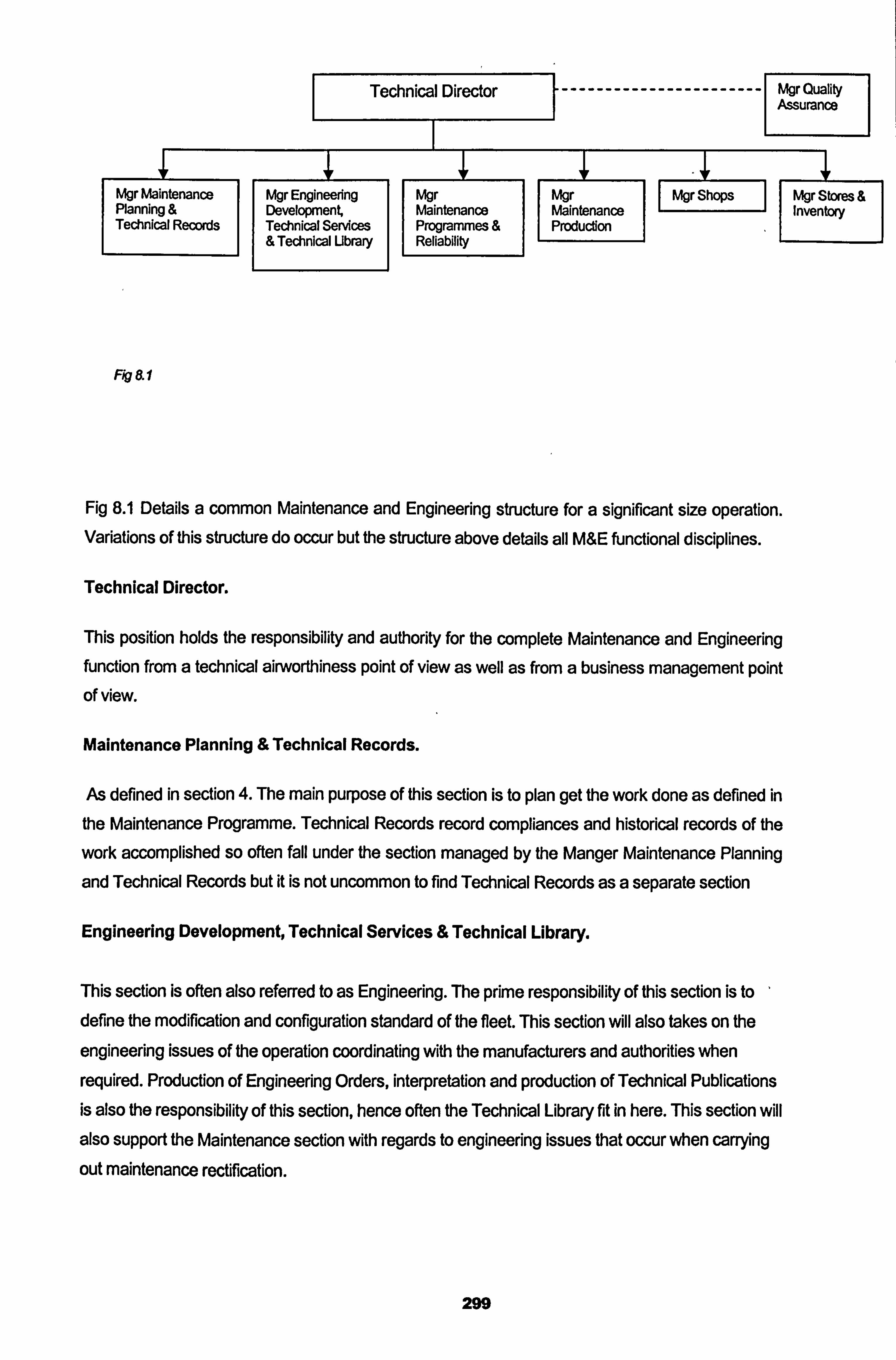
Technical Director Mgr Quality Assurance
Mgr Maintenance Planning & Technical Records
Mgr Engineering Development Technical Services &Technical Ubrary
Mgr Maintenance Programmes Reliability
I Mgr Mgr Shops II Mgr Stom Maintenance J Inventay Productim
II
Fig 8.1
Fig 8.1 Details a common Maintenance and Engineering structure for a significant size operation. Variations of this structure do occur but the structure above details all M&E functional disciplines.
Technical Director.
This position holds the responsibility and authority for the complete Maintenance and Engineering function from a technical airworthiness point of view as well as from a business management point of view.
Maintenance Planning &Technical Records.
As defined in section 4. The main purpose of this section is to plan get the work done as defined in
the Maintenance Programme. Technical Records record compliances and historical records of the
work accomplished so often fall under the section managed by the Manger Maintenance Planning
and Technical Records but it is not uncommon to find Technical Records as a separate section
Engineering Development, Technical Services & Technical Library.
This section is often also referred to as Engineering. The prime responsibility of this section is to define the modification and configuration standard of the fleet. This section will also takes on the
engineering issues of the operation coordinating with the manufacturers and authorities when
required. Production of Engineering Orders, interpretation and production of Technical Publications
is also the responsibility of this section, hence often the Technical Library fit in here. This section will also support the Maintenance section With regards to engineering issues that occur when carrying
out maintenance rectification.
299
Maintenance Programmes & Reliability.
This section is responsible for the definition and production of the Scheduled Maintenance
Programme and the accompanying task cards and work instructions. It is their responsibility that
the most efficient and effective maintenance programme is followed and through Reliability Monitoring the Maintenance Programme is revised. This section can also be found in the Maintenance Planning section or in the Engineering section depending upon the structure of the M&E division.
Maintenance Production.
This section is the technical front line and most staffed section in the M&E division. They are
responsible for accomplishing the scheduled maintenance and the defect rectification maintenance to keep the fleet operating. This section is often split into two sub sections; Line Maintenance and Base Maintenance.
Shops.
This section is responsible for the maintenance of components and the repair of off aircraft parts. Depending upon the capability of the organisation this can involve a multiple of shop types. Engine
shop, composite shop, electrical & avionic component shop, mechanical & hydraulic component
shops etc.
Stores & Inventory.
This section is responsible for ensuring the availability of tools and equipment and parts required to
support the technical operation. Often millions of dollars of inventory are controlled by this section. it
is their responsibility to ensure that the inventory is held correctly in a safe environment and that all inventory conform to correct specification. This section is often a section pulled in two directions,
with financial implications of holding so much expense the financial division often feels they should
control this section. Though perhaps not initially apparent but this section is essential to the
continued airworthiness of the fleet. If non conforming parts are allowed into inventory they can be
installed on the aircraft, this is why primarily the section belongs under the Technical Director rather than the Financial Director, but often today it is seen with the financial division.
Quality Assurance.
This section does not report directly to the Technical Director, but are a crucial section in the
Maintenance and Engineering function. The QA section shall normally today report directly to the
300
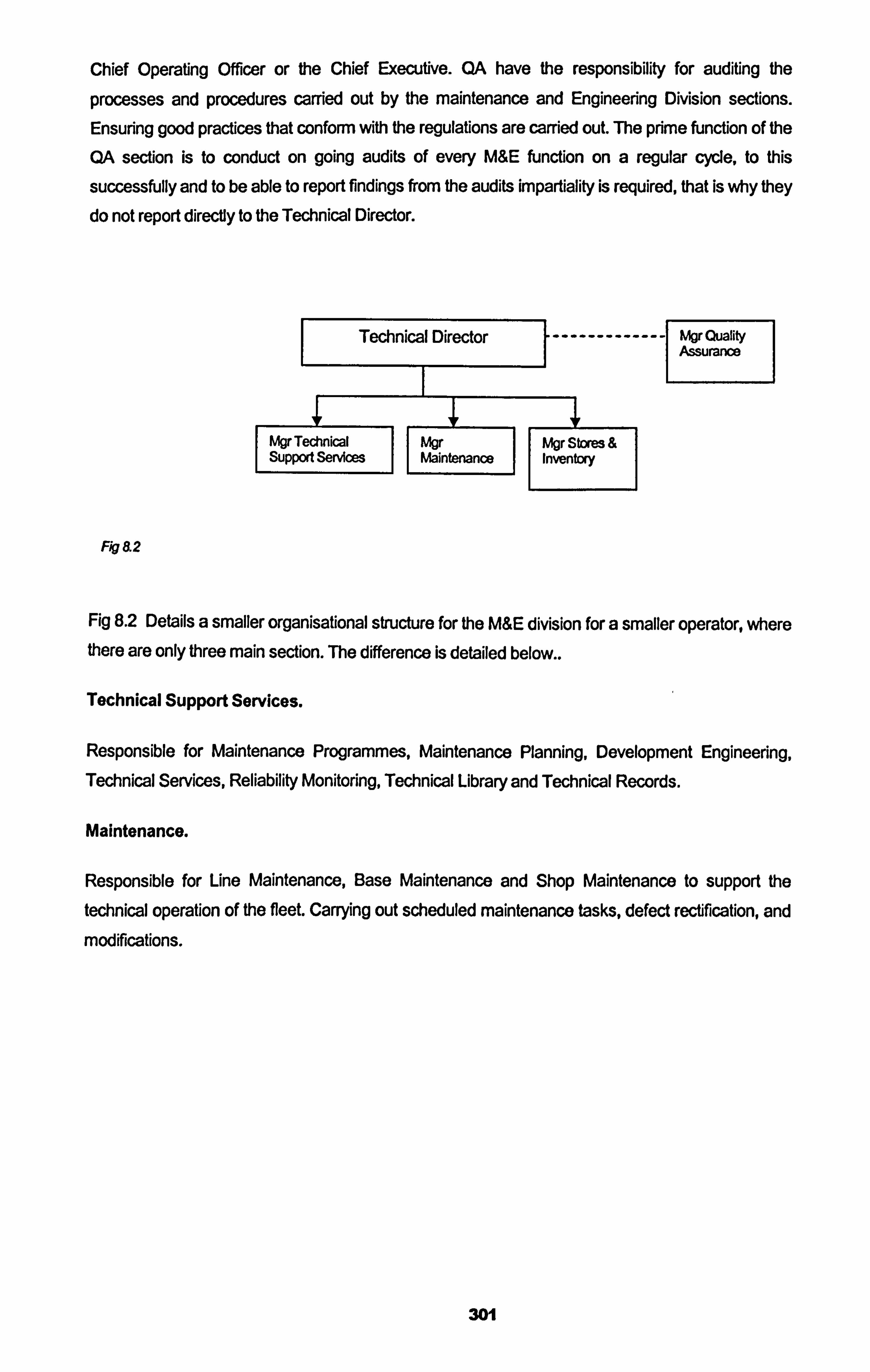
Chief Operating Officer or the Chief Executive. QA have the responsibility for auditing the
processes and procedures carried out by the maintenance and Engineering Division sections. Ensuring good practices that conform with the regulations are carried out. The prime function of the
QA section is to conduct on going audits of every WE function on a regular cycle, to this
successfully and to be able to report findings from the audits impartiality is required, that is why they do not report directly to the Technical Director.
Technical Director ------------- LIgr Quality Assurance
Mgr Technical Mgr ktr Stores & Support Services Maintenance
II Inventory
Fig 8.2
Fig 8.2 Details a smaller organisational structure for the ME division for a smaller operator, where there are only three main section. The difference is detailed below..
Technical Support Services.
Responsible for Maintenance Programmes, Maintenance Planning, Development Engineering, Technical Services, Reliability Monitoring, Technical Library and Technical Records.
Maintenance.
Responsible for Line Maintenance, Base Maintenance and Shop Maintenance to support the technical operation of the fleet. Carrying out scheduled maintenance tasks, defect rectification, and
modifications.
301
8.2 Maintenance Implications for the Requirements for an Air Operators
Certificate: JAR OPS.
An Introduction to Air transport Regulations.
In 1943 the USA initiated studies of post war civil aviation issues on an international scale. This
resulted in 1945 in the first International Civil Aviation Conference in Chicago USA. From this
convention an international body concerned with international air transport guidelines was formed
called "The International Civil Aviation Organisation" ICAO. ICAO was a specialised agency of the
United Nations (UN). ICAO's mission was defined as the following...
* Safe and coordinated growth in international civil aviation.
0 Guidelines for design and operation of civil aircraft.
Development of airways, airports and air traffic control facilities.
0 Promotion of aviation resources and fair competition for member states.
* Promotion of member states to be able to operate international air carriers.
0 Promotion of air safety standards in international civil aviation.
ICAO went on to define and publish Standard Recommended Practices (SARPs) that all member
states should follow. This was the first step towards regulating practices and procedures for
international air carriers. At around the same time, 1945, the "International Air Traffic Association"
IATA, was formed with 57 members from 31 nations. Today this number has grown to 267
members. IATA was a commercial operators association whose members would meet to discuss
and advice on international air transport issues with the intention to provide feed back into ICAO
who would if in agreement consider including issues discussed by IATA into the SARPs.
As recent as 1994 the IATA members re defined their mission goals with the intention to represent
the aviation commercial industry, with the following goals
To represent and to serve the airline industry in the fields of
1. Safety and Security.
2. Industry Recognition.
3. Financial Viability.
4. Product and Services.
302
5. Standards and Procedures.
in the mean time ICAO member states as well as non members started to formulate their own
national aviation regulations. ICAO member states used SARPs as their standards while others not. ICAO recognising the individual national aviation authorities requirements offered SARPs as a standards for them to build their own national regulations. In the UK the Civil aviation Authority
produced the regulations for British registered carriers, while in the US the federal Aviation Administration did. In France the DGCA, in Germany the LBA, in Switzerland the FOCA and so on. The one common standard the SARPs were used by the ICAO member states.
As European governments were working together in common marketing regulation and in building
a new airline building manufacturer, Airbus, in 1970 the European Joint Airworthiness Authorities
were formed. The intentions of this was to assist in a common standard for the manufacture of the
new products offered by Airbus, that would conform to a common European build standard. This
was built upon when in 1978 the JAA started to expend from not only a standard for the
manufacturing of aeronautical products, but of air transport maintenance and operational licensing. The JAA member states all had national aviation representatives on the JAA board. Again the JAA
respected and followed the guide lines of the ICAO SARPs in its attempt to define a common European regulation governing the design and manufacturing of aviation products, the
maintenance of aviation products and the operation of aviation products.
This philosophy started by the ICAO has now come complete circle and now the JAA and the FAA
are working together to harmonise regulations. The benefit of this harmonisation is seen as having
three major contributions ...
A common world standard for the manufacture of aircraft and aviation products.
2. A common world standard for the licensing of operators of aircraft.
3. A common world standard for the licensing of maintenance crew and flight crew.
The JAA started to define Airworthiness Standards by issuing JAR's, Joint Airworthiness
Requirements for member states to adopt into their own national regulations. Some examples
are
JAR 21: The Certification procedure for aircraft and related products and parts.
JAR 36: The requirements for aircraft noise.
303
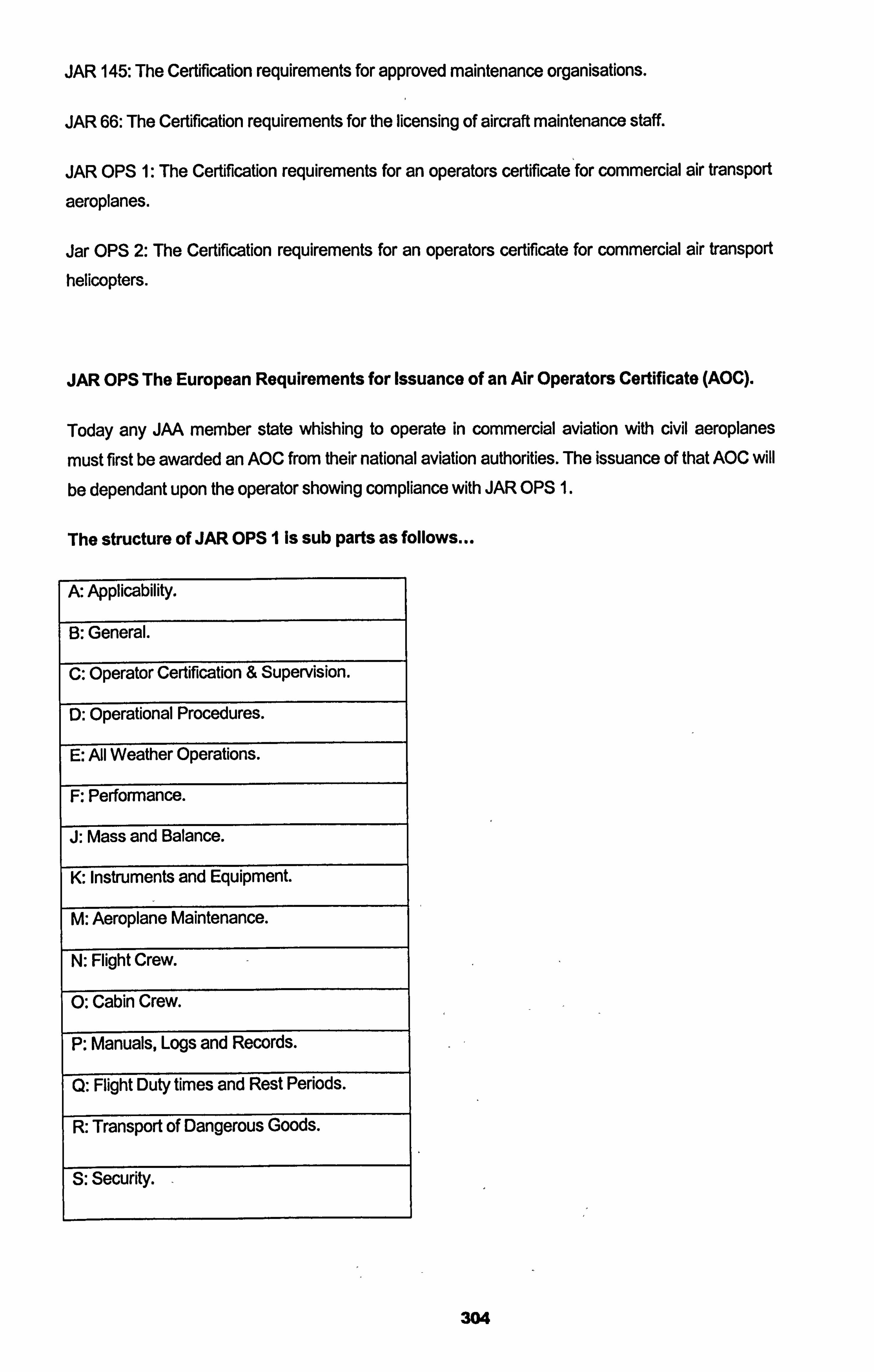
JAR 145: The Certification requirements for approved maintenance organisations.
JAR 66: The Certification requirements for the licensing of aircraft maintenance staff.
JAR OPS 1: The Certification requirements for an operators certificate for commercial air transport
aeroplanes.
Jar OPS 2: The Certification requirements for an operators certificate for commercial air transport
helicopters.
JAR OPS The European Requirements for Issuance of an Air Operators Certificate (AOC).
Today any JAA member state whishing to operate in commercial aviation with civil aeroplanes
must first be awarded an AOC from their national aviation authorities. The issuance of that AOC will
be dependant upon the operator showing compliance with JAR OPS 1.
The structure of JAR OPS I is sub parts as follows...
A: Applicability.
B: General.
C: Operator Certification & Supervision.
D: Operational Procedures.
E: All Weather Operations.
F: Performance.
J: Mass and Balance.
K: Instruments and Equipment.
M: Aeroplane Maintenance.
N: Flight Crew.
0: Cabin Crew.
P: Manuals, Logs and Records.
Q: Flight Duty times and Rest Periods.
R: Transport of Dangerous Goods.
S: Security.
304
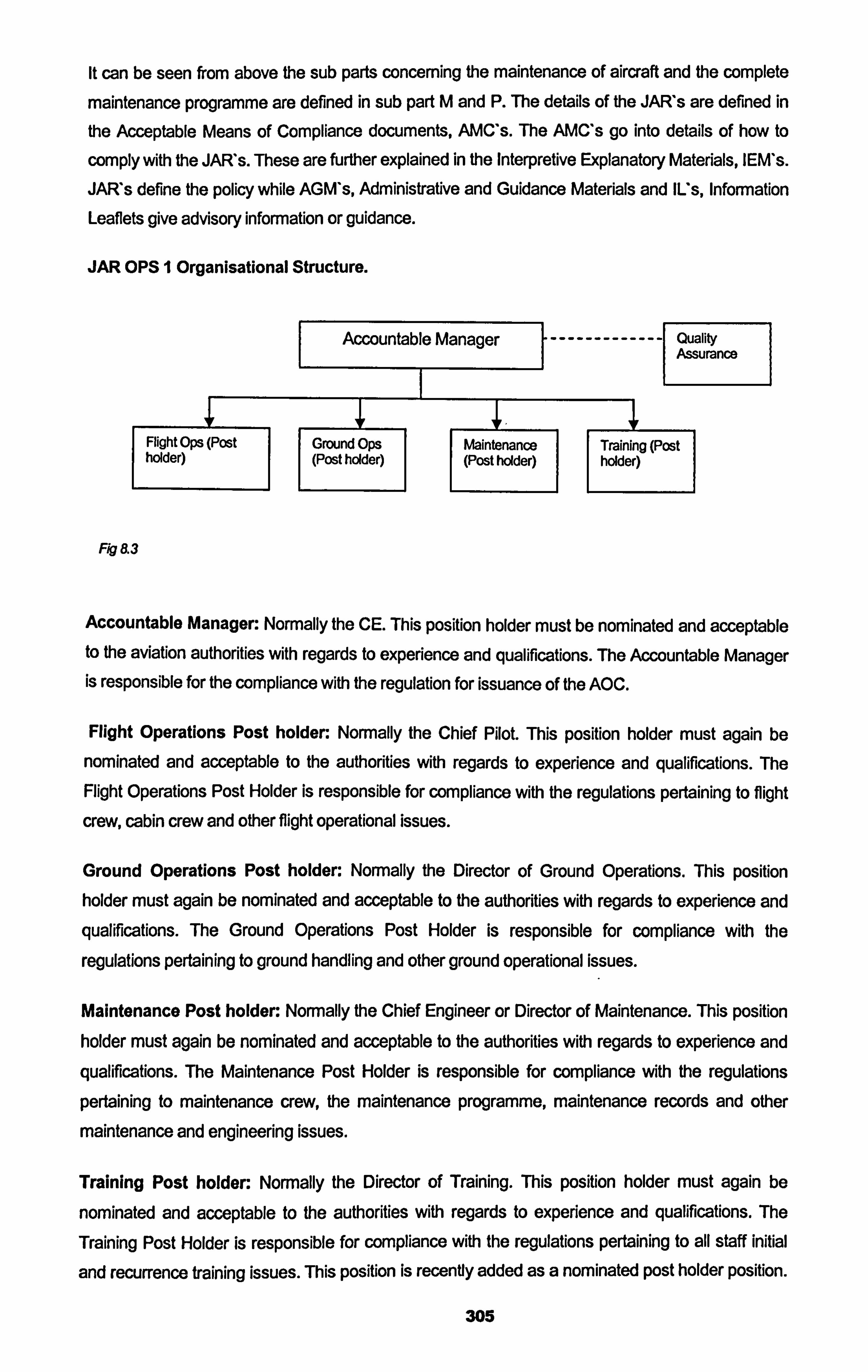
It can be seen from above the sub parts concerning the maintenance of aircraft and the complete
maintenance programme are defined in sub part M and P. The details of the JAF; Vs are defined in
the Acceptable Means of Compliance documents, AMC's. The AMC's go into details of how to
comply with the JAF; Vs. These are further explained in the Interpretive Explanatory Materials, IEM's.
JAF; Vs define the policy while AGM's, Administrative and Guidance Materials and Us, Information Leaflets give advisory information or guidance.
JAR OPS I Organisational Structure.
Accountable Manager
Flight Ops (Post Ground Ops Maintenance holder)
II (Post holder) (Post holder)
Fig 8.3
------------- Quality Assurance
Training (Post holder)
Accountable Manager: Normally the CE. This position holder must be nominated and acceptable to the aviation authorities with regards to experience and qualifications. The Accountable Manager is responsible for the compliance with the regulation for issuance of the AOC.
Flight Operations Post holder: Normally the Chief Pilot. This position holder must again be
nominated and acceptable to the authorities with regards to experience and qualifications. The Flight Operations Post Holder is responsible for compliance with the regulations pertaining to flight
crew, cabin crew and other flight operational issues.
Ground Operations Post holder: Normally the Director of Ground Operations. This position holder must again be nominated and acceptable to the authorities with regards to experience and
qualifications. The Ground Operations Post Holder is responsible for compliance with the
regulations pertaining to ground handling and other ground operational issues.
Maintenance Post holder: Normally the Chief Engineer or Director of Maintenance. This position holder must again be nominated and acceptable to the authorities with regards to experience and
qualifications. The Maintenance Post Holder is responsible for compliance with the regulations
pertaining to maintenance crew, the maintenance programme, maintenance records and other
maintenance and engineering issues.
Training Post holder: Normally the Director of Training. This position holder must again be
nominated and acceptable to the authorities with regards to experience and qualifications. The
Training Post Holder is responsible for compliance with the regulations pertaining to all staff initial
and recurrence training issues. This position is recently added as a nominated post holder position.
305
It may be acceptable to the national aviation authorities to nominate the training requirements to
each nominated post holder thus eliminating the need for a separate position, but the processes of
correctly managing the training of staff must be clearly assigned to a post holder.
Quality Assurance: Normally the Director of Quality Assurance. This position is not a post holder
or a nominated person, but must show acceptable experience and qualifications to hold the
position. The QA position is as shown above directly under the Accountable Manager. This enables impartial reporting back to the person responsible for the maintenance of the AOC requirements. The QA section is an audit section, who conducts regular audits of the operators procedures of
operation to ensure compliance with the regulations. It should be noted that the JAR's define the
QA audit role as imperative to the continuation of compliance with the regulations. The audit role
not only should involve maintenance and engineering but also all the flight operational and ground
operational requirements. The process of parallel auditing is recommended by the JAIT s rather
than in line monitoring, that was the tradition of previous quality control systems.
JAR OPS 1 sub part B, C, M and P Requirements Concerning the Maintenance of Aircraft.
The compliance requirements with regards to the maintenance of the continued airworthiness fo
an aircraft are as previously stated defined mainly in JAR OPS I sub part M, but relevant
requirements can also be found in JAR OPS I sub part B, C and P.
The seven main maintenance regulations pertaining to the issuance of JAA AOC are as follows
Maintenance Management (JAR OPS 1.895) :A JAR OPS operators that is not a JAR 145
approved maintenance facility must have in place a, contract with a JAR 145 approved
maintenance organisation. This contract must define in detail the following..
Duties and responsibilities of both the JAR OPS I operator and the JAR 145 approved
nominated maintenance organisation.
Procedures followed for the exchange of technical,, maintenance and engineering
information between the JAR OPS I approved operator and the nominated JAR 145
approved maintenance organisation.
The over all responsibility of the management of the maintenance of the aircraft lies with the
nominated Maintenance Post Holder.
306
Maintenance Management Exposition (JAR OPS 1.905): This is a document that defines how
the operator complies with the maintenance requirements of the JAR OPS. It details the technical
procedure that the operator will follow. In the case when an operator is not JAR 145 approved, this document will define what JAR 145 approved organisation will be contracted to carry out the
maintenance of the fleet and how the coordination of the maintenance will take place. The MME
must also contain the operators policy of compliance with the Maintenance Programme, Air Worthiness Directives and optional Service Bulletins. The document should contain four distinct
parts.
Part 0: The General Organisation of the Maintenance Division.
Part 1: JAR OPS Maintenance Procedures.
Part 2: Quality System.
Part 3: Contracted Maintenance.
The Maintenance Post Holder is named in this document as the responsible manager for ensuring the procedures are followed. This document and its procedures must be approved and accepted by the national aviation authorities.
Operator Maintenance Programme (JAR OPS 1.91o) : This document contains all scheduled maintenance tasks with their intervals that the operator will comply with to ensure the continued airworthiness of the fleet. The Maintenance Programme will also define the processes and procedures followed to maintain the aircraft to the maintenance scheduled and should define how the maintenance schedule is developed including a reliability monitoring programme. The
maintenance programme must include a Pre Flight Inspection programme that must be carried out prior to every flight. The responsibility of compliance with the Pre Flight Inspection programme must be clearly defined. Each aircraft type operated must have its own Maintenance Programme.
Maintenance and Engineering Records (JAR OPS 1.920) : The operators must ensure that the technical records of the aircraft are maintained and stores in a way acceptable to the authorities. This includes all maintenance and engineering activities carried out on the aircraft and all flight hours and cycles accomplished by the aircraft. Compliance with this requirement is the
responsibility of the Maintenance Post Holder.
Quality System (JAR OPS 1.900 & 1.035) : The operators must have in place Quality Assurance
processes and procedures that the operator will follow in conducting a Quality Assurance System
of audit programmes of the technical maintenance operation. Compliance with this document is the
responsibility of the Quality Assurance manager.
Aircraft Technical Log (JAR OPS 1.915) :A document that will be called the Technical Log must be defined and accepted by the aviation authorities for the following function...
307
0 To record defects and malfunctions discovered during the operation of the aircraft.
0 To record maintenance activities carried out on the aircraft.
0 To record the operational activities of the aircraft.
0 To record operating safety information.
Minimum Equipment List (JAR OPS 1.030) : An operator must have in place a Minimum
Equipment List (MEL) that is based upon the Master Minimum Equipment List (MMEL) issued by
the Manufacturer, approved by the Type Certificate issuing authority. The operators MEL must be
acceptable to and approved by the national aviation authority. The MEL gives details of authority for
operation with defective or non operational systems that deviate from the original design. The
operator must comply and refer to the MEL when operating with un serviceable systems and must
comply with the requirements of the MEL at all times. The production and development of the
operators MEL is the responsibility of the Maintenance Post Holder with coordination with the Flight
operations Post Holder.
The above maintenance regulations must be shown to be in place before the JAA member state
national aviation authority will issue an AOC in accordance with JAR OPS 1. Attached is a model
plan including a time frame for establishing such a plan. It also details the appointment of the
nominated post holders.
See Aftachment 6, A Plan for preparing for an AOC under JAR OPS 1., .. \Personal\, JAAOps. xis.
it can be seen that emphasis of the JAR's with regards to maintenance is to establish the
following
Responsible managers accountable for the compliance with the regulations. These
managers must not only be qualified but also be acceptable to the authorities.
Clear procedures and processes in place that will ensure the maintenance of the
continued airworthiness of the aircraft operated by the JAR OPS approved operator.
On going monitoring through a Quality Assurance System that will ensure the continuation
of compliance with the procedures and processes required by the issuance of the JAA
AOC and identify deficiencies that may occur during the operation.
it should be noted that today the Joint Aviation Authorities are in the process of transitioning from
the JAA to EASA (European Aviation Safety Authority). It is intended that the EASA will take over
the role of the JAA by publishing and maintaining the requirements as regulation for state
members. The main issue here is that while in the past each JAA member state aviation authorities
accepted and adopted the JAR's, EASA will in fact replace the member state aviation authorities
and issue and enforce the regulations directly from EASA and not through the national aviation
308
authorities. This means the disappearance of the national aviation authorities and the introduction
of EASA as the aviation authority for all member states. EASA Rules will then replace the JAR's
and be enforceable under European Law for EASA member states. The Management Board of EASA was established in October 2002 and is meeting with a high frequency to make the
necessary decisions for facilitating the starting of the Agency as planned by 28 September 2003.
The exact date when EASA will take over from the JAA is still under review.
309
9. Thesis Conclusions.
This thesis is entitled "Aircraft Maintenance Engineering: The Development of an Aircraft
Maintenance Programmd. It brings together and explains an area that the author feels Is not well documented or published today in the world of aviation maintenance management, yet it is
fundamental to the continued airworthiness of an aircraft. It is the authors experience that too many times operators have attempted to carry out the function of maintenance engineering without full
understanding of the reasons and implication of their actions. Thus ending up with an ineffective
and non-applicable collection of maintenance activities that can only add to the expense of the
technical operation and even at times contribute to the possibility of occurrences. The thesis also
goes on to develop new decision tree diagrams for the use in developing the Maintenance
Programme and incorporating new aspects of aircraft operation.
The maintenance programme is the building block of ensuring the continued airworthiness of an
aircraft and in meeting the regulatory requirements for the technical operation of civil commercial
aircraft. If the initial production of the maintenance programme is done correctly and the ongoing development of the programme is taken into consideration correctly, the maintenance management
process of the aircrafts complete technical operation will only lend itself to a safer and more cost
effective technical operation. The conclusions defining the new and original suggestions are within
each of the detailed sections but are again reiterated below...
Section 2. Reliability Centred Maintenance (RCM).
This section introduces the concepts of why maintenance is required and why systems fail. It
identifies RCM as the most efficient and preferred method for producing a scheduled maintenance
programme as its motivation are in realising the inherent reliability of the original design and
elimination any tasks that do not contribute to the maintenance of the inherent design. It introduces
RCM in aviation as MSG3 detailing the exact decision tree diagrams and makes critical
examination of the diagrams identifying areas in the process that can be improved. The section defines damage tolerance and shows areas where RCM I MSG3 is insufficient in ensuring the on
going airworthiness of the aircraft and at times life limitations do need to be introduced. This
departure from RCM / IVIGS3 philosophy is required when the failure of a system or component
would result in catastrophic failure effects, on these occasions an alternative method to RCM /
MSG3 must be applied and the additional cost of applying this kind of concept must be absorbed. It
is shown in section 3 that this may be required for those structural items that are identified as Principle Structural Elements, such as single load bearing monolithic elements, landing gear,
engine discs or engine shafts, whose function is critical and whose failure can not allowed to occur in-service, these items must have life limitation applied to them. In this section the decision tree
analysis is identified as a valuable method for decision making and does again many times
influence the way maintenance decisions are made through out the thesis.
310
Section 3. The Maintenance Steering Group. (MSG).
This section takes from that described in section 2 on RCM and defines how it has developed and how it is today applied and managed today in aviation defined as MSG3. It details the evolution of how MSG developed over the years in the aviation industry and it bring together and shows how in
aviation that the industry and the regulators have organised and developed the management of the
production and development of the scheduled maintenance programme and have identified RCM / MSG3 as today's industry standard. The section goes on and identifies the regulation in place with regards to the production and development of the scheduled maintenance programme and shows how those regulations are complied with by the manufacturers and the operators of modem air liner
aircraft. It defines a system in producing an aircraft maintenance programme for an operator that
conforms to present day regulations and industry standards then leads into section 4 where enhancements and improvements are developed to the present day standards.
Section 4. New Enhancements to the MSG3 Process.
Extended Twin Operations has made regulators and manufacturers think again about ways of improving the maintenance programme of an aircraft. This has been done by the regulators defining new rules for design, manufacture and operation of twin engined aircraft. The author has
established how to comply with these rules and has taken the philosophy of the rules further to
apply the ETOP theories to also three and four engined aircraft. The conclusions here are two fold -
1. The complete philosophy should introduce to the MSG3 / RCM initial analysis the ETOPs issues by inserting an ETOPs question in the initial analysis rather than adding them in as an addendum by the operator at a later stage. This way the ETOPs issue is impregnated inherently into the
process resulting in the identification and definition of ETOPs significant items and tasks. Figure 4.1 in section 4 inserts the ETOPs question in the MSG3 analysis by determining a new failure
category Operational ETOPs Effect Cat 6ER, then again in figure 4.2 Hidden Non Safety Effect Cat
9ER. As a result of this new identified MSG3 category the maintenance tasks can be selected and
applied with the ETOPs philosophy inserted from the inception of the development of the
scheduled maintenance programme produced and issued in the MRBR.
1 2. The second part of the conclusion here is that the increased airworthiness that such a philosophy
brings to an aircraft is as relevant to all aircraft and not just twin jets. Inclusion of ETOPs standards
into the normal technical operation of all aircraft makes safe airworthiness sense for a slight
increase in cost. This means the introduction of ETOPs Philosophy training for three and four
engine aircraft maintenance staff making them aware of sensitive systems and the reasons for
maintenance tasks, introducing simple ETOPs style reliability monitoring of oil consumption and
recurrent defects, avoiding multiple maintenance tasks on similar systems at the same time by the
same maintenance staff, the use of specific and clear English in reporting and detailing findings and
maintenance actions and finally the avoidance of swapping components between an aircrafts
similar systems.
311
Section 4.2 goes further to define improvements to the development of the maintenance programme by introducing the need to include a consideration for utilisation, specifically Low Utilisation. The author defines what should be considered as low utilisation and the conclusion is that low utilisation should be and can be relevantly considered in the development of the scheduled maintenance programme by two methods...
Method I by adjusting the originally MRBR MSG3 defined tasks and intervals for low utilisation.
Method 2 by inserting a low utilisation question in the original MSG3 analysis process.
Figure 4.3 proposes a MSG3 style analysis for low utilisation that applies a new set of five
questions to make the MSI or SSI relevant for low utilisation. The author defines that method is the
correct conclusion for an effective and applicable low utilisation maintenance programme, where the MRBR provides a programme for such an operation inherently rather than an adaptation of an established programme for none low utilisation operations. The author expresses that if this method is not applied then the maintenance programme will be inefficient and possible non effective.
Section 4 finishes with section 4.3 an economic comparison of a non MSG3 scheduled maintenance programme versus an MSG3 scheduled maintenance programmes. It uses an actual in-service modem aircraft (MD80) that has underwent both types of analysis where it was shown that a reduction in life limited components was realised as well as a 40% plus reduction in the man hours to carry out the scheduled maintenance tasks. The figures were then applied to a model that take into consideration the operating life of the aircraft, using scheduled maintenance man hours for the life cycle and the anticipated total flight hours for the in-service life of the aircraft to define a ratio of scheduled maintenance man hours required for 1 hour of flight. The MSG 3 scheduled
maintenance programme was shown to require about 40% less man-hours per flight hour, thus defining that while modem manufacturing techniques and improvements in design technology and materials can influence a reduction in maintenance requirements, MSG3 could be attributed as the
single most significant contributor to a reduction in cost in maintaining the inherent reliability through the scheduled maintenance programme. A simple model was developed that could be used to
compare scheduled maintenance programmes. It should also be noted that it was identified that at times MSG3 was not sufficient in it self in maintaining complete airworthiness with requirements on
occasion to revert to the introduction of life limitations for those structural items that were identified
as whose failure would result in catastrophic failure consequences. These Principle Structural
Elements (PSEs) were identified through the MSG3 process but life limited by other engineering
analysis methods. So while MSG3 can be considered as the most efficient maintenance analysis method available today it must on occasion be supplemented by the introduction of life limits to those Principle Structural Elements. -
312
Section 5. Maintenance Engineering Planning.
This section defines Maintenance Engineering Planning as the process of enabling the
accomplishment of the scheduled maintenance tasks identified in the previous section in the most efficient and effective manner. In this section 5 processes are identified
1. Defining, 2. Planning. 3. Implementation, 4. Completion and 5. Evaluation and Review.
The conclusions to be made in this section is that the planning tasks are essential to a cost effective and efficient maintenance programme. With out good planning and management the
established maintenance programme can become ineffective and very costly to the operation. Section 5 establishes the 4 forecast levels of maintenance engineering planning..
1. Short term, 2. medium term, 3. Long Term and 4. Production Planning.
Section 5.3 deals with a very new and totally relevant issue of human factors in maintenance engineering of aircraft and concludes that to avoid the consideration of human factors
-in the
maintenance of aircraft is irresponsible and potentially can affect the airworthiness of the aircraft. This section defines a process that can efficiently incorporate consideration to human factors in the maintenance programme and promotes the use of a simple and efficient error reporting mechanism that encourages a culture of human factor awareness.
Section 6. The Reliability Programme: Reliability Monitoring and Development of the MSG3 Maintenance Programme.
This section is perhaps the most relevant part of the thesis as it addresses where the author believes is a significant gap in the industry. That is the misunderstanding that the reliability programme is an integral and completely necessary part of the complete maintenance programme of an aircraft. At the beginning of the section there is a paragraph that states...
A Maintenance Program is a Set of Rules and Practices for Managing Maintenance and Controlling and Developing the Scheduled Maintenance Program. The Reliability
Programme is an Integral part of the Maintenance Programme that supports and verifies the
effectiveness and applicability of the scheduled maintenance tasks through monitoring the
In-service findings resulting from the technical operation of the fleet and maintenance findings resulting from the scheduled maintenance tasks.
The conclusion the author is making here is that since MSG3 analysis considers maintenance
actions based upon evidence of failures and inherent reliability of the design it is essential to
the programme that findings and defects are monitored and studied for their implications to
the maintenance programme. The author goes further to conclude that not only do operators fail at times to understand this even the regulators also by not mandating that reliability
313
programmes are put in place by operators. The author goes on to suggest simple effective
methods that can enable relevant reliability studies. Figure 6.2 continues in the MSG3 I RCM
style of decision tree analysis and defines a method of analysing and tracking recurrent defects that may be symptomatic of an ineffective maintenance programme. The conclusions
also made in this section suggest that at times the recording and reporting of data is not the
most relevant or efficient method of conducting reliability studies. Too often significant defects
can be lost with in a mound of data, the author goes on to recommend that getting to the root
cause of findings or failures confirming rectification action is the most relevant way of
addressing reliability issues. The author concludes that the three most relevant methods that
can identify reliability issues can be enabled through..
1. The monitoring of recurrent discrepancies.
2. Engine Condition Monitoring.
3. Oil Consumption Monitoring.
These three monitoring methods can instigate the research required to get to the root cause of all
events. Section 6.2 is a very important part of the thesis and defines how to improve and develop the
maintenance programme in the most efficient way utilising reliability monitoring. The conclusions here are that the maintenance programme can be developed and adjusted from two different
origins, from in operation findings and from on maintenance findings. To consider one but not the
other would not be correct. Section 6.2.3 defines a relevant and efficient method of establishing and developing an effective maintenance programme which is in the authors opinion an essential practice. The author then goes on in section 6.2.4 to describe a process that is not in common use today with operators that is an occasional complete review of the maintenance programme to
ensure that the scheduled maintenance tasks are continuing to provide validity in maintaining the inherent reliability of the original aircraft design. This optimisation process is detailed and time
consuming but the author concludes that it is necessary even when conducting a simple reliability
monitoring programme. Figures 6.4,6.5,6.6,6.7,6.8,6.9 and 6.10 again use the MSG3 / RCM
decision tree style analysis to identify redundant tasks that do not contribute to the continued
airworthiness of the aircraft or task that need to be introduced or developed. Continuing to expand the MSG3 / RCM philosophy the author in section 6.3 returns to one of the initial tenants of MSG3
philosophy that involves the operating crew. The author concludes that their part in the continuation
of the airworthiness of the aircraft through the development of the maintenance programme is not fully understood as it perhaps is not also with the maintenance crew. The author concludes that
training of the crews is essential ensuring they understand the complete philosophy behind the
maintenance programme enabling them to play a more relevant part in the reporting of events and in the rectification of those events.
Section 7. Maintenance Programme Control Software.
Section 7 deals with the availability of software to enhance the maintenance programme
management. It identifies a process that can be followed to asses, select and implement a relevant
314
MPCS. The conclusion in this section are that by utilising the "Super User" group philosophy this
will enable success by involving all relevant maintenance engineering sections in the complete
process. The methods the author defines in the section along with their attachments can be
concluded as being an efficient and effective process ensuring the optimisation of an MCPS in the
management of the maintenance programme.
Section 8. The Organisation and the Maintenance Programme.
The thesis ends with section 8. In section 8 the author defines a simple organisational structure that
can efficiently carry out and manage the maintenance programme that will satisfy the European
JAA standards, he goes on to clarify the relevant regulation in effect today concerning the technical
operation and maintenance of civil aircraft for a European Operator who belongs to a JAA member state. The conclusion here is that a maintenance organisation does not have to be heavily layered
and complex and by using the organisational structure suggested in figure 8.1 or 8.2 the
maintenance engineering functions can be efficiently managed and served.
In summary it can be concluded that the author has described the basic philosophy of IVISG3 /
RCM in the early parts of the thesis defining the need to maintain the on going airworthiness of the
aircraft. He has then gone on to identify and conclude that to stop there and to just apply the
scheduled maintenance tasks without further consideration is not effective and does not enable an
efficient and effective maintenance programme. He has established that the concept of the
maintenance programme includes on going review and development of the programme through
reliability monitoring and training of those involved with the maintenance and operation of the
aircraft. Using the already established concepts of MSG3 / RCM and decision tree logic the author has continued these methods in a variety of other applications for example in the introducing of ETOPs standards for all operations, for the consideration of low utilisation, for the monitoring of
recurrent defects and for the complete optimisation review of the maintenance programme. It was
also shown that at times RCM / MSG3 analysis required supplementing with life limitations to
PSE's, this is an important point that must be understood, with out the inclusion of PSE life
limitations catastrophic failures could occur. In conclusion the author suggests that through better
understanding of the concepts of the maintenance programme, better development of the
maintenance programme, better monitoring of the reliability of the operation and better
management of the maintenance programme will only result in a more airworthy fleet and cost
effective maintenance engineering operation.
315
10. Recommendations for Further Work.
The author believes that during the research for this thesis he has identified a gap in the guidance
and documentation available in the maintenance management of civil aircraft. This thesis brings
together the variety of subjects concerned with maintaining civil aircraft and suggests the adoption
of existing sound standard practices and the adoption of new processes and procedures based on his research and experiences.
Over the period of this thesis the author has consulted with many operators, maintainers and
manufacturers in the aviation industry and debated and discussed the ideas in this thesis. During
this processes he began to realise that clarification of the complete Maintenance Programme
process was required and a document that details the complete maintenance programme and
maintenance management process is needed in the industry, further more he believes that we have now experience around 12 years of the successful use of RCM / MSG3 with large civil
airliners, it is time again to review the process and take another step further to develop a more
efficient and effective Maintenance Programme standard. It is the authors belief that this thesis is
on its way to providing that requirement. Continuing the concepts and practical application of this
thesis the author has started to implement the conclusions defined in the thesis for a small Boeing
fleet of B737-NG's and B747-400's where he is the Maintenance and Engineering Planning
Manager. The MPCS process has been followed by the author and shown to be a great success. The implementation of the reliability monitoring processes described in this thesis has also been
implemented by the author for the Boeing fleet as has the inclusion of the ETOPs standards to twin
jets and to four engined aircraft. Aso the introduction of the low utilisation concepts into the
maintenance programme also has been implemented. The process of the maintenance
programme optimisation study has still to be done on the subject Boeing fleet. The author regards this optimisation process as a test and indicator of the success of all the improved procedures and
conclusion defined in this thesis. The author feels that once he has accomplished the optimisation
process depending upon the findings of that process, i. e. will that process identify significant
changes required to the complete maintenance programme, this will be conformation that the
recommendation with in this thesis do contribute to an effective, applicable and efficient
maintenance programme. The author intends to conduct the optimisation process with in the next
year for the B737-NG's, after four complete years of operation of the fleet, once sufficient data has
been gathered.
In addition to continuing the development of the Maintenance Programme concepts described in
this thesis for the fleet managed by the author he will continue to work with the Aviation Standard
bodies such as IATA and ICAO as well as the aircraft manufacturers Boeing and Airbus in
improving the scheduled maintenance programmes that operators of airliners utilise. Also the
author will attempt to take the maintenance programme philosophy out of aviation and encourage the application of the standards into other industries such as marine vessels, tanks and even
plants. The standards described and developed with in this thesis are totally transferable into non
aviation applications meaning other industries could benefit in reduced maintenance times, more
316

effective maintenance tasks, better reliability monitoring as well as all the other management benefits from what has been developed in the aviation world over the last 20 years. While there. is
evidence that RCM / MSG3 has been adopted in part in non aviation applications, the author feels
the full understanding that RCM/MSG3 in itself is not sufficient and must on occasion be
supplemented by life limitations and that RCM/MSG3 must include reliability monitoring adopting the philosophy at least of simple event based reliability monitoring in support of defining the
effectivity and applicability of the scheduled maintenance tasks. The author has approached BAE Systems a manufacturer of marine vessels (submarines and battle ships) as well as land and air vehicles (tanks and fighter jets), on the adoption of civil aviation MSG3 Maintenance Programme Standards and the use of MPCS in managing the maintenance programme on those craft. This is a
great opportunity in the discipline of maintenance engineering to share with non aviation
applications the aviation standards that have been developed due to strict regulations and safety
concerns, the author will explore this further and continue to work with BAE Systems in this area.
317
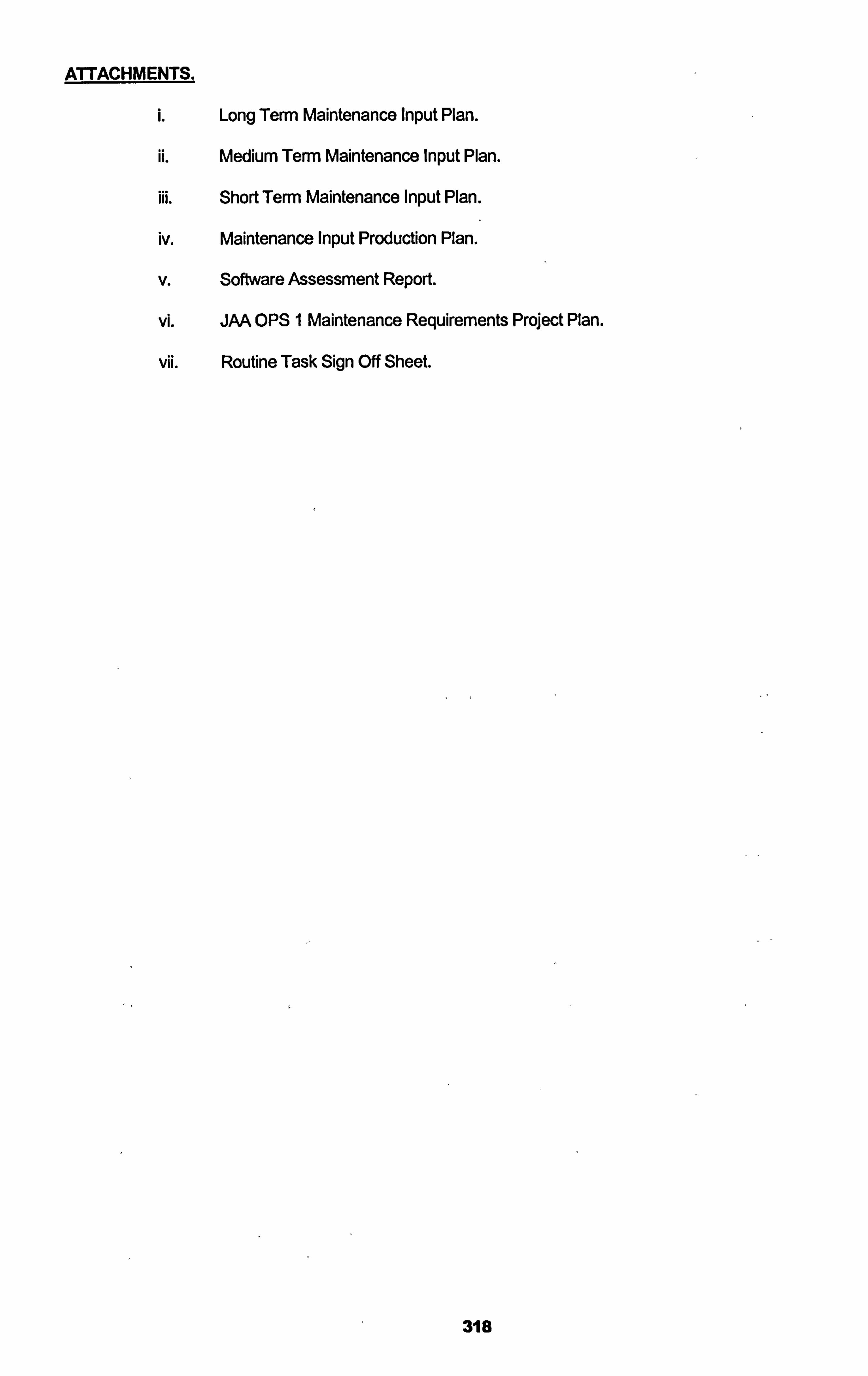
ATTACHMENTS.
Long Term Maintenance Input Plan.
ii. Medium Term Maintenance Input Plan.
iii. Short Term Maintenance Input Plan.
iv. Maintenance Input Production Plan.
V. Software Assessment Report.
vil. JAA OPS I Maintenance Requirements Project Plan.
vii. Routine Task Sign Off Sheet.
318
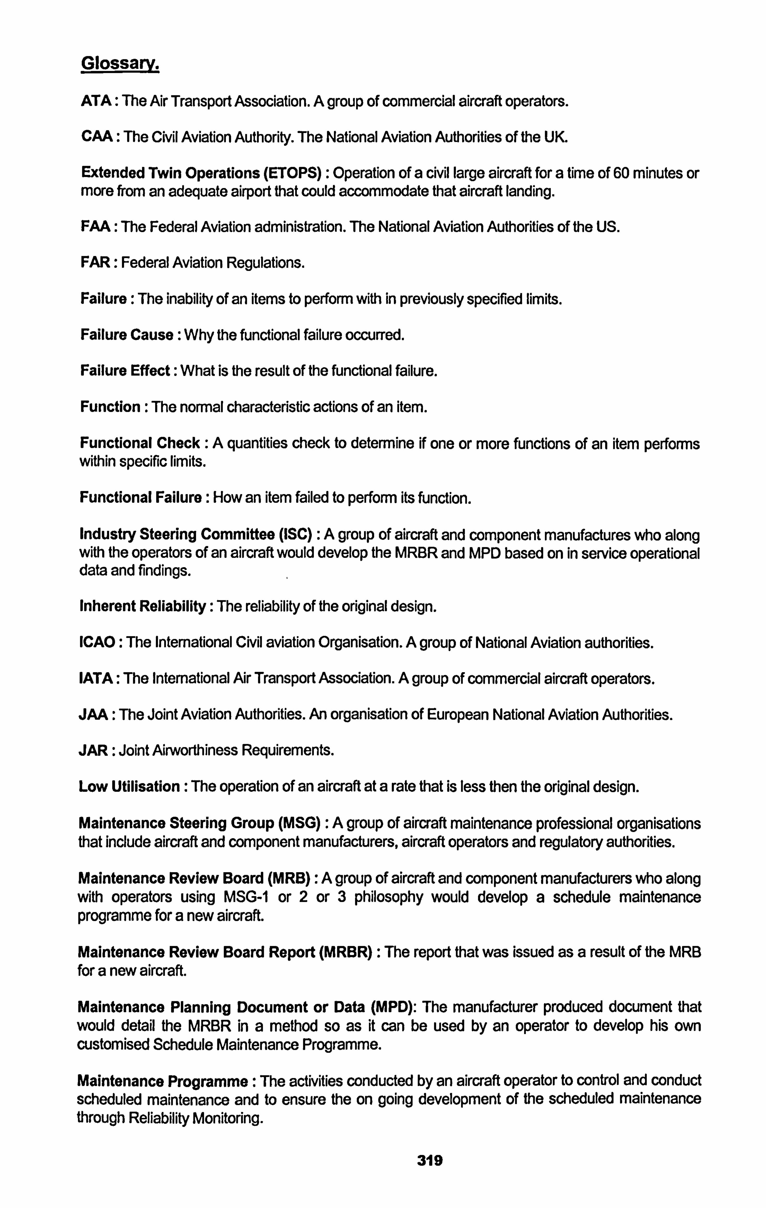
Glossarv.
ATA: The Air Transport Association. A group of commercial aircraft operators.
CAA: The Civil Aviation Authority. The National Aviation Authorities of the UK.
Extended Twin Operations (ETOPS) : Operation of a civil large aircraft for a time of 60 minutes or more from an adequate airport that could accommodate that aircraft landing.
FAA: The Federal Aviation administration. The National Aviation Authorities of the US.
FAR: Federal Aviation Regulations.
Failure: The inability of an items to perform with in previously specified limits.
Failure Cause : Why the functional failure occurred.
Failure Effect: What is the result of the functional failure.
Function : The normal characteristic actions of an item.
Functional Check :A quantities check to determine if one or more functions of an item performs within specific limits.
Functional Failure : How an item failed to perform its function.
Industry Steering Committee (ISC) :A group of aircraft and component manufactures who along with the operators of an aircraft would develop the MRBR and MPD based on in service operational data and findings.
Inherent Reliability: The reliability of the original design.
ICAO : The International Civil aviation Organisation. A group of National Aviation authorities.
IATA: The International Air Transport Association. A group of commercial aircraft operators.
JAA: The Joint Aviation Authorities. An organisation of European National Aviation Authorities.
JAR: Joint Airworthiness Requirements.
Low Utilisation : The operation of an aircraft at a rate that is less then the original design.
Maintenance Steering Group (MSG) :A group of aircraft maintenance professional organisations that include aircraft and component manufacturers, aircraft operators and regulatory authorities.
Maintenance Review Board (MRB) :A group of aircraft and component manufacturers who along with operators using MSG-1 or 2 or 3 philosophy would develop a schedule maintenance programme for a new aircraft.
Maintenance Review Board Report (MRBR) : The report that was issued as a result of the MRB for a new aircraft.
Maintenance Planning Document or Data (MPD): The manufacturer produced document that would detail the MRBR in a method so as it can be used by an operator to develop his own customised Schedule Maintenance Programme.
Maintenance Programme: The activities conducted by an aircraft operator to control and conduct scheduled maintenance and to ensure the on going development of the scheduled maintenance through Reliability Monitoring.
319
Maintenance Programme Control Software (MPCS) :A computerised software that assists in managing the Maintenance Programme activities.
MSG-1: A decision tree philosophy used to establish the B747-100 schedule maintenance programme. Developed by the Maintenance Steering Group.
MSG-2: A development of the MSG-1 philosophy.
MSG-3: A further development of the MSG-2 philosophy incorporating RCM to develop a schedule aircraft maintenance programme.
MSI: Maintenance Significant Item.
Non Routine Maintenance :A maintenance activity that results from carrying out scheduled maintenance, its objective is to return the aircraft or component to it state of inherent reliability.
Notice of a Recurring Defect (NORD): method for monitoring and instigating the investigation of recurring in service defects.
Reliability Centred Maintenance (RCM) :A methodology to identify schedule maintenance using decision tree logic.
Reliability Programme: A sub part of the Maintenance Programme that includes the monitoring of findings and non routine maintenance to ensure the effectiveness and applicability and on going development of the scheduled maintenance programme.
Schedule Maintenance :A maintenance activity that is designed to identify when the inherent reliability of an aircraft has been reduced.
SSI : Structural Significant Item.
320
Biblioqraphv.
Published Books.
Reliability Centred Maintenance 11. (John Moubray, 1992, Industrial Press).
Handbook of Reliability Engineering and Management. (W. Grant Ireson, Clyde F. Coombs Jr, Richard Y. Moss, 1996 McGraw Hill).
Aircraft Structures for Engineering Students. (T. H. G. Megson, Butterworth, 2002)
Technical Documents & Manuals.
Reliability Centred Maintenance. (F. S. Nowland, US Dept of Commerce, 1978)
B737-NG Maintenance Review Board Report. (Boeing Aircraft Corporation & the US Federal Aviation Administration, Department of Transport 1998).
B737-NG Maintenance Planning Document. (Boeing Commercial Aircraft Corporation, 1998).
Maintenance Evaluation and Programme Development Document MSG-1 (13747 Maintenance Steering Group, Boeing Commercial Aircraft 1968).
Aldine / Manufacturer Maintenance Programme Planning Document MSG-2 (R&M Sub Committee, the Air Transport Association 1970).
Boeing ETOPs Guide Volume 11 and Ill. (Boeing Commercial Aircraft 1993).
Evaluation Criteria for reliability Centred Maintenance (RCM) Processes. (The Engineering Society for Advancing Mobility Land, Sea and Space. SAE JA1 0111999).
Federal Aviation Advisory Circular 120-17B 2001.
Federal Aviation Advisory Circular 120-16D 2003.
JAA Information Leaflet 20.
City University ATM Structures Course Notes. City University 2002.
ATA Specification 100. (ATA 1996).
Amid Flight Approved ETOPs Maintenance & Engineering Procedures. (Mark J Pierofti, 2000).
Amid Flight B737-BBJ Approved Maintenance Schedule. (Mark J Pierotti, 1999),
Amid Flight Maintenance Engineering Planning Procedures. (Mark J. Pierofti 1999).
Maintenance Programme Control Programme Implementation Procedures. (Mark J. Pierotti 2003).
Joint Airworthiness Regulation, JAR's. (Joint Aviation Authorities 2003).
Federal Aviation Regulations, FAR's (Federal Aviation Administration 2003).
Civil Aviation Inspection Procedures, CAIP's (UK Civil Aviation Authorities 1989).
321
Professional Aviation Seminar Notes.
Operator / Manufacturer Scheduled Maintenance Development Document MSG-3 (Air Transport Association Aircraft maintenance Division 2000).
Maintenance Programme Optimisation. (IATA 1997).
TSC Aircraft Maintenance and Reliability Seminar Notes. (Transport System Consultancy 2003).
Boeing Aircraft Maintenance Reliability and Cost Analysis Seminar Notes. (Boeing Commercial Aircraft 2003).
Boeing Aircraft Production Planning Requirements for Continued Airworthiness Seminar Notes. (Boeing Commercial Aircraft 2001).
European Academy for Aviation Safety JAR OPS , 145 & QA Systems Seminar Notes. (EAAS 2003).
Boeing Airline Maintenance Programme Development Seminar Notes (Boeing Commercial Aircraft 2002).
Aviation Magazines & Letters.
Aero, The Boeing Monthly Magazine.
Airbus No Fault Found, Airbus May 1999.
Flight International Magazine numerous articles.
Aircraft Maintenance Technology Magazine numerous articles.
Air Transport World Magazine, numerous articles.
Aviation Week Magazine, numerous articles.
Non Aviation Published Papers.
Reliability Centred Maintenance by M. Rausand, Published by Elsevier 1998
Age Related Maintenance versus Reliability Cantered Maintenance by J Crocker, I. I. D. Kumar, Published by Elsevier 1999.
Measuring Reliability Cantered Maintenance Implementation by D. Johnson Published by IEE 2002.
Reliability Centred maintenance Concepts & Applications by A. Al-Ghamdi Published by IEE 2000.
RCM Closing the Loop Between Design & Operation Reliability by M. Rausand & H. Sandtorv Published by Maintenance 1991.
The Reality of Reliability Centred Maintenance by R. Barnes, Published by Safety & Reliability Society 1996.
Practical Application of Reliability Centred Maintenance by R. Hoch, Published by The American Society of Mechanical Engineers 1990.
322
Economic Consideration Underlying the Adoption of Reliability Centred Maintenance by D. J. Bowler, Published by IEE Conference Publications 1994.
Websites.
www. JAA. or-q. nl: The Joint Aviation Authorities.
www. FAA. -qov:
The US federal Aviation Administration.
www. Boeinq. com: Boeing Commercial Aircraft.
www. Airbus. com: Airbus Industries.
www. Gulfstream. com: Gulfstrearn Aircraft Manufacturer.
www. Falconoet. com: Dassualt Falcon Aircraft Manufacturer.
www. Bombardier. com: Bombardier. Aircraft Manufacturer.
www. Reliabili! yweb. com: Reliability Engineering.
www. SMRP. com: The Society for Maintenance and Reliability Professionals.
www. aviationnow. com: Aviation Weeks magazine Website.
323
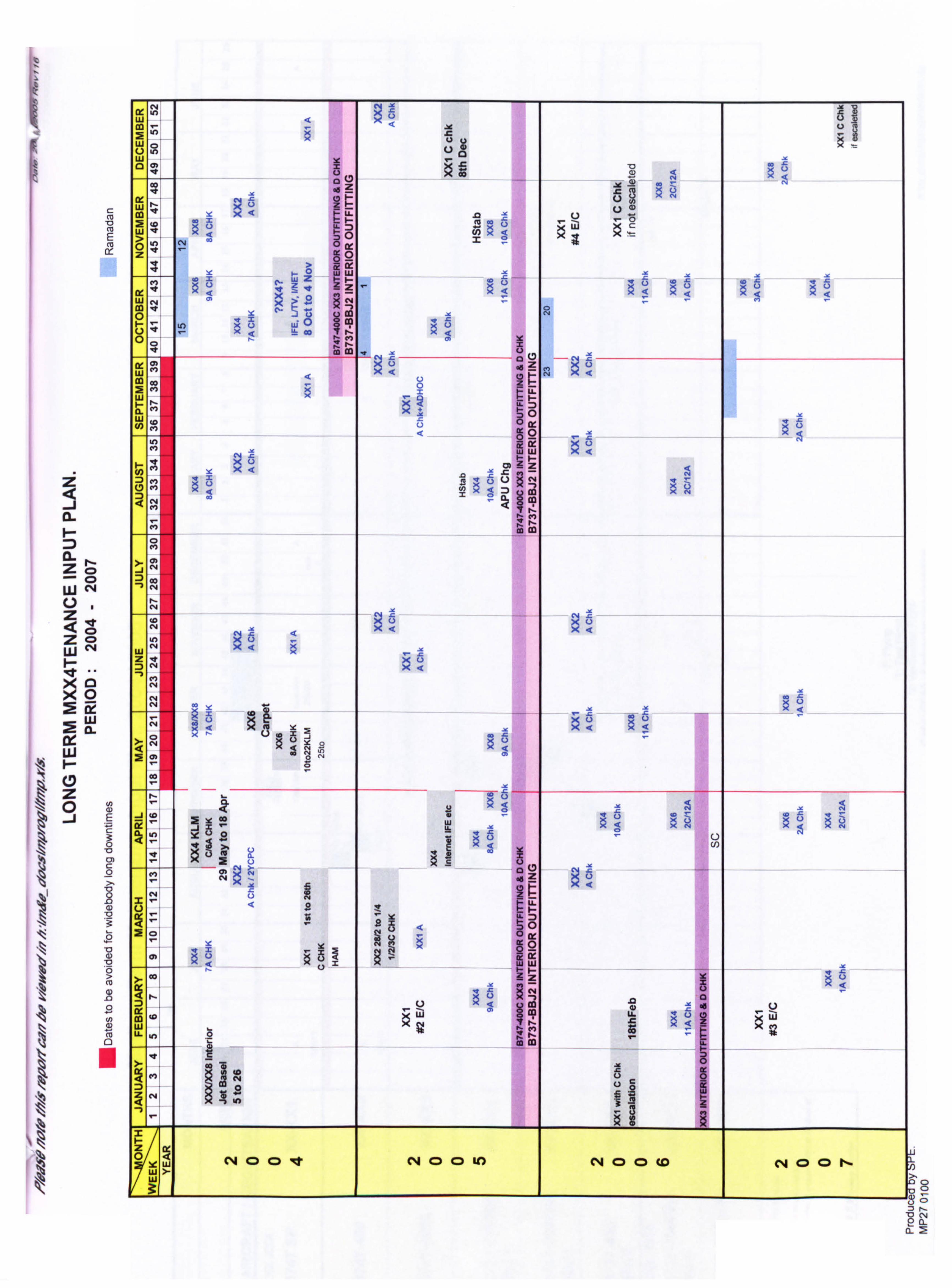
CL i- D CL z
z 4 z ui
LU i- Lr) z 0 -i
r-
C14
13 0 Ix w a.
0)
0
CNI w
Co Z
W 0 w 12 0)
leý Z 0 m ý -0 0
ý (Z
J rý c4 ý XU
0 ý: 3 0 LL X< 00
W e Q
> 0 c4
ir 0 > 0 Ft
Lu
Z
< W c4 < 0
>- 0 :; x o .0
w X0 X
0 0 f
w cl
Qä - 42 -4 ý3
cm ý ll
Co
CL w U) m
0 Om
Ir 0 w
c3) w
Z :3 m
cn 0 <
.9 ci U e c4 2'
e Z:
ý C) 0
Co Co 0
-) C, 4
w Z
:> -, l c4 ý <jýI e (n C, 4
c4
c4 C. )
Co
rx - - < Z N
x0
, _j Z 4, 0
e - o 0 c4
ý> n -4 Z
LL
50 0X
0 uä w : CO ZZ ý0
LL. cj
LL cl
'n in
Co
%
2 C%4 (D (D le c4 CD CD to c4 CD 0 (0 (4 CD (D N 1-9
0- 0-2
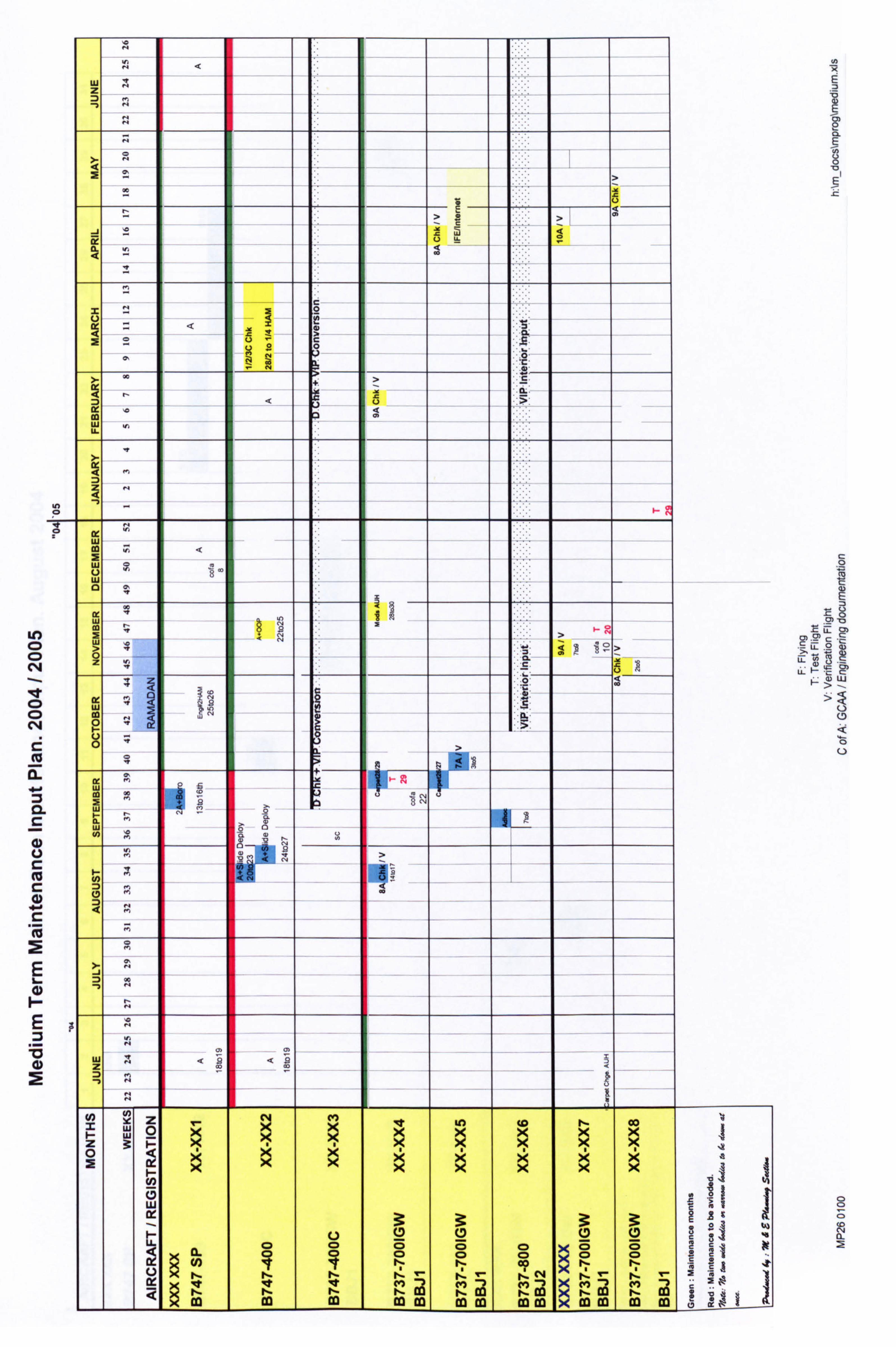
0
Ln 0 CD C, 4
N
EL
CL
E
E
2
LU
c 2
< c
+
to w U.
w
w u
I
LU
lz uj
> uj
z CL
LU co
>
le
w co A w L I
- w
.9 >
UA <9
LU w
co 9
z 0
I
(D w
0 0 0 (D CD to 1 11.1
U) 5 q CD 0 11
a 0 pr
a 0 rý
Q CD co
Q I-
5 a
r- '. I
.5fI It , C) I
r- t- I--
r- V- cq V
Pý - in Pý (4 1ý - I
IýL 2 . - 0ý L
t.
co ea ImI , co 37 ra r- J co co
r-
m co co co Im im !,
'0
'0 1
, FT E g> ýB w
0 0
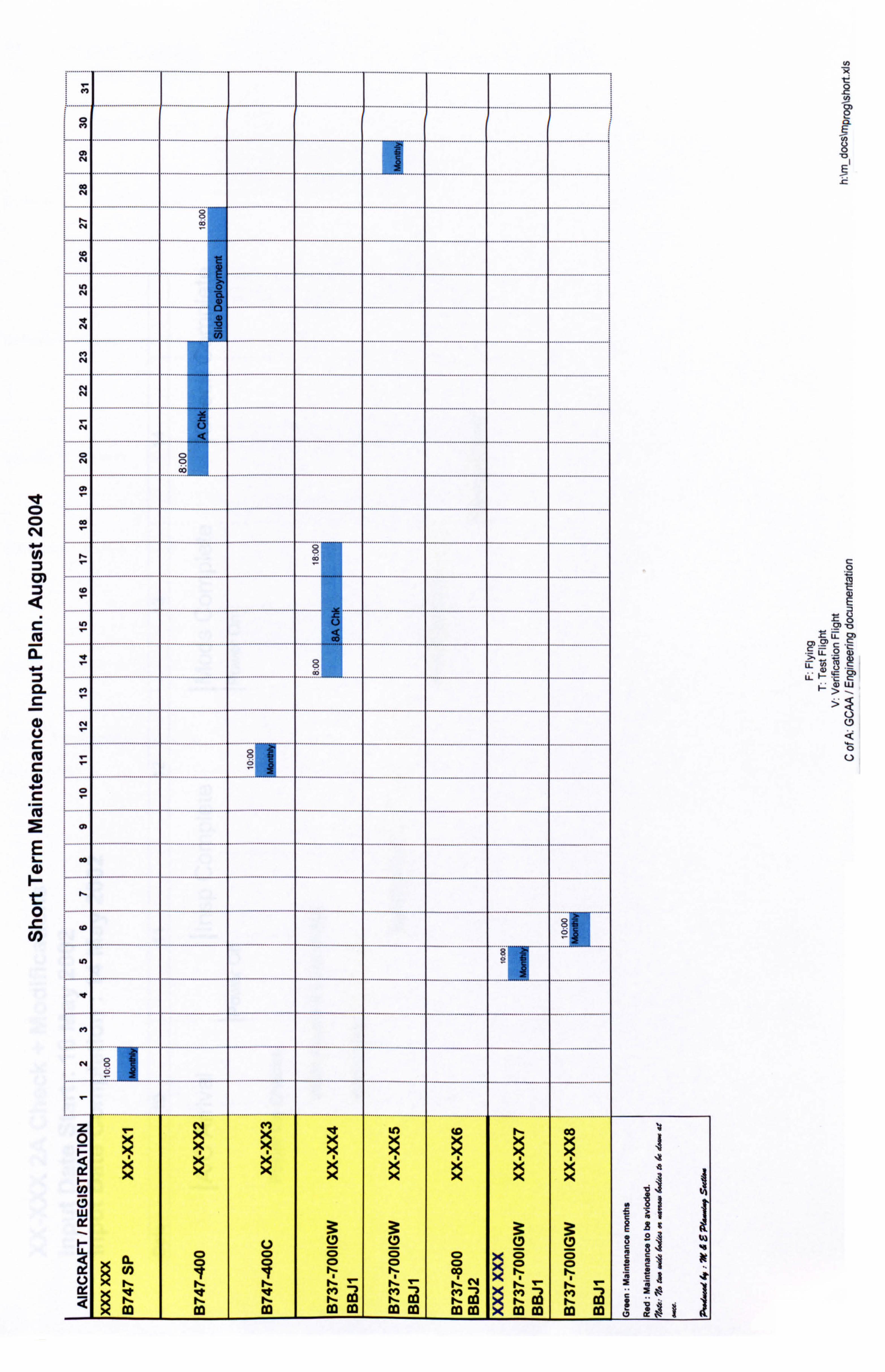
10
Q (14
CL C
C 4)
E
0 .a CO)
le- q 'n
eile ýýlle le 5ýlýe ýý
U) Q q q CD 0 I-N
cn co m mm co m m
I
C
,a
. -'0
0 0
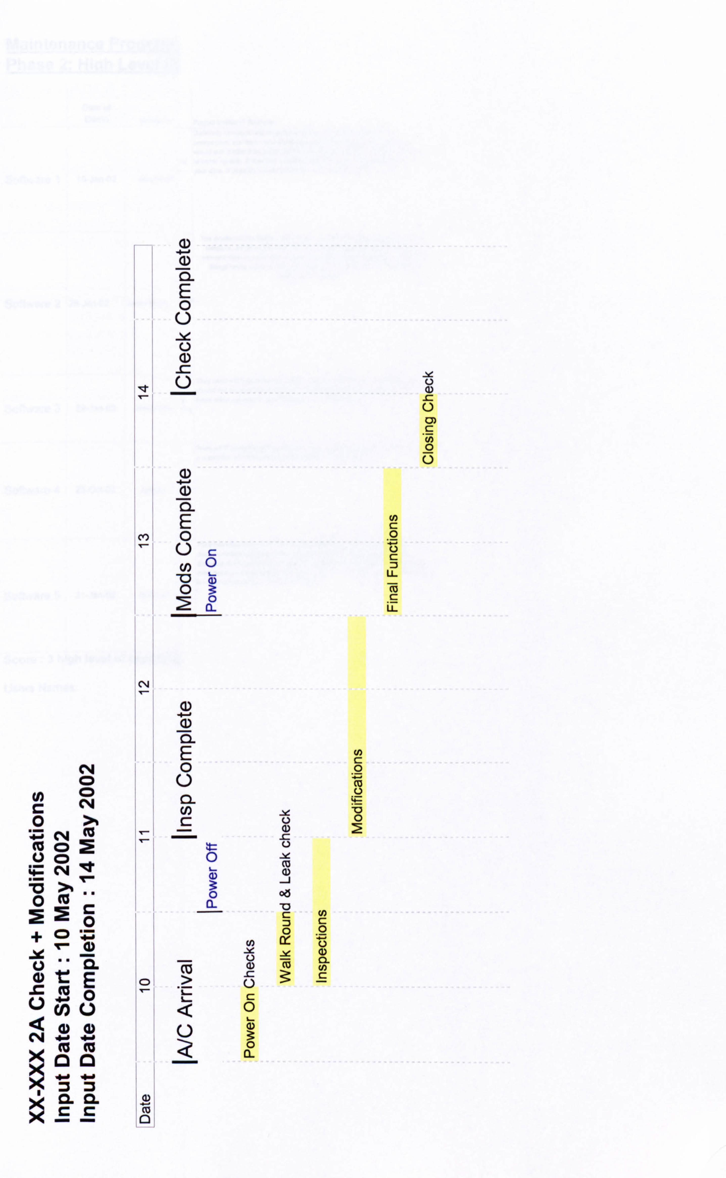
N CD
C C114 0 >%
= C44 M cc CD 0a
= C44 ;a >% .. 0ma P_ 20 +Q ýp
CL E o U U) L)
CL CL
cC
I-
cv, r
0
I I
a) 4-A
a) 0- E 0
a) 4-0 (D cl E 0 C) C: cn 0 -0 "
0 CL
(D -I- CD CL E 0 CL Cl) C:
Co >
0
0
12-
C)
-ýe
ozs
70
0 w
3:
U) 0 C. ) a) 0. U) C
U)
0
Co 0
9-
0 2
LL
LL
0)
0
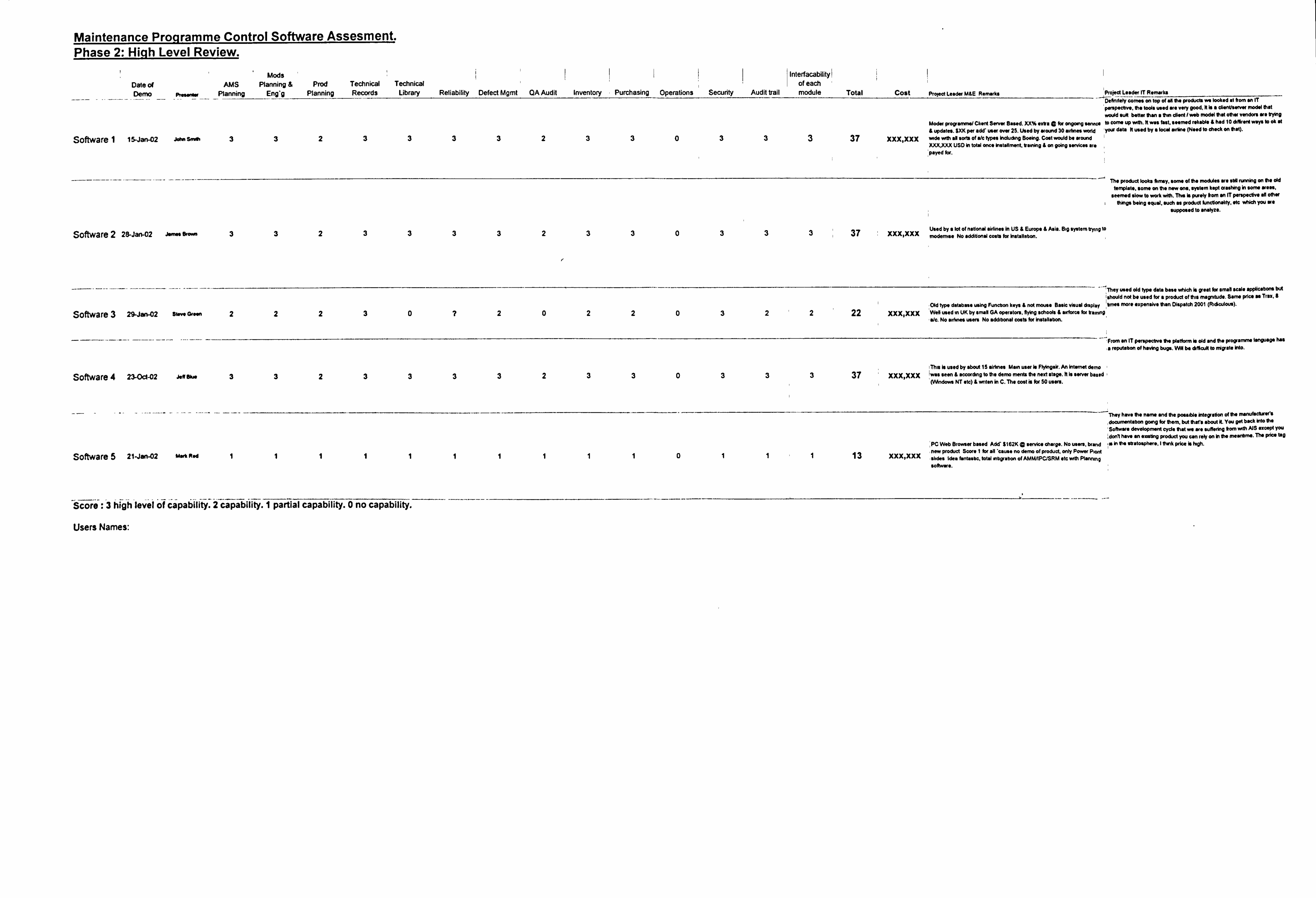
Maintenance Proqramme Control Software Assesment. Phase 2: Hicih Level Review.
Date of AMS Dem ismosess, Planning
Mods Planning &
Eng'g Prod
Planning Technical Records
Technical Library Reliability Defect Mgmt QAAudit Inventory Purchasing Operations Security
Interfacability! ofeach
Audit trail module Total Cost Project Leader WE Remarks project Leader IT Rimuorks -4 ---- -- j5eAmlaWwmwi an top of all the products we looked at frorn an IT -
P. P. 'tvio. the tools mod we very good, it is a dienusenee model that would WK befter than a thin client I wob model that other vendors we trying
Moder programme/ Client Server Based. XX% extra a for ongoing service to cam up wdh. It "a fast. *earned reliable & had 10 diffirent ways to ok at & updates. $XK par add'usw ow 25. Used by wound 30 airlines world yaw data It mod by a local airline (N*ed to check on that).
Software I 15-Jan-02 John SmAh 3 3 2 3 33323303 33 37 xxx'Xxx wide with sit soft of a/c types Including Boeing, Cost would be around XXX)(XX USD in total once Installment. orruning & on going servii; es ors, payed for.
The product looks fhmy. acma of the modluln we stAl running an the old template. some an the new one, system kept crashing in owns wass,
seemed at" to work with. Thin is purely trom an IT perspective all other I things being equal, such as product functionality, oft which you we
supposed to analyze.
Software 2 28-Jan-02 James 9- 3 3 2 3 33323303 33 37 xxx'Xxx Used by a lot of national Wifines in US & Europe & Asia. Big system trying to modernise No additiomil costs for Installation.
They wed old type data bass vftch Is great for small scale aWicstOns but
should not be used for a Product of this magnitude. Sam price as Trax, III
Software 3 29-JWV-02 11-901- 22230? 202 Old type database using Funcirm keys & not mus* Basic visual display tmes mre expensivit than Dispatch 2001 (Ridiculow).
20322 22 XXX, XXX Welf wed m UK by emit GA operators, flying schools & awforce for tranong, a/c. No anknes usens No additional costo for installabon.
---, From an IT perspectrw the platform is old and the PmWOMMI language hall
,a reputation of having bugs. WN be afficuit to rnigrato into.
This is used try about 15 airlines Mamuseris"gair. Aninternotdom
Software 4 23-Oct-02 Jeff Oka 33233332330333 37 XXX, XXX ILMS seen & accorchng to the dam ments the next stage. It is server based (VIAndave NT *tc) & mten in C. The cost is for 50 users.
They have the nam, and the possible Integration of the mmf4ckWs
clocurnentrabon gmg for thern, but there about it You gel back Into the
'Soft-me cleveloPrnerd cycle that vra m* uffering frorn th AJS except you
I don't how an existing product you con rely on In the M*N*M. The prim too
PC Web Srovser based Add'3162K Q service charge. No users, brand is in the stratosphere, I tank price is high.
Software 5 21-jan-02 Mot Fted 11011 13 xxx, xxx - product Score I for all 'caw* no dam of product, only Povgm Plant
shrles Idea fainlasbc, total rnbgrabon of AMMAPCISRM etc with Piannrnq
so*-*.
Score :3 high level of capability. 2 capability. I partial capability. 0 no capability.
Users Names:
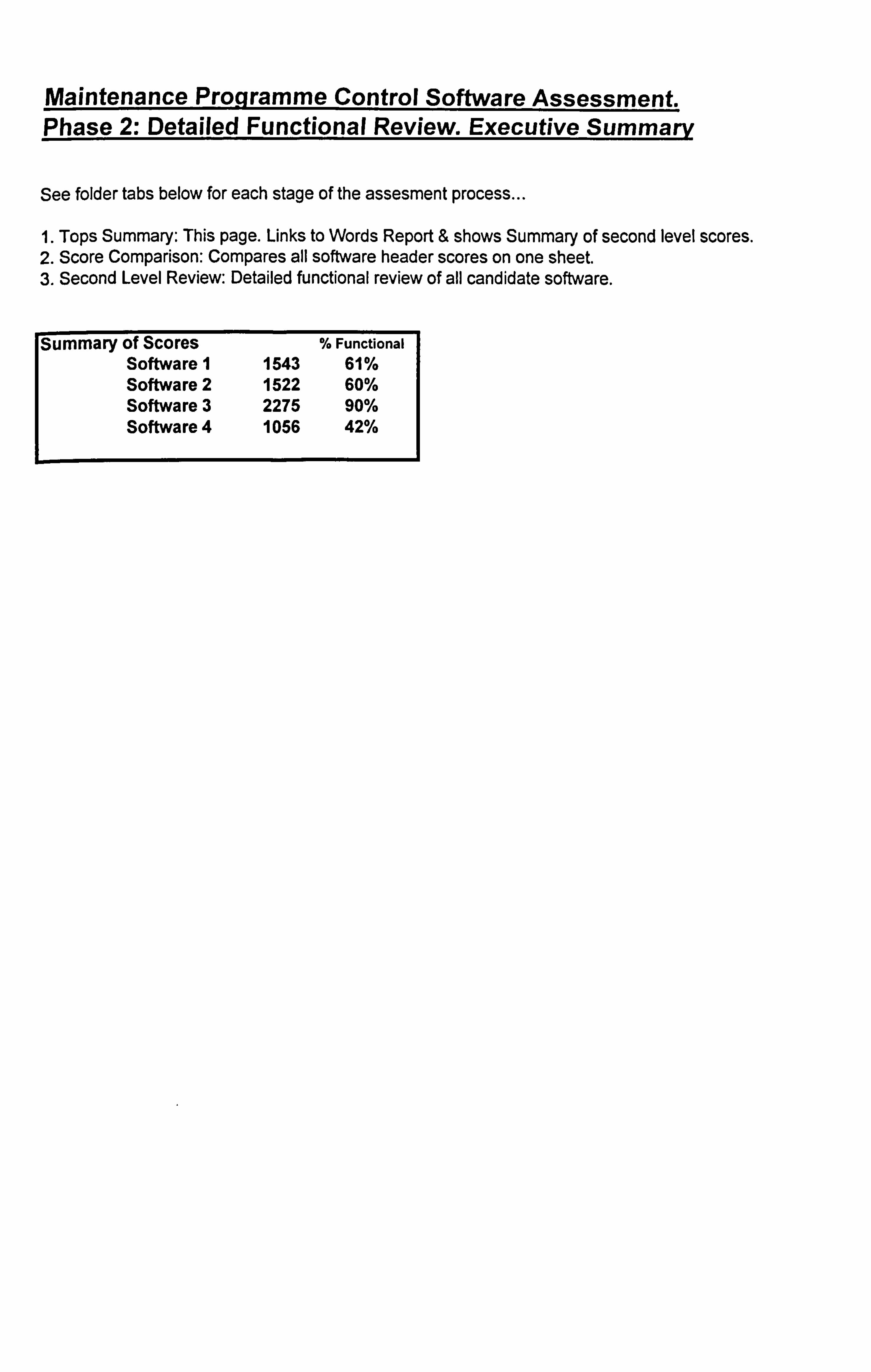
Maintenance Programme Control Software Assessment. Phase 2: Detailed Functional Review. Executive SummarV
See folder tabs below for each stage of the assesment process
1. Tops Summary: This page. Links to Words Report & shows Summary of second level scores. 2. Score Comparison: Compares all software header scores on one sheet. 3. Second Level Review: Detailed functional review of all candidate software.
Summary of Scores % Functional Software 1 1543 61% Software 2 1522 60% Software 3 2275 90% Software 4 1056 42%
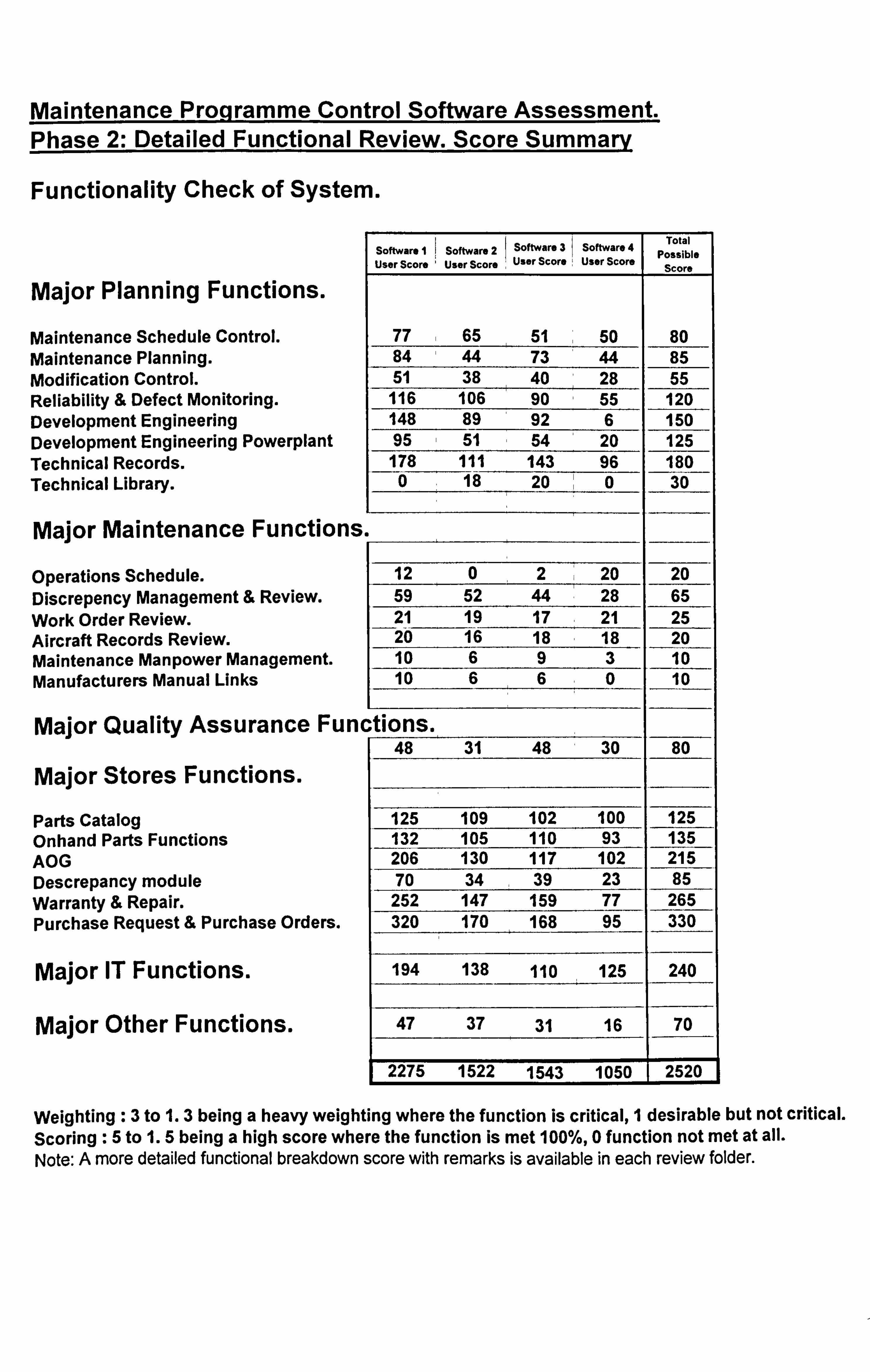
Maintenance Programme Control Software Assessment. Phase 2: Detailed Functional Review. Score SummarV
Functionality Check of System.
Major Planning Functions.
Maintenance Schedule Control. Maintenance Planning. Modification Control. Reliability & Defect Monitoring. Development Engineering Development Engineering Powerplant Technical Records. Technical Library.
Major Maintenance Functions
operations Schedule. Discrepency Management & Review. Work Order Review. Aircraft Records Review. Maintenance Manpower Management. Manufacturers Manual Links
Major Quality Assurance Fum
Major Stores Functions.
Parts Catalog Onhand Parts Functions AOG Descrepancy module Warranty & Repair. Purchase Request & Purchase Orders.
Major IT Functions.
Major Other Functions.
Software I Software 2 Software 3 Software 4 User Score User Score User Score User Score
Total Possible
Score
77 65 51 50 80 84 44 73 44 85 51 38 40 28 55 116 106 90 55 120 148 89 92 6 ISO 95 51 54 20 125 178 111 143 96 180 0 18 20 0 30
12 0 2 20 20 59 52 44 28 65
_21 19 17 21 25
20 16 18 18 20 10 6 9 lo 10 6 6 0 10
. tions. 48 31 48 30 80
125 109 102 100 125 132 105 110 5 206 130 117 102 215 70 34 39 23 85 252 147 159 77 265 320 170 168 95 330
194 138 110 125 240
47 37 31 16 70
2275 1522 1543 1050
Weighting :3 to 1.3 being a heavy weighting where the function is critical, 1 desirable but not critical. Scoring :5 to 1.5 being a high score where the function is met 100%, 0 function not met at all. Note: A more detailed functional breakdown score with remarks is available in each review folder.
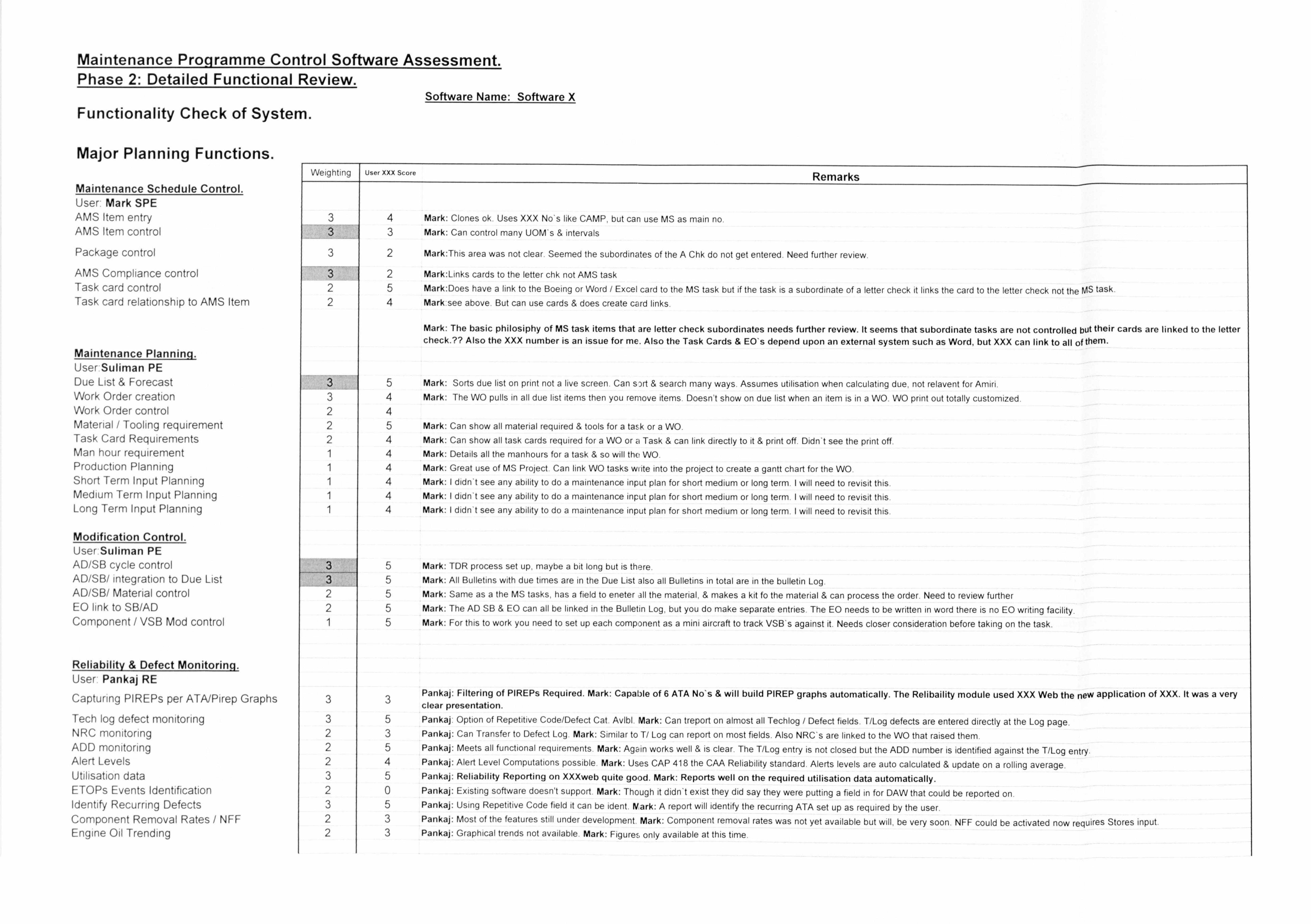
Maintenance Proqramme Control Software Assessment. Phase 2: Detailed Functional Review.
Functionality Check of System.
Major Planning Functions.
Software Name: Software X
Weighting I User XXX Score Remarks Maintenance Schedule Control. User Mark SPE AMS Item entry 3 4 Mark: Clones ok. Uses XXX No's like CAMP, but can use MS as main no. AIVIS Item control 3 3 Mark: Can control many UOM's & intervals
Package control 3 2 Mark: This area was not clear. Seemed the subordinates of the A Chk do not get entered. Need further review.
AMS Compliance control 3 2 Mark: Links cards to the letter chk not AMS task Task card control 2 5 Mark: Does have a link to the Boeing or Word / Excel card to the MS task but if the task is a subordinate of a letter check it links the card to the letter check not the MS task Task card relationship to AIVIS Item 2 4 Markýsee above. But can use cards & does create card links.
Maintenance Plannin User Suliman PE
Mark: The basic philosiphy of MS task items that are letter check subordinates needs further review. It seems that subordinate tasks are not controlled buttheir cards are linked to the letter check.?? Also the XXX number is an issue for me. Also the Task Cards & EO's depend upon an external system such as Word, but XXX can link to all of them.
Due List & Forecast 3 5 Mark: Sorts due list on print not a live screen. Can s)rt & search many ways. Assumes utilisation when calculating due, not relavent for Amiri. Work Order creation 3 4 Mark: The WO pulls in all due list items then you remove items. Doesn't show on due list when an item is in a WO. WO print out totally customized. Work Order control 2 4 Material / Tooling requirement 2 5 Mark: Can show all material required & tools for a task or a WO. Task Card Requirements 2 4 Mark: Can show all task cards required for a WO or a Task & can link directly to it & print off. Didn't see the print off. Man hour requirement 1 4 Mark: Details all the manhours for a task & so will the WO. Production Planning 1 4 Mark: Great use of VIS Project. Can link WO tasks wi ite into the project to create a gantt chart for the WO. Short Term Input Planning 1 4 Mark: I didn't see any ability to do a maintenance input plan for short medium or long term. I will need to revisit this. Medium Term Input Planning 1 4 Mark: I didn't see any ability to do a maintenance input plan for short medium or long term. I will need to revisit this Long Term Input Planning 1 4 Mark: I didn't see any ability to do a maintenance input plan for short medium or long term. I will need to revisit this
Modification Control. User Suliman PE AD/SB cycle control 3 5 Mark: TDR process set up, maybe a bit long but is there. AD/SB/ integration to Due List 3 5 Mark: All Bulletins with due times are in the Due List also all Bulletins in total are in the bulletin Log. AD/SB/ Material control 2 5 Mark: Same as a the MS tasks, has a field to eneter all the material, & makes a kit fo the material & can process the order. Need to review further EO link to SB/AD 2 5 Mark: The AD SB & EO can all be linked in the Bulletin Log, but you do make separate entries. The EO needs to be written in word there is no EO writing facility. Component / VSB Mod control 1 5 Mark: For this to work you need to set up each component as a mini aircraft to track VSB's against it. Needs closer consideration before taking on the task.
Reliability & Defect Monitoring. User Pankaj RE
Capturing PIREPs per ATA/Pirep Graphs 3 3 Pankaj: Filtering of PIREPs Required. Mark: Capable of 6 ATA No's & will build PIREP graphs automatically. The Relibaility module used XXX Web the new application ofXXX. Itwas a very clear presentation.
Tech log defect monitoring 3 5 Pankajý Option of Repetitive Code/Defect Cat. Avibl. Mark: Can treport on almost all Techlog / Defect fields. T/Log defects are entered directly at the Log page. NRC monitoring 2 3 Pankaj: Can Transfer to Defect Log. Mark: Similar to T/ Log can report on most fields. Also NRC's are linked to the WO that raised them. ADD monitoring 2 5 Pankaj: Meets all functional requirements Mark: Again works well & is clear. The T/Log entry is not closed but the ADD number is identified against the T/Log entry Alert Levels 2 4 Pankaj: Alert Level Computations possible. Mark: Uses CAP 418 the CAA Reliability standard. Alerts levels are auto calculated & update on a rolling average. Utilisation data 3 5 Pankaj: Reliability Reporting on XXXweb quite good. Mark: Reports well on the required urtilisation data automatically. ETOPs Events Identification 2 0 Pankaj: Existing software doesn't support. Mark: Though it didn't exist they did say they were putting a field in for DAW that could be reported on. Identify Recurring Defects 3 5 Pankaj: Using Repetitive Code field it can be ident. Mark: A report will identify the recurring ATA set up as required by the user. Component Removal Rates / NFF 2 3 Pankaj: Most of the features still under development, Mark: Component removal rates was not yet available but will, be very soon. NFF could be activated now requires Stores input. Engine Oil Trending 2 3 Pankaj: Graphical trends not available, Mark: Figure, ý, only available at this time
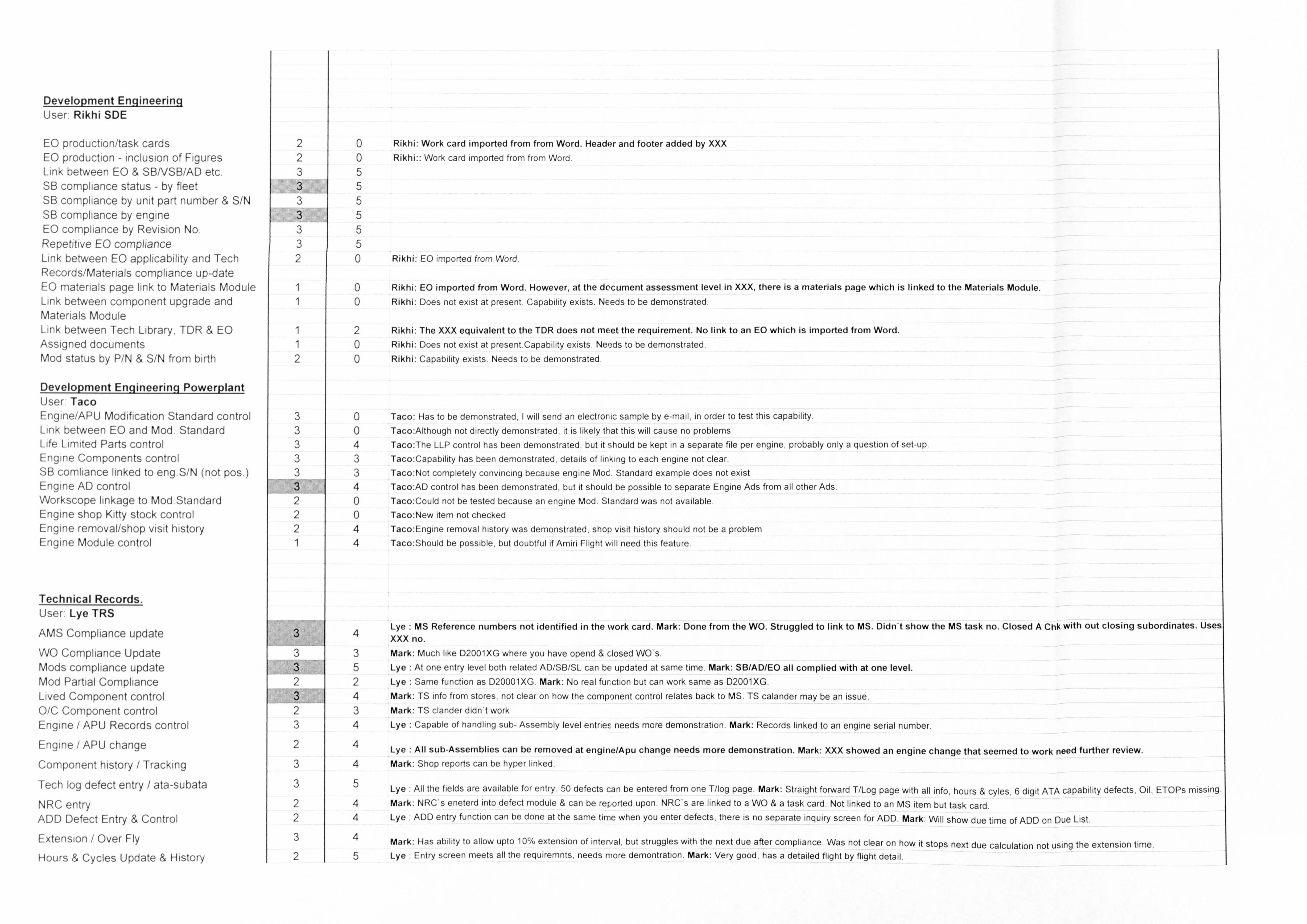
Development Engineering User Rikhi SDE
EO production/task cards EO production - inclusion of Figures Link between EO & SBNSB/AD etc. SB compliance status - by fleet SB compliance by unit part number & S/N SIB compliance by engine EO compliance by Revision No. Repetitive EO compliance Link between EO applicability and Tech Records/Materials compliance up-date EO materials page link to Materials Module Link between component upgrade and Materials Module Link between Tech Library, TDR & EO Assigned documents Mod status by P/N & S/N from birth
Development Enplineerinq Powerplant User: Taco Engine/APU Modification Standard control Link between EO and Mod. Standard Life Limited Parts control Engine Components control SIB comliance linked to eng. S/N (not pos. ) Engine AD control Workscope linkage to Mod. Stanclard Engine shop Kitty stock control Engine removal/shop visit history Engine Module control
Technical Records. User Lye TRS
AMS Compliance update WO Compliance Update Mods compliance update Mod Partial Compliance Lived Component control O/C Component control Engine / APU Records control Engine / APU change Component history / Tracking
Tech log defect entry / ata-subata
NRC entry ADD Defect Entry & Control
Extension / Over Fly
Hours & Cycles Update & History
2 2
3
3 3 2
1 1
1 1 2
3 3 3 3 3
2 2
3 3
2
2 3
2
3
3
2 2
3 2
0 Rikhi: Work card imported from from Word. Header and footer added by XXX 0 Rikhi:: Work card imported from from Word.
5 5 5 5 5 5 0 Rikhi: EO imported from Word.
0 Rikhi: EO imported from Word. However, at the document assessment level in XXX, there is a materials page which is linked to the Materials Module. 0 Rikhi: Does not exist at present. Capability exists. NEeds to be demonstrated.
2 Rikhi: The XXX equivalent to the TDR does not meet the requirement. No link to an EO which is imported from Word. 0 Rikhi: Does not exist at present. Capability exists. Needs to be demonstrated. 0 Rikhi: Capability exists. Needs to be demonstrated.
0 Taco: Has to be demonstrated, I will send an electronic sample by e-mail, in order to test this capability. 0 Taco: Although not directly demonstrated, it is likely that this will cause no problems 4 Taco: The LLP control has been demonstrated, but it should be kept in a separate file per engine, probably only a question of set-up. 3 Taco: Capability has been demonstrated, details of linking to each engine not clear. 3 Taco: Not completely convincing because engine Moc. Standard example does not exist 4 Taco: AD control has been demonstrated, but it should be possible to separate Engine Ads from all other Ads. 0 Taco: Could not be tested because an engine Mod. Standard was not available. 0 Taco: New item not checked 4 Taco: Engine removal history was demonstrated, shol) visit history should not be a problem 4 Taco: Should be possible, but doubtful if Amin Flight will need this feature.
4 Lye : MS Reference numbers not identified in the work card. Mark: Done from the WC. Struggled to link to MS. Didn't show the MS task no. Closed A Chk with out closing subordinates. U XXX no.
3 Mark: Much like D2001XG where you have opend & closed WO's. 5 Lye At one entry level both related AD/SB/SL can be updated at same time. Mark: SB/AD/EO all complied with at one level. 2 Lye Same function as D20001XG. Mark: No real furction but can work same as D2001XG. 4 Mark: TS info from stores, not clear on how the component control relates back to MS. TS calander may be an issue. 3 Mark: TS clander didn't work 4 Lye Capable of handling sub- Assembly level entries needs more demonstration. Mark: Records linked to an engine serial number,
4 Lye All sub-Assemblies can be removed at engine/Apu change needs more demonstration. Mark: XXX showed an engine change that seemed to work need further review.
4 Mark: Shop reports can be hyper linked,
5 Lye All the fields are available for entry. 50 defects can be entered from one T/log page. Mark: Straight forward T/Log page with all info, hours & cyles, 6 digit ATA capability defects. Oil, ETOPs missing 4 Mark: NRC's eneterd into defect module & can be reported upon. NRC's are linked to a WO &a task card. Not linked to an MS item but task card. 4 Lye ý ADD entry function can be done at the same time when you enter defects, there is no separate inquiry screen for ADD. Mark: Will show due time of ADD on Due List. 4 Mark: Has ability to allow upto 10% extension of intental, but struggles with the next due after compliance. Was not clear on how it stops next due calculation not using the extension time. 5 Lye . Entry screen meets all the requirerrints, needs more clemontration. Mark: Very good, has a detailed flight by flight detail,
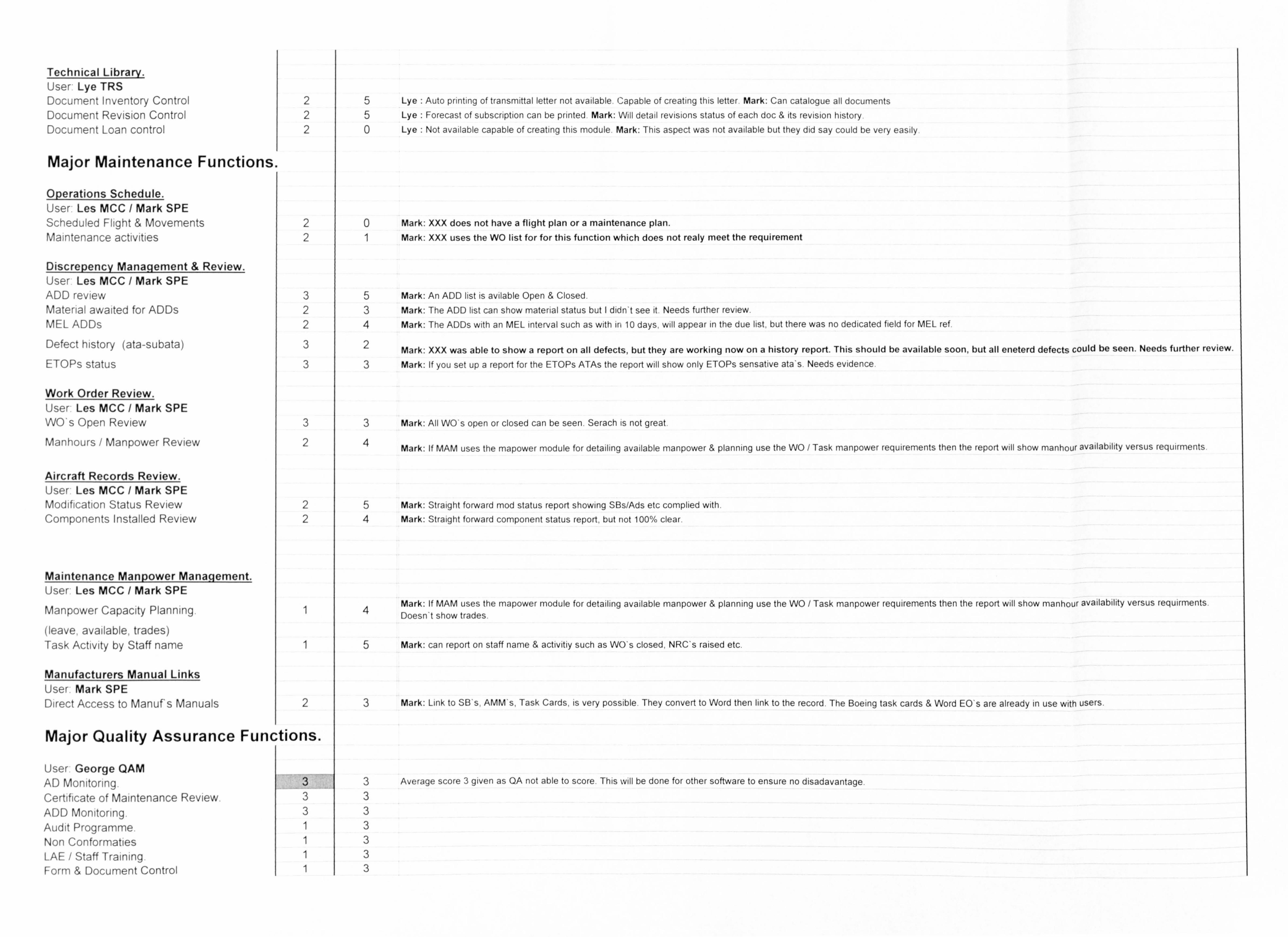
Technical Library. User Lye TRS Document Inventory Control Document Revision Control Document Loan control
Major Maintenance Functions.
Operations Schedule. User Les MCC / Mark SPE Scheduled Flight & Movements Maintenance activities
Discrepency Manaqement & Review. User Les MCC / Mark SPE ADD review Material awaited for ADDs MEL ADDs
Defect history (ata-subata)
ETOPs status
Work Order Review. User Les MCC / Mark SPE WO's Open Review
Manhours / Manpower Review
Aircraft Records Review. User Les MCC / Mark SPE Modification Status Review Components Installed Review
Maintenance Manpower Manaqement. User Les MCC / Mark SPE
Manpower Capacity Planning
(leave, available, trades) Task Activity by Staff name
Manufacturers Manual Links User Mark SPE Direct Access to Manufs Manuals
2 2 2
5 5 0
2
33
2 2
5 4
14
15
23
Major Quality Assurance Functions.
User George QAM AD Monitoring Certificate of Maintenance Review ADD Monitoring. Audit Programme Non Conformaties LAE / Staff Training Form & Document Control
3 3 3 3 3 3 3 3
Lye Auto printing of transmittal letter not available. Capable of creating this letter. Mark: Can catalogue all documents Lye Forecast of subscription can be printed. Mark: Will detail revisions status of each doc & its revision history. Lye Not available capable of creating this module. Mark: This aspect was not available but they did say could be very easily
Mark: XXX does not have a flight plan or a maintenance plan. Mark: XXX uses the WO list for for this function which does not realy meet the requirement
Mark: An ADD list is avilable Open & Closed.
Mark: The ADD list can show material status but I didn't see it. Needs further review. Mark: The ADDs with an MEL interval such as with in 10 days, will appear in the due list, but there was no dedicated field for MEL ref.
Mark: XXX was able to show a report on all defects, but they are working now on a history report. This should be available soon, but all eneterd defects could be seen. Needs further review.
Mark: If you set up a report for the ETOPs ATAs the report will show only ETOPs sensative ata s Needs evidence
Mark: All WO's open or closed can be seen. Serach is not great.
Mark: If MAM uses the mapower module for detailing available manpower & planning use the WO I Task manpower requirements then the report will show manhour availability versus requirments
Mark: Straight forward mod status report showing SBs/Ads etc complied with. Mark: Straight forward component status report, but not 100% clear.
Mark: If MAM uses the mapower module for detailing available manpower & planning use the WO / Task manpower requirements then the report will show manhour availability versus requirments. Doesn't show trades
Mark: can report on staff name & activitiy such as WO s closed, NRC's raised etc.
Mark: Link to SB s AMM s, Task Cards, is very possible They convert to Word then link to the record. The Boeing task cards & Word EO s are already in use with users.
Average score 3 given as QA not able to score. This will be done for other software to ensure no disadavantage.
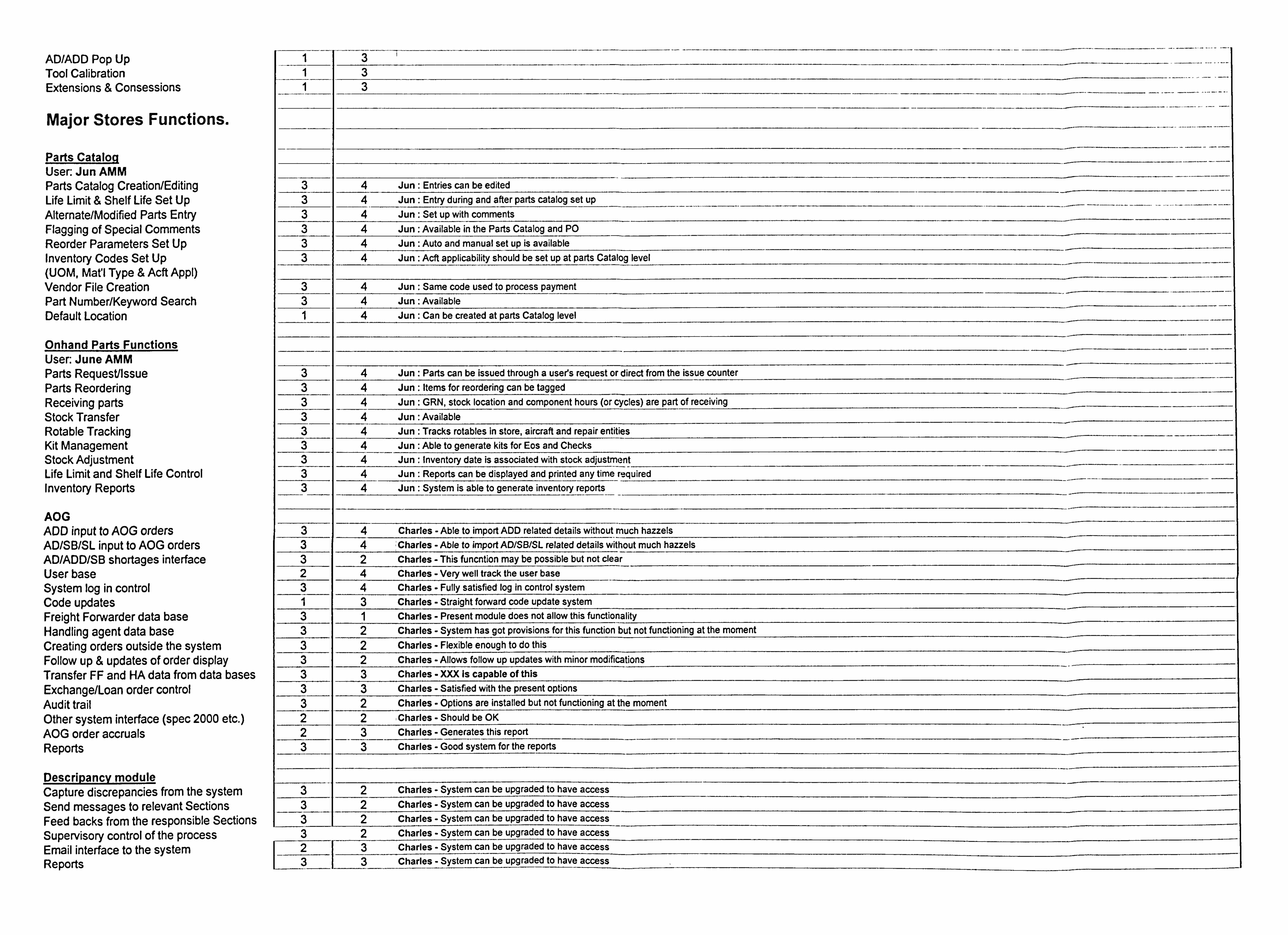
ADIADD Pop Up Too[ Calibration Extensions & Consessions
Major Stores Functions.
Parts Cataloq User: Jun AMM Parts Catalog Creation/Editing Life Limit & Shelf Life Set Up Alternate/Modified Parts Entry Flagging of Special Comments Reorder Parameters Set Up Inventory Codes Set Up (UOM, Mat'l Type & Acft Appl) Vendor File Creation Part Number/Keyword Search Default Location
Onhand Parts Functions User: June AMM Parts Request/Issue Parts Reordering Receiving parts Stock Transfer Rotable Tracking Kit Management Stock Adjustment Life Limit and Shelf Life Control Inventory Reports
AOG ADD input to AOG orders AD/SB/SL input to AOG orders AD/ADD/SB shortages interface Userbase System log in control Code updates Freight Forwarder data base Handling agent data base Creating orders outside the system Follow up & updates of order display Transfer FF and HA data from data bases Exchange/Loan order control Audit trail Other system interface (spec 2000 etc. ) AOG order accruals Reports
Descripancv module Capture discrepancies from the system Send messages to relevant Sections Feed backs from the responsible Sections Supervisory control of the process Email interface to the system Reports
Jun Entries can be edited Jun Entry during and after parts catalog set up Jun: Set up with comments Jun: Available in the Parts Catalog and PO Jun Auto and manual set up is available Jun Acft applicability should be set up at parts Catalog level
Jun Same code used to process payment Jun: Available Jun Can be created at parts Catalog level
Jun Parts can be issued through a user's request or direct from the issue counter Jun Items for reordering can be tagged Jun GRN, stock location and component hours (or cycles) are part of receiving Jun: Available Jun Tracks rotables in store, aircraft and repair entities Jun Able to generate kits for Eos and Checks Jun Inventory date is associated with stock adjustment Jun Reports can be displayed and printed any time required Jun System is able to generate inventory reports
Charles - Able to import ADD related details without much hazzels : Charles - Able to import AD/SB/SL related details without much hazzels Charles - This funcntion may be possible but not clear Charles - Very well track the user base Charles - Fully satisfied log in control system Charles - Straight forward code update system Charles - Present module does not allow this functionality Charles - System has got provisions for this function but not functioning at the moment Charles - Flexible enough to do this Charles - Allows follow up updates with minor modifications Charles - XXX Is capable of this Charles - Satisfied with the present options Charles - Options are installed but not functioning at the moment Charles - Should be OK Charles - Generates this report Charles - Good system for the reports
2 Charles - System can be upgraded to have access 2 Charles - System can be upgraded to have access 2 Charles - System can be upgraded to have access 2 Charles - System can be upgraded to have access 3 3
Charles - System can be upgraded to have access Charles - System can be upgraded to have access
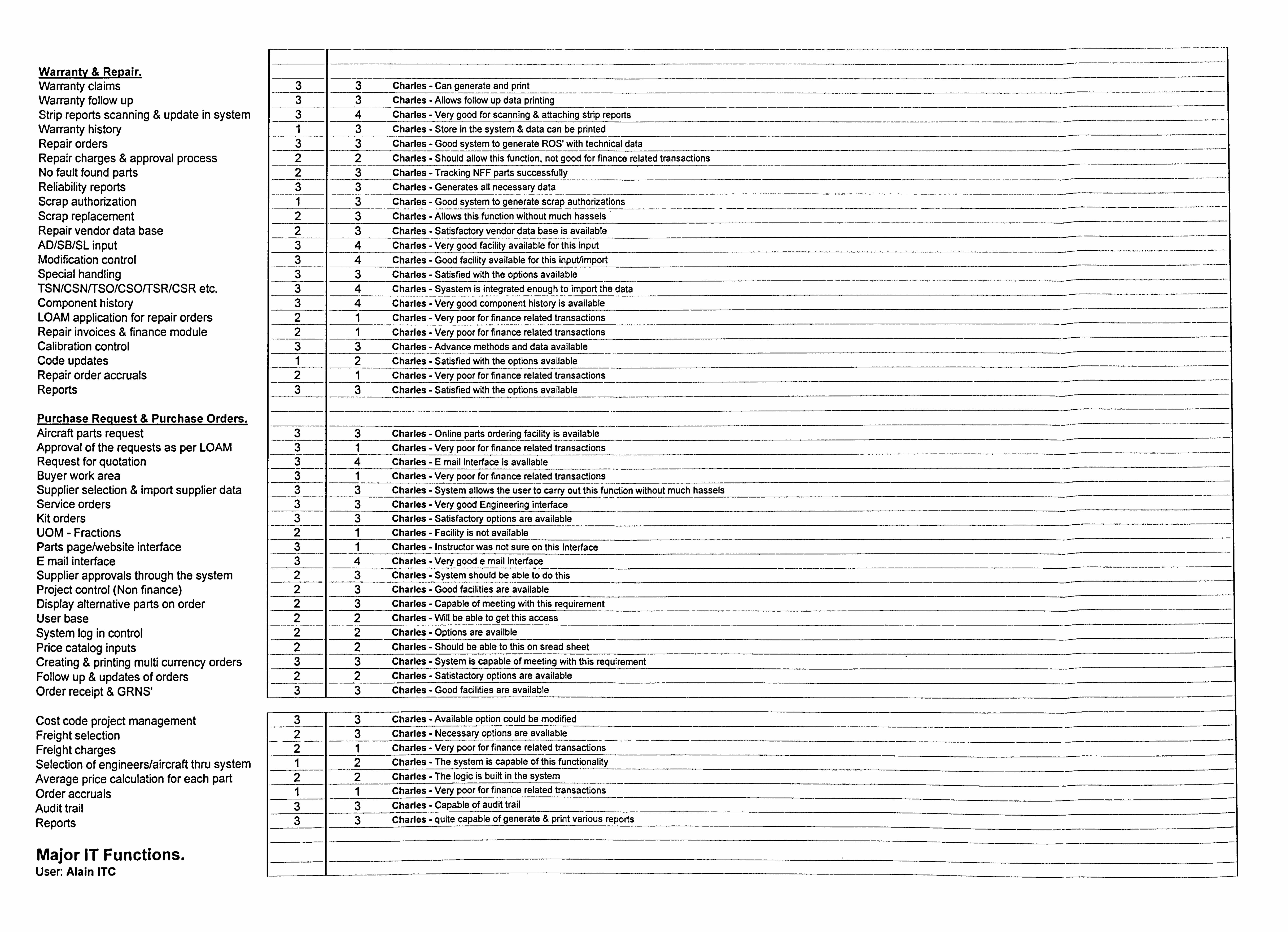
Warranty & Repair. Warranty claims Warranty follow up Strip reports scanning & update in system Warranty history Repair orders Repair charges & approval process No fault found parts Reliability reports Scrap authorization Scrap replacement Repair vendor data base AD/SB/SL input Modification control Special handling TSN/CSN/TSO/CSOITSR/CSR etc. Component history LOAM application for repair orders Repair invoices & finance module Calibration control Code updates Repair order accruals Reports
Purchase Request & Purchase Orders. Aircraft parts request Approval of the requests as per LOAM Request for quotation Buyer work area Supplier selection & import supplier data Service orders Kit orders UOM - Fractions Parts pagetwebsite interface E mail interface Supplier approvals through the system Project control (Non finance) Display alternative parts on order Userbase System log in control Price catalog inputs Creating & printing multi currency orders Follow up & updates of orders Order receipt & GRNS'
Cost code project management Freight selection Freight charges Selection of engineers/aircraft thru system Average price calculation for each part Order accruals Audit trail Reports
Major IT Functions. User: Alain ITC
Charles - Can generate and print Charles - Allows follow up data printing Charles - Very good for scanning & attaching strip reports Charles - Store in the system & data can be printed Charles - Good system to generate ROS'with technical data Charles - Should allow this function, not good for finance related transactions Charles - Tracking NFF parts successfully Charles - Generates all necessary data Charles - Good system to generate scrap authorizations Charles - Allows this function without much hassels Charles - Satisfactory vendor data base is available Charles - Very good facility available for this input Charles - Good facility available for this inputlimport Charles - Satisfied with the options available Charles - Syastern is integrated enough to import the data Charles - Very good component history is available Charles - Very poor for finance related transactions Charles - Very poor for finance related transactions Charles - Advance methods and data available Charles - Satisfied with the options available Charles - Very poor for finance related transactions Charles - Satisfied with the options available
Charles - Online parts ordering facility is available Charles - Very poor for finance related transactions Charles -E mail interface is available Charles - Very poor for finance related transactions Charles - System allows the user to carry out this function without much hassels Charles -Very good Engineering interface Charles - Satisfactory options are available Charles - Facility is not available Charles - Instructor was not sure on this interface Charles - Very good e mail interface Charles - System should be able to do this 'Charles - Good facilities are available Charles - Capable of meeting with this requirement Charles - Will be able to get this access Charles - Options are availble Charles - Should be able to this on sread sheet Charles - System is capable of meeting with this requirement Charles - Satistactory options are available Charles - Good facilities are available
Charles - Available option could be modified Charles - Necessary options are available
___ Charles - Very poor for finance related transactions Charles - The system is capable of this functionality Charles - The logic is built in the system Charles - Very poor for finance related transactions Charles - Capable of audit trail Charles - quite capable of generate & print various reports
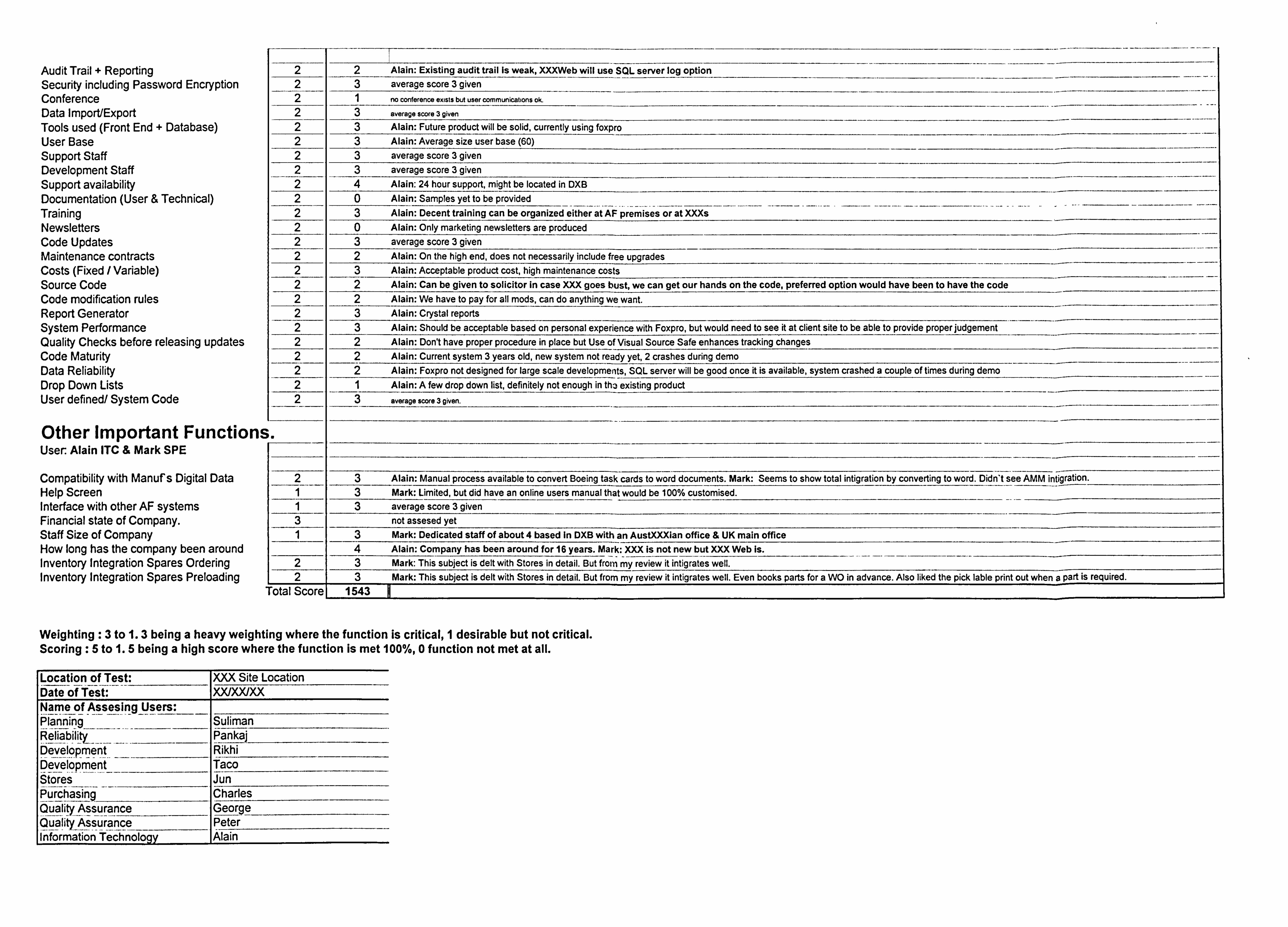
Audit Trail + Reporting Security including Password Encryption Conference Data Import/Export Tools used (Front End + Database) User Base Support Staff Development Staff Support availability Documentation (User & Technical) Training Newsletters Code Updates Maintenance contracts Costs (Fixed / Variable) Source Code Code modification rules Report Generator System Performance Quality Checks before releasing updates Code Maturity Data Reliability Drop Down Lists User defined/ System Code
Other Important Functions User Alain ITC & Mark SPE
Compatibility with Manuf s Digital Data Help Screen Interface with other AF systems Financial state of Company. Staff Size of Company How long has the company been around Inventory Integration Spares Ordering Inventory Integration Spares Preloading
2 2 Alain: Existing audit trail Is weak, XXXWeb will use SL server log option 2 3 average score 3 given 2 1 no conference exists but user communications ok.
2 3 average score 3 given
2 3 Alain: Future product will be solid, currently using foxpro 2 3 Alain: Average size user base (60) 2 3 average score 3 given 2 3 average score 3 given 2 4 Alain: 24 hour support, might be located in DXB 2 0 Alain: Samples yet to be provided 2 3 Alain: Decent training can be organized either at AF premises or at XXXs 2 0 Alain: Only marketing newsletters are produced 2 3 average score 3 given 2 2 Alain: On the high end, does not ne cessarily include free upgrades 2 3 Alain: Acceptable product cost, high maintenance costs 2 2 Alain: Can be given to solicitor in case XXX goes bust, we can get our hands on the code, preferred option would have been to have the code 2 2 Alain: We have to pay for all mods, can do anything we want. 2 3 Alain: Crystal reports 2 3 Alain: Should be acceptable based on personal experience with Foxpro, but would need to see it at client site to be able to provide proper judgement 2 2 Alain: Don't have proper procedure in place but Use of Visual Source Safe enhances tracking changes 2 2 Alain: Current system 3 years old, new system not ready yet, 2 crashes during demo 2 2 Alain: Foxpro not designed for large scale developments, SQL server will be good once it is available, system crashed a couple of times during demo
2 1 Alain: A few drop down list, definitely not enough in th. - existing product 2 3 average score 3 given.
3 Alain: Manual process available to convert Boeing task cards to word documents. Mark: Seems to show total intigration by converting to word. Didn't see AMM intigration. 1 3 Mark: Limited, but did have an online users manual that would be 100% customised. 1 3 average score 3 given 3 not assesed yet 1 3 Mark: Dedicated staff of about 4 based in DX13 with an AustXXXian office & UK main office
4 Alain: Company has been around for 16 years. Mark- j66ýýIsnoýt new but XXX Web Is. 2 3 Mark: This subject is delt with Stores in detail. But frorn ýýreview it intigrates well.
L2 13 Mark: This subject is dell with Stores in detail. But from my review it intigrates well. Even books parts for a WO in advance. Also liked the pick lable print out when a part is required. - Total Score 1 1543 1
Weighting :3 to 1.3 being a heavy weighting where the function is critical, 1 desirable but not critical. Scoring :5 to 1.5 being a high score where the function is met 100%, 0 function not met at all.
Location of Test: XXX Site Location Date of Test: XX/XX/XX Name of Assesing Users:
Suliman Reliabýlq Pankal
_____ b-eve-lopment Rikhi Development Taco ýt-o-re-s Jun Purchasing Charles Quality Assurance George
Peter lWf6rmation Technoloqy Alain
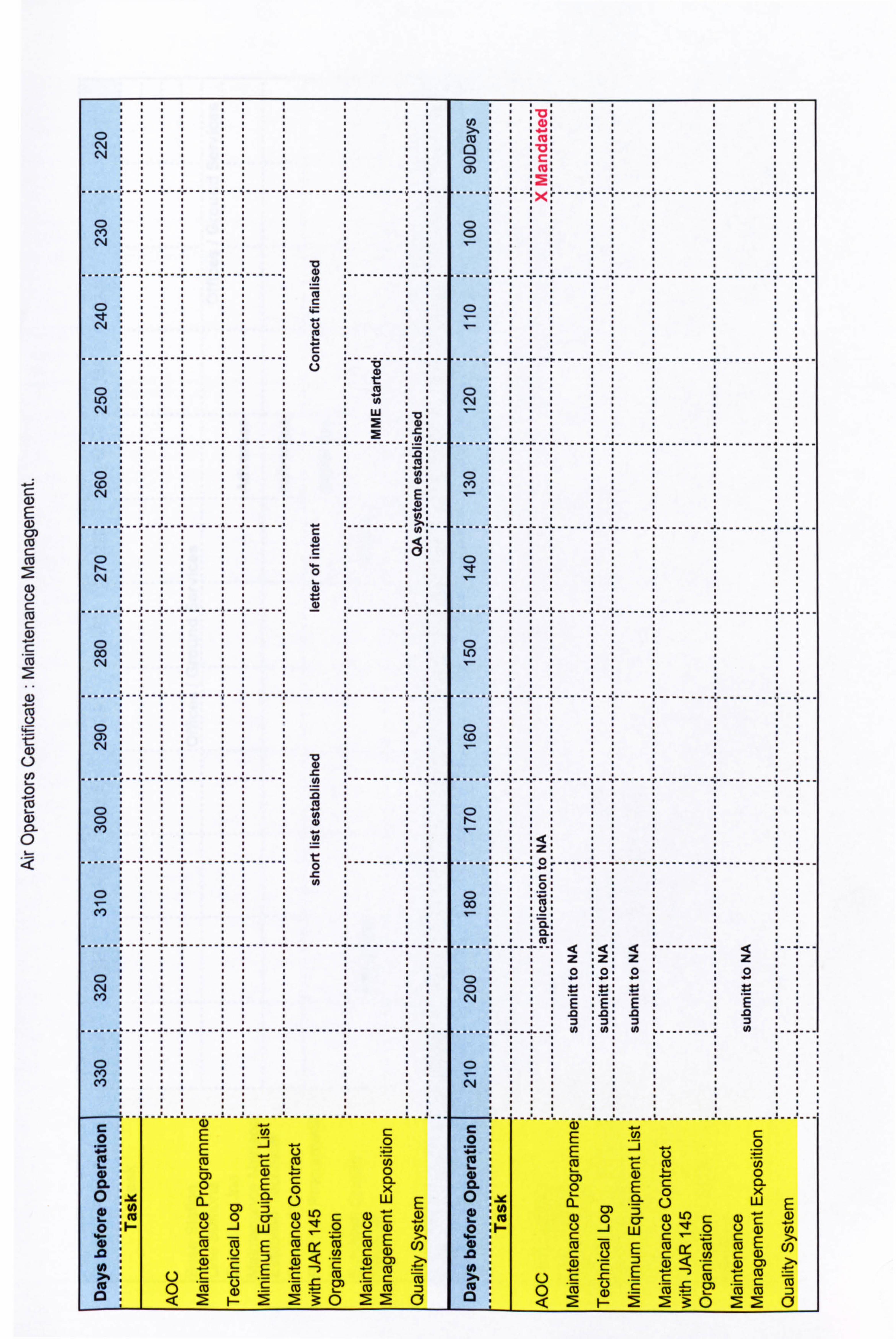
0) ca C: ca
C: cu C: (D C: cc 2 (1) co
0 co
(D CL
0
CN 04
C") C-4
Mn
04
---------------------- 0
U) C'14 w
........................ ------ -------------------
CD
C) 0 C'*4
co :: ":
---------- ---------- ---------
C)
04
----------
C) :::: -:: 0:::::: 0::
-------------------V................. 0
CD
--------------------- ------- I -------- I ---------
C) N cn
I----- --- -------- --- --------
0
C',
-- --------- ------------------------------------- t6
c
_j -6 0 r, :E cu cc U) 0 CL . 0) ca-
02E '0 x WE
M (D 0 a) a) 0 : 1- 0 -j wQ0 L) %: c-cý:; -- C: E, CU E (o CU CU U) C: c 1) c :3<T 4) E (1) C: 2 CF)
-c- E C: CU c CU
cc ia 4) c- *FU : t__ 0) Co (o :3 0 <2 F- 223: 0ý20
T3 41
(D ... cc
--- lxr ----- *1 --- I ------- 11----
c) C)
------------------------ ---------
............ -------- ------ I ------------------------
04
----------- ...... I --------- ---------
CD (Y)
I ----- i- ------ -------- ---------
0
I ---------- ---------
C)
---------- ........ I -------------------
a
---------------------
0
::: z:
00
z : Z: zz o: 0: oo C) :::: -: -: -:
CN
...... .I: to : 0: 01 -------- I
----------------------- C: 0
TC CU Cl) 0: 0) . ':; 0 cm (a. CL 0EC: 0x cl ui 0
IAI a_ - .=0 LLJ 0 ci E r= M IU r- E IV
(D < *E q) c3)
1-- <2 h- : 3: 0 22 -
W) -1 0
ca .0
w E E
U)
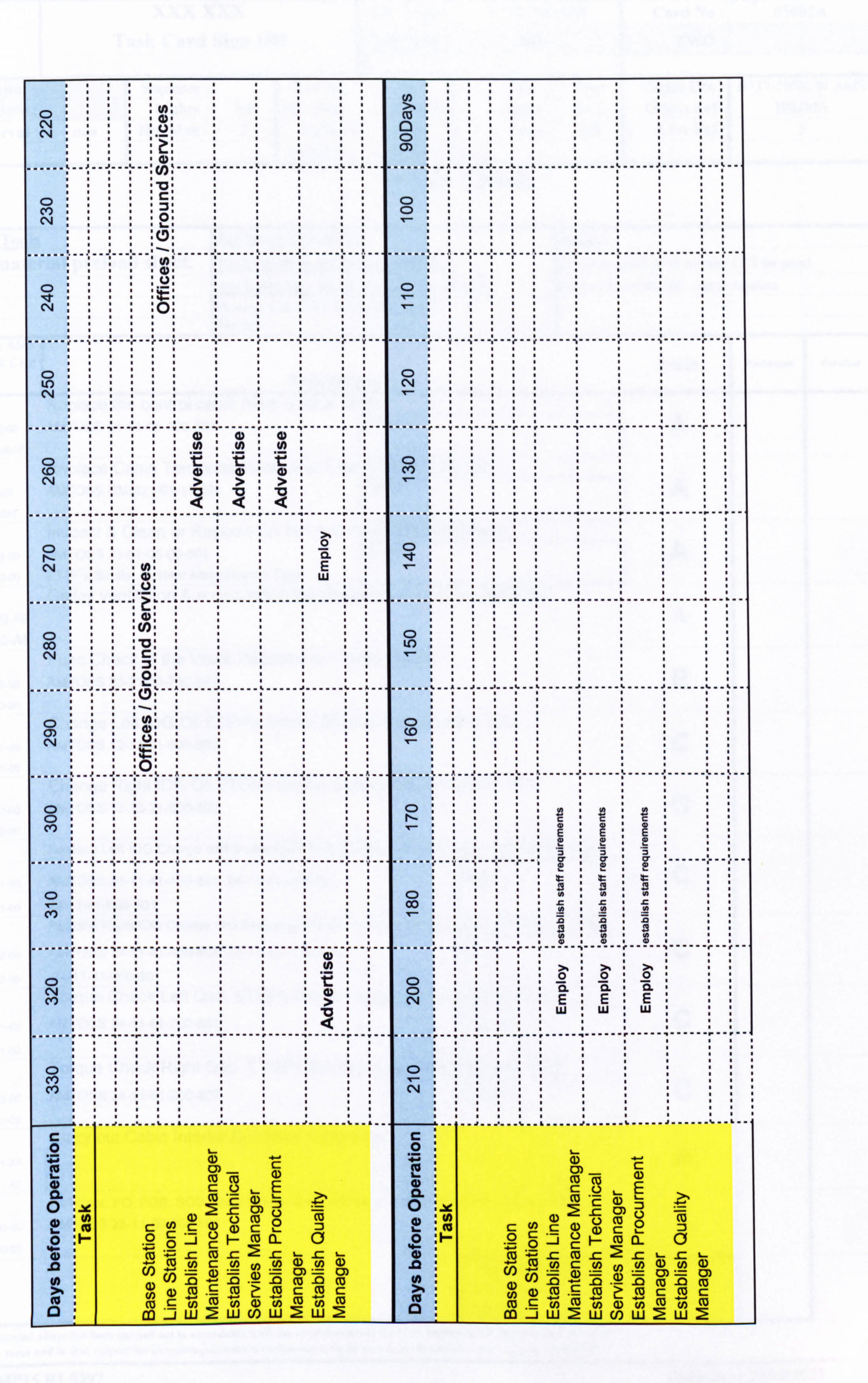
C'4 04
C) C",
::::: 0.1 1
------------ ---------------
C'4
I ------ e ----- I ------
LO 04
---------------------- ------ W: 13) : U) to W
(0 :::::: 4) : 4) : (D :I: C'4 :::::: >0 :>: >::
------------ ------------ ---------
0 1ý CL 04 :::: (4: :I. E--
........... ------------- ----------------
0 00 ::::, 0: : C*4 C
:::. (D: ---------- : ..... . 1. : C) :::: 0: :I: I
-:... : 0: : 1. --A
C)
------------- ----------
C)
(Y)
------------ ------
U)
CN
------------ ------------
............ -------
--------------------
C> C')
--------------- ------------ ---------------
C>
-------------- ---- -------------
0 LO
---------------
C)
C) 4r
E) OE
47
ig a is 'A 'A 0 1.
1 .5, -5 ::: co 10 to CA
::: -:: IUR : . 09 10,1
............
C) 2 CL CL CL 0
C\I: ::: I: E: E: E::: LU Ui Ui
------------------------------------
C> 04
c 0
C)) co m CD
X ca
E a) 0
CL 0
c0 M c E
CD 0 cc
Q c U) c 4) CU 0 c 1-
M :3
to . (U 0 4) a)
Co 0 C: cu
:aC: zi L) ý- 0 C: (0 d- a o J- 0 -j c CU a- a
== CU M ch c: U) (J) a) w 4) Z- -c cu cu c U)
2 C-- u) U) r- w U) -- 4) = U) - .0
(1) 0) = co -0
0) co U) : (D = WE -. 0 a) =
- -0 0) = (D n
0)
") 4) (u .9 cu
CU cu
1) 10 ER a) US
c CU (u -ch
c cu m U) a) C13 C- cu
cu co M c CU
cu ( c cu
I) _jw 1 2 Lu (D w 0: m -i ww cl) U) w
A w 2
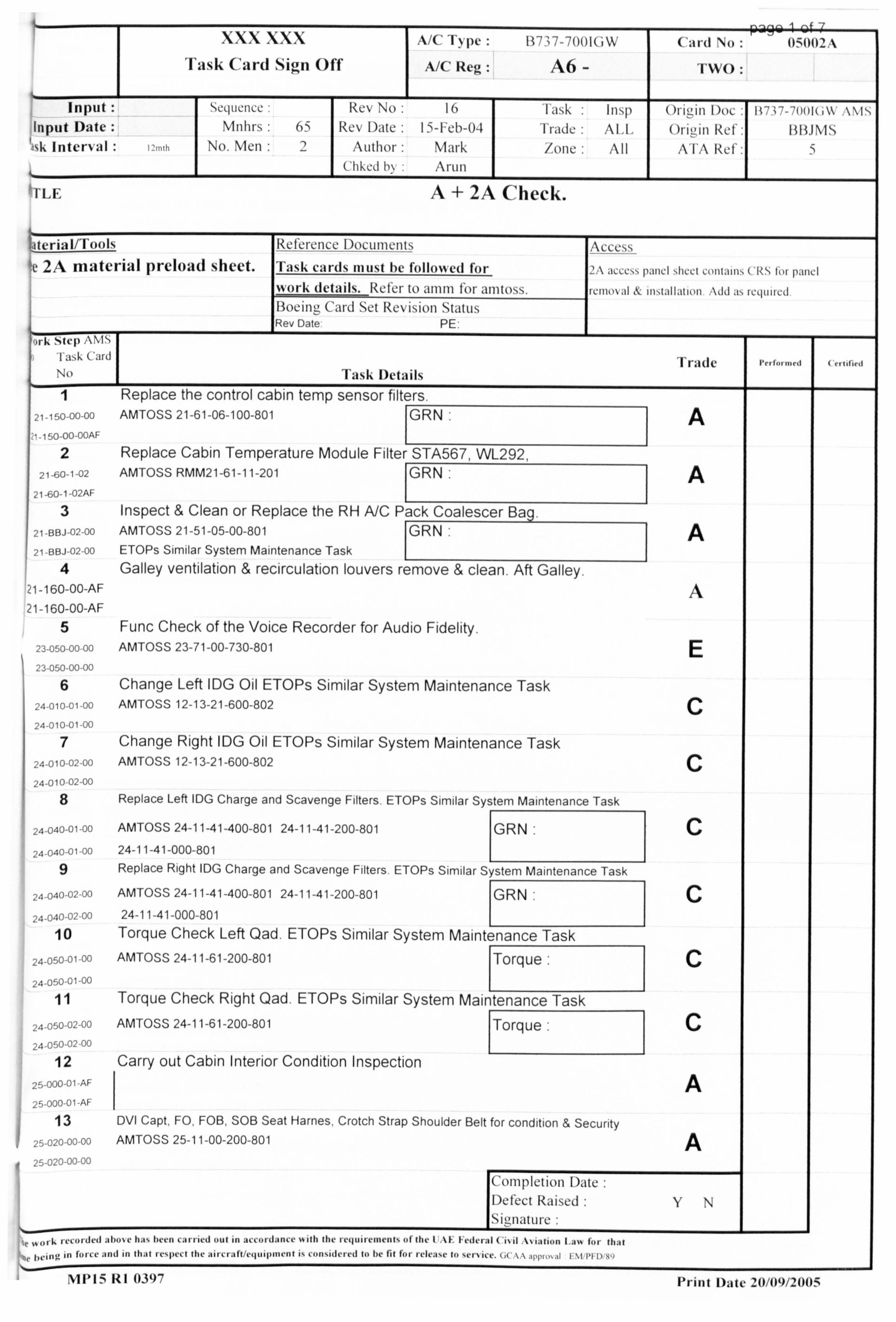
xxx xxx AX-11) pe 117', 7-7001(IW Rii9w 1w0
Card No: 05002A
Task Card Sign Off A/C Reg: A6 - TWO:
Input se(luclice: Rev No 16 1 ask Insp I, _, III Doc Input Date Mnlirs 65 Rev Date I ý-I`eb-04 Frade Al, [, ()111-- -111 Ref: MUMS j%k Interval I ', mh No. Men 2 Author Mark /olle All A VA Re f:
Cliked 1),, Arun
I! TLE
i
A+ 2A Check.
Lateriall/Tools Ret'CI-C_I1CC I)OCLI111CIltS Access
Ile 2A material preload sheet. Task cards inust he folloiýed for 2A ýICCCýN I) MIC1 ý11CCI CMWIITIý WN t0l 1)ýJjlcl ivork details. Refer to amin t'or anitoss, icilloNal 1 11ý(A[, Itlon Ukl, t, IL-quilcd Boeinu, Card Set Revision Status Rev Date PE
'()rk stcP AM
I aýk Car Trade No Task Details I Replace the control cabin temp sensor filters.
21-150-00-00 AMTOSS 21-61-06-100-801 ýGRN: A -1 50-00-OOAF
2 Replace Cabin Temperature Module Filter STA567, WI-292, 21-60-1-02 AMTOSS RMM21-61-11-201 GRN: 1 A
21-60-1-02AF
3 Inspect & Clean or Replace the RH A/C Pack Coalescer Bag. 21 -1313-1-02-00
AMTOSS 21-51-05-00-801 rr-, A 21 -1313-1-02-00
ETOPs Similar System Maintenance Task I
4 Galley ventilation & recirculation louvers remove & clean. Aft Galley. '21-160-00-AF A 21-160-00-AF
5 Func Check of the Voice Recorder for Audio Fidelity. 23-050-00 00 AMTOSS 23-71-00-730-801 E 23-050-00-00
6 Change Left IDG Oil ETOPs Similar System Maintenance Task 24-010-01-00 AMTOSS 12-13-21-600-802 C
24-010-01 00
7 Change Right IDG Oil ETOPs Similar System Maintenance Task 24-010-02 00 AMTOSS 12-13-21-600-802 C
24-010 02-00
8 Replace Left IDG Charge and Scavenge Filters. ETOPs Similar System Maintenance Task
AMTOSS 24 11 41 C 24-040-01-00 - - -400-801 24-11-41-200-801 GRN: 24-040-01-00 24-11-41-000-801
9 Replace Right IDG Charge and Scavenge Filters. ETOPs Similar System Maintenance Task
24-040-02-00 AMTOSS 24-11-41-400-801 24-11-41-200-801 GRN: C 24-040 02 00 24-11-41-000-801
10 Torque Check Left Qad. ETOPs Similar System Maintenance Task 24-OFIO 01 C)C) AMTOSS 24-11-61-200-801 Torque C 24-05C) ()1-00
Torque Check Right Qad. ETOPs Similar System Maintenance Task -14-01,0-02-00 AMTOSS 24-11-61-200-801 ue C 24-C)50-02 00
12 Carry out Cabin Interior Condition Inspection 25-000-01 AF A 25-000-01 -AF
13 DVI Capt, FO, FOB, SOB Seat Harnes, Crotch Strap Shoulder Belt for condition & Security
25-020-00 00 AMTOSS 25-11-00-200-801 A 2ý 02-) ()ý) 00
Completion Date
Dcl'ect Raised YN
Si-natul-e
" ork r-ccorded aboNe ha, been carried out ill accoidance ýs ith the tequilement, of the I Ak. I e(jel-: 11 ( j% il itio, Ior that
h, ing in force and ill that tespect the aircraft/equipment i, con, idered to he fit fol releaw to 'er% ice. (. ( \ "Iy-"d ] \1 '1 1) -
MP15 RI 0397 Print Date 20/09/2005
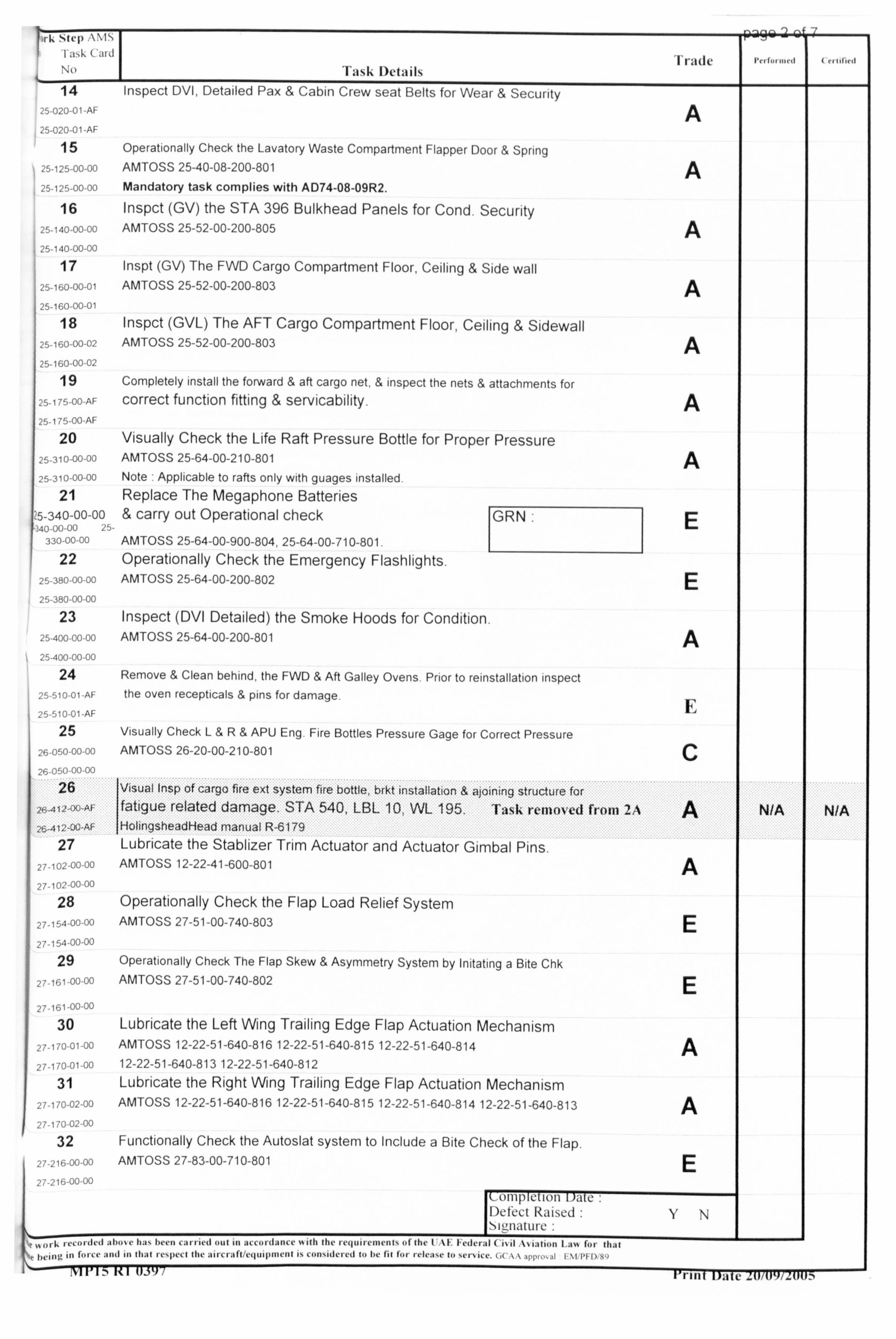
I aýk ( aid No
4. -
1
'Fask Details Trade
14 Inspect DVI, Detailed Pax & Cabin Crew seat Belts for Wear & Security 25-020-01 -AF A
-020-01-AF 15 Operationally Check the Lavatory Waste Compartment Flapper Door & Spring
AMTOSS 25-40-08-200-801 A 25-125-00-00 Mandatory task complies with AD74-08-09R2.
16 Inspct (GV) the STA 396 Bulkhead Panels for Cond. Security 25-140-00-00 AMTOSS 25-52-00-200-805 A 25-140-00-00
Inspt (GV) The FWD Cargo Compartment Floor, Ceiling & Side wall 125-160-00-01 AMTOSS 25-52-00-200-803 A
25-160-00-01
18 Inspct (GVL) The AFT Cargo Compartment Floor, Ceiling & Sidewall
,, ý-160-00-02 AMTOSS 25-52-00-200-803 A 25-160-00-02
19 Completely install the forward & aft cargo net, & inspect the nets & attachments for 25-175-00-AF correct function fitting & servicability. A 25-175 00-AF
20 Visually Check the Life Raft Pressure Bottle for Proper Pressure 115-310-00-00 AMTOSS 25-64-00-210-801 A 25-310-00-00 Note ý Applicable to rafts only with guages installed
21 Replace The Megaphone Batteries 25-340-00-00 & carry out Operational check GRN. E '40-00-00 25-
330 00-00 AMTOSS 25-64-00-900-804,25-64-00-710-801. 22 Operationally Check the Emergency Flashlights.
25 380-00-00 AMTOSS 25-64-00-200-802 E 25-380-00-00
23 Inspect (DVI Detailed) the Smoke Hoods for Condition. 25-400-00-00 AMTOSS 25-64-00-200-801 A 25 400-00 00
24 Remove & Clean behind, the FWD & Aft Galley Ovens. Prior to reinstallation inspect 510 01 AF the oven recepticals & pins for damage.
E 25-510-01 -AF 25 Visually Check L&R& APU Eng. Fire Bottles Pressure Gage for Correct Pressure
26 0', 0 00 00
ý "')ý Iý 1) ")
AMTOSS 26-20-00-210-801 C
d from 2. A 26,412, W, AF IHolingsheadHead manual R-66179
27 Lubricate the Stablizer Trim Actuator and Actuator Gimbal Pins. 27 -102
00-00 AMTOSS 12-22-41-600-801
27 -102 OC) C)o
28 Operationally Check the Flap Load Relief System 27-154 00-00 AMTOSS 27-51-00-740-803 E 27-154-00-00
29 Operationally Check The Flap Skew & Asymmetry System by Initating a Bite Chk 27 161 -00-00 AMTOSS 27-51-00-740-802 E 27-161-00-00
30 Lubricate the Left Wing Trailing Edge Flap Actuation Mechanism 27-170-01-00 AIVITOSS 12-22-51-640-816 12-22-51-640-815 12-22-51-640-814 A 27 1 iO 01 -00 12-22-51-640-813 12-22-51-640-812
31 Lubricate the Right Wing Trailing Edge Flap Actuation Mechanism 27 170-02-00 AIVITOSS 12-22-51-640-816 12-22-51-640-815 12-22-51-640-814 12-22-51-640-813 A 27-170-02-00
32 Functionally Check the Autoslat system to Include a Bite Check of the Flap.
27 216-00-00 AIVITOSS 27-83-00-710-801 E 27 '16 00 00
Raised :YN
I, ý, f, ý,,.. ýdI(,, I. t., d
or-k le-1111-11 IM, b-) CM-6ed out in accoidance %i ith the ivilmicivicrit% (if the I AF I-ederal CiN it AN ati(ill ]ý; Ivj fit t1l; 1I t""'v ill foic'. and in that I e'llect file ailct aft/c(IIIIIIIII"Ill J, coll'idel"I I., h, fit f"' to "rlice. ( .(\\ q'I II %I PI I) v,
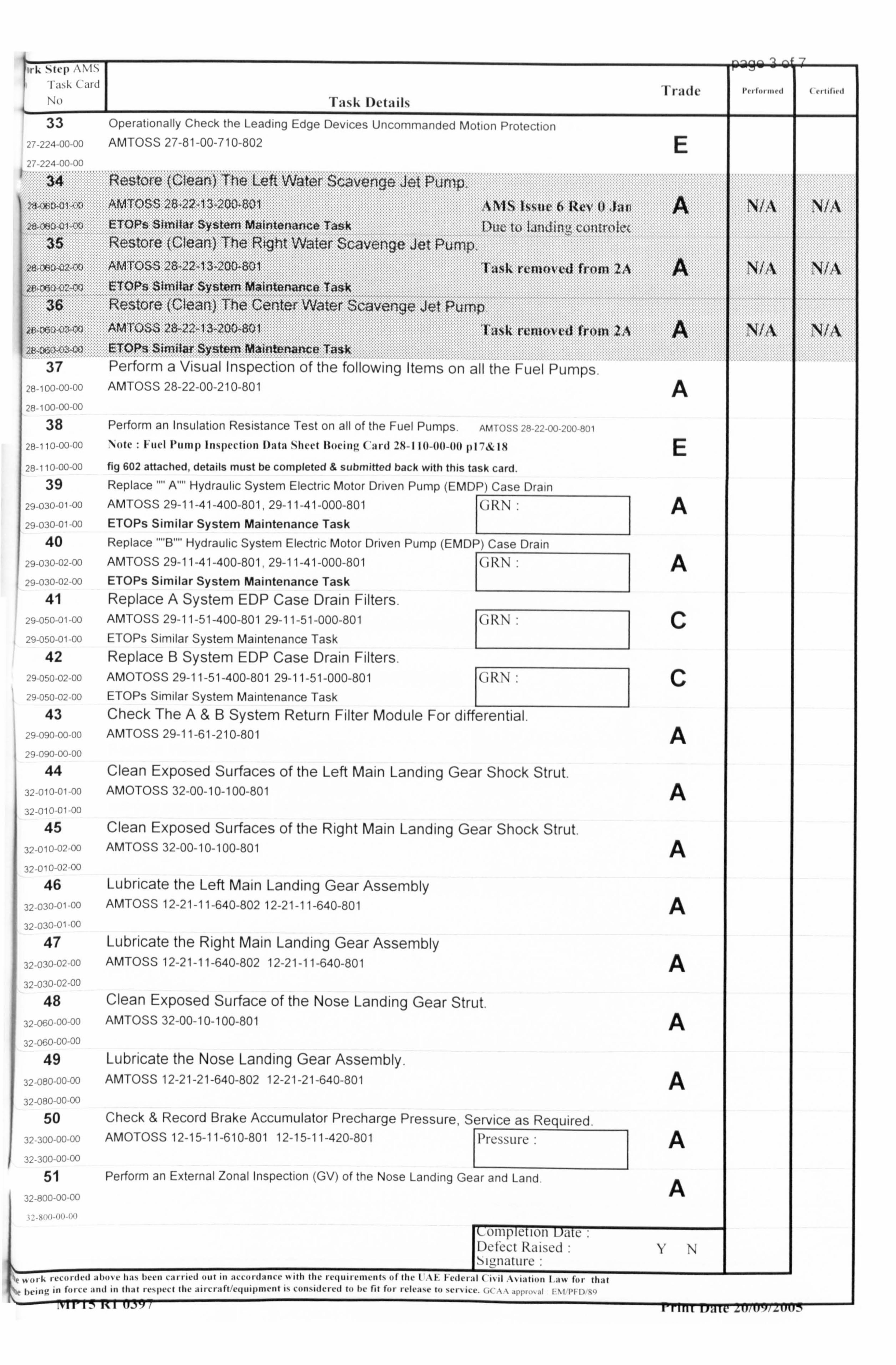
'I ask Card No
33 27-224-00-00
27-224-00-00
Trade
E
opintil ( tuisloil
I
IA
37 28-100-00-00
28-100-00 00
38 28-110-00-00
Task Details Operationally Check the Leading Edge Devices Uncommanded Motion Protection AMTOSS 27-81-00-710-802
Perform a Visual Inspection of the following Items on all the Fuel Pumps AMTOSS 28-22-00-210-801
Perform an Insulation Resistance Test on all of the Fuel Pumps. AM 10 SS 00 '00 80 1 Noile : ll, uel Ptimp Inspection Da(a Shect Illocing Cai-d 28-110-00-00 1)17&18 fig 602 attached, details must be completed & submitted back with this task card. Replace A Hydraulic System Electric Motor Driven Pump (EMDP) Case Drain AMTOSS 29-11-41-400-801,29-11-41-000-801 6RN ETOPs Similar System Maintenance Task
I
Replace B Hydraulic System Electric Motor Driven Pump (EMDP) Case Drain AMTOSS 29-11-41-400-801,29-11-41-000-801 GRN: ETOPs Similar System Maintenance Task Replace A System EDP Case Drain Filters. AMTOSS 29-11-51-400-801 29-11-51-000-801 GRN ETOPs Similar System Maintenance Task Replace B System EDP Case Drain Filters. AMOTOSS 29-11-51-400-801 29-11-51-000-801 GRN ETOPs Similar System Maintenance Task
I
Check The A&B System Return Filter Module For differential. AMTOSS 29-11-61-210-801
Clean Exposed Surfaces of the Left Main Landing Gear Shock Strut. AMOTOSS 32-00-10-100-801
Clean Exposed Surfaces of the Right Main Landing Gear Shock Strut. AMTOSS 32-00-10-100-801
Lubricate the Left Main Landing Gear Assembly AMTOSS 12-21-11-640-802 12-21-11-640-801
Lubricate the Right Main Landing Gear Assembly AMTOSS 12-21-11-640-802 12-21-11-640-801
Clean Exposed Surface of the Nose Landing Gear Strut. AMTOSS 32-00-10-100-801
Lubricate the Nose Landing Gear Assembly. AMTOSS 12-21-21-640-802 12-21-21-640-801
Check & Record Brake Accumulator Precharge Pressure, Service as Required. AMOTOSS 12-15-11-610-801 12-15-11-420-801 :
Perform an External Zonal Inspection (GV) of the Nose Landing Gear and Land
Det'ect Rarsed 'm'-niature :
A
E
A
A
c
c
A
A
A
A
A
A
A
A
A
k cco, -ded AMONe 11A, been cM tell out tit accordance I, ith file requirements of the I kiý' 1-cile, ; 11 ( IN il I, N i; Ition I fol 111; lt 1"n", in I OlCe and In Illat lespect tile ait craft/etinipment v, considered to be fit I'm iclease to sciAic, (, ý \\ jpj d 111 1) -
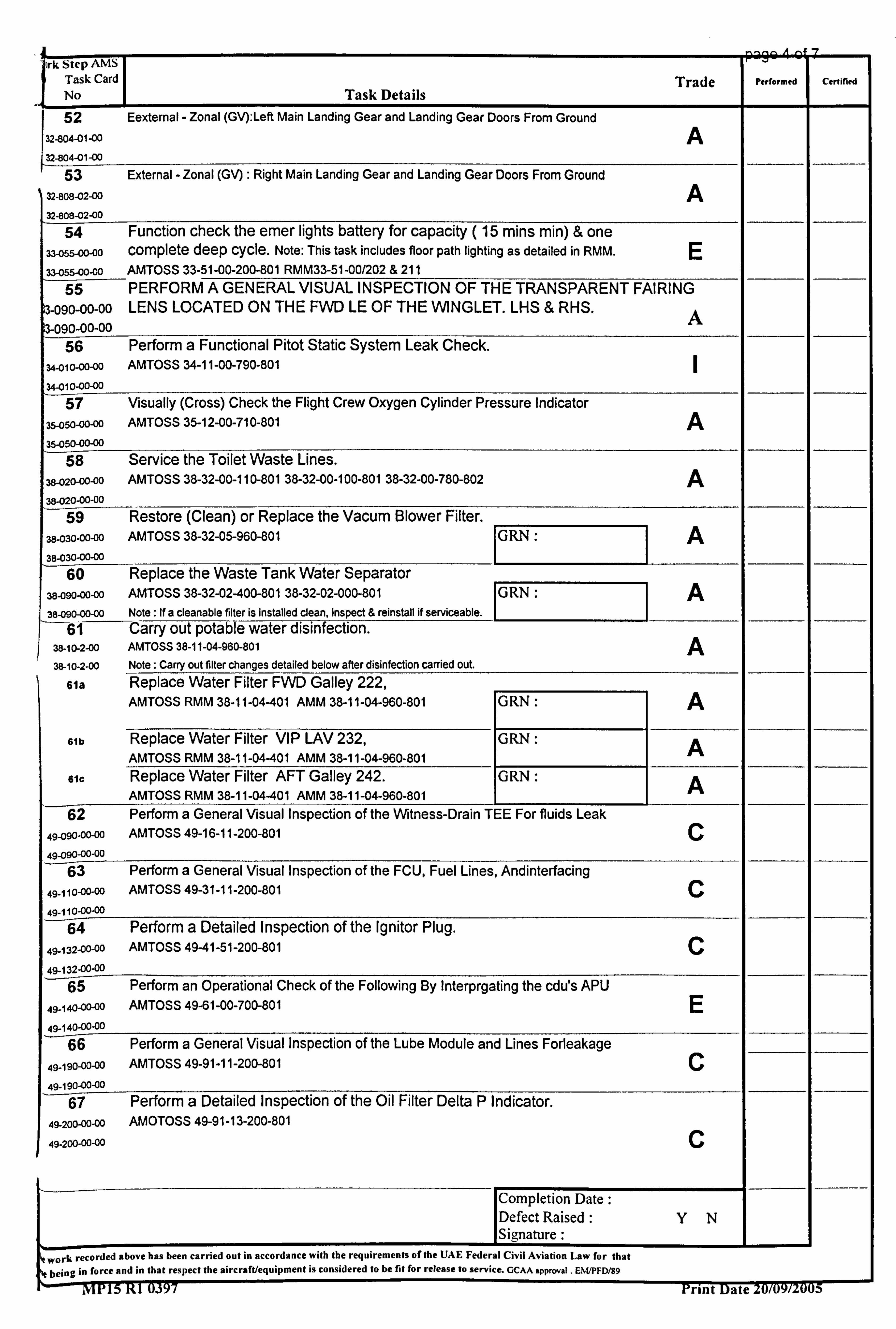
A -9 ý
ork Step AMS Task Card Trade Performed Certified
No Task Details 52 Eexternal - Zonal (GV): Left Main Landing Gear and Landing Gear Doors From Ground
32-8134-011 -00 A 32-804-01-00
53 External - Zonal (GV) : Right Main Landing Gear and Landing Gear Doors From Ground 32-808-02-00 A 32-808-02-00
54 Function check the emer lights battery for capacity ( 15 mins min) & one 33-055-00-00 complete deep cycle. Note: This task includes floor path lighting as detailed in RMM. E 33455-00-00 AMTOSS 33-51-00-200-801 RMM33-51-00/202 & 211
55 PERFORM A GENERAL VISUAL INSPECTION OF THE TRANSPARENT FAIRING 3-090-00-00 LENS LOCATED ON THE FWD LE OF THE WINGLET. LHS & RHS.
A 3-090-00-00 56 Perform a Functional Pitot Static System Leak Check.
U-010-00-00 AMTOSS 34-11-00-790-801 34-010-00-00
57 Visually (Cross) Check the Flight Crew Oxygen Cylinder Pressure Indicator 35-050-00-00 AMTOSS 35-12-00-710-801 A 35-050-00-00
58 Service the Toilet Waste Lines. 38-020-00-00 AMTOSS 38-32-00-110-80138-32-00-100-80138-32-00-780-802 A 38-020-00-00
59 Restore (Clean) or Replace the Vacum Blower Filter. 38-030-00-00 AMTOSS 38-32-05-960-801 GRN: 11 A 38-030-00-00
60 Replace the Waste Tank Water Separator 38-090-00-00 AMTOSS 38-32-02-400-80138-32-02-000-801 GRN A 38-090-00-00 Note : if a cleanable filter is installed clean, inspect & reinstall if serviceable.
6-1-- Carry out potable water disinfection. 38-10-2-00 AMTOSS 38-11-04-960-801 A 38-10-2-00 Note: Carry out filter changes detailed below after disinfection carried out.
61a Replace Water Filter FWD Galley 222, AMTOSS RMM 38-11-04-401 AMM 38-11-04-960-801 GRN: A
61b Replace Water Filter VIP LAV 232, GRN: A AMTOSS RMM 38-11-04-401 AMM 38-11-04-960-801 61C Replace Water Filter AFT Galley 242. 1 GRN: A AMTOSS RMM 38-11-04-401 AMM 38-11-04-960-801 62 Perform a General Visual Inspection of the Witness-Drain TEE For fluids Leak
49-090-00-00 AMTOSS 49-16-11-200-801 C
49-090-00-00
U, Fuel Lines, Andinterfacing
49-110-00-00 AMTOSS 49-31-11-200-801 C
49-110-00-00
r Plug.
49-132-00-00 AMTOSS 49-41-51-200-801 C
49-132-00-00 g By Interpirgating the cdu's APU
49-140-00-00 AMTOSS 49-61-00-700-801 E 49-140-00-00
be Module and Lines Forleakage 49-190-00-00 AMTOSS 49-91-11-200-801 C
49-190-00-00 67 Perform a Detailed Inspection of the Oil Filter Delta P Indicator.
49-200-00-00 AMOTOSS 49-91-13-200-801
49-2GO-00-00 C
Completion Date: Defect Raised: YN Signature :
work recorded above has been carried out in accordance with the requirements of the UAE Federal Civil Aviation Law for that being in force and in that respect the aircraft/equipment is considered to be fit for release to service. GCAA approval . EWPFD/89
1-----MPIS Rl 0.397 Print-Date-20/09/2005
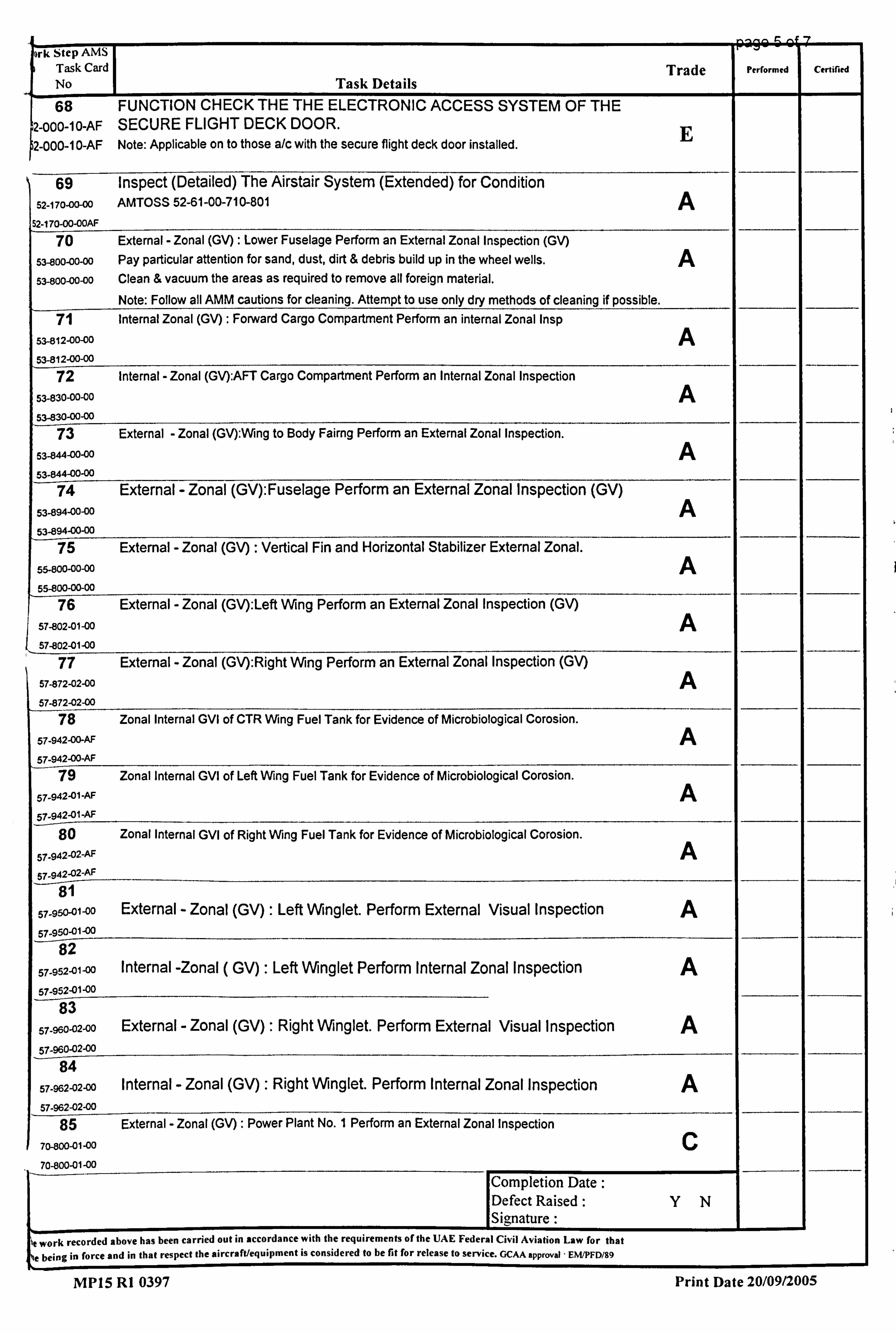
'ork Step AMS Task Card
I
Trade Performed Cerfified
No Task Details
68 FUNCTION CHECK THE THE ELECTRONIC ACCESS SYSTEM OF THE
2-000-1 O-AF SECURE FLIGHT DECK DOOR. E 2-000-1 O-AF Note: Applicable on to those a/c with the secure flight deck door installed.
69 Inspect (Detailed) The Airstair System (Extended) for Condition
52-170-00-00 AMTOSS 52-61-00-710-801 A 52-170-00-OOAF
70 External - Zonal (GV): Lower Fuselage Perform an External Zonal Inspection (GV)
53-800-00-00 Pay particular attention for sand, dust, dirt & debris build up in the wheel wells. A 53-800-00-00 Clean & vacuum the areas as required to remove all foreign material.
Note: Follow all AMM cautions for cleaning. Attempt to use only dry methods of cleaning if possible. 71 Internal Zonal (GV): Forward Cargo Compartment Perform an internal Zonal Insp
53-812-00-00 A 53-812-00-00
72 Internal - Zonal (GV): AFT Cargo Compartment Perform an Internal Zonal Inspection
53-830-00-00 A 53-830-00-00
73 External - Zonal (GV): Wing to Body Fairng Perform an External Zonal Inspection.
53-844-00-00 A 53-844-00-00
74 External - Zonal (GV): Fuselage Perform an External Zonal Inspection (GV)
53-894-00-00 A 53-894-00-00
75 External - Zonal (GV) : Vertical Fin and Horizontal Stabilizer External Zonal.
55-800-00-00 A 5"00-moo 76 External - Zonal (GV): Left Wing Perform an External Zonal Inspection (GV)
57-802-01-00 A 57-802-01-00
77 External - Zonal (GV): Right Wing Perform an External Zonal Inspection (GV)
57-872-02-00 A 57-872-02-00
78 Zonal Internal GVl of CTR Wing Fuel Tank for Evidence of Microbiological Corosion.
57-942-00-AF A 57-942-00-AF
79 Zonal Internal GVI of Left Wing Fuel Tank for Evidence of Microbiological Corosion.
57-942-01 -AF A 57-942-01-AF
80 Zonal Internal GVI of Right Wing Fuel Tank for Evidence of Microbiological Corosion.
57.942-02-AF A 57.942-02-A
_'i-_ 81
57-95041-00 External - Zonal (GV) : Left Winglet. Perform External Visual Inspection A
82
57-952-01-00 Internal -Zonal ( GV) Left Winglet Perform Internal Zonal Inspection A
57-952-01-00 83
57-96o-02-00 External -Zonal (GV) Right Winglet. Perform External Visual Inspection A
57-960-02-00 84
57-962-02-00 Internal - Zonal (GV) Right Winglet. Perform Internal Zonal Inspection A 67-962-02-00
85 External - Zonal (GV) : Power Plant No. I Perform an External Zonal Inspection
00 C
70-800-01- 70-800-01-00
Completion Date: L
Defect Raised
I
YN S ignature
trecorded above has been carried out in accordance with the requirements ofthe UAE Federal Civil Aviation Law for that
te being in force and in that respect the aircraft/equipment is considered to be fit for release to service. GCAA approval, EWPFD/99
MP15 Rl 0397 Print Date 20/09/2005
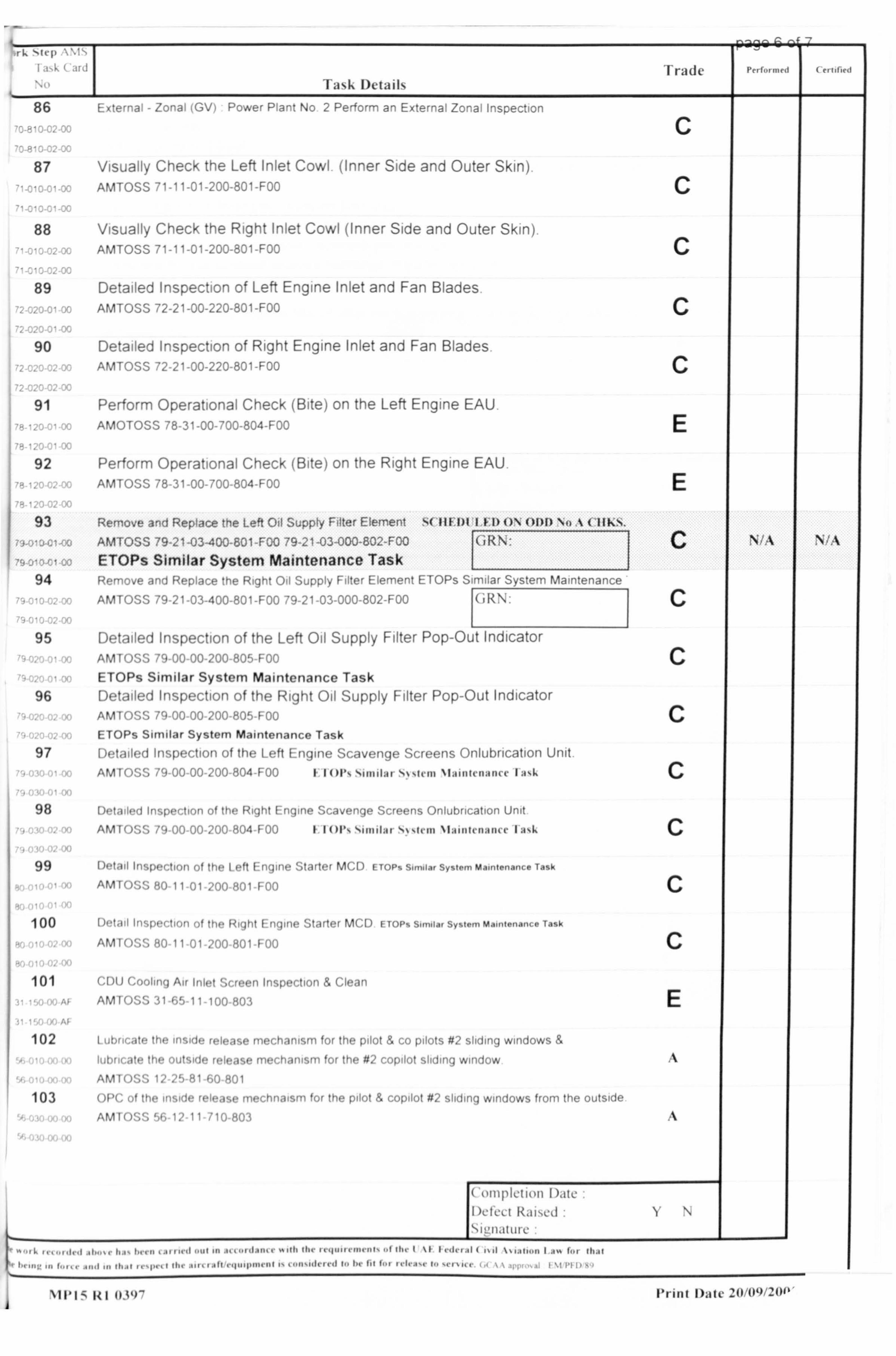
Task Details Trade
External - Zonal (GV) Power Plant No 2 Perform an External Zonal Inspection
C Visually Check the Left Inlet Cowl (Inner Side and Outer Skin)
AM70SS '1 11 K'-FDý C
Visually Check the Right Inlet Cowl (Inner Side and Outer Skin) AMTOSS 71-11-01-200-801-FOý C
Detailed Inspection of Left Engine Inlet and Fan Blades AMTOSS 72-21-00-220-801 -FOO
C
Detailed Inspection of Right Engine Inlet and Fan Blades APATOSS 72-21-00-220-801-FOO
Per-form Operational Check (Bite) on the Left Engine EAU
AM()T0 ý3 ', 'Pý I' --1 0-ý -j 8 -- ,-F -- -, ý
Perform Operational Check (Bite) on the Right Engine EAU APA TOSS 78-31-00-700-804-FOý E
Remove and Replace the Left Oil Supply Filter Element s( 111FIDI I H) ONODD N(). % ( Ilk. S. _ AMTOSS 79-21-03-400-801-FOO 79-21-03-000-802-FOO GRN: I
ETOPs Similar System Maintenance Task Por-, ve anj Ppnixýe ! he Riqh! C)d Supply Filter Element ETOPs Similar System Maintenance
ArATOSS 79-21-03-400-801-FOO 79-21-03-000-802-FOO I (JRN:
Detailed Inspection of the Left Oil Supply Filter Pop-Out Indicator AMTOSS 79-00 00 200-805 FOO
ETOPs Similar System Maintenance Task Detailed Inspection of the Right Oil Supply Filter Pop-Out Indicator AIVITOSS 79-00 00-200 805 F00
ETOPs Similar System Maintenance Task
Detailed Inspection of the Left Engine Scavenge Screens Onlobrication Unit
AMTOSS 79-00-00-200-804-FOO I 11011's. Smidaf S. Nslem Nlainlenanct- I; i, k
Detailed Inspection of the Right Engine Scavenge Screens Onlubrication Unit
AMTOSS 79-00-00-200-804-FOO I 1(111'ýNimilar SNocin Nimim-mmic Ij, k
Detail Inspection of the Left Enqme M(A) F TOP, Syo-, T. %k
AMTOSS 80-11-01-200-801 -F M
1)(lad Inspection of the Right I n(im, M(A) t toF,, 1--l- Sy, t, - M-Aý T., k
AMTOSS 80-11-01-200-801-F Of ý
f. [)IJ (-. r)olin(j Air InJol ', rr(, Pf) tiwi l. (Ji-xi
AMP)''" ý! - ".. , ý,
lubricate the outside release mechanism for the #2 copilot sliding window AMTOSS 12-25-81-60-801
( )[ IC of the inside release mechnatsm for the pilot & copilot #2 sliding windows frorn the OUtside AM 1 1,1 - 1,1 11 i'l 1, W) 1,
('111pictioll Dilte
.... ...... d, Ai
N%IN%
Print Da(c 20/09/20P.
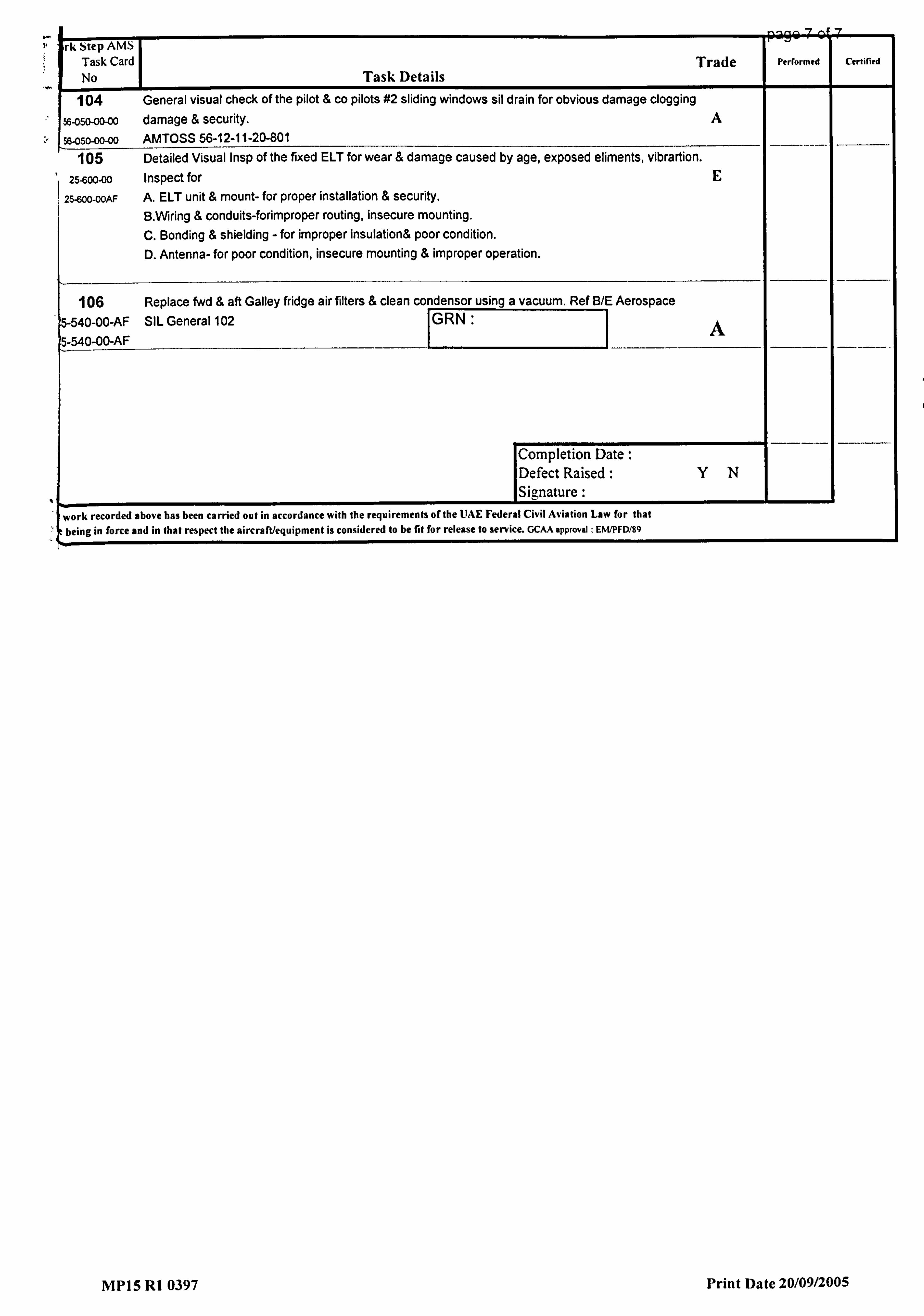
---- -9 '7
rk Step AMS Task Card
I Trade Perrormed Certified
No Task Details 104 General visual check of the pilot & co, pilots #2 sliding windows sil drain for obvious damage clogging
56-050-00-00 damage & security. A
%-050-00-00 AMTOSS 56-12-11-20-801 105 Detailed Visual Insp of the fixed ELT for wear & damage caused by age, exposed eliments, vibrartion.
25-600-00 Inspect for E 25-600-OOAF A, ELT unit & mount- for proper installation & security.
B. Wring & conduits-forimproper routing, insecure mounting. C. Bonding & shielding - for improper insulation& poor condition. D. Antenna- for poor condition, insecure mounting & improper operation.
106 Replace fwd & aft Galley fridge air filters & clean condensor using a vacuum. Ref B/E Aerospace _ 5-540-00-AF
5-540-00-AF SIL General 102 RN: 7
Completion Date: Defect Raised: YN Signature
work recorded above has been carried out in accordance with the requirements of the UAE Federal Civil Aviation Law for that t being in force and in that respect the aircraft/equipment is considered to be fit for release to service. GCAA approval : EWPFD/89
MP15 RI 0397 Print Date 20/09/2005