Embed Size (px)
Citation preview

Drop Deformation in Stokes Flow through Converging Channels
Luiz C. Wrobel1*, Delfim Soares Jr2 and Claire L. Das Bhaumik1,3 1School of Engineering and Design, Brunel University, Uxbridge UB8 3PH, UK
2 Structural Engineering Department, Federal University of Juiz de Fora, Juiz de Fora,
Brazil
3Current address: BRE, Garston, Watford WD25 9XX, UK
Keywords: Boundary elements, Stokes flow, drop deformation, drop interaction,
converging channels
Abstract. This work presents an application of a direct BEM formulation for drop
deformation and interaction in Stokes flows through converging channels. Parametric
studies are conducted to investigate the effect, on drop deformation, of the channel’s
convergence ratio, the drop-fluid viscosity ratio, the interfacial tension and the initial
relative position of the drops.
1. Introduction
Suspensions of particles, drops and bubbles in viscous fluids occur in many biological
systems, industrial applications and processes including blood flow, pharmaceutical
manufacturing, food and chemical processing. It is important to understand the
properties of the suspensions in order to gain a better understanding of their behaviour
in these systems. This knowledge can then be used to predict fluid behaviour and
improve industrial processes.
The study of the motion of particles, drops and bubbles in viscous fluids at low
Reynolds number dates back to 1851, when Stokes [1] published a paper on the problem
of a rigid sphere translating through a fluid at zero Reynolds number. Since then, there
has been much research in this area, both experimental and theoretical. Important areas * Corresponding author. E-mail: [email protected]; Tel: +44 1895 266696; Fax: +44 1895 269803.

of study include flow with rigid boundaries, such as solid inclusions and plane walls,
and flows involving deformable boundaries, e.g. flows containing viscous liquid drops
or gas bubbles [2].
The BEM is an efficient technique for problems involving deforming boundaries such
as fluid-fluid interfaces. In these problems, the position of the interfaces must be
determined as part of the solution. The BEM enables direct calculation of the interface
velocity. Numerical techniques for ordinary differential equations can then be used to
find new nodal positions. The BEM also has the ability to deal with large surface
deformations and other surface effects, such as interfacial tension, can be easily
incorporated [3, 4].
Recent reviews of boundary integral methods for viscous free-boundary problems
involving the deformation of single and multiple fluid-fluid interfaces were produced by
Weinbaum and Ganatos [5] and Tanzosh et al. [6], while a review of drop deformation
and break-up at low Reynolds number flows was produced by Stone [7]. Briscoe et al.
[8] reviewed developments in the understanding of the mixing process of a dispersed
fluid phase in a continuous fluid phase.
Manga and Stone [9] used a boundary integral method to study the buoyancy-driven
interactions between two deformable viscous drops based on a formulation similar to
Rallison and Acrivos’ pioneering work [10]. In this case large deformations are seen
due to buoyancy forces being much larger than the restoring interfacial tension forces.
The same formulation was later used to investigate the low Reynolds number motion of
bubbles, drops and rigid spheres through fluid-fluid interfaces [11]. In this study, one of
the drops was considered to be infinitely large. Manga and Stone [12] also carried out a
three-dimensional study of the behaviour of deformable buoyant drops and bubbles in
dilute low Reynolds number suspension, in which a boundary integral method was used
to model up to four drops.
Pozrikidis [13] studied the buoyancy-driven motion of a train of drops in a vertical tube,
with drops of the same viscosity as the surrounding fluid which settle or rise along the
axis of a vertical cylindrical tube. The method employed used an axisymmetric periodic
Green’s function for flow in a cylindrical tube. Drop motion was studied as a function

of the tube radius σc, the drop radius a, the drop separation L and the Bond number.
Two types of drops were considered, classified according to the value of the ratio σc/a.
Drops where σc/a>1 were called compact drops, otherwise drops were called elongated.
Where surface tension was large, compact drops assume a spherical shape and
elongated drops tend to adhere to the tube wall. For compact drops, a smaller value of
drop separation ratio L/a leads to more elongated drops and the drops develop a fishtail
shape at the rear.
Zhou and Pozrikidis studied the two-dimensional flow of single files of drops [14] and
the shear-driven flow of ordered periodic suspensions of two-dimensional liquid drops
in a channel [15], using the method of interfacial dynamics. Periodically random
suspensions were also studied. The behaviour of random suspensions was found to be
significantly different from that of ordered suspensions.
Li et al. [16] studied the shearing motion of monodisperse suspensions of two-
dimensional deformable liquid drops with uniform surface tension in an infinite domain.
The drop viscosity was the same as that of the surrounding fluid. A periodic distribution
of squares of randomly distributed drops was used. Loewenberger and Hinch [17]
developed a three-dimensional numerical formulation for a concentrated emulsion in
shear flow. As in the study of Li et al. [16], a periodic distribution of squares of
randomly distributed drops is used. The number of random particles in each periodic
box was limited to twelve due to computational costs. The emulsion was found to have
complex non-Newtonian rheology.
Roumeliotis and Fulford [18] developed a boundary integral method in which the drop
surfaces are parameterized with respect to arc length using cubic splines, enabling the
surface tension to be represented as piecewise linear. This is applied to the buoyancy-
driven interaction of two and three axisymmetric drops in Stokes flow.
In order to calculate the surface tension forces accurately, the surface curvature must be
computed accurately. Zinchenko et al. [19] eliminated the mean curvature term from the
boundary integral formulation. A three-dimensional formulation was developed for
interacting deformable drops in Stokes flow which was applicable to very large
deformations and problems with drops having cusped interfaces and drops closely

approaching break-up. Instead of the curvature, the formulation contained only the
normal vectors, which are generally less sensitive to discretisation errors than the
curvature. This allows simulation of problems including point and line singularities.
Khayat et al. [20] used a boundary element formulation to study two-dimensional two-
phase incompressible creeping flow, applying the method to the deformation of a
viscous drop inside a hyperbolic convergent channel in the absence of surface tension.
The effect of changing the degree of channel convergence and the viscosity ratio, λ ,
were studied. It was found that the channel geometry significantly influenced drop
deformation and that drop deformation increased with decreasing viscosity ratio, with
particularly large extension when λ <1. Both initially circular and elliptical drops were
considered.
Khayat et al. [21] later studied the deformation of single drops in two-dimensional
convergent-divergent channel flows. Both Newtonian and viscoelastic fluids were
considered. The effect of drop size, drop initial position relative both to the channel axis
and the constriction throat, interfacial tension and fluid elasticity on the drop
deformation were studied. Experimental results were also obtained and good agreement
between computational and experimental results was seen. For drops initially positioned
away from the channel axis, the distance from the axis was found to influence the rate
and magnitude of drop deformation. In this case, the value of the viscosity ratio was
found to be particularly important as, for drops with high viscosity ratios, little
deformation was seen due to the drop rotating and being alternately stretched and
compressed.
Giraldo et al. [22] recently studied the mobility problem of two particles in a shear flow
for the complete range of viscous ratio, including bubbles, drops and solid particles. A
completed indirect boundary integral equation formulation was used [4], and the motion
of drops studied for different viscosity ratios and capillary numbers.
The present paper extends the above works of Khayat et al. [20, 21] by analysing the
interaction between two drops. Appropriate numerical algorithms developed for this
application with quadratic boundary elements are reported in the paper.

2. Integral Equation Formulation for Drop Deformation in Stokes Flow
Since the problem involves drops of a viscous fluid in another carrying fluid, a standard
subregions technique is applied by considering compatibility and equilibrium conditions
along the interfaces.
The relevant compatibility conditions at the interface between drop and bulk fluid are:
0)()( =− xuxu di
fi (1)
where fiu is the interface velocity of the bulk fluid and d
iu is the velocity at the drop
surface. This equation represents continuity of velocity.
The relevant equilibrium conditions are
)()()()( xnxxtxt idi
fi γκ=− (2)
where it is the traction, jiji nt σ= , γ is the surface tension coefficient, in is the unit
outward normal vector and κ is the surface curvature. The difference between the
tractions fit and d
it is due to the existence of surface tension.
The velocity field for a point x' in Stokes flow can be written as [3, 4]
∫∫ −=S
jijS
jijjij dSxuxxpdSxtxxuxuxc )(),'()(),'(1)'()'( **
μ (3)
where μ is the fluid viscosity, ijc is the free term, and *iju is the velocity field of the
fundamental solution with traction *ijp [3, 4].
Since the BEM formulation in this paper is only concerned with the evolution of the
drop boundary, and not with the calculation of the tractions on the drop boundary, it is
possible to combine two integral equations, one for source points belonging to the bulk

fluid and the other for source points belonging to the drop, in order to eliminate the
interface tractions by using the equilibrium equation (2) [20, 21], generating the
following integral equations:.
∫∫ +−=
eSjij
eSjij
fjij dSxuxxpdSxtxxuxuxc )(),'()(),'(1)'()'( **
μ
( ) ∫∫ −−
dSjij
dSjij
fdSxuxxpdSxnxxxu )(),'(1)()(),'( ** λκ
μγ
(4)
for source points on the solid boundary, and
( ) ∫∫ +−=+
eSjij
eSjij
fjij dSxuxxpdSxtxxuxuxc )(),'()(),'(1)'()'(1 **
μλ
( ) ∫∫ −−
dSjij
dSjij
fdSxuxxpdSxnxxxu )(),'(1)()(),'( ** λκ
μγ
(5)
for source points on the drop. In the above equations, d
f
μλμ
= is the viscosity ratio,
with fμ the bulk fluid viscosity and dμ the drop viscosity, eS and dS represent the
external and the drop boundary.
3. Numerical Algorithms
The numerical formulation employed quadratic boundary elements. Since small time
steps are used in the simulation, the previous drop position and shape provide a very
good initial guess for the iteration process at the next time step. Some of the specific
algorithms adopted in the current implementation are briefly discussed below.

3.1 Mass Conservation
A measure of the accuracy of the numerical algorithms is mass conversation. For this, a
simple application of the divergence theorem can be derived that allows the drop area at
each time step to be calculated through the boundary integral
∫= S ii dSnxA21 (6)
3.2 Node Relocation
Initially, elements on the drop surfaces are of equal size with evenly spaced nodes. After
deformating the drop surfaces by translating nodes as if they were individual particles,
there is no guarantee that the mid-element nodes will still be equidistant from each end
node and, in addition, the elements will no longer be of equal size.
As is well known, the physical coordinates (x and y) that describe quadratic element
geometries can be written as a function of a natural coordinate ξ, as follows:
( ) ( )( ) ( ) 321 121111
21 xxxx +++−+−= ξξξξξξ (7)
( ) ( )( ) ( ) 321 121111
21 yyyy +++−+−= ξξξξξξ (8)
where xi and yi stand for element node coordinates (see the sketch depicted in Figure 1).
The mid-node location can be computed by evaluating the natural coordinate Mξ
corresponding to the physical mid-element position. In order to do so in a simple way,
first, the horizontal and vertical centres of the element are computed (XM = [x3 + x1]/2
and YM = [y3 + y1]/2) and, in the sequence, their respective natural coordinates ( xξ and
yξ ) are evaluated by finding the roots of the following second-order equations:
( ) ( ) ( ) 022 2132
321 =−+−++− Mxx Xxxxxxx ξξ (9)
( ) ( ) ( ) 022 2132
321 =−+−++− Myy Yyyyyyy ξξ (10)

Once xξ and yξ are computed, Mξ can be calculated by taking into account a simple
weighted arithmetic mean,
( ) ( )YXYX yxM Δ+ΔΔ+Δ= /ξξξ (11)
and the new element mid-node location (coordinates x and y) can be obtained by
applying the computed Mξ into equations (7) and (8).
In the present work, at each time step, the above described procedures are employed
three times: twice to relocate the element mid-nodes and once to relocate the element
end-nodes. First, the mid-nodes of the quadratic elements are translated to their central
positions (as discussed above); secondly, the above described procedures are employed
to relocate the element end-nodes, fitting a quadratic curve between adjacent element
mid-nodes and finding its central position; finally, considering the newly-dimensioned
elements, the relocation procedures are once again applied to centre the element mid-
nodes.
4. Numerical Simulations
The numerical simulations study initially circular drops placed in a converging channel
and released, becoming instantaneously subject to the motion of the suspending fluid.
The fluid in the channel flows due to a pressure difference between inlet and outlet. A
sketch of the converging channel and drops (initial configuration), as well as some
geometric parameters, is depicted in Figure 2. In all the numerical simulations discussed
here, the circular drops are discretised by using 30 equal-sized quadratic boundary
elements and the adopted time-step is Δt = 0.04 (in the present text, all units are omitted
since any compatible unit system is valid).
In order to investigate the effect of a second drop on an initially centered drop, a
parametric study is carried out by considering different initial relative positions of the
drops, physical properties and geometric definitions. This initial study neglects surface
tension, thus the capillary number Ca takes the value Ca-1 = 0 (Ca = fμ v/γ , with v a

characteristic velocity). Figure 3 depicts the evolution of the drops along a channel with
L = 8.0 and converging ratio H2/H1 = 0.2, considering different physical properties for
the first drop (initially centered drop) and different radii for the second drop. Snapshots
are shown in Figure 3 for time intervals of 100Δt. The figure shows that, once the drops
have entered the constriction, they take on an elongated shape due to elongational and
shear effects. The results in Figures 3(a)-(b) (one drop analyses) are consistent with
those of Khayat et al. [20, 21], obtained for different channel geometry but similar
convergence and viscosity ratios. Results in Figures 3(c)-(h) illustrate how the
interaction between the drops can increase or decrease, according to the geometrical
and/or physical parameters involved. The presence of the second drop drastically
influences the first drop flow in Figure 3(h), while no significant influence is observed
in that flow due to the second drop presence in Figure 3(c).
Figure 4 shows the time evolution of the horizontal and vertical mass centre position of
the initially centered drop, considering the different physical and geometrical
parameters adopted. It can be observed that the horizontal velocity (tangent to the curve)
of the initially centered drop is not drastically affected by the second drop, for the cases
considered. The influence of the second drop on the symmetry of the model can be
analyzed regarding the vertical mass centre evolution of the initially centered drop: as
can clearly be observed in Figure 4, the larger the radius of the second drop, the more
asymmetric the model becomes.
Figure 5 depicts boundary element discretisations for the deformed drop, at time 600Δt
(one drop analysis – λ = 1.0), taking into account the proposed remeshing procedure and
no remeshing. Figure 5(b) shows that there is a gradual decrease in the length of the
elements approaching the drop ends, making the discretisation more refined in this
region, when no remeshing procedures are considered. As is well known, this may cause
numerical problems if elements become very small and nodes become too close, as the
integrals required for the computations of the BEM matrices may become nearly
singular. The boundary element discretisation depicted in Figure 5(a) highlights the
effectiveness of the proposed remeshing technique, as approximately equal-sized
elements (and equally-spaced nodes) are still observed in the BEM discretisation.

In order to further explore the interactions between two drops (one initially centered)
flowing through a converging channel, several analyses are carried out next, fixing the
radii of the drops (r1 = r2 = 1.0) and varying their relative positions and physical
properties, as well as the channel convergence ratio. Considering the same physical
properties for both drops, four cases are considered, namely: (i) Case 1: Ca = 0.5 and λ
= 0.5; (ii) Case 2: Ca = 0.5 and λ = 5.0; (iii) Case 3: Ca = 5.0 and λ = 0.5; (iv) Case 4:
Ca = 5.0 and λ = 5.0. The selected initial relative positions between the drops are given
by d1 = 0.0 or 2.0 and d2 = 2.2 or 3.0 and the selected convergence ratios for the channel
are given by H2/H1 = 0.2 or 0.4 (with L = 3.0, for both cases).
Figure 6 shows the evolution of the drops along a channel with converging ratio defined
by H2/H1 = 0.2, considering d1 = 0.0, d2 = 2.2 and 3.0, and the four cases analysed with
different physical properties of the drops. Figure 7 is analogous to Figure 6, considering
d1 = 2.0. Figures 8 and 9 are analogous to Figures 6 and 7, respectively, considering
H2/H1 = 0.4. Once again, Figures 6-9 depict snapshots at time intervals of 100Δt.
As expected, the results show that the addition of surface tension decreases drop
deformation, forcing the drop back to a circular shape as can be seen in Figures 6-9,
where drops are less elongated and their ends are less pointed. The viscosity ratio also
influences the flow and drop interaction, and surface tension effects on drop
deformation are more significant when the viscosity ratio is lower. Geometric aspects,
such as different initial relative positions between the drops and different channel
convergence ratios, also have a major influence on the results, as can be observed in the
figures (in some analyses, the relative position of the drops in the constricted part of the
channel completely changes, as for instance, in Figures 8(a) and 9(a) or Figures 9(a) and
(b), where the leading drop within the constricted part of the channel is shifted). It
should be noted that, in some simulations described in Figures 6-9, extreme physical
and geometric configurations are being considered: for instance, in Figures 7(a) and (c),
the deformed drops do not fit in the constricted part of the channel, and the evolution of
the drops is not depicted for times greater than 300Δt. In these cases, non-physical
results may arise since the present formulation does not consider drop coalescence.
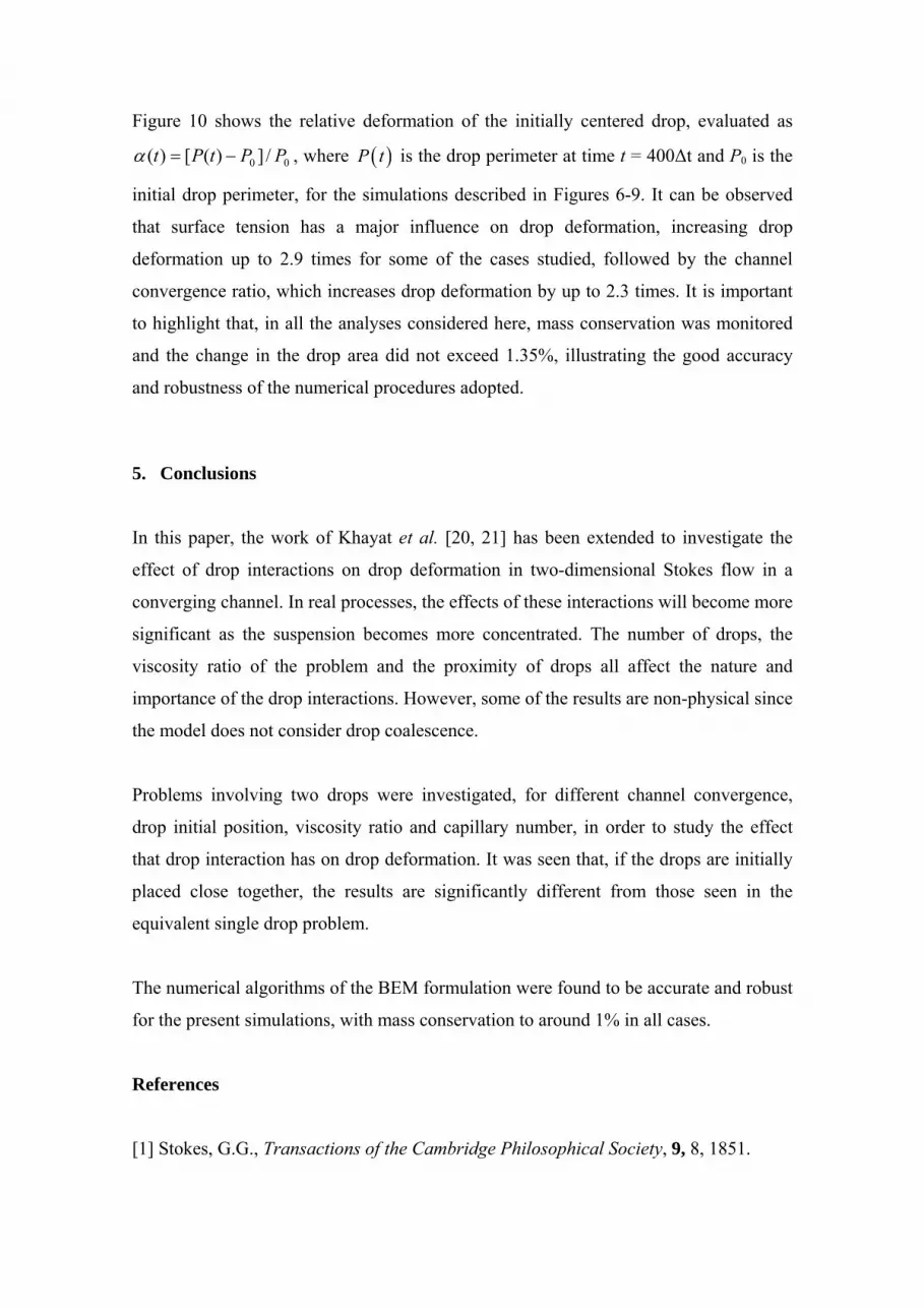
Figure 10 shows the relative deformation of the initially centered drop, evaluated as
00 /])([)( PPtPt −=α , where ( )P t is the drop perimeter at time t = 400Δt and P0 is the
initial drop perimeter, for the simulations described in Figures 6-9. It can be observed
that surface tension has a major influence on drop deformation, increasing drop
deformation up to 2.9 times for some of the cases studied, followed by the channel
convergence ratio, which increases drop deformation by up to 2.3 times. It is important
to highlight that, in all the analyses considered here, mass conservation was monitored
and the change in the drop area did not exceed 1.35%, illustrating the good accuracy
and robustness of the numerical procedures adopted.
5. Conclusions
In this paper, the work of Khayat et al. [20, 21] has been extended to investigate the
effect of drop interactions on drop deformation in two-dimensional Stokes flow in a
converging channel. In real processes, the effects of these interactions will become more
significant as the suspension becomes more concentrated. The number of drops, the
viscosity ratio of the problem and the proximity of drops all affect the nature and
importance of the drop interactions. However, some of the results are non-physical since
the model does not consider drop coalescence.
Problems involving two drops were investigated, for different channel convergence,
drop initial position, viscosity ratio and capillary number, in order to study the effect
that drop interaction has on drop deformation. It was seen that, if the drops are initially
placed close together, the results are significantly different from those seen in the
equivalent single drop problem.
The numerical algorithms of the BEM formulation were found to be accurate and robust
for the present simulations, with mass conservation to around 1% in all cases.
References
[1] Stokes, G.G., Transactions of the Cambridge Philosophical Society, 9, 8, 1851.

[2] Clift, R., Grace, J.R. and Weber, M.E., Bubbles, Drops and Particles, Academic
Press, London, 1978.
[3] Pozrikidis, C., Boundary Integral and Singularity Methods for Linearized Viscous
Flow, Cambridge University Press, Cambridge, 1992.
[4] Power, H. and Wrobel, L.C., Boundary Integral Methods in Fluid Mechanics,
Computational Mechanics Publications, Southampton, 1995.
[5] Weinbaum, S. and Ganatos, P., Numerical multipole and boundary integral equation
techniques in Stokes flow, Annu. Rev Fluid Mech, 22, 275-316, 1990.
[6] Tanzosh, J., Manga, M. and Stone, H.A., Boundary integral methods for viscous
free-boundary problems: deformation of single and multiple fluid-fluid interfaces,
Boundary Element Technology VII, 19-39, Computational Mechanics Publications,
Southampton, 1992.
[7] Stone, H., Dynamics of drop deformation and breakup in viscous fluids, Annu. Rev
Fluid Mech, 26, 65-102, 1994.
[8] Briscoe, B.J., Lawrence, C.J. and Mietus, W.G.P., A review of immiscible fluid
mixing, Advances In Colloid And Interface Science, 81, 1-17, 1999.
[9] Manga, M. and Stone, H.A., Buoyancy-driven interactions between two deformable
viscous drops, J. Fluid Mechanics, 259, 647-683, 1993.
[10] Rallison, J.M.and Acrivos, A.A., A numerical study of the deformation and burst of
a viscous drop in an extensional flow, J. Fluid Mechanics, 89, 191-200, 1978.
[11] Manga, M. and Stone, H.A., Low Reynolds number motion of bubbles, drops and
rigid spheres through fluid-fluid interfaces, J. Fluid Mechanics, 287, 279-298, 1995.
[12] Manga, M., Stone, H.A., Collective hydrodynamics of deformable drops and
bubbles in dilute low-Reynolds-number suspensions, J. Fluid Mechanics, 300, 231-263,
1995.

[13] Pozrikidis, C., The buoyancy-driven motion of a train of viscous drops within a
cylindrical tube, J. Fluid Mechanics, 237, 627-648, 1992.
[14] Zhou, H. and Pozrikidis, C., The flow of suspensions in channels: single files of
drops, Phys. Fluids A, 5, 311-324, 1993.
[15] Zhou H. and Pozrikidis C., The Flow of ordered and random suspensions of two-
dimensional drops in a channel, J. Fluid Mechanics, 255:103-127, 1993
[16] Li, X., Charles, R. and Pozrikidis, C., Simple shear flow of suspensions of liquid
drops, J. Fluid Mechanics, 320, 395-416, 1996.
[17] Loewenberger, M. and Hinch, E.J., Numerical simulations of a concentrated
emulsion in shear flow, J. Fluid Mechanics, 321, 395-419, 1996.
[18] Roumeliotis, J. and Fulford, G.R., Droplet interactions in creeping flow, Computers
& Fluids, 29, 435-450, 2000.
[19] Zinchenko, A.Z., Rother, M.A. and Davis, R.H., Cusping, capture, and breakup of
interacting drops by a curvatureless boundary-integral algorithm, J. Fluid Mechanics,
391, 249-292, 1999.
[20] Khayat R.E., Luciani A. and Utracki L.A., Boundary-element analysis of planar
drop deformation in confined flow. Part 1. Newtonian fluids, Eng. Anal. Bound. Elem.,
19, 279-289, 1997.
[21] Khayat R.E., Luciani A., Utracki L.A. Godbille F. and Picot J., Influence of shear
and elongation on drop deformation in convergent-divergent flows, International
Journal of Multiphase Flow, 26, 17-44, 2000.
[22] M. Giraldo, H. Power and W.F. Florez, Mobility of a viscous Newtonian drop in
shear Newtonian flow, International Journal of Dynamic of Fluids, 3, 109-132, 2007.

1
ΔX/2 ΔX/2
ΔY/2
ΔY/2
ξ X
ξ Y
2
3
ξ = 0
ξ = -1
ξ = +1
XM
YM
ξM
Figure 1 – Sketch for the element mid-node relocation procedure.

L
H2
H1
d1
d2
r1
r2
Figure 2 – Geometric (initial) configuration for the channel and drops

(a)
(b)
(c)
(d)
(e)
(f)
(g)
(h)
Figure 3 – Evolution of drops in channel with convergence ratio H2/H1 = 0.2 and L = 8.0 (d1 = 1.0; d2 = 2.2; Ca-1 = 0; r1 = 0.6 and λ2 = 5.0): (a) λ1 = 5.0 and r2 = 0.0; (b) λ1 = 1.0 and r2 = 0.0; (c) λ1 = 5.0 and r2 = 0.2; (d) λ1 = 1.0 and r2 = 0.2; (e) λ1 = 5.0 and r2 = 0.6;
(f) λ1 = 1.0 and r2 = 0.6; (g) λ1 = 5.0 and r2 = 1.0; (h) λ1 = 1.0 and r2 = 1.0.

0 4 8 12 16 20 24-0.05
0.00
0.05
0.10
0.15
0.20
0.25
Time
Y O
r2 = 0.0 r2 = 0.2 r2 = 0.6 r2 = 1.0
0 4 8 12 16 20 243
6
9
12
15
18
21
24
Time
X O
r2 = 0.0 r2 = 0.2 r2 = 0.6 r2 = 1.0
0 4 8 12 16 20 243
6
9
12
15
18
21
24
Time
X O
r2 = 0.0 r2 = 0.2 r2 = 0.6 r2 = 1.0
0 4 8 12 16 20 24-0.05
0.00
0.05
0.10
0.15
0.20
0.25
Time
Y O
r2 = 0.0 r2 = 0.2 r2 = 0.6 r2 = 1.0
(a)
(b)
Figure 4 – Time evolution of the mass centre position (X0 and Y0) of the initially centered drop (see Figure 3): (a) λ1 = 5.0; (b) λ1 = 1.0.
(a)
(b)
Figure 5 – Boundary element discretization for the drop, at time 600Δt (see Figure
3(b)): (a) considering remeshing procedures; (b) without remeshing.

(a) (b)
(c) (d)
(e) (f)
(g)
(h)
Figure 6 – Evolution of drops in channel with convergence ratio H2/H1 = 0.2 and L = 3.0 (d1 = 0.0): (a) case 1 and d2 = 2.2; (b) case 1 and d2 = 3.0; (c) case 2 and d2 = 2.2; (d)
case 2 and d2 = 3.0; (e) case 3 and d2 = 2.2; (f) case 3 and d2 = 3.0; (g) case 4 and d2 = 2.2; (h) case 4 and d2 = 3.0.

(a)
(b)
(c)
(d)
(e)
(f)
(g)
(h)
Figure 7 – Evolution of drops in channel with convergence ratio H2/H1 = 0.2 and L = 3.0
(d1 = 2.0): (a) case 1 and d2 = 2.2; (b) case 1 and d2 = 3.0; (c) case 2 and d2 = 2.2; (d) case 2 and d2 = 3.0; (e) case 3 and d2 = 2.2; (f) case 3 and d2 = 3.0; (g) case 4 and d2 =
2.2; (h) case 4 and d2 = 3.0.

(a)
(b)
(c)
(d)
(e)
(f)
(g)
(h)
Figure 8 – Evolution of drops in channel with convergence ratio H2/H1 = 0.4 and L = 3.0
(d1 = 0.0): (a) case 1 and d2 = 2.2; (b) case 1 and d2 = 3.0; (c) case 2 and d2 = 2.2; (d) case 2 and d2 = 3.0; (e) case 3 and d2 = 2.2; (f) case 3 and d2 = 3.0; (g) case 4 and d2 =
2.2; (h) case 4 and d2 = 3.0.
(a)
(b)
(c)
(d)
(e)
(f)
(g)
(h)
Figure 9 – Evolution of drops in channel with convergence ratio H2/H1 = 0.4 and L = 3.0
(d1 = 2.0): (a) case 1 and d2 = 2.2; (b) case 1 and d2 = 3.0; (c) case 2 and d2 = 2.2; (d) case 2 and d2 = 3.0; (e) case 3 and d2 = 2.2; (f) case 3 and d2 = 3.0; (g) case 4 and d2 =
2.2; (h) case 4 and d2 = 3.0.

1 2 3 40.0
0.5
1.0
1.5
2.0
Rel
ativ
e D
efor
mat
ion
Case
d1=2.0; d2=2.2 d1=2.0; d2=3.0 d1=0.0; d2=2.2 d1=0.0; d2=3.0
1 2 3 40.0
0.5
1.0
1.5
2.0
Rel
ativ
e D
efor
mat
ion
Case
d1=2.0; d2=2.2 d1=2.0; d2=3.0 d1=0.0; d2=2.2 d1=0.0; d2=3.0
(a)
(b)
Figure 10 – Relative deformation of the initially centered drop at time 400Δt
considering different relative positions (d1 and d2) and physical properties (Cases 1-4) for the drops: (a) H2/H1 = 0.2; (b) H2/H1 = 0.4.


