Embed Size (px)
Citation preview

Applied Mathematics and Computation 148 (2004) 809–821
www.elsevier.com/locate/amc
Dusty gas model of flow throughnaturally occurring porous media
Fathi M. Allan a,*, Naji Qatanani b, Imad Barghouthi c,Khaled M. Takatka b
a Department of Mathematics, Birzeit University, P.O. Box 14, Birzeit, Palestineb Department of Mathematics, Al Quds University, Abu Deis, Jerusalem, Palestine
c Department of Physics, Al Quds University, Abu Deis, Jerusalem, Palestine
Abstract
In this article, we develop a set of partial differential equations describing the flow of
a dusty fluid in variable porosity media. The developed equations take into account the
effect of the porous microstructure on the flowing phases.
We presented and overview of the equations governing the flow of a dusty gas in
various type media, including that in naturally occurring porous media. Numerical
techniques are used to solve the set of partial differential equations describing the flow
for different values of the porous media parameters of interest. These parameters are the
Forchheimr drag coefficient Cd, the permeability g and the Reynold number Re.� 2003 Elsevier Inc. All rights reserved.
1. Introduction
Gas-particle flow, dusty fluid flow and the flow of suspension through po-
rous media have received considerable attention due to the importance of these
types of flow in studies associated with the design of industrial filters, liquid-
dust seperators and water purification plants.
* Corresponding author. Current address: Department of Mechanical Engineering MIT, 77
Mass. Ave. 3-339, Cambridge, MA 02139, USA.
E-mail addresses: [email protected], [email protected] (F.M. Allan), [email protected] (N.
Qatanani), [email protected] (I. Barghouthi).
0096-3003/$ - see front matter � 2003 Elsevier Inc. All rights reserved.
doi:10.1016/S0096-3003(02)00939-6
810 F.M. Allan et al. / Appl. Math. Comput. 148 (2004) 809–821
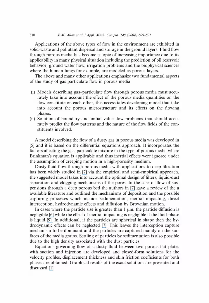
Applications of the above types of flow in the environment are exhibited in
solid-waste and pollutant dispersal and storage in the ground layers. Fluid flowthrough porous media has become a topic of increasing importance due to its
applicability in many physical situation including the prediction of oil reservoir
behavior, ground water flow, irrigation problems and the biophysical sciences
where the human lungs for example, are modeled as porous layers.
The above and many other applications emphasize two fundamental aspects
of the study of gas particulate flow in porous media
i(i) Models describing gas–particulate flow through porous media must accu-rately take into account the effect of the porous media quantities on the
flow constitute on each other, this necessitates developing model that take
into account the porous microstructure and its effects on the flowing
phases.
(ii) Solution of boundary and initial value flow problems that should accu-
rately predict the flow patterns and the nature of the flow fields of the con-
stituents involved.
A model describing the flow of a dusty gas in porous media was developed in
[5] and it is based on the differential equations approach. It incorporates the
factors affecting the gas–particulate mixture in the type of porous media where
Brinkman�s equation is applicable and thus inertial effects were ignored under
the assumption of creeping motion in a high-porosity medium.
Dusty fluid flow through porous media with applications to deep filtration
has been widely studied in [7] via the empirical and semi-empirical approach,
the suggested model takes into account the optimal design of filters, liquid-dustseparation and clogging mechanisms of the pores. In the case of flow of sus-
pensions through a deep porous bed the authors in [7] gave a review of the a
available literature and outlined the mechanisms of deposition and the possible
capturing processes which include sedimentation, inertial impacting, direct
interception, hydrodynamic effects and diffusion by Brownian motion.
In cases where the particle size is greater than 1 lm, the particle diffusion is
negligible [6] while the effect of inertial impacting is negligible if the fluid-phase
is liquid [9]. In additional, if the particles are spherical in shape then the hy-drodynamic effects can be neglected [7]. This leaves the interception capture
mechanism to be dominant and the particles are captured mainly on the sur-
faces of the media grains. Settling of particles by sedimentation is also possible
due to the high density associated with the dust particles.
Equations governing flow of a dusty fluid between two porous flat plates
with suction and injection are developed and closed-form solutions for the
velocity profiles, displacement thickness and skin friction coefficients for both
phases are obtained. Graphical results of the exact solutions are presented anddiscussed [1].

F.M. Allan et al. / Appl. Math. Comput. 148 (2004) 809–821 811
The problem of gas-particulate flow through a two-dimensional porous
channel bounded by curved boundaries is considered [6], and a set of generalaveraged transport equations for a multi-phase system consisting of an arbi-
trary number of phased, interfaces and contact lines is established in [8]. A
structure for the system is proposed and hydrodynamic interaction between the
phases, interfaces and contact lines is also presented.
2. Mathematical formulation
The steady flow of an incompressible dusty fluid in a porous medium of
constant permeability is given by the following coupled set of equations. Theseequations take into account the absence of dust effects, that is, the fluid-phase
momentum equation takes the well-known Darcy–Lapwood–Brinkman (DLB)
form. In this type of porous media the speed of the flow is not small and the
viscous shearing action is important [4,8]. The set of equations are:
The fluid-phase equations given by
The continuity equation
ru ¼ 0 ð1Þ
and the momentum equation
quru ¼ �rp þ lr2u� lgu ð2Þ
The dust-phase equations given by
The continuity equation
r:Nv ¼ 0 ð3Þ
and the momentum equation
vrv ¼ k=mðu� vÞ ð4Þ
where u and v are the fluid and dust macroscopic velocity vectors, p is the
pressure, l is the viscosity coefficient, q is the density, N is the particle number
density, m is the mass of a single dust particle, g is the permeability and k is the
drag coefficient on the dust particle in the porous medium.
The fluid-phase momentum equation (2) is valid in a variety of settings and
in different types of porous media. We will discuss the following cases that
illustrate the variety of settings and the different types that this equations is
valid in [3,6–9].(i) When the inertial effects are negligible or insignificant, that is, the flow is
fully developed with no macroscopic stream-wise fluid-phase velocity gradient,
Eq. (2) becomes
812 F.M. Allan et al. / Appl. Math. Comput. 148 (2004) 809–821
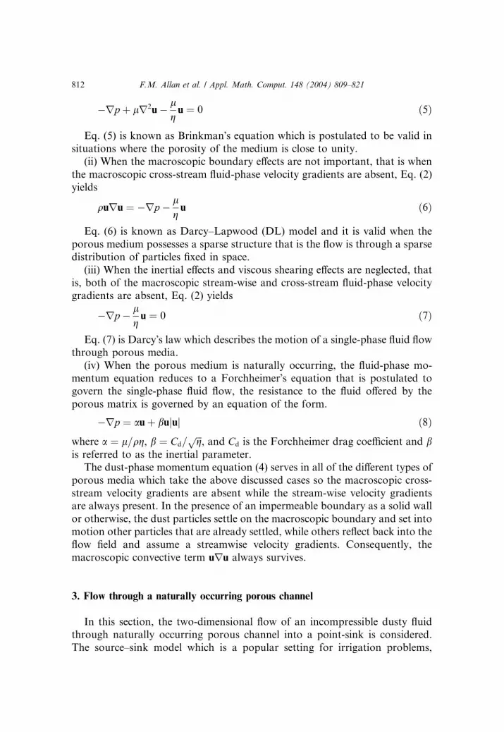
�rp þ lr2u� lgu ¼ 0 ð5Þ
Eq. (5) is known as Brinkman�s equation which is postulated to be valid in
situations where the porosity of the medium is close to unity.
(ii) When the macroscopic boundary effects are not important, that is when
the macroscopic cross-stream fluid-phase velocity gradients are absent, Eq. (2)
yields
quru ¼ �rp � lgu ð6Þ
Eq. (6) is known as Darcy–Lapwood (DL) model and it is valid when the
porous medium possesses a sparse structure that is the flow is through a sparse
distribution of particles fixed in space.
(iii) When the inertial effects and viscous shearing effects are neglected, that
is, both of the macroscopic stream-wise and cross-stream fluid-phase velocity
gradients are absent, Eq. (2) yields
�rp � lgu ¼ 0 ð7Þ
Eq. (7) is Darcy�s law which describes the motion of a single-phase fluid flowthrough porous media.
(iv) When the porous medium is naturally occurring, the fluid-phase mo-
mentum equation reduces to a Forchheimer�s equation that is postulated to
govern the single-phase fluid flow, the resistance to the fluid offered by the
porous matrix is governed by an equation of the form.
�rp ¼ auþ bujuj ð8Þ
where a ¼ l=qg, b ¼ Cd=ffiffiffig
p, and Cd is the Forchheimer drag coefficient and b
is referred to as the inertial parameter.
The dust-phase momentum equation (4) serves in all of the different types of
porous media which take the above discussed cases so the macroscopic cross-
stream velocity gradients are absent while the stream-wise velocity gradientsare always present. In the presence of an impermeable boundary as a solid wall
or otherwise, the dust particles settle on the macroscopic boundary and set into
motion other particles that are already settled, while others reflect back into the
flow field and assume a streamwise velocity gradients. Consequently, the
macroscopic convective term uru always survives.
3. Flow through a naturally occurring porous channel
In this section, the two-dimensional flow of an incompressible dusty fluid
through naturally occurring porous channel into a point-sink is considered.
The source–sink model which is a popular setting for irrigation problems,

F.M. Allan et al. / Appl. Math. Comput. 148 (2004) 809–821 813
might be thought of here as a means for solid-waste disposal. The model at
thus shed some light on the behavior of the solid particles in the flow field asthey are dispersed in a porous layer. The determinate nature of the model
equations is illustrated by numerically studying the flow at hand.
The flow setting under consideration is governed by the coupled set of Eqs.
(1), (3), (4) and (8).
We introduce the dimensionless macroscopic streamfunctions W1ðx; yÞ, and
W2ðx; yÞ and macroscopic vorticities f1ðx; yÞ and f2ðx; yÞ in terms of the di-
mensionless horizontal and vertical components of velocity defined by
u1 ¼ W1y ; v1 ¼ �W1x
u2 ¼ W2y ; v2 ¼ �W2x
And the dimensionless vorticities are defined by
f1 ¼ v1x � u1y
f2 ¼ v2x � u2y
The stream function vorticity equations governing the flow at hand in each
of the coupled set of Eqs. (1) and (8) for the fluid-phase, and Eqs. (3) and (4)
for the dust-phase are obtained by taking the curl of each of the momentum
equations and the subsequent use of the equations of continuity and are givenby the following set of equations [8]:
The fluid-phase equations:
r2W1 ¼ �f1 ð9Þ
and
f1
gRe
ffiffiffiffiffiffiffiffiffiffiffiffiffiffiffiffiffiffiffiffiffiW2
1x þ W21y
qþ f1Cdffiffiffi
gp W2
1x
nþ W2
1y
o
¼ Cdffiffiffig
p W21xW1xx
nþ 2W1xW1yW1xy þ W2
1yW1yy
oð10Þ
and the dust-phase equations:
r2W2 ¼ �f2 ð11Þ
and
W2yf2x � W2xf2y ¼KM
½f1 � f2 ð12Þ
The flow variables have been rendered dimensionless with respect to a
characteristic velocity U1 and a characteristic length L using the followingdimensionless equations:
X ¼ x=L, Y ¼ y=L, ~UU ¼~uu=U1, f ¼ f�L=U1, K ¼ k=L2, W ¼ W�=LU1 and
the Reynolds number is defined as Re ¼ qU1L=l.

814 F.M. Allan et al. / Appl. Math. Comput. 148 (2004) 809–821
4. Numerical example
Consider the flow of dusty fluid in a straight porous channel, bounded below
and above by impermeable walls. Associated with this flow are boundary
conditions and entry conditions to the channel. Any appropriate boundary
conditions must be compatible with the type of medium, the governing model
equations and the type of the impermeable bounding walls.
Suitable boundary conditions for the flow at hand, in the shown configu-
ration, are as follows:
W1 ¼ W2 ¼ 0 along the walls ab and bcW1 ¼ W2 ¼ 1 along the upper wall dcW1 ¼ W2 ¼ y 06 y6 1 along the ad
The fluid-phase and the dust-phase velocities are quantities to be determined
on the impermeable walls. In addition no explicit boundary conditions are
available for the vorticities of the phases involved. Thus, f1 and f2 are updated
on the boundary in terms of the streamfunction values at internal grid points
using standard first-order accurate schemes. On the boundary in terms of thestreamfunction values at internal grid points using standard first-order accu-
rate schemes.
Numerical integration is therefore accomplished by solving Eqs. (9) and (10)
iteratively using successive over-relaxation techniques.
Results have been obtained for various values of permeability, Forchheimer
drag coefficient and Reynolds number. The test cases considered are perme-
ability k ¼ 1, 0.1, 0.01 and 0.00001, drag coefficient Cd ¼ 0:5, 0.55, 0.75 and for
the Reynolds number Re ¼ 0:5, 0.65, 0.85 and 1.Solutions were obtained using a step size H ¼ DX ¼ DY ¼ 0:01 for the
computational domain ½0; 1 ½0; 1. The numerical scheme presented in [2,9] is
used for solving Eq. (9) and it is given by
Wðnþ1Þði;jÞ ¼WðnÞ
ði;jÞ þx4
Wðnþ1Þði�1;jÞ
�þWðnÞ
ðiþ1;jÞ þWðnþ1Þði;j�1Þ þWðnÞ
ði;jþ1Þ �4WðnÞði;jÞ �H 2fði;jÞ
�
ð13Þ

F.M. Allan et al. / Appl. Math. Comput. 148 (2004) 809–821 815
The iterated result converges for 16x < 2, and it converges most rapidly
where x is assigned the optimum value
x ¼ 4
2 þffiffiffiffiffiffiffiffiffiffiffiffiffiffiffiffiffiffiffiffiffiffiffiffiffiffiffiffiffiffiffiffiffiffiffiffiffiffiffiffiffiffiffiffiffiffiffiffiffiffiffi4 � cos P
m
� �þ cos P
n
� � q 2ð14Þ
where nXm is the grid dimension. The stream function may take an arbitrary
additive constant, in order to start the iteration, a constant value of 0.5 is
guessed fore the stream function at all interior points. The absolute value of the
difference between this and the previous value of W1 at the same point is cal-culated and is added to the value of a variable called ERROR, whose starting
value at the beginning of an iteration is zero. At the end of one iteration, when
the values of W1 at all interior points have been updated, the value of ERROR
is compared with ERRMAX. If ERROR is less than or equal to ERRMAX,
then calculate the value of ZETA 1. Whose starting value at the beginning of
iteration is zero, the absolute value of the difference between this and the
previous value of ZETA 1. At the same point is calculated and is added to
ERROR. At the end of one iteration, when the values of ZETA 1 At all interiorpoints have been reached, so the iterating process can be stopped. Otherwise,
the iteration counter ITER is increased by 1 and a new iteration is started. In
our program we let ERRMAX¼ 0.1 10�5.
After convergence, the fluid and dust velocity components are calculated in
terms of W1 by backward difference schemes. The fluid-phase vorticity is then
calculated using a finite difference form of Eq. (9). The same techniques is
applied to the coupled Eqs. (11) and (12) after the value of f1 has been de-
termined.
5. Discussion of the results
The numerical results illustrate the effect of the variation of the dust pa-rameters on the fluid phase velocities. Figs. 1 and 4 illustrate the effect of the
permeability on the horizontal velocity component along the vertical centerline
and the boundary lower of the channel respectively. They demonstrate the
increase of this velocity component with increasing permeability in the lower
region of the channel. In the upper regions, the effect of the sink becomes more
noticeable in attracting the fluid faster for lower values of permeability.
Fig. 5 illustrates the effect of the Forchheimer drag coefficient on the fluid-
phase horizontal velocity component along the boundary lower of the channel.It demonstrates the decrease in this velocity component with increasing coef-
ficient in the lower regions of the channel.

Fig. 1. Horizontal velocity component along the vertical center line of the channel for different
permeability and Cd ¼ 0:5, Re ¼ 1.
Fig. 2. Horizontal velocity component along the vertical center line of the channel for different
Forchheimer drag coefficient and K ¼ 10�2, Re ¼ 1.
816 F.M. Allan et al. / Appl. Math. Comput. 148 (2004) 809–821

Fig. 4. Horizontal velocity component along the lower boundary of the channel for different
permeability and Cd ¼ 0:75, Re ¼ 1.
Fig. 3. Horizontal velocity component along the vertical center line of the channel for different
Reynolds number and K ¼ 10�2, Ce ¼ 0:75.
F.M. Allan et al. / Appl. Math. Comput. 148 (2004) 809–821 817
Figs. 3 and 6 illustrate the effect of the Reynolds number on the fluid-phase
horizontal velocity component along the vertical centerline and the boundary
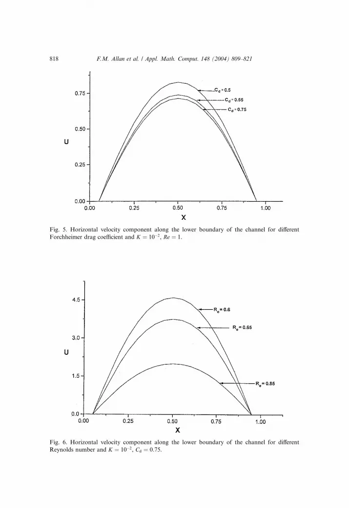
Fig. 5. Horizontal velocity component along the lower boundary of the channel for different
Forchheimer drag coefficient and K ¼ 10�2, Re ¼ 1.
Fig. 6. Horizontal velocity component along the lower boundary of the channel for different
Reynolds number and K ¼ 10�2, Cd ¼ 0:75.
818 F.M. Allan et al. / Appl. Math. Comput. 148 (2004) 809–821

F.M. Allan et al. / Appl. Math. Comput. 148 (2004) 809–821 819
lower of the channel. The demonstrate the decrease in this velocity component
with increasing Reynolds number in the lower regions of the channel.Fig. 7 describes the effect of the permeability on the horizontal velocity
component along the horizontal centerline of the channel. It demon-
strates the increase of this velocity component with increasing perme-
ability.
Figs. 2 and 8 illustrate the effect of the Forchheimer drag coefficient on the
fluid-phase vertical and horizontal velocity component along the vertical and
horizontal centerlines of the channel respectively. These results demonstrate
the increase in this velocity component with increasing Forchheimer drag co-efficient Cd.
Fig. 9 demonstrates the effect of the Reynolds number on the fluid-phase
horizontal velocity component along the horizontal centerline of the channel.
It demonstrates the decrease in this velocity component with increasing Rey-
nolds number.
The increase of the velocity component in the lower part of the channel, and
its decrease in the upper part as Cd increases sheds some light on the appro-
priate value of Cd. Although a critical value of Cd has not been determined in this study, the above behavior indicates that the critical value of Cd is approxi-
mately.
Fig. 7. Horizontal velocity component along the horizontal center line of the channel for different
permeability and Cd ¼ 0:75, Re ¼ 1.

Fig. 8. Horizontal velocity component along the horizontal center line of the channel for different
Forchheimer drag coefficient and K ¼ 10�2, Re ¼ 1.
Fig. 9. Horizontal velocity component along the horizontal center line of the channel for different
Reynolds number and K ¼ 10�2, Cd ¼ 0:75.
820 F.M. Allan et al. / Appl. Math. Comput. 148 (2004) 809–821

F.M. Allan et al. / Appl. Math. Comput. 148 (2004) 809–821 821
References
[1] A.J. Chamkha, Analytical solutions for flow of a dusty fluid between two porous flat plates,
Trans. ASME, J. Fluids Eng. 116 (1994) 354–356.
[2] C. Chow, An Introduction to Computational Fluid Mechanics, Wiley, New York, 1979.
[3] M.H. Hamdan, R.M. Barren, On the Darcy–Lapwood–Brinkman–Saffman dusty fluid flow
models in porous media. Part 1. Models development, J. Appl. Math. Comput. 54 (1) (1993)
65–79.
[4] M.H. Hamdan, R.M. Barron, Gas-particulate through isotropic porous media, Part II.
Boundary and entry conditions, in: D.T. Mook, D.L. Zagottis, (Eds.), Proceedings, Third PAN
AMERICAN Congress of Applied Mechanics, January 1993, pp. 307–310.
[5] M.H. Hamdan, R.M. Barren, Fluid flow through curved porous channels, Math. Computer Sci.
(August) (1990).
[6] M.H. Hamdan, R.M. Barron, A dusty gas flow model in porous media, Comput. Applied Math.
30 (1990) 21–37.
[7] M.H. Hamdan, R.A.R. Ford, Numerical simulation of gas particulate flow through curvilinear
porous channels, J. Appl. Math. Comput. 4 (1998) 267–284.
[8] K. Takataka, One-way and two-way interaction gas-particulate flow through porous media,
MA thesis, Alquds University, Department of Mathematics, Jerusalem, 2001.
[9] A. Newneier, Introduction to Numerical Analysis, Cambridge University Press, Cambridge,
2001.


