Embed Size (px)
Citation preview

Available online at www.sciencedirect.com
Available online at www.sciencedirect.com
Procedia
Engineering Procedia Engineering 00 (2011) 000–000
www.elsevier.com/locate/procedia
The Twelfth East Asia-Pacific Conference on Structural Engineering and Construction
Dynamic tests on a Steel Frame Equipped with Hysteretic and Visco-Re-Centring Energy Dissipating Bracing Systems
A. DI CESARE1a, F. C. PONZO1b, D. NIGRO1 and D. MOCCIA1 1Department of Structure, Geothecnic and applied Geology, University of Basilicata, Italy
Abstract
An extensive program of dynamic experimental tests, named JetPacs (Joint Experimental Testing on Passive and semiActive Control Systems), has been carried out at the Structural Laboratory of the University of Basilicata considering a 1:1.5 scaled three-dimensional steel frame, derived from a 2-storey, 1-bay prototype building. The JetPacs Project was developed within the RELUIS 2005-08 project, founded by Italian Dept. of Civil Protection. This work refers to the experimental tests on the model equipped with two different EDB systems based on Hysteretic Dampers (HD) and visco-re-centering devices (SMA+VD). The devices were designed with the purpose of limiting the inter-storey drifts so that the frame yielding is surely prevented. The visco-re-centering device was obtained by coupling Viscous Dampers (VD), with re-centering device based on shape memory alloy (SMA) wires, while the Hysteretic Damper was constituted by low-carbon U-shaped steel plates. The main objective of this paper is to compare the seismic response of the structure with SMA+VD and HD EDB’s in order to calibrate a new performance based design procedure for the evaluation of the mechanical characteristics of SMA+VD devices. In this paper, the experimental results of the shaking table tests, in terms of comparison of both design solutions which lead to a comparable level of protection for the framed structure, are shown. The results obtained by numerical nonlinear time history analysis (NTHA) of both design solutions are also showed and compared with experimental ones. © 2011 Published by Elsevier Ltd. Keywords: Shaking table tests, Energy dissipation bracing, hysteretic dampers, shape memory alloys, performance based design
a Corresponding author: Email: [email protected] b Presenter: Email: [email protected]
1877–7058 © 2011 Published by Elsevier Ltd.doi:10.1016/j.proeng.2011.07.369
Procedia Engineering 14 (2011) 2931–2940

2932 A. DI CESARE et al. / Procedia Engineering 14 (2011) 2931–29402 Author name / Procedia Engineering 00 (2011) 000–000
1 INTRODUCTION
Traditional retrofitting techniques for framed structures are based on a diffuse strengthening of the structure or on the introduction of additional, very stiff, structural members. In the last twenty years, innovative strategies, based on the use of Energy Dissipating Braces (EDB), have been developed and tested (Constantinou et al., 1998). In recent times, special EDB systems, characterized by a strong supplemental re-centering capability, based on the superelastic properties of Shape Memory Alloy (SMA) wires, have been proposed (Dolce et al. 2000). The functioning principles and basic mechanical properties of the SMA-based re-centering devices exploited to re-centre the gravity-load-resisting system in its initial configuration at the end of the earthquake are described in (Dolce et al., 2004). The great potential of SMA braces has been confirmed by the experimental results of recent research projects carried out on reduced-scale structural models, by means of shaking table tests (Ponzo et al. 2008b), and on full-scale prototype building, by means of release tests (Dolce et. al, 2004). Suitable methods for the design of SMA braces, however, are still needed.
This work reports the experimental results obtained by shaking table tests carried out on a steel frame at the Structural Laboratory of the University of Basilicata (UNIBAS) within a wide research program, named JETPACS (“Joint Experimental Testing on Passive and semi-Active Control Systems”), which involved many Research Units working for the Research Line 7 of the RELUIS 2005-2008 project (Dolce et al., 2008). During testing, a total of seven different passive or semi-active energy dissipating devices based on currently available technologies (i.e. viscous and hysteretic damping) or innovative systems (i.e. shape-memory-alloy wires, magneto-rheological fluids) have been installed on the model. In particular a new solution for EDB system based on Visco-re-centring (VD+SMA) devices, proposed in (Ponzo et al., 2008a), have been selected as one of the EDB’s tested by the Research Units UNIBAS (Ponzo et al., 2009a). The devices are constituted by SMA-based re-centering devices working in parallel with viscous dampers (VD).
A new iterative procedure to design the mechanical characteristics of SMA+VD devices is proposed in this work. The design procedure evaluates the theoretical behaviour of the SMA+VD devices, described by means of double flag shape (FS) model, starting from an equivalent Hysteretic Device (HD), described by elasto-plastic (EP) model, designed to reach the same performance objective (Ponzo et al., 2009b). Both EDB’s are designed with goal of limiting the inter-storey drifts so that the frame yielding is surely prevented. In order to validate the proposed design procedure, this paper focus on the comparison of the experimental results of the tests on the experimental model equipped with HD EDB’s and with both SMA and SMA+VD EDB’s configurations. Moreover, the experimental results have been reproduced by numerical non linear time history analysis (NTHA).
2 ENERGY DISSIPATION BRACING (EDB) SYSTEMS
2.1 Experimental and numerical model
The experimental 1/1.5-scaled model for dynamic tests has been designed starting from a steel building prototype for civil residence housing. Figure 1a shows the general layout of the experimental scaled model. The test model is a two-storey steel frame, with a single span in the test direction. The two floors are made of a 100 mm thick steel-concrete slab, with plan dimensions of 4.2 m by 3.2 m. Main and secondary beams have the same steel section (IPE 180) at all the storey. Similarly, all the columns have constant cross section (HEB 140) along the height of the model.
The experimental model is realized using S235 grade steel, having Young modulus E = 206000 N/mm2 and fy = 235 N/mm2 yielding strength. Additional masses have been placed on each slab, to take into

A. DI CESARE et al. / Procedia Engineering 14 (2011) 2931–2940 2933 Author name / Procedia Engineering 00 (2011) 000–000 3
account the non structural dead loads and a proper amount (30%) of live loads, as well as the contribution due to the mass-similitude scaling. A set of natural earthquakes, defined by 7 spectrum-compatible accelerograms for high seismicity zones and for medium soil, selected within the European Strong Motion Database (identified as: 1228, 196, 535, 187, 291, 4673, 4677), have been considered in the experimental tests and NTHA (Ponzo et al., 2009a). To ensure consistency with the scale of the experimental model, all acceleration profiles were scaled down in the time by the factor (1.5)1/2. The steel frame has been modelled by SAP2000_Nonlinear (CSI, 2004), using frame-type 3D finite elements shown in Figure 1c. In order to take into account a possible nonlinear behaviour of the structure, suitable plastic hinges, with an axial load-dependent behaviour, have been inserted at the ends of each frame element. The connection between the columns and the stiff beams at the base of the model has been simulated through perfect restraints. while, the in-plane behaviour of the floor slabs has been captured by means of rigid diaphragm constraints. More details on the experimental model, shaking table system apparatus, dynamic identification test on the non-upgraded model, seismic inputs and numerical simulations can be found in (Dolce et al. 2008, Ponzo et al. 2009a; Ponzo et al. 2010).
(a)
(b)
(c)
Figure 1: (a) Experimental model, (b) Test Apparatus and (c) Numerical model

2934 A. DI CESARE et al. / Procedia Engineering 14 (2011) 2931–29404 Author name / Procedia Engineering 00 (2011) 000–000
2.2 Design Procedure of Visco-re-centring EDB’s
The performance objective considered in the design was to prevent damage to frame members. It has been pursued establishing a threshold value of the maximum inter-storey drift (Δmax) that does not exceed the limit of the yield inter-storey drift (Δy) of the frame, then supposing the framed structure responding within its elastic range (Δmax<Δy) during the shaking table tests.
The procedure considered to design the visco-re-centring EDB’s in this experimental application aims to calibrate the fundamental parameters of SMA+VD devices (strength FFS,1, stiffness K0, re-centring parameter β and post-yield hardening ratio α, - Fig 2b) starting from an equivalent Hysteretic Damper (HD) designed for the same performance objective (characterized by a strength FEP, stiffness K0, ductile capability μ and post-yield hardening ratio α, see - Fig. 2a).
FEP(x)K0
f EP(x)
a
x
f EP,y
xEP,y
11
1
11
xEP,y
μ*xEP,y
(a)
11
xFS,y
a1+a
1
K0f FS(x) FFS(x)
x
f FS,1
xFS,yβ f FS,1
11
xFS,y
1
μ*FS,y
f FS,2
(b)
Figure 2: Equivalent models of (a) Elasto-Plastic (EP) and (b) Flag-Shaped (FS)
The behavior factor of Flag-Shaped models (Fig. 2b) strongly depends on their strength ratio β (Ponzo et al. 2008b), defined as ratio between the force amplitude of the elasto-plastic cycle and the activation force of the system:
)()()(
,1,
,2,,1,
yFSFS
yFSFSyFSFS
xFxFxF −
=β (1)
where: FFS,1 and FFS,2 are the force levels of the FS model at the “yield” displacement xFS,y in loading and unloading condition, respectively. The β-parameter accounts for the re-centering and energy dissipating capabilities of the device. It ranges from 0 (Bilinear elastic behavior) to 2 (Elasto-plastic behaviour).
According to previous studies, the behavior factor qEPP(T, μ) of an hysteretic elasto-perfectly plastic (EPP) models is a function of structural period (T) and target ductility (μ). The analytical law proposed by Newmark and Hall (Newmark and Hall, 1973) can be expressed by the equation (1).
⎪⎪⎩
⎪⎪⎨
⎧
>
=
=
=
C
gEPP
T T
T T 1-2
0 T 1
q
μ
μ (1)

A. DI CESARE et al. / Procedia Engineering 14 (2011) 2931–2940 2935 Author name / Procedia Engineering 00 (2011) 000–000 5
where μ is the ratio between the maximum displacement attained in the structure during an earthquake and its yield displacement; Tg is the characteristic period of the considered ground motions (i.e. the period associated to the peak spectral acceleration, approximately equal to 0.2 sec in the case under consideration) and TC is the period associated to the transition from the constant acceleration to the constant velocity branch of the spectrum (equal to 0.5sec for soil type B). The q-factor varies linearly between 0 and Tg, as well as between Tg and TC.
The analytical expression of the q-factor for FS models have been obtained through regression analyses (Ponzo et al., 2008b) carried out by using the outcomes of several non-linear time-history analyses made on SDOF systems considering the following parameter variation: (i) target ductility ratios 1, 2, 3 and 4, (ii) natural periods of the SDOF system ranging from 0.1 sec to 0.8 sec (step 0.1 sec). Each characteristic parameter of the FS model was assumed to be independent from each other in the evaluation of the q-factor in order to accelerate and simplify the regression analysis. The q-factor for FS models can be expressed in the following functional form:
( ) βαμβαμ CCTqTfq EPPFS ⋅⋅= ,),,,( (2)
where Cα and Cβ are the coefficients considered as correction factors accounting for the effect of post-yield hardening (Cα) and re-centring capacity (Cβ) of the FS model.
The correction factors Cα and Cβ used to derive the behavior factor of FS models from that of EPP model (ref. Eq. (2)) are shown in Figure 3. In more detail, Figure 3a highlights the behavior of Cβ as a function of the β-parameter (α = 0), and Figure 3b shows Cα as a function of the post-yield hardening ratio α (β = 1.33), for a Flag-Shaped SDOF systems with natural period of vibration equal to 0.3 sec (corresponding to the fundamental period of the experimental model). Different ductility ratio (μ = 2, 3 and 4) have been also considered in the study, according to the typical values for buildings (CEN, 2003) ranging from approximately 2 (inverted pendulum systems) to 4.5 (frame systems). The diagrams show a low dependency of both correction factors from the ductility ratio μ, as better specified in (Ponzo et al 2008b). In the case of Jet-Pacs Project the ductility demand is considered all developed by the energy dissipation devices, while the experimental frame model can be assumed within its elastic range.
0.0
0.5
1.0
1.5
2.0
0 0.2 0.33 0.66 1 1.33 1.66 1.8 2 β
cβμ=2 μ=3 μ=4
(a)
0.5
0.8
1.0
1.3
1.5
0% 5% 10% 15% 20% 25% α
μ=2 μ=3 μ=4cα
(b)
Figure 3: Correction factors (a) Cβ as a function of the strength ratio β (α=0) and (b) Cα as a function of the post-yield hardening ratio α (β=1.33).
As can be seen from eq. 2 and Figure 3, the q-factor of the FS model increases while increasing the strength ratio β, reaching a peak values for β = 1.3. The q-factor of the FS model is low sensitive to the changes in the post-yield ratio of the system. Moreover the correction factor Cβ turns out to be low

2936 A. DI CESARE et al. / Procedia Engineering 14 (2011) 2931–29406 Author name / Procedia Engineering 00 (2011) 000–000
sensitive to variations of the ductility ratio, at least in the range of interest for buildings. The same holds for the correction factor Cα (see Fig. 3(b)). As a matter of fact, the correction factor Cα is very close to unity and as a consequence it can be neglected.
From this point of view, it can be assumed an optimal design value of β = 0.2-0.3, as the best compromise between a good energy dissipation and a full re-centring capacity of the FS model, in order to reach the same maximum displacement (performance objective) of the equivalent EP model (Cβ=1). Moreover, the design procedure of HD devices aims to optimize the EDB system as a function of: (i) mechanical characteristics of the specimen; (ii) expected performance level; and (iii) seismic inputs. The main steps of the iterative procedure considered for the experimental model are summarized below, while the criteria followed for the evaluation of mechanical characteristics of the HD are detailed in (Ponzo et al. 2009b): STEP 1: Preliminary evaluation of the lateral resistance of the steel frame (i.e. w/o EDB systems). Non-
linear static analysis have been carried out in order to evaluate the maximum inter-storey drifts related to the onset of yielding (Δy), equal to about 0.7%. Assuming a Safety Factor (SF) equal to 1.5, a target drift (Δmax) of approximately 0.5% is defined (Ponzo et al. 2009b).
STEP 2: Evaluation of the mechanical properties of HD EDB system. In the case of Jet-Pacs experimental model a set of HD EDB’s has been considered with the main objective of limiting the maximum inter-storey drifts below the target drift for seismic inputs corresponding to that prescribed for high seismicity zones and medium soil according to (NTC 2008). It is worth noting that the reference Peak Ground Acceleration (PGA 100%) is 0.44g. The mechanical characteristics of the devices (named HD2), obtained considering a design ductility values μ=5 and a post hardening ratio α=3% have been designed (Ponzo et al., 2009b).
STEP 3: Determination of the cyclic behaviour of both SMA and SMA+VD devices, captured by means of a double flag-shaped (FS) model (Ponzo et al., 2008a). Starting from the parameters of the EP model, given by strength FEP,y, stiffness k0= FEP,y /xEP,y, μ and α (see Fig. 2a), an equivalent FS model, characterized by FFS,1 = FEP,y , FFS,1 /xFS,y = k0, α equal to that of EP model and reaching the same ductility demand μ, could be defined by using a proper β-parameter ranking from 0.2 to 0.3, as said before. A devices set of visco-re-centring devices (named SMA2+VD equivalent to HD2), is then obtained as EDB systems.
STEP 4: Verification of the structure upgraded with SMA2+VD EDB’s by means of nonlinear time history analyses, coherently with the prescription of NTC 2008. In case of verification not satisfied it is necessary to increase the β-parameter until a maximum value equal to about 1.7.
2.3 Energy Dissipation Devices
The EDB systems consist of four devices (HD or SMA/SMA+VD), two for each storey, mounted on the top of two stiff steel chevron braces (HEA100), as shown in Figure 4. Bolts ensure the rigid connection between the stiff braces and the devices. The hysteretic devices HD (manufactured by T.I.S S.p.A) and the visco-re-centring devices SMA+VD considered in this study have been designed, engineered and tested at the Laboratory of University of Basilicata (UNIBAS).
The hysteretic devices (HD) are based on the hysteretic properties of steel plates, capable of providing the necessary additional horizontal strength, stiffness and energy dissipation capacity whilst limiting inter-storey drifts.

A. DI CESARE et al. / Procedia Engineering 14 (2011) 2931–2940 2937 Author name / Procedia Engineering 00 (2011) 000–000 7
(a) (b)
Figure 4: Dissipating devices considered in the experimental tests: a) HD and b) SMA+VD
The particular technology adopted to realize these devices is based on low-carbon U-shaped steel plates capable of dissipating energy by means of yielding due to flexural mechanisms during the seismic motion (see Fig. 4a). The particular mechanism allows to obtain a very large range of stiffness and strength values. The strongly nonlinear behaviour of the steel-based energy dissipating devices is modeled in SAP 2000 by using link elements characterized by Wen hysteretic behaviour (Wen and Chopra 2003) added to the nonlinear model (Ponzo et al., 2009b). The visco-re-centering devices (SMA+VD) were obtained by coupling uni-axial re-centering devices based on the super-elastic properties of pre-strained SMA wires with a couple of uni-axial viscous dampers (VD) units, mounted together and working in parallel (see Fig. 4b). In particular, the pre-strained SMA wires are always subjected to elongation, for any positive or negative mutual movements of the steel tubes, due to a special arrangement of wires, steel studs and holes (Dolce et al. 2000), while the VD, based on the extrusion of a fluid inside a cylinder by a piston endowed with suitable orifices, aimed at improving the energy dissipation capacity to β = 0.2-0.3. The force-displacement cyclic behaviuor of the SMA wire loops has been modelled by a suitable combination of elastic-perfectly plastic and multi-linear elastic unidirectional link elements, while the VD with a damper link element (Ponzo et al., 2010).
3 EXPERIMENTAL AND NUMERICAL RESULTS
Extensive shaking table tests have been carried out on the experimental model without EDB and with HD2, SMA2 and SMA2+VD EDB’s, increasing the intensity of the selected natural earthquakes expressed as percentage of the reference Peak Ground Acceleration (PGA), as summarized in the Table 1.
The comparison between the response of the structure with SMA2, SMA2+VD and HD2 EDB’s configurations, as well as the frame w/o EDB’s, at different intensity of the seismic input (1228, 196 and 535) is reported in (Ponzo et al., 2010). In particular, in Figure 5 the experimental values of the (i) maximum inter-storey drift (MID), ii) maximum top floor acceleration (MA) and iii) Maximum damper Force (MF) obtained at both storey of the model with SMA2, SMA2+VD and HD2 EDB’s configurations, with reference to the seismic inputs 1228 and 196 for PGA=75%, are reported.
It is interesting to note that in both cases the mean values of the MID at both storey are comparable, that implies an optimal activation of the dampers along the model height, see also (Ponzo et al., 2009b).
The SMA2+VD show the average best performance in terms of MID, MA and MF.
2938 A. DI CESARE et al. / Procedia Engineering 14 (2011) 2931–29408 Author name / Procedia Engineering 00 (2011) 000–000
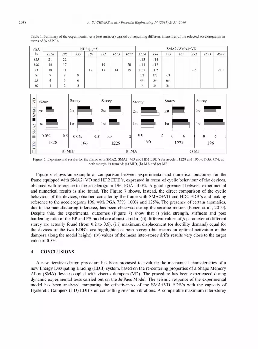
Table 1: Summary of the experimental tests (test number) carried out assuming different intensities of the selected accelerograms in terms of % of PGA.
PGA %
HD2 (μD=5) SMA2 / SMA2+VD 1228 196 535 187 291 4673 4677 1228 196 535 187 291 4673 4677
125 21 22 -/13 -/14 100 16 17 19 20 -/11 -/12 75 10 11 12 13 14 15 10/4 11/5 -/8 -/10 50 7 8 9 7/1 8/2 -/3 25 4 5 6 4/- 5/- 6/- 10 1 2 3 1/- 2/- 3/-
0.0% 0.5%
1st
2st
Storey
1228 0.0% 0.5%
1st
2st
Storey
196 0.0 2
1st
2st
Storey
1228
0.0 2
1st
2st
Storey
196 0 6 1
1st
2st
Storey
1228 0 6 1
1st
2st
Storey
196
a) MID b) MA c) MF
Figure 5: Experimental results for the frame with SMA2, SMA2+VD and HD2 EDB’s for acceler. 1228 and 196, to PGA 75%, at both storeys, in term of: (a) MID, (b) MA and (c) MF.
Figure 6 shows an example of comparison between experimental and numerical outcomes for the frame equipped with SMA2+VD and HD2 EDB’s, expressed in terms of cyclic behaviour of the devices, obtained with reference to the accelerogram 196, PGA=100%. A good agreement between experimental and numerical results is also found. The Figure 7 shows, instead, the direct comparison of the cyclic behaviour of the devices, obtained considering the frame with SMA2+VD and HD2 EDB’s and making reference to the accelerogram 196, with PGA 75%, 100% and 125%. The presence of certain anomalies, due to the manufacturing tolerance, has been observed during the seismic motion (Ponzo et al., 2010). Despite this, the experimental outcomes (Figure 7) show that i) yield strength, stiffness and post hardening ratio of the EP and FS model are almost similar, (ii) different values of β parameter at different storey are actually found (from 0.2 to 0.6), (iii) maximum displacement (or ductility demand) equal for the devices of the two EDB’s are highlighted at both storey (this means an optimal activation of the dampers along the model height); (iv) values of the mean inter-storey drifts results very close to the target value of 0.5%.
4 CONCLUSIONS
A new iterative design procedure has been proposed to evaluate the mechanical characteristics of a new Energy Dissipating Bracing (EDB) system, based on the re-centering properties of a Shape Memory Alloy (SMA) device coupled with viscous dampers (VD). The procedure has been experienced during dynamic experimental tests carried out on the JetPacs Model. The seismic response of the experimental model has been analyzed comparing the effectiveness of the SMA+VD EDB’s with the capacity of Hysteretic Dampers (HD) EDB’s on controlling seismic vibrations. A comparable maximum inter-storey

A. DI CESARE et al. / Procedia Engineering 14 (2011) 2931–2940 2939 Author name / Procedia Engineering 00 (2011) 000–000 9
drift and maximum acceleration among SMA2+VD and HD2 EDB’s, are experimentally found. The response of the model with SMA+VD EDB’s lead to a comparable level of protection for the framed structure with HD EDB’s, limiting to 0.45% the maximum inter-storey drift experienced by the steel frame under the reference seismic input, not much less than the target value (0.5%). The proposed iterative design procedure showed their capability in reaching the performance objective, at least for the considered typology of device SMA+VD. Numerical and experimental outcomes also pointed out the fundamental role of the energy dissipation capacity of the VD in reducing the seismic vibrations of the structure and improves the performance of the EDB’s. 2st Storey
-15
-10
-5
0
5
10
15
-10 -5 0 5d (m
F (kN) 1st Storey
-15
-10
-5
0
5
10
15
-10 -5 0 5d (m
F (kN) 2st Storey
-15
-10
-5
0
5
10
15
-10 -5 0 5d (m
F (kN) 1st Storey
-15
-10
-5
0
5
10
15
-10 -5 0 5 1d (mm
F (kN)
ExperimenNumerical
(a) HD2 (acc.196 100%) (b) SMA2+VD (acc.196 100%)
Figure 6: Experimental and numerical Force-displacement cyclic behaviours of the devices
2st S
tore
y
-15
-10
-5
0
5
10
15
-10 -5 0 5 10d (mm)
F (kN)
-15
-10
-5
0
5
10
15
-10 -5 0 5 10d (mm)
F (kN)
-15
-10
-5
0
5
10
15
-10 -5 0 5 10d (mm)
F (kN)
1st S
tore
y
-15
-10
-5
0
5
10
15
-10 -5 0 5 10d (mm)
F (kN)
-15
-10
-5
0
5
10
15
-10 -5 0 5 10d (mm)
F (kN)
-15
-10
-5
0
5
10
15
-10 -5 0 5 10d (mm)
F (kN)
HD2SMA2+VD
PGA 75% 100% 125%
Figure 7: Experimental behaviour of the frame equipped with SMA2+VD and HD2 EDB’s for accelerogram 196, PGA 75%, 100%, 125%

2940 A. DI CESARE et al. / Procedia Engineering 14 (2011) 2931–294010 Author name / Procedia Engineering 00 (2011) 000–000
Acknowledgements
The characterization tests of the devices and shaking table tests on the model, were funded by the Italian Department of Civil Protection within the DPC-RELUIS 2005-2008 project (research line 7).
References
[1] Constantinou M. C., Soong, T. T. and Dargush, G. F. (1998). Passive energy dissipation systems for structural design and retrot. MCEER, State University of New York at Buffalo.
[2] CSI, Computers and structures, Inc. (2004). SAP2000: Static and Dynamic Finite Element Analysis of Structures. University Avenue, Berkeley, CA, USA.
[3] Dolce M., Cardone D. and Marnetto R. (2000). Implementation and testing of passive control devices based on shape memory alloys. Earthquake engineering and structural dynamics 29: 945-968.
[4] Dolce M., Cardone D., Marnetto R., Mucciarelli M., Nigro D., Ponzo F.C. and Santarsiero G. (2004). Experimental static and dynamic response of a real r/c frame upgraded with sma re-centering and dissipating braces. Proc. 13th World Conference on Earthquake Engineering Vancouver, B.C., Canada.
[5] Dolce, M., Ponzo, F.C., Di Cesare, A., Ditommaso, R., Moroni, C., Nigro, D., Serino, G., Sorace, S., Gattulli, V., Occhiuzzi, A., Vulcano, A. and Foti, D. (2008). Jet-pacs project: joint experimental testing on passive and semiactive control systems. Proc.14th World Conference on Earthquake Engineering, October 12-17, 2008, Beijing, China.
[6] NTC (2008). Italian Technical Code for Constructions (in Italian), DM 14 gennaio 2008. Rome, Italy. [7] Ponzo F. C., Cardone D., Di Cesare A., Gesualdi G., Moroni C., Nigro D. and Dolce M. (2008a). JET-PACS Project:
dynamic test on steel frame equipped with visco-recentring system. Proc.14th World Conference on Earthquake Engineering, October 12-17, 2008, Beijing, China
[8] Ponzo F.C., Cardone D., Di Cesare A. and Blonna B. (2008b). Evaluation of Behaviour Factor for Flag-Shaped Hysteretic Models. EngOpt 08 - International Conference on Engineering Optimization, 01 - 05 June, Rio de Janeiro, Brazil.
[9] Ponzo F.C., Di Cesare A., Moroni C., Nigro D., Ditommaso R., Auletta G. and Dolce M. (2009a), Progetto JET-PACS: Joint Experimental Testing on Passive and semiActive Control Systems. Proc. XIII Convegno Nazionale L’ingegneria Sismica in Italia ANIDIS, 28 giugno - 2 luglio, Bologna, Italy.
[10] Ponzo F.C., Di Cesare A., Nigro D., Moroni C., Auletta G., Dolce M., Marnetto R. (2009b), JET-PACS Project: comparison between experimental and numerical results obtained for a steel frame equipped with hysteretic damped braces. Proc. XIII Convegno Nazionale L’ingegneria Sismica in Italia ANIDIS, 28 giugno - 2 luglio, Bologna, Italy.
[11] Ponzo F.C., Di Cesare A., Nigro D., Moccia D., Moroni C., Dolce M., (2010), JET-PACS project: Preliminary Results of Dynamic Tests on Steel Frame equipped with Visco-Re-Centring System. Proc. 14th European Conference on Earthquake Engineering, 30 August - 3 September, Ohrid, Macedonia.
[12] Newmark N. M. and Hall W. J., (1973), Procedures and criteria for earthquake resistant design, Building Research Series No. 46, National Bureau of Standards, U.S. Dept. of Commerce, Washington, 209-236.
[13] European Committee for Standardization (CEN). Eurocode 8: Design of structures for earthquake resistance, 2003, Brussels
![NOVATEUR PUBLICATIONS INTERNATIONAL JOURNAL OF INNOVATIONS IN ENGINEERING RESEARCH AND TECHNOLOGY [IJIERT] ANALYSIS OF MOMENT RESISTING FRAME BY KNEE BRACING](https://img.pdfslide.net/doc/110x75/635862fcdebc1859f6044020/novateur-publications-international-journal-of-innovations-in-engineering-research.jpg)


