Embed Size (px)
Citation preview
AIRBUS FLY YOUR IDEAS 2013
TEAM AMAZONS
LALITYA DHAVALA
M. ANUSYA
SOWMIYA MADHIAZHAGAN
REVATHY PRIYA R.
SIVARANJANI GANAPATHY SANTHANAM
DEPARTMENT OF AEROSPACE ENGINEERING
AMRITA VISHWA VIDYAPEETHAM
ECO-FRIENDLY, ENERGY EFFICIENT CABIN INTERIORS FOR HUMIDITY CONTROL
Abstract: The possibility of using humidity buffering properties of clay for increasing the
humidity levels in the aircraft cabin is investigated. By increasing the humidity levels in
the cabin, passenger experience is improved thus, resulting in higher number of
passengers and more revenue for airlines and aircraft manufacturers alike.
1 Objectives : To present initial approximate estimates of the amount of increase in humidity levels
and reduction in pressure differential for the cabin, by replacing cabin interiors with
clay and other natural materials.
• To propose methods of incorporating clay into the cabin, and limitations and
requirements for the same.
1.1 Approach: It was decided that a thorough understanding of how and why an aircraft cabin is maintained
at low humidity levels was to be the first step. We then, planned on proceeding to studying the
properties of clay and its present use world-wide. With the ideas clear, we concluded that an
analytical study to characterize the capabilities of clay and an experiment to demonstrate the
mechanism would be the best way to justify our proposal.
2 Description 2.1 Research/Background Information of Current Cabin Conditions This section presents results of background research into current cabin environments and clay
properties etc.
2.1.1 Survey: As a first step towards identifying the problems faced by passengers in airplanes, we conducted
a survey of around 30 people who were frequent flyers asking them to identify and rate the
factors which they felt was the most inconvenient during air travel. The economy class was
targeted as that is where the passengers face the most discomfort with airlines and aircraft
manufacturers dishing out various luxuries for the higher- end classes. The questionnaire used
and a sample response is attached as Appendix I.
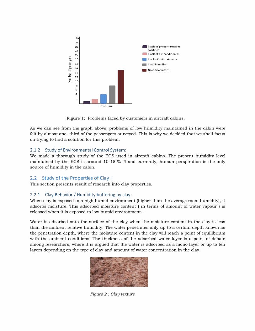
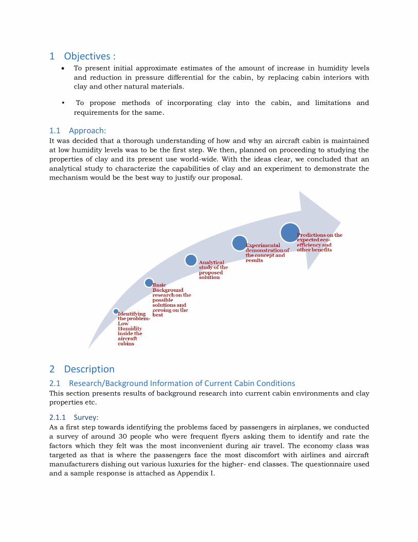
Figure 1: Problems faced by customers in aircraft cabins.
As we can see from the graph above, problems of low humidity maintained in the cabin were
felt by almost one- third of the passengers surveyed. This is why we decided that we shall focus
on trying to find a solution for this problem.
2.1.2 Study of Environmental Control System: We made a thorough study of the ECS used in aircraft cabins. The present humidity level
maintained by the ECS is around 10-15 % [7] and currently, human perspiration is the only
source of humidity in the cabin.
2.2 Study of the Properties of Clay : This section presents result of research into clay properties.
2.2.1 Clay Behavior / Humidity buffering by clay: When clay is exposed to a high humid environment (higher than the average room humidity), it
adsorbs moisture. This adsorbed moisture content ( in terms of amount of water vapour ) is
released when it is exposed to low humid environment. .
Water is adsorbed onto the surface of the clay when the moisture content in the clay is less
than the ambient relative humidity. The water penetrates only up to a certain depth known as
the penetration depth, where the moisture content in the clay will reach a point of equilibrium
with the ambient conditions. The thickness of the adsorbed water layer is a point of debate
among researchers, where it is argued that the water is adsorbed as a mono layer or up to ten
layers depending on the type of clay and amount of water concentration in the clay.
Figure 2 : Clay texture
Adsorption and desorption phenomena in clay are controlled by the differential entropy of the
water molecules in the clay and in the surrounding atmosphere. The nature of this adsorbed
water has been found to have an effect on the mechanical, thermodynamic, magnetic and
dielectrical properties of the clay. Clay also shows a swelling behavior when it adsorbs water
since it is an expansive soil but it has been proved that there are no potential problems due to
this behavior pertaining to its use in construction [2]. Studies have been performed on the
relation between swelling pressure experienced by the clay molecules and its moisture content
(G.Kahr et.al, Clay minerals 1990).
The ability of clay to absorb water vapour during periods of high humidity and release it during
periods of low humidity is knows as humidity buffering. This property helps to maintain a
constant relative humidity in the cabin. The amount of buffering increases as the amount of
clay used increases.
The amount of buffering or the damping of the RH cycle depends on four factors:
• Material’s capacity for absorbing water vapour
• Water vapour permeability
• Interaction of absorption and permeability in a dynamic situation
• The effect of ventilation
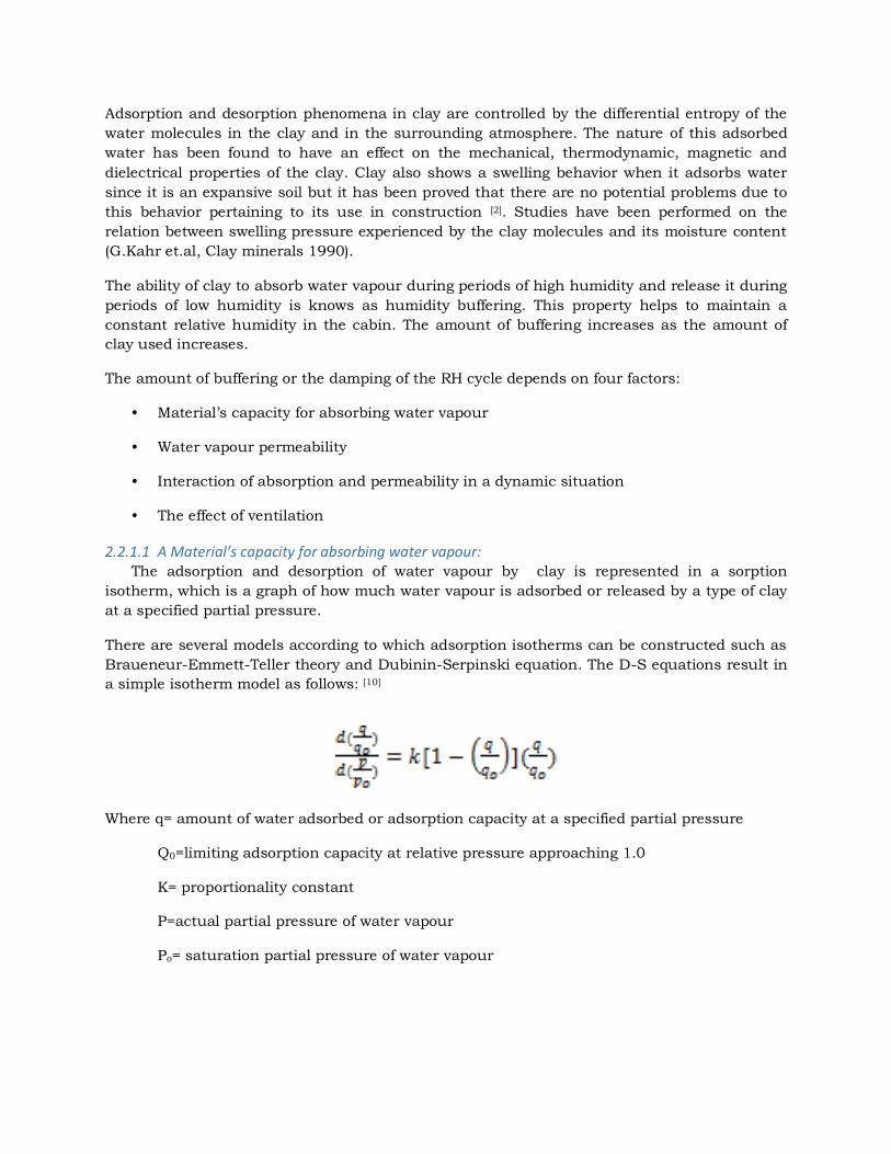
2.2.1.1 A Material’s capacity for absorbing water vapour: The adsorption and desorption of water vapour by clay is represented in a sorption
isotherm, which is a graph of how much water vapour is adsorbed or released by a type of clay
at a specified partial pressure.
There are several models according to which adsorption isotherms can be constructed such as
Braueneur-Emmett-Teller theory and Dubinin-Serpinski equation. The D-S equations result in
a simple isotherm model as follows: [10]
Where q= amount of water adsorbed or adsorption capacity at a specified partial pressure
Q0=limiting adsorption capacity at relative pressure approaching 1.0
K= proportionality constant
P=actual partial pressure of water vapour
Po= saturation partial pressure of water vapour
The limiting adsorption capacity is related to the limiting pore volume by the relation[10]
Where Vo= limiting pore volume
Ρ= density of condensed adsorbate i.e. water vapour in this case
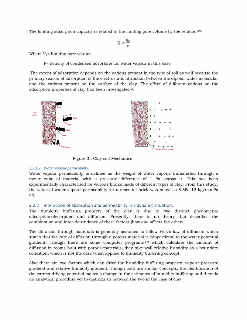
The extent of adsorption depends on the cations present in the type of soil as well because the
primary reason of adsorption is the electrostatic attraction between the dipolar water molecular
and the cations present on the surface of the clay. The effect of different cations on the
adsorption properties of clay had been investigated[2].
Figure 3 : Clay soil Mechanics
2.2.1.2 Water vapour permeability:
Water vapour permeability is defined as the weight of water vapour transmitted through a
meter cube of material with a pressure difference of 1 Pa across it. This has been
experimentally characterized for various bricks made of different types of clay. From this study,
the value of water vapour permeability for a smectite brick was noted as 8.55e-12 kg/m.s.Pa [19].
2.2.2 Interaction of absorption and permeability in a dynamic situation: The humidity buffering property of the clay is due to two distinct phenomena:
adsorption/desorption and diffusion. Presently, there is no theory that describes the
combination and inter-dependence of these factors (how one affects the other).
The diffusion through materials is generally assumed to follow Fick’s law of diffusion which
states that the rate of diffusion through a porous material is proportional to the water potential
gradient. Though there are some computer programs[17] which calculate the amount of
diffusion in rooms built with porous materials, they take wall relative humidity as a boundary
condition, which is not the case when applied to humidity buffering concept.
Also there are two factors which can drive the humidity buffering property: vapour pressure
gradient and relative humidity gradient. Though both are similar concepts, the identification of
the correct driving potential makes a change in the estimates of humidity buffering and there is
no analytical procedure yet to distinguish between the two in the case of clay.
The theoretical performance of clay as a humidity buffer can be characterized in terms of:
• Moisture effusivity
• Moisture Buffer Value
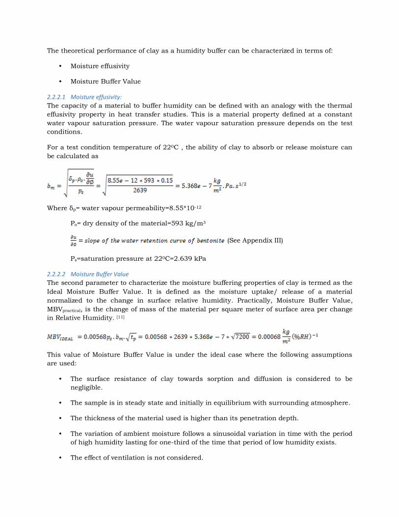
2.2.2.1 Moisture effusivity:
The capacity of a material to buffer humidity can be defined with an analogy with the thermal
effusivity property in heat transfer studies. This is a material property defined at a constant
water vapour saturation pressure. The water vapour saturation pressure depends on the test
conditions.
For a test condition temperature of 220C , the ability of clay to absorb or release moisture can
be calculated as
Where δp= water vapour permeability=8.55*10-12
Ρo= dry density of the material=593 kg/m3
(See Appendix III)
Ps=saturation pressure at 220C=2.639 kPa
2.2.2.2 Moisture Buffer Value
The second parameter to characterize the moisture buffering properties of clay is termed as the
Ideal Moisture Buffer Value. It is defined as the moisture uptake/ release of a material
normalized to the change in surface relative humidity. Practically, Moisture Buffer Value,
MBVpractical, is the change of mass of the material per square meter of surface area per change
in Relative Humidity. [11]
This value of Moisture Buffer Value is under the ideal case where the following assumptions
are used:
• The surface resistance of clay towards sorption and diffusion is considered to be
negligible.
• The sample is in steady state and initially in equilibrium with surrounding atmosphere.
• The thickness of the material used is higher than its penetration depth.
• The variation of ambient moisture follows a sinusoidal variation in time with the period
of high humidity lasting for one-third of the time that period of low humidity exists.
• The effect of ventilation is not considered.
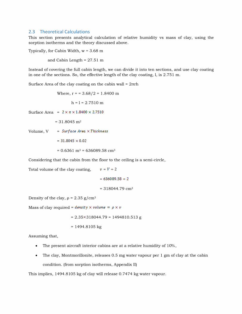
2.3 Theoretical Calculations This section presents analytical calculation of relative humidity vs mass of clay, using the
sorption isotherms and the theory discussed above.
Typically, for Cabin Width, w = 3.68 m
and Cabin Length = 27.51 m
Instead of covering the full cabin length, we can divide it into ten sections, and use clay coating
in one of the sections. So, the effective length of the clay coating, l, is 2.751 m.
Surface Area of the clay coating on the cabin wall = 2πrh
Where, r = = 3.68/2 = 1.8400 m
h = l = 2.7510 m
Surface Area =
= 31.8045 m2
Volume, V =
=
= 0.6361 m3 = 636089.58 cm3
Considering that the cabin from the floor to the ceiling is a semi-circle,
Total volume of the clay coating, =
=
= 318044.79 cm3
Density of the clay, ρ = 2.35 g/cm3
Mass of clay required =
= 2.35 318044.79 = 1494810.513 g
= 1494.8105 kg
Assuming that,
The present aircraft interior cabins are at a relative humidity of 10%,
The clay, Montmorillonite, releases 0.5 mg water vapour per 1 gm of clay at the cabin
condition. (from sorption isotherms, Appendix II)
This implies, 1494.8105 kg of clay will release 0.7474 kg water vapour.
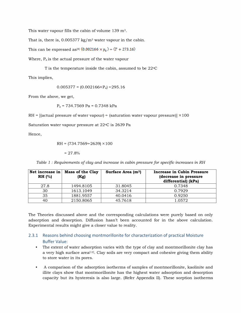
This water vapour fills the cabin of volume 139 m3.
That is, there is, 0.005377 kg/m3 water vapour in the cabin.
This can be expressed as[8]
Where, Pa is the actual pressure of the water vapour
T is the temperature inside the cabin, assumed to be 22oC
This implies,
0.005377 = (0.002166 Pa) 295.16
From the above, we get,
Pa = 734.7569 Pa = 0.7348 kPa
RH = [(actual pressure of water vapour) (saturation water vapour pressure)] 100
Saturation water vapour pressure at 22oC is 2639 Pa
Hence,
RH = (734.7569 2639) 100
= 27.8%
Table 1 : Requirements of clay and increase in cabin pressure for specific increases in RH
Net increase in RH (%)
Mass of the Clay (Kg)
Surface Area (m2) Increase in Cabin Pressure (decrease in pressure
differential) (kPa) 27.8 1494.8105 31.8045 0.7348 30 1613.1049 34.3214 0.7929 35 1881.9557 40.0416 0.9250 40 2150.8065 45.7618 1.0572
The Theories discussed above and the corresponding calculations were purely based on only
adsorption and desorption. Diffusion hasn’t been accounted for in the above calculation.
Experimental results might give a closer value to reality.
2.3.1 Reasons behind choosing montmorillonite for characterization of practical Moisture
Buffer Value: • The extent of water adsorption varies with the type of clay and montmorillonite clay has
a very high surface area[12]. Clay soils are very compact and cohesive giving them ability
to store water in its pores.
• A comparison of the adsorption isotherms of samples of montmorillonite, kaolinite and
illite clays show that montmorillonite has the highest water adsorption and desorption
capacity but its hysteresis is also large. (Refer Appendix II). These sorption isotherms
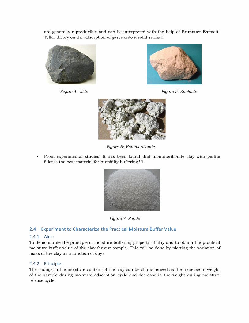
are generally reproducible and can be interpreted with the help of Brunauer-Emmett-
Teller theory on the adsorption of gases onto a solid surface.
Figure 4 : Illite Figure 5: Kaolinite
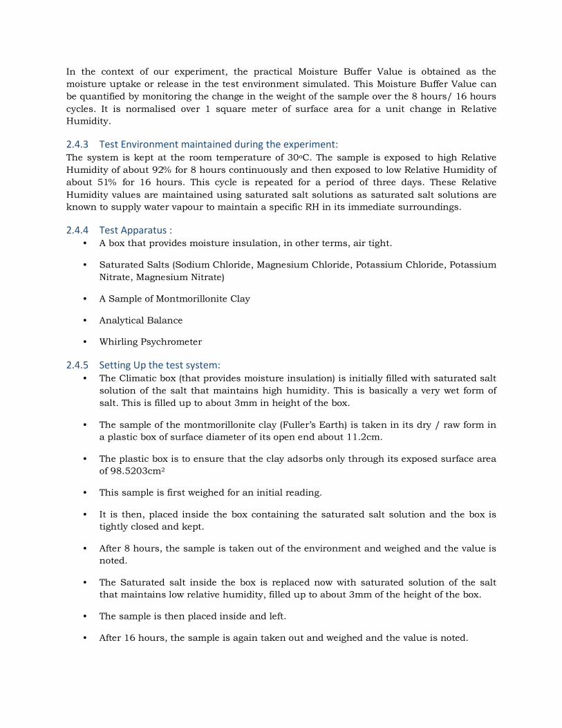
Figure 6: Montmorillonite
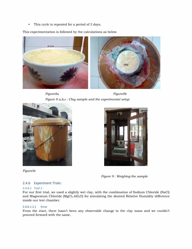
• From experimental studies. It has been found that montmorillonite clay with perlite
filler is the best material for humidity buffering[12].
Figure 7: Perlite
2.4 Experiment to Characterize the Practical Moisture Buffer Value
2.4.1 Aim : To demonstrate the principle of moisture buffering property of clay and to obtain the practical
moisture buffer value of the clay for our sample. This will be done by plotting the variation of
mass of the clay as a function of days.
2.4.2 Principle : The change in the moisture content of the clay can be characterized as the increase in weight
of the sample during moisture adsorption cycle and decrease in the weight during moisture
release cycle.
In the context of our experiment, the practical Moisture Buffer Value is obtained as the
moisture uptake or release in the test environment simulated. This Moisture Buffer Value can
be quantified by monitoring the change in the weight of the sample over the 8 hours/ 16 hours
cycles. It is normalised over 1 square meter of surface area for a unit change in Relative
Humidity.
2.4.3 Test Environment maintained during the experiment: The system is kept at the room temperature of 30oC. The sample is exposed to high Relative
Humidity of about 92% for 8 hours continuously and then exposed to low Relative Humidity of
about 51% for 16 hours. This cycle is repeated for a period of three days. These Relative
Humidity values are maintained using saturated salt solutions as saturated salt solutions are
known to supply water vapour to maintain a specific RH in its immediate surroundings.
2.4.4 Test Apparatus : • A box that provides moisture insulation, in other terms, air tight.
• Saturated Salts (Sodium Chloride, Magnesium Chloride, Potassium Chloride, Potassium
Nitrate, Magnesium Nitrate)
• A Sample of Montmorillonite Clay
• Analytical Balance
• Whirling Psychrometer
2.4.5 Setting Up the test system: • The Climatic box (that provides moisture insulation) is initially filled with saturated salt
solution of the salt that maintains high humidity. This is basically a very wet form of
salt. This is filled up to about 3mm in height of the box.
• The sample of the montmorillonite clay (Fuller’s Earth) is taken in its dry / raw form in
a plastic box of surface diameter of its open end about 11.2cm.
• The plastic box is to ensure that the clay adsorbs only through its exposed surface area
of 98.5203cm2
• This sample is first weighed for an initial reading.
• It is then, placed inside the box containing the saturated salt solution and the box is
tightly closed and kept.
• After 8 hours, the sample is taken out of the environment and weighed and the value is
noted.
• The Saturated salt inside the box is replaced now with saturated solution of the salt
that maintains low relative humidity, filled up to about 3mm of the height of the box.
• The sample is then placed inside and left.
• After 16 hours, the sample is again taken out and weighed and the value is noted.
• This cycle is repeated for a period of 3 days.
This experimentation is followed by the calculations as below.
Figure8a Figure8b
Figure 8 a,b,c : Clay sample and the experimental setup
Figure8c
Figure 9 : Weighing the sample
2.4.6 Experiment Trials:
2.4.6.1 Trial 1 :
For our first trial, we used a slightly wet clay, with the combination of Sodium Chloride (NaCl)
and Magnesium Chloride (MgCl2.6H2O) for simulating the desired Relative Humidity difference
inside our test chamber.
2.4.6.1.1.1 Error
From the start, there hasn’t been any observable change in the clay mass and we couldn’t
proceed forward with the same.
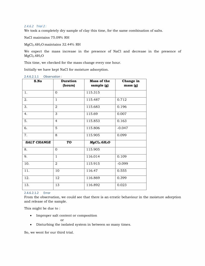
2.4.6.2 Trial 2 :
We took a completely dry sample of clay this time, for the same combination of salts.
NaCl maintains 75.09% RH
MgCl2.6H2O maintains 32.44% RH
We expect the mass increase in the presence of NaCl and decrease in the presence of
MgCl2.6H2O
This time, we checked for the mass change every one hour.
Initially we have kept NaCl for moisture adsorption.
2.4.6.2.1.1 Observation :
S.No Duration
(hours)
Mass of the
sample (g)
Change in
mass (g)
1. 0 115.315
2. 1 115.487 0.712
3. 2 115.683 0.196
4. 3 115.69 0.007
5. 4 115.853 0.163
6. 5 115.806 -0.047
7. 8 115.905 0.099
SALT CHANGE TO MgCl2.6H2O
8. 0 115.905
9. 1 116.014 0.109
10. 2 115.915 -0.099
11. 10 116.47 0.555
12. 12 116.869 0.399
13. 13 116.892 0.023
2.4.6.2.1.2 Error
From the observation, we could see that there is an erratic behaviour in the moisture adorption
and release of the sample.
This might be due to :
Improper salt content or composition
or
Disturbing the isolated system in between so many times.
So, we went for our third trial.
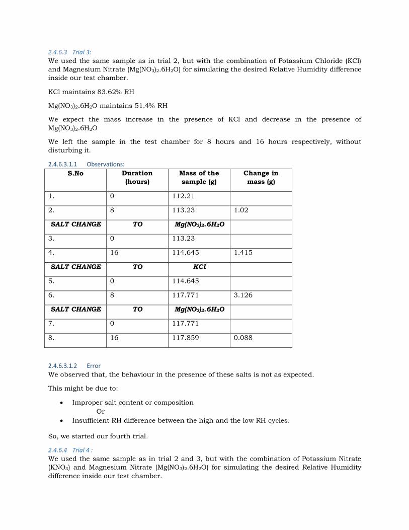
2.4.6.3 Trial 3:
We used the same sample as in trial 2, but with the combination of Potassium Chloride (KCl)
and Magnesium Nitrate (Mg(NO3)2.6H2O) for simulating the desired Relative Humidity difference
inside our test chamber.
KCl maintains 83.62% RH
Mg(NO3)2.6H2O maintains 51.4% RH
We expect the mass increase in the presence of KCl and decrease in the presence of
Mg(NO3)2.6H2O
We left the sample in the test chamber for 8 hours and 16 hours respectively, without
disturbing it.
2.4.6.3.1.1 Observations:
S.No Duration
(hours)
Mass of the
sample (g)
Change in
mass (g)
1. 0 112.21
2. 8 113.23 1.02
SALT CHANGE TO Mg(NO3)2.6H2O
3. 0 113.23
4. 16 114.645 1.415
SALT CHANGE TO KCl
5. 0 114.645
6. 8 117.771 3.126
SALT CHANGE TO Mg(NO3)2.6H2O
7. 0 117.771
8. 16 117.859 0.088
2.4.6.3.1.2 Error
We observed that, the behaviour in the presence of these salts is not as expected.
This might be due to:
Improper salt content or composition
Or
Insufficient RH difference between the high and the low RH cycles.
So, we started our fourth trial.
2.4.6.4 Trial 4 :
We used the same sample as in trial 2 and 3, but with the combination of Potassium Nitrate
(KNO3) and Magnesium Nitrate (Mg(NO3)2.6H2O) for simulating the desired Relative Humidity
difference inside our test chamber.
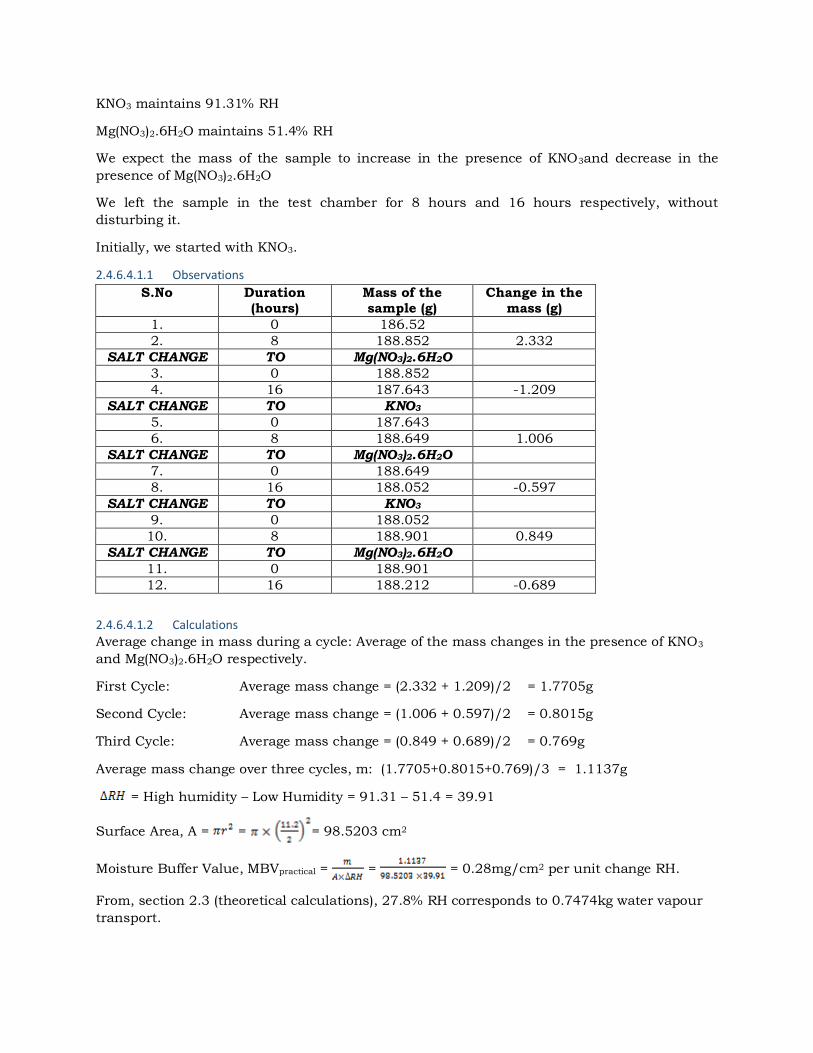
KNO3 maintains 91.31% RH
Mg(NO3)2.6H2O maintains 51.4% RH
We expect the mass of the sample to increase in the presence of KNO3and decrease in the
presence of Mg(NO3)2.6H2O
We left the sample in the test chamber for 8 hours and 16 hours respectively, without
disturbing it.
Initially, we started with KNO3.
2.4.6.4.1.1 Observations
S.No Duration (hours)
Mass of the sample (g)
Change in the mass (g)
1. 0 186.52
2. 8 188.852 2.332
SALT CHANGE TO Mg(NO3)2.6H2O
3. 0 188.852
4. 16 187.643 -1.209
SALT CHANGE TO KNO3
5. 0 187.643
6. 8 188.649 1.006
SALT CHANGE TO Mg(NO3)2.6H2O
7. 0 188.649
8. 16 188.052 -0.597
SALT CHANGE TO KNO3
9. 0 188.052
10. 8 188.901 0.849
SALT CHANGE TO Mg(NO3)2.6H2O
11. 0 188.901
12. 16 188.212 -0.689
2.4.6.4.1.2 Calculations
Average change in mass during a cycle: Average of the mass changes in the presence of KNO3
and Mg(NO3)2.6H2O respectively.
First Cycle: Average mass change = (2.332 + 1.209)/2 = 1.7705g
Second Cycle: Average mass change = (1.006 + 0.597)/2 = 0.8015g
Third Cycle: Average mass change = (0.849 + 0.689)/2 = 0.769g
Average mass change over three cycles, m: (1.7705+0.8015+0.769)/3 = 1.1137g
= High humidity – Low Humidity = 91.31 – 51.4 = 39.91
Surface Area, A = = = 98.5203 cm2
Moisture Buffer Value, MBVpractical = = = 0.28mg/cm2 per unit change RH.
From, section 2.3 (theoretical calculations), 27.8% RH corresponds to 0.7474kg water vapour
transport.
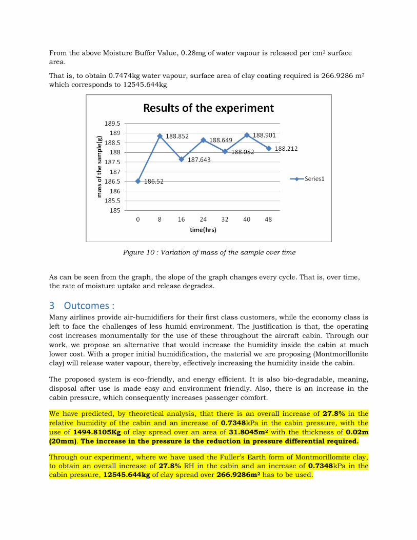
From the above Moisture Buffer Value, 0.28mg of water vapour is released per cm2 surface
area.
That is, to obtain 0.7474kg water vapour, surface area of clay coating required is 266.9286 m2
which corresponds to 12545.644kg
Figure 10 : Variation of mass of the sample over time
As can be seen from the graph, the slope of the graph changes every cycle. That is, over time,
the rate of moisture uptake and release degrades.
3 Outcomes : Many airlines provide air-humidifiers for their first class customers, while the economy class is
left to face the challenges of less humid environment. The justification is that, the operating
cost increases monumentally for the use of these throughout the aircraft cabin. Through our
work, we propose an alternative that would increase the humidity inside the cabin at much
lower cost. With a proper initial humidification, the material we are proposing (Montmorillonite
clay) will release water vapour, thereby, effectively increasing the humidity inside the cabin.
The proposed system is eco-friendly, and energy efficient. It is also bio-degradable, meaning,
disposal after use is made easy and environment friendly. Also, there is an increase in the
cabin pressure, which consequently increases passenger comfort.
We have predicted, by theoretical analysis, that there is an overall increase of 27.8% in the
relative humidity of the cabin and an increase of 0.7348kPa in the cabin pressure, with the
use of 1494.8105Kg of clay spread over an area of 31.8045m2 with the thickness of 0.02m
(20mm). The increase in the pressure is the reduction in pressure differential required.
Through our experiment, where we have used the Fuller’s Earth form of Montmorillomite clay,
to obtain an overall increase of 27.8% RH in the cabin and an increase of 0.7348kPa in the
cabin pressure, 12545.644kg of clay spread over 266.9286m2 has to be used.
By increasing the humidity levels in the cabin, passenger experience is improved thus,
resulting in higher number of passengers and more revenue for airlines and aircraft
manufacturers alike. The increase in weight and the consequent increase in fuel consumption,
can be offset by the use of bio-fuels, and more lighter composite structures (natural fibers have
very less density) for the aircraft.
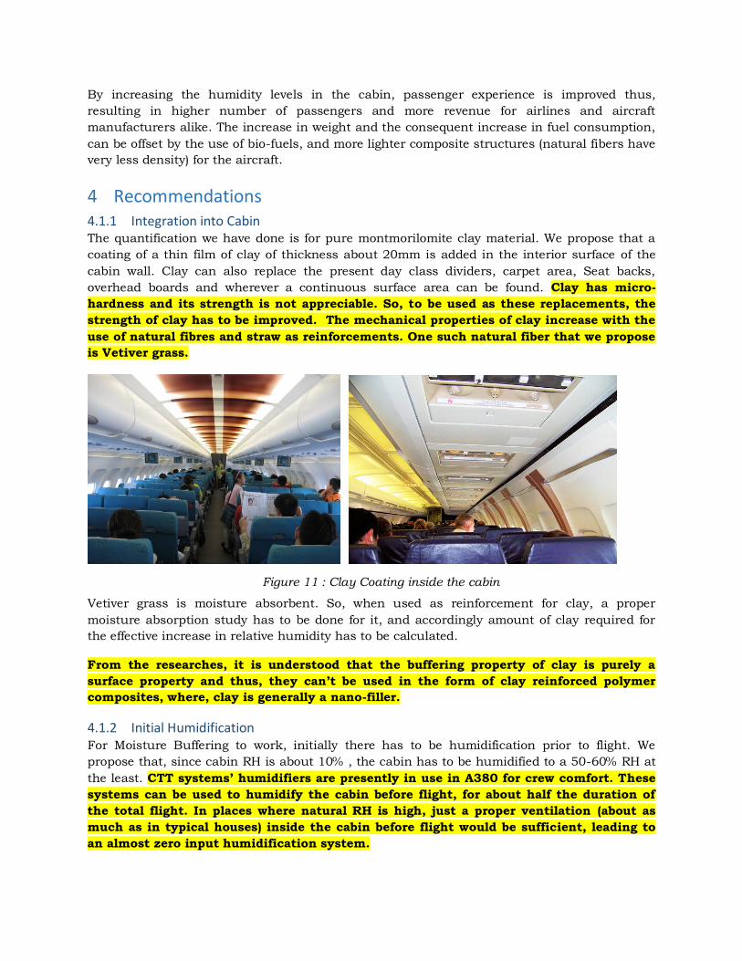
4 Recommendations 4.1.1 Integration into Cabin The quantification we have done is for pure montmorilomite clay material. We propose that a
coating of a thin film of clay of thickness about 20mm is added in the interior surface of the
cabin wall. Clay can also replace the present day class dividers, carpet area, Seat backs,
overhead boards and wherever a continuous surface area can be found. Clay has micro-
hardness and its strength is not appreciable. So, to be used as these replacements, the
strength of clay has to be improved. The mechanical properties of clay increase with the
use of natural fibres and straw as reinforcements. One such natural fiber that we propose
is Vetiver grass.
Figure 11 : Clay Coating inside the cabin
Vetiver grass is moisture absorbent. So, when used as reinforcement for clay, a proper
moisture absorption study has to be done for it, and accordingly amount of clay required for
the effective increase in relative humidity has to be calculated.
From the researches, it is understood that the buffering property of clay is purely a
surface property and thus, they can’t be used in the form of clay reinforced polymer
composites, where, clay is generally a nano-filler.
4.1.2 Initial Humidification For Moisture Buffering to work, initially there has to be humidification prior to flight. We
propose that, since cabin RH is about 10% , the cabin has to be humidified to a 50-60% RH at
the least. CTT systems’ humidifiers are presently in use in A380 for crew comfort. These
systems can be used to humidify the cabin before flight, for about half the duration of
the total flight. In places where natural RH is high, just a proper ventilation (about as
much as in typical houses) inside the cabin before flight would be sufficient, leading to
an almost zero input humidification system.
4.1.3 Scope For Improvement It has been studied that the effectiveness of moisture buffering increases with the
presence of moisture absorbents in the environment[5]. We propose that many of the
plastics in use inside the cabin could be replaced by natural fibers and substances that
are moisture absorbent.
Our Suggestions for some of these replacements:
Plastic water bottles and juice bottles – Bottle guard bottles
Added benefit: “The large bottle gourds are extremely useful among the
country people, by whom they are used as dippers. They are light, and
with good usage may last for months and even for several years.” - The
Farmer’s and Planter’s Encyclopaedia of Rural Affairs.
“These gourds were much preferable… for water, in these would remain
cool through the day of the hottest sun” – Journal of a private in
Tennessee Regiment of Cavalry in the campaign in Mexico
Soup and Salad Bowls – Clay-pot bowls
Plastic Sachets – Fiber/Bagasse sachets with silica gel packet inside for keeping
the food fresh
Plastic Plates and Spoons, Plastic cups for hot and cold beverages – Areca Palm
Bark plates, cups and spoons
Clay Containers with vetiver grass put in for water storage
Added Benefit: keeps water cool and thus, reduced refrigeration
required.
Our calculations are subject to assumptions aforementioned and the corresponding
changes in the values due to change in the operating conditions have to be taken into
consideration.
All our work has been done for pure clay and only desorption effect has been considered
during analytical quantification. The effectiveness of the humidity buffering can be
increased using Perlite as filler which helps in opening up the pores of the clay and
consequently increases the diffusion effects.
The ideal mixture of montmorilomite and perlite is :
For 1 volume of montmorillonite, 1.5 volumes of water and ten volumes of
perlite.
Fuller’s Earth form was the only form we tested. Other forms of Montmorillonite might
produce better results for very less increase in weight. Those should be tested for the
same and the best should be selected for implementation.
As seen from the experimental results, there is degradation of the buffering property of
clay over time. Thus, the life time of the clay that is going to be used should be
estimated. This can be done by doing the same experiment as we have discussed till
there is no change in the mass. This will effectively give us the time when the buffering
stops.
4.1.4 Limitations Humidity buffering has been found to be effective for ventilation rates of about 1 air change per
hour. In airplanes, typically there is about 1 air change every 2 minutes. Thus, the
effectiveness of the clay has to be tested in a similar environment before implementation.
4.1.5 Feasibility of the idea As mentioned earlier and observed in one of our experiment trials, ventilation could be a major
problem for immediately implementing the idea. The proposal could be efficiently implemented
once the moisture buffering of clay is properly characterized for the ventilation conditions of
the cabin during flight.
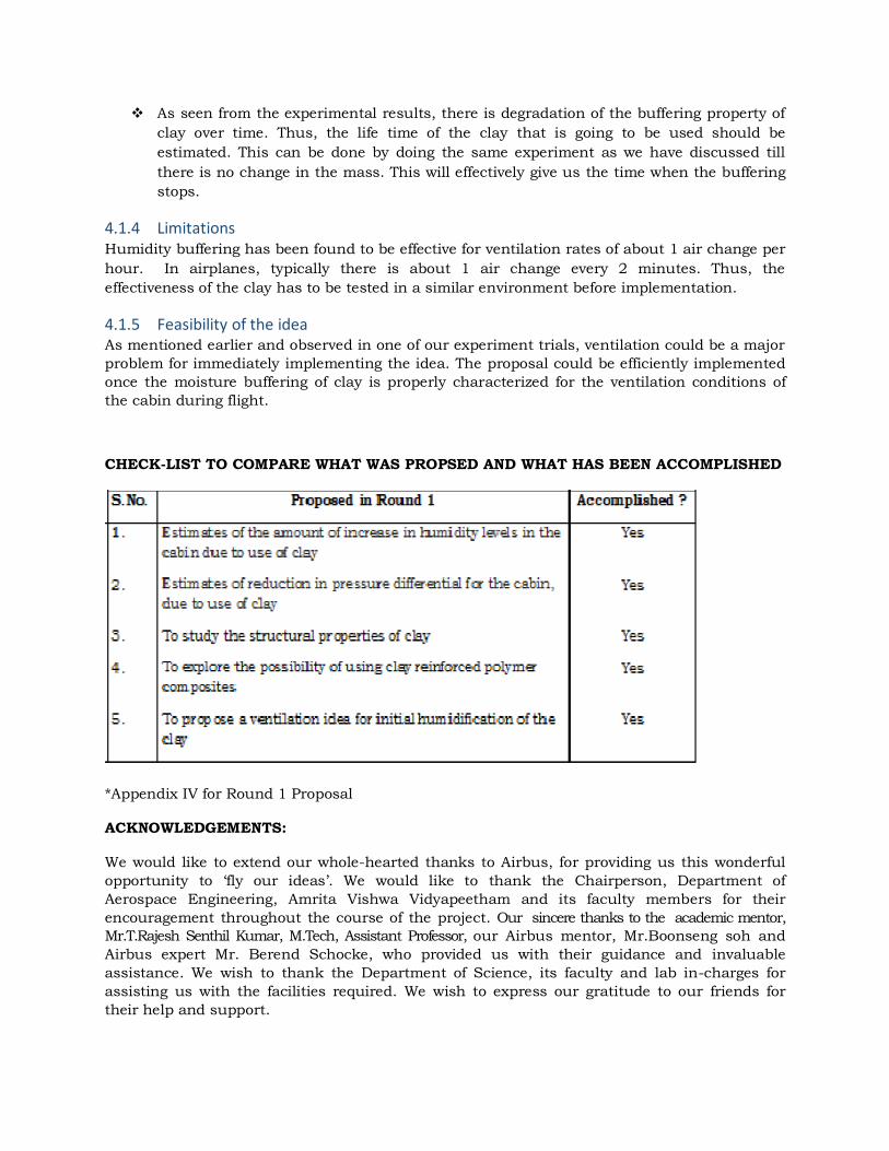
CHECK-LIST TO COMPARE WHAT WAS PROPSED AND WHAT HAS BEEN ACCOMPLISHED
*Appendix IV for Round 1 Proposal
ACKNOWLEDGEMENTS:
We would like to extend our whole-hearted thanks to Airbus, for providing us this wonderful
opportunity to ‘fly our ideas’. We would like to thank the Chairperson, Department of
Aerospace Engineering, Amrita Vishwa Vidyapeetham and its faculty members for their
encouragement throughout the course of the project. Our sincere thanks to the academic mentor,
Mr.T.Rajesh Senthil Kumar, M.Tech, Assistant Professor, our Airbus mentor, Mr.Boonseng soh and
Airbus expert Mr. Berend Schocke, who provided us with their guidance and invaluable
assistance. We wish to thank the Department of Science, its faculty and lab in-charges for
assisting us with the facilities required. We wish to express our gratitude to our friends for
their help and support.

References:
1. Maniatidis, Vasilios, Walker, Peter, "A Review of Rammed Earth Construction", DTi Partners in Innovation Project ‘Developing Rammed Earth for UK Housing’ (May 2003), Natural Building Technology Group, Department of Architecture & Civil Engineering, University of Bath, Bath.
2. Baeshad, Isaac, "Absorptive and Swelling Properties of Clay-Water System" (Bull. 169) Clays and Clay Technology
3. Martin, R. Torrence., "Adsorbed Water on Clay: A Review", Soil Engineering Division, Department of Civil Engineering, Massachusetts Institute of Technology, Cambridge, Massachusetts
4. Das, Braja. M., “Advanced Soil Mechanics”, Third Edition, Taylor and Francis group, London and New York, ISBN 0-415-42026-6
5. Pedersen, Carsten Rode.,"Combined Heat and Moisture Transfer in Building Constructions", Report 214 (1990), Thermal Insulation Laboratory, Technical University of Denmark.
6. "Equilibrium Relative Humidity Saturated Salt Solutions", www.omega.com 7. "Humidity Conversion Formulae" published by Vaisala Oyj, Finland. www.vaisala.com 8. Dr. Jaquin, Paul., Edinburgh, Ramboll., "Humidity Regulation in Earth Buildings",
University of Bath, Bath 9. Qi, Shaoying., Hay, K. James., Rood, Mark J., "Isotherm Equation for Water Vapour
Adsorption onto Activated Carbon,” Journal of Environmental Engineering (Nov 2008), 10. "Moisture Buffering of Building Materials - Report" (ISBN 87-7877-195-1), Department of
Civil Engineering, Technical University of Denmark. 11. Padfield, Tim.,"On the Usefulness of Water Absorbent Materials in Museum Walls"
Conservation Department, the National Museum of Denmark. 12. Dueck, Ann.,"Results from Suction Controlled Laboratory Tests on Unsaturated Bentonite
– Verification of a Model" Clay Technology AB, Ideon, SE-223 70 Lund, Sweden. 13. Kunzel, Hartwig M., Verlag, Fraunhofer IRB.,"Simultaneous Heat and Moisture Transport
in Building Components" (ISBN 3-8167-4535-0), Stuttgart (1996). 14. Toguyenia, David Y.K., Coulibalya, Ousmane., Ouedraogob, Abdoulaye., Koulidiatia,
Jean., Dutilc, Yvan., Roussec, Daniel., "Study of the Influence of Roof Insulation Involving Local Materials on Cooling Loads of Houses, Built of Clay and Straw"
15. Kahr, G., Kraehenbuehl, F., Stoeckli, H.F., Muller-Vonmoos, M., "Study of the Water-Bentonite System by Vapour Adsorption, Immersion Calorimetry and X-Ray Techniques: II Heats of Immersion, Swelling Pressures and Thermodynamic Properties" , Institute of Foundation Engineering and Soil Mechanics, Laboratory for Clay Mineralogy, Federal Institute of Technology, Chemistry department, University of Neuchatel.
16. Padfield, Tim., "The Role of Adsorbent Building Materials in Moderating Changes of Relative Humidity", Ph.D. Thesis, ISBN 87-7740-256-1(Oct 1998), Department of Structural Engineering and Materials, The Technical University of Denmark.
17. Johansen, Robert T., Dunning, H.N., “Water Vapour Adsorption on Clay”, Sixth National Conference on Clays and Clay Minerals, Oklahoma
18. Dondi, Michele., Principi, Paolo., Raimondo, Mariarosa., Zanarini, Giorgio.,"Water Vapour Permeability of Clay Bricks", Construction and Building Materials, 17 (2003) 253-258 ©2002 Elsevier Science Ltd.