Embed Size (px)
Citation preview


Volume 12 / Issue 3 / December 2018
Editorial Boardwww.anatomy.org.tr
Scientific Advisory Board
EditorsNihal Apayd›n, Ankara, TurkeyKyung Ah Park, Seoul, KoreaGeorge Paxinos, Sydney, AustraliaLuis Puelles, Murcia, SpainMustafa F. Sargon, Ankara, TurkeyÜmit S. fiehirli, Istanbul, TurkeyShane Tubbs, Birmingham, AL, USAEmel Ulup›nar, Eskiflehir, Turkey
Associate EditorsVaclav Baca, Prague, Czech RepublicÇa¤atay Barut, Istanbul, TurkeyJon Cornwall, Dunedin, New ZealandAyhan Cömert, Ankara, TurkeyGeorg Feigl, Graz, AustriaZeliha Kurto¤lu Olgunus, Mersin, TurkeyScott Lozanoff, Honolulu, HI, USALevent Sar›kç›o¤lu, Antalya, TurkeyCristian Stefan, Boston, MA, USA
Executive Board of Turkish Societyof Anatomy and Clinical AnatomyEsat Ad›güzel (President)Zeliha Kurto¤lu Olgunus (Vice President)Ça¤atay Barut (Vice President)Piraye Kervanc›o¤lu (Secretary General)Ayhan Cömert (Treasurer)‹lke Ali Gürses (Vice Treasurer)Nadire Ünver Do¤an (Member)
Editor-in-Chief
Gülgün fiengül, Izmir, Turkey
Founding EditorsSalih Murat Akk›n, Gaziantep, TurkeyHakan Hamdi Çelik, Ankara, Turkey
Honorary EditorDo¤an Akflit, Ankara, Turkey Peter H. Abrahams
Cambridge, UK
Halil ‹brahim Açar Ankara, Turkey
Esat Ad›güzel Denizli, Turkey
Marian Adamkov Martin, Slovakia
Mustafa Aktekin Istanbul, Turkey
Mahindra Kumar AnandGujarat, India
Doychin Angelov Cologne, Germany
Serap ArbakIstanbul, Turkey
Alp Bayramo¤luIstanbul, Turkey
Brion BenningerLebanon, OR, USA
Susana BiasuttoCordoba, Argentina
Dragica BobinacRijeka, Croatia
David BolenderMilwaukee, WI, USA
Eric BrennerInnsbruck, Austria
Mustafa BüyükmumcuKonya, Turkey
Richard Halti CabralSao Paulo, Brazil
Safiye ÇavdarIstanbul, Turkey
Katharina D’HerdeGhent, Belgium
Fabrice DuparcRouen, France
Behice DurgunAdana, Turkey
‹zzet DuyarIstanbul, Turkey
Mirela EricNovi Sad, Serbia
Cumhur ErtekinIzmir, Turkey
Mete ErtürkIzmir, Turkey
Reha ErzurumluBaltimore, MD, USA
Ali F›rat EsmerAnkara, Turkey
António José Gonçalves FerreiraLisboa, Portugal
Quentin FoggMelbourne, Australia
Christian FontaineLille, France
Rod GreenBendigo, Australia
Bruno GrignonNancy Cedex, France
Nadir GülekonAnkara, Turkey
Mürvet HayranIzmir, Turkey
David HeylingsNorwich, UK
Lazar JelevSofia, Bulgaria
David KachlíkPrague, Czech Republic
Samet KapakinErzurum, Turkey
Ahmet Ka¤an KarabulutKonya, Turkey
Piraye Kervanc›o¤luGaziantep, Turkey
Hee-Jin KimSeoul, Korea
Necdet Kocab›y›kAnkara, Turkey
Cem KopuzSamsun, Turkey
Mustafa Ayberk KurtBursa, Turkey
Marios LoukasGrenada, West Indies
Veronnica MacchiPadua, Italy
Mehmet Ali MalasIzmir, Turkey
Petru MatuszTimisoara, Romania
Bernard MoxhamCardiff, Wales, UK
Konstantinos NatsisThessaloniki, Greece
Helen NicholsonDunedin, New Zealand
Davut Özba¤Malatya, Turkey
P. Hande ÖzdinlerChicago, IL, USA
Adnan ÖztürkIstanbul, Turkey
Mehmet Hakan ÖztürkMersin, Turkey
Diogo PaisLisboa, PortugalFriedrich PaulsenErlangen, GermanyWojciech PawlinaRochester, MN, USATuncay Veysel PekerAnkara, TurkeyVid PersaudWinnipeg, MB, CanadaDavid PortaLouisville, KY, USA Jose Ramon SanudoMadrid, SpainTatsuo SatoTokyo, JapanMohammadali M. ShojaBirmingham, AL, USAAhmet S›navSakarya, TurkeyTakis SkandalakisAthens, GreeceVildan Sümbülo¤luGaziantep, Turkey (Biostatistics)Muzaffer fiekerKonya, TurkeyErdo¤an fiendemirBursa, Turkey‹brahim TekdemirAnkara, Turkey Hironubu TokunoTokyo, JapanTrifon TotlisThessaloniki, GreeceMehmet ‹brahim Tu¤luManisa, Turkey Selçuk Tunal›Ankara, TurkeyU¤ur TüreIstanbul, TurkeyMehmet ÜzelIstanbul, TurkeyIvan VargaBratislava, SlovakiaTuncay VarolManisa, TurkeyCharles WatsonSydney, AustraliaAndreas H. WeigleinGraz, AustriaBülent Yalç›nAnkara, TurkeyM. Gazi Yaflargil Istanbul, TurkeyÖzlem Y›lmazIzmir, Turkey
Hiroshi YorifujiGunma, Japan
Former Editor-in-Chief &Advising EditorSalih Murat Akk›n, Gaziantep, Turkey

Anatomy • Volume 12 / Issue 3 / December 2018
Instructions to Authorswww.anatomy.org.tr
Anatomy, an international journal of experimental and clinical anatomy, is theofficial publication of the Turkish Society of Anatomy and Clinical Anatomy,TSACA. It is a peer-reviewed journal that publishes scientific articles in English.For a manuscript to be published in the journal, it should not be published pre-viously in another journal or as full text in congress books and should be foundrelevant by the editorial board. Also, manuscripts submitted to Anatomy mustnot be under consideration by any other journal. Relevant manuscripts undergoconventional peer review procedure (at least three reviewers). For the publica-tion of accepted manuscripts, author(s) should reveal to the Editor-in-Chief anyconflict of interest and transfer the copyright to the Turkish Society of Anatomyand Clinical Anatomy, TSACA.
In the Materials and Methods section of the manuscripts where experimen-tal studies on humans are presented, a statement that informed consent wasobtained from each volunteer or patient after explanation of the proceduresshould be included. This section also should contain a statement that the inves-tigation conforms with the principles outlined in the appropriate version of 1964Declaration of Helsinki. For studies involving animals, all work must have beenconducted according to applicable national and international guidelines. Priorapproval must have been obtained for all protocols from the relevant author'sinstitutional or other appropriate ethics committee, and the institution name andpermit numbers must be provided at submission.
Anatomical terms used should comply with Terminologia Anatomica byFCAT (1998).
No publication cost is charged for the manuscripts but reprints and colorprintings are at authors’ cost.
Preparation of manuscripts
During the preparation of the manuscripts, uniform requirements of theInternational Committee of Medical Journal Editors, a part of which is statedbelow, are valid (see ICMJE. Uniform requirements for manuscripts submitted tobiomedical journals. Updated content is available at www.icmje.org). The man-uscript should be typed double-spaced on one side of a 21x 29.7 cm (A4) blanksheet of paper. At the top, bottom and right and left sides of the pages a spaceof 2.5 cm should be left and all the pages should be numbered except for thetitle page.
Manuscripts should not exceed 15 pages (except for the title page). Theymust be accompanied by a cover letter signed by corresponding author and theConflicts of Interest Disclosure Statement and Copyright Transfer Form signed byall authors. The contents of the manuscript (original articles and articles forTeaching Anatomy category) should include: 1- Title Page, 2- Abstract andKeywords, 3- Introduction, 4- Materials and Methods, 5- Results, 6- Discussion(Conclusion and/or Acknowledgement if necessary), 7- References
Title page
In all manuscripts the title of the manuscript should be written at the top andthe full names and surnames and titles of the authors beneath. These should befollowed with the affiliation of the author. Manuscripts with long titles are bet-ter accompanied underneath by a short version (maximum 80 characters) to bepublished as running head. In the title page the correspondence address andtelephone, fax and e-mail should be written. At the bottom of this page, if pres-ent, funding sources supporting the work should be written with full names ofall funding organizations and grant numbers. It should also be indicated in a sep-arate line if the study has already been presented in a congress or likewise sci-entific meeting. Other information such as name and affiliation are not to beindicated in pages other than the title page.
Abstract
Abstract should be written after the title in 100–250 words. In original articlesand articles prepared in IMRAD format for Teaching Anatomy category theabstract should be structured under sections Objectives, Methods, Results andConclusion. Following the abstract at least 3 keywords should be added inalphabetical order separated by semicolumns.
References
Authors should provide direct references to original research sources. Referencesshould be numbered consecutively in square brackets, according to the order inwhich they are first mentioned in the manuscript. They should follow the standardsdetailed in the NLM’s Citing Medicine, 2nd edition (Citing medicine: the NLM style
guide for authors, editors, and publishers [Internet]. 2nd edition. Updated contentis available at www.ncbi.nlm .nih.gov/books/NBK7256). The names of all con-tributing authors should be listed, and should be in the order they appear in theoriginal reference. The author is responsible for the accuracy and completeness ofreferences. When necessary, a copy of a referred article can be requested from theauthor. Journal names should be abbreviated as in Index Medicus. Examples ofmain reference types are shown below:
• Journal articles: Author's name(s), article title, journal title (abbreviated),year of publication, volume number, inclusive pages
– Standard journal article: Sargon MF, Celik HH, Aksit MD, Karaagaoglu E.Quantitative analysis of myelinated axons of corpus callosum in the humanbrain. Int J Neurosci 2007;117:749–55.
– Journal article with indication article published electronically before print:Sengul G, Fu Y, Yu Y, Paxinos G. Spinal cord projections to the cerebellum in themouse. Brain Struct Funct Epub 2014 Jul 10. DOI 10.1007/s00429-014-0840-7.
• Books: Author's name(s), book title, place of publication, publisher, yearof publication, total pages (entire book) or inclusive pages (contribution to abook or chapter in a book)
– Entire book:
- Standard entire book: Sengul G, Watson C, Tanaka I, Paxinos G. Atlas ofthe spinal cord of the rat, mouse, marmoset, rhesus and human. San Diego (CA):Academic Press Elsevier; 2013. 360 p.
- Book with organization as author: Federative Committee of AnatomicalTerminology (FCAT). Terminologia anatomica. Stuttgart: Thieme; 1998. 292 p.
- Citation to a book on the Internet: Bergman RA, Afifi AK, Miyauchi R.Illustrated encyclopedia of human anatomic variation. Opus I: muscular system[Internet]. [Revised on March 24, 2015] Available from: http://www.anatomyat-lases.org/AnatomicVariants/AnatomyHP.shtml
– Contribution to a book:
- Standard reference to a contributed chapter: Potten CS, Wilson JW.Development of epithelial stem cell concepts. In: Lanza R, Gearhart J, Blau H,Melton D, Moore M, Pedersen R, Thomson J, West M, editors. Handbook of stemcell. Vol. 2, Adult and fetal. Amsterdam: Elsevier; 2004. p. 1–11.
- Contributed section with editors: Johnson D, Ellis H, Collins P, editors.Pectoral girdle and upper limb. In: Standring S, editor. Gray's anatomy: theanatomical basis of clinical practice. 29th ed. Edinburgh (Scotland): ElsevierChurchill Livingstone; 2005. p. 799–942.
– Chapter in a book:
- Standard chapter in a book: Doyle JR, Botte MJ. Surgical anatomy of thehand and upper extremity. Philadelphia (PA): Lippincott Williams and Wilkins;2003. Chapter 10, Hand, Part 1, Palmar hand; p. 532–641.
Illustrations and tables
Illustrations and tables should be numbered in different categories in the manu-script and Roman numbers should not to be used in numbering. Legends of theillustrations and tables should be added to the end of the manuscript as a sep-arate page. Attention should be paid to the dimensions of the photographs tobe proportional with 10x15 cm. Some abbreviations out of standards can beused in related illustrations and tables. In this case, abbreviation used should beexplained in the legend. Figures and tables published previously can only be usedwhen necessary for a comparison and only by giving reference after obtainingpermission from the author(s) or the publisher (copyright holder).
Control list• Length of the manuscript (max. 15 pages) • Manuscript format (double space; one space before punctuation marks
except for apostrophes) • Title page (author names and affiliations; running head; correspondence) • Abstract (100–250 words) • Keywords (at least three) • References (relevant to Index Medicus)• Illustrations and tables (numbering; legends) • Conflicts of Interest Disclosure Statement and Copyright Transfer Form • Cover letter

IntroductionThe anterior interosseous nerve syndrome (AINS) is arare forearm nerve neuropathy. Compression of the nervedue to different anatomical variations such as Gantzer’smuscle[1,2] and inflammation of the anterior interosseousnerve (AIN) are the prominent considerations for the eti-ology of AINS.[3,4] Previously, AINS has also beendescribed as a clinical manifestation of neuralgic amyotro-phy (Personage-Turner syndrome).)[5,6] Thickening ofAIN and widespread muscle oedema at the distal third ofthe forearm, demonstrated by magnetic resonance imag-ing, also support the inflammatory pathophysiology.[3,4]
The patients can usually reach spontaneous recoveryby conservative treatment methods in one year.[7] Beforesurgical treatment, they can be followed with conservativetreatments such as injections, electrical stimulation andstrengthening of the remaining muscles from 3 months to1 year.[7–9] While a compressive lesion or a precise com-pression level are found by magnetic resonance imagingand electroneuromyography, corticosteroid or anestheticinjections can be applied to the injury level on the purposeof treatment or to diagnose the accurate surgery level. Thecorticosteroid and local anesthetic injections to the proxi-mal side of the injury level of the nerve are effective treat-
Morphometry of the anterior interosseousnerve: a cadaveric study
Sibel Kibar1,2, Burak Bileceno¤lu1,3, Luis Filgueira4, Aysun Uz1,4,5
1Department of Anatomy School of Medicine, Ankara University, Ankara, Turkey 2Department of Physical Medicine and Rehabilitation, FizyoCare Medical Center, Ankara, Turkey3Department of Anatomy, School of Dentistry, Ankara University, Ankara, Turkey4Department of Medicine Anatomy, Faculty of Sciences, University of Fribourg, Fribourg, Switzerland5Department of Neuroscience, Graduate School of Health Sciences, Ankara University, Ankara, Turkey
Abstract
Objectives: Pathophysiology and etiology of anterior interosseous nerve (AIN) syndrome are still controversial. This anatom-ical dissection study aimed to understand the anatomy of AIN.
Methods: From a random sample of upper extremities of whole-body human cadavers (n=10), 20 upper extremities were includ-ed in the study. Two of the cadavers were females and 8 were males (age range 34–62 years). Specimens were dissected withthe elbow in extension, wrist in neutral position and forearm in pronation. After superficial dissection, the pronator teres mus-cle was released, and the branching pattern of the AIN and the separation of the nerve from the interepicondylar line wererecorded. The branches to the pronator teres, flexor pollicis longus, flexor digitorum profundus and flexor digitorum superficialiswere recorded according to their distance from the interepicondylar line.
Results: The AIN branched from the main trunk 5.1 to 47.89 mm (mean 37.58±11.25 mm) distal to the interepicondylar line.AIN gave off 1–4 branches to the pronator teres. The first branch left the AIN 10.05–83.84 mm proximal and entered the mus-cle 23.49–43.72 mm distal to the interepicondylar line. AIN gave 1–4 branches to the flexor pollicis longus, flexor digitorum pro-fundus and flexor digitorum superficialis at varying distances. The origin of the branches of AIN, as well as the innervation byone or multiple branches for a muscle, was variable.
Conclusion: This study provides a detailed map of the anterior interosseous nerve innervating flexor pollicis longus, flexordigitorum profundus and flexor digitorum superficialis muscles, to serve as a guide for location of AIN block in patients withupper extremity spasticity and AIN syndrome.
Keywords: anterior interosseous nerve; cadaver; morphometry
Anatomy 2018;12(3):111–114 ©2018 Turkish Society of Anatomy and Clinical Anatomy (TSACA)
Original Articlewww.anatomy.org.trReceived: November 12, 2018; Accepted: November 28, 2018doi:10.2399/ana.18.026

ment options to relieve peripheral nerve neuropathy.[10]
Infiltration of the pronator teres muscle with corticos-teroids has been reported as an effective treatment methodin patients with pronator teres syndrome.[11]
Ideal timing of surgery for AINS is controversial.Proper treatment depends on precise and accurate diagno-sis.[9] Injection techniques to the AIN have been studiedpreviously.[12,13] Diagnostic lidocaine AIN block can help tospecify the spastic muscles for botulinum toxin injection toimprove the contractures of interphalangal joints.[13] Mostof the studies focused on the motor entry points of themedian nerve branches to find the accurate localization offorearm botulinum toxin injections.[14,15] However, thereare a few studies on the detailed morphology of theAIN.[16,17] The AIN arises from the posterior part of themedian nerve in various forms.[17,18] Canova et al.[18] report-ed that the AIN of the forearm and its branches showedthe least variability. Studies on the distribution of the AINon the pronator teres muscle are controversial. Somereported the AIN arising between the ulnar and humeralheads of the pronator teres, and some more distally fromthe heads of the pronator teres. AIN has a branch to theflexor indicis profundus and innervates the flexor digito-rum profundus of the middle finger and distally suppliesthe pronator quadratus muscle.[17]
Investigation of the morphological distribution of theAIN within the pronator teres muscle is important for thedevelopment of the proper injection techniques. AINtransfer has also become popular in recent years.Especially in proximal ulnar nerve injuries, reconstructionis usually performed transferring the distal branch of theAIN to the distal motor branch of the ulnar nerve.[8,19,20]
Therefore, anatomical variations of the distal branches ofthe AIN are significant. The purpose of this cadaver studywas to identify the trajectory and morphology of the AINfor augmenting its clinical applications.
Materials and MethodsTwenty upper extremities of 10 formalin fixed cadaverswere dissected with Zeiss OPMI 9-FC surgical microscope(Carl Zeiss, Goettingen, Germany) starting from the mid-dle third of the forearm to the wrist. Two of the cadaverswere females and 8 were males (age: 34–62 years). All spec-imens were preserved by intra-arterial injection of 10%formalin solution, and dissected while the elbow was inextension, the wrist in neutral position and forearm inpronation. After dissection of the skin and the superficialfasciae of the flexor compartment, the pronator teres mus-cle was exposed and the location of the AIN was recordedwith respect to this muscle. Thereafter, the pronator tereswas released from its origin at the medial epicondyle
(humeral portion) and the separation of the AIN wasrecorded as laterally, medially or posteriorly (towards thedeep compartment). The distance of the nerve from theinterepicondylar line was recorded in millimeters. Later,AIN branches to the flexor pollicis longus and the flexordigitorum superficialis muscles were recorded in relationto their distance from the interepicondylar line.
The cadavers used in our institution were unclaimedbodies which were delivered from Forensic Medicineaccording to the rules of Turkish legislation, studiedaccording to the Helsinki protocol.
ResultsThe AIN separated from the main trunk posteriorly in 14upper extremities, laterally in 5 upper extremities andmedially in only 1 upper extremity (Figures 1 and 2). TheAIN branched from the main trunk 5.1 to 47.89 mm (mean37.58±11.25 mm) distal to the interepicondylar line.
The AIN separated from the main trunk of the mediannerve before the level of the pronator teres (in the proximal1/3 of the forearm) in 7 upper extremities and at the levelof the pronator teres (in the middle 1/3 of the forearm) in13 upper extremities (Figures 1 and 2), in accordance withthe textbooks stating that the AIN separates usually withinthe pronator teres.
The AIN gave off 1–4 branches to the pronator teres.In 15 extremities, the AIN was giving a single branch topronator teres. In 3 upper extremities, there were 2 branch-es, while there were 4 branches in two extremities. All thebranches to the pronator teres branched from the AINproximal to the interepicondylar line and entered the mus-cle distal to the interepicondylar line. In the extremitieswhich the pronator teres had more than one branch, addi-tional branches were highly variable, while we measuredmore consistent values for 15 extremities, including only 1branch to the pronator teres (Figure 2). The first branch tothe pronator teres parted from the AIN 10.05–83.84 prox-imal to interepicondylar line and entered the muscle23.49–43.72 mm distal to the interepicondylar line. TheAIN gave off 2–3 branches to the flexor pollicis longus and1–3 branches to the radial part of the flexor digitorum pro-fundus (Figure 2).
There were two branches from the AIN to the flexorpollicis longus in 14 extremities and three branches in 6upper extremities. The first nerve to the flexor pollicislongus originated between 22.82–69.32 mm (mean 49.69±18.52 mm) and terminated between 97.94–109.41 mm(mean 102.06±3.68 mm) from the interepicondylar line(Figure 2). The second nerve to the flexor pollicis longusoriginated 35.79 to 80.9 mm (mean 59.37±16.77 mm) andterminated between 89.26 to 121.04 mm (mean 109.6±
112 Kibar S et al.
Anatomy • Volume 12 / Issue 3 / December 2018

11.43 mm) from the interepicondylar line. Furthermore, ifa third nerve to the flexor pollicis longus was present, itoriginated between 63.87 to 110.42 mm (mean 87.15±32.92 mm) and terminated between 128.65 to 163.77 mm(mean 146.21±24.83 mm) from the interepicondylar line.
The branches to the flexor digitorum profundus musclewere similarly variable. The AIN gave 1 branch to the flex-or digitorum profundus in four extremities, 2 branches in10 upper extremities and 3 branches in six upper extremi-ties. The first branch to the flexor digitorum profundusseparated from the AIN between 53.15–69.79 mm (61.59±7.11 mm) and terminated between 61.20–90.61 mm(78.79±10.61 mm) from the interepicondylar line. The sec-ond nerve to the flexor digitorum profundus originatedbetween 69.32–114.05 mm (81.59±18.87 mm) and termi-nated between 87.72–161.94 mm (114.30±30.73 mm) fromthe interepicondylar line. If present, the third nerve to theflexor digitorum profundus originated between 111.62–116.57 mm (114.1±3.5 mm) and terminated between134.8–139.12 mm (136.96±3.05 mm) from the interepi-condylar line.
The AIN gave a single branch to the flexor digitorumsuperficialis in 14, and 2 branches in 6 upper extremities.The first branch to the flexor digitorum superficialisshowed high variability, being separated from the AINbetween 55.2 mm proximal to 35.16 mm distal to theinterepicondylar line. The first branch to the flexor digito-rum superficialis entered the muscle 47.54–78.65 mm, andthe second branch 64.85–130.21 mm (85.96±23.05 mm)distal to the interepicondylar line, and terminated 159.86–161.05 mm (160.16±0.26 mm) distal to the epicondylarline (Figure 2).
After giving off these branches, the AIN reached thepronator quadratus muscle and terminated at the deep sur-face of this muscle, 174–187.69 mm and 178.6±2.65 mmdistal to the interepicondylar line, respectively (Figure 1).
Discussion This study aimed to reveal the anatomical location andbranching of the AIN innervating the flexor digitorumprofundus, flexor pollicis longus and pronator quadratusmuscles. Additionally, we tried to expose other branchesof the AIN to understand the precise distribution of thenerve on the forearm.
In contrast to previous published studies demonstrat-ing that the AIN separates from the main trunk posterior-ly, we found that it separated not only posteriorly, but alsolaterally from the main trunk in 5 (25%) upper extremitiesand medially in one upper extremity (5%).[16,21,22] The AINseparated from the main trunk 37.58 mm from theinterepicondylar line. This measurement is close to the
measurements of previous studies as 45 mm and 43 mmfrom the interepicondylar line.[16,21] The small standarddeviation of our measurement (11.25 mm) signified a lit-tle variability in this location.
Vincelet et al.[16] reported that the AIN gave twobranches to flexor pollicis longus and 72±15 mm distanceto the interepicondylar level. However, Lepage et al.[15]
demonstrated a single branch to the flexor pollicis longus.We observed that the AIN usually gave off 2 branches tothe flexor pollicis longus, and the number of the brancheswas 2 or 3. The level of the separation of the nerves andthe level of the entry to the muscle were different from
113Morphometry of the anterior interosseous nerve
Anatomy • Volume 12 / Issue 3 / December 2018
Figure 1. Course of the anterior interosseous nerve (AIN). Arrowheads:AIN; FDP: flexor digitorum profundus; FPL: flexor pollicis longus; m: medi-an nerve; PQ: pronator quadratus; PT: pronator teres. [Color figure can beviewed in the online issue, which is available at www.anatomy.org.tr]
Figure 2. Branches of the anterior interosseous nerve (AIN). FDP: flexordigitorum profundus; FDS: flexor digitorum superficialis; FPL: flexor pol-licis longus; m: median nerve; PL: palmaris longus; u: ulnar nerve; yel-low arrows: AIN; red arrow: nerve to FDP; arrowhead: nerve to FPL.[Color figure can be viewed in the online issue, which is available atwww.anatomy.org.tr]

each other. Nevertheless, a significant relationship wasnot found between these values. In this study, the flexorpollicis longus branches separated from the main trunk22.82–110.42 mm distal to the interepicondylar line. Wedemonstrated more variability for the flexor pollicislongus branches compared to other studies.[16,21] The AINgave off 1–3 branches to the flexor digitorum profundus,similar with the previous studies.[16,21]
ConclusionIn this study, we showed that the origin of the branches ofthe AIN, as well as the innervation by one or multiplebranches for a muscle, was highly variable. However, thelevel of the origin of the AIN was less variable comparedto other branches of the median nerve. Therefore, weconclude that the anterior interosseal nerve is probablythe best option for free muscle transfer to restore flexionof fingers. By knowing the exact location of the AIN, thesurgical operations in this area will be safer, particularlyfor nerve transfer. This study also provided a detailed mapof the AIN innervating the flexor pollicis longus, the flex-or digitorum profundus and the pronator quadratus, toserve as a guide for the location of the proper nerve blockin patients with upper extremity spasticity and AINS.
References1. Bileceno¤lu B, Uz A, Karalezli N. Possible anatomic structures caus-
ing entrapment neuropathies of the median nerve: an anatomicstudy. Acta Orthop Belg 2005;71:169–76.
2. Roy J, Henry BM, Pekala PA, Vikse J, Ramakrishnan PK, WalochaJA, Tomaszewski KA. The prevalence and anatomical characteristicsof the accessory head of the flexor pollicis longus muscle: a meta-analysis. Peer J 2015;3:e1255.
3. Maldonado AA, Amrami KK, Mauermann ML, Spinner RJ.Reinterpretation of electrodiagnostic studies and magnetic reso-nance imaging scans in patients with nontraumatic "isolated" anteri-or interosseous nerve palsy. Plast Reconstr Surg 2016;138:1033–9.
4. Dunn AJ, Salonen DC, Anastakis DJ. MR imaging findings of ante-rior interosseous nerve lesions. Skeletal Radiol 2007;36:1155–62.
5. Gaitzsch G, Chamay A. Paralytic brachial neuritis or Parsonage-Turner syndrome anterior interosseous nerve involvement. Reportof three cases. Ann Chir Main 1986;5:288–94.
6. Rennels GD, Ochoa J. Neuralgic amyotrophy manifesting as anteri-or interosseous nerve palsy. Muscle Nerve 1980;3:160–4.
7. Rodner CM, Tinsley BA, O'Malley MP. Pronator syndrome andanterior interosseous nerve syndrome. J Am Acad Orthop Surg2013;21:268–75.
8. Lubahn JD, Cermak MB. Uncommon nerve compression syn-dromes of the upper extremity. J Am Acad Orthop Surg1998;6:378–86.
9. Alexandre A, Alexandre AM, Zalaffi A. Considerations on the treat-ment of anterior interosseous nerve syndrome. Acta NeurochirSuppl 2011;108:247–50.
10. Eker HE, Cok OY, Aribogan A, Arslan G. Management of neuro-pathic pain with methylprednisolone at the site of nerve injury. PainMed 2012;13:443–51.
11. Morris HH, Peters BH. Pronator syndrome: clinical and electro-physiological features in seven cases. J Neurol Neurosurg Psychiatry1976;39:461–4.
12. Grutter PW, Desilva GL, Meehan RE, Desilva SP. The accuracy ofdistal posterior interosseous and anterior interosseous nerve injec-tion. J Hand Surg Am 2004;29:865–70.
13. Alfaro A. Anterior interosseous nerve blocks to treat finger flexormuscle spasticity. Muscle Nerve 2012;46:645.
14. Yang F, Zhang X, Xie X, Yang S, Xu Y, Xie P. Intramuscular nervedistribution patterns of anterior forearm muscles in children: a guidefor botulinum toxin injection. Am J Transl Res 2016;8:5485–93.
15. Lepage D, Parratte B, Tatu L, Vuiller F, Monnier G. Extra- andintramuscular nerve supply of the muscles of the anterior ante-brachial compartment: applications for selective neurotomy and forbotulinum toxin injection. Surg Radiol Anat 2005;27:420–30.
16. Vincelet Y, Journeau P, Popkov D, Haumont T, Lascombes P. Theanatomical basis for anterior interosseous nerve palsy secondary tosupracondylar humerus fractures in children. Orthop TraumatolSurg Res 2013;99:543–7.
17. Caetano EB, Vieira LA, Sabongi Neto JJ, Caetano MBF, SabongiRG. Anterior interosseous nerve: anatomical study and clinicalimplications. Rev Bras Ortop 2018;53:575–81.
18. Canovas F, Mouilleron P, Bonnel F. Biometry of the muscularbranches of the median nerve to the forearm. Clin Anat 1998;11:239–45.
19. Bilecenoglu B, Uz A, Karalezli N, Issi S. Two anatomic variations inthe arm related to the median nerve. Saudi Med J 2005;26:1827–8.
20. McNamara B. Clinical anatomy of median nerve. Advances in ClinicalNeuroscience and Rehabilitation 2003;2:19-20.
21. Canovas F, Mouilleron P, Bonnel F. Biometry of the muscularbranches of the median nerve to the forearm. Clin Anat 1998;11:239–45.
22. Sunderland S. The intraneural topography of the radial, median andulnar nerves. Brain 1945;68:243–99.
114 Kibar S et al.
Anatomy • Volume 12 / Issue 3 / December 2018
Correspondence to: Sibel Kibar, MD, PhD Alacaatl› Cad., 2587 Sok., No: 7, Çayyolu,Çankaya 06580 Ankara, TurkeyPhone: +90 505 688 87 24e-mail: [email protected]
Conflict of interest statement: No conflicts declared.
This is an open access article distributed under the terms of the Creative Commons Attribution-NonCommercial-NoDerivs 3.0 Unported (CC BY-NC-ND3.0) Licence (http://creativecommons.org/licenses/by-nc-nd/3.0/) which permits unrestricted noncommercial use, distribution, and reproduction in anymedium, provided the original work is properly cited. Please cite this article as: Kibar S, Bileceno¤lu B, Filgueira L, Uz A. Morphometry of the anteriorinterosseous nerve: a cadaveric study. Anatomy 2018;12(3):111–114.
Online available at: www.anatomy.org.tr
doi:10.2399/ana.18.026QR code:

IntroductionThe forearm of Black Bengal goat (Capra hircus) consistsof two large bones named radius and ulna. It extends ina vertical direction from elbow joint.[1,2] Radius is muchlarger, but not longer than the ulna bone. The posteriorsurface of the radius bone is concave and fused with thecranial surface of the shaft of ulna bone except for thetwo interosseous spaces situated at the proximal and dis-tal ends of the bone.[1,3] Proximal part of the ulna bearsthe olecranon tuberosity and the trochlear notch. Thecaudal border of the ulna is straight, thick and rounded.Styloid process is a pointed projection of the distal endof ulna which faces the posterolateral aspect of theradius. The ulnar nerve courses along the posterior bor-der of the ulna.[1,4] Block of the ulnar nerve for surgical
purposes can be performed at various levels along itscourse in the forearm region. There are very few studiesperformed for determination of the site of ulnar nerveblock.[4,5] Therefore, this study was planned to to deter-mine the site for ulnar nerve block in Black Bengal goatswith gross anatomical investigation of the posterolateralaspect of the forearm.
Materials and MethodsThe study was conducted on the forearm of Black Bengalgoats between March 2 and May 10, 2016. Fifteen fore-arms from different aged groups of Black Bengal goatswere collected from the local market, Khulshi,Chittagong, Bangladesh. The bones were graved for 2months, excavated out and processed as described by
Gross anatomical investigation of the posterolateral aspect of the forearm for ulnarnerve block in Black Bengal goat (Capra hircus)
Tuli Dey1, Sonnet Poddar2, Abdullah Al Faruq2, Jabin Sultana3, Salma Akter4
1Department of Medicine and Surgery, Chittagong Veterinary and Animal Sciences University, Khulshi, Chittagong, Bangladesh2Department of Anatomy and Histology, Chittagong Veterinary and Animal Sciences University, Khulshi, Chittagong, Bangladesh3Department of Physiology, Biochemistry and Pharmacology, Chittagong Veterinary and Animal Sciences University, Khulshi, Chittagong, Bangladesh4Department of Medicine, Surgery and Obstetrics, Hajee Mohammad Danesh Science and Technology University, Dinajpur, Bangladesh
Abstract
Objectives: The aim of this study was to investigate the gross anatomical features of the ulna and radius bones on the pos-terolateral aspect of the forearm in Black Bengal goat (Capra hircus) to determine the site for ulnar nerve block.
Methods: 15 radius and ulna bones of Black Bengal goats from three different age groups (Group A: 1–2 years; Group B: 2–3years; Group C: >3 years) were studied. Measurements of the length between the olecranon tuberosity and styloid process onthe posterolateral aspect of radius and ulna bones were made, and the mean midpoints on this line were determined.
Results: Ulna was always fused with the radius except on the posterolateral interosseous spaces at the proximal and distal ends.The ulnar nerve coursed posterior to the ulna, between the flexor carpi ulnaris and ulnaris lateralis muscles, and remained super-ficial at the midpoint of ulna. Mean lengths of the midpoint on the posterolateral aspect of the ulna (on the line between theolecranon tuberosity to the styloid process) were 7.27±0.16, 7.67±0.34 and 8.29±0.73 cm in Groups A, B and C, respectively.
Conclusion: These anatomical findings indicate that these mean midpoints are the most convenient sites for ulnar nerveblock in these three age groups of Black Bengal goats.
Keywords: blocking site; forearm; gross anatomy; ulnar nerve; Black Bengal goat
Anatomy 2018;12(3):115–117 ©2018 Turkish Society of Anatomy and Clinical Anatomy (TSACA)
Original Articlewww.anatomy.org.trReceived: May 10, 2018; Accepted: September 14, 2018doi:10.2399/ana.18.034

Gofur and Khan (2010).[6] The radius and ulna bones ofBlack Bengal goats were divided into three groupsaccording to their age. Group A: between 1–2 yearsGroup B: between 2–3 years, and Group C: older than 3years. Gross anatomical investigation of the posterolat-eral aspect of the forearm was performed at theDepartment of Anatomy and Histology, ChittagongVeterinary and Animal Sciences University (CVASU),Khulshi, Chittagong, Bangladesh.
Gross anatomical investigation of the radius and ulnabones from Groups A, B and C were made at their pos-terolateral aspects. Measurements of the length betweenthe olecranon tuberosity and styloid process on the pos-terolateral aspect of radius and ulna bones were made,and the mean midpoints on this line were determined.
After this, the most suitable site for ulnar nerve blockwas determined.
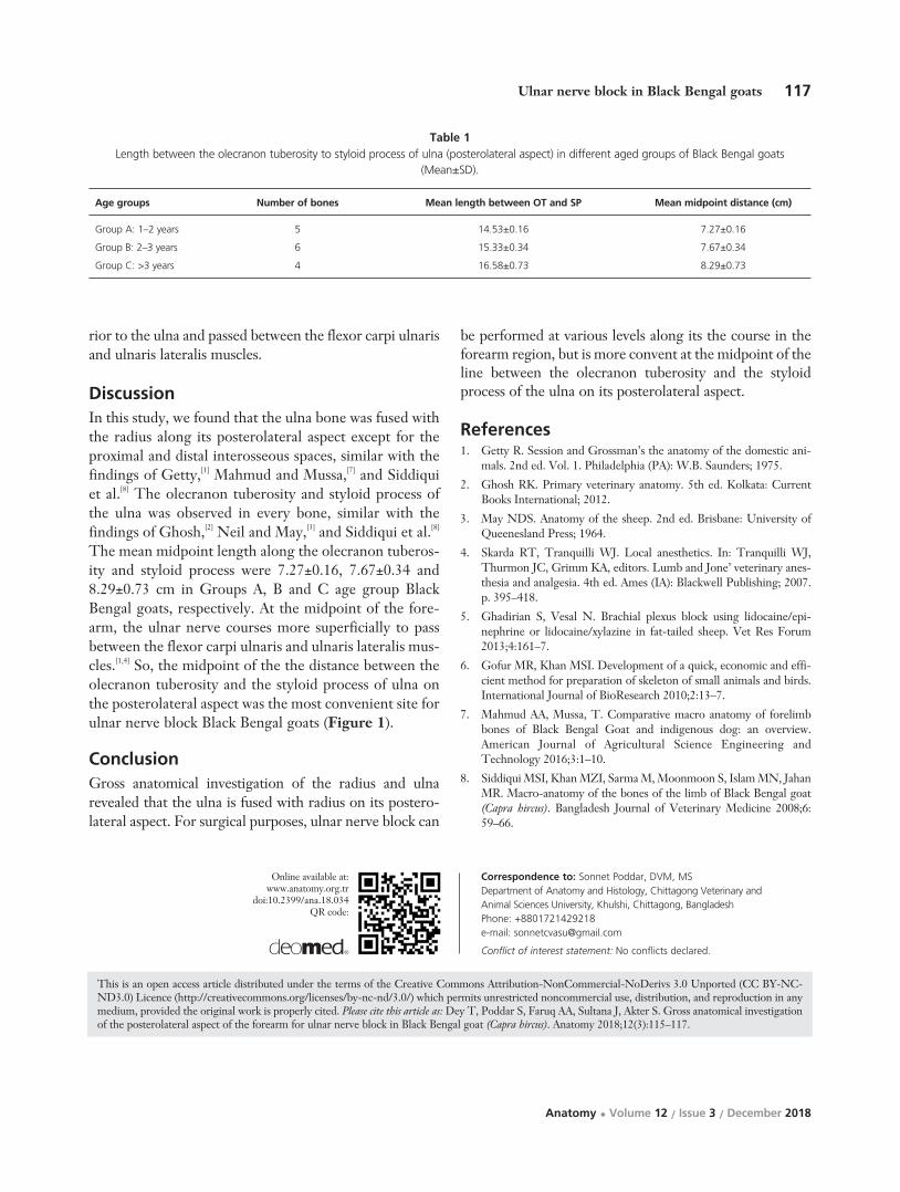
ResultsThe body of thw radius bone was flattened craniocaudal-ly. The ulna was longer and fused with radius along itsposterolateral aspect, except at the proximal and distalinterosseous spaces (Figure 1). Proximal end of the ulnawas expanded with a rough prominence called the olecra-non tuberosity. On the distal end, there was a pointed pro-jection named the styloid process of the ulna. The meanmidpoint on the line between the olecranon tuberosityand the styloid process were 7.27±0.16, 7.67±0.34 and8.29±0.73 cm in Groups A, B and C, respectively (Table1). At the forearm region, the ulnar nerve coursed poste-
116 Dey T et al.
Anatomy • Volume 12 / Issue 3 / December 2018
Figure 1. Radius and ulna bones, and the midpoint on the line between the olecranon tuberosity and the styloid process for ulnar nerve block.a: radius; b: ulna; c: olecranon tuberosity; d: styloid process; e: proximal interosseous space; f: distal interosseous space; g: total length alongolecranon tuberosity to styloid process; h: midpoint on the line between the olecranon tuberosity and the styloid process. [Color figure can beviewed in the online issue, which is available at www.anatomy.org.tr]
rior to the ulna and passed between the flexor carpi ulnarisand ulnaris lateralis muscles.
Discussion In this study, we found that the ulna bone was fused withthe radius along its posterolateral aspect except for theproximal and distal interosseous spaces, similar with thefindings of Getty,[1] Mahmud and Mussa,[7] and Siddiquiet al.[8] The olecranon tuberosity and styloid process ofthe ulna was observed in every bone, similar with thefindings of Ghosh,[2] Neil and May,[3] and Siddiqui et al.[8]
The mean midpoint length along the olecranon tuberos-ity and styloid process were 7.27±0.16, 7.67±0.34 and8.29±0.73 cm in Groups A, B and C age group BlackBengal goats, respectively. At the midpoint of the fore-arm, the ulnar nerve courses more superficially to passbetween the flexor carpi ulnaris and ulnaris lateralis mus-cles.[1,4] So, the midpoint of the the distance between theolecranon tuberosity and the styloid process of ulna onthe posterolateral aspect was the most convenient site forulnar nerve block Black Bengal goats (Figure 1).
ConclusionGross anatomical investigation of the radius and ulnarevealed that the ulna is fused with radius on its postero-lateral aspect. For surgical purposes, ulnar nerve block can
be performed at various levels along its the course in theforearm region, but is more convent at the midpoint of theline between the olecranon tuberosity and the styloidprocess of the ulna on its posterolateral aspect.
References1. Getty R. Session and Grossman’s the anatomy of the domestic ani-
mals. 2nd ed. Vol. 1. Philadelphia (PA): W.B. Saunders; 1975.
2. Ghosh RK. Primary veterinary anatomy. 5th ed. Kolkata: CurrentBooks International; 2012.
3. May NDS. Anatomy of the sheep. 2nd ed. Brisbane: University ofQueenesland Press; 1964.
4. Skarda RT, Tranquilli WJ. Local anesthetics. In: Tranquilli WJ,Thurmon JC, Grimm KA, editors. Lumb and Jone’ veterinary anes-thesia and analgesia. 4th ed. Ames (IA): Blackwell Publishing; 2007.p. 395–418.
5. Ghadirian S, Vesal N. Brachial plexus block using lidocaine/epi-nephrine or lidocaine/xylazine in fat-tailed sheep. Vet Res Forum2013;4:161–7.
6. Gofur MR, Khan MSI. Development of a quick, economic and effi-cient method for preparation of skeleton of small animals and birds.International Journal of BioResearch 2010;2:13–7.
7. Mahmud AA, Mussa, T. Comparative macro anatomy of forelimbbones of Black Bengal Goat and indigenous dog: an overview.American Journal of Agricultural Science Engineering andTechnology 2016;3:1–10.
8. Siddiqui MSI, Khan MZI, Sarma M, Moonmoon S, Islam MN, JahanMR. Macro-anatomy of the bones of the limb of Black Bengal goat(Capra hircus). Bangladesh Journal of Veterinary Medicine 2008;6:59–66.
117Ulnar nerve block in Black Bengal goats
Anatomy • Volume 12 / Issue 3 / December 2018
Correspondence to: Sonnet Poddar, DVM, MS Department of Anatomy and Histology, Chittagong Veterinary and Animal Sciences University, Khulshi, Chittagong, BangladeshPhone: +8801721429218e-mail: [email protected]
Conflict of interest statement: No conflicts declared.
This is an open access article distributed under the terms of the Creative Commons Attribution-NonCommercial-NoDerivs 3.0 Unported (CC BY-NC-ND3.0) Licence (http://creativecommons.org/licenses/by-nc-nd/3.0/) which permits unrestricted noncommercial use, distribution, and reproduction in anymedium, provided the original work is properly cited. Please cite this article as: Dey T, Poddar S, Faruq AA, Sultana J, Akter S. Gross anatomical investigationof the posterolateral aspect of the forearm for ulnar nerve block in Black Bengal goat (Capra hircus). Anatomy 2018;12(3):115–117.
Online available at: www.anatomy.org.tr
doi:10.2399/ana.18.034QR code:
Age groups Number of bones Mean length between OT and SP Mean midpoint distance (cm)
Group A: 1–2 years 5 14.53±0.16 7.27±0.16
Group B: 2–3 years 6 15.33±0.34 7.67±0.34
Group C: >3 years 4 16.58±0.73 8.29±0.73
Table 1Length between the olecranon tuberosity to styloid process of ulna (posterolateral aspect) in different aged groups of Black Bengal goats
(Mean±SD).

IntroductionIron overload is a common clinical problem that occursin conditions such as hereditary hemochromatosis andtransfusion dependent anaemia including sickle cell dis-ease and beta thalassemia.[1,2] Since the liver is the mainstorage site for iron, it is among the key organs to beadversely affected by iron overload toxicity resulting inhepatic fibrosis and hepatocellular necrosis.[3,4]
Currently, management of iron overload involvesiron chelation therapy and phlebotomy. These modali-ties however, have several limitations including highcost, patient incompliance and numerous associated sideeffects.[5–7] Furthermore, phlebotomy is contraindicatedin anaemic patients.[8] Thus, there is need for betteravenues to augment the management of iron overload.
Alpha-lipoic acid (ALA) is a widely available cheapbut potent antioxidant. It has lately been in use in themanagement of diabetic polyneuropathies where it scav-enges reactive oxygen species (ROS) produced as a resultof glucose auto-oxidation induced by hyperglycemia.[9] Afew studies have documented the possible iron chelatingproperties of ALA. For instance, Goralska et al.[10]
showed that treating isolated cultured lens epithelial cellswith ALA significantly lowered the size of the free intra-cellular iron. In another study by Suh et al.,[11] feedingALA to aged rats for 2 weeks showed a reversal of theage-related accumulation of iron in the cerebral cortex.However, these studies were conducted under conditionsof normal body iron levels. Hitherto, there are hardlyany studies that have investigated the effects of ALA onthe liver following iron overload. This study therefore
Alpha-lipoic acid attenuates iron overload-induced structural changes in the liver of thelaboratory mouse (Mus musculus)
William O. Sibuor, Fidel O. Gwala, Jeremiah K. Munguti, Moses M. Obimbo
Department of Human Anatomy, School of Medicine, University of Nairobi, Nairobi, Kenya
Abstract
Objectives: The role of alpha-lipoic acid in the amelioration of iron overload-induced hepatic damage remains largely under-explored. Therefore, this paper aimed at describing the structural effects of alpha-lipoic acid on the liver following iron over-load in mice.
Methods: After ethical approval, a total of 24 male mice were used. Twenty mice were randomly divided into two groups:A and B. Group A rats received 50 mg/kg of iron dextran intraperitoneally daily for 49 days, while those in Group B receiveda daily oral dose of 100 mg/kg alpha-lipoic acid by gavage in addition to the treatment in Group A. Four mice were used asnormal controls. At the endpoint of the experiment, the livers were harvested and studied for iron deposition, parenchymalhistoarchitecture and hepatocyte densities. Photomicrographs were taken using a digital photomicroscope for morphomet-ric analysis.
Results: Treatment of mice with iron led to a distortion of the histoarchitecture of the liver which was attenuated with co-admin-istration of alpha-lipoic acid. Additionally, co-treatment of iron with alpha-lipoic acid resulted in significant lowering of hepaticiron deposition (p<0.001), reduction in leukocyte infiltration and significantly greater hepatocyte densities (p<0.001).
Conclusion: Alpha-lipoic acid considerably attenuates the structural damage in the liver induced by iron overload.
Keywords: alpha-lipoic acid; iron; liver
Anatomy 2018;12(3):118–123 ©2018 Turkish Society of Anatomy and Clinical Anatomy (TSACA)
Original Articlewww.anatomy.org.tr
Received: October 20, 2018; Accepted: November 24, 2018doi:10.2399/ana.18.074

119Alpha-lipoic acid reduces iron overload-induced structural changes in the liver
Anatomy • Volume 12 / Issue 3 / December 2018
aimed to describe the structural effects of ALA on theliver of the mouse following iron overload.
Materials and MethodsALA was supplied by Nature’s Bounty, Inc. (Bohemia,NY, USA) while iron dextran (Dawafer) was supplied byChongqing Fangtong for Dawa Limited (Kenya). Theinjections were administered using 30 gauge (BD Micro-FineTM Plus; Becton Dickinson and Co., Franklin Lakes,NJ, USA) insulin syringes and a gavage tube for mice wasused for oral drug administration.
A total of 24 male 8 week old mice (Mus musculus)were purchased from The Department of Zoology,University of Nairobi, Kenya. Ethical approval to con-duct the study was obtained from the Animal Use andEthics Committee, Faculty of Veterinary Medicine,University of Nairobi, Kenya. The handling and care ofthe animals were in accordance with the guidelines pro-vided by the same committee.
Four mice were randomly selected for use as normalcontrols. One of the 4 mice selected as controls was usedto show the baseline histomorphology of the liver. Theremaining 20 mice were then randomly divided into twoequal groups: A and B. Group A received a daily intraperi-toneal (i.p.) injection of 50 mg/kg/day of iron dextran fol-lowed by daily oral gavage of 0.3 ml of normal saline, whileGroup B received a daily i.p. injection of 50 mg/kg/dayiron dextran followed by daily oral gavage of 100mg/kg/day of ALA. The normal control mice were givena daily i.p. normal saline (30 μl) followed by daily oral gav-age of 0.3 ml normal saline. The dose of iron dextran usedwas based on the study by Zhang et al.,[12] while that of ALAwas based on the studies by Budin et al.[13] and Ahmadvandand Jamor.[14] Three mice from each group were sacrificedat day 16 and 32 of the experiment while the remaining 4in each group were sacrificed at day 49.
The livers were harvested en masse and stored in 10%formalin. Independent uniform random sampling, asdescribed by Marcos et al.,[15] was used to select 5 randomfragments from each liver for histological processing andstaining with haematoxylin and eosin.
Photomicrographs of the stained sections were takenusing a 12 mega pixel Canon camera mounted on a pho-tomicroscope.
Estimation of iron deposition was done using theCavalieri principle of point counting[16] and data expressedas volumetric densities (%). Following the techniquedescribed by Gundersen et al.[17] and Bancroft and Cook,[18]
the selected histological areas were analysed using a super-imposed 80-point grid on the digital images on a monitorscreen using ImageJ software (National Institutes ofHealth, Bethesda, MD, USA) (Figure 1).
Hepatocyte density estimation was done using theCavalieri’s principle of point counting.[16] Using theImage J software, grid squares were superimposed on theimages then the cells within a square and those crossedby the inclusion line were counted (Figure 2).
Quantitative data on volumetric densities of irondeposits and hepatocyte densities was entered into theStatistical Package for Social Sciences (SPSS forWindows, version 21.0; SPSS Inc., Chicago, IL, USA)for analysis. Cell densities were expressed in mm2 whileiron deposition was expressed as a percentage. Kruskal-Wallis H test was used to compare medians of the quan-titative data across the various harvesting periods withineach group while Mann-Whitney U test was used tocompare the medians between Group A and B. A p value≤0.05 was considered significant at 95% confidenceinterval. Data are presented in photomicrographs andgraphs.
ResultsIron treatment resulted in a progressive increase in thevolumetric densities of the iron deposits from 6.4% at day16 to 12.03% and 27.26% at days 32 and 49, respectively(p<0.001). Co-administration of iron with ALA resulted in
Figure 1. The point counting method to estimate the volumetric densi-ty of the iron deposits. The volume densities of the iron deposits werecalculated by the formula Vv = Pp/Pt, where Vv is the volume density, pis the component under consideration (iron deposits), Pp is the numberof test points associated with p, and Pt is the total number of points ofthe test system. [Color figure can be viewed in the online issue, which isavailable at www.anatomy.org.tr]

120 Sibuor WO et al.
Anatomy • Volume 12 / Issue 3 / December 2018
significantly lower volumetric densities across all the har-vesting periods (p<0.001). The percentages in the ALAgroup were 3.76%, 7.52% and 15.79% at day 16, 32 and49, respectively (Figure 3).
Iron treatment resulted in distortion of the normalhepatic histoarchitecture proportional to the duration oftreatment. There was marked degeneration of hepatocyteswith distortion of the hepatocyte cords. The nuclei ofhepatocytes were enlarged and showed fragmented nucle-oli. There was also infiltration of deeply basophilic leuko-cytes around several clusters of large iron deposits.
ALA co-administration resulted in a reduction of themagnitude of the iron overload induced histoarchitecturalchanges as evidenced by the reduction in the sizes and areaof the iron deposits. The cord like arrangement of thehepatocytes was also preserved with discernible bound-aries between cells in adjacent cords. The nuclei of hepa-tocytes showed less enlargement and fragmentation. Theleukocyte infiltrates were also reduced (Figure 4 a–f).
Iron treatment resulted in a progressive decline in thehepatocyte densities from 1433.33/mm2 at day 16 to1383.33 and 689.89/mm2 at day 32 and 49 respectively(p<0.001). Time matched mice treated with iron andALA showed higher hepatocyte densities compared withthe mice treated with iron alone (p<0.001). The densitiesfor the mice treated with iron and ALA were 1572.22,1583.33 and 1055.56/mm2 at day 16, 32 and 49 respec-tively (Figure 5).
Discussion ALA reduced the hepatic iron deposition in a mannersimilar to previous studies using related compounds. Forinstance, Gao et al.[19] reported a reduction in iron depo-sition on the mouse liver using danshen, an antioxidantcompound. The reduction in iron deposition with ALAtreatment could be attributed to its iron chelating prop-erties.[20] This is a similar mechanism to that of deferox-amine and deferipone, known iron chelators that havebeen shown to reduce hepatic iron deposition in miceliver following iron overload.[21] The dithiolane ring inthe chemical structure of ALA confers its ability to bindredox active elements such as iron.[20,22] Since generationof ROS directly correlates with the concentration of freeintracellular iron,[23] administration of ALA to iron over-load patients could help chelate this free intracellulariron and thus reduce ROS generation and hepatic dam-age.
ALA treatment, as with other interventions reportedelsewhere, resulted in a reduction in the parenchymal
damage seen with iron overload. Hazra et al.[24] notedthat a flavonoid compound, Katha, was protectiveagainst iron overload induced liver damage, while Sarkaret al.[25] studied the effects of Emblica officinalis, an antiox-idant, on the mouse liver following iron overload, andalso noted an improvement in the histoarchitecture com-pared with iron treatment alone. The reduction inparenchymal damage may be attributed to the antioxi-dant capacity of ALA which makes it able to scavengeROS produced during iron overload.[26] Systemic ALAhas been shown to be protective against light inducedoxidative retinal damage, supporting its protective effectsagainst oxidative damage.[27] This is further supported by
Figure 2. The grids used in the determination of hepatocyte densities.The unit area for each grid square was 0.0018 mm2. Every secondsquare on the grid was selected for cell counting and a total of 12 gridsquares per field were considered. The average cellular count/mm2 ofthe 12 unit areas was then used as the cell density. [Color figure can beviewed in the online issue, which is available at www.anatomy.org.tr]
Figure 3. Line graph showing the volumetric densities of the irondeposits in the mouse liver tissue.

121Alpha-lipoic acid reduces iron overload-induced structural changes in the liver
Anatomy • Volume 12 / Issue 3 / December 2018
Figure 4. (a–f) Figure showing the histo-morphological changes in the livers of the control and experimental mice; (a, b) Liver of a normal con-trol mouse; (c, d) Liver of a mouse treated with iron dextran for 49 days; (e, f) liver of a mouse treated with iron and ALA for 49 days. BD: bileduct; CV: central vein; I: iron deposits; S: sinusoids; arrows: hepatocyte nuclei; arrowheads: leukocyte infiltrates. Scale bar=150 μm. [Color fig-ure can be viewed in the online issue, which is available at www.anatomy.org.tr]
a b
c d
e f

122 Sibuor WO et al.
Anatomy • Volume 12 / Issue 3 / December 2018
the works of Rezk and Abdel-Rahman,[28] who foundALA to be protective against lead and gamma-irradiationinduced oxidative damage to the lungs and kidneys ofalbino rats. Additionally, it is postulated that ALA hasthe ability to regenerate other endogenous antioxidantssuch as Vitamin C, E and glutathione.[29–31] For instance,biosynthesis of glutathione requires cysteine, an aminoacid which is enhanced by ALA through the accelerationof the conversion of cystine to cysteine.[30]
Previous studies have shown that iron overloadinduced hepatocellular damage causes hepatic dysfunctionwhich is alleviated by application of deferoxamine, an ironchelator.[19,32] Due to its potential iron chelating and antiox-idant property, ALA could therefore be used to preventhepatic cellular damage and subsequent dysfunction iniron overload conditions.
ConclusionALA considerably attenuates the structural damage inthe liver induced by iron overload. We recommend fur-ther clinical studies to investigate the possible utility ofALA in the management of iron overload patients.
References1. Hentze MW, Muckenthaler MU, Galy B, Camaschella C. Two to
tango: regulation of mammalian iron metabolism. Cell 2010;142:24–38.
2. Siddique A, Kowdley KV. Review article: the iron overload syn-dromes. Aliment Pharmacol Ther 2012;35:876–93.
3. Kohgo Y, Ikuta K, Ohtake T, Torimoto Y, Kato J. Body iron metab-olism and pathophysiology of iron overload. Int J Hematol2008;88:7–15.
4. Hershko C. Iron chelation therapy. New York (NY): Springer; 2012.28–36.
5. Sheth S. Iron chelation: an update. Curr Opin Hematol 2014;21:179–85.
6. Brissot P. Optimizing the diagnosis and the treatment of iron over-load diseases. Expert Rev Gastroenterol Hepatol 2016;10:359–70.
7. Mobarra N, Shanaki M, Ehteram H, Nasiri H, Sahmani M, SaeidiM, Goudarzi M, Pourkarim H, Azad M. A review on iron chelatorsin treatment of iron overload syndromes Int J Hematol Oncol StemCell Res 2016;10:239–47.
8. Assi TB, Baz E. Current applications of therapeutic phlebotomy.Blood Transfus 2014;12:75–83.
9. Ziegler D, Nowak H, Kempler P, Vargha P, Low PA. Treatment ofsymptomatic diabetic polyneuropathy with the antioxidant alpha-lipoic acid: a meta analysis. Diabet Med 2004;21:114–21.
10. Goralska M, Dackor R, Holley B, McGahan MC. Alpha lipoic acidchanges iron uptake and storage in lens epithelial cells. Exp Eye Res2003;76:241–8.
11. Suh JH, Moreau R, Heath SH, Hagen TM. Dietary supplementa-tion with (R)-α-lipoic acid reverses the age-related accumulation ofiron and depletion of antioxidants in the rat cerebral cortex. RedoxRep 2005;10:52–60.
12. Zhang Y, Zhang Y, Xie Y, Gao Y, Ma J, Yuan J, Li J, Wang J, Li L,Zhang J, Chu L. Multitargeted inhibition of hepatic fibrosis in chron-ic iron-overloaded mice by Salvia miltiorrhiza. J Ethnopharmacol2013;148:671–81.
13. Budin SB, Othman F, Louis SR, Bakar MA, Radzi M, Osman K, DasS, Mohamed J. Effect of alpha lipoic acid on oxidative stress and vas-cular wall of diabetic rats. Rom J Morphol Embryol 2009;50:23–30.
14. Ahmadvand H, Jamor P. Effects of alpha lipoic acid on level of NOand MPO activity in diabetic rats. Annals of Research in Antioxidants2017;2:4–7.
15. Marcos R, Monteiro RA, Rocha E. The use of design-based stereol-ogy to evaluate volumes and numbers in the liver: a review with prac-tical guidelines. J Anat 2012;220:303–17.
16. Mandarim-de-Lacerda CA. Stereological tools in biomedicalresearch. An Acad Bras Cienc 2003;75:469–86.
17. Gundersen HJ, Bagger P, Bendtsen TF, Evans SM, Korbo LX,Marcussen N, Møller A, Nielsen K, Nyengaard JR, Pakkenberg B,Sørensen FB. The new stereological tools: disector, fractionator,nucleator and point sampled intercepts and their use in pathologicalresearch and diagnosis. APMIS 1988;96:857–81.
18. Bancroft JD, Cook HC. Manual of histological techniques and theirdiagnostic application. London (UK): Churchill Livingstone; 1994.p. 35–67.
19. Gao Y, Wang N, Zhang Y, Ma Z, Guan P, Ma J, Zhang Y, ZhangX, Wang J, Zhang J, Chu L. Mechanism of protective effects of dan-shen against iron overload-induced injury in mice. J Ethnopharmacol2013;145:254–60.
20. Shay KP, Moreau RF, Smith EJ, Smith AR, Hagen TM. Alpha-lipoic acid as a dietary supplement: molecular mechanisms and ther-apeutic potential. Biochim Biophys Acta 2009;1790:1149–60.
21. Yatmark P, Morales NP, Chaisri U, Wichaiyo S, Hemstapat W,Srichairatanakool S, Svasti S, Fucharoen S. Iron distribution andhistopathological characterization of the liver and heart of β-tha-lassemic mice with parenteral iron overload: effects of deferoxamineand deferiprone. Exp Toxicol Pathol 2014;66:333–43.
22. Altintoprak N, Aydin S, Sanli A, Bilmez ZE, Kösemihal E. The pro-tective effect of intratympanic alpha lipoic acid on cisplatin-inducedototoxicity on rats. J Int Adv Otol 2014;10:217–21.
23. Fernandes MS, Rissi TT, Zuravski L, Mezzomo J, Vargas CR,Folmer V, Soares FA, Manfredini V, Ahmed M, Puntel RL.Oxidative stress and labile plasmatic iron in anemic patients follow-ing blood therapy. World J Exp Med 2014;4:38-45.
Figure 5. Line graph depicting the changes in hepatocyte densities inthe mouse liver tissue.

123Alpha-lipoic acid reduces iron overload-induced structural changes in the liver
Anatomy • Volume 12 / Issue 3 / December 2018
24. Hazra B, Sarkar R, Ghate NB, Chaudhuri D, Mandal N. Study ofthe protective effects of Katha (heartwood extract of Acacia catechu)in liver damage induced by iron overload. J Environ Pathol ToxicolOncol 2013;32:229–40.
25. Sarkar R, Hazra B, Mandal N. Amelioration of iron overload-induced liver toxicity by a potent antioxidant and iron chelator,Emblica officinalis Gaertn. Toxicol Ind Health 2015;31:656–69.
26. Al-Attar AM. Physiological and Histopathological Investigations onthe Effects of α-Lipoic Acid in Rats Exposed to Malathion. BioMedRes Int 2010;2010:203503
27. Zhao L, Wang C, Song D, Li Y, Song Y, Su G, Dunaief JL. Systemicadministration of the antioxidant/iron chelator α-lipoic acid protectsagainst light-induced photoreceptor degeneration in the mouse reti-na. Invest Ophthalmol Vis Sci 2014;55:5979–88.
28. Rezk RG, Abdel-Rahman NA. Protective effects of lipoic acidagainst oxidative stress induced by lead acetate and gamma-irradia-
tion in the kidney and lung in albino rats. Arab Journal of NuclearSciences and Applications 2013;46:324–37.
29. Biewenga GP, Haenen GR, Bast A. The pharmacology of the antiox-idant lipoic acid. Gen Pharmacol 1997;29:315–31.
30. Suh JH, Wang H, Liu RM, Liu J, Hagen TM. (R)-α-Lipoic acidreverses the age-related loss in GSH redox status in post-mitotic tis-sues: evidence for increased cysteine requirement for GSH synthesis.Arch Biochem Biophys 2004;423:126–35.
31. Zhang J, Zhou X, Wu W, Wang J, Xie H, Wu Z. Regeneration ofglutathione by ·-lipoic acid via Nrf2/ARE signaling pathway allevi-ates cadmium-induced HepG2 cell toxicity. Environ ToxicolPharmacol 2017;51:30–7.
32. Liu D, He H, Yin D, Que A, Tang L, Liao Z, Huang Q, He M.Mechanism of chronic dietary iron overload-induced liver damage inmice. Mol Med Rep 2013;7:1173–9.
Correspondence to: William O. Sibuor Department of Human Anatomy, School of Medicine, University of Nairobi, Nairobi, KenyaPhone: +254 02 318262e-mail: [email protected]
Conflict of interest statement: No conflicts declared.
This is an open access article distributed under the terms of the Creative Commons Attribution-NonCommercial-NoDerivs 3.0 Unported (CC BY-NC-ND3.0) Licence (http://creativecommons.org/licenses/by-nc-nd/3.0/) which permits unrestricted noncommercial use, distribution, and reproduction in anymedium, provided the original work is properly cited. Please cite this article as: Sibuor WO, Gwala FO, Munguti JK, Obimbo MM. Alpha-lipoic acid attenu-ates iron overload-induced structural changes in the liver of the laboratory mouse (Mus musculus). Anatomy 2018;12(3):118–123.
Online available at: www.anatomy.org.tr
doi:10.2399/ana.18.074QR code:

IntroductionThe shoulder joint is the most mobile joint in the body.This movement is mainly due to the anatomy of thehumerus head and the glenoid. The glenohumeral jointis the most frequently dislocated joint.[1] Anterior dislo-cation is most commonly observed, and there is a highrisk of recurrence.[2] The shoulder has a tendency to dis-locate after trauma, experienced generally in abductionand external rotation positions. The recurring disloca-tion rates reduce after arthroscopic treatment, but thissituation is still a problem.[2] Maintenance of the gleno-humeral joint association is linked to the dynamic andstatic stabilizers of the shoulder. The roles of capsulo-ligamentous structures and dynamic muscle balance inshoulder stability is well-defined in the literature.[3]
However, there are very few studies on the importanceof glenopolar angle (GPA).
GPA is the angle formed by the intersection of the linejoining the most caudal and most cranial points of the gle-noid cavity and the line joining the most cranial point ofthe glenoid cavity to the most caudal point of the scapula
body.[4,5] GPA is normally used to measure rotationalsequence disorders of the glenoid in scapula fractures onanteroposterior radiographs.[6] In this study, GPA wasinvestigated on direct radiographs of anterior shoulder dis-location cases for the first time with an aim to assess theglenoid with GPA measurements in cases with anteriorshoulder dislocation.
Materials and MethodsThe study included a total of 140 adult patients admittedto Department of Orthopaedics and Traumatology,School of Medicine, Cumhuriyet University from 2013to 2015. 70 patients were with anterior shoulder disloca-tion, and the remaining 70 had shoulder pain, but no dis-location or any other shoulder pathology during exami-nations. Patient information was retrospectively investi-gated. The age, side, gender and demographic informa-tion of patients were noted.
The same senior orthopedic surgeon and the same res-ident examined all AP shoulder radiographs. Radiographsof Group 1 patients were taken after reduction of shoulder
Scapular glenopolar angle in anterior shoulderdislocation cases
Özhan Pazarc›, Naz›m Aytekin, Seyran K›l›nç, Hayati Öztürk
Department of Orthopaedics and Traumatology, School of Medicine, Cumhuriyet University, Sivas, Turkey
Abstract
Objectives: The aim of this study was to assess the glenoid with glenopolar angle measurements in cases with anteriorshoulder dislocation and controls.
Methods: The glenopolar angle was measured retrospectively on direct radiographs of patients with shoulder dislocation (n=60),and a control group (n=42).
Results: The glenopolar angle of patients with anterior shoulder dislocation showed an anatomical difference, being signif-icantly lower in anterior shoulder dislocation cases compared to the control group; 32.31±2.01 and 34.5±2.32, respective-ly (p<0.001).
Conclusion: The glenopolar angle, and thus the glenoid alignment is a possible risk factor and should be considered dur-ing assessment and management of these cases.
Keywords: glenoid; glenopolar angle; shoulder dislocation
Anatomy 2018;12(3):124–127 ©2018 Turkish Society of Anatomy and Clinical Anatomy (TSACA)
Original Articlewww.anatomy.org.tr
Received: October 28, 2018; Accepted: December 5, 2018doi:10.2399/ana.18.075

125Scapular glenopolar angle in anterior shoulder dislocation cases
Anatomy • Volume 12 / Issue 3 / December 2018
dislocation. Patients with true shoulder AP view wereincluded in the evaluation, and radiographs of bad posi-tioning and rotation were excluded from the study.Additionally, patients with insufficient file informationwere excluded. Group 1 comprised 60 and Group 2 com-prised 42 cases for GPA measurements (Table 1). GPAmeasurements were made using the hospital PACS system(Medipacs® v3.8.5.1). In the system, the angle between theline from the most caudal to the most cranial points of theglenoid cavity and the line from the most cranial point ofthe glenoid cavity to the most caudal point of the scapulabody were calculated on true AP shoulder radiographs(Figure 1).
The study was approved by the ethics committee ofthe School of Medicine of Cumhuriyet University.Analysis of data was made using the Statistical Package forSocial Sciences (SPSS for Windows, version 22.0,Armonk, NY, USA). Data were given as percentage, fre-quency and the mean. The normality test of the GPA datawas examined using the Kolmogorov-Smirnov test. Thedistribution of the variable was calculated to be normal(p=0.2). Mean differences of GPA values were examinedby Student’s t-test. The mean difference between groupswas investigated using Mann-Whitney U test. The nor-mality test for age was not appropriate (p=0.007).
ResultsThe results from a total of 102 patients were assessed. Themean age of 60 patients in Group 1 was 45.68 years (min:18, max: 85). The mean age of 42 patients in Group 2 was47.57 years (min: 18, max: 83). There was no significantdifference between age groups (p=0.754). The mean fol-low-up duration for Group 1 patients was 23.46 months.Six patients had accompanying shoulder injuries, includingthree patients with rotator cuff injury, two patients with
Figure 1. (a) Glenopolar angle (GPA) measurement of the angle between the line joining the most caudal and most cranial points of the glenoidcavity and the line from the most cranial point of the glenoid cavity to the most caudal point of the scapula body in a Group 2 patient; (b) GPAmeasurement in a Group 1 patient.
a b
Category n %
Groups Group 1 60 58.8
Group 2 42 41.2
Side Right 55 53.9
Left 47 46.1
Gender Male 56 54.9
Female 46 45.1
Accompanying shoulder injury No 54 90
Yes 6 10
Table 1The distribution of groups, gender, sides and accompanying
shoulder injuries.

126 Pazarc› Ö et al.
Anatomy • Volume 12 / Issue 3 / December 2018
fracture of the greater tubercle of the humerus, and onepatient with proximal humerus fracture. These injuries didnot involve the glenoid and, therefore, these six patientswere not excluded from the study.
The distribution of gender for patients was 34 malesand 26 females in Group 1, and 22 males and 20 females inGroup 2. Table 1 shows the distribution of groups, ageand sides.
The comparison of GPA by groups, gender and sides isshown in Table 2. The GPA in Group 1 was measured32.31±2.01, while it was 34.5±2.32 in Group 2 (p<0.001)(Figure 2). There was no significant difference betweenmales and females (p>0.05).
Discussion The most important finding in this study was that theGPA of patients with anterior shoulder dislocation wassignificantly low. To our knowledge, this is the first studyto investigate the change in GPA with direct radiographyin dislocation cases. Glenoid alignment should be consid-ered in anterior shoulder dislocation cases. Previous stud-ies reported glenoid corrective osteotomy was superior toconservative treatment for patients with posterior instabil-ity.[7] There is no data on the benefit of corrective osteoto-my for anterior stability in the literature. However, thereare studies showing a correlation between success rate ofprosthesis and stability with the position of the glenoidcomponent in total shoulder prosthesis.[8] A study compris-ing 128 patients with anterior shoulder instability and acontrol group of 130 cases investigated the glenoid versionand inclination. They concluded that glenoid alignmentwas a risk factor for anterior shoulder instability andemphasized that care must be taken related to this forrecurrent instability treatment.[9] These studies empha-sized the effect of glenoid anatomy on shoulder stability.According to our results, GPA measurements on directradiographs of anterior shoulder dislocation cases will pro-vide rapid information for assessment of glenoid anatomyto orthopedists.
GPA was first described by Bestard et al.,[4] The use ofthis angle to assess scapula neck fractures.[10] and latergained popularity as a surgical treatment criterion forscapula neck and body fractures.[11,12]
There is no consensus for the optimal radiologicaltechnique to measure GPA or the standard values of GPAin the literature.[13] GPA can be measured directly oncadaver specimens, 3D scapula reconstructions, Neer viewX-ray images, AP shoulder or AP chest radiographs.[13] Inthis study, GPA measurement was performed on true(Grashey) AP shoulder radiographs. In the literature,there are studies with measurements made on different
imaging views.[14,15] The GPA angle value changes depend-ing on the measurement method. Of these, 3D CT recon-struction, Neer 1 images and cadaver bone specimens pro-vide similar results. AP shoulder and chest radiographsprovide lower values compared to these measurements.[14]
There are other studies in the literature that assessedglenoid anatomy. For example, Peter et al.[16] investigatedthe correlation between glenoid inclination and rotatorcuff tears.[16] Gregory et al.[17] investigated the correlationbetween greater tuberosity angle and rotator cuff tears.Maximilian et al.[18] emphasized the importance of glenoidmorphology in instability arthropathy. The above studiesemphasize the importance of glenoid anatomy similar toour study. Additionally, an advantage of our study is thatinformation on the glenoid was obtained with GPA meas-urements on direct radiographs, without advanced testslike MR or 3D CT. A difference of 2.5° was observedbetween the groups (Figure 2). This was statistically sig-nificant (p>0.05). GPA can easily be evaluated with X-ray
Figure 2. Box plot chart showing the means of GPAs.
Category n Mean±SD p-value
Groups Group 1 60 32.31±2.01<0.001
Group 2 42 34.5±2.32
Side Right 55 33.21±2.370.996
Left 47 33.21±2.44
Gender Male 56 33.15±2.170.769
Female 46 33.29±2.65
Table 2The comparison of GPA (mean±SD) by groups, gender and sides
using Student’s t-test.

127Scapular glenopolar angle in anterior shoulder dislocation cases
Anatomy • Volume 12 / Issue 3 / December 2018
in cases of shoulder dislocation. The clinical significanceof low GPA is that, this can give the orthopedic surgeon aquick idea about the glenoid.
This study has some limitations. Control group radi-ographs were chosen from patients admitted to the gener-al orthopedic clinic with shoulder pain. This sample maynot be representative of the normal healthy populationand may potentially be biased. However, only those withno pathology identified on radiography or examinationwere included in the control group. Although the GPAwas significantly different between the groups, it is diffi-cult to definitively determine whether our findings areclinically significant or not, because other factors mayaffect the risk of dislocation. Risk factors for patients withglenohumeral instability were described previously.[19]
GPA measurements provide information about the non-modifiable risk factor of glenoid morphology.
ConclusionThe GPA of patients with anterior shoulder dislocationwas significantly low compared to the control group,showing an anatomical difference for cases with anteriorshoulder dislocation. Should be considered in the assess-ment and management of these cases.
References1. Owens BD, Campbell SE, Cameron KL. Risk factors for anterior
glenohumeral instability. Am J Sports Med 2014;42:2591–6.
2. Peltz CD, Baumer TG, Mende V, Ramo N, Mehran N, MoutzourosV, Bey MJ. Effect of arthroscopic stabilization on in vivo gleno-humeral joint motion and clinical outcomes in patients with anteriorinstability. Am J Sports Med 2015;43:2800–8.
3. Lugo R, Kung P, Ma CB. Shoulder biomechanics. Eur J Radiol2008;68:16–24.
4. Bestard EA, Schvene HR, Bestard EH. Glenoplasty in managementof recurrent shoulder dislocation. Contemp Orthop 1986;12:47–55.
5. Tuček M, Naňka O, Malík J, Bartoníček J. The scapular glenopolarangle: standard values and side differences. Skeletal Radiol 2014;43:1583–7.
6. Wijdicks CA, Anavian J, Hill BW, Armitage BM, Vang S, Cole PA.The assessment of scapular radiographs: analysis of anteroposterior
radiographs of the shoulder and the effect of rotational offset on theglenopolar angle. Bone Joint J 2013;95–B:1114–20.
7. Lacheta L, Singh TSP, Hovsepian JM, Braun S, Imhoff AB,Pogorzelski J. Posterior open wedge glenoid osteotomy provides reli-able results in young patients with increased glenoid retroversion andposterior shoulder instability. Knee Surg Sports Traumatol Arthrosc2019;27:299–304.
8. Nyffeler RW, Sheikh R, Atkinson TS, Jacob HAC, Favre P, GerberC. Effects of glenoid component version on humeral head displace-ment and joint reaction forces: an experimental study. J ShoulderElbow Surg 2006;15:625–9.
9. Hohmann E, Tetsworth K. Glenoid version and inclination are riskfactors for anterior shoulder dislocation. J Shoulder Elbow Surg2015;24:1268–73.
10. Romero J, Schai O IA. Scapular neck fracture: the influence of per-manent malalignment of the glenoid neck on clinical outcome. ArchOrthop Trauma Surg 2001;121:313–6.
11. Cole PA, Hill BW. Scapula fracture. In: Obremskey WT, Sethi MK,Jahangir AA, editors. Orthopaedic traumatology: an evidence basedapproach. New York (NY): Springer; 2013. p. 71–86.
12. Bozkurt M, Can F, Kirdemir V, Erden Z, Demirkale I, BaflbozkurtM. Conservative treatment of scapular neck fracture: the effect ofstability and glenopolar angle on clinical outcome. Injury 2005;36:1176–81.
13. Tucek M, Nanka O, Malik J, Bartonicek J. The scapular glenopolarangle: standard values and side differences. Skeletal Radiol2014;43:1583–7.
14. Ohl X, Billuart F, Lagacé PY, Gagey O, Hagemeister N, Skalli W.3D morphometric analysis of 43 scapulae. Surg Radiol Anat2012;34:447–53.
15. Anavian J, Conflitti JM, Khanna G, Guthrie ST, Cole PA. A reliableradiographic measurement technique for extra-articular scapularfractures. Clin Orthop Relat Res 2011;469:3371–8.
16. Chalmers PN, Beck L, Granger E, Henninger H, Tashjian RZ.Superior glenoid inclination and rotator cuff tears. J Shoulder ElbowSurg 2018;27:1444–50.
17. Cunningham G, Nicodème-Paulin E, Smith MM, Holzer N, CassB, Young AA. The greater tuberosity angle: a new predictor for rota-tor cuff tear. J Shoulder Elbow Surg 2018;27:1415–21.
18. Haas M, Plachel F, Wierer G, Heuberer P, Hoffelner T, Schulz E,Anderl W, Moroder P. Glenoid morphology is associated with thedevelopment of instability arthropathy. J Shoulder Elbow Surg 2018;pii: S1058– 2746(18)30700–6. doi: 10.1016/j.jse.2018.09.010
19. Cameron KL, Mauntel TC, Owens BD. The epidemiology ofglenohumeral joint ›nstability: incidence, burden, and long-termconsequences. Sports Med Arthrosc Rev 2017;25:144–9.
Correspondence to: Özhan Pazarc›, MD Department of Orthopaedics and Traumatology, School of Medicine,Cumhuriyet University, 58140, Sivas, TurkeyPhone: +90 534 681 90 45e-mail: [email protected]
Conflict of interest statement: No conflicts declared.
This is an open access article distributed under the terms of the Creative Commons Attribution-NonCommercial-NoDerivs 3.0 Unported (CC BY-NC-ND3.0) Licence (http://creativecommons.org/licenses/by-nc-nd/3.0/) which permits unrestricted noncommercial use, distribution, and reproduction in anymedium, provided the original work is properly cited. Please cite this article as: Pazarc› Ö, Aytekin N, K›l›nç S, Öztürk H. Scapular glenopolar angle in ante-rior shoulder dislocation cases. Anatomy 2018;12(3):124–127.
Online available at: www.anatomy.org.tr
doi:10.2399/ana.18.075QR code:

IntroductionNeurological impairments are fast becoming commonglobal causes of disabilities.[1] Maulik et al.[2] observed thatprevalence of mental disabilities is higher in developingcountries compared to those in developed countries.Environmental factors, such as environmental pollution,can influence the prevalence of these mental disabilities.[2]
Poor health quality and high contamination level of heavymetals in developing countries may also contribute tothese prevalence rates.[3] In recent times, the continualheavy metal contamination in waterways has been a glob-al issue due to its persistence and resultant toxicity.[4,5] Poorwaste management and disposal, especially electronic
waste (e-waste) disposal and recycling in developing coun-tries were reported to enhance the elevated levels of heavymetal contamination in these regions.[3,6–8]
E-waste is defined as used electronics intended forreuse, resale, salvage, recycling, or disposal.[9] Osibanjo andNnorom[10] reported that electronic waste devices are usu-ally stored for a while for a perceived value - physical oremotional - before disposal with municipal waste inNigeria. Because of the absence of a special framework forthe separate collection and management of e-waste inNigeria, these devices are disposed with Municipal SolidWaste (MSW) at open dumpsites and/or into water-ways.[9–12] Informal disassembling and recycling of e-wastein backyards was also reported in Nigeria where primitive
Lead contamination induces neurodegenerationin prefrontal cortex of Wistar rats
Daniel Temidayo Adeniyi1, Peter Uwadiegwu Achukwu2
1Department of Medical Laboratory Science, School of Basic Medical Sciences, College of Pure and Applied Sciences, Kwara State University, Malete, Kwara State, Nigeria2Department of Medical Laboratory Science, Faculty of Health Science and Technology, College of Medicine, University of Nigeria, Enugu Campus, Enugu State, Nigeria
Abstract
Objectives: Neurodegenerative disorders have been associated with several environmental pollutants such as heavy metals.This study aimed at investigating the neurodegenerative impact of lead concentration obtained from the waterways in KwaraState, Nigeria on Wistar rats.
Methods: Twenty-first filial generation inbred adult male Wistar rats (Rattus norvegicus) with an average weight of 150–180 gwere divided into two groups of ten animals. The highest mean concentration of lead obtained from the waterways of the threegeographical zones of Kwara Nigeria was administered with water (0.009 mg of Pb(CH3CO2).3H2O per milliliter solution) to ratsin the treatment group ad libitum for 65 days. The harvested prefrontal cortex was processed for paraffin embedding and thesections were stained for haematoxylin and eosin stain and Bielschowsky’s silver impregnation stain, and glial fibrillary acidic pro-tein (GFAP) and inducible nitric oxide synthase (iNOS) immunohistochemistry.
Results: The histochemical stainings revealed shreds of evidence of neuronal degeneration in the treatment group compared tothe control group. Immunohistochemical analysis revealed marked astrocytosis, the hallmark of neuroinflammation, withinduced oxidative stress in the treatment group compared to the control group.
Conclusion: These results indicate lead obtained from the three geographical zones of Kwara Nigeria may have a possiblepathogenic role in development of neurodegenerative disorders and emphasize the effects of exposure to this environmen-tal pollutant.
Keywords: environmental pollutants; lead; neurodegenerative disorders; neuroinflammation; oxidative stress
Anatomy 2018;12(3):128–134 ©2018 Turkish Society of Anatomy and Clinical Anatomy (TSACA)
Original Articlewww.anatomy.org.tr
Received: November 3, 2018; Accepted: November 24, 2018doi:10.2399/ana.18.077

129Lead contamination induces neurodegeneration in prefrontal cortex of Wistar rats
Anatomy • Volume 12 / Issue 3 / December 2018
methods were used in recovering materials from e-waste.[13–15] The recovered materials are processed toreusable components and the unused portions are alsostockpiled or dumped and landfilled.[13,16] E-wastes containmore than a thousand different substances, of which manyare toxic, heavy metals inclusive.[17,18] These complex toxicsubstances, if not properly handled during recycling or dis-posal, adversely impact the environment.[13,19] Corrosion ofe-waste components after disposal result in mobility ofincorporated heavy metals which travel with leachate tocontaminate the environment.[20] Leaching of these toxicheavy metals eventually contaminates the ground and sur-face water.[6] The resultant effect is the high levels of heavymetals above the permissible limit recorded in Nigeriawaterways.[5,21,22]
Lead is a soft, ductile, flexible and malleable metal withhigh thermal expansion and electrical conductivity.[23]
Being the 5th most widely used metal,[24] it is toxic andfound in substantial amount in e-waste.[25] Lead is com-monly found in e-waste such as cathode ray tubes (CRTs)in computers monitors and televisions, fluorescent tubes,solder in printed circuit boards, as well as in liquid crystaldisplays (LCDs) and batteries.[11,26–29] In Nigeria, the popu-lation is at risk of lead exposure because of the intense useof leaded gasoline, the poor recovery and recycling ofautomotive lead-acid batteries, and the uncontrolled e-waste disposal and recycling.[30,31] Lead is not biodegrad-able. It stores faster in the human body than metabolizedor excreted, and hence tends to bio-accumulate in concen-trations above that found in the environment.[32] It is apotent neurotoxin that disrupts the functional integrity ofthe neurons with resultant negative implication on memo-ry and intelligence and cognitive deterioration.[23,33–35]
This study aimed at investigating the neurodegenera-tive impact of lead concentration obtained from the water-ways in Kwara State, Nigeria on Wistar rats as the experi-mental model.
Materials and MethodsThis study was carried out in Kwara State, Nigeria in2017. Experimental procedures used in this study wereapproved by the College of Medicine Research EthicsCommittee, University of Nigeria, Enugu State(approval number: 025/02/2017) in line with theNational Institute of Health (NIH) “Guide to the Careand Use of Animals in Research and Teaching”.
The lead (II) acetate trihydrate (Pb(CH3CO2).3H2O)salt used was obtained from the Department ofBiochemistry, College of Pure and Applied Science, KwaraState University, Malete, Kwara State, Nigeria. 0.009 g of
Pb(CH3CO2).3H2O was weighed and dissolved in 1 literof double distilled demineralized water to form 0.009 mgof Pb(CH3CO2).3H2O per liter to form the final concen-tration of 0.009 mg of Pb(CH3CO2).3H2O per millilitersolution. This was based on the empirical measurementof heavy metals obtained in the waterways of the KwaraNigeria in 2016 and reported by Adeniyi et al.[5]
Twenty (20) first filial (F1) generation inbred adultmale Wistar rats (Rattus norvegicus) with an averageweight of about 150–180 g were procured from the ani-mal facility of Institute for Advance Medical Researchand Training (IAMRAT), College of Medicine,University of Ibadan and employed in this study. Ratswere allowed to acclimatize for 14 days and fed pelletizedrat feed and water ad libitum throughout acclimatizationbefore use. Plastic cages containing wood shaving bed-ding were used to house the rats. The bedding waschanged once a day. They were kept in standard labora-tory conditions under natural light-dark cycle at roomtemperature and maintained on standard laboratory ratpellets and given water ad libitum. These rats were divid-ed at random into two groups of ten animals using themethod of Daniel et al.[36] The animals in the first grouphad access to diet and double distilled demineralizedwater ad libitum while those in the second group hadaccess to diet and lead-contaminated water ad libitum.The duration of treatment lasted over a period of 65days, a long-term standard for rats.[37] The animals weresacrificed by cervical dislocation. The skulls of the sacri-ficed animals were opened using bone forceps to exposethe brain. The skull was opened from the posterior partto leave the tissue intact.[38] The prefrontal cortex wasobtained from the anterior cerebral cortex. The harvest-ed tissues were fixed in 10% buffered formol saline,grossed and processed for paraffin tissue embedding fol-lowing Drury and Wellington[39] technique. The processedsections were stained for histological, histochemical andimmunohistochemical evaluation. Neuromorphologicaland histochemical analysis were carried out using haema-toxylin and eosin (H&E) staining technique[40] andBielschowsky’s silver impregnation technique,[41] respec-tively. Immunohistochemical evaluation was carried outusing glial fibrillary acidic protein (GFAP)[42,43] andinducible nitric oxide synthase (iNOS)[44] immunostain-ing techniques.
The stained sections were viewed and photographedwith an Olympus U-D03 microscope (Olympus, LakeSuccess, NY, USA) captured with Olympus DP21.Photomicrographs of stained sections were obtained andreported.

130 Adeniyi DT, Achukwu PU
Anatomy • Volume 12 / Issue 3 / December 2018
ResultsThere was no account of death recorded in the two groupsthroughout the 65 days of lead administration. The gener-al neuronal morphology of the prefrontal cortex in adultmale Wistar rats following administration with lead-con-taminated water demonstrated by haematoxylin and eosinstaining is shown in Figure 1. Sections from the prefrontalcortex of the control Wistar rats (Figure 1a) revealed intactand normal sized neurons with clear perikarya, centrallyplaced nucleus and small-sized neuroglia interspersed with-in normal neuropil stained slightly eosinophilic; whereassections from the prefrontal cortex from the treatmentgroup (Figure 1b) depicted numerous neurons with dis-torted morphology with different features of neurodegen-eration, which includes red neuron, shrunken neurons withkaryolitic nuclei, gliosis with focal neuropil vacuolationdegeneration.
The neuronal membrane was demonstrated usingBielschowsky’s silver impregnation stain (Figure 2). Thesection from the control group revealed normal neuronswith well-outlined neuronal membrane and axons sur-rounding a clear cytoplasm (Figure 2a). The treatmentgroup showed numerous neurons with various degenera-tive features characterized by pyknotic neurons with con-densed chromatin, nuclear shrinkage; with some neuronhaving no nuclei and neuropil vacuolation (Figure 2b).
Glial fibrillary acidic protein (GFAP) immunostainingwas used to demonstrate reactive glial immunoreactivity(Figure 3). The treatment groups showed strong astrocyt-
ic immunoreactivity (Figure 3b) compared with the con-trol group (Figure 3a). Inducible nitric oxide synthase(iNOS) immunostaining (Figure 4) was used for thedemonstration of oxidative stress. iNOS reactivity wasintensely expressed in the treatment groups (Figure 4b) incomparison to the control group (Figure 4a).
Discussion Several parameters were employed in this study to observethe morphology of the neurons in the prefrontal cortex ofrats following lead contaminated water consumption.Based on the higher functions of cognitive abilities associ-ated with prefrontal cortex of the brain,[45] the morpholo-gy of the neurons located in this region was investigated tocompare potential differences following lead exposure.
The results obtained with haematoxylin and eosinstaining method (Figure 1) showed features of neurode-generation in the treatment group (Figure 1b). Thedegeneration pattern of the neuron was apoptotic. Theseapoptotic neuronal cells are characterized by pyknoticnuclei involving irreversible condensation of chromatin inthe nucleus and shrinkage of the cells.[46,47] Changesobserved in neurons from the treatment group suggestedthat neuronal cell death occurred in the apoptotic mode.The excessive neuronal cell shrinkage is the result of thetightly packed cells that are smaller in size compared withthe control in accordance with the findings of Olajide etal.[48] Stefanis et al.[49] described neuronal apoptotic cellswith tightly packed with or without fragment which fur-ther supports our observation.
Figure 1. (a) Control group had intact neurons (red arrow), normal blood vessel (yellow arrow) in the neuropil area that stained slightly eosinophilic(blue arrow) and glial cells interspersed within this region (green arrow). (b) The cortical sections of rats from lead-contaminated group showedfeatures of neurodegeneration including red-colored neurons (red arrow), shrunken neurons with karyolysis nuclei (green arrows), gliosis (yellowarrow) and focal neuropil vacuolation (blue arrow) (×400 magnification, haematoxylin and eosin stain). [Color figure can be viewed in the onlineissue, which is available at www.anatomy.org.tr]
a b

131Lead contamination induces neurodegeneration in prefrontal cortex of Wistar rats
Anatomy • Volume 12 / Issue 3 / December 2018
The neuronal membrane and presence of neurodegen-erative features in the prefrontal cortex of the experimentalanimals throughout the 65 days of exposure are demonstrat-ed using Bielschowsky’s silver staining method as seen inFigure 2. Sections from the control group revealed normal
neurons with a well-outlined neuronal membrane (Figure2a). The treatment group showed neurons with differentdegenerative features (Figure 2b). The distinct morpholog-ical features observed in the treatment group also defineapoptotic neuronal cell death in pathological condition.[50]
Figure 2. (a) The control group appeared normal with intact neurons (red arrows). (b) Group with administration of water contaminated with leadshowed features of neurodegeneration in the cortex characterized by the presence of degenerate neurons with no nuclei (red arrows) and somewith pyknotic nuclei (blue arrows) (×400 magnification, Bielschowsky’s silver impregnation staining). [Color figure can be viewed in the onlineissue, which is available at www.anatomy.org.tr]
a b
Figure 3. (a) Control group showed mild astrocytic immunoreactivity with specific and uniform staining for glial fibrillary acidic protein (GFAP) (bluearrows). (b) Group with water contaminated with lead administration depicted strong GFAP immunoreactivity with numerous intensely stained astrocytes(blue arrows) (×400 magnification, GFAP immunostaining). [Color figure can be viewed in the online issue, which is available at www.anatomy.org.tr]
a b

132 Adeniyi DT, Achukwu PU
Anatomy • Volume 12 / Issue 3 / December 2018
Immunohistochemical expression of glial fibrillaryacidic protein (GFAP) (Figure 3) immunostainingrevealed GFAP-immunoreactive astroglia-like cells wereincreased in proportion, forming gliosis in the treatmentgroup when compared with the control. GFAP uniquelymarks for astrocytes which provide structural support andstrength to the surrounding neurons in the central nerv-ous system.[51,52] The immunoreactivity of GFAP increasedduring reactive gliosis characterized by astrocyte hyper-plasia and hypertrophy as observed in Figure 3b.[52]
Microglial and astrocytes are effectors of neuroinflamma-tion.[32] Neuroinflammation involving astrogliosis andmicroglial activation is common to several neurodegener-ative disorders.[53] The long-term impact of neuroinflam-mation-induced cell death is engendered by increasedproduction of reactive oxygen and nitrogen species(RONS).[54–56] Excessive generation of RONS duringoxidative stress is the major mechanism for the patholog-ical effect of heavy metals, lead inclusive.[32,57–59] RONS areprincipally involved in arousing apoptotic cell death bynitrosative or irreversible oxidative damage to neuronalelements.[55,56]
The demonstration of oxidative stress was also shownby immunohistochemical expression of induced nitricoxide synthase (iNOS) (Figure 4). iNOS immunoreactiv-ity revealed increased immunointensity in treatmentgroups (Figure 4b) when compared with control groups
(Figure 4a). Nitric oxide (NO) is mainly synthesized bynitric oxide synthase (NOS) through the conversion of L-arginine to NO and L-citrulline in mammals.[60] NOplays a vital role in both physiological and pathologicalprocesses in humans. Excessive production of NO asinvoked by neuroinflammation is implicated as onemajor causative agent for several neurodegenerative dis-orders pathogenesis.[56] Neuronal NO synthase is docu-mented to be the main NOS isoform in the brain.[61,62] Onthe contrary, iNOS is not normally expressed or comeswith minimal expression in the brain.[63,64] Nevertheless,increased iNOS expression in neuroglia and invadingmacrophages in response to brain injuries is revealed inpathological conditions.[65,66] Acute injury and iNOSupregulation may result in cell death.[67,68] All the same,chronic neurodegenerative disorders will ensue when alarge amount of NO is produced over a prolonged peri-od of time.[69]
ConclusionThe findings of this study show that lead, obtained fromthe three geographical zones of Kwara Nigeria, may havea possible pathogenic role in development of neurodegen-erative disorders and emphasize the effects of exposure tothis environmental pollutant.
Figure 4. (a) Control group showed mild NOS immunostaining (red arrows). (b) Group administered with lead contaminated water revealedstrong iNOS immunoreactivity (×400 magnification, iNOS immunostaining). [Color figure can be viewed in the online issue, which is available atwww.anatomy.org.tr]
a b

133Lead contamination induces neurodegeneration in prefrontal cortex of Wistar rats
Anatomy • Volume 12 / Issue 3 / December 2018
AcknowledgementsThe authors acknowledge Mr. Adekunle Fowotade thetechnical head of Pathology Department, University ofIlorin Teaching Hospital (UITH) for granting access touse their laboratory for this work and other staff especial-ly Pastor Oluwumi Olutunde and Mrs. Akanbiola for theirtechnical input.
References1. World Health Organization. World report on disability 2011
[Internet]. [Retrieved: August 11, 2016] Available from: http://www.who.int/disabilities/world_report/2011/en/index.html.
2. Maulik PK, Mascarrnhas MN, Mathers CD, Dua T, Saxena S.Prevalence of intellectual disability: a meta-analysis of population-based studies. Res Dev Disabil 2011;32:419–36.
3. Neal AP, Guilarte TR. Mechanisms of heavy metal neurotoxicity.Toxicol Res 2013;2:99–114.
4. Islam MS, Ahmed MK, Habibullah-Al-Mamun M, Hoque MF.Preliminary assessment of heavy metal contamination in surface sed-iments from a river in Bangladesh. Environmental Earth Sciences2015;73:1837–48.
5. Adeniyi TD, Achukwu PU, Abubakar AA. Frequency of electronicswaste generated heavy metals in urban waterways. InternationalJournal of Human Capital in Urban Management 2017;2:89–100.
6. Onwughara NI, Umeobika UC, Obianuko PN, Iloamaeke MI.Emphasis on effects of storm runoff in mobilizing the heavy metalsfrom leachate on waste deposit to contaminate Nigerian waters:improved water quality standards. International Journal ofEnvironmental Science and Development 2011;2:55–63.
7. Grant K, Goldizen FC, Sly PD, Brune M, Neira M, van den Berg M,Norman RE. Health consequences of exposure to e-waste: a system-atic review. Lancet Glob Health 2013;1:e350–61.
8. Huang J, Nkrumah PN, Anim DO, Mensah E. E-Waste disposaleffects on the aquatic environment: Accra, Ghana. Rev EnvironContam Toxicol 2014;229:19–34.
9. Adesina OS. The negative impact of globalization on Nigeria.International Journal of Humanities and Social Science 2012;2:193–201.
10. Osibanjo O, Nnorom IC. The challenge of electronic waste (e-waste) management in developing countries. Waste Manag Res2007;25:489–501.
11. Afiukwa JN, Agunwamba JC, Eneh OC. Reducing environmentalpollution: acid-precipitation of lead from electrical and electronicequipment. Journal of Chemical Society of Nigeria 2015;40:143–6.
12. Onwughara IN, Nnorom IC, Kanno OC. Issues of roadside dispos-al habit of municipal solid waste, environmental impacts and imple-mentation of sound management practices in developing country:Nigeria. International Journal of Environmental Science andDevelopment 2010a;1:409–17.
13. Onwughara NI, Nnorom IC, Kanno OC, Chukwuma RC. Disposalmethods and heavy metals released from certain electrical and elec-tronic equipment wastes in Nigeria: adoption of environmentalsound recycling system. International Journal of EnvironmentalScience and Development 2010b;1:290–6.
14. Azuka AI. The influx of used electronics into Africa: a perilous trend.Law Environment and Development Journal 2009;5:90.
15. Robinson BH. E-waste: an assessment of global production and envi-ronmental impacts. Sci Total Environ 2009;408:183–91.
16. Schmidt CW. Unfair trade: e-waste in Africa. Environ Health Perspect2006;114:232–5.
17. Ogungbuyi O, Nnorom IC, Osibanjo O, Schluep M. E-waste coun-try assessment Nigeria. Report of UNEP E-waste Africa project forNigeria. Ibadan, Nigeria: Basel Convention Coordinating Centre inNigeria (BCCC-Nigeria); 2012. 230 p.
18. Ousman WZ. Environmental impact assessment of waste electronicand electrical equipment (WEEE) management practices in devel-oping countries through leaching test. African Journal ofEnvironmental Science and Technology 2015;9:671–81.
19. Sepúlveda A, Schluep M, Renaud FG, Streicher M, Kuehr R,Hagelüken C, Gerecke AC. A review of the environmental fate andeffects of hazardous substances released from electrical and electron-ic equipments during recycling: Examples from China and India.Environmental Impact Assessment Review 2010;30:28–41.
20. Li Y, Richardson JB, Bricka RM, Niu X, Yang H, Li L, Jimenez A.Leaching of heavy metals from e-waste in stimulated landfillcolumns. Waste Manag 2009;29:2147–50.
21. Galadima A, Garba ZN, Leke L, Almustapha MN, Adam IK.Domestic water pollution among local communities in Nigeria –causes and consequences. European Journal of Scientific Research2011;52:592–603.
22. Izah SC, Chakrabarty N, Srivastav AL. A review on heavy metal con-centration in potable water sources in Nigeria: human health effectsand mitigating measures. Exposure and Health 2016;8:285–304.
23. Mason LH, Harp JP, Yan DY. Pb neurotoxicity: neuropsychologicaleffects of lead toxicity. Biomed Res Int 2014;840547.
24. Davis JR, Allen P, Lampman S, Zorc TB, Henry SD, Daquila JL,Ronke AW. Metals handbook: properties and selection: nonfer-rous alloys and special-purpose materials. Novelty (OH): ASMInternational; 1990. 3470 p.
25. Eneh OC, Agunwamba JC. E-waste management in Africa: recyclingof crude lead-extract from e-waste items. Journal of Applied Sciences2011;11:3215–20.
26. Chen A, Dietrich KN, Huo X, Ho S. Developmental neurotoxicantin E-Waste: an emerging health concern. Environ Health Perspect2011;119:43–438.
27. Fishbein B. Waste in the wireless world: the challenge of cell phones.New York (NY): Inform; 2002. 106 p.
28. Ibrahim U. E-waste environmental pollution and health risk impli-cations for early child care, growth and development in Nigeria.Sustainable Human Development Review 2017;9:41–54.
29. Song Q, Li J. A systematic review of the human body burden of e-waste exposure in China. Environ Int 2014;68:82–93.
30. Fakayode SO, Olu-Owolabi BI. Heavy metal contamination of road-side topsoil in Osogbo, Nigeria: its relationship to traffic density andproximity to highways. Environmental Geology 2003;44:150–7.
31. Lincoln JD, Ogunseitan OA, Saphores JD, Shapiro AA. Leachingassessments of hazardous materials in cellular telephones. EnvironSci Technol 2007;41:2572–8.
32. Monnet-Tschudi F, Zurich MG, Boschat C, Corbaz A, Honegger P.Involvement of environmental mercury and lead in the etiology ofneurodegenerative diseases. Rev Environ Health 2006;21:105–17.
33. Bellinger DC. Very low lead exposures and children’s neurodevelop-ment. Curr Opin Pediatr 2008;20:172–7.
34. Dorsey CD, Lee BK, Bolla KI, Weaver VM, Lee SS, Lee GS, ToddAC, Shi W, Schwartz BS. Comparison of patella lead with blood leadand tibia lead and their associations with neurobehavioral test scores.J Occup Environ Med 2006;48:489–96.
35. Lidsky TI, Schneider JS. Lead neurotoxicity in children: basic mech-anisms and clinical correlates. Brain 2003;126:5–19.
36. Daniel AT, Adekilekun TA, Adewale MA, Adekemi AT. Cyanide-induced hyperthyroidism in male Wistar rats. Niger Med J 2014;55:246–9.

134 Adeniyi DT, Achukwu PU
Anatomy • Volume 12 / Issue 3 / December 2018
37. Adeyemi O, Oloyede OB, Oladiji AT. Physicochemical and micro-bial characteristics of leachate-contaminated groundwater. AsianJournal of Biochemistry 2007;2:343–8.
38. Van Zutphen LFM, Baumans V, Beynen AC. Principles of laborato-ry animal science. Amsterdam: Elsevier. 1993. p. 265–276.
39. Drury RA, Wellington EA. Carleton Histological Technique. 5thed. New York (NY): Oxford University Press; 1980. 190 p.
40. Bancroft JD, Gamble H. Theory and practice of histological tech-nique, 6th ed. Philadelphia: Churchill Livingstone Elsevier, NewYork; 2008. 240 p.
41. Marsland TA, Glees P, Erikson LB. Modification of Glee's silverimpregnation for paraffin sections. J Neuropathol Exp Neurol 1954;13:587–91.
42. Lyck L, Dalmau I, Chemnitz J, Finsen B, Schroder HD.Immunohistochemical markers for quantitative studies of neurons andglia in human neocortex. J Histochem Cytochem 2008;56:201–21.
43. Delcambre GH, Liu J, Herrington JM, Vallario K, Long MT.Immunohistochemistry for the detection of neural and inflammato-ry cells in equine brain tissue. PeerJ 2016;4:e1601.
44. Hoehn T, Felderhoff-Mueser U, Maschewski K, Stadelmann C,Sifringer M, Bittigau P, Koehne P, Hoppenz M, Obladen M, BührerC. Hyperoxia causes inducible nitric oxide synthase-mediated cellu-lar damage to the immature rat brain. Pediatr Res 2003;54:179–84.
45. Semendeferi K, Armstrong E, Schleicher A, Zilles K, Van HoesenGW. Prefrontal cortex in humans and apes: a comparative study ofarea 10. Am J Phys Anthropol 2001;114:224–41.
46. Sharifi AM, Baniasadi S, Jorjani M, Rahimi F, Bakhshayesh M.Investigation of acute lead poisoning on apoptosis in rat hippocam-pus in vivo. Neurosci Lett 2002;329:45–8.
47. Osten P, Margrie TW. Mapping brain circuitry with a light micro-scope. Nat Methods 2013;10:515–23.
48. Olajide OJ, Akinola OB, Ajao MS, Enaibe BU. Sodium azide-induceddegenerative changes in the dorsolateral prefrontal cortex of rats:attenuating mechanisms of kolaviron. Eur J Anat 2016;20:47–64.
49. Stefanis L, Burke RE, Greene LA. Apoptosis in neurodegenerativedisorders. Curr Opin Neurol 1997;10:299–305.
50. Wyllie AH, Kerr JF, Currie AR. Cell death: the significance of apop-tosis. Int Rev Cytol 1980;68:251–306.
51. Mccall MA, Gregg RG, Behringer RR, Brenner M, Delaney CL,Galbreath EJ, Zhang CL, Pearce RA, Chiu SY, Messing A. Targeteddeletion in astrocyte intermediate filament (Gfap) alters neuronalphysiology. Proc Natl Acad Sci U S A 1996;93:6361–6.
52. Eng L, Ghirnikar R, Lee Y. Glial fibrillary acidic protein: GFAP-thirty-one years (1969-2000). Neurochem Res 2000;25:1439–51.
53. Blasko I, Stampfer-Koutchev M, Robastscher P, Veerhuis R,Eikelenboom P, Grubeck-Loebenstein B. How chronic inflamma-tion can affect the brain and support the development of Alzheimer’s
disease in old age: the role of microglia and astrocyte. Aging Cell2004;3:169–76.
54. Hsiang J, Díaz E. Lead and developmental neurotoxicity of the cen-tral nervous system. Current Neurobiology 2011;2:35–42.
55. Nakagawa T, Yokozawa T. Direct scavenging of nitric oxide andsuperoxide by green tea. Food Chem Toxicol 2002;40:1745–50.
56. Yuste JE, Tarragon E, Campuzano CM, Ros-Bernal F. Implicationsof glial nitric oxide in neurodegenerative diseases. Front CellNeurosci 2015;9:322.
57. Antonio-García MT, Massó-Gonzalez EL. Toxic effects of perinatallead exposure on the brain of rats: involvement of oxidative stress andthe beneficial role of antioxidants. Food Chem Toxicol 2008;46:2089–95.
58. Khan D, Qayyum S, Saleem S, Khan F. Lead-induced oxidativestress adversely affects health of the occupational workers. ToxicolInd Health 2008;24:611–8.
59. Tsang F, Soong TW. Interactions between environmental andgenetic factors in the pathophysiology of Parkinson’s disease.IUBMB Life 2003;55:323–7.
60. Knowles RG, Moncada S. Nitric oxide synthases in mammals.Biochem J 1994;298:249–58.
61. Huang PL, Dawson TM, Bredt DS, Snyder SH, Fishman MC.Targeted disruption of the neuronal nitric oxide synthase gene. Cell1993;75:1273–85.
62. Dawson TM, Dawson VL. Nitric oxide synthase: role as a transmit-ter/mediator in the brain and endocrine system. Annu Rev Med1996;47:219–27.
63. Lowenstein CJ, Glatt CS, Bredt DS, Snyder SH. Cloned andexpressed macrophage nitric oxide synthase contrasts with the brainenzyme. Proc Natl Acad Sci U S A 1992;89:6711–5.
64. Keilhoff G, Seidel B, Noack H, Tischmeyer W, Stanek D, Wolf G.Patterns of nitric oxide synthase at the messenger RNA and proteinlevels during early rat brain development. Neurosci 1996;75:1193–201.
65. Simmons ML, Murphy S. Induction of nitric oxide synthase in glialcells. J Neurochem 1992;59:897–905.
66. Wallace MN, Fredens K. Activated astrocytes of the mouse hip-pocampus contain high levels of NADPH-diaphorase. Neuroreport1992;3:953–6.
67. Adamson DC, Wildemann B, Sasaki M, Glass JD, McArthur JC,Christov VI, Ted M, Dawson TM, Dawson VL. Immunologic NOsynthase: elevation in severe AIDS dementia and induction by HIV-1 gp41. Science 1996;274:1917–21.
68. Iadecola C, Xu X, Zhang F, el-Fakahany EE, Ross ME. Markedinduction of calcium-independent nitric oxide synthase activity afterfocal cerebral ischemia. J Cereb Blood Flow Metab 1995;15:52–9.
69. Nathan C, Xie QW. Regulation of biosynthesis of nitric oxide. J BiolChem 1994;269:13725–8.
Correspondence to: Temidayo Daniel Adeniyi, PhD Department of Medical Laboratory Science, School of Basic Medical Sciences, Collegeof Pure and Applied Sciences, Kwara State University, Malete, Kwara State, Nigeria Phone: +234 803 061 2404e-mail: [email protected]
Conflict of interest statement: No conflicts declared.
This is an open access article distributed under the terms of the Creative Commons Attribution-NonCommercial-NoDerivs 3.0 Unported (CC BY-NC-ND3.0) Licence (http://creativecommons.org/licenses/by-nc-nd/3.0/) which permits unrestricted noncommercial use, distribution, and reproduction in anymedium, provided the original work is properly cited. Please cite this article as: Adeniyi DT, Achukwu PU. Lead contamination induces neurodegeneration inprefrontal cortex of Wistar rats. Anatomy 2018;12(3):128–134.
Online available at: www.anatomy.org.tr
doi:10.2399/ana.18.077QR code:

IntroductionThe bregma, an external promontory on the skull, is animportant bony landmark for various neurosurgical inter-ventions such as bedside ventriculostomy and variouscraniotomies. The coronal suture lateral to the bregma oneach side is used as guide to reach the precentral and post-central gyri and the central sulcus. Therefore, for preoper-ative and intraoperative localization of the relevant corticalareas, the bony superficial landmarks are of utmost impor-tance. Additionally, a frontal burr hole (Kocher’s point) ismade anterior to the coronal suture to approach the later-al ventricle and avoid the motor strip. Empirical methodssuch as finger pad palpation have been used in localizingthe bregma and the coronal suture.
This anatomical study aimed to verify the exact local-ization of the bregma and the coronal suture using dryskulls and computerized tomography (CT). Newer imag-ing techniques and improved technology such as naviga-tion systems can demonstrate fine details of the region.Although more than 2,000 medical facilities world-wideutilize these systems, many institutions do not have thistechnological capacity,[1] and in such situations it is valu-able to have fine anatomical knowledge of the localizationof the bregma as well as the coronal suture.
Materials and MethodsThe measurements were obtained from dry skulls and fromsagittal CT images. A total of seventy-two adult skulls of
Localization of the bregma and its clinicalrelevance
Bilgehan Solmaz
Department of Neurosurgery, Istanbul Education and Research Hospital, Istanbul, Turkey
Abstract
Objectives: External landmarks on the skull are important guides in various neurosurgical procedures. The localization ofthe bregma is vitally important in bedside ventriculostomy and craniotomies. The aim of the current study was to verify thelocalization of the bregma.
Methods: This was performed on dry skulls (n=72) and sagittal computerized tomography (CT) images of patients (n=100).The age and the sex of dry skulls were unknown. Of the 100 patients, 48 were males and 52 were females and the meanage for males was 51.14 and for females was 55.34. The distance between nasion to inion and nasion to bregma were meas-ured from both dry skulls and on multiplanar reformation (MPR) sagittal images. The ratio of the two measurements wascalculated.
Results: The nasion to bregma distances on 72 dry skulls ranged between 120–140 mm: the average distance was124.3±6.9 mm. The nasion to inion distance ranged between 295–345 mm; the average was 320.8±14.4 mm. The ratio ofnasion to bregma distance to nasion to inion distance was calculated as 0.384. The nasion to bregma distance obtained from100 CT images scans ranged from 107 to 139 mm (average 126.6±7.3) mm. The nasion to inion distances ranged between301 and 356 (average 330.2±15.2) mm. The ratio of nasion to bregma distance to nasion to inion distance was calculatedas 0.383. Measurements for females were lower than males, but there was no statistical significance between genders. Themultiplication of the nasion to inion distance by 0.38 gave the location of bregma for both genders.
Conclusion: An accurate and reliable ratio (0.38 times the distance from nasion to inion) was obtained to define the breg-ma. The coronal suture lay on each side of bregma, so knowing the exact localization of bregma and of the coronal suturecan be vitally important in various surgical procedures to the cranium.
Keywords: coronal suture; craniotomy; external landmark; ventriculostomy
Anatomy 2018;12(3):135–139 ©2018 Turkish Society of Anatomy and Clinical Anatomy (TSACA)
Original Articlewww.anatomy.org.trReceived: November 16, 2018; Accepted: November 27, 2018doi:10.2399/ana.18.084

unknown age and gender were obtained from theLaboratory of Human Anatomy, Istanbul University Schoolof Dentistry, Istanbul, Turkey. The CT images wereobtained from patients who underwent CT angiography fora suspicion of a ruptured aneurysm at the Department ofNeurosurgery of Marmara University, Istanbul, Turkey,from January 2012 to December 2014. Of the 100 patients,48 were males and 52 were females, and the mean age was53.39 (range 18–85) years.
Three anatomical landmarks on the outer surface of thedry skull were defined: nasion (intersection of the frontalbone and two nasal bones), bregma (intersection of thecoronal suture and the sagittal suture), and inion (the high-est point of the external occipital protuberance). The dis-tance between nasion-inion and nasion-bregma were meas-ured using a tape measure (Figure 1). The same measure-ments were repeated in two-dimensional (2D) multiplanarreformation (MPR) sagittal images with simultaneous cor-relation of coronal and axial plane CT images by using thePhilips IntelliSpace Portal (v5.0.2.40009; PhilipsHealthcare, Cleveland, OH, USA) software (Figure 2).
Independent t-test was used to compare means of twogroups. Data analysis was done with using SPSS Version21.0 statistical software (SPSS Inc., Chicago, IL, USA).
ResultsThe nasion to bregma distance obtained from 72 dryskulls ranged between 120 and 140 mm and the averagemeasurement was 124.3±6.9 mm. The nasion to inion dis-tance ranged between 295–345 (average 320.8±14.5) mm(Table 1). The ratio of nasion to bregma distance tonasion to inion distance was calculated as 0.384.
The nasion to bregma distance obtained from 100 CTimages ranged between 107–139 (average 126.6±7.3) mm.The nasion to inion distance ranged between 301–356(average 330.2±15.2) mm (Table 1). The ratio of nasionto bregma distance to nasion to inion distance was calcu-lated as 0.383. No statistically significant difference waspresent between two groups regarding either the nasion tobregma and nasion to inion measurements or the ratiobetween two groups (p<0.05).
136 Solmaz B
Anatomy • Volume 12 / Issue 3 / December 2018
Figure 1. Samples of the measurements made on a dry skull. (a, b)The distance between nasion (intersection of the frontal bone andtwo nasal bones) and bregma (intersection of the coronal suture andthe sagittal suture). (c) The distance between nasion and inion (thehighest point of the external occipital protuberance). [Color figure canbe viewed in the online issue, which is available at www.anatomy.org.tr]
c
a b

Discussion The bregma and the coronal suture are important bonylandmarks on the skull. Empiric methods are used tolocalize these structures. In the present study, we devel-oped an accurate and reliable ratio (0.38 times of the dis-tance between the nasion to inion) which determined thelocation of bregma and also of coronal suture situated lat-eral to bregma. The cranial sutures connecting the flatbones of the neurocranium are derived from neural crestcells and paraxial mesoderm. The single coronal suture isone of the synarthroses comprising the cranial vault, sep-arating the frontal from the parietal bones. The coronalsuture was first described by Avicenna in his Canon (al-Qanun fi’l-Tibb) as “an arc in whose center a perpendicu-lar line has been set up”. In the early half of 11th century,William of Saliceto, a prominent surgeon of 13th century,used the term “coronal suture” for the first time.[2]
Numerous craniometric methods have beendescribed to define the location of the central sulcus andthe motor cortex.[3–10] Additionally, there are studieswhich have shown the relation between the coronal
suture and central sulcus. However, there are few mor-phometric studies related to the bregma junction itself.[11]
In the literature, the average distance between the nasionto bregma was reported as 126.6 mm on CT. In the pres-ent study, we measured this distance as 124.3±6.9 mm ondry skulls and 126.6±7.3 mm on CT. Our CT measure-ments were exactly the same with the former study; how-ever, dry skull measurements were slightly lower thanthe CT measurements.[12] The only other study thatdefined the location of the bregma in terms of a ratio wasby Anderson and Makins in 1889.[13] They defined thebregma as two-fifths of the length of nasion to inion (0.4ratio) and in accordance with our ratio (0.38 ≈ 2/5 nasionto inion).
The bregma and the coronal suture are frequentlyused as landmarks since they can be easily recognized radi-ologically and palpated subcutaneously. However, some-times it can be a challenge to palpate these structures, par-ticularly if not performed by experienced hands. In caseswhen coronal suture is partly or completely synostotic, itis almost impossible to palpate. With the 0.38 ratio we
137Localization of the bregma and its clinical relevance
Anatomy • Volume 12 / Issue 3 / December 2018
Figure 2. Samples of measurements made on sagittal computerized tomography (CT) images of the patients. (a) The distance between nasion(red arrow) and bregma (white arrowhead). (b) The distance between nasion and inion (red arrowhead). [Color figure can be viewed in theonline issue, which is available at www.anatomy.org.tr]
a b
Dry skulls CT (male+female)
(n=72) (n=102) p-value
Nasion-bregma distance mean±SD (mm) 124.3±6.9 126.6±7.3 <0.001
Nasion-inion distance mean±SD (mm) 320.8±14.4 330.2±15.2 <0.001
Ratio Nasion-bregma/Nasion-inion 0.384 0.383 <0.001
n: sample count; SD: standard deviation.
Table 1Descriptive statistics of continuous data.

suggest, bregma can be midsagittally localized easily witha negligible error.
The coronal suture lies on each side of the bregmabut the coronal suture does not extend perpendicular tothe midline. Chen et al.[14] stated that the distance to thisperpendicular line; that is, the coronal plane from thecoronal suture gradually increases with distance from thebregma. In the same way, the central sulcus and the pre-central gyrus bow forward as they pass from the midline.Ebeling et al.[15] described the localization of the coronalsuture relative to the precentral gyrus being highly vari-able. Kendir et al.[16] reported that the precentral gyruswas located approximately 4.5 cm and the postcentralgyrus was located approximately 6.5 cm behind the breg-ma on the midline. Rivet et al.[17] stated that the distancefrom the coronal suture to the motor cortex was <3 cmin children under 6 years. Sarmento et al.[18] stated thatthe distance between the coronal suture and the centralsulcus ranged from 5 to 6.6 cm, in accordance to meas-urements of Gusmão et al.[11] and Ribas et al.[12] in theadult. Further, Frigeri et al.[19] reported that the precen-tral gyrus and central sulcus are closest at a point nearwhere the superior temporal line crossed the coronalsuture. Further, at this point all the branches of the mid-dle meningeal artery ran posterior to the coronal suture.Therefore, the location of bregma and coronal suture isused as an important guide during preoperative surgicalplanning.
The bregma point and croronal suture are importantbony landmarks for various neurosurgical procedures suchas external ventricular drainage (EVD) placement, endo-scopic third ventriculostomy (ETV) and craniotomy.[20]
Amongst them, EVD placement is one of the most com-mon emergent and life-saving procedures in neurosurgerypractice. For this purpose, freehand pass technique is fre-quently performed at the bedside by young neurosurgeontrainees. Ventricular catheter is inserted from a frontalburrhole toward the ipsilateral frontal horn of the lateralventricle. Kocher’s point is a common burrhole point thatis located 2.5 cm from midline and 1 cm anterior to thecoronal suture. ETV is increasingly used as a treatment ofchoice in various forms of hydrocephalus, particularlythose of obstructive types. The entry point and therebyoptimal trajectory are crucial to achieve into the third ven-tricle floor. Similarly, the coronal suture and bregma pointare used to estimate the entry point for ETV.
Sutures are primary sites of osteogenesis mediatingmuch of the growth of the skull instead of simple articula-tions between bones. The coronal suture provides sagittalgrowth of the skull. A significant increase, from childhood
to adolescence, is expected in the length of the cranialvault. An interruption during cranial growth may result inpremature ossification. The author of the present study isaware that suture morphogenesis is a highly complexprocess produced by multiple factors and their interactionscannot be established on a single algorithm. Even so, sincethe relationship between the cranial dimensions and sutur-al complexity plays a prominent role in the development ofthe adult cranium, there may be a developmental anomalyif the suggested ratio (0.38) does not fit.
In the present study, we specified a ratio which is thequantification of a multiplicative relationship, and thusprovided a more accurate number representing thedetailed topography. Further, giving a ratio can take indi-vidual variations into consideration.
ConclusionDespite the advancements in intraoperative image guidedsystems, information on constant landmarks such as breg-ma, inion and nasion points continue to be indispensablefor the neurosurgeon. Therefore, localization of the elo-quent cortical areas based on superficial landmarks is ofutmost importance in cranitomy procedures.
References1. Basarslan SK, Göcmez C. Neuronavigation: a revolutionary step of
neurosurgery and its education. The Medical Journal of MustafaKemal University 2014;17:24–31.
2. Di Leva A, Brunner E, Davidson J, Pisano P, Haider T, Stone SS,Cusimano MD, Tschabitscher M, Grizzi F. Cranial sutures: a multi-disciplinary review. Childs Nerv Syst 29:2013;893–905.
3. Broca P. Sur le principe des localisations cérébrales. Bull Soc d’AnthII 1861;190–204.
4. DaCosta JC, Spitzka EA. Anatomy, descriptive and surgical: HenryGray. 17th. ed. Philadelphia (PA): Lea & Febiger; 1908. p. 970.
5. Kido DK, LeMay M, Levinson AW, Benson WE. Computed tomo-graphic localization of the precentral gyrus. Radiology 1980;135:373–7.
6. Martin N, Grafton S, Viñuela F, Dion J, Duckwiler G, Mazziotta J,Lufkin R, Becker D. Imaging techniques for cortical functional local-ization. Clin Neurosurg 1992;38:132–65.
7. Rhoton AL Jr. The cerebrum. Neurosurgery 2002:51:S1–51.
8. Schultze OMS, Steward GD: Atlas and textbook of topographic andapplied anatomy. Philadelphia (PA): WB Saunders; 1905. p. 37.
9. Taylor AJ, Haughton VM, Syvertsen A, Ho KC. Taylor-Haughtonline revisited. AJNR Am J Neuroradiol 1980;1:55–6.
10. Wilkins RH, Rengachary SS (editors). Neurosurgery. New York(NY): McGraw-Hill; 1985. p. 3633–43.
11. Gusmão S, Reis C, Silveira RL, Cabral G. Relationships between thecoronal suture and the sulci of the lateral convexity of the frontallobe: neurosurgical applications. Arq Neuropsiquiatr 2001;59:570–6.
12. Ribas GC, Yasuda A, Ribas EC, Nishikuni K, Rodrigues AJ Jr. Surgicalanatomy of microneurosurgical sulcal key points. Neurosurgery2006;59:177–210.
138 Solmaz B
Anatomy • Volume 12 / Issue 3 / December 2018

13. Anderson W, Makins GH. Experiments in cranio-cerebral topogra-phy. J Anat Physiol 1889;23:455–65.
14. Chen F, Chen T, Nakaji P. Adjustment of the endoscopic thirdventriculostomy entry point based on the anatomical relationshipbetween coronal and sagittal sutures. J Neurosurg 2013;118:510–3.
15. Ebeling U, Rikli D, Huber P, Reulen HJ. The coronal suture, a use-ful bony landmark in neurosurgery? Craniocerebral topographybetween bony landmarks on the skull and the brain. Acta Neurochir(Wien) 1987;89:130–4.
16. Kendir S, Acar HI, Comert A, Ozdemir M, Kahilogullari G, ElhanA, Ugur HC. Window anatomy for neurosurgical approaches.Laboratory investigation. J Neurosurg 2009;111:365–70.
17. Rivet DJ, O'Brien DF, Park TS, Ojemann JG. Distance of the motorcortex from the coronal suture as a function of age. Pediatr Neurosurg40:2004;215–9.
18. Sarmento SA, Jácome DC, de Andrade EM, Melo AV, de OliveiraOR, Tedeschi H. Relationship between the coronal suture and thecentral lobe: how important is it and how can we use it in surgicalplanning? Arq Neuropsiquiatr 2008;66:868–71.
19. Frigeri T, Paglioli E, de Oliveira E, Rhoton AL Jr. Microsurgicalanatomy of the central lobe. J Neurosurg 122:2015;483–98.
20. Tubbs RS, Loukas M, Shoja MM, Bellew MP, Cohen-Gadol AA.Surface landmarks for the junction between the transverse and sig-moid sinuses: application of the “strategic” burr hole for suboccipitalcraniotomy. Neurosurgery 2009;65:37–41.
139Localization of the bregma and its clinical relevance
Anatomy • Volume 12 / Issue 3 / December 2018
Correspondence to: Bilgehan Solmaz, MD Department of Neurosurgery, Istanbul Education and Research Hospital,Istanbul, TurkeyPhone: +90 532 381 72 57e-mail: [email protected]
Conflict of interest statement: No conflicts declared.
This is an open access article distributed under the terms of the Creative Commons Attribution-NonCommercial-NoDerivs 3.0 Unported (CC BY-NC-ND3.0) Licence (http://creativecommons.org/licenses/by-nc-nd/3.0/) which permits unrestricted noncommercial use, distribution, and reproduction in anymedium, provided the original work is properly cited. Please cite this article as: Solmaz B. Localization of the bregma and its clinical relevance. Anatomy2018;12(3):135–139.
Online available at: www.anatomy.org.tr
doi:10.2399/ana.18.084QR code:

IntroductionBenign prostatic hyperplasia (BPH) is one of the most fre-quent health problems in males that impairs the quality oflife in sixth and seventh decades.[1,2] Medications such as 5-α-reductase inhibitors and selective α blockers may helpdecreasing the voiding symptoms in patients with BPH,but the curative treatment option is surgery. Because ofthe comorbidities in the elderly, open surgical prostatecto-my is considered high risk. Alternative treatments are theminimally invasive transurethral therapies and the prosta-tic artery embolization (PAE).[1,3]
In previous times, PAE was used to stop the bleedingafter radical prostatectomy or prostate biopsy. Reducedprostate volume after PAE was reported in experimentalanimal studies and case series in the literature.[1] PAE hasbeen shown as a minimal invasive technique that can serveas a strong alternative for surgery at BPH with low morbid-ity rates.[1] Maintenance of sexual functions and eliminationsof daily BPH medications are additional benefits of this pro-cedure.[4]
Knowledge of the radiological anatomy of the prostat-ic arteries (PAs) is very important before any kind of sur-
Evaluation of the prostatic artery origin usingcomputed tomography angiography
Emre Can Çelebio¤lu1, Sinem Akkaflo¤lu2, Selma Çal›flkan2, Ceren Günenç Befler3, Tanzer Sancak1
1Department of Radiology, School of Medicine, TOBB University, Ankara, Turkey2Department of Anatomy, School of Medicine, Ankara Y›ld›r›m Beyaz›t University, Ankara, Turkey3Department of Anatomy, School of Medicine, Hacettepe University, Ankara, Turkey
Abstract
Objectives: Radiological anatomy of the prostatic artery is important for any kind of surgical or interventional procedurerelated to the prostatic region. The aim of this study was to define prostatic arterial anatomy that is critical for both urolo-gists dealing with prostatic interventions and interventional radiologists dealing with prostatic arterial embolization.
Methods: Computed tomography angiography (CTA) is the gold standard for visualizing pelvic arterial anatomy. In this study,morphometric analyses were performed with CTA in 121 patients (41–89 years) retrospectively. The diameters and origins of242 prostatic arteries were evaluated.
Results: Average diameter of the right prostatic artery was 0.9–2.4 mm; in 39% of the patients the artery originated from theinferior vesical artery. The other origin patterns on the right side were the internal pudendal artery (36%), gluteopudendal trunk(7.4%), obturator (5,8%), inferior gluteal (3.3%), middle rectal (0.8%), umbilical (0.8%) and inferior rectal (0.8%) arteries, andthe vesical trunk (0.8%). Average diameter of the left prostatic artery was 0.9–2.7 mm; in 36% of the patients the artery orig-inated from the inferior vesical artery. Other origin patterns revealed for the left side were the internal pudendal artery (31%),obturator artery (13%), gluteopudendal trunk (9.1%), vesical trunk (2.5%) and inferior gluteal artery (2.5%).
Conclusion: CTA is crucial for better understanding of the prostatic arterial anatomy and preventing the complications insurgical or interventional procedures such as prostatic arterial embolization, especially for atherosclerotic patients. The dataobtained in this study is significant for determination of pelvic vascular disorders.
Keywords: anatomy; computed tomography angiography; embolization; prostatic artery; variation
Anatomy 2018;12(3):140–144 ©2018 Turkish Society of Anatomy and Clinical Anatomy (TSACA)
This study was presented as an oral presentation at the 19th National Anatomy and 1st International Mediterranean Anatomy Congress, September 6–9, 2018, Konya,Turkey, and this presentation was elected as the best oral presentation in the congress.
Original Articlewww.anatomy.org.tr
Received: November 14, 2018; Accepted: November 28, 2018doi:10.2399/ana.18.088

141Evaluation of the prostatic artery origin using computed tomography angiography
Anatomy • Volume 12 / Issue 3 / December 2018
gical or interventional procedure. Computed tomographyangiography (CTA) is the gold standard for showing pelvicarterial anatomy.[5] Prostate surgery may also cause erectiledysfunction due to the condition of the cavernous nerveand vascular variations such as accessory pudendal artery.[6]
CTA presents a detailed anatomical knowledge of vascularvariations, helps to prevent complications and ensuresoptimal postoperative sexual function.[6] Variations of thePA have critical importance and should be well known bythe interventional radiologists who are dealing with PAEto prevent ischemic damage of bladder, penis or rectumafter embolization.[5,7] Preprocedural CTA could be a goodoption to demonstrate pelvic arterial anatomy beforePAE.[7]
Pelvic arterial anatomy and most common variations inmales were previously studied. There are cadaveric andradiological studies in the literature enlightening the vas-cular supply of pelvic organs.[7–9]
In this study, we aimed to define and classify the PAvariations in Turkey by CTA and compare the differencesof PA anatomy with earlier studies performed in otherpopulations.
Materials and MethodsEthics committee approval was received by TOBB ETUFaculty of Medicine Clinical Research Ethics Committee(number: KAEK 118/031). A total of 121 patients wereincluded in the study and were evaluated retrospectivelyby CTA. Each pelvic side was considered seperately, andthe diameters and origins of 242 PAs were reported. Theages of the patients were between 41–89 (mean:65.29±10.66) years. The diameters of the right and leftPAs were measured and the mean diameter for each sidewas determined.
The CTA images of the cases were obtained from thearchive system of TOBB ETU University. CTA examina-tions were obtained with Philips Ingenuity 128 slice com-puterized tomography device (Philips Medical Systems,Cleveland, OH, USA). Patient dose parameters wereadjusted automatically by the device. 0.8 mm slice thicknessand a pitch value of 1 were used with a 300/100 ml or350/100 ml non-ionic iodinated contrast material. We didnot administer any IV or sublingual vasodilators before theangiography procedure. Patients in this study populationdid not use any kind of medications for prostate diseasesymptoms. CT scans were made at an area betweenabdominal aorta to common femoral or superficial femoralarteries near femoral heads. Pelvic arterial anatomy wasevaluated with the device software (Philips IntellispacePortal 9.0; Philips Medical Systems, Cleveland, OH, USA)
and post-process procedures like slice thickness arrange-ment, maximum intensity projection (MIP), multiplanarreconstructions (MPR) and 3D reconstructions were madeby the radiologist with the software, to reach at the utmostlevel for evaluating the pelvic anatomy of each patient.
Descriptive statistics were used to get the frequency ofeach vessel category. Statistical Package for SocialSciences (SPSS for Windows, version 21.0; SPSS Inc.,Armonk, NY, USA) was used for analyses. Differencesbetween two means were tested by using t-test and p<0.05was considered as statistical significant.
Results121 patients who underwent CTA imaging for variousindications were included in this study. Each pelvic sidewas considered seperately, and the diameters and originsof 242 PAs were reported.
The mean diameter of the right and left PAs weremeasured as 1.56±0.35 (0.9–2.4) mm and 1.54±0.3(0.9–2.7) mm respectively. The minimum, maximum andmean values of the diameters of the right and left PAs areshown in Figure 1.
In this study, a total of 242 PAs originating from ninedifferent sources were reported. Of the 121 right PAs, 47(39%) were found to originate from the inferior vesicalartery. Forty-three of the cases (36%) originated from theinternal pudendal artery, 9 (7.4%) from the gluteo-puden-dal trunk, 7 (5.8%) of from the obturator artery, 4 (3.3%)from the inferior gluteal artery, 1 (0.8%) from the middle
Figure 1. Diameter of the right and left prostatic artery.

142 Çelebio¤lu EC et al.
Anatomy • Volume 12 / Issue 3 / December 2018
rectal artery, 1 (0.8%) from the umbilical artery, 1 (0.8%)from the vesical trunk and 1 (0.8%) from the inferior rec-tal artery (Figures 2 and 3; Table 1).
Of the 121 left PAs, 43 (36%) originated from the infe-rior vesical artery. Thirty-eight (31%) cases originatedfrom the internal pudendal artery, 16 (13%) cases from theobturator artery, 11 (9.1%) from the gluteo-pudendaltrunk, 3 (2.5%) from the vesical trunk and 3 (%2.5) fromthe inferior gluteal artery (Figures 2 and 3; Table 2).
The origins of right and left PAs are summarized inTables 1 and 2.
In this study, accessory prostatic arteries were also eval-uated. Accessory prostatic arteries were found in 10 cases;8 of them were on the left and 2 of them were on rightside.
Discussion Because of the indistinguishable fat and small nerves andvessels, it is difficult to evaluate the pelvic vascular anato-my in cadavers.[10–12] Besides, cadaveric dissection proce-dure is likely to damage the relevant structures.[10]
Radiologic images present us detailed information aboutanastomoses, variations and dominance of arteries sup-plying the prostate. These are important parameterswhen planning PAE to prevent penis, rectum and blad-der from ischemia related to non-target embolization.[10]
CTA images are used in this study because of the abilityto receive more detailed information about branchingpatterns of vessels in large patient series in a short timeperiod.
PAs may be depicted by cadaver dissection and imag-ing modalities such as CTA, digital subtraction angiog-raphy (DSA), MR angiography (MRA) and cone beamCT.[5,7–12] Because CTA and MRA are non-invasive pro-cedures, they allow better planning of PAE than digitalangiography.[5] Besides, Bilhim et al.[5] claimed that CTAprovides more detailed anatomy than MRA. DSA issometimes incapable of identifying the PA originbecause of superimpositions.[10] Cone beam CT has beenconsidered as a good option for better understanding ofthe pelvic arterial anatomy, with less contrast media andless X-ray doses with similar results, in contrast to CTA.However, it is still an invasive technique that should bedone with an arterial puncture intra-procedurally at anangiography suite. It has recently been shown that thereare no subjective advantages of cone beam CT overCTA. Besides having a CTA before PA, embolizationmay affect the puncture site, catheter selection or evenabortion of the embolization procedure due to the arte-rial anatomy or atherosclerotic disease.[10,13] CTA is still
Figure 2. 3D rendered images of right internal iliac artery anterior divi-sion. InfGlt: inferior gluteal artery; IPA: internal pudendal artery; LCIA:left common iliac artery; P: prostatic artery; REIA: right external iliacartery; RIIA: right internal iliac artery; U: umblical artery; PrstGlnd: pro-static gland; PTrk: posterior trunk; V: vesical artery. [Color figure can beviewed in the online issue, which is available at www.anatomy.org.tr]
Origin n Ratio (%)
Internal pudendal artery 43 36
Inferior vesical artery 47 39
Middle rectal artery 1 0.8
Obturator artery 7 5.8
Gluteo-pudendal artery 9 7.4
Inferior gluteal artery 4 3.3
Umblical artery 1 0.8
Vesical trunk 1 0.8
Inferior rectal artery 1 0.8
Table 1Origin of the right prostatic artery.
REIA
LCFA
RIIA
U
PTrkV
P
IPA
InfGlt
PrstGlnd
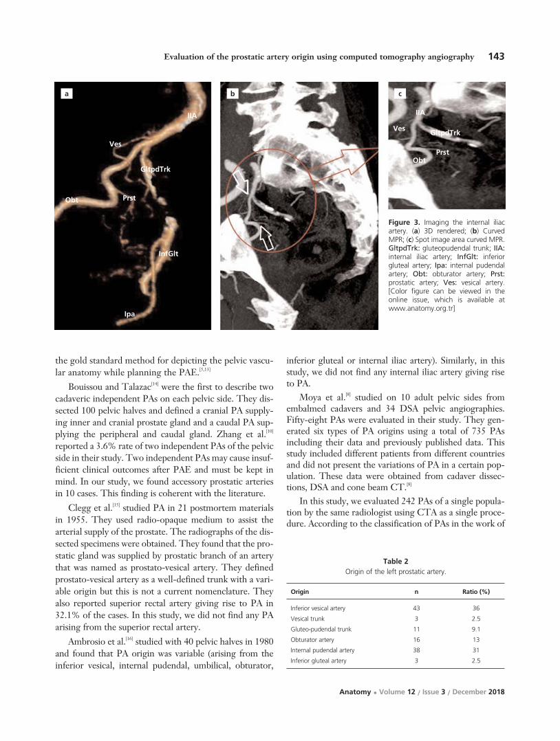
143Evaluation of the prostatic artery origin using computed tomography angiography
Anatomy • Volume 12 / Issue 3 / December 2018
the gold standard method for depicting the pelvic vascu-lar anatomy while planning the PAE.[5,13]
Bouissou and Talazac[14] were the first to describe twocadaveric independent PAs on each pelvic side. They dis-sected 100 pelvic halves and defined a cranial PA supply-ing inner and cranial prostate gland and a caudal PA sup-plying the peripheral and caudal gland. Zhang et al.[10]
reported a 3.6% rate of two independent PAs of the pelvicside in their study. Two independent PAs may cause insuf-ficient clinical outcomes after PAE and must be kept inmind. In our study, we found accessory prostatic arteriesin 10 cases. This finding is coherent with the literature.
Clegg et al.[15] studied PA in 21 postmortem materialsin 1955. They used radio-opaque medium to assist thearterial supply of the prostate. The radiographs of the dis-sected specimens were obtained. They found that the pro-static gland was supplied by prostatic branch of an arterythat was named as prostato-vesical artery. They definedprostato-vesical artery as a well-defined trunk with a vari-able origin but this is not a current nomenclature. Theyalso reported superior rectal artery giving rise to PA in32.1% of the cases. In this study, we did not find any PAarising from the superior rectal artery.
Ambrosio et al.[16] studied with 40 pelvic halves in 1980and found that PA origin was variable (arising from theinferior vesical, internal pudendal, umbilical, obturator,
inferior gluteal or internal iliac artery). Similarly, in thisstudy, we did not find any internal iliac artery giving riseto PA.
Moya et al.[8] studied on 10 adult pelvic sides fromembalmed cadavers and 34 DSA pelvic angiographies.Fifty-eight PAs were evaluated in their study. They gen-erated six types of PA origins using a total of 735 PAsincluding their data and previously published data. Thisstudy included different patients from different countriesand did not present the variations of PA in a certain pop-ulation. These data were obtained from cadaver dissec-tions, DSA and cone beam CT.[8]
In this study, we evaluated 242 PAs of a single popula-tion by the same radiologist using CTA as a single proce-dure. According to the classification of PAs in the work of
Figure 3. Imaging the internal iliacartery. (a) 3D rendered; (b) CurvedMPR; (c) Spot image area curved MPR.GltpdTrk: gluteopudendal trunk; IIA:internal iliac artery; InfGlt: inferiorgluteal artery; Ipa: internal pudendalartery; Obt: obturator artery; Prst:prostatic artery; Ves: vesical artery.[Color figure can be viewed in theonline issue, which is available atwww.anatomy.org.tr]
a b c
Origin n Ratio (%)
Inferior vesical artery 43 36
Vesical trunk 3 2.5
Gluteo-pudendal trunk 11 9.1
Obturator artery 16 13
Internal pudendal artery 38 31
Inferior gluteal artery 3 2.5
Table 2Origin of the left prostatic artery.
IIA
Ves
GltpdTrk
Prst
InfGlt
GltpdTrk
PrstObt
Ves
IIA
Ipa
Obt

144 Çelebio¤lu EC et al.
Anatomy • Volume 12 / Issue 3 / December 2018
Moya et al.[8] Type I, indicated anterior division of inter-nal pudendal artery to give rise to PA, and Type IV, whichpresents internal pudendal artery as the origin site of PA,were the most common types.
In the present study, the most common origin of thePA was the inferior vesical artery arising from the anteri-or division of the internal iliac arteries (Type I in Moyaclassification). The internal pudendal artery was the sec-ond most common site of origin for the PA in our popu-lation (Type IV in Moya classification).
In this study, there are differences from the previouslypublished studies in the literature. We suggest that thisdiscrepancy may depend on different patient populationsfrom different countries. However, we need larger patientseries to claim this hypothesis in terms of statistics, andthis is one of limitations of our study.
ConclusionIt is very important to understand the PA anatomy prior toany surgical or interventional procedure related to theprostate gland. Conventional CTA is the gold standard fordepicting PA anatomy, and should be considered as a firstline option before surgical or interventional procedures.
References1. Carnevale FC, Antunes AA, da Motta Leal Filho JM, de Oliveira
Cerri LM, Baroni RH, Marcelino AS, Freire GC, Moreira AM,Srougi M, Cerri GG. Prostatic artery embolization as a primarytreatment for benign prostatic hyperplasia: preliminary results in twopatients. Cardiovasc Intervent Radiol 2010;33:355–61.
2. Garvey B, Türkbey B, Truong H, Bernardo M, Periaswamy S,Choyke PL. Clinical value of prostate segmentation and volumedetermination on MRI in benign prostatic hyperplasia. Diagn IntervRadiol 2014;20:229–33.
3. Mirakhur A, McWilliams JP. Prostate artery embolization forbenign prostatic hyperplasia: current status. Can Assoc Radiol J2017;68:84–9.
4. Pisco J, Bilhim T, Pinheiro LC, Fernandes L, Pereira J, Costa NV,Duarte M, Oliveira AGJ. Prostate embolization as an alternative to
open surgery in patients with large prostate and moderate to severelower urinary tract symptoms. Vasc Interv Radiol 2016;27:700–8.
5. Bilhim T, Casal D, Furtado A, Pais D, O'Neill JE, Pisco JM.Branching patterns of the male internal iliac artery: imaging findings.Surg Radiol Anat 2011;33:151–9.
6. Park BJ, Sung DJ, Kim MJ, Cho SB, Kim YH, Chung KB, KangSH, Cheon J. The incidence and anatomy of accessory pudendalarteries as depicted on multidetector-row CT angiography: clini-cal implications of preoperative evaluation for laparoscopic androbot-assisted radical prostatectomy. Korean J Radiol2009;10:587–95.
7. Bilhim T, Tinto HR, Fernandes L, Martins Pisco J. Radiologicalanatomy of prostatic arteries. Tech Vasc Interv Radiol 2012;15:276–85.
8. Moya C, Cuesta J, Friera A, Gil-Vernet Sedo JM, Valderrama-Canales FJ. Cadaveric and radiologic study of the anatomical varia-tions of the prostatic arteries: a review of the literature and a new clas-sification proposal with application to prostatectomy. Clin Anat 2017;30:71–80.
9. Yamaki K, Saga T, Doi Y, Aida K, Yoshizuka M. A statistical studyof the branching of the human internal iliac artery. Kurume Med J1998;45:333–40.
10. Zhang G, Wang M, Duan F, Yuan K, Li K, Yan J, Chang Z, WangY. Radiological findings of prostatic arterial anatomy for prostaticarterial embolization: preliminary study in 55 Chinese patients withbenign prostatic hyperplasia. PLoS One 2015;10:e0132678.
11. Venuti JM, Imielinska C, Molholt P. New views of male pelvicanatomy: role of computer-generated 3D images. Clin Anat 2004;17:261–71.
12. Ding HM1, Yin ZX, Zhou XB, Li YB, Tang ML, Chen SH, Xu DC,Zhong SZ. Three-dimensional visualization of pelvic vascularity.Surg Radiol Anat 2008;30:437–42.
13. Desai H, Yu H, Ohana E, Gunnell ET, Kim J, Isaacson A.Comparative analysis of cone-beam CT angiogram and convention-al CT angiogram for prostatic artery identification prior toembolization. J Vasc Interv Radiol 2018;29:229–32.
14. Bou›ssou H, Talazac A. Arterial vascularization of the normal andthe pathological prostate. Ann Anat Pathol (Paris). 1959;4:63–79.
15. Clegg EJ. The arterial supply of the human prostate and seminalvesicles. J Anat 1955;89:209–16.
16. Ambrósio JD, De Almeida JS, De Souza A. Origin of prostatic arter-ies in man. Rev Paul Med 1980;96:52–5.
Correspondence to: Ceren Günenç Befler, MD, PhD Department of Anatomy, School of Medicine, Hacettepe University, S›hh›ye, Ankara, TurkeyPhone: +90 532 521 22 78 e-mail: [email protected]
Conflict of interest statement: No conflicts declared.
This is an open access article distributed under the terms of the Creative Commons Attribution-NonCommercial-NoDerivs 3.0 Unported (CC BY-NC-ND3.0) Licence (http://creativecommons.org/licenses/by-nc-nd/3.0/) which permits unrestricted noncommercial use, distribution, and reproduction in anymedium, provided the original work is properly cited. Please cite this article as: Çelebio¤lu EC, Akkaflo¤lu S, Çal›flkan S, Günenç Befler C, Sancak T. Evaluationof the prostatic artery origin using computed tomography angiography. Anatomy 2018;12(3):140–144.
Online available at: www.anatomy.org.tr
doi:10.2399/ana.18.088QR code:

IntroductionAnatomy, the study of the structures of the human bodyis one of the first, most basic and important subjectsstudied by medical students when they begin their med-ical education.[1] Dissection of the dead human body hasbeen central to medical education since Renaissance.[1,2]
Indeed, the Greek roots of the word anatomy indicatecutting apart; so, many anatomists are adamant that dis-section is the best way to learn anatomy.[3,4] Some schol-ars described dissection as the most universal and uni-versally recognizable step in becoming a doctor.[2] An oldfashioned way of anatomy teaching in medical schools is
based on the use of human cadaveric specimens, eithertaking the whole body specimens for complete dissectionor as prosected specimens.[2]
In the 18th century, the study of gross anatomy wasdependent on cadaveric dissection, because that was theonly available method for three-dimensional studies ofthe gross anatomical structures. However, with the pas-sage of time and, as a result of advances in science andtechnology, there have been revolutionary changes inteaching methodologies.[5] In spite of that, cadaveric dis-section cannot be dismissed as obsolete and is still ofparamount importance in medical education.[4]
Physical and emotional impact of cadaver dissection on innovative medical educationstudents: a survey in Ethiopia
Melese Shenkut Abebe
Department of Anatomy, School of Medicine, College of Medicine and Health Science, Wollo University, Dessie, Ethiopia
Abstract
Objectives: Although many studies have been conducted worldwide to investigate the positive and negative experiences ofthe cadaver room, there is no documented research in medical schools delivering the new innovative medical education(NIME) curriculum which involves teaching students who already receive a bachelor degree in any natural science includinghealth sciences and having at least two years of work experience. Therefore, this study aimed to assess the effect of cadav-er dissection both physically and emotionally on NIME students.
Methods: A survey was done on 82 first and second-year NIME students using standard structured questionnaire. The studentswere evaluated according to gender, religion and ethnicity.
Results: Students experienced multiple symptoms in the dissection room. The most prevalent physical symptoms were nausea(32%), palpitation (20.7%) and sweating (17.1%). In addition to these, sadness (41.5%), fear (34.1%) and worry (29.3%) weremostly reported emotional experiences. Females were more significantly nervous than males (p=0.03). Students of Oromo eth-nicity reported a significantly higher degree of fainting (p=0.03), dizziness (p=0.02), and palpitation (p=0.02) than other ethnicstudents. Sweating and breathlessness were significantly decreased in year two compared to year one students (p<0.05). Thesmell of the cadaver was the most stressing aspect of the cadaver room. Females had nightmares more significantly than malesin the post-dissection period (p=0.04).
Conclusion: Students experience a variety of physical and emotional symptoms during dissection. These can affect the per-formance of the students. this study provides data for these symptoms in NIME students, and their relation to gender, reli-gion and ethnicity.
Keywords: cadaver dissection; emotional impact; medical students; physical impact
Anatomy 2018;12(3):145–151 ©2018 Turkish Society of Anatomy and Clinical Anatomy (TSACA)
Teaching Anatomywww.anatomy.org.trReceived: October 15, 2018; Accepted: December 3, 2018doi:10.2399/ana.18.069
In addition, the use of the human body dissection forteaching medical students helps them to identify the real,natural and unbiased organs of the human being. It isalso a means to learn anatomical variation before theyare exposed to the real patient. This will let them prepareto face the challenges during their clinical practice.[6–8]
However, it is good to realize that cadaver dissectionhas multiple physical and psychological effects on stu-dents. These experiences especially worsen during thefirst period of dissecting the cadaver.[9]
In Ethiopia, there are two types of medical educationcurriculum; the conventional curriculum used to teachstudents directly coming from the high school, and theother called new innovative medical education (NIME)curriculum to teach students who already receive a bach-elor degree in any natural science including health sci-ences and have at least two years of work experience.
Wollo University is one of the 13 institutions thatlaunched the new NIME curriculum. In the NIME cur-riculum, the anatomy course is given as integrated withother basic science courses.
Therefore, dissection of the cadaver is done in thefirst two pre-clinical years of the NIME curriculum.
Multiple types of research have been conductedworldwide and indicated both positive and negativeexperiences of the cadaver room.[10–14] However, there isno documented research conducted in medical schoolsdelivering the NIME curriculum. This study aimed toassess the effect of cadaver dissection both physically andemotionally on NIME students.
Materials and MethodsThis research was conducted on 85 first and second yearNIME students of Wollo University in 2016. The stu-dents were informed about the objective of the study andthe volunteer students were briefed on the questionnaireused as a data collection tool. A standardized question-naire was used for data collection. The questionnaireincludes sociodemographic characteristics and physicaland emotional impacts of cadaver dissection on the stu-dents. The survey was done at one time after the firstsystem dissection schedule for year one students, andafter completion of all system dissection for the second-year students. For the first-year students, those who did-n’t attend the first system dissection and repeaters wereexcluded from the study. In addition to this, for bothyear students, those who didn’t avail at the time of datacollection were also excluded. The ethical review com-mittee of the School of Medicine, Wollo Universityapproved this work earlier to data collection. The datawere entered into Epi Info 7 (Centers for Disease
Control and Prevention, 2005) and analyzed using theStatistical Package for Social Sciences (SPSS forWindows, version 22.0, Armonk, NY, USA). p<0.05 wasconsidered as statistically significant.
ResultsThis study was conducted on 85 first and second-yearnew innovative medical students of Wollo University.From both years, 82 students filled the questionnaire.The average age range for most of the students (70.7%)is 24–27 years. 84.1% and 81.7% of the students weremales and Ethiopian Orthodox Christian followers,respectively. The majority (87.8%) of the students werefrom health science (paramedical science) educationalbackground. In addition to this, 57.3% of the studentswere urban residents and 80.5% of them were Amhara inethnicity as showed in Table 1.
In the present survey, most of the respondents 75(91.5%) agreed with the ethical acceptability of cadaverdissection for teaching medical students. All Muslim stu-dents agreed on the ethical acceptance of human body uti-lization for teaching purpose, while 89.6% of Christianstudents agreed. From a total of 82 students, 95.1% ofthem preferred cadaver dissections as the best method oflearning anatomy and 75.65% of the students didn’t thinkdissecting cadaver is replaced by other methods of teach-ing. Among the different teaching approaches on thecadaver, self or instructor assisted dissection was preferredby 92.7% of the students. Only 62.2% of the respondentswere excited in the first visit of dissection room (Table 2).
Since most of the students (87.7%) were from healthscience background 31.7% of them had previous expo-sure to the dead body. The previous exposure to deadbody resulted in slight and high degree of trauma in17.1% and 18.3% of the students, respectively.
The top three most stressing components of the dis-section room were the smell of the cadaver 45.1%, reli-gious incompatibility 32.9%, and touching a certain partof the cadaver 28% (Table 3). Females were morestressed by looking or touching certain parts of thecadaver and by the practical exam compared to males,while males were stressed by the smell, dissection work-load, infectiousness of the cadaver and religious incom-patibility. Looking at certain parts of the cadaver, smellof the cadaver, fear of infection and the practical examwere stressors for Christian students.
Nausea 32%, palpitation 20.7% and sweating 17.1%were the most prevalent physical symptoms experiencedin the dissection room. From the emotional symptomsreported by the students, sadness 41.5% was the first fol-lowed by fear (34.1%) and worry (29.3%) (Table 4).
146 Abebe MS
Anatomy • Volume 12 / Issue 3 / December 2018

Females were more nervous, depressed, sad and felteye irritation than the males. On the other hand, malessweated, felt nausea, and fainted.
In religion comparison, Christian students common-ly felt dry mouth, fear, depression, and satisfaction; in
contrast, Muslim students showed nervousness, sadness,irritation of the eye and vomiting.
Oromo students significantly reported fainting, dizzi-ness and palpitation as compared to the other three ethnicstudents (p<0.05). Although not statistically significant,
147Physical and emotional impact of cadaver dissection on innovative medical education students
Anatomy • Volume 12 / Issue 3 / December 2018
Variables n %
Age 24–27 58 70.7
28–31 22 26.8
32–35 1 1.2
>35 1 1.2
Gender Male 69 84.1
Female 13 15.9
Religion Orthodox Christian 67 81.7
Muslim 15 18.3
Educational background Health sciences 72 87.8
Teaching 1 1.2
Applied sciences 3 3.7
Agriculture 3 3.7
Veterinary medicine 1 1.2
Other 2 2.4
Ethnicity Amhara 66 80.5
Oromo 2 2.4
Tigre 8 9.8
Gurage 3 3.7
Other 3 3.7
Residence Urban 47 57.3
Rural 35 42.7
Year of study Year one 45 54.9
Year two 37 45.1
Table 1Sociodemographic characteristics of the NIME students of Wollo University.
Questions Responses n %
Cadaver dissection is ethically acceptable No 7 8.5
Yes 75 91.5
Dissection is best method of learning Anatomy No 4 4.9
Yes 78 95.1
Cadaver dissection is replaced by other methods No 62 75.6
Yes 20 24.4
Preferred method of learning in the cadaver room Deal with prosected specimen 5 6.1
Self or instructor assisted dissection 76 92.7
Deal with dissected cadaver 1 1.2
First visit to the dissection room was exciting No 31 37.8
Yes 51 62.2
Have self-mental preparedness prior to the dissection room No 10 12.2
Yes 72 87.8
Table 2Responses of the students on general information about cadaver dissection.

most of the physical and emotional symptoms were lesslikely to be seen in year one compared to second-year stu-dents. However, sweating and breathlessness were signifi-cantly less as 26.7% in year one compared to 5.4% in sec-ond-year, and 11.1% in year one compared to 0% in sec-ond-year students (p<0.05). Instead, nausea, palpitation,and dryness of the mouth were relatively higher for sec-ond-year students compared to the first year (Table 5).
The most common way of coping strategies used bythe students in the cadaver room was focusing on task46.3% (n=38) followed by seeking advice from instructoror lab assistant 43.9% (n=36) and thirdly stay within thegroup 25.6% (n=21) as presented in Table 6. In additionto this, Christian students sought advice from lab assis-tant or their instructor, while Muslim students wanted to
focus on their task as a coping mechanism in the dissec-tion room. Females prayed and stayed in the group, andmales sought an advice.
As shown in Table 7, most of the symptomsdecreased gradually. However, loss of appetite andheadache were still felt after leaving the dissection room.Both males and females, and Christian and Muslim stu-dents reported decrement symptoms after they left thecadaver room. However, female students reportedinsomnia which was statistically significant (p=0.04).
Discussion Cadaver dissection has been used for a long time as a cor-nerstone of dealing anatomical science for medical educa-tion. Dissection of the human body helps students gets a
148 Abebe MS
Anatomy • Volume 12 / Issue 3 / December 2018
All %Gender (%) Religion (%)
The most stressful component of the dissection room (n=82) Male Female Christian Muslim
Looking at certain part of the cadaver 26.8 24.6 38.5 22.4 46.8
Touching certain part of the cadaver 28.0 27.5 30.8 28.4 26.7
The smell of the body 45.1 46.4 38.5 44.8 46.7
Dissection workload 12.2 13 7.7 14.9 0
Religious incompatibility 32.9 33.3 30.8 37.3 13.3
Fear of infection 22.0 24.6 7.7 20.9 26.7
Thinking of practical exam 17.1 15.9 23.1 14.9 26.7
Table 3Student’s response of their most stressful component of the dissection room. For all comparisons p>0.05.
All (%)Gender (%) Religion (%) Ethnicity (%)
Physical symptoms (n=82) Male Female Christian Muslim Amhara Oromo Tigre Gurage
Fainting 4.9 5.8 0 4.5 6.7 3 50* 12.5 0
Dizziness 12.2 11.6 15.4 11.9 13.3 9.1 100* 12.5 33.3
Nausea 32.9 33.3 30.8 32.8 33.3 34.8 100 25 0
Vomiting 3.7 4.3 0 3 6.7 1.5 50 12.5 0
Palpitation 20.7 18.8 30.8 20.9 20 22.7 100* 0 0
Sweating 17.1 18.8 7.7 16.4 20 18.2 50 12.5 0
Breathlessness 6.1 5.8 7.7 6 6.7 6.1 50 0 0
Irritation of the eye 9.8 7.2 23.1 6.7 10.4 7.6 100 33.3 33.3
Dryness of the mouth 7.3 7.2 7.7 9 0 7.6 50 33.3 33.3
Worry 29.3 30.4 23.1 32.8 13.3 31.8 0 38.5 0
Fear 34.1 31.9 46.2 35.8 26.7 33 100 33 66.7
Satisfaction 18.3 11.6 7.7 11.9 6.7 9.1 0 37.5 33.3
Sadness 41.5 39.1 53.8 37.3 60 39.4 0 50 33.3
Depression 14.6 11.6 30.8 14.9 13.3 15.2 50 12.5 33.3
Nervousness 12.2 8.7 30.8* 10.4 20 10.6 50 33.3 33.3
*p<0.05.
Table 4Physical and emotional symptoms experienced by the students in the cadaver room.

meaningful and unbiased structure of human beings. Inspite of this, students are experiencing a variety of physicaland emotional symptoms at the time of dissection. Theseimpacts can affect the performance of the students.
The ethical acceptability of cadaver dissection asagreed by most students irrespective of religion indicatesthat cadaver is a valuable gift to medical education. Thisis supported by the findings of Agnihotri and Sagoo[15]
and Rajeh et al.[16]
Our students agreed that cadaver dissection shouldnot be replaced with plastic models or 3D images(75.6%) and is the best method of learning anatomy(95.1%). Self or instructor assisted dissection was pre-ferred by 92.7% of our respondents to studying prosect-
ed specimen or dissected cadaver. This is in close prox-imity with the findings of Agnihotri and Sagoo,[15]
Johnson,[17] Shugaba et al.,[18] but different from the studyof McLachlan et al.[2] This difference may be due to thestudent’s perception and level of understanding of newtechnology. Based on our findings, the idea of replacingthe cadaver dissection technique with plastic models,computer-assisted training or other methods is chal-lenged, as the utilization of human body dissection helpsstudents to grasp the three-dimensional anatomy andconcept of countless variations.[19]
This survey is intended to show the impacts of cadaverdissection immediately after the first-time dissection andafter repeated dissections. Therefore, according to thisinvestigation, nausea, palpitation and sweating were the
149Physical and emotional impact of cadaver dissection on innovative medical education students
Anatomy • Volume 12 / Issue 3 / December 2018
Year of study
n (%)
Variables Year one Year two p-value
Fainting 4 (8.9) 0 *
Dizziness 6 (13.3) 4 (10.8) *
Nausea 12 (26.7) 15 (40.5) *
Vomiting 3 (6.7) 0 *
Palpitation 9 (20) 8 (21.6) *
Sweating 12 (26.7) 2 (5.4) 0.011
Breathlessness 5 (11.1) 0 0.036
Irritation of the eye 5 (11.1) 3 (8.1) *
Skin irritation 2 (4.4) 0 *
Dryness of the mouth 2 (4.4) 4 (10.8) *
Worry 13 (28.9) 11 (29.7) *
Fear 16 (35.6) 12 (32.4) *
Satisfaction 8 (17.8) 7 (17.9) *
Sadness 20 (44.4) 14 (37.8) *
Depression 9 (20) 3 (8.1) *
Nervousness 6 (13.3) 4 (10.8) *
*p>0.05.
Table 5Physical and emotional symptoms of the respondents by year.
Gender (%) Religion (%)
Variables All (%) Male Female Christian Muslim
Focusing on the task 46.3 46.4 46.2 40.3 60.3
Self-prayer 9.8 7.2 23.1 11.9 0
Stay within the group 25.6 24.6 30.8 26.9 20
Temporary departure from the dissection room 1.2 1.4 0 1.5 0
Seeking advice from lab assistance/instructors 43.9 44.9 38.5 47.8 26.7
Table 6Strategies used by students to help them cope with dissection. For all comparisons p>0.05.

most prevalent physical symptoms experience in the dissec-tion room. This finding is almost consistent with a researchconducted in Tanzania at Muhimbili University whichshowed disgust, fear, nausea, loss of appetite and sweatingas the commonest symptom.[11] Another research done inIndia by Vinay et al.[20] indicated the commonest symptomsas eye irritation (63.33%), headache (10%), decrease inappetite (12%), nausea (3.3%) and sweating (35.33%).
The research conducted in Foundation UniversityMedical College, Rawalpindi, Pakistan pointed out eyesoreness and fatigue (39.9%) and throat irritation (41.6%)as the most common physical symptom. This finding wasdifferent from ours, possibly due to different laboratorysetup, age and educational background of our students asour study subjects had a minimum of bachelor degree.[21]
The most prevalent emotional symptoms depicted inthis research were sadness, fear and worry. This findingis also similar to the above researchers.
In the comparison done between males and females,females were more nervous than males. This variableshowed a significant difference (p=0.03). This may indicatea gender difference in behavioral response to cadaver dis-section.[22] Students with Oromo ethnicity reported a sig-nificantly higher degree of fainting (p=0.03), dizziness(p=0.02), and palpitation (p=0.02) than other ethnic stu-dents. No significant differences were found for the othersymptoms.
As presented in Table 6, this study also compared thedecrement of the symptoms between the two batch stu-dents. The prevalence for most of the symptomsdecreased for the second-year students. This is becauseof repeated exposure to the dissection. This finding wasalso reported in other studies.[20,23,24]
According to a research conducted in HawasaUniversity and the University of Gondar, Ethiopia, moststressing component of the dissection room was the smellof the dissection room. This is also the same in this study
as stated by 45.1% of the respondents, and also in line withthe study of Bataineh et al.[25] This is because of the estab-lished use of formalin as a preservative of cadavers in ourcountry, Ethiopia.[24,26] There were some ups and downs inthe frequency of responses between males and females,and Christians and Muslims; however, none of these werestatistically significant.
In this study, 90.2% of the symptoms decreased grad-ually. However, loss of appetite, headache, and night-mares were still felt after leaving the dissection room.Post-dissection continuity of the above two symptomsmay be due to long time (minimum of 3 hours) exposureat one dissection schedule. This may lead to an excessiveintake of irritant chemical (mainly formalin) that maybring loss of appetite and headache. Females had night-mares more than males in the post-dissection period(p=0.04). Nevertheless, no significant difference wasobserved in Christian and Muslim respondents. Karau etal.[27] presented similar findings.
The commonest way of coping strategy used by thestudents was focusing on task followed by seeking advicefrom instructor or lab assistant and thirdly stay within thegroup. Comparison of gender and race presented in Table7 did not show a significant difference between males andfemales and Christians and Muslims. Most students inOman (65%) and Jordan (89.8%) used rationalization tocope with fear and disturbance associated with cadaver dis-section.[28] Other coping mechanisms listed in this researchare utilized in different degrees by the above students. Theage and work experience of our subjects may be the factorsthat bring a difference in prioritizing coping mechanisms.
This study has some limitations having incorporatedonly two batches of medical students, of a number of 85.On the other hand, the concentration of embalmingfluid on air in the dissection room could not be measureddue to our laboratory facilities.
150 Abebe MS
Anatomy • Volume 12 / Issue 3 / December 2018
Gender (%) Religion (%)
Symptoms All (%) Male Female p-value Christian Muslim p-value
Loss of appetite 40.2 40.6 38.5 * 41.8 33.3 *
Insomnia or nightmare 13.4 10.1 30.8 0.04 14.9 6.7 *
Dizziness 11.0 10.1 15.4 * 10.4 13.3 *
Headache 22.0 18.8 38.5 * 20.9 26.7 *
Loss of concentration on study 13.4 11.6 23.1 * 14.9 6.7 *
Symptoms decrease gradually 90.2 91.3 84.6 * 88.1 100 *
*p>0.05.
Table 7Responses on the symptoms that continue after leaving the dissecting room.

ConclusionEven though dissection of the human body is the bestmethods of learning anatomy, multiple physical and emo-tional symptoms are experienced by the students.Commonly students felt nausea, palpitation, sweating sad-ness, fear, and worry in our cadaver room. Even some of thesymptoms are worsen for female. These findings are alsoreported by different investigators. Therefore, all medicalschools of Ethiopia should conduct nation-wide research toassess commonest symptoms, their causes and the maxi-mum level of embalming solution in the cadaver room.
AcknowledgmentsThe deepest gratitude is extended to the students who vol-untarily participated to fill in the questionnaire.
References1. Parker LM. What’s wrong with the dead body? Use of the human
cadaver in medical education. Med J Aust 2002;176:74–6.2. McLachlan JC, Bligh J, Bradley P, Searle J. Teaching anatomy with-
out cadavers. Med Educ 2004;38:418–24.3. O’Carroll RE, Whiten S, Jakson D, Sinclair DW. Assessing the
emotional impact of cadaver dissection on medical students. MedEduc 2002;36:550–4.
4. Snelling J, Sahai A, Ellis H. Attitudes of medical and dental studentsto dissection. Clin Anat 2003; 16:165–72.
5. Hancock D, Williams M, Taylor A, Dawson B. Impact of cadaverdissection on medical students. New Zealand Journal of Psychology2004;33:20–3.
6. Cahill KC, Ettarh R. Attitudes to anatomy dissection in an Irishmedical school. Clin Anat 2009; 22:386–91.
7. Older J. Anatomy: a must for teaching the next generation. Surgeon2004; 2:79–90.
8. Rajkumari A, Singh Y. Body donation and its relevance in anatomylearning - a review. J Anat Soc India 2007; 56:44–7.
9. Nnodim J. Preclinical student reactions to dissection, death, anddying. Clin Anat 1996;9:175–82.
10. Dempster M, Black A, McCorry N, Wilson D. Appraisal and conse-quences of cadaver dissection. Med Educ Online 2006; 11:4592.
11. Russa A, Mligiliche L. Inspiring Tanzanian medical students into theprofession: appraisal of cadaveric dissection stress and coping strate-gies. Ital J Anat Embryol 2014; 119:268–76.
12. Tschernig T, Schlaud M, Pabst R. Emotional reactions of medicalstudents to dissecting human bodies: a conceptual approach and itsevaluation. Anat Rec 2000;261:11–3.
13. Vijayabhaskar P, Shankar PR, Dubey AK. Emotional impact ofcadaver dissection: a survey in a medical college in western Nepal.Kathmandu Univ Med J (KUMJ) 2005;3:143–8.
14. Williams AD, Greenwald EE, Soricelli RL, DePace DM. Medicalstudents’ reactions to anatomic dissection and the phenomenon ofcadaver naming. Anat Sci Educ 2014;7:169–80.
15. Agnihotri G, Sagoo MG. Reactions of first year Indian medical stu-dents to the dissection hall experience. National Journal ofIntegrated Research in Medicine 2010;1:4–9.
16. Rajeh NA, Badroun LE, Alqarni AK, Alzhrani BA, Alallah BS,Almghrabi SA, Almalki LA. Cadaver dissection: a positive experienceamong Saudi female medical students. Journal of Taibah UniversityMedical Sciences 2017; 12:268–72.
17. Johnson JH. Importance of dissection in learning anatomy: personalversus peer teaching. Clin Anat 2002; 15:38–44.
18. Shugaba AI, Usman YM, Shimwen FJ, Uzokwe CB, Shinku F, RabiuAM, Hassan ZI. Attitude of Jos University medical students to theirinitial encounter with cadavers in the dissecting room. Journal ofExperimental and Clinical Anatomy 2015;14:101–4.
19. Winkelmann A. Anatomical dissection as a teaching method in med-ical school: a review of the evidence. Med Educ 2007; 41:15–22.
20. Vinay KV, Martin LA, Vishal K, Pradeep K. Attitude of first yearIndian medical students towards cadaver dissection. InternationalJournal of Anatomy and Research 2015;3:1255–58.
21. Khan H, Mirza T. Physical and psychological effects of cadaveric dis-section on undergraduate medical students. J Pak Med Assoc 2013;63:831–4.
22. Izunya A, Oaikhena G, Nwaopara A. Attitudes to cadaver dissectionin a Nigerian medical school. Asian Journal of Medical Sciences2010;2:89–94.
23. Lee Y, Lee Y, Kwon S, Park S. Reactions of first-year medical stu-dents to cadaver dissection and their perception on learning methodsin anatomy. Korean J Med Educ 2011;23:275–83.
24. Getacew D. Reaction of medical students to experiences in dissectionroom. Ethiop J Health Sci 2014;20:337–42.
25. Bataineh ZM, Hijazi TA, Hijleh MF. Attitudes and reactions ofJordanian medical students to the dissecting room. Surg Radiol Anat2006;28:416–21.
26. Mulu A, Tigabu D. Medical atudents’ attitudinal changes towardscadaver dissection. Ethiop J Health Sci 2012;22:51–8.
27. Karau PB, Wamachi A, Ndede K, Mwamisi J, Ongeti K. Physical andemotional impact of dissection: findings from a pioneer medical class ina Kenyan Medical School. Anatomy Journal of Africa 2016;5:746–59.
28. Abu-hijleh MF, Hamdi NA, Moqattash ST, Harris PF, HeseltineGF. Attitudes and reactions of Arab medical students to the dissect-ing room. Clin Anat 1997;10:272–8.
151Physical and emotional impact of cadaver dissection on innovative medical education students
Anatomy • Volume 12 / Issue 3 / December 2018
Correspondence to: Melese Shenkut Abebe, MSc Department of Anatomy, School of Medicine, College of Medicine andHealth Science, Wollo University, Dessie, EthiopiaPhone: +251 912 368 855e-mail: [email protected]
Conflict of interest statement: No conflicts declared.
This is an open access article distributed under the terms of the Creative Commons Attribution-NonCommercial-NoDerivs 3.0 Unported (CC BY-NC-ND3.0) Licence (http://creativecommons.org/licenses/by-nc-nd/3.0/) which permits unrestricted noncommercial use, distribution, and reproduction in anymedium, provided the original work is properly cited. Please cite this article as: Abebe MS. Physical and emotional impact of cadaver dissection on innovativemedical education students: a survey in Ethiopia. Anatomy 2018;12(3):145–151.
Online available at: www.anatomy.org.tr
doi:10.2399/ana.18.069QR code:

IntroductionThe piriformis is a flat, triangular muscle that originatesfrom the anterior surface of the sacrum, and then passesthrough the greater sciatic foramen to finally insert intothe greater trochanter of the femur.[1] Despite its smallsize and insignificant function as a lateral hip joint rota-tor, the piriformis has a great importance for the topog-raphy of the deep gluteal region. The upper and lowermuscle borders form together with the greater sciaticforamen the main foramina for the gluteal neuro-vascu-lar bundles. The piriformis has also special and some-times variable relations with the largest nerve of thelower limb – the sciatic nerve.[2] Some piriformis-sciaticnerve variations might be related to nerve compressionsymptoms described as piriformis syndrome.[3] A raretype of piriformis muscle variation is described here thatmay be a contribution to the understanding of this nervecompression syndrome.
Case ReportDuring routine anatomical dissection of the right lowerlimb of a 68-year-old male cadaver, skin over gluteal
region was dissected up to mid-thigh. The gluteus max-imus was transected in the middle to expose the deeperstructures. Upon dissecting the neurovascular bundlespassing through the supra-and infrapiriform foramina,an interesting variation, related to the piriformis muscleand the sciatic nerve was revealed (Figures 1a and b).The piriformis muscle presented a complete structurewith the usual origin and insertion. As usual, the sciaticnerve emerged from the infrapiriform foramen. Therewas an interesting additional small muscle identified,that also started from the anterior surface of the sacrumand passed through the greater sciatic foramen below theusual piriformis. The variant muscle presented a wellidentifiable lateral tendon that pierced through the prox-imal part of the sciatsic nerve and inserted to the greatertrochanter. The length of the additional small musclewas 85 mm with the broadest part of the muscle belly of9 mm.
Discussion In the literature, there are several variations of the piri-formis described – divided piriformis, cleavage of muscle
A rare muscle variation – accessory piriformismuscle
Albert Gradev, Lina Malinova, Lazar Jelev
Department of Anatomy, Histology and Embryology, Medical University of Sofia, Sofia, Bulgaria
Abstract
During routine anatomical dissection of the right lower limb of a 68-year-old male cadaver, a rare muscle variation wasrevealed and identified as an accessory piriformis muscle. This variant muscle started from the anterior surface of the sacrumbelow the usual piriformis muscle and extended in a well-identifiable lateral tendon also inserting to the greater trochanterof the femur. In the case described, the accessory piriformis pierced through the proximal part of the sciatic nerve. The lengthof the additional small muscle was 85 mm with the broadest part of the muscle belly as 9 mm. The course of the variantmuscle, especially its tendinous part, might irritate the sciatic nerve and cause piriformis syndrome and other sciatica-likesymptoms. The neurologists who diagnose piriformis syndrome and surgeons performing nerve releasing surgery should bewell aware of the described rare muscle variation.
Keywords: nerve compression syndrome; piriformis muscle; sciatic nerve; variation
Anatomy 2018;12(3):152–154 ©2018 Turkish Society of Anatomy and Clinical Anatomy (TSACA)
Case Reportwww.anatomy.org.tr
Received: October 30, 2018; Accepted: November 20, 2018doi:10.2399/ana.18.089

153Accessory piriformis muscle
Anatomy • Volume 12 / Issue 3 / December 2018
Figure 1. Photograph (a) and schematic diagram (b) of the deep gluteal region. The usual piriformis muscle was partially damaged by the studentdissection. The accessory piriformis (*) and its lateral tendon (arrow) passing through the sciatic nerve. PM: piriformis muscle; ScN: sciatic nerve.
a b
bellies, merging with other muscles, or even absence.[4,5]
The most important muscle variations, however, arethose related to the structure of the proximal sciaticnerve.[6] Six basic types of piriformis-sciatic nerve vari-tions are described in the literature and their distribu-tion among the human population are presented indetails.[7,8]
The muscle described here resembles a variation ofthe piriformis muscle. It is not simply a case of a dividedor cleavaged muscle, because it has a separate origin andinsertion and distinct proportion of muscle belly to ten-don. It can be accepted that this is an accessory muscle.In our case, the sciatic nerve passed below the usual pir-iformis and was pierced by the accessory piriformis mus-cle. From a review of the pertinent literature, it seemsthat the accessory piriformis is quite a rare muscle varia-tion. A similar small muscle below the usual piriformis isalso described by Carro et al.[9] In their case, however, theaccessory piriformis did not penetrate through the sciat-ic nerve fibers. In two other reports,[10,11] the anomaloussacral attachment of the piriformis with accessory fibers
extending over the sacral nerve, seen on MRI, were alsodescribed as accessory piriformis muscle.
The reported aberrant muscle might provoke symp-toms of compression of the sciatic nerve and be the causeof piriformis syndrome, coccygodynia and followingmuscle atrophy in the zone innervated by the sciaticnerve. Piriformis syndrome includes hip pain, buttockpain, sciatica and intolerance to sitting.[3,12,13] In up to16.2% of surgical case series, piriformis syndrome iscaused by anatomical variations.[14] The accessory piri-formis, piercing the sciatic nerve, might be one of therare causes of nerve compression. Therefore, the sur-geons who operate in this region must be well aware ofthe reported muscle variation, as well as the neurologistswho diagnose piriformis syndrome and other relatedsensory symptomatology.
References1. Clemente CD. Anatomy of the human body. 30th ed. Philadelphia
(PA): Lea and Febiger; 1985. pp. 565–71.2. Beaton LE, Anson BJ. The relation between the sciatic nerve and of
its subdivisions to the piriformis muscle. Anat Rec 1938;70:1–5.

154 Gradev A, Malinova L, Jelev L
Anatomy • Volume 12 / Issue 3 / December 2018
3. Jankovic D, Peng P, van Zundert A. Brief review. Piriformis syn-drome: etiology, diagnosis, and management. Can J Anaesth 2013;60:1003–12.
4. Bergman RA, Afifi AK, Miyauchi R. Illustrated encyclopaedia ofhuman anatomic variation. Opus I: Muscular system [Revised onJanuary 1, 2019] [Retrieved: March 2019]. Available from: https://www.anatomyatlases.org/AnatomicVariants/MuscularSystem/Text/P/24Piriformis.shtml
5. Brenner E, Tripoli M, Scavo E, Cordova A. Case report: absence ofthe right piriformis muscle in a woman. Surg Radiol Anat 2019 Feb13. doi: 10.1007/s00276-018-02176–6
6. Natsis K, Totlis T, Konstantinidis GA, Paraskevas G, Piagkou M,Koebke J. Anatomical variations between the sciatic nerve and thepiriformis muscle: a contribution to surgical anatomy in piriformissyndrome. Surg Radiol Anat 2014;36:273–80.
7. Adibatti M, Sangeetha V. Study on variant anatomy of sciatic nerve.J Clin Diagn Res 2014;8:AC07–9.
8. Sinha MB, Aggarwal A, Sahni D, Harjeet K, Gupta R, Sinha HP.Morphological variations of sciatic nerve and piriformis muscle
in gluteal region during fetal period. Eur J Anat 2014;18:261–6.
9. Carro LP, Hernando MF, Cerezal L, Navarro IS, Fernandez AA,Castillo AO. Deep gluteal space problems: piriformis syndrome,ischiofemoral impingement and sciatic nerve release. MusclesLigaments Tendons J 2016;6:384–96.
10. Lee EY, Margherita AJ, Gierada DS, Narra VR. MRI of piriformissyndrome. AJR Am J Roentgenol 2004;183:63–4.
11. Sen A, Rajesh S. Accessory piriformis muscle: an easily identifiablecause of piriformis syndrome on magnetic resonance imaging.Neurol India 2011;59:769–71.
12. Beers MH, Porter RS, Jones TV, Kaplan JL, Berkwits M. TheMerck manual of diagnosis and therapy. 18th ed. New Jersey (NJ):Merck Research Laboratories; 2006. p. 2635.
13. Han SK, Kim YS, Kim TH, Kang SH. Surgical treatment of piri-formis syndrome. Clin Orthop Surg 2017;9:136–44.
14. Smoll NR. Variations of the piriformis and sciatic nerve with clinicalconsequence: a review. Clin Anat 2010;23:8–17.
Correspondence to: Lazar Jelev, MD, PhD Department of Anatomy, Histology and Embryology, Medical University ofSofia, BG-1431, Sofia, BulgariaPhone: +359 897 87 27 51e-mail: [email protected]
Conflict of interest statement: No conflicts declared.
This is an open access article distributed under the terms of the Creative Commons Attribution-NonCommercial-NoDerivs 3.0 Unported (CC BY-NC-ND3.0) Licence (http://creativecommons.org/licenses/by-nc-nd/3.0/) which permits unrestricted noncommercial use, distribution, and reproduction in anymedium, provided the original work is properly cited. Please cite this article as: Gradev A, Malinova L, Jelev L. A rare muscle variation – accessory piriformismuscle. Anatomy 2018;12(3):152–154.
Online available at: www.anatomy.org.tr
doi:10.2399/ana.18.089QR code:
Leonardo da Vinci’s early yearsDa Vinci was born on 15 April 1452 in Mount Albano,Florence. He was the son of Sar Pierro da Vinci, a lawyer.Her mother was a peasant woman. Due to the requirementsof that period, her parents never got married. Leonardo’sfather married to a noble woman and Leonardo had to livewith his grandparents who raised him well.[1]
Leonardo da Vinci’s Interest in AnatomyLeonardo da Vinci’s interest in anatomy began in Milanwhen he was working for Ludovico Maria Sforza. DaVinci’s favorite tools were sharp knives, chisels and bonesaws. He had no assistant at that time. That’s why he hadto transcribe quickly his observation right after each dissec-tion section. It is still not known how he preserved thecadavers.[2] He performed approximately 30 cadaver dissec-tions.[3] After 1510, he collaborated with a young professornamed Marcantonio della Torre. Later on, with theadvance of science, dissection studies increased. In this way,the accuracy of the teachings of the previous period beganto be questioned, and it was then found that Leonardo daVinci’s work had some mistakes.[4–7] For example, his work“The anatomy of a foot” is confusing like “Mona Lisa”.
“The Anatomy of a Foot”At a quick glance to the illustration, to the alignment ofthe metatarsal bones and phalanges, we can say this is the
lateral side of the foot. Also, the phalanges are graduallybecoming smaller. So, the illustrated tendons in thiswork probably belong to the peroneus brevis and per-oneus longus muscles. In addition, the location of thenerve lying from the back of the leg to dorsum of thefoot implies this is the superficial peroneal nerve. Thisnerve becomes superficial by penetrating the deep fasciain the junction between upper 2/3 and lower 1/3 of theposterior leg. It’s divided into two branches at the dor-sum of the foot: the dorsal medial cutaneous nerve andthe dorsal intermedial cutaneous nerve.[8] It’s not possibleto say this is the peroneus tertius muscle (Figure 1a),because the tendon of the peroneus tertius muscle pass-es under the extensor retinaculum.
However, there is another tendon in the drawing(marked in Figure 1a). This also refutes the idea ofbeing the lateral side of the foot. If it’s the medial side, itcan be assumed that the tibialis posterior, flexor digito-rum longus and flexor hallucis longus muscles areobserved behind the medial malleolus. On the medialside, we should clearly see the extensor hallucis longusmuscle with a thick tendon. Also, the structure with thequestion mark can be assumed as the great saphenousvein (Figure 1b). However, this structure goes to theposterior of the leg, and therefore, does not suit with thepath of the great saphenous vein. It’s not possible to saythis is the tibialis anterior muscle, because the muscle
Da Vinci’s foot illustration and its errors
Didem Dönmez, Menekfle Karahan, O¤uz Taflk›nalp
Department of Anatomy, School of Medicine, Trakya University, Edirne, Turkey
Abstract
Leonardo da Vinci is an important philosopher, astronomer, architect, engineer, inventor, mathematician, anatomist, musi-cian, sculptor, writer and painter who lived in the Renaissance period. In addition to his skills in numerous diverse areas ofstudy, he has important contributions to anatomy, cornerstone of medicine. Leonardo da Vinci performed many cadaver dis-sections. His anatomical illustartions are brilliant, despite the limitations of his time. However, a number of errors have beenfound in these illustrations. Here, we interpreted the illustration of da Vinci named “The anatomy of a foot”.
Keywords: foot; illustration; Leonardo da Vinci
Anatomy 2018;12(3):155–157 ©2018 Turkish Society of Anatomy and Clinical Anatomy (TSACA)
Historical Viewwww.anatomy.org.trReceived: May 10, 2018; Accepted: September 14, 2018doi:10.2399/ana.18.060

passes under the extensor retinaculum. So, we could notcome to a decision on which side this may be.
Jastifer et al. [10] examined another drawing of foot byLeonardo da Vinci. In this work, the anatomical struc-tures supporting the medial arch of the foot are clearlyseen. Compared to the work studied in this article, thetwo drawings look quite different from each other. Thework we studied can be one of his early works. In thisrespect, this piece reminded us Mona Lisa’s face.
ConclusionLeonardo da Vinci has been influencing people for cen-turies with his magnificent intelligence. His anatomicalwork presented new details for the surgical treatment ofpreviously unexplored areas. Therefore, surgeons andanatomists owe him as his works facilitated and improvedtheir practice. We can understand his respect for his work
from his words before his death: “I have offended God andmankind because my work did not reach the quality itshould have”.[1]
References1. Jose AM. Anatomy and Leonardo da Vinci. Yale J Biol Med 2001;74:
185–95.
2. White M. Leonardo: the first scientist. London (UK): Little, Brown;2001. 384 p.
3. Toledo-Pereyra LH. Leonardo da Vinci: the hidden father of mod-ern anatomy. J Invest Surg 2002;15:247–9.
4. Bowen G, Gonzales J, Iwanaga J, Fisahn C, Loukas M, Oskouian RJ,Tubbs RS. Leonardo da Vinci (1452–1519) and his depictions of thehuman spine. Childs Nerv Syst 2017;33:2067–70.
5. Clayton M, Philo R. Leonardo da Vinci: anatomist. London (UK):Royal Collection Trust; 2012. 260 p.
6. O’Malley CD, Saunders JB de CM. Leonardo da Vinci on thehuman body: the anatomical, physiological, and embryological draw-
156 Dönmez D, Karahan M, Taflk›nalp O
Anatomy • Volume 12 / Issue 3 / December 2018
Figure 1. . Lateral (a) and medial (b) views of the human foot showing tendons which support the foot, respectively.[9] [Color figure can be viewedin the online issue, which is available at www.anatomy.org.tr]
a b

ings of Leonardo da Vinci: with translations, emendations and abiographical introduction. New York (NY): Henry Schuman; 1952.506 p.
7. Tubbs RI, Gonzales J, Iwanaga J, Loukas M, Oskouian RJ, TubbsRS. The influence of ancient Greek thought on fifteenth centuryanatomy: Galenic influence and Leonardo da Vinci. Childs NervSyst 2018;34:1095–101.
8. Garg K. Human anatomy: regional and applied dissection and clini-cal. New Delhi: CBS Publishers; 2010. 472 p.
9. The anatomy of a foot - by Leonardo da Vinci. [Internet].[Cited2018 May 8]. Available from: [https://www.leonardodavinci.net/ the-anatomy-of-a-foot].
10. Jastifer JR, Toledo-Pereyra LH. Leonardo da Vinci’s foot: historicalevidence of concept. J Invest Surg 2012;25:281–5.
157Da Vinci’s foot illustration and its errors
Anatomy • Volume 12 / Issue 3 / December 2018
Correspondence to: Didem Dönmez, MD Department of Anatomy, School of Medicine, Trakya University, Balkan Campus, 22040, Edirne, TurkeyPhone: +90 284 235 76 41/1510e-mail: [email protected]
Conflict of interest statement: No conflicts declared.
This is an open access article distributed under the terms of the Creative Commons Attribution-NonCommercial-NoDerivs 3.0 Unported (CC BY-NC-ND3.0) Licence (http://creativecommons.org/licenses/by-nc-nd/3.0/) which permits unrestricted noncommercial use, distribution, and reproduction in anymedium, provided the original work is properly cited. Please cite this article as: Dönmez D, Karahan M, Taflk›nalp O. Da Vinci’s foot illustration and its errors.Anatomy 2018;12(3):155–157.
Online available at: www.anatomy.org.tr
doi:10.2399/ana.18.060QR code:

Author names for abstract of poster presentation published in Volume 12, Supplement 2, September 2018, page S140;O-74 “Virtual reality technology in anatomy education” is erroneously published as: Topuz Y, Özdener DN. Correctedversion is as follows: Topuz Y, Özdener DN, Verimli U.
Correction: (O-74) Virtual reality technology inanatomy education
Anatomy 2018;12(3):158 ©2018 Turkish Society of Anatomy and Clinical Anatomy (TSACA)
Topuz Y1, Özdener DN2, Verimli U3
1Department of Information Technologies and Security, Beykoz University, Istanbul, Turkey2Department of Computer Education and Instructional Technology, Marmara University Atatürk Faculty of Education, Istanbul, Turkey3Department of Anatomy, School of Medicine, Marmara University, Istanbul, Turkey
Correspondence to: Yasemin Topuz, MD Department of Information Technologies and Security, Beykoz University, Istanbul, Turkey
This is an open access article distributed under the terms of the Creative Commons Attribution-NonCommercial-NoDerivs 3.0 Unported (CC BY-NC-ND3.0) Licence (http://creativecommons.org/licenses/by-nc-nd/3.0/) which permits unrestricted noncommercial use, distribution, and reproduction in anymedium, provided the original work is properly cited. Please cite this article as: Topuz Y, Özdener DN, Verimli U. Correction: (O-74) Virtual reality technologyin anatomy education. Anatomy 2018;12(3):158.
Online available at: www.anatomy.org.tr
doi:10.2399/ana.18.S2S140.err001O74QR code:
Erratumwww.anatomy.org.tr
Received: November 22, 2018; Accepted: November 25, 2018doi:10.2399/ana.18.S2S140.err001O74
Dear colleagues, We are happy to announce that Abstract Submission andRegistration to the International Meeting of AnatomiaClinica (European Association of Clinical Anatomist,EACA) and the International Symposium of Clinical andApplied Anatomy (ISCAA), which will take place from 24thto 26th June 2019 in Madrid (Spain) is now open.
Visit www.eaca2019.com to get an account which willallow you to submit abstracts, register to the meeting.
Deadline for receipt of abstracts – 11 April 2019 The accepted abstracts will be published in the Surgical
and Radiologic Anatomy journal.
We look forward to meeting you all in Madrid, June2019 for an enjoyable Meeting!
Sincerely,
Prof. Jose Sanudo President of the Congress
Department of Human Anatomy & Embryology,Faculty of Medicine,Complutense Universtiy of MadridAv. Ciudad Universitaria s/n 28040-Madrid. Spain. Tel: +34 91 394 1381 e-mail: [email protected]
International Meeting of Anatomia Clinica &International Symposium of Clinical andApplied Anatomy (ISCAA), 24th to 26th June2019, Madrid, Spain
Anatomy 2018;12(3):159 ©2018 Turkish Society of Anatomy and Clinical Anatomy (TSACA)
Announcementwww.anatomy.org.trReceived: December 21, 2018; Accepted: December 24, 2018doi:10.2399/ana.18.090
This is an open access article distributed under the terms of the Creative Commons Attribution-NonCommercial-NoDerivs 3.0 Unported (CC BY-NC-ND3.0) Licence (http://creativecommons.org/licenses/by-nc-nd/3.0/) which permits unrestricted noncommercial use, distribution, and reproduction in anymedium, provided the original work is properly cited. Please cite this article as: Sanudo J. International Meeting of Anatomia Clinica & International Symposiumof Clinical and Applied Anatomy (ISCAA), 24th to 26th June 2019, Madrid, Spain. Anatomy 2018;12(3):159.
Online available at: www.anatomy.org.tr
doi:10.2399/ana.18.090QR code:
Acknowledgment of Reviewers for Volume 12, 2018The Editorial Staff of Anatomy expresses their appreciation to the following reviewers who have evaluated the manuscripts forVolume 12, 2018.
Esat Ad›güzelNihal Apayd›n Yüksel AydarEbru Ball›Ça¤atay BarutMustafa BüyükmumcuServet ÇelikBurcu ErçakmakTolga ErtekinMete Ertürk
Zeliha Fazl›o¤ullar›Georg FeiglNadir GülekonCeren Günenç BeflerZ. Asl› ‹kizDavid KachlickS. Tuna KarahanPiraye Kervanc›o¤luZeliha Kurto¤luBernard Moxham
Helen NicholsonEren Ö¤ütDavut Özba¤Cenk Murat ÖzerTuncay Veysel PekerMustafa F. SargonLevent Sar›kç›o¤luIsabel StabileLütfiye Bikem SüzenÜmit S. fiehirli
Gülgün fiengülTrifon TotlisM. ‹brahim Tu¤luEmel Ulup›nar‹lknur UysalHülya ÜçerlerNadire Ünver Do¤anTuncay VarolUral Verimli
Author Index to Volume 12, 2018(The bold typed references are the ones in which the person is the first author.)
AAbebe MS 145Achukwu PU 128Adeniyi DT 128Akkaflo¤lu S 61, 140Akkeçeci N 83Akk›n SM 53Aksu E 45Akter S 115Arslan A 13Arslan S 71Atay E 33Avnio¤lu S 105Aytaç G 101Aytekin N 124
BBa¤c› Z‹ 13Bamaç B 45Baykara M 83Bayko S 90Beger O 49Bileceno¤lu B 111
C-ÇCesaretli S 13Cheruiyot I 65Cüce MA 53Çal›flkan S 61, 140Çelebio¤lu EC 61, 140Çetkin M 90Çiçek M 33, 83Çolak S 45Çolak T 45
DDe¤irmenci B 13Demir M 33, 83
Develi S 38Dey T 115Do¤aner A 83Dönmez D 155
EElvan Ö 49Erto¤rul R 33Esen A 97
FFaruq AA 115Filgueira L 111
GGradev A 152Günenç Befler C 140Güneri B 33Gürsel IT 13Güzelordu D 45Gwala FO 118
HHakbilen S 97
‹‹kida¤ MA 53
JJelev L 152Jimmy EO 1
KKamau M 65Karab›y›k Ö 76Karahan M 155K›l›nç S 124Kibar S 111Koç A 76Köksal V 105
Kurto¤lu Z 49Kuto¤lu T 90
MMa¤at G 97Malinova L 152Mandela P 65Munguti JK 118
NNatsis K 57
O-ÖObimbo MM 118Olabu B 65Ongeti K 65Otountzidis N 57Öktem H 13Örs A 45Özafllamac› A 76Özcan fiener S 97Özdemir A 71Özdemir M 76Özdener DN 158Özgür Ö 101Özk›l›ç fi 53Özsoy U 7Öztürk H 124
PPaparoidamis G 57Pazarc› Ö 124Pekçevik Y 20Piagkou M 57Poddar S 115
S-fiSancak T 140Sanudo J 159
Sargon MF 61Seringeç N 33Sibuor WO 118Sindel M 101Sindel T 101Sivri ‹ 45Solmaz B 135Sultana J 115Süzen LB 7fiahin H 20fiençelikel T 13fiengül G 56
TTafldemir R 45Taflk›nalp O 155Tiruneh ST 27Tokmak TT 76Topuz Y 158Totlis T 57Trentzidis K 57Tuncer N‹ 13Türk G 76
UUmoh IU 1Uysal E 53Uz A 111
VVerimli U 158
YYarkan ‹S 90Yener MD 45Yi¤itkanl› T 83Yoldafl A 33, 83
Acknowledgmentwww.anatomy.org.trAnatomy 2018;12(3):160 ©2018 Turkish Society of Anatomy and Clinical Anatomy (TSACA)
Indexwww.anatomy.org.tr
Anatomy 2018;12(3):160 ©2018 Turkish Society of Anatomy and Clinical Anatomy (TSACA)