Embed Size (px)
Citation preview
Raytheon Aircraft Company
~eechcraft
BONANZA SERIES
V35B (D-10097, D-10120 and After)
F33A (CE-748, CE-772 and After)
F33C (CJ-149 and After)
A36 (E-?ll~, E-1241 thru E-3635, Except E-3630)
A36TC (EA-11 thru EA-272, Except EA-242)
B36TC (EA-242, EA-273 and After)
G36 (E-3630, E-3636 and After)
Maintenance Nlanual
Copyright 0 Raytheon Aircraft Company 2005
PIN 36-590001-9 PIN 36-590001-9A28
Issued: May 9, 1980 Revised: August 31, 2005
Published byRATTHEON AIRCRAFT COMPANY
P.O. Box 85
Wichita, Kansas 67201
U, S.A.
NOTE
Where seech Aircraft Corporation is referred to in this publication,it will be taken to read Raytheon Aircraft Company.
The export of these commodities, technology or software are subject to the US ExportAdministration Regulations. Diversion contrary to U.S. law is prohibited. For guidance on exportcontrol requirements, contact the Commerce Department’s Bureau of Export Administration at 202-
482-4811 or at www.bxa.doc.gov.
Ry~heon Imb´•lnO~iM1I
Aircraft CompanyGeneral Aviation
GAMA Manufacturers Association
Ray~heon AiKraft CompanyBONANZA SERIES MAINTEr\jiiNCE MANUAL
RECORD OF REVISIONS
When a revision is inserted, the revision number, the date the revision is inserted into the manual, and the initials of
the person(s) inserting the revision should be recorded on this page.
REV I I I I REV I I I I REV
NO. REVISION DATE INIT I I NO. REVISIONDATE INIT I I NO. REVISION DATE INIT
A26 11/18/04
A27 5/27/05
TPA28 12/9/05
Page 1
Sep 30/04
Ray~heon nircralt CompanyBONANZA SERIES MAINTENANCE MANUAL
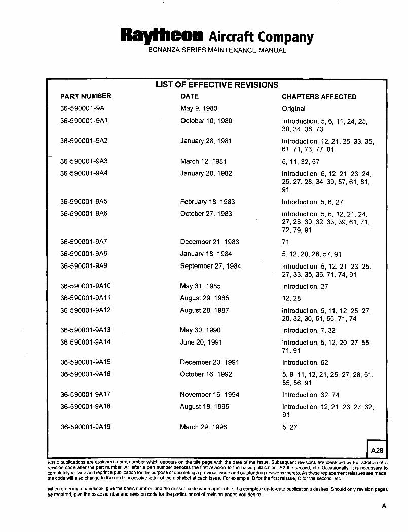
LIST OF EFFECTIVE REVISIONS
PART NUMBER DATE CHAPTERS AFFECTED
36-590001-9A May 9, 1980 Original
36-590001-9A1 October 10, 1980 Introduction, 5, 6, 11, 24, 25,30, 34, 36, 73
36-590001-9A2 January 28, 1981 Introduction, 12, 21, 25, 33, 35,61, 71, 73, 77, 81
36-590001-9A3 March 12, 1981 5, 11, 32, 57
36-590001-9A4 January 20, 1982 Introduction, 6, 12, 21, 23, 24,25, 27, 28, 34, 39, 57, 61, 81,
36-590001-9A5 February 18, 1983 Introduction, 5, 6, 27
36-590001-9A6 October 27, 1983 introduction, 5, 6, 12, 21, 24,27, 28, 30, 32, 33, 39, 61, 71,72, 79, 91
36-590001-9A7 December 21, 1983 71
36-590001-9A8 January 18, 1984 5, 12, 20, 28, 57, 91
36-590001-9A9 September 27, 1984 Introduction, 5, 12, 21, 23, 25,27, 33, 35, 36, 71, 74, 91
36-590001-9A10 May 31, 1985 Introduction, 27
36-590001-9A11 August 29, 1985 12, 28
36-590001-9A12 August 28, 1987 Introduction, 5, 11, 12, 25, 27,28, 32, 36, 51, 55, 71, 74
36-590001-9A13 May 30, 1990 Introduction, 7, 32
36-590001-9A14 June 20, 1991 Introduction, 5, 12, 20, 27, 55,71, 91
36-590001-9A15 December 20, 1991 Introduction, 52
36-590001-9A16 October 16, 1992 5, 9, 11, 12, 21, 25, 27, 28, 51,55, 56, 91
36-590001-9A17 November 16, 1994 Introduction, 32, 74
36-590001-9A18 August 18, 1995 Introduction, 12, 21,23, 27, 32,
36-590001-9A19 March 29, 1996 5, 27
A28
Basic publications are assigned a part number which appears on the title page with the date of the issue. Subsequent revisions are identified by the addition of a
revision code after the part number. Al after a part number denotes the first revision to the basic publication, A2 the second, etc. Occasionally, it is necessary to
completely reissue and reprint a publication for the purpose of obsoleting a previous issue and outstanding revisions thereto. As these replacement reissues are made.the code will also change to the next successive letter of the alphabet at each issue. For example, B for the first reissue, C for the second, etc.
When ordering a handbook, give the basic number, and the reissue code when applicable, if a complete up-to-date publicationis desired. Should only revision pagesbe required, give the basic number and revision code for the particular set of revision pages you desire.
Raytheon Aircraft CompanyBONANZA SERIES MAINTENANCE MANUAL
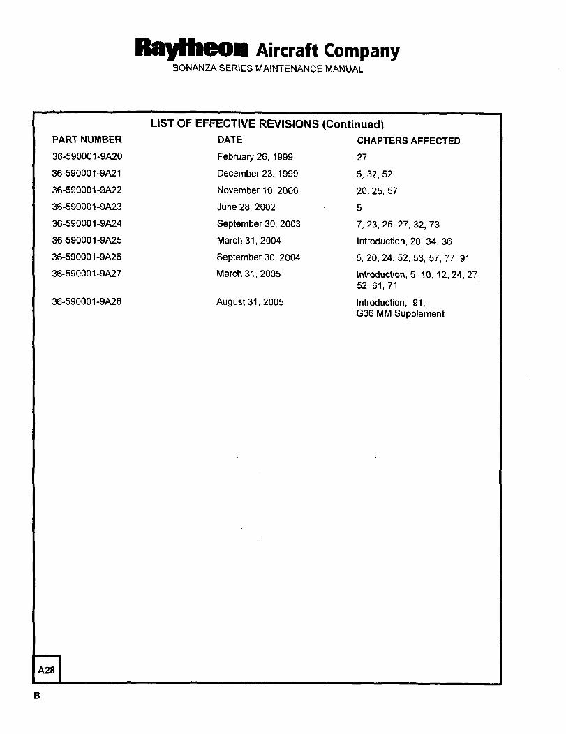
LIST OF EFFECTIVE REVISIONS (Continued)PART NUNISER DATE CHAPTERS AFFECTED
36-590001-9A20 February 26, 1999 27
36-590001-9A21 December 23, 1999 5, 32, 52
36-590001-9A22 November 10, 2000 20, 25, 57
36-590001 -9A23 June 28, 2002 5
36-590001-9A24 September 30, 2003 7, 23, 25, 27, 32, 73
36-590001-9A25 March 31, 2004 Introduction, 20, 34, 36
36-590001-9A26 September 30, 2004 5, 20, 24, 52, 53, 57, 77, 91
36-590001-9A27 March 31, 2005 Introduction, 5, 10, 12, 24, 27,52, 61, 71
36-590001-9A28 August 31, 2005 Introduction, 91,036 MM Supplement
A28
Raytt~eon AiKraft CompanyBONANZA SERIES MAINTENANCE MANUAL
RECORD OF TEMPORARY REVISIONS
Temporary Inserted Removed
Revision Affected
No. Chapter By Date By Revision No. Date
NOTE: Insert this Record of Temporary Revisions after the Log of Temporary Revisions page(s).
Page f
Sep 30/04
aevpeeen Aircraft CompanyBONANZA SERIES MAINTENAN~E jV1ANUAL
Record of Temporary Revisions (Continued)
Temporary Inserted Removed
Revision Affected
No. Chapter By Date By Revision No. Date
Page 2
Sep 30/04
Raytheon AiKraft CompanyBONANZA SERIES MAli;jiENANCE MANUAL
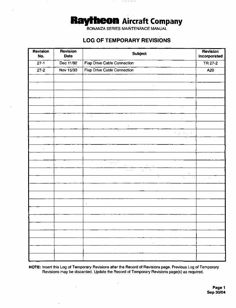
LOG OF TEMPORARY REVISIONS
Revision Revision RevisionSubject
No. Date Incorporated
27-1 Dec 11192 Flap Drive Cable Connection TR 27-2
27-2 Nov 15/93 Flap Drive Cable Connection A20
NOTE: Insert this Log of Temporary Revisions after the Record of Revisions page. Previous Log of TemporaryRevisions may be discarded. Update the Record of Temporary Revisions page(s) as required.
Page 1
Sep 30/04
Raytheon Aircraft CompanyBONANZA SERIES MAINTENANCE MANUAL
LOG OF TEMPORARY REVISIONS (Continued)
Revision Revision Revision
No. DateSubject
Incorporated
Page 2
Sep 30/04
Raytheon Aircraft CompanyBONANZA SERIES MAINTENANCE MANUAL
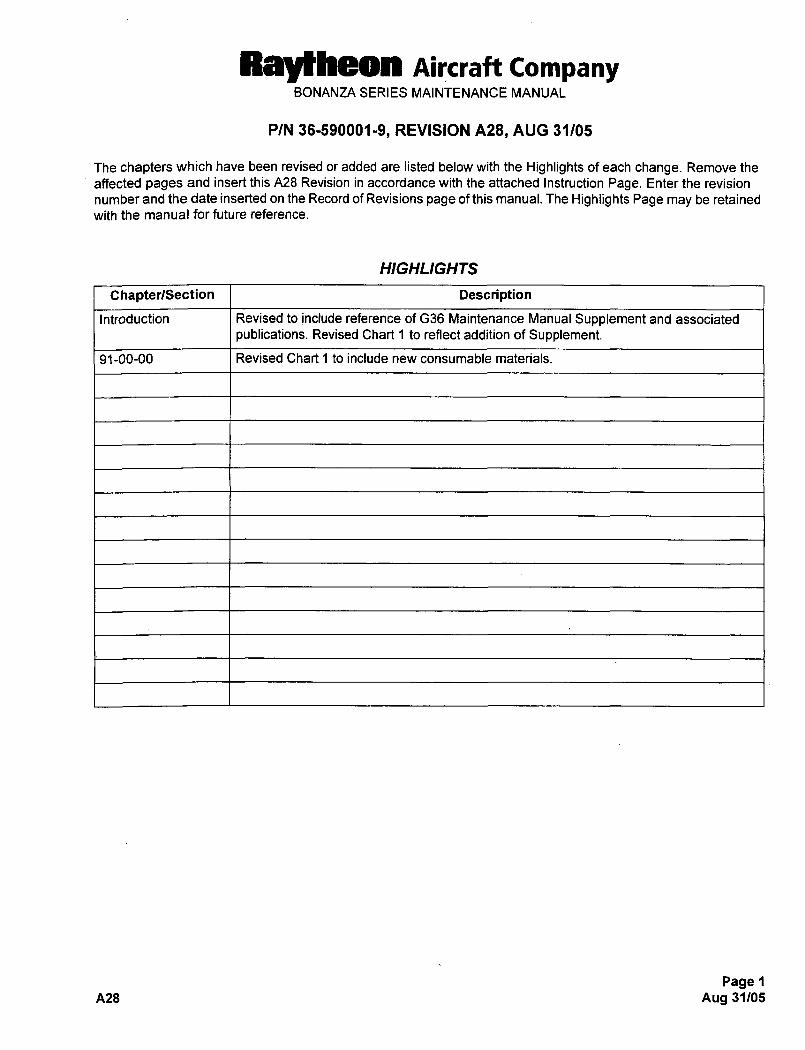
P/N 36-590001-9, REVISION A28, AUG 31/05
The chapters which have been revised or added are listed below with the Highlights of each change. Remove the
affected pages and insert this A28 Revision in accordance with the attached Instruction Page. Enter the revision
number and the date inserted on the Record of Revisions page of this manual. The Highlights Page may be retained
with the manual for future reference.
HIGHLIGHTS
ChapterlSection Description
Introduction Revised to include reference of G36 Maintenance Manual Supplement and associated
publications. Revised Chart i to reflect addition of Supplement.
91-00-00 Revised Chart 1 to include new consumable materials.
Page 1
A28 Aug 31/05
Raytheon Aircraft CompanyBONANZA SERIES MAINTENANCE MANUAL
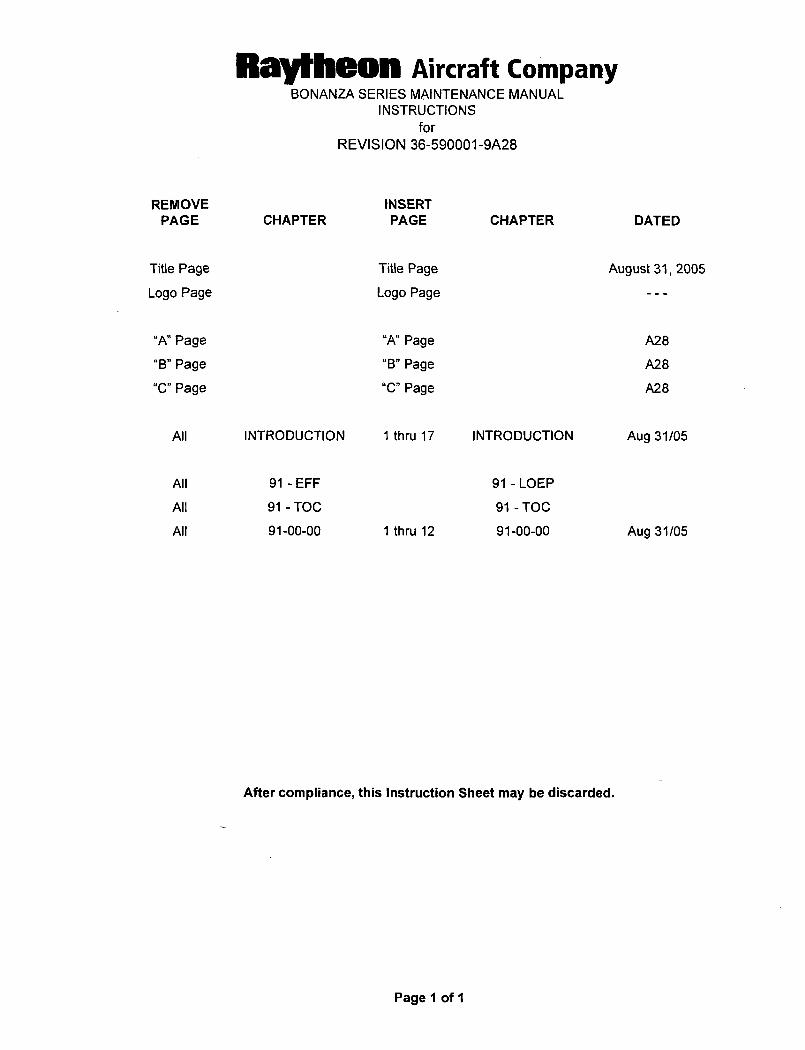
INSTRUCTIONS
for
REVISION 36-590001-9A28
REMOVE INSERT
PAGE CHAPTER PAGE CHAPTER DATED
Title Page Title Page August 31, 2005
Logo Page Logo Page
"A" Page "A" Page A28
"B" Page "B" Page A28
"C"Page "C"Page A28
All INTRODUCTION 1 thru 17 INTRODUCTION Aug 31/05
All 91-EFF 91-LOEP
All 91-TOC 91-TOC
All 91-00-00 1 thru 12 91-00-00 Aug 31/05
After compliance, this Instruction Sheet may be discarded.
Page 1 of 1
Ral~heon Aircraft CompanyBONANZA SERIES MAINTENANCE MANUAL
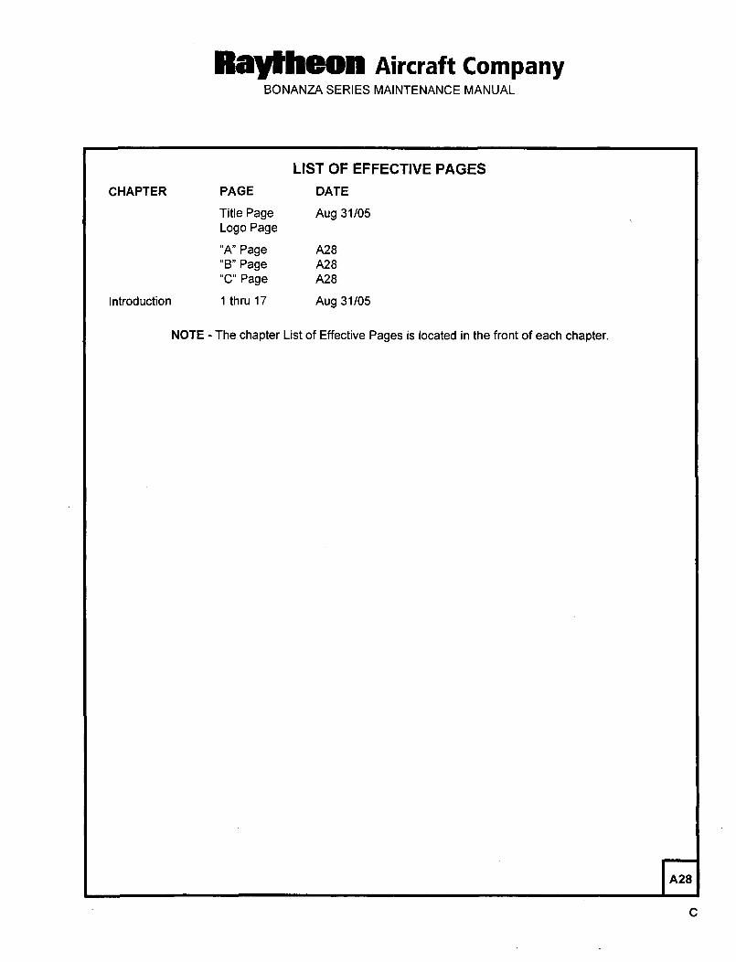
LIST OF EFFECTIVE PAGES
CHAPTER PAGE DATE
Title Page Aug 31/05
Logo Page
"A" Page A28
"B" Page A28
"C" Page A28
Introduction 1 thru 17 Aug 31/05
NOTE The chapter List of Effective Pages is located in the front of each chapter.
A28
Raytheon nircraft CompanyBONANZA SERIES MAINTENANCE MANUAL
INTRODUCTION
NOTE: Neither reissues nor revisions are automatically provided to the holder of this manual. For information on
how to obtain reissues or revisions applicable to this manual, refer to the latest revision of the RaytheonAircraft Company Service Bulletin No. 2001.
Additional publications are listed in the current Publications Price List CD-ROM (P/N 994-32808). For
Information on these publications contact the Technical Manual Distributions Center (TMDC) at
1-800-796-2665, fax (316) 676-4824, E-mail [email protected] or visit our web site at http:llpubs. raytheonaircraft.com.
The Bonanza Series Maintenance Manual is prepared in accordance with the GAMA (General Aviation
Manufacturers Association) Specification No. 2 format. It also meets the intent of the requirements of the ATA
Specification 1 00 (Air Transport Association of America) with respect to the arrangement and content of the System/Chapters within the designated chapter-numbering system. This maintenance manual is supplemented by the
following publications:
NOTE: It shall be the responsibility of the owner/operator to ensure that the latest revision of publications referenced
in this handbook are utilized during operation, servicing, and maintenance of the airplane.
The Bonanza 36 Series Illustrated Parts Catalog, PIN 36-590001-1
The Bonanza 35 Series Illustrated Parts Catalog, P/N 35-590102-5
The Bonanza 33 Series Illustrated Parts Catalog, PIN 33-590010-7
The Bonanza Wiring Diagram Manual, P/N 35-590102-9
(covers Models F33A, F33C, V35B, A36 "serials E-2110 and prior, except E-1946 and E-2104",and A36TC 8 B36TC "serials EA-388 and prior, except EA-320")
The Bonanza Wiring Diagram Manual, P/N 35-590102-11
(covers Models A36 "serials E-1946, E-2104, E-2111 thru E-3635, except E-3630" and
B36TC "serials EA-320, EA-389 and After")
The Bonanza Model G36 Electrical Wiring Diagram Manual, PIN 36-590001-13
The Bonanza Model G36 Avionics W~ring Diagram Manual, P/N 36-590001-15
The Bonanza 33, 35 and 36 Series Continuing Care Inspection Guide, P/N 98-36711
The Bonanza Model 33, 35 and 36 Inspection Guide, P/N 98-32227
The Bonanza Model G36 Maintenance Manual Supplement, PIN 36-590001-11
NOTE: Raytheon Aircraft Company expressly reserves the right to supersede, cancel and/or dedare obsolete any
parts, part numbers, kits, or publications that may be referenced in this manual without prior notice.
Since a wide variety of avionic components and equipment is available and because avionic manufacturers normallysupply parts and servicing manuals with each set/component, the avionic publications are not included in the
Publications Price List. The manufacturer of the equipment should be contacted when additional parts or servicinginformation is required.
nts INTRODUCTION Aug 31105Pagel
Raldheon Aircraft CompanyBONANZA SERIES MAINTENANCE MANUAL
WARNING: Use only parts obtained from sources approved by Raytheon Aircraft Company, in connection
with the maintenance and repair of Raytheon Aircraft Company airplanes.
Genuine Raytheon Aircraft Company parts are produced and inspected under rigorousprocedures to insure airworthiness and suitability for use in Raytheon Aircraft Companyairplane applications. Parts purchased from sources other than those approved by RaytheonAircraft Company, even though outwardly identical in appearance, may not have had the
required tests and inspections performed, may be different in fabrication techniques and
materials, and may be dangerous when installed in an airplane.
Salvaged airplane parts, reworked parts obtained from sources not approved by the RaytheonAircraft Company or parts, components or structural assemblies, the service history of which
is unknown or cannot be authenticated, may have been subjected to unacceptable stresses or
temperatures or have other hidden damage, not discernible through routine visual or usual
nondestructive testing techniques. This may render the part, component or structural
assembly, even though originally manufactured by the Raytheon Aircraft Company, unsuitable
and unsafe for airplane use.
Raytheon Aircraft Company expressly disclaims any responsibility for malfunctions, failures,damage or injury caused by use of parts not approved by the Raytheon Aircraft Company.
CORRESPONDENCE
If a question should arise concerning the care of you; airplane, it is important to include the airplane serial number
in any correspondence. The serial number appears on the model designation placard. Refer to Chapter 11-00-00
for placard location.
PUBLICA TIONS CHANGE REQUEST (PCR)
If an irregularity or missing information is noted, the user of this manual may access a PCR form at
www. raytheonaircraft.comlservice_support/publications_change.htm. This form and the information that was
entered will be electronically forwarded to Raytheon Aircraft Customer Support. The change request will be
researched for any necessary updates to the publication. Assistance is available, at any time, by contacting-Raytheon Aircraft Technical Support at 800-429-5372 or 316-676-3140.
ASSIGNMENT OF SUBJECT MA TERIAL
The content of this publication is organized into four levels. The four levels are:
GROUP Identified by different colored divider tabs. These are the primary divisions of the manual that enable broad
separation of content. Typical of this division is the separation between Airframe Systems and the Power Plant.
SYSTEM/CHAPTER The various groups are broken down into major systems such as Environmental Systems,Electrical Power, Landing Gear, etc. The systems are arranged more or less alphabetically rather than byprecedence or importance. They are assigned a number, which becomes the first element of the standardized
numberi ng system. Thus, the element 28 of the number 28-00-00 refers to the chapter FU EL. Everyth ing concerningthe fuel system will be covered in this chapter.
SUBSYSTEM/SECTION The major systems/chapters of an airplane are broken down into subsystems. These
subsystems are identified by the second element of the standard numbering system. The element 40 of the number
28-40-00 concerns itself with the indicating section of the fuel system.
Aug 31/05Page 2 INTRODUCTION us
Rallheon AiKraft CompanyBONANZA SERIES MAINTENANCE MANUAL
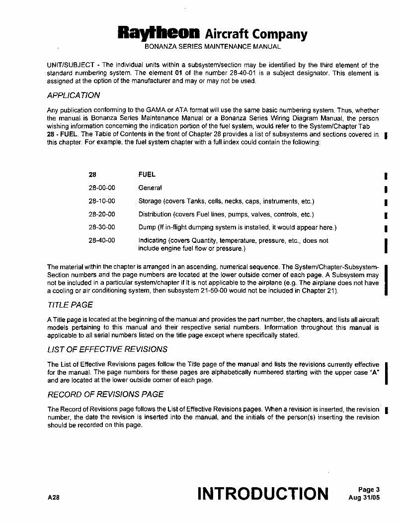
UNIT/SUBJECT The individual units within a subsystemlsection may be identified by the third element of the
standard numbering system. The element 01 of the number 28-40-01 is a subject designator. This element is
assigned at the option of the manufacturer and may or may not be used.
APPLICATION
Any publication conforming to the GAMA or ATA format will use the same basic numbering system. Thus, whether
the manual is Bonanza Series Maintenance Manual or a Bonanza Series Wiring Diagram Manual, the person
wishing information concerning the indication portion of the fuel system, would refer to the System/Chapter Tab
28 FUEL. The Table of Contents in the front of Chapter 28 provides a list of subsystems and sections covered in Ithis chapter. For example, the fuel system chapter with a full index could contain the following:
28 FUEL
28-00-00 General
28-10-00 Storage (covers Tanks, cells, necks, caps, instruments, etc.)
28-20-00 Distribution (covers Fuel lines, pumps, valves, controls, etc.)
28-30-00 Dump (If in-flight dumping system is installed, it would appear here.)
28-40-00 Indicating (covers Quantity, temperature, pressure, etc., does not
include engine fuel flow or pressure.)
The material within the chapter is arranged in an ascending, numerical sequence. The System/Chapter-Subsystem-Section numbers and the page numbers are located at the lower outside corner of each page. A Subsystem maynot be included in a particular systemlchapter if it is not applicable to the airplane (e.g. The airplane does not have
a cooling or air conditioning system, then subsystem 21-50-d0 would not be included in Chapter 21).
TITLE PAGE
A Title page is located at the beginning of the manual and provides the part number, the chapters, and lists all aircraft
models pertaining to this manual and their respective serial numbers. Information throughout this manual is
applicable to all serial numbers listed on the title page except where specifically stated.
LIST OF EFFECTIVE REVISIONS
The List of Effective Revisions pages follow the Title page of the manual and lists the revisions currently effective
for the manual. The page numbers for these pages are alphabetically numbered starting with the upper case "A"
and are located at the lower outside corner of each page.
RECORD OF REVISIONS PAGE
The Record of Revisions page follows the List of Effective Revisions pages. When a revision is inserted, the revision Inumber, the date the revision is inserted into the manual, and the initials of the person(s) inserting the revision
should be recorded on this page.
nns INTRODUCTION Aug 31105Page 3
Raytheon nircraft CompanyBONANZA SERIES MAINTENANCE MANUAL
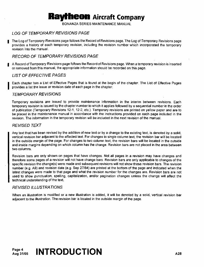
LOG OF TEMPORARY REVISIONS PAGE
I The Log of Temporary Revisions page follows the Record of Revisions page. The Log of Temporary Revisions page
provides a history of each temporary revision, including the revision number which incorporated the temporaryrevision into the manual.
RECORD OI" TEMPORARY REVISIONS PAGE
I A Record of Temporary Revisions page follows the Record of Revisions page. When a temporary revision is inserted
or removed from this manual, the appropriate information should be recorded on this page.
LIST OF EFFECTIVE PAGES
I Each chapter has a List of Effective Pages that is found at the begin of the chapter. The List of Effective Pagesprovides a list the issue or revision date of each page in the chapter.
TEMPORARY REVISIONS
Temporary revisions are issued to provide maintenance information in the interim between revisions. Each
temporary revision is issued by the chapter number to which it applies followed by a sequential number in the order
of publication (Temporary Revisions 12-1, 12-2, etc.). Temporary revisions are printed on yellow paper and are to
be placed in the maintenance manual in accordance with the instructions provided on each page included in the
revision. The information in the temporary revision will be included in the next revision of the manual.
REVISED TEXT
Any text that has been revised by the addition of new text or by a change to the existing text, is denoted by a solid,vertical revision bar adjacent to the affected text. For changes to single column text, the revision bar will be located
in the outside margin of the page. For changes to two column text, the revision bars will be located in the outside
and inside margins depending on which column has the change. Revision bars are not placed in the area between
two columns.
Revision bars are only shown on pages that have changes. Not all pages in a revision may have changes and
therefore some pages of a revision will not have change bars. Revision bars are only applicable to changes of the
specific revision the change(s) were made and subsequent revisions will not show these revision bars. The revision
number (e.g. A9) and revision date (e.g. Sep 27/84) are printed at the bottom of the page and indicated when the
latest changes were made to that page and what the revision number for the changes are. Revision bars are not
used to show punctuation, spelling, capitalization, andlor pagination changes unless the change will affect the
technical understanding of the text.
REVISED ILLUSTRATIONS
When an illustration is modified or a new illustration is added, it will be denoted by a solid, vertical revision bar
adjacent to the illustration. The revision bar is located in the outside margin of the page.
Aug 31105INTRODUCTION ua
Ray~heon Aircraft CompanyBONANZA SERIES MAINTENANCE MANUAL
WARNINGS, CAUTIONS AND NOTES
WARNING Brings attention to an operating procedure, inspection, repair or maintenance practices, which if
not correctly followed, could result in personal injury or loss of life.
CAUTION Brings attention to an operating procedure, inspection, repair or maintenance condition, which if not
strictly observed, could result in damage or destruction of equipment.
NOTE Brings attention to an operating procedure, inspection, repair or maintenance condition, which is
essential to highlight.
.-SCHEMA TIC DIAGRAMS
Schematic diagrams are illustrated with the following conditions:
Airplane is on the ground.
All doors are closed and locked.
Electrical power is not applied to the airplane.
A note will be shown on the schematic diagram if the above conditions are different (e.g. NOTE Airplane shown
with power applied and entrance door open.).
Contacts on connectors that are identified with lower case letters will be shown by an underlined letter or a letter
with an asterisk (A*).
SPECIAL CONDITIONS CAUTIONARY NOTICE
Airplanes operated for Air Taxi, or other than normal operation, and airplanes operated in humid tropics, cold and
damp climates, etc., may need more frequent inspections for wear, corrosion andlor lack of lubrication. Under these
adverse conditions, perform periodic inspections in compliance with this guide at more frequent intervals until the
owner or operator can set his own inspection periods based on the contingencies of field experience.
CAUTION: The recommended periods do not constitute a guarantee the item will reach the period without
malfunction as the aforementioned factors cannot be controlled by the manufacturer.
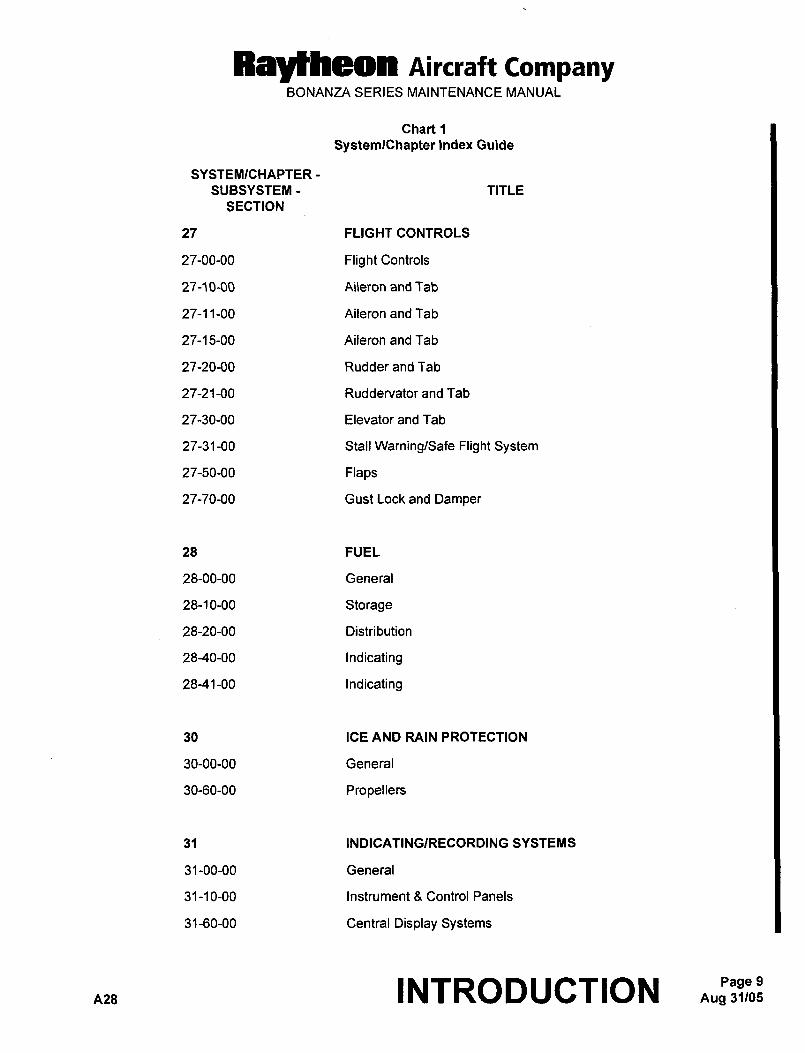
SYSTEM/CHAPTER INDEX GUIDE
The SystemlChapter Index Guide (refer to Chart 1) is prepared in accordance with both ATA Specification No. 100
and GAMA Specification No. 2 for use with this maintenance manual and its applicable illustrated parts catalogs,electrical wiring diagram manuals, avionics wiring diagram manuals, and maintenance manual supplements. The
guide provides a list of all system/chapters and subsystems that are applicable to this maintenance manual. The
following chapters are not applicable to this maintenance manual: 4, 26, 29, 37, 38, 49, 60, 70, 75, 76, 77, 78, 83
and 95.
nzs INTRODUCTION Aug 31/05Page 5
Ray~heon Aircraft CompanyBONANZA SERIES MAINTENANCE MANUAL
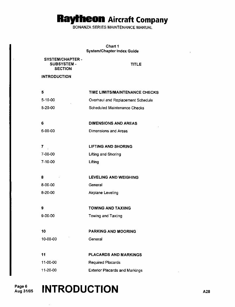
Chart 1
SystemlChapter Index Guide
SYSTEMICHAPTER
SUBSYSTEM- TITLE
SECTION
INTRODUCTION
5 TIME LIMITSIMAINTENANCE CHECKS
5-10-00 Overhaul and Replacement Schedule
5-20-00 Scheduled Maintenance Checks
6 DIMENSIONS AND AREAS
6-00-00 Dimensions and Areas
7 LIFTING AND SHORING
7-00-00 Lifting and Shoring
7-10-00 Lifting
8 LEVELING AND WEIGHING
8-00-00 General
8-20-00 Airplane Leveling
9 TOWING AND TAXIING
9-00-00 Towing and Taxiing
10 PARKING AND MOORING
10-00-00 General
11 PLACARDS AND MARKINGS
11-00-00 Required Placards
11-20-00 Exterior Placards and Markings
Aug 31105Page 6 INTRODUCTION A28
Raytheon AiKraft CompanyBONANZA SERIES MAINTENANCE MANUAL
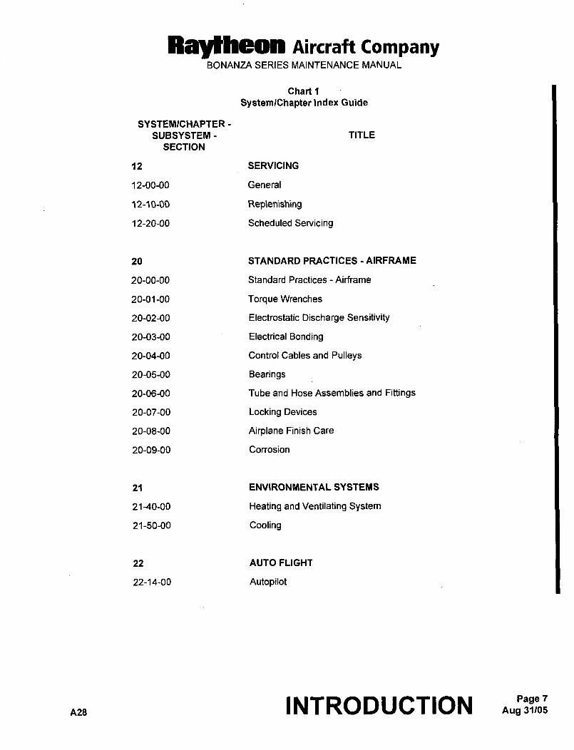
Chart 1
SystemlChapter Index Guide
SYSTEI~ICHAPTER
SUBSYSTEM- TITLE
SECTION
12 SERVICING
12-00-00 General
12-10-00 Rep\enishing
12-20-00 Scheduled Servicing
20 STANDARD PRACTICES AIRFRAME
20-00-00 Standard Practices- Airframe
20-01-00 Torque Wrenches
20-02-00 Electrostatic Discharge Sensitivity
20-03-00 Electrical Bonding
20-04-00 Control Cables and Pulleys
20-05-00 Bearings
20-06-00 Tube and Hose Assemblies and Fittings
20-07-00 Locking Devices
20-08-00 Airplane Finish Care
20-09-00 Corrosion
21 ENVIRONMENTAL SYSTEMS
21-40-00 Heating and Ventilating System
21-50-00 Cooling
22 AUTO FLIGHT
22-14-00 Autopilot
A28 INTRODUCTION AUgPBjS~;:Page 7
Raytheon AiKraft CompanyBONANZA SERIES MAINTENANCE MANUAL
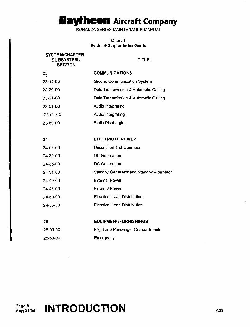
Chart 1
SystemlChapter Index Guide
SYSTEMICHAPTER-
SUBSYSTEM- TITLE
SECTION
23 COMMUNICATIONS
23-10-00 Ground Communication System
23-20-00 Data Transmission 8 Automatic Calling
23-21-00 Data Transmission 8 Automatic Calling
23-51-00 Audio Integrating
23-52-00 Audio Integrating
23-60-00 Static Discharging
24 ELECTRICAL POWER
24-05-00 Description and Operation
24-30-00 DC Generation
24-35-00 DC Generation
24-31-00 Standby Generator and Standby Alternator
24-40-00 External Power
24-45-00 Extemal Power
24-50-00 Electrical Load Distribution
24-55-00 Electrical Load Distribution
25 EQUIPMENTIFURNISHINGS
25-00-00 Flight and Passenger Compartments
25-60-00 Emergency
Aug 31/05Page 8 INTRODUCTION A28
Raytheon nircraft CompanyBONANZA SERIES MAINTENANCE MANUAL
Chart 1
SystemlChapter Index Guide
SYSTEMICHAPTER
SUBSYSTEM- TITLE
SECTION
27 FLIGHT CONTROLS
27-00-00 Flight Controls
27-10-00 Ai\eron and Tab
27-11-00 Aileron and Tab
27-15-00 Aileron and Tab
27-20-00 Rudder and Tab
27-21-00 Ruddervator and Tab
27-30-00 Elevator and Tab
27-31-00 Stall WarninglSafe Flight System
27-50-00 Flaps
27-70-00 Gust Lock and Damper
28 FUEL
28-00-00 General
28-10-00 Storage
28-20-00 Distribution
28-40-00 Indicating
28-41-00 Indicating
30 ICE AND RAIN PROTECTION
30-00-00 General
30-60-00 Propellers
31 INDICATINGIRECORDING SYSTEMS
31-00-00 General
31-10-00 Instrument 8 Control Panels
31-60-00 Central Display Systems
A28 INTRODUCTION 9
Raytheon nircraft CompanyBONANZA SERIES MAINTENANCE MANUAL
Chart 1
SystemlChapter Index Guide
SYSTEMICHAPTER-
SUBSYSTEM- TITLE
SECTION
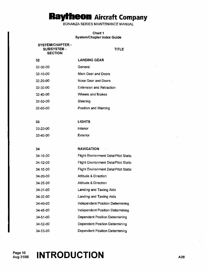
32 LANDING GEAR
32-00-00 General
32-10-00 Main Gear and Doors
32-20-00 Nose Gear and Doors
32-30-00 Extension and Retraction
32-40-00 Wheels and Brakes
32-50-00 Steering
32-60-00 Position and Warning
33 LIGHTS
33-20-00 Interior
33-40-00 Exterior
34 NAVIGATION
34-10-00 Flight Environment Data/Pitot Static
34-12-00 Flight Environment Data/Pitot Static
34-15-00 Flight Environment Data/Pitot Static
34-20-00 Attitude Direction
34-25-00 Attitude 3 Direction
34-31-00 Landing and Taxiing Aids
34-32-00 Landing and Taxiing Aids
34-40-00 Independent Position Determining
34-45-00 Independent Position Determining
34-51-00 Dependent Position Determining
34-52-00 Dependent Position Determining
34-53-00 Dependent Position Determining
Aug 31105Page 10 INTRODUCTION A28
Raytheon Aircraft CompanyBONANZA SERIES MAINTENANCE MANUAL
Chart 1
SystemlChapter Index Guide
SYSTEMICHAPTER
SUBSYSTEM- TITLE
SECTION
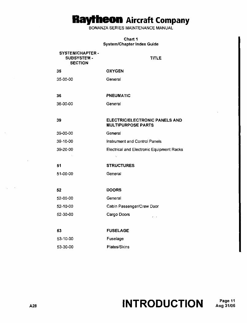
35 OXYGEN
35-00-00 General
36 PNEUMATIC
36-00-00 General
39 ELECTRICIELECTRONIC PANELS AND
MULTIPURPOSE PARTS
39-00-00 General
39-10-00 Instrument and Control Panels
39-20-00 Electrical and Electronic Equipment Racks
51 STRUCTURES
51-00-00 General
52 DOORS
52-00-00 General
52-10-00 Cabin Passenger/Crew Door
52-30-00 Cargo Doors
53 FUSELAGE
53-10-00 Fuselage
53-30-00 Plates/Skins
A28 INTRODUCTIONPage 11
Raytheon AiKraft CompanyBONANZA SERIES MAINTENANCE MANUAL
Chart 1
SystemlChapter Index Guide
SYSTEMICHAPTER-
SUBSYSTEM- TITLE
SECTION
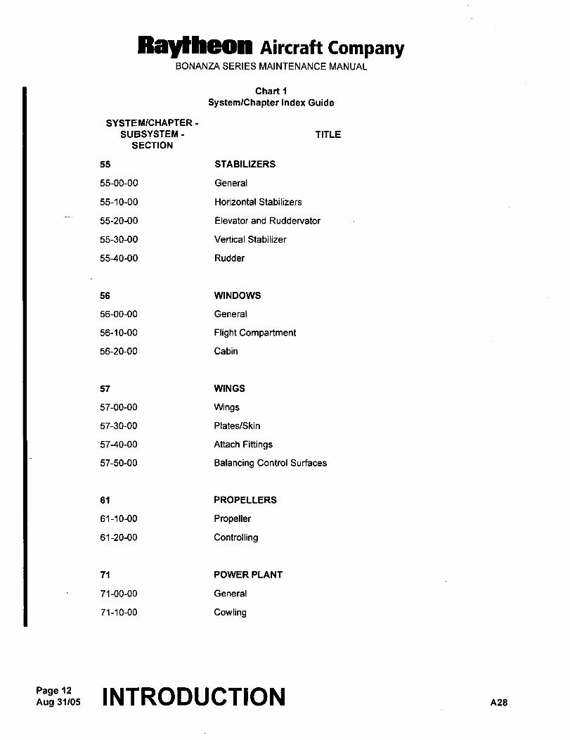
55 STABILIZERS
55-00-00 General
55-1 0-00 Horizontal Stabilizers
55-20-00 Elevator and Ruddervator
55-30-00 Vertical Stabilizer
55-40-00 Rudder
56 WINDOWS
56-00-00 General
56-10-00 Flight Cornpartrnent
56-20-00 Cabin
57 WINGS
57-00-00 Wings
57-30-00 Plates/Skin
57-40-00 Attach Fittings
57-50-00 Balancing Control Surfaces
61 PROPELLERS
61-10-00 Propeller
61-20-00 Controlling
71 POWER PLANT
71-00-00 General
71-10-00 Cowling
Aug 31/05Page 12 INTRODUCTION A28
Raylheon AiKraft CompanyBONANZA SERIES MAINTENANCE MANUAL
Chart 1
SystemlChapter Index Guide
SYSTEMICHAPTER
SUBSYSTEM- TITLE
SECTION
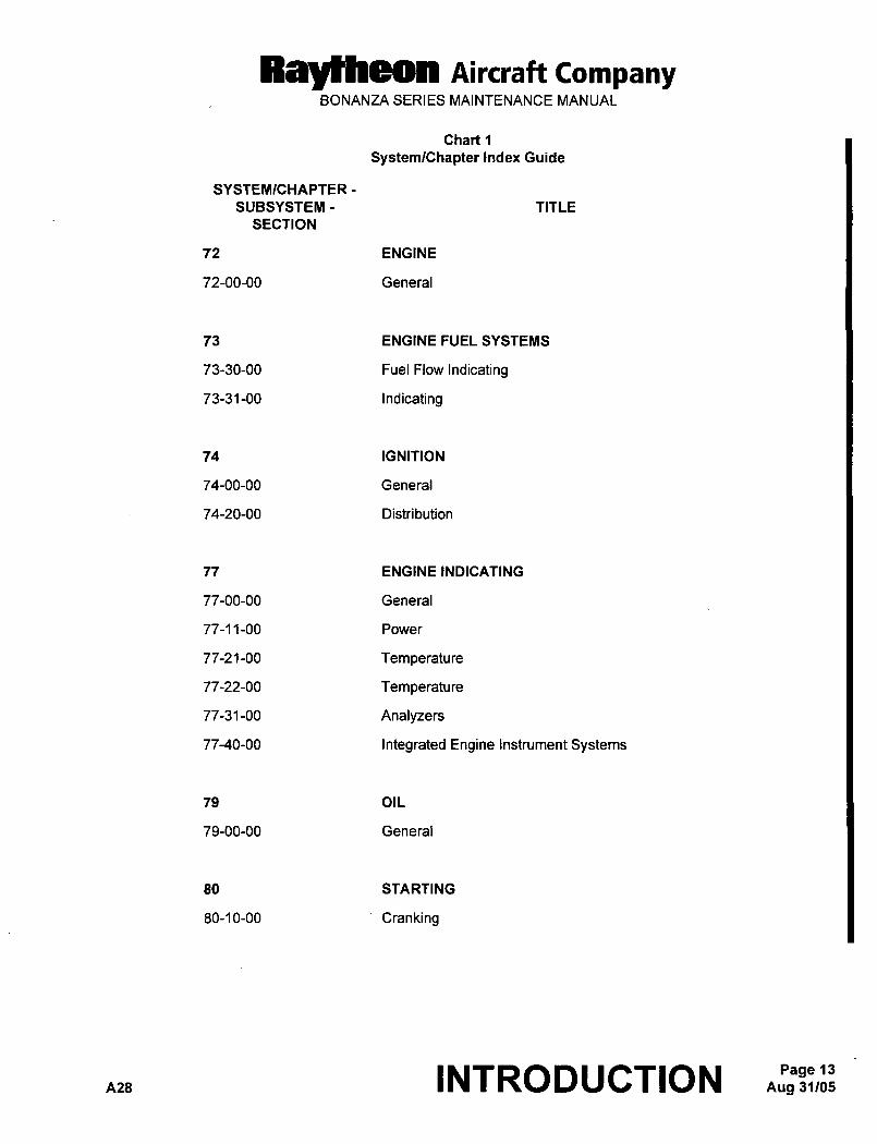
72 ENGINE
72-00-00 General
73 ENGINE FUEL SYSTEMS
73-30-00 Fuel Flow Indicating
73-31-00 Indicating
74 IGNITION
74-00-00 General
74-20-00 Distribution
77 ENGINE INDICATING
77-00-00 General
77-11-00 Power
77-21-00 Temperature
77-22-00 Temperature
77-31-00 Analyzers
77-40-00 Integrated Engine Instrument Systems
79 OIL
79-00-00 General
80 STARTING
80-10-00 Cranking
A28 INTRODUCTION Aug 31/05Page 13
Raytheon Aircraft CompanyBONANZA SERIES MAINTENANCE MANUAL
Chart 1
SystemlChapter Index Guide
SYSTEMICHAPTER-
SUBSYSTEM- TITLE
SECTION
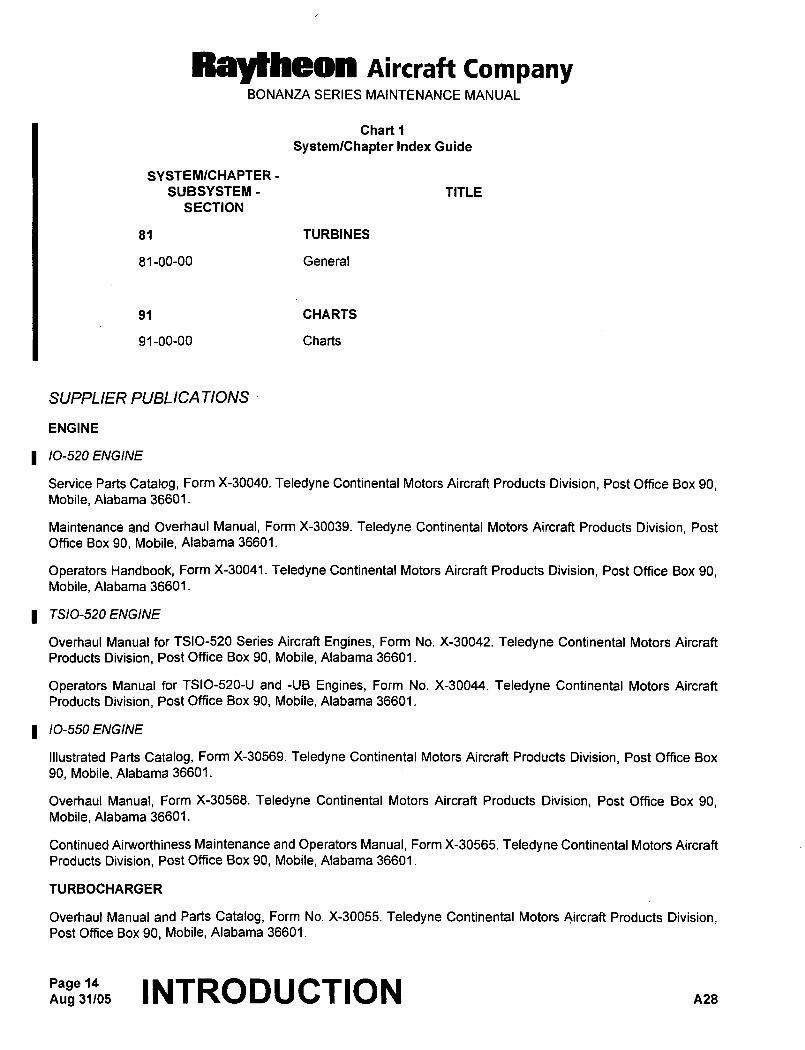
81 TURBINES
81-00-00 General
91 CHARTS
91-00-00 Charts
SUPPLIER PUBLICA nONS
ENGINE
1 ’0-520 ENGINE
Service Parts Catalog, Form X-30040. Teledyne Continental Motors Aircraft Products Division, Post Office Box 90,Mobile, Alabama 36601.
Maintenance and Overhaul Manual, Form X-30039. Teledyne Continental Motors Aircraft Products Division, Post
Office Box 90, Mobile, Alabama 36601.
Operators Handbook, Form X-30041. Teledyne Continental Motors Aircraft Products Division, Post Office Box 90,Mobile, Alabama 36601.
TSIO-520 ENGINE
Overhaul Manual for TSIO-520 Series Aircraft Engines, Form No. X-30042. Teledyne Continental Motors Aircraft
Products Division, Post Office Box 90, Mobile, Alabama 36601.
Operators Manual for TSIO-520-U and -UB Engines, Form No. X-30044. Teledyne Continental Motors Aircraft
Products Division, Post Office Box 90, Mobile, Alabama 36601.
10-550 ENGINE
Illustrated Parts Catalog, Form X-30569. Teledyne Continental Motors Aircraft Products Division, Post Office Box
90, Mobile, Alabama 36601.
Overhaul Manual, Form X-30568. Teledyne Continental Motors Aircraft Products Division, Post Office Box 90,Mobile, Alabama 36601.
Continued Aimorthiness Maintenance and Operators Manual, Form X-30565. Teledyne Continental Motors Aircraft
Products Division, Post Office Box 90, Mobile, Alabama 36601.
TURBOCHARGER
Overhaul Manual and Parts Catalog, Form No. X-30055. Teledyne Continental Motors Aircraft Products Division,Post Office Box 90, Mobile, Alabama 36601.
Page 14Aug31105 INTRODUCTION n2s
RBYtheoll Aircraft CompanyBONANZA SERIES MAINTENANCE MANUAL
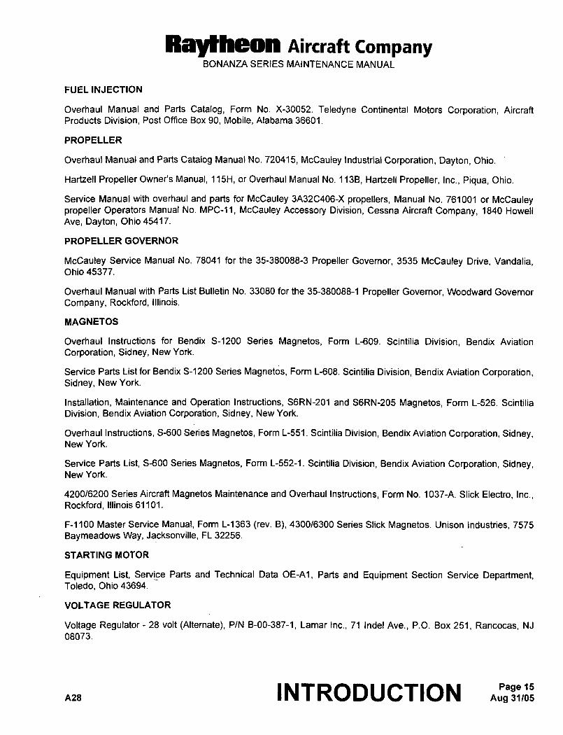
FUEL INJECTION
Overhaul Manual and Parts Catalog, Form No. X-30052. Teledyne Continental Motors Corporation, Aircraft
Products Division, Post Office Box 90, Mobile, Alabama 36601.
PROPELLER
Overhaul Manual and Parts Catalog Manual No. 720415, McCauley Industrial Corporation, Dayton, Ohio.
Hartzell Propeller Owner’s Manual, 115H, or Overhaul Manual No. 113B, Hartzell Propeller, Inc., Piqua, Ohio.
Service Manual with overhaul and parts for McCauley 3A32C406-X propellers, Manual No. 761001 or McCauleypropeller Operators Manual No. N1PC-11, McCauley Accessory Division, Cessna Aircraft Company, 1840 Howell
Ave, Dayton, Ohio 45417.
PROPELLER GOVERNOR
McCauley Service Manual No. 78041 for the 35-380088-3 Propeller Governor, 3535 McCauley Drive, Vandalia,Ohio 45377.
Overhaul Manual with Parts List Bulletin No. 33080 for the 35-380088-1 Propeller Govemor, Woodward Governor
Company, Rockford, Illinois.
MAGNETOS
Overhaul Instructions for Bendix S-1200 Series Magnetos, Form L-609. Scintilia Division, Bendix Aviation
Corporation, Sidney, New York.
Service Parts List for Bendix S-1200 Series Magnetos, Form L-608. Scintilia Division, Bendix Aviation Corporation,Sidney, New York.
Installation, Maintenance and Operation Instructions, S6RN-201 and S6RN-205 Magnetos, Form L-526. Scintilia
Division, Bendix Aviation Corporation, Sidney, New York.
Overhaul Instructions, 5-600 Series Magnetos, Form L-551. Scintilia Division, Bendix Aviation Corporation, Sidney,New York.
Service Parts List, S-600 Series Magnetos, Form L-552-1. Scintilia Division, Bendix Aviation Corporation, Sidney,New York.
420016200 Series Aircraft Magnetos Maintenance and Overhaul Instructions, Form No. 1037-A. Slick Electro, Inc.,Rockford, Illinois 61101.
F-1100 Master Service Manual, Form L-1363 (rev. B), 4300/6300 Series Slick Magnetos. Unison Industries, 7575
Baymeadows Way, Jacksonville, FL 32256.
STARTING MOTOR
Equipment List, Servj_ce Parts and Technical Data OE-A1, Parts and Equipment Section Service Department,Toledo, Ohio 43694.
VOLTAGE REGULATOR
Voltage Regulator 28 volt (Alternate), P/N B-00-387-1, Lamar Inc., 71 Indel Ave., P.O. Box 251, Rancocas, NJ
08073.
n2a INTRODUCTION Aug 31105Page 15
Raytheon nircraft CompanyBONANZA SERIES MAINTENANCE MANUAL
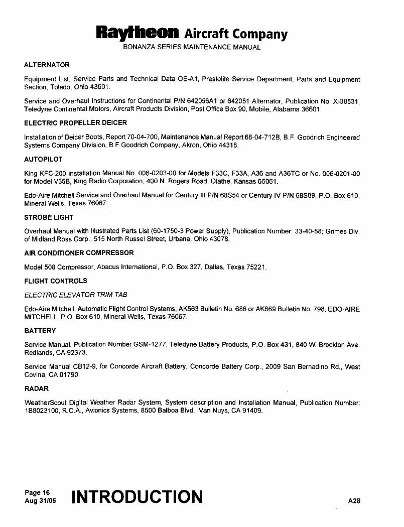
ALTERNATOR
Equipment List, Service Parts and Technical Data OE-A1, Prestolite Service Department, Parts and EquipmentSection, Toledo, Ohio 43601.
Service and Overhaul Instructions for Continental P/N 642056A1 or 642051 Alternator, Publication No. X-30531,Teledyne Continental Motors, Aircraft Products Division, Post Office Box 90, Mobile, Alabama 36601.
ELECTRIC PROPELLER DEICER
Installation of Deicer Boots, Report 70-04-700, Maintenance Manual Report 68-04-7126, B.F. Goodrich EngineeredSystems Company Division, B F Goodrich Company, Akron, Ohio 44318.
AUTOPILOT
King KFC-200 Installation Manual No. 006-0203-00 for Models F33C, F33A, A36 and A36TC or No. 006-0201-00
for Model V35B, King Radio Corporation, 400 N. Rogers Road, Olathe, Kansas 66061.
Edo-Aire Mitchell Service and Overhaul Manual for Century III P/N 68854 or Century IV P/N 68S89, P.O. Box 610,Mineral Wells, Texas 76067.
STROBE LIGHT
Overhaul Manual with Illustrated Parts List (60-1750-3 Power Supply), Publication Number: 33-40-58; Grimes Div.
of Midland Ross Corp., 515 North Russel Street, Urbana, Ohio 43078.
AIR CONDITIONER COMPRESSOR
Model 508 Compressor, Abacus International, P.O. Box 327, Dallas, Texas 75221.
FLIGHT CONTROLS
ELECTRIC ELEVATOR TRIM TAB
Edo-Aire Mitchell, Automatic Flight Control Systems, AK563 Bulletin No. 686 or AK669 Bulletin No. 798, EDO-AIRE
MITCHELL, P.O. Box 610, Mineral Wells, Texas 76067.
BATTERY
Service Manual, Publication Number GSM-1277, Teledyne Battery Products, P.O. Box 431, 840 W. Brockton Ave.
Redlands, CA 92373.
Service Manual CB12-9, for Concorde Aircraft Battery, Concorde Battery Corp., 2009 San Bernadino Rd., West
Covina, CA 01790.
RADAR
WeatherScout Digital Weather Radar System, System description and Installation Manual, Publication Number:
168023100, R.C.A., Avionics Systems, 8500 Balboa Blvd., Van Nuys, CA 91409.
Aug 31/05Page 16 INTRODUCTION nzs
Raytheon AiKraft C6mpanyBONANZA SERIES MAINTENANCE MANUAL
INTEGRATED AVIONICS SYSTEM
Garmin G1000TM, Cockpit Reference Guide for the Beechcraft A36/G36, Publication Number: 190-00525-00 01,Garmin Internationa\, Inc., 1200 E151S’ Street, Olathe, KS 66062 USA.
Garmin G1000TM, Configuration Manual, Publication Number: 190-00303-04,Garmin International, Inc., 1200 E 151S’ Street, Olathe, KS 66062 USA.
Garmin G1000TM, Line Maintenance Manual, Publication Number: 190-00352-00,Garmin International, Inc., 1200 E 1515’ Street, Olathe, KS 66062 USA.
SUPPLEMENTARY PUBLICA TIONS
98-35012 Servicing Maintenance Instructions and Illustrated Parts Breakdown for the Main Wheel, Nose Wheel and
Brake Assembly.
32-31-24 Maintenance Information and Illustrated Parts Breakdown for EM 27-8 Landing Gear Motor.
nzs INTRODUCTION Aug 31105Page 17
CHAPTER
TIME LIMITS/
MAINTENANCE
CH ECKS
RayMheon nircraft CompanyBONANZA SERIES MAINTENANCE MANUAL
CHAPTER 5 TIME LIMITS/MAINTENANCE CHECKS
TABLE OF CONTENTS
SUBJECT PAGE
5-10-00
Overhaul and Replacement Schedule.........._....._
.1
Special ConditionsCautionary Notice.........._____
..................1
Landing Gear........._____ ........._____
Power Plant
Flaps and Flight Controls ........4
Fuel SystemInstruments
Electrical SystemMiscellaneous
W~ngs. ..6
5-20-00
Scheduled MaintenanceChecks -Maintenance Practices ...1
Electric Propeller Deicer (50 Hour Guide). ...........____ ........._____
...............1
Electric Propeller Deicer(100 HourGuide). ................._ ................._
..............1
Turbocharger(EA-ll and After) .3
25 Hours
50 Hours
100Hours...........................................................................3
E33C, F33C Spin Inspection (AcrobaticCategory). ........3
100-HourorAnnual Inspection Guide. ..................6
FACTS Program(ModelsA36and B36TC) ..............7
Special Conditions Cautionary Notice. ..................7
100-HourorAnnual Inspection .....9
A. Operational Inspection ......9
B. Power Plant
C. Cabin and Baggage Compartment. ..............14
D. Wingsand Carry-Through Structure........._._._.._
.............15
E. Nose Gear
F Main Gear and Brakes .....17
G Main Gear Operation ......18
H. Nose Gear Operation. .....19
I. Rear Fuselage and Empennage .................19
J. General
A27 5-CONTENTS Mar 31/05Page 1
Rlytheon nircraft CompanyBONANZA SERIES MAINTENANCE MANUAL
CHAPTER 5 TIME LIMITS/MAINTENANCE CHECKS
TABLE OF CONTENTS (Continued)
SUBJECT PAGE
5-50-00
Unscheduled Maintenance Checks -Maintenance Practices 1
OperationAfterSudden Stoppage Incidents 1
When Operating in Areas of High Dust Content 1
When Operating in Areas of High Humidity 1
After Receiptof the Airplane 2
Operating fromVery SoftorUnusualTerrain........._._.._.._ 2
Inspection AfterHard Landing ........._._....__ 3
Inspection AfterEncountering TurbulentAir 7
Inspection AfterLightning Strike 10
Page 2;H~t, 5-CONTENTS anr
Ray~heon Aircraft CompanyBONANZA SERIES MAINTENANCE MANUAL
CHAPTER 5 TIME LIMITS/MAINTENANCE CHECKS
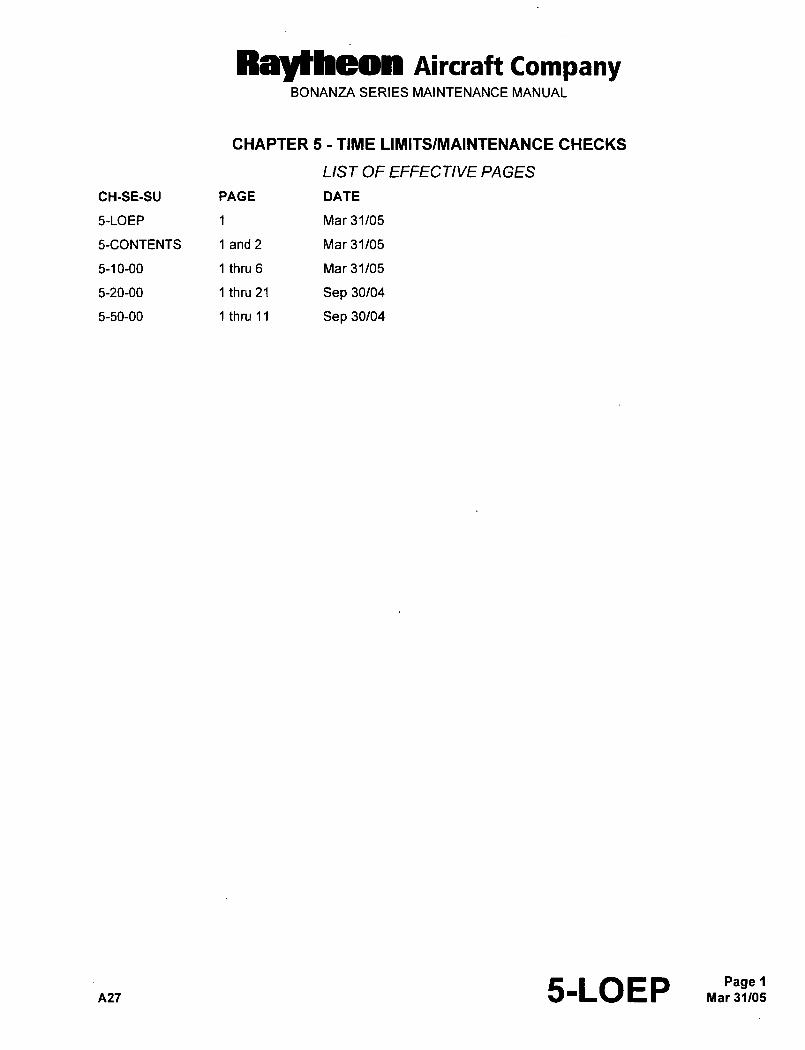
LIST OF EFFECTIVE PA GES
CH-SE-SU PAGE DATE
5-LOEP 1 Mar 31/05
5-CONTENTS 1 and 2 Mar 31/05
5-10-00 1 thru 6 Mar 31/05
5-20-00 1 thru 21 Sep 30/04
5-50-00 1 thru 11 Sep 30/04
A27 5-LOEP Mar 31105Page 1
Rayrheon nircraft CompanyBONANZA SERIES MAINTENANCE MANUAL
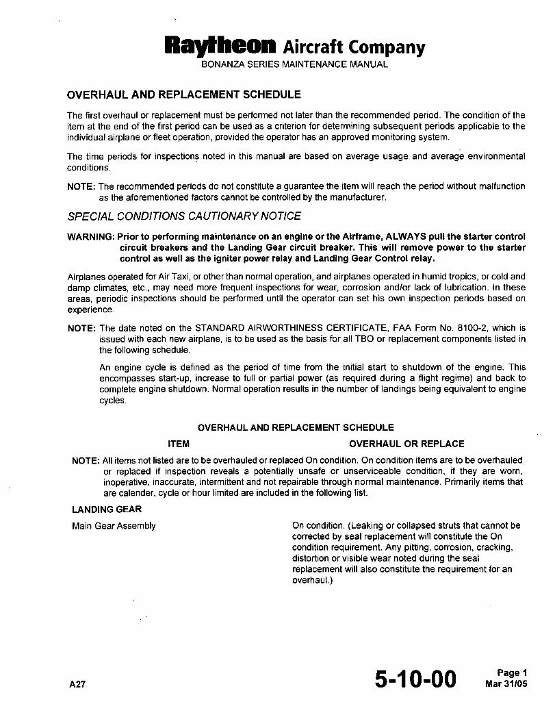
OVERHAUL AND REPLACEMENT SCHEDULE
The first overhaul or replacement must be performed not later than the recommended period. The condition of the
item at the end of the first period can be used as a criterion for determining subsequent periods applicable to the
individual airplane or fleet operation, provided the operator has an approved monitoring system.
The time periods for inspections noted in this manual are based on average usage and average environmental
conditions.
NOTE: The recommended periods do not constitute a guarantee the item will reach the period without malfunction
as the aforementioned factors cannot be controlled by the manufacturer.
SPECIAL CONDITIONS CAUTIONARY NOTICE
WARNING: Prior to performing maintenance on an engine or the Airframe, ALWAYS pull the starter control
circuit breakers and the Landing Gear circuit breaker. This will remove power to the starter
control as well as the igniter power relay and Landing Gear Control relay.
Airplanes operated for Air Taxi, or other than normal operation, and airplanes operated in humid tropics, or cold and
damp climates, etc., may need more frequent inspections for wear, corrosion and/or lack of lubrication. In these
areas, periodic inspections should be performed until the operator can set his own inspection periods based on
experience.
NOTE: The date noted on the STANDARD AIRWORTHINESS CERTIFICATE, FAA Form No. 8100-2, which is
issued with each new airplane, is to be used as the basis for all TBO or replacement components listed in
the following schedule.
An engine cycle is defined as the period of time from the initial start to shutdown of the engine. This
encompasses start-up, increase to full or partial power las required during a flight regime) and back to
complete engine shutdown. Normal operation results in the number of landings being equivalent to enginecycles.
OVERHAUL AND REPLACEMENT SCHEDULE
ITEM OVERHAUL OR REPLACE
NOTE: All items not listed are to be overhauled or replaced On condition. On condition items are to be overhauled
or replaced if inspection reveals a potentially unsafe or unserviceable condition, if they are worn,
inoperative, inaccurate, intermittent and not repairable through normal maintenance. Primarily items that
are calender, cycle or hour limited are included in the following list.
LANDING GEAR
Main Gear Assembly On condition. (Leaking or collapsed struts that cannot be
corrected by seal replacement will constitute the On
condition requirement. Any pitting, corrosion, cracking,distortion or visible wear noted during the seal
replacement will also constitute the requirement for an
overhaul.)
n27 5-1 0-00
Raytheon AiKraft CompanyBONANZA SERIES MAINTENANCE MANUAL
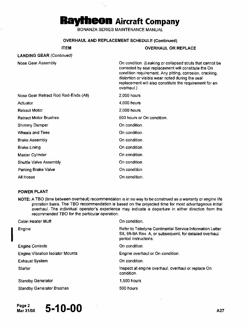
OVERHAUL AND REPLACEMENT SCHEDULE (Continued)
ITEM OVERHAUL OR REPLACE
LANDING GEAR (Continued)
Nose Gear Assembly On condition. (Leaking or collapsed struts that cannot be
corrected by seal replacement will constitute the On
condition requirement. Any pitting, corrosion, cracking,distortion or visible wear noted during the seal
replacement will also constitute the requirement for an
overhaul.)
Nose Gear Retract Rod Rod-Ends (All) 2,000 hours
Actuator 4,000 hours
Retract Motor 2,000 hours
Retract Motor Brushes 500 hours or On condition.
Shimmy Damper On condition.
Wheels and Tires On condition.
Brake Assembly On condition.
Brake Lining On condition.
Master Cylinder On condition.
Shuttle Valve Assembly On condition.
Parking Brake Valve On condition.
All Hoses On condition.
POWER PLANT
NOTE: A TBO (time between overhaul) recommendation is in no way to be construed as a warranty or engine life
proration basis. The TBO recommendation is based on the projected time for most advantageous initial
overhaul. The individual operator’s experience may indicate a departure in either direction from the
recommended TBO for the particular operation.
Cabin Heater Muff On condition.
Engine Refer to Teledyne Continental Service Information Letter
SIL 98-9A Rev. A, or subsequent, for detailed overhaul
period instructions.
Engine Controls On condition.
Engine Vibration Isolator Mounts Engine overhaul or On condition.
Exhaust System On condition.
Starter Inspect at engine overhaul, overhaul or replace On
condition.
Standby Generator 1,500 hours
Standby Generator Brushes 500 hours
Page 2Mar31/05 5-1 0-00 A27
Raylheon Aircraft CompanyBONANZA SERIES MAINTENANCE MANUAL
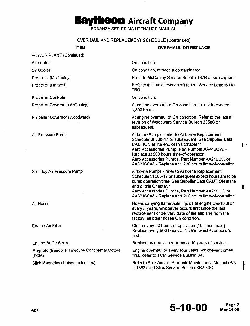
OVERHAUL AND REPLACEMENT SCHEDULE (Continued)
ITEM OVERHAUL OR REPLACE
POWER PLANT (Continued)
Alternator On condition.
Oil Cooler On condition, replace if contaminated.
Propeller (McCauley) Refer to McCauley Service Bulletin 137B or subsequent.
Propeller (Hartzell) Refer to the latest revision of Hartzell Service Letter 61 for
TBO.
Propeller Controls On condition.
Propeller Governor (McCauley) At engine overhaul or On condition but not to exceed
1,800 hours.
Propeller Governor (Woodward) At engine overhaul or On condition. Refer to the latest
revision of Woodward Service Bulletin 33580 or
subsequent
Air Pressure Pump Airborne Pumps refer to Airborne ReplacementSchedule SI 300-17 or subsequent. See Supplier Data
CAUTION at the end of this Chapter.Aero Accessories Pump, Part Number AA442CW,Replace at 500 hours time-of-operation.Aero Accessories Pumps, Part Number AA216CW or
AA3216CW, Replace at 1,200 hours time-of-operation.
Standby Air Pressure Pump Airborne Pumps refer to Airborne ReplacementSchedule SI 300-17 or subsequent except hours are to be
pump operation time. See Supplier Data CAUTION at the
end of this Chapter.Aero Accessories Pumps, Part Number AA216CW or
AA3216CW, Replace at 1,200 hours time-of-operation.
All Hoses Hoses carrying flammable liquids at engine overhaul or
every 5 years, whichever occurs first since the last
replacement or delivery date of the airplane from the
factory; all other hoses On condition.
Engine Air Filter Clean every 50 hours of operation (10 times max.).Replace every 500 hours or 1 year, whichever occurs
first.
Engine Baffle Seals Replace as necessary or every 10 years of service.
Magneto (Bendix 8 Teledyne Continental Motors Engine overhaul or every four years, whichever comes
(TCM) first. Refer to TCM Service Bulletin 643.
Slick Magnetos (Unison Industries) Refer to Slick Aircraft Products Maintenance Manual (P/N tL-1363) and Slick Service Bulletin SB2-80C.
nlr 5-1 0-00Page 3
Raytheon Aircraft CompanyBONANZA SERIES MAINTENANCE MANUAL
OVERHAUL AND REPLACEMENT SCHEDULE (Continued)
ITEM OVERHAUL OR REPLACE
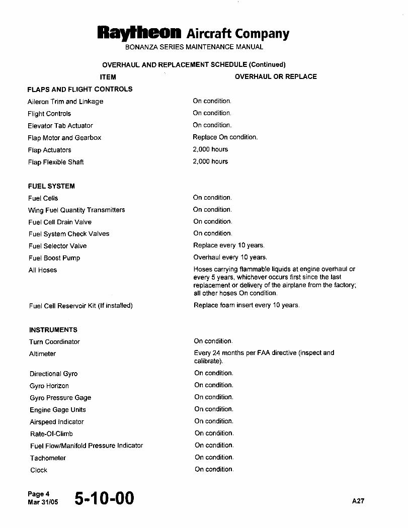
FLAPS AND FLIGHT CONTROLS
Aileron Trim and Linkage On condition.
Flight Controls On condition.
Elevator Tab Actuator On condition.
Flap Motor and Gearbox Replace On condition.
Flap Actuators 2,000 hours
Flap Flexible Shaft 2,000 hours
FUEL SYSTEM
Fuel Cells On condition.
W~ng Fuel Quantity Transmitters On condition.
Fuel Cell Drain Valve On condition.
Fuel System Check Valves On condition.
Fuel Selector Valve Replace every 10 years.
Fuel Boost Pump Overhaul every 10 years.
All Hoses Hoses carrying flammable liquids at engine overhaul or
every 5 years, whichever occurs first since the last
replacement or delivery of the airplane from the factory;all other hoses On condition.
Fuel Cell Reservoir Kit (If installed) Replace foam insert every 10 years.
INSTRUMENTS
Turn Coordinator On condition.
Altimeter Every 24 months per FAA directive (inspect and
calibrate).
Directional Gym On condition.
Gym Horizon On condition.
Gym Pressure Gage On condition.
Engine Gage Units On condition.
Airspeed Indicator On condition.
Rate-Of-Climb On condition.
Fuel Flow/Manifold Pressure Indicator On condition.
Tachometer On condition.
Clock On condition.
Page 4Nlar31105 5-~ 0-00 A27
RBYtbeon Aircraft CompanyBONANZA SERIES MAINTENANCE MANUAL
OVERHAUL AND REPLACEMENT SCHEDULE (Continued)
ITEM OVERHAUL OR REPLACE
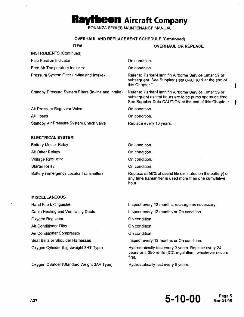
INSTRUMENTS (Continued)
Flap Position Indicator On condition.
Free Air Temperature Indicator On condition.
Pressure System Filter (In-line and Intake) Refer to Parker-Hannifin Airborne Service Letter 59 or
subsequent. See Supplier Data CAUTION at the end of
this Chapter." I
Standby Pressure System Filters (In-line and Intake) Refer to Parker-Hannifin Airborne Service Letter 59 or
subsequent except hours are to be pump operatidn time.
See Supplier Data CAUTION at the end of this Chapter." I
Air Pressure Regulator Valve On condition.
All Hoses On condition.
Standby Air Pressure System Check Valve Replace every 10 years.
ELECTRICAL SYSTEM
Battery Master Relay On condition.
Ail Other Relays On condition.
Voltage Regulator On condition.
Starter Relay On condition.
Battery (Emergency Locator Transmitter) Replace at 50% of useful life las stated on the battery) or
any time transmitter is used more than one cumulative
hour.
MISCELLANEOUS
Hand Fire Extinguisher Inspect every 12 months, recharge as necessary.
Cabin Heating and Ventilating Ducts Inspect every 12 months or On condition.
Oxygen Regulator On condition.
Air Conditioner Filter On condition.
Air Conditioner Compressor On condition.
Seat Belts or Shoulder Harnesses Inspect every 12 months or On condition.
Oxygen Cylinder (Lightweight 3HT Type) Hydrostatically test every 3 years. Replace every 24
years or 4,380 refills (ICC regulation), whichever occurs
first.
Oxygen Cylinder (Standard Weight 3AA Type) Hydrostatically test every 5 years.
A27 5-~ 0-00 Mar 31105Page 5
Raytheon Aircraft CampanyBONANZA SERIES MAINTENANCE MANUAL
OVERHAUL AND REPLACEMENT SCHEDULE (Continued)
ITEM OVERHAUL OR REPLACE
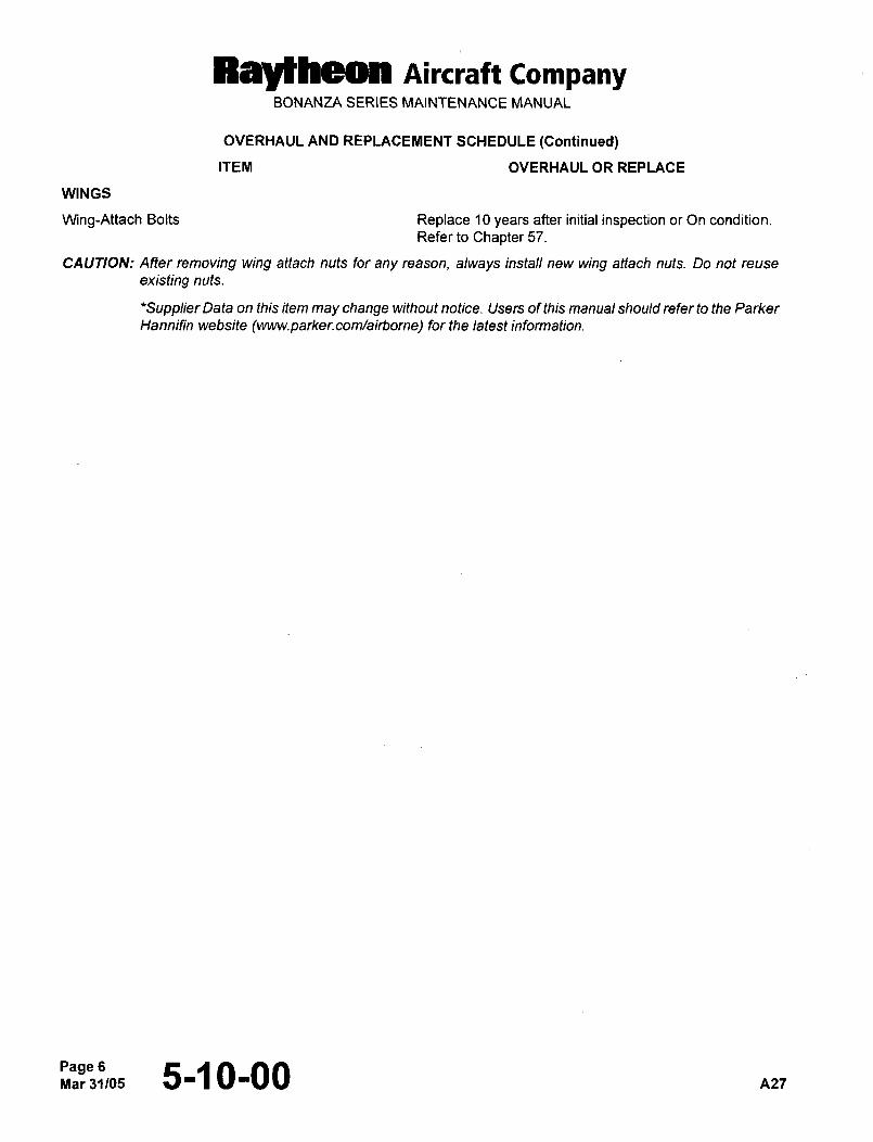
WINGS
Wing-Attach Bolts Replace 10 years after initial inspection or On condition.
Refer to Chapter 57.
CAUTIONs After removing wing attach nuts for any reason, always install new wing attach nuts. Do not reuse
existing nuts.
*Supplier Data on this item may change without notice. Users of this manual should refer to the Parker
Hannifin website (www.parker.com/airborne) for the latest information.
Page 6Mar31105 5-~ 0-00 A27
Raytheon Aircraft CompanyBONANZA SERIES MAINTENANCE MANUAL
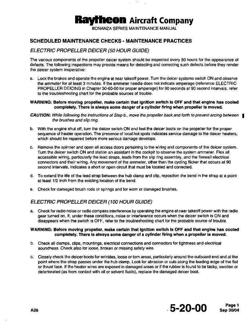
SCHEDULED MAINTENANCE CHECKS MAINTENANCE PRACTICES
ELECTRIC PROPELLER DNCER (50 HOUR GUIDE)
The various components of the propeller deicer system should be inspected every 50 hours for the appearance of
defects. The following inspections may provide means for detecting and correcting such defects before they render
the deicer system inoperative:
a. Lock the brakes and operate the engine at near takeoff power. Tum the deicer systems switch ON and observe
the ammeter for at least 3 minutes. If the ammeter needle does not indicate amperage (reference ELECTRIC
PROPELLER DEICING in Chapter 30-60-00 for proper amperage) for 90 seconds at 90 second intervals, refer
to the troubleshooting chart for the probable sources of trouble.
WARNING: Before moving propeller, make certain that ignition switch is OFF and that engine has cooled
completely. There is always some danger of a cylinder firing when propeller is moved.
CAUTION: While following the instructions of Step b., move the propeller back and forth to prevent arcing between
the brushes and slip ring.
b. With the engine shut off, tum the deicer switch ON and feel the deicer boots on the propeller for the proper
sequence of heater operation. The presence of local hot spots indicates service damage to the deicer heaters,which should be repaired before more serious damage develops.
c. Remove the spinner and open all access doors pertaining to the wiring and components of the deicer system.Turn the deicer switch ON and station an assistant in the cockpit to observe the system ammeter. Flex all
accessible wiring, particularly the lead straps, leads from the slip ring assembly, and the firewall electrical
connectors and their wiring. Any movement of the ammeter, other than the cycling flicker that occurs at 90
second intervals, indicates a short or open circuit that must be located and corrected.
d. To extend the life of the lead strap between the hub clamp and clip, reposition the bend in the strap at a pointat least 112 inch from the existing location of the bend.
e. Check for damaged brush rods or springs and for worn or damaged brushes.
ELECTRIC PROPELLER DNCER (100 HOUR GUIDE)
a. Check for radio noise or radio compass interference by operating the engine at near takeoff power with the radio
gear turned on. If, under these conditions, noise or interference occurs when the deicer switch is ON and
disappears when the switch is OFF, refer to the troubleshooting chart for the probable source of trouble.
WARNING: Before moving propeller, make certain that ignition switch is OFF and that engine has cooled
completely. There is always some danger of a cylinder firing when a propeller is moved.
b. Check all clamps, clips, mountings, electrical connections and connectors for tightness and electrical
soundness. Check also for loose, broken or missing safety wire.
c. Closely check the deicer boots for wrinkles, loose or torn areas, particularly around the outboard end and at the
point where the strap passes under the hub clamp. Look for abrasion or cuts along the leading edge of the flat
or thrust face. If the heater wires are exposed in damaged areas or if the rubber is found to be tacky, swollen or
deteriorated las from contact with oil or solvent fluids), replace the damaged deicer boot.
A26 .5-20-00 SepP~b:Pager
Ral~heon Aircraft CompanyBONANZA SERIES MAINTENANCE MANUAL
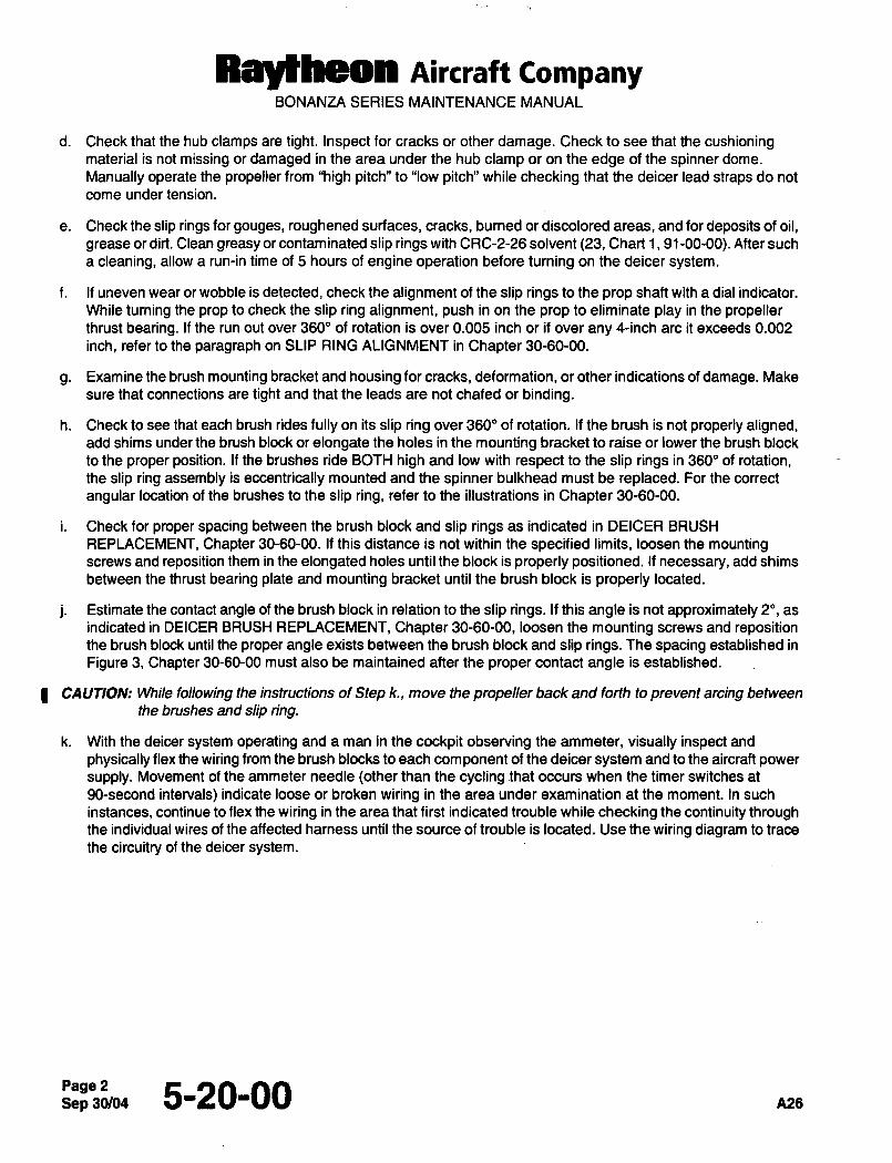
d. Check that the hub clamps are tight. Inspect for cracks or other damage. Check to see that the cushioningmaterial is not missing or damaged in the area under the hub clamp or on the edge of the spinner dome.
Manually operate the propeller from "high pitch" to "low pitch" while checking that the deicer lead straps do not
come under tension.
e. Check the slip rings for gouges, roughened surfaces, cracks, burned or discolored areas, and for deposits of oil,
grease or dirt. Clean greasy or contaminated slip rings with CRC-2-26 solvent (23, Chart 1, 91-00-00). After such
a cleaning, allow a run-in time of 5 hours of engine operation before turning on the deicer system.
f. If uneven wear or wobble is detected, check the alignment of the slip rings to the prop shaft with a dial indicator.
While turning the prop to check the slip ring alignment, push in on the prop to eliminate play in the propellerthrust bearing. If the run out over 360" of rotation is over 0.005 inch or if over any 4-inch are it exceeds 0.002
inch, refer to the paragraph on SLIP RING ALIGNMENT in Chapter 30-60-00.
g. Examine the brush mounting bracket and housing for cracks, deformation, or other indications of damage. Make
sure that connections are tight and that the leads are not chafed or binding.
h. Check to see that each brush rides fully on its slip ring over 360" of rotation. If the brush is not properly aligned,add shims under the brush block or elongate the holes in the mounting bracket to raise or lower the brush block
to the proper position. If the brushes ride BOTH high and low with respect to the slip rings in 360" of rotation,the slip ring assembly is eccentrically mounted and the spinner bulkhead must be replaced. For the correct
angular location of the brushes to the slip ring, refer to the illustrations in Chapter 30-60-00.
i. Check for proper spacing between the brush block and slip rings as indicated in DEICER BRUSH
REPLACEMENT, Chapter 30-60-00. If this distance is not within the specified limits, loosen the mountingscrews and reposition them in the elongated holes until the block is properly positioned. If necessary, add shims
between the thrust bearing plate and mounting bracket until the brush block is properly located.
j. Estimate the contact angle of the brush block in relation to the slip rings. If this angle is not approximately 2", as
indicated in DEICER BRUSH REPLACEMENT, Chapter 30-60-00, loosen the mounting screws and repositionthe brush block until the proper angle exists between the brush block and slip rings. The spacing established in
Figure 3, Chapter 30-60-00 must also be maintained after the proper contact angle is established.
CAUTION: While following the instructions of Step k., move the propeller back and forth to prevent arcing between
the brushes and slip ring.
k. With the deicer system operating and a man in the cockpit observing the ammeter, visually inspect and
physically flex the wiring from the brush blocks to each component of the deicer system and to the aircraft power
supply. Movement of the ammeter needle (other than the cycling that occurs when the timer switches at
90-second intervals) indicate loose or broken wiring in the area under examination at the moment. In such
instances, continue to flex the wiring in the area that first indicated trouble while checking the continuity throughthe individual wires of the affected harness until the source of trouble is located. Use the wiring diagram to trace
the circuitry of the deicer system.
Sep 5-20’00 A26
Ray~heon nircraft CompanyBONANZA SERIES MAINTENANCE MANUAL
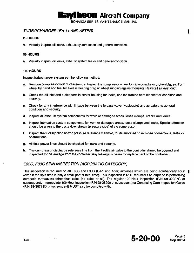
TURBOCHARGER (EA-11 AND AFTER)
25 HOURS
a. Visually inspect oil leaks, exhaust system leaks and general condition.
50 HOURS
a. Visually inspect oil leaks, exhaust system leaks and general condition.
100 HOURS
Inspect turbocharger system per the following method:
a. Remove compressor inlet duct assembly. Inspect the compressor wheel for nicks, cracks or broken blades. Turn
wheel by hand and feel for excess bearing drag or wheel rubbing against housing. Reinstall air inlet duct.
b. Check the oil inlet and outlet ports in center housing for leaks, and the turbine heat blanket for condition and
security.
c. Check for any interference with linkage between the bypass valve (wastegate) and actuator, its generalcondition and security.
d. Inspect all exhaust system components for worn or damaged areas, loose clamps, cracks and leaks.
e. Inspect lubrication system components for worn or damaged areas, loose clamps and leaks. Special attention
should be given to the ducts downstream (pressure side) of the compressor.
f. Inspect the fuel injection nozzle pressure reference manifold, for deteriorated hose, loose connections, leaks or
obstructions.
g. All fluid power lines should be checked for leaks and security.
h. The compressor discharge reference line from the throttle air valve to the controller should be opened and
inspected for oil leakage from the controller. Any leakage is cause for replacement of the controller.
E33C, F33C SPIN INSPECTION (ACROBATIC CA TEGORY)
This inspection is required on all E33C and F33C (CJ-1 and After) airplanes which are being acrobatically spun
(even if the spin time is only a small part of total time). This inspection is NOT required if an airplane is performingacrobatic maneuvers other than spins (no spins at all). The regular 100-Hour Inspection (P/N 98-322276 or
subsequent), Intermediate 1 GO-Hour Inspection (P/N 98-38999 or subsequent) or Continuing Care Inspection Guide
(P/N 98-36711D or subsequent) MUST also be complied with.
5-20-00 3
Ray~heon AiKraft companyBONANZA SERIES MAINTENANCE MANUAL
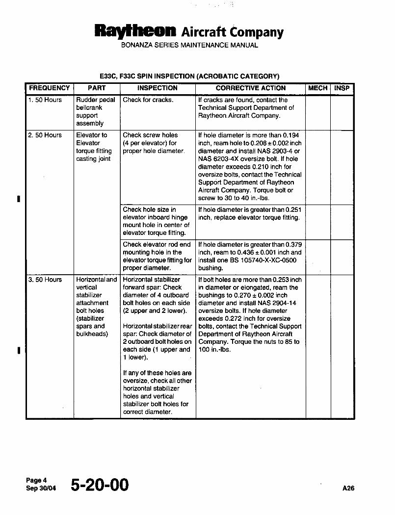
E33C, F33C SPIN INSPECTION (ACROBATIC CATEGORY)
FREQUENCY PART INSPECTION CORRECTIVE ACTION MECH INSP
1. 50 Hours Rudder pedal Check for cracks. If cracks are found, contact the
bellcrank Technical Support Department of
support Raytheon. Aircraft Company.assembly
2. 50 Hours Elevator to Check screw holes If hole diameter is more than 0.194
Elevator (4 per elevator) for inch, ream hole to 0.208 0.002 inch
torque fitting proper hole diameter. diameter and install NAS 2903-4 or
casting joint NAS 6203-4)( oversize bolt. If hole
diameter exceeds 0.210 inch for
oversize bolts, contact the Technical
Support Department of RaytheonAircraft Company. Torque bolt or
screw to 30 to 40 in.-lbs.
Check hole size in If hole diameter is greater than 0.251
elevator inboard hinge inch, replace elevator torque fitting.mount hole in center of
elevator torque fitting.
Check elevator rod end If hole diameter is greater than 0.379
mounting hole in the inch, ream to 0.436 0.001 inch and
elevator torque fitting for install one BS 1 05740-X-XC-0500
proper diameter, bushing.
3. 50 Hours Horizontaland Horizontal stabilizer If bolt holes are more than 0.253 inch
vertical forward spar: Check in diameter or elongated, ream the
stabilizer diameter of 4 outboard bushings to 0.270 0.002 inch
attachment bolt holes on each side diameter and install NAS 2904-14
bolt holes (2 upper and 2 lower), oversize bolts. If hole diameter
(stabilizer exceeds 0.272 inch for oversize
spars and Horizontal stabilizer rear I bolts, contact the Technical Supportbulkheads) spar: Check diameter of Department of Raytheon Aircraft
2 outboard bolt holes on Company. Torque the nuts to 85 to
each side (1 upper and 100 in.-lbs.
1 lower).
If any of these holes are
oversize, check all other
horizontal stabilizer
holes and vertical
stabilizer bolt holes for
correct diameter.
Page45-20-00 A26
Raytheon Aircraft CompanyBONANZA SERIES MAINTENANCE MANUAL
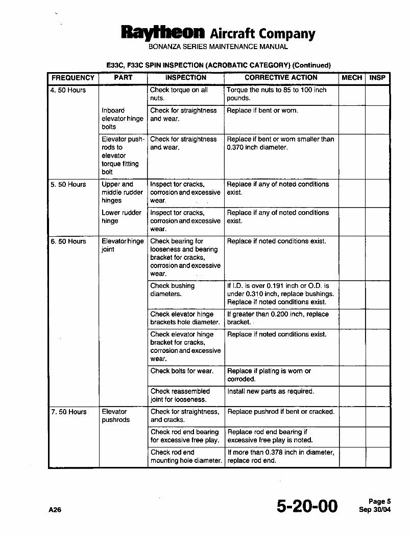
5330, F33C SPIN INSPECTION (ACROBATIC CATEGORY) (Continued)
FREQUENCY PART INSPECTION CORRECTIVE ACTION MECH INSP
4. 50 Hours Check torque on all Torque the nuts to 85 to 100 inch
nuts, pounds.
Inboard Check for straightness Replace if bent or worn.
elevatorhinge and wear.
bolts
Elevator push- I Check for straightness Replace if bent or worn smaller than
rods to and wear. 0.370 inch diameter.
elevator
torque fittingbolt
5. 50 Hours Upper and Inspect tor cracks, Replace if any of noted conditions
middle rudder corrosion and excessive exist.
hinges wear.
Lower rudder Inspect tor cracks, Replace if any of noted conditions
hinge corrosion and excessive exist.
wear.
6. 50 Hours Elevator hinge I Check bearing for Replace if noted conditions exist.
joint looseness and bearingbracket for cracks,corrosion and excessive
wear.
Check bushing I If I.D. is over 0.191 inch or O.D. is
diameters. under 0.310 inch, replace bushings.Replace if noted conditions exist.
Check elevator hinge If greater than 0.200 inch, replacebrackets hole diameter. bracket.
Check elevator hinge Replace if noted conditions exist.
bracket for cracks,corrosion and excessive
wear.
Check bolts for wear. Replace if plating is worn or
corroded.
Check reassembled Install new parts as required.joint for looseness.
7. 50 Hours Elevator Check for straightness, Replace pushrod if bent or cracked.
pushrods and cracks.
Check rod end bearing Replace rod end bearing if
for excessive free play, excessive free play is noted.
Check rod end If more than 0.378 inch in diameter,mounting hole diameter. I replace rod end.
A26 5-20-00 5
Raytheon Aircraft CampanyBONANZA SERIES MAINTENANCE MANUAL
E33C, F33C SPIN INSPECTION (ACROBATIC CATEGORY) (Continued)
FREQUENCY PART INSPECTION CORRECTIVE ACTION MECH INSP
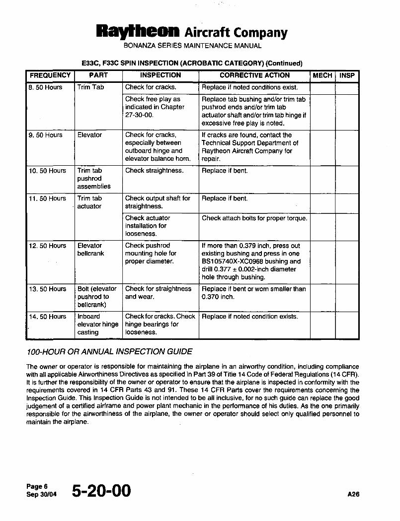
8. 50 Hours Trim Tab Check for cracks. Replace if noted conditions exist.
Check free play as Replace tab bushing and/or trim tab
indicated in Chapter pushrod ends, and/or trim tab
27-30-00. actuator shaft and/or trim tab hinge if
excessive free play is noted.
9. 50 Hours Elevator Check for cracks, If cracks are found, contact the
especially between Technical Support Department of
outboard hinge and Raytheon Aircraft Company for
elevator balance horn. repair.
10. 50 Hours Trim tab Check straightness. Replace if bent.
push rod
assemblies
11. 50 Hours Trim tab Check output shaft for Replace if bent.
´•I actuator Istraightness.
Check actuator Check attach bolts for proper torque.installation for
looseness.
12. 50 Hours Elevator Check pushrod If more than 0.379 inch, press out
bellcrank mounting hole for existing bushing and press in one
proper diameter. BS105740X-XC0958 bushing and
drill 0.377 rt 0.002-inch diameter
hole through bushing.
13. 50 Hours Bolt (elevator Check for straightness Replace if bent or worn smaller than
pushrod to and wear. 0.370 inch.
bellcrank)
14. 50 Hours Inboard Check for cracks. Check Replace if noted condition exists.
elevatorhinge hinge bearingsforcasting looseness.
100-HOUR OR ANNUAL INSPECTION GUIDE
The owner or operator is responsible for maintaining the airplane in an airworthy condition, including compliancewith all applicable Airworthiness Directives as specified in Part 39 of Title 14 Code of Federal Regulations (14 CFR).It is further the responsibility of the owner or operator to ensure that the airplane is inspected in conformity with the
requirements covered in 14 CFR Parts 43 and 91. These 14 CFR Parts cover the requirements concerning the
Inspection Guide. This Inspection Guide is not intended to be all inclusive, for no such guide can replace the goodjudgement of a certified airframe and power plant mechanic in the performance of his duties. As the one primarily´•responsible for the airworthiness of the airplane, the owner or operator should select only qualified personnel to
maintain the airplane.
Sep 30/045-20-00 nns
Raytheon Aircraft CompanyBONANZA SERIES MAINTENANCE MANUAL
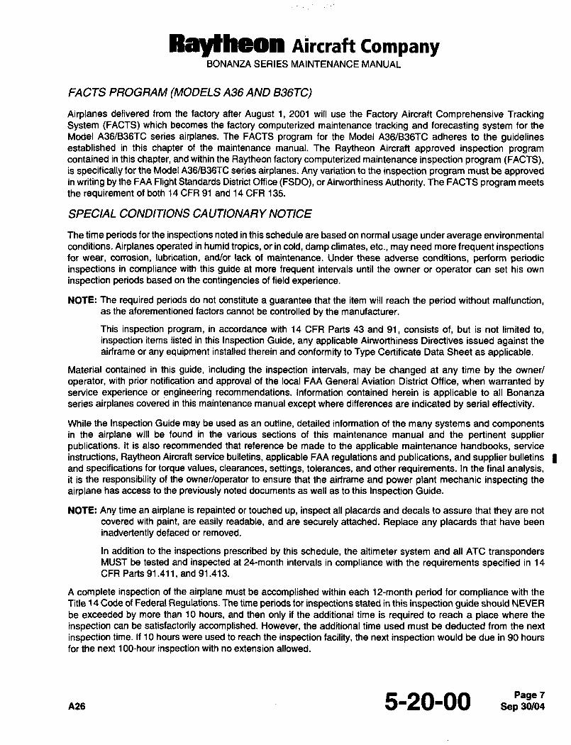
FACTS PROGRAM (MODELS A36 AND 836TC)
Airplanes delivered from the factory after August 1, 2001 will use the Factory Aircraft Comprehensive TrackingSystem (FACTS) which becomes the factory computerized maintenance tracking and forecasting system for the
Model A36/B36TC series airplanes. The FACTS program for the Model A36/B36TC adheres to the guidelinesestablished in this chapter of the maintenance manual. The Raytheon Aircraft approved inspection programcontained in this chapter, and within the Raytheon factory computerized maintenance inspection program (FACTS),is specifically for the Model A36/B36TC series airplanes. Any variation to the inspection program must be approvedin writing by the FAA Flight Standards District Office (FSDO), or Ain~vorthineSs Authority. The FACTS program meets
the requirement of both 14 CFR 91 and 14 CFR 135.
SPECIAL CONDITIONS CAUTIONARY NOTICE
The time periods for the inspections noted in this schedule are based on normal usage under average environmental
conditions. Airplanes operated in humid tropics, or in cold, damp climates, etc., may need more frequent inspectionsfor wear, corrosion, lubrication, and/or lack of maintenance. Under these adverse conditions, perform periodicinspections in compliance with this guide at more frequent intervals until the owner or operator can set his own
inspection periods based on the contingencies of field experience.
NOTE: The required periods do not constitute a guarantee that the item will reach the period without malfunction,as the aforementioned factors cannot be controlled by the manufacturer.
This inspection program, in accordance with 14 CFR Parts 43 and 91, consists of, but is not limited to,
inspection items listed in this Inspection Guide, any applicable Airworthiness Directives issued against the
airframe or any equipment installed therein and conformity to Type Certificate Data Sheet as applicable.
Material contained in this guide, including the inspection intervals, may be changed at any time by the owner/
operator, with prior notification and approval of the local FAA General Aviation District Office, when warranted byservice experience or engineering recommendations. Information contained herein is applicable to all Bonanza
series airplanes covered in this maintenance manual except where differences are indicated by serial effectivity.
While the Inspection Guide may be used as an outline, detailed information of the many systems and componentsin the airplane will be found in the various sections of this maintenance manual and the pertinent supplierpublications. It is also recommended that reference be made to the applicable maintenance handbooks, service
instructions, Raytheon Aircraft service bulletins, applicable FAA regulations and publications, and supplier bulletins
and specifications for torque values, clearances, settings, tolerances, and other requirements. In the final analysis,it is the responsibility of the owner/operator to ensure that the airframe and power plant mechanic inspecting the
airplane has access to the previously noted documents as well as to this Inspection Guide.
NOTE: Any time an airplane is repainted or touched up, inspect all placards and decals to assure that they are not
covered with paint, are easily readable, and are securely attached. Replace any placards that have been
inadvertently defaced or removed.
In addition to the inspections prescribed by this schedule, the altimeter system and all ATC transpondersMUST be tested and inspected at 24-month intervals in compliance with the requirements specified in 14
CFR Parts 91.411, and 91.413.
A complete inspection of the airplane must be accomplished within each 12-month period for compliance with the
Title 14 Code of Federal Regulations. The time periods for inspections stated in this inspection guide should NEVER
be exceeded by more than 10 hours, and then only if the additional time is required to reach a place where the
inspection can be satisfactorily accomplished. However, the additional time used must be deducted from the next
inspection time. If 10 hours were used to reach the inspection facility, the next inspection would be due in 90 hours
for the next 100-hour inspection with no extension allowed.
PiZS 5-20-00 7
Ralfheon Aircraft CompanyBONANZA SERIES MAINTENANCE MANUAL
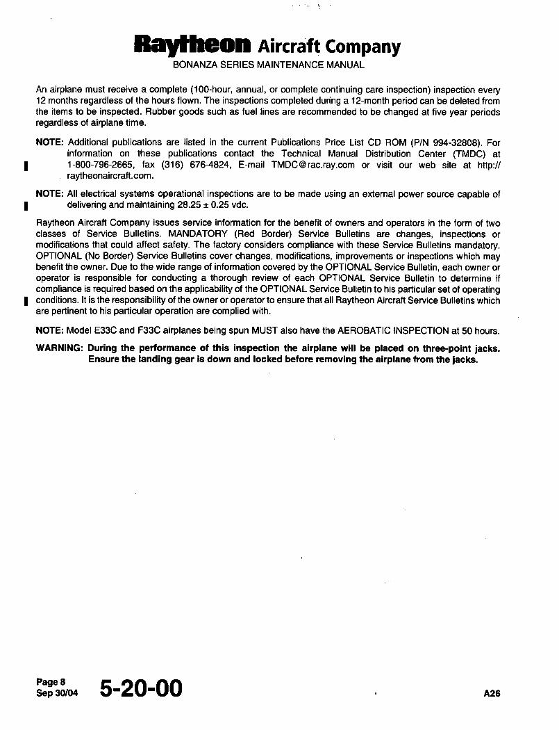
An airplane must receive a complete (100-hour, annual, or complete continuing care inspection) inspection every12 months regardless of the hours flown. The inspections completed during a 12-month period can be deleted from
the items to be inspected. Rubber goods such as fuel lines are recommended to be changed at five year periodsregardless of airplane time.
NOTE: Additional publications are listed in the current Publications Price List CD ROM (P/N 994-32808). For
information on these publications contact the Technical Manual Distribution Center (TMDC) at
1-800-796-2665, fax (316) 676-4824, E-mail TMDCQrac.ray.com or visit our web site at http:~raytheonaircraft.com.
NOTE: All electrical systems operational inspections are to be made using an external power source capable of
delivering and maintaining 28.25 0.25 vdc.
Raytheon Aircraft Company issues service information for the benefit of owners and operators in the form of two
classes of Service Bulletins. MANDATORY (Red Border) Service Bulletins are changes, inspections or
modifications that could affect safety. The factory considers compliance with these Service Bulletins mandatory.OPTIONAL (No Border) Service Bulletins cover changes, modifications, improvements or inspections which maybenefit the owner. Due to the wide range of information covered by the OPTIONAL Service Bulletin, each owner or
operator is responsible for conducting a thorough review of each OPTIONAL Service Bulletin to determine if
compliance is required based on the applicability of the OPTIONAL Service Bulletin to his particular set of operatingconditions. It is the responsibility of the owner or operator to ensure that all Raytheon Aircraft Service Bulletins which
are pertinent to his particular operation -are complied with.
NOTE: Model E33C and F33C airplanes being spun MUST also have the AEROBATIC INSPECTION at 50 hours.
WARNING: During the performance of this inspection the airplane will be placed on three-point jacks.Ensure the landing gear isdown and locked before removing the airplane from the jacks.
Sep 30/04~Z’3&4 5-20-00
Raytheon Aircraft CompanyBONANZA SERIES MAINTENANCE MANUAL
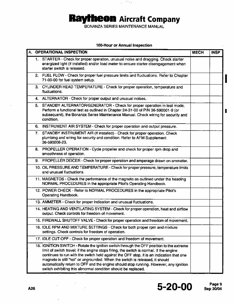
100-Hour or Annual Inspection
A. OPERATIONAL INSPECTION MECH INSP
1. STARTER Check for proper operation, unusual noise and dragging. Check starter
energized light (if installed) and/or load meter to ensure starter disengagement when
starter switch is released.
2. FUEL FLOW Check for proper fuel pressure limits and fluctuations. Refer to Chapter71-00-00 for fuel system setup.
3. CYLINDER HEAD TEMPERATURE Check for proper operation, temperature and
fluctuations.
4. ALTERNATOR Check for proper output and unusual noises.
5. STANDBY ALTERNATOR/GENERATOR Check for proper operation in test mode.
Perform a functional test as outlined in Chapter 24-31-00 of P/N 36-590001-9 (orsubsequent), the Bonanza Series Maintenance Manual. Check wiring for security and
condition.
6. INSTRUMENT AIR SYSTEM Check for proper operation and output pressure.
7. STANDBY INSTRUMENT AIR (If installed) Check for proper operation. Check
plumbing and wiring for security and condition. Refer to AFM Supplement36-590006-23.
3. PROPELLER OPERATION Cycle propeller and check for proper rpm drop and
smoothness of operation.
9. PROPELLER DEICER Check for proper operation and amperage drawn on ammeter.
10. OIL PRESSURE AND TEMPERATURE Check for proper pressure, temperature limits
and unusual fluctuations.
11. MAGNETOS Check the performance of the magneto as outlined under the headingNORMAL PROCEDURES in the appropriate Pilot’s Operating Handbook.
12. POWER CHECK Refer to NORMAL PROCEDURES in the appropriate Pilot’s
Operating Handbook.
13. AMMETER Check for proper indication and unusual fluctuations.
14. HEATING AND VENTILATING SYSTEM Check for proper operation, heat and airflow
output. Check controls for freedom of movement.
15. FIREWALL SHUTOFF VALVE Check for proper operation and freedom of movement.
16. IDLE RPM AND MIXTURE SETTINGS Check for both proper rpm and mixture
settings. Check controls for freedom of operation.
17. IDLE CUT-OFF Check for proper operation and freedom of movement.
18. IGNITION SWITCH Rotate the ignition switch through the OFF position to the extreme
limit of switch travel; if the engine stops firing, the switch is normal. If the enginecontinues to run with the switch held against the OFF stop, it is an indication that one
magneto is still "hot" or ungrounded. When the switch is released, it should
automatically return to OFF and the engine should stop running. However, any ignitionswitch exhibiting this abnormal condition should be replaced.
5-20-00 9
RayNReon nircra)t tompanyBONANZA SERIES MAINTENANCE MANUAL
100-Hour or Annual Inspection (Continued)
A. OPERATIONAL INSPECTION (Continued) MECH INSP
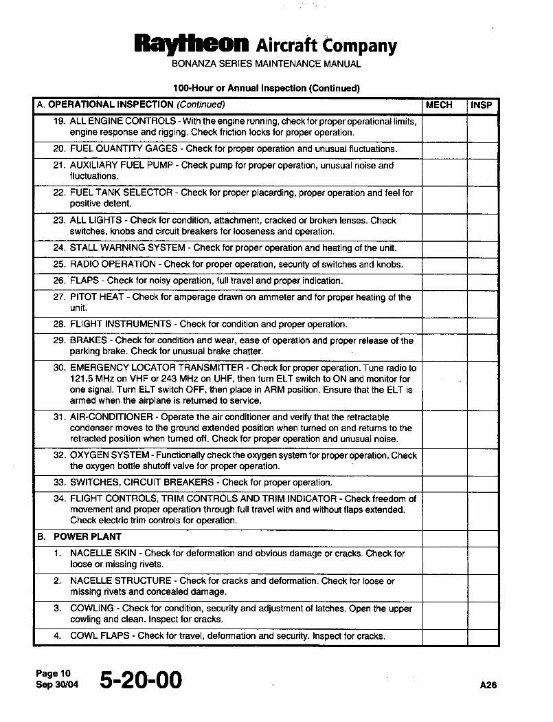
19. ALL ENGINE CONTROLS With the engine running, check for proper operational limits,engine response and rigging. Check friction locks for proper operation.
20. FUEL QUANTITY GAGES Check for proper operation and unusual fluctuations.
21. AUXILIARY FUEL PUMP Check pump for proper operation, unusual noise and
fluctuations.
22. FUEL TANK SELECTOR Check for proper placarding, proper operation and feel for
positive detent.
23. ALL LIGHTS Check for condition, attachment, cracked or broken lenses. Check
switches, knobs and circuit breakers for looseness and operation.
24. STALL WARNING SYSTEM Check for proper operation and heating of the unit.
25. RADIO OPERATION Check for proper operation, security of switches and knobs.
26. FLAPS Check for noisy operation, full travel and proper indication.
27. PITOT HEAT Check for amperage drawn on ammeter and for proper heating of the
unit.
23. FLIGHT INSTRUMENTS Check for condition and proper operation.
29. BRAKES Check for condition and wear, ease of operation and proper release of the
parking brake. Check for unusual brake chatter.
30. EMERGENCY LOCATOR TRANSMITTER Check for proper operation. Tune radio to
121.5 MHz on VHF or 243 MHz on UHF, then turn ELT switch to ON and monitor for
one signal. Turn ELT switch OFF, then place in ARM position. Ensure that the ELT is
armed when the airplane is returned to service.
31. AIR-CONDITIONER Operate the air conditioner and verify that the retractable
condenser moves to the ground extended position when turned on and returns to the
retracted position when turned off. Check for proper operation and unusual noise.
32. OXYG EN SYSTEM Functionally check the oxygen system for proper operation. Check
the oxygen bottle shutoff valve for proper operation.
33. SWITCHES, CIRCUIT BREAKERS Check for proper operationl34. FLIGHT CONTROLS, TRIM CONTROLS AND TRIM INDICATOR Check freedom of
movement and proper operation through full travel with and without flaps extended.
Check electric trim controls for operation.
B. POWERPLANT
1. NACELLE SKIN Check for deformation and obvious damage or cracks. Check for
loose or missing rivets.
2. NACELLE STRUCTURE Check for cracks and deformation. Check for loose or
missing rivets and concealed damage.
3. COWLING Check for condition, security and adjustment of latches. Open the upper
cowling and clean. Inspect for cracks.
4. COWL FLAPS Check for travel, deformation and security. Inspect for cracks.
Sep 5-20-00
Raylheon nirclaft CompanyBONANZA SERIES MAINTENANCE MANUAL
1GO-Hour or Annual Inspection (Continued)
B. POWER PLANT (Continued) MECH INSP
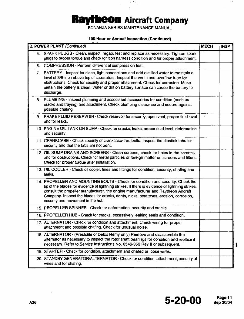
5. SPARK PLUGS Clean, inspect, regap, test and replace as necessary. Tighten sparkplugs to proper torque and check ignition harness condition and for proper attachment.
6. COMPRESSION Perform differential compression test.
7. BATTERY Inspect for clean, tight connections and add distilled water to maintain a
level of 3/8-inch above top of separators. Inspect the vents and overflow tube for
obstructions. Check for security and proper attachment. Check for corrosion. Make
certain the battery is clean. Water or dirt on battery surface can cause the battery to
discharge.
8. PLUMBING Inspect plumbing and associated accessories for condition (such as
cracks and fraying) and attachment. Check plumbing clearance and secure againstpossible chafing.
9. BRAKE FLUID RESERVOIR Check reservoir for securifl, open vent, proper fluid level
and for leaks.
10. ENGINE OIL TANK OR SUMP Check for cracks, leaks, proper fluid level, deformation
and security.
11. CRANKCASE Check security of crankcase-thru bolts. Inspect the dipstick tabs for
security and that the tabs are not bent.
12. OIL SUMP DRAINS AND SCREENS Clean screens, check for holes in the screens
and for obstructions. Check for metal particles or foreign matter on screens and filters.
Check for proper torque after installation.
13. OIL COOLER Check oil cooler, lines and fittings for condition, security, chafing and
leaks.
14. PROPELLER AND MOUNTING BOLTS Check for condition and security. Check the
tip of the blades for evidence of lightning strikes. If there is evidence of lightning strikes,consult the propeller manufacturer, the engine manufacturer and Raytheon Aircraft
Company. Inspect the blades for cracks, dents, nicks, scratches, erosion, corrosion,security and movement in the hub.
15. PROPELLER SPINNER Check for deformation, security and cracks.
16. PROPELLER HUB Check for cracks, excessively leaking seals and condition.
17. ALTERNATOR Check for condition and attachment. Check wiring for properattachment and possible chafing. Check for unusual noise.
18. ALTERNATOR (Prestolite or Delco Remy only) Remove and disassemble the
alternator as necessary to inspect the rotor shaft bearings for condition and replace if
necessary. Refer to Service Instructions No. 0546-359 Rev II or subsequent.
19. STARTER Check for condition, attachment and chafed or loose wires.
20. STANDBY GENERATOR/ALTERNATOR Check for condition, attachment, security of
wires and for chafing.
~as 5-20-00 Sep 30/04Pagell
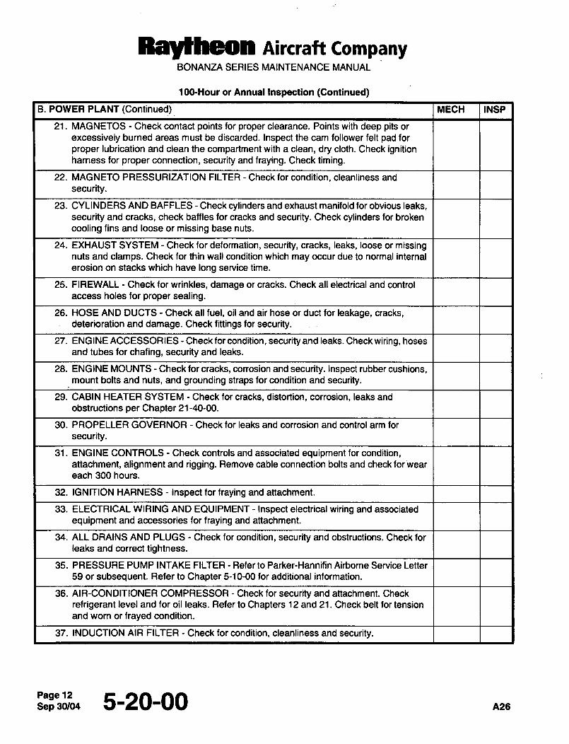
Raytheon Aircraft CompanyBONANZA SERIES MAINTENANCE MANUAL
100-Hour or Annual Inspection (Continued)
B. POWER PLANT (Continued) MECH INSP
21. MAGNETOS Check contact points for proper clearance. Points with deep pits or
excessively burned areas must be discarded. Inspect the cam follower felt pad for
proper lubrication and clean the compartment with a clean, dry cloth. Check ignitionharness for proper connection, security and fraying. Check timing.
22. MAGNETO PRESSURIZATION FILTER Check for condition, cleanliness and
security.
23. CYLINDERS AND BAFFLES Check cylinders and exhaust manifold for obvious leaks,
security and cracks, check baffles for cracks and security. Check cylinders for broken
cooling fins and loose or missing base nuts.
24. EXHAUST SYSTEM Check for deformation, security, cracks, leaks, loose or missingnuts and clamps. Check for thin wall condition which may occur due to normal internal
erosion on stacks which have long service time.
25. FIREWALL Check for wrinkles, damage or cracks. Check all electrical and control
access holes for proper sealing.
26. HOSE AND DUCTS Check all fuel, oil and air hose or duct for leakage, cracks,deterioration and damage. Check fittings for security.
27. ENG INE ACCESSORIES Check for condition, security and leaks. Check wiring, hoses
and tubes for chafing, security and leaks.
28. ENGINE MOUNTS Check for cracks, corrosion and security. Inspect rubber cushions,mount bolts and nuts, and grounding straps for condition and security.
29. CABIN HEATER SYSTEM Check for cracks, distortion, corrosion, leaks and
obstructions per Chapter 21-40-00.
30. PROPELLER GOVERNOR Check for leaks and corrosion and control arm for
security.
31. ENGINE CONTROLS Check controls and associated equipment for condition,attachment, alignment and rigging. Remove cable connection bolts and check for ~wear
each 300 hours.
32. IGNITION HARNESS Inspect for fraying and attachment.
33. ELECTRICAL WIRING AND EQUIPMENT Inspect electrical wiring and associated
equipment and accessories for fraying and attachment.
34. ALL DRAINS AND PLUGS Check for condition, security and obstructions. Check for
leaks and correct tightness.
35. PRESSURE PUMP INTAKE FILTER Refer to Parker-Hannifin Airborne Service Letter
59 or subsequent. Refer to Chapter 5-10-00 for additional information.
36. AIR-CONDITIONER COMPRESSOR Check for security and attachment. Check
refrigerant level and for oil leaks. Refer to Chapters 12 and 21. Check belt for tension
and wom or frayed condition.
37. INDUCTION AIR FILTER Check for condition, cleanliness and security.
Sep 5-20-00 C125
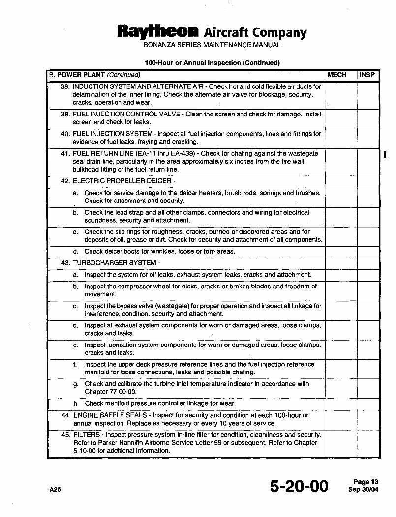
RBYllheOn nircraft CompanyBONANZA SERIES MAINTENANCE MANUAL
1GO-Hour or Annual Inspection (Continued)
B. POWER PLANT (Continued) MECH INSP
38. INDUCTION SYSTEM AND ALTERNATE AIR Check hot and cold flexible air ducts for
delamination of the inner lining. Check the alternate air valve for blockage, security,cracks, operation and wear.
39. FUEL INJECTION CONTROL VALVE Clean the screen and check for damage. Install
screen and check for leaks.
40. FUEL INJECTION SYSTEM Inspect all fuel injection components, lines and fittings for
evidence of fuel leaks, fraying and cracking.
41. FUEL RETURN LINE (EA-11 thru EA-439) Check for chafing against the wastegateseal drain line, particularly in the area approximately six inches from the fire wall
bulkhead fitting of the fuel return line.
42. ELECTRIC PROPELLER DEICER
a. Check for service damage to the deicer heaters, brush rods, springs and brushes.
Check for attachment and security.
b. Check the lead strap and all other clamps, connectors and wiring for electrical
soundness, security and attachment.
c. Check the slip rings for roughness, cracks, burned or discolored areas and for
deposits of oil, grease or dirt. Check for security and attachment of all components.
d. Check deicer boots for wrinkles, loose or tom areas.
43. TURBOCHARGER SYSTEM
a. Inspect the system for oil leaks, exhaust system leaks, cracks and attachment.
b. Inspect the compressor wheel for nicks, cracks or broken blades and freedom of
movement.
c. Inspect the bypass valve (wastegate) for proper operation and inspect all linkage for
interference, condition, security and attachment.
d. Inspect all exhaust system components for worn or damaged areas, loose clamps,cracks and leaks.
e. Inspect lubrication system components for worn or damaged areas, loose clamps,cracks and leaks.
f. Inspect the upper deck pressure reference lines and the fuel injection reference
manifold for loose connections, leaks and possible chafing.
g. Check and calibrate the turbine inlet temperature indicator in accordance with
Chapter 77-00-00.
h. Check manifold pressure controller linkage for wear.
44. ENGINE BAFFLE SEALS Inspect for security and condition at each 100-hour or
annual inspection. Replace as necessary or every 10 years of service.
45. FILTERS Inspect pressure system in-line filter for condition, cleanliness and security.Refer to Parker-Hannifin Airbome Service Letter 59 or subsequent. Refer to Chapter5-10-00 for additional information.
A26 5-20-00 13
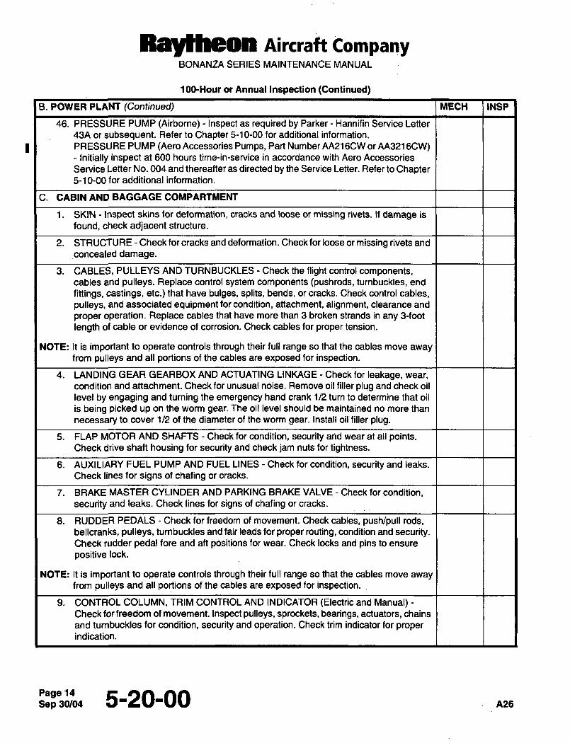
Raytheon nircraft CompanyBONANZA SERIES MAINTENANCE MANUAL
10~Hour or Annual Inspection (Continued)
8. POWER PLANT (Continued) MECH INSP
46. PRESSURE PUMP (Airborne)- Inspect as required by Parker Hannifin Service Letter
43A or subsequent. Refer to Chapter 5-10-00 for additional information.
PRESSURE PUMP (Aero Accessories Pumps, Part Number AA216CW or AA3216CW)Initially inspect at 600 hours time-in-service in accordance with Aero Accessories
Service Letter No. 004 and thereafter as directed by the Service Letter. Refer to Chapter5-10-00 for additional information.
C. CABIN AND BAGGAGE COMPARTMENT
1. SKIN Inspect skins for deformation, cracks and loose or missing rivets. If damage is
found, check adjacent structure.
2. STRUCTURE Check for cracks and deformation. Check for loose or missing rivets and
concealed damage.
3. CABLES, PULLEYS AND TURNBUCKLES Check the flight control components,cables and pulleys. Replace control system components (pushrods, turnbuckles, end
fittings, castings, etc.) that have bulges, splits, bends, or cracks. Check control cables,
pulleys, and associated equipment for condition, attachment, alignment, clearance and
proper operation. Replace cables that have more than 3 broken strands in any 3-foot
length of cable or evidence of corrosion. Check cables for proper tension.
NOTE: It is important to operate controls through their full range so that the cables move awayfrom pulleys and all portions of the cables are exposed for inspection.
4. LANDING GEAR GEARBOX AND ACTUATING LINKAGE Check for leakage, wear,
condition and attachment. Check for unusual noise. Remove oil filler plug and check oil
level by engaging and turning the emergency hand crank 1/2 turn to’deiermine that oil
is being picked up on the worm gear. The oil level should be maintained no more than
necessary to cover 1/2 of the diameter of the worm gear. Install oil filler plug.
5. FLAP MOTOR AND SHAFTS Check for condition, security arid wear at all points.Check drive shaft housing for security and check jam nuts for tightness.
6. AUXILIARY FUEL PUMP AND FUEL LINES Check for condition, security and leaks.
Check lines for signs of chafing or cracks.
7. BRAKE MASTER CYLINDER AND PARKING BRAKE VALVE Check for condition,
security and leaks. Check lines for signs of chafing or cracks.
8. RUDDER PEDALS Check for freedom of movement. Check cables, push/pull rods,bellcranks, pulleys, turnbuckles and fair leads for proper routing, condition and security.Check rudder pedal fore and aft positions for wear. Check locks and pins to ensure
positive lock.
NOTE: It is important to operate controls through their full range so that the cables move awayfrom pulleys and all portions of the cables are exposed for inspection...
9. CONTROL COLUMN, TRIM CONTROL AND INDICATOR (Electric and Manual)Check for freedom of movement. Inspect pulleys, sprockets, bearings, actuators, chains
and tumbuckles for condition, security and operation. Check trim indicator for properindication.
Sep 5-20-00
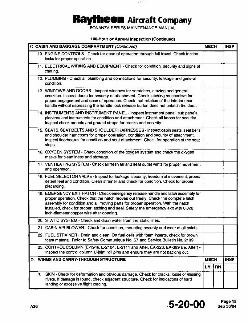
Ral~heon Aircraft CompanyBONANZA SERIES MAINTENANCE MANUAL
100-Hour or Annual Inspection (Continued)
C. CABIN AND BAGGAGE COMPARTMENT (Continued) MECH INSP
10. ENGINE CONTROLS Check for ease of operation through full travel. Check friction
locks for proper operation.
11. ELECTRICAL WIRING AND EQUIPMENT Check for condition, security and signs of
chafing.
12. PLUMBING Check all plumbing and connections for security, leakage and generalcondition
13. WINDOWS AND DOORS Inspect windows for scratches, crazing and generalcondition. Inspect doors for security of attachment. Check latching mechanism for
proper engagement and ease of operation. Check that rotation of the interior door
handle without depressing the handle lock release button does not unlatch the door.
14. INSTRUMENTS AND INSTRUMENT PANEL Inspect instrument panel, sub panels,placards and instruments for condition and attachment. Check all knobs for security.Inspect shock mounts and ground straps for cracks and security.
15. SEATS, SEAT BELTS AND SHOULDER HARNESSES Inspect cabin seats, seat belts
and shoulder harnesses for proper operation, condition and security of attachment.
Inspect floorboards for condition and seat attachment. Check for operation of the seat
stops.
16. OXYGEN SYSTEM Check condition of the oxygen system and check the oxygenmasks for cleanliness and stowage.
17. VENTILATING SYSTEM Check all fresh air and heat outlet vents for proper movement
and operation.
18. FUEL SELECTOR VALVE Inspect for leakage, security, freedom of movement, properdetent feel and condition. Clean strainer and check for condition. Check for proper
placarding.
19. EMERGENCY EXIT HATCH Check emergency release handle and latch assembly for
proper operation. Check that the hatch moves out freely. Check the complete latch
assembly for condition and all moving parts for proper operation. With the hatch
installed, check for proper latching and seal. Safety the emergency exit with 0.020
inch-diameter copper wire after opening.
20. STATIC SYSTEM Check and drain water from the static lines.
21. CABIN AIR BLOWER Check for condition, mounting security and wear at all points.
22. FUEL STRAINER Drain and clean. On fuel cells with foam inserts, check for brown
foam material. Refer to Safety Communique No. 67 and Service Bulletin No. 2109.
23. CONTROL COLUMN (E-1946, E-2104, E-2111 and After; EA-320, EA-389 and After)Inspect the control column U-joint roll pinb and ensure they are not backing out.
D. WINGS AND CARRY-THROUGH STRUCTURE MECH INSP
LH RH
1. SKIN Check for deformation and obvious damage. Check for cracks, loose or missingrivets. If damage is found, check adjacent structure. Check for indications of hard
landing or excessive flight loading.
.5-20-00 15
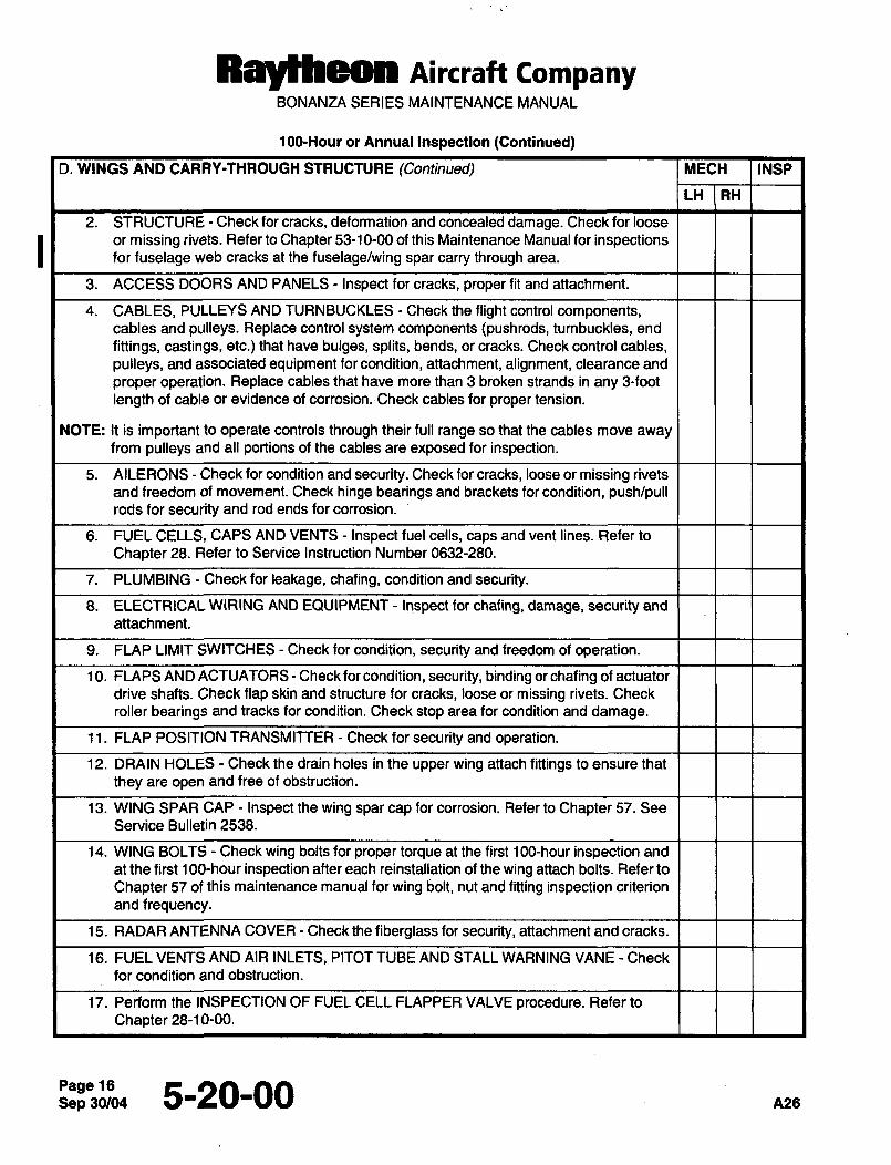
Ray~heon Aircraft CompanyBONANZA SERIES MAINTENANCE MANUAL
1 GO-Hour or Annual Inspection (Continued)
D. WINGS AND CARRY-THROUGH STRUCTURE (Continued) MECH INSP
LH RH
2. STR UCTURE Check for cracks, deformation and concealed damage. Check for loose
or missing rivets. Refer to Chapter 53-10-00 of this Maintenance Manual for inspectionsfor fuselage web cracks at the fuselage/wing spar carry through area.
3. ACCESS DOORS AND PANELS Inspect for cracks, proper fit and attachment.
4. CABLES, PULLEYS AND TURNBUCKLES Check the flight control components,cables and pulleys. Replace control system components (pushrods, turnbuckles, end
fittings, castings, etc.) that have bulges, splits, bends, or cracks. Check control cables,
pulleys, and associated equipment for condition, attachment, alignment, clearance and
proper operation. Replace cables that have more than 3 broken strands in any 9-foot
length of cable or evidence of corrosion.´•Check cables for proper tension.
NOTE: It is important to operate controls through their full range so that the cables move awayfrom pulleys and all portions of the cables are exposed for inspection.
5. AILERONS Check for condition and security. Check for cracks, loose or missing rivets
and freedom of movement. Check hinge bearings and brackets for condition, push/pullrods for security and rod ends for corrosion.
6. FUEL CELLS, CAPS AND VENTS Inspect fuel cells, caps and vent lines. Refer to
Chapter 28. Refer to Service Instruction Number 0632-280.
7. PLUMBING Check for leakage, chafing, condition and security.
8. ELECTRICAL WIRING AND EQUIPMENT Inspect for chafing, damage, security and
attachment.
9. FLAP LIMIT SWITCHES Check for condition, security and freedom of operation.
10. FLAPS AND ACTUATORS Check for condition, security, binding or chafing of actuator
drive shafts. Check flap skin and structure for cracks, loose or missing rivets. Check
roller bearings and tracks for condition. Check stop area for condition and damage.
11. FLAP POSITION TRANSMITTER Check for security and operation.
12. DRAIN HOLES Check the drain holes in the upper wing attach fittings to ensure that
they are open and free of obstruction.
13. WING SPAR CAP Inspect the wing spar cap for corrosion. Refer to Chapter 57. See
Service Bulletin 2538.
14. WING BOLTS Check wing bolts for proper torque at the first 100-hour inspection and
at the first 1 GO-hour inspection after each reinstallation of the wing attach bolts. Refer to
Chapter 57 of this maintenance manual for wing bolt, nut and fitting inspection criterion
and frequency.
15. RADAR ANTENNA COVER Check the fiberglass for security, attachment and cracks.
16. FUEL VENTS AND AIR INLETS, PITOT TUBE AND STALL WARNING VANE Check
for condition and obstruction.
17. Perform the INSPECTION OF FUEL CELL FLAPPER VALVE procedure. Refer to
Chapter 28-10-00.
Sep 30/045-20-00 A28
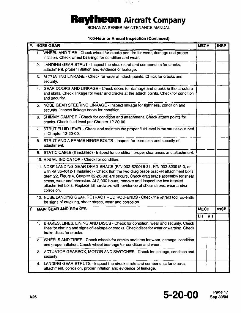
RaytPleon Aircraft CompanyBONANZA SERIES MAINTENANCE MANUAL
100-Hour or Annual Inspection (Continued)
E. NOSEGEAR MECH INSP
1. WHEEL AND TIRE Check wheel for cracks and tire for wear, damage and properinflation. Check wheel bearings for condition and wear.
2. LANDING GEAR STRUT Inspect the shock strut and components for cracks,attachment, proper inflation and evidence of leakage.
3. ACTUATING LINKAGE Check for wear at attach points. Check for cracks and
security.
4. GEAR DOORS AND LINKAGE Check doors for damage and cracks to the structure
and skins. Check linkage for wear and cracks at the attach points. Check for condition
and security.
5. NOSE GEAR STEERING LINKAGE Inspect linkage for tightness, condition and
security. Inspect linkage boots for condition.
6. SHIMMY DAMPER Check for condition and attachment. Check attach points for
cracks. Check fluid level per Chapter 12-20-00.
7. STRUT FLUID LEVEL Check and maintain the proper fluid level in the strut as outlined
in Chapter 12-20-00.
8. STRUT AND A-FRAME HINGE BOLTS Inspect for corrosion and security of
attachment.
9. STATIC CABL~ (If installed) Inspect for condition, proper clearances and attachment.
10. VISUAL INDICATOR Check for condition.
11. NOSE LANDING GEAR DRAG BRACE (P/N 002-820016-31, P/N 002-820018-3, or
with Kit 35-4012-1 Installed) Check that the two drag brace bracket attachment bolts
(Item 22, Figure 4, Chapter 32-20-00) are secure. Check drag brace assembly for shear
stress, wear and corrosion. At 2,000 hours, remove and inspect the two bracket
attachment bolts. Replace all hardware with evidence of shear stress, wear and/or
corrosion.
12. NOSE LANDING GEAR RETRACT ROD ROD-ENDS Check the retract rod rod-ends
for signs of cracking, sheer stress, wear and corrosion.
F. MAINGEARAND BRAKES MECH INSP
LH RH
1. BRAKES, LINES, LINING AND DISCS Check for condition, wear and security. Check
lines for chafing and signs of leakage or cracks. Check discs for wear or warping. Check
brake discs for cracks.
2. WHEELS AND TIRES Check wheels for cracks and tires for wear, damage, condition
and proper inflation. Check wheel bearings for condition and wear.
3. ACTUATOR GEARBOX, MOTOR AND SWITCHES Check for leakage, condition and
security.
4. LANDING GEAR STRUTS Inspect the shock struts and components for cracks,attachment, corrosion, proper inflation and evidence of leakage.
n,s 5-20-00 17
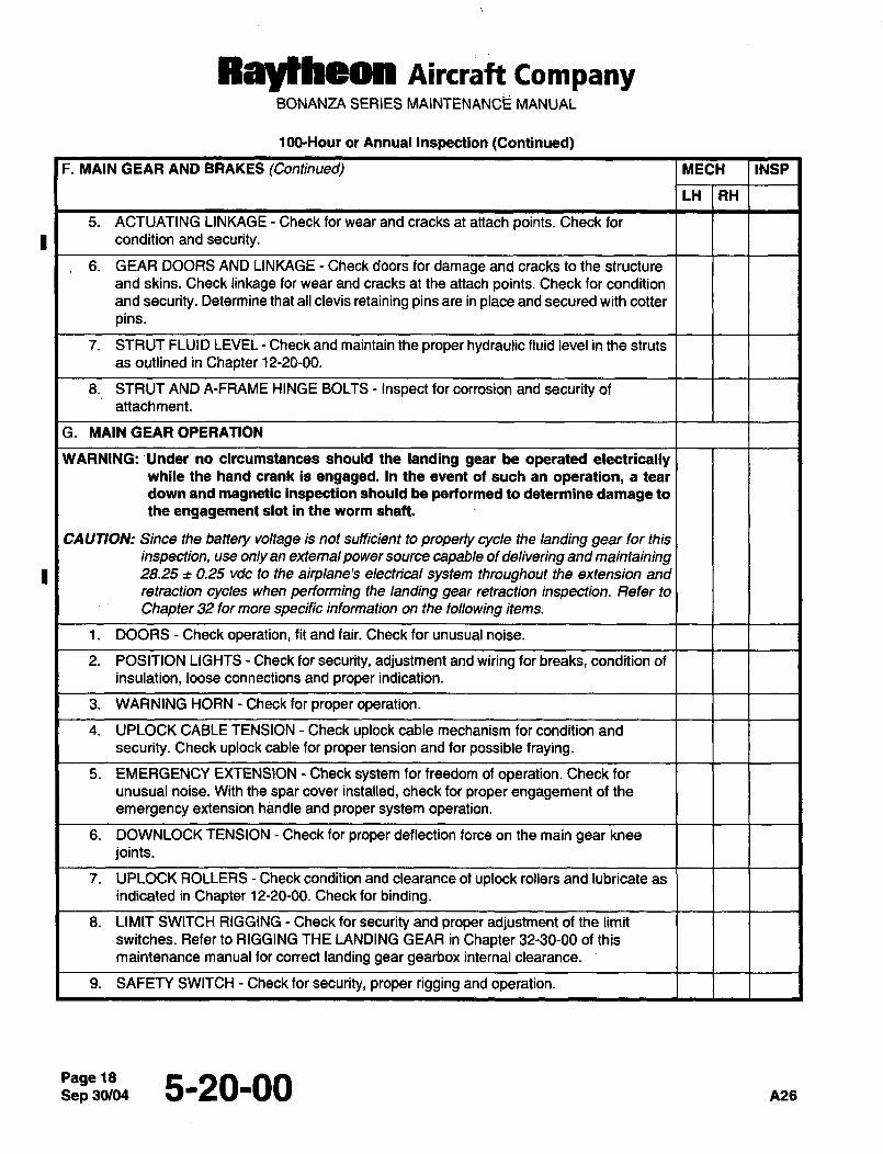
RayNheon Aircraft CompanyBONANZA SERIES MAINTENANCE MANUAL
100-Hour or Annual Inspection (Continued)
F. MAIN GEAR AND BRAKES (Continued) MECH INSP
LH RH
5. ACTUATING LINKAGE Check for wear and cracks at attach points. Check for
condition and security.
6. GEAR DOORS AND LINKAGE Check doors for damage and cracks to the structure
and skins. Check linkage for wear and cracks at the attach points. Check for condition
and security. Determine that ail clevis retaining pins are in place and secured with cotter
pins.
7. STRUT FLUID LEVEL Check and maintain the proper hydraulic fluid level in the struts
as outlined in Chapter 12-20-00.
8. STRUT AND A-FRAME HINGE BOLTS Inspect for corrosion and security of
attachment.
G. MAIN GEAR OPERATION
WARNING: ~Under no circumstances should the landing gear be operated electricallywhile the hand crank is engaged. In the event of such an operation, a tear
down and magnetic inspection should be performed to determine damage to
the engagement slot in the worm shaft.
CAUTION: Since the battery voltage is not sufficient to properly cycle the landing gear for this
inspection, use only an extemal power source capable of delivering and maintaining28.25 0.25 vdc to the airplane’s electrical system throughout the extension and
retraction cycles when performing the landing gear retraction inspection. Refer to
Chapter 32 for more specific information on the following items.
1. DOORS Check operation, fit and fair. Check for unusual noise.
2. POSITION LIGHTS Check for security, adjustment and wiring for breaks, condition of
insulation, loose connections and proper indication.
3. WARNING HORN Check for proper operation.
4. UPLOCK CABLE TENSION Check uplock cable mechanism for condition and
security. Check uplock cable for proper tension and for possible fraying.
5. EMERGENCY EXTENSION Check system for freedom of operation. Check for
unusual noise. With thespar cover installed, check for proper engagement of the
emergency extension handle and proper system operation.
6. DOWNLOCK TENSION Check for proper deflection force on the main gear knee
joints.
7. UPLOCK ROLLERS Check condition and clearance of uplock rollers and lubricate as
indicated in Chapter 12-20-00. Check for binding.
8. LIMIT SWITCH RIGGING Check for security and proper adjustment of the limit
switches. Refer to RIGGING THE LANDING GEAR in Chapter 32-30-00 of this
maintenance manual for correct landing gear gearbox internal clearance.
9. SAFETY SWITCH Check for security, proper rigging and operation.
Page 185-20-00 A26
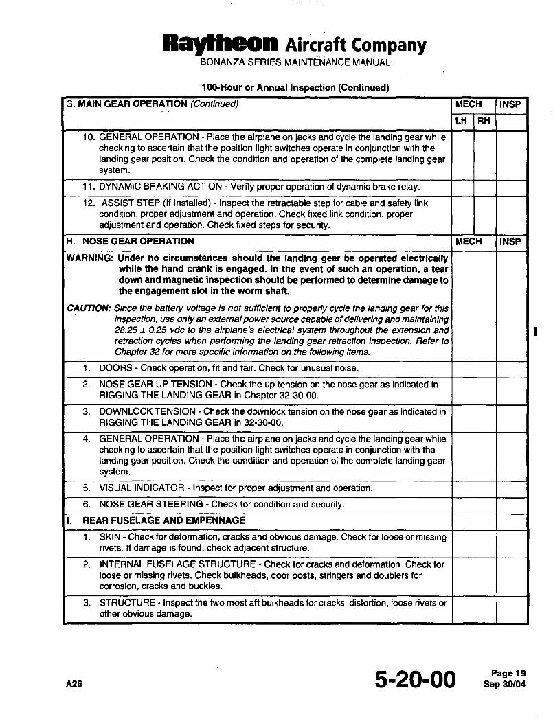
Raytheon Aircraft CompanyBONANZA SERIES MAINTENANCE MANUAL
100-Hour or Annual Inspection (Continued)
G. MAIN GEAR OPERATION (Continued) MECH INSP
LH RH
10. GENERAL OPERATION Place the airplane on jacks and cycle the landing gear while
checking to ascertain that the position light switches operate in conjunction with the
landing gear position. Check the condition and operation of the complete landing gear
system.
11. DYNAMIC BRAKING ACTION Verify proper operation of dynamic brake relay.
12. ASSIST STEP (If Installed) Inspect the retractable step for cable and safety link
condition, proper adjustment and operation. Check fixed link condition, properadjustment and operation. Check fixed steps for security.
H. NOSE GEAR OPERATION MECH INSP
WARNING: Under no circumstances should the landing gear be operated electricallywhile the hand crank is engaged. In the event of such an operation, a tear
down and magnetic inspection should be performed to determine damage to
the engagement slot in the worm shaft.
CAUTION: Since the battery voltage is not sufficient to properly cycle the landing gear for this
inspection, use only an externalpower source capable of delivering and maintaining28.25;t 0.25 vde to the airplane’s electrical system throughout the extension and
retraction cycles when performing the landing gear retraction inspection. Refer to
Chapter 32 for more specific information on the following items.
1. DOORS Check operation, fit and fair. Check for unusual noise.
2. NOSE GEAR UP TENSION Check the up tension on the nose gearas indicated in
RIGGING THE LANDING GEAR in Chapter 32-30-00.
3. DOWNLOCK TENSION Check the downlock tension on the nose gear as indicated in
RIGGING THE LANDING GEAR in 32-30-00.
4. GENERAL OPERATION Place the airplane on jacks and cycle the landing gear while
checking to ascertain that the position light switches operate in conjunction with the
landing gear position. Check the condition and operation of the complete landing gear
system.
5. VISUAL INDICATOR Inspect for proper adjustment and operation.
6. NOSE GEAR STEERING Check for condition and security.
I. REAR FUSELAGE AND EMPENNAGE
1. SKIN Check for deformation, cracks and obvious damage. Check for loose or missingrivets. If damage is found, check adjacent structure.
2. INTERNAL FUSELAGE STRUCTURE Check for cracks and deformation. Check for
loose or missing rivets. Check bulkheads, door posts, stringers and doublers for
corrosion, cracks and buckles.
3. STRUCTURE Inspect the two most aft bulkheads for cracks, distortion, loose rivets or
other obvious damage.
A26 5-20-00 19
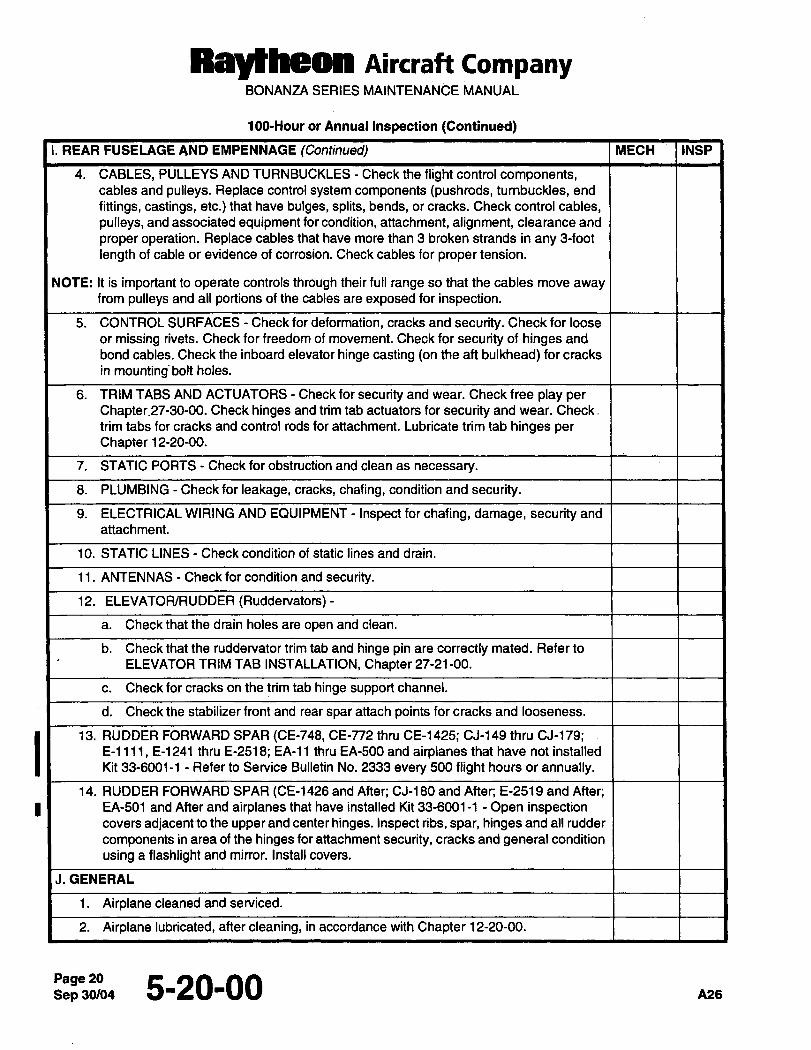
Raytheon AiKraft CompanyBONANZA SERIES MAINTENANCE MANUAL
100-Hour or Annual Inspection (Continued)
I. REAR FUSELAGE AND EMPENNAGE (Continued) MECH IINSP
4. CABLES, PULLEYS AND TURNBUCKLES Check the flight control components,cables and pulleys. Replace control system components (pushrods, turnbuckles, end
fittings, castings, etc.) that have bulges, splits, bends, or cracks. Check control cables,
pulleys, and associated equipment for condition, attachment, alignment, clearance and
proper operation. Replace cables that have more than 3 broken strands in any 3-foot
length of cable or evidence of corrosion. Check cables for proper tension.
NOTE: It is important to operate controls through their full range so that the cables move awayfrom pulleys and all portions of the cables are exposed for inspection.
5. CONTROL SURFACES Check for deformation, cracks and security. Check for loose
or missing rivets. Check for freedom of movement. Check for security of hinges and
bond cables. Check the inboard elevator hinge casting ton the aft bulkhead) for cracks
in mounting~bolt holes.
6. TRIM TABS AND ACTUATORS Check for security and wear. Check free play per
Chapter.27-30-00. Check hinges and trim tab actuators for security and wear. Check.
trim tabs for cracks and control rods for-attachment. Lubricate trim tab hinges per
Chapter 12-20-00.
7. STATIC PORTS Check for obstruction and clean as necessary.
8. PLUMBING Check for leakage, cracks, chafing, condition and security.
9. ELECTRICAL WIRING AND EOUIPMENT Inspect for chafing, damage, security and
attachment.
10. STATIC LINES Check condition of static lines and drain.
11. ANTENNAS Check for condition and security.
12. ELEVATOWRUDDER (Ruddervators)-
a. Check that the drain holes are open and clean.
b. Check that the ruddervator trim tab and hinge pin are correctly mated. Refer to
ELEVATOR TRIM TAB INSTALLATION, Chapter 27-21-00.
c. Check for cracks on the trim tab hinge support channel.
d. Check the stabilizer front and rear spar attach points for cracks and looseness.
13. RUDDER FORWARD SPAR (CE-748, CE-n2 thru CE-1425; CJ-149 thru CJ-179;E-llll, E-1241 thru E-2518; EA-11 thru EA-500 and airplanes that have not installed
Kit 33-6001-1 Refer to Service Bulletin No. 2333 every 500 flight hours or annually.
14. RUDDER FORWARD SPAR (CE-1426 and After; CJ-180 and After; E-2519 and After;
I I EA-501 and After and airplanes that have installed Kit 33-6001-1 Open inspectioncovers adjacentto the upper and center hinges. Inspect ribs, spar, hinges and all rudder
components in area of the hinges for attachment security, cracks and general condition
using a flashlight and mirror. Install covers.
J.GENERAL
1. Airplane cleaned and serviced.
2. Airplane lubricated, after cleaning, in accordance with Chapter 12-20-00.
Page 20Sep30/04 5-20-00 nze
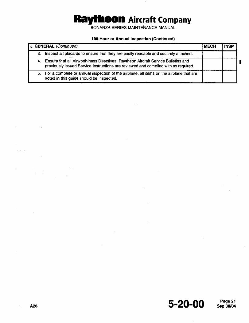
Ra~heon Aircraft CompanyBONANZA SERIES MAINTENANCE MANUAL
10O-Hour or Annual Inspection (Continued)
J. GENERAL (Continued) MECH INSP
3. Inspect all placards to ensure that they are easily readable and securely attached.
4. Ensure that all Airworthiness Directives, Raytheon Aircraft Service Bulletins and I Ipreviously issued Service Instructions are reviewed and complied with as required.
5. For a complete or annual inspection of the airplane, all items on the airplane that are
noted in this guide should be inspected.
pas 5-20-00Page 21
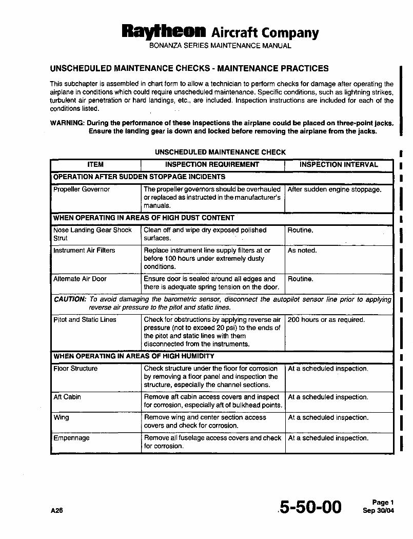
RaytheOn AiKraft CampanyBONANZA SERIES MAINTENANCE MANUAL
UNSCHEDULED MAINTENANCE CHECKS MAINTENANCE PRACTICES
This subchapter is assembled in chart form to allow a technician to perform checks for damage after operating the
airplane in conditions which could require unscheduled maintenance. Specific conditions, such as lightning strikes,turbulent air penetration or hard landings, etc., are included. Inspection instructions are included for each of the
conditions listed.
WARNING: During the performance of these inspections the airplane could be placed on three-point jacks.Ensure the landing gear is down and locked before removing the airplane from the jacks.
UNSCHEDULED MAINTENANCE CHECK
ITEM INSPECTION REQUIREMENT INSPECTION INTERVAL I
OPERATION AFTER SUDDEN STOPPAGE INCIDENTS
Propeller Governor The propeller governors should be overhauled After sudden engine stoppage.or replaced as instructed in the manufacturer’s
manuals.
WHEN OPERATING iN AREAS OF HIGH DUST CONTENT
Nose Landing Gear Shock Clean off and wipe dry exposed polished Routine.
Strut surfaces.
Instrument Air Filters Replace instrument line supply filters at or As noted.
before 100 hours under extremely dustyconditions.
Alternate Air Door Ensure door is sealed around all edges and Routine.
there is adequate spring tension on the door.
CAUTION: To avoid damaging the barometric sensor, disconnect the autopilot sensor line prior to applyingreverse air pressure to the pitot and static lines.
Pitot and Static Lines Check for obstructions by applying reverse air 200 hours or as required.pressure (not to exceed 20 psi) to the ends of
the pitot and static lines with them
disconnected from the instruments.
WHEN OPERATING IN AREAS OF HIGH HUMIDITY
Floor Structure Check structure under the floor for corrosion At a scheduled inspection.by removing a floor panel and inspection the
structure, especially the channel sections.
Aft Cabin Remove aft cabin access covers and inspect At a scheduled inspection.for corrosion, especially aft of bulkhead points.
Wing Remove wing and center section access At a scheduled inspection.covers and check forcorrosion.
Empennage Remove all fuselage access covers and check At a scheduled inspection.for corrosion.
n2e .5-50-00Page 1
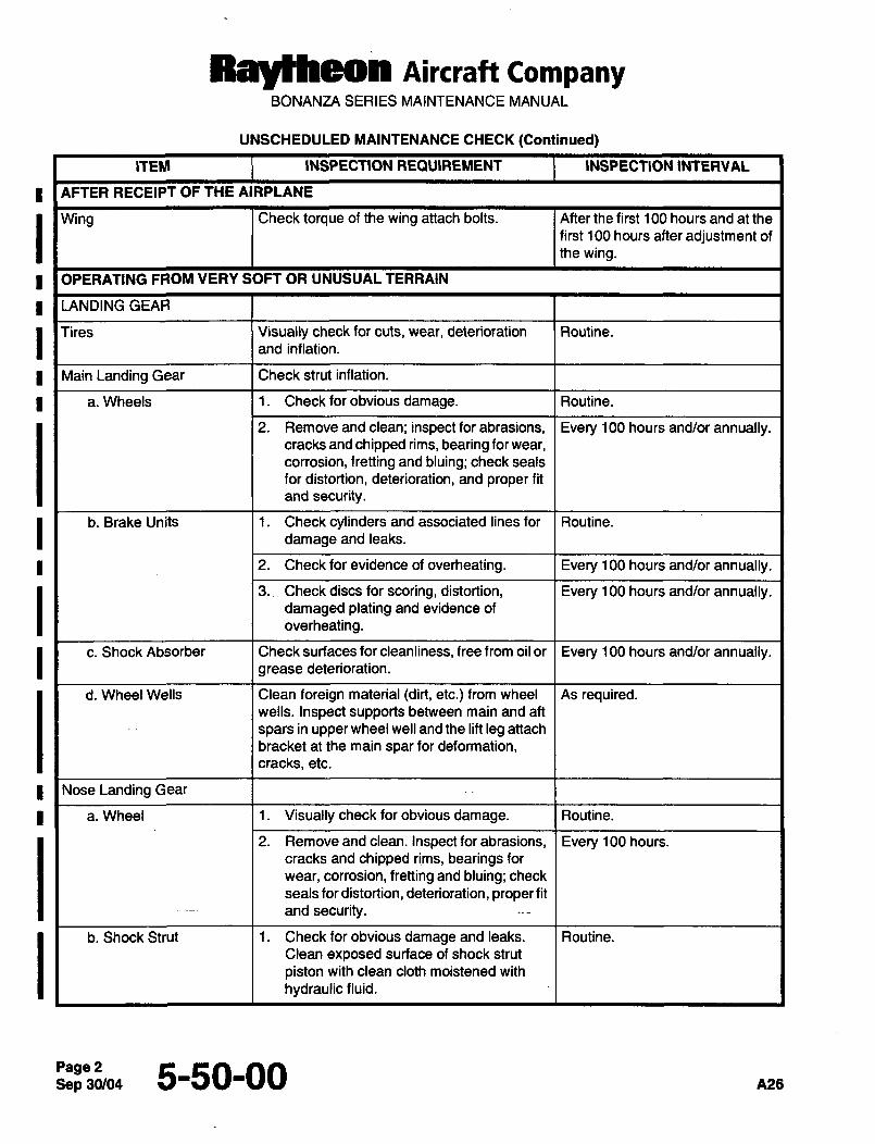
Aircraft CompanyBONANZA SERIES MAINIENANCE MANUAL
UNSCHEDULED MAINTENANCE CHECK (Continued)
ITEM INSPECTION REQUIREMENT INSPECTION INTERVAL
AFTER RECEIPT OF THE AIRPLANE
Wing Check torque of the wing attach bolts. After the first 100 hours and at the
first 100 hours after adjustment of
the wing.
I OPERATING FROM VERY SOFT OR UNUSUAL TERRAIN
LANDING GEAR
Tires Visually check for cuts, wear, deterioration Routine.
and inflation.
I Main Landing Gear Check strut inflation.
a. Wheels 1. Checkforobvious damage. Routine.
2. Removeandclean; inspectforabrasions, Every 100 hours and/or annually.cracks and chipped rims, bearing for wear,
corrosion, fretting and bluing; check seals
for distortion, deterioration, and proper fit
and security.
b. Brake Units 1. Check cylinders and associated lines for Routine.
damage and leaks.
2. Check for evidence of overheating. Every 100 hours and/or annually.
3.~ Check discs for scoring, distortion, Every 100 hours and/or annually.damaged plating and evidence of
overheating.
c. Shock Absorber Check surfaces for cleanliness, free from oil or Every 100 hours and/or annually.grease deterioration.
d. Wheel Wells Clean foreign material (dirt, etc.) from wheel As required.wells. Inspect supports between main and aft
spars in upper wheel well and the lift leg attach
bracket at the main spar for deformation,cracks, etc.
Nose Landing Gear
a. Wheel 1. Visually check for obvious damage. Routine.
2. Remove and clean. Inspect for abrasions, Every 100 hours.
cracks and chipped rims, bearings for
wear, corrosion, fretting and bluing; check
seals for distortion, deterioration, proper fit
and security.
b. Shock Strut 1. Check for obvious damage and leaks. Routine.
Clean exposed surface of shock strut
piston with clean cloth moistened with
hydraulic fluid.
Page25-50-00 AZS
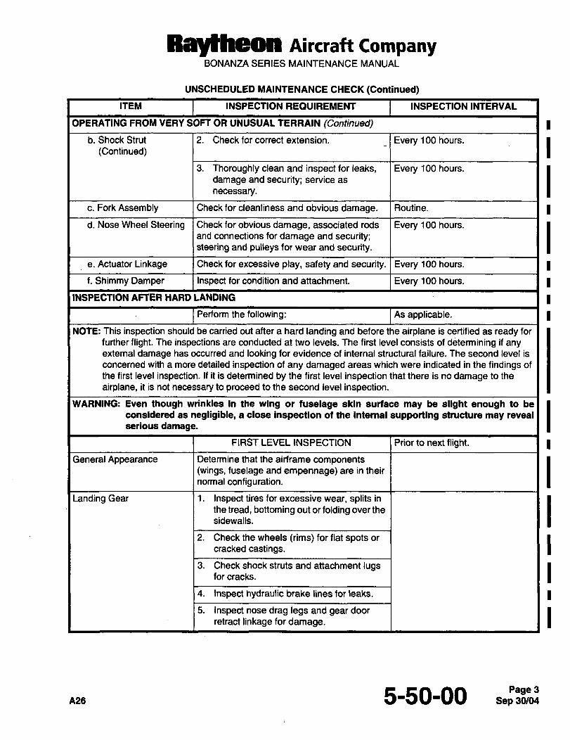
Raytheon Aircraft CompanyBONANZA SERIES MAINTENANCE MANUAL
UNSCHEDULED MAINTENANCE CHECK (Continued)
ITEM INSPECTION REQUIREMENT INSPECTION INTERVAL
OPERATING FROM VERY SOFT OR UNUSUAL TERRAIN (Continued)
b. Shock Strut(Continued) 2. Checkforcorrect extension. Every 100 hours.
3. Thoroughly clean and inspect for leaks, Every 100 hours.
damage and security; service as Inecessary.
c. Fork Assembly Check for cleanliness and obvious damage. Routine.
d. Nose Wheel Steering Check for obvious damage, associated rods Every 100 hours, iand connections for damage and security;steering and pulleys for wear and security.
e. Actuator Linkage Check for excessive play, safety and security. I Every 100 hours.
f. Shimmy Damper Inspect for condition and attachment. Every 100 hours. I I
INSPECTION AFTER HARD LANDING I I
Perform the following: As applicable. I I
NOTE: This inspection should be carried out after a hard landing and before the airplane is certified as ready for
further flight. The inspections are conducted at two levels. The first level consists of determining if anyexternal damage has occurred and looking for evidence of internal structural failure. The second level is
concerned with a more detailed inspection of any damaged areas which were indicated in the findings of
the first level inspection. If it is determined by the first level inspection that there is no damage to the
airplane, it is not necessary to proceed to the second level inspection.
WARNING: Even though wrinkles in the wing or fuselage skin surface may be slight enough to be
considered as negligible, a close inspection of the internal supporting structure may reveal
serious damage.
FIRST LEVEL INSPECTION Prior to next flight.
General Appearance Determine that the airframe components(wings, fuselage and empennage) are in their
normal configuration.
Landing Gear 1. Inspect tires for excessive wear, splits in
the tread, bottoming out or folding over the Isidewalls.
2. Checkthewheels (rims)forflatspotsor Icracked castings.
3.
for cracks.Check shock struts and attachment lugs I4. Inspect hydraulic brake lines for leaks.
5. Inspectnosedrag legsandgeardoor iretract linkage for damage.
5-so-oo
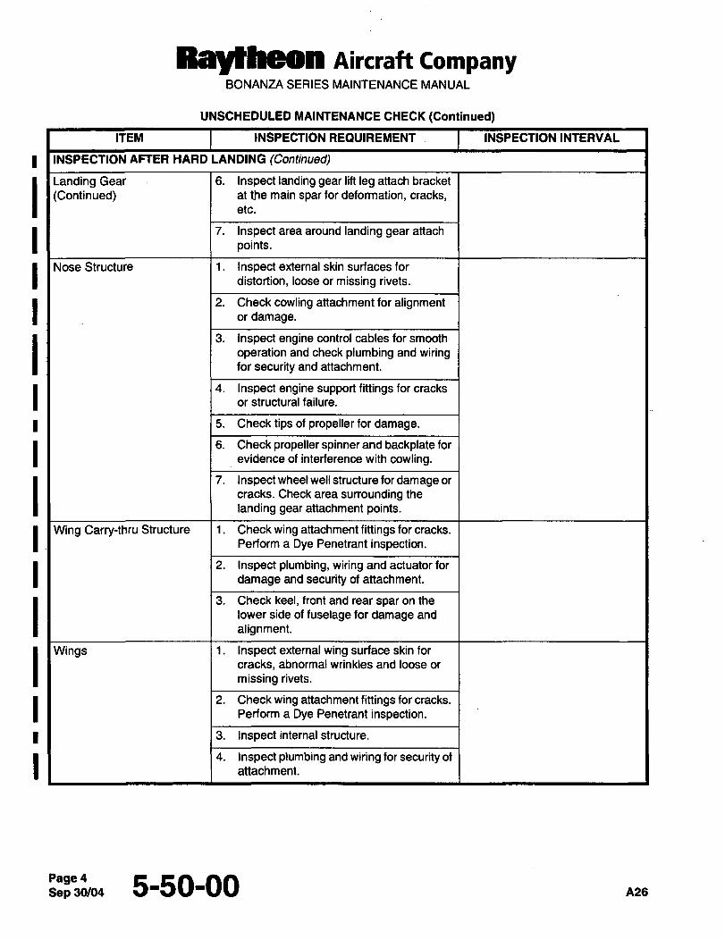
Ray~heon Aircraft CompanyBONANZA SERIES MAINTENANCE MANUAL
UNSCHEDULED MAINTENANCE CHECK (Continued)
ITEM INSPECTION REQUIREMENT I INSPECTION INTERVAL
INSPECTION AFTER HARD LANDING (Continued)
Landing Gear 1 6. Inspect landing gear lift leg attach bracket
(Continued) at the main spar for deformation, cracks,etc.
I 7. Inspect area around landing gear attachpoints.Nose Structure 1. Inspect external skin surfaces for
distortion, loose or missing rivets.
I 2. Check cowling attachment for alignmentordamage.
3. Inspectenginecontrol cablesforsmooth
operation and check plumbing and wiringfor security and attachment.
11 14 Inspect engine support fittings for cracks
or structural failure.
5. Check tips of propeller for damage.
6. Check propeller´•spinnerand backplateforevidence of interference with cowling.
7. Inspectwheelwell structurefordamage or
I cracks. Check area surrounding the
landing gear attachment points.
I Wing Carry-thru Structure 1. Checkwing attachmentfittings forcracks.
Perform a Dye Penetrant inspection.
I 2. Inspect plumbing, wiring and actuator for
damage and security of attachment.
3. Checkkeel,frontand rearsparonthelower side of fuselage for damage and
alignment.
Wings 1. Inspect external wing surface skin for
I cracks, abnormal wrinkles and loose ormissingrivets.
I 2. Checkwing attachmentfittings forcracks.
Perform a Dye Penetrant inspection.
3. Inspect internal structure.
4. attachment.Inspect plumbing and wiring for security of
Page45-50-00
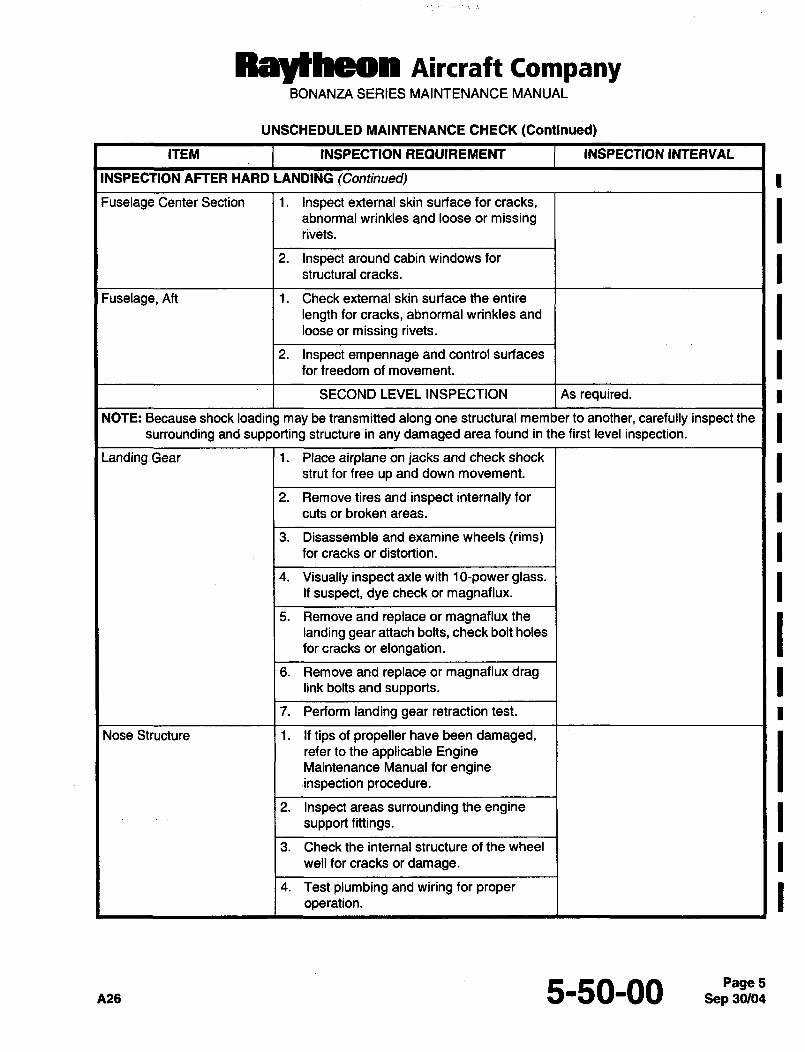
Ray~heon Aircraft CompanyBONANZA SERIES MAINTENANCE MANUAL
UNSCHEDULED MAINTENANCE CHECK (Continued)
ITEM INSPECTION REQUIREMENT INSPECTION INTERVAL
INSPECTION AFTER HARD LANDING (Continued)
Fuselage Center Section 1. Inspect external skin surface for cracks,abnormal wrinkles and loose or missingrivets.
2. Inspect around cabin windows for
structural cracks.
Fuselage, Aft 1. Check external skin surface the entire
length for cracks, abnormal wrinkles and
loose or missing rivets.
2. Inspect empennage and control surfaces
for freedom of movement.
SECOND LEVEL INSPECTION As required.
NOTE: Because shock loading may be transmitted along one structural member to another, carefully inspect the Isurrounding and supporting structure in any damaged area found in the first level inspection.
Landing Gear i. Place airplane on jacks and check shock
strut for free up and down movement.
2. Remove tires and inspect internally for
cuts or broken areas.
3. Disassemble and examine wheels trims)for cracks or distortion.
4. Visually inspectaxlewith 10-powerglass.If suspect, dye check or magnaflux.
5. Removeand replaceormagnafluxthelanding gear attach bolts, check bolt holes
for cracks or elongation.
6. Remove and replace or magnaflux draglink bolts and supports.
7. Perform landing gear retraction test.
Nose Structure 1. If tips of propeller have been damaged,refer to the applicable EngineMaintenance Manual for engine.inspection procedure.
2. Inspect areas surrounding the enginesupport fittings.
3. Check the internal structure of the wheel
well for cracks or damage.
4. Test plumbing and wiring for proper
operation.
nae 5-so-ooPage 5
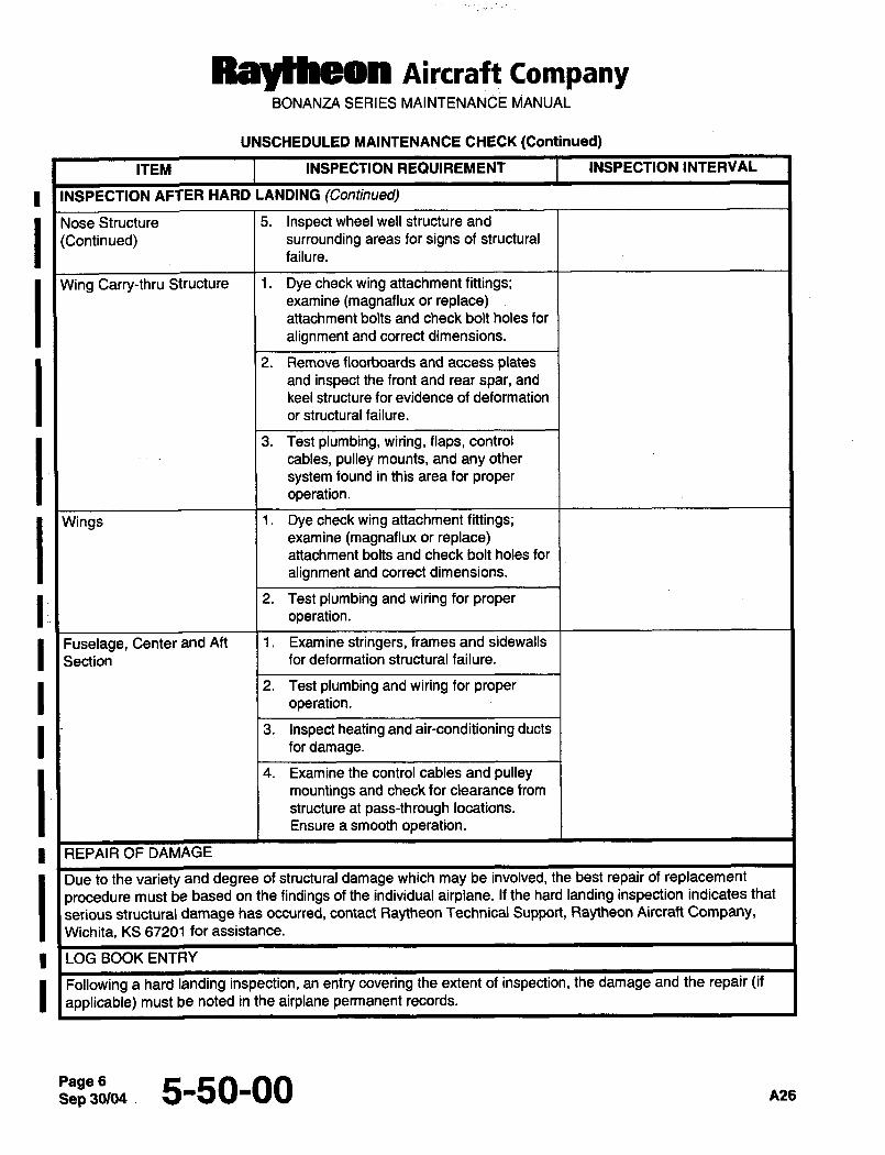
Ral~heon AiKraft CompanyBONANZA SERIES MAINTENAN~E MANUAL
UNSCHEDULED MAINTENANCE CHECK (Continued)
ITEM INSPECTION REQUIREMENT INSPECTION INTERVAL
INSPECTION AFTER HARD LANDING (Continued)
Nose Structure 5. Inspect wheel well structure and
(Continued) surrounding areas for signs of structural
failure.
Wing Carry-thru Structure 1. Dyecheckwing attachmentfittings;examine (magnaflux or replace)attachment bolts and check bolt holes for
alignment and correct dimensions.
2. Remove floorboards and access platesand inspect the front and rear spar, and
keel structure for evidence of deformation
or structural failure.
3. Test plumbing, wiring, flaps, control
cables, pulley mounts, and any other
system found in this area for proper
operation.
Wings i. Dyecheckwing attachmentfittings;examine (magnaflux or replace)attachment bolts and check bolt holes for
alignment and correct dimensions.
2. Test plumbing and wiring for proper
operation.
I Fuselage, Center and Aft 1. Examine stringers, frames and sidewalls
Section for deformation structural failure.
2. Test plumbing and wiring for proper
operation.
3. Inspect heating and air-conditioning ducts
for damage.
4. Examinethecontrol cablesandpulleymountings and check for clearance from
structure at pass-through locations.
Ensure a smooth operation.
REPAIR OF DAMAGE
Due to the variety and degree of structural damage which may be involved, the best repair of replacement
procedure must be based on the findings of the individual airplane. If the hard landing inspection indicates that
serious structural damage has occurred, contact Raytheon Technical Support, Raytheon Aircraft Company,Wichita, KS 67201 for assistance.
LOG BOOK ENTRY
Followingahardlanding inspection, an entry covering the extent of inspection, the damage and the repair (if
applicable) must be noted in the airplane permanent records.
Sep 30/04 .Page6 5-50-00 A26
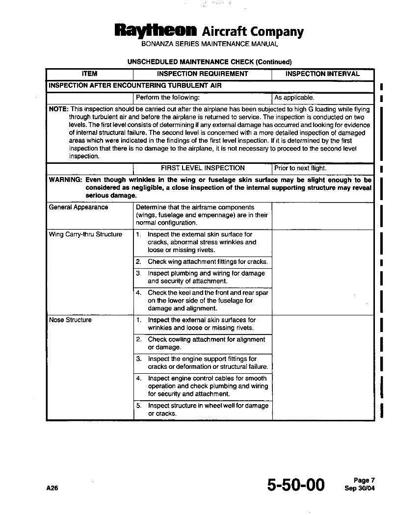
Raytheon AiKraft CompanyBONANZA SERIES MAINTENANCE MANUAL
UNSCHEDULED MAINTENANCE CHECK (Continued)
ITEM INSPECTION REQUIREMENT INSPECTION INTERVAL
INSPECTION AFTER ENCOUNTERING TURBULENT AIR
Perform the following: As applicable.
NOTE: This inspection should be carried out after the airplane has been subjected to high G loading while flyingthrough turbulent air and before the airplane is returned to service; The inspection is conducted on two
levels. The first level consists of determining if any external damage has occurred and looking for evidence
of internal structural failure. The second level is concerned with a more detailed inspection of damagedareas which were indicated in the findings of the first level inspection. If it is determined by the first
inspection that there is no damage to the airplane, it is not necessary to proceed to the second level
inspection.
FIRST LEVEL INSPECTION Prior to next flight.
WARNING: Even though wrinkles in the wing or fuselage skin surface may be slight enough to be
considered as negligible, a close inspection of the internal supporting structure may reveal
serious damage.
General Appearance Determine that the airframe components(wings, fuselage and empennage) are in their
normal configuration.
Wing Carry-thru Structure 1. Inspect the external skin surface for
cracks, abnormal stress wrinkles and
loose or missing rivets.
2. Check wing attachmentfittings for cracks.
3. Inspectplumbing andwiringfordamageand security of attachment.
4. Check the keel and the front and rear sparon the lower side of the fuselage for
damage and alignment.
Nose Structure 1. Inspect the external skin surfaces for
wrinkles and loose or missing rivets.
2. Check cowling attachment for alignmentor damage.
3. Inspecttheengine supportfittingsforcracks or deformation or structural failure.
4. Inspectenginecontrol cablesforsmooth
operation and check plumbing and wiringfor security and attachment.
5. Inspectstructure inwheelwellfordamageor cracks.
5-50-00 SepPa~g&bi:Page 7
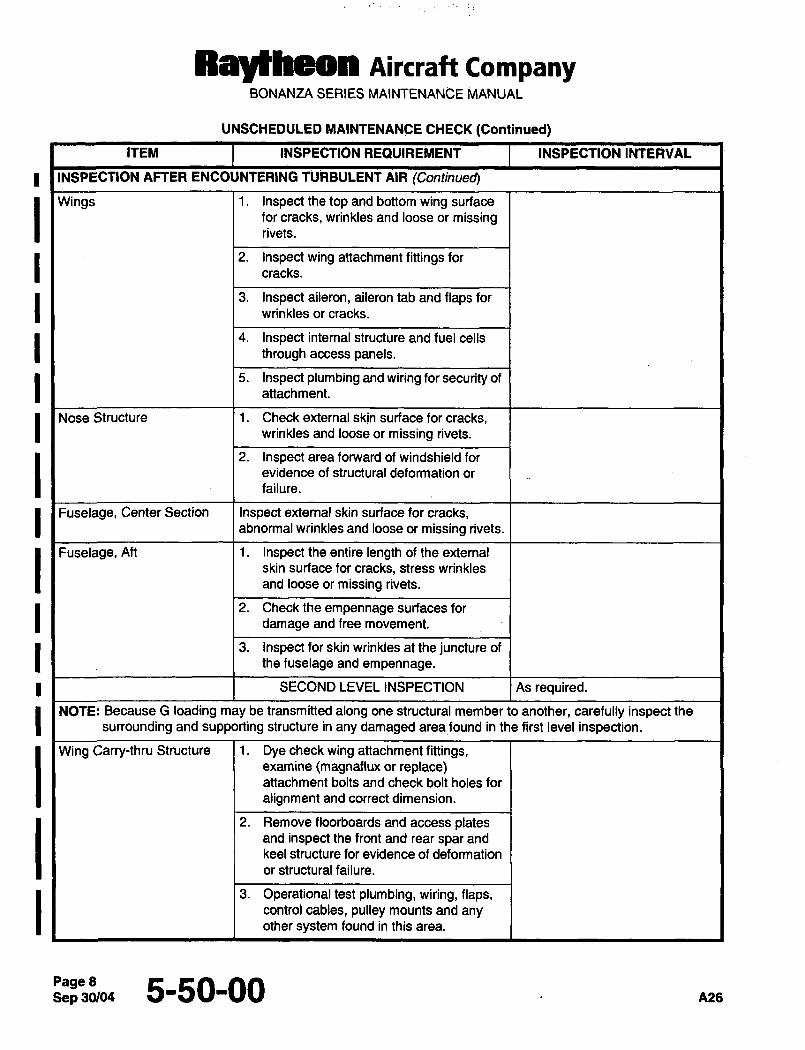
Ray~heon AiKraft CompanyBONANZA SERIES MAINTENANCE MANUAL
UNSCHEDULED MAINTENANCE CHECK (Continued)
ITEM INSPECTION REQUIREMENT INSPECTION INTERVAL
INSPECTION AFTER ENCOUNTERING TURBULENT AIR (Continued)
Wings 1. Inspectthetopand bottomwingsurfacefor cracks, wrinkles and~ loose or missingrivets.
2. Inspectwing attachmentfittingsforcracks.
3. Inspect aileron, aiierontab and flaps for
wrinkles or cracks.
4. Inspect internal structure and fuel cells
through access panels.
5. Inspectplumbingand wiringforsecurityofattachment.
Nose Structure 1. Checkexternalskjn surfaceforcracks,wrinkles and loose or missing rivets.
2. Inspect area forward of windshield for
evidence of structural deformation or
failure.
I Fuselage, Center Section Inspect external skin surface for cracks,abnormal wrinkles and loose or missing rivets.
Fuselage, Aft 1. Inspect the entire length of the external
skin surface for cracks, stress wrinkles
and loose or missing rivets.
2. Checktheempennage surfacesfor
damage and free movement.
3. Inspect for skin wrinkles at the juncture of
the fuselage and empennage.
SECOND LEVEL INSPECTION As required.
NOTE: Because G loading may be transmitted along one structural member to another, carefully inspect the
surrounding and supporting structure in any damaged areafound in the first level inspection.
Wing Carry-thru Structure 1. Dyecheckwing attachmentfittings,examine (magnaflux or replace)attachment bolts and check bolt holes for
alignment and correct dimension.
2. Remove floorboards and access platesand inspect the front and rear spar and
keel structure for evidence of deformation
or structural failure.
3. Operational test plumbing, wiring, flaps,control cables, pulley mounts and anyother system found in this area.
Sep 30/045-50-00 n28
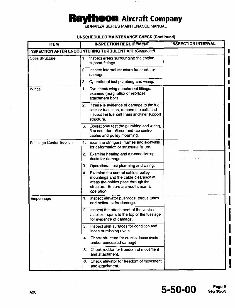
RayPheon AiKraft CompanyBONANZA SERIES MAINTENANCE MANUAL
UNSCHEDULED MAINTENANCE CHECK (Continued)
ITEM INSPECTION REQUIREMENT INSPECTION INTERVAL
INSPECTION AFTER ENCOUNTERING TURBULENT AIR (Continued)
Nose Structure i. Inspect areas surrounding the enginesupport fittings.
2. Inspect internal structure for cracks or
damage.
3. Operational test plumbing and wiring.
Wings 1. Dyecheckwing attachmentfittings,examine (magnaflux or replace)attachment bolts.
2. If there is evidence of damage to the fuel
cells or fuel lines, remove the cells and
inspect the fuel cell liners and liner supportstructure.
3. Operationaltestthe plumbingandwiring,flap actuator, aileron and tab control
cables and pulley mounting.
Fuselage Center Section 1. Examinestringers, framesandsidewalls
for deformation or structural failure.
2. Examine heating and air-conditioningducts for damage.
3. Operational test plumbing and wiring.
4. Examine the control cables, pulleymountings and the cable clearance at
areas the cables pass through the
structure. Ensure a smooth, normal
operation.
Empennage 1. Inspect elevator pushrods, torque tubes
and bellcrank for damage.
2. Inspect the attachment of the vertical
stabilizer spars to the top of the fuselagefor evidence of damage.
3. Inspect skin surfaces for condition and
loose or missing rivets.
4. Check structure for cracks, loose rivets
and/or concealed damage.
5. Check rudder for freedom of movement
and attachment.
6. Check elevator for freedom of movement
and attachment.
5-50-00 Sep 30104Page 9
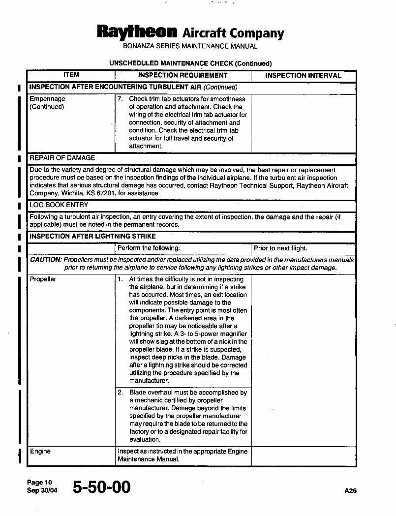
Rayrheon AiKraft CompanyBONANZA SERIES MAINTENANCE ~IANUAL
UNSCHEDULED MAINTENANCE CHECK (Continued)
ITEM INSPECTION REQUIREMENT INSPECTION INTERVAL
INSPECTION AFTER ENCOUNTERING TURBULENT AIR (Continued)
Empennage 7. Check trim tab actuators for smoothness
(Continued) of operation and attachment. Check the
wiring of the electrical trim tab actuator for
connection, security of attachment and
condition. Check the electrical trim tab
actuator for full travel and security of
attachment.
REPAIR OF DAMAGE
Due to the variety and degree of structural damage which may be involved, the best repair or replacementprocedure must be based on the inspection findings of the individual airplane. If the turbulent air inspectionindicates that serious structural damage has occurred, contact Raytheon Technical Support, Raytheon Aircraft
Company, Wichita, KS 67201, for assistance.
LOG BOOK ENTRY
Following a turbulent air inspection, an entry covering the extent of inspection, the damage and the repair (ifapplicable) must be noted in the permanent records.
I I INSPECTION AFTER LIGHTNING STRIKE
Perform the following: Prior to next flight.
CAUTION: Propellers must be inspected and/or replaced utilizing the data provided in the manufacturers manuals
prior to retuming the airplane to service following any lightning strikes or other impact damage.
Propeller i. At times the difficulty is not in inspectingthe airplane, but in determining if a strike
has occurred. Most times, an exit location
will indicate possible damage to the
components. The entry point is most often
the propeller. A darkened area in the
propeller tip may be noticeable after a
lightning strike. A 3- to 5-power magnifierwill show slag at the bottom of a nick in the
propeller blade. If a strike is suspected,inspect deep nicks in the blade. Damageafter a lightning strike should be corrected
utilizing the procedure specified by the
manufacturer.
2. Blade overhaul must be accomplished bya mechanic certified by propellermanufacturer. Damage beyond the limits
specified by the propeller manufacturer
may require the blade to be returned to the
factory or to a designated repair facility for
evaluation.
I Engine Inspect as instructed in the appropriate EngineMaintenance Manual.
Sep 5-50-00 ~25
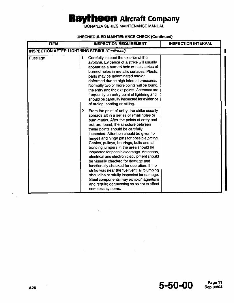
Raytheon AiKraft CompanyBONANZA SERIES MAINTENANCE MANUAL
UNSCHEDULED MAINTENANCE CHECK (Continued)
ITEM INSPECTION REQUIREMENT INSPECTION INTERVAL
INSPECTION AFTER LIGHTNING STRIKE (Continued)
Fuselage 1. Carefully inspect the exterior of the
airplane. Evidence of a strike will usuallyappear as a burned hole or as a series of
burned holes in metallic surfaces. Plastic
parts may be delaminated and/or
deformed due to high internal pressures.
Normally two or more points will be found,the entry and the exit points. Antennas are
frequently an entry point of lightning and
should be carefully inspected for evidence
of arcing, sooting or pitting.
2. From the point of entry, the strike usuallyspreads aft in a series of small holes or
burn marks. After the points of entry and
exit are found, the structure between
these points should be carefullyinspected. Attention should be given to
hinges and hinge pins for possible pitting.Cables, pulleys, bearings, bolts and all
bonding jumpers in the area should be
inspected for possible damage. Antennas,electrical and electronic equipment should
be visually checked for damage and
functionally checked for operation. If the
strike was near the fuel vent, all plumbingshould be carefully inspected for damage.Steel components may exhibit magnetismand require degaussing so as not to affect
compass systems.
s-so-oo 11
CHAPTER
DIMENSIONS
AND AREAS
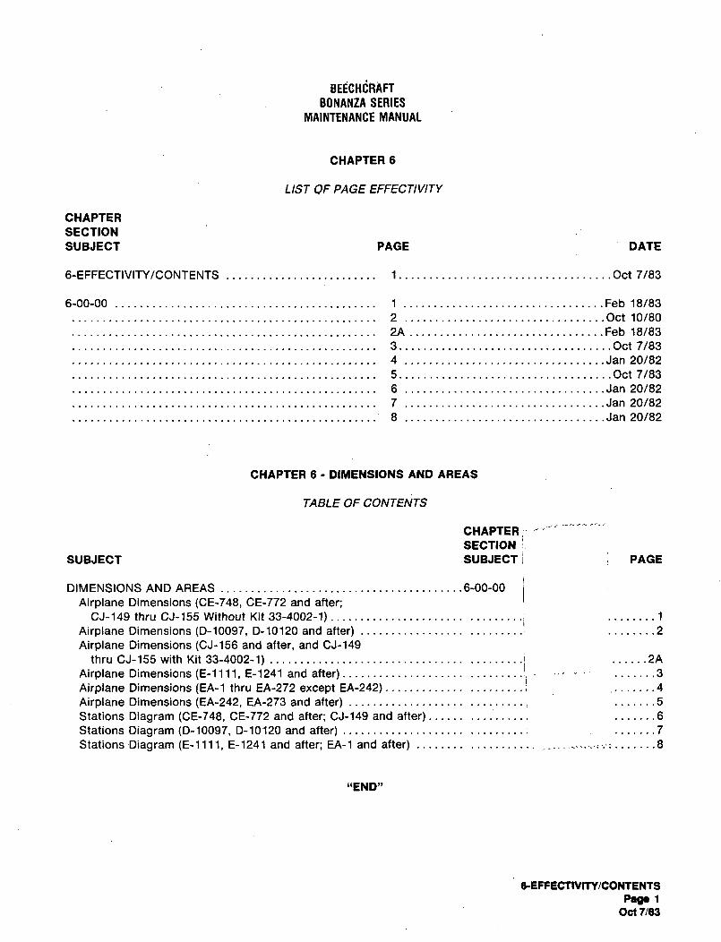
BEECHCRAFT
BONANZA SERIES
MAINTENANCE MANUAL
CHAPTER 6
LIST OF PAGE EFFECTIVITY
CHAPTER
SECTION
SUBJECT PAGE DATE
6-EFFECTIVITY/CONTENTS 1 .........,,,.Oct 7/83
6-00-00 1 Feb 18/83
2 Oct 10/80
2A Feb 18/83
3 ...............Oct 7/83
4 ..........,,.Jan 20/82
5 ...........,.Oct 7/83
6 ..............Jan 20/82
7 ..............Jan 20/82
8.................................Jan
20/82
CHAPTER 6 DIMENSIONS AND AREAS
TABLE OF CONTENTS
CHAPTER
SECTION iSUBJECT SUBJECT i PAGE
DIMENSIONS AND AREAS ..6-00-00
Airplane Dimensions (CE-748, CE-772 and after;CJ-149 thru CJ-155 Without Kit 33-4002-1) ........1
’’’’’’’’’iAirplane Dimensions (D-10097, D-10120 and after) ........2
Airplane Dimensions (CJ-156 and after, and CJ-149
thru CJ-155 with Kit 33-4002-1) .........i ......2A
Airplane Dimensions (E-llll, E-1241 and after) ..........I! .......3
Airplane Dimensions (EA-1 thru EA-272 except EA-242) .........i .......4
Airplane Dimensions (EA-242, EA-273 and after) .......5
Stations Diagram (CE-748, CE-772 and after; CJ-149 and after) .......6
Stations Diagram (D-10097, 0-10120 and after) .........1 .......7
Stations Diagram (E-llll, E-1241 and after; EA-1 and after) ´•8
"END"
6EFFECTIVTTY/CONTENTS
PaaclOct 7/83
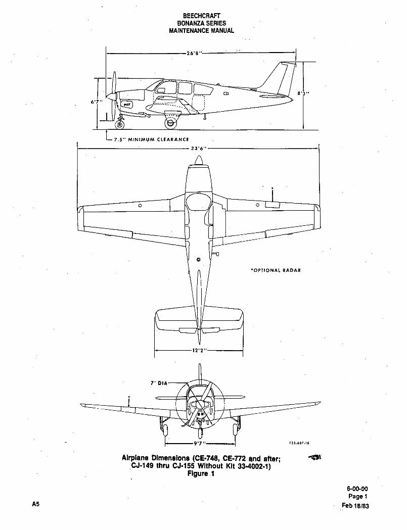
BEECHCRAFT
BONANZA SERIES
MAINTENANCE MANUAL
26’8"
8’3"
6’5" P~ lr~
7.5" MINIMUM CLEARANCL~
33’6"
O o
’OPTIONAL RADAR
12’2"
7’ DIA
9’7" 1 rii.toi.ic
Airplane Dimenaione (CE=148, CE-n2 and atter;CJ-149 thru CJ´•155 Without Kit 33-40(32-1)
Figure 1
6-00-00
PagelA5 Feb 18/83
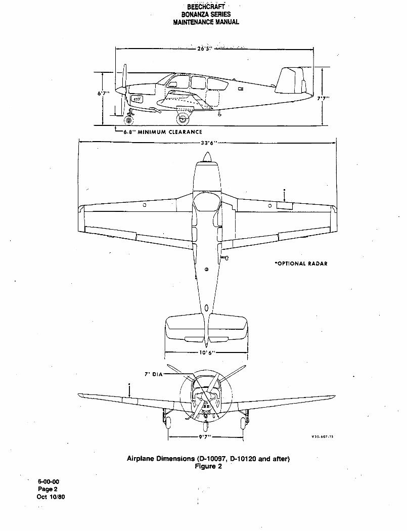
BEECHCRAFT
BONANtA SERIESMAINTENANCE MANUAL
76’5
Tcn
c:e j 7’7"6’7"
6´•8" MINIMUM CLEARANCE
33’6"
O I h\ o
’OPTIONAL RADAR
10’6"
7’ DIA
9’7"--------1
Airplane Dimensions (D-10097, P10120 and after)Figure 2
s-00-00
Page2Oct 10/80
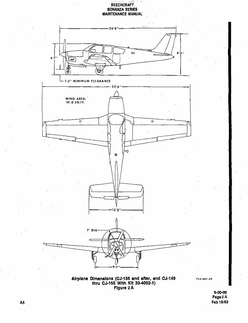
BEECHCRAFT
BONANZA SERIES
MAINTENANCE MANUAL
26’8"
23 .CI~S ra 8’J"
6’7"
1_L!L
7.5.. MINIMVMCL~RPINCE
33’6"
WING AREA:
181.0 SO.FT.
O I M /H\I o
12’2"
7’
9’7
Alrp(ane blmensIans (CJ-155 and after, and CJ-149 ~33-601.29
thru CJ-155 With Kit 33-4002-1)Figure 2A
MKMO
Page 2 A
A5 Feb 19183
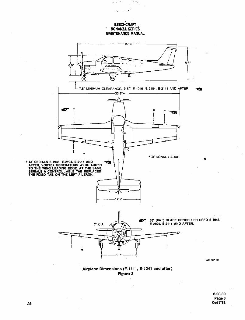
BEECHCRAFIBONANtA SERIEb.
MAINTENANCE ~ANilAi
ras´•
6.a’
7.5" MINIMUM CLEARANCE, 9.5’’ E-1946. E-2104. E-2111 AND 4FTER -a,
33’6"-
Ss tt ~k
*OPTIONAL RADAR
tAT SERIALS 6-1946, 6-2104, 6-2111 AND ~kAFTER, VORTEX GENERATORS WERE ADDEDTO THE WING LEADING EDGE. AT THE SAMESERIALS A CONTROLLABLE TAB REPLACEDTHE FIXED TAB ON THE LEFT AILERON.
12’2"
IC~ 80" DIA 3 BLADE PROPELLER USED 6-1946,
7’ DIA 6-2104, E-2111 AND AFTER.
t t
t9’7"A36607- 33
Airplane Dimensions (E-llll, E-1241 and after)
Figure 3
M~-OO
Page3
A6 Oc17/83
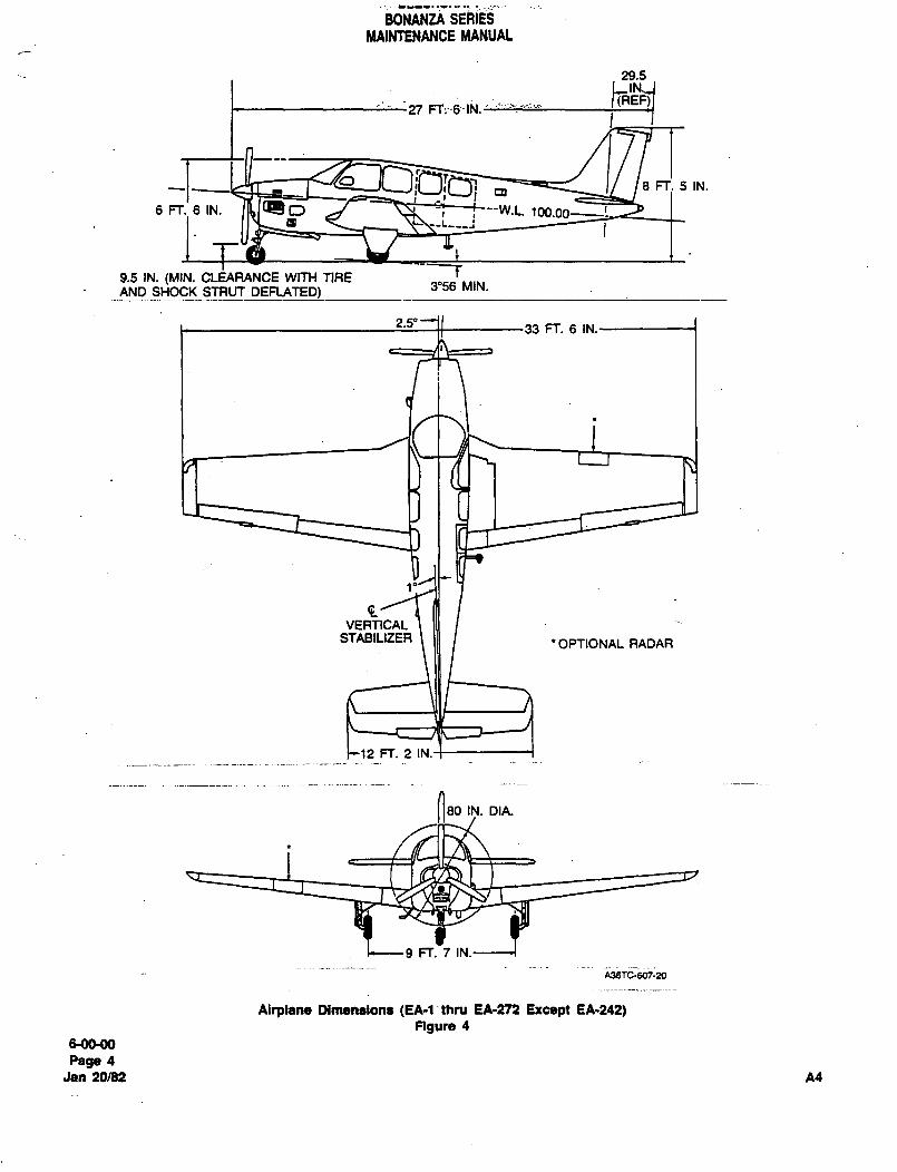
BONANZA SERIES
MAlNTENANCE MANUAL
29.5
27 FT;G´•INi’
~I le FT;5 IN.
6Fr.’61N.a
9.5 IN. (MIN. CLEARANCE WITH TIRE3"56 MIN.
AND SHOCK STRUT DEFLATED)
2.5"33 FT. 6 IN.
VERTICALSTABIUZER
’OPTIONAL RADAR
12 FT. 2 IN.
80 IN. DIA.
9 FT. 7 IN.
A36TC-607-20
Airplane Dlmenalona (EA-l’thru EA-272 Excspt EA´•242)ngure 4
6-00´•00
Page 4
Jan 20/82 A4
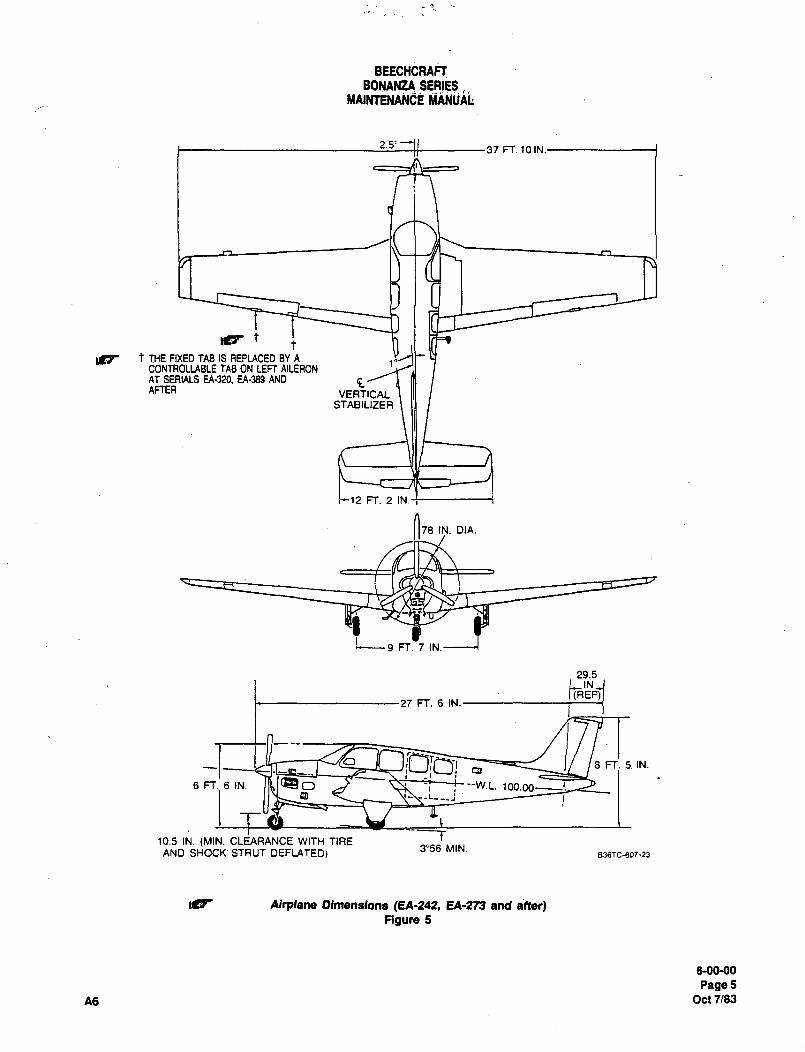
BEECHCRAFTBONANtA SERIES
YAINTENANGE iiANiji~k
2.5’37 FT. 10IN.
t
Jg t THE FIXED TAB IS REPLACED BY ACONTAOLLABLE TAB ON LEFT AILERONAT SERIALS EA320. EA-389 AND gAFTER VERTICAL
STABILIZER
12 FT. 2 IN.t
O78 IN. DIA.
;--9 FT. 7 IN.
29.5
8 FT. 5 IN.
6 FT. 6 IN. C> --W.L. 100.00~D .;--_1~
r10.5 IN. (MIN. CLEARANCE WITH TIRE
AND SHOCK. STRUT DEFLATED)3"56 MIN.
836TC-607-23
ILP Altplene Olmensions (EA-245 EA-273 and
Rgun, 5
6-OM)O
Page5A6 Oct 7/83
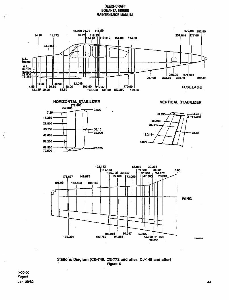
BEECHCRAFIBONANZA SERIES
MAINTENANCE MANUAL
82.960 94.75 118.50 27200 292.0014.96 41.172 1Iarl;19.81 2 151.00 174.50
257.649.00
Yi( /II~04.901_1 I I I ._Lu I 11 1_1_1 1 1111
w.L.
246.30I m!lu88;1
79.362~-201.00 233.50 256.90 297.00
18.25 149b0 83.09017.s7 170.00 FUSELAGE4.50 39.50 68.0012125 29.25 58.50 112138 131.00 152250 173.00
VERTICAL STABILIZER272.000
251.6063.500
i~26-----
15.250i i I I I
38.403225.500
36~1J36.900 23.06
46.000 1311
ss.25o~\-( I I 0.000
752572.500
123.182 66.000 39.375113.172 59.000 131.30 0.00
136.188 /W175.837 ~48.815 23.881
imll iTi191.00 162563
UWING
108981 80.b47 53.d00 1336036
122.750 94.864 45.000
36.030
Stations"Diagram (CE-748, CE-T72 and after; CJ-149 and after)figur, 6
6-00-00
Page 6
Jan 20/82 A4
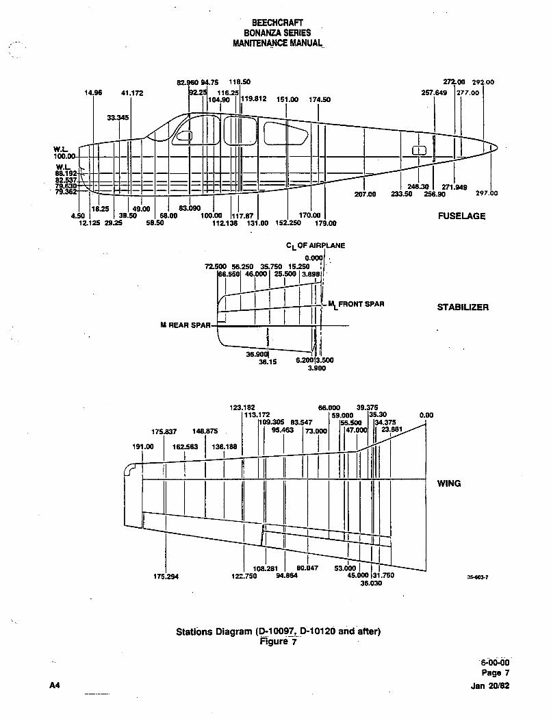
BEECHCRAFTBONANZA SERIES
MANmNANCE MANUAL
75 118.50 27200 292.00
14.96 41.1;12 1I19.812 151.00 1’14.50257.649 277.00
04.90
33.345
1V~ I 1 1111 1 I I Y’ 1111 11111 1 II I I I I 1 ~3
82.53~W.L246.30
I,,!,88.1
1815 83.090 I17.87170.00 FUSELAGE
207.00 233.50 256.90 297.00
4.50 39.50 68.00 100.0012125 23~25 58.50 112138 131.00 152.250 179.00
CL OF AIRPLANE
g0.000
72506 56.250 35.750 15.25046.000 "´•pol"~
IIFRONTSPAR STABILIZER
M REAR SP
36.153.900
123.182 66.000 39.375113.172 s9.000 135.30 0.00
175.837 148.875 I I 1 95.463 1 ‘13.0001.I09.305 83.547
23.881
I191.00 162.563 136.1 88
UWING
108.281 80.b47 53.d00 IIreo~r175.294 122.150 94.864 45.000
36.030
StatibnS Diagram (P10097,P-10120 and after)Figure 7
s;ot-0oPage 7
A4 Jan 20/82
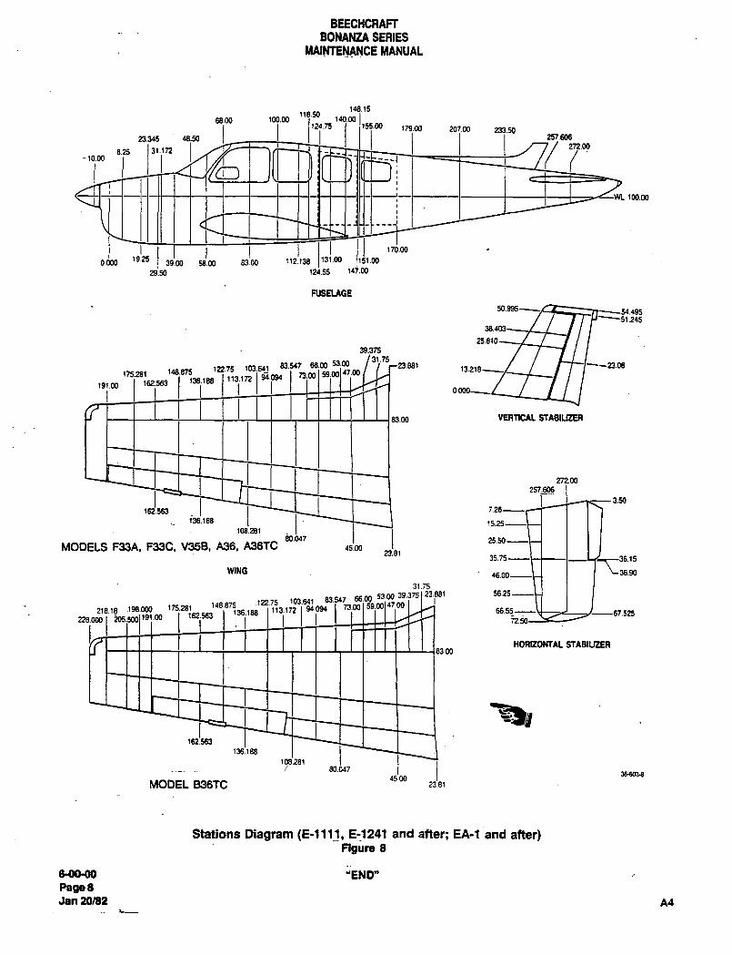
BEECHCRAFTBONANZA SERIES
MAINTENANCE MANUAL
148.15
1(B~rs 14Gm I’55.00 179.00 207.00 233.50
68.00 100.00
23.345 48.50 257.606
8.25 31.172 j/ 272.00
-10.00
100.00
O.dOO ’9.2539.OF 58.00 83.00 ~12.138
ibm 170.00
29:50 124.55 14j.W
NSELAGE
1.245
39.375
31.75
175.281 188~5 122.75 103.641 83´•547 66.00 53.00
Islm1191" 91091 1303 ll.m
r23.881
83.00 VERTICAL SIABIUZER
272.00
257.606
3.50
162’.563 1 I ~-C I I 1 7
136.188
108.28180.047
MODELS F33A, F33C, V35B, A36, A36TC 15.0023.81
36.15
WING I I 1 ~36.90
31.75
2((.11 198.Wa (7528( 1"8875 1P75 103.M1 83.Y7 66.00 53-00 39.375( 23.p81 55.25
162.563 ~36.188 113.172 94.094 73.00 47.0066.55-- .525
HORIZOHTAL STABIUZER
~iY162.563
136.188
108.28(80.047
38d03-845.00
MODEL B36TC 23.81
Stations Diagam (E1111I, E-1241 and after; EA-1 and after)Figure 8
&0090 "END"
PageBJan 20/82 A4

CHAPTER
LIFTING AND
SHORING
Raytheon nircraft CompanyBONANZA SERIES ~iAINiEi\lANCE MANUAL
CHAPTER 7 LIFTING AND SHORING
TABLE OF CONTENTS
SUBJECT PAGE
7-00-00
Lifting and Shoring MaintenancePractices ..............1
Jacking ..........1
Main Wheel Jacking
Hoisting ......3
7-CONTENTS Sep 30/03Page 1
RBYtheOn Aircraft CompanyBONANZA SERIES MAINTENANCE MANUAL
CHAPTER 7 LIFTING AND SHORING
LIST OF EFFECTIVE PAGES
CH-SE-SU PAGE DATE
7-LOEP 1 Sep 30/03
-/-CONTENTS 1 Sep 30/03
7-00-00 1 thru 4 Sep 30/03
A24 7-LOEP Sep 30/03Page f
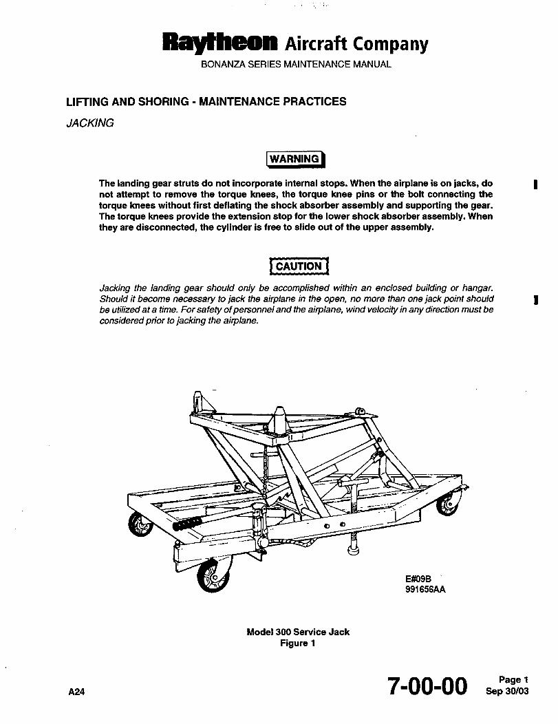
RBythdMI Aircraft CompanyBONANZA SERIES MAINTENANCE MANUAL
LIFTING AND SHORING MAINTENANCE PRACTICES
JACKING
I WbRNING)WARNING
The landing gear struts do not incorporate internal stops. When the airplane is on jacks, do Inot attempt to remove the torque knees, the torque knee pins or the bolt connecting the
torque I<nees without first deflating the shock absorber assembly and supporting the gear.The torque knees provide the extension stop for the lower shock absorber assembly. When
they are disconnected, the cylinder is free to slide out of the upper assembly.
I CAUTION 1CAUTION
Jacking the landing gear should only be accomplished within an enclosed building or hangar.Should it become necessary to jack the airplane in the open, no more than one jack point should Ibe utilized at a time. For safety ofpersonnel and the airplane, wind velocity in any direction must be
considered prior to jacking the airplane.
a a
E~09B
991 656AA
Model 300 Service Jack
Figure 1
pas 7-00-00 Sep 30/03Page 1
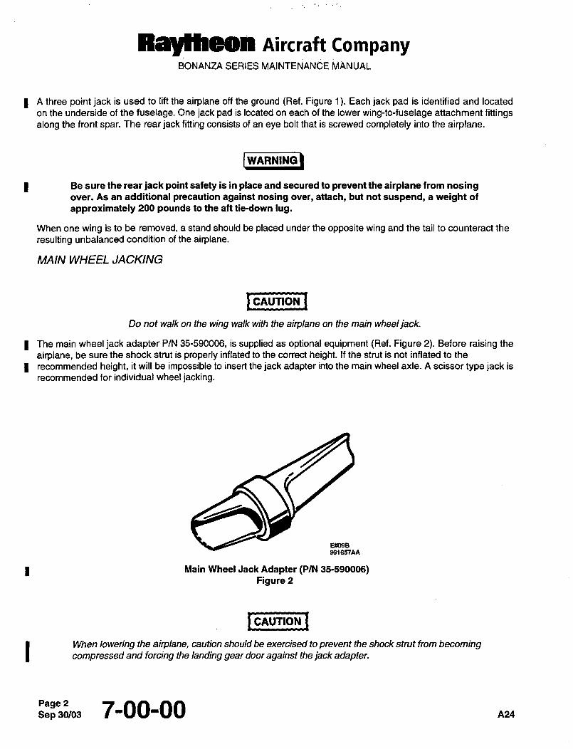
Rayfheen nircraff CompanyBONANZA SERIES MAINTENANCE MANUAL
I A three point jack is used to lift the airplane off the ground (Ref. Figure 1). Each jack pad is identified and located
on the underside of the fuselage. One jack pad is located on each of the lower wing-to-fuselage attachment fittingsalong the front spar. The rear jack fitting consists of an eye bolt that is screwed completely into the airplane.
I W6~RNING)WARNING
Be sure the rear jack point safety is in place and secured to prevent the airplane from nosingover. As an additional precaution against nosing over, attach, but not suspend, a weight of
approximately 200 pounds to the aft tie-down lug.
When one wing is to be removed, a stand should be placed under the opposite wing and the tail to counteract the
resulting unbalanced condition of the airplane.
MAIN WHEEL JACKING
I cnlmou ICAUTION
Do not walk on the wing walk with the airplane on the main wheeljack.
I The main wheel jack adapter P/N 35-590006, is supplied as optional equipment (Ref. Figure 2). Before raising the
airplane, be sure the shock strut is properly inflated to the correct height. If the strut is not inflated to the
I recommended height, it will be impossible to insert the jack adapter into the main wheel axle. A scissor type jack is
recommended for individual wheel jacking.
E~Yose
941657AA
Main Wheel Jack Adapter (P/N 35-590006)Figure 2
I cnvTloN ICAUTION
When lowering the airplane, caution should be exercised to prevent the shock strut from becomingcompressed and forcing the landing gear door against the jack adapter.
Sep 7-00-00 P124
R5lyfhdOll AiKraft tompanyBONANZA SERIES MAINTENANCE MANUAL
HOISTING
The airplane may be hoisted for maintenance or parts replacement as follows:
a. Install the hoisting sling fitting, P/N 35-590067, at each upper forward wing attach bolt location using bolts
of the proper length with 5/8-18UNF threads.
b. Attach the hoisting sling assembly, P/N 35-590064-1, to the hoisting sling fittings (Ref. Figure 3).
c. Install the strap assembly around the propeller blade shanks.
d. Hoistthe airplane smoothly.
NOTE
Adjust the strap assembly to keep the airplane in a level or slightly nose down attitude.
e. As an added precaution, a stand may be installed under the tail of the airplane.
I CAUTION ICAUTION
A spreader must be used above the cabin to prevent damaging the door moulding and window
frame.
If the airplane must be hoisted and the hoisting sling assembly, P/N 35-590064-1, is not available, remove the
cabin door, the left front window and the front seats. Attach a sling to the front wing spar in the fuselage and a line
to the hoist fitting on the engine.
~a4 7-00-00 Sep 30/03Page 3
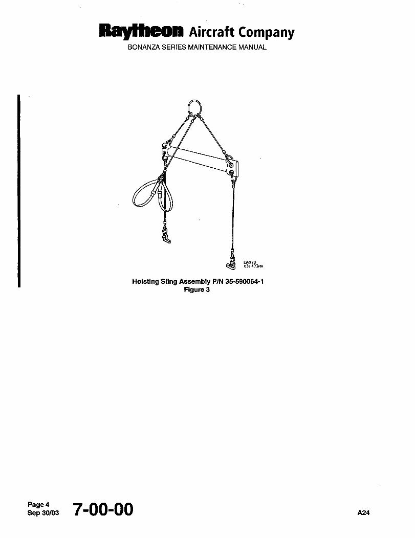
Raytheon Airc~raft CompanyBONANZA SERIES MAINTENANCE MANUAL
EF~07B031473F(A
Hoisting Sling Assembly P/N 35-590064-1
Figure 3
Sep 7-00-00 A24
CHAPTE R
LEVE LING AN D
VVEIGHING
BEECHCRATT
MAINTENANCE MANUAL
CHAPTER 8
LIST OF PAGE EFFECTIVITY
CHAPTER
SECTION
SUBJECT PAGE DATE
8-EFFECTIVITY/CONTENTS 1 ...............May 9/80
8-00-00 1
CHAPTER 8 LEVELING AND WEIGHING
TABLE OF CONTENTS
CHAPTERI
SECTION I
SUBJECT SUBJECT PAGE
GENERAL 8-00-00
Maintenance Practices .....´•...il.......1
Leveling .........i.......1
"END"
&EFFECTIVITV/CONTENTS
Pag´•lM´•y 9/80
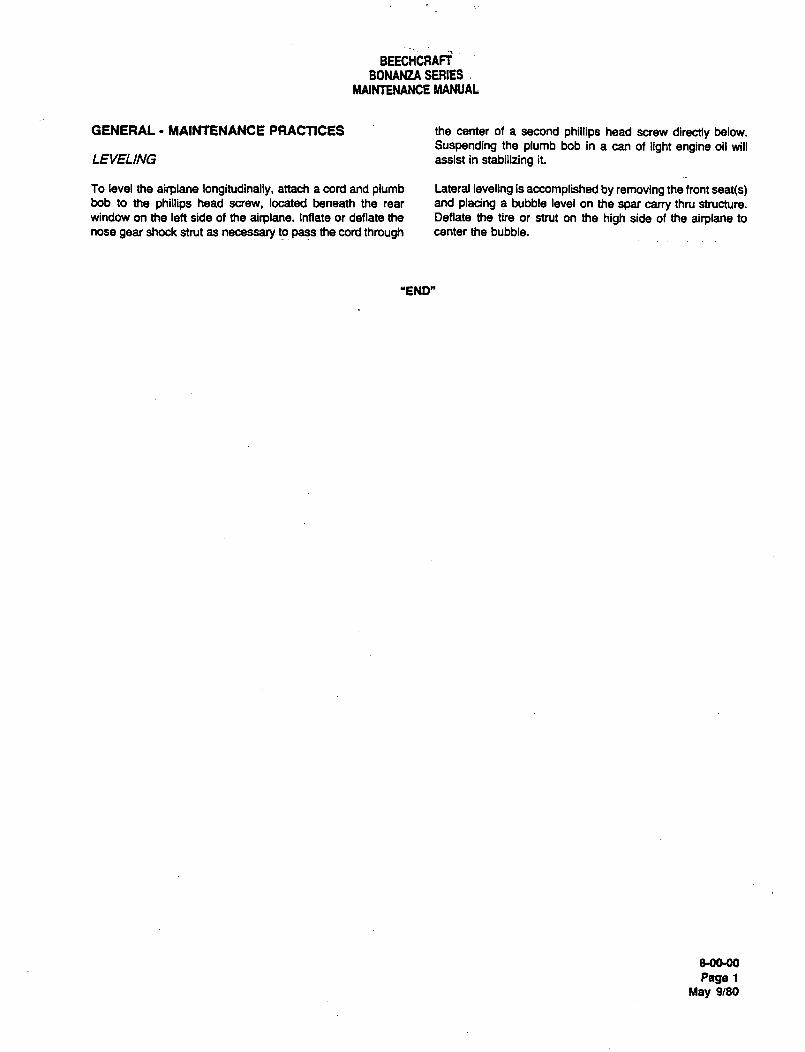
BEECHCRAFTBONANZA SERIES
MAINTENANCE MANUAL
GENERAL- MAINTENANCE PRACTICES the center of a second phillips head screw directly below.
Suspending the plumb bob in a can of light engine oil will
LEI/ELING assist in stabilizing it.
To level the airplane longitudinally, attach a cord and plumb Lateral leveling is accomplished by removing the front seat(s)bob to the phillips head screw, located beneath the rear and pladng a bubble level on the spar carry thru structure.
window on the left side of the airplane. Inflate or deflate the Deflate the tire or strut on the high side of the airplane to
nose gear shock strut as necessary to pass the cord through center the bubble.
"END"
800-00
Page 1
May 9/80

cHAPTE R
TOVVING AND
TAXIING
BEECHCRAFT
BONANZA SERIES
MAINTENAN~E i\iiA~UAL
CHAPTER 9-TOWING AND TAXIING
TABLF OF CONTFNTS
SUBJECT CHAPTER PACE
9-00-00
Towing and Taxiing Maintenance Practices
TowingOne Person TowingTowing With a Tractor or Tug
Taxiing
"END"
9-CONTENTS
Page 1
Ale Oct 16/92
BEECHCRAFT
BONANZA SERIES
MAINTENANCE MANUAL
CHAPTER 9
LIST OF FACE EFFECTIVITY
CHAPTER
SECTION
SUBJECT PAGE DATE
9-EFFECTIVITY i Oct 16/92
9-CONTENTS 1 Oct 16/92
9-00-00 1 Oct 16/92
"END"
O-EFFECTIVIN
Page 1
A16 Ocl 16I92
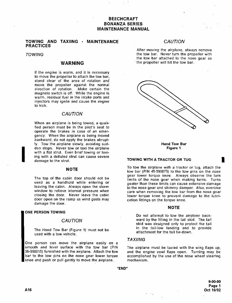
BEECHCRAFT
BONANZA SERIES
MAINTENANCE MANUAL
TOWING AND TAXIING MAINTENANCE CAUTIONPRACTICES
After moving the airplane, always remove
TO WING the tow bar. Never turn the propeller with
the tow bar attached to the nose gear as
WARNING the propeller will hit the tow bar.
If the engine is warm, and it is necessaryto move the propeller to attach the tow bar,stand clear of the area of rotation and
move the propeller against the normal
direction of rotation. Make certain the
magneto switch is off. While the engine is
warm, residual fuel in the intake ports and
injectors may ignite and cause the engineto kick.
CAUTION
When an airplane is being towed, a quali-fied person must be in the pilot’s seat to
operate the brakes in case of an emer-
gency. When the airplane is being moved
backward, do not apply the brakes abrupt-ly. Tow the airplane slowly, avoiding sud- Hand Tow Bar
den stops. Never tow or taxi the airplane Figure 1
with a flat strut. Even brief towing or taxi-
ing with a deflated strut can cause severe
damage to the strut. TOWING WITH A TRACTOR OR TUG
NOTETo tow the airplane with a tractor or tug, attach the
tow bar (P/N 45-590075) to the tow pins on the nose
gear lower torque knee. Always observe the turnThe top of the cabin door should not be limits of the nose gear when making turns. Turnsused as a handhold while entering or geater than these limits can cause extensive damageleaving the cabin. Always open the storm to the nose gear and shimmy damper. Also, exercisewindow to relieve internal pressure when care when removing the tow bar from the nose gearclosing the door. Never leave the cabin lower torque knee to prevent damage to the lubri-door open on the ramp as wind gusts may cation fittings on the torque knee.
damage the door.
NOTE
ONE PERSON TOWINGDo not attempt to tow the airplane back-
CAUTION ward by the fitting in the tail skid. The tail
skid was designed only to protect the tail
in the tail-low landing and to provideThe Hand Tow Bar (Figure 1) must not beattachment for the tail tie-down.
used with a tow vehicle.
TAXIINGOne person can move the airplane easily on a
smooth and level surface with the tow bar (P/N The airplane must be taxied with the wing naps up,36-590015) furnished with the airplane. Attach the tow and the engine cowl naps open. Turning may be
bar to the tow pins on the nose gear lower torque accomplished by the use of the nose wheel steeringknee and push or pull gently to move the airplane. mechanism.
"END"
9-00-00
Page 1
A16 Oct 16192

CHAPTER
PARKING,MOORING
STORAG Ej
RTN TO SVC.
Raytheon Aircraft CompanyBONANZA SERIES MAINTENANCE MANUAL
CHAPTER 10- PARKING AND MOORING
TABLE OF CONTENTS
SUBJECT PAGE
10-00-00
General Maintenance Practices ....1
ParkingMoo~ng................................................................................1
Normal Tie-down
Extended Storageand HighW~nd ..................1
ControlLock................................................................. ...........1
StorageFlyable Storage -7 to 30 Days. ........._____ .........___..__
.2
Temporary Storage 30 to 90 Days .................3
Indefinite StoragePreparation forService. .......5
~O-CONTENTS Mar 31/05Page 1
PaYMfaayl Aircraft CompanyBONANZA SERIES MAINTENANCE MANUAL
CHAPTER 10 PARKING AND MOORING
LIST OF EFFECTIVE PA GES
CH-SE-SU PAGE DATE
10-LOEP 1 Mar 31105
10-CONTENTS 1 and 2 Mar 31/05
10-00-00 1 thru 6 Mar 31/05
A27 1 O-LOEP Mar 31/05Page 1
Ray~heon Aircraft CompanyBONANZA SERIES MAINTENANCE MANUAL
GENERAL- MAINTENANCE PRACTICES
PARKING
The brakes are set for parking by pulling out the parking brake control, then pressing the pilot’s brake pedals until
firm. Do not attempt to lock the parking brake by applying force to the parking brake handle; it controls a valve onlyand cannot apply pressure to the brake master cylinders.
CA UTION: Do not set the parking brake control when the brakes are hot from severe use or during low temperaturewhen an accumulation of moisture may cause the brakes to freeze. An increase in outside air
temperature can build up excessive pressure in the system. In addition, the parking brake should be left
OFF and wheel chocks installed if the airplane is to be left unattended.
MOORING
This section is designed to provide guidelines which can be followed when mooring and securing Bonanza series
airplanes. Mooring procedures for normal tie-down operations as well as mooring for extended storage and highwind conditions follow:
NORMAL TIE-DOWN
On Bonanza series airplanes, a tie-down lug is installed on each wing, and on the aft fuselage. The tie-downs should
be nylon or dacron ropes or chains with sufficient strength to restrain the airplane in high or gusty winds. Manila or
hemp ropes should never be used; The tie-downs should allow very little or no movement when tightened, too much
slack will allow the airplane to jerk against the tie-downs. When securing the tail section of the airplane, the tie-down
should have a slight slack so that the nose of the airplane will not be raised off the ground. In a strong headwind, a
tail tie-down that is too tight will increase the angle between the wing and the oncoming air. This creates an
additional lifting force, which causes more pressure to be placed on the wing tie-down ropes and anchors. Adequateantislip knots such as bowlines or square knots should be used when securing the lines.
Securing operations should be planned so the airplane is tied down facing the prevailing wind, if the groundattachment permits. Once the airplane has been positioned into the wind, the wheels should be checked fore and
aft. The flight control surfaces must then be secured to prevent banging against the stops. The controls should be
secured in position with control locks that are installed in the control column. When mooring, be sure to fasten all
doors and windows properly. Pitot-static tubes should be covered.
EXTENDED STORAGE AND HIGH WIND
When mooring the Bonanza, the following method is recommended: Place chocks fore and aft of each main wheel.
Position a tail stand under the tail skid, adjusting the height of the stand to slightly compress the nose gear shock
strut. Run a line through each wing mooring lug, fastening each end to a ground point, one forward and one aft of
the wing. Run a line through the hole in the tail skid and anchor at the sides of the airplane approximately 5 feet from
the base of the stand. If a storm is anticipated, two lines may be secured to each main landing gear strut barrel near
the V-brace and also a line may be attached around the nose gear strut near the lower torque knee. It is
recommended that the airplane be tied down headed into the wind, with the control lock installed.
nz~ 10’00’00 1
Ral~heon AiKraft CompanyBONANZA SERIES MAINTENANCE MANUAL
CONTROL LOCK
A control column lock pin is provided for the control column and the aileron control wheel. The lock pin secures both
the aileron control wheel and the elevator control. A cover is provided on the control lock to cover the throttle control,boost pump, and the propeller control. Install the control lock assembly in the following sequence:
a. Rotate the control wheel to the right and move the column forward so the hole in the bracket and the column
align to accept the pin.
b. Push the control column lock pin through the hole provided in the control column guide and into the control
column.
c. Ensure positive retention of the lock pin by placing the cover assembly over the throttle control, boost pump,and the propeller control.
WARNING: Always completely remove the control lock assembly before engine start, taxiing, and flight.
STORAGE
The storage procedures listed are intended to protect the airplane from deterioration while it is not in use. The
primary objectives of these measures are to prevent corrosion and damage from exposure to the elements. Three
types of storage are considered:
a. FLYABLE STORAGE- 7 to 30 days.
b. TEMPORARY STORAGE- up to 90 days.
c. INDEFINITE STORAGE.
FLYABLE STORAGE 7 TO 30 DAYS
a. MOORING- If the airplane cannot be placed in a hangar, install the control lock and tie the airplane down
securely at the three points provided. Do not use hemp or manila rope. It is recommended a tail support be used
to compress the nose strut and reduce the angle of attack of the wings. Attach a line to the nose gear.
b. ENGINE PREPARATION FOR STORAGE- Engines in airplanes that are flown only occasionally tend to exhibit
cylinder wall corrosion much more than engines that are flown frequently.
i. Check for correct oil level and add oil if necessary to bring level to full mark
2. Run engine at least five minutes at 1,200 to 1,500 rpm with oil and cylinder head temperatures in the normal
operating range.
WARNING: Before rotation of propeller blades, ascertain magneto switch is OFF, throttle in CLOSED
position and mixture control is in the IDLE CUT-OFF position. Always stand in the clear while
turning propeller.
c. DURING FLYABLE STORAGE- Each seven days during flyable storage, the propeller shall be rotated by hand.
After rotating the engine six revolutions, stop the propeller 60 to 120" from the position it was in.
i. If at the end of 30 days, the airplane will not be removed from storage, the engine should be started and
run. The preferred method is to fly the airplane for 30 minutes in order to keep the internal parts of the enginelubricated. Ground running of the engine will not provide proper heating of the oil without possible damageto other engine compartment components due to lack of air flow, and will result in condensation of moisture
in the oil supply, increasing the possibility of cylinder/crankshaft rust.
Page 2~0-00-00 A27
Raytheon nircraft CompanyBONANZA SERIES MAINTENANCE MANUAL
d. FUEL CELLS- Fill to capacity to minimize fuel vapor and protect cell inner liners.
e. FLIGHT CONTROL SURFACES- Lock with internal and external locks.
f. GROUNDING- Static ground airplane securely and effectively.
g. PITOTTUBE- Install cover.
h. WINDSHIELD AND WINDOWS- Close all windows and window vents. It is recommended that covers be
installed over windshield and windows.
i. PREPARATION FOR SERVICE- Remove all covers and tape, clean the airplane and give it a thoroughinspection, particularly wheel wells, flaps, and control openings.
1. If the eng ine has a total time of more than 25 hours and the oil consumption has stabilized, drain the break-in
oil after a ground warm-up and install oil per Teledyne Continental Motors Specification MHS-24C.
2. Preflightthe airplane.
TEMPORARY STORAGE 30 TO 90 DAYS
a. MOORING-SeeFLYABLE STORAGE.
b. ENGINE PREPARATION FOR STORAGE- Operate engine (Preferably in Right) until oil temperature reaches
normal range. Drain oil supply from sump while engine is still warm and replace drain plug.
1. Fill the sump to the full mark on the dipstick gage with corrosion preventive oil (3, Chart 1, 91-00-00), which
will mix with normal oil and provide protection against corrosion.
2. Remove the top spark plug and atomize spray preservative oil (4, Chart 1, 91-00-00) at room temperature,through the upper spark plug hole of each cylinder with piston in the down position. Rotate crankshaft as
each pair of cylinders is sprayed. Stop crankshaft with no piston at top position, and thoroughly respray each
cylinder. Reinstall spark plugs.
3. Apply preservative to engine interior by spraying the above specified oil (approximately two ounces) throughthe oil filler tube. Seal all engine openings exposed to the atmosphere using suitable plugs, or moisture
resistant tape, and attach red streamers at each point. Affix a tag to the propeller in a conspicious place with
the following notation; DO NOT TURN PROPELLER, ENGINE PRESERVED. Seal the propeller blade
spinner cutouts with tape.
c. FUEL CELLS- Fill to capacity to minimize fuel vapor and protect cell inner liners.
d. FLIGHT CONTROL SURFACES- Lock with internal and external locks.
e. GROUNDING- Static ground airplane securely and effectively.
f. PITOT TUBE- Install cover.
g. WINDSHIELD AND WINDOWS- Close all windows and window vents. It is recommended cover be installed
over windshield and windows.
h. BATTERY- Remove and store according to standard practices.
A27 1 0-00-00 Mar 31/05Page 3
Raytheon Aircraft CompanyBONANZA SERIES MAINTENANCE MANUAL
i. PREPARATION FOR SERVICE- Remove all covers, tape, and tags. Clean the airplane and give it a thoroughinspection, particularly wheel wells, flaps, and control openings. With bottom spark plugs removed, hand turn
propeller several revolutions to clear excess preservative oil, then reinstall plugs. Preflight the airplane and flighttest.
INDEFINITE STORAGE
a. MOORING-SeeFLYABLE STORAGE.
ENGINE PREPARATION FOR INDEFINITE STORAGE- Drain the engine oil and service with corrosion
I preventive oil (3, Chart 1, 91-00-00).
1. Immediately after servicing with the corrosion preventive oil, fly the airplane for a period of time not to
exceed a maximum of 30 minutes.
2. It is recommended the propeller be removed and the engine removed from the airplane. The propeller shaft
should be coated with preservative oil (4, Chart 1, 91-00-00) and wrapped with moisture proof material and
tape.
NOTE: If engine is removed from the airplane, a tail mooring stand must be used.
1 3. Remove the top spark plug from each cylinder and spray thoroughly with corrosion preventive oil (3, Chart
1, 91-00-00), at a temperature range of 221 to 250"F.
4. Install protex plugs in each of the top spark plug holes, making sure that each plug is blue in color when
installed. Protect and support the spark plug leads with AN-4060~1 protectors.
5. Place a bag of desiccant in the exhaust pipes and seal openings with moisture resistant tape.
6. Seal cold air inlet to the heater muff with moisture resistant tape.
7. Seal engine breather by inserting a protex plug in the breather hose and clamping in place.
8. Wrap engine with moisture proof material and tape after desiccant bags have been installed.
9. Attach a red streamer to each place on the engine where bags of desiccant are placed. Either attach red
streamers outside of the sealed area with tape or to the inside of sealed area with safety wire to preventwicking of moisture into sealed area.
10. If the propeller has not been removed, affix a tag in a conspicuous place with the following notation: DO
NOT TURN PROPELLER- ENGINE PRESERVED.
c. DURING INDEFINITE STORAGE- The cylinder protex plugs shall be inspected weekly. The plugs should be
changed as soon as their color indicates unsafe conditions of storage. If the dehydrator plugs have changedcolor in one-half or more of the cylinders, all desiccant material on the engine should be replaced.
I 1. The cylinder bores should be resprayed with corrosion preventive oil every six months or more frequently if
bore inspection indicates corrosion has started. Replace all desiccant and protex plugs. Before spraying,the engine shall be inspected for corrosion as follows: Inspect the interior of at least one cylinder on the
engine through a spark plug hole. If cylinder shows start of-rust, spray cylinder with corrosion preventive oil
(3, Chart 1, 91-00-00) and turn prop over five or six times, then respray. Remove the rocker box cover from
the engine and inspect the valve mechanism.
d. PROPELLER- Coat blades with preservative oil and wrap with moisture proof material and tape. If propeller has
been removed, coat all parts with protective material to exclude dust, and then tape.
Page 42e,f 11 0-00-00 A27
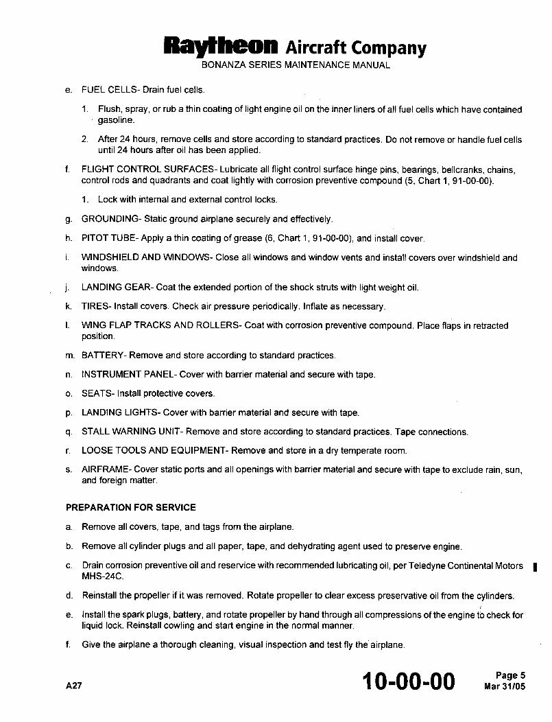
Ray~heon AiKraft CompanyBONANZA SERIES MAINTENANCE MANUAL
e. FUEL CELLS- Drain fuel cells.
1. Flush, spray, or rub a thin coating of light engine oil on the inner liners of all fuel cells which have contained
gasoline.
2. After 24 hours, remove cells and store according to standard practices. Do not remove or handle fuel cells
until 24 hours after oil has been applied.
f. FLIGHT CONTROL SURFACES- Lubricate all flight control surface hinge pins, bearings, bellcranks, chains,control rods and quadrants and coat lightly with corrosion preventive compound (5, Chart 1, 91-00-00).
1. Lock with internal and external control locks.
g. GROUNDING- Static ground airplane securely and effectively.
h. PITOT TUBE- Apply a thin coating of grease (6, Chart 1, 91-00-00), and install cover.
i. WINDSHIELD AND WINDOWS- Close all windows and window vents and install covers over windshield and
windows.
j. LANDING GEAR- Coat the extended portion of the shock struts with light weight oil.
k. TIRES- Install covers. Check air pressure periodically. Inflate as necessary.
I. WING FLAP TRACKS AND ROLLERS- Coat with corrosion preventive compound. Place flaps in retracted
position.
m. BATTERY- Remove and store according to standard practices.
n. INSTRUMENT PANEL- Cover with barrier material and secure with tape.
o. SEATS- Install protective covers.
p. LANDING LIGHTS- Cover with barrier material and secure with tape.
q. STALL WARNING UNIT- Remove and store according to standard practices. Tape connections.
r. LOOSE TOOLS AND EQUIPMENT- Remove and store in a dry temperate room.
s. AIRFRAME- Cover static ports and all openings with barrier material and secure with tape to exclude rain, sun,
and foreign matter.
PREPARATION FOR SERVICE
a. Remove all covers, tape, and tags from the airplane.
b. Remove all cylinder plugs and all paper, tape, and dehydrating agent used to preserve engine.
c. Drain corrosion preventive oil and reservice with recommended lubricating oil, per Teledyne Continental Motors
MHS-24C.
d. Reinstall the propeller if it was removed. Rotate propeller to clear excess preservative oil from the cylinders.
e. Install the spark plugs, battery, and rotate propeller by hand through all compressions of the engine check for
liquid lock. Reinstall cowling and start engine in the normal manner.
f. Give the airplane a thorough cleaning, visual inspection and test fly the airplane.
nlr 10’00’00 5

CHAPTER
PLACARDS AND
MARKINGS
BEECHCRAFT
BONANZA SERIES
MAINTENANCE MANUAL
CHAPTER PLACARDS
TABLF OF CONTFNTS
SUBJEC~ CHAPTER PAG~
11-00-00
Required Placards Description and Operation
FAA Required Placards and MarkingsModel Designation Placard
11-20-00
Exterior Placards and Markings Description and Operation
"END"
11-CONTENTS
Page 1
A16 Oct 16192
BEE6Hi=RAFfBONANZA SERIES
MAINTENANCE MANUAL
CHAPTER 11
LIST OF FACE EFFECTIVITY
CHAPTER
SECTION
SUBJECT PAGE DATE
11-EFFECTIVITY i Oct 16/92
11-CONTENTS 1 Oct 16/92
11-00-00 i Oct 16/92
11-20-00 1 May 9/80
2 Oct 16/92
3 Oct 16/92
4 Oct 16/92
5 Oct 16/92
6 Oct 16/92
"END"
11-EFFECTIVITY
Page 1
Ale Oct 16/92
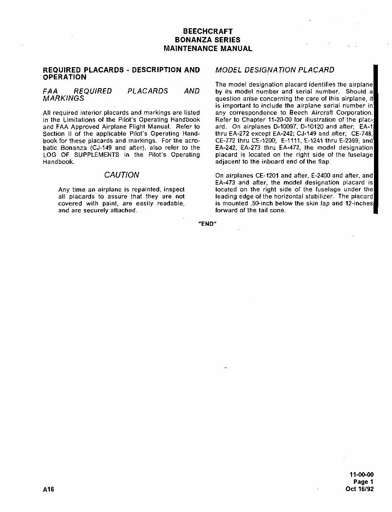
BEECHCRAFT
BONANZA SERIES
MAINTENANCE MANUAL
REQUIRED PLACARDS DESCRIPTION AND MODEL DESIGNA TION PLACARDOPERATION
The model designation placard identifies the airplaneFAA REQUIRED PLACARDS AND by its model number and serial number. Should a
MARKINGS question arise concerning the care of this airplane, it
is important to include the airplane serial number in
All required interior placards and markings are listed any correspondence to Beech Aircraft Corporation.in the Limitations of the Pilot’s Operating Handbook Refer to Chapter 11-20-00 for illustration of the plac-and FAA Approved Airplane Flight Manual. Refer to ard. On airplanes D-10097, D-10120 and after; EA-1
Section II of the applicable Pilot’s Operating Hand- thru EA-272 except EA-242; CJ-149 and after, CE-748,book for these placards and markings. For the acro- CE-772 thru CE-120); E-llll, E-1241 thiu E-2399; and
batic Bonanza ~CJ-149 and after), also refer to the EA-242, EA-273 thru EA-472, the model designationLOG OF SUPPLEMENTS in the Pilot’s Operating placard is located on the right side of the fuselageHa nd book. adjacent to the inboard end of the flap.
CAUTION On airplanes CE-120I and after, E-2400 and after, and
EA-473 and after, the model designation placard is
Any time an airplane is repainted, inspect located on the right side of the fuselage under the
all placards to assure that they are not leading edge of the horizontal stabilizer. The placardcovered with paint, are easily readable, is mounted .50-inch below the skin lap and 12-inches
and are securely attached. forward of the tail cone.
"END"
11-00-00
Page 1
A16 Oct 16/92
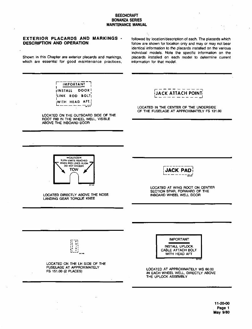
BEECHCRAFT
BONANZA SERIES
MAINTENANCE MANUAL
EXTERIOR PLACARDS AND MARKINGS followed by locationldescription of each. The placards which
DESCRIPTION AND OPERATION follow are shown for location only and may or may not bear
identical information to the placards installed on the various
individual models. Note the specific information on the
Shown in this Chapter are exterior placards and markings, placards installed on each model to determine current
which are essential for good maintenance practices, information for that model.
IINSTALL DOORIACK ATTACH POINrlILINK ROD BOLT;
1"WITH
LOCATED IN THE CENTER OF THE UNDERSIDEOF THE FUSELAGE AT APPROXIMATELY FS 131.00
LOCATED ON THE OUTBOARD SIDE OF THE
ROOT RIB IN THE WHEEL WELL, VISIBLE
ABOVE THE INBOARD DOOR
-CAVTION-
TURN LIMTTS REACHEDWHEN RED LINES ALIGN
DO NOTEXCEED I r-- ITOW IJACK PADI
L________1
LOCATED AT WING ROOT ON CENTER
SECTION SPAR, FORWARD OF THE
LOCATED DIRECTLY ABOVE THE NOSE INBOARD WHEEL WELL DOOR
LANDING GEAR TORQUE KNEE
IMPORTANT
INSTALL UPLOCK
CABLE ATTACH BOLT
WITH HEAD AFT
LOCATED ON THE LH SIDE OF THE
FUSELAGE AT APPROXIMATELYLOCATED AT APPROXIMATELY WS 60.00
FS 151.00 (2 PLACES) IN EACH WHEEL WELL, DIRECTLY ABOVE
THE UPLOCK ASSEMBLY
11-20-00
Page iMay 9/80
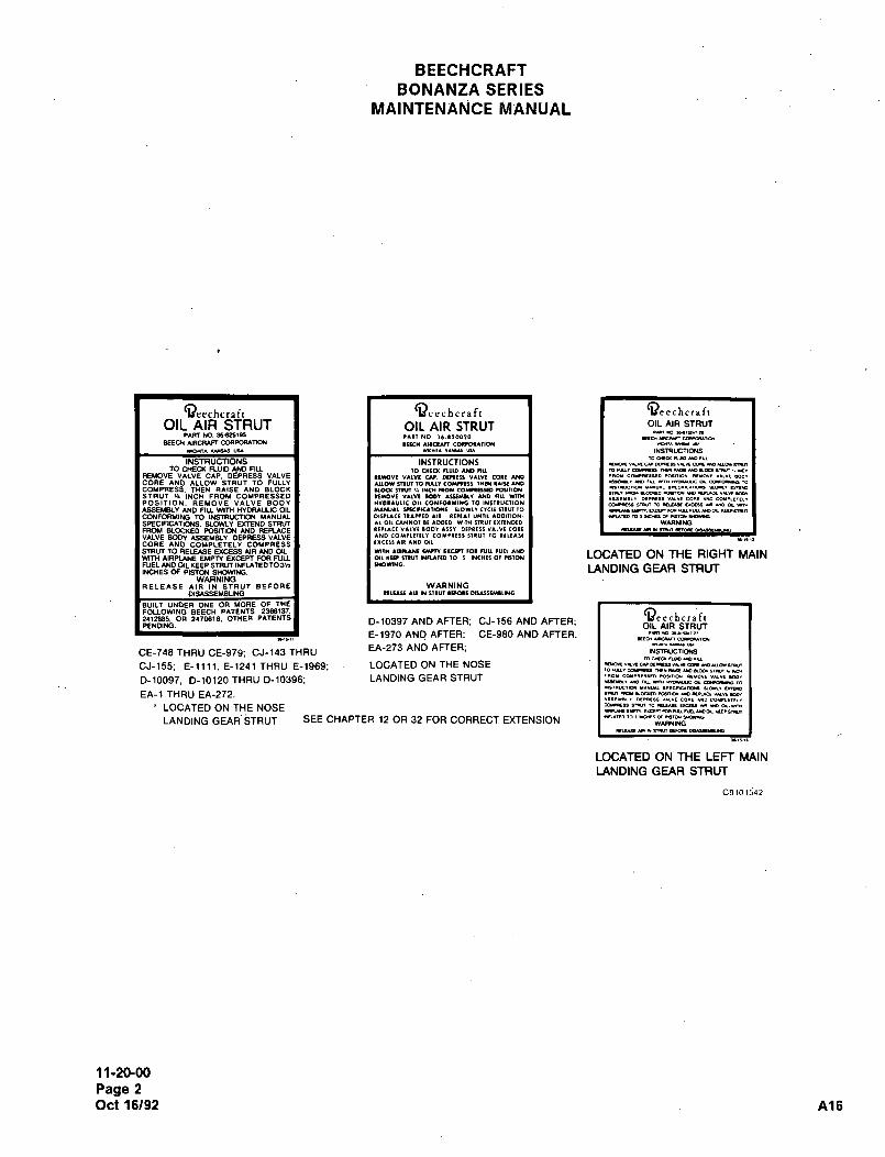
BEECHCRAFT
BONANZA SERIES
MAINTENAhjCE MANUAL
(ileechrrlll I (i)ce~hcraft I aerchcrlf~OIL AIR STRUT OIL AIR STRUT OIL AIR STRUT
PART NO. ~W25(05 malb´•l~rn)*)r NO 1~´•110010 rra ucsn mrwa
BEED( *IRCRAFT CWPOTUMN I(KW IIICI*n COIIOI~IIOU
*c*nlu*ws uu I rml~ ´•´•*YI VY I I INSTRUCTIONS
INSTRUCTIONSmaaruawcru
INSTRUCTIONSTO CHECK FLUID AND Flu ~o CNKlI nulD ANO nu mnurmrrrs
REU)VE VALVE CAP. DEPRESS VALVE ~uow uALvi cu. orllte cell wo I I ’"O’ CO’"’l’fD M.l1l0* .rlOV. I´•LYI MDI
CORE AND ALLOW STRUT TO FULLY 11101 mvr to Rlur caunnl lurw l~m ~310 ~a´• uo ´•um* ´•muc a mrol-r ~o
COMPRESS. THEN RAISE AND BLOCK UOQ mvl Irrw ~o* co*nara, ronno*u´•*ull~ Irrounno u~´• rmle
STRUT v´• INCH FROM COMPRESSEDr~arrrmro arm*uc´•mu ru~ a~
rrYOYI V´•Ln UW)´•I ISY*UI AND HLL WlrWY´•IYr CO´•t COYILLIIL’
POSITION. REMOVE VALVE BODYI I oil EONIOIYIIIG TO INII)UCIION COln ~M X) II~UWL 1~ UO a m
ASSEMBLY AND FILL WITH HYDRAULIC OIL I I YLIIU*I vKnc´•1IOWr, ILOWL* crm rr,m rO I I 1Ulm.fUln U.´•.M
CONFORMING TO INS~RVCTION MANUAL I IOlIILICl I,lnto´•l, YNIII*ODI11ON- I IIUWIO1*t*r~DTCDIDtlO´•´•C´•SPECIFICATIONS. SLOWLY EY~ND STR~r I I LL 011CINN0111DDtD WI1W ITIU1IXnND(D I I WARNING
FROM BLOCKED POSITION AND REPLACE ~tlllCt VILY( IODI lrr~ DrIllII V´•LVICOII I I rrwru*rnul´•r~
VALVE BODY ~SSEYBLY. DEPRESS VALVE ~ND COY)LIIII~ COYIIII) Il´•U1 10 Itltll(
CORE AND COMPLETELY COMPRESS IXCtl(´•LIIYDOIL
S~RLIT TO RELEASE U(CESS AIR AND OIL. I I *n~u ´•n~wr ur* rxcm rot RII1 H)tl *K) LOCATED ON THE RIGHT MAINmTH AIRPLANE EMPTY UCEPT FOR FULL 011 IINI ITIUT INRlnD 10 1 INCI(B Or mTOW
FUEL AND OIL KEEP STRUT INFLATED T03n I IIwowlm LANDING GEAR STRUTINCHES OF PISTON SHOWING.WARNING
RELEASE AIR IN STRUT BEFORE WARNINGDlsAssEueuNo I ’auY ill ill rIlul awwr DIIIIWI1II1G
BUILT UNDER ONE OR MORE OF THE
2~12885. OR 24708(6; OTHER PATENTS (I)eechcraftFOLLOW(NO BEECH PATENTS: 2368(37.
PENDING.D-10397 AND AFTER; CJ-156 AND AFTER; OIL AIR STRUTE-1970 AND AFTER; CE-980 AND AFTER. ´•ur*o ~llr´•n
,I~II Eraucunrm*ru~a
EA-273 AND AFTER;INSTRUCTIONSCE-748 THRU CE-979; CJ-143 THRU
~oora ~uorcru
CJ-155; E-llll. E-1241 THRU E-1969; LOCATED ON THE NOSEIO TULILIY~I´• Ilf*Uly uolm
D-10097. D-10120 THRU D-10396; LANDING GEAR STRUT 1I~I EOlelT´•´•rD´•O~IIIO´•´• 1.101. VILII ~OD´•10 ru n~ nou*C a cora4 m
I*´•IIYCIIO I´•U11 I´•lcrL´•IOIO Yanlmm
EA-1 THRU EA-272. r~n nrlmro roumucrwcr ur ror
I~Llr CDlr 1*i) CO´•DLII~L*
i LOCATED ON THE NOSE COI~ mn 10 I~LL*Y T´•CIU U UDOI´•IIT*
UWlm.UPnU*rULNLUOa
LANDING GEAR’STRUT SEE CHAPTER 12 OR 32 FOR CORRECT EXTENSION I
LOCATED ON THE LEFT MAIN
LANDING GEAR STRUT
C9101~42
11-20-00
Page 2
Oct 16/92 A16
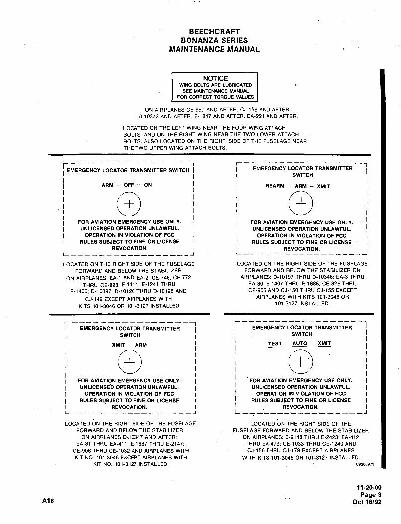
BEECHCRAFT
BONANZA SERIES
MAINTENANCE MANUAL
NOTICEWING BOLTS ARE LUBRICATED
SEE MAINTENANCE MANUAL
FOR CORRECT TOROUE VALUES
ON AIRPLANES CE-950 AND AFTER, CJ-156 APJD AFTER,
D-10372 AND AFTER, E-1847 AND AFTER, EA-221 AND AFTER.
LOCATED ON THE LEFT WING NEAR THE FOUR WING ATTACH
BOLTS AND ON THE RIGHT WING NEAR THE TWO´• LOWER ATTACH
BOLTS. ALSO LOCATED ON THE RIGHT SIDE OF THE FUSELAGE NEAR
THE TWO UPPER WING ATTACH BOLTS.
ri
EMERGENCY LOCATOR TRANSMITTER SWITCH EMERGENCY LOCATOR TRANSMITTER
I SWITCH
ARM OFF ON I REARM ARM XMIT
O OFOR AVIATION EMERGENCY USEONLY. FOR AVIATION EMERGENCY USE ONLY.
UNLICENSED OPERATION UNLAWFUL. I UNLICENSED OPERATION UNLAWFUL.
OPERATION IN VIOLATION OF FCC I OPERATION IN VIOLATION OF FCC
RULES SUBJECT TO FINE OR LICENSE I RULES SUBJECT TO FINE OR LICENSE
REVOCATION. REVOCATION.L________----------l L__________________I
LOCATED ON THE RIGHT SIDE OF THE FUSELAGE LOCATED ON THE RIGHT SIDE OF THE FUSELAGE
FORWARD AND BELOW THE STABILIZER FORWARD AND BELOW THE STABILIZER ON
ON AIRPLANES: EA-1 AND EA-2; CE-748, CE-772 AIRPLANES: D-10197 THRU D-10346; EA-3 THRU
THRU CE-828; E-llll, E-1241 THRU EA-80; E-1407 THRU E-1686: CE-829 THRU
E-1406, D-10097, D-10120 THRU D-10196 AND CE-905 AND CJ-150 THRU CJ-155 EXCEPT
AIRPLANES WITH KITS 101-3046 ORCJ-149 EXCEPT AIRPLANES WITH
101-3127 INSTALLED.KITS 101-3046 OR 101-3127 INSTALLED.
r-----------------I -1EMERGENCY LOCATOR TRANSMITTER EMERGENCY LOCATOR TRANSMITTER
SWITCH I SWITCH
XMIT ARM I TEST AUTO XMIT
FOR AVIATION EMERGENCY USE ONLY. I I FOR AVIATION EMERGENCY USE ONLY.
UNLICENSED OPERATION UNLAWFUL. I UNLICENSED OPERATION UNLAWFUL.
OPERATION IN VIOLATION OF FCC I I OPERATION IN VIOLATION OF FCC
RULES SUBJECT TO FINE OR LICENSE i I RULES SUBJEdT TO FINE OR LICENSE
REVOCATION. i I REVOCATION.L____-__-----__---J L
_ _ __ ___´•_ _ _ _ _ _ _ __ _
_I
LOCATED ON THE RIGHT SIDE OF THE FUSELAGE LOCATED ON THE RIGHT SIDE OF THE
FORWARD AND BELOW THE STABILIZER FUSELAGE FORWARD AND BELOW THE STABILIZER
ON AIRPLANES D;10347 AND AFTER; ON AIRPLANES: E-2148 THRU E-2423; EA-412
EA-81 THRU EA-411: E-1687 THRU E-2147, THRU EA-479, CE-1033 THRU CE-1240 AND
CE-906 THRU CE-1032 AND AIRPLANES WITH CJ-156 THRU CJ-ljS EXCEPT AIRPLANES
KIT NO. 101-3046 EXCEPT AIRPLANES WITH WITH KITS 101-3046 OR 101-3127 INSTALLED.
KIT NO. 101-3127 INSTALLED. C9200973
11-20-00
Page 3Ai6 Oct 16/92
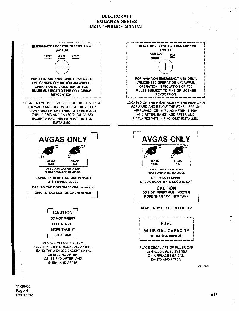
BEECHCRAFT
BONANZA SERIES
NIAINTENANCE WIANUAL
r---------------------------- r-----------------------------1
EMERGENCY LOCATOR TRANSMITTER I EMERGENCY LOCATOR TRANSMITTER
SWITCH I SWITCHARMEDI
TEST ARM XMIT ONRESET
O iFOR AVIATION EMERGENCY USE ONLY. FOR AVIATION EMERGENCY USE ONLY.
UNLICENSED OPERATION UNLAWFUL. I UNLICENSED OPERATION UNLAWFUL.
OPERATION IN VIOLATION OF FCC I OPERATION IN VIOLATION OF FCC
RULES SUBJECT TO FINE OR LICENSE I i RULES SUBJECT TO FINE OR LICENSE
REVOCATION. REVOCATION.L t--______________~
LOCATED ON THE RIGHT SIDE OF THE FUSELAGE LOCATED ON THE RIGHT SIDE OF THE FUSELAGE
FORWARD AND BELOW THE STABILIZER ON FORWARD AND BELOW THE STABILIZER ON
AIRPLANES: CE-1241 THRU CE-1646; E-2424 AIRPLANES: CE-1647 AND AFTER; E-2694
THRU E-2693 AND EA-480 THRU EA-530 AND AFTER; EA-531 AND AFTER AND
EXCEPT AIRPLANES WITH KIT 101-3127 AIRPLANES WITH KIT 101-3127 INSTALLED.
INSTALLED.I
r rAVGAS ONLY AVGAS ONLY
BE"GRADE GRADE GRADE GRADE
100LL 100 1 I 1M)LL ~00
FOR ALTERNATE FUELS SEE FOR ALTERNATE FUELS SEE
PILOTS OPERATING nANDBOOK PILOTS OPERATING nANDBOOK
CAPACITY 40 US GALLONS (37 USABLE) DEPRESS FLAPPER
WITH WINGS LEVEL CHECK OUANTITY a SECURE CAP
CAP. TO TAB BOTTOM 30 GAL (27 USABLE) CAUTION
LCCIP. TO T~B SLOT 35 GPIL (12 US*BLEI~J DO NOT INSERT FUEL NOZZLE
L MORE THAN 1%" INTO TANK _1PLACE INBOARD OF FILLER CAP
J-CAUTION?DO NOT INSERT r------------1
FUEL NOZZLE i FUEL
MORE THAN 3" i 54 US GAL CAPACITY
L INTO TANK __( (51 US OAL USABLE)L-----------J
80 GALLON FUEL SYSTEM
ON AIRPLANES D-10303 AND AFTER; PLACE DECAL AFT OF FILLER CAP
EA-33 THRU EA-272 EXCEPT EA-242; 108 GALLON FUEL SYSTEMCE-884 AND AFTER; ON AIRPLANES EA-242,
CJ-156 AND AFTER; AND EA-273 AND AFTERE-1594 AND AFTER
99200974
11-20-00
Page 4
Oct16/92 A?6
Lj
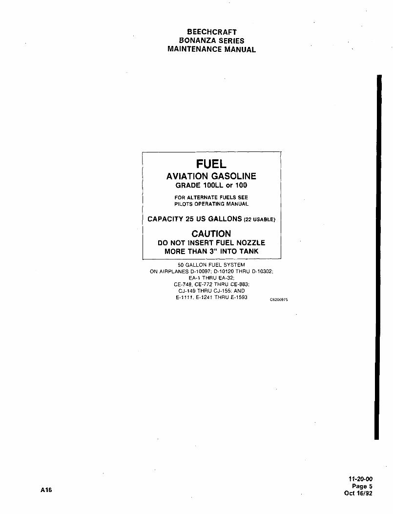
BEECHCRAFTBONANZA SERIES
MAINTENANCE MANUAL
FUELAVIATION GASOLINE
GRADE 100LL or 100
FOR ALTERNATE FUELS SEE
PILOTS OPERATING MANUAL
CAPACITY 25 US GALLONS (22 USABLE)
CAUTIONDO NOT INSERT FUEL NOZZLE
MORE THAN 3" INTO TANK
50 GALLON FUEL SYSTEM
ON AIRPLANES D-10097; D-10120 THRU D-10302;EA-1 THRU EA-32;
CE-748. CE-772 THRU CE-883;
CJ-149 THRU CJ-155; AND
E-llll, E-1241 THRU E-1593C9200975
11-20-00
Page 5A16
Oct 16/92
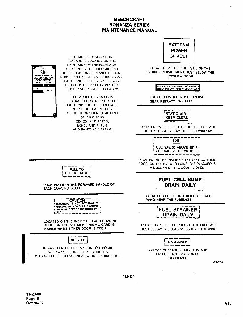
BEECHCRAFT
BONANZA SERIES
MAINTENANCE MANUAL
EXTERNAL
POWER
THE MODEL DESIGNATION 24 VOLT
PLACARD IS LOCATED ON THE
RIGHT SIDE OF THE FUSELAGE
ADJACENT TO THE INBOARD END LOCATED ON THE RIGHT SIDE OF THE
OF THE FLAP ON AIRPLANES D-10097, ENGINE COMPARTMENT, JUST BELOW THE
0-10120 AND AFTER; EA-1 THRU EA-272; COWLING DOOR
CORPORATION CJ-149 AND AFTER; CE-748, CE-772sEnl~L LIODEL
THRU CE-1200, E-llll, E-1241 THRU ~USE ONLY MS20392-X25 ORTC. E-2399, AND EA-273 THRU EA-472. ISHEAR PIN WITH THIS PLUNGER
PC
THE MODEL DESIGNATION LOCATED ON THE NOSE LANDING
PLACARD IS LOCATED ON THE GEAR RETRACT LINK ROD
RIGHT SIDE OF THE FUSELAGE
UNDER THE LEADING EDGEr------I
OF THE HORIZONTAL STABILIZER i STATIC AIR.ON AIRPLANES I KEEP CLEAN I
CE-1201 AND AFTER,
E-2400 AND AFTER,LOCATED ON THE LEFT SIDE OF THE FUSELAGE
AND EA-473 AND AFTER.JUST AFT AND BELOW THE REAR WINDOW
T-----o~-----!USE SAE 50 ABOVE 40" F
I IUSE SAE 30 BELOW 40" F I
LOCATED ON THE INSIDE OF THE LEFT COWLING
DOOR, ON THE FORWARD SIDE. THE PLACARD ISr--------~ VISIBLE WHEN THE DOOR IS OPEN
PULL TOI CHECK LATCHL -----J
r-----------I
I FUEL CELL SUMPII DRAIN DAILYLOCATED NEAR THE FORWARD HANDLE OF
EACH COWLING DOOR L-
LOCATED ON THE UNDERSIDE OF EACH
r- CAUTION WING NEAR THE FUSELAGE
i MAGNETO IS NOT INTERNALLY I
I GROUNDED. CONSULT OWNERS I
I YINUAL BEFORE DISCOHNECT- I
LING IDRAIN DAILY _IL_________
LOCATED ON THE INSIDE OF EACH COWLING
DOOR, ON THE AFT SIDE. THIS PIACARD IS LOCATED ON THE LEFT SIDE OF THE FUSELAGE
VISIBLE WHEN EITHER DOOR IS OPEN JUST BELOW THE LEADING EDGE OF THE WING
I TNos~l r---~L -I NO HANDLEL,,, I
INBOARD END LEFT FLAP. JUST OUTBOARDON TOP SURFACE NEAR OUTBOARD
WALKWAY ON RIGHT FLAP, 4 INCHESEND OF EACH HORIZONTAL
OUTBOARD OF FUSELAGE NEAR WING LEADING EDGE.STABILIZER.
C9200972
"END"
11-20-00
Page 6
Oct 16/92 A16

CHAPTER
SERVICING
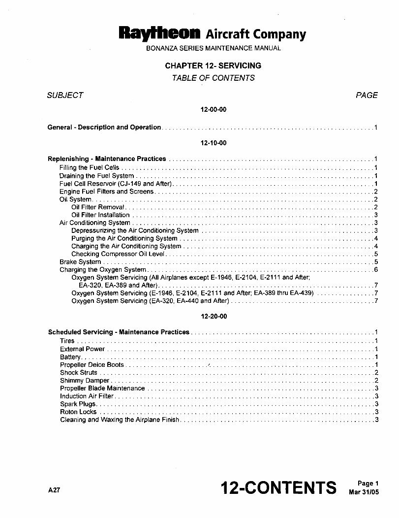
Raytheon Aircraft CompanyBONANZA SERIES MAINTENANCE MANUAL
CHAPTER 12- SERVICING
TABLE OF CONTENTS
SUBJECT PAGE
12-00-00
General Description and Operation ..1
12-10-00
Replenishing Maintenance Practices................_
.1
Filling the FuelCells................._ ................._
Drainingthe Fuel System .........__...............1
Fuel Cell Reservoir (CJ-149 and After) ..................1
Engine Fuel Filtersand Screens. ...2
Oil System.Oil Filter Removal
........._......._
Oil Filter Installation
Air Conditioning SystemDepressurizing theAirConditioning System ..........3
Purging theAirConditioning System ................4
Charging theAirConditioning System ...............4
Checking Compressor Oil Level .5
Brake SystemCharging the Oxygen System. .....6
Oxygen System Servicing (All Airplanes except E-1946, E-2104, E-2111 and After;
EA-320, EA-389 and After). ..7
Oxygen System Servicing (E-1946, E-2104, E-2111 and After; EA-389 thru EA-439) ............._7
Oxygen System Servicing (EA-320, EA-440 andAfter) ..7
12-20-00
Scheduled Servicing Maintenance Practices .............1
Tires
External Power
Battery....... .............1
Propeller Deice Boots................._
....r.
Shock Struts
Shimmy DamperPropeller Blade Maintenance ......3
Induction Air Filter
Spark Plugs.Roton Locks
Cleaning and Waxing the Airplane Finish .3
nzr 12-CONTENTS 1
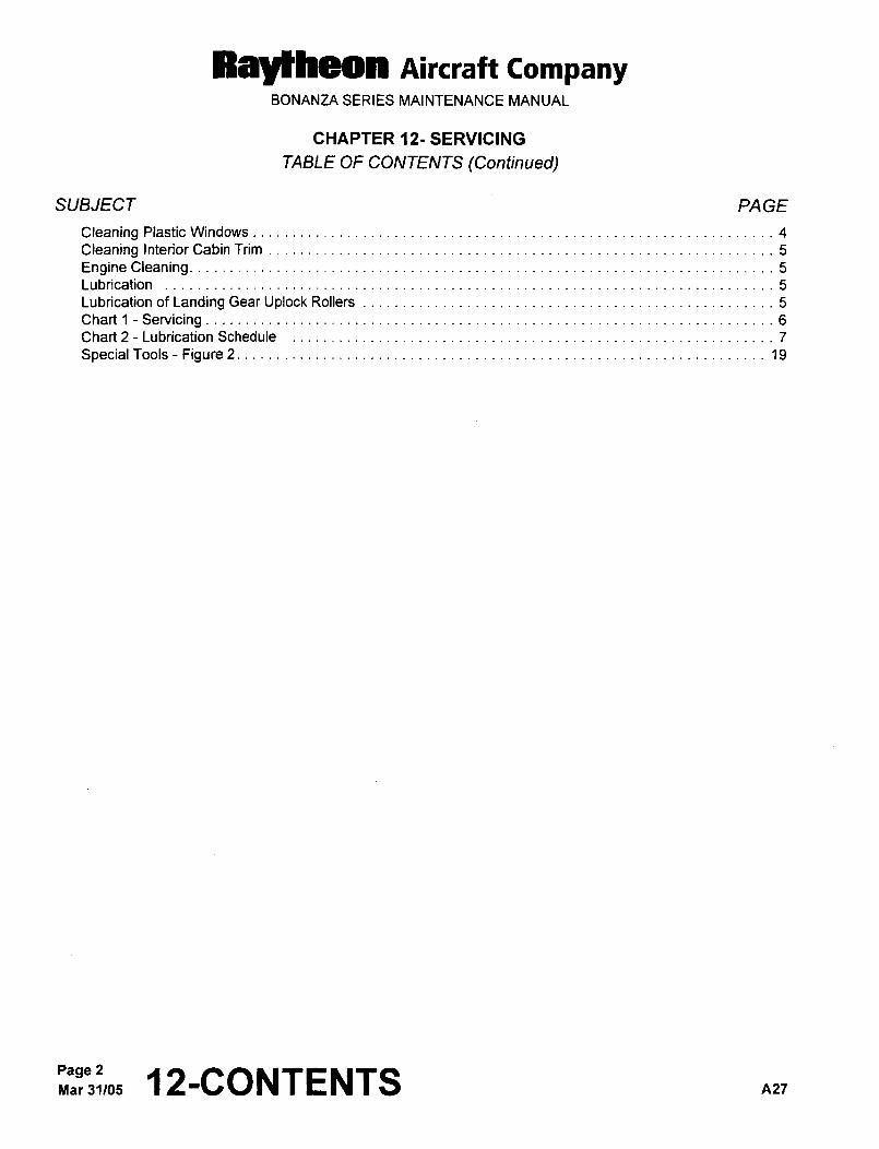
Raytheon Aircraft CompanyBONANZA SERIES MAINTENANCE MANUAL
CHAPTER 12- SERVICING
TABLE OF CONTENTS (Continued)
SUBJECT PA GE
Cleaning Plastic Windows........._____ ........._____
4
Cleaning InteriorCabin Trim 5
Engine Cleaning.Lubrication
Lubrication of Landing GearUplockRollers 5
Chart i-ServicingChart 2 Lubrication Schedule 7
Special Tools Figure 2.
Page ~2-CONTENTS nzr
Raylheon AiKraft CompanyBONANZA SERIES MAINTENANCE MANUAL
CHAPTER 12-SERVICING
LIST OF EFFECTIVE PA GES
CH-SE-SU PAGE DATE
12-LOEP 1 Mar 31/05
12-CONTENTS 1 and 2 Mar 31/05
12-00-00 1 May 9/80
12-10-00 1 thru 7 Mar 31/05
12-20-00 1 May 9/80
2 Jun 20/91
3 thru 5 Aug 28/87
6 and 6A Sep 27/84
7 Oct 7/83
8 May 9180
S,10,andlOA Aug29/85
11 Oct 7/83
12 thru 14 May 9/80
15 thru 18 Oct 7183
19 thru 21 Jan 18/84
22 Aug 29/85
A27 2-LOEP Mar 31/05Page 1
BEECHCRAFTBONANZA SERIES
MAINTENANCE MANUAL
GENERAL DESCRIPTION AND OPERATION Detailed maintenance information pertaining to these
systems will be found in the applicable chapters. Overhaul
information for components of several systems will be
The information contained within this chapter pertains to the contained within this manual. For electrical wiring diagrams
general servicing procedures and maintenance practices refer to the BONANZA F33A, F33C, V358 5 A36 Wiring
used when servicing the various systems of the airplane. Diagram Manual, P/N 35-590102-9.
"END"
12M)M)´•
Page 1
May 9/80
Raytheon Aircraft CompanyBONANZA SERIES MAINTENANCE MANUAL
REPLENISHING -IIIIAINTENANCE PRACTICES
FILLING THE FUEL CELLS
CAUTION: Any time the fuel system is drained or a fuel cell is empty for any reason, air may enter the system. If
the possibility that air has entered the system does exist, start and operate the engine on the grounduntil all air is removed from the system. Operate the engine forseveral minutes on each tank untilproperengine operation is assured. Refer to the Pilot’s Operating Handbook and Airplane Flight Manual before
starting and operating the engine.
Either the 44-gallon-usable (50-gallon-capacity) standard fuel system or the 74-gallon-usable (80-gallon-capacity)optional fuel system is available for all Bonanzas except EA-242, EA-273 and After. At serials EA-242, EA-273 and
After, (B36TC) a 102-gallon-usable (1 08-gallon-capacity) fuel system is standard. The fuel system consists of
rubber cells in the leading edge of the wings. A visual measuring tab in each cell (except EA-242, EA-273 and After)is attached to the filler neck of the 44-gallon system. The bottom of the tab indicates 27 gallons of usable fuel and
the detent indicates 32 gallons of usable fuel in the tanks. At serials EA-242, EA-273 and After, a float-type sightgage is installed in the fuel system. This gage will indicate a partial load of 25, 30 or 35 gallons of fuel in its respectivewing. When the gage is indicating in the black zone, do not use the gage. On all airplanes except CJ-149 and After,each wing contains a baffled main fuel cell which provides an uninterrupted flow of fuel to the engine.
When filling the airplane fuel cells, always observe the following:
a. The airplane is designed for operation on 100/130 grade (green) or 100LL grade (blue) aviation gasoline (1,Chart 1, 91-00-00). If these fuels are not available, 1 15/145 grade (purple) may be used.
b. Make sure the airplane is statically grounded to the servicing unit.
c. Do not fill fuel cells near open flame or within 100 feet of any open energized electrical equipment capable of
producing sparks.
NOTE: Care should be exercised while filling the fuel cell to prevent scratching, denting, or otherwise damaging the
surface or leading edge of the wing. Do not allow the fuel nozzle to contact the rubber fuel cell.
DRAINING THE FUEL SYSTEM
The three snap-type drains should be opened daily to purge any condensed water vapor from the system. (EA-242,EA-273 and After have push-type drains which require the preflight drain tool. Refer to Chapter 12-20-00, SPECIAL ITOOLS.) Each fuel cell drain is located on the bottom of the wing, just outboard of the root. The system low spotdrain at the bottom of the fuel selector valve is accessible through a door inboard of the left wing root.
CAUTION: After defueling or fuel cell replacement, operate the engine on each fuel tank with the airplane on the
ground to ensure that all air has been purged from the fuel cells and the fuel lines to the engine.
FUEL CELL RESERVOIR (CJ-149 AND AFTER)
A non collapsible, sponge-filled reservoir is incorporated into some of the fuel cells of acrobatic airplanes to providean uninterrupted supply of fuel to the engine during slow rolls, uncoordinated maneuvers, fast tums, slips, etc. in
either the 25-gal. (22-gal. usable) or 40-gal. (37-gal. usable) fuel cells. An extra long tube extends into the spongearea to allow use of the fuel contained in the sponge-filled reservoir.
nn7 12’10’00 1
Raytheon Aircraft CompanyBONANZA SERIES MAINTENANCE MANUAL
ENGINE FUEL FILTERS AND SCREENS
Most fuel injection system malfunctions can be attributed to contaminated fuel. Inspecting and cleaning the fuel
strainers should be considered to be of the utmost importance as a regular part of preventive maintenance.
Normally the fuel strainers should be inspected and cleaned every 100 hours. However, the strainers should be
inspected and cleaned at more frequent intervals in response to severe conditions of service, unknown fuel handlingpractices, and operation in areas of excessive sand or dust.
OIL SYSTEM
The airplane is equipped with a wet sump oil system with a capacity of 12 quarts of oil. The oil filler cap is accessible
through an access door in the left engine cowling.
To drain the engine sump, remove the right hand access plate and unscrew the sump drain plug in the lower righthand side of the engine crankcase. An oil drain trough, furnished with each airplane is used to convey the oil throughthe bottom of the engine cowl prior to D-10364; CE-922; CJ-156; E-1752 and EA-129. At D-10364 and After; CE-922
and After; CJ-156 and After; E-1752 and After and EA-129 and After, a quick attach, snap-type fuel/oil drain adapterand approximately 18 inches of hose will be used to drain the oil sump. Refer to Chapter 12-20-00, SPECIAL
TOOLS.
Under normal operating conditions, the recommended number of operating hours between oil changes is 100 hours.
The oil filter should be removed and replaced at each oil change. When operating under adverse weather conditions
or continuous high power settings, the oil should be changed more frequently. Before draining the oil, run up the
engine until the oil reaches operating temperature to assure complete draining of the oil. Oil grades, (2, Chart 1,91-00-00) are’general recommendations only, and will vary with individual circumstances. Check oil~inlettemperature during flight in determining use of the correct grade of oil. Inlet temperatures consistently near the
maximum allowable indicates a heavier oil is needed. The new airplane is delivered with corrosion preventativecompound (3, Chart 1, 91-00-00) in the engine. This is a corrosion-preventive oil and should be removed at 20 hours
of operation, but no later than 25 hours of operation. If the corrosion preventative compound is not removed at the
proper time, varnish may form in the engine. Oil conforming to mineral oil may be added to the corrosion preventativecompound as necessary. After removing the corrosion preventative compound, refill with mineral oil, which should
be used until oil consumption has stabilized (until after engine break-in). After the break-in period, use an ashless
dispersant (AD) aviation grade oil in the heaviest weight that will give satisfactory starting. Above 40"F (4.4"C), SAE
50 viscosity should be used; below 40"F (4.4"C), SAE 30 is recommended. Any aviation grade engine oil which
meets Continental Motors Corporation Specification MHS-24B is acceptable for use.
CAUTION: If metal contamination of the oil system is detected and the cause is corrected, the oil cooler should be
replaced. In addition, flush out the system through the interconnected oil system plumbing and replaceor clean any other accessories that will remain with the engine.
OIL FILTER REMOVAL
a. Gain access to the engine oil filter by opening the LH engine cowl access door.
b. Remove the engine oil filter safety wire.
c. Loosen the spin-off filter and remove filter.
Page 2-~ 0-00 n2-r
Ray~heon Aircraft CompanyBONANZA SERIES MAINTENANCE MANUAL
OIL FILTER INSTALLATION
a. Clean and lubricate the new filter gasket with engine oil.
b. Position the new filter on the engine mounting adapter and tighten the filter to a torque of 18 to 20 ft-lbs. If a
torque wrench is not available, tighten the filter with a suitable wrench for three-quarters to one full turn after
gasket contact
c. Safety wire the filter to the engine adapter.
d. Secure the left engine cowl access door.
AIR CONDITIONING SYSTEM
Servicing the air conditioning system consists of periodically checking the refrigerant level, checking compressor oil
level, checking the compressor belt tension, and changing the system air filter. Recharge the system as outlined
under CHARGING THE AIR CONDITIONING SYSTEM whenever the refrigerant level is low, air has entered the
system, or components carrying refrigerant are replaced. Refrigerant leaks may be detected by inspection with a
flameless leak detector. When working on a refrigerant air cooling system, observe the following special servicingprecautions:
WARNING: A face shield should be worn when performing maintenance on the lines because refrigerantcoming in contact with the eyes can cause loss of sight.
Do not smoke when servicing the system with refrigerant because it converts to a highly toxic
gas when exposed to an open flame.
a. Due to the air quality control regulations enacted in the United States, R-12 refrigerant cannot be vented into
the atmosphere. When performing maintenance on the air-conditioning system where R-12 can escape from
the system, evacuate the system with only a recovery or recycle servicing unit that will salvage the refrigerant.
b. The air-conditioning system is a high pressure system. Before disconnecting a refrigerant line, the system must
be discharged with a recovery servicing unit. Purge the entire system to a 125-micron level.
DEPRESSURIZING THE AIR CONDITIONING SYSTEM
WARNING: A face shield should be worn when performing maintenance on the lines because refrigerantcoming in contact with the eyes can cause loss of sight.
Do not smoke when servicing the system with refrigerant because it converts to a highly toxic
gas when exposed to an open flame.
The servicing points for discharging the system are located under the copilot’s seat.
a. Connect a service unit that recycles the refrigerant to the service valves and open the low pressure valve.
b. When the pressure is depleted, open the pressure valve and operate the vacuum pump to completely remove
the refrigerant from the system.
c. After the system is depressurized, perform the CHECKING COMPRESSOR OIL LEVEL procedures. I
n27 Maj);~;b:
RayMheon Aircraft CompanyBONANZA SERIES MAINTENANCE MANUAL
PURGING THE AIR CONDITIONING SYSTEM
To purge the system, connect a recycle servicing unit to the low pressure side of the air conditioning system (locatedunder the copilot’s seat). Purge the entire system with the vacuum pump operating at the 125-micron level. Refer to
the Chapter 21-50-00, AIR CONDITIONING SYSTEM SCHEMACTIC illustration in the Maintenance Practices
section.
CHARGING THE AIR CONDITIONING SYSTEM
WARNING: A face shield should be worn when performing maintenance on the lines because refrigerantcoming in contact with the eyes can cause loss of sight.
Do not smoke when servicing the system with refrigerant because it converts to a highly toxic
gas when exposed to an open flame.
The servicing points for charging the system are located under the copilot’s seat.
a. For airplane serials prior to CE-1792; E-2945 and EA-579 use refrigerant R-12 (7, Chart 1, 91-00-00). For
airplane serials CE-1792 and After; E-2945 and After; and EA-579 and After, use refrigerant R-134a (64, Chart
1, 91-00-00). Other refrigerants, particularly those containing methyl chloride, will cause rapid deterioration of
the aluminum compressor components.
b. Connect the recycle/recovery service unit to the air conditioning system service ports located under the copilot’sseat. If the system contains a partial charge, evacuate all refrigerant prior to charging.
c. Perform the compressor oil level check procedures provided in this chapter to determine if additional refrigerantoil is required.
CAUTIOIV: Do not over charge the air conditioning system. A full charge is 2.4 pounds of refrigerant. Failure to
comply could result in damage to the air-conditioning system.
d. Add an initial charge of 1 pound of refrigerant to the air conditioning system and any additional refrigerant oil
required.
e. Start the engine in accordance with the applicable Pilot’s Operating Handbook and run the air conditioningsystem.
CAUTIOEI: Never add liquid refrigerant to the air conditioning system while the compressor is running. Refrigerantadded while the compressor is operating must be in vapor form.
NOTE: Charging the air conditioning system through observation of the sight glass (bubbles disappearing) requiresthe temperature to be above 75"F (23.9"C). Charging the air conditioning system, through observation of
the sight glass, is not recommended at ambient temperatures below 75"F (23.9"C). At temperatures below
75"F (23.9"C) the refrigerant should be measured into the air conditioning system.
f. If the ambient temperature is above 75"F (23.9"C), slowly add vapor refrigerant into the air conditioning systemuntil the sight glass is clear (no bubbles). If the ambient temperature is below 75"F (23.9"C), measure 1.4
pounds of vapor refrigerant into the system making the total charge 2.4 pounds.
Mar 31/05Page 4
All
Rayseon Aircraft CompanyBONANZA SERIES MAINTENANCE MANUAL
CHECKING COMPRESSOR OIL LEVEL
The air conditioner compressor oil level should be checked by a qualified air conditioner service man if the
refrigerant charge is lost (evidenced by oil loss). For airplane serials prior to CE-1792; E-2945 and EA-579, the air
conditioner system requires 4 to 5 ounces of 500-viscosity oil (8, Chart 1, 91-00-00). For airplane serials CE-1792
and After; E-2945 and After and EA-579 and After, the air conditioner system requires 4 to 5 ounces of Ester Oil (65,Chart 1, 91-00-00).
Check the compressor oil level as follows:
a. Fabricate a dipstick by bending a wire to a 90" angle so that 1 1/2 inches of the wire will insert into the
compressor.
b. Paint the dipstick with a fiat black paint. Allow sufficient time for the paint to dry.
c. Start the engine in accordance with the applicable Pilot’s Operating Handbook and run the air-conditioningsystem for 15 minutes with the engine running at low.rpm to allow oil to accumulate in the compressor. Observe
the engine operating limitations as noted in the applicable Pilot’s Operating Handbook. Shut down the enginein accordance with the applicable Pilot’s Operating Handbook.
d. Relieve the air conditioner system pressure by evacuating the system with a recycle servicing unit.
e. After the system pressure is relieved, remove the oil filler plug.
f. Insert the dipstick through the oil filler port, slowly rotate the clutch shaft until the dipstick will insert to the bottom
of the compressor.
g. Withdraw the dipstick; oil should register on the dipstick at 5/8 inch below the filler port. Add oil as necessary to
maintain this measurement.
h. Install the oil filler plug with O-ring and secure plug.
NOTE: Make sure that the O-ring is not twisted and that dirt or particles are NOT ON the O-ring seat. The plugshould be snug. Do not overtighten the plug.
i. Perform the CHARGING THE AIR CONDITIONING SYSTEM procedures.
j. Check the area around the filler plug for leaks. If leaks exist, do not overtighten the filler plug. Remove the plugas noted in Step e. and install a new O-ring after depressurizing the system with a recycle servicing unit. Secure
the plug and recharge the system as noted in Step h. and Step i..
BRAKE SYSTEM
The hydraulic brakes are self-compensating and require no adjustment. Linings should be checked for small nicks
or sharp edges which could damage the brake discs. Worn, dished or distorted brake discs should be replaced. The
brake fluid is supplied to the brake system from the reservoir tank located in the engine accessory section and is
accessible by raising the right side of the engine cowl. The reservoir should be filled to within 1 112 inches of the topand a visible fluid level maintained on the dipstick at all times. Use only hydraulic fluid (9, Chart 1, 91-00-00) in the
brake system. Ensure that no dirt or foreign matter is allowed to enter the brake system.
nn-I 12’10’00 5
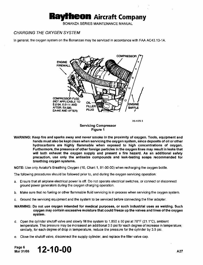
Raytheon AiKraft CompanyBONANZA SERIES MAINTENANCE MANUAL
CHARGING THE OXYGEN SYSTEM
In general, the oxygen system on the Bonanzas may be serviced in accordance with FAA AC43.13-1A.
COMPRESSOR
ENGINE
FIREWALL
.r"
o
(NOT APPLICABLE TO OIL
b/\oCOMPFIESS6R FUSE
E-2104, E-2111 AND ENGINEFILLER
AFTER; EA320, BAFFLEEA440 AND AFTEA)
PLUG L~ ---I I I
55-425-1
Servicing CompressorFigure 1
WARNING: Keep fire and sparks away and never smoke in the proximity of oxygen. Tools, equipment and
hands must also be kept clean when servicing the oxygen sy~tem, since deposits of oil or other
hydrocarbons are highly fiammable when exposed to high concentrations of oxygen.Furthermore, the presence of other foreign particles in the oxygen lines may result in leaks that
will both exhaust the oxygen supply and present a fire hazard. As an additional safetyprecaution, use only the antiseize compounds and leak-testing soaps recommended for
breathing oxygen systems.
NOTE: Use only Aviator’s Breathing Oxygen (10, Chart 1, 91-00-00) when recharging the oxygen bottle.
The following procedures should be followed prior to, and during the oxygen servicing operation:
a. Ensure that all airplane electrical power is off. Do not operate electrical switches, or connect or disconnect
ground power generators during the oxygen charging operation.
b. Make sure that no fueling or other flammable fluid servicing is in process when servicing the oxygen system.
c. Ground the servicing equipment and the system to be serviced before connecting the filler adapter.
WARNING: Do not use oxygen intended for medical purposes, or such industrial uses as welding. Such
oxygen may contain excessive moisture that could freeze up the valves and lines of the oxygen
system.
d. Open the cylinder shutoff valve and slowly fill the system to 1,850 50 psi at 70"F (21.1"C), ambient
temperature. This pressure may be increased an additional 3.5 psi for each degree of increase in temperature;similarly, for each degree of drop in temperature, reduce the pressure for the cylinder by 3.5 psi.
e. Close the shutoff valve, disconnect the supply cylinder, and replace the filler valve cap.
Page 6Mar31105 12-~ 0-00 A27
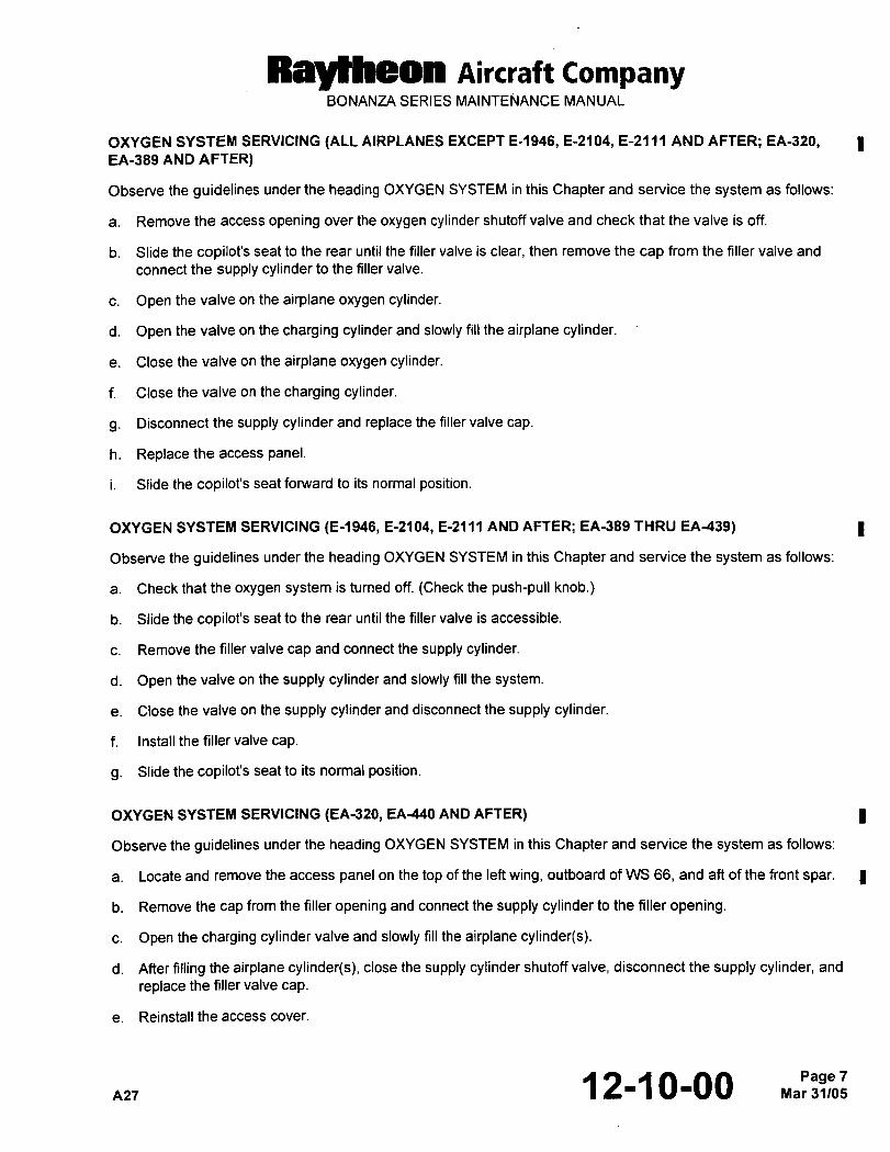
Ral~heon AiKraft CompanyBONANZA SERIES MAINTENANCE MANUAL
OXYGEN SYSTEM SERVICING (ALL AIRPLANES EXCEPT E-1946, E-2104, E-2111 AND AFTER; EA-320, IEA-389 AND AFTER)
Observe the guidelines under the heading OXYGEN SYSTEM in this Chapter and service the system as follows:
a. Remove the access opening over the oxygen cylinder shutoff valve and check that the valve is off.
b. Slide the copilot’s seat to the rear until the filler valve is clear, then remove the cap from the filler valve and
connect the supply cylinder to the filler valve.
c. Open the valve on the airplane oxygen cylinder.
d. Open the valve on the charging cylinder and slowly fill the airplane cylinder.
e. Close the valve on the airplane oxygen cylinder.
f. Close the valve on the charging cylinder.
g. Disconnect the supply cylinder and replace the filler valve cap
h. Replace the access panel.
i. Slide the copilot’s seat forward to its normal position.
OXYGEN SYSTEM SERVICING (E-1946, E-2104, E-2111 AND AFTER; EA-389 THRU EA-439)
Observe the guidelines under the heading OXYGEN SYSTEM in this Chapter and service the system as follows:
a. Check that the oxygen system is turned off. (Check the push-pull knob.)
b. Slide the copilot’s seat to the rear until the filler valve is accessible.
c. Remove the filler valve cap and connect the supply cylinder.
d. Open the valve on the supply cylinder and slowly fill the system.
e. Close the valve on the supply cylinder and disconnect the supply cylinder.
f. Install the filler valve cap.
g. Slide the copilot’s seat to its normal position.
OXYGEN SYSTEM SERVICING (EA-320, EA-440 AND AFTER) I
Observe the guidelines under the heading OXYGEN SYSTEM in this Chapter and service the system as follows:
a. Locate and remove the access panel on the top of the left wing, outboard of WS 66, and aft of the front spar.
b. Remove the cap from the filler opening and connect the supply cylinder to the filler opening.
c. Open the charging cylinder valve and slowly fill the airplane cylinder(s).
d. After filling the airplane cylinder(s), close the supply cylinder shutoff valve, disconnect the supply cylinder, and
replace the filler valve cap.
e. Reinstall the access cover.
AZ7 ~2-10-00 Rna~a3;J,eo:Page 7
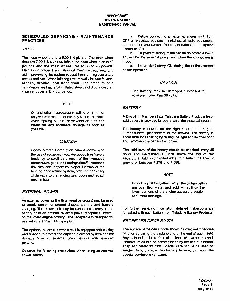
BEECHCRAFT
BONANZA SERIES
MAINTENANCE MANUAL
SCHEDULED SERVICING MAINTENANCE a. Before connecting an external power unit, turn
PRACTICES OFF all electrical equipment switches, all radio equipment,and the alternator switch. The battery switch in the airplane
TIRES should be ON.
b. To prevent arcing, make certain no power is beingThe nose wheel tire is a 5.00-5 4-ply tire. The main wheel applied by the external power unit when the connection is
tires are 7.00-6 6-ply tires. Inflate the nose wheel tires to 40 made.
pounds and the main wheel tires to 33 to 40 pounds. c. Leave the battery ON during the entire extemal
Maintaining proper tire inflation will minimize tread wear and power operation.aid in preventing tire rupture caused from running over sharpstones and ruts. When inflating tires, visually inspect for cuts,
cracks, breaks, and tread wear. The pressure of a CAUTION
serviceable tire that is fully inflated should not drop more than
4 percent over a 24-hour period. The battery may be damaged if exposed to
voltages higher than 30 volts.
NOTEBA ~TERY
Oil and other hydrocarbons spilled on tires not
only weaken the rubber but may cause it to swell. A 24-volt, 1 10 ampere hour Teledyne Battery Products lead-
Avoid spilling oil, fuel or solvents on tires and acid battery is provided for operation of the electrical system.clean off any accidental spillage as soon as
possible. The battery is located on the right side of the enginecompartment, just forward of the firewail. The battery is
accessible for servicing by raising the right engine cowl door
CAUTION and removing the battery box cover.
Beech Aircraft Corporation cannot recommend The fluid level of the battery should be checked every 25
the use of recapped tires. Recapped tires have a hours and maintained 3/8 inch above the top of the
tendency to swell as a result of the increased separators. Add only distilled water to maintain the specific
temperature generated during takeoff. Increased gravity of between 1.275 and 1.295.
tire size can jeopardize proper function of the
landing gear retract system, with the possibilityof damage to the landing gear doors and retract NOTE
mechanism.
Do not overfill the battery. When the battery cells
are overfilled, water and acid will spill on the
EXTERNAL POWER lower portions of the engine accessory section
and lower fuselage.An extemal power unit with a negative ground may be used
to supply power for ground checks, starting and batterycharging. The power unit may be connected directly to the For further servicing information, detailed instructions are
battery or to an optional external power receptacle, located furnished with each battery from Teledyne Battery Products.
on the lower engine cowling. The receptacle is designed for
use with a standard AN type plug. PROPELLER DEICE BOOTS
The optional external power circuit is equipped with a relay The surface of the deice boots should bechecked for engineand a diode to protect the airplane electrical system against oil after servicing the airplane and at the end of each flight.
damage from an external power source with reversed Any oil found on the surface of the boots should be removed.
polarity. Removal of oil can be accomplished by the use of a neutral
soap and water solution. Special care should be used on
Observe the following precautions when using an extemal electric deice boots, while cleaning, to avoid damaging the
power source, special conductive surfacing.
12-20-00
Page 1
May 9/80
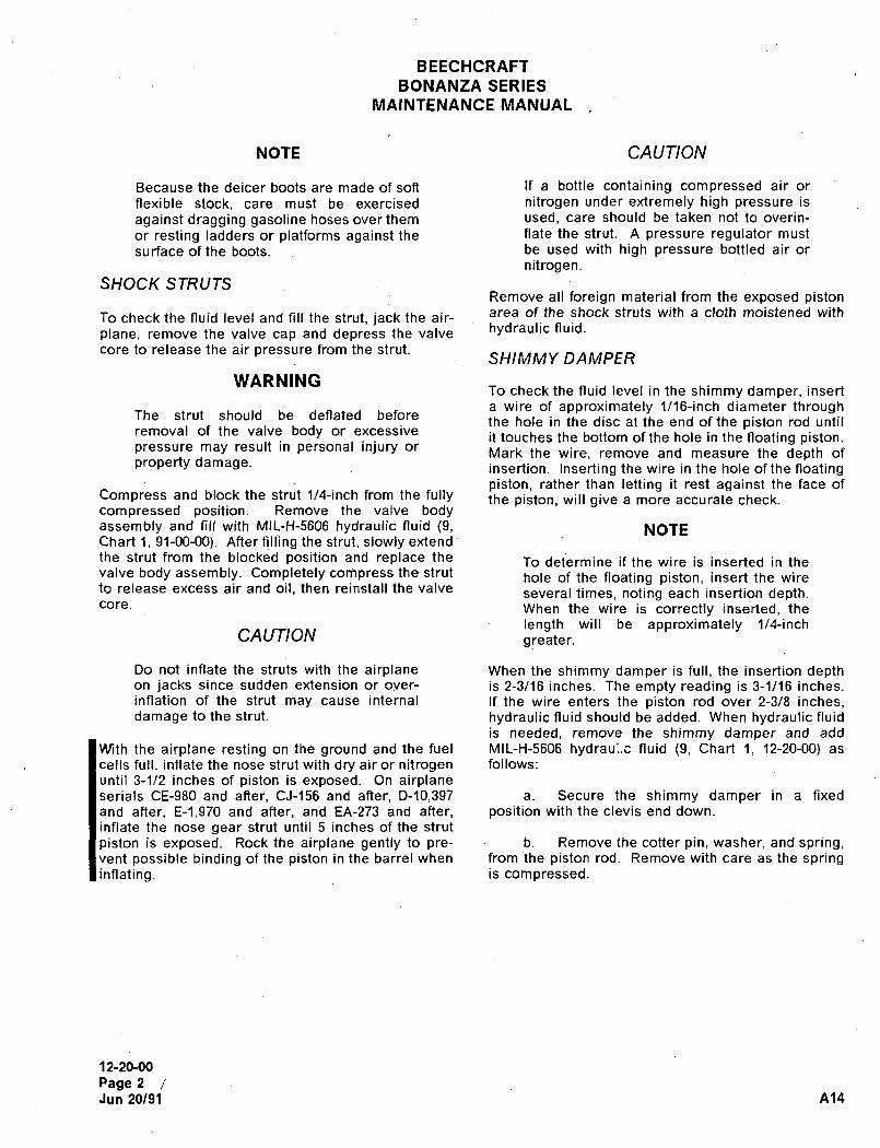
BEECHCRAFT
BONANZA SERIES
RIIAINTENANCE MANUAL
NOTE CAUTION
Because the deicer boots are made of soft If a bottle containing compressed air or
flexible stock, care must be exercised nitrogen under extremely high pressure is
against dragging gasoline hoses over them used, care should be taken not to overin-
or resting ladders or platforms against the flate the strut. A pressure regulator must
surface of the boots. be used with high pressure bottled air or
nitrogen.SHOCK STRUTS
Remove all foreign material from the exposed pistonarea of the shock struts with a cloth moistened with~o check the fluid level and fill the strut, jack the air-
plane, remove the valve cap and depress the valve hydraulic fluid.
core to release the air pressure from the strut.SHIIMMY DAMP~R
WARNINGTo check the fluid level in the shimmy damper, insert
a wire of approximately 1/16-inch diameter throughThe strut should be deflated before
the hole in the disc at the end of the piston rod untilremoval of the valve body or excessive
it touches the bottom of the hole in the floating piston.pressure may result in personal injury or
Mark the wire, remove and measure the depth ofproperty damage. insertion. Inserting the wire in the hole of the floating
piston, rather than letting it rest against the face ofCompress and block the strut 1/4-inch from the fully the piston, will give a more accurate check.compressed position. Remove the valve bodyassembly and fill with MIL-H-5606 hydraulic fluid (9, NOTEChart 1, 91-00-00). After filling the strut, slowly extend
the strut from the blocked position and replace the To determine if the wire is inserted in thevalve body assembly. Completely cori~press the strut hole of the floating piston, insert the wireto release excess air and oil, then reinstall the valve several times, noting each insertion depth.core. When the wire is correctly inserted, the
length will be approximately 1M-inchCAUTION greater.
Do not inflate the struts with the airplane When the shimmy damper is full, the insertion depthon jacks since sudden extension or over- is 2-3/16 inches. The empty reading is 3-1/16 inches.inflation of the strut may cause internal If the wire enters the piston rod over 2-3/8 inches,damage to the strut. hydraulic fluid should be added. When hydraulic fluid
is needed, remove the shimmy damper and add
With the airplane resting on the ground and the fuel MIL-H-5606 hydrau;..e fluid (9, Chart 1, 12-20-00) as
cells full, inflate the nose strut with dry air or nitrogen follows:
until 3-1/2 inches of piston is exposed. On airplaneserials CE-980 and after, CJ-156 and after, D-10,397 a. Secure the shimmy damper in a fixed
and after, E-1,970 and after, and EA-273 and after, position with the clevis end down.
inflate the nose gear strut until 5 inches of the strut
piston is exposed. Rock the airplane gently to pre- b. Remove the cotter pin, washer, and spring,vent possible binding of the piston in the barrel when from the piston rod. Remove with care as the springinflating. is compressed.
12-20-00
Page 2
Jun 20/91 A14
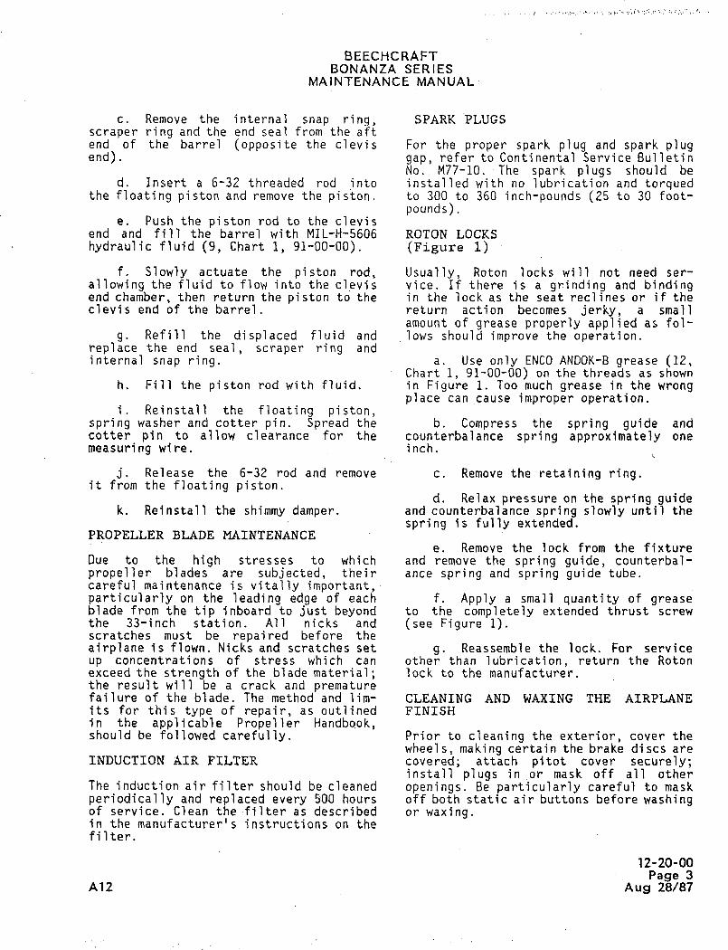
BEECHCRAFTBONANZA SERIES
MAINTENANCE MANUAL
c. Remove the internal snap ring, SPARK PLUGS
scraper ring and the end seal from the aftend of the barrel (opposite the clevis For the proper spark plug and spark plugend). gap, refer to Continental Service Bulletin
No. M77-10. The spark plugs should bed. Insert a 6-32 threaded rod into installed with no lubrication and torqued
the floating piston and remove the piston. to 300 to 360 inch-pounds (25 to 30 foot-
pounds).e. Push the piston rod to the clevis
end and fill the barrel with MIL-H-5606 ROTON LOCKS
hydraulic fluid (9, Chart 1, 91-00-00). (Figure 1)
f. Slowly actuate the piston rod, Usually, Roton locks will not need ser-
allowing the fluid to flow into the cievis vice. If there is a grinding and bindingend chamber, then return the piston to the in the lock as the seat reclines or if theclevis end of the barrel, return action becomes jerky, a small
amount of grease properlyapplied as fol-
g. Refill the di spl aced fluid and lows should improve the operation.replace the end seal, scraper ring andinternal snap ring. a. Use only ENCO ANDOK-B grease (12,
Chart 1, 91-00-00) on the threads as shownh, Fill the piston rod with fluid. in Figure 1. Too much grease in the wrong
place cancause improper operation.i. Reinstall the floating piston,
spring washer and cotter pin. Spread the b. Compress the spring guide andcotter pin to allow clearance for the counterbalance spring approximately one
measuring wire. inch.
j, Release the 6-32 rod and remove c. Remove the retaining ring.it from the floating piston.
d. Relax pressure on the spring guidek. Reinstall the shimmy damper. and counterbalance spring slowly until the
spring is fully extended.PROPELLER BLADE MAINTENANCE
e. Remove the lock from the fixtureDue to the high stresses to which and remove the spring guide, counterbal-
propeller blades are subjected, their ance spring and spring guide tube.careful maintenance is vitally important,particularly on the leading edge of each f. Apply a small quantity of greaseblade from the tip inboard to just beyond to the completely extended thrust screw
the 33-inch station. All nicks and (see Figure 1).scratches must be repaired before theairplane is flown. Nicks and scratches set g. Reassemble the lock. For service
up concentrations of stress wh i ch can other than lubrication, return the Rotonexceed the strength of the blade material; lock to the manufacturer.the result will be a crack and prematurefailure of the blade. The method and lim- CLEANLNG AND WAXING THE AIRPLANEits for this type of repair, as outlined FINISHin the applicable Propeller Handbook,should be followed carefully. Prior to cleaning the exterior, cover the
wheels, making certain the brake discs are
INDUCTION ~IR FILTER cove red attach p i tot cover securely;install plugs in or mask off all other
The induction air filter should be cleaned openings. Be particularly careful to maskperiodically and replaced every 5‘00 hours off both static air buttons before washingof service. Clean the´•filter as described or waxing.in the manufacturer’s instructions on thefilter.
12-20-00Page 3
A12 Aug 28/87
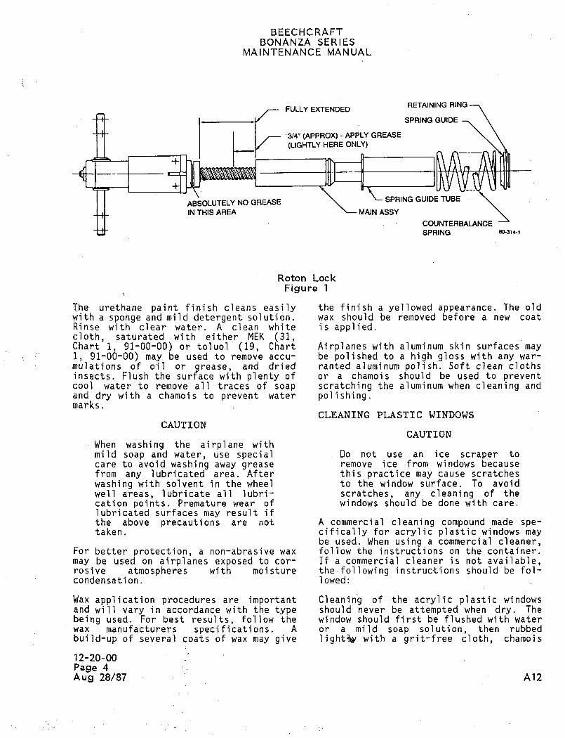
BEECHCRAFTBONANZA SERIES
MAINTENANCE MANUAL
RETAINING RINGFULLY EXTENDED
-I- SPRING GUIDE
3/4" (APPROX)- APPLY GREASE
(LIGHTLY HERE ONLY)
ABSOLUTELY NO GREASE SPRING GUIDE TUBE
IN THIS AREA ~MAINASSY
COUNTERBALANCE
SPRING 6~314-1
Roton Lock
Figure 1
The urethane paint finish cleans easily the finish a yellowed appearance. The old
with a sponge and mild detergent solution. wax should be removed before a new coat
Rinse with clear water. A clean whi te i s appl i ed.
cloth, saturated with either MEK (31,Chart i, 91-00-00) or toluol (19, Chart Airplanes’with aluminum skin surfaces may
1, 91-00-00) may be used to remove accu- be polished to a high gloss with any war-
mulations of oil or grease, and dried ranted aluminum polish. Soft clean clothsinsects. Flush the surface with plenty of or a chamois should be used to preventcool water to remove all trades of soap scratching the aluminum when cleaning andand dry with a chamois to prevent water polishing.marks.
CLEANING PLASTIC WINDOWSCAUTION
CAUTION
When washing the airplane withmild soap and water, use special Do not use an ice scraper to
care to avoid washing away grease remove ice from windows becausefrom any lubricated area. After this practice may cause scratches
washing with solvent in the wheel to the window surface: To avoidwell areas, lubricate all lubri- scratches, any clean-Ing of thecation points. Premature wear of winddws should bedone with care.
lubricated surfaces may result ifthe above precautions are not A commercial cleaning compound made spe-taken. cifically for acrylic plastic windows may
be used. When using a commercial cleaner,For better protection, a non-abrasive wax follow the instructions on the container.
may be used on airplanes exposed to cor- If a commercial cleaner is not available,rosSve atmospheres with moisture the´•following instruc~ions should be fol-condensation. lowed:
Wax application procedures are important Cleaning of the acrylic plasticwindowsand will vary in accordance with the type should never be attempted when dry. The
being used. For best results, follow the window should first be flushed with water
wax manufacturers specifications. A or a mild soap solution, then rubbed
build-up of several coats of wax may give light’t~ with a grit-free cloth, chamois
12-20-00Page 4
Aug 28/87 A12
BEECHCRAFTBONANZA SERIES
MAINTENANCE MANUAL
or sponge. Stubborn grease or oil deposits ENGINE CLEANING
are readily removed with aliphatic naphthaor hexane. Rinse with clear water. The engine may be cleaned with Stoddard
solvent, or any standard neutral solventCAUTION recommended for cleaning engines. The
cleaner may be sprayed or brushed on theDo not use thinner or aromatic engine. Compressed air may be used to
abrasive cleaners to clean the speed up drying time.wi ndows; they wi 11 damage thesurface of the plastic. Aliphatic LUBRICATION
naphtha and similar solvents are
highly flammable, and extreme Lubrication charts :and diagrams~ withincare must be taken when using this section contain informati,on- thatthem. ensure the proper operation and preierva-
tion of the airplane. Locat´•ion, intervalCLEANING INTERIOR CABIN TRIM and lubricant required are given. Avoi~
excessive application of lubricants.
Proper care and cleaning of the interiorcabin trim (Noryl and Kydex plastics) is LUBRICATION OF LANDING GEAR UPLOCKof primary importance to maintain a ROLLERSdesirable appearance. Clean the interiorcabin trim with a detergent soap and The uplock roller bearings should be
water, and brush scrub with a soft bristle lubricated with MIL-G-23827 greas’e (11,brush will dislodge most dirt. Wet wipe Chart,l, 91-00-00) every 100 hours or anywith clean water and wipe dry. Alcohol may time after cleaning the wheel well thebe used to remove foreign material that bearings are subjected to degreasingwithis alcohol soluble. solvent under pressure: Using a ´•pressure
gun, the uplock bear~ng is lubricatedCAUTION through a grease fitting installed in the
uplock bearing bolt.The interior cabin trim can be
easily contaminated if cleaned NOTEwith methyl ethyl ketone,naphtha, Mufti, standard solvent, The grease fitting on the draggasoline, lacquer thinner and leg, di rectly above the uplockother types of thinners. Sharp roller bearing, does not supplyedges or cuts on the edge of the lubrication for the uplock rollerinterior cabin trim material may bearing.cause it to crack.
12-20-00
Page 5A12 Aug 28/87
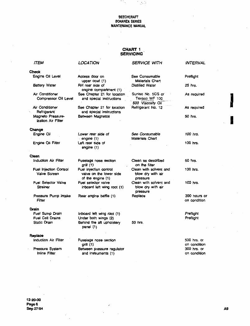
BEECHCRAFT
BONANZA SEAIES
MAIMENANCE MANUAL
CHART 1
SERVICING
ITEM LOCATION SERVICE WIT~ INTERVAL
Check
Engine Oil Level Access door on See Consumable Preflightupper cowl (1) Materials Chart
Battery Water RH rear side of Distilled Water 25 hrs.
engine compartment(l)Ar Conditioner See Chapter 21 for location Suniso No. 5GS or As required
Compressor Oil Level and special instructions Texaco WF 100
500 d~iAir Conditioner See Chapter 21 for location Refn’geran~ No. 12 As required
Refrigerant and special instructions
Magneto Pressure- Between Magnetos 50 hrs.
bation Air Filter
ChangeEngine Oil Lower rear side of See Consumable 100 hrs.
engine (1) Materials Chart
Engine Oil n~ter Left rear side of 100 hrs.
engine (1)
Clean
induction Air Filter Fuselage nose section Clean as described 50 hrs.
9rill (1) on the filter
Fuel Injection Control Fuel injection control Clean with solvent and 100 hrs.
Valve Screen valve on the lower side blow dry with air
of the engine (1) pressureFuel Selector Valve Fuel selector valve Clean with solvent and 100 hrs.
Strainer inboard left wing mot (1) blow dry with air
pressurePressure Pump Intake Rear engine baffle (1) Replace 300 hours or
Filter on condition
Drain
Fuel Sump Drain Inboard left wing root (1) PreflightFuel Cell Drains Under both wings (2) PreflightStatic Drain Behind the ah upholstery 50 hrs.
panel (1)
ReplaceInduction Air Rite~ Fuselage nose-section 500 hrs. or
grill (1) on condition
Pressure System Between pressure regulator 300 hrs. or
Inline Rlter and instruments (1) on condition
12´•20-00
PagesSep 27/84 A9
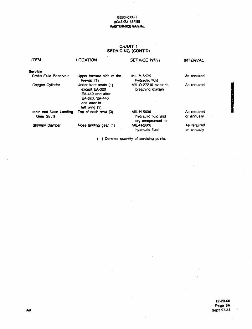
BEECHCRAFT
BONANZA SERIES
MA\MENANCE
CHART 1
SERVIC1NG (CONT*D)
ITEM LOCATION SERVICE WITH INTERVAL
Service
Brake Fluid Reservoir Upper forward side of the MIL-H-S606 As requiredRlewJI (1) hydraulic fluid
Oxygen Cylinder Under front seats (1) Mil-0-27210 aviator’s As requiredexcept EA-320 breathing oxygenEA-440 and after.
EA-320, EA-440
and after in
left wing (1)Main and Nose Landing top of each strut (3) MIL-H-5606 As required
Gear Struts hydraulic fluid and or annuallydry compressed air
Shimmy Damper Nose landing gear (1) MIL-H-5606 As requiredhydraulic fluid or annually
Denotes quantity of servicing points.
12-2000
Page 6A
A9 Sept 27:84
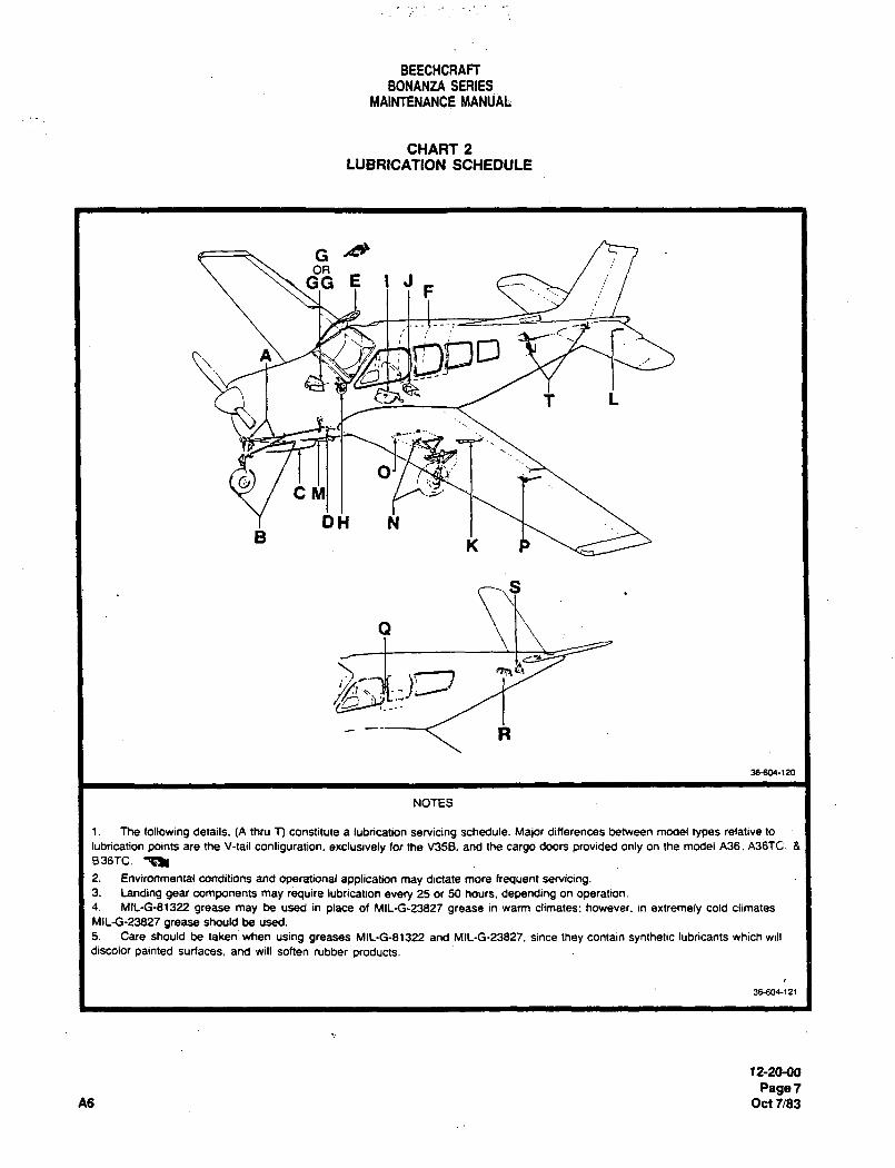
BEECHCRAFTBONANZA SERIES
MAINTENANCE MANUAL
CHART 2
LUBRICATION SCHEDULE
G
c~
A
t L
O
DH N
Q
R
36606-120
NOTES
1. The following details. (A thru T) constitute a lubrication servicing schedule. Major differences between model types relative to
lubrication points are l~e V-tail configuration, exclusively for the V35B. and the cargo doors provided only on the model A36. A36TC. 8
ass-re. ~k
2. Environmental conditions and operational application may dictate more frequent setvidng.3. Landing gear components may require lubrication every 25 or 50 hours. depending on operation.4. MIL-G-81322 grease may be used in place of MIL-G-23827 grease in warm climates. however. in extremely cold climates
MIL-G-23827 grease should be used.
5. Care should be taken when using greases MIL-G-81322 and MIL-G-23827, since they contain synthetic lubricants which will
discolor painted surfaces, and will soften rubber products.
38-M)4-(2I
12-20-00
PagerA6 Oct f/83
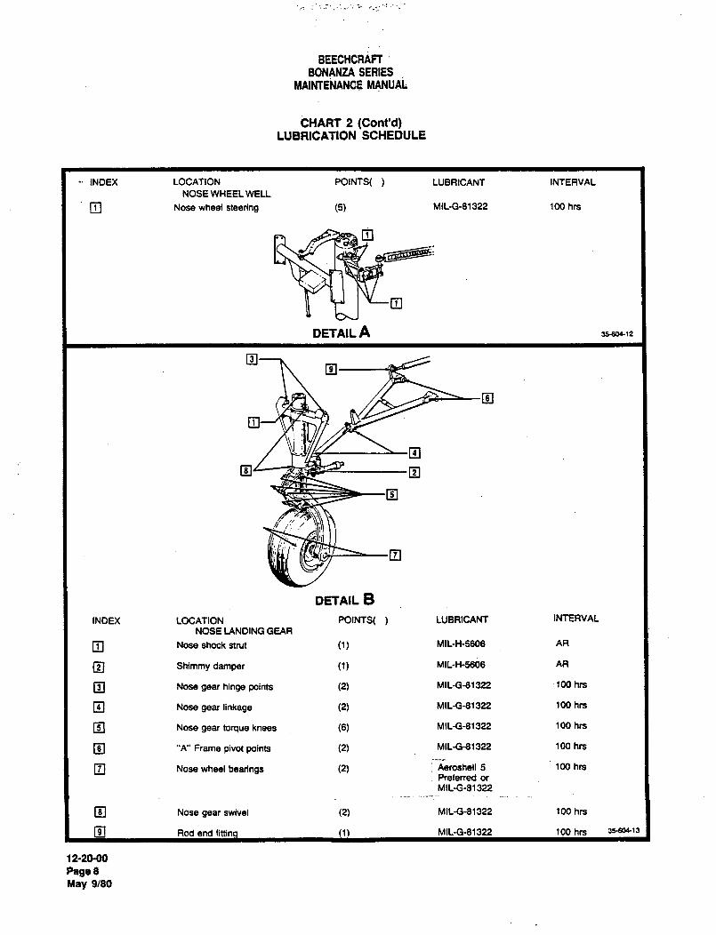
3
BEECHCRAFT.BONANZA SERIES
MAINTENANCE MANUAL
CHART 2 (Cont’d)LUBRICATION SCHEDULE
INDEX LOCATION POINTS( LUBRICANT INTERVAL
NOSE WHEEL WELL
O Nose wheel steering (5) MlL-G-81322 100 hrs
n
o
DETAIL A 35600´•12
IZI
~3
DETAIL B
INDEX LOCATION POINTS( LUBRICANT INTERVAL
NOSE LANDING GEAR
O Nose shook strut (1) MlL-H-5608 AR
O Shimmy damper MlL-H-5606 AR
Nose gear hinge points (2) MILG-81322 -100 hrs
O Nose gear linkage (2) MIL-Gg1322 100 hrs
O Nose gear torque knees (6) MIL-Gd1322 100 hrs
I~ "A" Flame pivot points (2) MIL-G-81322 100 hrs
O Nose wheel bearings (2) 1 Aeroshell 5 100 hrs
Pre~ened or
MlL-G-81322
Nose gear swivel (2) MIL-G-81322 100 hrs
9 Rod end fittino (1) MIL-G-81322 100 hrs 3s~604-’3
12-20´•00
Page 8
May 9/80
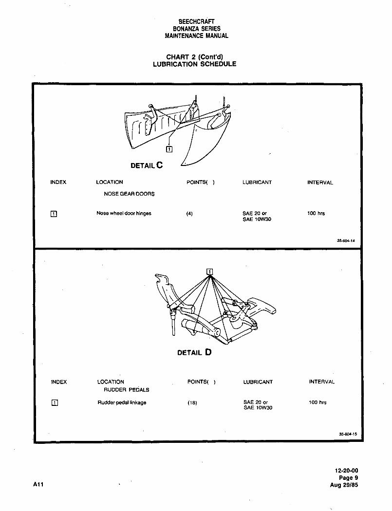
BEECHCRAFT
BONANtA SERIES
MAINTENANCE MANUAL
CHART 2 (Cont’d)LUBRICATION SCHEDULE
ys1~3
DETAIL C
INDEX LOCATION .POINTS( LUBRICANT INTERVAL
NOSE GEAR DOORS
O Nose wheel door hinges (4) SAE 20 or 100 hrs
SAE 10W30
35604-(4
DETAIL O
INDEX LOCATION eOlNTS( LUBRICANT INTERVAL
RUDDER PEDALS
O Rudder pedal linkage (13) SAE 20 or 100 hrsSAE 10W30
35-604-~5
12-20-00
Page 9
All Aug 29/85
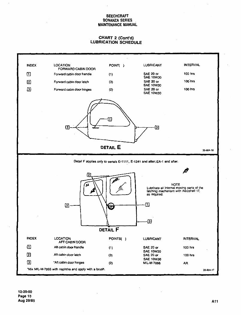
BEECHCRAFTBONANZA SERIES
MAINTENANCE MANUAL
CHART 2 (Cont’d)LUBRICATION SCHEDULE
INDEX LOCATION POINT( LUBRICANT INTERVAL
FORWARD CABIN DOOR
O Forward cabin door handle (1) SAE 20 or 100 hrs
SAE 10W30
O Forward cabin door latch (3) SAE 20 or 100 hrs
SAE 10W30
O Forward cabin door hinges (2) SAE 20 or 100 hrs
SAE 10W30
~3--t--1
DETAIL E35604-18
Detail F applies only to sen’als E-ll11. 8-1241 and after; EA-1 and after.
P
II NOTELubricate all internal moving parts of the
latching mechanism with Aeroshell 17,as required.
D
DETAIL F
INDEX LOCATION POINTS( LUBRICANT INTERVALAFT CABIN DOOR
O Aft cabin door handle SAE 20 or 100 hrs
SAE 10W30
O Aft cabin door latch (3) SAE 20 or 100 hrs
SAE 10W30O ’Aft cabin door hinges (2) MIL-M-7866 AR
’Mix MIL-M-7666 with naphtha and apply with a brush. 35604-32
12-20-00
Page 10
Aug 29/85 All
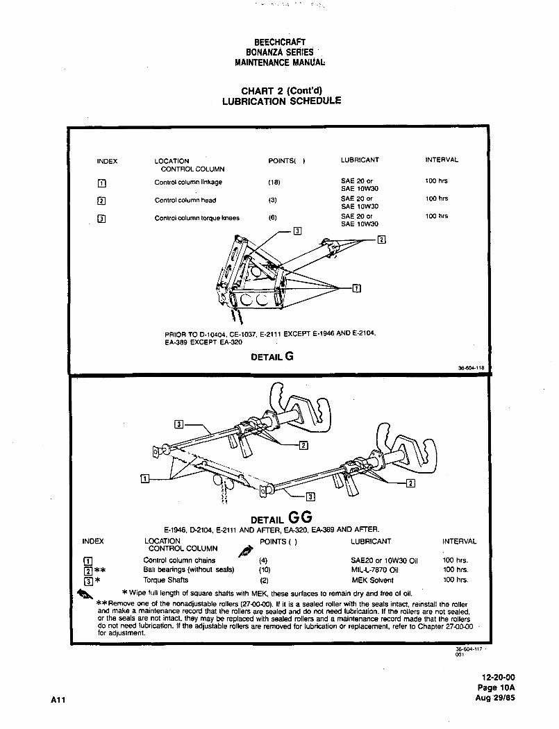
BEECHCRAFTBONANZA SEdrES:’
MAINTENANCE MANUAL
CHART 2 (Cont’d)LUBRICATION SCHEDULE
INDEX LOCATION POINTS( LUBRICANT INTERVAL
CONTROL COLUMN
O Controlcolumn linkage (le) SAE 20 or l00 hrs
SAE 10W30
O Control column head (3) SAE 20 or 100 hrs
SAE 10W30
O Control column torque knees (6) SAE 20 or 100 hrs
SAE 10W30
OO
~IP cc:
PRIOR TO 0-10404, CE-1037, E-2111 EXCEPT E-~946 AND 8-2104,
EA-389 EXCEPT EA-320
DETAIL G56a~-( ce
O
ei I-J- ~-o
DETAIL GGE-1946. D-2104, E-2111 AND AFTER. EA320, EA389 AND AFTER.
INDU( LOCATION POINTS( LUBRICANT INTERVALCONTROLCOLUMN
Control column chains (4) SAEP0 or 10W30 Oil 100 hrs.
O"* Ball bearings (without seals) (10) MIL-L-7870 Oil 100 hrs.
Torque Shafts (2) MEK Solvent 100 hrs.
a, Wipe lull length of square shafts with MEK, these surfaces to remain dry and free of oil.
Remove one of the nonadjustable rollers (27-00~00). 11 it is a sealed roller with the seals intact, reinstall the rollerand make a maintenance record that the rollers are sealed and do not need lubrication. If the rollers are not sealed,or the seals are not intact, they may be replaced with sealed rollers and a maintenance record made that the rollersdo not need iubrication. If the adjustable rollers are removed for lubrication or replacement, refer to Chapter 27~0-00for adjustment.
36-604-1(7
12-20-00
Page 10A
All Aug:29/85
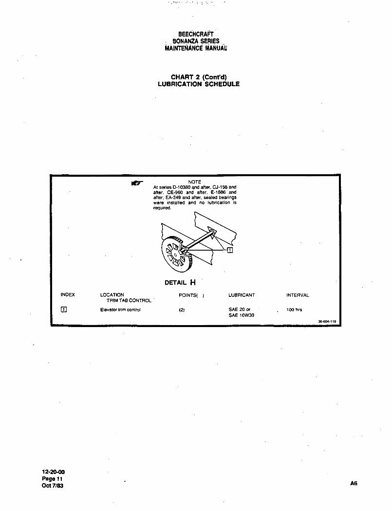
BEECHCRAFT
BONANZA SERIES.
CHART 2 (Cont’d)LUBRICATION SCHEDULE
ICb NOTE
At series 0-10380 and after. CJ-156 and
after. CE-960 and after. 6-1666 and
after. EA-249 and after. sealed bearingswere installed and no lubrication is
required.
1
DETAIL H
INDEX LOCATION POINTS( LUBRICANT INTERVAL
TRIM TAB CONTROL
O Elevator him control (2) SAE 20 or 100 hn
SAE 10W30
36604-1(9
12-20M)
Page 11
Oc17/83 A6
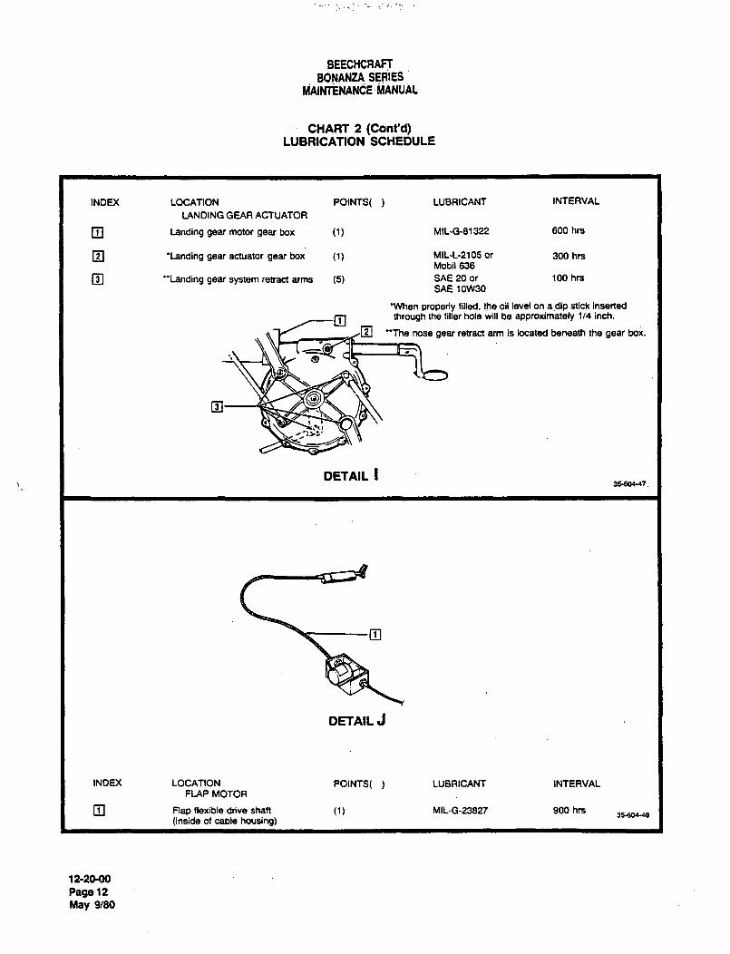
BEECHCRAFTBONANtA SEdIES
´•~ANUAL
CHART 2 (Cont’d)LUBRICATION SCHEDULE
INDEX LOCATION POINTS( LUBRICANT INTERVAL
LANDING GEAR ACTUATOR
O Landing gear motor gear box (1) MIL-G-81322 600 hn
O ’Landing gear actuator gear box (1) MIL´•L-2105 or 300 hrsMobil 636
O "Landing gear system retract arms (5) SAE 20 or 100 hrs
SAE1OW30
’When properly filled. the oil level on apip stick inserted
j7 through the filler hole will be approximately 1/4 inch.
2~ "The nose gear retract arm is located beneath the gear box.
’!~zL’
DETAIL I3560(-47.
DETAIL J
INDEX LOCATION POINTS( LUBRICANT INTERVALFLAP MOTOR
m Flap flexible drive shaft MIL-G-23827 900 hrs35-soe4e
(inside of cable housing)
12-2(MO
Rage 12
May 9/80
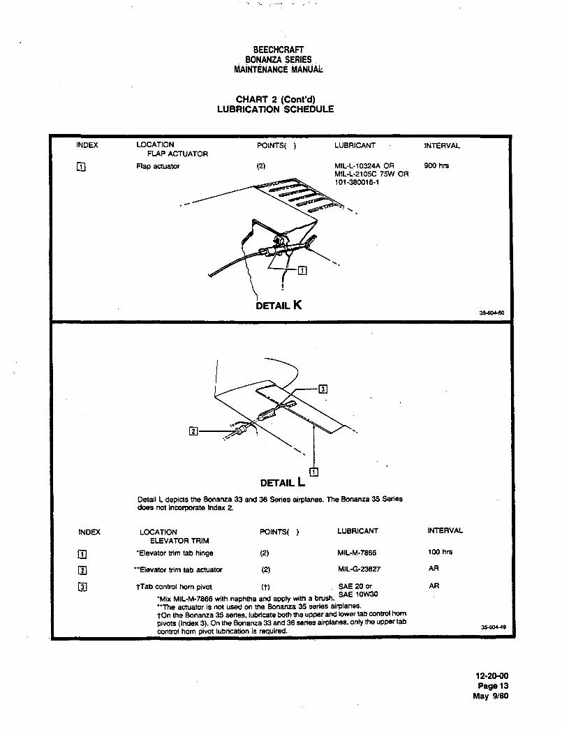
BEECHCRAFF
BONANZA SERIESMAINTENAN~E MANUAL:
CHART 2 (Cont’d)LUBRICATION SCHEDULE
INDEX LOCATION POINTS( LUBRICANT INTERVALFLAP ACTUATOR
O Flap actuator (2) MIL-L-10324A OR 900 hrs
MIL-L-2105C 75W OR
101-380016-1
O
i>ETAIL K3psoeso
DETAIL L
Detail L depicts the Bonanza 33 and 36 Series airplanes. The Bonanza 35 Series
does not incorporate Index 2.
INDEX LOCATION WINTS( LUBRICANT INTERVAL
ELEVATOR TRIM
O ’flevator trim tab hinge (2) MIL-M-7866 100 hrs
O "Elevator trim tab actuator (2) MIL-G-23827 AR
O tTab control horn pivot (t) SAE 20 or AR
SAE 10W30’Mix MlL-M-7866 with naphtha and apply with a brush.
’7he actuator is not used on the Bonanza 35 series airplanes.tOn the Bonanza 35 series, lubricate both the upper and lower tab control horn
pivots (Index 3). On the Bonanza 33 and 36 series airplanes, only the upper tab3560449
control horn pivot lubrication is required.
12-2(H)O
Rage 13
May 9/80
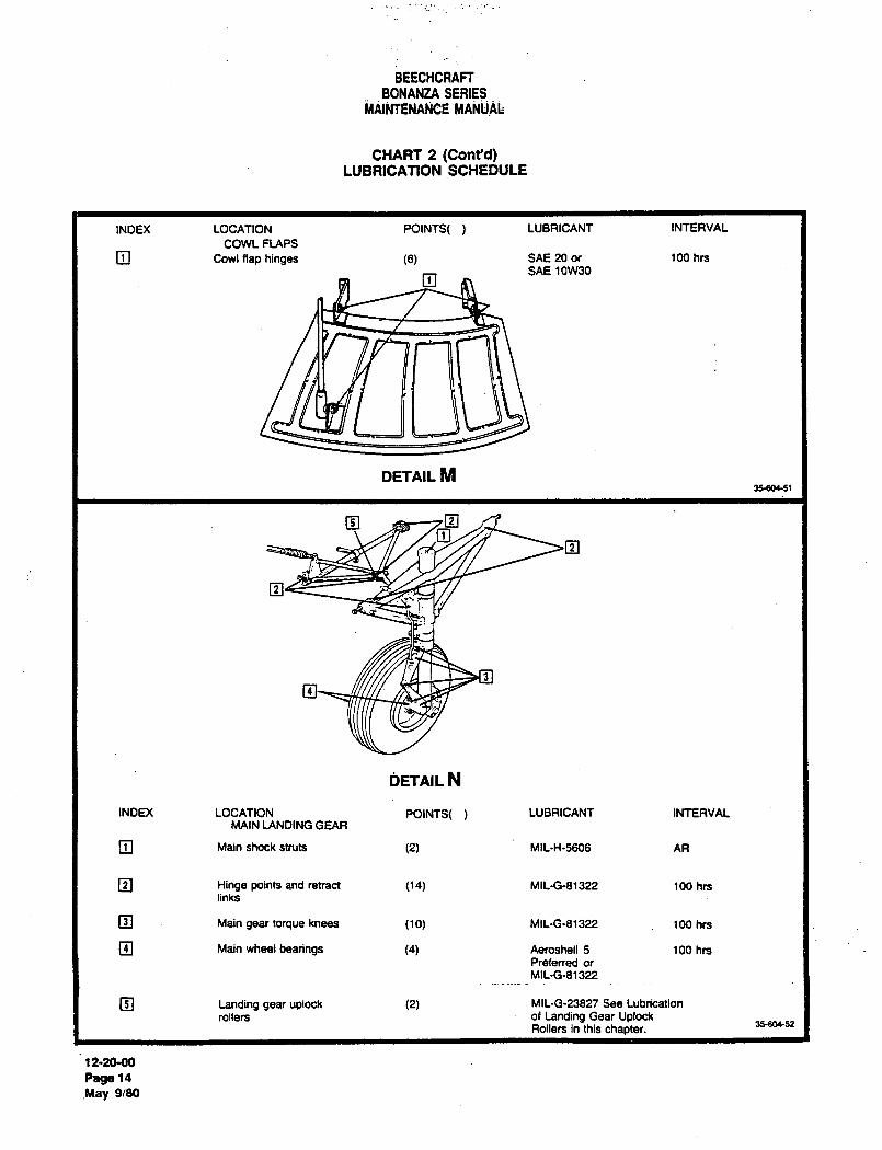
BEECHCRAFT
BONANZA SERIESMAINTENANBE ’MANUA~
CHART 2 (ConPd)LUBRICATION SCHEDULE
INDEX LOCATION POINTS( LUBRICANT INTERVAL
COWL FLAPS
O Cowl flap hinges (6) SAE 20 or 100 hrs
SAE 10W30
DETAIL M35604-51
~3
~ETAIL N
INDEX LOCATION POINTS( LUBRICANT INTERVALMAIN LANDING GEAR
O Main shock struts (2) MlL-H-5606 AR
O Hinge points and retract (14) MlL-G-81322 100 hrslinks
Main gear torque knees (10) MIL-G-81322 100 hrs
O Main wheel bearings (4) Aeroshell 5 100 hrsPreferred or
Mll-G-81 322
O Landing gear uplock (2) MIL-G-23827 See Lubrication
rollers of Landing Gear UplockRollers in this chapter.
35~soe52
12-20-00
Rage 14
May 9/80
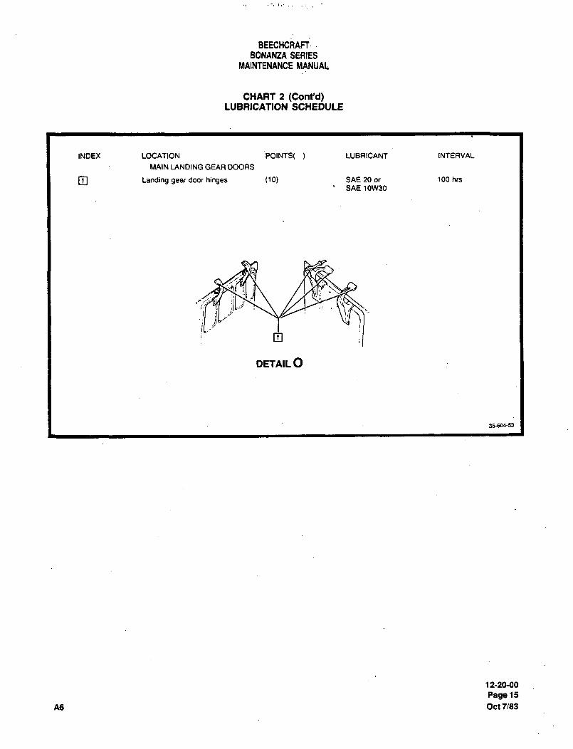
BEECHCRAFT
BONANZA SEAIESMAINTENANCE MANUAL,
CHART 2 (Conrd)LUBRICATION SCHEDULE
INDEX LOCATION POINTS( LUBRICANT INTERVAL
MAIN LANDING GEAR DOORS
O Landing gear door hinges (10) SAE 20 or 100 hrr
SAE 10W30
~i" BL.~
O
DETAIL O
35-604-53
12-20-00
Rage 15
A6 Oct7/83
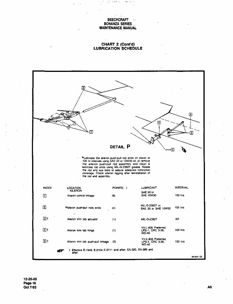
BEECHCRAFfBONANZA SERIES
MAINTENAN~E- MANUAL
CHART 2 (Cont~d)LUBRICATION SCHEDULE
O
o
o
DETAIL Pn9
´•Lubricate the aileron pushjpull rod ends tin place) at
100 hr intervals using SAE 20 or 10W30 oil. or remove
the aileron push/pull rod assembly and clean 6
lubricate rod ends using MILG-23827 grease. Rotate
the rod end eye balls to assure adequate lubrication
coverage. Check aileron rigging aRer reinstallation of
the rod end assembly.
INDEX LOCATION POINTS( LVBRICANT INTERVAL
AILERONSAE 20‘or
O Aileron control linkage (6) SAE 10w30 100 hrs
OM116-23827 or
~ileron push/pull rods ends (4) SAE 20 or SAE 10W30 100 hn
Ot Aileron trim tab actuator (1) MIL-G-23827 AR
W-LBM) Prefened.~t Aileron trim tab hinge (1) LPS-1. CRC 3-36. 100 hrs
WO-40
W-L-800 Preferred.Aileron trim tab push-pull linkage (5) LPS-1. CRC 3-38. 100 hrs
WD-40
t Eneaive 6-1946. E-2104. E-2~11 and after: EA-320. EA-389 and
after.
36-604-122
12-20-00
Page 16
Oct 7/83 A6
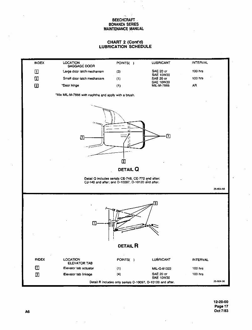
BEECHCRAFI
BONANZA SERIESMAINTENANCE MANUAL;
CHART 2 (Cont~d)LUBRICATION SCHEDULE
INDEX LOCATION POINTS( LUBRICANT INTERVALBAGGAGE DOOR
O Large´•door latch mechanism (3) SAE 20 or 100 hrs
SAE 10W30
O Small door latch mechanism SAE 20 or 100 hrs
SAE 10W30
O ’Door hinge MIL-M-7866 AR
’Mix MIL-M-7866 with naphtha and apply with a brush.
q3 O
DETAIL Q
Detail Q includes serials CE-748. CE-T72 and after:CJ-149 and after: and 0-10097. 0-10120 and after.
35-604-55
-iDETAIL R
INDEX LOCATION POINTS( LUBRICANT INTERVALELNATOR TAB
Elevator tab actuator (1) MIL-G-81322 100 hn
Elevator tab linkage (4) SAE 20 or 100 hrs
SAE 10W30
Detail R includes only serials 0-10097. 0-10120 and after. 35604-56
12-20-00
Rage 17
A6 Oct7/83
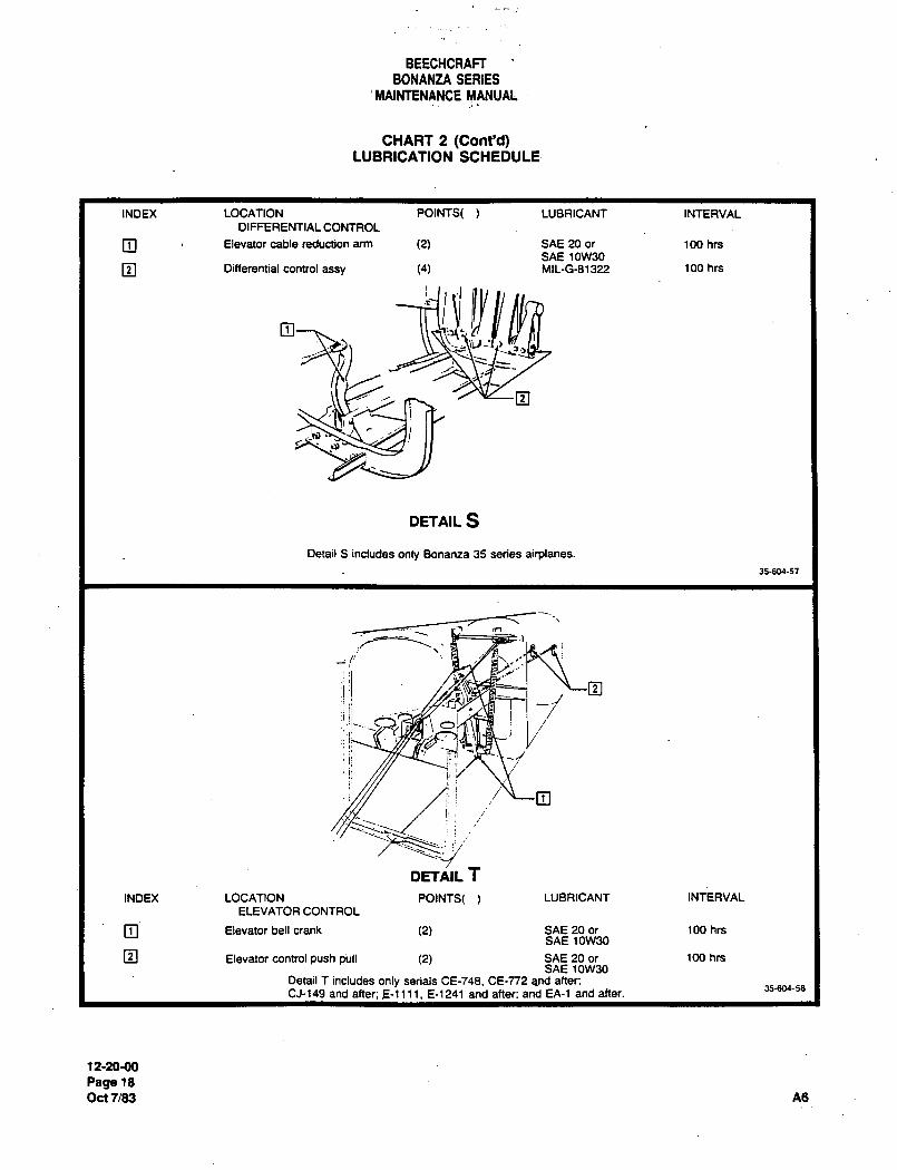
BEECHCRAFT
BONANZA SERIES
’MAINTENANCE MANUAL
CHART 2 (Cont’d)LUBRICATION SCHEDULE
INDEX LOCATION POINTS( LUBRICANT INTERVAL
DIFFERENTIAL CONTROL
Elevator cable reduction arm (2) SAE 20 or 100 hn
SAE 10W30
O Differential control assy (4) MIL-G-81322 100 hrs
3.j
DETAIL S
Detail S includes only Bonanza 35 series airplanes.
35-604-57
jl:I 2
ii!i t7~0!
´•ii
ii
ii
DETA;IL T
INDEX LOCATION POINTS( LUBRICANT INTERVAL
ELEVATOR CONTROL
Elevator bell crank (2) SAE 20 or 100 hrsSAE 10W30
O Elevator control push pull (2) SAE 20 or 100 hrsSAE 10W30
Detail T includes only serials CE-748. CE-772 and after;35-604-58
CJ-149 and after; E-1111. E-~241 and after: and EA-1 and after.
12-211-88
Rage 18
Oct7/83 A6
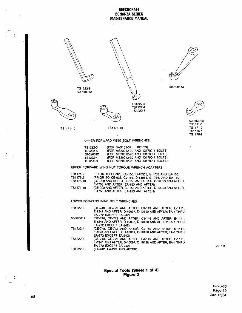
BEECHCRAFTBONANZA SERIES
MAINTENANCE MANUAL
0.
50-590014TS1222-5
50-590012
TS1222-4T51222-8
TS1222-3
50-590013
TS1171-1
TS1171-10 TS1176-10 TS1171-2
TS1176-1
TS1176-2
UPPER FORWARD WING BOLT WRENCHES:
TS1222-3 (FOR NAS152-37 BOLTS)TS1222-5 (FOR MS20012-20 AND 131790-1 BOLTS)50-590012 (FOR MS20012-20 AND 131790-1 BOLTS)TS1222-4 (FOR MS20012-20 AND 131790-1 BOLTS)TS1222-8 (FOR MS20012-20 AND 131790-1 BOLTS)
UPPER FORWARD WING NUT TORQUE WRENCH ADAPTERS:
TS1171-2 (PRIOR TO CE-928, CJ-156, D-10353, E-1758 AND EA-150)TS1176-2 (PRIOR TO CE-928, CJ-156, D-13053, E-1758, AND EA-150)TS1176-10 (CE-928 AND AFTER, CJ-156 AND AFTER, 0-10353 AND AFTER,
E-1758 AND AFTER, EA-~50 AND AFTER)TS1171-10 (CE-928 AND AFTER, CJ-156 AND AFTER. D-10353 AND AFTER,
E-1758 AND AFTER, EA-150 AND AFTER)
LOWER FORWARD WING BOLT WRENCHES:
TS1222-5 (CE-748, CE-772 AND AFTER; 01-149 AND AFTER; E-llll,E-1241 AND AFTER; D-10097, D-10120 AND AFTER; EA-1 THRUEA-272 EXCEPT EA-242)
50-590012 (CE-748, CE-772 AND AFTER; CJ-149 AND AFTER; E-llll.E-1241 AND AFTER; D-10097, D-10120 AND AFTER; EA-1 THRUEA-272 EXCEPT EA-242)
TS1222-4 (CE-748, CE-n2 AND AFTER; CJ-149 AND AFTER; E-llll,E-1241 AND AFTER; D-10097, D-10120 AND AFTER; EA-1 THRUEA-272 EXCEPT EA-242)
TS12228 (CE-748, CE-772 AND AFTER; CJ-149 AND AFTER; E-llll,E-l241 AND AFTER; D-10097, D-10120 AND AFTER; EA-1 THRUEA-272 EXCEPT EA-242) 3617-15
TS1222-3 (EA-242, EA-273 AND AFTER)
Special Tools (Sheet 1 of 4)Figure 2
12-20-00
Page 19
Jan 18/84A8
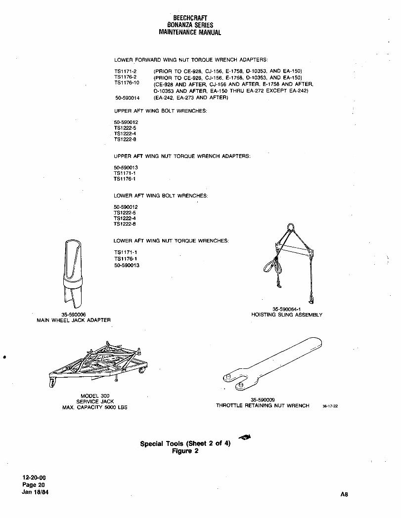
BEECHCRAFTBONANZA SERIES
MAINTENANCE MANUAL
LOWER FORWARD WING NUT TORQUE WRENCH ADAPTERS:
TS1171-2 (PRIOR TO CE-928, CJ-156, E-1758, D-10353, AND EA-150)TS1~76-2 (PRIOR TO CE-928, CJ-156, E-1758, 0-10353, AND EA-150)TS1176-10
(CE-928 AND AFTER. CJ-156 AND AFTER. E-1758 AND AFTER.
0-10353 AND AFTER, EA-150 THRU EA-272 EXCEPT EA-242)
50-590014 (EA-242, EA-273 AND AFTER)
UPPER AFT WING BOLT WRENCHES:
50-590012
TS1 222-5
TS1222-4TS1 222-8
UPPER AFT WING NUT TORQUE WRENCH ADAPTERS:
50-590013
TS1171-1
TS1176-1
LOWER AFT WING BOLT WRENCHES:
50-590012
TS1222-5
TS1 222-4
TS1222-8
LOWER AFT WING NUT TORQUE WRENCHES:
TS1171-1
TS11761 1- ‘V50-590013
35-590064-135-5900~ HOISTING SLING ASSEMBLY
MAIN WHEEL JACK ADAPTER
MODEL 300
SERVICE JACK 35-590009
MAX. CAPACITY 5000 LBS THROTTLE RETAINING NUT WRENCH 36-17-22
Special Taols (Sheet 2 of 4)Figure 2
12-20-00
Page 20
Jan 18/84 A8
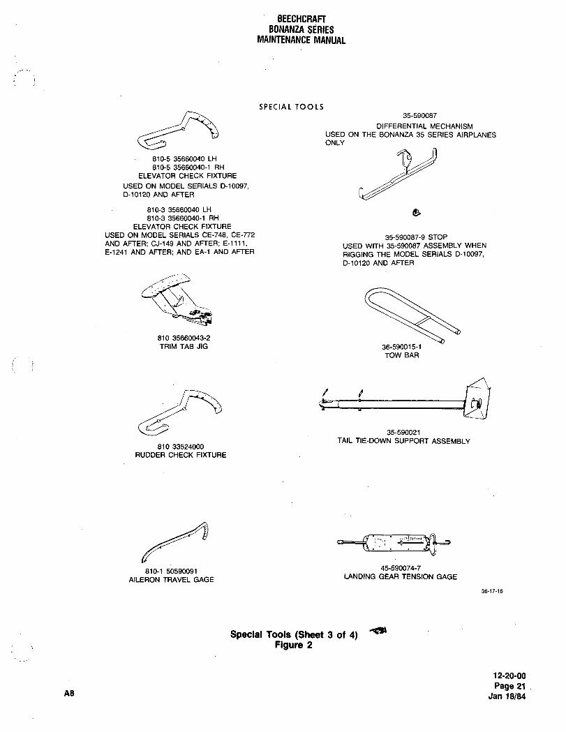
BEECHCRAFTBONANZA SERIES
MAINTENANCE MANUAL
SPECIAL TOOLS35-590087
DIFFERENTIAL MECHANISM
USED ON THE BONANZA 35 SERIES AIRPLANES
ONLY
810-5 35660040 LH
810-5 35660040-1 RH
ELEVATOR CHECK FIXTURE
USED ON MODEL SERIALS D-10097,D-10120 AND AFTER
810-3 35660040 LH 8810-3 35660040-1 RH
ELEVATOR CHECK FIXTURE
USED ON MODEL SERIALS CE-748, CE-772 35-590087-9 STOPAND AFTER; CJ-149 AND AFTER; E-llll, USED WITH 35-590087 ASSEMBLY WHENE-1241 AND AFTER; AND EA-1 AND AFTER RIGGING THE MODEL SERIALS D-10097,
D-10120 AND AFTER
810 35660043-2
TRIM TAB JIG 36-590015-1
TOW BAR
P
35-590021
TAIL TIE-DOWN SUPPORT ASSEMBLY810 33524000
RUDDER CHECK FIXTURE
45-590074-7810-1 50590091
AILERON TRAVEL GAGELANDING GEAR TENSION GAGE
36-17-16
Spclal Tools (Sheet 3 of 4)Figure 2
12-20-00
Page 21As Jan 18184
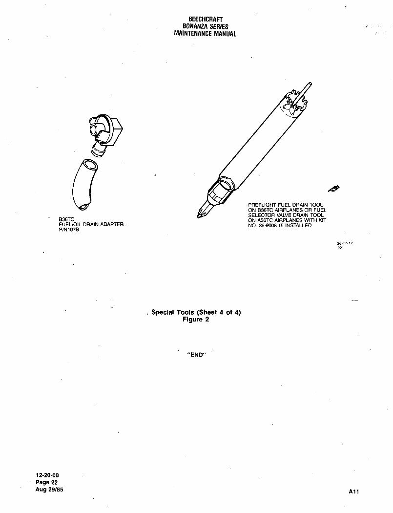
BEECHCRAFTBONANZA SERIES
MAINTENANCE MANUAL
PREFLIGHT FUEL DRAIN TOOL
ON B36TC AIRPLANES OR FUELSELECTOR VALVE DRAIN TOOL
B36TC ON A36TC AIRPLANES WITH KITFUEUOIL DRAIN ADAPTER NO. 36-9008-15 INSTALLEDPIN1O’IB
3617-17001
Special Tools (Sheet 4 of 4)Figure 2
"END"
12-20-00
Page 22
Aug 29/85 Atl

CHAPTER
STANDARD
PRACTICES
(AIRFRAME)
Raydheon nircraft CompanyBONANZA SERIES MAINTENANCE MANUAL
CHAPTER 20 STANDARD PRACTICES AIRFRAME
TABLE OF CONTENTS
SUBJECT PAGE
20-00-00
Standard Practices-Airframe .........1
20´•01 -00
Torque Wrenches
20-02-00
Electrostatic Discharge SensitSvlty- Description and Operation .................1
Electrostatic Discharge Sensitivity Classification ..1
Electrostatic DischargeSensitivity- MaintenancePractices .1
Removal/installation of ESDS Equipment. ..................1
Handling of ESDSComponentsand Equipment ..........3
Controlling StaticCharge Buildup. ..................6
PermanentStatic ControlWorkstation ..................6
Portable Static Control Workstation .8
Humidity and DustEffectson ESDSComponentsand Equipment
Packaging of ESDSComponents and Equipment ........10
Marking of ESDS Components and Equipment ................11
Storage and Transit of ESDS Components and Equipment .12
20-03-00
Electrical Bonding- Descriptionand Operation. ...........1
Electrical Bonding Methods. .......1
Direct Electrical Bonding ......i
Indirect Electrical Bonding ...............1
Electrical Bonding of Tubes .......1
Electrical Power Returns. .........1
Recommended Materials .........2
Electrical Bonding Maintenance Practices. ..............3
Metal Surface Preparation and Electrical Bonding .........3
Aluminum Surfaces. .........3
Corrosion-Resistant (CRES) Steel Surfaces ..........6
StainlessSteel and‘ritanium Surfaces. ..............6
Electrical Bonding Examples. ......6
Typical Blind GroundStud .....6
CRES SteelorTitanium Electrical Bonding ...........6
*26 50-CONTENTS 1
Ral~heon Aircraft CompanyBONANZA SERIES MAINTENANCE MANUAL
CHAPTER 20 STANDARD PRACTICES AIRFRAME
TABLE OF CONTENTS (Continued)
SUBJECT PAGE
Aluminum Electrical Bonding 7.
Tubing Clampto BondingJumper Electrical Bonding 8
Bonding JumperAcrossTubing Clamp Electrical Bonding 8
Typical Ground Stud Electrical Bonding ............._...11
Electrical Bonding of Ground Tabs 11
20-04-00
Control Cables and Pulleys Description and Operation. 1
Recommended Materials 1
ControlCablesand Pulleys- Maintenance Practices. 2
Control Cable System Inspection. 2
Control Cable Storage
Control Cable Pulley Inspection. 4
20-05-00
Bearings- Descriptionand Operation 1
Recommended Materials 1
Bearings- Maintenance Practices 1
Hydraulic Press Bearing Removal 1
Mechanical Press Bearing Removal 1
Bearing Housing Inspection 2
Bearing Installation Using Retaining Compound 2
Bearing Installation By Staking 3
20-06-00
Tube and Hose Assemblies and Fittings Description and Operation 1
Tubing, Hoseand Fmings- MaintenancePractices. 2
Removal of Tubeand HoseAssemblies.........,.,..._
2
Hose Assembly Installation 2
Tube Installation.
Fluid Line Fitting Installation 3
NonpositioningType Fitting Installation 4
PipeThread Fitting Installation 4
Tube Damage Limits
Page2Sep 30/04 20-CONTENTS nne
RByMheOn Aircraft CompanyBONANZA SERIES MAINTENANCE MANUAL
CHAPTER 20 STANDARD PRACTICES AIRFRAME
TABLE OF CONTENTS (Continued)
SUBJECT PAGE
20-07-00
Locking Devices Description And Operation ............,.._._.............1
Self-Locking Nuts
Slotted, Steel Locknuts (Prevailing TorqueType). ................._ .........1
Lockwire and Cotter Pin Requirements. .................1
Locking Devices- Maintenance Practices ................1
Lockwire Installation Procedures........._......._
...1
Lockwire Hole Alignment. .........4
Lockwire TwistingCotter Pin Installation
Keywashers (Taband CupTypes) Installation ............5
Retaining Rings (Spirolox, Etc.) Installation ............,5
Turnbuckle Lock Clip Installation ....5
20-0&00
Airplane Finish Care-Description. ...1
Recommended Materials ..1
Airplane Finish Care- Maintenance Practices ........._..3
Airplane Finish CleaningEnvironmental Fallout(Acid Rain). ................._
..3
Waxing Airplane Finishes .........3
Placard Replacement .........___.
Urethane Paints
Urethane Paint Repair Procedures. .4
Stripping and Cleaning Urethane Paint. .................4
Pretreatment(Wash) PrimerForUrethane Paint ..........5
Urethane Primer
Urethane TopcoatsUrethane Touch-Up Repair. .......5
Painting MagnesiumPaint Removal from Magnesium Surfaces ............6
Painting Magnesium Surfaces .................7
Special Procedures
Propeller Blades.i
Surfaces Susceptible to Mud and Spray .............7
Rubber Seals
EnclosedAreas Subjectto High Humidity ............7
Battery Boxand Lid
I, 50-CONTENTS ,.~Page 3
Raytheon nircraft CompanyBONANZA SERIES MAINTENANCE MANUAL
CHAPTER 20 STANDARD PRACTICES AIRFRAME
TABLE OF CONTENTS (Continued)
SUBJECT PAGE
Paint Free Areas................._
20-0900
Corrosion- DescriptionGalvanic Corrosion
Recommended Materials 3
Corrosion- Maintenance Practices 4
Corrosion Control
Corrosion Protection ..............4
Aluminum Corrosion Removal 4
Removal of Corrosionfrom Aluminum Surfaces 5
Aluminum Corrosion Treatment. 5
Magnesium Corrosion Removal.........._____
5
Magnesium Corrosion Treatment 6
Steel Corrosion Removal
Page 2OICONTENTS A26
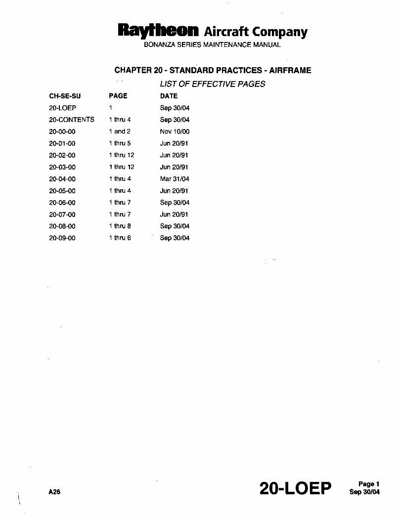
RaytLeOn AiKraft CompanyBONANZA SERIES MAINTENANCE MANUAL
CHAPTER 20 STANDARD PRACTICES AIRFRAME
LIST OF EFFECTIVE PAGES
CH-SE-SU PAGE DATE
20-LOEP 1 Sep 30/04
20-CONTENTS 1 thru 4 Sep 30/04
20-00-00 1 and 2 Nov 10/00
20-01-00 1 thru 5 Jun 20/91
20-02-00 1 thru 12 Jun 20/91
20-03-00 1 thru 12 Jun 20/91
20-04-00 1 thru 4 Mar 31/04
20-05-00 1 thru 4 Jun 20/91
20-06-00 1 thru 7 Sep 30/04
20-07-00 1 thru 7 Jun 20/91
20-08-00 1 thru 8 Sep 30/04
20-09-00 1 thru 6 Sep 30/04
A26 20-LOEP Sep 30/04Page 1
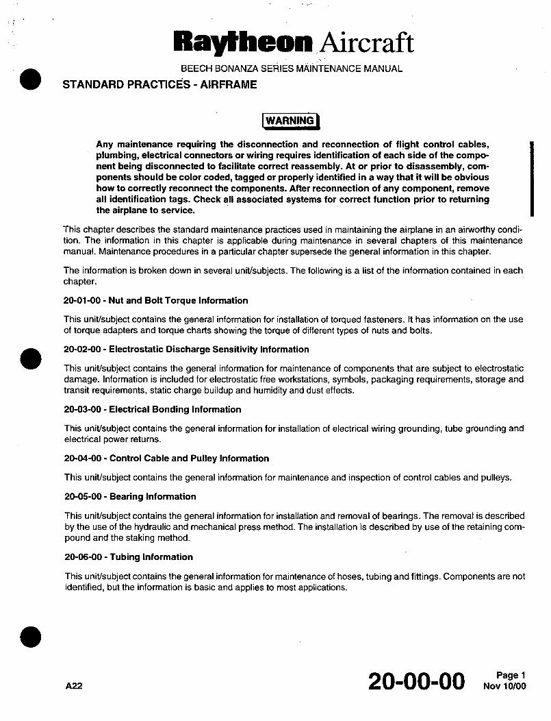
Ral~heon AircraftBEECH BONANZA SERIES MAINTENANCE MANUAL
STANDARD PRACTIC~S -AIRFRAME
I W~RNING)WARNING
Any maintenance requiring the disconnection and reconnection of flight control cables,plumbing, electrical connectors or wiring requires identification of each side of the compo-nent being disconnected to facilitate correct reassembly. At or prior to disassembly, com-
ponents should be color coded, tagged or properly identified in a way that it will be obvious
how to correctly reconnect the components. After reconnection of any component, remove
all identification tags. Check all associated systems for correct function prior to returningthe airplane to service.
This chapter describes the standard maintenance practices used in maintaining the airplane in an airworthy condi-
tion. The information in this chapter is applicable during maintenance in several chapters of this maintenance
manual. Maintenance procedures in a particular chapter supersede the general information in this chapter.
The information is broken down in several unit/subjects. The following is a list of the information contained in each
chapter.
20-01-00 Nut and Bolt Torque Information
This unit/subject contains the general information for installation of torqued fasteners. It has information on the use
of torque adapters and torque charts showing the torque of different types of nuts and bolts.
20-02-00 Electrostatic Discharge Sensitivity Information
This unit/subject contains the general information for maintenance of components that are subject to electrostatic
damage. Information is included for electrostatic free workstations, symbols, packaging requirements, storage and
transit requirements, static charge buildup and humidity and dust effects.
20-03-00- Electrical Bonding Information
This unit/subject contains the general information for installation of electrical wiring grounding, tube grounding and
electrical power returns.
20-04-00 Control Cable and Pulley Information
This unit/subject contains the general information for maintenance and inspection of control cables and pulleys.
20-05-00- Bearing Information
This unit/subject contains the general information for installation and removal of bearings. The removal is described
by the use of the hydraulic and mechanical press method. The installation is described by use of the retaining com-
pound and the staking method.
20-06-00- Tubing Information
This unit/subject contains the general information for maintenance of hoses, tubing and fittings. Components are not
identified, but the information is basic and applies to most applications.
nu 20-00-00
Ray~heon AircraftBEECH BONANZA SERIES MAINTENANCE MANUAL
20-07-00- Fastener Locking Information
This unit/subject contains the general information for the installation of cotter pins, lockwire, tab and cup type key-washers, retaining rings and turnbuckle locking clips.
20-08-00- Airplane Finish Information
This unit/subject contains the general information for maintenance of the finishes used on the airplane and paintremoval and application.
20-09-00- Corrosion Removal and Control Information
This unit/subject contains the general information for the control, treatment and removal of corrosion.
Nov 20-00-00
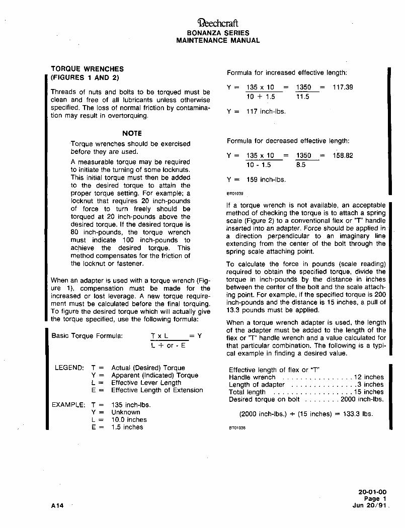
aeechcraftBONANZA SERIES
MAINTENANCE MANUAL
TOROUE WRENCHESFormula for increased effective length:
(FIGURES 1 AND 2)
Y 135 x 10 1350 117.39Threads of nuts and bolts to be torqued must be
10 1.5 11.5clean and free of all lubricants unless otherwise
specified. The loss of normal friction by contamina-y 117 inch-lbs.
tion may result in overtorquing.
NOTE
Torque wrenches should be exercisedFormula for decreased effective length:
before they are used.Y 135 x 10 1350 158.82
A measurable torque may be required 10 -1.5 8.5to initiate the turning of some locknuts.
This initial torque must then be added Y 159 inch-lbs.to the desired torque to attain the
proper torque setting. For example; a BT01039
locknut that requires 20 inch-poundsIf a torque wrench is not available, an acceptableof force to turn freely should bemethod of checking the torque is to attach a spring
torqued at 20 inch-pounds above thescale (Figure 2) to a conventional flex or "T" handle
desired torque. If the desired torque isinserted into an adapter. Force should be applied in
80 inch-pounds, the torque wrencha direction perpendicular to an imaginary line
must indicate 100 inch-pounds toextending from the center of the bolt through the
achieve the desired torque. Thisspring scale attaching point.
method compensates for the friction of
the locknut or fastener. To calculate the force in pounds (scale reading)required to obtain the specified torque, divide the
When an adapter is used with a torque wrench (Fig- torque in inch-pounds by the distance in inches
ure 1), compensation must be made for the between the center of the bolt and the scale attach-
increased or lost leverage. A new torque require- ing point. For example, if the specified torque is 200
ment must be calculated before the final torquing. inch-pounds and the distance is 15 inches, a pull of
To figure the desired torque which will actually give 13´•3 pounds must be applied.the torque specified, use the following formula:
When a torque wrench adapter is used, the lengthof the adapter must be added to the length of the
Basic Torque Formula: T x L Y flex or "T" handle wrench and a value calculated for
L or E that particular combination. The following is a typi-cal example in finding a desired value.
LEGEND: T Actual (Desired) Torque Effective length of flex or "T"Y Apparent (Indicated) Torque Handle wrench .........,.....12 inchesL Effective Lever Length Length of adapter ...............3 inchesE Effective Length of Extension Total length ..................1 5 inches
Desired torque on bolt ........2000 inch-lbs.EXAMPLE: T 135 inch-tbs.
Y Unknown (2000 inch-tbs.) i (15 inches) 133.3 Ibs.L 10.0 inches
E 1.5 inches 8T01038
20-01-00
Page 1
A14 Jun 20/91,
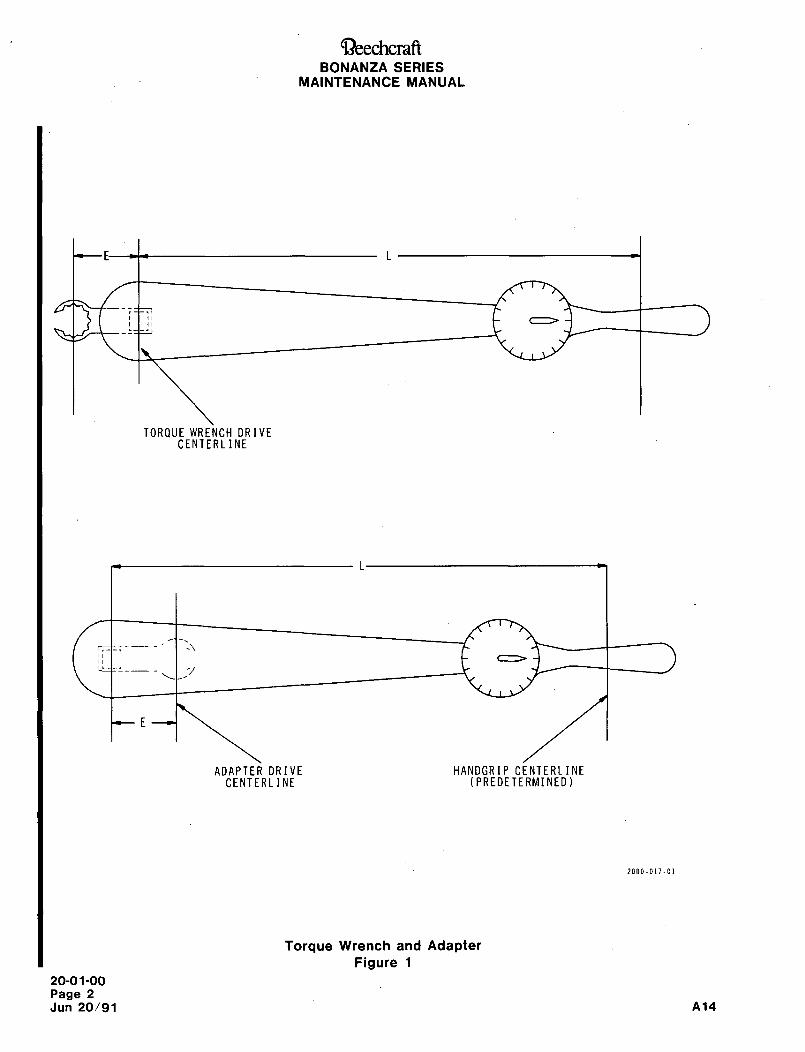
~eechcraftBONANZA SERIES
MAINTENANCE MANUAL
TORQUE WRENCH DRIVECENTERLINE
r
ADAPTER DRIVE HANDGRIP CENTERLINECENTERLINE (PREDETERMINED)
2000-017-01
Torque Wrench and Adapter
Figure 1
20-01-00
Page 2
Jun 20/91 A14
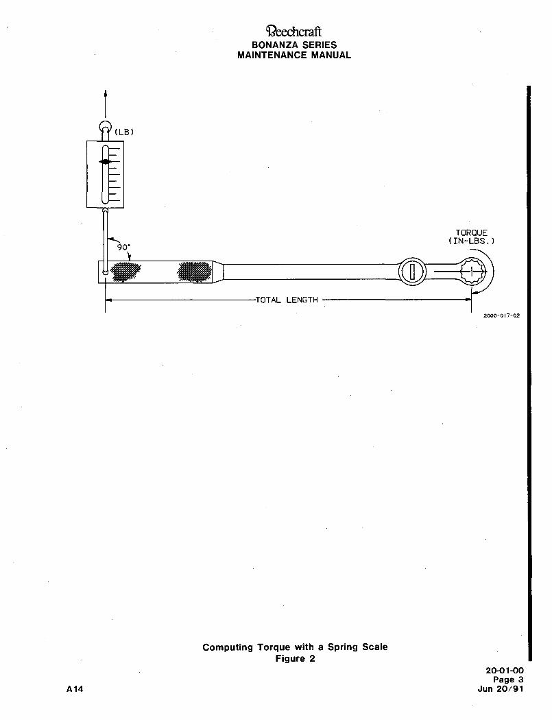
~-)eechcraftBONANZA SERIES
MAINTENANCE MANUAL
(LB)
TORQUE(IN-LBS.)
90’
OTAL LENGTH
2000-017-02
Computing Torque with a Spring Scale
Figure 2
20-01-00
Page 3
A14 Jun 20/91
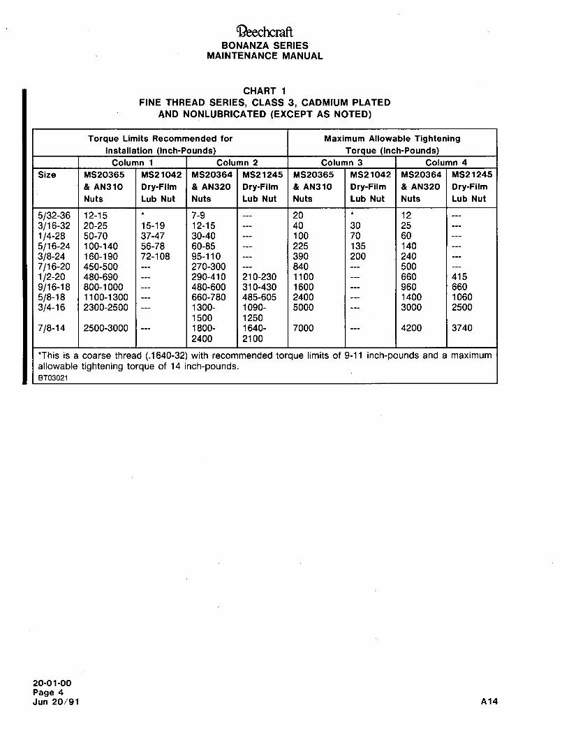
~3eechcraftBONANZA SERIES
MAINTENANCE MANUAL
CHART 1
FINE THREAD SERIES, CLASS 3, CADMIUM PLATED
AND NONLUBRICATED (EXCEPT AS NOTED)
Torque Limits Recommended for Maximum Allowable Tightening
Installation (Inch-Pounds) Torque (Inch-Pounds)
Column 1 Column 2 Column 3 Column 4
Size MS20365 MS21D42 MS20364 MS21245 MS20365 MS21042 MS20364 MS21245
AN310 Dry-Film AN320 Dry-Film AN310 Dry-Film AN320 Dry-Film
Nuts Lub Nut Nuts Lub Nut Nuts Lub Nut Nuts Lub Nut
5/32-36 12-15 1* 1 7-9 1 1 20 1* 1 12
3/1 6-32 20-25 15-19 12-15 1 1 40 30 25
1/4-28 50-70 37-47 30-40 1 Iloo 70 60
5/1 6-24 100-140 56-78 60-85 1 1 225 135 140
3/8-24 160-190 72-108 95-110 1 1 390 200 240
7/1 6-20 450-500 1 1 270-300 1 1 840 1 1 500
1/2-20 480-690 1 1 290-410 210-230 1100 1 1 660 415
9/1 6-18 800-1 000 1 1 480-600 310-430 1600 1 1 960 660
5/8-18 1100-1300 1--- 660-780 485-605 2400 1 11400 1060
3/4-16 2300-2500 1--- 1300- 1090- 5000 1 1 3000 2500
1500 1250
7/8-14 2500-3000 1--- 1800- 1640- 7000 1 1 4200 3740
2400 2100
*This is a coarse thread (.1640-32) with recommended torque limits of 9-11 inch-pounds and a maximum
allowable tightening torque of 14 inch-pounds.BT03021
20-01-00
Page 4
Jun 20/91 A14
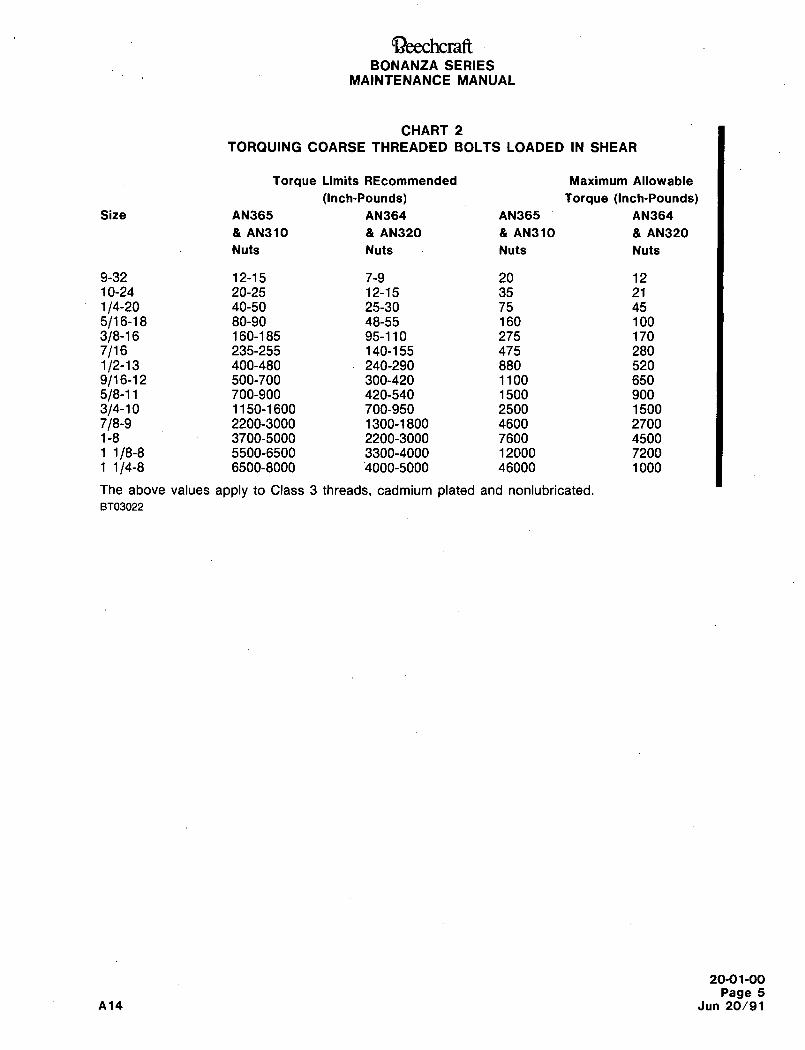
QeechcraRBONANZA SERIES
MAINTENANCE MANUAL
CHART 2
TORQUING COARSE THREADED BOLTS LOADED IN SMEAR
Torque Limits REcommended Maximum Allowable
(Inch-Pounds) Torque (Inch-Pounds)Size AN365 AN364 AN365 AN364
AN310 AN320 AN310 AN320
Nuts Nuts Nuts Nuts
9-32 12-15 7-9 20 12
10-24 20-25 12-15 35 21
1/4-20 40-50 25-30 75 45
5/1 6-18 80-90 48-55 160 100
3/8-16 160-185 95-110 275 170
7/16 235-255 140-155 475 280
1/2-13 400-480 240-290 880 520
9/16-12 500-700 300-420 1100 650
5/8-11 700-900 420-540 1500 900
3/4-10 1150-1600 700-950 2500 1500
7/8-9 2200-3000 1300-1800 4600 27001-8 3700-5000 2200-3000 7600 45001 1/8-8 5500-6500 3300-4000 12000 72001 1/4-8 6500-8000 ’4000-5000 46000 1000
The above values apply to Class 3 threads, cadmium plated and nonlubricated.
8T03022
20-01-00
Page 5
A14 Jun 20/91
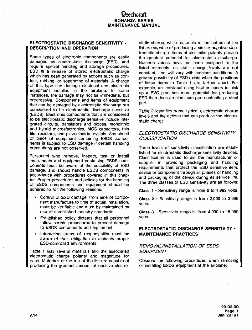
Ci3~eechcraftBONANZA SERIES
MAINTENANCE MANUAL
ELECTROSTATIC DISCHARGE SENSITIVITY static charge, while materials at the bottom of the
DESCRIPTION AND OPERATION list are capable of producing a similar negative elec-
trostatic charge. Items of dissimilar polarity provideSome types of electronic components are easily the greatest potential for electrostatic discharge.damaged by electrostatic discharge (ESD), and Numeric values have not been assigned to therequire special handling and storage procedures, listed materials, as static charge levels are notESD is a release of stored electrostatic charge constant, and will vary with ambient conditions. Awhich has been generated by actions such as con-
greater possibility of ESD exists when the positionstact, rubbing, or separating of materials. A charge of listed items in Table 1 are farther apart. For
this type can damage electrical and electronicexample, an individual using his/her hands to pick
equipment installed in the airplane. In someup a PVC pipe has more potential for producing
instances, the damage may not be immediate, butESD than does an aluminum part contacting a steel
progressive. Components and items of equipmentthat can be damaged by electrostatic discharge are
cart.
considered to be electrostatic discharge sensitive Table 2 identifies some typical electrostatic charge(ESDS). Electronic components that are considered levels and the actions that can produce the electro-to be electrostatic discharge sensitive include inte-
static charge.grated circuits, transistors and diodes, monolithic
and hybrid microelectronics, MOS capacitors, thin
film resistors, and piezoelectric crystals. Any circuit ELECTROSTA TIC DISCHARGE SENSITIVITY
or piece of equipment containing ESDS compo- CLASSIFICATIONnents is subject to ESD damage if certain handlingprecautions are not observed. Three levels of sensitivity classification are estab-
lished for electrostatic discharge sensitivity devices.Personnel who remove, inspect, test or install Classification is used to aid the manufacturer orinstruments and equipment containing ESDS com-
supplier in providing packaging and handlingponents must be aware of the possibility of ESD
requirements that protect the ESD sensitive item,damage, and should handle ESDS components in
device or component through all phases of handlingaccordance with procedures covered in this chap- and packaging of the device during its service life.ter. Proper procedures and policies for the handling The three classes of ESD sensitivity are as follows:of ESDS components and equipment should be
adhered to for the following reasons: Class 1 Sensitivity range is from 0 to 1,999 volts.
Control of ESD damage, from time of compo- Class 2 Sensitivity range is from 2,000 to 3,999nent manufacture to time of actual installation, volts.must be verifiable and must be maintained byuse of established industry standards. Class 3 Sensitivity range is from 4,000 to 15,999
Established policy dictates that all personnel volfs.
follow certain procedures to prevent damageto ESDS components and equipment. ELECTROSTATIC DISCHARGE SENSITIVITY
Interacting areas of responsibility must be MAINTENANCE PRACTICESaware of their obligation to maintain properESD-controlled environments.
REMOVAL/INSTALLA TION OF ESDS
Table 1 lists several materials and the associated EQUIPMENTelectrostatic charge polarity and magnitude for
each. Materials at the top of the list are capable of Observe the following procedures when removingproducing the greatest amount of positive electro- or installing ESDS equipment at the airplane:
20-02-00
Page 1
A14 Jun 20/91
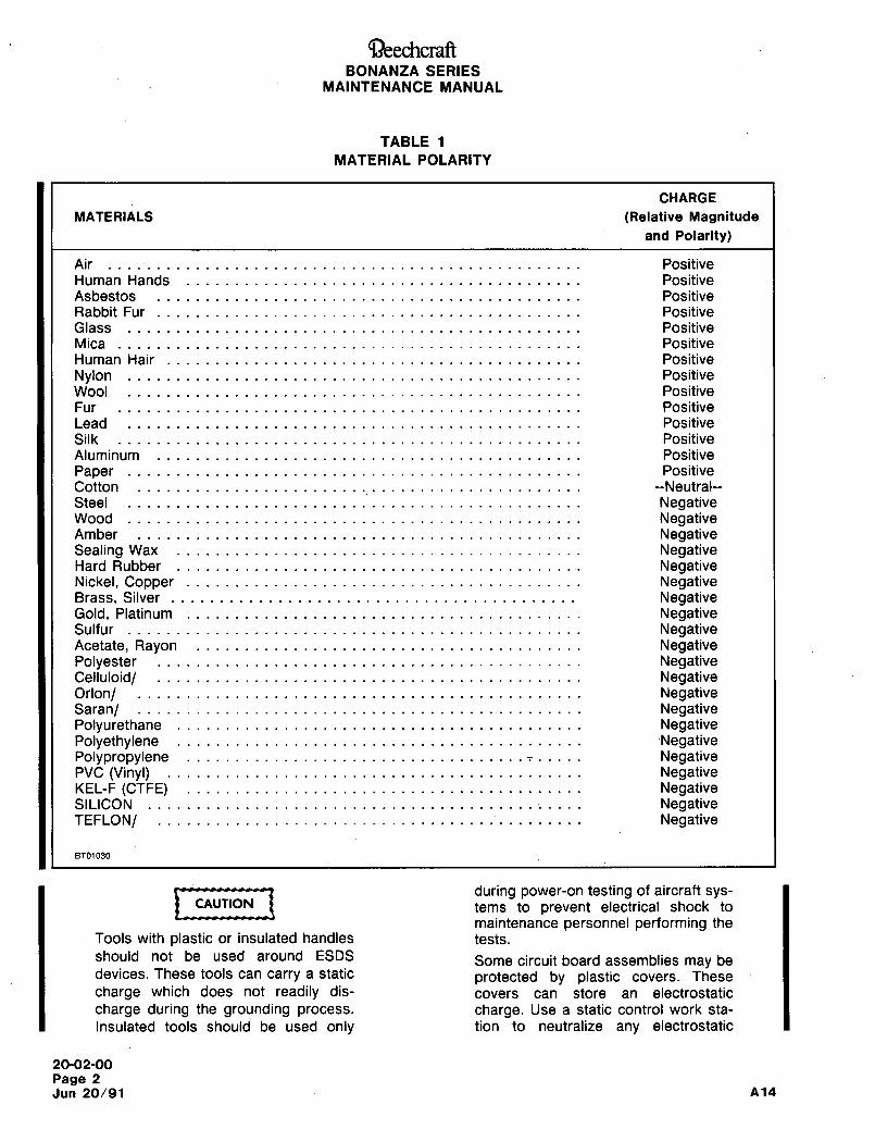
CiZ)eechcraftBONANZA SERIES
MAINTENANCE MANUAL
TABLE 1
MATERIAL POLARITY
CHARGE
MATERIALS (Relative Magnitude
and Polarity)
Air Positive
Human Hands Positive
Asbestos Positive
Rabbit Fur Positive
Glass Positive
Mica Positive
Human Hair Positive
Nylon Positive
Wool Positive
Fur Positive
Lead Positive
Silk Positive
Aluminum Positive
Paper Positive
Cotton --Neutral--
Steel NegativeWood NegativeAmber NegativeSealing Wax NegativeHard Rubber NegativeNickel, Copper NegativeBrass, Silver NegativeGold, Platinum NegativeSulfur NegativeAcetate, Rayon NegativePolyester NegativeCelluloid/ NegativeOrlon/ NegativeSaran/ NegativePolyurethane NegativePolyethylene -NegativePolypropylene NegativePVC (Vinyl) NegativeKEL-F (CTFE) NegativeSILICON NegativeTEFLON/ Negative
BT01030
i ,,,,,,-t during power-on testing of aircraft sys-CAUTION tems to prevent electrical shock to
maintenance personnel performing the
Tools with plastic or insulated handles tests.
should not be used around ESDS Some circuit board assemblies may bedevices. These tools can carry a static protected by plastic covers. These
charge which does not readily dis- covers can store an electrostatic
charge during the grounding process, charge. Use a static control work sta-
Insulated tools should be used only tion to neutralize any electrostatic
20-02-00
Page 2
Jun 20/91 A14
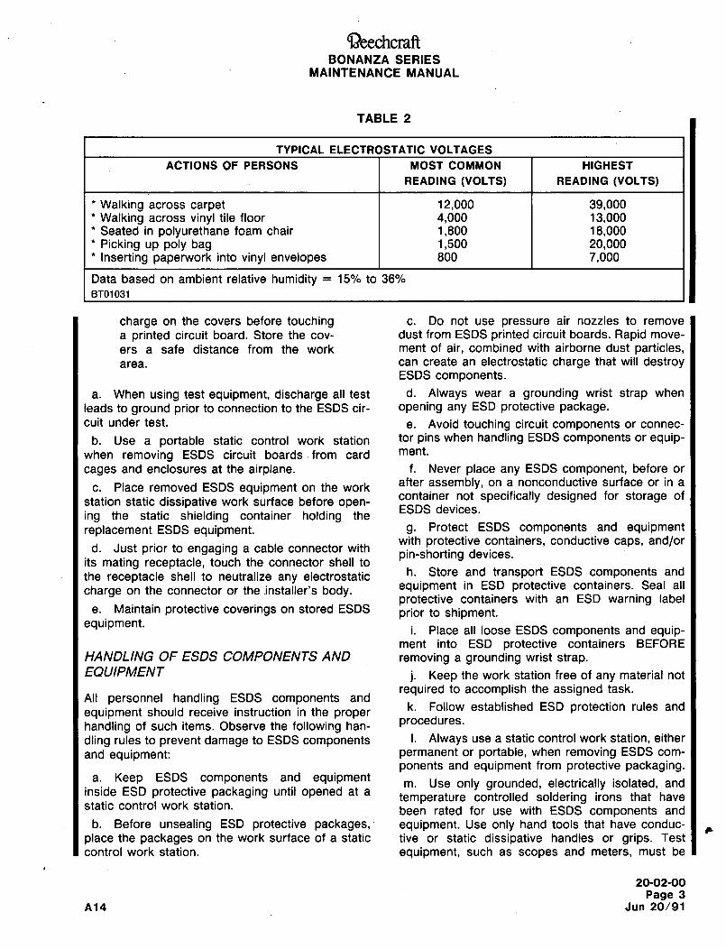
C~)eechcraftBONANZA SERIES
MAINTENANCE MANUAL
TABLE 2
TYPICAL ELECTROSTATIC VOLTAGES
ACTIONS OF PERSONS MOST COMMON HIGHEST
READING (VOLTS) READING (VOLTS)
’Walking across carpet 12,000 39,000’Walking across vinyl tile floor 4,000 13,000
Seated in polyurethane foam chair 1,800 18,000Picking up poly bag 1,500 20,000Inserting paperwork into vinyl envelopes 800 7,000
Data based on ambient relative humidity 15% to 36%
BT01031
charge on the covers before touching c. Do not use pressure air nozzles to remove
a printed circuit board. Store the cov- dust from ESDS printed circuit boards. Rapid move-
ers a safe distance from the work ment of air, combined with airborne dust particles,area. can create an electrostatic charge that will destroy
ESDS components.
a. When using test equipment, discharge all test d. Always wear a grounding wrist strap when
leads to ground prior to connection to the ESDS cir- opening any ESD protective package.cult under test, e. Avoid touching circuit components or connec-
b. Use a portable static control work station tor pins when handling ESDS components or equip-when removing ESDS circuit boards´•from card me"t.
cages and enclosures at the airplane. f. Never place any ESDS component, before or
c. Place removed ESDS equipment on the workafter assembly, on a nonconductive surface or in a
station static dissipative work surface before open-container not specifically designed for storage of
ESDS devices.ing the static shielding container holding the
replacement ESDS equipment. g. Protect ESDS components and equipmentwith protective containers, conductive caps, and/or
d. Just prior to engaging a cable connector withpin-shorting devices.
its mating receptacle, touch the connector shell toh. Store and transport ESDS components and
the receptacle shell to neutralize any electrostatic
charge on the connector or the.installer’s body. equipment in ESD protective containers. Seal all
protective containers with an ESD warning labele. Maintain protective coverings on stored ESDS prior to shipment.
equipment.i. Place all loose ESDS components and equip-
ment into ESD protective containers BEFORE
HANDLING OF ESDS COMPONENTS AND removing a grounding wrist strap.EQUIPMENT j. Keep the work station free of any material not
required to accomplish the assigned task.All personnelhandling ESDS components and
k. Follow established ESD protection rules andequipment should receive instruction in the proper
handling of such items. Observe the following han- procedures.
dling rules to prevent damage to ESDS components I´• Always use a static control work station, either
and equipment: permanent or portable, when removing ESDS com-
ponents and equipment from protective packaging.a. Keep ESDS components and equipment
m. Use only grounded, electrically isolated, andinside ESD protective packaging until opened at a
temperature controlled soldering irons that havestatic control work station.
been rated for use with ESDS components and
b. Before unsealing ESD protective packages,´• equipment. Use only hand tools that have conduc-
place the packages on the work surface of a static tive or static dissipative handles or grips. Test
control work station. equipment, such as scopes and meters, mljst be
20-02-00
Page 3
A14 Jun 20/91
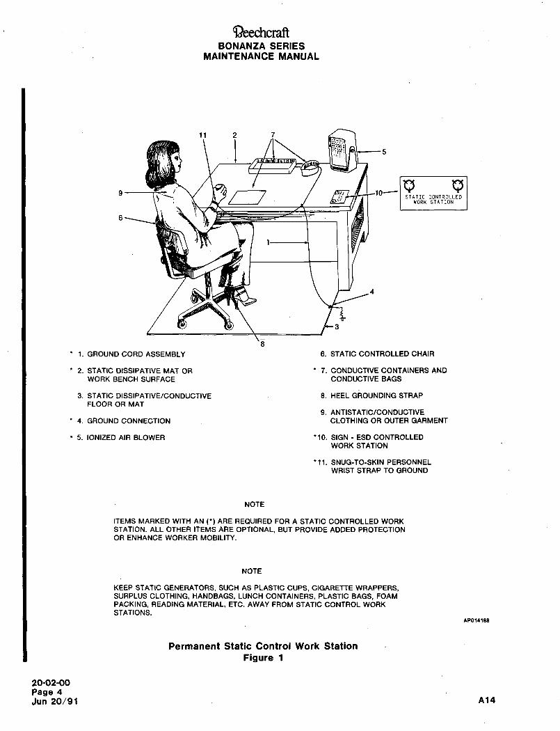
~-)eechcraftBONANZA SERIES
MAINTENANCE MANUAL
11 2 7
91;1 1;1
10~
6 1STATIC CONTROLLED
WORK STATION
1. GROUND CORD ASSEMBLY 6. STATIC CONTROLLED CHAIR
2. STATIC DISSIPATIVE MAT OR 7. CONDUCTIVE CONTAINERS AND
WORK BENCH SURFACE CONDUCTIVE BAGS
3. STATIC DISSIPATIVE/CONDUCTIVE 8. HEEL GROUNDING STRAP
FLOOR OR MAT
9. ANTISTATIC/CONDUCTIVE
4. GROUND CONNECTION CLOTHING OR OUTER GARMENT
1 5. IONIZED AIR BLOWER ’10. SIGN ESD CONTROLLED
WORK STATION
’11. SNUG-TO-SKIN PERSONNEL
WRIST STRAP TO GROUND
NOTE
ITEMS MARKED WITH AN ARE REQUIRED FOR A STATIC CONTROLLED WORK
STATION. ALL OTHER ITEMS ARE OPTIONAL, BUT PROVIDE ADDED PROTECTION
OR ENHANCE WORKER MOBILITY.
NOTE
KEEP STATIC GENERATORS, SUCH AS PLASTIC CUPS, CIGARETTE WRAPPERS,SURPLUS CLOTHING, HANDBAGS, LUNCH CONTAINERS, PLASTIC BAGS, FOAM
PACKING, READING MATERIAL, ETC. AWAY FROM STATIC CONTROL WORK
STATIONS.A~014188
Permanent Static Control Work Station
Figure 1
20-02-00
Page 4
Jun 20/91 A14
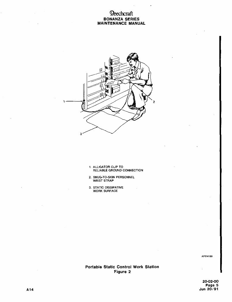
~eechcraftBONANZA SERIES
MAINTENANCE MANUAL
1 2
i. ALLIGATOR CLIP TO
RELIABLE GROUND CONNECTION
2. SNUG-TO-SKIN PERSONNEL
WRIST STRAP
3. STATIC DISSIPATIVE
WORK SURFACE
npol4les
Portable Static Control Work Station
Figure 2
20-02-00
Page 5
A14 Jun 20/91
Ci~)eechcraftBONANZA SERIES
MAINTENANCE MANUAL
rated for use around ESDS components and equip- diverting, to ground, electrostatic charges on con-
ment. ductive objects.
n. Avoid exposing ESDS components and equip- A permanent static control work station consists ofment to large electromagnetic or electrostatic fields the following items:such~ as transformers or transmitting antennas.
CONTROLLING STATIC CHARGE BUILDUP 1~7CAUTION
Four basic techniques are employed in ESD control. Never wear a grounding wrist strapThese are: over clothing. The strap must be in
contact with the wearer’s skin to ade-a. MINIMIZE THE CHARGE BUILDUP Minimize quately dissipate any electrostatic
electrostatic charge buildup by using conductive or charge. Under certain conditions, per-static dissipative flooring and static-dissipative work sonnet using a grounding wrist strapsurfaces. Wear leather shoes, cotton socks, and a may need to use a lotion-type skin
grounding ankle strap to dissipate body charge moisture enhancer to provide a low-
buildup. Wear cotton clothing instead of wool or resistance connection between the
synthetics. Use an ionized air blower to dissipate wrist and the wrist strap.
charges from nonconductive items.
b. DRAIN OFF THE CHARGE TO GROUND The a´• GROUNDING WRIST STRAP Each person
human body is a good electrical conductor and for that handles ESDS components and equipment
that reason electrostatic charges on the body canmust wear a grounding wrist strap to dissipate bod-
be dissipated by skin contact with a grounding ily electrostatic charges. The wrist strap must fit
firm against the skin and release quickly in case ofdevice such as a wrist or ankle strap. Always wear
an emergency. The wrist strap incorporates a 1a grounding wrist strap when opening ESD contain-
megohm current-limiting resistor, in series with theers or handling exposed ESDS components and
ground cord, to protect the wearer from electricalequipment. shock hazards.
c. NEUTRALIZE THE CHARGE Nonconductors, b. STATIC-DISSIPATIVE WORK SURFACEsuch as polystyrene coffee cups, plastic bags, and
Conductive mats on the work bench surface aresome clothing develop electrostatic charges that
designed to remove electrostatic charges from con-cannot be neutralized by grounding. lonized air flow
ductive items placed on the mat.will neutralize an electrostatic charge on a noncon-
c. CONDUCTIVE FLOORING Conductive floor-ductor as long as the ionized air blower puts out
both positive and negative ions, ing is used when additional control of ESD is
required. To maintain total control over ESD, used. MINIMIZE THE EFFECTS OF ELECTRO- conductive chairs, a grounding heel strap, and con-
STATIC FIELDS The immediate environment sur- ductive shoes. Conductive flooring in ESD controlrounding ESDS components and equipment must
areas must be free of all wax or other nonconduc-be free of electrostatic fields or must have suitable tive coatings.static shielding to mlnlmlze induced effects from
d. HARD GROUND CONNECTION Groundingelectrostatic fields.of the static control work station is accomplishedthrough one or more copper ground rods driven
PERMANENT STA TIC CONTROL into moist earth to a depth sufficient to provide a
WORKSTA TION low resistance path from the work station to
(FIGURE I) ground. All work station connections to ground are
made through a one megohm resistor to protectA static control work station provides for static-free work station personnel from electrical shock haz-
handling of ESDS components and equipment by ards by limiting current flow to ground.
20-02-00
Page 6
Jun 20/91 A14
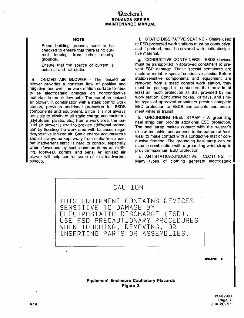
Ci~eechcraftBONANZA SERIES
MAINTENANCE MANUAL
NOTE f. STATIC DISSIPATIVE SEATING Chairs used
Some building grounds need to beat ESD protected work stations must be conductive,
checked to ensure that there is no cur-and if padded, must be covered with static dissipa-
rent looping from other nearby tive material.
grounds. g. CONDUCTIVE CONTAINERS ESDS devices
Ensure that the source of current is must be transported in approved containers to pre-
external and not static. vent ESD damage. These special containers are
made of metal or special conductive plastic. Before
e. IONIZED AIR BLOWER The ionized air static-sensitive components and equipment are
blower provides a constant flow of positive and removed from a static control work station, theynegative ions over the work station surface to neu- must be packaged in containers that provide at
tralize electrostatic charges on nonconductive least as much protection as that provided by the
materials in the air flow path. The use of an ionized work station. Conductive boxes, kit trays, and simi-
air blower, in combination with a static control work lar types of approved containers provide completestation, provides additional protection for ESDS ESD protection to ESDS components and equip-components and equipment. Since it is not always ment while in transit.
possible to eliminate all static charge accumulators h. GROUNDING HEEL STRAP A grounding(styrofoam, plastic, etc.) from a work area, the ion-
heel strap can provide additional ESD protection.ized air blower is used to provide additional protec- The heel strap makes contact with the wearer’stion by flooding the work area with balanced nega- skin at the ankle, and extends to the bottom of foot-tive/positive ionized air. Static charge accumulators
wear to make contact with a conductive mat or con-should always be kept away from static-free areas,
but inadvertent static is hard to control, especiallyductive flooring. The grounding heel strap can be
when developed by such common items as cloth-used in combination with a grounding wrist strap to
ing, footwear, combs, and pens. An ionized air provide maximum ESD protection.
blower will help control some of this inadvertent i. ANTISTATIC/CONDUCTIVE CLOTHING
buildup. Many types of clothing generate electrostatic
CAUTION
THIS EQUIPMENT CONTAINS DEVICESSENSITIVE TO DAMAGE BYELECTROSTATIC DISCHARGE (ESD)USE ESD PRECAUTIONARY~PROCEDURESWHEN TOUCHING, REMOVING, OR
INSERTING PARTS OR ASSEMBLIES,
C
Equipment Enclosure Cautionary Placards
Figure 3
20-02-00
Page 7
A14 Jun 20/91
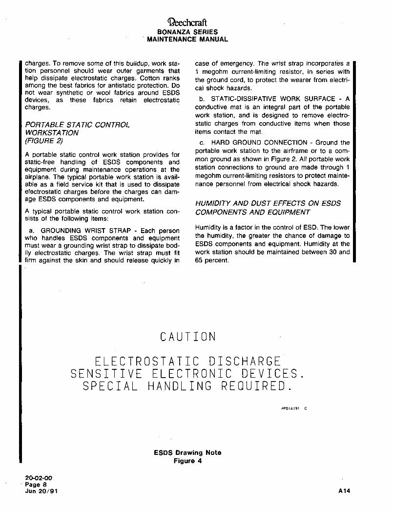
Cil)eechcraftBONANZA SERIES
MAINTENANCE MANUAL
charges. To remove some of this buildup, work sta- case of emergency. The wrist strap incorporates a
tion personnel should wear outer garments that 1 megohm current-limiting resistor, in series with
help dissipate electrostatic charges. Cotton ranks the ground cord, to protect the wearer from electri-among the best fabrics for antistatic protection. Do ,,I shock hazards.not wear synthetic or wool fabrics around ESDS
devices, as these fabrics retain electrostatic b´• STATIC-DISSIPATIVE WORK SURFACE A
charges. conductive mat is an integral part of the portablework station, and is designed to remove electro-
PORTABLE STATIC CONTROL static charges from conductive items when those
WORKSTA TION items contact the mat.
(FIGURE 2) c. HARD GROUND CONNECTION Ground the
portable work station to the airframe or to a com-A portable static control work station provides for
static-free handling of ESDS components andmon ground as shown in Figure 2. All portable work
equipment during maintenance operations at the station connections to ground are made through 1
airplane. The typical portable work station is avail- megohm current-limiting resistors to protect mainte-
able as a field service kit that is used to dissipate nance personnel from electrical shock hazards.
electrostatic charges before the charges can dam-
age ESDS components and equipment.HUMIDITY AND DUST EFFECTS ON ESDS
A typical portable static control work station con- COMPONENTS AND EQUIPMENTsists of the following items:
a. GROUNDING WRIST STRAP Each personHumidity is a factor in the control of ESD. The lower
who handles ESDS components and equipmentthe humidity, the greater the chance of damage to
must wear a grounding wrist strap to dissipate bod- ESDS components and equipment. Humidity at the
ily electrostatic charges. The wrist strap must fit work station should be maintained between 30 and
firm against the skin and should release quickly in 65 percent.
CAUTION
ELECTROSTATIC DISCHARGESENSITIVE ELECTRONIC DEVICES
SPECIAL HANDLING REQUIRED
AP014191
ESDS Drawing Note
Figure 4
20-02-00
Page 8
Jun 20/91 414
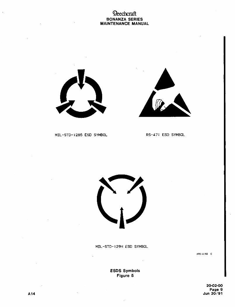
BONANZA SERIES
MAINTENANCE MANUAL
r u
MIL-STD-1285 ESD SYMBOL RS-471 ESD SYMBOL
MIL-STD-129H ESD SYMBOL
AP014193
ESDS SymbolsFigure 5
20-02-00
Page 9
A14 Jun 20/91
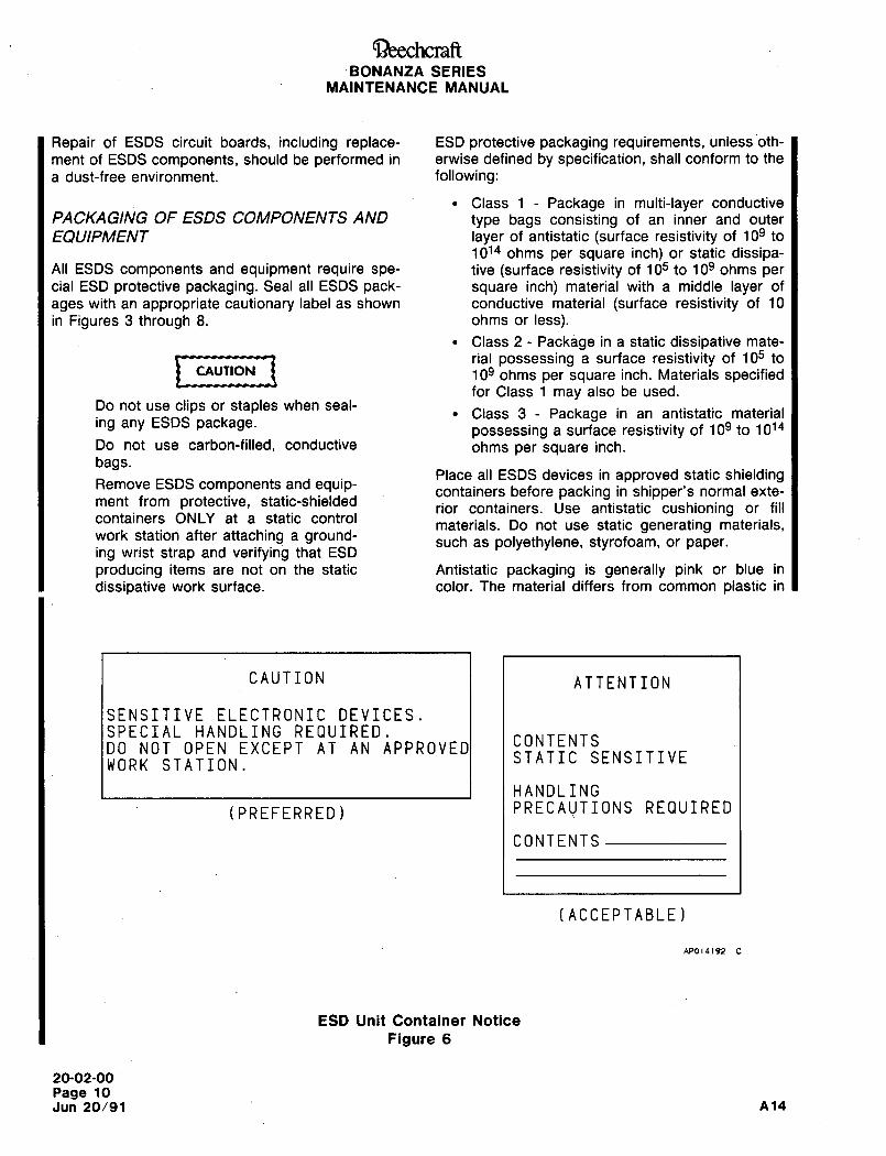
~eechcraft´•BONANZA SERIES
MAINTENANCE MANUAL
Repair of ESDS circuit boards, including replace- ESD protective packaging requirements, unless oth-
ment of ESDS components, should be performed in erwise defined by specification, shall conform to the
a dust-free environment. following:
Class 1 Package in multi-layer conductivePACKAGING OF ESDS COMPONENTS AND type bags consisting of an inner and outer
EQUIPMENT layer of antistatic (surface resistivity of 109 to
1014 ohms per square inch) or static dissipa-All ESDS components and equipment require spe- tive (surface resistivity of 105 to 109 ohms percial ESD protective packaging. Seal all ESDS pack- square inch) material with a middle layer of
ages with an appropriate cautionary label as shown conductive material (surface resistivity of 10
in Figures 3 through 8. ohms or less).
Class 2 Package in a static dissipative mate-
irial possessing a surface resistivity of 105 to
CAUTION 109 ohms per square inch. Materials specifiedfor Class 1 may also be used.
Do not use clips or staples when seal-Class 3 Package in an antistatic material
ing any ESDS package. possessing a surface resistivity of 109 to 1014Do not use carbon-filled, conductive ohms per square inch.
bags.Place all ESDS devices in approved static shielding
Remove ESDS components and equip- containers before packing in shipper’s normal exte-ment from protective, static-shielded
rior containers. Use antistatic cushioning or fillcontainers ONLY at a static control
materials. Do not use static generating materials,work station after attaching a ground- such as polyethylene, styrofoam, or paper.ing wrist strap and verifying that ESD
producing items are not on the static Antistatic packaging is generally pink or blue in
dissipative work surface. color. The material differs from common plastic in
CAUTION ATTENTION
SENSITIVE ELECTRONIC DEVICES.SPECIAL HANDLING REQUIRED.
CONTENTSDO NOT OPEN EXCEPT AT AN APPROVED
STATIC SENSITIVEWORK STATION.
HANDLING
(PREFERRED) PRECAUTIONS REQUIRED
CONTENTS
(ACCEPTABLE)
AP014192
ESD Unit Container Notice
Figure 6
20-02-00
Page 10
Jun 20/91 A14
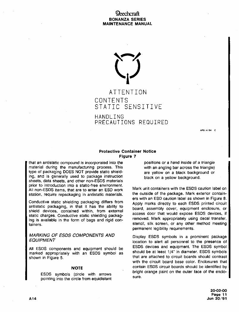
QeechcraftBONANZA SERIES
MAINTENANCE MANUAL
WATTENTION
CONTENTSSTATIC SENSITIVE
HANDLINGPRECAUTIONS REQUIRED
APOI*194
Protective Container Notice
Figure 7
that an antistatic compound is incorporated into the positions or a hand inside of a trianglematerial during the manufacturing process. This with an angling bar across the triangle)type of packaging DOES NOT provide static shield- are yellow on a black background or
ing, and is generally used to package instruction black on a yellow background.sheets, data sheets, and other non-ESDS materials
prior to introduction into a static-free environment.Mark unit containers with the ESDS caution label onAll non-ESDS items, that are to enter an ESD work
station, require repackaging in antistatic materials. the outside of the package. Mark exterior contain-
ers with an ESD caution label as shown in Figure 8.Conductive static shielding packaging differs from
Apply marks directly to each ESDS printed circuitantistatic packaging, in that it has the ability to
board, assembly cover, equipment enclosure, orshield devices, contained within, from external
access door that would expose ESDS devices, ifstatic charges. Conductive static shielding packag-ing is available in the form of bags and rigid con-
removed. Mark appropriately using decal transfer,
tainers. stencil, silk screen, or any other method meetingpermanent legibility requirements.
MARKING OF ESDS COMPONENTS AND Display ESDS symbols in a prominent packageEQUIPMENT location to alert all personnel to the presence of
ESDS devices and equipment. The ESDS symbolAll ESDS components and equipment should be
marked appropriately with an ESDS symbol asshould be at least 1/4" in diameter. ESDS symbols
shown in Figure 5. that are attached to circuit boards should contrast
with the circuit board base color. Enclosures that
NOTE contain ESDS circuit boards should be identified by
ESDS symbols (circle with arrowsbright orange paint on the outer face of the enclo-
sure.pointing into the circle from equidistant
20-02-00
Page 11
Ai4 Jun 20/91
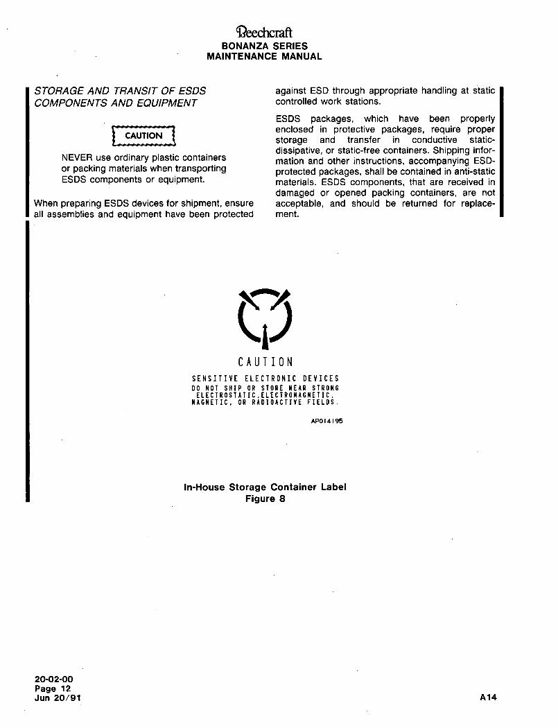
~)eechcraftBONANZA SERIES
MAINTENANCE MANUAL
STORAGE AND TRANSIT OF ESDS against ESD through appropriate handling at static
COMPONENTS AND EQUIPMENT controlled work stations.
ESDS packages, which have been properly
1 UUIIOK~1 enclosed in protective packages, require properCAUTION
storage and transfer in conductive static-
dissipative, or static-free containers. Shipping infor-NEVER use ordinary plastic containers mation and other instructions, accompanying ESD-or packing materials when transporting protected packages, shall be contained in anti-staticESDS components or equipment, materials. ESDS components, that are received in
damaged or opened packing containers, are not
When preparing ESDS devices for shipment, ensure acceptable, and should be returned for replace-all assemblies and equipment have been protected ment.
CAUTION
SENSITIVE ELECTRONIC DEVICES
DO NOT SHIP OR STORE NEAR STRONGELECTROSTATIC.ELECTROIAGNETIC.
WAGNETIC, OR RIDIOACTIYE FIELDS.
APO 14195
In-House Storage Container Label
Figure 8
20-02-00
Page 12
Jun 20/91 A14
Ci~)eechcraftBONANZA SERIES
MAINTENANCE MANUAL
ELECTRICAL BONDING DESCRIPTION AND INDIRECT ELECTRICAL BONDING
OPERATIONWhen direct electrical bonding methods are imprac-
The.following terms are defined as used in the sys-tical, indirect bonding methods are used. Indirect
tem description:electrical bonding is most commonly accomplishedby using bonding jumpers to make the desired con-
ELECTRICAL BOND: A reliable electrical con- nection. These flexible metal straps are attached to
nection between conductive parts which pro-a p’epared metal surface using screws, studs, nuts
vides electrical conductivity. and washers. The connection is always as short as
possible and uses a single jumper. Two bondingELECTRICAL BONDING: Conductive parts are jumpers connected in a series is unacceptable, as
considered electrically bonded when they are this can double the resistance between the groundmechanically interconnected to maintain a plane and bonded component. Bonding jumpers are
common electrical potential. also used to electrically connect tubes between
GROUND: A conducting connection, whether joi"ts.
intentional or accidental, by which an electrical
current or equipment is connected to maintainCAUTION
a common electrical potential.
Anytime maintenance is performed on
ELECTRICAL BONDING METHODS or around these flexible bonding jump-ers, the wire should not be bent or
There are two basic types of electrical bonding; damaged as this has a tendency to
direct and indirect. Both are accomplished by using weaken the jumper and reduce its
mechanical methods to attach the electrical conduc- effectiveness. "Waggling" the bondingtors. Bolts, rivets, conductive laminates, flashing jumper to see if the end terminals are
and bonding jumpers are commonly used. tight is unacceptable as this may also
induce fatigue on the crimped portionWhether direct or indirect, all electrical bonding of the bonding jumper.must reflect high maintenance standards to main-
tain the electrical integrity. Many times, an ill- Indirect electrical bonding is also used to connect
prepared surface may initially provide sufficient the airplane wire harness shielding terminals to a
grounding properties, but experience a rapid deteri- ground. The tubular braiding attaches t~ the electri-
oration in conductivity when corrosion from contam- cal connectors with clamps and shields the airplaneinants or moisture appears on the bonding surface. wi’e harness for its entire length.All bonding surfaces should be free of primer or
coatings not compatible with electrical conductance. ELECTRICAL BONDING OF TUBESThis includes but is not limited to, all protectivefilms such as anodize, grease, oil, paint, lacquer, or
All metallic tubes that carry petroleum products or
other finishes with high resistance properties. Once other fluids, including gases, must have a mechani-
the electrical bonding surface is cleaned, and the cally secure connection to the ground plane for
necessary protective coatings applied, the compo-static dissipation. Plumbing sections must be elec-
trically bonded to each other to eliminate a potentialnent is installed and a resistance check is per- electrical charge on the individual segments. Conti-formed to verify continuity of the electrical bond.
nuity between the plumbing segments is achieved
with electrical bonding clamps or jumpers. Electrical
DIRECT ELECTRICAL BONDING bonding clamps, used in some applications, have a
wire that contacts the plumbing on either side of the
Direct electrical bonds are frequently used for clamp, ensuring continuity across the joint.metal-to-metal joints. Before assembly, the jointsare treated with a conductive film that prevents cor- ELECTRICAL POWER RETURNSrosion of the bonding surface. Most direct electrical
bonds involve the installation of components on alu- Electrical power returns should be direct with the
minum. shortest possible path from the operating equip-
20-03-00
Page 1
A14 Jun 20/91
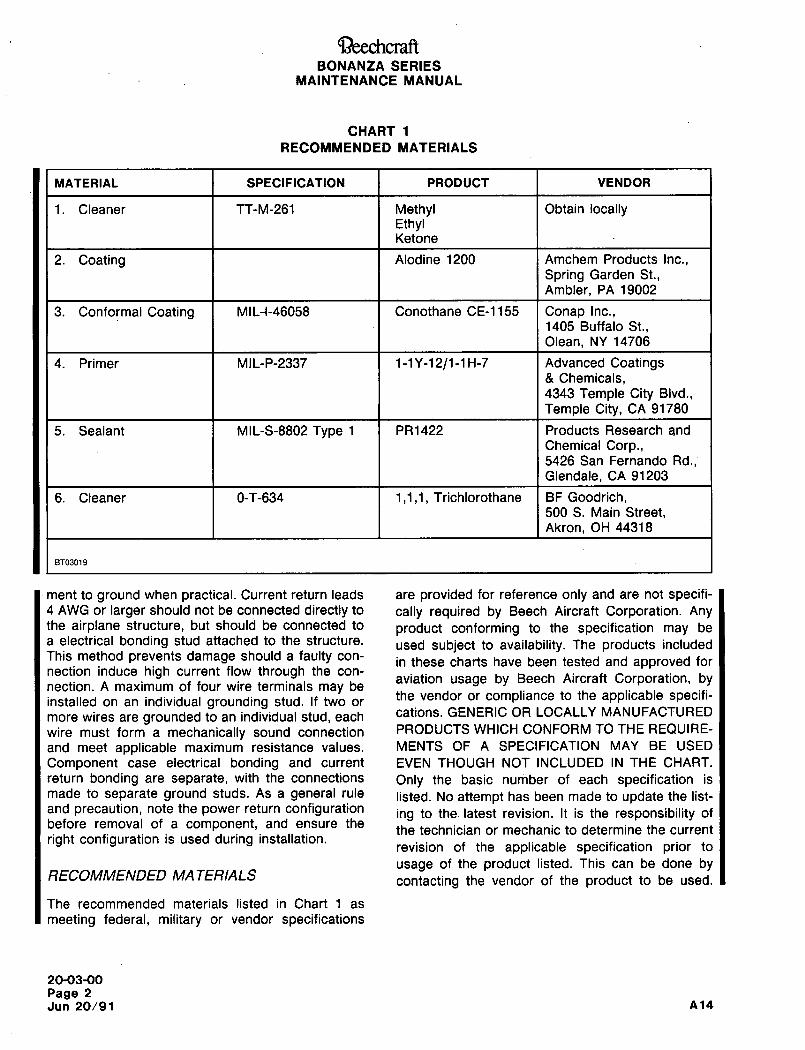
C~)eechcraftBONANZA SERIES
MAINTENANCE MANUAL
CHART 1
RECOMMENDED MATERIALS
MATERIAL SPECIFICATION PRODUCT VENDOR
1. Cleaner TT-M-261 Methyl Obtain locallyEthylKetone
2. Coating Alodine 1200 Amchem Products Inc.,
Spring Garden St.,Ambler, PA 19002
3. Conformal Coating MIL-I-46058 Conothane CE-1155 Conap Inc.,1405 Buffalo St.,Olean, NY 14706
4. Primer M1L-P-2337 1-1Y-12/1-1H-7 Advanced Coatings8 Chemicals,4343 Temple City Bivd.,Temple City, CA 91780
5. Sealant MIL-S-8802 Type 1 PR1422 Products Research and
Chemical Corp.,5426 San Fernando Rd.,Glendale, CA 91203
6. Cleaner 0-T-634 1,1,1, Trichlorothane BF Goodrich,500 S. Main Street,Akron, OH 44318
BT03019
ment to ground when practical. Current return leads are provided for reference only and are not specifi-4 AWG or larger should not be connected directly to cally required by Beech Aircraft Corporation. Anythe airplane structure, but should be connected to product conforming to the specification may bea electrical bonding stud attached to the structure. used subject~to availability. The products includedThis method prevents damage should a faulty con-
in these charts have been tested and approved fornection induce high current flow through the con-
aviation usage by Beech Aircraft Corporation, by´•nection. A maximum of four wire terminals may be
installed on an individual grounding stud. If two orthe vendor or compliance to the applicable specifi-
more wires are grounded to an individual stud, each cations. GENERIC OR LOCALLY MANUFACTURED
wire must form a mechanically sound connection PRODUCTS WHICH CONFORM TO THE REQUIRE-
and meet applicable maximum resistance values. MENTS OF A SPECIFICATION MAY BE USED
Component case electrical bonding and current EVEN THOUGH NOT INCLUDED IN THE CHART.
return bonding are separate, with the connections Only the basic number of each specification is
made to separate ground studs. As a general rule listed. No attempt has been made to update the list-and precaution, note the power return configuration ing to the. latest revision. It is the responsibility ofbefore removal of a component, and ensure the
the technician or mechanic to determine the currentright configuration is used during installation.
revision of the applicable specification prior to
usage of the product listed. This can be done byRECOMMENDED MA TERIALS
contacting the vendor of the product to be used.
The recommended materials listed in Chart 1 as
meeting federal, military or vendor specifications
20-03-00
Page 2
Jun 20/91 A14
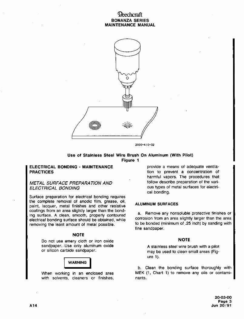
~iS)eechcraftBONANZA SERIES
MAINTENANCE MANUAL
2000-610-32
Use of Stainless Steel Wire Brush On Aluminum (With Pilot)Figure 1
ELECTRICAL BONDING MAINTENANCE provide a means of adequate ventila-
PRACTICES tion to prevent a concentration of
harmful vapors. The procedures that
METAL SURFACE PREPARATION AND follow describe preparation of the vari-
ELECTRICAL BONDING ous types of metal surfaces for electri-
cal bonding.Surface preparation for electrical bonding requiresthe complete removal of anodic film, grease, oil,
ALUMINUM SURFACESpaint, lacquer, metal finishes and other resistive
coatings from an area slightly larger than the bond-
ing surface. A clean, smooth, properly contoureda. Remove any nonsoluble protective finishes or
electrical bonding surface should be obtained, while corrosion from an area slightly larger than the area
removing the least amount of metal possible. to be bonded (minimum of .25 inch) by sanding with
fine sandpaper.
NOTE
Do not use emery cloth or iron oxide NOTE
sandpaper. Use only aluminum oxide A stainless steel wire brush with a pilotor silicon carbide sandpaper. may be used to clean small areas (Fig-
ure 1).
I -´•~´•´•Ib. Clean the bonding surface thoroughly with
WARNING
When working in an enclosed area MEK (1, Chart 1) to remove any oils or contami-
with solvents, cleaners or finishes, nants.
20-03-00
Page 3
A14 ´•Jun 20/91
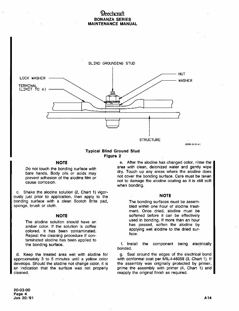
BONANZA SERIESMAINTENANCE MANUAL
BLIND GROUNDING STUD
NUT
LOCK WASHERWASHER
TERMINAL(LIMIT TO 41
STRUCTURE
20M)-~IO-41
Typical Blind Ground Stud
Figure 2
NOTE e. After the alodine has changed color, rinse the
Do not touch the bonding surface witharea with clean, deionized water and gently wipe
bare hands. Body oils or acids maydry. Touch up any areas where the alodine does
prevent adhesion of the alodine film ornot cover the bonding surface. Care must be taken
cause corrosion. not to damage the alodine coating as it is still soft
when bonding.
c. Shake the alodine solution (2, Chart 1) vigor-ously just prior to application, then apply to the NOTE
bonding surface with a clean Scotch Brite pad, The bonding surfaces must be assem-
sponge, brush or cloth. bled within one hour of alodine treat-
ment. Once dried, alodine must be
NOTE softened before it can be effectively
The alodine solution should have anused in bonding. If more than an hour
amber color. If the solution is coffeehas passed, soften the alodine by
colored, it has been contaminated. applying wet alodine to the dried sur-
face.Repeat the cleaning procedure if con-
taminated alodine has been applied to
the bonding surface. f. Install the component being electricallybonded.
d. Keep the treated area wet with alodine for g. Seal around the edges of the electrical bond
approximately 3 to 5 minutes until a yellow color with conformal coat per MIL-I-46058 (3, Chart 1). If
develops. Should the alodine not change color, it is the assembly was originally protected by primer,an indication that the surface was not properly prime the assembly with primer (4, Chart 1) and
cleaned. reapply the original finish as required.
20-03-00
Page 4
Jun 20/91 A14
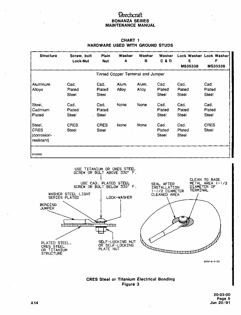
aeechcraftBONANZA SERIES
MAINTENANCE MANUAL
CHART 1
HARDWARE USED WITH GROUND STUDS
Structure Screw, bolt Plain Washer Washer Washer Lock Washer Lock Washer
Lock-Nut Nut A B C&D E F
MS35338 MS35338
Tinned Copper Terminal and Jumper
Aluminum Cad. Cad. Alum. Alum. Cad. Cad. Cad.
Alloys Plated Plated Alloy Alloy Plated Plated Plated
Steel Steel Steel Steel Steel
Steel, Cad. Cad. None None Cad. Cad. Cad.
Cadmium Plated Plated Plated Plated Plated
Plated Steel Steel Steel Steel Steel
Steel, CRES CRES None None Cad. Cad. CRES
CRES Steel Steel Plated Plated Steel
(corrosion- Steel Steel
resistant)
BT03020
USE TITANIUM OR CRES STEELSCREW OR BOLT ABOVE 330’ F.
CLEAN TO BASEUSE CAD. PLATED STEEL SEAL AFTER METAL AREA 1-1/2
SCREW OR BOLT BELOW 330’ F. INSTALLATION DIAMETER OF
j-1/2DIAMETER TERMINALWASHER STEEL LIGHT CLEANED AREASERIES PLATED I LOCK-WASHER
BONDINGJUMPER
PLATED STEEL, SELF-LOCKING NUT
CRES STEEL OR SELF-LOCKING
OR TITANIUM PLATE NUT
STRUCTURE
2000-610-33
CRES Steel or Titanium Electrical Bonding
Figure 3
20-03-00
Page 5
A14 Jun 20/91
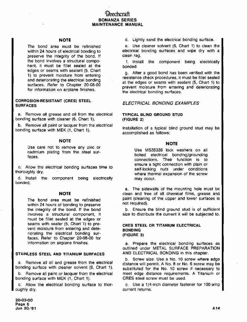
Ci~echcraftBONANZA SERIES
MAINTENANCE MANUAL
NOTE d. Lightly sand the electrical bonding surface.
The bond area must be refinished e. Use cleaner solvent (6, Chart 1) to clean the
within 24 hours of electrical bonding to electrical bonding surfaces and wipe dry with a
preserve the integrity of the bond. If clean rag.
the bond involves a structural compo- f. Install the component being electricallynent, it must be fillet sealed at the bonded.
edges or seams with sealant (5, Chartg. After a good bond has been verified with the
1) to prevent moisture from entering resistance check procedures, it must be fillet sealedand deteriorating the electrical bonding
at the edges or seams with sealant (5, Chart 1) tosurfaces. Refer to Chapter 20-08-00
prevent moisture from entering and deterioratingfor information on airplane finishes.the electrical bonding surfaces.
CORROSION-RESISTANT (CRES) STEELELECTRICAL BONDING EXAMPLES
SURFACES
a. Remove all grease and oil from the electrical TYPICAL BLIND GROUND STUD
bonding surface with cleaner (6, Chart 1). (FIGURE 2)
b. Remove all paint or lacquer from the electrical
bonding surface with MEK (1, Chart 1).Installation of a typical blind ground stud may be
accomplished as follows:
NOTENOTE
Use care not to remove any zinc orUse MS35338 lock washers on all
cadmium plating from the steel sur-bolted electrical bonding/groundingfaces.connections. Their function is to
ensure a tight connection with plain orc. Allow the electrical bonding surfaces time to
self-locking nuts under conditionsthoroughly dry. where thermal expansion of the screw
d. Install the component being electrically may occur.
bonded.
a. The sidewalls of the mounting hole must be
NOTE clean and free of all chemical films, grease and
The bond area must be refinished paint (cleaning of the upper and lower surfaces is
within 24 hours of bonding to preservenot required).
the integrity of the bond. If the bond b. Ensure the blind ground stud is of sufficient
involves a structural component, it size to distribute the current it will be subjected to.
must be fillet sealed at the edges or
seams with sealer (5, Chart 1) to pre- ORES STEEL OR TITANIUM ELECTRICALvent moisture from entering and dete- BONDINGriorating the electrical bonding sur- (FIGURE 3)faces. Refer to Chapter 20-08-00 for
information on airplane finishes, a. Prepare the electrical bonding surfaces as
outlined under METAL SURFACE PREPARATION
STAINLESS STEEL AND TITANIUM SURFACES AND ELECTRICAL BONDING in this chapter.
b. Screw size: Use a No. 10 screw where edgea. Remove all oil and grease from the electrical distance will permit. A No. 8 or No. 6 screw may be
bonding surface with cleaner solvent (6, Chart 1). substituted for the No. 10 screw if necessary to
b. Remove all paint or lacquer from the electrical meet edge distance requirements. A Titanium or
bonding surface with MEK (1, Chart 1). CRES steel screw must be used.
c. Allow the electrical bonding surface to thor- c. Use a 1/4-inch diameter fastener for 100-ampoughly dry, current returns.
20-03-00
Page 6Jun 20/91 A14
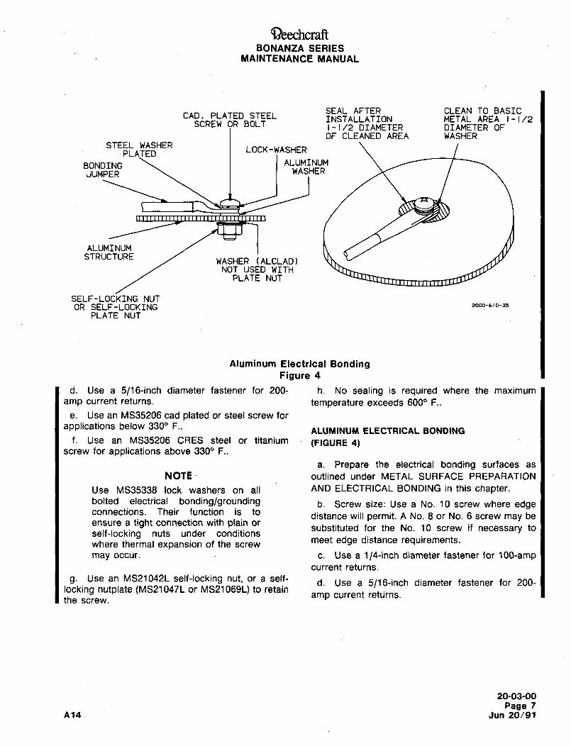
~)eechcraftBONANZA SERIES
MAINTENANCE MANUAL
SEAL AFTER CLEAN TO BASICCAD. PLATEDSTEEL INSTALLATION METAL AREA 1-1/2
SCREW OR BOLT 1-1/2 DIAMETER DIAMETER OFOF CLEANED AREA WASHER
STEEL WASHERLOCK-WASHER
PLATED
BONDING ALUMINUM
JUMPER WASHER
ALUMINUMSTRUCTURE
WASHER (ALCLAD)NOT USED WITH
PLATE NUT
SELF-LOCKING NUT(3R SELF-LOCKING 2000-610-35
PLATE NUT
Aluminum Electrical BondingFigure 4
d. Use a 5/16-inch diameter fastener for 200- h. No sealing is required where the maximum
amp current returns. temperature exceeds 6000 F..
e. Use an MS35206 cad plated or steel screw for
applications below 3309 F..ALUMINUM ELECTRICAL BONDING
f. Use an MS35206 CRES steel or titanium (FIGURE 4)screw for applications above 3300 F..
a. Prepare the electrical bonding surfaces as
NOTE outlined under METAL SURFACE PREPARATION
Use MS35338 lock washers on all AND ELECTRICAL BONDING in this chapter.bolted electrical bonding/grounding b. Screw size: Use a No. 10 screw where edgeconnections. Their function is to
distance will permit. A No. 8 or No. 6 screw may beensure a tight connection with plain or
self-locking nuts under conditionssubstituted for the No. 10 screw if necessary to
where thermal expansion of the screwmeet edge distance requirements.
may occur, c. Use a 1/4-inch diameter fastener for 100-ampcurrent returns.
g. Use an MS21042L self-locking nut, or a self-d. Use a 5/16-inch diameter fastener for 200-
locking nutplate (MS21047L or MS21069L) to retainamp current retLjrns.
the screw.
20-03-00
Page 7
A14 Jun 20/91
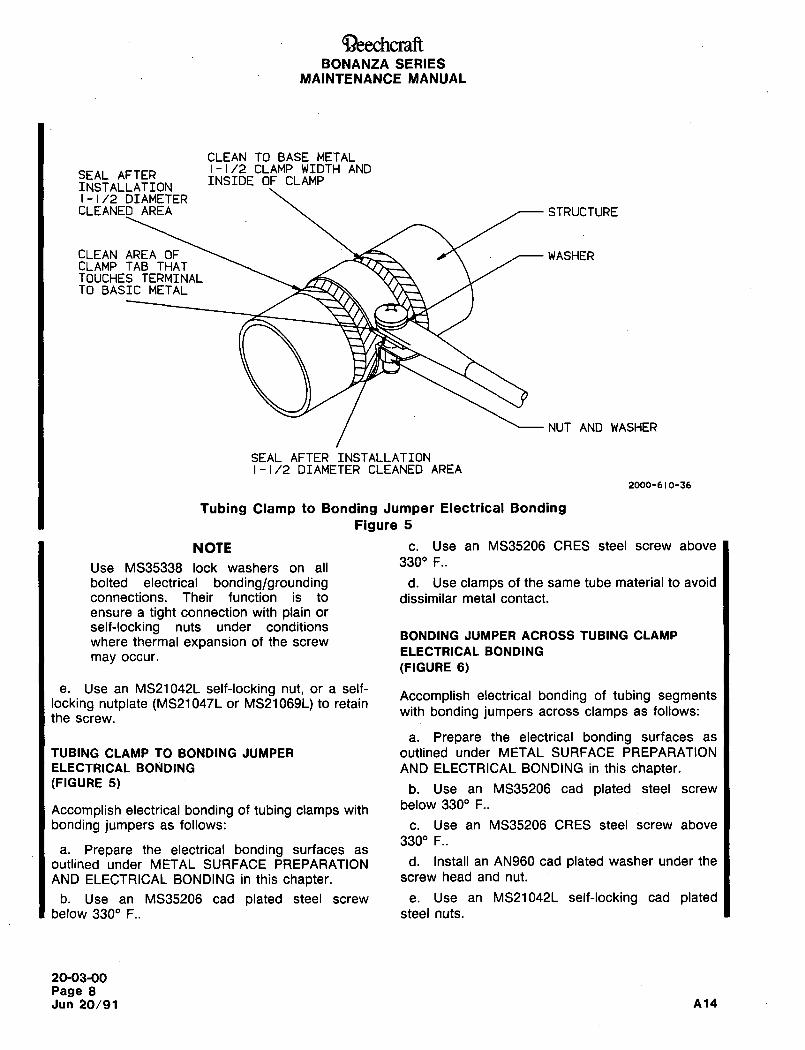
’i3eechcraftBONANZA SERIES
MAINTENANCE MANUAL
CLEAN TO BASE METAL1-1/2 CLAMP WIDTH AND
SEAL AFTERINSIDE OF CLAMP
INSTALLATION1-1/2 DIAMETER
CLEANED AREA STRUCTURE
CLEAN AREA OF J\ WASHERCLAMP TAB THATTOUCHES TERMINALTO BASIC METAL
NUT AND WASHER
SEAL AFTER INSTALLATION1-1/2 DIAMETER CLEANED AREA
2000-610-36
Tubing Clamp to Bonding Jumper Electrical Bonding
Figure 5
NOTE c. Use an MS35206 ORES steel screw above
3300 F..Use MS35338 lock washers on all
bolted electrical bonding/grounding d. Use clamps of the same tube material to avoid
connections. Their function is to dissimilar metal contact.
ensure a tight connection with plain or
self-locking nuts under conditionsBONDING JUMPER ACROSS TUBING CLAMP
where thermal expansion of the screwELECTRICAL BONDING
may occur.
(FIGURE 6)
e. Use an MS21042L self-locking nut, or a self-Accomplish electrical bonding of tubing segments
locking nutplate (MS21047L or MS21069L) to retain
the screw,with bonding jumpers across clamps as follows:
a. Prepare the electrical bonding surfaces as
TUBING CLAMP TO BONDING JUMPER outlined under METAL SURFACE PREPARATION
ELECTRICAL BONDING AND ELECTRICAL BONDING in this chapter.(FIGURE 5) b. Use an MS35206 cad plated steel screw
below 3300 F..Accomplish electrical bonding of tubing clamps with
bonding jumpers as follows: c. Use an MS35206 CRES steel screw above
330" F..a. Prepare the electrical bonding surfaces as
outlined under METAL SURFACE PREPARATION d´• Install an AN960 cad plated washer under the
AND ELECTRICAL BONDING in this chapter, screw head and nut.
b. Use an MS35206 cad plated steel screw e. Use an MS21042L self-locking cad platedbelow 3300 F.. steel nuts.
20-03-00
Page 8Jun 20/91 A14
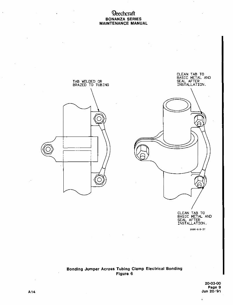
aeechcraftBONANZA SERIES
MAINTENANCE MANUAL
CLEAN TAB TOBASIC METAL AND
TAB WELDED OR SEAL AFTERBRAZED TO TUBING INSTALLATION.
O
I__
I
I I
O
CLEAN TAB TOBASIC METAL ANDSEAL AFTERINSTALLATION.
2000-610-37
Bonding Jumper Across Tubing Clamp Electrical~Bonding
Figure 6
20-03-00
Page 9
A14 Jun 20/91
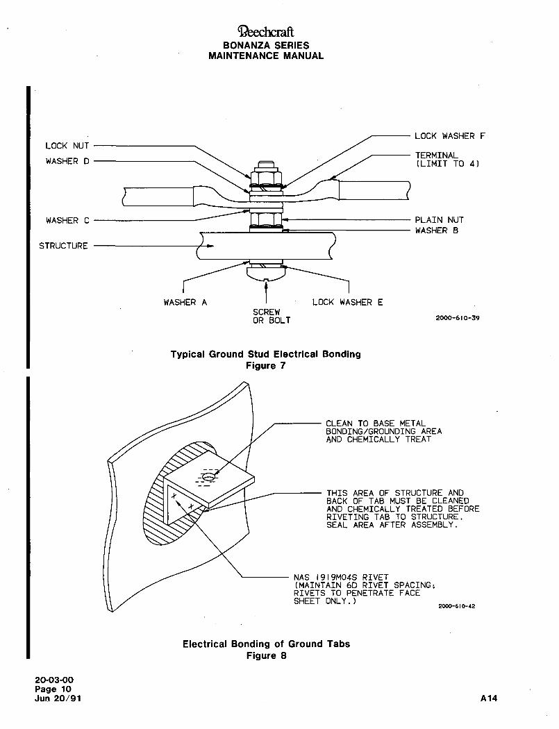
~eechcraftBONANZA SERIES
MAINTENANCE MANUAL
LOCK WASHER F
LOCK NUT
TERMINALWASHER D (LIMIT TO 4)
WASHER C I I I" PLAIN NUT
WASHER B
STRUCTURE
WASHER At
LOCK WASHER E
SCREWOR BOLT 2000-610-39
Typical Ground Stud Electrical BondingFigure 7
CLEAN TO BASE METALBONDING/GROUNDING AREAAND CHEMICALLY TREAT
THIS AREA OF STRUCTURE ANDBACK OF TAB MUST BE CLEANED
4 AND CHEMICALLY TREATED BEFORERIVETING TAB TO STRUCTURE.SEAL AREA AFTER ASSEMBLY.
NAS 1919M04S RIVET(MAINTAIN 6D RIVET SPACING;RIVETS TO PENETRATE FACESHEET ONLY.)
2000-610-42
Electrical Bonding of Ground Tabs
Figure 8
20-03-00
Page 10
Jun 20/91 A14
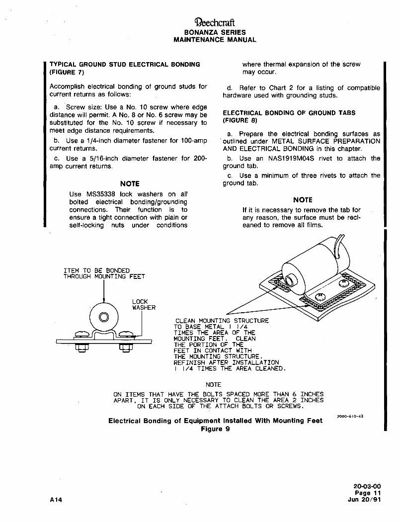
QeechcraftBONANZA SERIES
MAINTENANCE MANUAL
TYPICAL GROUND STUD ELECTRICAL BONDING where thermal expansion of the screw
(FIOURE 7) may occur.
Accomplish electrical bonding of ground studs for d. Refer to Chart 2 for a listing of compatiblecurrent returns as follows: hardware used with grounding studs.
a. Screw size: Use a No. 10 screw where edgedistance will permit. A No. 8 or No. 6 screw may be ELECTRICAL BONDING OF GROUND TABS
substituted for the No. 10 screw if necessary to (FIGURE 8)
meet edge distance requirements,a. Prepare the electrical bonding surfaces as
b. Use a ~/´•cl-inch diameter fastener for 100-amp ’outlined under METAL SURFACE PREPARATION
current returns. AND ELECTRICAL BONDING in this chapter.
c. Use a 5/16-inch diameter fastener for 200- b. Use an NAS1919M04S rivet to attach the
amp current returns. ground tab.
c. Use a minimum of three rivets to attach the
NOTE ground tab.
Use MS35338 lock washers on all
bolted electrical bondinglgrounding NOTE
connections. Their function is to If it is necessary to remove the tab for
ensure a tight connection with plain or any reason, the surface must be recl-
self-locking nuts under conditions eaned to remove all films.
ITEM TO BE BONDEDTHROUGH MOUNTING FEET
LOCKWASHER
CLEAN MOUNTING STRUCTURETO BASE METAL 1/4TIMES THE AREA OF THEMOUNTING FEET. CLEANTHE PORTION OF THEFEET IN CONTACT WITHTHE MOUNTING STRUCTURE.REFINISH AFTER INSTALLATION
1/4 TIMES THE AREA CLEANED.
NOTE
ON ITEMS THAT HAVE THE BOLTS SPACED MORE THAN 6 INCHESAPART. IT IS ONLY NECESSARY TO CLEAN THE AREA 2 INCHES
ON EACH SIDE OF THE ATTACH BOLTS OR SCREWS.
2000-610-43
Electrical Bonding of Equipment Installed With Mounting Feet
Figure 9
20-03-00
Page 11
A14 Jun 20/91
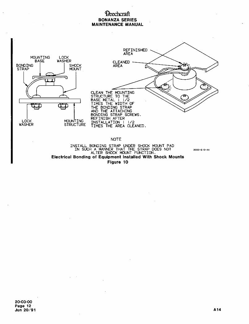
~)eechcraftBONANZA SERIES
MAINTENANCE MANUAL
REFINISHEDAREA
MOUNTING LOCK
BA~E WAS~HER CLEANEDBONDING SHOCK AREASTRAP MOUNT
CLEAN THE MOUNTINGSTRUCTURE TO THEBASE METAL 1/2TIMES THE WIDTH OFTHE BONDING STRAPAND THE ATTACHINGBONDING STRAP SCREWS.REFINISH AFTER
LOCK MOUNTING INSTALLATION 1/2WASHER STRUCTURE TIMES THE AREA CLEANED.
NOTE
INSTALL BONDING STRAP UNDER SHOCK MOUNT PADIN SUCH A MANNER THAT THE STRAP DOES NOT 2000-610-411
ALTER SHOCK MOUNT FUNCTION.
Electrical Bonding of Equipment Installed With Shock Mounts
Figure 10
20-03-00
Page 12
Jun 20/91 A14
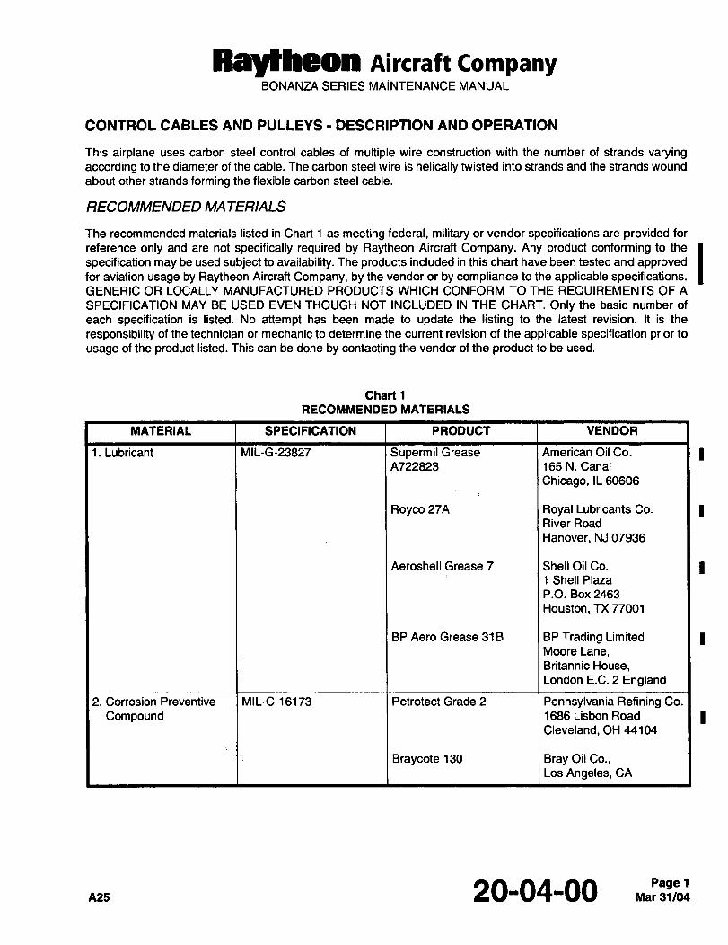
Ray~heon Aircraft CompanyBONANZA SERIES MAINTENANCE MANUAL
CONTROL CABLES AND PULLEYS DESCRIPTION AND OPERATION
This airplane uses carbon steel control cables of multiple wire construction with the number of strands varyingaccording to the diameter of the cable. The carbon steel wire is helically twisted into strands and the strands wound
about other strands forming the flexible carbon steel cable.
RECOMMENDED MA TERIALS
The recommended materials listed in Chart 1 as meeting federal, military or vendor specifications are provided for
reference only and are not specifically required by Raytheon Aircraft Company. Any product conforming to the
specification may be used subject to availability. The products included in this chart have been tested and approvedfor aviation usage by Raytheon Aircraft Company, by the vendor or by compliance to the applicable specifications.GENERIC OR LOCALLY MANUFACTURED PRODUCTS WHICH CONFORM TO THE REQUIREMENTS OF A
SPECIFICATION MAY BE USED EVEN THOUGH NOT INCLUDED IN THE CHART. Only the basic number of
each specification is listed. No attempt has been made to update the listing to the latest revision. it is the
responsibility of the technician or mechanic to determine the current revision of the applicable specification prior to
usage of the product listed. This can be done by contacting the vendor of the product to be used.
Chart 1
RECOMMENDED MATERIALS
MATERIAL SPECIFICATION PRODUCT VENDOR
1. Lubricant MIL-G-23827 Supermil Grease American Oil Co.
A722823 165 N. Canal
Chicago, IL 60606
Royco 27A Royal Lubricants Co. I IRiver Road
Hanover, NJ 07936
Aeroshell Grease 7 Shell Oil Co. I I1 Shell Plaza
P.O. Box 2463
Houston, TX 77001
BP Aero Grease 31B BP Trading Limited IMoore Lane,Britannic House,London E.C. 2 England
2. Corrosion Preventive MIL-C-16173 Petrotect Grade 2 Pennsylvania Refining Co.
Compound 1686 Lisbon Road I ICleveland, OH 44104
Braycote 130 Bray Oil Co.,Los Angeles, CA
20-04-00 Mar 31/04Page 1
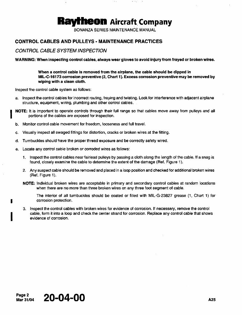
NayNmea Aircraft CompanyBONANZA SERIES MAINTENANCE MANUAL
CONTROL CABLES AND PULLEYS MAINTENANCE PRACTICES
CONTROL CABLE SYSTEM INSPECTION
WARNING: When inspecting control cables, always wear gloves to avoid injury from frayed or broken wires.
When a control cable is removed from the airplane, the cable should be dipped in
MIL-C-16173 corrosion preventive (2, Chart 1). Excess corrosion preventive may be removed bywiping with a clean cloth.
Inspect the control cable system as follows:
a. Inspect the control cables for incorrect routing, fraying and twisting. Look for interference with adjacent airplanestructure, equipment, wiring, plumbing and other control cables.
I NOTE: It is important to operate controls through their full range so that cables move away from pulleys and all
portions of the cables are exposed for inspection.
b. Monitor control cable movement for freedom, looseness and full travel.
c. Visually inspect all swaged fittings for distortion, cracks or broken wires at the fitting.
d. Turnbuckles should have the proper thread exposure and be correctly safety wired.
e. Locate any control cable broken or corroded wires as follows:
1. Inspect the control cables near fairlead pulleys by passing a cloth along the length of the cable. If a snag is
found, closely examine the cable to determine the extent of the damage (Ref. Figure 1).
2. Any suspect cable should be removed and placed in a loop position and checked for additional broken wires
(Ref. Figure 1).
NOTE: Individual broken wires are acceptable in primary and secondaty control cables at random locations
when there are no more than three broken wires on any three foot segment of cable.
The interior of all tumbuckles should be coated or filled with MIL-G-23827 grease (1, Chart 1) for
corrosion protection.
3. Inspect the control cables with broken wires for evidence of corrosion. If necessary, remove the control
cable, form it into a loop and check the center strand for corrosion. Replace any control cable that shows
evidence of corrosion.
Page 2Mar31/04 20-04-00
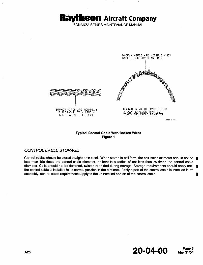
Raytheon Aircraft CompanyBONANZA SERIES MAINTEN#NCE MANUAL
BROKEN WIRES ARE VISIBLE WHENCABLE IS REMOVED AND BENT
BROKEN WIRES ARE NORMALLY DO NOT BEND THE CABLE INTO
DETECTABLE BY WIPING A A LOOP SMALLER THAN 50
CLOTH ALONG THE CABLE TIMES THE CABLE DIAMETER
2000-610-6 1
Typical Control Cable With Broken Wires
Figure 1
CONTROL CABLE STORAGE
Control cables should be stored straight or in a coil. When stored in coil form, the coil inside diameter should not be Iless than 150 times the control cable diameter, or bent in a radius of not less than 75 times the control cable
diameter. Coils should not be flattened, twisted or folded during storage. Storage requirements should apply until
the control cable is installed in its normal position in the airplane. If only a part of the control cable is installed in an
assembly, control cable requirements apply to the uninstalled portion of the control cable.
A25 20-04-00 Mar 31/04Page 3
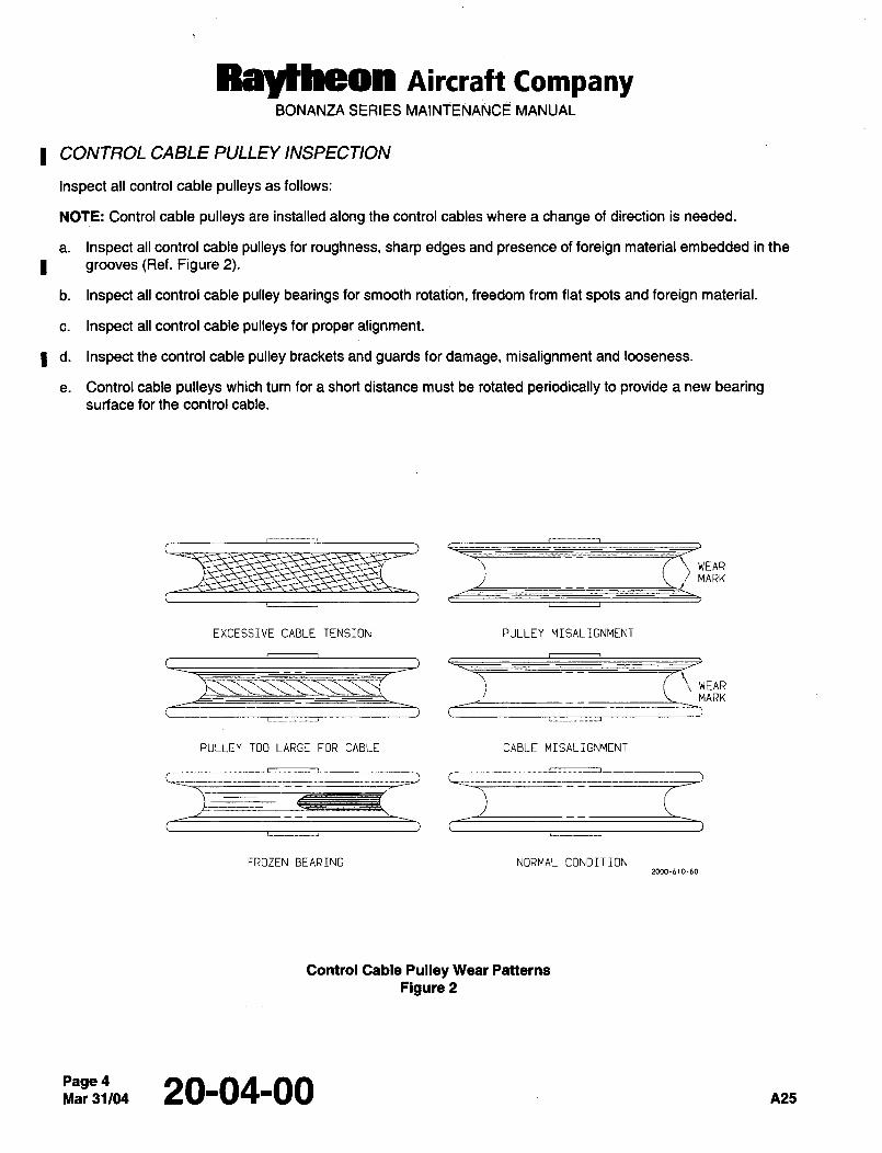
Raltheon Aircraft CompanyBONANZA SERIES MAINTENANCE MANUAL
CONTROL CABLE PULLEY INSPECTION
Inspect all control cable pulleys as follows:
NOTE: Control cable pulleys are installed along the control cables where a change of direction is needed.
a. Inspect all control cable pulleys for roughness, sharp edges and presence of foreign material embedded in the
I grooves (Ref. Figure 2).
b. Inspect all control cable pulley bearings for smooth rotation, freedom from flat spots and foreign material.
c. Inspect all control cable pulleys for proper alignment.
I d. Inspect the control cable pulley brackets and guards for damage, misalignment and looseness.
e. Control cable pulleys which turn for a short distance must be rotated periodically to provide a new bearingsurface for the control cable.
WEARMARK
EXCESSIVE CABLE TENSION PULLEY MISALIGNMENT
c-=-.------n-~-
WEARMARK
PULLEY TDO LARGE FOR CABLE CABLE MISALIGNMENT
.L=--i_FROZEN BEARING NORMAL CONDITION
Control Cable Pulley Wear Patterns
Figure 2
Page 4Mar31/04 20-04-00 A25
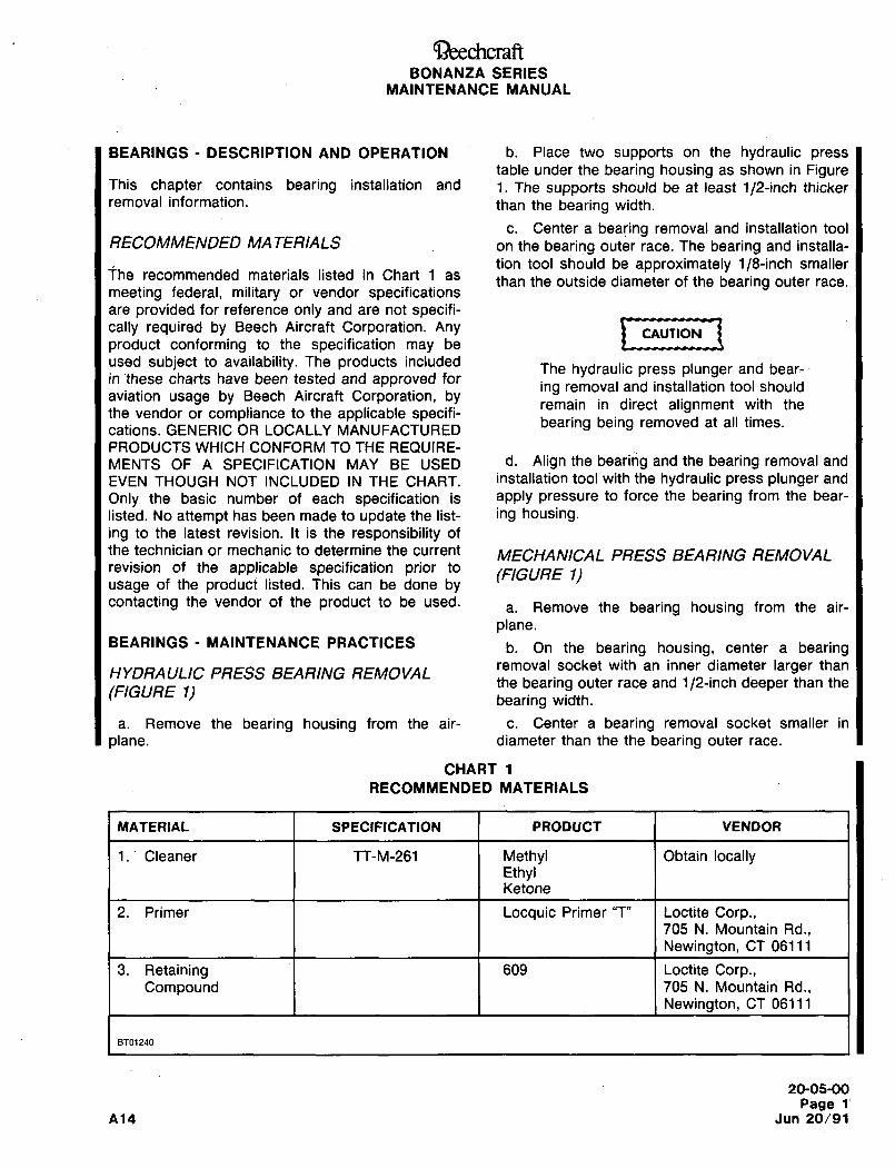
Cil)eechcraftBONANZA SERIES
MAINTENANCE MANUAL
BEARINGS DESCRIPTION AND OPERATION b. Place two supports on the hydraulic presstable under the bearing housing as shown in Figure
This chapter contains bearing installation and 1. The supports should be at least 1/2-inch thickerremoval information, than the bearing width.
c. Center a bearing removal and installation toolRECOMMENDED MATERIALS on the bearing outer race. The bearing and installa-
tion tool should be approximately 1/8-inch smallerihe recommended materials listed in Chart 1 as than the outside diameter of the bearing outer race.
meeting federal, military or vendor specificationsare provided for reference only and are not specifi-cally required by Beech Aircraft Corporation. Any I~ U´•nMllCAUTIONproduct conforming to the specification may be
used subject to availability. The products includedThe hydraulic press plunger and bear-
in these charts have been tested and approved foring removal and installation tool should
aviation usage by Beech Aircraft Corporation, byremain in direct alignment with the
the vendor or compliance to the applicable specifi-cations. GENERIC OR LOCALLY MANUFACTURED bearing being removed at all times.
PRODUCTS WHICH CONFORM TO THE REQUIRE-
MENTS OF A SPECIFICATION MAY BE USED d´• Align the bearing and the bearing removal and
EVEN THOUGH NOT INCLUDED IN THE CHART. installation tool with the hydraulic press plunger and
Only the basic number of each specification is apply pressure to force the bearing from the bear-
listed. No attempt has been made to update the list- ing housing.ing to the latest revision. It is the responsibility of
the technician or mechanic to determine the current MECHANICAL PRESS BEARING REMOVALrevision of the applicable specification prior to
(F/GURE I)usage of the product listed. This can be done bycontacting the vendor of the product to be used.
a. Remove the bearing housing from the air-
plane.BEARINGS MAINTENANCE PRACTICES b. On the bearing housing, center a bearing
HYDRAULIC PRESS BEARING REMOVALremoval socket with an inner diameter larger than
the bearing outer race and 1/2-inch deeper than the(FIGURE 1)
bearing width.
a. Remove the bearing housing from the air- c. Center a bearing removal socket smaller in
plane, diameter than the the bearing outer race.
CHART 1
RECOMMENDED MATERIALS
MATERIAL SPECIFICATION PRODUCT VENDOR
1.’ Cleaner TT-M-261 Methyl Obtain locallyEthylKetone
2. Primer Locquic Primer "T" Loctite Corp.,705 N. Mountain Rd.,
Newington, CT 06111
3. Retaining 609 Loctite Corp.,Compound 705 N. Mountain Rd.,
Newington, CT 06111
BT01240
20-05-00
Page 1’
A14 Jun 20/91
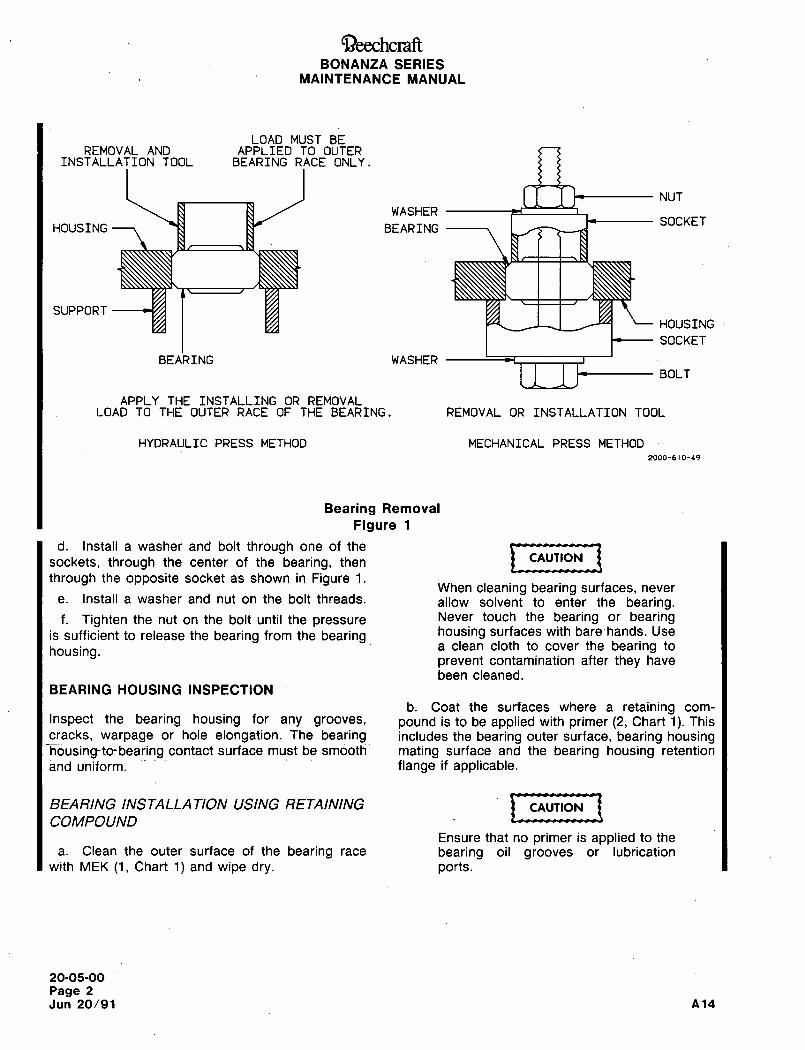
~-)eechcraftBONANZA SERIES
MAINTENANCE MANUAL
LOAD MUST BEREMOVAL AND APPLIED TO OUTER
INSTALLATION TOOL BEARING RACE ONLY.
NUT
WASHERSOCKET
HOUSING l~r BEARING
SUPPORT
HOUSING
SOCKET
BEARING WASHER
BOLT
APPLY THE INSTALLING OR REMOVALLOAD TO THE OUTER RACE OF THE BEARING. REMOVAL OR INSTALLATION TOOL
HYDRAULIC PRESS METHOD MECHANICAL PRESS METHOD
2000-610-49
Bearing Removal
Figure 1
d. Install a washer and bolt through one of the
t U´•,,,,(sockets, through the center of the bea~ng, then
through the opposite socket as shown in Figure 1.When cleaning bearing surfaces, never
e. Install a washer and nut on the bolt threads. allow solvent to enter the bearing.f. Tighten the nut on the bolt until the pressure Never touch the bearing or bearing
is sufficient to release the bearing from the bearing housing surfaces with bare-hands. Use
housing. a clean cloth to cover the bearing to
prevent contamination after they have
been cleaned.
BEARING HOUSING INSPECTION
b. Coat the surfaces where a retaining com-
Inspect the bearing housing for any grooves, pound is to be applied with primer (2, Chart 1). This
cracks, warpage or hole elongation. The bearing includes the bearing outer surface, bearing housinghousing-to-bearing contact surface must be smooth mating surface and the bearing housing retention
and uniform. flange if applicable.
BEAR/NC /NSTALLATION USING RETA/NING CAUTION
COMPOUND
Ensure that no primer is applied to the
a. Clean the outer surface of the bearing race bearing oil grooves or lubrication
with MEK (1, Chart l)and wipe dry. ports.
20-05-00
Page 2
Jun 20/91 A14
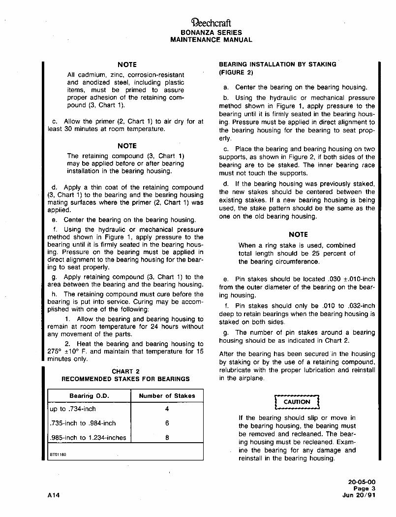
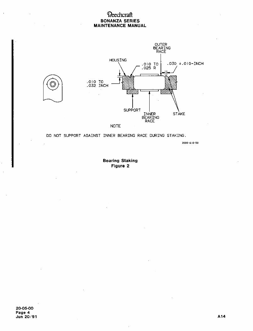
~eechcraftBONANZA SERIES
MAINTENANCE MANUAL
OUTERBEARING
RACE
HOUSING
.010 TO .030 ~.OIO-INCH
.025 R
~I .010 TO.032 INCH
SUPPORTINNER STAKE
BEARINGRACE
NOTE
DO NOT SUPPORT AGAINST INNER BEARING RACE DURING STAKING.
2000-610-50
Bearing StakingFigure 2
20-05-00
Page 4
Jun 20/91 A14
Ray~heon Aircraft CompanyBONANZA SERIES MAINTENANCE MANUAL
TUBE AND HOSE ASSEMBLIES AND FITTINGS DESCRIPTION AND OPERATION
This chapter contains information to remove, maintain and install hose and tube assemblies and fittings. Althoughall hoses and tubes may not be specifically identified herein, the basic maintenance practices normally apply. Anyhandling and installation of individual system hoses, tubes and fittings is identified in the appropriate system chapter.
The majority of tube assemblies used in the airplane are aluminum or steel machine formed tubing assemblies.
Hoses are used in areas of the airplane where a flexible line is more suitable for installations and freedom of
movement is necessary.
20-06-00 1
RBYtheon Aircraft CompanyBONANZA SERIES MAINTENANC~ ~ANUAL
TUBING, HOSE AND FITTINGS MAINTENANCE PRACTICES
Observe all WARNINGS, CAUTIONS and NOTES throughout this maintenance manual when performingmaintenance, repair or servicing on any fluid or pneumatic operated system.
CAUTION: Verify that systems which operate from fluids or pneumatics under pressure are fully depressurizedbefore opening or disconnecting a tubing or hose.
The following list of maintenance practices is provided as an aid for handling, removing, installing and repairingtubing and hoses.
a. Cap or plug all disconnected tubing and hose assemblies and fittings immediately to prevent contamination of
the system.
b. Visually check for cleanliness, evidence of contamination and obstructions prior to reconnection of tube or hose
assemblies.
c. Any hose and tube assemblies that did not have protective covers installed must be cleaned and checked for
obstruction prior to installation.
d. When connecting tube assemblies, do not force the tube assembly to the installed position. If a mismatch
between the male and female fittings should result, see Figure 1 for the allowable mismatch.
e. Never stretch a hose to make a connection.
f. The hose material must be compatible with the applicable system fluids. Substitution of a hose material that is
not compatible with the system fluid will contaminate the system.
REMOVAL OF TUBE AND HOSE ASSEIWBLIES
Tube and hose assemblies may be removed as follows:
a. Relieveallsystem pressure.
b. Disconnect both ends of the hose or tube assembly and immediately cap or plug the tube or hose ends and
fittings.
c. Remove all clamps securing the hose or tube assembly.
d. Remove the tube or hose assembly and tag identity both ends to aid in reinstallation.
HOSE ASSEMBL Y INSTALLA TION
Hose assemblies may be installed as follows:
NOTE: If a new hose assembly is to be installed, the hose assembly must be clean, the correct length, clear of
obstructions and material compatible with the system fluid.
a. Observe the maintenance practices outlined under the heading TUBE AND HOSE ASSEMBLIES AND
FITTINGS MAINTENANCE PRACTICES.
I Connect the B nuts of the hose assembly to the proper fittings.
Torque the B nuts to the fittings using the torque specified in Chart 1.
Sep 20-06-00 A26

Raythcon nircraft CompanyBONANZA SERIES MAINTENANCE MANUAL
d. After torquing the B nuts, inspect the hose to ensure that the hose is not under tension and that no indication of Itwisting is present.
e. Inspect the hose for proper length.
f. Inspect the hose for freedom to expand and contract.
g. Inspect the hose for clearance to all structure. If inadequate clearance exists between the hose and structure,
protection must be provided for the hose to prevent damage from chafing.
TUBE INSTALLA TION
NOTE: If a new tube assembly is to be installed, the tube assembly must be clean, the correct length, clear of
obstructions and manufactured of the correct material.
a. Observe the maintenance practices outlined under the heading TUBE AND HOSE ASSEMBLIES AND
FITTINGS MAINTENANCE PRACTICES.
b. Inspect the tube for damage, particularly at tube ends, fittings, and bends. Damaged Zube assemblies should be
replaced or repaired.
c. Make certain that the fittings are properly installed before connection of the tube assembly.
d. Check alignment and fit of the tube assembly as follows before installation:
1. Place the tube assembly in the proper position and tighten one coupling nut at one end of the tube assembly.
2. The opposite end of the tube must be within two degrees of parallel with the fitting (Ref. Figure 1).
3. The free tubing end must be aligned within 1/32 inch of the fitting per every 10 inches of tube length.
4. The free end of the tube must match the fitting cone lengthwise within 1/32 inch per every 10 inches of tube
length.
e. If necessary, apply the proper anti seize compound to fittings.
f. install the tube assembly on the fittings and tighten the B nuts to the torque values specified (Ref. Chart 1).
FLUID LINE FITTING INSTALLATION
Fluid line fittings may be installed as follows:
a. Lubricate the male threads of the fitting, backup ring and packing sparingly with the system fluid or petrolatum(AN-P-51, Vaseline).
b. Install the nut (AN6289) on the fitting until the nut is clear of the thread relief.
c. Install the teflon backup ring in the counterbore of the nut.
d. Install the packing (O-ring) on the thread relief.
NOTE: The packing must be compatible with the system fluid.
e. Turn the nut down until the packing is pushed firmly against the lower threaded section of the fitting.
f. Install the fitting into the boss with the nut turning with the fitting until the packing contacts the boss.
A26 20-06-00
Raytheon Aircraft CompanyBONANZA SERIES MAINTENANCE MANUAL
NOTE: This point can be detected by a sudden increase in torque.
g. Holding the nut with a wrench to prevent it from turning, rotate the fitting in an additional 1 112 turns. Position
the fitting in the proper direction by turning in no more than one additional turn.
h. Holding the fitting, turn the nut down tightly against the boss. Slight extrusion of the ring around the backup ringis acceptable.
NONPOSITIONING TYPE FITTING INSTALLATION
Nonpositioning type fittings may be installed as follows.
a. Lubricate the packing with the system fluid or petrolatum (AN-P-51, Vaseline).
b. Install the packing in the fitting thread relief.
c. Thread the fitting into the boss until it bottoms tightly on the boss.
d. Tighten the fitting to the specified torque value.
PIPE THREAD NTTING INSTALLA TION
Pipe thread fittings may be installed as follows:
a. Apply teflon tape to the threads as follows:
1. Start tape at or close to narrow end of threads.
2. Wrap the tape around the fitting in the direction of the threads. Wrap clockwise for right hand threaded
fittings. Wrap counterclockwise for left hand threaded fittings.
3. Apply tension to the tape to conform the tape to the shape of the threads.
4. The tape should overlap the previous wrap of tape up to one-half inch to seal pipe thread fittings up to two
I~inches in diameter.
Thread the fitting into the boss and tighten until it bottoms tightly on the boss.
Sep 20-06-00
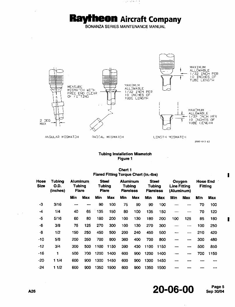
RayHheon Aircraft CompanyBONANZA SERIES MAINTENANCE MANUAL
tMAXIMUM
ALLOWABLEINCH PER
MAXIMUMALLOWABLE
t 10 INCHES OFTUBE LENGTH
MEASUREMISMATCH WITH
1/32 INCH PERFREE END CLEAR
10 INCHES OFII OF FITTING
TUBE LENGTH
2 DEGi i
MAXIMUMALLOWABLE
MAX
4 10 INCHES OF
1/32 INCH PER
TUBE LENGTH
ANGULAR MISMATCH RADIAL MISMATCH LENGTH MISMATCH
Tubing Installation Mismatch
Figure 1
Chart 1
Flared Fitting Torque Chart (In.-lbs)
Hose Tubing Aluminum Steel Aluminum Steel Oxygen Hose End
Size O.D. Tubing Tubing Tubing Tubing Line Fitting Fitting(inches) Flare Flare Flareless Flareless (Aluminum)
Min Max Min Max Min Max Min Max Min Max Min Max
-3 3/16 90 100 75 90 90 100 70 100
-4 1/4 40 65 135 150 80 100 135 150 70 120
-5 5/16 60 80 180 200 100 130 180 200 100 125 85 180
-6 3/8 75 125 270 300 100 130 270 300 100 250
-8 1/2 150 250 450 500 200 240 450 500 210 420
-10 5/8 200 350 700 800 360 400 700 800 300 480
-12 3/4 300 500 1100 1150 390 430 1100 1150 500 850
-16 1 500 700 1200 1400 600 900 1200 1400 700 1150
-20 11/4 600 900 1300 1450 600 900 1300 1450
-24 11/2 600 900 1350 1500 600 900 1350 1500
A26 20-06-00 5
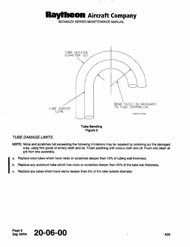
RBytheMI Aircraft CompanyBONANZA SERIES MAINTENANCE MANUAL
TUBE OUTSIDEDIAMETER (D)
BEND‘RADII IS MEASUREDTO TUBE CENTERLINE
TUBE CENTERLINE
2000-610-64
Tube BendingFigure 2
TUBE DAMAGE LIMITS
NOTE: Nicks and scratches not exceeding the following limitations may be repaired by polishing out the damagedarea, using fine grade of emery cloth and oil. Finish polishing with crocus cloth and oil. Flush and clean all
grit from line assembly.
a. Replace steel tubes which have nicks or scratches deeper than 10% of tubing wall thickness.
b. Replace any aluminum tube which has nicks or scratches deeper than 20% of the tube wall thickness.
c. Replace any tubes which have dents deeper than 5% of the tube outside diameter.
Sep 20-06-00 A26
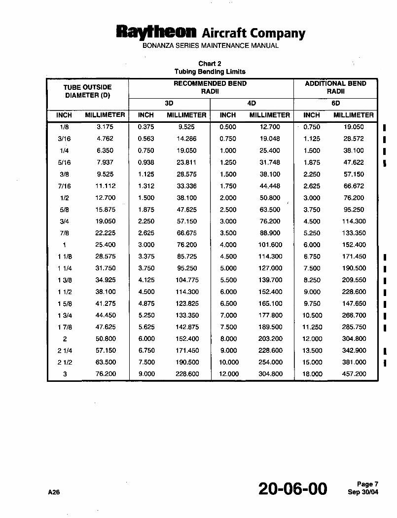
Raytheon AiKraft CompanyBONANZA SERIES MAINTENANCE MANUAL
Chart 2
Tubing Bending Limits
RECOMMENDED BEND ADDITIONAL BENDTUBE OUTSIDE
RADII RADIIDIAMETER (0)
30 4D 6D
INCH MILLIMETER INCH MILLIMETER INCH MILLIMETER INCH MILLIMETER
118 3.175 0.375 9.525 0.500 12.700 1´•0.750 19.050
3/16 4.762 0.563 14.286 0.750 19.048 1.125 28.572
1/4 6.350 0.750 19.050 1.000 25.400 1.500 38.100
5/16 7.937 0.938 23.811 1.250 31.748 1.875 47.622
3/8 9.525 1.125 28.575 1.500 38.100 2.250 57.150
7/16 11.112 1.312 33.336 1.750 44.448 2.625 66.672
1/2 12.700 1.500 38.100 2.000 50.800 3.000 76.200
518 15.875 1.875 47.625 2.500 63.500 3.750 95.250
3/4 19.050 2.250 57.150 3.000 76.200 4.500 114.300
718 22.225 2.625 66.675 3.500 88.900 5.250 133.350
1 25.400 3.000 76.200 4.000 101.600 6.000 152.400
11/8 28.575 3.375 85.725 4.500 114.300 6.750 171.450
11/4 31.750 3.750 95.250 5.000 127.000 7.500 190.500
13/8 34.925 4.125 104.775 5.500 139.700 8.250 209.550
11/2 38.100 4.500 114.300 6.000 152.400 9.000 228.600
15/8 41.275 4.875 123.825 6.500 165.100 9.750 147.650
13/4 44.450 5.250 133.350 7.000 177.800 10.500 266.700
17/8 47.625 5.625 142.875 7.500 189.500 11.250 285.750
2 50.800 6.000 152.400 8.000 203.200 12.000 304.800
21/4 57.150 6.750 171.450 9.000 228.600 13.500 342.900
21/2 63.500 7.500 190.500 10.000 254.000 15.000 381.000
3 76.200 9.000 228.600 12.000 304.800 18.000 457.200
A26 20-06-00Page 7
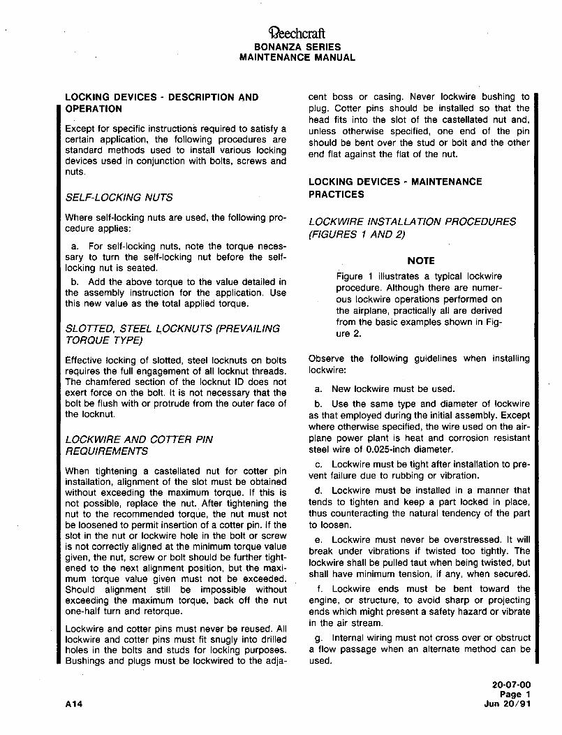
aeechcraftBONANZA SERIES
MAINTENANCE MANUAL
LOCKING DEVICES DESCRIPTION AND cent boss or casing. Never lockwire bushing to
OPERATION plug. Cotter pins should be installed so that the
head fits into the slot of the castellated nut and,Except for specific instructions required to satisfy a unless otherwise specified, one end of the pincertain application, the following procedures are should be bent over the stud or bolt and the otherstandard methods used to install various locking end flat against the flat of the nut.devices used in conjunction with bolts, screws and
nuts.
LOCKING DEVICES MAINTENANCE
SELF-LOCKING NUTS PRACTICES
Where self-locking nuts are used, the following pro- LOCKW/RE INSTALLA T/ON PROCEDUREScedure applies:
(FIGURES 1 AND 2)a. For self-locking nuts, note the torque neces-
sary to turn the self-locking nut before the self- NOTElocking nut is seated.
Figure 1 illustrates a typical lockwireb. Add the above torque to the value detailed in
procedure. Although there are numer-the assembly instruction for the application. Use
this new value as the total applied torque,ous lockwire operations performed on
the airplane, practically all are derived
from the basic examples shown in Fig-SLOTTED, STEEL LOCKNUTS (PREVAILING
ure 2.TORQUE TYPE)
Effective locking of slotted, steel locknuts on bolts Observe the following guidelines when installing
requires the full engagement of all locknut threads, lockwire:
The chamfered section of the locknut ID does not
exert force on the bolt. It is not necessary that the a. New lockwire must be used.
bolt be flush with or protrude from the outer face of b. Use the same type and diameter of lockwire
the locknut. as that employed during the initial assembly. Exceptwhere otherwise specified, the wire used on the air-
LOCKWIRE AND COTTER PIN plane power plant is heat and corrosion resistant
REQUIREMENTS steel wire of 0.025-inch diameter.
c. Lockwire must be tight after installation to pre-When tightening a castellated nut for cotter pin vent failure due to rubbing or vibration.installation, alignment of the slot must be obtained
without exceeding the maximum torque. If this is d´• Lockwire must be installed in a manner that
not possible, replace the nut.After tightening the tends to tighten and keep a part locked in place,nut to the recommended torque, the nut must not thus counteracting the natural tendency of the partbe loosened to permit insertion of a cotter pin. If the to loosen.
slot in the nut or lockwire hole in the bolt or screwe. Lockwire must never be overstressed. It will
is not correctly aligned at the minimum torque valuebreak under vibrations if twisted too tightly. The
given, the nut, screw or bolt should be further tight- lockwire shall be pulled taut when being twisted, butened to the next alignment position, but the maxi-
shall have minimum tension, if any, when secured.mum torque value given must not be exceeded.
Should alignment still be impossible without f. Lockwire ends must be bent toward the
exceeding the maximum torque, back off the nut engine, or structure, to avoid sharp or projectingone-half turn and retorque. ends which might present a safety hazard or vibrate
in the air stream.Lockwire and cotter pins must never be reused. All
lockwire and cotter pins must fit snugly into drilled 9´• Internal wiring must not cross over or obstruct
holes in the bolts and studs for locking purposes. a flow passage when an alternate method can be
Bushings and plugs must be lockwired to the adja- used.
20-07-00
Page 1
A14 Jun 20/91
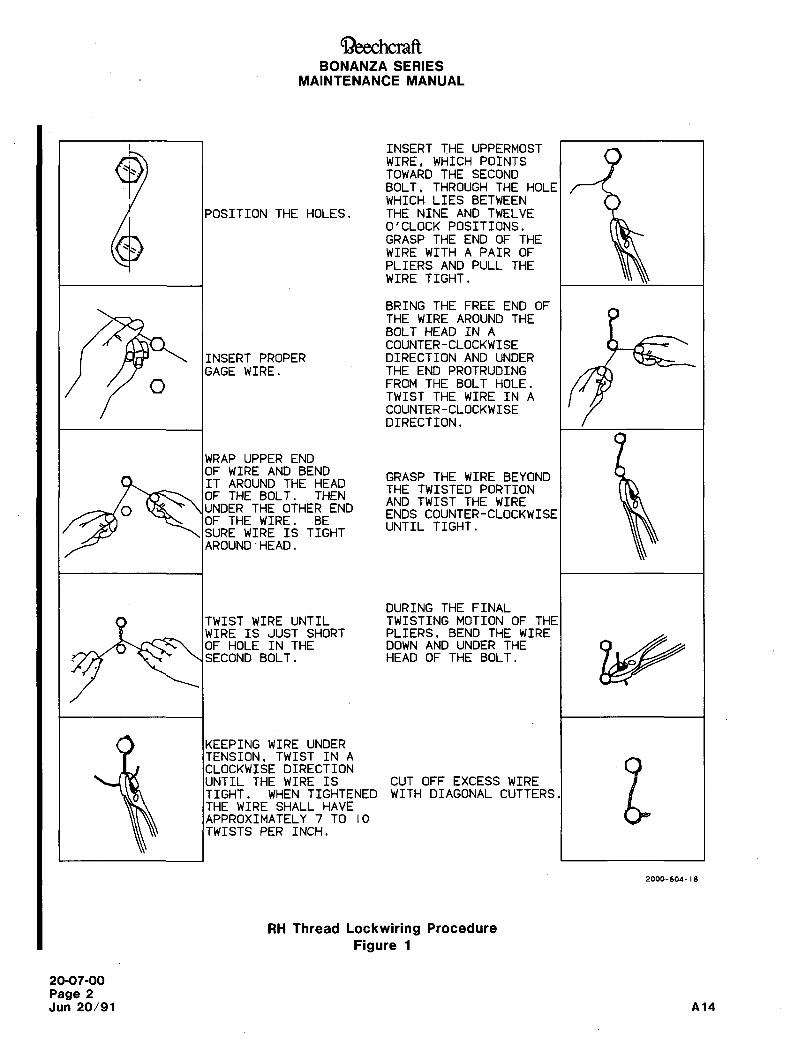
OeechcraftBONANZA SERIES
MAINTENANCE MANUAL
INSERT THE UPPERMOSTWIRE, WHICH POINTSTOWARD THE SECONDBOLT. THROUGH THE HOLE
WHICH LIES BETWEEN
POSITION THE HOLES. THE NINE AND TWELVEO’CLOCK POSITIONS.GRASP THE END OF THE
WIRE WITH A PAIR OF
PLIERS AND PULL THE
WIRE TIGHT.
BRING THE FREE END OF
THE WIRE AROUND THEBOLT HEAD IN A
COUNTER-CLOCKWISE
INSERT PROPER DIRECTION AND UNDER
GAGE WIRE. THE END PROTRUDINGFROM THE BOLT HOLE.
TWIST THE WIRE IN A
COUNTER-CLOCKWISEDIRECTION.
WRAP UPPER ENDOF WIRE AND BEND
GRASP THE WIRE BEYONDIT AROUND THE HEAD
THE TWISTEDPORTIONOF THE BOLT. THEN
AND TWIST THE WIREO UNDER THE OTHER END
ENDS COUNTER-CLOCKWISEOF THE WIRE. BE
UNTIL TIGHT.SURE WIRE IS TIGHTAROUND ´•HEAD.
DURING THE FINAL
TWIST WIRE UNTIL TWISTING MOTION OF THEWIRE IS JUST SHORT PLIERS. BEND THE WIREOF HOLE IN THE DOWN AND UNDER THESECOND BOLT. HEAD OF THE BOLT.
KEEPING WIRE UNDER
TENSION. TWIST IN A
UNTIL THE WIRE IS CUT OFF EXCESS WIREWITHDIAGONAL CUTTERS gCLOCKWISE DIRECTION
TIGHT. WHEN TIGHTENEDTHE WIRE SHALL HAVEAPPROXIMATELY 7 TO 10
TWISTS PER INCH.
2000-604-18
RH Thread Lockwiring Procedure
Figure 1
20-07-00
Page 2
Jun 20/91 A14
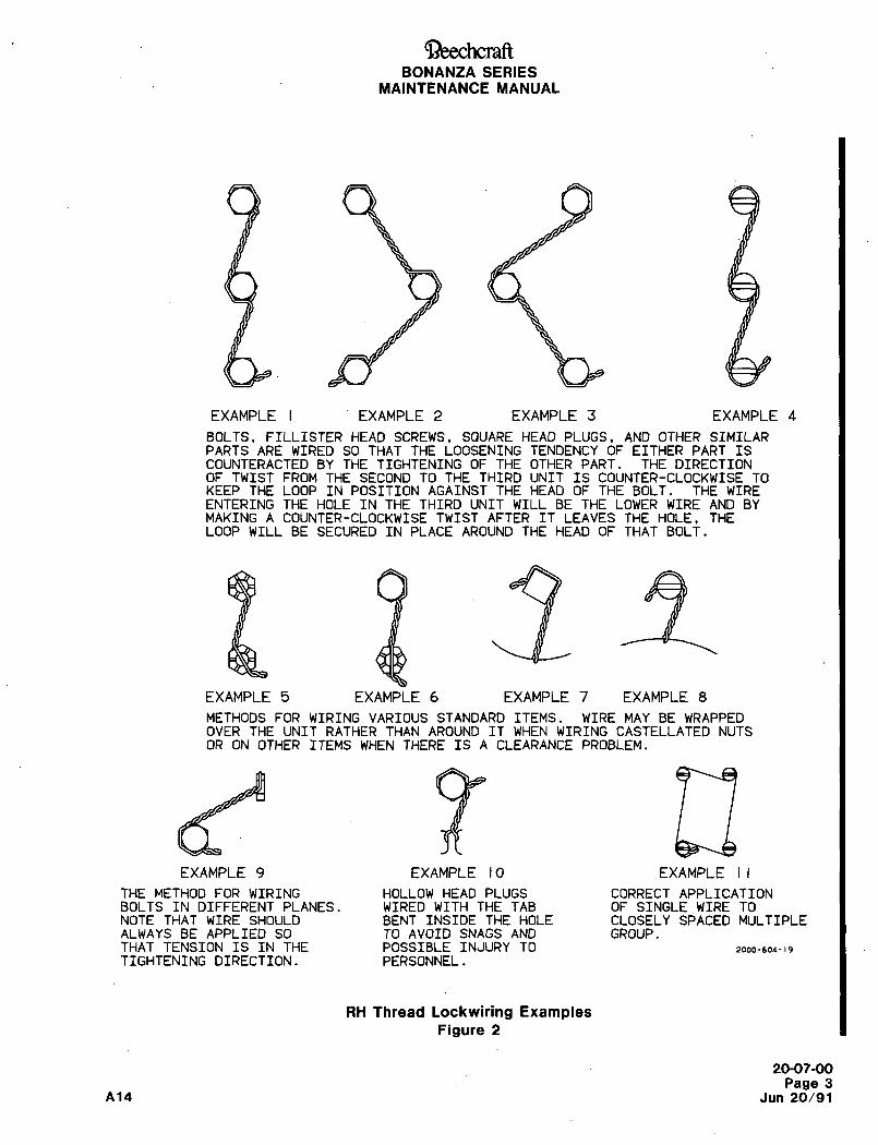
~eechcraftBONANZA SERIES
MAINTENANCE MANUAL
EXAMPLE I EXAMPLE 2 EXAMPLE 3 EXAMPLE 4
BOLTS, FILLISTER HEAD SCREWS, SQUARE HEAD PLUGS. AND OTHER SIMILARPARTS ARE WIRED SO THAT THE LOOSENING TENDENCY OF EITHER PART ISCOUNTERACTED BY THE TIGHTENING OF THE OTHER PART. THE DIRECTIONOF TWIST FROM THE SECOND TO THE THIRD UNIT IS COUNTER-CLOCKWISE TOKEEP THE LOOP IN POSITION AGAINST THE HEAD OF THE BOLT. THE WIREENTERING THE HOLE IN THE THIRD UNIT WILL BE THE LOWER WIRE AND BYMAKING A COUNTER-CLOCKWISE TWIST AFTER IT LEAVES THE HOLE. THELOOP WILL BE SECURED IN PLACE AROUND THE HEAD OF THAT BOLT.
EXAMPLE 5 EXAMPLE 6 EXAMPLE 7 EXAMPLE 8
METHODS FOR WIRING VARIOUS STANDARD ITEMS. WIRE MAY BE WRAPPEDOVER THE UNIT RATHER THAN AROUND IT WHEN WIRING CASTELLATED NUTSOR ON OTHER ITEMS WHEN THERE IS A CLEARANCE PROBLEM.
EXAMPLE 9 EXAMPLE 10 EXAMPLE II
THE METHOD FOR WIRING HOLLOW HEAD PLUGS CORRECT APPLICATIONBOLTS IN DIFFERENT PLANES. WIRED WITH THE TAB OF SINGLE WIRE TONOTE THAT WIRE SHOULD BENT INSIDE THE HOLE CLOSELY SPACED MULTIPLEALWAYS BE APPLIED SO TO AVOID SNAGS AND GROUP.THAT TENSION IS IN THE POSSIBLE INJURY TO 2000-604- 19
TIGHTENING DIRECTION. PERSONNEL.
RH Thread Lockwiring ExamplesFigure 2
20-07-00
Page 3A14 Jun 20/91
Ci~eechcraftBONANZA SERIES
MAINTENANCE MANUAL
LOCKWIRE HOLE ALIGNMENT c. When nuts are to be secured to a fastener
with cotter pins, tighten the fastener to the low sideCheck the units to be lockwired to make sure that (minimum) of the applicable specified or selected
they have been correctly torqued and that the wir- torque range, unless otherwise specified, and if
ing holes are properly positioned in relation to eachnecessary, continue tightening until the nut slot
other. When there are two or more units, it is desir-aligns with the fastener hole. Maximum torque must
able that the holes in the units be in the same rela-never be exceeded.
tionship to each other. Never overtorque or loosen
units to obtain proper alignment of the holes. It d´• Castellated nuts installed on fasteners are
should be possible to align the wiring holes when safetied with cotter pins. The preferred method is
the units are torqued within the specified limits. with the cotter pin bent parallel to the axis of the
However, if it is impossible to obtain a proper align- fastener. The alternate method, where the cotter pinment of the holes without either over or undertorqu- is mounted perpendicular to the axis of the fas-
ing, select another unit which will permit proper tener, may be used when the cotter pin in the pre-
alignment within the specified torque limits, ferred method is apt to become a snag.
e. If 50 percent or more of the cotter pin diame-
LOCKWIRE TWISTING ter is above the nut castellation, a washer should be
used under the nut or a shorter fastener should beTo prevent mutilation of the twisted section of the
installed. A maximum of two washers may be per-wire when using pliers, grasp the wire at the ends
mitted under a nut.or at a point that will not be twisted. Lockwire must
not be nicked, kinked or mutilated. Never twist the f´• Use the largest nominal diameter cotter pinwire ends off with the pliers and, when cutting off listed in MS24665 that the hole and slots’will
ends; leave at least three complete twists after the accommodate. No application of a cotter pin to any
loop, exercising extreme care to prevent the wire nut or fastener is permitted if the fastener hole size
ends from falling into areas where they might create is less than the required hole and slot size for the
a hazard or damage. The strength of lockwire holes cotter pin.is marginal.
9´• Install the cotter pin head firmly in the slot of
the nut with the axis of the cotter pin eye at rightCOTTER PIN INSTALLA TION angles to the fastener shank. Bend the cotter pin(FIGURE 3) prongs so that the cotter pin head and upper prong
are firmly seated against the fastener and the lowerUse the following to select and install cotter pins for
prong against the nut.the desired application:
h. In clevis pin or rod end applications, install the
a. Install new cotter pins, cotter pin with the axis of the eye parallel to the
b. Select cotter pin material in accordance with shank of the clevis pin or rod end. Bend the prongs
temperature, atmosphere and service limitations as around the shank of the clevis pin or rod end as
specified in Chart 1. shown in Figure 3.
CHART 1
COTTER PIN INFORMATION
MATERIAL TEMPERATURE SERVICE
MS24665 Cotter Pins Ambient Temperature Normal atmosphere cotter pinsCarbon Steel up to 4600F contacting cadimum plated bolts
or nuts.
MS24665 Cotter Pins Ambient Temperature Nonmagnetic requirements cotter
Corrosion-Resistant Steel up to 800"F pins contacting corrosion-resistant
steel bolts or nuts in a corrosive
atmosphere.
BT01083
20-07-00
Page 4
Jun 20/91 A14
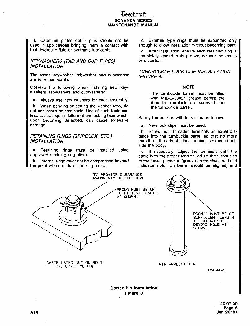
QccchcraftBONANZA SERIES
MAINTENANCE MANUAL
i. Cadmium plated cotter pins should not be c. External type rings must be expanded onlyused in applications bringing them in contact with enough to allow installation without becoming bent.
fuel, hydraulic fluid or synthetic lubricants. d. After installation, ensure each retaining ring is
completely seated in its groove, without looseness
KEYWASHERS (TAB AND CUP TYPES) or distortion.
INSTALLA TION
TURNBUCKLE LOCK CLIP INSTALLATIONThe terms keywasher, tabwasher and cupwasher (FIGURE 4)are interchangeable.
Observe the following when installing new key- NOTE
washers, tabwashers and dupwashers: The turnbuckle barrel must be filled
a. Always use new washers for each assembly,with MIL-G-23827 grease before the
threaded terminals are screwed intob. When bending or setting the washer tabs, do the turnbuckle barrel.
not use sharp pointed tools. Use of such tools can
lead to subsequent failure of the locking tabs which,Safety turnbuckles with lock clips as follows:
upon becoming detached, can cause extensive
damage. a. New lock clips must be used.
b. Screw both threaded terminals an equal dis-
RETAINING RINGS (SPIROLOX, ETC.) tance into the turnbuckle barrel so that no more
INSTALLA TION than three threads of either terminal is exposed out-
side the body.a. Retaining rings must be installed using c. If necessary, adjust the terminals until the
approved retaining ring pliers. cable is to the proper tension, adjust the turnbuckle
b. Internal rings must not be compressed beyond to the locking position (groove on terminals and slot
the point where ends of the ring meet. indicator notch on barrel should be aligned) and
TO PROVIDE CLEARANCEPRONG MAY BE CUT HERE
PRONG MUST BE OFSUFFICIENT LENGTHAS SHOWN.
PRONGS MUST BE OFSUFFICIENT LENGTHTO EXTEND 90’BEYOND HOLE ASSHOWN.
CASTELLATED NUT ON BOLT PIN APPLICATIONPREFERRED METHOD
2000-610-46
Cotter Pin Installation
Figure 3
20-07-00
Page 5
A14 Jun 20/91
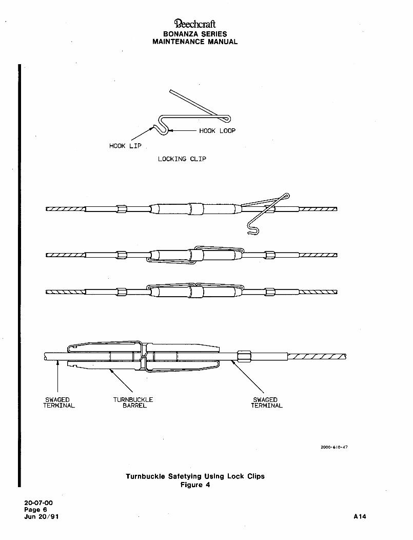
QeechcraftBONANZA SERIES
MAINTENANCE MANUAL
HOOK LOOP
HOOK LIP
LOCKING CLIP
SWAGED TURNBUCKLE SWAGEDTERMINAL BARREL TERMINAL
2000-610-47
Turnbuckle Safetying Using Lock ClipsFigure 4
20-07-00
Page 6
Jun 20/91 A14
C~)eechcraftBONANZA SERIES
MAINTENANCE MANUAL
insert the end of the locking clip into the terminal turnbuckle barrel using fingers only. Do not use a
and turnbuckle barrel end until the "U" curved end tool to check the lock clip installation as the lockingof the locking clip is over the hole in the center of clip could be distorted.the turnbuckle barrel.
g. Repeat the previous steps for installation ofd. Press the locking clip in the hole in the center
of the turnbuckle barrel to its full extent.the locking clip on the opposite end of the turn-
buckle barrel.e. The curved end of the locking clip will latch in
the hole in in the center of the turnbuckle barrel. h´• Both locking clips may be inserted in the same
f.side of the turnbuckle barrel center hole or in oppo-To check proper seating of the locking clip,site sides of the turnbuckle barrel center hole.
attempt to remove the pressed "U" end from the
20-07-00
Page 7
A~4 Jun 20/91
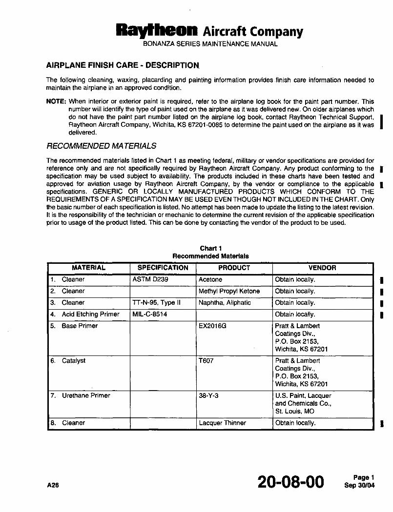
Raytheon Aircraft CompanyBONANZA SERIES MAINTE~ANCE MANUAL
AIRPLANE FINISH CARE DESCRIPTION.
The following cleaning, waxing, placarding and painting information provides finish care information needed to
maintain the airplane in an approved condition.
NOTE: When interior or exterior paint is required, refer to the airplane log book for the paint part number. This
number will identify the type of paint used on the airplane as it was delivered new. On older airplanes which
do not have the paint part number listed on the airplane log book, contact Raytheon Technical Support, IRaytheon Aircraft Company, Wichita, KS 67201-0085 to determine the paint used on the airplane as it was
delivered.
RECOMMENDED MATERIALS
The recommended materials listed in Chart 1 as meeting federal, military or vendor specifications are provided for
reference only and are not specifically required by Raytheon Aircraft Company. Any product conforming to the
specification may be used subject to availability. The products included in these charts have been tested and
approved for aviation usage by Raytheon Aircraft Company, by the vendor or compliance to the applicable Ispecifications. GENERIC OR LOCALLY MANUFACTURED PRODUCTS WHICH CONFORM TO THE
REQUIREMENTS OF A SPECIFICATION MAY BE USED EVEN THOUGH NOT INCLUDED IN THE CHART. Onlythe basic number of each specification is listed. No attempt has been made to update the listing to the latest revision.
It is the responsibility of the technician or mechanic to determine the current revision of the applicable specificationprior to usage of the product listed. This can be done by contacting the vendor of the product to be used.
Chart 1
Recommended Materials
MATERIAL SPECIFICATION PRODUCT VENDOR
1. Cleaner ASTM D239 Acetone Obtain locally.
2. Cleaner Methyl Propyl Ketone Obtain locally.
3. Cleaner TT-N-95, Type II Naphtha, Aliphatic Obtain locally.
4. Acid Etching Primer MIL-C-8514 Obtain locally.
5. BasePrimer EX2016G Pratt 8 Lambert
Coatings Div.,P.O. Box 2153,Wichita, KS 67201
6. Catalyst T607 Pratt 8 Lambert
Coatings Div.,P.O. Box 2153,Wichita, KS 67201
7. Urethane Primer 38-Y-3 U.S. Paint, Lacquerand Chemicals Co.,St. Louis, MO
8. Cleaner Lacquer Thinner Obtain locally.
A26 20-08-00 1
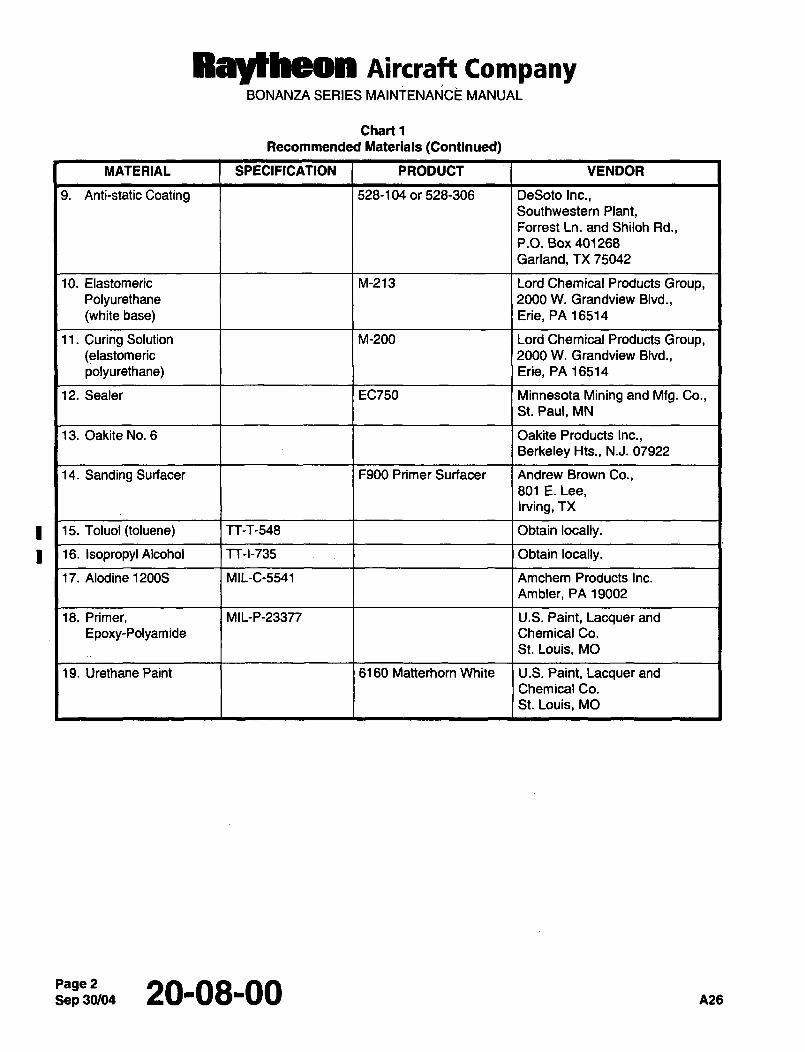
Ray~eon AiKraff companyBONANZA SERIES MAINTENANCE MANUAL
Chart 1
Recommended Materials (Continued)
MATERIAL SPECIFICATION PRODUCT VENDOR
9. Anti-static Coating 528-104 or 528-306 DeSoto Inc.,Southwestern Plant,Forrest Ln. and Shiloh Rd.,P.O. Box 401268
Garland, TX 75042
10. Elastomeric M-213 Lord Chemical Products Group,Polyurethane 2000 W. Grandview Blvd.,
(white base) Erie, PA 16514
11. Curing Solution M-200 Lord Chemical Products Group,(elastomeric 2000 W. Grandview Blvd.,
polyurethane) Erie, PA 16514
12. Sealer EC750 Minnesota Mining and Mfg. Co.,St. Paul, MN
13. Oakite No. 6 Oakite Products Inc.,Berkeley Hts., N.J. 07922
14. Sanding Surfacer F900 Primer Surfacer Andrew Brown Co.,801 E. Lee,
Irving, TX
1 15. Toluol (toluene) TT-T-548 Obtain locally.
))16. Isopropyl Alcohol TT-I-735; i Obtain locally.
17. Alodine 12008 MIL-C-5541 Amchem Products Inc.
Ambler, PA 19002
18. Primer, MIL-P-233n U.S. Paint, Lacquer and
Epoxy-Polyamide Chemical Co.
St. Louis, MO
19. Urethane Paint 6160 Matterhorn White U.S. Paint, Lacquer and
Chemical Co.
St. Louis, MO
Sep 20-08-00 A26
RBYtheOn ni~craft CompanyBONANZA SERIES MAINTENANCE MANUAL
AIRPLANE FINISH CARE MAINTENANCE PRACTICES
AIRPLANE FINISH´•´• CLEANING
CAUTION Since paint films do not obtain a hard finish fora considerable time after drying, airplanes thathave been
recently painted should not be polished or waved until the finish has cured for at least 60 days.
a. Remove dust and dirt from painted surfaces with a cellulose sponge and cool tap water.
b. Remove oil and grease with a cloth dampened with cleaner (3, Chart 1).
CAUTION: When washing the airplane with mild soap and water, use special care to avoid washing away greasefrom any lubricated area. After washing the wheel well areas with solvent, lubricate all lubrication points.Premature wear of lubricated surfaces may result if these precautions are not observed.
c. Remove insects with a cellulose sponge and a mild Ivory or Lux soap and water solution.
CAUTION: Harsh soaps and detergents will damage the airplane finish.
d. Carefully rinse the surface to remove ALL soap.
e. Dry the cleaned surface thoroughly with a chamois to prevent water marks.
ENVIRONMENTAL FALLOUT(ACID RAIN)
After the specified curing period of new paint, avoid outside storage when conditions exist where moisture maycollect on painted surfaces. Acids which remain in standing water can stain the paint topcoat and cause permanentdamage to the finish. Flush off residual moisture with clean tap water and dry the surface. At this time, waxing the
surface can provide protection from acid rain damage.
WAXING AIRPLANE FINISHES
A good coat of wax will protect the airplane finish from the sun’s rays and protect the surface against oxidation. Anygood automotive polish or wax may be used.
PLACARD REPLACEMENT
All placards must be in place and legible. Whenever the airplane has been repainted or touched up after repairs,replace any placard that has been defaced or is missing.
URETHANE PAINTS
NOTE: Any time the paint on the airplane is stripped for repainting, whether the repaint is to be on a localized area
of the airplane or on the entire airplane, a thorough inspection for possible hidden corrosion should be
conducted.
The need for an extremely hard finish for protection against sandblast during takeoff and landings led to the
development of urethane coatings for airplanes. Urethane paint dries to a high gloss and retains color much better
than standard finishes. It is unaffected by the chemicals in hydraulic fluids, deicer fluids and fuels and requires less
care and maintenance than standard finishes.
NOTE: After any painting repairs, inspect placards to ascertain that none have been covered with paint.
azs 20-08-00 3
Raytheon AiKraft CompanyBONANZA SERIES MAINTENANCE MANUAL
URETHANE PAINT REPAIR PROCEDURES
NOTE: The time normally required for urethane paint to cure must be extended at temperatures below 70"F. The
paint will not cure at temperatures below 60"F.
This airplane is finished with pretreatment (wash) primer, urethane primer and a top coat of urethane enamel. The
following procedures include cleaning, paint stripping, repaint preparation, priming, applying a urethane topcoat and
an alternate method for small repairs not requiring paint stripping. Careful observance of these procedures should
result in a smooth, hard, glossy finish with firm adhesion for maximum life.
I NOTE: Precut stripe, numeral and letter patterns are available through Modagrafics, 5300 Newport Dr., RollingMeadows, IL. 60008.
STRIPPING AND CLEANING URETHANE PAINT
CAUTION: DO NOT USE STRIPPER OFANY TYPE FOR REMOVING PAINT FROM FISERGLASS, NYLON OR
COMPOSITE SURFACES. Paint must be removed from these surfaces with fine sandpaper, using care
not to sand into the material. Never use aluminum foil to mask electrothermal windshields duringpainting, for most metal brighteners will combine with aluminum to form a hydrogen gas that eats awaythe stannous oxide used as an antistatic coating on electrothermal windshields. Ifmetal brighteners are
used, cover the windshield with paper or pasteboard masking material.
Because of their resistance to chemicals and solvents, urethane paints and primers require a special paint stripper.If a urethane stripper is not available, a good enamel stripper may be used. Removing the finish with such a
substitute will require several applications while working the stripper in with a stiff brush or wooden scraper.
a. Mask around the edge of the skin or skins containing the damaged area. Use a double thickness of heavy paperto prevent accidental splashes of paint stripper from penetrating the masking.
I b. Apply urethane stripper as instructed by the manufacturer. Stay approximately 1/8 inch away from the maskingtape. This will necessitate a little more cleanup upon finishing, but will prevent damage to the finish on the
adjacent skin. The stripper will not attack aluminum during the stripping process and can be neutralized
aftennrards by rinsing the affected area with water.
CAUTION: Urethane strippers usually contain acids that irritate or bum the skin. Wear rubber gloves and eye
protection when using stripper.
c. Rinse the area with water and dry.
I d. Wash the stripped area carefully with a cleaner (1, 2 or 8, Chart 1). This will prevent tiny particles of loose paintfrom adhering to the stripped area.
e. Using a nylon scratch pad or aluminum wool dipped in clean water, clean the surface with a cleanser such as
Bon Ami, Ajar, Comet cleaner, etc. A good scouring will leave the surface completely clean.
f. Thoroughly rinse with clean water and carefully dry the affected area. If the stripped area includes several jointsof skin laps, let the airplane sit until all moisture has dried. This may be accelerated by blowing the skin laps and
seams with compressed air. Wet masking should be replaced.
Sep 30/04Page 4 20-08-00
RBy~heOll nircraft CompanyBONANZA SERIES MAINiENANCE MANUAL
PRETREA TMENT (WASH) PRIMER FOR URETHANE PAINT
An acid etching primer (4, Chart l)should be applied to improve the adhesion of the finishing coats. A base primer(5, Chart 1) and catalyst (8, Chart 1) are used in equal parts as a pretreatment wash primer at the factory.
a. Mix the primer as instructed by the manufacturer.
b. Apply a thin wet coat of primer. It should be permitted to dry for at least an hour, but not over six hours, before ithe next coat of urethane primer is applied.
URETHANE PRIMER
a. Mix the urethane primer (7, Chart 1) as instructed by the manufacturer.
NOTE: For the best results these directions must be followed carefully, some manufacturers require that the primerbe allowed to set for 112 hour after the catalyst and base have been mixed while others recommend
immediate use after mixing.
b. Apply a coat of urethane primer with a spray gun using 35 to 40 psi of air pressure. A spotted appearance onlyindicates that the coat is thin.
c. If the initial primer coat is allowed to cure for more than 24 hours before the topcoat is applied, sand the primerslightly to roughen the surface and assure adhesion. Wipe off the sanding dust with a cloth dampened with a
cleaner (8, Chart 1), then apply the topcoat.
URETHANE TOPCOA TS
a. Mix the paint and catalyst as instructed by the manufacturer.
b. Apply the topcoat with a spray gun at 35 to 45 psi of air pressure. Two coats are normally required to fullyconceal the primer and build up the topcoat film necessary for adequate service life and beauty. The urethane
finish will normally cure to approximately 85% of its full hardness in 24 hours at temperatures of 80"F or higher.
URETHANE TOUCH-UP REPAIR
a. Mask around the skin containing the damaged area.
b. Remove all loose edges of paint by using a high tack adhesive tape around the edge of the damaged area.
c. Using a coarse sandpaper, fair the edge of the damaged area with the metal.
d. When the edge of the paint begins to fair into a smooth joint, use a fine grade of sandpaper to eliminate the
scratches left by the coarse paper. Take care to avoid removing any more metal than is absolutely necessary.
e. Wash the sanded area with a cleaner (2 or 8, Chart 1). Change often to clean wash cloths so that all of the
sanding dirt will be picked up.
f. After the area to be touched up has been cleaned until all traces of discoloration are gone, apply a thin coat of
pretreatment primer (4, Chart 1) to the damaged area.
A28 20-08-00Page 5
Raytheon Aircraft CompanyBONANZA SERIES MAINTENANCE MANUAL
NOTE: If a metal conversion coating such as iridite or alodine is used, the wash primer coating can be dispensedwith. If the metal has not been treated with a metal conversion coating but no wash primer is available,
carefully clean the surface to be touched up and apply urethane primer (7, Chart 1) to the bare metal. This
should produce a satisfactory undercoat for the repair area.
g. After the urethane primer has cured for 24 hours, sand the area under repair with medium line sandpaper. Sand
the edge of the repair area until the indentation where the metal and old paint meet is gone. If necessary, applyadditional urethane primer until the juncture of old paint with metal is no longer visible.
h. Spray on two urethane topcoats.
PAINTING MAGNESIUM
PAINT REMOVAL FROM MAGNESIUM SURFACES
WARNING: Do not use paint strippers that may cause an immediate corr~slve effect on magnesium andlor
aluminum surfaces. Acid base and some phenol base strippers are not recommended. Consult
the manufacturer for cautions if the stripper is not listed in the consumable materials chart of
this manual.
a. Mask areas not being stripped with two or more thicknesses of masking tape and aluminum foil to preventaccidental spillage from penetrating the masking.
b. Apply paint stripper (27, Chart 1, 91-00-00) to the surface being stripped with a brush or non-atomizing gun.
NOTE: Most strippers are neutralized with water; therefore, the surface being stripped must be thoroughly dry before
any application of the stripper. Magnesium surfaces are treated at the factory with a brown to amber Dow
19 primer coat. Any magnesium surfaces not displaying this color should be resprayed with a primer coat
before application of paint.
Dow 19 is used in the field to restore the original anti-corrosion surface treatment that may have been
I penetrated in service. The chemicals for Dow #19 formula may be purchased from a Raytheon Aircraft
Company Authorized Outlet in powder form or may be procured locally and produced as follows:
1. Place approximately 314 gallon of distilled water in a plastic container which will measure one gallon of fluid.
The water should be at a temperature of between 70 and 90"F.
2. Add 1 1/3 oz, of chromic acid (H2CT04)´•
3. Add 1 oz, of calcium sulfate (CaSO4) to the water.
4. Add distilled water to make one gallon of solution and stir vigorously for at least 15 minutes.
5. Brush the solution in and around the bare surfaces of the magnesium, keeping the area wet with the solution
for one to three minutes to produce a brown film. Do not exceed three minutes.
6. Rinse with cold running water and dry by exposure to hot air blast.
7. Apply a liberal coating of epoxy-based corrosion resistant primer.
WARNIOJG: Stripping should be accomplished in a well ventilated area, since prolonged exposure to
high concentrates of vapor may irritate the eyes and lungs.
c. Allow the paint stripper to remain on the airplane for 20 to 30 minutes, then work the remaining paint loose with
a bristle brush. The stripper may remain on the airplane for 2 hours but must not be allowed to dry on the surface.
Sep 20-08-00 A26
RaytheOn Aircraft CompanyBONANZA SERIES MAINTENANCE MANUAL
CAUTION: Never use a wire brush when removing paint from magnesium surfaces for it may cause damage to the
surface.
d. Remove the masking paper and wash the affected area thoroughly with water under high pressure. Remove all
remnants of paint with lacquer thinner.
PAINTING MAGNESIUM SURFACES
NOTE: Any time an airplane is repainted, inspect all placards to assure that they are not covered with paint, are
easily readable and are securely attached.
a. Prepare the surface to be repainted as indicated under PAINT REMOVAL FROM MAGNESIUM SURFACES.
Clean the affected area thoroughly with lacquer thinner or an equivalent solvent.
NOTE: Unprimed areas of magnesium castings are to be coated with MIL-M-3171 corrosion preventative compound(23, Chart 1, 91-00-00) unless these areas will come in contact with oil or grease after assembly. Any holes
in the castings which will receive bushings or bearings shall be coated with wet, unreduced zinc chromate
primer or corrosion preventative compound at the time of installation.
b. Prime the affected area with corrosion preventative compound and apply the urethane topcoat.
NOTE: Prior to application of the primer base, the magnesium surface should be thoroughly dried. Drying may be
accomplished by subjecting the magnesium to an elevated temperature of 130 to 140"F for a minimum of Ione hour. Allow a minimum of four hours drying time between application of the primer and topcoat.
SPECIAL PROCEDURES
PROPELLER BLADES
Paint the propeller blades as instructed by the propeller manufactures owner’s manual.
SURFACES SUSCEPTIBLE TO MUD AND SPRAY
Apply one coat of white epoxy paint to the following areas:
a. Main and nose landing gear wheel wells.
b. Interior surface of landing gear doors.
c. Main and nose landing gear assemblies.
RUBBER SEALS
Apply one coat of a thoroughly dissolved solution of one part Oakite No. 6 (13, Chart 1, 91-00-00) and two partswater to all rubber surfaces that are to come into contact with metal or other rubber surfaces.
ENCLOSED AREAS SUBJECT TO HIGH HUMIDITY
Steel, aluminum or magnesium parts and assemblies which are enclosed and subject to high humidity should be
protected against corrosion by coating with either epoxy primer, MIL-C-16173 corrosion preventative compound,light grease or heavy oil (5, Chart 1, 91-00-00).
na, 20-08-00 7
Raytheon Aircraft CompanyBONANZA SERIES MAINTENANCE MANUAL
BATTERY BOX AND LID
Finish the interior of the battery box and lid as follows:
a. Apply two (2) coats of Epoxy-Polyamide Primer per MIL-P-23377 (56, Chart 1, 91-00-00).
b. Apply two (2) coats of Matterhorn White urethane paint No. 6160 (57, Chart 1, 91-00-00).
PAINT FREE AREAS
The following areas shall be kept free from paint:
a. Engine controls.
b. Flight control cables and chains.
c. Exhaustmanifolds andexhauststacks.
d. Firewalls and wrought aluminum surfaces forward of the firewall, with the following exception:
1. Aluminum parts attached directly to the firewall shall be primed in detail.
e. Aluminumflexible conduit.
f. All tubing except unplated steel, which shall receive two coats of primer on the exterior, on interiors where the
I color scheme must be maintained, and except as noted, on the interior of the engine compartment.
g. Stall wamingvane.
h. Chromium plated portions of the landing gear piston tubes.
I i. Rubber and rubberlike surfaces.
j. Electrical wiring, unless otherwise noted as a specific requirement.
k. Glide path antenna (if installed).
I. Pitot mast and static buttons.
m. Cabin door sill and upper latch.
n. Utility door opening threshold (E-llll, E-1241 and After; EA-11 and After).
o. Window moldings, overhead console escutcheon, shoulder harness escutcheon, lower utility door escutcheon,window latch escutcheon, OAT escutcheon, ignition panel escutcheon, circuit breaker panel escutcheon, upper
utility door latch escutcheon, wing bolt cover escutcheons, and sidewall air valve escutcheons.
p. All bearing surfaces subject to rotation or sliding, such as elevator trim tab linkage joints.
q. All exterior placards. See Chapter 11 in this manual for placard locations.
Sep 30/04Page 8 20-08-00
RayNheon AiKraft CompanyBONANZA SERIES MAINTENANCE MANUAL
CORROSION- DESCRIPTION
Corrosion is the gradual eating away of material by chemical action.
Corrosion may develop at areas where the protective coating has been damaged. When this happens, it is importantto restore the protective coating. Corrosion also occurs when dissimilar metals are in contact with any moisture
present. High levels of humidity, high levels of environmental impurities (such as salt spray, acid rain, exhaust
deposits, or chemical fumes), or high ambient temperatures will increase the rate of corrosion. Some of the more
common types of corrosion are surface corrosion, inter granular corrosion, pitting, exfoliation, and electrolytic or Igalvanic corrosion.
GALVANIC CORROSION
The galvanic series shown below shows which metals are attacked when in contact with a dissimilar metal (Ref.Figure 1). The wider the separation in the series, from the top to the bottom, the faster the rate of corrosion. A partialgalvanic series list follows:
Anodic, or corroded end of series
Magnesium alloys
Aluminum alloys 5052, 5056, 5356, 6061, 6063
All other aluminum alloys
Zinc
Cadmium
Lead
Tin
Steel
Copper alloys
Nickel alloys
Titanium
Cathodic, or protected end of series
NOTE: Corrosion is relative. For example: aluminum alloys corrode when in contact with steel; steels corrode when
in contact with copper.
n~26 20-09-00
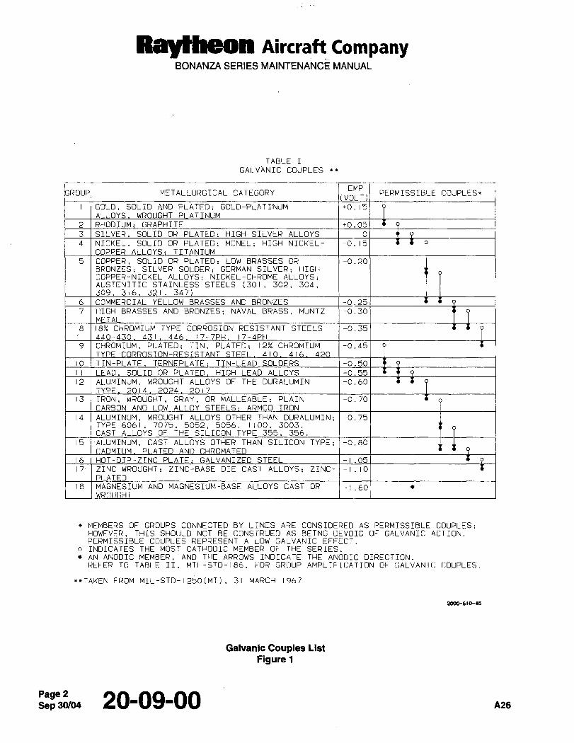
Raytheon Aircraft CompanyBONANZA SERIES MAINTENANCE MANUAL
TABLE I
GALVANIC COUPLES
EMPMETALLURGICAL CATEGORY PERMISSIBLE COUPLESr
[VOLT)
GOLD, SOLID AND PLATED; GOLD-PLATINUM ´•0.15
LOYS WROUGHT T NUM
2 RHODIUM: GRAPHITE +0.05
3 SILVER SOLID OR PLATED: HIGH SILVER ALLOYS O
4 NICKEL, SOLID OR PLATED; MONEL; HIGH NICKEL- -0.15
COPPER ALLOYS: TITANIUM
5 ICOPPER, SOLID OR PLATED; LOW BRASSES OR -0.20BRONZES; SILVER SOLDER; GERMAN SILVER: HIGH
COPPER-NICKEL ALLOYS; NICKEL-CHROME ALLOYS;AUSTENITIC STAINLESS STEELS (301, 302, 304,309, 316 321, 347)
6 COMMERCIAL YELLOW BRASSES AND BRONZES -0.25
7 HIGH BRASSES AND BRONZES: NAVAL BRASS, MUNTZ -0.30
METAL
8 18% CHROMIUM TYPE CORROSION RESISTANT STEELS -0.35
4~0-430 431 446 17-7PH 17-4PH
9 CHROMIUM, PLATED; TIN, PLATED; 12% CHROMTUM -0.45
TYPE ORROSION-RES TANT STEEL 410 416 4
10 TIN-PLATE TERNEPLATE: TIN-LEAD SOLDERS -0.50
II LEAD SOLID OR PLATED HIGH LEAD ALLOYS -0.55
12 ALUMINUM, WROUGHT ALLOYS OF THE DURALUMIN -0.60
T 2014 04 201
13 IRON, WROUGHT, GRAY, OR MALLEABLE: PLAIN -0.70
ARBON AND LOW ALLOY TEELS: ARMCO IRON
14 ALUMINUM, WROUGHT ALLOYS OTHER THAN DURALUMIN; -0.75TYPE 6061, 7075, 5052, 5056, 1100, 3003.
CAST ALLOYS OF THE SILICON TYPE 355, 356.
15 ALUMINUM, CAST ALLOYS OTHER THAN SILICON TYPE; -0.80
CADM UM PLATED A CHROMAT
16 HOT-DIP-ZINC PLATE: GALVANIZED STEEL -1.05
17´• ZINC WROUGHT; ZINC-BASE DIE CAST ALLOYS; ZINC- -1.10
AT
18 MAGNESIUM AND MAGNESIUM-BASE ALLOYS CAST OR -1.60WROUGHT
c MEMBERS OF GROUPS CONNECTED BY LINES ARE CONSIDERED AS PERMISSIBLE COUPLES:HOWEVER, THIS SHOULD NOT BE CONSTRUED AS BEING DEVOID OF GALVANIC ACTION.PERMISSIBLE COUPLES REPRESENT A iOW GALVANIC EFFECT.
o INDICATES THE MOST CATHODIC MEMBER OF THE SERIES.AN ANODIC MEMBER, AND THE ARROWS INDICATE THE ANODIC DIRECTION.REFER TO TABLE II, MIL-STD-I86. FOR GROUP AMPLIFICATION OF GALVANIC COUPLES.
**TAKEN FROM MIL-STD-I250[MI].´• 31~ MARCH 1967
2000-610-U
Galvanic Couples List
Figure 1
Sep 20-09-00 A26
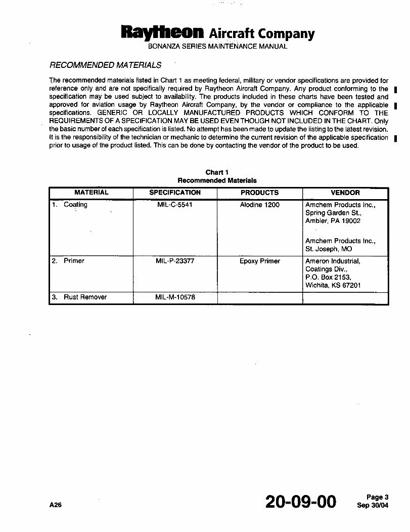
Raythwm AiKraft CompanyBONANZA SERIES MAINTENANCE MANUAL
RECOMMENDED MA TERIALS
The recommended materials listed in Chart 1 as meeting federal, military or vendor specifications are provided for
reference only and are not specifically required by Raytheon Aircraft Company. Any product conforming to the Ispecification may be used subject to availability. The products included in these charts have been tested and
approved for aviation usage by Raytheon Aircraft Company, by the vendor or compliance to the applicablespecifications. GENERIC OR LOCALLY MANUFACTURED PRODUCTS WHICH CONFORM TO THE
REQUIREMENTS OF A SPECIFICATION MAY BE USED EVEN THOUGH NOT INCLUDED IN THE CHART. Onlythe basic number of each specification is listed. No attempt has been made to update the listing to the latest revision.
It is the responsibility of the technician or mechanic to determine the current revision of the applicable specificationprior to usage of the product listed. This can be done by contacting the vendor of the product to be used.
Chart 1
Recommended Materials
MATERIAL SPECIFICATION PRODUCTS VENDOR
1. Coating MIL-C-5541 Alodine 1200 Amchem Products Inc.,
Spring Garden St.,Ambler, PA 19002
Amchem Products Inc.,St. Joseph, MO
2. Primer MIL-P-233n Epoxy Primer Ameron Industrial,Coatings Div.,P.O. Box 2153,Wichita, KS 67201
3. RustRemover MIL-M-10578
Ale 20-09-00 ,,,Pljso/~;JPage 3
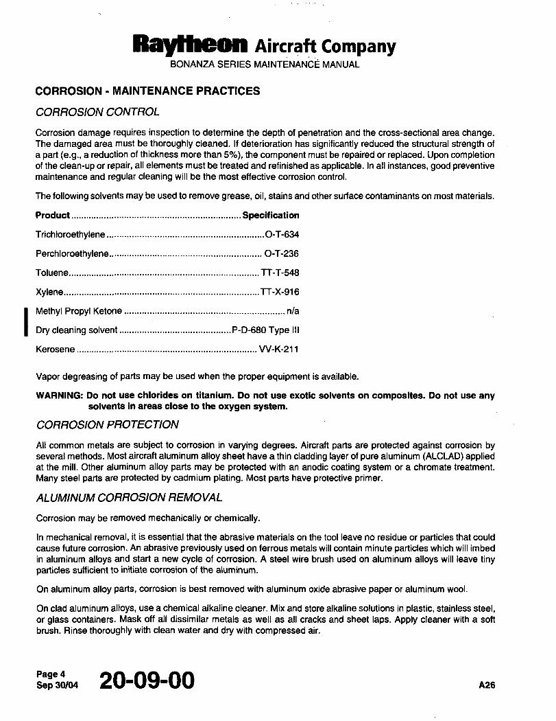
Raytheon Aircraft CompanyBONANZA SERIES MAINTENANC~ MANUAL
CORROSION MAINTENANCE PRACTICES
CORROSION CONTROL
Corrosion damage requires inspection to determine the depth of penetration and the cross-sectional area change.The damaged area must be thoroughly cleaned. If deterioration has significantly reduced the structural strength of
a part (e.g., a reduction of thickness more than 5%), the component must be repaired or replaced. Upon completionof the clean-up or repair, all elements must be treated and refinished as applicable. In all instances, good preventivemaintenance and regular cleaning will be the most effective corrosion control.
The following solvents may be used to remove grease, oil, stains and other surface contaminants on most materials.
Product Specification
Trichloroethylene .................................0-T-634
Perchloroethylene............................................................ O-T-236
Toluene........................................................................... TT-T-548
Xylene............................................................................. TT-X-916
I Methyl Propyl Ketone nla
Dry cleaning solvent............................................P-D-680 Type III
Kerosene VV-K-211
Vapor degreasing of parts may be used when the proper equipment is available.
WARNING: Do not use chlorides on titanium. Do not use exotic solvents on composites. Do not use anysolvents in areas close to the oxygen system.
CORROSION PROTECTION
All common metals are subject to corrosion in varying degrees. Aircraft parts are protected against corrosion byseveral methods. Most aircraft aluminum alloy sheet have a thin cladding layer of pure aluminum (ALCLAD) appliedat the mill. Other aluminum alloy parts may be protected with an anodic coating system or a chromate treatment.
Many steel parts are protected by cadmium plating. Most parts have protective primer.
ALUMINUM CORROSION REMOVAL
Corrosion may be removed mechanically or chemically.
In mechanical removal, it is essential that the abrasive materials on the tool leave no residue or particles that could
cause future corrosion. An abrasive previously used on ferrous metals will contain minute particles which will imbed
in aluminum alloys and start a new cycle of corrosion. A steel wire brush used on aluminum alloys will leave tinyparticles sufficient to initiate corrosion of the aluminum.
On aluminum alloy parts, corrosion is best removed with aluminum oxide abrasive paper or aluminum wool.
On clad aluminum alloys, use a chemical alkaline cleaner. Mix and store alkaline solutions in plastic, stainless steel,or glass containers. Mask off all dissimilar metals as well as all cracks and sheet laps. Apply cleaner with a soft
brush. Rinse thoroughly with clean water and dry with compressed air.
Page 20-09-00 P126

Raytheon Aircraft CompanyBONANZA SERIES MAINTE~ANCE MANUAL
WARNING: Always wear rubber gloves and protective clothing when working with acids. A face mask maybe necessary, depending upon ventilation in the area. If acid accidentally contacts skin or eyes,immediately flush with fresh water and seek medical advice.
REMOVAL OF CORROSION FROM ALUMINUM SURFACES
a. Strip all paint from the surface as directed under STRIPPING AND CLEANING URETHANE PAINT in Chapter20-08-00.
b. Mechanically remove corrosion by sanding or rubbing as necessary.
c. Inspect the surface carefully to ensure that sufficient material remains to satisfy structural requirements.
d. Clean the corrosion removed area with a chemical alkaline cleaner.
e. Treat all aluminum surfaces with MIL-C-5541 (1, Chart 1).
1. Rinse the treated area in COLD running water and dry in an oven or by exposure to hot air blast.
NOTE: If cold running water is not available, rinsing may be eliminated and the area dried as stated above.
2. Brush 2 coats (a minimum of 30 minutes apart) of epoxy primer (2, Chart l)on and around the reworked
area. Assure adequate penetration of primer into the treated area.
ALUMINUM CORROSION TREATMENT
After corrosion removal and surface cleaning, metals should be given protective treatment and painted. Alodine
treatment of aluminum alloys forms a protective coating which resists corrosion and provides a good surface for
adhesion of the paint primer.
Alodine 1200, 1200S, 1201 (1, Chart 1), or equivalent, when mixed 2 ounces per gallon of water, will be an
acceptable treatment material. Mix only in rubber, plastic or stainless steel containers. Alodine 1200 series productscontain fluorides that should not be mixed in glass containers. Coat the area with the Alodine solution and allow the
coating to dwell for approximately five minutes. After the dwell time has elapsed, wash the area with water and blow
dry (do not wipe dry). Paint the coated area with epoxy polyamide primer (2, Chart 1) and allow to dry.
WARNING: Brushes and cloths should not be left in the Alodine solution. They should be washed
immediately after use. If such items are left to dry in the open air, they could create a fire hazard.
CAUTION: Keep the Alodine solution confined to the affected area. Mask or seal all cracks and crevices, all steel
parts, and any mechanical components. Wash all brushes and cloths immediately after use to preventinadvertent contact with the acid solution and to eliminate a possible fire hazard from any such materials
that dry without being washed.
IVIAGNESIUM CORROSION REMOVAL
a. Strip all paint from the surface as directed under PAINT REMOVAL FROM MAGNESIUM SURFACES.
b, Mechanically remove corrosion by sanding or rubbing as necessary. If sanding, use aluminum sandpaper. Start
with 240 grit and finish with 400 grit.
c. Inspect the surface carefully to ensure that sufficient material remains to satisfy structural requirements.
d. Clean the corrosion removed area with Methyl Propyl Ketone (MPK) or naphtha.
e. Apply corrosion treatment to the unprotected magnesium.
A26 20-09-00Page 5
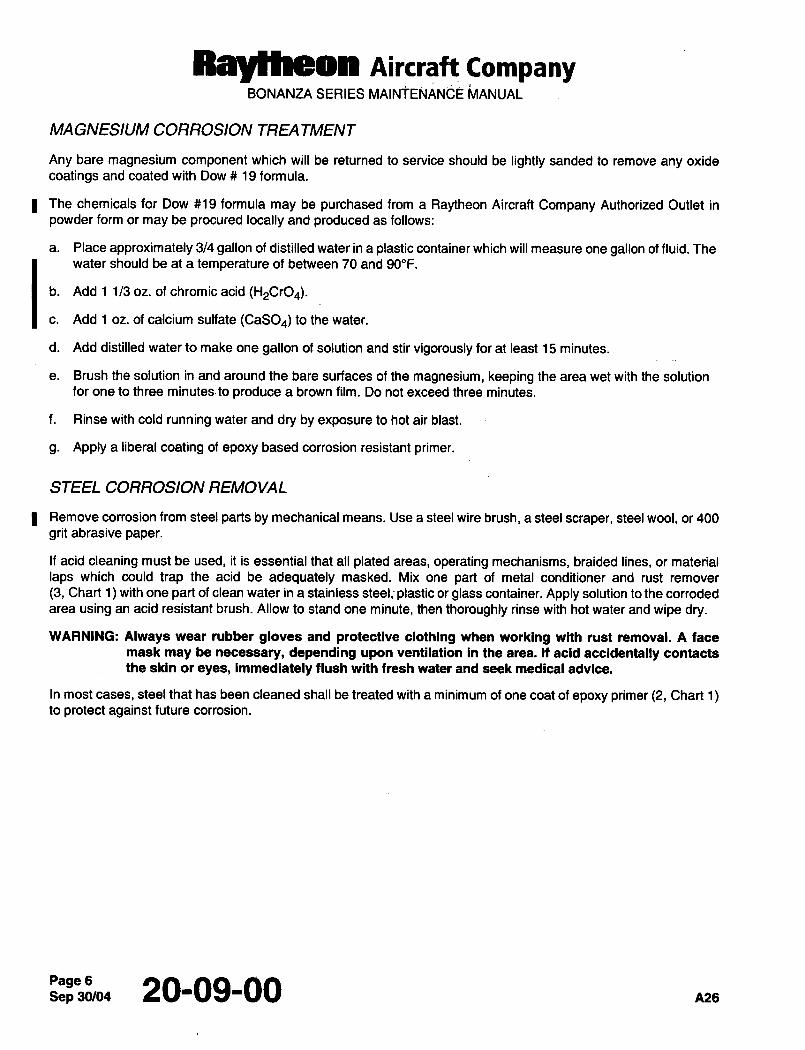
Raytheon Aircraft CompanyBONANZA SERIES MAINIENAN~E i~lANUAL
MAGNESIUM CORROSION TREA TMENT
Any bare magnesium component which will be returned to service should be lightly sanded to remove any oxide
coatings and coated with Dow 19 formula.
I The chemicals for Dow #19 formula may be purchased from a Raytheon Aircraft Company Authorized Outlet in
powder form or may be procured locally and produced as follows:
a. Place approximately 314 gallon of distilled water in a plastic container which will measure one gallon of fluid. The
water should be at a temperature of between 70 and 90"F.
Add 1 1/3 oz. of chromic acid (H,CrO4).
Add 1 oz, of calcium sulfate (CaSO4) to the water.
d. Add distilled water to make one gallon of solution and stir vigorously for at least 15 minutes.
e. Brush the solution in and around the bare surfaces of the magnesium, keeping the area wet with the solution
for one to three minutes to produce a brown film. Do not exceed three minutes.
f. Rinse with cold running water and dry by exposure to hot air blast.
g. Apply a liberal coating of epoxy based corrosion resistant primer.
STEEL CORROSION REMOVAL
I Remove corrosion from steel parts by mechanical means. Use a steel wire brush, a steel scraper, steel wool, or 400
grit abrasive paper.
If acid cleaning must be used, it is essential that all plated areas, operating mechanisms, braided lines, or material
laps which could trap the acid be adequately masked. Mix one part of metal conditioner and rust remover
(3, Chart 1) with one part of clean water in a stainless steel,- plastic or glass container. Apply solution to the corroded
area using an acid resistant brush. Allow to stand one minute, then thoroughly rinse with hot water and wipe dry.
WARNING: Always wear rubber gloves and protective clothing when working with rust removal. A face
mask may be necessary, depending upon ventilation in the area. It acid accidentally contacts
the skin or eyes, immediately flush with fresh water and seek medical advice.
In most cases, steel that has been cleaned shall be treated with a minimum of one coat of epoxy primer (2, Chart 1)to protect against future corrosion.
Sep 30/04Page 6 20-09-00 A26
CHAPTER
AIR
CONDITIOMING
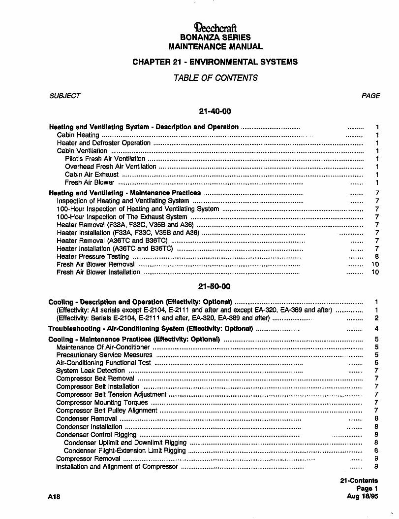
aeechclarfiEONANZA SERIES
MAINTENANCE MANUAL
CHAPTER 21 ENVIRONAIIENTAL SYSTEMS
TABLE OF CONTENTS
SU&IECT PAGE
21140´•´•00
Heating and Ventilating System Description and Operation 1
Cabin Heating 1
Heater and Defroster Operation 1
Cabin Ventilation 1
Pilot’s Fresh Air Ventilation 1
Overhead Fresh Air Ventilation 1
Cabin Air Exhaust 1
Fresh Air Blower 1
Heating and Ventilating Maintenance Practices 7
Inspection of Heating and Ventilating System 7
100-Hour Inspection of Heating and Ventilating System 7
100-Hour Inspection of The Exhaust System 7
Heater Removal (F38A, F33C, V95B and A36) 7
Heater Installation (F33A, F33C, V35B and A36) 7
Heater Removal (A36TC and B36TC) 7
Heater Installation (A36TC and B36TC) 7
Heater Pressure Testing 8
.Fresh Air Blower Removal 10
Fresh Air Blower Installation 10
21150100
Cooling Description and Operation (Eftectlvlty: Optional) 1
(Effectivity: All serials except E-2104, E-2111 and after and except EA-320, EA-389 and after) 1
(Effectivity: Serials E-2104, E-2111 and after, EA-320, EA-389 and after) 2
Troubleshooting Alr-Condltionlng System (Eftectivlty: Optional) 4
Cooling Maintenance Practices (Effectivlty: Optional) 5
Maintenance Of Air-Conditioner 5
Precautionary Service Measures 5
Air-Conditioning FunctionalTest 5
System Leak Detection 7
Compressor Belt Removal 7
Compressor Belt Installation 7
Compressor Belt Tension Adjustment 7
Compressor Mounting Torques 7
Compressor Belt Pulley Alignment 7
Condenser Removal 8
Condenser Installation 8
Condenser Control Rigging 8
Condenser Uplimit and Downlimit Rigging 8
Condenser Flight-Extension Limit Rigging 8
Compressor Removal 9
Installation and Alignment of Compressor 9
21 -Contents
Page~A18 Aug 18/95
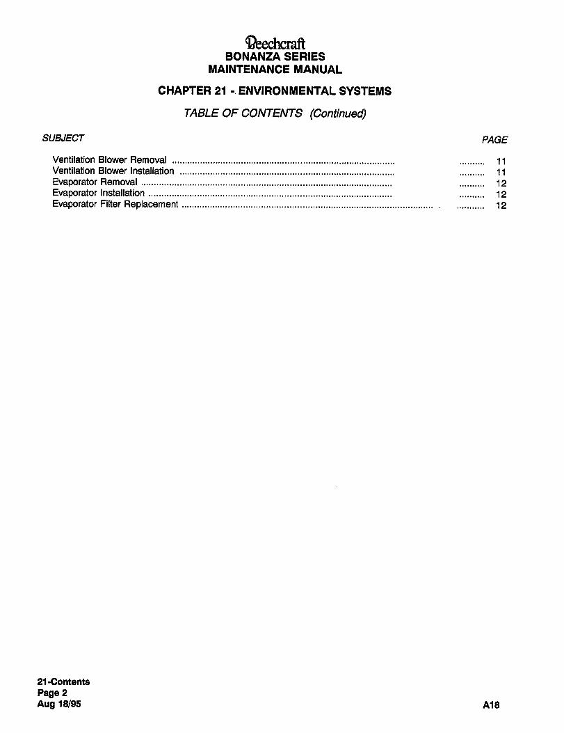
aeechcra~ftBONANZA SERIES
MAINTENANCE MANUAL
CHAPTER 21 ENVIRONMENTAL SYSTEMS
TABLE OF CONTENTS (Continued)
SU&IECT PAGE
Ventilation Blower Removal 11Ventilation Blower Installation 11
Evaporator Removal 12
Evaporator Installation 12
Evaporator Filter Replacement 12
21 -Contents
Page 2
Aug 18/95 A18
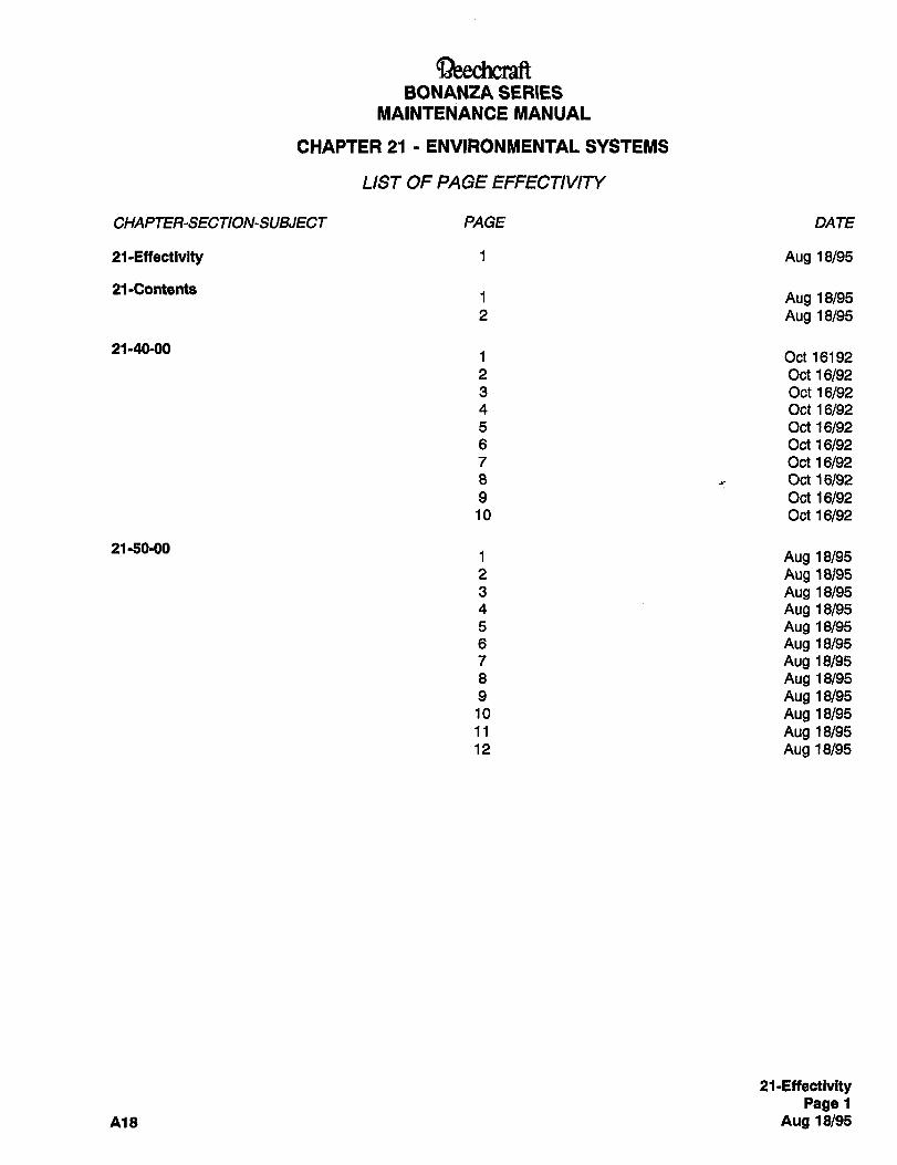
BONANZA SERIES
MAINTENANCE MANUAL
CHAPTER 21 1 ENVIRONMENTAL SYSTEMS
LIST OF PAGE EFFECTIVIP/
CHAPTER-SECTION-SUBJECT PAGE DATE
21-Effectivity 1 Aug 18/95
21-Contents1 Aug 18/952 Aug 18/95
21-40-001 Oct 16192
2 oct 16/923 Oct 16/924 Oct16/925 oct16/926 oct 16/927 oct 16/928 Oct161929 oct 16/9210 oct 16/92
21-50-001 Aug 18/952 Aug 18/953 Aug 18/954 Aug 18/955 Aug 18/956 Aug 18/957 Aug 18/958 Aug 18/959 Aug 18/9510 Aug 18/9511 Aug 18/9512 Aug 18/95
21-EffectivityPage 1
A18 Aug 18/95
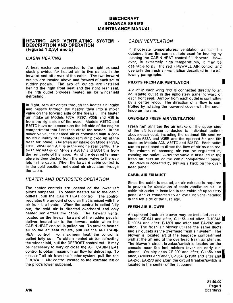
BEECHCRAFT
BONANZA SERIES
MAINTENANCE MANUAL
HEATING AND VENTILATING SYSTEM CABIN VENTILA TIONDESCRIPTION AND OPERATION
(Figures 1,2,3,4 and 5) In moderate temperatures, ventilation air can beobtained from the same outlets used for heating by
CABIN HEA TING pushing the CABIN HEAT control full forward. How-
ever, in extremely high temperatures, it may be
A heat exchanger connected to the right exhaust desirable to pull the red FIREWALL AIR control and
stack provides for heated air to five outlets in the use only the fresh air ventilation described in the fol-
forward and ah areas of the cabin. The two forward lowing paragraphs.outlets are located above and forward of each set of IPILOT’S FRESH AIR VENTILATIONrudder pedals. The two aft outlets are installed
behind the right front seat and the right rear seat.
The fifth outlet provides heated air for windshieldA duct in each wing root is connected directly to an
adjustable outlet in the upholstery panel forward ofdefrosting. each front seat. Airflow from each outlet is controlled
by a center knob. The direction of airflow is con-In night, ram air enters through the heater air intake trolled by rotating the louvered cover with the smalland passes through the heater, then into a mixer knob on the rim.valve on the forward side of the firewall. The heater
air intake on Models F33A, F33C, V35B and A36 is OVERHEAD FRESH AIR VENTILATION Ifrom the right side of the nose. Models A36TC and
B36TC have an airscoop on the left side of the engine Fresh ram air from the air intake on the upper sidecompartment that furnishes air to the heater. In the of the aft fuselage is ducted to individual outletsmixer valve, the heated air is combined with a con- above each seat, including the optional 5th seat on
fresh air intake. The fresh air intake on Models F33A, seats on Models A36, A36TC and B36TC. Each outlet Itrolled quantity of unheated ram air picked up at the Models F33A and V35B and the optional 5th and 6th
F33C, V35B and A36 is in the engine rear baffle. The can be positioned to direct the flow of air as desired.fresh air intake on Models A36TC and B36TC is from The volume of incoming air can be regulated bythe right side of the nose. Air of the desired temper- rotating the outlet. A shutoff va’lve is installed in the Iature is then ducted from the mixer valve to the out- fresh air duct aft of the cabin compartment panel. Ilets in the cabin. When the forward cabin control is The valve is operated by turning a knob on the over-
in the cold position, unheated air circulates through head panel.the cabin.
CABIN AIR EXHAUST
HEATER AND DEFROSTER OPERATIONSince the cabin is sealed, an air exhaust is required
The heater controls are located on the lower left to provide for circulation of cabin ventilation air. A
pilot’s subpanel. To obtain heated air to the cabin cabin air outlet is installed in the cabin aft upholstery
outlets, pull the CABIN HEAT control. The control panel and is connected to an exhaust vent installed
regulates the amount of cold air that is mixed with the in the left side of the fuselage.
air from the heater. When the control is pulled fullyFRESH AIR BLOWER
out, the cold air is directed overboard and onlyheated air enters the cabin. The forward vents, An optional fresh air blower may be installed on air-located on the firewall forward of the rudder pedals, planes CE-941 and after, CJ-156 and after, D-10348, 1deliver heated air to the forward cabin when the D-10364 and after, E-1809 and after and EA-192 andCABIN HEAT control is pulled out. To provide heated after. The fresh air blower utilizes the same ductsair to the aft seat outlets, pull out the AFT CABIN and air outlets as the overhead fresh air system. TheHEAT control. For maximum heat, the control is blower is located aft of the baggage compartmentpulled fully out. To obtain heated air for defrosting wall at the aft end of the overhead fresh air plenum.the windshield, pull the DEFROST control out. It may The blower’s circuit breaker/switch is located on thebe necessary to vary or close the AFT CABIN HEAT console near the fuel mixture lever on early air-control to obtain maximum air flow for defrosting. To planes. On airplanes CE-990 and after, CJ-156 andIclose off all air from the heater system, pull the red after, D-10390 and after, E-1954, E-1988 and after and
FIREWALL AIR control located to the extreme left of EA-243, EA-273 and after, the circuit breaker/switch is
the pilot’s lower subpanel. located in the center of the subpanel.
21-40-00
Page 1
A16 Oct 16/92
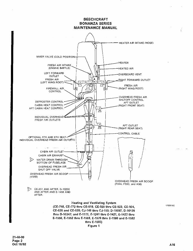
BEECHCRAFT
BONANZA SERIES
MAINTENANCE MANUAL
HEATER AIR INTAKE (NOSE)
MIXER VALVE (COLD POSITION)
HEATERFRESH AIR INTAKE
(ENGINE BAFFLE) \\\\tJ _\ -HEATED AIR
LEFT FORWARDVERBOARD VENT
(LEFT WING ROOT)~rOUTLET IRIGHT FORWARD OUTLETFRESH AIR
FRESH AIR
FIREWALL AIR\ L~fJ /-~MIYtl I~J ~(RIGHT WING ROOT)CONTROL
OVERHEAD FRESH AIR
SHUTOFF CONTROLDEFROSTER CONTROL I AFT OUTLETCABIN HEAT CONTROL~ I~H II H/’I I ~(RIGHT FRONT SEAT)
AFT CABIN HEAT CONTROL/ /Y~J
INDIVIDUAL OVERHEAD
FRESH AIR OUTLETS
AFT OUTLET
t~3/ ~i I REAR SEAT)
OL CABLE
OPTIONAL 5TH AND 6TH SEATi
INDIVIDUAL OVERHEAD FRESH AIR OUTtCTStllll t
CABIN AIR
CABIN AIR EXHAUST
WATER GRAIN THROVGH
BOTTOMOFFUSELAGE ~nl /~t
OVERHEAD FRESH AIR
SHUT OFF VALVE
OVERHEAD FRESH AIR SCOOP
(V35B)
OVERHEAD FRESH AIR SCOOP
(F33A, F33C, and A36)
I~ GE-831 AND AFTER. 0-10200
AND AFTER AND E-1408 AND
AFTER.
Heating and Ventilating System(CE-748, CE-772 thru CE-918, CE-920 thru CE-922, CE-924,
C9200100
CE-926 and CE-928; CJ-149 thru CJ-155; D-10097, D-10120
thru D-10347; and E-lll?, E-1241 thru E-1421, E-1423 thru
E-1550, E-1552 thru E-1568, E-1570 thru E-1580 and E-1582
thru E-1593)
Figure 1
21-40-00
Page 2
Oct 16/92 A16
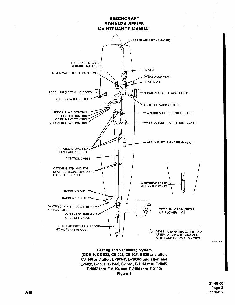
BEECHCRAFT
BONANZA SERIES
MAINTENANCE MANUAL
n HEATER AIR INTAKE (NOSE)
FRESH AIR INTAKE
(ENGINE BAFFLE)HEATER
MIXER VALVE (COLD POSI
OVERBOARD VENT
HEATED AIR
FRESH AIR (LEFT WING ROOT) I (I UIBII tc~--FRESH AIR (RIGHT WING ROOT)
LEFT FORWARD OUTLET
RIGHT FORWARD OUTLET
FIREWALL AIR CONTROL~ OVERHEAD FRESH AIR CONTROLDEFROSTER CONTROL
CABIN HEAT CONTROL
AFT CABIN HEAT CONTROL- I nv OUTLET (RIGHT FRONT SEATI
AFT OUTLET (RIGHT REAR SEAT)
INDIVIDUAL OVERHEAD
FRESH AIR OUTLETS
CONTROL CABLE
OPTIONAL 5TH AND 6TH
SEAT INDIVIDUAL OVERHEAD
FRESH AIR OUTLETS
AIR SCOOP (V35B)
CABIN AIR OUTLET
CABIN AIR EXHAUST
OF FUSELAGE r-- OPTIONAL CABIN FRESHWATER DRAIN THROUGH BOTTOM
AIRBLOWER g1 iOVERHEAD FRESH AIR
SHUT OFF VALVE
OVERHEAD FRESH AIR SCOOP
(F33A. F33C and A-36) j~ CE-941 AND AFTER. CJ-156 AND
AFTER, D-1034B, D-10364 ANDAFTER AND E-1809 AND AFTER.
C9200101
Heating and Ventilating System(CE-919, 08-923, 08-925, CE-927, E-929 and after;CJ-156 and after; D-10348, D-10353 and after; and
E-1422, 8-1551, 8-1569, E-1581, E-1594 thru E-1945,E-1947 thru E-2103, and E-2105 thru E-2110)
Figure 2
21-40-00
Page 3
A16 Oct 16/92
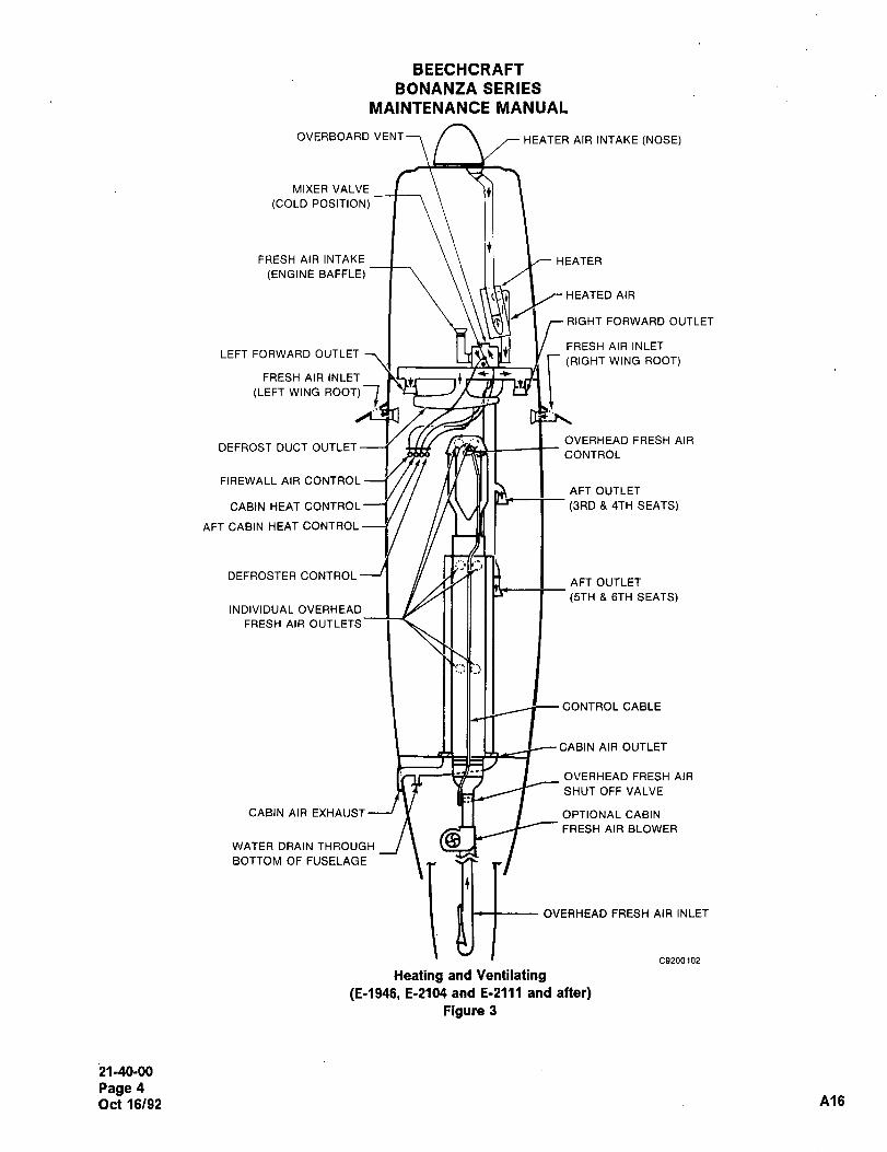
BEECHCRAFT
BONANZA SERIES
MAINTENANCE MANUAL
OVERBOARD VENT7 HEATER AIR INTAKE (NOSE)
MIXER VALVE
(COLD POSITION)
FRESH AIR INTAKE I I HEATER
(ENGINE BAFFLE)
HEATED AIR
RIGHT FORWARD OUTLET
FRESH AIR INLETLEFT FORWARD OUTLET 7 1 I
(RIGHT WING ROOT)
FRESH AIR INLET
(LEFT WING ROOT)
OVERHEAD FRESH AIRDEFROST DUCT OUTLET
CONTROL
FIREWALL AIR CONTROLAFT OUTLET
CABIN HEAT CONTROL 1 ln\ H/ 1-- I (3RD 4TH SEATS)
AFT CABIN HEAT CONTROL
DEFROSTER CONTROLAFT OUTLET
(5TH 6TH SEATS)INDIVIDUAL OVERHEAD
FRESH AIR OUTLETS
CONTROL CABLE
CABIN AIR OUTLET
OVERHEAD FRESH AIR
SHUT OFF VALVE
CABIN AIR EXHALJST----’ r I I I OPTIONAL CABIN
FRESH AIR BLOWER
WATER DRAINTHROUGH ~BBOTTOM OF FUSELAGE
~Qf OVERHEAD FRESH AIR INLET
C9200102
Heating and Ventilating(E-1946, E-2104 and E-2111 and after)
Figure 3
21-40-00
Page 4
Oct 16/92 A16
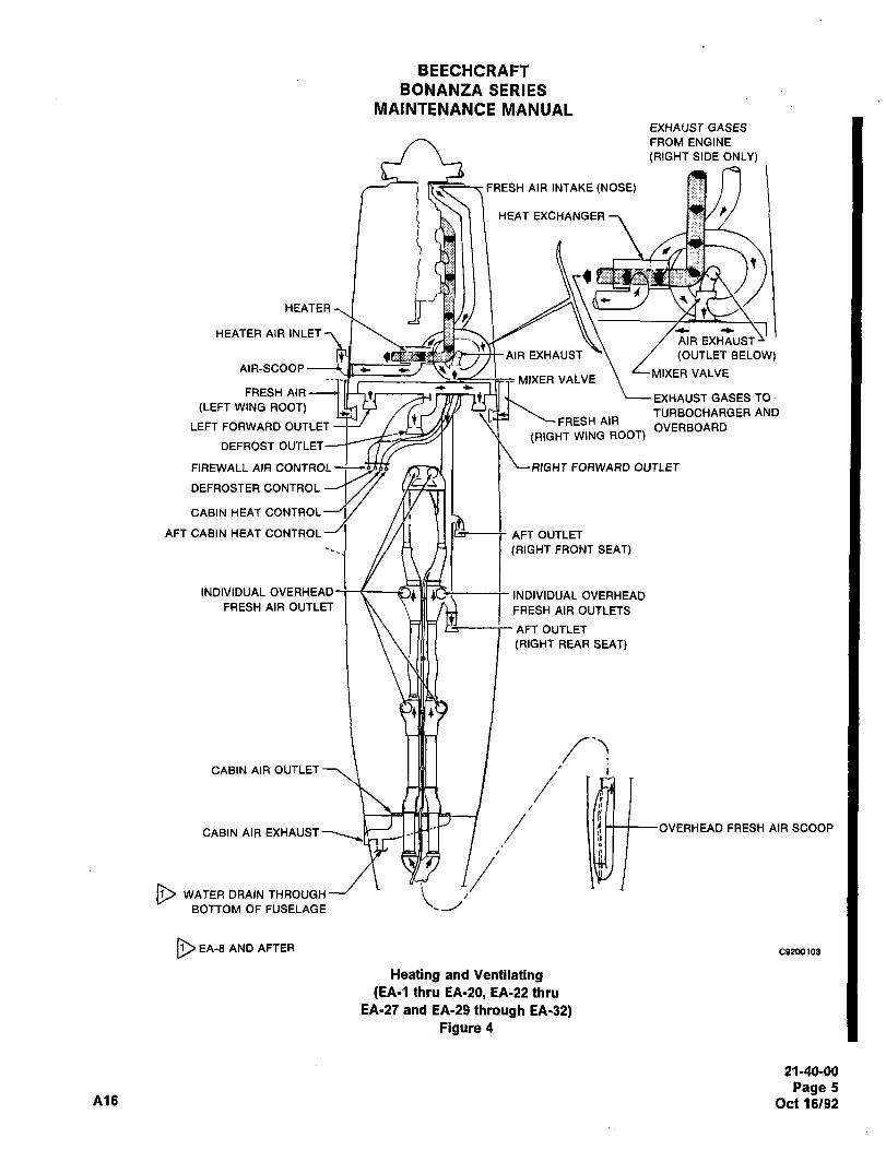
BEECHCRAFT
BONANZA SERIES
MAINTENANCE MANUALEXHAUST GASES
FROM ENGINE
(RIGHT SIDE ONLY)
FRESH AIR INTAKE (NOSE)
HEAT EXCHANGER
HEATER
HEATER AIR INLETAIR EXHAUST
AIREXHAUST (OUTLET BELOW)AIR-SCOOP
MIXER VALVEMIXER VALVE
´•L-FRESH AIR
EXHAUST GASES TO(LEFT WING ROOT) TURBOCHARGER AND
FRESH AIRLEFT FORWARD OUTLET OVERBOARD
(RIGHT WING ROOT)DEFROST OUTLET
FIREWALL AIR CONTROL --;-~53; 1 "RIGHT FORWARD OUTLET
DEFROSTER CONTROL
CABIN HEAT CONTROL
AFT CABIN HEAT CONTROL I //II 1 I AFT OUTLET
(RIGHT FRONT SEAT)
INDIVIDUAL OVERHEAD I ,YU INDIVIDUAL OVERHEADFRESH AIR OUTLET 111 I FRESH AIR OUTLETS
AFT OUTLET
(RIGHT REAR SEAT)
24
CABIN AIR OUTLET
CABIN AIR EXHAUST OVERHEAD FRESH AIR SCOOP
WATER DRAIN THROUGH jBOTTOM OF FUSELAGE
BEA-8ANDAFTER CB?m103
Heating and Ventilating(EA-1 thru EA-20, EA-22 thtu
EA´•ST and EA-29 through EA-32)Figure 4
21-40-00
Page 5A16 Oct 16/92
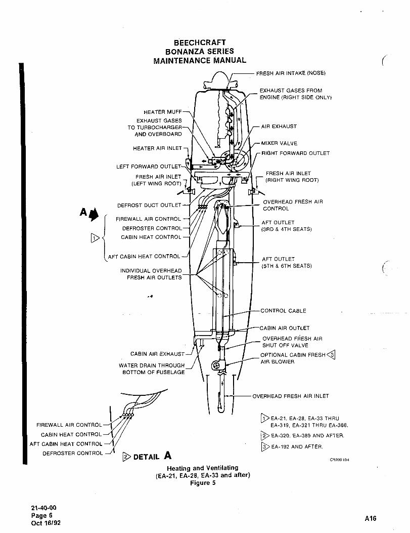
BEECHCRAFT
BONANZA SERIES
RIIAINTENANCE MANUAL
FRESH AIR INTAKE (NOSE)
EXHAUST GASES FROM
ENGINE (RIGHT SIDE ONLY)
HEATER MUFF
EXHAUST GASES
TO TURBOCHARGER--\ I I I~AIREXHAUSTAND OVERBOARD
MIXER VALVEHEATER AIR INLET
RIGHT FORWARD OUTLET
c
LEFT FORWARD OUTLET~SI
-e FRESH AIR INLETFRESH AIR INLET
(RIOHT WING ROOT)(LEFT WING ROOT) t
OVERHEAD FRESH AIRDEFROST DUCT OUTLET
ASCONTROL
FIREWALL AIR CONTROLAFT OUTLET
DEFROSTER CONTROLI// /n\ ~--r (3RD 4TH SEATS)
CABIN HEAT CONTROL
AFT CABIN HEAT CONTROLAFT OUTLET
(5TH 6TH SEATS)INDIVIDUAL OVERHEAD
FRESH AIR OUTLETS
I
OL CABLE
CABIN AIR OUTLET
OVERHEAD FRESH AIR
SHUT OFF VALVE
CABIN AIR EXHAUST--/ j~ I I I OPTIONAL CABIN FRESH
AIR BLOWERWATER DRAIN THROUGH
BOTTOM OF FUSELAGE
js~F OVERHEAD FRESH AIR INLET
~EA-21, EA-28. EA-33 THRU
FIREWALL AIR CONTROL-~ EA-319. EA-321 THRU EA-388.
CABIN HEAT CONTROL EA-320. EA-389 AND AFTER.
AFT CABIN HEA~ CONTAOLEA-192 AND AFTER
DEFROSTERCONTROL--~´•DETAIL A
C920010~1
Heating and Ventilating
(EA-21, EA-28, EA-33 and after)Figure 5
21-40-00
Page 6A16
Oct 16/92
BEECHCRAFT
BONANZA SERIES
MAINTENANCE MANUAL
HEATING AND VENTILATING MAINTE- HEATER INSTALLATION (F33A, F33C, V35BINANCE PRACTICES AND A36)
INSPECTION OF HEATING AND VENTILAT- a. Install the heater shroud and retainingING SYSTEM screws.
Inspect the air intake ducts leading to the heater; b. Install the heater in the airplane.check all clamps and connections for tightness and
the duct for holes and cracks. Check the duct forc. Connect the engine exhaust system to the
internal restrictions and/or collapsing. Check theheater.
screen at the intake duct; remove and clean as nec-
essary.d. Connect the heater ducts to the heater.
Inspect the heater control box for full stop-to-stoptravel and proper sealing of the valve. Inspect the e. Install the heater access panel.
condition of the air ducts leading to the windshield
defroster and cabin heat outlets. Seal or tape HEATER REMOVAL (A36TC AND B36TCJ Iopenings around wires, tubes, or cables passingthrough the firewall. a. Remove the heater access panel from the
right side.
Inspect around the removable web on the lower half
of the cabin rear bulkhead for leaks. Openings, b. Remove the heater ducting.stringer cutouts, or cracks must be kept sealed with
sealing compound (17, Chart 1, 91-00-00) between thec. Remove four bolts on the right side of the
bulkhead and the skin by removing the upper uphol- heater which attach it to the exhaust system.stery panel of the bulkhead. Also plug the levelinglug holes in the baggage doorframe to prevent entry
d. Loosen the clamp on the left side of theof cold air.
heate r.
100-HOUR INSPECTION OF HEATING ANDVENTILA TING SYSTEM e. Remove the heater through the access
hole.
Check for corrosion, cracks or worn areas in ducts,loose clamps, loose or missing fasteners or f. Remove the heater shroud from the heater.
obstructions. Check for proper operation, travel and
sealing of valves. g. Pressure test the heater as indicated in
HEATER PRESSURE TESTING in this Chapter.100-HOUR INSPECTION OF THE EXHAUST
SYSTEM HEA TER INS TALLA TION (A36TC ANDIsssTC)
Check per POWER PLANT EXHAUST SYSTEM in
Chapter 5-20-00. a. Install the heater shroud on the heater.
I~js4TER REMOI/AL (F33*. F33C, V358 ANL)b. Install the heater through the access hole.
c. Tighten the clamp on the left side of thea. Remove the heater access panel from the
heater.right side.
d. Install the four bolts on the right side of theb. Remove both heat ducts from the heater.
heater which attach it to the exhaust system. Tighten
c. Disconnect the heater from the exhaust to 100 to 110 inch-pounds.
system and remove it from the airplane.e. Install the ducts to the heater.
d. Remove the screws from the heater shroud
and slide the shroud off the heater, f. Install the heater access panel.
21-40-00
Page 7
A16 Oct16/92
BEECHCRAFT
BONANZA SERIES
MAINTENANCE MANUAL
HEA TER PRESSURE TESTING planes, pressurize the heater to 25 psig. On A36TC
and B36TC, pressurize the heater to 5 psig. Pres-
The heater should be inspected for cracks and leaks surize the heater with air or nitrogen and either
which could introduce carbon monoxide into the immerse in water or "paint" with a soap solution. If
heating system. any leaks are apparent, replace the heater. This test
is also recommended for the heater at every engineOn all Bonanzas except the turbocharged models change.(EA-1 and after), perform a visual inspection each 100
hours and pressure test each 500 hours. On the NOTE
turbocharged models (EA-1 and after), visuallyinspect and pressure test each 100 hours. The pres- The heat transfer studs along with the
sure test can be accomplished as follows: internal baffle and/or cone must be in
place for a correct supply of heat. Anya. Remove the heater as indicated in HEATER warpage is cause for replacement.
REMOVAL.
c. If the inspection indicates a good heater,b. Inspect the heater visually and pressure reinstall the heater as indicated in HEATER INSTAL-
Itest for leaks. On F33A, F33C, V35B and A36 air- LATION.
21-40-00
Page 8
Oct 16/92 Ale
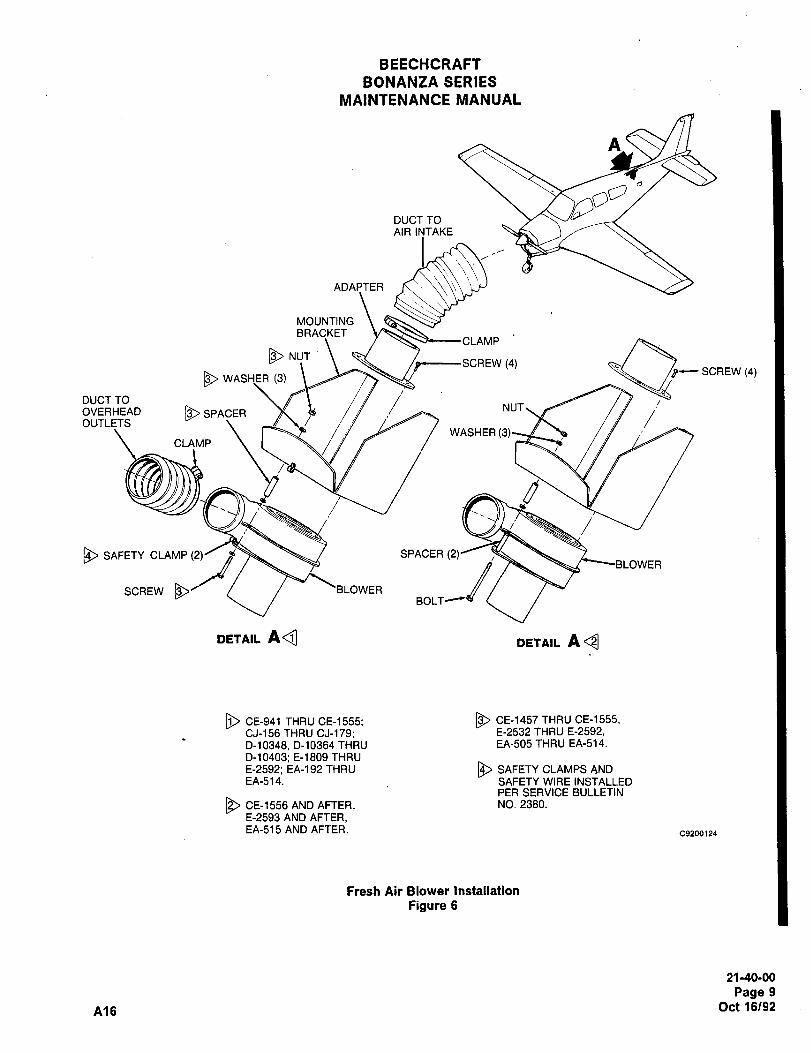
BEECHCRAFT
BONANZA SERIES
MAINTENANCE MANUAL
A
DUCT TO
AIR INTAKE
ADAPTER IC´•\\\\\
MOUNTING ~f_,,,,,BRACKET
DNUTSCREW (4)
13~ WASH,ER (3)’p-- SCREW 14)
OVERHEADDUCT TO
SPACERNUT
OUTLETSWASHER (3
CLAMP
g~/
SAFETY CLAMP (2)/ Ad~ SPACER (2)
SCREW \BLOWERBOLT
nETnlL A~ DETAIL A~
[j) CE-941 THRU CE-1555; I~ CE-1457 THRU CE-1555,
CJ-156 THRU CJ-179; E-2532 THRU E-2592,
D-10348, D-10364 THRU EA-505 THRU EA-514.
D-10403; E-1809 THRU
E-2592; EA-192 THRU SAFETY CLAMPS AND
EA-514. SAFETY WIRE INSTALLEDPER SERVICE BULLETIN
CE-1556 AND AFTER, NO. 2380.
E-2593 AND AFTER,EA-515 AND AFTER.
C9200124
Fresh Air Blower Installation
Figure 6
21-40-00
Page 9
A16 Oct 16/92
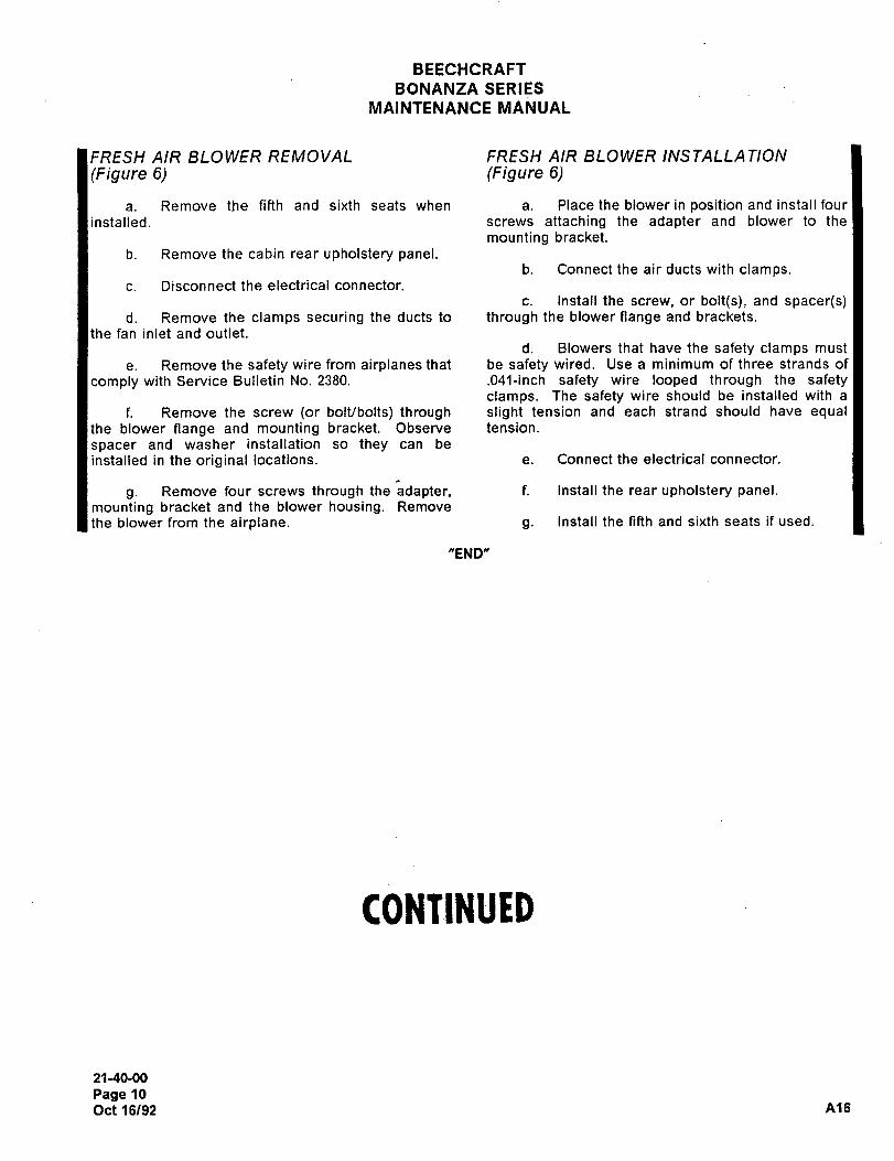
BEECHCRAFT
BONANZA SERIES
MAINTENANCE MANUAL
FRESH AIR BLOWER REMOVAL FRESH AIR BLOWER INSTALLATION
(Figure 6) (Figure 6)
a. Remove the fifth and sixth seats when a. Place the blower in position and install four
installed, screws attaching the adapter and blower to the
mounting bracket.
b. Remove the cabin rear upholstery panel.b. Connect the air ducts with clamps.
c. Disconnect the electrical connector.
c. Install the screw, or bolt(s), and spacer(s)d. Remove the clamps securing the ducts to through the blower fiange and brackets.
the fan inlet and outlet.
d. Blowers that have the safety clamps must
e. Remove the safety wire from airplanes that be safety wired. Use a minimum of three strands of
comply with Service Bulletin No. 2380. .041-inch safety wire looped through the safetyclamps. The safety wire should be installed with a
f. Remove the screw (or bolt/bolts) through slight tension and each strand should have equalthe blower flange and mounting bracket. Observe tension.
spacer and washer installation so they can be
installed in the original locations. e. Connect the electrical connector.
g. Remove four screws through the adapter, f. Install the rear upholstery panel.mounting bracket and the blower housing. Remove
the blower from the airplane. g. Install the fifth and sixth seats if used.
"END"
CONTINUEB
21-40-00
Page 10
Oct 16/92 A16
~eechcraftBONANZA SERIES
MAINTENANCE MANUAL
COOLING I DESCRIPTION AND refrigerant line drops to a pressure low enough to indi-
OPERATION (Effectivity: Optional) cate refrigerant and/or oil loss (below 7 psi), the switch
will open and prevent further operation of the com-The optional air-conditioning system is a recirculating presser. When the refrigerant system is properly12,000-BTU cooling system. The air-conditioner is charged (approximately 7 psi or mote), the switch willwired through the right landing gear uplock position b, activated closed allowing the compressor clutchswitch, the left landing gear safety switch, and the nor- ,il to be activated so the air-conditioner may operate.mally closed full throttle switch. With the air- The purpose of the switch is to prevent damage to theconditioner operating on the ground, the control circuit
compressor should oil and/or refrigerant loss occur.
is wired through the left landing gear safety switch,which fully opens the condenser air scoop door The condenser air scoop door under the airplanelocated under the airplane. With the gear extended automatically opens when the air-conditioner is turned
and the throttle fully opened, action of the full throttle on´• On the ground, the door opens to approximately 3
switch will remove power from the compressor clutch inches. In flight, the door opens to approximately 3/4
coil, and drive the condenser air scoop door closed. 112 inch. The air scoop door-actuator-limit switches
When the airplane is airborne and the landing gear is are preset; however if adjustment becomes neces-
retracted, power is transmitted from the normally open sary, refer to CONDENSER CONTROL RIGGING in
contacts of the full throttle switch (actuated closed this chapter.when the throttle is fully open), through the right land-
The belt-driven compressor, which is coupled with aing gear uplock-position switch (actuated closed when
magnetic clutch, compresses the refrigerant to a high
I the gear is up and locked) to the condenser air scooppressure, high temperature gas. This gas passes
through the condenser where cooling air removesnormally open contacts of the door flight-position-limit heat from the gas, condensing it to a liquid state. Theswitch located at the end of the door (actuated closed
liquid then passes through the expansion valve wherewhen the door is closed), causing the actuator to open it is metered into the evaporator at a rate of 55 psi, (30the door to the Right position. When the door flight- psi on serials E-2104, E-2111 and after; EA-320,position-limit switch is actuated, the power is then
EA-440 and after;and CE-1037 and after) whichdirected to the compressor clutch coil.
allows most of the liquid to return to a gas. The heat
A light, independent of the air-conditioner circuit, is required for evaporation is absorbed from cabin air
actuated by the condenser air scoop door, through the passing over the evaporator coils. After passingleft landing gear uplock-position switch’s normally through the evaporator, the refrigerant returns to the
closed contacts (closed with the landing gear compressor at a reduced pressure.
extended), which will indicate a door-open conditionA time delay relay has been added to the compressorwhile the gear is extended.circuit at serials E-2104, E-2111 and after; EA-320,
The high-pressure-sensing switch monitors the pres- EA-440 and after; CE-1037 and alter. The time delaysure of the refrigerant from the compressor to the relay prevents the compressor from being energizedexpansion valve. The normally closed high pressure while a high head pressure exists, which would cause
switch will actuate, causing an open circuit to the com- unnecessary stress on the belt and other components.presser clutch coil when the pressure in the line The time delay relay is located on the forward side ofreaches 390 a 10 psi, (340 a 10 psi on serials E-2121 the front spar carry-through on the right side of theand after; EA-320, EA-440 and after; CE-1030 and airplane.after) which disables the compressor. The high pres-sure switch automatically resets to the normally (Effectivity: All Serials except E-2104,closed position when the refrigerant falls to a safe E-211 I and after and except EA-320,pressure. There is also a high-pressure-poppet relief
valve, located on the forward side of the firewall,EA-369 and after)
which will relieve the system if the pressure reachesThe optional air-conditioning system is controlled by a
450 psi, and will reseal again at 360 psi. switch on the powerplant control panel and by both
The low pressure switch, normally open (actuated high- and low-pressure-sensing switches. The switch
closed when the system is charged with refrigerant) which controls the system is located on the power-senses system pressure. When the pressure in the plant control panel (console) and is placarded AIR
21-50-00
Page 1
A18 Aug 18/95
ciS3eechcfaftBONANZA SERIES
MAINTENANCE MANUAL
COND OFF HI LO. The system circuit breaker, umn and are placarded A/C OFF and BLOWER HI LO
located on the right hand subpanel, is placarded A/C and OFF. The two circuit breakers which protect the
CIR BKR. system are located in the left sidewall circuit breaker
The entire system is protected by a 15-amp circuit panel. One circuit breaker (5 amps) protects the com-
breaker. The compressor and condenser air scoop presser wiring, while the other (15 amps) protects the
door are protected by two separate 5-amp fuses. The blower wiring.
fuses are located on the forward side of the firewall inIf the air-conditioner switch is in the A/C position, the
front of the copilot. This allows the evaporator fan toair-conditioner will come on with the blower at low
be operated after the compressor has been removedspeed, even if the blower switch is off; however, mov-
from the system by a blown fuse.ing the blower switch from OFF or LO to HI will result
(Effectivity: Serials 8-2104, 8-2111 and in blower speed increasing to its maximum. With the
after, EA-320, EA-389 and after) air-conditioner switch off, the blower will operate at
either high or low speed according to the switch posi-The optional air-conditioning system is a recirculating tion.
cooling system. The two switches which control the
system are located to the left of the pilots control col-
21-50´•00
Page 2
Aug 18/95 A18
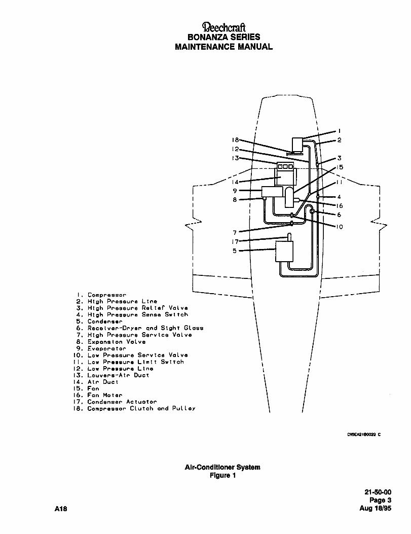
BONANZA SERIES
MAINTENANCE MANUAL
I i
15
r-- 9
16
10
6
17
I. Compressor2. High Pressure Line
3. High Pressure Reltef Valve
4. High Pressure Sense Switch
5. Condenser
6. Receiver-Drrer and Sioht Class
7. High Pressure Service Valve
8. Expansion Valve
9. Evaporator10. Low Pressure Service Valve
I. Low Pressure Limit SwitchI
12. Low Pressure Line i I13. Louvers-Atr Duct
14. Air Duct
15. Fan
16. Fan Mater
17. Condenser Actuator
ie. Compressor Clutch and Pullev
c95E~sleoon c
Alr-Condltloner SystemFigure 1
21-50-00
Page 3
A18 Aug 18/95
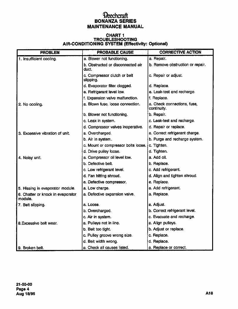
aeechcraftBONANZA SERIES
MAINTENANCE MANUAL
CHART 1TROUBLESHOOTING
AIR-CONDITIONING SYSTEM (EffectSvity: Optional)
PROBLEM PROBABLE CAUSE i CORRECTIVE ACTION
1. Insufficient cooling. a. Blower not functioning. a. Repair.
b. Obstructed or disconnected air b. Remove obstruction or repair.duct.
c. Compressor clutch or belt c. Repair or adjust.slipping.d. Evaporator filter clogged, d. Replace.
e. Refrigerant level low. e. Leak-test and recharge.
f. Expansion valve malfunction. f. Replace.
2. No cooling. a. Blown fuse, loose connection. a. Check connections, fuse,continuity.
b. Blower not functioning, b. Repair.
c. Leak in system. c. Leak-test and recharge.
d. Compressor valves inoperative. d. Repair or replace.
3. Excessive vibration of unit. a. Overcharged. a. Correct refrigerant charge.
b. Air in system. b. Purge and recharge system.
c. Mount or compressor bolts loose. Ic. Tighten.
d. Drive pulley loose. d. Tighten.
4. Noisy unit, a. Compressor oil level low, a. Add oil.
b. Defective belt. b. Replace.
c. Low refrigerant level. c. Add refrigerant.
d. Fan hitting shroud. d. Align and tighten shroud.
e. Defective compressor, e. Replace.
5. Hissing in evaporator module. a. Low charge. a. Add refrigerant.
6. Chatter or knock in evaporator a. Defective expansion valve. a. Replace.module.
7. Belt slipping. a. Loose. a. Adjust.
b. Overcharged. b. Correct refrigerant level.
c. Air in system, c. Evacuate and recharge.
8.Excessive belt wear. a. Pulleys not in line. a. Align pulleys.
b. Belt too tight. b. Adjust or replace.
c. Pulley groove wrong size. c. Replace.
d. Belt width wrong, d. Replace.
9. Broken belt. a. Check all causes listed, la. Replace or correct.
21-50-00
Page 4
Aug 18/95 A18
aeechcraftBONANZA SERIES
MAINTENANCE MANUAL
COOLING I MAINTENANCE PRACTICES freeze into ice at the expansion valve, but can also
(Effectivlty: Optional) cause the formation of hydrochloric or hydrofluoricacids in the system. The air-conditioning system must
MAINTENANCE OF AIR-CONDITIONER be purged if contaminated with foreign material or
moisture.
Servicing the air-conditioning system consists of peri-odically checking the refrigerant level, checking com-
age to fittings or connections. Even minute damage to Ie. All precautions should be taken to prevent dam-
pressor oil level and changing the system air filter.a connection could cause it to leak. Any fittings getting
Recharge the system whenever the refrigerant level isgrease or dirt on them should be wiped clean with a
low, air has entered the system or components carry-
ing refrigerant are replaced. Refrigerant leaks may becloth dampened with alcohol. Do not use chlorinated
solvents such as trichloroethylene for a cleaningdetected by inspection with a flameless leak detector.
agent, for they are contaminants. If dirt, grease or
PRECAUTIONARY SERVICE MEASURES moisture gets inside lines and cannot be removed, the
line will have to be replaced.a. Due to the air quality control regulations enacted
f. For airplane serials prior to CE-1792, E-2945 and Iin the United States, R-12 refrigerant cannot beEA-579, use a small amount of clean 500 viscosity
vented into the atmosphere. When performing mainte-refrigeration oil (8, Chart 1, 91-00-00) on all tube joints
nance on the air-conditioning system where R-12 can and dip the o-ring in this oil before assembling theescape from the system, evacuate the system with
joint.only a recovery or recycle servicing unit that will sal-
vage the refrigerant, g. For airplane serials CE-1792 and after, E-2945 1and after, and EA-579 and after, use a small amount
b. The air-conditioning system is a high pressure of Ester Oil (65, Chart 1, 91-00-00) on all tube jointssystem. Before disconnecting a refrigerant line, the
and dip the o-ring in this oil before assembling thesystem must be discharged with a recovery servicing joint. This will help in making a leak-proof joint.unit. Purge the entire system to a 125-micron level.
1,,,,41CAUTION
Insufficiently torqued tubing connections
WARNING
can result in loose joints while exces-A face shield should be worn when
sively torqued connections can cause
performing maintenance on the Ilnesdeformed joint parts. Either condition
because refrigerant coming In con-can result in refrigerant leakage.
tact with the eyes can cause loss of
sight.h. When connecting aluminum fittings in the refriger- Iant system, torque all 5/8-inch fittings to 18 21 foot-
Do not smoke when servicing the pounds and all 1/2-inch fittings to 11 13 foot-pounds.system with refrigerant because It
converts to a highly toxic gas when NOTE
exposed to an open flame.The receiver-dryer is the last assembly
c. Before any service is attempted which requires to be connected. This is necessary to
opening of refrigeration plumbing or units, the person reduce and/or eliminate the entry of
doing the work should be throughly familiar with moisture into the lines.
instructions on servicing the system. They should fol- For charging the air-conditioner or checking the oil,low very carefully these instructions when performing refer to Chapter 12-10-00.the task that will maintain this system in a proper func-
tioning order.AIR-CONDITIONING FUNCTIONAL TEST
I d. The major reasons for these measures are for
With the engine running at 1,000 rpm and the systemthe system. Dirt contaminants may cause leaky valves on, observe the sight glass. If refrigerant appears
or wear in the compressor. Moisture may not only milky or bubbles appear, charge the system as noted
21-50-00
Page 5
A18 Aug 18/95
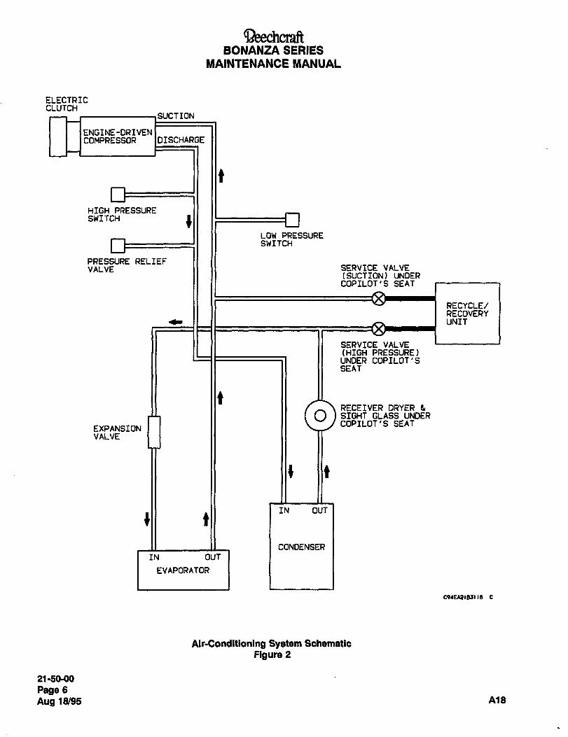
BONANZA SERIESMAINTENANCE I~ANUAL
ELECTRICCLUTCH
SUCTION
ENGINE-DRIVENCOMPRESSOR IDISCHARGE
HIGH PRESSURESWITCH
LOW PRESSURESWITCH
PRESSURE RELIEFVALVE SERVICE VALVE
[SUCTION) UNDERCOPILOT’S SEAT
RECYCLE/RECOVERYUNIT
SERVICE VALVE(HIGH PRESSURE)UNDER COPILOT’SSEAT
RECEIVER DRYER 5
O SIGHT GLASS UNDERCOPILOT’S SEAT
EXPANSIONVALVE
t
IN OUT
tII
CONDENSER
IN OUT
EVAPORATOR
C91E1~185118 C
Air-Conditioning System Schematic
Figure 2
21 -50-00
Page 6
Aug 18/95 A~8
aeechcraftBONANZA SERIES
MAINTENANCE MANUAL
under the heading CHARGING THE AIR- belt should be retensioned to 50 to 65 pounds and
CONDITIONING SYSTEM in Chapter 12-10-00. maintained at this tension. To check the compressorCheck the system for leaks using a flameless leak belt tension, use a Burrough’s Model BT-33-73F-50
detector. belt tension gage or equivalent. Position the belt ten-
sion gage as shown in Figure 3. If a belt tension gageSYSTEM LEAK DETECTION
is not available, a properly tensioned new belt will
A reduction of system cooling ability or the presence require 4.1 to 5.0 pounds force for a midspan deflec-
of bubbles in the refrigerant, may indicate a partial tion of 0.14 inch. After 5 hours operating time, the belt
loss of refrigerant. Check for bubbles in the sight glass should be retensioned. After 5 hours, a properly ten-
on the receiver-dryer located under the copilot’s seat. sioned belt will require a force of 3.3 to 4.1 pounds for
The sight glass should be checked during operation at a midspan deflection of 0.14 inch. The belt should be
maximum available ambient and cabin temperatures. maintained at this tension. See Figure 4 for belt ten-
Streams of bubbles past the glass and/or milky sion by midspan deflection.
appearance in the glass indicate an inadequate quan-
tity of refrigerant. If a loss of refrigerant is suspected, COMPRESSOR MOUNTING TORQUES
an inspection of the system plumbing should be car-Mounting Bracket to Engine
ried out to locate the source of the leak. Large leaks
may be located by the appearance of oily spots where Bolts 220 to 260 in. Ibs.
oil has been carried out by escaping refrigerant. Nut................................................275
to 325 in.lbs.
Smaller leaks, which are much more difficult to locate,Compressor to Bracket
may be detected by detergent bubbles, or an elec-
tronic detector. Nut on Bolt................................,.275
to 325 in. Ibs.
COMPRESSOR BELT REMOVAL Idler Pulley Bolt ...800 to 850 in. Ibs.
(Figure 4) Drive Pulley Nut...........................700
to 800 in Ibs.
a. Open the engine cowling to gain access to the Adjusting Bolt Jamnut .........,,,.275 to 325 in. Ibs.
compressor belt. Idler Arm Self-Locking Nut........,300 to 350 in. Ibs.
b. Loosen the jamnut on the adjusting bolt.COMPRESSOR BELT PULLEY
c. Loosen the self-locking nut on the idler arm.ALIGNMENT
d. Use the adjusting bolt to remove tension from the
compressor belt. If it is determined that the compressor belt pulleys are
e. Removethecompressor belt. out of alignment, they may be adjusted as follows:
COMPRESSOR BELT INSTALLATION NOTE
(Figure 4) An alignment gage is available (Bur-
a. install the compressor belt over the compressor rough’s No. 8082 for 0.38 pulleys and
pulley, idler pulley, and drive pulley.No. 8082A for 0.50 pulleys) to check belt
alignment.b. Use the adjusting bolt on the idler pulley bracket
to increase belt tension as indicated in COMPRES- a. Opentheengine cowling.SOR BELT TENSION ADJUSTMENT in this chapter, b. Removethe beltasindicated in COMPRESSOR
c. Torque the self-locking nut on the idler arm to 300 BELT REMOVAL.
to 350 inch pounds.c. Determine if the idler pulley or drive pulley is out
d. Torque the jam nut on the adjusting bolt to 275 to of alignment.325 inch pounds.
d. Remove the appropriate pulley and add or
e. Closetheengine cowling.remove shims as required per Figure 5.
COMPRESSOR BELT TENSION e. Reinstall the pulley and torque as indicated in Fig-ADJUSTMENT ure 5.
New belts should be installed with a static tension of f. If the drive pulley was removed, install the cotter
65 to 80 pounds. After 5 hours of operating time, the pin.
21-50-00
Page 7
A18 Aug 18/95
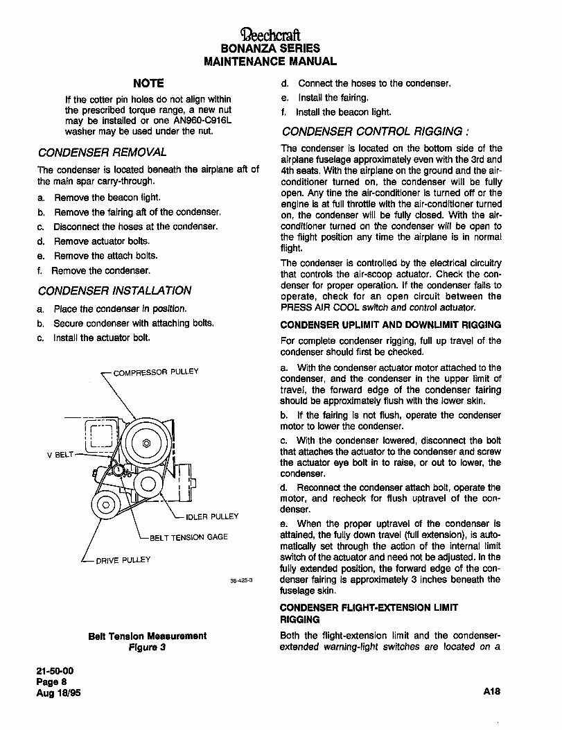
~eechcraftBONANZA SERIES
MAINTENANCE MANUAL
NOTE d. Connect the hoses to the condenser.
If the cotter pin holes do not align within e. Install the fairing.the prescribed torque range, a new nut f. Install the beacon light.may be installed or one AN960-C916L
washer may be used under the nut. CONDENSER CONTROL RIGGING
CONDENSER REMOVAL The condenser is located on the bottom side of the
airplane fuselage approximately even with the 3rd and
The condenser is located beneath the airplane aft of 4th seats. With the airplane on the ground and the air-
the main spar carry-through. conditioner turned on, the condenser will be fully
a. Remove the beacon light. open. Any tine the air-conditioner is turned off or the
engine is at full throttle with the air-conditioner turnedb. Removethefairing aft ofthecondenser.
on, the condenser will be fully closed. With the air-
c. Disconnectthe hosesatthecondenser. conditioner turned on the condenser will be open to
d. Remove actuator bolts. the flight position any time the airplane is in normal
flight.e. Remove the attach bolts.
The condenser is controlled by the electrical circuitryf. Remove the condenser. that controls the air-scoop actuator. Check the con-
CONDENSER INSTALLATIONdenser for proper operation. If the condenser fails to
operate, check for an open circuit between the
a. Place the condenser in position. PRESS AIR COOL switch and control actuator.
b. Secure condenser with attaching bolts. CONDENSER UPLIMIT AND DOWNLIMIT RIGGING
c. Installtheactuator bolt. For complete condenser rigging, full up travel of the
condenser should first be checked.
COMPRESSOR PULLEY a. With the condenser actuator motor attached to the
condenser, and the condenser in the upper limit of
travel, the forward edge of the condenser fairingshould be approximately flush with the lower skin.
b. If the fairing is not flush, operate the condenser
rT-T7I
c. With the condenser lowered, disconnect the bolt
motor to lower the condenser.
that attaches the actuator to the condenser and screwV BELT
the actuator eye bolt in to raise, or out to lower, the
condenser.
O d. Reconnect the condenser attach bolt, operate the
denser.motor, and recheck for flush uptravel of the con-
IDLER PULLEYe. When the proper uptravel of the condenser is
TTENSION GAGE attained, the fully down travel (full extension), is auto-
matically set through the action of the internal limit
DRIVE PULLEY switch of the actuator and need not be adjusted. In the
fully extended position, the forward edge of the con-
36-425-3 denser fairing is approximately 3 inches beneath the
fuselage skin.
CONDENSER FLIGHT-UCTENSION LIMIT
R1GG1NG
Belt Tension Measurement Both the flight-extension limit and the condenser-
Figure 3 extended warning-light switches are located on a
21-50-00
Page 8
Aug 18/95 A18
aeechcraftBONANZA SERIES
MAINTENANCE MANUAL
bracket near the aft end on the right side of the con-
denser assembly. To rig both of the switches, proceed ARNING
as follows:
The air-conditioning system Is a high
a. Remove the 12 screws and washers from the fair- pressure system. Before dlsconnect-
ing which covers the switches and pressure hoses aft Ing a reMgenmt line, the system must
of the condenser. be discharged with a recovery servlc-
Ing unit. Purge the entire system to a
b. Remove the fairing. 125-micron level.
c. Disconnect each of the two pressure hoses
located on each side of the condenser assembly. A face shield should be worn when
performing maintenance on the linesd. Connect a voltmeter to the Right-extension-limit because refrigerant coming In con-switch (outboard switch), by attaching one lead to the
tact with the eyes can cause loss oftop screw on the switch and one lead to the bottom
sight.screw. Do not make connection with the center screw.
e. Adjust the bolt on the end of the condenser toDo not smoke when servicing the
actuate the switch when the forward edge of the con- system with refrigerant because It
denser is lowered 1.25 inches perpendicular to the converts to a highly toxic gas when
fuselage skin at the airplane centerline. exposed to an open flame
f. Connect the voltmeter as indicated in step c to the a. Open the right engine cowling.condenser-extended warning-light switch (inboard b. Remove electrical leads from compressor clutch
switch). Adjust the switch actuating bolt on the con- terminals.denser to actuate the switch when the forward edge of
c. Disconnect refrigerant lines at the compressor.the condenser is lowered 1.5 inches perpendicular to
the fuselage skin at the airplane centerline. Cap refrigerant lines and compressor fittings.
d. Remove the compressor belt as noted in COM-NOTE PRESSOR BELT REMOVAL in this chapter.
Using a voltmeter to adjust the above e. Remove the compressor mounting bolts and nutsswitches is not necessary if the click of and remove compressor.switches upon actuation is audible.
INSTALLA TION AND ALIGNMENT OF
g. Connect and tighten the pressure hoses, place COMPRESSOR
the aft condenser fairing in position and install the 12a. The starter drive pulley nut is torqued to 700 800
washers and screws. inch-pounds. If the cotter pin holes will not align,h. Purge and charge the air-conditioning system as change the nut and/or use a washer under the nut. Do
indicated in CHARGING THE AIR-CONDIIIONING not overtorque the drive pulley nut. Install the cotter
SYSTEM in Chapter 12. pin.
COMPRESSOR REMOVAL NOTE
The use of AN960-C916L washer, orNOTE equivalent, as required for cotter pin
Due to the air quality control regulations alignment, is permissibie.enacted in the United States, R-12 b. Remove the spacer from the bolt through the Irefrigerant cannot be vented into the
case. Inspect the o-ring for damage and replace ifatmosphere. When performing mainte-
necessary.nance on the air-conditioning systemwhere R-12 can escape from the sys- c. Install the compressor bracket assembly and align Itom, evacuate the system only with a the idler pulley with the drive pulley. The idler should
recovery or recycle servicing unit that be tightened snug within track. Install the existing nut
will salvage the refrigerant. and washer on the through bolt, then install the two
21-50-00
Page 9
A18 Aug 18/95
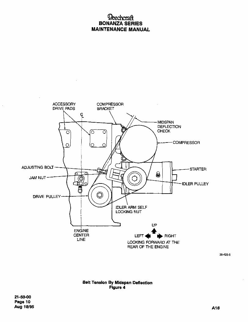
~eechcraftBONANZA SERIES
MAINTENANCE MANUAL
ACCESSORY COMPRESSORDRIVE PADS BRACKET
GMIDSPAN
DEFLECTION
I\.ro~-o7 I CHECK
COMPRESSORO
ADJUSTING BOLTSTARTER
JAM NUT
IDLER PULLEY
DRIVE PULLEY
IDLER ARM SELF
LOCKING NUT
UP
ENGINE ´•CCENTER LEFT I)RIGHT
LINELOOKING FORWARD AT THE
REAR OF THE ENGINE
36-425-5
Belt Tension By Midspan Deflection
Figure 4
21-50-00
Page 10
Aug 18/95 A18
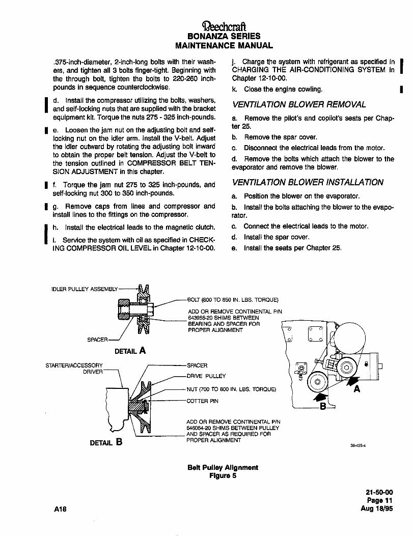
BONANZA SERIES
MAINTENANCE MANUAL
.375-inch-diameter, e-inch-long bolts with their wash- j. Charge the system with refrigerant as specified in Iers, and tighten all 3 bolts finger-tight. Beginning with
the through bolt, tighten the bolts to 220-260 inch- Chapter 12-10-00.
pounds in sequence counterclockwise. k. Closetheengine cowling. j
I and self-locking nuts that are supplied with the bracketVENTILATION BLOWER REMOVAL
d. Install the compressor utilizing the bolts, washers,
equipment kit. Torque the nuts 275 325 inch-pounds. a, Remove the pilot’s and copilot’s seats per Chap-ter 25.
a. Loosen the jam nut on the adjusting bolt and self-
locking nut on the idler arm. Install the V-belt. Adjust b´• Remove the spar cover.
the idler outward by rotating the adjusting bolt inward c. Disconnect the electrical leads from the motor.to obtain the proper belt tension. Adjust the V-belt to
d. Remove the bolts which attach the blower to thethe tension outlined in COMPRESSOR BELT TEN-
evaporator and remove the blower.SION ADJUSTMENT in this chapter.
I f. Torque the jam nut 275 to 325 inch-pounds, and VENTILATION BLOWER INSTALLATION
self-locking nut 300 to 350 inch-pounds,a. Position the blower on the evaporator.
I g. Remove caps from lines and compressor and b. install the bolts attaching the blower to the evapo-install lines to the fittings on the compressor, rater.
I h. Install the electrical leads to the magnetic clutch. c´• Connect the electrical leads to the motor.
i. Service the system with oil as specified in CHECK- d´• I"stallthespar cover.
ING COMPRESSOR OIL LEVEL in Chapter 12-10-00, e. Installtheseats perChapter25.
IDLER PULLEY ASSEMBLY
BOLT (800 TO 850 IN. LBS. TORQUE)
ADD OR REMOVE CONTINENTAL PIN
64395~20 SHIMS BFlWEEN
BEARING AND SPACER FOR
PROPERIVIGNMENT ~jSPACER
DETAIL A
DRIVERPULLEY
~iYSTARTER/ACCESSORY SPACER
NUT (700 TO 800 IN. LBS. TORQUE) A
PIN
ADD OR REMOVE CONTINENTAL P/N
646064-20 SHIMS BFlWEEN PULLEY
AND SPACER AS REQUIRED FOR
DETAIL B PROPER ALIGNMENT36425-4
Belt Puiley AlignmentFigure 5
21-50-00
Page 11
A18 Aug 18/95
BONANZA SERIES
MAINTENANCE MANUAL
EVAPORATOR REMOVAL b. Connectthe refrigerantlines.
a. Depressurize the air-conditioning system with a c. Connect the electrical leads to the motor.
recycle servicing unit as specified in DEPRESSURIZ-
ING THE AIR-CONDITIONING SYSTEM in Chapter d. Install the ducts and tape with duct tape (29, Chart
12. 1, 91-00-00) to the evaporator and connect the drain
tubes.b. Remove the pilot’s and copilot’s seats per Chap-ter 25. e. Charge the system with refrigerant as specified in
c. Remove the filter cover and filter. CHARGING THE AIR-CONDITIONER SYSTEM in Id. Remove the cover from over the ducts.
e. Disconnect the drain tubes and remove the tape f´• I"stall the spar cover.
between the evaporator and duct.g. Install the filter and filter cover.
f. Removethe sparcover.h. Install the cover over the ducts.
g. Removethe ducts.i. Install the seats per Chapter 25.
h. Disconnect the electrical leads from the motor,
i. Disconnect the refrigerant lines and cap the open EVAPORATOR FILTER REPLACEMENTports.
j. Remove the bolts attaching the evaporator to the The evaporator filter should be replaced if clogged,floorboard. Remove the evaporator from the airplane. dirty or defective. Remove the screws in the spat
cover located on the underside of the airplane on theEVAPORATOR INSTALLAT/ON copilot’s side to gain access to the filter,
a. Position the evaporator in the airplane and install
the bolts attaching it to the floorboard.
21 -50-00
Page 12
Aug Al8

CHAPTER
COMMUNICATIONS
Raytheon Aircraft CompanyBONANZA SERIES MAINTENANCE MANUAL
CHAPTER 23 COMMUNICATIONS
TABLE OF CONTENTS
SUBJECT PAGE
23-10-00
Ground Communication System Description and Operation .....1
Ground Communication (E-2104, E-2111 and After; EA-320, EA-389 and After) ....1
23-60-00
Static Discharging- Description and Operation ...........1
Static Discharging- Maintenance Practices ...............1
Static Wick Removal (Priorto D-10383; CJ-156; CE-978; E-1932; EA-273) ........1
Static Wick Installation (Priorto D-10383; CJ-156; CE-978; E-1932; EA-273) .......1
Static Wick Removal (D-10383; CJ-156; CE-978; E-1932; EA-273 and After) ......2
Static Wick Installation (D-10383; CJ-156; CE-978; E-1932; EA-273 and After) .....2
Static Wick Inspection.
nzl 23-CONTENTS

Ray~heon Aircraft CompanyBONANZA SERIES MAINTENANCE MANUAL
CHAPTER 23 COMMUNICATIONS
LIST OF EFFECTIVE PAGES
CH-SE-SU PAGE DATE
23-LOEP 1 Sep 30/03
23-CONTENTS 1 Sep 30/03
23-10-00 1 Sep 27/84
23-60-00 1 and 2 Sep 30/03
A24 23-LOEP 1
BEECHCRAFT
BONANZA SERIES
NIAINTENANCE #ANUAL
GROUND COMMUNICATION SYSTEM communication while all other electrical equipment is turned
DESCRIPTION AND OPERATION off. The switch for this system is a push-on, push-off switch
located near the top of the instrument panel to the right of
O~OUND COMMUNICATION center. The system’s two 5-amp circuit breakers are located
(E-2104, E-2111 and afte~ EA-320, EA-389 and after) below the battery box. On airplane serials CE-1037 and
after, this optional equipment is available on the model
The airplane may be equipped with an optional ground F33A; however, there are no standard locations for the
communication system. This system allows radio equipment.
"END"
23-1090
Page 1
A9 399 27/84
Ray~hean Aircraft CompanyBONANZA SERIES MAINTENANCE MANUAL
STATIC DISCHARGING DESCRIPTION AND OPERATION
A static electrical charge may build up in the surface of the airplane while it is in flight. This electrical charge, if
retained, can cause interference in radio and avionics equipment operation. Therefore, static wicks are installed on
the trailing edges of the flight surfaces to aid in the dissipation of the electrical charge.
STATIC DISCHARGING MAINTENANCE PRACTICES
On serials prior to D-10383; CJ-156; CE-978; E-1932, and EA-273, the static wicks are installed with one on each Ielevator, one on each aileron and one on the rudder. These five (four on model 35) static wicks are removed and
installed in the same manner. On serials D-10383; CJ-156; CE-978; E-1932; EA-273 and After, the static wicks are Iinstalled with one (three on the B36TC) on each wing tip, two (none on the B36TC) on each aileron, three on each
elevator and three on the rudder. These fifteen (twelve on the V35B) static wicks are removed and installed in the
same manner. The base of the later static wicks is riveted to the flight surface and need not be removed in normal
service.
STATIC WICK REMOVAL (PRIOR TO 0-10383; CJ-156; CE-978; E-1932; EA-273) I
a. Remove the two screws and lock washers securing the wick to the surface.
b. Removethewickfromthe surface.
STATIC WICK INSTALLATION (PRIOR TO D- 10383; CJ- 156; CE-978; E- 1932; EA-273) I
Clean around the static wick area by:
a. Removing all grease, oil, paints, metal finishes or other high resistance properties with Minnesota 3M No. 600
grit sandpaper, or equivalent. The mating surfaces must be smooth and contoured so that the maximum surface
area is in actual contact. Alodine treatment for aluminum or Dow treatment of magnesium is a suitable corrosion
preventative to use between the static wick base and the airplane surface.
NOTE
Dissimilar materials are not to be used in intimate contact unless suitably protected againstelectrolytic corrosion. Whenever it is necessary that any combination of such metals be assembled,an interposing material compatible to each should be used.
b. Install the wick, using the two screws and lock washers.
NOTE
Check the continuity between the static wick base and the surface to which it is attached. There
should be a resistance 05 2.5 milliohms or less.
c. Refinish the surface area around the wick attachment point.
23-60-00 Sep 30/03Page 1
Ray~heon Aircraft CompanyBONANZA SERIES MAINTENANCE MANUAL
I ’STATIC WICK REMOVAL (0-10383; CJ- 156; CE-978; E-1932; EA-273 AND AFTER)
a. Unscrewthestatic wickfromthebase.
b. Remove the static wick and the lock washer.
STATIC WICK INSTALLATION (0-10383; CJ- 156; CE-978; E- 1932; EA-273 AND AFTER)
The threads must be clean and free from grease, oil and paint.
a. Install the static wick and lock washer.
b. Torque the static wick to 4.7 in.-lbs.
STATIC WICK INSPECTION
Static wicks are inspected to ensure correct discharge capabilities. Use a megohmeter with a minimum test voltageof 500 volts to measure the resistance of the static wicks.
NOTE
All static wicks on the airplane must be the same type and manufacturer.
Use the following procedure to check the static wicks.
I CALmON 1CAUTION
Refer to the megohmeter manufacturers operating data to correctly use the megohmeter and
prevent electric shock.
a. Connect a test lead from the megohmeter to the tip of the static wick.
b. Connect the other test lead of the megohmeter to the base of the static wick.
c. Set the switch on the megohmeter to ON and read the meter:
1. If static wicks part number 35-5010-3 are installed, the meter reading must be 470 kilohms 20%.
2. For other static wicks the reading must be between 1 and 100 megohms.
d. Replace static wicks that are outside the ranges given in Step c. above.
e. Set the switch on the megohmeter to OFF and disconnect the test leads from the static wick.
Sep 30/03Page 2 23-60-00 n24

CHAPTER
ELECTRICAL
POVVER
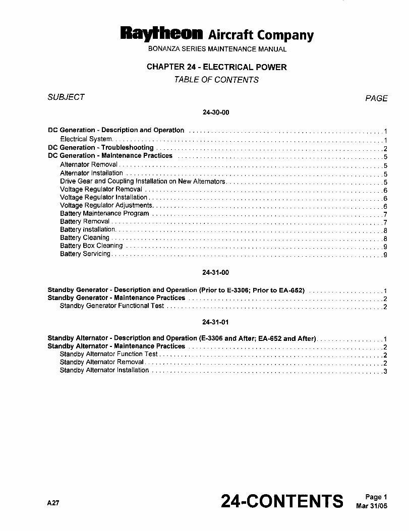
Raytheon AiKraft CompanyBONANZA SERIES MAINTENANCE MANUAL
CHAPTER 24 ELECTRICAL POWER
TABLE OF CONTENTS
SUBJECT PAGE
24-30-00
DC Generation -Descriptionand Operation........._____ .........___
~1
Electrical System. ........._____ ........._____
DC Generation -Troubleshooting........._ ~2
DC Generation Maintenance Practices................._ ........._ ~5
Alternator Removal
Alternator Installation
Drive Gear and Coupling Installation on New Alternators.........._
5
Voltage Regulator Removal ~6
Voltage Regulator Installation ~6
Voltage Regulator Adjustments. ~6
Battery Maintenance Program ~7
Battery Removal
Battery Installation.
Battery CleaningBattery Box CleaningBattery Servicing.
24-31-00
Standby Generator Description and Operation (Prior to E-3306; Prior to EA-652) .1
Standby Generator-Maintenance Practices................._ ........._
~2
Standby Generator Functional Test ~2
24-31-01
Standby Alternator Description and Operation (E-3306 and After; EA-652 and After) ..................1Standby Alternator- Maintenance Practices ~2
Standby Alternator Function Test ~2
Standby Alternator Removal................._ ~2
Standby Alternator Installation................._ ~3
nzr 24-CONTENTS Mar 31/05Page 1
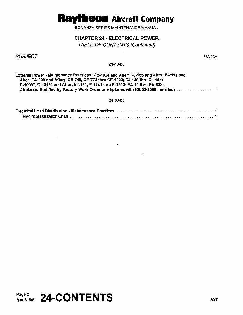
MaYffraen nircraft CompanyBONANZA SERIES MAINTENANCE MANUAL
CHAPTER 24 ELECTRICAL POWER
TABLE OF CONTENTS (Continued)
SUBJECT PAGE
24-40-00
External Power Maintenance Practices (CE-1024 and After; CJ-156 and After; E-2111 and
After; EA-339 and After) (CE-748, CE-772 thru CE-1023; CJ-149 thru CJ-154;
D-1009’1, D-10120 and After; E-1241 thru E-2110; EA-11 thru EA-338;Airplanes Modified by Factory Work Order or Airplanes with Kit 33-3008 Installed) 1
24-50-00
Electrical Load Distribution Maintenance Practices 1
Electrical Utilization Chart 1
Page 2~nar 31105 24-CONTENTS A2l
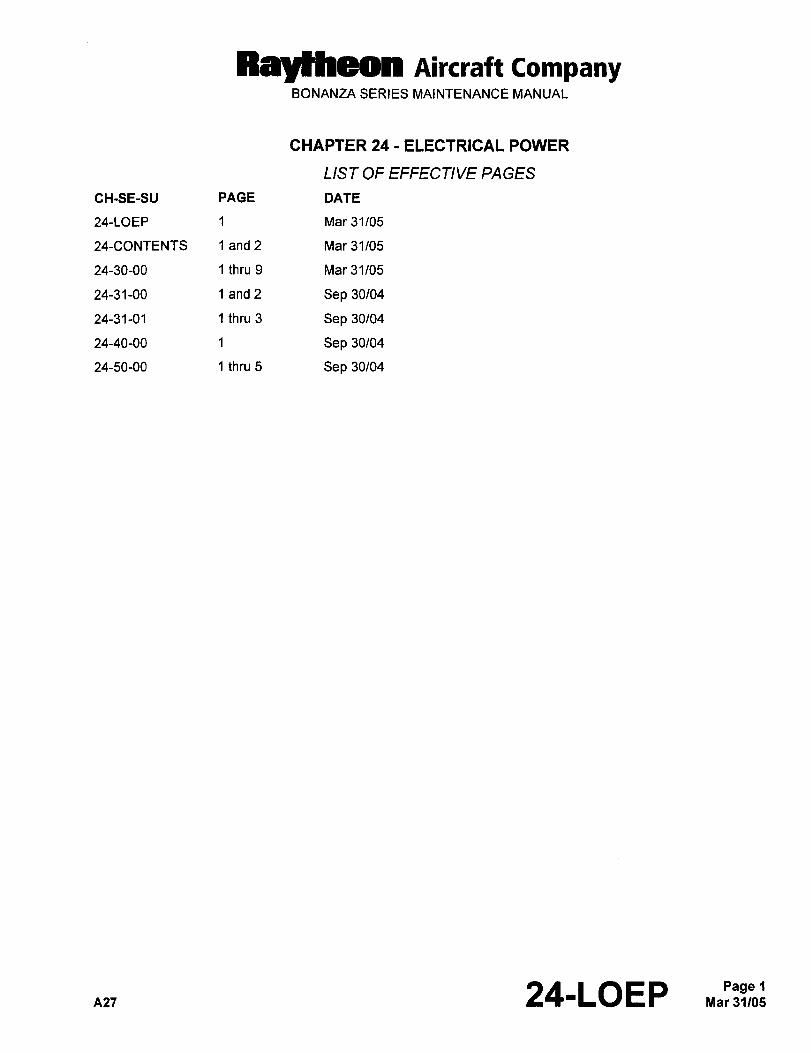
Ray~heon AiKraft CompanyBONANZA SERIES MAINTENANCE MANUAL
CHAPTER 24 ELECTRICAL POWER
LIST OF EFFECTIVE PAGES
CH-SE-SU PAGE DATE
24-LOEP 1 Mar 31/05
24-CONTE NTS 1 and 2 Mar 31/05
24-30-00 1 thru 9 Mar 31/05
24-31-00 1 and 2 Sep 30104
24-31-01 1 thru 3 Sep 30/04
24-40-00 1 Sep 30/04
24-50-00 1 thru 5 Sep 30/04
A27 24-LOEP Mar 31/05Page 1
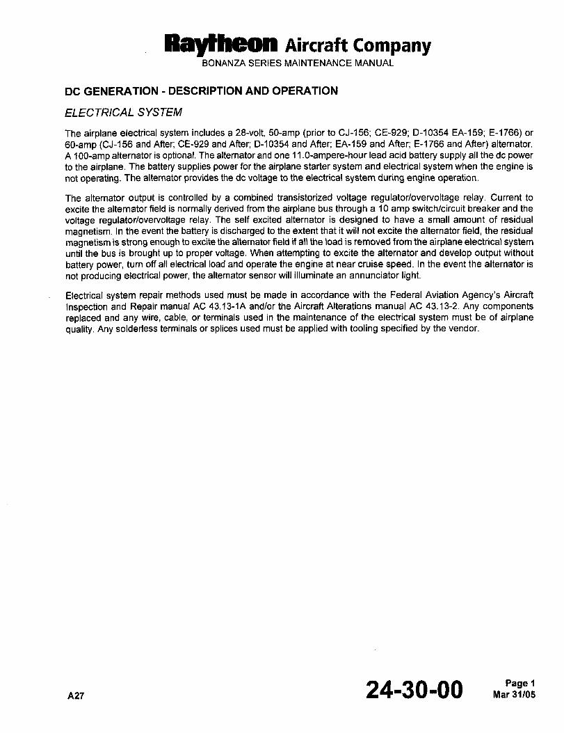
RBytheOn Aircraft CompanyBONANZA SERIES MAINTENANCE MANUAL
DC GENERATION DESCRIPTION AND OPERATION
ELECTRICAL SYSTEM
The airplane electrical system includes a 28-volt, 50-amp (prior to CJ-156; CE-929; D-10354 EA-159; E-1766) or
60-amp (CJ-156 and After; CE-929 and After; D-~0354 and After; EA-159 and After; E-~766 and After) alternator.
A 1 OO-amp alternator is optional. The alternator and one 1 l.O-ampere-hour lead acid battery supply all the de power
to the airplane. The battery supplies power for the airplane starter system and electrical system when the engine is
not operating. The alternator provides the de voltage to the electrical system during engine operation.
The alternator output is controlled by a combined transistorized voltage regulator/overvoitage relay. Current to
excite the alternator field is normally derived from the airplane bus through a 10 amp switch/circuit breaker and the
voltage regulator/overvoltage relay. The self excited alternator is designed to have a small amount of residual
magnetism. In the event the battery is discharged to the extent that it will not excite the alternator field, the residual
magnetism is strong enough to excite the alternator field if all the load is removed from the airplane electrical systemuntil the bus is brought up to proper voltage. When attempting to excite the alternator and develop output without
battery power, turn off all electrical load and operate the engine at near cruise speed. In the event the alternator is
not producing electrical power, the alternator sensor will illuminate an annunciator light.
Electrical system repair methods used must be made in accordance with the Federal Aviation Agency’s Aircraft
inspection and Repair manual AC 43.13-1A andlor the Aircraft Alterations manual AC 43.13-2. Any components
replaced and any wire, cable, or terminals used in the maintenance of the electrical system must be of airplanequality. Any solderless terminals or splices used must be applied with tooling specified by the vendor.
n27 24-30-00 1
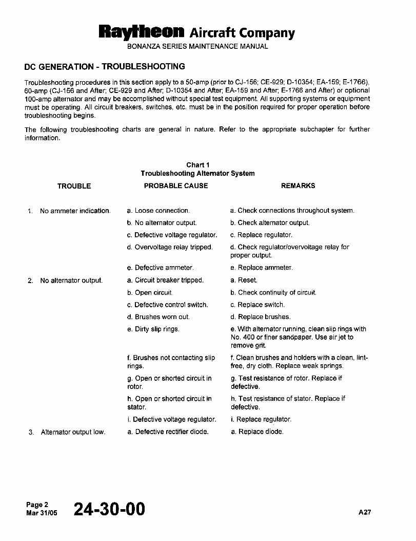
Raytheon Aircraft CompanyBONANZA SERIES MAINTENANCE MANUAL
DC GENERATION -TROUBLESHOOTING
Troubleshooting procedures in this section apply to a 50-amp (prior to CJ-156; CE-g29; D-10354; EA-159; E-l 766),60-amp (CJ-156 and After; CE-929 and After; D-10354 and After; EA-159 and After; E-1766 and After) or optional100-amp alternator and may be accomplished without special test equipment. All supporting systems or equipmentmust be operating. All circuit breakers, switches, etc. must be in the position required for proper operation before
troubleshooting begins.
The following troubleshooting charts are general in nature. Refer to the appropriate subchapter for further
information
Chart
Troubleshooting Alternator System
TROUBLE PROBABLE CAUSE REMARKS
1. No ammeter indication. a. Loose connection. a. Check connections throughout system.
b. No alternator output. b. Check alternator output.
c. Defective voltage regulator, c. Replace regulator.
d. Overvoltage relay tripped, d. Check regulator/overvoltage relay for
proper output.
e. Defective arnmeter. e. Replace ammeter.
2. No alternator output, a. Circuit breaker tripped, a. Reset.
b. Open circuit. b. Check continuity of circuit.
c. Defective control switch. c. Replace switch.
d. Brushes worn out. d. Replace brushes.
e. Dirty slip rings, e. With alternator running, clean slip rings with
No. 400 or finer sandpaper. Use air jet to
remove grit.
f. Brushes not contacting slip f. Clean brushes and holders with a clean, lint-
rings. free, dry cloth. Replace weak springs.
g. Open or shorted circuit in g. Test resistance of rotor. Replace if
rotor. defective.
h. Open or shorted circuit in h. Test resistance of stater. Replace if
stater. defective.
i. Defective voltage regulator, i. Replace regulator.
3. Alternatoroutput low. a. Defective rectifier diode. a. Replace diode.
Page 2Mar31/05 24-30-00 nz7
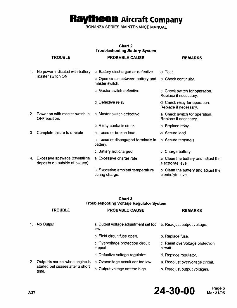
Raycheon Aircraft CompanyBONANZA SERIES MAINTENANCE MANUAL
Chart 2
Troubleshooting Battery System
TROUBLE PROBABLE CAUSE REMARKS
1. No power indicated with battery a. Battery discharged or defective. a. Test.
master switch ON.b. Open circuit between battery and b. Check continuity.master switch.
c. Master switch defective. c. Check switch for operation.Replace if necessary.
d. Defective relay. d. Check relay for operation.Replace if necessary.
2. Poweronwith masterswitch in a. Master switch defective. a. Check switch for operation.OFF position. Replace if necessary.
b. Relay contacts stuck. b. Replace relay.
3. Complete failure to operate. a. Loose or broken lead. a. Secure lead.
b. Loose or disengaged terminals in b. Secure terminals.
battery.
c. Battery not charged. c. Charge battery.
4. Excessive spewage (crystalline a. Excessive charge rate. a. Clean the battery and adjust the
deposits on outside of battery). electrolyte level.
b. Excessive ambient temperature b. Clean the battery and adjust the
during charge. electrolyte level.
Chart 3
Troubleshooting Voltage Regulator System
TROUBLE PROBABLE CAUSE REMARKS
1. NoOutput. a. Output voltage adjustment set too a. Readjust output voltage.low.
b. Field circuit fuse open. b. Replace fuse.
c. Overvoltage protection circuit c. Reset overvoltage protectiontripped. circuit.
d. Defective voltage regulator. d. Replace regulator.
2. Outputisnormalwhen engineis a. Overvoltage circuitsettoo low. a. Readjust overvoltage circuit.
started but ceases after a short
time.b. Output voltage set too high. b. Readjust output voltages.
nzT 24-30-00 3
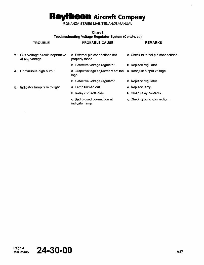
Raytheon Aircraft CompanyBONANZA SERIES MAINTENANCE MANUAL
Chart 3
Troubleshooting Voltage Regulator System (Continued)
TROUBLE PROBABLE CAUSE REMARKS
3. Overvoltage circuitinoperative a. External pin connections not a. Check external pin connections.
at any voltage, properly made.
b. Defective voltage regulator. b. Replace regulator.
4. Continuous high output, a. Output voltage adjustment set too a. Readjust output voltage.high.
b. Defective voltage regulator, b. Replace regulator.
5. Indicatorlampfailsto light. a. Lamp burned out, a. Replace lamp.
b. Relay contacts dirty, b. Clean relay contacts.
c. Bad ground connection at c. Check ground connection.
indicator lamp.
Page 42’3t,, 24-30-00
RB~heOn Aircraft CompanyBONANZA SERIES MAINTENANCE MANUAL
DC GENERATION MAINTENANCE PRACTICES
AL TERNA TOR REMOVAL
CAUTION: The output terminal of the alternator is connected directly to the battery. Make sure the battery switch is
OFF before removing the wires at the alternator or serious damage to the wiring harness and alternator
may result from accidental grounding of the output stud.
a. Access to the alternator is gained through the right cowl door and through the forward opening of the cowl.
b. Disconnect the electrical wiring harness from the alternator.
c. Remove the four attaching bolts. Remove the alternator.
AL TERNA TOR INSTALLA TION
CAUTION: Do not force the alternator into position or damage to the alternator or drive gears could result. Care
must be taken to assure that the alternator pilot enters the crankcase bore squarely, and the alternator
is resting flat on the engine pad.
d. Install a new gasket on the alternator flange.
e. Position the alternator on the mounting pad.
f. Install the attaching nuts and washers bringing to a snug condition. Torque the nuts to 150 to 180 in-lb in
diagonally opposite pairs.
CAUTION: Never turn the battery switch ON until all wiring harness connections have been made and properlytightened or serious damage to the wiring harness and alternator may result from accidental grounding.
g. Connect the electrical wiring to the alternator.
h. Start the engine and check for oil seepage and proper operation.
NOTE: If a new alternator is to be installed, refer to DRIVE GEAR AND COUPLING INSTALLATION ON NEW
ALTERNATORS to change the drive gear and coupling to the new alternator.
DRIVE GEAR AND COUPLING INSTALLA TION ON NEWALTERNA TORS
The new alternator may be received with or without a new drive gear and coupling. The drive gear and coupling from
the old alternator may need to be installed on the new alternator. The drive and coupling may be changed byfollowing the procedures as follows:
a. Remove the shipping spacer and washer (if installed) from the replacement alternator.
b. Install the woodruff key (if not already installed), coupling assembly and thrust washer. Ensure the bearingsurface (copper color) of the thrust washer is installed toward the alternator.
c. Install the nut and tighten to a torque of 400 in-lb. If the slots of the castellated nut do not align with the cotter
pin hole in the shaft, the nut should be tightened further, but not to exceed 500 in-lb. Do not back off the nut to
align holes.
d. Install an 1\11824665-302 cotter pin carefully to ensure clearance when the alternator is installed in the engine.
A27 24-30-00Page 5
Raytheon Aircraft CompanyBONANZA SERIES MAINTENANCE MANUAL
NOTE: Do not clamp the alternator body or mounting flange in a vise. The cotter pin must be installed and then
trimmed. The portion bent toward the alternator housing must NOT touch the thrust washer when bent over
the nut. The portion bent away from the alternator housing must NOT reach beyond the threads on the end
of the shaft.
VOL TA GE REGULA TOR REMOVAL
a. Ensure that the battery switch is OFF, the battery is disconnected, and the external power source is
disconnected.
b. Locate the voltage regulator installed on the right aft side of the firewall in the flight compartment.
c. Tag and remove all wires from the voltage regulator.
d. Remove the voltage regulator attaching screws and remove the voltage regulator.
VOL TAGE REGULA TOR INSTALLA TION
a. Ensure that the battery switch is OFF, the battery is disconnected, and the external power source is
disconnected.
b. Place the voltage regulator in position and secure with attaching screws.
c. Install electrical wires on the voltage regulator and remove tags.
d. Connect the battery.
e. Operate the engine and confirm the voltage regulator setting under various loads.
VOL TAGE REGULA TOR ADJUSTMENTS
CAUTION: Observe engine operating limitations.
NOTE: The voltage regulator is set and sealed at the factory. Breaking the seal prior to the warranty limitations voids
the warranty. Should it become necessary to adjust the voltage regulator, adjustments may be made in the
following manner.
a. Bring the voltage regulator and the alternator up to operating temperature (preferably by flying), by operatingthe engine at 1,800 rpm with approximately 50% load for a minimum of 15 minutes.
b. Connect a precision voltmeter to the circuit breaker bus.
c. Operate the engine at cruise rpm (2,500 rpm) with the alternator ON, and the electrical load reduced to a
minimum.
d. Check the bus voltage. If it is not 28.50 0.25 vdc, adjustment should be made as indicated in the following Step.
e. Remove the plastic plug labeled REG from the corner of the regulator and adjust the regulator by turning the
potentiometer clockwise to increase the voltage and counterclockwise to decrease the voltage. Make any
adjustments in small increments and allow 2 or 3 minutes operation time for the system to stabilize between
adjustments.
f. For final check and adjustment, the engine should be operated at cruise rpm (2,500 rpm) with the alternator ON
and carrying approximately 50% load.
Page 62~L, 24-30-00 n2l
Rayeheon Aircraft CompanyBONANZA SERIES MAINTENANCE MANUAL
BA TTERY MAINTENANCE PROGRAM
The battery is accessible for servicing by raising the right engine cowl and removing the battery box cover. A
systematic battery maintenance program should be established as follows:
a. A log in the services performed on the battery should be maintained.
b. The battery should be removed from the airplane and serviced after 100 flight hours or 30 days, whichever
occurs first. If the ambient temperatures are above 90"F or the time between engine starts averages less than
30 minutes, the time between servicing may be reduced.
c. The fluid level of the battery should be checked every 25 hours and when fully charged, should barely touch or
be slightly short of the eyelet at the bottom of the vent well. if the fluid level is low, add distilled water to fill.
Recheck the battery after charging for a proper specific gravity.
NOTE: Do not overfill the battery. When the battery cells are overfilled, water and acid will spill on the lower portionsof the engine accessory section and lower fuselage. Neutralize the acid spillage immediately with a water
solution of sodium bicarbonate (baking soda).
Do not allow the fluid level to drop below the top of the plates.
During periods when the ambient temperature is below 32"F, the battery should be maintained in a fully chargedstate to prevent freezing. When distilled water is added, the battery should be charged sufficiently to thoroughly mix
the water with the electrolyte as a precaution against freezing.
CAUTION: Excessive spewage may result if the cell vents are not kept clean and open.
d. For peak performance, the battery must be kept clean and dry. If foreign materials are present in sufficient
quantities, the resultant deposits may form conductive paths that permit a rapid self discharge of the battery. To
prevent the collection of such deposits, the battery should be cleaned after each 100 hours of service or every30 days, whichever occurs first.
e. The log of battery service performed should be evaluated to determine the need to service the battery at the
above recommended intervals or to extend the intervals if justified. Accurate water consumption data is a valid
barometer to use for adjustment of the servicing intervals. For further servicing, information instructions are
furnished with each battery.
BATTERY REMOVAL
a. Place the battery switch in the OFF position and ensure that the external power unit is disconnected.
b. Locate the battery in the engine compartment on the upper right hand side of the firewall.
CAUTION: Always remove the ground cable terminal first and install if last to prevent accidental short circuits.
c. Remove the negative battery cable from the battery.
d. Disconnect the positive cable from the battery and position it so it will not interfere with the removal of the
battery.
e. Remove the battery box from the firewall.
f. Remove the battery from the airplane.
n27 24-30-00 7
Raytheon Aircraft CompanyBONANZA SERIES MAINTENANCE MANUAL
BA TTERY INSTALLA TION
a. Place the battery switch in the OFF position and ensure that the external ground power unit is disconnected.
b. Position the battery in the battery box.
c. Install the battery box at the firewall.
CAUTION: If the positive battery terminal is not marked POS, or painted red and the negative battery terminal
is not marked NEG, or painted black, use a voltmeter to determine the battery polarity before
connecting the battery in the airplane. Reverse polarity will destroy the diodes and other electronic
components in the electrical system.
d. Coat the battery terminals and cable terminal with a light coat of petroleum jelly.
e. Position the positive cable on the battery and secure.
f. Position the negative cable on the battery and secure.
g. Remove any excess petroleum jelly from the terminals.
h. Position the battery box lid on the battery box and secure.
i. Secure the aft fuselage access panel.
BA TTERY CLEANING
a. Remove the battery. Refer to BATTERY REMOVAL procedure.
CAUTION: Never use a wire brush or brush with a metal construction for this purpose as short circuiting or other
damage may result.
b. Ensure that the battery cell filler caps are in place and tight. Brush dirt off with a stiff bristle brush.
CAUTION: Entrance of ammonia or soda solution into a battery cell will neutralize the cell electrolyte. Never use
solvents to clean the battery, for these may damage the battery case.
c. Scrub the battery with a solution of ammonia or bicarbonate of soda tone part of soda to a gallon of water). This
will neutralize any electrolyte sprayed or spilled out.
d. Rinse the battery with clear water, then sponge off the excess water. Allow the battery to air-dry.
e. Wash the battery filler caps with clean hot water and no soap, then examine the vent holes in the battery filler
caps to make sure they are clear.
f. Inspect the battery for cracks, holes, or burn spots. Replace if necessary.
g. Make sure that all battery hardware is clean and in good mechanical condition.
NOTE: If additional cleaning of the battery terminals and cable terminal is required, use a battery terminal cleaningtool and brighten up the terminals to ensure a good electrical connections.
Page 824-30-00 n27
RBytheOn AiKraft CompanyBONANZA SERIES MAINTENANCE MANUAL
BA TTERY BOX CLEANING
The battery box is vented overboard to dispose of electrolyte and hydrogen gas fumes discharged during normal
charging operation. To ensure the disposal of these fumes, the vent hose connections at the battery box should be
checked frequently for obstructions. The battery box should be washed out thoroughly and dried each time the
battery is removed and cleaned.
BA TTERY SERVICING
The battery should be maintained in a fully charged state at all times and the electrolyte level checked at regularintervals. A clean fully charged battery will provide peak performance. Never add anything but distilled water when
adjusting the electrolyte level of the battery. If electrolyte is added each time the level in the battery is low, a highconcentration of electrolyte may cause dissolution of the plates. Under high temperature conditions, this may be
indicated by the presence of black particles in the electrolyte of the affected cells.
NOTE: Do not over fill the battery. Only lead-acid equipment should be used when servicing lead-acid type batteries.
nzl 24-30-00 9
RaytLdOn AiKraft companyBONANZA SERIES MAINTENANCE MANUAL
STANDBY GENERATOR DESCRIPTION AND OPERATION
(PRIOR TO E13306; PRIOR TO EA-652) IAn optional standby generator system is provided to power essential equipment in the event of loss of electrical
power on the main system.
The optional standby generator system is an independent electrical system incorporated into the main system in Isuch a manner as to furnish power only to essential engine instruments, fuel quantity, certain lights, turn coordinator
and navigation and communication system. A diode in the circuit from the battery to the standby generator systemprevents the generator from furnishing any power to the battery, but allows the battery (if serviceable) to supplypower to the essential equipment in the event of inadequate output or failure of the standby generator.
NOTE: For airplanes with 12 vdc battery, the circuits from the battery to the standby generator system and the Ibattery to the stall warning system are always alive, even though the battery switch may be in the OFF
position
The optional standby generator system should only be used when there is a loss of electrical power on the main
electrical system. As soon as loss of electrical power is evident, turn the alternator and battery switches OFF (thisis to prevent possible damage to the main system if a short exists therein, and to save battery power for loweringthe flaps and gear if the problem is determined to be only a faulty alternator). After turning the switches OFF, turn
the standby generator on. This optional generator is mounted aft of the right magneto aft of the engine baffle and is
cooled by air that is picked up from the engine baffle.
The switch and voltmeter are located on the right side of the instrument panel prior to E-2111 (except E-1946 and
E-2104), and EA-389 (except EA-320). At the noted serials the switch is moved to the left subpanel and the standard
voltmeter near the pedestal is used. The switch is placarded OFF-ON-GEN/RESET. The voltage regulator/overvoltage relay is mounted aft of the firewall and controls the generator output.
The standby generator is self-exciting and requires no external electrical power for it to function, although it does
require 2,925 to 4,050 rpm (engine rpm is 1,950 to 2,700) to function proper\y. At a minimum engine speed of 1,950
rpm, the generator will produce a continuous 6.5 amps at 28 volts or for intermittent (1 minute on 2 minutes off)operation 11 amps at 24 volts.
The standby generator system is controlled and protected by a voltage regulator/overvoltage relay. The regulatorwill control the voltage at 28.50 0.50 volts. The overvoltage relay will remove the standby generator from the circuit
should the voltage reach 32.0 0.5 volts. The overvoltage relay is not sensitive to small voltage spikes (at 33 volts
it will not trip for 50 milliseconds). Should a transient voltage spike cause the overvoltage relay to trip removing the
generator from the system, it may be reset in flight by moving the switch momentarily to the GEN/RESET position.
24-31-00 Sep 30/04Page 1
Ray~heon nireraft CompanyBONANZA SERIES MAINTENANCE MANUAL
STANDBY GENERATOR MAINTENANCE PRACTICES
STANDBY GENERA TOR FUNCTIONAL TEST
a. Turn the generator switch OFF.
b. Turnthebatteryswitch OFF.
c. Turn the standby generator switch ON (do not contact the GEN/RESET position).
d. The volt meter should register approximately 24 volts.
e. Place the switch momentarily in the GEN/RESET position.
f. The volt meter should register approximately 28 volts, with the engine operating at 1,950 rpm.
Sep 24-31-00 426
Raylheon nircraft CompanyBONANZA SERIES MAINTENANCE MANUAL
STANDBY ALTERNATOR DESCRIPTION AND OPERATION
(E-3306 AND AFTER; EA-652 AND AFTE~)
The standby alternator is mounted on the aft side of the engine, behind the right magneto, aft of the engine baffle.
The standby alternator system is an independent electrical source that is connected to the main busing system and
will supply power to any components in the airplane up to it’s load limitation of 20 amps.
When the STBY ALT switch is set to ON, the standby alternator will be regulated to approximately 26.0 volts with
overvoltage trip off set at 32 volts. The standby alternator will then automatically power the airplane bus in the event
the primary alternator fails and/or the airplane bus voltage drops below 26 volts. System activation is controlled bythe standby alternator voltage regulator which monitors the airplane bus voltage. The automatic switching from the
primary alternator to the standby alternator is indicated by the illumination of the amber STBY ALT ON annunciator.
The primary alternator switch should be placed to the OFF position when the standby alternator is operating. If the
existing electrical load is small, such as may occur during the preflight check, automatic switching of the standbyalternator may be delayed until the bus voltage drops below 26 volts. Increasing the load, such as turning on the
taxi or landing lights, will facilitate the lowering of the bus voltage allowing the standby alternator to power the batterybus more quickly. The standby alternator is not self exciting and requires that the battery master switch be left in the
ON position.
In normal operation, the standby alternator switch is turned on at the same time as the primary alternator switch.
The standby alternator switch should remain in the ON position for the duration of the flight.If the LOW BUS VOLT annunciator illuminates during the operation of the standby alternator, engine speed may be
too slow for the alternator load or the load may exceed 20 amps. Annunciator illumination is a function of enginespeed, load on the standby alternator and ambient conditions within the standby alternator. Maintaining an enginespeed of 2,300 rpm or more and a standby alternator load of 20 amps or less, will keep the annunciator extinguished.
The standby alternator load may be monitored by placing the loadmeter switch to STANDBY from PRIMARY. On
airplanes equipped with a 100 amp primary alternator, the maximum output of 20 amps will be indicated as 100%
on the loadmeter. On airplanes equipped with a 60 amp primary alternator, the output of the standby alternator maybe read in amps directly from the loadmeter, i.e. a 20 amp output will indicate 20 on the loadmeter.
Output voltage of the standby alternator will be indicated on the BUS VOLTS meter and will indicate approximately26.0 volts with the engine at 2,300 rpm or above. If voltage drops below 25 volts, the electrical load should be
checked and reduced if above the 20 amp limit. The standby alternator is capable of outputs greater than 20 ampsfor up to 5 minutes. Extended operation above 20 amps may cause immediate or premature alternator failure and
depletion of the battery reserve.
On early versions of the voltage regulator used in the standby alternator system, the STBY ALT ON annunciator
light will flash (light may go solid if left flashing for a period of time) if the STBY ALT switch is not selected ON with
power on the bus of the airplane. This is an indication to the pilot that the standby alternator is not activated. The
STBY ALT ON light should illuminate whenever the airplane bus voltage is 26 volts or below and the standbyalternator switch is ON.
On later versions of the voltage regulator, if the standby alternator switch is OFF the STBY ALT ON light is
extinguished.With the standby alternator switch ON, the standby alternator light will be illuminated whenever the airplane bus
voltage is 26 volts or below and extinguished anytime the bus voltage is above 26 vdc.
During standby alternator operation, if the electrical load is over 20 amps, the STBY ALT ON annunciator light will
flash. After reducing the electrical load to less than 20 amps the annunciator light will be on steady.Procedures for proper operation of the standby alternator system can be found in the supplement section of the
Pilots Operating Hand Book.
A2e 24-31-01
Ray~heon Aircraft CompanyBONANZA SERIES MAINTENANCE MANUAL
STANDBY ALTERNATOR MAINTENANCE PRACTICES
STANDBYALTERNATOR FUNCTION TEST
a. Set the throttle to 2,300 rpm.
b. Set primary alternator switch to OFF.
1. The STBY ALT ON annunciator will illuminate.
2. The loadmeter reads no load.
NOTE: Depending upon the battery bus voltage, the electrical load may need to be increased (such as turning on
the landing and/or taxi lights) to activate the standby alternator.
c. Set the loadmeter switch to STANDBY.
d. Check the loadmeter reading (greater than O, less than 100% or 20 amps).
e. Check the voltmeter reading (26.0 volts).
f. Set the throttle between 1,000 and 1,200 rpm (LOW BUS VOLT annunciator light should illuminate).
g. Set the standby alternator switch to:
i. OFF the STBY ALT ON annunciator light will extinguish.
2. ON the STBY ALT ON annunciator light will illuminate.
h. Set primary alternator switch to ON.
1. STBY ALT ON annunciator light will extinguish.
2. LOW BUS VOLT annunciator light will extinguish.
i. Set the loadmeter switch to PRIMARY.
j. Verify a normal indication for the primary alternator load.
STANDBY ALTERNA TOR REMOVAL
a. Gain access to the alternator through the right cowl door.
b. Disconnect the electrical wiring harness from the alternator.
c. Remove the four attaching bolts. Remove the alternator.
Page 24-31-01 ~126
AiKraft CompanyBONANZA SERIES MAINTENANCE MANUAL
STANDBYALTERNATOR INSTALLATION
a. Install a new gasket on the alternator flange.
CAU710N: Do not force the alternator into position or damage to the alternator or drive gears could result. Care
must be taken to assure that the alternator pilot enters the accessory case bore squarely, and the
alternator is resting flat on the engine pad.
b. Position the alternator on the mounting pad.
c. Install the attaching nuts and washers to a snug condition.
d. Torque the nuts to 90 to 110 in.-lb in diagonally opposite pairs.
e. Connect the electrical wiring to the alternator.
f. Start the engine and check for oil seepage and proper operation.
24-31-01 Sep 30/04Page 3
RayNheon Aircraft CompanyBONANZA SERIES MAINTENANCE MANUAL
EXTERNAL POWER MAINTENANCE PRACTICES (CE-1024 AND AFTER; CJ-156 AND
AFTER; E-2111 AND AFTER; EA-339 AND AFTER) (CE1748, CE-772 THRU CE-1023; CJ-l 49
THRU CJ-154; D-10097, D-10120 AND AFTER; E-llll, E-1241 THRU E12110; EA-11 THRU
EA-338; AIRPLANES MODIFIED BY FACTORY WORK ORDER OR AIRPLANES WITH KIT
33-3008 INSTALLED)
The airplane electrical system is protected against damage from reverse polarity by a relay and diodes in the
external power circuit. The external power receptacle is located on the right side of the fuselage and just aft of the Iengine. The receptacle is designed for a standard AN type plug. To supply power for ground checks and for groundpower unit assisted engine starts, a ground power unit capable of supplying a continuous load of 300 amperes at
24 to 30 volts is required. Use of an inadequate ground power unit can cause a voltage drop below the drop-outvoltage of the starter relay, resulting in relay chatter and welded contacts. By the same token, a maximum
continuous load in excess if 350 amperes will damage the external power relay and power cables of the airplane.
Observe the following precautions when using an external power source:
a. Use only an auxiliary power source that is negatively grounded. If the polarity of the power source is unknown,determine the polarity with a voltmeter before connecting the unit to the airplane.~
b. Before connecting the external power unit, turn OFF all radio equipment and alternator switches, but leave the
battery master switch on to protect transistorized equipment against transient voltage spikes.
CAUTION: When the battery switch is turned off for extended ground power operation, place an external battery in
parallel with the output of the externalpower unit before operating any transistorized avionic equipment.
c. If the ground power unit does not have a standard AN plug, check the polarity of the plug. The positive lead from
the ground power unit must connect to the center post, the negative lead must connect to the front post and a
positive voltage of 24 to 28 vdc must be applied to the small polarizing pin of the airplane’s external power
receptacle. The power output of the external power receptacle must be capable of maintaining 28.5 0.25 vde
and should be checked periodically with a voltmeter of known accuracy.
n?e 24-40-00Pagel
Ral~heon AiKraft CompanyBONANZA SERIES MAINTENANCE MANUAL
ELECTRICAL LOAD DISTRIBUTION MAINTENANCE PRACTICES
ELECTRICAL UTILIZATION CHART
The following specifies the electrical load for each piece of equipment, either standard or optional, available on the
airplane. Based on this information, the total electrical load for the airplane may be determined.
The electrical loads have been divided into 4 categories as follows:
1. Continuous Load (Standard Equipment). Refer to Chart 1
2. Continuous Load (Optional Equipment). Refer to Chart 2.
3. Intermittent Load (Standard Equipment). Refer to Chart 3.
4. Intermittent Load (Optional Equipment). Refer to Chart 4.
Intermittent loads are defined as those items which will be operated for two minutes or less. Intermittent items shouldnot be figured into the total figure since the short duration of their usage will not significantly alter the standard load.
Under no condition shall the total continuous electrical load be more than 80% of the total alternator capacity. Totalcontinuous load consists of loads listed continuous and the avionics receiving loads. Transient loads are intermittentloads.
NOTE: The loads listed as continuous loads are for equipment which will be operated for periods of 15 minutes or
longer; however, the intermittent loads and avionics transmitting loads should be considered for determiningpossible overloading during shorter periods of time, i.e., takeoff and landing.
Ate 24-50-00Page 1
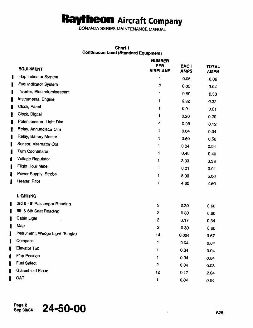
Ray~heon AiKlaft CompanyBONANZA SERIES MAINTENANCE MANUAL
Chart 1
Continuous Load (Standard Equipment)
NUMBER
PER EACH TOTALEOUIPMENT AIRPLANE AI~PS AMPS
Flap Indicator System 1 0.06 0.06
Fuel Indicator System 2 0.02 0.04
Inverter, Electroluminescent 1 0.50 0.50
Instruments, Engine 1 0.32 0.32
Clock, Panel1 0.01 0.01
Clock, Digital 1 0.20 0.20
Potentiometer, Light Dim 4 0.03 0.12
Relay, Annunciator Dim 1 0.04 0.04
Relay, Battery Master 1 0.50 0.50
Sensor, Alternator Out 1 0.04 0.04
Turn Coordinator 1 0.40 0.40
Voltage Regulator 1 3.33 3.33
Flight Hour Meter 1 0.01 0.01
Power Supply, Strobe 1 5.00 5.00
Heater, Pitot 1 4.80 4.60
LIGHTING
3rd 4th Passenger Reading 2 0.30 0.60
5th 6th Seat Reading 2 0.30 0.60
Cabin Light 2 0.17 0.34
Map 2 0.30 0.60
Instrument, Wedge Light (Single) 14 0.024 0.67
Compass 1 0.04 0.04
ElevatorTab 1 0.04 0.04
Flap Position 1 0.04 0.04
Fuel Select 2 0.04 0.08
G[areshie[d Flood 12 0.17 2.04
OATf 0.04 0.04
Page 2 24150100A26
Sep 30/04
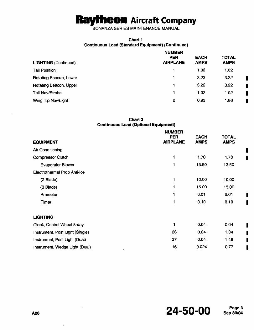
RayNeon nircraft CompanyBONANZA SERIES MAINTENANCE MANUAL
Chart 1
Continuous Load (Standard Equipment) (Continued)
NUMBER
PER EACH TOTAL
LIGHTING (Continued) AIRPLANE AMPS AMPS
Tail Position 1 1.02 1.02
Rotating Beacon, Lower 1 3.22 3.22
Rotating Beacon, Upper 1 3.22 3.22
Tail Nav/Strobe 1 1.02 1.02
Wing Tip Nav/Light 2 0.93 1.86
Chart 2
Continuous Load (Optional Equipment)
NUMBER
PER EACH TOTAL
EQUIPMENT AIRPLANE AMPS AMPS
Air Conditioning
Compressor Clutch 1 1.70 1.70
Evaporator Blower 1 13.50 13.50
Electrothermal Prop Anti-ice
(2 Blade) 1 10.00 10.00
(3 Blade) 1 15.00 15.00
Ammeter 1 0.01 0.01
Timer 1 0.10 0.10
LIGHTING
Clock, Control Wheel 3-day 1 0.04 0.04
Instrument, Post Light (Single) 26 0.04 1.04
Instrument, Post Light (Dual) 37 0.04 1.48
Instrument, Wedge Light (Dual) 16 0.024 0.77
A26 24-50-00 3
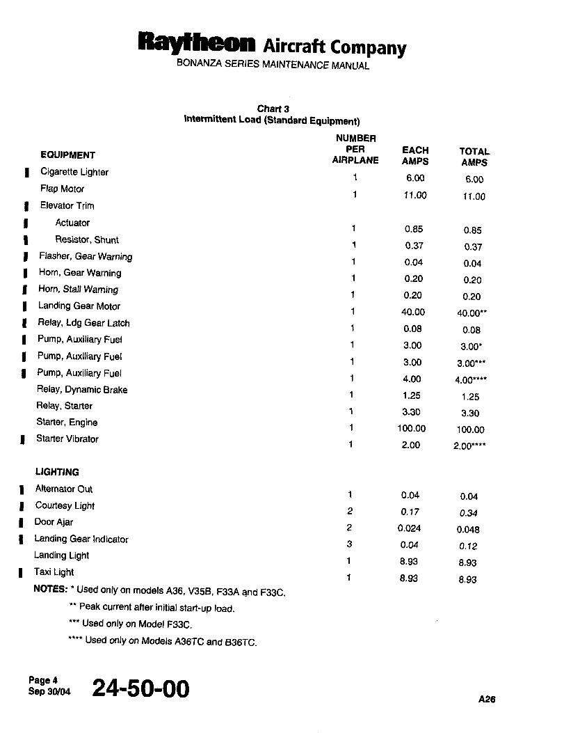
Raydheon nircraft CompanyBONANZA SERIES MAINTENANCE MANUAL
Chart 3
Intermittent Load (Standard Equipment)
NUMBER
PER EACH TOTALEQUIPMENTAIRPLANE AMPS AMPS
Cigarette Lighter1 6.00 6.00
Flap Motor1 11.00 11.00
Elevator Trim
Actuator1 0.85 0.85
Resistor, Shunt1 0.37 0.37
Flasher, Gear Warning 1 0.04 0.04Hem, Gear Warning 1 0.20 0.20Horn, Stall Warning 1 0.20 0.20Landing Gear Motor
1 40.00 40.00**Relay, Ldg Gear Latch
1 0.08 0.08Pump, Auxiliary Fuel
1 3.00 3.00*Pump, Auxiliary Fuel
1 3.00 3.00***Pump, Auxiliary Fuel
1 4.00 4.00****Relay, Dynamic Brake
1 1.25 1.25Relay, Starter
1 3.30 3.30Starter, Engine
1 100.00 100.00Starter Vibrator
1 2.00 2.00****
LIGHTING
Alternator Out1 0.04 0.04
Courtesy Light2 0.17 0.34
Door Ajar2 0.024 0.048
Landing Gear Indicator3 0.04 0.12
Landing Light1 8.93 8.93
Taxi Light1 8.93 8.93
NOTES: Used only on models A36, V358, F33A and F33C,
Peak current after initial start-up load.
Used only on Model F33C.
Used only on Models A36TC and B36TC.
Sep 30/04Page 4 24-50-00A26
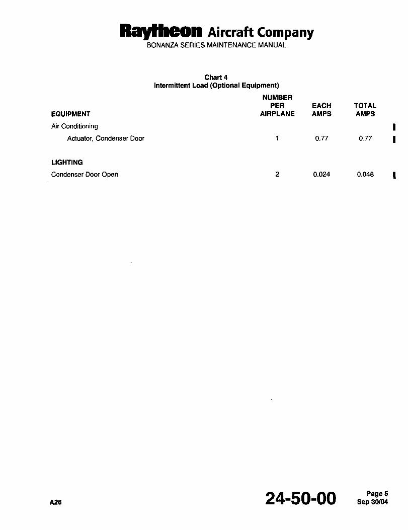
Raytheon AiKraft CompanyBONANZA SERIES MAINTENANCE MANUAL
Chart 4
Intermittent Load (Optional Equipment)
NUMBER
PER EACH TOTAL
EQUIPMENT AIRPLANE AMPS AMPS
Air Conditioning
Actuator, Condenser Door 1 0.77 0.77
LIGHTING
Condenser Door Open 2 0.024 0.048
A26 24-50-00

CHAPTER
EQUIPMENT/
FURNISHINGS
Ra)(thaan Aircraft CompanyBONANZA SERIES MAINTENANCE MANUAL
CHAPTER 25 EQUIPMENTIFURNISHINGS
TABLE OF CONTENTS
SUBJECT PAGE
25-00-00
Flight and Passenger Compartments Description and Operation ........._...1
Flight Compartment and Passenger Compartment Seating ..1
Flightand Passenger Compartments Maintenance Practices ..................1
Pilotand CopilotSeat Removal ....1
Pilotand Copilot Seat installation ...1
Passenger Seat Removal .......2
Passenger Seat Installation .......4
Fifth Seat Removal (CE-748, CE-772 and After; D-10097, D-10120 and After) ......4
Fifth Seat Installation (CE-748, CE-772 and After; D-10097, D-10120 and After) ....4
Fifth Seat Stowage (CE-748, CE-772 and After; D-10097, D-10120 and After) ......5
Fifth and Sixth Seat Removal (E-llll, E-1241 and After; EA-1 and After) .........5
Fifth and Sixth Seat Installation (E-llll, E-1241 and After; EA-1 and After) ........5
Fifth and Sixth Seat Stowage (E-llll, E-1241 and After; EA-1 and After) .5
Vertical Position
Horizontal Position
Headliner Removal (CE-919, CE-923, CE-925, CE-927, CE-929 and After; CJ-156 and After;D-10348, D-10353 and After; E-1422, E-1551, E-1569, E-1594 and After; EA-21, EA-28,EA-33 and After).Header Installation (CE-919, CE-923, CE-925, CE-927, CE-929 and After; CJ-156 and After;D-10348, D-10353 and After; E-1422, E-1551, E-1569, E-1594 and After; EA-21, EA-28,EA-33 and After)Forward Carry-Through SparCover Removal ............7
Forward Car~y-Through SparCover Installation. ..........7
25-60-00
Emergency Description and Operation. .................1
Emergency Locator Transmitter ....1
Communications Components Corporation ELTTR70-17 and TR70-13 ........1
NarcoELT10........................................................................1
Dorneand Margolin ELT. ......1
ArtexELT 110-4
Emergency- Maintenance Practices. .3
Emergency LocatorTransmitter Maintenance ............3
Communications Components Corporation Battery Replacement ................3
Narco Batte~y Replacement .......5
Dorne and Margolin Battery Replacement ...............7
Atrex ELT 110-4 Battery Pack Replacement ...............9
P5-CONTENTS
RBytheOn Aircraft CompanyBONANZA SERIES MAINTENANCE MANUAL
CHAPTER 25 EQUIPMENT/FURNISHINGS
TABLE OF CONTENTS (Continued)
SUBJECT PAGE
Testingthe Emergency LocatorTransmitter 11
Testing the Communications Components Corporation ELT TR70-13 and TR70-17 11
Testingthe Narco ELT 10. 11
Testingthe Dorneand Margolin ELT 12
Testing the Artex ELT 110-4. 12
Sep 30/03Page 2 25-CONTENTS

Raytheon Aircraft CompanyBONANZA SERIES MAINTENANCE MANUAL
CHAPTER 25 EQUIPMENT/FURNISHINGS
LIST OF EFFECTIVE PAGES
CH-SE-SU PAGE DATE
25-LOEP 1 Sep 30/03
25-CONTENTS 1 and 2 Sep 30/03
25-00-00 1 thru 7 Sep 30/03
25-60-00 1 thru 13 Oct 16/92
A24 25-LOEPPagel
Ray~heon AiKra´•H CompanyBONANZA SERIES MAINTENANCE MANUAL
FLIGHT AND PASSENGER COMPARTMENTS DESCRIPTION AND OPERATION I
FLIGHT COMPARTMENT AND PASSENGER COMPARTMENT SEA TING
On all serials except CJ-149 and After, the pilot and copilot seat backs fold forward to facilitate passengers entering Iand leaving the airplane. Airplane serials CJ-149 and After have locking seat backs on the pilot and copilot seats
which can be folded forward by rotating the seat back release lever, located on the lower inboard side of each seat.
An additional lever located behind copilot’s seat on the upper right corner is also used to fold the copilots seat
forward for access to the passenger seats.
The passenger seat backs can be folded forward by rotating the seat back release lever located on the lower inboard
side of each seat. All passenger seats have locking backs.
To adjust the pilot, copilot, and passenger seats forward or aft, an adjustment lever, located beneath the front of the
seats, must be pulled up. The seat can then be slid to the desired position.
A seat back adjustment lever, located on the lower inboard side of the pilot, copilot, passenger, and on the fifth and
sixth seats (A36 Series), enables the seat back to be adjusted to several positions. It is controlled by a mechanical,three position cam lock. An optional seat installation is available whereby the adjustment of the copilot and
passenger seat backs are controlled by a Roton lock lever located on the forward inboard side of the seat bottom.
IAirplane serials E-2104, E-2111 and After, and EA-389 and After are equipped with vertically adjusting seats in the
flight compartment (copilot’s seat is optional). The seat is raised and lowered by gas springs mounted underneath
the seat. The seat is adjustable through a range of 1.3 inches for improved visibility and crew comfort. The raising Iand lowering action is initiated by pulling up on a release lever located on the front RH side of the seat. When the
release lever is raised, two ratchet type camlocks are disengaged from sector gears attached to the gas springsmounted on each side underneath the seat, allowing the gas spring piston rods to extend or retract to raise or lower Ithe seat. To raise the seat the pilot’s weight must be shifted forward. To lower the seat the weight must be shifted
to the rear to overcome the gas spring tension.
FLIGHT AND PASSENGER COMPARTMENTS MAINTENANCE PRACTICES I
PILOTAND COPILOT SEA T REMOVAL
a. Remove the seat stops at the aft end of the mounting tracks.
b. Pull up on the fore and aft adjustment lever located beneath the front of each seat, and slide the seat off the
mounting tracks.
PILOTAND COPILOT SEA T INSTALLATION
NOTE
If shims were installed in the seat support, they should be reinstalled in the same location from
which they were removed to achieve proper seat locking engagement with the seat track.
a. Align the seat guide with the seat track. If shims were installed in the front seat guide, they should be reinstalled
in the same location as that from which they were removed.
b. Pull up on the fore and aft adjustment lever and slide the seat onto the seat track. Release the adjustment lever
and ensure that the seat is securely in place.
~124 25-00-00 S,pP83Be~:Pagel
Ray~heom Aircraft CompanyBONANZA SERIES MAINTENANCE MANUAL
c. If the lock pin does not align with the holes in the center seat track, it will be necessary to reposition the guideswith shims. Use shims as needed to center the locking pin with the holes in the seat track.
NOTE
I Shims (three inches long x 0.3 inch wide) may be fabricated from 0.016 6061-T6 Sheet aluminum.
The shims are placed inside the seat guide and formed around the guide (Ref. Figure 2).
d. Pull up on the fore and aft adjustment lever and slide the seat through the full travel of seat adjustment. Ensure
that the locking pin has positive engagement in all holes of the seat track.
e. Install the seat stops at the aft end of the seat track.
NOTE
I When airplane serials CJ-149 and After are used for aerobatics and parachutes are worn, the
headrests for the pilot and copilot seats must be removed and the seat back cushions rotated over
the seat backs and reattached to the bottom of the seat backs. The headrest can then be
reinstalled.
PASSENGER SEAT REMOVAL
I a. When airplane serials CJ-149 and After are being operated in the aerobatics category, the passenger seats mayneed to be removed in order to meet the center of gravity requirements.
b. Remove the seat stops at the aft end of the seat tracks.
c. Pull up on the fore and aft adjustment lever, located beneath the front of each seat, and slide the seat off the
mounting track.
Sep 30/03Page 2 25-00-00 nn4
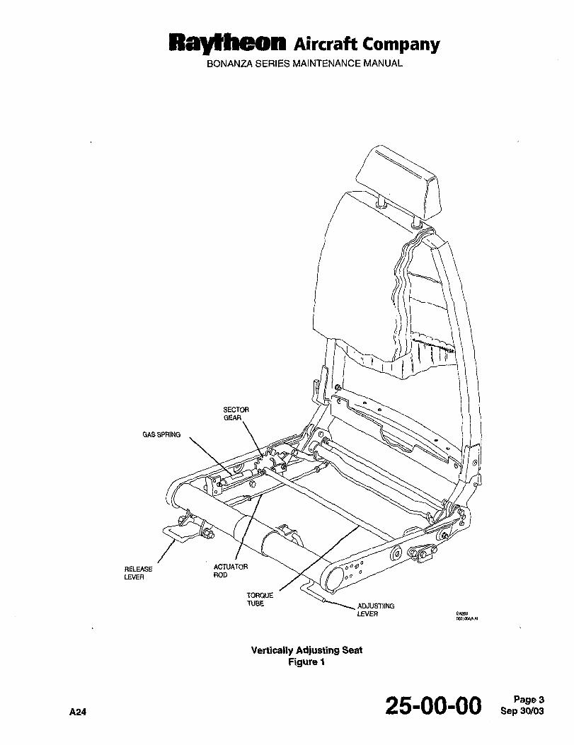
Raytheom Aircraft CompanyBONANZA SERIES MAINTENANCE MANUAL
SECTOR
GEAR
GAS SPRlNG
RELEASE
I
ACTUATOR
LEVER ROD
TORQUETUBE ADJUST))NG
LNER EA258
Vertically Adjusting Seat
Figure 1
A24 25-00-00 Sep 30/03Page 3
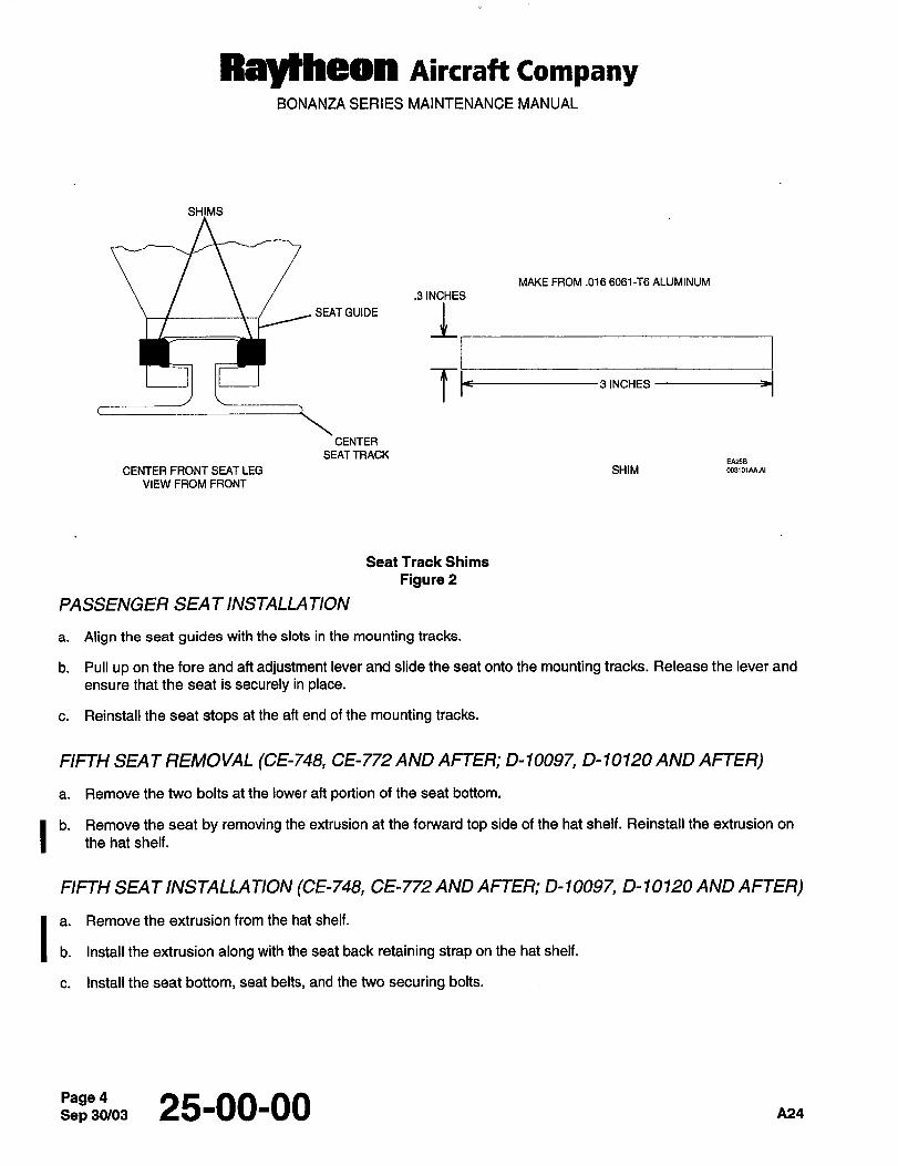
RBYLLheOn Aircraft CompanyBONANZA SERIES MAINTENANCE MANUAL
SHIMS
MAKE FROM .016 6061-T6 ALUMINUM
.3 INCHES
SE~GUOE LI
T~--31NCHES
CENTER
SEAT TRACK
CENTER FRONT SEAT LEG SHIM
VIEW FROM FRONT
Seat Track Shims
Figure 2
PASSENGER SEAT INSTALLA TION
a. Align the seat guides with the slots in the mounting tracks.
b. Pull up on the fore and aft adjustment lever and slide the seat onto the mounting tracks. Release the lever and
ensure that the seat is securely in place.
c. Reinstall the seat stops at the aft end of the mounting tracks.
FIFTH SEAT REMOVAL (CE-748, CE-772 AND AFTER; D-10097, D- 10120 AND AFTER)
a. Remove the two bolts at the lower aft portion of the seat bottom.
I" the hat shelf.Remove the seat by removing the extrusion at the forward top side of the hat shelf. Reinstall the extrusion on
FIFTH SEA T INSTALLATION (CE-748 CE-772 AND AFTER; 0-10097, D- 10120 AND AFTER)
Ia. Remove the extrusion from the hat shelf.
b. Install the extrusion along with the seat back retaining strap on the hat shelf.
c. Install the seat bottom, seat belts, and the two securing bolts.
Sep 25-00-00 A24
Rarytheon Aircraft CompanyBONANZA SERIES MAINTENANCE MANUAL
FIFTH SEA T STOWAGE (CE-748, CE-772 AND AFTER; D-10097, 0-10120 AND AFTER)
a. Pull forward on the lower portion of the seat back until the seat back is in a horizontal position. Lift up on the
forward side on the seat bottom, rotate the seat bottom to a vertical position, and position the seat bottom legsparallel with the seat bottom.
b. Lower the seat back into a vertical position and snap the retaining strap into position.
FIFTH AND SIXTH SEAT REMOVAL (E- 1 I 1 1, E- 124 1 AND AFTER; EA-1 AND AFTER)
a. Fold the bottom of the seat up to a vertical position and fold the seat support in the retract position.
b. Removetheseatattach pins.
FIFTH AND SIXTH SEA T INSTALLA TION (E- I I I I, E 124 1 AND AFTER; EA-1 AND AFTER)
a. Position the seats.
b. Installtheseatattach pins.
c. Fold the seat bottom and seat support down and snap the support into the floor base.
FIFTH AND SIXTH SEAT STOWAGE (E- 1 I 1 1, E- 124 1 AND AFTER; EA- 1 AND A~-TER)
The fifth and sixth seats may be folded either in a horizontal or vertical position to provide additional cargo space.
This may be accomplished as follows:
VERTICAL POSITION
a. Fold the seat bottom up to a vertical position.
b. Fold the seat support into the retract position.
c. Position the seat against the rear bulkhead in a vertical position.
HORIZONTAL POSITION
a. Fold the seat support into retract position and position the seat bottom on the floorboard.
b. Fold the seat back forward and position on top of the seat bottom.
NOTE
A club seating arrangement is available (A36, A36TC and B36TC series only) that enables the third
and fourth passenger seats to be turned facing aft. On A36 serials prior to E-1371, when this
arrangement is used, the fifth and sixth seats must be moved four (4) inches aft to maintain proper
weight and balance. If the seats are returned to a standard seating arrangement (facing forward),the fifth and sixth seats MUST be moved back to their original position. Holes are located in the
floorboard under the carpeting to facilitate installation of the side mounting brackets and the seat
support base. It is recommended that both the third and fourth passenger seats face the same Idirection at all times.
A24 25-00-00 5
Raytheon Aircraft CompanyBONANZA SERIES MAINTENANCE MANUAL
HEADLINER REMOVAL (CE-919, CE-923, CE-925, CE-927, CE-929 AND AFTER; CJ-156
AND AFTER; 0-10348, 0-10353 AND AFTER; E-1422, E-1551, E-1569, E-1594 AND AFTER;EA-21, EA-28, EA-33 AND AFTER)
I a. Perform the FIFTH SEAT REMOVAL and the FIFTH AND SIXTH SEAT REMOVAL procedures.
b. Remove the aft bulkhead closure.
c. Working through the aft bulkhead, remove the tape from around the air ducts that connects the air duct to the
headliner duct.
d. Remove the screws which hold the overhead console in place.
e. Disconnect the wires to the light and remove the console.
f. Remove the window moldings.
g. Remove the doortrim.
h. Perform the GLARESHIELD REMOVAL procedure in Chapter 39-10-00.
i. Remove the windshield trim.
j. Remove the garment hanger.
k. Gently pull on the headliner to disconnect the fabric hook and loop fasteners. These hook and loop fasteners
are located wherever the airplane frame and headliner come together.
I. Separate the forward air ducts from the air duct in the headliner. A spatula or similar tool may be used to work
between the ducts to work the sealer loose.
m. Disconnect the electrical wiring to the headliner lights. (This connector is located near the center of the headliner
toward the front, or aft of the pilot’s side window.)
n. Remove the headlinerthrough the door.
HEADLINER INSTALLA TION (CE-919 CE-923, CE-925, CE-927, CE-929ANDAFTER; CJ- 156
AND AFTER; D- 19348 0-10353 AND AFTER; E- 1422, E- 1551, E- 1569, E- 1594 AND AFTER;EA-21, EA-28, EA-33 AND AFTER)
I a. Placethe headlinerin theairplane.
b. Connect the electrical wiring to the headliner lights.
c. Connect the forward ventilation ducts. Seal ducts with adhesive (54, Chart 1, 91-00-00).
d. Engage the hook and loop fasteners to hold headliner in place.
e. Install the garment hanger.
f. Install the windshield trim.
g. Perform the GLARESHIELD INSTALLATION procedure in Chapter 39-10-00.
h. Install the doormoldings.
Sep 25-00-00
RayYheon Aircraff CompanyBONANZA SERIES MAINTENANCE MANUAL
i. Install the window molding.
j. Connect the wires to the console light and install the console.
k. Connect the duct aft of the rear bulkhead closure. Tape the joint with two-inch wide tape (55, Chart 1 91 -00-00).
i. Install the bulkhead closure.
m. Perform the FIFTH SEAT INSTALLATION and the FIFTH AND SIXTH SEAT INSTALLATION procedures.
FORWARD CARRY-THROUGH SPAR COVER REMOVAL
a. Perform the PILOT AND COPILOT SEAT REMOVAL procedures. I
b. Remove emergency landing gear crank cover from spar cover.
c. On aft side of spar cover, pull back carpet and remove screws from spar cover.
d. On forward side of spar cover, pull back carpet and remove screws from spar cover.
e. Remove RHaccesscover.
f. From inside of RH access cover, loosen clamp and remove air duct from plenum and grill assembly.
g. Lift spar cover and remove from forward spar.
FORWARD CARRY-THROUGH SPAR COVER INSTALLA71ON
I CAUTION 1CAUTION
Improper installation of the forward carry-through spar cover may interfere with the landing gear
emergency hand crank operation. Ensure the landing gear hand crank will engage and rotate
without interference with the spar cover.
a. Center spar cover on the forward spar.
b. From inside of RH access cover, install air duct on plenum and grill assembly and tighten clamp.
c. Install RH access cover assembly.
d. On forward side of spar cover, install screws to secure forward end of spar cover and install carpet.
e. On aft side of spar cover, install screws to secure aft end of spar cover and install carpet. I
f. Check the emergency landing gear hand crankto ensure handle will engage and rotate without interference with
the forward carry-through spar cover.
g. Install emergency landing gear crank cover to spar cover.
h. Perform the PILOT AND COPILOT SEAT INSTALLATION procedures. I
25-00-00 ,,~:Page 7
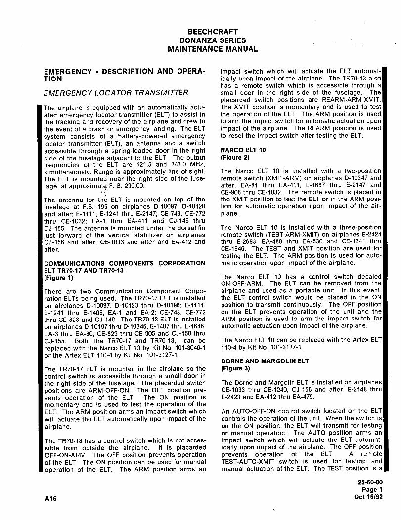
BEECHCRAFT
BONANZA SERIES
MAINTENANCE MANUAL
EMERGENCY DESCRIPTION AND OPERA- impact switch which will actuate the ELT automat-
TION ically upon impact of the airplane. The TR70-13 also
has a remote switch which is accessible through a
LOCA TOR TRANSMITTER small door in the right side of the fuselage. The
placarded switch positions are REARM-ARM-XMIT.
The airplane is equipped with an automatically actu- The XMIT position is momentary and is used to test
ated emergency locator transmitter ~ELT) to assist in the operation of the ELT. The ARM position is used
the tracking and recovery of the airplane and crew in to arm the impact switch for automatic actuation upon
the event of a crash or emergency landing. The ELT impact of the airplane. The REARM position is used
system consists of a battery-powered emergency to reset the impact switch after testing the ELT.
locator transmitter (ELT), an antenna and a switch
accessible through a spring-loaded door in the right NARCO ELT 10
side of the fuselage adjacent to the ELT. The output (Figure 2)
frequencies of the ELT are 121.5 and 243.0 MHz,
simultaneously. Range is approximately line of sight. The Narco ELT 10 is installed with a two-positionThe ELT is mounted near the right side of the fuse- remote switch (XMIT-ARM) on airplanes 0-10347 and
lage, at approximate, F. S. 230.00. after, EA-81 thru EA-411, E-1687 thru E-2147 and
i CE-906 thru CE-1032. The remote switch is placed in
The antenna for th.’e ELT is mounted on top of the the XMIT position to test the ELT or in the ARM posi-fuselage at F.S. 195 on airplanes 0-10097, 0-10120 tion for automatic operation upon impact of the air-
and after; E-llll, E-1241 thru E-2147; CE-748, CE-772 plane.thru CE-1032; EA-1 thru EA-411 and CJ-149 thru
CJ-155. The antenna is mounted under the dorsal fin The Narco ELT 10 is installed with a three-positionjust forward of the vertical stabilizer on airplanes remote switch (TEST-ARM-XMIT) on airplanes E-2424
CJ-156 and after, CE-1033 and after and EA-412 and thru E-2693, EA-480 thru EA-530 and CE-1241 thru
after. CE-1646. The TEST and XMIT position are used for
testing the ELT. The ARM position is used for auto-
COMMUNICATIONS COMPONENTS CORPORATION matic operation upon impact of the airplane.ELT TR70-17 AND TR70-13
(Figure 1) The Narco ELT 10 has a control switch decaled
ON-OFF-ARM. The ELT can be removed from the
There are two Communication Component Corpo- airplane and used as a portable unit. In this event,
ration ELT~ being used. The TR70-17 ELT is installed the ELT control switch would be placed in the ON
on airplanes D-10097, D-10120 thru D-10196; E-llll, position to transmit continuously. The OFF positionE-1241 thru E-1406; EA-1 and EA-2; CE-748, CE-772 on the ELT prevents operation of the unit and the
thru CE-828 and CJ-149. The TR70-13 ELT is installed ARM position is used to arm the impact switch for
on airplanes D-10197 thru D-10346, E-1407 thru E-1686, automatic actuation upon impact of the airplane.EA-3 thru EA-80, CE-829 thru CE-905 and CJ-150 thru
CJ-155. Both, the TR70-17 and TR70-13, can be The Narco ELT 10 can be replaced with the Artex ELT
replaced with the Narco ELT 10 by Kit No. 101-3046-1 110-4 by Kit No. 101-3127-1.
or the Artex ELT 110-4 by Kit No. 101-3127-1.DORNE AND MARGOLIN ELT
The TR70-17 ELT is mounted in the airplane so the (Figure 3)control switch is accessible through a small door in
the right side of the fuselage. The placarded switch The Dorne and Margolin ELT is installed on airplanes
positions are ARM-OFF-ON. The OFF position pre- CE-1033 thru CE-1240, CJ-156 and after, E-2148 thru
vents operation of the ELT. The ON position is E-2423 and EA-412 thru EA-479.
momentary and is used to test the operation of the
ELT. The ARM position arms an impact switch which An AUTO-OFF-ON control switch located on the ELT
will actuate the ELT automatically upon impact of the controls the operation of the unit. When the switch is
airplane, on the ON position, the ELT will transmit for testingor manual operation. The AUTO position arms an
The TR70-13 has a control switch which is not acces- impact switch which will actuate the ELT automat-
sible from outside the airplane. It is placarded ically upon impact of the airplane. The OFF positionOFF-ON-ARM. The OFF position prevents operation prevents operation of the ELT. A remote
of the ELT. The ON position can be used for manual TEST-AUTO-XMIT switch is used for testing and
operation of the ELT. The ARM position arms an manual actuation of the ELT. The TEST position is a
2160-00
Page 1
A16 Oct 16/92
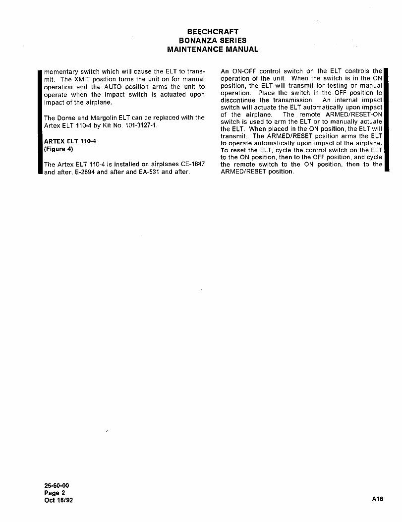
BEECH%RAFT
BONANZA SERIES
MAINTENANCE MANUAL
momentary switch which will cause the ELT to trans- An ON-OFF control switch on the ELT controls the
mit. The XMIT position turns the unit on for manual operation of the unit. When the switch is in the ON
operation and the AUTO position arms the unit to position, the ELT will transmit for testing or manual
operate when the impact switch is actuated upon operation. Place the switch in the OFF position to
impact of the airplane. discontinue the transmission. An internal impactswitch will actuate the ELT automatically upon impactof the airplane. The remote ARMED/RESET-ON
The Dorne and Margolin ELT can be replaced with theswitch is used to arm the ELT or to manually actuate
Artex ELT 110-4 by Kit No. 101-3127-1.the ELT. When placed in the ON position, the ELT will
transmit. The ARMED/RESET position arms the ELTARTEX ELT 110-4 to operate automatically upon impact of the airplane.(Figure 4) To reset the ELT, cycle the control switch on the ELT
to the ON position, then to the OFF position, and cycleThe Artex ELT 110-4 is installed on airplanes CE-1647 the remote switch to the ON position, then to the
and after, E-2694 and after and EA-531 and after. ARMED/RESET position.
25-60-00
Page 2
Oct 16/92 A16
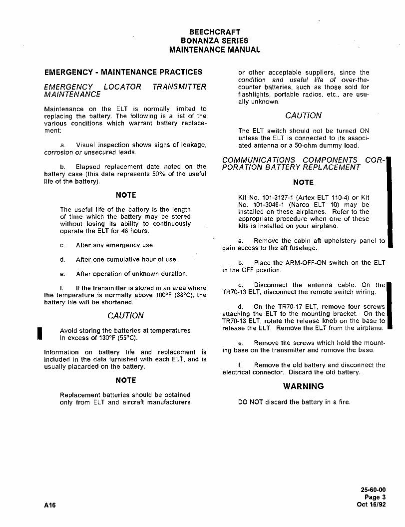
BEECHCRAFT
BONANZA SERIES
MAINTENANCE MANUAL
EMERGENCY MAINTENANCE PRACTICES or other acceptable suppliers, since the
condition and useful life of over-the-
EMERGENCY LOCATOR TR A NSMI TT~R counter batteries, such as those sold for
MAINTENANCE flashlights, portable radios, etc., are usu-
ally unknown.
Maintenance on the ELT is normally limited to
replacing the battery. The following is a list of the CAUTIONvarious conditions which warrant battery replace-ment: The ELT switch should not be turned ON
unless the ELT is connected to its associ-
a. Visual inspection shows signs of leakage, ated antenna or a 50-ohm dummy load.corrosion or unsecured leads.
COMMUNICATIONS COMPONENTS COR-b. Elapsed replacement date noted on the PORA TION BA TTER Y REPLACEMENT
battery case (this date represents 50% of the useful
life of the battery). NOTE
NOTE Kit No. 101-3127-1 (Artex ELT 110-4) or Kit
No. 101-3046-1 (Narco ELT 10) may beThe useful life of the battery is the length installed on these airplanes. Refer to theof time which the battery may be stored appropriate procedure when one of thesewithout losing its ability to continuously kits is installed on your airplane.operate the ELT for 48 hours.
a. Remove the cabin aft upholstery panel toc. After any emergency use.
gain access to the ah fuselage.
d. After one cumulative hour of use.b. Place the ARM-OFF-ON switch on the ELT
in the OFF position.e. After operation of unknown duration.
c. Disconnect the antenna cable. On thef. if the transmitter is stored in an area where
the temperature is normally above 1000F (380C), theTR70-13 ELT, disconnect the remote switch wiring.
battery life will be shortened.d. On the TR70-17 ELT, remove four screws
CAUTION attaching the ELT to the mounting bracket. On the
TR70-13 ELT, rotate the release knob on the base to
Avoid storing the batteries at temperaturesrelease the ELT. Remove the ELT from the airplane.
in excess of 1300F (550C).e. Remove the screws which hold the mount-
Information on battery life and replacement is i"g base on the transmitter and remove the base.
included in the data furnished with each ELT, and is
usually placarded on the battery. f. Remove the old battery and disconnect the
electrical connector. Discard the old battery.NOTE
WARNING
Replacement batteries should be obtained
only from ELT and aircraft manufacturers DO NOT discard the battery in a fire.
25-60-00
Page 3
A16 Oct 16/92
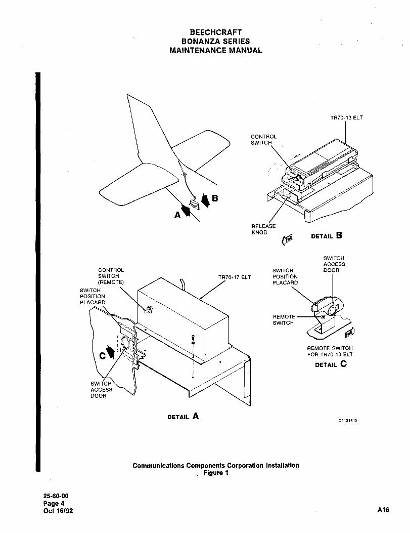
BEECHCRAFT
BONANZA SERIES
MAINTENANCE MANUAL
TR70-13 ELT
CONTROL
SWITCH
A
RELEASE
KNOBDETAIL Bd
SWITCH
ACCESS
CONTROL SWITCH DOOR
SWITCH TR70-17 ELT POSITION
(REMOTE) PLACARD
SWITCH
POSITION
PLACARD
REMOTE
SWITCH
REMOTE SWITCH
FOR TR70-13 ELT
DETAIL C
SWITCH
ACCESS
DOOR
DETAIL AC9101610
Communications Components Corporation Installation
Figure 1
25-60-00
Page 4
Oct 16/92 A16
BEECHCRAFT
BONANZA SERIES
MAINTENANCE MANUAL
g. Inspect for, and properly treat, any corro- e. Extend the portable antenna.
sion that may be indicated in the area where the
battery was installed. CAUTION
h. Connect a fresh battery and install it in the To avoid damage to the antenna or the
compartment. plastic tab on the upper end, care must be
exercised in extending the portable anten-
i. Replace the base and screws. na and handling the control head.
j. Install the transmitter in the airplane and f. Remove the four screws attaching theattach the antenna cable. On the TR70-13 ELT, con- control head to the battery casing and slide the con-
nect the remote switch wiring. trol head and battery case apart. The battery con-
nection leads are approximately 3-inches long.k. The new replacement date should be
marked on the ELT in a visible area. This wil\ aid in NOTEfuture inspections of the ELT. This date is 50% of the
useful life of the battery as defined by the battery Do not remove the sealant on the inside lipmanufacturer. of the battery pack or a watertight seal will
not be made when the ELT unit is reas-i. Test the ELT as instructed in TESTING THE sembled.
EMERGENCY LOCATOR TRANSMITTER.
g. Disconnect the battery by unsnapping them. Install the cabin aft upholstery panel. battery terminals from the bottom of the transmitter
PC board. Discard the old battery.NARCO BA TTER Y RIFPLACEMENT
(Figure 2) WARNING
NOTEDO NOT discard the battery in a fire.
Kit No. 101-3127-1 (Artex ELT 110-4) maybe installed on these airplanes. Refer to
h. Inspect for and properly treat any corro-
the Artex ELT 110-4 procedure when this sion that may be indicated in the area where the
kit is installed on your airplane. battery was installed.
a. Remove the cabin aft upholstery panel to i. Connect the terminals of the new battery
gain access to the aft fuselage. to the bottom of the transmitter PC board.
b. Place the ARM-OFF-ON control switch on j. Using a spatula, apply a bead of sealant
the ELT in the OFF position. (supplied with each battery pack) around the area of
the control head which is joined with the battery case
c. Disconnect the antenna cable from the when reassembled.
ELT. Disconnect the remote switch wiring from the
terminals on the ELT. NOTE
d. Unlatch the mounting strap and remove the This sealant provides a watertight seal
ELT from the airplane. when the unit is assembled.
25-60-00
Page 5
A16 Oct 16/92
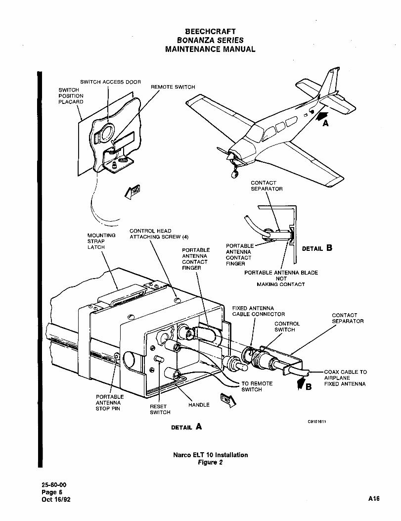
BEECHCRAFT
BONANZA SERIES
MAINTENANCE MANUAL
SWITCH ACCESS DOORREMOTE SWITCH
SWITCH
POSITION
PLACARD
A
SEPARATOR
CONTACT
CONTROL HEADMOUNTING ATTACHING SCREW (4)STRAP
FINGER
DETAIL BLATCH PORTABLEPORTABLE ANTENNAANTENNA CONTACTCONTACT FINGER
PORTABLE ANTENNA BLADE
NOT
MAKING CONTACT
FIXED ANTENNA
CABLE CONNECTOR CONTACT
SEPARATORCONTROL
SWITCH
I ’"UYYT(\L, COAX CABLE TO
AIRPLANE
TO le
ANTENNAPORTABLERESET HANDLE
STOP PINSWITCH
C91a1611
DETAIL A
Natco ELT 10 Installation
Figure 2
2160-00
Page 6
Oct 16/92 A16
BEECHCRAFT
BONANZA SERIES
MAINTENANCE MANUAL
k. Insert the control head section into the s. Install the cabin aft upholstery panel.battery case, being careful not to pinch the wires and
install the four attaching screws. Wipe any excess DORNE AND MARGOLIN BA TTER Ysealant from the outside of the unit. REPLACEMENT
(Figure 3)NOTE
NOTEIf the four screw holes do not line up, rotate
the battery case 1800 and reinsert. Kit No. 101-3127-1 (Artex ELT 110-4) or Kit
No. 101-3046-1 (Narco ELT 10) may be
i. Stow the portable antenna. installed on these airplanes. Refer to the
appropriate procedure when one of these
CAUTION kits is installed on your airplane.
Exercise extreme care in order to avoid a. Remove the cabin ah upholstery panel to
damage to the antenna or the plastic tab gain access to the ah fuselage.on the upper end.
b. Make certain the ELT is turned off.
m. Install the transmitter in the airplane and
secure the mounting strap. c. Disconnect the antenna cable.
n. Connect the fixed antenna cable to the ELT. d. Disconnect the remote switch.
Ensure that the contact (plastic) separator is inserted
between the portable antenna contact and the port- e. Remove the screws holding the ELT in
I able antenna as shown in Figure 2. place.
NOTE f. Remove the ELT from the airplane.
With the contact separator not in place, a g. Remove the screws from the bottom of the
very weak signal may be transmitted, ELT and remove the bottom.
which is strong enough for a functional
test, but too weak for emergency use. h. Disconnect the battery and discard it.
o. Connect the remote switch wiring to the WARNINGterminals on the ELT.
DO NOT discard the battery in a fire.
p. Press the RESET button and place the
ARM-OFF-ON switch on the ELT in the ARM position, i. Inspect for and properly treat any corro-
sion that may be indicated in the area where the
q. The new replacement date should be battery was replaced.marked on the ELT in a visible area. This will aid in
future inspections of the ELT. This date is 50% of the j. Connect the new battery.useful life of the battery as defined by the batterymanufacturer. k. The new replacement date should be
marked on the ELT in a visible area. This will aid in
r. Test the ELT as instructed in TESTING THE future inspections of the ELT. This date is 50% of the
Iter.Eh71ERGENCY LOCATOR TRANSMITTER in this chap- useful life of the battery as defined by the batterymanufacturer.
25-60-00
Page 7
A16 Oct 16/92
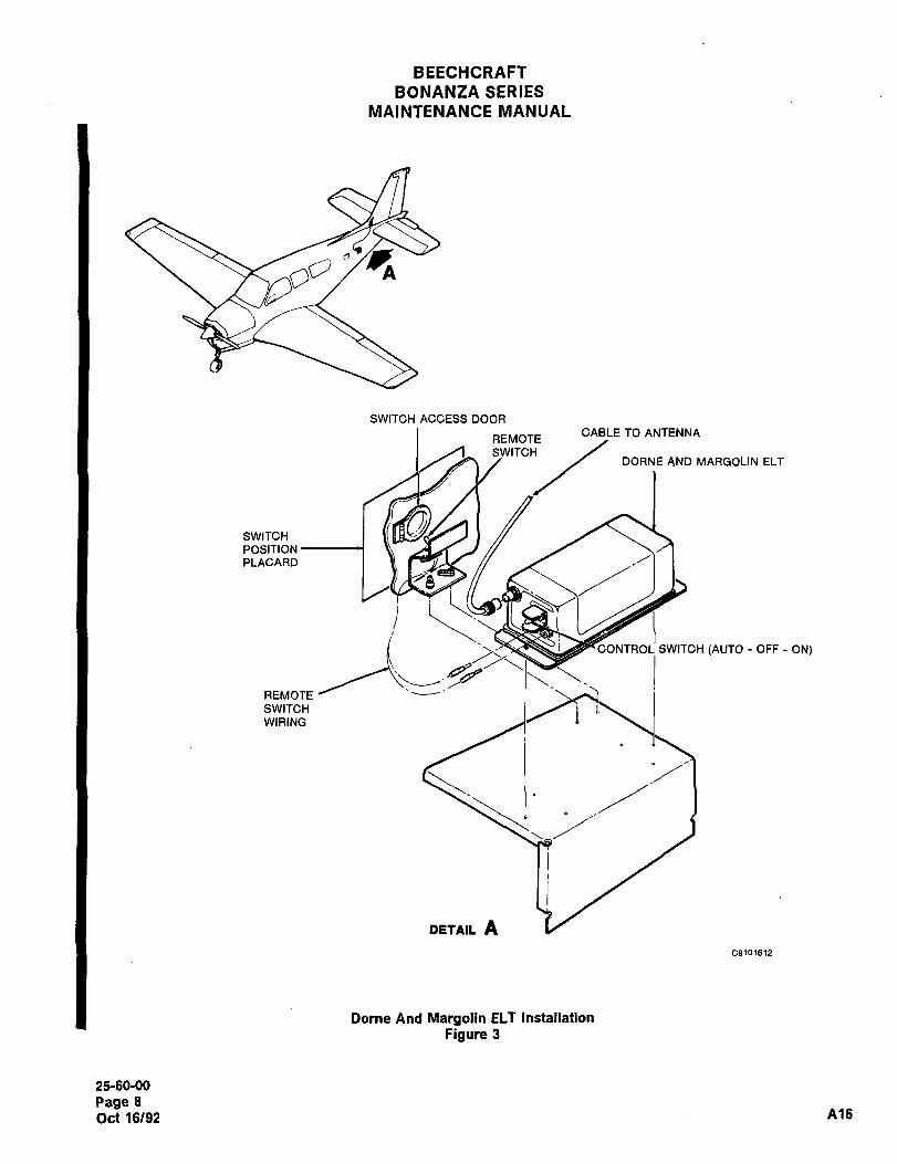
BEECHCRAFT
BONANZA SERIES
MAINTENANCE MANUAL
A
SWITCH ACCESS DOOR
CABLE TO ANTENNAREMOTE
SWITCHDORNE AND MARGOLIN ELT
SWITCH
POSITION
PLACARD
REMOTE
CONTROL SWITCH (AUTO OFF ON)
SWITCH
WIRING
DEtAIL A
C9101612
Dorne And Margolin ELT Installation
Figure 3
25-60-00
Page 8
Oct 16/92 A16
BEECHCRAFT
BONANZA SERIES
MAINTENANCE MANUAL
i. Install the bottom of the ELT and the WARNINGscrews
Do not discard battery pack in a f~re.
m. Install the ELT in the airplane and install
the screws which hold it in place. NOTE
n. Test the ELT as instructed in TESTING THE Replacement battery packs should be
EMERGENCY LOCATOR TRANSMITTER in this chap- obtained only from ELT and airplane man-
ter. ufacturers or from other acceptable sup-pliers, since the condition and useful lifeof over-the-counter batteries, such as
o. Install the cabin aft upholstery panel.those sold for flashlights, portable radios,
ART~X ELT 1 10-4 BA TTER Y PA CK etc., are usually unknown.
R~PLACEMENTi. Inspect for and properly treat any corro-(Figure 4) sion that may be indicated in the area where the
battery was installed.NOTE
j. A new battery pack replacement date mustThis procedure must be used for airplanes be marked on the outside of the transmitter. Thethat have Kit No. 101-3127-1 installed on date is 50% of the useful life of the battery pack asthem. defined by the battery pack manufacturer.
a. Remove the cabin aft upholstery panel to k. Connect the battery pack electrical con-
gain access to the aft fuselage. nector (10).
b. Place the control switch (12) on the ELT in I. Secure the battery pack to the ELT with the
the OFF position, screws (8). Make certain that ail gaskets are properlyaligned and in good condition.
c. Loosen the two thumb screws (1) securingthe mounting frame cap (2) to the mounting frame m. Insert the antenna cable (4) through the
base (5). mounting frame cap (2) and connect to the ELT (11).
d. Disconnect the antenna cable (4) from the n. Insert the remote switch harness (3)
ELT. through the mounting frame cap (2) and connect to
the ELT (1´•1).
e. Disconnect the remote switch harness (3)o. Install the ELT (11) in the mounting frame
from the ELT (11). base (5). Position the ELT in the mounting framebase so that the arrow on the top of the ELT is pointed
f. Remove the ELT (11) from the mounting in the direction of flight.frame base (5).
p. Install the mounting frame cap (2) onto theg. Disconnect the battery pack connector (10) mounting frame base ~5) and secure with the thumb
from the ELT. screws ~1).
h. Remove the screws (8) securing the bat- q. Place the control switch (12) on the ELT in
tery pack to the ELT (li). the OFF position.
25-60-00
Page 9
Ale Oct 16/92
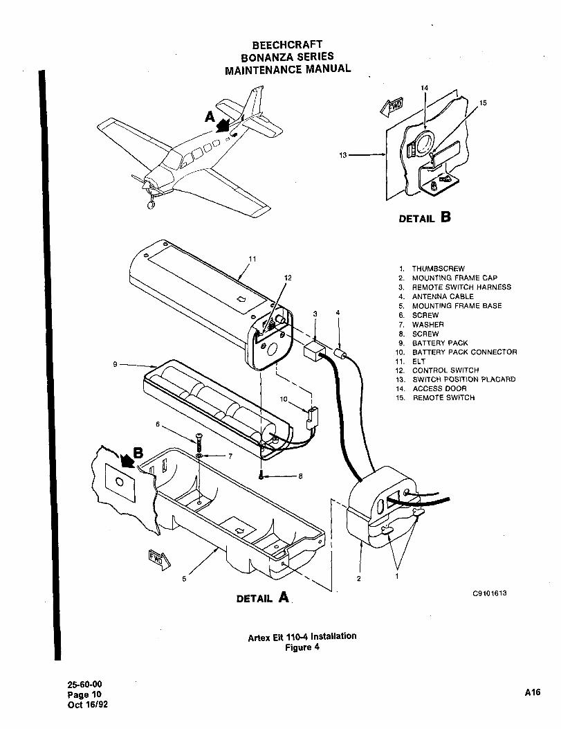
BEECHCRAFTBONANZA SERIES
MAINTENANCE NIANUAL
14
n~, 15
0"13
O
DETAIL B
11
1. THUMBSCREW
12 2. MOUNTING FRAME CAP
3. REMOTE SWITCH HARNESS
4. ANTENNA CABLE
5. MOUNTING FRAME BASE
3 4 6. SCREW
7. WASHER
3. SCREW
009 anrrERupncK
10. BATTERY PACK CONNECTOR
9 11. ELT
i 12. CONTROL SWITCH
13. SWISCH POSITION P~ACARD
14. ACCESSDOOR
10 15. REMOTE SWITCH
B 7Ytl gs_
O
5 iii 2 1
DETAIL A C9101613
Artex Elt 110-4 Installation
Figure 4
25-60-00
Page 10 A16
Oct 16/92
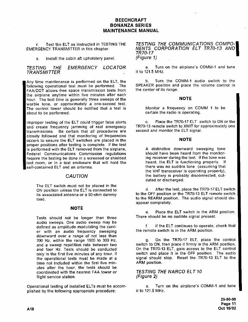
BEECHCRAFT
BONANZA SERIES
MAINTENANCE ~1ANUAL
r. Test the ELT as instructed in TESTING THE TESTING THE COMMUNICATIONS COMPO-
EMERGENCY TRANSMITTER in this chapter. NENTS CORPORATION ELT TR70-13 ANDTR 70-1 7
s. Install the cabin an upholstery panel. (Figure 1)
TESTING THE EMERGENCY LOCATOR a. Turn on the airplane’s COMM-1 and tune
TRANSMI TTER it to 121.5 MHz.
Any time maintenance is performed on the ELT, the b. Turn the COMM-1 audio switch to the
following operational test must be performed. The SPEAKER position and place the volume control in
FAA/DOT allows free space transmission tests from the center of its range.
the airplane anytime within five minutes after each
hour. The test time is generally three sweeps of the NOTE
warble tone, or ap~proximately a one-second test.
The control tower should be notified that a test is Monitor a frequency on COMM 1 to be
about to be performed. certain the radio is operating.
Improper testing of the ELT could trigger false alerts c. Place the TR70-17 ELT switch to ON or the
and create frequency jamming of real emergency TR70-13 remote switch to XMIT for approximately one
transmissions. Be certain that all procedures are second and monitor the ELT signal.
closely followed and that monitoring of frequenciesoccurs to ensure the ELT switches are placed in the NOTE
proper positions after testing is complete. If the test
is performed with the ELT removed from the airplane, A distinctive downward sweeping tone
Federal Communications Commission regulations should have been heard from the monitor-
require the testing be done in a screened or shielded ing receiver during the test. if the tone was
test room, or in a test enclosure that will hold the heard, the ELT is functioning properly. If
self-contained ELT and an antenna. there was no audible tone (assuming that
the VHF transceiver is operating properly),CAUTION the battery is probably disconnected, out-
dated or discharged.
The ELT switch must not be placed in the
ON position unless the ELT is connected to d. After the test, place the TR70-17 ELT switch
its associated antenna or a 50-ohm dummy to the OFF position or the TR70-13 ELT remote switch
load. to the REARM position. The audio signal should dis-
appear completely.
NOTEe. Place the ELT switch in the ARM position.
Tests should not be longer than three There should be no audible~signal present.
audio sweeps. One audio sweep may be
defined as amplitude modulating the carri- f. If the ELT continues to operate, check that
er with an audio frequency sweeping the remote switch is in the ARM position.
downward over a range of not less than
700 Hz, within the range 1600 to 300 Hz, g. On the TR70-17 ELT, place the control
and a sweep repetition rate between two switch to ON, then place it firmly in the ARM position.and four Hz. Tests should be conducted On the TR70-13 ELT, gain access to the ELT control
only in the first five minutes of any hour. If switch and place it in the OFF position. The audio
the operational tests must be made at a signal should stop. Reset the.TR70-13 ELT to the
time not included within the first five min- ARM position.utes after the hour, the tests should be
coordinated with the nearest FAA tower or TESTING THE NARCO ELT 10
night service station. (Figure 2)
Operational testing of installed ELTs must be accom; a. Turn on the airplane’s COMM-1 and tune
plished by the following appropriate procedure: it to 121.5 MHz.
25-60-00
Page 11
A16 Oct 16/92
BEECHCRAFT
BONANZA SERIES
MAINTENANCE MANUAL
b. Turn the COMM-1 audio switch to’the c. Place the remote TEST-AUTO-XMIT switch
SPEAKER position and place the volume control in in the TEST position and hold the switch for app
the center of its range. mately one second.
NOTE NOTE
Monitor a frequency on COMM 1 to be A distinctive downward sweeping tone
certain the radio is operating, should have been heard from the monitor-
ing receiver during the test, if the tone was
c. Place the remote ELT (TEST-AUTO-XMIT, heard, the ELT is functioning properly. If
MIT-ARM) switch to XMIT for approximately onethere was no audible tone (assuming that
cond and monitor the ELT signal.the VHF transceiver is operating properly),the battery is probably disconnected, out-
NOTEdated or discharged.
d. After the test, place the remoteA distinctive downward sweeping tone
TEST-AUTO-XMIT switch in the AUTO position.should have been heard from the monitor-
ing receiver during the test. If the tone wase. Monitor the emergency channel to ensure
heard, the ELT is functioning properly. Ifthe ELT has discontinued operation.
there was no audible tone (assuming that
the VHF transceiver is operating properly), f. If the ELT continues to operate, be certainthe battery is probably disconnected, out-
the remote switch is in the AUTO position. Gaindated or discharged,
access to the ELT and check that the control switch
is in the AUTO position also.d. After the test, place the remote
TEST-AUTO-XMIT switch to the AUTO position or theg. If the ELT still continues to send a signal,
XMIT-ARM switch to the ARM position. The audio cycle the control switch on the ELT to the ON positionsignal should disappear completely. and then to the AUTO position to reset the ELT impact
switch.
e. If the ELT continues to operate, check that
the remote XMIT- ARM switch is in the ARM position TESTING THE ARTEX ELT 110-4
or the TEST-AUTO-XMIT switch is in the AUTO posi- (Figure 4)tion.
a. Turn on the airplane’s COMM 1 and tune
f. If the ELT continues to send a signal, gain it to 121.5 MHz.
access to the ELT and firmly press the reset switch
on the front of the ELT and listen to ensure that the b. Turn the COMM-1 audio switch to the
audio signal disappears from the COMM 1. The ELT’s SPEAKER position and place the volume control in
control switch must be in the ARM position when the center of its range.
completing the test procedure.NOTE
TESTING THE DORNE AND MARGOLIN ELT
(Figure 3)Monitor a frequency on COMM 1 to be
certain the radio is operating.
a. Turn on the airplane’s COMM 1 and tunec. Place the remote ARMED/RESET-ON
it to 121.5 MHz.switch in the ON position for approximately one sec-
end.b. Turn the COMM-1 audio switch to the
SPEAKER position and place the volume control in NOTEthe center of its range.
A distinctive downward sweeping tone
NOTE should have been heard from the monitor-
ing receiver during the test. if the tone was
Monitor a frequency on COMM 1 to be heard, the ELT is functioning properly. If
certain the radio is operating, there was no audible tone (assuming that
25-60-00
Page 12
Oct 16/92 A16
BEECHCRAFT
BONANZA SERIES
MAINTENANCE MANUAL
the VHF transceiver is operating properly), f. If the ELT continues to operate, be certain
the battery is probably disconnected, out- the remote switch is in the ARMED/RESET position.dated or discharged. Gain access to the ELT and check that the control
switch is in the OFF position also.
d. After the test, place the remote
ARMED/RESET-ON switch in the ARMED/RESET g. If the ELT still continues to send a signal,position. cycle the control switch on the ELT to the ON and
then OFF position and the remote switch to the ON
e. Monitor the emergency channel to ensure and then ARMED/RESET position to reset the ELT
that the ELT has discontinued operation, impact switch.
"END"
25-60-00
Page 13
A16 Oct 16/92

CHAPTE R
FLIGHT
CONTROLS
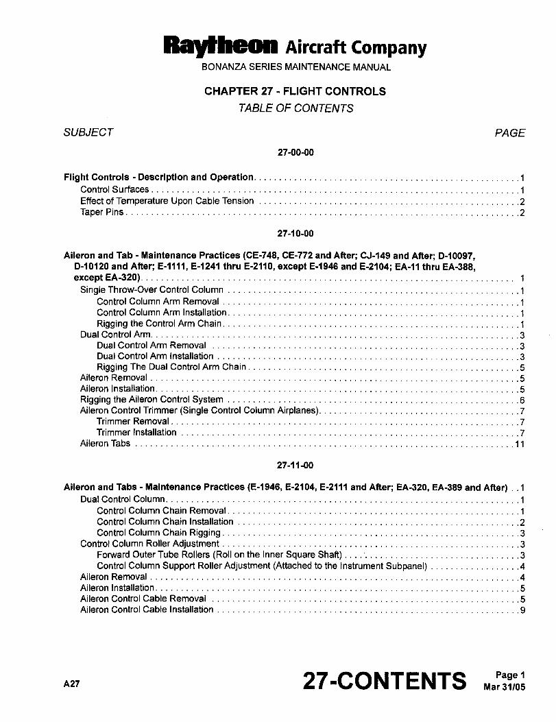
RBYtheOll Aircraft CompanyBONANZA SERIES MAINTENANCE MANUAL
CHAPTER 27 FLIGHT CONTROLS
TABLE OF CONTENTS
SUBJECT PAGE
27-00-00
FlightControls -Description and Operation.........._
~1
ControlSurfaces............................................................... ..........1
EffectofTemperature Upon CableTension ..............2
Taper Pins................._
27-10-00
Aileron and Tab Maintenance Practices (CE-748, CE-772 and After; CJ-149 and After; D-10097,D-10120 and After; E-llll, E-1241 thru E-2110, except E-1946 and E-2104; EA-~1 thru EA-388,except EA-320).
Single Throw-Over Control Column .1
Control ColumnArm Removal........._
~´•1
Control Column Arm Installation. ~1
Rigging theControl Arm Chain. ~1
Dual Control Arm.........._......._
Dual Control Arm Removal ~3
Dual ControlArm Installation ~3
Rigging The Dual ControlArm Chain. ~5
Aileron Removal........._......._
Aileron Installation
RiggingtheAileron Control System............_.._._
.6
Aileron ControlTrimmer(Single Control ColumnAirplanes). ~7
Trimmer Removal
Trimmer Installation .........~7
Aileron Tabs
27-11-00
Aileron and Tabs Maintenance Practices (E-1946, E-2104, E-2111 and After; EA-320, EA-389 and After) ..1
Dual Control Column.........._____
Control Column Chain Removal........._____
.1
ControlColumn Chain Installation.........__...._ ................._
..................2
Control Column Chain Rigging. .3
Control Column RollerAdjustment ................._..3
FoMlard OuterTube Rollers (Roll onthe InnerSquare Shaft) ................._........._3
Control Column Support RollerAdjustment (Attached to the Instrument Subpanel) .........___...4
Aileron Removal
Aileron Installation........._......._
AileronControlCable Removal ....5
Aileron Control Cable Installation ...9
A27 27-CONTENTS Mar 31/05Page 1
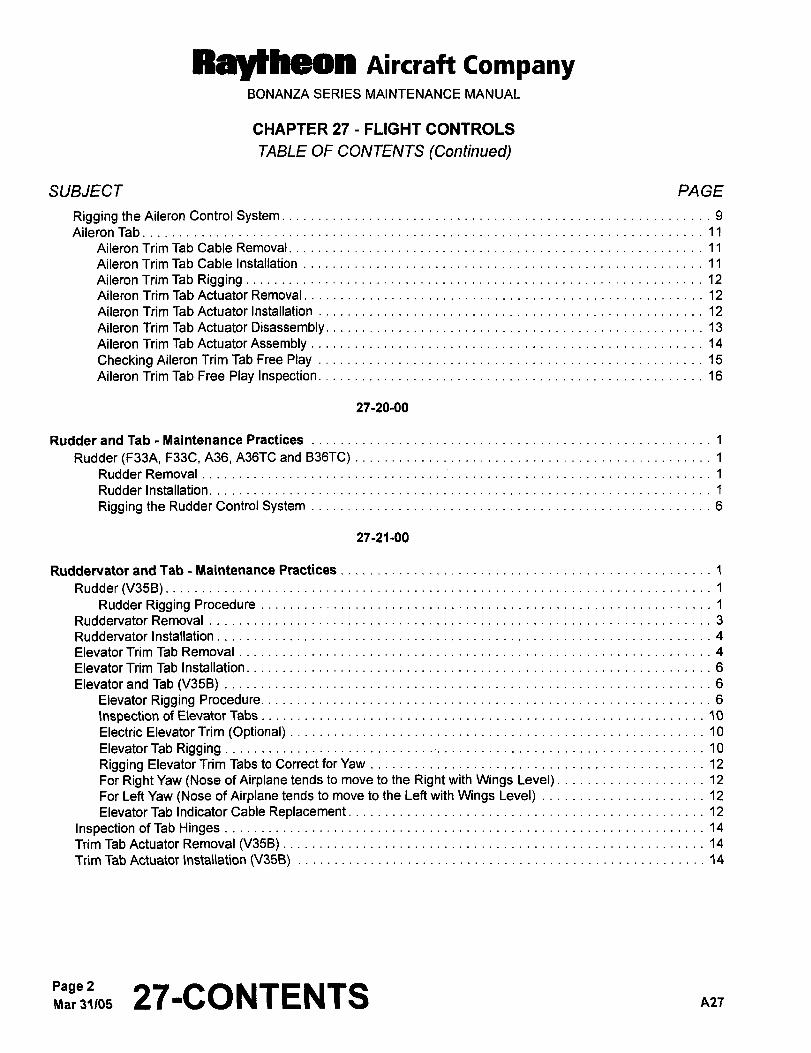
PaYtheery AiKraft CompanyBONANZA SERIES MAINTENANCE MANUAL
CHAPTER 27 FLIGHT CONTROLS
TABLE OF CONTENTS (Continued)
SUBJECT PAGE
Rigging theAileron Control System. 9
Aileron Tab
Aileron Trim Tab Cable Removal. 11
AileronTrimTab Cable Installation 11
Aileron TrimTab Rigging 12
Aileron Trim Tab Actuator Removal. 12
Aileron Trim TabActuatorlnstallation 12
Aileron Trim Tab Actuator Disassembly ................._ 13
Aileron Trim TabActuatorAssembly 14
CheckingAileron TrimTabFree Play 15
AileronTrimTab Free Play Inspection. 16
27-20-00
RudderandTab -Maintenance Practices 1
Rudder(F33A, F33C, A36, A3GTCand B36TC) 1
Rudder Removal
Rudder Installation.
Rigging the RudderControl System 6
27-21-00
Ruddervator and Tab Maintenance Practices 1
Rudder(V35B)....... 1
Rudder Rigging Procedure 1
Ruddervator Removal
Ruddervator Installation
ElevatorTrim Tab Removal 4
Elevator Trim Tab Installation 6
Elevatorand Tab (V35B)Elevator Rigging Procedure. 6
inspection of ElevatorTabs 10
Electric ElevatorTrim (Optional) 10
ElevatorTab Rigging 10
Rigging ElevatorTrim Tabs to CorrectforYaw 12
For Right Yaw (Nose of Airplane tends to move to the Right with Wings Level) 12
ForLeftYaw(Nose ofAirplanetends to moveto the Leftwith Wings Level) 12
ElevatorTab Indicator Cable Replacement 12
Inspection of Tab Hinges 14
TrimTabActuator Removal (V35B) ........._._._.._14
TrimTabActuator \nstal\ation(V35B) .................14
Page 2Mar31105 27-CONTENTS
Ral~heon AiKraft companyBONANZA SERIES MAINTENANCE MANUAL
CHAPTER 27 FLIGHT CONTROLS
TABLE OF CONTENTS
SUBJECT PAGE
27-30-00
Elevator and Tab Maintenance Practices (F33A, F33C, A36, A36TC, B36TC) ...............___
......1
Elevator Removal
Elevatorlnstalla~on.
Rigging the Elevator Control System (CE-748, CE-772 and After; CJ-149 and After; Prior to E-2111,
except E-1946 and E-2104; Priorto EA-389, exceptEA-320) .................1
Rigging the Elevator Control System (E-1946, E-2104, E-2111 and After; EA-320, EA-389 and After) .6
Elevator Tab Indicator Cable Replacement (CE-748, CE-772 and After; CJ-149 and After; Prior to E-2111,
exceptE-1946 and E-2104; Priorto EA-389, exceptEA-320) .................6
Elevator Trim Tab Forward Cable Replacement (E-1946, E-2104, E-2111 and After; EA-320,
EA-389 and After).Rigging the ElevatorTrimTab. 68
ElevatorTrim TabActuator 68
Elevator Trim Tab Actuator Disassembly (F33A, B36TC, A36TC and A36, except E-llll; F33C
Priorto CJ-156, except thoseAirplanes with Kit 33-4002-1 Installed) 68
Elevator Trim Tab Actuator Assembly (F33A, B36TC, A36TC and A36, except E-llll; F33C
Priorto CJ-156, exceptthose Airplaneswith Kit 33-4002-1 Installed) 6C
ElevatorTrim TabActuator Disassembly (E-llll Only) .7
ElevatorTrim Tab ActuatorAssembly (E-llll Only) .8
Elevator Trim Tab Actuator Disassembly Model F33C (CJ-l 56 and After, and Earlier AirplanesIncorporating Kit 33-4002-1). .8
Elevator Trim Tab Actuator Assembly Model F33C (CJ-156 and After, and Earlier AirplanesIncorporating Kit 33-4002-1). .9
Checking Elevator Tab Free Play (CE-748, CE-772 and After; E-llll, E-1241 and After;CJ-149 and After)
Elevator Trim Tab Actuator Removal (F33A, F33C, A36, A36TC and B36TC) ......11
Elevator Trim Tab Actuator Installation (F33A, F33C, A36, A36TC and B36TC) .........___
....12
ElevatorTrim Tab Actuator Color Coding (F33A, F33C, A36, A36TC and B36TC) ........._.._._
.12
Electric Elevator Trim (Optional) ...12
ModelA36, A36TC and B36TC 12A
Electric ElevatorTrimTab Servo Removal 12A
Electric ElevatorTrimTabServo Installation 12A
Electric ElevatorTrim Ground Checks (Airplanes withoutAutopilot) 12A
Model F33A, F33C andVB58. 128
Electric Trim Tab Actuator Removal 128
ElectricTrim TabActuator Installation 128
NewTabCable Installation. 128
Magnetic Clutch Removal 128
Magnetic Clutch Installation. 128
Electric Trim Tab Actuator Brush Replacement Schedule ...............13
Magnetic Clutch Torque Test 13
n2l 27-CONTENTS 3
Raycbeon Aircraft CompanyBONANZA SERIES MAINTENANCE MANUAL
CHAPTER 27 FLIGHT CONTROLS
TABLE OF CONTENTS (Confinued)
SUBJECT PA GE
27-31-00
Stall WarninglSafe FlightSystem -Description and Operation 1
Stall Warning SystemStall Warning -´•Maintenance Practices 1
Stall Warning SystemAdjustments
........._
27-50-00
Flaps-Description and Operation 1
Flaps- Maintenance Practices 1
Flap Removal
Flap Installation................._
Flap TrackWear Limits
Flap Limit Switch Adjustment. ........._......._2
Two-Position Flaps (CE-748, CE-772 thru CE-815; CJ-149; D-10097, D-10120 thru D-10178;E-llll, E-1241 thru E-1370) 2
Three-Position Flaps (CE-816 and After; CJ-150 and After; D-10179 and After; E-1371 and After;EA-1 and After)
................._
Flap Position Indicatorand Adjustment 5
Flap Motor Removal.
Connecting Flexible Flap Drive Shaftto Flap MotorShaft. 5
Flap Motor Installation
Flap Shaft Removal
Flap Shaft Installation.........._._...._
Flap Actuator Removal
Flap Actuator Installation
Flap InnerflexShaft Removal. 9
Flap Inner FlexShaft Installation 9
Flap Actuator Disassembly 10
Flap ActuatorAssembly. 11
27-70-00
GustLockAnd DamperControlLock. 1
Page 27-CONTENTS ntl
Ral~heon Aircraft CompanyBONANZA SERIES MAINTENANCE MANUAL
CHAPTER 27 FLIGHT CONTROLS
LIST OF EFFECTIVE PA GES
CH-SE-SU PAGE DATE CH-SE-SU PAGE DATE
27-LOEP 1 Mar 31/05 27-30-00 1 thru 6C Aug 18/95
7 Jun 20/9127-CONTENTS 1 thru 4 Mar 31/05
8 and 9 May 31/85
27-00-00 1 and 2 Sep 30/03 10 Oct 7/83
11 May 31/8527-10-00 1 thru 11 Mar 31/05
12 thru 128 Jun 20/91
27-11-00 i thru 18 Sep 30/03 13 Oct 7/83
27-20-00 1 thru 6 Feb 26/99 27-31-00 1 May 9/80
27-21-00 1 Mar 29/96 27-50-00 1 thru 13 Sep 30103
2 Aug 18/9527-70-00 1 May 9/80
3 thru 15 Mar 29/96
A27 27-LOEP Mar 31/05Page 1
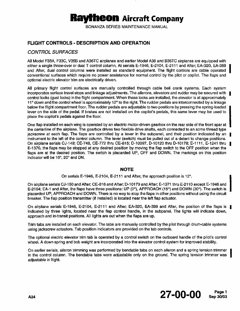
Raytheon Aircraft CompanyBONANZA SERIES MAINTENANCE MANUAL
FLIGHT CONTROLS DESCRIPTION AND OPERATION
CONTROL SURFACES
All Model F33A, F33C, V35B and A36TC airplanes and earlier Model A36 and B36TC airplanes are equipped with
either a single throw-over or dual T control column. At serials E-1946, E-2104, E-2111 and After; EA-320, EA-389 Iand After, dual control columns were installed as standard equipment. The flight controls are cable operatedconventional surfaces which require no power assistance for normal control by the pilot or copilot. The flaps and
optional electric elevator trim are electrically driven.
All primary flight control surfaces are manually controlled through cable bell crank systems. Each systemincorporates surface travel stops and linkage adjustments. The ailerons, elevators and rudder may be secured with icontrol locks (gust locks) in the flight compartment. When these locks are installed, the elevator is at approximately11" down and the control wheel is approximately 12" to the right. The rudder pedals are interconnected by a linkagebelow the flight compartment floor. The rudder pedals are adjustable to two positions by pressing the spring-loadedlever on the side of the pedal. If brakes are not installed on the copilot’s pedals, this same lever may be used to
place the copilot’s pedals against the floor.
One flap installed on each wing is operated by an electric motor-driven gearbox on the rear side of the front spar at
the centerline of the airplane. The gearbox drives two flexible drive shafts, each connected to an acme thread typejackscrew at each flap. The flaps are controlled by a lever in the subpanel, and their position indicated by an Iinstrument to the left of the control column. The lever (switch) must be pulled out of a detent to change positions.On airplane serials CJ-149; CE-748, CE-772 thru CE-815; D-10097, D-10120 thru D-10178; E-llll, E-1241 thru IE-1370, the flaps may be stopped at any desired position by moving the flap switch to the OFF position when the
flaps are at the desired position. The switch is placarded UP, OFF and DOWN. The markings on this positionindicator will be 10", 20" and DN.
NOTE
On serials E-1946, E-2104, E-2111 and After, the approach position is 12".
On airplane serials CJ-150 and After; CE-816 and After; D-10179 and After; E-1371 thru E-2110 except E-l 946 and
E-2104; EA-1 and After, the flaps have three positions: UP (O"), APPROACH (15") and DOWN (30"). The switch is
placarded UP, APPROACH and DOWN. There is no way to stop the flaps in other positions without using the circuit
breaker. The flap position transmitter (if installed) is located near the left flap actuator.
On airplane serials E-1946, E-2104, E-2111 and After; EA-320, EA-389 and After, the position of the flaps is 1indicated by three lights, located near the flap control handle, in the subpanel. The lights will indicate down,
approach and in-transit positions. All lights are out when the flaps are up.
Trim tabs are installed on each elevator. The tabs are manually controlled by the pilot through drum-cable systemsusing jackscrew actuators. Tab position indicators are provided on the tab controls.
The optional electric elevator trim tab is operated by a control switch on the outboard handle of the pilot’s control
wheel. A down spring and bob weight are incorporated into the elevator control system for improved stability.
On earlier serials, aileron trimming was performed by bendable tabs on each aileron and a spring tension trimmer Iin the control column. The bendable tabs were adjustable only on the ground. The spring tension trimmer was
adjustable in flight.
nz4 27-00-00 Sep 30/03Pagel
Rayfheon nircraft CompanyBONANZA SERIES MAINTENANCE MANUAL
IThe spring tension trimmer and left bendable tab were replaced by an inflight adjustable trim tab at serials E-2111
and After, except E-1946 and E-2104, and on serials EA-320, EA-389 and After. This system is a cable control
system with a jackscrew actuator and a trim wheel in the pedestal.
Positive stops on the primary flight control surfaces limit their travel, and traveling stops secured to the cables limit
trim tab movement. Because the cables are connected at turnbuckles, each cable has one left hand and one right
I hand threaded cable end. Proper routing of the cables as shown in the applicable sub-chapter will aid againstcrossing the cables, and causing improper movement after the cables have been removed and reinstalled.
Refer to the applicable rigging procedures for details regarding chain and cable tension, control wheel movement
I and force, and down spring force and system friction.
EFFECT OF TEMPERATURE UPON CABLE TENSION
Graphs specifying the correct maximum and minimum cable tension permissible for the various controls appear on
the individual control system illustrations. The graphs provide rigging limits at temperatures varying from O" to
I 1100 F. The horizontal scale on the graphs designates the temperature in degrees Fahrenheit at which the control
cables may be rigged, and the vertical scale designates the correct tension in pounds for each temperature reading.
TAPER PINS
Refer to the applicable rigging procedures for details regarding chain and cable tension, control wheel movement
I and force, and system friction. Any time the control column has been removed and disassembled, the followingprecautions should be observed:
I CAUTION 1CAUTION
The taper pin may crack the torgue tube if driven excessively.
a. When taper pins are to be installed, use a light weight rawhide or nylon mallet to set the pin. The small end of
the tapered shank should be flush with, or extend no more than 0.06 inch over the surface.
IWARNINQ)WARNING
On airplane serials 6-1946, 6-2104, 6-2111 and After; EA-320, 6-389 and After, observe the
color on all parts when replacing or reinstalling control cables, bellcranks and/or other
control system components. DO NOT connect coded parts of one color to coded parts of
different color.
Sep 27-00-00 n24
Ray~heon AiKraft CompanyBONANZA SERIES MAINTENANCE MANUAL
AILERON AND TAB MAINTENANCE PRACTICES (D-~0097, D-10120 AND AFTER;CE-748, CE-772 AND AFTER; CJ-~49 AND AFTER; E-llll, E-~241 THRU E-2110, EXCEPT
E-1946 AND E-2104; THRU EA-388, EXCEPT EA-320) I
SINGLE THROW-OVER CONTROL COLUMN
CONTROL COLUMN ARM REMOVAL
a. Remove the four screws that secure the retainer collar assembly to the control column housing (Ref. Figure i).
b. Disconnect any electrical wiring.
c. Remove the aileron trimmer. Perform the AILERON CONTROL TRIMMER REMOVAL procedure.
d. Pull the T handle located on the forward side of the control arm.
e. Rotate the control column arm to the nearly vertical position and slide the control column arm off the housing.
CONTROL COLUMN ARM INSTALLATION
a. Position the control column arm vertical (Ref. Figure 1). Make sure that the slot in the lower sprocket is
approximately parallel to the sides of the arm and that the turnbuckles between the long and short chains are
opposite each other near the access opening.
b. The ailerons MUST be in the neutral position.
c. Pull the T handle located on the forward side of the control arm.
d. Slide the control column arm on the control column housing.
e. Connectall electricalwiring.
f. Install the retainer collar and attach it with the four screws.
g. Install the aileron trimmer. Perform the AILERON CONTROL TRIMMER INSTALLATION procedure.
h. Check the control column for full movement and the control surfaces for proper direction of movement.
RIGGING THE CONTROL ARM CHAIN
a. Position the control arm, control wheel and sprockets (Ref. Figure i). The long and short chains must be
centered on the sprockets within one link. The turnbuckles must be near the access opening. The slot in the
lower sprocket should be approximately parallel to the sides of the arm.
b. Remove the safety wire from the turnbuckles and loosen or tighten the chain as necessary.
NOTE: Tighten the chain until friction or binding is felt on the control wheel, then loosen the chain just enough to
remove the binding or friction from the control wheel.
c. Check the control wheel and control surfaces for proper operation and freedom of movement.
d. After the adjustments are complete, check that the location of the control wheel, sprockets and turnbuckles are
as shown (Ref. Figure 1).
e. Safety wire the turnbuckles.
n27 27’1 0-00 1
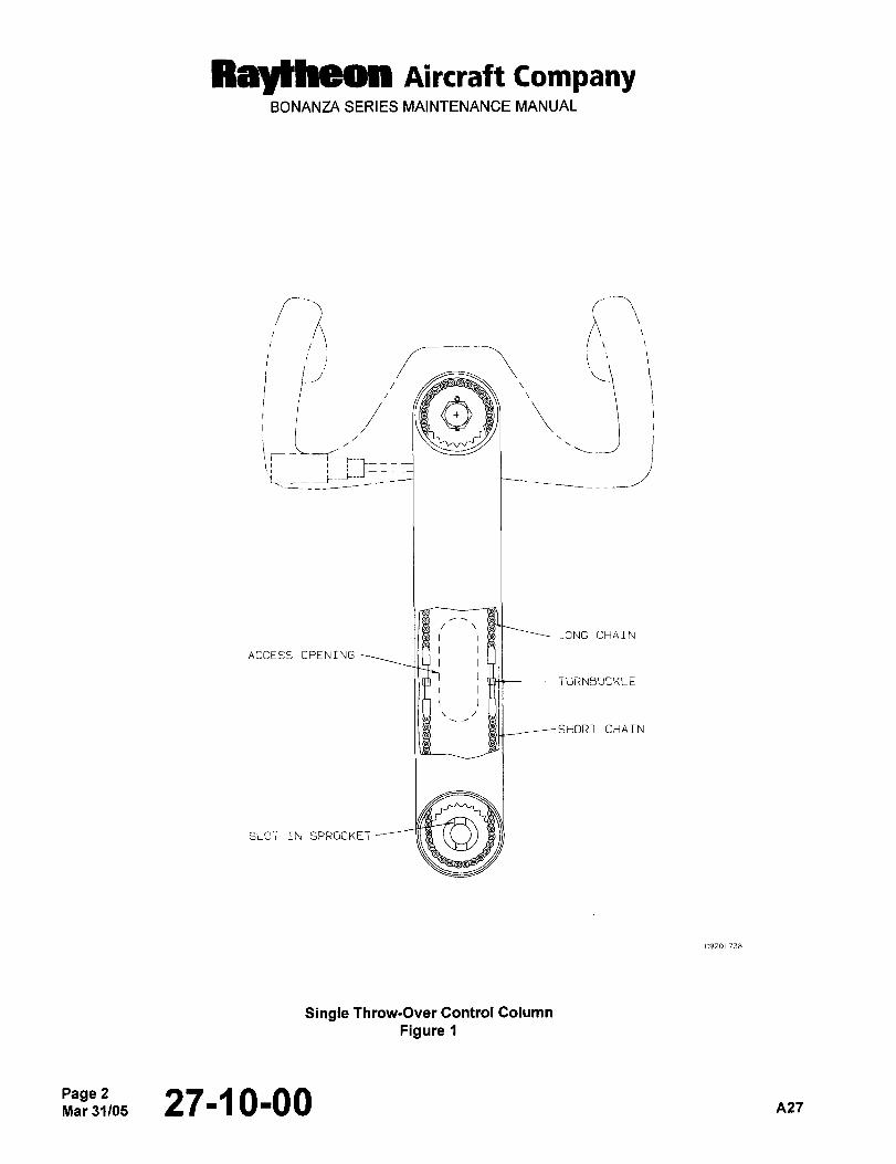
RBYtheOll Aircraft tompanyBONANZA SERIES MAINTENANCE MANUAL
’;AI :;i
c-´•r:
LONG CHAIN
ACCESS OPENING
TURNBUCKLE
CHAIN
SLOT IN SPROCKET
C9201 738
Single Throw-Over Control Column
Figure
Page 2Mar31/05 27-~ 0-00 A27
Ray~heon Aircraft CompanyBONANZA SERIES MAINTENANCE MANUAL
DUAL CONTROL ARM
DUAL CONTROL ARM REMOVAL
a. Remove the four screws that secure the retainer collar assembly to the control column housing (Ref. Figure 2).
NOTE: Some installations may have a T handle on the right forward side of the control arm. Pull the T handle
and omit the following step.
b. Remove the screw and washer retaining the pin assembly on the right forward side of hub of the control arm.
c. Disconnect all electrical wiring.
d. Slide the control arm off the installation.
DUAL CONTROL ARIVI INSTALLATION
a. Position the control arm as shown (Ref. Figure 2).
b. Make sure the slot in the center sprocket is approximately vertical and the turnbuckles between the long chains
and the short chains are opposite each other near the access openings.
c. The ailerons MUST be positioned at neutral.
NOTE: Some installations may have a T handle on the right forward side of the control arm. Pull the T handle.
d. Slide the control column arm on the control column housing.
NOTE: On installations with a T handle, omit the next step.
e. Install the pin assembly on the right side of the control arm hub.
f. Install the retainer collar and attach it with the four screws.
g. Check for full control movement and for proper direction of movement.
A2727-1 0-00 3
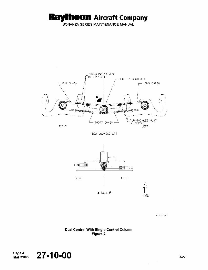
RaY(iheOn Aircraft CompanyBONANZA SERIES MAINTENANCE MANUAL
TURNBUCKLES MUST
BE OPPOSITESLOT IN SPROCKEI
A ´•j;IONGCHAIN
QAl
C
Z:SHORTCHAIN -BE OPPOSITE
TURNBUCKLES MUS~
RIGHT LEFT
VIEW LOOKING AFT
RIGHT LEFT
DETAIL AFWD
C920 759 C
Dual Control With Single Control Column
Figure 2
Page4Mar31/05 271~ 0100 A27
Raytheon Aircraft CompanyBONANZA SERIES MAINTENANCE MANUAL
RIGGING THE DUAL CONTROL ARM CHAIN
a. Position the control arm, control wheel and sprocket as shown (Ref. Figure 2).
b. Center the long and short chains on their sprockets within one link.
c. The slot in the center sprocket must be approximately vertical as shown.
d. Remove the safety wire from the turnbuckles.
e. Adjustthechainsas necessary.
NOTE: The chains are properly adjusted by tightening the chains until binding is noticed on the control wheel;then loosen the chains just enough to remove the binding or friction from the control wheel.
f. After the adjustments are complete, check that the location of the control arm, control wheels, sprockets and
turnbuckles are as shown.
g. Safety wire the turnbuckles.
h. Check the controls for freedom of movement and the control surfaces for proper direction of movement.
AILERON REMOVAL
a. Support the aileron and remove the two attaching screws from the top and bottom of each hinge bracket.
b. Pull the aileron straight away from the wing to avoid damage to the attaching areas.
c. Remove the screws attaching the bonding cable to the aileron.
AILERON INSTALLA nON
a. Attachthebonding cabletotheaileron.
b. Place the aileron in position on the hinge brackets. The hinge brackets must be in the correct place between the
aileron skin and the reinforcing structure.
c. Install the upper and lower hinge bracket screws.
d. Pull on the aileron in a direction straight away from the wing to make sure that the hinge brackets are positionedcorrectly. If there is any movement of the aileron, recheck the position of all hinge brackets.
27-1 0-00 5
Raytheon Aircraft CompanyBONANZA SERIES MAINTENANCE MANUAL
RIGGING THE AILERON CONTROL SYSTEM
NOTE: Raytheon Aircraft Company recommends the use of the aileron travel gage. Refer to Chapter 12-20-00,SPECIAL TOOLS. The front of the travel gage should be located over the leading edge skin splice with the
aft portion over the number 8 wing rib (just outboard of the inboard aileron hinge).
a. Aileron and flap surfaces must align with the upper and lower surfaces of the wing within 1/16 inch.
b. Adjust the aileron downstops in the wing until the bellcrank just clears the gusset on the wing rib. Set the aileron
upstep in the wing so that the aileron bellcrank just misses the aileron pushrod (Ref. Figure 3).
c. Adjust the link connecting the aileron to the bellcrank to allow full travel of the ai leron surface between the upstepand downstop.
NOTE: The aileron is in neutral when the aileron trailing edge aligns with the trailing edge of the wing, and its inboard
end is parallel with the outboard end of the flap.
d. Adjust the cables from the wing to the control column cables. The turnbuckles are in the wheel wells.
e. Secure the control column wheel in neutral by securing a bar across the top of the control wheel and levelingthe control wheel with a bubble level. (With the control locks installed, the control wheel is rotated 12" to the
right). Adjust the tension as shown on the aileron temperature cable tension graph (Ref. Figure 3).
NOTE: The control wheel must be level in relation to the airplane. If the airplane is not level, make a correspondingchange to the position of the control wheel using a spirit level protractor.
Take the cable reading in the wheel well where the control column cables attach to the wing cables.
f. Rotate the control wheel to ascertain by feel that the wing bellcranks reach their stops before the control column
reaches its stops.
g. If there is less travel of the control wheel in one direction than in the other direction, loosen one turnbuckle on
the lower cable and tighten the opposite lower cable turnbuckle, depending on which way the travel is off.
Maintain the correct cable tension.
h. Secure the control wheel in neutral after the correct travel of the wheel is obtained. Adjust the link connectingthe aileron to the wing bellcrank to obtain the aileron in neutral. Neutral position of the aileron is determined byaligning the inboard end of the aileron with the outboard end of the flap with the flap in the up position.
i. Set the bellcrank stops to give a deflection of 20 2" up and/or down (Ref. Figure 3).
NOTE: The aileron bellcrank stops should make contact 1/16 inch before the control column stops are reached.
j. Be sure each aileron bellcrank contacts its upstep at the same time as the bellcrank in the opposite wingcontacts its downstop.
k. Check the control stop (secondary stop) in the control column for 1/16 inch clearance in each direction. If the
clearance is not correct, recheck the entire aileron control system for correct chain and cable rigging.
NOTE: The control stop clearance provides a slight movement of the control wheel (a cushion) after the travel stopsand the aileron bellcranks make contact.
PageGMar 31105 27-1 0-00 n21
Ray~heon Aircraft CompanyBONANZA SERIES MAINTENANCE MANUAL
I. Recheck cable tension and safety wire the turnbuckles.
m. Tighten alljam nuts.
WARNING: Check the ailerons for correct direction of movement. When the control wheel is moved to
the left, the left aileron must move up and the right aileron must move down. When the
control wheel is moved to the right, the right aileron must move up and the left aileron must
move down.
Check to make sure that cabin floorboards, floorboard insulation and other interior partsdo not contact the control cables.
AILERON CONTROL TRIMMER (SINGLE CONTROL COLUMN AIRPLANES)
The aileron control system is equipped with an aileron control trimmer which functions by applying tension on the
aileron control cables to level the wings as needed. The holding pressure exerted by the aileron control trimmer can
be easily overridden at the discretion of the pilot. The trimmer does not change the system rigging but should be
removed before checking the cable tension.
TRIMMER REMOVAL
a. Unscrew the two body halves by holding the clutch body housing touter half) and turning the clutch body nut
(inner half) counterclockwise (Ref. Figure 4).
b. Separate the two body halves by pulling out on the clutch body housing.
TRIMMER INSTALLATION
a. Carefully insert the shaft through the felt seal into the hub bearing, being careful not to shear the felt seal.
b. Screw the two halves of the unit together by holding the clutch body and turning the clutch body nut. Hand
tightening the two halves should be sufficient.
c. Check that the tangs of the drive shaft engage properly with the sprocket as the unit is being tightened by hand.
Also note that the position indicator on the face of the unit is right side up as the shaft engages with the sprocket
tRef. Figure 4).
nlr27-~ 0-00Page 7
Raytheon Aircraft CompanyBONANZA SERIES MAINTENANCE MANUAL
This Page Intentionally Left Blank
PageS~"3105 27110100 A27
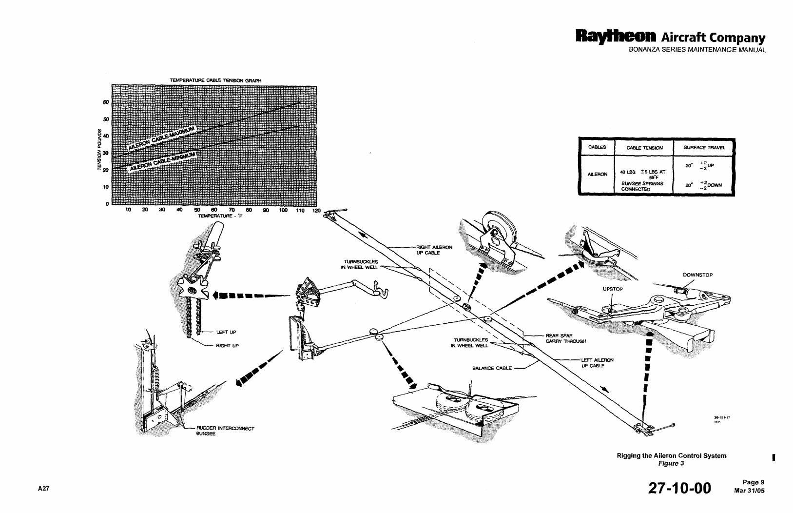
Raytheon Aircraft CompanyBONANZA SERIES MAINTENANCE MANUAL
TMPERATURE CABLE TENSK)S ~RAPH
50
50
CABLES I CABLE TENSM3N I SURFACE TRAVEL
20´°UP-2
AILERON 40LBS +-S LBS AT
59"F
BUNGEE SPRINGS 20"+2
10 DOWNCONNECTED -2
10 20 30 40 50 66 70 Se 90 100 110fEkdPERATURE- ’F
RIGHT AILERONUP CABLE
T~RNBOCI(LES
IN WHEEL WEU
DOWNSTOP
UPSTOP
Illll~llre
LEFT UP
THAWGHd%- ‘L- RK;HT UP
LEFT AILERON
UPCABLE
i~B*I
,i
\1 36-151-17
oO~
RUDDER INTERCONNECTBUMGEE
Rigging the Aileron Control SystemFigure 3
A27 27-1 0-00 Mar 31/05Page 9
Raytheon Aircraft CompanyBONANZA SERIES MAINTENANCE MANUAL
This Page Intentionally Left Blank
27-11 0-00 nzT
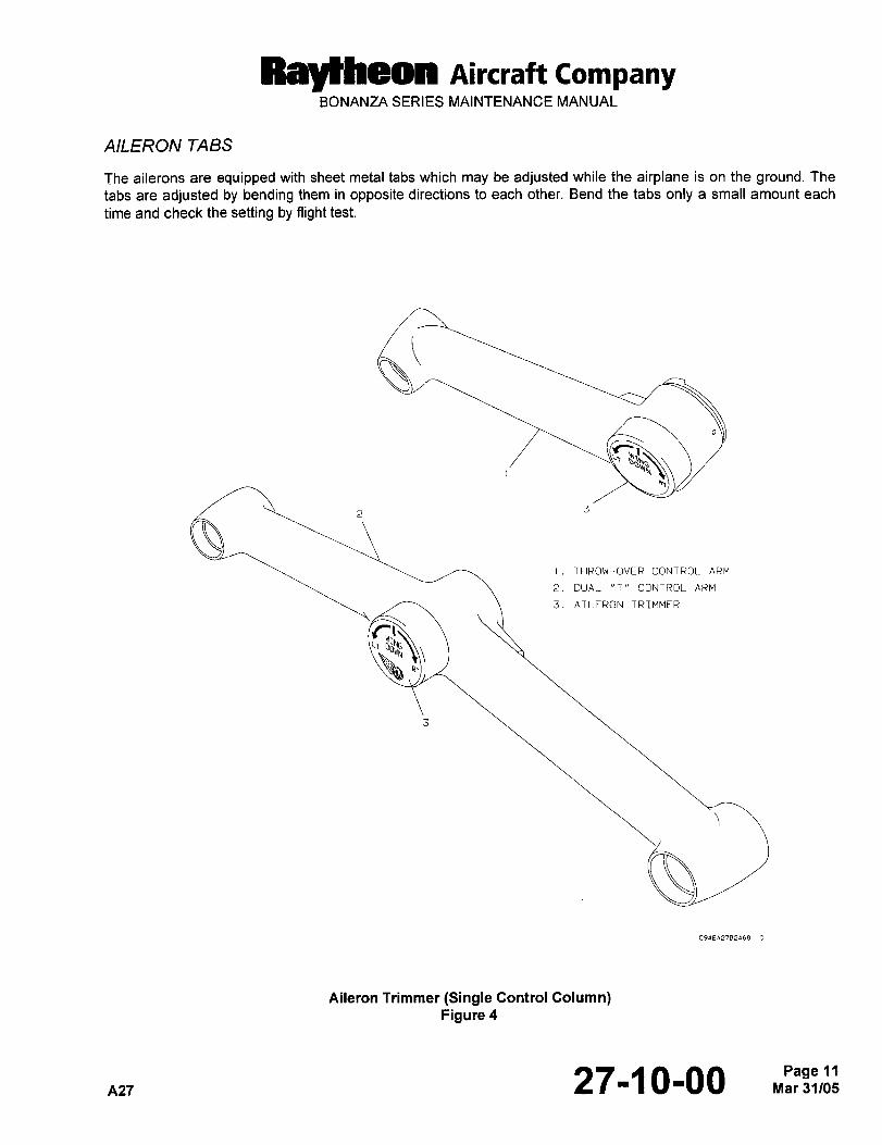
Raytheon AiKraft CompanyBONANZA SERIES MAINTENANCE MANUAL
AILERON TABS
The ailerons are equipped with sheet metal tabs which may be adjusted while the airplane is on the ground. The
tabs are adjusted by bending them in opposite directions to each other. Bend the tabs only a small amount each
time and check the setting by flight test.
I. THROW-OVER CONTROL ARM
2. DUAL "T" CONTROL ARM
3. AILERON TRIMMER
Aileron Trimmer (Single Control Column)Figure 4
A27 27-~ 0-00 Mar 31/05Page II:
Raytheon AiKra´•H CompanyBONANZA SERIES MAINTENANCE MANUAL
AILERON AND TAB MAINTENANCE PRACTICES
(E-1946, E-2104, E-2111 AND AFTER; EA-320, EA-389 AND AFTER)
I WARNING)WARNING
Make certain that insulation, tie wraps, etc. do not interfere with control components such
as cables, chains, etc.
DUAL CONTROL COLUMN
IWARNING)WARNING
On airplane serials E-1946, E-2104, E-2111 and After; EA-320, EA-389 and After, observe the Icolor coding on all parts when replacing or installing control cables, bellcranks and/or other
control system components. DO NOT connect parts of one color to coded parts of a different
color.
CONTROL COLUMN CHAIN REMOVAL
a. Paint one tooth of each control column’s sprocket and its corresponding chain link to ensure proper alignmentof the control wheels at installation (Ref. Figure 1).
b. Loosen the turnbuckles of the control column chain and the aileron turnbuckles in the wheel well.
c. Remove the safety wire from the four bolts (two on each end), and remove the six bolts from the channel
between the control columns.
d. Remove the channel from the airplane.
e. Disconnect the turnbuckles from the chain of the control column.
f. Remove the four connector links from the stop link assembly, then remove the stop link assembly. I
NOTE
It may be necessary to remove the stop block before removing the stop link assembly.
g. Slide the sprocket support assembly aft over the joint then remove the chains from the control columns.
n24 27-11-00 Sep 30/03Page 1
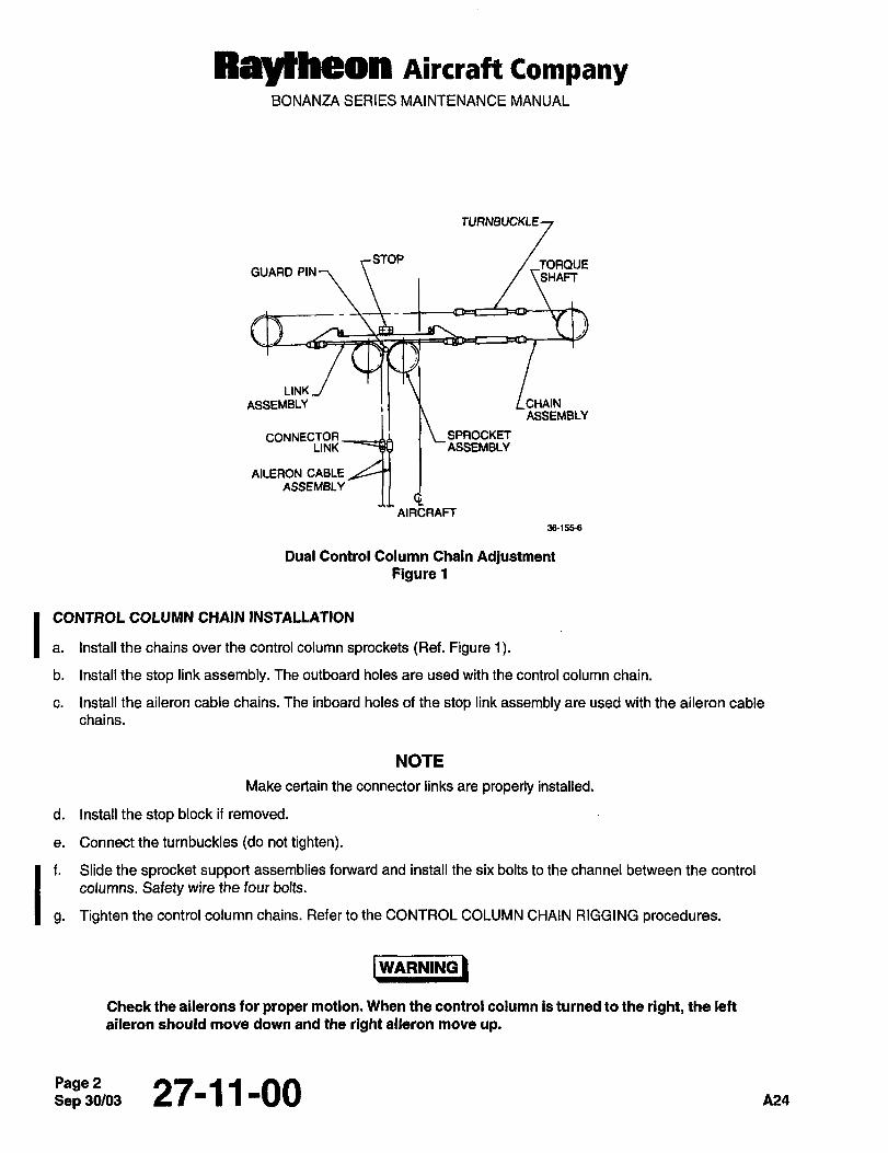
Raytheon Aircraft CompanyBONANZA SERIES MAINTENANCE MANUAL
TURNBUCKLE
STOP TORQUEGUARD PIN
SHAFT
LINK
ASSEMBLY CHAIN
Q
ASSEMBLY
CONNECTOR SPROCKFTLINK ASSEMBLY
AILERON CABLE
ASSEMBLY
AIRCRAFT
36´•1558
Dual Control Column Chain AdjustmentFigure 1
CONTROL COLUMN CHAIN INSTALLATION
a. Install the chains over the control column sprockets (Ref. Figure 1).
b. Install the stop link assembly. The outboard holes are used with the control column chain.
c. Install the aileron cable chains. The inboard holes of the stop link assembly are used with the aileron cable
chains.
NOTE
Make certain the conn~ctor links are properly installed.
d. Install the stop block if removed.
e. Connect the turnbuckles (do not tighten).
f. Slide the sprocket support assemblies forward and install the six bolts to the channel between the control
Ig. Tighten the control column chains. Refer to the CONTROL COLUMN CHAIN RIGGING procedures.
columns. Safety wire the four bolts.
WARNING
Check the ailerons for proper motion. When the control column is turned to the right, the left
aileron should move down and the right aileron move up.
Sep 30/03Page 2 27-11-00 A24
RaylheQn AiKlaft CompanyBONANZA SERIES MAINTENANCE MANUAL
CONTROL COLUMN CHAIN RIGGING I
Rigging of the control column chain may be accomplished by the following:
a. Rig neutral on the control wheels by placing a straightedge across the top of the control wheels. One of the grips
may be It 0.06 inch off the straightedge (Ref. Figure 1). Ib. Ensure that the ends of the control column chain around the right sprocket are within one link of equidistancefrom the centerline of the sprocket.
c. If the stop link assembly is not centered within f 0.02 inch with respect to its stop, adjust the turnbuckles to Icenter the link.
d. Place a vertical load of two pounds on the top chain near the airplane centerline. The chain should deflect 0.25
0.06 inches. Adjust the turnbuckles as necessary to obtain this deflection. I
e. After rigging the control column chain, refer to RIGGING THE AILERON CONTROL SYSTEM and make certain
the ailerons are properly rigged.
CONTROL COLUMN ROLLER ADJUSTMENT IFORWARD OUTER TUBE ROLLERS (ROLL ON THE INNER SQUARE SHAFT)
There are four rollers on the forward end of each control column which transmit torque to the square inner shaft.
Two of the rollers of each control column are installed with eccentric bolts which allow for adjustment of roller
clearance. These two bolts may be identified by their 10-32 threads. Refer to Figure 2 and adjust the rollers as Ifollows:
a. Wipetheshaftsclean anddry.
b. Hold one of the nonadjustable rollers firmly against the shaft.
c. The roller on the opposite side of the shaft should turn freely while having no more than 0.002 inch clearance.
d. If the conditions of Step c. are not met, loosen the nut on the roller which has the bolt with 10-32 threads.
e. Turn the bolt until the conditions of Step c. are complied with.
f. Tighten the nut, then recheck the roller clearance in accordance with Steps b. and c..
g. Check the other pair of rollers as indicated in Steps b. and c..
h. If the adjustment is needed, follow Steps d., e. and f. for the second set of rollers.
Repeat this procedure for the other control column.
27-11-00 Sep 30/03Page 3
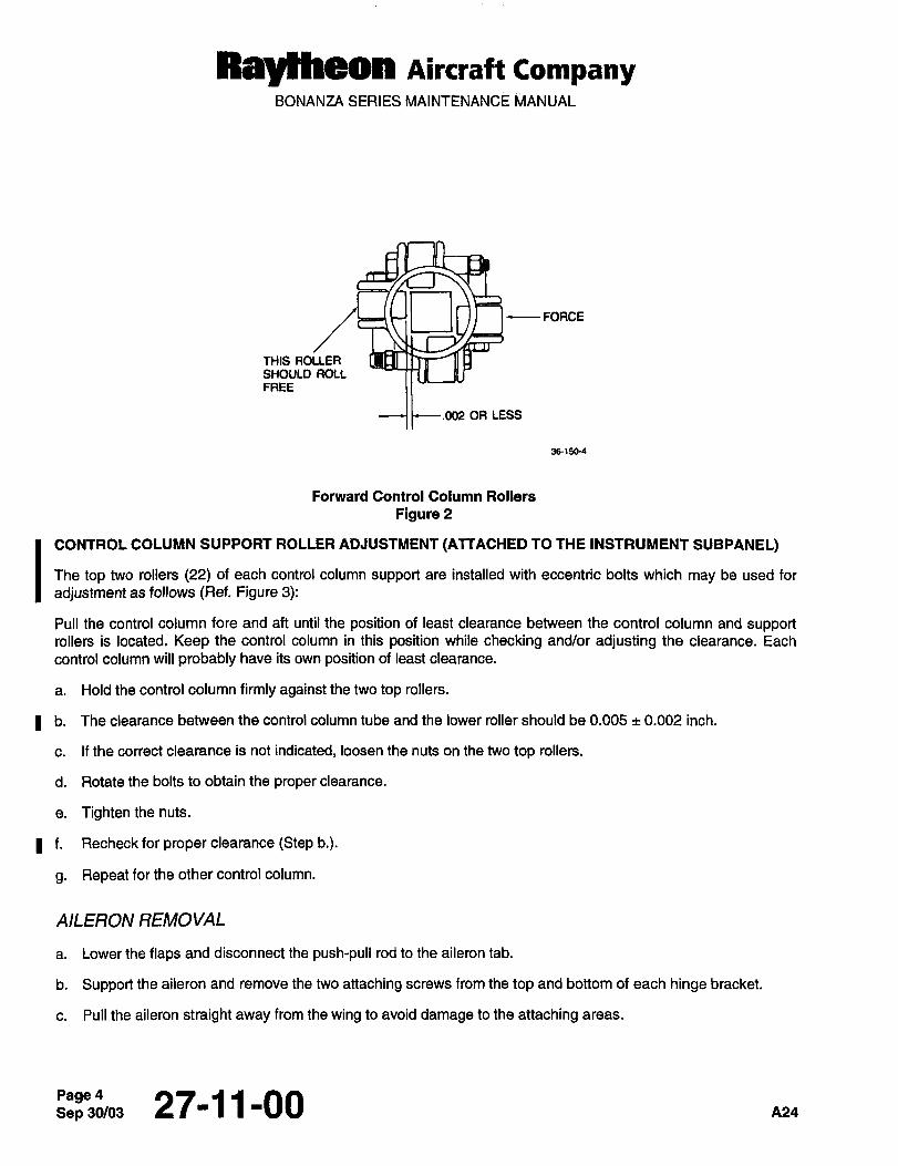
RMJlheon Aircraft CompanyBONANZA SERIES MAINTENANCE MANUAL
O FORCE
THIS ROLLERSHOULD ROLLFREE
.002 OR LESS
381506
Forward Control Column Rollers
Figure 2
ICONTROL COLUMN SUPPORT ROLLER ADJUSTMENT (ATTACHED TO THE INSTRUMENT SUBPANEL)
The top two rollers (22) of each control column support are installed with eccentric bolts which may be used for
adjustment as follows (Ref. Figure 3):
Pull the control column fore and aft until the position of least clearance between the control column and supportrollers is located. Keep the control column in this position while checking and/or adjusting the clearance. Each
control column will probably have its own position of least clearance.
a. Hold the control column firmly against the two top rollers.
b. The clearance between the control column tube and the lower roller should be 0.005 0.002 inch.
c. If the correct clearance is not indicated, loosen the nuts on the two top rollers.
d. Rotate the bolts to obtain the proper clearance.
e. Tighten the nuts.
f. Recheck for proper clearance (Step b.).
g. Repeatforthe othercontrol column.
AILERON REMOVAL
a. Lower the flaps and disconnect the push-pull rod to the aileron tab.
b. Support the aileron and remove the two attaching screws from the top and bottom of each hinge bracket.
c. Pull the aileron straight away from the wing to avoid damage to the attaching areas.
Sep 30/03Page 4 27-11-00
RaJlheon Aircraft CompanyBONANZA SERIES MAINTENANCE MANUAL
d. Remove the screws attaching the bonding cables to the aileron.
AILERON INSTALLATION
a. Attach the bonding cables to the aileron.
b. Place the aileron in position on the hinge brackets. Be sure the hinge bracket is in the proper place between the
aileron skin and the reinforcing structure.
c. Install the upper and lower hinge bracket screws.
d. Pull on the aileron in a direction straight away from the wing to assure that the hinge brackets are properlypositioned. If any movement of the aileron is noted, recheck the position of all hinge brackets.
e. Lower the flap and connect the aileron tab push-pull rod and install the cotter pin.
AILERON CONTROL CABLE REMOVAL I
a. Remove the pilot’s and copilot’s seat, and the floorboards in the pilot’s compartment.
b. Remove the forward passenger seats and the floorboards between the main and rear spars.
c. Remove the access plates as necessary to gain access to the aileron cables and pulley brackets on the lower
trailing edge of the wings.
d. Remove all necessary cable retaining pins from the cable pulley brackets.
e. Disconnect the forward aileron cables from the chain and cable assembly at the connector link below the control
column. Install lead lines to both aileron cables (Ref. Figure 4). 1
f. Disconnect the forward aileron cables and the forward outboard wing cable at the turnbuckles in each wing.Connect a lead line to one end of the cable and remove the cable.
g. Disconnect the balance cable at the turnbuckle in each wing. Connect a lead line to one end of the cable and
remove the cable.
h. Disconnect the forward outboard and the aft outboard cables at the bellcrank in each wing. Identify and remove
the cables.
Pi24 27-11-00 5
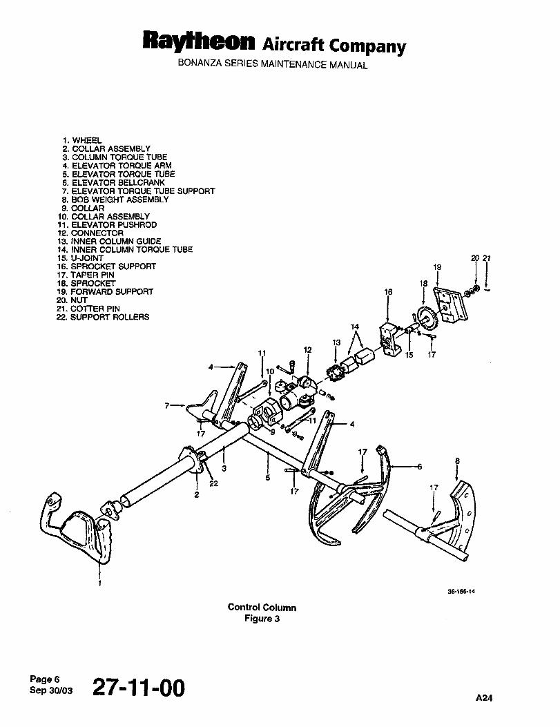
Raytheon nircraft CompanyBONANZA SERIES MAINTENANCE MANUAL
1~ WHEEL2. COLLAR ASSEMBLY3. COLUMN TORQUE TUBE4. ELEVATOR TORQUE ARM5. ELEVATOR TORQUE TUBE6. ELEVATOR BELtCRANK7. ELEVATOR TORQUE TUBE SUPPORT8. BOB WEIGHT ASSEMBLYS.COUAR
10. COLLAR ASSEMBLY11. ELEVATOR PUSHROD12. CONNECTOR13. INNER COLUMN GUIDE14. INNER COLUMN TORQUE TUBE15. UJO1M 20 2116. SPROCI<FF SUPPORT 19 !j18. SPROCKFT 117. TAPER PIN
20. NUT19. FORWARD SUPPORT 16 121. COTTER PIN22. SUPPORT ROLLERS
12 K15 1711
4---~ 1 BJjq
Q~k
4
17 ~B
3 ii 8
522
1717
j c
3&(55´•(4
Control Column
Figure 3
Sep 30/03Page 6 27-11-00A24
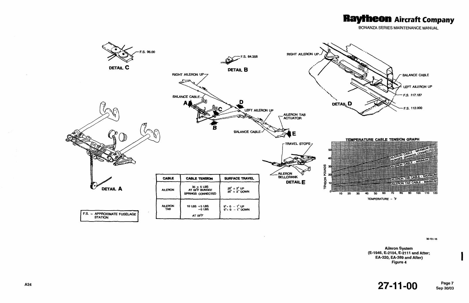
RayIheon Airuaft CompanyBONANZA SERIES MAINTENANCE MANUAL
e
F.S. 96.001 a RIGHT A1LERON UP
F.S. 84.358
DETAILC oE´•rAI1BN
RIGHT AILERON BALANCE CABLE
LEFT AILERON UP
BALANCE ‘2. ~c- F.S. 117.187
A BDETAIL D
F.S. 112.000C LEFT AILERON UP
AILERON TABACTUATOR
BBALANCE CABLE EQD TEMPERATURE CABLE TENSION GRAPH
~m ~-TRAVEL STOPS
AILERON gBEUCRANK ~AB.CABLE I CABLE TENBIDN SURFACETRAVU B
DETAIL E z~
DETAIL A 35 5 Las W~AILERON AT 59"5 BUN~EE 20~ 2" ilP
20" 21 DOWN70 80 90 100 HO 120SPRINGS CONNECTED 10 20 .30 ´•40 50 60
TEMPERATURE "F
AILERON ~O LBS +5 LBS 9’e 0 1" UPTAB -0 LBS 9"~ 0 1" WWN
F.S. APPROXIMATE FUS~LAGE AT 59’FSTATION
~6151-18
Aileron System(2-1946, E-2104, E-2111 and After;
EA-320, EA-389 and After)Figure 4
A24 27-11-00 Sep 30/03Page 7
Raytheon Aircraft CompanyBONANZA SERIES MAINTENANCE MANUAL
This Page Intentionally Left Blank
27111100 A24
RayYheon Aircraft CompanyBONANZA SERIES MAINTENANCE MANUAL
AILERON CONTROL CABLE INSTALLA TION I
a. Connect the foMlard outboard and the aft outboard cables to the bellcrank in each wing. Route the cables
inboard and disconnect the lead lines (Ref. Figure 4).
b. Route the balance cable through one wing, the fuselage, then through the opposite wing. Disconnect the lead
line and connect the balance cable and the aft outboard cables to the turnbuckles in each wing.
c. Route one end of the aileron cables outboard in each wing, and the other end forward to the control column.
Connect the cables to the turnbuckles at the forward outboard cable in each wing.
d. Connect the chain and cable assembly to both aileron cables at the connector link below the control column.
e. Install all retaining pins in the pulley brackets.
f. Rig the aileron control system.
g. Install the access plates on the lower trailing edge of the wings.
h. Install the floorboards and the forward passenger seats.
i. Install the floorboards and the pilot’s and copilot’s seats.
I WARNI~NQ)WARNING
Make certain that insulation, tie wraps, etc. do not interfere with control components such
as cables, chains, etc.
Check for correct direction of movement by moving the control wheel. When the control
wheel is moved to the left, the left aileron should move up and the right aileron move down.
When the control wheel is turned to the right, the right aileron should move up and the left
aileron down.
Check to make sure that cabin floorboards, floorboard insulation and other interior parts do Inot contact the control cables.
RIGGING THE AILERON CONTROL SYSTEM
NOTE
Raytheon Aircraft Company recommends the use of the aileron travel gage. Refer to SPECIAL ITOOLS in Chapter 12-2q-00. The front of the travel gage should be located over the leading edgeskin splice with the aft portion over the number 8 wing rib (just outboard of the inboard aileron
acceptable.hinge). Alternate rigging with TE-100TB Universal Travel Board and KS6005 Digital Protractor is Ia. Aileron and tab surfaces must align with the upper and lower surfaces of the wing within 1/16 inch.
b. Place the aft arm of both aileron bellcranks parallel to the adjacent wing rib. If the aileron is not in neutral, loosen
the locknuts on both ends of the push-pull tube and adjust the push-pull tube until the aileron is in neutral.
c. Tightenthe locknuts.
~22427-11-00 Sep 30/03Page 9
Raytheon Aircraft CompanyBONANZA SERIES MAINTENANCE MANUAL
d. Rig neutral on the control wheels by placing a straightedge across the top of the two control wheels. One grip
I may be 0.06 inch off of the straightedge.
e. Assure that the ends of the chain around the right control column are within one link of equidistance from the
centerline of the sprocket.
f. If the link stop assembly is not centered with respect to its stop, adjust the turnbuckles to center the link.
g. Place a vertical load of two pounds on the top chain near the airplane centerline. The chain should deflect 0.25
I 0.06 inch. Adjust the turnbuckles as necessary to obtain this deflection.
h. Connectthe bungee springs.
i. With a straight rig pin installed between the pilot’s rudder pedals and with a simulated (10 Ibs.) cable tension,
adjust the turnbuckle above the forward aileron bungee spring until both bungee springs are extended equallyI rt 0.06 inch.
j. Adjust the turnbuckles in the wheel wells to bring the ailerons to neutral (O").
k. Remove the straightedge from the control wheels.
I i. Adjust the aileron bellcrank stops (primaly stops) for a deflection of 20 zt 20 UP, and 20 2" down from neutral.
m. Tighten the locknuts on the bellcrank stop bolts.
n. Rig the aileron cables to the tension indicated in Figure 4. Use the turnbuckles in the wheel wells.
o. Be sure each bellcrank contacts its upstep at the same time the bellcrank in the opposite wing contacts its
downstop.
p. Set the secondary stop bolts (the stop link atthe forward end of the control column) to maintain 0.06 to 0.12 inch
clearance from the stop with the ailerons at full travel (both right and left).
q. With a straight rig pin installed between the pilot’s rudder pedals, the control wheels should center within 5" of
neutral. If necessary, readjust the vertical turnbuckle above the forward bungee spring and the aft turnbuckle in
the wheel well as required to center the control wheels.
Recheck cable tension and safety the turnbuckies. Make certain all locknuts are tight.
s. With the ailerons fully rigged (bungee springs disconnected), the torque required to move either control wheel
10" right or left of neutral shall not exceed 15 inch-pounds.
t. Connect the bungee springs.
I W~RNING)WARNING
Check for correct direction of movement by moving the control wheel. When the control
wheel is moved to the left, the left aileron should move up and the right aileron move down.
When the control wheel is turned to the right, the right aileron should move up and the left
aileron down.
u. Removeallrigging pins.
Sep 27-11-00
Raylheon Aircraft CompanyBONANZA SERIES MAINTENANCE MANUAL
AILERON TAB
A trim tab has been installed in the left aileron which is controllable from inside the airplane while in flight. The aileron
tab is controlled through normal cable and chain linkage to a control wheel located in the pedestal with the indicator.
AILERON TRIM TAB CABLE REMOVAL
a. Remove the pilot’s seat and the left floorboard.
b. Remove the lower forward upholstery panel on the left side of the pedestal.
c. Remove the forward left passenger seat and the floorboard.
d. Remove necessary access plates to gain access to the trim tab cables, actuator, and cable pulley brackets.
e. Remove the cable retaining pins at the pulley brackets.
f. Disconnect the tab cables at the turnbuckles in the left wing. Identify and connect lead lines on the cable ends.
g. Remove the cable stops at WS 43.375.
h. Remove the outboard cable from the actuator sprocket. Remove the cable through the actuator access opening.
i. Remove chain master link at the sprocket on the pedestal. Remove cable through the actuator access opening.
AILERON TRIM TAB CABLE INSTALLATION
a. Position the chain of the forward tab cable around the pedestal sprocket and install the chain master link.
b. Route the cable ends aft in the fuselage and outboard into the left wing and disconnect the lead lines.
c. Position the chain of the outboard cable around the actuator sprocket and route the cable ends inboard.
d. Install the cable stops at WS 43.375 and connect the cables at the turnbuckles in the wing. I
e. Install the cable retaining pins in the pulley brackets.
f. Rig the aileron trim tab control system, refer to AILERON TRIM TAB RIGGING procedure. I
g. Install all access plates in the left wing.
h. Install the floorboard and the left forward passenger seat.
i. Install the floorboard and the pilot’s seat.
j. Install the upholstery panel on the left side of the pedestal.
lwnREllNaIWARNING
Make certain that insulation, tie wraps, etc. do not interfere with control components such
as cables, chains, etc.
The aileron tab should stay in the same plane with respect to the aileron when the aileron is
moved. When the tab control wheel is turned to indicate left wing up, the aileron tab should
move up. If the aileron and aileron tab do not move in the proper direction, recheck rigging.
nz4 27-11-00 Sep 30/03Page 11
RayMheon Aircraft CompanyBONANZA SERIES MAINTENANCE MANUAL
AILERON TRIM TAB RIGGING
NOTE
Place the aileron in neutral.
a. Place the aileron trim tab control in neutral position.
b. Place the aileron in neutral position and connect the trim tab to the tab actuator.
c. By tu ming the sprocket on the actuator, adjust the trim tab to both extremes of travel; measu re both settings and
return the tab to the midpoint of the two extremes of travel. This will place the actuator in the neutral position.
d. If the trim tab is not in the neutral position upon completion of Step c., adjust the pushrod to place the tab in
neutral position.
e. Center the chain on the sprocket and tighten the cable.
f. Set the aileron tab stop (at WS 43.375) to obtain a surface deflection of 9" 0" 1" up and down. Torque the
Ig. Rig cable tension and adjust travel (Ref. Figure 4).
stops to 40 to 60 inch pounds.
h. Check trim tab travel, safety all turnbuckles and stops.
I WARNINQ)ARNINO
After rigging the aileron and aileron tab control system, check for correct movement of the
control surfaces with respect to the movement of the controls. The aileron tab should stayin the same plane with respect to the aileron when the aileron is moved. When the tab control
wheel is turned to indicate left wing up, the aileron tab should move up. If the aileron and
aileron tab do not move in the proper direction, recheck the rigging.
AILERON TRIM TAB ACTUATOR REMOVAL
a. Remove the access plates at the actuator.
b. Disconnect the outboard cable at the turnbuckles in the wing.
c. Remove the outboard cable from the actuator sprocket.
d. Disconnect the actuator from the trim tab linkage.
e. Remove the bolts attaching the actuator to the wing structure. Remove the actuator.
AILERON TRIM TAB ACTUATOR INSTALLATION
a. Position the actuator against the wing structure and install the attaching bolts.
b. Connectthe actuatortothetab linkage.
c. Install the outboard cable on the actuator sprocket.
Sep 30/03Pagel2 27-11-00 n24
RayMheon Aircraft CompanyBONANZA SERIES MAINTENANCE MANUAL
d. Connect the cables at the turnbuckles in the wing.
e. Rig the aileron trim tab control system.
f. Install the access plates at the actuator.
AILERON TRIM TAB ACTUATOR DISASSEMBLY I
a. Remove the pins from the nut assembly (5) and sprocket (1) and remove the sprocket from the actuator
assembly (Ref. Figure 5). 1
b. Remove the snap ring (10) from the actuator housing (6), and pull the nut assembly (5) out of the housing.
c. Remove the actuator screw (8) from the nut assembly (5).
d. Remove the pins from the actuator screw (8) and the actuator rod end (11) and remove the actuator rod end
from the actuator screw. The bearing (4) and the bushing (9) can now be removed from the actuator screw.
e. Remove the check nut (2), and screw out the adjusting bushing (3) with a spanner wrench.
f. Remove the bearing (4) from the nut assembly (5). 1
nn~Pagel3
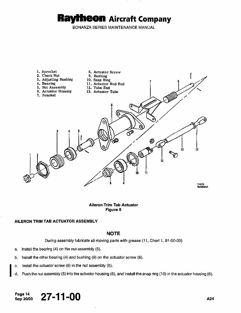
Ray~heon Aircraft CompanyBONANZA SERIES MAINTENANGE MANUAL
1. Spracket 8. Actuator Screw2. Check Nut 9. Bushing I3. Adjusting Bushing 10. Snap Ring 7 a4. Bearing 11. Actuator Rod End5. Nut Assembly 12. Tube End8. Actuator Rousing 13. Actuator Tube7. Bracket
V/
9 4 5
f
13 1?
2
ta 11
s TH27B98~BS9AA
Aileron Trim Tab Actuator
Figure 5
AILERON TRIM TAB ACTUATOR ASSEMBLY
NOTE
During assembly lubricate all moving parts with grease (11, Chart 1, 91-00-00).
a. Install the bearing (4) on the nut assembly (5).
b. Install the other bearing (4) and bushing (9) on the actuator screw (8).
c. Install the actuator screw (8) in the nut assembly (5).
d. Push the nut assembly (5) into the actuator housing (6), and install the snap ring (10) in the actuator housing (6).
Sep 27-11-00 A24
RayMheon Aircraft CompanyBONANZA SERIES MAINTENANCE MANUAL
e. Use a spanner wrench to install the adjusting bushing (3) into the actuator housing (6) until the end play between Ithe screw housing and nut assembly (5) is less than 0.025 inch. If the end play cannot be reduced to within limits,replace the actuator.
f. Install the check nut (2) on the adjusting bushing (3).
h. Align the holes in the actuator screw (8) with those of the actuator rod end (1 1) and install the two pins.
g. Install the actuator rod end (11) on the actuator screw (8).
i. Install the sprocket (1) on the actuator assembly.
j. Align the holes in the sprocket (1) with those in the nut assembly (5) and install the two pins.
CHECKING AILERON TRIM TAB FREE PLAY
Visually inspect the aileron trim tab for damage, security of hinge attach points, and for tightness of the actuatingsystem. Inconsistencies must be corrected before checking the free play of the tab.
A check fixture (P/N 45-135030-9/810) or equivalent, a dial indicator, and a push-pull scale for applying accurate
loading to the tab are required for making the inspection for tab free play (Ref. Figure 6).
a. Securely lock the control surfaces to prevent movement of the ailerons. Set the aileron trim tab in neutral.
b. Use shot bags to hold the dial indicator check fixture so that the point of the dial indicator is 2.0 inches aft of the
tab hinge line and on the outboard edge of the aileron tab.
c. Apply a small piece of masking tape (for paint protection) 4.0 inches aft of the tab hinge line and along the
centerline of the tab actuator. This is the point of pressure against the tab by the push-pull scale.
d. Apply another piece of masking tape in the corresponding location on the bottom surface of the tab.
e. Set the dial indicator at zero. Do not reset the dial indicator during the checking procedure.
f. With the push-pull scale on the masking tape, apply a 3.0 pound downward load. Record the dial reading as A.
g. Release half of the load to obtain a 1.5 pound downward load. Record the dial reading as B.
h. On the masking tape on the bottom surface, apply a 3.0 pound upward load. Record the dial reading as C.
i. Release half of the load to obtain a 1.5 pound upward load. Record the reading as D.
j. Enter the recorded readings on a copy of Chart 1 and proceed as follows:
1. SubtractAfrom2Band recordasX.
2. MultiplyBby2and recordases.
3. MultiplyDbyeand recordas2D.
4. Subtract C from 2D and record as Y.
NO~E
X and Y can be negative numbers.
Pi24 27-11-00
Raytheon Aircraft CompanyBONANZA SERIES MAINTENANCE MANUAL
5. Add X and Y and record as E.
k. (E 0.094 INCH MAXIMUM)
i. If the free play is over the maximum specified in Chart 1, inspect all components of the tab actuator system to
determine the cause. All worn parts must be replaced.
AILERON TRIM TAB FREE PLAY INSPECTION
This check should be performed at least once a year to ensure that the trim tab free play falls within the prescribedlimits.
A check fixture (P/N 45-135030-9/810) or equivalent, a dial indicator, and a push-pull scale for applying accurate
I loading to the tab are required for making the inspection for free play of the tab (Ref. Figure 6).
a. Securely lock the control surfaces to prevent movement of the ailerons. Set the aileron tab in the neutral
position.
b. Using shot bags, affix the dial indicator check fixture so that the dial indicator point is 2.00 inches aft of the tab
hinge line and on the outboard edge of the aileron tab.
c. Apply a small piece of masking tape (for paint protection) 4.00 inches aft of the tab hinge line and along the
centerline of the tab actuator. This will be the point of pressure against the tab by the push-pull scale.
d. Apply another piece of masking tape in the corresponding position on the bottom surface of the tab for the same
purpose.
e. Zero the dial indicator at no load initially. Do not reset during the checking procedure.
f. With the push-pull scale at the point of masking tape, apply a full 3-pound downward load. Record the dial
reading as A.
I g. Release half the load until a 1.5 pound downward load is obtained. Record the dial reading as B.
h. Apply a full 3 pound upward load at the masking tape on the bottom surface. Record the dial reading as C.
I i. Release half the load until a 1.5 pound upward load is obtained. Record the dial reading as D.
j. Enter the recorded values on a copy of Chart 1 and proceed as follows:
1. MultiplyBby2and recordas2B.
2. Subtract A from 28 and record as X.
3. MultiplyDby2and recordas2D.
4. SubtractCfrom2Dand recordas\(.
NOTE
The results of X and Y can be negative numbers.
5. Add X and Y and record as E.
k. If the free play exceeds 0.094 inch, inspect all components of the tab actuator system to determine the cause.
All wom parts should be replaced.
Sep 30/03PagelG 27-11-00 nz4
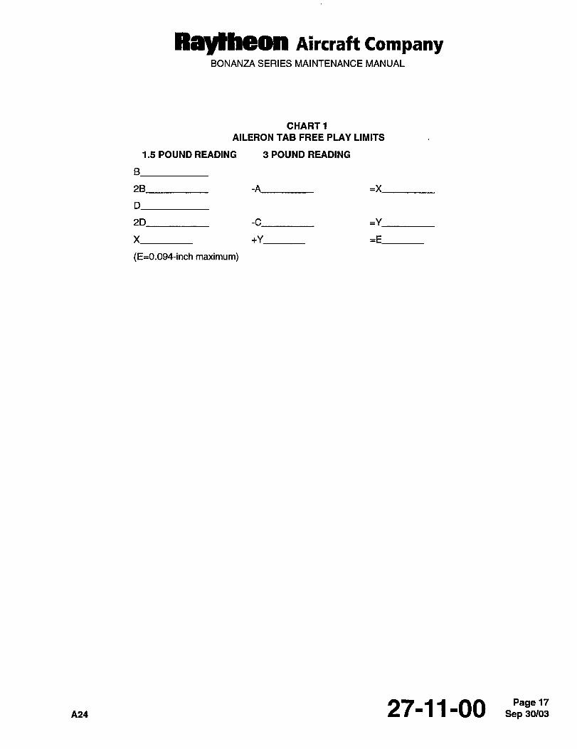
Ray~heon Aircraft CompanyBONANZA SERIES MAINTENANCE MANUAL
CHART1
AILERON TAB FREE PLAY LIMITS
1.5 POUND READING 3 POUND READING
2B -A =X
2D -C =Y
X +Y =E
(E=O.Og4-inch maximum)
A24 27-11-00 Sep 30/03Pagel7
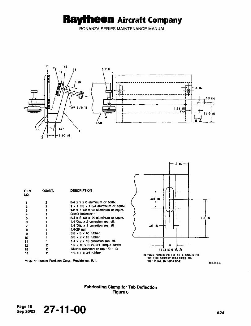
Ray~heon Aircraft CompanyBONANZA SERIES MAINTENANCE MANUAL
9 12~o
13 678
11I.8 IN
5
~1’-----------.25 IN
I
HLJ TAP 5/8-11 O 1.25 1
I_ _,,TYPI2.9 IN
I i I It tnAITAB
14
1.30 IN
t~
ITEM QUANT. DESCRIPTION 1 1----C-C i
NO.
.68 IN
71 2 3/4 x i x 8 aluminum or equlv.2 2 1 x 1 9/8 x i 3/4 aluminum or equlv.3 1 1/2 x 7 1/2 x 10 aluminum or equiv.4 i C81P Indicator"
5 1 3/4 x 2 1/2 x 14 aluminum or equlv. 1.6 IN
6 114 Dia. x 2 oarrosion res. stl.
7 i 1/4 Dia. ~e 1 corrosion res, sH. .31 IN
8 1 114-28 nut
9 1 3/8 x 5 x 10 rubber
10 1 3/8 x 2 x 10 rubber
12 2 1M x 13 x 3 VLIER Torque sorew SEC710N,t11 i 1/4 x 2 x 10 corrosion res. sil,
13 2 KNB13 Keensert or tap 1/2 13
14 2 1/8 x 1 x 3/4 rubber4k THIS GROOVE TO BE A SNUG FIT
TO THE SCREW 5RACKET ON"P/N or Federal Products Corp., Proddence, R. I. THE DIAL INDICATOR
ioo-,,5-e
Fabricating Clamp for Tab Deflection
Figure 6
Sep 30/03Page 18 27-11-00A24
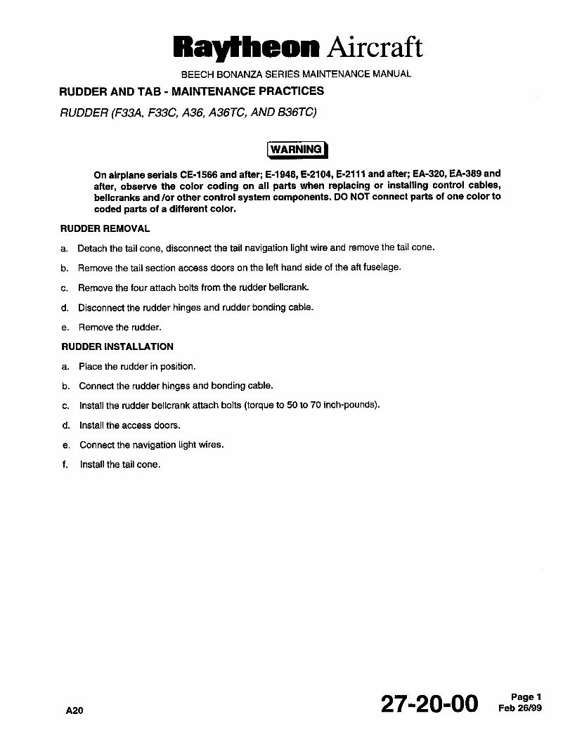
RayIIheoIlt AircraftBEECH BONANZA SERIES MAINTENANCE MANUAL
RUDDER AND TAB MAINTENANCE PRACTICES
RUDDER (F33A, F33C, A36, A36TC, AND B36TC)
I WARNING IWARNING
On airplane serials 06-1566 and after; 6-1946, 6-2104, 6-2111 and after; EA-320, EA-389 and
after, observe the color coding on all parts when replacing or installing control cables,
bellcranks and /or other control system components. DO NOT connect parts of one color to
coded parts of a different color.
RUDDER REMOVAL
a. Detach the tail cone, disconnect the tail navigation light wire and remove the tail cone.
b. Remove the tail section access doors on the left hand side of the aft fuselage.
c. Remove the four attach bolts from the rudder bellcrank.
d. Disconnect the rudder hinges and rudder bonding cable.
e. Removethe rudder.
RUDDER INSTALLATION
a. Placethe rudderinposition.
b. Connect the rudder hinges and bonding cable.
c. Install the rudder bellcrank attach bolts (torque to 50 to 70 inch-pounds).
d. Install the access doors.
e. Connectthenavigation lightwires.
f. Install the tail cone.
nm27-20-00 Feb 26/99Pagel
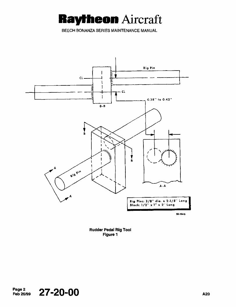
RayZhe8888 AircraftBEECH BONANZA SERIES MAINTENANCE MANUAL
Rig Pin
CL
CL
0.38" to 0.45"
8-8
i.,B
jA-A
Rig Pin~: 3/8" die. x 2-)/8" Long
8loek: 1/2" r 1" x 2" Long
56-1~46
Rudder Pedal Rig Tool
Figure 1
Page 2Feb26/99 27-20-00 A20
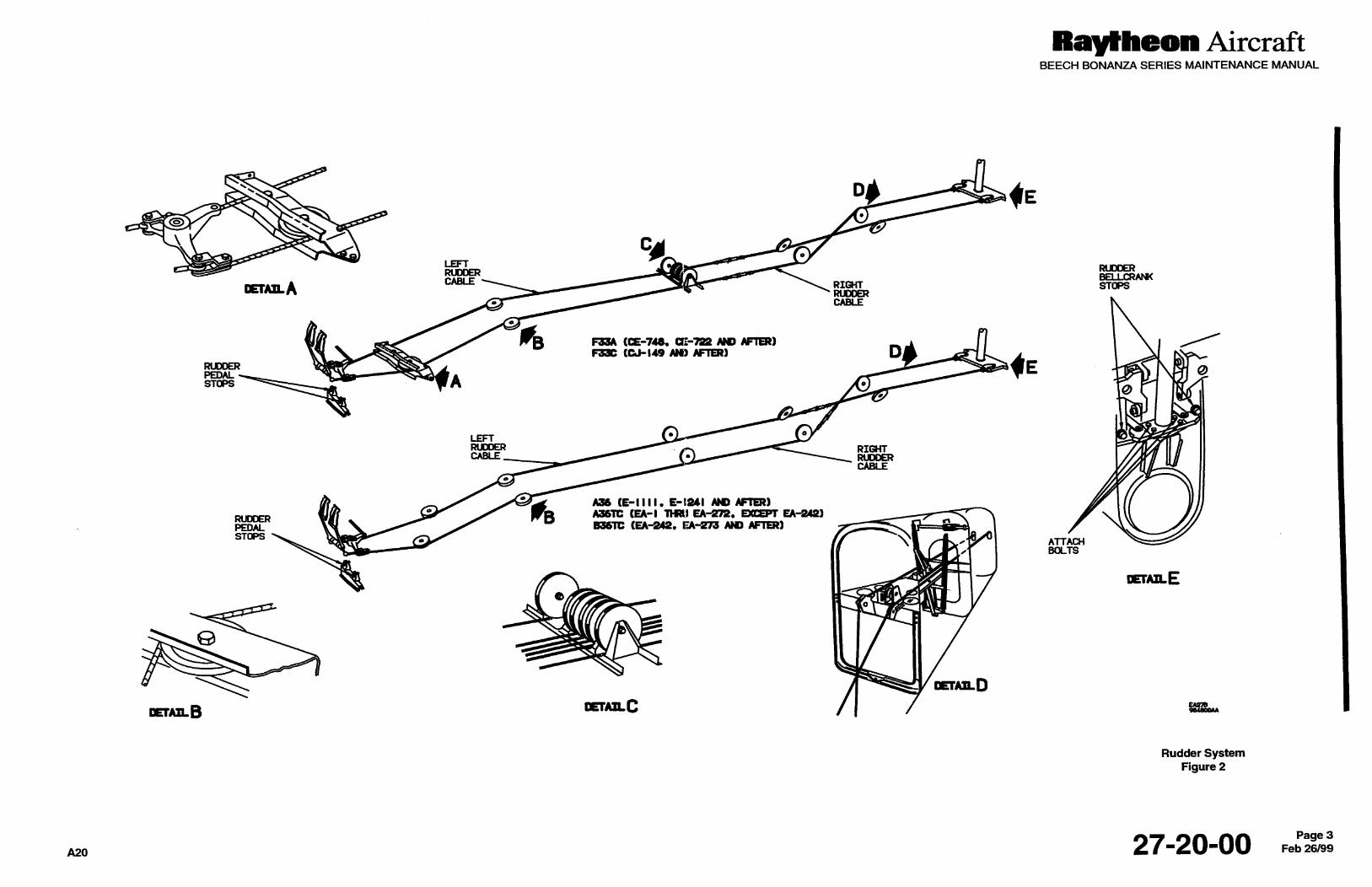
RayEheon AircraftBEECH BONANZA SERIES MAINTENANCE MANUAL
LEFTRUDDER
RUDDERRFII.CRAM(
mAnA C*BLE~_ STOPS
CABLE
6336 (eE-74~ AH9 AFTER)F33C tC3-149 CUI) AFTER) D
RU~DERPEDAL ASTOPS
LEFTRUDDER RIGHTCABLE RUDDER
CABLE
RUDOER
WB (9-1111. E-tUI AH) AFTER)A;3CSTC ~EA-I THRII U-~2´• U-2~)
PEDAL 836Tl: (EA-2~´• EA-273 C1~9 AFTER)sToas
ATTACHBOLTS
DerA~aE
DETAPLD
mAI~B m~C /I ~e,
Rudder SystemFigure 2
A2027-20-00 Feb 26/99Page 3
Ray~heon AircraftBEECH BONANZA SERIES MAINTENANCE MANUAL
THIS PAGE INTENTIONALLY LEFT BLANK
Page 4Feb26/99 27120100 A20
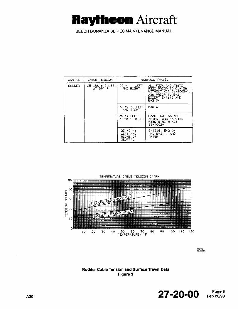
Raytheon AircraftBEECH BONANZA SERIES MAINTENANCE MANUAL
CABLES CABLE TENSION SURFACE TRAVEL
RUDDER 25 LBS 5 LBS 25 i LEFT ALL F33A AND A36TC.AT 59’ F AND RIGHT F33C PRIOR TO CJ-156
WITHOUT KIT 33-4002-1,A36 PRIOR TO E-2111EXCEPT E-1946 ANDE-2104
20 +0 -I LEFT B36TCAND RIGHT
25 ii LEFT F33C, CJ-156 AND20 cO -I RIGHT AFTER. AND EARLIER
F33C’S WITH KIT33-4002-1
23 +O -1 E-1946, E-2104LEFT AND AND E-2111 ANDRIGHT OF AFTERNEUTRAL
TEMPERATURE CABLE TENSION GRAPH
50
,40
a30
n 204
io
10 20 30 40 50 60 70 80 90 100 110 120TEMPERATURE- "F
EA278sadaol*a
Rudder Cable Tension and Surface Travel Data
Figure 3
A20 27-20-00 Feb 26/99Page 5
Raytheon AircraftBEECH BONANZA SERIES MAINTENANCE MANUAL
RIGGING THE RUDDER CONTROL SYSTEM
I FIGURES 2 AND 3
NOTE
To facilitate rigging of the rudder pedals a rigging tool may be fabricated from a steel block 1/2 inch
X 1 inch X 2 inches; and two 3/8-inch- x 2-1/8-inch-long pins. The rig pins are located parallel and
forward of the block, one on each side, and welded. The rig pins should be spaced as noted in
Figure 1.
a. Place the rudder pedals in the aft position.
b. Install a rig tool in the holes provided in the pilot’s rudder pedals.
c. With the bellcrank in the neutral position, rig the cables to the tension shown on the temperature cable tension
graph in Figure 3, then remove the rig pin.
NOTE
Installation of the rig pin in the pilot’s rudder pedals will bring the copilot’s pedals to the same ad-
justment as the pilot’s pedals.
The right hand rudder pedals are rigged 0.38 0.45 inch forward of the neutral position.
d. Adjust the rudder travel at the rudder bellcrank stops as indicated in Figure 2.
e. Adjust the rudder pedal travel at the rudder pedal stops so that contact with the rudder bellcrank stops occurs
immediately prior to contact with the rudder pedal stops.
f. Make sure that the rudder movement corresponds to the movement of the rudder pedals.
Page 627-20-00
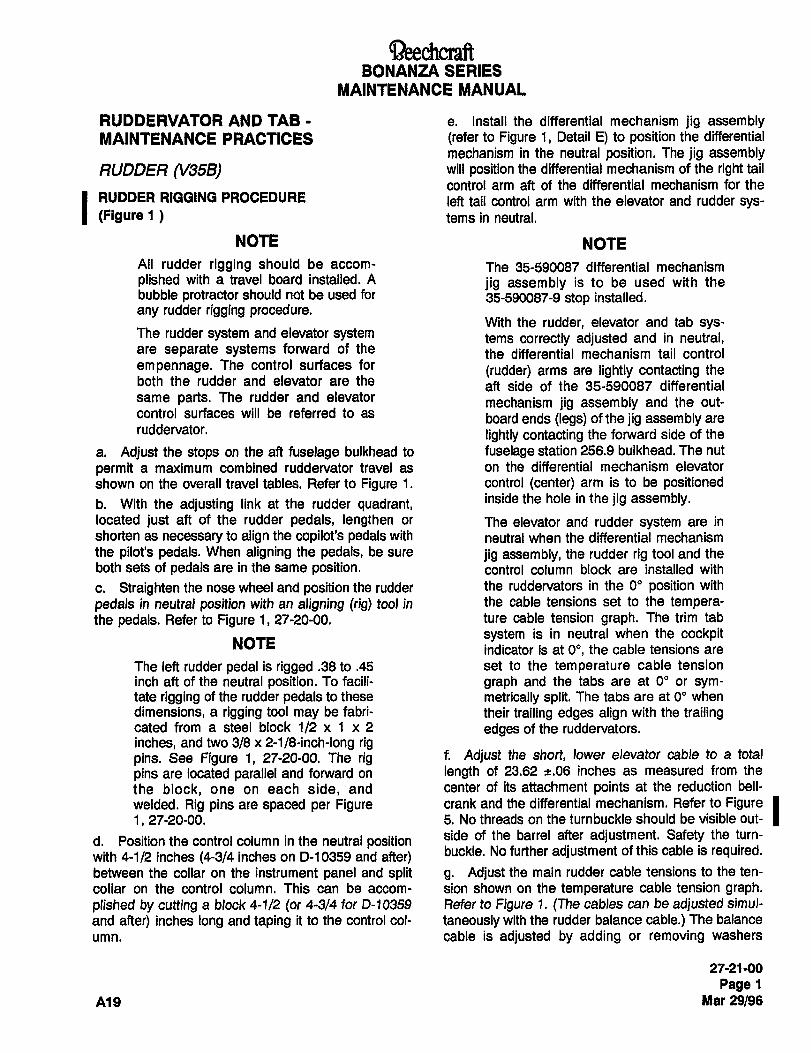
aeechcraftBONANZA SERIES
MAINTENANCE MANUAL
RUDDERVATOR AND TAB e. Install the differential mechanism jig assemblyMAINTENANCE PRACTICES (refer to Figure 1, Detail E) to position the differential
mechanism in the neutral position. The jig assemblyRUDDER (V35B) will position the differential mechanism of the right tail
control arm aft of the differential mechanism for the
I RUDDER RIGGING PROCEDURE left tail control arm with the elevator and rudder sys-(Flgure 1 tems in neutral.
NOTE NOTE
All rudder rigging should be accom- The 35-590087 differential mechanismplished with a travel board installed. A jig assembly is to be used with thebubble protractor should not be used for 35-590087-9 stop installed.
any rudder rigging procedure.With the rudder, elevator and tab sys-
The rudder system and elevator system tems correctly adjusted and in neutral,are separate systems forward of the the differential mechanism tail controlempennage. The control surfaces for (rudder) arms are lightly contacting theboth the rudder and elevator are the aft side of the 35-590087 differentialsame parts. The rudder and elevator mechanism jig assembly and the out-control surfaces will be referred to as board ends (legs) of the jig assembly areruddervator, lightly contacting the forward side of the
a. Adjust the stops on the aft fuselage bulkhead to fuselage station 256.9 bulkhead. The nut
permit a maximum combined ruddervator travel as on the differential mechanism elevator
shown on the overall travel tables. Refer to Figure 1. control (center) arm is to be positioned
b. With the adjusting link at the rudder quadrant, inside the hole in the jig assembly.
located just aft of the rudder pedals, lengthen or The elevator and rudder system are in
shorten as necessary to align the copilot’s pedals with neutral when the differential mechanismthe pilot’s pedals. When aligning the pedals, be sure jig assembly, the rudder rig tool and theboth sets of pedals are in the same position, control column block are installed with
c. Straighten the nose wheel and position the rudder the ruddervators in the 0" position with
pedals in neutral position with an aligning (rig) tool in the cable tensions set to the tempe~a-the pedals. Refer to Figure 1, 27-20-00. ture cable tension graph. The trim tab
system is in neutral when the cockpitNOTE
indicator is at 0", the cable tensions are
The left rudder pedal is rigged .38 to .45 set to the temperature cable tension
inch aft of the neutral position. To facili- graph and the tabs are at O" or sym-tate rigging of the rudder pedals to these metrically split. The tabs are at 00 when
dimensions, a rigging tool may be fabri- their trailing edges align with the trailingcated from a steel block 1/2 x 1 x 2 edges of the ruddervators.
inches, and two 3/8 x 2-1/8-inch-long rigpins. See Figure 1, 27-20-00. The rig f. Adjust the short, lower elevator cable to a total
pins are located parallel and forward on length of 23.62 ~t.06 inches as measured from the
the block, one on each side, and center of its attachment points at the reduction bell-
welded. Rig pins are spaced per Figure crank and the differential mechanism. Refer to Figure Id. Position the control column in the neutral position side of the barrel after adjustment. Safety the turn-
with 4-1/2 inches (4-3/4 inches on D-10359 and after) buckle. No further adjustment of this cable is required.
between the collar on the instrument panel and split g. Adjust the main rudder cable tensions to the ten-
collar on the control column. This can be accom- sion shown on the temperature cable tension graph.plished by cutting a block 4-1/2 (or 4-3/4 for D-10359 Refer to Figure 7. (The cables can be adjusted simul-
and after) inches long and taping it to the control coi- taneously with the rudder balance cable.) The balance
umn. cable is adjusted by adding or removing washers
27-21 -00
Page 1
A19 Mar 29/96
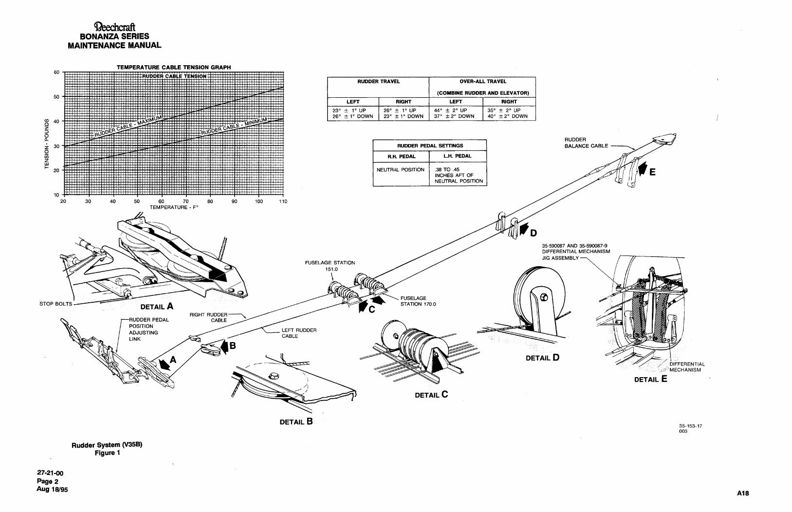
BONANZA SERIES
MAINTENANCE MANUAL
TEMPERATURE CABLE TENSION GRAPHso
CARL" TENSION:H RUDDER TRAVEL OVER-ALL TRAVEL
(COMBINE RUDDER AND ELEVATOR)50
LEFT RIGHT LEFT RIGHT
"~tI23’ i UP 26"+ 1’ UP 44"+ 2’ UP 350 20 UP
260 i 1" DOWN 23e i 10 DOWN 370 f 20 DOWN 400 i20 DOWN
z
H
gI
RUDDER
i 30r
RUDDER PEDAL SETLlNGS BALANCE CABLE
O aR.H. PEDAL LH. PEDAL
NEUTRi~L POSITION .38 TO .45
INCHES AFT OF
NEUTRAL POSITION
10
20 30 40 50 60 70 80 90 100 110
TEMPERATURE-FO
fD35-590087 AND 35-590087-9
DIFFERENTIAL MECHANISM
JIG ASSEMBLYFUSELAGE STATION
151.0
STOP BOLTS STATION 170.0FUSELAGEDETAILAC
RIGHT RUDDER
PEDAL CABLE
POSITIONLEFT RUDDER
ADJUSTINGCABLE YLINK
B
LA DETAIL DDIFFERENTIAL
:i::: MECHANISM
DETAIL E
DETAIL C
DETAIL B35-153-17
003
Rudder System (V35B)Figure 1
27-21-00
Page 2
Aug 18/95Ai8
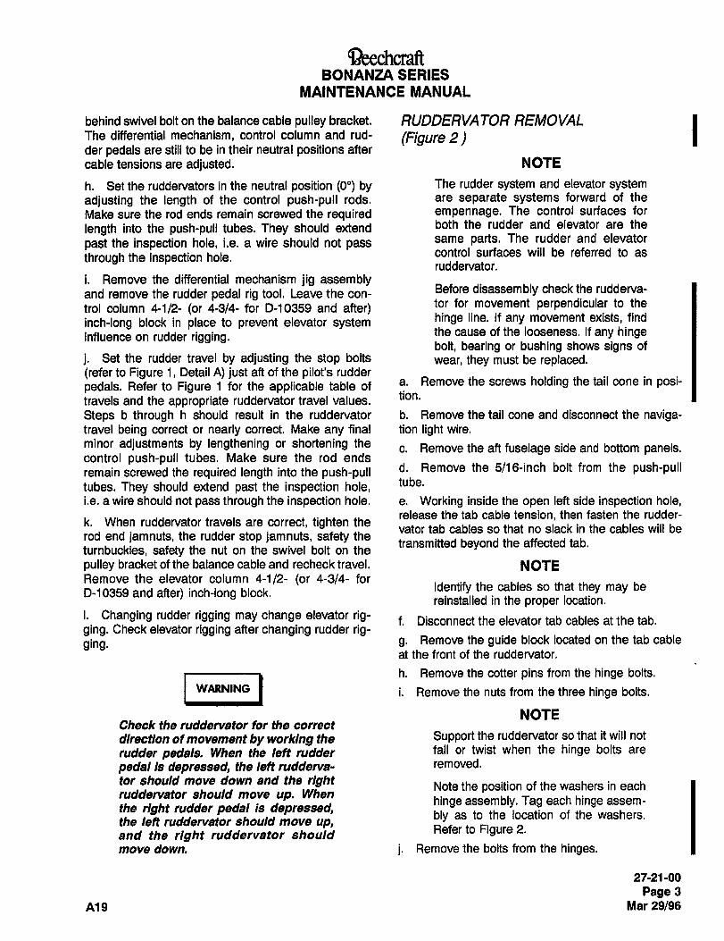
BaeechcraftBONANZA SERIES
MAINTENANCE MANUAL
behind swivel bolt on the balance cable pulley bracket. RUDDERVATOR REMOVAL IThe differential mechanism, control column and rud- (Figure 2)der pedals are still to be in their neutral positions after
cable tensions are adjusted. NOTE
h. Set the ruddervators in the neutral position (00) by The rudder system and elevator system
adjusting the length of the control push-pull rods, are separate systems forward of the
Make sure the rod ends remain screwed the required empennage. The control surfaces for
length into the push-pull tubes. They should extend both the rudder and elevator are the
past the inspection hole, i.e. a wire should not passsame parts. The rudder and elevator
control surfaces will be referred to asthrough the inspection hole.ruddervator.
i. Remove the differential mechanism jig assemblyand remove the rudder pedal rig tool. Leave the con-
Before disassembly check the rudderva-
trol column 4-1/2- (or 4-3/4- for D-10359 and after) tor for movement perpendicular to the
inch-long block in place to prevent elevator system hinge line. If any movement exists, find
influence on rudder rigging. the cause of the looseness. If any hingebolt, bearing or bushing shows signs of
j. Set the rudder travel by adjusting the stop bolts wear, they must be replaced.(refer to Figure 1, Detail A) just aft of the pilot’s rudder
pedals. Refer to Figure 1 for the applicable table of a. Remove the screws holding the tail cone in posi-tion.travels and the appropriate ruddervator travel values.
Steps b through h should result in the ruddervator b. Remove the tail cone and disconnect the naviga-travel being correct or nearly correct. Make any final tion light wire.
minor adjustments by lengthening or shortening thec. Remove the aft fuselage side and bottom panels.
control push-pull tubes. Make sure the rod ends
remain screwed the required length into the push-pull d. Remove the 5/16-inch bolt from the push-pull
tubes. They should extend past the inspection hole, tube.
i.e. a wire should not pass through the inspection hole. e. Working inside the open left side inspection hole,release the tab cable tension, then fasten the rudder-
k. When ruddervator travels are correct, tighten thevator tab cables so that no slack in the cables will be
rod end jamnuts, the rudder stop jamnuts, safety thetransmitted beyond the affected tab.
turnbuckles, safety the nut on the swivel bolt on the
pulley bracket of the balance cable and recheck travel. NOTERemove the elevator column 4-1/2- (or 4-3/4- for
Identify the cables so that they may beD-10359 and after) inch-long block.
reinstalled in the proper location.
i. Changing rudder rigging may change elevator rig- f. Disconnect the elevator tab cables at the tab.ging. Check elevator rigging after changing rudder rig-ging. g. Remove the guide block located on the tab cable
at the front of the ruddervator.
I -´•I´•´•Ih. Remove the cotter pins from the hinge bolts.
WARNING i. Remove the nuts from the three hinge bolts.
NOTECheck the ruddervator for the correct
direction of movement by working the Support the ruddervator so that it will not
rudder pedals. When the left rudder fall or twist when the hinge bolts are
pedal is depressed, the left rudderva- removed.
tor should move down and the right Note the position of the washers in eachruddervator should move up. When
hinge assembly. Tag each hinge assem-the right rudder pedal Is depressed,
bly as to the location of the washers.the left ruddervator should move up,and the right ruddervator should
Refer to Figure 2.
move down. j. Remove the bolts from the hinges.
27-21-00
Page 3
A19 Mar 29/96
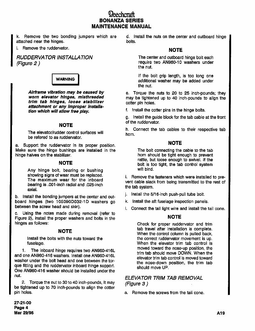
aeechcnnftBONANZA SERIES
MAINTENANCE MANUAL
k. Remove the two bonding jumpers which are d. Install the nuts on the center and outboard hingeattached near the hinges. bolts.
i. Remove the ruddervator. NOTE
RUDDERVATOR INSTALLATION The center and outboard hinge bolt each
(Figure 2) require two AN960-10 washers underthe nut.
1´•U´•1~1 additional washer may be added under
If the bolt grip length, is too long one
the nut.
Airframe vibration may be caused by e. Torque the nuts to 20 to 25 inch-pounds; theyworn elevator hinges, mlsthreaded may be tightened up to 40 inch-pounds to align thetrim tab hinges, loose stablll~er cotter pin holes.attachment or any Improper Installa-tion which will allow free play. f. Install the cotter pins in the hinge bolts.
g. Install the guide block for the tab cable at the front
of the ruddervator.NOTE
h. Connect the tab cables to their respective tabThe elevator/rudder control surfaces will horn.be refered to as ruddervator.
NOTEa. Support the ruddervator in its proper position.Make sure the hinge bushings are installed in the The bolt connecting the cable to the tab
hinge halves on the stabilizer, horn should be tight enough to preventrattle, but loose enough to swivel. If the
NOTE bolt is too tight, the tab control system
Any hinge bolt, bearing or bushing will bind.
showing signs of wear must be replaced. i. Remove the fasteners which were installed to pre-The maximum wear for the inboard
vent cable slack from being transmitted to the rest ofbearing is.001-inch radial and .025-inch
the tab system.axial.
j. Install the 5/16-inch push-pull tube bolt.b. Install the bonding jumpers at the center and out-
board hinges (two 105090D032-1D washers go k´• Install the aft fuselage inspection panels.between the screw head and skin). i. Connect the tail light wire and install the tail cone.
c. Using the notes made during removal (refer to
Figure 2), install the proper washers and bolts in the NOTE
hinges as follows: Check for proper ruddervator and trim
NOTEtab travel after installation is complete.When the control column is pulled back,
Install the bolts with the nuts toward the the correct ruddervator movement is up.fuselage. When the elevator trim tab control is
1.moved toward the nose-up position, the
The inboard hinge requires two AN960-416Ltrim tab should move DOWN. When the
and one AN960-416 washers. Install one AN960-416Lelevator trim tab control is moved toward
washer under the bolt head and one between the tor- the nose-down position, the trim tabque fitting and the ruddervator inboard hinge support, should move UP.One AN960-416 washer should be installed under the
nut.ELEVATOR TRIM TAB REMOVAL
2, Torque the nut to 30 to 40 inch-pounds, It may (Figure 3)be tightened up to 70 inch-pounds to align the cotter
pin holes. a. Remove the screws from the tail cone.
27-21-00
Page 4
Mar 29/96 A19
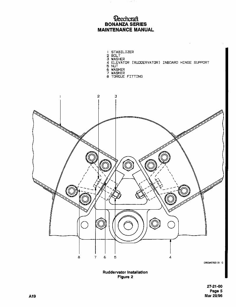
QeechcraftBONANZA SERIES
MAINTENAN~E iVIANUAL
STABILIZER2 BOLT3 WASHER4 ELEVATOR (RUDDERVATOR) INBOARD HINGE SUPPORT
5 NUT6 WASHER7 WASHER8 TOROUE FITTING
23
‘c~´•I
~Y?
a
~O8765 4
C950X2783131
Ruddervator Installation
Figure 2
27-21-00
Page 5
A19 Mar 29/96
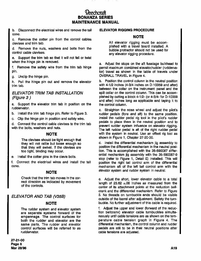
BONANZA SERIES
MAINTENANCE MANUAL
b. Disconnect the electrical wires and remove the tail ELEVATOR RIGGING PROCEDURE
cone.NOTE
c. Remove the cotter pin from the control cables
devises and trim tab. All elevator rigging must be accom-
plished with a travel board installed. Ad. Remove the nuts, washers and bolts from the
bubble protractor should not be used forcontrol cable devises.
any elevator rigging procedure.e. Support the trim tab so that it will not fall or twist
when the hinge pin is removed.a. Adjust the stops on the aft fuselage bulkhead to
f. Remove the safety wire from the trim tab hinge permit maximum combined elevator/rudder (rudderva-pin. tor) travel as shown in the table of travels under
g. Unclip the hinge pin. OVERALL TRAVEL in Figure 4.
h. Pull the hinge pin out and remove the elevator b´• Position the control column in the neutral positiontrim tab. with 4-1/2 inches (4-314 inches on D-10359 and after)
between the collar on the instrument panel and the
ELEVATOR TRIM TAB INSTALLATION split collar on the control column. This can be accom-
(Figure 3) plished by cutting a block 4-1/2- (or 4-3/4- for D-10359
and after) inches long as applicable and taping it to
a. Support the elevator trim tab in position on the the control column.ruddervator.
c. Straighten the nose wheel and adjust the pilot’sb. Install the trim tab hinge pin. Refer to Figure 3. rudder pedals (fore and aft) to the same position.c. Clipthe hingepin in positionandsafetywire. Install the rudder pedal rig tool in the pilot’s rudder
pedals to place them in the neutral position and tod. Connect the control cable devises to the trim tab
prevent rudder system influence on´•elevator rigging.with the bolts, washers and nuts.
The left rudder pedal is aft of the right rudder pedalNOTE with the system in neutral. Use an offset rig tool as
shown in Figure 1, Chapter 27-20-00.The devises should be tight enoi~gh that
they will not rattle but loose enough so d. Install the differential mechanism jig assembly to
that they will swivel. If the devises are position the differential mechanism in the neutral posi-too tight, binding may occur. tion. This is accomplished with the 35-590087 differ-
ential mechanism jig assembly with the 35-590087-9e. Install the cotter pins in the clevis bolts.
stop (refer to Figure 1, Detail E) installed. This willf. Connect the electrical wires and install the tail position the right tail control arm of the differentialcone. mechanism aft of the left tail control arm with the
NOTEelevator system and rudder system in neutral.
Check that the trim tab moves in the cor- e. Adjust the short, lower elevator cable to a totalrect direction as indicated by movement length of 23.62 ~.06 inches as measured from theof the controls.
center of its attachment points at the reduction bell-
crank and the differential mechanism. Refer to Figure
ELEVATOR AND TAB (V35B) 5. No threads on turnbuckle ends should be visible
outside of the barrel after adjustment. Safety the turn-
NOTE buckle. No further adjustment of this cable is required.
The rudder system and elevator system f. Adjust the upper and lower (forward of the reduc-
are separate systems forward of the tion bellcrank) elevator cable turnbuckles simulta-
empennage. The control surfaces for neously until cable tensions are as shown on the tem-
both the rudder and elevator are the perature cable tension graph in Figure 4. The
same parts. The rudder and elevator differential mechanism, the control column and rudder
control surfaces will be referred to as pedals are still to be in their neutral positions after
ruddervator. cable tensions are adjusted.
27-21-00
Page 6
Mar 29/96 A19
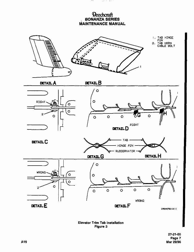
BONANZA SERIES
MAINTENANCE MANUAL
i. TAB HINGEPIN
2. TAB HORNCABLE BOLT
1’
DETAIL A DETAIL B
RIGHT ./Q\I I o
OI I lo o o o
RIGHT
DETAIL D
DETAIL C_
Be TAB
HINGE PIN
~e RUDDERVATOR
#TAlL G DETAflH
WRONGO O
O O O O O
WRONG
DETAIL E DETAIL FC91011785155 5
Elevator Trim Tab Installation
Figure 3
27-21-00
Page 7
A19 Mar 29/96
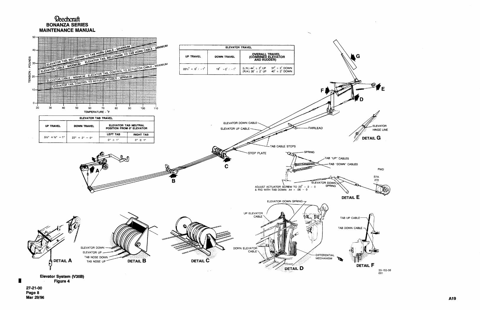
Beec~M´•dftBONANZA SERIES
MAINTENANCE MANUAL
50
5 I ELEVATOR TRAVEL
OVERALL TRAVELGUP IRCIYEL WWN TRLIVEL (C~OMBINU) CL~YATOR
3V"L
_
*N~RvDDER)
g ,E ~2ipr ,,_,;~ ,,,,,.-iuPli~-raowNi
a_
DOWNF- i (R.H.) 35. 2~ UP
PF
i
~C,1 F
~I i’ ~D0
20 30 40 50 60 70 80 90 100 110
TEMPERATURE -"F
ELEVATOR TAB TRAVEL
ELEVATOR DOWN CABLE
UP TRAVEL DOWN TRAVEL ELEVATOR TAB NEUTRAL IPOSITION FROIO" ELEVATOR ELEVATOR UP CABLE FAIRLEAD
HINGE LINE
LEFT TAB RIGHT TAB5’/i" +1/20 --10 230 2~ O~ DETAIL G
O" i 1" 00 i 1"
TAB CABLE STOPS
STOP PLATE y-~SPRING
TAB "UP" CABLES
TAB "DOWN" CABLESC
A FWD
4iSTA.
BELEVATOR DOWNS.
272
ADJUST ACTUATOR SCREW TO 23 2 O SPRING
8 RIG WITH TAB DOWN .44 ;.06 0
DETAIL EELEVATOR DOWN SPRING
UP ELEVATOR
CABLETAB UP CABLE
UTAB DOWN CABLE
ij
ELEVATOR UP ----C~ CABLE 8’’
ELEVATOR DOWN DOWN ELEVATOR
NOSE WWN ii
DETAIL A TAB NOSE UP DETAIL B DETAIL CDETAIL F
DETAIL D35-152-38
001
Elevator System (V35B)Figure 4
27-21-00
Page 8
Mar 29/96 A19
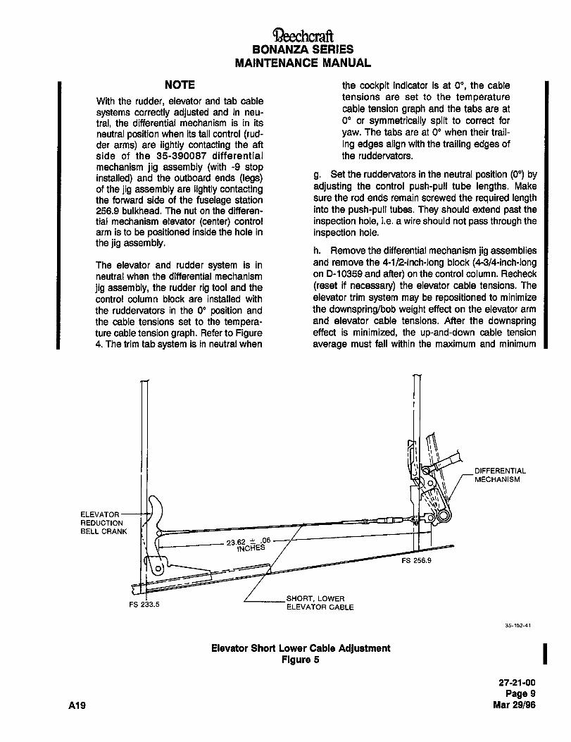
~eechcraftBONANZA SERIES
MAINTENANCE MANUAL
NOTE the cockpit indicator is at 0", the cable
With the rudder, elevator and tab cable tensions are set to the temperature
systems correctly adjusted and in neu-cable tension graph and the tabs are at
tral, the differential mechanism is in its 0" or symmetrically split to correct for
neutral position when its tail control (rud- yaw. The tabs are at O" when their t~ail-
der arms) are lightly contacting the aft ing edges align with the trailing edges of
side of the 35-390087 differential the ruddervators.
mechanism jig assembly (with -9 stopinstalled) and the outboard ends (legs) g. Set the ruddervators in the neutral position (O") by
of the jig assembly are lightly contacting adjusting the control push-pull tube lengths. Make
the forward side of the fuselage station sure the rod ends remain screwed the required length256.9 bulkhead. The nut on the differen- into the push-pull tubes. They should extend past the
tial mechanism elevator (center) control inspection hole, i.e. a wire should not pass through the
arm is to be positioned inside the hole in inspection hole.
the jig assembly.h. Remove the differential mechanism jig assemblies
The elevator and rudder system is in and remove the 4-1/2-inch-long block (4-3/4-inch-longneutral when the differential mechanism on D-10359 and after) on the control column. Recheck
jig assembly, the rudder rig tool and the (reset if necessary) the elevator cable tensions. The
control column block are installed with elevator trim system may be repositioned to minimize
the ruddervators in the 0" position and the downspring/bob weight effect on the elevator arm
the cable tensions set to the tempera- and elevator cable tensions. After the downspringture cable tension graph. Refer to Figure effect is minimized, the up-and-down cable tension
4. The trim tab system is in neutral when average must fall within the maximum and minimum
DIFFERENTIAL
MECHANISM
ELEVATOR
REDUCTION
BELL CRANK
23.62 ?1 ´•06
INCHES
FS 256.9
SHORT, LOWERFS 233.5 ELEVATOR CABLE
35-152-41
Elevator Short Lower Cable Adjustment IFigure 5
27-21-00
Page 9
A19 Mat 29/96
aeechcraftBONANZA SERIES
MAINTENANCE MANUAL
values designated by the temperature cable tension a. Check the up and down travel of the elevator tabs.
graph. Refer to Figure 4. The travel should be 5-1/2" +1/2" -1" up and 23" +2"
i. Check the elevators for correct up-and-down travel ’00 down.
limits: 22-1/2 degrees +0 -1 degree up and 19 +2 -1 b. Check the main and the aft tab cables for properdegrees down. The stops are nonadjustable stops for- tension as shown on the temperature cable tensionward of the instrument panel and underneath the con- graph. Refer to Figure 4. The same number of termi-trol column. Steps b through h should result in the nal threads should be visible on each end of the turn-ruddervator travel being correct or close to correct. buckle barrels (a maximum of three threads may beMake any final minor adjustments by lengthening or visible).shortening the ruddervator push-pull tubes, but make
sure the rod ends remain screwed the required length ELECTRIC ELEVATOR TRIM (OPTIONAL)into the push-pull tubes. They should extend past the For the Model F33A, E33C and V35B electric trim sys-inspection hole, i.e. a wire should not pass through the teml see Chapter 27-30-00.inspection hole.
j. Adjust the elevator downspring cable turnbuckle ELEVATOR TAB RIGGING
with the ruddervators 9" up and the tabs 20" down NOTE(nose up) to remove all slack from this cable system;then check the force on the elevator control column. The use of a bubble protractor is not
With the trim tabs set at neutral (O"), a force of 19 ~3 adequate to set the ruddervator travels.
pounds applied on the control column is required to A travel board must be used for this.
move the ruddervators through neutral. If necessary, However, with the ruddervator set at
adjust the elevator downspring cable turnbuckle to neutral, a tab travel board or a bubble
obtain the value. protractor may be used to set elevator
tab travel.k. When the elevator travels and forces are correct,tighten the rod-end jam nuts, safety the turnbuckles Elevator tabs should be rigged with the
and recheck the travels. Remove the rudder rig tool. travel board or bubble protractor perpen-
I. Changing elevator rigging may change rudder rig- dicular to the chord plane of the stabi-
ging. Check rudder rigging after changing elevator rig- lizer or tab respectively.
ging. a. Install a 4-1/2-inch-long block (or 4-3/4-inch-longon D-10359 and after) on the control column and
I install the rudder pedal rig tool (Figure 1, 27-20-00) toARNING
maintain the ruddervators in neutral. Rotate the eleva-
tor tab wheel in the cabin so the indicator dial is set on
Check for correct direction of rudder- zero.
vator travel by moving the control
column. When the control column Is NOTE
pushed forward, the correct rudder- Both elevator trim tabs should be at neu-
vator movement Is down. When the tral (tab trailing edge aligned with rud-control column Is pulled back, the dervator trailing edge; see the procedurecorrect ruddervator movement Is up. for RIGGING ELEVATOR TRIM TABSWhen the elevator trim tab control Is TO CORRECT FOR YAW). Trim tab act-moved toward the nose-up position, uator stops on the cables should bethe trim tab should move DOWN. moved away from the stops in the fuse-When the elevator trim tab control is lage.moved toward the nose-down posl-tlon, the trim tab should move UP. b. Rotate the elevator trim tab control wheel to full
INSPECTION OF ELEVATOR TABS nose up on the indicator (tabs down). Check the tab
actuator at F.S. 233.5. for a distance of.38 to .50 inchNOTE
between the face of the actuator and the centerline of
The trim tabs have an upper contoured the bolt in the clevis end of the actuator screw as
surface. shown in Figure 6.
27-21-00
Page 10
Mar 29/96 Ai9
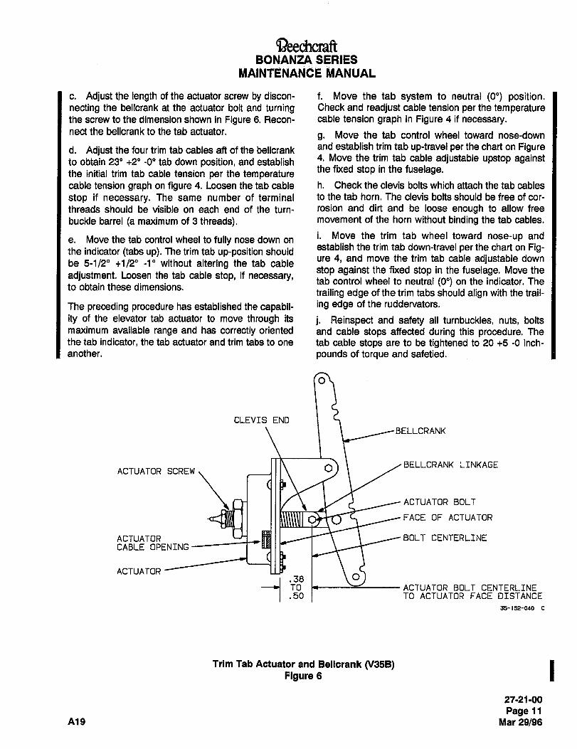
aee~hcraftBONANZA SERIES
MAINTENANC~ ~ANUAL
c. Adjust the length of the actuator screw by discon- f. Move the tab system to neutral (0") position.necting the bellcrank at the actuator bolt and turning Check and readjust cable tension per the temperaturethe screw to the dimension shown in Figure 6. Recon- cable tension graph in Figure 4 if necessary.nect the bellcrank to the tab actuator.
g. Move the tab control wheel toward nose-down
d. Adjust the four trim tab cables aft of the bellcrank a"d establish trim tab up-travel per the chart on Figure
to obtain 23" +2" -0" tab down position, and establish4. Move the trim tab cable adjustable upstep against
the initial trim tab cable tension per the temperaturethe fixed stop in the fuselage.
cable tension graph on figure 4. Loosen the tab cable h. Check the clevis bolts which attach the tab cables
stop if necessary. The same number of terminal to the tab horn. The clevis bolts should be free of cor-
threads should be visible on each end of the turn- rosion and dirt and be loose enough to allow free
buckle barrel (a maximum of 3 threads). movement of the horn without binding the tab cables.
i. Move the trim tab wheel toward nose-up ande. Move the tab control wheel to fully nose down on
the indicator (tabs up). The trim tab up-position shouldestablish the trim tab down-travel per the chart on Fig-
be 5-1/2" +1/20 -1" without altering the tab cableure 4, and move the trim tab cable adjustable down
stop against the fixed stop in the fuselage. Move theadjustment. Loosen the tab cable stop, if necessary, tab control wheel to neutral (O") on the indicator. Theto obtain these dimensions.
trailing edge of the trim tabs should align with the trail-
The preceding procedure has established the capabil- i"g edge of the ruddervators.
ity of the elevator tab actuator to move through its j. Reinspect and safety all turnbuckles, nuts, boltsmaximum available range and has correctly oriented and cable stops affected during this procedure. Thethe tab indicator, the tab actuator and trim tabs to one tab cable stops are to be tightened to 20 +5 -O inch-
another, pounds of torque and safetied.
CLEVIS END
BELLCRANK
ACTUATOR SCREW O BELLCRANK LINKAGE
ACTUATOR BOLT
FACE OF ACTUATOR
ACTUATOR ut~ I I ~BOLT CENTERLINE
CABLE OPENING
ACTUATOR
.50.38 1 \OACTUATOR BOLT CENTERLINETOTO ACTUATOR FACE DISTANCE
35-152-040
Trim Tab Actuator and Bellcrank 0/358) I27-21-00
Page 11
A19 Mar 29/96
~S)eechcraftBONANZA SERIES
MAINTENANCE MANUAL
b. Adjust the left elevator tab down approximately 1"
WUNING by lengthening the upper left cable and shorteningthelowerleft cable.
ARNING
After rigging the ruddervator and c. Set cable tension to the graph specifications on
elevator trim tab control system, Figure 4.
check for correct movement of thed. Safety the two turnbuckles, close inspection pan-
control surfaces with respect to the
movement of the controls. When theels and test fly the airplane.
control column is moved forward, the NOTEruddervators should move DOWN.
When the control column Is moved In the event the above procedure results
ah, the ruddervators should move in overcorrecting, partial readjustment to
UP. When the elevator trim tab con- reduce the rudder effect can be accom-
trol Is moved toward the nose up plished on one tab only. The maximum
position, the trim tab should move allowable amount of split between trim
DOWN. When the elevator trim tab tabs is 6". The average degree of tab
control Is moved toward the nose travel at fully up or down cannot exceed
down position, the trim tab should the limit of travel.
move UP.ELEVATOR TAB INDICATOR CABLE
k. Close all inspection panels and test fly the air-REPLACEMENT
plane.(Figure 7)
i. If yawing occurs in level flight, with the ailerons in
neutral, adjust the tabs per the instructions under RIG- a. Place the proper tension on the trim cables inGING ELEVATOR TRIM TABS TO CORRECT FOR neutral position. Both turnbuckles aft of Fuselage Sta-YAW. tion 185 should be approximately even.
RIGGING ELEVATOR TRIM TABS TO CORRECT b. To install the dial indicator cable, thread the cable
FOR YAW through the hole in the head of the cotter pin and out
through the holes in the indicator drum.The elevator tabs can be rigged to function as a rud-
der tab by making minor adjustments up and down c. With the dial at 0 degrees, slip the cable so thatfrom neutral position. both ends of the cable are of equal length.
FOR RIGHT YAW (NOSE OF AIRPLANE TENDS d. Wrap the cable around the drum one full turn in
TO MOVE TO RIGHT WITH WINGS LEVEL) each direction. The end that wraps to the right will be
wrapped clockwise around the drum, and the end thata. Adjust the right elevator tab down approximately wraps to the left will be wrapped counterclockwise, as1" by lengthening the upper right trim tab cable and viewed from the left side.shortening the lower right trim tab cable.
e. Route the cable over the appropriate idler pulleyb. Adjust the left elevator tab up approximately 1" by down to the shaft of the tab control wheel.shortening the upper left trim tab cable and lengthen-ing the lower left cable. f. With the dial still in O degrees position, take the
c. Set cable tensions to the graph specifications oncable coming off the top of the elevator tab dial
Figure 4.sheave and bring it down to the forward side of the tab
wheel shaft to the left of the small hole.d. Safety the two turnbuckles, close inspection pan-els and test fly the airplane. g. Wrap the cable (counterclockwise) around the
shaft toward the hole three turns. Insert the cableFOR LEFT YAW (NOSE OF AIRPLANE TENDS TO through the hole. Wrap the surplus cable around the
MOVE LEFT WITH WINGS LEVEL) shaft.
a. Adjust the right elevator tab up approximately 1" h. With the dial set at 0 degrees, take the cable com-
by lengthening the lower right tab cable and shorten- ing off the bottom of the trim tab dial sheave and bringing the upper right tab cable. it down to the aft side of the tab wheel shaft, to the
2’1-21-00
Page 12
Mar 29/96 A~9
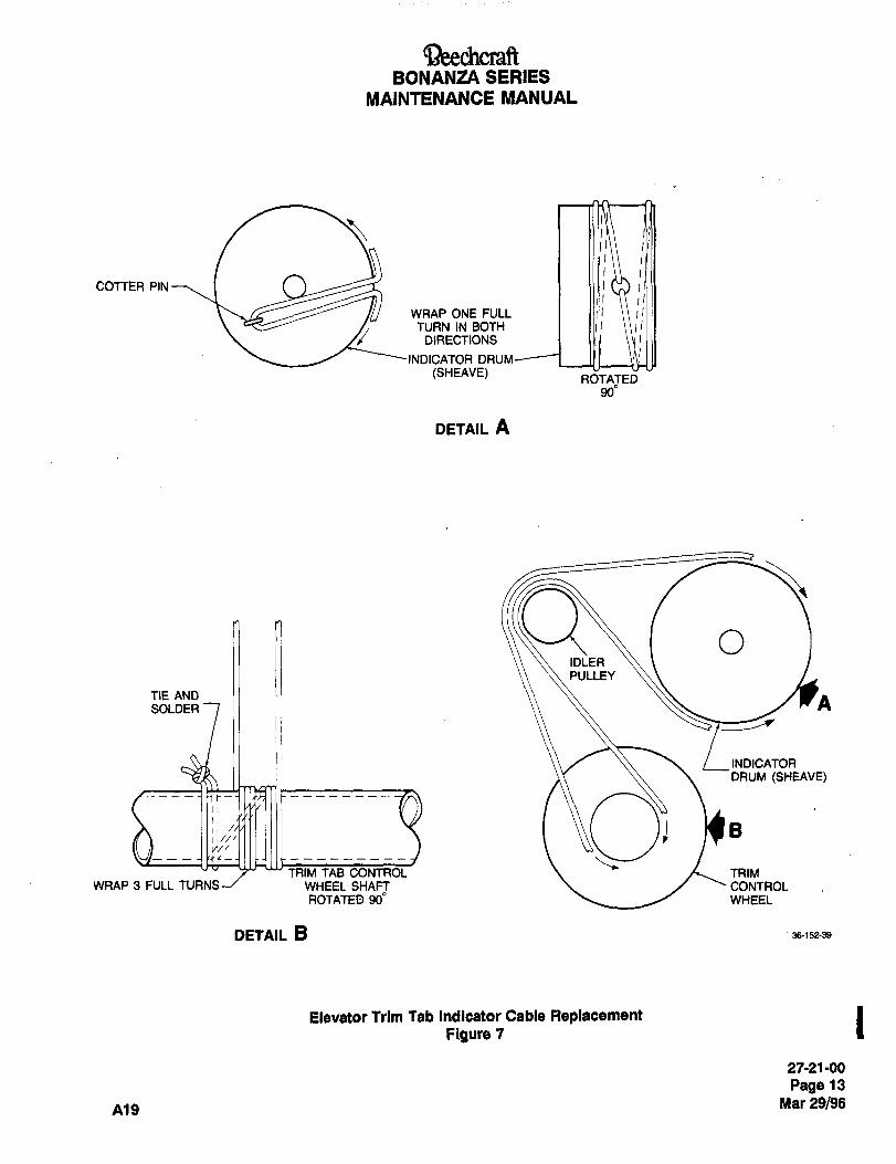
BeechcraftBONANZA SERIES
MAINTENANCE MANUAL
COTTER PIN
WRAP ONE FULL 1 11111TURN IN BOTH 1 1111,
DIRECTIONS
INDICATOR DRUM
(SHEAVE) ROVTATEDU900
DETAIL A
TIEANDIDLER
OPULLEY
SOLDER A
INDICATOR
DRUM ~SHEAVE)
B
r-
II///W/
----~yylL--
TRIM TAB CONTROL TRIMWRAP 3 FULL TURNS--/ WHEEL SHAFT CONTROL
ROTATED 900 WHEEL
DETAIL B .36-152-39
Elevator Trim Tab Indicator Cable ReplacementFigure 7
27-21-00
Page 13
A19 Mar 29/96
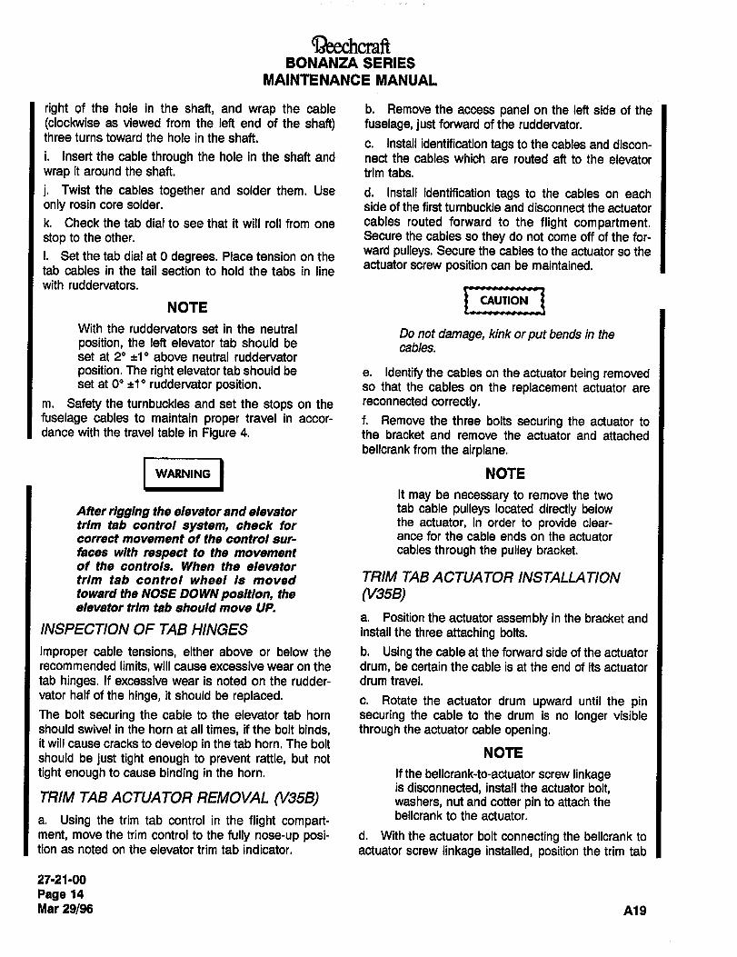
BONANZA SERIES
MAINTENANCE MANUAL
right of the hole in the shaft, and wrap the cable b. Remove the access panel on the left side of the
(clockwise as viewed from the left end of the shaft) fuselage, just forward of the ruddervator.three turns toward the hole in the shaft.
c. Install identification tags to the cables and discon-i. Insert the cable through the hole in the shaft and nect the cables which are routed aft to the elevatorwrap it around the shaft. trim tabs.
j. Twist the cables together and solder them. Use d. Install identification tags to the cables on eachonly rosin core solder. side of the first turnbuckle and disconnect the actuator
k. Check the tab dial to see that it will roll from one cables routed forward to the flight compartment.stop to the other. Secure the cables so they do not come off of the for-
i. Set the tab dial at O degrees. Place tension on theward pulleys. Secure the cables to the actuator so the
tab cables in the tail section to hold the tabs in lineactuator screw position can be maintained.
with ruddervators.
NOTE r~CAUTION
With the ruddervators set in the neutral Do not damage, kink orput bends in theposition, the left elevator tab should be cables.set at 2" ~1" above neutral ruddervator
position. The right elevator tab should be e. Identify the cables on the actuator being removedset at 0" ~10 ruddervator position. so that the cables on the replacement actuator are
m. Safety the turnbuckles and set the stops on the reconnected correctly.fuselage cables to maintain proper travel in accor- f. Remove the three bolts securing the actuator todance with the travel table in Figure 4. the bracket and remove the actuator and attached
bellcrank from the airplane.
I --,´•´•I NOTE~ING
It may be necessary to remove the two
After rigging the elevator and elevator tab cable pulleys located directly below
trim tab control system, check for the actuator, in order to provide clear-
correct movement of the control sur- ance for the cable ends on the actuator
faces with respect to the movement cables through the pulley bracket.
of the controls. When the elevatortrim tab control wheel Is moved TRIM TAB ACTUATOR INSTALLATIONtoward the NOSE DOWN position, the (V35B)elevator trim tab should move UP.
a. Position the actuator assembly in the bracket andINSPECTION OF TAB HINGES install the three attaching bolts.
Improper cable tensions, either above or below the b. Using the cable at the forward side of the actuatorrecommended limits, will cause excessive wear on the drum, be certain the cable is at the end of its actuator
tab hinges. If excessive wear is noted on the rudder- drum travel.
vator half of the hinge, it should be replaced. c. Rotate the actuator drum upward until the pinThe bolt securing the cable to the elevator tab horn securing the cable to the drum is no longer visibleshould swivel in the horn at all times, if the bolt binds, through the actuator cable opening.it will cause cracks to develop in the tab horn. The bolt
NOTEshould be just tight enough to prevent rattle, but not
tight enough to cause binding in the horn. If the bellcrank-to-actuator screw linkageis disconnected, install the actuator bolt,
TRIM TAB ACTUATOR REMOVAL (V35B) washers, nut and cotter pin to attach the
a. Using the trim tab control in the flight compart-bellcrank to the actuator.
ment, move the trim control to the fully nose-up posi- d. With the actuator bolt connecting the bellcrank to
tion as noted on the elevator trim tab indicator. actuator screw linkage installed, position the trim tab
27-21-00
Page 14
Mar 29/96 A19
~eechcraftBONANZA SERIES
MAINTENANCE MANUAL
actuator screw by rotating the actuator drum to obtain h. The elevator trim tab indicator on the pilot’s instru-
the actuator bolt-centerline-to-actuator-face distance ment panel should indicate the fully nose-up positionof.38 to .50 as shown in Figure 6. in degrees as noted in Figure 4.
e. Connect the actuator cables to the cables routed
aft from the flight compartment. CAUTION
f. If the two tab cable pulleys, located directly below
the actuators, were removed to provide clearance for Be certain that all cables are hooked upthe ends of the actuator cable, install the two pulleys correctly. Operate the elevator systemat this time. through the full travel to ensure com-
plete and proper degrees of travel of the
clwnohlttrim tabs. Check for proper direction of
travel. For a nose-up condition on the
airplane, the trim tab should move down.
Do not damage, kink or put bends in the For a full nose-down condition, the trim
cables. tab should move up.
g. Connect the bellcrank cables routed aft to the i. Install the access panel on the left side of the fuse-
elevator trim tabs, lage, just forward of the ruddervator.
27-21-00
Page 15
A19 Mar 29/96
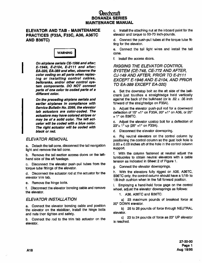
c~T)eechcraftBONANZA SERIES
MAINTENANCE MANUAL
ELEVATOR AND TAB MAINTENANCE c. Install the attaching nut at the inboard point for the
PRACTICES (F33A, F33C, A36, A36TC elevator and torque to 50-70 inch-pounds.
AND B38TC) d. Connect the push-pull tubes at the torque tube fit-
ting for the elevator.
I -´•I´•´•Ie. Connect the tail light wires and install the tail
WARNING cone.
f. Install the access doors.
On airplane serials CE-I566 and after;8-1946, 8-2104, 8-2111 and after; R/GGING THE ELEVATOR CONTROL
EA-320, 84-389 and after, observe the SYSTEM (CE-748, CE-772 AND AFTER,color coding on all parts when replac- CJ-149 AND AFTER, PRIOR TO E-21 I Iing or Installing control cables, EXCEPT E-1946 AND E-2104, AND PRIORbellcranks, and/or other control sys-tem components. DO NOT connect TO EA-389 EXCEPT EA-320)parts of one color to coded parts of a
a. Set the downstop bolt so the aft side of the bell-different color. crank just touches a straightedge held verticallyOn the preceding airplane serials and against the back of the bulkhead (or is .62 .05 inch
earlier airplanes in compliance with forward of the straightedge on F33A).Service Bulletin No. 2399, the elevator b. Adjust the elevator push-pull rod for a downwardtab actuators are color-coded. The deflection of 15" on F33A, 20" ~tl" on A36, or 25"actuators may have colored stripes or
~t 1" on B36TC.
may be of a solid color. The left act-
uator will be ooded with a blue color. c. Adjust the elevator upstep bolt for a deflection of
The right actuator will be coded with23"~10 up (25" ~10 on F33A).
black or red. d. Disconnect the elevator downspring.
e. Rig neutral elevators on the control column byELEVATOR REMOVAL positioning the control column so the gust lock hole is
a. Detach the tail cone, disconnect the tail navigation 2.00 ~t 0.03 inches aft of the hole in the control column
light and remove the tail cone. support.
b. Remove the tail section access doors on the left- f. With the column fastened at neutral adjust the
turnbuckles to obtain neutral elevators with a cablehand side of the aft fuselage.
tension as indicated in Sheet 2 of Figure 1.c. Disconnect the elevator push-pull tubes from the
torque tube fittings of the elevator. g. Connectthe elevatordownsprings.
d. Disconnect the actuator rod at the actuator for the h´• With the elevators fully rigged on A36, A36TC,
elevator trim tab.B36TC only, the control column should have a 1/16- to
1/8-inch cushion when in the full forward position.e. Removethe hingebolts.
i. Employing a hand-held force gage on the controlf. Disconnect the elevator bonding cable and remove wheel, adjust the elevator downsprings as follows:the elevator.
1. A36, A36TC and B36TC:
ELEVATOR INSTALLATION a) 23 maximum pounds of breakout force at
20" DOWN elevator.a. Connect the elevator bonding cable and positionthe elevator on the stabilizer, install the hinge bolts b) 25 to 26 pounds of force through NEUTRAL
and nuts then tighten and safety. elevator.
b. Connect the rod to the trim tab actuator on the c) 23 to 24 pounds of force as 23" UP elevator
is reached.elevator.
2790-00
Page 1
A18 Aug 18/95
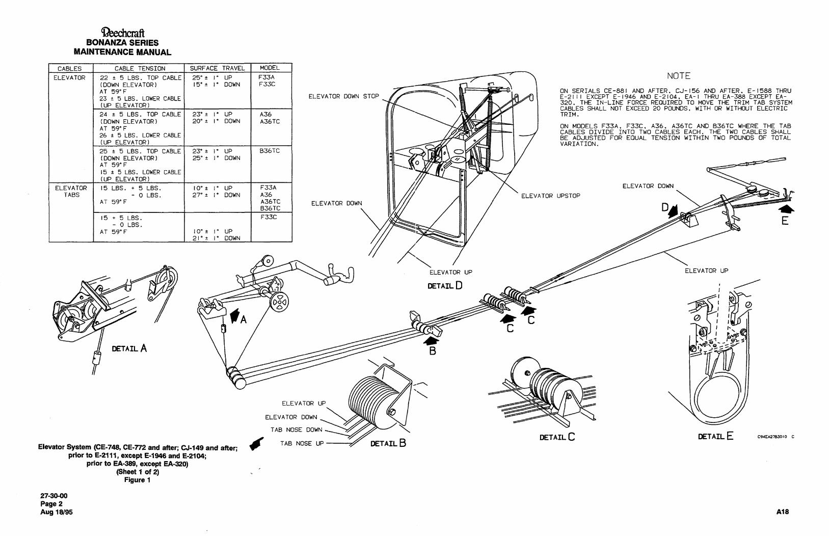
4aeechcraftBONANZA SERIES
MAINTENANCE MANUAL
CABLES CABLE TENSION SURFACE TRAVEL MODEL
ELEVATOR 22 5 LBS. TOP CABLE 25"~ 1" UP F33A I NOTE(DOWN ELEVATOR) 15’f 1" DOWN F33C I
AT 59"F I I I I ON SERIALS CE-881 AND AFTER. CJ-156 AND AFTER. E-1588 THRU
23 t 5 LBS. LOWER CABLE ELEVATOR DOWN STOP E-2111 EXCEPT E-1946 AND E-2104. EA-I THRU EA-388 EXCEPT EA-
(UP ELEVATOR)320. r~ IN-LINE FORCE REOUIRED TO MOYE THE TRIM TAB SYSTEMCABLES SHALL NOT EXCEED 20 POUNDS. WITH OR WITHOUT ELECTRIC
24 5 LBS. TOP CABLE 23’~ 1’ UP A36 I IIII I I TRIM.
(DOWN ELEVATOR) 20’+ 1’ DOWN A36TC
AT 59"F ON MODELS F33A. F33C, A36. A36TC AND B36TC WHERE THE TABCABLES DIVIDE INTO TWO CABLES EACH. THE TWO CABLES SHALL
26 5 LBS. LOWER CABLEBE ADJUSTED FOR EOUAL TENSION WITHIN TWO POUNDS OF TOTAL
(UP ELEVATOR) VARIATION.C,
25 5 LBS. TOP CABLE 23’~ 1" UP B36TC o\ o(DOWN ELEVATOR) 25"~ 1’ DOWN I 1 1131AT 59"F I I MO15 5 LBS. LOWER CABLE
(UP ELEVATOR)
ELEVATOR 15 LBS. 5 LBS. 10"~ 1’ UP I F33A I II II IIIY ELEVATOR DOWN
TABS O LBS. 27"~ 1’ DOWN A36 1 1111 A II ELEVATOR UPSTOPAT 59’F A36TC ELEVATOR DOWN
B36TC
15 5 LBS. F33C EO LBS.
AT 59"F 10"+ 1" UP
21’~ 1" DOWN
ELEVATOR UP ELEVATOR UP
r~ uv~-- DETAIL D
O
C
e oDoO 5YS 8
fAC
MTIAILA B c\SC
7 a
?1ELEVATOR UP
ELEVATOR DOWN
TAB NOSE DOWN
DETAIL C DETAIL E C9aE~783010 C
Elevator System (CE-748, CE-m and after; ~149 and atter:TAB NOSE UP DETAIL E3
prior to E-2111, except E-1948 and E-2104;prior to EA-389, except EA-320)
(Sheet 1 of 2)Figure 1
27-30´•00
Page 2
Aug 18/95 A18
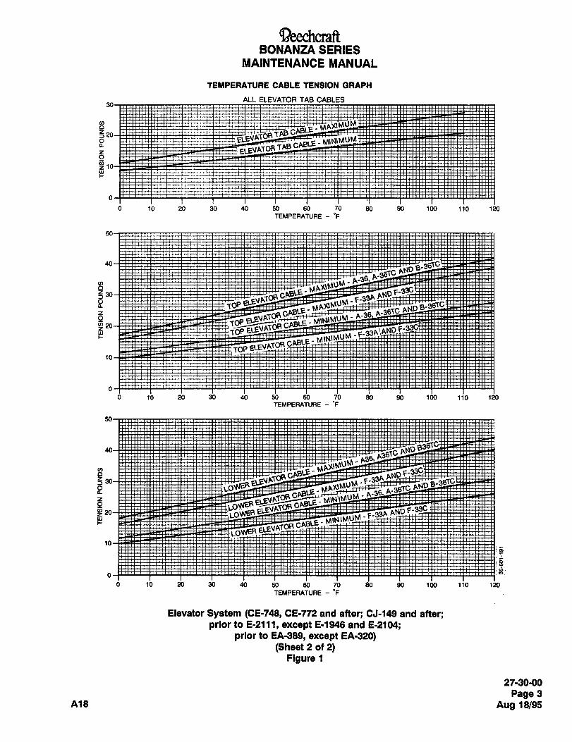
aeechcraftBONANZA SERIES
MAINTENANCE MANUAL
TE#PERATURE CABLE TENSION GRAPH
ALL ELEVATOR TAB CABLES
3
f 10
0 10 20 30 40 50 60 70 80 90 100 110 120
TEMPERATURE "F
40
I~
i TOP’ELE~P
0 10 00 30 40 50 60 70 80 90 100 110 1X)
TEMPERATURE- "F
B ANS!i
;;6~*B ~E; MU~
4~e r´•AL)LS_
~WER.
16
0 10 20 30 40 50 60 70 80 90 100 110 120
TEMPERATURE- ’F
Elevator System (CE-748, CE-772 and after; CJ-149 and after;prior to E-2111, except E-1948 and E-2104;
prior to EA-389, except EA-320)(Sheet 2 of 2)
Figure 1
27-30-00
Page 3
A18 Aug 18/95
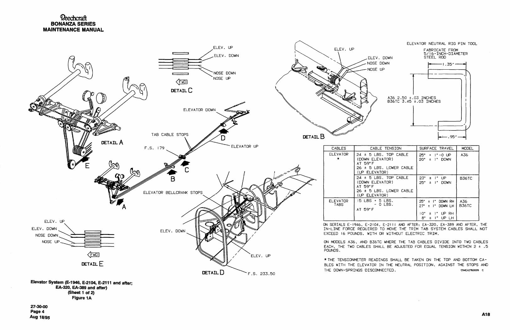
Beechc~ftBONANZA SERIES
MAINTENANCE MANUAL
ELEVATOR NEUTRAL RIG PIN TOOLELEV. UP
ELEV. UP FABRICATE FROMz c 5/)6-INCH-DIAMETER
ELEV. DOWNELEV. DOWN STEEL ROD
\‘NOSE DOWN
NOSE DOWN1
’.35"I NOSE UP
NOSE UP
DETAIL CA36 2.50 t.03 INCHESB36TC 3.45 +.03 INCHES
ELEVATOR DOWN L~47
~TnILBTAB CABLE STOPS
DETAIL AF.s. ELEVATOR UP
179 CABLES I CABLE TENSION SURFACE TRAVEL MODEL
ELEVATOR 24 5 LBS. TOP CABLE 25’ I"-0 UP A36
(DOWN ELEVATOR) 20" i I" DOWN
OP~ EAT 59"F
26 L 5 LBS. LOWER CABLE
I (UP ELEVATOR)
ELEVATOR BELLCRANK STOPS
B 24 5 LBS. TOP CABLE 23’ I’ UP B36TC
(DOWNELEVATOR) 25" +I"DOWN
AT 59"F
26 5 LBS. LOWER CABLE
(UP ELEVATOR)
ELEVATOR 15 LBS 5 LBS. 25’ t I’ DOWN RH A36
ATABS o LBS.
27’ i I’ DOWN LH B36TCAT 59"F
10" ´•e 10 UP RH
8" I" UP LHELEV. UP
ON SERIALS E-1946. E-2104. E-2111 AND AFTER: EA-320. EA-389 AND AFTER. THE
ELEV. DOWN IN-LINE FORCE REOUIRED TO MOVE THE TRIM TAB SYSTEM CABLES SHALL NOT
NOSE DOWN‘--"ELEV. DOWN
EXCEED 16 POUNDS. WITH OR WITHOUT ELECTRIC TRIM.7
NOSE UP L--;.3 ON MODELS A36. AND B36TC WHERE THE TAB CABLES DIVIDE INTO TWO CABLES
EACH. THE TWO CABLES SHALL BE ADJUSTED FOR EOUAL TENSION WITHIN 2 .5
POUNDS.
1111 ELEV. UP
THE TENSIONMETER READINGS SHALL BE TAKEN ON THE TOP AND BOTTOM CA-
DETAIL E BLES WITH THE ELEVATOR IN THE NEUTRAL POSITION. AGAINST THE STOPS AND
DETAIL D THE GOWN-SPRINGS DISCONNECTED. C9aEn21BX)09
F.S. 233.50
Elevator System (8-1948, E-2104, E-2111 and after;EA-320, EA-389 and after)
(Sheet 1 of 2)Figure 1A
27-30-00
Page 4A18
Aug 18/95
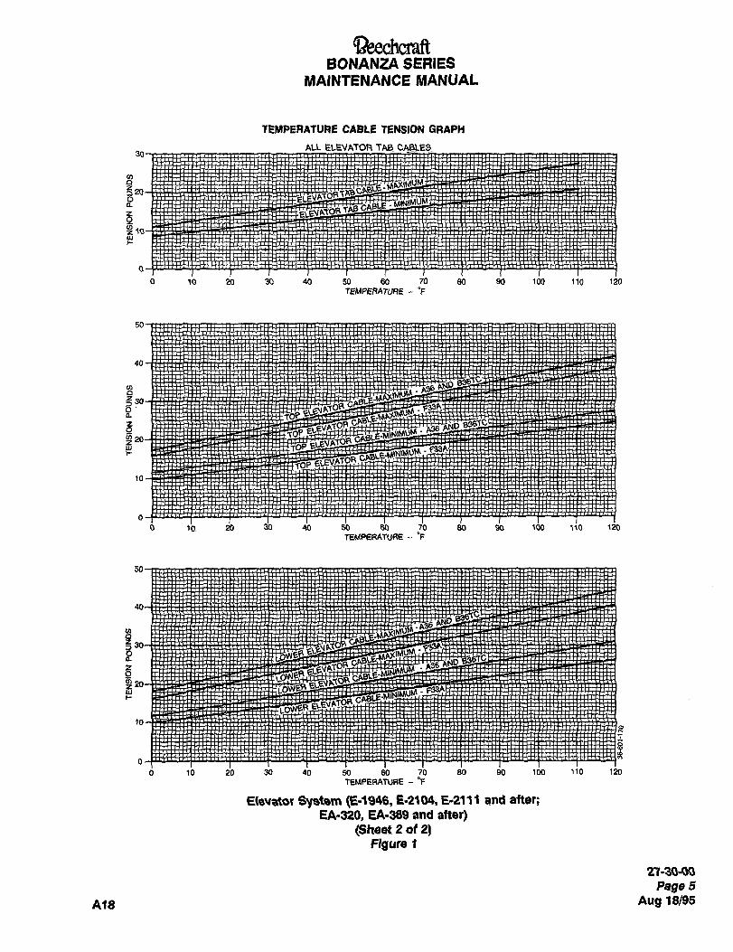
~aeechrraftBONANZA SERIES
MAINTENANCE MANUAL
TEMPERATURE CABLE TENSION GRAPH
AU ELEVATOFI TA8 CABLES
q20&ikiMUM
0 10 20 30 40 50 60 70 80 90 100 11O 120
TEMPERATURE- "F
40
8
o’’a TbrZ
0 10 20 30 40 50 60 70 80 90 100 110 190
TEMPERATURE-P
50
t~
0 10 20 30 40 50 60 70 80 90 100 110 120
TEMPERATUAE- ~F
E(e~ator System E´•2104, E-2111 and atter;
EA´•320, EA-389 and after)(Sheet 2 of 2)
Ngure 1
2’1-30-00
Page 5
A1B Aug 18/95
aeechcraftBONANZA SERIES
MAINTENANCE MANUAL
2. F33A and F33C: g. Remove the rig tool.
a) 17 to 18 pounds of force through NEUTRAL h. Connect the elevator downsprings.elevator.
i. With the elevators fully rigged (including autopilotb) 15 to 16 pounds of force as 25" fully UP and electric trim if installed), the force required to pull
elevator is reached. the control wheelaft through neutral must be 25 to 29
j. The gage reading at NEUTRAL elevator and 23" POU"dS. The force required to return the wheel
(A36, A36TC, and B36TC) or 25" (F33A, F33C) UP through neutral shall be 20 to 24 pounds. The differ-
elevator (.06 inch off fully upstep) must be taken while ence (friction of the system) between the two readingsthe control wheel is in motion. shall never exceed 9 pounds (7 pounds is desired) nor
be less than 4 pounds.k. Adjust each spring by transferring the upper end
to a spring-attaching hole providing increased or j´• Maintain a minimum clearance of .06 inch between
decreased tension, as applicable. The elevator sys- the control wheel adapter and the inner control column
tem should have sufficient freedom to allow free return guide assembly (both the pilot’s and copilot’s) at fullyof the elevator from fully UP to fully DOWN. down elevator on the A36 and B36TC.
NOTE NOTE
After rigging the elevator and elevator After rigging the elevator and trim tab
trim tab control system, check for correct system, check for correct movement of
movement of the control surfaces with the control surfaces with respect to the
respect to the movement of the controls. movement of the controls. When the trimtab control wheel is moved toward the
RIGGING THE ELEVATOR CONTROL NOSE DOWN position, the trim tab
SYSTEM (E-1946, E-2104, E-2111 AND should move UP.
AFTER, EA-320, EA-389 AND AI-ltH)ELEVATOR TAB INDICATOR CABLE
a. Set the downstop bolt so that the center of the REPLACEMENT (CE-748, CE-772 ANDhole in the bellcrank is .38 inch .05 inch forward of a AFTER, CJ-149 AND AFTER, PR/OR TOstraightedge held against the back of the bulkhead at
F.S. 257.606.E-2111 EXCEPT E-1946, AND E-2104,PRIOR TO EA-389 EXCEPT EA-320)
b. Adjust the elevator push-pull rod for an elevator
deflection of 20" ~tl" down ton B36TC 25" ~1"). a. Place the proper tension on the trim cables in
c. Adjust the elevator upstep bolt for a deflection of neutral position.25" +1" -00 on A36 and 23" ~10 up on B36TC. b. To install the dial indicator cable, thread the cable
d. Disconnect the elevator downsprings. through the hole in the head of the cotter pin and out
through the holes in the indicator drum.e. Rig neutral elevators on the control column bypositioning the pilot’s control column so the gust lock c. With the dial at 0 degrees, slip the cable so that
hole is 2.50 1.03 ton B36TC 3.45 ~.03) inches aft of both ends of the cable are equal length.the hole in the control column support and install rig d. Wrap the cable around the drum one full turn intool (Sheet 1 of Figure 1A). each direction. The end that wraps to the right will be
NOTE wrapped clockwise around the drum, and the end that
wraps to the left will be wrapped counterclockwise, asThe short end of the tool is inserted into
viewed from the left side.the control column support and the longend is inserted into the control column, e. Route the cable over the appropriate idler pulleyThe weight of the control column will down to the shaft of the tab control wheel.
hold the tool in place, f. With the dial still in O degrees position, take thef. Adjust the turnbuckles to obtain neutral elevators cable coming off the top of the elevator tab dialwith a cable tension as indicated in Sheet 2 of Figure sheave and bring it down to the forward side of the tab
1A. wheel shaft to the left of the small hole.
27-30´•00
Page 6
Aug 18/95 A18
aeec~craftBONANZA SERIES
MAINTENANCE MANUAL
g. Wrap the cable (counterclockwise) around the c. Remove the upholstery panel from the back of the
shaft toward the hole three turns. Insert the cable baggage area.
through the hole. Wrap the surplus cable around the d~ After identifying and tagging the cables for rein-shaft. stallation, disconnect the forward trim tab cables at the
h. With the dial set at 0 degrees, take the cable com- turnbuckles in the aft fuselage.ing off the bottom of the trim tab dial sheave and bring e. Tie nylon strings to each of the cable ends. Use ait down to the aft side of the tab wheel shaft to the small knot.right of the hole in the shaft, and wrap the cable
f. Remove the access panel (actuator door) which is(clockwise as viewed from the left end of the shaft)three turns toward the hole in the shaft.
located under the pulleys below the pedestal.
g. Removb the panel on the left side of the pedestal.i. Insert the cable through the hole in the shaft and
wrap it around the shaft, h. Remove the autopilot panel (if installed) below the
engine and propeller controls.j. Twist the cables together and solder them. Use
only rosin core solder. NOTE
k. Check the tab dial to see that it will roll from one Station a man in the aft fuselage to keepstop to the other. a small amount of tension on the strings
i. Set the tab dial at O degrees. Place tension on the as they are pulled through the fuselage.
tab cables in the tail section to hold the tabs in line i. Place the elevator tab control in neutral and mark
with the elevators. the neutral position on the sprocket and chain.
NOTE j. Count the number of chain links on each side of
the mark and note the number for later reference.With the elevators set in the neutral
k. Pull the cables and strings from the fuselage outposition, the left elevator tab should be
set at 2" +1" above neutral elevator posi- through the pedestal.tion. The right elevator tab should be set NOTEat O" +1" elevator position.
Note which color (blue and black) goesm. Safety the turnbuckles and set the stops on the over the top, forward side of thefuselage cables to maintain proper travel in accor- sprocket.dance with the travel table.
i. Tie the new cable to the strings.NOTE
NOTEAfter rigging the elevator and elevator
The shorter (color coded blue) cabletrim tab control system, check for correct
movement of the control surfaces with goes over the top forward side of the
sprocket.respect to the movement of the controls.
When the elevator trim tab control wheel m. Pull the strings and cables back through the fuse-
is moved toward the NOSE DOWN posi- lage.tion, the elevator trim tab should move
UP. NOTE
Make sure that the trim tab cables do not
ELEVATOR JRIM TAB FORWARD CABLE interfere with the engine and propellerREPLACEMENT (E- 1943 E-2104, E-2111 controls located adjacent to them.
AND Ar-rtn, EA-320, EA-339 AND AFI;ER) n. Check the pulleys below the pedestal to deter-
mine that the cables are properly installed.a. Remove the fifth and sixth seats (if installed) as
shown in FIFTH AND SIXTH SEAT REMOVAL in O´• Make certain that the correct number of chain
Chapter 25-00-00. links are on each side of the mark on the sprocket.
b. Remove the screws from the baggage area floor P. Co""ect the turnbuckles in the aft fuselage.
and remove the floor. q. Tension the cables per Sheet 2 of Figure 1A.
27-30-00
Page 6A
A~8 Aug 10195
aeechcraftBONANZA SERIES
MAINTENANCE MANUAL
r. Check for proper elevator tab travel. 2. The normal total difference between the tab
s. Set the tab travel as indicated in Sheet 1 of Figure Surfaces is to be 2"+ .5" for all positions.
1A. 3. Set the cable stops to provide 8" +1" up on LH
t. Installtheaft upholstery panel. tab and 10" ~tl" up on RH tab, and 27" ~1" down on
LH tab and 25" +1" down on RH tab as indicated inu. Install the baggage floor panel. Sheet 1 of Figure 1A.
v. Install the back seats. See FIFTH AND SIXTH 4. The cockpit indicator is to read 9" ~2" up andSEAT INSTALLATION in Chapter 25-00-00. 26" ~2" down.
w. Install the access panel (actuator door) below the d~ Adjust the stops on the cables to allow surfacepedestal. travel as shown in Sheet 1 of Figure 1 except on air-
x. Install the access panel(s) on the pedestal. 2rb, planes with the serials listed in the preceding note.
e. Torque the stop bolts to 40 to 60 inch-pounds.
I w~., I NOTEWARNING
After rigging the elevator and elevator
Make certain that Insulation, tie tab control system, check for correct
wraps,etc. do not Interfere with con- movement of the control surfaces with
trol components such as cables, respect to the movement of the controls.
chains, etc. When the elevator tab control is moved
toward the "NOSE DOWN" position, the
tab should move up.
After rigging the elevator and elevatorELEVATOR TRIM TAB ACTUATOR
tab control system, check for correct
movement of the control surfacesELEVATOR TRIM TAB ACTUATOR
with respect to the movement of the
controls. When the elevator tab con-DISASSEMBLY (F33A, B36TC, A36TC AND A36,
trol Is moved toward the "NOSEEXCEPT E-llll, F33C PRIOR TO CJ-156 EXCEPT
DOWN’ position, the tab should moveTHOSE AIRPLANES WITH KIT 334002-1
up. INSTALLED)(Figure 2)
RIGGING THE ELEVATOR TRIM TABa. Remove the snap ring (6) from the actuator hous-
a. Place the elevator tab indicator in the neutral posi- ing and pull the nut assembly (10) out of the housing.I tion. b. Remove the actuator screw (9) from the nut
b. Rig the cables to the tension shown on the eleva- assembly.tor temperature cable tension graph in Sheet 2 of Fig-ure 1 or 1A, as applicable. CAUIION
c. Place the elevator in neutral position and adjustthe trim tab pushrod to bring the tab into the neutral Do not damage the rod end when drillingposition. out rivets.
NOTEc. Remove nut (2), washer (3) and shoulder pin (5)To improve elevator centering, the LHthen drill out rivet (1). Remove actuator rod end (4)and RH trim tabs are rigged to a different
setting in the neutral position on serials from the screw. The bearing (7) and the bushing (8)can now be removed from the screw.E-1946, E-2104, E-2111 and after,
EA-320 and EA-389 and after. Rig these d. Remove check nut (15) and screw out the end
airplanes per steps 1 through 4. adjusting bushing (14) with appropriate spanner
1. Rig neutral tab surfaces with LH down 1" .5" w’e"ch.
and RH up 1" .5" with indicator at O". e. RemovetheO-ring (13).
27-30´•00
Page 66
Aug 18/95 A18
aeedacraftBONANZA SERIES
MAINTENANCE MANUAL
f. Remove the bearing (12) from the housing (11). deterioration. Lubricate all parts with MIL-G-23827
grease (11, Chart 1, 91-00-00) prior to assembly.ELEVATOR TRIM TAB ACTUATOR ASSEMBLY
(f33A, B36TC, A36TC AND A36, U<CEPT E-llll,F33C PRIOR TO CJ-156, U(CEPT THOSE
AIRPLANES WITH KIT 33-4002-1 INSTALLED
(Flgure 2)
Clean all parts in PD680 solvent (16, Chart 1, 91-00-
00) and inspect for cracks, corrosion, and distortion.
Replace bushings and any parts showing evidence of
27-30´•00
Page 6C
A18 Aug 18/95
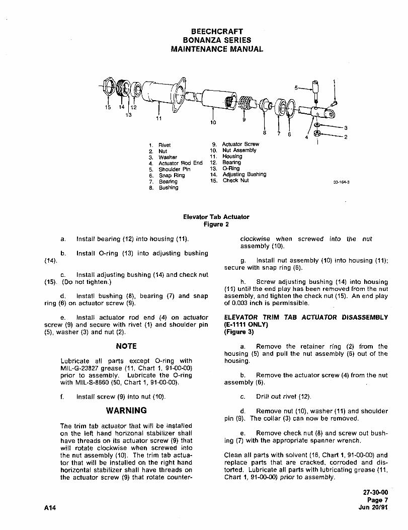
BEECHCRAFT
BONANZA SERIES
MAINTENANCE MANUAL
:-B i15 14 12
1311 8
1. Rivet 9. ActuatorScrew
2. Nut 10. NutAssembly3. Washer 11. Housing4. Actuator Rod End 12. Bearing5. Shoulder Pin 13. O-Ring6. SnapRing 14. Adjusting Bushing
7. Bearing 15. CheckNut 33-164-3
8. Bushing
Elevator Tab Actuator
Figure 2
a. Install bearing (12) into housing (11). clockwise when screwed into the nut
assembly (10).b. Install O-ring (13) into adjusting bushing
~14). g. Install nut assembly (10) into housing (11);secure with snap ring (6).
c. Install adjusting bushing (14) and check nut
(15). (00 not tighten.) h. Screw adjusting bushing (14) into housing(11) until the end play has been removed from the nut
d. Install bushing (8), bearing (7) and snap assembly, and tighten the check nut(l5). An end playring (6) on actuator screw (9). of 0.003 inch is permissible.
e. Install actuator rod end (4) on actuator ELEVATOR TRIM TAB ACTUATOR DISASSEMBLY
screw (9) and secure with rivet (1) and shoulder pin (E-llll ONLY)(5), washer (3) and nut (2). (Figure 3)
NOTE a. Remove the retainer ring (2) from the
housing (5) and pull the nut assembly (6) out of the
Lubricate all parts except O-ring with housing.MlL-G-23827 grease (11, Chart 1, 91-00-00)prior to assembly. Lubricate the O-ring b. Remove the actuator screw (4) from the nut
with MIL-S-8660 (50, Chart 1, 91-00-00). assembly (6).
f. Install screw (9) into nut (10). c. Drill out rivet (12).
WARNING d. Remove nut (10), washer (11) and shoulder
pin (9). The collar (3) can now be removed.
The trim tab actuator that will be installed
on the left hand horizonal stabilizer shall e. Remove check nut (8) and screw out bush-
have threads on its actuator screw (9) that ing (7) with the appropriate spanner wrench.
will rotate clockwise when screwed into
the nut assembly (10). The trim tab actua- Clean all parts with solvent (16, Chart 1, 91-00-00) and
tor that will be installed on the right hand replace parts that are cracked, corroded and dis-
horizontal stabilizer shall have threads on torted. Lubricate all parts with lubricating grease (11,the actuator screw (9) that rotate counter- Chart 1, 91-00-00) prior to assembly.
27-30-00
Page 7
A14 Jun 20/91
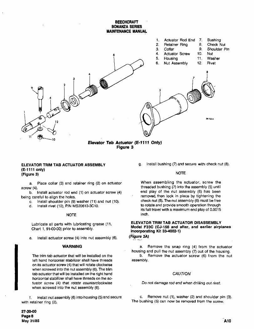
BEECHCRAFTBONANZA SERIES
MAINTENANCE MANUAL
1. Actuator Rod End 7. Bushing2. Retainer Ring 8. Check Nut
3. Collar 9. Shoulder Pin
4. Actuator Screw 10. Nut
5. Housing 11. Washer
6. Nut Assembly 12. Rivet
5
3 7
1~ 36153´•8
II’
Elevator Tab Actuator Only)Figure 3
ELEVATOR TRIM TAB ACTUATOR ASSEMBLY g. Install bushing (7) and secure withl check nut (8).
(E-llll only)(Figure 3) NOTE
a. Place collar (3) and retainer ring (2) on actuator When assembling the actuator, screw the
screw (4). threaded bushing (7) into the assembly (5) until
b. Install actuator rod end (1) on actuator screw (4) end play of the nut assembly (6) has been
being careful to align the holes. removed, then lock in place by tightening the
c. Install shoulder pin (9) washer (11) and nut (10). check nut (8). The nut assembly (6) must be free
d. Install rivet (12), P/N MS20613-3C10. to rotate and provide smooth operation throughits full travel with a maximum end play of 0.0015
NOTE inch.
Lubricate all parts with lubricating grease (11, ELEVATOR TRIM TAB ACTUATOR DISASSEMBLV
Chart 1, 91-00-00) prior to assembly.Model F33C (CJ-156 and after, and earlier airplanesincorporating Kit 33-4002-1)
e. Install actuator screw (4) into nut assembly (6). (Figure~3A)
WARNING a. Remove the snap ring (4) from the actuator
housing and pull the nut assembly (7) out of the housing.The trim tab actuator that will be installed on the b. Remove the actuator screw (6) from the nut
left hand horizontal stabilizer shall have threads assembly.on its actuator screw (4) that will rotate clockwise
when screwed into the nut assembly (6). The trim
tab actuator that will be installed on the right hand CAUTION
horizontal stabilizer shall have threads on the ac-
tuator screw (4) that rotate counterclockwise Do not damage rod end when drilling out rivet.
when screwed into the nut assembly (6).
f. Install nut assembly (6) into housing (5) and secure c. Remove nut (1), washer (2) and shoulder pin (3).with retainer ring (2). The bushing (5) can now be removed from the screw.
27-3090
PageBMay 31/85 A10
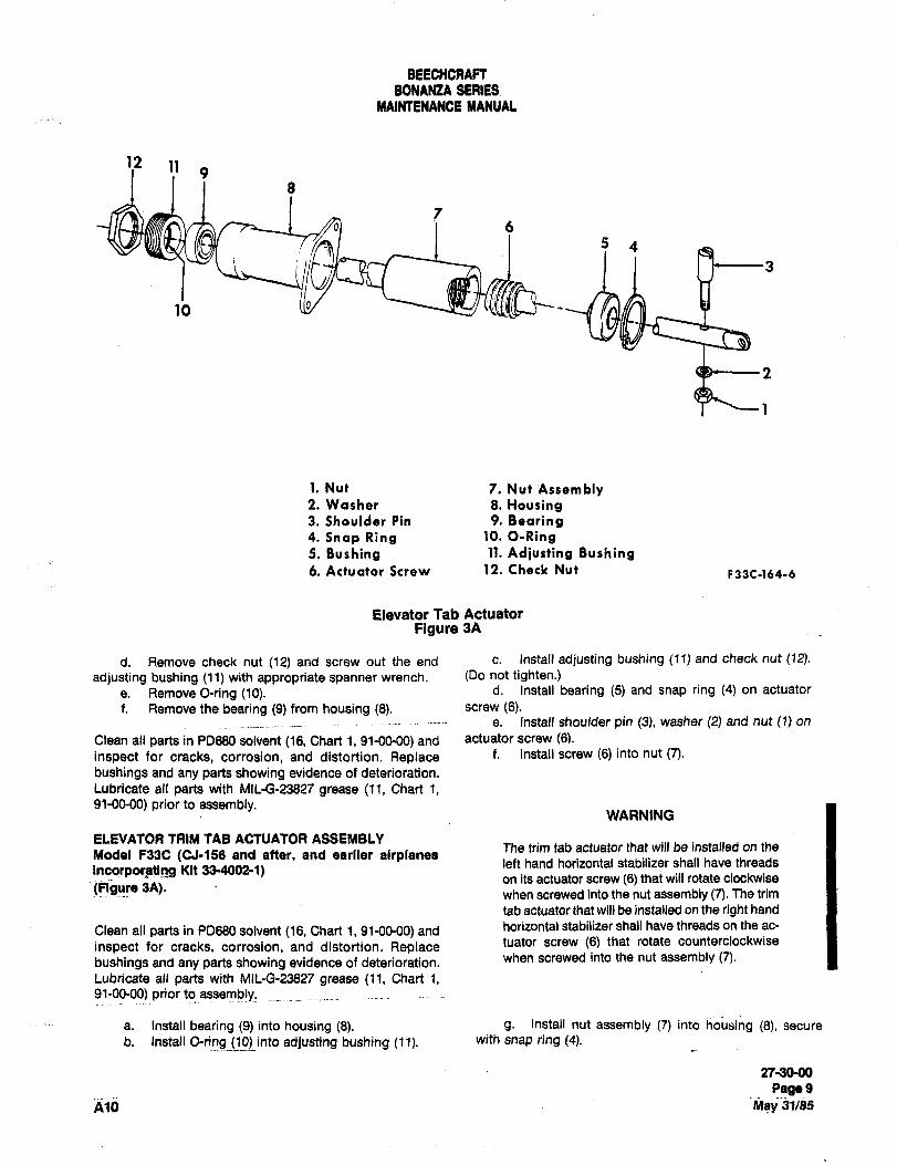
BEECHCRAFTBONANZA SERIES
MAINTENANOE UANUAL
112 1! 9
b) ’I b
4
10
1. Nut 7. Nut Assembly2. Washer 8, Housing3. Shoulder Pin 9, Bearing4. Snap Ring 10, O-Rng5. Bushing 11. Adjusting Bushing6. Actuator Screw 12, Check Nut F33C-164-6
Elevator Tab Actuator
Figure 3A
d. Remove check nut (12) and screw out the end c. Install adjusting bushing (11) and check nut (12).
adjusting bushing (11) with appropriate spanner wrench. (Do not tighten.)
e. Remove O-ring (10). d. Install bearing (5) and snap ring (4) on actuator
f. Remove the bearing (9) from housing 18). screw (6).e. Install shoulder pin (3), washer (2) and nut (1) on
Clean all parts in PD680 solvent (16, Chart 1, 91-00´•00) and actuator screw (61.
inspect for cracks, corrosion, and distortion. Replace f. Install screw (6) into nut (7).
bushings and any parts showing evidence of deterioration.
Lubricate all parts with Mll-G-23827 grease (If, Chart 1,91-00-00) prior to assembly.
WARNING
ELEVATOR TRIM TAB ACTUATOR ASSEMBLYThe trim tab actuator that will be installed on the
Model F33C (CJ´•156 and after, and earlier airplanesleft hand horizontal stabilizer shall have threads
incorporati~ng Kit 33´•4002-1)on its actuator screw (6) that will rotate clockwise
(Ftgure 3A).when screwed into the nut assembly (7). The trim
tab actuator that will be installed on the right hand
Clean all parts in PD680 solvent (16, Chart 1, 91-00-00) and horizontal stabilizer shall have threads on the ac-
inspect for cracks, corrosion, and distortion. Replace tuator screw (6) that rotate counterclockwise
bushings and any parts showing evidence of deterioration, when screwed into the nut assembly (7).
Lubricate all parts with MlL-G-23827 grease (11, Chart 1,91-00-00) prior to assembly.
a. Install bearing (9) into housing (8). g. Install nut assembly (7) into housing (8), secure
b. Install O-ring (10) into adjusting bushing (11). with snap ring (4).
27-3090
PagegA10 IMBy31/85
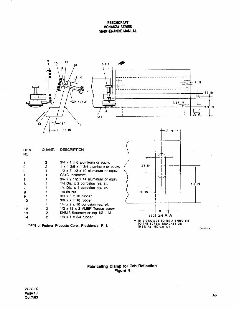
BEECHCRAFTBONANZA SERIES
~IIAINTENANCE MANUAL
9 12io
13 678
11I.8 IN
5
-t F~ .5 IN
:S
.25 IN
TAP5/8-ll TbllI _____TYPI 2.9 IN
4
I_A A~a ITAB
14
1.30 IN IN --e
ITEM QUANT. DESCRIPTION
NO.
1 2 3/4 x 1 x 6 aluminum or equiv.2 2 1 x 1 3/8 x 1 3/4 aluminum or equiv. .6811N3 1 1/2 x 7 1/2 x 10 aluminum or equiv.4 1 C81Q Indicator’* I\t5 1 3/4 x 2 1/2 x 14 aluminum or equiv.6 1 1/4 Dia. x 2 corrosion res. stl. II I II 1 1.61 IN
7 1 1/4 Dia. xl corrosion res. stl.
8 1 1/4-28 nut .311N
9 1 3/8 x 5 x 10 rubber
10 1 3/8 x 2 x 10 rubber
11 i 1/4 x 2 x 10 corrosion res. stl.
12 2 1/2 x 13 x 3 VLIER Torque screw C13 2 KN813 Keensert or tap 1/2 13
SECTION A A14 2 1/8 x 1 x 3/4 rubber
~e THIS GROOVE TO BE A SNUG FITTO THE SCREW BRACKET ON
*’P/N of Federal Products Corp., Providence, R. I. THE DIAL INDICATOR100-1)5-8
Fabricating Clamp for Tab Deflection
Figure 4
27-30-00
PagelO A6Oct 7/83
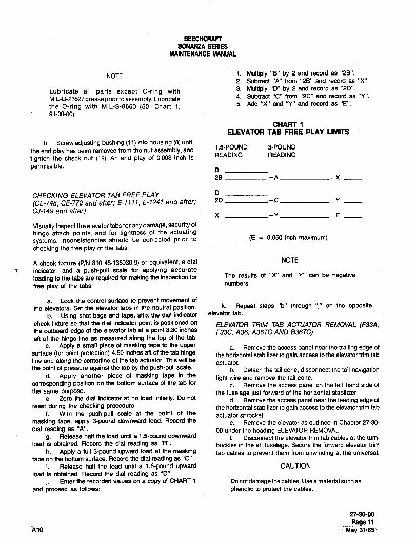
BEECHCRAFTBONANZA SERIES
MAINTENANCE MANUAL
NOTE 1. Multiply "B" by 2 and record as "28".
2. Subtract "A" from "28" and record as "X".
Lubricate all parts except O-ring with 3. Multiply "D" by 2 and record as "2D".
MI L-G-23827 g rease prior to assembly. Lubricate4. Subtract "C" from "20" and record as "Y".
the O-ring with MIL-S-8660 (50, Chart 1,5. Add "X" and "Y" and record as "E".
91-00-00).
CHART 1
ELEVATOR TAB FREE PLAY LIMITS
h. Screw adjusting bushing (11) into housing (8) until
the end play has been removed from the nut assembly, and 1.5-POUND 3-POUND
READING READINGtighten the check nut (12). An end play of 0.003 inch is
permissible.
28 -A =X
CHECKING ELEVATOR TAB FREE PLAY D
(CE-748, CE-772 and after; E-llll, E-1241 and after; 2D
CJ-149 and after)X +Y =E
Visually inspect the elevator tabs for any damage, secu rity of
hinge attach points, and for tightness of the actuating
systems. Inconsistencies should be corrected prior to (E 0.050 inch maximum)
checking the free play of the tabs.
A check fixture (P/N 810 45135030-9) or equivalent, a dial NOTE
indicator, and a push-pull scale for applying accurate
Ioading to the tabs are required for making the inspection for The results of "X" and "Y" can be negativenumbers.
free play of the tabs.
a. Lock the control surface to prevent movement of
the elevators. Set the elevator tabs in the neutral position. k. Repeat steps "b" through "j" on the opposite
b. Using shot bags and tape, affix the dial indicator elevator tab.
check fixture so that the dial indicator point is positioned on ELEVATOR TRIM TAB ACTUATOR REMOVAL (F33A,the outboard edge of the elevator tab at a point 3.30 inches F33C, A36, A36TC AND B36TC)aft of the hinge line as measured along the top of the tab.
c. Apply a small piece of masking tape to the upper a. Remove the access panel near the trailing edge ofsurface (for paint protection) 4.50 inches aft of the tab hinge the horizontal stabilizer to gain access to the elevator trim tabline and along the centerline of the tab actuator. This will be
actuatorthe point of pressure against the tab by the push-pull scale. b. Detach the tail cone, disconnect the tail navigation
d. Apply another piece of masking tape in thelight wire and remove the tail cone.
corresponding position on the bottom surface of the tab forc. Remove the access panel on the left hand side of
the same purpose. the fuselage just forward of the horizontal stabilizer.e. Zero the dial indicator at no load initially. Do not d. Remove the access panel near the leading edge of
reset during the checking procedure, the horizontal stabilizer to gain access to the elevator trim tabf. With the push-pull scale at the point of the
actuator sprocket.masking tape, apply 9pound downward load. Record the
e. Remove the elevator as outlined in Chapter 27-30-
dial reading as "A". 00 under the heading ELEVATOR REMOVAL.
g. Release half the load until a 1.5-pound downward f. Disconnect the elevator trim tab cables at the turn-
load is obtained. Record the dial reading as "8". buckles in the aft fuselage. Secure the forward elevator trimh. Apply a full 9pound upward load at the masking tab cables to prevent them from unwinding at the universal.
tape on the bottom surface. Record the dial reading as "C".
i. Release half the load until a i.£ upward CAUTION
load is obtained. Record the dial reading as "D".
j. Enter the recorded values on a copy of CHART 1 Do not damage the cables. Use a material such as
and proceed as follows: phenolic to protect the cables.
27-30-00
Page 11’A10 May 31/85’
BEECHCRAFT
BONANZA SERIES
MAINTENANCE MANUAL
g. Remove the chain and cable assembly g. Install the access panel located near the
from the elevator trim tab actuator sprocket. leading edge of the horizontal stabilizer.
h. Remove the hardware attaching the eleva- h. Install the access panel located near thetor trim tab actuator to the horizontal stabilizer. trailing edge of the horizontal stabilizer.Remove the actuator from the airplane.
i. Install the access panel on the left handELEVATOR TRIM TAB ACTUATOR INSTAL- side of the fuselage just forward of the horizontalLATION (F33A, F33C, A36, A36TC AND stabilizer.
sssrc)j. Connect the tail navigation light wire and
WARNING install the tail cone.
The elevator trim tab actuators must not ELEVATOR TRIM TAB ACTUATOR COLORbe interchanged between the right and left
CODING (F33A, F33C, A36, A36TC AND.horizontal stabilizers when they are rein-
B36TC)stalled after removal. Reversing the actu-
ators reverses the direction, and planenose-up trim would actually rescilt in an
On airplanes serials CE-1566 and after, CJ-180 and
inadvertent nose-down trim condition that after, E-2111 and after, and EA-389 and after, elevator
could result in an uncontrollable airplane trim tab actuators have been color coded LH blue and
attitude. Refer to ELEVATOR TRIM TAB RH black. Actuators may be inspected for proper
ACTUATOR COLOR CODING to reduce the installation by removing the actuator inspection hole
probability of unintentionally switching the cover and visually inspecting that the appropriateactuators upon installation. color coded actuator is installed (LH blue and RH
black).a. Position the elevator trim tab actuator in
the horizontal stabilizer and install the attaching On earlier airplanes, elevator trim tab actuators were
hardware. not color coded. Color coding of the elevator trim tab
actuators can be accomplished with the actuators
b. Position the chain and cable assembly on installed or before installation. This will reduce the
the actuator sprocket so that the ends of the chain probability of unintentionally switching the actuators.
are equidistant within +.20 inch at the sprocket cen- Use BEECHCRAFT Mandatory Service Bulletin No.
terline. 2399 for painting instructions on how to color code
elevator trim tab actuators.
c. Install the elevator as outlined under the
heading INSTALLATION OF THE ELEVATOR. WARNING
d. Connect the elevator trim tab cables to theDo not install a blue-coded actuator on a
turnbuckles in the ah fuselage. black-coded stabilizer or a black-coded
actuator on a blue-coded stabilizer.e. Remove material used to protect the
cables.ELECTRIC ELEVATOR TRIM (OPTIONAL)
f. Rig the elevator trim tab control system as
outlined under the heading RIGGING THE ELEVATOR The optional electric trim system offered on the
TRIM TAB. Bonanza airplanes allows the pilot to correct the
elevator trim without removing his hands from the
NOTE controlwheel. The switch requires 2 actions before
it will actuate the system: first depressed ~enable
After rigging the elevator and elevator trim switch), then moved forward (down-trim) or rearward
tab control system, check for correct (up-trim). On the control wheel left hand grip is a
movement of the control surfaces with quick-interrupt switch (placarded TRIM INTER) which
respect to the movement of the controls. opens the circuit to the servo and stops the action of
When the elevator trim tab control wheel the electric trim system. The PITCH TRIM OFF-ON
is moved toward the NOSE DOWN position, switch is located in the lower left corner of the float-
the elevator trim tab should move UP. ing instrument panel and the circuit breaker (plac-
27-30-00
Page 12
Jun 20/91 A14
BEECHCRAFT
BONANZA SERIES
MAINTENANCE MANUAL
arded TRIM) is located in the electroluminescent ELEC TRIC ELEVA TOR TRIM GROUNDcircuit breaker panel below the instrument panel. CHECKS (AIRPLANES WITHOUT AUTOPI-I
LOT)MODEL A36, A36TC, AND B36TC
a. After inspection of the electric trim instal-ELECTRIC ELEVATOR TRIM TAB SERVO lation for loose wires, obstructions safetied cables,REMOVAL etc., turn "ON" airplane master switch.
a. Gain access to the servo by removing the b. Turn ON the trim master switch andfifth and (if installed) sixth seat (refer to Chapter 25 engage the "TRIM" system circuit breaker.under FIFTH AND SIXTH SEAT REMOVAL AND
INSTALLATION) and the partition between the bag- c. Simultaneously press the enable switch
gage compartment and ah section of the airplane, and move pilot’s control wheel switch forward. Note
that the trim wheel moves toward "DOWN" trim posi-b. Unsafety the turnbuckle on the left trim tion.
cable and loosen the cable.
d. With pilot’s control wheel switch stillc. Remove the cable (make a note and dia-
engaged, grasp the manual trim wheel and check forgram of the cable routing for reinstallation) from the manual override capability; the clutch will slip.pulleys and capstan.
e. Simultaneously press the enable switchld. Remove the 4 bolts, nuts, and 8 washers
and move pilot’s control wheel switch rearward. Notewhich secure the servo to the brackets in the air-
that the trim wheel moves toward the "UP" trim posi-plane. tion.
e. Remove the servo ~note on which side off. With pilot’s control wheel switch still
the brackets the servo is mounted) from the airplane.engaged, grasp the trim wheel and check for manual
ELECTRIC ELEVATOR TRIM TAB SERVOOve"ide capability; the clutch will slip.
INSTALLATIONg. Press the enable switch only; trim system
must not run.a. Place the servo in position and install the
4 bolts, 8 washers, and 4 nuts (make certain the servo
is installed in the same position from which it wash. Move the trim switch fore and ah only; trim
removed). system must not run.
b. Install the cables on the servo. The left i. The control wheel mounting includes an I
(outboard) trim cable should be routed forward electric trim-interrupt switch. This switch has the
around the outside groove of the capstan and back to primary purpose of stopping all trim action by inter-
the aft pulley, then forward to the other pulley; wrap rupting both the trim A and ground. The interrupt
around the forward pulley and aft around the inside switch is a momentary type pushbutton, which may
groove of the capstan and forward to the turnbuckle. be Checked as follows:
c. Install the right (inboard) elevator trim i. With the trim system still turned on,
cable to the pulley as indicated in step "b". actuate the trim switch to drive the trim system. While
system is being driven, push the interrupt switch and
d. Adjust the capstan cable guard to within note that the trim system stops running while the
1/32 inch of the capstan and secure with the attaching switch is depressed.screws. Tighten the attaching bolts of the 2 idler
pulleys. 2. If the trim system operates while the
interrupt switch is depressed, the trouble should be
e. Adjust the cable tension per RIGGING THE located and corrected before flying the airplane.ELEVATOR CONTROL SYSTEM and Figure 1.
j. If the circuit breaker trips or the trim runs
f. Operate the elevator trim system through without both the enable switch and the direction
its complete range of of travel to check for any bind- switch actuated, pull the trim circuit breaker, turn the
ing or restrictions, trim master switch OFF and leave disconnected until
27-30-00
Page 12A
A14 Jun 20/91
BEECHCRAFT
BONANZA SERIES
MAINTENANCE MANUAL
the trouble is located. If the trim runs with the circuit NEW TAB CABLE INSTALLATIONbreaker out, do not fly the airplane.
Note the position of the old cable in relation to thek. After the electric trim system check-out, cable drum and forward end cable fittings. Install the
the airplane manual trim system should be free of new cable in the same positionsexcessive friction and should function normally.
MAGNETIC CLUTCH REMOVALMODEL F33A, F33C AND V358 (Figure 5)
ELECTRIC TRIM TAB ACTUATOR REMOVALa. Remove the lid from the clutch housing.
a. Remove the access door on the fuselage b. Loosen the set screw in the clutch rotorjust below the leading edge of the L.H. stablizer, and armature hubs.
b. Disconnect the actuator wire harness atc. Remove the motor from the clutch housing.
the disconnect splices.
d. Slide the cable drum and shaft assemblyc. Disconnect the actuator cable at the turn-
from the clutch housing.buckle. Tape the cable to the actuator to preventunwinding of the cable.
e. Remove the clutch from the clutch housing.
d. Remove the three bolts securing the actu-MAGNETIC CLUTCH INS TALLA nON
ator to the bracket. The actuator may now be
removed from the airplane. (Figure 5)
ELECTRIC TRIM TAB ACTUATOR INSTAL- a. Install the clutch in the clutch housing.LA TION
b. Slide the cable drum and shaft assemblya. Place the actuator in its mounting location, into the clutch housing.
b. Install the bolts securing the actuator in c. Tighten the clutch armature set screws
place. until there is no visible end play in the cable drum
shaft. Slide the clutch rotor on the motor shaft to
c. Connect the cables at the turnbuckles obtain .010 to .015 inch clearance between the friction
surfaces of the clutch before tightening the set
d. Connect the wire harness. screws. Stake both set screws.
21-30-00
Page 128
Jun 20/91 A14
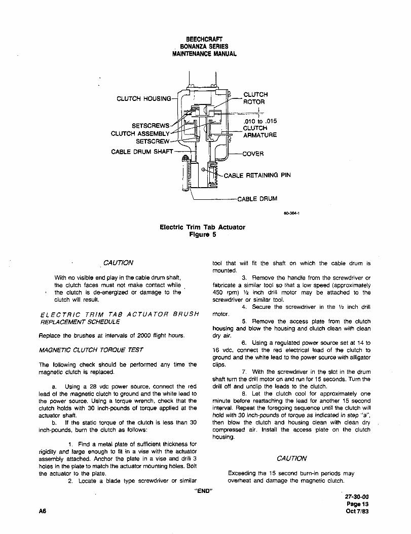
BEECHCRAFTBONANZA SERIES
MAINTENANCE MANUAL
CLUTCHCLUTCH HOUSING
ROTOR
.010 to .015SETSCREWS CLUTCH
CLUTCH ASSEMBLY"n L_J~J WE´•C~ARMATURESETSCREW
CABLE DRUM SHAFT
CABLE RETAINING PIN
CABLE DRUM
60-364-1
Electric Trim Tab Actuator
Figure 5
CAUTION tool that will fit the shaft on which the cable drum is
mounted.
With no visible end play in the cable drum shaft, 3. Remove the handle from the screwdriver or
the clutch faces must not make contact while fabricate a similar tool so that a low speed (approximatelythe clutch is de-energized or damage to the 450 rpm) ’/2 inch drill motor may be attached to the
clutch will result. screwdriver or similar tool.
4. Secure the screwdriver in the ’/2 inch drill
ELECTRIC TRIM TAB ACTUATOR BRUSH motor.
REPLACEMENT SCHEDULE 5. Remove the access plate from the clutch
housing and blow the housing and clutch clean with clean
Replace the brushes at intervals of 2000 fright hours, dry air.
6. Using a regulated power source set at 14 to
MAGNETIC CLUTCH TORQUE TEST 16 vdc, connect the red electrical lead of the clutch to
ground and the white lead to the power source with alligatorThe following check should be performed any time the clips.magnetic clutch is replaced. 7. With the screwdriver in the slot in the drum
shaft turn the drill motor on and run for 15 seconds. Turn the
a. Using a 28 vdc power source, connect the red drill off and unclip the leads to the clutch.
lead of the magnetic clutch to ground and the white lead to 8. Let the clutch cool for approximately one
the power source. Using a torque wrench, check that the minute before reattaching the lead for another 15 second
clutch holds with 30 inch-pounds of torque applied at the interval. Repeat the foregoing sequence until the clutch will
actuator shaft, hold with 30 inch-pounds of torque as indicated in step "a",
b. If the static torque of the clutch is less than 30 then blow the clutch and housing clean with clean dryinch-pounds, burn the clutch as follows: compressed air. Install the access plate on the clutch
housing.1. Find a metal plate of sufficient thickness for
rigidity and large enough to fit in a vise with the actuator
assembly attached. Anchor the plate in a vise and drill 3 CAUTION
holes in the plate to match the actuator mounting holes. Bolt
the actuator to the plate. Exceeding the 15 second burn-in periods may
2. Locate a blade type screwdriver or similar overheat and damage the magnetic clutch.
"END"27-30-00
Page 13
A6 Oct7183
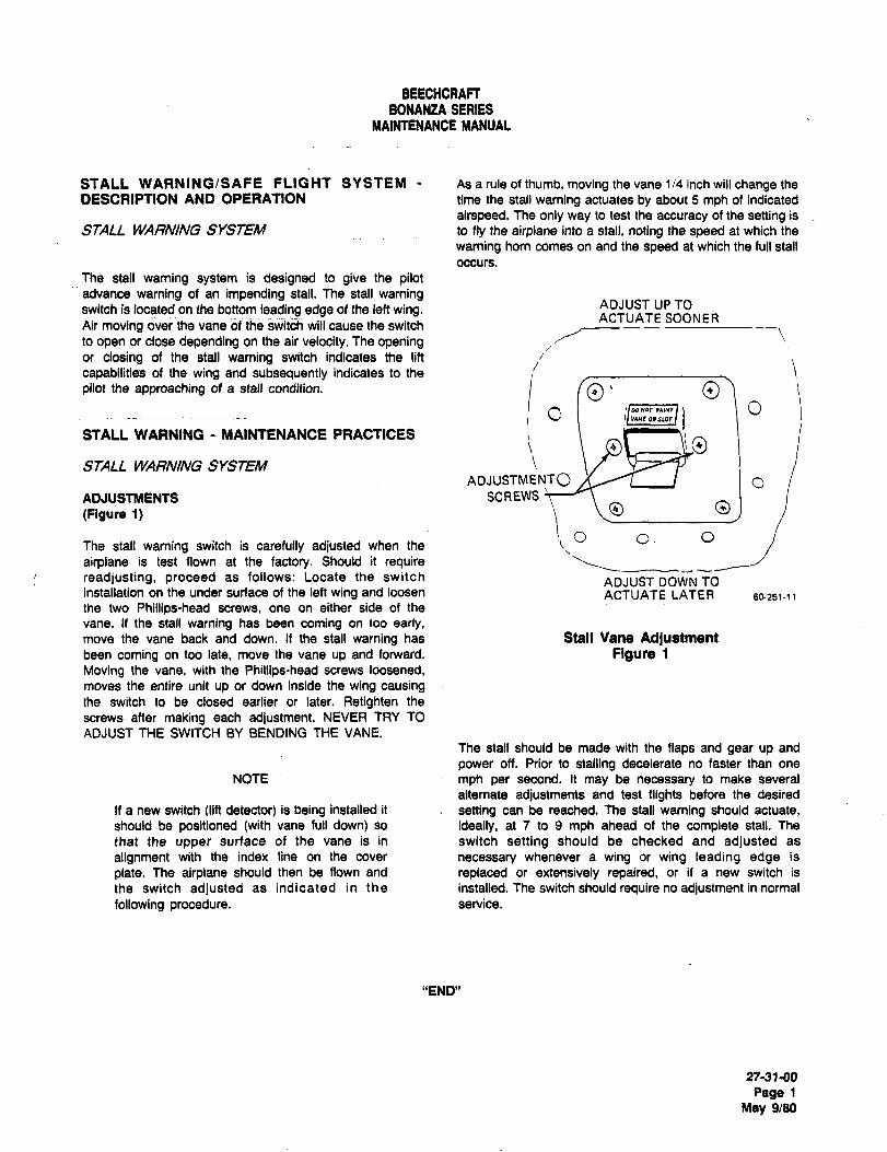
BEECHCRAFTBONANZA SERIES
MAINTENANCE MANUAL
STALL WARNING/SAFE FLIGHT SYSTEM As a rule of thumb, moving the vane 1/4 inch will change the
DESCRIPTION AND OPERATION time the stall warning actuates by about 5 mph of indicated
airspeed. The only way to test the accuracy of the setting is
STALL WARNING SYSTEM to fly the airplane into a stall, noting the speed at which the
warning horn comes on and the speed at which the full stall
occurs.
The stall waming system is designed to give the pilotadvance warning of an impending stall. The stall warningswitch is located on the bottom leading edge of the left wing. ADJUST UP TO
ACTUATE SOONERAir moving over the vane of the switch will cause the switch
to open or close depending an the air velocity. The openingor closing of the stall warning switch indicates the lift
capabilities of the wing and subsequently indicates to the
iVIN~OISU)t
Opilot the approaching of a stall condition.
STALL WARNING MAINTENANCE PRACTICES8~mmli, o i
to
ADJUSTMENTO
OO
O
STALL WA~NING SYSTEM
ADJUSTMENTS SCREWS?
(Figure 1)
me sta~l warning switch is carefully adjusted when Ihe :~O o. O
airplane is test flown at the factory. Should it requirereadjusting, proceed as follows: Locate the switch ADJUST DOWN TOinstallation on the under surface of the left wing and loosen ACTUATE LATER 60-251-11
the two Phillips-head screws, one on either side of the
vane. If the stall warning has been coming on too early,move the vane back and down. If the stall warning has Stall Vane Adjustmentbeen coming on too late, move the vane up and forward. Figure 1
Moving the vane, with the Phillips-head screws loosened,
moves the entire unit up or down inside the wing causingthe switch to be closed earlier or later. Retighten the
screws after making each adjustment. NEVER TRY TO
ADJUST THE SWITCH BY BENDING THE VANE.
The stall should be made with the flaps and gear up and
power off. Prior to stalling decelerate no faster than one
NOTE mph per second. It may be necessary to make several
alternate adjustments and test flights before the desired
If a new switch (lift detector) is being installed it setting can be reached. The stall warning should actuate,
should be positioned (with vane full down) so ideally, at 7 to 9 mph ahead of the complete stall. The
that the upper surface of the vane is in switch setting should be checked and adjusted as
alignment with the index line on the cover necessary whenever a wing or wing leading edge is
plate. The airplane should then be flown and replaced or extensively repaired, or if a new switch is
the switch adjusted as indicated in the installed. The switch should require no adjustment in normal
following procedure. service.
"END"
27-3140
Page i
May 9/80
RaylSleon Aircraft CompanyBONANZA SERIES MAINTENANCE MANUAL
FLAPS DESCRIPTION AND OPERATION
The flaps are hinged in specially designed tracks. When extended, the flap moves rearward as it pivots downward.
This gives a large, effective wing area, which produces additional lift and drag.
One flap is installed on each wing. The flaps are operated by an electric-motor-driven gearbox on the aft side of the
front spar at the centerline of the airplane. The gearbox drives two flexible drive shafts, each connected to an
acme-thread-type jackscrew at each flap. The flaps are controlled by a lever in the subpanel, and the flap positionis indicated by an instrument to the left of the control column. The lever (switch) must be pulled out of a detent to
change positions. On airplane serials E-llll, E-1241, thru E-1370; CJ-149; CE-748, CE-772 thru CE-815; ID-10097, and D-10120 thru D-10178, the flaps may be stopped at any position by moving the flap switch to OFF
when the flaps reach the desired position. The switch is placarded UP, OFF, and DOWN. The markings on the
position indicator will be UP, 10", 20", and DN. On airplane serials CJ-150 and After; CE-816 and After; D-l 0179
and After; E-1371 thru E-2110 except E-1946 and E-2104; EA-1 thru EA-388 except EA-320, the indicator is marked
UP, 15", and DN. Serials E-1946, E-2104 and E-2111 and After; EA-320, EA-389 and After have lights to indicate
flap position. These lights are marked to indicate the down, in-transit, and approach positions of the flaps. All lightsare out when the flaps are up. The flaps can be stopped only on the up, approach, or down position as indicated bythe flap switch.
The flap position transmitter (if installed) is located near the left flap actuator. Power to operate the indicator lightsof later serials is controlled by the flap relay and limit switches.
NOTE
After an emergency extension at speeds above the normal extension speeds, inspect the flaps for
damage or distortion before the next flight.
FLAPS MAINTENANCE PRACTICES
FLAP REMOVAL
a. Remove the bolt from the flap actuating arm.
b. Remove the bonding cable from the flap tracks.
c. Remove the bolts from the flap track brackets and remove the flaps.
FLAP INSTALLATION
a. Hold the flap in position and install the rollers and the bolts in the flap track bracket.
NOTE
Install the flap track rollers (four rollers per flap and two rollers per track) in the flap track brackets
with the flanges of the rollers in one track facing the flanges of the rollers in other track.
b. Connect the bonding cable and install the bolt in the flap actuating arm.
p~, 27-50-00 Sep 30/03Page 1
Ray)lheon Air~raft CompanyBONANZA SERIES MAINTENANCE MANUAL
FLAP TRACK WEAR LIMITS
I The allowable track wear on the bearing surface is 0.032 inch resulting in a maximum dimension of 0.785 inch in
the track slot. The allowable wear into the track side surface is 0.050 inch. Track wear within the precedinglimitations may be dressed smooth with light emery cloth to prevent roller binding. Lubricant mixed with solvent (49and 26, Chart 1, 91-00-00) may be brushed on the flap tracks during servicing of the airplane.
FLAP LIMIT SWITCH ADJUSTMENT
NOTE
Battery voltage is not sufficient to properly cycle the flaps during rigging. An auxiliary power supply
I capable of maintaining 28.25 0.25 volts should be used. If an external power receptacle is not
available on the airplane, jumper cables may be used between the battery and the power supply.Be sure of the polarity before making the connection.
I CAUTIOW 1CAUTION
Excessive operation of the flap motor withoutpropercooling may cause damage to the motor Allow
a short cooling time after each extension and retraction cycle.
The flap limit switches are mounted on a bracket and installed on the outboard side of the inboard flap track in the
left wing panel. The limit switches control the travel of the flaps by breaking the circuit to the flap motor at the extreme
limits of travel. They are accessible by lowering the flaps.
TWO-POSITION FLAPS
(05-748, 05-772 THRU 05-815; CJ-149; 0-10097, 0-10120 THRU 0-10178; E-llll, 5-1241 THRU 5-1370)
There are two limit switches for this system, one for the uplimit position, and one for the downlimit position. To adjustthe flaps to neutral position, loosen the screws of the switch assembly so that the assembly can pivot on the fomard
elongated hole. Adjust the switch as necessary to stop the flaps in neutral position. Actuate the flap switch to the
down position and measure the degrees of travel (proper degree of travel is 300 0" 2"). Adjustment of the down
position of the flaps is made on the downlimit switch.
THREE-POSITION FLAPS
(05-816 AND AFTER; CJ-150 AND AFTER; 0-10179 AND AFTER; 5-1371 AND AFTER; EA-1 AND AFTER)
The limit switches, one for up, two for the approach position and one for the down travel, control the travel of the
flaps by breaking the circuit to the flap motor at the extreme limits of selected travel. The switches are accessible bylowering the flaps.
The flap travel is adjusted by moving the limit switches. The left flap is rigged first, then the right flap is synchronizedwith it. Rig as follows:
Sep 27-50-00
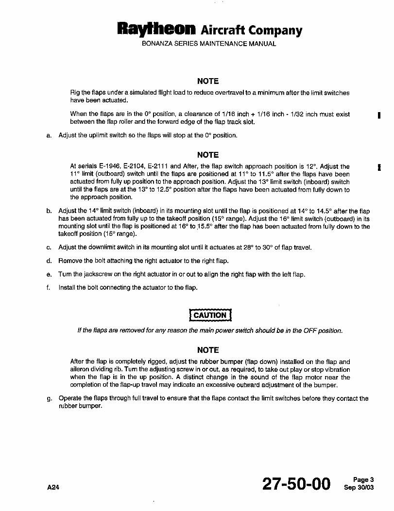
RByeheOn Aircraft CompanyBONANZA SERIES MAINTENANCE MANUAL
NOTE
Rig the flaps under a simulated flight load to reduce overtravel to a minimum after the limit switches
have been actuated.
When the flaps are in the 0" position, a clearance of 1/16 inch 1/16 inch 1/32 inch must exist Ibetween the flap roller and the forward edge of the flap track slot.
a. Adjust the uplimit switch so the flaps will stop at the 0" position.
NOTE
At serials E-1946, E-2104, E-2111 and After, the flap switch approach position is 12". Adjust the
11" limit (outboard) switch until the flaps are positioned at 11" to 11.5" after the flaps have been
actuated from fully up position to the approach position. Adjust the 13" limit switch (inboard) switch
until the flaps are at the 13" to 12.5" position after the flaps have been actuated from fully down to
the approach position.
b. Adjust the 14" limit switch (inboard) in its mounting slot until the flap is positioned at 14" to 14.5" after the flaphas been actuated from fully up to the takeoff position (15" range). Adjust the 16" limit switch (outboard) in its
mounting slot until the flap is positioned at 16" to !5.50 after the flap has been actuated from fully down to the
takeoff position (15" range).
c. Adjust the downlimit switch in its mounting slot until it actuates at 28" to 300 of flap travel.
d. Remove the bolt attaching the right actuator to the right flap.
e. Turn the jackscrew on the right actuator in or out to align the right flap with the left flap.
f. Install the bolt connecting the actuator to the flap.
I cnuTlou ICAUTION
If the flaps are removed for any reason the main power switch should be in the OFF position.
NOTE
After the flap is completely rigged, adjust the rubber bumper (flap down) installed on the flap and
aileron dividing rib. Turn the adjusting screw in or out, as required, to take out play or stop vibration
when the flap is in the up position. A distinct change in the sound of the flap motor near the
completion of the flap-up travel may indicate an excessive outward adjustment of the bumper.
g. Operate the flaps through full travel to ensure that the flaps contact the limit switches before they contact the
rubber bumper.
0124 27-50-00 Sep 30/03Page 3
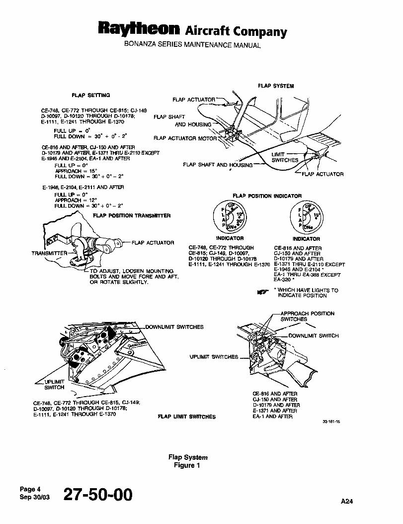
RaYHleOll nircraft CompanyBONANZA SERIES MAINTENANCE MANUAL
FLAP SYSTEM
FLAP SETTINGFLAP ACTUATOR
CE-748, CE-772 THROUGH CE-815; 01-149
0-10097, 0-10120 THROUGH 0-10178; FLAP SHAFTE-lll1, E´•1241 THROUGH E-1370
AND HOUSING
FULL UP 00FULL DOWN 30" 0" 2" FLAP ACTUATOR MOTO;I
CE-816 AND AFTER, CJ-150 AND AFTER
0-10179 AND AFTER, 5-1371 THRU E-2110 EXCEPT LIMITE-1946 AND E-2104, EA-1 AND AFTER SWITCHES
FULL UP O" FLAP SHAFT AND HOUSINGAPPROACH 15"
FLAP ACTUATORFULL DOWN 30" 0" 2"
5-1946 E-2104, 5-2111 AND AFTER
FULL U)E O" FLAP POSITION INDICATORAPPROACH 12"FULL DOWN 30" 0" 2"
FLAP PSSTION TRANSMITTER
INDICATOR INDICATORo~--FLAP ACTUATOR
CE-748, CE-n2 THROUGH CE-816ANDAFTERTRANSMITTER~ CE-B15; 01-149, D-~0097, CJ-150 AND AFTER
0-10120 THROUGH D-10178 D-10179 AND AFTER
E-llll, 5-1241 THROUGH E-1370 E-1371 THRU 5-2110 EXCEPT
TO ADJUST, LOOSEN MOUNTING E-1946 AND E-21D4’
BOLTS AND MOVE FORE AND AFT,EA-1 THRU EA-388 EXCEPTEA-320
OR ROTATE SLIGHTLY.
IC9 WH’CH HAVE LIGHTS fOINDICATE POSITION
POSITIONSWITCHES
SWITCHES
DOWNLIMIT SWITCH
""C"’S
UPLIMITSWITCH
CE-816 AND AFTERCJ-150 AND AFTER
CE-748, CE-n2 THROUGH CE-815, 01-149;D-lOlm AND ARER
0-10097, 010120 THROUGH D´•10178; 5-1371 AND AFTERE-llll, E-1241 THROUGH E-13f0
FLAP LIMIT SWITCHES EA-1 AND AFTER33-161-15
Flap SystemFigure t
Sep 27-50-00A24
Raytheon Aircraft CompanyBONANZA SERIES MAINTENANCE MANUAL
FLAP POSITION INDICA TOR AND ADJUSTMENT
The flap position indicator gage is installed in the instrument panel. An adjustable flap position indicator transmitter
is installed on the flap actuator in the left wing just forward of the rear spar to coordinate gage reading with flap travel.
a. Adjust the flap travel limit switches to provide the correct up and down travel of the flaps. Refer to FLAP LIMIT ISWITCH ADJUSTMENT procedure.
b. Run the flaps down and check the pilot’s compartment flap position indicator for 100% flaps. If down flaps are
not indicated, loosen the transmitter attachment bolts and adjust transmitter fore and aft or rotate slightly until
the reading is correct, then tighten the transmitter attaching bolts.
c. Run the flaps up and check the indicator for up flaps reading.
FLAP MOTOR REMOVAL
ICAUTIONICAUTION
If the flap motor fails or if major overhaul is required for it to operate properly, the flap motor should
be replaced. No attempt should be made to overhaul the motor in the field.
a. Remove the front seat assemblies.
b. Removethe sparcover.
c. Detach the clamp supporting the electrical wiring from the right-hand flap-shaft housing.
d. Disconnect the motor electrical wiring at the quick disconnect.
e. Loosen the two set screws on each cable retainer.
f. Rotate the cable retainers 90".
g. Loosen the nuts on the inboard side of the mounting supports.
h. Pull the flexible drive shafts from the flap motor shafts and retainers.
i. Remove the flap motor attaching bolts and remove the flap motor.
CONNECTING FLEXISLE FLAP DRIVE SHAFT TO FLAP MOTOR SHAFT
Connect the LH and RH flexible flap drive shafts to the flap drive motor shaft as follows, refer to Figure 2 for Icomponent locations:
a. Install the outboard nut and washer as far as they will go onto the threaded portion of the flap shaft housing.
b. Start set screws (2) into retainer. Insert the retainer through the flap shaft mounting support and onto the motor Ishaft as far as it will go.
c. Align retainer keyway with key slot in flap motor drive shaft and tighten one set screw temporarily.
d. While inserting the flap shaft through the mounting support, install the inboard washer and nut.
27-50-00 Sep 30/03Page 5
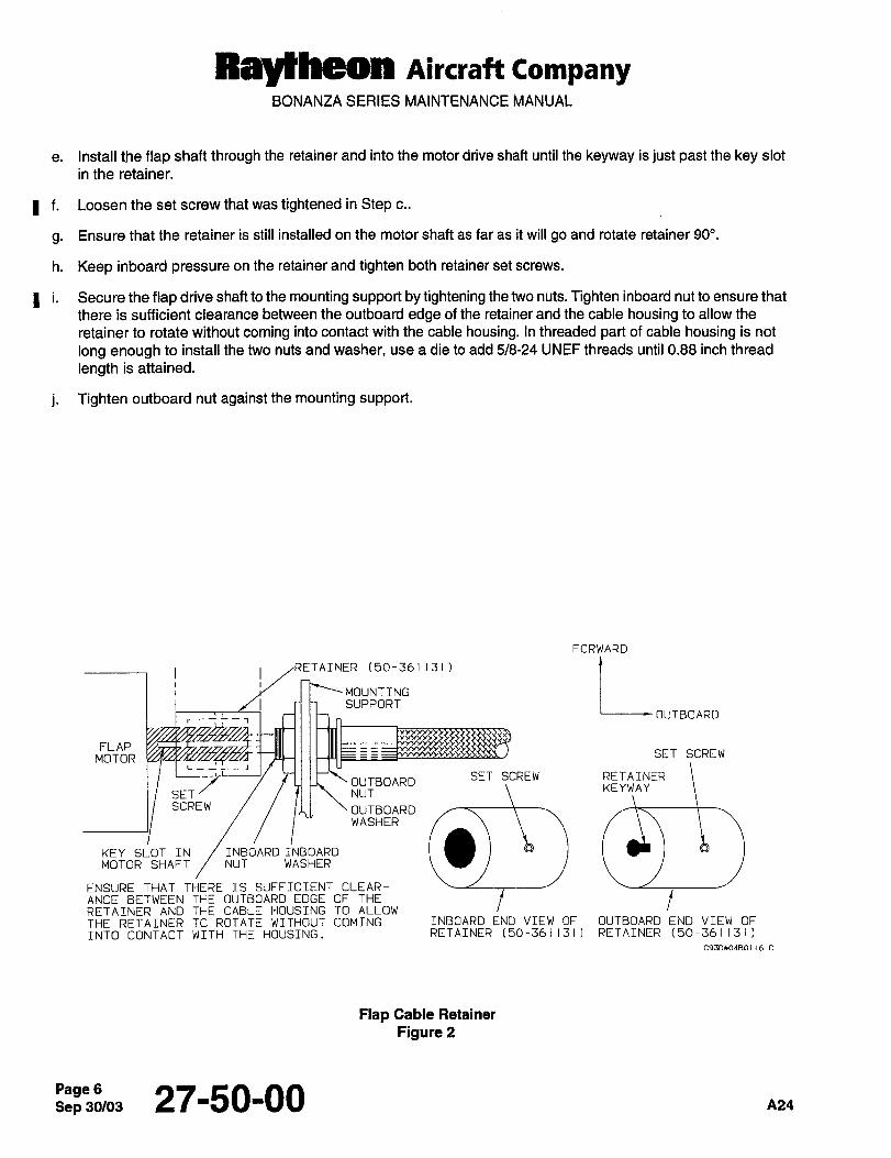
Raytheon Aircraft CompanyBONANZA SERIES MAINTENANCE MANUAL
e. Install the flap shaft through the retainer and into the motor drive shaft until the keyway is just past the key slot
in the retainer.
I f. Loosen the set screw that was tightened in Step c..
g. Ensure that the retainer is still installed on the motor shaft as far as it will go and rotate retainer 90".
h. Keep inboard pressure on the retainer and tighten both retainer set screws.
I i. Secure the flap drive shaft to the mounting support by tightening the two nuts. Tighten inboard nut to ensure that
there is sufficient clearance between the outboard edge of the retainer and the cable housing to allow the
retainer to rotate without coming into contact with the cable housing. In threaded part of cable housing is not
long enough to install the two nuts and washer, use a die to add 5/8-24 UNEF threads until 0.88 inch thread
length is attained.
j. Tighten outboard nut against the mounting support.
FORWARD
LOUTBOARDTAINER (50-361131)
MOUNTINGSUPPORT
r---,
MOTOR SET SCREWFLAP
SETSCREW ii’ OUTBOARDSET SCREW RETAINER
KEYWAYNUT
OUTBOARDWASHER
KEY SLOT IN INBOARD TNBOARD
MOTOR SHAFT NUT WASHER
ENSURE THAT THERE IS SUFFICIENT CLEAR-
RETAINER AND THE CABLE HOUSING TO ALLOWfANCE BETWEEN THE OUTBOARD EDGE OF THE
THE RETAINER TO ROTATE WITHOUT COMING INBOARD END VIEW OF OUTBOARD END VIEW OF
INTO CONTACT WITH THE HOUSING. RETAINER (50-361131) RETAINER (50-361131)
C93DX04B0116 C
Flap Cable Retainer
Figure 2
Sep 27-50-00 A24
Ray)heon Aircraft CompanyBONANZA SERIES MAINTENANCE MANUAL
FLAP MOTOR INSTALLATION
Icnunou iCAUTION
Should the flap motor fail or should major overhaul be required for the flap motor to operateproperly, it should be replaced. No attempt should be made to overhaul the motor in the field.
a. Place the flap motor in position and secure with the flap motor attach bolts.
b. Connect the flap motor electrical wiring at the quick disconnect.
c. Install flexible flap drive shafts into the flap motor shafts, refer to CONNECTING FLEXIBLE FLAP DRIVE
SHAFT TO FLAP MOTOR SHAFT procedure. I
d. Attach the clamp that supports the electrical wiring from the right flap shaft housing.
e. Run the flaps through full travel, up and down, to check flap rigging.
f. Install the spar cover.
g. Install the front seat assemblies.
FLAP SHAFT REMOVAL
a. Place the airplane on jacks and use the circuit breaker to retract the landing gear until the inboard doors are
open.
b. Remove the front seat assemblies.
c. Remove the spar cover.
d. Loosen the two set screws on each cable retainer.
e. Rotatethecable retainer90".
f. Remove the nut on the inboard side of the mounting support.
g. Pull the flexible drive shaft from the flap motor shaft and retainer.
h. Disconnect all clamps securing the shaft housing to the wing structure.
i. Remove the dust cover in the rear section of the wheel well.
j. Disconnect the flap actuator from the wing flap and the wing spar section.
k. Pull the actuator and flexible shaft housing out of the wing.
FLAP SHAFT INSTALLA TION
a. Pull the flexible shaft and housing through the wing and attach the actuator to the wing flap and wing sparsection.
27-50-00 7
Ray~heon Aircraft CompanyBONANZA SERIES MAINTENANCE MANUAL
b. Settheflapsinthe upposition.
c. Push the flexible shaft into the flap motor shaft and retainer.
d. Rotatethe retainer90".
e. While holding the retainer onto the motor shaft as far as possible, tighten the two set screws in each retainer.
f. Tighten the nut on the inboard side of the mounting support.
g. Install the clamps securing the shaft housing to the wing structure.
h. Install the dust cover in the rear section of the wheel well.
i. Run the flaps through full travel, up and down, to check flap rigging.
j. Lower the landing gear and remove the airplane from the jacks.
k. Install the spar cover.
i. Install the front seat assemblies.
FLAP ACTUA TOR REMOVAL
a. Place the airplane on jacks and retract the landing gear until the inboard door is open (use the circuit breaker).
b. Remove the dust cover in the rear section of the wheel well to gain access to the actuator.
c. Lower the flaps and disconnect the actuator from the flap.
NOTE
To retain the original rigging of the flaps, mark the extension of the flap actuator before it is removed
so that it may be installed in the same position.
d. Remove the flap position transmitter from the flap actuator.
e. Remove the snap ring and disconnect the flexible drive housing.
f. Remove the pivot bolts from the flap actuator mounting bracket and remove the flap actuator.
FLAP ACTUATOR INSTALLA TION
a. Place the flap actuator in position and secure it to the flap actuator mounting bracket with the pivot bolts.
b. Connect the flexible drive housing and install the snap ring.
c. Install the flap position transmitter to the flap actuator.
NOTE
The flap position transmitter is on the left-hand flap actuator only.
d. Connect the flap actuator to the flaps in the extended position marked during removal.
Sep 30/03Page 8 27-50-00 na4

Ray~heon Aircraft CompanyBONANZA SERIES MAINTENANCE MANUAL
e. Install the dust cover in the rear section of the wheel well.
f. Check the flap rigging.
g. Lower the landing gear and remove the airplane from the jacks.
FLAP INNER FLEX SHAFT REMOVAL
a. Place the airplane on jacks and retract the landing gear (using the circuit breaker) until the inboard door is open.
b. Removethe frontseatassemblies.
c. Remove the spar cover.
d. Loosen the two set screws on the cable retainer (Ref. Figure 2). 1
e. Rotatethecable retainer90".
f. Remove the dust cover in the rear of the wheel well to gain access to the actuator.
g. Remove the two bolts holding the forward end of the actuator in place.
NOTE
The first clamp which secures the flex drive to the wing may have to be removed to allow more
flexibility to the flex drive.
The position transmitter on the left flap may need to be removed.
h. Remove the snap ring holding the flex drive to the actuator
NOTE
Do not lose the spacers located under the flange of the flex drive.
i. To facilitate installation, note how far the shaft protrudes past the flange of the housing.
j. Pull the flex inner shaft from the housing.
FLAP INNER FLEX SHAFT INSTALLA TION
a. Lubricate the inner flex shaft with grease (11, Chart 1, 91-00-00).
b. Install the inner flex shaft into its housing (Ref. Figure 2). 1
c. Rotate the inner flex shaft until the key on the inner end of the shaft slides into place. (When this is
accomplished, the measurement noted in FLAP INNER SHAFT REMOVAL procedure Step i. should again be Inoted at this time.)
d. Push the flap shaft into the flap motor shaft and retainer.
e. Rotatethe retainer90".
f. While holding the retainer onto the motor shafts as far as possible, tighten the two set screws in the retainer.
nns 27-50-00 Sep 30/03Page 9
Raylheon Aircraft CompanyBONANZA SERIES MAINTENANCE MANUAL
NOTE
Be certain the spacers are in place in the actuator.
g. Install the flap shaft into the actuator and install the snap ring.
NOTE
A screwdriver may be used to make small adjustments to the screw of the actuator if the slot in the
actuator does not align with the key of the flex shaft.
h. Secure the actuator in place with the two bolts, washers, and nuts.
NOTE
The position transmitter will have to be installed on the left flap if it was removed. Install the clampon the shaft if it was removed.
i. Install the dust cover.
j. Lower the landing gear and remove the airplane from the jacks.
k. Cycle the flaps to determine that they are properly rigged.
NOTE
For correct adjustment and rigging of the flap position transmitter refer to the FLAP POSITION
I INDICATOR AND ADJUSTMENT procedure.
FLAP ACTUA TOR DISASSEMBL Y
a. Remove the snap ring (2) to disconnect the flexible shaft (I)from the actuator (Ref. Figure 3).
b. Tap on the piston plug (11) to drive out the seal (17), spacers (3) and bearings (4).
c. Slide the piston (6) out of the housing (8).
I d. Check that the end play between the piston (6) and the actuator screw (5) does not exceed 0.012 inch under 25
to 50 pounds of force in both compression and tension at any of the following positions:
1. With the actuator screw full in and backed out 1 turn.
2. Withtheactuatorscrew 1/2extended.
3. With the actuator screw fully extended and backed in 1 turn.
e. If the 0.012 inch tolerance is exceeded, replace the piston and plug with a new one. If the tolerance is still
unacceptable replace the screw. Check the end play of the new piston and screw per the preceding step.
NOTE
Mark the piston and screw so that the same threads will be in contact when the piston and screw
are assembled.
Sep 30/03PagelO 27-50-00 ~24
Raylheon Aircraft CompanyBONANZA SERIES MAINTENANCE MANUAL
f. Remove the O-ring (12) from the housing (8). 1
g. Remove the actuator screw (5) from the piston (6).
NOTE
The following step should be accomplished only if the piston (6) or piston plug (1 1) is to be replaceddue to damage or wear.
h. Drill out the pin (14) and take the piston plug (11) out of the piston (6). ;1
FLAP ACTUA TOR ASSEMBL Y
NOTE
A replacement plug (11) may be supplied without the hole for the pin (14).
A replacement piston (6) may be supplied with an under sized hole for the pin (14), on one side of
the piston only.
a. If necessary drill a 0.185 to 0.189 inch diameter hole through the piston (6) and piston plug (1 1) for the pin (14).Countersink the hole on both sides of the piston 100" to 0.250 inch.
b. Clean all parts with solvent (16, Chart 1, 91-00-00) and inspect for cracks, corrosion, distortion and excessive
wear. Refer to Chart 1 for tolerances and wear limits.
c. Replace the O-ring (12) and seal (17).
d. Coat the piston plug (11) and pin (14) with adhesive (68, Chart 1, 91-00-00) before assembly. I
e. Peen the pin (14) and file it flush with the piston (6).
i. Pack the bearings (4) with lubricating grease (50, Chart 1, 91-00-00) before inserting the piston (6) in the
housing (8).
g. Pour lubricating oil (51, Chart 1, 91-00-00) into the housing (8) until it is about two inches from being full. I
h. Slide a bearing (4) on the screw (5).
NOTE
When the screw and piston are assembled, be sure the same threads are in contact as when theywere disassembled. Check the piston and screw assembly end play per Step d. of FLAP IACTUATOR DISASSEMBLY procedure.
i. Start the screw (5) in the piston (6) and slide the piston into the housing (8).
j. Install the remaining bearing (4) and seal (17). Seat these parts in the housing (8) with approximately 100 Ibs.
pressure, or use a suitable drift and mallet ii a press is not available.
k. Install the spacers (3), shaft (1) and snap ring (2).
I. Tap the piston plug (11) with a rawhide mallet to seat the parts against the snap ring (2).
p~, 27-50-00 Sep 30/03Pagell
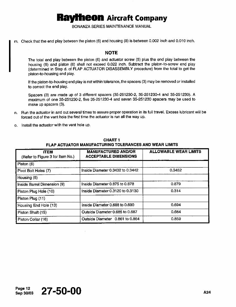
Raytheon Aircraft CompanyBONANZA SERIES MAINTENANCE MANUAL
m. Check that the end play between the piston (6) and housing (8) is between 0.002 inch and 0.010 inch.
NOTE
The total end play between the piston (6) and actuator screw (5) plus the end play between the
housing (8) and piston (6) shall not exceed 0.022 inch. Subtract the piston-to-screw end play
(determined in Step d. of FLAP ACTUATOR DISASSEMBLY procedure) from the total to get the
piston-to-housing end play.
If the piston-to-housing end play is not within tolerance, the spacers (3) may be removed or installed
to correct the end play.
Spacers (3) are made up of 3 different spacers (35-251230-2, 35-251230-4 and 35-251230). A
maximum of one 35-251230-2, five 35-251230-4 and seven 35-251230 spacers may be used to
make up spacers (3).
n. Run the actuator in and out several times to assure proper operation in its full travel. Excess lubricant will be
forced out of the vent hole the first time the actuator is run all the way up.
o. Install the actuator with the vent hole up.
CHART1
FLAP ACTUATOR MANUFACTURING TOLERANCES AND WEAR LIMITS
ITEM MANUFACTURED AND/OR ALLOWABLE WEAR LIMITS
(Refer to Figure 3 for Item No.) ACCEPTABLE DIMENSIONS
Piston (6)
Pivot Bolt Holes (7) Inside Diameter 0.3432 to 0.3442 0.3452
Housing (8)
Inside Barrel Dimension (9) Inside Diameter 0.875 to 0.878 0.879
Piston Plug Hole (10) Inside Diameter 0.3120 to 0.3130 0.314
Piston Plug (11)
Housing End Hole (13) Inside Diameter 0.688 to 0.690 0.694
Piston Shaft (15) Outside Diameter 0.685 to 0.687 0.684
Piston Collar (16) Outside Diameter 0.861 to 0.864 0.859
Page 27-50-00 a24
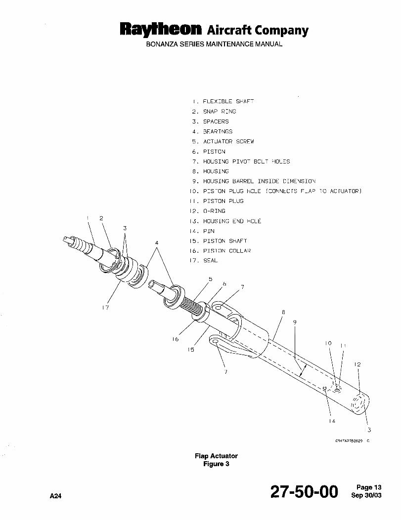
Ray~heon nircraft CompanyBONANZA SERIES MAINTENANCE MANUAL
I. FLEXIBLE SHAFT
2. SNAP RING
3. SPACERS
4. BEARINGS
5. ACTUATOR SCREW
6. PISTON
HOUSING PIVOT BOLT HOLES
8. HOUSING
9. HOIJSING BARREL INSIDE DIMENSION
10. PISTON PLUG HOLE (CONNECTS FLAP TO ACTUATOR)
II. PISTON PLUG
12. O-RING
13. HOUSING END HOLE
14. PTN
4 15. PISTON SHAFT
16. PISTON COLLAR
17. SEAL
17
1610
15
12
14
13
C94EA2782829
Flap Actuator
Figure 3
A24 27-50-00
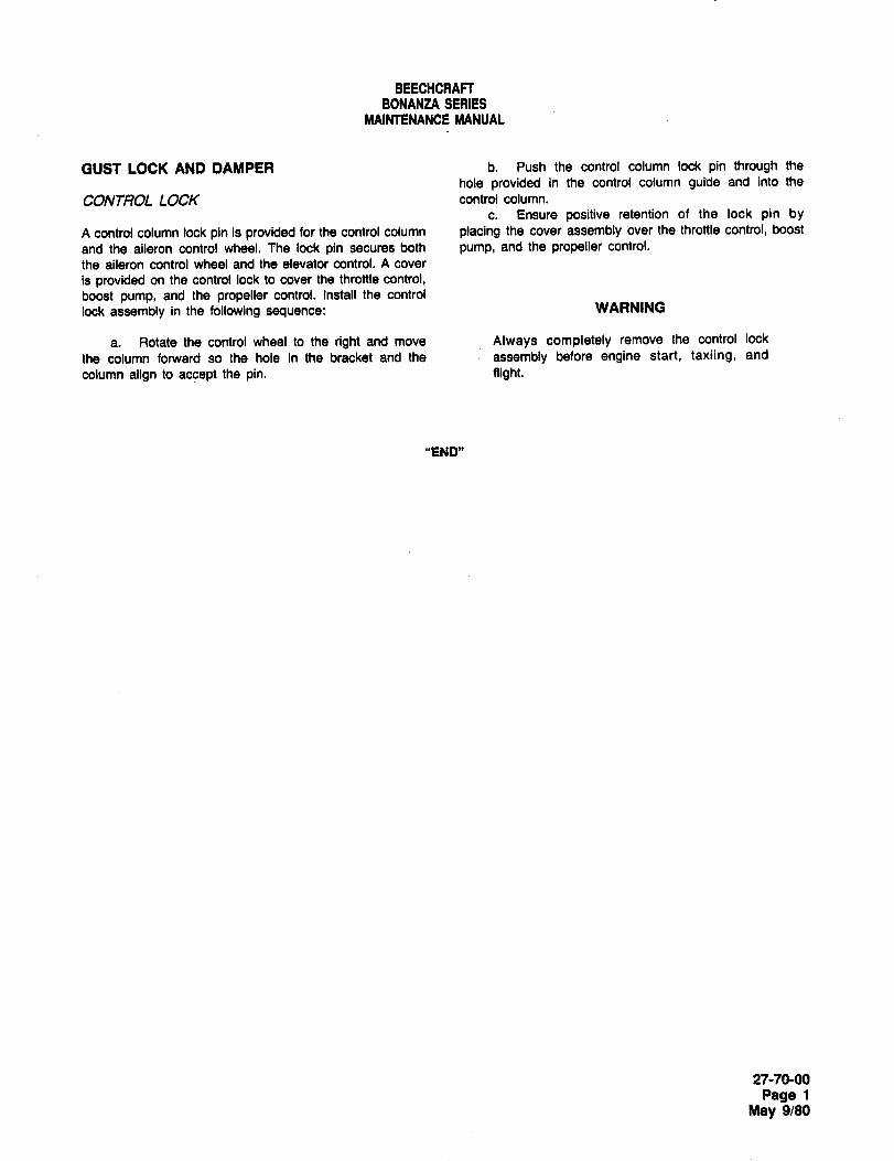
BEECHCRAFTBONANtA SERIES
MAINTENANCE MANUAL
GUST LOCK AND DAMPER b. Push the control column lock pin through the
hole provided in the control column guide and into the
CONTROL LOCK control column.
c. Ensure positive retention of the lock pin by
A control column lock pin is provided for the control column placing the cover assembly over the throttle control, boost
and the aileron control wheel. The lock pin secures both pump, and the propeller control.
the aileron control wheel and the elevator control. A cover
is provided on the control lock to cover the throttle control,
boost pump, and the propeller control, install the control
lock assembly in the following sequence: WARNING
a. Rotate the control wheel to the right and move Always completely remove the control lock
the column forward so the hole in the bracket and the assembly before engine start, taxiing, and
column align to accept the pin. flight.
"END"
27-70-00
Page 1
May 9/80

CHAPTER
FUEL
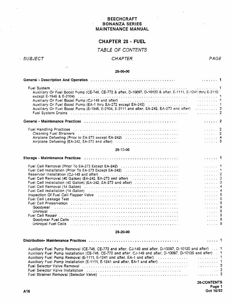
BEECHCRAFT
BONANZA SERIES
MAINTENANCE MANUAL
CHAPTER 28 FUEL
TABLE OF CONTENTS
SUBJECT CHAPTER PAGE
28-00-00
General Description And Operation 1
Fuel SystemAuxiliary Or Fuel Boost Pump (CE-748, CE-772 after, D-10097, D-10120 8 after, E-llll, E-1241 thru E-2110
except E-1946 8 E-2104) 1
Auxiliary Or Fuel Boost Pump (CJ-149 and after) 1
Auxiliary Or Fuel Boost Pump (EA-I thru EA-272 except EA-242) 1
Auxiliary Or Fuel Boost Pump (E-1946, E-2104, E-2111 and after, EA-242, EA-273 and after) 2
Fuel System Drains 2
General Maintenance Practices 2
Fuel Handling Practices 2
Cleaning Fuel Strainers 2
Airplane Defueling (Priorto EA-273 except EA-242) 4
Airplane Defueling (EA-242, EA-273 and after) 5
28-1 E-OO
Storage Maintenance Practices 1
Fuel Cell Removal (Prior To EA-273 Except EA-242) 1
Fuel Cell installation (Prior To EA-273 Except EA-242) 1
Reservoir Installation ~CJ-149 and after) 2
Fuel Cell Removal (40 Gallon) (EA-242, EA-273 and after) 3
Fuel Cell Installation (40 Gallon) (EA-242, EA-273 and after) 3
Fuel Cell Removal (14 Gallon) 4
Fuel Ceil Installation (14 Gallon) 4
Inspection Of Fuel Cell Fiapper Valve 6
Fuel Cell Leakage Test 6
Fuel Cell Preservation 9
Goodyear 9
Uniroyal 9
Fuel Cell Repair 9
Goodyear Fuel Cells 9
Uniroyal Fuel Cells 9
28-20-00
Distribution- Maintenance Practices 1
Auxiliary Fuel Pump Removal (CE-748, CE-772 and after, CJ-~49 and after, D-10097, D-10120 and after) 1
Auxiliary Fuel Pump installation (CE-748, CE-772 and after, CJ-´•149 and after, D-10097, D-~0120 and after) 1
Auxiliary Fuel Pump Removal (E-llll, E-1241 and after, EA-1 and after) 1
Auxiliary Fuel Pump Installation (E-llli, E-1241 and after, EA-1 and after) 1
Fuel Selector Valve Removal 2
Fuel Selector Valve Installation 2
Fuel Strainer Removal (Selector Valve) 2
28-CO NTENTS
Page i
A16 Oct16192
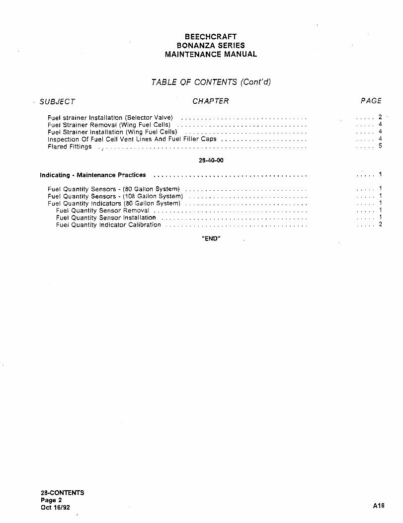
BEECHCRAFT
BONANZA SERIES
MAINTENANCE MANUAL
TABLE OF CONTENTS (Cont’d)
SUBJECT CHAPTER PAGE
Fuel strainer Installation (Seiector Valve) 2
Fuel Strainer Removal (Wing Fuel Cells) 4
Fuel Strainer Installation (Wing Fuel Cells) 4
Inspection Of Fuel Cell Vent Lines And Fuel FillerCaps 4
Flared Fittings 5
28-40-00
Indicating Maintenance Practices 1
Fuel Quantity Sensors -(80 Gallon System) 1
Fuel Quantity Sensors -(108 Gallon System) 1
Fuel Quantity Indicators (80 Gallon System) 1
Fuel Quantity Sensor Removal 1
Fuel Quantity Sensor Installation 1
Fuel Quantity Indicator Calibration 2
"END"
28-CONTENTS
Page 2
Oct 16/92 A16
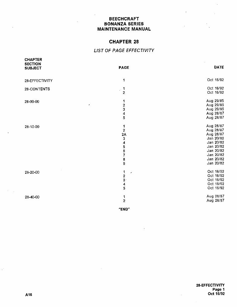
BEECHCRAFT
BONANZA SERIES
MAINTENANCE MANUAL
CHAPTER 28
LIST OF PAGE EFFECTIVITY
CHAPTER
SECTIONSusJECT PACE DATE
28-EFFECTIVITY 1 Oct 16/92
28-CONTENTS 1 Oct 16/92
2 Oct 16/92
28-00-00 1 Aug 29/85
2 Aug 29/85
3 Aug 29/85
4 Aug 28/87
5 Aug 28/87
28-10-00 1 Aug 28/87
2 Aug 28/87
2A Aug 28/87
3 Jan 20/82
4 Jan 20/82
5 Jan 20/82
6 Jan 20/82
7 Jan 20/82
8 Jan 20/82
9 Jan 20/82
28-20-00 1 Oct 16/92
2 Oct 16/92
3 Oct 16/92
4 Oct 16/92
5 Oct 16/92
28-40-00 1 Aug 28/87
2 Aug 28/87
"END"
5&EFFECTIVITY
Page 1
Ale Oct 16/92
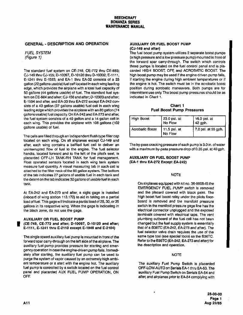
BEECHCRAFTBONANZA SEAIES
MAINTENANCE MANUAL
GENERAL DESCRIPTION AFID OPERATION AUXILIARY OR FUEL BOOST PUMP
(CJ-149 and after)FUEL SYSTEM The fuel boost pump system utilizes 2 separate boost pumps
(Figure 1) (a high pressure and a low pressure pump) mounted in front of
the forward spar carry-through. The switch which controls
these pumps is located on the fuel control panel and is pla-The standard fuel system on CE-748, CE-772 thru CE-883; carded MIGH BOOST, OFF, and ACROBATIC BOOST. The
CJ-149 thru CJ-155; D-10097, D-10120 thru 0-10302; E-llll, high boost pump may be used if the engine driven pump fails,E-1241 thru E-1593; and EA-1 thru EA-32 consists of a 25 if starting the engine during high ambient temperatures or if
gallon (22 gallons usable) fuel cell located in each wing leading the engine is hat. The switch must be in the acrobatic boost
edge, which provides the airplane with a total fuel capacity of position during acrobatic maneuvers. Both pumps are for
50 gallons (44 gallons usable) of fuel. The standard fuel sys- intermittent use only. The boost pump pressures should be as
tem on CE-884 and after; CJ-156 and after; 0-10303 and after; indicated in Chart 1.
E-1594 and after, and EA-33 thru EA-272 except EA-242 con-
sists of a 40 gallon (37 gallons usable) fuel cell in each wing Chart 1
leading edge which provides the airplane with an 80 gallon (74 Fuel Boost Pump Pressures
gallons usable) fuel capacity. On EA-242 and EA-273 and after,the fuel system consists of a 40 gallon and a 14 gallon cell in High Boost 23.0 psi. at 16.0 psi, at
each wing. This provides the airplane with 108 gallons (102 No Flow 42 gph.gallons usable) of fuel.
Acrobatic Boost 1 11.5 psi. at 1 7.0 psi. at 55 gph.No Flow
The cells are filled through an independent flush type filler caplocated on each wing. On all airplanes except CJ-149 and
after, each wing contains a baffled fuel cell to deliver an The by-pass cracking pressure of each pump is 3.0 in, of water
uninterrupted flow of fuel to the engine. The fuel selector with a maximum by-pass pressure drop of 0.35 psi. at 40 gph.handle, located forward and to the left of the pilot’s seat, is
placarded OFF-LH TANK-RH TANK for fuel management. AUXILIARY OR FUEL BOOST PUMP
Float operated sensors located in each wing tank system (EA-1 thro EA-272 Except EA-242)measure fuel quantity. A visual measuring tab in each cell is
attached to the filler neck of the 80 gallon system. The bottom
of the tab indicates 27 gallons of usable fuel in each tank and NOTE
the detent on the tab indicates 32 gallons of usable fuel in each
tank. On airplanes equipped with kit no. 36-9008-18 the
EMERGENCY FUEL PUMP switch is removed
At EA-242 and EA-273 and after, a sight gage is installed and the placard covered with black paint. The
(inboard of wing station 113.172) to aid in taking on a partial high boost fuel boost relay under the pilots floor-
load of fuel. This gage will indicate a partial load of 25, 30, or 35 board is removed and the manifold pressure
gallons in its respective wing. When the gage is indicating in switch in the manifold pressure gage line has the
Ihe black zone, do not use the gage, electrical connector unplugged and the exposedterminals covered with electrical tape. The vent
AUXILIARY OR FUEL BOOST PUMP plumbing outboard of the fuel cell has not been
I (CE-748, CE-772 and after; D-10097, D-10120 and after; changed but the fuel supply system is essentiallyE-llll, 6-1241 thru E-2110 except E-1946 and E-2104) that of a B36TC (EA-242, EA-273 and after). The
fuel selector valve drain requires the use of the
The single speed auxiliary fuel pump is mounted in front of the same type tool (see special tools) as the B36TC.
forward spar carry-through on the left side of the airplane. The Refer to the B36TC(EA-242, EA-273 and after) for
auxiliary fuel pump provides pressure for starting and emer- the description and operation.
gency operation in case the engine-driven pump fails. Immedi-
ately after starting, the auxiliary fuel pump can be used to NOTE
purge the system of vapor caused by an extremely high ambi-
ent temperature or a start with the engine hot. The auxiliary The auxiliary Fuel Pump Switch is placardedfuel pump is controlled by a switch located on the fuel control OFF-LOW-AUTO on Serials EA-1 thru EA-53. The
panel and placarded AUX FUEL PUMP OPERATION, ON auxiliary Fuel Pump Switch on Serials EA´•54 andOFF: after, and airplanes prior to EA64 complying with
28-00-00
Page 1
All Aug 29/85
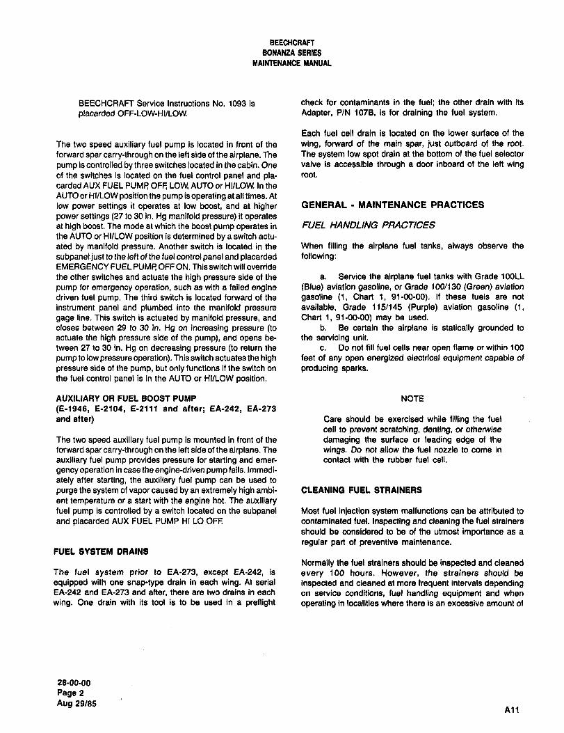
BEECHCRAFT
BONANZA SERIES
hlAINTENAMCE IliANUAL
BEECHCRAFT Service Instructions No. 1093 is check for contaminants in the fuel; the other drain with its
placarded OFF-LOW-HI/LOW. Adapter, P/N 1078, is for draining the fuel system.
Each fuel cell drain is located on the lower surface of the
The two speed auxiliary fuel pump is located in front of the wing, forward of the main spar, just outboard of the root.
forward spar carry-through on the left side of the airplane. The The system low spot drain at the bottom of the fuel selector
pump is controlled by three switches located in the cabin. One valve is accessible through a door inboard of the left wingof the switches is located on the fuel control panel and pla- root.
carded AUX FUEL PUMP OFF; LOW, AUTO or HIILOW. In the
AUTO or HI/LOW position the pump is operating at all times. At
low power settings it operates at low boost, and at higher GENERAL MAINTENANCE PRACTICES
power settings (27 to 30 in. Hg manifold pressure) it operatesat high boost. The mode at which the boost pump operates in FUEL HANDLING PRACTICES
the AUTO or HIILOW position is determined by a switch actu-
ated by manifold pressure. Another switch is located in the When filling the airplane fuel tanks, always observe the
subpanel just to the left of the fuel control panel and placarded following:EMERGENCY FUEL PUMP OFF ON. This switch will override
the other switches and actuate the high pressure side of the a. Service the airplane fuel tanks with Grade 100LL
pump for emergency operation, such as with a failed engine (Blue) aviation gasoline, or Grade 100/130 (Green) aviation
driven fuel pump. The third switch´• is located forward of the gasoline (1, Chart 1, 91-00-00). If these fuels are not
instrument panel and plumbed into the manifold pressure available, Grade 115/145 (Purple) aviation gasoline (1,
gage line. This switch is actuated by manifold pressure, and Chart 1, 91-00-00) may be used.
closes between 29 to 30 in. Hg on increasing pressure (to b. Be certain the airplane is statically grounded to
actuate the high pressure side of the pump), and opens be- the servicing unit.
tween 27 to 30 in. Hg on decreasing pressure (to return the c. Do not fill fuel cells near open flame or within 100
pump to low pressure operation). This switch actuates the high feet of any open energized electrical equipment capable of
pressure side of the pump, but only functions if the switch on producing sparks.the fuel control panel is in the AUTO or HIILOW position.
AUXILIARY OR FUEL BOOST PUMP NOTE
(8-1946, 8-2104, E´•2111 and after; EA-242, EA-273
and after) Care should be exercised while filling the fuel
cell to prevent scratching, denting, or otherwise
The two speed auxiliary fuel pump is mounted in front of the damaging the surface or leading edge of the
forward spar carry-through on the left side of the airplane. The wings. Do not allow the fuel nozzle to come in
auxiliary fuel pump provides pressure for starting and emer- contact with the rubber fuel cell.
gency operation in case the engine-driven pump fails. Immedi-
ately after starting, the auxiliary fuel pump can be used to
purge the system of vapor caused by an extremely high ambi- CLEANING FUEL STRAINERS
ant temperature or a start with the engine hot. The auxiliaryfuel pump is controlled by a switch located on the subpanel Most fuel inlection system malfunctions can be attributed to
and placarded AUX FUEL PUMP Hr LO OFF contaminated fuel. Inspecting and cleaning the fuel strainers
should be considered to be of the utmost importance as a
regular part of preventive maintenance.FUEL SYSTEM DRAINS
Normally the fuel strainers should be inspected and cleanedThe fuel system prior to EA-273, except EA-242, is every 100 hours. However, the strainers should be
equipped with one snap-type drain in each wing. At serial inspected and cleaned at more frequent intervals dependingEA-242 and EA-273 and after, there are two drains in each on service conditions, fuel handling equipment and when
wing. One drain with its tool is to be used in a preflight operating in localities where there is an excessive amount of
28-00-00
Page 2
Aug 29/85All
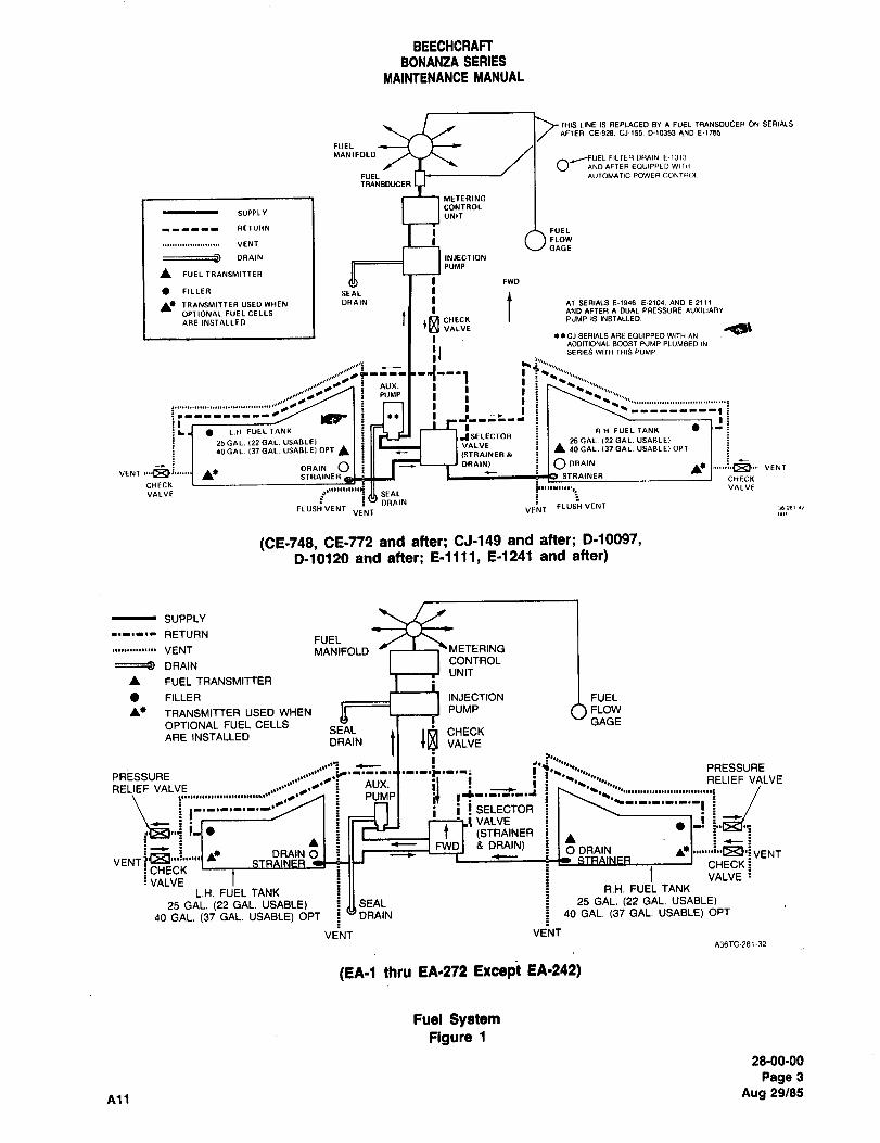
BEECHCRAFTBONANZA SERIES
MAINTENANCE MANUAL
THIS LINE IS REPLACED BY A FUEL TRANSDUCER ON SERIALS
AFTER CE´•928. CJ-(55. D-(0353 AND E´•1155
FUEL
MANIFOLD,JFUEL FILTER DRAIN E-1313
V- AND AFTER EOUIPPED WITI1
FUEL I ALITOMATIC POWER CONTROL
TRANSDUCER
METERING
CONTROLSUPPLY UNIT
RETURN I I i FUEL
FLOWVENT
GAGE
DRAIN I I I INJECTION
PUMP
1L FUEL TRANSMITTERFWD
FILLER I SEAL
CHECKtTRPINSMITrER USED WHEN DRAIN AT SERIALS E-1946. 61104. AND E´•2111
OPTIONAL FUEL CELLS AND AFTER A DUAL PRESSURE AUXILIARY
PUMP IS INSTALLEDARE INSTALLED
VALVEL,CJ SERIALS ARE EOUIPPED WITH AN
ADDITIONAL BOOST PUMP PLUMBED IN
Il SERIES WITH THIS PUMP
c´•1 -I--´•´•1nUx.
PVMP 5
1~----11-1
~I(Cp i
I~
it L.H FUEL TANK R.H FUEL. TANK~SELECTOR
26CAL I~SGPIL.USARLE)250AL.IZZGAL.VSPIBLEI VALVE40cnL.137cnL.usnsLE,oPT40 GAL 137 GAL. USABLEI OPT
(STRAINER&
oHalN O DAI\INI ODRI\IN It L(X1´• VENTVENT STRAINER STRAINER CHECK
CHECK VALVEVALVE SEAL
f DRAINFLUSH VENT FLUSH VENT 36 Itll 11
VENT VENT
(CE-748, CE=n2 and after; CJ-149 and after; 0-10097,
D-10120 and after; E-llli, 0-1241 and after)
SUPPLY
RETURNFUEL
VENT MANIFOLDCONTROL
DRAINUNIT
FUEL TRANSMITTER
FILLER 1 1 INJECTION FUELIa TRANSMITTER USED WHEN PUMP FLOW
OPTIONAL FUEL CELLS GAGE
ARE INSTALLED SEALDRAIN ti ~d CHECK
VALVE
~´•jPRESSURE
PRESSURE ~iCII´•l´•l 11.~
RELIEF VALVE ~´•)´•I AUX.PUMP ii RELIEF V~LVEI ii
!SELECTORVALVE
j i t (STRAINERNVD &DRAIN) ODRAIN !VENT3 DRAIN O
VALVEL.H. FUEL TANK R.H. FUEL TANK
25 GAL. (22 GAL. USABLE) SEAL 25 GAL. (22 GAL. USABLE)
40 GAL. (37 GAL. USABLE) OPT i VDRAIN 40 GAL. (37 GAL. USABLE) OPT
VENT VENT
A36TC-2B(´•32
(EA-1 thru EP~´•272 Excapl 84-242)
Fuel SystemFigure 1
28-00-00
Page 3
All Aug 29/85
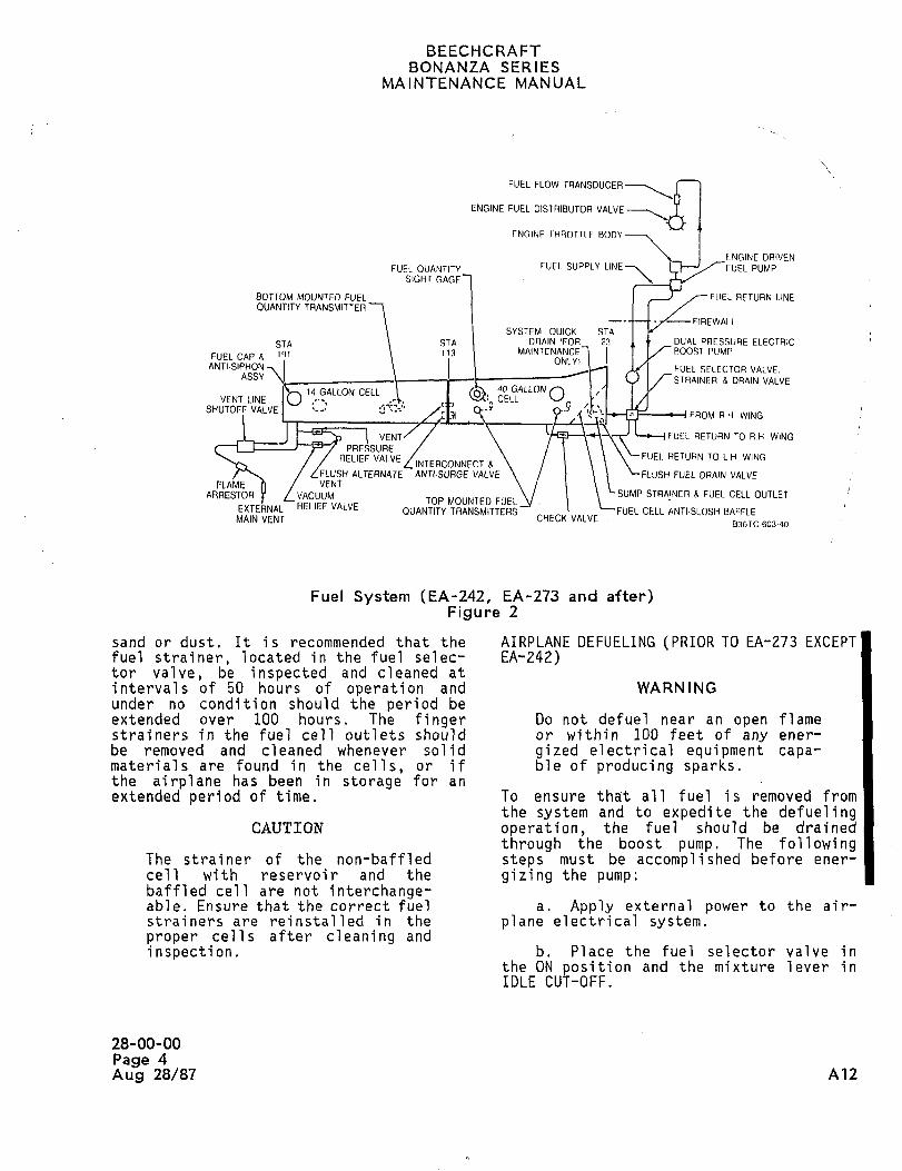
BEECHCRAFTBONANZA SERIES
MAIN~ENANCE MANUAL
FUEL FLOW TRANSDUCER
ENGINE FUEL DISTRIBUTOR VALVE
FNT~INF THROTTLE BODY
ENGINE DRIVEN
FUEL OUANTITY FUEI. SUPPLY LINE 7 PUMPSIGHT GAGE
BOTTOM MOVNTED FUEL I I 1 /--FUEL RETURN LINEOUANTITY TRANSMITTER
FIREWALLSYSTEM OUICK STA
STA STA DRAIN lFOR 23 1 t DUAL PRESSURE ELECTRIC
FUELCAPR 191 MAINTENANCE I I I/ ROOST PUMP
ONLVIANTI-SIPHON FUEL SELECTOR VALVE.
ASSY STRAINER 8 DRAIN VALVE
14 GALLON CELL 40 GALLON OVENT LINE CELL
SHUTOFF VALVEFROM RH WING
VENT/ c-y FUEL RETURN TO R H WING
PRESSURERELIEF VALVE FUEL RETURN TO L H WING
INTERCONNECT R
FLVSHALTERNATE ANTI-SURGEVALVE ’FLVSH FUEL DHAIN VALVEFLAME h VENT
ARRESTOR r VACUUM SUMP STRAINER R FUEL CELL OUTLETTOP MOUNTED FUEL
EXTEkNAL RELIEF VALVEOUANTITY TRANSMITTERS FUEL CELL ANTI´•SLOSH BAFFLE
MAIN VENT CHECK VALVE836TC´•603-40
Fuel System (EA-242, EA-273 and after)Figure 2
sand or dust. It is recommended that the AIRPLANE DEFUELING (PRIOR TO EA-273 EXCEPTfuel strainer, located in the fuel selec- EA-242)tor valve, be inspected and cleaned at
intervals of 50 hours of operation and WARN INGunder no condition should the period beextended over 100 hours. The finger Do not defuel near an open flamestrainers in the fuel cell outlets should or within 100 feet of any ener-
be removed and cleaned whenever solid gized electrical equipment capa-materials are found in the cells, or if ble of producing sparks.the airplane has been in storage for an
extended period of time. To ensure tha’t all fuel is removed fromthe system and to expedite the defueling
CAUTION operation the fuel should be drained
through boost pump. The followingThe strainer of the non-baffled steps must be accomplished before ener-
cell with reservoir and the gizing the pump:baffled cell are not interchange-able. Ensure that the correct fuel a. Apply external power to the air-strainers are reinstalled in the plane electrical system.proper cells after cleaning and
inspection. b. Place the fuel selector valve inthe ON position and the mixture lever inIDLE CUT-OFF.
28-00-00
Page 4
Aug 28/87 A12
BEECHCRAFTBONANZA SERIES
MAINTENANCE MANUAL
c. Remove the filler caps to vent the gized electrical equipment capa-system, ble of producing sparks.
d. Disconnect the fuel line at the a. Provide a suitable container for
firewall and attach a drain hose. Provide the fuel.
a suitable container for the fuel.b. Remove the access cover under the
e. Energize the boost pump, drain valve located under the wing near
the fuselage.f. When the fuel is no longer pumped
from the airplane, open the sump drains c. Remove the filler caps to vent theto complete the defueling operation. system.
CAUTION d. Insert the drain adapter (sup-plied as loose tool) into the drain valve.
After defueling or fuel cell
replacement, operate the engine e. After draining the fuel, remove
on each fuel tank with the air- the drain adapter and install the access
plane on the ground to ensure that cover.
all air has been purged from thefuel cells and the fuel lines to CAUTIONthe engine upon refueling.
After defueling or fuel cellAIRPLANE DEFUELING (EA-242, EA-273 AND replacement, operate the engineAFTER) on each fuel tank with the air-
plane on the ground to ensure thatWA.RNING all air has been purged from the
fuel cells and the fuel lines to
Do not defuel near an open flame the engine upon refueling.or within 100 feet of any ener-
"END"
28-00-00
Page 5
A12 Aug 28/87
BEECHCRAFTBONANZA SERIES
MAINTENANCE MANUAL
STORAGE MAINTENANCE PRACTICES after incorporate a fuel cell witha collapsible fuel cell reservoir
CAUTION in place of a baffled fuel cell.To avoid damage to the fuel cells,
Any time the fuel system is the fuel cell cavities MUST bedrained or a fuel cell replaced, clean of any debris beforeair may enter the system. If the installing a replacement cell.
possibility that air has enteredthe system does exist, start and a. Return the fuel cell through the
operate the engine on the ground outboard fuel cell access hole and snapuntil all air is removed from the it into place.system. Operate the engine for
several minutes on each tank until CAUTION
proper engine operation isassured. Refer to the Pilot’ s Before closing the zipper,Operating Manual before starting inspect the fuel cell for anyand operating the engine, foreign material. If the cell is
not thoroughly clean, it shouldFUEL CELL REMOVAL (PRIOR TO EA-273 be cleaned with a lint-free clothEXCEPT EA-242) moistened in water, alcohol or
kerosene. No other solvent shoulda. Drain and purge the fuel cells. be used to clean the fuel cell.
b. Remove the outboard fuel cell The molded nipple fittings used on the
access plate and fuel quanti ty sensor, fuel cell are lightweight fittings devel-
(The outboard fuel quantity sensor is oped for ease of installation in certaininstalled only in the optional 80 gallon locations in the airplane. To get the bestfuel system). service from this type fitting, it is
necessary to exercise certain proceduresc. Remove the inboard access cover at the time of installation. The specific
and fuel quantity sensor. precautions other than the general care
in handling are as follows:d. Disconnect all fuel and vent
plumbing. 1. Insert the flow tube into the
fitting until 3/8 inch or more of the tubee. Unsnap the fuel cell and remove extends through the fitting.
it through the outboard fuel cell access
hole. 2: Locate the hose clamp on thefabric-re7nforced area of the nipple; it
CAUTION should clear the end of the fitting by 1/4inch.
Tape the edge of the access holeto prevent damage to the fuel 3. Torque hose clamps as indi-cell, cated in Chart 1 in this chapter. They
should be drawn up in one operation; ifFUEL CELL INSTALLATION (PRIOR TO retightening is n e c e s s a ry rel e a s e theEA-273 EXCEPT EA-242) clamp completely and wait at least 15
minutes before retightening.CAUTION
4. Use no sealing paste or gasketCare should be taken when replac- compounds.ing fuel cells to ensure that thecorrect type fuel cell is used as 5. Ap_qly a thin film of Simonizea replacement. All Bonanza Series wax to metal tlow tubes as a lubricant.
Airplanes except CJ-149 and after No other lubricant should be used.use baffled fuel cells. CJ-149 and
28-10-00
Page 1A1Z Aug 28/87
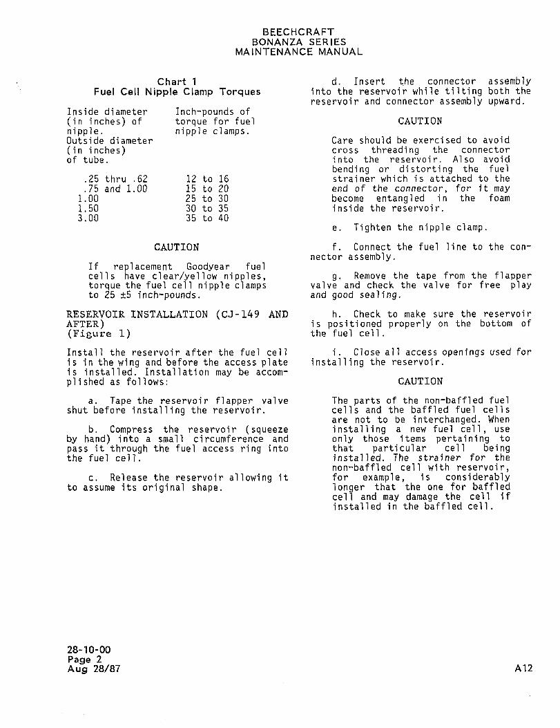
BEECHCRAFTBONANZA SERIES
MAINTENANCE MANUAL
Chart 1 d. Insert the connector assemblyFuel Cell Nipple Clamp Torques into the reservoir while tilting both the
reservoir and connector assembly upward.Inside diameter Inch-pounds of
tin inches) of torque for fuel CAUTION
nipple. nipple clamps.Outside diameter Care should be exercised to avoid
tin inches) cross threading the connector
of tube. into the reservoir. Also avoid
bending or distorting the fuel.25 thru ,62 12 to 16 strainer which is attached to the
.75 and 1.00 15 to 20 end of the connector, for it may1.00 25 to 30 become entangled in the foam
1.50 30 to 35 inside the reservoir.3.00 35 to 40
e. Tighten the nipple clamp.
CAUTION f. Connect the fuel line to the con-
nector assembly.If replacement Goodyear fuelcells have clear/yellow nipples, g. Remove the tape from the flappertorque the fuel cell nipple clamps valve and check the valve for free playto 25 +5 inch-pounds, and good sealing.
RESERVOIR INSTALLATION (CJ-149 AND h. Check to make sure the reservoir
AFTER) is positioned properly on the bottom of
(Figure 1) the fuel cell.
Install the reservoir after the fuel cell i. Close all access openings used for
is in the wing and before the access plate installing the reservoir.is installed. Installation may be accom-
pi i shed as fol lows: CAUTION
a. Tape the reservoir flapper valve The parts of the non-baffled fuelshut before installing the reservoir. cells and the baffled fuel cells
are not to be interchanged. Whenb. Compress the reservoir (squeeze installing a new fuel cell, use
by hand) into a small circumference and only those items pe rtaining to
pass it through the fuel access ring into that particular cell beingthe fuel cell, installed. The strainer for the
non-baffled cell with reservoir,c. Release the reservoir allowing it for example, is considerably
to assume its original shape. longer that the one for baffledcell and may damage the cell ifinstalled in the baffled cell.
28-10-00
Page 2
Aug 28/87 A?2
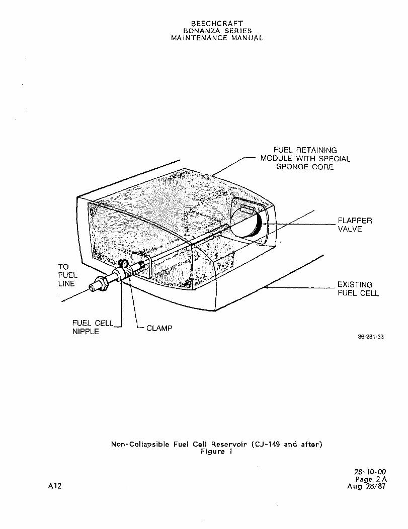
BEECHCRAFTBONANZA SERIES
MAINTENANCE MANUAL
FUEL RETAININGMODULE WITH SPECIAL
SPONGE CORE
FLAPPER
VALVE
-::::´•::_:::
TO
FUEL
LINE EXISTINGFUEL CELL
FUEL CELLCLAM P
NIPPLE36-28~-33
Non-Collapsible Fuel Cell Reservoir (CJ-149 and after)Figure 1
28-10-00
Page 2AA12 Aug 28/87
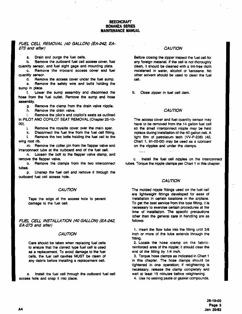
BEECHCRAFTBONANtA SPiRIES
MAlNTENANCE MANUAL
FUEL CELL REMO1/AL (40 GALLON) (EA-242, EA-2f3 and after) CAUTION
a. Drain and purge the fuel cells. Before closing the zipper inspect the fuel cell for
b. Remove the outboard fuel cell access cover, fuel any foreign material. n the cell is not thoroughlyquantity sensor, and fuel sight gage and mounting plate. clean, it should be cleaned with a lint-free cloth
c. Remove the inboard access cover and fuel moistened in water, alcohol or kerosene. No
quantity sensor. other solvent should be used to clean the fuel
d. Remove the access cover under the fuel sump. cell.
e. Remove the safety wire and bolts holding the
sump in place.f. Lower the sump assembly and disconnect the b. Close zipper in fuel cell dam.
hose from the fuel outlet. Remove the sump and hose
assembly.g. Remove the clamp from the drain valve nipple.h. Remove the drain valve. CA UTIONi. Remove the pilot’s and copilot’s seats as outlined
in PILOT AND COPILOT SEAT REMOVAL(Chapter 25-10- The access cover and fuel quantity sensor may00). have to be removed from the 14 gallon fuel cell
i. Remove the royalite covet over the main spat. so the small interconnect nipple may be held
k. Disconnect the fuel line from the fuel cell fitting, inplace during installation of the 40 gallon cell. A
i. Remove the two bolts holding the fuel cell to the light film of petrolatum tech (VV-P-236) 142,wing root rib. Chart 1, 91-00-00) may be used as a lubricant
m; Remove the cotter pin from the flapper valve and on the nipples and under the clamps.interconnect tube at the outboard end of the fuel cell.
n. loosen the bolt to the fiapper valve clamp, and
remove the fiapper valve, c. Install the fuel cell nipples on the interconnect
o. Remove the clamps from the two interconnect tubes. Torque the nipple clamps per Chart 1 in this chapter.tubes.
p. Unsnap the fuel cell and remove it through the
outboard fuel cell access hole.CAUTION
CAUTION The molded nipple flttings used on the fuel eel
are lightweight fittings developed for ease of
Tape the edge of the access hole to pevent installation in certain locations in the airplane.damage to the fuel cell. To gel the best service from this type fitting, it is
necessary to exercise certain procedures at the
time of installation. The specific precautionsother than the general care in handling are as
FUEL CELL INSTALUI TION (40 GALLON) (EA-242, follows:
EA-273 and after)1. Insert the flow tube into the fitting until 3/8
CAUTION inch or more of the tube extends through the
fitting.Care should be taken when replacing fuel cells 2. Locate the hose clamp on the fabric-
to ensure that the correct type fuel cell is used reinforced area of the nipple; it should clear the
as a replacement. To avoid damage to the fuel end of the fitting by 1/4 inch.
cells, the fuel cell cavities MUST be clean of 3. Torque hose clamps as indicated in Chart 1
any debris before installing a replacement cell. in this chapter. The hose clamps should be
tightened in one operation; if retightening is
necessary, release the clamp completely and
a. Install the fuel cell through the outboard fuel cell wait at least 15 minutes before retightening.access hole and snap it into place. 4. Use no sealing paste or gasket compounds.
2810-00
Page 3A4 Jan 20182
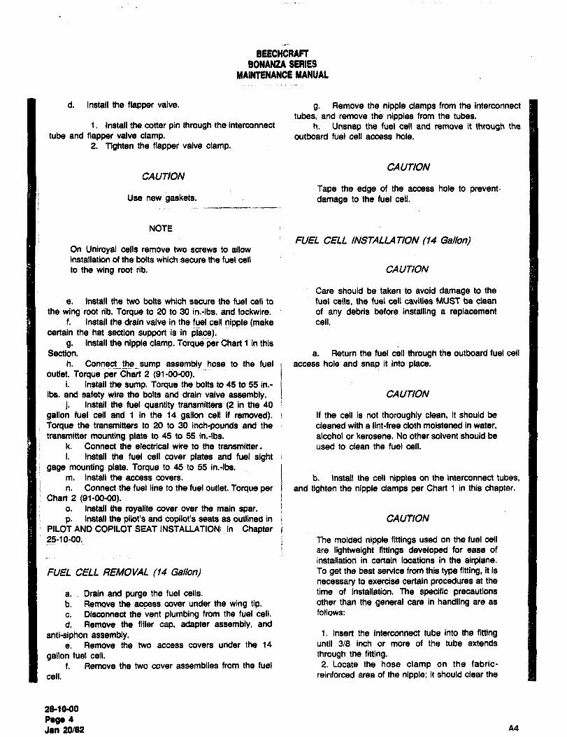
BEECHCRAFTBONANZA SERIES
MAINtENANCE YANUAL
d. Install the flapper valve. g. Remove the nipple clamps from the interconnect
tubes, and remove the nipples from the tubes.1. Install the cotter pin through the interconnect h. Unsnap the fuel cell and remove it through the
tube and flapper valve clamp, outboard fuel cell access hole.
2. Tighten the fiapper valve clamp.
CAUTIONCAUTION
Tape the edge of the access hole to preventUse new gaskets. damage to the fuel cell.
NOTE
FUEL CELL INSTALLATION (14 GaIIon)On Uniroyal cells remove two screws to allow
installation of the bolts which secure the fuel cell
to the wing root rib. CAUTION
Care should be taken to avoid damage to the
e. Install the two bolts which secure the fuel cell to fuel cells, the fuel cell cavities MUST be clean
the wing root rib. Torque to 20 to 30 in.-lbs. and lockwire. of any debris before installing a replacementf. Install the drain valve in the fuel cell nipple (make cell.
certain the hat section support is in place).g. install the nipple clamp. Torqueper Chart 1 in this
Section. a. Return the fuel cell through the outboard fuel cell
h. Connectthesump assembly hose to the fuel I access hole and snap it into place.outlet. Torque per Chart 2 (91-00-00).
i. Install the sump. Torque the bolts to 45 to 55 in.-
ibs. and safety wire the bolts and drain valve assembly. CAUTION
j. Install the fuel quantity transmitters (2 in the 40
gallon fuel cell and 1 in the 14 gallon cell if removed). i If the cell is not thoroughly clean, it should be
Torque the transmitters to 20 to 30 inch-pounds and the cleaned with a lint-free cloth moistened in water,transmitter mounting plate to 45 to 55 in.-lbs. alcohol or kerosene. No other solvent should be
k. Connect the electrical wire to the transmitter~ used to clean the fuel cell.
i. Install the fuel cell cover plates and fuel sightgage mounting plate. Torque to 45 to 55 in.-lbs.
m. Install the access covers. b. Install the cell nipples on the interconnect tubes,
n. Connect the fuel line to the fuel outlet. Torque per and tighten the nipple clamps per Chart 1 in this chapter.i Chart 2 (91-00-00).
o. Install the royalite cover over the main spar.
p. Install the pilot’s and copilot’s seats as outlined in CAUTIONPILOT AND COPILOT SEAT INSTALLA710N!:in Chapter B
i The molded nipple fittings used on the fuel cell
are lightweight fittings developed for ease of
installation in certain locations in the airplane.FUEL CELL REMOVAL (14 GaIIon) To get the best service from this type fitting, it is
necessary to exercise certain procedures at the
a.. Drain and purge the fuel cells. time of installation. The specific precautionsb. Remove the access cover under the wing tip, other than the general care in handling are as
c. Disconnect the vent plumbing from the fuel cell.´• follows:
d. Remove the filler cap, adapter assembly, and
anti-siphon assembly. 1. Insert the interconnect tube into the fittinge. Remove the two access covers under the 14 until 3/8 inch or more of the tube extends
gallon fuel cell, through the fitting.f. Remove the two cover assemblies from the fuel 2. Locate the hose clamp on the fabric-
cell, reinforced area of the nipple; it should clear the
a&1000
page 4
Jan 20/82 44
BEECHCRAFTBONANZA SERIES
MAINTENANCE MANUAL
end of the fitting by 114 inch. NOTE
3. Torque hose clamps as indicated in Chart 1
in this chapter. This should be drawn up in one Use all new gaskets.operation; if retightening is necessary, release
the clamp completely and wait at least 15 d. Install the anti-siphon assembly. Torque the bolts
minutes before retightening. to 45 to 55 in.:lbs. and lockwire.
4. Use no sealing paste or gasket compounds. e. Install the adapter assembly. Use Permatex No. 2
5. A light film of petrolatum tech (VV-P-236) between the skin and adapter.(42, Chart 1, 91-00-00) may be used as a f. Install the fuel cap.
lubricant under the clamps and nipples. g. Install the two cover assemblies, the one with the
fuel quantity transmitter is the inboard one. Torque to 45 to
55 in.-lbs. and lockwire.
c. Connect the vent plumbing in the wing tip. Torque h. Connect the electrical wire to the transmitter.
the clamps per Chart 1 in this chapter, ii. Install the three access covers.
28-10QO
Page 5
A4 Jan 20/82
BEECHCRAFT
BONANZA SERIESklAINTENANCE MANUAL
INSPECTION OF FUEL CELL FLAPPER VAL~E full travel. There should be no binding and the element
should seat securely against the valve plate.On airplanes that are equipped with baffled fuel cells, the 2. If the flapper element binds and/or does not
flapper valves (metal or phenolic) should be inspected seat properly, the upper rear side of the flapper element
periodically (Beech Aircraft recommends that the inspection may be binding against the valve plate.be accomplished at each 100 hr. inspection) for freedom of 3. The flapper valve element may be relieved
operation and proper seating, from binding by filing a small radius on the upper rear side
of the element.
The inspection may be accomplished as follows:
a. Drain all fuel from the airplane. NOTE
b. Remove the rectangular access plate located justoutboard of the fuselage on the upper skin of each wing i
A shop towel saturated with light oil may be
leading edge, i placed directly below the flapper valve to absorb
c. Cut the safety wire and remove the attaching bolts i the phenolic dust during rework.
from the fuel cell access plate.
4. After determining that the flapper valve is
NOTE functioning properly, thoroughly wipe the area in the vicinityof the flapper valve with an oil saturated shop towel.
Clean the area around the access plate before
removing the plate. h. Clean the gasket contact area on the fuel cell and
fuel ceil access plate.i. Close the zipper in the baffle.
d. Remove the fuel cell access plate and open the i. Install a new gasket and secure the fuel cell
zipper in the baffle, access plate in place.e. Locate the flapper valve in the lower outboard k. Tighten the fuel cell access plate attaching bolts
section of the baffle and determine if the flapper valve is to a torque of 45 to 50 inch-pounds and safety wire.
metal or phenolic. i. Reinstall the rectangular access plate on the wingf. If the flapper valve is metal, it should be inspected leading edge skin.
and repaired, if necessary, as follows:
1. Move the flapper element of the valve FUEL CELL LEAKAGE TEST
through its full travel. There should be no binding and the (Figure 2)element should seat securely against the valve plate.
2. If the flapper element binds andlor does not i Rubber bladder type fuel cells may be bench tested for
seat properly, the flapper element arm could be bent. The leakage by sealing off all openings and inflating the emptyarm can be straightened by placing a screwdriver between cell to 1/4 psi with a mixture of shop air and ammonia gas,
the arm and the element and pressing the element toward then checking for visible indications of leakage on a cloth
the closed position, i saturated with phenolphthalein solution. To set up and
3. If after straightening the arm, the flapper t donduct the leakage test, proceed as follows:
element still binds and/or does not seat properly, the flapperelement should be removed and replaced with a new a. The following equipment is required and should
flapper element assembly. The flapper element assembly j be hooked up as indicated in the schematic in Figure 2.
may be replaced by removing the two attaching bolts from
the upper part of the flapper valve. The same attaching 1. Closure plates for the fuel cell openings.
parts should be used to install the new flapper element Such plates may be fabricated of aluminum sheet cut to a
assembly. The new flapper element assembly should be size sufficient to cover the cell openings. Drill holes in the
inspected after installation to determine that the assembly closure plate to match the hole pattern around the openingdid not receive damage during installation that could cause i in the fuel cell.
it to bind and/or not seat properly. 2. Rubber stoppers to plug the fitting openingsin the fuel cell. One of the stoppers should have a hole for
g. If the flapper valve is phenolic, it should be insertion of the plastic tubing used to connect the fuel cell
inspected and reworked, if necessary,´•as follows: into the test setup.3. A manometer for measun’ng 6 inches of
1. Move the flapper valve element through its water differential. The manometer can be fabricated from
UI-10´•00
Rage 6A4
Jan 20/02
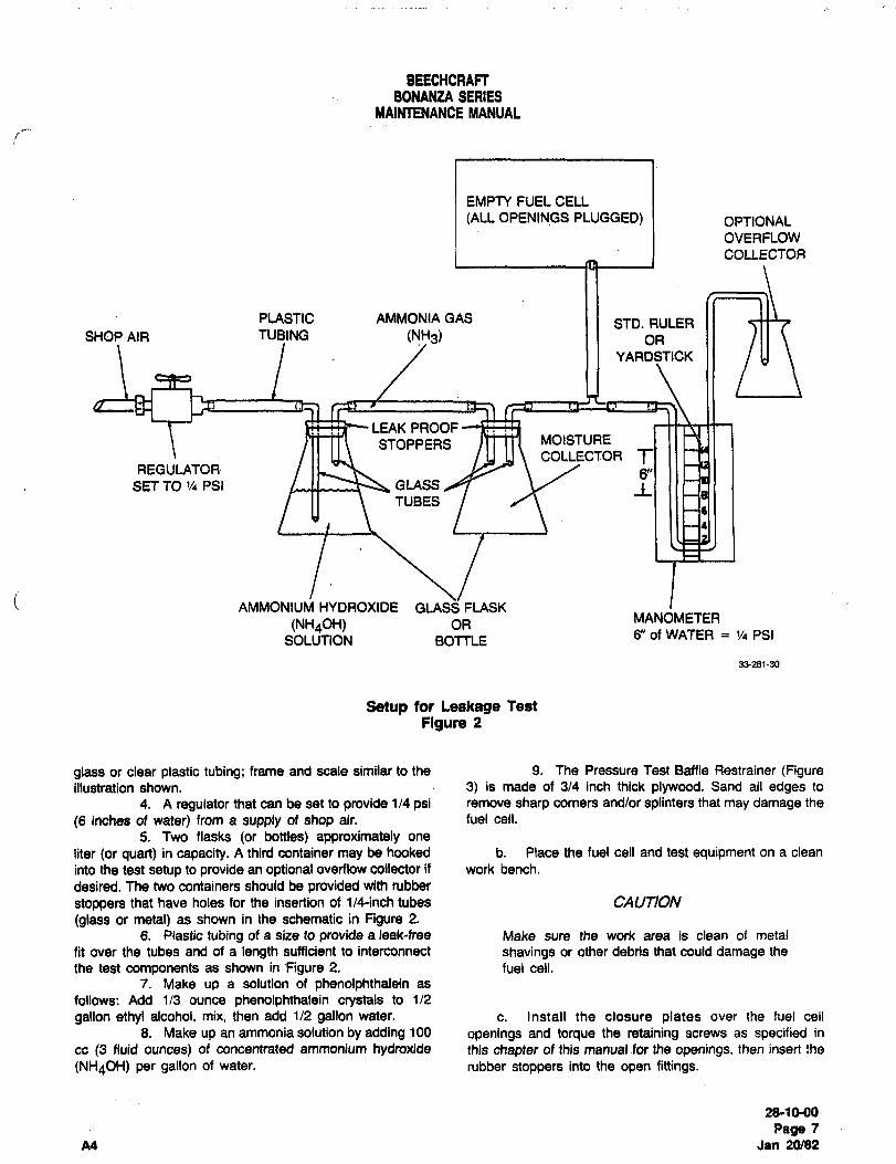
BEECHCRAFTBONANZA SERIES
MAIMENANCE MANUAL
EMPTY FUEL CELL
(ALL OPENINGS PLUGGED) OPTIONAL
OVERFLOW
COLLECTOR
PLASTIC AMMONIA GAS STD. RULERSHOP AIR TUC~ING (NH3) I I OR
YARDSTICK
LEAK PROOF
STOPPERS ,rrtn MOISTURE
COLLECTORREGULATOR
SET TO ’/4 PSI GLASS
TUBES
i AMMONIU~ HYDROXIDE GLAsSFLASK
(NH40H) ORMANOMETER
SOLUTION BOTTLE6" of WATER 1/4 PSI
33´•281-30
Setup for Leakage Test
Figure 2
glass or clear plastic tubing; frame and scale similar to the 9. The Pressure Test Baffle Restrainer (Figureillustration shown. 3) is made of 3/4 inch thick plywood. Sand all edges to
4. A regulator that can be set to provide 1/4 psi remove sharp corners and/or splinters that may damage the
(6 inches of water) from a supply of shop air. fuel cell.
5. Two flasks (or bottles) approximately one
liter (or quart) in capacity. A third container may be hooked b. Place the fuel cell and test equipment on a clean
into the test setup to provide an optional overflow collector if work bench.
desired. The two containers should be provided with rubber
stoppers that have holes for the insertion of 1/4-inch tubes CAUTION
(glass or metal) as shown in the schematic in Figure 2.
6. Plastic tubing of a size to provide a leak-free Make sure the work area is clean of metal
fit over the tubes and of a length sufficient to interconnect shavings or other debris that could damage the
the test components as shown in figure 2. fuel ceil.
7. Make up a solution of phenolphthalein as
follows: Add 1/3 ounce phenolphthalein crystals to 1/2
gallon ethyl alcohol, mix, then add 112 gallon water. c. Install the closure plates over the fuel cell
6. Make up an ammonia solution by adding 100 openings and torque the retaining screws as specified in
cc (3 fluid ounces) of concentrated ammonium hydroxide this chapter of this manual for the openings, then insert the
(NH40H) per gallon of water, rubber stoppers into the open fittings.
2810-00
Page f
All Jan 20/02
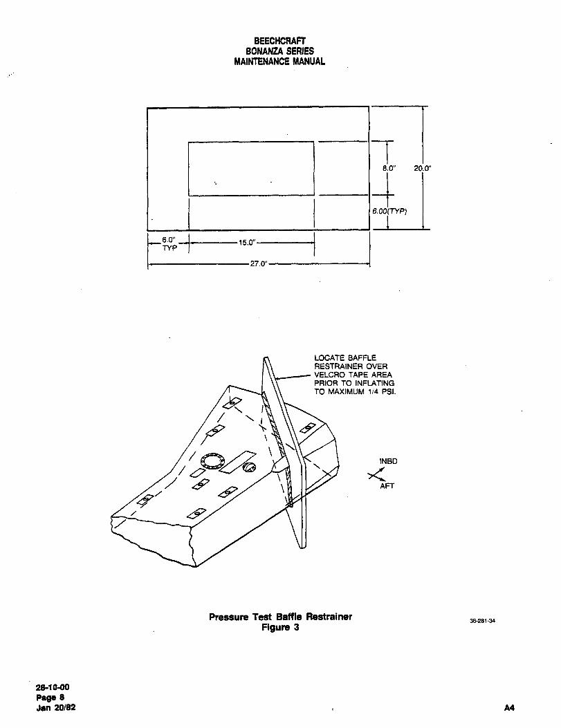
BEECHCRACTBONANZA SERIES
MAlNtENANOE MANUAL
8.0" 20.0"
6.00(NP)
TYPi--27.0"1~
6.0" 15.0"
LOCATE BAFFLE
RESTRAINER OVERVELCRO TAPE AREA
PRIOR TO INFLATING
TO MAXIMUM 1/4 PSI.
83
INBD~y/ /8~a
AFT
Pressure Test Baffle Restrainer36-281´•34
Figure 3
2&10´•00
Paga 8
Jan 20182 A4
BEECHCRAFTBONANZA SERIES
MAINTENANCE MANUAL
d. The flask (or bottle) containing the ammonium NOTE
hydroxide solution should be 1/3 to 1/2 full as shown in the
illustration. Refer to BEECHCRAFT Service Instruction No.
e. Connect a shop air supply to the regulator and 0632-280, Rev. I or subsequent and Goodyearinterconnect the regulator, beakers, fuel cell, and Aerospace Corporation Fuel Tank Repairmanometer as indicated in Figure 2. Manual AP368 far further information on
f. Place the baffle restrainer over the velcro tape inspection of fuel cells for leakage.area prior to inflation as indicated in Figure 3.
WARNING FUEL CELL P~ESERVATION
inflation of the fuel cell without the baffle .i 000bYEAR
restrainer can result in irrepairable damage to
the baffle. I Goodyear fuel cells (Construction No. BTC-39, BTC-54A
and ETC-67) installed in the airplane do not requirepreservation when the cell is to be empty for an indefinite
g. Inflate the fuel cell to 1/4 psi with a mixture of period of time. The fuel cell should not be open to the
shop air and ammonium gas. A 6inch difference in the two atmosphere except for the normal vent lines in the airplane.water levels of the manometer will indicate that the fuel cell The cell is assumed wet from a previous filling.is inflated to 1/4 psi. It is not necessary to restrain the cell
other than to keep it from rolling off the bench. The filling of
the ceU will be rather slow at the 1/4 psi, but should not be UNI#OYAL
rushed as overpressure of the cell could result.
h. Saturat~ a large, clean cloth with phenolphthalein. Uniroyal fuel cells must be filled every 10 days or the walls
(Immerse it in a container and squeeze out excess liquid.) coated with a thin coat of light engine-oil if they are to be
preserved for periods of up to one year. Uniroyal fuel cells
that are to be stored for periods of one year or longer should
CAUTION be coated with a thin coat of light engine oil and then
removed from the airplane as outlined under FUEL CELL
Wear rubber gloves to protect against skin REMOVAL in this chapter. After the fuel cell is removed
irritation when handling the cloth. As a further from the airplane, it should be wrapped in plastic, placed in
protection against possible penetration of the a box, and stored in a cool dry area.
phenolphthalein solution through the gloves,wash your hands thoroughly after finishing the
test. NOTE
The fuel cell should not be removed or handled
i. Lay the cloth over the various portions of the fuel until 24 hours after the oil has been applied.cell until the entire exterior of the cell has been covered.
With each application of the cloth, watch for the formation of
a reddish pink stain on the cloth to indicate the presence of FUEL CELL REPAIR
a leak. Encircle the area on the fuel cell beneath such steins
with a chalk mark to pinpoint the locations of leaks. GOODYEAR FUEL CELLS
For repairs of Goodyear fuel cells, refer to Goodyear Fuel
NOTE Cell Repair Manual AP368, Vithane Fuel Cells.
Continued use of the testing cloth will requirerepeated saturations with phenolphthalein since UNIROYAL FUEL CELLS
rapid evaporation of the alcohol from the cloth
progressively reduces the sensitivity of the test For repairs of Uniroyal fuel cells, refer to Uniroyal Handbookunless the solution in the cloth is frequently "Recommended Handling and Storage Procedures forrenewed. Bladder Type and Oil Cells" P/N FC 1473-73.
"END"
2~1M10
Page 9A4 Jan 20/82
BEECHCRAFT
BONANZA SERIES
MAINTENANCE MANUAL
DISTRIBUTION- MAINTENANCE PRACTICES c. Secure the fuel selector valve to the
mounting bracket with the four attach bolts.
CAUTIONd. Reconnect the fuel plumbing to the fuel
Any time the fuel system plumbing is selector valve.
opened, air may enter the system. This
condition may cause rough engine opera- e. Replace the royalite truss cover.
tion or loss of power. If the possibility that
air has entered the system does exist, start f. Replace the fuel selector handle and the
and operate the engine for several minutes post light covers.
on each tank until proper engine operationis assured. Refer to the Pilot’s Operating
g. Replace the royalite cover over the mainHandbook and Airplane Flight Manual
spar.before starting and operating the engine.
h. Reinstall the pilot and copilot seats asAUXILIARY FUEL PUMP REMOVAL (CE-748, outlined in PILOT AND COPILOT SEAT INSTALLA-CE-772 AND AFTER, CJ-149 AND AFTER,
TION (25-10-00).D-10097, 0-10120 AND AFTER)
AUXILIARY FUEL PUMP REMOVAL ~-1111,a. Drain and purge the fuel system. E-1241 AND AFTER, EA-l AND AFTER)
b. Remove the pilot and copilot seats as out-
lined in PILOT AND COPILOT SEAT REMOVALa. Drain and purge the fuel system.
(25-10-00).b. Remove the pilot and copilot seats as out-
lined in PILOT AND COPILOT SEAT REMOVALc. Remove the royalite cover over the main
(25-10-00).spar.
d. Remove the fuel selector handle and c. Remove the royalite cover over the main
unscrew the postlight covers from the royalite truss SPa’.
cover, then remove the truss cover.
d. Disconnect the fuel plumbing from the
e. Disconnect the fuel plumbing from the fuel auxiliary fuel pump.
selector valve.e. Remove the four bolts securing the auxil-
f. Remove the bolts securing the fuel selec- ia’y fuel pump to the mounting bracket and remove
tor valve to the mounting bracket and remove the fuel the auxiliary fuel pump. The pump is located in front
selector valve. of the spar carry-through on the pilot’s side.
g. Disconnect the fuel plumbing from the AUXILIARY FUEL PUMP INS TA LLA TION
auxiliary Tuel pump.(E-llll, L~-1241 AND AFTER, EA-1 AND
AFTER)h. Remove the four bolts securing the auxil-
iary fuel pump to the mounting bracket and remove a. Secure the auxiliary fuel pump and bracket
the auxiliary fuel pump.to the airplane with the four attach bolts.
AUXILIARY FUEL PUMP INS TALLA TION b. Reconnect the fuel plumbing to the auxil-
(CE-748, CE-772 AND AFTER, CJ-149 AND iary fuel pump.
AFTER, D-10097, 0-10120 AND AFTER)c. Replace the royalite cover over the main
a. Secure the auxiliary fuel pump and mount- spar.
ing bracket to the airplane with the attach bolts.
d. Install the pilot and copilot seats as out-
b. Reconnect the fuel plumbing to the auxil- lined in PILOT AND COPILOT SEAT INSTALLATION
iary fuel pump. (25-10-00).
28-20-00
Page 1
A16 Oct 16/92
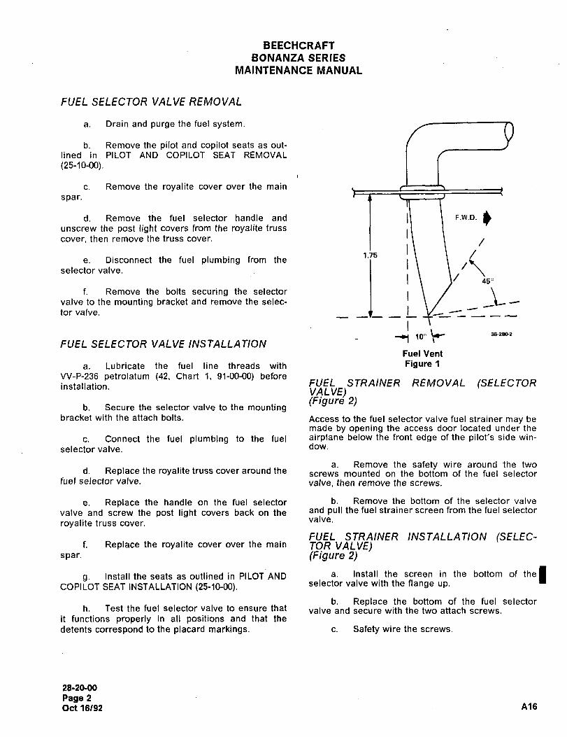
BEECHCRAFT
BONANZA SERIES
MAINTENANCE MANUAL
FUEL SELECTOR VALVE REMOVAL
a. Drain and purge the fuel system.
b. Remove the pilot and copilot seats as out-
lined in PILOT AND COPILOT SEAT REMOVAL
(25-10-00).
c. Remove the royalite cover over the main
spar.
d. Remove the fuel selector handle and
unscrew the post light covers from the royalite truss
cover, then remove the truss cover. Il.j5 I\
e. Disconnect the fuel plumbing from the
IL \450selector valve.
f. Remove the bolts securing the selector Lvalve to the mounting bracket and remove the selec-
tor valve.
3e-2ao210"FUEL SELECTOR VALVE INSTALLATION
Fuel Vent
a. Lubricate the fuel line threads with Figure 1
VV-P-236 petrolatum (42, Chart 1, 91-00-00) before
installation. FUEL STRAINER REMOVAL (SELECTORVALVE)(Flgure 2)
b. Secure the selector valve to the mountingbracket with the attach bolts. Access to the fuel selector valve fuel strainer may be
made by opening the access door located under the
c. Connect the fuel plumbing to the fuel airplane below the front edge of the pilot’s side win-
selector valve. dow.
a. Remove the safety wire around the twod. Replace the royalite truss cover around the mounted on the bottom of the fuel selector
fuel selector valve, valve, then remove the screws.
e. Replace the handle on the fuel selector b. Remove the bottom of the selector valve
valve and screw the post light covers back on the and pull the fuel strainer screen from the fuel selectorvalve.
royalite truss cover.
FUEL STRAINER INSTALLATION (SELEC-f. Replace the royalite cover over the main TOR VALVE)
spar. (Frgure 2)
s´• Install the seats as outlined in PILOT AND a. Install the screen in the bottom of the(COPILOT SEAT INSTALLATION (25-10-00). selector valve with the flange up.
b. Replace the bottom of the fuel selectorh. Test the fuel selector valve to ensure that valve and secure with the two attach screws.
it functions properly in all positions and that the
detents correspond to the placard markings. c. Safety wire the screws.
28-20-00
Page 2
Oct 16/92 Ale
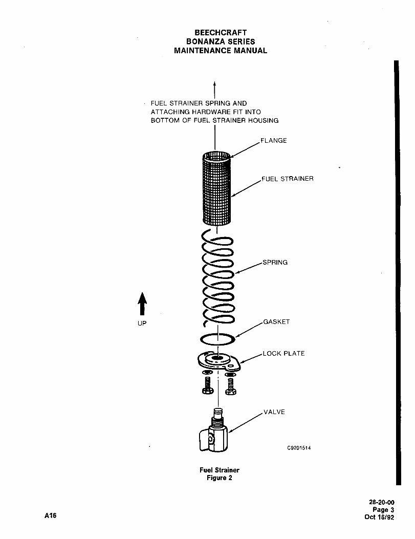
BEECHCRAFT
BONANZA SERIES
MAINTENANCE MANUAL
FUEL STRAINER SPRING AND
ATTACHING HARDWARE FIT INTO
BOTTOM OF FUEL STRAINER HOUSING
FLANGE
FUEL STRAINER
SPRING
tUP
~3GISI(ET
d~/"-’C9201514
Fuel Strainer
Figure 2
28-20-00
Page 3Ale Oct 16/92
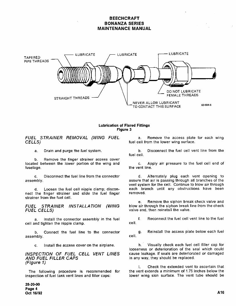
BEECHCRAFT
BONANZA SERIES
MAINTENANCE MANUAL
LUBRICATE LUBRICATE LUBRICATE
TAPEREDPIPE THREADS
DO NOT LUBRICATE
FEMALE THREADSSTRAIGHT THREADS
NEVER ALLOW LUBRICANT60-604-5
TO CONTACT THIS SURFACE
Lubrication of Flared FittingsFigure 3
FUEL STRAINER REMOVAL (WING FUEL a. Remove the access plate for each wingCELLS) fuel cell from the lower wing surface.
a. Drain and purge the fuel system. b. Disconnect the fuel cell vent line from the
fuel cell.
b. Remove the finger strainer access cover
located between the lower portion of the wing and c. Apply air pressure to the fuel cell end of
fuselage. the vent line.
c. Disconnect the fuel line from the connector d. Alternately plug each vent opening to
assembly, assure that air is passing through all branches of the
vent system for the cell. Continue to blow air throughd. Loosen the fuel cell nipple clamp; discon- each branch until any obstructions have been
nect the finger strainer and slide the fuel finger removed.
strainer from the fuel cell.
e. Remove the siphon break check valve and
FUEL STRAINER INS TALLA TION (WING blow air through the siphon break line from the check
FUEL CELLS) valve end, then reinstall the valve.
a. Install the connector assembly in the fuel f. Reconnect the fuel cell vent line to the fuel
cell and tighten the nipple clamp, cell.
b. Connect the fuel line to the connector g. Reinstall the access plate below each fuel
assembly. cell.
c. Install the access cover on the airplane. h. Visually check each fuel cell filler cap for
looseness or deterioration of the seal which could
INSPECTION OF FUEL CELL VENT LINES cause leakage. If seals are deteriorated or damagedAND FUEL FILLER CAPS in any way, they should be replaced.
(Figure 1)i. Check the extended vent to ascertain that
The following procedure is recommended for the vent extends a minimum of 1.75 inches below the
inspection of fuel tank vent lines and filler caps: lower wing skin surface. The vent tube should be
28-20-00
Page 4
Oct 16/92 A16
BEECHCRAFT
BONANZA SERIES
MAINTENANCE MANUAL
scarfed at a 450 angle on the forward side and should FLARIFD FITTINGS
be canted forward 100 from perpendicular to the skin. (Figure 3)
NOTE When installing flared fittings and hoses, make sure
the threads are lubricated properly (see Figure 2)with VV-P-236 petrolatum ~42, Chart 1, 91-00-00).
Any configuration of the vent other than asWhen previously installed fittings are removed, they
noted in step "i" may create a negative should be wiped clean and relubricated before theyvent pressure. A negative vent pressure are reinstalled. Torque all fittings in accordance withwill pull the air, or air and fuel from the fuel the FLARE FITTING TORQUE CHART (Chart 2,tank. 91-00-00).
"END"
28-20-00
Page 5
A16 Oct 16/92
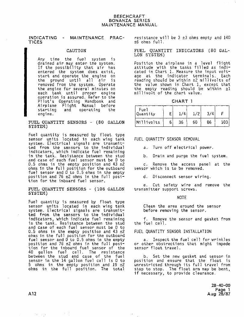
BEECHCRAFTBONANZA SERIES
MAINTENANCE MANUAL
INDICATING MA IN TENANCE PRAC- resistance will be 3 +3 ohms empty and 140TICES +6 ohms full.
CAUTION FUEL QUANTITY INDICATORS (80 GAL-LON SYSTEM)
Any time the fuel system isdrained air may enter the system. Position the airplane in a level flightIf the possibility that air has attitude with the tanks filled as indi-entered the system does exist, cated in Chart 1. Measure the input volt-start and operate the engine on age at the indicater terminals. Eachthe ground until all air is reading should be within +2 millivolts ofremoved from the system. Operate the value shown in Chart 1, except thatthe engine for several minutes on the empty reading should be within ~1each tank until proper engine millivolt of the chart value.
operation is assured. Refer to thepilot’s Operating Handbook and CHART 1
Airplane Flight Manual before
starting and operating the Fuel
engine. Quantity E 1/4 1/2 3/4 F
FUEL QUANTITY SENSORS (80 GALLON Millivolts 61 36 60 86 1 103
SYSTEM)
Fuel quantity is measured by float typesensor units located in each wing tank FUEL QUANTITY SENSOR REMOVAL
system. Electrical signals are transmit-ted from the sensors to the individual a. Turn off electrical power.indicators, which indicate fuel remainingin the tank. Resistance between the stud b. Drain and purge the fuel system.and case of each fuel sensor must be O to
0.5 ohms in the empty position and 43 +2 c. Remove the access panel at theohms in the full position for the outboard sensor which is to be removed.fuel sensor and 0 to 0.5 ohms in the emptyposition and 76 ~2 ohms in the full posi- d. Disconnect sensor wiring.tion for the inboard fuel sensor.
e. Cut safety wire and remove theFUEL QUANTITY SENSORS (108 GALLON transmitter support screws.
SYSTEM)NOTE
Fuel quantity is measured by float typesensor units located in each wing tank Clean the area around the sensor
system. Electrical signals are transmit- before removing the sensor.
ted from the sensors to the individual
indicators, which indicate fuel remaining f. Remove the sensor and gasket fromin the tank. Resistance between the stud the fuel cell.and case of each fuel sensor must be 0 to
0.5 ohms in the empty position and 43 +2 FUEL QUANTITY SENSOR INSTALLATIONohms in the full position for the outboardfuel sensor and 0 to 0.5 ohms in the empty a. Inspect the fuel cell for wrinklesposition and 76 ~2 ohms in the full posi- or other obstructions that might impedetion for the inboard fuel sensor of the sensor float travel.40 gallon fuel cell. The resistancebetween the stud and case of the fuel b. Set the new gasket and sensor insensor in the 14 gallon fuel cell is O to position and ensurethat the float is5 ohms in the empty position and 19 ´•t2 unrestricted through its full travel fromohms in the full posi ti on The total stop to stop. The float arm may be bent,
if necessary, to provide clearance.
28-40-00
Page 1A12 Aug 28/87
BEECHCRAFTBONANZA SERIES
MAINTENANCE MANUAL
c. Install the sensor support FUEL QUANTITY INDICATOR CALIBRATIONscrews, torque to 25 inch-pounds, andsafety, a. Remove the glareshield over the
instrument panel.d. Connect sensor wiring. Turn the
power on and check fuel gage for empty b. Locate the two printed ci rcui t
reading. boards located on the back of the instru-ment panel just to the left of center.
NOTEc. Locate the calibration screw in
If the gage does not read empty, the back of each printed circuit board.
reinspect the sensors to ensure
the float arm is on the down stop d. Calibrate the fuel quantity indi-and the float clears the bottom cater as follows:of the fuel cell. Check all wiringfor faulty connections. 1. Ensure that the fuel tank that
corresponds to the fuel quantity beinge. Fill the tanks and check the fuel calibrated is full.
gages for full readings.2. Turn the calibration screw in
NOTE back of the corresponding printed circuitboard until the needle onthe fuel quan-
See Service Instructions No. tity indicator points to the "F" (full)0925, Rev. I or subsequent for mark.more information on replacementof fuel quantity sensors, e. Reinstall the glareshield.
"END"
28-40-00
Page 2
Aug 28/87 A12

CHAPTER
ICE AND RAIN
PROTECTION
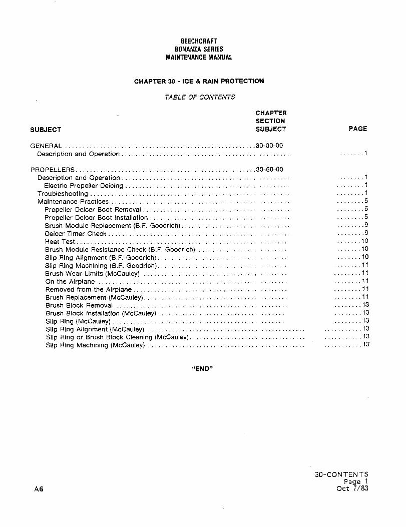
BEECHCRAFT
BONANZA SERIES
MAINTENANCE MANUAL
CHAPTER 30 ICE 8 RAIN PROTECTION
TABLE OF CONTENTS
CHAPTER
SECTION
SUBJECT SUBJECT PAGE
GENERAL 30-00-00
Description and Operation .......1
PROPELLERS 30-60-00
Description and Operation ..................1
Electric Propeller Deicing ........1
Troubleshooting ........1
Maintenance Practices ........5
Propeller Deicer Boot Removal ........5
Propeller Deicer Boot Installation ........5
Brush Module Replacement (B.F. Goodrich) .................9
Deicer Timer Check ........9
Heat Test .......10
Brush Module Resistance Check (B.F. Goodrich) .......10
Slip Ring Alignment (8.F. Goodrich) .......10
Slip Ring Machining (B.F. Goodrich). ........11
Brush Wear Limits (McCauley) ........11
On the Airplane ........11
Removed from the Airplane ........11
Brush Replacement (McCauley) ..............11
Brush Block Removal ........13
Brush Block installation (McCauley) ........13
Slip Ring (McCauley) ........13
Slip Ring Alignment (McCauley) 13
Slip Ring or Brush Block Cleaning (McCauley). .........´•.13
Slip Ring Machining (McCauley) 13
"END"
30-CONTENTS
Page 1
A6 Oct 7/83
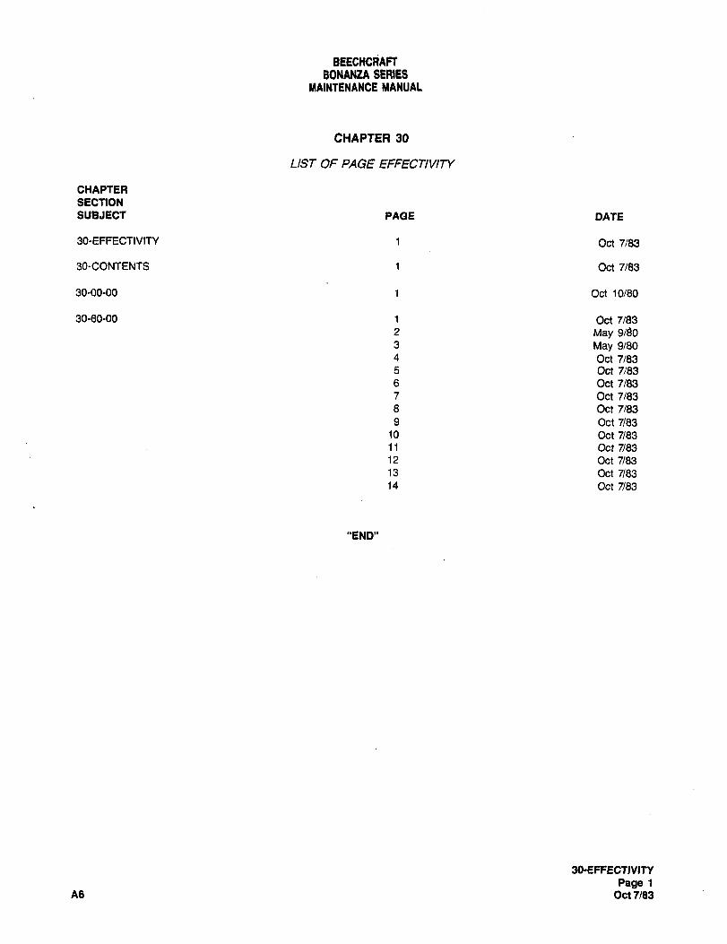
BEECHCRAFTBONANZA SERIES
MAINTENANCE MANUAL
CHAPTER 30
LIST OF PAGE EFFECTIVITY
CHAPTER
SECTION
SUBJECT PAGE DATE
30-EFFECTIVlfY 1 Oct 7/83
90-CONTENTS 1 Oct 7/83
30-00-00 1 Oct 10/80
30-60-00 1 Oct 7/83
2 May 9~03 May 9/80
4 Oct 7/835 Oct7/83
6 Oct 7183
7 Oct 7/83
8 Oct 7/83
9 Oct 7/8310 Oct 7/8311 Oct 7/8312 Oct 7/8313 Oct 7/8314 Oct 7/83
"END"
30-EFFECflYITY
Page 1
A6 Oct 7/83
BEECHCRAFT
BONANZA SERIESMAINtENANCE MANUAL
GENERAL DESCRIPTION AND OPERATION the airplane electrical system for protecting the pitotopening from becoming clogged with ice.
The airplane is equipped with a variety of ice and rain
protection systems that can be utilized during operation An optional weather radar system is available for the
under inclement weather conditions. Air from the cabin Bonanza series airplanes starting at serials GO-878 and
heating system prevents the windshield from fogging. The after, D-10284 and after, E-1534, E-1537 and after, andpropellers are protected against icing by optional EA-11 and after. The indicator is located in the radio
electrothermal boots on each blade that, when activated, section of the instrument panel and the antenna is located
automatically cycle to aid in dispersing the formation of ice. in the outboard leading edge of the right wing. (See 34-40-
The pitot mast contains a heating element connected to 00.)
"END"
30-00-00
Page 1
Oct 10180
BEECHCRAFTBONANZA SERIES
MAINTENANCE MANUAL
PROPELLERS DESCRIPTION AND OPERATION phase the timer is in.
PROPELLER TROUBLESHOOTING DEICER
SYSTEMELECTRIC PROPELLER DEICING
The ammeter of the deicer system can be used to indicate
The electric propeller deicer system. includes an on-off the general nature of most electrical problems.switch ion the LH instrument subpanel), an ammeter, a Consequently, it is recommended that, to determine which
timer, a brush assembly, slip rings, and an electrically circuits are involved, troubleshooting be preceded by the
heated boot for each propeller blade. When the on-oh ammeter test outlined in step "a." of the 50-hour inspectionswitch is turned ON, the ammeter (near the center of the (Chapter 5), and the HEAT TEST described in this chapter.
instrument panel) registers the amount of current (Bbladed, A reading of two-thirds the nonnal amount of current (or
8-12 amps; 3bladed, 14-18 amps) passing through the one-half on two-bladed props) is an indication that one of
system. If the current rises beyond the switch limit, an the circuits is open between the slip ring assembly and
integral circuit breaker will cut off the power to the timer. deicer heater. If the ammeter registers excess current, the
The current flows from the timer (forward of instrument power lead is shorted to ground. It is possible that the
panel) to the brush assembly (mounted in front of the excess current has welded the timer contacts in one phase.
engine case) and is conducted by the brush assembly to the Under these circumstances, the timer will either feed current
slip rings installed on the spinner backing plate. At serials D- to the welded contacts continuously, or not cycle. If the
10404 and after, CE-1024 and after, E-2069 and after, and former is true, the heat test wil\ show heating throughout the
EA-378 and after, the slip rings became part of an assembly two phases. Unless the grounded power lead is located and
attached between the engine hub and the propeller. The slip corrected, any new timer that is installed may suffer the
rings distribute current to the deicer boots on the propeller same internal damage during the first use of the system. In
blades. Heat from the boots reduces the grip of the ice, general, for most effective use of the troubleshooting chart,
which is then removed by the centrifugal effect of propeller all of the "indication" entries should be read to locate that
rotation and by the blast of the airstream. The timer cycles which matches conditions of the particular system being
power to the heating element on each blade. It takes 3 checked. The numbered "probable cause" and "remarks"
minutes for the timer to complete a cycle of 90 seconds on, then indicate the proper sequence of checks. It should be
90 seconds off. Whenever the system is turned on, the noted, however, that such numbers are assigned with
the proper amerage, or zero amperage, depending on the than to the most likely sequence of occurance.
ammeter in the instrument panel or subpanel and registers respect to the approximate usefulness of the check rather
30-60-00
Page 1
A6 Oct 7/83
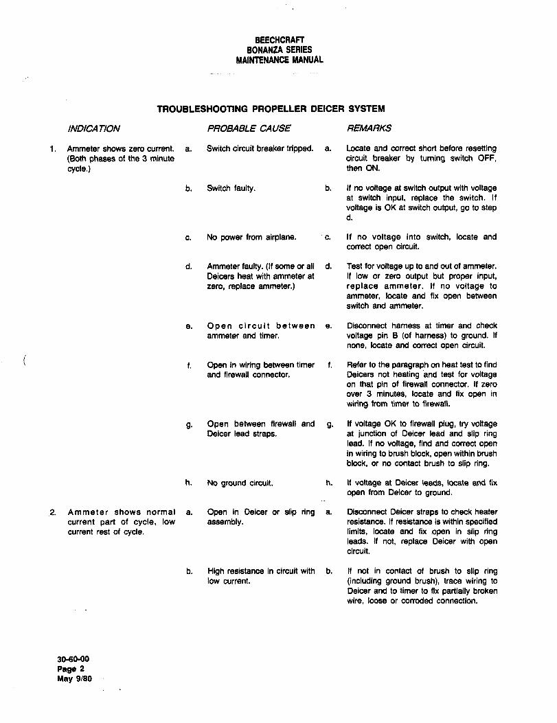
BEECHCRAFTBONANtA SERIES
MAINTENANCE MANUAL
TROUBLESHOOTING PROPELLER DEICER SYSTEM
INDICA TION P~OBABLE CAUSE
i. Ammeter shows zero current. a. Switch circuit breaker tripped. a. Locate and correct short before resetting(8oth phases of the 3 minute circuit breaker by turning switch OFF,
cycle.) then ON.
b. Switch faulty. b. If no voltage at switch output with voltageat switch input, replace the switch. If
voltage is OI< at switch output, go to step
c. No power from airplane. ’c. If no voltage into switch, locate and
correct open circuit.
d. Ammeter faulty. (If some or all d. Test for voltage up to and out of ammeter.
Deicers heat with ammeter at If low or zero output but proper input,zero, replace ammeter.) replace ammeter. If no voltage to
ammeter, locate and fix open between
switch and ammeter.
a. Open circuit between a. Disconnect hamess at timer and check
ammeter and timer, voltage pin B (of harness) to ground. If
none, locate and correct open circuit.
i1. Open in wl~ng balween timer t Rater to Ihepara~raphon heattesttofind
and firewall connector. Deicers not heating and test for voltageon that pin of firewall connector. If zero
over 3 minutes, locate and fix open in
wiring from tirner to firswall.
g. Open between firewall and g. If voltage OK to firewall plug, try voltageDeicer lead straps, at junction of Deicer lead and slip ring
lead. If no voltage, find and correct openin wiring to brush block, open within brush
block, or no contact brush to slip ring.
h. No ground circuit, h. If voltage at Oeicer leads, locate and fix
open from Deicer to ground.
2. Ammeter shows normal a. Open in Deicer or slip ring a. Disconnect Deicer straps to check heater
current part of cycle, low assembly. resistance. If resistance is within specifiedcurrent rest of cycle, limits, locate and fix open in slip ring
leads. If not, replace Deicer with opencircuit.
b. High resistance in circuit with b. If not in contact of brush to slip ringlow current. (including ground brush), trace wiring to
Deicer and to timer to fix partially broken
wire, loose or corroded connection.
3060-00
Page 2
May 9/80
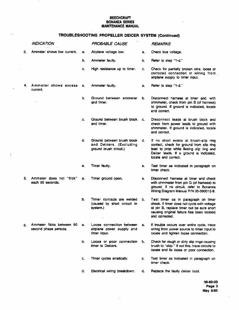
BEECHCRAFTBONANZA SERIES
MAINtENANCE MANUAL
TROUBLESHOOTING PROPELLER DEICER SYSTEIIII (Contlnued)
INDICA TION PROBABLE CAUSE REMARKS
3. Ammeter shows low current. a. Airplane voltage low, a. Check bus voltage.
b. Ammeter faulty, b. Refer to step "l-d."
c. High resistance up to timer, c. Check for partially broken wire, loose or
corroded connection in wiring from
airplane supply to timer input.
4. Ammeter shows excess a. Ammeter faulty, a. Refer to step "l-d."
current.
b. Ground between ammeter b. Disconnect harness at timer and, with
and timer. ohmmeter, check from pin B (of harness)to ground. If ground is indicated, locate
and correct.
c. Ground between brush block c. Disconnect leads at brush block and
and timer. check from power leads to ground with
ohmmeter. If ground is indicated, locate
and correct.
d. Ground between brush block d. If no short exists at brush-slip ringand Deicers. (Excluding contact, check for ground from slip ringground brush circuit.) lead to prop while flexing slip ring and
Deicer leads. If a ground is indicated,locate and correct.
e. Timer faulty, e. Test timer as indicated in paragraph on
timer check.
5. Ammeter does not "flick" a. Timer ground open, a. Disconnect harness at timer and check
each 90 seconds, with ohmmeter from pin G tot harness) to
ground. If no circuit, refer to Bonanza
Wiring Diagram Manual P/N 35-590012-9.
b. Timer contacts are welded b. Test timer as in paragraph on timer
(caused by short circuit in check. If timer does not cycle with voltagesystem.) at pin B, replace timer but be sure short
causing original failure has been located
and conected.
5. Ammeter flicks between 90 a. Loose connection between a. If trouble occurs over entire cycle, trace
second phase periods. airplane power supply and wiring from power source to timer input to
timer input, locate and tighten loose connection.
b. Loose or poor connection b. Check for rough or dirty slip rings causingtimer to Deicers. brush to "skip." If not this, trace circuits to
locate and fix loose or poor connection.
c. Timer cycles erratically. c. Test timer as indicated in paragraph on
timer check.
d. Electrical wiring breakdown. d. Replace the faulty deicer boot.
3060-00
Page 3
May 9/80
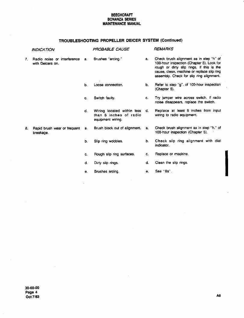
BEECHORAFTBONANZA SERIES
MAIWTENANCE MANUAL
TROUBLESHOOTING PROPELLER DEICER SYSTEM (Continued)
INDICA TION PROBABLE CAUSE REMARKS
7. Radio noise or interference a. Blushes "arcing." a. Check brush alignment as in step "h" of
with Deicers on. 100-hour inspection (Chapter 5). Look for
rough or dirty slip rings. If this is the
cause, clean, machine or replace slip ringassembly. Check for slip ring alignment.
b. Loose connection, b. Refer to step "g", of 100-hour inspection(Chapter 5).
c. Switch faulty. c. Try jumper wire across switch. If radio
noise disappears, replace the switch.
d. Wiring located within less d. Replace at least 8 inches from inputthan 8 inches of radio wiring to radio equipment.equipment wiring.
8. Rapid brush wear or frequent a. Brush block out of alignment. a. Check brush alignment as in step "h." of
breakage. 100-hour inspection (Chapter 5).
b. Slip ring wobbles. b. Check slip ring alignment with dial
indicator.
c. Rough slip ring surfaces, c. Replace or machine.
d. Dirty slip rings. d. Clean the slip rings.
e. Brushes arcing. e. See "8a".
3060-00
Page 4
Oct7183 A6
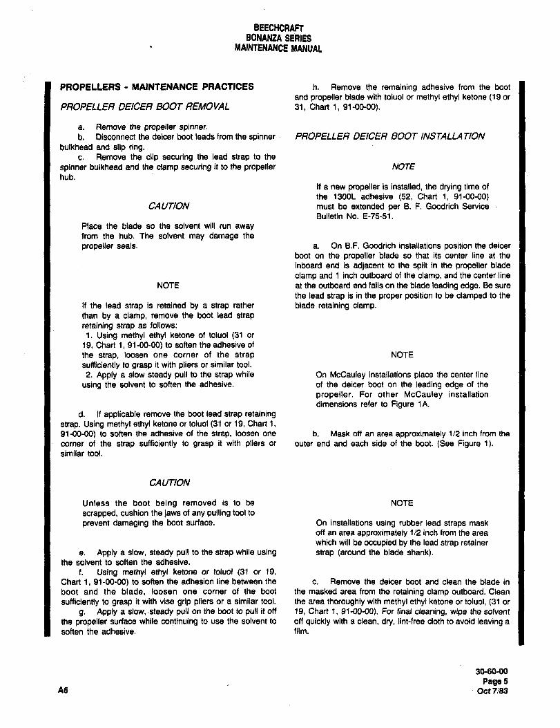
BEECHCRAFTBONANZA SERIES
MAINTENANCE MANUAL
PROPELLERS MAINtENANCE PRACTICES h. Remove the remaining adhesive from the boot
and propeller blade with toluol or methyl ethyl ketone (19 or
PROPELLER DEICEfl BOOT REMOVAL 31, Chart 1, 91-00-00).
a. Remove the propeller spinner.b. Disconnect the deicer boot leads from the spinner PROPELLER DEICER BOOT INSTALLA T7ON
bulkhead and slip ring.c. Remove the clip securing the lead strap to the
spinner bulkhead and the clamp securing it to the propeller NOTE
hub.
If a new propeller is installed, the drying time of
the 1300L adhesive (52, Chart i, 91-00-00)CAUTION must be extended per 8. F. Goodrich Service
Bulletin No. E-75-51.
Place the blade so the solvent will run awayfrom the hub. The solvent may damage the
propeller seals. a. On B.F. Goodrich installations position the deicer
boot on the propeller blade so that its center line at the
inboard end is adjacent to the split in the propeller blade
clamp and 1 inch outboard of the clamp, and the center line
NOTE at the outboard end falls an the blade leading edge. Be sure
the lead strap is in the proper position to be clamped to the
It the lead strap is retained by a strap rather blade retaining clamp.than by a clamp, remove the boot lead strap
retaining strap as follows:
1. Using methyl ethyl ketone of toluol (31 or
19, Chart i, 91-00-00) to soften the adhesive of
the strap, loosen one corner of the strap NOTE
sufficiently to grasp it with pliers or similar tool.
2. Apply a slow steady pull to the strap while On McCauley installations place the center line
using the solvent to soften the adhesive, of the deicer boot on the leading edge of the
propeller. For other McCauley installation
dimensions refer to Figure tA.
d. If applicable remove the boot lead strap retainingstrap. Using methyl ethyl ketone or toluol (31 or 19, Chart i,
91-00-00) to soften the adhesive of the strap, loosen one b. Mask off an area approximately 1/2 inch from the
corner of the strap sufficiently to grasp it with pliers or outer end and each side of the boot. (See Figure 1).similar tool.
CAUTION
Unless the boot being removed is to be NOTE
scrapped, cushion the jaws of any pulling tool to
prevent damaging the boot surface. On installations using rubber lead straps mask
off an area approximately 112 inch from the area
which will be occupied by the lead strap retainer
e. Apply a slow, steady pull to the strap while using strap (around the blade shank).the solvent to soften the adhesive.
f. Using methyl ethyl ketone or toluol (31 or 19,
Chart 1, 91-00-00) to soften the adhesion line between the c. Remove the deicer boot and clean the blade in
boot and the blade, loosen one corner of the boot the masked area from the retaining clamp outboard. Clean
sufficiently to grasp it with vise grip pliers or a similar tool. the area thoroughly with methyl ethyl ketone or toluol, (31 or
g. Apply a slow, -steady pull on the boot to pull it off 19, Chart i, 91-00-00). For final cleaning, wipe the solvent
the propeller surface while continuing to use the solvent to off quickly with a clean, dry, lint-free cloth to avoid leaving a
soften the adhesive. film.
3060-00
Page5A6 Oct7/83
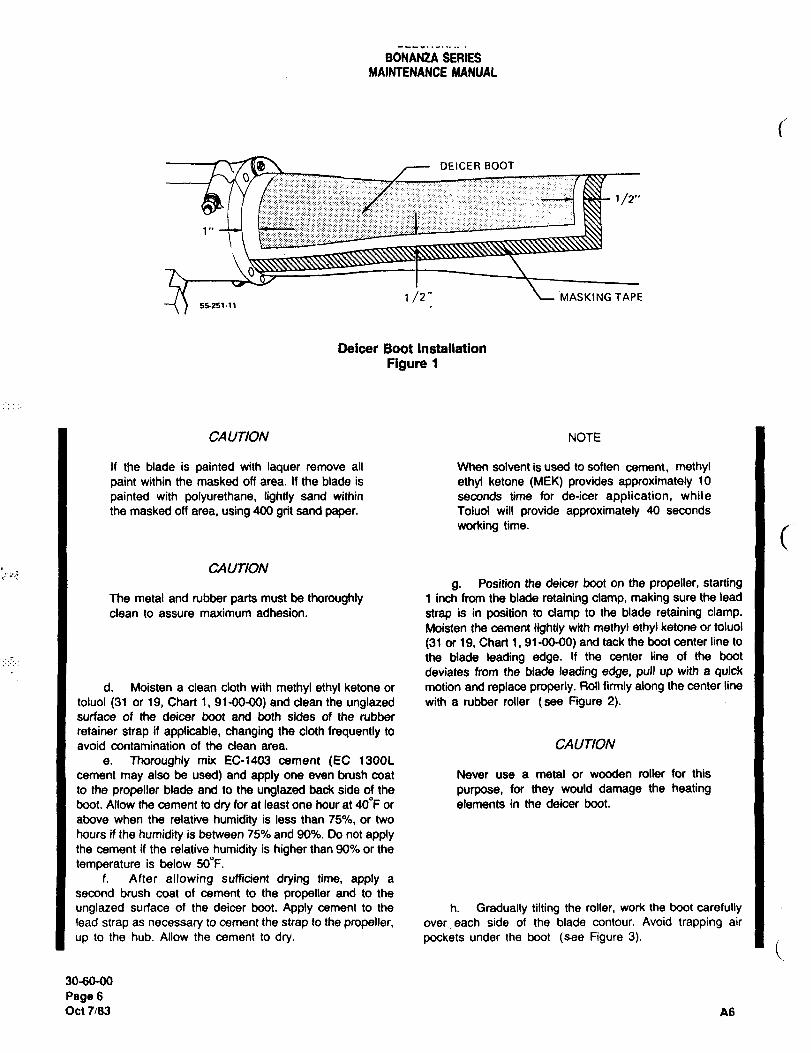
BONANZA SERIESMAINTENANCE MANUAL
OEICERBOOT
I-:--:::::I
1/2"
t /2" MASKING TAPEecal´•~1
Deicer Boot Installation
Figure 1
CAU770N NOTE
If the blade is painted with laquer remove all When solvent is used to soften cement, methylpaint within the masked off area. If the blade is ethyl ketone (MEK) provides approximately 10
painted with polyurethane, lightly sand within seconds time for de-icer application, while
the masked off area, using 400 grit sand paper. Toluol will provide approximately 40 seconds
working time.
CAUT/ON
g. Position the deicer boot on the propeller, startingThe metal and rubber parts must be thoroughly 1 inch from the blade retaining clamp, making sure the lead
clean to assure maximum adhesion. strap is in position to clamp to the blade retaining clamp.Moisten the cement lightly with methyl ethyl ketone or toluol
(31 or 19, Chart 1, 91-00-00) and tack the boot center line to
the blade leading edge. If the center line of the boot
deviates from the blade leading edge, pull up with a quickd. Moisten a clean cloth with methyl ethyl ketone or motion and replace properly. Roll firmly along the center line
toluol (31 or 19, Chart i, 91-00-00) and clean the unglazed with a rubber roller (see Figure 2).surface of the deicer boot and both sides of the rubber
retainer strap if applicable, changing the cloth frequently to
avoid contamination of the clean area. CAUTION
a. Thoroughly mix EC-1403 cement (EC 1300L
cement may also be used) and apply one even brush coat Never use a metal or wooden roller for this
to the propeller blade and to the unglazed back side of the purpose, for they would damage the heatingboot. Allow the cement to dry for at least one hour at 400F or elements in the deicer boot.
above when the relative humidity is less than 75%, or two
hours if the humidity is between 75% and 90%. Do not applythe cement if the relative humidity is higher than 90% or the
temperature is below 50"F.f. After allowing sufficient drying time, apply a
second brush coat of cement to the propeller and to the
unglated surface of the deicer boot. Apply cement to the h. Gradually tilting the roller, work the boot carefullylead strap as necessary to cement the strap to the propeller, over each side of the blade contour. Avoid trapping air
up to the hub. Allow the cement to dry. pockets under the boot (see Figure 3).
30-60-00
pagesOct 7/83 A6
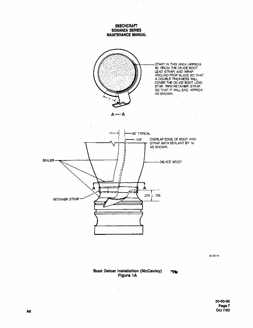
BEECHCRAFTBONANZA SERIES
MAINTENANCE MANUAL
START IN THIS AREA (APPROX.90: FROM THE DE-ICE BOOT
~ii LEAD STRAP) AND WRAP
AROUND PROP BLADE SO THAT
A DOUBLE THICKNESS WILL
COVER THE DE-ICE BOOT LE’ADSTAP. TRIM RETAINER STRAPSO THAT IT WILL END APPROX.
AS SHOWN.
A--A
i jc.50" TYPICAL
~c-- .129’ OVERLAP EDGE OF BOOT AND
STRAP WITH SEALANT BY ~a"
AS SHOWN.
SEALER ;I ~------DE-ICE BOOT
.375+ .125
RETAINER STRAP
36-251-8
Boot Deicer Installation (McCauley) T~IFigure 1A
30-60-00
Page 7
A6 Oct 7/83
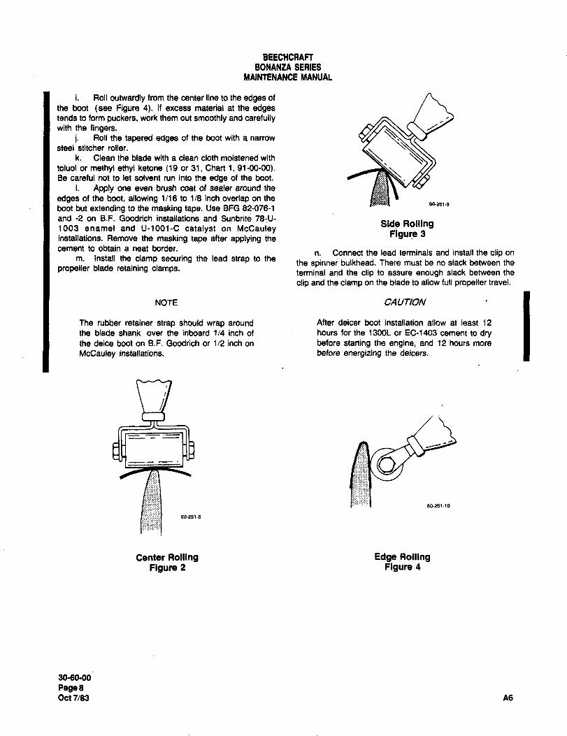
BEECHCRAFTBONANZA SERIES
MAINTENANCE MANUAL
Roll outwardly from the center line to the edges of
the boot (see Figure 4). If excess material at the edgestends to form puckers, work them out smoothly and carefullywith the fingers.
i’. Roll the tapered edges of the boot with a narrow
steel stitcher roller.
k. Clean the blade with a clean cloth moistened with
toluol or methyl ethyl ketone (19 or 31, Chart 1, 91-00-00).Be careful not to let solvent run into the edge of the boot.
i. Apply one even brush coat of sealer around the
edges of the boot, allowing 1/16 to 1/8 inch overlap on the502519
boot but extending to the masking tape. Use BFG 82-076-1
and -2 on B.F. Goodrich installations and Sunbrite 78-U-Side Rolling1003 enamel and U-1001-C catalyst on McCauley
installations. Remove the masking tape after applying the Figure 3
cement to obtain a neat border.n. Connect the lead terminals and install the clip on
m. Install the clamp securing the lead strap to thethe spinner bulkhead. There must be no slack between the
propeller blade retaining clamps. terminal and the clip to assure enough slack between the
clip and the clamp on the blade to allow full propeller travel.
NOTE CAUT1ON
The rubber retainer strap should wrap around After deicer boot installation allow at least 12
the blade shank over the inboard 1/4 inch of hours for the 1300L or EC-1403 cement to drythe deice boot on B.F. Goodrich or 1/2 inch on before starting the engine, and 12 hours more
McCauley installations, before energizing the deicers.
acr2s~´•lo
60251´•8
Center Rolling Edge RollingFigure 2 Figure 4
30-60-00
PagerOct 7/83 A6
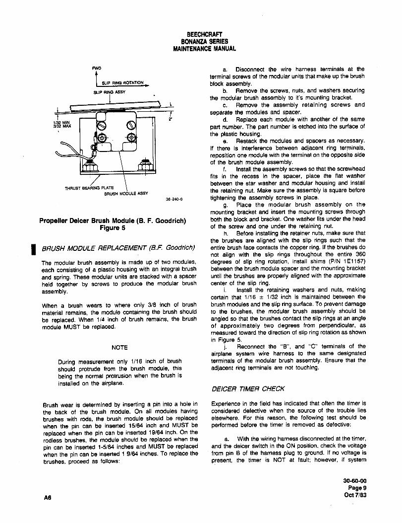
BEECHCRAFTBONANZA SERIES
MAINTENANCE MANUAL
Fwo a. Disconnect the wire harness terminals at the
terminal screws of the modular units that make up thebrushblockassembly.SLIP RING Assv b. Remove the screws, nuts, and washers securing
the modular brush assembly to it’s mounting bracket.
c. Remove the assembly retaining screws and
-tt separate the modules and spacer.
2´• d. Replace each module with another of the sameIn:, MIN3/32 MAX part number. The part number is etched into the surface of
the plastic housing.a. Restack the modules and spacers as necessary.
If there is interference between adjacent ring terminals,
reposition one module with the terminal on the opposite side
of the brush module assembly.f. Install the assembly screws so that the screwhead
fits in the recess in the spacer, place the flat washer
between the star washer and modular housing and installTHRUJT BE*RING PL~ESH MDULE 188Y
the retaining nut. Make sure the assembly is square befwe
38240-6 tightening the assembly screws in place.
g. Place the modular brush assembly on the
mounting bracket and insert the mounting screws through
Propeller Deicer Brush Module (B. F. Goodrich) both the block and bracket. One washer fits under the head
Figure 5 of the screw and one under the retaining nut.
h. Before installing the retainer nuts, make sure that
the brushes are aligned with the slip rings such that the
I BRUSH MaDULE REPLACEIWI~NT(B.F. Good~ch) entire brush face contacts the copper ring. If the brushes do
not align with the slip rings throughout the entire 360
The modular brush assembly is made up of two modules, degrees of slip ring rotation, install shims (P/N 151157)
each consisting of a plastic housing with an integral brush between the brush module spacer and the mounting bracket
and spring. These modular units are stacked with a spacer until the brushes are properly aligned with the approximate
held together by screws to produce the modular brush center of the slip ring.
assembly, i. Install the retaining washers and nuts, makingcertain that 1/16 c 1/32 inch is maintained between the
When a brush wears to where only 3/8 inch of brush brush modules and the slip ring surface. To prevent damage
material remains, the module containing the brush should to the brushes, the modular brush assembly should be
be replaced. When 1/4 inch of brush remains, the brush angled so that the brushes contact the slip rings at an angle
module MUST be replaced. of approximately two degrees from perpendicular, as
measured toward the direction of slip ring rotation as shown
in Figure 5.
NOTE j. Reconnect the "B", and "C" terminals of the
airplane system wire harness to the same designated
During measurement only 1116 inch of brush terminals of the modular brush assembly. Ensure that the
should protrude from the brush module, this adjacent ring terminals are not touching.
being the normal protrusion when the brush is
installed on the airplane.DEICER ’TIMER CHECK
Brush wear is determined by inserting a pin into a hole in Experience in the field has indicated that often the timer is
the back of the brush module. On all modules having considered defective when the source of the trouble lies
brushes with rods, the brush module should be replaced elsewhere. For this reason, the following test should be
when the pin can be inserted 15/64 inch and MUST be performed before the timer is removed as defective:
replaced when the pin can be inserted 19/64 inch. On the
rodless brushes, the module should be replaced when the a. With the wiring harness disconnected at the timer,
pin can be inserted 1-5/64 inches and MUST be replaced and the deicer switch in the ON position, check the voltage
when the pin can be inserted 1 9/64 inches. To replace the from pin B of the harness plug to ground. If no voltage is
brushes, proceed as follows: present, the timer is NOT at fault; however, if system
30-60-00
Page9Oc17/83
A6
BEECHCRAFTBONANZA SERIES
MAINTENANCE MANUAL
voltage is present at pin B, check the circuit from harness WARNING
plug pin G to ground with an ohmmeter. If no circuit is
indicated, the fault is in the ground lead rather than in the Before moving the propeller, make certain that
timer. If ground connection is open, the timer step switch will the ignition switch is off and that the engine has
not change position, cooled completely. There is always some
b. After the ground and power circuits have been danger of a cylinder firing when the propeller is
checked, connect a jumper wire from pin B of the timer moved.
receptacle to terminal B of the connector plug and from pinG of the timer receptacle to ground. With the deicing systemswitch ON, check the voltage to ground from pin B of the BRUSH MODULE RES/STANCE CHECK (B.F. I
Itimer. The voltmeter should indicate bus voltage. Next, Goodrich)check the DC voltage to ground from pin C or pin D on
serials D-10404 and after, CE-1024’and after, E-2069 and To check for a short circuit, or high resistance in the brush
after, and EA-378 and after; it should indicate bus voltage module, measure the resistance from the face of the brush
for 90 seconds, zero volts for 90 seconds, bus voltage 90 to its terminal studs or receptacle pin with a low range
seconds, etc, ohmmeter. If this resistance measures over 0.013 ohm,locate and repair the cause of excessive resistance. If the
resistance measures zero, locate and correct the openHEAT TEST circuit or replace the module. Check the resistance between
the terminal studs or receptacle pins. This resistance should
Before this test can be performed, the jumper wire installed not be less than 0.5 meg-ohm.for the timer test must be removed so that the connector
plug can be replaced in the timer receptacle. Two men are
required to perform this test: one in the cockpit to monitor SLIP RING AL/GNMENT(B.F. Goodrich) Ithe ammeter; the other outside by the prop to check the
deicer boots. The man in the cockpit turns the deicer system The slip rings- are properly aligned when they run in a true
ON while the man outside feels the deicer boots to see if plane relative to the brush module. This condition may be
they are heating properly. The man in the cabin observes checked by attaching a dial indicator gage to the front of the
the ammeter for the proper readings (2-bladed: 8-12 amps, engine crankshaft housing in such a manner that a reading3-bladed:l4-80 amps) throughout the timing sequence. The of the slip ring wobble may be obtained. To avoid error in
ammeter needle should deflect every 90 seconds in readings, rotate the slip rings slowly while pushing in on the
response to the switching action of the timer. Each time this propeller to take the play out of the thrust bearings. If the
occurs, the man in the cockpit must notify the man’ total run-out over 360 degrees of rotation exceeds 0.005
inspecting the propeller deicer boots so that the latter can inch, or 0.002 inch for any 4-inch are, the slip rings should
check the proper heating sequence of the propeller deicer be aligned as follows:
boots (the entire boot will either heat or cool, depending on
the timer sequence). If any irregularities are detected, a a. Approximately a 0.012 inch adjustment may be
continuity check should be performed on the wiring from the made to correct the slip ring wobble by varying the torquetimer to the brush module holder and the propeller deicer on the attachment bolts. Using the dial indicator to follow the
terminal connections. points of maximum deviation, adjust the slip ring assemblyto the prescribed run-out limits by varying the torque of the
mounting bolts as required within a range of 40 to 100 inch-
pounds.b. If more than 0.012 inch of adjustment is required
CAUTION for alignment, the slip ring assembly may be shimmed to
within the prescribed limits for true running by the addition of
While following the instructions of the "HEAT AN960C416L washers on the mounting bolts between the
TEST" section, move the propeller back and slip ring assembly and the spinner bulkhead. If necessary,forth to prevent arcing between the brushes and fabricate thinner shims to the AN960 size. Again the torqueslip ring. may be varied as in step "a".
30-60-00
page 10
Oct7183 A6
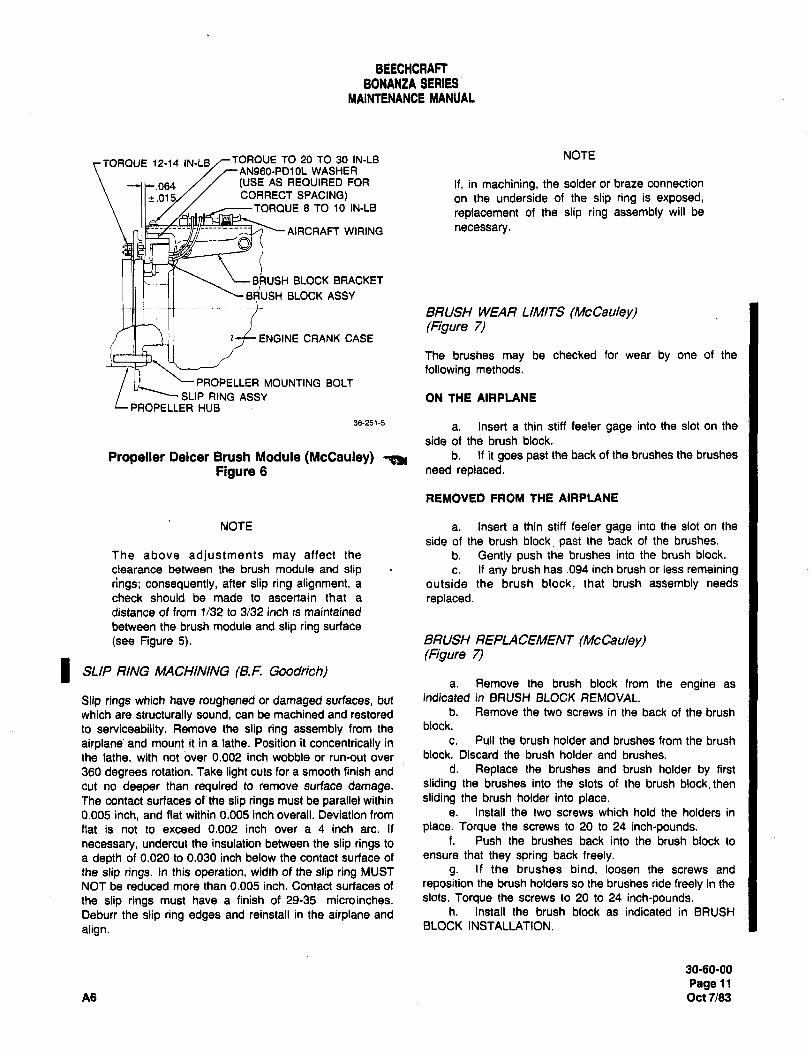
BEECHCRAFTBONANtA SERIES
MAINTENANCE MANUAL
TORQUE 12-14 IN-LB TORQUE TO 20 TO 30 IN-LB NOTE
AN980-PD10L WASHER
(USE AS REQUIRED FOR If, in machining, the solder or brats connection
.01 CORRECT SPACING) on the underside of the slip ring is exposed,TORQUE 8 TO 10 IN-LB
replacement of the slip ring assembly will be
AIRCRAFT WIRING necessary.
BRUSH BLOCK BRACKET
sdUSH BLOCK ASSY
BRUSH WEAR LIMITS (McCauleyl(Figure 7)
ENGINE CRANK CASE
The brushes may be checked for wear by one of the
following methods.
PROPELLER MOUNTING BOLT
SLIP RING ASSY ON THE AIRPLANEPROPELLER HUB
36-251-5a. Insert a thin stiff feeler gage into the slot on the
side of the brush block.
Propeller Deicer Brush Module (McCauley) ~51 b´• If it goes past the back of the brushes the brushes
Figure 6 need replaced.
REMOVED FROM tHE AIRPLANE
NOTE a. Insert a thin stiff feeler gage into the slot on the
side of the brush block past the back of the brushes.
The above adjustments may affect the b. Gently push the brushes into the brush block.
clearance between the brush module and slip c. If any brush has .094 inch brush or less remainingrings; consequently, after slip ring alignment, a outside the brush block, that brush assembly needs
check should be made to ascertain that a replaced.distance of from 1/32 to 3/32 inch is maintained
between the brush module and slip ring surface
(see Figure 5). BRUSH REPLACEMENT (McCauleyl(Figure 7)
I SLIP RING MACHINING (B.F. Goodrich)a. Remove the brush block from the engine as
Slip rings which have roughened or damaged surfaces, but indicated in BRUSH BLOCK REMOVAL.
which are structurally sound, can be machined and restored b. Remove the two screws in the back of the brush
to serviceability. Remove the slip ring assembly from the block.
airplane’ and mount it in a lathe. Position it concentrically in c. Pull the brush holder and brushes from the brush
the lathe, with notover 0.002 inch wobble or run-out over block. Discard the brush holder and brushes.
360 degrees rotation. Take light cuts for a smooth finish and d. Replace the brushes and brush holder by first
cut no deeper than required to remove surface damage, sliding the brushes into the slots of the brush block,then
The contact surfaces of the slip rings must be parallel within sliding the brush holder into place.0.005 inch, and flat within 0.005 inch overall. Deviation from e. Install the two screws which hold the holders in
flat is not to exceed 0.002 inch over a 4 inch are. If place. Torque the screws to 20 to 24 inch-pounds.
necessary, undercut the insulation between the slip rings to f. Push the brushes back into the brush block to
a depth of 0.020 to 0.030 inch below the contact surface of ensure that they spring back freely.
the slip rings. In this operation, width of the slip ring MUST g. If the brushes bind, loosen the screws and
NOT be reduced more than 0.005 inch. Contact surfaces of reposition the brush holders so the brushes ride freely in the
the slip rings must have a finish of 29-35 microinches. slots. Torque the screws to 20 to 24 inch-pounds.Deburr the slip ring edges and reinstall in the airplane and h. Install the brush block as indicated in BRUSH
align. BLOCK INSTALLATION.
3060-00
Page 11
A6 Oct 7183
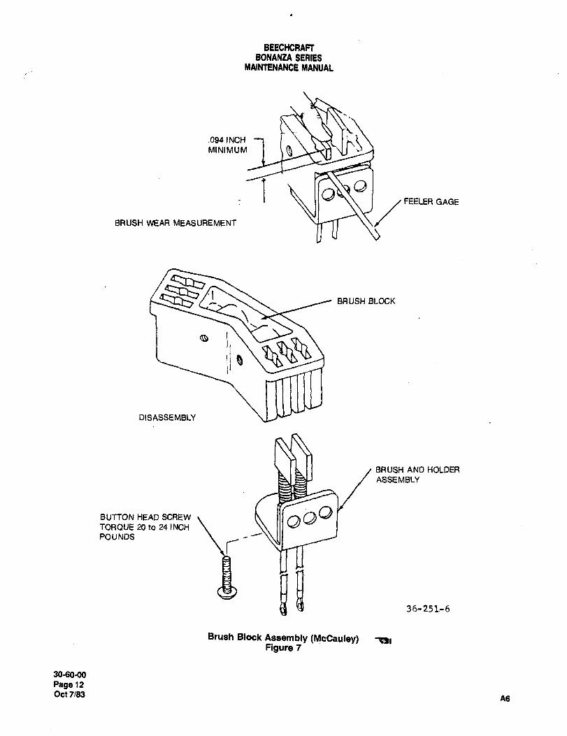
BEECHCRAFTBONANtA SERLS
MAINTENANCE MANUAL
.094 1 NCH
I aa
BRUSH WEAR MEASUREMENT
FEELER GAGE
BRUSH BLOCK
DI SASSE MBLY
BRUSH AND HOLDER
ASSEMBLY
BUTTON HEAD SCREW as"TORQUE 20 to 24 INCH
POUNDS
iia36-251r6
Brush Block Assembly (McCauley) ~rFigure 7
3060-00
Page 12
Oct 7/33As
BEECHCRAFTBONANZA SERIES
MAINTENANCE MANUAL
BRUSH BLOCK REMOVAL (McCauleyl SLIP RING MACHINING (McCauley)
a. Disconnect the lead wires from the terminal strip. Structurally sound slip rings with damaged surfaces may be
b. Disconnect the brush block mounting screws and machined to restore sen/iceability.remove the brush block from the engine.
a. Clean the slip ring assembly with methyl ethylketone before machining.
BRUSH BLOCK INSTALL4 TION (McCauleyl b. Check the assembly mounting surface flatness. It
(Figure 8) must be flat within .005 inch overall.
c. Locate the assembly concentrically in a lathe so
a. Install the brush block on the engine with the two that there is no more than .002 inch wobble or run-out over
screws, but do not tighten the screws. 360" of rotation. The assembly should be fixed in the lathe in
b. Add or remove shims (see Figure 6) to the brush the same manner as it was attached to the propellerblock mounting screws until each entire brush is in contact assembly. This will ensure that run-out held while machiningwith it’s slip ring throughout 360~ of rotation, the assembly will be transferred when it is mounted on the
c. Position the brush block on the mounting bracket propeller.so that the distance between the brush block and the face of d. Take a light cut for a smooth finish (25 to 20 micro
the slip rings is .064 .015 inch. inches).d. Tighten the screws.
SLIP RING (McCauleylNOTE
On these slip rings the mounting bolts can not be retorquedor shims added to correct wobble or nonconcentric rotation. The spindle speed should be 500 rpm or
Wear or slight wobble may be removed by machining, greater. If machine vibration is noticed,it must
be corrected. Machine vibration which is not
corrected will result in a chattered finish. Feed
NOTE rate is to be .002 inch or less with a final pass of
.005 inch to .010 inch.
Friction from the brushes will cause a concave
wear pattern on the slip rings. This does not
necessitate replacement or machining unless e. Ensure that the face surface of the slip rings are
rapid brush wear is encountered. When a new parallel and flat within .008 overall.
brush assembly is installed on slip rings with f. The slip ring holder face and the insulation around
normal wear, the brushes will rapidly seat and between the slip rings must be undercut to .050 inch to
without degradation of operation or service life. .060 inch (Figure 8).
SLIP RING ALIGNMENT (McCauley)
If a chattering or screeching noise is heard coming from the CA UTION
brush black/slip ring area, the probable cause is improperbrush block-to-slip ring alignment. A chattering or When undercutting the insulation between the
screeching detected while turning the propeller tin the slip rings, do not cut the inside diameters or the
normal direction of rotation) by hand should be corrected outside diameters of the slip rings more than
immediately. If the chattering or screeching is heard above .003 inch past the original diameters.
idling engine noise;the problem is severe. Repositioning the
brush block as indicated in Figure 7 should correct the
problem. g. Deburr the slip ring edges.h. Polish the ring faces with crocus cloth to obtain a
SLIP RING OR BRUSH BLOCK CLEANING (McCauiey) finish of 16 to 22 microinches.
i. Check the electrical resistance between each ringThe Slip rings and brush block may be cleaned with a clean and the holder .and between each ring. The resistance
cloth dampened with methyl ethyl ketone. should be a minimum of 50K ohms.
30-60-00
Page 13
A6 Oct 7/83
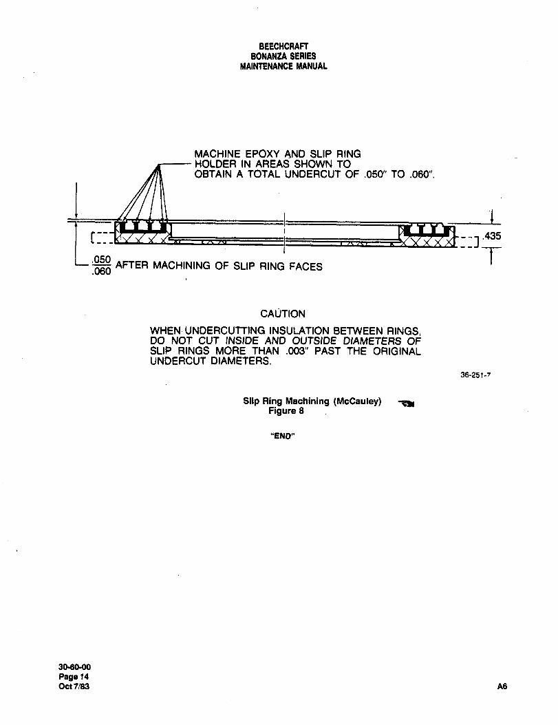
BEECHCRAFTBONANtA SERIES
MAINTENANCE MANUAL
MACHINE EPOXY AND SLIP RINGHOLDER IN AREAS SHOWN TOOBTAIN A TOTAL UNDERCUT OF .050" TO .060".
I
rIZ-: 1:3.435
050 TAFTER MACHINING OF SLIP RING FACES
.060
CAljTION
WHEN UNDERCUTTING INSULATION BETWEEN RINGS,DO NOT CUT INSIDE AND OUTSIDE DIAMETERS OFSLIP RINGS MORE THAN .003" PAST THE ORIGINALUNDERCUT DIAMETERS.
36-251-7
Slip Ring Machining (McCauley) ~ekFigure 8
"END"
30´•60-00
Page 14
Oct7/63 A6
CHAPTER
LANDING GEAR
Raylheon Aircraft CompanyBONANZA SERIES MAINTENANCE MANUAL
CHAPTER 32 1 LANDING GEAR
TABLE OF CONTENTS
SUBJECT PAGE
32-00-00
General Description and Operation ..1
Landing Gear System
Optional Landing GearSafetySystem ..................1
Troubleshooting Landing Gear Electrical System, ,,,,,,,.2
32-1 0-00
Main Gearand Doors- Maintenance Practices ............1
Main Landing GearServicing ......1
..........................................................................1
Main Landing Gear Removal ......1
Main Landing Gearlnstallation .....1
Main Landing GearOverhaul ,,,,,.2
Main Landing GearDisassembly .3
Main GearCieaning, Replacement Partsand Repairs, ,,5
Cleaning... .,,.....,,,..,5
Replacement Parts, ...,.,.5
Repairs,Main Landing Gear Assembly. .,..,7
32-20-00
NoseGearand Doors- Maintenance Practices ............1
Nose Gear Shock Strut,
Lubrication.
Nose Gear Removal
Nose Gear Installation.
Nose Gear Overhaul
Nose Gear Disassembly, ......2
NoseGearCleaning, ReplacementPartsand Repairs ..4
Cleaning, .................................................4
Replacement Parts, ...,.,,4
Repairs......Nose Gear Assembly ........1
Nose Gear Shimmy Damper Servicing .................12
Nose Gear Shimmy Damper Removal .................12
Nose Gear Shimmy Damper Instaliation ................12
~4 32-CONTENTS Sep 30/03Page 1
Raytheon Aircraft CompanyBONANZA SERIES MAINTENANCE MANUAL
CHAPTER 32 LANDING GEAR
TABLE OF CONTENTS (Continued)
SUBJECT PAGE
NoseGearShimmy DamperOverhaul 12
NoseGearShimmy DamperDisassembly 13
NoseGearShimmy DamperCleaning, Replacement Parts and Repairs 13
Cleaning
Replacement Parts 14
RepairsNose GearShimmy DamperAssembly. 17
Nose GearRetract Mechanism Servicing 19
Nose Gear Retract Brace Assembly Check (E-1103 and After; E-l thru E-1102 With Kit
35-4012-1 Installed .........19
32-30-00
Extension and Retraction- Maintenance Practices 1
Lub~cation.............................................................................1
Manual Landing Gear ExtensionSystem. 1
Landing GearActuatorAssembly Removal 1
Landing GearActuatorAssembly Installation 2
Landing GearMotor Removal 2
Landing Gear Motor Installation. 2
Dynamic Brake Relay Check. 3
Landing Gear Dynamic Brake Relay Removal. 3
Landing GearDynamic Brake Relay Installation 3
Main Landing Gear Retract Rod Removal 3
Main Landing GearRetractRod Installation 5
Riggingthe Landing Gear 5
RetractActuator Disassembly 10
Retract Actuator Cleaning and Parts Replacement 12
Retract Actuator Assembly 12
Landing Gear RetractActuator Functional Test. 13
Landing GearSafetySystem Maintenanceand Adjustment 14
Check of Landing Gear Safety System With Safety Switch in Test Position 14
Landing GearSafety System Microswitch Adjustment 14
Landing GearSafetySystem Pressure Switch Adjustment. 14
32-40-00
Wheelsand Brakes- Descriptionand Operation 1
Main Wheel Assemblies.
Nose Wheel Assembly.
Page 2Sep30/03 32-CONTENTS
Raytheon Aircraft CompanyBONANZA SERIES MAINTENANCE MANUAL
CHAPTER 32 LANDING GEAR
TABLE OF CONTENTS
SUBJECT PAGE
Tires ..........1
Brake AssemblyShuttle Valve
Brake Wear and Wear Limits ......1
Hydraulic Brake SystemTroubleshooting Brake System ......3
Wheelsand Brakes-Maintenance Practices .........,.,3
Wheelsand Tire Maintenance .....3
Main Wheel and BrakeAssembly Removal ............,3
MainWheel Inspectionand Cleaning .4
BrakeAssembly Inspection and Cleaning. ...............4
MainWheel and BrakeAssembly Installation. ............4
Nose Wheel Removal
Nose Wheel Inspection and Cleaning .5
Nose Wheel Installation
Relining the Brakes
Brake MasterCylinder Removal ....6
Brake MasterCylinder Installation ..6
Brake MasterCylinder Linkage Adjustment ...........,.6
Brake Master Cylinder Disassembly. .6
Brake MasterCylinderCleaning and Parts Replacement. ...6
Brake MasterCylinderAssembly ...7
Parking BrakeValve Removal. .....7
Parking BrakeValve Installation ....7
Parking Brake Adjustment. ........7
Parking BrakeValve Disassembly ..7
Parking BrakeCleaning and Parts Replacement ..........7
Parking BrakeValve Assembly. ....7
Bleedingthe Brake System. .......3
Gravity BleedingPressure Pot BleedingElectric Bleeding
32-50-00
Steering- Maintenance Practices ....1
Nose Wheel Travel Stop Adjustment .1
ns 32-CONTENTS Sep 30/03Page 3
Raytheon nircraft CompanyBONANZA SERIES MAINTENANCE MANUAL
CHAPTER 32 LANDING GEAR
TABLE OF CONTENTS (Continued)
SUBJECT PAGE
32-60-00
PositionandWarning- Maintenance Practices. 1
Landing GearPosition LightAdjustment 1
Main Gear
NoseGear.............................................................. 1
Engine-Compartment-Located Landing Gear Warning Switch Adjustment (CE-748, CE-772 thru
CE-1300, CE-1302 thru CE-1306; CJ-149 thru CJ-179; D-10097, D-10120 and After; E-llll, E-1241
thru E-2110, except E-1946 and E-2104; EA-1 thru EA-388, except EA-320). 1
Engine-Compartment-Located Landing Gear Warning Switch Adjustment (CE-1301, CE-1307 and After;
CJ-180 and After).Pedestal-Located Landing Gear Warning Switch Adjustment (E-1946, E-2104, E-2111 and After; EA-320,
EA-389 and After)
Engine-Compartment-Located Landing Gear Retract-Prevent Switch Adjustment (CE-1301, CE-1307 and
After; CJ-180 and After).Pedestal-Located Landing Gear Retract-Prevent Switch Adjustment (E-2458, E-2468 and After; EA-320,
EA-389 and After)
Page 4Sep30/03 32-CONTENTS
Ray~heon AiKraft CompanyBONANZA SERIES MAINTENANCE MANUAL
CHAPTER 32 LANDING GEAR
LIST OF EFFECTIVE PAGES
CH-SE-SU PAGE DATE CH-SE-SU PAGE DATE
32-LOEP 1 Sep 30/03 32-20-00 1 thru 22 Sep 30/03
32-CONTENTS 1 thru 4 Sep 30/03 32-30-00 1 thru 16 Dec 23/99
32-00-00 1 thru 3 Nov 16/94 32-40-00 1 thru 13 Nov 16/94
32-10-00 1 thru 13 Sep 30/03 32-50-00 1 Nov 16/94
32-60-00 1 thru 10 Sep 30/03
A24 32-LOEPPagel
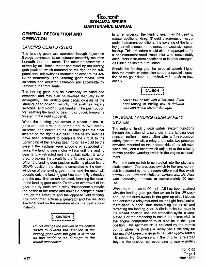
BONANZA SERIES
MAINTENANCE MANUAL
GENERAL-DESCRIPTION AND In an emergency, the landing gear may be used to
OPERATION create additional drag. Should disorientation occur
under instrument conditions, the lowering of the land-
LANDING GEAR SYSTEM ing gear will reduce the tendency for excessive speedbuildup. This procedure would also be appropriate for
The landing gears are operated through adjustable a noninstrument-rated rated pilot who unavoidablylinkage connected to an actuator assembly mounted encounters instrument conditions or in other emergen-beneath the front seats. The actuator assembly is cies such as severe turbulence.driven by an electric motor controlled by the landinggear position switch mounted on the right or left sub- Should the landing gear be used at speeds higher
panel and limit switches mounted adjacent to the act- than the maximum extension speed, a special inspec-
uator assembly. The landing gear motor, \imit tion of the gear doors is required, with repair as nec-
switches and actuator assembly are accessible by essa’y.
removing the front seats.
The landing gear may be electrically retracted and CAUTION
extended and may also be lowered manually in an
emergency. The landing gear circuit consists of the Never tow or taxi with a flat strut. Even
landing gear position switch, limit switches, safety brief towing or taxiing with a deflated
switches, and motor circuit breaker. The push button strut can cause severe damage.for resetting the landing gear motor circuit breaker is
located in the right subpanel. OPTIONAL LANDING GEAR SAFETYWhen the landing gear switch is placed in the UP SYSTEMposition, the circuit is completed to two safetyswitches, one located on the left main gear, the other The optional landing gear safety system functions
located on the right main gear. If the safety switches through the action of a solenoid in the landing gear
have been actuated to complete the circuit to the position switch in conjunction with a three-position
up-winding of the landing gear motor, as would be the safety system switch, a relay and diode, two pressureswitches mounted on the inboard side of the left main
case if the airplane were airborne or supported on
jacks, the landing gear motor will run until the landingwheel well, and a microswitch adjacent to the existing
gear is fully retracted and the uplimit switch is actu-throttle position warning switch in the engine compart-
ated, breaking the circuit to the landing gear motor.me"t.
When the landing gear position switch is placed in the Each pressure switch is connected into the pitot and
DOWN position, the circuit is completed to the down- static system. The pressure switch in the gear-up cir-
windings of the landing gear motor, and the motor will cult is actuated by the pressure differential that exists
operate until the landinggear has been fully extended between the pitot and static air system and will close
and the downlimit switch actuated, breaking the circuit with increasing pressure at approximately 90 mphto the landing gear motor. To prevent overtravel of the IAS.
gear, the dynamic brake relay simultaneously breaksWhen an air speed of 90 mph IAS has been attained
the power to the motor and makes a complete circuitwith the landing gear position switch in the UP posi-
through the armature and the opposite field winding,tion, the pressure switch in the gear-up circuit closes
The motor then acts as a generator and the resulting and actuates a relay mounted on the right-hand instru-electrical load on the armature stops the gear almost
ment panel support, thus completing the circuit andinstantly.
retracting the landing gear. A diode locks the relay in
the closed position until the retraction cycle is com-
CAUTION pleted. For the preceding to occur, the microswitch in
the engine compartment must also be in the open
Do not change the position of the control position. This microswitch is actuated by the throttle
switch to reverse the direction of the control when the throttle is advanced sufficiently for
landing gear while the gear is in transit the manifold pressure gage to register approximatelyas this could cause damage to the 18 inches Hg. Conversely, if the throttle is retarded
retract mechanism. beyond the position corresponding to approximately
32-00-00
Page 1
A17 Nov 16/94
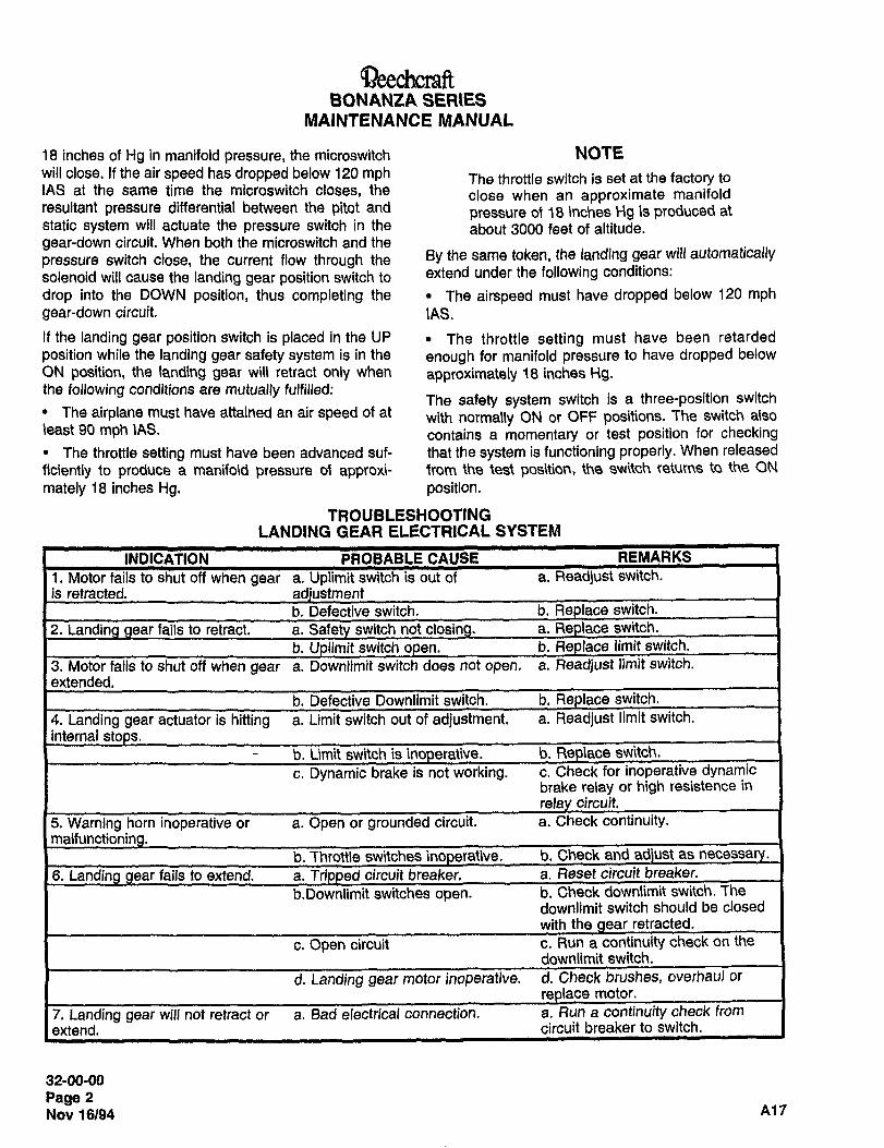
~eechcraRBONANZA SERIES
MAINTENANCE MANUAL.
18 inches of Hg in manifold pressure, the microswitch NOTEwill close. If the air speed has dropped below 120 mph The throttle switch is set at the factory toIAS at the same time the microswitch closes, the close when an approximate manifoldresultant pressure differential between the pitot and
pressure of 18 inches Hg is produced atstatic system will actuate the pressure switch in the about 3000 feet of altitude.gear-down circuit. When both the microswitch and the
pressure switch close, the current flow through the By the same token, the landing gear will automatically
solenoid will cause the landing gear position switch to extend under the following conditions:
drop into the DOWN position, thus completing the The airspeed must have dropped below 120 mphgear-down circuit. IAS.
If the landing gear position switch is placed in the UP The throttle setting must have been retarded
position while the landing gear safety system is in the enough for manifold pressure to have dropped below
ON position, the landing gear wil retract only when approximately 18 inches Hg.the following conditions are mutually fulfilled:
The safety system switch is a three-position switchThe airplane must have attained an air speed of at with normaly ON or OFF positions. The switch also
least 90 mph \AS. contains a momentary or test position for checkingThe throttle setting must have been advanced suf- that the system is functioning properly. When released
ficiently to produce a manifold pressure of approxi- from the test position, the switch returns to the ON
mately 18 inches Hg. position.
TROUBLESHOOTINGLANDING GEAR ELECTRICAL SYSTEM
INDICATION PROBABLE CAUSE REMARKS
1. Motor fails gear a. Uplimit switchis out of a. Readjust switch.
is retracted. adiustment
b.Defective switch. b. Replace switch.
2. Landina retract. a. Safety switchnotclosing. a. Replace switch.
b.Ualimit switch open. b. Replace limit switch.
3. Motor fails does not open. a. Readjust limit switch.
extended.
Downlimit switch. b. Replace switch-
actuatoris switch out of adjustment, a. Readjust limit switch.
internal
b. Umit switch is inoperative. b. Replace switch.
c. Dynamic brake is not working. c. Check for inoperative dynamicbrake relay or high resistence in
circuit,
5. Warning horn inoperative or a. Open or groundedcircuit. a. Check continuity.
b. Thrott\eswitches inoperative. b. Check and adjust as
6. Landina aear fa7jstoextend. a. Tn’Doed circuit breaker. a. Reset circuit breaker.
b.8ownlimit switches open. b,Check downiimit switch. The
downlimit switch should be closed
with the clear retracted.
c. Open circuit c. Run a continuity check on the
downlimit switch.
d. Landing gear motorinoperative. d. Check brushes, overhaul or
motor.
7. Landing gear will not retract or a. Bad electrical connection. a. Run a continuity check from
extend. circuit breaker to switch.
32-00-00
Page 2
Nov 16/94 A17
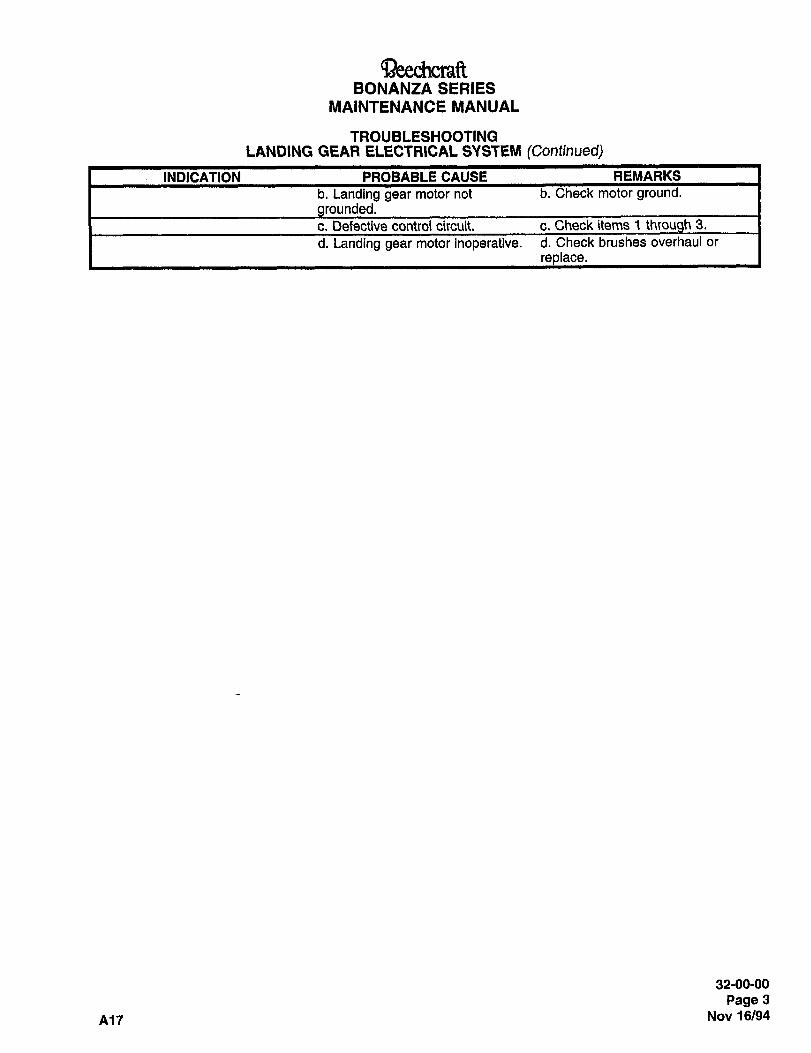
BONANZA SERIESMAINTENANCE MANUAL
TROUBLESHOOTINGLANDING GEAR ELECTRICAL SYSTEM (Continued)
INDICATION PROBABLE CAUSE REMARKS
b. Landing gear motor not b. Check motor ground.rounded.
c. Defective control circuit. c. Check items 1 thr 3.
d. Landing gear motor inoperative. d. Check brushes overhaul or
replace.
32-00-00
Page 3
A17 Nov 16/94
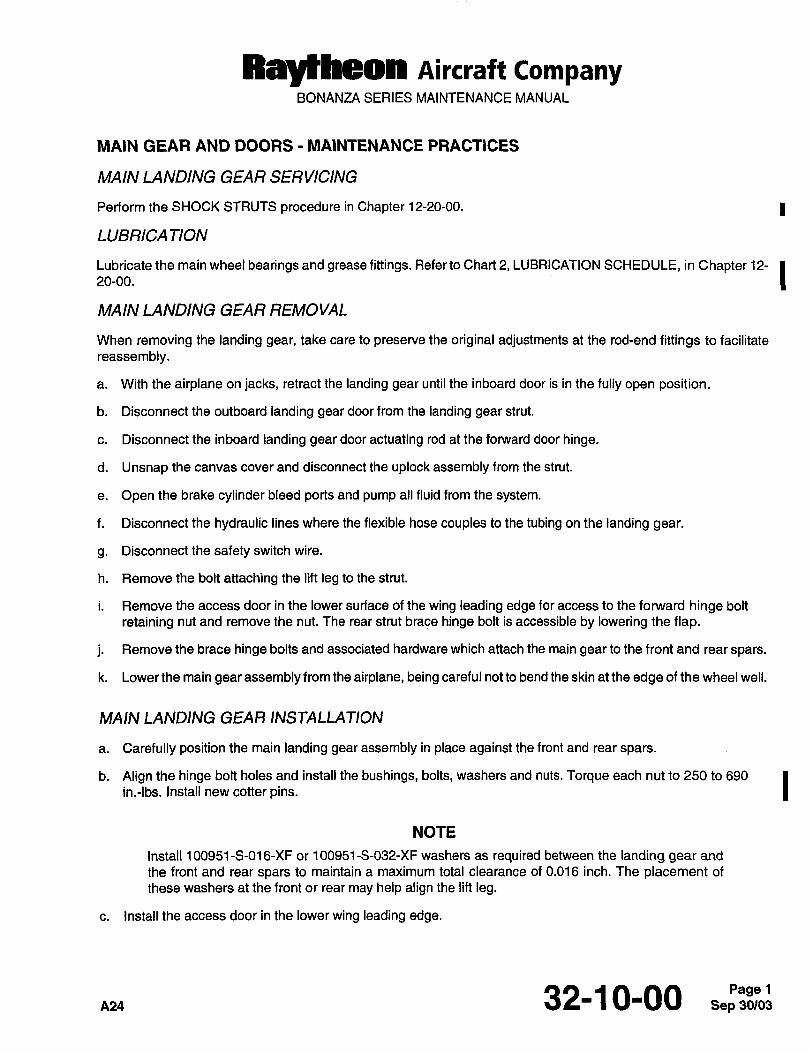
Raytheon Aircraft CompanyBONANZA SERIES MAINTENANCE MANUAL
MAIN GEAR AND DOORS MAINTENANCE PRACTICES
MAIN LANDING GEAR SERVICING
Perform the SHOCK STRUTS procedure in Chapter 1 2-20-00. 1
LUBRICA TION
20-00.Lubricate the main wheel bearings and grease fittings. Refer to Chart 2, LUBRICATION SCHEDULE, in Chapter 12-
MAIN LANDING GEAR REMOVAL
When removing the landing gear, take care to preserve the original adjustments at the rod-end fittings to facilitate
reassembly.
a. With the airplane on jacks, retract the landing gear until the inboard door is in the fully open position.
b. Disconnect the outboard landing gear door from the landing gear strut.
c. Disconnect the inboard landing gear door actuating rod at the forward door hinge.
d. Unsnap the canvas cover and disconnect the uplock assembly from the strut.
e. Open the brake cylinder bleed ports and pump all fluid from the system.
f. Disconnect the hydraulic lines where the flexible hose couples to the tubing on the landing gear.
g. Disconnectthe safetyswitch wire.
h. Remove the bolt attaching the lift leg to the strut.
i. Remove the access door in the lower surface of the wing leading edge for access to the forward hinge bolt
retaining nut and remove the nut. The rear strut brace hinge bolt is accessible by lowering the flap.
j. Remove the brace hinge bolts and associated hardware which attach the main gear to the front and rear spars.
k. Lower the main gear assembly from the airplane, being careful not to bend the skin at the edge of the wheel well.
MAIN LANDING GEAR INSTALLATION
a. Carefully position the main landing gear assembly in place against the front and rear spars.
b. Align the hinge bolt holes and install the bushings, bolts, washers and nuts. Torque each nut to 250 to 690 Iin.-lbs. install new cotter pins.
NOTE
Install 100951-S-016-XF or 100951-S-032-XF washers as required between the landing gear and
the front and rear spars to maintain a maximum total clearance of 0.016 inch. The placement of
these washers at the front or rear may help align the lift leg.
c. Install the access door in the lower wing leading edge.
32-10-00
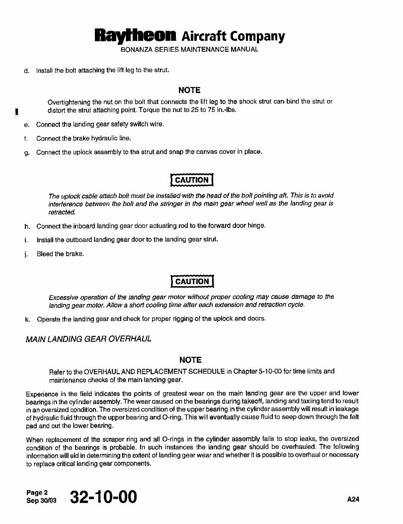
Raytheon Aircraft CompanyBONANZA SERIES MAINTENANCE MANUAL
d. Install the bolt attaching the lift leg to the strut.
NOTE
Overtightening the nut on the bolt that connects the lift leg to the shock strut can bind the strut or
I distort the strut attaching point. Torque the nut to 25 to 75 in.-lbs.
e. Connect the landing gear safety switch wire.
f. Connect the brake hydraulic line.
g. Connect the uplock assembly to the strut and snap the canvas cover in place.
pcnunoN ICAUTION
The uplock cable attach bolt must be installed with the head of the bolt pointing aft. This is to avoid
interference between the bolt and the stringer in the main gear wheel well as the landing gear is
retracted.
h. Connect the inboard landing gear door actuating rod to the forward door hinge.
i. Install the outboard landing gear door to the landing gear strut.
j. Bleed the brake.
[CAUTION ICAUTION
Excessive operation of the landing gear motor without proper cooling may cause damage to the
landing gear motor. Allow a short cooling time after each extension and retraction cycle.
k. Operate the landing gear and check for proper rigging of the uplock and doors.
MAIN LANDING GEAR OVERHAUL
NOTE
Refer to the OVERHAUL AND REPLACEMENT SCHEDULE in Chapter 5-10-00 for time limits and
maintenance checks of the main landing gear.
Experience in the field indicates the points of greatest wear on the main landing gear are the upper and lower
bearings in the cylinder assembly. The wear caused on the bearings during takeoff, landing and taxiing tend to result
in an oversized condition. The oversized condition of the upper bearing in the cylinder assembly will result in leakageof hydraulic fluid through the upper bearing and O-ring. This will eventually cause fluid to seep down through the felt
pad and out the lower bearing.
When replacement of the scraper ring and all O-rings in the cylinder assembly fails to stop leaks, the oversized
condition of the bearings is probable. In such instances the landing gear should be overhauled. The followinginformation will aid in determining the extent of landing gear wear and whether it is possible to overhaul or necessary
to replace critical landing gear components.
Sep 30/03Page 2 32-1 0-00
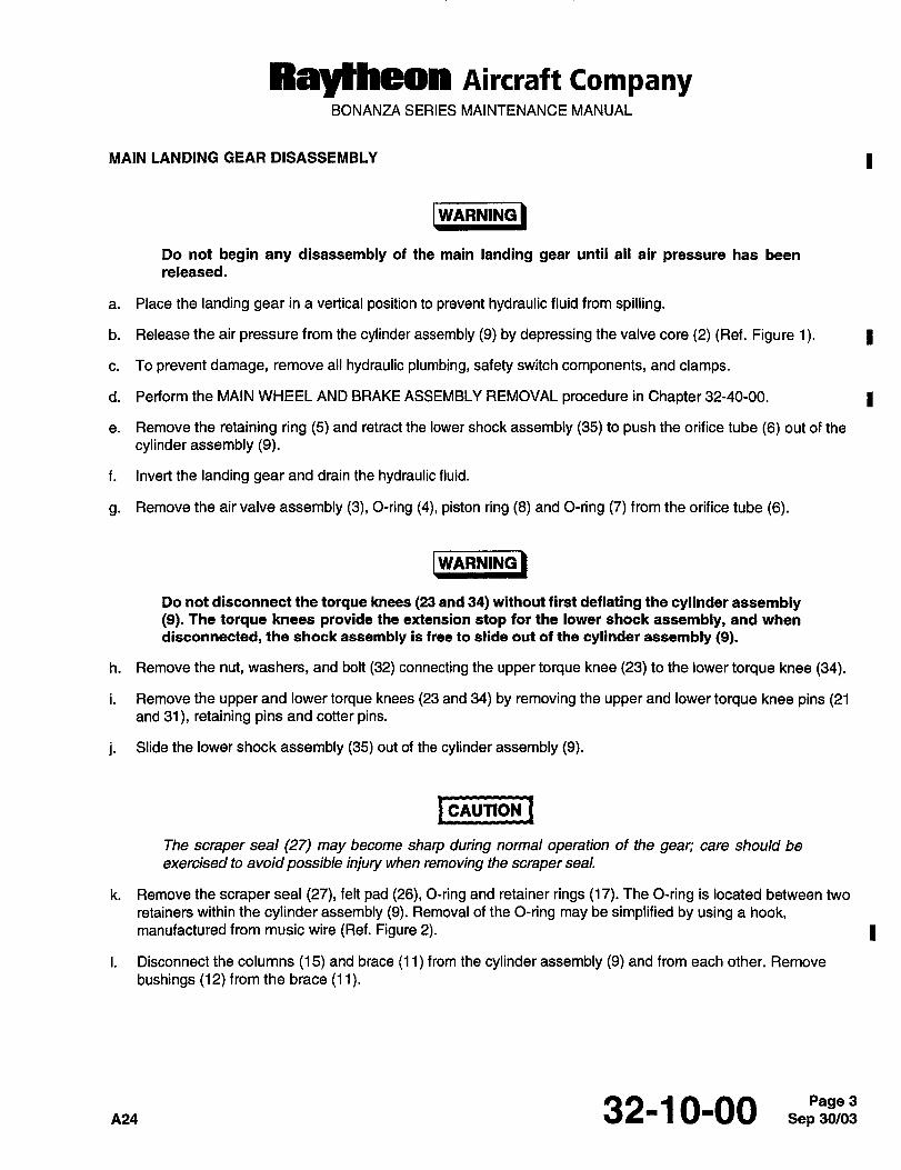
Raytheon AiKraft CompanyBONANZA SERIES MAINTENANCE MANUAL
MAIN LANDING GEAR DISASSEMBLY I
/WARNINO IARNING
Do not begin any disassembly of the main landing gear until all air pressure has been
released.
a. Place the landing gear in a vertical position to prevent hydraulic fluid from spilling.
b. Release the air pressure from the cylinder assembly (9) by depressing the valve core (2) (Ref. Figure 1). I
c. To prevent damage, remove all hydraulic plumbing, safety switch components, and clamps.
d. Perform the MAIN WHEEL AND BRAKE ASSEMBLY REMOVAL procedure in Chapter 32-40-00. 1
e. Remove the retaining ring (5) and retract the lower shock assembly (35) to push the orifice tube (6) out of the
cylinder assembly (9).
f. Invert the landing gear and drain the hydraulic fluid.
g. Remove the air valve assembly (3), O-ring (4), piston ring (8) and O-ring (7) from the orifice tube (6).
IWARNIN(I IWARNING
Do not disconnect the torque knees (23 and 34) without first deflating the cylinder assembly(9). The torque knees provide the extension stop for the lower shock assembly, and when
disconnected, the shock assembly is free to slide out of the cylinder assembly (9).
h. Remove the nut, washers, and bolt (32) connecting the upper torque knee (23) to the lower torque knee (34).
i. Remove the upper and lower torque knees (23 and 34) by removing the upper and lower torque knee pins (21and 31), retaining pins and cotter pins.
j. Slide the lower shock assembly (35) out of the cylinder assembly (9).
I causlon ICAUTION
The scraper seal (27) may become sharp during normal operation of the gear; care should be
exercised to avoid possible injury when removing the scraper seal.
k. Remove the scraper seal (27), felt pad (26), O-ring and retainer rings (17). The O-ring is located between two
retainers within the cylinder assembly (9). Removal of the O-ring may be simplified by using a hook,manufactured from music wire (Ref. Figure 2). 1
I. Disconnect the columns (15) and brace (11) from the cylinder assembly (9) and from each other. Remove
bushings (12) from the brace (11).
32-1 0-00 Sep 30/03Page 3
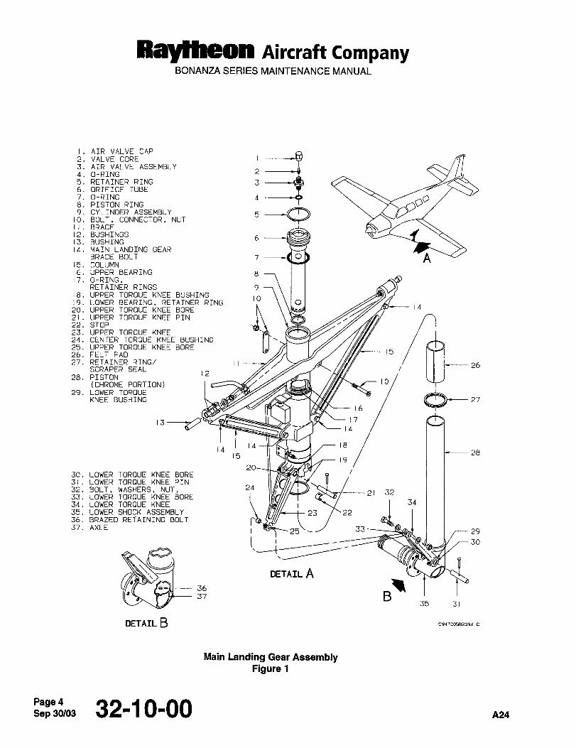
Ray~heon Aircraft CompanyBONANZA SERIES MAINTENANCE MANUAL
I. AIR VALVE CAP
2. VALVE CORE3. AIR VALVE ASSEMBLY
4. O-RING
5. RETAINER RING 36. ORIFICE TUBE
7. O-RING 48. PISTON RING
9. CYLINDER ASSEMBLY
10. BOLT, CONNECTOR, NUT
I I BRACE
12. BUSHINGS13. BUSHING
14. MAIN LANDING GEARBRACE BOLT 7 ----d0 A
15. COLUMN16. UPPER BEARING 817. O-RING,
RETAINER RINGS 918. UPPER TORQUE KNEE BUSHING
22.19.LOWER
BEARING.STOPRETAINER RING O
20. UPPER TORQUE KNEE BORE14
21. UPPER TOROUE KNEE PIN
23. UPPER TORQUE KNEE24. CENTER TOROUE KNEE BUSHING
25. UPPER TOROUE KNEE BORE26. FELT PAD 15
27. RETAINER RING/ IISCRAPER SEAL
1228. PISTON
(CHROME PORTION) 10
29. LOWER TOROUEKNEE BUSHING
16
13~ 141714 18
14 2815
19
30. LOWER TOROUE KNEE BORE31. LOWER TOROUE KNEE PIN
32. BOLT, WASHERS, NUT. 24
jh21 32
33. LOWER TOROUE KNEE BORE34. LOWER TOR~UE KNEE 34
35. LOWER SHOCK ASSEMBLY 23 2236. BRAZED RETAINING BOLT
37. AXLE 25\-~ 1 29
30
DETAIL A36
3735 31
OETAIL B cp~rcosszosa c
Main ktnding Gear AssemblyFigure 1
Sep 30/03~"3"Wo3 32-10-00 A24
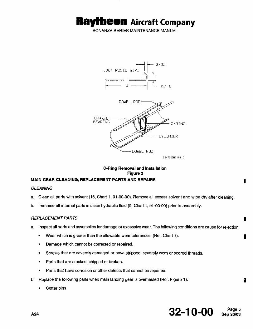
RBytheOn Aircraft CompanyBONANZA SERIES MAINTENANCE MANUAL
.Obn MUSICWIil~-I ~I3/32
B14 ----t( 5/ 6
DOWEL ROD
BRAZEDBEARING
O-RING
CYLINDER
DOWEL ROD
C94TC058219d C
O-Ring Removal and Installation
Figure 2
MAIN GEAR CLEANING, REPLACEMENT PARTS AND REPAIRS I
CLEANING
a. Clean all parts with solvent (16, Chart 1, 91-00-00). Remove all excess solvent and wipe dry after cleaning.
b. Immerse all internal parts in clean hydraulic fluid (9, Chart 1, 91-00-00) prior to assembly.
REPLACEMENT PARTS I
a. Inspect all parts and assemblies for damage or excessive wear. The following conditions are cause for rejection:
Wear which is greater than the allowable wear tolerances. (Ref. Chart 1). I
Damage which cannot be corrected or repaired.
Screws that are severely damaged or have stripped, severely worn or scored threads.
Parts that are cracked, chipped or broken.
Parts that have corrosion or other defects that cannot be repaired.
b. Replace the following parts when main landing gear is overhauled (Ref. Figure 1): I
Cotter pins
A24 32-10-00 5
Raytheon Aircraft CompanyBONANZA SERIES MAINTENANCE MANUAL
DU Bushings (12)
I Bushing (13)
Felt Pad (26)
Piston Ring (8)
O-Rings (4, 7, 17)
Retainer Rings (5, 17, 19)
Safety Wire
Scraper Seal (27)
c. Replace the following parts on condition when main landing gear is overhauled:
Bearings (16, 19)
I Bushings (18, 24, 29)
Grease Fittings
Grommets
Huck Bolt and Collar (Replace if removed from the upper bearing (16).)
Hydraulic Hoses
Hydraulic Tubing
Safety Switch Components
Valve Core (2)
Wiring
I REPAIRS
a. Visually inspect castings for cracks and pitting; and finished surfaces for scoring, pitting, nicks, cracks, distortion
and wear. Refer to Chart 1 for tolerances to aid in determining the extent of wear. Replace all defective and
excessively worn parts.
b. If fluid leaks have been observed on top of the air valve assembly (3), check the small O-ring (4) of the valve;then look for defects in the valve (Ref. Figure 1).
c. If the leak is from the junction of the orifice tube assembly (6) with the cylinder assembly (9) walls, check the
O-ring (7) in the orifice tube (6).
d. All parts or assemblies may be repaired if the following conditions exist:
Slight scoring of shafts may be corrected by lapping carefully with a flat oil stone.
Sep 30/03Page 6 32-1 0-00
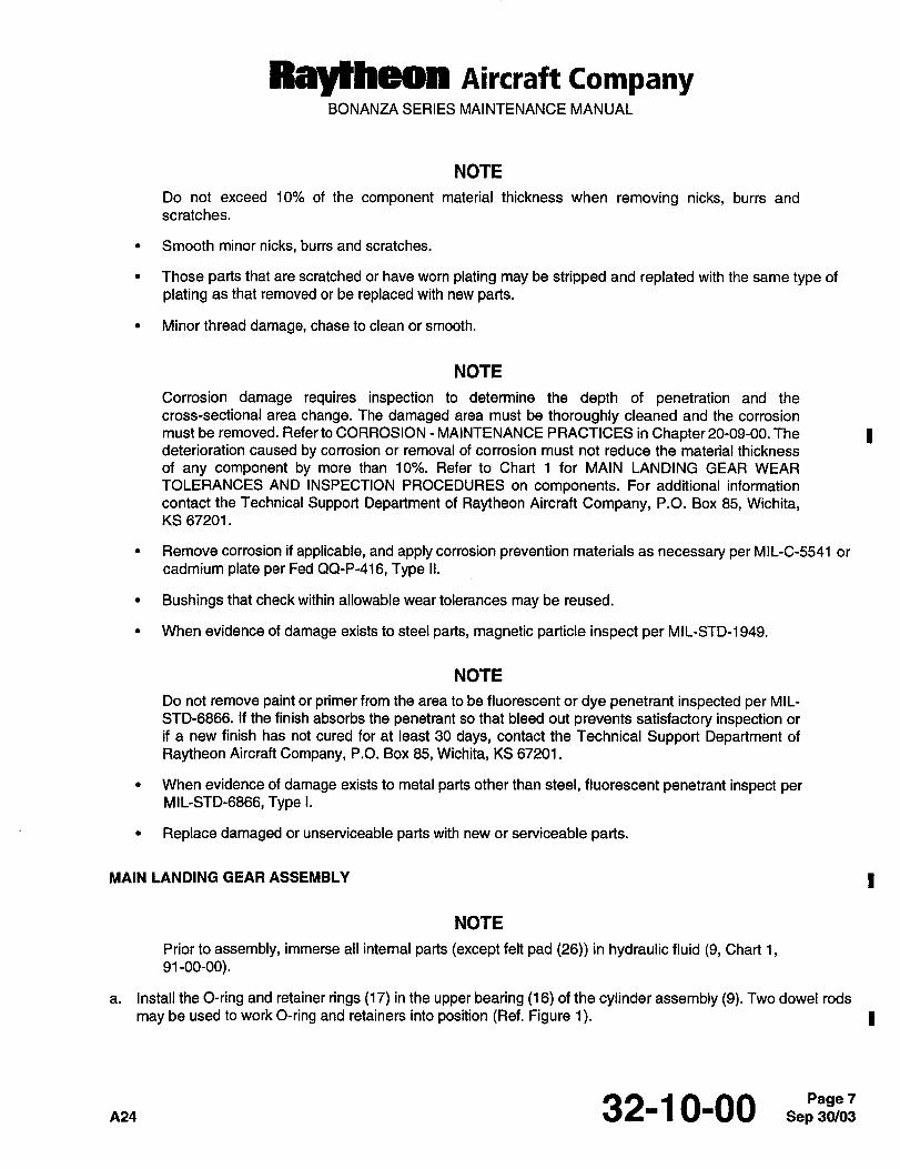
Raytheon Aircraft CompanyBONANZA SERIES MAINTENANCE MANUAL
NOTE
Do not exceed 10% of the component material thickness when removing nicks, burrs and
scratches.
Smooth minor nicks, burrs and scratches.
Those parts that are scratched or have worn plating may be stripped and replated with the same type of
plating as that removed or be replaced with new parts.
Minor thread damage, chase to clean or smooth.
NOTE
Corrosion damage requires inspection to determine the depth of penetration and the
cross-sectional area change. The damaged area must be thoroughly cleaned and the corrosion
must be removed. Refer to CORROSION MAINTENANCE PRACTICES in Chapter 20-09-00. The Ideterioration caused by corrosion or removal of corrosion must not reduce the material thickness
of any component by more than 10%. Refer to Chart 1 for MAIN LANDING GEAR WEAR
TOLERANCES AND INSPECTION PROCEDURES on components. For additional information
contact the Technical Support Department of Raytheon Aircraft Company, P.O. Box 85, Wichita,KS 67201.
Remove corrosion if applicable, and apply corrosion prevention materials as necessary per MIL-C-5541 or
cadmium plate per Fed QQ-P-416, Type II.
Bushings that check within allowable wear tolerances may be reused.
When evidence of damage exists to steel parts, magnetic particle inspect per MIL-STD-1949.
NOTE
Do not remove paint or primer from the area to be fluorescent or dye penetrant inspected per MIL-
STD-6866. If the finish absorbs the penetrant so that bleed out prevents satisfactory inspection or
if a new finish has not cured for at least 30 days, contact the Technical Support Department of
Raytheon Aircraft Company, P.O. Box 85, Wichita, KS 67201.
When evidence of damage exists to metal parts other than steel, fluorescent penetrant inspect per
MIL-STD-6866, Type I.
Replace damaged or unserviceable parts with new or serviceable parts.
MAIN LANDING GEAR ASSEMBLY I
NOTE
Prior to assembly, immerse all internal parts (except felt pad (26)) in hydraulic fluid (9, Chart 1,91-00-00).
a. Install the O-ring and retainer rings (17) in the upper bearing (16) of the cylinder assembly (9). Two dowel rods
may be used to work O-ring and retainers into position (Ref. Figure 1). I
~24 32-1 0-00 Sep 30/03Page 7
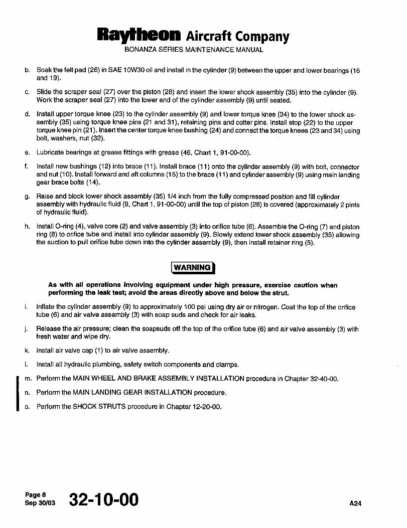
Raylheon Aircraft CompanyBONANZA SERIES MAINTENANCE MANUAL
b. Soak the felt pad (26) in SAE 1 0W30 oil and install in the cylinder (9) between the upper and lower bearings (16and 19).
c. Slide the scraper seal (27) over the piston (28) and insert the lower shock assembly (35) into the cylinder (9).Work the scraper seal (27) into the lower end of the cylinder assembly (9) until seated.
d. Install upper torque knee (23) to the cylinder assembly (9) and lower torque knee (34) to the lower shock as-
sembly (35) using torque knee pins (21 and 31), retaining pins and cotter pins. Install stop (22) to the uppertorque knee pin (21). Insert the center torque knee bushing (24) and connect the torque knees (23 and 34) usingbolt, washers, nut (32).
e. Lubricate bearings at grease fittings with grease (46, Chart 1, 91-00-00).
f. Install new bushings (12) into brace (11). Install brace (11) onto the cylinder assembly (9) with bolt, connector
and nut (10). Install forward and aft columns (15) to the brace (1 1 and cylinder assembly (9) using main landinggear brace bolts (14).
g. Raise and block lower shock assembly (35) 1/4 inch from the fully compressed position and fill cylinderassembly with hydraulic fluid (9, Chart 1, 91-00-00) until the top of piston (28) is covered (approximately 2 pintsof hydraulic fluid).
h. Install O-ring (4), valve core (2) and valve assembly (3) into orifice tube (6). Assemble the O-ring (7) and pistonring (8) to orifice tube and install into cylinder assembly (9). Slowly extend lower shock assembly (35) allowingthe suction to pull orifice tube down into the cylinder assembly (9), then install retainer ring (5).
I wnR#IN~IWARNING
As with all operations involving equipment under high pressure, exercise caution when
performing the leak test; avoid the areas directly above and below the strut.
i. Inflate the cylinder assembly (9) to approximately 100 psi using dry air or nitrogen. Coat the top of the orifice
tube (6) and air valve assembly (3) with soap suds and check for air leaks.
j. Release the air pressure; clean the soapsuds off the top of the orifice tube (6) and air valve assembly (3) with
fresh water and wipe dry.
k. Install air valve cap (1) to air valve assembly.
I. Install all hydraulic plumbing, safety switch components and clamps.
Im. Perform the MAIN WHEEL AND BRAKE ASSEMBLY INSTALLATION procedure in Chapter 32-40-00.
n. Perform the MAIN LANDING GEAR INSTALLATION procedure.
o. Perform the SHOCK STRUTS procedure in Chapter 12-20-00.
Sep 30/03Page 8 32-1 0-00
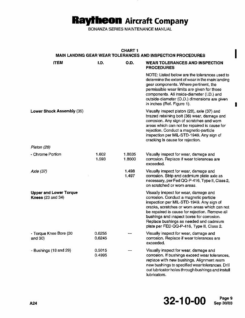
RayHheon Aircraft CompanyBONANZA SERIES MAINTENANCE MANUAL
CHART1 IMAIN LANDING GEAR WEAR TOLERANCES AND INSPECTION PROCEDURES
ITEM I.D. O.D. WEAR TOLERANCES AND INSPECTION
PROCEDURES
NOTE: Listed below are the tolerances used to
determine the extent of wear in the main landinggear components. Where pertinent, the
permissible wear limits are given for those
components. All inside-diameter (I.D.) and
outside-diameter (O.D.) dimensions are givenin inches (Ref. Figure 1). I
Lower Shock Assembly (35) Visually inspect piston (28), axle (37) and
brazed retaining bolt (36) wear, damage and
corrosion. Any sign of scratches and worn
areas which can not be repaired is cause for
rejection. Conduct a magnetic-particleinspection per MIL-STD-1949. Any sign of
cracking is cause for rejection.
Piston (28)
Chrome Portion 1.602 1.8635 Visually inspect for wear, damage and
1.593 1.8600 corrosion. Replace if wear tolerances are
exceeded.
Axle (37) 1.498 Visually inspect for wear, damage and
1.497 corrosion. Strip and cadmium plate axle as
necessary, per Fed QQ-P-416, Type II, Class 2,on scratched or worn areas.
Upper and Lower Torque Visually inspect for wear, damage and
Knees (23 and 34) corrosion. Conduct a magnetic particleinspection per MIL-STD-1949. Any sign of
cracks, scratches or worn areas which can not
be repaired is cause for rejection. Remove all
bushings and inspect bores for corrosion.
Replace bushings as needed and cadmium
plate per FED QQ-P-416, Type II, Class 2.
Torque Knee Bore (20 0.6255 Visually inspect for wear, damage and
and 30) 0.6245 corrosion. Replace if wear tolerances are
exceeded.
Bushings (18 and 29) 0.5015 Visually inspect for wear, damage and
0.4995 corrosion. If bushings exceed wear tolerances,replace with new bushings. Alignment ream
new bushings to specified weartolerances. Drill
out lubricator holes through bushings and install
lubricators.
32-1 0-00 Sep 30/03Page 9
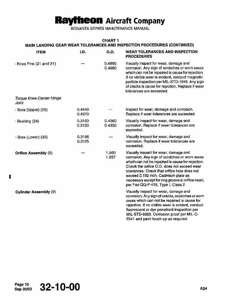
Raytheon Aircraft CompanyBONANZA SERIES MAINTENANCE MANUAL
CHARTI
MAIN LANDING GEAR WEAR TOLERANCES AND INSPECTION PROCEDURES (CONTINUED)
ITEM I.D. O.D. WEAR TOLERANCES AND INSPECTION
PROCEDURES
Knee Pins (21 and 31) 0.4990 Visually inspect for wear, damage and
0.4980 corrosion. Any sign of scratches or worn areas
which can not be repaired is cause for rejection.If no visible wear is evident, conduct magneticparticle inspection per MIL-STD-1949. Any signof cracks is cause for rejection. Replace if wear
tolerances are exceeded.
Torque Knee Center HingeJoint
Bore (Upper) (25) 0.4440 Inspect for wear, damage and corrosion.
0.4370 Replace ii wear tolerances are exceeded.
Bushing (24) 0.3150 0.4360 Visually inspect for wear, damage and
0.3120 0.4330 corrosion. Replace if wear tolerances are
exceeded.
Bore (Lower) (33) 0.3195 Visually inspect for wear, damage and
0.3125 corrosion. Replace if wear tolerances are
exceeded.
Orifice Assembly (6) 1.560 Visually inspect for wear, damage and
1.557 corrosion. Any sign of scratches or worn areas
which can not be repaired is cause for rejection.Check the orifice O.D, does not exceed wear
tolerances. Check that orifice hole does not
exceed 0.192 inch. Cadmium plate as
necessary except for ring groove in orifice head,
per Fed QQ-P-416, Type i, Class 2.
Cylinder Assembly (9) Visually inspect for wear, damage and
corrosion. Any sign of cracks, scratches orworn
areas which can not be repaired is cause for
rejection. If no visible wear is evident, conduct
fluorescent or dye penetrant inspection perMIL-STD-6866. Corrosion proof per MIL-C-
5541 and paint touch up as required.
Sep 32-10-00 A24
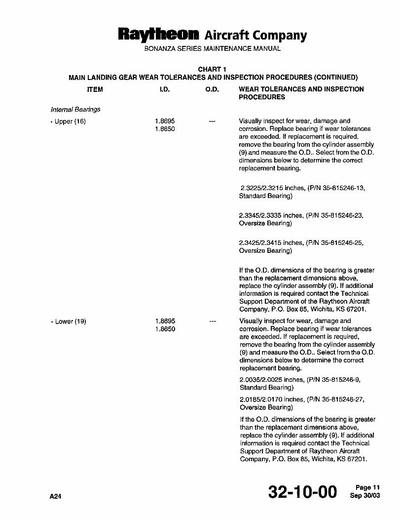
Ray~heon Aircraft CompanyBONANZA SERIES MAINTENANCE MANUAL
CHART1
MAIN LANDING GEAR WEAR TOLERANCES AND INSPECTION PROCEDURES (CONTINUED)
ITEM I.D. O.D. WEAR TOLERANCES AND INSPECTION
PROCEDURES
Internal Bearings
Upper (16) 1.8695 Visually inspect for wear, damage and
1.8650 corrosion. Replace bearing if wear tolerances
are exceeded. If replacement is required,remove the bearing from the cylinder assembly(9) and measure the O.D.. Select from the O.D.
dimensions below to determine the correct
replacement bearing.
2.3225/2.3215 inches, (P/N 35-815246-13,Standard Bearing)
2.3345/2.3335 inches, (P/N 35-815246-23,Oversize Bearing)
2.3425/2.3415 inches, (P/N 35-815246-25,Oversize Bearing)
If the O.D. dimensions of the bearing is greaterthan the replacement dimensions above,replace the cylinder assembly (9). If additional
information is required contact the Technical
Support Department of the Raytheon Aircraft
Company, P.O. Box 65, Wichita, KS 67201.
Lower (19) 1.8695 Visually inspect for wear, damage and
1.8650 corrosion. Replace bearing if wear tolerances
are exceeded. If replacement is required,remove the bearing from the cylinder assembly(9) and measure the O.D.. Select from the O.D.
dimensions below to determine the correct
replacement bearing.
2.0035/2.0025 inches, (P/N 35-815246-0Standard Bearing)
2.0185/2.0170 inches, (P/N 35-815246-27,Oversize Bearing)
If the O.D. dimensions of the bearing is greaterthan the replacement dimensions above,
replace the cylinder assembly (9). If additional
information is required contact the Technical
Support Department of Raytheon Aircraft
Company, P.O. Box 85, Wichita, KS 67201.
32-10-00 S.PpaS3~Pagell
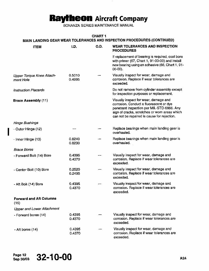
Raytheon Aircraft CompanyBONANZA SERIES MAINTENANCE MANUAL
CHART 1
MAIN LANDING GEAR WEAR TOLERANCES AND INSPECTION PROCEDURES (CONTINUED)
ITEM I.D. O.D. WEAR TOLERANCES AND INSPECTION
PROCEDURES
If replacement of bearing is required, coat bore
with primer (67, Chart 1,91-00-00) and install
new bearing using an adhesive (66, Chart 1, 91-
oo-oo).
Upper 7orque Knee Attach- 0.5010 Visually inspect for wear, damage and
ment Hole 0.4995 corrosion. Replace if wear tolerances are
exceeded.
Instruction Placards Do not remove from cylinder assembly exceptfor inspection purposes or replacement.
Brace Assembly (11) Visually inspect for wear, damage and
corrosion. Conduct a fluorescent or dyepenetrant inspection per MIL-STD-6866. Anysign of cracks, scratches or worn areas which
can not be repaired is cause for rejection.
Hinge Bushings
I Outer Hinge (12) Replace bearings when main landing gear is
overhauled.
Inner Hinge (13) 0.6240 Replace bearings when main landing gear is
0.6230 overhauled.
Brace Bores
Forward Bolt (14) Bore 0.4395 Visually inspect for wear, damage and
0.4370 corrosion. Replace if wear tolerances are
exceeded.
Center Bolt (10) Bore 0.2520 Visually inspect for wear, damage and
0.2495 corrosion. Replace if wear tolerances are
exceeded.
Aft Bolt (14) Bore 0.4395 Visually inspect for wear, damage and
0.4370 corrosion. Replace if wear tolerances are
exceeded.
Fonnrard and Aft Columns
(15)
Upper and Lower Attachment
Fomard bores (14) 0.4395 Visually inspect for wear, damage and
0.4370 corrosion. Replace if wear tolerances are
exceeded.
Aft bores (14) 0.4395 Visually inspect for wear, damage and
0.4370 corrosion. Replace if wear tolerances are
exceeded.
Page 12Sep30103 32-1 0-00 A24
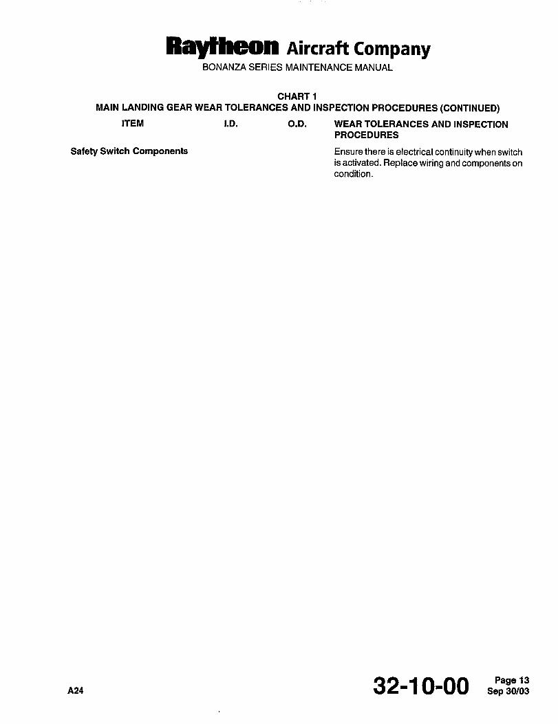
Ray~heon Aircraft CompanyBONANU~ SERIES MAINTENANCE MANUAL
CHART1
MAIN LANDING GEAR WEAR TOLERANCES AND INSPECTION PROCEDURES (CONTINUED)
ITEM I.D. O.D. WEAR TOLERANCES AND INSPECTION
PROCEDURES
Safety Switch Components Ensure there is electrical continuity when switch
is activated. Replace wiring and components on
condition.
A24 32-1 0-00 Sep 30/03Page 13
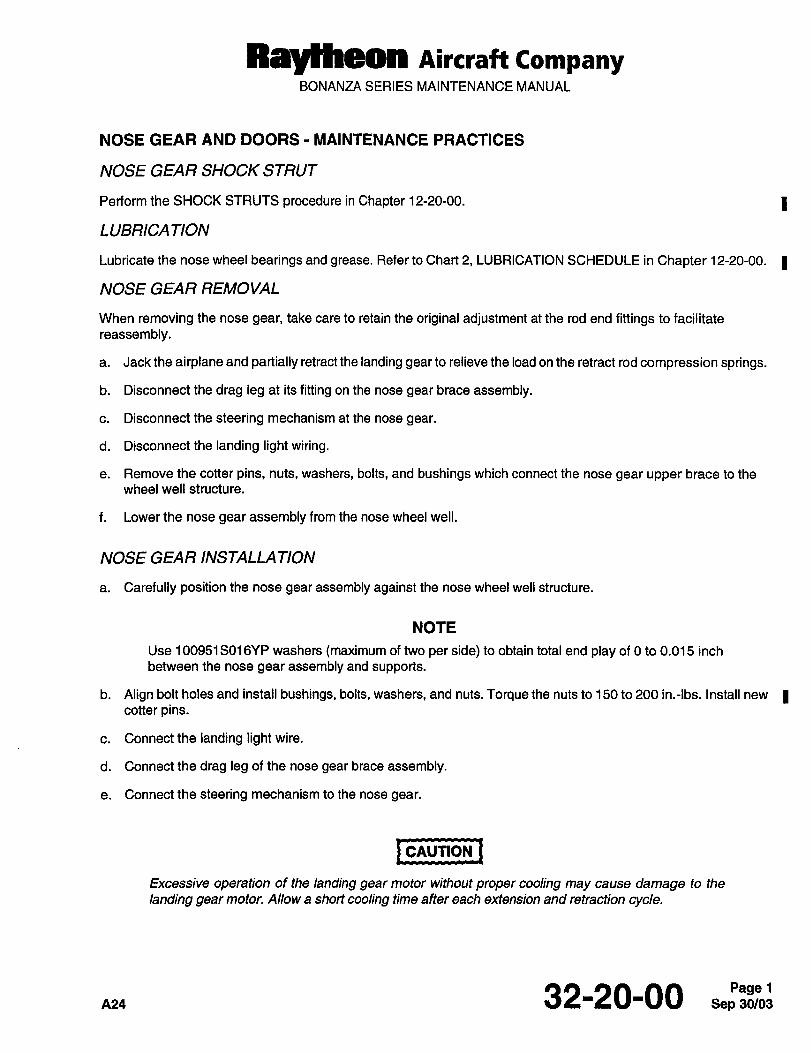
RayYheon Aircraft CompanyBONANZA SERIES MAINTENANCE MANUAL
NOSE GEAR AND DOORS I MAINTENANCE PRACTICES
NOSE GEAR SHOCK STRUT
Perform the SHOCK STRUTS procedure in Chapter 12-20-00. 1
LUBRICATION
Lubricate the nose wheel bearings and grease. Refer to Chart 2, LUBRICATION SCHEDULE in Chapter 12-20-00. 1
NOSE GEAR REMOVAL
When removing the nose gear, take care to retain the original adjustment at the rod end fittings to facilitate
reassembly.
a. Jack the airplane and partially retract the landing gear to relieve the load on the retract rod compression springs.
b. Disconnect the drag leg at its fitting on the nose gear brace assembly.
c. Disconnect the steering mechanism at the nose gear.
d. Disconnectthe landing lightwiring.
e. Remove the cotter pins, nuts, washers, bolts, and bushings which connect the nose gear upper brace to the
wheel well structure.
f. Lower the nose gear assembly from the nose wheel well.
NOSE GEAR INSTALLATION
a. Carefully position the nose gear assembly against the nose wheel well structure.
NOTE
Use 100951S016YP washers (maximum of two per side) to obtain total end play of 0 to 0.015 inch
between the nose gear assembly and supports.
b. Align bolt holes and install bushings, bolts, washers, and nuts. Torque the nuts to 150 to 200 in.-lbs. Install new Icotter pins.
c. Connectthelanding lightwire.
d. Connect the drag leg of the nose gear brace assembly.
e. Connect the steering mechanism to the nose gear.
rCAUTION ICAUTION
Excessive operation of the landing gear motor without proper cooling may cause damage to the
landing gear motor. Allow a short cooling time after each extension and retraction cycle.
32-20-00 Sep 30/03Page 1
Raytheon AirrraflCompanyBONANZA SERIES MAINTENANCE MANUAL
f. Operate the landing gear and check for proper rigging and nose gear adjustment. (Cycle the landing gear a min-
imum of six complete cycles.)
NOSE GEAR OVERHAUL
NOTE
Refer to the OVERHAUL AND REPLACEMENT SCHEDULE in Chapter 5-10-00 for time limits and
maintenance checks of the nose gear.
Experience in the field indicates the points of greatest wear on the nose gear are the upper and lower bearings in
the barrel assembly. The forces exerted on the bearings during takeoff and landing tend to result in an oversized
condition. The oversized condition of the upper bearing in the barrel assembly will result in leakage of hydraulic fluid
through the upper bearing and O-ring. This will eventually cause fluid to seep down through the felt pad and out the
lower bearing.
When replacement of the scraper ring and all O-rings in the landing gear fails to stop leaks, the oversized condition
of the bearings is probable. In such instances the landing gear should be overhauled. The following information will
aid in determining the extent of landing gear wear and whether it is possible to overhaul or necessary to replacecritical landing gear components.
I NOSE GEAR DISASSEMBLY
IwnRNINalWARNING
Do not begin any disassembly of the nose landing gear until all air pressure has been re-
leased.
a. Place the strut in a near vertical position to prevent the hydraulic fluid from spilling when the air valve assemblyI (1) is removed (Ref. Figures 1 and 2).
b. Depress the valve core to deflate the strut and remove the air valve assembly (1).
I c. Perform the NOSE WHEEL REMOVAL procedure in Chapter 32-40-00.
d. Remove the snap ring (4) retaining the orifice tube (6).
e. Retract the piston and fork assembly (48) to push the orifice tube (6) out of the barrel (23).
f. Remove the orifice tube (6). Remove the O-ring (5) and piston ring (7).
g. Invert the nose gear and drain out the hydraulic fluid.
IWARNING)WARNING
Do not disconnect the torque knees (37 and 46) without first deflating the nose gear. The
torque knees provide the extension stop for the piston and fork assembly (48). When dis-
connected, the piston and fork assembly (48) is free to slide out of the barrel assembly (23).
h. Remove the cotter pin (40), nut (41), washers (39 and 44), bushing (45), and bolt (43).
Sep 30/03Page 2 32-20-00
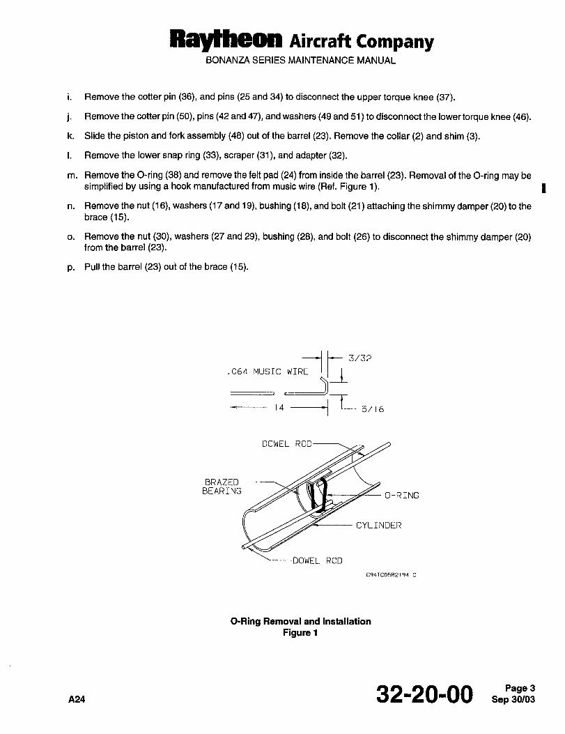
RBycheOn nircraff CompanyBONANZA SERIES MAINTENANCE MANUAL
i. Remove the cotter pin (36), and pins (25 and 34) to disconnect the upper torque knee (37).
j. Remove the cotter pin (50), pins (42 and 47), and washers (49 and 51 to disconnect the lower torque knee (46).
k. Slide the piston and fork assembly (48) out of the barrel (23). Remove the collar (2) and shim (3).
i. Remove the lower snap ring (33), scraper (31), and adapter (32).
m. Remove the O-ring (38) and remove the felt pad (24) from inside the barrel (23). Removal of the O-ring may be
simplified by using a hook manufactured from music wire (Ref. Figure 1). I
n. Remove the nut (16), washers (17 and 19), bushing (18), and bolt (21) attaching the shimmy damper (20) to the
brace (15).
o. Remove the nut (30), washers (27 and 29), bushing (28), and bolt (26) to disconnect the shimmy damper (20)from the barrel (23).
p. Pull the barrel (23) out of the brace (15).
.Obd. MUSICWTR~--/ i’l3/32
$15/ b
DOWEL ROD
BRAZEDBEARING
O-RTNG
CYLINDER
DOWEL ROD
C94TC05B2194 C
O-Ring Removal and Installation
Figure 1
A24 32-20-00 Sep 30/03Page 3
RayYheon Aircraft CompanyBONANZA SERIES MAINTENANCE MANUAL
NOSE GEAR CLEANING, REPLACEMENT PARTS AND REPAIRS
CLEANING
a. Clean all parts with solvent (16, Chart 1, 91-00-00). Remove all excess solvent and wipe dry after cleaning.
b. Immerse all internal parts in clean hydraulic fluid (9, Chart 1, 91-00-00) prior to assembly.
REPLACEMENT PARTS
a. Inspect all parts and assemblies for damage or excessive wear. The following conditions are cause for rejection:
I Wear which is greater than the allowable wear tolerances (Ref. Chart 1).
Damage which cannot be corrected or repaired.
Screws that are severely damaged or have stripped, severely worn or scored threads.
Parts that are cracked, chipped or broken.
Parts that have corrosion or other defects that cannot be repaired.
b. Replace the following parts when nose gear is overhauled:
Adapter (32)
Bushing (12)
Cotter Pins
Felt Pad (24)
Piston Ring (7)
O-Rings(5,38)
Safety Wire
Scraper (31)
Snap Rings (4, 33)
Bearings (8, 22)
c. Replace the following parts on condition when nose gear is overhauled:
Bushings (18, 28, 35, 45)
Grease Fittings
Placards
Valve Core (1)
Sep 32-20’00 A24
RaytheMI Aircraft CompanyBONANZA SERIES MAINTENANCE MANUAL
REPAIRS I
a. Visually inspect castings for cracks and pitting; and finished surfaces for scoring, pitting, nicks, cracks, distortion
and wear. Chart 1 lists wear tolerances to aid in determining the extent of wear. Replace all defective and
excessively worn parts.
b. If fluid leaks have been observed on top of the air valve assembly (1), check the small O-ring of the valve; then
look for defects in the valve (Ref. Figure 2). 1
c. If the leak is from the junction of the orifice tube assembly (6) and the barrel (23), check the O-ring (5) on the
orifice tube (6).
d. All parts or assemblies may be repaired if the following conditions exist:
Slight scoring of shafts may be corrected by lapping carefully with a flat oil stone.
NOTE
Do not exceed 10% of the component material thickness when removing nicks, burrs and
scratches.
Those parts that are scratched or have worn plating may be stripped and replated with the same type of
plating as that removed or be replaced with new parts.
Smooth minor nicks, burrs, and scratches.
Minor thread damage, chase to clean or smooth.
NOTE
Corrosion damage requires inspection to determine the depth of penetration and the
cross-sectional area change. The damaged area must be thoroughly cleaned and the corrosion
must be removed. Refer to CORROSION MAINTENANCE PRACTICES in Chapter 20-09-00. The
deterioration caused by corrosion or removal of corrosion must not reduce the material thickness
of any component by more than 10%. Refer to Chart 1 for NOSE GEAR WEAR TOLERANCES
AND INSPECTION PROCEDURES on components. For additional information contact the
Technical Support Department of Raytheon Aircraft Company, P.O. Box 85, Wichita, KS 67201.
Remove corrosion if applicable and apply corrosion prevention materials as necessary per MIL-C-5541 or
cadmium plate per Fed QQ-P-416, Type II.
Bushings that check within allowable wear tolerances may be reused.
When evidence of damage exists to steel parts, magnetic particle inspect per MIL-STD-1949.
NOTE
Do not remove paint or primer from the area to be fluorescent or dye penetrant inspected per
MIL-STD-6866. If the finish absorbs the penetrant so that bleed out prevents satisfactory inspectionor if a new finish has not cured for at least 30 days, contact the Technical Support Department of
Raytheon Aircraft Company, P.O. Box 85, Wichita, KS 67201.
When evidence of damage exists to metal parts other than steel, fluorescent penetrant inspect per
MIL-STD-6866, Type I.
Replace damaged or unserviceable parts with new or serviceable parts.
,432-20-00 Sep 30/03Page 5
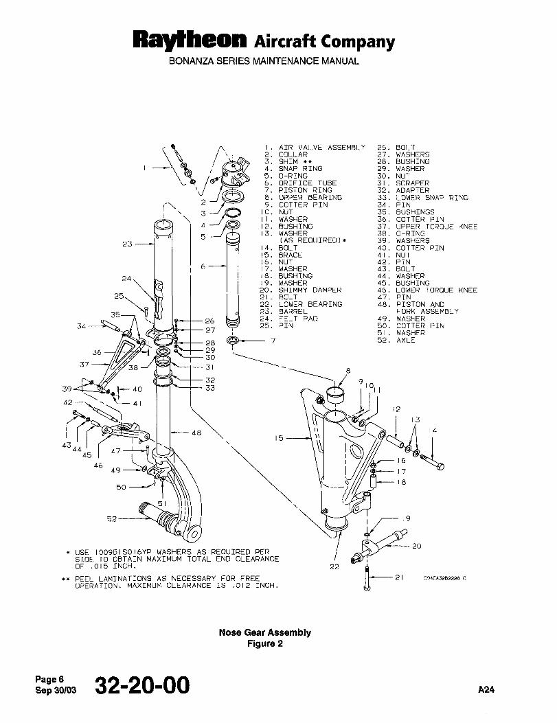
Raylheon Aircraft CompanyBONANZA SERIES MAINTENANCE MANUAL
2
9
i. AIR VALVE ASSEMBLY 26. BOLT2. COLLAR 27. WASHERS3. SHTM 28. BUSHING4. SNAP RING 29. WASHER5. O-RING 30. NUT
aP~ 6. ORIFICE TUBE 31. SCRAPER
7. PISTON RING 32. ADAPTER~31 8. UPPER BEARING 33. LOWER SNAP RING
9. COTTER PIN 34. PIN10. NUT 35. BUSHINGSII. WASHER 36. COTTER PIN12. BUSHING 37. UPPER TOR[3UE KNEE
5J~I 13. WASHER 38. O-RING(AS REOUIRED)* 39. WASHERS
2314. BOLT 40. COTTER PIN15. BRACE 41. NUT16. NUT 42. PIN
6 17. WASHER 43. BOLT18. BUSHING 44. WASHER2419. WASHER 45. BUSHING20. SHIMMY DAMPER 46. LOWER TOROUE KNEE
~e26
21. BOLT 47. PIN22. LOWER BEARING 48. PISTON AND23. BARREL FORK ASSEMBLY24. FELT PAD 49. WASHER
34 25. PIN 50. COTTER PIN27
36 P~t-- 2930
3738 10~2 ~--t-- 3 1
m--m--~- 32 9
39 ~c40 33 101
42 41
43ii;12
o161718
4445 t-B~46
49
so’t
51ii;
O
52
USE 100951SOlbYP WASHERS AS REQUIRED PERSIDE TO OBTAIN MAXIMUM TOTAL END CLEARANCEOF .015 INCH. 22
PEEL LAMINATIONS AS NECESSARY FOR FREEINCH. 8-’ C94EA3282228 C
OPERATION. MAXIMUM CLEARANCE IS .012
Nose Gear AssemblyFigure 2
Sep 30/03Page 6 32-20-00 A24
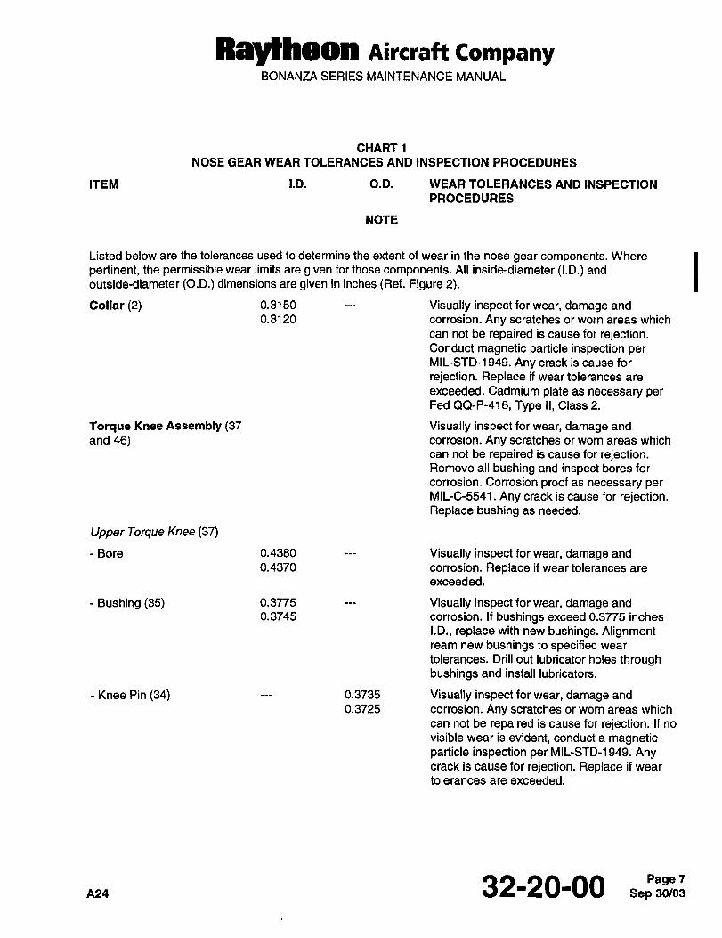
RayCheon Aircraft CompanyBONANZA SERIES MAINTENANCE MANUAL
CHART1
NOSE GEAR WEAR TOLERANCES AND INSPECTION PROCEDURES
ITEM I.D. O.D. WEAR TOLERANCES AND INSPECTION
PROCEDURES
NOTE
Listed below are the tolerances used to determine the extent of wear in the nose gear components. Where
pertinent, the permissible wear limits are given for those components. All inside-diameter (I.D.) and
outside-diameter (O.D.) dimensions are given in inches (Ref. Figure 2).
Collar (2) 0.3150 Visually inspect for wear, damage and
0.3120 corrosion. Any scratches or worn areas which
can not be repaired is cause for rejection.Conduct magnetic particle inspection perMIL-STD-1949. Any crack is cause for
rejection. Replace if wear tolerances are
exceeded. Cadmium plate as necessary perFed QQ-P-416, Type II, Class 2.
Torque Knee Assembly (37 Visually inspect for wear, damage and
and 46) corrosion. Any scratches or worn areas which
can not be repaired is cause for rejection.Remove all bushing and inspect bores for
corrosion. Corrosion proof as necessary perMIL-C-5541. Any crack is cause for rejection.Replace bushing as needed.
Upper Torque Knee (37)
-Bore 0.4380 Visually inspect for wear, damage and
0.4370 corrosion. Replace if wear tolerances are
exceeded.
Bushing (35) 0.3775 Visually inspect for wear, damage and
0.3745 corrosion. if bushings exceed 0.3775 inches
I.D., replace with new bushings. Alignmentream new bushings to specified wear
tolerances. Drill out lubricator holes throughbushings and install lubricators.
Knee Pin (34) 0.3735 Visually inspect for wear, damage and
0.3725 corrosion. Any scratches or worn areas which
can not be repaired is cause for rejection. If no
visible wear is evident, conduct a magneticparticle inspection per MIL-STD-1949. Anycrack is cause for rejection. Replace if wear
tolerances are exceeded.
32-20-00 Sep 30/03Page 7
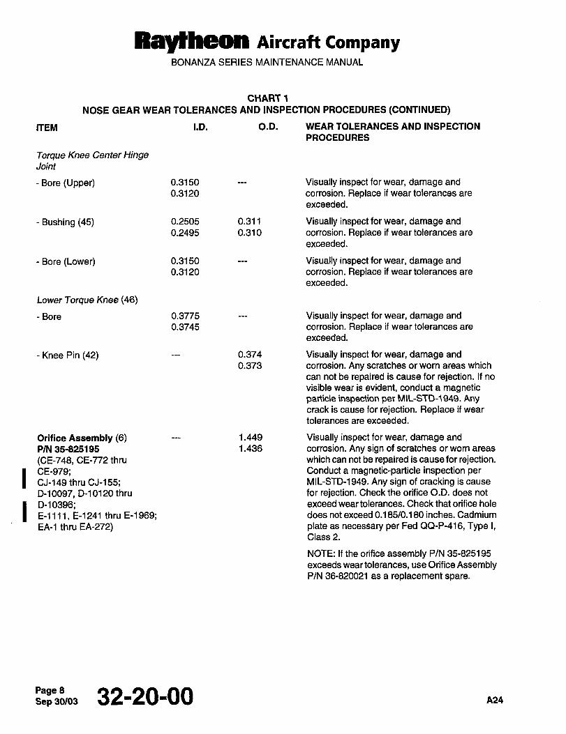
Raytheon Aircraft CompanyBONANZA SERIES MAINTENANCE MANUAL
CHART1
NOSE GEAR WEAR TOLERANCES AND INSPECTION PROCEDURES (CONTINUED)
ITEM i.D. O.D. WEAR TOLERANCES AND INSPECTION
PROCEDURES
Torque Knee Center HingeJoint
Bore (Upper) 0.3150 Visually inspect for wear, damage and
0.3120 corrosion. Replace if wear tolerances are
exceeded.
Bushing (45) 0.2505 0.31 1 Visually inspect for wear, damage and
0.2495 0.310 corrosion. Replace if wear tolerances are
exceeded.
Bore (Lower) 0.3150 Visually inspect for wear, damage and
0.3120 corrosion. Replace if wear tolerances are
exceeded.
Lower Torque Knee (46)
-Bore 0.3775 Visually inspect for wear, damage and
0.3745 corrosion. Replace if wear tolerances are
exceeded.
Knee Pin (42) 0.374 Visually inspect for wear, damage and
0.373 corrosion. Any scratches or worn areas which
can not be repaired is cause for rejection. If no
visible wear is evident, conduct a magneticparticle inspection per MIL-STC)-1949. Anycrack is cause for rejection. Replace if wear
tolerances are exceeded.
Orifice Assembly (6) 1.449 Visually inspect for wear, damage and
P/N 35-825195 1.436 corrosion. Any sign of scratches or worn areas
(CE-748, CE-772 thru which can not be repaired is cause for rejection.
I CE-979; Conduct a magnetic-particle inspection per
CJ-149 thru CJ-155; MIL-STD-1949. Any sign of cracking is cause
D-10097, D-l 0120 thru for rejection. Check the orifice O.D. does not
I D-l 0396; exceed wear tolerances. Check that orifice hole
E-llll, E-1241 thru E-l 969; does not exceed 0.185/0.180 inches. Cadmium
EA-1 thru EA-272) plate as necessary per Fed QQ-P-416, Type I,Class 2.
NOTE: If the orifice assembly P/N 35-825195
exceeds wear tolerances, use Orifice AssemblyP/N 36-820021 as a replacement spare.
Page 8~, 32-20-00 A24
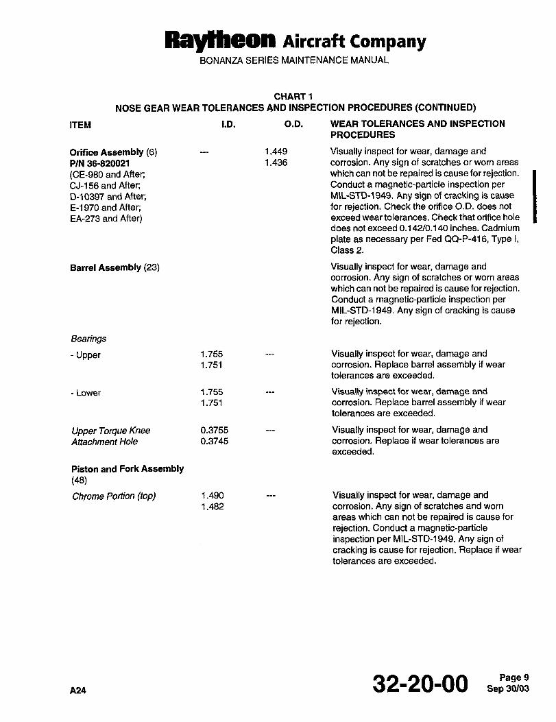
Ray~heon Aircraft CompanyBONANZA SERIES MAINTENANCE MANUAL
CHART1
NOSE GEAR WEAR TOLERANCES AND INSPECTION PROCEDURES (CONTINUED)
ITEM I.D. O.D. WEAR TOLERANCES AND INSPECTION
PROCEDURES
Orifice Assembly (6) 1.449 Visually inspect for wear, damage and
P/N 36-820021 1.436 corrosion. Any sign of scratches or worn areas
(CE-980 and After; which can not be repaired is cause for rejection.CJ-156 and After; Conduct a magnetic-particle inspection per
D-10397 and After; MIL-STD-1949. Any sign of cracking is cause
E-l 970 and After; for rejection. Check the orifice O.D. does not
EA-273 and After) exceed wear tolerances. Check that orifice hole
does not exceed 0.142/0.1 40 inches. Cadmium
plate as necessary per Fed QQ-P-416, Type I,Class 2.
Barrel Assembly (23) Visually inspect for wear, damage and
corrosion. Any sign of scratches or worn areas
which can not be repaired is cause for rejection.Conduct a magnetic-particle inspection perMIL-STD-1949. Any sign of cracking is cause
for rejection.
Bearings
-Upper 1.755 Visually inspect for wear, damage and
1.751 corrosion. Replace barrel assembly if wear
tolerances are exceeded.
-Lower 1.755 Visually inspect for wear, damage and
1.751 corrosion. Replace barrel assembly if wear
tolerances are exceeded.
Upper Torque Knee 0.3755 Visually inspect for wear, damage and
Attachment Hole 0.3745 corrosion. Replace if wear tolerances are
exceeded.
Piston and Fork Assembly(48)
Chrome Portion (topl 1.490 Visually inspect for wear, damage and
1.482 corrosion. Any sign of scratches and worn
areas which can not be repaired is cause for
rejection. Conduct a magnetic-particleinspection per MIL-STD-1949. Any sign of
cracking is cause for rejection. Replace if wear
tolerances are exceeded.
A24 32-20-00 9
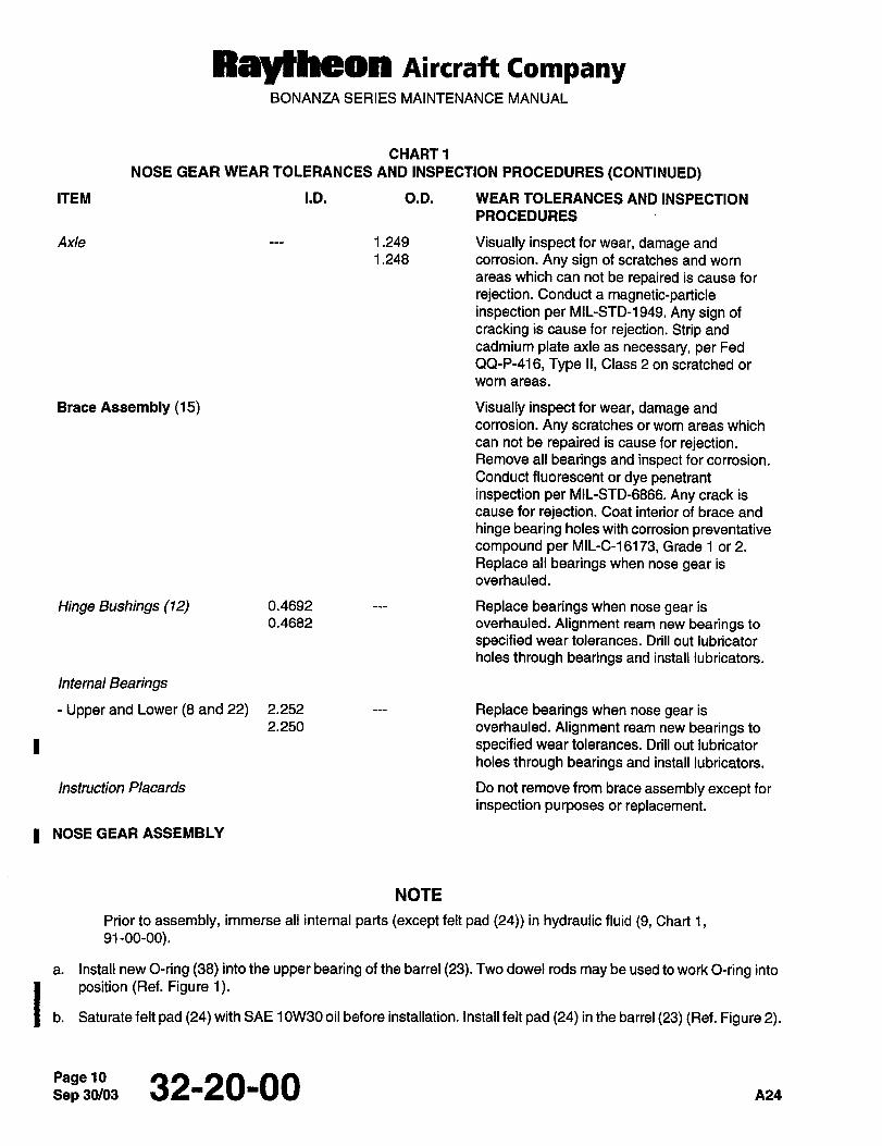
Raytheon Aircraft CompanyBONANZA SERIES MAINTENANCE MANUAL
CHART1
NOSE GEAR WEAR TOLERANCES AND INSPECTION PROCEDURES (CONTINUED)
ITEM I.D. O.D. WEAR TOLERANCES AND INSPECTION
PROCEDURES
Axle 1.249 Visually inspect for wear, damage and
1.248 corrosion. Any sign of scratches and worn
areas which can not be repaired is cause for
rejection. Conduct a magnetic-particleinspection per MIL-STD-1949. Any sign of
cracking is cause for rejection. Strip and
cadmium plate axle as necessary, per Fed
QQ-P-416, Type II, Class 2 on scratched or
wom areas.
Brace Assembly (15) Visually inspect for wear, damage and
corrosion. Any scratches or worn areas which
can not be repaired is cause for rejection.Remove all bearings and inspect for corrosion.
Conduct fluorescent or dye penetrantinspection per MIL-STD-6866. Any crack is
cause for rejection. Coat interior of brace and
hinge bearing holes with corrosion preventativecompound per MIL-C-16173, Grade 1 or 2.
Replace all bearings when nose gear is
overhauled.
Hinge Bushings (12) 0.4692 Replace bearings when nose gear is
0.4682 overhauled. Alignment ream new bearings to
specified wear tolerances. Drill out lubricator
holes through bearings and install lubricators.
Internal Bearings
Upper and Lower (8 and 22) 2.252 Replace bearings when nose gear is
2.250 overhauled. Alignment ream new bearings to
I specified wear tolerances. Drill out lubricator
holes through bearings and install lubricators.
Instruction Placards Do not remove from brace assembly except for
inspection purposes or replacement.
I NOSE GEAR ASSEMBLY
NOTE
Prior to assembly, immerse all internal parts (except felt pad (24)) in hydraulic fluid (9, Chart 1,91-00-00).
a. Install new O-ring (38) into the upper bearing of the barrel (23). Two dowel rods may be used to work O-ring into
1. position (Ref. Figure 1).
Saturate felt pad (24) with SAE 1 0W30 oil before installation. Install felt pad (24) in the barrel (23) (Ref. Figure 2).
Sep 30/03PagelO 32-20-00 n24
RayCheon nircraft CompanyBONANZA SERIES MAINTENANCE MANUAL
c. Install new scraper (31), adapter (32) and secure with snap ring (33).
d. Install barrel (23) into the brace (15).
e. Install shim (3) as necessary.
NOTE IAdd or remove lamination from shim (3) as necessary for free operation. Maximum clearance is
0.012 between collar (2) and brace (15).
f. Install collar (2) to brace (15) and tighten two bolts securing collar. Rotate collar to ensure freedom of movement
after tightening bolts. Adjust shim (3) as necessary to allow collar to rotate freely. Secure bolts with safety wire. I
g. Install air valve assembly (1) excluding valve core.
h. Install upper torque knee (37) with the pins (25 and 34), and cotter pin (36).
NOTE
Install the washers (17 and 19) above or below the bushing (18) on the brace (15) to align the
shimmy damper (20) with the lug on the barrel (23)
i. Position shimmy damper (20) and install the bushing (18), bolt (21), washers (17 and 19) and nut (16).
j. Install the bushing (28), bolt (26), washers (27 and 29) and nut (30) to connect the shimmy damper (20). Ik. Slide the piston and fork assembly (48) into the barrel (23).
i. Connect the lower torque knee (46) with the pins (42 and 47), washers (49 and 51) and cotter pin (50).
m. Install the bushing (45), bolt (43), washers (39 and 44), nut (41) and cotter pin (40), to connect the upper and
lower torque knees (37 and 46).
n. Install new O-ring (5) and piston ring (7) to orifice tube (6). Push orifice tube (6) down into the barrel (23) and
secure by attaching snap ring (4) to the top of collar (2).
o. Lubricate bearings at grease fittings with grease (46, Chart 1, 91-00-00).
p. With the strut in the vertical position and approximately 114 inch from fully compressed, fill through the air valve
assembly (1) with approximately 500/550 cc of hydraulic fluid (9, Chart 1, 91-00-00).
q. Fully extend and recompress the piston and fork assembly (48) three times or until no additional fluid can be
added. Add additional fluid as required with the strut in the compressed position.
r. With the piston and fork assembly (48) compressed, install the valve core into air valve assembly (1).
32-20-00
NglYNteOn Aircraft CompanyBONANZA SERIES MAINTENANCE MANUAL
I WARUINO)WARNING
As with all operations involving equipment under high pressure, exercise caution when per-
forming the leak test; avoid the areas directly above and below the strut.
s. To leak test, inflate the nose gear to approximately 90 psi using dry air or nitrogen. Coat the top of the collar (2)and air valve assembly (1) with soapsuds and test for air leaks.
t. Release the air pressure by depressing the valve core in the air valve assembly (1). Clean the soapsuds from
the top of the collar (2) and air valve assembly (1) with fresh water.
u. Install the air valve cap to the air valve assembly (1).
a. Perform the NOSE WHEEL INSTALLATION procedure in Chapter 32-40-00.
a. Perform the NOSE GEAR INSTALLATION procedure in 32-20-00.
a. Perform the SHOCK STRUTS procedure in Chapter 12-20-00.
NOSE GEAR SHIMMY DAMPER SERVICING
IPerform the SHIMMY DAMPER procedure in Chapter 12-20-00.
NOSE GEAR SHIMMY DAMPER REMOVAL
a. Remove the nut (16), washers (17 and 19), bushing (18), and bolt (21) which attach the shimmy damper (20) to
I the brace (15) (Ref. Figure 2).
b. Remove the nut (30), washers (27 and 29), bushing (28), bolt (26) and remove the shimmy damper (20) from
the barrel (23).
I NOSE GEAR SHIMMYDAMPER INSTALLATION
a. Install the bushing (28), washers (27 and 29), nut (30) and bolt (26) attaching the shimmy damper (20) to the
barrel (23).
b. Install the bushing (18), washers (17 and 19), nut (16) and bolt (21) attaching the shimmy damper (20) to the
nose gear brace (15). For alignment purposes, attach a 100951-X031-YN washer (19) between the damper and
the lug on the brace, and a 100951-X031-YM washer (17) under the nut.
c. Swivel the nose wheel to check the turning radius of the strut and for freedom of movement without binding or
rough spots. Adjust the nose gear steering travel adjustment bolts to stop shimmy damper piston 1/32 inch to
114 inch from maximum travel in both directions.
NOSE GEAR SHIMMY DAMPER OVERHAUL
NOTE
Refer to the OVERHAUL AND REPLACEMENT SCHEDULE in Chapter 5-10-00 for time limits and
maintenance checks of the nose gear shimmy damper.
Sep 30/03Page 12 32-20-00 ns~
Raytheon nircraff CompanyBONANZA SERIES MAINTENANCE MANUAL
NOSE GEAR SHIMMY DAMPER DISASSEMBLY I
a. Remove cotter pin (1), washer (8) and compression spring (9) by holding the washer (8) down with a small rod
or screw driver so that the parts will not spring out when the cotter pin (1) is removed (Ref. Figure 3). 1
b. Remove the floating piston (10) by engaging it with a long 6-32 screw or threaded rod. Remove O-ring (1 1) fromthe floating piston (10).
c. Remove the snap ring (2) and piston scraper (3). Force the barrel end (5) out of the barrel (6) by working the
piston rod (12) back and forth. Remove O-rings (4) from the barrel end (5).
d. Remove all remaining hydraulic fluid by inverting shimmy damper and pumping the piston rod (12).
e. Remove the snap ring (23) and slide the piston rod (12) with the remaining parts out of the barrel (6).
f. Insert a long 6-32 screw or threaded rod into the hole at the clevis (24) end of the piston rod (12) and engagethe forward floating piston (17). Pull floating piston (17) toward clevis (24) so that the piston retaining pin (15)can be driven-out.
g. Remove the piston retaining pin (15) and push the floating piston (17) out the open end of the piston rod (12)and remove O-ring (16).
h. Remove the remaining compression spring (1 8) and slide the damper piston (14) off the piston rod (12). Remove
O-rings (13) from the damper piston (14).
i. Remove remaining barrel end (19) and piston scraper (22) from the piston rod (12). Remove O-rings (20) and
(21) from the barrel end (19).
NOSE GEAR SHIMMY DAMPER CLEANING, REPLACEMENT PARTS AND REPAIRS
CLEANING
Clean all parts with cleaning solvent (16, Chart 1, 91-00-00). Rinse and dry thoroughly after cleaning.
I CAUTION 1CAUTION
For replacement, use O-rings approved for use with mineral base hydraulic fluid.
Lubricate all internal parts with hydraulic fluid (9, Chart 1, 91-00-00) prior to assembly.
REPLACEMENT PARTS
a. Inspect all parts and assemblies for damage or excessive wear (Ref. Figure 3). The follo~n/ing conditions are Icause for rejection:
Wear which is greater than the allowable wear tolerances. Refer to Chart 2, NOSE GEAR SHIMMY IDAMPER WEAR TOLERANCES AND 1NSPECTION PROCEDURES.
Damage which cannot be corrected or repaired.
Parts that are cracked, chipped or broken.
Parts that have corrosion or other defects that cannot be repaired.
*24 32-20-00 13
Ray~heon Aircraft CompanyBONANZA SERIES MAINTENANCE MANUAL
b. Replace the following parts when nose gear shimmy damper is overhauled:
Cotter Pin (1)
Retaining Pin (15)
O-Rings (4, 11,13, 16, 20, 21)
Safety Wire
Snap Ring (2)
Springs (9, 18)
Piston Scrapers (3, 22)
Washer (8)
REPAIRS
a. Visually inspect casting for cracks and pitting; and finished surfaces for scoring, pitting, nicks, cracks, distortion
and wear. Refer to Chart 2 for tolerances to aid in determining the extent of wear. Replace all defective and
excessively worn parts.
b. All parts or assemblies may be repaired if any of the following problems exist:
Slight scoring of shafts may be corrected by lapping carefully with a flat oil stone.
NOTE
Do not exceed 10% of the component material thickness when removing nicks, burrs and
scratches.
Smooth minor nicks, burrs, and scratches.
Those parts that are scratched or have worn plating may be stripped and replated with the same type of
plating as that removed or be replaced with new parts.
Minor thread damage, chase to clean or smooth.
NOTE
Corrosion damage requires inspection to determine the depth of penetration and the
cross-sectional area change. The damaged area must be thoroughly cleaned and the corrosion
must be removed. The deterioration caused by corrosion or removal of corrosion must not reduce
the material thickness of any component by more than 10%. Refer to Chart 2 for NOSE GEAR
SHIMMY DAMPER WEAR TOLERANCES AND INSPECTION PROCEDURES on components.For additional information contact the Technical Support Department of Raytheon Aircraft
Company, P.O. Box 85, Wichita, KS 67201.
Remove corrosion if applicable, and apply corrosion prevention materials as necessary per MIL-C-5541 or
cadmium plate per Fed QQ-P-416, Type II.
Bushings that check within allowable wear tolerances may be reused.
Sep 30/03Pagel4 32-20-00
Ral~heon Aircraft CompanyBONANZA SERIES MAINTENANCE MANUAL
When evidence of damage exists to steel parts, magnetic particle inspect per MIL-STD-1949.
NOTE
Do not remove paint or primer from the area to be fluorescent or dye penetrant inspected perMIL-STD-6866. If the finish absorbs the penetrant so that bleed out prevents satisfactory inspectionor if a new finish has not cured for at least 30 days, contact the Technical Support Department of
Raytheon Aircraft Company, P.O. Box 85, Wichita, KS 67201.
When evidence of damage exists to metal parts other than steel, fluorescent penetrant inspect perMIL-STD-6866, Type I.
Replace damaged or unserviceable parts with new or serviceable parts.
~2, 32-20-00 Sep 30/03Pagel5
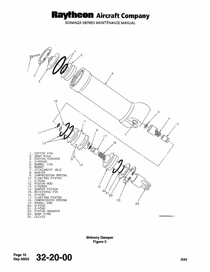
Ray~heon Aircraft CompanyBONANZA SERIES MAINTENANCE MANUAL
3
12
149
io
16I I
17
13
iI. COTTER PIN
2. SNAP RING3. PISTON SCRAPER4. O-RINGS5. BARREL END 156. BARREL7. ATTACHMENT HOLE8. WASHER9. COMPRESSION SPRING
10. FLOATING PISTON
I I O-RING12. PISTON ROD
W13. O-RINGS 1914. DAMPER PISTON SS
15. RETAINING PTN 20
ib. O-RING 212;17. FLOATING PISTON18. COMPRESSION SPRING 2319. BARREL END 2420. O-RING21 O-RING22. PISTON SCRAPER
23. SNAP RING
24. CLEVIS C94E03282874 C
Shimmy DamperFigure 3
Sep 32-20-00 A24
Raytheon Aircraff CompanyBONANZA SERIES MAINTENANCE MANUAL
NOSE GEAR SHIMMY DAMPER ASSEMBLY I
a. Replace the O-rings (20 and 21j on the barrel end (19). Slide the piston scraper (22) and barrel end onto pistonrod (12) (Ref. Figure 3). 1
b. Replace the O-ring (16) on the floating piston (17) and insert the compression spring (18) and the floating pistoninto the piston rod (12). With a long 6-32 screw or threaded rod, engage the floating piston (17) by pulling it
toward the clevis (24) so that the retaining pin (15) can be inserted. Install the damper piston (14) on the pistonrod (12) and insert the retaining pin (15). Replace the O-rings (13) on the damper piston (14).
c. insert the piston rod (12) and components into the barrel (6) and place the snap ring (23) into position.
d. Place the barrel (6) in a vise with the open end up and fill the barrel (6) and piston rod (12) with hydraulic fluid
(9, Chart 1, 91-00-00). Work the piston rod (12) up and down until bubbles stop appearing in the fluid, then refill
the barrel (6) and the piston rod (12). To eliminate the possibility of an air pocket under the barrel end (5), ensure
that the barrel (6) is completely full of hydraulic fluid. Any excess fluid will be forced into the piston rod (12) as
the barrel end (5) is inserted.
e. Replace the O-rings (4) on the barrel end (5). Insert the barrel end (5) and piston scraper (3) into the barrel (6)and secure with snap ring (2).
f. Fill the piston rod (12) with hydraulic fluid (9, Chart 1, 91-00-00). Engage the floating piston (17) with a 6-32 longscrew and pull towards the clevis (24). At the same time, insert and push the floating piston (10) down into the
piston rod (12). This will cause hydraulic fluid to be sucked into the piston rod (12) and preventing the entry of air.
g. Install compression spring (9), washer (8) and secure with cotter pin (1). Release the 6-32 rod from the piston(17) and remove from the assembly.
h. Check the fluid level in the shimmy damper by spreading the cotter pin (1) and inserting a 1/16-inch-diameterwire into the piston rod (12). Measure the distance to the top of the floating piston (10). If the distance to the
piston rod (10) exceeds 2 3/16 inches, remove the floating piston (10) and add more fluid to the piston rod (12).
i. Install shimmy damper on nose gear of the airplane. Perform the NOSE GEAR SHIMMY DAMPER
INSTALLATION procedure.
j. Service the shimmy damper. Perform the SHIMMY DAMPER procedure in Chapter 12-20-00.
~24 32-20-00 Sep 30/03Pagel7
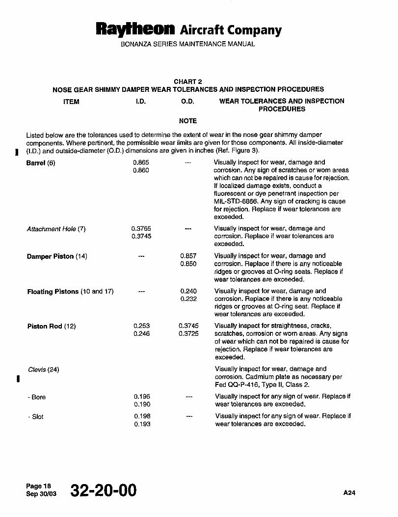
RayWleon Aircraft CompanyBONANZA SERIES MAINTENANCE MANUAL
CHART 2
NOSE GEAR SHIMMY DAMPER WEAR TOLERANCES AND INSPECTION PROCEDURES
ITEM I.D. O.D. WEAR TOLERANCES AND INSPECTION
PROCEDURES
NOTE
Listed below are the tolerances used to determine the extent of wear in the nose gear shimmy damper
components. Where pertinent, the permissible wear limits are given for those components. All inside-diameter
I (I.D.) and outside-diameter (O.D.) dimensions are given in inches (Ref. Figure 3).
Barrel (6) 0.865 Visually inspect for wear, damage and
0.860 corrosion. Any sign of scratches or worn areas
which can not be repaired is cause for rejection.If localized damage exists, conduct a
fluorescent or dye penetrant inspection perMIL-STD-6866. Any sign of cracking is cause
for rejection. Replace if wear tolerances are
exceeded.
Attachment Hole (7) 0.3765 Visually inspect for wear, damage and
0.3745 corrosion. Replace if wear tolerances are
exceeded.
Damper Piston (14) 0.857 Visually inspect for wear, damage and
0.850 corrosion. Replace if there is any noticeable
ridges or grooves at O-ring seats. Replace if
wear tolerances are exceeded.
Floating Pistons (10 and 17) 0.240 Visually inspect for wear, damage and
0.232 corrosion. Replace if there is any noticeable
ridges or grooves at O-ring seat. Replace if
wear tolerances are exceeded.
Piston Rod (12) 0.253 0.3745 Visually inspect for straightness, cracks,0.246 0.3725 scratches, corrosion or worn areas. Any signs
of wear which can not be repaired is cause for
rejection. Replace if wear tolerances are
exceeded.
Clevis (24) Visually inspect for wear, damage and
I corrosion. Cadmium plate as necessary perFed QQ-P-416, Type II, Class 2.
-Bore 0.196 Visually inspect for any sign of wear. Replace if
0.190 wear tolerances are exceeded.
-Slot 0.198 Visually inspect for any sign of wear. Replace if
0.193 wear tolerances are exceeded.
Sep 32-20-00 A24
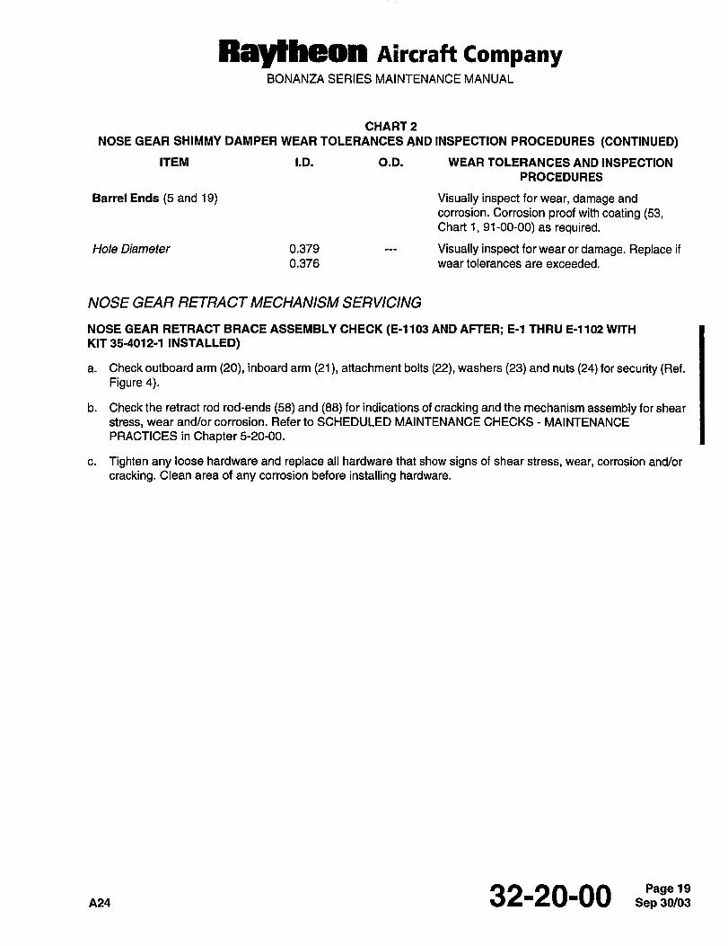
Raytheon Aircraff CompanyBONANZA SERIES MAINTENANCE MANUAL
CHARTP
NOSE GEAR SHIMMY DAMPER WEAR TOLERANCES AND INSPECTION PROCEDURES (CONTINUED)
ITEM I.D. O.D. WEAR TOLERANCES AND INSPECTION
PROCEDURES
Barrel Ends (5 and 19) Visually inspect for wear, damage and
corrosion. Corrosion proof with coating (53,Chart 1, 91-00-00) as required.
Hole Diameter 0.379 Visually inspect for wear or damage. Replace if
0.376 wear tolerances are exceeded.
NOSE GEAR RETRACT MECHANISM SERVICING
NOSE GEAR RETRACT BRACE ASSEMBLY CHECK (E-1103 AND AFTER; E-l THRU E-1102 WITH
KIT 35-4012-1 INSTALLED)
a. Check outboard arm (20), inboard arm (21), attachment bolts (22), washers (23) and nuts (24) for security (Ref.Figure 4).
b. Check the retract rod rod-ends (58) and (88) for indications of cracking and the mechanism assembly for shear
stress, wear and/or corrosion. Refer to SCHEDULED MAINTENANCE CHECKS MAINTENANCE
PRACTICES in Chapter 5-20-00.
c. Tighten any loose hardware and replace all hardware that show signs of shear stress, wear, corrosion and/or
cracking. Clean area of any corrosion before installing hardware.
32-20-00 19
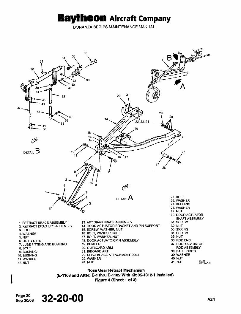
Rayeheon Aircraft CompanyBONANZA SERIES MAINTENANCE MANUAL
36
sSi31
1
30
33
4038 U 39
41
37 20 21
38
~913
29
37
41
28
39 22, 23, 2438
41
38 19
18
1415
DETAIL B11
26
9’/ /y/ I- ~BC. 8
104 9
II /dB/ ~7
4 DETAILA 25.BOLT
26. WASHER
27. BUSHING
5/ -Y"~- 28. WASHER
29. NUT
30. DOOR ACTUATOR
SHAFT ASSEMBLY
1. RETRACT BRACE ASSEMBLY 13. AFT DRAG BRACE ASSEMBLY 31. SCREW
2. RETRACT DRAG LEG ASSEMBLY 14. DOOR ACTUATOR BRACKET AND PIN SUPPORT 32. NUT
3. BOLT 15. SCREW, WASHER, NUT 33. SPRING
4. WASHER 16. BOLT, WASHER, NUT 34. SCREW
5. NUT 17. BOLT, WASHER, NUT 35. NUT
6. COTTER PIN 18. DOOR ACTUATOR PIN ASSEMBLY 36. ROD END
7. LUBE FITTING AND BUSHING 19. BUMPER 37. DOOR ACTUATOR
8. BOLT 20. OUTBOARD ARM ROD ASSEMBLY
9. BUSHING 21. INBOARD ART 38. BALL JOINTS
10. BUSHING 22. DRAG BRACE ATTACHMENT BOLT 39. WASHER
11. WASHER 23. WASHER 40. NUT
12. NUT 24. NUT 41. NUT
Nose Gear Retract Mechanism
(E-1103 and After; E-l thru E-1102 With Kit 35-4012-1 Installed)Figure 4 (Sheet 1 of 3)
Sep 30/03Page 20 32-20-00 A24
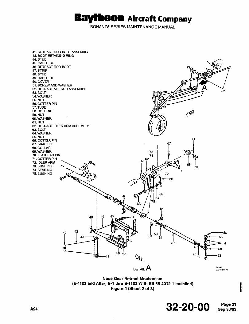
Raylheon nircraft CompanyBONANZA SERIES MAINTENANCE MANUAL
42. RETRACT ROD BOOT ASSEMBLY
43. BOOT RETAINING RING
44. STUD
45. CABLE TIE
46. RETRACT ROD BOOT
47. STRIP
48. STUD
49. CABLE TIE
50. COVER
S1.SCRNV AMD WASHER ~A52. RETRACT AFT ROD ASSEMBLY52
53. BOLT
54. WASHER
55. NUT
56. COTTER PIN
57. TUBE
58. ROD END
59.NUT
60. WASHER
61. NUT
62. RETRACT IDLER ARM ASSEMBLY
63. BOLT
64.WASHER
65. NUT71
66. COTTER PIN
67. BRACKET 67
69.WASHER 73 B68. COLLAR
70. FLATHEAD PIN 7471. COTTER PIN 62
73. BUSHING
69
6872. IDLER ARM
7074. BEARINGII75. BUSHING
67n
fi 9c66L
64
65
bii~"j 6P
49 i 46 47_ ,8~751
45 4243 64 6‘1 1 Bgc-55
57 ~h
50 48f6059
DETAILA
Nose Gear Retract Mechanism
(E-1103 and After; E-l thru E-1102 With Kit 35-4012-1 Installed)Figure 4 (Sheet 2 of 3)
A24 32-2000 21
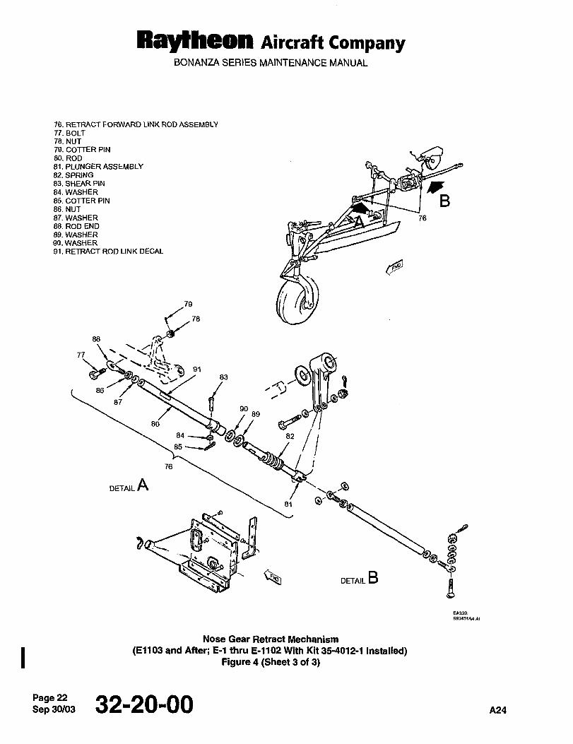
Ray~Hleon Aircraft CompanyBONANZA SERIES MAINTENANCE MANUAL
76. RETRACT FORWARD LINK ROD ASSEMBLY
77. BOLT
78. NUT
79. COTTER PIN
80. ROD
81. PLUNGER ASSEMBLY
82. SPRING83. SMEAR PIN
84. WASHER85. COTTER PIN B86. NUT
87. WASHER /1C~n ~I 7688. ROD END
89. WASHER90. WASHER91. RETRACT ROD LINK DECAL
78 li:i
88
/I77
86
87 B9" ss
80
82/’i85
76
DETAIL As; o-
tB OETAILB
B
Nose Gear Retract Mechanism
(E1103 and After; E-l thru E-1102 With Kit 35-4012-1 Installed)Figure 4 (Sheet 3 of 3)
Sep 30/03Page 22 32-20-00 A24
Raylheon AircraftBEECH BONANZA SERIES MAINTENANCE MANUAL
EXTENSION AND RETRACTION MAINTENANCE PRACTICES
LUBRICATION
Lubricate the landing gear and retract system as detailed in the Lubrication Chart in Chapter 12-20-00. Note LUBRI-
CATION OF LANDING GEAR UPLOCK ROLLERS in Chapter 12-20-00.
MANUAL LANDING GEAR EXTENSION SYSTEM
In the event of landing gear malfunction in flight, the gear may be manually extended by a hand crank located behind
the front spar between the pilot’s and copilot’s seats.
IW~RNINO iWARNING
If the gear’has been extended manually for emergency reasons, the airplane must be put on
jacks and inspected before the gear controls are returned to their normal position.
pcnunoN ICAUTION
Do not attempt to retract the landing gear using the hand crank. The manual extension system is
designed to lower the landing gear only. Refer to the appropriate Pilot’s Operating Handbook for
emergency op~rating instructions.
The landing gear should not be operated electrically with the hand crank engaged. In the event of
such operation, a teardown and magnetic inspection should be performed to check for damage to
the engagement slot in the worm shaft of the landing gear actuator.
LANDING GEAR ACTUA TOR ASSEMBLY REMOVAL
a. Removethe cabinfrontseats.
b. Remove the access cover on top and directly behind the front carry-through structure.
c. Disconnect the main landing gear retract rods at the actuator.
d. Remove the flap motor attaching bolts and disconnect the landing gear door attaching rods at the actuator.
e. Remove the four screws securing the landing gear limit switch assembly on the left-hand side of the actuator
and move the switch assembly aside to permit removal of the actuator.
f. Disconnect the electrical wiring to the landing gear motor. Identify the wires for ease of reinstallation.
ICAVTIONICAUTION
Do not remove the shaft from the sector gear of the actuator. If the shaft is removed, teardown of
the actuator is necessary for reinstallation of the shaft.
Az´•I 32-30-00Page 1
Ray~heon AircraftBEECH BONANZA SERIES MAINTENAN%E MANUAL
NOTE
For ease of reinstallation, note the index marks on the arm and actuator.
g. Remove the landing gear actuator access door on the bottom of the fuselage, and remove the nose gear actu-
ator arm and linkage from the actuator.
h. Remove the four actuator attaching nuts and remove the actuator.
LANDING GEAR ACTUA TOR ASSEMBL Y INSTALLA TION
a. Position the actuator and install the four attaching bolts.
b. Connect the nose landing gear rod and linkage to the actuator. Make certain that the index mark on the arm
coincides with the index mark on the actuator shaft.
c. Install the landing gear actuator access door on the bottom of the fuselage.
d. Connect the landing gear motor electrical wiring.
e. Attach the landing gear limit switch assembly to its bracket.
f. Connect the landing gear door attaching rods at the actuator. Attach the flap motor attaching bolts.
g. Connect the main gear retract rods at the actuator.
h. Install cotter pins and safety wire.
I cnunohllCAUTION
Excessive operation of the landing gear motor without proper cooling may cause damage to the
landing gear motor. Allow a P-minute-cooling time after each extension and retraction cycle.
i. Check rigging of landing gear system. When cycling the gear, listen for unusual noises at the motor and actua-
tor. Cycle the gear a minimum of six times.
j. Install the access covers on top and directly behind the front carry-through structure.
k. Install the cabin front seats.
LANDING GEAR MOTOR REMOVAL
a. Removethe rightfrontseat.
b. Remove the access plate over the motor and disconnect the electrical wiring. Identify the wires for ease of re-
installation.
c. Remove the three landing gear motor attaching bolts and remove the landing gear motor.
LANDING GEAR MOTOR INSTALLA TION
a. Position the landing gear motor on the actuator and install the attaching bolts. Safety wire the attaching bolts.
b. Connect the landing gear motor electrical wiring and install the access plate over the motor.
Dec 32-30-00 all
Ray~heon AircraftBEECH BONANZA SERIES MAINTENANCE MANUAL
c. Install the right hand seat.
DYNAMIC BRAKE RELA Y CHECK
The landing gear is operated by a split-field, series-wound motor located on the forward side of the main spar car-
ry-through. One field is used to drive the motor in each direction. To prevent overtravel of the gear, a dynamic brake
relay is incorporated into the landing gear circuit and acts as a brake on the motor. When either the up or downlimit
switches activate, the relay simultaneously breaks the power circuit to the motor and makes a complete circuit
through the armature and the unused field windings, turning the motor onto a generator. The resulting electrical load
applied to the armature stops the gear almost instantly.
To check the dynamic brake relay for proper operation, it is necessary to remove the spar cover to gain access to
the actuator and limit switches.
Actuate the landing gear with the landing gear handle (either up or down). When the actuator reaches midtravel po-sition, actuate the appropriate limit switch in the direction the actuator is traveling. The landing gear motor should
stop immediately without any noticeable coast.
LANDING GEAR DYNAMIC BRAKE RELA Y REMOVAL
a. Removethe rightfrontseat.
b. Remove the access plate which covers both the landing gear motor and the dynamic brake relay.
c. The dynamic brake relay is located slightly outboard and below the landing gear motor. Identify and disconnect
the wiring to the dynamic brake relay.
d. Remove the two screws which secure the dynamic brake relay assembly to its attaching bracket.
e. Removethedynamicbrake relay.
LANDING GEAR DYNAMIC BRAKE RELA Y INSTALLA TION
a. Position the dynamic brake relay on its attaching bracket and install the two attaching screws.
b. Connect the wiring which was disconnected during removal.
c. Install the access cover which covers the landing gear motor and the dynamic brake relay.
d. Installthe rightfrontseat.
MAIN LANDING GEAR RETRACT ROD REMOVAL
FIGURE I
a. Remove the pilot’s and the right front seat.
b. Remove the access covers directly aft of the front carry-through spar.
c. With the airplane on jacks, partially retract the landing gear until the inboard door is fully open.
d. Remove the attaching bolts and disconnect the retract rod from the landing gear actuator retract arm.
e. Remove the attaching bolt and disconnect the retract rod from the main landing gear V-brace.
f. Remove the retract rod through the wheel well.
~al 32-30-00
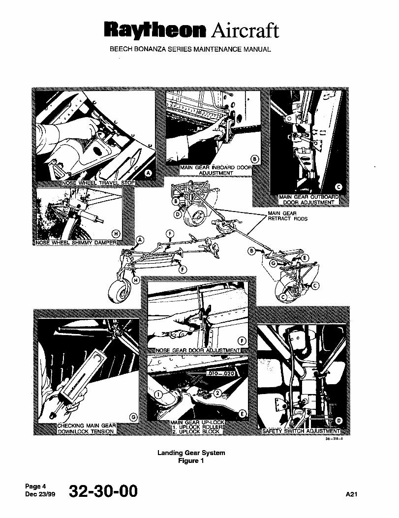
Raytheon AircraftBEECH BONANZA SERIES MAINTENANCE MANUAL
i1~9 I´•
id o
GEAR INBOARD
I/
ADJUSTMENT
MAIN GEAR
J/ MAIN GEARRETRACT RODS
OA O
WHEEL SHIMMY
(G
h~------
GEAR DOOR
C
.010-.020
O E
GEAR OMAIN i. UPLOCK
UPLOCK BLOCK
36--211--1
Landing Gear SystemFigure 1
Page 4Dec23/99 32-30-00 A21
Rayl~hean AircraftBEECH BONANZA SERIES MAINTENANCE MANUAL
MAIN LANDING GEAR RETRACT ROD INSTALLA TION
FIGURE f
a. Position the landing gear retract rod in the main landing gear V-brace located in the wheel well.
b. Install the attaching bolt in the main landing gear V-brace and the main landing gear retract rod.
c. Position the main landing gear retract rod in the main landing gear actuator retract arm and install the attachingbolts.
d. Install the access covers immediately aft of the front carry-through spar.
e. install the pilot’s and the right front seat.
RIGGING THE LANDING GEAR
Read the entire landing gear rigging procedure before any attempt to rig the landing gear system. Physically locate
each item while reading through the rigging instructions. When any part of the landing gear system requires rigging,it is recommended that ALL of the rigging steps be accomplished in the order shown.
I cnlmoru ICAUTION
Do not change the position of the control switch to reverse the direction of the landing gear while
the landing gear is in transit, as this could cause damage to the landing gear retract mechanism.
After the airplane is placed on jacks, but before beginning to rig the landing gear, start the retraction cycle enoughto break the downlock tension. Apply a sharp load by hand against the nose landing gear strut. Approximately a half
to one inch of movement under this load by the main landing gear wheels is a good indication that the landing gearactuator needs to be overhauled and/or adjusted.
I cnunon iCAUTION
Battery voltage is not sufficient to properly cycle the landing gear during the rigging procedure. A
28.25 0.25 volt power supply should be utilized for the landing gear during rigging. If an external
power supply is not available on the airplane, jumper cables may be used between the battery and
the power supply. Be sure of the polarity before connecting the power supply to the battery.
Excessive operation of the landing gear motor without proper cooling may cause damage to the
landing gear motor. Allow a Fminute-cooling time after each extension and retraction cycle.
Whenever the landing gear mechanism or doors are removed or disconnected, retract the landing gear and check
the rigging. The following procedure for rigging the landing gear was written on the assumption that the entire land-
ing gear is out of rig.
IWARNINO iWARNING
To prevent possible injury, the emergency landing gear actuator hand crank must always be
disengaged when operating the landing gear electrically.
pal 32-30-00 5
Rayl~heon AircraftBEECH BONANZA SERIES MAINTENANCE MANUAL
I CAUTION ICAUTION
Overtightening the nut on the bolt connecting the drag leg to the shock strut can bind the strut or
distort the strut attaching points. Torque the nut to 25 to 75 inch-pounds.
a. Place the airplane on jacks as instructed in Chapter 7-00-00.
b. Lengthen the main and nose landing gear retract rods sufficiently to prevent excessive tension on the nose gear
retract rods and to eliminate the danger of the V-brace on the main landing gears damaging the skin when the land-
ing gear is retracted. Damage to vital parts may result if abnormal loads are applied to the landing gear retract sys-tem. By lengthening the main and nose gear retract rods, such danger is removed.
c. Insert the landing gear retract arm/retract rod attach bolt pointing aft.
d. Disconnect the uplock cables at the brackets, leaving the springs attached. If the springs are disconnected, the
uplock arm may damage the wing skin upon retraction of the gear. Place the uplock block in the lower position.
e. Lengthen the nose landing gear retract rod.
f. Disconnect the nose landing gear door linkage at the attaching point on the nose landing gear door. Unscrew
the nose landing gear door links from the upper ball joint.
g. Remove the bolts attaching the main landing gear outboard door links at the main strut. Remove the actuator
rod to the inboard main landing gear door by unscrewing from the inboard rod ends and removing the bolt in the
door bracket.
h. Screw the stop bolts into the main gear V-brace assembly until approximately four or five threads are showing.
[CAMON 1CAUTION
When running the landing gear electrically before the switches are reset, or for the first time after
resetting the switches, run the landing gear with extreme care to make sure the switches open the
electrical circuits before the sector gear hits the internal stops in the gearbox. The sector gearshould not be touching the stop when the motor stops. Serious damage may result if the internal
stops are hit by the sector gear. When checking the dynamic brake system, actuate one of the limit
switches and the motor should stop immediately.
On airplanes with a 5-amp push-pull landing gear control circuit breaker, use this circuit breaker to
"bump" the landing gear. On earlier airplanes without the damp push-pull circuit breaker, manuallyoperate the limit switches and use the 30-amp landing gear motor circuit breaker to "bump" the
landing gear. When using the 30-amp circuit breaker, use extreme care because the dynamic brake
is inoperative.
i. Run the gear about two thirds up, then stop and "bump" the landing gear the remaining distance to either the
limit switch setting or to the internal stop by intermittent operation of the LDG GEAR circuit breaker. With the actuator
in the retracted position, check that the hand crank will rotate 1/8 to 1/4 turn (5/8 to 3/4 turn on new, or white actu-
ators) before reaching the internal stop of the actuator.
Dec 32-30-00
Ray~heon AircraftBEECH BONANZA SERIES MAINTENANCE MANUAL
NOTE
A new actuator may be installed on earlier airplanes as a spare. The new actuator may be identified
by white epoxy paint on the upper actuator arm, and the upper and lower actuator housing. When
the new actuator is installed as a spare on earlier airplanes, the actuator should be adjusted by us-
ing the 518 to 3/4 hand crank turns remaining after the motor has stopped. If this clearance is not
obtained, adjust the uplimit switch. To adjust the uplimit switch, lower the landing gear 518 to 3/4
turns of the emergency hand crank, and adjust the switch by turning the screw in the actuator in or
out to increase or decrease travel so that it just breaks the circuit.
j. Extend the landing gear and check the hand crank. There should be 1/8 to 1/4 turn (or 5/8’ to 314 turn on the new
(or white) actuators) between the extended position and the internal stop. The downlimit switch adjustment is ac-
complished by bending the switch actuator arm tab so that it just breaks the circuit. On newer actuators, there is an
adjustment screw for use when adjusting the downlimit switch.
NOTE
On airplane serials CE-959 and after, CJ-156 and after, D-10380 and after, E-1879 and after, and
EA-247 and after, the landing gear will retract slightly slower than on previous serials because the
motor used runs slower in the retract cycle.
Allow 2 minutes of cooling time between each extend and retract cycle
k. Extend and retract the landing gear two or three times to assure that the switches are correctly set and the dy-namic brake is operating correctly. Check the hand crank each time to ensure proper adjustment.
NOTE
It may be necessary to make a closer setting of the limit switches, but there should never be less
than 118 of a turn (5/8 of a turn with the new (or white) actuators) on the hand crank in either the
extended or retracted position.
i. Adjust the main landing gear retract rod (either right or left) to maintain a minimum of I/l&inch clearance be-
tween the joint (knee) of the V-brace and the lift leg and the top wing skin with the landing gear fully retracted. The
main landing gear should retract only far enough to clear the inboard door while maintaining the minimum clearance
of I/l&inch. To decrease the clearance between the knee and the top wing skin, shorten the retract rod; to increase
clearance, lengthen the retract rod.
m. When the proper setting is obtained, leave the landing gear in the retracted position and screw the upper stopbolt down against the main strut. To assure a firm seating, insert a 0.003inch feeler gage under the bolt head and
adjust the bolt until a firm, steady effort is required to pull the feeler gage from under the bolt head. With the feeler
gage removed, screw the bolt down an additional 314 turn. Tighten the locknut securely.
NOTE
Refer to service instructions No. 0448-211, Rev, 1, entitled Landing Gear Main Gear Retract
Mechanism Installation of Uplock Roller Lubricating Bolt Assembly.
n. Check the uplock roller for free movement and a maximum clearance of 0.010 to 0.020 inch between the roller
and the uplock block. If this clearance is not correct, the uplock block must be adjusted. To adjust, loosen the block
retaining bolts and adjust the clearance between the roller and the uplock block. The uplock bracket and the block
are serrated and the serrations must be interlocked.
na 32-30-00 Dec 23/99Page 7
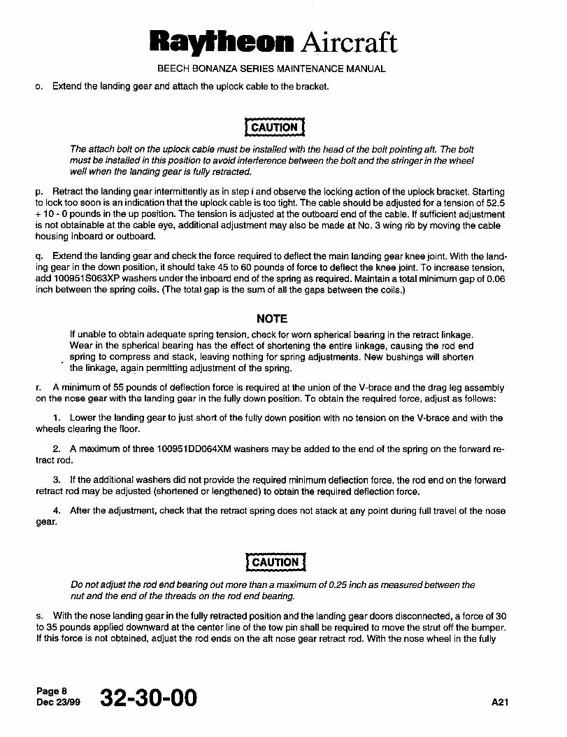
Raylheon AircraftBEECH BONANZA SERIES MAINTENANCE MANUAL
o. Extend the landing gear and attach the uplock cable to the bracket.
I CAUTION ICAUTION
The attach bolt on the uplock cable must be installed with the head of the bolt pointing aft. The bolt
must be installed in this position to avoid interference between the bolt and the stringer in the wheel
well when the landing gear is fully retracted.
p. Retract the landing gear intermittently as in step i and observe the locking action of the uplock bracket. Startingto lock too soon is an indication that the uplock cable is too tight. The cable should be adjusted for a tension of 52.5
10 0 pounds in the up position. The tension is adjusted at the outboard end of the cable. If sufficient adjustmentis not obtainable at the cable eye, additional adjustment may also be made at No. 3 wing rib by moving the cable
housing inboard or outboard.
q. Extend the landing gear and check the force required to deflect the main landing gear knee joint. With the land-
ing gear in the down position, it should take 45 to 60 pounds of force to deflect the knee joint. To increase tension,add 100951S063XP washers under the inboard end of the spring as required. Maintain a total minimum gap of 0.06
inch between the spring coils. (The total gap is the sum of all the gaps between the coils.)
NOTE
If unable to obtain adequate spring tension, check for worn spherical bearing in the retract linkage.Wear in the spherical bearing has the effect of shortening the entire linkage, causing the rod end
spring to compress and stack, leaving nothing for spring adjustments. New bushings will shorten
the linkage, again permitting adjustment of the spring.
A minimum of 55 pounds of deflection force is required at the union of the V-brace and the drag leg assemblyon the nose gear with the landing gear in the fully down position. To obtain the required force, adjust as follows:
1. Lower the landing gear to just short of the fully down position with no tension on the V-brace and with the
wheels clearing the floor.
2. A maximum of three 100951DD064XM washers may be added to the end of the spring on the forward re-
tract rod.
3. If the additional washers did not provide the required minimum deflection force, the rod end on the forward
retract rod may be adjusted (shortened or lengthened) to obtain the required deflection force.
4. After the adjustment, check that the retract spring does not stack at any point during full travel of the nose
gear.
1 CAUTION ICAUTION
Do not adjust the rod end bearing out more than a maximum of 0.25 inch as measured between the
nut and the end of the threads on the rod end bearing.
s. With the nose landing gear in the fully retracted position and the landing gear doors disconnected, a force of 30
to 35 pounds applied downward at the center line of the tow pin shall be required to move the strut off the bumper.If this force is not obtained, adjust the rod ends on the aft nose gear retract rod. With the nose wheel in the fully
Page 32130-00 A21
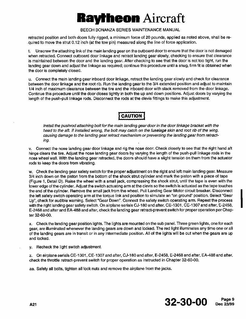
Raytheon AircraftBEECH BONANZA SERIES MAINTENANCE MANUAL
retracted position and both doors fully rigged, a minimum force of 20 pounds, applied as noted above, shall be re-
.quired to move the strut 0.12 inch (at the tow pin) measured along the line of force application.
t. Unscrew the attaching link of the main landing gear on the outboard door to ensure that the door is not damagedwhen retracted. Connect outboard door linkage and retract landing gear slowly, checking to ensure that clearance
is maintained between the door and the landing gear. After checking to see that the door is not too tight, run the
landing gear down and adjust the linkage as required; continue this procedure until a snug, firm fit is obtained when
the door is completely closed.
u. Connect the main landing gear inboard door linkage, retract the landing gear slowly and check for clearance
between the door linkage and the root rib. Run the landing gear to the 314 extended position and adjust to maintain
1/4 inch of maximum clearance between the tire and the inboard door with slack removed from the door linkage.Continue this procedure until the door closes tightly in both the up and down positions. Adjust doors by varying the
length of the push-pull linkage rods. Disconnect the rods at the clevis fittings to make this adjustment.
I CAUTION ICAUTION
Install the pushrod attaching bolt for the main landing gear door in the door linkage bracket with the
head to the aft. If installed wrong, the bolt may catch on the fuselage skin and root rib of the wing,causing damage to the landing gear retract mechanism orpreventing the landing gear from retract-
ing.
Connect the nose landing gear door linkage and rig the nose door. Check closely to see that the right hand aft
hinge clears the tire. Adjust the nose landing gear doors by varying the length of the~push-pull linkage rods in the
nose wheel well. With the landing gear retracted, the doors should have a slight tension on them from the actuator
rods to keep the doors from vibrating.
w. Check the landing gear safety switch for the proper adjustment on the right and left main landing gear. Measure
3/4 inch down on the piston from the bottom of the shock strut cylinder and mark the piston with a piece of tape(Figure 1, Detail D). Raise the wheel with a small jack, compressing the shock strut, until the tape is even with the
lower edge of the cylinder. Adjust the switch actuating arm at the clevis so the switch is actuated as the tape touches
the end of the cylinder. Remove the small jack from the wheel. Pull Landing Gear Motor circuit breaker. Disconnect
the left safety switch operating arm at the torque link and position to simulate an "on ground" position. Select "Gear
Up", check for audible warning. Select "Gear Down". Connect the safety switch operating arm. Repeat the process
with the right landing gear safety switch. On airplane serials CJ-180 and after, CE-1301, CE-1307 and after, E-2458,E-2468 and after and EA-488 and after, check the landing gear retract-prevent switch for proper operation per Chap-ter32-60-00.
x. Check the landing gear position lights. The lights are mounted on the sub panel. Three green lights, one for each
gear, are illuminated whenever the landing gears are down and locked. The red light illuminates any time one or all
of the landing gears are in transit or in any intermediate position. Ail of the lights will be out when the gears are up
and locked.
y. Recheckthe light switch adjustment.
z. On airplane serials CE-1301, CE-1307 and after, CJ-180 and after, E-2458, E-2468 and after, EA-488 and after,check the throttle retract-prevent switch for proper operation as instructed in Chapter 32-60-00.
aa. Safety all bolts, tighten all lock nuts and remove the airplane from the jacks.
A21 32-30-00 9
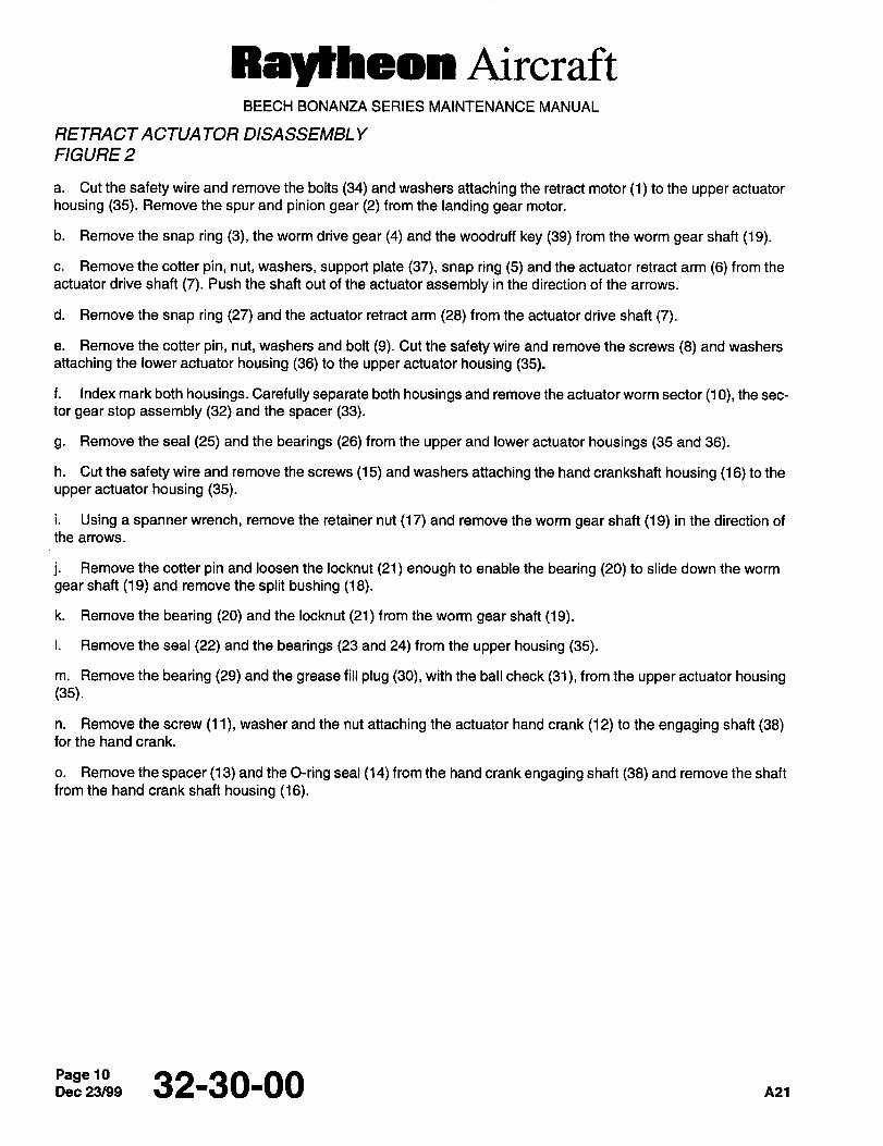
Raytheon AircraftBEECH BONANZA SERIES MAINTENANCE MANUAL
RETRACTACTUA TOR DISASSEMBL Y
FIGURE 2
a. Cut the safety wire and remove the bolts (34) and washers attaching the retract motor (1) to the upper actuator
housing (35). Remove the spur and pinion gear (2) from the landing gear motor.
b. Remove the snap ring (3), the worm drive gear (4) and the woodruff key (39) from the worm gear shaft (19).
c. Remove the cotter pin, nut, washers, support plate (37), snap ring (5) and the actuator retract arm (6) from the
actuator drive shaft (7). Push the shaft out of the actuator assembly in the direction of the arrows.
d. Remove the snap ring (27) and the actuator retract arm (28) from the actuator drive shaft (7).
e. Remove the cotter pin, nut, washers and bolt (9). Cut the safety wire and remove the screws (8) and washers
attaching the lower actuator housing (36) to the upper actuator housing (35).
f. Index mark both housings. Carefully separate both housings and remove the actuator worm sector (10), the sec-
tor gear stop assembly (32) and the spacer (33).
g. Remove the seal (25) and the bearings (26) from the upper and lower actuator housings (35 and 36).
h. Cut the safety wire and remove the screws (15) and washers attaching the hand crankshaft housing (16) to the
upper actuator housing (35).
i. Using a spanner wrench, remove the retainer nut (17) and remove the worm gear shaft (19) in the direction of
the arrows.
j. Remove the cotter pin and loosen the locknut (21) enough to enable the bearing (20) to slide down the worm
gear shaft (19) and remove the split bushing (18).
k. Remove the bearing (20) and the locknut (21) from the worm gear shaft (1 9).
i. Remove the seal (22) and the bearings (23 and 24) from the upper housing (35).
m. Remove the bearing (29) and the grease fill plug (30), with the ball check (31), from the upper actuator housing(35).
n. Remove the screw (11), washer and the nut attaching the actuator hand crank (12) to the engaging shaft (38)for the hand crank.
o. Remove the spacer (13) and the O-ring seal (14) from the hand crank engaging shaft (38) and remove the shaft
from the hand crank shaft housing (16).
Dec 32-30-00 nn
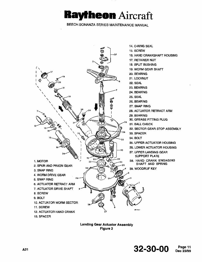
Ray~heon AircraftBEECH BONANZA SERIES MAINTENANCE MANUAL
14. O-RING SEAL
5\
15. SCREW
16. HAND CRANKSHAFT HOUSING
17. RETAINER NUT
18. SPLIT BUSHING
r\ 19. WORM GEAR SHAFT
21. LOCKNUT
20. BEARING
23. BEARING22. SEAL
’F",,, 24. BEARING
25. SEAL
26. BEARING
3930
27. SNAP RING
28. ACTUATOR RETRACT ARM
29. BEARING
30. GREASE FITTING PLUG31 35
31. BALL CHECK
32 SECTOR GEAR STOP ASSEMBLY
\3~m
26JB.SPACER
~ihY 34. BOLT
35. UPPER ACTUATOR HOUSING
36. LOWER ACTUATOR HOUSING
37. UPPER LANDING GEAR
SUPPORT PLATE33
38. HAND CRANK ENGAGING1. MOTOR J25 25
2. SPUR AND PINION GEARSHAFT AND SPRING
39. WOODRUF KEY3. SNAP RING
4. WORM DRIVE GEAR
5. SNAP RING36
6. ACTUATOR RETRACT ARM
7. ACTUATOR DRIVE SHAFT
8.SCREW
9. BOLT
10. ACTUATOR WORM SECTOR
11. SCREW
12. ACTUATOR HAND CRANK 27
13. SPACER
Landing Gear Actuator AssemblyFigure 2
A21 32-30-00 Dec 23/99Page 11
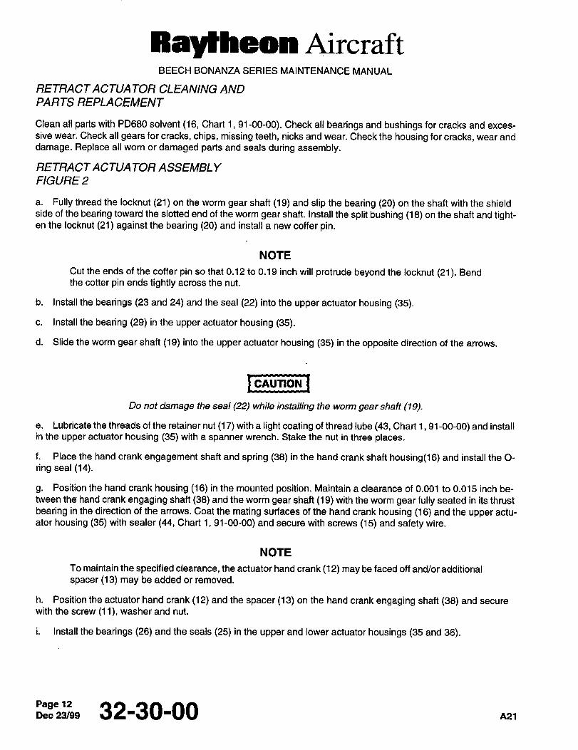
Ral~heon AircraftBEECH BONANZA SERIES MAINtENANCE MANUAL
RETRACTACTUA TOR CLEANING AND
PARTS REPLACEMENT
Clean all parts with PD680 solvent (16, Chart 1, 91-00-00). Check all bearings and bushings for cracks and exces-
sive wear. Check all gears for cracks, chips, missing teeth, nicks and wear. Check the housing for cracks, wear and
damage. Replace all worn or damaged parts and seals during assembly.
RETRACTACTUATOR ASSEMBLY
FIGURE 2
a. Fully thread the locknut (21) on the worm gear shaft (19) and slip the bearing (20) on the shaft with the shieldside of the bearing toward the slotted end of the worm gear shaft. Install the split bushing (18) on the shaft and tight-en the locknut (21) against the bearing (20) and install a new coffer pin.
NOTE
Cut the ends of the coffer pin so that 0.12 to 0.19 inch will protrude beyond the locknut (21). Bendthe cotter pin ends tightly across the nut.
b. Install the bearings (23 and 24) and the seal (22) into the upper actuator housing (35).
c. Install the bearing (29) in the upper actuator housing (35).
d. Slide the worm gear shaft (19) into the upper actuator housing (35) in the opposite direction of the arrows.
I CAUTION ICAUTION
Do not damage the seal (22) while installing the worm gear shaft (19).
e. Lubricate the threads of the retainer nut (17) with a light coating of th read lube (43, Chart 1, 91-00-00) and installin the upper actuator housing (35) with a spanner wrench. Stake the nut in three places.
f. Place the hand crank engagement shaft and spring (38) in the hand crank shaft housing(l6) and install the 0-
ring seal (14).
g. Position the hand crank housing (16) in the mounted position. Maintain a clearance of 0.001 to 0.015 inch be-
tween the hand crank engaging shaft (38) and the worm gear shaft (19) with the worm gear fully seated in its thrust
bearing in the direction of the arrows. Coat the mating surfaces of the hand crank housing (16) and the upper actu-
ator housing (35) with sealer (44, Chart 1, 91-00-00) and secure with screws (15) and safety wire.
NOTE
io maintain the specified clearance, the actuator hand crank(l2) may be faced off and/or additional
spacer (13) may be added or removed.
h. Position the actuator hand crank (12) and the spacer (13) on the hand crank engaging shaft (38) and secure
with the screw (11), washer and nut.
i. Install the bearings (26) and the seals (25) in the upper and lower actuator housings (35 and 36).
Page 32-30-00 A21
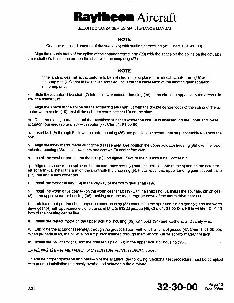
Ray~heon AircraftBEECH BONANZA SERIES MAINTENANCE MANUAL
NOTE
Coat the outside diameters of the seals (25) with sealing compound (45, Chart 1, 91-00-00).
j. Align the double tooth of the spline of the actuator retract arm (28) with the space on the spline on the actuator
drive shaft (7). Install the arm on the shaft with the snap ring (27).
NOTE
If the landing gear retract actuator is to be installed in the airplane, the retract actuator arm (28) and
the snap ring (27) should be sacked and tied until after the installation of the landing gear actuator
in the airplane.
k. Slide the actuator drive shaft (7) into the lower actuator housing (36) in the direction opposite to the arrows. In-
stall the spacer (33).
i. Align the space of the spline on the actuator drive shaft (7) with the double center tooth of the spline of the ac-
tuator worm sector (10). Install the actuator worm sector (10) on the shaft.
m. Coat the mating surfaces, and the machined surfaces where the bolt (9) is installed, on the upper and lower
actuator housings (35 and 36) with sealer (44, Chart 1, 91-00-00).
n. insert bolt (9) through the lower actuator housing (36) and position the sector gear stop assembly (32) over thebolt.
o. Align the index marks made during the disassembly, and position the upper´•actuator housing (35) over the lower
actuator housing (36). Install washers and screws (8) and safety wire.
p. Install the washer and nut on the bolt (9) and tighten. Secure the nut with a new cotter pin.
q. Align the space of the spline of the actuator drive shaft (7) with the double tooth of the spline on the actuator
retract arm (6). Install the arm on the shaft with the snap ring (5). Install washers, upper landing gear support plate(37), nut and a new cotter pin.
r. Install the woodruff key (39) in the keyway of the worm gear shaft (19).
s. Install the worm drive gear (4) on the worm gear shaft (19) with the snap ring (3). Install the spur and pinion gear(2) in the upper actuator housing (35), making sure the teeth engage those of the worm drive gear (4).
t. Lubricate that portion of the upper actuator housing (35) containing the spur and pinion gear (2) and the worm
drive gear (4) with approximately one ounce of MIL-G81322 grease (46, Chart 1, 91-00-00). Fill to within 0 0.10
inch of the housing center line.
u. Install the retract motor on the upper actuator housing (35) with bolts (34) and washers, and safety wire.
v. Lubricate the actuator assembly, through the grease fill port, with one half pint of grease (47, Chart 1, 91-00-00).When properly filled, the oil level on a dip stick inserted through the filler port will be approximately 1/4 inch.
w. Install the ball check (31) and the grease fill plug (30) in the upper actuator housing (35).
LANDING GEAR RETRACTACTUATOR FUNCTIONAL TEST
To ensure proper operation and break-in of the actuator, the following functional test procedure must be compliedwith prior to installation of a newly overhauled actuator in the airplane.
32-30-00
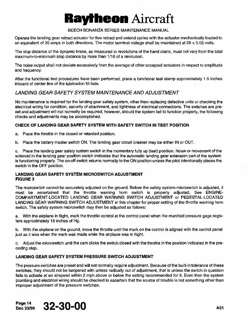
Ray~heon AircraftBEECH BONANZA SERIES MAINTENANCE MANUAL
Operate the landing gear retract actuator for five retract and extend cycles with the actuator mechanically loaded to
an equivalent of 20 amps in both directions. The motor terminal voltage shall be maintained at 28 ~c_0.03 volts.
The stop distance of the dynamic brake, as measured in revolutions of the hand crank, must not vary from the total
maximum-to-minimum stop distance by more than 1/16 of a revolution.
The noise output shall not deviate excessively from the average of other accepted actuators in respect to amplitudeand frequency.
After the functional test procedures have been performed, place a functional test stamp approximately 1.5 inches
inboard of center line of the lubrication fill hole.
LANDING GEAR SAFETY SYSTEM MAINTENANCE AND ADJUSTMENT
No maintenance is required for the landing gear safety system, other than replacing defective units or checking the
electrical wiring for condition, security of attachment, and tightness of electrical connections. The switches are pre-set and adjustment will not normally be required; however, should the system fail to function properly, the followingchecks and adjustments may be accomplished.
CHECK OF LANDING GEAR SAFETY SYSTEM WITH SAFETY SWITCH IN TEST POSITION
a. Place the throttle in the closed or retarded position.
b. Place the battery master switch ON. The landing gear circuit breaker may be either IN or OUT.
c. Place the landing gear safety system switch in the momentary fully up (test) position. Noise or movement of the
solenoid in the landing gear position switch indicates that the automatic landing gear extension part of the systemis functioning properly. The on-off switch returns normally to the ON position unless the pilot intentionally places the
switch in the OFF position.
LANDING GEAR SAFETY SYSTEM MICROSWITCH ADJUSTMENT
FIGURE 3
The microswitch cannot be accurately adjusted on the ground. Before the safety system microswitch is adjusted, it
must be ascertained that the throttle warning horn switch is properly adjusted. See ENGINE-
COMPARTMENT-LOCATED LANDING GEAR WARNING SWITCH ADJUSTMENT or PEDESTAL-LOCATED
LANDING GEAR WARNING SWITCH ADJUSTMENT in this chapter for proper setting of the throttle warning horn
switch. The safety system microswitch may then be adjusted as follows:
a. With the airplane in flight, mark the throttle control at the control panel when the manifold pressure gage regis-ters approximately 18 inches of Hg.
b. With the airplane on the ground, move the throttle until the mark on the control is aligned with the control paneljust as it was when the mark was made while the airplane was in flight.
c. Adjust the microswitch until the cam clicks the switch closed with the throttle in the position indicated in the pre-
ceding step.
LANDING GEAR SAFETY SYSTEM PRESSURE SWITCH ADJUSTMENT
The pressure switches are preset and will not normally require adjustment. Because of the built-in tolerance of these
switches, they should not be tampered with unless radically out of adjustment, that is unless the switch in questionfails to actuate at an airspeed within 2 mph above or below the setting recommended for it. Even then the systemplumbing and electrical wiring should be checked to ascertain that the source of trouble is not something other than
improper adjustment of the pressure switches.
Dec 23/99~ 32-30-00
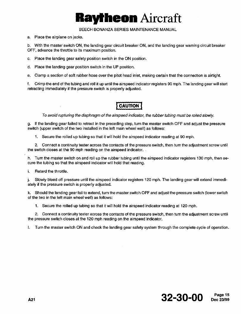
Raylheon AircraftBEECH BONANZA SERIES MAINTENANCE MANUAL
a. Place the airplane on jacks.
b. With the master switch ON, the landing gear circuit breaker ON, and the landing gear warning circuit breaker
OFF, advance the throttle to its maximum position.
c. Place the landing gear safety position switch in the ON position.
d. Place the landing gear position switch in the UP position.
e. Clamp a section of soft rubber hose over the pitot head inlet, making certain that the connection is airtight.
f. Crimp the end of the tubing and roll it up until the airspeed indicator registers 90 mph. The landing gear will start
retracting immediately if the pressure switch is properly adjusted.
I CAUTION ICAUTION
To avoid rupturing the diaphragm of the airspeed indicator, the rubber tubing must be rolled slowly.
g. If the landing gear failed to retract in the preceding step, turn the master switch OFF and adjust the pressureswitch (upper switch of the two installed in the left main wheel well) as follows:
1. Secure the rolled up tubing so that it will hold the airspeed indicator reading at 90 mph.
2. Connect a continuity tester across the contacts of the pressure switch, then turn the adjustment screw until
the switch closes at the 90 mph ´•reading on the airspeed indicator.
h. Turn the master switch on and roll up the rubber tubing until the airspeed indicator registers 130 mph, then se-
cure the tubing so that the airspeed indicator will hold that reading.
i. Retard the throttle.
j. Slowly bleed off pressure until the airspeed indicator registers 120 mph. The landing gear will extend immedi-
ately if the pressure switch is properly adjusted.
k. Should the landing gear fail to extend, turn the master switch OFF and adjust the pressure switch (lower switch
of the two in the left main wheel well) as follows:
1. Secure the rolled up tubing so that it will hold the airspeed indicator reading at 120 mph.
2. Connect a continuity tester across the contacts of the pressure switch, then turn the adjustment screw until
the pressure switch closes at the 120 mph reading on the airspeed indicator.
I. Turn the master switch ON and check the landing gear safety system through the complete cycle of operation.
n21 32-30-00
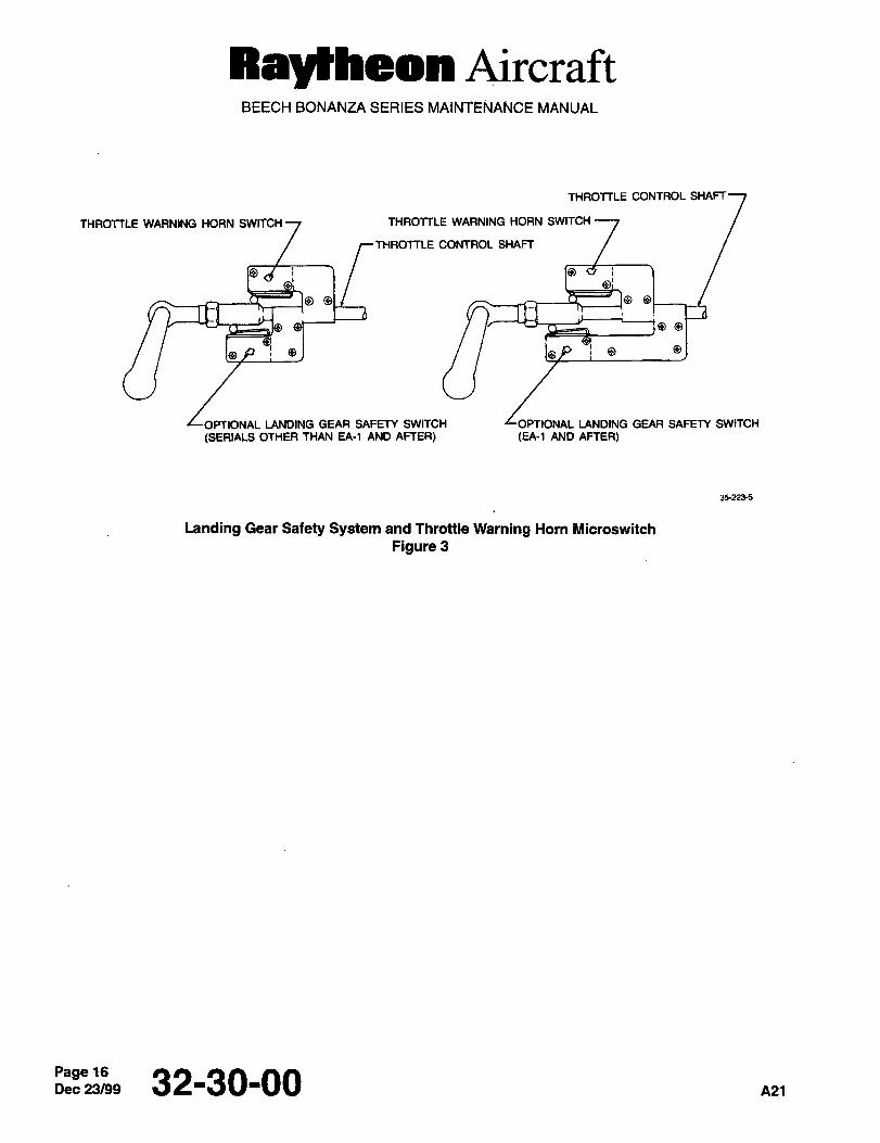
Raytheon AircraftBEECH BONANZA SERIES MAINTENANCE MANUAL
THROTTLE CONTROL SHAFT
THROTTLE WARNING HORN SWITCH 1 THROTTLE WARNING HORN SWITCH
THROTTLE CONTROL SHAFT
LANDING GEAR SAFETY SWITCH LOPTIONAL LANDING GEAR SAFETY SWITCH
(SERIALS OTHER THAN EA-1 AND AFTER) (EA-1 AND AFTER)
35-223-5
Landing Gear Safety System and Throttle Warning Horn Microswitch
Figure 3
Page 16Dec23/99 32-30-00 A21
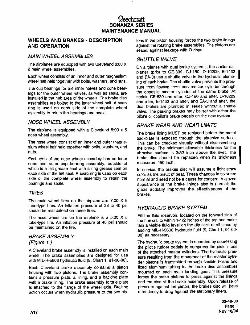
aeechc~ftBONANZA SERIES
MAINTENANCE MANUAL
WHEELS AND BRAKES DESCRIPTION tons in the piston housing forces the two brake iiningsAND OPERATION against the rotating brake assemblies. The pistons are
sealed against leakage with O-rings.
MAIN WHEEL ASSEMBLIESSHUTTLE VALVE
The airplanes are equipped with two Cleveland 6:00 X
6 main wheel assemblies.On airplanes with dual brake systems, the earlier air-
planes (prior to CE-839, CJ-150, D-10209, E-1432 IEach wheel consists of an inner and outer magnesium and EA-3) use a shuttle valve in the hydraulic plumb-wheel half held together with bolts, washers, and nuts. ing of each brake. The shuttle valve prevents the pres-
The cup bearings for the inner halves and cone bear- sure from flowing from one master cylinder through
ings for the outer wheel halves, as well as seals, arethe opposite master cylinder of the same brake. At
installed in the hub area of the wheels. The brake disc serials CE-839 and after, CJ-150 and after, D-10209
assemblies are bolted to the inner wheel half. A snapand after, E-1432 and after, and EA-3 and after, the
ring is used on each side of the complete wheel dual brakes are plumbed in series without a shuttle
assembly to retain the bearings and seals. valve. The parking brakes may be set with either the
pilot’s or copilot’s brake pedals on the new system.
NOSE WHEEL ASSEMBLYBRAKE WEAR AND WEAR LIMITS
The airplane is equipped with a Cleveland 5:00 x 5
nose wheel assembly.The brake lining MUST be replaced before the metal
backplate is exposed through the abrasive surface~The nose wheel consist of an inner and outer magne- This can be checked visually without disassemblingslum wheel half held together with bolts, washers, and th, brake. The minimum allowable thickness for the
nuts. abrasive surface is 3/32 inch above the rivet. The
Each side of the nose wheel assembly has an inner brake disc should be replaced when its thickness
cone and outer cup bearing assembly, outside of measures.450 inch.
which is a felt grease seal with a ring grease seal on In service, the brakes disc will assume a light straw
each side of the felt seal. A snap ring is used on each color as the result of heat. These changes in color are
side of the complete wheel assembly to retain the normal and need not be a cause for concern. A glazedbearings and seals, appearance of the brake linings also is normal; the
glaze actually improves the effectiveness of theTIRES brakes.
The main wheel tires on the airplane are 7:00 X 6
tube-type tires. An inflation pressure of 33 to 40 psi HYDRAULIC BRAKE SYSTEMshould be maintained on these tires.
Fill the fluid reservoir, located on the forward side ofThe nose wheel tire on the airplane is a 5:00 X 5
the firewall, to within 1-1/2 inches of the top and main-tube-type tire. An inflation pressure of 40 psi should
tain a visible fluid level on the dip stick at all times bybe maintained on the tire.
adding MIL-H-5606 hydraulic fluid (9, Chart 1, 91-00-
BRAKE ASSEMBL Y 00) as necessary.
(Figure I The hydraulic brake system is operated by depressingthe pilot’s rudder pedals to compress the piston rods
A Cleveland brake assembly is installed on each mainof the attached master cylinders. The hydraulic pres-
wheel. The brake assemblies are designed for usesure resulting from the movement of the master cylin-
with MIL-H-5606 hydraulic fluid (9, Chart 1, 91-00-00). der pistons is transmitted through flexible hoses and
Each Cleveland brake assembly contains a piston fixed aluminum tubing to the brake disc assemblies
housing with two pistons. The brake assembly con- mounted on each main landing gear. This pressure
tains a pressure plate, a lining, and a backing plate forces the brake pistons to press against the liningswith a brake lining. The brake assembly torque plate and the disc of the brake assembly. Upon release of
is attached to the flange of the wheel axle. Braking pressure against the piston, the brakes disc will have
action occurs when hydraulic pressure to the two pis- a tendency to drag against the stationary liners.
32-40-00
Page 1
A17 Nov 16/94
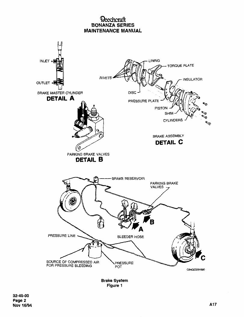
BONANZA SERIES
MAINTENANCE MANUAL
INLET ~LINING
AIVETSTORQUEPLATE
INSULATOROUTLET
BRAKE MASTER GYLINDER DISC
D~TAIL APRESSURE PLATE
~aPISTON
sHlhn-/ .~ae~a
CYLINDERS
BRAKE ASSEMBLY
IDETAIL C
PARKING BRAKE VALVES
DETAIL B
BRAKE RESERVOIR
PARKING BRAKEVALVES
jj
PRESSURE LINE BLEEDER HOSE
i iiC
SOURCE OF COMPRESSED AIR EFOR PRESSURE BLEEDING POT
C94CE32B1990
Elrake SystemFigure 1
32-40-00
Page 2
Nov 16194 A17
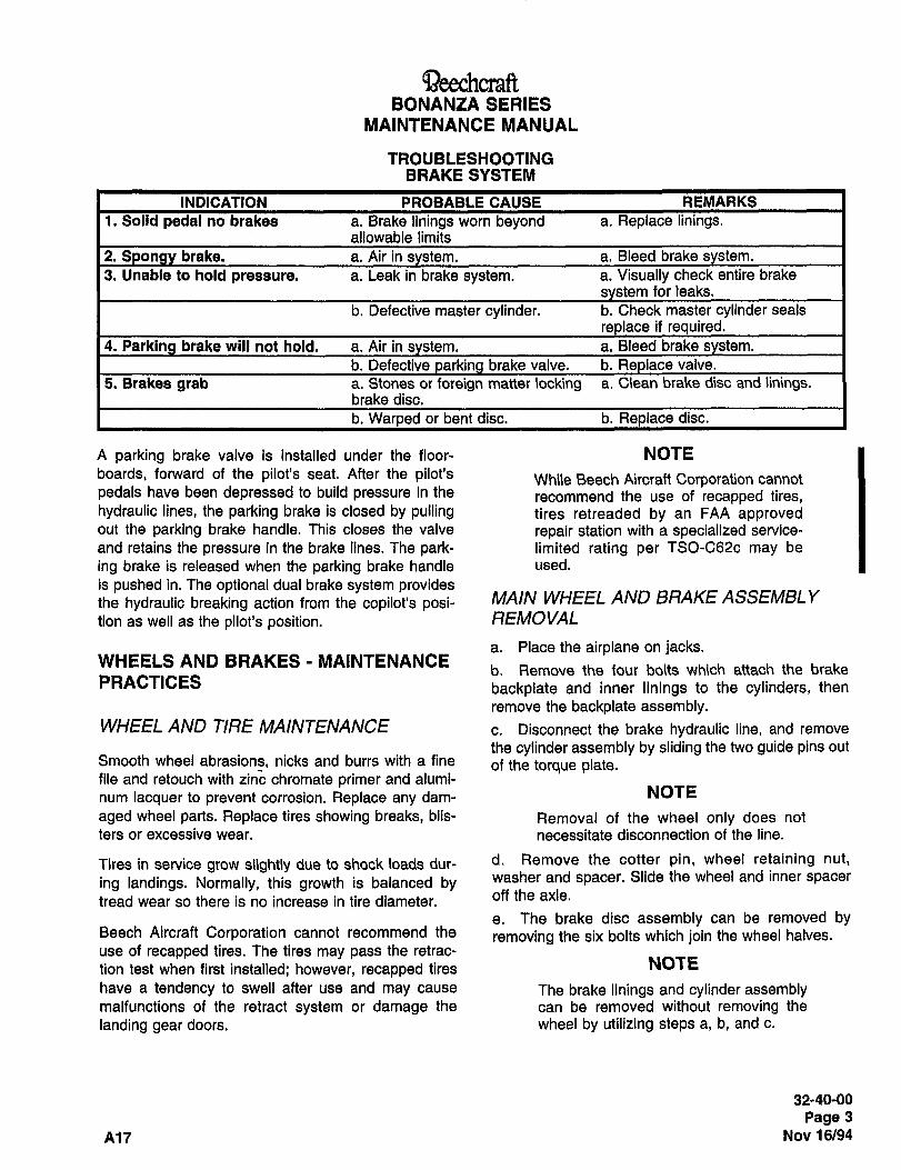
BONANZA SERIES
MAINTENANCE MANUAL
TROUBLESHOOTINGBRAKE SYSTEM
INDICATION PROBABLE CAUSE REMARKS
1. Solid pedal no brakes a. Brake linings worn beyond a. Replace linings.allowable limits
2. brake. a. Air in a. Bleed brake
3. Unable to hold pressure. a. Leak in brake system. a. Visually check entire brake
for leaks.
b. Defective master cylinder, b. Check master cylinder seals
if uired.
4. Parki brake will not hold. a. Air in a. Bleed brake
b. Defective brake valve, b. valve.
5. Brakes grab a. Stones or foreign matter locking a. Clean brake disc and linings.brake disc.
b. Warped or bent disc. b. Replace disc.
A parking brake valve is installed under the floor- NOTE
boards, forward of the pilot’s seat. After the pilot’s While Beach Aircraft Corporation cannot
pedals have been depressed to build pressure in the recommend the use of recapped tires,hydraulic lines, the parking brake is closed by pulling tires retreaded by an FAA approvedout the parking brake handle. This closes the valve repair station with a specialized service-
and retains the pressure in the brake lines. The park- limited rating per TSO-C62c may be
ing brake is released when the parking brake handle used.
is pushed in. The optional dual brake system providesthe hydraulic breaking action from the copilot’s posi- MAIN WHEEL AND BRAKE ASSEMBLY
tion as well as the pilot’s position. REMOVAL
a. Place the airplane on jacks.WHEELS AND BRAKES MAINTENANCE
b. Remove the four bolts which attach the brakePRACTICES backplate and inner linings to the cylinders, then
remove the backplate assembly.WHEEL AND TIRE MAINTENANCE c. Disconnect the brake hydraulic line, and remove
the cylinder assembly by sliding the two guide pins outSmooth wheel abrasions, nicks and burrs with a fine ,f the torque plate.file and retouch with zinc chromate primer and alumi-
num lacquer to prevent corrosion. Replace any dam- NOTE
aged wheel parts. Replace tires showing breaks, blis- Removal of the wheel only does not
ters or excessive wear, necessitate disconnection of the line.
Tires in service grow slightly due to shock loads dur- d. Remove the cotter pin, wheel retaining nut,
ing landings. Normally, this growth is balanced by washer and spacer. Slide the wheel and inner spacer
tread wear so there is no increase in tire diameter. off the axle.
e. The brake disc assembly can be removed byBeech Aircraft Corporation cannot recommend the removing the six bolts which join the wheel halves.use of recapped tires. The tires may pass the retrac-
tion test when first installed; however, recapped tires NOTE
have a tendency to swell after use and may cause The brake linings and cylinder assemblymalfunctions of the retract system or damage the can be removed without removing the
landing gear doors. wheel by utilizing steps a, b, and c.
32-40-00
Page 3
A17 Nov 16/94
BONANZA SERIESMAINTENANCE MANUAL
MAIN WHEEL INSPECTION AND g. Inspect the brake disc assembly for cracks,
CLEANING excessive wear, or scoring, rust and corrosion.
Remove rust and blend out small nicks with a fine
emery cloth. The brake disc should be replaced when
I -´•I´•´•I its thickness measures .450 inch.
h. Inspect the wheel bolts for cracks, corrosion or
other damage. Replace any cracked bolts.Because dry cleaning solutions are
toxic and volatile, use in a well- BRAKE ASSEMBL Y INSPECTION ANDventilated area, avoid contact withskin or clothing and do not inhale the
CLEANING
vapors. a. Clean O-rings in clean hydraulic fluid (9, Chart i,a. Degrease all parts and dry thoroughly. A soft 91-00-00) or denatured alcohol. If O-rings are dam-
bristled brush may be used to remove hardened aged or excessively worn they should be replaced.grease, dust, and dirt.
CAUIION
Gasoline and dry cleaning fluids are
Do not spin the bearings with com- unsuitable as cleaning agents because
pressed air as this will cause damage, they will damage O-rings.
b. Visually inspect bearing cups and cones for nicks,scratches, water stains, galling, heat discoloration, b. Clean dirty and greasy surfaces with denatured
roller wear, cage damage, and cracks or distortion, alcohol.
Replace if damaged or worn.c. Inspect entire brake assembly for cracking, nicks,
c. Inspect the wheel bearing grease for contamina- corrosion, damaged threads, etc. Check cylinder walls
tion and solidification at each periodic maintenance for scoring or excessive wear.
inspection, d. Carefully inspect pistons for nicks or burrs which
d. Inspect wheel halves for cracks, corrosion and might damage the O-rings. Remove nicks and burrsother damage. Cracked and badly corroded castings with fine crocus cloth, then thoroughly clean.
should be replaced. Small nicks, scratches or pits cane. Inspect all brake linings for cracks. Linings should
be blended out using fine (400-grit) sandpaper. be replaced if they are worn 3/32 inch above the riv-
e. Inspect snap rings and grease seals for deteriora- ets.
tion and wear; replace if damaged or deformed.
Lightly saturate the felt seals with 10W30 oil (remove MAIN WHEEL AND BRAKE ASSEMBLYexcess by pressing lightly). Coat the sides and outer INSTALLATIONdiameter with same type of grease as that used on the
bearing. a. Clean and repack wheel bearings as indicated in
MAIN WHEEL INSPECTION AND CLEANING in thisf. Inspect bearing cups for looseness, scratches, pit- chapter. Replace any damaged grease seals, and beting, corrosion, or evidence of overheating. Coat the
sure the grease seal retaining rings and snap ringsbearing cups with bearing grease. Repack with either
are in place before reinstalling the wheel.Aero Shell No. 5 or other greases per MIL-G-81322
(46, Chart 1, 91-00-00). b. Install inner spacer, wheel, outer spacer, washer,
retaining nut and cotter pin.
NOTE
At least one 100951X100VY or
Aero Shell No. 5 grease is not compat- 100951X050VY washer shall be
ible with other greases covered by MIL- installed between the outer spacer andG-81322. Use only Aero Shell No. 5 or wheel retaining nut to permit free rota-
one of the other greases; do not mix. tion of the wheel
32-40-00
Page 4
Nov 16/94 A17
Beechc~ftBONANZA SERIES
MAINTENANCE MANUAL
c. Install the brake cylinder assembly by inserting b. Visually inspect bearing cups and cones for nicks,the two guide pins into the torque plate. scratches, water staining, galling, heat discoloration,
NOTE roller wear, cage damage, and cracks or distortion.
Replace if damaged or worn.
If the torque plate has been removed, itshould be reinstalled so that the guide
c. Inspect the wheel bearing grease for contamina-
pin holes are positioned aft and centered tion and solidification at each periodic maintenance
above and below the horizontal center- inspection.line of the axle. The torque plate nuts d. Inspect wheel halves for cracks, corrosion, andare to be torqued to 100 to 140 inch- other damage. Cracked or badly corroded castingspounds. should be replaced. Small nicks, scratches, or pits can
d. Torquetheaxle nutasfollows: be blended out using fine (400-grit) sandpaper.1. Check for burrs or rough threads on the axle e. Inspect the snap rings and grease seals for dete-
and retaining nut. Apply bearing grease to the axle rioration and wear; replace if damaged or deformed.
threads and the bearing surface of the nut. Lightly saturate felt seals with 10W30 oil (remove2. While rotating the wheel, tighten the axle excess by pressing lightly). Coat the sides and outer
retaining nut to 180 to 240 inch-pounds to ensure that diameter with the same type grease as that used on
the bearings are properly seated. the bearings.
3. Back off the axle retaining nut to zero torque. f´• Inspect the bearing cups and cones for looseness,
4. Retighten the nut with fingers to remove end scratches, pitting, corrosion, or evidence of overheat-
play in the bearings, ing. Coat the cups and cones with bearing grease.
Repack with either Aero Shell No. 5 grease or other5. Torque the axle retaining nut to the next key-
greases per MIL-G-81322 (46, Chart 1, 91-00-00).ing position and install the cotter pin.e. Bleed the brake system if necessary, iNOSE WHEEL REMOVAL
a. Jack the nose wheel. Aero Shell No. 5 grease is not compat-b. Remove the cotter pin, nut, and bushing which ible with other greases covered with
retain the nose wheel assembly on the axle. MIL-G-81322. Use only Aero Shell No. 5
or one of the other greases; do not mix.c. Remove the nose wheel assembly by sliding it offthe axle.
NOSE WHEEL INSPECTION AND g. Inspect the wheel bolts for cracks, corrosion or
CLEANING other damage. Replace any cracked bolts.
NOSE WHEEL INSTALLATION
I -´•I´•´•I a. Clean and repack wheel bearings as indicated inWARNING
NOSE WHEEL rNSPECTION AND CLEANING in this
Dry cleaning solutions are toxic and chapter. Replace any damaged grease seals, and be
volatile. Use In a well ventilated area, sure the grease seal retaining rings and snap ringsAvoid contact with skin or clothing, are in place before reinstalling the wheel.Do not inhale the vapors.
NOTEa. Degrease all parts and dry thoroughly. a soft
bristle brush may be used to remove hardened A bushing is permanently installed on
grease, dust, and dirt. the inboard end of the axle. No other
hardware is required between the wheel
b. Install the wheel, outer spacer, retaining nut and
and the inboard end of the axle.CAUTION
Do not spin the bearings with com-cotter pin.
pressed air. This M/i/ cause damage, c. Torque theaxle nutas follows:
32-40-00
Page 5
A17 Nov 16/94
QeechcraftBONANZA SERIES
MAINTENANCE MANUAL
1. Check for burrs or rough threads on the axle c. Disconnect the two brake hydraulic lines at each
and retaining nut. Apply bearing grease to the axle master cylinder and mark the lines to assure correct
threads and bearing surface of the nut. reinstallation.
2. While rotating the wheel, tighten the axle d. Remove the master cylinder attaching bolts and
retaining nut to 150 200 inch-pounds to insure that nuts and remove the master cylinder.the bearings are properly seated.
BRAKE MASTER CYLINDER3. Back off the axle retaining nut to zero torque.
INSTALLATION4. While rotating the wheel, retorque the axle
retaining nut to 30 inch-pounds and check for align- a´• Place the cylinder in position beneath the brake
ment of the locking holes. pedal and install the attaching bolts and nuts.
5. If not at a locking position, continue tightening b´• Connect the two hydraulic lines to the cylinder.the axle nut to the first locking locking position and The inlet port is the upper port.install the cotter pin. c. Replenish the hydraulic fluid and bleed the brake
system.RELINING THE BRAKES
d. Install the floorboard and floor mat.
ADJUSTMENTCAUTION BRAKE MASTER CYLINDER LINKAGE
Do not have the parking brake engaged The proper linkage adjustment will adjust the brakewhile removing the brakes. pedals to a straight upright position. This is considered
a. Remove the four bolts that attach the backplatethe best adjustment since it will prevent the pedals
assembly to the cylinder assembly,from hitting the firewall in their extreme forward posi-tion. Linkage adjustment is obtained by removing the
NOTE clevis from the rudder pedal and turning the clevis on
The hydraulic brake line does not have or off the piston rod as required. After both pistons are
to be disconnected to remove the brake adjusted to the same length, tighten the jam nuts.
linings. BRAKE MASTER CYL~NDERb. Remove the backplate assemblies from the DISASSEMBL Yinboard side of the brake disc and seperate the pres- (Figure 2)sure plate assembly from the cylinder assembly.
c. Place the backplate assembly on a table with thea. Remove the snap ring (1) and pull the assembled
lining facing down and punch or-drill out the rivets that piston out of the brake cylinder (2).
attach the linings to the backplate. b. Remove the clevis (3) from the piston (14) and the
d.check nut (4); this will free the washer (5), pistonThe linings on the pressure plate may be removed
by using the same procedure as used on the back- guide bushing (6), retainer O-ring (7) and the rear seat
plate.washer (8) from the piston (14).
c. Remove the cotter pin (9) from the collar (1 0) ande. Place the new \inings on the backplate and install
pull the collar from the piston.the rivets. Set the rivets with the punch until the liningis firmly against the backplate. d. Remove the cotter pin (11) from the plunger end
of piston to free the flow lock piston (12). The returnf. The rivets on the pressure plate may be set by
spring (13) will fall free of the cylinder with the pistonusing the same procedure as used on the backplate. removed.
BRAKE MASTER CYLINDER REMOVAL BRAKE MASTER CYLINDER CLEANING
a. Close the parking brake valve by pulling the park- AND PARTS REPLACEMENT
ing brake handle. Clean all parts with PD680 Solvent (16, Chart i,b. Unsnap the floor mat and remove the floorboard 91-00-00). Check all parts for cracks, corrosion, dis-
section below the brake pedals. tortion and wear. Replace all washers and seals at
32-40-00
Page 6
Nov 16/94 A17
QeechcraRBONANZA SERIES
MAINTENANCE MANUAL
reassembly. Lubricate all parts with MIL-H-5606 b. Remove the floorboards forward of the pilotshydraulic fluid (9, Chart 1, 91-00-00) prior to assem- seats.
bly. Reassemble the cylinder.c. Loosen the set screw in the cable attach fitting
BRAKE MASTER CYLINDER ASSEMBLY and adjust the cable housing through the mountingblock to obtain 1-1/2 inch of travel between the cable
(Figure 2) housing and the attach fitting. The 1-1/2 inch clsar-
a. Place the return spring (13) in the brake cylinder. ance should be made with the parking brake valve
lever in the OPEN position.b. Slide the flow lock piston (12), into the plungerend of the piston (14) and install the cotter pin (11) d´• Tighten the mounting block, insert the cable in the
through the piston and the flow lock piston. cable attach fitting, tighten and safety wire the set
screw in the attach fitting.c. Place the collar (10) on the piston and place the
cotter pin (9) through the collar and piston. e. Test the parking brake adjustment by pulling the
d. Install the rear seat washer (8), retainer O-ring (7), parking brake handle out and operating the brake ped-als.
piston guide bushing (6), and washer (5), on the pis-ton (14). Install the check nut (4) and clevis (3) on the f. If the brake pedals are not solid, place the parking
piston, brake control in the OFF position and recheck the rig-
e. Slide the assembled piston into the brake cylinder gi"g.
(2). Install the snap ring (1). g. Inspect the parking brake valve for hydraulic fluid
loss.PARKING BRAKE VALVE REMOVAL
PARKING BRAKE VALVE DISASSEMBLYa. Bleed the brake system of all hydraulic fluid.
(Figure 3)b. Remove the floorboards forward of the pilot’s and
copilot’s seats, a. Disconnect and remove each of the two side-by-
e. Disconnect he parking brake cable from the park-side fittings (13) from the valve body. Remove the
ing brake valve by loosening the set screw and pulling O-ring (7), spring (1), steel ball (6), O-ring (8), seal (2),
the cable free of the cable attach fitting.and pin (3) from each of the two orifices from which
the fittings were removed.d. Disconnect and cap the hydraulic lines from the
parking brake valve. Identify hydraulic lines for ease of b. Disconnect and remove the retaining ring (10)
installation. from the end of the cam lever assembly (4).
a. Remove the attach bolts, and remove the valve. c. Remove the cam lever assembly (4) by graspingthe lever and rotating the cam lever assembly counter-
PARKING BRAKE VALVE INSTALLATION clockwise while pulling outward to prevent scoring of
the cam lever assembly surface.a. Place the parking brake valve in position under
the floorboards, forward of the pilot’s and copilot’s PARKING BRAKE CLEANING AND PARTSseats. Install the attach bolts. REPLACEMENTb. Connect the hydraulic lines to the same ports from
which they were removed. Clean all parts with PD680 Solvent (16, Chart 1,
91-00-00). Check all parts foy cracks, corrosion, dis-c. Connect the parking brake cable. Adjust the park- tortion and wear. Replace all washers and seals at
ing brake as covered in PARKING BRAKE ADJUST- reassembly. Lubricate all parts with hydraulic fluid (9,MENT in this chapter. Chart 1, 91-00-00) prior to assembly. Reassemble the
d. Bleedthe brakesystem. parking brake valve.
e. Install the floorboards forward of the pilot’s-andPARKING BRAKE VALVE ASSEMBLY
copilot’s seats.
a. Install the cam lever (4) with the new O-rings (9)PARKING BRAKE ADJUSTMENT
by grasping the lever and rotating clockwise while
a. Place the parking brake control in the OFF (valve pushing inward to prevent scoring of the cam lever
OPEN) position. assembly surface
32-40-00
Page 7
A17 Nov 16/94
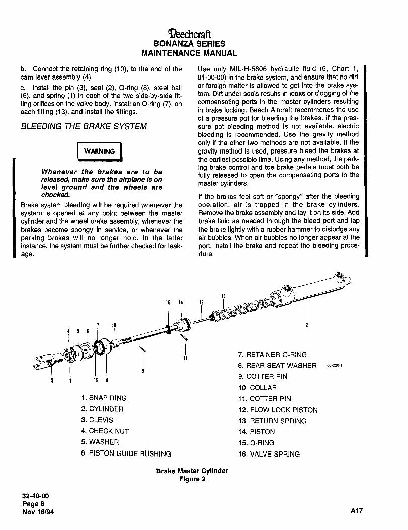
BONANZA SERIES
MAINTENANCE NiANUAL
b. Connect the retaining ring (10), to the end of the Use only MIL-H-5606 hydraulic fluid (9, Chart 1,cam lever assembly (4). 91-00-00) in the brake system, and ensure that no dirt
c. Install the pin (3), seal (2), O-ring (8), steel ball or foreign matter is allowed to get into the brake sys-
(6), and spring (1) in each of the two side-by-side fit- tem. Dirt under seals results in leaks or clogging of the
ting orifices on the valve body. Install an O-ring (7), on c0mpensating ports in the master cylinders resulting
each fitting (13), and install the fittings. in brake locking. Beech Aircraft recommends the use
of a pressure pot for bleeding the brakes. If the pres-
BLEEDING THE BRAKE SYSTEM sure pot bleeding method is not available, electric
bleeding is recommended. Use the gravity method
Ionly if the other two methods are not available. If the
WARNING gravity method is used, pressure bleed the brakes at
the earliest possible time. Using any method, the park-ing brake control and toe brake pedals must both be
Whenever the brakes are to befully released to open the compensating ports in the
released, make sure the airplane is onmaster cylinders.level ground and the wheels are
checked. If the brakes feel soft or "spongy" after the bleedingBrake system bleeding will be required whenever the operation, air is trapped in the brake cylinders.
system is opened at any point between the master Remove the brake assembly and lay it on its side. Add
cylinder and the wheel brake assembly, whenever the brake fluid as needed through the bleed port and tapbrakes become spongy in service, or whenever the the brake lightly with a rubber hammer to dislodge any
parking brakes will no longer hold. In the latter air bubbles. When air bubbles no longer appear at the
instance, the system must be further checked for leak- port, install the brake and repeat the bleeding proce-
age. dure.
16 14 12
7 10 2
456
:1 7. RETAINER O-RING
8. REAR SEAT WASHER 60´•220-1
9. COTTER PIN3 1 15 8
10. COLLAR
i. SNAP RING 11. COTTER PIN
2. CYLINDER 12. FLOW LOCK PISTON
3. CLEVIS 13. RETURN SPRING
4. CHECK NUT 14. PISTON
5. WASHER 15. O-RING
6. PISTON GUIDE BUSHING 16. VALVE SPRING
Brake Master CylinderFigure 2
32-40-00
Page 8
Nov 16/94 A17
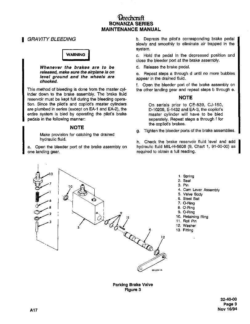
aeechcraftBONANZA SERIES
MAINTENANCE MANUAL
1 GRAVITY BLEEDING b. Depress the pilot’s corresponding brake pedalslowly and smoothly to eliminate air trapped in the
I WUIIING I c. Hold the pedal in the depressed position andsystem.WARNING
close the bleeder port at the brake assembly.
Whenever the brakes are to be d. Release the brake pedal.released, make sure the airplane is on
e. Repeat steps a through d until no more bubbleslevel ground and the wheels are
appear in the drained fluid.checked.
f. Open the bleeder port of the brake assembly on
This method of bleeding is done from the master cyl- the other landing gear and repeat steps b through e.
inder down to the brake assembly. The brake fluid
reservoir must be kept full during the bleeding opera-NOTE
tion. Since the pilot’s and copilot’s master cylinders On serials prior to CE-839, CJ-150,are plumbed in series (except on EA-1 and EA-2), the D-10209, E-1432 and EA-3, the copilot’sentire system is bled by operating the pilot’s brake master cylinder will have to be bled
pedals in the following manner: separately. Repeat steps a through f for
the copilot’s brakes.NOTE
g. Tighten the bleeder ports of the brake assemblies.Make provision for catching the drained
hydraulic fluid.h. Check the brake reservoir fluid level and add
a. Open the bleeder port of the brake assembly on hydraulic fluid MIL-H-5606 (9, Chart 1, 91-00-00) as
one landing gear. required to obtain a full reading.
u: 1. Spring2. Seal
3. Pin
14. Cam Lever Assembly5. Valve Body6. Steel Ball
7. O-Ring8 1 1 8. O-Ring
2 )4 _9 9. O-Ring
G~ 11 10. Retaining Ring
,11. Roll Pin
13. Fitting
502211~
Parking Brake Valve
figure 3
32-40-00
Page 9
A17 Nov 16/94
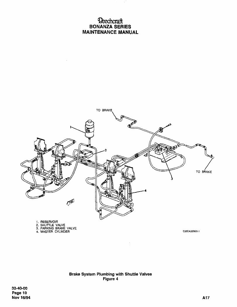
~eechcraftBONANZA SERIES
MAINTENANCE MANUAL
TO BRAKE
11~2
TO BRAKE
i. RESERVOIR2. SHUTTLE VALVE3..PARKING BRAKE VALVE4. MASTER CYUNDER C93EA32B00tl
Brake System Plumbing with Shuttle Valves
Figure 4
32-40-00
Page 10
Nov 16/94 A17
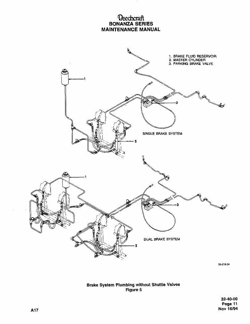
aeechcraRBONANZA SERIES
MAINTENANCE MANUAL
i. BRAKE F~U\D RESERVOIR2. MASTER CYLINDER3. PARKING BRAKE VALVE
SINGI_E BRAKE SYSTEM
i 1
i
Y
1.i DUAL BRAKE SYSTEM
35´•219-24
Brake System Plumbing without Shuttle Valves
Figure 5
32-40-00
Page 11
A17 Nov 16/94

QeechcraftBONANZA SERIES
MAINTENANCE MANUAL
i. Check the brakes for proper operation. When the k. Remove the bleeder hose from each landing gear.brake pedals are depressed, there must be no spongy i. Close the bleeder port of each brake assembly.feeling and the pedal pressure equal on both brakes.
m. Connect the fluid reservoir supply line to the res-
PRESSURE POT BLEEDING ervoir.
(Figure I) n. Check the hydraulic fluid reservoir and add MIL-
H-5606 hydraulic fluid (9, Chart 1 91-00-00) as
I -´•I´•´•Irequired to obtain a full reading.
WARNINGo. Installthe capon the reservoir.
p. Check the operation of the brakes. There must beWhenever the brakes are to be no soft or spongy feeling at the brake pedals and the
released, make sure the airplane is on pedal pressure must be equal on both brakes.level ground and the wheels are
checked. ELECTRIC BLEEDING
The hookup for electric bleeding is nearly the same asPressure bleeding is the most efficient method of
pressure pot bleeding except the pressure pot bleederbleeding the brakes. This procedure involves attach- is replaced with an electric bleeder (refer to Figure 1).ing a pressure pot to the brake assembly bleeder portand back bleeding the system to the fluid reservoir.
a. Remove the cap from the brake fluid reservoir. I U,.,.. IWARNING
b. Remove the brake fluid from the reservoir.
c. Disconnect the fluid supply line from the reservoir,Whenever the brakes are to be
and attach a hose to the supply line, released, make sore the airplane Is on
level ground and the wheels ared. Place the end of the hose in a clean container to chacked.collect the brake fluid overflow.
a. Remove the cap from the brake fluid reservoir.e. Open the bleeder port of each brake assembly, b. Remove the brake fluid from the reservoir.f. Install a bleeder hose (shown in Figure 1) ontoeach brake bleeder port,
c. Disconnect the fluid supply line from the reservoir,and attach the electric bleeder fluid return line to the
g. Connect the bleeder hose assemblies (shown in supply line.Figure 1) to the pressure lines of the pressure pot. d. Open the bleeder port of each brake assembly.
NOTE_
e. Connect the infusion line on the electric bleeder to
On serials prior to CE-839, CJ-150, each brake bleeder port (Figure 1).D-10209, E-1432 and EA-3 (airplanes NOTEwith shuttle valves in the brake system)depress the pilot’s brake pedals to actu- On serials prior to CE-839, CJ-150,ate the shuttle valve to bleed the pilot’s D-10209, E-1432 and EA-3 (airplanesbrakes, then proceed through step j. with shuttle valves in the brake system)After the pilot’s brakes are bled, depress depress the pilot’s brake pedals to actu-
the copilot’s brake pedals to actuate the ate the shuttle valve to bleed the pilot’sshuttle valve to bleed the copilot’s brakes, then proceed through step h.
brakes and follow steps g through j. After the pilot’s brakes are bled, depress
h.the copilot’s brake pedals to actuate the
Apply a constant pressure of not more than 30 shuttle valve to bleed the copilot’spounds to the pressure pot. Open the pressure pot brakes and follow steps f through i.control valve.
f. Activate the bleeder and set the relief valve toi. Bleed the system until the draining fluid is free of
approximately 15 pounds; this may be ascertained bybubbles.
observing the pressure gage prior to opening the elec-
j. Close the pressure pot valve. tric bleeder control valve.
32-40-00
Page 12
Nov 16/94 A17
aeechcraftBONANZA SERIES
MAINTENANCE MANUAL
g. Open the electric bleeder control valve and j. Disconnect the fluid return line from the brake fluid
observe the returning fluid through the in-line sight reservoir supply line.
glass.k. Connect the fluid reservoir supply line to the res-
NOTE ervoir.
Pumping the pilot’s and copilot’s pedals i. Check the brake fluid level and add MIL-H-5606during the bleeding process may help to hydraulic fluid (9. Chart 1, 91-00-00) as required todislodge any air bubbles trapped in the obtain a full readingmaster cylinders.
h. When the returning fluid shows no further evi- m´• I"stallthecaponthe reservoir.
dance of air bubbles, close the electric bleeder controln. Check the operation of the brakes. When the
valve, brake pedals are depressed there should be no
i. Disconnect the fluid infusion line from the bleeder spongy feeling and the pedal pressure should be
port. Close the bleeder port valves, equal on both brakes.
32-40-00
Page 13
A17 Nov 16/94
~eechrraftBONANZA SERIES
MAINTENANCE MANUAL
STEERING MAINTENANCE PRACTICES b. Turn the nose wheel to the extreme left turn posi-tion: the adjustment bolts must be clear of the stops
The nose wheel should be parallel to the fore and aftwith the nose wheel in this position.
centerline of the airplane with the rudder pedals in the
neutral position. Loosen the nose gear steering act- c. Place tape around the aft end of the shimmyuator arm at the aft end and screw the end fitting damper piston rod at a point 1/32 to 114 inch from theeither in or out to make the adjustment, scraper ring.
NOSE WHEEL TRAVEL STOP d. Turn the locknuts on the adjustment bolts so that
ADJUSTMENT the nose wheel is turned and the tape on the pistonrod just contacts the scraper ring. Tighten the locknuts
The travel stop must be adjusted so that the nose securely.wheel travel is stopped when the shimmy damper is
1/32 to 114 inch from its maximum travel. e. Repeat preceding steps b, c and d, except turn
If adjustment is required, the following procedure isthe nose wheel to the extreme right, and place the
recommended: tape on the forward end of the piston rod.
a. Loosen the locknuts on the adjustment: bolts so
that they clear the stops on the nose wheel straight-ener.
32-50-00
Page 1
A17 Nov 16/94
Aircraft CompanyBONANZA SERIES MAINTENANCE MANUAL
POSITION AND WARNING MAINTENANCE PRACTICES
LANDING GEAR POSITION LIGHTADJUSTMENT
The landing gear position lights are mounted on the right subpanel on early serial number airplanes. On airplaneserials E-1946, E-2104, E-2111 and After; EA-320, and EA-389 and After, the landing gear position lights were Imoved to the left side of the pilot’s subpanel. Three green lights, one for each gear, are illuminated whenever the
landing gear is down and locked. The red light illuminates any time any portion of the landing gear is in transit or at
any intermediate position. All of the lights will be extinguished when the landing gear is up and locked.
The landing gear position lights on the instrument panel are operated by the up-indicator switches and
down-indicator switches on each gear.
Before making the following adjustments, place the airplane on jacks as instructed in Chapter 7-00-00, LIFTING IAND SHORING MAINTENANCE PRACTICES.
MAIN GEAR
With the landing gear down and locked, adjust the downswitch, located on the forward side of the main gear V-brace,so that the overtravel of the switch plunger is 0.05 in. after the switch is actuated to the ON position. With the landing Igear in fully up position, adjust the up-switch, located inboard of the fon~vard side of the main landing gear V-brace,so that the overtravel of the switch plunger is 0.05 in, after the switch is actuated to the ON position. I
NOSE GEAR
With the landing gear down and locked, adjust the down-switch, located on the right hand side of the wheel well, so
that the overtravel of the switch plunger is 0.05 in. after the switch is actuated to the ON position. With the landing Igear in the fully up position, adjust the upswitch, located on the right-hand side of the wheel well, so that theovertravel of the switch plunger is 0.05 in. after the switch is actuated to the ON position. Check the instrument panel Ito be sure the indicator lights correspond to the landing gear position.
Recheck the switch adjustment and remove the airplane from the jacks.
ENGINE-COMPARTMENT-LOCA TED LANDING GEAR WARNING SWITCH ADJUSTMENT
(CE-748 CE-772 THRU CE-1300, CE- 1302 THRU CE- 1306; CJ- 149 THRU CJ- 1 79; D- 166970-10120 AND AFTER; E- 1 1 1 1, E- 1241 THRU E-21 10, EXCEPT E- 1946 AND E-2104; EA-1
THRU EA-388, EXCEPT EA-320)
NOTE
The following steps must be made by pulling the throttle control back. Incorrect settings may occur
if the throttle control is pushed fonnrard to check the switch adjustment.
If the altitude referenced in the following step cannot be obtained, use Table 1 for alternate altitude settings.
a. With the airplane in flight at 100 to 110 knots with 3,000 100 ft of pressure altitude (5,000 100 ft pressure Ialtitude with the propeller at 2,400 rpm on EA serials) and the landing gear retracted, retard the throttle to obtain
12 ~1 in. of Hg in manifold pressure (15 ~1 in. of Hg on EA serials). The landing-gear-up warning horn should Isound at this manifold pressure, but not before.
b. If the horn did not sound under the conditions established in Step a., measure and note the distance from the Ithrottle to the subpanel.
nn, 32-60-00 Sep 30/03Pagel
RBYYh6011 Aircraft CompanyBONANZA SERIES MAINTENANCE MANUAL
c. Land the airplane and shut down the engine.
Id. Set the throttle at the position noted in Step b..
e. Open the engine cowling and locate the gear warning (throttle) switch. Referto the Chapter 32-30-00 LANDING
GEAR SAFETY SYSTEM AND THROTTLE WARNING HORN MICROSWITCH illustration in the Landing Gear
Safety System Maintenance and Adjustment section.
f. Loosen the upper switch bracket and slide the bracket until the gear warning switch closes as indicated by a
clicking sound.
g. Anchor the switch bracket at this position.
I h. Repeat Step a. to check the warning horn adjustment. If the adjustment is incorrect, repeat Steps a. thru g..
i. Working with the throttle control, check that the switch actuator roller rides up smoothly on the throttle control
actuator and operates without catching or hanging on the tapered end. Readjust if the switch roller hangs up or
does not operate smoothly during the throttle control movement from idle to full power travel. Ensure full th rottle
travel and ease of movement.
I j. Close the engine cowling.
TED LANDING GEAR WARNING SWITCH ADJUSTMENT
(CE- 1301, CE- 1307 AND AFTER; CJ- 180 AND AFTER)
NOTE
The landing gear retract-prevent switch may be checked and/or adjusted at the same time the
landing gear warning switch is being adjusted because of the similarity of the adjustment.Accomplish the instructions under the ENGINE-COMPARTMENT-LOCATED
RETRACT-PREVENT SWITCH ADJUSTMENT heading.
a. Gain access to the throttle linkage in the engine compartment.
I b. Inspect the landing gear warning switch for proper installation (Ref. Figure 1). The switch plunger is NOT to be
under the dimple in the switch actuator arm.
c. Push the throttle to the fully forward position.
d. Inspect the switch plunger and switch actuator arm. The switch plunger should be touching the switch actuator
arm. If the switch plunger and the switch actuator arm are not touching, mark the position of the upper switch
I bracket on the throttle control housing. Remove the switch actuator assembly from the upper switch bracket and
bend the switch actuator arm so that, when installed, the switch actuator arm will be touching the switch plunger.
I e. If removed, return the upper switch bracket to the position noted in Step d..
NOTE
The following checks must be made by pulling the throttle control back. Incorrect settings may occur
if the throttle control is pushed forward to check the switch adjustment.
If the altitude referenced in the following step cannot be obtained, use Table 1 for alternate altitude settings.
Sep 30/03Page 2 32-60-00
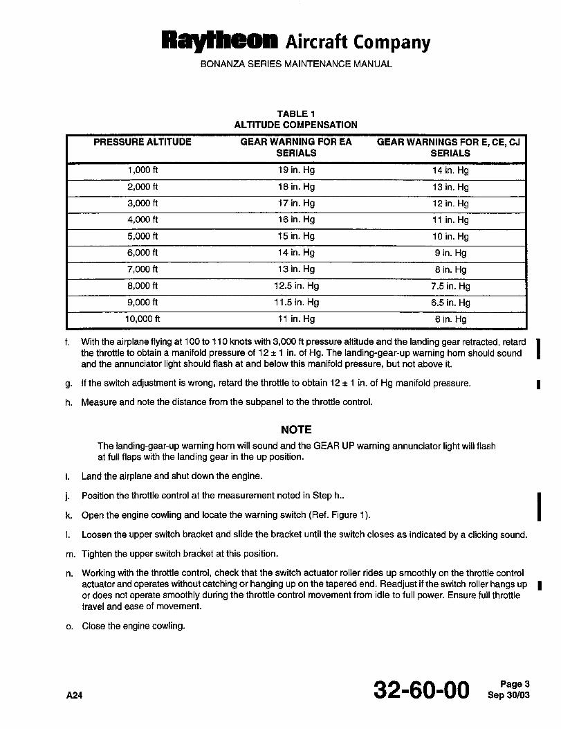
Ray~h´•on AiKraft CompanyBONANZA SERIES MAINTENANCE MANUAL
TABLE 1
ALTITUDE COMPENSATION
PRESSURE ALTITUDE GEAR WARNING FOR EA GEAR WARNINGS FOR E, CE, CJ
SERIALS SERIALS
1,000 ft 19 in. Hg 14 in. Hg
2,000 ft 18 in. Hg 13 in. Hg
3,000 ft 17 in. Hg 12 in. Hg
4,000 ft 16 in. Hg 11 in. Hg
5,000 ft 15 in. Hg 10 in. Hg
6,000 ft 14 in. Hg 9 in. Hg
7,000 ft 13 in. Hg 8 in. Hg
8,000 ft 12.5 in. Hg 7.5 in. Hg
9,000 ft 11.5 in. Hg 6.5 in. Hg
10,000 ft 11 in. Hg 6 in. Hg
f. With the airplane flying at 100 to 110 knots with 3,000 ft pressure altitude and the landing gear retracted, retard Ithe throttle to obtain a manifold pressure of 12 1 in, of Hg. The landing-gear-up warning horn should sound
and the annunciator light should flash at and below this manifold pressure, but not above it.
g. If the switch adjustment is wrong, retard the throttle to obtain 12 1 in. of Hg manifold pressure. I
h. Measure and note the distance from the subpanel to the throttle control.
NOTE
The landing-gear-up warning horn will sound and the GEAR UP warning annunciator light will flash
at full flaps with the landing gear in the up position.
i. Land the airplane and shut down the engine.
j. Position the throttle control at the measurement noted in Step h..
Ik. Open the engine cowling and locate the warning switch (Ref. Figure 1).
i. Loosen the upper switch bracket and slide the bracket until the switch closes as indicated by a clicking sound.
m. Tighten the upper switch bracket at this position.
n. Working with the throttle control, check that the switch actuator roller rides up smoothly on the throttle control
actuator and operates without catching or hanging up on the tapered end. Readjust if the switch roller hangs up Ior does not operate smoothly during the throttle control movement from idle to full power. Ensure full throttle
travel and ease of movement.
o. Close the engine cowling.
32-60-00 Sep 30/03Page 3
Ray~bdOn Aircraft CompanyBONANZA SERIES MAINTENANCE MANUAL
p. Repeat the flight check of the switch setting at the airspeed and altitude of the first check. The landing gearwarning horn should sound and the gear warning annunciator light on the instrument panel should flash at
settings below the manifold pressure being used to adjust the switch. If necessary, readjust the switch as
previously instructed.
PEDESTAL-LOCA TED L4NDING GEAR WARNING SWITCH ADJUSTMENT (E- 1946, E-2 1 04,E-2111 AND AFTER; EA-320, EA-389 AND AFTER)
NOTE
The landing gear warning switch may be checked and/or adjusted at the same time as the landinggear retract-prevent switch because of the similarity of the adjustment. Perform the
PEDESTAL-LOCATED LANDING GEAR RETRACT-PREVENT SWITCH ADJUSTMENT
I procedures.
The following checks must be made by pulling the throttle control back. Incorrect settings may occur
if the throttle control is pushed forward to check the switch adjustment.
IIf the altitude referenced in the following steps cannot be obtained, refer to TABLE 1, ALTITUDE COMPENSATION.
a. With the airplane flying at 100 to 110 knots with 3,000 ft pressure altitude (5,000 ~t 100 ft pressure altitude with
the propeller at 2,400 rpm on serials EA-320, EA-389 and After) and the landing gear retracted, retard the
throttle to obtain 12 1 in. of Hg manifold pressure (15 ~t 1 in. of Hg on serials EA-320, EA-389 and After). The
landing gear up warning horn should sound (the gear warning annunciator light should flash also on serials
1 E-2458, E-2468 and After and EA-488 and After) at and below this manifold pressure. Mark this throttle positionon the pedestal.
I" On serials E-2761 and After, advance the throttle to above 13 in. Hg (above 16 in. Hg on serials EA-320, EA-389
and After). Lower the flaps to fully down and the warning horn should sound and GEAR UP annunciator lightshould flash.
c. After landing the airplane and shutting down the engine, set the throttle at the position marked on the pedestalin Step a..
d. Remove the pedestal side covers.
e. Loosen the retaining nuts on the cam located on the end of the actuator rod arm for the landing gear warningI switch (Ref. Figure 2).
f. Adjust the cam so that the switch closes, indicated by a click, with the throttle control at the top position noted
I in Step a..
g. Retighten the cam retaining nuts.
h. Ensure full throttle control travel and ease of movement.
i. Reinstall the pedestal side covers.
I j. Repeat the check of the switch setting at the airspeed and altitude stated in Step a.. If necessary, readjust the
switch as previously instructed.
Sep 32-60-00 nn4
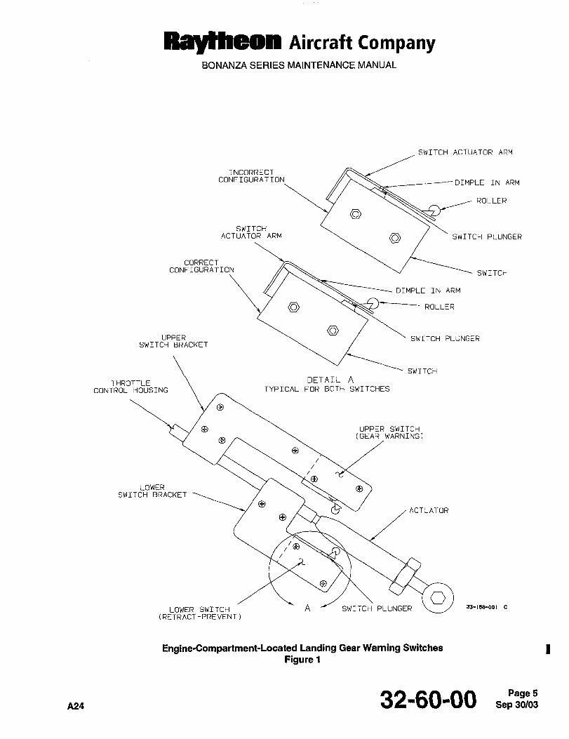
Aircraft tompanyBONANZA SERIES MAINTENANCE MANUAL
SWITCH ACTUATOR ARM
INCORRECT
CONFIGURATION\ _--~- DIMPLE IN ARM
ROLLER
SWITCHACTUATOR ARM ‘SWITCH PLUNGER
CORRECTCONFIGURATION SWITCH
DIMPLE IN ARM
ROLLER
UPPER SWITCH PLUNGERSWITCH BRACKET
SWITCH
DETAIL ATHROTTLE
CONTROL HOUSING TYPICAL FOR BOTH SWITCHES
O
UPPER SWITCH(GEAR WARNINGI
O
LOWERSWITCH BRACKET
OACTUATOR
//e
LOWER SWITCH A SWITCH PLUNGER "-1LMB-OO’
(RETRACT-PREVENT)
Engine-Compartment-Located Landing Gear Warning Switches
Figure 1
A24 32-60-00 Sep 30/03Page 5
RayiRec~ nircra~t CompanyBONANZA SERIES MAINTENANCE MANUAL
ENGINE-COMPARTMENT-LOCA TED LANDING GEAR RETRACT-PREVENT SWITCH
ADJUSTMENT (CE- 1301, CE- 1307 AND AFTER; CJ- 1 80 AND AFTER)
NOTE
The landing gear warning switch may be checked and/or adjusted at the same time the landing gear
retract-prevent switch is being adjusted because of the similarity of the adjustment. Accomplish the
instructions under the ENGINE-COMPARTMENT-LOCATED LANDING GEAR WARNING
SWITCH ADJUSTMENT heading.
a. Gain access to the throttle linkage in the engine compartment.
I b. Inspect the switch for proper installation (Ref. Figure 1). The switch plunger is NOT to be under the dimple in
the switch actuator arm.
c. Push the throttle to the full forward position.
d. Inspect the switch plunger and switch actuator arm. The switch plunger should be touching the switch actuator
arm. If the switch plunger and the switch actuator arm are not touching, mark the position of the lower switch
I bracket on the throttle control housing. Remove the switch actuator assembly from the lower switch bracket and
bend the switch actuator arm so that, when installed, the switch actuator arm will be touching the switch plunger.
I e. If removed, return the upper switch bracket to the position noted in Step d..
NOTE
The following checks must be made by pulling the throttle control back. Incorrect settings may occur
if the throttle control is pushed forward to check the switch adjustment.
I If the altitude referenced in the following step cannot be obtained, refer to TABLE 2, ALTITUDE COMPENSATION.
f. With the airplane flying at 100 to 110 knots with 3,000 rt 100 feet of pressure altitude and the landing gear
I extended, the landing gear must not retract at any manifold pressure below 17 1 in. of Hg. It is acceptable to
initially check this by advancing the throttle from a manifold pressure below 17 in. of Hg with the landing geardown and the cockpit landing gear position switch in the up position.
I g. If the retract-prevent switch adjustment is wrong, retard the throttle control to obtain 17 ~t 1 in. of Hg manifold
pressure.
h. Measure and note the distance from the subpanel to the throttle control.
NOTE
There is a latching relay in the circuit which allows the landing gear to fully retract once retraction
starts. Retarding the throttle should not stop the landing gear in midtravel.
i. Land the airplane and shut down the engine.
I j. Open the engine cowling and locate the switch (Ref. Figure 1).
k. Place the throttle at the distance from the subpanel measured in Step h..
I. Loosen the lower switch bracket and slide the bracket until the switch closes as indicated by a clicking sound.
Sep 32-60-00
Raylheon Aircraft companyBONANZA SERIES MAINTENANCE MANUAL
m. Tighten the lower switch bracket at this position.
n. Working with the throttle control, check that the actuator roller for the retract-prevents switch rides up smoothlyon the throttle control actuator and operates without catching or hanging up on the tapered end (Ref. Figure 1). IReadjust if the switch roller hangs up or does not operate smoothly during the throttle control travel from idle to
full power. Ensure full throttle travel and ease of movement.
o. Closethe enginecowling.
p. Repeat the flight check of the retract-prevent switch setting at the airspeed and altitude stated in Step f.. If Inecessary, readjust the switch as previously instructed.
32-60-00 Sep 30/03Page 7
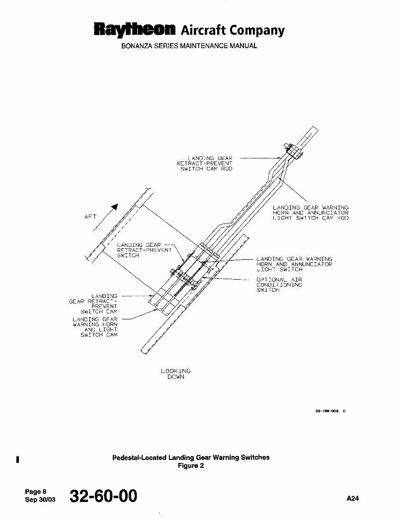
RayCheon Aircraft CompanyBONANZA SERIES MAINTENANCE MANUAL
LANDING GEARRETRACT-PREVENT
SWITCH CAM ROD
AFT LIGHT SWITCH CAM ROD
LANDING GEAR WARNINGHORN AND ANNUNCIATOR
LANDING GEARRETRACT-PREVENTSWITCH
LANDING GEAR WARNING
HORN AND ANNUNCIATORLIGHT SWITCH
OPTIONAL AIRCONDITIONINGSWITCH
LANDINGGEAR RETRACT- C´•.~ Y~ Y/
PREVENTSWITCH CAM
LANDING GEARWARNING HORN
AND LIGHTSWITCH CAM
LOOKINGDOWN
33-1o8-002 C
Pedestal-Located Landing Gear Warning Switches
Figure 2
Sep 32-6000 A24
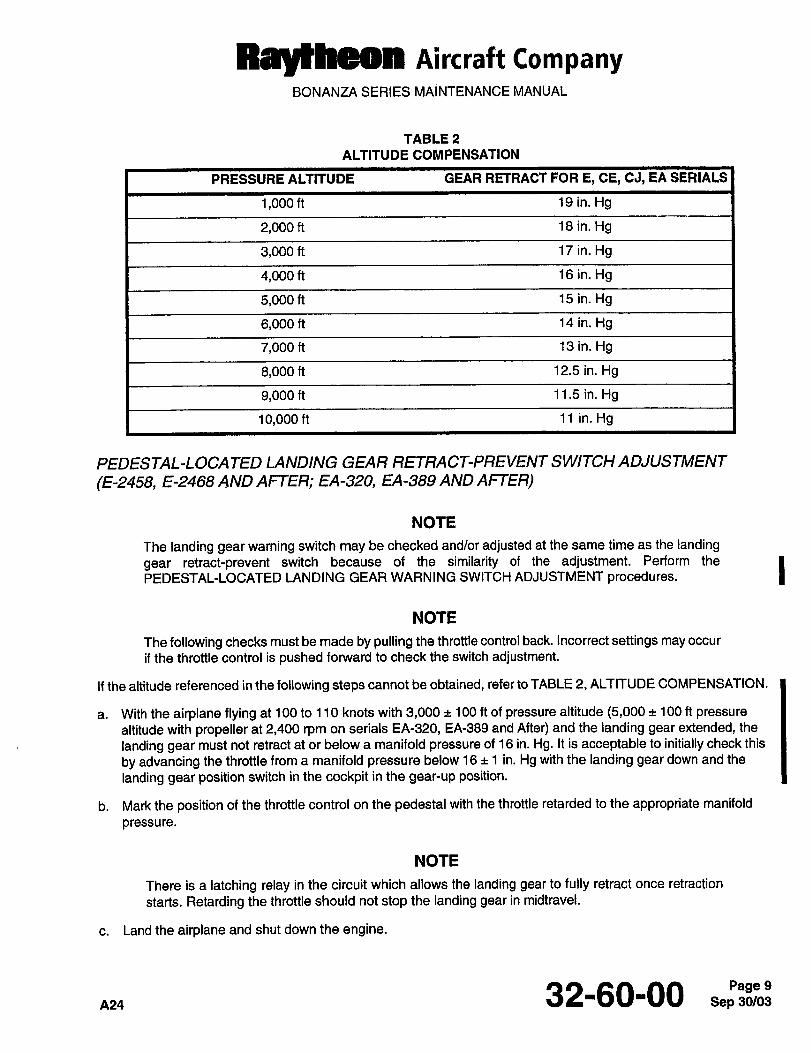
Aircraft CompanyBONANZA SERIES MAINTENANCE MANUAL
TABLE 2
ALTITUDE COMPENSATION
PRESSURE ALTITUDE GEAR RETRACT FOR E, CE, CJ, EA SERIALS
1,000 ft 19 in. Hg
2,000 ft 16 in. Hg
3,000 ft 17 in. Hg
4,000 ft 16 in. Hg
5,000 ft 15 in. Hg
6,000 ft 14 in. Hg
7,000 ft 13 in. Hg
8,000 ft 12.5 in. Hg
9,000 ft 11.5 in. Hg
10,000 ft 11 in. Hg
PEDESTAL-LOCA TED LANDING GEAR RETRACT-PREVENT SWITCH ADJUSTMENT
(E-2458, E-2468 AND AFTER; EA-320, EA-389 AND AFTER)
NOTE
The landing gear warning switch may be checked and/or adjusted at the same time as the landing
gear retract-prevent switch because of the similarity of the adjustment. Perform the
PEDESTAL-LOCATED LANDING GEAR WARNING SWITCH ADJUSTMENT procedures.
NOTE
The following checks must be made by pulling the throttle control back. Incorrect settings may occur
if the throttle control is pushed forward to check the switch adjustment.
If the altitude referenced in the following steps cannot be obtained, refer to TABLE 2, ALTITUDE COMPENSATION.
a. With the airplane flying at 100 to 110 knots with 3,000 100 ft of pressure altitude (5,000 100 ft pressure
altitude with propeller at 2,400 rpm on serials EA-320, EA-389 and After) and the landing gear extended, the
landing gear must not retract at or below a manifold pressure of 16 in. Hg. It is acceptable to initially check this
by advancing the throttle from a manifold pressure below 16 1 in. Hg with the landing gear down and the
landing gear position switch in the cockpit in the gear-up position.
b. Mark the position of the throttle control on the pedestal with the throttle retarded to the appropriate manifold
pressure.
NOTE
There is a latching relay in the circuit which allows the landing gear to fully retract once retraction
starts. Retarding the throttle should not stop the landing gear in midtravel.
c. Land the airplane and shut down the engine.
32-60-00 Sep 30/03Page 9
RBYBCOn nircraft CompanyBONANZA SERIES MAINTENANCE MANUAL
I d. Place the throttle control at the mark made on the pedestal in Step b..
e. Removethe pedestalsidecovers.
f. Loosen the retaining nuts on the cam located on the end of the actuator rod for the gear retract-prevent switch
I (Ref. Figure 2).
g. Adjust the cam so that the switch closes, indicated by a click, with the throttle control at the position noted in
I Step b..
h. Retightenthecam retainingnuts.
i. Ensure full throttle travel and ease of movement.
j. Reinstall the pedestal side covers.
I k. Repeat the flight check of the switch setting at the airspeed and altitude stated in Step a.. If necessary, readjustthe switch as previously instructed.
Page 32’60-00 Pi24

CHAPTER
LIGHTS
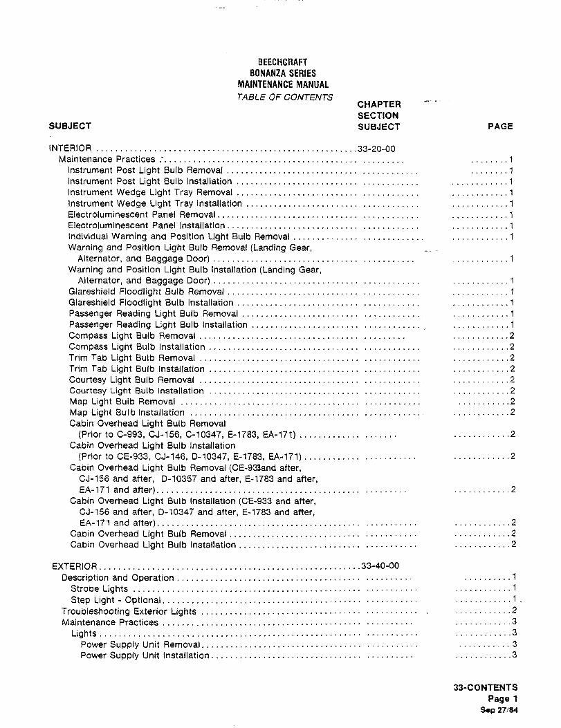
BEECHCRAFT
BONANZA SERIES
MAINTENANCE MANUAL
TABLE OF CONTENTSCHAPTER
SECTION
SUBJECT SUBJECT PAGE
INTERIOR 33-20-00
Maintenance Practices ..1
Instrument Post Light Bulb Removal ........1
instrument Post Light Bulb Installation................._
............1
Instrument Wedge Light Tray Removal ............1
Instrument Wedge Light Tray Installation ............1
Electroluminescent Panel Removal........._ ........._
............1
Electroluminescent Panel Installation ..............1
individual Warning and Position Light 8ulb Removal ............1
Warning and Position Light Bulb Removal (Landing Gear,Alternator, and Baggage Door) ...........1
Warning and Position Light Bulb Installation (Landing Gear,Alternator, and Baggage Door) ............1
Glareshield Floodlight Bulb Removal ..............1
Glareshield Floodlight Bulb Installation ............1
Passenger Reading Light Bulb Removal ............1
Passenger Reading Light Bulb Installation_
............1
Compass Light Bulb Removal .........,.2
Compass Light Bulb Installation ..................2
Trim Tab Light Bulb Removal ............2
Trim Tab Light Bulb Installation ............2
Courtesy Light Bulb Removal .....2
Courtesy Light Bulb Installation .....2
Map Light Bulb Removal ...........2
Map Light aulblnstailation ........2
Cabin Overhead Light Bulb Removal
(Prior to C-993, CJ-156, C-10347, 8-1783, EA-171) .....2
Cabin Overhead Light Bulb Installation
(Prior to CE-933, CJ-146, D-10347, E-1783, EA-171)............ ....2
Cabin Overhead Light Bulb Removal (CE-933and after,CJ-156 and after, D-10357 and after, E-1783 and after,EA-171 and after) ............2
Cabin Overhead Light Bulb Installation (CE-933 and after,CJ-156 and after, D-10347 and after, E-1783 and after,EA-171 and after) ............2
Cabin Overhead Light Bulb Removal ................2
Cabin Overhead Light Bulb Installation ............2
EXTERIOR.......................................................33-40-00
Description and Operation ..........1
Strobe Lights ............1
Step Light Optional. ............1.
Troubleshooting Exterior Lights ´•2
Maintenance Practices ............3
Lights ............3
Power Supply Unit Removal ...........3
Power Supply Unit Installation ............3
33-CONTENTS
Page 1
S´•p 27/84
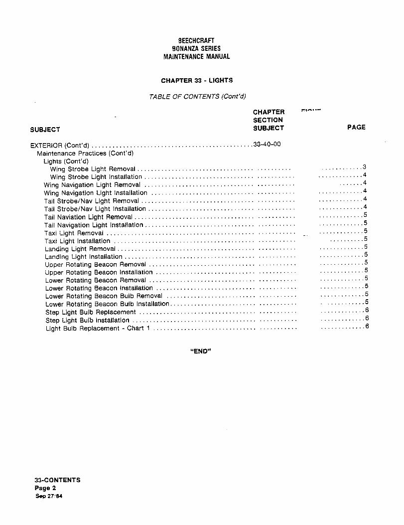
BEECHCRAFT
BONANZA SERIES
MAINTENANCE MANUAL
CHAPTER 33 LIGHTS
TABLE OF CONTENTS (Cont’d)
CHAPTER
SECTION
SUBJECT SUBJECT PAGE
EXTERIOR (Cont’d) ´•´•´•´•´•´•´•´•33-40-00
Maintenance Practices (Cont’d)Lights (Cont’d)
Wing Strobe Light Removal ...........3
Wing Strobe Light Installation .............4
Wing Navigation Light Removal .......4
Wing Navigation Light Installation .............4
Tail Strobe/Nav Light Removal .............4
Tail Strobe/Nav Light I~stallation .............4
Tail Naviation Light Removal .............5
Tail Navigation Light Installation .............5
Taxi Light Removal .............5
Taxi Light Installation ..........5
Landing Light Removal .............5
Landing Light Installation .............5
Upper Rotating Beacon Removal .............5
Upper Rotating Beacon installation .............5
Lower Rotating Beacon Removal .............5
Lower Rotating Beacon Installation .............5
Lower Rotating Beacon Bulb Removal .............5
Lower Rotating Beacon Bulb Installation. ...........5
Step Light Bulb Replacement .............6
Step Light Bulb installation .............6
Light Bulb Replacement Chart 1 .............6
"END"
33-CONTENTS
Page 2
Sep 27/84
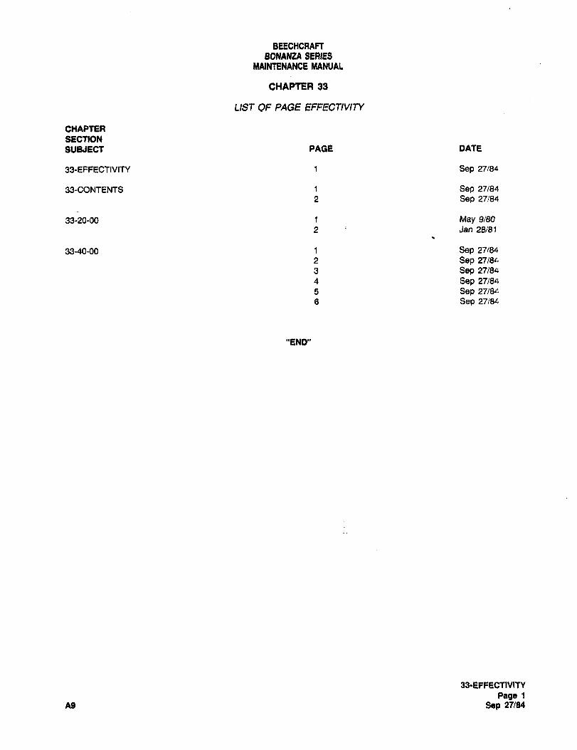
BEECHCRAFTBONANZA SERIES
MAINtENANCE MANUAL
CHAPTER 33
LIST OF PA%E EFFECT1VIP/
CHAPTER
SECTION
SU&IECt PACE DATE
33-EFI=ECTIVITY t Sep 27/84
33-CONTENTS 1 Sep 27/84
2 Sep 27/84
33-20-00 1 May 9/80
2 Jan 28/81
33-40-00 1 Sep 27/84
2 Sep 27/811
3 Sep 27/84
4 Sep 27/8a
5 Sep 27/8~:
6 Sep 27/8L
"END"
1&EFFECTIVITY
Page 1
A9 Sep 27/84
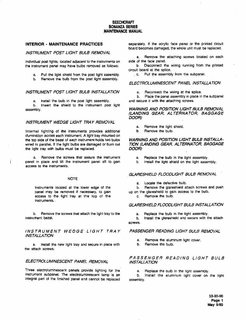
BEECHCRAFTBONANZA SERIES
MAINtENANCE MANUAL
INTERIOR MAINTENANCE PRACTICES separately. If the acrylic face panel or the printed circuit
board becomes damaged, the whole unit must be replaced.INSTRUMENT POST LIGHT BULB REMOVAL
a. Remove the attaching screws located on each
Individual post lights, located adjacent to the instruments on side of the face panel.the instrument panel may have bulbs removed as follows: b. Disconnect the wiring running from the printed
circuit board at the splice.a. Pull the light shield from the post light assembly. c. Pull the assembly from the subpanel.b. Remove the bulb from the post light assembly.
ELECTROLUMINESCENT PANEL INSTALLA TION
INSTRUMENT POST LIGHT BULB INSTALLATION a. Reconnect the wiring at the splice.b. Place the panel assembly in place in the subpanel
a. Install the bulb in the post light assembly. and secure it with the attaching screws.
b. Insert the shield to the instrument post lightassembly. WARNING AND POSITION LIGHT BULB REMOVAL
(LANDING GEAR, ALTERNATOR, BAGGAGE
DOOR)INSTRUMENT WEDGE LIGHT TRA Y REMOVAL
a. Remove the light shield.
Internal lighting of the instruments provides additional b. Remove the bulb.
illumination across each instrument. A light tray mounted on
the top side of the bezel of each instrument holds two bulbs WARNING AND POSITION LIGHT BULB INSTALL(I-
wired in parallel. If the light bulbs are damaged or burn out TION (LANDING GEAR, ALTERNATOR, BAGGAGE
the light tray with bulbs must be replaced. DOOR)
a. Remove the screws that secure the instrument a. Replace the bulb in the light assembly.panel in place and tilt the instrument panel aft to gain b. Install the light shield on the light assembly.access to the instruments.
GLARESHIELD FLOODLIGHT BULB REMOVAL
NOTE
a. Locate the defective bulb.
Instruments located at the lower edge of the b. Remove the glareshield attach screws and push
panel may be removed if necessary, to gain up on the glareshield to gain access to the bulb.
access to the light tray at the top of the c. Remove the bulb.
instruments.
GLARESHIELD FLOODLIGHT BULB INSTALLA TION
b. Remove the screws that attach the light tray to the a. Replace the bulb in the light assembly.instrument bezel. b. Install the glareshield and secure with the attach
screws.
INSTRUMENT WEDGE LIGHT TRA Y PASSENGER READING LIGHT BULB REMOVALINSTALLA TION
a. Remove the aluminum light cover.
a. Install the new light tray and secure in place with b. Remove the bulb.
the attach screws.
PASSENGER READING LIGHT BULBELECTROLUMINESCENT PANEL REMOVAL INSTALLA TION
Three electroluminescent panels provide lighting for the a. Replace the bulb in the light assembly.instrument subpanel. The electroluminescent lamp is an b. Install the aluminum light cover on the lightintegral part of the finished panel and cannot be replaced assembly.
33-20-00
Page 1
May 9180
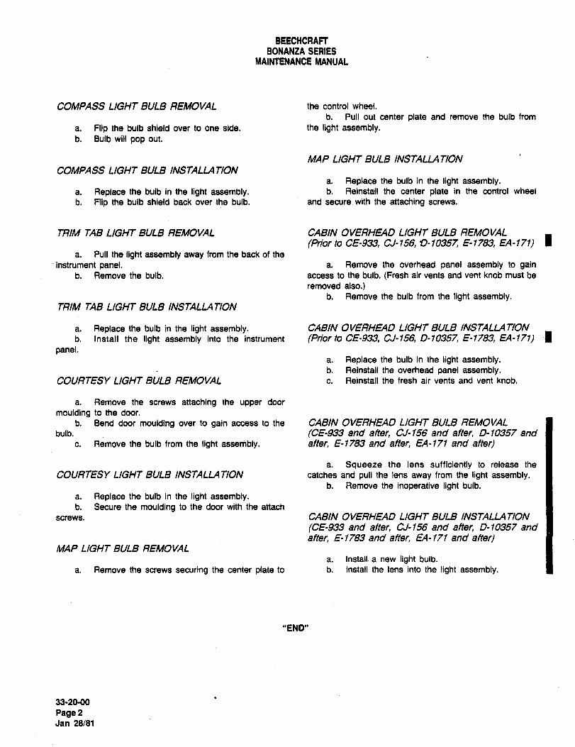
BEECHCRAFTBONANZA SERIES
MAINTENANCE MANUAL
COMPASS LIGHT BULB REMOVAL the control wheel.
b. Pull out center plate and remove the bulb from
a. Flip the bulb shield over to one side. the light assembly.b. Bulb will pop out.
MAP LIGHT BULB INSTALLATION
COMPASS LIGHT BULB INSTALLA TIONa. Replace the bulb in the light assembly.
a, Replace the bulb in the light assembly. b. Reinstall the center plate in the control wheel
b. Flip the bulb shield back over ´•the bulb. and secure with the attaching screws.
TRIM TAB LIGHTBULB REMOVAL CABIN OVERHEAD LIGHT BULB REMOVAL
(Prior to CE-933, CJ-156, 0-10357, E-1783, EA-171) Ia. Pull the light assembly away from the back of the
instrument panel. a. Remove the overhead panel assembly to gainb. Remove the bulb. access to the bulb. (Fresh air vents and vent knob must be
removed also.)b. Remove the bulb from the light assembly.
TRIM TAB LIGHT BULB INSTALLATION
a. Replace the bulb in the light assembly. CABIN OVERHEAD LIGHT BULB INSTALLATION
b. Instsll the light assembly into the instrument (Prior to CE-933, CJ-156, 0-10357, E-1783, EA-171) Ipanel.
a. Replace the bulb in the light assembly.b. Reinstall the overhead panel assembly.
COURTESY LIGHT BULB REMOVAL c. Reinstall the fresh air vents and vent knob.
a. Remove the screws attaching the upper door
moulding to the door.
b. Bend door moulding over to gain access to the CABIN OVERHEAD LIGHT BULB REMOVALbulb. (05-933 and after, CJ-156 and after, 0-1~351 and
c. Remove the bulb from the light assembly. after, E-1183 and after, EA-171 and after)
a. Squeeze the lens sufficiently to release the
COURTESY LIGHT BULB INSTALLATION catches and pull the lens away from the light assembly.b. Remove the inoperative light bulb.
a. Replace the bulb in the light assembly.b. Secure the moulding to the door with the attach
screws. CABIN OVERHEAD LIGHT BULB INSTALLA TION
(CE-933 and after, CJ-156 and after, 0-10357 and
after, E-1183 and after EA-III and after)MAP LIGHT BULB REMOVAL
a. Install a new light bulb.
a. Remove the screws securing the center plate to b. Install the lens into the light assembly.
"END"
33-20-00
Pagd2Jan 28/81
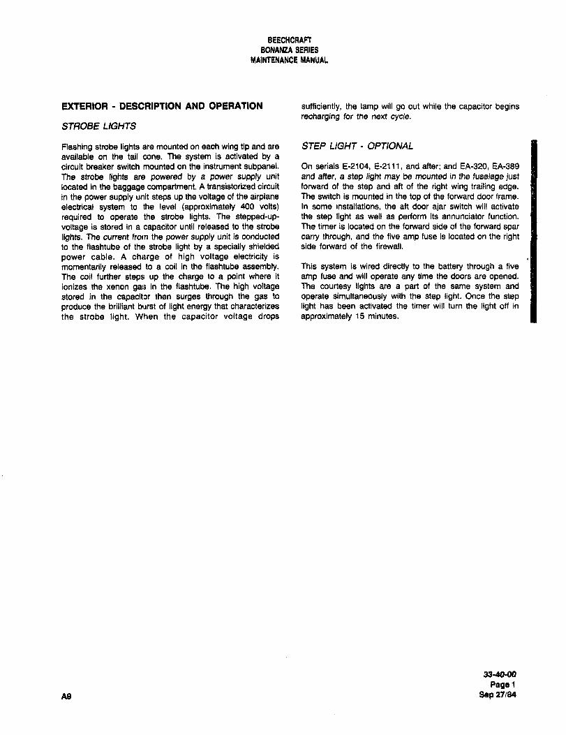
BEECHCRAFT
BONANZA SEAIES
MAIMENANCE MANUAL
EXTERIOR DESCRIPTION AND OPERATION sufficiently, the lamp will go out while the capacitor beginsrecharging for the next cycle.
STF~OBE LIGHTS
Flashing strobe lights are mounted on each wing tip and are STEP LIGHT OPTIONAL
available on the tail cone. The system is activated by a
circuit breaker switch mounted on the instrument subpanel. On serials E-2104, E-2111, and after; and EA-320, EA-389
The strobe lights are powered by a power supply unit and after, a step light may be mounted in the fuselage justlocated in the baggage compartment. A transistorized circuit forward of the step and aft of the right wing trailing edge.in the power supply unit steps up the voltage of the airplane The switch is mounted in the top of the forward door frame.
electrical system to the level (approximately 400 volts) In some installations, the aft door ajar switch will activate
required to operate the strobe lights. The stepped-up- the step light as well as perform its annunciator function.
voltage is stored in a capacitor until released to the strobe The timer is located on the forward side of the forward spar
lights. The current from the power supply unit is conducted carry through, and the five amp fuse is located on the rightto the flashtube of the strobe light by a specially shielded side forward of the firewall.
power cable. A charge of high voltage electricity is
momentarily released to a coil in the flashtube assembly. This system is wired directly to the battery through a five
The coil further steps up the charge to a point where it amp fuse and will operate any time the doors are opened.ionizes the xenon gas in the flashtube. The high voltage The courtesy lights are a part of the same system and
stored in the capacitw then surges through the gas to operate simultaneously with the step light. Once the step
produce the brilliant burst of light energy that characterizes light has been activated the timer will turn the light off in
the strobe light. When the capacitor voltage drops approximately 15 minutes.
33´•40-00
PagelAg Sgp 271%]4
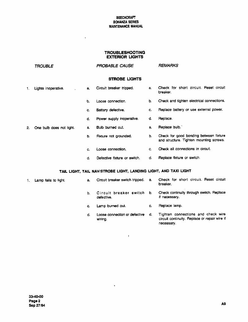
BEECHCRAFT
BONANZA SERIES
MAIMENA#CE MANUAL
TROUBLESHOOTINGEXTERIOR LIGHTS
TROUBLE PROBABLE CAUSE REMARKS
STROBE LIGHTS
1. Lights inoperative. a. Circuit breaker tripped. a. Check for short circuit. Reset circuit
breaker.
b. Loose connection, b. Check and tighten electrical connections.
c. Battery defective. c. Replace battery or use external power.
d. Power supply inoperative, d. Replace.
2. One bulb does not light. a. Bulb burned out. a. Replace bulb.’
b. Fixture not grounded, b. Check for good bonding between fixture
and structure. Tighten mounting screws.
c. Loose connection. c. Check all connections in circuit.
d. Defective fixture or switch, d. Replace fixture or switch.
TAIL LIGHT, TAIL NAV/STROBE LIGHT, LANDING LIGHT, AND TAXI LIGHT
1. Lamp fails to light. a. Circuit breaker switch tripped. a. Check for short circuit. Reset circuit
breaker.
b. Circuit breaker switch b. Check continuity through switch. Replacedefective. if necessary.
c. Larr;p burned out. c. Replace lamp.
d. Loose connection or defective d. Tighten connections and check wire
wiring. circuit continuity. Replace or repair wire if
necessary.
3340-00
PagePA9
Sep 27/84
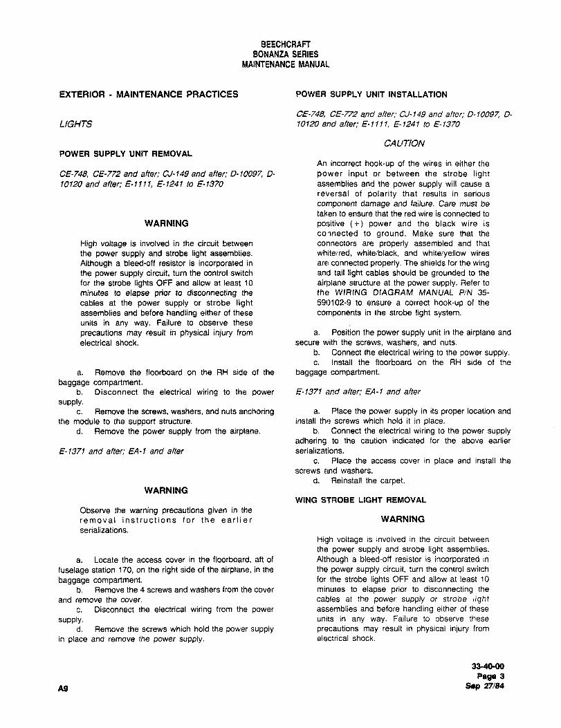
BEECHCRAFT
BONANZA SERIES
MAINTENANCE MANUAL
EXTERIOR MAINTENANCE PRACTICES POWER SUPPLY UNIT INSTALLATION
CE-748, CE-772 and after; CLJ- 149 and after, 0-10097, D-
LIGHTS 10120 and after; E-1I11, ~-1241 to 8-1370
CA UTION
POWER SUPPLY UNIT REMOVALAn incorrect hook-up of the wires in either the
CE-748, CE-772 and after; CJ-149 and after; 0-10097, D- power input or between the strobe light10120 and after; E-llll, E-1241 to E-1370 assemblies and the power supply will cause a
reversal of polarity that results in serious
component damage and failure. Care must be
taken to ensure that the red wire is connected to
WARNING positive power and the black wire is
connected to ground. Make sure that the
High voltage is involved in the circuit between connectors are properly assembled and that
the power supply and strobe light assemblies. whiteired, white/black, and whiteiyellow wires
Although a bleed-off resistor is incorporated in are connected properly. The shields for the wingthe power supply circuit, turn the control switch and tail light cables should be grounded to the
far the strobe lights OFF and allow at least 10 airplane structure at the power supply. Refer to
minutes to elapse prior to disconnecting the the WIRING DIAGRAM MANUAL PIN 35-
cables at the power supply or strobe light 59()102-9 to ensure a correct hook-up of the
assemblies and before handling either of these components in the strobe light system.units in any way. Failure to observe these
precautions may result in physical injury from a. Position the power supply unit in the airplane and
electrical shock. secure with the screws, washers, and nuts.
b. Connect the electrical wiring to the power supply.c. Install the floorboard on the RH side of the
a. Remove the floorboard on the RH side of the baggage compartment.
baggage compartment.b. Disconnect the electrical wiring to the power E´•1371 and aftec EA-I and after
supply.c. Remove the screws, washers, and nuts anchoring a. Place the power supply in its proper location and
the module to the support structure. install the screws which hold it in place.d. Remove the power supply from the airplane, b. Connect the electrical wiring to the power supply
adhering to the caution indicated for the above earlier
E- 1371 and after; EA-I and after serializations.
c. Place the access cover in place and install the
screws and washers.
d, Reinstall the carpet.WARNING
WING STROBE LIGHT REMOVAL
Observe the warning precautions given in the
removal instructions for the earlier WARNING
serializations.
High voltage is involved in the circuit between
the power supply and strobe light assemblies.
a. Locate the access cover in the floorboard, aft of Although a bleed-off resistor is incorporated in
fuselage station 170, on the right side of the airplane, in the the power supply circuit, turn the control switch
baggage compartment. for the strobe lights OFF and allow at least 10
b. Remove the 4 screws and washers from the cover minutes to elapse prior to disconnecting the
and remove the cover, cables at the power supply or strobe lightc. Disconnect the electrical wiring from the power assemblies and before handling either of these
supply. units in any way. Failure to observe these
d. Remove the screws which hold the power supply precautions may result in physical injury from
in place and remove the power supply, electrical shock.
33-40-00
Page 3
A9 Sep 27/84
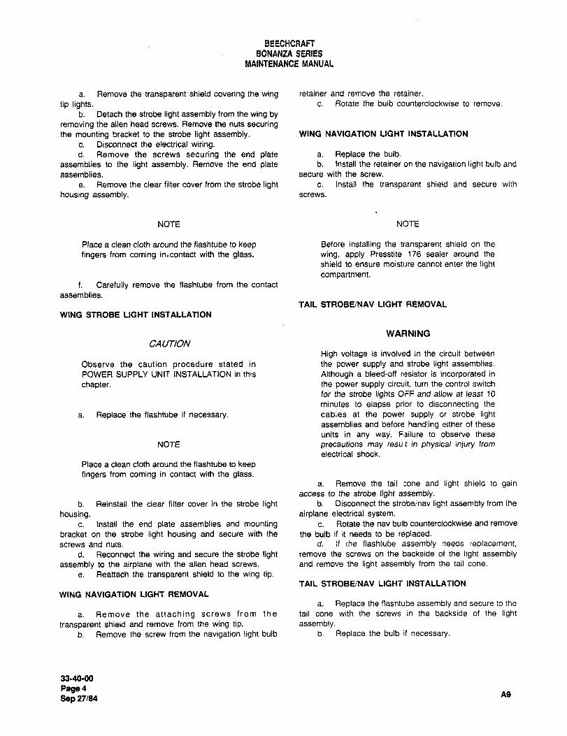
BEECHCRAFT
BONANZA SERIES
MAINTENANCE MANUAL
a. Remove the transparent´•shield covering the wing retainer and remove the retainer.
tip lights. c. Rotate the bulb counterclockwise to remove.
b. Detach the strobe light assembly from the wing byremoving the alien head screws. Remove the nuts securingthe mounting bracket to the strobe light assembly. WING NAVIGATION LIGHT INSTALLATION
c. Disconnect the electrical wiring.d. Remove the screws securing the end plate a. Replace the bulb.
assemblies to the light assembly. Remove the end plate b. Install the retainer on the navigation light bulb and
assemblies, secure with the screw.
e. Remove the clear filter cover from the strobe light c. Install the transparent shield and secure with
housing assembly, screws.
NOTE N()TE
Place a clean cloth around the flashtube to keep Before installing the transparent shield on the
fingers from coming in,contact with the glass. wing, apply Presstite 176 sealer around the
shield to ensure moisture cannot enter the lightcompartment.
f. Carefully remove the flashtube from the contact
assemblies.
TAIL STROBEINAV LIGHT REMOVAL
WING STROBE LIGHT INSTALLATION
WARNING
CAUTION
High voltage is involved in the circuit between
Observe the caution procedure stated in the power supply and strobe light assemblies.
POWER SUPPLY UNIT INSTALLATION in this Although a bleed-off resistor is incorporated in
chapter. the power supply circuit, turn the control switch
for the strobe lights OFF and allow at least 10
minutes to elapse prior to disconnecting the
a. Replace the flashtube if necessary. cables at the power supply or strobe lightassemblies and before handling either of these
units in any way’. F.ilure to observe these
NOTE precautions may resu t in physical injury from
electrical shock.
Place a clean cloth around the flashtube to keepfingers from coming in contact with the glass.
a. Remove the tail :one and light shield to gainaccess to the strobe light assembly.
b. Reinstall the clear filter cover in the strobe light b. Disconnect the strobeinav light assembly from the
housing. airplane electrical system.c. Install the end plate assemblies and mounting c. Rotate the nav bulb counterclockwise and remove
bracket on the strobe light housing and secure with the the bulb if it needs to be replaced.screws and nuts. d. If the flashtube assembly needs replacement,
d. Reconnect the wiring and secure the strobe light remove the screws on the backside of the light assemblyassembly to the airplane with the alien head screws, and remove the light assembly from the tail cone.
e. Reattach the transparent shield to the wing tip.TAIL STROBE/NAV LIGHT INSTALLATION
WING NAVIGATION LIGHT REMOVAL
a. Replace the flashtube assembly and secure to the
a. Remove the attaching screws from the tail cone with the screws in the backside of the light
transparent shield and remove from the wing tip. assembly.b. Remove the screw from the navigation light bulb b. Replace the bulb if necessary.
33-40-00
Page4A9
Sep 27/84
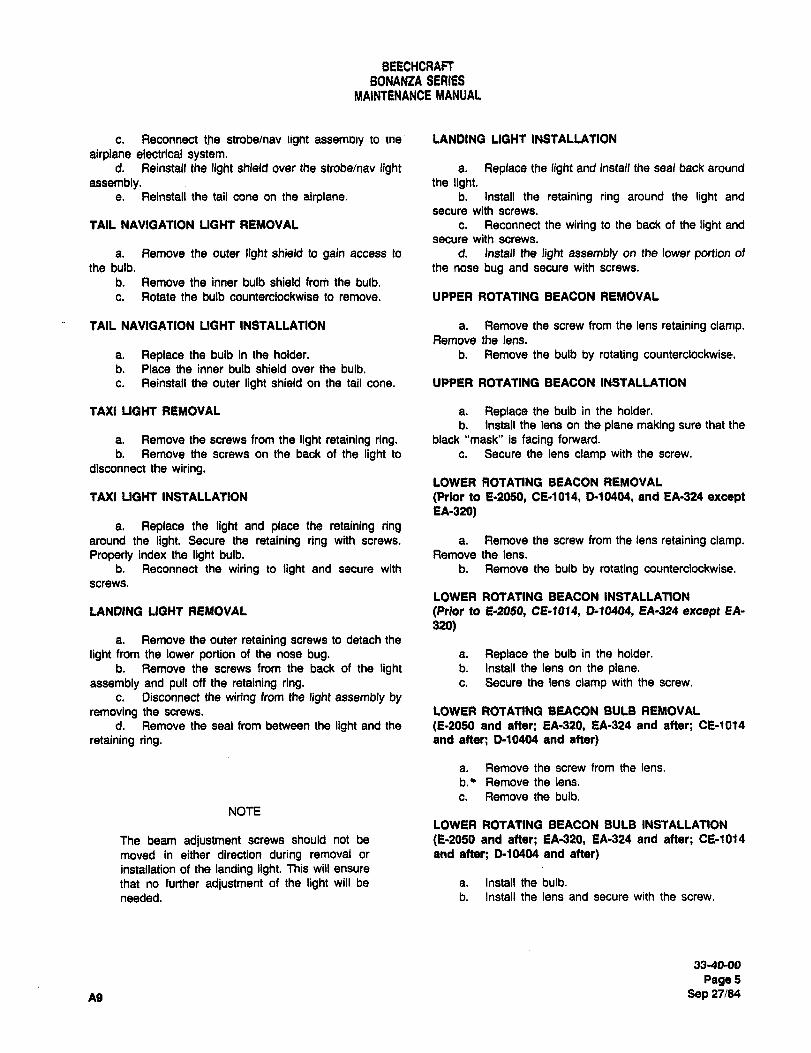
BEECHCRAFTBONANZA SERIES
MAINTENANCE MANUAL
c. Reconnect the strobelnav lignt assemDly to tne LANDING LIGHT INSTALLATION
airplane electrical system.d. Reinstall the light shield over the strobe/nav light a. Replace the light and install the seal back around
assembly. the light.e. Reinstall the tail cone on the airplane. b. Install the retaining ring around the light and
secure with screws.
TAIL NAVIGATION LIGHT REMOVAL c. Reconnect the wiring to the back of the light and
secure with screws.
a. Remove the outer light shield to gain access to d. Install the light assembly on the lower portion of
the bulb. the nose bug and secure with screws.
b. Remove the inner bulb shield from the bulb.
c. Rotate the bulb counterclockwise to remove. UPPER ROTATING BEACON REMOVAL
TAIL NAVIGATION LIGHT INSTALLATION a. Remove the screw from the lens retaining clanlp.Remove the lens.
a. Replace the bulb in the holder. b. Remove the bulb by rotating counterclockwise.
b. Place the inner bulb shield over the bulb.
c. Reinstall the outer light shield on the tail cone. UPPER ROTATING BEACON INSTALLATION
TAXI LIGHT REMOVAL a. Replace the bulb in the holder.
b. Install the lens on the plane making sure that the
a. Remove the screws from the light retaining ring. back "mask" is facing forward.
b. Remove the screws on the back of the light to c. Secure the lens clamp with the screw.
disconnect the wiring.LOWER ROTATING BEACON REMOVAL
TAXI LIGHT INSTALLATION (Plror to E´•2050, CE-1014, D-10404, and EA-324 exceptEA-320)
a. Replace the light and place the retaining ringaround the light. Secure the retaining ring with screws. a. Remove the screw from the lens retaining clamp.Properly index the light bulb. Remove the lens.
b. Reconnect the wiring to light and secure with b. Remove the bulb by rotating counterclockwise.
screws.
LOWER ROTATING BEACON INSTALLATION
LANDING LIGHT REMOVAL (Prlor to E2054 CE-1014, D-10404, EA-324 except EA-
320)a. Remove the outer retaining screws to detach the
light from the lower portion of the nose bug. a. Replace the bulb in the holder.
b. Remove the screws from the back of the light b. Install the lens~ on the plane.assembly and pull off the retaining ring. c. Secure the lens clamp with the screw.
c. Disconnect the wiring from the light assembly byremoving the screws. LOWER ROTATING BEACON BULB REMOVAL
d. Remove the seal from between the light and the (E-2050 and after; EA´•32d, EA-324 and after; CE-1014
retaining ring. end after; D-10404 and after)
a. Remove the screw from the lens.
b.’ Remove the lens.
c. Remove the bulb.
NOTE
LOWER ROTATING BEACON BULB INSTALLATION
The beam adjustment screws should not be (E´•2050 and aftar; EA-320, EA-324 and after; CE-1014
moved in either direction during removal or and after; D-10404 and after)installation of the landing light. This will ensure
that no further adjustment of the light will be a. Install the bulb.
needed. b. Install the lens and secure with the screw.
33-40-00
Page5
A9 Sep 27184
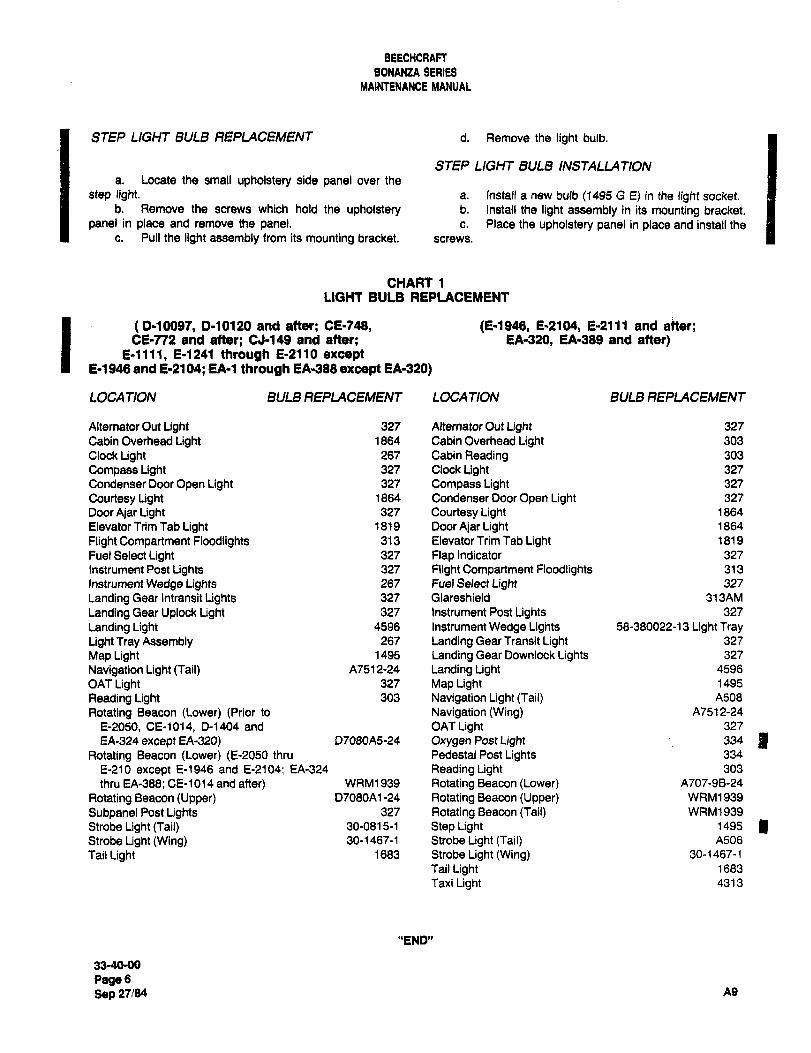
BEECHCRAFT
8084824 SERIES
MAINTENANCE MANUAL
STEP LIGHT BULB REPLACEMENT d. Remove the light bulb.
STEP LIGHT BULB INSTALLATIONa. Locate the small upholstery side panel over the
step light. a. InsWl a new bulb (1495 G E) in the light socket.b. Remove the screws which hold the upholstery b. Install the light assembly in its mounting bracket.
panel in place and remove the panel. c. Place the upholstery panel in place and install the
c. Pull the light assembly from its mounting bracket. screws.
CHART 1
LIGHT BULB REPLACEMENT
(P10097, 0-10120 and after; CE-748, (E1946, E-2104, E-2111 and atter;CE-772 and after; CJ-149 and after; EA-320, EA-389 and after)
E-llll, E1241 through E-2110 exceptE-1946 and E-2104; EA-1 through EA-388 except EA-320)
LOCA TION BULB REPLACEMENT LOCATION BULB REPLACEMENT
Alternator Out Light 327 Alternator Out Light 327
Cabin Overhead Light 1864 Cabin Overhead Light 303
Clock Light 267 Cabin Reading 303
Compass Light 327 Clock Light 327
Condenser Door Open Light 327 Compass Light 327
Courtesy Light 1864 Condenser Door Open Light 327
Door Ajar Light 327 Courtesy Light 1864
Elevator Trim Tab Light 1819 Door Ajar Light 1864
Flight Compartment Floodlights 313 Elevator Trim Tab Light 1819
Fuel Select Light 327 Flap Indicator 327
Instrument Post Lights 327 Flight Compartment Floodlights 313
Instrument Wedge Lights 267 Fuel Select Light 327
Landing Gear Intransit Lights 327 Glareshield 313AM
Landing Gear Uplock Light 327 Instrument Post Lights 327
Landing Light 4596 Instrument Wedge Lights 58-380022-13 Light TrayLight Tray Assembly 267 Landing Gear Transit Light 327
Map Light 1495 Landing Gear Downlock Lights 327
Navigation Light (Taii) A7512-24 Landing Light 4596
OAT Light 327 Map Light 1495
Reading Light 303 Navigation Light (Tail) A506
Rotating Beacon (Lower) (Prior to Navigation (Wing) A7512-24
E-2050, CE-1014, D-1404 and OAT Light 327
EA-324 except EA-320) D7060A5-24 Oxygen Post Light 334 IRotating Beacon (Lower) (E-2050 thru Pedestal Post Lights 334
E-210 except E-1946 and E-2104; EA-324 Reading Light 303
thru EA-388; CE-1014 and after) WRM1939 Rotating Beacon (Lower) A707-98-24
Rotating Beacon (Upper) D7080A1 -24 Rotating Beacon (Upper) WRM1939
Subpanel Post Lights 327 Rotating Beacon (Tail) WRM1939
Strobe Light (Tail) 30-0815-1 Step Light 1495
Strobe Light (Wing) 30-1467-1 Strobe Light (Tail) A506
Tail Light 1683 Strobe Light (Wing) 30-1467-1
Tail Light 1683
Taxi Light 4313
"END"
33-40-00
PageGSep 27184 69

CHAPTER
NAVIGATION
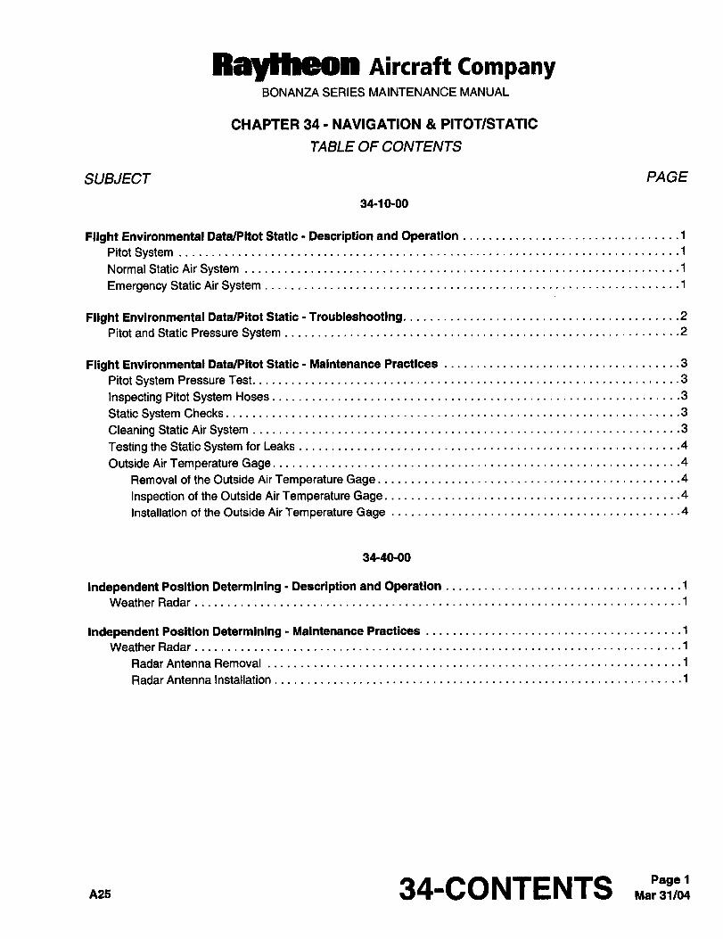
Ray~heon AiKraft CompanyBONANZA SERIES MAINTENANCE MANUAL
CHAPTER 34- NAVIGATION PITOT/STATIC
TABLE OF CONTENTS
SUBJECT PAGE
34-1 0-00
Flight Environmental Data/PitotStatic Descriptionand Operation ..............1
Pitot SystemNormal Static AirSystem ´•1
Emergency Static Air System ´•1
Flight Environmental DatalPitot Static Troubleshooting. .2
Pitotand Static Pressure System ...2
Flight Environmental Data/PitotStatsc- Maintenance Practices .................3
Pitot System Pressure Test. .......3
Inspecting PitotSystem Hoses. ....3
Static System Checks
Cleaning Static Air System ........3
Testingthe StaticSystemforLeaks ´•4
Outside AirTemperature Gage. .4
Removal of the Outside AirTemperature Gage. .......4
Inspection of theOutside AirTemperature Gage. ......4
Installation of the Outside AirTemperature Gage ´•4
34-40-00
IndependentPosition Determining- Descriptionand Operation .................1
Weather Radar
IndependentPosition Determinlng- MaintenancePractlces .1
Weather Radar
Radar Antenna Removal ......1
Radar Antenna Installation ´•1
34-CONTENTS ..~:Pagel
RayYheon AiKlaft CompanyBONANZA SERIES MAINTENANCE MANUAL
CHAPTER 34 NAVIGATION PITOT/STATIC
LIST OF EFFECTIVE PAGES
CH-SE-SU PAGE DATE
34-LOEP 1 Mar 31/04
34-CONTENTS 1 Mar 31/04
34-10-00 1 thru 5 Mar 31/04
34-40-00 1 and 2 Oct 10/80
A25 34-LOEP Mar 31/04Page 1
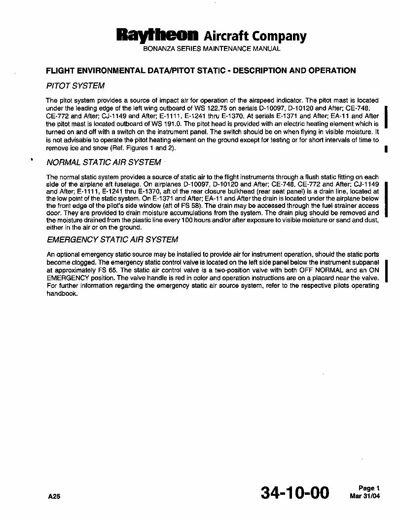
Raytheon AiKraft CompanyBONANZA SERIES MAINTENANCE MANUAL
FLIGHT ENVIRONMENTAL DATA(PITOT STATIC DESCRIPTION AND OPERATION
PITOTSYSTEM
The pitot system provides a source of impact air for operation of the airspeed indicator. The pitot mast is located
under the leading edge of the left wing outboard of WS 122.75 on serials D-10097, D-10120 and After; CE-748,CE-772 and After; CJ-1149 and After; E-llll, E-1241 thru E-1370. At serials E-1371 and After; EA-11 and After
the pitot mast is located outboard of WS 191.0. The pitot head is provided with an electric heating element which is
turned on and off with a switch on the instrument panel. The switch should be on when flying in visible moisture. It
is not advisable to operate the pitot heating element on the ground except for testing or for short intervals of time to
remove ice and snow (Ref. Figures 1 and 2). 1
NORMAL STA TIC AIR SYSTEM
The normal static system provides a source of static air to the flight instruments through a flush static fitting on each
side of the airplane aft fuselage. On airplanes D-10097, D-10120 and After; CE-748, CE-772 and After; CJ-1149
and After; E-llll, E-1241 thru E-1370, aft of the rear closure bulkhead (rear seat panel) is a drain line, located at
the low point of the static system. On E-1371 and After; EA-11 and After the drain is located under the airplane below
the front edge of the pilot’s side window (aft of FS 58). The drain may be accessed through the fuel strainer access
door. They are provided to drain moisture accumulations from the system. The drain plug should be removed and
the moisture drained from the plastic line every 100 hours and/or after exposure to visible moisture or sand and dust,either in the air or on the ground.
EMERGENCY STA TIC AIR SYSTEM
An optional emergency static source may be installed to provide air for instrument operation, should the static portsbecome clogged. The emergency static control valve is located on the left side panel below the instrument subpanelat approximately FS 65. The static air control valve is a two-position valve with both OFF NORMAL and an ON
EMERGENCY position. The valve handle is red in color and operation instructions are on a placard near the valve.
For further information regarding the emergency static air source system, refer to the respective pilots operatinghandbook.
nzs 34-1 0-00
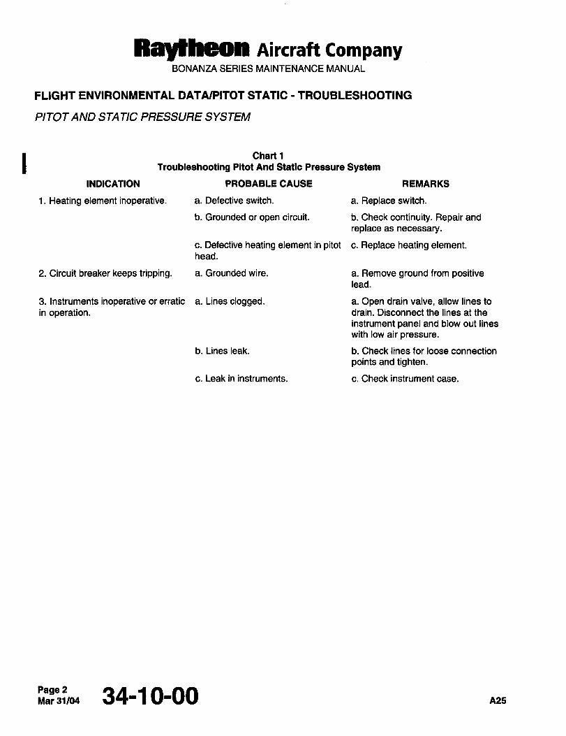
RaytheOR Aireraft CompanyBONANZA SERIES MAINTENANCE MANUAL
FLIGHT ENVIRONMENTAL DATA/PITOT STATIC I TROUBLESHOOTING
PITOT AND STA TIC PRESSURE SYSTEM
I Chart 1
Troubleshooting Pltot And Static Pressure System
INDICATION PROBABLE CAUSE REMARKS
1. Heating element inoperative. a. Defective switch. a. Replace switch.
b. Grounded or open circuit, b. Check continuity. Repair and
replace as necessary.
c. Defective heating element in pitot c. Replace heating element.
head.
2. Circuit breaker keeps tripping, a. Grounded wire. a. Remove ground from positivelead.
3. Instruments inoperative or erratic a. Lines clogged. a. Open drain valve, allow lines to
in operation. drain. Disconnect the lines at the
instrument panel and blow out lines
with low air pressure.
b. Lines leak, b. Check lines for loose connection
points and tighten.
c. Leak in instruments. c. Check instrument case.
Page 2Mar31104 34-10-00 A25
Ray~heon AiKraft CompanyBONANZA SERIES MAINTENANCE MANUAL
FLIGHT ENVIRONMENTAL DATA/PITOT STATIC MAINTENANCE PRACTICES
PITOT SYSTEM PRESSURE TEST
A functional test of the pitot system can be made by using an observer in the cabin to watch the airspeed indicator
while air pressure is built up artificially by using a section of soft rubber tubing as follows:
a. Clamp the rubber tubing over the pitot head inlet, making certain that the connection is airtight.
CAUTION: To avoid rupturing the diaphragm of the airspeed indicator, roll up the rubber tubing slowly.
b. Crimp the end of the tubing and slowly roll it up until the airspeed indicator registers approximately 100 knots. I
c. Secure the rolled up tubing so that it will hold the airspeed reading.
d. If there is no decline in the reading after several minutes, there is no leak in the pitot system.
e. If a decline in the reading of the airspeed indicator is observed, check the pitot system plumbing for leaky hoses
and loose connections.
CAUTION: Flelease the air pressure slowly by unrolling the rubber tubing; a sudden release of the airpressure may
damage the airspeed indicator.
INSPECTING PITOT SYSTEM HOSES
Before the pitot system is checked for leaks, the hose sections should be visually inspected for signs of deterioration.
There are two sections of hose in the pitot system: one hose at the pitot mast, accessible by removing the inspectiondoor adjacent to the mast, and the other hose behind the floating instrument panel which connects the pitot line to
the airspeed indicator, accessible through the access door in the left side of the firewall. Hoses that are cracked or
hardened should be replaced with rubber hose (14, Chart 1, 91-00-00). Anytime a hose is replaced, repeat the IPITOT SYSTEM PRESSURE CHECK.
STA TIC SYSTEM CHECKS
Proper functioning of the static air system is vital to safety of flight, particularly on instrument flight. Correct
maintenance of the system should be performed as required.
The amount of attention required by the static system will depend largely on operating conditions. Extremes of
humidity or precipitation, or of dry, dusty conditions, should be signals for increased emphasis on static systemscheck, since both are favorable to accumulations of foreign matter in the ports and lines.
CLEANING STA TIC AIR SYSTEM
CAUTION: Never blow air through the line toward the instrument panel; to do so will seriously damage the
instruments. When blowing back through the line from the instrument panel, make sure that no air is
blown into the instruments.
NOTE: Wax or polish applied to the air buttons can cause wrong instrument readings. The static air buttons should
be cleaned periodically with a cleaning solvent to insure that no film exists on the static air buttons.
Blow LOW pressure air through the lines from the disconnected lines at the airspeed indicator, altimeter and vertical
speed indicator to the static ports. Cover each static port separately when blowing to insure that each line is clear.
Instrument error or possible damage could result if even one port is clogged with dirt or foreign matter.
34-1 0-00
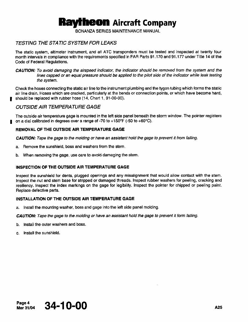
RBy~heOn nircraft CompanyBONANUI\ SERIES MAINTENANCE MANUAL
TESTING THE STA TIC SYSTEM FOR LEAKS
The static system, altimeter instrument, and all ATC transponders must be tested and inspected at twenty four
month intervals in compliance with the requirements specified in FAR Parts 91.170 and 91.177 under Title 14 of the
Code of Federal Regulations.
CAUTION: To avoid damaging the airspeed indicator, the indicator should be removed from the system and the
lines capped or an equal pressure should be applied to the pitot side of the indicator while leak testingthe system.
Check the hoses connecting the static air line to the instrument plumbing and the tygon tubing which forms the static
air line drain. Hoses which are cracked, particularly at the bends or connection points, or which have become hard,
I should be replaced with rubber hose (14, Chart 1, 91-00-00).
OUTSIDE AIR TEMPERATURE GAGE
The outside air temperature gage is mounted in the left side panel beneath the storm window. The pointer registerson a dial calibrated in degrees over a range of -70 to +150"F (-50 to +60"C).
REMOVAL OF THE OUTSIDE AIR TEMPERATURE GAGE
CAUTION: Tape the gage to the molding or have an assistant hold the gage to prevent it from falling.
a. Remove the sunshield, boss and washers from the stem.
b. When removing the gage, use care to avoid damaging the stem.
INSPECTION OF THE OUTSIDE AIR TEMPERATURE GAGE
Inspect the sunshield for dents, plugged openings and any misalignment that would allow contact with the stem.
Inspect the nut and stem base for stripped or damaged threads. Inspect rubber washers for peeling, cracking and
resiliency. Inspect the index markings on the gage for legibility. Inspect the pointer for chipped or peeling paint.Replace defective parts.
INSTALLATION OF THE OUTSIDE AIR TEMPERATURE GAGE
a. Install the mounting washer, boss and gage into the left side panel molding.
CAUTION: Tape the gage to the molding or have an assistant hold the gage to prevent it form falling.
b. Install the outer washers and boss.
c. Install the sunshield.
Page 4Mar31104 34-1 0-00 A25
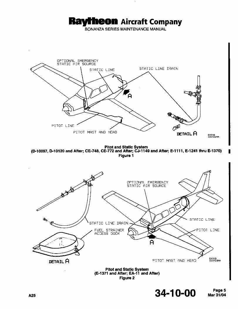
Ray~hgOn AiKrait CompanyBONANZA SERIES MAINTENANCE MANUAL
OPTIONAL EMERGENCYSTATIC AIR SOURCE
STATIC LINE STATIC LINE DRAIN
A
PITOT LINE QPITOT MAST AND HEAD
DETAIL AEA34B034922FIR
Pitot and Static System(0-10097, 0-10120 and After; CE-743, CE-772 and After; CJ-1149 and After; E-llll, E-1241 thru E-1370)
Figure 1
OPTIONAL EMERGENCYSTATIC AIR SOURCE
0’STATIC LINE
STATIC LINE DRAIN
FUEL STRAINER ,PITOT LINEACCESS DOOR
A
DETAIL AER34B
PITOT MAST AND HEAD 034923F1A
Prtot and Static System(0-1371 and After; EA-11 and After)
Figure 2
A25 34-1 0-00 Mar 31/04Page 5
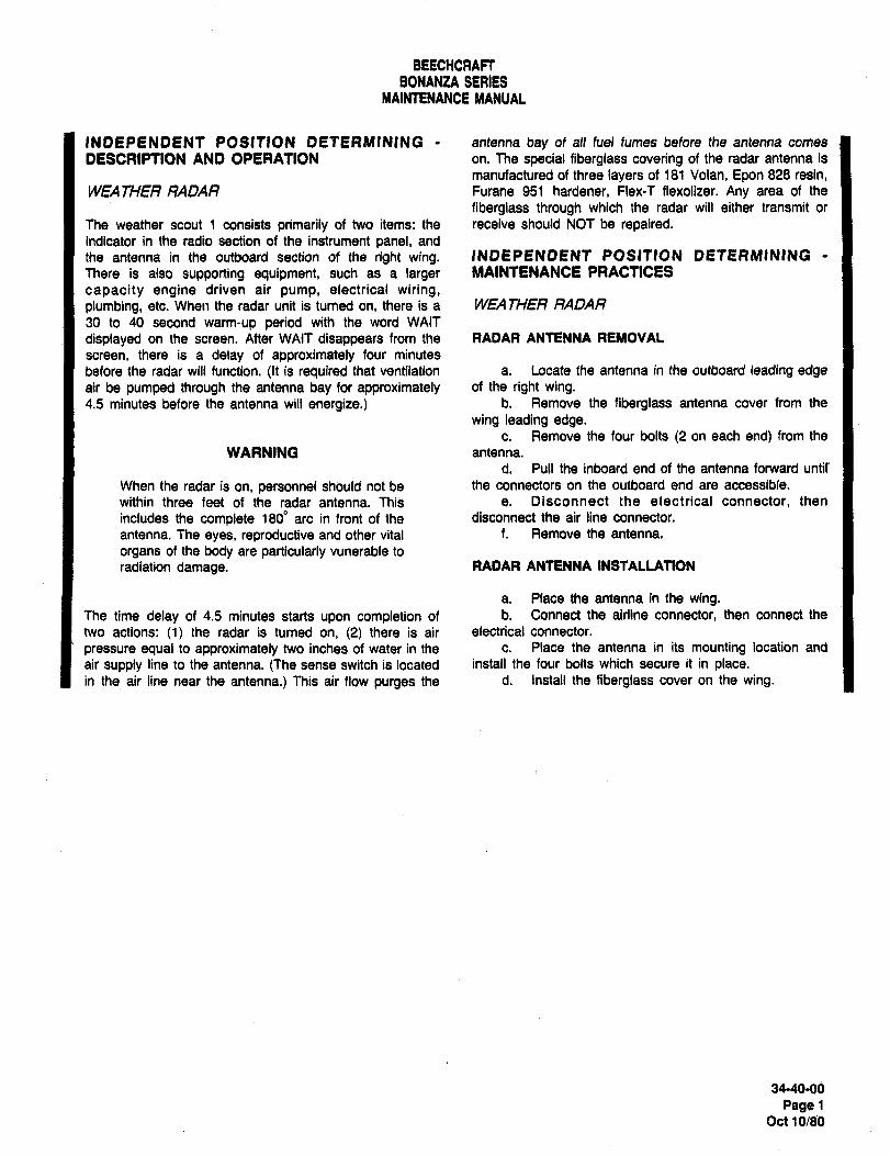
BEECHCRAFT
BONANtA SERIESMAINTENANCE MANUAL
INDEPENDENT POSITION DETERMINING antenna bay of all fuel fumes before the antenna comes
DESCRIPTION AND OPERATION on. The special fiberglass covering of the radar antenna is
manufactured of three layers of 181 Volan, Epon 828 resin,WEA THER RADAR Furane 951 hardener, Flex-T flexolizer. Any area of the
fiberglass through which the radar will either transmit or
The weather scout 1 consists primarily of two items: the receive should NOT be repaired.indicator in the radio section of the instrument panel, and
the antenna in the outboard section of the right wing. INDEPENDENT POSITION DETERIWINING
There is also supporting equipment, such as a larger MAINTENANCE PRACTICES
capacity engine driven air pump, electrical wiring,plumbing, etc. When the radar unit is turned on, there is a WEATHER RADAR
30 to 40 second warm-up period with the word WAIT
displayed on the screen. After WAIT disappears from the RADAR ANTENNA REMOVAL
screen, there is a delay of approximately four minutes
before the radar will function. ~lt is required that ventilation a. Locate the antenna in the outboard leading edgeair be pumped through the antenna bay for approximately of the right wing.4.5 minutes before the antenna will energize.) b. Remove the fiberglass antenna cover from the
wing leading edge.c. Remove the four bolts (2 on each end) from the
WARNING antenna.
d. Pull the inboard end of the antenna forward untir
When the radar is on, personnel should not be the connectors on the outboard end are accessible.
within three feet of the radar antenna. This e. Disconnect the electrical connector, then
includes the complete 180" are in front of the disconnect the air line connector.
antenna. The eyes, reproductive and other vital f. Remove the antenna.
organs of the body are particularly vunerable to
radiation damage. RADAR ANTENNA INSTALLATION
a. Place the antenna in the wing.The time delay of 4.5 minutes starts upon completion of b. Connect the airline connector, then connect the
two actions: (1) the radar is turned on, (2) there is air electrical connector.
pressure equal to approximately two inches of water in the c. Place the antenna in its mounting location and
air supply line to the antenna. (the sense switch is located install the four bolts which secure it in place.in the air line near the antenna.) This air flow purges the d. Install the fiberglass cover on the wing.
34-40´•00
PagelOct 10/86
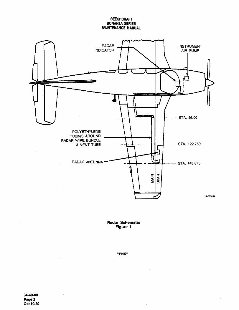
BEECHCRAFTBONAN;LA SERIES
MAINTENANCE MANUAL
RADAR I I INSTRUMENTINDICATOR I I I I AIR PUMP
STA. 66.00
POLYETHYLENE
TUBING AROUND
RADAR WIRE BUNDLE
g, VENT TUBE tz~--´• --mz~-- STA. 122.750
RADAR ANTENNA I C~LI ISTA. 148.875
fs
38´•603-34
Radar Schematic
Figure 1
"END"
34-40-00
Page2Oct 10180

CHAPTER
O~YG EN
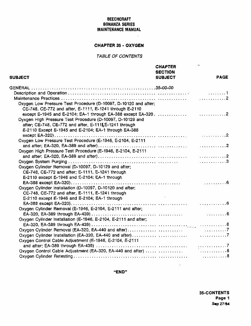
BEECHCRAFT
BONANZA SERIES
MAINTENANCE MANUAL
CHAPTER 35 OXVCEN
TABLE OF CONTENTS
CHAPTER
SECTION
SUBJECT SUBJECT PAGE
GENERAL 35-00-00
Description and Operation ........1
Maintenance Practices ............2
Oxygen Low Pressure Test Procedure (D-10097, D-10120 and after;CE-748, CE-772 and after, E-llll, E-1241 through E-2110
except E-1945 and E-2104; EA-1 through EA-388 except EA-320 .......2
Oyxgen High Pressure Test Procedure (D-10097, D-10129 and
after; CE-748, CE-772 and after, E-1111,E-1241 throughE-2110 Except E-1945 and E-2104; EA-1 through EA-388
except EA-320) ...........2
Oxygen Low Pressure Test Procedure (E-1946, E-2104, E-2111
and after; EA-320, EA-389 and after) ............2
Oxygen High Pressure Test Procedure (E-1946, E-2104, E-2111
and after; EA-320, EA-389 and after) ............2
Oxygen System Purging ........3
Oxygen Cylinder Removal (D-10097, D-10129 and after;
CE-748, CE-772 and after; E-l111, E-1241 throughE-2110 except E-1946 and E-2104; EA-1 throughEA-388 except EA-320) ..6
Oxygen Cylinder Installation (D-10097, 0-10120 and after;CE-748, CE-772 and after, E-llll, E-1241 throughE-2110 except E-1946 and E-2104; EA-1 throughEA-388 except EA-320) ........6
Oxygen Cylinder Removal (E-1946, E-2104, E-2111 and after;EA-320, EA-389 through EA-439) .........6
Oxygen Cylinder Installation (E-1946, E-2104, E-2111 and after;
EA-320, EA-389 through EA-439) ..6
Oxygen Cylinder Removal (EA-320, EA-440 and after) ...............7
Oxygen Cylinder Installation ~EA-320, EA-440 and after)........... ............7
Oxygen Control Cable Adjustment (E-1946, E-2104, E-2111
and after; EA-389through EA-439) :............7Oxygen Control Cable Adjustment (EA-320, EA-440 and after) .........8
Oxygen Cylinder Retesting .......8
"END"
3S-CONTENTS
Page 1
S´•p 27/84
BEECHCRARBONANZA SERIES
MAINTENANCE MANUAL
CHAPTER 35
LIST OF PAGE EFFECTIVITY
CHAPTER
SECTION
SUBJECT PAGE DATE
35-EFFECTIVITY 1 Sep 27184
96CONTENTS 1 Sep 27184
35-00´•00 1 Sep 27184
2 Sep 27/84
3 Sep 27/84
4 Sep 27/84
5 Sep 27184
6 Sep 27/84
7 Sep 27184
8 Sep 27/84
"END"
SS-EFFECTIVITY
Page I
A9 Sep 27/84
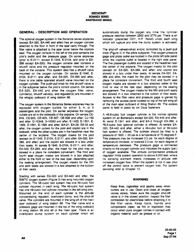
BEECHCRAm
BONANZA SERIESMAIMENANCE MANAUL
GENERAL DESCRIPTION AND OPERATION automatically dump the oxygen any time the cylinderpressure reaches between 2500 and 2775 psi. There is an
The optional oxygen system in the Bonanza series airplanes indicator (placarded OXY, H.P. Relief) under each wing
(except EA-320, EA-440 and after) has an oxygen cylinder which will rupture any time the dump system is activated.
attached to the floor in front of the spar carry through. The
filler valve is attached to the spar cover below the copilots The shut-off valves(valve) are(is) controlled by a push-pullseat. The oxygen console to the left of the pilot contains the knob (Figure 4) in the pilots subpanel. The oxygen pressure
pilot’s outlet and the pressure gage. On some airplanes gage and pilots outlet are located in the pilots left side panel~prior to E-2111, except E-1946, E-2104; and prior to EA- while the copilots outlet is located in the right side panel.389 except EA-320), the oxygen console also contains a The five passenger outlets are located in the headliner near
shutoff valve and the pressure regulator mounted on the the center of the airplane. The oxygen masks for the pilotback of the console. This system also has a shutoff valve (except on EA-320, EA-389, and after) and copilot are
mounted on the oxygen cylinder. On serials E-194f~ E- stowed in a box under their seats. At serials EA-320, EA-
2104, E-2111 and after; and EA-320, EA-389 and after, 389 and after, the mask for the pilot may be stowed in a
there is one cable operated shutoff valve mounted on the place he considers convenient. The third and fourth seat
oxygen cylinder. The push-pull knob for this shutoff valve is oxygen masks are stowed in a box attached either to the
in the subpanel below the pilot’s control column. On serials front or rear of the rear spar, depending on the seatingEA-320, EA-440 and after the oxygen filler valve, arrangement. The oxygen masks for the fifth and sixth seats
cylinder(s), shutoff valve(s), and regulator(s) are mounted in are stowed in a box attached to the bottom of their seats.
the wing(s) outboard of wing station 66. Access to the filler valve and pressure gage is gained by
removing the access panel located on top of the left wing aft
The oxygen system in the Bonanza Series airplanes may be of the main spat outboard of Wing Station 66. The access
equipped with oxygen outlets for either 3, 4, or 5 panel is held in place by six Dzus fasteners.
passengers and the pilot, On earlier airplanes the oxygen
outlets are all in the sidewalls of the airplane. On serials CE- A 49.8-cubic foot oxygen cylinder is the normal optional919, CE-923, CE-925, CE-927, CE-929 and after; CJ-156 system on all Bonanza’s except EA-320, EA-J40 and after.
and after; 0-10348, 0-10353 and after; E-1422, E-1551, E- At serial E-1241 and after, and EA-2 through EA-388, a
1569, E-1581, E-1594 and after; EA-21, EA-28, EA-33 and 76.5-cubic foot optional cylinder is offered. At serials EA-
after, the oxygen outlets for the pilot and copilot are in the 320, EA-440 and after, either a ´•Qe-cubic foot or 98-cubic
sidewall, while the other outlets are in the headliner near the foot system is offered. The cylinder should be filled to a
center of the airplane. The oxygen masks for the pilot pressure of 1850 50 psi at a temperature of 70 degrees F.
(except on E-1946, E-2104, E-2111, and after; EA-320, EA- This pressure may be increased 3.5 psi. for each degree of
389, and after) and the copilot are stowed in a box under temperature increase, or lowered 3.5 psi. for each degree of
their seats. At serials E-1946, E12104, E-2111, and after; temperature decrease. The pressure gage is connected
EA-320, EA-289, and after, the mask for the pilot may be directly to the oxygen cylinder and indicates the supply (psi.)stowed in a place he considers convenient. The third and of oxygen available. The altitude compensated pressure
fourth seat oxygen masks are stowed in a box attached regulator limits system operation to above 8,000 feet, where
either to the front or rear of the rear spar, depending upon its sensing element meets increases in altitude with
the seating arrangement. The oxygen masks for the fifth increased oxygen flow. When the system is not in use, shut
and sixth seats are stowed in a box attached to the bottom off the control valve to prevent oxygen loss. For systemof their seats, servicing refer to Chapter 12.
Starting with serials EA-320 and EA-440 and after, the
B36TC oxygen system (Figure 3) has wing mounted oxygen WARNING
cylinders. The 98-cubic foot system has one 49-cubic foot
cylinder mounted in each wing. The 49-cubic foot system Keep fires, cigarettes and sparks away when
has one 49-cubic foot cylinder mounted in the left wing only. outlets are in use. Open and close all oxygen
Mounted on the end of each cylinder is the altitude valves slowly. Make sure the oxygen shut-off
compensating regulator, overboard dump, and the shut-off valve is in the closed position. Inspect the filler
valve. The cylinders are mounted in the wing aft of the main connection for cleanliness before attaching it to
spar outboard of wing station 66. The filler valve and a the filler valve. Keep tools, hands and
pressure gage are mounted in the top of the wing outboard components clean, as fire or explosion may
of wing station 66 and aft of the main spar. There is an occur when pure oxygen comes in contact with
ov’erboard dump system on each cylinder which will organic material such as grease or oil.
35-00-00
Paget
A9 Sep 27/84
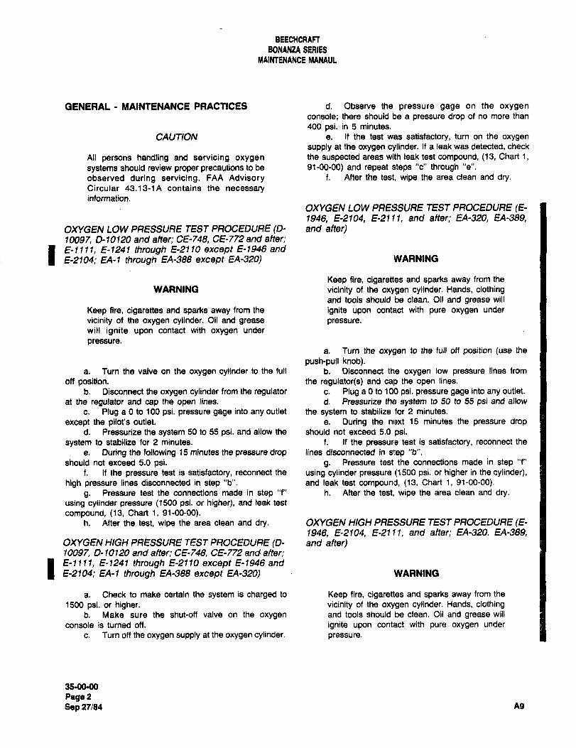
BEECHCRAFT
B0NAN2A SERIES
MAIMENANCE MANAUL
GENERAL MAINTENANCE PRACTICES d. Observe the pressure gage on the oxygen
console; there should be a pressure drop of no more than
400 psi. in 5 minutes.
CAUTION e. if the test was satisfactory, turn on the oxygen
supply at the oxygen cylinder. If a leak was detected, check
All persons handling and servicing oxygen the suspected areas with leak test compound, (13, Chart 1,
systems should review proper precautions to be 91-00-00) and repeat steps "c" through "e".
observed during servicing. FAA Advisory f. After the test, wipe the area clean and dry.Circular 43.13-1A contains the necessaryinformation.
OXYGEN LOW PRESSURE TEST PROCEDURE (E-1946 E-2104, E-2111, and after; EA-320, EA-389,
OXYGEN LOW PRESSURE TEST PROCEDURE (D- and after)10097 0-10120 and after; CE-748, CE-772 and after´•
1 E-Illl, E-1241 through ~-21 10 except E-1946 an~E-2104; EA-1 through EA-388 except EA-320) ’WARNING
Keep fire, cigarettes and sparks away from the
WARNING vicinity of the oxygen cylinder. Hands, clothingand tools should be clean. Oil and grease will
Keep fire, cigarettes and sparks away from the ignite upon contact with pure oxygen under
vicinity of the oxygen cylinder. Oil and grease pressure.will ignite upon contact with oxygen under
pressure.a. Turn the oxygen to the full off position (use the
push-pull knob).a. Turn the valve on the oxygen cylinder to the full b. Disconnect the oxygen low pressure lines from
oft position. the regulator(s) and cap the open lines.
b. Disconnect the oxygen cylinder from the regulator c. Plug a 0 to 100 psi. pressure gage into any outlet.
at the regulator and cap the open lines. d. Pressurize the system to 50 to 55 psi and allow
c. Plug a 0 to 100 psi. pressure gage into any outlet the system to stabilize for 2 minutes.
except the pilot’s outlet, e. During the nc,xt 15 minutes the pressure dropd. Pressurize the system 50 to 55 psi. and allow the should not exceed 5.0 psi.
system to stabilize for 2 minutes. f. If the pressure test is satisfactory, reconnect the
e. During the following 15 minutes the pressure drop lines disconnected in seep "b".
should not exceed 5.0 psi. g. Pressure test the connections made in step "f"
f. If the pressure test is satisfactory, reconnect the using cylinder pressure (1500 psi. or higher in the cylinder),high pressure lines disconnected in step "b". and leak test compound, (13, Chart 1, 91-00-00).
g. Pressure test the connections made in step "f" h. After the test, wipe the area clean and dry.using cylinder pressure (1500 psi. or higher), and leak test
compound, (13, Chart 1, 91-00-00).h. After the test, wipe the area clean and dry. OXYGEN HIGH PRESSURE TEST PROCEDURE (E-
1946, E-2104, E-2111, and after; EA-3201 EA-389,OXYGEN HIGH PRESSURE TEST PROCEDURE (D- and after)10097 0- 10120 and aiter; CE-748, CE-772 and a~er;
I E-llll, E-1241 through E-2110 except E-1946 and
E-2104; EA-1 through EA-388 except EA-320) WARNING
a. Check to make certain the system is charged to Keep fire, cigarettes and sparks away from the
1500 psi. or higher, vicinity of the oxygen cylinder. Hands, clothingb. Make sure the shut-off valve on the oxygen and tools should be clean. Oil and grease will
console is turned off. ignite upon contact with pure oxygen under
c. Turn off the oxygen supply at the oxygen cylinder. pressure.
35-0090
PagePSep 27/84 A9
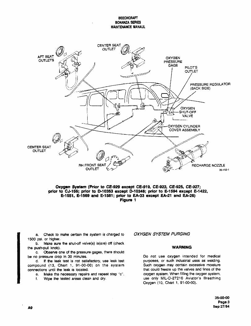
BEECHCRAFT
BONANZA SERIES
MAINTENANCE MANAUL
AFT SEAT
CENTER SEATOUTLET
OXYGEN
OVTLETS1~~T
PRESSURE
OUTLET
GAGEPILOT’S
PRESSURE REGULATOR
(BACK SIDE)
5;OXYGEN
SHUT-OFFVALVE
i
OXYGEN CY~INDERCOVER ASSEMBLY
6,,p,CENTER SEAT
OUTLET
C~i ~iRH FRONT SEAT RECHARGE NOZZLE
OUTLET 36-452-1
Oxygen System (PrJor to CE-929 except OS-gig, 02-923, 02-925, CE-g27;prior to CJ-156; prior to D-10353 except P10348; prior to 2-1594 except 2-1422,
2-1551, 2-1589 and 2-1581; prior to EA-33 except EA-21 and EA-28)Figure 1
a. Check to make certain the system is charged to OXYGEN SYSTEM PURGING
1500 psi. or higher.b. Make sure the shut-off valve(s) is(are) off (check
the push-pull knob). WARNING
c. Observe one of the pressure gages, there should
be no pressure drop in 30 minutes. Do not use oxygen intended for medical
d. If the leak test is not satisfactory, use leak test purposes, or such industrial uses as welding.
compound (13, Chart 1, 91-00-00) on the system Such oxygen may contain excessive moisture
connections until the leak is located. that could freeze up the valves and lines of the
e. Make the necessary repairs and repeat step "c". oxygen system. When filling the oxygen system,f. Wipe the tested areas clean and dry. use only MIL-0-27210 Aviator’s Breathing
Oxygen (10, Chart 1, 91-00-00).
35-00-00
p91ge3
A9 Sep 27/84
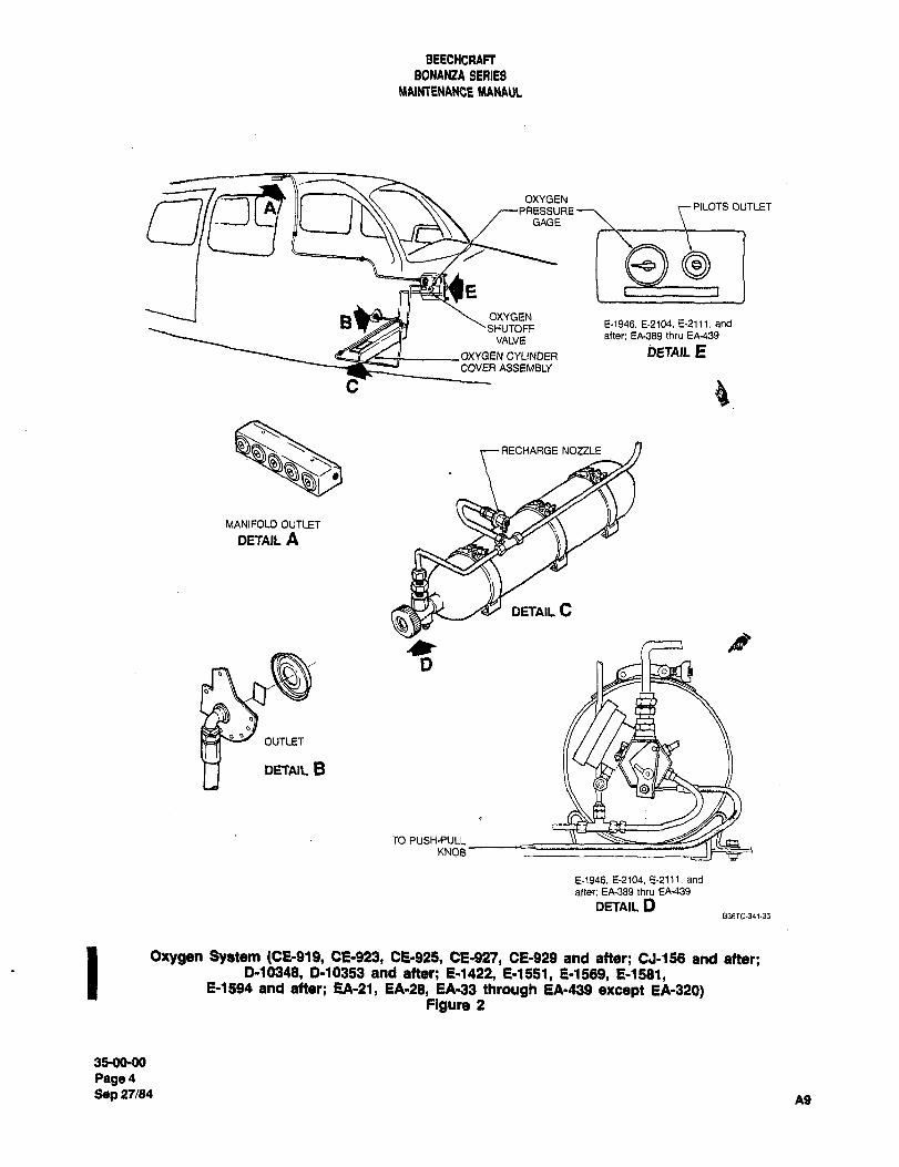
BEECHCRAFTBONANZA SERIES
NIAIMENANCE MANAUL
OXYGENPRESSUREPILOTS OUTLET
GAGE
Is OXYGENSHUTOFF E-1946. E-2104. E-2111. and
VALVE after; EA-389 thru EA-439
OXYGEN CYLINDER i)ETAIL ECOVER ASSEMBLY
C~
RECHARGE NOZZLE
MANIFOLD OUTLET
DETAIL A
DETAIL C
bO
OUTLET
DETAIL B
TO PUSH-PULLKNOB
E-1946. E-2104. E-2111, and
atter; EA-389 thru EA-439
DETAIL DB36TC-34135
Oxygen System (CE-glS, CE-923, CE-925, CE-92’1, CE-929 and after; CJ-158 and after;0-10348, 0-10353 and after; 0-1422, 0-1551, 0-1589, 0-1581,
0-1594 and after; EA-21, EA-28, EA133 through EA-439 except EA-320)Figure 2
35-OMK)
Page4Sep 27/84
A9
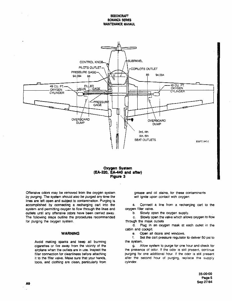
BEECHCIRAA
BONANZA SERIES
MAINTENANCE MANAUL
CONTROL KNOB, I I riSUBPANEL
PILOTS OUTLET7 _L \rCOPILOTS OUTLET
PRESSURE66 94.09494.094 66
49 CU. FT. FILLER 49 CU. FI:
OXYGEN IVALVE I,´•GAGE OXYGENCYLINDER
CYLINDER
GAGE
OVERBOARD OVERBOARDDUMP
DUMP
3rd,4th
5th,6th
SEAT OUTLETS836TC-340-2
Oxygen System(EA-320, EA440 and atter)
Figure 3
Offensive odors may be removed from the oxygen system grease and oil stains, for these contaminants
by purging. The system should also be purged any time the will ignite upon contact with oxygen.lines are left open and subject to contamination. Purging is
accomplished by connecting a recharging cart into the a. Connect a line from a recharging cart to the
system and permitting oxygen to flow through the lines and oxygen filler valve.
outlets until any offensive odors have been carried away, b. Slowly open the oxygen supply.The following steps outline the procedures recommended c. Slowly open the valve which allows oxygen to flow
for purging the oxygen system. through the mask outlets
d. Plug in an oxygen mask at each outlet in the
cabin and cockpit.WARNING a. Open all doors and windows.
f, Set the cart pressure regulator to deliver 50 psi to
Avoid making sparks and keep all burning the system.
cigarettes or fire away from the vicinity of the g, Allow system to purge for one hour and check for
airplane when the outlets are in use. Inspect the the presence of odor. If the odor is still present, continue
filler connection for cleanliness before attaching purging for one additional hour. If the odor is still presentit to the filler valve, Make sure that your hands, after the second hour of purging, replace the supplytools, and clothing are clean, particularly from cylinder.
35-0040
Page5
A9 Sep 27184
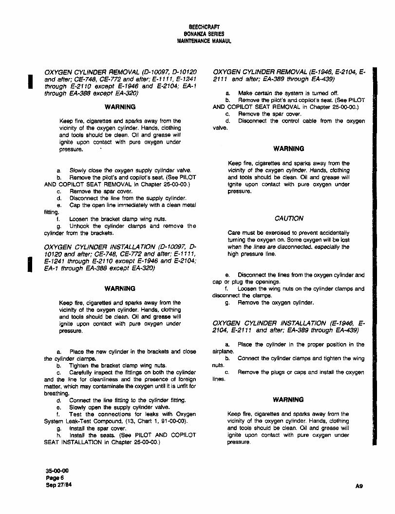
BEECHCRACT
BONAN~A SERIES
MAIWTENANCE MANAUL
OXYGEN CYLINDER REMOVAL (0-10097, 0-10120 OXYGEN CYLINDER REMOVAL (E-1946, E2104, E-
1 and after; CE-748, CE-772 and alter; E-llll, f-1241 2111 and after; EA-389 through EA-439)through E-2110 except E-1946 and E-2104; EA-1
through EA-388 except EA-320/ a. Make certain the system is turned off.
b. Remove the pilot’s and copilot’s seat. (See PILOT
WARNING AND COPILOT SEAT REMOVAL in Chapter 25-00-00.)c. Remove the spar cover.
Keep fire, cigarettes and sparks away from the d. Disconnect the control cable from the oxygen
vicinity of the oxygen cylinder. Hands, clothing valve.
and tools should be clean. Oil and grease will
ignite upon contact with pure oxygen under
pressure. WARNING
Keep fire, cigarettes and sparks away from the
a. Slowly close the oxygen supply cylinder valve, vicinity of the oxygen cylinder. Hands, clothingb. Remove the pilot’s and copilot’s seat. (See PILOT and tools should be clean. Oil and grease will
AND COPILOT SEAT REMOVAL in Chapter 25-00´•00.) ignite upon contact with pure oxygen under
c. Remove the spat cover. pressure.d. Disconnect the line from the supply cylinder.a. Cap the open line immediately with a clean metal
fitting.f. Loosen the bracket clamp wing nuts. CAUTION
g. Unhook the cylinder clamps and remove the
cylinder from the brackets. Care must be exercised to prevent accidentallyturning the oxygen an. Some oxygen will be lost
OXYGEN CYLINDER INSTALLATION (0´•10097, D- when the lines are disconnected, especially the
10120 and after; CE-74B, CE-772 and alter; E-llll, high pressure line.
I E-1241 through E-2110 except E-1946 and E-2104;EA-1 through EA-388 except EA-320)
e. Disconnect the lines from the oxygen cylinder and
cap or plug the openings.WARNING f. Loosen the wing nuts on the cylinder clamps and
disconnect the clamps.
Keep fire, cigaretteri and sparks away from the g. Remove the oxygen cylinder.vicinity of the oxygen cylinder. Hands, clothingand tools should be clean. Oil and grease will
ignite upon contact with pure oxygen under OXYGEN CYLINDER INSTALLATION (E-1946, E-
pressure. 2104, E-2111 and after; EA-389 through EA-439)
a. Place the cylinder in the proper position in the
a. Place the new cylinder in the brackets and close airplane.the cylinder clamps, b. Connect the cylinder clamps and tighten the wing
b. Tighten the bracket clamp wing nuts. nuts.
c. Carefully inspect the fittings on both the cylinder c. Remove the plugs or caps and install the oxygen
and the line for cleanliness and the presence of foreign lines.
matter, which may contaminate the oxygen until it is unfit for
breathing.d. Connect the line fitting to the cylinder fitting. WARNING
a. Slowly open the supply cylinder valve.
f. Test the connections for leaks with Oxygen Keep fire, cigarettes and sparks away from the
System Leak-Test Compound, (13, Chart 1, 91-00-00). vicinity of the oxygen cylinder. Hands, clothingg. Install the spar cover, and tools should be clean. Oil and grease will
h. Install the seats. (See PILOT AND COPILOT ignite upon contact with pure oxygen under
SEAT INSTALLATION in Chapter 25-00-00.) pressure.
3590-00
PageGSep 27184 Ag
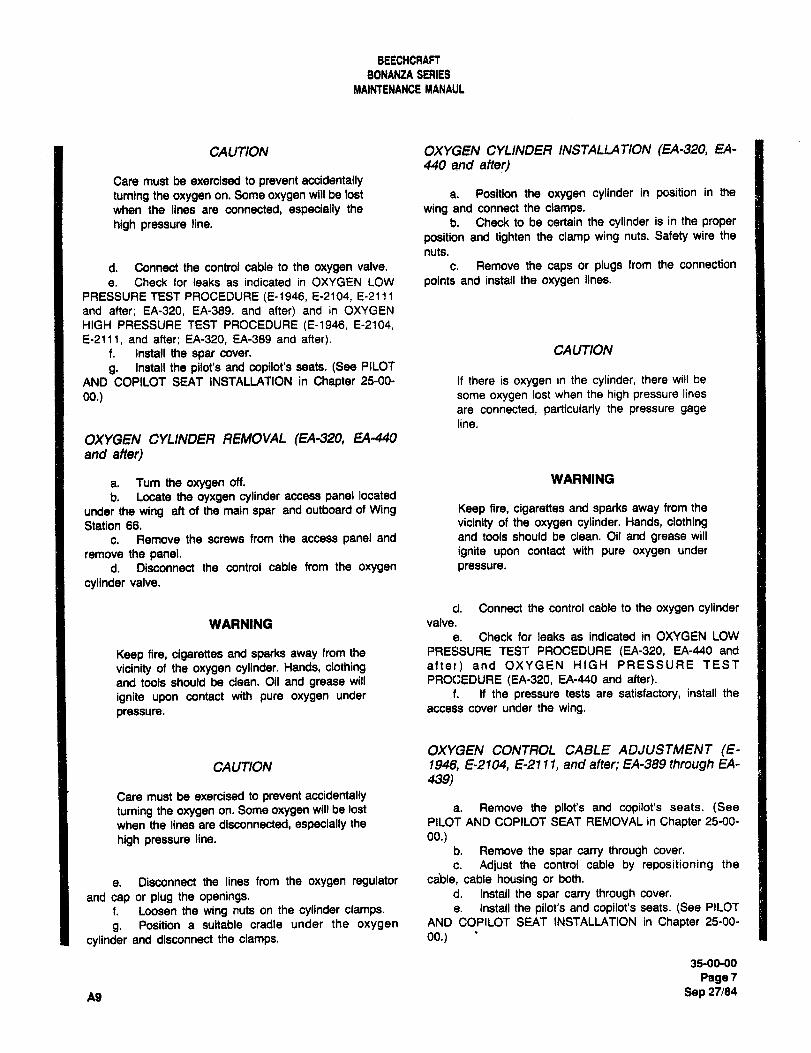
BEECHCRAW
BONANZA SERIES
MAINTENANCE MANAUL
CAUTION OXYGEN CYLINDER INSTALLATION (EA-320, EA-
440 and after)Care must be exercised to prevent accidentallyturning the oxygen on. Some oxygen will be lost a. Position the oxygen cylinder in position in the
when the lines are connected, especially the wing and connect the clamps.
high pressure line. b. Check to be certain the cylinder is in the proper
position and tighten the clamp wing nuts. Safety wire the
nuts.
d. Connect the control cable to the oxygen valve, c. Remove the caps or plugs from the connection
e. Check for leaks as indicated in OXYGEN LOW points and install the oxygen lines.
PRESSURE TEST PROCEDURE (E-1946, 8-2104, E-2111
and after; EA-320, EA-369, and after) and in OXYGEN
HIGH PRESSURE TEST PROCEDURE (E-1946, 8-2104,
E-2111, and after; EA-320, EA-389 and after).f. Install the spar cover. CAUTION
g. Install the pilot’s and copilot’s seats. (See PILOT
AND COPILOT SEAT INSTALLATION in Chapter 25-00- If there is oxygen in the cylinder, there will be
00.) some oxygen lost when the high pressure lines
are connected, particularly the pressure gage
line.
OXYGEN CYLINDER REMOVAL (EA-320, EA-440
and after)
a. Turn the oxygen off. WARNING
b. Locate the oyxgen cylinder access panel located
under the wing ah of the main spar and outboard of Wing Keep fire, cigarettes and sparks away from the
Station 66. vicinity of the oxygen cylinder. Hands, clothing
c. Remove the screws from the access panel and and tools should be clean. Oil and grease will
remove the panel. ignite upon contact with pure oxygen under
d. Disconnect the control cable from the oxygen pressure.
cylinder valve.
d. Connect the control cable to the oxygen cylinderWARNING valve.
a. Check for leaks as indicated in OXYGEN LOW
Keep fire, cigarettes and sparks away from the PRESSURE TEST PROCEDURE (EA-320, EA-440 and
vicinity of the oxygen cylinder. Hands, clothing after) and OXYGEN HIGH PRESSURE TEST
and tools should be clean. Oil and grease will PROCEDURE (EA-320, EA-440 and after).
ignite upon contact with pure oxygen under f. If the pressure tests are satisfactory, install the
pressure. access cover under the wing.
OXYGEN CONTROL CABLE ADJUSTMENT (E-CAUTION 1946, E-2104, E-21 11, and after; EA-389 through EA-
439)Care must be exercised to prevent accidentally
turning the oxygen on. Some oxygen will be lost a. Remove the pilot’s and copilot’s seats. (See
when the lines are disconnected, especially the PILOT AND COPILOT SEAT REMOVAL in Chapter 25-00-
high pressure line. 00.)b. Remove the spar carry through cover.
c. Adjust the control cable by repositioning the
e. Disconnect the lines from the oxygen regulator cable, cable housing or both.
and cap or plug the openings. d. Install the spar carry through cover.
f. Loosen the wing nuts on the cylinder damps. e. Install the pilot’s and copilot’s seats. (See PILOT
g. Position a suitable cradle under the oxygen AND COPILOT SEAT INSTALLATION in Chapter 25-00-
cylinder and disconnect the clamps. 00.)
35-00-00
Page7
A9 Sep 27/84
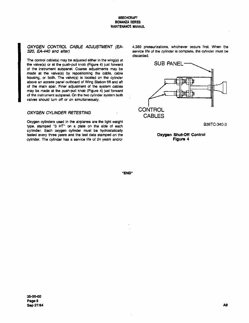
BEECMCRACT
BONANZA SERIES
MAINTENANCE MANAUL
OXYGEN CONTROL CABLE ADJUSTMENT (EA- 4,388 pregESuliZations, whichever occurs first. When the
320, EA-440 and after) service life of the cylinder is complete, the cylinder must be
discarded.The control cable(s) may be adjusted either in the wing(s) at
the valve(s) or at the push-pull knob (Figure 4) just forward SUB PANELof the instrument subpanel. Coarse adjustments may be
made at the valve(s) by repositioning the cable, cable
housing, or both. The valve(s) is located on the cylinderabove an access panel outboard of Wing Station 66 and aft
of the main spar. Finer adjustment of the system cables
may be made at the push-pull knob (Figure 4) just forward
of the instrument subpanel. On the two cylinder system both
valves should turn off or on simultaneously.
CONTROLOXYGEN CYLINDER I;7ETESTING
CABLESOxygen cylinders used in the airplanes are the light weight
8361C-340-3type, stamped "3 Hf" on a plate on the side of each
cylinder. Each oxygen cylinder must be hydrostaticallytested every three years and the test date stamped on the Oxygen Shut-Otf Csntrol
cylinder. The cylinder has a service life of 24 years and/or Figure 4
"END"
35-0090
88088Sep 27/84 A9

CHAPTER
PNEUMATIC
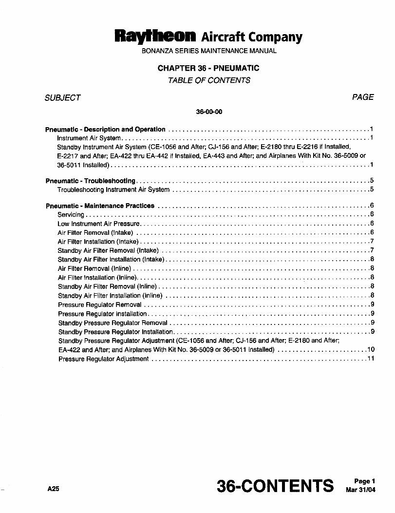
ttaYtbeea Aircraft CompanyBONANZA SERIES MAINTENANCE MANUAL
CHAPTER 36 PNEUMATIC
TABLE OF CONTENTS
SUBJECT PAGE
36-00-00
Pneumatic- Descript[onand Operation ..................1
Instrument Air System
Standby Instrument Air System (CE-1056 and After; CJ-156 and After; E-2180 thru E-2216 if Installed,
E-2217 and After; EA-422 thru EA-442 if Installed, EA-443 and After; and Airplanes With Kit No. 36-5009 or
36-5011 Installed)
Pneumatic- Troubleshooting ........5
Troubleshooting InstrumentAirSystem .................5
Pneumatic- Maintenance Practices ..6
ServicingLow InstrumentAir Pressure. ......6
AirFilterRemoval (Intake) ........6
AirFilter Installation (Intake) .......7
Standby Air Filter Removal (Intake) .7
Standby Air Filter Installation (Intake) .8
AirFilter Removal (Inline) .........8
AirFilter Installation (Inline). ..................8
Standby AirFilter Removal (Inline) ..8
StandbyAirFilter Installation (Inline) .8
Pressure Regulator Removal ......9
Pressure Regulator Installation .....9
Standby Pressure RegulatorRemoval ..................9
Standby Pressure Regulatorlnstallation. ................9
Standby Pressure Regulator Adjustment (CE-1056 and After; CJ-156 and After; E-2180 and After;
EA-422 and After; and Airplanes With Kit No. 36-5009 or 36-5011 Installed) ......10
Pressure Regulator Adjustment ...11
p~s 36-CONTENTS C~Pagel
Raytheon Aircraft CompanyBONANZA SERIES MAINTENANCE MANUAL
CHAPTER 36 PNEUMATIC
LIST OF EFFECTIVE PAGES
CH-SE-SU PAGE DATE
36-LOEP 1 Mar 31/04
36-CONTENTS 1 Mar 31/04
36-00-00 1 thru 11 Mar 31/04
A25 36-LOEP Mar 31/04Pagel
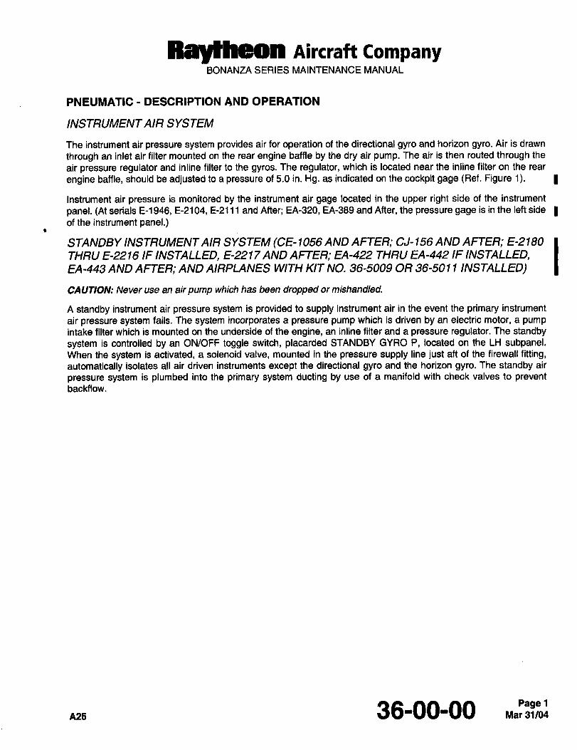
Raytheon AiKraft CompanyBONANZA SERIES MAINTENANCE MANUAL
PNEUMATIC DESCRIPTION AND OPERATION
INSTRUMENTAIR SYSTEM
The instrument air pressure system provides air for operation of the directional gyro and horizon gyro. Air is drawn
through an inlet air filter mounted on the rear engine baffle by the dry air pump. The air is then routed through the
air pressure regulator and inline filter to the gyros. The regulator, which is located near the inline filter on the rear
engine baffle, should be adjusted to a pressure of 5.0 in. Hg. as indicated on the cockpit gage (Ref. Figure 1).
Instrument air pressure is monitored by the instrument air gage located in the upper right side of the instrument
panel. (At serials E-1946, E-2104, E-2111 and After; EA-320, EA-389 and After, the pressure gage is in the left side
of the instrument panel.)
STANDBY INSTRUMENTAIR SYSTEM (CE- 1 056 AND AFTER; CJ- 156 AND AFTER; E-2 180
THRU E-2216 IF INSTALLED, E-22 17 AND AFTER; EA-422 THRU EA-442 IF INSTALLED,EA-443 AND AFTER; AND AIRPLANES WITH KIT NO. 36-5009 OR 36-501 1 INSTALLED)
CAUTION: Never use an air pump which has been dropped or mishandled.
A standby instrument air pressure system is provided to supply instrument air in the event the primary instrument
air pressure system fails. The system incorporates a pressure pump which is driven by an electric motor, a pumpintake filter which is mounted on the underside of the engine, an inline filter and a pressure regulator. The standby
system is controlled by an ON/OFF toggle switch, placarded STANDBY GYRO P, located on the LH subpanel.When the system is activated, a solenoid valve, mounted in the pressure supply line just aft of the firewall fitting,automatically isolates all air driven instruments except the directional gyro and the horizon gyro. The standby air
pressure system is plumbed into the primary system ducting by use of a manifold with check valves to preventbackfiow.
36-00-00Pagel
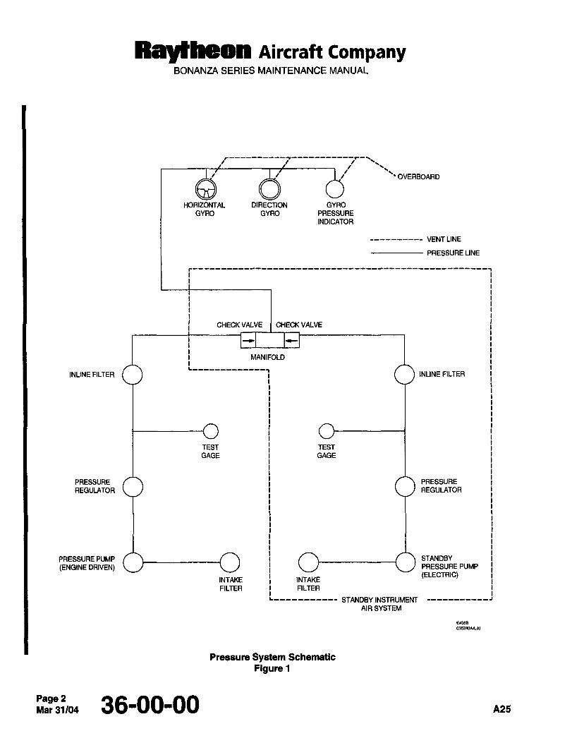
ttsYttresn Aircraft CompanyBONANZA SERIES MAINTENANCE MANUAL
i JI/ OVERBOARD
HORIZONTAL DIRECTION GYRO
GYRO GYRO PRESSURE
INDICATOR
CHECK VALVE CHECK VALVE
MANIFOLD
L-------------~INLINE FILTER INLINE FILTER
TEST TEST
GAGE 1 GAGE
PRESSURE I PRESSURE
REGULATOR 1 I REGULATOR
PRESSURE PUMP i STANDBY
(ENGINE DRIVEN) j I ~J PRESSURE PUMP
(ELECTRIC)INTAKE INTAKE
FILTER FILTER
L,,,,,,,,,,, STANDBYINSTRUMENT
AIR SYSTEM
Ew3as
035240AA.AI
Pressure System Schematic
Figure 1
Page 2Mar31/04 36-00-00 A25
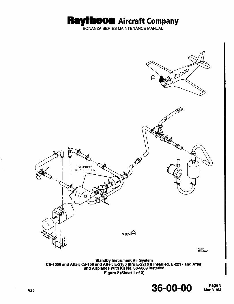
Rayfheon AiKraft CompanyBONANZA SERIES MAINTENANCE MANUAL
~-_ Ni AISRTClFNPLBTYER
es~
VIE\J A
035168AR
Standby Instrument ASr SystemCE-1056 and After; CJ-156 and After; &2180 thru 6-2216 If Installed, 6-2217 and After,
and Airplanes With Kit No. 36-5009 Installed
Figure 2 (3heet 1 of 2)
36-00-00 Mar 31/04Page 3
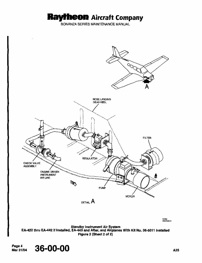
RayfkgMI AiKraft CompanyBONANZA SERIES MAINTENANCE MANUAL
NOSE LANDINGGEAR KEU
I)I r’
I
I\FILTER
,~B
REGULATOR
CHECK VALVE
ASSEMBLY
ENGINE DRIVEN
AIR LINEINSTRUMENT
PUMP
MOTOR
DETAIL A
E~368
Standby Instrument Air SystemEA422 thru EA-442 if Installed, EA´•443 and After, and Airplanes With Kit No. 36-5011 Instalred
Figure 2 (6heet 2 of 2)
Page 4Mar31/04 36-00-00 A25
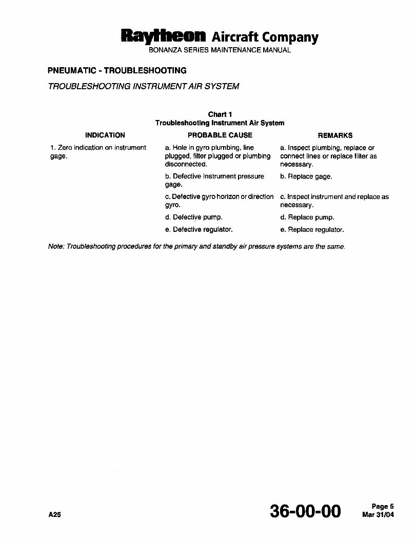
Raltheon Aircraft CompanyBONANZA SERIES MAINTENANCE MANUAL
PNEUMATIC- TROUBLESHOOTING
TROUBLESHOOTING INSTRUMENTAIR SYSTEM
Chart 1
Troubleshooting Instrument Air System
INDICATION PROBABLE CAUSE REMARKS
1. Zero indication on instrument a. Hole in gyro plumbing, line a. Inspect plumbing, replace or
gage, plugged, filter plugged or plumbing connect lines or replace filter as
disconnected. necessary.
b. Defective instrument pressure b. Replace gage.
gage.
c. Defective gyro horizon or direction c. Inspect instrument and replace as
gYro. necessary.
d. Defective pump. d. Replace pump.
e. Defective regulator. e. Replace regulator.
Note: Troubleshooting procedures for the primary and standby air pressure systems are the same.
A25 36-00-00 Mar 31/04Page 5
Raytheon AiKraft CompanyBONANZA SERIES MAINTENANCE MANUAL
PNEUMATIC MAINTENANCE PRACTICES
SERVICING
Impurities and foreign matter are removed from the air by two pressure system filters. The intake filter is located on
the top of the engine, ahead of the pressure pump. This filter should be replaced annually or every 300 to 500 hours
of service time depending upon operating conditions. The filter element must not be subjected to solvents and must
be replaced if this occurs. Always reinstall the filter cover with the opening facing down. The inline filter is located
between the pressure regulator and the instruments. The frequency of replacing this air filter will depend upon
service conditions; however, they should be checked approximately every 100 hours of operation and replacedevery 300 hours of operation, or sooner if conditions warrant.
The intake filter for the standby instrument air system is located on the underside of the engine attached to the keel
structure. The inline filter is mounted in the RH engine compartment between the pressure regulator and the
instruments, at FS 28.25 to 30.75. The intake filter should be replaced every 500 hours or on condition and the inline
filter should be replaced every 300 hours or on condition.
When operating in localities where there is a great amount of dust or sand in the air, the filters should be replacedat more frequent intervals. Under extremely dusty conditions, it may be necessary to inspect the filters daily. A
clogged filter reduces air flow and slows up the rotor, causing improper gym indication due to a loss of gyroscopicinertia.
LOW INSTRUMENTAIR PRESSURE
If the pressure pump has failed or operation of the instruments indicates a fluctuation of the system pressure or a
decrease in system pressure, check for excessive pressure, a partial restriction in the lines, a filter partiallyobstructed, or pressure loss resulting from loose connections. These conditions may be checked by:
NOTE: Use a dry, low pressure air source (10 psi maximum) for this test. If air flow resistance in the filter removed
from the airplane exceeds that of the new filter by more than 1.0 psi, replace the filter.
a. Removing the inline filter from the system and checking it for obstructions by comparing the resistance to flow
with a new filter.
b. Check all connections for tightness.
c. Check the lines for bends, kinks and excessive carbon.
With the discrepancy repaired, or whenever any components are replaced in the pressure system, adjust the
pressure, refer to PRESSURE REGULATOR ADJUSTMENT procedure.
AIR FILTER REMOVAL (INTAKE)
I a. Gain access to the filter by opening the left engine cowling (Ref. Figure 3).
b. Remove the nut, washers, and cover from the filter.
c. Remove the spacer and nut which secures the filter.
d. Remove the filter.
Page 6~’31"1w 36-00-00 nns
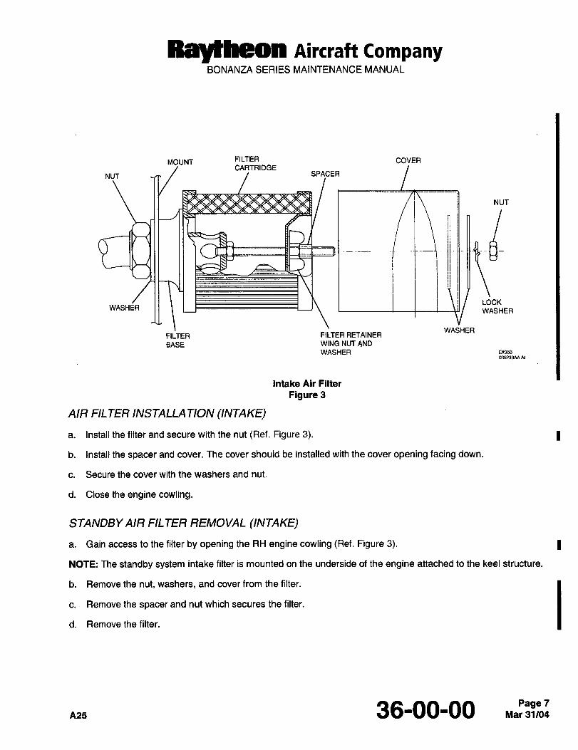
Raytheon Aircraft CompanyBONANZA SERIES MAINTENANCE MANUAL
MOUNT FILTER COVERCARTRIDGE
NUT SPACER
NUT
jj
LOCKWASHER
WASHER
WASHERFILTER FILTER RETAINER
BASE WING NUT AND
WASHERm5239AAA1
Intake Air Filter
Figure 3
AIR FIL TER INSTALLA TION (INTAKE)
a. Install the filter and secure with the nut (Ref. Figure 3).
b. Install the spacer and cover. The cover should be installed with the cover opening facing down.
c. Secure the cover with the washers and nut.
d. Close the engine cowling.
STANDBYAIR FILTER REMOVAL (INTAKE)
a. Gain access to the filter by opening the RH engine cowling (Ref. Figure 3).
NOTE: The standby system intake filter is mounted on the underside of the engine attached to the keel structure.
b. Remove the nut, washers, and cover from the filter.
c. Remove the spacer and nut which secures the filter.
d. Remove the filter.
A25 36-00-00 Mar 31/04Page 7
Raytheon AiKraft CompanyBONANZA SERIES MAlhiTENANCE MANUAL
STANDBY AIR FILTER INSTALLA TION (INTAKE)
a. Install the filter and secure with the nut (Ref. Figure 3).
b. Install the spacer and cover. The cover should be installed with the cover opening facing down.
c. Secure the cover with the washers and nut.
d. Closethe enginecowling.
AIR FILTER REMOVAL (INLINE)
a. Open the engine cowling and locate the filter attached to the bracket below the engine baffle.
b. Remove the inlet and outlet hoses from the filter.
c. Remove the nut and washer which hold the filter in place.
d. Remove the filter.
AIR FILTER INSTALLATION (INLINE)
a. Place the filter in position and secure with washer and nut.
b. Installthe inletandoutlethoses.
c. Closethe enginecowling.
STANDBYAIR FILTER REMOVAL (INLINE)
a. Open the LH engine cowling and locate the filter attached to the bracket below the engine baffle.
b. Remove the inlet and outlet hoses from the filter.
c. Remove the nut and washer which hold the filter in place.
d. Remove thefilter.
STANDBY AIR FILTER INSTALLATION (INLINE)
a. Place the filter in position and secure with washer and nut.
b. Install the inlet and outlet hoses.
c. Closethe enginecowling.
Page 8Mar31104 36-00-00 nea
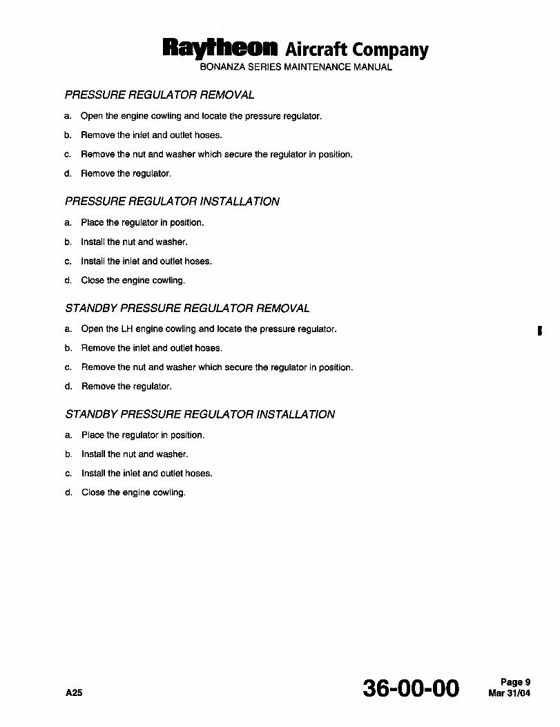
Ral~heon AiKlaft CompanyBONANZA SERIES MAINTENANCE MANUAL
PRESSURE REGULA TOR REMOVAL
a. Open the engine cowling and locate the pressure regulator.
b. Remove the inlet and outlet hoses.
c. Remove the nut and washer which secure the regulator in position.
d. Removethe regulator.
PRESSURE REGULA TOR INSTALLA TION
a. Place the regulator in position.
b. Installthe nutandwasher.
c. Install the inlet and outlet hoses.
d. Closetheengine cowling.
STANDBY PRESSURE REGULA TOR REMOVAL
a. Open the LH engine cowling and locate the pressure regulator. I
b. Remove the inlet and outlet hoses.
c. Remove the nut and washer which secure the regulator in position.
d. Removethe regulator.
STANDBY PRESSURE REGULA TOR INSTALLA TION
a. Placetheregulatorin position.
b. Install the nut and washer.
c. Install the inlet and outlet hoses.
d. Closetheengine cowling.
A25 36-00-00 Mar 31/04Page 9
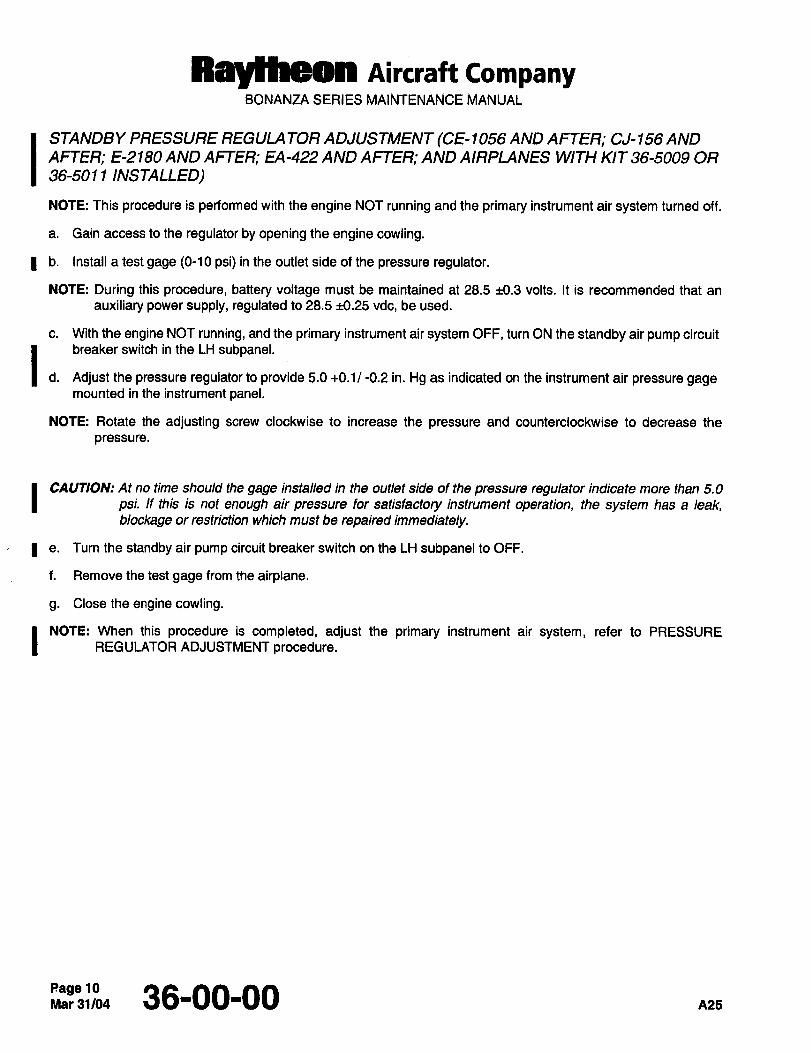
Raylheon AiKraft CompanyBONANZA SERIES MAINTENANCE MANUAL
ISTANDBY PRESSURE REGULA TOR ADJUSTMENT (CE- 1 056 AND AFTER; CJ- 156 AND
AFTER; E-2180 AND AFTER; EA-422 AND AFTER; AND AIRPLANES WITH KIT 36-5009 OR
36-501 1 INSTALLED)
NOTE: This procedure is performed with the engine NOT running and the primary instrument air system turned off.
a. Gain access to the regulator by opening the engine cowling.
I b. Install a test gage (0-10 psi) in the outlet side of the pressure regulator.
NOTE: During this procedure, battery voltage must be maintained at 28.5 ~0.3 volts. It is recommended that an
auxiliary power supply, regulated to 28.5 ~0.25 vdc, be used.
c. With the engine NOT running, and the primary instrument air system OFF, turn ON the standby air pump circuit
1..breaker switch in the LH subpanel.
Adjust the pressure regulator to provide 5.0 +0.1/ -0.2 in. Hg as indicated on the instrument air pressure gagemounted in the instrument panel.
NOTE: Rotate the adjusting screw clockwise to increase the pressure and counterclockwise to decrease the
pressure.
I CAUTION: At no time should the gage installed in the outlet side of the pressure regulator indicate more than 5.0
psi. If this is not enough air pressure for satisfactory instrument operation, the system has a leak,blockage or restriction which must be repaired immediately.
e. Turn the standby air pump circuit breaker switch on the LH subpanel to OFF.
f. Remove the test gage from the airplane.
g. Close the engine cowling.
NOTE: When this procedure is completed, adjust the primary instrument air system, refer to PRESSUREREGULATOR ADJUSTMENT procedure.
page 1036-00-00 n25
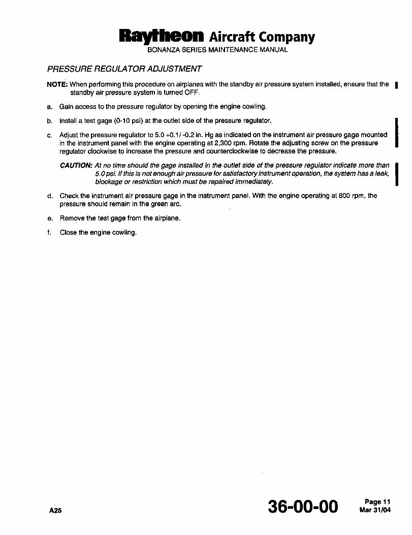
Raytheon AiKraft CompanyBONANZA SERIES MAINTENANCE MANUAL
PRESSURE REGULA TOR ADJUSTMENT
NOTE: When performing this procedure on airplanes with the standby air pressure system installed, ensure that the
standby air pressure system is turned OFF.
a. Gain access to the pressure regulator by opening the engine cowling.
b. Install a test gage (0-10 psi) at the outlet side of the pressure regulator.
c. Adjust the pressure regulator to 5.0 +0.1/ -0.2 in. Hg as indicated on the instrument air pressure gage mounted
in the instrument panel with the engine operating at 2,300 rpm. Rotate the adjusting screw on the pressure
regulator clockwise to increase the pressure and counterclockwise to decrease the pressure.
CAUTION: At no time should the gage installed in the outlet side of the pressure regulator indicate more than
5O psi. If this is not enough airpressure for satisfactory instrument operation, the system has a leak,
blockage or restriction which must be repaired immediately.
d. Check the instrument air pressure gage in the instrument panel. With the engine operating at 800 rpm, the
pressure should remain in the green are.
e. Remove the test gage from the airplane.
f. Close the engine cowling.
nw 36-00-00

CHAPTER
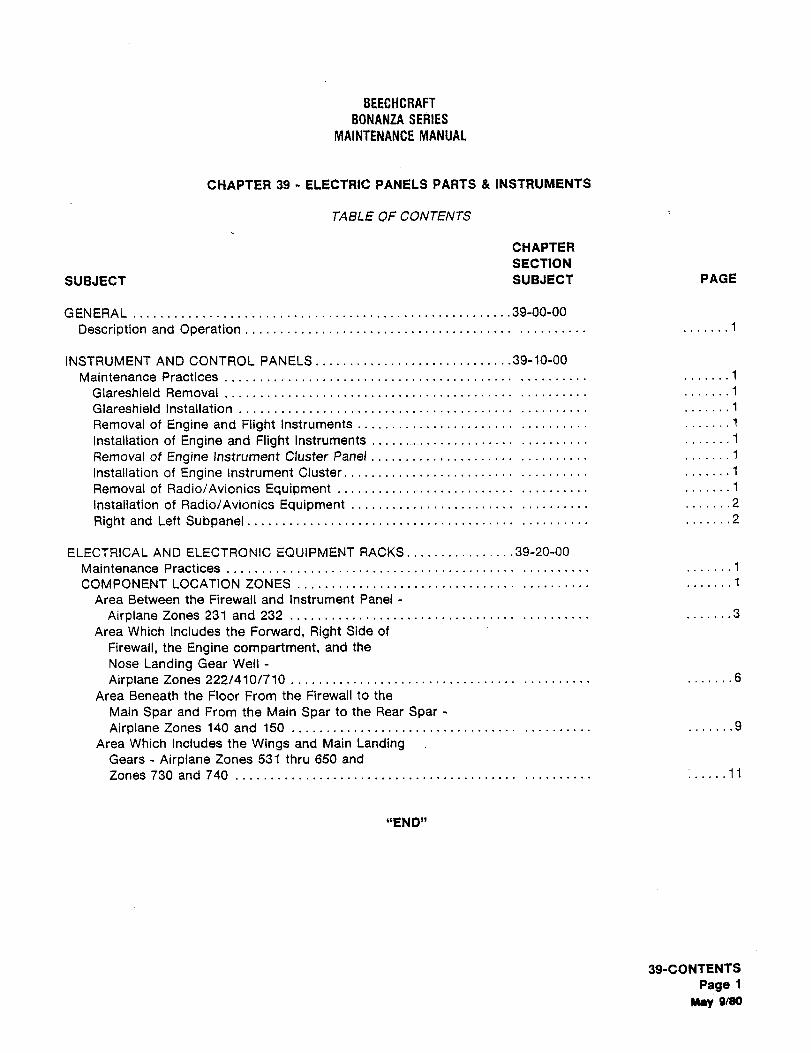
BEECHCRAFI
BONANZA SERIES
MAINTENANCE MANUAL
CHAPTER 39 ELECTRIC PANELS PARTS INSTRUMENTS
TABLE OF CONTENTS
CHAPTER
SECTION
SUBJECT SUBJECT PAGE
GENERAL 39-00-00
Description and Operation .......1
INSTRUMENT AND CONTROL PANELS .........39-10-00
Maintenance Practices .......1
Glareshield Removal .......1
Glareshield Installation .......1
Removal of Engine and Flight Instruments .......1
Installation of Engine and Flight Instruments ...1
Removal of Engine Instrument Cluster Panel .................1
Installation of Engine Instrument Cluster .......1
Removal of Radio/Avionics Equipment .......1
Installation of Radio/Avionics Equipment .......2
Right and Left Subpanel .......2
ELECTRICAL AND ELECTRONIC EQUIPMENT RACKS 39-20-00
Maintenance Practices .......1
COMPONENT LOCATION ZONES .................f
Area Between the Firewall and Instrument Panel
Airplane Zones 231 and 232 .................3
Area Which Includes the Forward, Right Side of
Firewall, the Engine compartment, and the
Nose Landing Gear Well
Airplane Zones 222/410/710 .......6
Area Beneath the Floor From the Firewall to the
Main Spar and From the Main Spat to the Rear SparAirplane Zones 140 and 150 .................9
Area Which Includes the Wings and Main LandingGears Airplane Zones 531 thru 650 and
Zones 730 and 740 :.....11
"END"
39-CONTENTS
Page: 1
M´•y WSO
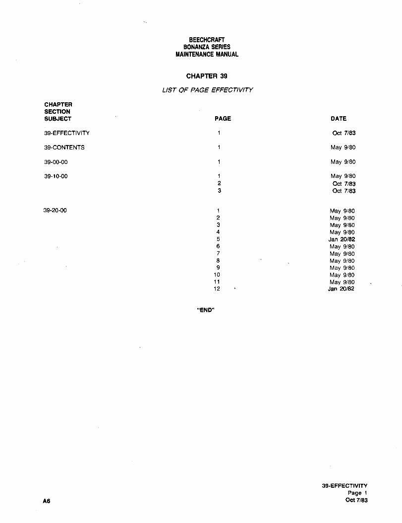
BEECHCRARBONANZA SERIES
MAINTENANCE MANUAL
CHAPTER 39
LIST OF PAGE EFFECTIVITY
CHAPTER
SECTION
SVBJECT PAGE DATE
39-EFFECTIVITY 1 Oct 7/83
39-CONTENTS 1 May 9i80
39-00-00 1 May 9i80
39-10-00 1 May 9/80
2 Oct 7/83
3 Oct 7/83
39-20-00 1 May 9/80
2 May 9/80
3 May 9/80
4 May 9180
5 Jan 20/82
6 May 9180
7 May 9/80
8 May 9180
9 May 9/80
10 May 9/80
11 May 9180
12 Jan 20/82
"END"
39-EFFECTIVITY
Page 1
A6 Oct 7/83
BEECHCRAFTBONANZA SERIES
MAINTENANCE MANUAL
GENERAL DESCRIPTION AND OPERATION receiving equipment. (4) The stationary right panel which
contains indicators, switching, and the glove box. (5) The
upper left subpanel, located below the left floating panel and
The instrument panel on the airplane is divided into seven above the left subpanel contains autopilot control switching,general groupings: (1) A floating panel, located on the upper OMNI indicators, and the flap position indicator. (6) The
left corner of the instrument panel, which contains those lower left subpanel contains the heater and air controls for
instruments necessary to sustain flight. (2) The center cabin temperature, ignition switch, circuit breaker switches,
stationary panel which contains instruments that indicate the light controls, flap control, and fuel pump controls. (7) The
various monitoring systems of the engine. (3) The avionics lower right subpanel contains the landing gear control and
and radio rack, located to the right of the engine instrument indicating lights, and the standard and optional circuit
panel, which contains various optional avionics and radio breakers.
"END"
340090
PegelAllay 9/80
BEECHCRAFTBONANZA SERIES
MAINTENANCE MANUAL
INSTRUMENT AND CONTROL PANELS CAUTION
MAINTENANCE PRACTICESIf any screws are replaced upon reinstallation of
any instrument, be sure they are the same
WARNING length as the original screws.
To avoid personal injury, shut off all electrical
power, both battery and external, before c. Connect the post lights as necessary.
removing or installing any electrical d. Connect the plumbing and/or electrical
components. connections to the flight instruments.
e. Install the glareshield.
GLARESHIELD REMOVALREMOVAL OF THE ENGINE INSTRUMENT
a. Remove the attach screws at each end of the CLUSTER PANEL
glareshWd.b. Lift the glareshield gently to detach it from the a. Remove the glareshield.
veicro hook and pile which secures it at its top side. b. Disconnect the harness connector on the back of
c. Disconnect the electrical quick disconnects for the engine instrument cluster.
both the compass and the glareshield lights, c. Remove the screws securing the instrument
d. Disconnect the defroster heat duct. cluster to the instrument panel. Support the cluster
e. Remove the glareshield. assembly while removing the screws to prevent dropping it.
d. Remove the cluster from the panel.
GLARESHIELD INSTALLATIONi INSTALLATION OF THE ENGINE INSTRUMENT
a. Place the glareshield in position and connect the CLUSTER PANEL
defroster heat duct.
b. Connect the electrical quick disconnects for both a. Place the engine instrument cluster panel in the
the compass and the glareshield lights. proper position in the instrument panel.c. Install the attach screws at each end of the b. Secure the instrument cluster to the instrument
glareshield, panel with the screws.
d. Press downward on the top side of the glareshieldto secure the velcro hook and pile.
CAUTION
REMOVAL OF ENGINE AND FLIGHT If replacement of the screws is required, use
INSTRUMENTS screws of the same length as the originalscrews to avoid internal damage to the
a. Remove the glareshield. instrument cluster.
b. Disconnect the plumbing and/or electrical
connections from the flight instruments.
c. Disconnect and remove any post lights. c. Connect the engine harness connector to the
d. Remove the mounting screws securing the back of the instrument cluster.
instrument to the panel section, d. Install the glareshield.e. Remove the instrument.
REMOVAL OF RADIO/A VIONICS EQUIPMENTINSTALLATION OF ENGINE AND FLIGHT
INSTRUMENTS a. Locate the component you wish to remove from
the radio/avionics rack.
a. Place the instrument in the proper position in the b. Loosen the Alien screw which secures the piece
panel, of gear in the rack.
b. Secure the instrument to the panel with the c. Slide the required piece of gear from the shelf on
attaching screws. the radio/avionics rack.
39iMK)
PagelMay 9/80
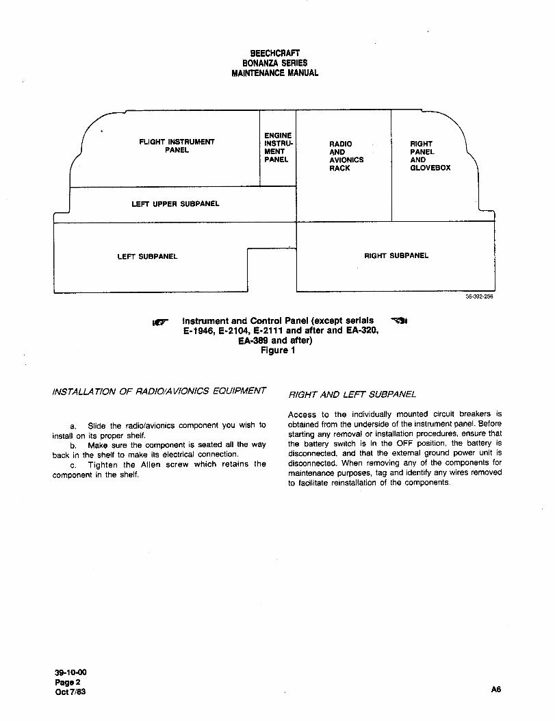
BEECHCRAFTBONANZA SERIES
MAINfENANCE MANUAL
ENGINEFLIGHT INSTRUMENT INSTRU- RADIO I RIGHT
PANEL MENT AND I PANEL
PANEL AVIONICS AND
RACK GLOVEBOX
LEFT UPPER SUBPANEL
LEFT SUBPANEL RIGHT SUBPANEL
35392-a56
~g Instrument and Control Panel (except serials
E-1946, E-2104, E-2111 and after and EA-320,EA´•389 and after)
Figure 1
INSTALLA TION OF RADIO/A VIONICS EQUIPMENTRIGHT AND LEFT SUBPANEL
Access to the individually mounted circuit breakers is
a. Slide the radio/avionics component you wish to obtained from the underside of the instrument panel. Before
install on its proper shelf, starting any removal or installation procedures, ensure that
b. Make sure the component is seated all the way the battery switch is in the OFF position, the battery is
back in the shelf to make itselectrical connection, disconnected, and that the external ground power unit is
c. Tighten the Alien screw which retains the disconnected. When removing any of the components for
component in the shelf. maintenance purposes, tag and identify any wires removed
to facilitate reinstallation of the components.
39-10-00
Pa9ePOc17/83 A6
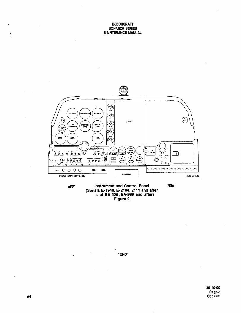
BEECHCRAFTBONANZA SERIES
MAINTENANCE MANUAL
osOIIREPI~O )LTIIRR
QwnrrruRn*"’ 8cooRaw~roR
00 Oo ,fp~
r- ´•-~r
LC: i
1(1HP8
O O
o om o
OQOO~OQQOQOQQ000000
IPEOEITIL
instrument and Control Panel
(Serlals E-1946, 8-2104, 2111 and after
and EA-320, EA-389 and after)Figure 2
"888"
39-1 0-00
Page3A6 Oct 7/83
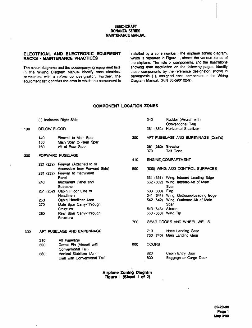
BEECHCRAFTBONANXA SERIES
MAINTENANCE MANUAL
ELECTRICAL AND ELECTRONIC EQUIPMENT installed by a zone number. The airplane zoning diagram,RACKS MAINTENANCE PRACTICES which is repeated in Figure 1, shows the various zones of
the airplane. The lists of components, and the illustrations
The circuit diagrams and the accompanying equipment lists showing their installation on the following pages, identify
in the Wiring Diagram Manual identify each electrical these components by the reference designator, shown in
component with a reference designator. Further, the parenthesis assigned each component in the Wiring
equipment list identifies the area in which the component is Diagram Manual, (P/N 35-590102-9).
COMPONENT LOCATION ZONES
Indicates Right Side 340 Rudder (Aircraft with
Conventional Tail)100 BELOW FLOOR 351 (352) Horizontal Stabilizer
140 Firewall to Main Spar 300 AFT FUSELAGE AND EMPENNAGE (Cont’d)150 Main Spar to Rear Spar160 Ah of Rear Spar 361 (362) Elevator
370 Tail Cone
200 FORWARD FUSELAGE
410 ENGINE COMPARTMENT
221 (222) Firewall (Attached to or
Accessible from FoMard Side) 500 (600) WING AND CONTROL SURFACES
231 (232) Firewall to Instrument
Panel 531 (631) Wing, Inboard Leading Edge240 Instrument Panel and 532 (638 Wing, Inboard-Aft of Main
Subpanel Spar251 (252) Cabin (Floor Line to 533(633) Flap
Headliner) 541 (641) Wing, Outboard-Leading Edge253 Cabin Headliner Area 542 (642) Wing, Outboard-Aft of Main
270 Main Spar Carry-Through SparStructure 543(643) Aileron
280 Rear Spar Carry-Through 550 (650) Wing TipStructure
700 GEAR DOORS AND WHEEL WELLS
300 AFT FUSELAGE AND EMPENNAGE 710 Nose Landing Gear
730 (740) Main Landing Gear
310 Ah Fuselage320 Dorsal Fin (Aircraft with 800 DOORS
Conventional Tail)330 Vertical Stabilizer (Air- 820 Cabin Entry Door
craft with Conventional Tail) 830 Baggage or Cargo Door
Airplane Zoning DlagtamFigure 1 (Sheet 1 of 2)
392090
PagslMay 9/80
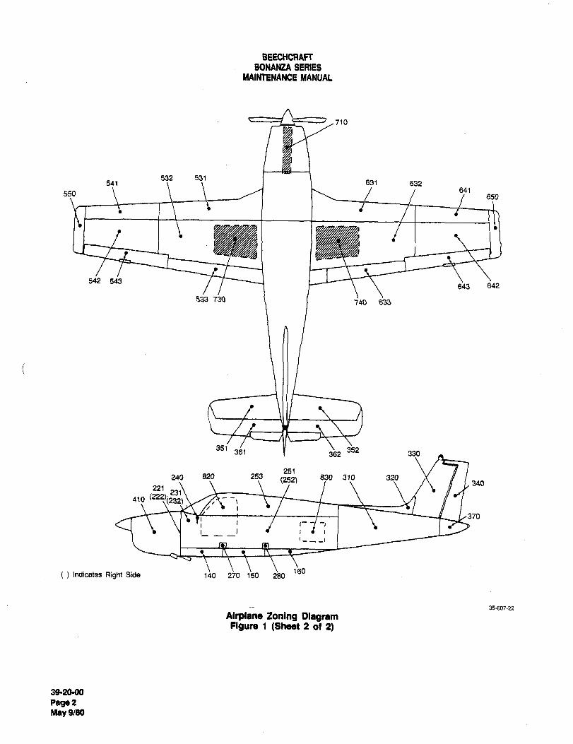
BEECHCRAF~BONA~UA SERIES
MAINTENANCE klANUAC
710
532 531541 831 632
641550 650
542 543643 642
533 730 740 633
351 352361 362 330
251240 820 253 830 310 320(252) 340
221
410 (222)´•(232)
370
-I
160Indicates Right Side 140 270 150 i80
35´•607-22
Alrplanb loning OlegrsmFigun, 1 (Sh(Hlt 2 012)
39´•2090
Pag~ 2
M~y 9/80
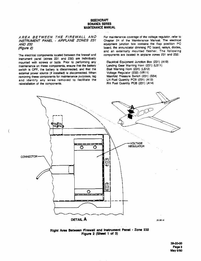
BEECHCRAFTBONANZA SERIES
MAIMENANCE MANUAL
AREA BETWEEN THE FIREWALL AND For maintenance coverage of the voltage regulator, refer to
INSTRUMENT PANEL AIRPLANE ZONES 231 Chapter 24 of the Maintenance Manual. The electrical
AND 232 equipment junction box contains the flap position PC
(ngure 2) board, the annunciator dimming PC board, relays, diodes,
and an externally mounted flasher. The followingThe electrical components located between the firewall and components are located in airplane zones 231 and 232:
instrument panel (zones 231 and 232) are individuallymounted with screws or bolts. Prior to performing any Electrical Equipment Junction Box (231) (A19)maintenance on these components, ensure that the battery Landing Gear Warning Horn (231) (LS11)
switch is OFF, the battery is disconnected, and that the Stall Warning Horn (231) (LS12)external power source (if installed) is disconnected. When Voltage Regulator (232) (VR11)
removing these components for maintenance purposes, tag Manifold Pressure Switch (231) (S54)
and identify any wires removed to facilitate the LH Fuel Quantity PCB (231) (A13)reinstaliation of the components. RH Fuel Quantity PCB (231) (A14)
r;-r--i
i, I ’I ;I\ /---VOLTAGE
o o II R"ULATOR
CONNECTOR
DETAIL A 35-351-6
Right Area Between firewall and Inarument Panel Zone 232
Figute (Sheet 1 at 3)
39-20QO
Page3May 9/39
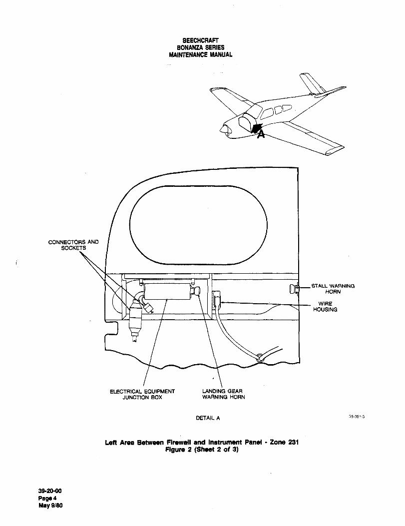
BEECHCRAFT
BONAN2A SERIES
MAINTENANCE MANUAL
CONNECTORS AND
SOCKETS
STALL WARNING
HORN
WIRE
HOUSING
ELECTRICAL EQVIPMENT LANDING GEAR
JUNCTION BOX WARNING HORN
DETAIL A 35-3513
Left Area Between Firewall and Instrument Panel Zone 231
Figure 2 (Sheet 2 of 3)
392090
Pe~4May 9/80
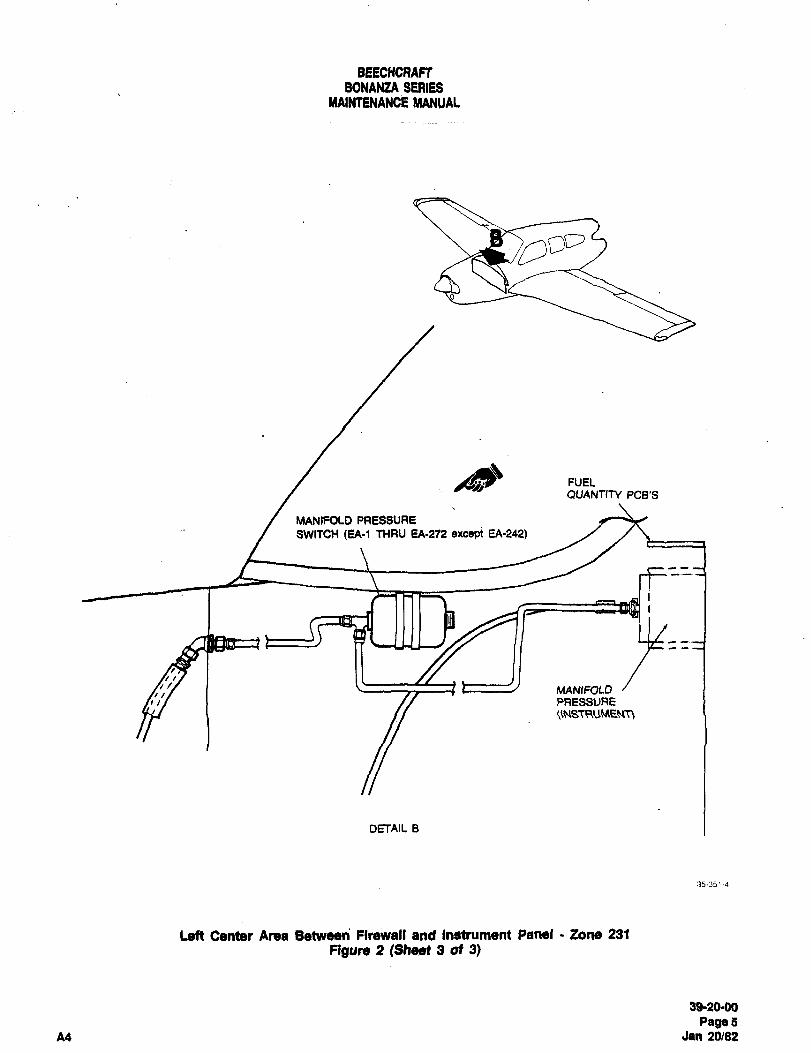
BEECHCRAFTBONAI~ZA SERIES
MAINTENANCE MANUAL
FUELQUANTrTY PCB’S
MANIFOLD PRESSURE
SWITCH (EA-I I1´•IRU fA-272 excepi EA-242)
MANIFOLDI PRESSURE
DETAIL B
35´•351-i
Left Center Area BenNeen Firewall and Instrument Panel Lone 231
Figure 2 (Sheet 3 of 3)
3920´•00
PageSA4 Jan 20/82
BEECHCRAFTBONA~IZA SERIES
MAINTENANCE MANUAL
AREA WHICH INCLUDES THE FORWARD, RIGHT located in tone 410. Adjustment and pictorial coverage of
SIDE OF THE FIREWALL, THE ENGINE these switches is found in Chapter 32 of the Maintenance
COMPARTMENT; AND THE NOSE LANDING GEAR Manual. All major engine electrical components i.e.,WELL AIRPL4NE ZONES 222/410/710 alternator, starter, etc., will be shown in the 10-520 or
(Figure 3) TSIO-520 Series Aircraft Engines Overhaul Manual, FORM
X-30039A or X-30042. The following components are
The electrical components located in the above areas and located in airplane zones 222 and 410:
zones are mounted with nuts, bolts, screws, or clamps.Prior to performing any maintenance on these components, Fuse blocks, both Standard and
ensure that the battery switch is OFF, the battery is Optional (222) (Fi5, F16, XF15)disconnected, and that the external power source (if Battery (222) (BT10)installed) is disconnected. When removing these Shunt (222 (R34)components for maintenance purposes, tag and identify Current Limiters (222) (F1, F2, XFi, XF2)any wires removed to facilitate the reinstallation of the Capacitor Filter (222) (Cli)components. Optional External Power Relay (222) (K12)
Optional External Power Receptacle (410) (J32)The nose landing gear uplock and downlock switches are Starter Relay (222) (K14)located in the nose wheel well, and are mounted on the Battery Master Relay (222) (K15)right, outboard side of the wheel well keel. These switches Alternator Out Sensor (222) (A16)work in conjunction with the indicator lights on the right Throttle Warning Horn Switch (410)subpanel to indicate nose landing gear position. (S41) Chapter 32
Optional Landing Gear Safety Switch
For maintenance coverage of the battery, refer to Chapter (410) (S34) Chapter 32
12 of the Maintenance Manual. The throttle warning horn Avionics Master Relay (222)switch (S41) and the optional landing gear safety switch Switch, Nose Landing Gear Uplock (710) (S62)
(S34) are located on the throttle control shaft and are Switch, Nose Landing Gear Downlock (710) (S63)
39´•2040
PegaBMay 9/80
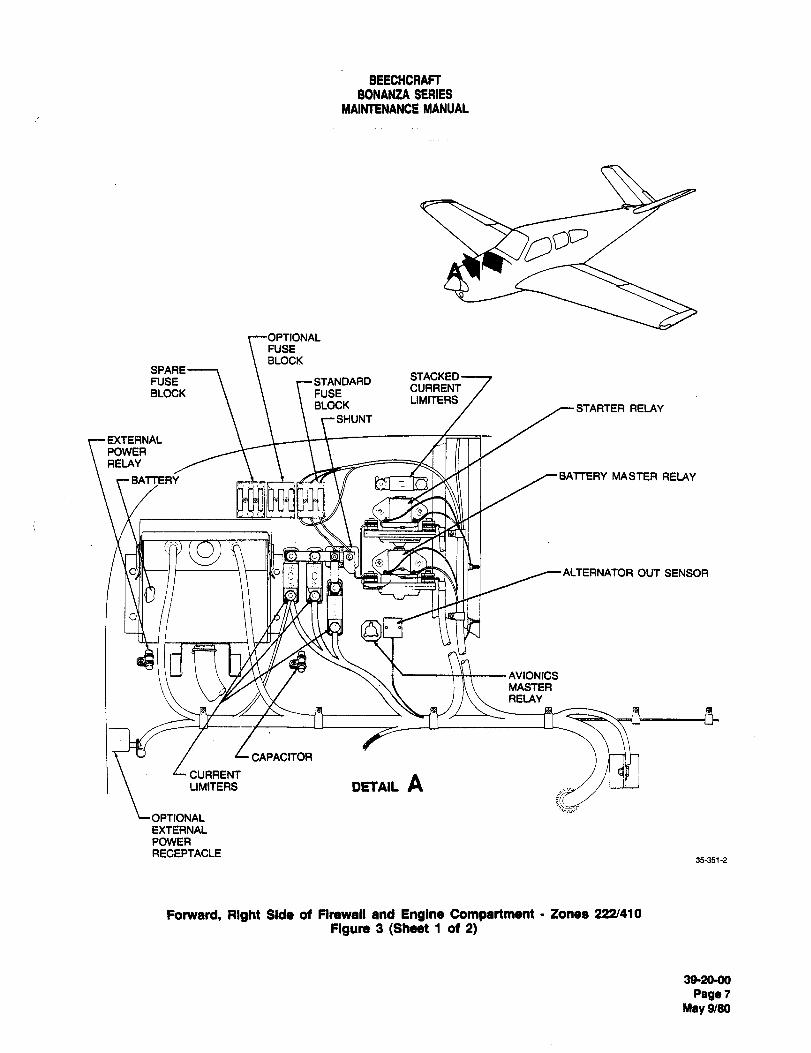
BEECHCRAFTBONANZA SERIES
MAINTENANCE MANUAL
FUSE
BLOCKSPARE
STACKEDFUSE STANDARD
CURRENTBLOCK FUSE
LIMITERSBLOCK STARTER RELAY
SMUNT
EXTERNALPOWERRELAY
BATTER~ I /--BATTERY MASTER RELAY
a Il ITT~I ~--ALTERNATOR OUT SENSOR
AVIONICSMASTERRELAY
CAPACITOR
CURRENTDETAIL ALIMITERS
OPTIONAL
EXTERNALPOWER
RECEPTACLE35-351-2
Fomard, Right 9ida ot nrewall and Englno Compartmant Zonaa 122/410
Figure 3 (Sheet 1 ot 2)
392040
Page7May 9/80
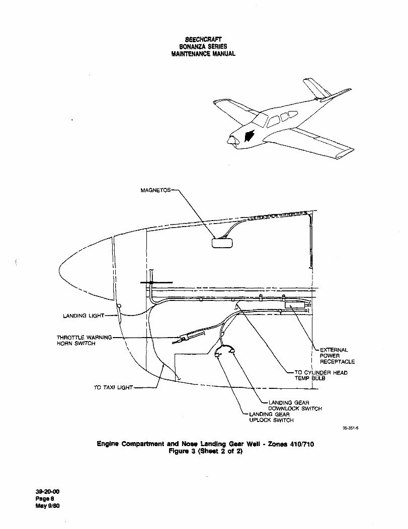
BEECHCAAFTBONANZA SERIES
MAINTENANCE MANUAL
MAGNETOS
LANDING LIGHT
THROTTLE WARNINGHORN SWITCH
I h !\-EXTERNALPOWERRECEPTACLE
TO CYLINDER HEADTEMP BULB
TO TAXI LIGHT~e "---1----~----
LANDING GEAROOWNLOCK SWITCH
LANDING GEARUPLOCK SWITCH
35´•351-5
Engine Compartment and Nose Landing Osar Well Zones 410/710
Flgunt 3 (Sheet 2 ot 2)
s920´•0o
Pege8May 9/80
BEECHCRAFTBONANZA SERIES
MAINTENANCE MANUAL
AREA BENEATH THE FLOOR FROM THE used for high boost pump. On serials CJ-149 and after,FIREWALL TO THE MAIN SPAR AND FROM THE two auxiliary boost pumps are used: Reference designatorMAIN SPAR TO THE REAR SPAR AIRPLANE (B11) for high boost and reference designator (812) for low
ZONES 140 AND 150 boost. On serials EA-1 and after, a single pump with both
(FIgure, 4) high and low speeds is used. The pump used on EA-1 and
after is reference designator (813).The electrical components located from the firewall to the
main spar, and from the main spat to the rear spar are The flight dimming transistor bracket assembly contains
mounted with nuts, bolts, screws, and clamps. Prior to four dimming transistors and is located in zone 150 (leftperforming any maintenance on these components, ensure side). For adjustment of the landing gear uplimit and
that the battery switch is OFF, the battery is disconnected, downlimit switches, refer to Chapter 32 of the Maintenance
and that the external power source (if installed) is Manual. The following components are located in airplanedisconnected. When removing these components for zones 140 and 150:
maintenance purposes, tag and identify any wires removed
to facilitate the reinstallation of the components. Auxiliary Fuel Boost Pump (140) (811,812, or 813) See above.
Light Dimming Transistor Bracket Assembly(150) (A21)
CAUTION Glareshield Light Dimming Transistor
(150) (Q1)Make sure the grommets are installed in the Subpanel Light Dimming Transistor
area of the main spar through which the wire (150) (02)harness passes, so chafing of the harness will Eng Inst and Avionics Console Lightnot occur. Dimming Transistor (150) (03)
Flight Instrument Light DimmingTransistor (150) (04)
The auxiliary fuel pumps are located forward of the main Inverter (150) (MG1)spar; all other components in this figure are located aft of Flap Motor (150) (822)the main spar. There are three different auxiliary fuel Landing Gear Motor (150) (821)pumps used in the Bonanza Series airplanes: On serials Dynamic Brake Landing Gear Relay (150) (K17)CE-743, CE-772 and after; D-10097, D-10120 and after; E- Landing Gear Uplimit Switch (150) (S39)1111, E-1241 and after, a reference designator (B11) is Landing Gear Downlimit Switch (150) (S40)
39-20-00
PageSMay 9/80
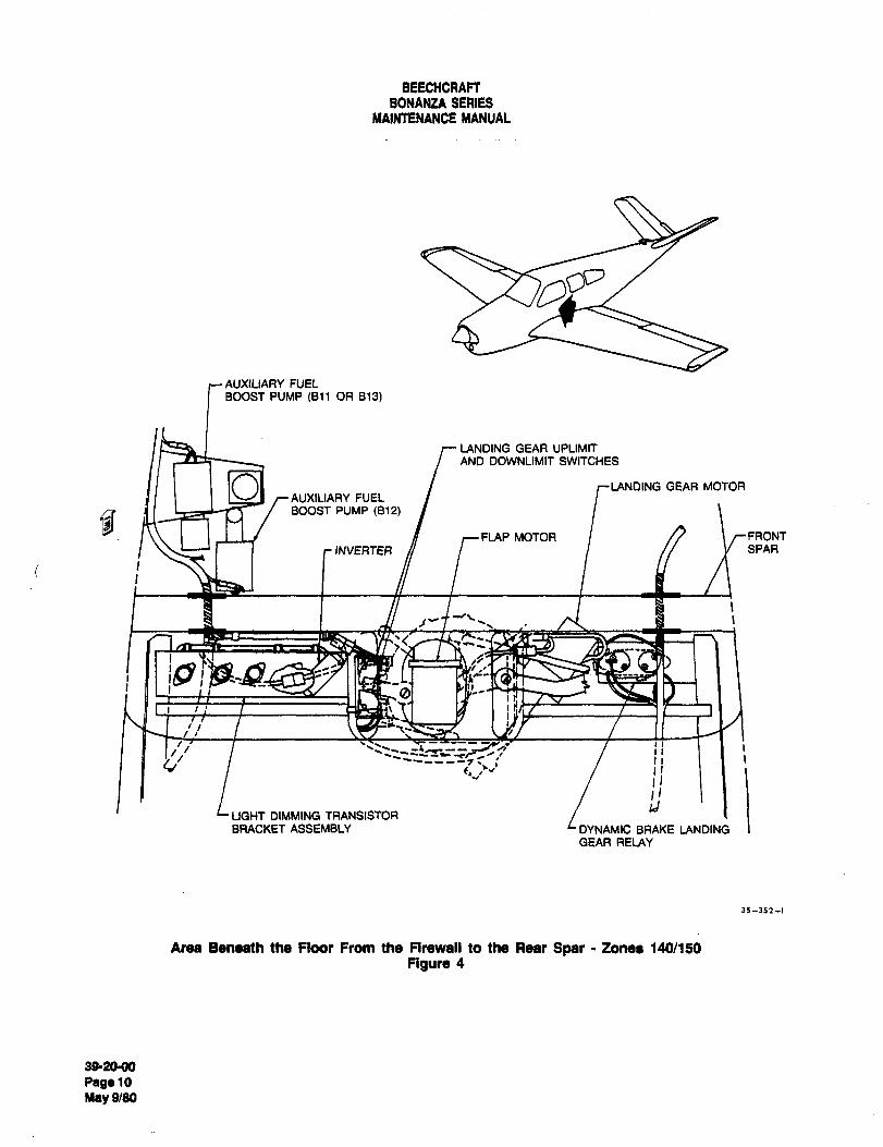
BEECHCRAFTBONANZA SERIES
MAINTENANCE MANUAL
AUXILIARY FUELBOOST PUMP ~B11 OR 813)
LANDING GEAR UPLIMITAND DOWNLIMIT SWITCHES
OAUXILIARY FUEL
GEAR MOTOR
BOOST PUMP (812)
FLAP MOTOR I rFRONTINVERTER I y SPAR
~t I
a
I Ib/ --+i II
b, LJ’ II
aLIGHT DIMMING TRANSISTOR
BRACKET ASSEMBLY LDYNAMIC BRAKE LANDINGGEAR RELAY
35--352--1
Area Benaath the Floor From the Frrewall to the Rear Soar Zonee 140/150
Figure 4
392000
Pag´•lOMey 9180
BEECHCRAFTBONANZA SERIES
MAINTENANCE MANUAL
AREA WHICH INCLUDES THE WINGS AND MAIN approximately WS 40.00. It is accessible through the
LANDING GEARS AIRPLANE ZONES 531 THRU landing gear wheel well forward of the wing rear spar. The
650, AND ZONES 730 AND 740 flap limit switches are accessible forward of the left flap
(Figure 5) and may be serviced with the flaps lowered. The flapswitches are located at approximately WS 33.00. For flap
The electrical components located within the‘wings and limit switch adjustment refer to Chapter 27 of the
main landing gear wheel wells are mounted with nuts, IMaintenance Manual. At airplane serials D-10179 and
bolts, screws, clamps, and rivets. Prior to performing any I after, CJ-150 and after, CE-816 and after, E-1371 and
maintenance on the components, ensure that the battery after, and EA-1 and after the airplanes are equipped with
switch is OFF, the battery is disconnected, and that the 14 degree and 16 degree approach flap limit switches in
external power source (if installed) is disconnected. When addition to the uplimit and downlimit flap switches of prior
removing the components for maintenance purposes, tag airplane serials.
and identify any wires removed to facilitate the
reinstallation of the components. A landing gear safety switch (squat switch) is located on
the strut of each main landing gear. The safety switches
Each wing contains two fuel level transmitters which are provided to prevent inadvertent retraction of the landing
provide fuel quantity information to their respective fuel gear on the ground. The switches open the control circuit
quantity indicator on the engine instrument panel. The when the struts are compressed. The landing gear safetyinboard fuel quantity transmitter for each wing is located at switches also serve to control the position of the
approximately WS 43.00, and the outboard transmitter is retractable air conditioner condenser. When the airplane is
located at approximately WS 97.00. on the ground and the air conditioner is turned on, the
condenser extends to the ground extension position.The heated pitot tube is mounted on the left outboard wingrib at approximately WS 125,00. The pitot tube heat The following electrical components ace located in the area
element wires are routed with the tube air line. When the which includes the wings and main landing gear. This area
pitot tube is removed for maintenance purposes, be sure to includes airplane zones 531 thru 650, and zones 730 and
cap the end of the air line to prevent entry of foreign 740:
material. Remove the cap upon reinstallation of the tube.
The stall warning switch is located on the left outboard Stall Warning Switch (531) (S43)
wing leading edge at approximately WS 140.00. Heated Pitot Tube (531) (HR23)
Adjustment coverage of the stall warning system is located Transmitter, LH Inboard Fuel (531) (R29)in Chapter 27 of the Maintenance Manual. The stall Transmitter, LH Outboard Fuel (531) (R21)
warning switch is removable by screws located around the Transmitter, RH Inboard Fuel (631) (R22)
perimeter of the mounting bracket. Transmitter, RH Outboard Fuel (631) (R23)Switch, LH Landing Gear Uplock (730) (S60)
The landing gear uplock and downlock switches, a pair for Switch, LH Landing Gear Downlock (730) (S61)each main landing gear, are located in the wheel well on Switch, AH Landing Gear Uplock (740) (564)the ah side of the front wing spar at WS 45.00 for the gear Switch, RH Landing Gear Downlock (740) (S65)
up switch, and at WS 52.00 for the gear down switch. Flap Position Transmitter (730) (MT2)These switches work in conjunction with the indicator lights Switch, Flap Uplimit (533) (S50)on the right subpanel to indicate landing gear position. Switch, Flap Dawnlimit (533) (S51)
Switch, 14 Degree Flap Limit (533) (S76)The electrical flap position transmitter and the flap limit Switch, 16 Degree Flap Limit (533) (S47)switches are located within the left wing. The flap position Switch, RH Landing Gear Safety (740) (S36)indicator is mounted at the left flap actuator at Switch, LH Landing Gear Safety (730) (S37)
392090
PagallMay 9/80
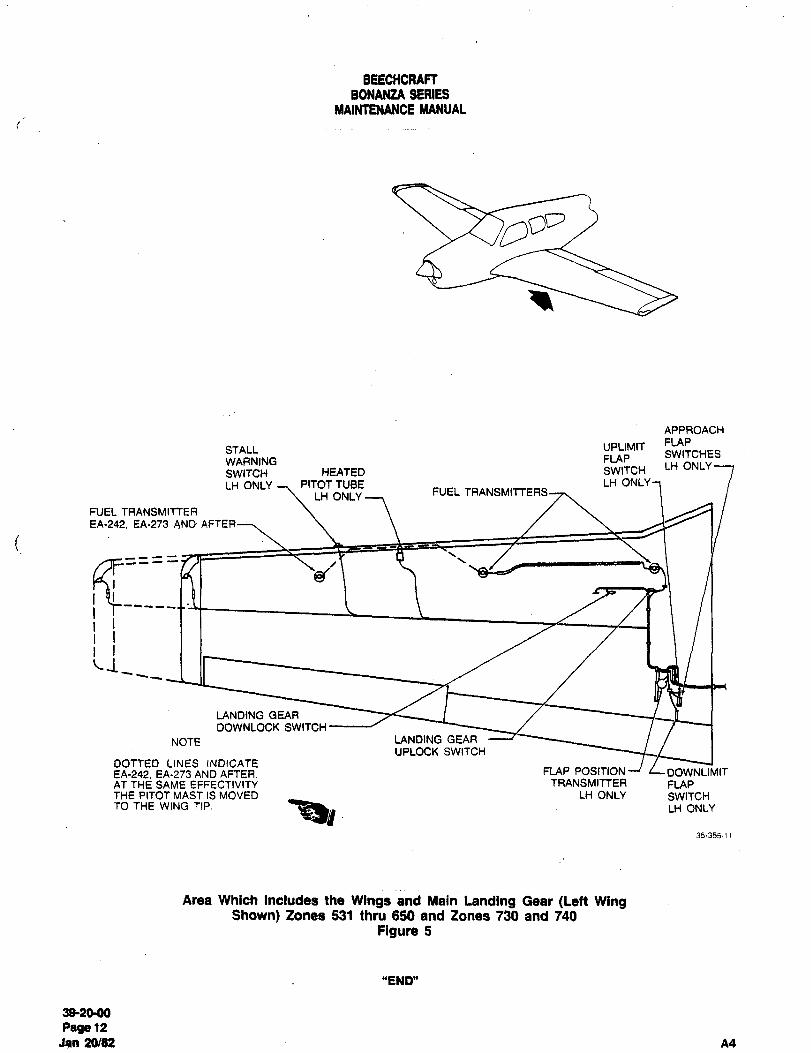
BEECHCRAFTBONANZA SERIES
MAINTENANCE MANUAL
APPROACH
STALL UPCIMIT FLAPSWITCHES
WARNING FLAPLH ONLY
SWITCH HEATED SWITCH
LH ONLY PITOT TUBE LH ONLY
LH ONLYFUEL TRANSMITTERS
FUEL TRANSMITTER
EA-242. EA´•273 AND
LANDING GEAR
DOWNLOCK SWITCH
NOTE LANDING GEAR
UPLOCK SWITCH
DOTTED LINES INDICATEEA-242. EA-273 AND AFTER. FLAP POSITION LDOWNLIMITAT THE SAME EFFECTIVITY TRANSMITTER FLAPTHE PITOT MAST IS MOVED LH ONLY SWITCHTO THE WING TIP. LH ONLY
35-355-11
Area Which Includes the Wings and Main Landing Gear (Lett WingShown) Zones 531 thru 650 and Zones 730 and 740
Figure 5
"END"
3820-00
Pags12Jan 20102 A4

CHAPTER
STANDARDPRACTICES-
STRUCTURES
BEECHCRAFT
BONANZA SERIES
MAINTENANCE MANUAL
CHAPTER 51 STRUCTURES
~ABLE OF CONTENTS
CHAPTER
SECTION
SUBJECT SUBJECT PAGE
GENERAL .................51 -00-00
Description and Operation ..................1
Primary Structural Components ........1
Secondary Structural Components ........1
Maintenance Practices ........1
Structural Repair ........1
Repair of Fiberglass Components ........2
"END"
51-CONTENTS
Page 1
A12 Aug 28/87

BEECHCRAFT
BONANZA SERIES
MAINTENANCE MANUAL
CHAPTER 51
LIST OF FACE EFFECTIVITY
CHAPTER
SECTION
SUBJECT PAGE DATE
51-EFFECTIVITY 1 Oct 16/92
51-CONTENTS 1 Aug 28/87
51-00-00 1 Oct 16/92
2 Oct 16/92
"END"
51-EFFECTIVITY
Page 1
A16 Oct 16/92
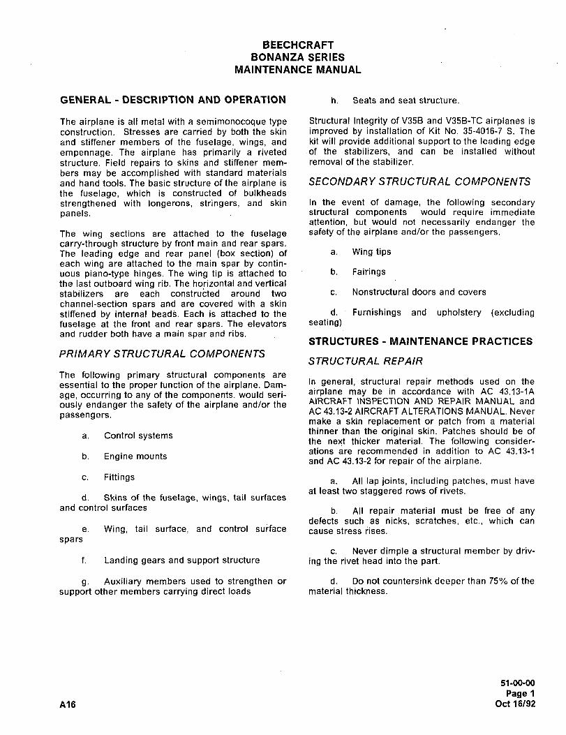
BEECHCRAFT
BONANZA SERIES
MAINTENANCE MANUAL
GENERAL DESCRIPTION AND OPERATION h. Seats and seat structure.
The airplane is all metal with a semimonocoque type Structural Integrity of V35B and V35B-TC airplanes is
construction. Stresses are carried by both the skin improved by installation of Kit No. 35-4016-7 S. The
and stiffener members of the fuselage, wings, and kit will provide additional support to the leading edgeempennage. The airplane has primarily a riveted of the stabilizers, and can be installed without
structure. Field repairs to skins and stiffener mem- removal of the stabilizer.
bers may be accomplished with standard materials
and hand tools. The basic structure of the airplane is SECONDARYSTRUCTURAL COMPONENTSthe fuselage, which is constructed of bulkheads
strengthened with longerons, stringers, and skin In the event of damage, the following secondarypanels. structural components would require immediate
attention, but would not necessarily endanger the
The wing sections are attached to the fuselage safety of the airplane and/or the passengers.
carry-through structure by front main and rear spars.The leading edge and rear panel (box section) of a. Wing tipseach wing are attached to the main spar by contin-
uous piano-type hinges. The wing tip is attached to b. Fairingsthe last outboard wing rib. The horizontal and vertical
stabilizers are each constructed around two c. Nonstructural doors and covers
channel-section spars and are covered with a skin
stiffened by internal beads. Each is attached to the d. Furnishings and upholstery (excludingfuselage at the front and rear spars. The elevators seating)and rudder both have a main spar and ribs.
STRUCTURES MAINTENANCE PRACTICES
PRIMARY STRUCTURAL COMPONENTSSTRUCTURAL REPAIR
The following primary structural components are
essential to the proper function of the airplane. Dam- In general, structural repair methods used on the
age, occurring to any of the components, would seri- airplane may be in accordance with AC 43.13-1A
ously endanger the safety of the airplane and/or the AIRCRAFT INSPECTION AND REPAIR MANUAL and
AC 43.13-2 AIRCRAFT A LTERATIO N S MAN UA L. Neverpassengers.
make a skin replacement or patch from a material
a. Control systemsthinner than the original skin. Patches should be of
the next thicker material. The following consider-
ations are recommended in addition to AC 43.13-1b. Engine mounts
and AC 43.13-2 for repair of the airplane.
c. Fittingsa. All lap joints, including patches, must have
at least two staggered rows of rivets.d. Skins of the fuselage, wings, tail surfaces
and control surfaces b. All repair material must be free of anydefects such as nicks, scratches, etc., which can
e. Wing, tail surface, and control surface cause stress rises.
spars
c. Never dimple a structural member by driv-
f. Landing gears and support structure ing the rivet head into the part.
g. Auxiliary members used to strengthen or d. Do not countersink deeper than 75% of the
support other members carrying direct loads material thickness.
51-00-00
Page 1
Ale Oct 16/92
BEECHCRAFT
BONANZA SERIES
MAINTENANCE MANUAL
RFPAIR OF FIBIFRGLASS COMPON~NTS d. Apply an even coat of resin to the sanded
area. Impregnate all three laminated glass cloth
a. Large holes and cracks require that the patches by laying the patches on clean waxed paper
damaged area be cut out and trimmed just beyond and working the resin through the fabric with a 2-inchbrush.
the area of damage. If the parts are painted, remove
the paint and sand that portion of the part extendinge. Place the large patch over the cutout area,
at least 2 inches beyond the cutout, working out all bubbles and wrinkles. If the patchstarts to sag, place a support behind the repair area.
b. Prepare 3 patches of laminated glass cloth, Coat the support with automobile wax or waxedsuch as Trevano, Uniglas, or their equivalent. Cut the paper to prevent the resin from adhering to the sup-first patch to the dimensions of the sanded area, the port. Work out all air bubbles and wrinkles while
second patch 1/2-inch smaller than the first, and the i"stalling the second patch over the first. Install the
third patch 1M-inch smaller than the second. third patch over the second in the same manner.
f. Brush the repaired area with an even coatc. Prepare the MIL-R-7575 resin (24, Chart 1, of resin. After the patches have cured for 24 hours at
91-00-00) for the patch in accordance with the man- temperatures between 230C ~750F) and 660C (1500F),ufacturer’s instructions. Make sure that your hands blend the patch into the contour of the part with fineare free of oil, grease, and dirt when handling the sandpaper. Paint the repair to match the rest of theresin. part.
"END"
51-00-00
Page 2
Oct16/92 A16

CHAPTER
DOORS
Raynnton Aircraft CompanyBONANZA SERIES MAINTENANCE MANUAL
CHAPTER 52 DOORS
TABLE OF CONTENTS
SUBJECT PAGE
52-00-00
General Description and Operation ..1
Cabin Door
Cabin Door QuickRelease Mechanism (CJ-149and AfterOnly) ........._____.................1
Utility Doors (E-llll, E-1241 andAfter; EA-1 and After). .........____._...1
Baggage Doors (CE-748, CE-772 and After; CJ-149 and After; D-10097, 0-10120 and After) ........._ .1
52-1 0-00
Cabin PassengerlCrew Door- Maintenance Practices ......1
Cabin Door Removal (E-llll, E-1241 and After; EA-11 and After; CE-748, CE-772 and After;
D-10097, D-10120 andAfter) ............_..._ ................._....1
Cabin Door Installation (E-llll, E-1241 and After; EA-11 and After; CE-748, CE-772 and After;D-10097, D-10120and After) ....´•1
Cabin DoorRemoval (CJ-149andAfterOnly) ............2
Cabin Door Installation (CJ-149and AfterOnly). ..........2
Cabin Door Adjustment.Installing Cabin Door Lock and Fitting Tumbler to Key .9
Removing and Installingthe Cabin DoorTeleflexCable. ....9
Interior Cabin Door Handle .......10
InteriorCabin DoorHandle Removaland Installation................._ ........._____
..10
52-30-00
Cargo Doors Maintenance Practices........._____ ........._____ ................._
.1
Utility DoorRemoval (E-llll, E-1241 andAfter; EA-1 andAfter)Utility Doorlnstallation (E-llll, E-1241 andAfter; EA-1 andAfter) ...............1
Utility Door Adjustment................._
AdjustmentoftheAft Half of the Utility Door........._____ ........._
.1
Adjustmentof the Fon~vard Half of the Utility Door........._.____
.1
Utility DoorLatch PinAdjustment ...1
InteriorUtility DoorHandle Removaland Installation .......2
Large Baggage Door Removal (CE-748, CE-772 and After; CJ-149 and After;D-10097, D-10120 andAfter) ....2
Large Baggage Door Installation (CE-748, CE-772 and After; CJ-149 and After;D-10097, D-10120 and After) ................._
....2
Small Baggage Door Removal (CE-748, CE-772 and After; CJ-149 and After;D-10097, D-10120 andAfter) ....2
Small Baggage Door Installation (CE-748, CE-772 and After; CJ-149 and After;D-10097, D-10120 andAfter) ........._ ....2
Baggage Door Ad~ustment (CE-748, CE-772 and After; CJ-149 and After;D-10097, D-10120 and After) ................._
....2
n27 52-CONTENTS Mar 31105Pagel
MaY)haOyl nircraft CompanyBONANZA SERIES MAINTENANCE MANUAL
CHAPTER 52 DOORS
LIST OF EFFECTIVE PA GES
CH-SE-SU PAGE DATE
52-LOEP Mar 31/05
52-CONTENTS 1 Mar 31/05
52-00-00 1 May 9/80
52-10-00 1 thru 11 Mar 31/05
52-30-00 1 thru 3 Dec 23/99
A27 52-LOEP Mar 31105Page 1
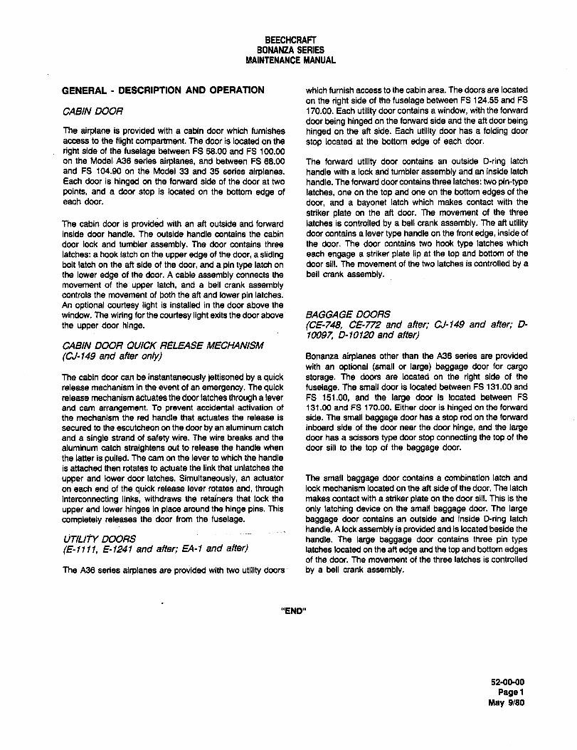
BEECHCRAFTBONANZA SERIES
MAINTENANCE MANUAL
GENERAL DESCRIPTION AND OPERATION which furnish access to the cabin area. The doors are located
on the right side of the fuselage between FS 124.55 and FS
CABIN DOOR 170.00. Each utility door contains a window, with the forward
door being hinged on the forward side and the aft door beingThe airplane is provided with a cabin door which furnishes hinged on the aft side. Each utility door has a folding door
access to the flight compartment. The door is located on the stop located at the bottom edge of each door.
right side of the fuselage between FS 58.00 and FS 100.00
on the Model A36 series airplanes, and between FS 68.00 The forward utility door contains an outside D-ring latch
and FS 104.90 on the Model 33 and 35 series airplanes, handle with a lock and tumbler assembly and an inside latch
Each door is hinged on the forward side of the door at two handle. The forward door contains three latches: two pin-typepoints, and a door stop is located on the bottom edge of latches, one on the top and one on the bottom edges of the
each door. door, and a bayonet latch which makes contact with the
striker plate on the aft door. The movement of the three
The cabin door is provided with an aft outside and forward latches is controlled by a bell crank assembly. The aft utilityinside door handle. The outside handle contains the cabin door contains a lever type handle on the front edge, inside of
door lock and tumbler assembly. The door contains three the door. The door contains two hook type latches which
latches: a hook latch on the upper edge of the door, a sliding each engage a striker plate lip at the top and bottom of the
bolt latch on the aft side of the door, and a pin type latch on door sill. The movement of the two latches is controlled by a
the lower edge of the door. A cable assembly connects the bell crank assembly.movement of the upper latch, and a bell crank assemblycontrols the movement of both the aft and lower pin latches.
An optional courtesy light is installed in the door above the
window. The wiring for the courtesy light exits the door above BAGGAGE DOORS
the upper door hinge. (CE-748, CE-772 and after; CJ-149 and after; D-
10097, 0-10120 and after)CABIN DOOR QUIC~ RELEASE MECHANISM
(C~-149 and after onlyl Bonanza airplanes other than the A36 series are providedwith an optional (small or large) baggage door for cargo
The cabin door can be instantaneously jettisoned by a quick storage. The doors ate located on the right side of the
release mechanism in the event of an emergency. The quick fuselage. The small door is located between FS 131.00 and
release mechanism actuates the door latches through a lever FS 151.00, and the large door is located between FS
and cam arrangement. To prevent accidental activation of 131.00 and FS 170.00. Either door is hinged on the forward
the mechanism the red handle that actuates the release is side. The small baggage door has a stop rod on the forward
secured to the escutcheon on the door by an aluminum catch inboard side of the door near the door hinge, and the largeand a single strand of safety wire. The wire breaks and the door has a scissors type door stop connecting the top of the
aluminum catch straightens out to release the handle when door sill to the top of the baggage door.
the latter is pulled. The cam on the lever to which the handle
is attached then rotates to actuate the link that unlatches the
upper and lower door latches. Simultaneously, an actuator The small baggage door contains a combination latch and
on each end of the quick release lever rotates and, through lock mechanism located on the aft side of the door. The latch
interconnecting links, withdraws the retai/lers that lock the makes contact with a striker plate on the door sill. This is the
upper and lower hinges in place around the hinge pins. This only latching device on the small baggage door. The largecompletely releases the door from the fuselage, baggage door contains an outside and inside D-ring latch
handle. A lock assembly is provided and is located beside the
WTILIjY DOORS handle. The large baggage door contains three pin type
(E-llll, E-1241 and after; EA-I and after) latches located on the aft edge and the top and bottom edgesof the door. The movement of the three latches is controlled
The A36 series airplanes are provided with two utility doors by a bell crank assembly.
"END"
52-00-00
PagelMay 9/80
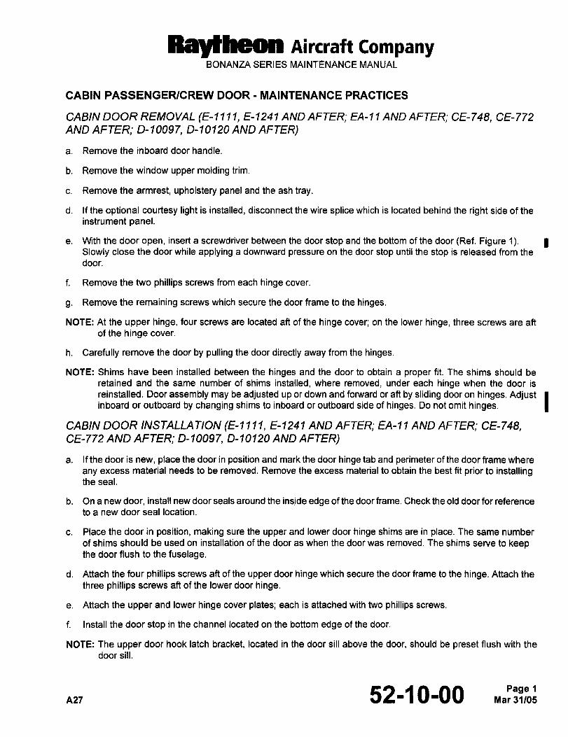
RBytheon Aircraft CompanyBONANZA SERIES MAINTENANCE MANUAL
CABIN PASSENGER/CREW DOOR MAINTENANCE PRACTICES
CABIN DOOR REMOVAL (E- I 11, E-1241 AND AFTER; EA-?1 AND AFTER; CE-748, CE-772
AND AFTER; D-10097, D-10120 AND AFTER)
a. Remove the inboard door handle.
b. Remove the window upper molding trim.
c. Remove the armrest, upholstery panel and the ash tray.
d. If the optional courtesy light is installed, disconnect the wire splice which is located behind the right side of the
instrument panel.
e. With the door open, insert a screwdriver between the door stop and the bottom of the door(Ref. Figure 1).Slowly close the door while applying a downward pressure on the door stop until the stop is released from the
door.
f. Remove the two phillips screws from each hinge cover.
g. Remove the remaining screws which secure the door frame to the hinges.
NOTE: At the upper hinge, four screws are located aft of the hinge cover; on the lower hinge, three screws are aft
of the hinge cover.
h. Carefully remove the door by pulling the door directly away from the hinges.
NOTE: Shims have been installed between the hinges and the door to obtain a proper fit. The shims should be
retained and the same number of shims installed, where removed, under each hinge when the door is
reinstalled. Door assembly may be adjusted up or down and forward or aft by sliding door on hinges. Adjust Iinboard or outboard by changing shims to inboard or outboard side of hinges. Do not omit hinges.
CABIN DOOR INSTALLA TION (E-? I E-1241 AND AFTER; EA-? 1 AND AFTER; CE-748,CE-772 AND AFTER; D-10097, D-10120 AND AFTER)
a. If the door is new, place the door in position and mark the door hinge tab and perimeter of the door frame where
any excess material needs to be removed. Remove the excess material to obtain the best fit prior to installingthe seal.
b. On a new door, install new door seals around the inside edge of the door frame. Check the old door for reference
to a new door seal location.
c. Place the door in position, making sure the upper and lower door hinge shims are in place. The same number
of shims should be used on installation of the door as when the door was removed. The shims serve to keepthe door flush to the fuselage.
d. Attach the four phillips screws aft of the upper door hinge which secure the door frame to the hinge. Attach the
three phillips screws aft of the lower door hinge.
e. Attach the upper and lower hinge cover plates; each is attached with two phillips screws.
f. Install the door stop in the channel located on the bottom edge of the door.
NOTE: The upper door hook latch bracket, located in the door sill above the door, should be preset flush with the
door sill.
n27 52-1 0-00 M,pa3jlleg:Page 1
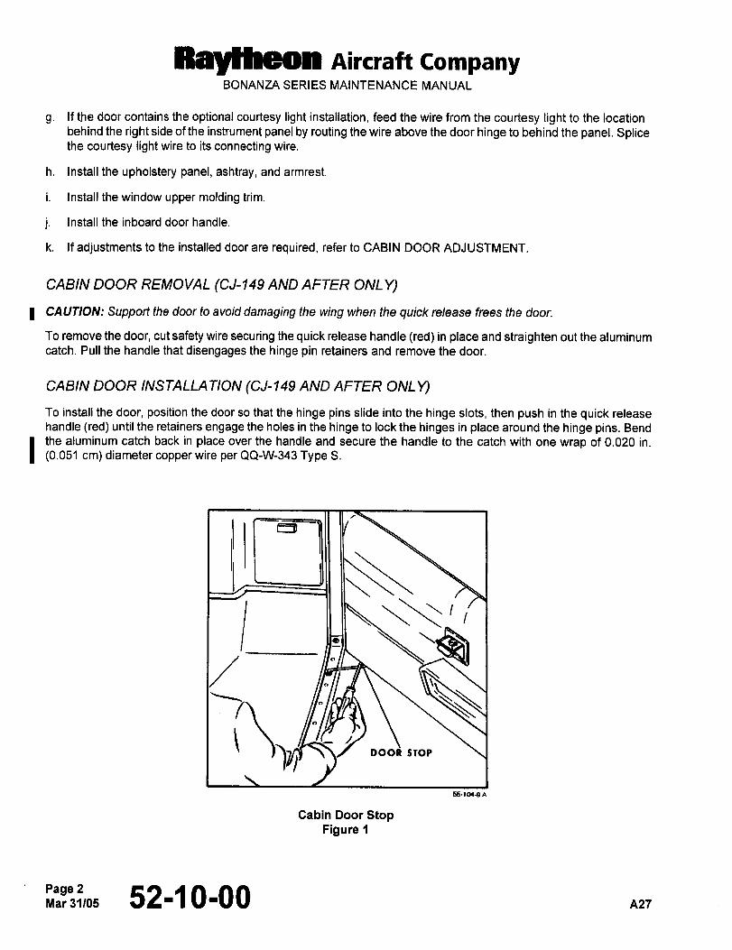
Raytheon Aircraft CompanyBONANZA SERIES MAINTENANCE MANUAL
g. If the door contains the optional courtesy light installation, feed the wire from the courtesy light to the locationbehind the right side of the instrument panel by routing the wire above the door hinge to behind the panel. Splicethe courtesy light wire to its connecting wire.
h. Install the upholstery panel, ashtray, and armrest.
i. Install the window upper molding trim.
j. Install the inboard door handle.
k. If adjustments to the installed door are required, refer to CABIN DOOR ADJUSTMENT.
CABIN DOOR REMOVAL (CJ-149 AND AFTER ONL Y)
I CAUTION: Support the door to avoid damaging the wing when the quick release frees the door.
To remove the door, cut safety wire securing the quick release handle (red) in place and straighten out the aluminumcatch. Pull the handle that disengages the hinge pin retainers and remove the door.
CABIN DOOR INSTALLA TION (CJ-149 AND AFTER ONLY)
To install the door, position the door so that the hinge pins slide into the hinge slots, then push in the quick releasehandle (red) until the retainers engage the holes in the hinge to lock the hinges in place around the hinge pins. Bend
I the aluminum catch back in place over the handle and secure the handle to the catch with one wrap of 0.020 in.
(0.051 cm) diameter copper wire per QQ-W-343 Type S.
Lj~ib
55-l(Y9*
Cabin Door StopFigure 1
Page 2Mar31105 52-~ 0-00 A21
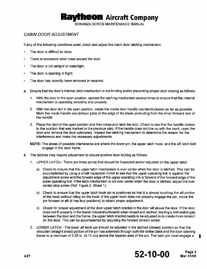
Raytheon Aircraft CompanyBONANZA SERIES MAINTENANCE MANUAL
CABIN DOOR ADJUSTMENT
If any of the following conditions exist, check and adjust the cabin door latching mechanism:
The door is difficult to close.
There is excessive wind noise around the door.
The door is not airtight or watertight.
The door is opening in flight.
The door has recently been removed or repaired.
a. Ensure that the door’s internal latch mechanism is not binding and/or preventing proper door closing as follows:
i. With the door in the open position, operate the latching mechanism several times to ensure that the internal
mechanism is operating smoothly and properly.
2. With the door still in the open position, rotate the inside door handle counterclockwise as far as possible.Mark the inside handle escutcheon plate at the edge of the blade protruding from the inner forward end of
the handle.
3. Place the latch in the open position and then close and latch the door. Check to see that the handle rotates
to the position that was marked in the previous step. If the handle does not line up with the mark, open the
door and remove the door upholstery. Inspect the latchirig mechanism to determine the reason for the
interference and make the necessary adjustments.
NOTE: The areas of possible interference are where the lower pin, the upper latch hook, and the aft latch bolt
engage in the door frame.
b. The latches may require adjustment to ensure positive door locking as follows:
1. UPPER LATCH There are three points that should be inspected and/or adjusted on the upper latch.
a) Check to ensure that the upper latch mechanism is over center when the door is latched. This can be
accomplished by using a small inspection mirror to see that the upper operating link is against the
adjustment screw and the forward edge of the upper operating link is forward of the forward edge of the
lower operating link. If the latch mechanism is not over center when the door is latched, adjust the over
center stop screw (Ref. Figure 2, Sheet 1).
b) Check to ensure that the upper latch hook pin is positioned so that it is almost touching the aft portionof the hook without riding on the hook. If the upper hook does not properly engage the pin, move the
pin forward or aft tit has four positions) to obtain proper adjustment.
c) Check for proper adjustment of the door upper latch bracket in the door sill above the door. If the door
does not fit properly in the frame (inboard/outboard) when closed and latched, leaving a noticeable gapbetween the door and the frame, the upper latch bracket needs to be adjusted in to create more tension
on the door. This can be accomplished by adjusting the forward tension screw.
2. LOWER LATCH The lower aft latch pin should be adjusted in the latched (closed) position so that the
shoulder (straight sided) portion of the pin has extended through both the striker plate and the door openingframe to a minimum of 0.05 in. (0.13 cm) above the tapered area of the pin. The latch pin must engage a I
ns-I 52-~ 0-00 3
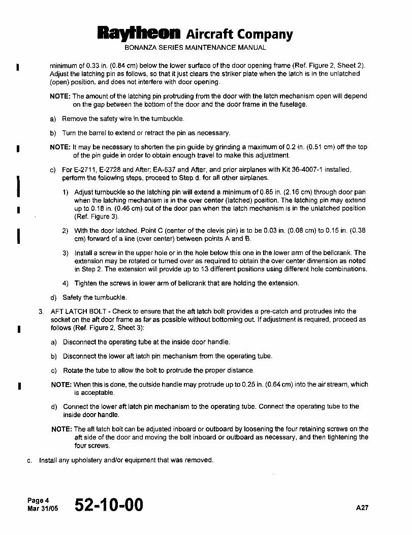
Ray~heon Aircraft CompanyBONANZA SERIES MAINTENANCE MANUAL
I minimum of 0.33 in. (0.84 cm) below the lower surface of the door opening frame (Ref. Figure 2, Sheet 2).Adjust the latching pin as follows, so that it just clears the striker plate when the latch is in the unlatched
(open) position, and does not interfere with door opening.
NOTE: The amount of the latching pin protruding from the door with the latch mechanism open will dependon the gap between the bottom of the door and the door frame in the fuselage.
a) Remove the safety wire in the turnbuckle.
b) Turn the barrel to extend or retract the pin as necessary.
I NOTE: It may be necessary to shorten the pin guide by grinding a maximum of 0.2 in. (0.51 cm) off the topof the pin guide in order to obtain enough travel to make this adjustment.
c) For E-2711, E-2728 and After; EA-537 and After, and prior airplanes with Kit’36-4007-1 installed,
perform the following steps, proceed to Step d. for all other airplanes.
1) Adjust turnbuckle so the latching pin will extend a minimum of 0.85 in. (2.16 cm) through door pan
when the latching mechanism is in the over center (latched) position. The latching pin may extend
I up to 0.18 in. (0.46 cm) out of the door pan when the latch mechanism is in the unlatched position(Ref. Figure 3).
2) With the door latched. Point C (center of the clevis pin) is to be 0.03 in. (0.OS cm) to 0.15 in. (0.38cm) forward of a line lover center) between points A and B.
3) Install a screw in the upper hole or in the hole below this one in the lower arm of the bellcrank. The
extension may be rotated or turned over as required to obtain the over center dimension as noted
in Step 2. The extension will provide up to 13 different positions using different hole combinations.
4) Tighten the screws in lower arm of bellcrank that are holding the extension.
d) Safety theturnbuckle.
3. AFT LATCH BOLT Check to ensure that the aft latch bolt provides a pre-catch and protrudes into the
socket on the aft door frame as far as possible without bottoming out. If adjustment is required, proceed as
I follows (Ref. Figure 2, Sheet 3).
a) Disconnect the operating tube at the inside door handle.
b) Disconnect the lower aft latch pin mechanism from the operating tube.
c) Rotate the tube to allow the bolt to protrude the proper distance.
I NOTE: When this is done, the outside handle may protrude up to 0.25 in. (0.64 cm) into the air stream, which
is acceptable.
d) Connect the lower aft latch pin mechanism to the operating tube. Connect the operating tube to the
inside door handle.
NOTE: The aft latch bolt can be adjusted inboard or outboard by loosening the four retaining screws on the
aft side of the door and moving the bolt inboard or outboard as necessary, and then tightening the
four screws.
c. Install any upholstery and/or equipment that was removed.
Page4Mar 31/05 52-~ 0-00 A27
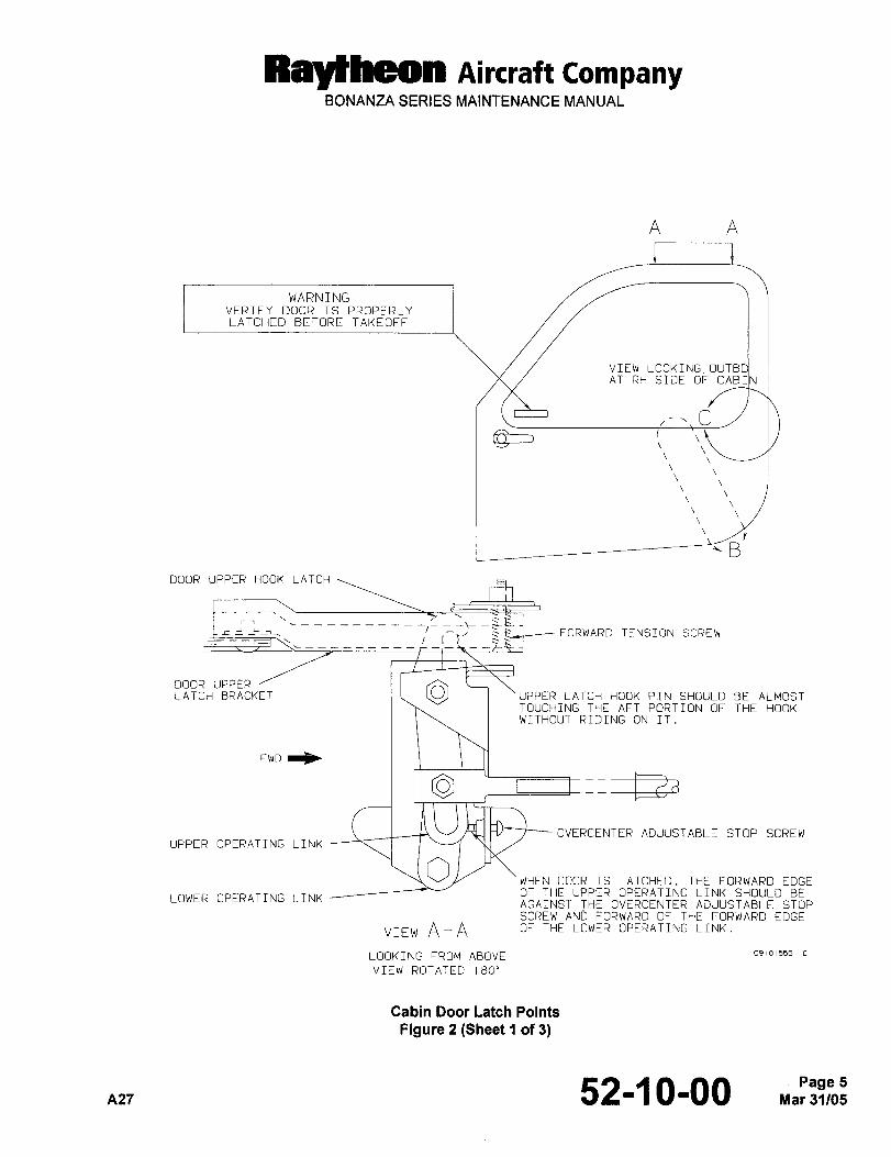
Raytheon nircraft CompanyBONANZA SERIES MAINTENANCE MANUAL
A A
~C_1
WARNINGVERIFY DOOR IS PROPERLYLATCHED BEFORE TAKEOFF
VIEW LOOKING,OUTBAT RH SIDE OF CAB
__
DOOR UPPER HOOK LATCH
FORWARD TENSION SCREW
DOOR UPPERUPPER LATCH HOOK PIN SHOULD BE ALMOSTLATCH BRACKETTOUCHING THE AFT PORTION OF THE HOOKWITHOUT RIDING ON IT.
FWD
OVERCENTER ADJUSTABLE STOP SCREWUPPER OPERATING LINK
OWHEN DOOR IS LATCHED. THE FORWARD EDGEOF THE UPPER OPERATING LINK SHOULD BE
LOWER OPERATING LINKAGAINST THE OVERCENTER ADJUSTABLE STOPSCREW ANb FORWARD OF THE FORWARD EDGE
VIEW A-A OF THE LOWER OPERATING LINK.
LOOKING FROM ABOVE C9101555
VIEW ROTATED 180"
Cabin Door iatch Points
Figure 2 (Sheet 4 of 3)
A27 52-~ 0-00 Mar 31/05Page 5
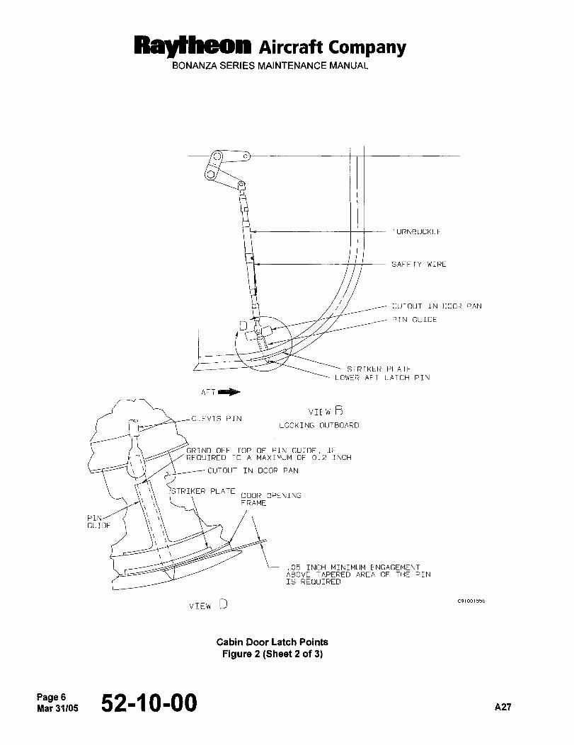
Ral~heon AiKlaR CompanyBONANZA SERIES MAINTENANCE MANUAL
O
TURNBUCKLE
SAFETY WIRE
CUTOUT IN DOOR PAN
DPIN GUIDE
STRIKER PLATE
LOWER AFT LATCH PIN
AFI
VIEW BCLEVIS PIN
LOOKING OUTBOARD
GRIND OFF TOP OF PIN GUIDE, IF
REOUIRED TO A MAXIMUM OF 0.2 INCH
CUTOUT IN DOOR PAN
TRIKER PLATEDOOR OPENINGFRAME
PIN/GUIDE
.05 INCH MINIMUM ENGAGEMENTTTS ABOVE TAPERED AREA OF THE PIN
IS REI3UIRED
VIEW D C91001556
Cabin Door Latch Points
Figure 2 (Sheet 2 of 3)
Page 6Yar31105 52-~ 0-00 A27
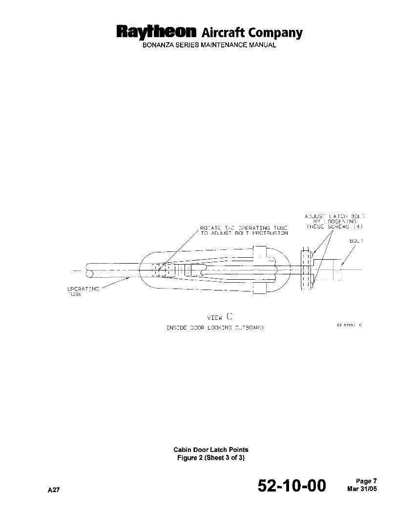
Raytheon AiKraft CompanyBONANZA SERIES MAINTENANCE MANUAL
ADJUST LATCH BOLTBY LOOSENING
ROTATE THE OPERATING TUBE THESE SCREWS 14)
TO ADJUST BOLT PROTRUSION
BOLT
OPERATINGTUBE
VIEW Ccs 01557
INSIDE DOOR LOOKING OUTBOARD
Cabin Door Latch Points
Figure 2 (Sheet 3 of 3)
A27 52-1 0-00 Mar 31/05Page 7
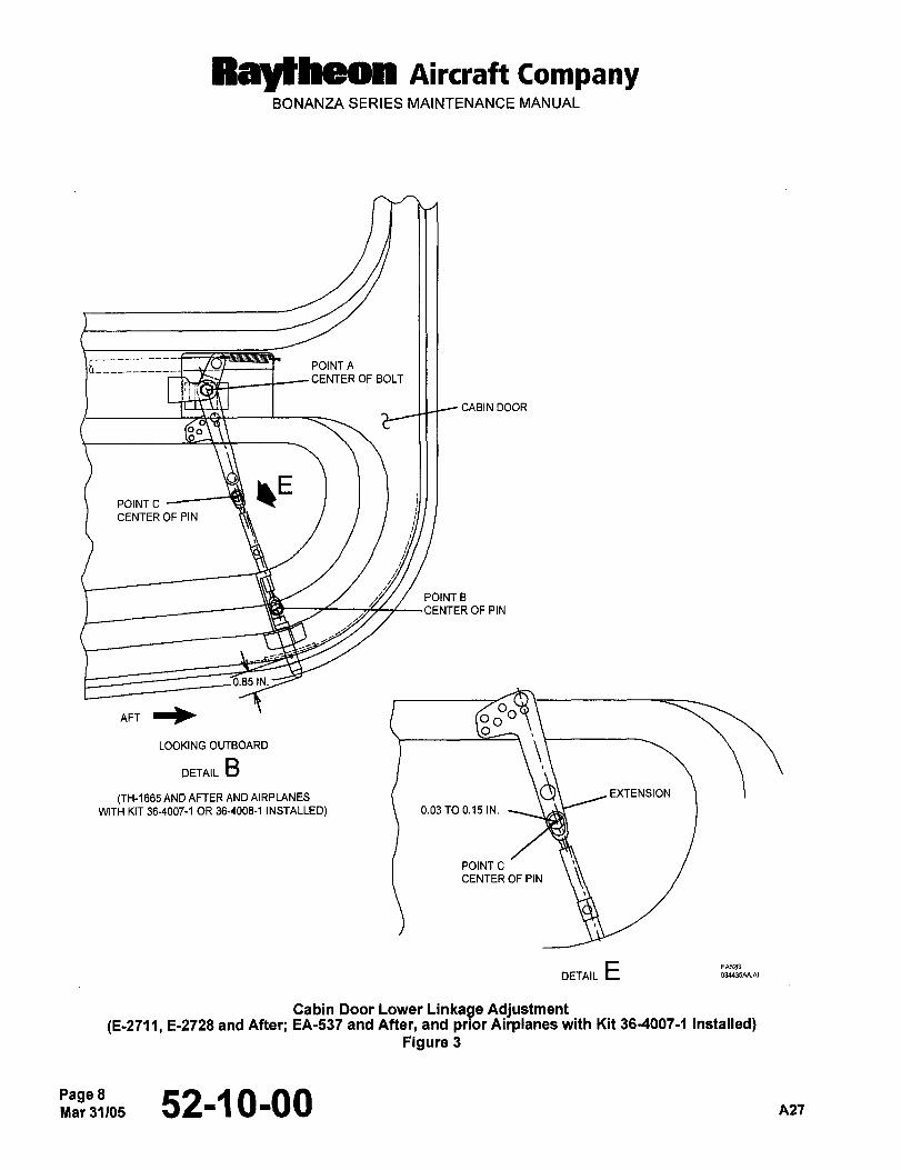
Raydheon Aircraft CompanyBONANZA SERIES MAINTENANCE MANUAL
6_________--~ ´•/V’ POINT A
CENTEROFBOLT
CABIN DOOR
POINT C
CENTER OF PIN
POINT B
CENTER OF PIN
0.85 IN.
I iLOOKING OUTBOARD
DETAIL B
(TH-1665 AND AFTER AND AIRPLANES EXTENSION
WITH KIT 36-4007-1 OR 36-4008-1 INSTALLED) 0.03 TO 0.15 IN.
POINT C
CENTER OF PIN
DETAIL E
Cabin Door Lower Linkage Adjustment(E-2711, 5-2728 and After; EA-537 and After, and prior Airplanes with Kit 36-4007-1 Installed)
Figure 3
Page 8Mar31 105 52-1 0-00 A27
RBytheoR Aircraft CompanyBONANZA SERIES MAINTENANCE MANUAL
INSTALLING CABIN DOOR LOCK AND FITTING TUMBLER TO KEY
When a lock on the baggage compartment door, cabin door or ignition is broken or worn, it is not necessary to install
a full set of replacement locks with a new key. A new tumbler can be readily converted tone time), for use with an
old key. To fit a new tumbler to a key proceed as follows:
a. Insert the key to be used into the new lock.
b. With key in the unlocked position, examine the top of the lock barrel where the slots for the tumbler are located.
c. Note that one or more tumblers are protruding through the slot.
d. With a fine file, remove the raised portion of each of these tumblers. The key will now operate the new lock.
To install a new lock in the cabin door, proceed as follows:
e. Loosen the upholstery panel on the cabin door to gain access to the handle mechanism through the cutout in
the channel under the latch assembly.
f. Remove the lower aft screw from the external door handle fairing directly under the lock mechanismand remove
the pin from the handle through the cutout in the door channel.
NOTE: Both the extreme aft screw and the lower aft screw of the outside latch housing serve as retainers. The
extreme aft screw secures the door handle spring in position, and the lower aft screw retains the sliding bolt
latch pin in position.
g. Remove the aft screw from the external door handle fairing. This will free the handle spring and allow the handle
to be disengaged from the actuating assembly.
h. After fitting the new lock to the key, install the lock barrelin the unlocked positioninto the handle.
i. Bevel the edges of the square hole in the locking cam (beveled edge must face outland place the cam on the
end of the lock barrel. The locking lug on the cam must be in line with the handle.
j. Cover a steel plate with cloth to prevent marring the latch handle and peen the end of the lock barrel until the
locking cam is firmly riveted in place.
k. Install the handle in the door.
REMOVING AND INSTALLING THE CABIN DOOR TELEFLEX CABLE
a. Remove the inside door handle and the machine screws on the upper door facing.
b. Remove the door upholstery panels.
c. Remove the bolt securing the teleflex cable to the upper door latch.
d. Remove the bolt securing the lower end of the cable to the lower actuating arm.
NOTE: Attach a length of safety wire to the lower end of the cable before removing it from the door and leave the
wire in the cable track as a means of positioning the new cable.
e. Grasp the upper end of the cable with vise grip pliers and pull it out through the upper latch opening. Remove
the safety wire from the cable.
NOTE: Braze or silver solder two AN340-832 nuts to two new AN742-4 clamps.
52-~ 0-00 9
Rayt~on AiKraft CompanyBONANZA SERIES MAINTENANCE MANUAL
f. Prior to installing the upper clevis, place one of the newly prepared clamps between the shoulders on the lower
end of the cable housing and attach the safety wire remaining in the door to the upper end of the cable housing.
g. Pull the housing into position by gripping it with vise grip pliers below the shoulder at the lower end. Pull on the
safety wire attached to the upper end while tapping on the vise grip pliers to drive the housing through the door
channel.
h. Align the lower clamp with the hole in the door facing and secure it with a machine screw, then install the upperclamp in place on the housing and secure it in the same manner.
i. Install the upper clevis and attach the cables to the upper and lower latch connections.
j. Adjust cable tension by varying the cable length at either latch connection.
INTERIOR CABIN DOOR HANDLE
INTERIOR CABIN DOOR HANDLE REMOVAL AND INSTALLATION
NOTE: It may be necessary to place the interior cabin door handle in the unlatched position to access both screws
that secure the door handle.
a. Remove the two screws that secure the interior door handle base plate.
b. Slide the interior door handle from the shaft, maintaining the same orientation of the door handle with respectto the shaft (Ref. Figure 4).
c. Rotate the door handle 90" clockwise, maintaining the base plate in the same position.
NOTE: Interior door handle configuration of some airplanes may differ from that shown in Figure 4. Initial setupis important to confirm proper movement and operation of the latching points.
d. Remove the necessary hardware and adjust clevis as required to position the inside door shaft assembly to
approximately 30" below horizontal when in locked position.
e. Attach clevis to inside door shaft assembly with removed hardware.
f. Slide the interior door handle over the shaft and secureusing the screws removed in Step a..
g. Latch the door by rotating the interior door handle counterclockwise.
CAUTION: Rotation of the interior door handle without depressing the handle lock release button should not result
in unlatching of the door.
h. Rotate the interior door handle clockwise without depressing the handle lack release button. If the door remains
latched, proceed to Step g.. If the door becomes unlatched, repeat Steps a. thru e..
i. V~th the door latched, depress the handle lock release button while rotating the door handle clockwise. The door
should unlatch.
Page 10ZB,:~, 52-~ 0-00 n27
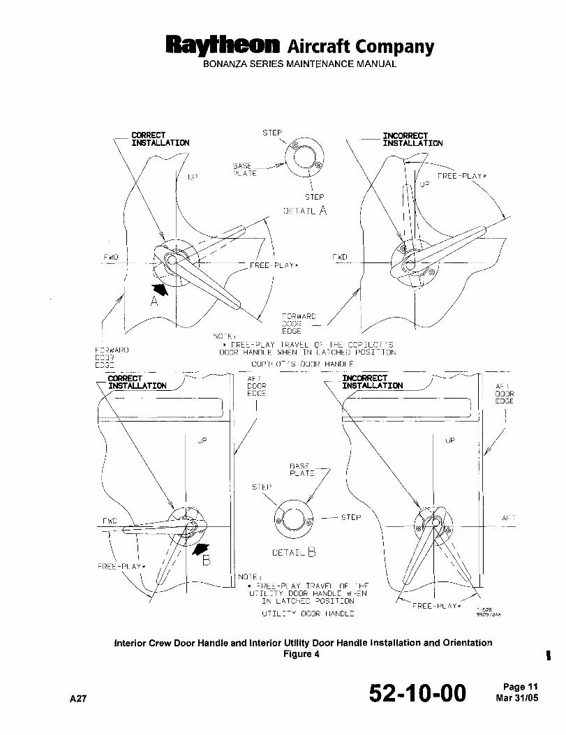
Ray~heon Aircraft CompanyBONANZA SERIES MAINTENANCE MANUAL
CORRECT STEP INCORRECTINSTALLATIONINSTALLATION
BASEPLATE FREE-PLAYx
up
STEP
DETAIL A
FWD i FWD I;FREE-PLAY+
I
A
EDGENOTE:
FREE-PLAY TRAVEL OF THE COPILOT’SFORWARD DOOR HANDLE WHEN IN LATCHED POSITIONDOOREDGE COPILOT’S DOOR HANDLE
CORRECT P AFT INCORRECTAF1
EDGE DOOREDGE
UP ii i UP
BASE
PLATE
STEP
FWO /I ii AFT
DETAIL B/B
FREE-PLAY*
NOTE:
x FREE-PLAY TRAVEL OF THEUTILITY DOOR HANDLE WHEN
IN LATCHED POSITIONFREE-PLAYx
TH528UTILITY DOOR HANDLE 992572AA
Interior Crew Door Handle and Interior Utility Door Handle Installation and Orientation
Figure 4
A27 52-~ 0-00 Mar 31105Page 11
Raytheon AircraftBEECH BONANZA SERIES MAINTENANCE MANUAL
CARGO DOORS MAINTENANCE PRACTICES
UTILITY DOOR REMOVAL (E- 1 I I I, E- 124 1 AND AFTER; EA- I AND AFTER)
a. With the doors open, remove the screws that attach the scissors door stop to the door sill.
b. Support the doors and remove the hinge pins by pulling straight up.
UTILITY DOOR INSTALLA TION (E- I I 1 I, E- 1241 AND AFTER; EA- I AND AFTER)
a. Support the doors and install the hinge pins.
b. Install the screws that attach the scissors door stop to the door sill.
UTILITY DOOR ADJUSTMENT
If the utility door does not close properly or permits air leaks while completely closed, several adjustments may be
made to assure proper sealing of the door. After determining the origin of the air leakage as to whether it is from
around the forward half of the utility door or the aft half of the door, make the following adjustments as necessary:
ADJUSTMENT OF THE AFT HALF OF THE UTILITY DOOR
a. Adjustments of the aft door may be performed by removing the upholstery paneling and shortening or length-ening the door latch connecting tube assembly.
NOTE
By shortening the connecting tube assemblies, the door will be pulled tighter against the door seal.
b. To adjust the length of the connecting tube assembly, remove the cotter key, washers and pin. Turn the pin eye"in" to shorten the tube assembly and turn the pin eye "out" to lengthen the tube assembly.
c. After the desired length has been set, install the pin, washers and cotter key.
d. Replacethe upholstery paneling.
ADJUSTMENT OF THE FORWARD HALF OF THE UTILITY DOOR
a. If air leakage is found around the forward half of the door, the necessary adjustments may be made at the aft
door latch striker plates, located slightly above and below the upper and lower door sill of the aft door.
b. For a tighter fit, loosen the screws on the upper and lower striker plates on the aft door and move them inboard.
By moving the plates inboard, the aft door will adjust inboard thus pulling inward the forward door when it is latched.
UTILITY DOOR LA TCH PIN ADJUSTMENT
If the forward door does not open freely, the door latch pins may not be retracting enough. This may be corrected
by the following adjustments:
a. Removethe upholsterypaneling.
b. Removethecotterkeys, pinsandwashers.
c. Loosen the pin eye jam nut and turn the pin eye "in" to shorten the tube assemblies; turn the pin eye "out" to
lengthen the tube assemblies.
nzl 52-30-00 ~.c’Z:
Ray~heon AircraftBEECH BONANZA SERIES MAINTENANCE MANUAL
d. After the desired length has been set, tighten the pin eye jam nut. Install the pins, washers and cotter keys.
e. Replacethe upholstery paneling.
INTERIOR UTILITY DOOR HANDLE REMOVAL AND INSTALLATION
Refer to Section 52-10-00, INTERIOR CABIN DOOR HANDLE for the removal, installation and checkout instruc-
tions for the interior utility door handle.
LARGE BAGGAGE DOOR REMOVAL (CE-748, CE-772 AND AFTER; CJ- 149 AND AFTER;D-10097, 0-10120 AND AFTER)
a. On the large type door, unlatch the door and remove the scissors type door stop at the top of the door.
b. Removethedoorhinge pin.
LARGE BAGGAGE DOOR INSTALLATION (CE-748 CE-772 AND AFTER;CJ- 149 AND AFTER; D- 10097 0-10120 AND AFTER)
a. Installthedoorhinge pin.
b. Install the scissors type door stop at the top of the door.
SMALL BAGGAGE DOOR REMOVAL (CE-748, CE-772 AND AFTER; CJ- 149 AND AFTER;D-10097, D- 10120 AND AFTER)
a. On the small door, unlatch the door and remove the door hinge pin while carefully holding the door in position.
b. Disconnect the door stop rod from the door at the door.
SMALL BAGGAGE DOOR INSTALLA TION (CE-748 CE-772 AND AFTER;CJ- 149 AND AFTER; D- 10097 D- 10120 AND AFTER)
a. Connectthestop rodtothedoor.
b. While carefully holding the door in position, install the hinge pin.
BAGGAGE DOOR ADJUSTMENT (CE-748 CE-772 AND AFTER; CJ- 149 AND AFTER;D- 10097 0-10120 AND AFTER)
If the large baggage door does not open freely, the door latch pins may not be retracting enough. This may be cor-
rected by the following adjustments:
a. Removethe upholsterypaneling.
b. Remove the cotter keys, pins, and washers.
c. Loosen the pin eye jam nut and turn the pin eye "in" to shorten the tube assemblies; turn the pin eye "out" to
lengthen the tube assemblies.
d. After the desired length has been set, tighten the pin eye jam nut. Install the pins, washers and cotter keys.
e. Replacethe upholstery paneling.
Page 2~’2’3199 52130100 A21
Ray~heon AircraftBEECH BONANZA SERIES MAINTENANCE MANUAL
If additional inward tension for a tighter fit of the door is required, adjust inward the three striker plates on the door
sill (large door), or inward on the single latch mechanism contact plate on the door sill (small door).
A21 52-30-00 Dec 23/99Page 3

CHAPTER
FUSELAGE
Raycheon Aircraft CompanyBONANZA SERIES MAINTENANCE MANUAL
CHAPTER 53 FUSELAGE
TABLE OF CONTENTS
SUBJECT PAGE
53-1 0-00
Fuselage- Maintenance Practices ...1
Wing FoMlard SparCarry-Through Structure Inspection Without Repair Kit ........1
Wing Forward SparCarry-Through Structure Inspection With Repair Kit. ..........1
Wing FoMlard SparCarry-Through Structure Repair/inspection .................3
Bend RadiusCrack. ´•3
Web Face Crack.
Combination Bend RadiusAndWeb FaceCracks. .....3
53-30-00
Plates/Skin- Maintenance Practices ..1
Fuselage Access Openings (CE-748, CE-772 and After, CJ-149 and After) ........1
Fuselage Access Openings (D-10097, D10120 and After). ..2
Fuselage Access Openings(E-llll, E-1241 and After, EA-1 and After). ..........3
Fuselage Skin Thickness (CE-748, CE-772 and After, CJ-149 and After) ..........4
Fuselage SkinThickness (D-10097, 010120 and After). ....8
Fuselage Skin Thickness(E-llll, E-1241 and After, EA-1 and After) ............8
Page 1
53-CONTENTS Sep 30/04
Ray~heon nircraft CompanyBONANZA SERIES MAINTENANCE MANUAL
CHAPTER 53 FUSELAGE
LIST OF EFFECTIVE PAGES
CH-SE-SU PAGE DATE
53-LOEP 1 Sep 30/04
53-CONTENTS 1 Sep 30/04
53-10-00 1 thru 5 Sep 30/04
53-30-00 1 thru 9 May 9/80
A26 53-LOEP Sep 30/04Page 1
Ray~heon Aircraft CompanyBONANZA SERIES MAINTENANCE MANUAL
FUSELAGE MAINTENANCE PRACTICES
WING FORWARD SPAR CARRY-THROUGH STRUCTURE INSPECTION WITHOUT REPAIR
KIT
This procedure provides inspection and repair information relating to the forward wing spar structure at the forward
and aft frames.
NOTE: The areas identified in Figure 1 should be inspected for cracking at the intervals specified for non repairedstructures by Chart 1 using the following inspection procedure:
a. Remove the carry-through cover to obtain access to the forward spar carry-through structure. Refer to the
FORWARD CARRY-THROUGH SPAR COVER REMOVAL procedure in 25-00-00.
b. Thoroughly clean the forward and aft frames (webs) of the forward spar carry-through structure in the areas
shown in Figure 1 with solvent (26, Chart 1, 91-00-00).
c. Perform a visual inspection of the cleaned areas for evidence of cracks.
d. Perform a fluorescent or dye penetrant inspection of the cleaned area per MIL-STD-6866 and inspect for
evidence of cracks.
e. If cracks are discovered, determine the crack size and method of repair as outlined in the WING FORWARD
SPAR CARRY-THROUGH STRUCTURE REPAIR/INSPECTION procedure.
f. If no cracks are noted, install the carry-through cover. Refer to the FORWARD CARRY-THROUGH SPAR
COVER INSTALLATION procedure in 25-00-00.
WING FORWARD SPAR CARRY-THROUGH STRUCTURE INSPECTION WITH REPAIR KIT
NOTE: The areas identified in Figure 1 should be inspected for cracking at the intervals specified for repairedstructures by Chart 2 using the following inspection procedure:
a. Remove the carry-through cover to obtain access to the forward spar carry-through structure. Refer to the
FORWARD CARRY-THROUGH SPAR COVER REMOVAL procedure in 25-00-00.
b. Thoroughly clean the forward and aft frames (webs and reinforcing doubler) of the forward spar carry-throughstructure in the areas shown in Figure 1 with solvent (26, Chart 1, 91-00-00).
c. Perform a visual inspection of the cleaned areas for evidence of cracks.
d. Perform a fluorescent or dye penetrant inspection of the cleaned area per MIL-STD-6866 and inspect for
evidence of cracks.
e. If cracks are discovered in the doubler or the existing web face, the crack has progressed beyond the doubler
profile; contact the Technical Support Department at Raytheon Aircraft Company for further instructions.
f. If no cracks are noted, install the carry-through cover. Refer to the FORWARD CARRY-THROUGH SPAR
COVER INSTALLATION procedure in 25-00-00.
53-1 0-00 1
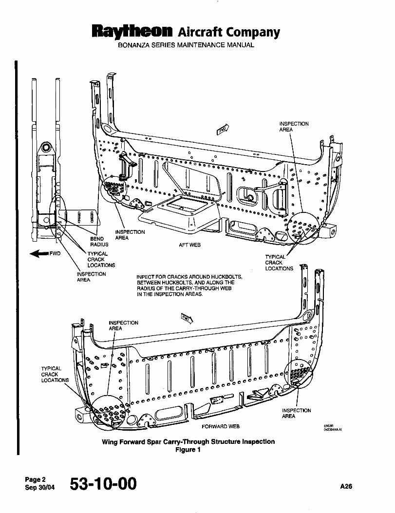
Raytheon AiKraft CompanyBONANZA SERIES MAINTENANCE MANUAL
INSPECTIONAREA
op
oso´•0´•8 3
898 a
aa oo
~O
:O O u iiOe~ I"ae
"e~eg
a as jl a\oa a,a a
a
aa O IIa
’Oso,,.~a
aaa a
BQisa,
INSPECTION a_s
BEND AREA o
RADIUS AFT WEB
TYPICALTYPICAL
CRACKCRACK
LOCATIONSLOCATIONS
INSPECTIONINFECT FOR CRACKS AROUND HUCKBOLTS,BETWEEN HUCKBOLTS, AND ALONG THE DAREA
RADIUS OF THE CARRY-THROUGH WEB
IN THE INSPECTION AREAS.
INSPECTIONnREa ~p´•´°"
6" O 80aa o
QO Qa
PD Oa
O O eb~O Og o
a 8 00TYPICAL Q
CRACK aaLOCATIONS a
daaa aa6
a ba
a aaaa
e _I~,. o´•´•´•6
QQ,QQ’a
AREAINSPECTIONFORWARD WEB EA53B
W2364AAAI
Wing Fonnrard Spar Carry-Through Structure InspectionFigure 1
Sep 30/04Page 2 53-1 0-00 A26
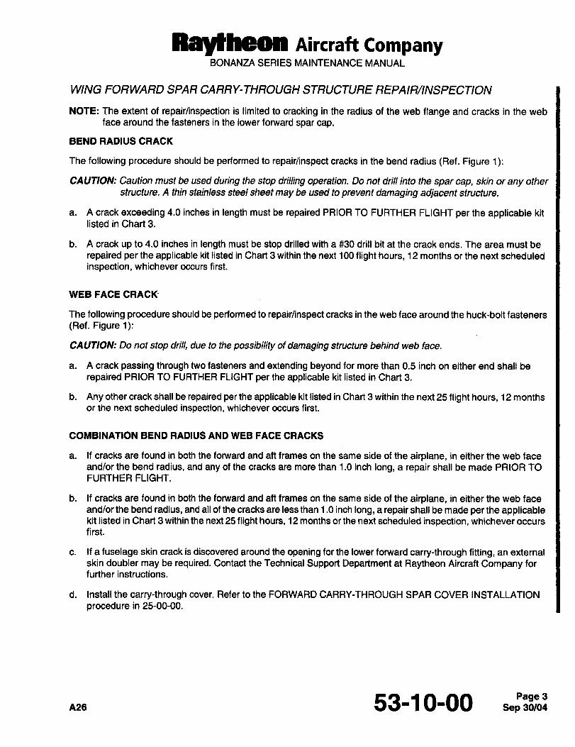
RBYtheOll AiKraft CompanyBONANZA SERIES MAINTENANCE MANUAL
WING FORWARD SPAR CARRY-THROUGH STRUCTURE REPAIR/INSPECTION
NOTE: The extent of repair/inspection is limited to cracking in the radius of the web flange and cracks in the web
face around the fasteners in the lower forward spar cap.
BEND RADIUS CRACK
The following procedure should be performed to repair/inspect cracks in the bend radius (Ref. Figure 1):
CAUTION: Caution must be used during the stop drilling operation. Do not drill into the spar cap, skin or any other
structure. A thin stainless steel sheet may be used to prevent damaging adjacent structure.
a. A crack exceeding 4.0 inches in length must be repaired PRIOR TO FURTHER FLIGHT per the applicable kit
listed in Chart 3.
b. A crack up to 4.0 inches in length must be stop drilled with a #30 drill bit at the crack ends. The area must be
repaired per the applicable kit listed in Chart 3 within the next 100 flight hours, 12 months or the next scheduled
inspection, whichever occurs first.
WEB FACE CRACK
The following procedure should be performed to repair/inspect cracks in the web face around the huck-bolt fasteners
(Ref. Figure 1):
CAUTION: Do not stop drill, due to the possibility of damaging structure behind web face.
a. A crack passing through two fasteners and extending beyond for more than 0.5 inch on either end shall be
repaired PRIOR TO FURTHER FLIGHT per the applicable kit listed in Chart 3.
b. Any other crack shall be repaired per the applicable kit listed in Chart 3 within the next 25 flight hours, 12 months
or the next scheduled inspection, whichever occurs first.
COMBINATION BEND RADIUS AND WEB FACE CRACKS
a. If cracks are found in both the forward and aft frames on the same side of the airplane, in either the web face
and/or the bend radius, and any of the cracks are more than 1.0 inch long, a repair shall be made PRIOR TO
FURTHER FLIGHT.
b. If cracks are found in both the forward and aft frames on the same side of the airplane, in either the web face
and/or the bend radius, and all of the cracks are less than 1.0 inch long, a repair shall be made per the applicablekit listed in Chart 3 within the next 25 flight hours, 12 months or the next scheduled inspection, whichever occurs
first.
c. If a fuselage skin crack is discovered around the opening for the lower forward carry-through fitting, an external
skin doubler may be required. Contact the Technical Support Department at Raytheon Aircraft Company for
further instructions.
d. Install the carry-through cover. Refer to the FORWARD CARRY-THROUGH SPAR COVER INSTALLATION
procedure in 25-00-00.
n2s 53-1 0-00Page 3
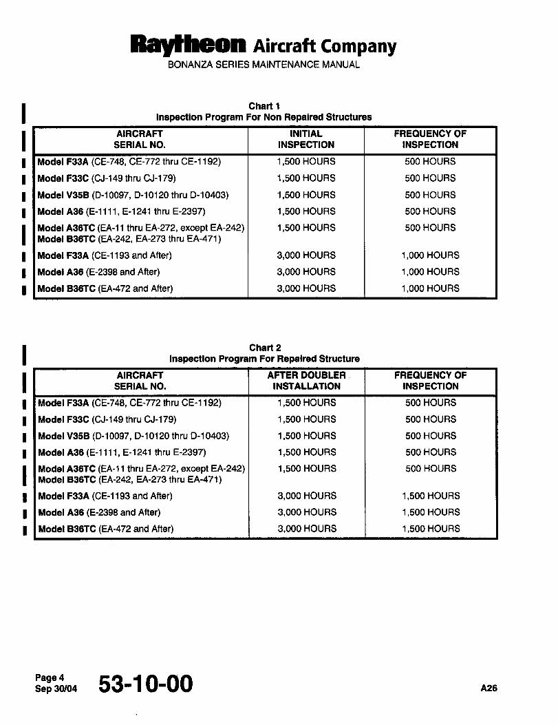
RBy~heOn AsKraft CompanyBONANZA SERIES MAINTENANCE MANUAL
I Chart 1
Inspection Program For Non Repaired Structures
I AIRCRAFT INITIAL FREQUENCY OF
SERIAL NO. INSPECTION INSPECTION
I Model F33A (CE-748, CE-772 thru CE-1192) 1,500 HOURS 500 HOURS
I Model F33C (CJ-149 thru CJ-179) 1,500 HOURS 500 HOURS
I Model V35B (D-10097, D-10120 thru D-10403) 1,500 HOURS 500 HOURS
Model A36 (E-llll, E-1241 thru E-2397) 1,500 HOURS 500 HOURS
Model A36TC (EA-I1 thru EA-272, except EA-242) 1,500 HOURS 500 HOURS
Model B36TC (EA-242, EA-273 thru EA-471)
I Model F33A (CE-1193 and After) 3,000 HOURS 1,000 HOURS
I Model A36 (E-2398 and After) 3,000 HOURS 1,000 HOURS
Model B36TC (EA-472 and After) 3,000 HOURS 1,000 HOURS
I Chart 2
Inspection Program For Repaired Structure
I AIRCRAFT AFTER DOUBLER I FREQUENCY OF
SERIAL NO. INSTALLATION INSPECTION
Model F33A (CE-748, CE-772 thru CE-1192) 1,500 HOURS 500 HOURS
Model F33C (CJ-149 thru CJ-179) 1,500 HOURS 500 HOURS
I Model V35B (D-10097, D-10120 thru D-10403) 1,500 HOURS 500 HOURS
Model A36 (E-llll, E-1241 thru E-2397) 1,500 HOURS 500 HOURS
Model A36TC (EA-11 thru EA-272, except EA-242) 1,500 HOURS 500 HOURS
Model B36TC (EA-242, EA-273 thru EA-471)
I Model F33A (CE-1193 and After) 3,000 HOURS 1,500 HOURS
Model A36 (E-2398 and After) 3,000 HOURS 1,500 HOURS
Model B36TC (EA-472 and After) 3,000 HOURS 1,500 HOURS
Sep 30/04Page 4 53-1 0-00 A26
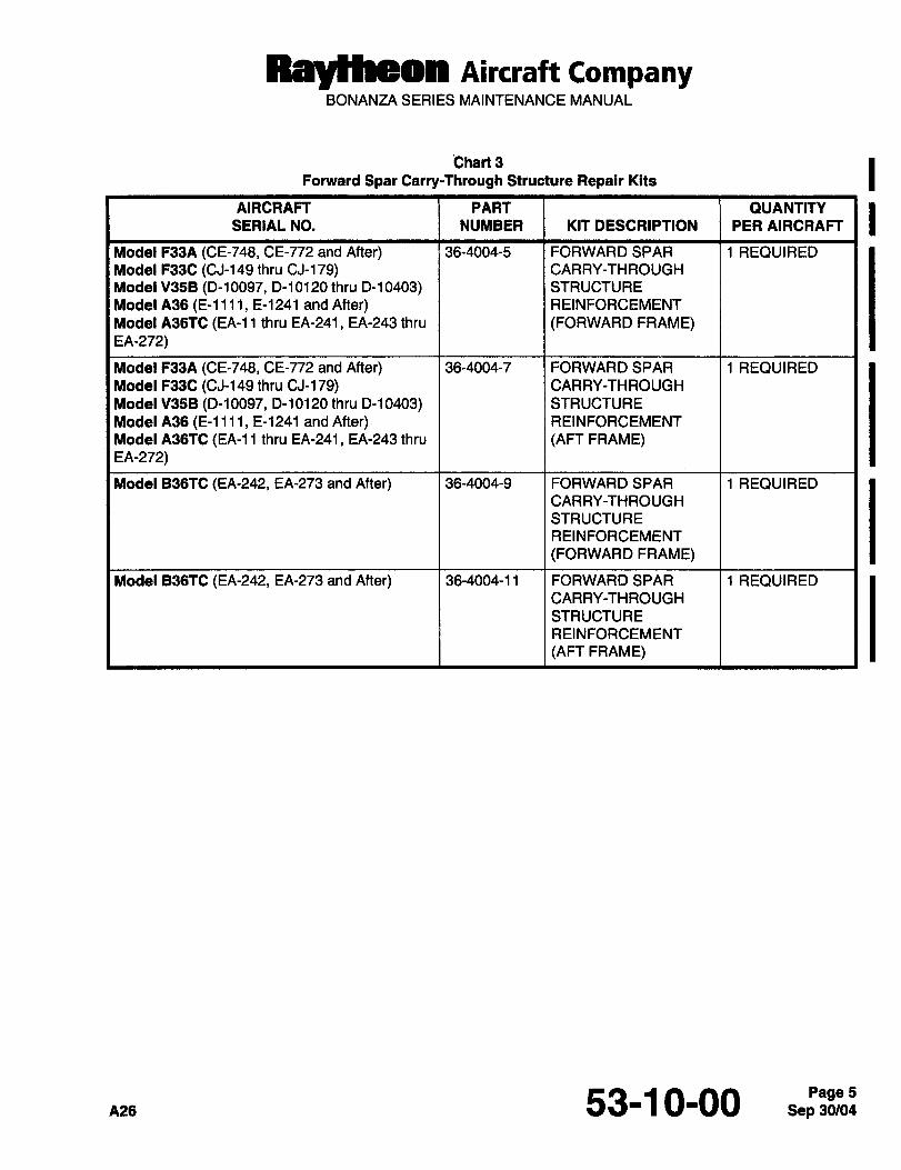
Raytheon AiKraft CompanyBONANZA SERIES MAINTENANCE MANUAL
~Chart 3 IForward Spar Carry-Through Structure Repair Kits
AIRCRAFT PART OUANTITY
SERIAL NO. NUMBER KIT DESCRIPTION PER AIRCRAFT
Model F33A (CE-748, CE-772 and After) 36-4004-5 FORWARD SPAR 1 REQUIRED
Model F33C (CJ-149 thru CJ-179) CARRY-THROUGH
Model V35B (D-10097, D-10120 thru D-10403) STRUCTURE
Model A36 (E-llll, E-1241 and After) REINFORCEMENT
Model A36TC (EA-11 thru EA-241, EA-243 thru (FORWARD FRAME)EA-272)
Model F33A (CE-748, CE-772 and After) 36-4004-7 FORWARD SPAR 1 REQUIRED
Model F33C (CJ-149 thru CJ-1 79) CARRY-TH ROUGH
Model V35B (D-10097, D-10120 thru 0-10403) STRUCTURE
Model A36 (E-llll, E-1241 and After) REINFORCEMENT
Model A36TC (EA-11 thru EA-241, EA-243 thru (AFT FRAME)EA-272)
Model B36TC (EA-242, EA-273 and After) 36-4004-9 FORWARD SPAR 1 REQUIRED
CARRY-THROUGH
STRUCTURE
REINFORCEMENT
(FORWARD FRAME)
Model B36TC (EA-242, EA-273 and After) 36-4004-11 FORWARD SPAR 1 REQUIRED
CARRY-THROUGH
STRUCTURE
REINFORCEMENT
(AFT FRAME)
A26 53-1 0-00 Sep 30/04Page 5
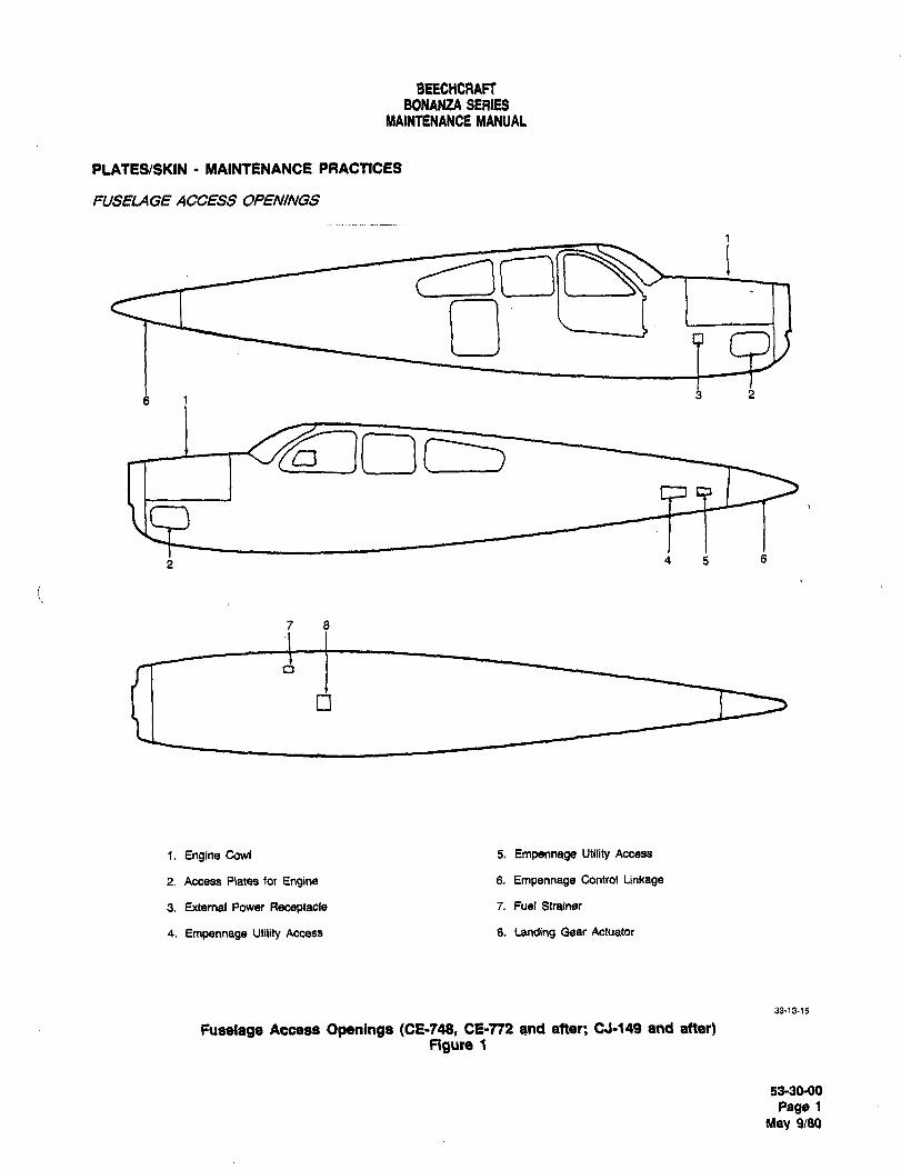
BEECHCRAFTBONAN;ZA SER6S
MAINTENANCE MANUAL
PLATES/SKIN MAINTENANCE PRACTICES
~USELAGE ACCESS OPENINGS
3 25 1
4 5 6
7 5
i. Engine Cowl 5. Empennage Utility Access
2. Access Plates for Engine 6. Empennage Control Linkage
3. External Power Receptacle 7. Fuel Strainer
4. Empennage Utility Access 8. Landing Gear Actuator
33´•13-15
Fuselage Access Openings (CE-t48, CE-772 and atter; CJ-149 and atter)Figu~e
53-3MK)
Page 1
Uay 9(80
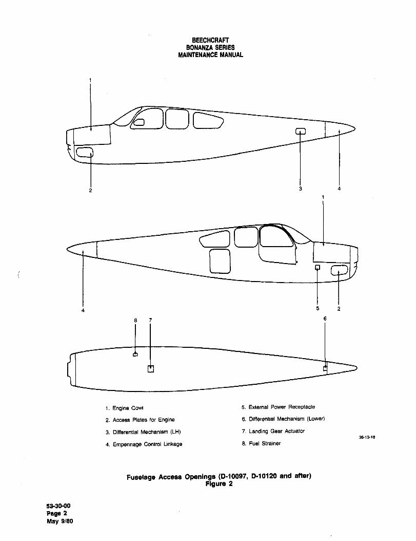
BEECHCRAFTBONANZA SERIES
MAINTENANCE MANUAL
TS
1 3 4
O
5 2
87 6
1. Engine Cowl 5. External Power Receptacle
2. Access Plates for Engine 6. Differential Mechanism (Lower)
3. Differential Mechanism (LH) 7. Landing Gear Actuator
38-13-16
4. Empennage Control Linkage 8. Fuel Strainer
Fuselage Access Openings (0-10097, 0-10120 and after)Figure 2
53-30-00
page 2
May 9/80
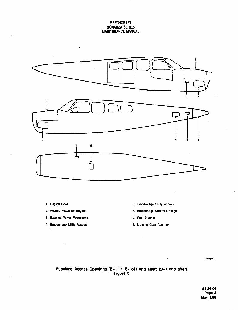
BEECHCRAFTBONANZA SERIES
MAINTENANCE MANUAL
1
3 2
1
~70 o~D
2 456
7 8
i. Engine Cowl 5. Empennage Utility Access
2. Access Plates for Engine 6. Empennage Control Linkage
3. External Power Receptacle 7. Fuel Strainer
4. Empennage Utility Access 8. Landing Gear Actuator
3&1517
Fuselage Access Openings (E-llll, E-1241 and alter; EA-1 and alter)Figure 3
53-30-00
Page 3
May 9/80
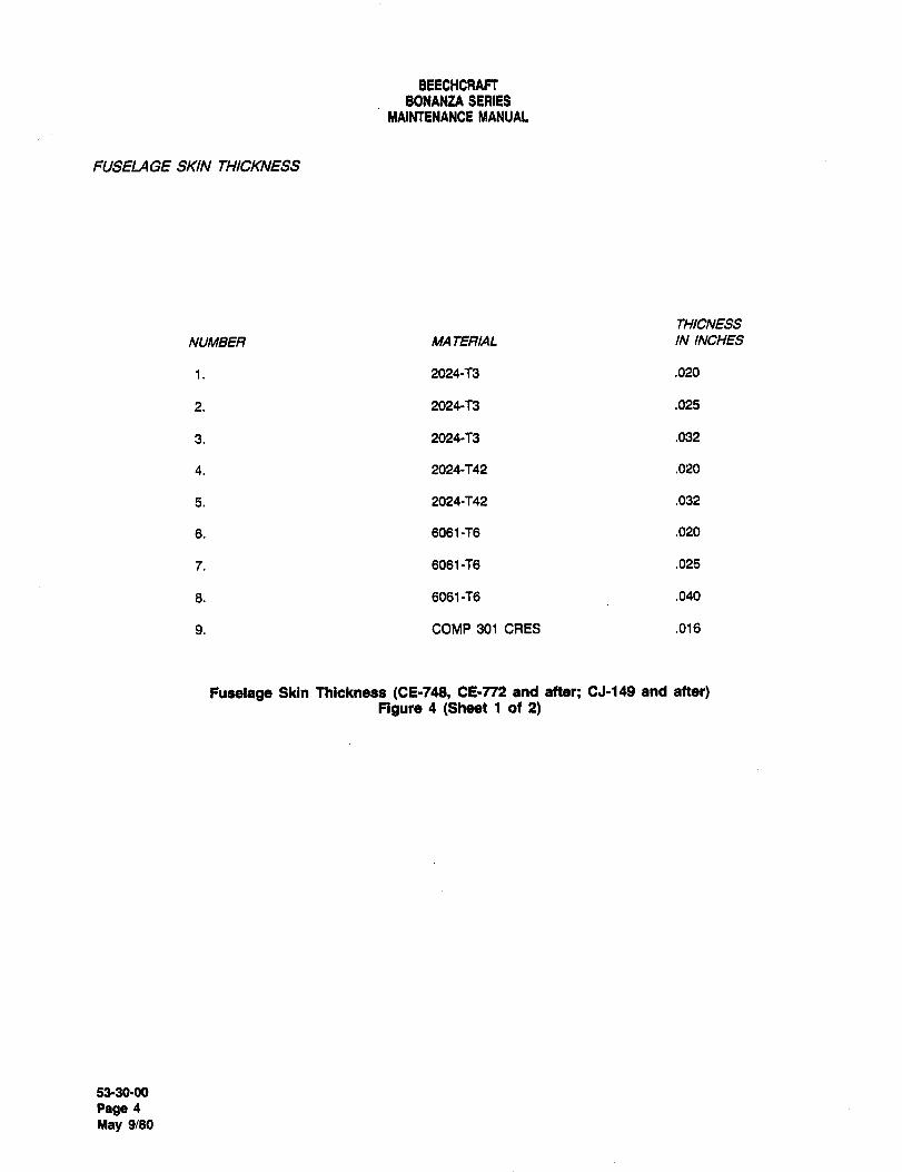
BEECHCRAFTBONANZA SERIES
MAINTENANCE MANUAL
FUSELAGE SKIN THICKNESS
THICNESS
NUMBER MA TEFIIAL ININCHES
1. 2024-T3 .020
2. 2024-73 .025
3. 2024-73 .032
4. 2024-742 .020
5. 2024-742 .032
6. 6061 -76 .020
7. 6061-76 .025
8. 6061-76 .040
9. COMP 301 CRES .016
Fuselage Skin Thickness (CE-748, CE-n2 and after; CJ-149 and atter)Figure 4 (Sheet 1 of 2)
53-30-00
Page 4
May 9/80
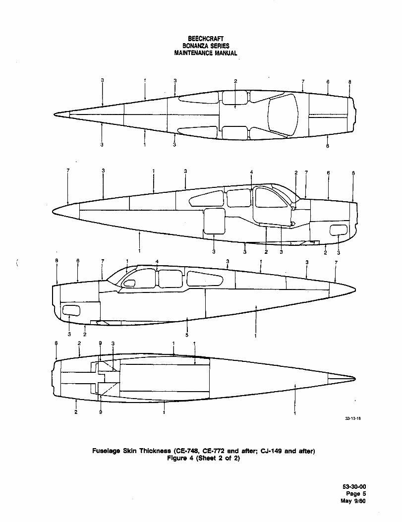
BEECHCRAFTBONANtA SERIES
MAINTENANCE MANUAL
9 3 3 7 6 8
3 1 3
;I i 3 e 2 7 6 8
1 3 3i3 19
i 8 4i 7 4 3 1 3 7
32 5 i
293 1 1
2 9 1 i33-13´•18
Fuselage Skin Thickness (CE-748, CE-772 and after; CJ-149 and after)Figure 4 (Sheet 2 of 2)
53-30-00
Page 5
May 9/80
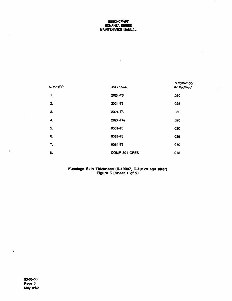
BEECHCFIAFTBONANZA SERIES
MAINTENANCE MANUAL
THICKNESS
NUMBER MA TERIAL ININCHES
1. 2024-73 .020
2. 2024-73 .025
3. 2024-73 .032
4. 2024-742 .020
5. 6061 -f6 .020
6. 6061-76 .025
7. 6061-76 .040
8. COMP 301 CRES .016
Fuselage Skin Thickness (D-10097, 0-10120 and after)Figure 5 ($9991 1 of 2)
53-3090
Page 6
May 9/80
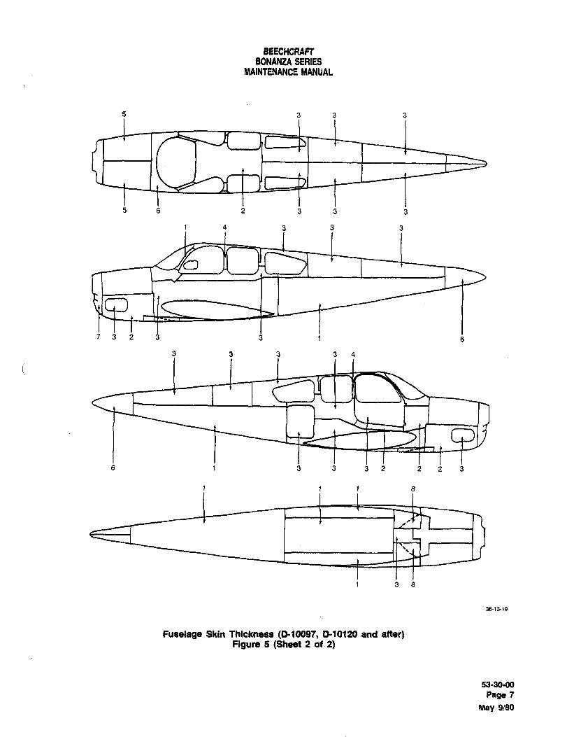
BEECHCRAFTBONANZA SERIES
MAINTENANCE MANUAL
s 3 3 3
s 8 2 3 3 j
1 4 3 3 3
7 3 2 3 3 i
3 3 3 3 4
6 1 3 3 32 223
1 1 1 8
1 3 8
36-13-19
Fuselage Skin Thickness (P-1009f, 0-10120 and after)Figure 5 (Sheet 2 of 2)
53-30-00
Page 7
May 9/80
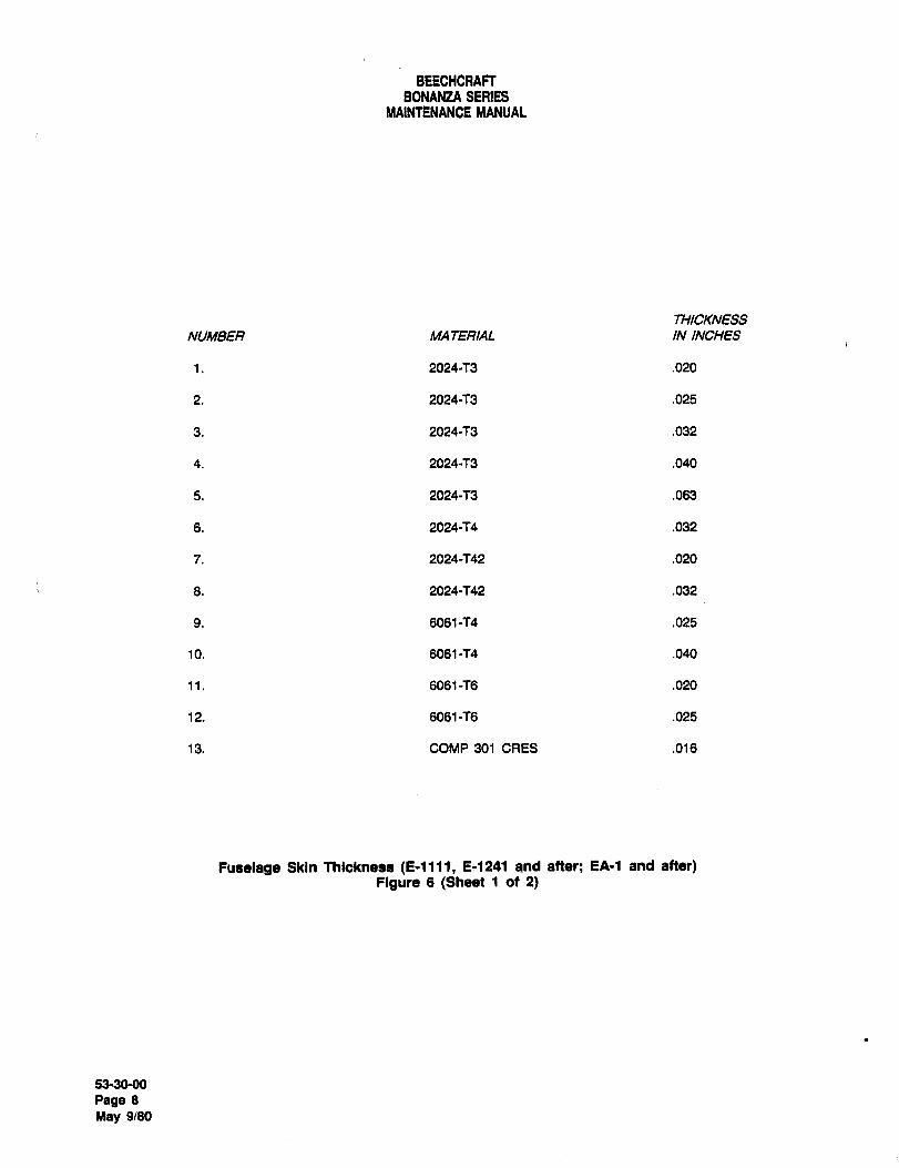
BEECHCRAFTBONANZA SERIES
MAINTENANCE MANUAL
THICKNESS
NUMBE~ MA TERIAL ININCHES
1. 2024-T3 .020
2. 2024-T3 .025
3. 2024-T3 .032
4. 2024-T3 .040
5. 2024-T3 .063
6. 2024-T4 .032
7. 2024-T42 .020
8. 2024-f42 .032
9. 6061-T4 .025
10. 6061-T4 .040
11. 6061-T6 .020
12. 6061-T6 .025
13. COMP 301 CRES .016
Fuselage Skin Thicknesa (E-llll, E11241 and after; EA-1 and after)Figure 6 (Sheet 1 ot 2)
53-30-00
Page 8
May 9/80
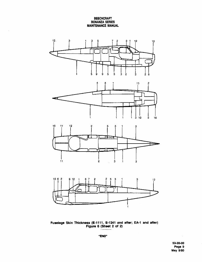
BEECHCRAFT
BONANZA SERIESMAINTENANCE MANUAL
i? 3 1 3 5 7 3 1 1.2 1
~10
i s s 9 s 3 3 1 i i:6
4 5 1 13 2
1 1 1 1 3 13 2 10
l~o 1~1 1? 2 5 3 1 3
11 2 3 1 3
‘Ip a 2 a 1? a 7 5 3 i 3 12
Fuselage Skin Thickness (E-llll, E-1241 and after; EA-1 and after)Figure 6 (Sheet 2 of 2)
"END"
53-30-00
Page 9
May 9/80

CHAPTER
STABILIZERS
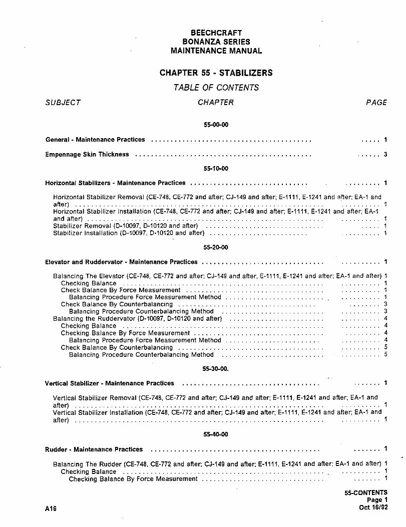
BEECHCRAFT
BONANZA SERIES
MAINTENANCE MANUAL
CHAPTER 55 STABILIZERS
TABLE OF CONTENTS
SUBJECT CHAPTER PAGE
55-00-00
General Maintenance Practices 1
Empennage Skin Thickness 3
55-10-00
Horizontal Stabilizers Maintenance Practices 1
Horizontal Stabilizer Removal ~CE-748, CE-772 and after; CJ-149 and after; E-llll, E-1241 and aqer; EA-1 and
after) 1
Horizontal Stabilizer Installation (CE-748, CE-772 and after; CJ-149 and after; E-llll, E-1241 and after; EA-1
and after)Stabilizer Removal (D-10097, D-10120 and after) 1
Stabilizer Installation (0-10097, D-10120 and after) 1
55-20´•00
Elevator and Ruddervator Maintenance Practices 1
Balancing The Elevator (CE-748, CE-772 and after; CJ-149 and after; E-llll, E-1241 and after; EA-1 and after) 1
Checking Balance 1
Check Balance By Force Measurement 1
Balancing Procedure Force Measurement Method_
1
Check Balance By Counterbalancing 3
Balancing Procedure Counterbalancing Method 3
Balancing the Ruddervator (D-10097, D-10120 and after) 4
Checking Balance 4
Checking Balance By Force Measurement 4
Balancing Procedure Force Measurement Method 4
Check Balance By Counterbalancing 5
Balancing Procedure Counterbalancing Method ..........5
55-30-00.
Vertical Stabilizer- Maintenance Practicesi
1
Vertical Stabilizer Removal (CE-748, CE-772 and after; CJ-149 and after; E-llll, E-1241 and after; EA-1 and
after) 1
Vertical Stabilizer Installation (CE-748, CE-772 and after, CJ-1$S and after; E-llll, E-1241 and after; EA-1 and
after) 1
55-40-00
Rudder Maintenance Practices 1
Balancing The Rudder (CE-748, CE-772 and after; CJ-149 and after; E-llll, E-1241 and after; EA-1 and after) 1
Checking Balance 1
Checking Balance By Force Measurement 1
55-CONTENTS
Page 1
A16 Oct 16/92
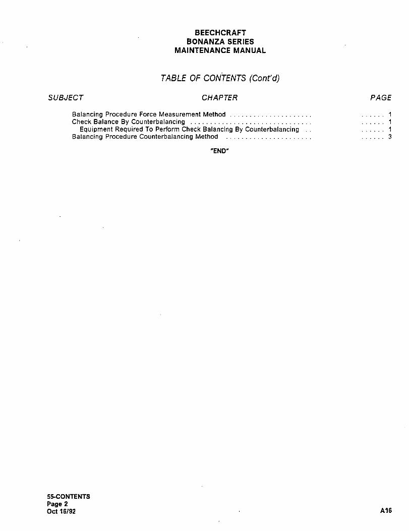
BEECHCRAFT
BONANZA SERIES
MAINTENANCE MANUAL
TABLE OF CON’TENTS (Cont’d)
SUBJECT CHAPTER PAGE
Balancing Procedure Force MeasurementMethod 1
Check Balance By Counterbalancing .........,._._.,.1
Equipment Required To Perform Check Balancing By Counterbalancing 1
Balancing Procedure Counterbalancing Method 3
"END"
55-CONTENTS
Page 2
Oct 16/92 A16
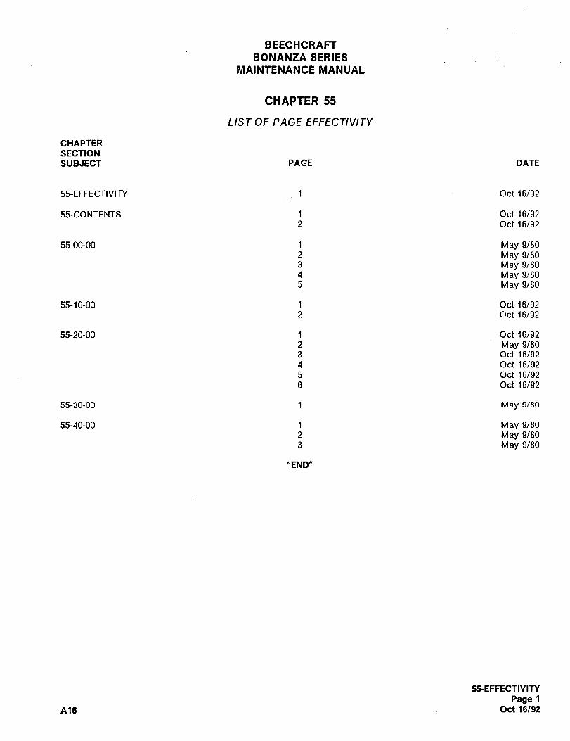
BEECHCRAFT
BONANZA SERIES
MAINTENANCE MANUAL
CHAPTER 55
LIST OF PAGE EFFECTIVITY
CHAPTER
SECTION
SUBJECT PAGE DATE
55-EFFECTIVITY 1 Oct 16/92
55-CONTENTS 1 Oct 16/92
2 Oct 16/92
55-00-00 1 May 9/80
2 May 9/80
3 May 9/80
4 May 9/80
5 May 9/80
55-10-00 1 Oct 16/92
2 Oct 16/92
55-20-00 1 Oct 16/92
2 May 9/80
3 Oct 16/92
4 Oct 16/92
5 Oct 16/92
6 Oct 16/92
55-30-00 1 May 9/80
55-40-00 1 May 9/80
2 May 9/80
3 May 9/80
"END"
55-EFFECTIVITY
Page 1
A16 Oct 16/92
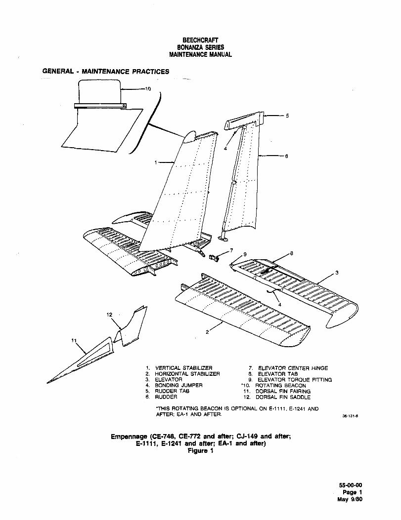
BEECHCRAFTBONANZA SERIEB
MAINTENANCE MANUAL
GENERAL ~1AIIJTENANCE PRACTICES
_
4
1
ri ii_
1
9 /8
~z 4
12
I. VERTICAL STABILIZER 7. ELEVATOR CENTER HINGE
2. HORIZONTAL STABILIZER 8. ELEVATORTAB3. ELEVATOR 9. ELEVATOR TORQUE FITTING4. BONDING JUMPER ’10. ROTATING BEACON5. RUDDERTAB 11. DORSAL FIN FAIRING6. RUDDER 12. DORSAL FIN SADDLE
’THIS ROTATING BEACON IS OPTIONAL ON E-lll~, E-1241 AND
AFTER; Ee-l AND AFTER. 36-131-8
Empennege (CE-748, CE-772 and after; CJ-149 and after;E-llll, E-1241 and after; EA-1 and after)
Figure 1
55-0090
Page 1
May 9/80
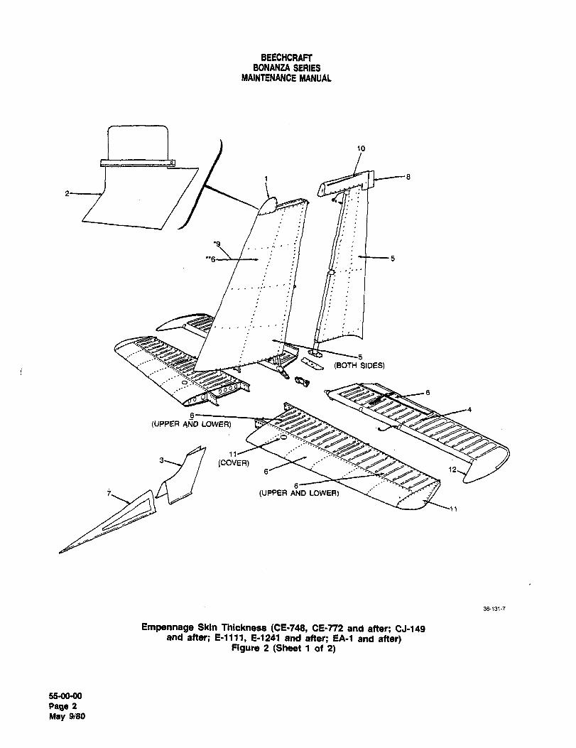
BEECHCRAFTBONANZA SERIES
MAINtENANCE MANUAL
1 ~-8
M5
I
6
(UPPER AND LOWER)
(COVER)6’ 12
(UPPER AND LOWER)
36-1317
Empennege Skin Thickness (CE-748, CE-T72 and after; CJ-149and after; E-llll, E-1241 and after; EA-1 and after)
Figure 2 (Sheet 1 of 2)
55-0060
Page 2
May 9/80
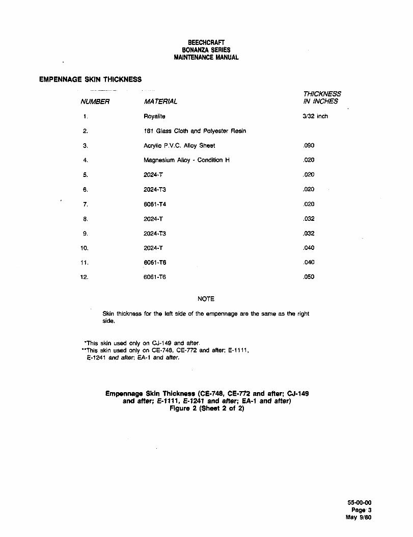
BEECHCRAFFBONANZA SERIES
MAINTENANCE MANUAL
EMPENNAGE SKIN THICKNESS
THICKNESS
NUMBE~ MA TEF~AL IN INCHES
1. Royalite 3/32 inch
2. 181 Glass Cloth and Polyester Resin
3. Acrylic P.V.C. Alloy Sheet .090
4. Magnesium Alloy Condition H .020
5. 2024-’7 .020
6. 2024-T3 .020
7. 6061-T4 .020
6. 2024-T .032
9. 2024-T3 .032
10. 2024-T .040
11. 6061-T6 .040
12. 6061-T6 .050
NOTE
Skin thickness for the left side of the empennage are the same as the rightside.
"This skin used only on CJ-149 and after.
"This skin used only on CE-748, CE-n2 and after; E-llll,E-1241 and after; EA-1 and after.
Empennage Skin Thickness (CE-f49, CE-n2 and after; CJ-149
and after; E-llll, E-1241 and after; EA-1 and after)Figure 2 (Sheet 2 of 2)
55-0090
99993May 9/80
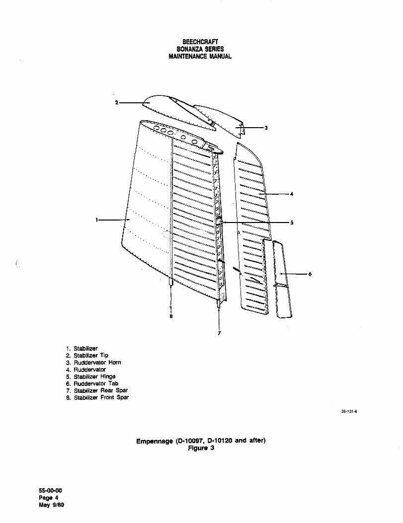
BEECHCRAFTBONANZA SERIES
NIAINTENANCE MANUAL
aa
1~3+---4
1s
1. Stabilizer
2. Stabilizer Tip3. Ruddervator Worn
4. Ruddervator
5. Stabilizer Hinge6. Ruddervator Tab
7. Stabilizer Rear Soar8. Stabilizer Front Spar
36-131´•6
Empennage (0-10097, 0-10120 and after)Figure 3
55-0090
Page 4
May 9/80
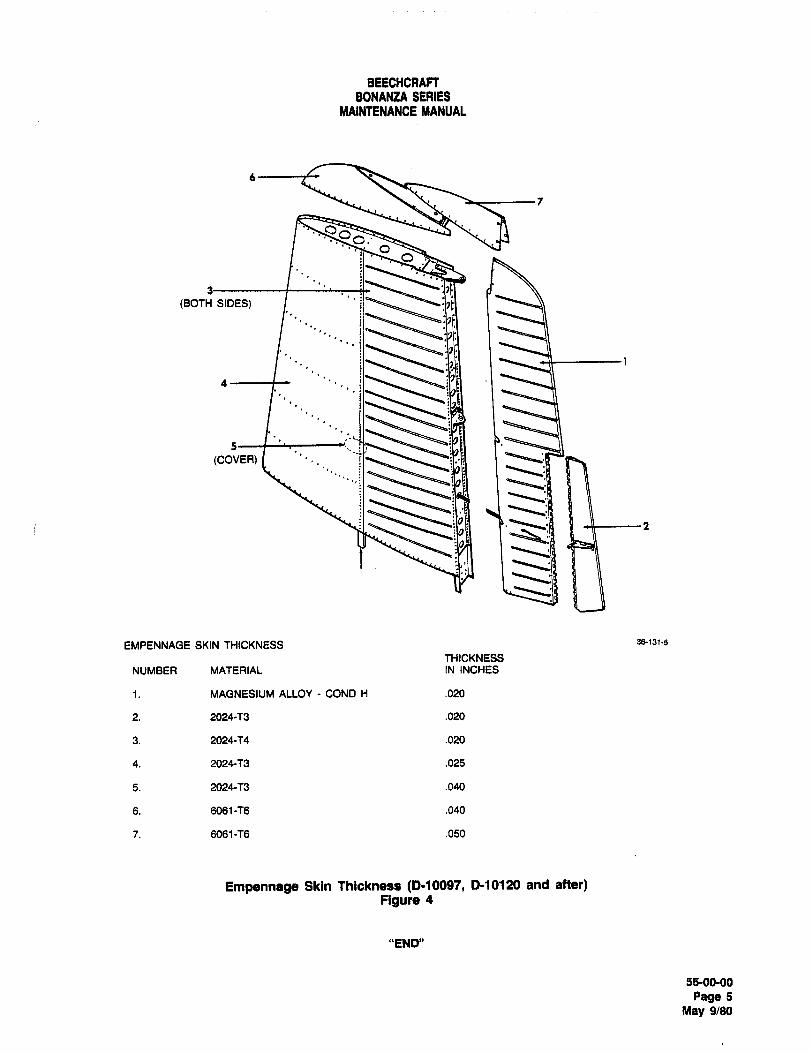
BEECHCRAFTBONAEUA SERIES
MAINTENANCE MANUAL
oQ
(BOTH SIDES) I ‘’j
41´•
(COVER)
EMPENNAOE SKIN THICKNESS 36131-5
THICKNESS
NUMBER MATERIAL IN INCHES
1. MAGNESIUM ALLOY COND H .020
2. 2024-T3 .020
3. 2024-T4 .020
4. 2024´•T3 .025
5. 2024-f3 .040
6. 6061-T6 .040
7. 6061-T6 .050
Empennage Skin Thlckneaa (D-1O017, 0-10120 and after)Figure 4
"END"
55-00-00
Page 5
May 9/80
BEECHCRAFT
BONANZA SERIES
MAINTENANCE MANUAL
HORIZONTAL STABILIZERS MAINTE- d. Install the inboard elevator hinge bracket
NANCE PRACTICES on the ah side of the ah spar with four bolts with
heads on the ah side of the hinge bracket. Place one
HORIZONTAL STABILIZER REMO VA L MS20002C4 washer under the head of each bolt and
(CE-748, CE-772 AND AFTER; CJ-149 AND two AN960-416 washers under each nut. Torque the
;9FTER; ~-1111, E-1241 AND AFTER; EA-1 nuts to 85-100 inch-pounds.AND AFTER)
e. Connect the trim tab pushrods to the sta-
a. Remove the applicable elevator. Refer to bilizer.
ELEVATOR REMOVAL in Chapter 27-30-00.
f. Connect the elevator tab cables, accessi-
b. Remove’the access panels located on the ble through the left side fuselage access openings.left side at the rear of the fuselage.
g. Install the access panels.
i c. Disconnect the elevator tab cables, acces-
sible through the left side fuselage access openings. h. Install the applicable elevator. Refer to
INSTALLATION OF ELEVATOR in Chapter 27-30-00.
d. Remove the elevator rear spar attachingbolts and the elevator center hinge bracket on therear
spar.STABILIZERAND AFTL~R)
REMOYBL ~-10097. D-1U1201e. Disconnect the trim tab pushrods. NOTE
f. While supporting the stabilizer, remove the If not already installed, kits are available
attach bolts at the front spar. to provide additional support to the stabi-
lizer leading edge on V-tail Bonanzas.
g. Remove the stabilizer. ’Refer to Chapter 51-00-00.
HORIZONTAL STABILIZER INSTALLATION a. Remove the applicable elevator. Refer to
(CE-748, CE-772 AND AFTER; CJ-149 AND ELEVATOR REMOVAL in Chapter 27-21-00.
AFTER; E-llll, t~-1241 AND AFTER; ~A-lAND AFTER) b. Remove the access panels located on the
left side, at the rear of the fuselage.
a. Place the stabilizer in position and install
the rear spar attaching bolts. c. Disconnect the elevator tab cables, acces-
sible through the left side fuselage access openings.
NOTEd. Remove the attach bolts at the front spar.
When installing the horizontal stabilizer,the nuts for the rear spar attaching bolts e. While supporting the stabilizer, remove the
must the placed on the forward side of the stabilizer attach bolts at the rear spar.
spar to avoid contact with the elevator
center hinge assembly. f. Remove the stabilizer.
b. Install the forward stabilizer spar attaching STABILIZER INS TALLA nON (0-10097. 1bolts. Place one MS20002C4 washer under the head 0-10120 AND AFTER)of each bolt and two AN960-416 washers under each
nut. Torque the nuts on the bolts to 85-100 inch- a. Place the stabilizer in position and install
pounds. the rear stabilizer attaching bolts.
c. Install four ah stabilizer spar attaching b. Install the forward stabilizer spar attachingbolts through the inboard holes in each spar with the bolts.
bolt heads on the ah side of the spar. Place one
MS20002C4 washer under the head of each bolt and c. Torque the front spar attaching nuts to
one AN960-416 washer under each nut. Torque the 200-225 inch pounds and the rear spar attaching bolts
nuts to 85-100 inch-pounds. to 85-100 inch pounds.
55-10-00
Page 1
A16 Oct 16/92
BEECHCRAFT
BONANZA SERIES
MAINTENANCE MANUAL
d. Connect the elevator tab cables, accessi- f. Install the applicable elevator. Refer to
ble through the left side fuselage access openings. ELEVATOR INSTALLATION in Chapter 27-21-00.
e. Install the access panels.
"END"
55-10-00
Page 2
Oct 16/92 Ale
BEECHCRAFT
BONANZA SERIES
MAINTENANCE MANUAL
ELEVATOR AND RUDDERVATOR MAINTE- a. A stand with knife-edge supports as illus-NANCE PRACTICES trated in Figure i. The knife edges should be in the
same horizontal plane.BALANCING TH~ ELE VA TOR (Cll-748,CE-772 AND AFTER; CJ-149 AND AFTER; b. A certified beam balance calibrated in
E-l?ll, E-1241 AND AFTER, EA-1 AND units of.Ol Ib. or less. The balance should have a flat
AFTER) weighing platform and its capacity should equal tare
(Figure I) plus 2.0 Ibs. minimum.
When the elevator control surface is being repainted, c. A support spindle similar to the illustrationsuspend it by the trailing edge so that excess paint and leveling blocks, as required ~blocks spindlewill drain toward the leading edge. AFTER ANY tare).REPAINTING OR REPAIR, THE FINISHED SURFACE
SHOULD BE CHECK BALANCED TO ENSURE THAT d. A straightedge, ruler and spirit level.ITS STATIC MOMENT ABOUT THE HINGE LINE IS
WITHIN THE MANUFACTURER’S PRESCRIBED LIM- Balancing Procedure Force Measurement MethodITS. The complete painted elevator assembly, includ-
ing the control arm and the tab control rod should not Locate the chord line by placing a straightedge at thebe tail-heavy over a maximum moment of 7.8 inch- inboard end of the elevator so that one end is alignedpounds. The static moment is the total unbalanced with the center of the torque tube and the other endweight of the elevator control surface multiplied by is centered on the trailing edge. Mark the chord linethe perpendicular distance from its hinge centerline by grease pencil or other means on the rib. Removeto the center of gravity, when the chord line is hor- the straightedge. Fit correct size bolts in the outboardizontally level. The weight is measured in pounds and and center hinge brackets and mount the elevator onthe distance in inches. The static moment of a 100 the knife edges. Ensure that it is free to rotate aboutpercent balanced elevator control surface is 0.0 Ib. A the hinge line. Support the trailing edge behind thetail-heavy surface exhibits static underbalance. A center hinge point with a spindle resting on a levelednose-heavy surface exhibits static overbalance. beam balance platform as illustrated. The spindle
must be vertical throughout the balancing procedure.CHECKING BALANCE Hold a spirit level against the marked chord line and
level it by extending or contracting the spindle.The elevator balance must be checked in a draft-free Measure the perpendicular distance from the hingearea with the elevator completely assembled in fiying centerline to the point supported by the spindle.condidtion. ALL PAINTING, INCLUDING STRIPES AND Ensure that the spirit level and rule are removed fromTOUCH-UP, MUST BE COMPLETED. The tab, tab th, surface and read the reaction on the beam bal-pushrod, static wicks, and hinge bolts must be
ance.attached. The chord line must be horizontally level
and the hinge line must be properly supported whenCalculate the static underbalance moment "M" from
the static moment is measured. Although many dif-th, formula:
ferent methods of check balancing exist, they can be
categorized under the following two headings:M D(R-T) inch-pounds where,
a. Actual Force Measurement- MeasurementD Perpendicular distance from the hinge center-of the force applied by the elevator surface on a sin-
gle support at a known distance from the centerlineline to the spindle point (inches).
of the hinge.R Reaction (pounds)read from the beam balance.
b. Counterbalancing The application of a
known force or weight at a measured distance from T Tare, i.e. spindle plus leveling blocks or shims
the hinge line to counter the unbalance moment of 0" the scale platform (pounds).the elevator assembly.
The following is an example:CHECK BALANCE BY FORCE MEASUREMENT
D is 13.5 inches, R is 1.49 Ib. and T 1.00 Ib.
The equipment required to perform the check balance
by force measurement is as follows: M 13.5 (1.49 -1.00); M 6.6 inch-pounds.
55-20-00
Page 1
A16 Oct 16/92
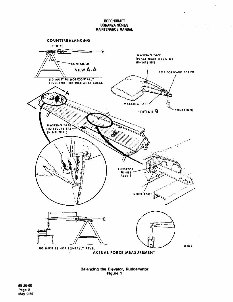
BEECHCRAFTBONANZA SERIES
YAIIJTENANCE #ANUAL
COUNTERBALANCING
MASKING TAPE
(PLACE NEAR ELEVATOR
CONTAINERHINGE LINE)
VIEW,A-ATOP FORWARD SCREW
JIG MUST BE HORIZONTALLY
LEVEL FOR UNDERBALANCE CHECK
A
MASKING TAPE
DETAIL B ’CONTAINER
MASKING TAPE
(TO SECURE 7AB
IN NEUTRAL)
~r´•
ELEVATOR
HINGECLEVIS i
KNIFE EDGE
D-----~t
55-1528
JIG MUST BE HORIZONTALLY~LEVEL
ACTUAL FORCE MEASUREMENT
Balancing the Elevator, Ruddervator
Figure 1
55-20-00
Page 2
May 9/80
BEECHCRAFT
BONANZA SERIES
MAINTENANCE MANUAL
M is within the range which is satisfactory. CAUTION
If M is not within the prescribed range, refer to step i Be certain the forward top screw on the
under BALANCING PROCEDURE COUNTERBALANC- elevator leading edge tip is secured after
ING METHOD. the elevator has been balanced.
CHECK BALANCE BY COUNTERBALANCING e. Add small quantities of lead shot to the cupuntil the elevator balances with the chord level.Check this by holding the spirit level aligned with the
The equipment required to perform check balancingmarked chord line.
by counterbalancing is as follows:
f. The distance "D" must be perpendicular toa. A stand with knife-edge supports as illus- the hinge line. Measure "D" from the hinge line to the
trated in Figure 1. The knife edges must be in the suspension point of the cup.same horizontal plane.
g. Remove the cup, contents, and string, thenb. A paper cup or similar lightweight contain- weigh them.
er.
NOTE
c. Approximately 2 pounds of lead shot.
Since any weighing error is magnified byd. A certified beam balance weighing device the distance "D", weighing is most impor-
calibrated in units of.Ol pound or lesS. tant and must be done carefully on scales
that are certified for accuracy.
e. A straightedge, ruler, and a spirit level.h. Calculate the static balance as follows:
Balancing Procedure Counterbalancing Methodi. The weight of the cup and contents is
designated by "W".a. Locate the chord line by placing a
straightedge at the inboard end of the elevator2. The over or underbalance moment is
assembly so that one end is on the hinge centerline designated by "M"and the other end is centered on the trailing edge.Mark the chord line with a suitable marker, such as 3. M W x D.a grease pencil, then remove the straightedge.
4. The following is a typical example of
b. Secure the trim tab in its neutral position a balancing calculation:
with a small piece of masking tape.Assume the elevator is underbalanced (tail-heav\g)
c. Fit the correct size bolts in the hinge clev- and the paper cup was suspended from the horn. If
ises and mount the elevator on the knife-edge sup-the elevator balances with the chord line level at "W
ports. Ascertain that the elevator is free to rotate 0.60 pound" and "D 12.6 inches", then:
about the hinge line.M 0.60 x 12.6
d. To determine if weight should be added orM 7.6 inch-pounds. In this instance, "M" is
removed, use a short length of small diameter string within the required static balance range and issecured to the surface with a small piece of masking therefore acceptable.tape and a paper cup hanging vertically as illustrated
in Figure 1. Slightly loosen the forward top screw on i. The complete painted elevator assembly,the elevator leading edge tip. Suspend the paper cup including the control arm and the tab control rod,on the inboard side of the tip and wrap the string must not be tail-heavy over a maximum moment of
around the screw. Secure the string to the surface 7.8 inch-pounds. If the static balance does not com-
with a small piece of masking tape aft of the top for- ply, remove the elevator horn cover and add or
ward screw and near the hinge centerline as shown remove solder to bring the elevator balance within
in Figure 1. The cup must be free to hange vertically. required limits.
55-20-00
Page 3
A16 Oct 16/92
BEECHCRAFT
BONANZA SERIES
MAINTENANCE MANUAL
NOTE CHECKING BALANCE BY FORCE MEASUREMENT
Coat the weight with a corrosion preven- The equipment required to perform the check balancetive material such as zinc chromate primer by force measurement is as follows:
(20, Chart 1, 91-00-00) to insulate the dis-
similar metals. Replace the elevator horn a. A stand with knife-edge supports as illus-cover and recheck the balance. trated in Figure 1. The knife edges should be in the
same horizontal plane.BALANCING THE RUDDERVATOR (0-10097,0-10120 AND AFTER) b. A certified beam balance calibrated in(Figure 1) units of.Ol Ib. or less. The balance should have a flat
weighing platform and its capacity should equal tareWhen the ruddervator control surface is being plus 2.0 Ibs. minimum.repainted, suspend it by the trailing edge so that
excess paint will drain toward the leading edge. c. A support spindle similar to the illustrationAFTER ANY REPAINTING OR REPAIR, THE FINISHED and leveling blocks, as required (blqcks spindleSURFACE SHOULD BE CHECK BALANCED TO
tare).ENSURE THAT ITS STATIC MOMENT ABOUT THEHINGE LINE IS WITHIN THE MANUFACTURER’S PRE-
d. A straightedge, ruler and spirit level.SCRIBED LIMITS. The complete paintedrudddervator assembly, including the control arm and
Balancing Procedure Force Measurement Methodthe tab control cable attach bolt, nut and washer for
both sides of the tab, must not be tail-heavy over a
maximum moment of 14.4 to 17.4 inch-pounds. TheLocate the chord line by placing a straightedge at the
static moment is the total underbalance weight ot theinboard end of the ruddervator so that one end is
ruddervator control surface multiplied by the perpen-aligned with the center of the torque tube and the
dicular distance from its hinge centerline to the cen-other end is centered on the trailing edge. Mark the
ter of gravity when the chord line is horizontally level,chord line by grease pencil or other means on the rib.
The weight is measured in pounds and the distanceRemove the straightedge. Fit correct size bolts in the
in inches. The static moment of a 100 percent bal-outboard and center hinge brackets and mount the
anced ruddervator control surface is 0.0 Ib. A tail-’Uddervator on the knife edges. Ensure that it is free
heavy surface exhibits static underbalance. Ato’Otate about the hinge line. Support the trailing
nose-heavy surface exhibits static overbalance. edge behind the center hinge point with a spindleresting on a leveled beam balance platform as illus-
CHECKING BALANCE trated. The spindle must be vertical throughout the
balancing procedure. Hold a spirit level against the
The balance must be checked in a draft free area withma’ked chord line and level it by extending or con-
the ruddervator completely assembled in a flying tracting the spindle. Measure the perpendicular dis-
condition. ALL PAINTING, INCLUDING STRIPES ANDtance from the hinge centerline to the point supported
TOUCH-UP, MUST BE COMPLETED. The tab, tab by the spindle. Ensure that the spirit level and rule
control cable attach bolt, nut and washer for bothare removed from the surface and read the reaction
on the beam balance.sides of the tab, static wicks and hinge bolts must be
attached. The chord line must be horizontally leveland the hinge line must be properly supported when Calculate the static underbalance moment "M" from
the static moment is measured. Although many dif- the formula:
ferent methods of check balancing exist, they can be
categorized under the following two headings: M D(R-T) inch-pounds where,
a. Actual Force Measurement Measurement D Perpendicular distance from the hinge center-
of the force applied by the ruddervator surface on a line to the spindle point (inches).single support at a known distance from the center-
line of the hinge. R Reaction (pounds)read from the beam balance.
b. Counterbalancing The application of a T Tare, i.e. spindle plus leveling blocks or shims
known force or weight at a measured distance from on the scale platform (pounds).the hinge line to counter the unbalance moment ofthe ruddervator assembly. The following is an example:
5120-00
Page 4
Oct 16/92 A16
BEECHCRAFT
BONANZA SERIES
MAINTENANCE MANUAL
D is 13.5 inches, R is 2.26 Ib. and T 1.00 Ib. CAUTION
M 13.5 (2.26 -1.00); M 17.0 inch-pounds. Be certain the forward top screw on the
ruddervator leading edge tip is securedM is within the range which is satisfactory, after the ruddervator has been balanced.
If M is not within the prescribed range, refer to step i e. Add small quantities of lead shot to the cupunder BALANCING PROCEDURE COUNTERBALANC- until the ruddervator balances with the chord lineING METHOD. level. Check this by holding a spirit level aligned with
the marked chord line.CHECK BALANCE BY COUNTERBALANCING
f. The distance "D" must be perpendicular toThe equipment required to perform check balancing the hinge line. Measure "D" from the hinge line to theby counterbalancing is as follows: suspension point of the cup.
a. A stand with knife-edge supports as illus-g. Remove the cup, contents, and string, then
trated in Figure 1. The knife edges must be in the weigh them.same horizontal plane.
NOTEb. A paper cup or similar lightweight contain-
er. Since any weighing error is magnified bythe distance "D", weighing is most impor-
c. Approximately 3.5 pounds of lead shot. tant and must be done carefully on scales
that are certified for accuracy.d. A certified beam balance weighing device
calibrated in units of.Ol pound or less.h. Calculate the static balance as follows:
e. A straightedge, ruler, and a spirit level.1. The weight of the cup and contents is
designated by "W".Balancing Procedure Counterbalancing Method
2. The over or underbalance moment isa. Locate the chord line by placing a´•
straightedge at the lower closure rib of the designated by "M".
ruddervator so that one end is aligned with the cen-
terline of the torque tube and the other end is cen-3. M W x D.
tered on the trailing edge. Mark the chord line with a
suitable marker, such as a grease pencil, then 4. The following is a typical example to
remove the straightedge. a balancing calculation:
b. Secure the trim tab in its neutral position Assume the ruddervator was underbalance (tail-with a small piece of masking tape, heavy) and the paper cup was suspended from the
leading edg’e. If the ruddervator balances with the
c. Fit the correct size bolts in the hinge clev- chord line level as "W 2.83 pounds" and "D 6.0
ises and mount the ruddervator on the knife-edge inches", then:
supports. Ascertain that the ruddervator is free to
rotate about the hinge line. M 2.83 x 6.0
d. To determine if weight should be added or M 17.0 inch-pounds. The product of "W x D". In this
removed, if the balance is tail-down: instance, "M" is within the required static balance
range and is therefore acceptable.On the ruddervator leading edge tip, slightly loosen
the forward top screw. Suspend a paper cup on the i. The complete painted ruddervator assem-
inboard side of the tip and wrap the string around the bly, including the control arm and the tab control
screw. Secure the string to the surface with a small cable attach bolt, nut and washer for both sides of the
piece of masking tape aft of the forward top screw tab, should not be tail-heavy over a maximum of 14.4
and near the hinge centerline as shown in Figure 1. to 17.4 inch-pounds. If the static balance does not
The cup must be free to hang vertically. comply, remove the ruddervator horn cover and add
55-20-00
Page 5
Ale Oct 16/92
BEECHCRAFT
BONANZA SERIES
MAINTENANCE MANUAL
or remove solder to bring the ruddervator balance (20, Chart 1, 91-00-00) to insulate the dis-
within the required limits. similar metals. Replace the ruddervator
horn cover and recheck the balance.NOTE
Coat the weight with a corrosion preven-tive material such as zinc chromate primer
"END"
5120-00
Page 6
Oct16/92 A16
BEECHCRAFTEIONAEUA SERIES
MAINTENANCE MANUAL
VERTICAL STABILIZER MAINTENANCE e. Pull the stabilizer straight up to remove it from the
PRACTICES fuselage.
VERTICAL STABILIZER REMOVAL VERTICAL STABILIZER INSTALLATION
(CE-74B, CE-772andafter,. C~l-149andafter;E-lllI, (CE-748, CE-772 and after; CJ- 149 and after; E- III I,E-1241 and after; EA-I and after) E-1241 and after; EA-I and after)
a. Carefully place the vertical stabilizer in positiona. Remove the elevators, horizontal stabilizers, and and install the bolts in the front and rear spars.
the rudder. Refer to the applicable chapters for removal b. Torque all AN4 vertical stabilizer attaching bolts to
instructions. 50-70 inch-pounds.b. Remove the stabilizer saddle and fairings. c. Connect the rotating beacon wires (if applicable).c. Disconnect the rotating beacon wires (if d. Install the stabilizer saddle and fairings.
applicable). e. Install the elevators, horizontal stabilizers, and
d. Support the stabilizer and remove the bolts at the rudder. Refer to the applicable chapters for installationfront and rear spars. procedures.
"END"
55-3040
Page 1
May 9/80
BEECHCRAFTBONANZA SERIES
MAINTENANCE MANUAL
RUDDER MAINTENANCE PRACTICES levelling blocks as required. (Blocks spindle tare).d. A straight edge, rule and spirit level.
BALANCING THE RUDDER
(CE-748, CE-772 and after; CJ- 149 and after; E- III I, BALANCING PROCEDURE FORCE MEASUREMENT
E-1241 and after; EA-1 and after) METHOD
(Figure 1)Locate the chord line by placing a straight edge at the
When the rudder surface is being repainted, suspend it by inboard end of the rudder so that one end is aligned with the
the trailing edge so that excess paint will drain toward the center of the torque tube and the other end is centered on
leading edge. After any repainting or repair, the finished the trailing edge. Mark the chord line by grease pencil or
surface must be check balanced to ensure that its static other means on the rib. Remove the straight edge. Fit
moment about the hinge line is within the manufacturers correct size bolts in the outboard and center hinge brackets
prescribed limits. The complete painted rudder assembly, and mount the rudder on the knife edges. Ensure that it is
including the control arm should not be tail-heavy over a free to rotate about the hinge line. Support the trailing edgemaximum of 8.4 inch-pounds. The static moment of the behind the center hinge point with a spindle resting on a
rudder is determined by multiplying the unbalanced weight levelled beam balance platform as illustrated. The spindleof the rudder assembly times the perpendicular distance must be vertical throughout the balancing procedure. Hold a
from the hinge center line to the center of gravity when the spirit level against the marked chord line and level it bychord line is horizontally level. The weight is measured in extending or contracting the spindle, or by using blocks and
pounds and the distance in inches. The static moment of a shims under the spindle. Measure the perpendicular100 percent balanced rudder assembly is 0.0 inch-pounds. distance from the hinge center line to the point supported byTail heaviness indicates static underbalance while nose the spindle. Ensure that the spirit level and rule are removed
heaviness indicates static overbalance, from the surface and read the reaction on the beam
balance. Calculate the static underbalance moment "M"
from the formula:
CHECKING BALANCEM D(R-T) inch-pounds where,
The rudder balance must be checked in a draft free area D Perpendicular distance from the hinge center line to
with the rudder completely assembled in flying condition. All the spindle point (inches).
painting, including stripes and touch-up, must be completed. R Reaction (Pounds) read from the beam balance.
the tab, static wicks, and hinge bolts must be attached. The T Tare, i.e. spindle plus levelling blocks or shims on the
chord line must be horizontally level and the hinge line must scale platform (Pounds).be properly supported when the static moment is measured.
Although many different methods of check balancing exist, The following is an example:
they can be categorized under the following two headings:D is 13.8 inches, R 1.49 Ib. and T is 1.00 Ib.
a. Actual Force Measurement Measurement of the M 13.8 (1.49 1.00); M 6.8 inch-pounds.
force applied by the rudder surface on a single support at a M is within the range which is satisfactory.known distance from the center Ilne of the hinge. If M is not within the prescribed range, refer to step h, under
b. Counterbalancing The application of a known BALANCING PROCEDURE COUNTEABALANCING
force or weight at a measured distance from the hinge line METHOD.
to counter the unbalance moment of the rudder assembly.
CHECK BALANCE BY COUNTERBALANCING
CHECK BALANCE BY FORCE MEASUREMENT
EQUIPMENT REQUIRED TO PERFORM CHECK
The equipment required to perform the check balance by BALANCING BY COUNTERBALANCING_force measurement is as follows:
a. A stand with knife edge supports as illustrated in
a. A stand with knife edge supports as illustrated in Figure 1. The knife edges must be in the same horizontal
Figure 1. The knife edges should be in the same horizontal plane.
plane, b. A paper cup or similar light weight container.
b. A certified beam balance calibrated in units of.Ol c. Approximately 2 pounds of lead shot.
Ib. or less. The balance should have a flat weighing platform d. A certified beam balance weighing device
and its capacity should equal tare plus 2.0 Ibs. minimum. calibrated in units of .01 pound or less.
c. A support spindle similar to the illustration and a. A straight edge, ruler, and spirit level.
55-40-00
Page 1
May 9/80
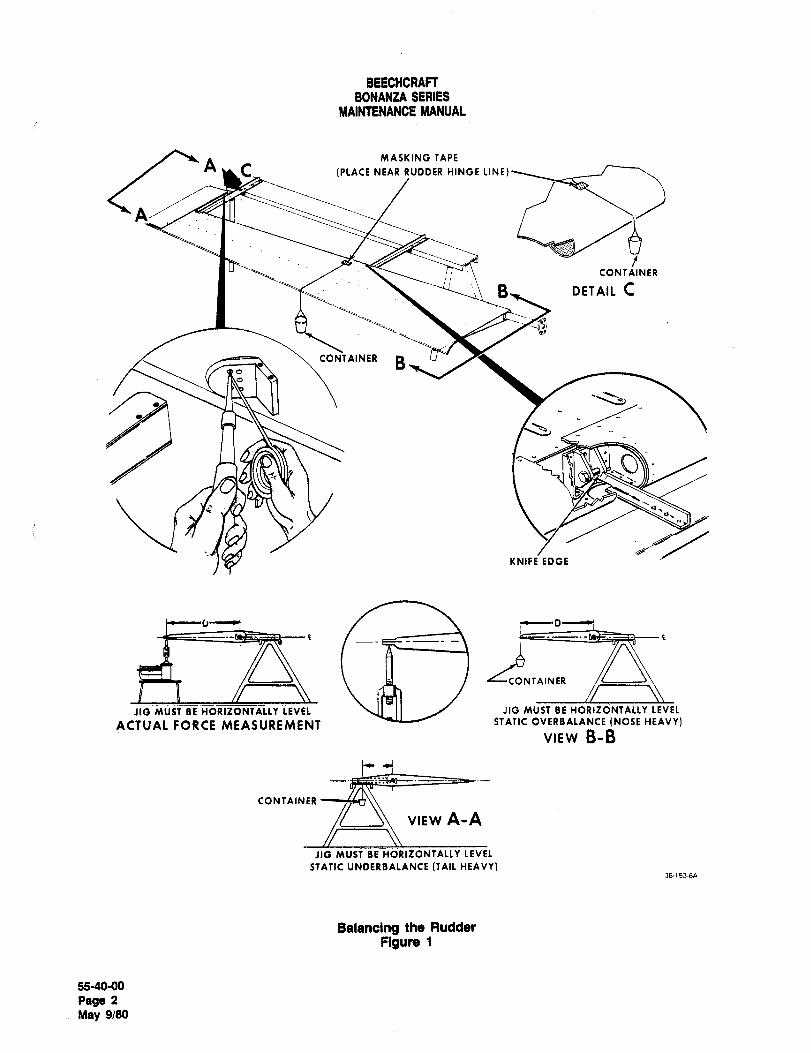
BEECHCRAFTBONANZA SERIES
NIAINTENANCE MANUAL
MASKING TAPE
A,C IPLPICI NEAR RUDDER HINGE LINT)
rCONTAINER
B, DETAIL C
CONTAINER B
KNIFE EDGE
1‘D
Iii
NTAINER
JiG MUST~Z HORIZOF~fALLY LEVEL \II II J JIG MUST BE HORIZONTALLY LEVEL
ACTUAL FORCE MEASUREMENT STATIC OVERBALANCE (NOSE HEAVY)
VIEW B-B
CONTAINER
VIEW A-A
JIG MUST BE HORIZONTALLY LEVEL
STATIC UNDERBALANCE (TAIL HEAVY)36-153´•6Pl
Balancing the Rudder
Figure 1
55-40-00
Pega 2
May 9/80
BEECHCRAFTBONANZA SERIES
MAINTENANCE MANUAL
BALANCING PROCEDUFIE COUNTERBALANCING g. Calculate the static balance as follows:
METHOD1. The weight of the cup and contents is
a. Locate the chord line by placing a straight edge at designated by "W".
the lower closure rib of the rudder so that one end is aligned 2. The over or underbalance moment is
with the center of the torque tube while the other end is designated by "M".
centered on the trailing edge. Mark the chord line with a 3. M W x D
suitable marker, such as a grease pencil, then remove the 4. The following is a typical example of a
straight edge, balancing calculation: Assume the rudder was slightlyb. Fit the correct size bolts in the hinge brackets and underbalance (tail-heavy) and the paper cup was
mount the rudder on the knife edge supports. Ascertain that suspended from the horn leading edge. If the rudder
the rudder is free to rotate about the hinge line. balances with the chord line level at "W .65 pound" and
c. To determine if weight should be added or "D 12.5 inches", then
removed, suspend a paper cup from a point near the center
of the rudder trailing edge if the balance is nose-down or M .65 x 12.5
near the center of the hom leading edge if the balance is
tail-down. Use a short length of small diameter string M 8.1 inch-pounds. In this instance, "M" is
secured to the surface with a small piece of masking tape within the required static balance range and is
as illustrated in Figure 1. The cup must be free to hang therefore acceptable.vertically.
d. Add small quantities of lead shot to the cup until h. The complete painted rudder assembly, includingthe rudder balances with the chord line level. Check this by the control arm must not be tail-heavy over a maximum of
holding a spirit level aligned with the marked chord line. 8.4 inch-pounds. If the static balance does not comply,a. The distance "D" must be perpendicular to the remove the weight in the rudder horn and add or remove
hinge line. Measure "D" from the hinge line to the solder to bring the rudder balance within required limits.
suspension point of the cup.f. Remove the cup, contents, and string, then weigh
them.
NOTE
NOTECoat the weight with a corrosion preventative
Since any weighing error is magnified by the material such as zinc chromate primer to
distance "D", weighing is most important and insulate the dissimilar metals. Replace the
must be done carefully on scales that are weight in the rudder horn and recheck the
certified for accuracy. rudder balance.
"END"
55-40´•00
Page 3
May 9/80

CHAPTER
VVINDOVVS
BEECHCRAFT
BONANZA SERIES
MAINTENANCE MANUAL
CHAPTER 56 WINDOWS
TABLE OF CONTENTSr~
CHAPTER
SECTION
SUBJECT SUBJECT PAGE
GENERAL 56-00-00
Description and Operation ......1
Maintenance Practices ......1
Cleaning Plastic Windows ......1
FLIGHI COMPARTMENT ....56-10-00
Maintenance Practices ..........j 1......1Windshield Removal ......1
Windshield Installation ......1
Forward Left Window Removal ......1
Forward Left Window Installation ..........i......1
Storm Window Removal :.......2
Storm Window Installation ......2
Cabin Door Window Removal 1......2
Cabin Door Window Installation ......2
CABIN .56-20-00
Maintenance Practices .´•´•´•´•´•´•´•´•I ......1
Openable Window Removal ..........I .......f
Openable Window Installation .......1
Utility Dears Window Removal (E-llll, E-1241
and after; EA-I and after) .......j .......1
Utility Doors Window Installation (E-llll, E-1241
and after; EA-1 and after) ..........i .......1
Windows Aft of Openable Windows Removal ..........I .......1
Windows Aft of Openable Windows Installation ..........i; :......1
"END"
S&CONTENTS
Page 1
May 9/80
BEECHCRAFT
BONANZA SERIES
MAINTENANCE MANUAL
CHAPTER 56
LIST OF PAOE EFF~CTIVITY
CHAPTER
SECTION
SUBJECT PAGE DATE
SE-EFFECTIVITY 1 Oct 16/92
56-CONTENTS 1 May 9/80
56-00-00 i Oct 16/92
56-10-00 1 May 9/80
2 May 9/80
56-20-00 i May 9/80
"END"
5&EFFECTIVITY
Page 1
A16 Oct 16/92
BEECHCRAFT
BONANZA SERIES
MAINTENANCE
GENERAL DESCRIPTION AND OPERATION moist chamois. Do not rub the plastic window with a
dry cloth because this will cause an electrostatic
The windshield and windows for the Bonanza Series charge which attracts dust.
airplanes are made of cast acrylic plexiglass.Remove oil and grease with a cloth moistened with
The flight compartment of each airplane is equipped kerosene (58, Chart 1, 91-00-00), aliphatic naphthawith a windshield, cabin door window, and a left cabin (26, Chart 1, 91-00-00) or hexane ~59, Chart 1,window with an enclosed storm window. The cabin 91-00-00), then rinse the window with clear water.
area of the airplane contains an openable window on
each side, just ah of the flight compartment. The CAUTIONcabin are of the Model A36 airplanes contains two
windows on each side, behind the openable windows; Never use gasoline, benzine, alcohol, ace-a window in each of two utility doors, and matching tone, carbon tetrachloride, fire extin-windows on the left side. The cabin area of the Model guisher or anti-ice fluid, lacquer thinner,33 and 35 series airplanes contains an aft window on
or glass cleaner with a base of theseeach side of the airplane, just behind the openable materials, for such materials will soften thewindows.
plastic and may cause crazing. Aliphaticnaphtha and similar solvents are highly
GENERAL MAINTENANCE PRACTICESnammable and extreme care must be
exercised when using these chemicals.CLEANING PLASTIC WINDOWS
CAUTIONif it is desirable to use a commercial cleaner to clean
the plastic windows, use only cleaners that are
approved by Beech Aircraft Corporation. There areDo not use an ice scraper to remove ice
several cleaners available commercially that statefrom windows because this practice may that they are approved for use on acrylic surfaces.cause scratches to the window surface. To
However, it has been discovered that some of theseavoid scratches, any cleaning of the win-
cleaners cause acrylic plastic to craze. Therefore,dows should be done with care.
only the following products are approved as cleaners
for acrylic plastic windows: Federal SpecificationPlastic windows should be kept clean and waxed at
PP-560, Part No. 403D; Parko Anti-Static Plastic Pol-all times. To prevent scratches and crazing, wash the
ish; and McGuiar’s MGH-10 (60, Chart 1, 91-00-00).windows carefully with plenty of soap and running Follow the directions on the container.water.
CAUTION After washing plastic windows with soap and water,
apply a good grade of commercial wax (61, Chart 1,
Whe~n washing the windows, do not use91-00-00). The wax will fill in minor scratches and help
water from a bucket or pail. Sand, dirt prevent further scratches. Apply a thin, even coat of
particles or other debris may collect in the wax and bring it to a high polish by rubbing lightly
standing water and cause scratches in the with a clean, dry, soft flannel cloth. Never use a
plastic, power buffer, as the heat generated by the buffingpad may soften the plastic.
Use the palm of the hand to feel and dislodge dirt and
mud. A soft cloth, chamois or sponge may be used If the windows were cleaned with one of the three
only for the purpose of carrying water to the surface commercial cleaners mentioned previously, it will not
of the window. After washing, rinse the window thor- be necessary to apply wax. Each of these cleaners
oughly with running water and dry it with a clean, contains wax, as well as cleaning agents.
"END"
56-00-00
Page 1
A16 Oct 16/92
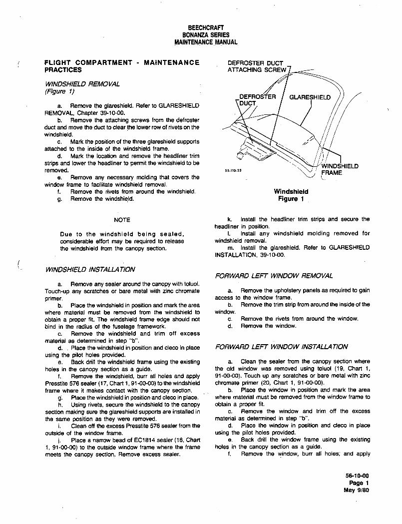
BEECHCRAFT
BONANZA SERIES
MAINTENANCE MANUAL
FLIGHT COAIIPARTMENT MAINTENANCE DEFROSTER DUCTPRACTICES ATTACHING SCREW
WINDSHIELD REMOVAL
(Figure I)DEFROSTER GLARESHIELD
a. Remove the glareshield. Refer to GLARESHIELD \DU/CT,REMOVAL, Chapter 39-10-00.
b. Remove the attaching screws from the defroster
duct and move the duct to clear the lower row of rivets on the
windshield.
c. Mark the position of the three giareshield supportsattached to the inside of the windshield frame. Y
d. Mark the location and remove the headliner trim jstrips and lower the headliner to permit the windshield to be
WINDSHIELDremoved. ,s.l,o-?5 FRAME
e. Remove any necessary molding that covers the
window frame to facilitate windshield removal.
f. Remove the rivets from around the windshield. Windshield
g. Remove the windshield. Figure 1
NOTE k. Install the headliner trim strips and secure the
headliner in position.Due to the windshield being sealed, i. Install any windshield molding removed for
considerable effort may be required to release windshield removal.
the windshield from the canopy section. m. Install the glareshield. Refer to GLARESHIELD
INSTAUATION, 39-10-00.
WINDSHIELD INSTALLA TIONFORWARD LEFT WINDOW REMOVAL
a. Remove any sealer around the canopy with toluol.
Touch-up any scratches or bare metal with zinc chromate a. Remove the upholstery panels as required to gain
primer. access to the window frame.
b. Place the windshield in position and mark the area b. Remove the trim strip from around the inside of the
where material must be removed from the windshield to window.
obtain a proper fit. The windshield frame: edge should not c. Remove the rivets from around the window.
bind in the radius of the fuselage framework. d. Remove the window.
c. Remove the windshield and trim off excess
material as determined in step "b".
d. Place the windshield in position and cleco in place FORWARD LEFT WINDOW INSTALLATION
using the pilot holes provided.e. Back drill the windshield frame using the existing a. Clean the sealer from the canopy section where
holes in the canopy section as a guide. the old window was removed using toluoi (19, Chart 1,
f. Remove the windshield, burr all holes and apply 91-00-00). Touch up any scratches or bare metal with zinc
Presstite 576 sealer (17, Chart 1, 91-00-00) to the windshield chromate primer (20, Chart 1, 91-00-00).frame where it makes contact with the canopy section, b. Place the window in position and mark the area
g. Place the windshield in position and cleco in place. where material must be removed from the window frame to
h. Using rivets, secure the windshield to the canopy obtain a proper fit.
section making sure the glareshield supports are installed in c. Remove the window and trim off the excess
the same position as they were removed. material as determined in step "b".
i. Clean off the excess Presstite 576 sealer from the d. Place the window in position and cleco in placeoutside of the window frame. using the pilot holes provided.
j. Place a narrow bead of EC1814 sealer (18, Chart e. Back drill the window frame using the existing1, 91-00-00) to the outside window frame where the frame holes in the canopy section as a guide.meets the canopy section. Remove excess sealer. f. Remove the window, burr all holes; and apply
56-1090
Page 1
May 9/80
BEECHCRAFT
BONANZA SERIES
MAINTENANCE MANUAL
i Presstite 576 sealer (17, Chart 1, 91-00-00) to an area c. Remove the trim strip around the inside of the
approximately 1/2 inch wide on the canopy section where the window.
old sealer was removed, d. To facilitate reinstallation, mark the location of the
g. Place the window in position and cleco in place. trim strip clips.h. Using rivets, secure the window to the canopy e. Remove the rivets around the window retainer.
section making sure the trim strip clips are reinstalled in the f. Remove the window.
same position as removed.
i. Install the upholstery panels.i. Install. the tirm strip. CABIN DOOR WINDOW INSTALLA TIONk. Clean off the excess Presstite 576 sealer from the
outside of the window frame, a. Clean the sealer from the door where the old
i. Place a narrow bead of EC1814 sealer (18, Chart window was removed, using toluol (19, Chart 1, 91-00-00).1, 91-00-00) to the outside window frame where the frame Touch up any scratches or bare metal with zinc chromate
meets the canopy section. Remove excess sealer. primer (20, Chart 1, 91-00-00).b. Apply Proseal 890 sealer (21, Chart 1,91-00-00) to
an area approximately 1/2 inch wide on the door where the
STORM WINDOW REMOVAL old sealer was removed.
c. Place the new window in position.a. Open the latch mechanism at the top of the storm d. Place the retainer in position, over the window, and
window, cleco the retainer to the cabin door.
b. Remove the two internally threaded hinge pins at e. Secure the window retainer to the door skin with
the bottom of the storm window, rivets.
STORM WINDOW INSTALLATION NOTE
a. Install the two internally threaded hinge pins at the When riveting the window in place, install the
bottom of the storm window. trim strip clips in the same locations as marked in
b. Close the latch mechanism at the top of the storm step "d" of the window removal procedure.window.
CABIN DOOR WINDOW REMOVAL f. Install the trim strip.g. Clean and paint as necessary.
a. Remove the inb;oard door handle, ash tray and arm h. Reinstall the center, upholstery panel.rest, i. Reinstall the inboard door handle, ash tray and
b. Remove the center upholstery panel. arm rest.
"END"
56-10-00.
Page2May 9/80
BEECHCRAFTBONANZA SERIES
MAINTENANCE MANUAL
i CABIN MAINTENANCE PRACTICES PR1221B1/2 sealer (22, Chart 1, 91-00-00) to the area of the
window located in step "d".
OPENABLE WINDOW REMOVAL f. Place the window in position and rivet the retainingstrips in place.
a. Remove the emergency release pin.b. Remove the hinge pin.
NOTE
OPENABLE WINDOW INSTALLATION Connect the latch link rod if the forward window
is being replaced.a. Install the hinge pin.b. Install the emergency release pin.
g. Clean excess sealer from the outside of the
window edge and install the interior window molding.UTILIN DOORS WINDOW REMOVAL
(E-llll, E-1241 and after; EA-1 and altar)WINDOWS AFT OF OPENABLE WINDOWS
a. Remove the window molding trim. REMOVALb. Remove the rivets from the window retaining
strips. a. Remove the upholstery panels as required to gainaccess to the window frame.
b. Remove the trim strip from around the inside of the
NOTE i window.
c. Remove the rivets (Model A36 series airplanes),When removing the rivets from the retainers on or screws from the window retaining strips,the fon~vard window, remove the latch link rod so d. Remove the window.
that all the rivets are accessible.
j WINDOWS AFT OF OPENABLE WINDOWSc. Remove the window. INSTALLA 7/ON
UTILIN DOORS WINDOW INSTALLATION a. Clean the sealer from the cabin section where the
(E-llll, E-1241 and after; EA-1 and aHer) old window was removed using toluol (19, Chart 1, 91-00-
00). Touch up any scratches or bare metal with zinc
a. Clean the old sealer from the door where the chromate primer (20, Chart 1, 91-00-00).window was removed, using toluol, (19, Chart 1, 91-00-00). b. Apply Presstite 576 sealer (17, Chart 1,‘91-00-00)Touch up any scratches´• or bare metal with zinc chromate to an area approximately 1/2 inch wide on the cabin section
primer (20, Chart 1, 91-00-00). where the old sealer was removed.
b. If new retaining strips are required, dimple the rivet c. Place the window in position and install the
holes in the retaining strips with a 5/16 inch dimpler. window retaining strips to the cabin section with screws. On
c. Place the window in position and cleco the the Model A36 series airplanes only, the retaining strips are
retaining strips in place. secured with screws on the top retainer and rivets on the
d. Tape the entire outside surface of the window, then side and bottom retainers.
trim the excess tape away from the area that overlaps the d. Clean excess sealer from the outside of the
door frame. This procedure locates the area that the new window edge and install the trim strips to the inside of the
sealer is to be applied. window.
e. Remove the retaining strips and window. Apply e. install the upholstery panels.
"END"
56-20-00
Page 1~
May 9/80

CHAPTER
VVINGS
Raytheon Aircraft CompanyBONANZA SERIES MAINTENANCE MANUAL
CHAPTER 57 WINGS
TABLE OF CONTENTS
SUBJECT PAGE
57-00-00
Wings- Description and Operation ´•1
Wings- MaintenancePractices ´•´•´•´•´•´•2
WingTip Removal.
WingTip Installation
Wing Removal.
Removalof Leading Edgeand Main Spar ...............3
Installation of Leading Edge and Main Spar ´•3
Wing Installation
Adjusting the Wings
Wing Boltand Fitting Inspection ´•10
Magnetic-Particle Inspection ´•´•´•´•´•´•13
Outboard Wing Main Spar Cap Inspection ´•15
57-30-00
PlateSkin Maintenance Practices ´•1
Wing Access Openings
Wing SkinThickness.
57-40-00
Attach Fittings- Maintenance Practices ´•1
57-50-00
BalancingControl Surfaces- Maintenance Practices ´•1
Balancing the Aileron
Checking Balance
Equipment Requiredto Perform CheckBalancing .........1
Balancing Procedure.
Counterbalancing Method -1
57-CONTENTS Sep 30/04Page 1
Raytheon Aircraft CompanyBONANZA SERIES MAINTENANCE MANUAL
CHAPTER 57 WINGS
LIST OF EFFECTIVE PAGES
CH-SE-SU PAGE DATE
57-LOEP 1 Sep 30/04
5-I-CONTENTS 1 Sep 30/04
57-00-00 1 thru 16 Sep 30/04
57-30-00 1 and 2 Jan 20/82
57-40-00 1 May 9/80
57-50-00 1 thru 3 Sep 30/04
A26 57-LOEP Sep 30/04Page 1
Raytheon AiKraft CompanyBONANZA SERIES MAINTENANCE MANUAL
WINGS DESCRIPTION AND OPERATION
The all metal wing group consists of the front and rear spars, leading edge, wing tips, flaps, ailerons, and fuel tanks.
The wing tips, flaps, and aiierons are readily removable. The forward wing attaching point is located at FS 83.00
while the rear wing attaching point is located at FS 118.00 on all Model 33, 35 and 36 series airplanes. An optional Iremote compass is located in the left wing tip on all serials except CJ-149 and After.
57-00-00Page 1
Ibytheon AiKraft CompanyBONANZA SERIES MAINTENAN~E MANUAL
WINGS MAINTENANCE PRACTICES
WING TIP REMOVAL
a. Remove the screws attaching the wing tip to the wing.
b. Disconnect the electrical leads to the navigation light.
c. Disconnect the remote compass at the left wing tip (if installed).
WING TIP INSTALLATION
a. Connect the remote compass at the left wing tip (if installed).
b. Connect the electrical leads to the navigation light.
c. Place the wing tip in position and secure it to the wing with screws.
WING REMOVAL
a. Drain and purge the fuel cells.
b. Removethe front seats.
c. Remove the rear seat panel.
d. Remove the wing mounting bolt access plates from the top and bottom of the wing.
e. Place the airplane on jacks and raise the airplane until the wheels are clear of the ground. Refer to Chapter7-00-00 for jacking instructions. A three point jack should be used because of the unbalanced condition of the
airplane after the wing is removed.
f. Disconnect and cap hydraulic lines at the wing root.
g. Operate the landing gear switch until the inboard landing gear doors are fully open.
h. Disconnect the inboard door actuator rod from the control horn.
i. Disconnect the landing gear uplock cable at the inboard connection in the wheel well.
j. Disconnect the landing gear actuator rod from the V-brace in the wheel well.
k. Disconnect and cap the fuel lines between the wing root rib and the fuselage.
i. Disconnect and cap the pitot line at the left wing root in the wheel well.
m. Disconnect and label electrical wiring in the wheel well.
n. Disconnect and identify the aileron cables at the turnbuckles located inside the cabin, forward of the rear sparbelow the floorboards.
o. Disconnect the flap drive shaft from the motor.
p. Cradlethe wing.
q. Place a wing stand under the wing not being removed and place a stand under the tail.
Sep 57-00’00 ~2B
Ray~heon Aircraft CompanyBONANZA SERIES MAINTENANCE MANUAL
r. Outline the position of the wing on the fuselage as a guide for reinstallation.
CAUTION: There should be no bolt binding during removal. Should binding occur, adjust the wing position until the
bolt disengages freely. Do not screw or drive a bolt in or out of the fittings.
s. Remove the mounting nuts, bolts and washers from the wing.
WARNING: A bushing is installed in the lower front spar attach fitting. This bushing should not be removed
when the wing is removed, and must be in place when the wing is reinstalled.
NOTE: Discard the mounting nuts. Install new mounting nuts when installing the wing.
Discard the special soft aluminum washer used on the wing upper mounting bolts. Install new aluminum
washers when installing the wing.
t. Disconnect the cold air flex duct at the wing leading edge.
u. Remove the wing by pulling it straight away from the fuselage.
REMOVAL OF LEADING EDGE AND MAIN SPAR
The wing must be removed from the airplane before the leading edge or main spar can be removed. Remove the
attaching screws at the wing tip and wing butts. Access to the screws at the main spar root is through the wheel well.
Pull the hinge pins which attach the leading edge, disconnect the landing gear and remove the main spar.
NOTE: Support the landing gear to avoid damaging the aft spar gear connection or remove the gear at both
connections.
INSTALLA TION OF LEADING EDGE AND MAIN SPAR
The hinge pins are to be driven with a rivet gun by supporting the hinge pin in telescoping tube, repair Kit 35-588 S. IMake sure the hinge halves are free of metal burrs and mated before attempting to drive the hinge pin. Grind the
end of the pin to a point before starting it in the hinge. A second rivet gun or mallet may be used to tap along the
upper or lower edge of the main spar to help the pin through the hinge. Use a wooden block as a pad to preventdamage to the spar.
CAUTION: Do not attempt to spin the hinge pin in with a drill motor. Heat and expansion may cause the wire to seize
or break.
57-00-00 SepPa39~Page 3
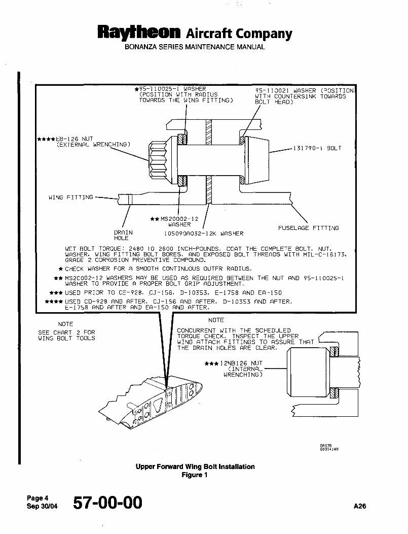
Ra~hMm nircraft CompanyBONANZA SERIES MAINTENANCE MANUAL
+95-110025-1 WASHER 95-110021 WASHER (POSITION(POSITION WITH RADIUS WITH COUNTERSINK TOWARDSTOWARDS THE WING FITTING) BOLT HEAD)
+*EB-126 NUT(EXTERNAL WRENCHING)
131790-1 BOLT
WING FITTING
t+MS20002-12WASHERFUSELAGE FITTING
DRAIN 105090A032-12K WASHERHOLE
WET BOLT TORQUE: 2480 TO 2600 INCH-POUNDS. COAT THE COMPLETE BOLT, NUT,WASHER, WING FITTING BOLT BORES, AND EXPOSED BOLT THREADS WITH MIL-C-1617~,GRADE 2 CORROSION PREVENTIVE COMPOUND.
CHECK WASHER FOR A SMOOTH CONTINUOUS OUTER RADIUS.
MS20002--12 WASHERS MAY BE USED AS REQUIRED BETWEEN THE NUT AND 95-110025-1WASHER TO PROVIDE A PROPER BOLT GRIP ADJUSTMENT.
USED PRIOR TO CE-928~ J_156, D-10353, E-1758 AND EA-I50
USED CD-928 AND AFTER, CJ-156 AND AFTER, D-10353 AND AFTER,E-1758 AND AFTER AND EA-150 AND AFTER.
NOTENOTE
SEE CHART 2 FOR CONCURRENT WITH THE SCHEDULED
WING BOLT TOOLS TORQUE CHECK, INSPECT THE UPPERWING ATTACH FITTINGS TO ASSURE THATTHE DRAIN HOLES ARE CLEAR.
++i 12NB126 NUT(INTERNAL
WRENCHING)
EF157Boo314iaa
Upper Fonnrard Wing Bolt Installation
Figure 1
Sep 57-00-00 A26
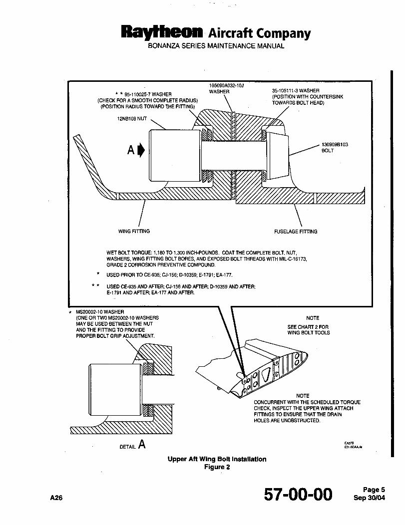
Ray6heoa AiKraft CompanyBONANZA SERIES MAINTENANCE MANUAL
105090A032-105
WASHER 35-105111-3 WASHER95-110025-7 WASHER
(POSITION WIM COUNTERSINK(CHECK FOR A SMOOTH COMPLETE RADIUS) TOWARDS BOLT HEAD)
(POSITION RADIUS TOWARD THE FITTING)
12NB108 NUT
1309098103
BOLT
WING FITTING FUSELAGE FITTING
WET BOLT TORQUE: 1,180 TO 1,3M) INCH-POUNDS. COAT THE COMPLETE BOLT, NUT,WASHERS, WING FITTING BOLT BORES, AND EXPOSED BOLT THREADS WITH MIL-C-16173,GRADE 2 CORROSION PREVENTIVE COMPOUND.
USED PRIOR TO CE-935; CJ-156; D10359; 8-1791, EA-ln.
USED CE-935 AND AFTER; CJ-156 AND AFTER; D-10359 AND AFTER;8-1791 AND AFTER; EA-177 AND AFTER.
MS20002-10 WASHER
(ONE OR TWO MS20002-10 WASHERS NOTE
MAY BE USED BETWEEN THE NUTSEE CHART 2 FOR
AND THE FITTING TO PROVIDEWING BOLT TOOLS
PROPER BOLT GRIP ADJUSTMENT.
O
NOTE
CONCURRENT WITH ME SCHEDULED TORQUE
CHECK, INSPECT THE UPPER WING ATTACH
FlmNGS TO ENSURE THAT THE DRAIN
HOLES ARE UNOBSTRUCTED.
A E~578
Upper Att Wing Bolt Installation
Figure 2
A26 57-00 00 Page 5
Sep 36/04
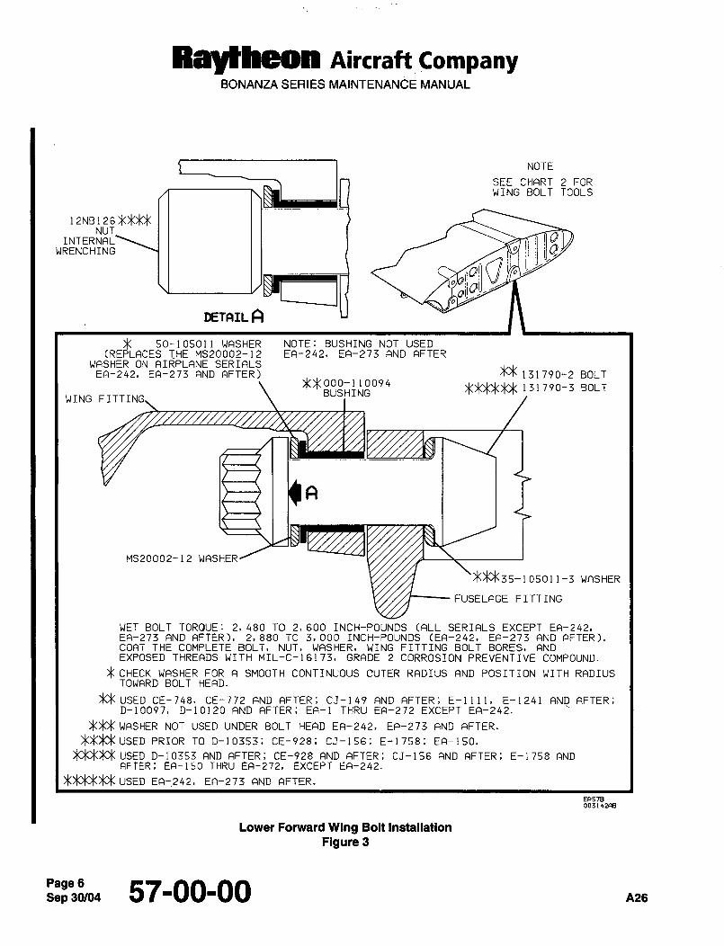
Raytheon Aircraft CompanyBONANZA SERIES MAINTENANCE MANUAL
NOTE
SEE CHART 2 FORWING BOLT TOOLS
12NB126NUT
INTERNAL OWRENCHING
I’
DETAIL A
50-105011 WASHER NOTE: BUSHING NOT USED(REPLACES THE MS20002-12 EA-242, EA-273 AND AFTER
WASHER ON AIRPLANE SERIALSEA-242, EA-273 AND AFTER) ~131790-2 BOLT
1317903 BOLi
WING FITTI
A
MS20002-12 WASHER
35-1 0501 1-3 WASHER
FUSELAGE FITTING
WET BOLT TORQUE: 2, 480 TO 2, 600 INCH-POUNDS (ALL SERIALS EXCEPT EA-242,EA-273 AND AFTER), 2,880 TO 3,000 INCH-POUNDS (EA-242, EA-273 AND AFTER).COAT THE COMPLETE BOLT, NUT, WASHER, WING FITTING BOLT BORES, AND
EXPOSED THREADS WITH MIL-C-16173, GRADE 2 CORROSION PREVENTIVE COMPOUND.
CHECK WASHER FOR A SMOOTH CONTINUOUS OUTER RADIUS AND POSITION WITH RADIUSTOWARD BOLT HEAD.
~X USED CE-748, CE-772 AND AFTER; CJ-149 AND AFTER; E-llll, E-1241 AND AFTER;D-10097, D-10120 AND AFTER; EA-1 THRU EA-272 EXCEPT EA-242.
WASHER NOT USED UNDER BOLT HEAD EA-242, EA-273 AND AFTER.
PRIOR TO D-10353; CE-928; CJ-156; E-1758; EA-150.
USED D-10353 AND AFTER, CE-928 AND AFTER; CJ-156 AND AFTER; E-1758 ANDAFTER; EA-150 THRU EA-272, EXCEPT EA-242.
USED EA-242, EA-273 AND AFTER.
EF(57B
Lower Forward Wing Bolt Installation
Figure 3
Sep 30/045700-00 A26
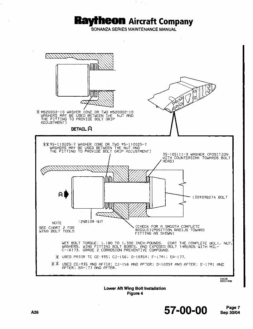
RayBheon Aircraft CompanyBONANZA SERIES MAINTENANCE MANUAL
01
MS20002-10 WASHER ONE OR TWO MS20002-10WASHERS MAY BE USED BETWEEN THE NUT ANDTHE FITTING TO PROVIDE BOLT GRIPADJUSTMENT)
DETAIL A
WASHER CONE OR TWO 95-110025-7WASHERS MAY BE USED BETWEEN THE NUT ANDTHE FITTING TO PROVIDE BOLT GRIP ADJUSTMENT)
35-105111-3 WASHER CPOSITIONWITH COUNTERSINK TOWARDS BOLTHEAD)
130909B274 BOLT
NOTE 12NB108 NUT
SEE CHART 2 FOR (CHECK FOR A SMOOTH COMPLETE
WING BOLT TOOLS RADIUS)(POSITION RADIUS TOWARDFITTING AS SHOWN)
WET BOLT TORQUE: 1,180 TO 1.300 INCH-POUNDS. COAT THE COMPLETE BOLT, NUT,WASHERS~ WING FITTING BOLT BORES, AND EXPOSED BOLT THREADS WITH MIL-C-16173, GRADE 2 CORROSION PREVENTIVE COMPOUND.
USED PRIOR TO CE-935; CJ-156; D-10359, E-1791; EA-177.
USED CE-935 FIND AFTER; CJ-156 AND AFTER; D-10359 AND AFTER; E-1791 ANDAFTER; EA-177 AND AFTER.
EF~578oa3143ns
Lower Aft Wing Bolt Installation
Figure 4
A26 57-00-00 Sep 30/04Page 7
RBYtheOn Aircraft CompanyBONANZA SERIES MAINTENANCE MANUAL
WING INSTALLATION
NOTE: When replacing wing bolts make sure that the replacement bolts have been properly inspected using the
magnetic particle process. Bolts must be magnetically inspected before installation as wing bolts. Bolts maybe acquired through Raytheon Aircraft Parts Inventory and Distribution (RAPID). The individual placing the
order must stipulate the need to have the bolts inspected before shipment.
a. Using a nonmetallic brush and solvent (26 or 31, Chart 1, 91-00-00), clean all wing attach fittings and hardware
I (bolts, washers and nuts). Inspect the wing attach fittings, bolts, washers, and nuts as instructed under WING
BOLT AND FITTING INSPECTION.
WARNING: Wing bolts that have reached their life limit (10 years after the initial inspection) must not be
reused. The mounting nuts must be replaced at each inspection interval.
b. Coat the fitting bolt bores and bearing faces, bolts, washers and nuts with corrosion preventive compound(5, Chart 1, 91-00-00).
WARNING: The bushing installed in the lower forward spat attach fitting must be in place prior to
installation of the wing attach bolts.
c. Move the wing into position, align the wing fittings with the carry-through fittings, and insert the bolts.
CAUTION: Each bolt must be inserted by hand without binding. If a bolt cannot be easily inserte;d, reposition the
wing until the bolt moves freely through fittings. Do not drive or screw bolt into the fittings. Bolts and nuts
must be oriented as shown in applicable illustration for each location (Figure 1, 2, 3, and 4).
d. Start the nuts on the upper fomard and aft bolts. Rotate the wing trailing edge until the wing is aligned with the
outline on the fuselage. After alignment is established, verify that the lower forward bolt is not binding in the bolt
bore. If bolt binding is encountered, adjust the wing position until the bolt moves freely.
e. Tighten the upper forward and aft nuts.
CAUTION: When torquing wing nuts, assure that the wrenches do not bottom out on wing attach fittings. Such an
occurrence could cause false torque readings and damage to fittings. After torquing the upper forward
wing attach nut, remove the holding force from the wing cradle and torque the remaining three nuts.
f.’ Torque the nuts in the following order: upper forward, upper aft, lower forward, and lower aft. When a torquewrench adapter is used, the length of the adapter must be added to the length of the torque wrench and the
proper torque value computed as detailed in Chapter 20-00-00.
CAUTION: Before the lower aft nut is torqued, a slight gap may be evident between the fittings. This gap should not
exceed 0.060 in width. No gap should remain after the nut is torqued. Torque the wing attach bolts at
the nut end, do not rotate the bolt in the bolt bore.
g. Coat the bolt threads that protrude through the nut with corrosion preventive compound (5, Chart 1, 91-00-00).
h. Connect the cold air duct at the wing leading edge.
i. Connect the flap drive shaft to the flap motor.
j. Connect the aileron cables at the turnbuckles.
k. Connect the electrical wiring in the wheel well.
I. Connect the pitot line in the wheel well (LH only).
Sep 30/04Page 8 57-00-00
Raytheon AiKraft CompanyBONANZA SERIES MAINTENANCE MANUAL
m. Connect the fuel lines.
n. Connect the landing gear actuator rod.
o. Connect the landing gear uplock cable.
p. Connect the inboard door actuator rod.
q. Connect the hydraulic brake lines and bleed the brakes.
r. At the first scheduled inspection after the wing has been installed, check the attaching bolts for proper torque.Check the drain ports to assure that they are unobstructed.
ADJUSTING THE WINGS
After the wing has been installed or repaired, flight tests may show the wing to be chronically heavy or light. This
condition may be corrected by rotating the wing to lower the trailing edge of a heavy wing or raise the trailing edgeof a light wing or by a combination of adjusting both wings. The aluminum washers between the upper wing fittingsmust be replaced each time the position of the wing is changed. If both wings have been removed, install the rightwing with the trailing edge at the highest point of the adjustment travel and the left wing 1/16 inch down from the
highest point of travel. The total adjustment on each wing is approximately 1/8 inch. The following steps should be
implemented when adjusting the wings:
a. Using a grease pencil, outline the position of the wing on the fuselage.
b. Place the airplane on a three point jack and raise until the wheels are clear. Refer to Chapter 7-00-00 for jackinginstructions. Place a suitable cradle under the wing being adjusted and a wing stand under the opposite wing.A tail stand will also be required to assure stability.
c. Loosen the nuts on the lower wingattach bolts’ and remove the bolts and nuts from the upper wing attach fittings.Coat the bearing faces and bolt bores of the fittings, the complete bolt, washers, and nut with corrosion
preventive compound (5, Chart 1, 91-00-00). Install new soft aluminum washers between the upper wing attach
fittings. Install the bolts, washers, and nuts into the fittings. Raise or lower the trailing edge as required and
torque the wing attach nuts in the following order: upper forward, upper aft, lower forward, and lower aft. There
should be no gap between the fittings after the last nut is torqued. Torque each nut to the wet torque value shown
in the appropriate illustration (Figure 1, 2, 3, and 4). Coat the exposed threads that protrude through the nuts
with corrosion preventive compound (5, Chart 1, 91-00-00).
NOTE: After torquing the upper forward wing attach nut, remove the holding force from the wing cradle prior to
torquing the remaining three nuts.
d. Remove the wing and tail stands, remove the airplane from the jack, and test fly the airplane.
e. At the first scheduled inspection after the wing has been adjusted, check for correct wing bolt torque. Check the
drain ports in the upper wing attach fittings to assure that they are unobstructed.
57-00-00Page 9
Raytheon Aircraft CompanyBONANZA SERIES MAINTENANCE MANUAL
WING BOLTAND FITTING INSPECTION
NOTE: Read the entire section before removing any wing bolts.
WARNING: The wing bolts installed in the Bonanza series airplanes five years old or older must be removed
and inspected. If the bolts prove to be free of all damage, they may be reinstalled for an
additional five year period. At the end of this period the bolts must again be removed and
inspected. Ten years after the initial inspection, all wing bolts must be replaced with new
hardware. The mounting nuts must be replaced at each inspection interval. Render
unserviceable all components removed in compliance with this warning. See Chart 1 for the
inspection and replacement cycle of the wing bolts.
a. Before removing any wing bolt, draw an outline of the wing position on the fuselage with a grease pencil. If wingbolt binding is encountered and the wing must be shifted, the outline will be helpful in returning the wing to its
original position.
WARNING: Use only the components specified in the applicable illustrations. DO NOT INSTALL THE BLACK
p/N H-20 NUTS, these nuts have been dry film lubricated with molybdenum disulfide. When
MIL-C-16173 Grade II corrosion preventive compound is added to these nuts, the additional
lubrication may cause improper preload in the bolt when It is torqued.
CAUTION: There should be no wing bolt binding during removal or installation of bolts. Do not screw or drive a bolt
in or out of the fittings. If wing bolt binding is encountered, place the airplane on a three pointjack and
raise until the wheels are clear (see Chapter 7-00-00 forjacking instructions). Place a wing stand under
each wing and a tail stand under the ah fuselage. Defuel the wing, loosen the remaining three bolts and
rotate the wing until the binding bolt moves freely through the fittings. Replace the soft aluminum
washers between the upper wing attach fittings and torque the bolts as instructed under WING
INSTALLATION. If bolt binding is not encountered and the wing has not shifted, replacement of soft
aluminum washers between the upper wing attach fittings is not required.
NOTE: Raytheon Aircraft Company supplies wing attach hardware that has been given an additional magneticparticle inspection since manufacture. These components may be identified by the green dye on the head
of the bolt and on some portion of the nut.
b. Starting at the lower wing attach point on each side, remove, inspect and torque one bolt at a time until the
complete set of eight bolts and nuts have been inspected.
c. Using a nonmetallic brush, thoroughly clean the bolt, washers and with solvent (26 or 31, Chart 1, 91-00-00).
I CAUTION: Assure that the 95-110025-1 (Ref. Figure 1~ the 50-105011 (Ref. Figure 3), and the 95-110025-7 (Ref.Figures 2 and 4) washers have a complete radius with no sharp edges that could damage the wingfittings.
I d. If the bolts do not exceed the life limit shown in Chart 1, visually inspect each bolt with a 10-power or strongermagnifying glass; inspect for corrosion, cracks, and mechanical damage. The cadmium plating may displayareas that appear rubbed, discolored, or polished. These areas are usually the result of prevailing installation
procedures and are of no significance. A bolt should not be rejected because of cadmium plating deterioration;however, any component that is cracked, corroded or has mechanical damage must be replaced.
I e. Using the magnetic particle inspection process described in this chapter, check each bolt for circumferential
crack indications. If the bolts prove to be free of all damage (corrosion, cracks, and mechanical damage), theymay be reused after demagnetization and cleaning.
Sep 57-00-00 n26
Raytheon AiKraft CompanyBONANZA SERIES MAINTENANCE MANUAL
f. Clean the spar fitting bolt bores with naphtha or methyl propyl ketone (26 or 31 Chart 1, 91-00-00). Do not stripthe epoxy paint from this area. Inspect the surface condition of each fitting; focus special attention on the washer
seat and bolt bore area. If scoring, corrosion pitting or washer impressions are discovered in this area, contact
Raytheon Aircraft Technical Support. If the fitting is satisfactory, coat the bolt bore and bearing faces of the fittingwith Alodine 1200, 1200S or 1201 (53, Chart 1, 91-00-00). Allow the coating to remain on the surface for
approximately five minutes. When the time has elapsed, wash the coated areas with water and blow dry (do not
wipe dry). Paint the treated areas with zinc chromate primer (20, Chart 1, 91-00-00) and allow to dry.
g. Coat the bearing faces and bolt bores of the fittings, the complete bolt, washers, and nut with corrosion
preventive compound (5, Chart 1,91-00-00).
h. Install the bolt, washers, and nut into the fitting.
CAUTION: Ensure that the wing bolt wrenches do not bottom out on the fittings when torquing the nut. This could
result in damage to the wing fittings and erroneous torque readings.
i. Torque the nut to the wet torque value shown in the appropriate illustration (Ref. Figures 1, 2, 3, and 4). When
a torque wrench adapter is used, the length of the adapter must be added to the length of the torque wrench
and the proper torque value computed as detailed in Chapter 20-00-00.
j. Coat the exposed threads that protrude through the nut with corrosion preventive compound(5, Chart 1, 91-00-00).
k. Check that the decal shown in Figure 5 is affixed to the appropriate locations on the airplane. When the
corrosion preventive compound has been applied to the wing bolts, affix the decal to the following locations:
1. On the side of the fuselage immediately above the RH forward and aft wing bolt covers.
2. On the wing immediately forward of the LH forward and aft wing bolt covers.
3. On the wing immediately forward of the lower forward wing bolt covers on both sides.
4. On the wing immediately aft of the lower ah wing bolt covers on both sides.
I. Check the drain ports in the upper wing attach fittings to ensure that they are unobstructed and free to drain.
m. At the first scheduled inspection after the wing bolts have been inspected or replaced, check for proper bolt
torque.
Chart 1
Wing Bolt And Nut Inspection And Replacement Cycle
NEW 5 years ’5 years 5 years 5 yearsAIRPLANE initial inspection second inspection firstreplacement repeatinspection and
interval replacement cycle
5 years 5 years 5 yearsinitial inspection second inspection firstreplacement repeat inspection and
(alrplanes 5 years old or older) interval replacement cycle
NOTE: At each inspection interval, the nuts must be replaced.At each replacement interval, all wing attach hardware (bolts, washers, and nuts) must be replaced.
57-00-00
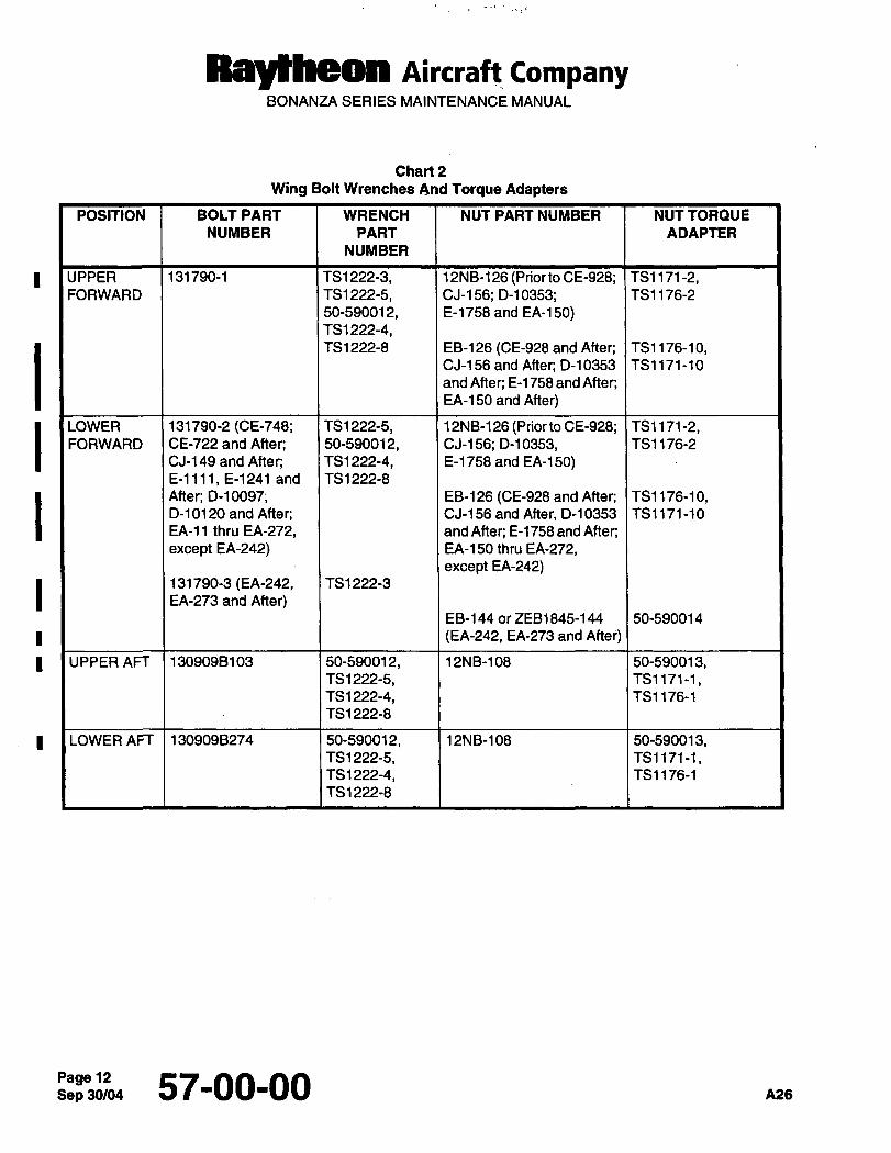
Raytheon Aircraft CompanyBONANZA SERIES MAINTENANCE MANUAL
Chart 2
Wing Bolt Wrenches And Torque Adapters
POSITION BOLT PART WRENCH NUT PART NUMBER NUT TORQUE
NUMBER PART ADAPTER
NUMBER
UPPER 131790-1 TS1 222-3, 12NB-126 (PriortoCE-928; TS1171-2,FORWAR D TS1 222-5, CJ-1 56; D-l 0353; TS1 1 76-2
50-590012, E-1758 and EA-150)TS1 222-4,TS1 222-8 EB-126 (CE-928andAfter; TS1176-10,
CJ-156andAfter; D-10353 TS1171-10
and After; E-l 758 and After;EA-150 and After)
LOWER 131790-2 (CE-748; TS1222-5, 12NB-126 (Priorto CE-928; TS1171-2,FORWARD CE-722 and After; 50-590012, CJ-156; D-10353, TS1176-2
CJ-149 and After; TS1222-4, E-1758 and EA-150)E-l 111, E-1241 and TS 1222-8
After; 0-10097; EB-126 (CE-928andAfter; TS1176-10,D-10120 and After; CJ-156andAfter, D-10353 TS1171-10
EA-11 thru EA-272, and After; E-1758 and After;
except EA-242) EA-150 thru EA-272,except EA-242)
131790-3 (EA-242, TS1 222-3
EA-273 and After)EB-l 44 or ZEB1845-144 50-590014
(EA-242, EA-273 and Aftei)
UPPER AFT 1309098103 50-590012, 12NB-108 50-590013,TS1 222-5, TS1171-1,TS1222-4, TS1176-1
TS1222-8
LOWER A~ 1309098274 50-590012, 12NB-108 50-590013,TS 1222-5, TS1171-1,TS1 222-4, TS1176-1
TS1222-8
Sep 30/0457-00-00 A26
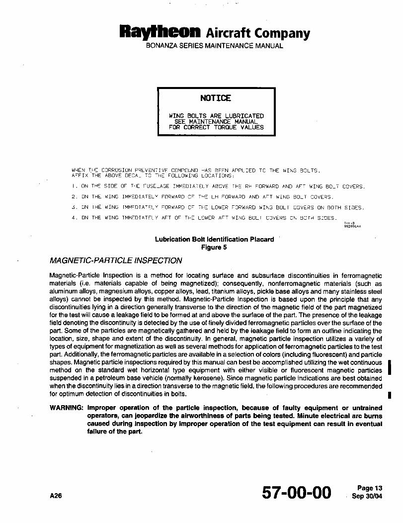
RBYtheOn AiKraft CompanyBONANZA SERIES MAINTENANCE MANUAL
NOTICE
WING BOLTS ARE LUBRICATEDSEE MAINTENANCE MANUAL
FOR CORRECT TORQUE VALUES
WHEN THE CORROSION PREVENTIVE COMPOUND HAS BEEN APPLIED TO THE WING BOLTS.AFFIX THE ABOVE DECAL TO THE FOLLOWING LOCATIONS:
I. ON THE SIDE OF THE FUSELAGE IMMEDIATELY ABOVE THE RH FORWARD AND AFT WING BOLT COVERS.
ON THE WING IMMEDIATELY FORWARD OF THE LH FORWARD AND AFT WING BOLT COVERS.
3. ON THE WING IMMEDIATELY FORWARD OF THE LOWER FORWARD WING BOLT COVERS ON BOTH SIDES.
4. ON THE WING IMMEDIATELY AFT OF THE LOWER AFT WING BOLT COVERS ON BOTH SIDES.THI iB992996**
Lubrication Bolt Identification Placard
Figure 5
MAGNETIC-PARTICLE INSPECTION
Magnetic-Particle Inspection is a method for locating surface and subsurface discontinuities in ferromagneticmaterials (i.e. materials capable of being magnetized); consequently, nonferromagnetic materials (such as
aluminum alloys, magnesium alloys, copper alloys, lead, titanium alloys, pickle base alloys and many stainless steel
alloys) cannot be inspected by this method. Magnetic-Particle Inspection is based upon the principle that anydiscontinuities lying in a direction generally transverse to the direction of the magnetic field of the part magnetizedfor the test will cause a leakage field to be formed at and above the surface of the part. The presence of the leakagefield denoting the discontinuity is detected by the use of finely divided ferromagnetic particles over the surface of the
part. Some of the particles are magnetically gathered and held by the leakage field to form an outline indicating the
location, size, shape and extent of the discontinuity. In general, magnetic particle inspection utilizes a variety of
types of equipment for magnetization as well as several methods for application of ferromagnetic particles to the test
part. Additionally, the ferromagnetic particles are available in a selection of colors (including fluorescent) and particleshapes. Magnetic particle inspections required by this manual can best be accomplished utilizing the wet continuous
method on the standard wet horizontal type equipment with either visible or fluorescent magnetic particlessuspended in a petroleum base vehicle (normally kerosene). Since magnetic particle indications are best obtained
when the discontinuity lies in a direction transverse to the magnetic field, the following procedures are recommended
for optimum detection of discontinuities in bolts.
WARNING: Improper operation of the particle inspection, because of faulty equipment or untrained
operators, can jeopardize the airworthiness of parts being tested. Minute electrical are burns
caused during inspection by improper operation of the test equipment can result in eventual
failure of the part.
A26 57-00-00 Sep 30/04Page 13
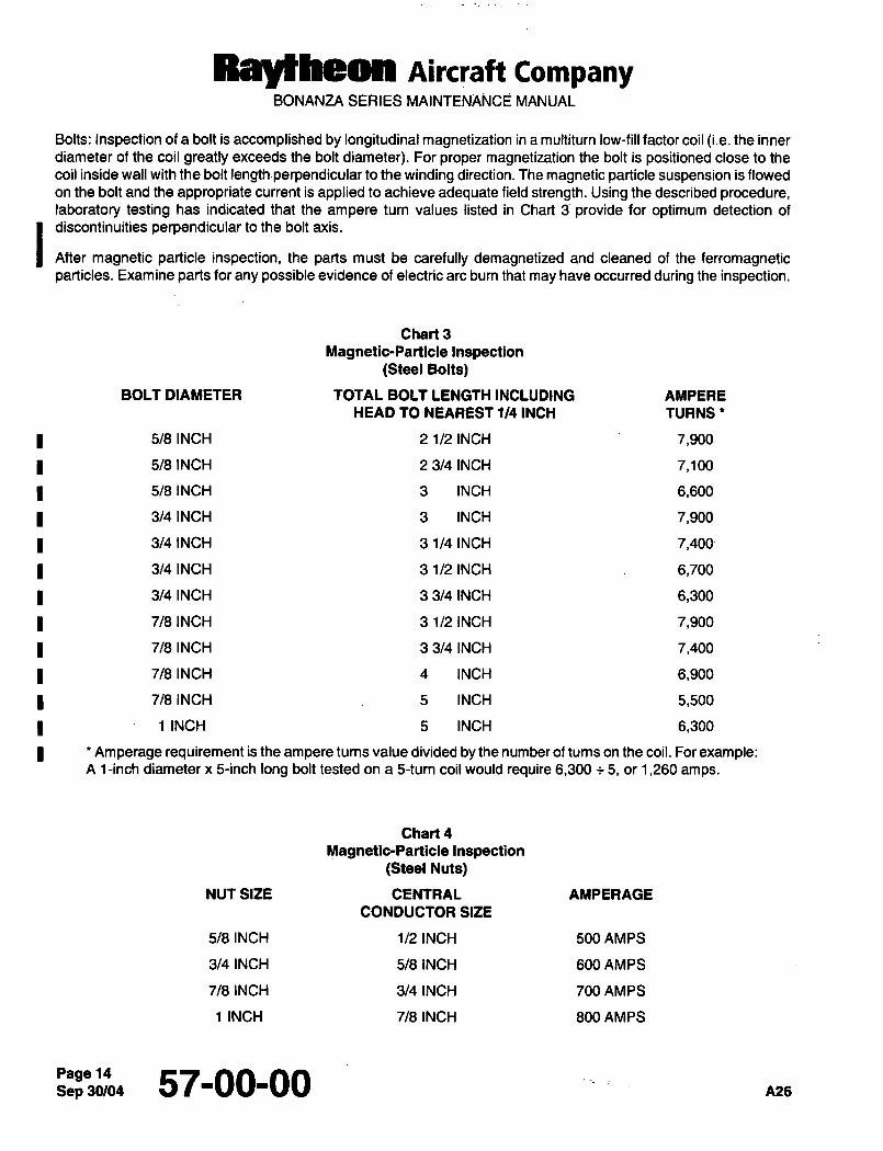
Raytheon Aircraft CompanyBONANZA SERIES MAINTENANCE MANUAL
Bolts: Inspection of a bolt is accomplished by longitudinal magnetization in a multiturn low-fill factor coil (i.e. the inner
diameter of the coil greatly exceeds the bolt diameter). For proper magnetization the bolt is positioned close to the
coil inside wall with the bolt length´•perpendicular to the winding direction. The magnetic particle suspension is flowed
on the bolt and the appropriate current is applied to achieve adequate field strength. Using the described procedure,laboratory testing has indicated that the ampere turn values listed in Chart 3 provide for optimum detection of
discontinuities perpendicular to the bolt axis.
After magnetic particle inspection, the parts must be carefully demagnetized and cleaned of the ferromagneticparticles. Examine parts for any possible evidence of electric are burn that may have occurred during the inspection.
Chart 3
Magnetic-Particle Inspection(Steel Bolts)
BOLT DIAMETER TOTAL BOLT LENGTH INCLUDING AMPERE
HEAD TO NEAREST 1/4 INCH TURNS’
5/8 INCH 21/21NCH 7,900
518 INCH 23141NCH 7,100
5/8 INCH 3 INCH 6,600
3/4 INCH 3 INCH 7,900
3/4 INCH 31141NCH 7,400
3/4 INCH 31/21NCH 6,700
3/4 INCH 33/41NCH 6,300
7/8 INCH 31/21NCH 7,900
7/8 INCH 33141NCH 7,400
7/8 INCH 4 INCH 6,900
7/8 INCH 5 INCH 5,500
1 INCH 5 INCH 6,300
Amperage requirement is the ampere turns value divided by the number of tums on the coil. For example:A i-inch diameter x &inch long bolt tested on a 5-turn coil would require 6,300 5, or 1,260 amps.
Chart 4
Magnetic-Particle Inspection(Steel Nuts)
NUT SIZE CENTRAL AMPERAGE
CONDUCTOR SIZE
5/8 INCH 112 INCH 500 AMPS
3/4 INCH 518 INCH 600 AMPS
718 INCH 3/4 INCH 700 AMPS
1 INCH 718 INCH 800 AMPS
Sep 30/0457-00-00 A26
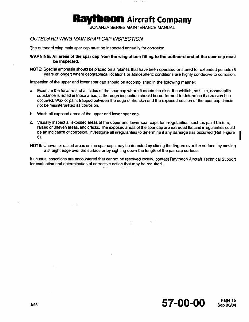
Raytheon Aircraft CompanyBONANZA SERIES MAINTENANCE MANUAL
OUTBOARD WING MAIN SPAR CAP INSPECTION
The outboard wing main spar cap must be inspected annually for corrosion.
WARNING: All areas of the spar cap from the wing attach fitting to the outboard end of the spar cap must
be inspected.
NOTE: Special emphasis should be placed on airplanes that have been operated or stored for extended periods (5years or longer) where geographical locations or atmospheric conditions are highly conducive to corrosion.
Inspection of the upper and lower spar cap should be accomplished in the following manner:
a. Examine the forward and aft sides of the spar cap where it meets the skin. If a whitish, salt-like, nonmetallic
substance is noted in these areas, a thorough inspection should be performed to determine if corrosion has
occurred. Wax or paint trapped between the edge of the skin and the exposed section of the spar cap should
not be misinterpreted as corrosion.
b. Wash all exposed areas of the upper and lower spar cap.
c. Visually inspect all exposed areas of the upper and lower spar caps for irregularities, such as paint blisters,raised or uneven areas, and cracks. The exposed areas of the spar cap are extruded flat and irregularities could
6).be an indication of corrosion. Investigate all irregularities to determine if any damage has occurred (Ref. Figure INOTE: Uneven or raised areas on the spar caps may be detected by sliding the fingers over the sitrface, by moving
-a straight edge over the surface or by sighting down the length of the par cap surface.
If unusual conditions are encountered that cannot be resolved locally, contact Raytheon Aircraft Technical Supportfor evaluation and determination of corrective action that may be required.
A26 57-00-00 15
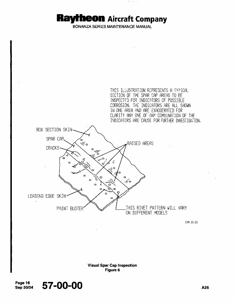
RaYtRetttt Aircraft CompanyBONANZA SERIES MAINTENANCE MANUAL
THIS ILLUSTRATION REPRESENTS A TYPICALSECTION OF THE SPAR CAP AREAS TO BEINSPECTED FOR INDICATORS OF POSSIBLECORROSION. THE INDICATORS ARE ALL SHOWNIN ONE AREA AND ARE EXAGGERATED FORCLARITY ANY ONE OF ANY COMBINATION OF THEINDICATORS ARE CAUSE FOR FURTHER INVESTIGATION.
BOX SECTION SKIN
SPAR CAP,-~o RAISED AREAS
CRACKS~’
o
o \´•’’~Oo O Z
c
\oO
\b~c0 O
",~oo o\;
o
LEADING EDGE SKIN
PAINT BUSTER/ I THIS RIVET PATTERN WILL VARYON DIFFERENT MODELS
C99-35-23
Visual Spar Cap InspectionFigure 6
Sep 57-00-00 A26
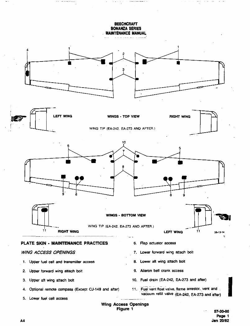
BEECHCRAFTBONANZA SERIES
MAINTENANCE MANUAL
4
lpFe5aLEFT WING WINGS TOP VIEW RIGHT WING
WING TIP (EA-242. EA-273 AND AFTER.)
10
9 a ij Q
sZWING TIP (EA-242. EA-273 AND AFTER.)
WINGS BOTTOY VIEW
11 RIGHT V~ING LEFT WING 1138(3-(4
PLATE SKIN MAINTENANCE PRACTICES 6. Flap actuator access
WING ACCESS OPENINGS 7. Lower forward wing attach bolt
1. Upper fuel cell and transmiiter access 8. Lower aft wing attach bolt
2. Upper forward wing attach bolt 9. Aileron bell crank access
3. Upper aft wing attach bolt 10. Fuel drain (EA-242, EA-273 and after)
4. Optional remote compass (Except CJ-149 and after) 11. Fuel vent float valve, flame anestor, vent and
vacuum refill valve (EA-2;42, EA-273 and~after)5. Lower fuel cell access
Wing Access OpeningsFigure 1
57-30-00
Page 1
A4 Jan 20/82
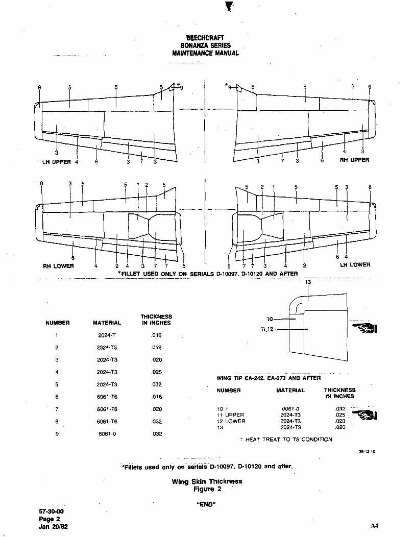
F
BEECHCRAFTBONANZA SERIES
MAINTENANCE MAN~AL
5 8 s8 s 5 5
-I-
4 3
LH UPPER 4 a ~j i 3 ti RH UPPER
8 3 5 5 1 2 5 5 2 1 5 5 3 8
6 4
RH LOWER 4 1 i 3 j j 5 5 j j j 2 LH LOWER
*RLLET USED ONLY ON SERIALS D10097. 0-10120 AND AFTER
THICKNESSNUMBER MATERIAL IN INCHES
11.12 ii1 2024-7 .016
2 2024-73 .016
3 2024-73 .020
4 2024-73 .025WING TIP EA-242, EA-213 AND AFTER
5 2024-73 .032
NUMBER MATERIAL THICKNESS
6 6061 -T6 .016 IN INCHES
7 6061-76 .020 ~o t 6061-0 .032t
11 UPPER 2024-73 .025
8 6061-76 .032 12 LOWER 2024-73 .020
13 2024-73 .020
9 6061-0 .032t HEAT TREAT TO T6 CONDI’TION
35-12-10
ifiliets used only bn-seriais~P10097, 0-10120 and after.
Wing Skin Thickness
Figure 2
"END"
87-28-88
Page 2
Jan 20/82 A4
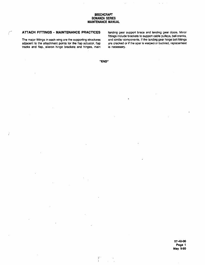
BEECHCRAFT
BONANZA SERIES
MAINTENANCE MANUAL
ATTACH FITTINGS MAINTENANCE PRACTICES landing gear support brace and landing gear doors. Minor
fittings include brackets to support cable pulleys, bell cranks,The major fittings in each wing are the supporting structures and similar components. If the landing gear hinge bolt fittingsadjacent to the attachment points for the flap actuator, flap are cracked or if the spar is warped or buckled, replacementtracks and flap, aileron hinge brackets and hinges, main is necessary.
"END"
57-401)0
Page 1
May 9/80
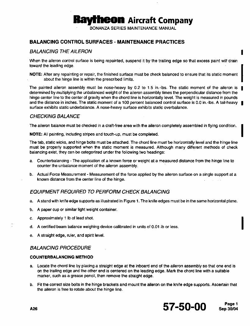
Ray~heon Aircraft CompanyBONANZA SERIES MAINTENANCE MANUAL
BALANCING CONTROL SURFACES MAINTENANCE PRACTICES
BALANCING THE AILERON
When the aileron control surface is being repainted, suspend it by the trailing edge so that excess paint will drain
toward the leading edge.
NOTE: After any repainting or repair, the finished surface must be check balanced to ensure that its static moment
about the hinge line is within the prescribed limits.
The painted aileron assembly must be nose-heavy by 0.2 to 1.5 in.-lbs. The static moment of the aileron is Idetermined by multiplying the unbalanced weight of the aileron assembly times the perpendicular distance from the
hinge center line to the center of gravity when the chord line is horizontally level. The weight is measured in poundsand the distance in inches. The static moment of a 100 percent balanced control surface is 0.0 in.-lbs. A tail-heavysurface exhibits static underbalance. A nose-heavy surface exhibits static overbalance.
CHECKING BALANCE
The aileron balance must be checked in a draft-free area with the aileron completely assembled in flying condition.
INOTE: All painting, including stripes and touch-up, must be completed.
The tab, static wicks, and hinge bolts must be attached. The chord line must be horizontally level and the hinge line
must be properly supported when the static moment is measured. Although many different methods of check
balancing exist, they can be categorized under the following two headings:
a. Counterbalancing The application of a known force or weight at a measured distance from the hinge line to
counter the unbalance moment of the aileron assembly.
b. Actual Force Measurement Measurement of the force applied by the aileron surface on a single support at a
known distance from the center line of the hinge.
EQUIPMENT REQUIRED TO PERFORM CHECK BALANCING
a. A stand with knife edge supports as illustrated in Figure 1.The knife edges must be in the same horizontal plane.
b. A paper cup or similar light weight container.
c. Approximately 1 Ib of lead shot.
d. A certified beam balance weighing device calibrated in units of 0.01 Ib or less.
e. A straight edge, ruler, and spirit level.
BALANCING PROCEDURE
COUNTERBALANCING METHOD
a. Locate the chord line by placing a straight edge at the inboard end of the aileron assembly so that one end is
on the trailing edge and the other end is centered on the leading edge. Mark the chord line with a suitable
marker, such as a grease pencil, then remove the straight edge.
b. Fit the correct size bolts in the hinge brackets and mount the aileron on the knife edge supports. Ascertain that
the aileron is free to rotate about the hinge line.
57-50-00
Ray~heon nircraft CompanyBONANZA SERIES MAINTENANCE MANUAL
c. To determine if weight should be added or removed, suspend a paper cup from a point near the center of the
aileron trailing edge. Use a short length of small diameter string secured to the surface with a small piece of
masking tape as illustrated in Figure 1.The cup must be free to hang vertically.
d. Add small quantities of lead shot to the cup until the aileron balances with the chord line level. Check this byholding the spirit level aligned with the marked chord line.
e. The distance D must be perpendicular to the hinge line. Meagure D from the hinge line to the suspension pointof the cup.
NOTE: Since any weighing error is magnified by the distance D, weighing is most important and must be done
carefully on scales that are certified for accuracy.
f. Remove the cup, contents, and string, then weigh them.
g. Calculate the static balance as follows:
1. The weight of the cup and contents is designated by W.
2. The over or underbalance moment is designated by M.
3. M=WxD
4. The following is a typical example of a balancing calculation: Assume the aileron is overbalance
(nose-heavy) and the paper cup was suspended from the trailing edge. Assume that the aileron balances
with the chord line level at W 0.150 Ib and D 10.0 in., then...
M 0.150 x 10.0
M 1.50 in.-lbs. The product of W x D. In this instance, M is within the required static balance range and is
therefore acceptable.
CAUTION: When a lead rod is added to obtain correct balance, it must be installed securely with rivets. A looselyinstalled rod will vibrate and may cause an undesirable vibration of the surface.
I h. The center of gravity of the aileron is forward of the hinge center line causing the surface to be nose-heavy.Proper aileron balance is obtained by adding or removing lead rod at the leading edge of the aileron. The rod is
I 15/32 in, diameter and is installed in brackets attached to the leading edge of the aileron. When addingadditional lead rod the maximum total of the length of the rod to be added is not to exceed 5 in. over the entire
length of the aileron and would be installed at the center brackets.
Sep 30/0457-50-00 ~26
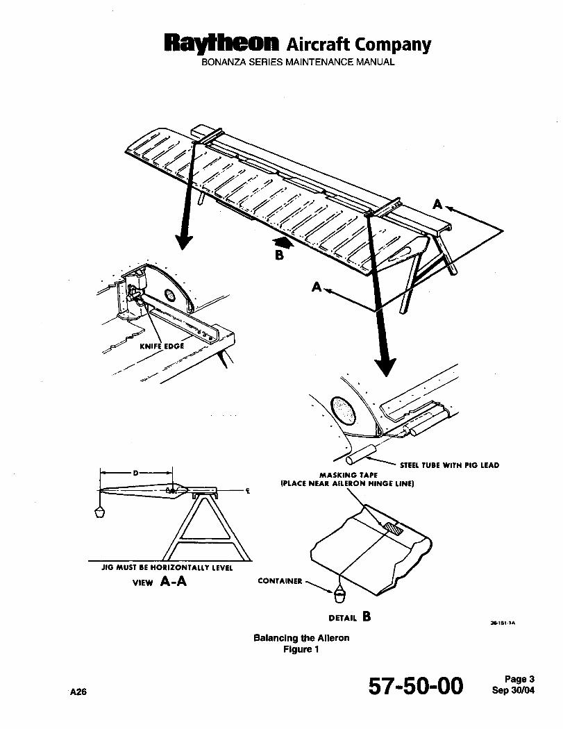
RaytheOR nircraft CompanyBONANZA SERIES MAINTENANCE MANUAL
A
B
AB
KNIFE EDGE
STEEL fUBE WITH PIO LEAD
D -I MASKING TAPE
(PLACE NEAR AILEION HINGE LINE)
JIG MUST BE HORIZONTALLI LEVEL
VIEW A-A CONTAINER
DEtAIL B36(6(-1~
Balancing the Aileron
Figure 1
A26 57-50-00 3

CH;9PTER
PROPELLERS/
PROPU LSORS
Raytheon Aircraft CompanyBONANZA SERIES MAINTENANCE MANUAL
CHAPTER 61- PROPELLER
TABLE OF CONTENTS
SUBJECT PAGE
61-10-00
Propeller- Description and Operation. .......1
Propellers
Propeller Maintenance Practices ....1
Propeller Removal.
Propeller installation
Propeller Adjustment.Minor Propeller Repair
61-20-00
Controlling -Maintenance Practices ´•1
Governor Remova\^. ´•Z
Propeller Governor Installation -1
Propeller Governor Adjustment. ´•1
High RPM Adjustment. ´•1
n27 61-CONTENTS

Raytheon Aircraft tompanyBONANZA SERIES MAINTENANCE MANUAL
CHAPTER 61 PROPELLERS
LIST OF EFFECTIVE PAGES
CH-SE-SU PAGE DATE
61-LOEP 1 Mar 31/05
61-CONTENTS 1 Mar 31/05
61-10-00 1 thru 5 Mar 31/05
61-20-00 1 May 9/80
A27 61-LOEP Mar 31/05Page 1
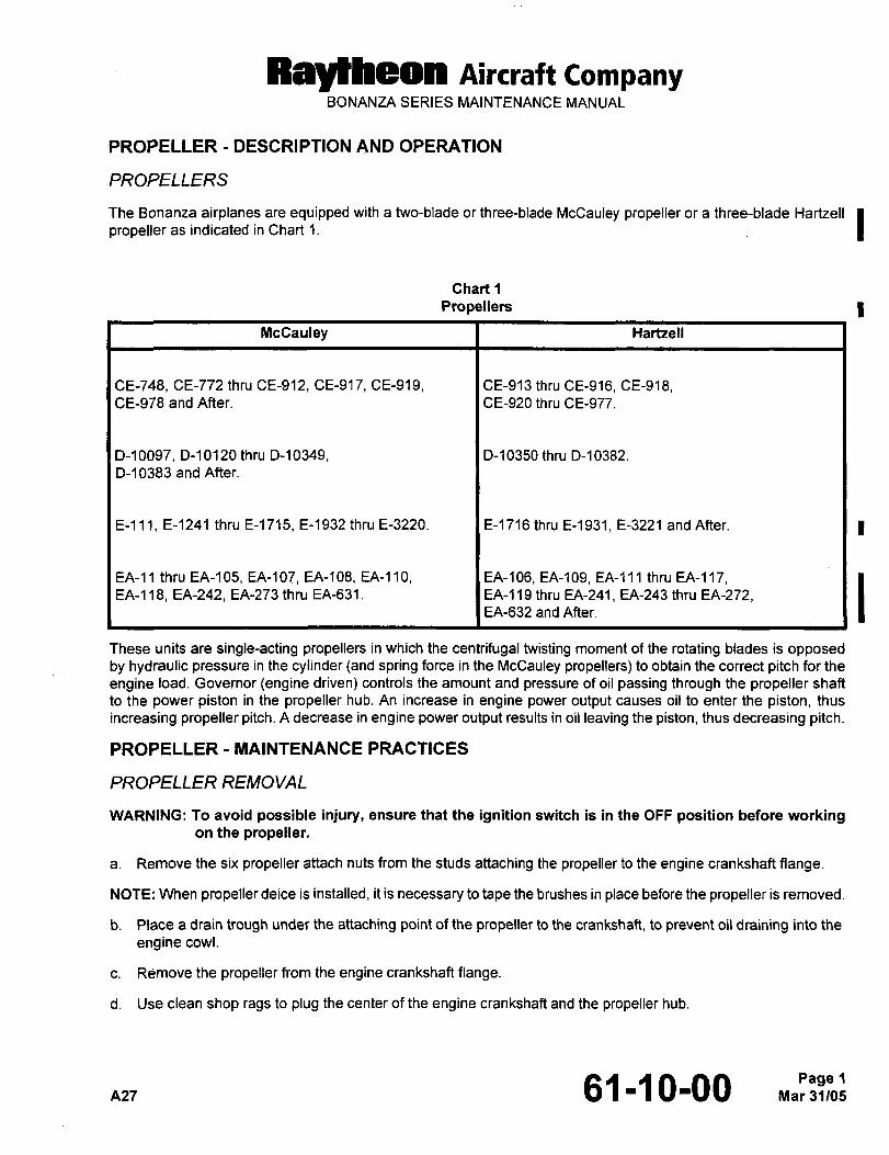
Raytheon Aircraft CompanyBONANZA SERIES MAINTENANCE MANUAL
PROPELLER DESCRIPTION AND OPERATION
PROPELLERS
The Bonanza airplanes are equipped with a two-blade or three-blade McCauley propeller or a three-blade Hartzell Ipropeller as indicated in Chart 1.
Chart 1
Propellers I
McCauley I Hartzell
CE-748, CE-772 thru CE-912, CE-917, CE-919, I CE-913 thru CE-916, CE-918,CE-998 and After. I CE-920 thru CE-977.
D-10097, D-10120 thru D-10349, 1 D-10350 thru D-10382.
D-10383 and After.
E-lll, E-1241 thru E-1715, E-1932 thru E-3220. 1 E-1716 thru E-1931, E-3221 and After.
EA-11 thru EA-105, EA-107, EA-108, EA-110, EA-106, EA-109, EA-111 thru EA-117,EA-118, EA-242, EA-273 thru EA-631. I EA-119 thru EA-241, EA-243 thru EA-272,EA-632and After.
These units are single-acting propellers in which the centrifugal twisting moment of the rotating blades is opposedby hydraulic pressure in the cylinder land spring force in the McCauley propellers) to obtain the correct pitch for the
engine load. Governor (engine driven) controls the amount and pressure of oil passing through the propeller shaft
to the power piston in the propeller hub. An increase in engine power output causes oil to enter the piston, thus
increasing propeller pitch. A decrease in engine power output results in oil leaving the piston, thus decreasing pitch.
PROPELLER MAINTENANCE PRACTICES
PROPELLER REMOVAL
WARNING: To avoid possible injury, ensure that the ignition switch is in the OFF position before workingon the propeller.
a. Remove the six propeller attach nuts from the studs attaching the propeller to the engine crankshaft flange.
NOTE: When propeller deice is installed, it is necessary to tape the brushes in place before the propeller is removed.
b. Place a drain trough under the attaching point of the propeller to the crankshaft, to prevent oil draining into the
engine cowl.
c. Rdmove the propeller from the engine crankshaft flange.
d. Use clean shop rags to plug the center of the engine crankshaft and the propeller hub.
n27 61-~0-00 1
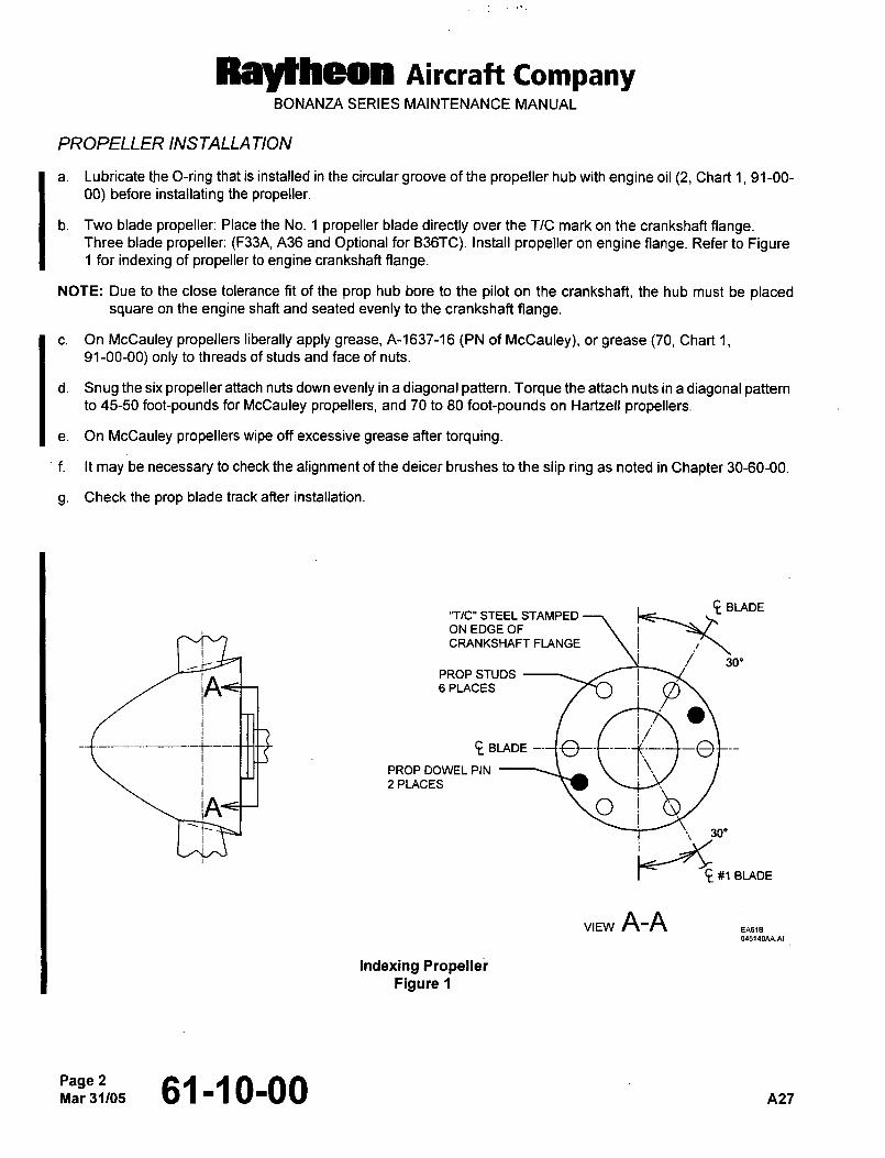
Raytheon nircraft CompanyBONANZA SERIES MAINTENANCE MANUAL
PROPELLER INSTALLA TION
a. Lubricate the O-ring that is installed in the circular groove of the propeller hub with engine oil (2, Chart 1, 91-00-
00) before installating the propeller.
b. Two blade propeller: Place the No. 1 propeller blade directly over the TIC mark on the crankshaft Range.Three blade propeller: (F33A, A36 and Optional for B36TC). Install propeller on engine flange. Refer to Figure1 for indexing of propeller to engine crankshaft flange.
NOTE: Due to the close tolerance fit of the prop hub bore to the pilot on the crankshaft, the hub must be placedsquare on the engine shaft and seated evenly to the crankshaft flange.
c. On McCauley propellers liberally apply grease, A-1637-16 (PN of McCauley), or grease (70, Chart 1,91-00-00) only to threads of studs and face of nuts.
d. Snug the six propeller attach nuts down evenly in a diagonal pattern. Torque the attach nuts in a diagonal patternto 45-50 foot-pounds for McCauley propellers, and 70 to 80 foot-pounds on Hartzell propellers.
e. On McCauley propellers wipe off excessive grease after torquing.
f. It may be necessary to check the alignment of the deicer brushes to the slip ring as noted in Chapter 30-60-00.
g. Check the prop blade track after installation.
e BLADE’7/C" STEEL STAMPED
ON EDGE OF
CRANKSHAFT FLANGE
j,.PROP STUDS
JA´• G PLACES
BLADE
PROPDOWELPIN
2 PLACES
~o T‘1=
30"
#1 BLADE
VIEW A-A
Indexing PropellerFigure 1
Page 2Mar31105 61-10-00 A27
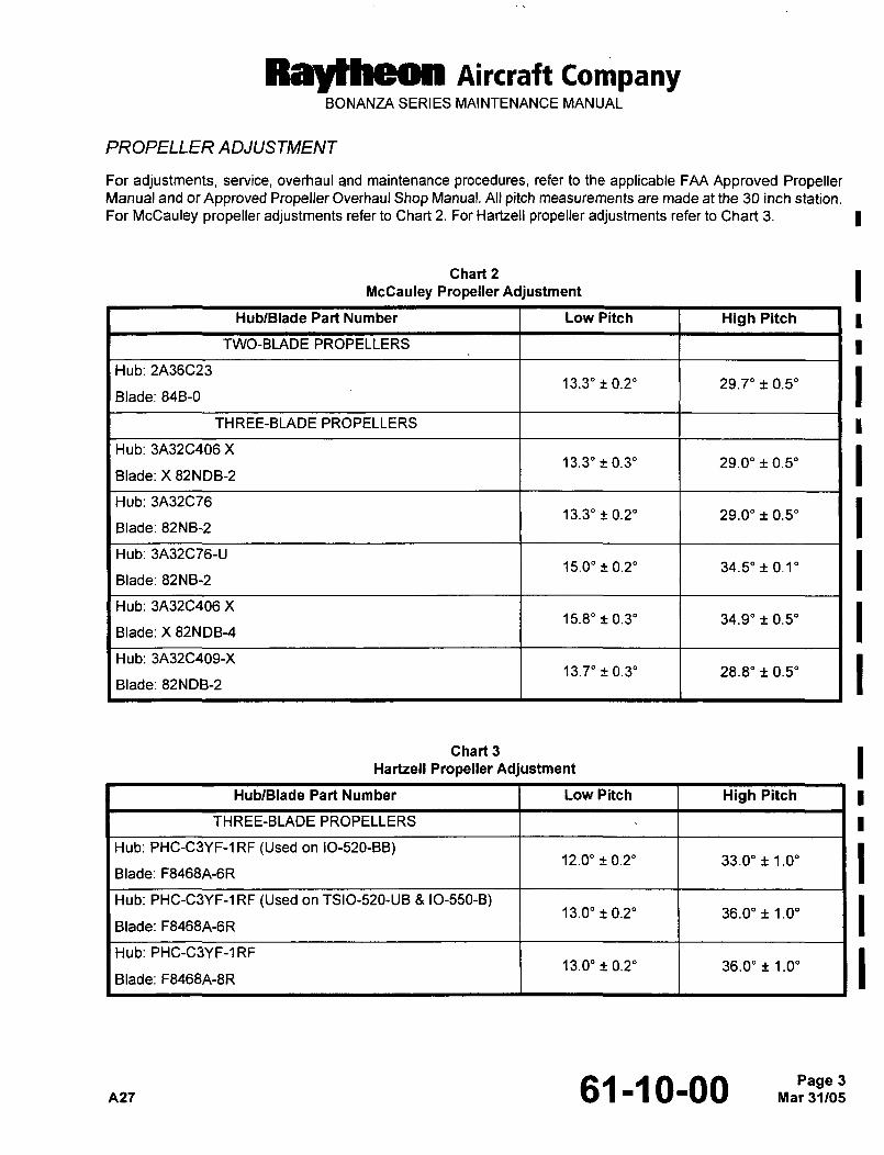
Ral~heon Aircraft CompanyBONANZA SERIES MAINTENANCE MANUAL
PROPELLER ADJUSTMENT
For adjustments, service, overhaul and maintenance procedures, refer to the applicable FAA Approved PropellerManual and or Approved Propeller Overhaul Shop Manual. All pitch measurements are made at the 30 inch station.
For McCauley propeller adjustments refer to Chart 2. For Hartzell propeller adjustments refer to Chart 3.
Chart 2
McCauley Propeller Adjustment
HublBlade Part Number Low Pitch High Pitch
TWO-BLADE PROPELLERS
Hub: 2A36C2313.3" 0.2" 29.7" 0.5"
Blade: 84B-0
THREE-BLADE PROPELLERS
Hub: 3A32C406 X13.3" 0.3" 29.0" 0.5"
Blade: X 82NDB-2
Hub: 3A32C7613.3" 0.2" 29.0" 0.5"
Blade: 82NB-2
Hub: 3A32C76-U15.0" 0.2" 34.5"~0.1"
Blade: 82NB-2
Hub: 3A32C406 X15.8" 0.3" 34.9" 0.5"
Blade: X 82NDB-4
Hub: 3A32C409-X13.7" 0.3" 28.8" 0.5"
Blade: 82NDB-2
Chart 3
Hartzell Propeller Adjustment
HublBlade Part Number Low Pitch High Pitch
THREE-BLADE PROPELLERS
Hub: PHC-C?IYF-1RF (Used on IO-520-BB)12.0" 0.2" 33.0" 1.0"
Blade: F8468A-6R
Hub: PHC-C3YF-1RF (Used on TSIO-520-UB 8 IO-550-B)13.0" 0.2" 36.0" 1.0"
Blade: F8468A-6R
Hub: PHC-C3YF-1RF13.0" 0.2" 36.0" 1.0"
Blade: F8468A-8R
A27 61-10-00 Mar 31/05Page 3
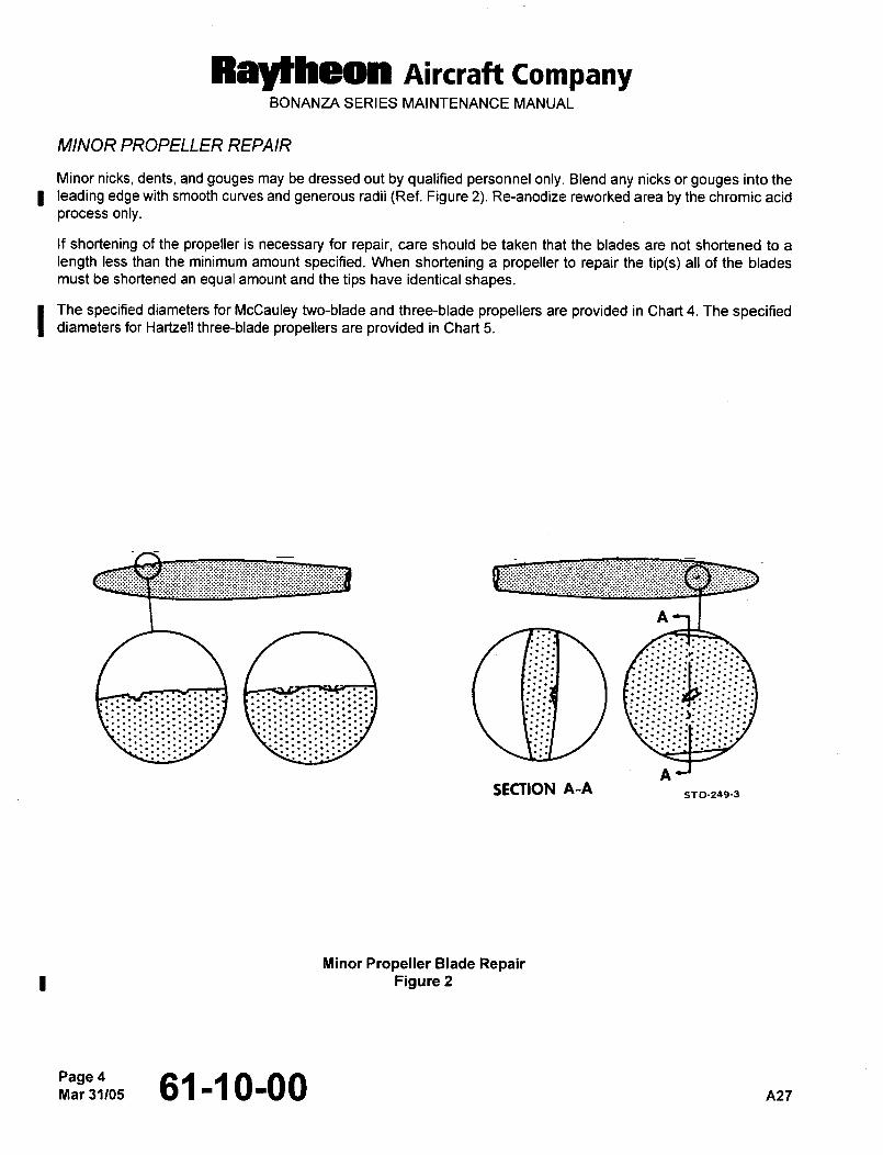
Raytheon Aircraft CompanyBONANZA SERIES MAINTENANCE MANUAL
MINOR PROPELLER REPAIR
Minor nicks, dents, and gouges may be dressed out by qualified personnel only. Blend any nicks or gouges into the
leading edge with smooth curves and generous radii (Ref. Figure 2). Re-anodize reworked area by the chromic acid
process only.
If shortening of the propeller is necessary for repair, care should be taken that the blades are not shortened to a
length less than the minimum amount specified. When shortening a propeller to repair the tip(s) all of the blades
must be shortened an equal amount and the tips have identical shapes.
The specified diameters for McCauley two-blade and three-blade propellers are provided in Chart 4. The specifieddiameters for Hartzell three-blade propellers are provided in Chart 5.
ji
SECTION A-A5TD-249-3
Minor Propeller Blade RepairFigure 2
61-10-00 A27
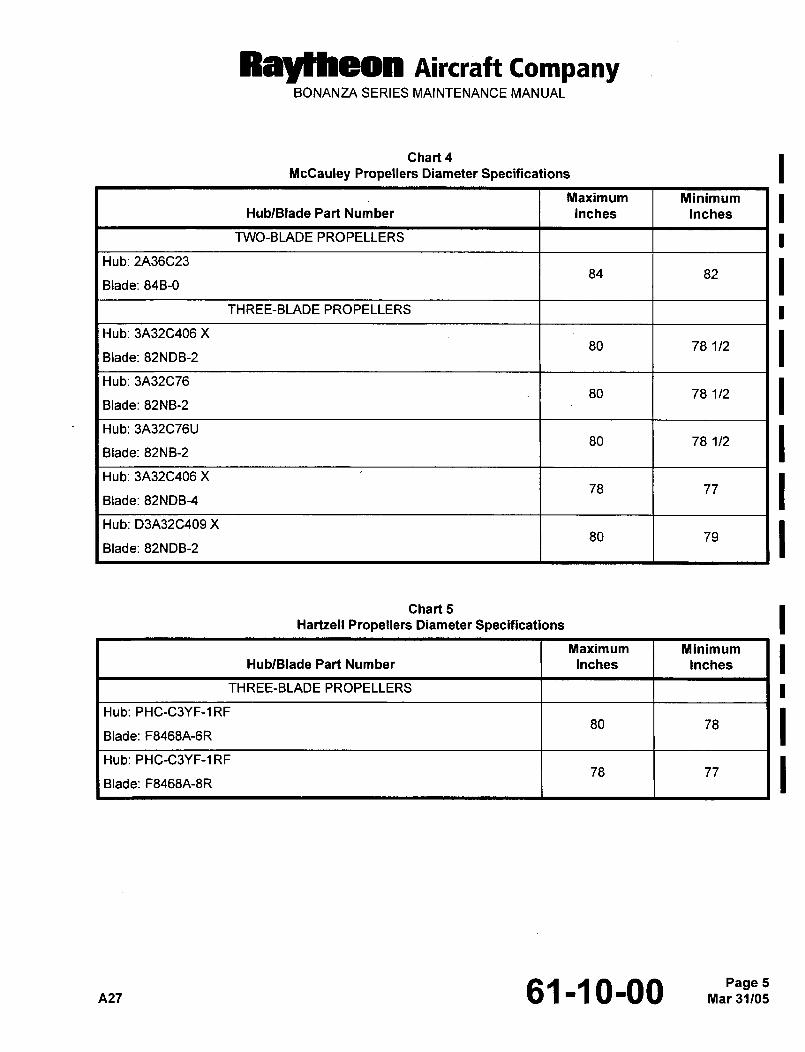
RaytPleon Aircraft CompanyBONANZA SERIES MAINTENANCE MANUAL
Chart 4
McCauley Propellers Diameter Specifications
Maximum Minimum
HublBlade Part Number Inches Inches
TWO-BLADE PROPELLERS
Hub: 2A36C2384 82
Blade: 84B-0
THREE-BLADE PROPELLERS
Hub: 3A32C406 X80 78 1/2
Blade: 82NDB-2
Hub: 3A32C7680 78 1/2
Blade: 82NB-2
Hub: 3A32C76U80 78 1/2
Blade: 82NB-2
Hub: 3A32C406 X78 77
Blade: 82NDB-4
Hub: D3A32C409 X80 79
Blade: 82NDB-2
Chart 5
Hartzell Propellers Diameter Specifications
Maximum Minimum
HublBlade Part Number Inches Inches
THREE-BLADE PROPELLERS
Hub: PHC-C3YF-1RF80 78
Blade: F8468A-6R
Hub: PHC-C3YF-1RF78 77
Blade: F8468A-8R
A27 61-~0-00 Mar 31/05Page 5
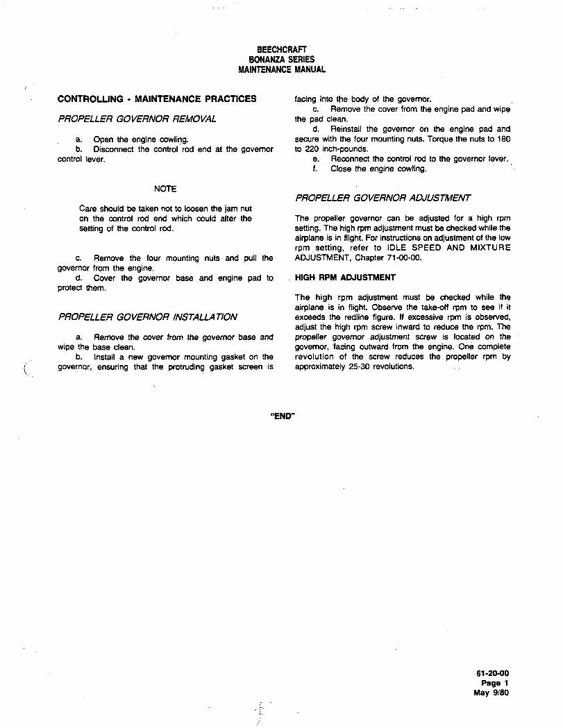
BEECHCRAFT
BONANZA SERIES
MAINTENANCE MANUAL
CONTROLLING MAINTENANCE PRACTICES facing into the body of the governor.c. Remove the cover from the engine pad and wipe
PROPELLER GOVERNOR REMOVAL the pad clean.
d. Reinstall the govemor on the engine pad and
a. Open the engine cowli?g. secure with the four mounting nuts. Torque the nuts to 180
b. Disconnect the control rod end at the governor to 220 inch-pounds.control lever. e. Reconnect the control rod to the governor lever.
f. Close the engine cowling.
NOTEPROPELLER GOVERNOR ADJUSTMENT
Care should be taken not to loosen the jam nut
on the control rod end which could alter the The propeller governor can be adjusted for a high rpm
setting of the control rod. setting. The high rpm adjustment must be checked while the
airplane is in flight. For instructions on adjustment of the low
rpm setting, refer to IDLE SPEED AND MIXTURE
c. Remove the four mounting nuts and pull the ADJUSTMENT, Chapter 71-00-00.
governor from the engine.d. Cover the governor base and engine pad to HIGH RPM ADJUSTMENT
protect them.
The high rpm adjustment must be checked while the
airplane is in flight. Observe the take-off rpm to see if it
PROPELLER GOVERNOR INSTALLATION exceeds the redline figure. If excessive rpm is observed,
adjust the high rpm screw inward to reduce the rpm. The
a. Remove the cover from the governor base and propeller governor adjustment screw is located on the
wipe the base clean. governor, facing outward from the engine. One completeb. Install a new governor mounting gasket on the revolution of the screw reduces the propeller rpm by
governor, ensuring that the protruding gasket screen is approximately 25-30 revolutions.
"END"
61-20-00
Page 1
May 9180

CHAPTE R
POVVERPLANT
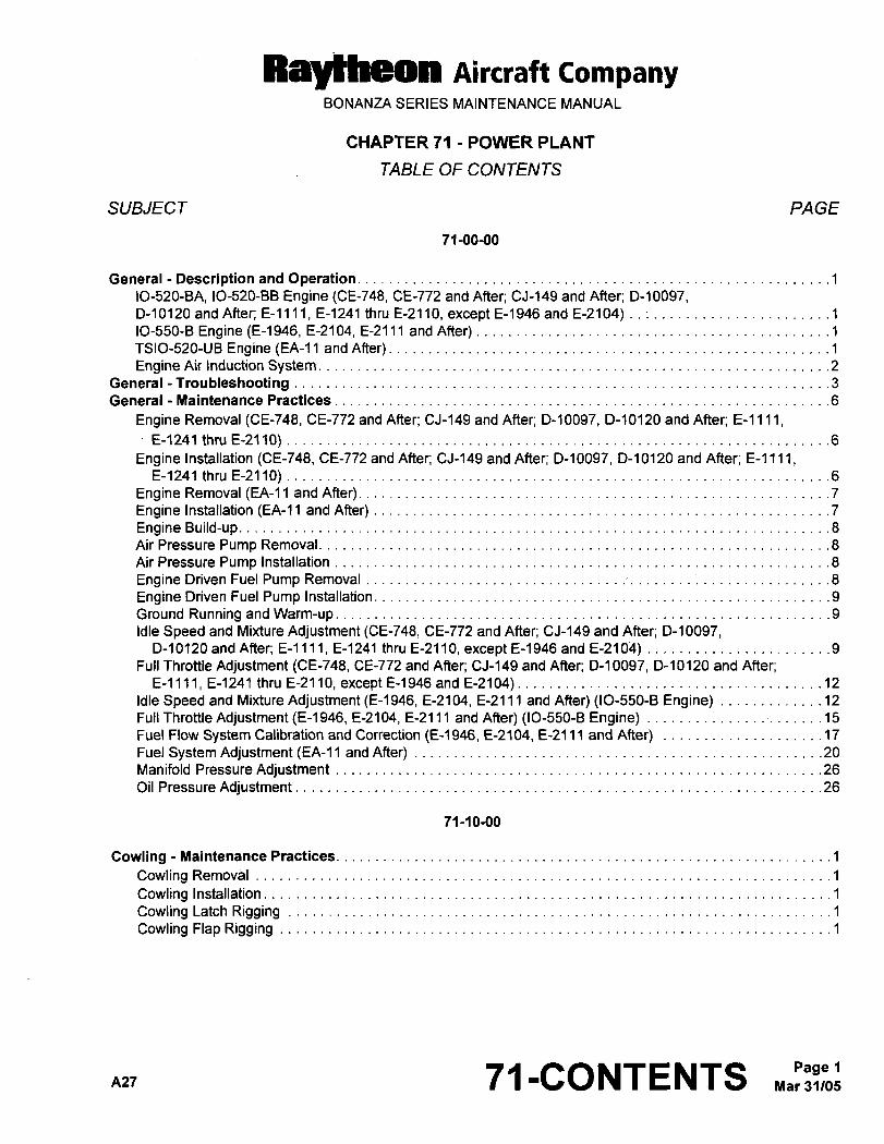
Ray~heon AiKraft CompanyBONANZA SERIES MAINTENANCE MANUAL
CHAPTER 71 POWER PLANT
TABLE OF CONTENTS
SUBJECT PAGE
71-00-00
General Description and Operation ........._____ ........._____
..1
1O-520-BA, 10-520-88 Engine (CE-748, CE-772 and After; CJ-149 and After; D-10097,D-10120andAfter; E-llll, E-1241 thru 8-2110, exceptE-1946and E-2104) ...1
10-550-8 Engine (E-1946, E-2104, E-2111 andAfter) ......1
TSIO-520-UB Engine (EA-11 and After). .1
Engine Air Induction System. ................._.2
General- TroubleshootingGeneral Maintenance Practices. ....6
Engine Removal (CE-748, CE-772 and After; CJ-149 and After; D-10097, D-10120 and After; E-llll,
E-1241 thru E-2110)Engine Installation (CE-748, CE-772 and After; CJ-149 and After; 0-10097, 0-10120 and After; E-llll,
E-1241 thru E-2110) ................._ ................._ ................._
Engine Removal (EA-11 and After). ................._.7
Engine Installation (EA-11 andAfter) .7
Engine Build-up.AirPressure Pump Removal.
........._......._......8
AirPressure Pump Installation .....8
Engine Driven Fuel Pump Removal ......8
EngineDriven Fuel Pump Installation.................._
................_9
Ground Running and Warm-up. ....9
Idle Speed and Mixture Adjustment (CE-748, CE-772 and After; CJ-149 and After; 0-10097,D-10120 andAfter; E-llil, E-1241 thru E-2110, except E-1946 and E-2104) ................._
....9
Full Throttle Adjustment (CE-748, CE-772 and After; CJ-149 and After; D-10097, D-10120 and After;E-llll, E-1241 thru E-2110, except E-1946 and E-2104) 12
Idle Speed and Mixture Adjustment (E-1946, E-2104, E-2111 and After) (10-550-8 Engine) ........._..12
Full Throttle Adjustment (E-1946, E-2104, E-2111 and After) (10-550-8 Engine) ......15
Fuel Flow System Calibration and Correction (E-1946, E-2104, E-2111 and After) .17
Fuel SystemAdjustment (EA-11 andAfter) ........._____.............20
Manifold Pressure Adjustment .26
Oil Pressure Adjustment ................._ .26
71-10-00
Cowling Maintenance Practices.................._
....1
Cowling Removal................._
Cowling Installation................._
Cowling Latch Rigging ................._ ................._
Cowling Flap Rigging ........._____ ........._____ ........._____
A27 71-CONTENTS 1
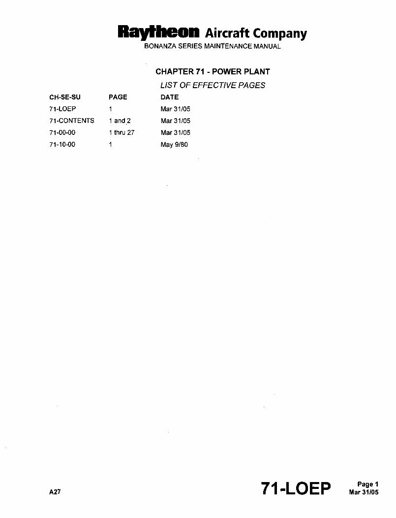
Raytheon Aircraft CompanyBONANZA SERIES MAINiENANCE MANUAL
CHAPTER 71 POWER PLANT
LIST OF EFFECTIVE PAGES
CH-SE-SU PAGE DATE
71-LOEP 1 Mar 31/05
71-CONTENTS 1 and 2 Mar 31105
71-00-00 1 thru 27 Mar 31/05
71-10-00 1 May 9/80
A27 7I-LOEP Mar 31/05Page 1
Raytheon Aircraft CompanyBONANZA SERIES MAINTENANCE MANUAL
GENERAL DESCRIPTION AND OPERATION
IO-520-BA, IO-520-BB ENGINE (CE-748, CE- 772 AND AFTER; CJ- 49 AND AFTER; D- 009 7 10-10120 AND AFTER; E-l I E-1241 THRU E-2110, EXCEPT E-1946 AND E-2104)
The above Bonanza serial airplanes are equipped with IO-520-BA Continental engines until the following serials, at
which time they are equipped with IO-520-BB engines: CE-816 and After; CJ-149 and After; D-10179 and After, and
E-1371 thru E-2110, except E-1946 and E-2104. The IO-520-BB engine differs from the previous engines in that it
has an improved crankshaft and other changes related to the improved crankshaft. The engine is a fuel injected,direct-drive, air-cooled, horizontally opposed, Gcylinder, 520 cubic-inch displacement, 285horsepower engine. The
engine crankshaft rotates in the clockwise direction. Recommended fuel for the engine is Aviation Gasoline 100LL
(blue), or 100/130 (green) minimum grade. The oil capacity for the engine is 12.0 quarts of oil conforming to
Continental Motors Bulletin MHS-24B. For overhaul of the engine, refer to Continental 10-520 Series Aircraft
Engines Overhaul Manual, FORM X-30039A.
IO-550-B ENGINE (E-1946, E-2104, E-211 1 AND AFTER)
At the above noted airplane serials, the A36 Bonanza airplanes were equipped with IO-550-B Continental engines.These are fuel injected, direct-drive, air-cooled, horizontally opposed, 6 cylinder, 550 cubic-inch displacement 300
horsepower engines.
On certain airplanes, as designated by Factory Work Order, a Quiet Bonanza is made. A red line of 2,550 rpm is
established for the tachometer and the throttle system is set to produce 2,550 rpm. A propeller governor set to 2,550
rpm along with a propeller that matches the governor and the engine is installed.
The engine crankshaft rotates in the clockwise direction. Recommended fuel for the engine is Aviation Gasoline
100LL (blue), or 100/130 (9reen) minimum grade. The oil capacity for the engine is 12.0 quarts of oil conforming to
Continental Motors Bulletin MHS-24B. For overhaul of the engine, refer to Continental 10-550 Series Aircraft
Engines Overhaul Manual, FORM X-30568.
TSIO-520-UB ENGINE (EA-?1 AND AFTER)
The Turbocharged Bonanza A36TC and B36TC airplanes are equipped with turbocharged Continental engines.EA-1 1 and After are equipped with TSIO-520-UB engines. These engines are rated at 300 horsepower at 2,700 rpm.The turbocharger provides a means by which the engine can maintain takeoff power from sea level through a critical
altitude of 20,500 feet with a maximum operating altitude of 25,000 feet.
The turbocharger is located beneath and to the left rear of the engine and is driven by exhaust gases. The
turbocharger is lubricated by engine oil and is dependent upon the engine oil pump for its lubrication. For this reason
the engine should be allowed to run at idle for a short period of time (4 to 5 minutes) before it is shut down. This idle
time will allow the turbocharger to slow down and cool before its oil supply is shut off. The turbocharger can obtain
maximum continuous speeds of 96,000 rpm tin an overspeed condition it must not exceed 1 15,000 rpm) and run for
1 to 2 minutes after the engine has been shut down. This 1 to 2 minutes of turbocharger operation occurs without
oil pressure because the engine oil pump is not running. Therefore it is important that the turbocharger be allowed
to slow down before the engine is shut down.
The engine is designed to operate with a maximum manifold pressure of 36 in. Hg, and is protected from overboost
by an automatic pressure relief valve. This valve is located downstream from the turbocharger and will relieve
pressure if the system reaches an overboost condition of 39.5 in. Hg.
For specific information regarding the turbocharger system, refer to Chapter 81-00-00.
nzl 71-00-00
Raytheon Aircraft CompanyBONANZA SERIES MAINTENANCE MANUAL
ENGINE AIR INDUCTION SYSTEM
Engine induction air is available from two sources, primary and alternate air. The primary air source is supplied
through an intake duct, located on the fcMlard cowling below the propeller. The primary air passes through an air
filter and then into the induction system.
NOTE: If, after cleaning, the surfaces of the air filter show metallic wires through the remaining flocking material, the
filter is no longer effective and should be replaced.
If the primary source of ram air is obstructed, the induction system low pressure opens an Alternate Air Source door
and permits the required volume of air flow for normal engine performance. The alternate air door is located just aft
of the air filter and on the left side of the intake duct.
Page 22’3:,,, 71-00-00 A,
RBytheOn nircraft CompanyBONANZA SERIES MAINTENANCE MANUAL
GENERAL- TROUBLESHOOTING
Chart 1 ITroubleshooting the Engine
INDICATION PROBABLE CAUSE REMARKS
1. Enginewill notstart. a. No fuel gage pressure No a. Check fuel control for proper position,fuel to engine. auxiliary pump ON and operating, fuel
fuel in tank.selector valve open. Fuel filter open, and Ib. Have gage pressure engine b. Turn off auxiliary pump and ignitionflooded, switch, set throttle to FULL OPEN and
fuel control to IDLE CUT-OFF, and crank
engine to clear cylinders of excess fuel.
Repeat starting procedures.
c. Have gage pressure No fuel c. Check for bent or loose fuel lines.
to engine. Loosen one line at fuel nozzle. If no fuel
shows replace fuel manifold valve.
2. Engine starts but fails to keep a. Inadequate fuel to fuel a. Set fuel control in FULL RICH position,running. manifold valve. turn auxiliary pump ON check to be sure
feed lines and filters are not restricted.
Clean or replace defective components.
b. Defective ignition system. b. Check accessible ignition cables and
connections. Tighten loose connections.
Replace defective spark plugs.
3. Engine runsrough atidle. a. Improper idle mixture a. Readjust idle setting. Tightenadjustment. adjustment nut to richen mixture and back
off adjustment nut to lean mixture.
b. Fouled spark plugs. b. Remove and clean plugs, adjust gaps.
Replace defective plugs.
4. Engine has poor acceleration, a. Idle mixture too lean. a. Readjust idle mixture as described in
3a.
b. Incorrect fuel-air mixture, b. Tighten loose connections, replaceworn dontrol linkage, or worn elements of linkage. Service air
restricted air cleaner. cleaner.
c. Defective ignition system. c. Check accessible cables and
connections. Replace defective plugs.
n27 71-00-00
RayMheon Aircraft CompanyBONANZA SERIES MAINTENANCE MANUAL
Chart 1
Troubleshooting the Engine (Continued)
INDICATION PROBABLE CAUSE REMARKS
5. Engine runs rough at speeds a. Improper fuel-air mixture. a. Check manifold connections for leaks.
above idle. Tighten loose connections. Check fuel
control and linkage for setting and
adjustment. Check fuel filters and screens
for dirt. Check for proper pump pressure,and replace pump if defective.
b. Restricted fuel nozzle. b. Remove and clean all nozzles.
c. Ignition system and spark c. Clean and regap spark plugs. Check
plugs defective. ignition cables for defects. Replacedefective components.
6. Engine lacks power, reduction a. Incorrectly adjusted throttle a. Check movement of linkage by movingin maximum manifold pressure control, sticky linkage or dirty air control from idle to full throttle. Make
or critical altitude. cleaner, proper adjustments and replace worn
components. Service air cleaner.
b. Defective ignition system. b. Inspect spark plugs for fouled
electrodes, heavy carbon deposits,erosion ofelectrodes, improperly adjustedelectrode gaps, and cracked porcelains.Test plugs for regular firing under
pressure. Replace damaged or misfiringplugs. Spark plug gap to be 0.015 to 0.019
inch.
c. Loose or damaged intake c. Inspect entire manifold system for
manifolding. possible leakage at connections. Replacedamaged components, tighten all
connections and clamps.
d. Fuel noules defective, d. Check for restricted nozzles and lines
and clean or replace as necessary.
7. Lowfuel pressure. a. Restricted flow to fuel a. Check mixture control for full travel.
metering valve. Check for restrictions in fuel filters and
lines, adjust control and clean filters.
Replace damaged parts.
b. Fuel control lever, b. Check operation of throttle control and
for possible contact with cooling shroud.
Adjust as required to obtain correct
operation.
c. Incorrect fuel injector pump c. Check and adjust using appropriateadjustment and operation, equipment. Replace defective pumps.
d. Defective fuel injector pump d. Replace pump.relief valve.
Page 471-00-00 n27
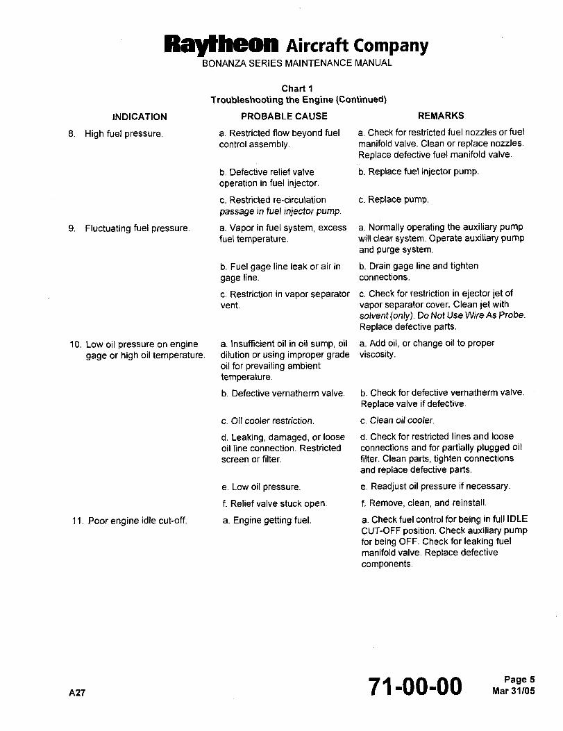
Ray~heon Aircraft CompanyBONANZA SERIES MAINTENANCE MANUAL
Chart 1
Troubleshooting the Engine (Continued)
INDICATION PROBABLE CAUSE REMARKS
8. High fuel pressure. a. Restricted flow beyond fuel a. Check for restricted fuel nozzles or fuel
control assembly. manifold valve. Clean or replace nozzles.
Replace defective fuel manifold valve.
b. Defective relief valve b. Replace fuel injector pump.
operation in fuel injector.
c. Restricted re-circulation c. Replace pump.
passage in fuel injector pump.
9. Fluctuating fuel pressure. a. Vapor in fuel system, excess a. Normally operating the auxiliary pumpfuel temperature. will clear system. Operate auxiliary pump
and purge system.
b. Fuel gage line leak or air in b. Drain gage line and tighten
gage line, connections.
c. Restriction in vapor separator c. Check for restriction in ejector jet of
vent, vapor separator cover. Clean jet with
solvent(only). Do Not Use Wire As Probe.
Replace defective parts.
?O. Low oil pressure on engine a. Insufficient oil in oil sump, oil a. Add oil, or change oil to proper
gage or high oil temperature. dilution or using improper grade viscosity.oil for prevailing ambient
temperature.
b. Defective vernatherm valve. b. Check for defective vernatherm valve.
Replace valve if defective.
c. Oil cooler restriction, c. Clean oil cooler.
d. Leaking, damaged, or loose d. Check for restricted lines and loose
oil line connection. Restricted connections and for partially plugged oil
screen or filter. filter. Clean parts, tighten connections
and replace defective parts.
e. Low oil pressure. e. Readjust oil pressure if necessary.
f. Relief valve stuck open, f. Remove, clean, and reinstall.
11. Poor engine idle cut-off, a. Engine getting fuel, a. Check fuel control for being in full IDLE
CUT-OFF position. Check auxiliary pumpfor being OFF. Check for leaking fuel
manifold valve. Replace defective
components.
7 ’1-00-00Page 5
Ral~beon Aircraft CompanyBONANZA SERIES MAINTENANCE MANUAL
GENERAL MAINTENANCE PRACTICES
ENGINE REMOVAL (CE-748, CE-772 AND AFTER; CJ-149 AND AFTER; D10097, 0-10120
AND AFTER; E-?lll, E-1241 AND AFTER)
CA UTION: Care should be taken when removing and installing the engine that no dirt or foreign objects, be allowed
to enter the induction system. Be careful not to damage duct work when removing and installing the
engine.
a. Check that the ignition switch is in the OFF position.
WARNING: To be safe, treat all magnetos as hot. To ground the magneto, disconnect the ignition switch
lead wire at the capacitor and ground the capacitor pole. If this is impractical, remove the
ignition harness on the magneto or disconnect the spark plug leads.
b. Remove the engine cowling. Refer to Chapter 71-10-00.
c. Drain the engine oil sump.
d. Remove the propeller. Refer to Chapter 61-10-00.
e. Disconnect and identify the ducts, engine controls, plumbing and wiring harness. Cap all open lines and fittings.
f. Place a support under the tail of the airplane.
g. Place the engine hoist in position and attach to the lifting eyes on the engine.
h. Hoist the engine sufficiently to remove the tension from the shock mount bolts.
i. Remove the shock mount bolts.
NOTE: It is recommended that the shock mounts be replaced at each engine change. Replace the mounts as a
complete set. All the shock mounts on a particular engine should be of the same manufacturer.
j. Position the engine slightly nose down and hoist slowly, making certain that the engine crankshaft flange clears
the nose cowl.
CAUTION: As the engine is hoisted away from the cowl, check to make sure that all wires, hoses and lines have
been disconnected.
ENGINE INSTALLATION (CE-748, CE-772 AND AFTER; CJ-149 AND AFTER; D10097,0-10120 AND AFTER; E-Il?l, E-1241 AND AFTER)
a. Observe the WARNINGS, CAUTIONS, and NOTES as noted in ENGINE REMOVAL.
b. Position the engine hoist and attach the hoisting sling to the engine.
c. Move the hoist into position in front of the airplane. Position the engine slightly nose down and lower slowly,making certain the engine crankshaft flange clears the nose cowl.
d. Align the shock mount bolt holes and install the shock mounts and bonding strap. Torque the four engine mount
bolts 300 to 350 in-lbs.
e. Disconnect the hoisting sling and move the hoist clear of the airplane.
f. Uncap all lines and fittings and connect the ducts, engine controls, plumbing and wiring harness.
7 L1 100100 A27
Raytheon Aircraft CompanyBONANZA SERIES MAINTENANCE MANUAL
g. Adjustall enginecontrols.
h. Install the propeller. Refer to PROPELLER INSTALLATION procedure in Chapter 61-10-00.
i. Install the engine cowling.
j. Perform an engine run-up as described in this chapter.
k. Complete the final adjustments.
NOTE: If a new or newly overhauled engine has been installed, the engine must be depreserved and serviced.
ENGINE REMOVAL (EA-?? AND AFTER)
CAUTION: The magnetos should be considered hot when the ground lead is disconnected. To avoid accidental
starting of the engine, ground the magneto by connecting a wire to the magneto switch lead and then to
the engine case, or disconnect the spark plug leads.
a. Remove the cowling as described in COWLING REMOVAL in this chapter.
b. Remove the upper portion of the nose bug by removing the screws and hinge pins.
c. Remove the propeller. Refer to PROPELLER REMOVAL procedure in Chapter 61-10-00.
d. Disconnect the heater induction tubing at the mixer valve.
e. Remove the air induction tubing between the air box and the turbocharger inlet.
f. Disconnect the exhaust stack from the turbocharger.
g. Disconnect the engine controls, plumbing, and wiring harness. Tag and label all items for reinstallation. Be sure
to cap all open tubing.
h. Place a support under the tail of the airplane.
i. Place the engine hoist in position and attach to the lifting eyes on the engine.
j. Hoist the engine sufficiently to remove the tension from the shock mount bolts.
k. Remove the two front and the right rear shock mount bolts. Remove the six bolts attaching the left rear enginemount to the wheel well.
i. Carefully hoist the engine from the airplane.
CAUTION: As the engine is hoisted away from the airplane, check to make ce~tain that all wires, hoses and lines
have been disconnected.
ENGINE INSTALLA TION (EA-? 1 AND AFTER)
a. Install the left rear engine mount to the engine and torque to 300 to 350 in-lbs.
b. Carefully lower the engine into the airplane.
c. Install the remaining three shock mount bolts and torque to 300 to 350 in-lbs. Install the six bolts securing the
left rear mount to the wheel well. Torque these bolts to 100 to 105 in-lbs.
d. Remove the hoist from the engine.
nz7 71100-00 7
Raytheon Aircraft CompanyBONANZA SERIES MAINTENANGE MANUAL
e. Install the wiring harness, plumbing, and engine controls.
f. Connect the exhaust to the turbocharger.
g. Install the induction tubing between the air box and turbocharger.
h. Connect the heater tubing at the mixer valve.
i. Install the propeller. Refer to PROPELLER INSTALLATION procedure in Chapter 61-10-00.
j. Install the upper portion of the nose bug.
k. Install the cowling. Refer to COWLING INSTALLATION procedure.
ENGINE BUILD-UP
Engine build-up consists of the removal of accessories and equipment from the old engine and installing them on
the new engine. Refer to the Continental Aircraft Engine Manuals for the proper torque values.
NOTE: Tag or identify all hoses, washers, nuts, electrical connectors, and note harness clamp locations for
reinstallation on the new engine. Cap all open hoses and engine ports to prevent contamination.
AIR PRESSURE PUMP REMOVAL
NOTE: All plumbing from the intake filter to the pump and on the outlet side of the pressure pump must be thoroughlycleaned, and all the filters replaced when the pressure pump is installed or replaced.
a. Access to the air pressure pump is gained through the left hand cowl door.
b. Disconnect the necessary plumbing from the pump.
c. Remove the four attaching nuts and washers and pull the pump straight out.
AIR PRESSURE PUMP INSTALLA nON
CAUTION: Never use an airpump which has been dropped or mishandled.
a. Install a new gasket on the mounting pad flange.
CAUTION: Neverjam or force the pump onto the engine mounting pad.
b. Position the pump on the mounting pad and install the attaching nuts and washers.
c. Reinstall the plumbing.
d. Start the engine and check for leakage at the mounting flange, and check for proper operation and pressure
readings.
ENGINE DRIVEN FUEL PUMP REMOVAL
a. Access to the engine-driven fuel pump is gained through the left upper cowling.
b. The fuel pump is located at the rear, in the center of the engine.
c. Disconnect the fuel plumbing and drain the fuel from the pump.
Page 82e,LS 71100100 A27
Ral~heon Aircraft CompanyBONANZA SERIES MAINTENANCE MANUAL
d. Remove the fuel pump cooling shroud from the pump.
e. Remove the pump retaining nuts and remove the pump.
CAUTION: Make sure the fuel pump drive is removed with the pump.
ENGINE DRIVEN FUEL PUMP INSTALLA TION
a. Install the fuel pump with a new gasket and tighten the two retaining nuts.
b. Install the fuel pump cooling shroud.
c. Connect and tighten the fuel pump plumbing.
CAUTION: Make sure the fuel pump drive is installed with the pump.
GROUND RUNNING AND WARM-UP
NOTE: The engine should be pre-oiled prior to starting, with spark plugs removed to relieve the starter load. To pre-oil, connect the auxiliary power unit and crank with the starter, (not to exceed 45 seconds) until slight oil
pressure is detected on the gage. Reinstall the spark plugs.
The engine cowl flaps should be open during all ground operation.
CAUTION: After starting the engine, an oil pressure indication of ?0 psi should be noted within 30 seconds in warm
weather and 60 seconds in cold weather. If no pressure is noted within the specified time, stop the
engine and investigate the cause. Normal oil pressure at maximum rpm should be 30-60 psi and ?0 psiat idle.
a. Head the airplane into the wind.
b. Start engine and maintain the engine speed at approximately 900 to 1,000 rpm for at least one minute in warm
weather, and as required during cold weather to prevent cavitation in the pressure oil pump, and to assure
adequate lubrication.
c. Advance the throttle to a setting of 1,200 rpm or slightly above and cycle the propeller two or three times to
ensure lubrication of the oil transfer collar assembly and propeller governor. Use 1,200 rpm for the rest of the Iwarm-up procedure.
d. Operate the engine on the ground with the propeller blade set at the minimum angle thigh rpm) setting.
e. Maintain the cylinder head temperature between 200 to 460"F (93 to 238"0). Never allow the cylinder head Itemperature to exceed 460"F (238"0).
f. Extended periods of idling at low rpm may result in fouled spark plugs.
g. The mixture control should remain in the FULL RICH position unless leaning is required during the checkout.
IDLE SPEED AND MIXTURE ADJUSTMENT (CE-748, CE-772, AND AFTER; CJ-149 AND
AFTER; D- 009 7 D- 1 0120 AND AFTER; E- 1 E-124 THRU E-2 1 1 O, EXCEPT E- 946 AND
E-2104)
NOTE: Fuel flow values and procedures are referenced in Teledyne Continental Motors SID 97-3 andand procedures are referenced in Teledyne Continental ~otors SID 97J and subsequent
A2~ 71-00-00
RayHH?on Aircraft CompanyBONANZA SERIES MAINTENANCE MANUAL
a. Start and run the engine according to the warm up procedures in this chapter. Place mixture control in full rich.
I b. Proceed to check the magnetos. Refer to MAGNETO DROP-OFF CHECK in Chapter 74-00-00. Maximum dropoff differential should not exceed 50 rpm. If the differential is within limitations, proceed with the idle adjustment.
Slowly retard the throttle lever to the idle position. The engine tachometer should indicate 600 rpm (normal idle
d.
(Ref. Figuresetting). To adjust, turn the idle speed adjusting screw at the throttle lever stop until the desired rpm is reached
Set the pump pressure at idle rpm (Ref. Chart 2), using the relief valve adjustment screw on the aft centerline
of the engine fuel pump (Ref. Figure 2). Turn the screw clockwise to increase pressure and counterclockwise
to decrease pressure.
e. When the idle setting has been stabilized, move the cockpit mixture control lever with a smooth steady pull into
the IDLE CUT-OFF position. Observe the rpm during the leaning out process. Adjust the idle mixture to obtain
approximately 25/50 rpm gain in the idle speed as the mixture control is slowly moved toward the IDLE
CUT-OFF. (If the mixture is set too lean, the idle speed will drop under the same conditions.) The idle mixture
adjustment is the locknut at the metering valve end of the linkage between the metering valve and air throttle
levers. Tightening the nut to shorten the linkage provides a richer mixture. A leaner mixture is obtained bybacking off the nut to lengthen the linkage.
f. After each idle mixture adjustment change, clear the engine by running it up to 2,000 rpm before making a
mixture check.
g. If the idle setting does not remain stable, check the idle linkage; any looseness in this linkage will cause erratic
idling. In all cases, allowance should be for this effect of weather conditions upon idling adjustments.
Page 1071100100 A27
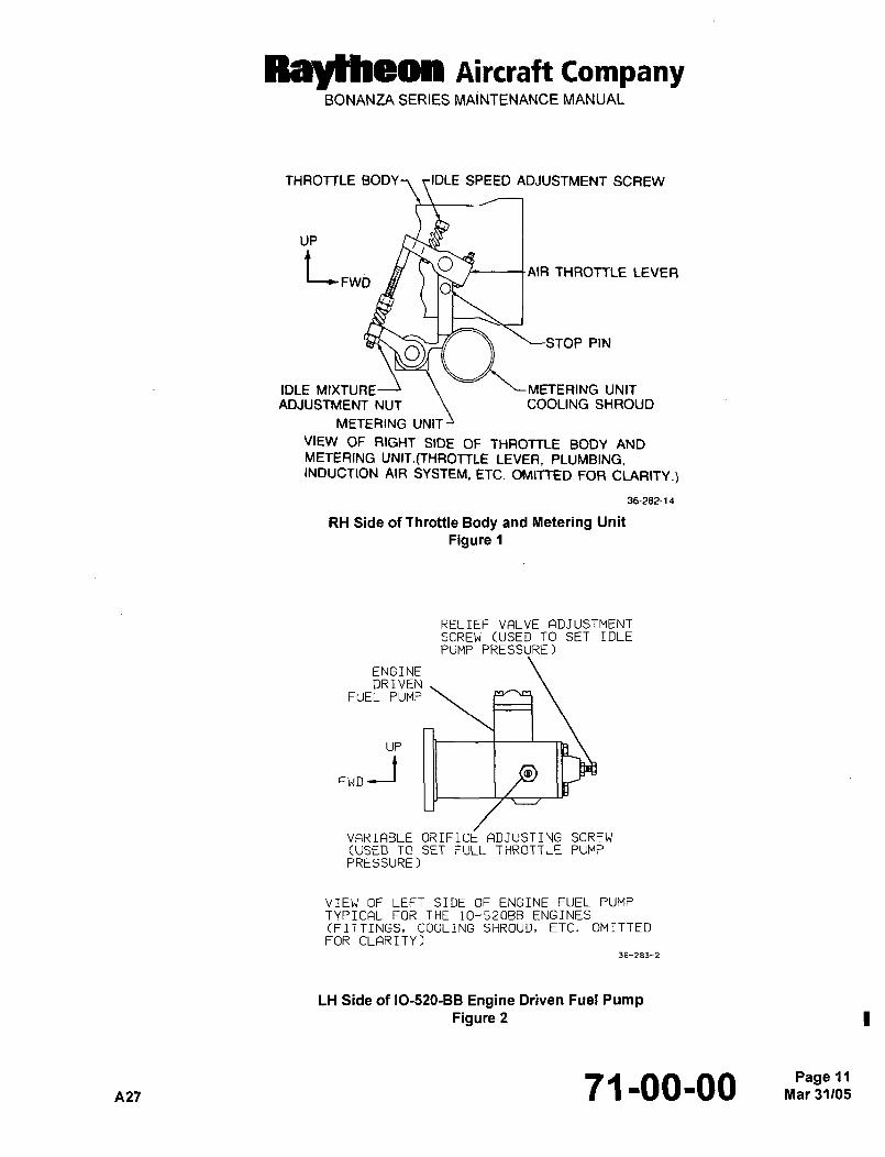
Raytheon nircraft CompanyBONANZA SERIES MAINTENANCE MANUAL
THROTTLE BODY-\ ~IDLE SPEED ADJUSTMENT SCREW
UP
tFWD OAIR THROTTLE LEVER
STOP PINO
IDLE MIXTURE~ ’METERING UNIT
ADJUSTMENT NUT COOLING SHROUD
METERING UNIT
VIEW OF RIGHT SIDE OF THROTTLE BODY ANDMETERING UNIT.(THROTTLE LEVER, PLUMBING,INDUCTION AIR SYSTEM, ETC. OMITTED FOR CLARITY.)
36-282-14
RH Side of Throttle Body and Metering Unit
Figure 1
RELIEF VALVE FlDJUSTMENTSCREW (USED TO SET IDLEPUMP PRESSURE)
ENGINEDRIVEN
FUEL PUMP
UP
FWD
VARIABLE ORIFICE ADJUSTING SCREW(USED TO SET FULL THROTTLE PUMP
PRESSURE)
VIEW OF LEFT SIDE OF ENGINE FUEL PUMP
TYPICAL FOR THE 10-520BB ENGINES(FITTINGS, COOLING SHROUD, ETC. OMITTED
FOR CLARITY)36-283-2
LH Side of IO-520-BB Engine Driven Fuel PumpFigure 2
A27 71-00-00 Mar 31105Page 11
RBylheOn Aircraft CompanyBONANZA SERIES MAINTENANCE MANUAL
FULL THROTTLE ADJUSTMENT (CE-748, CE-772 AND AFTER; CJ-149 AND AFTER;D- 1 0097 D- 1 0120 AND AFTER; E- 1 1 1 E- 124 1 THRUE-2 1 1 O, EXCEPT E- 1 946 AND E-2 1 04)
INOTE: Fuel flow values and procedures are referenced in Teledyne Continental Motors SID 97-3 and subsequent
revisions.
a. Complete the IDLE SPEED AND MIXTURE ADJUSTMENT before proceeding with this procedure.
b. With the mixture control at full rich, advance the throttle to full rated engine (2,700) rpm to check the fuel flow.
NOTE: Fuel flow values may be monitored by the fuel flow gage in the airplane or a pressure gage attached to the
manifold valve.
Ic. (10-520-BE) To obtain the specified values of noule pressure or fuel flow at full throttle and rated rpm, turn the
variable orifice adjusting screw (located on the side of the pump) clockwise to increase pressure and
counterclockwise to decrease pressure (Ref. Figure 2 and Chart 2).
NOTE: If the rated rpm cannot be achieved at full throttle during static run-up, adjust nozzle pressure or fuel flow
slightly below limits, making certain specified values are achieved when rated rpm is achieved during takeoff
roll.
IDLE SPEED AND MIXTURE ADJUSTMENT (E- 1946, E-2104, E-211 1 AND AFTER)(IO-550-B ENGINE)
I NOTE: Fuel flow values and procedures are referenced in Teledyne Continental Motors SID 97-3 and subsequentrevisions.a. Install a pressure gage in the fuel line between the engine driven fuel pump and the metering unit. The gage will
be used to monitor fuel pump idle pressure (also called unmetered pressure).
NOTE: The pressure gage should be vented to the atmosphere.
b. Start and run the engine until normal operating temperatures are attained. Refer to Pilot’s Operating Handbook.
Move the mixture control to full rich. The idle speed should be 625 to 650 rpm. If the engine is not idling within
I the specified range, change the idle-speed adjustment screw as required to obtain the proper idle speeb (Ref.Figure 1). Turn the idle speed adjustment screw clockwise to increase rpm and counterclockwise to decrease
rpm.
I c. The engine-driven fuel pump pressure should read 9.00 to 11.00 psig (Ref. Chart 2). If adjustment is requiredto achieve proper fuel pump pressure, turn the relief valve adjustment screw clockwise to increase pressure and
I counterclockwise to decrease pressure (Ref. Figure 3).
d. Maintain the specified idle rpm and the fuel pump pressure. Adjust the idle mixture to attain a momentary gainof 25 to 50 rpm when the mixture control is moved toward the idle cutoff position. If the mixture is too lean, the
rpm will drop. If it is too rich, the gain will be greater than 50 rpm. If an idle mixture adjustment is required, turn
the idle mixture nut as necessary (tighten the nut to enrich the mixture or loosen the nut to lean the mixture) to
obtain the correct idle mixture (Ref. Figure 1).
NOTE: After each idle mixture adjustment, clear the engine by running up to approximately 2,000 rpm before makingthe next mixture check.
Page 12Mar31/05 71-00-00 n27
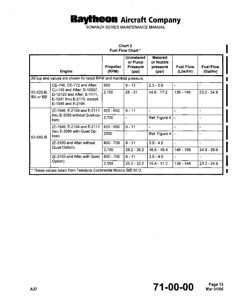
Raytheon Aircraft CompanyBONANZA SERIES MAINTENANCE MANUAL
Chart 2 IFuel Flow Chart
Unmetered Metered
or Pump or Nozzle
Propeller Pressure pressure Fuel Flow Fuel Flow
Engine (RPM) (psi) (psi) (LbslHr) (GallHr)
All top end values are shown for rated RPM and manifold pressure. I
CE-748, CE-772 and After; 600 9-11 2.3 3.0
CJ-149 and After; D-10097,IO-520-B, 2,700 28-31´• 14.9- 17.2 136-146 23.2-24.9
D-10120 and After; E-llll,BA or BE
E-1241 thru E-2110, exceptE-1946 and E-2104
(E-1946, E-2104 and E-2111 625 650 9-11
thru E-3099 without Quietop-I- I Ref. Figure 4 I(E-1946, E-2104 and E-2111 625 650 9-11
thru E-3099 with Quiet Op-2550 1- I Ref. Figure4 I
IO-550-B tion)
(E-3100 and After without 600 700 9-11 3.9 4.5
Quiet Option)2,700 29.2- 36.2 16.5-18.4 146-156 24.9-26.6 I
(E-3100andAfterwith Quiet 600-700 9-11 3.9 -4.5
Option)2,550 25.2-32.2 15.4- 17.2 136-146 23.2- 24.9 I
’These values taken from Teledyne Continental Motors SID 97-3. 1
A27 71-00-00 Mar 31/05Page 13
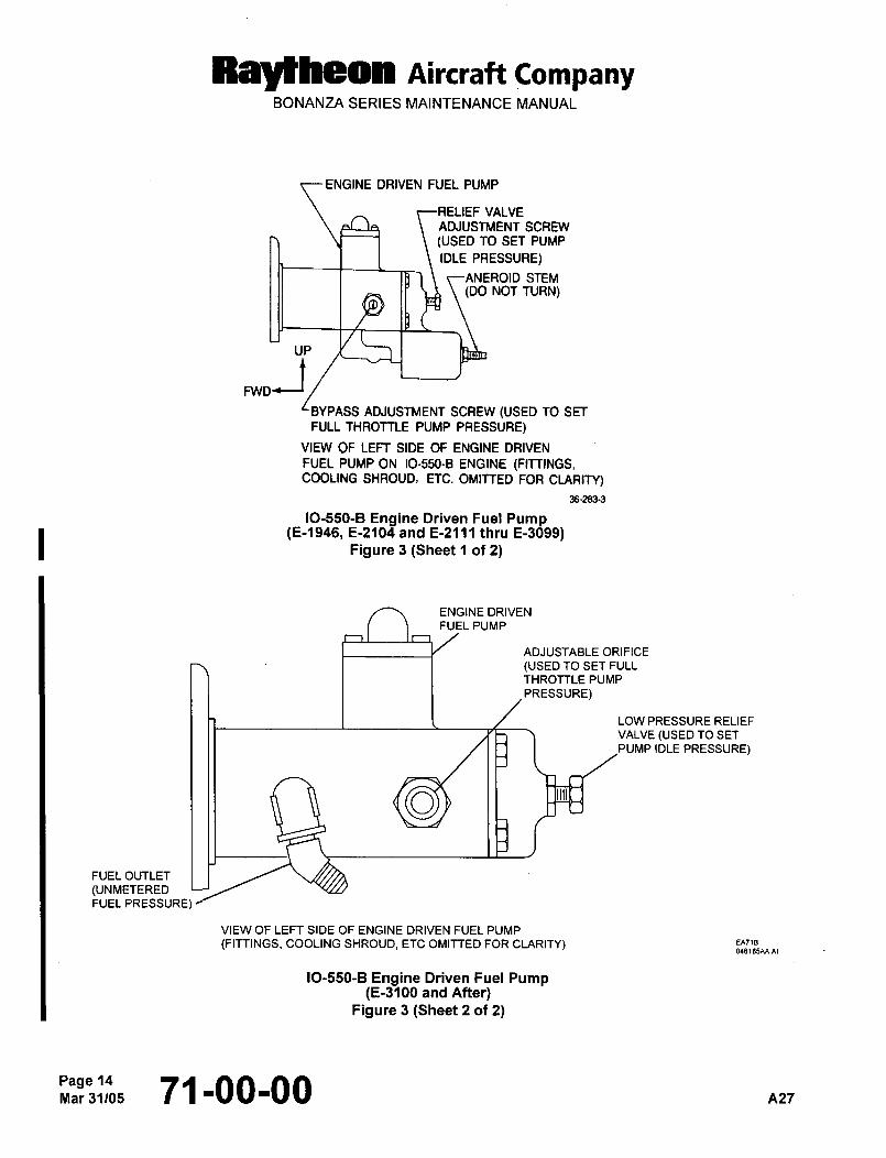
Raytheon nircraft CompanyBONANZA SERIES MAINTENANCE MANUAL
ENGINE DRIVEN FUEL PUMP
VALVE
ADJUSTMENT SCREW
(USED TO SET PUMP
IDLE PRESSURE)
ANEROID STEM(00 NOT TURN)
UP
,,ttBYPASS ADJUSTMENT SCREW (USED TO SET
FULL THROTTLE PUMP PRESSURE)
VIEW OF LEFT SIDE OF ENGINE DRIVEN
FUEL PUMP ON 10-550-8 ENGINE (FITTINGS,COOLING SHROUD, ETC. OMITTED FOR CLARITY)
36-2833
IO-550-B Engine Driven Fuel Pump(E-1946, E-2104 and E-2111 thru E-3099)
Figure 3 (Sheet 1 of 2)
ENGINE DRIVEN
FUEL PUMP
ADJUSTABLE ORIFICE
(USED TO SET FULL
THROTTLE PUMP
PRESSURE)
LOW PRESSURE RELIEF
VALVE (USED TO SET
PUMP IDLE PRESSURE)
i33b II
FUEL OUTLET
(UNMETEREDFUEL PRESSURE)
VIEW OF LEFT SIDE OF ENGINE DRIVEN FUEL PUMP
(FITTINGS, COOLING SHROUD, ETC OMITTED FOR CLARITY) EA718
0461B5AA.AI
IO-550-B Engine Driven Fuel Pump(E-3100 and After)
Figure 3 (Sheet 2 of 2)
Page 14Mar31105 71-00-00 A27
Raylheon AiKraft CompanyBONANZA SERIES MAINTENANCE MANUAL
FULL THROTTLE ADJUSTMENT (E-1946, E-2104, E-2111 AND AFTER) (IO-550-B ENGINE)
NOTE: Fuel flow values and procedures are referenced in Teledyne Continental Motors SID 97-3 andand procedures are reierenced in Te edyne Continental Motors SID 87-5 and subsequenl Ia. Install a pressure gage in the line between the engine fuel flow transducer and the manifold valve to read
metered fuel pressure.
NOTE: The pressure gage should be vented to the atmosphere and mounted at approximately the same level as
the manifold valve.
b. Run the engine until normal engine operating temperatures are attained.
c. With the mixture control in the full rich position, advance the throttle control to full throttle and maximum static
engine rpm (2,550 for auiet Bonanza installation) (Ref. Chart 2). Check the metered fuel pressure versus engine Imanifold pressure.
d. Refer to Figure 4 for determination of correct metered engine fuel pressure. If a fuel pressure adjustment is
required, turn the engine-driven fuel pump bypass adjustment screw as necessary (clockwise to increase
pressure or counterclockwise to decrease pressure) to obtain a correct pressure reading (Ref. Figure 3).
NOTE: This fuel pump adjustment procedure is NOT a complete procedure, but a starting point. For the completeprocedure FUEL FLOW CALIBRATION AND CORRECTION (E-1946, E-2104, E-2111 AND AFTER) MUST
also be completed.
AP~ 71-00-00
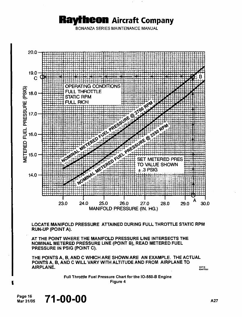
Raytheon AiKraft CompanyBONANZA SERIES MAINTENANCE MANUAL
20.0
19.0
C I~
OPERATING CONDITIONS
~j 18.0 FULL THROTTLE
STATIC
w FULL RICH(I
17.0
Is.o
o
Is.ow
ETERED PRESrTO VALUE SHOWN
14.0
H
+.3 PSIGH
23.0 24.0 25.0 26.0 27.0 28.0 29.0 30.0
MANIFOLD PRESSURE (1N. HG.)
LOCATE MANIFOLD PRESSURE ATTAINED DURING FULL THROTTLE STATIC RPM
RUN-UP (POINT A).
AT THE POINT WHERE THE MANIFOLD PRESSURE LINE INTERSECTS THE
NOMINAL METERED PRESSURE LINE (POINT B), READ METERED FUEL
PRESSURE IN PSIG (POINT C).
THE POINTS A, B, AND C WHICH ARE SHOWN ARE AN EXAMPLE. THE ACTUAL
POINTS A, B, AND C WILL VARY WITH ALTITUDE AND FROM AIRPLANE TO
AIRPLANE.
Full Throttle Fuel Pressure Chart far the IO-550-B EngineFigure 4
Page 16Mar31/05 71-00-00 nz7
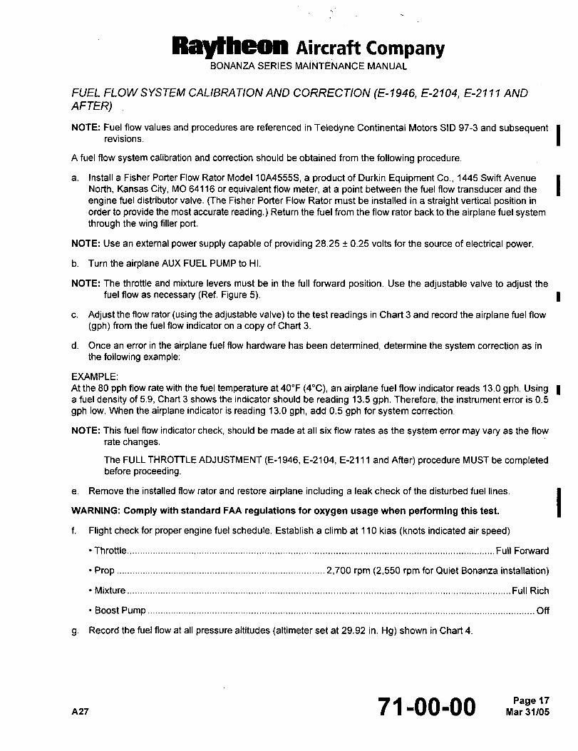
RBYtheO~ Aircraft CompanyBONANZA SERIES MAINTENANCE MANUAL
FUEL FLOW SYSTEIW CALIBRATION AND CORRECTION (E-1946, E-2104, E-211 1 AND
AFTER)
NOTE: Fuel flow values and procedures are referenced in Teledyne Continental Motors SID 97-3 andvalues and procedures are reterenced in Teiedyne Continental Motors SID 973 and subsequent IA fuel flow system calibration and correction should be obtained from the following procedure.
a. Install a Fisher Porter Flow Rater Model 10A4555S, a product of Durkin Equipment Co., 1445 Swift Avenue INorth, Kansas City, MO 64116 or equivalent flow meter, at a point between the fuel flow transducer and the
engine fuel distributor valve. (The Fisher Porter Flow Rater must be installed in a straight vertical position in
order to provide the most accurate reading.) Return the fuel from the flow rater back to the airplane fuel systemthrough the wing filler port.
NOTE: Use an external power supply capable of providing 28.25 0.25 volts for the source of electrical power.
b. Turn the airplane AUX FUEL PUMP to ~-II.
NOTE: The throttle and mixture levers must be in the full forward position. Use the adjustable valve to adjust the
fuel flow as necessary (Ref. Figure 5). 1
c. Adjust the flow rater (using the adjustable valve) to the test readings in Chart 3 and record the airplane fuel flow
(gph) from the fuel flow indicator on a copy of Chart 3.
d. Once an error in the airplane fuel flow hardware has been determined, determine the system correction as in
the following example:
EXAMPLE:
At the 80 pph flow rate with the fuel temperature at 40"F (4"C), an airplane fuel flow indicator reads 13.0 gph. Usinga fuel density of 5.9, Chart 3 shows the indicator should be reading 13.5 gph. Therefore, the instrument error is 0.5
gph low. When the airplane indicator is reading 13.0 gph, add 0.5 gph for system correction.
NOTE: This fuel flow indicator check, should be made at all six flow rates as the system error may vary as the flow
rate changes.
The FULL THROTTLE ADJUSTMENT (E-1946, E-2104, E-2111 and After) procedure MUST be completedbefore proceeding.
e. Remove the installed flow rater and restore airplane including a leak check of the disturbed fuel lines.
IWARNING: Comply with standard FAA regulations for oxygen usage when performing this test.
f. Flight check for proper engine fuel schedule. Establish a climb at 110 kias (knots indicated air speed)
´•Throttle....................._
Full Forward
Prop............. ..........._.._ .2,700 rpm (2,550 rpm for Quiet Bonanza installation)
´•Mixture.........__.._ ............_....
Full Rich
Boost Pump Off
g. Record the fuel flow at all pressure altitudes (altimeter set at 29.92 in. Hg) shown in Chart 4.
n27 71-00-00Page 17
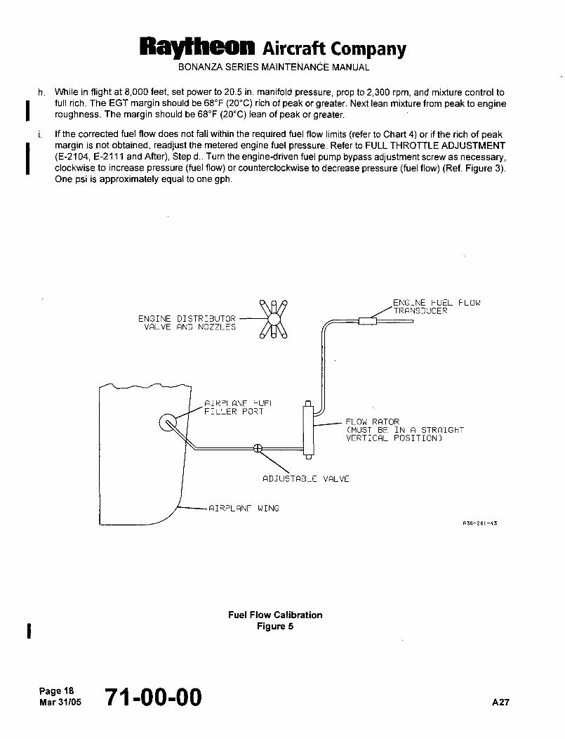
Raytheon Aircraft CompanyBONANZA SERIES MAINTENANCE MANUAL
h. While in flight at 8,000 feet, set power to 20.5 in. manifold pressure, prop to 2,300 rpm, and mixture control to
full rich. The EGT margin should be 68"F (20"C) rich of peak or greater. Next lean mixture from peak to engineroughness. The margin should be 68"F (20"C) lean of peak or greater.
i. If the corrected fuel flow does not fall within the required fuel flow limits (refer to Chart 4) or if the rich of peakmargin is not obtained, readjust the metered engine fuel pressure. Refer to FULL THROTTLE ADJUSTMENT
(E-2104, E-2111 and After), Step d.. Turn the engine-driven fuel pump bypass adjustment screw as necessary,clockwise to increase pressure (fuel flow) or counterclockwise to decrease pressure (fuel flow) (Ref. Figure 3).One psi is approximately equal to one gph.
ENGINE DISTRIBUTOR
ENGINE FUEL FLOWTRANSDUCER
VALVE AND NOZZLES
AIRPLANE FUELFILLER PORT
FLOW RATOR(MUST BE IN A STRAIGHTVERTICAL POSITION)
ADJUSTABLE VALVE
AIRPLANE WING
281-43
Fuel Flow Calibration
Figure 5
page 18Mar31/05 71-00-00 A27
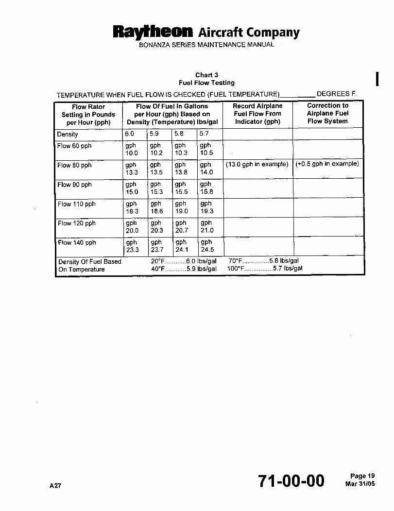
Raytheon Aircrait CompanyBONANZA SERIES MAINTENANCE MANUAL
Chart 3
Fuel Flow Testing
TEMPERATURE WHEN FUEL FLOW IS CHECKED (FUEL TEMPERATURE) DEGREES F.
Flow Rater Flow Of Fuel In Gallons Record Airplane Correction to
Setting in Pounds per Hour (gph) Based on Fuel Flow From Airplane Fuel
per Hour (pph) Density (Temperature) Ibslgal Indicator (9ph) Flow System
Density 6.0 5.9 5.8 5.7
Flow 60 pph gph gph gph gph10.0 10.2 10.3 10.5
Flow 80 pph gph gph gph gph (13.0 gph in example) (+0.5 gph in example)13.3 13.5 13.8 14.0
Flow 90 pph gph gph gph gph15.0 15.3 15.5 15.8
Flow 110 pph gph gph gph gph18.3 18.6 19.0 19.3
Flow 120 pph gph gph gph gph20.0 20.3 20.7 21.0
Flow 140 pph gph gph gph gph23.3 23.7 24.1 24.5
Density Of Fuel Based 20"F............6.0 Ibs/gal 70"F...............5.8 IbslgalOn Temperature 40"F............5.9 Ibs/gal 100"F..... ...........5.7 Ibs/gal
A2771-00-00 Mar 31~05Page 19
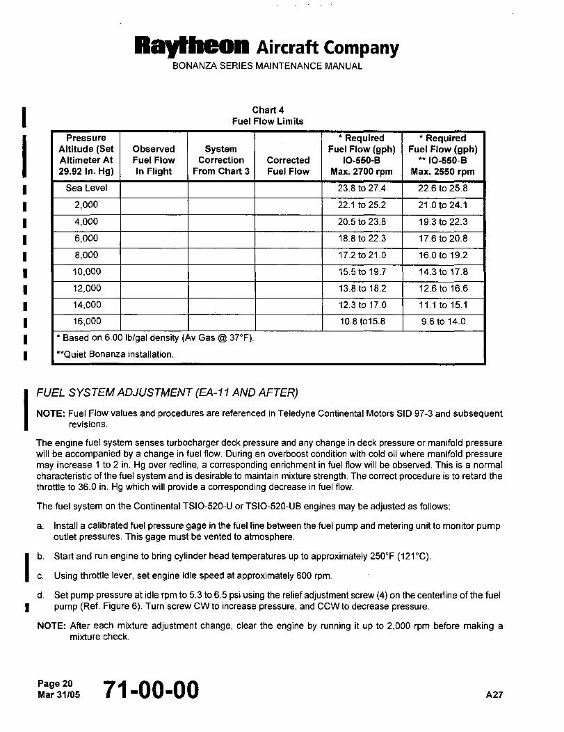
Ral~heon Aircraft CompanyBONANZA SERIES MAINTENANCE MANUAL
Chart 4
Fuel Flow Limits
Pressure *Required *RequiredAltitude (Set Observed System Fuel Flow (gph) Fuel Flow (gph)Altimeter At Fuel Flow Correction Corrected 10-550-8 IO-550-B
29.92 In. Hg) In Flight From Chart 3 Fuel Flow Max. 2700 rpm Max. 2550 rpm
i Sea Level I I I 1 23.8 to 27.4 22.6 to 25.8
I 1 21000 1 I I 22.1 to 25.2 21.0 to 24.1
1 4,000 1 I 1 20.5 to 23.8 19.3 to 22.3
6,000 I I I 1 18.8 to 22.3 17.6 to 20.8
1 8,000 1 I I 17.2 to 21.0 16.0 to 19.2
I I 10,000 I I I 15.5 to 19.7 14.3 to 17.8
1 12,000 1 1 13.8 to 18.2 12.6 to 16.6
14,000 1 I 1 12.3 to 17.0 11.1 to 15.1
1 16;000 1 I I 1 10.8 to15.8 9.6 to 14.0
I Based on 6.00 Ib/gal density (Av Gas 37"F).
’*Quiet Bonanza installation.
IFUEL SYSTEM ADJUSTMENT (EA-1 AND
AFTER)revisions.NOTE: Fuel Flow values and procedures are referenced in Teledyne Continental Motors SID 97-3 and subsequent
The engine fuel system senses turbocharger deck pressure and any change in deck pressure or manifold pressurewill be accompanied by a change in fuel flow. During an overboost condition with cold oil where manifold pressure
may increase 1 to 2 in. Hg over redline, a corresponding enrichment in fuel flow will be observed. This is a normal
characteristic of the fuel system and is desirable to maintain mixture strength. The correct procedure is to retard the
throttle to 36.0 in. Hg which will provide a corresponding decrease in fuel flow.
The fuel system on the Continental TSIO-520-U or TSIO-520-UB engines may be adjusted as follows:
a. Install a calibrated fuel pressure gage in the fuel line between the fuel pump and metering unit to monitor pumpoutlet pressures. This gage must be vented to atmosphere.
b. Start and run engine to bring cylinder head temperatures up to approximately 250"F (121"C).I c. Using throttle lever, set engine idle speed at approximately 600 rpm.
d. Set pump pressure at idle rpm to 5.3 to 6.5 psi using the relief adjustment screw (4) on the centerline of the fuel
I pump (Ref. Figure 6). Turn screw CW to increase pressure, and CCW to decrease pressure.
NOTE: After each mixture adjustment change, clear the engine by running it up to 2,000 rpm before making a
mixture check.
Page 2071100100 A27
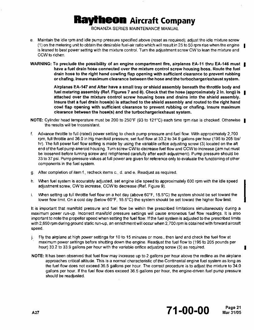
Raytkeon Airrraft CompanyBONANZA SERIES MAINTENANCE MANUAL
e. Maintain the idle rpm and idle pump pressure specified above (reset as required); adjust the idle mixture screw
(1) on the metering unit to obtain the desirable fuel-air ratio which will result in 25 to 50 rpm rise when the engine Iis leaned to best power setting with the mixture control. Turn the adjustment screw CW to lean the mixture and
CCW to richen.
WARNING: To preclude the possibility of an engine compartment fire, airplanes EA-11 thru EA-146 must
have a fuel drain hose connected over the mixture control screw housing boss. Route the fuel
drain hose to the right hand cowling flap opening with sufficient clearance to prevent rubbingor chafing. Insure maxim um clearance between the hose and the turbochargerlexhaust system.
Airplanes EA-147 and After have a small tray or shield assembly beneath the throttle body and
fuel metering assem bly (Ref. Figures 7 and 8). Check that the hose (approximately 2 in, long) is
attached over the mixture control screw housing boss and drains into the shield assembly.Insure that a fuel drain hose(s) is attached to the shield assembly and routed to the right hand
cow\ flap opening with sufficient clearance to prevent rubbing or chafing. Insure maximum
clearance between the hose(s) and the turbochargerlexhaust system.
NOTE: Cylinder head temperature must be 200 to 250"F (93 to 121"C) each time rpm rise is checked. Otherwise Ithe results will be inconsistent.
f. Advance throttle to full (rated) power setting to check pump pressure and fuel flow. W~th approximately 2,700
rpm, full throttle and 36.0 in Hg manifold pressure, set fuel flow at 33.2 to 34.9 gallons per hour(195 to 205 Ibs/
hr). The full power fuel Row setting is made by using the variable orifice adjusting screw (3) located on the aft
end of the fuel pump aneroid housing. Turn screw CW to decrease fuel flow and CCW to increase (jam nut must
be loosened before turning screw and retightened carefully after each adjustment). Pump pressure should be
33 to 37 psi. Pump pressure values at full power are given for reference only to evaluate the functioning of other
components in the fuel system.
g. After completion of item f., recheck items c., d. and e. Readjust as required.
h. When fuel system is accurately adjusted, set engine idle speed to approximately 600 rpm with the idle speedadjustment screw, CW to increase, CCW to decrease (Ref. Figure 9).
i. When setting up full throttle fuel flow on a hot day (above 60"F, 15.5"C) the system should be set toward the
lower flow limit. On a cold day (below 60"F, 15.5"C) the system should be set toward the higher flow limit.
It is important that manifold pressure and fuel flow be within the prescribed limitations simultaneously during a
maximum power run-up. Incorrect manifold pressure settings will cause erroneous fuel Row readings. It is also
important to note the propeller speed when setting the fuel flow. If the fuel system is adjusted to the prescribed limits
with 2,650 rpm during ground static run-up, an enrichment will occur when 2,700 rpm is obtained with forward aircraft
speed.
j. Fly the airplane at high power settings for 10 to 15 minutes or more., then land and check the fuel flow at
maximum power settings before shutting down the engine. Readjust the fuel flow to (195 to 205 pounds per
hour) 33.2 to 33.9 gallons per hour with the variable orifice adjusting screw (3) as required.
NOTE: It has been observed that fuel flow may increase up to 2 gallons per hour above the redline as the airplaneapproaches critical altitude. This is a normal characteristic of the Continental engine fuel system as long as
the fuel flow does not exceed 36.5 gallons per hour. The correct procedure is to adjust the mixture to 34.0
gallons per hour. If the fuel flow does exceed 36.5 gallons per hour, the engine-driven fuel pump pressureshould be readjusted.
nzl 71-00-00
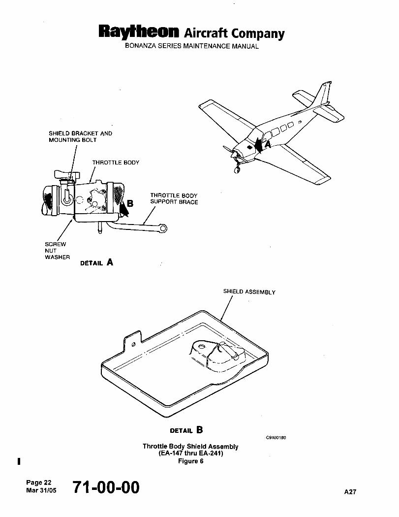
RayHleon AiKraft CompanyBONANZA SERIES MAINTENANCE MANUAL
Ob
OSHIELD BRACKET AND
MOUNTING BOLT
THROTTLE BODY
G~I I4PLB S)IPPORT BRACE
THROTTLE BODY
SCREW
NUT
WASHER
DETAIL A
SHIELD ASSEMBLY
8
DETAIL BC9100180
Throttle Body Shield Assembly(EA-147 thru EA-241)
Figure 6
Page 22Mar 31/05 71-00-00 A27
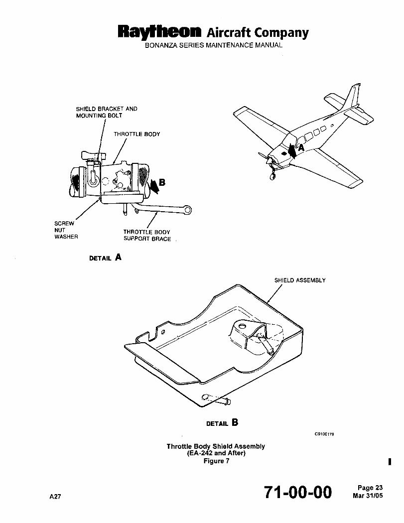
Raytheon nircraft CompanyBONANZA SERIES MAINTENANCE MANUAL
SHIELD BRACKET AND
MOUNTING BOLT
THROTTLE BODY
~n .1 14~LB
SCREW
NVT THROTTLE BODYWASHER SUPPORT BRACE
DETAIL A
SHIELD ASSEMBLY
8
DETAIL B
C910(1179
Throttle Body Shield Assembly(EA-242 and After)
Figure 7
A27 71-00-00 Mar 31105Page 23
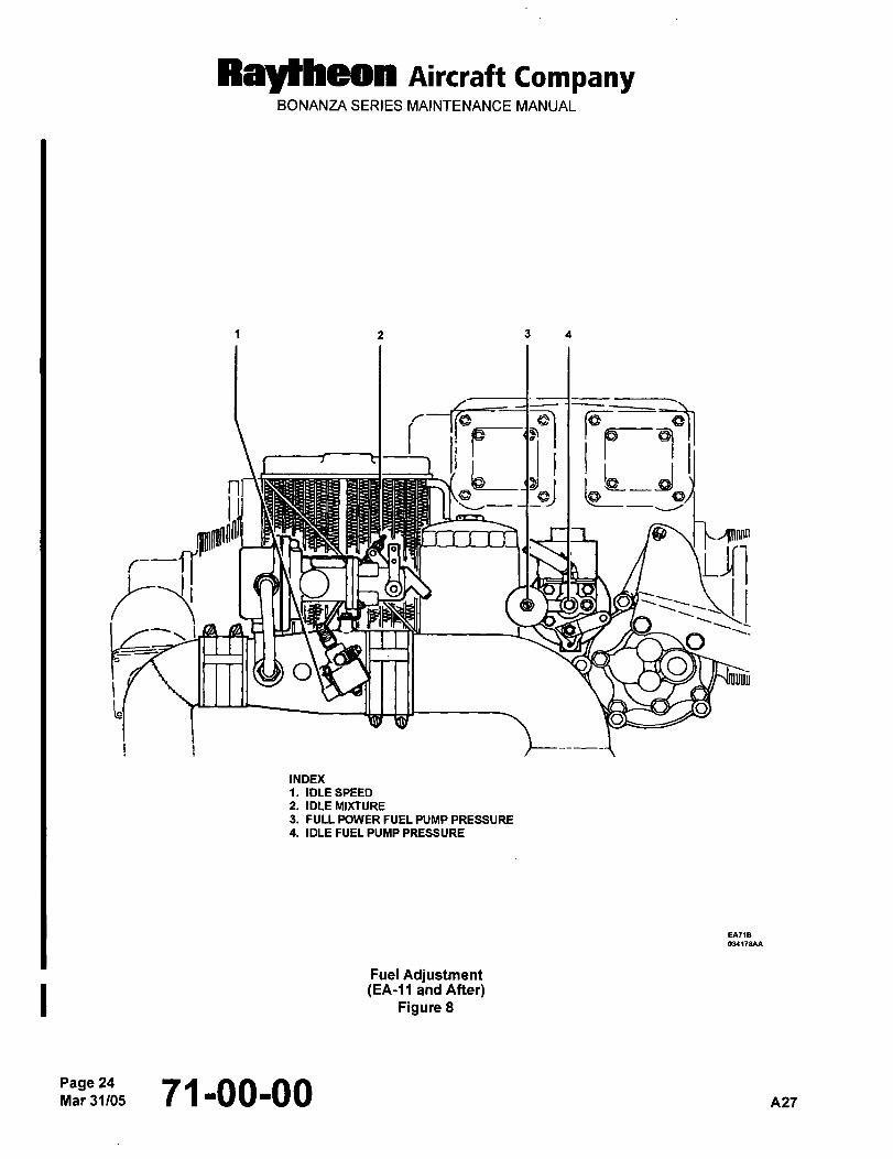
Ralfheon nircraft CompanyBONANZA SERIES MAINTENANCE MANUAL
1 2 3 4
iiF- P-"ilhd
~J
/Ilnnrm
JTi
O~IVT-T11 2~9
INDEX
IDLE SPEED
2. IDLE MIXTURE
3. FULL POWER FUEL PUMP PRESSURE
4. IDLE FUEL PUMP PRESSURE
Fuel Adjustment(EA-11 and After)
Figure 8
71-00-00 azr
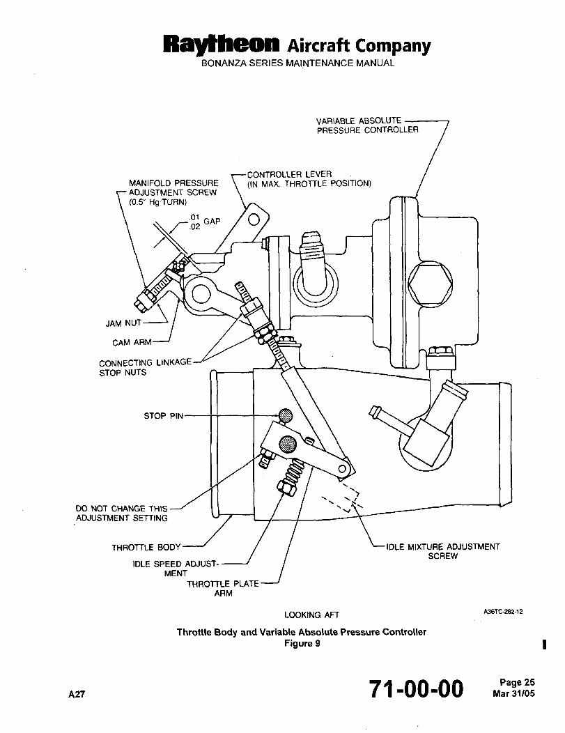
Ray~heon Aircraft CompanyBONANZA SERIES MAINTENANCE MANUAL
VARIABLE ABSOLUTEPRESSURE CONTROLLER
CONTROLLER LEVERMANIFOLD PRESSURE ((N MAX. THROTTLE POSITION)ADJUSTMENT SCREW
(O.S" HSITURN)
GAP /O
OJAM NUT
CAM
CONNECTING LINKAGE
STOP NUTS
STOP PIN
O
00 NOT CHANGE THIS I I ~VADJUSTMENT SETTING
THROTTLE BODY L IDLE MIXTURE ADJUSTMENTSCREW
IDLE SPEED ADJUST´•
MENT
THROTTLE PLATE
AAM
LOOKING AFT A36TC-282-12
Throttle Body and Variable Absolute Pressure Controller
Figure 9
A27 71-00-00 Mar 31/05Page 25
RayYheon Aircraft CompanyBONANZA SERIES MAINTENANCE MANUAL
MANIFOLD PRESSURE ADJUSTMENT
The waste gate is controlled by engine oil pressure which is regulated by the variable absolute pressure controller.
For this reason manifold pressure is quite sensitive to oil pressure and temperature as well as ambient
temperatures. It has been determined that the manifold pressure will vary: (1) 0.2 in. Hg per 10"F (-12"C) change in
oil temperature, (2) 0.3 in. Hg per 10 psig in oil pressure and (3) 0.05 in. Hg per 10"F (-12"C) change in ambient
temperature. The best time to make adjustments is shortly after the airplane has been flown under the conditions
described in Step c., the manifold pressure should be 36 in. Hg.
a. Locate the absolute variable pressure controller mounted the top of the throttle body in the left side of the engineaccessory compartment.
b. Check the controller-to-th rottle linkage for proper adjustment as follows:
1. Position the controller lever to allow full travel. Ensure that the throttle push-pull cable will allow full travel.
2. With the controller lever in the position shown and the throttle plate arm against the stop pin, adjust the
connecting linkage stop nuts to a position allowing 0.01 and 0.02 inch gap between the cam arm and the
controller maximum stop (Ref. Figure 9). On a new engine this adjustment should already be made byContinental Motors.
I c. Start and run the engine to bring the engine oil temperature up to 160 to 180"F (71 to 82"C). Adjust the oil
pressure to 40 to 50 psig (45 psig preferred) at 2,600 to 2,700 rpm.
d. After engine warm-up, advance the throttle (without turning the vernier control cable knob) to it’s maximum
position of 2,600 to 2,700 propeller rpm and full rich mixture. Check and (if required) adjust the manifold
pressure adjustment screw on the absolute variable controller. Loosen the jam nut and rotate the adjustmentscrew counterclockwise to increase, or clockwise to decrease manifold pressure, then retighten the jam nut.
CAUTION: Do not exceed 36 in. Hg manifold pressure.
NOTE: If the manifold pressure is adjusted with engine oil temperature at 100"F (38"C) rather than the 160 to 180"F
(71 to 82"C) recommended, a decrease in manifold pressure will occur when the oil temperature increases
to the normal operating range. Under these conditions, a decrease in manifold pressure of 1 to 2 in, of Hgbelow the rated 36 in. Hg will occur along the corresponding decreases in fuel flow. If, on the other hand,the manifold pressure is adjusted with engine oil temperature at 230"F (110"C), a corresponding increase
in manifold pressure above 36.0 in. Hg will occur on the next flight if the oil temperature is then much lower.
A corresponding enrichment in full rich fuel flow above the value obtained at 36.0 in Hg will also occur since
the full rich schedule is a function of both deck pressure and rpm. These characteristics must be taken into
consideration when manifold pressure adjustments are made. It is important that manifold pressure and fuel
flow be within the prescribed limitations simultaneously during a maximum power run up. Incorrect manifold
pressure settings will cause erroneous fuel flow readings.
e. Fly the airplane 10 to 15 minutes or more at the high power settings, land and check the manifold pressure at
maximum power settings before shutting off the engine. Readjust to 36.0 in. Hg as required.
OIL PRESSURE ADJUSTMENT
I The oil pressure adjustment screw is located approximately 3 inches below the oil filter housing (Ref. Figure 10). To
adjust, turn the adjusting screw clockwise to increase or counterclockwise to decrease the oil pressure. The oil
pressure should be between 30 and 60 psi at maximum operating rpm and temperature, 50 psi at cruise rpm and
10 psi minimum at idle rpm.
Page 2671-00-00 n27
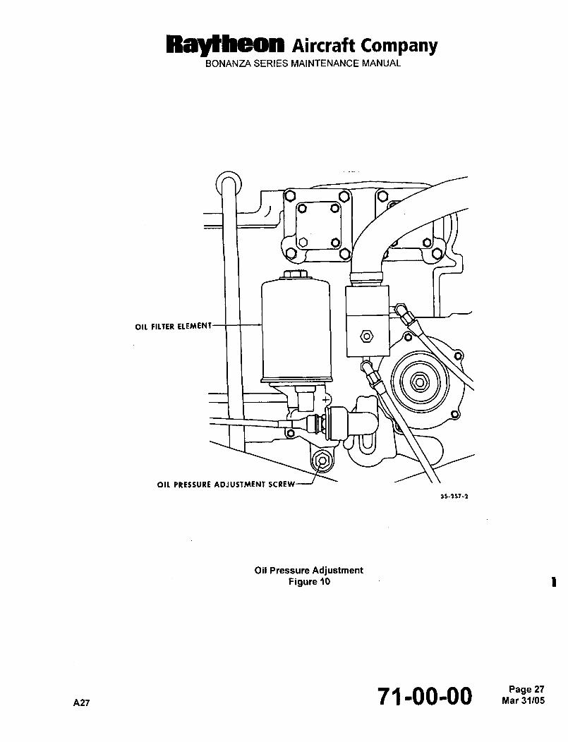
Raytheon nircraft CompanyBONANZA SERIES MAINTENANCE MANUAL
i3
OIL FILTER ELEMENT
OIL PRESSURE ADJUSTMENf SCREW
35-157-1
Oil Pressure AdjustmentFigure ?O
nz771-00-00Page 27
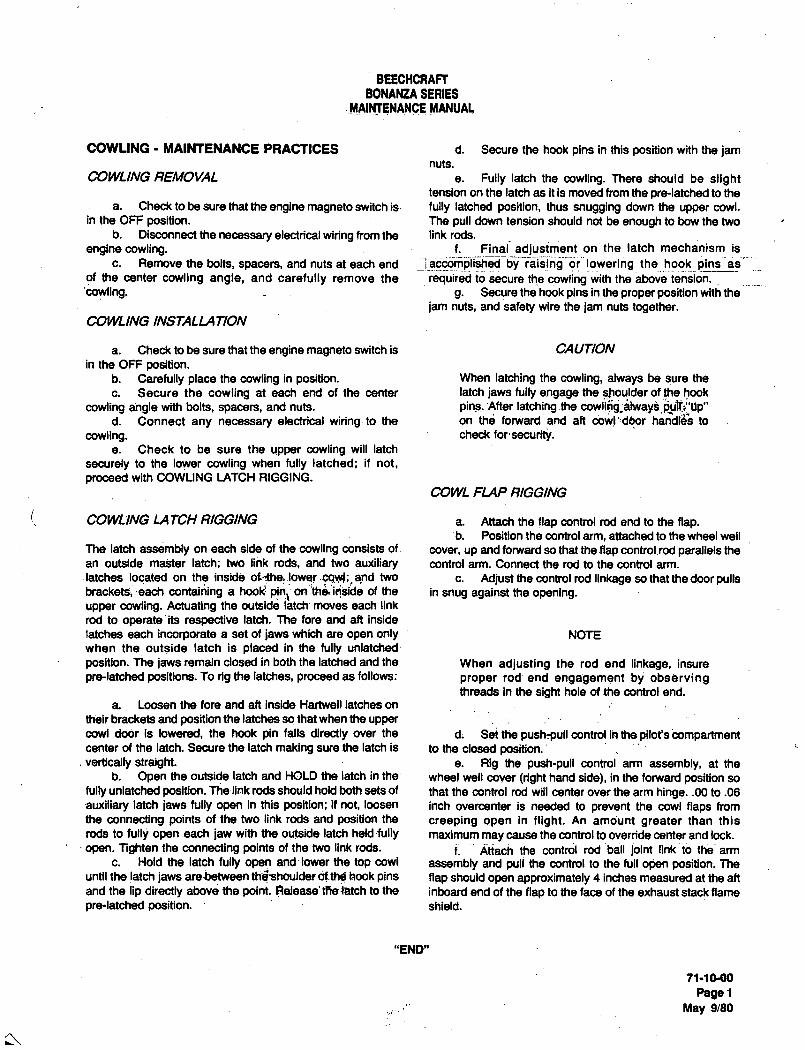
BEECHCRAFTBONANZA SERIES
.MAIHTENANCE MANUAL
COWUNG MAINTENANCE PRACTICES d. Secure the hook pins in this position with the jamnuts.
COWLING REEAOVAL e. Fully latch the cowling. There should be slighttension on the latch as it is moved from the pre-latched to the
a. Check to be sure that the engine magneto switch is´• fully latched position, thus snugging down the upper cowl.in the OFF position. The pull down tension should not be enough to bow the two
b. Disconnect the necessary electrical wiring from the link rods.
engine cowling. f. Final adjusiment on the latch mechanism is
c. Remove the bolts, spacers, and nuts at each end _! accomli;iishedbyraising‘oi’~ lowering the hook
of the center cowling angle, and carefully remove the Irequired to secure the abovetension.
’cowling. g. Secure the hook pins in the proper position with the
jam nuts, and safety wire the jam nuts together.COWLING INSTALLATION
a. Check to be sure that the engine magneto switch is CAUTION
in the OFF position.b. Carefully place the cowling in position. When latching the cowling, always be sure the
c. Secure the cowling at each end of the center latch jaws fully engage the shoulder of the hook
cowling angle with bolts, spacers, and nuts, pins..After latching.the cowli$g;blv~ay8 ~ulili"Up"d. Connect any necessary electrical wiring-to the on thcj forwardand aft dow!’:dqor h;mbl~s to
cowling. check forsecurity.e. Check to be sure the upper cowling will latch
securely to the lower cowling when fully latched; if not,
proceed with COWLING LATCH RIGGING.
COWL FLAP RIGGING
COWLING LA TCH RIGGING a. Attach the flap control rod end to the flap.b. Position the control arm, attached to the wheel well
The latch assembly on each side of the cowling consists of cover, up and forward so that the flap control~rod parallels the
an outside mal;ter latch; two link rods, and two auxiliary control arm. Connect the rod to the control arm.
latches located on the inside oflthel.lowe! .cowl; and two c. Adjust the control rod linkage so that the door pullsbracketsi each contaii~ing a hook’. pinl on’’th$’id~side of the in snug against the opening.upper cowling. Actuating the outside latch’ moves each link
rod to operate’its respective latch. The fore and ah inside
latches each incorporate a set of jaws which are open only NOTE
when the outside latch is placed in the fully unlatched
position. The jaws remain closed in both the latched and the When adjusting the rod end linkage, insure
pre-latched positions. To rig the latches, proceed as follows: proper rod end engagement by observingthreads in the sight hole of the control end.
a Loosenthe fore and ah inside Hartwell latches on
their brackets and position the latches so that when the uppercowl door is lowered, the hook pin falls directly over the d; Set the push-pull control iiJ the pilot’s compartmentcenter of the latch. Secure the latch making sure the latch is to the closed position.
.vertically straight. e. Rig the push-pull control arm assembly, at theb. Open the outside latch and HOLD the latch in wheel well cover (right hand side), in the forward position so
fully unlatched position. Thelink rods should hold both sets of that the control rod will center over the arm hinge. .00 to .06
auxiliary latch jaws fully open in this position; if not, loosen inch overcenter is needed to prevent the cowl flaps from
the connecting points of the two link rods and position the creeping open in fight. An amdunt greater than thisrods to fully openeach jaw with the outside latch held fully maximum may cause the control to override center and lock.
open. Tighten the connecting points of the two link rods. i. Atiacti the control rod ~ball joint linkto the~ arm
c. Hold the latch fully open and-lower the top cowl assembly and pull the control tothe full oljen position. Theuntil the latch jaws are;between th8"shoulder ~f.the Rook pins flap should open approximately 4 inches measured at the ah
and the lip directly above the point. to the inboard end of the flap to the face of the exhaust stack flame
pre-latched position. shield.
"END"
71-10QO
PagelMay 9/80
CHAPTER
ENGINES
BEECHCRAFTBONANtA SERIES
MAINTENANCE MANUAL
CHAPTER 72
LIST OF PAGE EFFECTIMN
CHAP~RSECTION
SUBJECT PAGE DATE
72 EFFECTIVITY/CONTENTS t Oct 7/83
CHAPTER 72 ENGINE
TABLE OF CONTENTS
CHAPTER
SECTION
SUBJECT SUBJECT( PAGE
INTROOUCT1ON
GENERAL DESCRIPTlON
SPECIAL TOOLS AND EQUIPMENT
DISASSEMBLY
CLEANING, REPAIR 8 REPLACEMENT
INSPECTION
ASSEMBLY OF SUBASSEMBLIES
FINAL ASSEMBLY AND TEST
LIST OF TABLES
NOTE
For detailed information on the above subjects, refer to the Continental 10-520 Series
Aircraft Engines Overhaul Manual, FORM X-30039A or TSIO-520 Series Aircraft EnginesOverhaul Manual, FORM X-30042 or 10-550-8 Series Aircraft Engine Overhaul Manual,
FORM X-30568.
CAUTlON
It is imperative that when replacement of engine components and accessories becomes
necessary, all part numbers be verified to ensure that the proper part has been obtained
for replacement. Incorrect part replacement may result in extensive damage to the engine.
"END"
72-ErrECT1VITYICONTENTS
Page 1
A6 Oct 7/83
CHAPTER
ENGINE FUEL
AND CONTROL
Raytheon nircraft CompanyBONANZA SERIES MAINTENANCE MANUAL
CHAPTER 73 ENGINE FUEL SYSTEMS
TABLE OF CONTENTS
SUBJECT PAGE
73-30´•00
Fuel Flow Indicating- Descriptionand Operation ..........1
Fuel Flow Indicator
Fuel Flow Indicating Maintenance Practices (CE-929 and After; CJ-156 and After; D-10354 and After;
E-~766andAfter; EA-1S9andAfter) ........´•1
Transducer Removal.
Transducer Installation
nz4 73-CONTENTS 1
Raytheon Aircraft CompanyBONANZA SERIES MAlrJT~i\i;ANCE MANUAL
CHAPTER 73 ENGINE FUEL AND CONTROL
LIST OF EFFECTIVE PAGES
OR-SE-SD PAGE DATE
73-LOEP 1 Sep 30/03
-/9-CONTENTS 1 Sep 30/03
73-30-00 1 Sep 30/03
2 Sep 30/03
A24 73-LOEP Sep 30/03Page 1
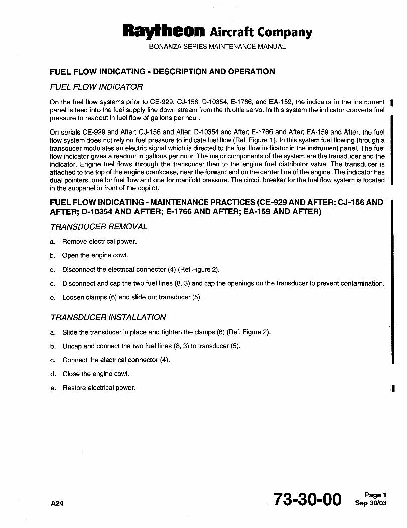
Raytheon Aircraft CompanyBONANZA SERIES MAINTENANCE MANUAL
FUEL FLOW INDICATING DESCRIPTION AND OPERATION
FUEL FLOW INDICATOR
On the fuel flow systems prior to CE-929; CJ-156; D-10354; E-1766, and EA-159, the indicator in the instrument Ipanel is teed into the fuel supply line down stream from the throttle servo. In this system the indicator converts fuel
pressure to readout in fuel flow of gallons per hour.
On serials CE-929 and After; CJ-156 and After; D-10354 and After; E-1766 and After; EA-159 and After, the fuel
flow system does not rely on fuel pressure to indicate fuel flow (Ref. Figure 1). In this system fuel flowing through a
transducer modulates an electric signal which is directed to the fuel flow indicator in the instrument panel. The fuel
flow indicator gives a readout in gallons per hour. The major components of the system are the transducer and the
indicator. Engine fuel flows through the transducer then to the engine fuel distributor valve. The transducer is
attached to the top of the engine crankcase, near the fonnrard end on the center line of the engine. The indicator has
dual pointers, one for fuel flow and one for manifold pressure. The circuit breaker for the fuel flow system is located
in the subpanel in front of the copilot.
FUEL FLOW INDICATING MAINTENANCE PRACTICES (CE-929 AND AFTER; CJ-l 56 AND
AFTER; D-10354 AND AFTER; E-1766 AND AFTER; EA-159 AND AFTER)
TRANSDUCER REMOVAL
a. Removeelectrical power.
b. Open the engine cowl.
c. Disconnect the electrical connector (4) (Ref Figure 2).
d. Disconnect and cap the two fuel lines (8, 3) and cap the openings on the transducer to prevent contamination.
e. Loosen clamps (6) and slide out transducer (5).
TRANSDUCER INSTALLATION
a. Slide the transducer in place and tighten the clamps (6) (Ref. Figure 2).
b. Uncap and connect the two fuel lines (8, 3) to transducer (5).
c. Connect the electrical connector (4).
d. Closethe engine cowl.
e. Restore electrical power. -;I
73-30-00
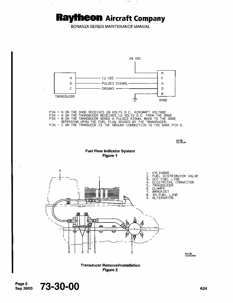
Raytheon Aircraft CompanyBONANZA SERIES MAINTENANCE MANUAL
28 VDC
12 VDC F
PULSED SIGNAL~ H
GROUND D
TRANSDUCER
GAGE
PIN A ON THE GAGE RECEIVES 28 VOLTS D.C. AIRCRAFT VOLTAGE.PIN A ON THE TRANSDUCER RECEIVES 12 VOLTS D.C. FROM THE GAGE.
PIN B ON THE TRANSDUCER SENDS A PULSED SIGNAL BACK TO THE GAGEDEPENDING UPON THE FUEL FLOW SENSED BY THE TRANSDUCER.
PIN C ON THE TRANSUCER IS THE GROUND CONNECTION TO THE GAGE PIN D.
EFi73B031701AA
Fuel Flow Indicator SystemFigure 1
i. CYLINDER2. FUEL DISTRIBUTOR VALVE3. OUT FUEL LINE4. ELECTRICAL CONNECTOR5. TRANSDUCER6. CLAMPS7. BRACKIET8. IN FUEL LINE9. ALTERNATOR
~s
~a
8 7 6 5 3 2V1743032509FW
Transducer RemovaVlnstallation
Figure 2
Sep 73-30-00 A24

CHAPTE R
IGNITION
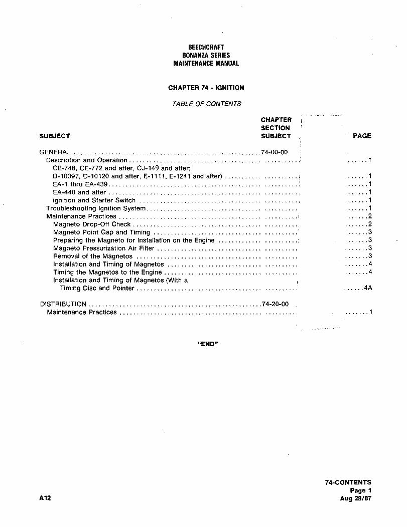
BEECHCRAFT
BONANZA SERIES
MAINTENANCE MANUAL
CHAPTER 74 IGNITION
TABLE OF CONTENTS
CHAPTER
SECTION
SUBJECT SUBJECT PAGE
GENERAL 74-00-00
Description and Operation .........,,_.
´•.....1
CE-748, CE-772 and after, CJ-149 and after;D-10097, D-10120 and after, E-llll, E-1241 and after) ......1
EA-1 thru EA-439 ..........1 ......1
EA-440 and after ......1
Ignition and Starter Switch ......1
Troubleshooting Ignition System ......1
Maintenance Practices ......2
Magneto Drop-Off Check :......2Magneto Point Gap and Timing .......3
Preparing the Magneto for Installation on the Engine .......3
Magneto Pressurization Air Filter .......3
Removal of the Magnetos .......3
Installation and Timing of Magnetos .......4
Timing the Magnetos to the Engine .......4
Installation and Timing of Magnetos (With a
Timing Disc and Pointer ......4A
DISTRIBUTION 74-20-00
Maintenance Practices .......1
"END"
74-CONTENTS
Page 1
A12 Aug 28/87
BONANZA SERIES
MAINTENANCE MANUAL
CHAPTER 74 IGNITION
LIST OF PAGE EFFECTIVITY
CHAPTER-SECTIONSUBJECT PAGE DATE
74-6ffectivity Nov 16/94
74-Contents1 Aug 28/87
74-00-001 Sep 27/84
2 Sep 27/84
3 Sep 27/84
4 Aug 28/87
4A Aug 28/87
5 Sep 27/84
6 Sep 27/84
74-20-001 May 9/80
74-EffectivityPage 1
A17 Nov16/94
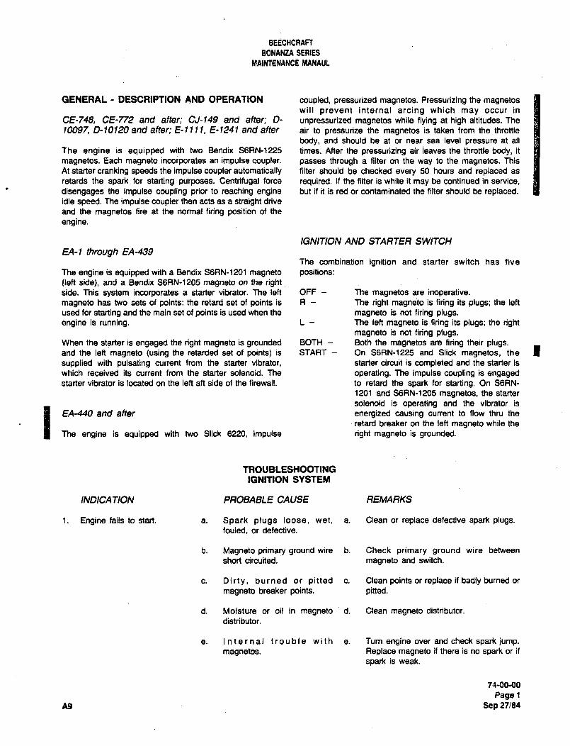
BEECHCRAFT
BONANtA SERIES
MAINTENANCE MANAUL
GENERAL DESCRIPTION AND OPERATION coupled, pressurized magnetos. Pressurizing the magnetoswill prevent internal arcing which may occur in
CE-748, CE-772 and after; CJ-149 and after; D- unpressurized magnetos while flying at high altitudes. The
10097 0-10120 and after; E-llll, E-1241 and after air to pressurize the magnetos is taken from the throttle
body, and should be at or near sea level pressure at all
The engine is equipped with two 8endix S6RN-1225 times. After the pressurizing air leaves the throttle body, it
magnetos. Each magneto incorporates an impulse coupler. passes through a filter on the way to the magnetos. This
At starter cranking speeds the impulse coupler automatically filter should be checked every 50 hours and replaced as
retards the spark for starting purposes. Centrifugal force required. If the filter is white it may be continued in service,
disengages the impulse coupling prior to reaching engine but if it is red or contaminated the filter should be replaced.idle speed. The impulse coupler then acts as a straight drive
and the magnetos fire at the normal firing position of the
engine.
IGNITION AND STARTER SWITCH
EA-1 ttwough fA-439The combination ignition and starter switch has five
The engine is equipped with a Bendix S6RN-1201 magneto positions:(left side), and a Bendix S6RN-1205 magneto on the rightside. This system incorporates a starter vibrator. The left OFF The magnetos are inoperative.magneto has two sets of points: the retard set of points is R The right magne’to is firing its plugs; the left
used for starting and the main set of points is used when the magneto is not firing plugs.engine is running. L The left magneto is firing its plugs; the right
magneto is not firing plugs.When the starter is engaged the right magneto is grounded BOTH Both the magnetos are firing their plugs.and the left magneta (using the retarded set of paints) is START On S6RN-1225 and Slick magnetos, the Isupplied with pulsating current from the starter vibrator, starter circuit is completed and the starter is
which received its current from the starter solenoid. The operating. The impulse coupling is engagedstarter vibrator is located on the left ah side of the firewall. to retard the spark for starting. On SGRN-
1201 and S6RN-1205 magnetos, the starter
solenoid is operating and the vibrator is
IThe engine is equipped with two Slick 6220, impulse
retard breaker on the left magneto while the
EA-440 and after energized causing current to flow thru the
right magneto is grounded.
TROUBLESHOOTINGIGNITION SYSTEM
INDICA TION PROBABLE CAUSE REMARKS
1. Engine fails to start. a. Spark plugs loose, wet, a. Clean or replace defective spark plugs.fouled, or defective.
b. Magneto primary ground wire b. Check primary ground wire between
short circuited. magneto and switch.
c. Dirty, burned or pitted c. Clean points or replace if badly burned or
magneto breaker points, pitted.
d. Moisture or oil in magneto d. Clean magneto distributor.
distributor.
e. Internal trouble with e. Turn engine over and check spark jump.magnetos. Replace magneto if there is no spark or if
spark is weak.
75-00-00
PagelA9 Sep 27/84
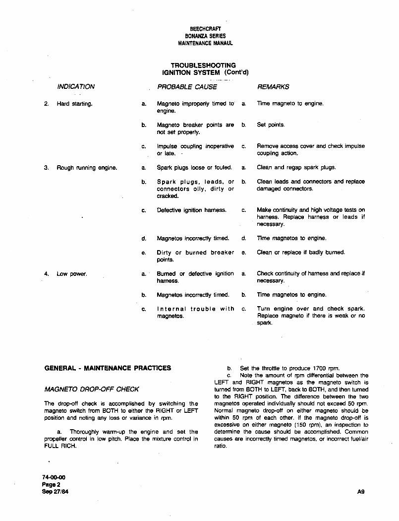
BEECMCRAFT
BONANZA SERIES
MAIMENANCE MANAUL
TROUBLESHOOTINGIGNITION SYSTEM (Cont’d)
INDICATION PROBABLE CAUSE REMARKS
2. Hard starting, a. Magneto improperly timed to~ a. Time magneto to engine.engine.
b. Magneto breaker points are b. Set points.not set properly.
c. Impulse coupling inoperative c. Remove access cover and check impulseorlate. coupling action.
3. Rough running engine, a. Spark plugs loose or fouled, a. Clean and regap spark plugs.
b. Spark plugs, leads, or b. Clean leads and connectors and replaceconnectors oily, dirty or damaged connectors.
cracked.
c. Defective ignition harness. c. Make continuity and high voltage tests on
harness. Replace harness or leads if
necessary.
d. Magnetos incorrectly timed, d. Time magnetos to engine.
e. Dirty or burned breaker a. Clean or replace ii badly burned.
points.
4. Low power. a. Burned or defective ignition a. Check continuity of harness and replace ii
harness. necessary.
b. Magnetos incorrectly timed. b. Time magnetos to engine.
c. Internal trouble with c. Turn engine over and check spark.magnetos. Replace magneto if there is weak or no
spark.
GENERAL MAIPTTENANCE PRACT1CES b. Set the throttle to produce 1700 rpm.c. Note the amount of rpm differential between the
LEFT and RIGHT magnetos as the magneto switch is
MAGNETO DROP-OFF CHECK turned from BOTH to LEFT, back to BOTH, and then turned
to the RIGHT position; The difference between the two
The drop-off check is accomplished by switching the magnetos operated individually should not exceed 50 rpm.
magneto switch from BOTH to either the RIGHT or LEFT Normal magneto drop-off on either magneto should be
position and noting any loss or variance in rpm, within 50 rpm of each other. If the magneto drop-off is
excessive on either magneto (150 rpm), an inspection to
a. Thoroughly warm-up the engine and set the determine the cause should be accomplished. Common
propeller control in low pitch. Place the mixture control in causes are incorrectly timed magnetos, or incorrect fuel/air
FULL RICH. ratio.
74-~0-00
Page 2
Sep n184 A9
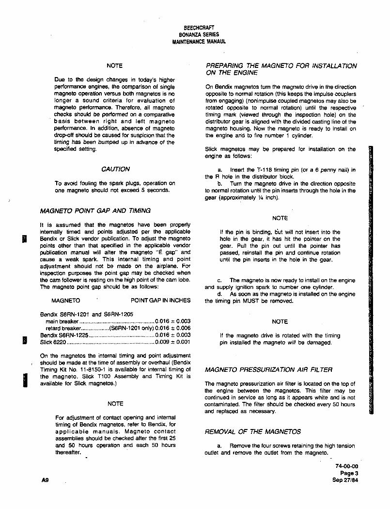
BEECHCRAFF
BONANZA SERIES
YAINTENANCE MANAUL
NOTE PREPARING THE MAGNETO FOR INSTALLATIONON THE ENGINE
Due to the design changes in today’s higherperformance engines, the comparison of single On Bendix magnetos turn the magneto drive in the direction
magneto operation versus both magnetos is no opposite to normal rotation (this keeps the impulse couplerslonger a sound criteria for evaluation of from engaging) (nonimpulse coupled magnetos may also be
magneto performance. Therefore, all magneto rotated opposite to normal rotation) until the respectivechecks should be performed on a comparative timing mark (viewed through the inspection hole) on the
basis between right and left magneto distributor gear is aligned with the divided casting line of the
performance. In addition, absence of magneto magneto housing. Now the magneto is ready to install on
drop-off should be caused for suspicion that the the engine and to fire number 1 cylinder.timing has been bumped up in advance of the
specified setting. Slick magnetos may be prepared for installation on the
engine as follows:
CALITION a. Insert the ~118 timing pin (or a 6 penny nail) in
the R hole in the distributor block.
To avoid fouling the spark plugs, operation on b. Turn the magneto drive in the direction oppositeone magneto should not exceed 5 seconds. to normal rotation until the pin inserts through the hole in the
gear (approximately 1/4 inch).
MAGNETO POINT GAP AND TIMING
NOTE
It is assumed that the magnetos have been properlyinternally timed and points adjusted per the applicable If the pin is binding, tjut will not insert into the
I Bendix or Slick vendor publication. To adjust the magneto hole in the gear, it has hit the pointer on the
points other than that specified in the applicable vendor gear. Pull the pin out until the pointer has
publication manual will alter the magneto "E gap" and passed, reinstall the pin and continue rotation
cause a weak spark. This internal timing and point until the pin inserts in the hole in the gear.
adjustment should not be made on the airplane. For
inspection purposes the point gap may be checked when
the cam follower is resting on the high point of the cam lobe. c. The magneto is now ready to install on the engineThe magneto point gap should be as follows: and supply ignition spark to number-one cylinder.
d. As soon as the magneto is installed on the engineMAGNETO POINT GAP IN INCHES the timing pin MUST be removed.
Bendix S6RN-1201 and S6RN-1205
main breaker................................................0.01
6 i 0.003 NOTE
retard breaker..................(SGRN-1 201 only) 0.016 a 0.006
Bendix S6RN-1225.......................................... 0.016 r 0.003 If the magneto drive is rotated with the timingI Slick 6220 0.009 -e 0.001 pin installed the magneto will be damaged.
On the magnetos the internal timing and point adjustmentshould be made at the time of assembly or overhaul (BendixTiming Kit No. 11-8150-1 is available for internal timing of MAGNETO PRESSURIt4TION AIR FILTER
I the magneto. Slick T100 Assembly and Timing Kit is
available for Slick magnetos.) The magneto pressurization air filter is located on the top of
the engine between the magnetos. This filter may be
continued in service as long as it appears white and is not
NOTE contaminated. The filter should be checked every 50 hours
and replaced as necessary.For adjustment of contact opening and internal
timing of Bendix magnetos, refer to Bendix, for
applicable manuals. Magneto contact REMOVAL OF THE MAGNETOSassemblies should be checked after the first 25
and 50 hours operation and each 50 hours a. Remove the four screws retaining the high tension
thereafter, outlet and remove the outlet from the magneto.
74-00-00
Page3A9 Sep 27/84
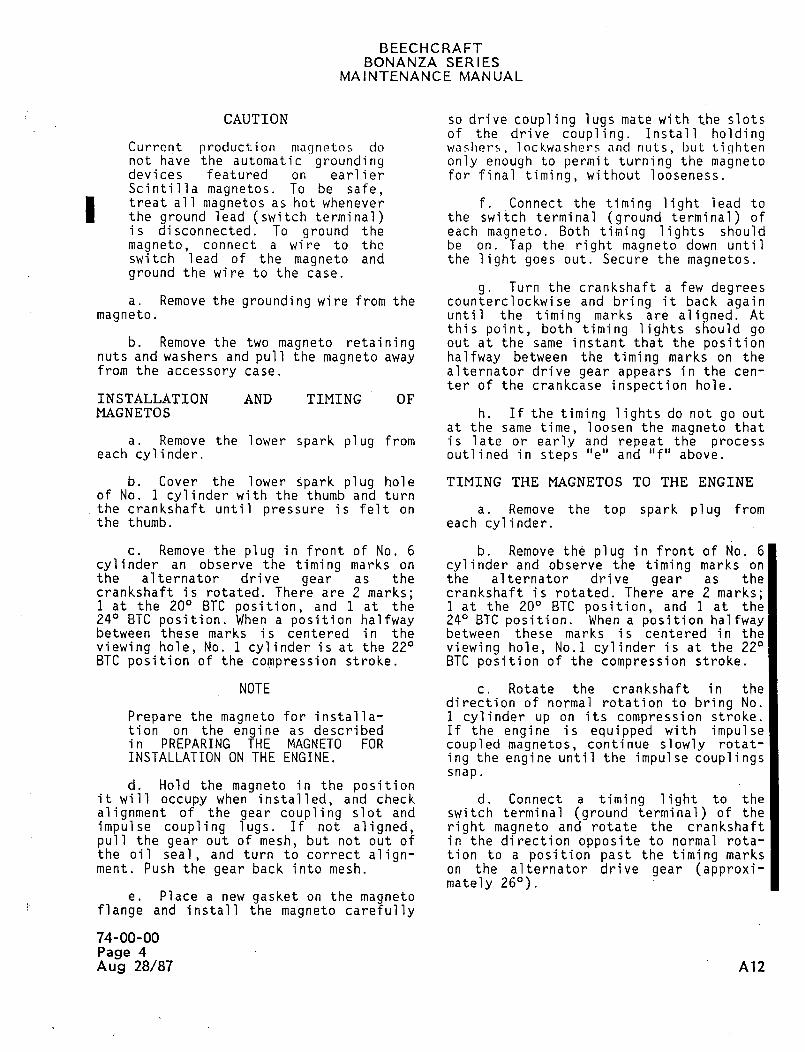
BEECHCRAFTBONANZA SERIES
MAINTENANCE MANUAL
CAUTION so drive coupling lugs mate with the slotsof the drive coupling. Install holding
Current production niannntos do was~icrs, lockwashers and nuts, but; tinhtennot have the automatic grounding only enough to permit turning the magnetodevices featured on earlier for final timing, without looseness.Scintilla magnetos. To be safe,treat all magnetos as hot whenever f. Connect the timing light lead to
the ground lead (switch terminal) the switch terminal (ground terminal) ofis di sconnected. To ground the each magneto. Both timing lights should
magneto, connect a wire to the be on. Tap the right magneto down untilswitch lead of the magneto and the light goes out. Secure the magnetos.ground the wire to the case.
g. Turn the crankshaft a few degreesa. Remove the grounding wire from the counterclockwise and bring it back again
magneto. until the timing marks are aligned. Atthis point, both timing lights should go
b. Remove the two magneto retaining out at the same instant that the positionnuts and washers and pull the magneto away halfway between the timing marks on thefrom the accessory case. alternator drive gear appears in the cen-
ter of the crankcase inspection hole.INSTALLATION AND TIMING OFMAGNETOS h. If the timing lights do not go out
at the same time, loosen the magneto thata. Remove the lower spark plug from is late or early and repeat the process
each cylinder. outlined in steps "e" and "f" above.
b. Cover the lower spark plug hole TIMING THE MAGNETOS TO THE ENGINEof No. 1 cylinder with the thumb and turn
the crankshaft until pressure is felt on a. Remove the top spark plug fromthe thumb, each cylinder.
c. Remove the plug in front of No. 6 b. Remove the plug in front of No. 6
cylinder an observe the timing marks on cylinder and observe the timing marks on
the alternator drive gear as the the alternator drive gear as thecrankshaft is rotated. There are 2 marks; crankshaft is rotated. There are 2 marks;1 at the 200 ETC position, and 1 at the 1 at the 200 ETC position, and 1 at the240 ETC position. When a position halfway 240 ETC position. When a position halfwaybetween these marks is centered in the between these marks is centered in the
viewing hole, No. 1 cylinder is at the 220 viewing hole, No.l cylinder is at the 220ETC position of the compression stroke. ETC position of the compression stroke.
NOTE c. Rotate the crankshaft in thedirection of normal rotation to bring No.
Prepare the magneto for installa- 1 cylinder up on its compression stroke.tion on the engine as described If the engine is equipped with impulsein PREPARING THE MAGNETO FOR coupled magnetos, continue slowly rotat-
INSTALLATION ON THE ENGINE. ing the engine until the impulse couplingssnap.
d. Hold themagneto in the positionit will occupy when installed, and check d. Connect a timing light to the
alignment of the gear coupling slot and switch terminal (ground terminal) of the
impulse coupling lugs. If not aligned, right magneto and rotate the crankshaft
pull the gear out of mesh, but not out of inthe direction opposite to normal rota-the oil seal, and turn to correct align- tion to a position past the timing marksment. Push the gear back into mesh, on the alternator drive gear (approxi-
mately 260).e. Place a new gasket on the magneto
flange and install the magneto carefully
74-00-00
Page 4
Aug 28/87 A12
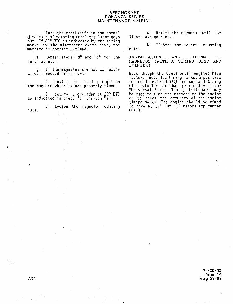
BEECHCRAFTBONANZA SERIES
MAINTENANCE MANUAL
e. Turn the crankshaft in the normal 4. Rotate the magneto until thedirection of rotation until the light goes light just goes out.
out. If 220 ETC is indicated by the timingmarks on the alternator drive gear, the 5. Tighten the magneto mountingmagneto is correctly timed. nuts.
f. Repeat steps "d" and "e" for the INSTALLATION AND TIMING OFleft magneto. MAGNETOS (WITH A TIMING DISC AND
POINTER)g. If the magnetos are not correctly
timed, proceed as follows: Even though the Continental engines have
factory installed timing marks, a positivei. Install the timing light on top dead center (TDC) locator and timing
the magneto which is not properly timed, disc similar to that provided with the"Universal Engine Timing Indicator" may
2. SetNo. 1 cylinder at 220 ETC be used to time the magneto to the engineas indicated in,steps "c" through "e" or to check the accuracy of the engine
timing marks. The engine should be timed
3. Loosen the magneto mounting to fire at 220 +00 -20 before top center
nuts. (BTC).
74-00-00Page 4A
A12 Aug 28/87
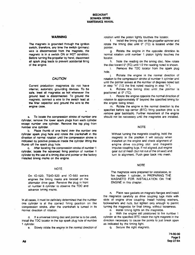
BEECHCRAFT
BONANtA SERIES
MAINTENANCE MANUAL
WARNING rotation until the piston lightly touches the locator.
f. Install the timing disc on the propeller spinner and
The magneto is grounded through the ignition rotate the timing disc until O" CTC) is located under the
switch, therefore, any time the switch (primary) pointer.wire is disconnected from the magneto, the g. Rotate the engine in the opposite direction to
magneto is in a switch ON or HOT condition, normal rotation until number 1 piston lightly touches the
Before turning the propeller by hand, disconnect locator.
all spark plug leads to prevent accidental firing h. Note the reading on the timing disc. Now rotate
of the engine. the disc toward O" (TC) until 1/2 the reading noted is shown.
i. Remove the TDC locator from the spark plughole.
i. Rotate the engine in the normal direction of´•
CAUTION rotation to the compression stroke of number 1 cylinder and
until the pointer arrives at the number of degrees noted last
Current production magnetos do not have in step "h" (112 the first noted reading in step "h").internal, automatic grounding devices. To be k. Rotate the timing disc until the pointer is
safe, treat all magnetos as hot whenever the positioned at O" (TC).ground lead is disconnected. To ground the I. Rotate the engine opposite the normal direction of
magneto, connect a wire to the switch lead at rotation to approximately 5" beyond the specified timing for
the filter capacitor and ground the wire to the the engine being timed.
engine case, m. Rotate the engine in the normal direction to the
specified before top center (BTC) firing position (this is to
remove gear backlash). Further movement of the enginea. To locate the compression stroke of number one should not be necessary until the magnetos are installed.
cylinder, remove the lower spark plugs from each cylinderexcept number one cylinder. Remove the top plug from
number one cylinder. NOTE
b. Place thumb of one hand over the number one
cylinder spark plug hole and rotate the crankshaft in the Without turning the magneto coupling, hold the
direction of normal rotation until the compression stroke is magneto in the position ~it will occupy when
indicated by positive pressure inside the cylinder lifting the installed on the encline and check alignment of
thumb off the spark plug hole. engine drive coupling slot and magneto
c. After locating the compression stroke of number 1 impulse coupling lu!as. If not aligned, pull engine
cylinder, locate the advanced firing position of number 1 gear out of mesh (but not out of the oil seal) and
cylinder by the use of a timing disc and pointer or the factory turn to alignment. Push gear back into mesh.
installed timing marks on the engine.
NOTE
NOTE
The magnetos were prepared for installation, to
On 10-520, TSIO-520 and 10-550 series fire number 1 cylinder, in PREPARING THE
engines the timing marks are located on the MAGNETO FOR INSTALLATION ON THE
alternator drive gear. Remove the plug in front ENGINE in this chapter.of number 6 cylinder to observe the TDC and
advance timing marks.
n. Place new gaskets on magneto flanges and install
the magnetos carefully so drive coupling lugs mate with
’In all cases, it must be definitely determined that the number slots of engine drive coupling. Install holding washers,
one cylinder is at the correct firing position on the lockwashers and nuts, but tighten only enough to permit
compression stroke, after the crankshaft is turned in its turning the magnetos for final timing, without looseness.
normal direction of rotation, o. Install timing lights on the magnetos.
p. With the engine still positioned to fire number 1
d. If a universal timing disc and pointer is to be used, cylinder at the specified ETC rotate the right magneto in the
install the TDC locator in the top spark plug hole of number direction necessary to cause the points to just break open
1 cylinder, as indicated by the timing light.e. Slowly rotate the engine in the normal direction of q. Secure the right magneto.
74-00-00
Page5A9 Sep 27/84
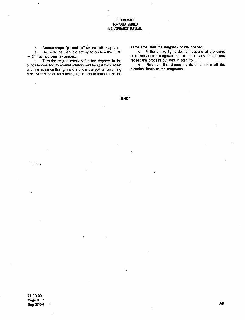
BEECHCRATT
BONANZA SERIES
MAINTENANCE MANUAL
r. Repeat steps "p" and "o" on the left magneto. same time, that the magneto points opened.
s. Recheck the magneto setting to confirm the O" u. If the timing lights do not respond at the same
2" has not been exceeded. time, loosen the magneto that is either early or late and
t. Turn the engine crankshaft a few degrees in the repeat the process outlined in step "p".
opposite direction to normal rotation and bring it back again v. Remove the timing lights and reinstall the
until the advance timing mark is under the pointer on timing electrical leads to the magnetos.
disc. At this point both timing lights should indicate, at the
"END"
7e00M)
Page6Sep 27/84 A9
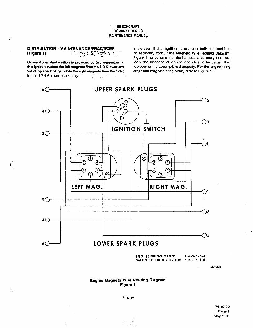
BEECHCRAFF
BONANZA SERIES
MAINTENANCE MANUAL
DISTRIBUTION In the event that an ignition hamess or an individual lead is to
(Figure 1) be replaced, consult the Magneto Wire Routing Diagram,Figure i, to be sure that the hamess is correctly installed.
Conventional dual ignition is provided by two magnetos. In Mark the locations of clamps and clips to be certain that
this ignition system the left magneto fires the 1-3-5 lower and replacement is accomplished properly. For the engine firing2-4-6 top spark plugs, while the right magneto fires the 1-3-5 order and magneto firing order, refer to Figure i.
top and 2-4-6 lower spark plugs.
6C)----7 UPPER SPARK PLUGS
IGNITION SWITCH
LEFT MAG.I I JRIGHT MAG.
60--1 LOWER SPARK PLUGS
ENGINE FIRING ORDER: 1-6-3-2-5-4
MAGNETO FIRING ORDER: 1-2-3-4-5-6
Engine Magneto Wire Routing DiagramFlgu~l
"END"
7620-00
Pager
May 9/80
CHAPTER
ENGINE
INDICATING
Raytheon Aircraft CompanyBONANZA SERIES MAINTENANCE MANUAL
CHAPTER 77- ENGINE INDICATING
TABLE OF CONTENTS
SUBJECT PAGE
77-00-00
General- Maintenance Practices(EA-ll andAfter). ........1
TIT Indicator Calibration
U6 77-CONTENTS ,5:~Page 1
RBYtheO´• Aircraft CompanyBONANZA SERIES MAINTENANCE MANUAL
CHAPTER 77 ENGINE INDICATING
LIST OF EFFECTIVE PAGES
CH-SE-SU PAGE DATE
77-LOEP 1 Sep 30/04
77-CONTENTS 1 Sep 30/04
77-00-00 1 and 2 Sep 30/04
A26 77-LOEP
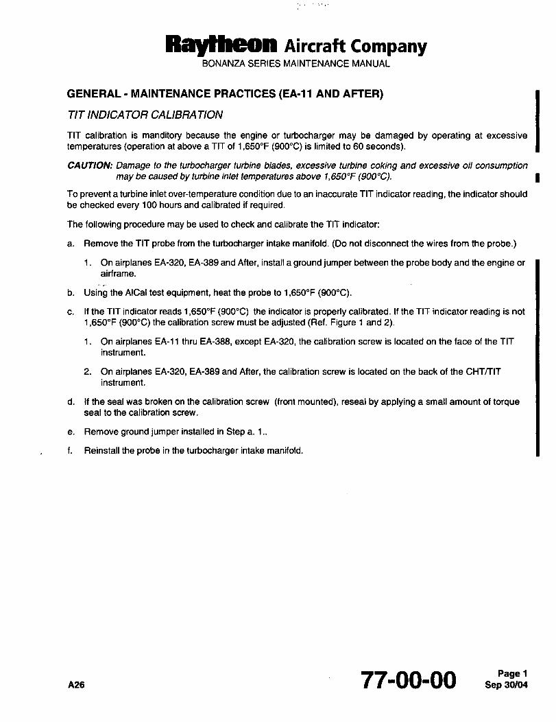
RByCheO´• Aircraft CompanyBONANZA SERIES MAINTEWANCE MANUAL
GENERAL MAINTENANCE PRACTICES (EA-11 AND AFTER)
TIT INDICA TOR CALISRA TION
TIT calibration is manditory because the engine or turbocharger may be damaged by operating at excessive
temperatures (operation at above a TIT of 1,650"F (900"C) is limited to 60 seconds).
CAUTION: Damage to the turbocharger turbine blades, excessive turbine coking and excessive oil consumptionmay be caused by turbine inlet temperatures above 1,650"F(900"C).
To prevent a turbine inlet over-temperature condition due to an inaccurate TIT indicator reading, the indicator should
be checked every 100 hours and calibrated if required.
The following procedure may be used to check and calibrate the TIT indicator:
a. Remove the TIT probe from the turbocharger intake manifold. (Do not disconnect the wires from the probe.)
1. On airplanes EA-320, EA-389 and After, install a ground jumper between the probe body and the engine or
airframe.
b. Using the AICal test equipment, heat the probe to 1,650"F (900"C).
c. If the TIT indicator reads 1,650"F(900"C) the indicator is properly calibrated. If the TIT indicator reading is not
1,650"F (900"C) the calibration screw must be adjusted (Ref. Figure 1 and 2).
1. On airplanes EA-11 thru EA-388, except EA-320, the calibration screw is located on the face of the TlT
instrument.
2. On airplanes EA-320, EA-389 and After, the calibration screw is located on the back of the CHTTTIT
instrument.
d. If the seal was broken on the calibration screw (front mounted), reseal by applying a small amount of torqueseal to the calibration screw.
e. Remove ground jumper installed in Step a. 1..
f. Reinstall the probe in the turbocharger intake manifold.
~as 77-00-00 Sep 30104Pagel
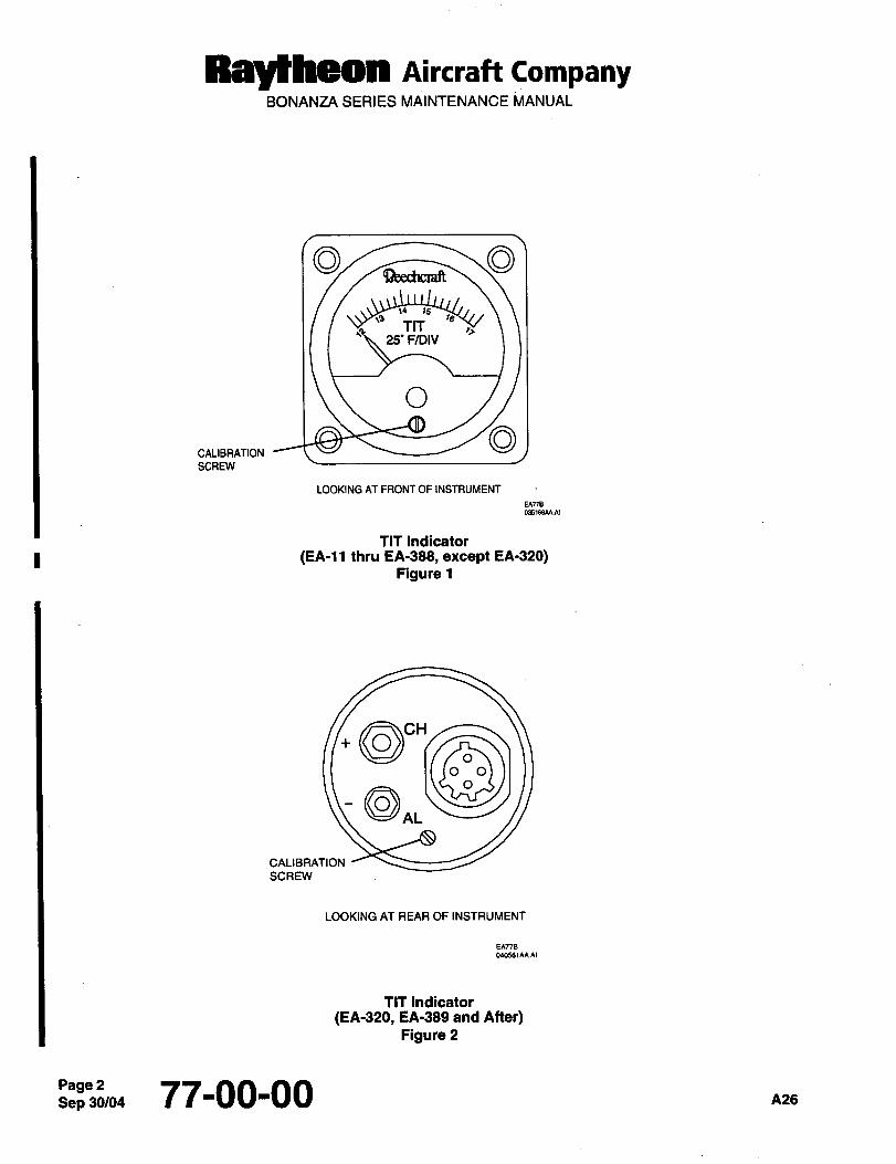
Raytheon AiKraft FompanyBONANZA SERIES MAINTENANCE MANUAL
TIT ,i25’ F/DIV
O
WIBRITION
SCREW
LOOKING AT FRONT OF INSTRUMENT
TIT Indicator
(EA-11 thru EA-388, except EA-320)Figure 1
\U~
ALCHCALIBRATION
SCREW
LOOKING AT REAR OF INSTRUMENT
TIT Indicator
(EA-320, EA-389 and Atter)Figure 2
Sep 30/04Page 2 77-00-00 A26

CHAPTER
OIL
BEECHCRATT
BONANZA SERIES
MAINTENANCE MANUAL
CHAPTER 79
LIST OF PAGE EFFECTIVITY
CHAPTER
SECTION
SUBJECT PAGE DATE
79-EFFECTIVITY/CONTENTS 1 ................Oct 7/83
77-00-00 1 ................Oct 7/83
2 ................Oct 7/83
CHAPTER 79 OIL
TABLE OF CONTENTS
CHAPTER iSECTION
SUBJECT SUBJECT PAGE
GENERAL 79-00-00
Oescription and Operation ........1
Maintenance Practices :.......1
Oil SystemHigh Oil Temperature ..............1
Oil Cooler Removal ..............1
Oil Cooler Installation ..............1
Break-in Engine Oil ..............1
Recommended Oil Grades for Engines .........2
"END"
79ErrECTIVrTYICONTENfS
Fags 1
Oct 7183
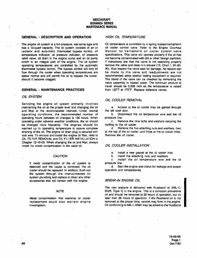
BEECHCRAFTBONANZA SERIES
MAINTENANCE MANUAL
GENERAL DESCRIPTION AND OPERATION HIGH OIL TEMPERA TURE
The engine oil system is a full-pressure, wet sump type and Oil temperature is controlled by a spring loaded\lernatherm
has a 12-quart capacity. The oil system consists of an oil oil cooler control valve.’Refer to the Engine Overhaul
radiator and automatic thermostat bypass control, oil Manual for Vernatherm oil cooler control valve
temperature indicator, oil pressure indicator, oil pressure specifications. This valve will operate property if the oil has
relief valve, oil drain in the engine sump and an oil pump not become contaminated with dirt or other foreign particles.which is an integral part of the engine. The oil system If indications are that the valve is not operating properlyoperating temperatures are controlled by the automatic remove the valve and clean it in solvent (16, Chart 1, 91-00-
thermostat bypass control. The bypass control will limit oil 00). Also inspect the valve seat for damage. No repairs can
flow through the cooler when operating temperatures are be made to this valve and readjustments are not
below normal and will permit the oil to bypass the cooler, recommended since special testing equipment is required.should it become clogged. The travel of the valve can be checked by immersing the
valve assembly in heated water. The minimum amount of
travel should be 0.090 inch as the temperature is raised
GENERAL MAINTENANCE PRACTICES from 1200F to 1700F. Replace defective valves.
OIL SYSTEMOIL COOLER REMOVAL
Servicing the engine oil system primarily involves
maintaining the oil at the proper level and changing the oil a. Access tq the oil cooler may be gained throughand filter at the recommended intervals. Under normal the left cowl door.
operating conditions, the recommended number of b. Disconnect the oil temperature wire and the oil
operating hours between oil changes is 100 hours. When pressure line.
operating under adverse weather conditions, the oil should c. Remove the nine bolts and washers securing the
be changed more frequently. The engines should be baming to the oil cooler.
warmed up to operating temperature to assure complete d. Remove the five attaching nuts and washers, (twodraining of the oil. The engine oil drain plug is secured with at the top of the oil cooler, and three~at the oil cooler inlet).lock wire. To remove and install the engine oil filter, refer to Remove the oil cooler.
OIL FILTER REMOVAL and OIL FILTER INSTALLATION in
Chapter 12-10-00. When changing the oil and filter, alwayscheck for metal contamination in the used oil. OIL COOLER INSTALLA 7/ON
a. Install a new gasket at the oil cooler inlet.
CAUTION b. Install the attaching nuts and washers.
c. Install the oil temperature wire and the oil
If metal contamination of the oil system is pressure line.
detected and the cause is corrected, the oil d. Start the engine and check for leakage and proper
cooler should be replaced. In addition, flush out operation and temperatures.the system through the interconnected oil
system plumbing and replace or clean any other
accessories that will remain with the engine. BREAK-IN ENGINE OIL
The new airplane is delivered with Rustband oil (MIL-C-NOTE 6529, Type II) in the engine. This is a corrosion preventive
oil and should be removed at 20 hours of operation, but no
Metal contamination that warrants oil cooler later than 25 hours of operation. If the Rustband oil is not
replacement would also warrant engine removed at the proper time, varnish may form in the engine.investigation. Oil conforming to MlL-L-6082 may be added to the Rustband
79-00-00
PagelA6 Oct 7/83
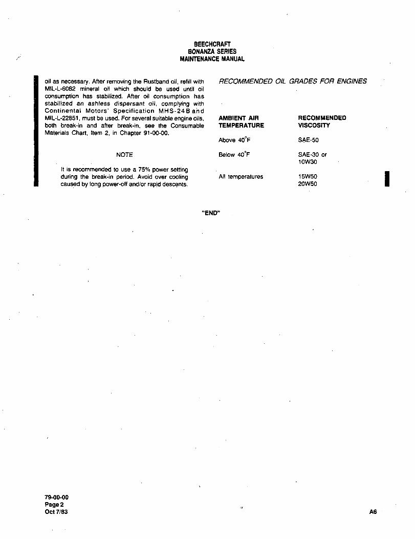
BEECHCRAFTBONANZA SERIES
MAINTENANCE MANUAL
oil as necessary. After removing the Rustband oil, refill with RECOIWMENDED OIL G~ADES FOFI ENGINESMIL-L-6082 mineral oil which should be used until oil
consumption has stabilized. After oil consumption has
stabilized an ashless dispersant oil. complying with
Continental Motors’ Specification MHS-24Ba‘nd
Mll-L-22851, must be used. For several suitable engine oils, AMBIENT AIR RECOMMENDED
both break-in and after break-in, see the Consumable TEMPERATURE VISCOSITY
Materials Chart, Item 2, in Chapter 91-00-00.
Above 40oF SAE-50
NOTE Below 400F SAE-90 or
10W30
It is recommended to use a 75% power settingduring the break-in period. Avoid over cooling All temperatures 15W50
caused by long power-dff and/or rapid descents. 20W50
"END"
79-00-00
Page2Oct 7/83 A6

CHAPTER
STARTING
BEECHCRAFT
BONANZA SERIES
MAINTENANCE MANUAL
CHAPTER 80
LIST OF PAGE EFFECTIVITY
CHAPTER
SECTION
SUBJECT PAGE DATE
80-EFFECTIVITY/CONTENTS 1 .........,.,May 9/80
80-10-00 1 ...............May 9/80
2 ...............May 9/80
CHAPTER 80 STARTING
TABLE OF CONTENTS
CHAPTER
SECTION
SUBJECT SUBJECT PAGE
CRANKING 80-10-00
Description and Operationi
.......t
Troubleshooting Starter System .........I .......1
Maintenance Practices ........1’’’’’’’’’i
Starter Removal ,.......1
Starter Installation ........1
Starter Overhaul ........1
Starter Lubrication ........1
Starter Brushes ........2
"END"
80-EFFECflVITYICONTENTS
Page 1
May 9/80
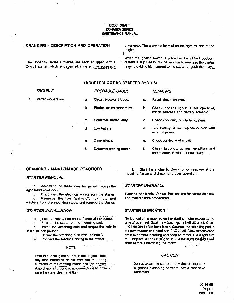
BEECHCRAFT
BONA~ZA SERIES
MAINTENANCE MANUAL
CRANKING DESCRIPTION AND OPERATION drive gear. The starter is located on the right ah side of the
engine.
When the ignition switch is placed in the START position,The Bonanza Series airplanes are each equipped with a current is supplied by the battery bus to energize the starter
?4-volt starter which with the engjns~:cessory relay, providing high current to the starter!hrough thelelay,
TROUBLESHOOTING STARTER SYSTEM
TROUBLE PROBABLE CAUSE REMARKS
1. Starter inoperative. a. Circuit breaker tripped, a. Reset circuit breaker.
b. Starter switch inoperative, b. Check cockpit lights; if not operative,check switches and battery solenoid.
c. Defective starter relay. c. Check continuity of starter system.
d. Low battery. d. Test battery; ii low, replace or start with
external power.
e. Open i~ircuit. a. Check continuity of circuit.
i. Defective starting motor, i. Check brushes, springs, condition, and
commutator. Replace if necessary.
CRANKING MAINTENANCE PRACTICES i. Start the engine to check for oil seepage at the
mounting flange and check for proper operation.STARTER REMOVAL
a. Access to the starter may be gained through the STARTER OVERHAUL
right hand cowl door.
b. Disconnect the electrical wiring from the starter. Refer to applicable Vendor Publications for complete tests
c. Remove the two "palnuts", hex nuts and and maintenance procedures.washers from the mounting studs, and remove the starter.
STARTER INSTALLA TION STARTER LUBRICATION
a. Install a new 6-ring on the flange of the starter. No lubrication is required on the starting motor except at the
b. Position the starter on the mounting pad. time of overhaul. Soak new bearings in SAE 20 oil (2, Chart
c. Install the attaching nuts and torque the nuts to 1, 91-00-00) before installation. Saturate the felt oiling pad in
150-180 inch-pounds. the commutator end head with SAE 20 oil. Allow excess oil to
d. Secure the attaching nuts with "palnuts". drain out before installing end head on motor. Put a light film
e. Connect the electrical wiring to the starter, of Lubriplate 1;shaft before assembling the motor.
NOTE
Prior to attaching the starter to the engine, clean CAUTION
any rust, corrosion or dirt from the mountingsurfaces of motor and the Do not clean the starter in any degreasing tank
Also check all ground strap conrii3cii;ji;s to make or grease dissolving solvents. Avoid excessive
sure they are clean and tight, lubrication.
80-1 0-00
PagelMay 9/80
BEECHCRAFTBONANZA SERIES
MAINTENANCE MANUAL
STARTER BRUSHES replaced when they have worn to 1/4 inch or less. Properbrush spring tension with new brushes installed is 32-40
ounces. This tension is measured with a scale hooked under
The starter brushes should slide in the holder and the brush spring near the’ brush and the reading taken just as
make full contact on the commutato!,‘rhe brusheS~Should be~ the spring leaves the brush.
"END"
80-1(M0’
Page2May 9/80

CHAPTER
TURBINES
BEECHCRAFT
BONANZA SERIES
MAINTENANCE MANUAL
CHAPTER 81 TURBINES
TABLE OF CONTENTS
CHAPTER iSECTION
IPAGESUBJECT SUBJECT
GENERAL 81-00-00
Description and Operation ;.......1
Turbocharger System (EA-1 and after) ........1
Troubleshooting Turbocharger System ........2
Maintenance Practices ........5
Manifold Pressure Adjustment ........5
Turbocharger Leak Test Procedure ´•´•´•´•´•´•´•´•´•1 ........7
Freeing Turbocharger Shaft ´•i........8
Turbocharger Removal ........8
Turbocharger Installation .........8
Turbocharger Controller Removal ~........8Turbocharger Controller Installation ´•8
"END"
B1-CONTENTS
Psg´• 1
Jan 28/81
BEECHCRAFTBONANZA SEFIIES
MAINTENANCE MANUAL
CHAPTER St
LIST OF PAGE EFFECTIVIN
CHAPTER
SECTION
SUBJECT PACE DATE
81-EFFECTIVITY 1. Jan 20/82
81-CONTENTS 1 Jan 28/81
81-00-00 1 May 9/80
2 May 9/80
3 May 9/80
4 May 9/80
5 Jan 28/81
6 Jan 28/81
7 Jan 28/81
8 Jan 20/82
"END"
B1-ERECnVln
Page 1
A4 Jan 20/82
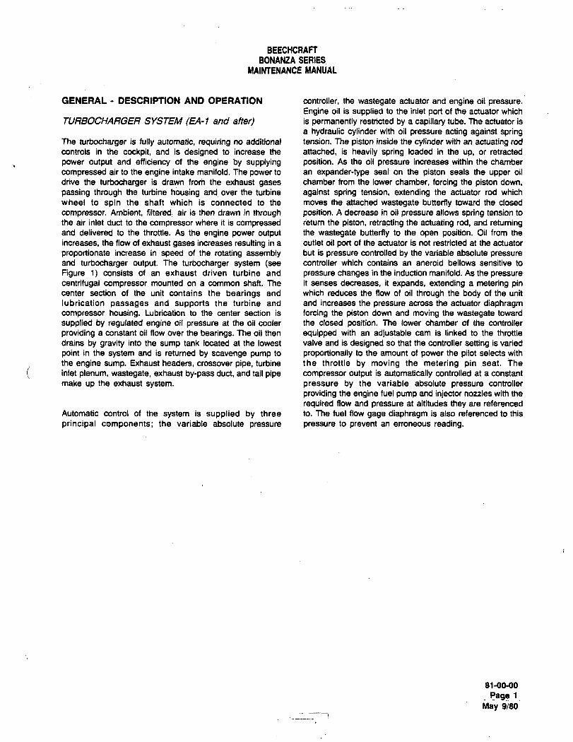
BEECHCRAFTBONANZA SERIES
MAINTENANCE MANUAL
GENERAL DESCRIPTION AND OPERATION controller, the wastegate actuator and engine oil pressure.
Engine oil is supplied to the inlet port of the actuator which
TURBOCHARGER SYS7;EM (EA-1 and afte~ is permanently restricted by a capillary tube. The actuator is
a hydraulic cylinder with oil pressure acting against springThe turbocharger is fully automatic, requiring no additional tension. The piston inside the cylinder with an actuating rod
controls in the cockpit, and is designed to increase the attached, is heavily spring loaded in the up, or retracted
power output and efficiency of the engine by supplying position. As the oil pressure increases within the chamber
compressed air to the engine intake manifold. The power to an expander-type seal on the piston seals the upper oil
drive the turbocharger is drawn from the exhaust gases chamber from the lower chamber, forcing the piston down,
passing through the turbine housing and over the turbine against spring tension, extending the actuator rod which
wheel to spin the shaft which is connected to the moves the attached wastegate butterfly toward the closed
compressor. Ambient, filtered, air is then drawn in through position. A decrease in oil pressure allows spring tension to
the air inlet duct to the compressor where it is compressed return the piston, retracting the actuating rod, and retumingand delivered to the throttle. As the engine power output the wastegate butterfly to the open position. Oil from the
increases, the flow of exhaust gases increases resulting in a outlet oil port of the actuator is not restricted at the actuator
proportionate increase in speed of the rotating assembly but is pressure controlled by the variable absolute pressureand turbocharger output. The turbocharger system (see controller which contains an aneroid bellows sensitive to
Figure 1) consists of an exhaust driven turbine and pressure changes in the induction manifold. As the pressure
centrifugal compressor mounted on a common shaft. The it senses decreases, it expands, extending a metering pincenter section of the unit contains the bearings and which reduces the flow of oil through the body of the unit
lubrication passages and supports the turbine and and increases the pressure across the actuator diaphragmcompressor housing. Lubrication to the center section is forcing the piston down and moving the wastegate toward
supplied by regulated engine oil pressure at the oil cooler the closed position. The lower chamber of the controller
providing a constant oil flow over the bearings. The oil then equipped with an adjustable cam is linked to the throttle
drains by gravity into the sump tank located at the lowest valve and is designed so that the controller setting is varied
point in the system and is returned by scavenge pump to proportionally to the amount of power the pilot selects with
the engine sump. Exhaust headers, crossover pipe, turbine the throttle by moving the metering pin seat. The
inlet plenum, wastegate, exhaust by-pass duct, and tail pipe compressor output is automatically controlled at a constant
make up the exhaust system. pressure by the variable absolute pressure controller
providing the engine fuel pump and injector noules with the
required flow and pressure at altitudes they are referenced
Automatic control of the system is supplied by three to. me fuel flow gage diaphragm is also referenced to this
principal components; the variable absolute pressure pressure to prevent an erroneous reading.
81-00-00
Rage 1
May 9/80
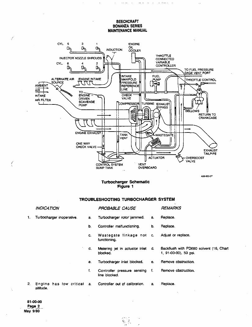
BEECHCRAFTBONANUA SERIES
MAINTENANCE MANUAL
CYL 5 3 1 ENGINE
OILINDUCTION COOLER
"Y"THROTTLE
INJECTOR NOZZLE SHROUDS mt v CONNECTED
CYL. 6. 4 2 VARIABLE
CONTROLLER
I: II TO FUEL PRESSUREVENT PORT
INTAKE III 11 FUELALTERNATEAIR ENGINEINTAKE MANIFOLD CONTROLSOURCE ~n n ~n 14 PRESSURE IAMBIENT
TOLINE
INTAKE ENGINE--~t7 CHECK
Al~ FILTERDRIVEN ~I VALVE
SCAVENGEPUMP EXHAUST
BELLOWS
RETURN TOI’ I L~IU F~ U~--’Y\ II 11 II1 CRANKCASE
j
ENGINE EXHAUSTTANK~! i: ~-WASTEGATEVENT
ONE WAY
CHECK VALVE
EXHAUSTi: I L TAILPIPE
i II ACTUATOR OVERBOOSTVALVE
CONTROL SYSTEM VENT
SUMP TANK OVERBOARD
A36-603-27
Turbocharger Schematic
Figure 1
TROUBLESHOOT1NG TURBOCHARGER SVSTEM
INDICA TION PROBABLE CAUSE REMARKS
i. Turbocharger inoperative. a. Turt~ocharger rotor’jammed. a. Replace.
b. Controller malfunctioning. b. Replace.
c. Wastegate linkage not c. Adjust or replace.functioning.
d. Metering jet in actuator inlet d. Backflush with PD680 solvent (16, Chart
blocked. i, 91-00-00), 50 psi.
e. Turbocharger inlet blocked. a. Remove obstruction.
f. Controller pressure sensing f. Remove obstruction.
line blocked.
2. Engine has low critical a. Controller out of calibration. a. Replace.altitude.
81-00-00
11.8981_
May 9/80
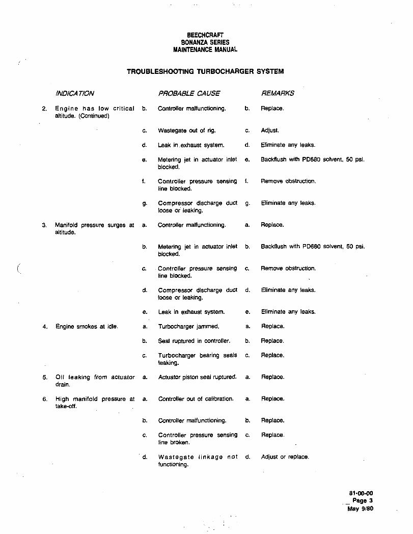
BEECHCRAFTBONANZA SERIES
MAINTENANCE MANUAL
TROUBLESHOOTING TURBOCHARGER SYSTEM
INDICA TION PROBABLE CAUSE REI~ARKS
2. Engine has low critical b. Controller malfunctioning. b. Replace.altitude. (Continued)
c. Wastegate out of rig. c. Adjust.
d. Leak inexhaust system, d. Eliminate any leaks.
e. Metering jet in actuator inlet e. BacMlush with PD680 solvent, 50 psi.blocked.
f. Controller pressure sensing f. Remove obstmction.
line blocked.
g. Compressor discharge duct g. Eliminate any leaks.
loose oi leaking.
3. Manifold pressure surges at a. Controller malfunctioning, a. Replace.altitude.
b. Metering jet in actuator inlet b. Backflush with PD680 solvent. 50 psi.blocked.
c. Controller pressure sensing c. Remove obstruction.
line blocked.
d. Compressor discharge duct d. Eliminate any leaks.
loose or leaking.
e. Leak in exhaust system. e. Eliminate any leaks.
4. Engine smokes at idle. a. Turbocharger jammed. a. Replace.
b. Seal ruptured in controller. b. Replace.
c. Turbocharger bearing seals c. Replace.leaking.
5. Oil leaking fiom actuator a. Actuator piston seal ruptured, a. Replace.drain.
6. High manifold pressure at a. Controller out of calibration. a. Replace.take-off.
b. Controller malfunctioning. b. Replace.
c. Controller pressure sensing c. Replace.line broken.
d. Wastegate linkage not d. Adjust or replace.
functioning.
81-00-00
Page 3
May 9/80
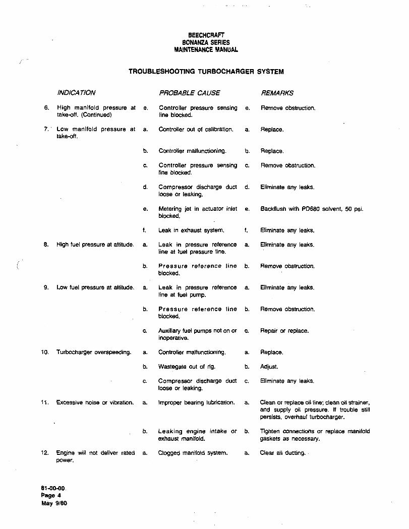
BEECHCRAFTBONANZA SERIES
MA1NTENAEICE MANUAL
TROUBLESHOOTING TURBOCHARGER SYSTEM
INDICA TION PROBABLE CAUSE REMARKS
6. High manifold pressure at e. Controller pressure sensing a. Remove obstruction.
take-off. (Continued) line blocked.
7.’ Low manifold pressure at a. Controller out of calibration. a. Replace.take-off.
b. Controller malfunctioning. b. Replace.
c. Controller pressure sensing c. Remove obstruction.
line blocked.
d. Compressor discharge duct d. Eliminate any leaks.
loose or leaking.
e. Metering jet in actuator inlet a. Backflush with P0680 solvent, 50 psi.blocked.
f. Leak in exhaust system, f. Eliminate any leaks.
8. High fuel pressure at altitude, a. Leak in pressure reference a. Eliminate any -leaks.
line at fuel pressure line.
b. Pressure reference line´• b. Remove obstruction.
blocked.
9. Low fuel pressure at altitude, a. Leak in pressure reference a. Eliminate any leaks.
line at fuel pump.
b. Pressure reference line b. Remove obstruction.
blocked.
c. Auxiliary fuel pumps not on or c. Repair or replace.inoperative.
10. Turbocharger overspeeding. a. Controller maltunctioning. a. Replace.
b. Wastegate out of rig, b. Adjust.
c. Compressor discharge duct c. Eliminate any leaks.
loose or leaking.
11. Excessive noise or vibration, a. Improper bearing lubrication, a. Clean or replace oil line; clean oil strainer,and supply oil pressure. If trouble still
persists, overhaul turbocharger.
b. Leaking engine intake or b. Tighten connections or replace manifold
exhaust manifold, gaskets as necessary.
12. Engine will not deliver rated a. Clogged manifold system. a. Clear ail ducting.power.
81-00-00.
Page 4
May 9/80
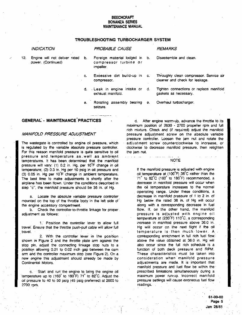
BEECHCRAFTBONANZA SERIES
MAINTENANCE MANUAL
TROUBLESHOOTING TURBOCHARGER SYSTEM
INDICA TION PROBAgLE CAUSE REMARKS
12. Engine will not deliver rated b. Foreign material lodged in b. Disassemble and clean.
.power. (Continued) compressor turbine or
impeller.
c. Excessive dirt build-up in c.~ Throughly clean compressor. Service air
compressor, cleaner and check for leakage.
d. ~Leak in engine intake or d. Tighten connections or replace manifold
exhaust manifold. gaskets as necessary.
e. Rotating assembly bearing e. Overhaul turbocharger.seizure;
GENERAL MAINTENANCE PRACTICES d. After engine warm-ub, advance the throttle to its
maximum position of 2600 2700 propeller rpm and full
rich mixture. Check and (if required) adjust the manifold
MANIFOLD PRESSURE ADJUSTiMENT~ pressure adjustment screw on the absolute variable
pressure controller. Loosen the jam nut and rotate the
The wastegate is controlled by engine oil pressure, which adjustment screw counterclockwise to.increase, or
is regulated by the variableabsolute pressure controller. ´•clockwise to decrease manifold pressure, then retightenFor this reason manifold pressure is quite sensitive to oil the jam nut.
pressure and.temperatureas ~.well .as ambie,nt....-temperatures. It has been determined that the manifold NOTE
pressure will vary: (1) 0.2 in. Hg. per 10oF change in oil
temperature; (2) 0.3 in. Hg per 10 psig in oil pressure and If the manifold pressure is adjusted with engine(3) 0.05 in. Hg per 10oF change in ambient temperature. oil temperature at (1000F) 380C rather than the
The best time to make adjustments is shortly after the 719 to 820C (160" to 180"F) recommended, a
airplane has been flown. Under the conditions described in decrease in manifold pressure will occur when
step "c", the manifold, pressure should be 36 in, of Hg. the oil temperature increases to the normal
operating range, Under these conditions, a
a, Locate the absolute variable pressure controller decrease in manifold pressure of 1 to 2 in, ofmounted on the top´•of the throttle body in the left side of’ Hg below the rated 36 in, of Hg will occur
the engine accessory compartment. along with a corresponding decrease in fuel
b. Check the controller-td-throttle linkage for proper flow. If, on t~e other hand, the manifold
adjustment. as follows: pressure is adjusted with engine oil
temperature at (2300F) flOoC,~a corresponding1.’ Position the controller lever to allow full increase in manifold pressure above 36.0 in.
travel; Ensure that the throttle push-pull cable will allow~full H9 will occur on the next flight if the oil
travel. temperature is then much lower. A
2. With the controller lever in the position corresponding enrichment in full rich’fuel flow-
shown in Figure 2 and the throttle plate arm against’the above the value obtained at 36.0 in. Hg will
stop pin, adju~t the connecting linkage stop nuts to a also occur since the full rich schedule is a
position allowing 0.01 to 0.02 inch gap between the cam function of both deck pressureand RPM.
arm and the controller maximum stop (see Figure 2). On a These characteristics must be taken into
new engine this adjustment should already be made’by consideration when manifold pressure
Continental~ Motors. adjustments are made. It is´•important that
manifold pressure and fuel flow be within the
c. Start and run’the engine to bring the engine oil prescribed limitations simultaneously during a
temperature up to (1600 to 180oF) 71" to 82"C. Adjust the maximum:power run-up. Incorrectmanifold
oil pressure to 40 to 50 psig (45 psigpreferred) at 2600 to pressure settings will cause erroneous. fuel flow
2700 rpm, readings.
81-00-00
Page 5
Jan 28/81
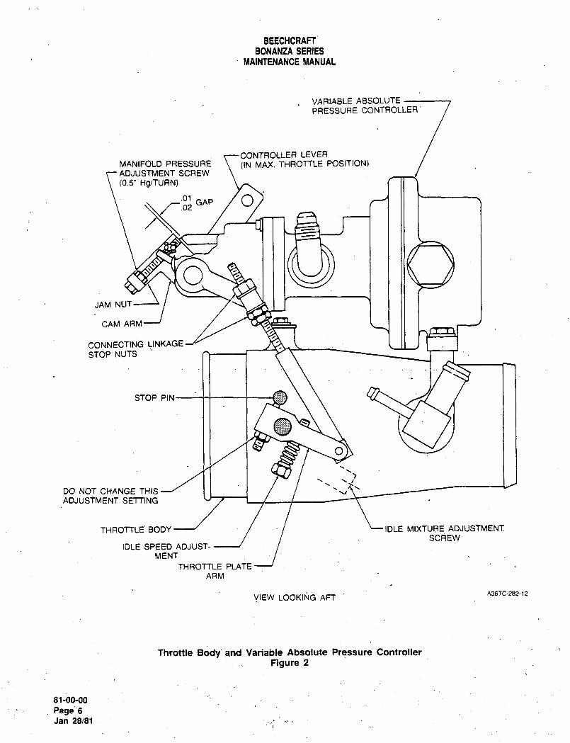
BEECHCRAFTBONANZA SERIES
MAIN’TENANCE MANUAL
VARIABLE ABSOLUTE
PRESSURE CONTROLLER‘
CONTROLLER LEVER
MANIFOLD PRESSURE ((N MAX. THROTTLE POSITION)ADJUSTMENT SCREW
(6.SI, MS/TURN)
GAP /O.01
OJAM NUT
CAM ARM
CONNECTING LINKAGE
STOP NUTS
STOP PIN
O
DO NOT CHANGE THIS-~ I I I \VADJUSTMENT SETTING
THROTTLE‘ BODY --J IDLE MIXTURE ADJUSTMENT:
SCREWIDLE SPEED ADJUST-
MENT
THROTTLE PLATE
ARM
A36TC-282-12VIEW LOOKING AFT
Throttle Body and Variable Absolute Pressure Controller
Figure 2
sl-bo-ooPage6Jan 28/81
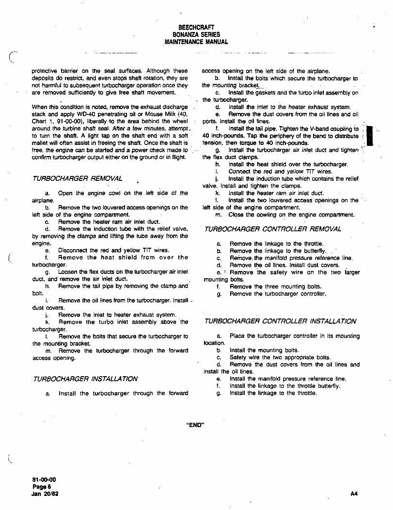
BEECHCRAF~BONANZA SEBIES
MAINfENANCE MANUAL
c’protective barrier on the seal surfaces. Although these access opening on the left side of the airplane.deposits do restrict, and even stops shaft rotation, they are b. Install the bolts which secure the turbocharger to
not harmful to subsequent turbocharger operation once they the mounting bracket.
are removed sufficiently to give free shaft movement, c. Install the gaskets and the turbo inlet assembly on
the turbocharger.When this condition is noted, remove the exhaust discharge d. Install the inlet to the heater exhaust system.stack and apply WO-40 penetrating oil or Mouse Milk (40, e. Remove the dust covers from the oil lines and oil
Chart i, 91-00-00), liberallyto the area behind the wheel ports. Install the oil lines.
around the turbine shaft seal. After a few minutes, attempt, f. Install the tail pipe. Tighten the V-band coupling to
to tum the shaft. A light tap on the shaft end with a soft 40 inch-pounds. Tap the periphery of the band to distribute
mallet will often assist in freeing the shaft. Once the shaft is tension, then torque to 40 inch-pounds.free, the engine can be started and a power check made to g. Install the turbocharger air inlet duct and tightenconfirm turbocharger output either on the ground or in flight, the flex duct clamps.
h. Install the heat shield over the turbocharger.i. Connect’the red and yellow TIT wires.
TURBOCHARGER REMOVAL i. Install the induction tube which contains the relief
valve. Install and tighten the clamps.a. Open the engine cowl on the left side of the k. Install the heater ram air inlet duct.
airplane. I. Install the two louvered access openings on the
b. Remove the two louvered access openings on the left side of the engine compartment.left side of the engine compartment. m. Close the cowling on the engine compartment.
c. Remove the heater ram air inlet duct.
d. Remove the induction tube with the relief valve, TURBOCHARGER CONTROLLER REMOVAL
by removing the clamps and lifting the tube away from the
engine. a. Remove the linkage to the throttle.
e. Disconnect the red and yellow TIT wires, b. Remove the linkage to the butterfly.i. f. Remove the heat shield from over the c. Re~bve.the manifold pressure reference line.
turbocharger. d. Remove the oil lines. Install dust covers.
g. Loosen the flex ducts on the turbocharger air inlet e. Remove ihe safety wire on the two largerduct, and remove the air inlet duct, mounting bolts.
h. Remove the tail pipe by removing the clamp and f. Remove the three mounting bolts.
bolt. g. Remove the turbocharger controller.
i. Remove the oil lines from the turbocharger. Install
dust covers.
i. Remove the inlet to heater exhaust system.k. Remove the turbo inlet assembly above ~the TURBOCHARGER CONTROLLER INSTALLATION
turbocharger.i. Remove the bolts that secure the turbocharger to a. Place the turbocharger controller in its mounting
the mounting bracket, location.
m. Remove the turbocharger through the forward b. install the mounting boltS.
access opening, c. Safety wire the two appropriate bolts.
d. Remove the dust covers from the oil lines and
install the oil lines.
TURBOCHARGER INSTALLATION e. Install the manifold pressure reference line.
f. Install the linkage to the throttle butterfly.a. Install the turbocharger through the forward g. Install the linkage to the throttle.
"END"
I)1-MUHI
Page8Jan 20/82 A4
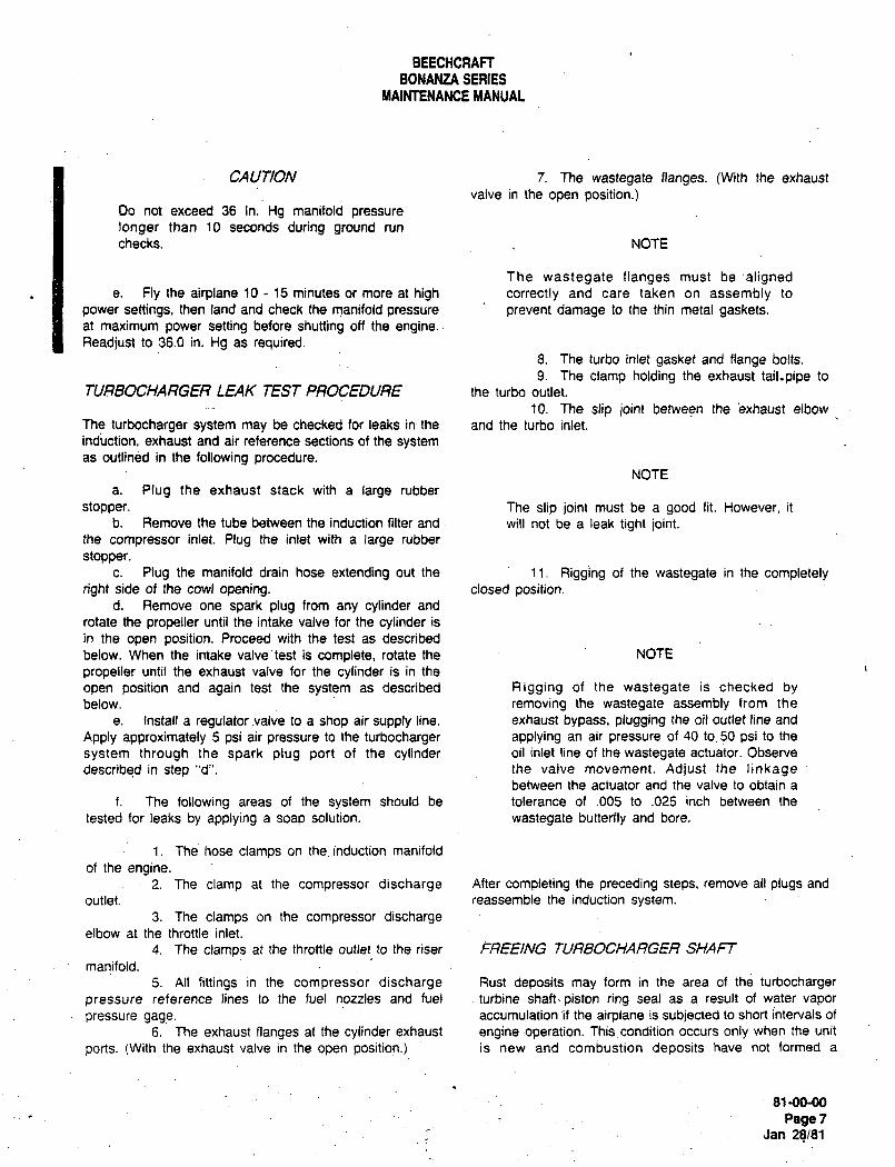
BEECHCRAFTBONANZA SERIES
MAINTENANCE MANUAL
CAUTION 7. The wastegate flanges. (With the exhaust
valve in the open position.)Do not exceed 36 In.Hg manifold pressure
longer than 10 seconds during ground run
checks. NOTE
The wastegate flanges must be’alignede. Fly the airplane 10 15 minutes or more at high correctly and care taken on assembly to
power settings, then land and check the manifold pressure prevent damage to the thin metal gaskets.at maximum power setting before shutting off the engine.Readjust to 36.0 in. Hg as required.
8. The turbo inlet gasket and flange bolts.
9. The clamp holding the exhaust tail.pipe to
TURBOCHARGER LEAK TEST PROCEDURE the turbo outlet.
10. The slip joint between the’exhaust elbow
The turbocharger system may be checked for leaks in the and the turbo inlet.
indiction, exhaust and air reference sections of the systemas´•outlined in the following procedure.
NOTE
a. Plug the exhaust stack with a large rubber
stopper. The slip joint must be a good fit. However, it
b. Remove the tube between the induction filter and will not be a leak tight joint.the compressor inlet. Plug the inlet with a large rubber
stopper.c. Plug the manifold drain hose extending out the 11. Rigging of the wastegate ~in the completely
right side of the cowl opening. closed position.d. Remove one spark plug from any cylinder and
rotate the propeller until the intake valve for the cylinder is
in the open position. Proceed with the test as described
below. When the intake valvetest is complete, rotate the NOTE
propeller until the exhaust valve for the cylinder is in the
open position and again test the system as described Rigging of the wastegate is checked bybelow, removing the wastegate assembly from the
e. Install a regulator valve to a shop air supply line. exhaust bypass, plugging the oil outlet line and
Apply approximately S psi air pressure to the turbocharger applying an air pressure of 40 to 50 psi to the
system through the spark plug port of the cylinder oil inlet line of the wastegate actuator. Observe
described in step "d". the valve movement. Adjust the linkagebetween the actuator and the valve to obtain a
f. The following areas of the system should be tolerance of .005 to .025 inch between the
tested for leaks by applying a soap solution, wastegate butterfly and bore.
1. The hose clamps on the induction manifold
of the engine.2. The clamp at the compressor discharge After completing the preceding steps, remove all plugs and
outlet, reassemble the induction system.
3. The clamps on the compressor dischargeelbow at the throttle inlet.
4. The clamps at the throttle outlet to the riser FREEING TURBOCHARGER SHAFT
manifold.
5. All fittings in the compressor discharge Rust deposits may form in the area of the turbocharger
pressure reference lines to the fuel nozzles and fuel turbine shaft´•piston ring seal as a result of water vapor
pressure gage. accumulation if the airplane is subjected to short intervals of
6. The exhaust flanges at the cylinder exhaust engine:operation. Thiscondition occurs only when the unit
ports. (With the exhaust valve in the open position.) is new and combustion deposits have not formed a
81-00-00
Page 7
Jan 28/81

CHAPTER
CHARTS
Ray~heon Aircraft tompanyBONANZA SERIES MAINTENANCE MANUAL
CHAPTER 91 CHARTS
TABLE OF CONTENTS
SUBJECT PAGE
91-00-00
Charts....................................................................................1
Consumable Materials........._._._._
Installation of Flared Fittings. .....12
A28 91 -CONTENTS Aug 31105Page 1
Raytheon Aircraft CompanyBONANZA SERIES MAINTENANCE MANUAL
CHAPTER 91 CHARTS
LIST OF EFFECTIVE PA GES
CH-SE-SU PAGE DATE
91-LOEP 1 Aug 31/05
91-CONTENTS 1 Aug 31/05
91-00-00 1 thru 12 Aug 31/05
A28 9~-LOEP Aug 31/05Pagel
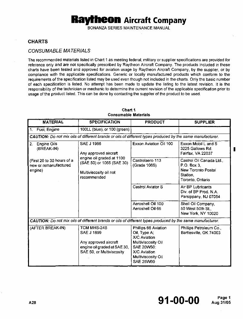
RallheMI nircraft CompanyBONANZA SERIES MAINTENANCE MANUAL
CHARTS
CONSUMABLE MA TERIALS
The recommended materials listed in Chart 1 as meeting federal, military or supplier specifications are provided for
reference only and are not specifically prescribed by Raytheon Aircraft Company. The products included in these
charts have been tested and approved for aviation usage by Raytheon Aircraft Company, by the supplier, or bycompliance with the applicable specifications. Generic or locally manufactured products which conform to the
requirements of the specification listed may be used even though not included in the charts. Only the basic number
of each specification is listed. No attempt has been made to update the listing to the latest revision. It is the
responsibility of the technician or mechanic to determine the current revision of the applicable specification prior to
usage of the product listed. This can be done by contacting the supplier of the product to be used.
Chart 1
Consumable Materials
MATERIAL SPECIFICATION PRODUCT SUPPLIER
1. Fuel,Engine 1 OOLL (blue), or 100 (green)
CAUTION: Do not mix oils of different brands or oils of different types produced by the same manufacturer.
2. EngineOils SAE J 1966 Exxon Aviation Oil 100 Exxon Mobil L and S
(BREAK-IN) 3225 Gallows Rd.
Any approved aircraft Fairfax, VA 22037
engine oil graded at 1100(First 20 to 30 hours of a Castrolaero 113 Castrol Oil Canada Ltd.,
(SAE 50) or 1065 (SAE 30)new or remanufactured (Grade 1065) P.O. Box 3,
engine) New Toronto PostalMultiviscosity oil not
Station,recommended
Toronto, Ontario
Castrol Aviator S Air BP Lubricants
Div. of BP Prod. N.A.
Parsippany, NJ 07054
Aeroshell Oil 100 Shell Oil Company,Aeroshell Oil 65 50 West 50th St.,
New York, NY 10020
CAUTION: Do not mix oils of different brands or oils of different types produced by the same manufacturer.
(AFTER BREAK-IN) TCM MHS-24B Phillips 66 Aviation Phillips Petroleum Co.,SAE J 1899 Oil, Type A; Bartlesville, OK 74003
XIC Aviation
Any approved aircraft Multiviscosity Oil
engineoil graded atSAE 30, SAE 20W50:
SAE 50, or Multiviscosity XIC Aviation
Multiviscosity Oil
SAE 25\1\160
nns 91-00-00 Aug 31105Page 1
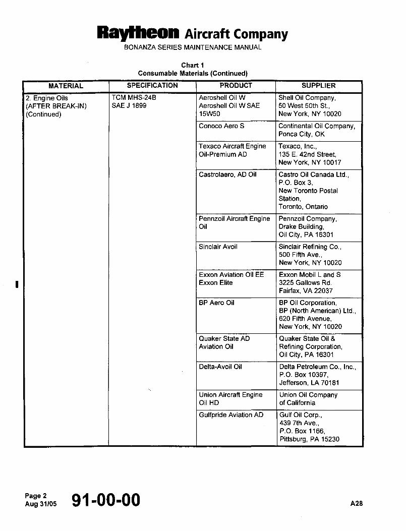
Raytheon AiKraft CompanyBONANZA SERIES MAINTENANCE MANUAL
Chart 1
Consumable Materials (Continued)
MATERIAL SPECIFICATION PRODUCT SUPPLIER
2. Engine Oils TCM MHS-24B Aeroshell Oil W Shell Oil Company,(AFTER BREAK-IN) SAE J 1899 Aeroshell Oil WSAE 50 West 50th St.,
(Continued) 15W50 New York, NY 10020
Conoco Aero S Continental Oil Company,Ponca City, OK
Texaco Aircraft Engine Texaco, Inc.,Oil-Piemium AD 135 E. 42nd Street,
New York, NY 10017
Castrolaero, AD Oil Castro Oil Canada Ltd.,P.O. Box 3,New Toronto Postal
Station,Toronto, Ontario
Pennzoil Aircraft Engine Pennzoil Company,Oil Drake Building,
oil City, PA 16301
Sinclair Avoil Sinclair Refining Co.,500 Fifth Ave.,New York, NY 10020
Exxon Aviation Oil EE Exxon Mobil L and S
Exxon Elite 3225 Gallows Rd.
Fairfax, VA 22037
BP Aero Oil BP Oil Corporation,BP (North American) Ltd.,620 Fifth Avenue,New York, NY 10020
Quaker State AD Quaker State Oil 8
Aviation Oil Refining Corporation,oil City, PA 16301
Delta-Avoil Oil Delta Petroleum Co., Inc.,P.O. Box 10397,Jefferson, LA 70181
Union Aircraft Engine Union Oil CompanyOil HD of California
Gulfpride Aviation AD Gulf Oil Corp.,439 7th Ave.,P.O. Box 1166,Pittsburg, PA 15230
Aug 31105Page 2 91-00-00 A28
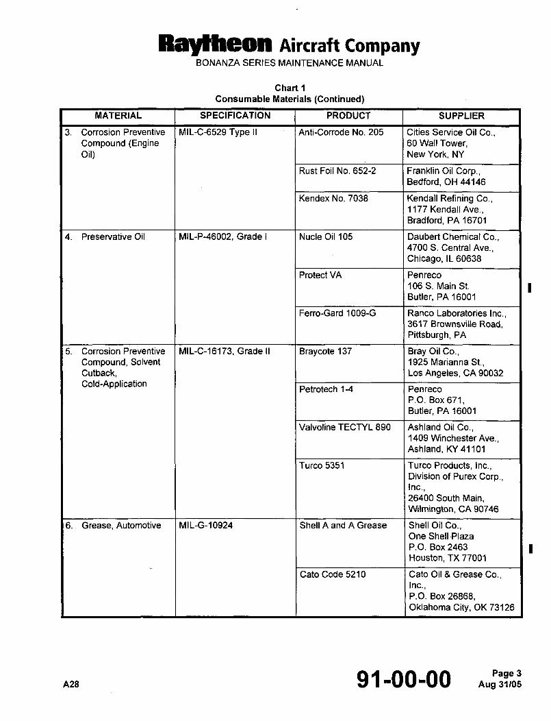
RBytheOn Aircraft CompanyBONANZA SERIES MAINTENANCE MANUAL
Chart 1
Consumable Materials (Continued)
MATERIAL SPECIFICATION PRODUCT SUPPLIER
3. Corrosion Preventive MIL-C-6529 Type II I Anti-Corrode No. 205 Cities Service Oil Co.,Compound (Engine 60 Wall Tower,Oil) New York, NY
Rust Foil No. 652-2 Franklin Oil Corp.,Bedford, OH 44146
Kendex No. 7038 Kendall Refining Co.,1177 Kendall Ave.,Bradford, PA 16701
4. Preservative Oil MIL-P-46002, Grade I Nude Oil 105 Daubert Chemical Co.,4700 S. Central Ave.,Chicago, IL 60638
Protect VA Penreco
106 S. Main St.
Butler, PA 16001
Ferro-Gard 1009-G Ranco Laboratories Inc.,3617 Brownsville Road,Pittsburgh, PA
5. Corrosion Preventive MIL-C-16173, Grade II Braycote 137 Bray Oil Co.,Compound, Solvent 1925 Marianna St.,Cutback, Los Angeles, CA 90032
Cold-Application I I Petrotech 1-4 1 Penreco
P.O. Box 671,Butler, PA 16001
Valvoline TECTYL 890 Ashland Oil Co.,1409 Winchester Ave.,Ashland, KY 41101
Turco 5351 Turco Products, Inc.,Division of Purer Corp.,Inc.,26400 South Main,W~lmington, CA 90746
6. Grease, Automotive MIL-G-10924 Shell A and A Grease Shell Oil Co.,One Shell´•Plaza
P.O. Box 2463
Houston, TX 77001
Cato Code 5210 Cato Oil 8 Grease Co.,Inc.
P.O. Box 26868,Oklahoma City, OK 73126´•
A28 91-00-00 3
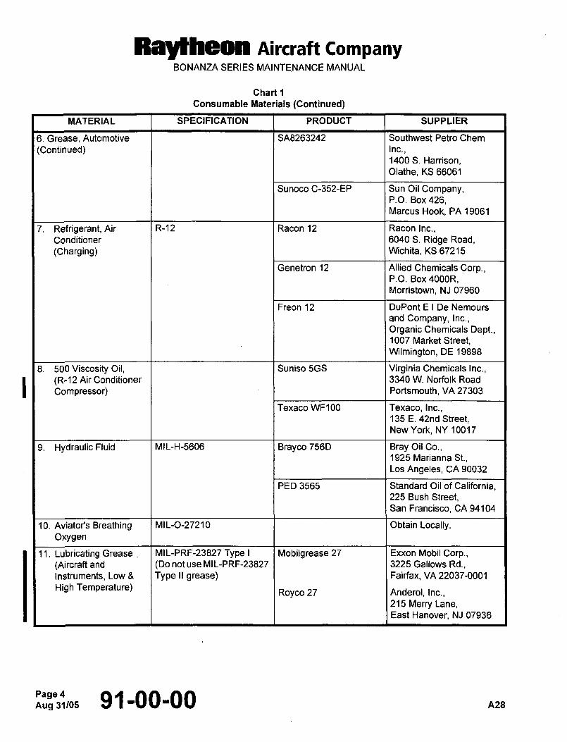
Raylheon Aircraft CompanyBONANZA SERIES MAINTENANCE MANUAL
Chart 1
Consumable Materials (Continued)
MATERIAL SPECIFICATION PRODUCT SUPPLIER
6. Grease, Automotive SA8263242 Southwest Petro Chem
(Continued) Inc.,1400 S. Harrison,Olathe, KS 66061
Sunoco C-352-EP Sun Oil Company,P.O. Box 426,Marcus Hook, PA 19061
7. Refrigerant, Air R-12 Racon 12 Racon Inc.,Conditioner 6040 S. Ridge Road,
(Charging) Wichita, KS 67215
Genetron 12 Allied Chemicals Corp.,P.O. Box 4000R,Morristown, NJ 07960
Freon 12 DuPont E I De Nemours
and Company, Inc.,
Organic Chemicals Dept.,1007 Market Street,Wilmington, DE 19898
8. 500Viscosity Oil, Suniso 5GS Virginia Chemicals Inc.,
I (R-12 Air Conditioner 3340 W. Norfolk Road
Compressor) Portsmouth, VA 27303
Texaco WF100 Texaco, Inc.,135 E. 42nd Street,New York, NY 10017
9. Hydraulic Fluid MIL-H-5606 Brayco 756D Bray Oil Co.,1925 Marianna St.,Los Angeles, CA 90032
FED 3565 Standard Oil of California,225 Bush Street,San Francisco, CA 94104
10. Aviator’s Breathing MIL-0-27210 Obtain Locally.Oxygen
11. Lubricating Grease MIL-PRF-23827 Type I Mobilgrease 27 Exxon Mobil Corp.,(Aircraft and (Do not use MIL-PRF-23827 3225 Gallows Rd.,
Instruments, Low 8 Type II grease) Fairfax, VA 22037-0001
High Temperature)Royco 27 Anderol, Inc.,
215 Merry Lane,East Hanover, NJ 07936
Aug 31105Page 4 91-00-00 A28
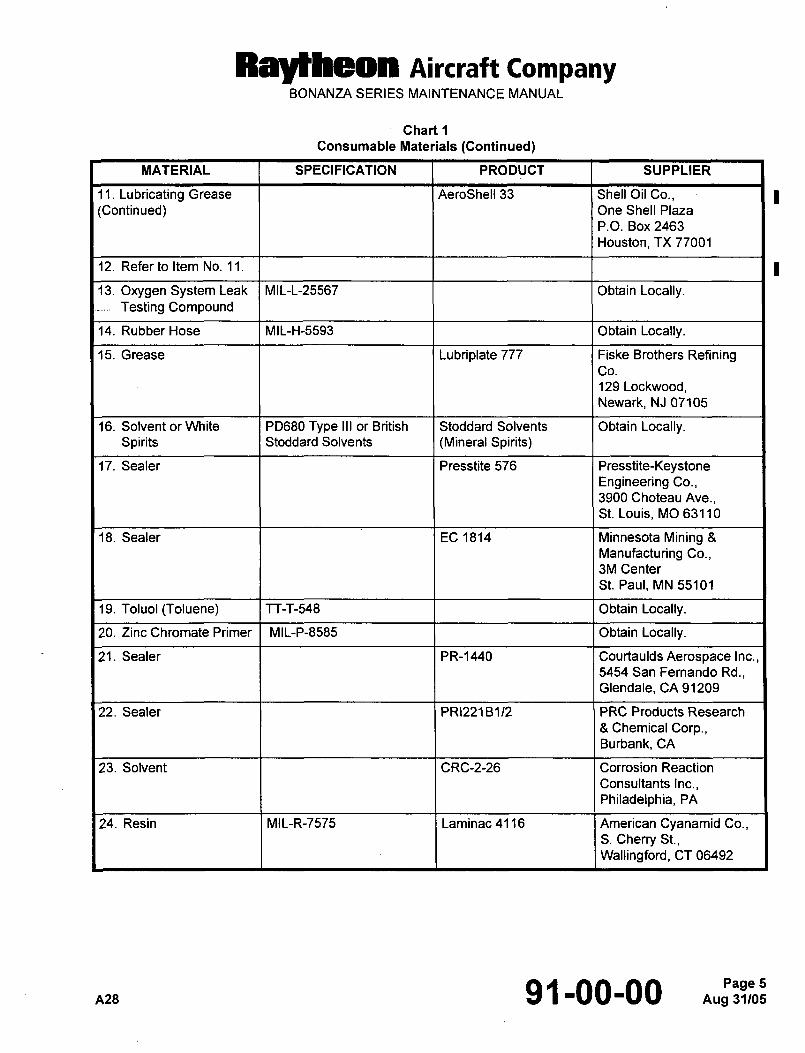
Raytheon Aircraft CompanyBONANZA SERIES MAINTENANCE MANUAL
Chart 1
Consumable Materials (Continued)
MATERIAL SPECIFICATION PRODUCT SUPPLIER
11. Lubricating Grease AeroShell 33 Shell Oil Co.,(Continued) One Shell Plaza
P.O. Box 2463
Houston, TX 77001
12. Refer to Item No. 11.
13. Oxygen System Leak MIL-L-25567 Obtain Locally.Testing Compound
14. Rubber Hose MIL-H-5593 Obtain Locally.
15. Grease Lubriplate 777 Fiske Brothers RefiningCo.
129 Lockwood,Newark, NJ 07105
16. Solvent or White PD680 Type III or British Stoddard Solvents Obtain Locally.Spirits Stoddard Solvents (Mineral Spirits)
17. Sealer Presstite 576 Presstite-KeystoneEngineering Co.,3900 Choteau Ave.,St. Louis, MO 63110
18. Sealer EC 1814 Minnesota Mining 8
Manufacturing Co.,3M Center
St. Paul, MN 55101
19. Toluol (Toluene) TT-T-548 Obtain Locally.
20. Zinc Chromate Primer MIL-P-8585 I I Obtain Locally.
21. Sealer PR-1440 Courtaulds Aerospace Inc.,5454 San Fernando Rd.,Glendale, CA 91209
22. Sealer PR122?B112 PRC Products Research
8 Chemical Corp.,Burbank, CA
23. Solvent CRC-2-26 Corrosion Reaction
Consultants Inc.,Philadelphia, PA
24. Resin MIL-R-7575 Laminac4116 American Cyanamid Co.,S. Cherry St.,Wallingford, CT 06492
A28 91-00-00 5
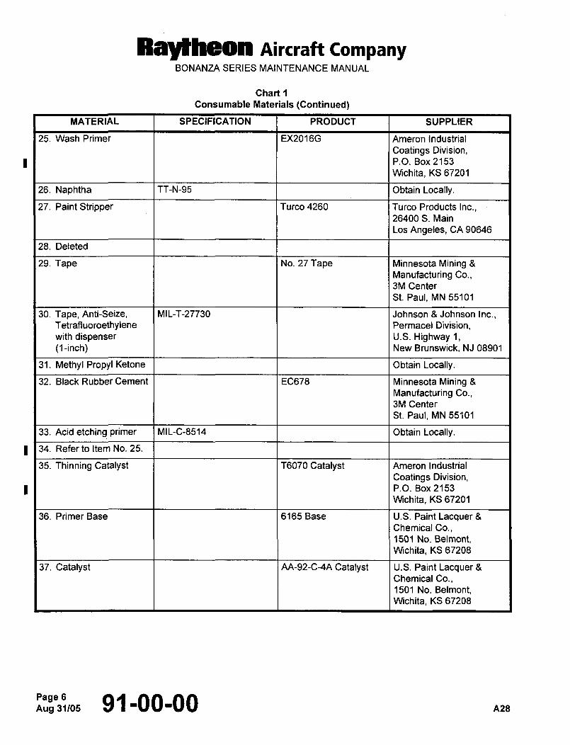
Ray~heon Aircraft CompanyBONANZA SERIES MAINTENANCE MANUAL
Chart 1
Consumable Materials (Continued)
MATERIAL SPECIFICATION PRODUCT SUPPLIER
25. Wash Primer EX2016G Ameron Industrial
Coatings Division,P.O. Box 2153
Wichita, KS 67201
26. Naphtha TT-N-95 Obtain Locally.
27. Paint Stripper Turco 4260 Turco Products Inc.,26400 S. Main
Los Angeles, CA 90646
28. Deleted
29. Tape No. 27 Tape ’I Minnesota Mining 8
Manufacturing Co.,3M Center
St. Paul, MN 55101
30. Tape, Anti-Seize, MIL-T-27730 Johnson 8 Johnson Inc.,Tetrafiuoroethylene Permacel Division,with dispenser U.S. Highway 1,(1-inch) New Brunswick, NJ 08901
31. Methyl Propyl Ketone Obtain Locally.
32. Black Rubber Cement EC678 Minnesota Mining 8
Manufacturing Co.,3M Center
St. Paul, MN 55101
33. Acid etching primer MIL-C-8514 Obtain Locally.
34. Refer to Item No. 25.
35. Thinning Catalyst T6070 Catalyst Ameron Industrial
Coatings Division,P.O. Box 2153
W~chita, KS 67201
36. Primer Base 6165 Base U.S. Paint Lacquer 8
Chemical Co.,1501 No. Belmont,Wichita, KS 67208
37. Catalyst AA-92-C-4A Catalyst U.S. Paint Lacquer 8
Chemical Co.,1501 No. Belmont,Wichita, KS 67208
Aug 31105Page 6 91-00-00 nzB
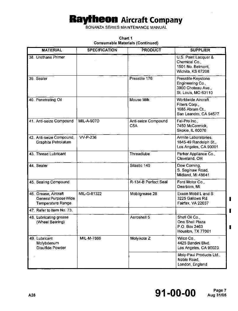
Raytheon Aircraft CompanyBONANU~ SERIES MAINTENANCE MANUAL
Chart 1
Consumable Materials (Continued)
MATERIAL SPECIFICATION PRODUCT SUPPLIER
38. Urethane Primer U.S. Paint LacquerChemical Co.,1501 No. Belmont,Wichita, KS 67208
39. Sealer Presstite 176 Presstite-KeystoneEngineering Co.,3900 Choteau Ave.,St. Louis, MO 63110
40. Penetrating Oil Mouse Milk Worldwide Aircraft
Filters Corp.,1685 Abram Ct.,San Leandro, CA 94577
41. Anti-seize Compound MIL-A-907D Anti-seize Compound Fel-Pro Inc.,C5A 7450 McCormick,
Skokie, IL 60076
42. Anti-seize Compound, VV-P-236 Armite Laboratories,Graphite Petrolatum 184549 Randolph St.,
Los Angeles, CA 90001
43. Thread Lubricant Threadlube Parker Appliance Co.,Cleveland, OH
44. Sealer Silastic 140 Dow Coming,S. Saginaw Road,Midland, M1 48641
45. Sealing Compound R-134-B Perfect Seal Ford Motor Co.,Dearborn, MI
46. Grease, Aircraft MIL-G-81322 Mobilgrease 28 Exxon Mobil L and S
GeneralPurposeWide I ~I 1 3225 Gallows Rd.
Temperature Range Fairfax, VA 22037
47. Refer to Item No. 73.
48. Lubricating grease Aeroshell 5 Shell Oil Co.,
(Wheel Bearing) One Shell Plaza
P.O. Box 2463
Houston, TX 77001
49. Lubricant MIL-M-7866 Molyikote 2 Wilco Co.,
Molybdenum 4425 Bandini Blvd.
Disulfide Powder Los Angeles, CA 90023
Moly-Paul Products Ltd.,Noble Road,London, England
A28 91-00-00 7
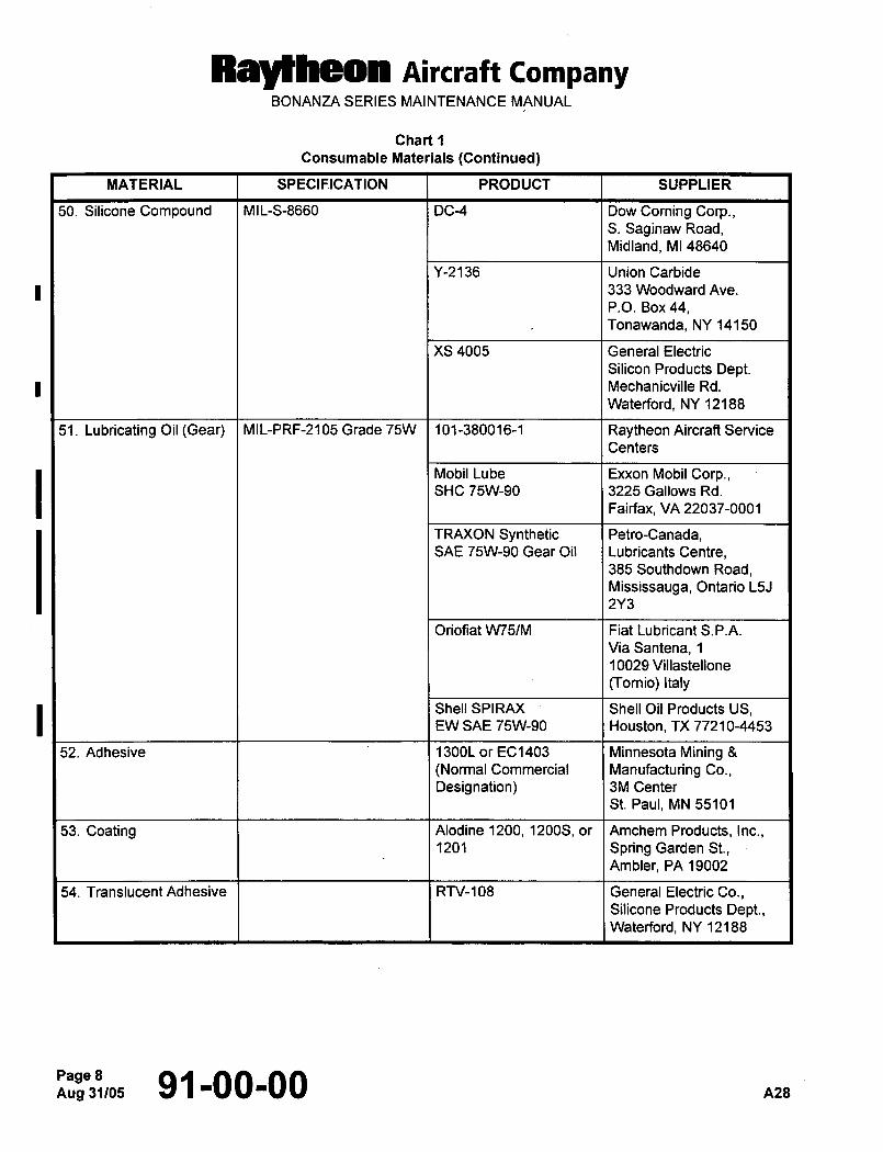
Raytheon Aircraft CompanyBONANZA SERIES MAINTENANCE MANUAL
Chart 1
Consumable Materials (Continued)
MATERIAL SPECIFICATION PRODUCT SUPPLIER
50. Silicone Compound MIL-S-8660 DC-4 Dow Coming Corp.,S. Saginaw Road,Midland, MI 48640
Y-2136 Union Carbide
333 Woodward Ave.
P.O. Box 44,Tonawanda, NY 14150
XS 4005 General Electric
Silicon Products Dept.Mechanicville Rd.
Waterford, NY 12188
51. Lubricating Oil (Gear) MIL-PRF-2105 Grade 75W 101-380016-1 Raytheon Aircraft Service
Centers
Mobil Lube Exxon Mobil Corp.,SHC 75\1\1-90 3225 Gallows Rd.
Fairfax, VA 22037-0001
TRAXON Synthetic Petro-Canada,SAE 75\1\1-90 Gear Oil Lubricants Centre,
385 Southdown Road,Mississauga, Ontario L5J
2Y3
Oriofiat W15/M Fiat Lubricant S.P.A.
Via Santena, 1
10029 Villastellone
(Tornio)ltaly
Shell SPIRAX I Shell Oil Products US,EW SAE 75\1\1-90 Houston, TX 77210-4453
52. Adhesive I I 1300L or EC1403 Minnesota Mining 8
(Normal Commercial Manufacturing Co.,
Designation) 3M Center
St. Paul, MN 55101
53. Coating Alodine 1200, 1200S, or Amchem Products, Inc.,1201 Spring Garden St.,
Ambler, PA 19002
54. Translucent Adhesive RN-108 I General Electric Co.,Siiicone Products Dept.,Waterford, NY 12188
Aug 31/05Page 8 91-00-00 A28
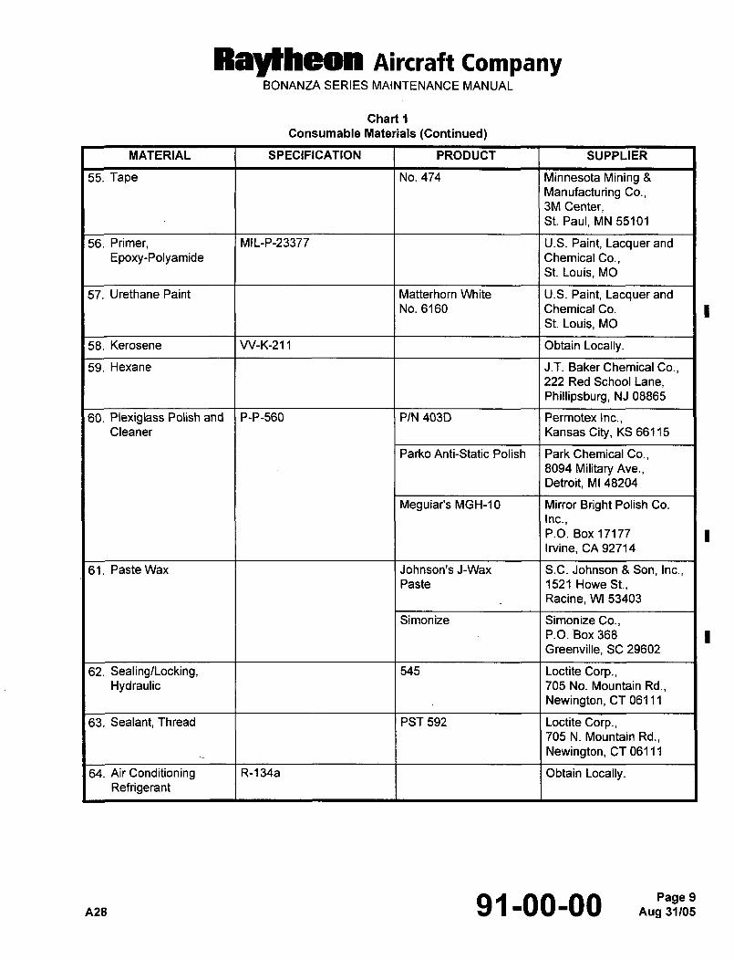
Ral~heon Aircraft CompanyBONANZA SERIES MAINTENANCE MANUAL
Chart 1
Consumable Materials (Continued)
MATERIAL SPECIFICATION PRODUCT SUPPLIER
55. Tape No. 474 Minnesota Mining 8
Manufacturing Co.,3M Center,St. Paul, MN 55101
56. Primer, MIL-P-23377 U.S. Paint, Lacquer and
Epoxy-Polyamide ChemicalCo.,St. Louis, MO
57. Urethane Paint Matterhorn White U.S. Paint, Lacquer and
No. 6160 Chemical Co.
St. Louis, MO
58. Kerosene W-K-211 Obtain Locally.
59. Hexane J.T. Baker Chemical Co.,222 Red School Lane,
Phillipsburg, NJ 08865
60. Plexiglass Polish and P-P-560 PIN 403D Permotex Inc.,Cleaner Kansas City, KS 66115
Parko Anti-Static Polish Park Chemical Co.,8094 Military Ave.,
Detroit, MI 48204
Meguiar’s MGH-10 Mirror Bright Polish Co.
Inc.,P.O. Box 17177
Irvine, CA 92714
61. Paste Wax Johnson’s J-Wax S.C. Johnson 8 Son, Inc.,Paste 1521 Howe St.,
Racine, WI 53403
Simonize Simonize Co.,P.O. Box 368
Greenville, SC 29602
62. Sealing/Locking, 545 Loctite Corp.,Hydraulic 705 No. Mountain Rd.,
Newington, CT 06111
63. Sealant, Thread PST 592 Loctite Corp.,705 N. Mountain Rd.,
Newington, CT 06111
64. Air Conditioning R-134a Obtain Locally.Refrigerant
A28 91-00-00 Aug 31105Page 9
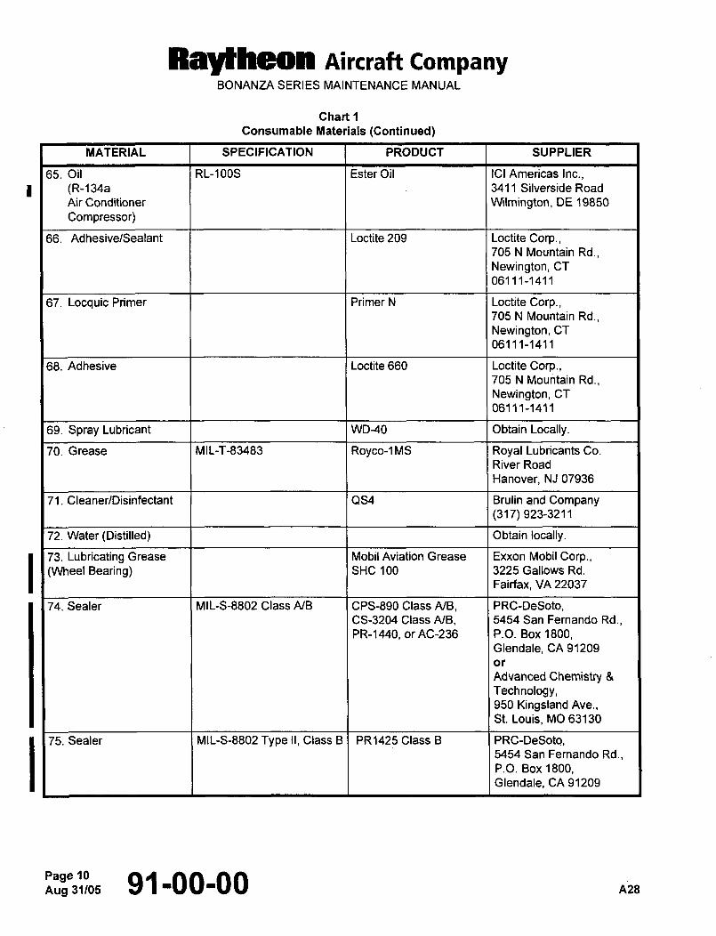
Raytheon Aircraft CompanyBONANZA SERIES MAINTENANCE MANUAL
Chart 1
Consumable Materials (Continued)
MATERIAL SPECIFICATION PRODUCT SUPPLIER
65. Oil RL-100S Ester Oil ICI Americas Inc.,(R-134a I 1 3411 Silverside Road
Air Conditioner W~lmington, DE 19850
Compressor)
66. Adhesive/Sealant Loctite 209 Loctite Corp.,705 N Mountain Rd.,
Newington, CT
06111-1411
67. Locquic Primer Primer N Loctite Corp.,705 N Mountain Rd.,
Newington, CT
06111-1411
68. Adhesive Loctite 660 Loctite Corp.,705 N Mountain Rd.,
Newington, CT
06111-1411
69. Spray Lubricant WD-40 Obtain Locally.
70. Grease MIL-T-83483 Royco-1MS Royal Lubricants Co.
River Road
Hanover, NJ 07936
71. Cleaner/Disinfectant QS4 Brulin and Company(317) 923-3211
72. Water (Distilled) Obtain locally.
73. Lubricating Grease I I Mobil Aviation Grease Exxon Mobil Corp.,(Wheel Bearing) SHC 100 3225 Gallows Rd.
Fairfax, VA 22037
74. Sealer MIL-S-8802 Class A/B CPS-890 Class A/B, PRC-DeSoto,CS-3204 Class A/B, 5454 San Fernando Rd.,PR-1440, or AC-236 P.O. Box 1800,
Glendale, CA 91209
or
Advanced Chemistry 8
Technology,950 Kingsland Ave.,St. Louis, MO 63130
75. Sealer MIL-S-8802 Type II, Class B PR1425 Class B PRC-DeSoto,5454 San Fernando Rd.,P.O. Box 1800,Glendale, CA 91209
Aug 31105~3:5, 91-00-00 A28
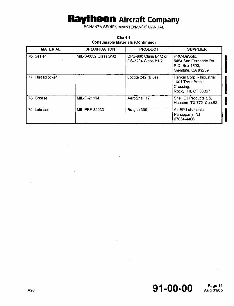
RBI~LOMI Aircraft CompanyBONANZA SERIES MAINTENANCE MANUAL
Chart 1
Consumable Materials (Continued)
MATERIAL SPECIFICATION PRODUCT SUPPLIER
76. Sealer MIL-S-8802 Class 81/2 CPS-890 Class 8112 or PRC-DeSoto,CS-3204 Class 81/2 5454 San Fernando Rd.,
P.O. Box 1800,Glendale, CA 91209
77. Threadlocker Loctite 242 (Blue) Henkel Corp. Industrial,1001 Trout Brook
Crossing,Rocky Hill, CT 06067
78. Grease MIL-G-21164 AeroShell 17 Shell Oil Products US,Houston, TX 77210-4453
79. Lubricant MIL-PRF-32033 Brayco 300 Air BP Lubricants,
Parsippany, NJ
07054-4406
A28 91-00-00 Aug 31405Page 11
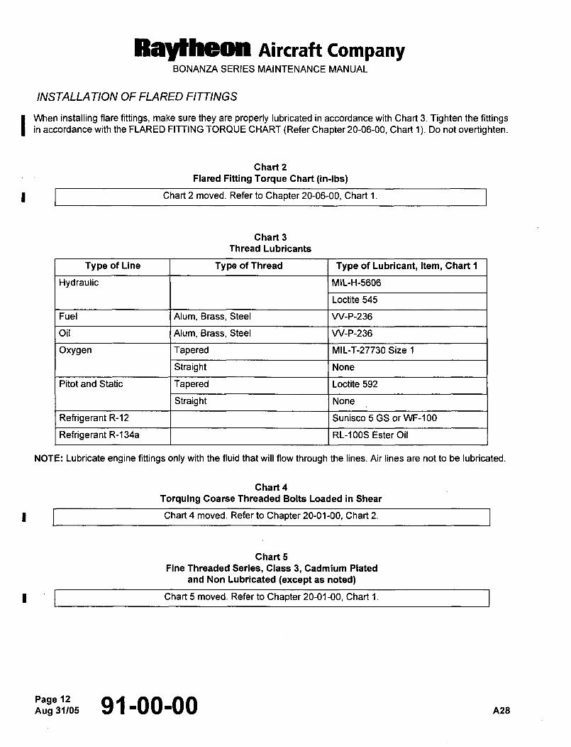
BaldNa(Hl Aircraft CompanyBONANZA SERIES MAINTENANCE MANUAL
INSTALLA TION OF FLARED FITTINGS
I When installing flare fittings, make sure they are properly lubricated in accordance with Chart 3. Tighten the fittingsin accordance with the FLARED FITTING TORQUE CHART (Refer Chapter 20-06-00, Chart 1). Do not overtighten.
Chart 2
Flared Fitting Torque Chart (in-lbs)
Chart 2 moved. Refer to Chapter 20-06-00, Chart 1.
Chart 3
Thread Lubricants
Type of Line Type of Thread Type of Lubricant, Item, Chart 1
Hydraulic MIL-H-5606
Loctite 545
Fuel Alum, Brass, Steel W-P-236
Oil Alum, Brass, Steel W-P-236
Oxygen Tapered MIL-T-27730 Size 1
Straight None
Pitot and Static Tapered Loctite 592
Straight None
Refrigerant R-12 Sunisco 5 GS or WF-100
Refrigerant R-134a RL-100S Ester Oil
NOTE: Lubricate engine fittings only with the fluid that will flow through the lines. Air lines are not to be lubricated.
Chart 4
Torquing Coarse Threaded Bolts Loaded in Shear
Chart 4 moved. Refer to Chapter 20-01-00, Chart 2.
Chart 5
Fine Threaded Series, Class 3, Cadmium Plated
and Non Lubricated (except as noted)
Chart 5 moved. Refer to Chapter 20-01-00, Chart 1.
Aug 91-00-00 nzs