Embed Size (px)
Citation preview
www.me‐journal.org Journal of Metallurgical Engineering (ME) Volume 4, 2015
doi: 10.14355/me.2015.04.003
18
Effect of Manganese Sulphide Shapes on the
Work‐hardening Coefficient of Hot Rolled
Structural Steel Ahmed I. Z. Farahat, Zainab Abdel‐hamid and Nasser Gomaa
Central Metallurgical Research and Development Institute, CMRDI, P.O.Box 87 Helwan, Egypt
Abstract
This paper studied the effect of non‐metallic inclusions shapes (manganese sulphides on the tensile testing behavior, the work‐
hardening coefficient and rate. Longitudinal and Transverse tensile testing was carried out. The fracture surface was studied
after tensile testing. Chemical analysis for the non‐metallic solution was conducted using EDS‐SEM. Tensile testing was carried
out in thickness direction and in parallel to the direction of rolling. The work‐hardening coefficient (with tensile samples of the
thickness) increases with the types II and III. It is found that the work‐hardening rate for types of non‐metallic inclusions is
similar and has critical change. It is also observed that the non‐metallic inclusions Type II and III can resist the crack
propagation due to crack tip or plastic zone at the onset of crack.
Keywords
Non‐Metallic Inclusions Shapes, Longitudinal And Transverse Tensile Testing, Fracture Surface, Work‐Hardening Coefficient
Introduction
Non‐metallic inclusions are very harmful in steel practice. After Oxygen, Sulpher is the most important non‐
metallic element in the field of steel metallurgy [1]. Therefore, sulphides form a second important group of
inclusions. Morphology of suphides inclusions has significant effect on the various properties of steels [2].
1. Sulfides are precipitated during solidification due to the solute elements (such as Mn and S) segregation;
2. Sulfides are precipitated during the δ ̸γ transformation due to the redistribution of solute elements and the
different sulfide solubility in δ‐Fe and γ‐Fe;
3. Sulfides are precipitated in γ‐Fe due to the decrease in solubility of sulfur in the matrix with decreasing
temperature;
4. Sulfides are precipitated during the γ/α transformation due to the difference of sulfur solubility in γ‐Fe and
α‐Fe.
Simms and Dhale, in 1938, classified the non‐metallic inclusions into three types depending on the morphology of
manganese sulphides [3]:
1. Type I that exist when there is practically no aluminum content, usually in silicon‐killed steels.
2. Type II is that appear with the first traces of aluminum, above 0.005 wt%.
3. Type III is that initially appears alongside type II at levels of 0.01 to 0.03 wt% total aluminum.
4. Type III is practically assured as the only type to occur with total aluminum of ≈0.04 wt%.
The type of manganese sulphide inclusions in wrought steels depends on the type of sulphide formed in the
original cast steel.
Type I manganese sulphide inclusions are much harder than the other types. During rolling, type I manganese
sulphide deforms to a ʹlozengeʹ shape. Any silicates usually deform more, ending up at the tips of the lozenge [4].
Elongated (Types II and III) inclusions also act as initiation sites for lamellar tearing. Farrar in 1979 found that

Journal of Metallurgical Engineering (ME) Volume 4, 2015 www.me‐journal.org
19
lamellar tearing could also be initiated by type I manganese sulphides, but the volume fraction of Type I
manganese sulphides required for initiation was very high, and such a high level of only type I inclusions is
unlikely to be found in structural steels. In such (high oxygen) steels, susceptibility to lamellar tearing is generally
controlled by oxides [5,6].
The final shape of the inclusions in wrought steel is particularly important with reference to hydrogen induced
cracking in sour service and lamellar tearing [7,8]. The elongated manganese sulphide inclusions in wrought steel
(Type II, III) act as initiation sites for hydrogen induced cracking in sour (H2S containing) environments. However,
type I manganese sulphide inclusions have been reported to trap hydrogen, inhibiting hydrogen diffusion and thus
inhibiting hydrogen induced cracking both at the initiation and propagation stage. Types II and III MnS inclusions
become much more elongated than type I upon rolling [9].
It is much more difficult to distinguish between these types in wrought steels than in cast steels. Type II is
characteristically in clusters, rather than isolated inclusions [10].
Hydrogen induced cracking (HIC) and sulphide stress cracking (SSC) represent two kinds of a specific hydrogen
provoked damage that are frequently met in petroleum and refinery industry. In the first case (HIC), it is generally
recognized that resistance of steels depends mainly on their microstructure features‐non‐metallic inclusions and
segregation bands. Elongated manganese sulphides are considered as the most dangerous initiation sites [4,11]. In
the second case sulphide stress cracking (SSC), it is believed that resistance of steels can be preferentially related to
their strength level while microstructure characteristics are less important [5‐8, 10, 12].
Manganese sulphide inclusions are responsible for the initiation coarse micro‐voids as a result of the separation of
the inclusion matrix interface. The subsequent growth of micro‐voids and the propagation of the cleavage cracks
depend on effective ferrite grain size and matrix strength [13].
This paper is a trial to detect the effect of sulphide shape on the opening of cracks especially in the direction of
rolling and thickness and to compare their work‐hardening coefficients.
Experimental Work
The Received Material
Plate of heats of steel with the thick plate were received and used for experimental studies. The chemical
composition of the studied heats is given in Table 1
TABLE 1CHEMICAL COMPOSITION OF STEEL (WT%)
Sample C Si Mn P S Al
1 0.172 0.267 1.69 0.0065 0.0086 0.0403
2 0.170 0.265 1.71 0.0600 0.0080 0.0401
3 0.171 0.270 1.68 0.0063 0.0084 0.0400
The tensile testing was carried out at room temperature to determine the tensile strength in the rolling direction
and in the thickness direction to evaluate the effect of non‐metallic inclusions on the work‐hardening coefficient.
Polished samples were metallographically prepared to determine the non‐metallic inclusions type and size. Optical
and SEM microstructure were used to recognize the different phases. The ASTM standard (E45‐97) was used to
recognize and to compare the different size of non‐metallic inclusions for the received plates. ASTM E8 ‐ Standard
Test Methods for Tension Testing of Metallic Materials was used to machine the tensile specimens. The tensile rate
was 5mm/minutes.
Optical Microstructure
The microstructure consists of ferrite (white phase) and pearlite (dark phase) as shown in Figs.1&2. The matrix
consists of banded layers of ferrite and pearlite.

ww
20
FI
No
Op
It i
ww.me‐journa
IG.1 OPTICAL M
FERRITR‐P
M
on‐METALLIC
ptical metallo
is found that
FIG.3
al.org
MICROSTRUCT
PEARLITR DUE
MANGGANESE
C Micrograph
ographic obs
t about 74% o
3 OPTICAL MIC
FIG
TURE CONTAI
E TO HOT ROL
E SEGREGATIO
hs FOR THE Re
servation rev
of non‐metal
CROGRAPHS O
G.4 HISTOGRA
INING BANDS
LLING AND
ON
eceived Samp
vealed that sa
llic inclusion
OF NON‐META
AM OF NON‐ME
J
OF
ples
ample 1 has
ns exhibit ≤10
ALLIC INCLUS
ETALLIC INCL
Journal of Met
FIG.2. SEM MI
non‐metallic
0μm as demo
IONS (TYPE I)
LUSIONS TYPE
tallurgical Eng
ICROSTRUCTU
PEAR
c inclusions o
onstrated in F
AT DIFFERENT
I FOR SAMPL
gineering (ME
URE CONTAIN
RLITR
of Type I as
Fig.4.
T ZONES SAMP
LE 1
E) Volume 4, 2
ING FERRITR‐
shown in Fi
PLE 1
2015
g.3.

Jou
SE
Th
che
Mi
mi
che
F
urnal of Metall
EM Micrograp
he SEM micr
emical comp
icrograph (F
icrographs ex
emical analy
FIG.6 SEM ANG
lurgical Engin
phs for the R
rographs em
position is ma
FIG
Fig.6) of sam
xhibit that th
ysis emphasiz
GULAR SHAPE
(TYPE III) F
neering (ME) V
Received Sam
mphasize the
ainly Fe, Mn
G5 SEM GLOBU
mple 2 clarif
he non‐metal
zes that the n
ES OF MANGAN
FOR SAMPLE 3
Volume 4, 201
mples
optical mic
n and S.
ULAR SHAPES
fies that the
llic inclusion
non‐metallic
NESE SULPHID
15
crographs (ty
OF MANGAN
e non‐metall
ns of the hot
is manganes
DES FIG
ype I) for sa
NESE SULPHIDE
lic inclusion
rolled samp
se sulphide (
G.7 EDS‐SEM A
ample 1 as d
ES FOR SAMPL
s are type I
les are type I
(See Fig.7).
ANALYSIS OF N
TYPE III FOR
www
demonstrate
LE 1
II. For samp
III as appare
NON‐METALLI
R SAMPLE 3
w.me‐journal.
ed in Fig.5. T
ple 3, the S
ent in Fig.8. T
IC INCLUSION
org
21
The
EM
The
NS

ww
22
Z T
Z t
ten
SE
Fig
F
SE
Fig
sul
ww.me‐journa
Tensile Te
testing was p
nsile on thick
EM Fracture o
gure 8 and 9
GENERAL VI
FIG.8 SEM GLO
EM Fracture Z
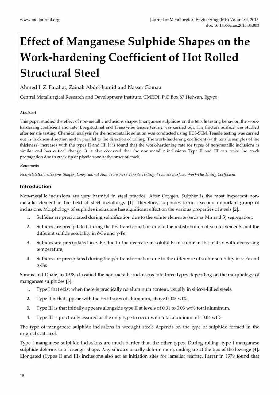
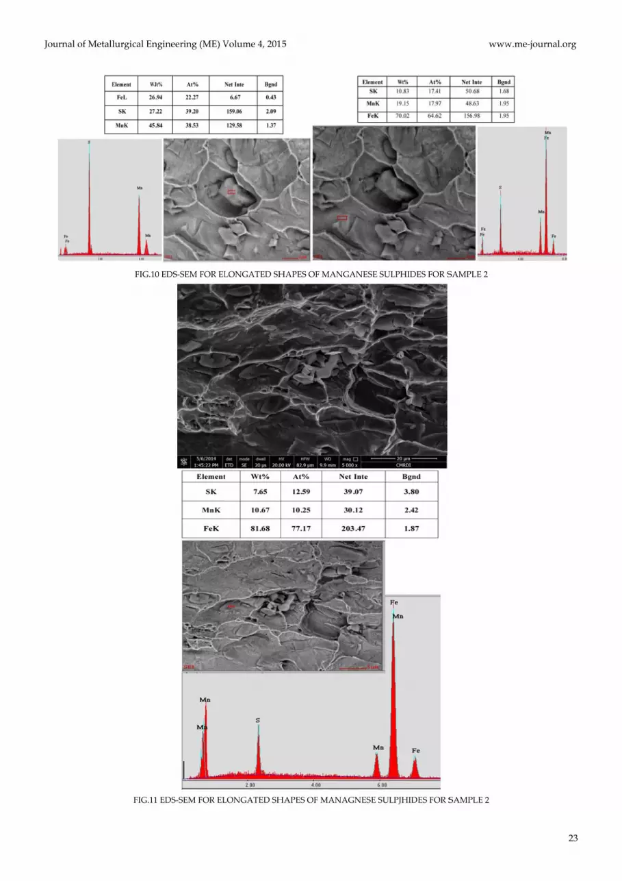
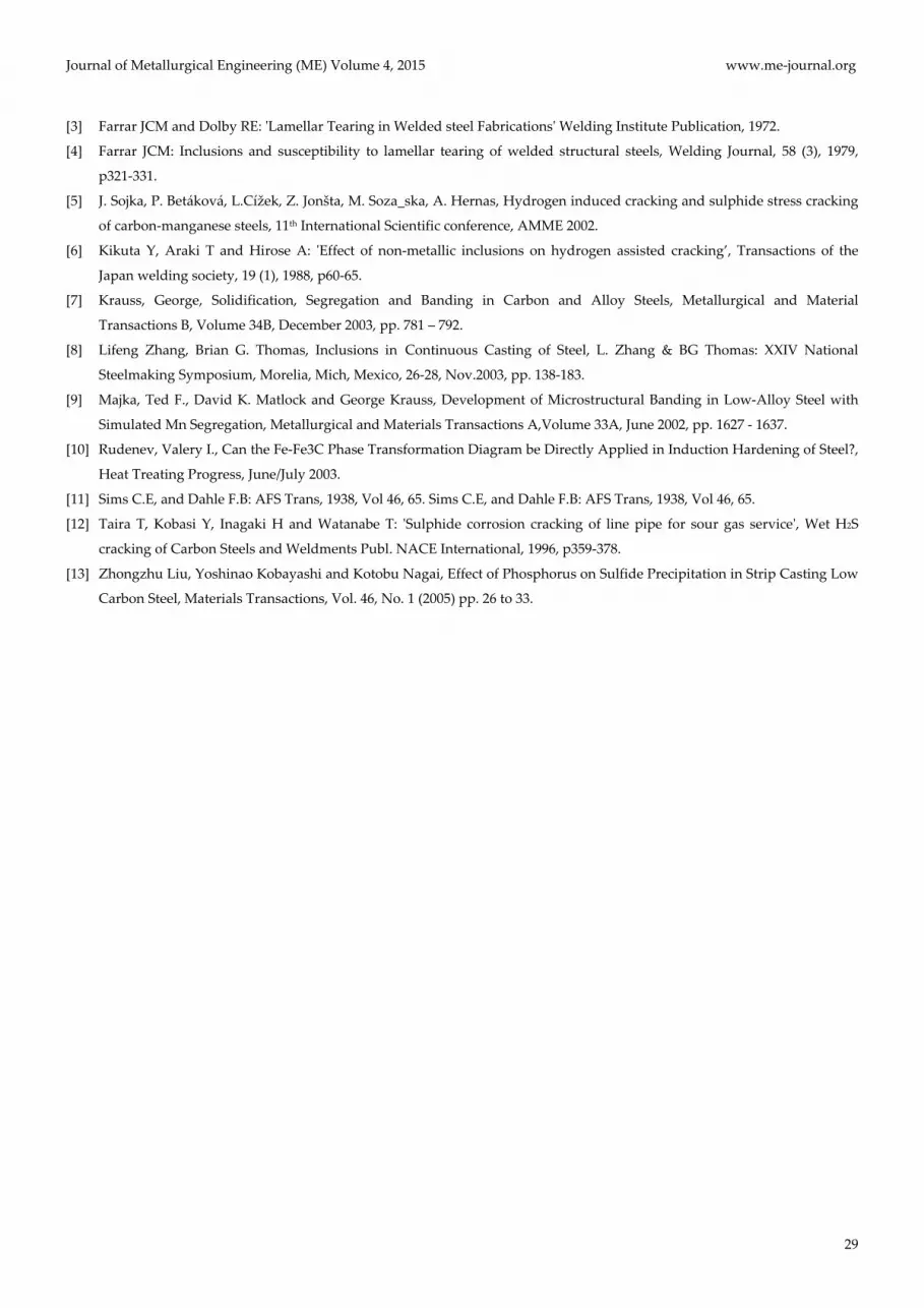
gure 10 and
lphide.
al.org
esting of C
performed to
kness sample
of Z‐Tensile
show the to
IEW OF FRACT
OBULAR SHAP
Z‐of Tensile
11 demonstr
Cross Secti
o recognize
es.
Test for 42%
opography fo
TURE SURFACE
PE OF MANGAN
Test for Frac
rate fracture
Globu
ion Evalua
the effect of
% Reduction o
or fracture o
E FOR SAMPLE
NESE SULPHID
cture Of 20%
e surface of Z
ular shape
J
ation
f manganese
of Sample 1
of Z‐tensile s
E 1
DES
FI
% Reduction
Z‐tensile sur
Journal of Met
sulphides o
ample. The m
IG.9 EDS‐SEM F
of Sample 2
rface for sam
tallurgical Eng
on the value
manganese s
FOR GLOBULA
SULPHIDES FO
mple 2. It clar
gineering (ME
of reduction
sulphide is s
AR SHAPES OF
OR SAMPLE 1
arifies elonga
E) Volume 4, 2
n of area due
spherical typ
MANGANESE
ated mangan
2015
e to
pe I.
E
nese
Jouurnal of Metalllurgical Engin
FIG.10 ED
FIG.11 ED
neering (ME) V
DS‐SEM FOR EL
DS‐SEM FOR EL
Volume 4, 201
LONGATED SH
LONGATED SH
15
HAPES OF MAN
HAPES OF MAN
NGANESE SUL
NAGNESE SUL
LPHIDES FOR S
PJHIDES FOR S
www
SAMPLE 2
SAMPLE 2
w.me‐journal.org
23

ww
24
SE
Fig
ww.me‐journa
EM Fracture o
gures 12, 13 a
al.org
of Z‐Tensile
and 14 show
FIG.12
FIG
Test for 17%
the flat man
EDS‐SEM OF E
G.13 EDS‐SEM O
Flat mangane
Disco
Mangane
% Reduction f
nganese sulph
ELONAGTED S
OF ELONGATE
ese sulphide
ontinuous
ese Sulphide
J
for Sample 3
hide and its
SHAPES MANG
ED SHAPES MA
Journal of Met
3
chemical com
GANESE SULPH
ANGANESE SU
tallurgical Eng
mposition.
HIDES FOR SAM
ULPHIDES TYP
gineering (ME
MPLE 3
PE II
E) Volume 4, 22015

Jou
Ef
Fig
lon
sha
wo
of
(gl
urnal of Metall
ffect of No
gure 15 show
ngitudinal te
ape). The glo
ork‐hardenin
the longitud
lobular shape
FI
lurgical Engin
n-Metallic
ws the longi
ensile streng
obular shape
ng coefficient
dinal tensile
e).
IG.15 THE TRU
neering (ME) V
FIG14 EDS‐S
Inclusion
itudinal stre
th increases
e (Type I) no
t of the longi
increases w
UE STRESS STRA
Manga
elon
Volume 4, 201
SEM OF GLOBU
s on the L
ss‐strain cur
with decrea
on‐metallic i
itudinal tens
with decreasin
AIN DIAGRAM
anese sulphides
ngated shape
15
ULAR SHAPES
ongitudina
rves for the
asing the non
inclusions pr
sile curves. It
ng the non‐m
MS FOR LONGIT
s
MANGANESE
al Tensile
different rec
n‐metallic si
rovide the h
t is apparent
metallic size
TUDINAL TEST
Manga
glob
E SULPHIDES
Test
ceived samp
ize as demon
ighest streng
t that the wo
especially a
TING OF DIFFE
nese sulphides
bular shape
www
ples. It seem
nstrated in t
gth. Figure 1
ork‐hardenin
as emphasize
ERENT SAMPL
s
w.me‐journal.
s clear that
type I (globu
16 describes
g coefficient
ed with type
LES
org
25
the
ular
the
(n)
es I

ww
26
Th
Fig
me
wh
an
rel
Ef
Fig
cro
sha
ww.me‐journa
FIG
he Work-Ha
gure 17 demo
etallic inclus
hile type II s
d III exhibit
latively highe
ffect of No
gure 18 show
oss‐sectional
ape).
al.org
G.16 THE WOR
ardening R
onstrates the
sions Type I
tarts at arou
t peal at abo
er increase d
FIG.
n-Metallic
ws the cross‐
tensile stren
RK HARDENIN
Rate
e effect of no
the highest
und 25000MP
out 2% strain
due to the mo
.17 EFFECT OF
Inclusion
‐sectional str
ngth increase
NG COEFFICIEN
n‐metallic m
value of the
Pa and type
n. Type I sh
orphology na
NON‐METALL
s on the C
ress‐strain cu
es with decre
J
NT FOR LONGI
morphology o
e onset of th
II starts at le
hows slight i
ature of the n
LC SHAPES ON
Cross-Secti
urves for the
easing the no
Journal of Met
ITUDINAL TES
on the work‐
he work‐har
ess than 2000
increase in th
non‐metallic
N THE WORK‐H
ion Tensile
e different re
on‐metallic s
tallurgical Eng
STING OF DIFF
‐hardening ra
dening rate
00MPa. All s
hat peal wh
inclusions.
HARDENING R
e Test
eceived samp
size as demo
gineering (ME
FERENT SAMPL
rates. It is cle
(approxima
samples of th
hile Type II a
RATE
ples. It seem
onstrated in t
E) Volume 4, 2
LES
ar that the n
tely 40000M
he all types I
and III prov
ms clear that
type I (globu
2015
non‐
MPa)
I, II
vide
the
ular

Jou
Fig
wo
em
inc
me
coe
urnal of Metall
FIG
FIG
gure 19 desc
ork‐hardenin
mphasized in
creases with
etal matrix a
efficient. The
lurgical Engin
G.18 THE TRUE
G.19 THE WOR
cribes the w
ng coefficien
n type I (glob
increasing th
and non‐met
e results of w
FIG.20 CRACK
neering (ME) V
STRESS‐STRAI
RK‐HARDENIN
work‐hardeni
nt (n) of the
bular shape).
he non‐meta
tallic bodies
work‐hardeni
K TIP AT THE O
Volume 4, 201
IN DIAGRAMS
NG COEFFICIEN
ng coefficien
cross‐sectio
However, th
allic shape as
as shown i
ing can be su
ONSET OF THE
15
S FOR CROSS‐S
NT FOR CROSS
nt of the cro
onal tensile i
the work‐har
s emphasized
in Fig.20. Th
ummarized in
E LONGITUDIN
SECTIONAL TE
S‐SECTION TES
oss‐sectional
increases wi
rdening coeff
d for Type II
his crack tip
n Fig.21.
NAL NON‐MET
STING OF DIFF
STING OF DIFF
tensile curv
ith decreasin
ficient (n) fo
II where it cr
s highly inc
TALLIC INCLUS
www
FERENT SAMP
FERENT SAMPL
ves. It is ap
ng the non‐m
or cross‐secti
reates crack
creases the w
SIONS TYPE III
w.me‐journal.
PLES
LES
parent that
metallic size
onal tensile t
tip between
work‐harden
I
org
27
the
e as
test
the
ning

ww
28
Fo
me
wo
no
Co
1‐E
red
2‐G
me
3‐T
dir
du
4‐A
pro
Elo
pro
AC
Te
ack
RE
[1]
[2]
ww.me‐journa
FIG.21
r longitudin
etallic inclusi
ork‐hardenin
n‐metallic is
onclusions
Elongated m
duction pct o
Globular man
echanical pro
The direction
rection (thick
uring dynami
Although the
opagation is
ongated ma
opagation. C
CKNOWLEDGE
chnical supp
knowledged
EFERENCE
A. Ghosh,
strain on
&Engineeri
Dolby, RE;
prints, 1973
834.
al.org
RELATIONSH
nal tensile te
ions and rea
ng coefficient
parallel to th
s
manganese su
of Z‐test.
nganese sulp
operties.
n of non‐me
kness) the ti
ic loading.
e globular m
s faster than
anganese sul
Consequently
EMENTS
ports of the E
.
S.Sahoo, M.G
the Charpy
ing A613(2014
Hart, PHM;
3 Offshore Tec
HIP BETWEEN T
esting, the w
aches the ma
t (n) because
he tensile dir
ulphide (typ
phide does n
etallic inclusi
ips of the m
manganese su
that done b
lphide (type
y, it will be ea
Egyptian Na
Ghosh, R.N.Gh
impact prope
4)37–47.
Bailey, N; Fa
chnology Con
THE REDUCTIO
work‐harden
aximum valu
e the non‐me
rection.
pe II & III)
not cause sev
ions highly
micro cracks
ulphide (typ
by type II or
e II and II)
asier to detec
tional Steel F
hosh, D.Chakr
erties of low
arrar, JCM ʹM
ference, Hous
J
ON OF TENSIL
ning coefficie
ue at the glo
etallic decrea
causes seve
vere crack in
affects the w
have plastic
pe I) does no
r III. This le
) causes sev
ct the cracks
Factory and
rabarti, Effect
w carbon HSL
Material Aspect
ston, Texas, 30
Journal of Met
LE AREA AND W
ent (n) high
bular shape
ases the cross
ere cracks du
nitiations and
work‐harden
c zone whic
ot cause seve
ads to sudd
vere crack
before they
Head of Qu
t of microstru
LA steel con
ts Controlling
0th April‐2nd
tallurgical Eng
WORK‐HARDE
hly increases
type I. the T
s section und
uring Z‐test
d consequen
ning coefficie
ch highly res
ere crack ini
en catastrop
initiation as
reach the cri
ality Contro
ctural parame
taining MnS
g Weld Defect
May 1973, Vo
gineering (ME
ENING COEFFI
s with enha
Type II and
der stress an
t leading to
ntly does not
ent where in
sists the cra
itiation, how
phically failu
ssociated w
itical size.
ol Departmen
eters, microte
inclusions M
ts In Offshore
ol.2, Paper No.
E) Volume 4, 2
ICIENT
ncing the n
III decrease
d the elonga
decreasing
t deteriorate
n the transve
ck propagat
wever, the cr
ure. Meanwh
ith slow cr
nt are gratefu
xture and ma
Materials Scie
e Structuresʹ P
. OTC 1908, p8
2015
non‐
the
ated
the
the
erse
tion
ack
hile,
rack
ully
atrix
ence
Pre‐
823‐
Journal of Metallurgical Engineering (ME) Volume 4, 2015 www.me‐journal.org
29
[3] Farrar JCM and Dolby RE: ʹLamellar Tearing in Welded steel Fabricationsʹ Welding Institute Publication, 1972.
[4] Farrar JCM: Inclusions and susceptibility to lamellar tearing of welded structural steels, Welding Journal, 58 (3), 1979,
p321‐331.
[5] J. Sojka, P. Betáková, L.Cížek, Z. Jonšta, M. Soza_ska, A. Hernas, Hydrogen induced cracking and sulphide stress cracking
of carbon‐manganese steels, 11th International Scientific conference, AMME 2002.
[6] Kikuta Y, Araki T and Hirose A: ʹEffect of non‐metallic inclusions on hydrogen assisted cracking’, Transactions of the
Japan welding society, 19 (1), 1988, p60‐65.
[7] Krauss, George, Solidification, Segregation and Banding in Carbon and Alloy Steels, Metallurgical and Material
Transactions B, Volume 34B, December 2003, pp. 781 – 792.
[8] Lifeng Zhang, Brian G. Thomas, Inclusions in Continuous Casting of Steel, L. Zhang & BG Thomas: XXIV National
Steelmaking Symposium, Morelia, Mich, Mexico, 26‐28, Nov.2003, pp. 138‐183.
[9] Majka, Ted F., David K. Matlock and George Krauss, Development of Microstructural Banding in Low‐Alloy Steel with
Simulated Mn Segregation, Metallurgical and Materials Transactions A,Volume 33A, June 2002, pp. 1627 ‐ 1637.
[10] Rudenev, Valery I., Can the Fe‐Fe3C Phase Transformation Diagram be Directly Applied in Induction Hardening of Steel?,
Heat Treating Progress, June/July 2003.
[11] Sims C.E, and Dahle F.B: AFS Trans, 1938, Vol 46, 65. Sims C.E, and Dahle F.B: AFS Trans, 1938, Vol 46, 65.
[12] Taira T, Kobasi Y, Inagaki H and Watanabe T: ʹSulphide corrosion cracking of line pipe for sour gas serviceʹ, Wet H2S
cracking of Carbon Steels and Weldments Publ. NACE International, 1996, p359‐378.
[13] Zhongzhu Liu, Yoshinao Kobayashi and Kotobu Nagai, Effect of Phosphorus on Sulfide Precipitation in Strip Casting Low
Carbon Steel, Materials Transactions, Vol. 46, No. 1 (2005) pp. 26 to 33.


