Embed Size (px)
Citation preview
Materials and Design 30 (2009) 2345–2354
Contents lists available at ScienceDirect
Materials and Design
journal homepage: www.elsevier .com/locate /matdes
Effect of pre-strain on the strength of spot-welds
G. Mukhopadhyay a,*,1, S. Bhattacharya b, K.K. Ray a
a Department of Metallurgical and Materials Engineering, Indian Institute of Technology, Kharagpur, West Bengal 721302, Indiab R&D and Scientific Services, Tata Steel, Jamshedpur 831001, India
a r t i c l e i n f o
Article history:Received 7 September 2008Accepted 4 November 2008Available online 21 November 2008
Keywords:D. Spot-weldingPre-strainF. MicrostructureG. Destructive testing
0261-3069/$ - see front matter � 2008 Elsevier Ltd. Adoi:10.1016/j.matdes.2008.11.006
* Corresponding author. Tel.: +91 9733503716; faxE-mail address: [email protected] (G. Muk
1 On study leave from R&D and Scientific Services, TIndia.
a b s t r a c t
This investigation primarily aims to reveal the effect of pre-strain of base metals on the strength of spot-welds. Strength of spot-welds have been determined using tensile-shear specimens made on as-receivedand uniaxially pre-strained sheets of extra interstitial free (EIF) and high strength interstitial free (HIF)commercial steels used for automobile applications. These experiments are supplemented by character-ization of microstructure, substructure, hardness profiles along the welds and post-failure fractographicexaminations. The major results infer that: (i) the strength of spot-welds increases with increasing pre-strain, (ii) the location of failure is commonly at the interface of heat-affected zone and base metal exceptfor the spot-welds on as-received HIF steel, where failure occurs at the base metal, and (iii) the remnantdislocation density around the spot-weld increases with increasing pre-strain. The increase in strength ofthe spot-welds of pre-strained specimens has been attributed to the amount of remnant dislocation den-sity around the weld zone. The location of failure has been discussed in terms of microstructure, sub-structure characterized by TEM and hardness profile along the weldment.
� 2008 Elsevier Ltd. All rights reserved.
1. Introduction
Spot-welding is being widely used in the automotive industryand as a consequence, understanding of its integrity in servicehas gained sufficient interest. Several investigations [1–8] havebeen directed in the past to acquire knowledge on the strengthof spot-welds of as-received sheet metals. But in most of theautomotive applications, pressing and stamping of sheets prior tospot-welding are common manufacturing steps, which induceadditional strain in the sheet metals. For example, Jeong [9] has re-ported that the magnitude of work-hardening in a simple press-formed outer-door panel of automotives is nearly equivalent toan amount of pre-strain, induced by approximately 1.1–7.5% ofuniaxial tensile strain. It is, therefore, necessary to acquire knowl-edge on the effect of pre-strain of sheet metals on the quality of thespot-welded joints, which is the primary focus of this investigation.
The strength of spot-welds depends on several factors likestructure and property of base metals, characteristics and configu-ration of the welds, size and geometry of the specimens, mode ofloading, test conditions, etc. Several researchers [1–8] have exam-ined the influence of these factors to predict failure of spot-weldswith improved reliability. VandenBossche [1] has shown that thestrength of a spot-weld is dependent up on the specimen thickness,
ll rights reserved.
: +91 3222 282280/255303.hopadhyay).ata Steel, Jamshedpur 831001,
the yield strength of the base metal, the diameter of the weld nug-get and the strength of the weld metal. Ewing et al. [2] have re-ported that strength of a spot-weld is function of loading rate,loading mode and welding process. Wung and his co-workers[3,4] and Lee et al. [5] have carried out a series of tests on spot-welds under varied loading modes and have extended a force-based failure criterion to predict the failure of spot-welds. Barkeyand Kang [6], Lee et al. [7] and Lin et al. [8] have carried out severalexperiments to examine the varying load carrying capacity of spot-welds under combined tension and shear loading conditions. Thepresent authors [10] have estimated the strength of spot-weldedjoints in terms of failure stress and reported that the strength oftensile-shear (TS) specimens is significantly higher than that ofcross-tension specimens; the phenomenon can be explained usingVonMises’ criterion.
While the possible factors that control the strength of spot-welds have been studied to a good extent, the estimated strengthvalues remain shrouded with uncertainty of unknown magnitudedue to the lack of understanding of the effect of pre-strain on theweld-strength. The possibility of the effect of pre-strain on thestrength of spot-welds can be traced to the report of Han et al.[11], who have demonstrated that pre-strain influences thestrength and fatigue behaviour of self-piercing riveted aluminumalloy sheets. The aim of this report is to illustrate the effect ofpre-strain on the strength of spot-welds, made on pre-strainedsteel sheets. The experiments have been carried out under slidingmode of loading using tensile-shear specimens of two grades ofinterstitial free (IF) steels.
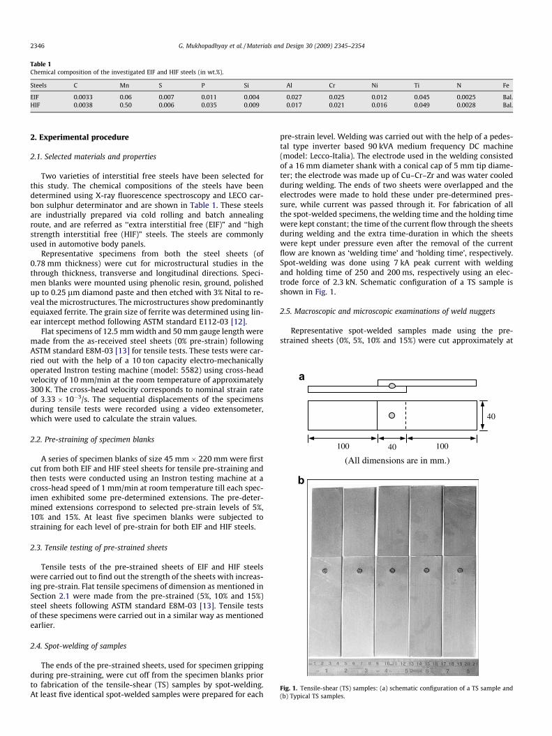
Table 1Chemical composition of the investigated EIF and HIF steels (in wt.%).
Steels C Mn S P Si Al Cr Ni Ti N Fe
EIF 0.0033 0.06 0.007 0.011 0.004 0.027 0.025 0.012 0.045 0.0025 Bal.HIF 0.0038 0.50 0.006 0.035 0.009 0.017 0.021 0.016 0.049 0.0028 Bal.
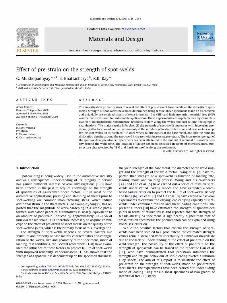
100 40 100
(All dimensions are in mm.)
40
a
b
Fig. 1. Tensile-shear (TS) samples: (a) schematic configuration of a TS sample and(b) Typical TS samples.
2346 G. Mukhopadhyay et al. / Materials and Design 30 (2009) 2345–2354
2. Experimental procedure
2.1. Selected materials and properties
Two varieties of interstitial free steels have been selected forthis study. The chemical compositions of the steels have beendetermined using X-ray fluorescence spectroscopy and LECO car-bon sulphur determinator and are shown in Table 1. These steelsare industrially prepared via cold rolling and batch annealingroute, and are referred as ‘‘extra interstitial free (EIF)” and ‘‘highstrength interstitial free (HIF)” steels. The steels are commonlyused in automotive body panels.
Representative specimens from both the steel sheets (of0.78 mm thickness) were cut for microstructural studies in thethrough thickness, transverse and longitudinal directions. Speci-men blanks were mounted using phenolic resin, ground, polishedup to 0.25 lm diamond paste and then etched with 3% Nital to re-veal the microstructures. The microstructures show predominantlyequiaxed ferrite. The grain size of ferrite was determined using lin-ear intercept method following ASTM standard E112-03 [12].
Flat specimens of 12.5 mm width and 50 mm gauge length weremade from the as-received steel sheets (0% pre-strain) followingASTM standard E8M-03 [13] for tensile tests. These tests were car-ried out with the help of a 10 ton capacity electro-mechanicallyoperated Instron testing machine (model: 5582) using cross-headvelocity of 10 mm/min at the room temperature of approximately300 K. The cross-head velocity corresponds to nominal strain rateof 3.33 � 10�3/s. The sequential displacements of the specimensduring tensile tests were recorded using a video extensometer,which were used to calculate the strain values.
2.2. Pre-straining of specimen blanks
A series of specimen blanks of size 45 mm � 220 mm were firstcut from both EIF and HIF steel sheets for tensile pre-straining andthen tests were conducted using an Instron testing machine at across-head speed of 1 mm/min at room temperature till each spec-imen exhibited some pre-determined extensions. The pre-deter-mined extensions correspond to selected pre-strain levels of 5%,10% and 15%. At least five specimen blanks were subjected tostraining for each level of pre-strain for both EIF and HIF steels.
2.3. Tensile testing of pre-strained sheets
Tensile tests of the pre-strained sheets of EIF and HIF steelswere carried out to find out the strength of the sheets with increas-ing pre-strain. Flat tensile specimens of dimension as mentioned inSection 2.1 were made from the pre-strained (5%, 10% and 15%)steel sheets following ASTM standard E8M-03 [13]. Tensile testsof these specimens were carried out in a similar way as mentionedearlier.
2.4. Spot-welding of samples
The ends of the pre-strained sheets, used for specimen grippingduring pre-straining, were cut off from the specimen blanks priorto fabrication of the tensile-shear (TS) samples by spot-welding.At least five identical spot-welded samples were prepared for each
pre-strain level. Welding was carried out with the help of a pedes-tal type inverter based 90 kVA medium frequency DC machine(model: Lecco-Italia). The electrode used in the welding consistedof a 16 mm diameter shank with a conical cap of 5 mm tip diame-ter; the electrode was made up of Cu–Cr–Zr and was water cooledduring welding. The ends of two sheets were overlapped and theelectrodes were made to hold these under pre-determined pres-sure, while current was passed through it. For fabrication of allthe spot-welded specimens, the welding time and the holding timewere kept constant; the time of the current flow through the sheetsduring welding and the extra time-duration in which the sheetswere kept under pressure even after the removal of the currentflow are known as ‘welding time’ and ‘holding time’, respectively.Spot-welding was done using 7 kA peak current with weldingand holding time of 250 and 200 ms, respectively using an elec-trode force of 2.3 kN. Schematic configuration of a TS sample isshown in Fig. 1.
2.5. Macroscopic and microscopic examinations of weld nuggets
Representative spot-welded samples made using the pre-strained sheets (0%, 5%, 10% and 15%) were cut approximately at
Weld nugget
HAZ
0.25 mm
Base metal
0.1 mm
Base metal
Fig. 2. Vickers micro-hardness measurements along the weldments.
G. Mukhopadhyay et al. / Materials and Design 30 (2009) 2345–2354 2347
the center of the weld nugget in the through thickness directionand were mounted, ground, polished and etched. A series of digitalphotographs of the weld nuggets were recorded with the help of aLeica optical microscope. The cross-section of a specimen revealsthe typical zones of the spot-weld, outlining the diameter andthickness of the weld nugget. The diameter of the fusion zone iscommonly referred as the ‘‘nugget diameter”. The nugget diameterand the thickness of the spot-welds were measured using thesephotographs with the help of an image analyzer coupled to themicroscope. At least five spot-welds have been examined to esti-mate the average nugget diameter and thickness for each set ofspecimen blanks having constant pre-strain. Polished and etchedspecimens were next examined using optical or scanning electronmicroscope (SEM) to assess the microstructural differencesamongst the different zones.
2.6. Determination of hardness profile across the spot-welds
The micro-hardness profiles across the investigated spot-weldswere determined using a Vickers hardness testing machine (mod-el: Leitz mini load-II). The hardness values were measured alongthe weldment at regular intervals of 0.25 mm in the long trans-verse direction of the original sheets as shown in Fig. 2. Measure-ment of hardness was carried out using a load of 100 gmf withindentation duration of 15 s.
2.7. Determination of strength of spot-welds
The strength of the spot-welds of pre-strained sheets (having0%, 5%, 10% and 15% pre-strain) was determined with the help ofthe Instron testing machine (model: 5582) using cross-head veloc-ity of 10 mm/min at the room temperature of approximately 300 K.The samples were tested using grips with flat jaw faces. The dis-placement values were recorded using a video extensometer. Thetests on the spot-welds were continued till the conjugate sheetsconstituting the weld were found to separate completely. Tests
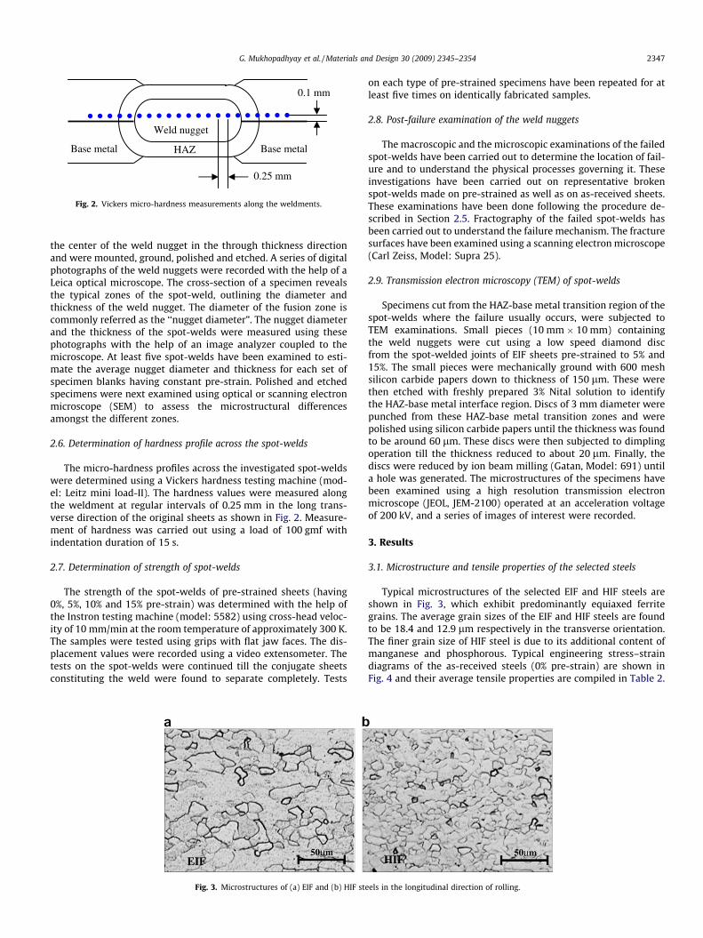
Fig. 3. Microstructures of (a) EIF and (b) HIF ste
on each type of pre-strained specimens have been repeated for atleast five times on identically fabricated samples.
2.8. Post-failure examination of the weld nuggets
The macroscopic and the microscopic examinations of the failedspot-welds have been carried out to determine the location of fail-ure and to understand the physical processes governing it. Theseinvestigations have been carried out on representative brokenspot-welds made on pre-strained as well as on as-received sheets.These examinations have been done following the procedure de-scribed in Section 2.5. Fractography of the failed spot-welds hasbeen carried out to understand the failure mechanism. The fracturesurfaces have been examined using a scanning electron microscope(Carl Zeiss, Model: Supra 25).
2.9. Transmission electron microscopy (TEM) of spot-welds
Specimens cut from the HAZ-base metal transition region of thespot-welds where the failure usually occurs, were subjected toTEM examinations. Small pieces (10 mm � 10 mm) containingthe weld nuggets were cut using a low speed diamond discfrom the spot-welded joints of EIF sheets pre-strained to 5% and15%. The small pieces were mechanically ground with 600 meshsilicon carbide papers down to thickness of 150 lm. These werethen etched with freshly prepared 3% Nital solution to identifythe HAZ-base metal interface region. Discs of 3 mm diameter werepunched from these HAZ-base metal transition zones and werepolished using silicon carbide papers until the thickness was foundto be around 60 lm. These discs were then subjected to dimplingoperation till the thickness reduced to about 20 lm. Finally, thediscs were reduced by ion beam milling (Gatan, Model: 691) untila hole was generated. The microstructures of the specimens havebeen examined using a high resolution transmission electronmicroscope (JEOL, JEM-2100) operated at an acceleration voltageof 200 kV, and a series of images of interest were recorded.
3. Results
3.1. Microstructure and tensile properties of the selected steels
Typical microstructures of the selected EIF and HIF steels areshown in Fig. 3, which exhibit predominantly equiaxed ferritegrains. The average grain sizes of the EIF and HIF steels are foundto be 18.4 and 12.9 lm respectively in the transverse orientation.The finer grain size of HIF steel is due to its additional content ofmanganese and phosphorous. Typical engineering stress–straindiagrams of the as-received steels (0% pre-strain) are shown inFig. 4 and their average tensile properties are compiled in Table 2.
els in the longitudinal direction of rolling.
0 10 20 30 40 50 600
100
200
300
400
Eng
inee
ring
Str
ess
(MP
a)
Engineering Strain (%)
0% Pre-strain 5% Pre-strain 10% Pre-strain 15% Pre-strain
Steel: EIF
0 10 15 20 25 30 35 400
100
200
300
400
500 0% Prestrain
5% Prestrain 10% Prestrain 15% Prestrain
Eng
inee
ring
Str
ess
(MP
a)
Engineering Strain (%)
Steel: HIF
5
a
b
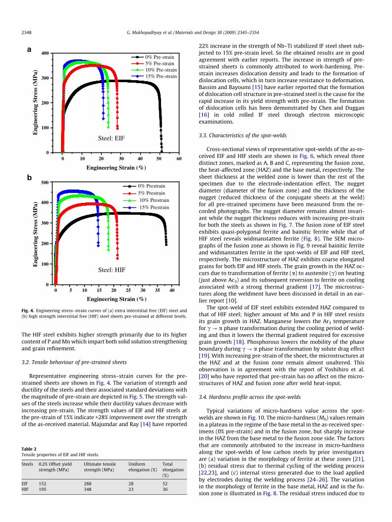
Fig. 4. Engineering stress–strain curves of (a) extra interstitial free (EIF) steel and(b) high strength interstitial free (HIF) steel sheets pre-strained at different levels.
2348 G. Mukhopadhyay et al. / Materials and Design 30 (2009) 2345–2354
The HIF steel exhibits higher strength primarily due to its highercontent of P and Mn which impart both solid solution strengtheningand grain refinement.
3.2. Tensile behaviour of pre-strained sheets
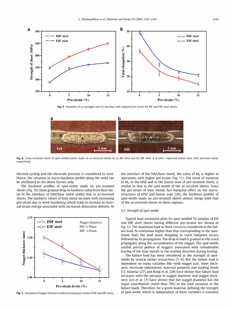
Representative engineering stress–strain curves for the pre-strained sheets are shown in Fig. 4. The variation of strength andductility of the steels and their associated standard deviations withthe magnitude of pre-strain are depicted in Fig. 5. The strength val-ues of the steels increase while their ductility values decrease withincreasing pre-strain. The strength values of EIF and HIF steels atthe pre-strain of 15% indicate >28% improvement over the strengthof the as-received material. Majumdar and Ray [14] have reported
Table 2Tensile properties of EIF and HIF steels.
Steels 0.2% Offset yieldstrength (MPa)
Ultimate tensilestrength (MPa)
Uniformelongation (%)
Totalelongation(%)
EIF 152 288 28 52HIF 195 348 23 36
22% increase in the strength of Nb–Ti stabilized IF steel sheet sub-jected to 15% pre-strain level. So the obtained results are in goodagreement with earlier reports. The increase in strength of pre-strained sheets is commonly attributed to work-hardening. Pre-strain increases dislocation density and leads to the formation ofdislocation cells, which in turn increase resistance to deformation.Bassim and Bayoumi [15] have earlier reported that the formationof dislocation cell structure in pre-strained steel is the cause for therapid increase in its yield strength with pre-strain. The formationof dislocation cells has been demonstrated by Chen and Duggan[16] in cold rolled IF steel through electron microscopicexaminations.
3.3. Characteristics of the spot-welds
Cross-sectional views of representative spot-welds of the as-re-ceived EIF and HIF steels are shown in Fig. 6, which reveal threedistinct zones, marked as A, B and C, representing the fusion zone,the heat-affected zone (HAZ) and the base metal, respectively. Thesheet thickness at the welded zone is lower than the rest of thespecimen due to the electrode-indentation effect. The nuggetdiameter (diameter of the fusion zone) and the thickness of thenugget (reduced thickness of the conjugate sheets at the weld)for all pre-strained specimens have been measured from the re-corded photographs. The nugget diameter remains almost invari-ant while the nugget thickness reduces with increasing pre-strainfor both the steels as shown in Fig. 7. The fusion zone of EIF steelexhibits quasi-polygonal ferrite and bainitic ferrite while that ofHIF steel reveals widmanstatten ferrite (Fig. 8). The SEM micro-graphs of the fusion zone as shown in Fig. 9 reveal bainitic ferriteand widmanstatten ferrite in the spot-welds of EIF and HIF steel,respectively. The microstructure of HAZ exhibits coarse elongatedgrains for both EIF and HIF steels. The grain growth in the HAZ oc-curs due to transformation of ferrite (a) to austenite (c) on heating(just above Ac3) and its subsequent reversion to ferrite on coolingassociated with a strong thermal gradient [17]. The microstruc-tures along the weldment have been discussed in detail in an ear-lier report [10].
The spot-weld of EIF steel exhibits extended HAZ compared tothat of HIF steel; higher amount of Mn and P in HIF steel resistsits grain growth in HAZ. Manganese lowers the Ar3 temperaturefor c ? a phase transformation during the cooling period of weld-ing and thus it lowers the thermal gradient required for excessivegrain growth [18]. Phosphorous lowers the mobility of the phaseboundary during c ? a phase transformation by solute drag effect[19]. With increasing pre-strain of the sheet, the microstructures atthe HAZ and at the fusion zone remain almost unaltered. Thisobservation is in agreement with the report of Yoshihiro et al.[20] who have reported that pre-strain has no affect on the micro-structures of HAZ and fusion zone after weld heat-input.
3.4. Hardness profile across the spot-welds
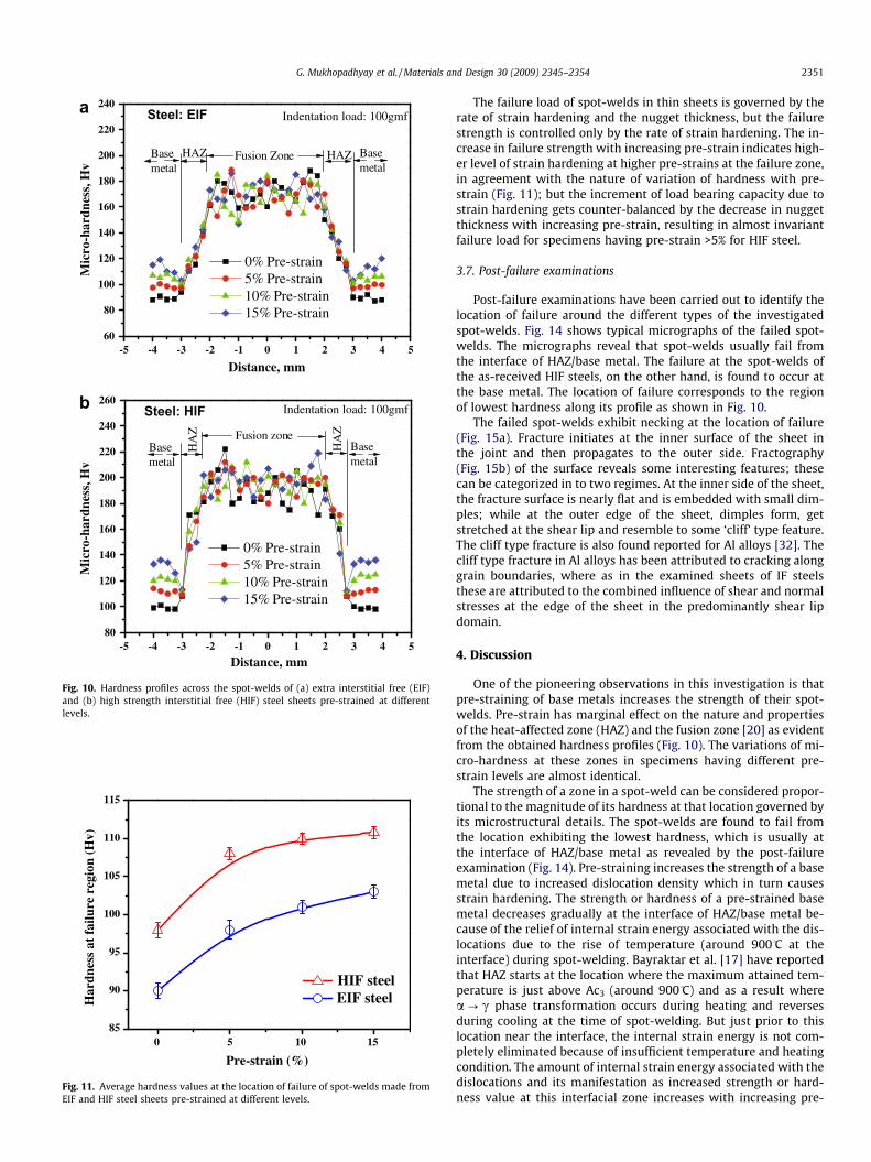
Typical variations of micro-hardness value across the spot-welds are shown in Fig. 10. The micro-hardness (Mh) values remainin a plateau in the regime of the base metal in the as-received spec-imens (0% pre-strain) and in the fusion zone, but sharply increasein the HAZ from the base metal to the fusion zone side. The factorsthat are commonly attributed to the increase in micro-hardnessalong the spot-welds of low carbon steels by prior investigatorsare (a) variation in the morphology of ferrite at these zones [21],(b) residual stress due to thermal cycling of the welding process[22,23], and (c) internal stress generated due to the load appliedby electrodes during the welding process [24–26]. The variationin the morphology of ferrite in the base metal, HAZ and in the fu-sion zone is illustrated in Fig. 8. The residual stress induced due to
0 10 1510
20
30
40
50
Tot
al e
long
atio
n (%
)
Pre-strain (%)
HIF steel
EIF steel
0 10 15250
300
350
400
450
500St
reng
th o
f sh
eet
(MP
a)
Pre-strain (%)
HIF steel
EIF steel
5 5
a b
Fig. 5. Variation of (a) strength and (b) ductility with imposed pre-strain for EIF and HIF steel sheets.
Fig. 6. Cross-sectional views of spot-welded joints made on as-received sheets of (a) EIF steel and (b) HIF steel. A, B and C represent fusion zone, HAZ and base metal,respectively.
G. Mukhopadhyay et al. / Materials and Design 30 (2009) 2345–2354 2349
thermal cycling and the electrode pressure is considered to exist.Hence, the variation in micro-hardness profile along the weld canbe attributed to the above factors only.
The hardness profiles of spot-welds made on pre-strainedsheets (Fig. 10) show gradual drop in hardness value from base me-tal to the interface of HAZ/base metal unlike that in as-receivedsheets. The hardness values of base metal increase with increasingpre-strain due to work-hardening which leads to increase in inter-nal strain energy associated with increased dislocation density. At
0 10 151.40
1.45
1.50
1.55
Nugget diameters-EIF: 4.76mmHIF: 4.85mm
HIF steel EIF steel
Nug
get
thic
knes
s (m
m)
Pre-strain levels (%)
5
Fig. 7. Variation of nugget thickness with increasing pre-strain of EIF and HIF steels.
the interface of the HAZ/base metal, the value of Mh is higher inspecimens with higher pre-strain (Fig. 11). The trend of variationin Mh in the HAZ and in the fusion zone of pre-strained sheets issimilar to that in the spot-welds of the as-received sheets. Sincethe pre-strain of base metals has marginal effect on the micro-structures of HAZ and fusion zone [20], the hardness profiles ofspot-welds made on pre-strained sheets almost merge with thatof the as-received sheets in these regimes.
3.5. Strength of spot-welds
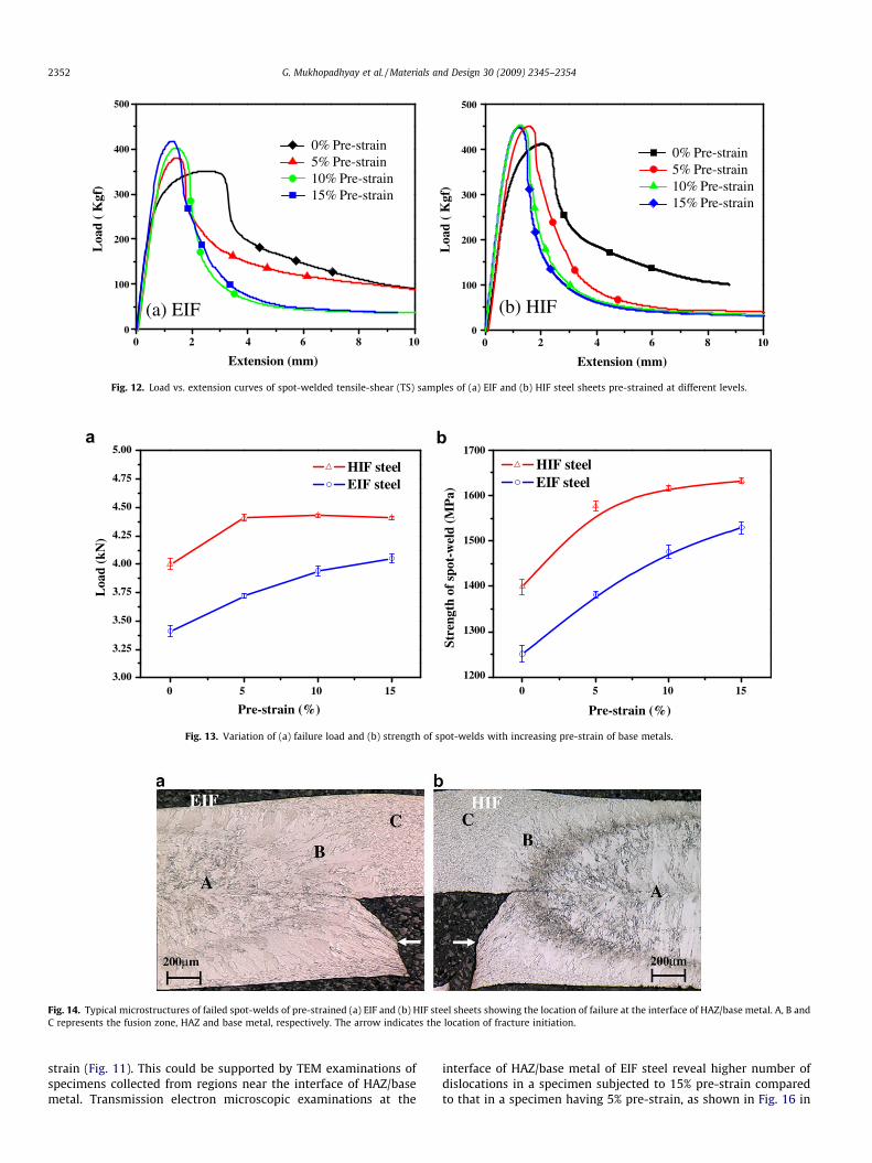
Typical load–extension plots for spot-welded TS samples of EIFand HIF steel sheets having different pre-strains are shown inFig. 12. The maximum load in these curves is considered as the fail-ure load. At extensions higher than that corresponding to the max-imum load, the load starts dropping as crack initiation occursfollowed by its propagation. The drop in load is gradual as the crackpropagates along the circumference of the nugget. The spot-weldsexhibit partial pullout of nuggets associated with considerabletearing of the base metals in the loading direction during testing.
The failure load has been considered as the strength of spot-welds by several earlier researchers [1–6]. But the failure load isdependent on many variables like weld nugget size, sheet thick-ness, electrode-indentation, material property and loading mode[1]. Aslanlar [27] and Kong et al. [28] have shown that failure loadincreases with the increase in nugget diameter and nugget thick-ness. Lee et al. [7] have shown that the nugget diameter has themajor contribution (more than 70%) to the total variation in thefailure loads. Therefore, for a given material, defining the strengthof spot-welds which is independent of these variables is essential
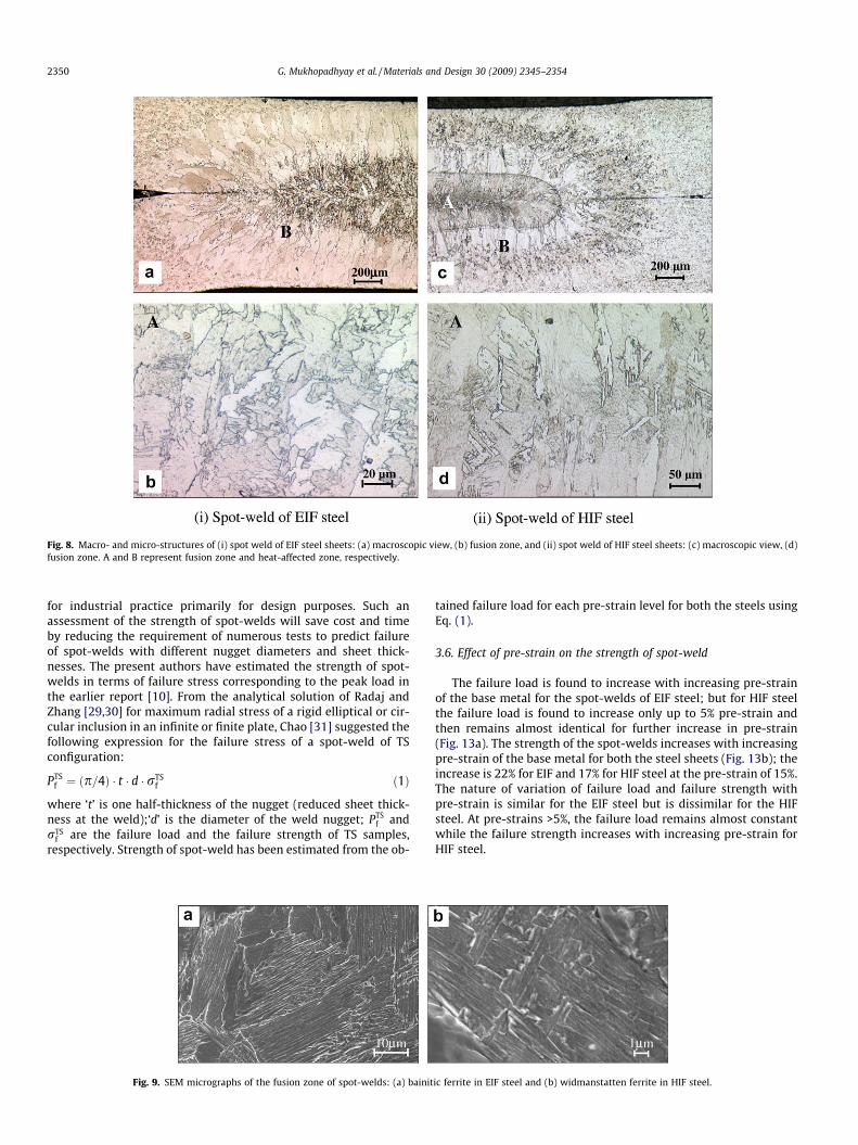
Fig. 8. Macro- and micro-structures of (i) spot weld of EIF steel sheets: (a) macroscopic view, (b) fusion zone, and (ii) spot weld of HIF steel sheets: (c) macroscopic view, (d)fusion zone. A and B represent fusion zone and heat-affected zone, respectively.
2350 G. Mukhopadhyay et al. / Materials and Design 30 (2009) 2345–2354
for industrial practice primarily for design purposes. Such anassessment of the strength of spot-welds will save cost and timeby reducing the requirement of numerous tests to predict failureof spot-welds with different nugget diameters and sheet thick-nesses. The present authors have estimated the strength of spot-welds in terms of failure stress corresponding to the peak load inthe earlier report [10]. From the analytical solution of Radaj andZhang [29,30] for maximum radial stress of a rigid elliptical or cir-cular inclusion in an infinite or finite plate, Chao [31] suggested thefollowing expression for the failure stress of a spot-weld of TSconfiguration:
PTSf ¼ ðp=4Þ � t � d � rTS
f ð1Þ
where ‘t’ is one half-thickness of the nugget (reduced sheet thick-ness at the weld);‘d’ is the diameter of the weld nugget; PTS
f andrTS
f are the failure load and the failure strength of TS samples,respectively. Strength of spot-weld has been estimated from the ob-
Fig. 9. SEM micrographs of the fusion zone of spot-welds: (a) bainit
tained failure load for each pre-strain level for both the steels usingEq. (1).
3.6. Effect of pre-strain on the strength of spot-weld
The failure load is found to increase with increasing pre-strainof the base metal for the spot-welds of EIF steel; but for HIF steelthe failure load is found to increase only up to 5% pre-strain andthen remains almost identical for further increase in pre-strain(Fig. 13a). The strength of the spot-welds increases with increasingpre-strain of the base metal for both the steel sheets (Fig. 13b); theincrease is 22% for EIF and 17% for HIF steel at the pre-strain of 15%.The nature of variation of failure load and failure strength withpre-strain is similar for the EIF steel but is dissimilar for the HIFsteel. At pre-strains >5%, the failure load remains almost constantwhile the failure strength increases with increasing pre-strain forHIF steel.
ic ferrite in EIF steel and (b) widmanstatten ferrite in HIF steel.
-5 -4 -3 -2 -1 0 180
100
120
140
160
180
200
220
240
260
Basemetal
HA
Z
Steel: HIF
Mic
ro-h
ardn
ess,
Hv
Distance, mm
0% Pre-strain 5% Pre-strain 10% Pre-strain 15% Pre-strain
Indentation load: 100gmf
Basemetal
HA
Z Fusion zone
-5 -4 -3 -2 -1 0 1 2 3 4 560
80
100
120
140
160
180
200
220
240
Basemetal
HAZ
Steel: EIF
Mic
ro-h
ardn
ess,
Hv
Distance, mm
0% Pre-strain 5% Pre-strain 10% Pre-strain 15% Pre-strain
Indentation load: 100gmf
Basemetal
HAZ Fusion Zone
2 3 4 5
a
b
Fig. 10. Hardness profiles across the spot-welds of (a) extra interstitial free (EIF)and (b) high strength interstitial free (HIF) steel sheets pre-strained at differentlevels.
0 10 1585
90
95
100
105
110
115
HIF steelEIF steelH
ardn
ess
at f
ailu
re r
egio
n (H
v)
Pre-strain (%)
5
Fig. 11. Average hardness values at the location of failure of spot-welds made fromEIF and HIF steel sheets pre-strained at different levels.
G. Mukhopadhyay et al. / Materials and Design 30 (2009) 2345–2354 2351
The failure load of spot-welds in thin sheets is governed by therate of strain hardening and the nugget thickness, but the failurestrength is controlled only by the rate of strain hardening. The in-crease in failure strength with increasing pre-strain indicates high-er level of strain hardening at higher pre-strains at the failure zone,in agreement with the nature of variation of hardness with pre-strain (Fig. 11); but the increment of load bearing capacity due tostrain hardening gets counter-balanced by the decrease in nuggetthickness with increasing pre-strain, resulting in almost invariantfailure load for specimens having pre-strain >5% for HIF steel.
3.7. Post-failure examinations
Post-failure examinations have been carried out to identify thelocation of failure around the different types of the investigatedspot-welds. Fig. 14 shows typical micrographs of the failed spot-welds. The micrographs reveal that spot-welds usually fail fromthe interface of HAZ/base metal. The failure at the spot-welds ofthe as-received HIF steels, on the other hand, is found to occur atthe base metal. The location of failure corresponds to the regionof lowest hardness along its profile as shown in Fig. 10.
The failed spot-welds exhibit necking at the location of failure(Fig. 15a). Fracture initiates at the inner surface of the sheet inthe joint and then propagates to the outer side. Fractography(Fig. 15b) of the surface reveals some interesting features; thesecan be categorized in to two regimes. At the inner side of the sheet,the fracture surface is nearly flat and is embedded with small dim-ples; while at the outer edge of the sheet, dimples form, getstretched at the shear lip and resemble to some ‘cliff’ type feature.The cliff type fracture is also found reported for Al alloys [32]. Thecliff type fracture in Al alloys has been attributed to cracking alonggrain boundaries, where as in the examined sheets of IF steelsthese are attributed to the combined influence of shear and normalstresses at the edge of the sheet in the predominantly shear lipdomain.
4. Discussion
One of the pioneering observations in this investigation is thatpre-straining of base metals increases the strength of their spot-welds. Pre-strain has marginal effect on the nature and propertiesof the heat-affected zone (HAZ) and the fusion zone [20] as evidentfrom the obtained hardness profiles (Fig. 10). The variations of mi-cro-hardness at these zones in specimens having different pre-strain levels are almost identical.
The strength of a zone in a spot-weld can be considered propor-tional to the magnitude of its hardness at that location governed byits microstructural details. The spot-welds are found to fail fromthe location exhibiting the lowest hardness, which is usually atthe interface of HAZ/base metal as revealed by the post-failureexamination (Fig. 14). Pre-straining increases the strength of a basemetal due to increased dislocation density which in turn causesstrain hardening. The strength or hardness of a pre-strained basemetal decreases gradually at the interface of HAZ/base metal be-cause of the relief of internal strain energy associated with the dis-locations due to the rise of temperature (around 900�C at theinterface) during spot-welding. Bayraktar et al. [17] have reportedthat HAZ starts at the location where the maximum attained tem-perature is just above Ac3 (around 900�C) and as a result wherea ? c phase transformation occurs during heating and reversesduring cooling at the time of spot-welding. But just prior to thislocation near the interface, the internal strain energy is not com-pletely eliminated because of insufficient temperature and heatingcondition. The amount of internal strain energy associated with thedislocations and its manifestation as increased strength or hard-ness value at this interfacial zone increases with increasing pre-
0 6 100
100
200
300
400
500L
oad
( K
gf)
Extension (mm)
0% Pre-strain 5% Pre-strain 10% Pre-strain 15% Pre-strain
(a) EIF
0% Pre-strain 5% Pre-strain 10% Pre-strain 15% Pre-strain
(b) HIF
42 80
100
200
300
400
500
Loa
d (
Kgf
)
0 6 10
Extension (mm)
42 8
Fig. 12. Load vs. extension curves of spot-welded tensile-shear (TS) samples of (a) EIF and (b) HIF steel sheets pre-strained at different levels.
0 10 151200
1300
1400
1500
1600
1700St
reng
th o
f sp
ot-w
eld
(MP
a)
Pre-strain (%)
HIF steel EIF steel
0 10 153.00
3.25
3.50
3.75
4.00
4.25
4.50
4.75
5.00
Loa
d (k
N)
Pre-strain (%)
HIF steel EIF steel
5 5
a b
Fig. 13. Variation of (a) failure load and (b) strength of spot-welds with increasing pre-strain of base metals.
Fig. 14. Typical microstructures of failed spot-welds of pre-strained (a) EIF and (b) HIF steel sheets showing the location of failure at the interface of HAZ/base metal. A, B andC represents the fusion zone, HAZ and base metal, respectively. The arrow indicates the location of fracture initiation.
2352 G. Mukhopadhyay et al. / Materials and Design 30 (2009) 2345–2354
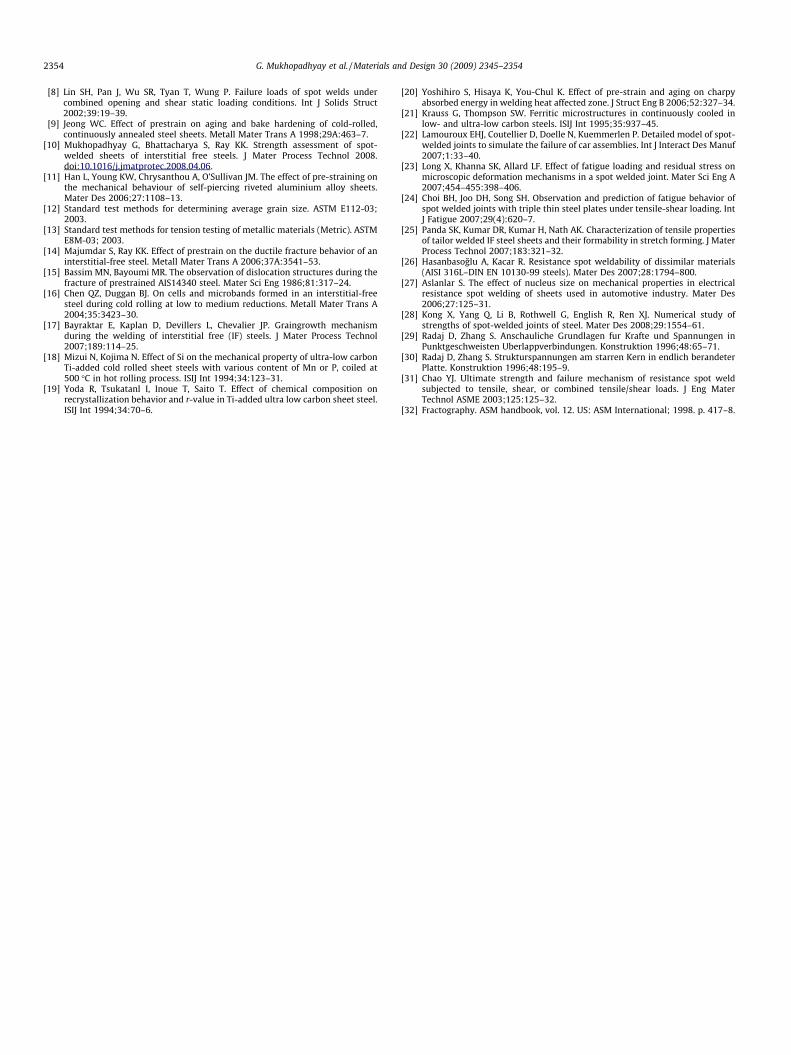
strain (Fig. 11). This could be supported by TEM examinations ofspecimens collected from regions near the interface of HAZ/basemetal. Transmission electron microscopic examinations at the
interface of HAZ/base metal of EIF steel reveal higher number ofdislocations in a specimen subjected to 15% pre-strain comparedto that in a specimen having 5% pre-strain, as shown in Fig. 16 in
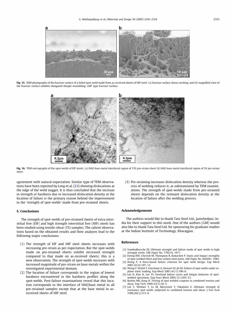
Fig. 15. SEM photographs of the fracture surface of a failed spot-weld made from as-received sheets of HIF steel: (a) fracture surface shows necking, and (b) magnified view ofthe fracture surface exhibits elongated dimple resembling ‘cliff’ type fracture surface.
Fig. 16. TEM micrographs of the spot-welds of EIF steels: (a) HAZ-base metal interfacial region of 15% pre-strain sheet (b) HAZ-base metal interfacial region of 5% pre-strainsheet.
G. Mukhopadhyay et al. / Materials and Design 30 (2009) 2345–2354 2353
agreement with natural expectation. Similar type of TEM observa-tions have been reported by Long et al. [23] showing dislocations atthe edge of the weld nugget. It is thus concluded that the increasein strength or hardness due to increased dislocation density at thelocation of failure is the primary reason behind the improvementin the ‘strength of spot-welds’ made from pre-strained sheets.
5. Conclusions
The strength of spot-welds of pre-strained sheets of extra inter-stitial free (EIF) and high strength interstitial free (HIF) steels hasbeen studied using tensile-shear (TS) samples. The salient observa-tions based on the obtained results and their analyses lead to thefollowing major conclusions:
(1) The strength of EIF and HIF steel sheets increases withincreasing pre-strain as per expectation. But the spot-weldsmade on pre-strained sheets exhibit increased strengthcompared to that made on as-received sheets; this is anew observation. The strength of spot-welds increases withincreased magnitude of pre-strain on base metals within theinvestigated experimental domain.
(2) The location of failure corresponds to the region of lowesthardness encountered in the hardness profiles along thespot-welds. Post-failure examinations reveal that this loca-tion corresponds to the interface of HAZ/base metal in allpre-strained samples except that at the base metal in as-received sheets of HIF steel.
(3) Pre-straining increases dislocation density whereas the pro-cess of welding reduces it, as substantiated by TEM examin-ations. The strength of spot-welds made from pre-strainedsheets depends on the remnant dislocation density at thelocation of failure after the welding process.
Acknowledgements
The authors would like to thank Tata Steel Ltd., Jamshedpur, In-dia for their support to this work. One of the authors (GM) wouldalso like to thank Tata Steel Ltd. for sponsoring his graduate studiesat the Indian Institute of Technology, Kharagpur.
References
[1] VandenBossche DJ. Ultimate strength and failure mode of spot welds in highstrength steels. SAE Paper No. 770214; 1977.
[2] Ewing KW, Cheresh M, Thompson R, Kukuchek P. Static and impact strengthsof spot-welded HSLA and low carbon steel joints. SAE Paper No. 820281; 1982.
[3] Wung P. A force-based failure criterion for spot weld design. Exp Mech2001;41(4):107–13.
[4] Wung P, Walsh T, Ourchane A, Stewart W, Jie M. Failure of spot welds under in-plane static loading. Exp Mech 2001;41(1):100–6.
[5] Lee H, Kim N, Lee TS. Overload failure curve and fatigue behavior of spot-welded specimens. Eng Fract Mech 2005;72:1203–21.
[6] Barkey ME, Kang H. Testing of spot welded coupons in combined tension andshear. Exp Tech 1999;23(5):20–2.
[7] Lee Y, Wehner T, Lu M, Morrissett T, Pakalnins E. Ultimate strength ofresistance spot welds subjected to combined tension and shear. J Test Eval1998;26(3):213–9.
2354 G. Mukhopadhyay et al. / Materials and Design 30 (2009) 2345–2354
[8] Lin SH, Pan J, Wu SR, Tyan T, Wung P. Failure loads of spot welds undercombined opening and shear static loading conditions. Int J Solids Struct2002;39:19–39.
[9] Jeong WC. Effect of prestrain on aging and bake hardening of cold-rolled,continuously annealed steel sheets. Metall Mater Trans A 1998;29A:463–7.
[10] Mukhopadhyay G, Bhattacharya S, Ray KK. Strength assessment of spot-welded sheets of interstitial free steels. J Mater Process Technol 2008.doi:10.1016/j.jmatprotec.2008.04.06.
[11] Han L, Young KW, Chrysanthou A, O’Sullivan JM. The effect of pre-straining onthe mechanical behaviour of self-piercing riveted aluminium alloy sheets.Mater Des 2006;27:1108–13.
[12] Standard test methods for determining average grain size. ASTM E112-03;2003.
[13] Standard test methods for tension testing of metallic materials (Metric). ASTME8M-03; 2003.
[14] Majumdar S, Ray KK. Effect of prestrain on the ductile fracture behavior of aninterstitial-free steel. Metall Mater Trans A 2006;37A:3541–53.
[15] Bassim MN, Bayoumi MR. The observation of dislocation structures during thefracture of prestrained AIS14340 steel. Mater Sci Eng 1986;81:317–24.
[16] Chen QZ, Duggan BJ. On cells and microbands formed in an interstitial-freesteel during cold rolling at low to medium reductions. Metall Mater Trans A2004;35:3423–30.
[17] Bayraktar E, Kaplan D, Devillers L, Chevalier JP. Graingrowth mechanismduring the welding of interstitial free (IF) steels. J Mater Process Technol2007;189:114–25.
[18] Mizui N, Kojima N. Effect of Si on the mechanical property of ultra-low carbonTi-added cold rolled sheet steels with various content of Mn or P, coiled at500 �C in hot rolling process. ISIJ Int 1994;34:123–31.
[19] Yoda R, Tsukatanl I, Inoue T, Saito T. Effect of chemical composition onrecrystallization behavior and r-value in Ti-added ultra low carbon sheet steel.ISIJ Int 1994;34:70–6.
[20] Yoshihiro S, Hisaya K, You-Chul K. Effect of pre-strain and aging on charpyabsorbed energy in welding heat affected zone. J Struct Eng B 2006;52:327–34.
[21] Krauss G, Thompson SW. Ferritic microstructures in continuously cooled inlow- and ultra-low carbon steels. ISIJ Int 1995;35:937–45.
[22] Lamouroux EHJ, Coutellier D, Doelle N, Kuemmerlen P. Detailed model of spot-welded joints to simulate the failure of car assemblies. Int J Interact Des Manuf2007;1:33–40.
[23] Long X, Khanna SK, Allard LF. Effect of fatigue loading and residual stress onmicroscopic deformation mechanisms in a spot welded joint. Mater Sci Eng A2007;454–455:398–406.
[24] Choi BH, Joo DH, Song SH. Observation and prediction of fatigue behavior ofspot welded joints with triple thin steel plates under tensile-shear loading. IntJ Fatigue 2007;29(4):620–7.
[25] Panda SK, Kumar DR, Kumar H, Nath AK. Characterization of tensile propertiesof tailor welded IF steel sheets and their formability in stretch forming. J MaterProcess Technol 2007;183:321–32.
[26] Hasanbasoglu A, Kacar R. Resistance spot weldability of dissimilar materials(AISI 316L–DIN EN 10130-99 steels). Mater Des 2007;28:1794–800.
[27] Aslanlar S. The effect of nucleus size on mechanical properties in electricalresistance spot welding of sheets used in automotive industry. Mater Des2006;27:125–31.
[28] Kong X, Yang Q, Li B, Rothwell G, English R, Ren XJ. Numerical study ofstrengths of spot-welded joints of steel. Mater Des 2008;29:1554–61.
[29] Radaj D, Zhang S. Anschauliche Grundlagen fur Krafte und Spannungen inPunktgeschweisten Uberlappverbindungen. Konstruktion 1996;48:65–71.
[30] Radaj D, Zhang S. Strukturspannungen am starren Kern in endlich berandeterPlatte. Konstruktion 1996;48:195–9.
[31] Chao YJ. Ultimate strength and failure mechanism of resistance spot weldsubjected to tensile, shear, or combined tensile/shear loads. J Eng MaterTechnol ASME 2003;125:125–32.
[32] Fractography. ASM handbook, vol. 12. US: ASM International; 1998. p. 417–8.


