Embed Size (px)
Citation preview
Theoretical and Applied Fracture Mechanics 67–68 (2013) 53–64
Contents lists available at ScienceDirect
Theoretical and Applied Fracture Mechanics
journal homepage: www.elsevier .com/locate / tafmec
Effect of projectile diameter on ballistic resistance and failuremechanism of single and layered aluminum plates
0167-8442/$ - see front matter � 2014 Elsevier Ltd. All rights reserved.http://dx.doi.org/10.1016/j.tafmec.2013.12.010
⇑ Corresponding author. Tel.: +91 9897379426, +91 1332 285866.E-mail addresses: [email protected], [email protected] (M.A. Iqbal).
K. Senthil, M.A. Iqbal ⇑Department of Civil Engineering, Indian Institute of Technology Roorkee, Roorkee 247667, India
a r t i c l e i n f o a b s t r a c t
Article history:Available online 4 January 2014
Keywords:Projectile diameterLayered targetFailure mechanismFriction effectBallistic limit
Finite element analysis has been carried out to study the effect of diameter of ogive nosed projectile onthe ballistic resistance of 1 mm thick monolithic and 0.5 mm thick double-layered in contact plates of1100-H12 aluminum alloy. The size of the projectile was varied by varying its shank diameter as 15,19 and 24 mm, keeping the length constant. Thus, the length to diameter ratio varied as 2, 2.6 and 3.3.The ABAQUS/Explicit finite element code in conjunction with Johnson–Cook elasto-viscoplastic materialmodel was employed to perform the simulation study. The numerical results were compared with avail-able experiments. The ballistic resistance has been found to increase with increase in the projectile diam-eter. For a given diameter, the monolithic target has been found to offer better resistance. However, theinfluence of target configuration was dominant against the larger projectile diameter. The projectile wasconsidered rigid and deformable to study its influence on the failure mechanism and ballistic limit. Fric-tion effect between the projectile and target was also studied and its influence thereon the ballistic per-formance is discussed.
� 2014 Elsevier Ltd. All rights reserved.
1. Introduction
There are a large number of parameters which may influencethe ballistic performance of metallic plates including angle of inci-dence, shape and size of projectile, target thickness and its config-uration. The influence of each of these has been reported in theliterature. A number of studies are available wherein the effect ofangle of incidence has been studied on the ballistic performance,and as such, all of these have concluded that the resistance ofmetallic plates remains almost same up to 30� obliquity and in-creases thereafter [1–4]. The effect of plate configuration, though,studied with single, layered and spaced target however, in contrastto the angle of incidence, the findings in this case are not converg-ing [5–8]. Corran et al. [5] performed experiments on aluminum,mild steel and stainless steel plates of various thicknesses and pro-jectile shapes. They concluded that the layered plate if failedthrough the membrane stretching of individual layer will absorbmore energy than an equivalent monolithic plate where the failureoccur through bending. Iqbal et al. [6] found that 1 mm thickmonolithic aluminum plate offers highest ballistic limit followedby double layered in contact (2 � 0.5 mm) and double layeredspaced plate with varying spacing (2–30 mm). This is due to thefact that monolithic plate experienced highest global deformationfollowed by layered in contact and spaced target respectively.
Dey et al. [7] on the other hand, observed that the ballistic perfor-mance of 12 mm thick monolithic steel plate was inferior to that ofthe double layered in contact plate of equal thickness against bluntnosed projectile. When the layers were spaced by 24 mm, theirperformance was between monolithic and layered in contact plate.However, when the same target configuration was impacted byogival nosed projectile, monolithic plate offered highest ballisticperformance followed by layered and spaced target respectively.It was concluded that the change in deformation and failure modeis responsible for the superior or inferior performance of a giventarget configuration. Teng et al. [8] concluded that at low incidencevelocity the double layered steel plate with upper layer of highductility and low strength material and lower layer of low ductilityand high strength material offered best performance compared tomonolithic plates of either material and the opposite layered con-figuration. At high incidence velocity however, the performancewas found to be dependent on target strength and projectile shape.The projectile shape, addressed through a number of studies [9–13], also has been found to have a significant effect on the ballisticresistance. There is some disagreement between the performanceof ogive and blunt nosed projectile. However, hemispherical nosedprojectile in general has been found to be the least efficient pene-trator among all the nose shapes. As far as the size effect of projec-tile is concerned, only one study has been found in the literature,see Gupta et al. [14] wherein the length to diameter ratio (l/d) ofan ogive nosed projectile was varied by varying its cylindricallength ‘‘l’’ (10–40 mm) and keeping diameter ‘‘d’’ (10 mm) and
d = 15.0 mm d = 24.0 mm
19.3
mm
l = 4
9.3
(a) (b)
30.0
mm
d = 19.0 mm
(c)
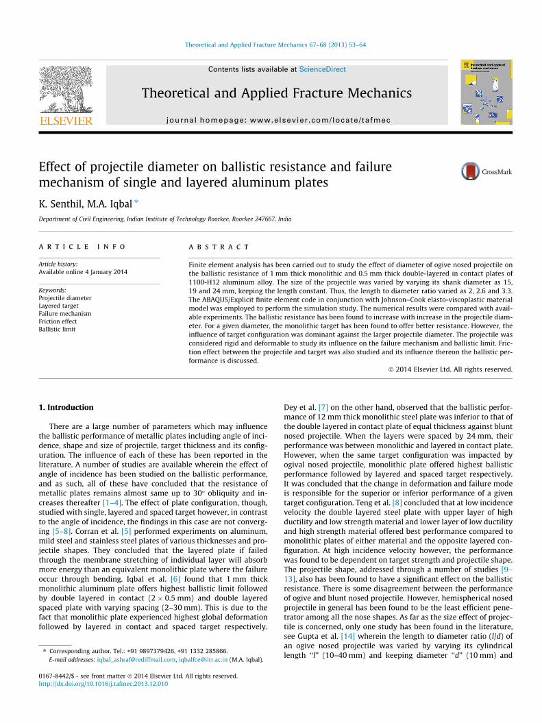
Fig. 1. Geometry of the projectiles with varying diameter.
Number of elements is 49832
(a) (b)
Fig. 2. Geometry of the 15 mm diameter projectile (a) rigid and (b) deformable.
Table 1Material parameters for 1100-H12 aluminum plate [6].
Modulus of elasticity E (N/m2) 65.762 � 109
Poisson’s ratio m 0.30Density q (kg/m3) 2700Yield stress constant A (N/m2) 148.361 � 106
Strain hardening constant B (N/m2) 345.513 � 106
n 0.183Viscous effect C 0.001Thermal softening constant m 0.859Reference strain rate _eo 1.000 s�1
Melting temperature hmelt (K) 893Transition temperature htransition (K) 293Fracture strain constant D1 0.071
D2 1.248D3 �1.142D4 0.0097D5 0.0
Table 2Material parameters for EN 24 steel [20].
Yield stress ro (N/m2) 1411 � 106
Ultimate tensile strength ru (N/m2) 1526 � 106
Fracture strain ef 0.287Modulus of elasticity E (N/m2) 2.05 � 1011
Poisson’s ratio m 0.33Density q (kg/m3) 7764Stress triaxiality r⁄ 0.333Strain rate _eo 0.000416 s�1
54 K. Senthil, M.A. Iqbal / Theoretical and Applied Fracture Mechanics 67–68 (2013) 53–64
nose length (13.3 mm) constant. The experiments carried out on1 mm thick aluminum plates suggested that the ballistic limit de-creased from 60 m/s to 40 m/s by increasing the l/d ratio from 1 to4. However, the ballistic resistance of the same target significantlydecreased by increasing the diameter of projectile from 10 to15 mm and keeping l/d ratio constant. Further, the studies basedon the performance of rigid and deformable projectile are rarelyavailable in the literature. However, it is well known that the entirekinetic energy of a rigid projectile is dissipated in the deformationof target while in case of deformable projectile some energy is alsodissipated in the deformation of projectile.
The present investigation addresses the influence of varyingprojectile diameter on the ballistic performance and fracturemechanism of monolithic and double-layered plates of 1100-H12aluminum. The 1 mm thick monolithic and 0.5 mm thick doublelayered plates have been subjected to impact by ogive nosed pro-jectiles of shank diameter 15, 19 and 24 mm. Hence, the totallength to diameter ratio of projectile (l/d) varied as 3.3, 2.6 and2.0 respectively keeping the total length constant (49.3 mm). Theeffect of rigid and deformable nature of projectile has also beenstudied. ABAQUS/Explicit finite element code has been employedto carry out the numerical simulations. The numerical results havebeen compared with the experiments conducted with 15 mm
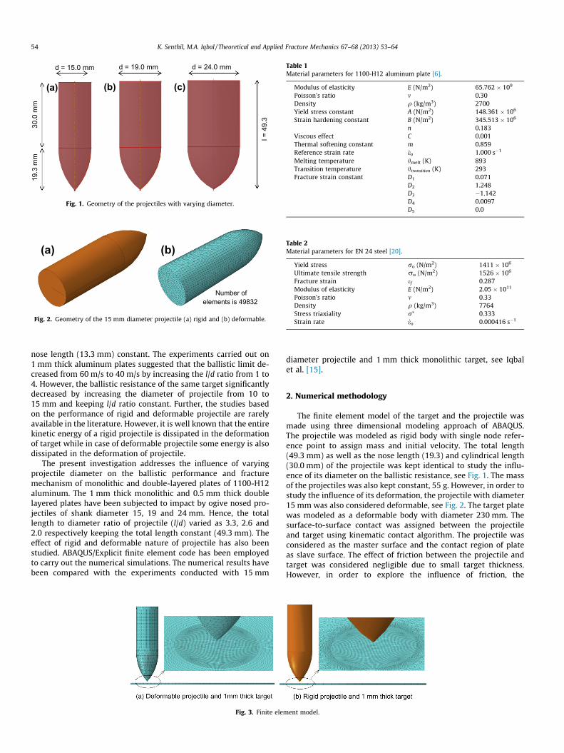
Fig. 3. Finite elem
diameter projectile and 1 mm thick monolithic target, see Iqbalet al. [15].
2. Numerical methodology
The finite element model of the target and the projectile wasmade using three dimensional modeling approach of ABAQUS.The projectile was modeled as rigid body with single node refer-ence point to assign mass and initial velocity. The total length(49.3 mm) as well as the nose length (19.3) and cylindrical length(30.0 mm) of the projectile was kept identical to study the influ-ence of its diameter on the ballistic resistance, see Fig. 1. The massof the projectiles was also kept constant, 55 g. However, in order tostudy the influence of its deformation, the projectile with diameter15 mm was also considered deformable, see Fig. 2. The target platewas modeled as a deformable body with diameter 230 mm. Thesurface-to-surface contact was assigned between the projectileand target using kinematic contact algorithm. The projectile wasconsidered as the master surface and the contact region of plateas slave surface. The effect of friction between the projectile andtarget was considered negligible due to small target thickness.However, in order to explore the influence of friction, the
ent model.
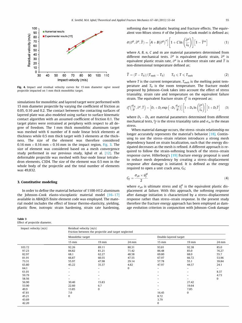
Fig. 4. Impact and residual velocity curves for 15 mm diameter ogive nosedprojectile impacted on 1 mm thick monolithic target.
K. Senthil, M.A. Iqbal / Theoretical and Applied Fracture Mechanics 67–68 (2013) 53–64 55
simulations for monolithic and layered target were performed with15 mm diameter projectile by varying the coefficient of friction as0.05, 0.10 and 0.2. The contact between the contacting surfaces oflayered plate was also modeled using surface to surface kinematiccontact algorithm with an assumed coefficient of friction 0.1. Thetarget plates were restrained at periphery with respect to all de-gree of freedom. The 1 mm thick monolithic aluminum targetwas meshed with 6 number of 8 node linear brick elements atthickness while 0.5 mm thick target with 3 elements at the thick-ness. The size of the element was therefore considered0.16 mm � 0.16 mm � 0.16 mm in the impact region, Fig. 3. Thesize of element was considered based on a mesh convergencestudy performed in our previous study, Iqbal et al. [12]. Thedeformable projectile was meshed with four-node linear tetrahe-dron elements, C3D4. The size of the element was 0.5 mm in thewhole body of the projectile and the total number of elementswas 49,832.
3. Constitutive modeling
In order to define the material behavior of 1100-H12 aluminumthe Johnson–Cook elasto-viscoplastic material model [16–17]available in ABAQUS finite element code was employed. The mate-rial model includes the effect of linear thermo-elasticity, yielding,plastic flow, isotropic strain hardening, strain rate hardening,
Table 3Effect of projectile diameter.
Impact velocity (m/s) Residual velocity (m/s)Friction between the projectile and target negl
Monolithic target
15 mm 19 mm
103.72 92.26 89.1197.23 84.82 81.2182.97 68.1 62.2781.91 66.87 60.5573.31 55.97 47.9865.80 45.22 35.3764.1 – –61.01 – –59.79 – –58.56 – –56.90 30.40 15.8353.90 22.60 6.749.9 13.85 047.81 7.045.21 043.6942.20
softening due to adiabatic heating and fracture effects. The equiv-alent von-Mises stress �r of the Johnson–Cook model is defined as;
�rð�epl; _�epl; bT Þ ¼ Aþ B �epl� �nh i
1þ C ln_�epl
_e0
!" #1� bT mh i
ð1Þ
where A, B, n, C and m are material parameters determined fromdifferent mechanical tests. _�epl is equivalent plastic strain, _�epl isequivalent plastic strain rate, _epl is a reference strain rate and bT isnon-dimensional temperature defined as;
bT ¼ ðT � T0Þ=ðTmelt � T0Þ T0 6 T 6 Tmelt ð2Þ
where T is the current temperature, Tmelt is the melting point tem-perature and T0 is the room temperature. The fracture modelproposed by Johnson–Cook takes into account the effect of stresstriaxiality, strain rate and temperature on the equivalent failurestrain. The equivalent fracture strain �epl
f is expressed as;
�eplf
rm
�r; _�epl; bT� �
¼ D1 þ D2 exp �D3rm
�r
� �h i1þ D4 ln
_�epl
_e0
!" #1þ D5
bTh ið3Þ
where D1 � D5 are material parameters determined from differentmechanical tests, rm
�r is the stress triaxiality ratio and rm is the meanstress.
When material damage occurs, the stress–strain relationship nolonger accurately represents the material’s behavior [18]. Contin-uing to use the stress–strain relation introduces a strong meshdependency based on strain localization, such that the energy dis-sipated decreases as the mesh is refined. A different approach is re-quired to follow the strain-softening branch of the stress–strainresponse curve. Hillerborg’s [19] fracture energy proposal is usedto reduce mesh dependency by creating a stress–displacementresponse after damage is initiated. It is defined as the energyrequired to open a unit crack area, Gf;
Gf ¼ry0 � �upl
f
2ð4Þ
where ry0 is ultimate stress and �uplf is the equivalent plastic dis-
placement at failure. With this approach, the softening responseafter damage initiation is characterized by a stress–displacementresponse rather than stress–strain response. In the present studytherefore the fracture energy approach has been employed as dam-age evolution criterion in conjunction with Johnson–Cook damage
ected
Double-layered target
24 mm 15 mm 19 mm 24 mm
80.31 93.81 92.38 85.071.42 86.48 85.0 76.2748.58 69.80 68.0 55.747.55 67.97 66.72 53.9629.14 57.78 55.1 39.844.82 47.97 44.57 24.10 – – –
– – 8.37– – 4.73– – 0– 27.42– 19.64– 7.8516.45 08.723.790
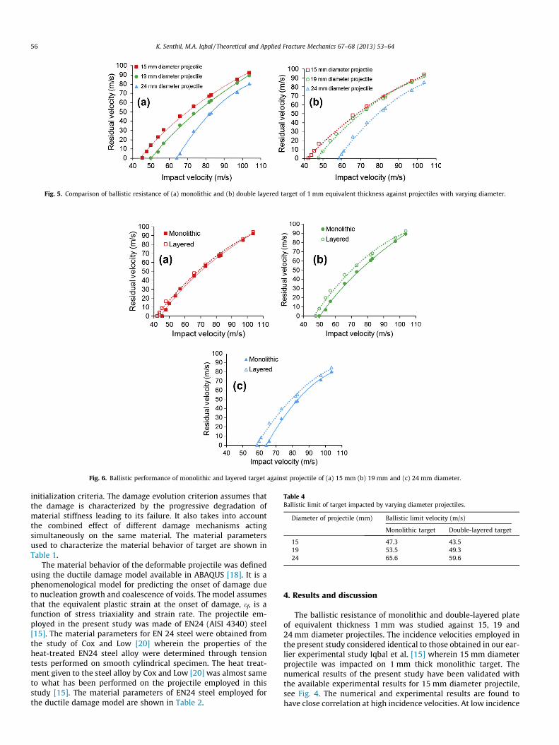
Fig. 5. Comparison of ballistic resistance of (a) monolithic and (b) double layered target of 1 mm equivalent thickness against projectiles with varying diameter.
Fig. 6. Ballistic performance of monolithic and layered target against projectile of (a) 15 mm (b) 19 mm and (c) 24 mm diameter.
Table 4Ballistic limit of target impacted by varying diameter projectiles.
Diameter of projectile (mm) Ballistic limit velocity (m/s)
Monolithic target Double-layered target
15 47.3 43.519 53.5 49.324 65.6 59.6
56 K. Senthil, M.A. Iqbal / Theoretical and Applied Fracture Mechanics 67–68 (2013) 53–64
initialization criteria. The damage evolution criterion assumes thatthe damage is characterized by the progressive degradation ofmaterial stiffness leading to its failure. It also takes into accountthe combined effect of different damage mechanisms actingsimultaneously on the same material. The material parametersused to characterize the material behavior of target are shown inTable 1.
The material behavior of the deformable projectile was definedusing the ductile damage model available in ABAQUS [18]. It is aphenomenological model for predicting the onset of damage dueto nucleation growth and coalescence of voids. The model assumesthat the equivalent plastic strain at the onset of damage, ef, is afunction of stress triaxiality and strain rate. The projectile em-ployed in the present study was made of EN24 (AISI 4340) steel[15]. The material parameters for EN 24 steel were obtained fromthe study of Cox and Low [20] wherein the properties of theheat-treated EN24 steel alloy were determined through tensiontests performed on smooth cylindrical specimen. The heat treat-ment given to the steel alloy by Cox and Low [20] was almost sameto what has been performed on the projectile employed in thisstudy [15]. The material parameters of EN24 steel employed forthe ductile damage model are shown in Table 2.
4. Results and discussion
The ballistic resistance of monolithic and double-layered plateof equivalent thickness 1 mm was studied against 15, 19 and24 mm diameter projectiles. The incidence velocities employed inthe present study considered identical to those obtained in our ear-lier experimental study Iqbal et al. [15] wherein 15 mm diameterprojectile was impacted on 1 mm thick monolithic target. Thenumerical results of the present study have been validated withthe available experimental results for 15 mm diameter projectile,see Fig. 4. The numerical and experimental results are found tohave close correlation at high incidence velocities. At low incidence
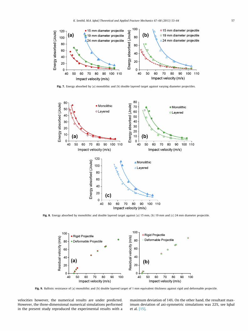
Fig. 7. Energy absorbed by (a) monolithic and (b) double layered target against varying diameter projectiles.
Fig. 8. Energy absorbed by monolithic and double layered target against (a) 15 mm, (b) 19 mm and (c) 24 mm diameter projectile.
Fig. 9. Ballistic resistance of (a) monolithic and (b) double layered target of 1 mm equivalent thickness against rigid and deformable projectile.
K. Senthil, M.A. Iqbal / Theoretical and Applied Fracture Mechanics 67–68 (2013) 53–64 57
velocities however, the numerical results are under predicted.However, the three-dimensional numerical simulations performedin the present study reproduced the experimental results with a
maximum deviation of 14%. On the other hand, the resultant max-imum deviation of axi-symmetric simulations was 22%, see Iqbalet al. [15].
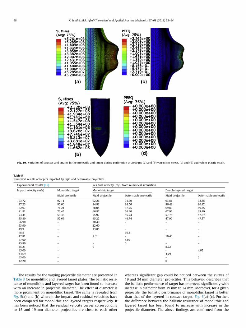
Fig. 10. Variation of stresses and strains in the projectile and target during perforation at 2500 ls; (a) and (b) von-Mises stress, (c) and (d) equivalent plastic strain.
Table 5Numerical results of targets impacted by rigid and deformable projectiles.
Experimental results [15] Residual velocity (m/s) from numerical simulation
Impact velocity (m/s) Monolithic target Monolithic target Double-layered target
Rigid projectile Rigid projectile Deformable projectile Rigid projectile Deformable projectile
103.72 92.11 92.26 91.70 93.81 93.8597.23 85.66 84.82 84.56 86.48 86.4282.97 71.21 68.08 67.75 69.80 69.7581.91 70.45 66.87 66.40 67.97 68.4973.31 59.38 55.97 55.74 57.78 57.6765.80 52.66 45.22 44.74 47.97 47.5756.90 – 30.40 – – –53.90 – 22.60 – – –49.9 – 13.85 – – –48.5 – – 10.31 – –47.81 – 7.01 – 16.45 –47.00 – – 5.92 – –45.80 – – 0 – –45.21 – 0 8.72 –45.00 – - 4.6543.69 – 3.79 –43.00 – – 042.20 – 0
58 K. Senthil, M.A. Iqbal / Theoretical and Applied Fracture Mechanics 67–68 (2013) 53–64
The results for the varying projectile diameter are presented inTable 3 for monolithic and layered target plates. The ballistic resis-tance of monolithic and layered target has been found to increasewith an increase in projectile diameter. The effect of diameter ismore prominent on monolithic target. The same is revealed fromFig. 5(a) and (b) wherein the impact and residual velocities havebeen compared for monolithic and layered targets respectively. Ithas been noticed that the residual velocity curves correspondingto 15 and 19 mm diameter projectiles are close to each other
whereas significant gap could be noticed between the curves of19 and 24 mm diameter projectiles. This behavior describes thatthe ballistic performance of target has improved significantly withincrease in diameter form 19 mm to 24 mm. Moreover, for a givenprojectile, the ballistic performance of monolithic target is betterthan that of the layered in contact target, Fig. 6(a)–(c). Further,the difference between the ballistic resistance of monolithic andlayered target has been found to increase with increase in theprojectile diameter. The above findings are confirmed from the
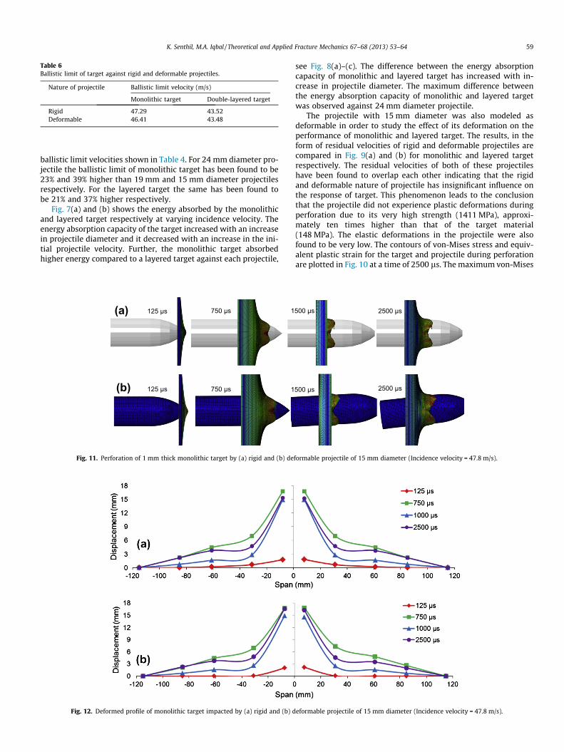
Table 6Ballistic limit of target against rigid and deformable projectiles.
Nature of projectile Ballistic limit velocity (m/s)
Monolithic target Double-layered target
Rigid 47.29 43.52Deformable 46.41 43.48
K. Senthil, M.A. Iqbal / Theoretical and Applied Fracture Mechanics 67–68 (2013) 53–64 59
ballistic limit velocities shown in Table 4. For 24 mm diameter pro-jectile the ballistic limit of monolithic target has been found to be23% and 39% higher than 19 mm and 15 mm diameter projectilesrespectively. For the layered target the same has been found tobe 21% and 37% higher respectively.
Fig. 7(a) and (b) shows the energy absorbed by the monolithicand layered target respectively at varying incidence velocity. Theenergy absorption capacity of the target increased with an increasein projectile diameter and it decreased with an increase in the ini-tial projectile velocity. Further, the monolithic target absorbedhigher energy compared to a layered target against each projectile,
125 µs 750 µs 1
1750 µs 125 µs
(a)
(b)
Fig. 11. Perforation of 1 mm thick monolithic target by (a) rigid and (b) de
Fig. 12. Deformed profile of monolithic target impacted by (a) rigid and (b) d
see Fig. 8(a)–(c). The difference between the energy absorptioncapacity of monolithic and layered target has increased with in-crease in projectile diameter. The maximum difference betweenthe energy absorption capacity of monolithic and layered targetwas observed against 24 mm diameter projectile.
The projectile with 15 mm diameter was also modeled asdeformable in order to study the effect of its deformation on theperformance of monolithic and layered target. The results, in theform of residual velocities of rigid and deformable projectiles arecompared in Fig. 9(a) and (b) for monolithic and layered targetrespectively. The residual velocities of both of these projectileshave been found to overlap each other indicating that the rigidand deformable nature of projectile has insignificant influence onthe response of target. This phenomenon leads to the conclusionthat the projectile did not experience plastic deformations duringperforation due to its very high strength (1411 MPa), approxi-mately ten times higher than that of the target material(148 MPa). The elastic deformations in the projectile were alsofound to be very low. The contours of von-Mises stress and equiv-alent plastic strain for the target and projectile during perforationare plotted in Fig. 10 at a time of 2500 ls. The maximum von-Mises
500 µs 2500 µs
2500 µs 500 µs
formable projectile of 15 mm diameter (Incidence velocity = 47.8 m/s).
eformable projectile of 15 mm diameter (Incidence velocity = 47.8 m/s).
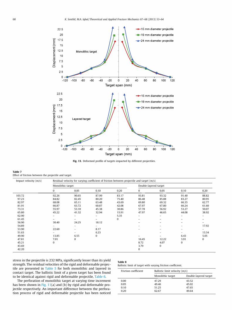
Fig. 13. Deformed profile of targets impacted by different projectiles.
Table 7Effect of friction between the projectile and target.
Impact velocity (m/s) Residual velocity for varying coefficient of friction between projectile and target (m/s)
Monolithic target Double-layered target
0 0.05 0.10 0.20 0 0.05 0.10 0.20
103.72 92.26 90.65 87.99 83.17 93.81 93.32 91.40 88.8297.23 84.82 82.45 80.20 75.40 86.48 85.88 83.27 80.9582.97 68.08 65.11 63.48 43.69 69.80 69.32 66.35 62.7781.91 66.87 63.72 60.87 42.08 67.97 67.80 66.24 61.6073.31 55.97 53.10 45.38 30.86 57.78 56.92 53.27 50.0765.80 45.22 41.32 32.94 15.91 47.97 46.65 44.08 38.9262.90 – – – 5.35 – – – –61.45 – – – 0 – – – –56.90 30.40 24.25 18.12 – – – –54.89 – – – – – – 17.9253.90 22.60 – 8.17 – – – –51.63 – – 6.23 – – 13.3449.90 13.85 6.55 0 – – 6.43 5.0547.81 7.01 0 16.45 12.22 3.91 045.21 0 8.72 4.07 043.69 3.79 042.20 0
Table 8Ballistic limit of target with varying friction coefficient.
Friction coefficient Ballistic limit velocity (m/s)
Monolithic target Double-layered target
0.00 47.29 43.520.05 49.46 45.020.10 51.25 47.650.20 62.67 49.64
60 K. Senthil, M.A. Iqbal / Theoretical and Applied Fracture Mechanics 67–68 (2013) 53–64
stress in the projectile is 232 MPa, significantly lesser than its yieldstrength. The residual velocities of the rigid and deformable projec-tile are presented in Table 5 for both monolithic and layered incontact target. The ballistic limit of a given target has been foundto be identical against rigid and deformable projectile, Table 6.
The perforation of monolithic target at varying time incrementhas been shown in Fig. 11(a) and (b) by rigid and deformable pro-jectile respectively. An important difference between the perfora-tion process of rigid and deformable projectile has been noticed
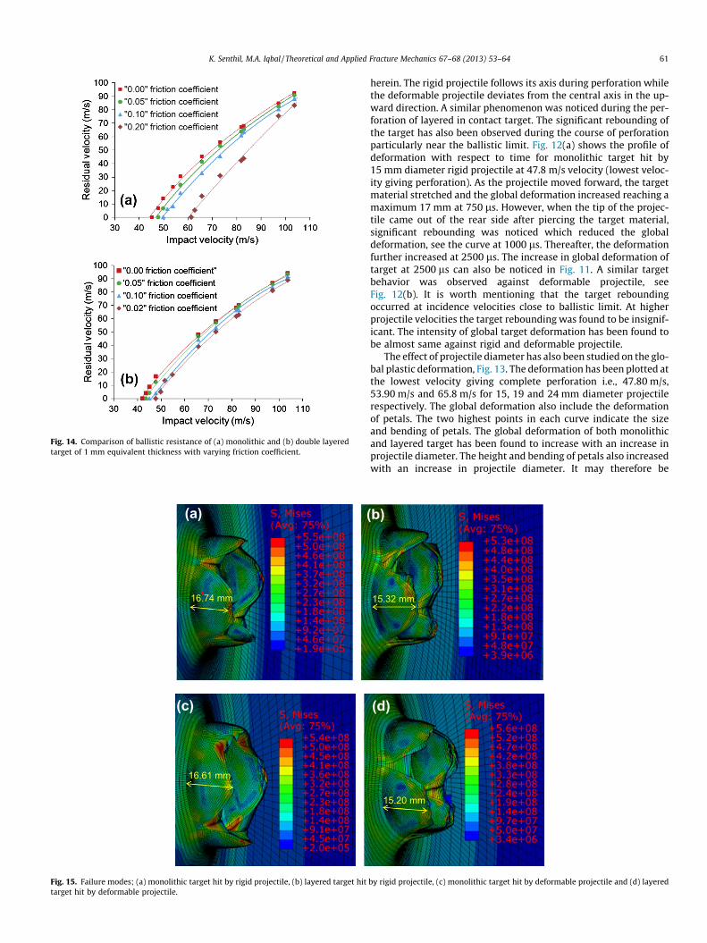
Fig. 14. Comparison of ballistic resistance of (a) monolithic and (b) double layeredtarget of 1 mm equivalent thickness with varying friction coefficient.
(a)
16.61 mm
16.74 mm
(
(c)
Fig. 15. Failure modes; (a) monolithic target hit by rigid projectile, (b) layered target hittarget hit by deformable projectile.
K. Senthil, M.A. Iqbal / Theoretical and Applied Fracture Mechanics 67–68 (2013) 53–64 61
herein. The rigid projectile follows its axis during perforation whilethe deformable projectile deviates from the central axis in the up-ward direction. A similar phenomenon was noticed during the per-foration of layered in contact target. The significant rebounding ofthe target has also been observed during the course of perforationparticularly near the ballistic limit. Fig. 12(a) shows the profile ofdeformation with respect to time for monolithic target hit by15 mm diameter rigid projectile at 47.8 m/s velocity (lowest veloc-ity giving perforation). As the projectile moved forward, the targetmaterial stretched and the global deformation increased reaching amaximum 17 mm at 750 ls. However, when the tip of the projec-tile came out of the rear side after piercing the target material,significant rebounding was noticed which reduced the globaldeformation, see the curve at 1000 ls. Thereafter, the deformationfurther increased at 2500 ls. The increase in global deformation oftarget at 2500 ls can also be noticed in Fig. 11. A similar targetbehavior was observed against deformable projectile, seeFig. 12(b). It is worth mentioning that the target reboundingoccurred at incidence velocities close to ballistic limit. At higherprojectile velocities the target rebounding was found to be insignif-icant. The intensity of global target deformation has been found tobe almost same against rigid and deformable projectile.
The effect of projectile diameter has also been studied on the glo-bal plastic deformation, Fig. 13. The deformation has been plotted atthe lowest velocity giving complete perforation i.e., 47.80 m/s,53.90 m/s and 65.8 m/s for 15, 19 and 24 mm diameter projectilerespectively. The global deformation also include the deformationof petals. The two highest points in each curve indicate the sizeand bending of petals. The global deformation of both monolithicand layered target has been found to increase with an increase inprojectile diameter. The height and bending of petals also increasedwith an increase in projectile diameter. It may therefore be
15.32 mm
15.20 mm
b)
(d)
by rigid projectile, (c) monolithic target hit by deformable projectile and (d) layered
(a)
Front view Rear view Side view
15 mm 15 mm
19 mm
24 mm 24 mm
19 mm
13.46 mm
25.85 mm
16.67 mm
(b)
(c)
Fig. 16. Failure modes of monolithic targets impacted by the projectile of diameter (a) 15 mm, (b) 19 mm, and (c) 24 mm (Incidence velocity = 103.72 m/s).
62 K. Senthil, M.A. Iqbal / Theoretical and Applied Fracture Mechanics 67–68 (2013) 53–64
concluded that the work done by the larger diameter projectile ishigher. Hence, target offered better performance against a largerdiameter projectile. However, no significant change between thedeformation of monolithic and layered target could be seen.
The effect of friction between the projectile and target wasstudied with the help of 15 mm diameter projectile, Table 7. Bothsingle and layered targets were impacted at the same incidencevelocities and ballistic limit was obtained corresponding to thecoefficient of friction 0.0, 0.05, 0.1 and 0.2, see Table 8. The frictionbetween the projectile and target has been found to improve theballistic performance of both monolithic and layered target,Fig. 14. With an increase in coefficient of friction from 0.0 to 0.2,the ballistic limit increased by 32% for monolithic and 15% for lay-ered target. Thus, the effect of friction is more significant for mono-lithic target despite the fact that the total thickness of the singleand layered target is same. The interplay between the layers maybe one of the reasons behind this outcome. It should be noted thatthe contacting surfaces of layers in a layered target have also beenassigned surface-to-surface contact with an assumed coefficient offriction 0.1 that may also affect the performance of layered target.
The failure mechanism in thin ductile targets is seen to be sig-nificantly influenced by the nose shape of the impacting projectile[1,2,6,14]. Petalling is a typical failure mode of thin metallic platesimpacted by conical and ogival nosed projectile. Landkof and Gold-smith [21] studied the sequence of events during crack initiationand propagation leading to the formation of petals in 2024-0aluminum plates impacted by cylindro-conical projectile. They
concluded that a star-shaped crack forms immediately after theinitial contact of the projectile nose. The fissures subsequentlypropagate outward under the pressure of the impacting projectileleading to formation of a hole. After partial perforation, the noseof the projectile tends to enlarge the circumference of the initiatedhole. The hoop stress is responsible for further radial extension ofcracks while the nose angle and nose radius is responsible for num-ber of petals.
Fig. 15(a)–(d) shows the failure mode of target hit by rigid anddeformable projectile. The target failed through petal formationagainst both of these projectiles. Four petals were formed in themonolithic as well as layered target against rigid and deformableprojectile. However, the petals formed against rigid projectile weredistinct and equal in size, see Fig. 15(a) for monolithic andFig. 15(b) for layered target. On the other hand, the petals formedagainst deformable projectile were unclear and irregular in size,see Fig. 15(c) for monolithic and Fig. 15(d) for layered target. How-ever, the petal length for a given target has been found to be unaf-fected by the rigid or deformable nature of projectile. For a givenprojectile the petal length has been found to be larger in mono-lithic target (16.7 mm) and smaller in layered target (15.3 mm).
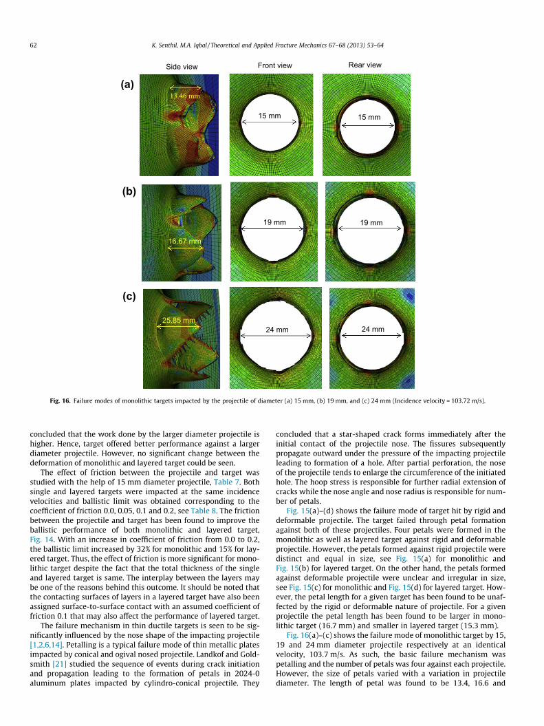
Fig. 16(a)–(c) shows the failure mode of monolithic target by 15,19 and 24 mm diameter projectile respectively at an identicalvelocity, 103.7 m/s. As such, the basic failure mechanism waspetalling and the number of petals was four against each projectile.However, the size of petals varied with a variation in projectilediameter. The length of petal was found to be 13.4, 16.6 and
(c)
(b)
(a) Front view Rear view Side view
15 mm 15 mm
24 mm 24 mm
19 mm 19 mm
15.42 mm
23.20 mm
12.62 mm
Fig. 17. Failure modes of layered targets impacted by the projectile of diameter (a) 15 mm, (b) 19 mm, and (c) 24 mm (Incidence velocity = 103.72 m/s).
(a) (b)
Incidence velocity = 65.8 m/s Incidence velocity = 59.76 m/s
Fig. 18. Failure mode of (a) monolithic and (b) layered target against rigid projectile of 24 mm diameter.
K. Senthil, M.A. Iqbal / Theoretical and Applied Fracture Mechanics 67–68 (2013) 53–64 63
25.5 mm against 15, 19 and 24 mm diameter projectile respec-tively. The change in shape of petals was also noticed due to in-crease in projectile diameter. The petals formed against 15 mm
diameter projectile are rounded in shape while for the other twoprojectiles the petals have been found to be triangular with sharpedges. The size of the circular hole formed in the target is exactly
64 K. Senthil, M.A. Iqbal / Theoretical and Applied Fracture Mechanics 67–68 (2013) 53–64
equal to the corresponding diameter of the projectile. It may there-fore be concluded that a larger diameter projectile required moreenergy to open a hole through the target and bend the petals.The failure mode and global deformation seems to be the impor-tant factors affecting the ballistic resistance of the target. Further,the radius of the ogival shape of projectile is responsible for theshape and sharpness of the petals. The larger projectile diameterwith small nose radius and large contact area, led to the formationof sharp and clear petals.
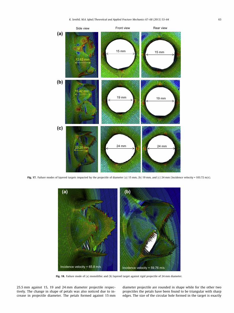
The failure mechanism of the layered target has been found tobe identical to that of the monolithic target, Fig. 17. The size of pet-als though increased with increase in the projectile diameter, how-ever, it remained smaller than that of the monolithic target. Thelength of petals was found to be 12.6, 15.4 and 23.2 mm against15, 19 and 24 mm diameter projectile respectively.
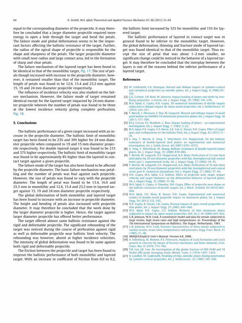
The influence of incidence velocity was also studied on the fail-ure mechanism. However, the failure mode of target remainedidentical except for the layered target impacted by 24 mm diame-ter projectile wherein the number of petals was found to be threeat the lowest incidence velocity giving complete perforation,Fig. 18.
5. Conclusions
The ballistic performance of a given target increased with an in-crease in the projectile diameter. The ballistic limit of monolithictarget has been found to be 23% and 39% higher for 24 mm diam-eter projectile when compared to 19 and 15 mm diameter projec-tile respectively. For double layered target it was found to be 21%and 37% higher respectively. The ballistic limit of monolithic targetwas found to be approximately 8% higher than the layered in con-tact target against a given projectile.
The failure mode of the target has also been found to be affectedby the projectile diameter. The basic failure mechanism was petal-ling and the number of petals was four against each projectile.However, the size of petals was found to vary with the projectilediameter. The length of petal was found to be 13.4, 16.6 and25.5 mm in monolithic and 12.6, 15.4 and 23.2 mm in layered tar-get against 15, 19 and 24 mm diameter projectile respectively.
The global deformation of both monolithic and layered targethas been found to increase with an increase in projectile diameter.The height and bending of petals also increased with projectilediameter. It may therefore be concluded that the work done bythe larger diameter projectile is higher. Hence, the target againstlarger diameter projectile has offered better performance.
The target offered almost same ballistic resistance against therigid and deformable projectile. The significant rebounding of thetarget was noticed during the course of perforation against rigidas well as deformable projectile near ballistic limit velocity. Therebounding was however, absent at higher incidence velocities.The intensity of global deformation was found to be same againstboth rigid and deformable projectile.
The friction between the projectile and target has been found toimprove the ballistic performance of both monolithic and layeredtarget. With an increase in coefficient of friction from 0.0 to 0.2,
the ballistic limit increased by 32% for monolithic and 15% for lay-ered target.
The ballistic performance of layered in contact target was ingeneral found to be inferior to the monolithic target. However,the global deformation, thinning and fracture mode of layered tar-get was found identical to that of the monolithic target. Thus ex-cept the size of petal that was about 1–2 mm smaller, nosignificant change could be noticed in the behavior of a layered tar-get. It may therefore be concluded that the interplay between thelayers is one of the reasons behind the inferior performance of alayered target.
References
[1] W. Goldsmith, S.A. Finnegan, Normal and oblique impact of cylindro-conicaland cylindrical projectiles on metallic plates, Int. J. Impact Engg. 4 (1986) 83–105.
[2] G.G. Corbett, S.R. Reid, W. Johnson, Impact loading of plates and shells by free-flying projectiles: a review, Int. J. Impact Engg. 18 (1996) 141–230.
[3] M.A. Iqbal, G. Gupta, N.K. Gupta, 3D numerical simulations of ductile targetssubjected to oblique impact by sharp nosed projectiles, Int. J. Solids/Struct. 47(2010) 224–237.
[4] T. Børvik, L. Olovsson, S. Dey, M. Langseth, Normal and oblique impact of smallarms bullets on AA6082-T4 aluminium protective plates, Int. J. Impact Engg. 38(2011) 577–589.
[5] R.S.J. Corran, P.J. Shadbolt, C. Ruiz, Impact loading of plates – an experimentalinvestigation, Int. J. Impact Engg. 1 (1983) 3–22.
[6] M.A. Iqbal, P.K. Gupta, V.S. Deore, S.K. Tak, G. Tiwari, N.K. Gupta, Effect of targetspan and configuration on the ballistic limit, Int. J. Impact Engg. 42 (2012) 11–24.
[7] S. Dey, T. Børvik, X. Teng, T. Wierzbicki, O.S. Hopperstad, On the ballisticresistance of double-layered steel plates: an experimental and numericalinvestigation, Int. J. Solids Struct. 44 (2007) 6701–6723.
[8] X. Teng, T. Wierzbicki, M. Huang, Ballistic resistance of double-layered armorplates, Int. J. Impact Engg. 35 (2008) 870–884.
[9] T. Borvik, M. Langseth, O.S. Hopperstad, K.A. Malo, Perforation of 12 mm thicksteel plates by 20 mm diameter projectiles with flat, hemispherical and conicalnoses part I: experimental study, Int. J. Impact Engg. 27 (2002) 19–35.
[10] T. Borvik, M. Langseth, O.S. Hopperstad, K.A. Malo, Perforation of 12 mm thicksteel plates by 20 mm diameter projectiles with flat, hemispherical and conicalnoses part II: numerical simulations, Int. J. Impact Engg. 27 (2002) 37–64.
[11] N.K. Gupta, M.A. Iqbal, G.S. Sekhon, Effect of projectile nose shape, impactvelocity and target thickness on the deformation behavior of layered plates,Int. J. Impact Engg. 35 (2008) 37–60.
[12] M.A. Iqbal, G. Gupta, A. Diwakar, N.K. Gupta, Effect of projectile nose shape onthe ballistic resistance of ductile targets, Int. J. Mech. A/Solids 29 (2010) 683–694.
[13] M.A. Iqbal, S.H. Khan, R. Ansari, N.K. Gupta, Experimental and numericalstudies of double-nosed projectile impact on aluminum plates, Int. J. ImpactEngg. 54 (2013) 232–245.
[14] N.K. Gupta, R. Ansari, S.K. Gupta, Normal impact of ogive nosed projectiles onthin plates, Int. J. Impact Engg. 25 (2001) 641–660.
[15] M.A. Iqbal, N.K. Gupta, G.S. Sekhon, Behavior of thin aluminum platessubjected to impact by ogive-nosed projectiles, Def. Sci. J. 56 (2006) 841–852.
[16] G.R. Johnson, W.H. Cook, A constitutive model and data for metals subjected tolarge strains, high strain rates and high temperatures, in: Proceedings of the7th International Symposium on Ballistics, The Hague, Netherlands, 1983.
[17] G.R. Johnson, W.H. Cook, Fracture characteristics of three metals subjected tovarious strains, strain rates, temperatures and pressures, Engg. Fract. Mech. 21(1985) 31–48.
[18] ABAQUS/Explicit User’s Manual, Version 6.8, 2008.[19] A. Hillerborg, M. Modeer, P.E. Petersson, Analysis of crack formation and crack
growth in concrete by means of fracture mechanics and finite elements, Cem.Concr. Res. 6 (1976) 773–782.
[20] T.B. Cox, J.R. Low, An investigation of the plastic fracture of AISI 4340 and 18Nickel-200 grade maraging steels, Metall. Trans. 5 (1974) 1457–1470.
[21] B. Landkof, W. Goldsmith, Petalling of thin, metallic plates during penetrationby cylindro-conical projectiles, Int. J. Solids/struct. 22 (1985) 245–266.


