Embed Size (px)
Citation preview
Citation: Shi, Y.; Zhou, X.; Wang, X.;
Feng, X.; Peng, L. Effects of
Electromagnetic Fields on the
Microstructure of Laser Cladding.
Materials 2022, 15, 4198. https://
doi.org/10.3390/ma15124198
Academic Editor: Beat
Neuenschwander
Received: 19 April 2022
Accepted: 2 June 2022
Published: 13 June 2022
Publisher’s Note: MDPI stays neutral
with regard to jurisdictional claims in
published maps and institutional affil-
iations.
Copyright: © 2022 by the authors.
Licensee MDPI, Basel, Switzerland.
This article is an open access article
distributed under the terms and
conditions of the Creative Commons
Attribution (CC BY) license (https://
creativecommons.org/licenses/by/
4.0/).
materials
Article
Effects of Electromagnetic Fields on the Microstructure ofLaser CladdingYongjun Shi *, Xiaoyu Zhou, Xiaogang Wang, Xingteng Feng and Laida Peng
College of Electromechanical Engineering, China University of Petroleum (East China), Qingdao 266580, China;[email protected] (X.Z.); [email protected] (X.W.); [email protected] (X.F.); [email protected] (L.P.)* Correspondence: [email protected]
Abstract: The fast heating and quenching of laser cladding increase the internal stresses in thecladding layer. Moreover, the quick condensation of the molten pool leads to an uneven distributionof the internal elements and coarse grains of the structure. To address the above defects and increasethe molding quality of laser cladding, an electromagnetic field was introduced into the laser claddingtechnique, and the effects of the external assisted electromagnetic field on the mixed metal fluid in themolten pool were explored. On this basis, the action of the electromagnetic field on the flow states ofthe molten pool was further analyzed. The results demonstrate that after introducing electromagneticassistance, the material flow in the molten pool accelerated as a response to the periodic changes inelectromagnetic forces and the influences of the electromagnetic field on crystallization, thus refiningthe grains and improving the grain distribution uniformity in the cladding layer. The dendriticcrystals in the cladding layer decreased, while the isometric crystals and the cellular-like dendritesincreased. The element distribution in the cladding layer increased in uniformity. Additionally, thismethod can decrease the dilution rate of the cladding layer and improve its overall hardness. A laser-cladding test of the Ni-based powder was carried out on the AISI 1045 steel surface under the coaxialpowder-feeding mode. Moreover, the influences of the electromagnetic field on the microstructure ofthe laser-cladding layer were compared, and the causes of the changes were disclosed.
Keywords: laser cladding; electromagnetic assistance; microstructure
1. Introduction
Laser cladding is a surface-strengthening technology that quickly applies a high-performance coating to the workpiece surface by using high-energy laser beams. Thistechnology can apply a high-performance coating to core equipment surfaces with a fewhigh-quality alloy materials, thus prolonging the service life of the equipment. Lasercladding has been extensively applied in the petroleum, transportation, and aerospaceindustries [1–3].
Nevertheless, various defects, like cracks and pores, are produced on the claddinglayer, due to differences in thermophysical properties between the base and cladding layermaterials and the fast heating and cooling of the molten pool during the cladding process.These defects limit the application of a cladding layer in industrial production [4–6]. Giventhe fast heating and cooling of laser cladding, the internal stress of the cladding layer isstronger than the yield strength, thus producing cracks. Melted metals contain gases thatcannot escape in a timely manner during fast condensation, thus resulting in pores in thecladding layer. Moreover, the stress concentrations at the tips of the pores cause cracks.
To address the above defects and improve the molding quality of laser cladding, re-search both at home and abroad in this field has explored various approaches. The majorresearch directions include improving the cladding process by establishing the optimaltechnological parameters, increasing the wettability by adjusting the element contents ofthe cladding layer, and applying an external force field during cladding. Abioye et al. [7,8]
Materials 2022, 15, 4198. https://doi.org/10.3390/ma15124198 https://www.mdpi.com/journal/materials
Materials 2022, 15, 4198 2 of 13
applied an Inconel 625 alloy coating to a 304 stainless-steel surface by using laser wire-feeding cladding technology and analyzed the molding quality, dilution rate, and corrosionresistance of the coating using different technological parameters. According to their analy-sis, the Inconel 625 coating applied by laser cladding achieved a relatively good corrosionresistance when the Fe content was low (the dilution rate was low). Fesharaki et al. [9]applied an Inconel 625 cladding layer to an Inconel 738 alloy surface by TIG welding andobserved the sections of the samples. They observed the formation of many cracks at theboundary between the base and the coating. The sensitivities to cracks of the base andcoating materials increased due to the high heat input. Silwal et al. [10] studied an Inconel625 coating prepared by hot-wire-assisted arc cladding. Under a relatively high currentintensity, the coating-based interface also developed many cracks. Wang et al. [11] pavedthe cladding material onto a base surface and the prepared Ni-based cladding layer. Inthe experiment, a large-area cladding layer was obtained through multi-channel joining; ahigh jointing rate could decrease the sensitivity of the entire cladding layer to cracks whileensuring its flatness.
To increase the uniformity of the distribution of elements and microstructure in thedepth direction of the molten pool, researchers have attempted to introduce external assis-tance to the molding process of laser cladding, thus increasing the mobility of the moltenpool and achieving important breakthroughs. Ram et al. [12] strengthened the mobility ofliquid metals in the molten pool through a pulse current during the arc welding of Inconel718 alloy and facilitated the breakage of the solid–liquid interface in the molten pool alongthe dendrites before condensation, thus forming a refined microstructure. Liu et al. [13]studied the precipitation state of the Laves phase in a GH4619 alloy molded through lasercladding, with the assistance of electromagnetic stirring. Their results show that the elec-tromagnetic stirring facilitated the flow of liquid metals in the molten pool, and the Lavesphase changed from networked precipitation into fine particles. The Nb content in thedendrite trunks increased effectively, thus increasing the microhardness of the moldingsamples. Meng et al. [14] introduced an alternating field to laser deep-welding and com-pared the flow behaviors of metals in the welding molten pool with and without alternatingmagnetic stirring, using calculations. They found that the electromagnetic field intensifiedthe flow in the molten pool and facilitated the refinement of the weld’s metal crystals.
Recently, electromagnetic-assisted laser cladding has been studied extensively. Someprogress in the numerical simulation of laser cladding, the role of the magnetic field on themolten pool, and the microstructure of the cladding layer under magnetic-field assistancehas been achieved. However, intensive studies on the preparation of excellent laser claddinglayers under electromagnetic assistance and the analysis of the microstructure of thelaser cladding layer are needed. In this study, a coaxial powder-feeding laser-claddingexperiment was performed under electromagnetic assistance, using AISI 1045 steel as thebase and a Ni-based self-melting metal powder as the cladding material. The influencingmechanism of the electromagnetic field on laser cladding was intensively investigated byobserving the microstructure of the specimens, the element distribution, and the micro-hardness of the cladding layer.
2. Experimental Method2.1. Materials
AISI 1045 steel was selected as the base material and self-melting Ni60AA metalpowder was used as the cladding material, which has a low melting point and good self-melting properties. In addition, Ni60AA has excellent wear, heat, and oxidation resistanceand is widely used in additive manufacturing. The chemical compositions of the base andcladding materials are shown in Tables 1 and 2, respectively.
Materials 2022, 15, 4198 3 of 13
Table 1. Chemical composition of AISI 1045 steel.
Elements C Si Mn Cr Ni Cu Fe
wt % 0.45 0.20 0.50 0.24 0.22 0.25 Bal.
Table 2. Chemical compositions of Ni60AA.
Elements C Si B Cr Fe Ni
wt % 0.85 4.2 3.7 17 7.1 Bal.
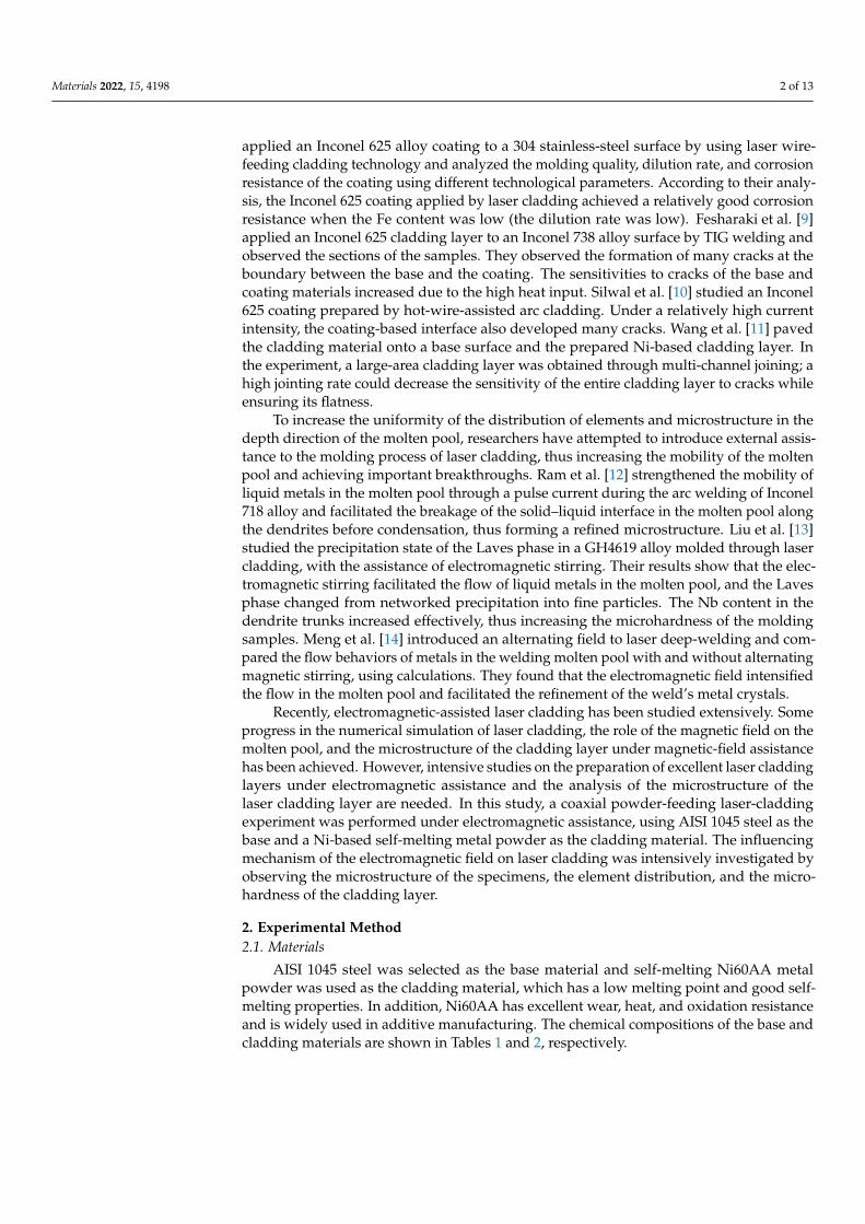
During cladding molding, the thermophysical properties of the base and claddingmaterials are related to temperature. Hence, the variation trends of the thermophysicalproperties (e.g., specific heat, thermal conductivity, and electric conductivity) of the baseand cladding materials with temperature are presented in Figure 1.
Figure 1. Changes in thermophysical properties with temperature: (a) AISI 1045 steel; (b) Ni60AA.
2.2. Experimental Platform
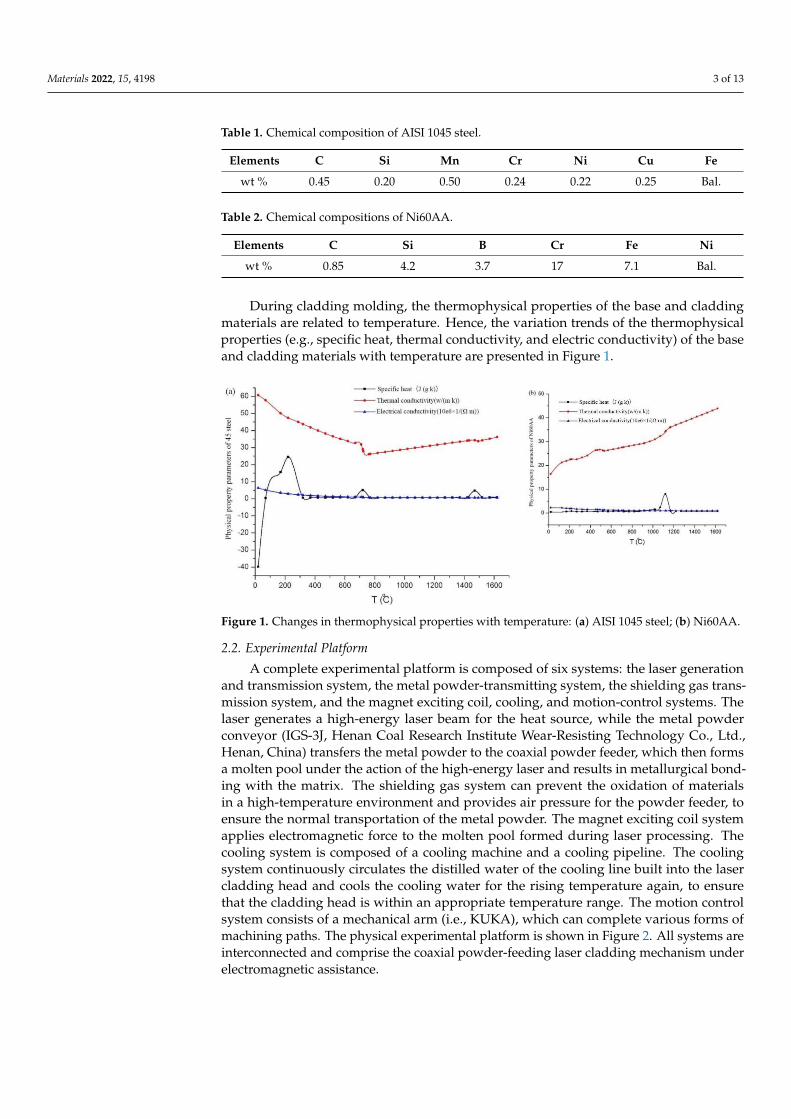
A complete experimental platform is composed of six systems: the laser generationand transmission system, the metal powder-transmitting system, the shielding gas trans-mission system, and the magnet exciting coil, cooling, and motion-control systems. Thelaser generates a high-energy laser beam for the heat source, while the metal powderconveyor (IGS-3J, Henan Coal Research Institute Wear-Resisting Technology Co., Ltd.,Henan, China) transfers the metal powder to the coaxial powder feeder, which then formsa molten pool under the action of the high-energy laser and results in metallurgical bond-ing with the matrix. The shielding gas system can prevent the oxidation of materialsin a high-temperature environment and provides air pressure for the powder feeder, toensure the normal transportation of the metal powder. The magnet exciting coil systemapplies electromagnetic force to the molten pool formed during laser processing. Thecooling system is composed of a cooling machine and a cooling pipeline. The coolingsystem continuously circulates the distilled water of the cooling line built into the lasercladding head and cools the cooling water for the rising temperature again, to ensurethat the cladding head is within an appropriate temperature range. The motion controlsystem consists of a mechanical arm (i.e., KUKA), which can complete various forms ofmachining paths. The physical experimental platform is shown in Figure 2. All systems areinterconnected and comprise the coaxial powder-feeding laser cladding mechanism underelectromagnetic assistance.
Materials 2022, 15, 4198 4 of 13
Figure 2. Experimental platform.
The alternating magnetic field produced in the coils during the experiment wasmeasured with an HT201 Gauss meter.
2.3. Selection of Technological Parameters
In coaxial powder-feeding laser cladding technology, effective technological parame-ters can not only ensure bonding stability between the cladding layer and the base materialsduring laser cladding but also form a relatively stable morphology, satisfying the continuityand size stability needs of the cladding layer and avoiding large-area processing defects onthe specimens.
In this research, the laser power (P), the processing velocity (v0), the powder-feedingamount (L), and the defocusing amount (d1) were viewed as the major factors that influencelaser cladding. In the experiment, the protective air pressure (pb) and the powder-feedingpressure (pf) were constant: pb = 0.2 MPa and pf = 0.1 MPa. The diameter of the laser spotwas 3 mm.
To determine the order of significance of the above technological parameters in terms ofmolding and to recognize their appropriate intervals, the above parameters were optimizedthrough an orthogonal test. The test parameters are shown in Table 3. Each parameter hasfive values. The cladding layer was evaluated comprehensively, according to its size, sizestability, defect quantity, and bonding strength with the base. Moreover, the orthogonaltest results were analyzed.
A qualitative method was used for scoring, and a benchmark of 80 points was addedto or subtracted from each sample. The main evaluation indexes were the combination,the size, and the number of defects. The binding situation is divided into three aspects:the presence/absence of binding, the depth of the transition zone, and the width of theheat-affected zone. For a sample that fails to combine, the fraction will be subtracted; for asample with an extremely deep or shallow transition zone, the fraction will be subtracted;for a sample with a high combination degree and a moderate transition zone, a set fractionwill be added. In terms of size, the score will be low if the cladding layer is extremelylarge or small. In terms of cladding defects, points will be subtracted from the score whenexcessive cracks, uneven surfaces, and pores occur. The highest score was 135, while thelowest score was 25.
Each specimen was qualitatively scored after the above orthogonal test. The majorevaluation indexes include the binding state, the size, and the defect quantity. All specieswere scored, using a score of 80 as the benchmark. The binding state was divided intothe binding existence, the depth of the transition area, and the width of the heat-affectedzone (HAZ). With respect to size, the score of the cladding layer decreased when the sizewas inadequate or extremely large or small. With respect to the defects of the cladding
Materials 2022, 15, 4198 5 of 13
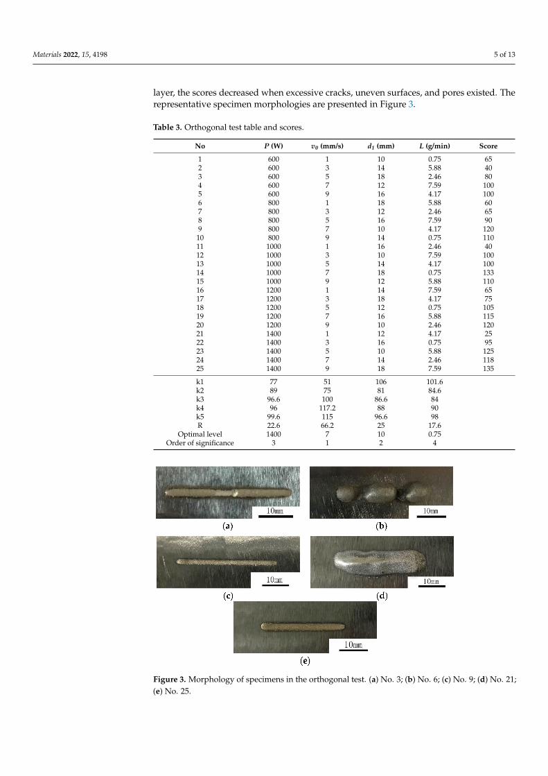
layer, the scores decreased when excessive cracks, uneven surfaces, and pores existed. Therepresentative specimen morphologies are presented in Figure 3.
Table 3. Orthogonal test table and scores.
No P (W) v0 (mm/s) d1 (mm) L (g/min) Score
1 600 1 10 0.75 652 600 3 14 5.88 403 600 5 18 2.46 804 600 7 12 7.59 1005 600 9 16 4.17 1006 800 1 18 5.88 607 800 3 12 2.46 658 800 5 16 7.59 909 800 7 10 4.17 12010 800 9 14 0.75 11011 1000 1 16 2.46 4012 1000 3 10 7.59 10013 1000 5 14 4.17 10014 1000 7 18 0.75 13315 1000 9 12 5.88 11016 1200 1 14 7.59 6517 1200 3 18 4.17 7518 1200 5 12 0.75 10519 1200 7 16 5.88 11520 1200 9 10 2.46 12021 1400 1 12 4.17 2522 1400 3 16 0.75 9523 1400 5 10 5.88 12524 1400 7 14 2.46 11825 1400 9 18 7.59 135
k1 77 51 106 101.6k2 89 75 81 84.6k3 96.6 100 86.6 84k4 96 117.2 88 90k5 99.6 115 96.6 98R 22.6 66.2 25 17.6
Optimal level 1400 7 10 0.75Order of significance 3 1 2 4
Figure 3. Morphology of specimens in the orthogonal test. (a) No. 3; (b) No. 6; (c) No. 9; (d) No. 21;(e) No. 25.
Materials 2022, 15, 4198 6 of 13
Specimen #3 presents low binding strength and many cracks on the cladding layer, butits size is relatively stable. Specimen #6 experienced a discontinuous cladding process andmetal powder accumulation during the test; the cladding layer is coarse and the bindingstrength is low. Specimen #9 has a relatively narrow cladding layer and a superficialtransition area. Specimen #21 failed to bind with the cladding layer, which is extremelywide. Moreover, the cladding layer experienced red-hot due to powder accumulation in theprocessing. Hence, Specimen #21 obtained the lowest scores and the poorest technologicalparameters. Specimen #25 exhibited good performance in terms of morphology and bindingstrength and has very few defects in the cladding layer. This specimen obtained the highestscores and has relatively good technological parameters. The maximum and minimumscores are 135 and 25, respectively.
The optimal intervals of the molding technological parameters were P > 1200 W,v0 = 5–8 mm/s, and d1 = 12–18 mm. A relatively low powder-feeding amount can meet themolding quality requirements. In this study, L was fixed at 1.18 g/min in the laser claddingtest under electromagnetic assistance. The magnet exciting coil used 1000 turns of a copperconductor with a diameter of 0.8 mm. An alternating voltage of 220 V 50 Hz was applied.
2.4. Test Method of Molding Parts
Specimens with representative significance were selected for metallographic analysis.The length of the metallographic specimens was 10 mm. The microstructures of thespecimens were analyzed by combining metallographic light microscopy and scanningelectron microscopy. The binding zone between the cladding layer and the base was selectedfor EDS testing. The hardness of the cladding layer was tested using a microhardnessmeter and the applied load of the instrument was 200 g, which was maintained for 5 s.The mid-line of the specimens was used as the position of the hardness testing point.Six and five testing points were chosen at intervals of 0.2 mm on the cladding layer and thebase, respectively. The bottom testing point, which was nearest to the cladding layer, wasattached to the binding line in the test.
3. Results and Analysis3.1. Effects of Electromagnetic Field Assistance on the Macroscopic Morphology of Specimens
To explore the influencing mechanism of the external electromagnetic field in thelaser cladding process and its influence on the final molding morphology, the effects ofthe alternating electromagnetic field on the microscopic morphology of the molten pooland the cladding layer were further analyzed, based on the optimization of the abovetechnological parameters. In the experiment, some parameters were fixed, includingpb = 0.2 MPa, pf = 0.1 Mpa, and the laser pot diameter = 3 mm. The controller voltageof the powder feeder was 5 V (the corresponding L = 1.18 g/min). The AISI 1045 steeland the Ni60AA self-melting powder were used as the base and cladding layer materials,respectively. The technological parameters are shown in Table 4.
Table 4. Process parameters.
No Electromagnetic Field(Yes/No) d1 (mm) v0 (mm/s) P (W)
1 No 12 5 12002 No 18 8 18003 Yes 12 5 12004 Yes 18 8 1800
After experimental studies based on the technological parameters in Table 4, themacroscopic morphologies of the molding specimens were analyzed. The results showthat after optimizing the technological parameters, the macroscopic morphologies of thespecimens improved significantly, basically causing no cladding layer defects such as
Materials 2022, 15, 4198 7 of 13
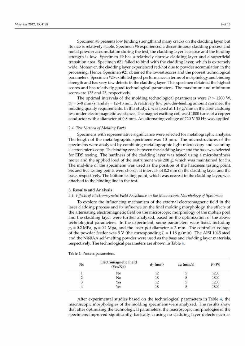
inadequate or excessive binding strength. The macroscopic morphologies of the specimensare shown in Figure 4.
Figure 4. Macroscopic morphology of the specimens. (a) No. 1; (b) No. 2; (c) No. 3; (d) No. 4.
Specimens #1 and #2 are cladding layers without electromagnetic field assistance,while Specimens #3 and #4 are cladding layers with electromagnetic field assistance. Thesurface variations of Specimens #3 and #4 were flatter and the quality of binding with thebases was smoother than those of Specimens #1 and #2.
3.2. Effects of Electromagnetic Field on the Microstructure
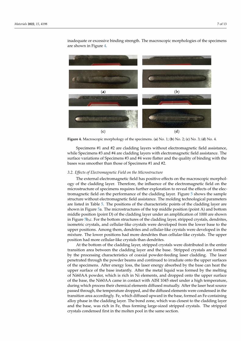
The external electromagnetic field has positive effects on the macroscopic morphol-ogy of the cladding layer. Therefore, the influence of the electromagnetic field on themicrostructure of specimens requires further exploration to reveal the effects of the elec-tromagnetic field on the performance of the cladding layer. Figure 5 shows the samplestructure without electromagnetic field assistance. The molding technological parametersare listed in Table 5. The positions of the characteristic points of the cladding layer areshown in Figure 5a. The microstructures of the top middle position (point A) and bottommiddle position (point D) of the cladding layer under an amplification of 1000 are shownin Figure 5b,c. For the bottom structures of the cladding layer, stripped crystals, dendrites,isometric crystals, and cellular-like crystals were developed from the lower base to theupper positions. Among them, dendrites and cellular-like crystals were developed in themixture. The lower positions had more dendrites than cellular-like crystals. The upperposition had more cellular-like crystals than dendrites.
At the bottom of the cladding layer, stripped crystals were distributed in the entiretransition area between the cladding layer and the base. Stripped crystals are formedby the processing characteristics of coaxial powder-feeding laser cladding. The laserpenetrated through the powder beams and continued to irradiate onto the upper surfacesof the specimens. After energy loss, the laser energy absorbed by the base can heat theupper surface of the base instantly. After the metal liquid was formed by the meltingof Ni60AA powder, which is rich in Ni elements, and dropped onto the upper surfaceof the base, the Ni60AA came in contact with AISI 1045 steel under a high temperature,during which process their chemical elements diffused mutually. After the laser heat sourcepassed through, the temperature dropped, and the diffused elements were condensed in thetransition area accordingly. Fe, which diffused upward in the base, formed an Fe-containingalloy phase in the cladding layer. The bond zone, which was closest to the cladding layerand the base, was rich in Fe, thus forming large-sized stripped crystals. The strippedcrystals condensed first in the molten pool in the same section.
Materials 2022, 15, 4198 8 of 13
Figure 5. Structures of specimens without electromagnetic field assistance. (a) The overall morphol-ogy of the sample; (b) microstructure at point A; (c) microstructure at point D.
Table 5. Process parameters.
Electromagnetic Field(Yes/No) d1 (mm) v0 (mm/s) P (W) pb (MPa) pf (MPa)
No 18 8 1800 0.2 0.1
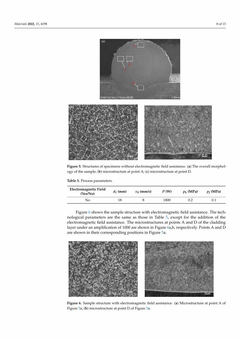
Figure 6 shows the sample structure with electromagnetic field assistance. The tech-nological parameters are the same as those in Table 5, except for the addition of theelectromagnetic field assistance. The microstructures at points A and D of the claddinglayer under an amplification of 1000 are shown in Figure 6a,b, respectively. Points A and Dare shown in their corresponding positions in Figure 5a.
Figure 6. Sample structure with electromagnetic field assistance. (a) Microstructure at point A ofFigure 5a; (b) microstructure at point D of Figure 5a.
Materials 2022, 15, 4198 9 of 13
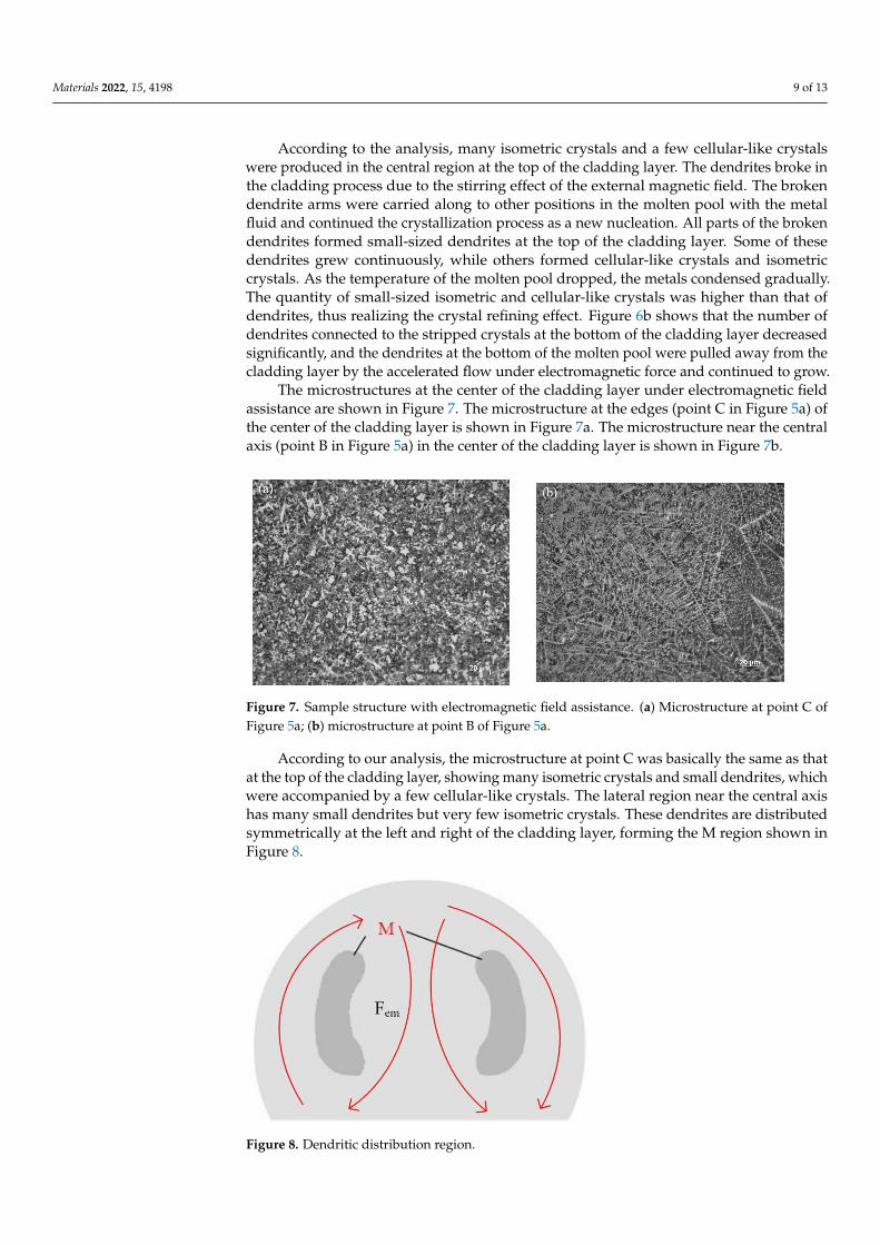
According to the analysis, many isometric crystals and a few cellular-like crystalswere produced in the central region at the top of the cladding layer. The dendrites broke inthe cladding process due to the stirring effect of the external magnetic field. The brokendendrite arms were carried along to other positions in the molten pool with the metalfluid and continued the crystallization process as a new nucleation. All parts of the brokendendrites formed small-sized dendrites at the top of the cladding layer. Some of thesedendrites grew continuously, while others formed cellular-like crystals and isometriccrystals. As the temperature of the molten pool dropped, the metals condensed gradually.The quantity of small-sized isometric and cellular-like crystals was higher than that ofdendrites, thus realizing the crystal refining effect. Figure 6b shows that the number ofdendrites connected to the stripped crystals at the bottom of the cladding layer decreasedsignificantly, and the dendrites at the bottom of the molten pool were pulled away from thecladding layer by the accelerated flow under electromagnetic force and continued to grow.
The microstructures at the center of the cladding layer under electromagnetic fieldassistance are shown in Figure 7. The microstructure at the edges (point C in Figure 5a) ofthe center of the cladding layer is shown in Figure 7a. The microstructure near the centralaxis (point B in Figure 5a) in the center of the cladding layer is shown in Figure 7b.
Figure 7. Sample structure with electromagnetic field assistance. (a) Microstructure at point C ofFigure 5a; (b) microstructure at point B of Figure 5a.
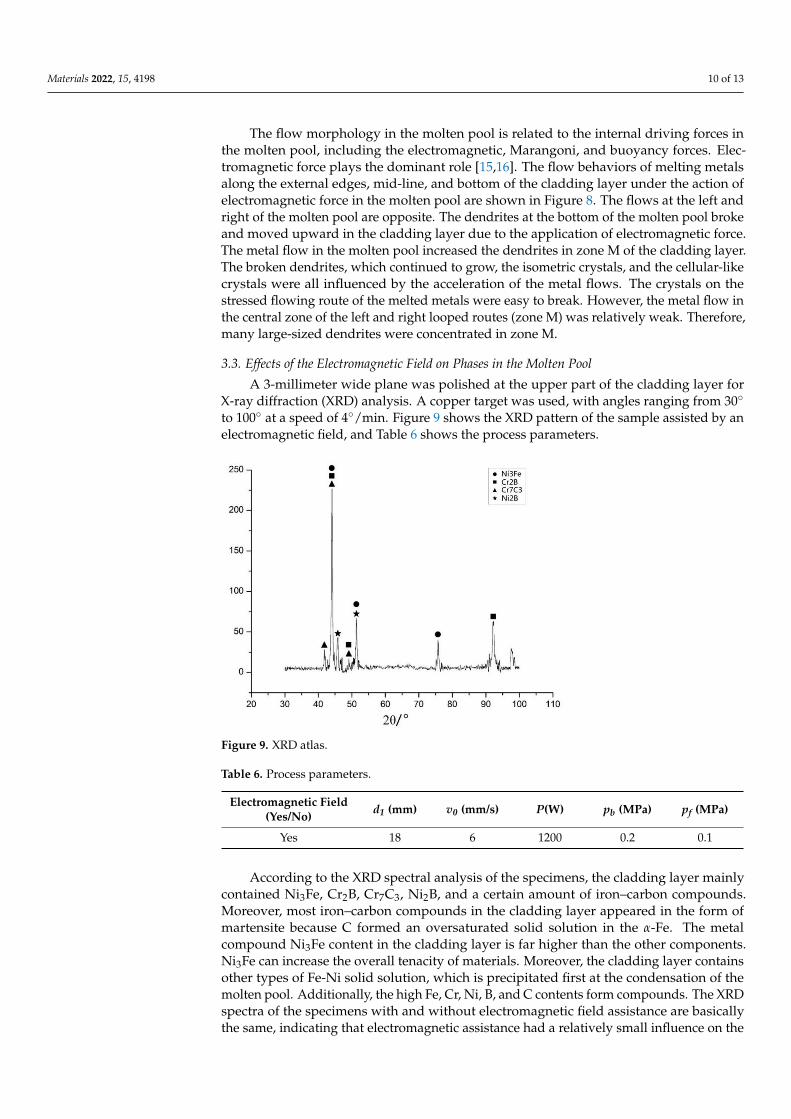
According to our analysis, the microstructure at point C was basically the same as thatat the top of the cladding layer, showing many isometric crystals and small dendrites, whichwere accompanied by a few cellular-like crystals. The lateral region near the central axishas many small dendrites but very few isometric crystals. These dendrites are distributedsymmetrically at the left and right of the cladding layer, forming the M region shown inFigure 8.
Figure 8. Dendritic distribution region.
Materials 2022, 15, 4198 10 of 13
The flow morphology in the molten pool is related to the internal driving forces inthe molten pool, including the electromagnetic, Marangoni, and buoyancy forces. Elec-tromagnetic force plays the dominant role [15,16]. The flow behaviors of melting metalsalong the external edges, mid-line, and bottom of the cladding layer under the action ofelectromagnetic force in the molten pool are shown in Figure 8. The flows at the left andright of the molten pool are opposite. The dendrites at the bottom of the molten pool brokeand moved upward in the cladding layer due to the application of electromagnetic force.The metal flow in the molten pool increased the dendrites in zone M of the cladding layer.The broken dendrites, which continued to grow, the isometric crystals, and the cellular-likecrystals were all influenced by the acceleration of the metal flows. The crystals on thestressed flowing route of the melted metals were easy to break. However, the metal flow inthe central zone of the left and right looped routes (zone M) was relatively weak. Therefore,many large-sized dendrites were concentrated in zone M.
3.3. Effects of the Electromagnetic Field on Phases in the Molten Pool
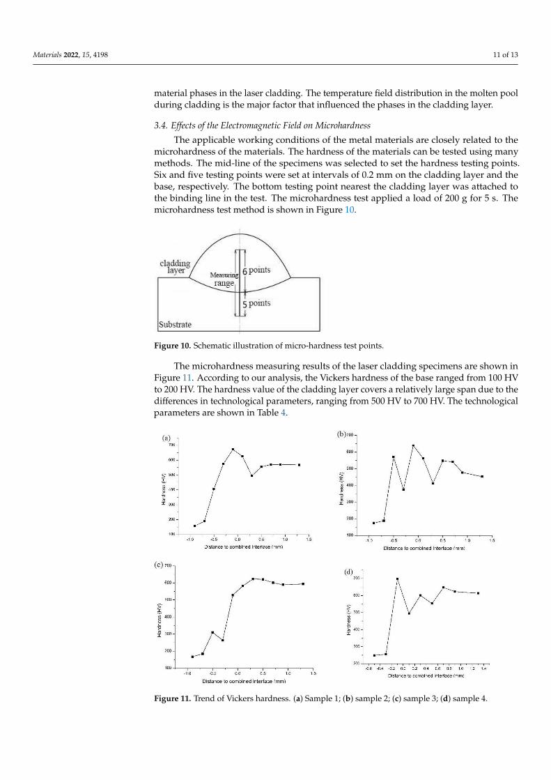
A 3-millimeter wide plane was polished at the upper part of the cladding layer forX-ray diffraction (XRD) analysis. A copper target was used, with angles ranging from 30◦
to 100◦ at a speed of 4◦/min. Figure 9 shows the XRD pattern of the sample assisted by anelectromagnetic field, and Table 6 shows the process parameters.
Figure 9. XRD atlas.
Table 6. Process parameters.
Electromagnetic Field(Yes/No) d1 (mm) v0 (mm/s) P(W) pb (MPa) pf (MPa)
Yes 18 6 1200 0.2 0.1
According to the XRD spectral analysis of the specimens, the cladding layer mainlycontained Ni3Fe, Cr2B, Cr7C3, Ni2B, and a certain amount of iron–carbon compounds.Moreover, most iron–carbon compounds in the cladding layer appeared in the form ofmartensite because C formed an oversaturated solid solution in the α-Fe. The metalcompound Ni3Fe content in the cladding layer is far higher than the other components.Ni3Fe can increase the overall tenacity of materials. Moreover, the cladding layer containsother types of Fe-Ni solid solution, which is precipitated first at the condensation of themolten pool. Additionally, the high Fe, Cr, Ni, B, and C contents form compounds. The XRDspectra of the specimens with and without electromagnetic field assistance are basicallythe same, indicating that electromagnetic assistance had a relatively small influence on the
Materials 2022, 15, 4198 11 of 13
material phases in the laser cladding. The temperature field distribution in the molten poolduring cladding is the major factor that influenced the phases in the cladding layer.
3.4. Effects of the Electromagnetic Field on Microhardness
The applicable working conditions of the metal materials are closely related to themicrohardness of the materials. The hardness of the materials can be tested using manymethods. The mid-line of the specimens was selected to set the hardness testing points.Six and five testing points were set at intervals of 0.2 mm on the cladding layer and thebase, respectively. The bottom testing point nearest the cladding layer was attached tothe binding line in the test. The microhardness test applied a load of 200 g for 5 s. Themicrohardness test method is shown in Figure 10.
Figure 10. Schematic illustration of micro-hardness test points.
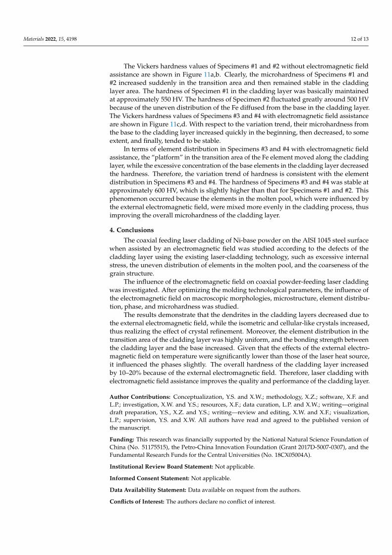
The microhardness measuring results of the laser cladding specimens are shown inFigure 11. According to our analysis, the Vickers hardness of the base ranged from 100 HVto 200 HV. The hardness value of the cladding layer covers a relatively large span due to thedifferences in technological parameters, ranging from 500 HV to 700 HV. The technologicalparameters are shown in Table 4.
Figure 11. Trend of Vickers hardness. (a) Sample 1; (b) sample 2; (c) sample 3; (d) sample 4.
Materials 2022, 15, 4198 12 of 13
The Vickers hardness values of Specimens #1 and #2 without electromagnetic fieldassistance are shown in Figure 11a,b. Clearly, the microhardness of Specimens #1 and#2 increased suddenly in the transition area and then remained stable in the claddinglayer area. The hardness of Specimen #1 in the cladding layer was basically maintainedat approximately 550 HV. The hardness of Specimen #2 fluctuated greatly around 500 HVbecause of the uneven distribution of the Fe diffused from the base in the cladding layer.The Vickers hardness values of Specimens #3 and #4 with electromagnetic field assistanceare shown in Figure 11c,d. With respect to the variation trend, their microhardness fromthe base to the cladding layer increased quickly in the beginning, then decreased, to someextent, and finally, tended to be stable.
In terms of element distribution in Specimens #3 and #4 with electromagnetic fieldassistance, the “platform” in the transition area of the Fe element moved along the claddinglayer, while the excessive concentration of the base elements in the cladding layer decreasedthe hardness. Therefore, the variation trend of hardness is consistent with the elementdistribution in Specimens #3 and #4. The hardness of Specimens #3 and #4 was stable atapproximately 600 HV, which is slightly higher than that for Specimens #1 and #2. Thisphenomenon occurred because the elements in the molten pool, which were influenced bythe external electromagnetic field, were mixed more evenly in the cladding process, thusimproving the overall microhardness of the cladding layer.
4. Conclusions
The coaxial feeding laser cladding of Ni-base powder on the AISI 1045 steel surfacewhen assisted by an electromagnetic field was studied according to the defects of thecladding layer using the existing laser-cladding technology, such as excessive internalstress, the uneven distribution of elements in the molten pool, and the coarseness of thegrain structure.
The influence of the electromagnetic field on coaxial powder-feeding laser claddingwas investigated. After optimizing the molding technological parameters, the influence ofthe electromagnetic field on macroscopic morphologies, microstructure, element distribu-tion, phase, and microhardness was studied.
The results demonstrate that the dendrites in the cladding layers decreased due tothe external electromagnetic field, while the isometric and cellular-like crystals increased,thus realizing the effect of crystal refinement. Moreover, the element distribution in thetransition area of the cladding layer was highly uniform, and the bonding strength betweenthe cladding layer and the base increased. Given that the effects of the external electro-magnetic field on temperature were significantly lower than those of the laser heat source,it influenced the phases slightly. The overall hardness of the cladding layer increasedby 10–20% because of the external electromagnetic field. Therefore, laser cladding withelectromagnetic field assistance improves the quality and performance of the cladding layer.
Author Contributions: Conceptualization, Y.S. and X.W.; methodology, X.Z.; software, X.F. andL.P.; investigation, X.W. and Y.S.; resources, X.F.; data curation, L.P. and X.W.; writing—originaldraft preparation, Y.S., X.Z. and Y.S.; writing—review and editing, X.W. and X.F.; visualization,L.P.; supervision, Y.S. and X.W. All authors have read and agreed to the published version ofthe manuscript.
Funding: This research was financially supported by the National Natural Science Foundation ofChina (No. 51175515), the Petro-China Innovation Foundation (Grant 2017D-5007-0307), and theFundamental Research Funds for the Central Universities (No. 18CX05004A).
Institutional Review Board Statement: Not applicable.
Informed Consent Statement: Not applicable.
Data Availability Statement: Data available on request from the authors.
Conflicts of Interest: The authors declare no conflict of interest.

Materials 2022, 15, 4198 13 of 13
References1. Lin, C.-M.; Chang, C.-M.; Chen, J.-H.; Hsieh, C.-C.; Wu, W. Microstructure and wear characteristics of high-carbon Cr-based alloy
claddings formed by gas tungsten arc welding (GTAW). Surf. Coat. Technol. 2010, 205, 2590–2596. [CrossRef]2. Zhang, H.; Shi, Y.; Kutsuna, M.; Xu, G. Laser cladding of Colmonoy 6 powder on AISI316L austenitic stainless steel. Nucl. Eng.
Des. 2010, 240, 2691–2696. [CrossRef]3. Marchese, G.; Colera, X.G.; Calignano, F. Characterization and Comparison of Inconel 625 Processed by Selective Laser Melting
and Laser Metal Deposition. Adv. Eng. Mater. 2017, 19, 1600635. [CrossRef]4. Torims, T. Laser Cladding Device for In Situ Repairs of Marine Crankshafts. Adv. Mater. Res. 2013, 712–715, 709–714. [CrossRef]5. Hu, D.; Kovacevic, R. Modelling and measuring the thermal behaviour of the molten pool in closed-loop controlled laser-based
additive manufacturing. Proc. Inst. Mech. Eng. Part B J. Eng. Manuf. 2003, 217, 441–452. [CrossRef]6. Janicki, D. Laser cladding of Inconel 625-based composite coatings reinforced by porous chromium carbide particles. Opt. Laser
Technol. 2017, 94, 6–14. [CrossRef]7. Abioye, T.E.; Mccartney, D.G.; Clare, A.T. Laser cladding of Inconel 625 Wire for Corrosion Protection. J. Mater. Process. Technol.
2014, 217, 232–240. [CrossRef]8. Abioye, T.E.; Folkes, J.; Clare, A.T. A parametric study of Inconel 625 wire laser deposition. J. Mater. Process. Technol. 2013, 213,
2145–2151. [CrossRef]9. Fesharaki, M.N.; Shoja-Razavi, R.; Mansouri, H.A. Microstructure investigation of Inconel 625 coating obtained by laser cladding
and TIG cladding methods. Surf. Coat. Technol. 2018, 353, 25–31. [CrossRef]10. Silwal, B.; Walker, J.; West, D. Hot-wire GTAW cladding: Inconel 625 on 347 stainless steel. Int. J. Adv. Manuf. Technol. 2019, 102,
3839–3848. [CrossRef]11. Wang, Z.P.; Hu, F.Y.; Hu, B. Research on laser cladding super alloy K418 by multipass and multi-layer method. New Technol. New
Process 2009, 4, 78–80.12. Ram, G.D.J.; Reddy, A.V.; Rao, K.P. Control of Laves phase in Inconel 718 GTA welds with current pulsing. Sci. Technol. Weld. Join.
2004, 9, 390–398.13. Liu, F.; Cheng, H.; Yu, X.; Yang, G.; Huang, C.; Lin, X.; Chen, J. Control of microstructure and mechanical properties of laser solid
formed Inconel 718 superalloy by electromagnetic stirring. Opt. Laser Technol. 2017, 99, 342–350. [CrossRef]14. Meng, X.; Bachmann, M.; Artinov, A.; Rethmeier, M. Experimental and numerical assessment of weld pool behavior and final
microstructure in wire feed laser beam welding with electromagnetic stirring. J. Manuf. Process 2019, 45, 408–418. [CrossRef]15. Zhang, W.; Roy, G.G.; Elmer, J.W.; DebRoy, T. Modeling of heat transfer and fluid flow during gas tungsten arc spot welding of
low carbon steel. J. Appl. Phys. 2003, 93, 3022. [CrossRef]16. Zhang, W. Probing Heat Transfer, Fluid Flow and Microstructural Evolution during Fusion Welding of Alloys. Ph.D. Thesis, The
Pennsylvania State University, State College, PA, USA, 2004.


