Embed Size (px)
Citation preview
II
ELECTRIC
BRISBANE CITY COUNCIL
EDMONDSTONE STREET SEWAGE PUMPING STATION
SP 23V AUGMENTATION
CONTRACT BW 19 01/02
Job Number JO 6375
MAIN SWITCHBOARD
OPERATIONS and MAINTENANCE MANUAL
MANUFACTURED BY
SJ Electric (Qld) 19 Elliot Street Albion Qld, 4010
Telephone 07 3256 1522Fax 07 3256 1533
Completed 20-APRIL-2002
1111111111111111
SJ ELECTRIC (VIC) PTY LTD A.B.N. 82 074 448 481 R.E.C. 13700
SJ ELECTRIC (QLD) PTY LTD A.B.N. 22 573 962 619 R.E.C. 7623
SJ ELECTRIC (NSW) PTY LTD A.B.N. 68 537 948 401 R.E.C. 23788C
SJ ELECTRIC (WA) PTY LTD A.B.N. 47 078 494 738 R.E.C. EC006006
MELBOURNE BRISBANE SYDNEY PERTH 76 Commercial Drive, 19 Elliot Street, 25 Lidco Street, 226 Planet Street,
' Thomastown Vic 3074 Albion Qld 4010 Arndell Park NSW 2148 Carlisle WA 6101
Phone: (03) 9466 3977
Fax: (03) 9466 4752
Phone: (07) 3256 1522
Fax: (07) 3256 1533
Phone: (02) 9672 7922
Fax: (02) 9672 7252
Email: mail©sjelectricvic.com.au Email: [email protected] Email: [email protected]
ELECTRICAL ENGINEERS, CONTRACTORS & SWITCHBOARD QASJ - 01 ISSUE No. 2.1
Phone: (08) 9470 4292
Fax: (08) 9470 4787 Email: [email protected]
MANUFACTURERS
1
Edmonstone Street Newmarket SPS SP023 Main Switchboard OM Manual
Q-Pulse Id TMS695 Active 29/01/2014 Page 1 of 236
ELECTRIC
BRISBANE CITY COUNCIL
EbMONDSTONE STREET SEWAGE PUMPING STATION
SP 23 AUGMENTATION
CONTRACT BW 19 01102
Job Number JO 6375
MAIN SWITCHBOARD
OPERATIONS and MAINTENANCE MANUAL
MANUFACTURED BY
=
SJ Electric (Qld) 19 Elliot Street Albion Qld. 4010
Telephone 07 3256 1522 Fax 07 3256 1533
Completed 20-APRIL 2002
= I
SJ ELECTRIC (VIC) PTY LTD SJ ELECTRIC (OLD) PTY LTD SJ ELECTRIC (NSW) PTY LTD SJ ELECTRIC (WA) PTY LTD A.B.N. 82 074 448 481 R.E.C. 13700 A.B.N. 22 573 962 619 R.E.C. 7623
MELBOURNE BRISBANE SYDNEY PERTH 76 Commercial Drive, 19 Elliot Street, 25 Lidco Street, 226 Planet Street,
gli Thomastown Vic 3074 Albion Qld 4010 Arndell Park NSW 2148 Carlisle WA 6101
l'hone: (03) 9466 3977 Phone: (07) 3256 1522 Phone: (02) 9672 7922 Phone: (08) 9470 4292
Fax: (03) 9466 4752 Fax: (07) 3256 1533 Fax: (02) 9672 7252 Fax: (08) 9470 4787 Email: [email protected] Email: [email protected] Email: [email protected] Email: [email protected]
ELECTRICAL ENGINEERS, CONTRACTORS & SWITCHBOARD MANUFACTURERS OASJ - 01 ISSUE No. 2.1
A.B.N. 68 537 948 401 R.E.C. 23788C A.B.N. 47 078 494 738 R.E.C. EC006006
Edmonstone Street Newmarket SPS SP023 Main Switchboard OM Manual
Q-Pulse Id TMS695 Active 29/01/2014 Page 2 of 236

iieps. ELECTRIC
INDEX
SECTION 1. GENERAL
1.1 General Workplace Health & Safety 1.2 Project Overview 1.3 Plant Maintenance 1.4 Electrical Control System 1.5 Control & Monitoring System
2. MANUFACTURER'S TECHNICAL DATA 2.1 Merlin Gerin C8OIN & NS Circuit Breaker.. 2.2 Merlin Gerin Multi 9 Circuit breaker. 2.3 Critec Surge Divertor 2.4 Telemecanique ZB Series Pushbuttons, indicators & controls 2.5 Telemecanique control relays 2.6 Multitrode Level Control relay. 2.7 Mann Industries Signal Isolator 2.8 Crompton Phase Failure Relay 2.9 Crompton Current Transducer. 2.10 Satec Power Monitor 2.11 Kraus & Naimer selector Switch. 2.12 Danfoss VSD
3. DRAWINGS 3.1 Drawing Register 3.2 General Arrangement Drawings 3.3 Equipment Schedule
4. INSPECTION & TEST RESULTS
CAWINDOWSVIEMPTdmondstone Street Indexdoc
ELECTRICAL ENGINEERS, CONTRACTORS & SWITCHBOARD MANUFACTURERS
Edmonstone Street Newmarket SPS SP023 Main Switchboard OM Manual
Q-Pulse Id TMS695 Active 29/01/2014 Page 3 of 236

GENERAL
Edmonstone Street Newmarket SPS SP023 Main Switchboard OM Manual
Q-Pulse Id TMS695 Active 29/01/2014 Page 4 of 236

Page 1
General Workplace Health and Safety
The Queensland Workplace Health and Safety Act (1995) details
minimum requirements relating to safe working in the electrical industry.
Nothing in this document is designed, in any way, to undermine the
authority of the Act.
All reasonable care must always be taken to ensure the plant is without
risk to the health and safety of personnel operating and maintaining plant
and equipment.
Employers have an obligation to ensure the workplace health and safety
of all personnel at work.
It is employer responsibility to ensure that all persons entering or working
on the premises use appropriate personal protective equipment.
Personal protective equipment includes gloves, safety glasses, hard hats,
ear protection, safe foot ware and, where necessary, specialist protective
clothing for hazardous areas.
Any item of equipment should always be isolated before maintenance or
repairs commence to ensure that inadvertent operation of the item does
not result in risk to the health and safety of any person.
Where the item is isolated, any total or partial shutdown should not allow
a hazardous situation to be created.
Where the item cannot be isolated, another person should be stationed at
the controls of the item and an effective means of direct communication
should exist between the persons carrying out the maintenance and the
person at the controls.
C' A WC ITILITINALS ATI I7 .g ..4
Edmonstone Street Newmarket SPS SP023 Main Switchboard OM Manual
Q-Pulse Id TMS695 Active 29/01/2014 Page 5 of 236

Page 2
General Operating Principles
All persons working the premises must be qualified Electrical Engineers
or electrical trades persons capable of performing the required tasks
competently. All personnel must also be familiar with plant and
equipment.
Adequate information, instruction, training and supervision must be
provided to enable personnel to perform work without risk to health and
safety.
Work in an orderly way.
Plan work in advance to avoid hazardous situations.
Warn others of any hazards.
Make inquiries before starting work, particularly on any unfamiliar
installation or equipment
Before any work begins ensure that any instructions received or given are
fully understood.
Concentrate on the task on hand.
Do not distract others or allow yourself to be distracted by foolish actions.
Work from a safe and convenient position that provides a maximum
working space that you do not have to over reach, you cannot slip, trip or
stumble and so endanger yourself and others.
Keep the working area tidy and free of unwanted materials and
equipment.
Use insulated tools where possible.
Inspect tools and equipment regularly and ensure that any necessary
maintenance is carried out
Keep yourself in good health.
Do not work if ill or over tired, to the extent that your concentration,
movement or alertness is affected. Illness or fatigue can endanger yourself
and others.
Edmonstone Street Newmarket SPS SP023 Main Switchboard OM Manual
Q-Pulse Id TMS695 Active 29/01/2014 Page 6 of 236

Page 3
Project Overview
Contract BW 19 1/2 was for the Design ,manufacture and testing of a new
Main switchboard for the Edmondstone Street Sewage Pumping Station
located in Brisbane.
Equipment provided by SJ Electric ensures safe and efficient operation of the
Inlet Works. Equipment supplied and installed by SJ Electric includes: -
Switchboard;
Generator Terminal Box
Energex metering Cubicle.
The switchboard incorporates the latest technology in motor control, power
monitoring, and instrumentation. It is important engineers, technicians and
operators are familiar with the equipment installed before attempting any
adjustments, modifications or maintenance.
The following Sections of this manual contain a comprehensive description
of all equipment supplied, bq SJ Electric . It is recommended that this manual
be referred to before cat-tying out any work on any equipment.
It should be noted that the Danfoss Variable speed drives where supplied by
Brisbane Water.
^*.Irsrranmesum,,,ca .s..4 .1. -
Edmonstone Street Newmarket SPS SP023 Main Switchboard OM Manual
Q-Pulse Id TMS695 Active 29/01/2014 Page 7 of 236

Page 4
Plant Maintenance
To ensure proper operation of the plant the following should be observed :-
The plant should be kept clean and tidy at all times. Not only is this of
aesthetic value, it extends equipment life.
Check that all plant and equipment is operating correctly. Correctly
operating equipment promotes overall plant efficiency.
All items and areas of equipment should be hosed down and cleaned
regularly.
WARNING
Avoid directly hosing any drive motor or electrical item.
All maintenance, service, modifications and significant deviations from
Normal operating conditions should be recorded in the Plant Service Log
After a month of operation, check the tension of all bolts associated with
the plant and thereafter periodically. Bolted connections on painted
surfaces can loosen due to thinning of the paint underneath the bolt head
bearing surface. Motor mounting bolts and other bolted connections
subjected to vibration should be periodically checked for loosening.
WARNING
Before starting work on any item ensure that the power supply is
isolated, tagged off, and the item cannot be started.
The importance of preventative maintenance cannot be over-emphasized.
Regular maintenance and suitable care of the equipment will ensure a
long and reliable service life of the equipment
Many stoppages can be avoided by following the recommended
maintenance procedures. Do not wait until you hear the grinding of
equipment that has broken down. If you see any item wearing down,
replace it, before it causes damage to other associated items.
Preventive Maintenance
in.% as rwl..r.s.rtax rot nnr., _4 A -
Edmonstone Street Newmarket SPS SP023 Main Switchboard OM Manual
Q-Pulse Id TMS695 Active 29/01/2014 Page 8 of 236

Page 5
Maintenance procedures recommended to extend switchboard life are outlined
as follows :-
Switchboard exterior should be regularly wiped down with a solvent base
cleaner such as "Spray & Wipe". This will ensure longevity of the powder
coated surface.
Accessible areas like distribution boards and motor starter panels should
be cleaned with a vacuum cleaner to remove dust and foreign matter.
PLC panels should be maintained as dust free as possible. Dusting with a
dry rag is recommended - taking care not allow dust inside the 1/0
modules or processor.
When removing or installing PLC modules care should be taken to ensure
that power is turned off to the rack before modules are removed or
installed.
Connections and efficient operation of circuit breakers, contactors and
isolators should be checked every 12 months - especially where connected
to busbars.
Busbar connections should be checked every 12 months.
Globes for indicator lights should be checked on a weekly basis with any
faulty lamps replaced.
rr.nrib ff-rus-, a .. J J -
Edmonstone Street Newmarket SPS SP023 Main Switchboard OM Manual
Q-Pulse Id TMS695 Active 29/01/2014 Page 9 of 236
Page 6
Electrical Control System
General Description
Electrical control equipment for the installation is housed in the switchboard
located under the inlet works structure, this switchboard is comprised of the
following discrete sections:
Main Incomer
Generator Incomer
Pump Circuit Breakers
Distribution Section
Pump Control Cubicles
Common Control Cubicle.
The switchboard has been constructed of mild steel of a dead front
construction.
Control and Monitoring System.
The control and monitoring of the system is performed by the Brisbane Water
telemetry system and was not included in this contract.
41", .1 XV 71,17,7111111S1 V, -1 -
Edmonstone Street Newmarket SPS SP023 Main Switchboard OM Manual
Q-Pulse Id TMS695 Active 29/01/2014 Page 10 of 236

MANUFACTURER'S TECHNICAL DATA
Edmonstone Street Newmarket SPS SP023 Main Switchboard OM Manual
Q-Pulse Id TMS695 Active 29/01/2014 Page 11 of 236

TECHNICAL DATA SHEET
For
Edmondstone Street Pump Station
Equipment Type:
Location:
Model Numbers:
110 Manufacturer:
Supplier:
Circuit Breaker
Main Incomer Pump Circuit Breakers
C8OIN STR25DE NS 400 & NS160
Merlin Gerin
Schneider Electric. 30 Graystone Street TINGALPA QLD 4173
Ph: 07 3890 2112 Fx: 07 3890 2098
Edmonstone Street Newmarket SPS SP023 Main Switchboard OM Manual
Q-Pulse Id TMS695 Active 29/01/2014 Page 12 of 236
00 to O Lc) o (7) in z z
0 U)
o a Zul 0 0
CD (.0, Cf)
0 0 C,2" 0 1- 0 Izt
U. o U) U) U ZZZZ
a) ...0 u);r1) c.) 0 o co cp 4, -o a) c 3 C.) 3 L. 13 ea
13 GIL CL- a 0 .0 0 0 .
ealCM 0(53 OC°CMMC/3).150 - ...
0 1: a Ca n° , a s TI E °' 3'
CJ 40 r: 0 co s- .... w 15 - - M4D3 mal=...(1)-...0 -1Emm.J.Smo
(/) 3 C 0. (i)
(3) b
Edmonstone Street Newmarket SPS SP023 Main Switchboard OM Manual
Q-Pulse Id TMS695 Active 29/01/2014 Page 13 of 236
S
A r-row, _ -er Ar
V ."
"Vg-c
E %/\A_A° 44..-4=Ait
Aill1111=11111111-
Edmonstone Street Newmarket SPS SP023 Main Switchboard OM Manual
Q-Pulse Id TMS695 Active 29/01/2014 Page 14 of 236
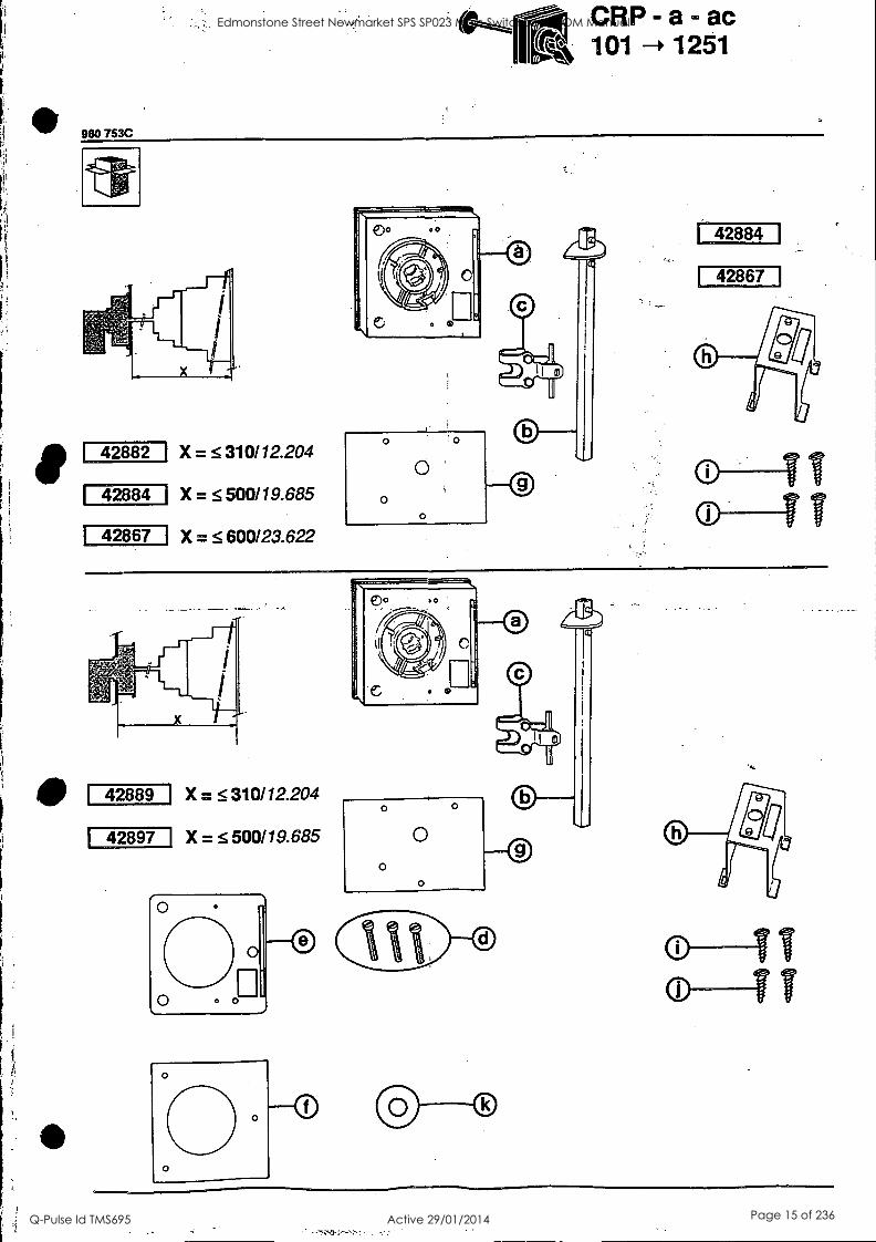
980 783C
r---(0 CRP-a - ac 101 1251
42882 X = 310112.204
42884 X = S 500119.685
X = 5 600/23.622 42867
42884
42867
42889
42897
X = 5 310112.204
X = 5 500119.685
0
0 0
0
0
o TT o IT
Edmonstone Street Newmarket SPS SP023 Main Switchboard OM Manual
Q-Pulse Id TMS695 Active 29/01/2014 Page 15 of 236
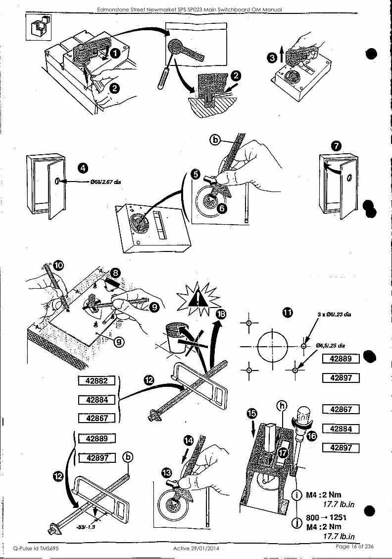
3 x 061.23 dia
42882
42884
42867
42889
42897
42867
42884
42897
M4 :2 Nm 17.7 lb.in
800 --, 1251 M4 :2 Nm
17.7 lb.in
0
6
Edmonstone Street Newmarket SPS SP023 Main Switchboard OM Manual
Q-Pulse Id TMS695 Active 29/01/2014 Page 16 of 236
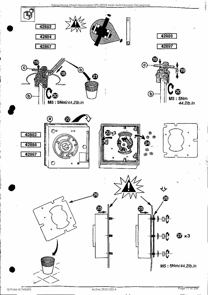
42882
42884
42867
42882
42884
42867
42889
42897
M5 5Nrn/44.21b.in
Edmonstone Street Newmarket SPS SP023 Main Switchboard OM Manual
Q-Pulse Id TMS695 Active 29/01/2014 Page 17 of 236
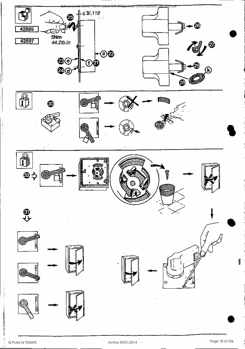
J®
Edmonstone Street Newmarket SPS SP023 Main Switchboard OM Manual
Q-Pulse Id TMS695 Active 29/01/2014 Page 18 of 236
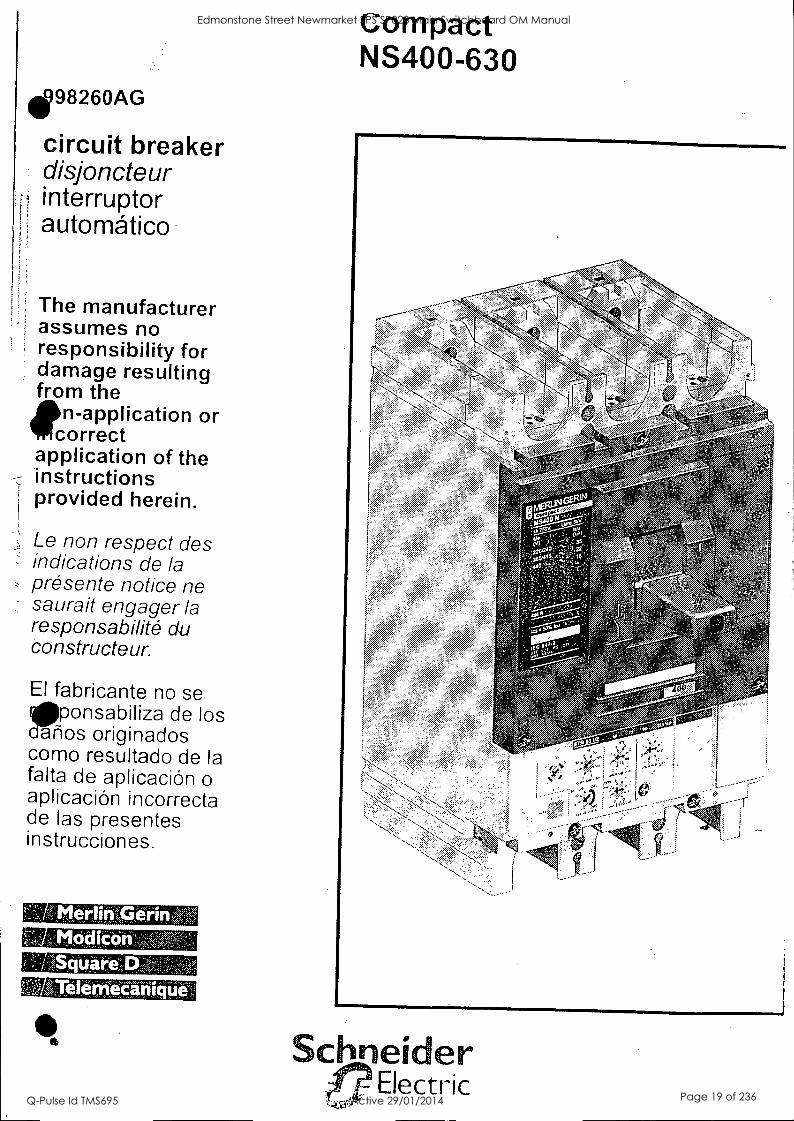
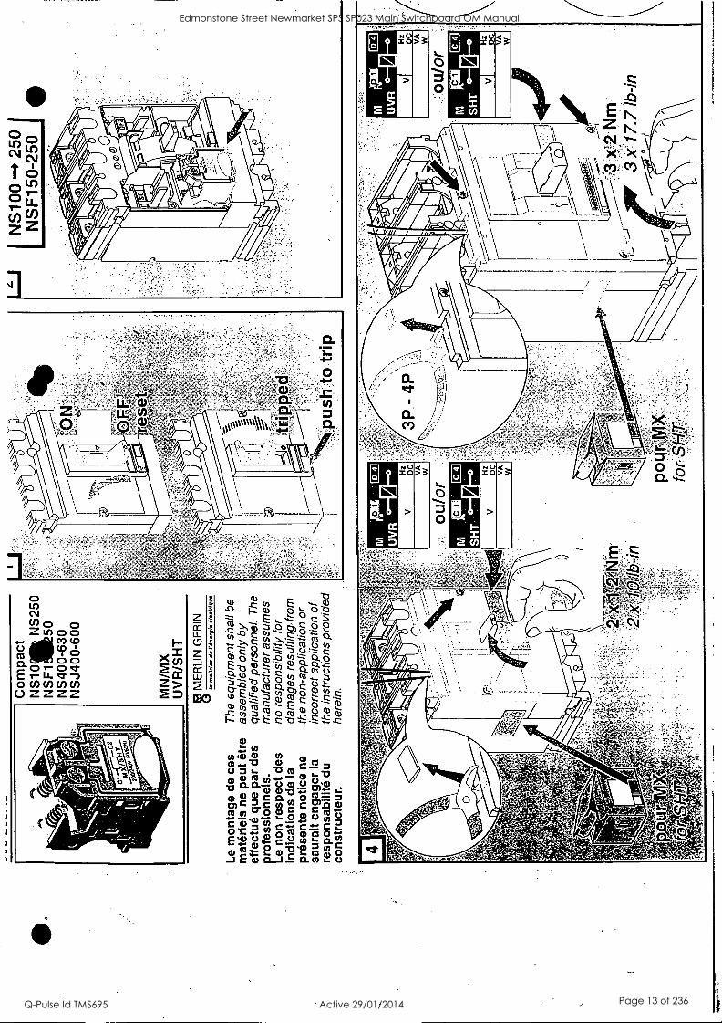
498260AG
circuit breaker disjoncteur interruptor automatic°
The manufacturer assumes no responsibility for damage resulting from the
n-application or correct
application of the instructions provided herein.
Le non respect des indications de la presente notice ne saurait engager la responsabilitO du constructeur.
El fabricante no se ponsabiliza de los
afios originados como resultado de la falta de aplicacion o aplicacion incorrecta de las presentes instrucciones.
din. erir ' 'Modica
uares
erriecarii
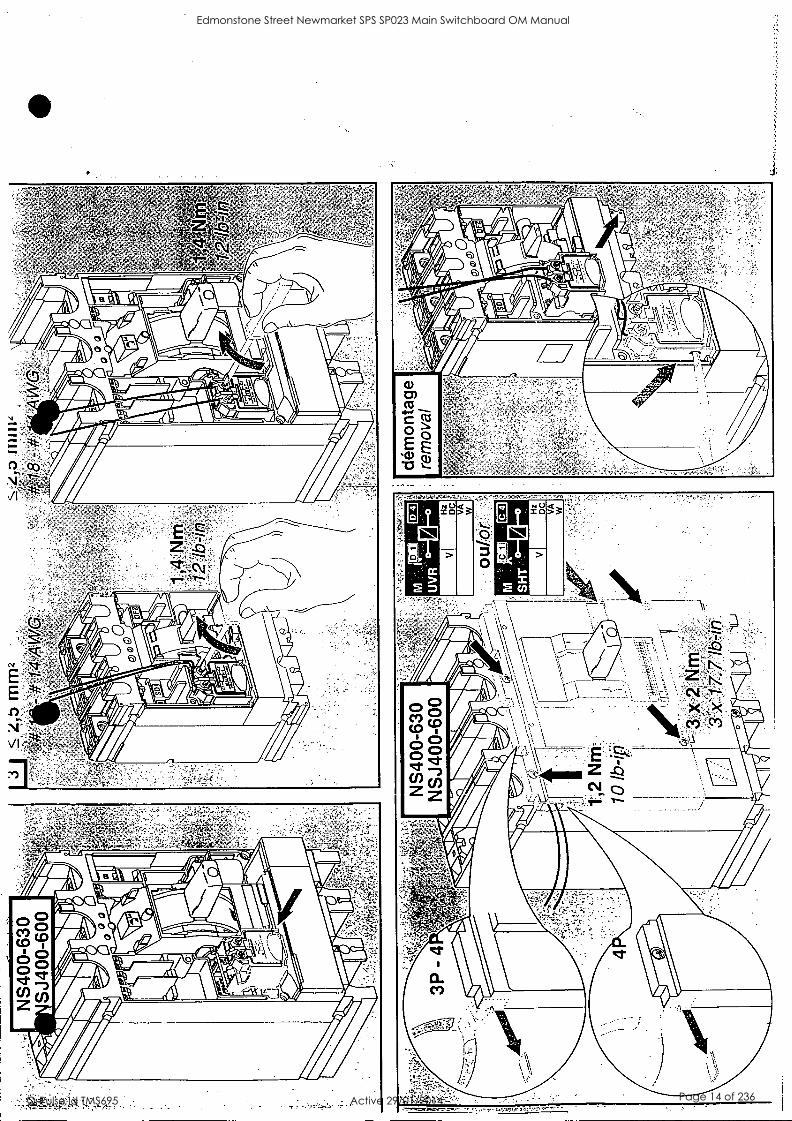
compact NS400-630
,tel ' / ..1,,,,:'
,, -... ,It.i., '..../ ,,,5
Schneider Electric
Edmonstone Street Newmarket SPS SP023 Main Switchboard OM Manual
Q-Pulse Id TMS695 Active 29/01/2014 Page 19 of 236

3P 4P
M10 x 27,5
4
1
M4 x 14 slotted screwdriver
pozidriv n°1, 2 ou plat /
Edmonstone Street Newmarket SPS SP023 Main Switchboard OM Manual
Q-Pulse Id TMS695 Active 29/01/2014 Page 20 of 236
I
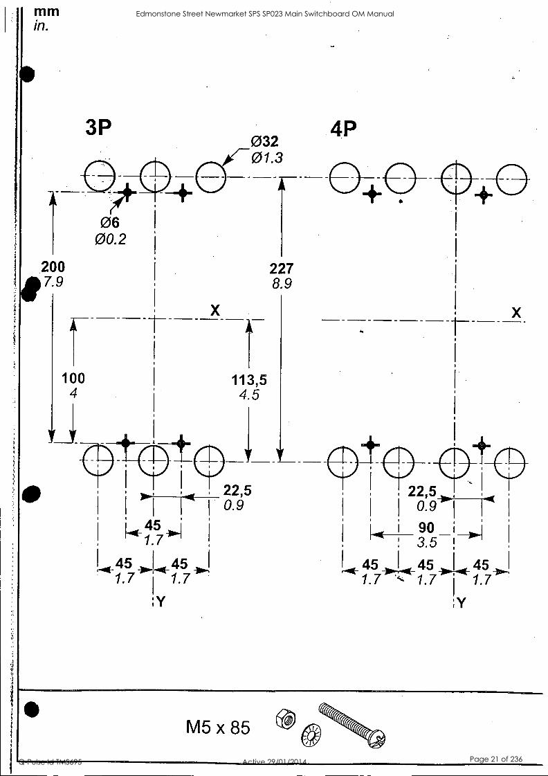
3P
06 00.2
200 7.9
100 4
X
032 01.3
113,5 45
227
, 22,5 )7-47 0.9
45 I 45 4,..!
1.7 1.7
'Y
8.9
4P
22,5 ,
0.9 I
90 ; 0.1 3.5
45 45 I 45 1.7 1.7 I 1.7
'Y
S M5x85
Edmonstone Street Newmarket SPS SP023 Main Switchboard OM Manual
Q-Pulse Id TMS695 Active 29/01/2014 Page 21 of 236
hi
4 SSSS
"!"
5
0
1 0
0
0
' 3( ' . -%- -
- / ' z.
- .;%'
", .: -5' '5''';
; 5v,' ,"
5 ' .4.,"- - ',,";";"'" " . 5 ,,,,,4,'-e ,
-, 5
5 ",,,I, "x : .,:" .
. /k04.,
,le ,,,,,;,--,1i,, i ''.;,
-;t;4i;-,- ,,. ,,.5-7',V",- 7 -fit", "- , ',0g,114";, -;:-
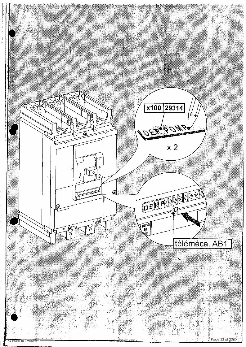
x10 0 1293141 1
Imegors'w5mw-- ----1
x2
pus, to
telemeca. AB1
Edmonstone Street Newmarket SPS SP023 Main Switchboard OM Manual
Q-Pulse Id TMS695 Active 29/01/2014 Page 22 of 236
;
0 / 0000
0
0 _
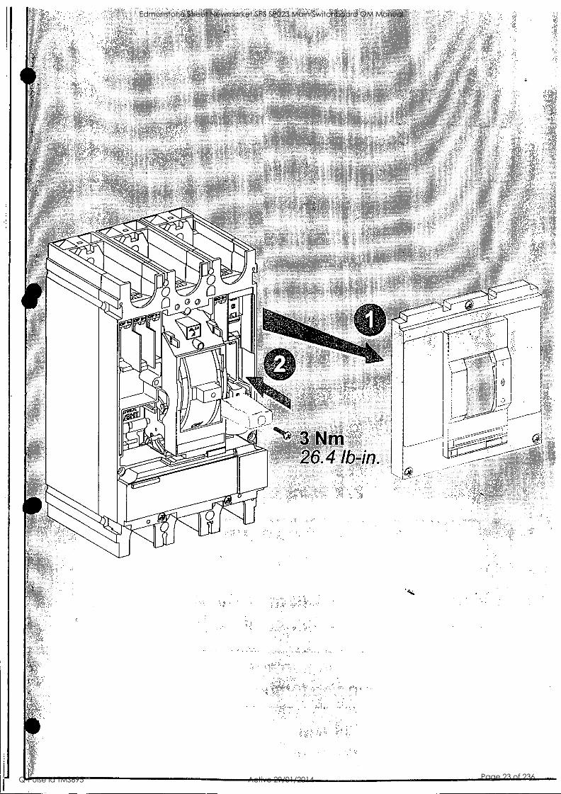
6 N*) 3 Nm 26.4 lb-in.
. , ' , ' , z
-
-7
Edmonstone Street Newmarket SPS SP023 Main Switchboard OM Manual
Q-Pulse Id TMS695 Active 29/01/2014 Page 23 of 236
Edmonstone Street Newmarket SPS SP023 Main Switchboard OM Manual
Q-Pulse Id TMS695 Active 29/01/2014 Page 24 of 236
0-
a 5
' , V "'(' ""'' ^ ' ''' '''''''Z; ':', % S; 5 '' ' , ' '' '., '''' , ,
' ,, l''ii.'1,k i.,,,Wr; ' ,.. .4, XI,' . e:s ,., ' ^ . ' . ' '''' 3' .. ' '. ,,..,!,;" ..;. 5:::, , .P.,,,
'' ' ' % .,1'' * s:4''''. ' t '.1.". ', ,;/,,;? Tx'.; C.,:' > ' yi ,
5' 'i Z -"Q '' (.' ';" ... `.---- :r L) 't ,,,_5
! / 0 '1... ' : ' '.7 .,,-;`,-, '. ,C
' ' .. ,:. . r, s atV1Z ' "... ' , 4 . v. , vcr, .
,
',' 57, ° ('
'I\ . hl.:1,3
-*
' i"
\ , "
A."."--,
' `,151..
.47:7-
. ' 5'
,
"
,1
Edmonstone Street Newmarket SPS SP023 Main Switchboard OM Manual
Q-Pulse Id TMS695 Active 29/01/2014 Page 25 of 236
0
O
O
O
O
Edmonstone Street Newmarket SPS SP023 Main Switchboard OM Manual
Q-Pulse Id TMS695 Active 29/01/2014 Page 26 of 236
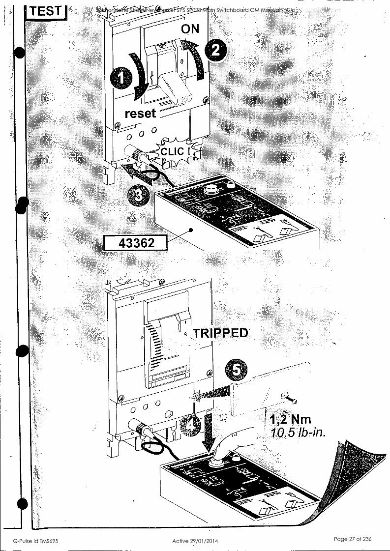
TEST ON
c. 0')
reset EEEEE
0 ° CLIC !
Edmonstone Street Newmarket SPS SP023 Main Switchboard OM Manual
Q-Pulse Id TMS695 Active 29/01/2014 Page 27 of 236
9'05
17'0565k '0 01505£
'U/
LULU
up-qi 17LE
wN
1C
anbiol 51.quem611
aBenas op eidno3
frzE
wN
1E
enbiol 5t4ualq5.11 aB
enas op aidno3
r1661V/nd`O
Mift4
;
nOzull
Lll-qi LE
E%
wN
LE
.. -lay° re,4,40,stra
'ffi%
N'011103S
. 44tV
3Wift±
r4C7
pzz w
N
enbiol 5cqualti6u aB
enes op oidnoO
Ts7JtvE
r 3 0 JrS3a
of4a,
Cn
(1).
cD
O
0) 5'
(1)
cD
5. Z
' 3 C
A
CD
F15 2 0 b Q
. C
D
CD
O
S
U
0 0 <
*. CD
F"
Sn - 0
a) cy- 0. 6'
CD
O
rIT
0 0 C
4 a)
co :It o
0 6' a. c E
r F
TT
Edmonstone Street Newmarket SPS SP023 Main Switchboard OM Manual
Q-Pulse Id TMS695 Active 29/01/2014 Page 28 of 236
,011
,i,<
q525
v
3P
4P
3256
4 32
565
3257
0
,
3P
3248
5 4P
32
484
a .`
" :
.; ,
t
M10
x 2
7,5
0
_ 2x 1
,2 N
m
2x 1
0,51
b-in
.
1 .1
or'
50 N
m
442
lb-in
.
e
1 0
0
3P
4P 32
576
3257
7 I
3P
4P 32
578
3257
9 3P
4P
3249
0 32
491
3P
4P 32
492
3249
3
FZ
3
x M
3x7
1 N
m
8,8
lb-in
.
Edmonstone Street Newmarket SPS SP023 Main Switchboard OM Manual
Q-Pulse Id TMS695 Active 29/01/2014 Page 29 of 236
Edmonstone Street Newmarket SPS SP023 Main Switchboard OM Manual
Q-Pulse Id TMS695 Active 29/01/2014 Page 30 of 236
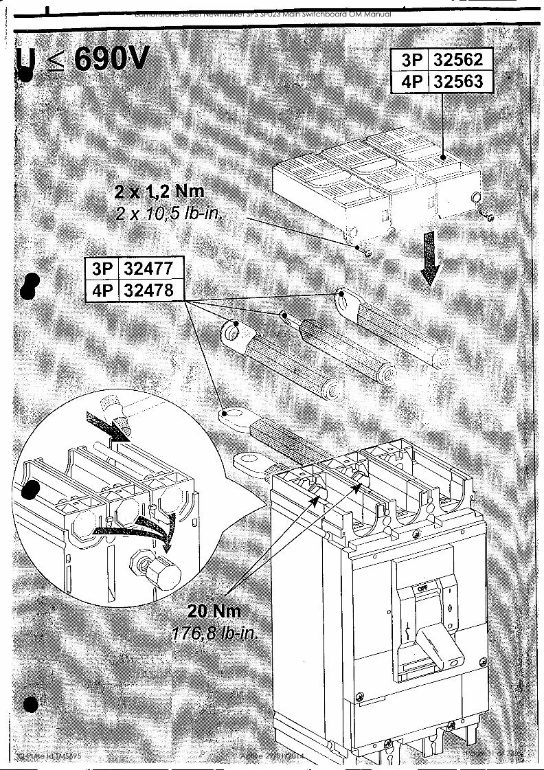
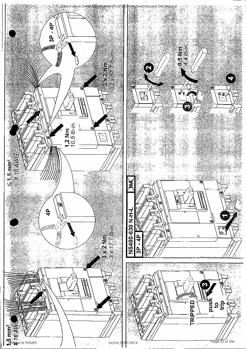
2 x1,2 Nm 2x 10,5 lb-in.
3P 4P
32477 32478
, ' .
S, ss ; tie:y
" ' 55 . , 4,41 ," , s: 5.` 5
.
,
, ,
3P 32562 4P 32563
*.
"zss, s'
-....----",, . ' ...."--:
....." -- - ..1.%---.-- - -..:,--,,---
',' --- ."-- ' . ::',.- "'- ' ."..:=-'-=
"... ' ."....-........ 7.::":_-:::-----
-.. ,-..-....
- --="1-:'''":"-r - - ....-;....., -
----
.., -, `,...------N,. '
--------- 1-: --..---:----- -- -' -- I
11
<,:-....:::::::----.:,_________---- r -",
..",........, , 1..11
(s_
- -
c:D
0 55-
. SS
SS5SS 5555
' ., " s
555 55S
...";;;
;:,
0
Edmonstone Street Newmarket SPS SP023 Main Switchboard OM Manual
Q-Pulse Id TMS695 Active 29/01/2014 Page 31 of 236
4 4.
, <
<
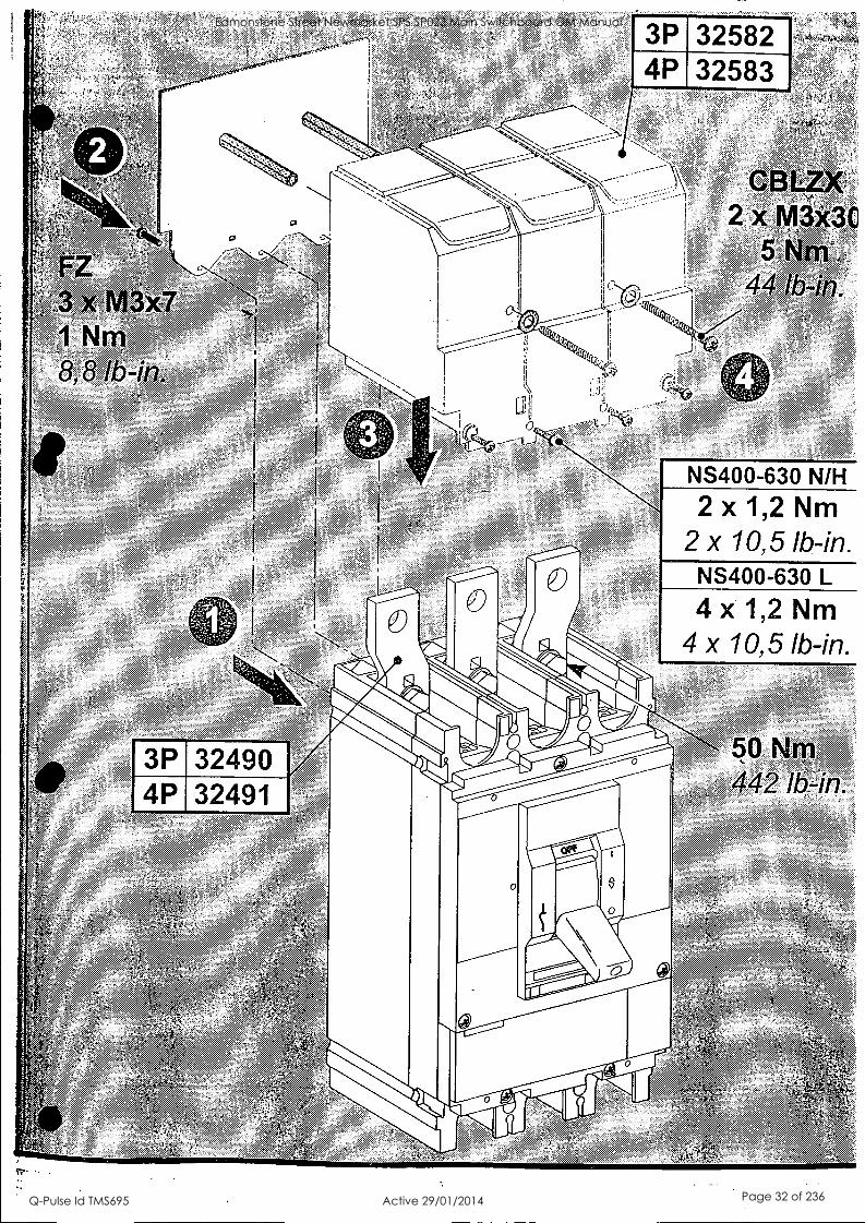
3P 32582 w,
4P 32583 fp
1°)-
1'1
44/3' 4.+:31
.."..460
rill 0
32490 " 32491
0
0 0 -
0
o0
NS400-630 N/H
2 x 1,2 Nm I 2 x 10,5 lb-in.
NS400-630 L
4x 1,2 Nm 4 x 10,5 lb-in.
-1/4's 50 Nm 442 lb-in.
0
Edmonstone Street Newmarket SPS SP023 Main Switchboard OM Manual
Q-Pulse Id TMS695 Active 29/01/2014 Page 32 of 236
V\V' ' a
VVS' VS ' VVSVV?VVVVSSV
,r ;.;:44 ' s
; A;
:, , .; ' ,
, ,;;:k,
".;
s:"
`, ,
, , ;;
ekt
3x7 Nm
;;;.;;
, "
a
3P -'ss- 4P
- I
ar.-1 \ - - ;
it
'44'-41 it III
/-` *1-6""
411
SI
0
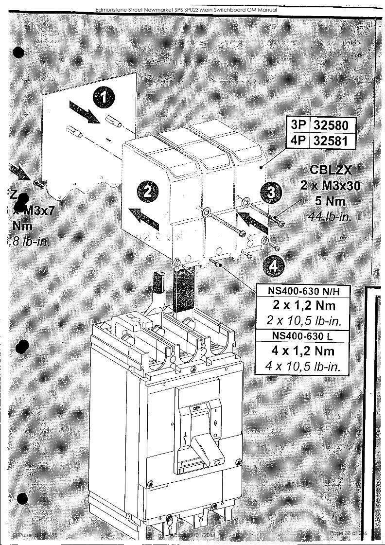
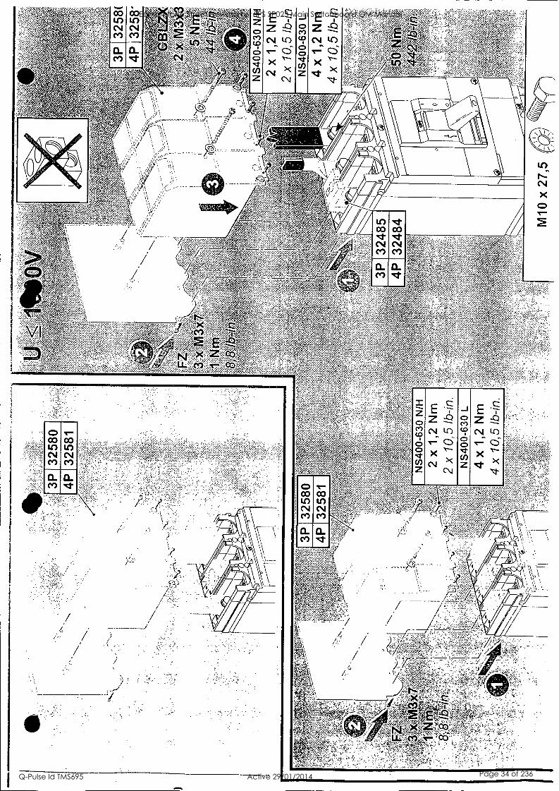
-32580 32581
CBL 2 x M3x30
5 Nm 44 lb-in.
NS400-630 N/H
2x 1,2 Nm 2 x 10,5 lb-in.
NS400-630 L
4x 1,2 Nm 4 x 10,5 lb-in.
' %% ;`, -
Edmonstone Street Newmarket SPS SP023 Main Switchboard OM Manual
Q-Pulse Id TMS695 Active 29/01/2014 Page 33 of 236
a ce)
In N. N X 0 T-
0 CO LC) N Ce)
V"' CO LC) N Ce)
5-
i - 2 0 '9 r) o :r ° (/) Z
z E -7- z -Q N LC)
- - T- O X .`s
(NI >< N
-1 2 (t) 8 o V. zu)
z --0
(N1 10 - e- 0
X Nr. ><
'I-
Edmonstone Street Newmarket SPS SP023 Main Switchboard OM Manual
Q-Pulse Id TMS695 Active 29/01/2014 Page 34 of 236
Exploitation guide
Merlin Gerin Modicon Square D Telemecanique
Low voltage switchgear Compact Merlin Gerin
Schneider 0 Electric
Edmonstone Street Newmarket SPS SP023 Main Switchboard OM Manual
Q-Pulse Id TMS695 Active 29/01/2014 Page 35 of 236

summary
discovering your circuit breaker 3
how to adjust your trip unit 9
supplementary functions 32
operational conditions 41
Edmonstone Street Newmarket SPS SP023 Main Switchboard OM Manual
Q-Pulse Id TMS695 Active 29/01/2014 Page 36 of 236

2 Schneider Electric
Edmonstone Street Newmarket SPS SP023 Main Switchboard OM Manual
Q-Pulse Id TMS695 Active 29/01/2014 Page 37 of 236

discovering your circuit breaker
the toggle operated circuit breaker
the motor mechanisms 5
the circuit breaker with rotary handle 7
electrical auxiliaries 8
Schneider Electric 3
Edmonstone Street Newmarket SPS SP023 Main Switchboard OM Manual
Q-Pulse Id TMS695 Active 29/01/2014 Page 38 of 236
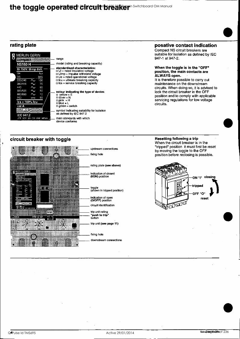
the toggle operated circuit breaker
rating plate
range
model (rating and breaking capacity)
standardised characteristics: Ui = rated insulation voltage Uimp = impulse withstand voltage Ue = rated operational voltage
I Icu = ultimate breaking capacity Ics = service breaking capacity
colour indicating the type of device: yellow = E silver = N
o pink =H blue = L green = switch
symbol indicating suitability for isolation as defined by IEC 947.2
main standards with which device conforms
posative contact indication Compact NS circuit breakers are suitable for isolation as defined by IEC 947-1 et 947-2.
When the toggle is in the "OFF" position, the main contacts are ALWAYS open. It is therefore possible to carry out maintenance on the downstream circuits. When doing so, it is advised to lock the circuit breaker in the OFF position and to comply with applicable servicing regulations for low voltage circuits.
circuit breaker with toggle
upstream connections
fixing hole
rating plate (see above)
indication of closed (I/ON) position
toggle (shown in tripped position)
indication of open (0/OFF) position
circuit identification
trip unit rating "push to trip" button
trip unit (see page 11)
fixing hole
downstream connections
Resetting following a trip When the circuit breaker is in the "tripped" position it must first be reset by moving the toggle to the OFF position before reclosing is possible.
4 Schneider Electric
Edmonstone Street Newmarket SPS SP023 Main Switchboard OM Manual
Q-Pulse Id TMS695 Active 29/01/2014 Page 39 of 236
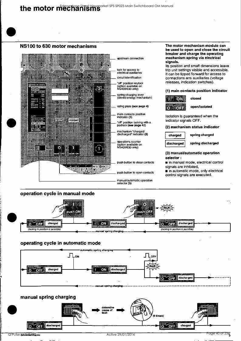
the motor mechanisms
NS100 to 630 motor mechanisms
charged
lost CI fad,
7A A so f
upstream connection
lock for access to electrical auxiliaries
circuit identification
°off° position keylock (option available on NS400/630 only)
spring-charging lever (stored-energy mechanism)
rating plate (see page 4)
main contacts position indicator (1)
°off° position locking with a padlock (see page 42)
mechanism °charged/ discharged° indicator (2)
operations counter (option available on NS400/630 only)
push button to close contacts
push button to open contacts
manual/automatic operation selector (3)
The motor mechanism module can be used to open and close the circuit breaker and charge the operating mechanism spring via electrical signals. Its position and small dimensions leave trip unit settings visible and accessible. It can be tipped forward for access to connections ans auxiliaries (voltage releases, indication switches).
(1) main contacts position indicator
closed
open/isolated l'OFF
Isolation is guaranteed when the indicator signals OFF.
(2) mechanism status indicator
charged
discharged
spring charged
spring discharged
(3) manual/automatic operation selector :
in manual mode, electrical control signals are inhibited,
in automatic mode, only electrical control signals are executed.
operation cycle in manual mode
(locking in position is possible) manual spring charging
operating cycle in automatic mode automatic spring charging
110
0 OFF: charged
manual spring charging
ON discharged
manual spring charging
J _OFF
(locking in position is possible)
---11141Mat dischn;:11---1110-
Schneider Electric 5
Edmonstone Street Newmarket SPS SP023 Main Switchboard OM Manual
Q-Pulse Id TMS695 Active 29/01/2014 Page 40 of 236
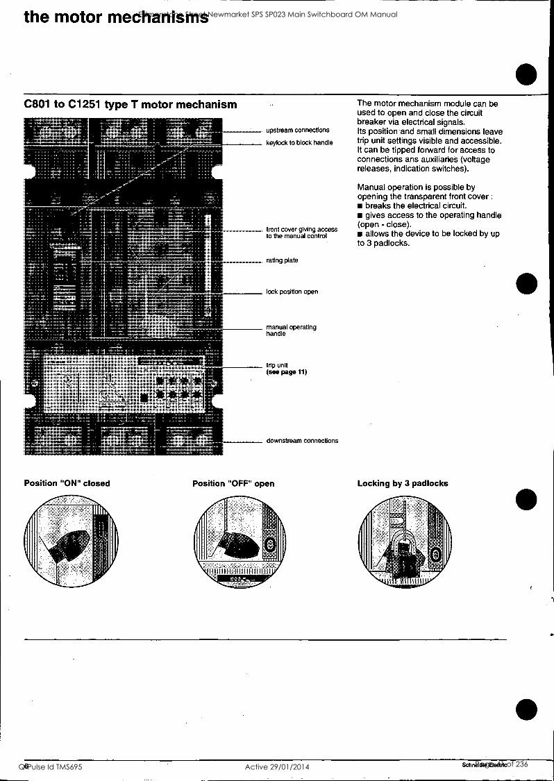
the motor mechanisms
C801 to C1251 type T motor mechanism
I 4 upstream connections
keylock to block handle
front cover giving access to the manual control
rating plate
lock position open
manual operating handle
Position "ON" closed
trip unit (see page 11)
downstream connections
Position "OFF" open
The motor mechanism module can be used to open and close the circuit breaker via electrical signals. Its position-and small dimensions leave trip unit settings visible and accessible. It can be tipped forward for access to connections ans auxiliaries (voltage releases, indication switches).
Manual operation is possible by opening the transparent front cover :
breaks the electrical circuit. gives access to the operating handle
(open - close). allows the device to be locked by up
to 3 padlocks.
Locking by 3 padlocks
6 Schneider Electric
Edmonstone Street Newmarket SPS SP023 Main Switchboard OM Manual
Q-Pulse Id TMS695 Active 29/01/2014 Page 41 of 236
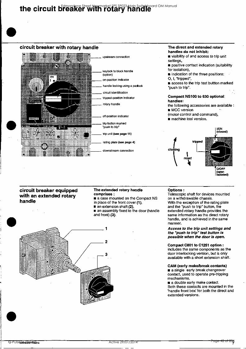
the circuit breaker with rotary handle
circuit breaker with rotary handle
ON
I -
upstream connection
keylock to block handle (option)
on-position indicator
handle locking using a padlock
circuit identification
tripped-position indicator
rotary handle
off-position indicator
trip button marked 'push to trip"
trip unit (see page 11)
rating plate (see page 4)
downstream connection
The direct and extended rotary handles do not inhibit:
visibility of and access to trip unit settings,
positive contact indication (suitability for isolation),
indication of the three positions: 0, I, "tripped",
access to the trip test buttton marked "push to trip".
Compact NS100 to 630 optional: handles: the following accessories are available :
MCC version (motor control and command),
machine tool version.
closing
reset
tripped
WON (closed)
a/OFF (open isolated)
circuit breaker equipped with an extended rotary handle
The extended rotary handle comprises :
a case mounted on the Compact NS in place of the front cover (1),
an extension shaft (2), an assembly fixed to the door (handle
and front) (3).
Options :
Telescopic shaft for devices mounted on a withdrawable chassis. With the exception of the rating plate and the "push to trip" button, the extended rotary handle provides the same information as the direct rotary handle, and is achieved in the same manner.
Access to the trip unit settings and the "push to trip" test button is possible when the door is open.
Compact C801 to C1251 option :
includes the same components as the door interlocking version, but is only available with a short extension shaft.
CAM (early make/break contacts) a single early break changeover
contact, used to operate pre-tripping mechanisms.
a double early make contact. Both these contacts are mounted in the 'handle front box' for both the direct and extended versions.
Schneider Electric 7
Edmonstone Street Newmarket SPS SP023 Main Switchboard OM Manual
Q-Pulse Id TMS695 Active 29/01/2014 Page 42 of 236
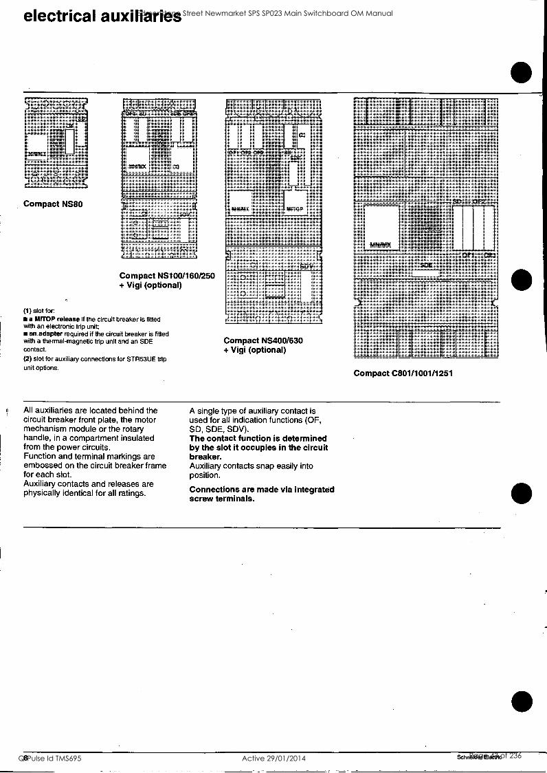
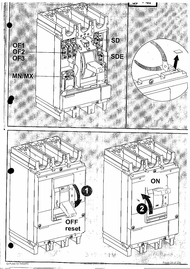
electrical auxiliaries
590009 SD
8°808
OF
[roll Re.umx
Compact NS80
U U U Ft SD SDE OI
O
O I
Compact NS1001160/250 + Vigi (optional)
(1) slot for a MITOP release if the circuit breaker is fitted
with an electronic trip unit; an adapter required if the circuit breaker is fitted
with a thermal-magnetic trip unit and an SDE contact.
(2) slot for auxiliary connections for STR53UE trip unit options.
OF1 OF2 0
MNJMX
(2)
SOE
MITOP
0 SDV
0
0
Compact NS400/630 + Vigi (optional) 1111____11 II II I
Compact C801/1001/1251
All auxiliaries are located behind the circuit breaker front plate, the motor mechanism module or the rotary handle, in a compartment insulated from the power circuits. Function and terminal markings are embossed on the circuit breaker frame for each slot. Auxiliary contacts and releases are physically identical for all ratings.
A single type of auxiliary contact is used for all indication functions (OF, SD, SDE, SDV). The contact function is determined by the slot it occupies in the circuit breaker. Auxiliary contacts snap easily into position.
Connections are made via integrated screw terminals.
8 Schneider Electric
Edmonstone Street Newmarket SPS SP023 Main Switchboard OM Manual
Q-Pulse Id TMS695 Active 29/01/2014 Page 43 of 236
electrical auxiliaries
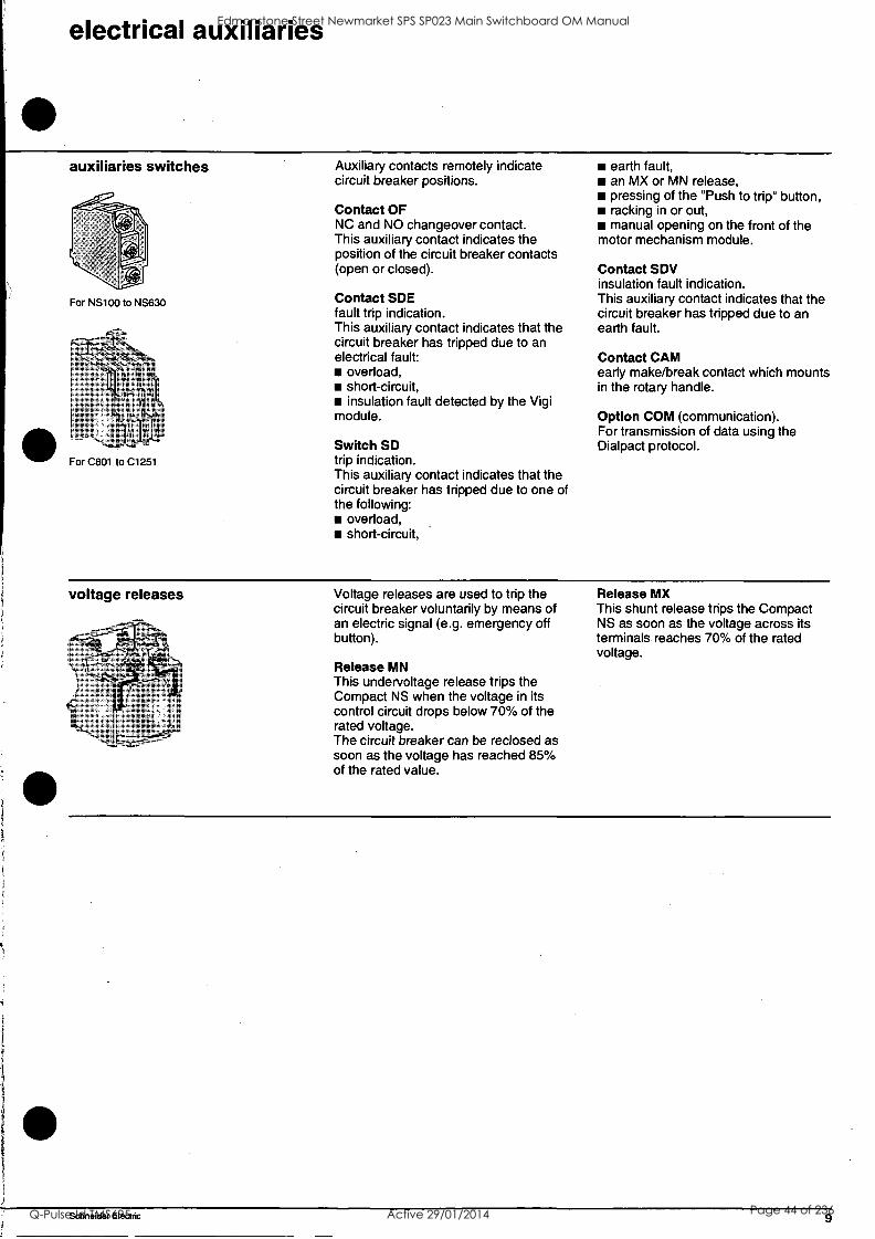
auxiliaries switches
For NS100 to NS630
Ilk))
For C801 to C1251
Auxiliary contacts remotely indicate circuit breaker positions.
Contact OF NC and NO changeover contact. This auxiliary contact indicates the position of the circuit breaker contacts (open or closed).
Contact SDE fault trip indication. This auxiliary contact indicates that the circuit breaker has tripped due to an electrical fault:
overload, short-circuit, insulation fault detected by the Vigi
module.
Switch SD trip indication. This auxiliary contact indicates that the circuit breaker has tripped due to one of the following:
overload, short-circuit,
earth fault, an MX or MN release, pressing of the "Push to trip" button, racking in or out, manual opening on the front of the
motor mechanism module.
Contact SDV insulation fault indication. This auxiliary contact indicates that the circuit breaker has tripped due to an earth fault.
Contact CAM early make/break contact which mounts in the rotary handle.
Option COM (communication). For transmission of data using the Dialpact protocol.
voltage releases Voltage releases are used to trip the circuit breaker voluntarily by means of an electric signal (e.g. emergency off button).
Release MN This undervoltage release trips the Compact NS when the voltage in its control circuit drops below 70% of the rated voltage. The circuit breaker can be reclosed as soon as the voltage has reached 85% of the rated value.
Release MX This shunt release trips the Compact NS as soon as the voltage across its terminals reaches 70% of the rated voltage.
Schneider Electric 9
Edmonstone Street Newmarket SPS SP023 Main Switchboard OM Manual
Q-Pulse Id TMS695 Active 29/01/2014 Page 44 of 236

10 Schneider Electric
Edmonstone Street Newmarket SPS SP023 Main Switchboard OM Manual
Q-Pulse Id TMS695 Active 29/01/2014 Page 45 of 236
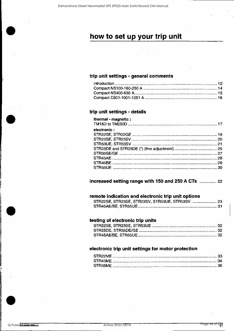
how to set up your trip unit
trip unit settings - general comments introduction 12
Compact NS100-160-250 A 14
Compact NS400-630 A 15
Compact C801-1001-1251 A 16
trip unit settings - details thermal - magnetic : TM16D to TM250D 17
electronic :
STR22SE, STR22GE 18
STR23SE, STR23SV 20
STR53UE, STR53SV 21
STR25DE and STR25DE (*) (fine adjustment) 25
STR35SE/GE 27
STR45AE 28
STR45BE 29
STR55UE 30
increased setting range with 150 and 250 A CTs 22
remote indication and electronic trip unit options STR22SE, STR23SE, STR23SV, STR53UE, STR53SV 23
STR45AE/BE, STR55UE 31
testing of electronic trip units STR22SE, STR23SE, STR53UE 32
STR25DE, STR35DE/GE 32
STR45AE/BE, STR55UE 32
electronic trip unit settings for motor protection STR22ME 33
STR43ME 34
STR35ME 36
Schneider Electric 11
Edmonstone Street Newmarket SPS SP023 Main Switchboard OM Manual
Q-Pulse Id TMS695 Active 29/01/2014 Page 46 of 236

trip unit settings - general comments
The trip unit is the component that monitors the electrical current flowing through the circuit breaker and opens the circuit breaker in the event of a fault.
thermal-magnetic and electronic trip units detect overloads and short- circuits;
Compact circuit breakers can also be fitted with a Vigi earth-fault protection module that trips the circuit breaker in
the event of an insulation fault (risk of electrocution or fire due to earth leakage current).
All Compact trip units (NS100 to NS630) incorporate the reflex-tripping system, an exclusive Merlin Gerin feature that ensures discrimination, even for very high short-circuit currents.
overload protection Tripping time depends on the level of the fault:
the circuit breaker will trip within 2 hours for a current equal to :
120% of Ir for electronic trip units, 130% of Ir for thermal-magnetic trip
units. the circuit breaker must not trip for a
load under 105% of Ir.
short circuit protection
8 10 1
X In x to
120 2
.60
The tripping is :
time delayed as soon as the current exceeds the Isd threshold.
instantaneous as soon as the current exceeds the li threshold. The ME trip units conform to IEC 947-4.1 (motor protection).
;X it 10
.3
In 1997, IEC 947-4.2 brought modification to the symbols related to the settings of the trip units. These modifications are :
the short circuit threshold is lsd (instead of Im) re the short circuit time delay is tsd (instead of tm)
the instantaneous threshold is Ii (instead of I)
the earth fault protection threshold is Ig (instead of In)
the earth fault protection time delay is tg (instead of tn) These new symbols have been applied to NS400/630 trip units STR53UE and STR43ME (issued after the modification)
12 Schneider Electric
Edmonstone Street Newmarket SPS SP023 Main Switchboard OM Manual
Q-Pulse Id TMS695 Active 29/01/2014 Page 47 of 236
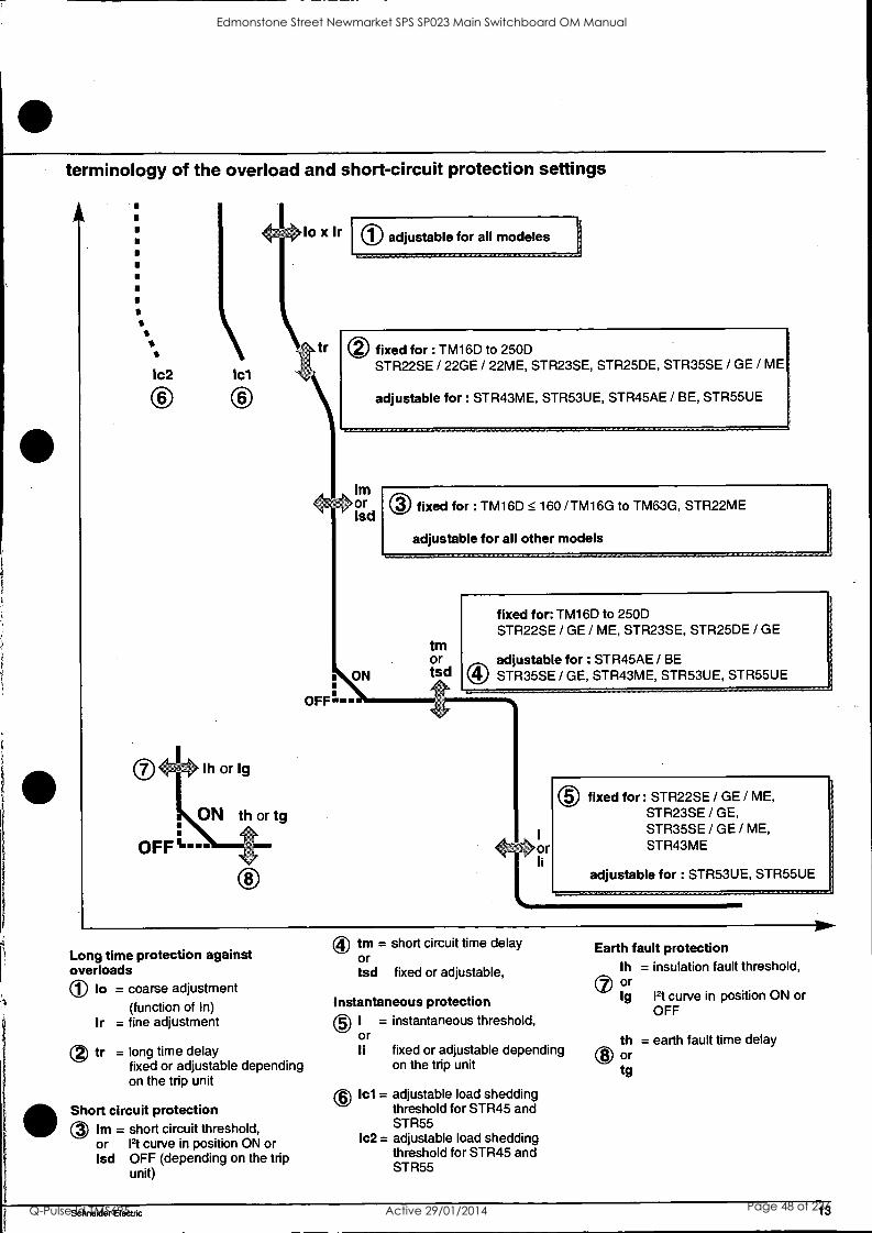
terminology of the overload and short-circuit protection settings
Ic2 1cl
lo x 1r
r
0 adjustable for all modeles
0 fixed for : TM16D to 250D STR22SE / 22GE / 22ME, STR23SE, STR25DE, STR35SE / GE / ME
adjustable for : STR43ME, STR53UE, STR45AE / BE, STR55UE
Im ,or
lsd 0 fixed for : TM16D 160 /TM16G to TM63G, STR22ME
adjustable for all other models
tm or
ON tsd
OFFS --
fixed for: TM16D to 250D STR22SE / GE / ME, STR23SE, STR25DE / GE
adjustable for : STR45AE / BE STR35SE / GE, STR43ME, STR53UE, STR55UE
® fixed for : STR22SE / GE / ME, STR23SE / GE, STR35SE / GE / ME, STR43ME
adjustable for : STR53UE, STR55UE
Long time protection against overloads 0 lo = coarse adjustment
(function of In) Ir = fine adjustment
tr = long time delay fixed or adjustable depending on the trip unit
Short circuit protection 0 Im = short circuit threshold,
or Pt curve in position ON or Isd OFF (depending on the trip
unit)
0 tm = short circuit time delay Or tsd fixed or adjustable,
Instantaneous protection ® I = instantaneous threshold,
or Ii fixed or adjustable depending
on the trip unit
0 1c1= adjustable load shedding threshold for STR45 and STR55
Ic2 = adjustable load shedding threshold for STR45 and STR55
Earth fault protection lh = insulation fault threshold,
Ct or Ig Pt curve in position ON or
OFF
th = earth fault time delay Or
tg
Schneider Electric 13
Edmonstone Street Newmarket SPS SP023 Main Switchboard OM Manual
Q-Pulse Id TMS695 Active 29/01/2014 Page 48 of 236
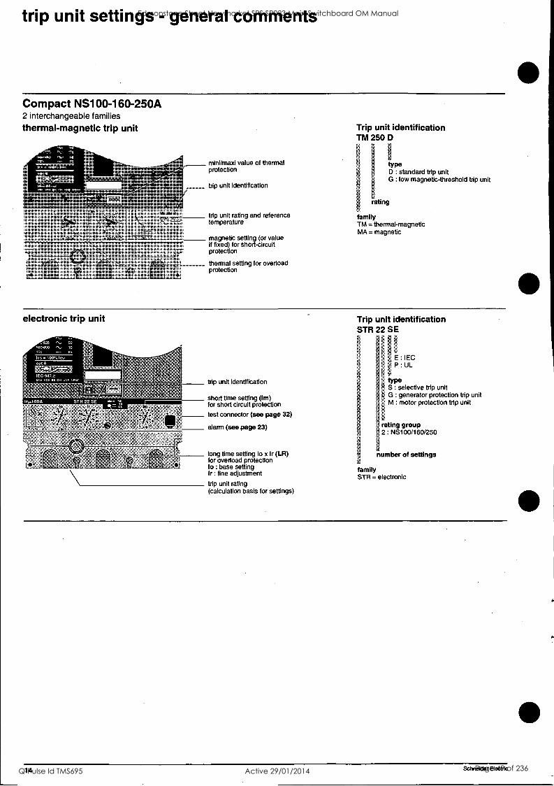
trip unit settings - general comments
Compact NS100-160-250A 2 interchangeable families
thermal-magnetic trip unit
mini/maxi value of thermal protection
trip unit identification
trip unit rating and reference temperature
magnetic setting (or value if fixed) for short-circuit protection
thermal setting for overload protection
Trip unit identification TM 250 D
type D : standard trip unit G : low magnetic-threshold trip unit
rating
family TM = thermal-magnetic MA = magnetic
electronic trip unit
trip unit identification
short time setting (Im) for short circuit protection
test connector (see page 32)
alarm (see page 23)
long time setting lo x Ir (LR) for overload protection lo : base setting Ir : fine adjustment
trip unit rating (calculation basis for settings)
Trip unit identification STR 22 SE
E : IEC P : UL
type S selective trip unit G generator protection trip unit
; M motor protection trip unit
rating group 2 NS100/1 60/250
number of settings
family STR = electronic
14 Schneider Electric
Edmonstone Street Newmarket SPS SP023 Main Switchboard OM Manual
Q-Pulse Id TMS695 Active 29/01/2014 Page 49 of 236
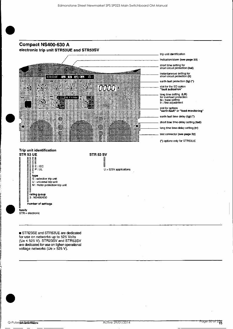
Compact NS400-630 A electronic trip unit STR53UE and STR53SV
Trip unit identification STR 53 UE
- r
ci
E : IEC li 9 P : UL
I! --
{type li S selective trip unit
U universal trip unit 1 M motor protection trip unit
,
' rating group ' 3 NS400/630 F
number of settings
family STR = electronic
STR 53 SV
U > 525V applications
trip unit identification
indication/alarm (see page 23)
short time setting for short circuit protection (Isd)
instantaneous setting for short circuit protection (Ii)
earth fault protection (Ig) () slot for the SD option "fault indication"
long time setting (LR) for overload protection lo : base setting Ir : fine adjustment
slot for options "earth-fault" or "load monitoring"
earth fault time delay (tg) () short time time-delay setting (tsd)
long time time-delay setting (tr)
test connector (see page 32)
( ") options only for STR53UE
STR23SE and STR53UE are dedicated for use on networks up to 525 Volts (Ue < 525 V). STR23SV and STR53SV are dedicated for use on ligher operational voltage networks (Ue > 525 V).
Schneider Electric 15
Edmonstone Street Newmarket SPS SP023 Main Switchboard OM Manual
Q-Pulse Id TMS695 Active 29/01/2014 Page 50 of 236
trip unit settings - general comments
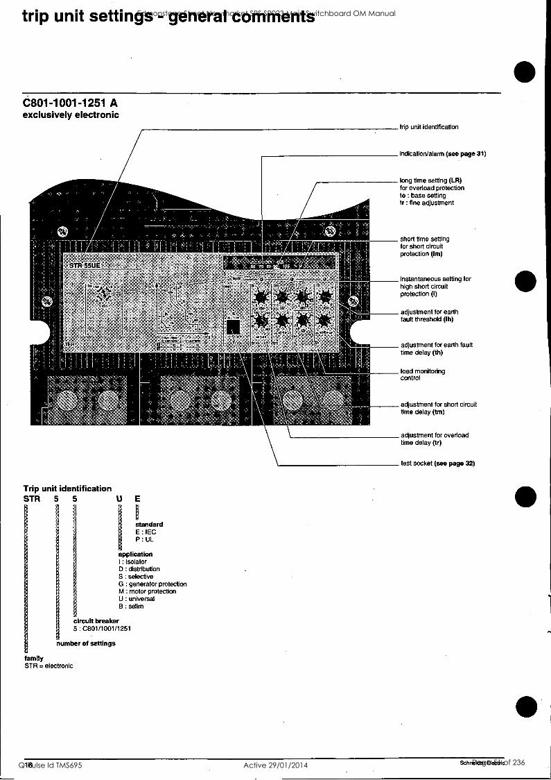
C801-1001-1251 A exclusively electronic
trip unit identification
indication/alarm (see page 31)
long time setting (LR) for overload protection lo : base setting Ir : fine adjustment
short time setting for short circuit protection (Im)
Trip unit identification STR 5 5
standard E : IEC P : UL
application : isolator
D : distribution S : selective G : generator protection M : motor protection U : universal B : selim
circuit breaker 5 : C801/1001/1251
number of settings
family STR = electronic
instantaneous setting for high short circuit protection (I)
adjustment for earth fault threshold (Ih)
adjustment for earth fault time delay (th)
load monitoring control
adjustment for short circuit time delay (tm)
adjustment for overload time delay (tr)
test socket (see page 32)
16 Schneider Electric
Edmonstone Street Newmarket SPS SP023 Main Switchboard OM Manual
Q-Pulse Id TMS695 Active 29/01/2014 Page 51 of 236
t.
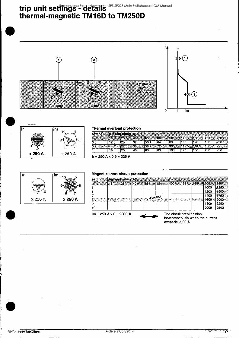
trip unit settings - details thermal-magnetic TM16D to TM250D
:, '
- -- ,, ,
,,,,; v, , ,,, ,,,, ,- =-
-r; 8', 5',
x4250A' , - " '
hrl ic)' 5/ . i ,s, g rc , ..,, ,,,- r",- ,,,:..-- 6 , , ;0 .' . - %
4
' ; %
: ., OA .
,x, 25
, ,
-
-
--
; ;, ' -' :
,
,' / , ,,,, %.'
1 '. ' ,
ii-m260, /7 5110A 250A140°C
- 2- ' ,'e\-0, ., ,--.
* ; ; , , .,
,- '
-Ir I nl ';
, :%' '
Thermal overload protection Setting ', = trip:unit rating (A) ..; ,. -, ;;,.L "5, .- ' , -, .: V , 4 ; ,,'
'N..; ; ' 25 , ,40 ; 63' 80' 100 = ' 125 : 160 : 200 F',... 250, ' I
08 12 8 20 32 50 4 64 80 100 128 160 200 0.9 , . ,14 4 22 5 36 56 7 72, - 90 112 5. 144, 180, 225 1 16 25 40 63 80 100 125 160 200 250
Ir= 250 Ax 0.9 = 225 A
Magnetic short-circuit protection Setting- , trip unit rating (A), .!;=,, ,. ',,' -ler, ,P ,:. ,.; 1-' ',. c;
25 '' 40 ey" 63 - 80 = 100"' 125'. . 1611;; ,,. 200 , 25o, , .i
5 1000 1250 t
6 1200 1500 7
ed- 1400 1750 ,
8 1600 2000 ' 9 1800 2250 10 2000 2500
Im = 250 A x 8 = 2000 A The circui breaker trips instantaneously when the current exceeds 2000 A.
Schneider Electric 17
Edmonstone Street Newmarket SPS SP023 Main Switchboard OM Manual
Q-Pulse Id TMS695 Active 29/01/2014 Page 52 of 236
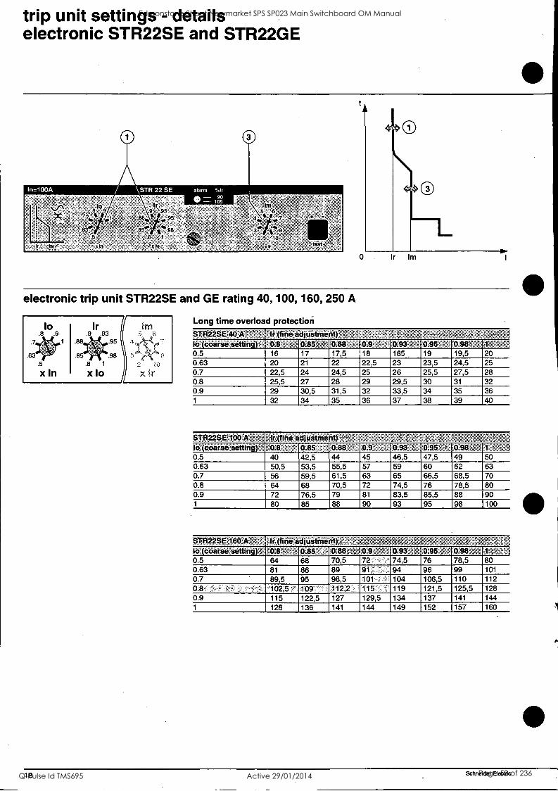
trip unit settings - details electronic STR22SE and STR22GE
I I
electronic trip unit STR22SE and GE rating 40, 100, 160, 250 A
10 .8 .9
.63
.5
x In
Ir .9 .93
.88 .95
.85 .98 .8 1
x to X it
Long time overload protection STR22SE 40'Ai '', ' Ir (fine adjustment): to (coarse setting); 0.8 , t 0.85. ',; 0.88 , 0.9 - 0.93 ; 0.95' " '0.98 ,1 ^
0.5 16 17 17,5 18 185 19 19,5 20 0.63 20 21 22 22,5 23 23,5 24,5 25 0.7 22,5 24 24,5 25 26 25,5 27,5 28 0.8 25,5 27 28 29 29,5 30 31 32 0.9 29 30,5 31,5 32 33,5 34 35 36 1 32 34 35 36 37 38 39 40
STR22SE 100 A ;), Ir (tine adjustment) ID tVCOtiftie swung) %La V", ; V.00 ' V. , r ULM, 'a V.VO . V.70 1 '
0.5 40 42,5 44 45 46,5 47,5 49 50 0.63 50,5 53,5 55,5 57 59 60 62 63 0.7 56 59,5 61,5 63 65 66,5 68,5 70 0.8 64 68 70,5 72 74,5 76 78,5 80 0.9 72 76,5 79 81 83,5 85,5 88 90 1 80 85 88 90 93 95 98 100
STR22SE160'K 1 : lilinaladjUstnientKi- lo (coarse setting), t0.8"; ^t' ';.- 0.85 0:884 a 4'44 0.9 4' '" - 0.93 / 0:95 .: 0.98, I, 1- "4; : 0 5 64 68 70,5 72 74,5 76 78,5 80 0 63 81 86 89 91 94 96 99 101
0 7 89,5 95 98,5 101 104 106,5 110 112 08 '102,5. 109 112,2 115 ' 119 121,5 125,5 128 0.9 115 122,5 127 129,5 134 137 141 144 1 128 136 141 144 149 152 157 160
18 Schneider Electric
Edmonstone Street Newmarket SPS SP023 Main Switchboard OM Manual
Q-Pulse Id TMS695 Active 29/01/2014 Page 53 of 236
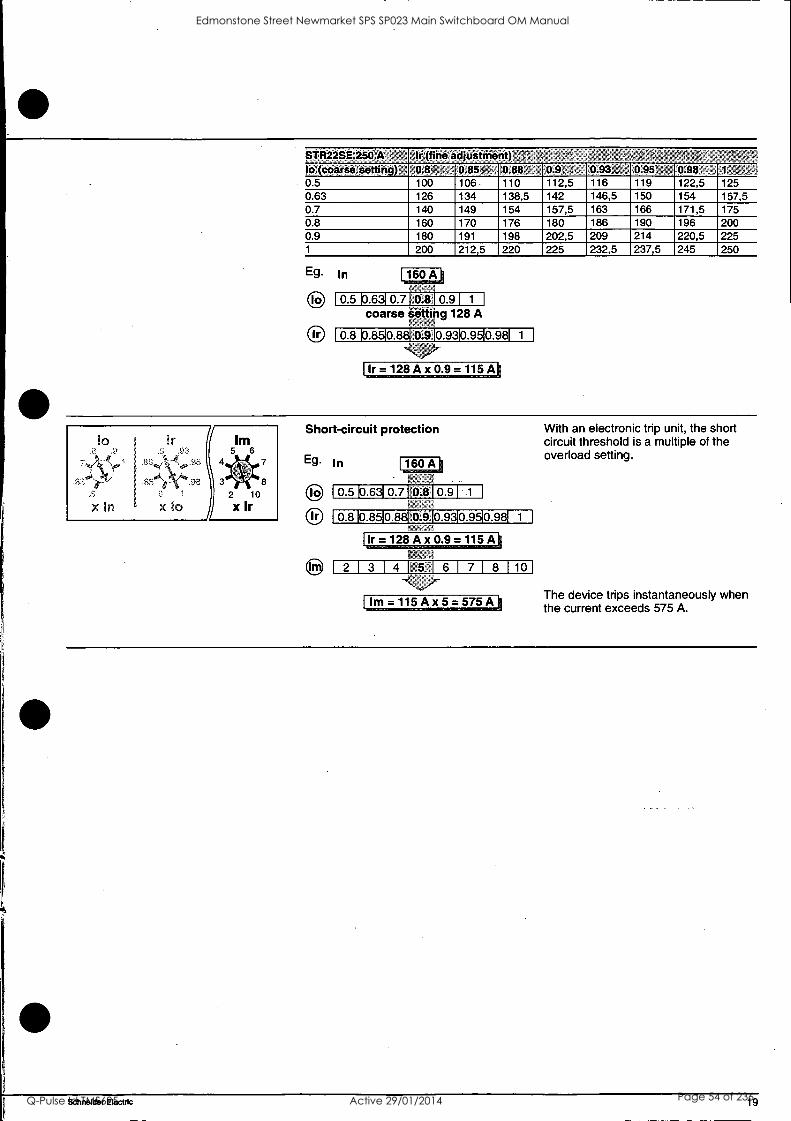
pTR22SE'250 A h. (fine adjUstirient) 'r- ou,kcuarammetungy, , u.o ; , um70..-- umao..; um r . U.V17,,. 1./..V0 , %LUC/ l ,P1, , 3
0.5 100 106 110 112,5 116 119 122,5 125 0.63 126 134 138,5 142 146,5 150 154 157,5 0.7 140 149 154 157,5 163 166 171,5 175 0.8 160 170 176 180 186 190 196 200 0.9 180 191 198 202,5 209 214 220,5 225 1 200 212,5 220 225 232,5 237,5 245 250
Eg. In
to
Ir
160 A
0.5 10.6 0.70.81 0 91 1 1
coarse setting 128 A t"
0.8 0.9 0.93 Mg 0.98EN
Ir=128Ax 0.9=115A
r x in x lo
Urn 5 6
2 10
x Ir
8
Short-circuit protection
Eg. In
IO
Ir
160 A
0.5 k16310.710.810 91 1
0.8 0.85 0.8 0.9 CU 0.98E1
Ir= 128 Ax 0.9=115A
2 1 3 1 4 1 5 1 6 1 7 1 8 1 10
Im = 115 Ax 5=575A
With an electronic trip unit, the short circuit threshold is a multiple of the overload setting.
The device trips instantaneously when the current exceeds 575 A.
Schneider Electric 19
Edmonstone Street Newmarket SPS SP023 Main Switchboard OM Manual
Q-Pulse Id TMS695 Active 29/01/2014 Page 54 of 236
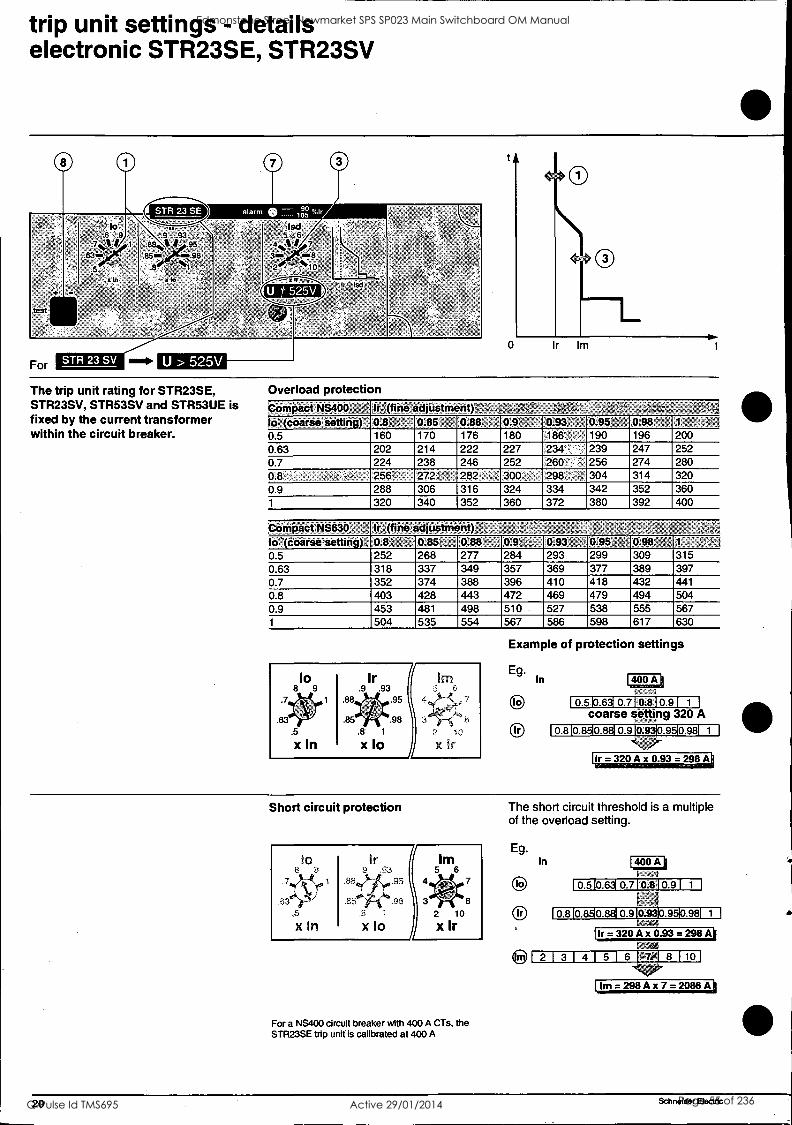
ilm= 298 Ax 7 =2086 Ali
trip unit settings - details electronic STR23SE, STR23SV
The trip unit rating for STR23SE, STR23SV, STR53SV and STR53UE is fixed by the current transformer within the circuit breaker.
Overload protection Compact NS400 ' ,,,? IrAfine adjustinehtP" ,
to '(coarse setting) 0:8 0.85 0.88 0.9 , 10.93 0.95' 0.98 1
0 5 160 170 176 180 186 190 196 200 0 63 202 214 222 227 234- 239 247 252 0.7 224 238 246 252 260.' 256 274 280 0.8 256. 272 282 300 298 304 314 320 0.9 288 306 316 324 334 342 352 360 1 320 340 352 360 372 380 392 400
Compact NS630 Ir (fine adjustment) to -(coarse setting) 0.8,4i 0.85, 0:88. 0.9%.,, - 0.93- 0.95 s ,, 0.98 ;:, 1 ;,R1
0.5 252 268 277 284 293 299 309 315 0.63 318 337 349 357 369 377 389 397 0.7 352 374 388 396 410 418 432 441
0.8 403 428 443 472 469 479 494 504 0.9 453 481 498 510 527 538 555 567 1 504 535 554 567 586 598 617 630
Example of protection settings
Eg. In
0 Ir
400 A
0.510.631 0.710.810.91 1
coarse setting 320 A 0.8 DERIIE IlEDER0.9817 0.9
Ir=320Ax 0.93 = 298 A
Short circuit protection
Ir 9 93
1-15
x to
IM 5 6
2 10
x Ir
For a NS400 circuit breaker with 400 A CTs, the STR23SE trip unit is calibrated at 400 A
The short circuit threshold is a multiple of the overload setting.
Eg. In 400 A
to 0.510.6310.710.810.91 1
Ir 0.8 0.8 0.9 0.98 KM
1.1r= 320 Ax 0.93 = 298A11
2 1 3 r 4 1 5 1 6 13.711 8 1 10 1
20 Schneider Electric
Edmonstone Street Newmarket SPS SP023 Main Switchboard OM Manual
Q-Pulse Id TMS695 Active 29/01/2014 Page 55 of 236
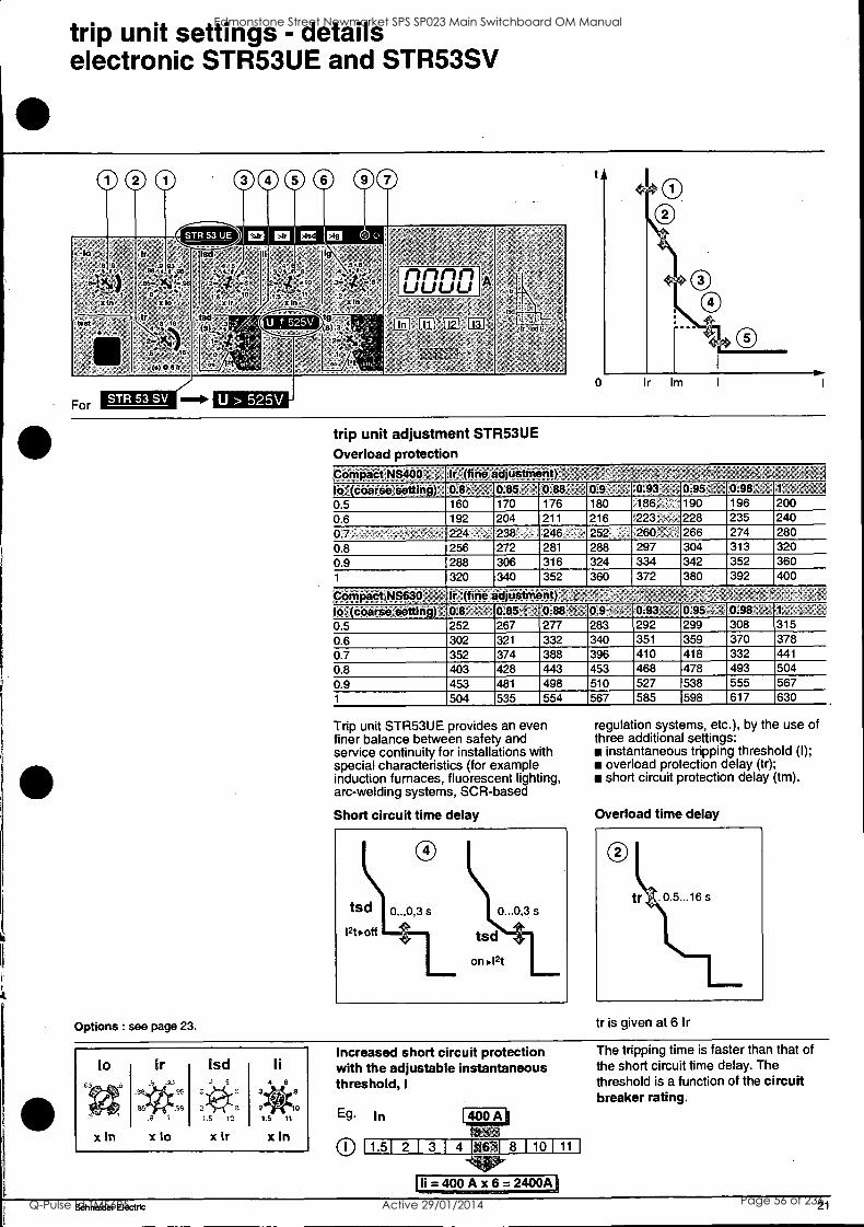
trip unit settings - details electronic STR53UE and STR53SV
trip unit adjustment STR53UE Overload protection Compact NS400 , ; li (fine adjustment) ' -
lo" cdarse setting) 0.8> ,, 0.85 - 0.88 , 0.9 - 0.93 7 .- 0.95 t, 0.98' " 1:' ,' % ' i
0 5 160 170 176 180 186 190 196 200 0 6 192 204 211 216 223 . 228 235 240
0 7 ^ . 224 238 246 252 260 - 266 274 280 0.8 256 272 281 288 297 304 313 320
0.9 288 306 316 324 334 342 352 360
1 320 340 352 360 372 380 392 400
:Compaat,NS630 . il- li (fine ciditistment) . '
to.(coarse setting)' 0.8, 0.85 `;' 0.88 -- - 0.9 ->', 0.93 . . 0.95 - `- 0.98 _1 :. . ..
0.5 252 267 277 283 292 299 308 315
0.6 302 321 332 340 351 359 370 378 0.7 352 374 388 396 410 418 332 441
0.8 403 428 443 453 468 478 493 504
0.9 453 481 498 510 527 538 555 567 1 504 535 554 567 585 598 617 630
Trip unit STR53UE provides an even finer balance between safety and service continuity for installations with special characteristics (for example induction furnaces, fluorescent lighting, arc-welding systems, SCR-based
Short circuit time delay
Options : see page 23.
regulation systems, etc.), by the use of three additional settings:
instantaneous tripping threshold (I); overload protection delay (tr); short circuit protection delay (tm).
Overload time delay
tr is given at 6 Ir
Increased short circuit protection with the adjustable instantaneous threshold, I
Eg In
11.51 2 1 3 1 4 (691 8 1 10 1 11 1
-411P- li=400Ax6=2400A
The tripping time is faster than that of the short circuit time delay. The threshold is a function of the circuit breaker rating.
Schneider Electric 21
Edmonstone Street Newmarket SPS SP023 Main Switchboard OM Manual
Q-Pulse Id TMS695 Active 29/01/2014 Page 56 of 236
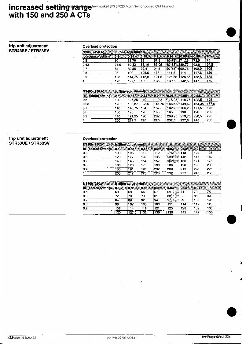
increased setting range with 150 and 250 A CTs
trip unit adjustment STR23SE / STR23SV
Overload protection NS400 (180 A)-: 7 lr: (fine adjuiltment ) lo coarse'setting) , 0.8. k4 0.85 , ,"''' 0.418' 0.9 ' ' 0.93 ,_ " 0.95 °. . 0.98 1 - ..r. .=,1
05 60 63,76 66 67,5 69,75 71,25 73,5 75 0 63 75,6 80,32 83,16 85,05 87,88 ' 89,77 92,61 94,5 0 7 84 89,25 92,4 94,5 97,65 99,75 102,9 105 0.8 96 102 105,6 138 111,5 114 117,6 120 0.9 108 114,75 118,8 121,5 125,55 128,55 132,5 135 1 120 127,5 132 135 139,5 142,5 147 150
,448400 (250 A) = , Jr One adjUstment) ',, ,- .
to (coarse setting) 0:8 0.85 ' . 0.813 0.9; . ' "0.93 i 0.95 , 0.98 ,,i- 1., ' ,- 4
0.5 100 106,25 110 112,5 116,25 118,75 122,5 125 0.63 126 133,87 138,6 141,75 146,57- 149,62 154,35 157,6 0.7 140 148,75 154 157,5 162,75 , 166,25 171,5 175
0.8 160 170 176 180 185 190 196 200 0.9 180 191,25 198 202,5 209,25 213,75 220,5 225 1 200 212,2 220 225 232,5 237,5 245 250
trip unit adjustment STR53UE / STR53SV
Overload protection 44S400.(150 A) - , < Ir (fine adjustment) ,,,,,;,, ',, .
lo (coarse setting) , 0.8 , - 0.85 '': 0.88 ., 0.9 t , 0.93 0.95' 0.98 , 4' - 0.5 100 106 110 112 116 118 122 125 0.6 120 127 132 135 139. 142 147 150 0.7 140 148 154 157 162 166 171 175
0.8 160 170 176 180 186 190 200 0.9 180 191 198 202 209 213
_196 220 225
1 200 212 220 225 232 237 245 250
1%1S400 (250 A)",- Jr (fine adjustment) !
lo -(coarse Setting) 0.8 0.85' 0.9 0.93t 0:95 4 0.98' 1
05 60 63 66 67 69 71 73 75 06 72 76 79 81 85 88 90 07 84 89 92 94 97 99 102 105 0.8 96 102 105 108 111 114 117 120 0.9 108 114 118 121 125 128 132 135 1 120 127.5 132 135 139 142 147 150
22 Schneider Electric
Edmonstone Street Newmarket SPS SP023 Main Switchboard OM Manual
Q-Pulse Id TMS695 Active 29/01/2014 Page 57 of 236
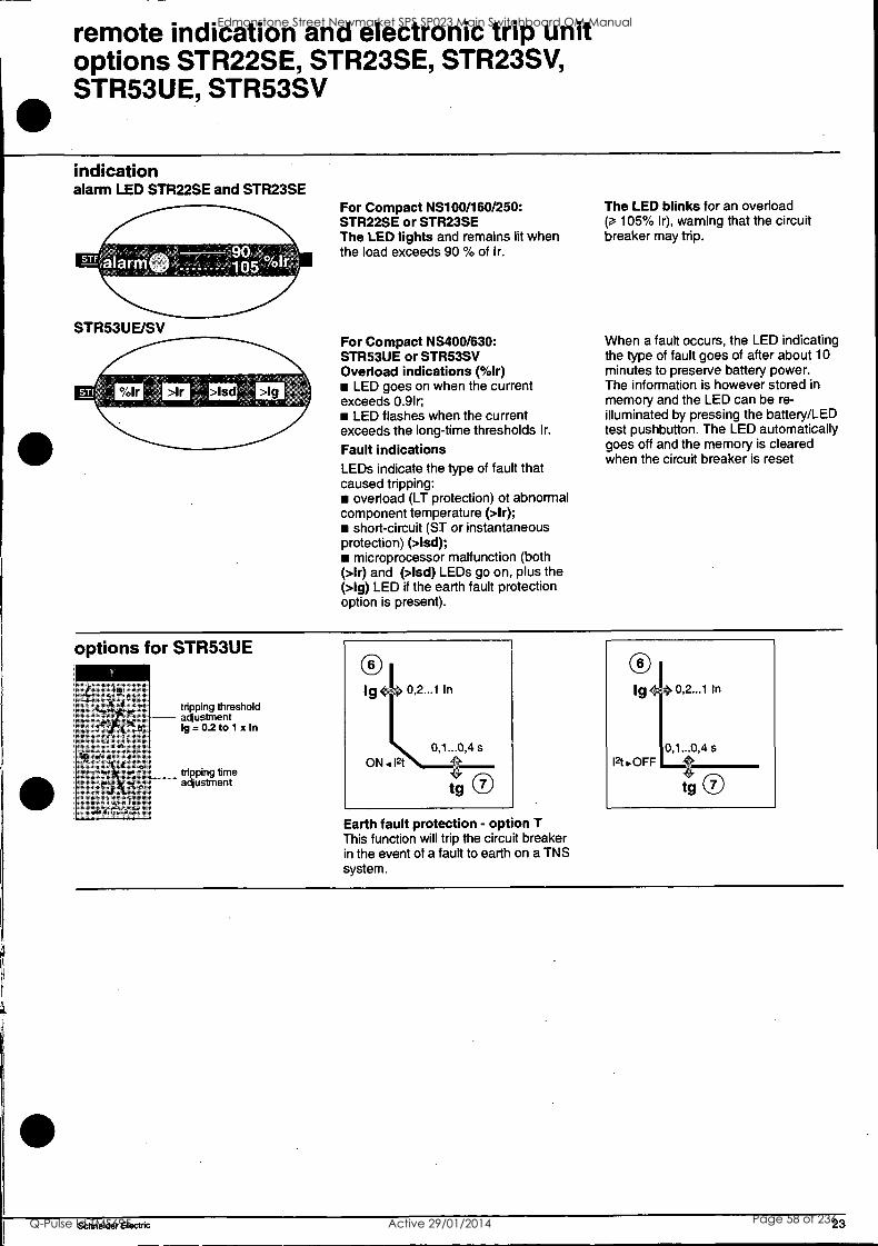
remote indication and electronic trip unit options STR22SE, STR23SE, STR23SV, STR53UE, STR53SV
indication alarm LED STR22SE and STR23SE
STR53UE/SV
For Compact NS100/160/250: STR22SE or STR23SE The LED lights and remains lit when the load exceeds 90 % of Ir.
For Compact NS400/630: STR53UE or STR53SV Overload indications (%Ir)
LED goes on when the current exceeds 0.9lr;
LED flashes when the current exceeds the long-time thresholds Ir.
Fault indications LEDs indicate the type of fault that caused tripping:
overload (LT protection) of abnormal component temperature (>1r);
short-circuit (ST or instantaneous protection) (>Isd);
microprocessor malfunction (both (>1r) and (>Isd) LEDs go on, plus the (>Ig) LED if the earth fault protection option is present).
The LED blinks for an overload 105% Ir), warning that the circuit
breaker may trip.
When a fault occurs, the LED indicating the type of fault goes of after about 10 minutes to preserve battery power. The information is however stored in memory and the LED can be re- illuminated by pressing the battery/LED test pushbutton. The LED automatically goes off and the memory is cleared when the circuit breaker is reset
options for STR53UE
7 tripping threshold adjustment Ig 0.2 to 1 x In
tripping time adjustment
Earth fault protection - option T This function will trip the circuit breaker in the event of a fault to earth on a TNS system.
0 Ig0,2...1 In
12t .OFF 0,1...0,4 s
tg 0
Schneider Electric 23
Edmonstone Street Newmarket SPS SP023 Main Switchboard OM Manual
Q-Pulse Id TMS695 Active 29/01/2014 Page 58 of 236

remote indication and electronic trip unit options STR22SE, STR23SE, STR53UE
ammeter (I) A digital display continuously indicates the current of the phase with the greatest load. By pressing a scroll button, it is also possible to display successively the readings of 11,12,13 and I neutral. LEDs indicate the phase for which the current is displayed.
Ammeter display limits: minimum current 0,2 x In (lower currents
are not displayed) ;
maximum current 10 x In.
zone selective interlocking (ZSI)
A number of circuit breakers are interconnected one after another by a pilot- wire. In the event of a short-time or earth fault:
if a given trip unit STR53UE detects the fault, it informs the upstream circuit breaker which applies the set time delay;
if the trip unit STR53UE does not detect the fault, the upstream circuit breaker trips after its shortest time delay. In this way, the fault is cleared rapidly by the nearest circuit breaker. In addition, the thermal stresses on the circuits are minimised and time discrimination is maintained throughout the installation.
The trip unit STR53UE can only handle the downstream end of a zone selective interlocking function. Consequently, the zone selective interlocking option cannot be implemented between two Compact NS circuit breakers.
Opto-electronic outputs The use of opto-transistors ensures total isolation between the internal circuits of the trip unit and the circuits wired by the user.
communication (COM) Transmission of data to Digipact distribution monitoring and control modules. Transmitted data:
settings; phase and neutral currents (rms values); highest current of the three phases; overload condition alarm;
cause of tripping (overload, short-circuit, etc.).
24 Schneider Electric
Edmonstone Street Newmarket SPS SP023 Main Switchboard OM Manual
Q-Pulse Id TMS695 Active 29/01/2014 Page 59 of 236
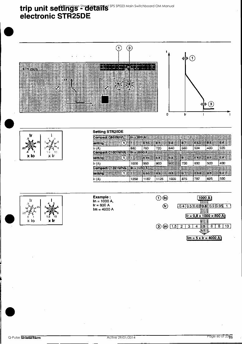
trip unit settings - details electronic STR25DE
CD ®
Setting STR25DE
Compact C801114/H/C; ',' i,=:8904V-- ,,- , ,"4- --: o
setting .r: ;' ; ; : ' 1 41 'I. ;; 0.95 k ' 0* ' ' 0.8 -: ,7- 0.7 -," :,. 003 :1 0le,...4, 0,4 ri
Ir(A) 800 760 720 640 560 504 400 320 Compact C1001N/H/Lq In =10004k - -, -- - ' 1 -"- P ' ''' . ` ,' 5' ..' r ' 5' V <,' "
'90titiog ;',' ' - t;',' 0,' 1,i - '.,- 0.95 , ,' 0.9 ,:- 08 , '0.:7: 9.83 :,, 0.5 :,::, 0,4";
Ir (A) 1000 950 900 800 , ' 700 630 500 400
Compact C1251WH/L, In,=1250 A:- , ', : ' - - ' ; ' -1 - -: - ' - , 0 -1,-,
'aettiaii - !': ':! ','- ,1i a: - 0.95 ' -, 0.9` : ' 0.9 -:-"0.7 -: , 0.63- oli, ..;9,4 i:, Ir(A) 1250 1187 1125 1000 875 787 625 500
Example :
In = 1000 A, 1r = 800 A lm = 4000 A
1000 A
0.410.510.6310.810.910.951 1
P-
Ir = 08 x 1000 = 800 A
1.51 2 I 3 1 4 14.5 1 61 8 110
lm= 5 xlr= 4000A
Schneider Electric 25
Edmonstone Street Newmarket SPS SP023 Main Switchboard OM Manual
Q-Pulse Id TMS695 Active 29/01/2014 Page 60 of 236
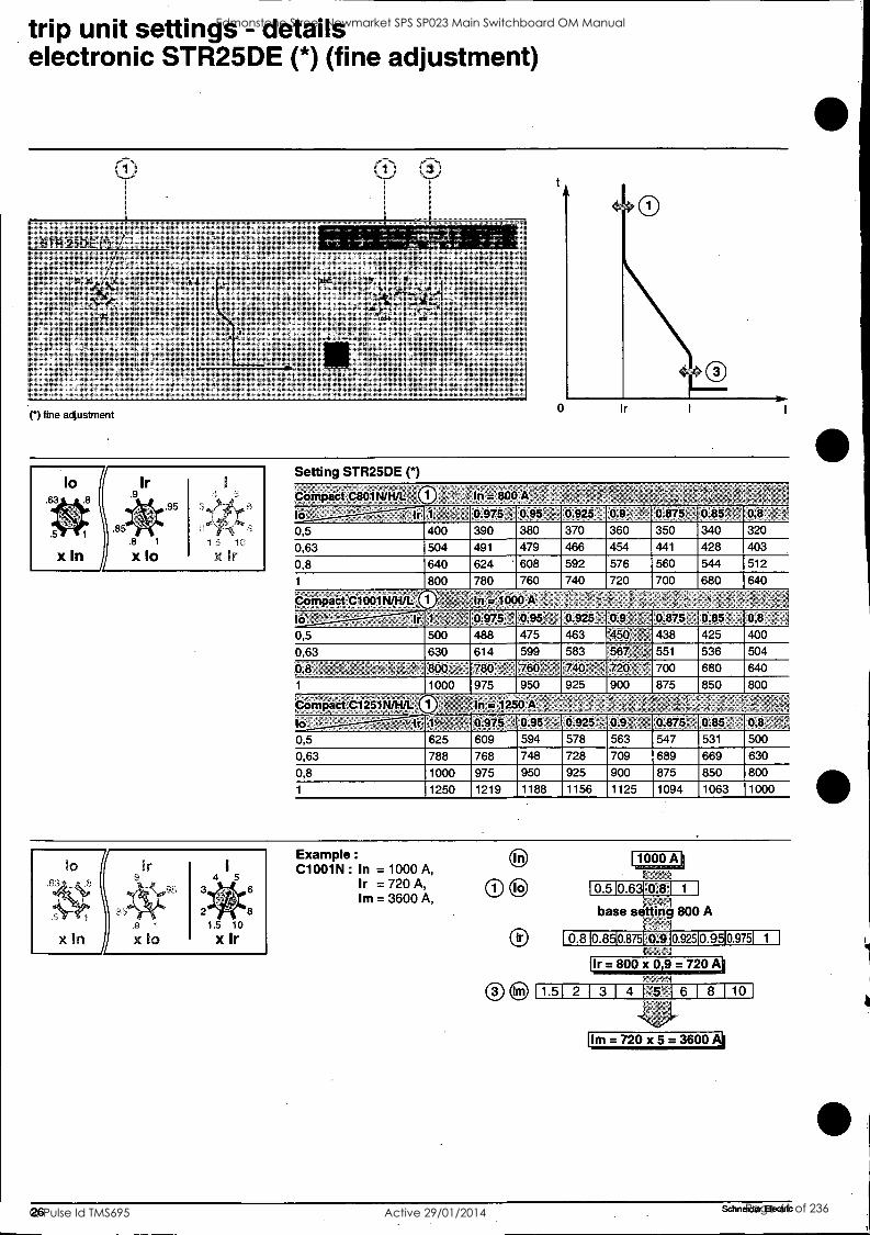
trip unit settings - details electronic STR25DE (*) (fine adjustment)
STR 25DE
10 83
IA,
7
1 -
I
. .1%
,
r) fine adjustment
Setting STR25DE (*)
Compact t88114/HAH In = 800 A'f 3
la: i. , Jr I: ,', , 0275 0.95- .-- 0.925: 09 r, -, 0.875 . 0.85 ', 02 0,5 400 390 380 370 360 350 340 320
0,63 504 491 479 466 454 441 428 403
0,8 640 624 ' 608 592 576 560 544 512
1 800 780 760 740 720 700 680 640
nniaCtD1091pUR/I. , - .= 1000 A 2 I - ,
lo -- ,- ' -°' ° Ir 1: ' ,'" 0.975 7 0.94: ';, 0.925- 0.9: ,, '0.875;_ 0.851 7 0,8 . -1
0,5 500 488 475 463 '450 438 425 400
0,63 630 614 599 583 567, , 551 536 504
0,8 ,, 4 4 s ,` spty,:. 780 - 760 -' 740 ;', 720 ' 700 680 640
1 1000 975 950 925 900 875 850 800 .,,
'tom 'act C1251N/H/L: 1 In = 1250K .. X 4 1, i 4,, . . . .....
lo- : - ir ,
ti 0.975 '; 0.95 _ - 0.925-e 02 ' A 0.875'; ' 025,- 0,8,
0,5 625 609 594 578 563 547 531 500
0,63 788 768 748 728 709 689 669 630
0,8 1000 975 950 925 900 875 850 800
1 1250 1219 1188 1156 1125 1094 1063 1000
x In .8
x 10
3
2
4 5
1.5 10
x Ir
6
8
Example :
C1001N : In = 1000 A, Ir = 720 A, Im = 3600 A,
C)*
1000 A
0.510.630.8 1 1
- 1
base setting 800 A
0.810.8510.87510.910.92510.9510.9751 1
{Ir=800x 0,9 = 720 Ai ; I
1 1.51 2 3 1 4 1;.5'=-1 6 1 8 1 10
Im=720x 5=3600
26 Schneider Electric
Edmonstone Street Newmarket SPS SP023 Main Switchboard OM Manual
Q-Pulse Id TMS695 Active 29/01/2014 Page 61 of 236
[1.51 2 1 3 1 4 I51 6 1 8 1 10]
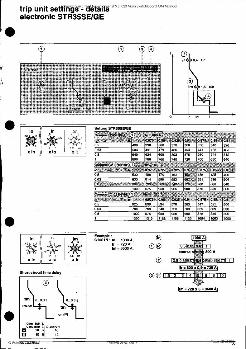
trip unit settings - details electronic STR35SE/GE
0 0 0
SIR 35SE
20; ; .4%/"%l:
4, / / ; t,%. 4',' "' /,.. ; ,A", 4 ,, ' " , 1, ' *',,' '4:4' -rr, /%r,- r': r r% % ''' 11% ..,%, ..f, :,; ;,%, i .,,, ,% ^. ,, , X /., / ,,,,',,, ' 4' , , , , , " ,,,,,::; ' / ' -5; ' 7 i; 1r ,".. ;../ ; 1,nl ,',%s ,,,, <, , ,.. , '' !.. ; ", i * a- ,%, , ,,,, . ,. V . , . :4 ' ,
./ 4,4 , . , ..3.,;.te i , ', , -/ , ,xle "xtr ' 4 / ,
,,: /r,
"/ ' '1, egt4PC1,41
' %;
g % : : g '0"0' /- %.' ' /
i ' ; iin ' l'i , % % % 4 % %; , CsitNi
0
lo
x In
.8
Ir .9
.8 1
xlo
.95
M 4- -5
11- 10
X fr
Setting STR35SE/GE
CoMpact C801N/HA. ir; - ; 7
'.. . ^ ;h. 1 0.975' 0.95 ' , 0.925' 0.9 0.875' 0.85 ! 0,8 ': 1 0,5 400 390 380 370 360 350 340 320
0,63 504 491 479 466 454 441 428 403 0,8 640 624 608 592 576 560 544 512 1 800 780 760 740 720 700 680 640
CdriiPaci Cl mkt* 0 - In = ici&A , : -;, 1,, 1 ; , ,,;,!, , ,, : , ,,f T':
10' * - '. ' ' ' - 1,, -, 0.975 0.95 rl 0.925 , 0.9 :;, , Q.875 ;. 0.85. 0,8 0,5 500 488 475 463 450:-',-; 438 425 400 0,63 630 614 599 583 5674 ', : 551 536 504 0,8 ,,, f- ',,. !.(-F):4-:-:. 800 ,,, 780 , 760 - ., 740 , 7 720: ' 700 680 640 1 1000 975 950 925 900 875 850 800
Compact pi251N/Htt: in =li° A - . e
10 '%, : ' ' . 4 . ,- 1r 1, , ' : 0.975 0.95 , 0.925; 0.9 I -- ` 0.875 'i 0.85' 0,8, :1 0,5 625 609 594 578 563 547 531 500
0,63 788 768 748 728 709 689 669 630 0,8 1000 975 950 925 900 875 850 800
1 1250 1219 1188 1156 1125 1094 1063 1000
Io
x In X
95 3
2
Im 4 5
1.5 10
x lr
6
8
Short circuit time delay
Example :
C1001N : In = 1000 A, Ir = 720 A, Im = 3600 A,
1000 A t I
0.5 Ca 0.8 EM coarse setting 800 A
F-r'fv1 0.810.8510.87510.910.92510.95I0.9751 1
t i
Ir = 800 x 0,9 = 720 A I
Im=720x5=3600
Schneider Electric 27
Edmonstone Street Newmarket SPS SP023 Main Switchboard OM Manual
Q-Pulse Id TMS695 Active 29/01/2014 Page 62 of 236
1 0.5 10.631 0.81 1 1
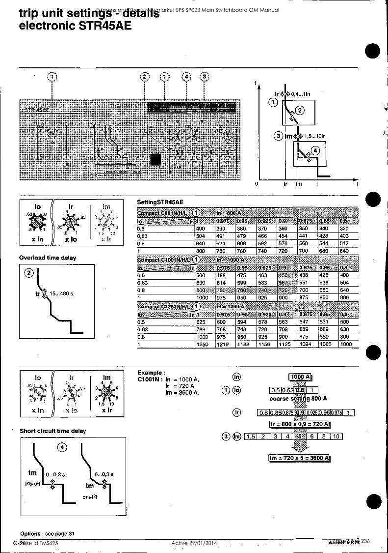
trip unit settings - details electronic STR45AE
®
,S1-1:145AE
lo;,63
TFR e
xln
. t
- 8.tm
ern'' -,
4 '01, *
C11011444 C19011444 C 1251844, tr tm '
A et"1
Iirr- ual4Maat
Overload time delay
SettingSTR45AE
t
0
0 rn4li.1,5...101r
rn Ir Im
compact 401N/1.1/L A In; 800 A
Id ' l' 0.975, 0.95 0.925 0.9, 0.875' 0.85'' 0,8 , ';
0,5 400 390 380 370 360 350 340 320
0,63 504 491 479 466 454 441 428 403
0,8 640 624 608 592 576 560 544 512
1 800 780 760 740 720 700 680 640
Compact C1001N/H/L ". In =1000 A
lo, = 3 Ir 1 0.975'; 0.95 ', : 0.925 0.9_ , 0.875 0.85- , 0,8
0,5 500 488 475 463 450 - 438 425 400
0,63 630 614 599 583 567 ,,: ' 551 536 504
0,8 :800- 780 , , 760' - 740. -.- 720 , 700 680 640
1 1000 975 950 925 900 875 850 800
Compact '&1251NIA/L. n =12'50 -
lb! ' , , ,1' A 0.975' 0.95 0.925 4 0.0 -, 0.875" 0:85 1 ,. 0,8- ,
0,5 625 609 594 578 563 547 531 500
0,63 788 768 748 728 709 689 669 630
0,8 1000 975 950 925 900 875 850 800
1 1250 1219 1188 1156 1125 1094 1063 1000
lo Im 4 5
5 6
2 8
1.5 10
xIn X IC X Ir
Short circuit time delay
Options : see page 31
Example :
C1001N : In = 1000 A, Ir =720 A, Im = 3600 A,
1000 A I 1
coarse slr atting 800 A
0.8 10.8510.8751 0.910 92510.9510.9751 1
Ir= 800 x 0 9=720A
1.51 2[ 3 1 4 F55',1 6 1 8 1 10
Im =720 x 5 =3600
28 - Schneider Electric
Edmonstone Street Newmarket SPS SP023 Main Switchboard OM Manual
Q-Pulse Id TMS695 Active 29/01/2014 Page 63 of 236
Ir = 800 x 0,9 = 720 Ai
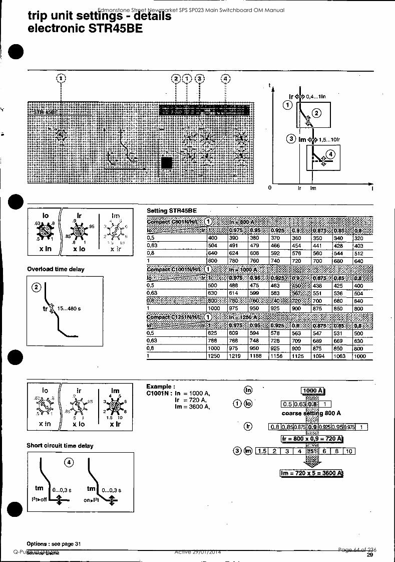
trip unit settings - details electronic STR45BE
lo .63
x In
Ir .9
.8
.8
X lo
.95
X lr
Overload time delay
Setting STR45BE
Compact 08014*. to It 1 0:975' 0.95 J 0.925 0.9g 0.875 0.85 0,
0,5 400 390 380 370 360 350 340 320 0,63 504 491 479 466 454 441 428 403 0,8 640 624 608 592 576 560 544 512 1 800 780 760 740 720 700 680 640
Compact.C1001N/H/L. In r:iboo 10 a 1r 1 0 975 , 0.95 t 0 925 0.9 0.875 > 0 85 0,8 0,5 500 488 475 463 450 438 425 400 0,63 630 614 599 583 567 551 536 504 0: 800 780 -:, 760 740 :. 720 1: 700 680 640 1 1000 975 950 925 900 875 850 800
oMPact 01251
lo 'f - ' 1r 1, 0:975 0.95: 0.925 ' 0.9' ' =- M875 0.85 ; ,: 0,110,, I 0,5 625 609 594 578 563 547 531 500 0,63 788 768 748 728 709 689 669 630 0,8 1000 975 950 925 900 875 850 800 1 1250 1219 1188 1156 1125 1094 1063 1000
lo
x In X
93
Im 4 5
1.5 10
x Ir
8
Short circuit time delay
Options : see page 31
Example :
C1001N : In = 1000 A, Ir =720 A, Im = 3600 A,
O to
Ir
Cs*
1000 A 1 ;
0.5 10.631 0.8 1 1
se_ 4
coarse tting 800 A
0.810.8510.8751:0.910.92510.9510.9751 1
F
1.51 2 1 3 1 4 145 M 6 1 8 110
Im= 720 x 5 =3600
Schneider Electric 29
Edmonstone Street Newmarket SPS SP023 Main Switchboard OM Manual
Q-Pulse Id TMS695 Active 29/01/2014 Page 64 of 236
Im=720x5=3600A1
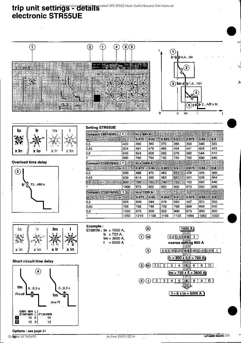
trip unit settings - details electronic STR55UE
® 10 10 0®
'STR 55UE
TFR
4
Cm, lizni C10a1 N. 1. C1251t141
tito s too .g 15,n. , 12
4,
+
<int: , 44.6
65., 1f644;-.3"-'7*-!'n tt, .4,1! 1,1):1
11,924° -fa
1,- 4;3 Ir tzSe, lel
tr ' A tm th
lo Ir
.8 1
X 10
.95
x In
Overload time delay
Short circuit time delay
Options : see page 31
Setting STR55UE
Compact C801 WH/L 41=i
lo - Ir 0.975 '4 0:95 ', 0.925 0.9. : 0.875 , 0.85 , 0,8,
0,5 400 390 380 370 360 350 340 320
0,63 504 491 479 466 454 441 428 403
0,8 640 624 608 592 576 560 544 512
1 800 780 760 740 720 700 680 640
to
Compact`O1001 NINA, In = 1000A
tel ' - '" 0.975 0.95 , 0.925' 0.9 x , 0.875- '2 0.85 b 0,8
0,5 500 488 475 463 450: 438 425 400
0,63 630 614 599 583 567, 551 536 504
0,8 F 800 ' 780, 760; 740'1 720; : 700 680 640
1 1000 975 950 925 900 875 850 800
oinPaCt 0251N/hit:, -In,= 1250 A- to lr 1 0.975 -,, 0.95 0.925' : 0.9 , 0.875- 0.85 0,8
0,5 625 609 594 578 563 547 531 500
0,63 788 768 748 728 709 689 669 630
0,8 1000 975 950 925 900 875 850 800
1 1250 1219 1188 1156 1125 1094 1063 1000
Example :
C1001 N : In = 1000 A, Ir =720 A, Urn = 3600 A, I = 6000 A
E)
100
1000 A '
1_0.510.6310.81 1
coarse setting 800 A
0.810.8510.8751°0.91092510.9510.9751 1
- t
Ir=800x09=720A
1.51 2 1 3 1 4 1;5'1 6 1 8 110
21 31 41 5 16', 8 1A1B
I, I = 6 x In = 6000 A
30 Schneider Electric
i fl
"
Edmonstone Street Newmarket SPS SP023 Main Switchboard OM Manual
Q-Pulse Id TMS695 Active 29/01/2014 Page 65 of 236
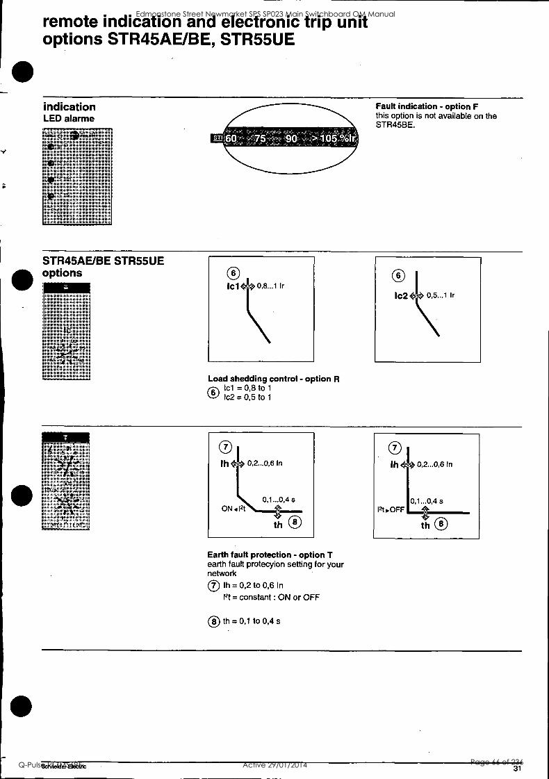
remote indication and electronic trip unit options STR45AE/BE, STR55UE
indication LED alarme
SB 60 75 90 >405.%Iri
Fault indication - option F this option is not available on the STR45BE.
STR45AE/BE STR55UE options
ter 9 .93'
85441)41i .98
Load shedding control - option R Icl = 0,8 to 1
v-f) Ic2= 0,5 to 1
Earth fault protection - option T earth fault protecyion setting for your network 0 lh = 0,2 to 0,6 In
12t = constant : ON or OFF
0 th = 0,1 to 0,4 s
Schneider Electric 31
Edmonstone Street Newmarket SPS SP023 Main Switchboard OM Manual
Q-Pulse Id TMS695 Active 29/01/2014 Page 66 of 236
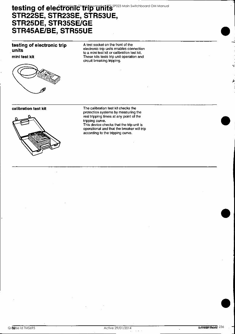
testing of electronic trip units STR22SE, STR23SE, STR53UE, STR25DE, STR35SE/GE STR45AE/BE, STR55UE
testing of electronic trip units mini test kit
A test socket on the front of the electronic trip units enables connection to a mini test kit or calibration test kit. These kits tests trip unit operation and circuit breaking tripping.
calibration test kit The calibration test kit checks the protection systems by measuring the real tripping times at any point of the tripping curve. This device checks that the trip unit is operational and that the breaker will trip according to the tripping curve.
32 Schneider. Electric
Edmonstone Street Newmarket SPS SP023 Main Switchboard OM Manual
Q-Pulse Id TMS695 Active 29/01/2014 Page 67 of 236
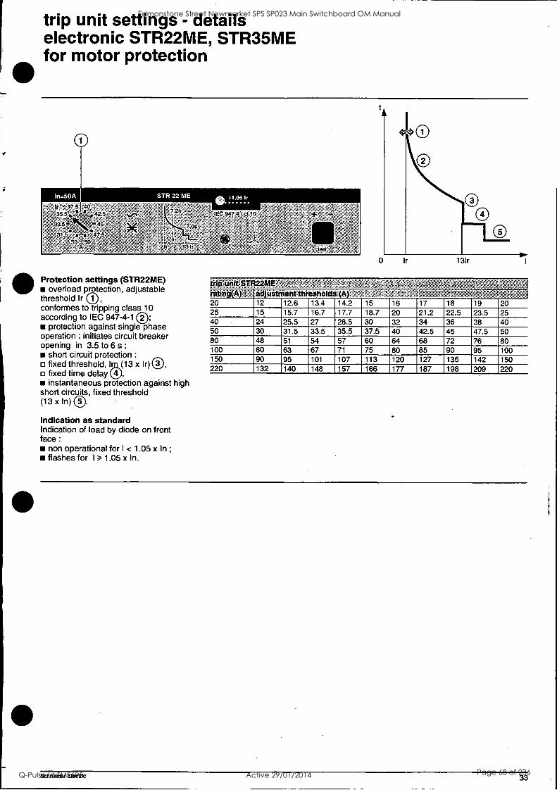
trip unit settings - details electronic STR22ME, STR35ME for motor protection
Protection settings (STR22ME) overload protection, adjustable
threshold Ir conformes to tripping class 10 according to IEC 947-4-1
protection against single phase operation : initiates circuit breaker opening in 3.5 to 6 s ;
short circuit protection :
fixed threshold, 193,03 x Ir) Q, fixed time delay 1'. instantaneous protection against high
short circuits, fixed threshold (13 x In)
Indication as standard Indication of load by diode on front face :
non operational for I < 1.05 x In ;
flashes for I 1.05 x In.
trip unit STR22ME' rating(A) 2 ; adjustment thresholds (A) . '
20 12 12.6 13.4 14.2 15 16 17 18 19 20 25 15 15.7 16.7 17.7 18.7 20 21.2 22.5 23.5 25 40 24 25.5 27 28.5 30 32 34 36 38 40 50 30 31.5 33.5 35.5 37.5 40 42.5 45 47.5 50 80 48 51 54 57 60 64 68 72 76 80 100 60 63 67 71 75 80 85 90 95 100 150 90 95 101 107 113 120 127 135 142 150 220 132 140 148 157 166 177 187 198 209 220
Schneider Electric 33
Edmonstone Street Newmarket SPS SP023 Main Switchboard OM Manual
Q-Pulse Id TMS695 Active 29/01/2014 Page 68 of 236
trip unit settings - details electronic STR43ME for motor protection
%I
/ to',' P ir ' Ind , .
?5 731 , .90.93 , 9 10
83. , - ', 8.,.
2.: . 85..* , 98 7....., .,L .,.. 12
8 '". N1 , 60 '13 8 in x to > x 0 ,
', ti 20 0
1 0At ,
.:; /
sir sharIM .!. MOM
IEC 947-4-1
nrin ULOUU
111 1111 1131
tr
Ir tsd .
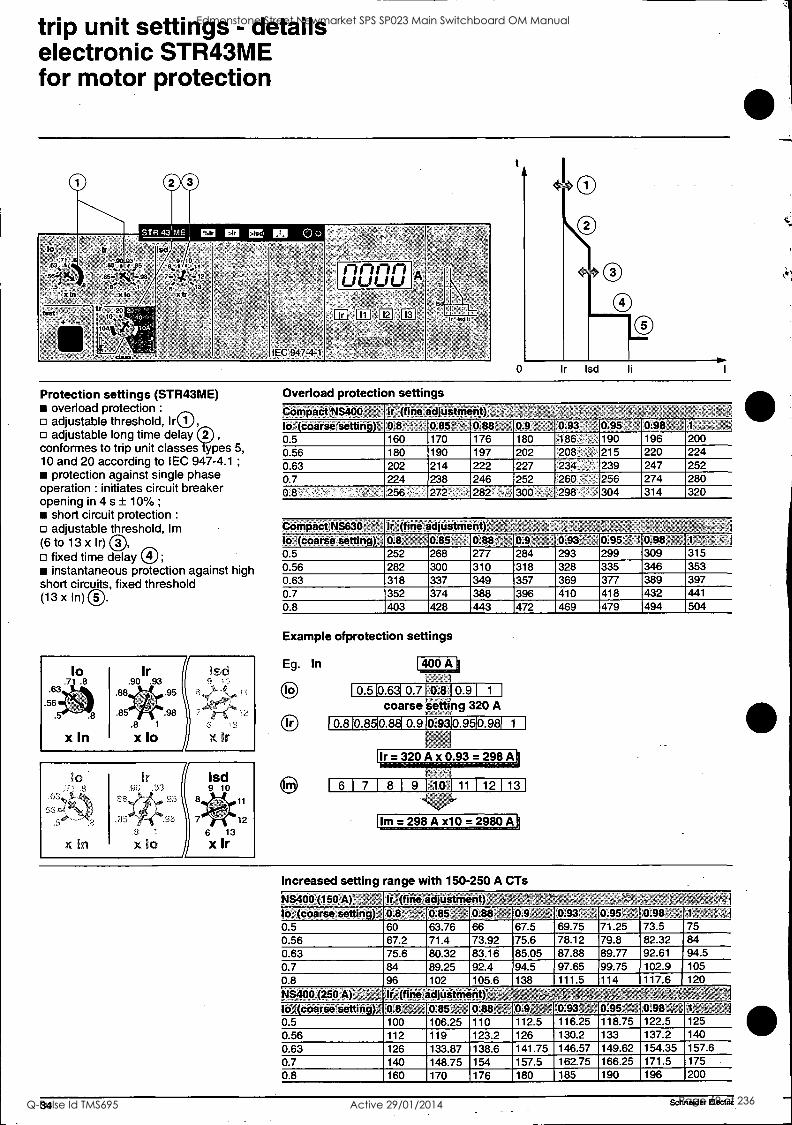
Protection settings (STR43ME) overload protection :
adjustable threshold, h.®, adjustable long time delay
conformes to trip unit classes types 5, 10 and 20 according to IEC 947-4.1 ;
protection against single phase operation : initiates circuit breaker opening in 4 s ± 10%;
short circuit protection :
adjustable threshold, Im (6 to 13 x Ir)
fixed time delay instantaneous protection against high
short circuits, fixed threshold (13 x In)
Overload protection settings Compact NS400 : ' If (fine adjustment) , :. , ,
Iot(coarse setting) 0:8" 0.85: - 0.88' -, 0.9 ' 0.93 , i 0.95 0.98 1 , x
0 5 160 170 176 180 186 190 196 200 0 56 180 190 197 202 208 . 215 220 224 0 63 202 214 222 227 234, - 239 247 252 0.7 224 238 246 252 260 256 274 280 08 ' 256 272 282 300 298 304 314 320
Compact NS630, Ir -(fine adjustment)' - ,,,
to (coarse setting) 0.8. 0.85 - 0.88 0.9, - 0.93 0.95" r 0.98 , 1 '; ; j 0.5 252 268 277 284 293 299 309 315 0.56 282 300 310 318 328 335 346 353 0.63 318 337 349 357 369 377 389 397 0.7 352 374 388 396 410 418 432 441
0.8 403 428 443 472 469 479 494 504
Example ofprotection settings
Eg. In
to
Ir
400 A
0.510.631 0.710.810.9 1 1
setting coarse settmg 320 A
0.8 0.8 0.8 0.9 ME 0.98p
Ir = 320 A x 0.93 = 298 A
6 1 7 1 8 1 9 110.1 11 1 12 1 13
Im = 298 A x10 = 2980 A
Increased setting range with 150-250 A CTs
Ns400 (150 ik)-- ,-- :-. Ir;(fine,adjustnient)Z IOAcoarse,setting):F 0.85' 0.85= 4. 0.811,e, 0.9,4 ;14: 0.93' : 0.95`,r 0.98,;', '?, 1:,c ;
0.5 60 63.76 66 67.5 69.75 71.25 73.5 75 0.56 67.2 71.4 73.92 75.6 78.12 79.8 82.32 84 0.63 75.6 80.32 83.16 85.05 87.88 89.77 92.61 94.5 0.7 84 89.25 92.4 94.5 97.65 99.75 102.9 105 0.8 96 102 105 6 138 111_5 114 117.6 120
NS400 (250}V,i,, '-1"1 Ire(fineadjUifinent) --;;;;;V' '1
lo'AcCiarse'settifigy, 0.8 ;',,- r,f, 0.85 It ; 0.88W ,0.9f t' ',0:93'il," 0.95 =:'.'. 0:98'441,A5,;-":1 0.5 100 106.25 110 112.5 116.25 118.75 122.5 125 0.56 112 119 123.2 130.2 133 137.2 140
0.63 126 133.87 138.6 .126 141.75 146.57 149.62 154.35 157.6
0.7 140 148.75 154 157.5 162.75 166.25 171.5 175 0.8 160 170 176 180 185 190 196 200
34 Schneider Electric
Edmonstone Street Newmarket SPS SP023 Main Switchboard OM Manual
Q-Pulse Id TMS695 Active 29/01/2014 Page 69 of 236

1'
options for trip unit STR43ME
ammeter (I) A digital display continuously indicates the current of the phase with the greatest load. By pressing a scroll button, it is also possible to display successively the readings of 11, 12,13 an the long time threshold setting Ir.
LEDs indicate the phase or setting for which the current is displayed.
Ammeter display limits: minimum current 0,2 x In (lower currents
are not displayed) ;
maximum currents 10 x In.
contactor tripping module (SDTAM)
opens the contactor in the event of an overload. It is thus possible to differentiate between tripping due to overloads and short- circuits;
may also be used to signal a thermal fault; must be reset manually (locally or
remotely; compatible with the following control
voltages: 24 to 72 V DC and 24 to 48 V AC, 110 to 240 V AC / DC;
fits in place of the MN and MX auxiliary voltage releases.
communication (COM) Transmission of data to Digipact distribution monitoring and control modules. Transmitted data:
settings; phase currents (rms values); highest current of the three phases;
overload condition alarm; cause of tripping (overload, short-circuit,
etc.).
Schneider Electric 35
Edmonstone Street Newmarket SPS SP023 Main Switchboard OM Manual
Q-Pulse Id TMS695 Active 29/01/2014 Page 70 of 236
oveload protection inoperative'
1 1 . 5 1 2 1 3 1 4 1 5 1 1 8 1 10 1
trip unit settings - details electronic STR35ME for motor protection
0 0
'STR 35ME
t
tt ktele "
'__on,,- -
,ett , 4
I
C SDI 14.14 " C10012144 C C12S1ON
z - It le 12 12
- - A
BS 0-* 2 S''e X101 1:5 "
ij zte
orodnitit,
' tin
.8
.63
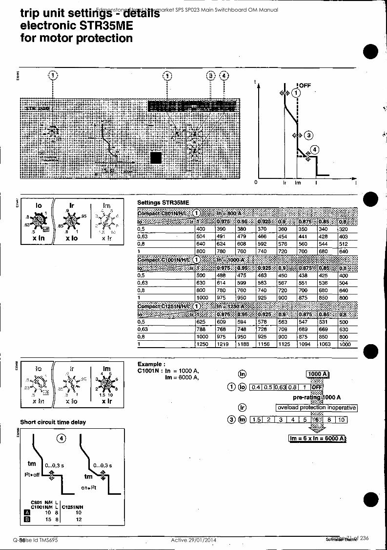
lo Settings STR35ME
Compact C80114/1-1/1: In= 800 A
"::: 0.975 'O95 : 0.925. 0:9 1 , 0.875 - 0.85 0,8 - ' !
0,5 400 390 380 370 360 350 340 320
0,63 504 491 479 466 454 441 428 403
0,8 640 624 608 592 576 560 544 512
1 800 780 760 740 720 700 680 640
Co:41108'a C1001NIMAL .1aou-A -
13: - Jr, 1 " 0.975' 395- _ .0.925 ,. 0.9 , 0.875 0.85 :, 0,8 ' 0,5 500 488 475 463 450 438 425 400
0,63 630 614 599 583 567 551 536 504 0,8 800 780 760 740 720 700 680 640 1 1000 975 950 925 900 875 850 800
CrirritiaCt 01251,1/11/1. CO' 1 1 in =1250 A . , -, :-: -1'73
lo= -- - " , 2 Ir 1 :.' r 0.975 0.95 ', . 0.925 0.9; 1 ' 0.875 0.85 : 0,8 .', .;
0,5 625 609 594 578 563 547 531 500 0,63 788 768 748 728 709 689 669 630
0,8 1000 975 950 925 900 875 850 800
1 1250 1219 1188 1156 1125 1094 1063 1000
.63
Jo
x 8 1
x lo
Urn 4 5
1.5 10
x Ir
8
Short circuit time delay
Example :
C1001N : In = 1000 A, Im = 6000 A,
1000 A
0.410.510.6310.81 1 'OFF
pre-rating:1000 A
Im=6x1n=6000 A
36 Schneider Electric
Edmonstone Street Newmarket SPS SP023 Main Switchboard OM Manual
Q-Pulse Id TMS695 Active 29/01/2014 Page 71 of 236
supplementary functions
Vigi bloc and Visu bloc 38
plug-in base 39
withdrawable chassis for Compact NS100 to 630 40
universal chassis for Compact C801 to 1251 41
locking options 42
locking and lead sealing 43
Schneider Electric 37
Edmonstone Street Newmarket SPS SP023 Main Switchboard OM Manual
Q-Pulse Id TMS695 Active 29/01/2014 Page 72 of 236

Vigi bloc and Visu bloc
Vigi bloc
intermediate terminal shield (1)
sealable fixing screw for the intermediate terminal shield
sealing point for plate blocking access to the settings
plate blocking access to the settings
test push-button
reset push-button
rating plate
slot for SDV auxiliary switch (optional)
trip time delay settings (2)
sensitivity settings
The Vigi bloc provides residual current protection against indirect contact and the risk of fire and destruction due to faults to earth. It actuates the trip unit
by means of a direct mechanical action. The Vigi bloc can be fitted with an alarm contact (SDV) which can be used to remotely indicate that the device has tripped due to an earth fault .
The "Test" push button allows regular verification that the Vigi bloc is operational by simulating an earth fault. The test cannot be carried out with the circuit braker in the open position. The "Reset" push button. After all trips initiated by the Vigi, this button must be pressed in order to reset the Vigi.
(1) The intermediate terminal shield is necessary in order for the Vigi to function. (2) When the device is set to 30mA, any time delay selected is nullified i.e. instantaneous operation.
rating plate
cOily.e
type of Vigi module
operational voltage and frequency
standardised symbols: (see page 4)
n. immunity to current 8/20 wave and electromagnetic environment class A immunity to DC components (6 mA insensitivity)
zs minimum operating temperature as per VDE 664
schematic diagram
the Visu bloc The standard fixed versions of the Compact circuit breakers exist in ratings 100 A to 1250 A. A Visu bloc can be directly connected, which provides visible break isolation according to French standard NF C 13.100 : the contacts are visibles through a transparent cover, and are operated by means of a handle. The Visu bloc is padlockable as standard with barrel locking optional. Specific auxiliaries are available for the Visu bloc : auxiliary contacts, terminal shields, etc. The Compact NS100/630 and C801/ 1251 can be equiped, as an option, with a pre-tripping mechanism preventing the "on-load" opening of the Visu bloc.
The Visu bloc must be fitted with a CAM contact and the circuit breaker with a voltage release.
Connection fixed front connected. The Compact
circuit breakers with Visu bloc are delivered ready for connection by bars or cables fitted with lugs;
connection of bare cables : upstream by a set of terminals for the Visu bloc and downstream a set of teminals for the Compact;
accessories : the Visu bloc can be fitted with terminal spreaders, right angle terminals, terminal extensions and lugs.
fixed rear connected : by adaptation of the Compact's specific rear connectors with the Visu bloc, delivered per pole.
The Ccimpact circuit breakers with Visu bloc can be fitted with specific short terminal shields (rear connection) or standard long terminal shields (front connection), both of which are lead sealable.
Accessories Compact NS100/630 with Visu bloc can be fitted with :
in the Visu bloc : auxiliary contacts (OF, CAM), Ronis or Profalux barrel locks, a contact to earth the neutral (obligatory if the tansformer neutral is earthed downstream of the Compact with Visu bloc), etc.
in the Compact NS frame : all the Compact NS auxiliaries.
38 Schneider Electric
Edmonstone Street Newmarket SPS SP023 Main Switchboard OM Manual
Q-Pulse Id TMS695 Active 29/01/2014 Page 73 of 236
plug-in version
the plug-in circuit breaker unplugging
1 - open the circuit breaker.
2 - remove the two fixing screws.
3 - pull the circuit breaker out horizontally.
The auxiliary circuits are disconnected by the automatic auxiliary connector block located at the back of the device.
Safety mechanism If the circuit breaker is closed (I/ON position) when pulled out, advanced opening ensures operator safety, i.e. the poles automatically open before the power connections are withdrawn.
plugging in
degree of protection against direct contact with the power circuits
1 - open the circuit breaker.
2 - plug the circuit breaker in.
3 - refit the fixing screws. 4 - the circuit breaker is ready for operation.
device plugged in: IP40 (with terminal shields),
device unplugged: IP20, device unplugged and base fitted with
safety shutters: IP40.
Schneider Electric 39
Edmonstone Street Newmarket SPS SP023 Main Switchboard OM Manual
Q-Pulse Id TMS695 Active 29/01/2014 Page 74 of 236
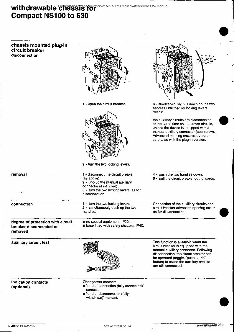
withdrawable chassis for Compact NS100 to 630
chassis mounted plug-in circuit breaker disconnection
1 - open the circuit breaker.
2 - turn the two locking levers.
3 - simultaneously pull down on the two handles until the two locking levers "clack".
the auxiliary circuits are disconnected at the same time as the power circuits, unless the device is equipped with a manual auxiliary connector (see below). Advanced opening ensures operator safety, as with the plug-in version.
removal 1 - disconnect the circuit breaker (as above). 2 - unplug the manual auxiliary connector (if installed). 3 - turn the two locking levers, as for disconnection.
4 - push the two handles down. 5 - pull the circuit breaker out forwards.
connection 1 - turn the two locking levers. Connection of the auxiliary circuits and 2 - simultaneouly push up the two circuit breaker advanced opening occur handles. as for disconnection.
degree of protection with circuit breaker disconnected or removed
no special equipment: IP20, base fitted with safety shutters: IP40.
auxiliary circuit test
>NI
This function is available when the circuit breaker is equipped with the manual auxiliary connector. Following disconnection, the circuit breaker can be operated (toggle, "push to trip" button) to check the auxiliary circuits are still connected.
indication contacts (optional)
Changeover contacts: "end-of-connection (fully connected)" contact, "end-of-disconnection (fully withdrawn)" contact.
Schneider Electric
Edmonstone Street Newmarket SPS SP023 Main Switchboard OM Manual
Q-Pulse Id TMS695 Active 29/01/2014 Page 75 of 236
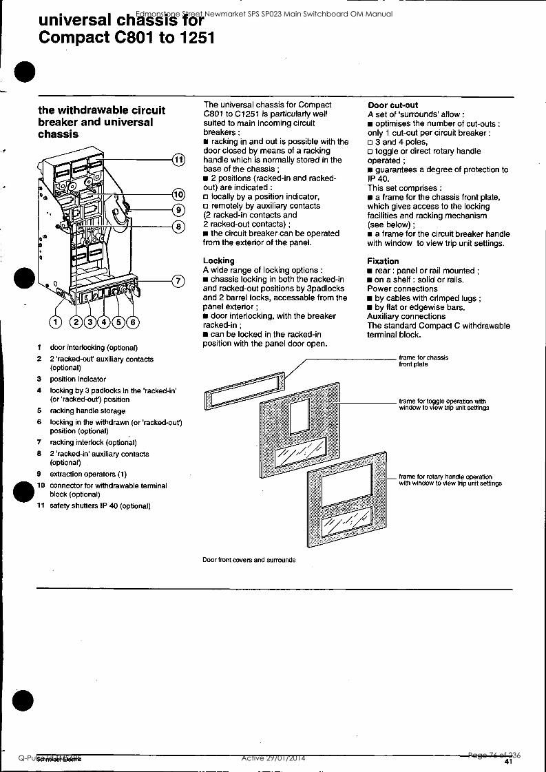
universal chassis for Compact C801 to 1251
the withdrawable circuit breaker and universal chassis
1 door interlocking (optional)
2 2 'racked-out auxiliary contacts (optional)
3 position indicator
4 locking by 3 padlocks in the 'racked-in' (or 'racked-out) position
5 racking handle storage
6 locking in the withdrawn (or 'racked-out) position (optional)
7 racking interlock (optional)
8 2 'racked-in' auxiliary contacts (optional)
9 extraction operators (1)
10 connector for withdrawable terminal block (optional)
11 safety shutters IP 40 (optional)
The universal chassis for Compact C801 to C1251 is particularly well suited to main incoming circuit breakers :
racking in and out is possible with the door closed by means of a racking handle which is normally stored in the base of the chassis ;
2 positions (racked-in and racked- out) are indicated :
locally by a position indicator, remotely by auxiliary contacts
(2 racked-in contacts and 2 racked-out contacts) ;
the circuit breaker can be operated from the exterior of the panel.
Locking A wide range of locking options :
chassis locking in both the racked-in and racked-out positions by 3padlocks and 2 barrel locks, accessable from the panel exterior ;
door interlocking, with the breaker racked-in ;
can be locked in the racked-in position with the panel door open.
Door cut-out A set of 'surrounds' allow :
optimises the number of cut-outs :
only 1 cut-out per circuit breaker :
3 and 4 poles, toggle or direct rotary handle
operated ;
guarantees a degree of protection to IP 40. This set comprises :
a frame for the chassis front plate, which gives access to the locking facilities and racking mechanism (see below) ;
a frame for the circuit breaker handle with window to view trip unit settings.
Fixation rear : panel or rail mounted ;
on a shelf : solid or rails. Power connections
by cables with crimped lugs ;
by flat or edgewise bars. Auxiliary connections The standard Compact C withdrawable terminal block.
Door front covers and surrounds
frame for chassis front plate
frame for toggle operation with window to view trip unit settings
frame for rotary handle operation with window to view trip unit settings
Schneider Electric 41
Edmonstone Street Newmarket SPS SP023 Main Switchboard OM Manual
Q-Pulse Id TMS695 Active 29/01/2014 Page 76 of 236
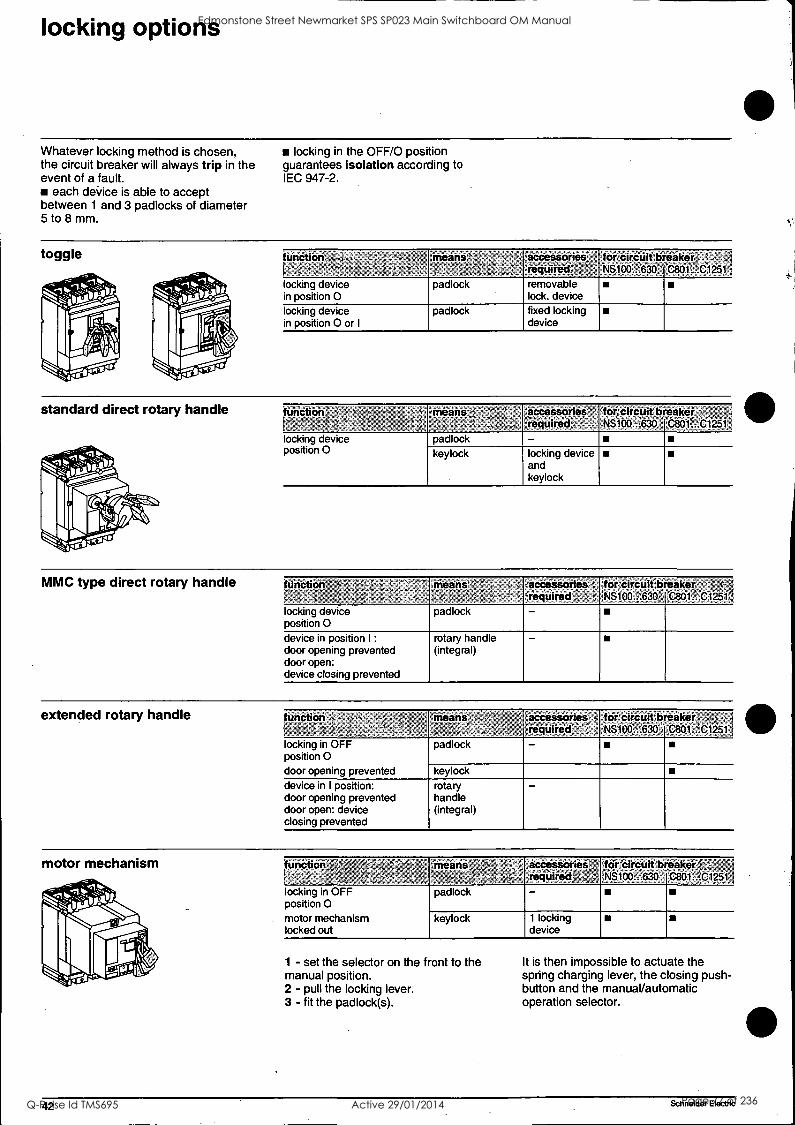
ocking options
Whatever locking method is chosen, the circuit breaker will always trip in the event of a fault.
each deVice is able to accept between 1 and 3 padlocks of diameter 5 to 8 mm.
locking in the OFF/0 position guarantees isolation according to IEC 947-2.
toggle furiction .
..
means,- . , .. .,
'occiesporiOs- required o',, $
for circuit breaker NS100 . 630
:1- : '.
'C801...01261 i
locking device in position 0
padlock removable lock. device
locking device in position 0 or I
padlock fixed locking device
standard direct rotary handle function - means % :- accessories for:circiiit breaker - ' required -- --, NS100...630 C801:..C1251
locking device padlock - position 0 keylock locking device
and keylock
MMC type direct rotary handle function '
I., : , , ,
Means : ;1-ccessoriei -required L -
for circuit Breaker -NS100 72.630 csol ':.c1251.4
locking device position 0
padlock -
device in position I :
door opening prevented door open: device closing prevented
rotary handle (integral)
-
extended rotary handle kinction ; c , , - . -.
rneans, accessories' ' required ' 7:
,for Cireuit:breakefj NS100. '630
: ,
P801.:.C1251
locking in OFF position 0 door opening prevented
padlock -
keylock device in I position: door opening prevented door open: device closing prevented
rotary handle (integral)
-
motor mechanism function r ' '-->
means ' ' ' ,accessories,,, required ' for circuit breakers'.
:118160..!636 ,/.,
C801.:!.01261,,
locking in OFF position 0 motor mechanism locked out
padlock -
keylock 1 locking device
1 - set the selector on the front to the manual position. 2 - pull the locking lever. 3 - fit the padlock(s).
It is then impossible to actuate the spring charging lever, the closing push- button and the manuaVautomatic operation selector.
42 Schneider Electric
Edmonstone Street Newmarket SPS SP023 Main Switchboard OM Manual
Q-Pulse Id TMS695 Active 29/01/2014 Page 77 of 236
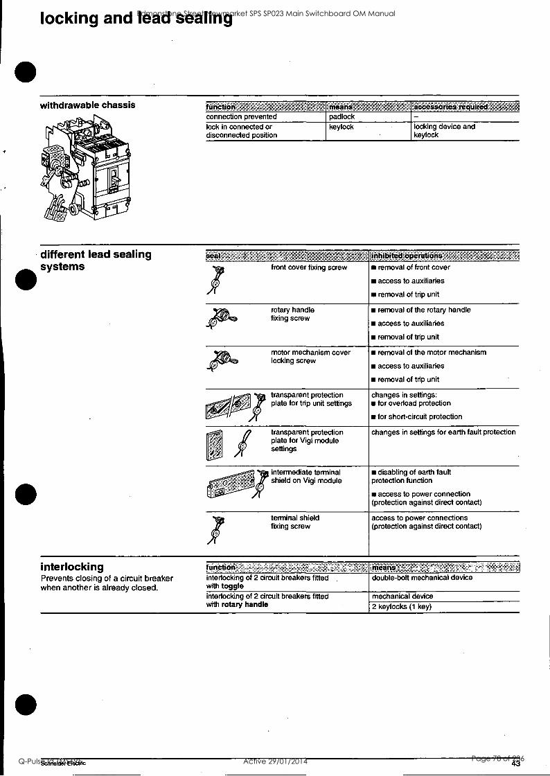
locking and lead sealing
withdrawable chassis furiction connection prevented lock in connected or disconnected position
means. padlock
accessories: required
locking device and keylock
keylock
different lead sealing systems
seal inhipited operations
front cover fixing screw removal of front cover
access to auxiliaries
removal of trip unit
rotary handle fixing screw
removal of the rotary handle
access to auxiliaries
removal of trip unit
motor mechanism cover locking screw
removal of the motor mechanism
access to auxiliaries
removal of trip unit
transparent protection plate for trip unit settings
transparent protection plate for Vigi module settings
jintermediate terminal shield on Vigi module
changes in settings: for overload protection
for short-circuit protection
changes in settings for earth fault protection
disabling of earth fault protection function
access to power connection (protection against direct contact)
terminal shield fixing screw
access to power connections (protection against direct contact)
interlocking Prevents closing of a circuit breaker when another is already closed.
*Ow means interlocking of 2 circuit breakers fitted with toggle
double-bolt mechanical device
interlocking of 2 circuit breakers fitted with rotary handle
mechanical device
2 keylocks (1 key)
Schneider Electric 43
Edmonstone Street Newmarket SPS SP023 Main Switchboard OM Manual
Q-Pulse Id TMS695 Active 29/01/2014 Page 78 of 236

44 Schneider Electric
Edmonstone Street Newmarket SPS SP023 Main Switchboard OM Manual
Q-Pulse Id TMS695 Active 29/01/2014 Page 79 of 236

operational conditions
environmental conditions 46
commissioning and exploitation 48
operational anomalies 50
practical advice 51
Schneider Electric 45
Edmonstone Street Newmarket SPS SP023 Main Switchboard OM Manual
Q-Pulse Id TMS695 Active 29/01/2014 Page 80 of 236
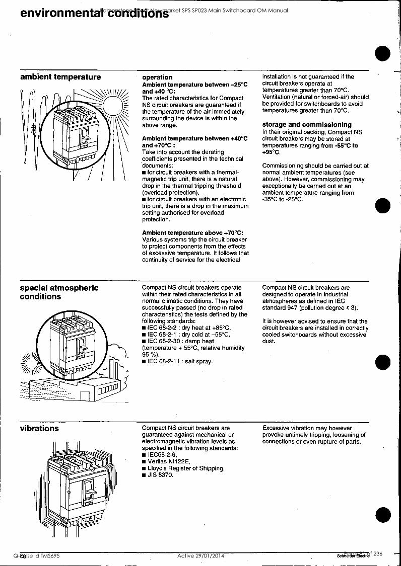
environmental conditions
ambient temperature operation Ambient temperature between -25°C and +40 °C: The rated characteristics for Compact NS circuit breakers are guaranteed if the temperature of the air immediately surrounding the device is within the above range.
Ambient temperature between +40°C and +70°C :
Take into account the derating coefficients presented in the technical documents:
for circuit breakers with a thermal- magnetic trip unit, there is a natural drop in the thermal tripping threshold (overload protection),
for circuit breakers with an electronic trip unit, there is a drop in the maximum setting authorised for overload protection.
Ambient temperature above +70°C: Various systems trip the circuit breaker to protect components from the effects of excessive temperature. It follows that continuity of service for the electrical
installation is not guaranteed if the circuit breakers operate at temperatures greater than 70°C. Ventilation (natural or forced-air) should be provided for switchboards to avoid temperatures greater than 70°C.
storage and commissioning In their original packing, Compact NS circuit breakers may be stored at temperatures ranging from -55°C to +95°C.
Commissioning should be carried out at normal ambient temperatures (see above). However, commissioning may exceptionally be carried out at an ambient temperature ranging from -35°C to -25°C.
special atmospheric conditions
Compact NS circuit breakers operate within their rated characteristics in all normal climatic conditions. They have successfully passed (no drop in rated characteristics) the tests defined by the following standards:
IEC 68-2-2 : dry heat at +85°C, IEC 68-2-1 : dry cold at -55°C, IEC 68-2-30 : damp heat
(temperature + 55°C, relative humidity 95 %),
IEC 68-2-11 : salt spray.
Compact NS circuit breakers are designed to operate in industrial atmospheres as defined in IEC standard 947 (pollution degree < 3).
It is however advised to ensure that the circuit breakers are installed in correctly cooled switchboards without excessive dust.
vibrations Compact NS circuit breakers are guaranteed against mechanical or electromagnetic vibration levels as specified in the following standards:
IEC68-2-6, Veritas NI122E, Lloyd's Register of Shipping, JIS 8370.
Excessive vibration may however provoke untimely tripping, loosening of connections or even rupture of parts.
Schneider Electric
Edmonstone Street Newmarket SPS SP023 Main Switchboard OM Manual
Q-Pulse Id TMS695 Active 29/01/2014 Page 81 of 236
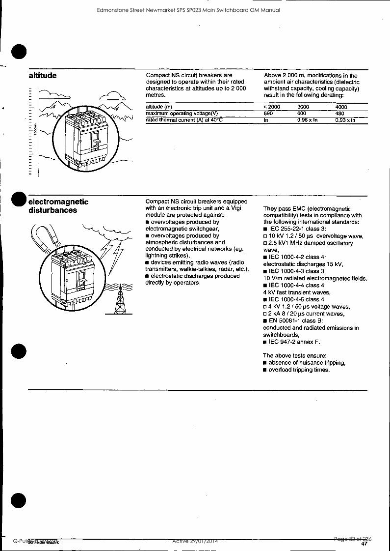
altitude
electromagnetic disturbances
Compact NS circuit breakers are designed to operate within their rated characteristics at altitudes up to 2 000 metres.
Above 2 000 m, modifications in the ambient air characteristics (dielectric withstand capacity, cooling capacity) result in the following derating:
altitude (m) maximum operating voltage(V) rated thermal current (A) at 40°C
2000 3000 4000 690 600 480 In 0,96 x In 0,93 x In
Compact NS circuit breakers equipped with an electronic trip unit and a Vigi module are protected against:
overvoltages produced by electromagnetic switchgear,
overvoltages produced by atmospheric disturbances and conducted by electrical networks (eg. lightning strikes),
devices emitting radio waves (radio transmitters, walkie-talkies, radar, etc.),
electrostatic discharges produced directly by operators.
They pass EMC (electromagnetic compatibility) tests in compliance with the following international standards:
IEC 255-22-1 class 3: 10 kV 1.2 / 50 Lis overvoltage wave, 2.5 kV1 MHz damped oscillatory
wave, IEC 1000-4-2 class 4:
electrostatic discharges 15 kV, IEC 1000-4-3 class 3:
10 V/m radiated electromagnetec fields, IEC 1000-4-4 class 4:
4 kV fast transient waves, I EC 1000-4-5 class 4: 4 kV 1.2 / 50 Lis voltage waves, 2 kA 8 / 20 pis current waves, EN 50081-1 class B:
conducted and radiated emissions in switchboards,
IEC 947-2 annex F.
The above tests ensure: absence of nuisance tripping, overload tripping times.
Schneider Electric 47
Edmonstone Street Newmarket SPS SP023 Main Switchboard OM Manual
Q-Pulse Id TMS695 Active 29/01/2014 Page 82 of 236

commissioning and exploitation
prior to commissioning new circuit breakers or following an extended shutdown
A general check requires only a few minutes and eliminates any risks of incorrect operation due to error or neglect.
All checks must be carried out with the switchboard de-energised. For compartmented switchboards, it is sufficient that all accessible sections be de-energised.
E, prior to commissioning periodically during service life
following servicing on the switchboard periodically during an extended shutdown following an extended shutdown
A electrical tests B switchboard inspection C conformity with diagram D device mounting, connections- E auxiliaries F mechanical operation
(1) (2)
G operation of the electronic trip units and the Vigi modules.
(1) extended shutdown or modifications in the switchboard (2) modification in the switchboard
electrical tests Insulation and dielectric withstand capacity tests are carried out prior to delivery of the switchboard. These tests are governed by applicable standards and must always be carried out by an authorised specialist.
switchboard inspection Check that the circuit breakers are installed in a clean environment, free of dust and all installation debris (tools, wiring, chips, metal particles, etc.).
compliance with diagram Check the conformity of devices with the installation diagram:
ratings and breaking capacities indicated on the rating plates,
trip unit identification (type, rating), presence of additional functions (Vigi
earth fault protection, motor mechanism, rotary handle, auxiliaries, indication and measurement modules),
protection settings (overload, short- circuit, earth fault),
outgoing circuit identification on the front of devices,
for Vigicompact earth fault protection circuit breakers, check that the intermediate terminal shield is installed, otherwise the earth fault protection function is inoperative.
device mounting-status of connections and auxiliaries
Check device mounting in the switchboard and the tightness of power connection.
Check that auxiliaries and accessories are correctly installed:
motor mechanism modules or rotary handles,
accessories (terminal shields, door escutcheons, etc.),
connection of auxiliary circuits.
mechanical operation Check the mechanical operation of devices:
contact opening, contact closing, tripping using the "push to trip".
operation of the electronic trip units and the Vigi modules
Check the electronic trip units using the mini test kit or calibration test kit (see page 13).
Check the Vigi modules using the test button on the front plate. This test guarantees tripping in the event of an earth fault.
48 Schneider Electric
Edmonstone Street Newmarket SPS SP023 Main Switchboard OM Manual
Q-Pulse Id TMS695 Active 29/01/2014 Page 83 of 236
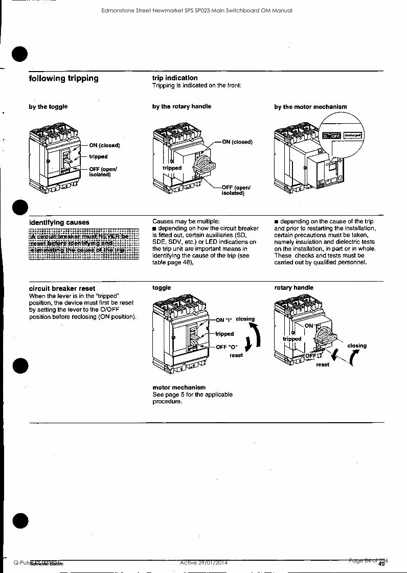
following tripping
by the toggle
ON (closed)
tripped
OFF (open/ isolated)
trip indication Tripping is indicated on the front:
by the rotary handle
ON (closed)
OFF (open/ isolated)
by the motor mechanism
identifying causes
irreiker must NEVER'be rjesetbefore identifying and elkninafing"thei cause of the trip.
Causes may be multiple: depending on how the circuit breaker
is fitted out, certain auxiliaries (SD, SDE, SDV, etc.) or LED indications on the trip unit are important means in identifying the cause of the trip (see table page 48),
depending on the cause of the trip and prior to restarting the installation, certain precautions must be taken, namely insulation and dielectric tests on the installation, in part or in whole. These checks and tests must be carried out by qualified personnel.
circuit breaker reset When the lever is in the "tripped" position, the device must first be reset by setting the lever to the 0/OFF position before reclosing (ON position).
toggle
ON "I" closing
tripped
OFF "0" reset
motor mechanism See page 5 for the applicable procedure.
rotary handle
Schneider Electric 49
Edmonstone Street Newmarket SPS SP023 Main Switchboard OM Manual
Q-Pulse Id TMS695 Active 29/01/2014 Page 84 of 236
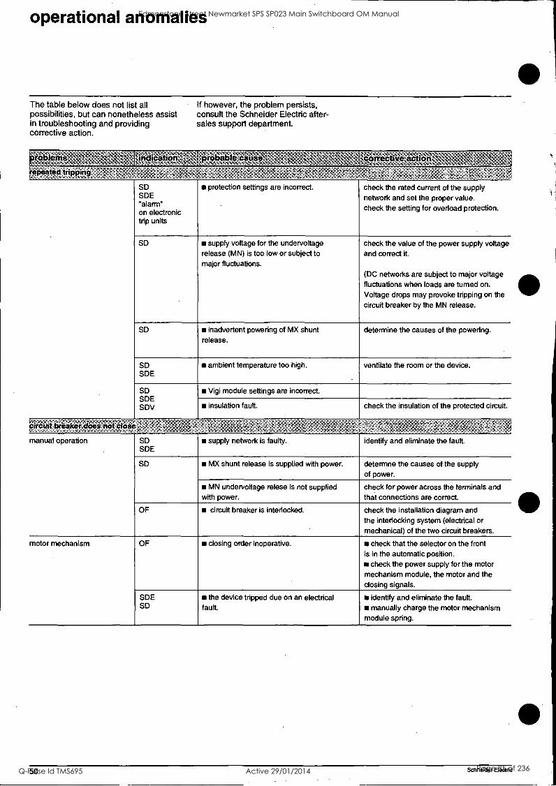
operational anomalies
The table below does not list all possibilities, but can nonetheless assist in troubleshooting and providing corrective action.
If however, the problem persists, consult the Schneider Electric after- sales support department.
roblems
repeated tripping
indication k'55 5.5,,
probablocause, .convetive `55
SD SDE "alarm" on electronic trip units
protection settings are incorrect. check the rated current of the supply network and set the proper value. check the setting for overload protection.
SD supply voltage for the undervoltage release (MN) is too low or subject to major fluctuations.
check the value of the power supply voltage and correct it.
(DC networks are subject to major voltage fluctuations when loads are tumed on.
Voltage drops may provoke tripping on the circuit breaker by the MN release.
SD inadvertent powering of MX shunt release.
determine the causes of the powering.
SD SDE
ambient temperature too high. ventilate the room or the device.
SD SDE SDV
Vigi module settings are incorrect.
insulation fault. check the insulation of the protected circuit.
circuit beaker does not close
manual operation SD SDE
supply network is faulty. identify and eliminate the fault.
SD MX shunt release is supplied with power. determne the causes of the supply of power.
MN undervottage relese is not supplied with power.
check for power across the terminals and that connections are correct.
OF circuit breaker is interlocked. check the installation diagram and the interlocking system (electrical or mechanical) of the two circuit breakers.
motor mechanism OF closing order inoperative. check that the selector on the front is in the automatic position.
check the power supply for the motor mechanism module, the motor and the closing signals.
SDE SD
the device tripped due on an electrical fault.
iii identify and eliminate the fault. manually charge the motor mechanism
module spring.
50 Schneider Electric
Edmonstone Street Newmarket SPS SP023 Main Switchboard OM Manual
Q-Pulse Id TMS695 Active 29/01/2014 Page 85 of 236
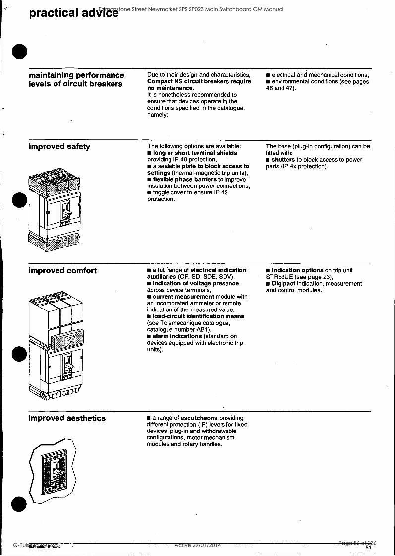
practical advice
maintaining performance levels of circuit breakers
Due to their design and characteristics, Compact NS circuit breakers require no maintenance. It is nonetheless recommended to ensure that devices operate in the conditions specified in the catalogue, namely:
electrical and mechanical conditions, environmental conditions (see pages
46 and 47).
improved safety The following options are available: long or short terminal shields
providing IP 40 protection, a sealable plate to block access to
settings (thermal-magnetic trip units), flexible phase barriers to improve
insulation between power connections, toggle cover to ensure IP 43
protection.
The base (plug-in configuration) can be fitted with:
shutters to block access to power parts (IP 4x protection).
improved comfort a full range of electrical indication auxiliaries (OF, SD, SDE, SDV),
indication of voltage presence across device terminals,
current measurement module with an incorporated ammeter or remote indication of the measured value,
load-circuit identification means (see Telemecanique catalogue, catalogue number AB1),
alarm indications (standard on devices equipped with electronic trip units).
indication options on trip unit STR53UE (see page 23),
Digipact indication, measurement and control modules.
improved aesthetics a range of escutcheons providing different protection (IP) levels for fixed devices, plug-in and withdrawable configutations, motor mechanism modules and rotary handles.
Schneider Electric 51
Edmonstone Street Newmarket SPS SP023 Main Switchboard OM Manual
Q-Pulse Id TMS695 Active 29/01/2014 Page 86 of 236

notes Edmonstone Street Newmarket SPS SP023 Main Switchboard OM Manual
Q-Pulse Id TMS695 Active 29/01/2014 Page 87 of 236

Schneider Electric Industries SA As standards, specifications and designs change from time to time, please ask for confirmation of the information given in this publication.
5, rue Nadar 92506 Rueil-Malmaison Cedex France
Tel: +33 (0)1 41 29 82 00 Fax:+33 (0)1 47 51 80 20
http://www.schnelderelectrIc.com
C9 This document has been printed on ecological paper.
Design: Schneider Electric Concetion: AMEG Printed: Evol'Repro
ART 73432 07-99
Edmonstone Street Newmarket SPS SP023 Main Switchboard OM Manual
Q-Pulse Id TMS695 Active 29/01/2014 Page 88 of 236
TECHNICAL DATA SHEET
For
Edmondstone Street Pump Station
Equipment Type: Circuit Breaker
Location:
Model Numbers:
Manufacturer:
Supplier:
Switchboard Circuit Breaker Chassis
Multi 9
Merlin Gerin
Schneider Electric. 30 Graystone Street TINGALPA QLD 4173
Ph: 07 3890 2112 Fx: 07 3890 2098
Edmonstone Street Newmarket SPS SP023 Main Switchboard OM Manual
Q-Pulse Id TMS695 Active 29/01/2014 Page 89 of 236
Multi 9 Miniature Circuit Breakers
Selection Guide
SCIINEIDER Merlin Gerin 11Nledicon Square D 1Telemecanique
Edmonstone Street Newmarket SPS SP023 Main Switchboard OM Manual
Q-Pulse Id TMS695 Active 29/01/2014 Page 90 of 236
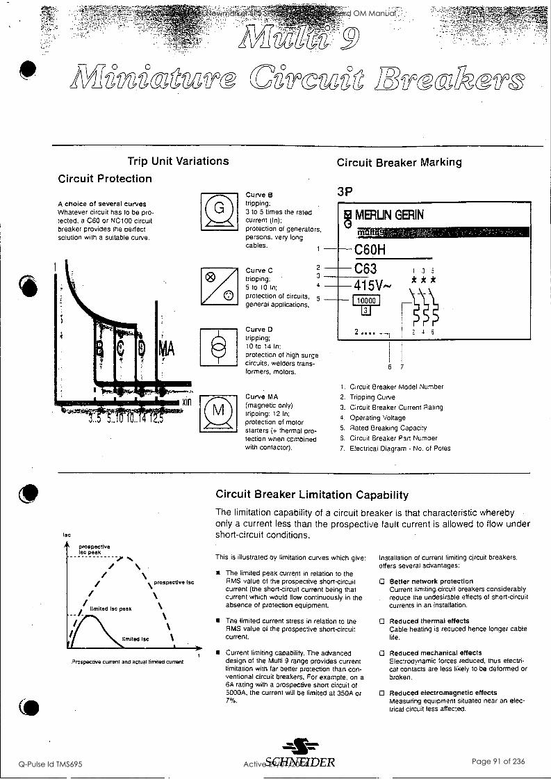
'IC3gWffS aTiZtd )83TS0 STZ
Trip Unit Variations
Circuit Protection
A choice of several curves Whatever circuit has to be pro- tected, a C60 or NC100 circuit breaker provides the perfect solution with a suitable curve.
Curve B tripping: 3 to 5 times the rated current (In); protection of generators, persons, very long cables.
Curve C tripping: 5 to 10 In; protection of circuits, general applications.
3
4
5
Curve tripping; 10 to 14 In; protection of high surge circuits, welders trans- formers, motors.
Curve MA (magnetic only) tripping: 12 In;
protection of motor starters (+ thermal pro- tection when combined with contactor).
Circuit Breaker Marking
3P
MERLIN GAIN molgg C6OH
C63 1 3 5
415V-- * * *
i0000 1
2 .... 2 4 6
6 7
1. Circuit Breaker Model Number
2. Tripping Curve
3. Circuit Breaker Current Rating
4. Operating Voltage
5. Rated Breaking Capacity
6. Circuit Breaker Part Number
7. Electrical Diagram - No. of Poles
lac
prospective lsc peak
/ /
limited I= peak
limited tsc
prospective lac
Prospective current and actual limited current
Circuit Breaker Limitation Capability The limitation capability of a circuit breaker is that characteristic whereby only a current less than the prospective fault current is allowed to flow under short-circuit conditions.
This is illustrated by limitation curves which give:
The limited peak current in relation to the RMS value of the prospective short-circuit current (the short-circuit current being that current which would flow continuously in the absence of protection equipment.
The limited current stress in relation to the RMS value of the prospective short-circuit current.
Current limiting capability. The advanced design of the Multi 9 range provides current limitation with far better protection than con- ventional circuit breakers. For example, on a 6A rating with a prospective short circuit of 5000A. the current will be limited at 350A or 7%.
S CHNEIDER
Installation of current limiting circuit breakers. offers several advantages:
Better network protection Current limiting. circuit breakers considerably reduce the undesirable effects of short-circuit currents in an installation.
Reduced thermal effects Cable heating is reduced hence longer cable life.
O Reduced mechanical effects Electrodynamic forces reduced, thus electri- cal contacts are less likely to be deformed or broken.
O Reduced electromagnetic effects Measuring equipment situated near an elec- trical circuit less affected.
Edmonstone Street Newmarket SPS SP023 Main Switchboard OM Manual
Q-Pulse Id TMS695 Active 29/01/2014 Page 91 of 236
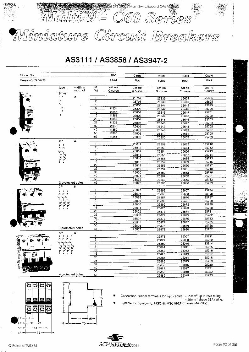
1510 as naZ 6,63,VZTS 06frOVZ6 IRTsalefrz
AS3111 / AS3858 / AS3947-2
Model No.
Breaking Capacity
D60 C6ON C6OH C6OH C6OH
4.5kA 6kA 10kA 10kA 10kA
type . width in In cat no cat no mod. of (A) C curve C curve
9mm 1p 2
*
2
cat no B curve
cat no C curve
cat no D curve
2P 4 1 5
* *
LS
2 4
2 protected poles 3P 6
1 3 5
2 1 6
3 protected poles
4P 8 1 3 5 7
* * * *
P 2 4 6 6
4 protected poles
memo I'll
2P 36
3P 54
4.P 72
81
6
1 25797 25839 25639 25696 2 25798 25840 25640 25698 4 25800 25841 25642 25699 6 11354 25801 25842 25643 25700 10 11355 25802 25843 25644 25701 16 11356 25803 25844 25646 25702 20 11357 25804 25845 25646 25703 25 11339 25805 25846 25647 25704 32 11358 25806 25847 25648 25705 40 11359 25807 25848 25649 25707 50 11360 25808 25849 25651 25708 63 11361 25809 25850 25652 25709
1 25811 25852 25653 '25710 2 25812 25853 25654 25712 4 25814 25854 25656 25713 6 25815 25855 25657 25714
10 25816 25856 25658 25715 16 25817 25857 25659 25716 20 25818 25858 25660 25717 25 25819 25859 25661 25718 32 25820 25860 25662 25719 40 25821 25861 25663 25721 50 25822 25862 25665 25722 83 25823 25363 25666 25723
1 25825 - 25865 25667 25724 2 25826 25866 25668 25726 4 25828 25867 25670 25727 6 25829 25868 25671 25728 10 25830 25869 25672 25729 16 25831 25870 25673 25730 20 25832 25871 25674 25731 25 25833 25872 25675 25732 32 25834 25873 25676 25733 40 25835 25874 25677 25735 50 25836 25875 25679 25736 63 25837 25876 25680 25737
1 25878 25007 25211 2 25879 25008 25212 4 25880 25010 25214 6 25881 25011 25215 10 25882 25012 25216 16 25883 25013 25217 20 25884 25014 25218 25 25885 25015 25219 32 25886 25016 25220 40 25887 25017 25221 50 25888 25018 25222 63 25889 25019 25223
44 -.1161-.1 70
45 Connection: tunnel terminals for rigid cables - 25mm2 up to 25A rating
- 35mm2 above 25A rating. Suitable for Busscomb. MSC18. MSC18/27 Chassis Mounting.
SCHNEIDER .101
Edmonstone Street Newmarket SPS SP023 Main Switchboard OM Manual
Q-Pulse Id TMS695 Active 29/01/2014 Page 92 of 236
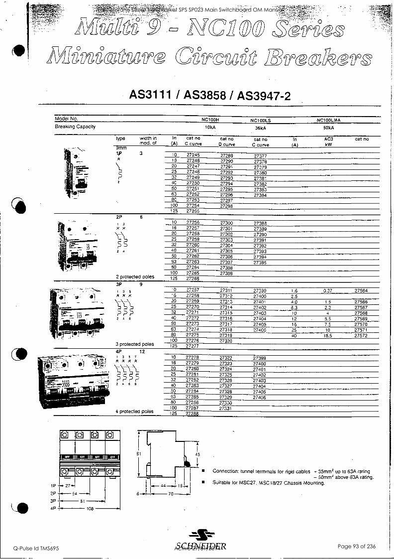
C,100 ST6SQT
S 6:0g TS ca6Tovzig )8 effz
AS3111 / AS3858 / AS3947-2
Model No. NC100H NC100LS NC100LMA Breaking Capacity 10kA 36kA 50kA
cat no In. cat no In AC3 type cat no width in A C curve 0 curve C curve (A) kW
-- mm mod. of
I ' 7, -, .: .....:...
25 27
......
7 m"--
1 .J1 1 =
63 27252
ip
2
3 10 27245
32 27224489
40 27250 50 27251
27289 27290 27291 27292 27293 27294 27295 27296
27377 : * 16 27246 27378 20 27247 27379
27383 firr 27384
80 27253 27297 100 27254 27298 125 27255
cat no
2P 6
Igt---3333 6'1
1 3
2
2 protected poles
3P 9
3 5
)'<
10 27256 27300 27388 16 27257 27301 27389 20 27258 27302 27390 25 27259 27303 27391 32 27260 27304 27392 40 27261 27305 27393 50 27262 27306 27394 63 27263 27307 27395 80 27264 27308 100 27265 27309 125 27266
3 protected poles 4p 12
1 3 5 7
* * *
2 4 8 9
10 27267 27311 27399 1.6 16 27268 27312 27400 2.5 20 27269 27313 27401 4.0 25 27270 27314 27402 6.3 32 27271 27315 27403 10 40 27272 27316 27404 12 50 27273 27317 27405 16 63 27274 27318 27406 25 80 27275 27319 40 100 27276 27320 125 27277
0.37 27564
1.5 27566 2.2 27567 4 27568
5.5 27569 7.5 27570 10 27571
18.5 27572
4 protected poles
10 27278 27322 27399 16 27279 27323 27400 20 27280 27324 27401 25 27281 27325 27402 32 27282 27326 27403 40 27283 27327 27404 50 27284 27328 27405 63 27285 27329 27406 80 27286 27330 100 27287 27331 125 27288
(21 Lci LoJ
81 45
7E1 P
2P 54
3P 31
4 p 108
4.4
6 70
Connection: tunnel terminals for rigid cables - 35mm2 up to 63A rating - 50mm2 above 63A rating.
Suitable for MSC27. MSC18/27 Chassis Mounting.
SCHNEIDER
Edmonstone Street Newmarket SPS SP023 Main Switchboard OM Manual
Q-Pulse Id TMS695 Active 29/01/2014 Page 93 of 236
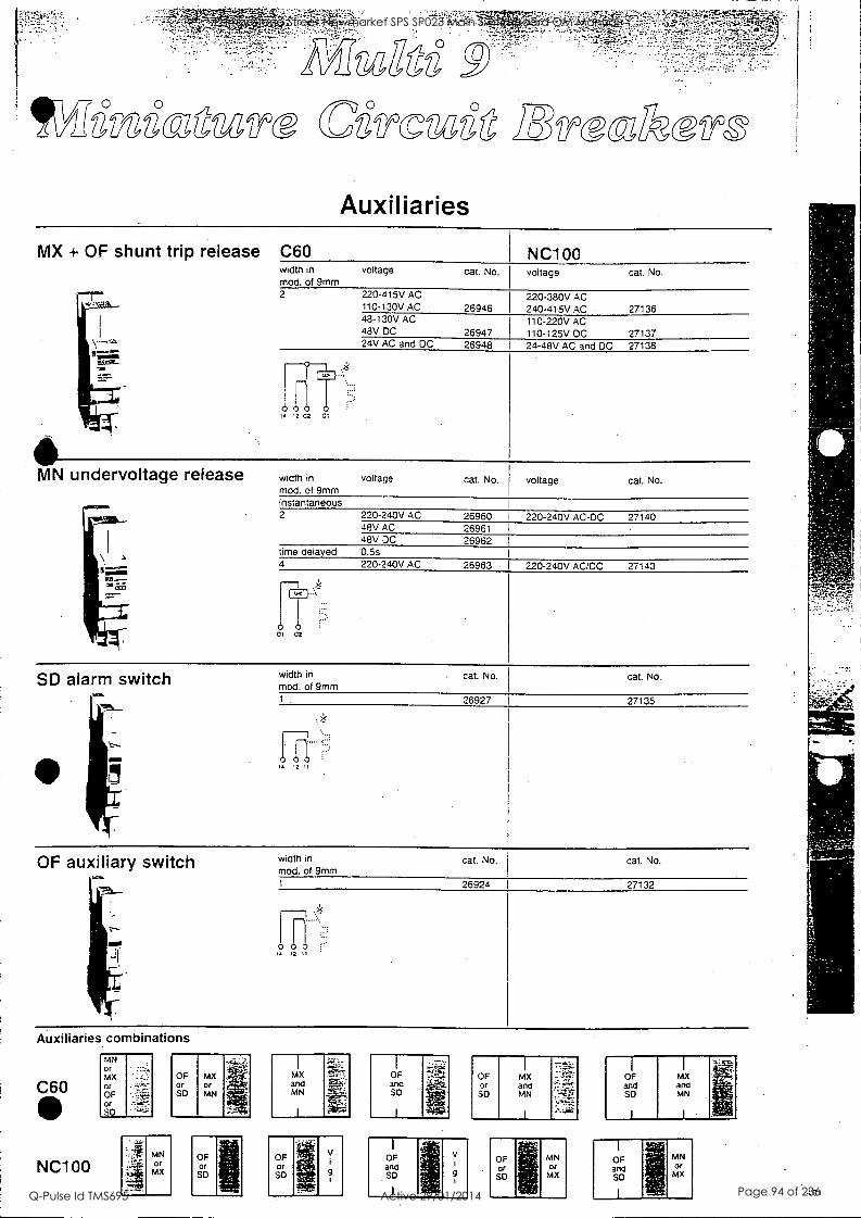
MX + OF shunt trip release C60
MN undervoltage release
Auxiliaries
width in voltage mod. of 9mm 2 220-415V AC
110-130V AC 48-130V AC 48V DC 24V AC and DC
1 4 12 02 CI
width in
mod. of 9mm voltage
NC100 cat. No. voltage cat. No.
26946
26947 26948
cat. No.
instantaneous 2 220-240V AC 26960
48V AC 26961 48V DC 26962
time delayed 0.5s 4 220-240V AC 26963
220-380V AC 240-415V AC 27136 110-220V AC 110-125V DC 27137 24-48V AC and DC 27138
voltage cat. No.
220-240V AC-DC 27140
220-240V AC/DC 27143
SD alarm switch
ti
OF auxiliary switch
01 02
width in
mod. of 9mm cat. No. cat. No.
26927 I 27135
width in
mod. of 9mm cat. No. cat. No.
26924 27132
0 0 1 12
Auxiliaries combinations MN Of MX OF MX MX OF OF MX Of Or Or and and Of and OF SD MN MN SO SD MN Or SD
NC100 MN Of
MX
OF Of
SO
OF Or SD
V
9
OF and SD
V
9
OF Of SD
OF MX and and SD MN
II I
OF and SD
MN Of MX
-101
Edmonstone Street Newmarket SPS SP023 Main Switchboard OM Manual
Q-Pulse Id TMS695 Active 29/01/2014 Page 94 of 236
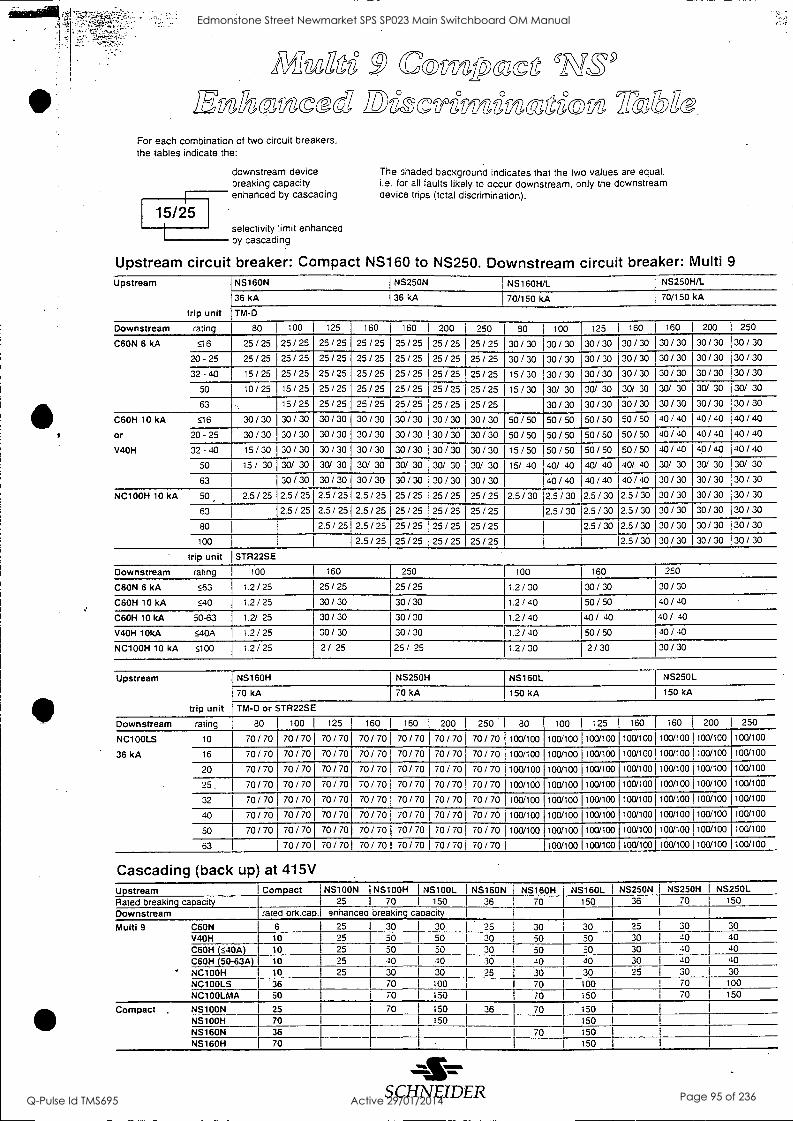
M:sage g Co- fpocc )8'.%1k2,ccattsced ZezCfP6f1124,g-Oft8, 771133172
For each combination of two circuit breakers, the tables indicate the:
15/25
downstream device breaking capacity enhanced by cascading
selectivity limit enhanced by cascading
Upstream circuit breaker: Compact NS160 to NS250. Downstream circuit breaker: Multi 9
The shaded background indicates that the two values are equal. i.e. for all faults likely to occur downstream, only the downstream device trips (total discrimination).
Upstream NS160N
36 kA
trip unit TM-D
NS250N
36 kA
NS160H/L
70/150 kA
I NS250H/L
I 70/150 kA
Downstream rating 80 100 125 160 160 1 200 250 80 100 125 160 160 200 250
C60N 6 kA 516 25/25 25/25 25/25 25/25 25/25 25/25 25/25 30/30 30/30 30/30 30/30 30/30 30/30 30/30 20-25 25/25 25/25 25/25 25/25 25/25 25/25 25/25 30/30 30/30 30/30 30/30 30/30 30/30 30/30 32-40 15/25 25/25 25/25 25/25 25/25 25/25 25/25 15/30 30/30 30/30 30/30 30/30 30/30 30/30
50 10 /25 15 / 25 25 /25 25 /25 25 /25 25 /25 25/25 15 /30 30/ 30 30/ 30 30/ 30 30/ 30 30/ 30 30/ 30
63 15/25 25/25 25/25 25/25 25/25 25/25 30/30 30/30 30/30 30/30 30/30 30/30
C60H 10 kA 516 30/30 30/30 30/30 30/30 30/30 30/30 30/30 50/50 50/50 50/50 50/50 40/40 40/40 40/40 Or 20-25 30/30 30/30 30/30 30/30 30/30 30/30 30/30 50/50 50/50 50/50 50/50 40/40 40/40 40/40 V4OH 32 -40 15/30 30/30 30/30 30/30 30/30 30/30 30/30 15/50 50/50 50/50 50/50 40/40 40/40 40/40
50 15 / 30 30/ 30 30/ 30 30/ 30 30/ 30 30/ 30 30/ 30 15/ 40 40/ 40 40/ 40 40/ 40 30/ 30 30/ 30 30/ 30
63 30/30 30/30 30/30 30/30 30/30 30/30 40/40 40/40 40/40 30/30 30/30 30/30 NC100H 10 kA 50, 2.5 / 25 2.5 / 25 2.5 / 2512.5 / 25 25 / 25 25 / 25 25 / 25 2.5 / 30 2.5 / 30 2.5 / 30 2.5 / 30 30 / 30 30 / 30 30 / 30
63 25 / 25 2.5 / 25 2.5 / 25 25 / 25 25 / 25 25 / 25 2.5 / 30 2.5 / 30 2.5 / 30 30 / 30 30 / 30 30 / 30
80 2.5 / 25 2.5 / 25 25 / 25 25 / 25 25 / 25 2.5 / 30 2.5 / 30 30 / 30 30 / 30 30 / 30
100 2.5/25 25/25 25/25 25/25 2.5/30 30/30 30/30 30/30 trip unit STR22SE
Downstream rating 100 160 250 100 160 1 250
C6ON 6 kA 563 1.2/25 25/25 25/25 1.2/30 30/30 130/30
C6OH 10 kA 540 1.2/25 30/30 30/30 1.2/40 50/50 140/40
C6OH 10 kA 50-63 1.2/ 25 30/30 30/30 1.2/40 40/ 40 140/ 40
V4OH 10kA 540A 1.2/25 30/30 30/30 1.2/40 50/50 140 / 40
NC100H 10 kA 5100 1.2/25 2/ 25 25/ 25 1.2/30 2/30 130/30
Upstream NS160H NS250H NS160L NS250L
70 kA I 70 kA 150 kA I 150 kA
trip unit TM-13 or STR22SE
Downstream rating 80 100 125 160 160 200 250 80 100 1 125 160 1 160 200 250
NC100LS
36 kA
10 70 / 70 70 / 70 70 / 70 70 / 70 70 / 70 70 / 70 70 / 70 100/100 100/100 100/100 100/1001100/100 100/100 100/100
16 70 / 70 70 / 70 70 / 70 70 / 70 70 / 70 70 / 70 70 / 70 100/100 100/100 100/100 100/1001100/100 100/100 100/100
20 70 / 70 70 / 70 70 / 70 70 / 70 70 / 70 70 / 70 70 / 70 100/100 100/100 100/100 100/1001100/100 100/100 100/100
25. 70 / 70 70 / 70 70 / 70 70 / 70 70 / 70 70 / 70 70 / 70 100/100 100/100 100/100 100/1001100/100 100/100 100/100
32 70 / 70 70 / 70 70 / 70 70 / 70 70 / 70 70 / 70 70 / 70 100/100 100/100 100/100 100/1001100/100 100/100 100/100
40 70 / 70 70 / 70 70 / 70 70 / 70 70 / 70 70 / 70 70 / 70 100/100 100/100 100/100 100/1001100/100 100/100 100/100
50 70 / 70 70 / 70 70 / 70 70 / 70 70 / 70 70 / 70 70 / 70 100/1001100/100 100/100 100/1001100/100 100/100 100/100
63 70/70 70/70 70/70 70/70 70/701 70/70 100/100 100/100 100/1001100/100 100/100 100/100
Cascading (back up) at 415V Ustream Com act NS100N I NS100H I NS100L NS160N NS160H NS160L I NS250N NS250H NS250L Rated breakin caoaci 25 I 70 I 150 I 36 I 70 150 36 70 150
Downstream !rated brk.cap. enhanced breaking capacity
Multi 9 C6ON 6 25 I 30 I 30 I 25 j 30 i 30 I 25 30 30 V4OH 10 25
1 50 I 50 I 30 50 I 50 I 30 40 40
C6OH (540A) 10 25 I 50 i 50 I 30 50 I 50 30 40 40 C6OH (50-63A) 10 25 I 40 I 10
I 30 40 40 30 40 40
NC100H 10 25 I 30 I 30 I 25 30 I 30 I 25 30 30 NC100LS 36 I 70 I 100
1 70 I 100 I I 70 100
NC100LMA I 50 I 70 I 150 I 70 I 150 I i 70 150
Compact . NS100N 25 I 70 I 150 l 36 l 70 I 150 NS100H 70 I I 150 I 1 I 150 NS160N 36 I I I 70 1
150 NS160H 70 I I I 150
SCHNEIDER
Edmonstone Street Newmarket SPS SP023 Main Switchboard OM Manual
Q-Pulse Id TMS695 Active 29/01/2014 Page 95 of 236
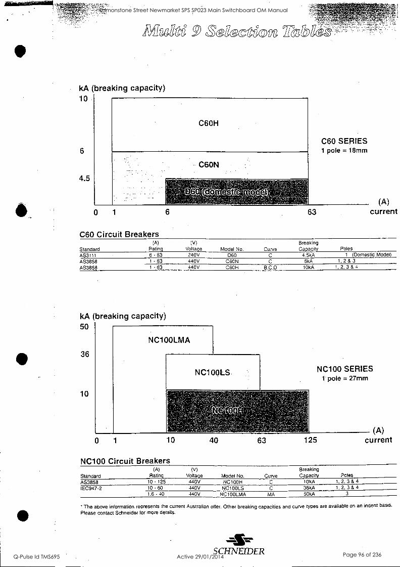
kA (breaking capacity) 10
6
4.5
feecgdom 1rtW-
C6OH
C6ON
0 1 6
C60 Circuit Breakers
C60 SERIES 1 pole = 18mm
63 (A)
current
Standard (A)
Rating (V)
Voltage Model No. Curve Breaking Capacity Poles
AS3111 6 - 63 240V D60 C 4.5kA 1 (Domestic Model)
AS3858 AS3858
1 - 63 440V C6ON C 6kA 1, 2 & 3
1 63 440V C6OH B.C,D 10kA 1, 2, 3 & 4
kA (breaking capacity) 50
36
10
NC100LMA
NC1OOLS- NC100 SERIES t pole = 27mm
0 1 10 40 63 125
NC100 Circuit Breakers
(A) current
Standard (A)
Rating (V)
Voltage Model No. Curve Breaking Capacity Poles
AS3858 10 - 125 440V NC100H C 10kA 1, 2. 3 & 4
IEC947-2 10 - 60 440V NC100LS C 36kA 1. 2. 3 & 4
1.6 - 40 440V NC100LMA MA 50kA 3
' The above information represents the current Australian offer. Other breaking capacities and curve types are available on an indent basis.
Please contact Schneider for more details.
s CHNEIDER
Edmonstone Street Newmarket SPS SP023 Main Switchboard OM Manual
Q-Pulse Id TMS695 Active 29/01/2014 Page 96 of 236
O
O
4,4
Queensland State Office: 9 Graystone Street Tingaloa .4173 Tel: (07) 3890 2112
°Fax: (07) 3890 2098:
3 New South Wales State Office: Stock O. Princes Roaa East Regents Pan< 2113
1021 9743 7700 Fax: 1021 9743 7716
) Victoria State Office: 77 Ricketts Roar] Mt. 'Navertey 3149 Tel: (031 9558 9876 Fax: (03) 9553 9701
Manufacturing Tel: (03) 9553 9876 Fax: (03) 9558 9700
Transformer Manufacturing Tel: (031 5762 3411 Fax '0315762 5113
South Australia ) State Office:
A Corbett Coun Export Park Adelaide .Airoon 5950 Tel: (08) 8234 -1388 Fax: (08) 8234 -1122
Western Australia State Office: 26 Gibberd Road 3alcatta 5021 Tel: ;09) 344 2727 Fax: k09) 344 5335
Regional Offices:
Townsville Tel: 018 773 114
Fax: (0771791 497
Gladstone Tel: 018 787 354 Fax: (079) 739 457
Newcastle Tel: (049) 526 900 Fax: (049) 529 403
Wollongong Tel: 018 212 475 Fax: '042) 973 970
Albury Tel: 013 387 539 Fax: (060) 591 954
Mt Gambier Tel: 018 ;08 915 Fax: (037) 251 219
Launceston Tel: 0418 555 631 Fax: (031 5330 1936
at:S970101
Edmonstone Street Newmarket SPS SP023 Main Switchboard OM Manual
Q-Pulse Id TMS695 Active 29/01/2014 Page 97 of 236

TECHNICAL DATA SHEET
For
Edmondstone Street Pump Station
Equipment Type: Surge Diverter
Location: Main Incomer
Model Numbers: TDS-MT-275
Manufacturer: Critec
Supplier: SCA Distributors 178 Wecker Road MANSFIELD QLD 4122
Ph: 07 3849 5077 Fx: 07 3849 7035
Edmonstone Street Newmarket SPS SP023 Main Switchboard OM Manual
Q-Pulse Id TMS695 Active 29/01/2014 Page 98 of 236

NI) 4,f,
) -
tl
1 < ,f
5 f \
=;;. sr;v. z
kZ:X `3- " £
AO.
MX=
\
.47-1
CD 4-1
-11-f
C O 0 2 "4-,
2 E
2 c a) w
V 0 C 2
\ ..90%, 4
E1
E -0
OC C LLI
Edmonstone Street Newmarket SPS SP023 Main Switchboard OM Manual
Q-Pulse Id TMS695 Active 29/01/2014 Page 99 of 236
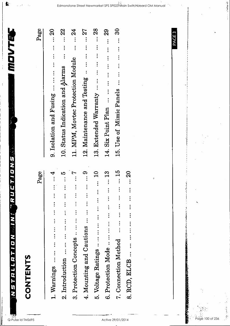
CO
NT
EN
TS
Page
1. W
arni
ngs
... .
.. ...
4
2. I
ntro
duct
ion
... .
.. 5
3. P
rote
ctio
n C
once
pts
.. ...
...
7
4. M
ount
ing
and
Cau
tions
...
9
5. V
olta
ge R
atin
gs .
. ...
10
6. P
rote
ctio
n M
ode
.. ...
13
7. C
onne
ctio
n M
etho
d . .
.. ...
15
8. R
CD
, E
LC
B
20
1170
VT
INIF
Page
9. I
sola
tion
and
Fusi
ng .
.. ...
...
...
20
10.
Stat
us I
ndic
atio
n an
d 4l
arm
s 22
11.
MPM
, M
ovte
c Pr
otec
tion
Mod
ule
24
27
28
29
15.
Use
of
Mim
ic P
anel
s 30
12.
Mai
nten
ance
and
'bes
ting
..
13.
Ext
ende
d W
arra
nty
... .
.. ...
14.
Six
Poin
t Pla
n ...
...
PA
GE
3
Edmonstone Street Newmarket SPS SP023 Main Switchboard OM Manual
Q-Pulse Id TMS695 Active 29/01/2014 Page 100 of 236
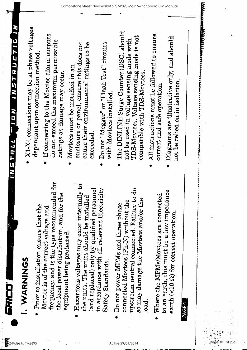
ER
Ca
I. W
AR
NIN
GS
Pr
ior t
o in
stal
latio
n en
sure
that
the
Mov
tec
is o
f the
cor
rect
vol
tage
and
fr
eque
ncy,
and
is t
he ty
pe r
ecom
men
ded
for
the
loca
l po
wer
dis
trib
utio
n, a
nd fo
r th
e eq
uipm
ent
bein
g pr
otec
ted.
Haz
ardo
us v
olta
ges
may
exi
st in
tern
ally
to
the
units
. T
he u
nits
sho
uld
be i
nsta
lled
(and
rep
lace
d) o
nly
by q
ualif
ied
pers
onne
l in
acc
orda
nce
with
all
rele
vant
Ele
ctri
city
Sa
fety
Sta
ndar
ds.
Do
not
pow
er M
PMs
and
thre
e ph
ase
conn
ecte
d M
ovte
cs (
Ph-N
) w
ithou
t the
up
stre
am n
eutr
al c
onne
cted
. Fa
ilure
to d
o so
may
dam
age
the
Mov
tecs
and
/or
the
load
.
Whe
re th
e M
PMs/
Mov
tecs
are
con
nect
ed
to a
n ea
rth,
thi
s m
ust b
e a
low
impe
danc
e ea
rth
(<10
S/)
for
cor
rect
ope
ratio
n.
PA
GE
4
INS
.TR
LL
ON
IN
ST
RU
CT
ICi_
IS
X1-
X4
conn
ectio
ns m
ay b
e at
pha
se v
olta
ges
depe
ndan
t upo
n co
nnec
tion
met
hod.
If
conn
ectin
g to
the
Mov
tec
alar
m o
utpu
ts
do n
ot e
xcee
d th
e m
axim
um p
erm
issi
ble
ratin
gs a
s da
mag
e m
ay o
ccur
. M
ovte
cs m
ust b
e in
stal
led
in a
n en
clos
ure
or p
anel
, en
sure
this
doe
s no
t ca
use
thei
r en
viro
nmen
tal r
atin
gs to
be
exce
eded
.
Do
not
"Meg
ger"
or
"Fla
sh T
est"
cir
cuits
w
ith M
ovte
cs i
nsta
lled.
T
he D
INL
INE
Sur
ge C
ount
er (
DSC
) sh
ould
no
t be
used
in v
olta
ge s
ensi
ng m
ode
with
T
DS-
Mov
tecs
. Vol
tage
sen
sing
mod
e is
not
co
mpa
tible
with
TD
S-M
ovte
cs.
All
inst
ruct
ions
mus
t be
follo
wed
to
ensu
re
corr
ect a
nd s
afe
oper
atio
n.
Dia
gram
s ar
e ill
ustr
ativ
e on
ly,
and
shou
ld
not
be r
elie
d on
in i
sola
tion.
Edmonstone Street Newmarket SPS SP023 Main Switchboard OM Manual
Q-Pulse Id TMS695 Active 29/01/2014 Page 101 of 236
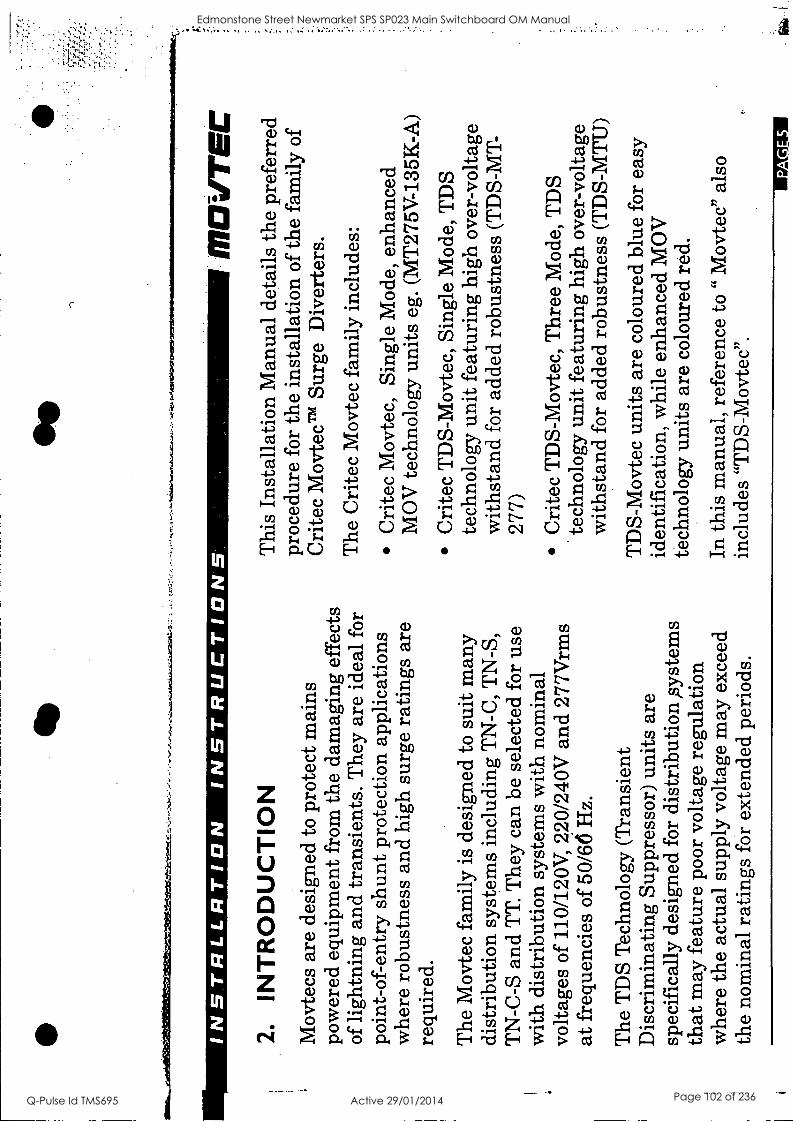
tem
esor
ilibi
lso
e.
INS
TR
LLR
TIO
N
INS
TR
UC
TIO
NS
2.
INT
RO
DU
CT
ION
M
ovte
cs a
re d
esig
ned
to p
rote
ct m
ains
po
wer
ed e
quip
men
t fro
m t
he d
amag
ing
effe
cts
of li
ghtn
ing
and
tran
sien
ts.
The
y ar
e id
eal
for
poin
t-of
-ent
ry s
hunt
pro
tect
ion
appl
icat
ions
w
here
rob
ustn
ess
and
high
sur
ge r
atin
gs a
re
requ
ired
.
The
Mov
tec
fam
ily is
des
igne
d to
sui
t m
any
dist
ribu
tion
syst
ems
incl
udin
g T
N-C
, T
N-S
, T
N-C
-S a
nd T
T.
The
y ca
n be
sel
ecte
d fo
r us
e w
ith d
istr
ibut
ion
syst
ems
with
nom
inal
vo
ltage
s of
110
/120
V,
220/
240V
and
277
Vrm
s at
freq
uenc
ies
of 5
0/66
Hz.
The
TD
S T
echn
olog
y (T
rans
ient
D
iscr
imin
atin
g Su
ppre
ssor
) un
its a
re
spec
ific
ally
des
igne
d fo
r di
stri
butio
n ,s
yste
ms
that
may
fea
ture
poo
r vo
ltage
reg
ulat
ion
whe
re t
he a
ctua
l sup
ply
volta
ge m
ay e
xcee
d th
e no
min
al r
atin
gs f
or e
xten
ded
peri
ods.
1170
11T
EC
Thi
s In
stal
latio
n M
anua
l de
tails
the
pre
ferr
ed
proc
edur
e fo
r th
e in
stal
latio
n of
the
fam
ily o
f C
rite
c M
ovte
c'm
Sur
ge
Div
erte
rs.
The
Cri
tec
Mov
tec
fam
ily i
nclu
des:
Cri
tec
Mov
tec,
Si
ngle
Mod
e, e
nhan
ced
MO
V t
echn
olog
y un
its e
g. (
MT
275V
-135
K-A
)
Cri
tec
TD
S-M
ovte
c, S
ingl
e M
ode,
TD
S te
chno
logy
uni
t fea
turi
ng h
igh
over
-vol
tage
w
ithst
and
for
adde
d ro
bust
ness
(T
DS-
MT
- 27
7)
Cri
tec
TD
S-M
ovte
c, T
hree
Mod
e, T
DS
tech
nolo
gy u
nit f
eatu
ring
hig
h ov
er-v
olta
ge
with
stan
d fo
r ad
ded
robu
stne
ss (T
DS-
MT
U)
TD
S-M
ovte
c un
its a
re c
olou
red
blue
for
eas
y id
entif
icat
ion,
whi
le e
nhan
ced
MO
V
tech
nolo
gy u
nits
are
col
oure
d re
d.
In t
his
man
ual,
refe
renc
e to
" M
ovte
c" a
lso
incl
udes
"T
DS-
Mov
tec"
.
Edmonstone Street Newmarket SPS SP023 Main Switchboard OM Manual
Q-Pulse Id TMS695 Active 29/01/2014 Page 102 of 236
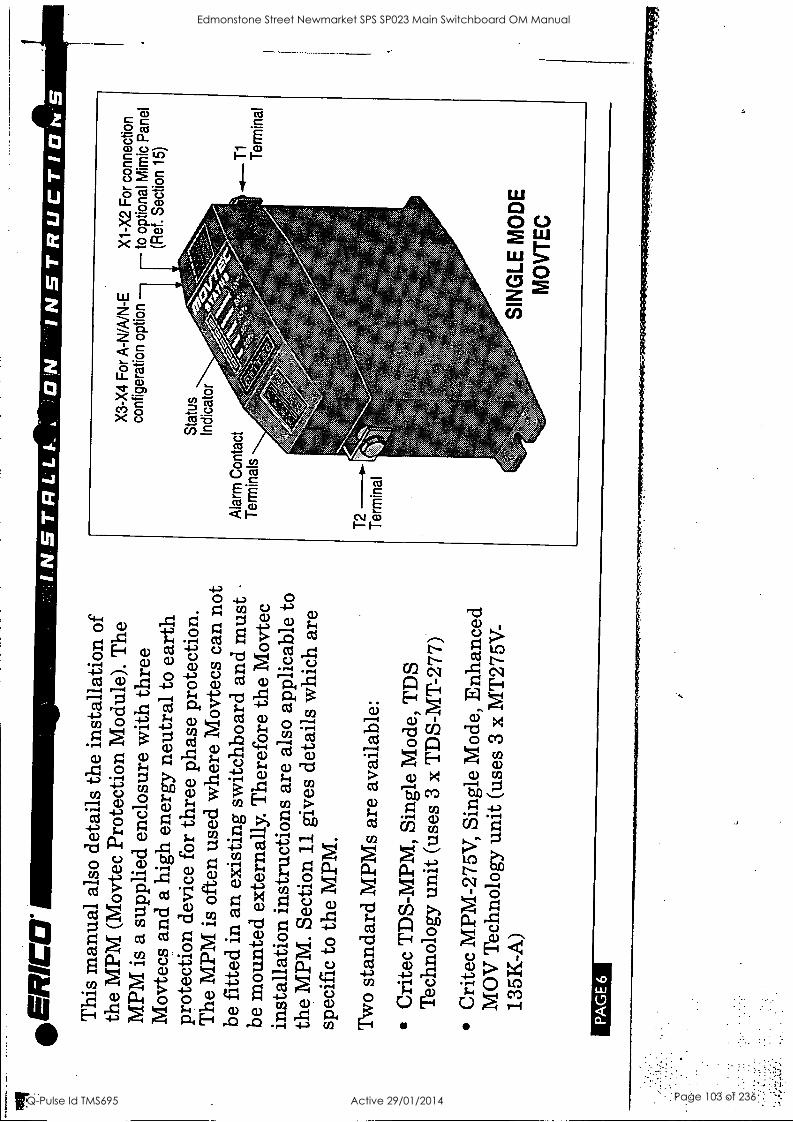
II
.
IN
INS
TR
LLI-
. O
'N
INS
TR
UC
TIO
NS
.
. -
. -
. .
0 - ' I "
'
. -
I . ' . - .
. '
- .
-
-
'
:
I
a
' .. I
-
0
" . '
.
. . .
I. . . .
' . .
. .
- .
.. '
. I
- . . I
.
' .
' -
I .
.
I1
D
I 0
- '
' S
:i 1
A.
PA
GE
6
. I
. -
D
D
I I
I
I -
'
I I
1..
II
. a.
lo
. .
I I
II
Edmonstone Street Newmarket SPS SP023 Main Switchboard OM Manual
Q-Pulse Id TMS695 Active 29/01/2014 Page 103 of 236
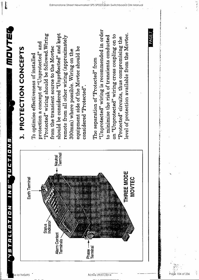
1-V
ST
RLL
RT
ION
IN
S'R
UC
TIO
NS
.
.
ifr.
%,,s
%.
'
I
I I
.9
"I
"I
I I^
"5
I
1-
- -
.
- "
"5 .
. -
I
1
- -
. "I
I I
I I
I-
' Il
l -
I I
.!
I '
' .
' .
i -
II
0'
I "I
"I
I -
I-
-I
" I '
8
"8
I
II
II
I .
. . I 1
11
I I
PAG
E 7
Edmonstone Street Newmarket SPS SP023 Main Switchboard OM Manual
Q-Pulse Id TMS695 Active 29/01/2014 Page 104 of 236
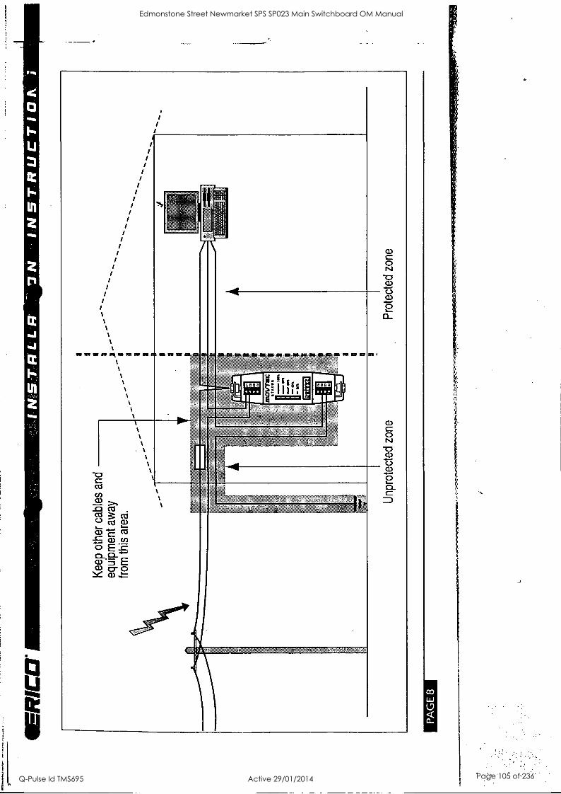
Kee
p ot
her c
able
s an
d
equi
pmen
t aw
ay
from
thi
s ar
ea.
a
men
`,T
7'17
.-
7-
y
Unp
rote
cted
zon
e
1111
2V7V
C
STA
TU
S m
. r MM
TO
Y
Pro
tect
ed z
one
PA
GE
8
:.t..1
4,.:1
.7a.
747r
rer,
"="1
7.7
Edmonstone Street Newmarket SPS SP023 Main Switchboard OM Manual
Q-Pulse Id TMS695 Active 29/01/2014 Page 105 of 236
It-S
TR
LLR
TIO
N
4.
MO
UN
TIN
G &
CA
UT
ION
S
The
per
form
ance
of
surg
e, d
iver
ters
can
be
dram
atic
ally
aff
ecte
d by
the
met
hod
of
conn
ectio
n (r
efer
sec
tion
7).
Whe
re p
ossi
ble
sele
ct a
mou
ntin
g m
etho
d th
at a
llow
s th
e M
ovte
c to
be
conn
ecte
d in
the
"Pre
ferr
ed.
Con
nect
ion
Met
hod"
.
Failu
re o
f a M
ovte
c un
der
seve
re A
C o
ver-
vo
ltage
, su
ch a
s 11
kV o
n 24
0V m
ains
, ca
n re
sult
in th
e ge
nera
tion
of s
igni
fica
nt h
eat.
Con
side
ratio
n sh
ould
be
give
n to
ens
ure
that
M
ovte
cs a
re n
ot in
stal
led
in c
lose
pro
xim
ity to
co
mbu
stib
le m
ater
ials
.
Uni
ts m
ust b
e in
stal
led
in a
n en
clos
ure
or
pane
l to
pro
vide
the
app
ropr
iate
deg
ree
of
elec
tric
al a
nd e
nvir
onm
enta
l pr
otec
tion.
Onl
y us
e en
clos
ures
tha
t:
MO
VT
EC
0
Do
not
caus
e th
e M
ovte
c te
mpe
ratu
re to
ex
ceed
60
deg
C
Prov
ide
adeq
uate
ele
ctri
cal
and
safe
ty
prot
ectio
n
Prev
ent t
he i
ngre
ss o
f moi
stur
e an
d w
ater
Allo
w M
ovte
c St
atus
Ind
icat
ion
to b
e in
spec
ted
PA
GE
9
Edmonstone Street Newmarket SPS SP023 Main Switchboard OM Manual
Q-Pulse Id TMS695 Active 29/01/2014 Page 106 of 236
IkR
Ca
5 V
OLT
AG
E R
AT
ING
S
The
TD
S (T
rans
ient
Dis
crim
inat
ing
Supp
ress
or)
tech
nolo
gy h
as b
een
spec
ific
ally
de
velo
ped
to c
ater
for
abn
orm
al o
ver-
volta
ge
cond
ition
s th
at m
ay o
ccur
on
site
s w
ith p
oor
volta
ge r
egul
atio
n, o
r du
e to
wir
ing
or
dist
ribu
tion
faul
ts.
The
TD
S un
its f
eatu
re a
n ex
trem
ely
high
ove
r-vo
ltage
with
stan
d to
el
imin
ate
heat
bui
ld u
p th
at c
an o
ccur
with
st
anda
rd te
chno
logi
es w
hen
the
prot
ectio
n de
vice
s st
art t
o cl
amp
on th
e pe
ak o
f eac
h ab
norm
al m
ains
cyc
le.
Tra
ditio
nal M
OV
tech
nolo
gy (
eg M
T-2
75V
/ 13
5K/A
) is
not
sui
tabl
e in
app
licat
ions
w
here
sus
tain
ed o
ver-
volta
ge c
ondi
tions
ca
n be
exp
erie
nced
.
PA
GE
10
INS
TR
I.LR
IN
ST
RU
CT
IDK
Exa
mpl
es o
f poo
rly
regu
late
d vo
ltage
en
viro
nmen
ts in
clud
e:
Smal
ler
pow
er g
ener
atio
n su
pplie
s
Site
s w
ith l
arge
ear
th c
urre
nts
Var
iabl
e m
otor
spe
ed c
ontr
ol c
ircu
its
Hig
h ha
rmon
ic v
olta
ge e
nvir
onm
ents
(no
n-
linea
r lo
ads)
The
TD
S ra
nge
of M
ovte
cs w
ith a
hig
her
over
-vol
tage
with
stan
d m
ay b
e ab
le to
be
used
in th
ese
envi
ronm
ents
follo
win
g ad
vice
.
Tra
nsie
nt p
rote
ctio
n de
vice
s ar
e us
ually
rat
ed
to p
rote
ct a
gain
st n
on-r
epet
itive
pul
ses
from
su
ch s
ourc
es a
s di
rect
or
indu
ced
light
ning
st
rike
s. T
hey
are
not
desi
gned
to p
rovi
de
prot
ectio
n ag
ains
t re
peat
ed c
yclic
ano
mal
ies.
N
or a
re t
hey
desi
gned
to
prov
ide
prot
ectio
n
owc.
.04W
4r-t
re.
Edmonstone Street Newmarket SPS SP023 Main Switchboard OM Manual
Q-Pulse Id TMS695 Active 29/01/2014 Page 107 of 236
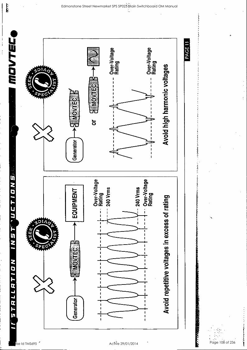
tr S
TR
LLR
T IO
N
INS
V lU
CT
ION
S
MO
VT
EC
.
Gen
erat
or
EQ
UIP
ME
NT
f f
Ove
r-V
olta
ge
Rat
ing
- 240
Vrm
s
240
Vrm
s
Ove
r-V
olta
ge
Rat
ing
Avo
id r
epet
itive
vol
tage
s in
exc
ess
of r
atin
g
PA
GE
I
I
Edmonstone Street Newmarket SPS SP023 Main Switchboard OM Manual
Q-Pulse Id TMS695 Active 29/01/2014 Page 108 of 236
IFR
ICC
I ag
ains
t sus
tain
ed o
ver-
volta
ge c
ondi
tions
w
here
the
supp
ly v
olta
ge e
xcee
ds t
he p
rote
ctio
n eq
uipm
ent's
nom
inal
rat
ing
for
an e
xten
ded
peri
od o
f tim
e, i
e co
ntin
uous
ove
r-vo
ltage
s fr
om p
oorl
y re
gula
ted
gene
rato
rs o
r di
stri
butio
n sy
stem
s.
Smal
ler
pow
er g
ener
atio
n eq
uipm
ent
(par
ticul
arly
cap
aciti
ve e
xcita
tion
indu
ctio
n ge
nera
tors
) do
es n
ot g
ener
ally
con
form
to th
e sa
me
stan
dard
s of
vol
tage
reg
ulat
ion
that
are
in
pla
ce f
or m
ains
pow
er r
etic
ulat
ion.
A la
rge
num
ber
of s
mal
ler
and/
or c
heap
er g
ener
ator
s ha
ve a
vol
tage
wav
efor
m th
at is
"lo
osel
y"
240V
rms
(oft
en p
oorl
y re
gula
ted)
, but
mor
e im
port
antly
, of
ten
cont
ains
sig
nifi
cant
hig
her
orde
r ha
rmon
ics.
The
se g
ener
ator
s m
ay
exhi
bit a
pea
k vo
ltage
on
each
hal
f cyc
le f
ar in
ex
cess
of t
he n
orm
al 3
40V
. T
he p
robl
em is
us
ually
wor
se w
hen
the
gene
rato
r is
light
ly
load
ed.
PAG
E 1
2
Whi
lst
elec
tric
al e
quip
men
t may
tole
rate
thi
s ov
er-v
olta
ge f
or a
per
iod
of ti
me,
the
cla
mpi
ng
elem
ents
in th
e po
wer
pro
tect
ion
devi
ces
will
be
gin
to c
ondu
ct o
n th
e pe
ak o
f eac
h 50
Hz
cycl
e, a
s th
eir
volta
ge t
hres
hold
is r
each
ed
(typ
ical
ly 4
00V
pea
k fo
r a
trad
ition
al 2
75V
di
vert
er).
Thi
s w
ill c
ause
slo
w d
egra
datio
n an
d ul
timat
e fa
ilure
of t
he c
lam
ping
dev
ice
(tim
e de
pend
ent
upon
how
poo
r th
e w
avef
orm
is
).
Har
mon
ic v
olta
ges
may
als
o be
pre
sent
in
dist
ribu
tion
syst
ems
that
do
not f
eatu
re
gene
rato
rs.
Thi
s is
nor
mal
ly w
here
non
-lin
ear
load
s ar
e us
ed,
such
as
UPS
s, r
ectif
iers
, sw
itch
mod
e po
wer
sup
plie
s an
d m
otor
spe
ed
cont
rols
. The
hig
h ha
rmon
ic v
olta
ges
in
cert
ain
appl
icat
ions
may
hav
e pe
ak v
olta
ges
in e
xces
s of
the
prot
ectiv
e cl
ampi
ng v
olta
ge
caus
ing
prob
lem
s as
des
crib
ed a
bove
. Se
ek th
e m
anuf
actu
rer's
adv
ice
befo
re in
stal
ling
any
Edmonstone Street Newmarket SPS SP023 Main Switchboard OM Manual
Q-Pulse Id TMS695 Active 29/01/2014 Page 109 of 236
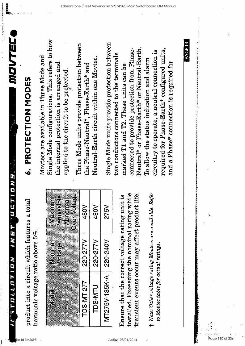
It' S
TR
LLR
TIO
N
N 5
T.
UC
TIO
.NS
.
prod
uct
into
a c
ircu
it w
hich
fea
ture
s a
tota
l ha
rmon
ic v
olta
ge r
atio
abo
ve 5
%.
Abn
orrr
ial
oter
-Vol
iag6
TD
S-M
T-2
77
220-
277V
48
0V
TD
S-M
TU
22
0-27
7V
480V
MT
275V
-135
K-A
22
0-24
0V
275V
Ens
ure
that
the
corr
ect v
olta
ge r
atin
g un
it is
in
stal
led.
Exc
eedi
ng th
e no
min
al r
atin
g w
hile
tr
ansi
ent e
vent
s oc
cur
may
aff
ect
prod
uct l
ife.
t N
ote:
Oth
er v
olta
ge r
atin
g M
ovte
cs a
re a
vaila
ble.
Ref
er
to M
ovte
c ta
ble
for
actu
al r
atin
gs.
1170
VT
EE
40
6.
PR
OT
EC
TIO
N M
OD
ES
Mov
tecs
are
ava
ilabl
e in
Thr
ee M
ode
and
Sing
le M
ode
conf
igur
atio
ns. T
his
refe
rs t
o ho
w
the
inte
rnal
pro
tect
ion
is a
rran
ged
and
appl
ied
to th
e ci
rcui
t to
be p
rote
cted
.
Thr
ee M
ode
units
pro
vide
pro
tect
ion
betw
een
the
Phas
e-N
eutr
al*,
Pha
se-E
arth
* an
d N
eutr
al-E
arth
cir
cuit
with
in o
ne M
ovte
c.
Sing
le M
ode
units
pro
vide
pro
tect
ion
betw
een
two
cond
ucto
rs c
onne
cted
to t
he t
erm
inal
s m
arke
d T
1 an
d T
2. T
hese
uni
ts c
an b
e co
nnec
ted
to p
rovi
de p
rote
ctio
n fr
om P
hase
- N
eutr
al*
or P
hase
-Ear
th*
or N
eutr
al-E
arth
. T
o al
low
the
stat
us in
dica
tion
and
alar
m
circ
uitr
y to
ope
rate
, a
neut
ral c
onne
ctio
n is
re
quir
ed fo
r Ph
ase-
Ear
th*
conf
igur
ed u
nits
, an
d a
Phas
e* c
onne
ctio
n is
req
uire
d fo
r
PA
GE
13
Edmonstone Street Newmarket SPS SP023 Main Switchboard OM Manual
Q-Pulse Id TMS695 Active 29/01/2014 Page 110 of 236
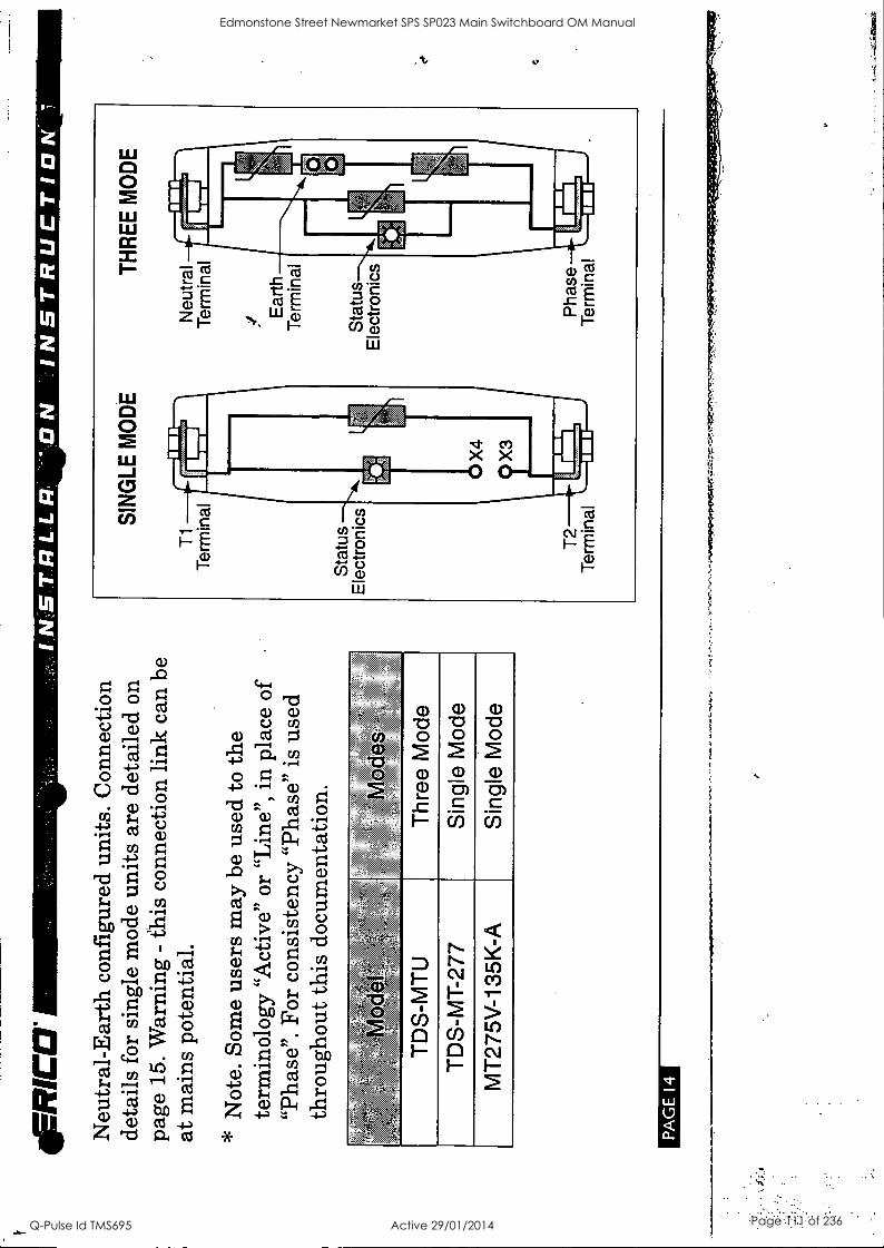
ER
RIC
CI
Neu
tral
-Ear
th c
onfi
gure
d un
its.
Con
nect
ion
deta
ils f
or s
ingl
e m
ode
units
are
det
aile
d on
pa
ge 1
5. W
arni
ng -
this
con
nect
ion
link
can
be
at m
ains
pot
entia
l.
* N
ote.
Som
e us
ers
may
be
used
to t
he
term
inol
ogy
"Act
ive
or "
Lin
e",
in p
lace
of
"Pha
se".
For
con
sist
ency
"Ph
ase"
is
used
th
roug
hout
this
doc
umen
tatio
n.
:, )
:,
e, '
, :`
. - ,
, * ,:.
: =.
`,,p
Z
&A
,':;
.t,, , .;e
nd
,,
6A,
Sid w
12
&00
,1;,,
;?
1,':;
,::
: ,
.. ,,
.
TD
S-M
TU
T
hree
Mod
e
TD
S-M
T-2
77
Sin
gle
Mod
e
MT
275V
-135
K-A
S
ingl
e M
ode
PA
GE
14
T1
Ter
min
al
SIN
GLE
MO
DE
Sta
tus
Ele
ctro
nics
S
tatu
s E
lect
roni
cs TH
RE
E M
OD
E
Neu
tral
T
erm
inal
ist E
arth
T
erm
inal
T2
Pha
se
Ter
min
al
I..
Ter
min
al
Edmonstone Street Newmarket SPS SP023 Main Switchboard OM Manual
Q-Pulse Id TMS695 Active 29/01/2014 Page 111 of 236
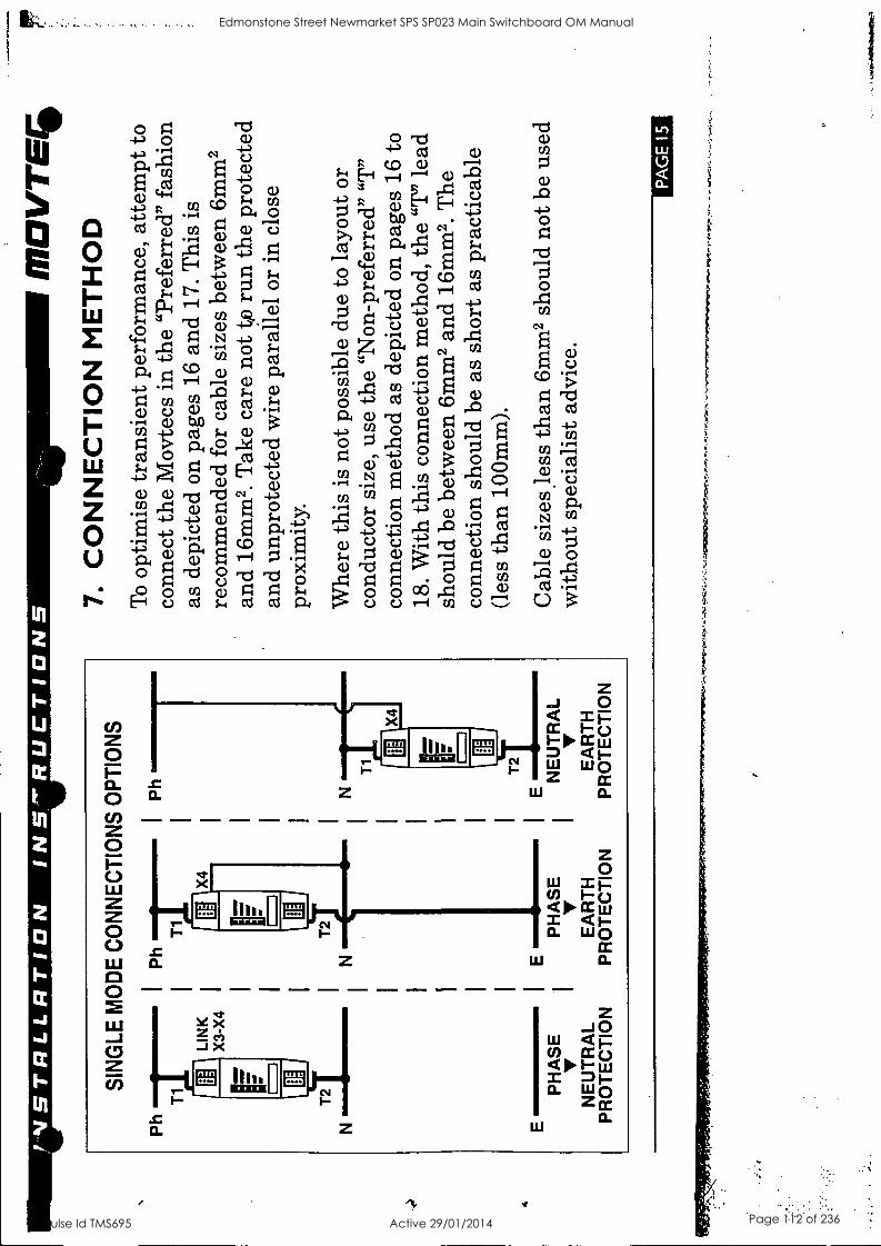
4
,INS
TR
LLR
TIO
N
INS
'RU
CT
ION
S
SIN
GLE
MO
DE
CO
NN
EC
TIO
NS
OP
TIO
NS
Ph
T1I
T241N
LIN
K
X3-
X4
Ph
ir T
1.1.
E
E
=N
W
ME
I
T2
X4
PH
AS
E
PH
AS
E
V
NE
UT
RA
L E
AR
TH
E
AR
TH
P
RO
TE
CT
ION
P
RO
TE
CT
ION
P
RO
TE
CT
ION
1110
1/T
ES
7.
CO
NN
EC
TIO
N M
ET
HO
D
To
optim
ise
tran
sien
t per
form
ance
, at
tem
pt to
co
nnec
t the
Mov
tecs
in
the
"Pre
ferr
ed"
fash
ion
as d
epic
ted
on p
ages
16
and
17.
Thi
s is
re
com
men
ded
for
cabl
e si
zes
betw
een
6mm
2 an
d 16
mm
2. T
ake
care
not
tp
run
the
prot
ecte
d an
d un
prot
ecte
d w
ire
para
llel
or in
clo
se
prox
imity
.
Whe
re t
his
is n
ot p
ossi
ble
due
to l
ayou
t or
co
nduc
tor
size
, us
e th
e "N
on-p
refe
rred
" "T
" co
nnec
tion
met
hod
as d
epic
ted
on p
ages
16
to
18.
With
this
con
nect
ion
met
hod,
the
"T
" le
ad
shou
ld b
e be
twee
n 6m
m2
and
16m
m2.
The
co
nnec
tion
shou
ld b
e as
sho
rt a
s pr
actic
able
(l
ess
than
100
mm
).
Cab
le s
izes
les
s th
an 6
mm
2 sh
ould
not
be
used
w
ithou
t spe
cial
ist a
dvic
e.
PA
GE
15
. .^
.7=
s,,,,
-.1.
1et
. .
77..
.
Edmonstone Street Newmarket SPS SP023 Main Switchboard OM Manual
Q-Pulse Id TMS695 Active 29/01/2014 Page 112 of 236
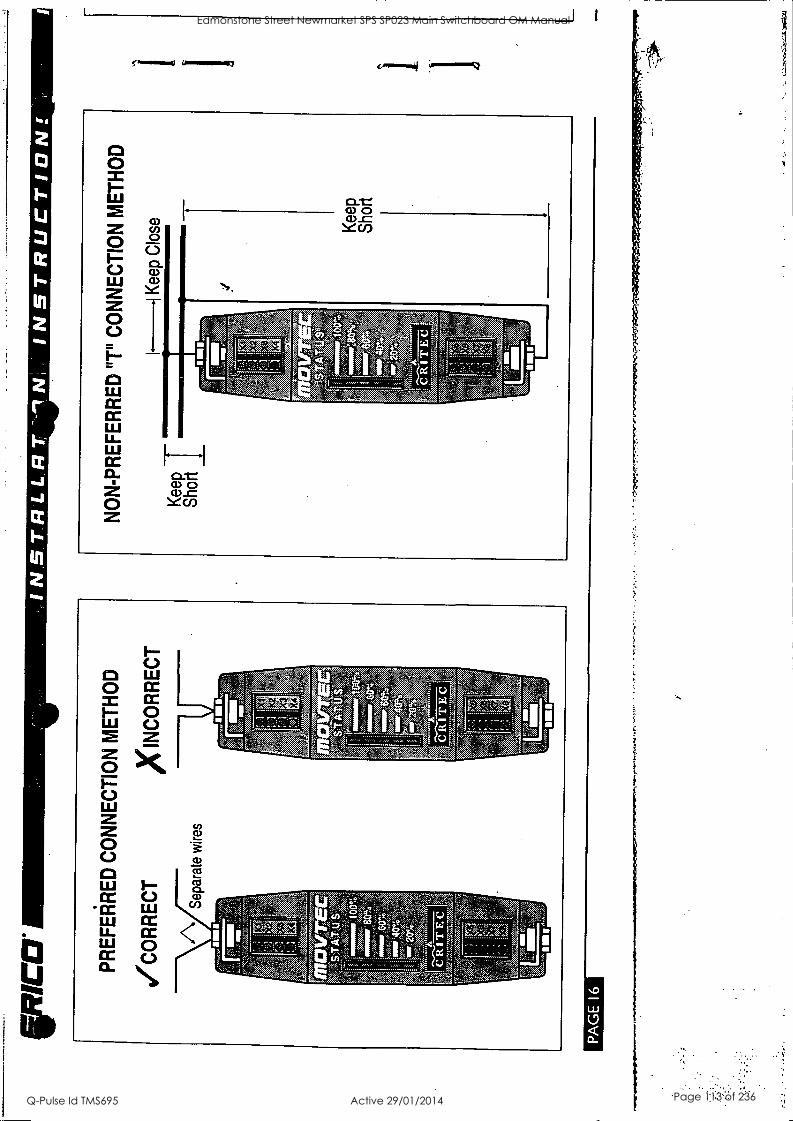
hod
in
al
''':1:;',.....T.' ,,
- -1 g'-.5.- ,.., . ., ;4: ...,..,1,-1 44E., pk Ex-,;?../...;aA gm' . . -: NI Il-- -- ---:1.)>°X '11
' '' ' -'-' '1(1:3 t; -, , - ii ":,,i 4, - - - - - Is ; : -. - '," ::-:-'371;^--"Jf ,,,,,, "I .;L:: '..) il'
A
1
Edmonstone Street Newmarket SPS SP023 Main Switchboard OM Manual
Q-Pulse Id TMS695 Active 29/01/2014 Page 113 of 236
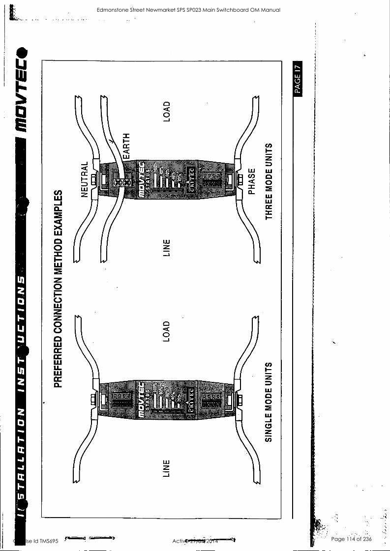
It S
TR
LLR
TIO
N
INS
T
'UC
TIO
NS
M
OV
TE
C
PR
EF
ER
RE
D C
ON
NE
CT
ION
ME
TH
OD
EX
AM
PLE
S
SIN
GLE
MO
DE
UN
ITS
PH
AS
E
TH
RE
E M
OD
E U
NIT
S
PA
GE
17
Edmonstone Street Newmarket SPS SP023 Main Switchboard OM Manual
Q-Pulse Id TMS695 Active 29/01/2014 Page 114 of 236
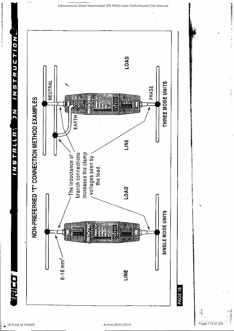
RIC
a IN
ST
RLL
FI%
IN
ST
RU
CT
ION
'_:
NO
N-P
RE
FE
RR
ED
"T
" C
ON
NE
CT
ION
ME
TH
OD
EX
AM
PLE
S
The
ind
ucta
nce
of
bran
ch c
onne
ctio
ns
incr
ease
s th
e cl
amp
volta
ges
seen
by
the
load
.
LIN
E
SIN
GLE
MO
DE
UN
ITS
LOA
D
PH
AS
E
TH
RE
E M
OD
E U
NIT
S
LOA
D
PA
GE
18
I. ,0
.1ft
ipar
Edmonstone Street Newmarket SPS SP023 Main Switchboard OM Manual
Q-Pulse Id TMS695 Active 29/01/2014 Page 115 of 236
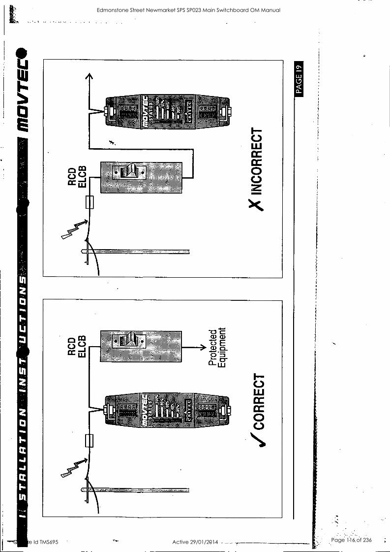
61 30Vc1
0331AD
LU
IIMM
ITV
,s1,0 33.1.11f3
Edmonstone Street Newmarket SPS SP023 Main Switchboard OM Manual
Q-Pulse Id TMS695 Active 29/01/2014 Page 116 of 236
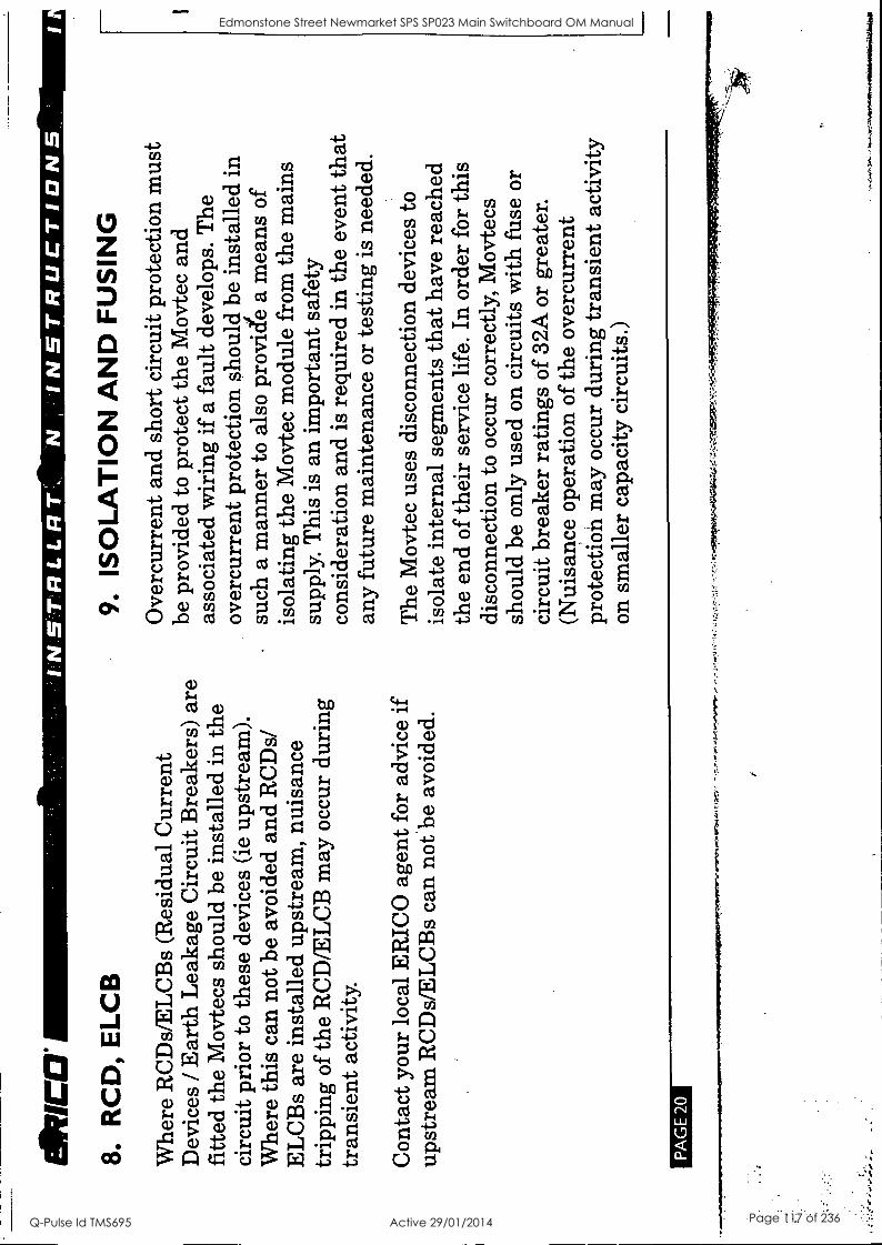
aura
8.
R
CD
, E
LCB
Whe
re R
CD
s/E
LC
Bs
(Res
idua
l C
urre
nt
Dev
ices
/ E
arth
Lea
kage
Cir
cuit
Bre
aker
s) a
re
fitte
d th
e M
ovte
cs s
houl
d be
ins
talle
d in
the
ci
rcui
t pri
or t
o th
ese
devi
ces
(ie
upst
ream
).
Whe
re t
his
can
not b
e av
oide
d an
d R
CD
s/
EL
CB
s ar
e in
stal
led
upst
ream
, nui
sanc
e tr
ippi
ng o
f the
RC
D/E
LC
B m
ay o
ccur
dur
ing
tran
sien
t act
ivity
.
Con
tact
you
r lo
cal
ER
ICO
age
nt f
or a
dvic
e if
up
stre
am R
CD
s/E
LC
Bs
can
not b
e av
oide
d.
PA
GE
20
NS
`TR
LLR
T,
N
INS
TR
UC
TIO
NS
9.
ISO
LAT
ION
AN
D F
US
ING
Ove
rcur
rent
and
sho
rt c
ircu
it pr
otec
tion
mus
t be
pro
vide
d to
pro
tect
the
Mov
tec
and
asso
ciat
ed w
irin
g if
a fa
ult d
evel
ops.
The
ov
ercu
rren
t pro
tect
ion
shou
ld b
e in
stal
led
in
such
a m
anne
r to
als
o pr
ovid
e a
mea
ns o
f is
olat
ing
the
Mov
tec
mod
ule
from
the
mai
ns
supp
ly.
Thi
s is
an
impo
rtan
t sa
fety
co
nsid
erat
ion
and
is r
equi
red
in t
he e
vent
that
an
y fu
ture
mai
nten
ance
or
test
ing
is n
eede
d.
The
Mov
tec
uses
dis
conn
ectio
n de
vice
s to
is
olat
e in
tern
al s
egm
ents
that
hav
e re
ache
d th
e en
d of
thei
r se
rvic
e lif
e. I
n or
der
for
this
di
scon
nect
ion
to o
ccur
cor
rect
ly, M
ovte
cs
shou
ld b
e on
ly u
sed
on c
ircu
its w
ith f
use
or
circ
uit b
reak
er r
atin
gs o
f 32A
or
grea
ter.
(N
uisa
nce
oper
atio
n of
the
over
curr
ent
prot
ectio
n m
ay o
ccur
dur
ing
tran
sien
t act
ivity
on
sm
alle
r ca
paci
ty c
ircu
its.)
Edmonstone Street Newmarket SPS SP023 Main Switchboard OM Manual
Q-Pulse Id TMS695 Active 29/01/2014 Page 117 of 236
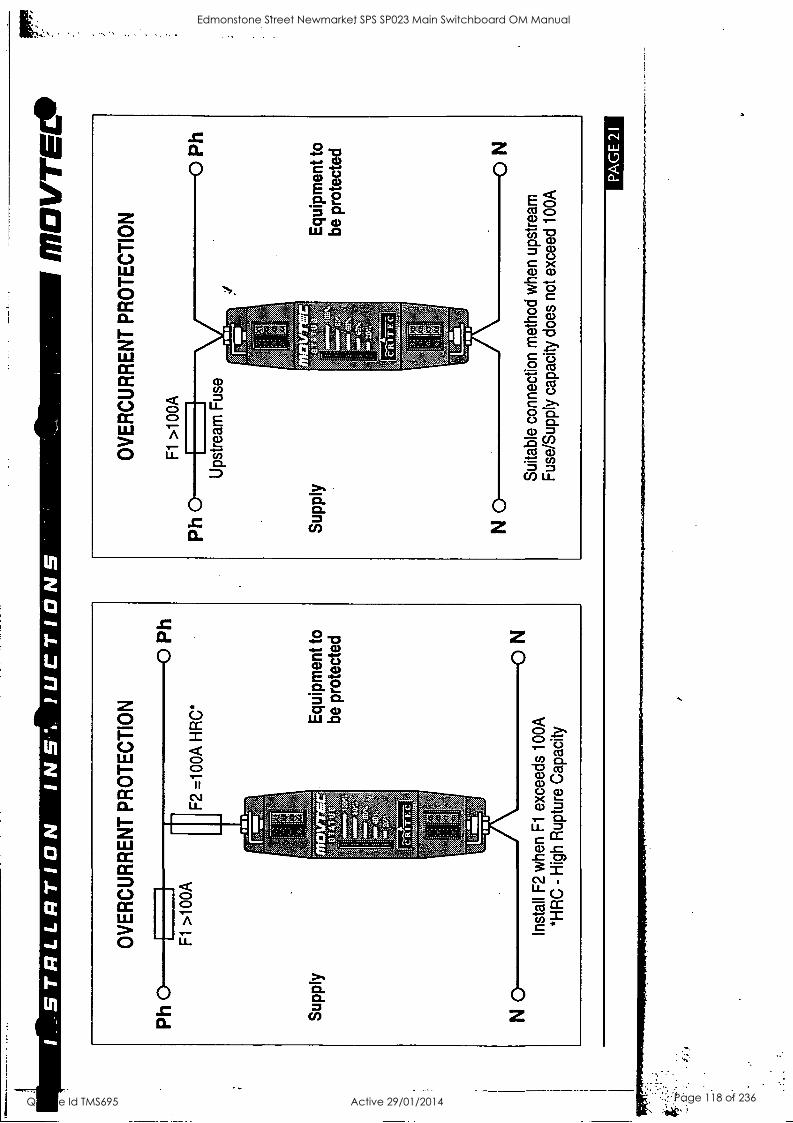
1._.
ST
RLL
RT
ION
IN
S I
UC
TIO
NS
OV
ER
CU
RR
EN
T P
RO
TE
CT
ION
Equ
ipm
ent
to
be p
rote
cted
Inst
all
F2
whe
n F
l ex
ceed
s 10
0A
*HR
C -
Hig
h R
uptu
re C
apac
ity
FP
11
112V
TE
L.
OV
ER
CU
RR
EN
T P
RO
TE
CT
ION
Fl
>10
0A
Ups
trea
m F
use
Equ
ipm
ent t
o be
pro
tect
ed
Sui
tabl
e co
nnec
tion
met
hod
whe
n up
stre
am
Fus
e/S
uppl
y ca
paci
ty d
oes
not
exce
ed 1
00A
PA
GE
21
Edmonstone Street Newmarket SPS SP023 Main Switchboard OM Manual
Q-Pulse Id TMS695 Active 29/01/2014 Page 118 of 236
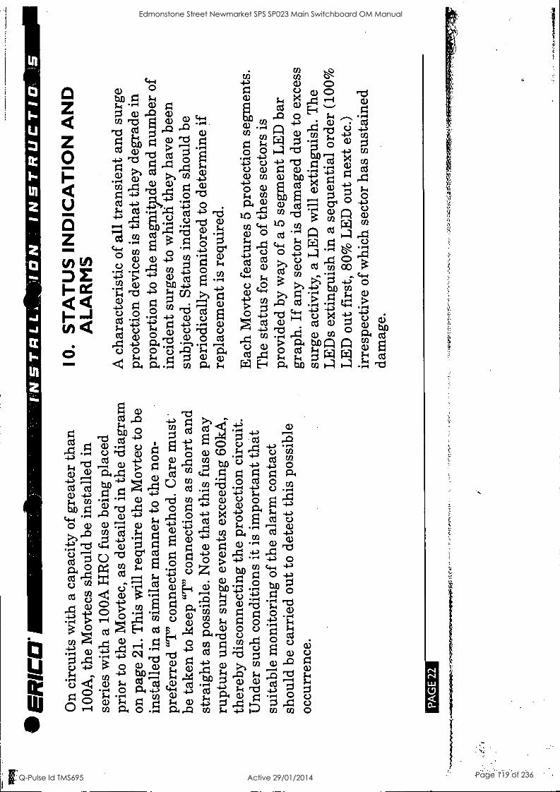
ER
ICE
1
On
circ
uits
with
a c
apac
ity o
f gr
eate
r th
an
100A
, th
e M
ovte
cs s
houl
d be
inst
alle
d in
se
ries
with
a 1
00A
HR
C f
use
bein
g pl
aced
pr
ior
to t
he M
ovte
c, a
s de
taile
d in
the
dia
gram
on
pag
e 21
. T
his
will
req
uire
the
Mov
tec
to b
e in
stal
led
in a
sim
ilar
man
ner
to t
he n
on-
pref
erre
d "T
" co
nnec
tion
met
hod.
Car
e m
ust '
be t
aken
to k
eep
"T"
conn
ectio
ns a
s sh
ort
and
stra
ight
as
poss
ible
. N
ote
that
this
fus
e m
ay
rupt
ure
unde
r su
rge
even
ts e
xcee
ding
60k
A,
ther
eby
disc
onne
ctin
g th
e pr
otec
tion
circ
uit.
Und
er s
uch
cond
ition
s it
is i
mpo
rtan
t th
at
suita
ble
mon
itori
ng o
f the
ala
rm c
onta
ct
shou
ld b
e ca
rrie
d ou
t to
det
ect
this
pos
sibl
e oc
curr
ence
.
PA
GE
22
10.
ST
AT
US
IN
DIC
AT
ION
AN
D
ALA
RM
S
A c
hara
cter
istic
of a
ll tr
ansi
ent a
nd s
urge
pr
otec
tion
devi
ces
is th
at th
ey d
egra
de i
n pr
opor
tion
to th
e m
agni
tpde
and
num
ber
of
inci
dent
sur
ges
to w
hich
they
hav
e be
en
subj
ecte
d. S
tatu
s in
dica
tion
shou
ld b
e pe
riod
ical
ly m
onito
red
to d
eter
min
e if
re
plac
emen
t is
req
uire
d.
Eac
h M
ovte
c fe
atur
es 5
pro
tect
ion
segm
ents
. T
he s
tatu
s fo
r ea
ch o
f th
ese
sect
ors
is
prov
ided
by
way
of
a 5
segm
ent
LE
D b
ar
grap
h. I
f an
y se
ctor
is
dam
aged
due
to
exce
ss
surg
e ac
tivity
, a
LE
D w
ill e
xtin
guis
h. T
he
LE
Ds
extin
guis
h in
a s
eque
ntia
l or
der
(100
%
LE
D o
ut f
irst
, 80
% L
ED
out
nex
t et
c.)
irre
spec
tive
of w
hich
sec
tor
has
sust
aine
d da
mag
e.
Edmonstone Street Newmarket SPS SP023 Main Switchboard OM Manual
Q-Pulse Id TMS695 Active 29/01/2014 Page 119 of 236
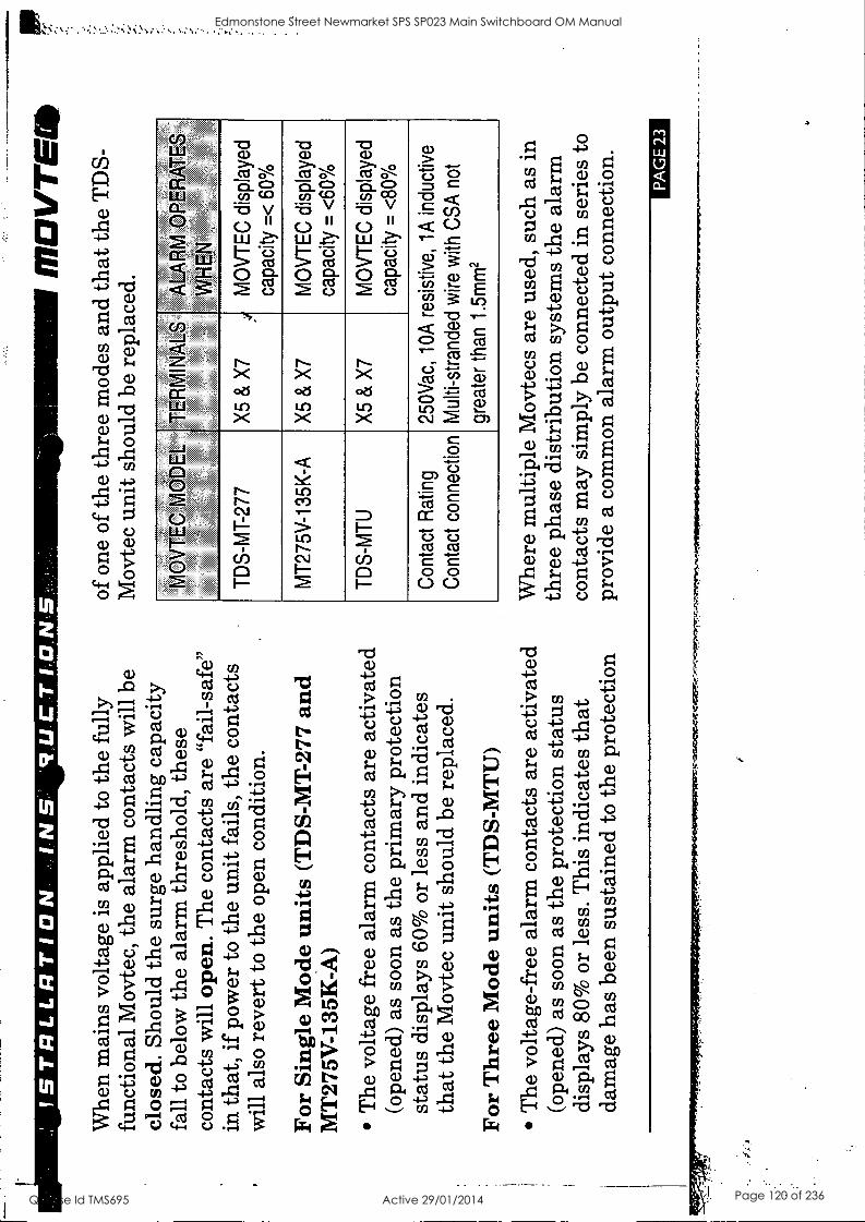
' IS
TR
LAR
TIO
N
VU
CT
IITN
.5-,
Whe
n m
ains
vol
tage
is a
pplie
d to
the
ful
ly
func
tiona
l M
ovte
c, t
he a
larm
con
tact
s w
ill b
e cl
osed
. Sh
ould
the
sur
ge h
andl
ing
capa
city
fa
ll to
bel
ow th
e al
arm
thre
shol
d, t
hese
co
ntac
ts w
ill o
pen.
The
con
tact
s ar
e "f
ail-
safe
" in
that
, if p
ower
to
the
unit
fails
, th
e co
ntac
ts
will
als
o re
vert
to th
e op
en c
ondi
tion.
For
Sing
le M
ode
units
(TD
S-M
T-2
77 a
nd
MT
275V
-135
K-A
)
The
vol
tage
fre
e al
arm
con
tact
s ar
e ac
tivat
ed
(ope
ned)
as
soon
as
the
prim
ary
prot
ectio
n st
atus
dis
play
s 60
% o
r le
ss a
nd i
ndic
ates
th
at th
e M
ovte
c un
it sh
ould
be
repl
aced
.
For
Thr
ee M
ode
units
(T
DS-
MT
U)
The
vol
tage
-fre
e al
arm
con
tact
s ar
e ac
tivat
ed
(ope
ned)
as
soon
as
the
prot
ectio
n st
atus
di
spla
ys 8
0% o
r le
ss.
Thi
s in
dica
tes
that
da
mag
e ha
s be
en s
usta
ined
to t
he p
rote
ctio
n
fl7D
VT
EW
of
one
of t
he th
ree
mod
es a
nd th
at th
e T
DS-
M
ovte
c un
it sh
ould
be
repl
aced
.
MO
VT
EC
MO
DE
L T
ER
MIN
ALS
' A
LAR
M O
PE
RA
TE
S
WH
EN
,',-,
''
' ''t
M
OV
TE
C d
ispl
ayed
ca
paci
ty =
< 6
0%
TD
S-M
T-2
77
X5
& X
7 ,
MT
275V
-135
K-A
X
5 &
X7
MO
VT
EC
dis
play
ed
capa
city
= <
60%
TD
S-M
TU
X
5 &
X7
MO
VT
EC
dis
play
ed
capa
city
= <
80%
Con
tact
Rat
ing
Con
tact
con
nect
ion
250V
ac,
10A
res
istiv
e, 1
A i
nduc
tive
Mul
ti-st
rand
ed w
ire w
ith C
SA
not
grea
ter
than
1.5
mm
2
Whe
re m
ultip
le M
ovte
cs a
re u
sed,
suc
h as
in
thre
e ph
ase
dist
ribu
tion
syst
ems
the
alar
m
cont
acts
may
sim
ply
be c
onne
cted
in s
erie
s to
pr
ovid
e a
com
mon
ala
rm o
utpu
t co
nnec
tion.
PA
GE
23
Edmonstone Street Newmarket SPS SP023 Main Switchboard OM Manual
Q-Pulse Id TMS695 Active 29/01/2014 Page 120 of 236
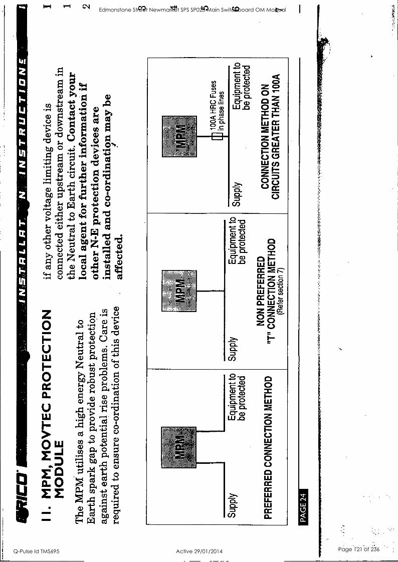
WN
W
I I.
MP
M,
MO
VT
EC
PR
OT
EC
TIO
N
MO
DU
LE
The
MPM
util
ises
a h
igh
ener
gy N
eutr
al to
E
arth
spa
rk g
ap t
o pr
ovid
e ro
bust
pro
tect
ion
agai
nst e
arth
pot
entia
l ris
e pr
oble
ms.
Car
e is
re
quir
ed t
o en
sure
co-
ordi
natio
n of
this
dev
ice
IALS
TR
LLR
TI,
INS
TR
UC
TIO
N_
if a
ny o
ther
vol
tage
lim
iting
dev
ice
is
conn
ecte
d ei
ther
ups
trea
m o
r do
wns
trea
m in
th
e N
eutr
al to
Ear
th c
ircu
it. C
onta
ct y
our
loca
l ag
ent f
or f
urth
er in
form
atio
n if
ot
her
N-E
pro
tect
ion
devi
ces
are
inst
alle
d an
d co
-ord
inat
io;if
n m
ay b
e af
fect
ed.
Sup
ply
Equ
ipm
ent
to
be p
rote
cted
PR
EF
ER
RE
D C
ON
NE
CT
ION
ME
TH
OD
Sup
ply
Equ
ipm
ent t
o be
pro
tect
ed
NO
N P
RE
FE
RR
ED
"T
" C
ON
NE
CT
ION
ME
TH
OD
(R
efer
sec
tion
7)
Sup
ply
100A
HR
C F
uses
in
pha
se l
ines
Equ
ipm
ent t
o be
pro
tect
ed
CO
NN
EC
TIO
N M
ET
HO
D O
N
CIR
CU
ITS
GR
EA
TE
R T
HA
N 1
00A
PA
GE
24
I 1 2 3 4 5 6 7 Edmonstone Street Newmarket SPS SP023 Main Switchboard OM Manual
Q-Pulse Id TMS695 Active 29/01/2014 Page 121 of 236
r--
IN-7
TR
LLR
TIO
N
'ICT
ION
S
INST
AL
LA
TIO
N P
RO
CE
DU
RE
FO
R M
PM
1 R
emov
e th
e co
ver
from
the
MPM
2 Se
lect
the
MPM
mou
ntin
g po
sitio
n to
en
sure
opt
imum
ele
ctri
cal c
onne
ctio
n m
etho
d (r
efer
sec
tion
7) a
nd i
n ac
cord
ance
w
ith a
ll gi
ven
inst
ruct
ions
3 Po
sitio
n an
d m
ark
the
mou
ntin
g po
sitio
n of
th
e M
PM o
n th
e w
all
4 Pr
epar
e su
itabl
e an
chor
ing
hole
s fo
r th
e m
arke
d po
sitio
ns
5 M
ount
the
unit
to th
e w
all,
pres
ervi
ng IP
ra
ting
(if r
equi
red)
6 Pr
epar
e th
e ap
prop
riat
e ca
ble
glan
ds,
pres
ervi
ng I
P ra
ting
(if
requ
ired
) us
ing
suita
ble
seal
ants
7 In
stal
l wir
ing,
tak
ing
care
to
supp
ort
MO
VT
EC
ca
blin
g di
rect
ly c
onne
ctin
g to
the
MPM
un
it, a
nd t
ight
en a
ll te
rmin
als
8 C
heck
that
the
MPM
is
inst
alle
d in
ac
cord
ance
with
all
inst
ruct
ions
, an
d re
leva
nt e
lect
rica
l and
saf
ety
code
s ;if
9
Rep
lace
MPM
cov
er, th
en a
pply
pow
er
10 C
orre
ct o
pera
tion
of th
e M
PM u
nit i
s es
tabl
ishe
d by
che
ckin
g th
at a
ll 5
LE
D's
on
each
Mov
tec
bar
grap
h ar
e lit
, an
d th
at
pow
er is
cor
rect
ly b
eing
sup
plie
d to
the
lo
ad(s
)
INST
AL
LA
TIO
N A
RR
AN
GE
ME
NT
FO
R
AU
STR
AL
IAN
ME
N S
YST
EM
S
Und
er A
ustr
alia
n St
anda
rds
clas
sifi
catio
n,
MPM
s ar
e co
nsid
ered
a p
iece
of e
quip
men
t to
be c
onne
cted
to
the
mai
ns s
uppl
y. T
he M
PMs
are
not i
nten
ded
for
use
as,
nor
are
they
, a
et,D
Ir.c
Ne"
4"41
41ri
tr.
PA
GE
25
Edmonstone Street Newmarket SPS SP023 Main Switchboard OM Manual
Q-Pulse Id TMS695 Active 29/01/2014 Page 122 of 236
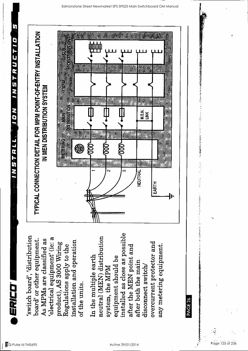
40
o a a
a
UI
z MDR
I
40
559
4TA.t
11.
I'
11Will1111"
iii
0
I
11
IMO
ED
111 I
411
Ea
a a
a
I
w
CL a
Edmonstone Street Newmarket SPS SP023 Main Switchboard OM Manual
Q-Pulse Id TMS695 Active 29/01/2014 Page 123 of 236
.ST
RLL
RT
ION
IN
57 !
UC
TIO
NS
.
I2.
MA
INT
EN
AN
CE
& T
ES
TIN
G
Bef
ore
rem
ovin
g an
y un
it fr
om s
ervi
ce
ensu
re th
at p
ower
to t
he d
evic
e is
is
olat
ed. R
epla
cem
ent o
f an
y M
ovte
c un
its s
houl
d on
ly b
e un
dert
aken
in
acco
rdan
ce w
ith a
ll re
leva
nt E
lect
rici
ty
and
Safe
ty S
tand
ards
by
suita
bly
qual
ifie
d pe
rson
nel.
Mov
tecs
sho
uld
be i
nspe
cted
per
iodi
cally
, and
al
so f
ollo
win
g an
y pe
riod
s of
ligh
tnin
g or
tr
ansi
ent
activ
ity.
Che
ck t
he s
tatu
s in
dica
tors
an
d re
plac
e if
in t
he "
Ala
rm"
cond
ition
as
deta
iled
in S
ectio
n 10
-ST
AT
US
IND
ICA
TIO
N.
For
high
tran
sien
t exp
osur
e si
tes
or th
ose
of a
cr
itica
l op
erat
iona
l nat
ure,
it i
s re
com
men
ded
that
the
alar
m o
utpu
ts b
e m
onito
red
to
prov
ide
an a
dditi
onal
war
ning
of r
educ
ed
capa
city
(re
fer
Sect
ion
10).
MO
VT
EC
ID
Mov
tecs
are
des
igne
d fo
r op
timum
pe
rfor
man
ce u
nder
sev
ere
tran
sien
t act
ivity
. T
o pr
ovid
e th
is p
erfo
rman
ce,
elec
tron
ic
com
pone
nts
in th
e M
ovte
c ar
e en
case
d in
a
pate
nted
pro
prie
tary
, sho
ck a
nd th
erm
al
abso
rban
t com
poun
d. U
nits
can
not b
e se
rvic
ed, t
hey
mus
t be
ref:
plac
ed.
Do
not
atte
mpt
to o
pen
or ta
mpe
r w
ith t
he
units
in
any
way
as
this
may
com
prom
ise
perf
orm
ance
and
will
voi
d w
arra
nty.
Do
not
"Meg
ger"
or
perf
orm
oth
er ty
pes
of
elec
tric
al t
ests
that
app
ly v
olta
ges
grea
ter
than
the
nom
inal
ope
ratin
g vo
ltage
of th
e M
ovte
c. T
he M
ovte
c w
ill a
ttem
pt to
lim
it th
ese
volta
ges
ther
eby
affe
ctin
g th
e te
st re
sult.
W
here
thes
e te
sts
mus
t be
per
form
ed, r
emov
e th
e M
ovte
c fr
om c
ircu
it fi
rst.
Mir.
....."
1711
MO
OM
MIN
IIMP
OR
IMIM
ME
m""
Am
tsfa
siaN
AR
P=
--.
.
84:1
2Z
.
PA
GE
27
Edmonstone Street Newmarket SPS SP023 Main Switchboard OM Manual
Q-Pulse Id TMS695 Active 29/01/2014 Page 124 of 236
E
R=
13
. E
XT
EN
DE
D W
AR
RA
NT
Y
Thi
s pr
oduc
t has
a li
mite
d w
arra
nty
to b
e fr
ee
from
def
ects
in
mat
eria
ls a
nd w
orkm
ansh
ip f
or a
pe
riod
of f
ive
(5)
year
s fr
om t
he d
ate
of d
ispa
tch
from
the
Man
ufac
ture
r.
The
Pur
chas
er
ackn
owle
dges
tha
t lig
htni
ng is
a n
atur
al e
vent
w
ith s
tatis
tical
var
iatio
n in
beh
avio
ur a
nd e
nerg
y le
vels
whi
ch m
ay e
xcee
d pr
oduc
t rat
ings
, an
d 10
0 %
pr
otec
tion
is n
ot o
ffer
ed a
nd c
anno
t be
prov
ided
fo
r.
The
refo
re t
he M
anuf
actu
rer's
lia
bilit
y is
lim
ited
to t
he r
epai
r or
rep
lace
men
t of t
he p
rodu
ct
(at
the
Man
ufac
ture
r's s
ole
optio
n) w
hich
in
its
judg
emen
t has
not
bee
n ab
used
, m
isus
ed,
inte
rfer
ed w
ith b
y an
y pe
rson
not
aut
hori
sed
by
the
Man
ufac
ture
r, o
r ex
pose
d to
ene
rgy
or
tran
sien
t lev
els
exce
edin
g th
e M
anuf
actu
rer's
sp
ecif
icat
ions
for
the
prod
uct.
The
pro
duct
mus
t be
ins
talle
d an
d ea
rthe
d (w
here
app
licab
le)
in
stri
ct a
ccor
danc
e w
ith t
he M
anuf
actu
rer's
sp
ecif
icat
ions
and
all
rele
vant
nat
iona
l Ele
ctri
city
an
d Sa
fety
Sta
ndar
ds.
The
Man
ufac
ture
r an
d th
e
PA
GE
28
INS
TR
UC
TI
NS
Purc
hase
r m
utua
lly a
ckno
wle
dge
that
the
prod
uct,
by it
s na
ture
, may
be
subj
ect t
o de
grad
atio
n as
a c
onse
quen
ce o
f th
e nu
mbe
r an
d se
veri
ty o
f sur
ges
and
tran
sien
ts th
at it
ex
peri
ence
s in
nor
mal
use
, an
d th
at th
is w
arra
nty
excl
udes
suc
h gr
adua
l or
sud
den
degr
adat
ion.
T
his
war
rant
y do
es n
ot i
ndem
nify
the
Purc
hase
r of
the
prod
uct f
or a
ny c
onse
quen
tial c
laim
for
da
mag
es o
r lo
ss o
f op
erat
ions
or
serv
ice
or p
rofi
ts.
Cus
tom
ers
shou
ld c
onta
ct t
heir
nea
rest
m
anuf
actu
rer's
age
nt to
obt
ain
a Pr
oduc
t R
epai
r A
utho
risa
tion
Num
ber
prio
r to
mak
ing
any
clai
m
unde
r th
is w
arra
nty.
T
his
is o
nly
a su
mm
ary
of
the
war
rant
y gi
ven
by th
e M
anuf
actu
rer.
T
he f
ull
text
of t
he w
arra
nty
is s
et o
ut i
n th
e M
anuf
actu
rer's
Con
ditio
ns o
f Quo
tatio
n an
d Sa
le.
The
abo
ve l
imite
d w
arra
nty
is a
dditi
onal
to r
ight
s w
hich
ari
se i
n re
spec
t of
the
sale
of i
ndus
tria
l an
d te
chni
cal p
rodu
cts
and
serv
ices
to
know
ledg
able
bu
yers
und
er th
e A
ustr
alia
n T
rade
Pra
ctic
es A
ct
1974
as
amen
ded.
Edmonstone Street Newmarket SPS SP023 Main Switchboard OM Manual
Q-Pulse Id TMS695 Active 29/01/2014 Page 125 of 236

:
I --
ST
RLL
RT
ION
IN
ST
"UC
TIO
NS
14.
SIX
PO
INT
PLA
N
Cri
tec
Mov
tec
surg
e di
vert
ers
form
an
impo
rtan
t par
t of
the
muc
h la
rger
ER
ICO
lig
htni
ng,
surg
e an
d tr
ansi
ent p
rote
ctio
n ph
iloso
phy
(ER
ICO
Lig
htni
ng T
echn
olog
ies
"Six
Poi
nt P
lan"
). T
he l
evel
of p
rote
ctio
n an
d th
e de
gree
of
atte
ntio
n de
dica
ted
to e
ach
of
the
six
poin
ts w
ill r
equi
re c
aref
ul
cons
ider
atio
n fo
r ea
ch s
ite.
The
deg
ree
of
prot
ectio
n re
quir
ed is
det
erm
ined
by
the
indi
vidu
al s
ite l
ocat
ion/
expo
sure
with
the
aid
of ri
sk m
anag
emen
t pr
inci
pals
.
For
furt
her
advi
ce o
n yo
ur p
rote
ctio
n ne
eds
plea
se c
onta
ct y
our
loca
l re
pres
enta
tive.
MO
VT
EC
e
LIG
HT
NIN
G T
EC
HN
OLO
GIE
S
PO
INT
PR
OT
EC
TIO
N P
LAN
Cap
ture
the
light
ning
str
ike
5 Pro
tect
equ
ipm
ent
from
sur
ges
on
pow
er li
nes
6 Pro
tect
equ
ipm
ent
from
tra
nsie
nts
on
tele
com
mun
icat
ion
and
sign
al li
nes
tr
ttega
rAPA
PP14
42=
',. 'P
r
PA
GE
29
Edmonstone Street Newmarket SPS SP023 Main Switchboard OM Manual
Q-Pulse Id TMS695 Active 29/01/2014 Page 126 of 236
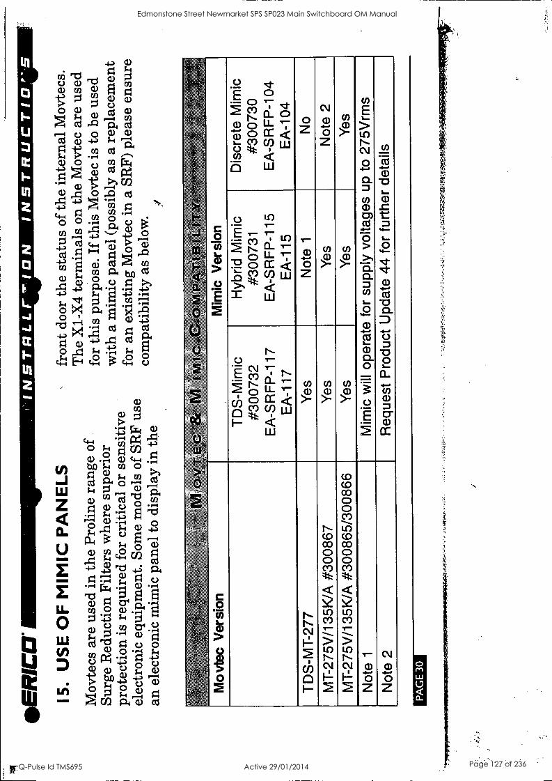
ER
C11
15
. U
SE
OF
MIM
IC P
AN
ELS
INS
TR
LLr'I
ON
IN
ST
RU
CT
ICIP
'S
Mov
tecs
are
use
d in
the
Pro
line
rang
e of
Su
rge
Red
uctio
n Fi
lters
whe
re s
uper
ior
prot
ectio
n is
req
uire
d fo
r cr
itica
l or
sens
itive
el
ectr
onic
equ
ipm
ent.
Som
e m
odel
s of
SR
F us
e an
ele
ctro
nic
mim
ic p
anel
to d
ispl
ay in
the
Mov
tec
Ver
sion
fron
t doo
r th
e st
atus
of t
he in
tern
al M
ovte
cs.
The
X1-
X4
term
inal
s on
the
Mov
tec
are
used
fo
r th
is p
urpo
se.
If th
is M
ovte
c is
to
be u
sed
with
a m
imic
pan
el (p
ossi
bly
as a
rep
lace
men
t fo
r an
exi
stin
g M
ovte
c in
a S
RF)
ple
ase
ensu
re
com
patib
ility
as
belo
w.
74.-
-Arr
.1
0
Mim
ic V
ersi
on
TD
S-M
imic
#3
0073
2 E
A-S
RF
P-1
17
EA
-117
Hyb
rid M
imic
#3
0073
1 E
A-S
RF
P-1
15
EA
-115
Dis
cret
e M
imic
#3
0073
0 E
A-S
RF
P-1
04
EA
-104
TD
S-M
T-2
77
Yes
N
ote
1 N
o
MT
-275
V/1
35K
/A #
3008
67
Yes
Y
es
Not
e 2
MT
-275
V/1
35K
/A #
3008
65/3
0086
6 Y
es
Yes
Y
es
Not
e 1
Mim
ic w
ill o
pera
te f
or s
uppl
y vo
ltage
s up
to
275V
rms
Not
e 2
Req
uest
Pro
duct
Upd
ate
44 f
or f
urth
er d
etai
ls
PA
GE
30
Edmonstone Street Newmarket SPS SP023 Main Switchboard OM Manual
Q-Pulse Id TMS695 Active 29/01/2014 Page 127 of 236
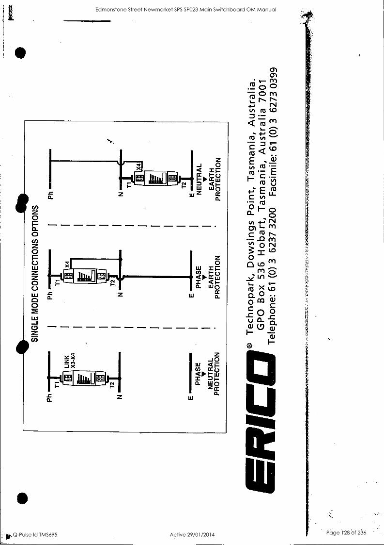
LIN
K
X3-
X4
E
PH
AS
E
V
NE
UT
RA
L P
RO
TE
CT
ION
SIN
GLE
MO
DE
CO
NN
EC
TIO
NS
OP
TIO
NS
Ph
T1
N
4
E
PH
AS
E
V
EA
RT
H
PR
OT
EC
TIO
N
Ph N
T1
X4
FEU
NE
UT
RA
L
EA
RT
H
PR
OT
EC
TIO
N
I-
1 ®
T
echn
opar
k,
Dow
sing
s P
oint
, T
asm
ania
, A
ustr
alia
. G
PO
B
ox
536
Hob
art,
Tas
man
ia,
Aus
tral
ia 7
001
Tel
epho
ne:
61
(0)
3 62
37 3
200
Fac
sim
ile:
61
(0)
3 62
73 0
399
Edmonstone Street Newmarket SPS SP023 Main Switchboard OM Manual
Q-Pulse Id TMS695 Active 29/01/2014 Page 128 of 236

TECHNICAL DATA SHEET
For
Edmondstone Street Pump Station
Equipment Type:
Location:
Model Numbers:
Manufacturer:
Supplier:
Pushbuttons, Indicator Lights &.
Switchboard Starter Section Local Control Stations
ZB Series
TELEMECANIQUE
Schneider Electric. 30 Graystone Street TINGALPA QLD 4173
Ph: 07 3890 2112 Fx: 07 3890 2098
Edmonstone Street Newmarket SPS SP023 Main Switchboard OM Manual
Q-Pulse Id TMS695 Active 29/01/2014 Page 129 of 236

Harmony Style 4
ZB4 Metal
22 111-1'04
Selection guide to the new metal pushbutton range
from Telemecanique
Merlin Gerin Modicon Square D Telemecanique
IP65 and NEMA 4X
Schneider Electric
Edmonstone Street Newmarket SPS SP023 Main Switchboard OM Manual
Q-Pulse Id TMS695 Active 29/01/2014 Page 130 of 236

XAL Double Insulated Control Stations Same mounting points as the old products Stainless steel screws as standard Compact overall dimensions Up to 3 electrical blocks per head
Website
Complete Stop/Start Function (light grey base/dark grey lid) Old New
XALB103 XALD103 XALD114
XALB215 XALD215
XALB134 XALD134
XALB144 XALD144
XALD363B XALD363G
XALB376 XALD363M
"Start" Marking on pushbutton 1 N/O Flush Green "Stop" Marking on pushbutton 1 N/C Flush Red "Start" Marking on pushbutton "Stop"
1 N/O 1 N/C
Flush Flush
Green Red
"0 -I" Marking on legend plate 1 selector switch, 2 position stay put
1 N/O
"0 -I" Marking on legend plate 1 key selector switch, 2 position stay put
Marking on pushbutton "0" 1pilot light with red "Protected LED"
1 N/O 1 N/C
24VAC/DC 110...120VAC 230...240VAC
Complete Emergency Stop Function (light grey base/yellow lid) 1 mushroom head pushbutton, red XALJ174 XALK17 040mm, latching "turn to release" 1 mushroom head pushbutton, red XALJ184 XALK184 040mm, latching "key release"
Components for Customer Assembly light grey base 1 hole XALB01 XALD01 dark grey lid 2 holes XALB02 XALD02
3 holes XALB03 XALD03 4 holes XALB04 XALD04 5 holes XALB05 XALD05
(see XB5A heads on left pages)
Electrical Contact Blocks (for base mounting with metal clip) Contact blocks
N/O XENL1111 ZENL1111 N/C XENL1121 ZENL1121
"Protected LED" modules White 24VAC/DC XALV6+bulb ZALVB1 Green XALW6+bulb ZALVB3 Red ZALVB4A11 Yellow ZALVB5W Blue ZALVB6 White 48...120VAC XALV6+bulb ZALVG1 ®
Green XALW6+bulb ZALVG3 Red ZALVG4 Yellow ZALVG5 Blue ZALVG6 White 230...240VAC XALV7+bulb ZALVM1 Green XALW7+bulb ZALVM3 Red ZALVM4 Yellow ZALVM5 Blue ZALVM6
(1) You can also mount XB5A contact blocks directly beneath the heads.
Volt-free terminal for XAL stations (common/earth) XALZ09
Help Cent www.schneider.com.au Schneider 1300 369 233 0) Electric
AUS990901
Edmonstone Street Newmarket SPS SP023 Main Switchboard OM Manual
Q-Pulse Id TMS695 Active 29/01/2014 Page 131 of 236

Illuminated Pushbuttons and Selector Switches Unique, patented "Protected LED" technology
2 references ZB5AW = 1 complete product
Illuminated Pushbuttons Old New Flush White ZA2BW37 ZB5AW313 Flush Green ZA2BW33 ZB5AW333 Flush Red ZA2BW34 ZB5AW343 Flush Yellow ZA2BW35 ZB5AW353 Flush Blue ZA2BW36 ZB5AW363 Booted White ZA2BW57 ZB5AW513 Booted Green ZA2BW53 ZB5AW533 Booted Red ZA2BW54 ZB5AW543 Booted Yellow ZA2BW55 ZB5AW553 Booted Blue ZA2BW56 ZB5AW563
Illuminated Selector Switches 2 osition sta ut () White ZA2BK127 5 1213 Green ZA2BK123 ZB5AK1233 Red ZA2BK124 ZB5AK1243 Yellow ZA2BK125 ZB5AK1253 Blue ZA2BK126 ZB5AK1263
(*) other configurations are available.
Collar + LED module + Contact Block (1) 24VAC/DC 1 N/O White ZA2BW061+bulb ZB5AW0B11
1 N/O Green ZA2BW061+bulb ZB5AWOB31 1 N/C Red ZA2BW062+bulb ZB5AWOB42 1 N/O Yellow ZA2BW061+bulb ZB5AWOB51 1 N/O Blue ZA2BW061+bulb ZB5AWOB61
48...120VAC 1 N/O White ZA2BW061+bulb ZB5AWOG11 1 N/O Green ZA2BW061+bulb ZB5AWOG31 1 N/C Red ZA2BW062+bulb ZB5AWOG42 1 N/O Yellow ZA2BW061+bulb ZB5AWOG51 1 N/O Blue ZA2BW061+bulb ZB5AWOG61
230...240VAC 1 N/O White ZA2BW071 ZB5AWOM11 1 N/O Green ZA2BW071 ZB5AWOM31 1 N/C Red ZA2BW072 ZB5AWOM42 1 N/O Yellow ZA2BW071 ZB5AWOM51 1 N/O Blue ZA2BW071 ZB5AWOM61
(1) for 1 N/O + 1 N/C contacts, replace In ZB5AW0*1, the last digit "1" by "5"
Accessories Description For use with Plastic blanking plug, round, black (1)
For 022 control and signalling units with circular head
ZB5SZ3
Add-on square trim
Gives square appearance to circular heads ZB5-A
ZB5AZ31
Lock nut Fixing head ZB5AZ901 lightening tool ZB5AZ905 Anti-rotation plate For selection switches ZB5AZ902 Single boot Double boot
Booted pushbuttons with circular head Double headed pushbuttons with or without pilot light
ZB PO
ZBW008
(1) Fixing nut included with blanking plug.
Schneider Electric
Edmonstone Street Newmarket SPS SP023 Main Switchboard OM Manual
Q-Pulse Id TMS695 Active 29/01/2014 Page 132 of 236

(11
La
Pushbuttons and Selector Switches 2 references ZB4B = 1 complete product
XB4B Mounting
Pushbuttons Old New Flush Black ZB2BA2 ZB4BA2 Flush Green ZB2BA3 ZB4BA3 Flush Red ZB2BA4 ZB4BA4 Flush Yellow ZB2BA5 ZB4BA5 Flush Blue ZB2BA6 ZB4BA6 Booted Black ZB2BP2 ZB4BP2 Booted Green ZB2BP3 ZB4BP3 Booted Red ZB2BP4 ZB4BP4 Booted Yellow ZB2BP5 ZB4BP5 Booted Blue ZB2BP6 ZB4BP6
Selector Switches (1) 2 position stay put N/ ZB2BD2 ZB4BD2 2 position spring return S7 ZB2BD4 ZB4BD4 , 3 position stay put \l/ ZB2BD3 ZB4BD* 3 position spring return q7 ZB2BD5 ZB4BD 3 position spring return \17 ZB2BD8 ZB4BD8
Key Selector Switches (1) 2 position stay put °./ ZB2BG2 ZB4BG2 2 position stay put s\l' ZB2BG4 ZB4BG4 2 position spring return \--7 ZB2BG6 ZB4BG6 3 position stay put '44' ZB2BG0 ZB4BG0 3 position stay put \i/ ZB2BG3 ZB4BG3 2 position spring return ZB2BG7 ZB4BG7
The symbol l indicates key removal posItIon(s) (1) For activation of lateral contacts only.
Mushroom Head Pushbuttons (Spring Return) 040mm Green ZB2BC3 ZB4BC3 040mm Red ZB2BC4 ZB4BC4
Emergency Stop Pushbuttons (Latching) 040mm Red turn to release ZB2BS54 ZB4BS54 040mm Red push/pull ZB2BT4 ZB4BT4 040mm Red key release ZB2BS14 ZB4BS14
Collar + Contact Block(s) 1 N/O 1 N/C 2 N/O 2 N/C 1 N/O + 1 N/C
11? ZB2BZ102 ZB4BZ ZB2BZ101 ZB4BZ
ZB2BZ103 ZB4BZ1 03 ZB2BZ104 ZB4BZ104 ZB2BZ105 ZB41321 05
Additional Contact Block 1 N/O 1 N/C 2 N/O 2 N/C 1 N/O + IN/C
ZB2BE101 ZBE101 ZB2BE102 ZBE102
ZBE203 ZBE204 ZBE205
Support Panel Cut-Out (suitable for mounting all types of pushbuttons and pilot lights) 0
J 022 Panel thickness: 1 to 6mm
Assembly -3 simple steps
Schneider aElectric
Oti
Edmonstone Street Newmarket SPS SP023 Main Switchboard OM Manual
Q-Pulse Id TMS695 Active 29/01/2014 Page 133 of 236

Pilot Lights Unique, patented "Protected LED" technology
1 reference XB4BV = 1 complete product
Pilot lights with integral LED Old New 24VAC/DC White ZB2BV6+ZB2BV07+bulb XB4BVB1
Green ZB2BV6+ZB2BV03+bulb XB4BVB3 Red ZB2BV6+ZB2BV04+bulb XB4BVB4 Yellow ZB2BV6+ZB2BV05+bulb XB4BVB5 Blue ZB2BV6+ZB2BV06+bulb XB4BVB6
48...120VAC White ZB2BV6+ZB2BV07+bulb XB4BVG1 Green ZB2BV6+ZB2BV03+bulb XB4BVG3 Red ZB2BV6+ZB2BV04+bulb XB4BVG4 Yellow ZB2BV6+ZB2BV05+bulb XB4BVG5
IIII Blue ZB2BV6+ZB2BV06+bulb
230...240VAC White ZB2BV7+ZB2BV07 Green ZB2BV7+ZB2BV03
Yellow Red
Blue
ZB2BV7+ZB2BV04 ZB2BV7+ZB2BV05 ZB2BV7+ZB2BV06 XB4BVM6
XB4BVM1 XB4BVM3 XB4BVM4 XB4BVM5
XB4BVG6
"Protected LED" technology High resistance to vibrations In-built patented electronic protection against voltage transients and electromagnetic interference (IEC 100-4)
hence a 100,000 hour service life
Efficient signalling Low current consumption Reduced heat dissipation No access to live connection from the front
A new aesthetics Enhanced brightness Purity of colours (white, green, red, yellow, blue) Available in three voltages (24VACDC, 48-120VAC, 230VAC)
Contact blocks Dismounting
1) untighten the screw
2) lift the tag
Schneider ,Electric
Edmonstone Street Newmarket SPS SP023 Main Switchboard OM Manual
Q-Pulse Id TMS695 Active 29/01/2014 Page 134 of 236

Pilot Lights Unique, patented "Protected LED" technology
1 reference XB5AV = 1 complete product
Pilot lights with integral LED Old New
24VAC/DC White ZA2BV6+ZA2BV07+bulb XB5AVB1 Green ZA2BV6+ZA2BV03+bulb XB5AVB3 Red ZA2BV6+ZA2BV04+bulb XB5AVB4 Yellow ZA2BV6+ZA2BV05+bulb XB5AVB5 Blue ZA2BV6+ZA2BV06+bulb XB5AVB6
48...120VAC White ZA2BV6+ZA2BV07+bulb XB5AVG1 Green ZA2BV6+ZA2BV03+bulb XB5AVG3 Red ZA2BV6+ZA2BV04+bulb XB5AVG4 Yellow ZA2BV6+ZA2BV05+bulb XB5AVG5 Blue ZA2BV6+ZA2BV06+bulb XB5AVG6
230...240VAC White ZA2BV7+ZA2BV07 XB5AVM1 Green ZA2BV7+ZA2BV03 XB5AVM3 Red ZA2BV7+ZA2BV04 XB5AVM4 Yellow ZA2BV7+ZA2BV05 XB5AVM5 Blue ZA2BV7+ZA2BV06 XB5AVMO
"Protected LED" technology High resistance to vibrations In-built patented electronic protection against voltage transients and electromagnetic interference (IEC 100-4)
hence a 00,000 hour service life
Efficient signalling Low current consumption Reduced heat dissipation No access to live connection from the front
A new aesthetics Enhanced brightness Purity of colours (white, green, red, yellow, blue) Available in three voltages (24VACDC, 48-120VAC, 230VAC)
Contact blocks
Schneider aElectric
Edmonstone Street Newmarket SPS SP023 Main Switchboard OM Manual
Q-Pulse Id TMS695 Active 29/01/2014 Page 135 of 236

Pushbuttons and Selector Switches 2 references ZB5A = 1 complete product
XB5A Mounting
Pushbuttons (1) Old New Flush Black ZA2BA2 ZB5AA2 Flush Green ZA2BA3 ZB5AA3 Flush Red ZA2BA4 ZB5AA4 Flush Yellow ZA2BA5 ZB5AA5 Flush Blue ZA2BA6 ZB5AA6 Booted Black ZA2BP2 ZB5AP2 Booted Green ZA2BP3 ZB5AP3 Booted Red ZA2BP4 ZB5AP4 Booted Yellow ZA2BP5 ZB5AP5 Booted Blue ZA2BP6 ZB5AP6
(1) Square heads are also available
Selector Switches (1) 2 position stay put \/ ZA2BD2 ZB5AD2 2 position spring return ZA2BD4 ZB5AD4 3 position stay put * ZA2BD3 ZB5AD3 3 position spring return qi ZA2BD5 ZB5AD5 3 position spring return \l7 ZA2BD8 ZB5AD8
Key Selector Switches (1) 2 position stay put °,\/ 2 position stay put M 2 position spring return S-7 3 position stay put \?, 3 position stay put \!,/ 3 position spring return 1i
The symbol It indicates key removal position(s) (1) For activation of lateral contacts only.
ZA2BG2 ZB5AG2 ZA2BG4 ZB5AG4 ZA2BG6 ZB5AG6 ZA2BG0 ZB5AGO ZA2BG3 ZB5AG3 ZA2BG7 ZB5AG7
Mushroom Head Pushbuttons (Spring Return) 040mm Green ZA2BC3 ZB5AC3 040mm Red ZA2BC4 ZB5AC4
Emergency Stop Pushbuttons (Latching) 040mm Red turn to release ZA2BS54 ZB5AS54 040mm Red push/pull ZA2BT4 ZB5AT4 040mm Red key release ZA2BS14 ZB5AS14
Collar + Contact Block(s) 1 N/O 1 N/C 2 N/O 2 N/C 1 N/O + 1 N/C
ZA2BZ101 ZB5AZ101 ZA2BZ102 ZB5AZ102 ZA2BZ103 ZB5AZ103 ZA2BZ104 ZB5AZ104 ZA2BZ105 ZB5A2105
Additional Contact Block 1 N/O 1 N/C 2 N/O 2 N/C 1 N/O + 1 N/C
ZB2BE101 ZBE101 ZB2BE1 02 ZBE102
ZBE203 ZBE204 ZBE205
Support Panel Cut-Out (suitable for mounting all types of pushbuttons and pilot lights)
Assembly -3 simple steps
Panel thickness: 1 to 6mm 4 Schneider a Electric
Edmonstone Street Newmarket SPS SP023 Main Switchboard OM Manual
Q-Pulse Id TMS695 Active 29/01/2014 Page 136 of 236

Illuminated Pushbuttons and Selector Switches Unique, patented "Protected LED" technology 2 references ZB4BW = 1 complete product
Illuminated Pushbuttons Old Flush White ZB2BW37 Flush Green ZB2BW33 Flush Red ZB2BW34 Flush Yellow ZB2BW35 Flush Blue ZB2BW36 Booted White ZB2BW57 Booted Green ZB2BW53 Booted Red ZB2BW54 Booted Yellow ZB2BW55 Booted Blue ZB2BW56
Illuminated Selector Switches (2 position White Green Red Yellow Blue
New ZB4BW313 ZB4BW333 ZB4BW343 ZB4BW353 ZB4BW363 ZB4BW513 ZB4BW533 ZB4BW543 ZB4BW553 ZB4BW563
stay put (*)) ZB2BK127 ZB2BK123 ZB2BK124 ZB2BK125 ZB2BK126
ZB4B K1213 ZB4B K1233 ZB4BK1216 ZB4BK12 ZB4B K1263
(*) other configurations are available.
Illuminated Selector Switches 3 osition sta ut (*)
White ZB2BK137 Green ZB2BK133 Red ZB2BK134 Yellow ZB2BK135 Blue ZB2BK136
(*) other configurations are available.
Z 4 : 1313 ZB4BK1333 ZB4BK1343 ZB4B K1353 ZB4BK1363
Collar + LED module + Contact Block (1) 24VAC/DC 1 N/O White
1 N/O Green 1 N/C Red 1 N/O Yellow 1 N/O Blue
48...120VAC 1 N/O White 1 N/O Green 1 N/C Red 1 N/O Yellow 1 N/O Blue
230...240VAC 1 N/O White 1 N/O Green 1 N/C Red 1 N/O Yellow 1 N/O Blue
(1) for 1 N/O + 1 N/C contacts, replace in ZB4BWO**1, the last digit "1" by "5"
ZB2BW061+bulb ZB2BW061+bulb ZB2BW062+bulb ZB2BW061+bulb ZB2BW061+bulb ZB2BW061+bulb ZB2BW061+bulb ZB2BW062+bu lb ZB2BW061+bulb ZB2BW061+bulb ZB2BW071 ZB2BW071 ZB2BW072 ZB2BW071 ZB2BW071
ZB4BWOB11 ZB4BWOB31 ZB4BWOB42 ZB4BWOB51 ZB4BWOB61 ZB4BWOG11 ZB4BWOG31 ZB4BWOG42 ZB4BWOG51 ZB4BWOGIS ZB4BWOM WI/ ZB4BWOM31 ZB4BWOM42 ZB4BWOM51 ZB4BWOM61
Schneider Electric
Edmonstone Street Newmarket SPS SP023 Main Switchboard OM Manual
Q-Pulse Id TMS695 Active 29/01/2014 Page 137 of 236

Accessories (also to suit ZB5A double insulated pushbuttons
& XAL control stations)
Standard (30 x 40mm) legend plates Description Legend
Colour With blank legend (for engraving)
Black or red background
White or yellow background
Already engraved O (black background) ZBY2146 HAND O (red background) ZBY2931 HAND-OFF-AUTO 1 ZBY2147 INCH
ZBY2148 LEFT
STOP 0-1 ZBY2178 OFF 1-11 ZBY2179 OFF-ON 1-0-11 ZBY2186 OPEN AUTO ZBY2115 POWER ON
STOP (red background) ZBY2304 RESET (red background) AUTO-HAND ZBY2364 RESET (black background) AUTO-O-HAND ZBY2385 REVERSE CLOSE ZBY2314 RIGHT DOWN ZBY2308 RUN EMERGENCY STOP ZBY2330 SLOW FAST ZBY2328 START (black background)
ok G4 FORWARD ZBY2305 STOP-START UP
4 Circular legends for emergency stop mushroom heads Diameter Marking on yellow background mm
Reference
ZBY2101
ZBY4101
ZBY2316 ZBY2387 ZBY2321 ZBY2310 ZBY2312 ZBY2367 ZBY2313 ZBY2326 ZBY2323 ZBY2322 ZBY2306 ZBY2309 ZBY2334 ZBY2327 ZBY2303 ZBY2366 ZBY2307
60 90
EMERGENCY STOP EMERGENCY STOP
Metal guards Padlocking possible
040 emergency stop and mushroom head pushbuttons
Blue
Black
Red
Yellow
Metal blanking plug. round, chromium plated (1)
Plastic blanking plug, round. black (2)
For 022 control and signalling units
Reference
ZBY9330 ZBY8330
ZBZ1601
ZBZ1602
ZBZ1604
ZBZ1605
ZB4SZ3
For 022 control and signalling units
ZB5SZ3
(1) Requires a ZB4BZ009 body/fixing collar for mounting. (2) Fixing nut included with blanking plug.
410ebsite www.schneider.com.au Schneider
aElectric
Help Centre 1300 369 233
AUS990901
Edmonstone Street Newmarket SPS SP023 Main Switchboard OM Manual
Q-Pulse Id TMS695 Active 29/01/2014 Page 138 of 236

Selection guide to the new double insulated pushbutton
range from Telemecanique
Harmony Style S
ZBS Double insulated
XAL Control stations
022
Merlin Gerin Modicon Square D Telemecanique
1P65 and NEMA 4X
Schneider ei Electric
Edmonstone Street Newmarket SPS SP023 Main Switchboard OM Manual
Q-Pulse Id TMS695 Active 29/01/2014 Page 139 of 236

TECHNICAL DATA SHEET
For
Edmondstone Street Pump Station
Equipment Type:
Location:
Model Numbers:
Manufacturer:
Supplier:
Control Relays
Switchboard Starter Section
CA2 KN22
TELEMECANIQUE
Schneider Electric. 30 Graystone Street TINGALPA QLD 4173
Ph: 07 3890 2112 Fx: 07 3890 2098
Edmonstone Street Newmarket SPS SP023 Main Switchboard OM Manual
Q-Pulse Id TMS695 Active 29/01/2014 Page 140 of 236
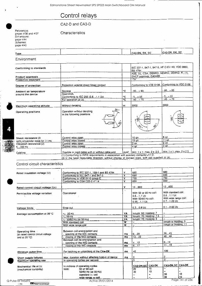
S
I
Control relays CA2-D and CA3-D
References: pages 4/36 and 4/37 Characteristics Dimensions: page 4/44 Schemes: page 4/45
Type CA2-DN, DK, DC CA3-ON, DK, DC
Environment
Conforming to standards IEC 337-1, 947-1, 947-5, NF C 63-140, VDE 0660,
BS 4794 ASE, UL, CSA, DEMKO, NEMKO, SEMKO, FI, (1),
SNCF approval, CA3-ON Product approvals Protective treatment "TH"
Degree of protection Protection a.ainst direct fin.er contact Conformin. to VDE 0106 Conformin. to VDE 0106
Ambient air temperature around the device
Storage °C - 60...+ 80 - 60...+ 80
Operation, Conforming to IEC 255 (0.8...1.1 tic) °C ...+ 55 5...÷ 55
For operation at Uc ° - 40...+ 70 - 40...+ 70
Maximum operating altitude Without derating m 3000 3000
Operating positions Operation without derating in the following positions
30 °
°3
. Pall
lila
Shock resistance (2) semi-sinusoidal wave for 11 ms
Control relay open 102n 15 gn
max: 2 x 2.5
8 gn 11 qn 2 gn 3 gn
Min: 1 x 1: max: 2 x 2.5
Control relay closed Vibration resistance (2) 5...300 Hz
Control relay open
mm2
2 gn 4 gn
Min: 1 x 1.
Control relay closed
Cabling Flexible or rigid cable with or without cable end (1) Conforming to INRS requirements in association with auxiliary contacts LA1-0. (2) In the least favourable direction, without change of contact state, with coil supplied at Uc.
Control circuit characteristics
Rated insulation voltage (Ui) Conforming to IEC 337.1, 158-1 and BS 4794 V 660
Conforming to IEC 947-1 and 947.5 V .660 690 690
Conforming to VDE 0110 group C V 750 750
Conforming to CSA C22-2 n° 14 V 600 600
Rated control circuit voltage (Uc) V 12...660 12...600
Permissible voltage variation Operational With 50 or 60 Hz coil: 0.8...1.1 Uc With 50/60 Hz coil: 0.85...1.1 Uc
With standard coil: 0.8...1.1 Uc With wide range coil: 0.7...1.25 Uc
Voltage limits Drop-out 0.3...0.6 Uc 0.1...0.65 Uc
Average consumption at 20 °C "., 50 Hz VA VA VA
Inrush: 60 Holding: 7
Inrush: 70; Holding: 7.5
Inrush: 70 Holdin.: 8
- - ,
- ,.., 60 Hz -N., 50/60 Hz at 50 Hz With standard coil W - Inrush or Holding: 9
With wide range coil W - Inrush or Holding: 11
35...43 Operating time (at rated control circuit voltage and at 20 °C)
Between coil energisation and - opening of the N/C contacts ms 6...20 - closing of the N/O contacts ms 12...22 40...48
Between coil de-energisation and - opening of the N/O contacts ms 4...12 6...14
- closing of the N/C contacts
For latching or unlatching of the CA.-0K
Max. duration without affecting_hold-in of device
ms
ms
ms
6...17
40
2
11...19
100 _:
2
Minimum pulse time
Short supply failures Maximum operating rate In operating cycles per second 3 3' _
Mechanical life at Uc (mechanical durability)
In millions of operating cycles With: 50 or 60 coil
50/60 Hz (at 50 Hz) standard :77_ coil wide range.= coil...
CA2-ON,DC CA2-DK CA3-DN,DC CA3-DK
20 30 -
10
10 - -
- - 30 30
- - 10 10
I 0 Thier-we iaue I
Edmonstone Street Newmarket SPS SP023 Main Switchboard OM Manual
Q-Pulse Id TMS695 Active 29/01/2014 Page 141 of 236
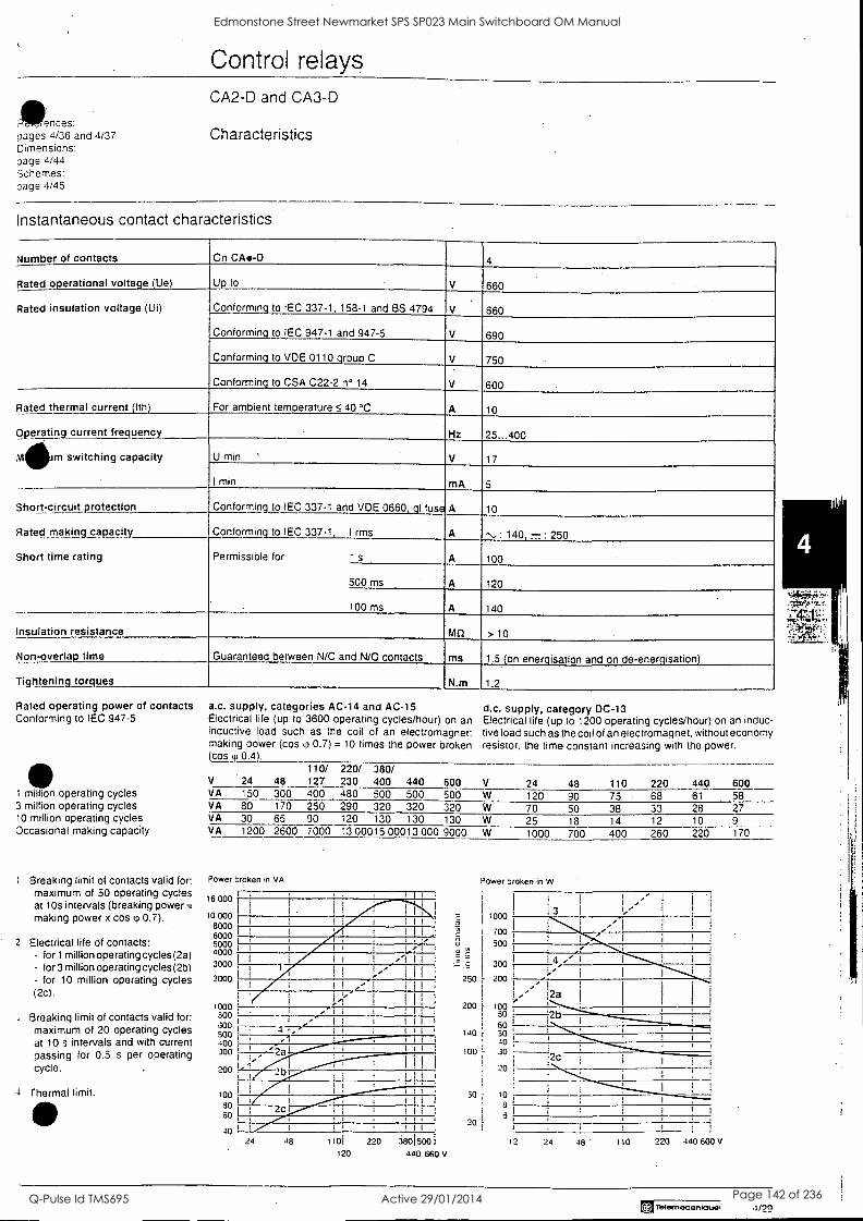
Control relays
'Woes: pages 4/36 and 4/37 Dimensions: page 4/44 Schemes: page 4/45
CA2-D and CA3-D
Characteristics
Instantaneous contact characteristics
Number of contacts On CA -0 4
Rated o erational voltage (Ue) Up to V 660
Rated insulation voltage (Ui) Conforming to IEC 337-1, 158-1 and BS 4794 V 660
Conforming to IEC 947-1 and 947-5 V 690
Conforming to VDE 0110 group C V 750
Conforming to CSA C22-2 n° 14 V 600
Rated thermal current (Ith) For ambient temperature 5 40 °C A 10
Operating current frequency Hz 25...400
Mikm switching capacity U min V 17
I min mA 5 .._
Short-circuit protection Conforming to IEC 337-1 and VDE 0660, gl fuse
Conforming to IEC 337-1, I rms
A
A
10
,.., : 140, = : 250
100
Rated making capacity
Short time rating Permissible for 1 s A
500 ms A 120
100 ms A 140
Insulation resistance Mil > 10
Non-overlap time Guaranteed between N/C and N/O contacts ms 1.5 on ener.isation and on de-ener.isation
Tightening torques N.m 1.2
Rated operating power of contacts Conforming to IEC 947-5
a.c. supply, categories AC-14 and AC-15 d.c. supply, category DC-13 Electrical life (up to 3600 operating cycles/hour) on an Electrical life (up to 1200 operating cycles/hour) on an induc- inductive load such as the coil of an electromagnet: five load such as the coil of an electromagnet, without economy making power (cos 0.7) = 10 times the power broken resistor, the time constant increasing with the power. (cosg 0.4).
110/ 220/ 380/ V 24 48 127 230 400 440 600 V 24 48 110 220 440 600
1 million operating cycles VA 150 300 400 480 500 500 500 W 120 90 75 68 61 58 3 million operating cycles VA 80 170 250 290 320 320 320 W 70 50 38 33 28 27 10 million operating cycles VA 30 65 90 120 130 130 130 W 25 18 14 12 10 9 Occasional making capacity VA 1200 2600 7000 13 00015 00013 000 9000 W 1000 700 400 260 220 170
Breaking limit of contacts valid for: maximum of 50 operating cycles at 10s intervals (breaking power = making power x cos p 0.7).
2 Electrical life of contacts: - for 1 million operating cycles (2a) - for 3 million operating cycles (2b) - for 10 million operating cycles (2c).
Power broken in VA
16 000
10 000 8000 6000 5000 4000
3000
I I I 1
1
I I I
I I I
t,4 I i I I I
2000 1 1 V 1 1 1
1 ! '..1 I l l
woo I I 1
: Breaking limit of contacts valid for: 300 ' . :II 1
600 1 ,"- !II 1
maximum of 20 operating cycles 4"-i I
500 . at 10 s intervals and with current IGO 1
passing for 0.5 s per operating 300 4,-- --'a I
cycle. 200
4 Thermal limit. 100 SO
60
40 24 48 1101
120
Power broken in W
250
200
140
1000 I 3
I
..--i
700 ,.' I
500 I I 1
300 1 4, I
/ 200 -1..
_.' i
,2a 100
30
60 30
100 30
50 10
a
2
2b
220 38015001 12 24 48 110 220 440 600
440 660 V
Ilemecenlauel 4/29
Edmonstone Street Newmarket SPS SP023 Main Switchboard OM Manual
Q-Pulse Id TMS695 Active 29/01/2014 Page 142 of 236
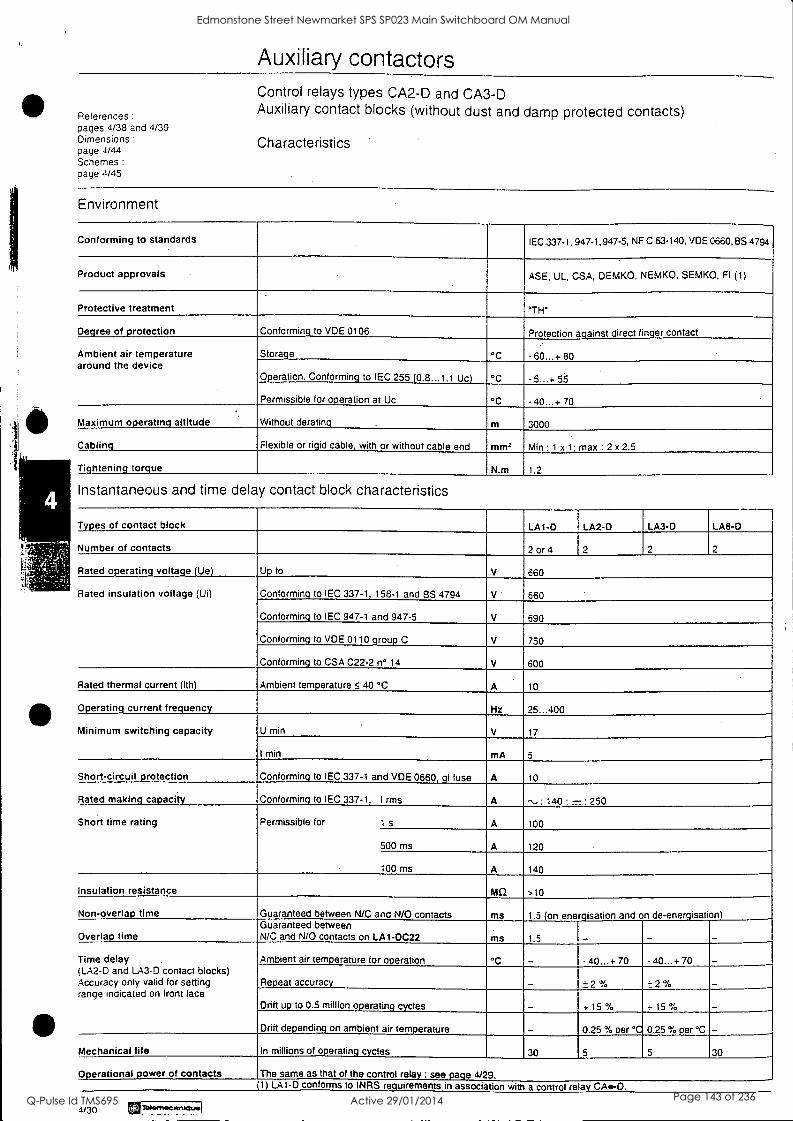
Auxiliary contactors
References :
pages 4/38 and 4/39 Dimensions :
page 4/44 Schemes :
page 4/45
Control relays types CA2-D and CA3-D Auxiliary contact blocks (without dust and damp protected contacts)
Characteristics
Environment
Conforming to standards IEC 337-1, 947-1,947-5, NF C 63-140, VDE 0660, BS 4794
Product approvals ASE, UL, CSA, DEMKO, NEMKO, SEMKO, Fl (1)
Protective treatment "TH"
Degree of protection Conforming to VDE 0106 Protection against direct finger contact
Ambient air temperature around the device
Storage °C - 60...+ 80
Operation. Conforming to IEC 255 (0.8...1.1 Uc) °C 5...+ 55
Permissible for operation at Uc °C - 40...+ 70
Maximum operating altitude Without derating m 3000
Cabling_ Flexible or rigid cable with or without cable end mm, Min : 1 x 1. max : 2 x 2.5
Tightening torque N.m 1.2
Instantaneous and time delay contact block characteristics
Types of contact block LA1-D LA2-0 LA3-D LA8-D
Number of contacts 2 or 4 2 2
Rated operating voltage (Ue) Up to V 660
Rated insulation voltage (Ui) Conforming to IEC 337 -1, 158-1 and BS 4794 V 660
Conforming to IEC 947-1 and 947-5 V 690
Conforming to VDE 0110 group C V 750
Conforming to CSA C22-2 n° 14 V 600
Rated thermal current (Ith) Ambient temperature 5 40 °C A 10
Operating current frequency Hz 25...400
Minimum switching capacity U min V 17
I min
Short-circuit protection Conforming to IEC 337-1 and VDE 0660, qI fuse A 10
Rated making capacity Conforming to IEC 337-1, I rms
Permissible for 1 s
A
A
,... : 140 - : 250
100 Short time rating
500 ms A 120
100 ms A 140
Insulation resistance Mil >10
Non -overlap time Guaranteed between N/C and N/O contacts ms
ms
1.5 (on energisation
1.5
and on de-energisatio19
Overlap time Guaranteed between N/C and N/O contacts on LA1-DC22
Time delay (LA2-D and LA3-D contact blocks) Accuracy only valid for setting range indicated on front face
Ambient air temperature for operation °C 40...+ 70 - 40...+ 70
Repeat accuracy ± 2 % ± 2 %
Drift up to 0.5 million operating cycles + 15 % + 15 %
Drift depending_ on ambient air temperature
30
0.25 % per °C
5
0.25 % per °C
5 30 Mechanical life In millions of operating cycles
Operational power of contacts The same as that of the control relay : see page 4/29. _ (1) LA1 -D conforms to INRS requirements in association with a control relay CA.-D.
4/30 UTISamecaniquel
Edmonstone Street Newmarket SPS SP023 Main Switchboard OM Manual
Q-Pulse Id TMS695 Active 29/01/2014 Page 143 of 236
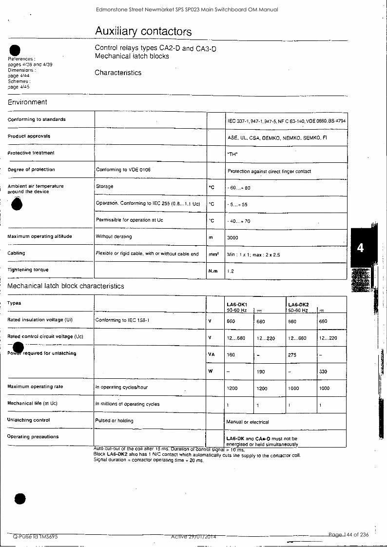
Auxiliary contactors
4110 Control relays types CA2-D and CA3-D
References : Mechanical latch blocks
pages 4/38 and 4/39 Dimensions :
page 4/44 Schemes :
page 4/45
Characteristics
Environment
Conforming to standards IEC 337-1, 947-1,947-5, NF C 63-140, VDE 0660, BS 4794
Product approvals ASE, UL, CSA, DEMKO, NEMKO, SEMKO, Fl
Protective treatment "TH"
Degree of protection Conforming to VDE 0106 Protection against direct finger contact
Ambient air temperature around the device
111-
Storage °C - 60...1- 80
Operatioh. Conforming to IEC 255 (0.8...1.1 Uc) °C - 5...+ 55
Permissible for operation at Uc °C - 40...+ 70
Maximum operating altitude Without derating m 3000
Cabling Flexible or rigid cable, with or without cable end mm2 Min : 1 x 1; max : 2 x 2.5
Tightening torque N.m 1.2
Mechanical latch block characteristics
Types LA6-0K1 50-60 Hz 7.7
LA6-DK2 50-60 Hz 77
Rated insulation voltage (Ui) Conforming to IEC 158-1 V 660 660 660 660
Rated control circuit voltage (Uc) V 12...660 12...220 12...660 12...220
Pow required for unlatching VA 160 - 275 -
W - 190 - 330
Maximum operating rate In operating cycles/hour 1200 1200 1000 1000
Mechanical life (at Uc) In millions of operating cycles 1 1 1 1
Unlatching control Pulsed or holding Manual or electrical
Operating precautions LA6-0K and CA.-0 must not be energised or held simultaneously
cut -out Auto . Duration of cont of signa > 10 ms. Block LA6-0K2 also has I N/C contact which automatically cuts the supply to the contactor coil. Signal duration = contactor operating time ÷ 20 ms.
Edmonstone Street Newmarket SPS SP023 Main Switchboard OM Manual
Q-Pulse Id TMS695 Active 29/01/2014 Page 144 of 236
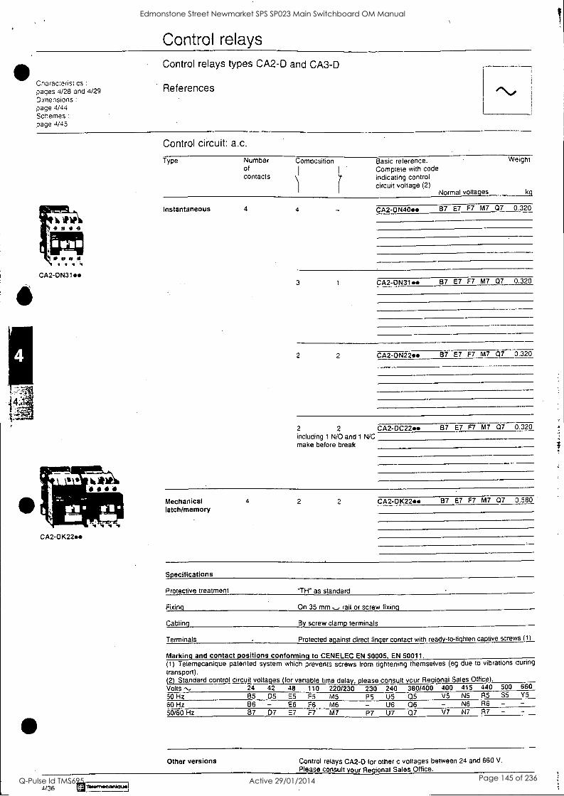
Control relays
Characteristics pages 4/28 and 4/29 Dimensions :
page 4/44 Schemes :
page 4/45
Control relays types CA2-D and CA3-D
References ti
W1P 9.9
7111111
*vat) CA2- 0N31..
CA2-0K22.
Control circuit: a.c.
Type Number of contacts
Composition
)1
Basic reference. Complete with code indicating control circuit voltage (2)
Normal voltages
Weight
kg
Instantaneous 4 4 CA2-ON40. B7 E7 F7 M7 07 0.320
3 1 CA2-DN31. 87 E7 F7 M7 07 0.320
2 2 CA2-DN22.. 87 E7 F7 M7 07 0.320
2 2 CA2-0C22. 87 E7 F7 M7 07 0.320 including 1 N/0 and 1 N/C make before break
Mechanical latch/memory
4 2 2 CA2431(224 87 E7 F7 M7 07 0.580
Specifications
Protective treatment "TH" as standard
Fixin On 35 mm - rail or screw fixin
Cabling By screw clamp terminals
Terminals Protected a ainst direct fin er contact with read -to-t hten ca tive screws 1
Marking and contact positions conforming to CENELEC EN 50005, EN 50011. (1) Telemecanique patented system which prevents screws from tightening themselves (eg due to vibrations during
transport). (2) Standard control circuit voltages (for variable time delay, please consult your Regional Sales Office). Volts ,.. 24 42 48 50 Hz 85 D5 E5 60 Hz B6 - E6 50/60 Hz 37 07 E7
110 220/230 230 240 380/400 400 415 440 500 660
F5 M5 P5 U5 05 V5 N5 R5 S5 Y5
F6 M6 - U6 Q6 - N6 R6 - - F7 M7 P7 U7 Q7 V7 Ni R7 - -
Other versions Control relays CA2-0 for other c voltages between 24 and 660 V.
Please consult our R 'onal Sales Office.
1/36 EiTelemscartlauel
Edmonstone Street Newmarket SPS SP023 Main Switchboard OM Manual
Q-Pulse Id TMS695 Active 29/01/2014 Page 145 of 236
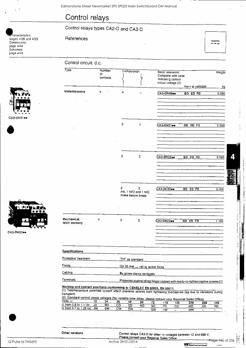
Control relays
Saracteristics: pages 4/28 and 4/29 Dimensions: page 4/44 Schemes: page 4/45
Control relays types CA2-D and CA3-D
References
71_11!11111..i11,ni 64
'41
CA3-0K22.
S
Control circuit: d.c.
Type Number of contacts
Composition
Instantaneous 4 4
Basic reference. Complete with code indicating control circuit voltage (2)
Normal voltages
CA3-0N40. BD ED FO
Weight
kg
0.580
3 1 CA3- 0N31.. BD ED FD 0.580
2 2 CA3- 0N22.. BD ED FD 0.580
2 2 Inc. 1 N/O and 1 N/C make before break
CA3-13C22.4 80 ED FD 0.580
Mechanical 4 2 2 CA3-13)(22. BD ED FD 1.100 latch memory
Specifications
Protective treatment "TH" as standard
Fixing
Cabling
Terminals
On 35 mm ,_.,- rail or screw fixing
By screw clamp terminals
Protected a ainst direct fin er contact with read -to-ti hten c tive screws 11
Markin and contact ositions conformin to CENELEC EN 50005 EN 50011. (1) Telemecanique patented system which prevents screws from tightening themselves (eg due to vibrations during transport). 2) Standard control circuit voltages for variable time dela .lease consult our Regional Sales Office Volts = 12 24 36 48 60 72 110 125 220 250 440
M U from 0.8 to 1.1 Uc JD BD CD ED ND SD FD GO U from 0.7 to 1.25 Uc JW BW CW EW - SW FW -
MO UD RD - -
Other versions Control relays CA3-D for other 7.7 voltages between 12 and 660 V. Please consult your Regional Sales Office
Edmonstone Street Newmarket SPS SP023 Main Switchboard OM Manual
Q-Pulse Id TMS695 Active 29/01/2014 Page 146 of 236
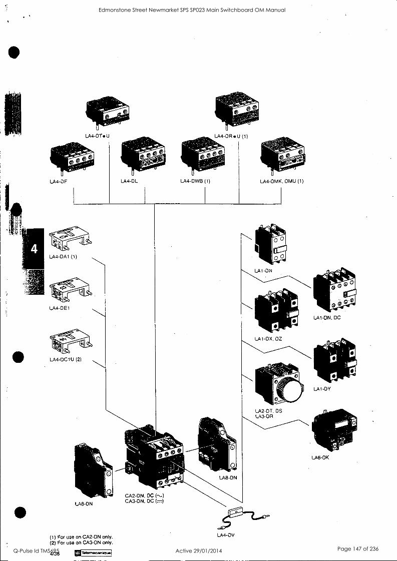
LA4-DT U
LA4-DF LA4-DL LA4-DWB (1) LA4-DMK, DMU (1)
LA4-DA1 (1)
LA4-DE1
LA1 -DN, DC
LA1-DX, DZ
LA4-0C1U (2)
LA2-DT DS LA3-OR
LA8-ON
(1) For use on CA2-ON only. (2) For use on CA3-ON only.
4/38 alblernecanktuel
CA2 -DN, DC (--) CA3-0N, DC (..=)
LA4-DV
LA1 -DY
LA6 -DK
Edmonstone Street Newmarket SPS SP023 Main Switchboard OM Manual
Q-Pulse Id TMS695 Active 29/01/2014 Page 147 of 236

TECHNICAL DATA SHEET
For
Edmondstone Street Pump Station
Equipment Type: Level Relay
Location: Sump Pump Control
Model Numbers: MTR-2
Manufacturer: Multitrode
Supplier: Multitrode.. 130 Kingston Road Underwood Qld 4119
Ph: 07 3808 4011 Fx: 07 3808 0011
Edmonstone Street Newmarket SPS SP023 Main Switchboard OM Manual
Q-Pulse Id TMS695 Active 29/01/2014 Page 148 of 236
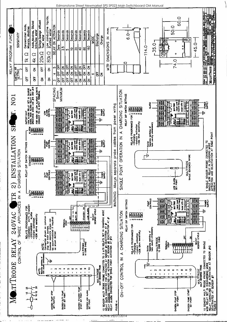
MT
ITR
OD
E
RE
LA
Y
240V
AC
ST
R 2
) IN
STA
LL
AT
ION
SI
-lbf
. N
O1
CO
NT
RO
L O
F
TH
RE
E
AP
PLI
AN
CE
S
IN
A
CH
AR
GIN
G
SIT
UA
TIO
N
RE
LAY
P
RO
GR
AM
F
UN
GIS
S
NIT
CH
N
a S
ET
TIN
G
I 2
SE
NS
ITIV
ITY
OF
F
OF
F
1 k
Q
Con
cent
rate
d A
cids
, M
iner
als,
A
lkal
ises
if
2f
RE
LAY
S
PR
OG
RA
MM
ED
FO
R
-CH
AR
GIN
G
DU
TY
, S
TA
ND
BY
'
DU
TY
-D
ISC
HA
RG
ING
A
LAR
M
CL'
--4-
1-1-
j1 q
-Ins
tant
act
ivat
ion
i 2
N
16
18
28
-20K
ohm
s se
nsiti
vity
3
P_:
1 9.
a#
ha/
RE
LAY
D
IP
SW
ITC
H
ST
AN
DB
Y
1 2 3 4 5 6 D
UT
Y
PU
MP
C
ON
TR
OLS
vlx#
tta
# [e
a
CI
tt.
E .
1
SE
TT
ING
S
ALA
RM
t 2 3
Lt..1
E
aal
Ai
Vaa
l B
.ai
UZ
I
IMP
OR
TA
NT
LO
W A
LAR
M
RE
LAY
S
ET
IN
C
HA
RG
E
MC
OE
. H
IGH
A
LAR
M
RE
LAY
S
ET
IN
DIS
CH
AR
GE
MO
DE
U
SE
05
AN
D
/18
OF
F
ON
4k
Q
Aci
ds,A
lkal
ines
, D
ilute
d
brin
eSea
wat
er
CH
OS
EN
P
UM
P
ST
OP
NO
TE
: S
wan
n.
nort
hing
to
* us
ually
- 1-
3./
I I -
of
°mam
mar
y ni
,,,
NO
TE
: :.
Con
nect
ion
show
n as
co
mm
on
stop
fo
r bo
th
pum
ps,
how
ever
se
para
te s
tops
ca
n be
ac
com
mod
ated
If
requ
ired
as
show
n do
tted
5 6
['AB
E
taal
W
I S
TA
ND
BY
CO
NT
RO
L
5 6
PU
MP
FO
R
HIG
H
CR
C
ON
NE
CT
TO
LOW
A
LAR
M
CONTROL
LOW
A
LAR
MS
A
LWA
YS
H
I IN
PU
T T
ER
MIN
AL
-SP
AC
ING
ON
O
FF
r-
1 p%
1 ,
rN
Sul
lage
,Sew
age
efflu
ent
20k
XL
Tow
n w
ater
ON
O
N
n Lo
w
cond
uctiv
e liq
uids
, 8u
k iL
P
urifi
ed
wat
er
3 -
4 5
DE
LAY
ON
A
CT
IVA
TIO
N
SE
T P
OIN
T(S
)
CH
OS
EN
D
UT
Y
PU
MP
I I
2
TE
RM
INA
L
ST
P
(:::k
d:)
1(4%
il[g
ilil _
C4:
- )kV
IC':]
k:)
itm . =
-,-.
.- z
...-
= =
IC
:10:
141C
tddg
11::
5mm
M
INIM
UM
.
OF
F
OF
F
OF
F
Zer
o S
econ
ds
OF
F
OF
F
ON
2.
5 S
econ
ds
an N
M N
M I
M M
I 14
111,
14 IL
I HA
11:1
S
TA
RT
S
ET
P
ON
T
CH
OS
EN
S
TA
ND
BY
PU
MP
I I
4
- 6
I
177.
Ka
111:
111,
11F4
O
FF
O
N
OF
F
5 S
econ
ds
1441
13iii
nalia
II
I O
PT
M
P O
w
IN
Ow
O
FF
O
N
ON
10
S
econ
ds
2 3
.; V., -
NI
purr
ON
W
EL
A
1111
44
MA
Y I
I
11;6
8.
WP
M
t Ll
ose
Lew
d 1
1 ca
ntrd
Rd
I
Mot
el M
-
. 104.
A
Em
. M
AY
0
ilia&
Mal
TR
U
i W
ad L
eal
I C
ambe
r R
Mor
al 1
17R
-
: r.
A
C
Jae
I
a i .."
OIL
AY
egli
1111
Ton
1 C
one
ol L
C
II
Mod
al
MR
- :
mnr
aa
ON
O
FF
O
FF
20
S
econ
ds
4 5 (
.. Ni
I 1
ON
O
FF
O
N
40
Sec
onds
S
TA
RT
S
ET
P
ON
T
CH
OS
EN
LO
W A
LAR
M I 8
I -
9 M
ULT
1TR
OD
E
5 V
..1
V')
I 2
AC
O
N
ON
O
FF
80
S
econ
ds
to C
OR
E
CA
BLE
8 a
ST
AN
DB
Y
IA
I-.4
LO
W
ALA
RM
ItI
I
SE
LEC
T
ON
1 10
1011
1M11
1100
:11
It
1013
1111
:1
10
1111
8011
1111
11:1
ON
O
N
ON
16
0 S
econ
ds
SE
T
PO
INT
R
10
0
I I ' i''
] 8)
:]
%.1
J g
C8)
ON
1 al
l MI
MI
(14.
41(t
ZIC
.,kt.e
..]
11 E
lm o
I cf
t][...
.41.
1104
1(4d
6
MO
DE
D
ES
IRE
D
LEV
ELS
MU
LTIT
RO
DE
U
.LII
1101
93R
ED
PR
OB
E
io S
EN
SO
R
MU
LTI
TR
OD
E
PR
OB
E
CO
NN
EC
TE
D
TO
3
MT
R
RE
LAY
S
SE
T
IN
CH
AR
GIN
G
MO
DE
RE
LAY
DU
Tt
CO
NN
EC
TE
D
FO
R
AC
TIV
AT
ION
A
T S
EN
SO
R
#4
DE
AC
TIV
T1O
N
AT
#1
RE
LAY
ST
AN
TIR
Y
CO
NN
EC
TE
D
FO
R
AC
TIV
AT
ION
A
T S
EN
SO
R
#8
DE
AC
TIV
AT
ION
A
T
in
-L
- f P
OM
ER
S
UP
PLY
i .._
- P
ON
ER
S
UP
PLY
. - PO
WE
R
SU
PP
LY
OF
F
Dis
char
ge
ON
C
harg
e
MT
R
DIM
EN
SIO
NS
IN
m
m.
-
RE
LAY
ALA
RM
C
ON
NE
CT
ED
F
OR
S
ING
LE
PO
INT
A
CT
IVA
TIO
N
AT
#10
FIG
UR
E -4
W
AR
NIN
G:
Alw
ays
sepa
rate
pr
obe
cabl
es
from
po
wer
w
iring
ON
-OF
F
CO
NT
RO
L IN
A
C
HA
RG
ING
S
ITU
AT
ION
R
ELA
Y
DIP
S
WIT
CH
I R
ELA
YS
P
RO
GR
AM
ME
D
FO
R
2 D
A
re.,-
24
KiA
l M
K
a 17
11
SE
TT
ING
S
SIN
GLE
P
OIN
T
OP
ER
AT
ION
IN
A
C
HA
RG
ING
R
ELA
Y D
IP
SN
AT
CH
1
RE
LAY
S
PR
OG
RA
MM
ED
FO
R 2
-Cha
rgin
g 3
IDA
E
iji
kiA
C
Li-4
9:
Lil
E11
SIT
UA
TIO
N
SE
TT
ING
S
-1
CH
OS
EN
P
UM
P
ST
OP
' I i-
2 I
--
5 I
- 6
I 7
I -
8 I
- 9
I 10
1
-Cha
rgin
g 3
-Ins
tant
act
ivat
ion
4 -2
0k O
hm
sens
itivi
ty
5 6
Not
e:
r.
-Ins
tant
act
ivat
ion
4 -2
0k
Ohm
se
nsiti
vity
5 6
Not
e:
' 11
4.0
35.0
P
UM
P
Sep
arat
e ea
rthi
ng 0
CO
NT
RO
LS
tank
us
ually
unn
eces
sary
MU
LTIT
RO
DE
Sep
arat
e ea
rthi
ng o
f A
LAR
M
tank
us
ually
unn
eces
sary
10
CO
RE
C
AB
LE
TE
RM
INA
L
ST
IP
I(V
IOIC
:i)ki
gIC
8)1
74.0
. p .1
014.
7a1
ei.I
.,-.w
el
. 0
1111
tri
I
__
PI
50.0
6 0
14.1
14:1
1114
1111
1.11
1:1
LOW
A
LAR
M
311,
41uo
ditiL
ewili
All
1 2 3 4 5 6
VA
f-
.1
I..1
(.7.
1 (-
) I.1
MA
Y 0
lir
MU
T=
I
Orr
et
rep
iiir:
E
H
DE
LA
Y 3
PR
O"
r".
MO
T=
A
MID
I
I M
I A
11 E
t4
loai
I L
AM
Lev
i i
1 C
cotr
d R
E
I
i Nod
al
SE
T
PO
INT
I
J I
Con
trol
R
A
Nat
e IR
R-
I 1=
2EI
SE
T
PO
INT
CH
OS
EN
P
UM
P
ST
AR
T
MU
LTIT
RO
DE
S
ING
LE
SE
NS
OR
ED
P
RO
SE
,
7 8 a
..a
I-
.111
R-
Ni
[1
1011
1111
1311
1111
021
1110
1111
:111
4011
11:1
. -
VIM OM
1(41
[1:7
1(8.
71:)
1:1
I--
45.0
--I
SE
T
PO
INT
c.
, I
.. -
k!)1
:1[1
:')1C
gld
MU
L 16
.4.1
1 S
EN
SO
RE
D
SE
LEC
T
TR
OD
E
DE
WE
D
LEW
IS
PR
OB
E
-=-
7-=
=7_
-"-
=.
III
.=-
PHO
NE
eo
s-w
m
12K
AT
M10
11r-
tire.
:15-
`71.
AIM
ET
Z14
:4T
X4M
7.1I
Milt
e.i1
114
10 S
EN
SO
R
MU
LTI
TR
OD
E
PR
OB
E
CO
NN
EC
TE
D
TO
S
ING
LE
- 1
SIN
GLE
S
EN
SO
R
PR
OB
E
CO
NN
EC
TE
D
TO
=
P
OW
ER
S
UP
PLY
S
ING
LE
MT
R
RE
LAY
IN
C
HA
RG
ING
M
OD
E
AC
TIV
AT
ION
A
ND
D
EA
CT
IVA
TIO
N A
T
SA
ME
P
OIN
T
FIG
UR
E-6
FA
4 '
405-
0011
tr
ail
.111
:11=
7.11
11:B
il C L
le. a
_1!1
11=
111;
/:11 ir
is,
Pow
cw
MT
R
RE
LAY
S
ET
IN
D
ISC
HA
RG
ING
MO
DE
S
UP
PLY
R
ELA
Y C
ON
NE
CT
ED
F
OR
A
CT
IVA
TIO
N
AT
S
EN
SO
R
010
DE
AC
TIV
AT
ED
A
T
SE
NS
OR
#7
F
IGU
RE
-5
le.*
-7.7
1.41
4711
1111
11M
IEW
FX
1I-.
!!-11
21*
MU
LT
ITR
OD
E
'1. -i
C7i
l11.
731
., 0.
...
le.:E
ZZ
LIIM
iF.V
,F-1
10.0
1:V
e.: l
e.:1
3.M
tle=
1-I-
14:
Edmonstone Street Newmarket SPS SP023 Main Switchboard OM Manual
Q-Pulse Id TMS695 Active 29/01/2014 Page 149 of 236
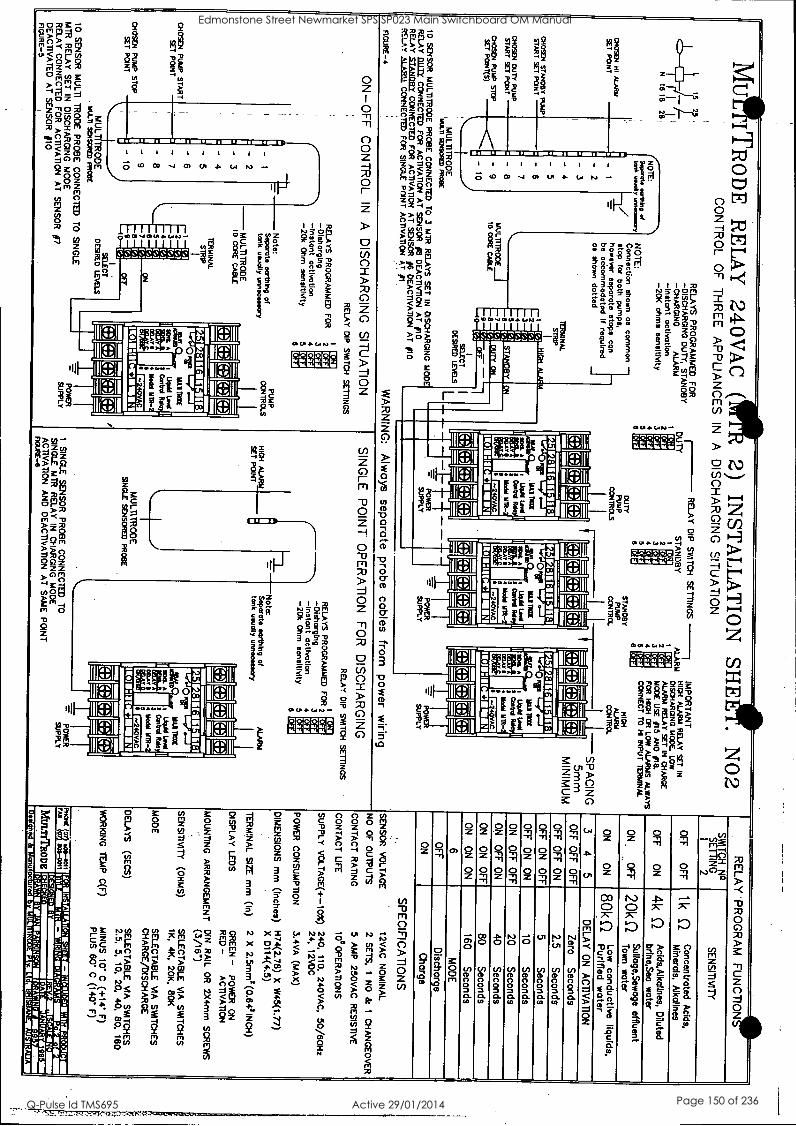
MU
!! TR
OD
E
RE
LA
Y
240VA
C
(1111 2)
INST
AL
LA
TIO
N
SHE
ET
. N
O2
CO
NT
RO
L O
F
TH
RE
E
AP
PLIA
NC
ES
IN
A
D
ISC
HA
RG
ING
S
ITU
AT
ION
PR
OG
RA
M
FU
NC
TIO
N!"
TO
RE
LAY
W
I N
S
ET
HN
G o
I 2
SE
NS
ITIV
ITY
OF
F
OF
F
1 k 0 C
oncentrated Acids,
'` M
inerals, A
lkalines
RE
LAY
S
PR
OG
RA
MM
ED
FO
R
-DIS
CH
AR
GIN
G
DU
TY
, S
TA
ND
BY
-C
HA
RG
ING
A
LAR
M
1/;1 -Instant
activation 1 2
N
16 18 26,
-20K
ohms
sensitivity 3 D
UT
Y
1111 kiil D
ai [tad K
ai 138
RE
LAY
DIP
S
WIT
CH
ST
AN
DB
Y
1 2 3 4 5 6
DU
TY
P
UM
P
CO
NT
RO
LS
(4411
D
Ce
4
E.,41,11
V.
14 d
SE
TT
ING
S
ALA
RM
1 2 3 4 5 6
ST
AN
DB
Y
PU
MP
C
ON
TR
OL
1,111 E
ui [,,, D
IA
D.aA
W
aal
IMP
OR
TA
NT
H
IGH
A
LAR
M
RE
LAY
SE
T
IN
DIS
CH
AR
GIN
G
MO
DE
, LOW
A
LAR
M
RE
LAY
S
ET
IN
CH
AR
GE
M
OD
E U
SE
/15 A
ND
/16. F
OR
H
IGH
O
R
LOW
ALA
RM
S
ALW
AY
S
CO
NN
EC
T T
O
HI
INP
UT
T
ER
MIN
AL
HIG
H
ALA
RM
C
ON
TR
OL
OF
F
ON
A
cids,Alkolines, D
iluted 4k 0
brine,Sea
water
CH
OS
EN
H
I A
LAR
M
NO
TE
: S
oporato twitting
took laud
1
- 2
- 3
- 4
. -
5 1
of .... r
NO
TE
: C
onnection show
n as
comm
on stop
for both
pumps,
however
separate stops con
be accom
modated
If required ale
shown
dotted
4 5 a O
N
OF
F
Sullage,S
ewage effluent
n AL IL
zuK IL
Tow
n w
ater
ON
O
N
80k (-1 Low
conductive liquids,
" P
urified w
ater S
ET
P
OIN
T
CH
0504 S
TA
ND
BY
PU
MP
I I
3 4
5 D
ELA
Y
ON
A
CT
IVA
TIO
N
-SP
AC
ING
TE
RM
INA
L S
TR
IP
(::1/1(.8j1g1(tdrJI
----......---- .-1 ...,J
..,1 io ...., ...t
IC
IC
1( = del
..,, 1[8i1C
. IC
) 11;) 8)
I( IC
'4;) 1
5mm
M
INIM
UM
O
FF
O
FF
' O
FF
Z
ero S
econds
OF
F
OF
F
ON
2.5
Seconds
14.-S1:111:1111:111:1 I I
11:111118M111:1
0 Ill "M
II "
14.119.FA
IGIF
FIIII:1
0 111 M
. O
FF
O
N
OF
F
5 S
econds H
IGH
A
LAR
M
ir M
ir
OF
F
ON
O
N
10 S
econds S
TA
RT
SE
T P
OIN
T
CH
OSE
N
DU
TY
P
UM
P
6
- 7
2 D
iA
3 1-4
4 E
.1.1
5 V
A
jg, A
ye
ulna( t
UM
Ild Lord I
0216.01
a M
aki MT
R_
ado ica
A
EA
00.A
T
11
I* B
LIT=
,
1184t1 LAW
I
a coital R
S
I
Nadi
ML
R_
ll 111D
O.
A
II 1814 M
AY
II
ALI P
DX
1
Uqual Lea
1 c°1"4 M
old um-
ON
O
FF
OF
F
20 S
econds O
N
OF
F
ON
40
Seconds
ST
AR
T
SE
T P
ON
T
CH
OS
EN
P
UM
P
ST
OP
8
- 9
MU
LTIT
RO
DE
10 C
CR
E C
AB
LE
8 (,,,
7 V
I S
TA
ND
BY
DU
TY
O
N
ON
'
a 44240V
:
ME
150gi ftili
: EgrM
ii O
N
ON
O
FF
80
Seconds
8 1.,
9 V
A
oFr - --1
1018:1111001111 10 1:111012111M
il 10 1:1100111E
11 S
ET
PC
INT
(S)
- 10
ON
O
N
ON
160
Seconds
1., t
SE
LEC
T
L C: r) g
[4' V I (4 :] g
R.
.. AL ALI AL A.
ici.t.Ic.4kc. AL AL AL AL
ALI
jjc.41(.41c.,)1[.. 6
MO
DE
D
ES
IRE
D
LEV
ELS
M
ULT
ITR
OD
E
MU
LTI g
PR
OB
E
10 S
EN
SO
R
MU
LTI7R
OC
E
PR
OB
E
CO
NN
EC
TE
D
TO
3
MIR
RE
LAY
S
SE
T
IN
DIS
CH
AR
GIN
G
MO
DE
R
ELA
Y LILLE
C
CO
NN
EC
TE
D
FO
R
AC
TIV
AT
ION
A
T
SE
NS
OR
#8
DE
AC
TIV
TIO
N
AT
/10
RE
LAY
S
TA
ND
BY
C
ON
NE
CT
ED
F
OR
A
CT
IVA
TIO
N
AT
SE
NS
OR
#6
DE
AC
TIV
AT
ION
AT
j10
- =
i PO
WE
R
----- -
PO
WE
R Y
SU
PP
L
=-- -
PO
.-
SU
PP
Y
L
OF
F
Discharge
ON
C
harge S
UP
PLY
SP
EC
IFIC
AT
ION
S
SE
NS
OR
V
OLT
AG
E
12VA
C
NO
MIN
AL
NO
O
F O
UT
PU
TS
2
SE
TS
, 1
NO
&
1
CH
AN
GE
OV
ER
CO
NT
AC
T
RA
TIN
G
5 A
MP
250VA
C
RE
SIS
TIV
E
CO
NT
AC
T
LIFE
105 O
PE
RA
T1 O
N S
SU
PP
LY
VO
LTA
GE
(+-1 C
M)
240, 110,
240VA
C.
50/60Hz
24, 12V
DC
PO
WE
R
CO
NS
UM
PT
ION
3.4V
A
(MA
X)
DIM
EN
SIO
NS
mm
(inches)
H74(2.78) X
W
45(1.77) .
X
D114(4.5)
TE
RM
INA
L S
IZE
mm
(In)
2 X
2.5m
m2 (0.642 IN
CH
)
DIS
PLA
Y
LEG
S
GR
EE
N -
PO
WE
R
ON
R
ED
- A
CT
IVA
TIO
N
MO
UN
TIN
G
AR
RA
NG
EM
EN
T
DIN
R
AIL
OR
2X
4rnm
SC
RE
WS
.
(3/16")
SE
NS
ITIV
ITY
(O
HM
S)
SE
LEC
TA
BLE
V
IA
SW
ITC
HE
S
1K,
4K,
20K,
80K
MO
DE
S
ELE
CT
AB
LE
,4A
SW
ITC
HE
S
CH
AR
GE
/DIS
CH
AR
GE
DE
LAY
S
(SE
CS
) S
ELE
CT
AB
LE
VIA
S
WIT
CH
ES
2.5,
5,
10, 20,
40, 80,
160
WO
RK
ING
T
EM
P
C(F
) M
INU
S
10' C
(+14' F
) P
LUS
60' C
(140' F
)
RE
LAY
A
l A
R11. C
ON
NE
CT
ED
F
OR
S
ING
LE
PO
INT
A
CT
IVA
TIO
N
AT
pa
FIG
UR
E-4
WA
RN
ING
: A
lways
separate probe
cables from
pow
er w
iring O
N-O
FF
C
ON
TR
OL
IN
A
DIS
CH
AR
GIN
G
SIT
UA
TIO
N
RE
LAY
D
IP
SW
ITC
H
1
RE
LAY
S
PR
OG
RA
MM
ED
F
OR
2
-DIsharging
3 Kig
Da
re,16 E
RA
Itli tuili
SE
TT
ING
S
SIN
GLE
P
OIN
T
OP
ER
AT
ION
F
OR
D
ISC
HA
RG
ING
R
ELA
Y
DIP
S
NIT
CH
1 2 R
ELA
YS
P
RO
GR
AM
ME
D F
OR
-D
lehorgIng 3
P.21
ELI
It VA
['ii reiai
SE
TT
ING
S
CH
OS
EN
P
UM
P
ST
AR
T
-
. -
2 1
- 3
I I -
5 I
- 6
I ; 7
I - 8
i - 9
I 10
I
-Instant activation 4
-20k O
hm
sensitivity 5 a
Note:
HIG
H
-=
-Instant activation
4 -20k
Ohm
sensitivity
5 6
PU
MP
S
eparate eorthIng of
CO
NT
RO
LS
tank N
sogate earthing of
ALA
RM
tank
unitedly unnecessary ti m
idly unnecessary S
ET
P
OIN
T
-MU
LTIT
RO
DE
10
CO
RE
CA
BLE
TE
RM
INA
L S
TR
IP
(I 21(1 21[fl +
.)1(4 )l IC
I I [4' *I r::%
IC: 21[:
II II I i
KR
IM 1114I1 R
IM
1 2 3 4 5 6
I
r-..] (-A
1'.1 E
'.1 114 1:1
.
0 A
in S
IMI
A
I Etri
I ftif' IF
w
i.i TID
E
1 LA
484104 7
Can"
4 1144331
MT
h -
liti.,111:111:1111:1111:11
' 0 1111641 31018
A
04 R
N&
Ills
Pir
'1" all T
RO
X
I U
SA
Leal II
5 G
imbel R
ola II
Moil M
IR-
: cs=4
SE
T
PO
INT
CH
OS
EN
P
UM
P
ST
OP
7 a a
1 '
--` E
CU
M
MU
LTIT
RO
OE
S
ING
LE
SE
NS
OR
ED
PR
OB
E
1-A
D',,
(
Ks 11:110M
11111:11 IIM
ININ
ZII
SE
T
PO
INT
m
em.
ems m
e Ism
Em
s ems=
mem
Ew
e I
.
Ir: -.: __. 7:- I :jig
' - .-
, _ _. L 11.:]1.(g
=- --_ - -
/h. AL AL
Ilk AL
[e 41&41C1P]l[N 44 A.
MU
L S
ELE
CT
T
RO
DE
D
ES
IRE
D
LEV
ELS
M
ULT
I S
EN
SC
NE
D
PR
OB
E
10 S
EN
SO
R
MU
LTI
TR
OD
E
PR
OB
E
CO
NN
EC
TE
D
TO
S
ING
LE
IIII -
,
7-7 P
OW
ER
1
SIN
GLE
S
EN
SO
R
PR
OB
E
CO
NN
EC
TE
D
TO
S
UP
PLY
S
ING
LE
MT
R
RE
LAY
IN
C
HA
RG
ING
M
OD
E
AC
TIV
AT
ION
A
ND
D
EA
CT
IVA
TIO
N A
T
SA
ME
PO
INT
nouE
-6
RIC
K
3 008-4011
lie.:111:114:11kIIKZ
IF=
.113-1/1:51:V.V
10.1711111;;a4:MA
IMI
PO
WE
R
MT
R
RE
LAY
S
ET
IN
D
ISC
HA
RG
ING
M
OD
E
SU
PP
LY
RE
LAY
C
ON
NE
CT
ED
F
OR
A
CT
IVA
TIO
N
AT
SE
NS
OR
#7
DE
AC
TIV
AT
ED
A
T
SE
NS
OR
#I0 Ira
00k-CO
M
il A ilM
111191:111=,1:11Z
1,1110.1.::71!1=E
llE :V
IMI W
EIN
1.74.-T
t'ZI.ilia=
68111747,141,1MI41:11111211
MuunT
RO
DE
17147Fill1111 f *T
.1 i Aorm
nra-aTr.Liew
0
lq:7.771T/U
11;;;,11::11::F171Z
I./181:14MF
GU
RE
-5 ..,
nu as ,.;
Iliflotl InILIIII
Edmonstone Street Newmarket SPS SP023 Main Switchboard OM Manual
Q-Pulse Id TMS695 Active 29/01/2014 Page 150 of 236

TECHNICAL DATA SHEET
For
Edmondstone Street Pump Station
Equipment Type: Signal Isolator
Location: Common Control
Model Numbers: SFI/20/4-20
Manufacturer: Mann Industries
Supplier: Burkert. 3/43 Sandgate Road Albion QLD 4010
Ph: 07 3262 8611 Fx: 07 3262 8801
Edmonstone Street Newmarket SPS SP023 Main Switchboard OM Manual
Q-Pulse Id TMS695 Active 29/01/2014 Page 151 of 236
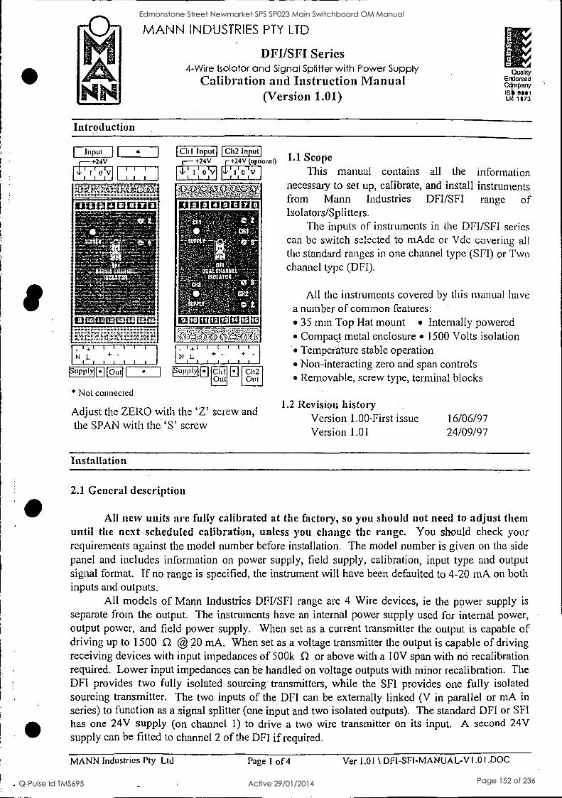
MANN INDUSTRIES PTY LTD
DFI/SFI Series 4-Wire Isolator and Signal Splitter with Power Supply
Calibration and Instruction Manual (Version 1.01)
Quality Endorsed
PanY IS Lie 1873
Introduction
Input +24V
1 1 1 1
I 0 V I III I I I
10113E112100E1EI
U 10 EtZEM11:1111
_ I +1 N L +
1 I I
(Supply! lout)
* Not connected
Cla Input ICU Input +24V +24V (optional)
I 1 1 0 11111 0 IV I i I
1E113E1E1013E110
U 10 camera EMI
_ I+I I I I
N L
I I
-
ISupplyi Cli Ch2 I
Otit I
Out
Adjust the ZERO with the 'Z' screw and the SPAN with the 'S' screw
1.1 Scope This manual contains all the information
necessary to set up, calibrate, and install instruments from Mann Industries DFI/SFI range of Isolators/Splitters.
The inputs of instruments in the DFI/SFI series can be switch selected to mAdc or Vdc covering all the standard ranges in one channel type (SFI) or Two channel type (.DFI).
All the instruments covered by this manual have a number of common features:
35 mm Top Hat mount Internally powered Compact metal enclosure 1500 Volts isolation Temperature stable operation Non-interacting zero and span controls Removable, screw type, terminal blocks
1.2 Revision history Version 1.00-First issue Version 1.01
16/06/97 24/09/97
Installation
2.1 General description
All new units are fully calibrated at the factory, so you should not need to adjust them until the next scheduled calibration, unless you change the range. You should check your requirements against the model number before installation. The model number is given on the side panel and .includes information on power supply, field supply, calibration, input type and output signal format. If no range is specified, the instrument will have been defaulted to 4-20 mA on both inputs and outputs.
All models of Mann Industries DFI/SFI range are 4 Wire devices, ie the power supply is
separate from the output. The instruments have an internal power supply used for internal power, output power, and field power supply. When set as a current transmitter the output is capable of driving up to 1500 S2 @ 20 mA. When set as a voltage transmitter the output is capable of driving receiving devices with input impedances of 500k S2 or above with a 10V span with no recalibration required. Lower input impedances can be handled on voltage outputs with minor recalibration. The DFI provides two fully isolated sourcing transmitters, while the SFI provides one fully isolated sourcing transmitter. The two inputs of the DFI can be externally linked (V in parallel or mA in series) to function as a signal splitter (one input and two isolated outputs). The standard DFI or SFI has one 24V supply (on channel 1) to drive a two wire transmitter on its input. A second 24V supply can be fitted to channel 2 of the DFI if required.
MANN Industries Pty Ltd Page 1 of 4 Ver 1.01 \ DFI-SFI-MANUAL-V 1.01.DOC
Edmonstone Street Newmarket SPS SP023 Main Switchboard OM Manual
Q-Pulse Id TMS695 Active 29/01/2014 Page 152 of 236
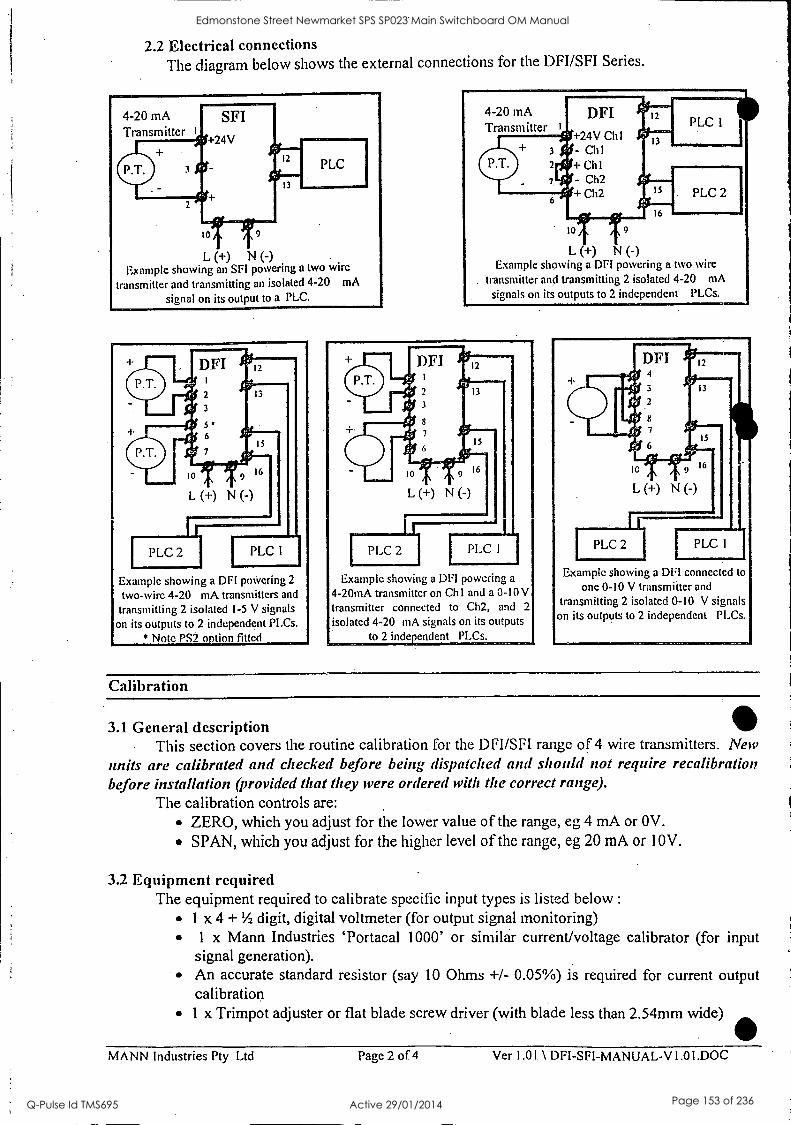
2.2 Electrical connections The diagram below shows the external connections for the DFI/SFI Series.
4-20 mA Transmitter
L (+) N (-) Example showing an SFI powering a two wire
transmitter and transmitting an isolated 4-20 mA
signal on its output to a PLC.
Example showing a DPI powering .2
two-wire 4-20 mA transmitters and
transmitting 2 isolated 1-5 V signals
on its outputs to 2 independent PLCs.
* Note PS2 option fitted
4-20 mA DFI Transmitter
jg+24V Ch1
3 $1:1- Ch I
Cili 7 - Ch2
Ch2 14-
15 !0- 16
10 9
L (+) N (-) Example showing a DPI powering a two wire
transmitter and transmitting 2 isolated 4-20 mA
signals on its outputs to 2 independent PLCs.
Example showing a DPI powering a
4-20mA transmitter on Chi and a 0-10V transmitter connected to Ch2, and 2
isolated 4-20 mA signals on its outputs
to 2 independent PLCs.
DFI 12
4
3 13
2
13
7 15
le
L (+) N (-)
PLC 2 PLC 1
Example showing a DPI connected to
one 0-10 V transmitter and
transmitting 2 isolated 0-10 V signals on its outputs to 2 independent PLCs.
Calibration
3.1 General description This section covers the routine calibration for the DFI/SFI range of 4 wire transmitters. New
units are calibrated and checked before being dispatched and should not require recalibration before installation (provided that they were ordered with the correct range).
The calibration controls are: ZERO, which you adjust for the lower value of the range, eg 4 mA or OV.
SPAN, which you adjust for the higher level of the range, eg 20 mA or 10V.
3.2 Equipment required The equipment required to calibrate specific input types is listed below :
1 x 4 + Y2 digit, digital voltmeter (for output signal monitoring) 1 x Mann Industries `Portacal 1000' or similar current/voltage calibrator (for input signal generation). An accurate standard resistor (say 10 Ohms +/- 0.05%) is required for current output calibration
1 x Trimpot adjuster or flat blade screw driver (with blade less than 2.54mm wide)
MANN Industries Ply Ltd Page 2 of 4 Ver 1.01 \ DFI-SFI-MANUAL-V1.01.DOC
Edmonstone Street Newmarket SPS SP023 Main Switchboard OM Manual
Q-Pulse Id TMS695 Active 29/01/2014 Page 153 of 236
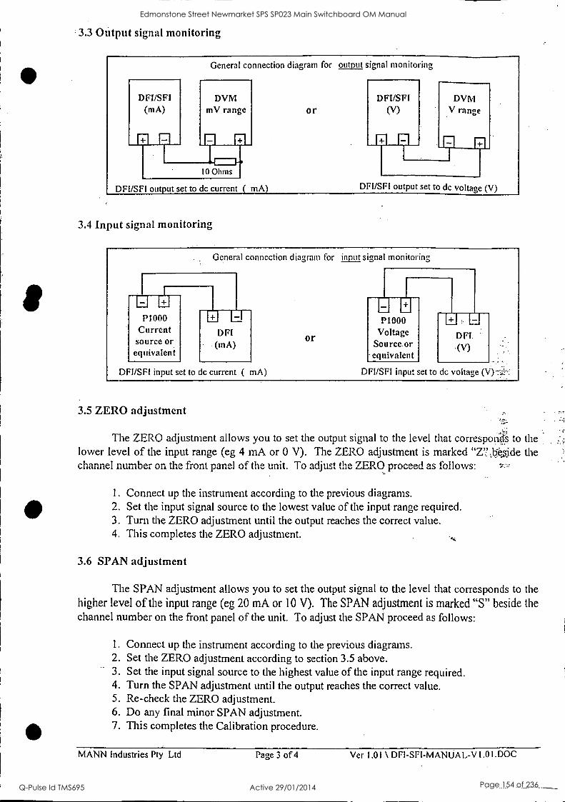
3.3 Output signal monitoring
General connection diagram for output, signal monitoring
DFI/SFI (mA)
DVM mV range
F-1 R1
IL 10 Ohms
DFI/SFI output set to dc current ( mA)
Or
DFI/SFI output set to dc voltage (V)
3.4 Input signal monitoring
General connection diagram for input signal monitoring
P1000 Current source or equivalent
DFI/SFI input set to dc current ( mA)
or
LI E P1000
Voltage Source or equivalent
DFI/SFI input set to dc voltage (V)-7,
3.5 ZERO adjustment
The ZERO adjustment allows you to set the output signal to the level that corresponds to the lower level of the input range (eg 4 mA or 0 V). The ZERO adjustment is marked "Z71ide the channel number on the front panel of the unit. To adjust the ZERO proceed as follows:
1. Connect up the instrument according to the previous diagrams. 2. Set the input signal source to the lowest value of the input range required. 3. Turn the ZERO adjustment until the output reaches the correct value. 4. This completes the ZERO adjustment.
3.6 SPAN adjustment
The SPAN adjustment allows you to set the output signal to the level that corresponds to the higher level of the input range (eg 20 mA or 10 V). The SPAN adjustment is marked "S" beside the channel number on the front panel of the unit. To adjust the SPAN proceed as follows:
1. Connect up the instrument according to the previous diagrams. 2. Set the ZERO adjustment according to section 3.5 above. 3. Set the input signal source to the highest value of the input range required. 4. Turn the SPAN adjustment until the output reaches the correct value. 5. Re-check the ZERO adjustment. 6. Do any final minor SPAN adjustment. 7. This completes the Calibration procedure.
MANN Industries Pty Ltd Page 3 of 4 Ver 1.01 \ DFI-SFI-MANUAL-V1.01.DOC
Edmonstone Street Newmarket SPS SP023 Main Switchboard OM Manual
Q-Pulse Id TMS695 Active 29/01/2014 Page 154 of 236
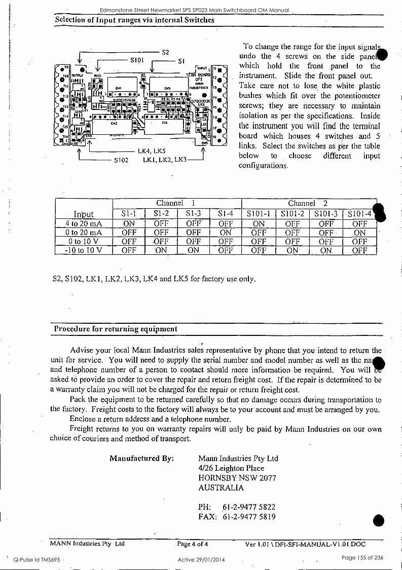
Selection of Input ranges via internal Switches
S2
rINPUT
Tail BOARD CFI rAnt
INOUSTIIIES
97020020 11(3
LK4, LK5
S102 LK1, LK2, LK3
To change the range for the input signal undo the 4 screws on the side paneW which hold the front panel to the instrument. Slide the front panel out. Take care not to lose, the white plastic bushes which fit over the potentiometer screws; they are necessary to maintain isolation as per the specifications. Inside the instrument you will find the terminal board which houses 4 switches and 5
links. Select the switches as per the table below to choose different input configurations.
Input Channel 1 Channel 2
S 1 -1 S1-2 S1-3 SI-4 S101-1 S101-2 S101-3 S10 1F-4
4 to 20 mA ON OFF OFF OFF ON OFF OFF F 011 ON OFF OFF
0 to 20 mA OFF OFF OFF ON OFF OFF OFF 0 to 10 V OFF. OFF OFF OFF OFF OFF OFF
-10 to 10 V OFF ON ON OFF OFF "ON ON
S2, S102, LK I, LK2, LK3, LK4 and LK5 for factory use only.
Procedure for returning equipment
Advise your local Mann Industries sales representative by phone that you intend to return the unit for service. You will need to supply the serial number and model number as well as the na and telephone number of a person to contact should more information be required. You will asked to provide an order to cover the repair and return freight cost. If the repair is determined to be a warranty claim you will not be charged for the repair or return freight cost.
Pack the equipment to be returned carefully so that no damage occurs during transportation to the factory. Freight costs to the factory will always be to your account and must be arranged by you.
Enclose a return address and a telephone number. Freight returns to you on warranty repairs will only be paid by Mann Industries on our own
choice of couriers and method of transport.
Manufactured By: Mann Industries Pty Ltd 4/26 Leighton Place HORNSBY NSW 2077 AUSTRALIA
PH: 61-2-9477 5822 FAX: 61-2-9477 5819
MANN Industries Pty Ltd Page 4 of 4 Ver 1.01 \ DFI-SFI-MANUAL-V1.01.DOC
Edmonstone Street Newmarket SPS SP023 Main Switchboard OM Manual
Q-Pulse Id TMS695 Active 29/01/2014 Page 155 of 236
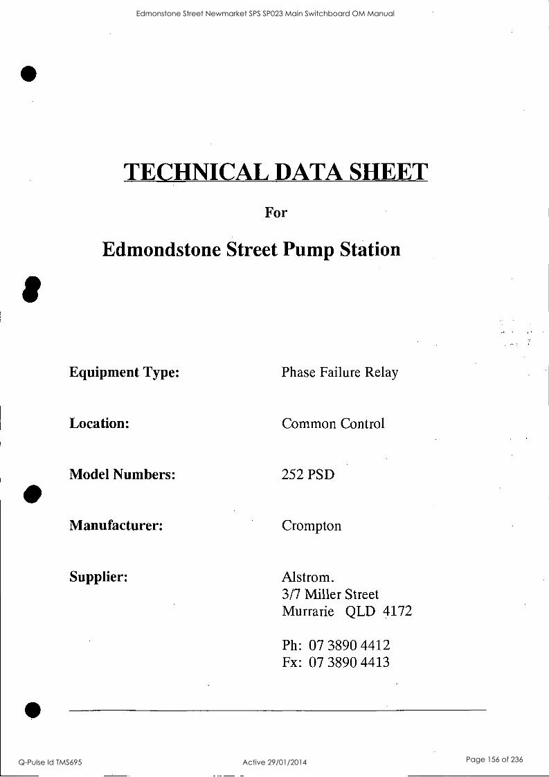
TECHNICAL DATA SHEET
For
Edmondstone Street Pump Station
Equipment Type: Phase Failure Relay
Location: Common Control
Model Numbers: 252 PSD
Manufacturer: Crompton
Supplier: Alstrom. 3/7 Miller Street Murrarie QLD 4172
Ph: 07 3890 4412 Fx: 07 3890 4413
Edmonstone Street Newmarket SPS SP023 Main Switchboard OM Manual
Q-Pulse Id TMS695 Active 29/01/2014 Page 156 of 236

ifiompton INSTRUMENTS
IIN250PMSH Edition 4 April 1997
Thermistor Trip, Speed Sensing, Phase Angle Protector Relay Installation Instructions
Models Covered 252-PMM 252-PSG 252-PMT
252-PMT 253-PH3
252-PSF 252-PMM
Introduction Thermistor Trip Relay (252-PMM & 252-PMT) Tip inputs are monitored within settable limits. In the event of the input moving outside these limits, the unit will initiate a trip signal via a double pole changeover relay: An illuminated green LED indicates when the thermistor temperature is within normal working limits. The unit is designed such that the alarm relay is energised at normal temperatures is reached, until manual intervention occurs. Model 252-PMM has the facility for manual resetting, so that the trip condition remains after normal operating temperature is reached, until manual intervention occurs.
retaliation Protector should be installed in a dry position, not in
erect sunlight and where the ambient temperature is reasonably stable and will not be outside the range 0 to 60 degrees Celsius. Mounting will normally be on a vertical surface but other positions will not affect the operation and vibrations should be kept to a minimum. The Protectors are designed for mounting on a 35mm rail to DIN 46277. Alternatively they may be screw fixed, a special adaptor can be supplied to mount 252 types.
To mount a protector on a DIN rail, the top edge of the cutout on the back is hooked over one edge of the rail and the bottom edge carrying the release clip clicked into place. Check that the unit is firmly fixed. Removal or repositioning may be achieved by levering down the release clip and lifting the unit up and off the rail.
Phase Balance Relay (252-PSF & 252-PSG) Trip inputs are monitored within settable limits. In the event
the input moving outside these limits, the unit will initiate a signal via a double pole changeover relay. An illuminated LED indicates that the supply is within limits.
Speed Sensing Relay (253-PH3) Trip inputs are monitored within settable limits. In the event of the input moving outside these limits, the unit will initiate a trip signal. The illuminated red LED's indicates that the single pole, output relays are in an energised state and at normal running speed all three relays should be energised. Units are factory adjusted for normal running speed = 0.75mA output. The meter adjust pot on the product front is used for this requirement, which also ensures the trip levels are set to the calibrated values. Terminal 8 is connected to terminal 5 internally. Terminals 15 and 16 give a 0/1mA signal proportion to speed. Terminal 8 is connected to terminal 5 internally. No.1 Relay energises on rising speed No.2 Relay energises on rising speed No.3 Relay de-energises on rising speed
This product is designed for use only with magnetic coil uctive sensors.
252-PMM, 252-PMT & 253-PH3 Pick up, input and output leads should be kept separate from any other wiring.
Setting Controls (252-PSF, 252-PSG) These products have two calibration facilities which can be set to suit operating requirements and they are factory calibrated as follows: - 1. % unbalance set points
Voltages of and below 380 volts L-L are calibrated to 1.0% class index of rated voltage. Voltages above 380 volts L-L are calibrated to 1.5% class index of rated voltage.
2. Time Delay For all voltage ranges 10% maximum delay.
3. Voltage Withstand Continuous overload = 1.35 x rated voltage
Setting Up (all other models) The calibration marks around the controls are provided as a guide if the installer does not have access to accurate equipment. The maximum error of the calibration marks is typically 10% of the span of the control concerned.
Maintenance The unit should be inspected to normal standards for this class of equipment. For example remove accumulations of dust and check all connections for tightness and corrosion. In the unlikely event of a repair being necessary it is recommended that the unit is returned to the factory or to the nearest Crompton Instruments Service Centre, (details on page 2). Should repair be attempted then replacement components must be of the same type, rating and tolerance as those used in the original circuit. It is important that should calibration be deemed necessary, say after repair, then this should only be attempted if the required high accuracy equipment is available. With any enquiry please quote the full model number found on the side label. The unit must be recalibrated after repair. . Electromagnetic Compatibility (EMC) Installation Requirements This product range has been designed to meet the certification requirements of the EU Directives when installed to a good code of practice for EMC in industrial environments. e.g. 1. Screen output and low signal input leads. In the event of RF fields causing problems where screened leads can not be used, provision for fitting RF suppression components, such as ferrite absorbers, line filters Etc., must be made. N.B. It is good practice to install sensitive electronic instruments, that are performing critical functions, in EMC enclosures that protect against electrical interference causing a disturbance in function. 2. Avoid routing leads alongside cables and products that are, or could be, a source of interference. 3. To protect the product against permanent damage, surge transients must be limited to 2kV pk. 4. Electro Static Discharge (ESD) precautions must be taken at all times when handling this product. For assistance on protection requirements please contact your local sales office.
Edmonstone Street Newmarket SPS SP023 Main Switchboard OM Manual
Q-Pulse Id TMS695 Active 29/01/2014 Page 157 of 236
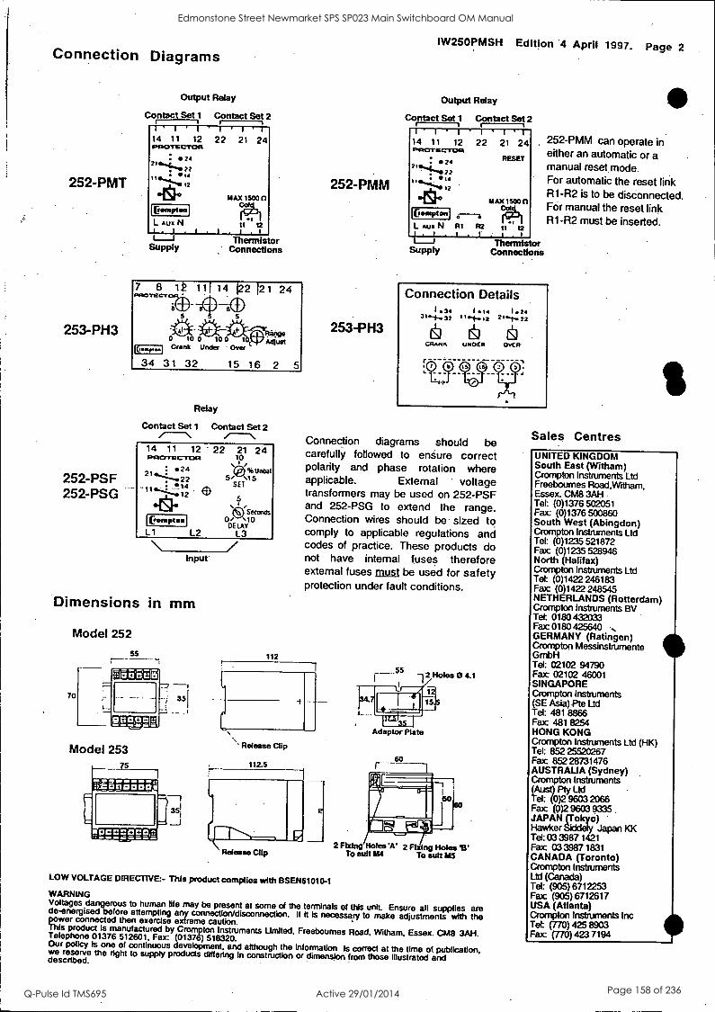
Connection Diagrams
252-PMT
253-PH3
252-PSF 252-PSG
Output Relay
Contact Set 1 Contact Set 2 1'1'1' I I 'I 14 11 12 22 21 24 PROTECTOR
Pompton
L Aux N
MAX 1500 n
tl 12 I . l .
L__J Supply
Thermistor ,' Connections
Relay
Contact Set 1 Contact Set 2
14 11 12 - 22 21 24 to, '42) % Unbal 5/ .15 SET
PACITECTIMI 24
21
1146:.4-111
°b. Pompton
L1
43) 5
seconds 0/ '1
DELAY 0
L2 L3
Input
Dimensions in mm
Model 252
70
Model 253
112
252-PMM
253-PH3
IW250PMSH Edition 4 April 1997. Page 2
Output Relay
Contact Set 1 Contact Set 2 i 141 -I 14 11 12 22 PROTECTOR
. 24 "S 72
Gompten
I I
21 24
RESET
1MAX 1500 ft
II t2 L AUlt N RI R2 . I'
1---I Supply
Thermistor Connectloha
Connection Details
252-PMM can operate in either an automatic or a manual reset, mode. For automatic the reset link R1-R2 is to be disconnected. For manual the reset link R1-R2 must be inserted.
CRANK UNDER
Connection diagrams should be carefully followed to ensure correct polarity and phase rotation where applicable. External voltage transformers may be used on 252-PSF and 252-PSG to extend the range. Connection wires should be sized to comply to applicable regulations and codes of practice. These products do not have internal fuses therefore external fuses must be used for safety protection under fault conditions.
\ Release Clip
1123
12
Adaptor Plate
so r
2 Fixing Holes'A' 2 Fixing Holes To suit le14 To sun MS
LOW VOLTAGE DIRECTIVE:- This product complies with BSEN61010-1
WARNING Voltages dangerous to human life may be present at some of the terminals of this unit. Ensure all supplies are de-energised before attempting any connectiorddisconnection. If it Is necessary to make adjustments with the power connected then exercise extreme caution. This product Is manufactured by Crompton Instruments Limited. Freeboumes Road, Witham, Essex. CM8 3AH. Telephone 01376 512601, Fax: (01376) 518320. Our policy is one of continuous development, and although the Information is correct at the time of publication, we reserve the right to supply products differing in construction or dimension from those illustrated and described.
Sales Centres UNITED KINGDOM South East (Witham) Crompton Instruments Ltd Freeboumes Road,Witham, Essex. CM8 3AH Tel: (0)1376 502051 Fax: (0)1376 500860 South West (Abingdon) Crompton Instruments Ltd Tel: (0)1235 521872 Fax (0)1235 528946 North (Halifax) Crompton Instruments Ltd Tel: (0)1422 246183 Fax (0)1422 248545 NETHERLANDS (Rotterdam) Crompton Instruments BV Tel 0180 432033 Fax 0180425640 GERMANY (Ratingen) Crompton Messinstnanente GmbH Tel: 02102 94790 Fax 02102 46001 SINGAPORE Crompton Instruments (SE Asia) Pte Ltd Tel: 481 8866 Fax 481 8254 HONG KONG Crompton Instruments Ltd (HK) Tel: 852 25520267 Fax 852 28731476 AUSTRAUA (Sydney) Crompton Instruments (Aust) Ply Ltd Tel: (0)2 9603 2066 Fax (0)2960033 9335 JAPAN (Tolryo) Hawker Sidd* Japan KK Tel: 03 3987 1421 Fax 033987 1831 CANADA (Toronto) Crompton Instruments Ltd (Canada) Tel: (905) 6712251 Fax (905) 6712617 USA (Atlanta) Crompton Instruments Inc Tel: (770)425 Fax (770) 423 7194
Edmonstone Street Newmarket SPS SP023 Main Switchboard OM Manual
Q-Pulse Id TMS695 Active 29/01/2014 Page 158 of 236

TECHNICAL DATA SHEET
For
Edmondstone Street Pump Station
Equipment Type: Current Transducer
Location: Pump Control
Model Numbers: 244-01RG
Manufacturer: Crompton
Supplier: Alstrom. 3/7 Miller Street Murrarie QLD 4172
Ph: 07 3890 4412 Fx: 07 3890 4413
Edmonstone Street Newmarket SPS SP023 Main Switchboard OM Manual
Q-Pulse Id TMS695 Active 29/01/2014 Page 159 of 236
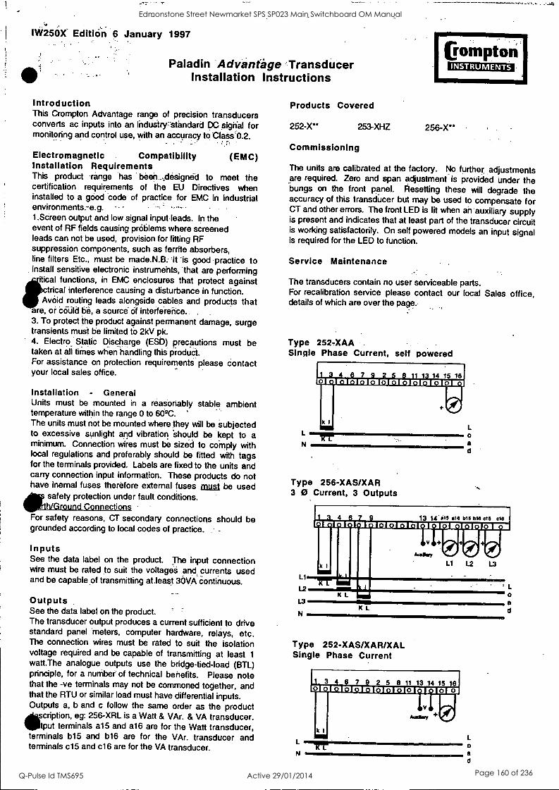
IW250X- Edition 6 January 1997
Paladin Advantage Transducer Installation Instructions
Introduction This Crompton Advantage range of precision transducers converts ac inputs into an industry7standard DC signal for monitoring and control use, with an accuracy to 'Class'0.2.
Electromagnetic . Compatibility (EMC) Installation Requirements This product -range *has . been -,designed to meet the certification requirements of the EU Directives when installed to a good 'code of practice for EMC in industrial environments.-e.g. - .-, ' -"- - .
1.Screen output and low signal input-leads. In the event of RF fields causing problems where screened leads can not be used, provision for fitting RF suppression components, such as ferrite absorbers, line filters Etc., must be made.N.B: 'It Is good practice to install sensitive electronic instruments, that are performing
iflice! functions, in EMC enclosures that protect against ctrical interference causing a disturbance in function. Avoid routing leads alongside cables and products that
are, or could be, a source- Of interference. . .
3. To protect the product against permanent damage, surge transients must be limited 6 2kV pk. 4. Electro Static Discharge (ESD) precautions must be . .. ...
taken at all times when handling this produCt. For assistance on protection requirements please contact your local sales office.
Installation - General Units must be mounted in a reasonably stable ambient temperature within the range 0 to 60 °C. The units must not be mounted where they will be subjected to excessive sunlight and vibration 'should be kept to a minimum. Connection wires must be sized to comply with local regulations and preferably should be fitted with tags for the terminals provided. Labels are fixed to the units and cam/ connection input information. These products do not have inemal fuses therefore external fuses must be used
*safety protection under fault conditions. h/Ground Connections
For safety reasons, CT secondary connections should be grounded according to local codes of practice.
Inputs See the data label on the product. The input connection wire must be rated to suit the voltages wick currents used and be capable of transmitting at.least 30VA continuous.
Outputs See the data label on the product. ' The transducer output produces a current sufficient to drive standard panel meters, computer hardware, relays, etc. The connection wires must be rated to suit the isolation voltage required and be capable of transmitting at least 1
watt.The analogue outputs use the bridge-tied-load (BTL) principle, for a number of technical benefits. Please note that the -ve terminals may not be commoned together, and that the RTU or similar load must have differential inputs. Outputs a, b and c follow the same order as the product
scription, eg: 256-XRL is a Watt & VAr. & VA transducer. 11/tput terminals a15 and a16 are for the Watt transducer, terminals b15 and b16 are for the VAr. transducer and terminals c15 and c16 are for the VA transducer.
ICompton INSTRUMENTS
Products Covered
252-X** 253-XHZ 256-X**
Commissioning
The units are calibrated at the factory. No further. .adjustments are required. Zero and span adjustment is provided under the bungs on the front panel. Resetting these will degrade the accuracy of this transducer but may be used to compensate for CT and other errors. The front LED is lit when an-auxiliary supply is present and indicates that at least part of the transducer circuit is working satisfactorily. On self powered models an input signal is required for the LED to function.
Service Maintenance
The transducers contain no user serviceable parts. For recalibration service please contact our local Sales office, details of which are over the page.-
Type 252-XAA Single Phase Current, self powered
N 'Fr
Type 256-XAS/XAR 3 0 Current, 3 Outputs
L1
L2
L3
N
0 a
13 14' itS ale bid ble olS C16
ran ra ra ra ra CM ra WM
11 I V PR PP PR 0 0 0
Ll 12 L3
K L 0 a d K L
Type 252-XAS/XAR/XAL Single Phase Current
N
1 3 4 ; 7 9 2 5 8 11 13 14 1 6
0 a d
Edmonstone Street Newmarket SPS SP023 Main Switchboard OM Manual
Q-Pulse Id TMS695 Active 29/01/2014 Page 160 of 236
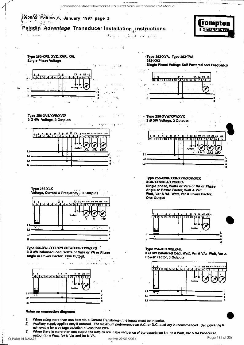
, .
.1W250X Edition 6, January 1997 page 2
P4I4diti Advantage Transducer Installation. Instructions
Type 252-XVS, XVZ, XVR, XVL Single Phase Voltage
Type 256- XVS/XVR/XVZ/ 3 0 4W Voltage, 3 Outputs
LI
L2
L3
N
11 13 14 15 816 b15 b16 615. 616
ceraviriiraranririHrarairininfil[11171
L1/N L2/N L3/N
L1
L2
L3
N
Type 256-XLK Voltage, Curient & Frequency , 3 Outputs
a d
13 14 .16 610 615 816 15 e10 ri nrarin It7 CIO CI 11:111a 117 SI CI 11171
PIM PI 0 0 0
0
a d
Type 256- XWL/XXIJXYL/XFW/XFG/XPW/XPG 3 0 3W balanced load, Watts or. Vars or VA or Phase Angle or Power Factor. One Output.
LI
L3
1 3 2 5 6 13 14 .15 616
Notes on connection diagrams
Type 252-XVA, Type 253-TVA 253-XHZ Single Phase Voltage Self Powered and Frequency
: Cling:IMO CI 1017111:11F1 C1121.71
L 0
L1
L2
13
Type 256-XVW/XVY/XVX 3 0 3W Voltage, 3 Outputs
in mom ra ram PI ea Dm:1mm NI CI MN
0 PI PI 0 PI 0 L1/1.2 L2/1.3 II Atreikary
Type 256-XWICDOOC/XYKADKAEK XGK/XFS/XFA/XPS/XPA Single phase, Watts or Vars or VA or Phase Angle or Power Factor, Watt & Var: Watt, Var & VA: Watt, Var & Power Factor. One Output
4444 44 2 5 8 II 13 14 815 116 nnnnnionnionnnno
L
0
a d
Type 256-XRIJXSLJXJL 3 0 3W balanced load, Watt, Var & VA: Watt, Var & Power Factor, 3 Outputs
LI
L2
L3
1 3 2 5 8 13 14 815 06 1315 016 616 616
tiararaCIEIVICIFICIMFICICIIC1111111111111111
I II V 111 PI
ci Cs Co
0 a d
1) When using more than one item via a Current Transformer, the inputs must be in series. 2) Auxiliary supply applies only if ordered. For maximum performance an A.C. or D.C. auxiliary is recommended. Self powering is
achievable for a voltage variation of less than 20%. 3) When there is more than one output the outputs are in the sequence of the description i.e. on a Watt, Var & VA transducer,
output (a) is Watt, (b) is Var and (c) is VA.
Edmonstone Street Newmarket SPS SP023 Main Switchboard OM Manual
Q-Pulse Id TMS695 Active 29/01/2014 Page 161 of 236
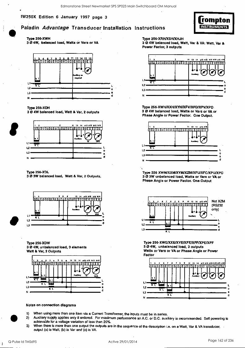
IW250X Edition 6 January 1997 page 3
Paladin Advantage Transducer Installation Instructions
Type 256 -XWH 3 0 4W, balanced load, Watts or Vars or VA
L1
L2
L3
N
8 11. 13 14 15 1
0 0 0 0 0 0 0 0 0 0 0
K L
Type 256-XDH 3 0 4W balanced load, Watt & Var, 2 outputs
L1
12
L3
N
I 3 2 11 13 14 An ADS 015 b16
ra MI CI 0 CIE71 fl ratan RI 13111[11 MON
k I rdO 0 1
K L
Type 256-XDL 3 0 3W balanced load, Watt & Var, 2 Outputs.
L1
L2
L3
I 3 2 5 II 13 14 .15 .10 b15 bib 0 VI CI 0 OM PI non DI CI CI CII CI CM
k I
+ Amelbsty
PR ip lb. PR rd
VAR
K L
Type 256-XDW 3 0 4W, unbalanced load, 3 elements Watt & Var, 2 Outputs
L1
L2
1.3
N
3 4 8 7 0 2 5 6 11 13 14 .15 816 DIS D16
0 FICICICIMI FICICICICICICICIICI
k 1 11 Assebery
Pig 0 P11
CO VAR
k1 NM K L
111 K L
Notes on connection diagrams
L
0
a d
IGompton INSTRUMENTS
Type 256-XRH/XSWXHJH 3 0 4W balanced load, Watt, Var & VA: Watt, Var & Power Factor, 3 outputs
L1
L L2
O L3 a d N
1 3 11 13 14 IS .16 515 b16 cIS 016
lo j o lol o I 0 I
k I
101oloJolo (ol 0J0101o10
Type 256-XWH/XXH/XYWXFV/XFO/XPV/XPD 3 0 4W balanced load, Watts or Vars or VA or Phase Angle or Power Factor. One Output.
3 2 11 13 14 AIS 016
Type 256 XWWXXWXYWXZliA/XFU/XFC/XPU/XPC 3 0 3W unbalanced load, Watts or Vars or VA or Phase Angle or Power Factor. One Output
0 a d
I 3 4 8 7 0 2 5 8 11 13 14
0 SI In CI MCI CI CI
Ll I mill K L
L2
L3
L
0 a d
K
.15 8111
In
0
Not XZM (RS232 only)
Type 256-XWE/XXE/XYE/XFE/XFF/XPE/XPF 3 0 4W, unbalanced load, 3 outputs Watts or Vars or VA or Phase Angle or Power Factor
0
a d
1 3 4 6 7 9 2 5 8 11 13 14 IS b15 16 b16 e1S eta
0 El la CIO CIO DI VI CI MI PI CI Ka [I ra VI Fl
L1
k I 11 A:m.y. IN
L2 k1 Da
K 1 gm
N K L
a
1) When using more than one item via a Current Transformer, the inputs must be in series. 2) Auxiliary supply applies only if ordered. For maximum performance an A.C. or D.C. auxiliary is recommended. Self powering is
achievable for a voltage variation of less than 20%. 3) When there is more than one output the outputs are in the sequence of the description i.e. on a Watt, Var & VA transducer,
output (a) is Watt, (b) is Var and (c) is VA.
Edmonstone Street Newmarket SPS SP023 Main Switchboard OM Manual
Q-Pulse Id TMS695 Active 29/01/2014 Page 162 of 236
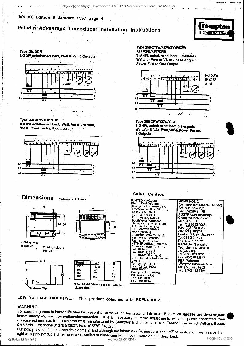
IW250X' Edition .6 January 1997 page 4
Paladin-Advantage Transducer Installation Instructions
Type 256-XDM 3 0 3W.unbalanced load, Watt & Var, 2 Outputs
Li
1 4 0 7 9"2 3 6.. 11. 13 '14 15 .16913 916
CI Ca CI la ICI CI CM CI IMICIO11
11111
I v M4474 10.
a
K L
Type 256-XRM/XSWXJM 3 0 3W unbalanced load, Watt, Var & VA: Watt, Var & Power Factor, 3 outputs.'
LI
L2
L3
1 3 4 6 7 9 2 3 11 13 14 an 4111 0 FM RIICICIEIVICICIE:2211C111117113131:111C1
K L MENU
PI III pp Co co
K L
DiMensions measurements in mm
2 Fixing holes to suit M4
2 Fixing holes to suit M5
112.5
a
A
Model -- A ' B 250' 22.5 252 55 253 75 60 256 150 135
Note: Model 256 case is fitted with two release clips
Type 256-XWW/XiW/XYW/XZW XFT/XFB/XPT/XPB 3 0 4W, unbalanced load, 3 elements Watts or Vars or VA or Phase Angle or Power Factor. One Output
Ll
L2
L3
N
1 3 4 . 6 7 0 2 6 6, 13 14 415 .16
111111I L
K L
Not XZW (RS232 only)
K L
Type 256-XRW/XSW/XJW 3 0 4W, unbalanced load, 3 elements Watt,Var VA: Watt,Vai4.Power, Fitctor, 3 Outputs
I 3 4 6 7 0 2 6 0 11 13 14 En 101 915 We 613 616 Mr/ 1131131CICICMCI cura CICICICHICIIII3
LI
k -1 11 .1111 v 1111 PI
X I .
L2 k I MINN
K L L3
' IN c
N K L
Sales Centres UNITED KINGDOM South East (Witham) Crompton Instruments Ltd Freebournes RoadNitham, Essex. CM8 3AH Tel: (0)1376 502051 Fax: (0)1376 500860 South West (Abingdon) Crompton Instruments Ltd Tel: (0)1235 521872 Fax: (0)1235 528946 North (Halifax) Crompton Instruments Ltd Tel: (0)1422 246183 Fax: (0)1422 248545 NETHERLANDS (Rotterdam) Crompton Instruments BV Tel: 0180 432033 Fax: 0180 425640 GERMANY (Ratingen) Crompton Messinstrumente GmbH Tel: 02102 94790 Fax: 02102 46001 SINGAPORE Crompton Instruments (SE Asia) Pte Ltd Tel: 481 8866 Fax: 481 8254
HONG KONG Crompton Instruments Ltd (HK) Tel: 852 25520267 Fax 852 28731476 AUSTRALIA (Sydney) Crompton Instruments (Aust) Pty Ltd Tel: (0)2 9603 2066 Fax: (0)2 9603 9335 JAPAN (Tokyo) Hawker Siddely Japan KK Tel: 03 3987 1421 Fax 03 3987 1831 CANADA (Toronto) Crompton Instruments Ltd (Canada) Tel: (905) 6712253 Fax: (905) 6712617 USA (Atlanta) CrOMpton Instruments Inc Tel: (770) 425 8903 Fax: (770) 423 7194
LOW VOLTAGE DIRECTIVE:- This product complies with BSEN61010-1
WARNING Voltages dangerous to human life may be present at some of the terminals of this unit. Ensure all supplies are de-energised before attempting any connection/disconnection. If it is necessary to make adjustments with the power connected then exercise extreme caution. This product is manufactured by Crompton Instruments Limited, Freeboumes Road, Witham, Essex. CM8-3AH. Telephone 01376 512601, Fax: (01376) 518320. Our policy is one of continuous development, and although the information is correct at the time of pi.iblication, we reserve the right to supply products differing in construction or dimension from those illustrated and described.
Edmonstone Street Newmarket SPS SP023 Main Switchboard OM Manual
Q-Pulse Id TMS695 Active 29/01/2014 Page 163 of 236

TECHNICAL DATA SHEET
For
Edmondstone Street Pump Station
Equipment Type: Power Monitor
Location: Incoming Section
Model Numbers: PM290-05-2AC-00-0-0
Manufacturer: Satec
Supplier: VMS Systems. 65 Park Road Milton QLD 4064
Ph: 07 3307 1388 Fx: 07 3307 1295
Edmonstone Street Newmarket SPS SP023 Main Switchboard OM Manual
Q-Pulse Id TMS695 Active 29/01/2014 Page 164 of 236

PM290 POWERMETER
.1/4
Installation and Operation Manual
Edmonstone Street Newmarket SPS SP023 Main Switchboard OM Manual
Q-Pulse Id TMS695 Active 29/01/2014 Page 165 of 236
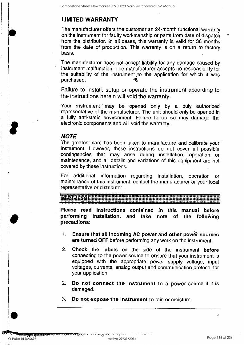
LIMITED WARRANTY
The manufacturer offers the customer an 24-month functional warranty on the instrument for faulty workmanship or parts from date of dispatch from the distributor. In all cases, this warranty is valid for 36 months from the date of production. This warranty is on a return to factory basis.
The manufacturer does not accept liability for any damage caused by instrument malfunction. The manufacturer accepts no responsibility for the suitability of the instrument ,to the application for which it was purchased. -A
Failure to install, setup or operate the instrument according to the instructions herein will void the warranty.
Your instrument may be opened only by a duly authorized representative of the manufacturer. The unit should only be opened in a fully anti-static environment. Failure to do so may damage the electronic components and will void the warranty.
NOTE The greatest care has been taken to manufacture and calibrate your instrument. However, these instructions do not cover all possible contingencies that may arise during installation, operation or maintenance, and all details and variations of this equipment are not covered by these instructions.
For additional information regarding installation, operation or maintenance of this instrument, contact the manufacturer or your local representative or distributor.
sim#bitt 75P54-; rfR 'RK:Pe
Please read instructions contained in this manual before performing installation, and take note of the folloWing precautions:
1. Ensure that all incoming AC power and other power sources are turned OFF before performing any work on the instrument.
2. Check the labels on the side of the instrument before connecting to the power source to ensure that your instrument is equipped with the appropriate power supply voltage, input voltages, currents, analog output and communication protocol for your application.
2. Do not connect the instrument to a power source if it is damaged.
3. Do not expose the instrument to rain or moisture.
Edmonstone Street Newmarket SPS SP023 Main Switchboard OM Manual
Q-Pulse Id TMS695 Active 29/01/2014 Page 166 of 236

4. The secondary of an external current transformer must never be allowed to be open circuit when the primary is energized. Ensure that the current transformer wiring is made through shorting switches and is secured using an external strain relief to reduce mechanical strain on the screw terminals, if necessary.
Setup procedures must be performed only by qualified personnel familiar with the instrument and its associated electrical equipment.
6. DO NOT attempt to ope:`o the instrument under any circumstances.
Modbus is a trademark of Modicon, Inc.
'21"Read through this manual thoroughly before connecting the instrument to the current carrying 'circuits. During operation, hazatdous voltages. are present on input terminals. Failure to observe precautions can result in fatal Injury and/or damage to equipment. '
BG0208 Rev. Al
ii
L
Edmonstone Street Newmarket SPS SP023 Main Switchboard OM Manual
Q-Pulse Id TMS695 Active 29/01/2014 Page 167 of 236

Table of Contents
Quick Start iv
1 Introduction 1
2 Installation and Interfaces 4 2.1 Mechanical Installation 4 2.2 Electrical Installation .' 6
3 Setup 14 3.1 Setup Procedure 14 3.2 Wiring Mode: CnF 16 3.3 Potential Transformer Ratio: Pt 17 3.4 Current Transformer: Ct 18 3.5 Maximum Power Demand Period: P 18 3.6 Maximum Ampere Demand Period: AP 19 3.7 Memory Buffer: buF 20 3.8 Reset: rSt 20 3.9 Baud Rate: br 21 3.10 Communication Address: Add 21 3.11 Handshake Mode: H.Sh 22 3.12 Communication Protocol: CoP 22 3.13 Relays 23 3.14 Analog Output: A (optional) 25
4 Data Display 28 4.1 Display Pages 28 4.2 Self-Test Diagnostics 29 4.3 RESET 29
Appendix A: Technical Specifications 30
Appendix B: Communication Cable Drawings 35
Edmonstone Street Newmarket SPS SP023 Main Switchboard OM Manual
Q-Pulse Id TMS695 Active 29/01/2014 Page 168 of 236
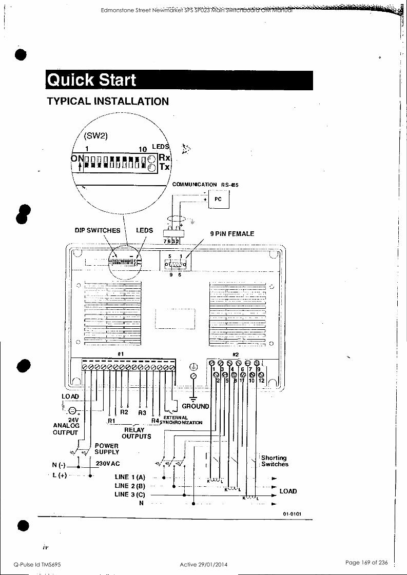
TYPICAL INSTALLATION
/ (SW2) LED, / 1 10
".1
FTbx() *
COMMUNICATION RS-485 , / / + PC
f DIP SWITCHES LEDS 9 PIN FEMALE
/ hoiIl tifit8112
5 1
P 'q 9 6
11_
i 1 "
" --
#1
W4009100q1000000',
LOAD
24V ANALOG OUTPUT
N (-)
L (+)
SUPPLY POWER
230VAC
GROUND R2 R3
EXTERNAL ritbSYNOIRONIZAT1ON
RELAY OUTPUTS
LINE 1 (A) LINE 2 (B) LINE 3 (C)
N
#2
6 ri 1 c 4679 e el c# Et
2 5 1 10 12 n : . )
....
'
K Jja L
101-k L
K
Shorting Switches
LOAD
01-0101
iv
Edmonstone Street Newmarket SPS SP023 Main Switchboard OM Manual
Q-Pulse Id TMS695 Active 29/01/2014 Page 169 of 236
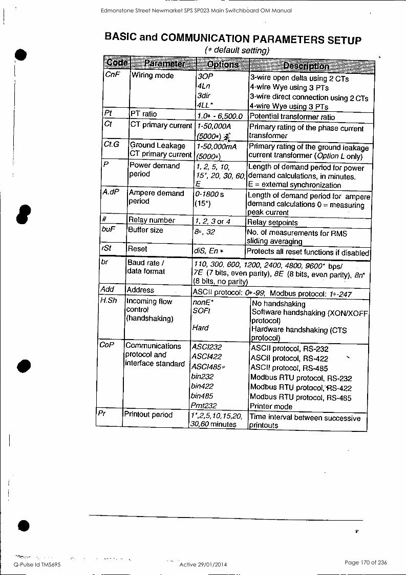
S BASIC and COMMUNICATION PARAMETERS SETUP
(* default setting)
Pahl met r ptions ss
se on CnF Wiring mode 30P
4Ln 3dir 4LL *
3-wire open delta using 2 CTs 4-wire Wye using 3 PTs 3-wire direct connection using 2 CTs 4-wire Wye using 3 PTs
Pt PT ratio 1.0i - 6,500.0 Potential transformer ratio Ct CT primary current 1-50,000A
(5000*) Primary rating of the phase current transformer
Ct.G Ground Leakage CT primary current
1-50,000mA (5000*)
Primary rating of the ground leakage current transformer (Option L only)
P Power demand period
1, 2, 5, 10, 15*, 20, 30, 60, E
Length of demand period for power demand calculations, in minutes. E = external synchronization
A.dP Ampere demand period
0-1800s (15*)
Length of demand period for ampere demand calculations 0 = measuring peak current
# Relay number 1, 2, 3 or 4 Relay setpoints buF Buffer size 8*, 32 No. of measurements for RMS
sliding averaging rSt Reset diS, En * Protects all reset functions if disabled br Baud rate /
data format 110, 300, 600, 1200, 2400, 4800, 9600* bps/ 7E (7 bits, even parity), BE (8 bits, even parity), 8n* (8 bits, no parity)
Add Address ASCII protocol: 0*-99, Modbus protocol: 1*-247 H.Sh Incoming flow
control (handshaking)
nonE* SOFt
Hard
No handshaking Software handshaking (XON/XOFF protocol) Hardware handshaking (CTS protocol)
CoP Communications protocol and interface standard
ASC1232 ASC1422
ASC1485* bin232 bin422 bin485 Prnt232
ASCII protocol, RS-232 ASCII protocol, RS-422 .` ASCII protocol, RS-485 Modbus RTU protocol, RS-232 Modbus RTU protocolj1S-422 Modbus RTU protocol, RS-485 Printer mode
Pr Printout period 1*,2,5,10,15,20, 30,60 minutes
Time interval between successive printouts
Edmonstone Street Newmarket SPS SP023 Main Switchboard OM Manual
Q-Pulse Id TMS695 Active 29/01/2014 Page 170 of 236
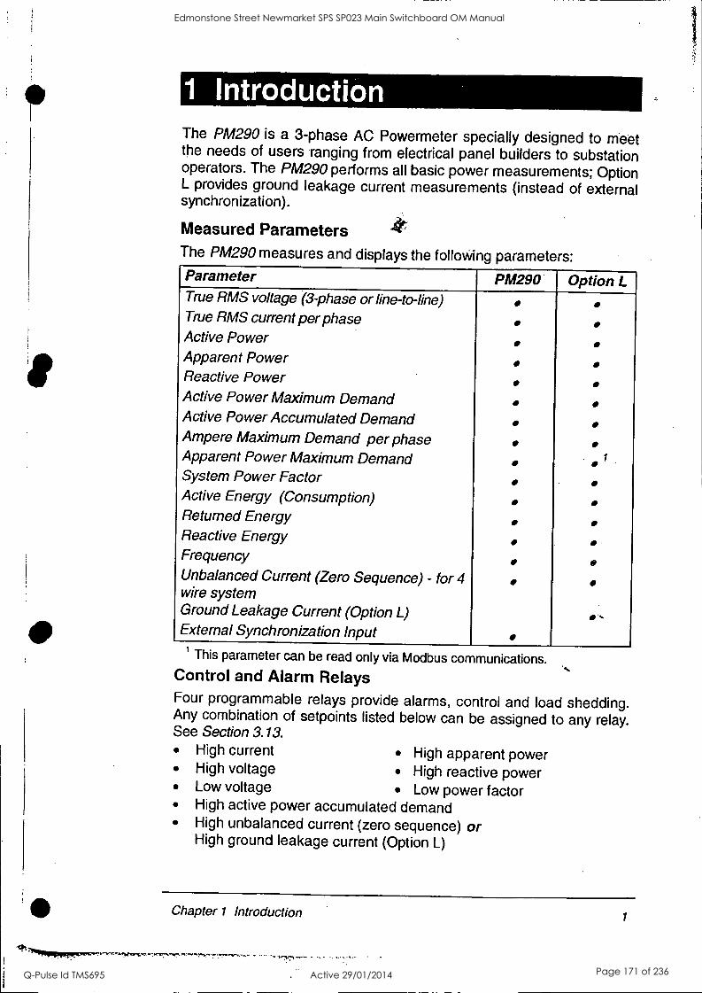
1 Introduction The PM290 is a 3-phase AC Powermeter specially designed to meet the needs of users ranging from electrical panel builders to substation operators. The PM290 performs all basic power measurements; Option L provides ground leakage current measurements (instead of external synchronization).
Measured Parameters The PM290 measures and displays the folloviing parameters: Parameter PM290 Option L True RMS voltage (3-phase or line-to-line) True RMS current per phase Active Power Apparent Power Reactive Power Active Power Maximum Demand Active Power Accumulated Demand Ampere Maximum Demand per phase Apparent Power Maximum Demand System Power Factor Active Energy (Consumption) Returned Energy Reactive Energy Frequency Unbalanced Current (Zero Sequence) - for 4 wire system Ground Leakage Current (Option L) External Synchronization Input
-,
This parameter can be read only via Modbus communications. Control and Alarm Relays Four programmable relays provide alarms, control and load shedding. Any combination of setpoints listed below can be assigned to any relay. See Section 3.13.
High current High apparent power High voltage High reactive power Low voltage Low power factor High active power accumulated demand High unbalanced current (zero sequence) or High ground leakage current (Option L)
Chapter 1 Introduction 1
""111111111priperrw^7.,,,,,-.,:ravwc,. r-fi
Edmonstone Street Newmarket SPS SP023 Main Switchboard OM Manual
Q-Pulse Id TMS695 Active 29/01/2014 Page 171 of 236

Communications Connection (optional) Connection to a printer, computer or central control room is enabled by an RS-232/RS-422/RS-485 communications port that can operate at baud rates of up to 9,600 bps. The RS-422/RS-485 port can operate in multi-drop mode, permitting the connection of up to 32 instruments to a single communications line. In the printer mode, the Powermeter provides direct output of measurement parameters in printable format. See Section 2.2.9 for pinouts and Appendix C for cable drawings.
Analog Output (optional) One optional internal analog output is available for the following measured Ka lues:
Voltage (3-phase or line-to-line) Current (3-phase or line-to-line) Active power accumulated demand Power factor
Active power Apparent power Reactive power Frequency
An external power supply (15-30VDC,24 VDC nominal) is required. See Section 2.2.8 for connection.
If more than one analog output is desired, up to two AX-8 analog expanders are available, providing up to 12 analog outputs. Contact your distributor for purchasing AX-8 units.
Digital Input One optically isolated digital input is provided for external synchronization of power demand period. See Typical Installation on page iv for connection.
Ground Leakage (Option L) Option L provides ground leakage current measurements for monitoring and alarm setting. A special ground leakage current transformer (secondary current 5 mA) is required. See Section 2.2.10 for connection.
2 Chapter 1 Introduction
Edmonstone Street Newmarket SPS SP023 Main Switchboard OM Manual
Q-Pulse Id TMS695 Active 29/01/2014 Page 172 of 236

Getting Started Connect the Powermeter to a suitable power supply. The Powermeter will initiate a series of self-tests. Upon completion of the self-tests, all of the front panel LEDs will light up for one second and indicate a one- digit diagnostic code. An '8' represents normal power up. If a different diagnostic code constantly appears when you apply power to the instrument, contact your local distributor.
The Front Panel
tiqf *PAX<
Up/Down arrow keys are used to scroll pages forward/backward
Select is used to enter the setup mode from the default monitoring mode; it is also used to define the setup parameters (see Chapter 3, Initial Setup)
Enter/Reset is used to reset measured values (if in monitoring mode) or to enter setup parameter values (if in setup mode)
Chapter 1 Introduction 3
Edmonstone Street Newmarket SPS SP023 Main Switchboard OM Manual
Q-Pulse Id TMS695 Active 29/01/2014 Page 173 of 236
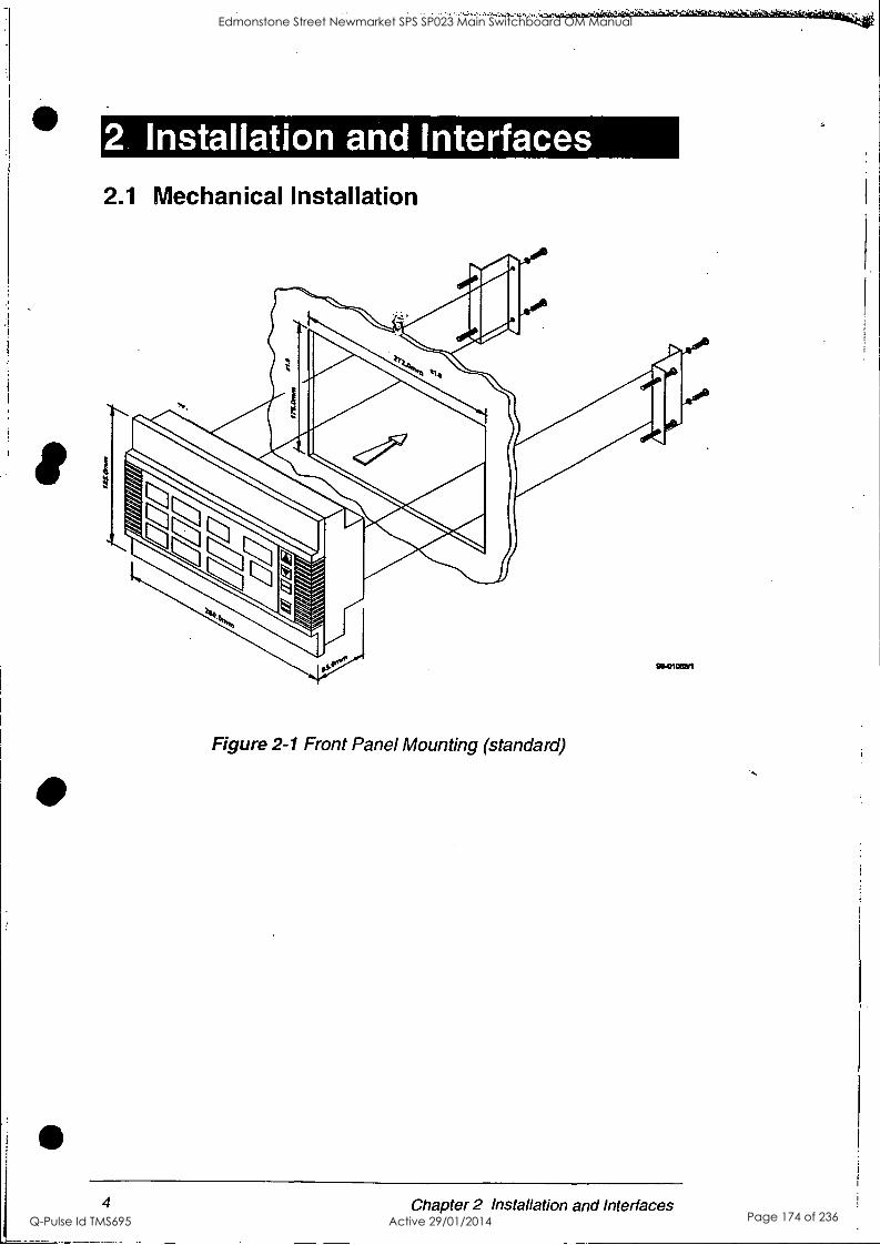
Mb
2.1 Mechanical Installation
..,
Figure 2-1 Front Panel Mounting (standard)
4 Chapter 2 Installation and Interfaces
Edmonstone Street Newmarket SPS SP023 Main Switchboard OM Manual
Q-Pulse Id TMS695 Active 29/01/2014 Page 174 of 236
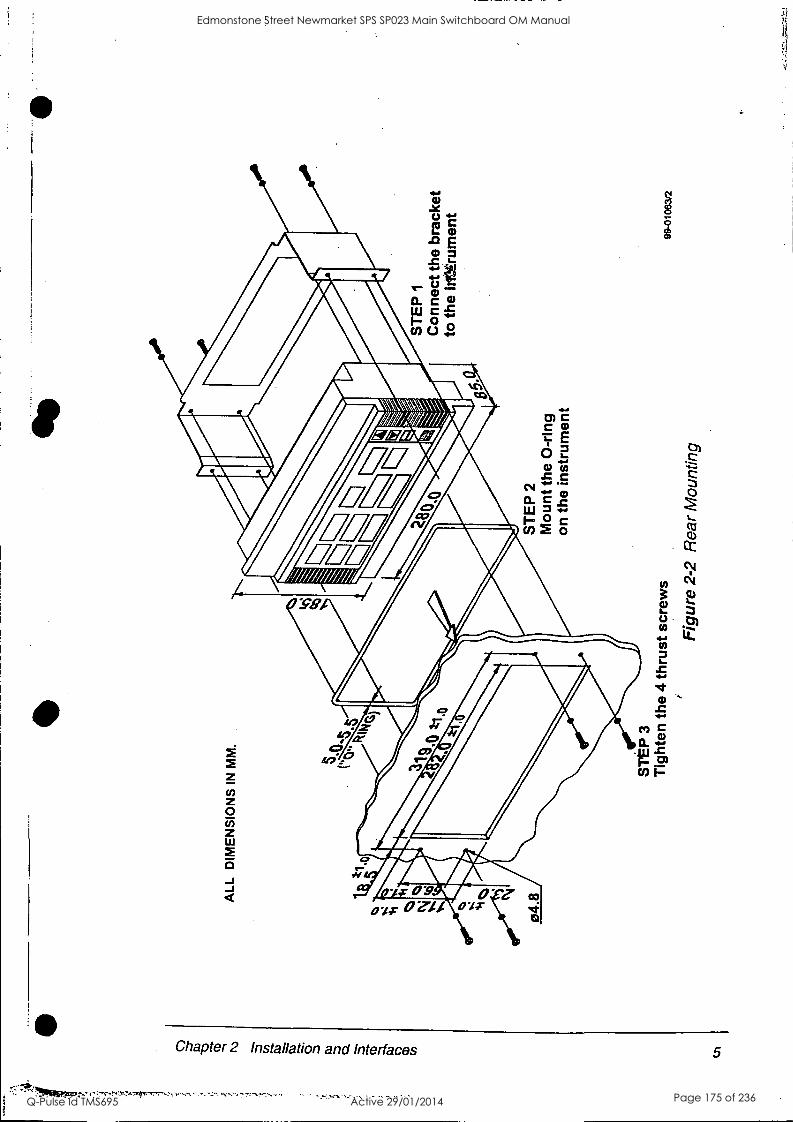
c.n
ALL
D
IME
NS
ION
S I
N M
M.
5,0
04.8
ST
EP
3
Tig
hten
the
4 t
hrus
t scr
ews
Fig
ure
2-2
Rea
r M
ount
ing
ST
EP
2
Mou
nt th
e 0-
ring
on t
he i
nstr
umen
t
ST
EP
1
Con
nect
the
brac
ket
to t
he ir
l.ltr
umen
t
99-0
1063
/2
Edmonstone Street Newmarket SPS SP023 Main Switchboard OM Manual
Q-Pulse Id TMS695 Active 29/01/2014 Page 175 of 236
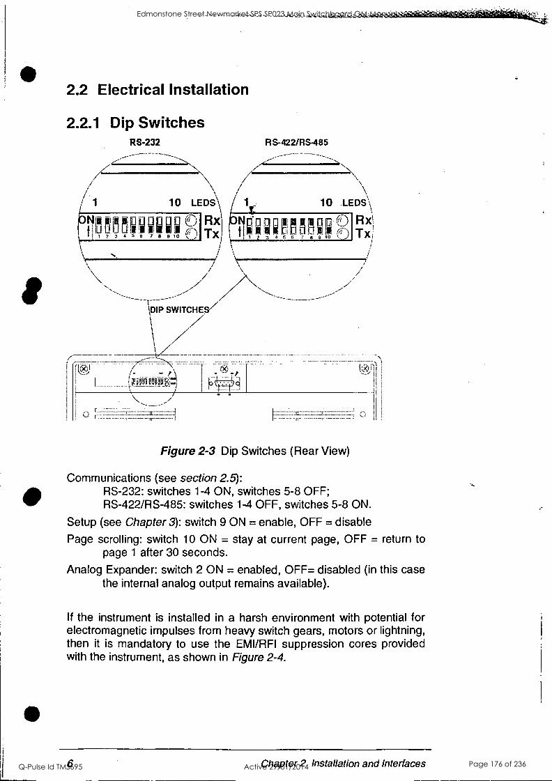
2.2 Electrical Installation
2.2.1 Dip Switches RS-232
II 34r`1f1[1
\DIP SWITCHES/
R S- 422/RS -485
10 .LEDs
FM-15R° 6 7 8 9 10
C
Rx; Tx,
-
r:
Figure 2-3 Dip Switches (Rear View)
Communications (see section 2.5): RS-232: switches 1-4 ON, switches 5-8 OFF; RS-422/RS-485: switches 1-4 OFF, switches 5-8 ON.
Setup (see Chapter 3): switch 9 ON = enable, OFF = disable
Page scrolling: switch 10 ON = stay at current page, OFF = return to page 1 after 30 seconds.
Analog Expander: switch 2 ON = enabled, OFF= disabled (in this case the internal analog output remains available).
If the instrument is installed in a harsh environment with potential for electromagnetic impulses from heavy switch gears, motors or lightning, then it is mandatory to use the EMI/RFI suppression cores provided with the instrument, as shown in Figure 2-4.
6 Chapter 2 Installation and Interfaces
Edmonstone Street Newmarket SPS SP023 Main Switchboard OM Manual
Q-Pulse Id TMS695 Active 29/01/2014 Page 176 of 236
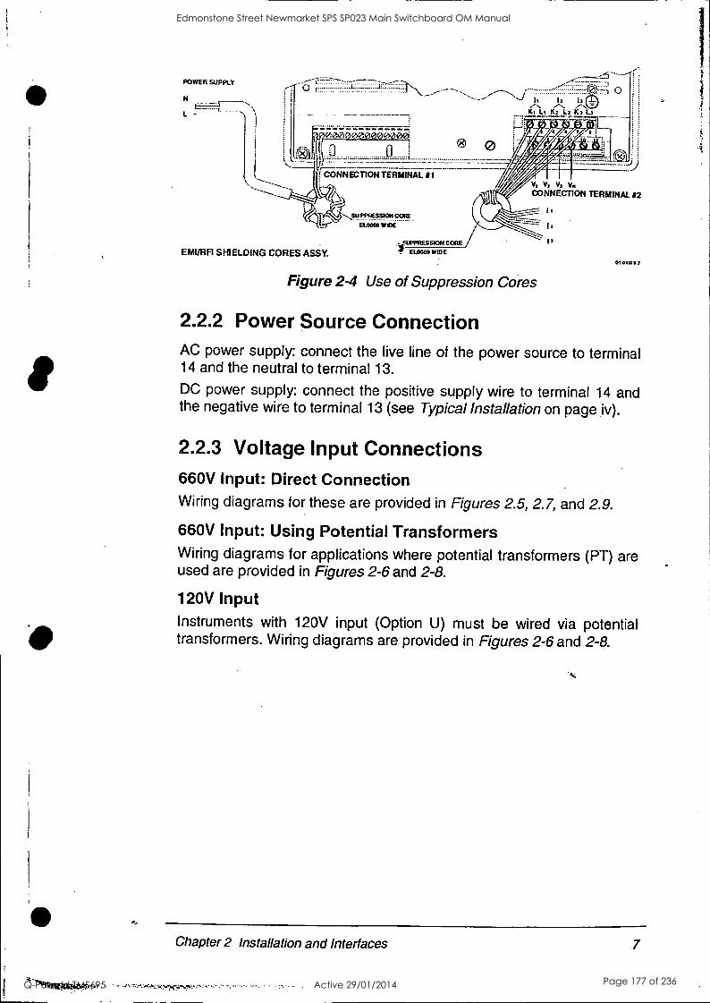
POWER SUPPLY
t. .
L -
11 12 13
K1 Li K2 L2 K3 L3
vioeoo@oggeweee
0
CONNECTION TERMINAL #1
EMI/RF1 SHIELDING CORES ASSY.
SUPPRESSION CORE
EL000) WIDE
0
;<.
ELOOOO
J..)
V, Vi Vs Vii CONNECTION TERMINAL #2
010t013.2
Figure 2-4 Use of Suppression Cores
2.2.2 Power Source Connection AC power supply: connect the live line of the power source to terminal 14 and the neutral to terminal 13.
DC power supply: connect the positive supply wire to terminal 14 and the negative wire to terminal 13 (see Typical Installation on page iv).
2.2.3 Voltage Input Connections 660V Input: Direct Connection Wiring diagrams for these are provided in Figures 2.5, 2.7, and 2.9.
660V Input: Using Potential Transformers Wiring diagrams for applications where potential transformers (PT) are used are provided in Figures 2-6 and 2-8.
120V Input Instruments with 120V input (Option U) must be wired via potential transformers. Wiring diagrams are provided in Figures 2-6 and 2-8.
Chapter 2 Installation and Interfaces 7
Edmonstone Street Newmarket SPS SP023 Main Switchboard OM Manual
Q-Pulse Id TMS695 Active 29/01/2014 Page 177 of 236

2.2.4 Current Input Connections See Typical Installation on page iv for current input connections.
tv*csAll et-S:routit,:pe`cOnneCted in the, correct Order and With the come Pali* as ,Shawn" the." wiring diagrams for the
-instrument tooperate properly. if the instrument displays a' powet!.Ipatpi;ottzerp:or close to it, or if power readings show unreaeonable'valuisisOhle may indicate a reversal of polirity, Of the et connections.
2.2.5 Ground Connection Connect theinstrunnent chassis ground to the switchgear earth ground using dedicated wire greater than 2mm2/14AWG. See Typical Installation on page iv for ground connection.
2.2.6 Wiring Configurations There are 5 possible wiring configurations, illustrated through 2-9:
in Figures 2-5
No. Wiring Configuration Wiring Mode
1) 3-wire direct connection using 2 CTs 3dir
2) 3-wire open delta connection using 2 PTs, 2 CTs 30P
3) 4-wire WYE direct connection using 3 CTs 4L-n or 4L-L
4) 4-wire WYE connection using 3 PTs, 3 CTs 4L-n or 4L-L
5) 4-wire grounded delta connection using 3 CTs 4L-n or 4L-L
L-n = line-to-neutral; L-L = line-to-line voltage readings; voltage readings in
3-wire configurations always represent line-to-line voltages
8 Chapter 2 Installation and Interfaces
Edmonstone Street Newmarket SPS SP023 Main Switchboard OM Manual
Q-Pulse Id TMS695 Active 29/01/2014 Page 178 of 236
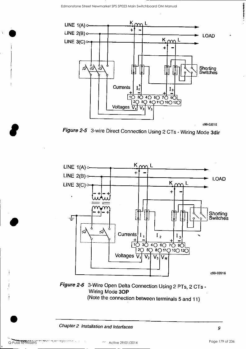
LINE 1(A)o
LINE 2(B) 0
LINE 3(C)0
Currents II! I
+ -
1_112 9 S 801101001201
0 30 40 60 70 601_,
Voltages Vij V2 V3
LOAD
Shorting Switches
c99-02015
Figure 2-5 3-wire Direct Connection Using 2 CTs - Wiring Mode 3dir
LINE 1(A) 0
LINE 2(B) 0
LINE 3(C) 0 K
+ - +, ,AAAAA,
+ r + 17:7- ron- Li I
I Currents I
LQJ 0
I2 I3
1110 36 40 60 70 80L 20 50 80110100120
Voltages V1 V2 V VN
Figure 2-6 3-Wire Open Delta Connection Using 2 PTs, 2 CTs - Wiring Mode 30P (Note the connection between terminals 5 and 11)
LOAD
Shorting Switches
c99-02016
Chapter 2 Installation and Interfaces 9
Edmonstone Street Newmarket SPS SP023 Main Switchboard OM Manual
Q-Pulse Id TMS695 Active 29/01/2014 Page 179 of 236
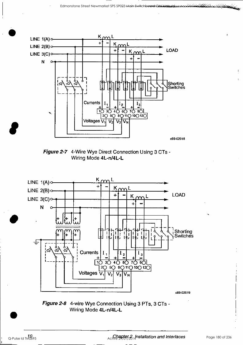
LINE 1(A) 0
LINE 2(B) 0
LINE 3(C)o
K L
K L
L
Currents I + - +
LOAD
C'-' Shorting Switches
_J
12 13
H102 305 dr.` 6r. L3 'Y107(1)0(3?2151
Voltages Vi V2 V3 VN
c99-02018
Figure 2-7 4-Wire Wye Direct Connection Using 3 CTs - Wiring Mode 4L-n/4L-L
LINE 1(A) 0
LINE 2(B) 0
LINE 3(C)o
N o
K ery, L
+ K L
K
"Yr
- _s
o- 1- rO4- 1 1
I o 1
o
LOAD
--I 0 .1\4- r 1 Shorting Lo; ) Switches
Currents 11 12 13 + +
1110 30 40 60 70 90 5Q 8011010012P-1
Voltages V, V2 V3 VN
Figure 2-8 4-wire Wye Connection Using 3 PTs, 3 CTs - Wiring Mode 4L-n/4L-L
c99-02019
10 Chapter 2 Installation and Interfaces
Edmonstone Street Newmarket SPS SP023 Main Switchboard OM Manual
Q-Pulse Id TMS695 Active 29/01/2014 Page 180 of 236
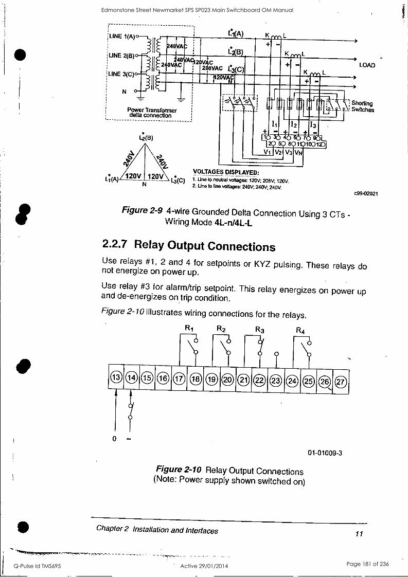
LINE 1(A)
LINE 2(B)
LINE 3(C)
N
Ci(A) K
40:VAC 1!XI3).
i40iACI2 VIC
VAC
121VAC L3(C) polar
Power Transformer delta connection
L1(A)
L2(B)
r--
12 + + + 00 30 40 60 7 "1
5Q V14
13
VOLTAGES DISPLAYED: 1(C) 1. Line to neutral voltages: 12W; 208V; 120V.
2. Line to line voltages: 240V; 240V; 240V.
LOAD
-1 Shorting _2 Switches
Figure 2-9 4-wire Grounded Delta Connection 'Using 3 CTs - Wiring Mode 4L-n/4L-L
c99-02021
2.2.7 Relay Output Connections Use relays #1, 2 and 4 for setpoints or KYZ pulsing. These relays do not energize on power up.
Use relay #3 for alarm/trip setpoint. This relay energizes on power up and de-energizes on trip condition.
Figure 2-10 illustrates wiring connections for the relays.
R1 R2 R3 R4
CYD 15 CXD 0 sCD @ CX) 23 CD 0 CIS)
0
Figure 2-10 Relay Output Connections (Note: Power supply shown switched on)
01-01009-3
Chapter 2 Installation and Interfaces 11
Edmonstone Street Newmarket SPS SP023 Main Switchboard OM Manual
Q-Pulse Id TMS695 Active 29/01/2014 Page 181 of 236

2.2.8 Analog Output The Analog Output requires a galvanically isolated external power supply. See Figure 2-11 for connections: negative to terminal 15 and positive to terminal 16. In certain industrial applications, a circuit may be required to protect against accidental shorts.
To terminal #16
To terminal #15
D1
FUSE 24V
D1=1 N 4002
C1=0.1 MF/50V
VR1=250Vrms
FUSE=100mA(S.B.)
Figure 2-11 Analog Output Connection
2.2.9 Communications Connector Pinout The serial interface connector is a standard D-type 9-pin plug-in, located at the top center of the back of the instrument. Tables 2-1 and 2-2 list the pinout of the connector.
Table 2-1 RS-232 Pinout
Pin Name Function
1 Gnd Ground (common) 2 TxD Transmit Data 3 RxD Receive Data 4 DTR Data Terminal Ready 5 DSR Data Set Ready
Table 2-2 RS-4221RS-485 Pinout
Pin Name Function
2 TxD+ + Transmit Data
3 RxD+ + Receive Data
6 TxD - - Transmit Data 7 RxD - - Receive Data
DIP Switch Block
rannu 1 2 3 4 5 6 7
ON
OFF
DIP Switch Block
)1 2 3 4 5 6 7 8
ON
OFF
For RS-485 communications, connect together pins 2-3 (TXD+ and RXD+), and pins 6-7 (TXD- and RXD-).
For cable drawings, refer to Appendix C.
12 Chapter 2 Installation and Interfaces
Edmonstone Street Newmarket SPS SP023 Main Switchboard OM Manual
Q-Pulse Id TMS695 Active 29/01/2014 Page 182 of 236
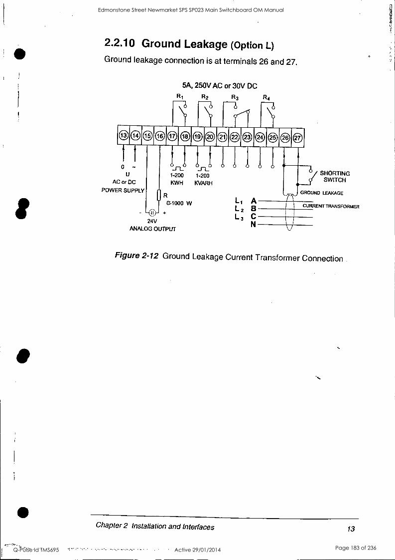
2.2.10 Ground Leakage (option L)
Ground leakage connection is at terminals 26 and 27.
5A, 250V AC or 30V DC
R1 R2 R3
6 6 R4
@ 14 @ 16 17 @C) 20 21 @ 23 @ 25 0 CD
0 - U
AC or DC
POWER SUPPLY
24V ANALOG OUTPUT
1-200 1-200 KWH KVARH
R
a-i000 w +
Li L 2
L 3
A B C N
SHORTING SWITCH
CURRENT TRANSFORMER
Figure 2-12 Ground Leakage Current Transformer Connection
Chapter 2 Installation and Interfaces 13
Edmonstone Street Newmarket SPS SP023 Main Switchboard OM Manual
Q-Pulse Id TMS695 Active 29/01/2014 Page 183 of 236
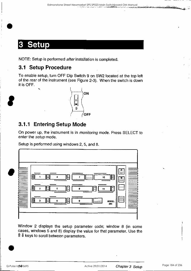
3 Setu
NOTE: Setup is performed after installation is completed.
3.1 Setup Procedure To enable setup, turn OFF Dip Switch 9 on SW2 located at the top left of the rear of the instrument (see Figure 2-3). When the switch is down it is OFF.
ON
) 9 ?OFF
3.1.1 Entering Setup Mode On power up, the instrument is in monitoring mode. Press SELECT to enter the setup mode.
Setup is performed using windows 2, 5, and 8.
1
2
3
4 I
5
6
0 7 I EH
8
9
10 fl I 0:
MODEL 290
Window 2 displays the setup parameter code; window 8 (in some cases, windows 5 and 8) display the value for that parameter. Use the 1111 keys to scroll between parameters.
14 Chapter 3 Setup
Edmonstone Street Newmarket SPS SP023 Main Switchboard OM Manual
Q-Pulse Id TMS695 Active 29/01/2014 Page 184 of 236
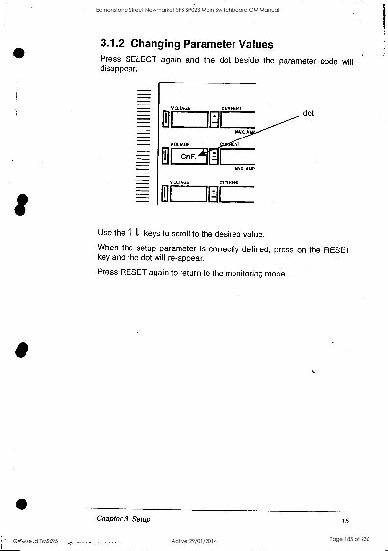
3.1.2 Changing Parameter Values Press SELECT again and the dot beside the parameter code will disappear.
VOLTAGE CURRENT
0 lEi MAX. A
VOLTAGE ENT RN El I
YAK. ANP
VOLTAGE CURRENT
U I I
dot
Use the 11 11 keys to scroll to the desired value.
When the setup parameter is correctly defined, press on the RESET key and the dot will re-appear.
Press RESET again to return to the monitoring mode.
Chapter 3 Setup 15
Edmonstone Street Newmarket SPS SP023 Main Switchboard OM Manual
Q-Pulse Id TMS695 Active 29/01/2014 Page 185 of 236
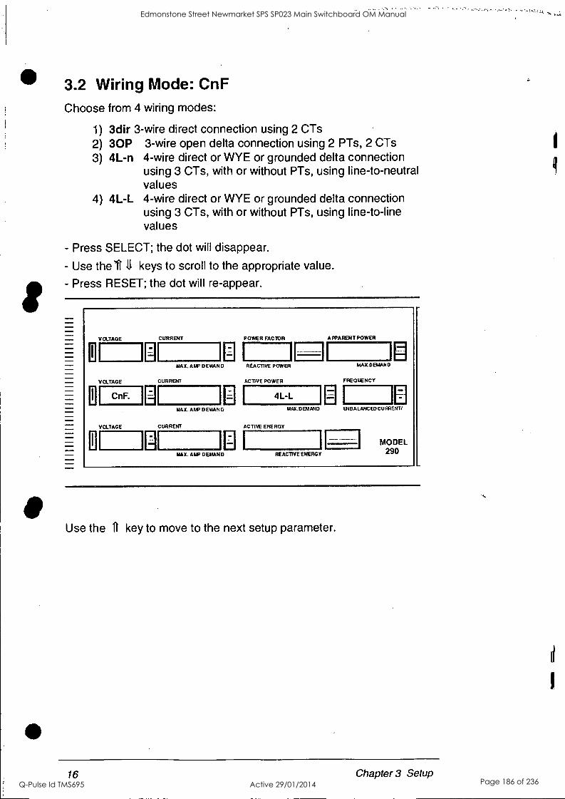
3.2 Wiring Mode: CnF
Choose from 4 wiring modes:
1) 3dir 3-wire direct connection using 2 CTs 2) 30P 3-wire open delta connection using 2 PTs, 2 CTs 3) 4L-n 4-wire direct or WYE or grounded delta connection
using 3 CTs, with or without PTs, using line-to-neutral values
4) 4L-L 4-wire direct or WYE or grounded delta connection using 3 CTs, with or without PTs, using line-to-line values
- Press SELECT; the dot will disappear.
- Use the U 11 keys to scroll to the appropriate value.
- Press RESET; the dot will re-appear.
El
El
VOLTAGE
VOLTAGE
CnF.
VOLTAGE
CURRENT
LI MAX. AWE' DEMAND
El D
El
CURRENT
El MAX. AMP DEMAN
CURRENT
LI MAX. AWN DEMAND
POWER FACTOR
REACTIVE POWER
ACTIVE POWER
4L-L
ACTIVE ENERGY
APPARENT POWER
El MAX. D EM AND
REACTIVE ENERGY
MAX.DEMAND
FREQUENCY
ALANC ED CU RRENT/
MODEL 290
Use the n key to move to the next setup parameter.
16 Chapter 3 Setup
Edmonstone Street Newmarket SPS SP023 Main Switchboard OM Manual
Q-Pulse Id TMS695 Active 29/01/2014 Page 186 of 236
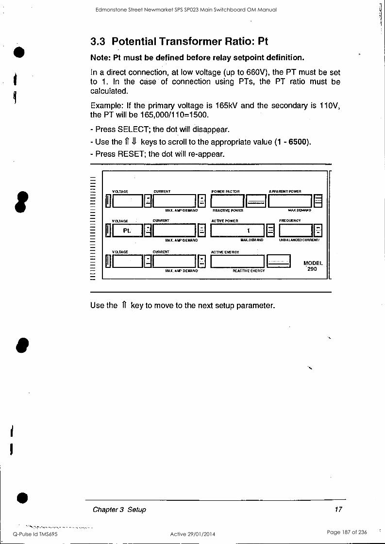
I
3.3 Potential Transformer Ratio: Pt
Note: Pt must be defined before relay setpoint definition.
In a direct connection, at low voltage (up to 660V), the PT must be set to 1. In the case of connection using PTs, the PT ratio must be calculated.
Example: If the primary voltage is 165kV and the secondary is 110V, the PT will be 165,000/110=1500.
- Press SELECT; the dot will disappear.
- Use the 11,11 keys to scroll to the appropriate value (1 - 6500).
- Press RESET; the dot will re-appear.
VOLTAGE
V CLTAGE
Pt.
V OLTAGE
CURRENT
MAX. AM, DEMAND
CURRENT
MAX. AM' DEMAND
CURRENT
El MAX. AIR DEMAND
POWER FACTOR
I REACTIVE POWER
ACTIVE POWER
1
LlAX.D BA AND
ACTIVE ENERGY
REACTIVE ENERGY
APPARENT POWER
MAX DEMAN 0
FREQUENCY
LNBALANCEDCURREND
MODEL 290
Use the ft key to move to the next setup parameter.
Chapter 3 Setup 17
Edmonstone Street Newmarket SPS SP023 Main Switchboard OM Manual
Q-Pulse Id TMS695 Active 29/01/2014 Page 187 of 236
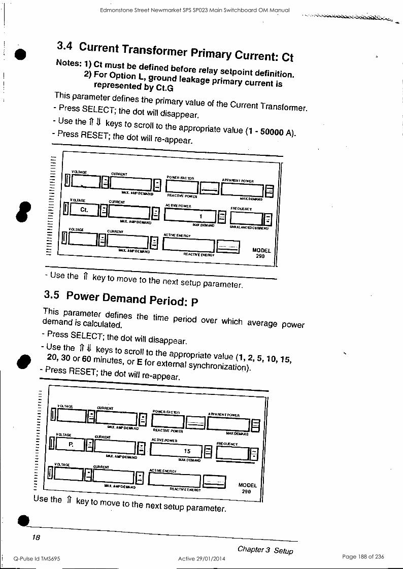
3.4 Current Transformer Primary Current: Ct Notes: 1) Ct must be defined before relay setpoint definition. 2) For Option L, ground leakage primary current is represented by Ct.G This parameter defines the primary value of the Current Transformer. - Press SELECT; the dot will disappear.
- Use the 1111 keys to scroll to the appropriate value (1 - 50000 A). - Press RESET; the dot will re-appear.
El
VOLTAGE
VOLTAGE
Ct.
VOLTAGE
CURRENT
o 1:1 MAX. ADP DEMAND
CURRENT
E El MAX. ALP DEMAND
CURRENT
El MAX. AN. DEMAND
POWER FACTOR
REACTIVE POWER
AC LIVE POWER
1
!AUDEN AND
AC ME ENERGY
REACTNE ENERGY
AMA RENT POWER
MAKG9AAND
FFE 0 LE NCY
UCH ALANC EDC URRENT/
MODEL 290
- Use the ft key to move to the next setup parameter. 3.5 Power Demand Period: P This parameter defines the time period over which average power demand is calculated. - Press SELECT; the dot will disappear. - Use the 11 11 keys to scroll to the appropriate value (1, 2, 5, 10, 15, 20, 30 or 60 minutes, or E for external synchronization). - Press RESET; the dot will re-appear.
II
V CLTAGE
VOLTAGE
R
V OLTAGE
CURRENT
El LAX. Air DEMAND
CURRENT
El El MAX. AMP DEMAND
CURRENT
El MAX. ALP DEMAND
POWER FACTOR
REACTIVE POWER
ACTIVE POWER
15
LIAX.DEMAND
ACTIVE ENERGY
RE ACT PI E ENERGY
A PPA RENT POWER
MAKDEAAND
FREOUENCY
MODEL 290
Use the n key to move to the next setup parameter.
18
Chapter 3 Setup
Edmonstone Street Newmarket SPS SP023 Main Switchboard OM Manual
Q-Pulse Id TMS695 Active 29/01/2014 Page 188 of 236
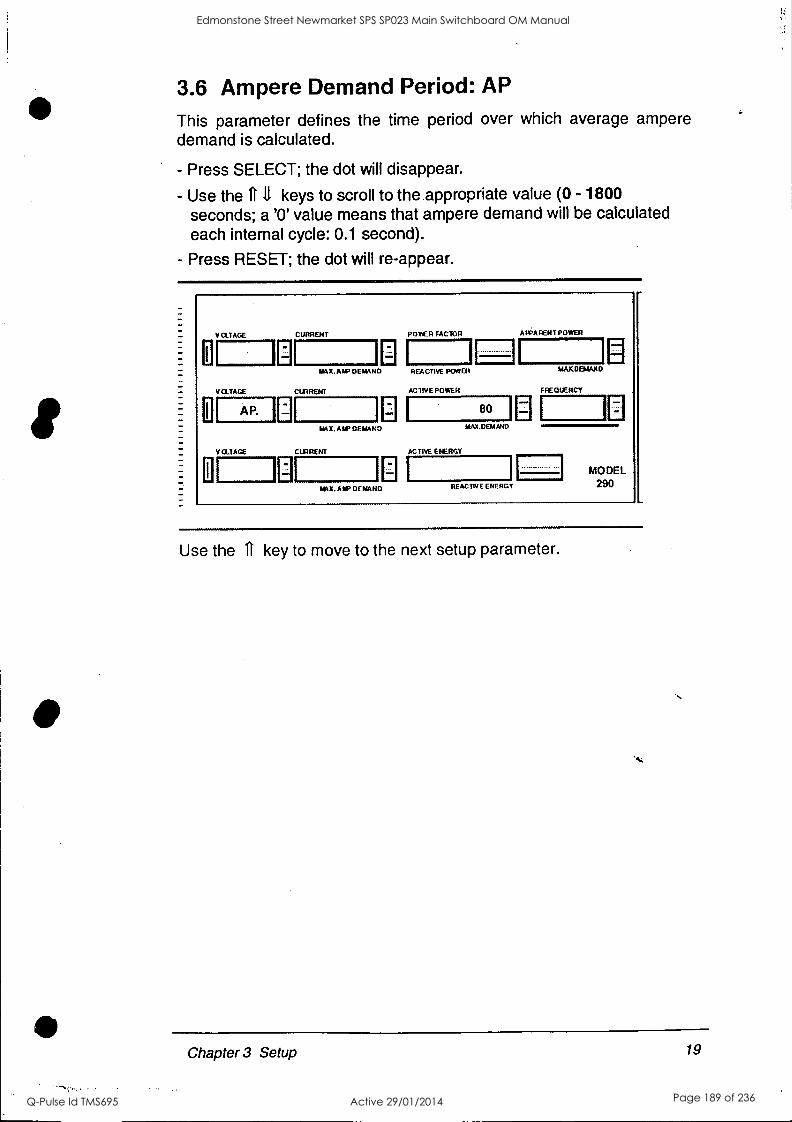
3.6 Ampere Demand Period: AP
This parameter defines the time period over which average ampere demand is calculated.
- Press SELECT; the dot will disappear.
- Use the ft 11 keys to scroll to the appropriate value (0 - 1800 seconds; a '0' value means that ampere demand will be calculated each internal cycle: 0.1 second).
- Press RESET; the dot will re-appear.
V CLTAGE
V CLTAGE
AP. I
CLIAGE
CURRENT
El MAX.A1P DEMAND
CIPRENT
CI MAX. AMP DEMAND
CIXARENT
MAX. AMP DEMAND
POWER FACTOR
REACTIVE POWER
ACTIVE POWER
IAAX.DEM AND
ACTIVE ENERGY
AR;ARENT POWER
wocoatato
F RE 0 UE N CY
REACTIVE ENERGY
MODEL 290
Use the it key to move to the next setup parameter.
Chapter 3 Setup 19
Edmonstone Street Newmarket SPS SP023 Main Switchboard OM Manual
Q-Pulse Id TMS695 Active 29/01/2014 Page 189 of 236

3.7 Memory Buffer: buF This parameter defines the number of measurements which will serve as the basis for calculating average values of voltage, current and power.
- Press SELECT; the dot will disappear. - Use the 11 11 keys to scroll to the appropriate value:
nor (normal) = 8 (for stable voltage and current situations) unSt (unstable) = 32 (for unstable voltage and current situations.
Readings in this mode will be slower.). - Press RESET; the dot will re-appear.
I
V ct.IALE
VOLTAGE
buF.
V QTAGE
CURRENT
1;1 CI MAX. ATV GUANO
CURRENT
El El MX. A IP DEIAA NO
CURRENT
El El AUX. A IP DEWING
POWER FACTOR
REACTIVE POWER
AC THE POWER
nor WALDO/NV
AC THE ENERGY
REACTIV E ENERGY
A IPA FENT POWEFI
AIALCEMAN 0
FREQUENCY
UNSALANCEUCURRENN
MODEL 290
Use the 11 key to move to the next setup parameter.
3.8 Reset: rSt This parameter enablesdisables the reset of energies and demands. - Press SELECT; the dot will disappear. - Use the 11 11 keys to scroll to the appropriate value:
ON = reset function enabled; OFF = reset function disabled - Press RESET; the dot will re-appear.
El
VOLTAGE CURRENT
CI MX. ALP DEATAND
VOLTAGE CURRENT
rSt la a MIL ALP DEMAND
VOLTAGE
El"'IRE)" ML OAP DEJFAND
POWER FACTOR
REACTIVE POWER
ACTIVE POWER
OFF MAYA:MINA)
ACTIVE ENERGY
REACTIV E ENERGY
A PPAREN T POWER
MAKDBIAN D
FREQUENCY
El tEl
MODEL 290
Use the 11 key to move to the next setup parameter.
20 Chapter 3 Setup
Edmonstone Street Newmarket SPS SP023 Main Switchboard OM Manual
Q-Pulse Id TMS695 Active 29/01/2014 Page 190 of 236

3.9 Baud Rate: br This parameter defines the communication speed. Here, 3 display windows are used.
- Press SELECT; the dot will disappear.
- Use the 1111 keys to scroll to the appropriate values:
middle window: number of bits and parity - 7E, 8n, 8E
right window: bits per second - 110, 300, 600, 1200, 2400, 4800, 9600
Both values (windows) change simultaneously.
- Press RESET; the dot will re-appear.
11
VOLTAGE
VOLTAGE
br.
VOYAGE
CURRENT
CI MAX. ALP REWIND
CURRENT
en
MAX. *UP DEMAND
CURRENT
CI AIN' DEMAND
POWER FACTOR
REACTNE POWER
ACTIVE POWER
A FPAFENT POWER
9600
/EMDEN/WO
ACTIVE ENERGY
El
MAX013AUID
FREQUENCY
fE ACTIVE ENERGY
El
MODEL 290
Use the 11 key to move to the next setup parameter.
3.10 Communication Address: Add
Each Powermeter on the network must have a unique address,
according to the communication protocol used (see Section 3.12).
- Press SELECT; the dot will disappear.
- Use the 1111 keys to scroll to the appropriate value: ASCII protocol: 0 - 32 Modbus protocol: 1* - 247
- Press RESET; the dot will re-appear.
LI
VOLTAGE
VOLTAGE
Add. I
VOLTAGE
CURRENT
El El MAX./UPROAR°
CURRENT
CI W.X.ANP REMAND
CURRENT
El MAX. A IP RENARD
POWER TAMA
A EA CTP,E POWER
AC THE POWER
1E!
11
MAXXIBIAND
AC TOE ENERGY
APPARENT POWER
El
MAX ERRAND
FREQUENCY
El
LNPALANCEOCURREIRT
RE ACUTE ENERGY
MODEL 290
Use the 11 key to move to the next setup parameter.
*The PM2b0 will accept a value of '0' but the lOodbus protocol will not recognize it.
Chapter 3 Setup 21
Edmonstone Street Newmarket SPS SP023 Main Switchboard OM Manual
Q-Pulse Id TMS695 Active 29/01/2014 Page 191 of 236

3.11 Handshake Mode: H.Sh Handshaking refers to a signal from the receiving device indicating its readiness to receive data. Handshaking is achieved by means of either hardware signals or software commands. - Press SELECT; the dot will disappear. - Use the 11 11 keys to scroll to the appropriate value: sOFt or Hard - Press RESET; the dot will re-appear.
II
VQTAGE
VCLTAGE
*H.Sh.
VCLTAGE
CURRENT POWER MC TOR
0 0 MAX. AID DEMAN D REACTIVE POWER
ACTIVE POWER CUR RENT
II MAX. AMP DEMAND
CURRENT
MAX. AMP DEMAND
A PPA RENT POWER
sOFt MAX DEMAND
ACRIVE ENERGY
MAX.DEMAND
FREQUENCY
REACTIVE ENERGY
MODEL 290
Use the 1 key to move to the next setup parameter.
3.12 Communication Protocol: CoP Here, 3 display windows are used. - Press SELECT; the dot will disappear. - Use the 11 11 keys to scroll to the appropriate values:
middle window: protocol - ASCII (ASCI), Modbus (bin) or printer (Prnt) right window: serial line - RS-232 (232), RS-422 (422) or RS-485 (485) Both values (windows) change simultaneously.
- Press RESET; the dot will re-appear.
VOLTAGE
VCI.TAOE
CoP.
EI
CURRENT
El MAX. ALP DEIMIID
CURRENT
El ASCI El MAX. AAP DEMAND
VOLTAGE CURRENT
ICI 1:1 MAX. ALP DEMAND
POWER FACTOR
REACTIVE POWER
ACME POWER
232
ACTIVE ENERGY
A FPA RENT POWER
J
El MAX.DBTAND
MAXO6.KND
FREQUENCY
El
IRMA LANCEDCURRENT/
RF ACTIVE ENERGY
MODEL 290
Use the 11 key to move to the next setup parameter.
22 Chapter 3 Setup
Edmonstone Street Newmarket SPS SP023 Main Switchboard OM Manual
Q-Pulse Id TMS695 Active 29/01/2014 Page 192 of 236
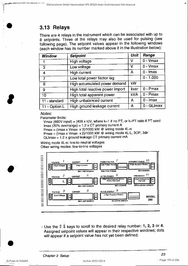
3.13 Relays There are 4 relays in the instrument which can be associated with up to 8 setpoints. Three of the relays may also be used for pulsing (see
following page). The setpoint values appear in the following windows
(each window has its number marked above it in the illustration below):
Window Setpoint Unit Range
1 High voltage V 0 - Vmax
3 Low voltage V 0 - Vmax
4 High current A 0 - {max
7 Low total power factor lag 0 - 1.000
8 High accumulated power demand kW
9 High total reactive power import kvar 0 - Pmax
10 High total apparent power kVA 0 - Pmax
11 - standard High unbalanced current A 0 - Imax
11 - Option L High ground leakage current A 0 - GLImax
Notes: Parameter limits:
Vmax (660V input) = (400 x k)V, where k=1 if no PT, or k=PT ratio if PT used
Imax (20% overrange) = 1.2 x CT primary current A
Pmax = (Imax x Vmax x 3)/1000 kW @ wiring mode 4L-n Pmax = (Imax x Vmax x 2)/1000 kW @ wiring mode 4L-L, 30P, 3dir
GLImax = 1.2 x ground leakage CT primary current mA
Wiring mode 4L-n: line-to-neutral voltages Other wiring modes: line-to-line voltages
O
11
VOLTAGE . CURRENT 4 POWER FACTOR APPA RENT POWER 10
(High Voltage) (high Current) (Low Power Facto' (High Apparent Power)
MAX. Aral DEMAND
VOLTAGE 2 CURRENT 5
REACTIVE POWER MAX.DEMAND
ACTIVE POWER 8 FREQUENCY 11
1. (Ng h Accumulated Active
Power Demand) Current) [High Unbalanced In
MAX. AAP DEMAND
VOLTAGE 3 CURRENT 6
MAX.DEMAM UNBALANCEDCURRENV
ACTIVE ENERGY 9 [ (Low Vdtage) I
MAX. ALP DEMAND
( High Reactive Power)
RE ACTIVE ENERGY
MODEL 290
- Use the U 11 keys to scroll to the desired relay number: 1, 2, 3 or 4.
Assigned setpoint values will appear in their respective windows; dots
will appear if a setpoint value has not yet been defined.
23 Chapter 3 Setup
Edmonstone Street Newmarket SPS SP023 Main Switchboard OM Manual
Q-Pulse Id TMS695 Active 29/01/2014 Page 193 of 236

- Press SELECT; the dot after the relay number will disappear. Window 5 will display 'on'. This allows the user to set or change the value at which the setpoint is activated. The 'High Voltage' setpoint value (or dots) will appear in window 1; the other windows will be empty.
- Use the it 4 keys to set the 'ON' value for the High Voltage setpoint.
- Press SELECT; window 5 will display 'on.d', indicating the time delay until setpoint operation. This may take a value from 0.1 to 99.9 seconds.
- Use the ft 4 keys to define the delay to operation. - Press SELECT; window 5 will display 'OFF'.
- Use the fill keys to scroll to the value at which the displayed setpoint will be released.
- Press SELECT; window 5 will display 'OFF.d', indicating the time delay until setpoint release. This may take a value from 1
to 999 seconds. - Press either: SELECT to move to another setpoint parameter, or
RESET to exit this relay and move to another relay/parameter.
- Press RESET to exit the relay after all desired setpoint values are defined; the dot will re-appear, and ON setpoint values will be displayed.
- Press RESET again to exit the parameter. Use the ft key to move to the next setup parameter.
NOTE It is possible to cancel both ON and OFF setpoints by pressing the fr and 11 keys simultaneously. A canceled setpoint can be re-instated by pressing either the 11
or 4 key.
Pulses Pulses may be defined for relays 1, 2 and 4. When one of these relays is displayed, the pulsing value in Window 9 can be set, from 1 to 200 units per pulse.
Pulse Name Description Units Pull Ac.En Pulse 1 - Active Energy kWh Pu12 rE.En Pulse 2 - Reactive Energy kvarh Pul4 rEt.E Pulse 4 - Returned Energy kWh
24 Chapter 3 Setup
Edmonstone Street Newmarket SPS SP023 Main Switchboard OM Manual
Q-Pulse Id TMS695 Active 29/01/2014 Page 194 of 236
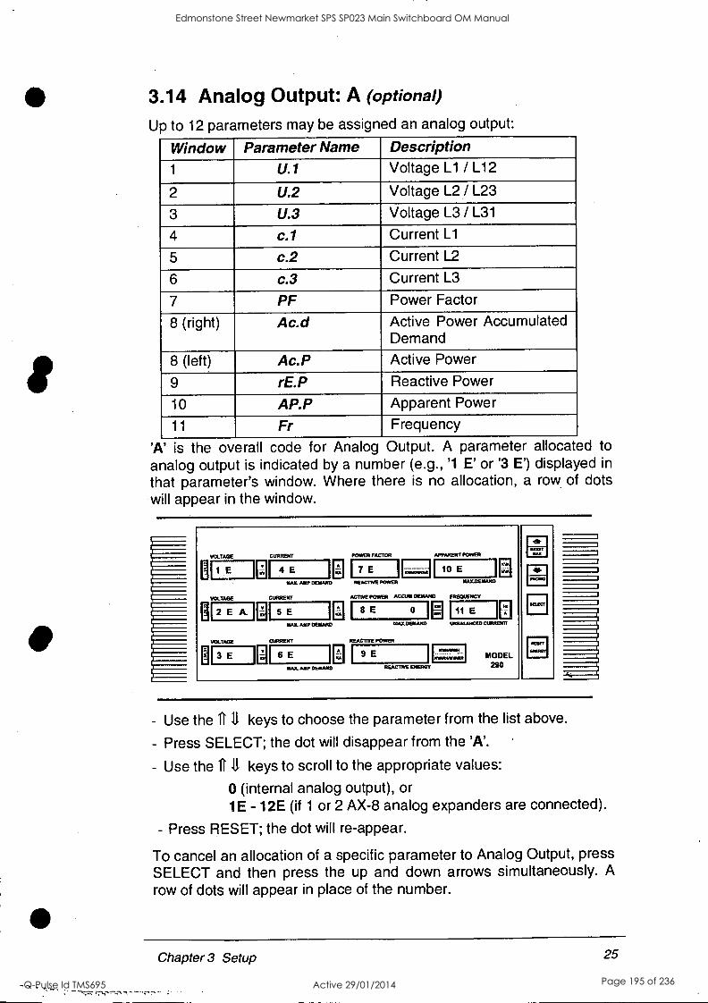
3.14 Analog Output: A (optional)
Up to 12 parameters may be assigned an analog output:
Window Parameter Name Description 1 u.1 Voltage L1 / L12
2 U.2 Voltage L2 / L23
3 U.3 Voltage L3 / L31
4 c./ Current L1
5 c.2 Current L2
6 c.3 Current L3
7 PF Power Factor
8 (right) Ac.d Active Power Accumulated Demand
8 (left) Ac.P Active Power
9 rE.P Reactive Power
10 AP.P Apparent Power
11 Fr Frequency
'A' is the overall code for Analog Output. A parameter allocated to
analog output is indicated by a number (e.g., '1 E' or '3 E') displayed in
that parameter's window. Where there is no allocation, a row of dots will appear in the window.
VOLTAGE
H 1 E
VOLTAGE
2 E A.
VOLTAGE
H 3 E
CUITERBIT
4 E
MA AMP DEMAND
CURRENT
5 E
MAX. AMP DENAND
CURRENT
6E MAX. AMP DEMAND
POWER FACTOR
I7 E I REACTIVE POWER
APPARENT POWER
10 E
ACTIVE POWER ACCUNI DEMAND
8 E 0
AIATLOENAND
REACITVE POWER
9 E
NANDEATAND
FROMIENCY
11 E 1.11tELALAMIXO Milner FT
RFACINE ENERGY
MODEL 290
RESET
CI
- Use the 1111 keys to choose the parameter from the list above.
- Press SELECT; the dot will disappear from the 'A'.
- Use the ft 11 keys to scroll to the appropriate values:
0 (internal analog output), or 1E - 12E (if 1 or 2 AX-8 analog expanders are connected).
- Press RESET; the dot will re-appear.
To cancel an allocation of a specific parameter to Analog Output, press SELECT and then press the up and down arrows simultaneously. A
row of dots will appear in place of the number.
Chapter 3 Setup 25
Edmonstone Street Newmarket SPS SP023 Main Switchboard OM Manual
Q-Pulse Id TMS695 Active 29/01/2014 Page 195 of 236
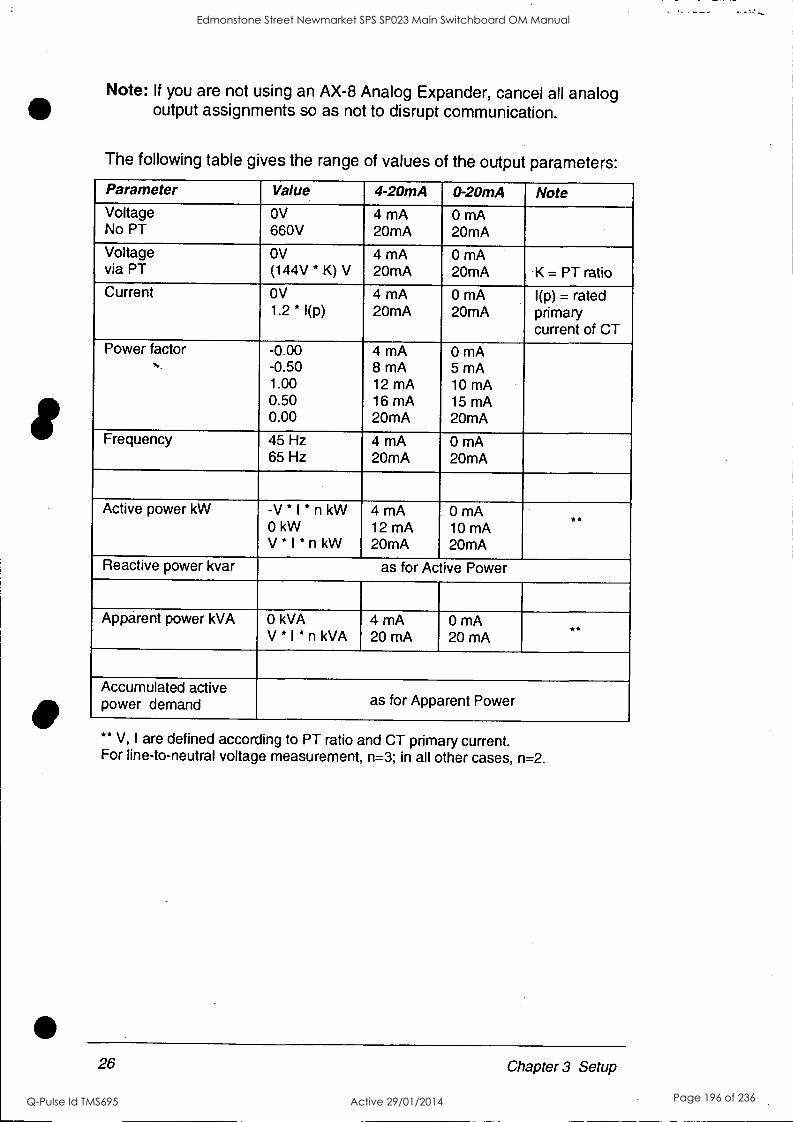
Note: If you are not using an AX-8 Analog Expander, cancel all analog output assignments so as not to disrupt communication.
The following table gives the range of values of the output parameters:
Parameter Value 4-20mA 0-20mA Note Voltage No PT
OV
660V 4 mA 20mA
0 mA 20mA
Voltage via PT
OV
(144V * K) V 4 mA 20mA
0 mA 20mA K = PT ratio
Current OV 1.2 * 1(p)
4 mA 20mA
0 mA 20mA
1(p) = rated primary current of CT
Power factor N.
-0.00 -0.50 1.00 0.50 0.00
4 mA 8 mA 12 mA 16 mA 20mA
0 mA 5 mA 10 mA 15 mA 20mA
Frequency 45 Hz 65 Hz
4 mA 20mA
0 mA 20mA
Active power kW -V * I * n kW 0 kW V * I * n kW
4 mA 12 mA 20mA
0 mA 10 mA 20mA
Reactive power kvar as for Active Power
Apparent power kVA 0 kVA V * I * n kVA
4 mA 20mA
0 mA 20mA
**
Accumulated active power demand as for Apparent Power
** V, I are defined according to PT ratio and CT primary current. For line-to-neutral voltage measurement, n=3; in all other cases, n=2.
26 Chapter 3 Setup
Edmonstone Street Newmarket SPS SP023 Main Switchboard OM Manual
Q-Pulse Id TMS695 Active 29/01/2014 Page 196 of 236
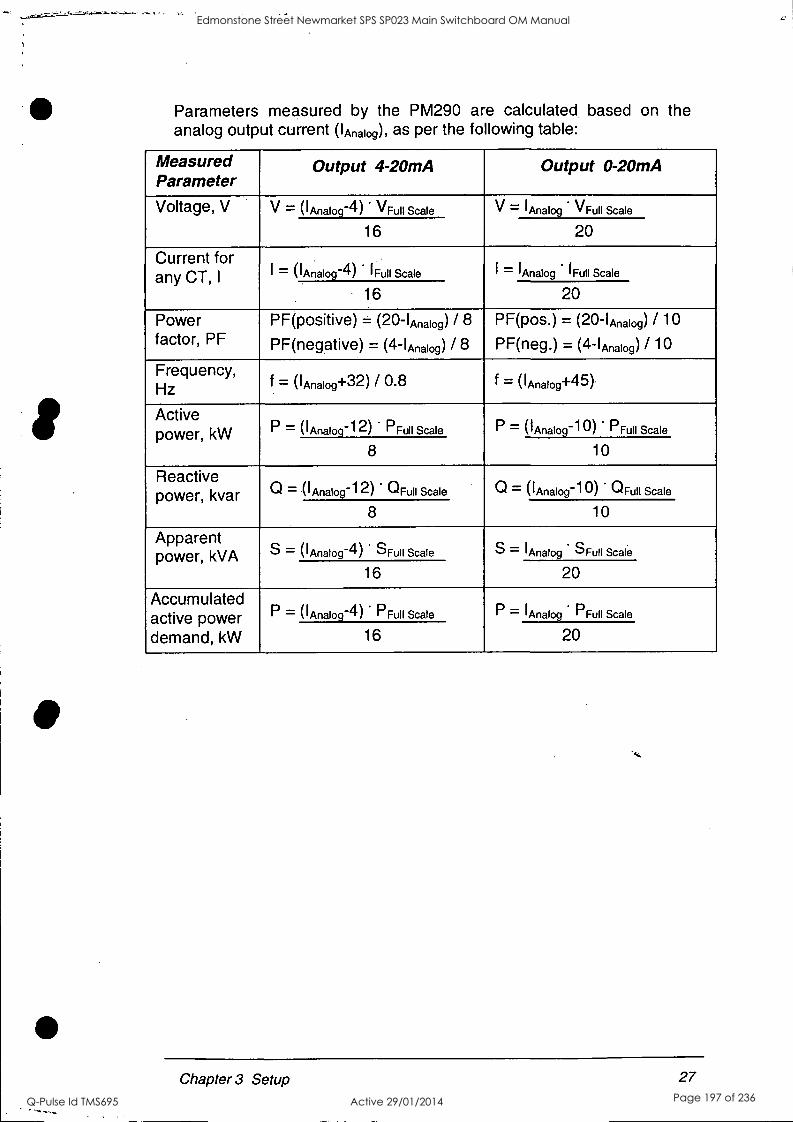
Parameters measured by the PM290 are calculated based on the analog output current ('Analog), as per the following table:
Measured Parameter
Output 4-20mA Output 0-20mA
Voltage, V V = ('Analog -4) VFull Scale V = 'Analog VFull Scale
16 20
Current for any CT, I
= i ('Analog -4) 'Full Scale I = 'Analog 'Full Scale
16 20
Power factor, PF
PF(positive) = (20- 'Analog) / 8
PF(negative) = (4- (Analog) / 8
PF(pos.) = (20- (Analog) / 10
PF(neg.) = (4-IAnalog) / 10
Frequency, Hz f llAnalog+32) / 0.8 f = (lAnalog+45 ).
Active power, kW P = ('Analog -12) PFull Scale P = ('Analog -10) PFull Scale
8 10
Reactive power, kvar Q = ('Analog -12) ' °Full Scale Q = ('Analog -10) °Full Scale
8 10
Apparent power, kVA S = ('Analog -4) SFull Scale S = 'Analog SFull Scale
16 20
Accumulated active power demand, kW
P 1-- = ('Analog -4) PFull Scale P = 'Analog PFull Scale
16 20
Chapter 3 Setup 27
Edmonstone Street Newmarket SPS SP023 Main Switchboard OM Manual
Q-Pulse Id TMS695 Active 29/01/2014 Page 197 of 236

4 Data Dis la
In the monitoring mode, values are displayed on 3 pages. Use the 11
key to scroll through the pages. The display will return to page 1 after 30 seconds. For resolution and parameter ranges, see Appendix A, Measurement Specifications.
4.1 Display Pages Page 1
Voltage
999
Voltage
Voltage
999
999
Current
9999
Power Factor Apparent Power
9.99 1 9999
Current Active Power Frequency
Current
9999
9999
_Energy
99999
99999
99.9
Page 2
Voltage
Voltage
999
999
999
Maximum Ampere Demand Reactive Power Maximum Demand kVA
9999
Maximum Ampere Demand
9999
999 9999
Maximum Demand Unbalanced current
99999
Maxim um Am ere Demand Reactive Enerqy
9999 99999
999
Note: For Option L., ground leakage current is displayed instead of unbalanced current
Page 3
9.99 I
Returned Energy
- 9999
28 Chapter 4 Display
Edmonstone Street Newmarket SPS SP023 Main Switchboard OM Manual
Q-Pulse Id TMS695 Active 29/01/2014 Page 198 of 236

4.2 Self-Test Diagnostics
The PM290 periodically perform self-test diagnostics. If the instrument
fails the self-test diagnostics, it discards the last measurement results,
and an error code (from 1 to 7) is displayed for 2 seconds on all LEDs.
Code 8 represents Power Down (Normal).
If the instrument resets itself continuously, contact your local
distributor.
If the Powermeter malfunctions, it is recommended to switch it off for
one minute and then to turn it on again.
4.3 RESET
In the monitoring mode, press the RESET button (towards the bottom
of the front panel) continuously for more than 5 seconds to reset the
following parameters to zero:
Energy kWH Returned energy kWH Reactive energy kVARH
Press the RESET MAX button (at the top of the front
panel) continuously for more than 5 seconds to reset
the following parameters to zero:
Ampere max. demand per phase
Active power max. demand Apparent power max. demand
RESET MAX
PAGING
SELECT
.1/4
RESET
ENERGY
To prevent unauthorized resetting, disable the reset function (see
Section 3.8).
Chapter 4 Display 29
r-."7."T":77'"CrK7
Edmonstone Street Newmarket SPS SP023 Main Switchboard OM Manual
Q-Pulse Id TMS695 Active 29/01/2014 Page 199 of 236
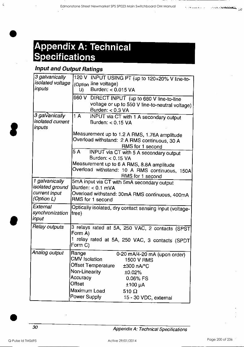
Appendix A: Technical Secifications Input and Output Ratings 3 galvanically isolated voltage inputs
120 V INPUT USING PT (up to 120+20% V line-to- (Option line voltage)
U) Burden: < 0.015 VA
660 V DIRECT INPUT (up to 660 V line-to-line voltage or up to 550 V line-to-neutral voltage) Burden: < 0.3 VA
3 gali7anically isolated current inputs
1 A INPUT via CT with 1 A secondary output Burden: < 0.15 VA
Measurement up to 1.2 A RMS, 1.76A amplitude Overload withstand: 2 A RMS continuous, 30 A
RMS for 1 second 5 A INPUT via CT with 5 A secondary output
Burden: < 0.15 VA Measurement up to 6 A RMS, 8.8A amplitude Overload withstand: 10 A RMS continuous, 150A
RMS for 1 second 1 galvanically isolated ground current input (Option L)
5mA input via CT with 5mA secondary output Burden: < 0.1 mVA Overload withstand: 30mA RMS continuous, 400mA RMS for 1 second
External synchronization input
Optically isolated, dry contact sensing input (voltage- free)
Relay outputs 3 relays rated at 5A, 250 VAC, 2 contacts (SPST Form A) 1 relay rated at 5A, 250 VAC, 3 contacts (SPDT Form C)
Analog output Range 0-20 mA/4-20 mA (upon order) CMV Isolation 1500 V RMS Offset Temperature ±300 nA/ °C Non-Linearity ±0.02% Accuracy 0.06% FS Offset ±100 pA Maximum Load 510 Q Power Supply 15 - 30 VDC, external
30 Appendix A: Technical Specifications
Edmonstone Street Newmarket SPS SP023 Main Switchboard OM Manual
Q-Pulse Id TMS695 Active 29/01/2014 Page 200 of 236

In put and Output Ratings Communication One serial port, EIA RS-232 or RS-422/RS-485
(optically isolated) standards Connector: 9-pin female D-type
Display .
High-brightness seven-segment digital LEDs, 11
windows. A total of 3 pages with simultaneous display of up to 11 parameters.
Voltage and current input terminals
Standard 9.52 mm pitch (UL recognized) Screw M 3 Maximum wire diameter 2.591 mm (10 AWG)
Service terminals
Standard 5 mm pitch (UL recognized XCFR2) Screw M2.6 Maximum wire diameter 2 mm (12 AWG)
Power supply 95-135V AC, 185-250VAC, 50/60 Hz, 20 VA
10-20V DC 20-38VDC 15 W 38-72VDC 80-160VDC 160-290VDC
Environmental Conditions Operating temperature
-20°C to 60°C (-4°F to 140°F)
Storage temperature
-25°C to 80°C (-13°F to 176°F)
Humidity 0 to 95% non-condensing
Construction Instrument body CASE ENCLOSURE: plastic ABS
(UL recognized QMFZ2) FRONT PANEL: plastic polycarbonate ,,
Instrument weight 2.65 kg (5.83 lbs.)
Standards UL File #E129258(N)
CE-EMC: 89/336/EEC as amended by 92/31/EEC and 93/68/EEC
CE-LVD: 73/23/EEC as amended by 93/68/EEC and 93/465/EEC
Appendix A: Technical Specifications
rv;rv.,s!57.tmr,-7,, ..-
31
Edmonstone Street Newmarket SPS SP023 Main Switchboard OM Manual
Q-Pulse Id TMS695 Active 29/01/2014 Page 201 of 236
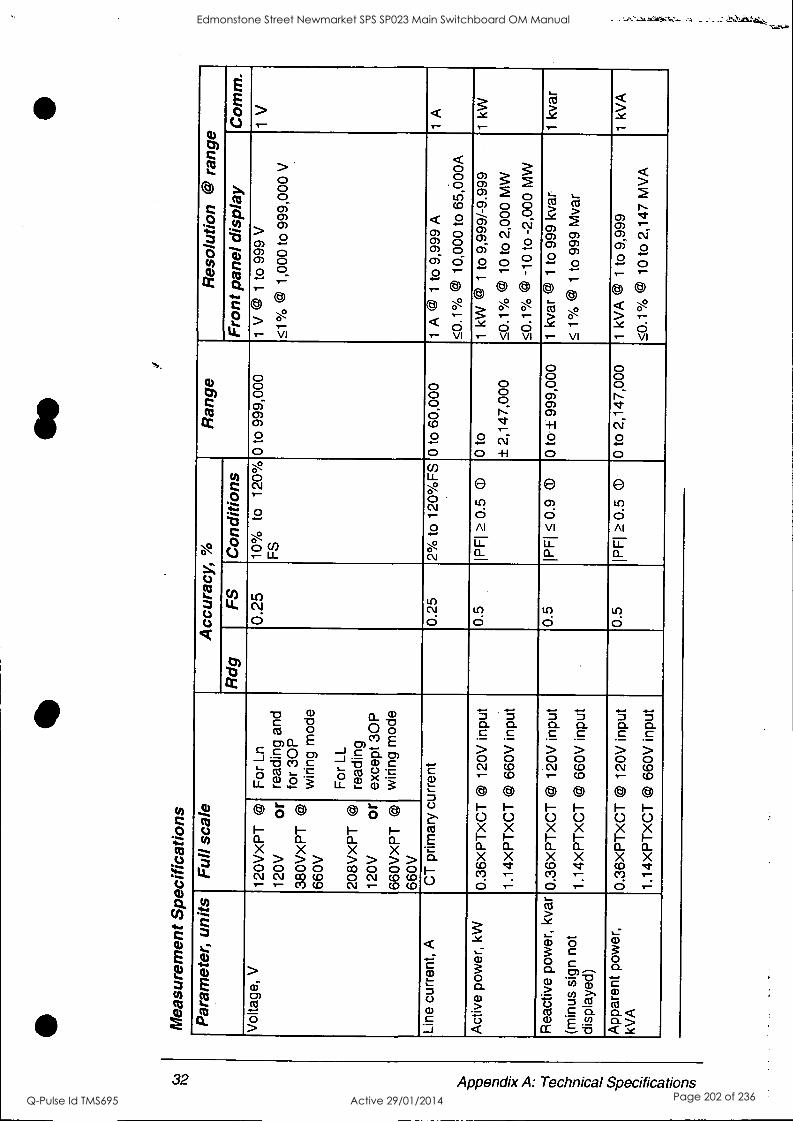
Mea
sure
men
t S
peci
ficat
ions
se
Par
amet
er,
units
F
ull s
cale
A
ccur
acy,
%
Ran
ge
Res
olut
ion
@ r
ange
R
dg
FS
C
ondi
tions
F
ront
pan
el d
ispl
ay
Com
m.
Vol
tage
, V
12
0VxP
T
@
120V
or
38
0VX
PT
@
660V
208V
XP
T
@
120V
or
66
0VX
PT
@
660V
For
Ln
read
ing
and
for 30
P
wiri
ng m
ode
For
LL
read
ing
exce
pt 3
0P
wiri
ng m
ode
0.25
10
%
to
120%
F
S
0 to
999
,000
1
V ©
1 to
999
V
.51°
/0 ©
1,0
00 to
999
,000
V
1 V
Line
cur
rent
, A
C
T p
rimar
y cu
rren
t 0.
25
2% to
120
%F
S 0
to 6
0,00
0 1
A @
1
to 9
,999
A
50.1
`)/0
@
10
,000
to
65,0
00A
1 A
Act
ive
pow
er,
kW
0.36
xPT
xCT
(4)
120V
inp
ut
1.14
XP
TX
CT
@ 6
60V
inpu
t
0.5
IPF
I 0.
5 o
0 to
± 2
,147
,000
1 kW
@
1 to
9,9
99/-
9.99
9
50.1
°/0
CO
10
to
2,00
0 M
W
50.1
% ©
-10
to
-2,0
00 M
W
1 kW
Rea
ctiv
e po
wer
, kv
ar
(min
us s
ign
not
disp
laye
d)
0.36
XP
TX
CT
@ 12
0V in
put
1.14
XP
TX
CT
@ 66
0V in
put
0.5
IPF
I <
0.9
0
0 to
± 9
99,0
00
1 kv
ar @
1
to 9
99 k
var
< 1
% ©
1 to
999
Mva
r
1 kv
ar
App
aren
t po
wer
, kV
A
0.36
xPT
xCT
@ 12
0V i
nput
1.14
XP
TX
CT
@ 66
0V in
put
0.5
IPF
I >
0.5
0
0 to
2,1
47,0
00
1 kV
A @
1
to 9
,999
50.1
cY0
@
10 to
2,1
47 M
VA
1 kV
A
Edmonstone Street Newmarket SPS SP023 Main Switchboard OM Manual
Q-Pulse Id TMS695 Active 29/01/2014 Page 202 of 236
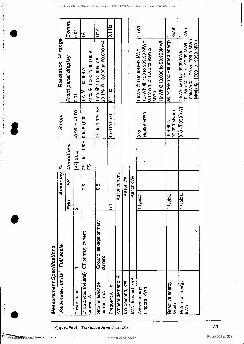
Mea
sure
men
t Spe
cific
atio
ns
N
Par
amet
er,
units
F
ull s
cale
A
ccur
acy,
%
Ran
ge
Res
olut
ion
@ r
ange
Rdg
F
S
Con
ditio
ns
Fro
nt p
anel
dis
play
C
omm
.
Pow
er fa
ctor
1
2 IP
FI
0.5
-0.9
9 to
+1.
00
0.01
0.
01
Unb
alan
ced
(neu
tral
) cu
rren
t, A
C
T p
rimar
y cu
rren
t 0.
5 2%
to
12
0%
FS
0
to 6
0,00
0 1
A @
1
to 9
99 A
51°/
0 ©
1,0
00 t
o 60
,000
A
1A
Gro
und
leak
age
curr
ent,
mA
G
roun
d le
akag
e pr
imar
y cu
rren
t 0.
5 2%
to
120%
FS
1m
A ©
1
to 9
,999
mA
50
.1')/
0 ©
10,
000
to 6
0,00
0 m
A
1mA
Fre
quen
cy,
Hz
0.1
45.0
to
65.0
0.
1 H
z 0.
1 H
z
Am
pere
dem
and,
A
As
for
curr
ent
kW d
eman
d, k
W
As
for
kW
kVA
dem
and,
kV
A
As
for
kVA
Act
ive
ener
gy
(impo
rt),
kW
h 1
typi
cal
0 to
99
,999
MW
h 1
kWh
© 0
to
99,9
99 k
Wh
10kW
h ©
100
to
999.
99 M
Wh
0.1M
Wh
(4/
1000
to
9999
.9
MW
h
1MW
h@l0
,000
to
99,9
99M
Wh
1 kW
h
Rea
ctiv
e en
ergy
, kv
arh
1 ty
pica
l -9
,999
to
99,9
99 M
varh
as
Act
ive
and
Ret
urne
d en
ergy
1 kv
arh
Ret
urne
d en
ergy
, kW
h 1
typi
cal
0 to
-9,
999
kWh
1 kW
h ©
0 t
o -9
999
kWh
10 k
Wh
© -
10 t
o -9
9.99
MW
h 10
0kW
h@ -
100
to -
999.
9 M
Wh
1MW
h ©
-10
00 t
o -9
999
MW
h
1 kWh
Edmonstone Street Newmarket SPS SP023 Main Switchboard OM Manual
Q-Pulse Id TMS695 Active 29/01/2014 Page 203 of 236

Key
:
PT
- e
xter
nal p
oten
tial
tran
sfor
mer
rat
io
CT
, C
T p
rimar
y cu
rren
t -
the
prim
ary
curr
ent
ratin
g of
the
ext
erna
l cur
rent
tra
nsfo
rmer
0
@ 10
% t
o 12
0 %
of
volta
ge fu
ll sc
ale
and
2% t
o 12
0 %
of
curr
ent
full
scal
e
NO
TE
S
1.
Acc
urac
y is
exp
ress
ed a
s ±
(pe
rcen
tage
of
read
ing
+ p
erce
ntag
e of
full
scal
e) ±
1 di
git.
Thi
s do
es n
ot i
nclu
de i
nacc
urac
ies
intr
oduc
ed b
y th
e us
er's
pot
entia
l and
cur
rent
tran
sfor
mer
s.
2.
The
se s
peci
ficat
ions
ass
ume
volta
ge a
nd
curr
ent
wav
efor
ms
with
T
HD
5.
5 %
(e
xcep
t ha
rmon
ic m
easu
rem
ents
) an
d an
op
erat
ing
tem
pera
ture
of
20 t
o 26
°C
.
Edmonstone Street Newmarket SPS SP023 Main Switchboard OM Manual
Q-Pulse Id TMS695 Active 29/01/2014 Page 204 of 236

Appendix B: Communication Cable Drawin is
RS-232 25-pin Computer Connector, Hardware Handshake
DB9 connector
male DB25 connector
female
1
GND GND 7
Tx Rx 2 3
Rx Tx To IBM PC/Compatible To PM 290 3
4 DTR DSR 6
DSR DTR 20
RS-232 25 pin
Note: For software handshake, short between pins 6 and 20; do not
connect to pins 4, 5.
9-pin Computer Connector, Software Handshake
DB9 male connector
GND
To PM290 4-
1
2
3
5
DB9 female
GND connector
5
Tx Rx
Rx Tx
DTR DSR
DSR I DTR
MII/a/aMI
2
3
6
To IBM PC/Compatible
RS -232 9 pin
Note: For hardware handshake, connect to pins 4, 5; do not short between pins 6 and 4.
Printer Connector - Example DB9 connector
male
GND GND
DB25 connector
female
1 7
Tx Rx 1111
2 3
Tx To PIV290 4- To printer 3 2
DTR CTS 5
RTS
R S-232 printer
Appendix B: Communication Cable Drawings 35
Edmonstone Street Newmarket SPS SP023 Main Switchboard OM Manual
Q-Pulse Id TMS695 Active 29/01/2014 Page 205 of 236
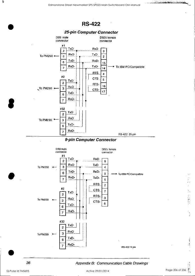
RS-422 25-pin Computer Connector
DB9 male DB25 female connector connector
To PM290
To PM290
To PM290 4--
#1 TxD RxD
2 3 RxD TxD
TxD- I RxD- o-
RxD-
#2 TxD
2
TxD-
RxD-
#32
2 TxD
3 RxD
TxD- 6
7 RxD-
TxD- .-
2
15
14
CTS_
RTS-
4
5
CTS- 16
17
---to To IBM PC/Compatible
RS-422 25 pin
,L
9-pin Computer Connector
DB9 male DB25 female connector corn ctcx
To PM290
To PM290
To PM290
4--
#1
2 TxD
3 RxD
6 TxD-
RxD- 7
TxD - - - -
RxD
TxD-
#2
2
3
6
RxD- 7
TxD #32
2
RxD 3
TAD-
RxD-
6
7
RxD 8
TxD
RxD-
TxD-
4
9
5
RTS 2
CTS
RTS- 3
I CTS- ---- 6
7
-* To IBM PC/C,ompalible
RS-422 9 pin
36 Appendix B: Communication Cable Drawings
Edmonstone Street Newmarket SPS SP023 Main Switchboard OM Manual
Q-Pulse Id TMS695 Active 29/01/2014 Page 206 of 236
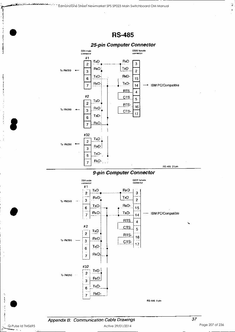
To PM290 4-
To PM290 4-
To PM290 4-
RS-485
25-pin Computer Connector 089 male connector
4.11
2
3
6
7
DB25 female connector
TxD RxD 3
RxD1 I TxD
TxD-
RxD-
#2 TxD
2
3
6
7
#32
2
3
6
7
RxD
TxD-
RxD
TxD
RxD
TxD-
RxD-
RxD-
TxD-
RTS
2
15
14
CTS
4
RTS-
CTS-
5
16
17
IBM PC/Compatible
RS-485 25 pi)
9-pin Computer Connector
connector
To PM290 -
To PM290 -
To F'M290
039 male
#1
2
3H TxD
RxDi
TxD-1
RxD
1 TxD
0825 female connector
2
IBM PC/Compatible
RxD-
TxD-
6
7
#2
2
15
14
1
Rx
TxD
RxD
TxD-
RxD-
TxD
RxD
ió S
RTS 4
CTS 5
r 16
17
RTS-
3
6
7
CTS-
#32
2
3
6 TxD-
RxD-
RS-485 9 pin
Appendix B: Communication Cable Drawings 37
Edmonstone Street Newmarket SPS SP023 Main Switchboard OM Manual
Q-Pulse Id TMS695 Active 29/01/2014 Page 207 of 236
TECHNICAL DATA SHEET
For
Edmondstone Street Pump Station
Equipment Type: Selector Switch
Location: Common Control
Model Numbers: CA 10
Manufacturer: Krais & Naimer
Supplier: Australian Solenoid. 22 Brookes Street Bowen Hills QLD 4006
Ph: 07 3252 8344 Fx: 07 3252 1497
Edmonstone Street Newmarket SPS SP023 Main Switchboard OM Manual
Q-Pulse Id TMS695 Active 29/01/2014 Page 208 of 236
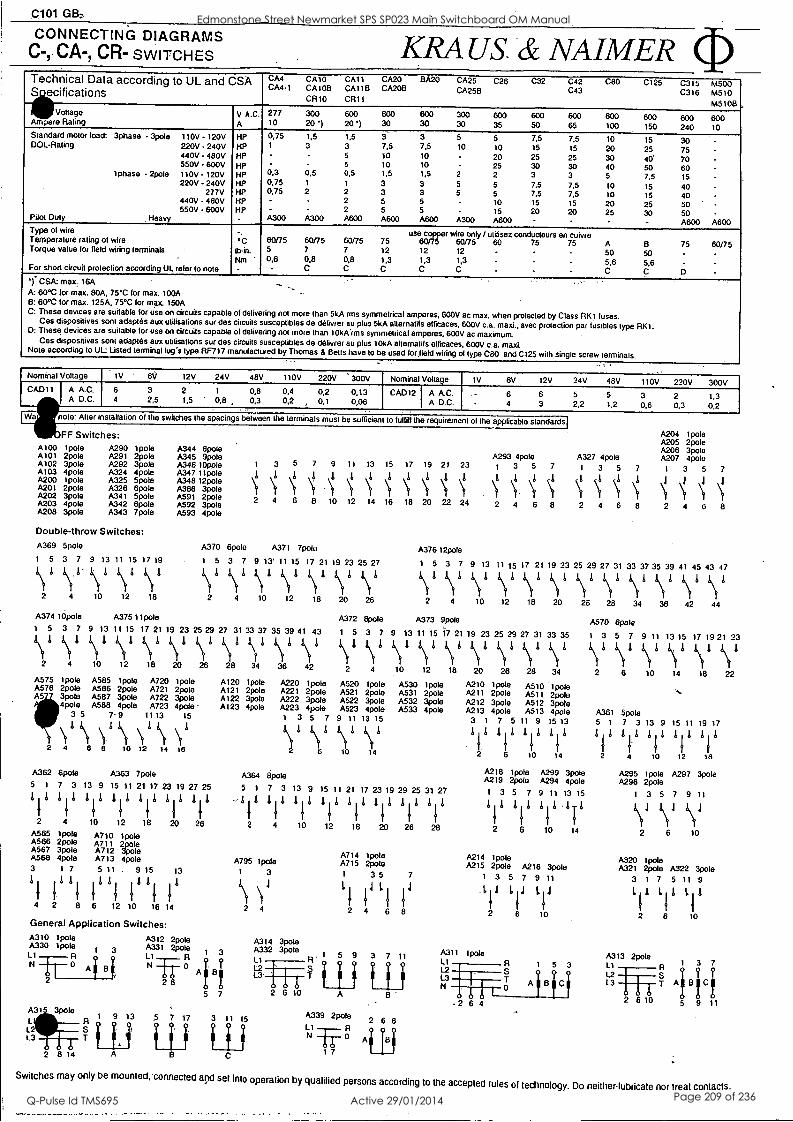
CONNECTING DIAGRAMS C-, CA-, CR- SWITCHES KRA US & NAIMER Technical Data according to UL and CSA
cifications CA4 CA10 CA11 CA20 BA20 CA25 C26 C32 C42 C80 C125 CM-1 CA1013 CAI 1B CA20B CA256 C43
CR10 CR11
0315 C316
M500 M510 M5108
Voltage V A.C. 277 300 600 600 600 300 600 600 600 600 600 600 600 Ampere Rating A 10 20') 20') 30 30, 30 35 50 65 100 150 240 10 Standard motor load: 3phase 3pole 110V - 120V HP 0,75 1,5 1,5 3 3 5 5 7,5 7,5 10 15 30 001-Rating 220V - 240V HP 1 3 3 7,5 7,5 10 10 15 15 20 25 75
440V - 480V HP - 5 10 10 - 20 25 25 30 40' 70 - 550V - 600V HP - ' 5 10 10 - 25 30 30 40 50 60 -
1phase - 2pole 110V - 120V HP CO 0.5 0,5 1,5 1,5 2 2 3 3 5 7,5 15 220V 240V HP 0,75 1 1 3 3 5 5 7,5 7.5 10 15 40 -
277V HP 0.75 2 2 3 3 5 5 7,5 7,5 10 15 40 440V - 480V HP 2 5 5 10 15 15 20 25 50 550V - 600V HP - - 2 5 5 - 15 20 20 25 30 50 Pilot Duty Heavy A300 A300 A600 A600 A800 A300 A600 - A600 A600
Type ol wire - . use copper wire only / ulilisez conducteurs en cuivre Temperature rating of wire *C 60/75 60/75 60/75 75 60/75 60/75 60 75 75 A - B 75 60/75 Torque value for field wiring terminals lb-in. 5 7 7 12 12 12 - 50 50 Not ' 0,6 0,8 0,8 1,3 1,3 1,3 - 5.6 5.6 - For short circuit protection according UL refer to note - C C C C C - - C C D
1. CSA: max: 16A A: 60°C for max. 80A, 75°C for max. 100A B: 60°C for max. 125A, 75°C for max. 150A C: These devices are suitable for use on circuits capable of delivering not more than 5kA rms symmetrical amperes, 600V ac max. when protected by Class RIO fuses. Ces dispositives sont adaptes aux utilisations sur des circuits susceptibles de delivrer au plus 5kA alternatifs efficaces, 600V c.a. maxi., avec protection par fusibles type RIO. 0: These devices are suitable for use on circuits capable ol delivering not more than 10kkrms symmetrical amperes, 600V ac maximum.
Ces disposilives sont adaptes aux utilisations sur des circuits susceptibles de delivrer au plus 10kA alternatils &Peaces, 600V c.a. maxi. Note according to UL: Listed terminal lug's type RF717 manufactured by Thomas & Betts have lo be used for field wiring of type C80 and C125 with single screw terminals.
Nominal Voltage tv 6V 12V 24V 48V 110V 220V ' 300V Nominal Voltage 1V 6V 12V 24V 48V 110V 220V 300V CAD11 ik A A.C.
A D.C. 6 4
3 2,5
2 1.5
1
0,8 0,8 0,3
0,4 0,2
0,2 0,1
0,13 0,06
CAD12 I A A.G. A D.C.
6 - 4
6 3
5
2,2 5
1,2 3 0,6
2 0,3
1,3 0,2
Wa note: Alter installation of the switches the spacings between the terminals must be sulficien to fulfill the requirement of the applicable standards
FF Switches: A100 1pole A101 2pole A102 3pole A103 4pole A200 Vole A201 2pole A202 3pole A203 Opole A208 3pole
A290 1pole A291 2pole A292 3pole A324 4pole A325 5pole A326 6pole A341 5pole A342 6pole A343 7pole
Double-throw Switches: A369 5pole
1 5 3 7 9 13 11 15 17 19
1,ft
2 4 10 12 18
A344 Boole A345 9pole A346 lOpole A347 11pole A348 12pole A386 3pole A591 2pole A592 3pole A593 4pole
A204 1pole A205 2pole A206 3pole
A293 4pole A327 4pole A207 4pole 1 3 5 7 9 11 13 15 17 19 21 23 1 3 5 7 1 3 5 7 1 3 5 7 1111111111
\t /
\' 1
. \If if 1 2 4 6 8 10 12 14 16 18 20 22 24 2 4 6 8 2 4 6 8 2 4 6 8
A370 6pole A37I 7pole A37612pole 1 5 3 7 9 13' 11 15 17 21 19 23 25 27 1 5 3 7 9 13 11 15 17 21 19 23 25 29 27 31 33 37 35 39 41 45 43 47 1\1 1\1 1\1 1\i1 y by 1\1 1 y
Y y
Y Y Y V V if 2 4 10 12 18 20 26 2 4 10 12 18 20 26 28 34 36 42 44
A374 10pole A375 11pole A372 Opole A373 9pole A570 6pole 1 5 3 7 9 13 11 15 17 21 19 23 25 29 27 31 33 37 35 39 41 43 1 5 3 7 9 13 11 15 17 21 19 23 25 29 27 31 33 35 1 3 5 7 9 11 13 15 17 19 21 23 it 1\11 1\1 1\1 1\1 1\1 1\1 Syl 1\1 /\1 /\1 1\1 1\1 \lb 1\11 1\11 by! b\tb by. 1\1 1\1 1\1 \ fl 1\ 4 1\1 1\1
2 4 10 12 18 20 26 28 34 36 42 2 4 .10 12 18 20 26 28 34 2 6 10 14 18 22 A575 1pole A585 1pole A720 1pole A120 1pole A220 1pole A520 1pole A530 1pole A210 1pole A510 Opole ,.. A578 2pole A586 2pole A721 2pole A121 2pole A221 2pole A521 2pote A531 2pole A211 2pole A511 2pole A5 3pole A587 3pote A722 3pole A122 3pole A222 3pole A522 3pole A532 3pole A212 3pole A512 3pole 4pole A588 4pole A723 Opole A123 4pole A223 4pole A523 Opole A533 4pole A213 4pole A513 4pole A361 Spate 3 5 7 -9 11 13 15 1 3 5 7 9 11 13 15 3 1 7 5 11 9 15 13 5 1 7 3 13 9 15 11 19 17
2 4 6 8 10 12 14 16
V11\ \'1. 1\1 \fl Vi
\I 1 i\IS 11411111 1- 1 1 I
1
./
1, A
F
I 1
1
L 1
1
1 1
I
1
6 10 14 2 6 10 14 2 4 10 12 18
A218 1pole A299 3pole A295 1pole A297 3pole A362 6pole A363 7pole A364 apole A219 2pole A294 4pole A296 2pole 5 1 7 3 13 9 15 11 21 17 23 19 27 25 5 1 7 3 13 9 15 11 21 17 23 19 29 25 31 27 1 3 5 7 9 11 13 15 1 3 5 7 9 11 I it 1111.11 Ili 11 LI -1/1111111111111/ 111111-11 1/1111 11111111 IIIT 4\J 1\1 1\J 2 4 10 12 18 20 26 2 4 10 12 18 20 26 28 2 6 10 14 2 6 10 A565 1pole A710 1pole
A566 2pOle A711 29ole A567 3pole A712 3pole A568 4pole A713 4pole 3 1 7 5 11 9 15 13
il
1 1
1
Al 11 11
11
/ li
4 2 8 6 12 10 16 14
General Application Switches:
A315 3pole L L3 T
2 8 14
1
A3I2 2pole A331 2pole 1 3
N 0 i AiB 6
5 7
9 13 5 7 17
A714 1pote A214 1pote A795 1pole A715 2pote A215 2pole A216 3pole 1 3 1 35 7 1 3 5 7 9 11
L
I 11
L
I 14
111./ 11,1 / 1 2 4 6 8 2 6 10
2 4
3 11 15 A339 2pole 2 6
0 Ai 1Bi 1 7
A311 Vole Li 12
r ° A 13
L3
1 5
0 2 6 4
3
A320 1pole A321 2pole A322 3pole
3 1 7 5 11 9
LI1 LII LI1
2 6 10
A313 2pole Li L2 13
2 6 10
1 3 7
BiCi 5 9 11
Switches may only be mounted, connected and set into operation by qualified persons according to the accepted rules of technology. Do neither-lubricate nor treat contacts.
Edmonstone Street Newmarket SPS SP023 Main Switchboard OM Manual
Q-Pulse Id TMS695 Active 29/01/2014 Page 209 of 236
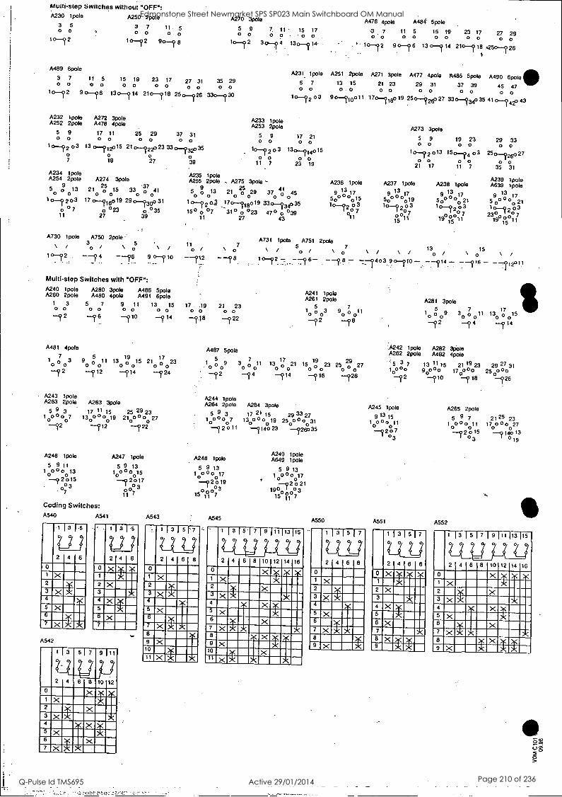
Multi-step Switches without "OFF": A230 1pole
3 5 O 0
10-12
A250 2pole
3 7 11 5 o o o o
1 o-72 90-4 6
A489 6pole
3 7 11 5 15 19 23 17 O 0 0 0 0 0 0 0
10-12 9 0-16 130-114 210--1).113 250-126 330-130
A270 3pole
5 9 o o
to-72
27 31 35 29 a 0 0 0
A232 Vole A252 2pole
5 9 o o
A272 3pole A478 4pole
17 11 o o
25 29 0 0
10 --4203 13 (3-11,15 210 -122z'23 7 19 27
A234 1pole A254 2pole
o So 9
013
1 0--? 2 03 0 °7
11
A274 3pole
21 2,75, 15 33 .307 41 o o o o
17 0-716019 29 0-?300 31
o °23 o °35 27 39
37 31
33 o-732035
A730 loofa A750 2pole \ / 3 5
10-72 --9 4 - -76 9 0-910 1 '
Multi-step Switches with "OFF": A240 'pole A280 3pole A486 5pole A260 2pole A480 4pole A491 6pole
1 3 5 7 9 11 13 15 o o 0 0 0 0 0 0 -12 -16 --710 --714
A481 4pole
7 1 0
-7 2
3 9 5
0 011
-112
19 17 130 0 015 21 0 023
-714 -724
A243 Ipole A263 2pole A283 3pole
5 9 3 0 o
o7 -72 -712 --722
17 11 15 25 29 23
130 °0019 210 °00 27
A246 loofa
5 9 11 1
o 000
o 13
-7 2 o15 03
07
Coding Switches: A540 A541
1 1 3 1 -5
007 2 4 6
0 1 X 2
3 4
5
6
7
X
A542
A247 1pole
5 9 13 1.013 0.15 -9 2:17
°3 0 11 7
A543
039
A235 1pole A255 2pole
5o
9
° 0 13
10--72 oJ 150 07
11
"0 , --712
17 .19 o o
-118
7. 11 - 15 17
3o -74 130-714.
A476 4pole A484' 5pole
3 7 11 5 15 19 23 17 27 29 o o o o o o o o o o . ' 10-72 90--7 6 13 0--714 210 --418 .250-7 26
1
A231. 1pole A251 2pole A27I 3pole A477 Opole A485 5pole A490 6pole 5 7 13 15 21 23 29 31 37 39 45 47 O 0 0 . 0 0 0 0 0 0 0 0 0 10-12 o 3 9 o-710o 11 170- 718o19 250-725o 27 33 o--734o 35 41 o-7 410 43
A233 1pole A253 2pole
5 9 17 21 o o o o
03 130 -- 414015 - T2 O 0 O 0
11 7 23 19
A275 3pole 25 41
o 21 0 29 37 45 o o
0
17o-715019 330-734035 31° 0 023 47° 0 039
27 43
\ 0
-18
21 23 o o -7 22
A236 ;pole 1 90 o 3 01715
50
A273 3pole
5 9 o
1°-? 2 °13 O o
21 17
A237 1pole 1 9 n 3
17 50° - 0019 10- --7203
o 5
19 23 O 0
150-14 o3 o o
11 7
A238 1pole 1 9
00-3 17
5 00 21
10-7 2 0 3 o 1905°0 7
29 33 o o
250-126°27 o o
35 31
A239 1pole A639 1pole
13 9 n 17 5 0°- 00 21
1°12:3 23° 7
190;3,01,
A731 1pole A751 2pole 13 / 50
o 7
o / 015 / 10-72 6- --?.8,7 --_14039 010 - -112011
A487 5pole
5 7 10 o 09 3 o 011
-72 -74
A244 1pole A264 2pole
5 9 3 1
o 0 007
-72°11
A248 1pole
5 9 13 1 0 17
--9 2 o19 03
15;31107
0
1 1 3 1 .5
o o, 0
2
X 4 6
1
-i 3 15 h.7
o o o
2 4 6 8
0
2
3 3 X X
5
6 X 7
1 1
2
3
4
5 1 7 9 1 11
o 0
6 8 10 i2 0 X X 1 X
f 2
X 3 X f X 4 X 5 X 6 X 7 X
Y;.
X 5 X 6
7 X X 8 X
X 10
11 X
A545
A241 1pole A261 2pole
5
10 ° 3 90 ° o" -72
17 19 29 13 0 21 15 0 23 25 0 27 o o o o o o --714 -716 ---726
A284 3pole 17 21 15 29 33 27
130000°19 250 °0031 31
-7140 23 --7280 35
A249 "pole A649 1pole
5 9 13 1
o 00
o 17
--72021 19% o°3
15 11 7
1
°WOW° 2
3
4
5
6
7--19
8
111
10 12
13
14
15
16
0 X rim nun nu i x u n x U x gm E311 mi 11
4 NEI x ra a u x II 5 Pall x 11 7 X ara a 8 Ea X EllEg
90 X Ell; fig il x ii xm EE Ea
A550
1 1 3 1 5 1 7
o .000
2 4 6 8
0 1 X 2
3 X 4 X 5 X 6
7 X fX 9 X
A281 3pole
10 0 5
09 300 011 130 0 015
-72 -7 4 -714
A242 1pole A282 3pole A262 2pole A482 4pole
5 3 7 13 1115 1 000 90000
A245 1pole 9 13 15
1 0 00011 o -0207
03
A551
-710
0
1
2
3
4
5
6
1 1 3 1 5 1 7
oo oo
2 4 6 8
21 19 23 29 27 31
-7 18 25 04206 17 0 000
A265 2pole
5 9 7 1
oo 0o011
A552
2 015 03
21 25 23 17o 0 0 0027
-7140 13 019
1
0
3 5 7 9 11 13 15
a/ o o
2 4 6 8 10 12 14 16
o X meg Ulla 1 x 2 Ela X 1111 3 X ES EMI 4 M X M Ill 5 x 1111 Pa II 6 1311 x II 7 X Eng El 8 Es x ram 9 X M MEI
Edmonstone Street Newmarket SPS SP023 Main Switchboard OM Manual
Q-Pulse Id TMS695 Active 29/01/2014 Page 210 of 236
o
TECHNICAL DATA SHEET
For
Edmondstone Street Pump Station
Equipment Type: Variable Speed Drive
Location: Pump Control
Model Numbers: VLT 6275
Manufacturer: Danfoss
Supplier: Danfoss. 32 Billabong Court Stafford QLD 4053
Ph: 07 3356 7911 Fx: 07 3890 4413
Edmonstone Street Newmarket SPS SP023 Main Switchboard OM Manual
Q-Pulse Id TMS695 Active 29/01/2014 Page 211 of 236
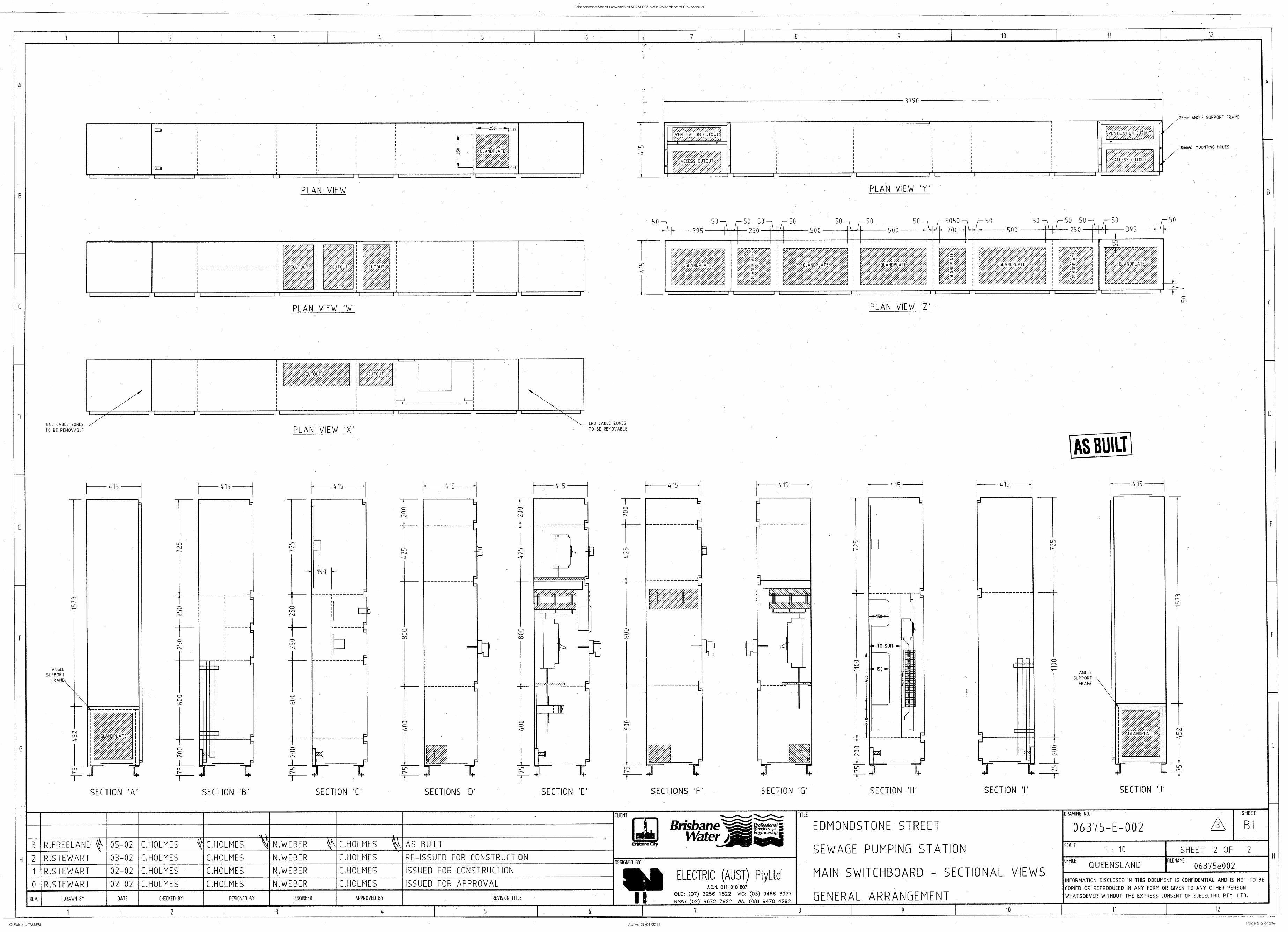
CUTOUT
10 11 12
END CABLE ZONES
TO BE REMOVABLE
ANGLE
SUPPORT FRAME
PLAN VIEW
w, 4 ,/, ,. , /,.., v . / . ,' / /., , r m
,T , / /j // A
PLAN VIEW 'W'
415
SECTION 'A'
Lit 1,1
415
SECTION 'B'
PLAN VIEW 'X'
415
SECTION 'C'
N''N'_ END CABLE ZONES
TO BE REMOVABLE
415
SECTIONS 'D' SECTION 'E'
/ V U
_ R" A
7 ,./ //zit/ , 'VENTILATION CUTOUT'
.2/ /// //%/, ,VENTILATiON CUTOUT)
/
, ACCESS CUTOUT //
." ' ,,,/, A o
ACCESS CUTOUT Ui
PLAN VIEW 'Y'
50 5050 -- 50
500 200
2Smm ANGLE SUPPORT FRAME
10mm0 MOUNTING HOLES
0
415
-LF
SECTIONS 'F'
415
-I-
SECTION '0'
PLAN VIEW 1'
415
O
SECTION 'I'
ANGLE
SUPPORT FRAME
415
SECTION 'J'
US
3 R.FREELAND 05-02 C.HOLMES
2 R.STEWART 03-02 C.HOLMES
R.STEWART 02-02 C.HOLMES
0 R.STEWART 02-02 C.HOLMES
REV. DRAWN BY DATE CHECKED BY
r\ C.HOLMES N.WEBER C.HOLMES AS BUILT
C.HOLMES N.WEBER C.HOLMES RE-ISSUED FOR CONSTRUCTION
C.HOLMES N.WEBER C.HOLMES ISSUED FOR CONSTRUCTION
C.HOLMES N.WEBER C.HOLMES ISSUED FOR APPROVAL
DESIGNED BY ENGINEER APPROVED BY REVISION TITLE
CLIENT
Brisbane Water AV
DESIGNED BY
1111 ELECTRIC (AUST) PtyLtd A.C.N. 011 010 807
OLD: (07) 3256 1522 VIC: (03) 9466 3977
NSW: (02) 9672 7922 WA: (08) 9470 4292 I I
TITLE
EDMONDSTONE STREET
SEWAGE PUMPING STATION
MAIN SWITCHBOARD - SECTIONAL VIEWS
GENERAL ARRANGEMENT
DRAWING NO.
06375-E-002 SHEET
B1
SCALE
1 : 10 SHEET 2 OF
OFFICE
QUEENSLAND FILENAME
06375e002
INFORMATION DISCLOSED IN THIS DOCUMENT IS CONFIDENTIAL AND IS NOT TO BE
COPIED OR REPRODUCED IN ANY FORM OR GIVEN TO ANY OTHER PERSON
WHATSOEVER WITHOUT THE EXPRESS CONSENT OF SJELECTRIC PTY. LTD.
2 4 5 7 8 9 10 11 12
Edmonstone Street Newmarket SPS SP023 Main Switchboard OM Manual
Q-Pulse Id TMS695 Active 29/01/2014 Page 212 of 236

DRAWINGS
Edmonstone Street Newmarket SPS SP023 Main Switchboard OM Manual
Q-Pulse Id TMS695 Active 29/01/2014 Page 213 of 236
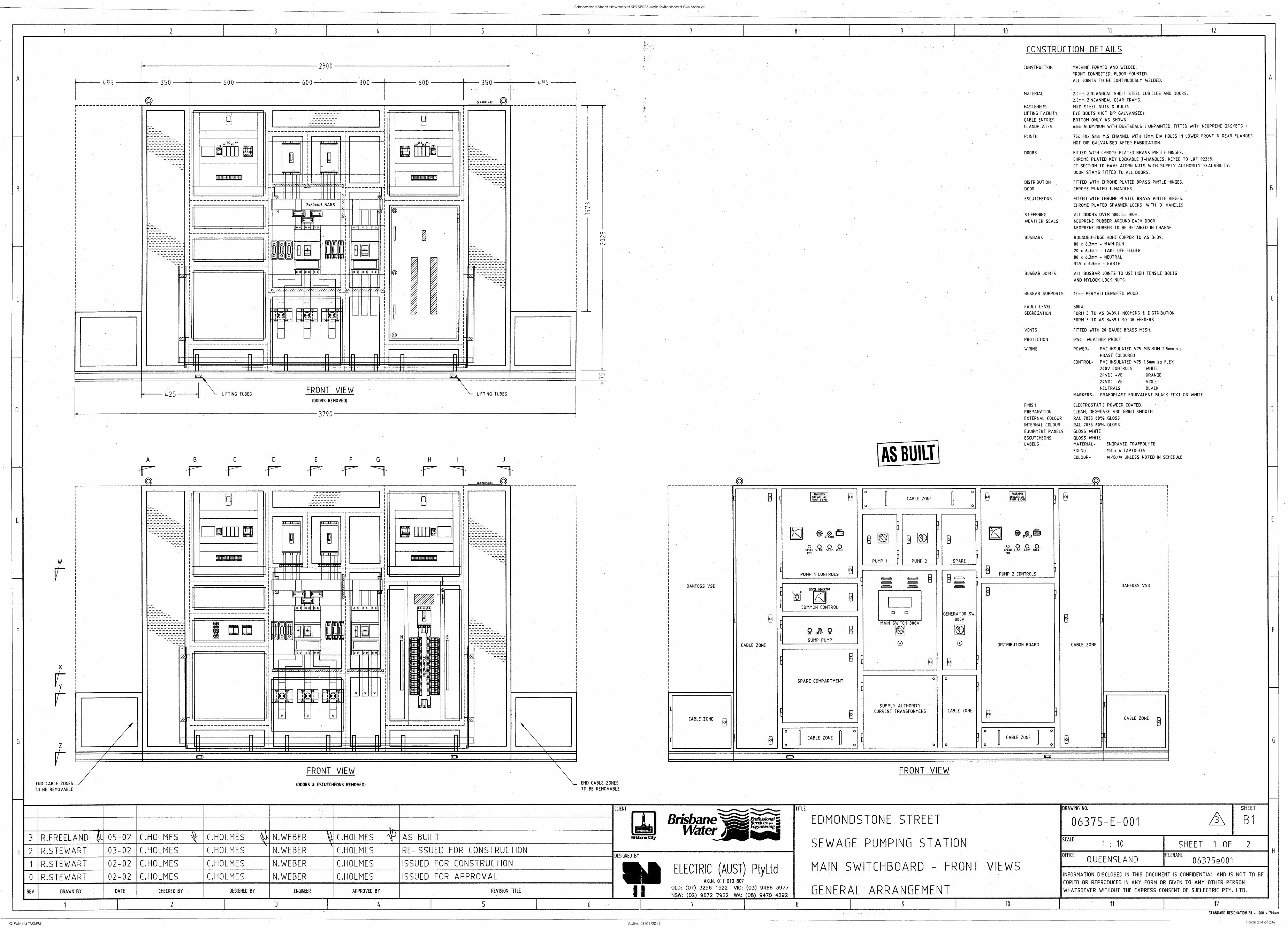
10 11 12
495
r (6)
350 600 600
2800
300 600 350
L.
' kiuo. ! 1111
IIIINIIIII0IINIHN01111
r
IN MI IBM 11111
L
425
191
4'1fi
,.., iillE
IIIIIIIIIIIIIIIIIIIIIIIIIUI
L
1
495
1
LIFTING TUBES FRONT VIEW
(DOORS REMOVED)
r
A B C D E
3790
LIFTING TUBES
F G
111111111111111111111111
L
=1=11
r
.I 1..1 I.
LJ
D 0 9 0
1111111111111111111111 III Ill
r
mg 111 =
N
L
FRONT VIEW
END CABLE ZONES MOORS 8 ESCUTCHEONS REMOVED) END CABLE ZONES
TO BE REMOVABLE TO BE REMOVABLE
CONSTRUCTION DETAILS
A
AND DOORS.
FITTED WITH NEOPRENE GASKETS I
HOLES IN LOWER FRONT & REAR FLANGES
HINGES.
KEYED TO L&F 92268.
AUTHORITY SEALABILITY.
HINGES.
B
HINGES.
HANDLES
BOLTS
sq.
FLEX
TEXT ON WHITE
D
SCHEDULE
B
CONSTRUCTION
MATERIAL
FASTENERS
LIFTING FACILITY
CABLE ENTRIES
GLANDPLATES
PLINTH
DOORS
DISTRIBUTION
DOOR
ESCUTCHEONS
STIFFENING
WEATHER SEALS
BUSBARS
BUSBAR JOINTS
BUSBAR SUPPORTS
FAULT LEVEL
SEGREGATION
VENTS
PROTECTION
WIRING
FINISH
PREPARATION
EXTERNAL COLOUR
INTERNAL COLOUR
EQUIPMENT PANELS
ESCUTCHEONS
LABELS
FRONT VIEW
MACHINE FORMED AND WELDED.
FRONT CONNECTED, FLOOR MOUNTED.
ALL JOINTS TO BE CONTINUOUSLY WELDED
2.0mm ZINCANNEAL SHEET STEEL CUBICLES
2.0mm ZINCANNEAL GEAR TRAYS.
MILD STEEL NUTS & BOLTS.
EYE BOLTS (HOT ZIP GALVANISED)
BOTTOM ONLY AS SHOWN.
6mm ALUMINIUM WITH DUSTSEALS 1 UNPAINTED,
75x 40x 5mm M.S CHANNEL WITH 13mrn DIA
HOT DIP GALVANISED AFTER FABRICATION.
FITTED WITH CHROME PLATED BRASS PINTLE
CHROME PLATED KEY LOCKABLE T-HANDLES,
CT SECTION TO HAVE ACORN NUTS WITH SUPPLY
DOOR STAYS FITTED TO ALL DOORS.
FITTED WITH CHROME PLATED BRASS PINTLE
CHROME PLATED T-HANDLES.
FITTED WITH CHROME PLATED BRASS PINTLE
CHROME PLATED SPANNER LOCKS, WITH '0'
ALL DOORS OVER 1000mm HIGH.
NEOPRENE. RUBBER AROUND EACH DOOR.
NEOPRENE RUBBER TO BE RETAINED IN CHANNEL
ROUNDED-EDGE HDHC COPPER TO AS 3439.
HO x 6.3mm - MAIN- RUN
20 x 6.3mm - TAKE OFF FEEDER
80 x 6.3mm - NEUTRAL
31.5 x 6.3mm - EARTH
ALL BUSBAR JOINTS TO USE HIGH TENSILE
AND NYLOCK LOCK NUTS.
12mm PERMALI DENSIFIED WOOD
50KA
FORM 3 TO AS 3439.1 INCOMERS & DISTRIBUTION
FORM 3 TO AS 3439.1 MOTOR FEEDERS
FITTED WITH 20 GAUGE BRASS MESH.
IP54 WEATHER PROOF
POWER- PVC INSULATED V75 MINIMUM 2.5mm
PHASE COLOURED
CONTROL- PVC INSULATED V75 1.5mm sq
240V CONTROLS WHITE
24VOC +NE ORANGE
24VDC -VE VIOLET
NEUTRALS BLACK
MARKERS- GRAFOPLAST EQUIVALENT BLACK
ELECTROSTATIC POWDER COATED.
CLEAN, DEGREASE AND GRIND SMOOTH
RAL 7035 60% GLOSS
RAL 7035 60% GLOSS
GLOSS WHITE
GLOSS WHITE
MATERIAL- ENGRAVED TRAFFOLYTE
FIXING- M3 x 6 TAPTIGHTS
COLOUR- W/B/W UNLESS NOTED IN
TITLE
EDMONDSTONE STREET
SEWAGE PUMPING STATION
MAIN SWITCHBOARD - FRONT VIEWS
GENERAL ARRANGEMENT
DRAWING NO.
06375-E-001 SHEET
B1
SCALE
1 : 10 SHEET 1 OF 2
OFFICE
QUEENSLAND H
FILENAME
06375e001
INFORMATION DISCLOSED IN THIS DOCUMENT IS CONFIDENTIAL AND IS NOT TO BE
COPIED OR REPRODUCED IN ANY FORM OR GIVEN TO ANY OTHER PERSON
WHATSOEVER WITHOUT THE EXPRESS CONSENT OF SJELECTRIC PTY. LTD.
DANFOSS VSD
3 9 3
Ei ]
CABLE ZONE
,
DANEOSS VSD
CABLE ZONE
E
El
meatus 0.0l. DT POW I L/11
0 *
. CABLE ZONE
o
0
Anna ISOlt. 91 8 PLAIP 2 I/B
n 9.6 Sal =OTC .9,-
P01
0
PUMP
0
1
3
0
) PUMP
0
2
3
SPARE
9.15
5129 Si 520 PR 7
DOT
[ PUMP 1 CONTROLS 13 H PUMP 2 CONTROLS
, ,---.
, . 2 , 2- r-. ,-.
GENERATOR SW.
800A
t1s10
0
o
E
L1] 8 COMMON CONTROL
DISTRIBUTION BOARD
1
CI 0
rL 9 R. 9 o
SUMP PUMP
MAIN SWITCH 800A
E
0
o
SPARE COMPARTMENT
E
El
o
SUPPLY AUTHORITY
CURRENT TRANSFORMERS
o
CABLE ZONE
ry
CABLE ZONE
E
CABLE ZONE B
E 8
o
. CABLE ZONE
o
0
. . .
o
1 . CABLE ZONE
o
CMD L=1
3 R.FREELAND 05-02 C.HOLMES C.HOLMES N.WEBER C.HOLMES
2 R.STEWART 03-02 C.HOLMES C.HOLMES N.WEBER C.HOLMES
R.STEWART 02-02 C.HOLMES C.HOLMES N. WEBER C.HOLMES
0 R.STEWART 02-02 C.HOLMES C.HOLMES N.WEBER C.HOLMES
REV. DRAWN BY DATE CHECKED BY DESIGNED BY ENGINEER
AS BUILT
RE-ISSUED FOR CONSTRUCTION
CLIENT
pig Brisbane'--;.'---.---k.,;Er-si- WaterArti
Elisbro Cry
ISSUED FOR CONSTRUCTION
ISSUED FOR APPROVAL
APPROVED BY
2 3 4
REVISION TITLE
5
DESIGNED BY I ELECTRIC (AUST) PtyLtd A.C.N. 011 010 807
I I 6
OLD: (07) 3256 1522 VIC: (03) 9466 3977 NSW: (02) 9672 7922 WA: (08) 9470 4292
7 8 9 10 11 12
STANDARD DESIGNATION 13I - 1000 x 707s
Edmonstone Street Newmarket SPS SP023 Main Switchboard OM Manual
Q-Pulse Id TMS695 Active 29/01/2014 Page 214 of 236

INSPECTION & TEST RESULTS
Edmonstone Street Newmarket SPS SP023 Main Switchboard OM Manual
Q-Pulse Id TMS695 Active 29/01/2014 Page 215 of 236
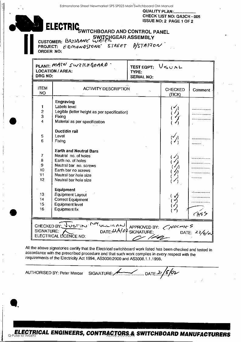
I I
QUALITY PLAN- CHECK LIST NO: QA3CH - 005 ISSUE NO: 2 PAGE 1 OF 2
ELECTRIC, ,IIVITCHBOARD AND CONTROL PANEL
SWITCBG EAR ASSEMBLY CUSTOMER: 13/V.SAA/Ve Wei t PROJECT: 6-- 0 ni c4iva go 11)c s 7 Ace T lYS Trl rzo ORDER NO:
PLANT: /11601/ s Lt/T- rut 304A4 -
LOCATION / AREA: DRG NO.
TEST EQPT: V IS u rk I-- TYPE: SERIAL NO:
ITEM NO
ACTIVITY DESCRIPTION CHECKED (TICK)
Comment -
1
2 3 4
5
6
7 8 9 10 11
12
13
14 15 16
Engraving Labels level Legible (letter height as per specification) Fixing Material as per specification
Duct/din rail Level Fixing
Earth and Neutral Bars Neutral no. of holes Earth no. of holes Neutral bar no. screws Earth bar no screws Neutral bar hole size Neutral bar hole size
Equipment Equipment Layout Correct Equipment Equipment level Equipment fix
.
( ji) ( 1) ( I ( 1)
( 1 A
( I )
( 7) ( //) (f/)
( // .) ( )
( j)
(
( )
(J) ( )
---
CHECKED BYr:77)`brili '11"."- 1 C. Al''`3, SIGNATURE: DATE:AM 0).SIGNATURE: ELECTRICAL L CENCE NO:
APPROVED BY: ../s/Oc,i-ic-- DATE:
..!--0....--
5 -Z 24/a,
All the above signatories certify that the Electrical switchboard work listed has been checked and tested in accordance with the prescribed procedure and that such work complies in every respect with the requirements of the Electricity Act 1994, AS3000:2000 and AS3008.1.1.1998.
AUTHORISED BY: Peter Mercer SIGNATURE/ DATE-2/570
ELECTRICAL ENGINEERS, CONTRACTORS & SWITCHBOARD MANUFACTURERS
Edmonstone Street Newmarket SPS SP023 Main Switchboard OM Manual
Q-Pulse Id TMS695 Active 29/01/2014 Page 216 of 236
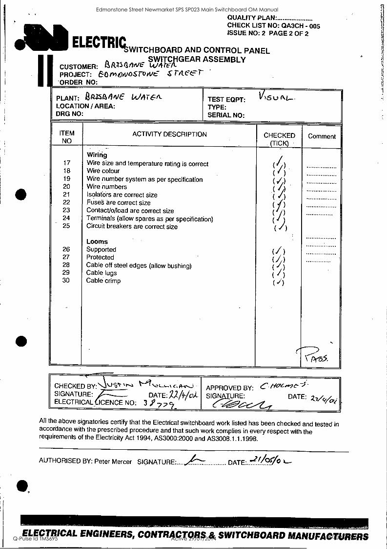
Mama= .WITCHBOARD AND CONTROL PANEL
QUALITY PLAN. CHECK LIST NO: QA3CH - 005 ISSUE NO: 2 PAGE 2 OF 2
SWITCHGEAR ASSEMBLY CUSTOMER: aimantvE- witren. PROJECT: 60 rv+0rv4ST rV S T4 C.677-
ORDER NO:
PLANT: AR-rsative WA E/_ LOCATION / AREA: DRG NO
TEST EQPT: 1/1 Su N.-. TYPE: SERIAL NO:
ITEM NO
ACTIVITY DESCRIPTION CHECKED (TICK)
Comment
17 18 19 20 21
22 23 24 25
26 27 28 29 30
Wiririg Wire size and temperature rating is correct Wire colour Wire number system as per specification Wire numbers Isolatdrs are correct size Fuse-s are correct size Contact/o/load are correct size Terminals (allow spares as per specification) Circuit breakers are correct size
Looms Supported
. Protected Cable off steel edges (allow bushing) Cable lugs Cable crimp
( //) (1) (1 ) ( //) ( ) ( /') ( i) ( 4
( ))
( I) ( ./ )
( I) ( /) ( j)
(-- \ Pr-35
CHECKED BY:4-/Vt 1-1.1L-""ac*A'Ji SIGNATURE: DATE: /2#10A- ELECTRICAL ICENCE NO: 3 7 2
APPROVED BY: C- SIGNgt DATE: zvvoy
All the above signatories certify that the Electrical switchboard work listed has been checked and tested in accordance with the prescribed procedure and that such work complies in every respect with the requirements of the Electricity Act 1994, AS3000:2000 and AS3008.1.1.1998.
AUTHORISED BY: Peter Mercer SIGNATURE "4-- DATE. flOrio
ELECTRICAL ENGINEERS, CONTRACTORS & SWITCHBOARD MANUFACTURERS
Edmonstone Street Newmarket SPS SP023 Main Switchboard OM Manual
Q-Pulse Id TMS695 Active 29/01/2014 Page 217 of 236
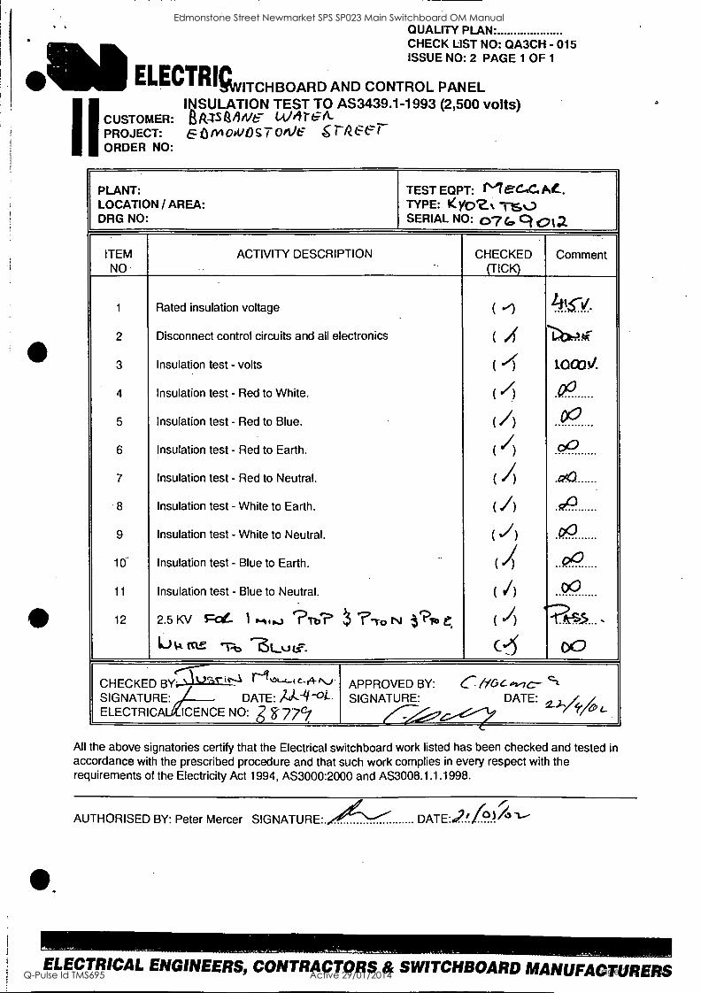
I I
QUALITY PLAN. CHECK LIST NO: QA3CH - 015 ISSUE NO: 2 PAGE 1 OF 1
ELECTRICA, ,...ITCHBOARD AND CONTROL PANEL INSULATION TEST TO AS3439.1-1993 (2,500 volts)
CUSTOMER: IA it4S /we Will-GA- PROJECT: EoniodiOs7 We 6 rize-err ORDER NO:
PLANT: LOCATION / AREA: DRG NO.
TEST EQPT: ME-C-IC.Ae... TYPE: Kyoz% Ts0 SERIAL NO: 07 Gcl 012
ITEM NO
ACTIVITY DESCRIPTION CHECKED (TICK)
Comment
1
2
3
4
5
6
7
8
9
10.
11
12
Rated insulation voltage
Disconnect control circuits and all electronics
Insulation test - volts
Insulation test - Red to White.
Insulation test - Red to Blue.
Insulation test - Red to Earth.
Insulation test - Red to Neutral.
Insulation test - White to Earth.
Insulation test - White to Neutral.
Insulation test - Blue to Earth.
Insulation test - Blue to Neutral.
2.5 KV Fa- ) .-it... ?To? 7-ro NI t"Pi'a C.
10 vk Kt!: 'T-t) .-61.....n.i:
( '')
( A ( 4 ( /) (/) ( l) ( / ( I) ( 1) ( ..4
( I) ( I) C4
.1.c
-4X-AAF
1.000v.
.0°
00
DD
.090
4743
.PO
000
GO
e,c5 ,
DO
CHECKED SIGNATURE: ELECTRICA
'.---)'' BY; \ - 1-----% .-".."- 1-31`°"-`c-04-N). DATE: itA.4-°i--
APPROVED SIGNATURE:
BY:
---__ ,Oe-Y C /166,2,7c-
DATE: c't
2.)-4,./,, ICENCE NO: g F 77,
All the above signatories certify that the Electrical switchboard work listed has been checked and tested in accordance with the prescribed procedure and that such work complies in every respect with the requirements of the Electricity Act 1994, AS3000:2000 and AS3008.1.1.1998.
AUTHORISED BY: Peter Mercer SIGNATURE. DATE:;ii (3)1'51--
ELECTRICAL ENGINEERS, CONTRACTORS & SWITCHBOARD MANUFACTURERS
Edmonstone Street Newmarket SPS SP023 Main Switchboard OM Manual
Q-Pulse Id TMS695 Active 29/01/2014 Page 218 of 236
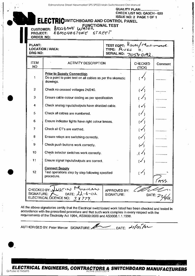
QUALITY PLAN. CHECK LIST NO: QA3CH - 020 ISSUE NO: 2 PAGE 1 OF 1
ELECTRIOWITCHBOARD AND CONTROL PANEL FUNCTIONAL TEST
CUSTOMER: AT-S MI6 (AMT.& k. PROJECT: 60MO/lits s role sr /Zees r v ORDER NO:
PLANT: LOCATION / AREA: DRG NO
TEST EQPT: 11)5u tiqrlut....7- ,I....,a.re4. TYPE: 10 46 II .
SERIAL NO: 705.-zi._ 0 ictot
ITEM ACTIVITY DESCRIPTION CHECKED Comment NO (TICK)
Prior to Supply Connection / 1 Do a point to point test on all cables as per the skematic ( ) drawings.
2 Check no crossed voltages 24/240. () 3 Ensure cable colour coding as per specification ( I) 4 Check analog inputs/outputs have shielded cable. ( s7)
5 Check all cables are numbered. ( /). 6 Ensure indicator lights have right colour lenses. (4 7 Check all CT's are earthed. ( I) 8 Ensure relays are switching correctly. ( 4 9 Check push buttons work correctly. () 10 Check selector switches work correctly. .. ( 4 11 Ensure signal inputs/outputs are correct. (I)
Connect Supply 12 Test operations step by step following specified
procedure. ( /) ,
f-----1
'.-4----------1..----1 CHECKED BY:..si-i2a.r1"-) 1.4k1,(1"-Ic`IN-1). APPROVED BY: SIGNATURE: (C._, DATE: /Zi--- 4 -0).- SIGNATURE: DATE: 27/,/ ELECTRICAL ICENCE NO: 3 r 777. 7r4..
All the above signatories certify that the Electrical switchboard work listed has been checked and tested in accordance with the prescribed procedure and that such work complies in every respect with the requirements of the Electricity Act 1994, AS3000:2000 and AS3008.1.1.1998.
AUTHORISED BY: Peter Mercer SIGNATURE..?"-N-- DATE: 4"2/70 7°
ELECTRICAL ENGINEERS, CONTRACTORS & SWITCHBOARD MANUFACTURERS
Edmonstone Street Newmarket SPS SP023 Main Switchboard OM Manual
Q-Pulse Id TMS695 Active 29/01/2014 Page 219 of 236
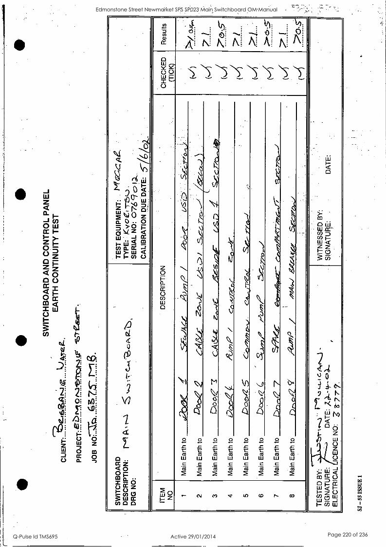
SW
ITC
HB
OA
RD
AN
D C
ON
TR
OL
PA
NE
L E
AR
TH
CO
NT
INU
ITY
TE
ST
C
LIE
NT
:.....
. .!f
F6.
?1.4
9.:.)
.L...
e....
.!'!-
?..e
.geg
-
PR
OJE
CT
: gP
. 9
":1T
:.:el
niI
.7 e
erie
r
JOB
SW
ITC
HB
OA
RD
D
ES
CR
IPT
ION
: r-
ci P
k ,
T--
1 ...
...
, -,
- C-4
-k '.
...01
' 9-
--
, D
RG
NO
:
TE
ST
EQ
UIP
ME
NT
: l'i
laiC
A4.
T
YP
E:
'
Kyo
et M
L.).
.
SE
RIA
L N
O:
076
9 1 ,.
CA
LIB
RA
TIO
N D
UE
DA
TE
:
ITE
M
NO
D
ES
CR
IPT
ION
.
'
CH
EC
KE
D
(TIC
K)
Res
ults
1 2 3 4 5 6 7 8
Mai
n E
arth
to
4120
eX
Z
Se-e
4.1A
4G
120/
P
/ ..0
0cla
hJ)
(,c
(...1
(
(1/4
- 4 a (-4
7 5-
-
i .. . 1
,
0-5.
Mai
n E
arth
to
1ek5
e C
p4iY
.z-
7-6-
1.)E
.-
Z4:
, L>
/ .S
rf
c.--
---1
()
.
Mai
n E
arth
to
Do
c>
7 C
A L
.Stz
z-
.,/e.
; zr
xes.
z)e-
(.
,S,D
_.
c.: cr
/a-s
i4t,
Mai
n E
arth
to
E7c
o ,c
-)/)
,P /
cO -t
irzen
c o-
*.
.
Mai
n E
arth
to
Pos
t. 5
(-:;n
/2,/7
2 0.
-,..
ces-
v-T
-OL
..S
.-..-
77
co-1
.,,
_
Mai
n E
arth
to
boo
( S
c.),
)7,
/Ci/7
7,
<-5
-G-7
70,.J
Mai
n E
arth
to
Dr)
,..,
7 .c
.-c-
7--,
tx--
/
Mai
n E
arth
to
1)nO
CZ
q
/4-a
/iP /
TE
ST
ED
BY
: b.
r-vc
-1"
1...2
1 D
LL-
1 c A
ctJ
- .
SIG
NA
TU
RE
: D
AT
E:
AX
- 9--
.=,.4
-.
, E
LEC
TR
ICA
L IC
EN
CE
NO
: 3
8-
, .
WIT
NE
SS
ED
BY
: '
.
SIG
NA
TU
RE
: .
DA
TE
:
SJ -
55 IS
SUE
1
Edmonstone Street Newmarket SPS SP023 Main Switchboard OM Manual
Q-Pulse Id TMS695 Active 29/01/2014 Page 220 of 236
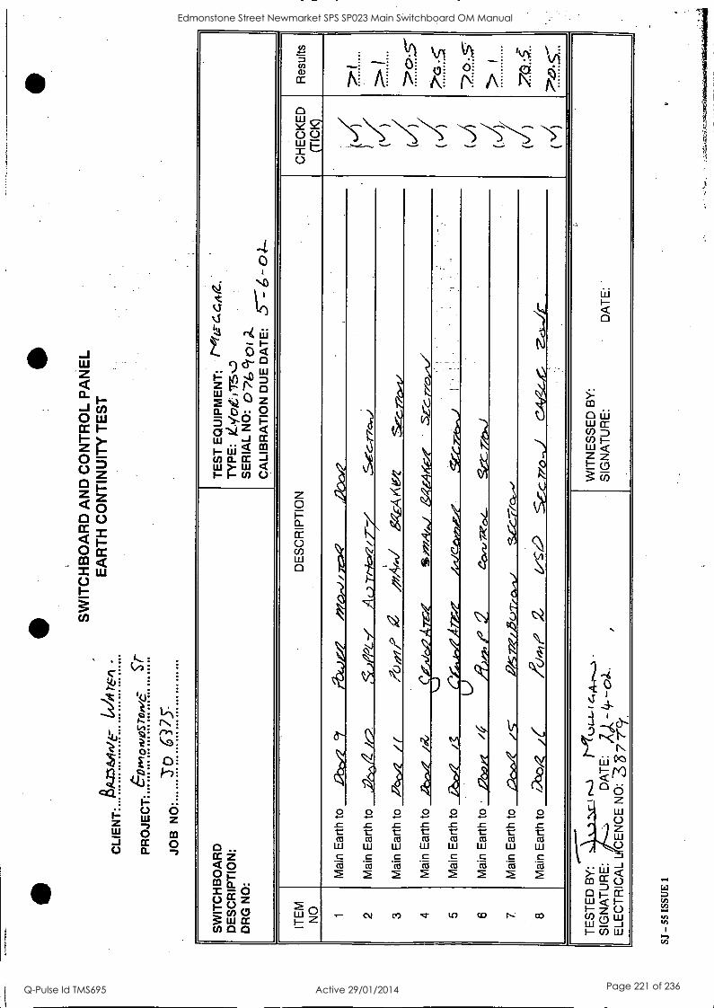
CLI
EN
T:
4/LE
36*1
/6-
74:1
JOB
N
O
SW
ITC
HB
OA
RD
AN
D C
ON
TR
OL
PA
NE
L E
AR
TH
CO
NT
INU
ITY
TE
ST
SW
ITC
HB
OA
RD
D
ES
CR
IPT
ION
: D
RG
NO
:
TE
ST
EQ
UIP
ME
NT
: r4
tia-6
.442
. T
YP
E:
IZV
o/t,
7-5D
S
ER
IAL
NO
:
CA
LIB
RA
TIO
N D
UE
DA
TE
: 5-
: 6 -0
4--
ITE
M
NO
D
ES
CR
IPT
ION
C
HE
CK
ED
(T
ICK
) R
esul
ts
1 2 3 4 5 6 7 8
Mai
n E
arth
to
,Gbc
, cy
g)
4.),
7 ?P
c."1
/ y-e
;,Q
,
( (4
(((/
/
LA
(I)/
(i
) ( x/
)
71
> I
?(5-
57
> I 70
.
Mai
n E
arth
to
.iiZ
//2
,,uP
ioz.
'7/
AL
,77-
7k=
q/7-
r M
ain
Ear
th t
o R
oc,
/(
/70,
,i/P
a
"4/..
/ Sg
EA
A e 4
S
ecr?
c#4.
/
Mai
n E
arth
to
ibts
.. /R
. S
r"4/
../
&gM
tf71
5X-C
. r7o
."./
LS,A
hWA
TP
- ,
Mai
n E
arth
to
IZn,
4 kg
44
-(C
ep-,
2.r.
e L5
1,4i
-t<
A7r
-/Z
M
ain
Ear
th to
J7
o /
An"
, 2
ao.-
1,70
/..-
gjzz
ei
Mai
n E
arth
to
Doc
X
/6--
R
S 72
e/ 2
3c.)
.7-.
0.-1
/ S
C-C
_T-lo
..-
Mai
n E
arth
to
aso.
i(
V2
SE-C
770
,1
C4g
e-y0
zd
i-ir
, ,
TE
ST
ED
..-
--
BY
: ..
k )
( r-
-.1
NT
k..n
a.- t
4,
4_,..
....1
.
WIT
NE
SS
ED
BY
: S
IGN
AT
UR
E:
DA
TE
: S
IGN
AT
UR
E:
DA
TE
: L)
, _ 4_
-0,1
...
ELE
CT
RIC
AL
L C
EN
CE
NO
: 33
7 re
SJ -
55 I
SSU
E 1
Edmonstone Street Newmarket SPS SP023 Main Switchboard OM Manual
Q-Pulse Id TMS695 Active 29/01/2014 Page 221 of 236
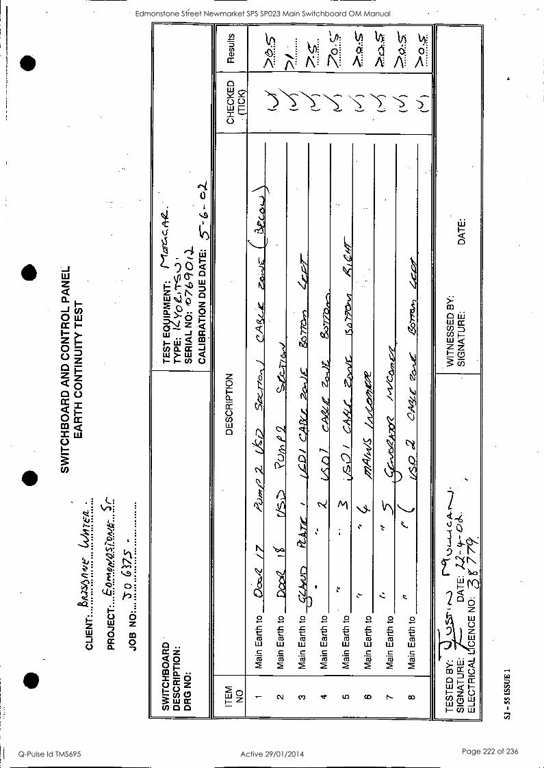
CLI
EN
T:
AM
-56/
14/6
"T
E/L
PR
OJE
CT
: ...6
..t-.
1.1m
6a.s
.
o 17
.5"
SW
ITC
HB
OA
RD
AN
D C
ON
TR
OL
PA
NE
L E
AR
TH
CO
NT
INU
ITY
TE
ST
SW
ITC
HB
OA
RD
D
ES
CR
IPT
ION
: D
RG
NO
:
TE
ST
EQ
yIP
ME
NT
: 1l
izei
c11-
0-
TY
PE
: 14
. V
o C
I TS
,
SE
RIA
L N
O:
0769
0 ( .
)-
CA
LIB
RA
TIO
N D
UE
DA
TE
: 5-
- 6 -
ciZ
.
ITE
M
NO
D
ES
CR
IPT
ION
S
CH
EC
KE
D
(TIC
K)
Res
ults
1 2 3 4 5 6 7 8
Mai
n E
arth
to
Ooc
/7
/>
(.),
,,/, Z
O
tO
5.-r
7.=
:.- I
CA
3c-e
0-
-L) C
C
atc
a,...
))
(t/
0-4
(j)
(J)
( ti)
(c/ )
>5'
5'-
>/ . 5
: '
'.5;?
...S
.--
>01
5-
Mai
n E
arth
to
Dpi
I f
rIs
?c)/
y, P
2 Se
c-I-
7 6,
, M
ain
Ear
th t
o P
GA
I---
/
CD
/ C
A-&
i 7-
o.-J
g0
770.
1-)
Z.C
.7--
- LS
ZA
Tfu
r)
,..
Mai
n E
arth
to
Z
LA
!) 7
C
A(
zo-J
t 8,
37-7
b1,-
,
Mai
n E
arth
to
.
LYS
° /
0,Ir
l/C
Icel
77:1
4-1,
7 I<
/ Cif
f-
ri
.
Mai
n E
arth
to
..,
..,
/174
/14/
-5
bz./G
e,e/
:
(,
Mai
n E
arth
to
,, .5
A
ve?
A,c
. 0
Mai
n E
arth
to
e'
C
t/So0
.2
61/V
e 00
.-ue
,e
3o-r
ns",
4,
c_,-
/- _
TE
ST
ED
S
IGN
AT
UR
E:
ELE
CT
RIC
AL
BY
:j---
k-)
I 1.
.3
1.-c
k k.
),-,
....(
C. A
-r...
, j .
DA
TE
: ,4
2- 9
-- O
ck.
S
I, C
EN
CE
NO
: 3
r 779
'
WIT
NE
SS
ED
BY
: S
IGN
AT
UR
E:
DA
TE
:
SJ -
55 I
SSU
E 1
Edmonstone Street Newmarket SPS SP023 Main Switchboard OM Manual
Q-Pulse Id TMS695 Active 29/01/2014 Page 222 of 236
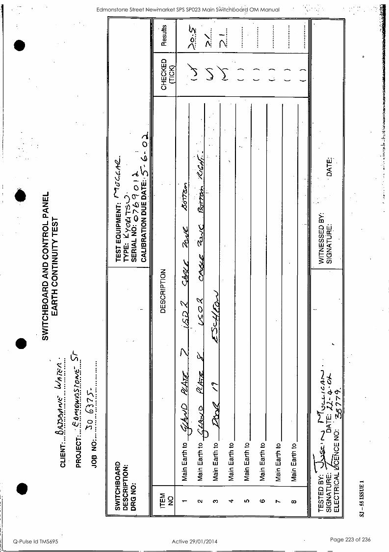
" P
RO
JEC
T:
e611
/0W
6ST
Oit/
C
6)75
- JO
B
SW
ITC
HB
OA
RD
AN
D C
ON
TR
OL
PA
NE
L E
AR
TH
CO
NT
INU
ITY
TE
ST
SW
ITC
HB
OA
RD
D
ES
CR
IPT
ION
: D
RG
NO
: ,
TE
ST
EQ
UIP
ME
NT
: 1"
LFC
.CA
-12-
- T
YP
E:
SE
RIA
L N
O:
c, 7
&9
01 )
, C
ALI
BR
AT
ION
DU
E D
AT
E: .
,5--
-- 6
, IT
EM
N
O
DE
SC
RIP
TIO
N
CH
EC
KE
D
(TIC
K)
Res
ults
1 2 3 4 5 6 7 8
Mai
n E
arth
to
SA
,tiD
Pa
r/E
r 7'
i , s
D 2
cA
ltrzi
e:
26,il
e 46
77r
1 ( .1
1/
GA
( )
( )
( )
( )
( )
( )
>O
$ >
/
.
Mai
n E
arth
to
6.4.
4..,
o R
A-7
-Az
7 vc
0 2
c"
64e
e7c.
a..,.
/c
acer
raer
, /e
le
_
Mai
n E
arth
to
Z7&
, /7
M
ain
Ear
th t
o
.
Mai
n E
arth
to
Mai
n E
arth
to
Mai
n E
arth
to
Mai
n E
arth
to
TE
ST
ED
S
IGN
AT
UR
E:
ELE
CT
RIC
AL
, .
BY
:17.
..slc
z, 1.
....3
1T
1/4_
9 r.
...j
,
/....,
D
AT
E:
,t2-
4.- ok
e
tICE
NC
E N
O:
'
35 7
7 cf
r.
,
.
WIT
NE
SS
ED
BY
: S
IGN
AT
UR
E:
DA
TE
:
.
SJ -
55 I
SSU
E 1
Edmonstone Street Newmarket SPS SP023 Main Switchboard OM Manual
Q-Pulse Id TMS695 Active 29/01/2014 Page 223 of 236
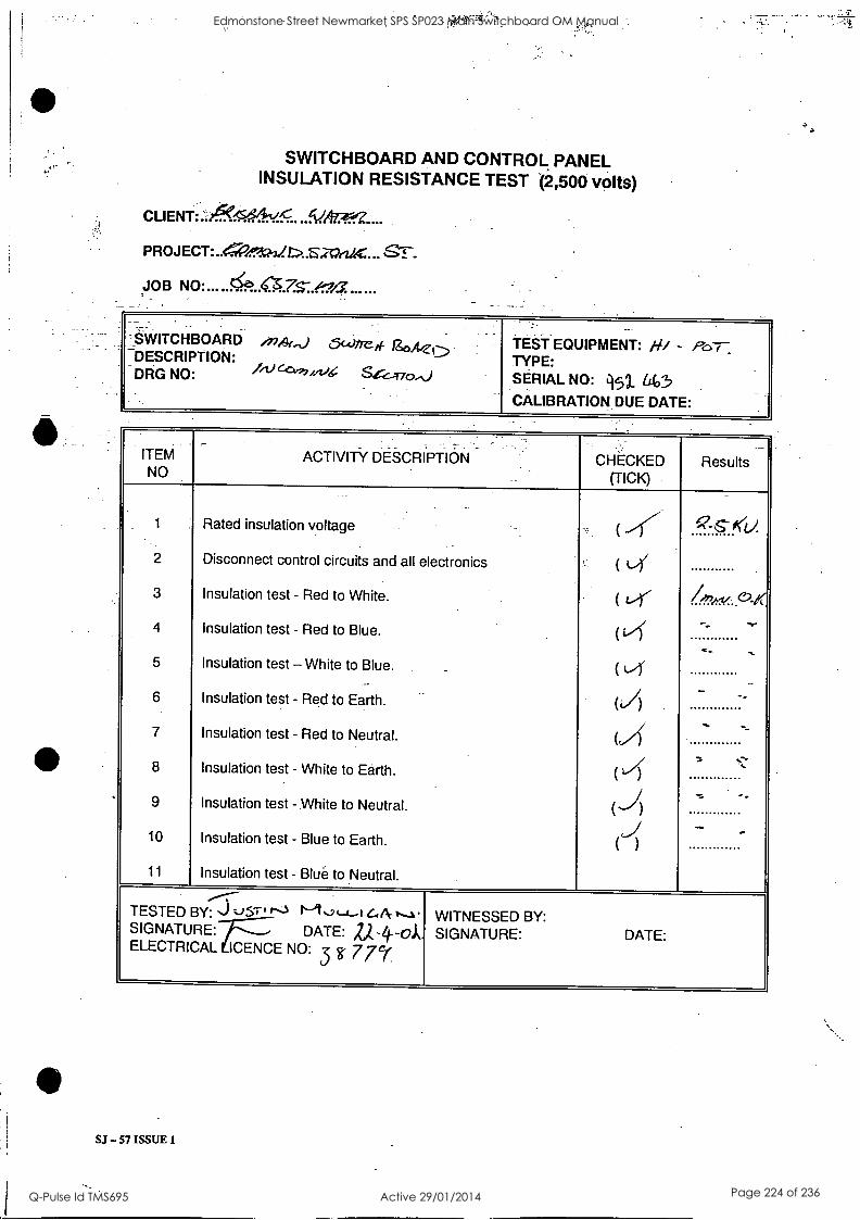
SWITCHBOARD AND CONTROL PANEL INSULATION RESISTANCE TEST (2,500 volts)
GT. -
JOB
SWITCHBOARD "41(") 5c4)/Terf igoA,Zt DESCRIPTION: Ai) SG-vo".) DRG NO:
TEST EQUIPMENT: /19 - OoT- TYPE: SERIAL NO: q5 La03
CALIBRATION DUE DATE:
ITEM NO
ACTIVITY DESCRIPTION CHECKED (TICK)
Results
1 Rated insulation voltage ( -r -6--eti.
2 Disconnect control circuits and all electronics ( k/Y
3 Insulation test - Red to White. ( t-r 47,/.
4 Insulation test - Red to Blue. ( .s...
5 Insulation test - White to Blue. _ (t--r
6 Insulation test - Red to Earth. (A ...
7 Insulation test - Red to Neutral. (,Zf ,.
7... ....::-.
8 Insulation test - White to Earth. ( 4 9 Insulation test - White to Neutral. () -,-. .
10 Insulation test - Blue to Earth. ( )
11 Insulation test - Blue to Neutral.
..---- TESTED BY: J %;51-11----1 I-1Q t-4-A 14 A- vs-1 WITNESSED BY: SIGNATURE: DATE: ZA-4--01 SIGNATURE: DATE: ELECTRICAL ICENCE NO: 3 g 77e(
SJ - 57 ISSUE 1
Edmonstone Street Newmarket SPS SP023 Main Switchboard OM Manual
Q-Pulse Id TMS695 Active 29/01/2014 Page 224 of 236
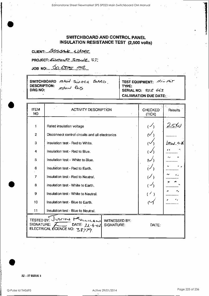
SWITCHBOARD AND CONTROL PANEL INSULATION RESISTANCE TEST (2,500 volts)
PROJECT:E.-P.4maiZe...qzckliC..
JOB
SWITCHBOARD inAt;ii Sri) ,T-e..44 130A/10 DESCRIPTION: in Ai vs) 1SC..5 DRG NO:
TEST EQUIPMENT: ' "- TYPE: SERIAL NO: 952 OKS
CALIBRATION DUE DATE::
ITEM NO
ACTIVITY DESCRIPTION CHECKED (TICK)
Results
1 Rated insulation voltage ,
( I) ,Zs,Cd
2 Disconnect control circuits and all electronics (1)
3 Insulation test - Red to White. (si) ind.. I 4 Insulation test - Red to Blue. ( I) et ' 5 Insulation test- White to Blue. t-)
.._ 14
6 Insulation test - Red to Earth. () - e
t.. 7 Insulation test - Red to Neutral. (J) 8 Insulation test - White to Earth. _I
( )
4,-
9 Insulation test - White to Neutral. ( / )
,.. -,,
10 Insulation test - Blue to Earth.
,
(`4 4
11 Insulation test - Blue to Neutral.
TESTED BY: Y'r ° 1"....4 U 1-1-1 C. 4 r.-) WITNESSED BY: SIGNATURE: A.- DATE: 2),-4.-0), SIGNATURE: DATE: ELECTRICAL kICENCE NO: 3 g-77?.
Edmonstone Street Newmarket SPS SP023 Main Switchboard OM Manual
Q-Pulse Id TMS695 Active 29/01/2014 Page 225 of 236
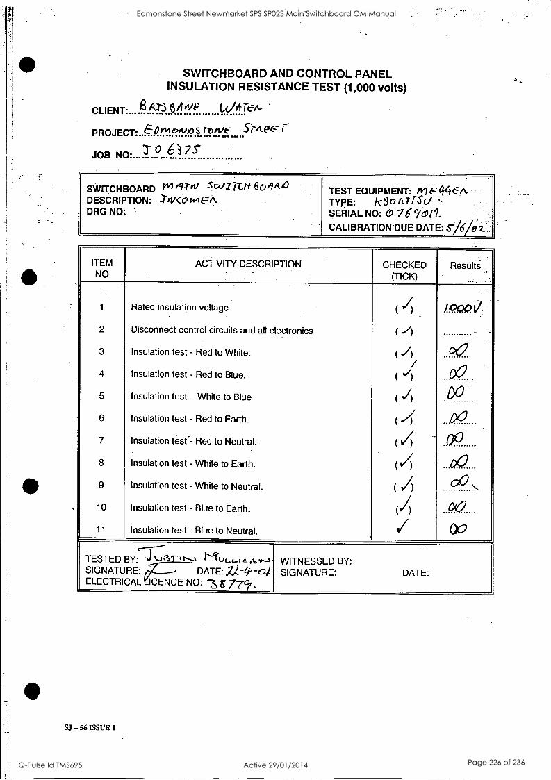
SWITCHBOARD AND CONTROL PANEL INSULATION RESISTANCE TEST (1,000 volts)
CLIENT:- B.6-.7.A.0.0.1:I!
PROJECT:..P.r.1:1-RfY.P.§../..9.1.ff....:5'rit r JOB NO:...
SWITCHBOARD ;41 /9-1-41 SW/ Tiff 4ofitto DESCRIPTION: -1-kvco men DRG NO:
TEST EQUIPMENT: 6:446-A. TYPE: 0 Ara() SERIAL NO: 76 1=911--
CALIBRATION DUE DATE: Sieloz_
ITEM NO
ACTIVITY DESCRIPTION CHECKED (TICK)
Results
1 Rated insulation voltage / ( ) /P0(2 11.
2 Disconnect control circuits and all electronics ( ./) 3 Insulation test - Red to White. ( A / 4 Insulation test - Red to Blue. ( 1/) 00 5 Insulation test - White to Blue ( 1)
6 Insulation test - Red to Earth. (4' 00 7 Insulation test- Red to Neutral. 04 -
8 Insulation test - White to Earth. ( 4 ...QC
9 Insulation test - White to Neutral. ( /) 00 10 Insulation test - Blue to Earth. (/) 00 11 Insulation test - Blue to Neutral. / DO
TESTED BY: J J81--i r---i Niui_c_i c. A-v--1 WITNESSED BY: SIGNATURE: DATE: V--4---0,4- SIGNATURE: DATE: ELECTRICAL ICENCE NO: '3 g 779'.
SJ - 56 ISSUE 1
Edmonstone Street Newmarket SPS SP023 Main Switchboard OM Manual
Q-Pulse Id TMS695 Active 29/01/2014 Page 226 of 236
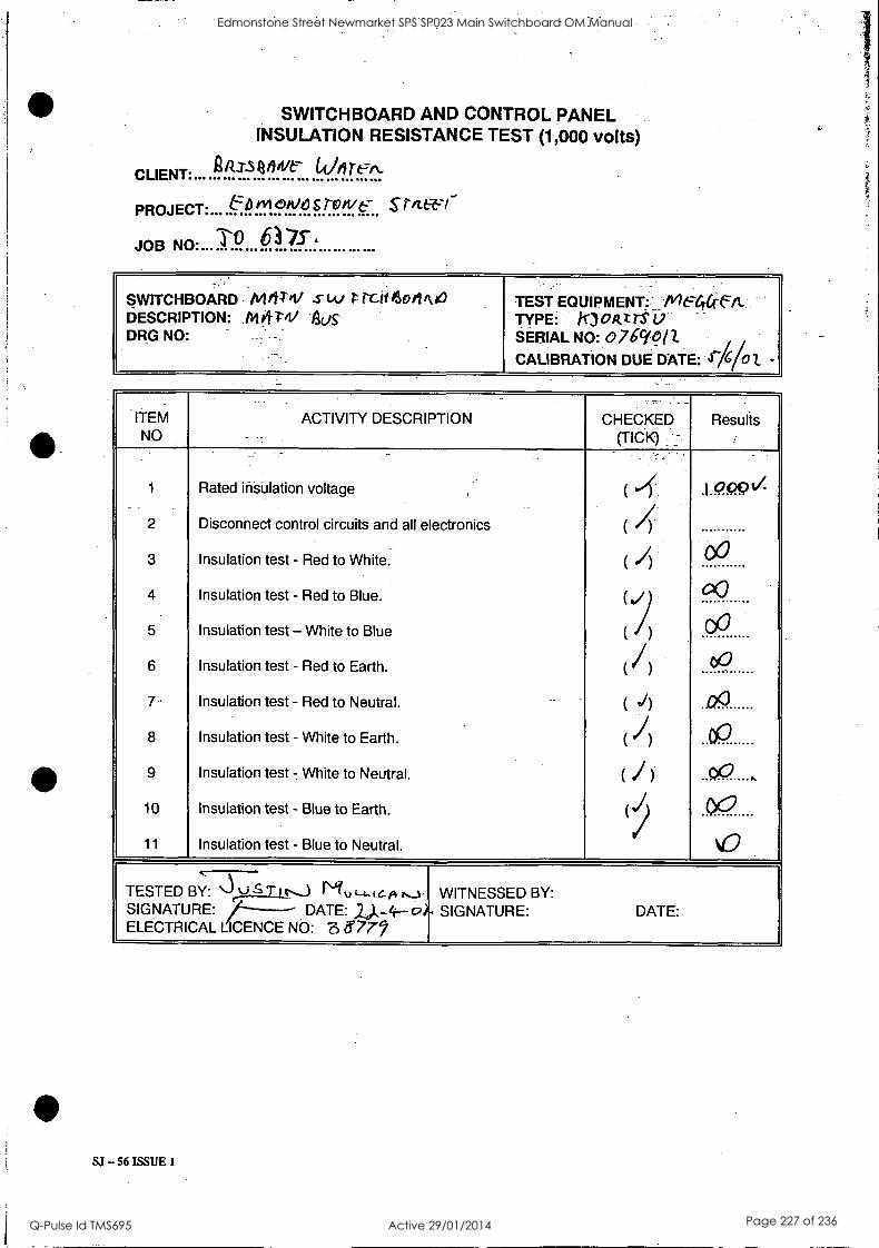
SWITCHBOARD AND CONTROL PANEL INSULATION RESISTANCE TEST (1,000 volts)
/2.-T3 QA/Ve 1,01 re-A,
r
inn Nn. TO 617.s-,
SWITCHBOARD Mi4Z1/ SW rcti ?Son Ike) TEST EQUIPMENT: MEGrafit DESCRIPTION: MOW AOS TYPE: ill oat rS DRG NO: - SERIAL NO: o76cion
CALIBRATION DUE. DATE: 4-76/0 Z -
ITEM NO
ACTIVITY DESCRIPTION CHECKED (TICK)
Results
1 Rated insulation voltage ( 4 .1000v.
2 Disconnect control circuits and all electronics ( 4 3 Insulation test - Red to White. ( .1) 00
4 Insulation test - Red to Blue. ( ./) °GI
5 Insulation test -White to Blue ( / ) 00
6 Insulation test - Red to Earth. (/) ) 09
7 Insulation test - Red to Neutral. - ( d) ..120
8 Insulation test - White to Earth. ( I) CP
9 Insulation test - White to Neutral. ( 1) 00
10 Insulation test - Blue to Earth. (, 00 11 Insulation test - Blue to Neutral. kr)
TESTED BY: `...),Q.S Tit---) Mu (-4- f c.6v1._.%. WITNESSED BY: SIGNATURE: /----- DATE: L),-4--0). SIGNATURE: DATE: ELECTRICAL LICENCE NO: 3 877,
Edmonstone Street Newmarket SPS SP023 Main Switchboard OM Manual
Q-Pulse Id TMS695 Active 29/01/2014 Page 227 of 236
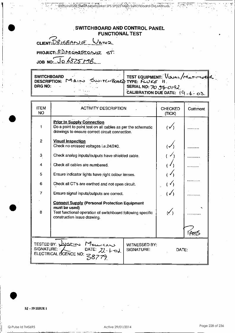
SWITCHBOARD AND CONTROL PANEL FUNCTIONAL TEST
PROJECT: AD.D-3.0.it:t9.1r.A/AZ Sr. JOB NO: ...J.
SWITCHBOARD TEST EQUIPMENT: V.S..)pt r-I cre DESCRIPTION: r'si Pt rc.A-470441> TYPE: ri_tjezr:- I)
DRG NO: - SERIAL NO: 70 3-4-otq2. CALIBRATION DUE DATE: ei _4-- 0
ITEM NO
ACTIVITY DESCRIPTION CHECKED (TICK)
CoMment
1
2
3.
4
5
6
7
8
Prior to Supply Connection the schematic
cable.
circuit.
Equipment
following specific
(
/
,
(I) ( /) ( /) ( ') ( /) ( /)
(7) .
7frz6
Do a point to point test on all cables as per drawings to ensure correct circuit connection.
Visual Inspection Check no crossed voltages i.e.24/240.
Check analog inputs/outputs have shielded
Check all cables are numbered.
Ensure indicator lights have right colour lenses.
Check all CT's are earthed and not open
Ensure signal inputs/outputs are correct.
Connect Supply (Personal Protection must be used) Test functional operation of switchboard construction issue drawing.
TESTED SIGNATURE: ELECTRICAL
WITNESSED BY: SIGNATURE: DATE:
BY: M.° t-4-i C, A-,-...). DATE: 2/._ ...1)..1..
L CENCE NO: ---
SJ - 59 ISSUE 1
Edmonstone Street Newmarket SPS SP023 Main Switchboard OM Manual
Q-Pulse Id TMS695 Active 29/01/2014 Page 228 of 236
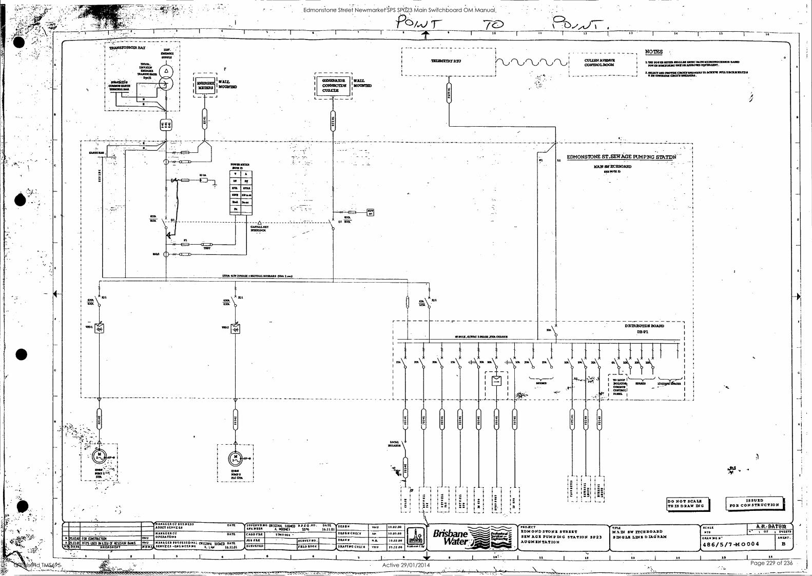
TRANSPOREER HAT
i.I. 11:1001:1LIRA
1
i massua ,
50110111322ER 'OTTO
-I-
_ _ ----------------- CASTELLICET VOISSOCX
1
GENERATOR WAIL co:cowl:int I movarizo
L
'ft rl 02 "R
a
Poi,k) t 9
C) -O./A-I 1
12 13 14 16
.THIEWEIRT RIO
Ti
1502A OA 3 NOSE INEVIRES IR/SEARS 1935114md
301
rA..) rAjr !
COLTER AVENUE CONTROLROOK
NOTES
LOU mica Erna sew= ixo:catzforrnossocsason sum POSIERIE011/01.11GINOIVISAPYROSIRIDER/ONISNT.
2.6CUTTAND SIOTEITCPCOVIRTARRE TO MIME TO1LOSOLEZIATD11 OE orrawas CItCOOSMOJOIRS.
EDMONSIONE STSER AGE PUMPNG STATDN
HAN ECHBOARD
TOO
113 60111.1150C SPEOSCANA0121.1:415
DOI WM 71
DBIRED133N BOARD
DB-P1
i
I I
s
so.
r - saL\
L._ SPARES
\ EDAM/ 15S.Pytta6013 I
I
L
I coinsoLI i
--V&A/FACER Ct 503111.33 ASSET SERVO'S
1
1
224M1 1 14101
PIG
DATE YSIttlIVISII ORIGINAL SIDED A SO .00 . DATE V01 1.110 11615 A. 131:SET 5536 16.11.01
20.0162 21.1101
NO,DETE
(CS &sauna 400 NAMAGER OP OPERA TO N 5
DATE CADD PIZ 57/40004
1101 01(0 01 1.1W Of Esisiat Lusts AMES DMUS
0
Imo MANAGER PROMSDNA: ORIGIpm SIDED DATE 1111:4,- SERV CS -ENG NEER RIG E. I RN 16.11.01 3131001TED
JOS ISA
5 . 5,75
56 6011 MO.
T
- , --- 77
!
TKO 1002.00
DESERCRECT AN 10A300
DRAY S HA. 10.0200
'1--;
TEED ROOK
I
..
DRAfTOG COCCI IoU 25..3D0
1. 4. L
ii .1 I. "1 !I I 1.1 I I
: i!! 1"; iRi r' i
-
PROJECT EDMOND STONE STREET aw
SEW AGE PUN PDIG AUGMENTATION
STATION 3 P 2 3 3N
us: 11 is
11 DO NOT SCALE THIS DRAW INC
ISSUED FOR CONSTRUCTION
TITLE MAIN SW ITCHEOARD SINGLE LINE DIAGRAM
13 14
NTS
AA: DATUM *I I Of 1 !MEETS
DRAM NG
486/5/7-H 0004 AMEND.
B
15 16
A
C
C
Edmonstone Street Newmarket SPS SP023 Main Switchboard OM Manual
Q-Pulse Id TMS695 Active 29/01/2014 Page 229 of 236
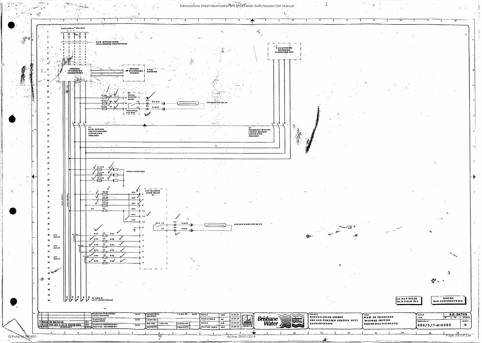
a
12 14 IS I 16
1
2
3
.
IsIC140. PVC/PIrC
E 11.404 B I
f ;f f 1 f
1 1
I , I I 't 1 I
5 I I I
I I I I I
'10131 14531415 CAMS[ MOM BBBB TILILIESIOKII
4 --.K....:. I ..:1 .. :-.....1J--........:::.,:i 7 e 117111411
; et lima's. - I int la 1 1211/1 I
C0111115111111 C.2.1 ID IT
10
11
12
13
14
15
16
17
.18
19
21
21
23
24
25
26
72
28
29
33
31
31
33
34
35
36
37
35 C7/ 000/5
39
40 CT2 1100/S
41
42 CT) 100/5
43
44
as'
48
49
50
E
23
110171170
YO/Li rArunci -1
") h.ozz -El-
'2) /1-012 23
C5012/70 .
L..192.1..07. J. t, I
Now I1C01111 CERC13 IT I31100112/00 TE02105.2
15112112 0 15 00
r
Of01111ATOR DIC041121
CLP.C13 Xt0011,7/100 £1108551
.. v ALL 1111140
aIRATOR C011210/ 5411
I. 134
25 034
V °2,
4
Pt
N
SI
PI
021 501 017152151
1.1
/.ps, 22 D72 3
: 101 [RN /711 110 talk 11 100
2 121
030 4i + 5
150
170 t
11
010 14
170 13
:
SI V/030 " 21)1 57 4 41713,,
.,,,/ D73 L4 074
P1 SI .4.1/5 55 031 LS
C1=D 7
f JD 75 za .71 . vr CMD
9
B TO LEIN 31 ON :1145/5/714002
!_.20.113.02 fat CCIISIFUCIICR TNU ,04au.L.:9 CIS USED 18 LIEU CI RESISTOR OAKS 9910
4112.10215117
11-1 14 137
40E111
141 0 II I _a_
107'
,
STATION 31412 VOW 1501
-
it
41144 CR Of 1112311E3S ASSET 3504t2-3
DATE
NAM AGER Of OPERATDRS
DATE
MANAGE, PROVESSDNAL 2501155 -104 DIMING
DATE
SUP211113110 DIG PEER
CAD° FLE
JOB I'LL 5700305
SURVITED
200.00. DATE DES EN V141/ 1052.00
DESZIIEMECII 10.0500
SURVEY PO .1
VII° 11001
-- DRAW 0
CHECK
Ni THU
15.02.00
25.0200 *000. C
Brisbane WaterArig
140.2LCT
IOW ONDSTONI STRIRT SIR AGO PUNP/IIG STATION SP23 AUG14 TATION
DO NOT SCALZ TR IS DRAW MC
48.1 '
ISSULD [TOR CONSTRUCTION]
TILE HAW SW ITCHBOARD INCONZR SZCTION ILZCTRICAL SCRIHATIC
14
STALE ITS
AM: DATUM 1 Of 35E172
DRAW NG II'
486/5/7-H 0005 API/PL.
IS 10
Edmonstone Street Newmarket SPS SP023 Main Switchboard OM Manual
Q-Pulse Id TMS695 Active 29/01/2014 Page 230 of 236
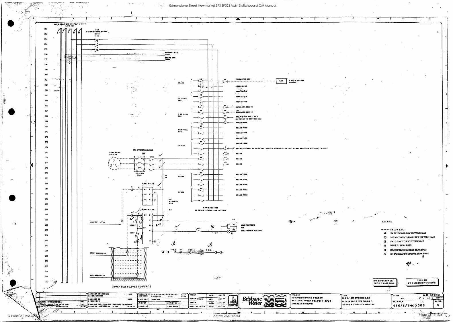
10 II 12
A
251
252
253
254
255
256
257
258
259
260
261
2(3
264
265
266
267
269
270
272
273
214
VS
2,1
279
279
F 290 '
2131
282
283
284
295
289
2%
291
292
291
2%
2%
291
2%
299
30)
rao sr DRAW UM 4114/3/7.4to 007 1.21112 200
E N
1
/ R
/ W
/ B
101 DISTRINIITIO BOAIII1
' IICCO IISA
04......r
K......lr--
K ....I.1,
. .
_IIIIIITRAL W.
20 1
'....---4.'
1 .'i...i.+', I-1 aim amt I-I
CRANK
DRY LLL 11111
- 1 -0.4,24
-C.,&..,.
I
L
20 -0,... I
te...1: 10
0 2./ ELL 214.1
20
---CL-T-2:
10
10
DRY ILL PO
I., GPo
311 07/11117.0AD MAT OMP PON 220
, IS
--0.........). I
----CN"-k.. ___<1..L.2...
1
10 s". --0....7,..m
1
____ 4 ( .
--0...L.,-' <10L1 x TLC I SA ie/ r ' ,a4 - -- - -.` -41-r-Lit 1 o i o
I 1 v I L _ _ 1 f-1 I
1
j 3....+,..-
- DIEPLOAD
1-_
Y ift 3, RZ1AT / III
off _ 20
--0............ fl {A
---N-.... -0 -*
20 _ _ 00 L
O III
Is C
MI SPARE -----h"--2.
.3-1-Z i, TO 0.L 11 -...I.-
11 2112lAt BAR
1)=-12 1111230411 G 40 POLS DISTRIIMItION CRAT.2111
116
12) Vs, 24412 RSLAY
.
. RI 1 0
(- LOC2 OUT LEV1L
s
START
co IS
11.14 2 r-- -,
I 11114 5_
{TOP
...
. 40
.._ a ItiCTIO D2 I-
0.012 11) r rat-1 _SI,. *002 Q ''' 3 .-0.- -":ie-." Cr 01
-:.-.T.:4' STOP111.2C2110Dt
.411
I
- r ,_
,
102 1D451711C1101
1.9000 iEllf %CEO Am
SUM P PUN P LEVEL CON TRO L
AMAGER Of 11030ESS ASSET SEAM= MANAGE/10f OPERAMIS
MANAGER PROTESSIDNAL SERVLE3 YEEILDG
LATE '30PIAVIOCO NIG PEAL SIGNED SPED . =GREER A. MOON= 1=4
DATE 01.00
YD23511 V140.
DATE CLOD FLE sm000a 023D2 CHECK PI A. 10 01.00
OAS NAL SIGNED/ATE N.LAM 2001100
200 PLC SUEVET NO.: DRAW N 11.71-
NMI).
010200
122.02.00 SURVEYED TOLD BOOK ORATING CHECK
3 I 4 7 1
RIOT IllTU
CUM POLE
PS., vizi
PARR tQLN
P ARE POLS
STERN- AL LION TS
team AL Llail Ts
OA IWO= 1170 (217 )
lOOTED ON IISCOTCO ZO
_17140750
PARE PO=
PARS POLE
PARE POLE
gnunivoza
_ LTV ALLY
CAS IR St
40104C SUPPLY TO LOOP ISOLATOR = COMMON coo TOOL
PARE
PARE
PARK
11003.110L1
B ARE POLE
PARK POLE
uts POLE
PARS POLE
SUMP MCP RCA! 271
1101.714.001021 VIOLATOR
c WaterfAtto4
10
tans Ow 0:4114/S/7-440 0011
"
St! LEGEND
S.
POW ER MN NAIS
PANEL)/ RNG TERM DAIS
BOX TERM NAIS
NAM
CUBE= TERM NAM
CONTROLTERM.NALS
'
FEID W RWG
SW Br HBOARD
0 mc.ALcorrraoL
FEID J.RICTDR
GI MARI TERM
NAR-SHAILNG
0 SW IrCHEGARD
DO NOT SCALE THIS- D RAW. nir G
ISSUED FOR CONSTRUCTION
PROTECT TITLE SCALE AA: DATUM IDMOND STONE STRUT MA331 SW ITCHHOARD MTS II 4 of 4 SHEETS
SEW AGE PUMP STATION SP23 DISTRIBUTION BOARD DRAW 0G7I AM ES D.
AU GM IN TAT ION ELECTRICAL SCHEMATIC 486/5/7 -M0008
It 11 14 IS
Edmonstone Street Newmarket SPS SP023 Main Switchboard OM Manual
Q-Pulse Id TMS695 Active 29/01/2014 Page 231 of 236
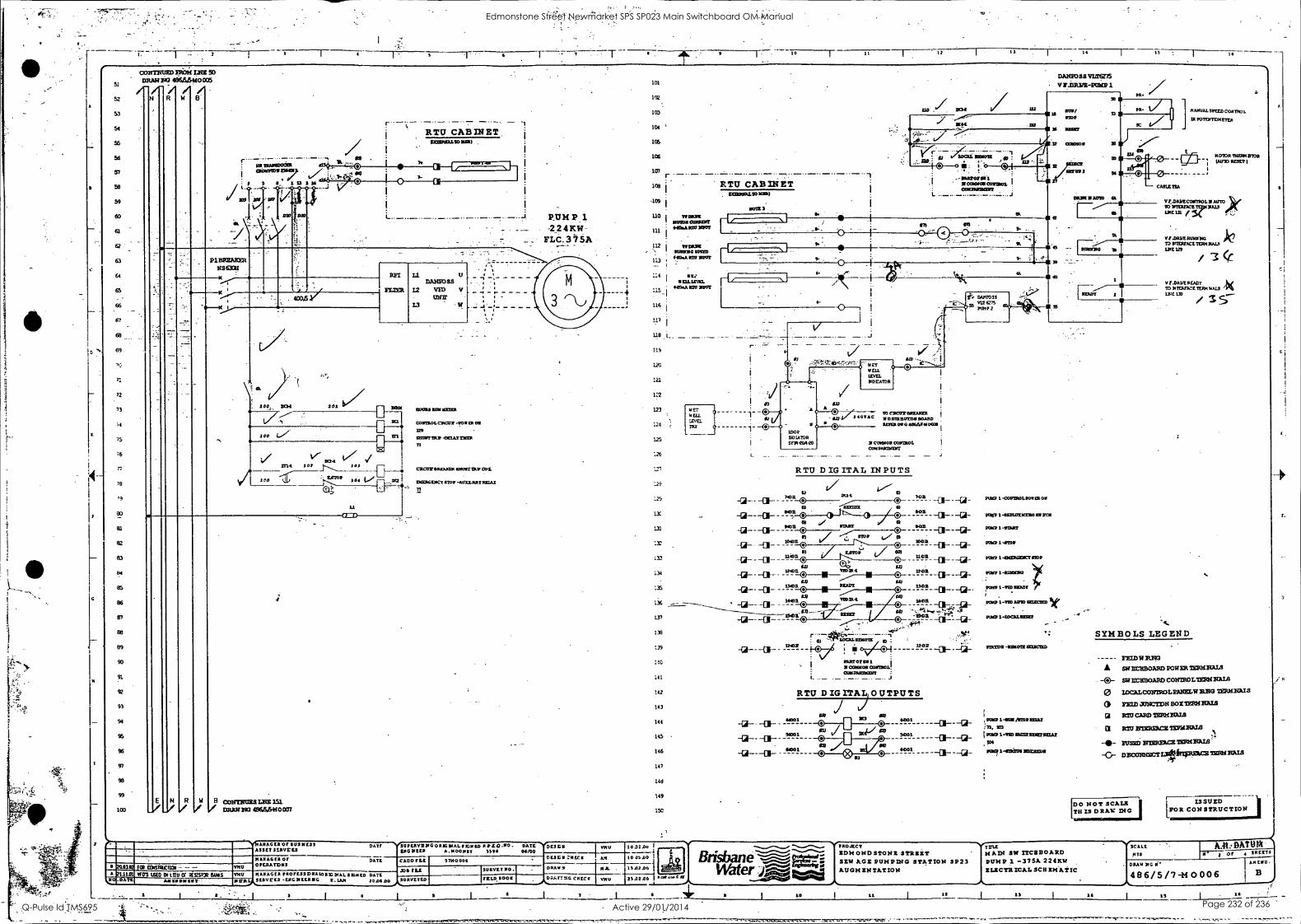
I
D
4.4
6 T 10 1 2 I 11 -.---1---- 14 15 16
51
52
53
54
55
56
5'7
58
59
60
a
63
64
65
66
67
68
69
71
72
73
81
02
83
t!4
85
86
87
88
89
90
91
92
93
94
96
'36
91
93
99
103
CONTRUED 219296 iloc so DRAW VG 496.6.61:100:15
N R 14
:,. tallsmesnala - 4 - amummies47
I 1 13 5 m
020 DSO
.
RTU CABINET IECIIR0L991LSR)
co
_._._._._
P1BREAKER NS ECM
"N.
100 DOE 101
RPI
FLIER
21 1:1ARSOSS ,
12 UM V Ulflr
18101 SODAS IU10:1101
IT1
tE2
DCE-L mi 102 101 EL---- 100
E N R N B common me / taturno 48446HO007
200162 1. 03616.6001 - - -
ANAGEROP9116111E33 ASSET SEAVELS
MAAGER Or OPEAATISIS VDU
A 1.1101 Was WED DI tau cr 6:Emma BURS 7144/ PIAIIAGEA PROFESSDNALORIG DIAL SIGN tO DATE ,,S,611VE4.1 -CMG NEERNG R.LAM 0.DATE AMS 100600
DATE
DATE
a
CE:
4
COIITROLCMCITX -00111111 OS
us -
111LUIPTIRD-DEUSIMSR
71
cactor lissom:a murmur 001.
21CIERGOK7 STOP -111011LARYRICIAT
TY
RUMP 1
-2241KW - FLC_315A
SUPERVISMGOR162AL0IGNIORPZEI110- DATE LSO NW 8.1400611 096 06/00
CADDELL
XIS ILL SURVEYED
DES Eli
DE3011:11ECII
101
102
103
104
166
106
sai
108
-109
RTU CABINET 0:1001751410 MIMI
NOTE
1U I
MOTOR 0016117/ GOSM1PX0 MOOT
WORMS U0
112 4
i wok=
113 Hoar= =DT suoulc woo 1
i .
1:4 1 ce 1 ' ME:XS=
- __ -4 ,...:_i eso.A1011 EMT
116 i L 1_17 1
1111 _1_ . _ . - .. _ .-.- _ 115
i 0.1
126. ?"4:4;40,,.-
DAATTNG CHECK
I
DOE
DANSOSS inaNZ15 VE.DRI/Z-PUNS I
Lil 11
r - - - - -
sus/ STOP
is passr
V:. COMO/
of, o GI .11 .
11031004100111201. I C0111190210111
!wro9
9-
4.
4-
121
122
1234 ,
MET WELL
124 IEVV.
1
125
126
127
12i
.129
11
131
1r
133
134
135
136
137
133
139
141
142
143
144
145
146
10
144
149
a A
NET NE11. LEVEL IIDE/1100
DA2tFOSS
VIZ el5 PUMP 2
to
TO CMCOTMATAXER I
2.0TA0 1111=130113111 WARD REFERDIEGSP6M4100/43 6
LOOP BOIATOR SF16-204P0
I I
1100401011 CONTROL comssprocurr
RTU D IG ITAL IN PUTS
u / I---- °
-2-- -01-- 7" 7" --a- - --Gi- . -a--co-- awn
`"n -co- -a- y . -a------ mi ®
. -c- 7 3--u- . -1-- ..... ,..../ .>
A-- -13 "" 2 °1 --a12-
TI-ve' - -(4--- -co--- - -?I'lc. --11-_,'" e 12' -co-- --1--4--
0, to --11.98
RUDY O -
avow.' --01-- 0 0 -14-
DM= 0 -isan
.., 1"2
031202101 11COMMON COMAE! COMPAMOCEST
RTU D IGITAL OUTPUTS
) - -a-- - "*1
-a-- - "mu
NO
102100 I 101.....12 -,..../..s...
LO 0500 1 Brithane ..........41 150106 I Wdter -J2.....°"
so....mm... , 001 CO ...A..., 1/~ rW:i
.....61110441160 -..-....-..". 10
9001
7001
4.001
HAMA/ SPEED CONTROL
IX POTINTDMETER
DAR M AVID
1
*DT 2
SALPL-COVEROLPOSCR OM
161101-11EFTEXICERO SIR=
MEP 1-0TAPS
PUMP 1.4101?
POMP 1-0133621111CTSTOP
POMP 1-RUM=
6E90 1-WIT 111701
SOPU11-9611/111)SEDIESED
PIMP 1-1DCAL911612
SIMEDS-PSYVIIILEGICEED
, KULP 1-107111/11701 sum In.
I coo -wa 1110129X6121026.1
Poo t -swam max=
. 4
M010RTIER1431011 (AUTO P/3E7 I
V7.01112CONTROLINAUTO.ok 10 SI1 111E 371
VP-DRYERUX1111G TO 141E2PICETER1124010 111E 129
k / cc
VP-0020E1W 10 DITEAPATE TERMNALS 1240170
SYMBOLS LEGEND
YEW RIM SWUM:BOARD POWER 73222421ALI
-0- SW =Immo Com:Rom:ammo
O zocaLccarrRoLuumw Rao TERN MIS
aszto zascrpli Box Tem mus Gi 1=C= 7:02421AI9
CI MU moss= mcnizaLs
sum. ariotmcac 113011131I13.
-0- DISO3NNYCILUfarIPEICE TiattRALS
[DO NOT SCALE TB IS D RAW INC
ISSUED [TOR CONSTRUCTION
NrP-ROJECT SOH OND STOT/Z STRMRT SEW ACE PUMPING STATION AUGMENTATION
TITIL
3122 3 PUMP -375A 224KW MAIN SW ITCSBOARD
ELECTRICAL SCH EIS &TIC
11 14
N'eSCALL
pus A.#t: DATUM- M 2 or 1 561113
AR LSO,
B DRAW NG
486/5/7-M 0006
19 16
mA -Os?, --""-
r.
E.
Edmonstone Street Newmarket SPS SP023 Main Switchboard OM Manual
Q-Pulse Id TMS695 Active 29/01/2014 Page 232 of 236
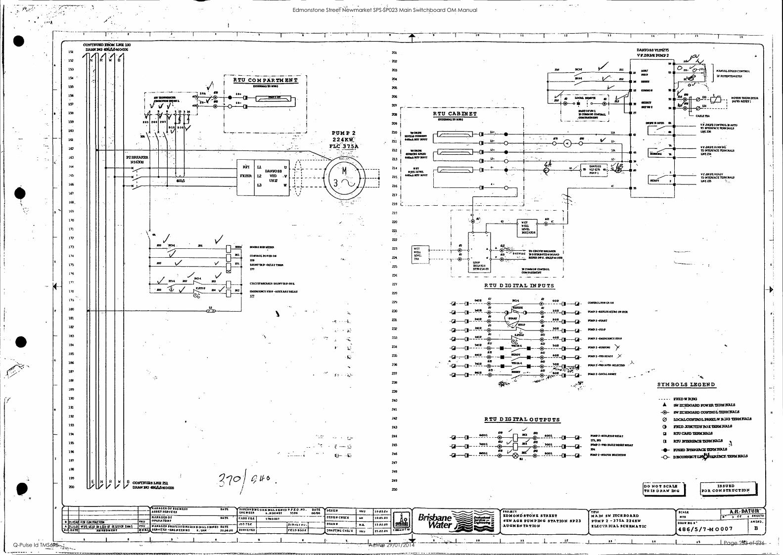
A
C
- r 3 10 11 14 ' 15 16
151
152
153
154 '
155
156
157
158
159
160
161
161
16.s.
164
155
166
167
166.
169
170
171
172
173
174
175
176
17.7
172
176
100
181
182
183
184
185
186
100
186
189
193
191
192
193
194
1%
196
171
1%
199
203
cornrow neow zacir 103 DRAW 103 4841466860006
N R 14 B
RTU COMPARTMENT 1 A 1:132110/240 m)
10. MN 2112112170122 i /.----------.
IrMin'tiMI -..... ! .
4 ,-, 10- V V 141' i
L 2
205 204
-\
2111
- -
. ..
0110
i 15
1/20
1 1..., t
Cli 3 14
I
--- ------ P2 BRF.AXER
MOOR RLT
TIMER
Lt U DANSOSS
12 VID -V utra
L3 w
. -1 . - ,-
. _: _
. _, _
,
10---x> ---<
, ,
--sc.....1, cob
i V/ 710 3104. 711 -
PIA KC=
*------1----------G- 1262111
'a V m
COM7201.901.131 OW
229
$211111TTRP -DECAT TILER
177
cacnraxouacs smorman COIL
ESPERGENCI STOP -ACCELAILTILIIAX
117
...
.. ,.../ V/ 21.2-1
r2......,01211 204
ay,
12
E
_./ N
_II R W /
=
.
'/40 i 6 u- 6 B C011TRURS Luz 2s3 / wpm wo 4866. 6wocc3
a .12.
A 1J IDS It .DATE
I' t0ii121C1106 mV
AVAGER OF 511316023 33333 3512255
110.29.GLA OF OPERA:DNS
OA Tt
DATE
Kai 1510 DC MU OF 6691S10R PARS ,010 KMDMIMIt 2 Cal
01111AGE9 P20/225179410110101AL SEXED DATE WIT E5 -DK MEER MG R. LAM - 20.0600
1 I
5119E2VBUG 0 A /G1NAL SIG910 PD20.00. DATE ENGWEER 11.11000112 5596 04100
GADD FLE I
ME 5700007
38060053 S- 31114+1,
a.
'
201
204
205
206
201
203
209 i
Z10 01010003122191
W0222
211 141134A12111 /MT
212 I 111
WONG UM 112.22
213 402A 030 NWT
214 i
.CT 1 2FL 12192. 1 420.21203 SMUT
--7 1 as
.I.
I 216 1
217.1
218 I: .._
219
220
221
222
223
224
225
221
229
229
233
231
232
233
234
221
236
237
239
239
240
241
RTU CABINET 4012121GALTD UM)
DAKEOSS
V P.DRIM POMP 2
BOlt r 141 magi ill Is
STOP
10
MANUAL SPIXDCO211501.
UC POTENTDMETEP.
O 50101011 10
22a I® o 0 @I
. . 22/ 81 22
SO= MW 2
40 IOC= MOO= in
. I
0A120001 2 =OWE 03612110L
020 14A093
442
94
CA111/19A
RTU DIGITAL INPUTS
50271971. POW ER cm
9120 2-112211711CC210 0 MIR
12111172-21,11T
POY92 -805
ROM 2 -12aRGINGT 0008
MEP 2-00 Si<
Me 2 -310 READY ..><
2-TE9ADTO SCIEC15D
PEW 2- 000.10!40
_._ _._ ° 002 _a____u__
toa_a____Giv
2°1-1:1-C4-
" 0-C1--ci-
--a--a- -tia2L -®--- . 23
"M --421-011.- .2
IC2 -12-0- -GE---13- --®--18Ed"
igp
. -------O- au
52332 203124.
WM
00 - -(27-
so - -0-
227
w
"2-CI---12-
51124,1-Uf-
- -4-e1-01-Gt-
1a2y.,
A a -al' -111-...../-1.- ex
-G1-=-C1-- -6-412- -0- --11--.1- s. .-
!1 032
-12-411- "'2- M" 1ESQ av 602 -0-
.4, .....,.. .
da-r-V ....!... . , ® .4....... -.01--H0-
242 RTU DIGITAL OUTPUTS 243
244
245
246
20
249
249
250
44001
1001
0001
RIO 2 -1133241205 RELAY
171.
2-125121073922029222.2 206
IMP 2 -SIM= 3052212130
M0100911713427011 16010 szsrr 1
vi.ossozcomsol. a AlFTO TO 11TERF2CE1123121ALS 1.16E236
80.DAVE 81211121t TO 111ERFPCE TEM 54813 02234
VF.DAYE AMOY 70 MlERUCE TERM MALS
1.749 235
SYMBOLS LEGEND
PEW W
SW =BOARD POW1Ift TERM IIALS
-0- SW 10:IMOARD COITMOL =IMAM O IDCALCONTROLIMELW isM3 TERMIIAIS
O Flaw mic-rpu BOX 752012tALS
O RIO CARD 12212121Ala
CI Pau =mace toisnaIll
-IV FUSED 321RME4CE TDQf2A78 '. -0- 0916091 Liwpitounsmunanaus
DO NOT SCALI TS IS DRAW MG
ISSUZD TOR CONSTRUCTION.
DESLS 10.0229
DESZ11 GRECS
DRAWS
AM 10.05 DO
712- 15.0200
250 GOOK I PAAFTXG CMEX Put, 25.02.00 L4 1410AMCq
PROJECT
RD14ONDSTONZ STRZIT 11XX ADZ 6014 PD40 STATION 3623
AUGN Zt2T1STIOW
TIIIL NADI SW ITCHBOARD 6014 2 -375A 224KW ILICTR ICAL SCRIMATIC
V.SC All 073
DATOtr T. OF
DRAW 1IG I
4 311 LETS
AMEND.
486/5/7-M0007 B
10 L 11 19 I 14 L_ 15 96
Edmonstone Street Newmarket SPS SP023 Main Switchboard OM Manual
Q-Pulse Id TMS695 Active 29/01/2014 Page 233 of 236
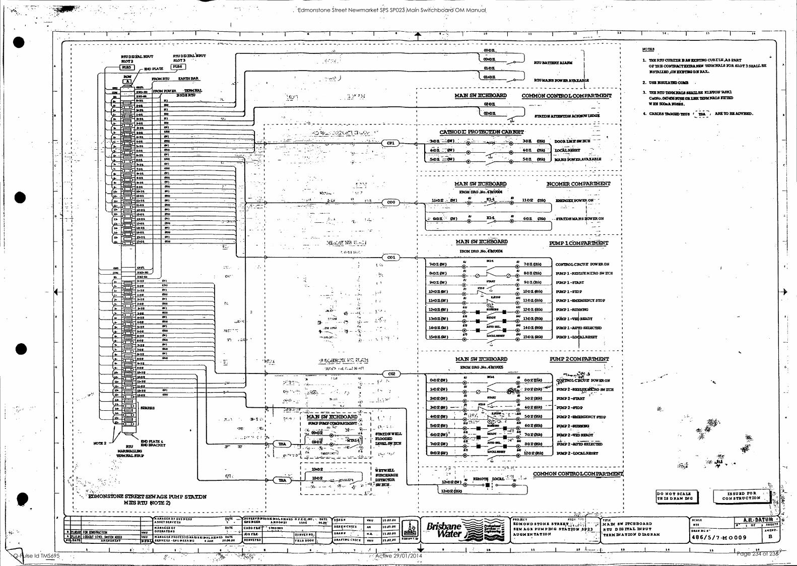
.
A
C
F
C
a
2 7 1 10 I I
12 - 11 14_
i
'I
MU ODELL Asir =YIP 1=311
__ _______ a-- - _ _ ______________ _______ __________ - ____ ________ 1
03-0D._
MU PATTIZ= MARE
MU DII11:111.211Kr! SLOT 3
IND MATE P18/ 6 I
0.
II-
U. 14-
211141
O 10710 X4111
1401
01 1701 1-01 41:11
401 431 1411 401 4-01
401 3-01 1401 401 4151 101 O .01 401 401 001 11401
1001 11701 11-01
1401 12-01
1401 1101 1401 1401 1401 1401
1530700
O 42-01 0.20 002 1704 1-02 402 202 401
MDR
402 3.02
-02 141111
402 401
&DT
P OP
1402 1-04 /OD;
1401 11-04
72.01 1.402
PRONE MU ZARIN EAR
MOH POWER TIRMIAL 2 SDZ RAJ
1PS
1
01.-DX . .
. 01H)31 REMAIN POWIRMIMADLI
-.- - -L _______ MAN SW ILCHBOARD COMMON CONTROL COMPARTMENT 1, .
'..Cj . . *:... .:"`" -'..:T") 1
I . 02-02. .4. - _ .
0140D. 1 MIT= A.11:12MT =MOW =Dag. - - 1
1 1
- - I '
1
1 1
CAWOD RO7ECTDN CABNET TM P , ,:-.-...' T-10.....:- ','',',"_;:t o--1. 0:...t'....,.- . -
IPS
44i)i 7.- i )
poDOOR X SA
-zocitz.RiEssr- '
7 _
54:11I. CM MANS iOVERAVAIABiX. .:
Al
HO
.1
12) 120
00 520 0.
mon 2
go. ADO
011
Mn OIl
0))
OK I
MOO
DID PLATE
MU IND BRACEET
10PSFALLEP THRHEAL MAP
CP1
_
:7'2. . _
cci
ONSTONE STREET SEWAGE PUMP STATDN MIES R1U t TOTE 2)
_
1I/. 14. ra
j
t
.5.01 ..7--01N)
30/1 01113
402. Mk)
MAN SW RBOARD
IRCHIDRO 11c4/3030131
11402 _ - Pi)
NCOMER comPARliaarr
11-02 013)0
0,1) 21.4. 6011 eBk)
MAN SW itc-RBO-ARD MOH DRG So.-41HIPOI
ENERGEXPOWER ON
- -STILTON MAAS nouraoll
PUMP 'COMPARTMENT
CO2)
7+01.01)
13.01ear )
0 171
7-D110333p
Iv 8-0112830 I 0
0:1102 9.011 Oak)
not Ar. 10011 IWO
12102
2.
so. 11-011. (331g)
on 12-1131. 0
to 1303103k)
so 1401 NMI
150E. PDS 0
MAN SW RCHBOARD FROM DRG .No.411,11I005
cotrutoLcRcur POW ER ON
PUHP 1 -RIOT= mrRo SW UCH
PUMP 1 -STitger
PUMP 1-STOP
PUMP 1 -EHEMENCT STOP
PUMP 1-RUNNAG
ikirel-vzi mai PPM 1-AU1O SELECTED
PUMP 1 - MEET
PUMP 2 COMPARTMENT
. ...
MAN SW ar.,HBOARD,'7, i SO/LP AMP 03NPAP1ICE5T II I _ I I - '
X9.02 SIM:DNA= 1/mta - - FLOODED
-:
_ 10402
113012
I isrwlaz. 1 I SURCHARGE
TOLISCISalt
-
__ ;A 411'.7 SW
-.41.114 ASAGER Or 1111311033 DATE __-Y-312111134C0 RIC INAL S ID -A PLO .110 DATE ... K ASSET SLAWC11 44G112ta AKOOPIT 3514 . 04.00-
DLSGCISECA
I
2ulai 2L11.11 Dan
601 IDOW4C1101 111112
MANAGER 0 OPERATORS
DATE CADD me' 31110009
5)110
LOMOD1 Lfla .ltd ICED A14E40414?
a
Jos Psi- 5)2111 5)A2A1C0 PROTE5SDNAb00.4.ALS125ED DATE x WEAVELS -LPG MEERVIG 4/74 20D4 31145)1.104
0345)0120. DRAW
'LLD 4001
s
174.
DRAFTING CHECK mu
7 I
- , .
10 02 00
11.02 00 -I rid 10.0100
23.02.40 101.777
0+02 )
14D2i)
2402 OP)
3.02 Iff )
oplaaiik)
2o2 ea ROM
(11 402
5.02 PH) "
p3k)
T. u°1"
602
7402
MG
. 4402 eel) 5132 elk)
0 :1-11F--- U -6402 PA33
0 . HOD 013k)
n SH)2 pi) a
IN) 2 6Bk1 Z 0
1/1012.1/W
3-1:12 034
12;02 )
1 12402 CiR33
.14 ..7t
C:
VIROLCACUN POWER ON
MEP 2 -111131331.9ebtO SW NCH
PUMP 2 -ram PUMP 2 -8IDP
PIMP 2 -11NERGENCT STOP
PUMP 2 -RUNWER
MASA 2
a. PAM 2 -AUTO SETECEED
PIMP 2 -10CALRINIT
o ; o 0 COMMON CONTROL COM PARIMEN
1
1
1
1
1
1
1
1
NOTES
1. THY MU CUBE= B AN MCBTNG CUBE= ,A3 PART
OF THE CONTRACTS TIERNPALS IOR RIOT 3 SHALL PE
NSIALIED ,ON =MAO DA RAM.
2. USE 21SUIATED 03123
3. THE MO 12RILIAJA- WAILER KLIMA WM Cad2lo .0117.1661USE OR LAIC ISIENNALS WEE 5132A
4. CARIES TANGS) TAUS TB11. ABE 20 212 AMMO
-7,
DO HOT SCALP TH IS DRAW DIG
..._...-....._, -....-....r...... PROJECT 1722.: -". TII1E Thil ."..-....-....-/. ..........."-"*..-.. ADM oND s TON I 3 TRIRTz ,.., , .14 Am. SW ITCHBOARD e , -....-........ SEW AG a putt PING STATION .3p23 RTU DIGITAL INPUT
-'-. Wat AU G M IN TA T it) N '' , 'TIM( Zia ATION DIAGRAM H
.....A" -
' .... -. 10 .L_- 111
NIPS
ISSUED VOL . '!'. N STRUCTION
AM: DATUM g Of
DRAW 111111
486/5/744 0009 *d
13 IS
30E125
AMCWO
Edmonstone Street Newmarket SPS SP023 Main Switchboard OM Manual
Q-Pulse Id TMS695 Active 29/01/2014 Page 234 of 236
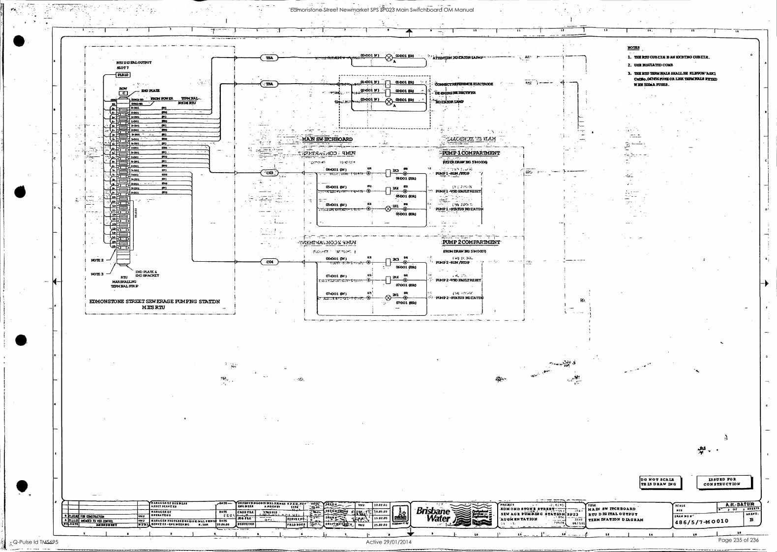
I DO NOT SCALE THIS S DRAM INC
A
C
6 11 14_ I IS
RTUDDEALOUTWT SIOT 7
I:00515 FROM MIER TERTUIAL- CadeM NS= RR/ atm. 9.11
owl -
161101 pat 1001 0161
IRDDI
0001 053 1.201 - RI 34333 ole 0151 4001 1.201 SO01 OBRI
11701 dl DC91.
1.001 VII 7-001 INS
5.301 All 0001 4511
5.001
9-001
NOTE 2
3243 RATE NOTE 3 -1
RTU END BRACKET
HARSHAU.PG TERNIIALSTRP
EDMONSION:E STREET SEWERAGE PUMPWG STATDN MIL'S RTII
FOlt COGNIETER 110030 TO OD COMA
Ammons
171-T.T110114) ApP1 C0001 010
'CY A
4,:_,,p1400 r) :9 moot OkO
- 'ff.4,34:,;.. LI 924113 0r) 'D °HMI 810 I
V) 6o 0)001 pm
j "7 A
ikeaticrinoessimarzlIIECZRODE I "
1,13-DOERONERRCITNR I ;
":*=041:0RIA1331
MAW SWILCHBOARD VLA3t.i
RIU,/
017.;i:F
. 034001 TM) so
- runt 114, Q,.
osopoi. Pr/ et; _ LI, 4 ®
754001 )
oto. 03,0
11 4 0 001 (134
" 0
esixn MOS
-17 A.`,. MOD q 1.1tiq
06001 01)
-
074001 01)
074001 01) al) 2H1 03 0
- 07001 KW
014 ANAC LA Of II US 11131 'DARK -.7iTITifAVD5C.04110 DIAL SLIMS R D I
sk.wa1---sglr C ASSET SCARER I RAC II LER £000Fav ista. ' 500 :
DATZ CARD I'LL '57550010 - . i
f S1'. ! ,../' - .1. " -, it A .a 141 - I rrl -'," j311 MS- - --- MOLT pd.; ,%1'"' 9 ̂ I % VMS II /PAGER PRO fL111011A b I IQ DIAL 1 ON DATE
VA 101)41)0 SO ROUE°
-.-P014P-16:114PAlintIENT
MN:10RM Da socoo -", 1 .
PUMP 1-RUN /010P 1
PU4I11-ymEmi1z1izszr1
141 sot:, -PUNS 1rSLk7US BorxrDs
-
. -7-;:.7".- 'j- PUMP 2 COMPARTMENT-
IRON DRAW EIG 5340033)
1 )4) V. 3+3, P5HS2',RUNIST0P
'...PUMP 2 -VS0 EAULTRESCT
' PUMP 2 -91ATUS 11,r.74.
I
YOU
PI AXAG LA Of OPERATOR!
SCRIM LS -6NC 11111:1111C R. LAX
e Pf100LCT 1:61 Trrix .EDM OND 5TON; SEW ACE PUMIN -P,G STA70_,..! 3223
'7Gic.,E.NTATION - _
11
NO=
1. T I M P a o C O B T : L E BAN EXOTBO CUBEIR.
2. USE EISUIATED COUR
3. IRRICD:113ERNNATIS BHAILSY ICLIMOWASIC1
Cattio.0/14561USZORuavn00[icus PE W 9001iAIUSES.
MAW SW ITCHBOARD RTU DIG ITAL OUTPUT TERM 'NATION DIAGRAM
V.
'c.
&Ai
ISSUED FOR CONSTRUCTION
NISCALE
VS
DRAW DIG
486/5/7-40010
Edmonstone Street Newmarket SPS SP023 Main Switchboard OM Manual
Q-Pulse Id TMS695 Active 29/01/2014 Page 235 of 236
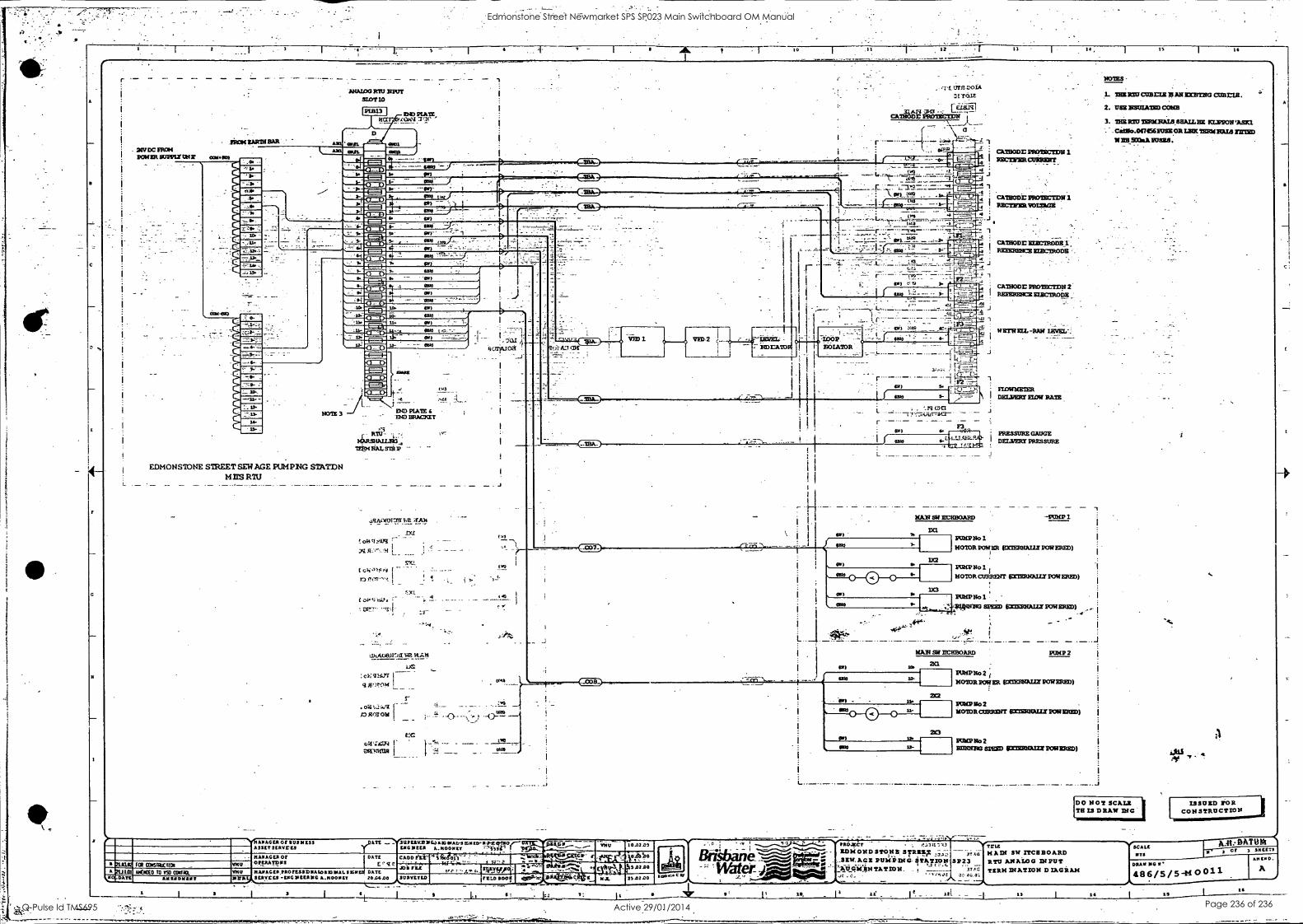
A
C
X
5 - I I -
17
r ANALOG MU NPUT
SLOT 10
POLO Mar,
D
MA MD TE, ah,/ 71,:le
COW- -11E)
NOTE 3
EDMONSTONE STREET SEWAGE PUMPIIG STATDN MR'S MU _ _ - - - , - _ -
4111SAGLA Of 5531(533 ASSET sritvres
DD PIATE 11113 EREC/CET
MONSHA.U.N13,;
IMM NAL STEP -
.151A0M17T7 ..2
t 0;4
4.11.4.08.111-pl WE_
cv;g173. w'row L _
ra1;.,.a,1 ru
CC cA14',1e.^31
ZWITHWI
: I urn r-solA
"Jf.Tcaz
pRomicrptr
NOTES
1. ZNE SaucuBrI2EANDZSTNGCOHEIR.
2. USE MEDIATED COMB
3. TICE MU 19R1LNA1A 6HRJ.I. EC !CLIME( 'ABM "...Catlio.0a456RISD.OD LNIC TEIGINEM ram
11( NE 5013BA POSES. opID
CATHODE Emriscmti REcriesacusszer, 4.1a.::z............----- 1111111*11=1113 -__ - ........4) .*
. i WO . .2 .fit...."......"' OMIM ,( --41_
, - -,:t..- mlif.
-e 1 ,i A Ir ,-- ----- - ..----;-ri - 7, --vc.,E.,,,,,o ____ -1.. . .
-I
8(-71141°.3
.J
aw
lc:(1A'AJ
VE3 I itpralo
.1
4 CATBODE PROTECTDR ! RECTEIERIOIMGE
4.
.7 754-'7
LOOP. NOIATOR
1
CATHODE 103MIROiiII REIERENCE ZIECTRODE
CATHODE PROTECIDN I REEERnicz gurcribmz
..._.....
- - . ,
4-
J
40)
101
wgrwzrz -RAW IEVEL-:
Li7 r-77,E3-1
1 FICOMETER R- I DELVERI EIDE RAIN
5-3 G.
SS/
4*, 1.2..L.D.re..lgt-
-. V'2 T.& -127
NAN IICHBOARD
L.
. - ... -_ 1
ATE
21/102 A 0.11.01
110cDATE
FOR ONSIAC
MANAGED Or ERATVIS
DATE
E I e
Alecto to Ts° wax Amiga DOSS?
1114s !IMAGES TAOTE3SDN11101151MAL SIGN DATE 1(VAWERVELS -LNG IMAMS 11.1100557 20.0600
'L
UPL111/1911C411.1G4NAL-3 ESN ID- 1({L ISCIIEED A.11005 ET '"5-521S CM1152112V1 1g2aiiiMMEMMWEATal LUERMINWMMIRIPAIIIIM=1=1
W.M21131=111
10.42.00
St/ EVLTED xt.() Boo!!
7;
25.0200 I ciew,,
a1
PRESSURE GAUGE DELVED PRESSURE
-PUMP
WISP No 1.
MOTOR POEM ADULT POWERED)
PUMP Ho 1
A- I_ MOTOR CURRENT RECIEDRIFALLY POW ERIE)
DO A PUMP No 1
SPEED WILT POWERED).
.te - - vet'
NAN SW IIVHBOARD
2X1
PUMP 2
PUN:PRIG 2 t MOTOR POWER MMIMNALET POWEREI))
IMP No 2 -
NOT= oppENT EXTERNMIT POWERED)
POMP No 2 ROHM= SPEED =MIX POWERED)
.W.TrILE B-irsiban -- EDM ON D STONE: SEL;E:i37.13,, 3-1.2-334 tfreTuA DIAnSWAto/T:11324130pAuRTD
.,SEW. AGE ptmiinia-tiTATleto 'Wat EN EASTON. . 1
;-
3TA' TERM 'NATION DIAGRAM
DO NOT SCALE TH IS DRAW DIG -
10, 17
SCALE
STS
ISSUED TOR CONSTRUCTION
DATO -re , Cr 3 MILTS
DRAW 1(6
4 8 6 / 5 / 5 44 0 0 11 AMEND.
A
14 I 13 GG
Edmonstone Street Newmarket SPS SP023 Main Switchboard OM Manual
Q-Pulse Id TMS695 Active 29/01/2014 Page 236 of 236


