Embed Size (px)
Citation preview

Renewable and Sustainable Energy Reviews 54 (2016) 34–47
Contents lists available at ScienceDirect
Renewable and Sustainable Energy Reviews
http://d1364-03
n Corr5536187
E-mratil.eee
journal homepage: www.elsevier.com/locate/rser
Electric vehicles charging using photovoltaic: Statusand technological review
Abdul Rauf Bhatti a,d, Zainal Salam a,c,n, Mohd Junaidi Bin Abdul Aziz b, Kong Pui Yee b,Ratil H. Ashique a
a Centre of Electrical Energy Systems (CEES), Universiti Teknologi Malaysia (UTM), 81310 Johor Bahru, Johor, Malaysiab Power Electronics and Drives Research Group, Universiti Teknologi Malaysia (UTM), 81310 Johor Bahru, Johor, Malaysiac Insitute of Future Energy, Universiti Teknologi Malaysia, 81310 Johor Bahru, Johor, Malaysiad Department of Electrical Engineering, Government College University Faisalabad, Pakistan
a r t i c l e i n f o
Article history:Received 27 February 2014Received in revised form16 July 2015Accepted 22 September 2015
Keywords:Photovoltaic (PV) systemElectric vehicle (EV) charging systemState of charge (SOC)Maximum power point tracking (MPPT)MPPT dc–dc converterBi-directional InverterBi-directional dc–dc chargerControl algorithmEV charging algorithmPrediction modelsOptimization techniques
x.doi.org/10.1016/j.rser.2015.09.09121/& 2015 Elsevier Ltd. All rights reserved.
esponding author at: Centre of Electrical Ene; fax: +60 7 5566272.ail addresses: [email protected] ([email protected] (R.H. Ashique).
a b s t r a c t
The integration of solar photovoltaic (PV) into the electric vehicle (EV) charging system has been on therise due to several factors, namely continuous reduction in the price of PV modules, rapid growth in EVand concerns over the effects of greenhouse gases. Despite the numerous review articles published on EVcharging using the utility (grid) electrical supply, so far, none has given sufficient emphasis on the PVcharger. With the growing interest in this subject, this review paper summarizes and update all therelated aspects on PV–EV charging, which include the power converter topologies, charging mechanismsand control for both PV–grid and PV-standalone/hybrid systems. In addition, the future outlook and thechallenges that face this technology are highlighted. It is envisaged that the information gathered in thispaper will be a valuable one-stop source of information for researchers working in this topic.
& 2015 Elsevier Ltd. All rights reserved.
Contents
1. Introduction . . . . . . . . . . . . . . . . . . . . . . . . . . . . . . . . . . . . . . . . . . . . . . . . . . . . . . . . . . . . . . . . . . . . . . . . . . . . . . . . . . . . . . . . . . . . . . . . . . . . . . . . . 352. Brief overview of EV and PV technologies . . . . . . . . . . . . . . . . . . . . . . . . . . . . . . . . . . . . . . . . . . . . . . . . . . . . . . . . . . . . . . . . . . . . . . . . . . . . . . . . . 35
2.1. EV and battery . . . . . . . . . . . . . . . . . . . . . . . . . . . . . . . . . . . . . . . . . . . . . . . . . . . . . . . . . . . . . . . . . . . . . . . . . . . . . . . . . . . . . . . . . . . . . . . . . 352.2. PV system . . . . . . . . . . . . . . . . . . . . . . . . . . . . . . . . . . . . . . . . . . . . . . . . . . . . . . . . . . . . . . . . . . . . . . . . . . . . . . . . . . . . . . . . . . . . . . . . . . . . 36
3. PV–grid charging . . . . . . . . . . . . . . . . . . . . . . . . . . . . . . . . . . . . . . . . . . . . . . . . . . . . . . . . . . . . . . . . . . . . . . . . . . . . . . . . . . . . . . . . . . . . . . . . . . . . . 363.1. Review of the power converters for EV . . . . . . . . . . . . . . . . . . . . . . . . . . . . . . . . . . . . . . . . . . . . . . . . . . . . . . . . . . . . . . . . . . . . . . . . . . . . . 36
3.1.1. dc–dc converter with MPPT . . . . . . . . . . . . . . . . . . . . . . . . . . . . . . . . . . . . . . . . . . . . . . . . . . . . . . . . . . . . . . . . . . . . . . . . . . . . . . . 363.1.2. Bidirectional charger . . . . . . . . . . . . . . . . . . . . . . . . . . . . . . . . . . . . . . . . . . . . . . . . . . . . . . . . . . . . . . . . . . . . . . . . . . . . . . . . . . . . . 363.1.3. Bidirectional inverter . . . . . . . . . . . . . . . . . . . . . . . . . . . . . . . . . . . . . . . . . . . . . . . . . . . . . . . . . . . . . . . . . . . . . . . . . . . . . . . . . . . . . 38
3.2. Charging modes . . . . . . . . . . . . . . . . . . . . . . . . . . . . . . . . . . . . . . . . . . . . . . . . . . . . . . . . . . . . . . . . . . . . . . . . . . . . . . . . . . . . . . . . . . . . . . . . 403.3. Practical PV–grid charging systems . . . . . . . . . . . . . . . . . . . . . . . . . . . . . . . . . . . . . . . . . . . . . . . . . . . . . . . . . . . . . . . . . . . . . . . . . . . . . . . . 41
4. PV-standalone charging. . . . . . . . . . . . . . . . . . . . . . . . . . . . . . . . . . . . . . . . . . . . . . . . . . . . . . . . . . . . . . . . . . . . . . . . . . . . . . . . . . . . . . . . . . . . . . . . 414.1. With intermediate storage battery . . . . . . . . . . . . . . . . . . . . . . . . . . . . . . . . . . . . . . . . . . . . . . . . . . . . . . . . . . . . . . . . . . . . . . . . . . . . . . . . . 414.2. Hybrid systems . . . . . . . . . . . . . . . . . . . . . . . . . . . . . . . . . . . . . . . . . . . . . . . . . . . . . . . . . . . . . . . . . . . . . . . . . . . . . . . . . . . . . . . . . . . . . . . . 41
rgy Systems, Faculty of Electrical Engineering, Universiti Teknologi Malaysia, 81310 Johor Bahru, Malaysia. Tel.: +60 7
. Bhatti), [email protected] (Z. Salam), [email protected] (M.J.B.A. Aziz), [email protected] (K.P. Yee),

A.R. Bhatti et al. / Renewable and Sustainable Energy Reviews 54 (2016) 34–47 35
4.3. PV on EV body . . . . . . . . . . . . . . . . . . . . . . . . . . . . . . . . . . . . . . . . . . . . . . . . . . . . . . . . . . . . . . . . . . . . . . . . . . . . . . . . . . . . . . . . . . . . . . . . . 415. Future outlook and challenges . . . . . . . . . . . . . . . . . . . . . . . . . . . . . . . . . . . . . . . . . . . . . . . . . . . . . . . . . . . . . . . . . . . . . . . . . . . . . . . . . . . . . . . . . . 41
5.1. Modeling, optimization and control . . . . . . . . . . . . . . . . . . . . . . . . . . . . . . . . . . . . . . . . . . . . . . . . . . . . . . . . . . . . . . . . . . . . . . . . . . . . . . . . 415.2. Prospects of V2G and V2V. . . . . . . . . . . . . . . . . . . . . . . . . . . . . . . . . . . . . . . . . . . . . . . . . . . . . . . . . . . . . . . . . . . . . . . . . . . . . . . . . . . . . . . . 455.3. Issue on the integration with smart grid system . . . . . . . . . . . . . . . . . . . . . . . . . . . . . . . . . . . . . . . . . . . . . . . . . . . . . . . . . . . . . . . . . . . . . . 45
6. Conclusions . . . . . . . . . . . . . . . . . . . . . . . . . . . . . . . . . . . . . . . . . . . . . . . . . . . . . . . . . . . . . . . . . . . . . . . . . . . . . . . . . . . . . . . . . . . . . . . . . . . . . . . . . 45Acknowledgments . . . . . . . . . . . . . . . . . . . . . . . . . . . . . . . . . . . . . . . . . . . . . . . . . . . . . . . . . . . . . . . . . . . . . . . . . . . . . . . . . . . . . . . . . . . . . . . . . . . . . . . . 45References . . . . . . . . . . . . . . . . . . . . . . . . . . . . . . . . . . . . . . . . . . . . . . . . . . . . . . . . . . . . . . . . . . . . . . . . . . . . . . . . . . . . . . . . . . . . . . . . . . . . . . . . . . . . . . 45
1. Introduction
The concern over the environment due to the greenhouse gasesemitted by the conventional internal combustion engines (ICE) isseen as a major factor that will accelerate and sustain the growthof the electric vehicle (EV) usages. With the recent technologicaladvancement in the battery technology, power electronics con-verters, control and microelectronics, EV is expected to makeserious inroads in the motor industry. Moreover, these prospectshave initiated the integration of electrical power and transporta-tion systems in a way that has not been conceivable before [1]. Themain link between the two sectors is the charging of the batteries,which is the source of power for the traction, control, lighting andair-conditioning. However, charging by grid imposes an extraburden on the electrical supply, particularly during the peakdemand duration [2]. One viable solution to reduce the negativeimpact is to promote charging using alternative sources.
With the continuous downward trend on the price of photo-voltaic (PV) modules, solar power is recognized as the competitivesource for this purpose [3]. Furthermore, PV system is almostmaintenance free, both in terms of fuel and labor [4]. The appli-cation of PV is further enhanced by the advancement in conversiontechnologies, battery management as well as the improvedinstallation practices [5]. During daytime, the EV is parked idly inthe parking area under the exposure of the full sun. If the car-parkis roofed by PV, the availability of PV power allows for an oppor-tunity for “charging while parking” [6]. This is an economical andconvenient solution to charge EV at workplaces and parking areas[4]. An example of a structural diagram of PV parking is shown inFig. 1 [7]. Structural-wise, the roofed parking provides free sheltersfrom sun and rain, which is a favorable feature in hot climatecountries [8]. Since the charging is done during the peak demand(daytime), the savings from the electricity tariff is substantial [9].
Over the years, a number of charging methods using PV havebeen proposed. The most prominent is the combination of PV andthe grid, which is referred in this paper as the PV–grid charging. Ituses the PV power whenever possible, but switches to the gridwhen the PV power is insufficient or unavailable. Another
Fig. 1. An example of PV based parking lots for EV charging [7].
approach is to utilize the PV minus the grid, which is known as thePV-standalone charger [10]. There are several variations for thisapproach, with the inclusion of other power sources such fuel celland auxiliary storage. In addition, efforts have also been made tointegrate the PV modules/cells onto the body of the EV itself.
Numerous works have been published on EV charging usinggrid, including several excellent review papers, for example[11,12]. However, so far there is no effort has been done to compileand update the works related to charging using solar energydespite the growing interest in this topic. From the survey, it isfound that the number of papers on this issue has risen sig-nificantly over the last decade, hence the impetus for this review.The discussion begins with a brief summary of the electric vehi-cles, batteries and the structure of charger that includes PV. This isfollowed by the evaluation on the actual charging hardware whichcomprises of MPPT dc–dc converter, bi-directional dc charger andbi-directional inverter. Next, the charging modes for the PV–gridapproach is detailed out. In addition, a table on recent work isprovided to summarize the research conducted for the PV–gridcharging. In the subsequent section, the PV-standalone chargingthat includes several hybrid configurations is described. Finally, adiscussion on the future outlook and the challenges—which focuson the energy management system is given. To probe further, a listof 117 related papers is provided in the reference.
2. Brief overview of EV and PV technologies
2.1. EV and battery
The EV is widely referred to an electrically powered vehiclewhich uses one or more motors for its propulsion. The terminol-ogy includes electric car, train, lorry/bus, motorcycles, scooters etc.In this paper, the definition of EV is limited to the hybrid electric(HEV), plug-in hybrid electric (PHEV) and purely battery electric(BEV) vehicles. In charging context, the main difference betweenthe PHEV/pure EV is that it provides plugs that allow for externalcharging, while the HEV does not. The HEV charges its batteryinternally by the kinetics of its combustion engine. [13]. The evo-lution of the EV propulsion battery begins with the lead-acid,progressing to nickel and currently to lithium [14]. Modern EV isno longer using the lead-acid due to its low specific energy, che-mical leakage and poor temperature characteristics. They havesince by replaced by nickel and now, almost exclusively lithium[15]. Lithium battery is the preferable choice due to its higherenergy efficiency, power density, compact and lighter weight [16].Moreover, it provides fast charging capability, wide operatingtemperature range, no memory effect, long cycle life and low self-discharge rate. Currently, lithium-based battery includes a widediversity of chemical substances; for instance, the lithium ferrophosphate (LiFePO4) provides ease in term of handling due to itssuperior thermal stability in the fully charged condition. In addi-tion it has a low risk of explosion when accidentally over chargedor short circuited. Lithium–titanate (LTO) is the latest type, which

PV Array
=
dc-dc converter with MPPT
Bidirectional Inverter
ac g
rid==
Bidirectional dc charger
Central Controller
EV Battery
Fig. 2. The overall PV–grid block diagram of EV charging system [29,30].
IPV
VPV
PV Array
dc-dc converter
Vdc,bus
+
-
Fig. 3. Block diagram of dc–dc converter with MPPT.
A.R. Bhatti et al. / Renewable and Sustainable Energy Reviews 54 (2016) 34–4736
provides a wider operating temperature range, faster to rechargeand accepts higher recharge rate [17–19].
2.2. PV system
The most widely used PV modules are based on poly- or mono-crystalline technology [20]. However, recently, thin film is gettingpopular, especially for large installations [21]. For EV chargingapplications, the modules are arranged in series strings to achievethe required dc bus voltage. To increase the power, several stringsare connected in parallel to form an array. The behavior of a PVsystem under varying irradiance (G) and temperature (T) can beunderstood by examining its current–voltage (I–V) and power–voltage (P–V) characteristics. At any time, there exists a uniqueoperating point at which the power is at peak, i.e. the maximumpower point (MPP). Naturally, the MPP is not fixed; it fluctuatescontinuously as G or T varies. Due to these dynamics, the MPPtracker (MPPT) is needed to ensure the maximum power is alwaysextracted from the array.
Invariably, EV charging imposes an additional loading to theelectrical utility system due to the large current it draws from thegrid [1,22]. Furthermore, if the charging takes place during peakhours, the owner may have to pay a high premium for the tariff. Tooffset this burden, PV charging system is a viable solution toreduce the utility's spinning reserve and greater grid stability[23,24]. It is also expected be a major influence in the smart gridsystem, which is envisaged to dominate the future power systemtopology. Currently, two charging approaches using PV, namelythe PV–grid and PV-standalone, are known. The PV–grid charginghas one major advantage: during insufficient irradiance, the EVcan be continuously charged by deriving the power from the grid[25]. It is also more flexible because in the absence of EV (to becharged) the PV power can be injected to the utility. On the otherhand, the PV-standalone is convenient in remote areas whereutility supply is not available or too costly [26,27]. More recently,the hybridization of standalone chargers with secondary powersources such as fuel cell and auxiliary battery are introduced. It mustbe noted that using PV, the EV is charged with dc, which means itneeds to bypass the Level 1 and Level 2 charging [12,28] 1.
3. PV–grid charging
A typical PV–grid EV charging system is shown in Fig. 2. It hasthree main components, namely 1) a dc–dc power converter witha built-in MPPT, 2) a bidirectional dc charger and 3) a bidirectionaldc–ac inverter. A dc common bus (200–500 Vdc) provides a con-venient point for the integration of these components [29]. Cru-cially, a central controller (computer system of microcontroller) isrequired to decide the power flow and activation of the converters.The operation of the controller is based on intelligent decision-making algorithms. It is primarily governed by certain objectivefunctions, for example minimum charging cost, maximumprofit etc.
3.1. Review of the power converters for EV
3.1.1. dc–dc converter with MPPTThe main function of this unidirectional converter, shown in
Fig. 3, is to extract the maximum power from the PV and to sustainthe voltage at the common dc bus. This is achieved by the
1 Level 1 charging: 120 V ac charging is known as Level 1 charging.Level 2 charging: 240 V ac charging is known as Level 2 charging. Level 2 char-
ging draws higher current from the grid.
adjusting operating voltage and current of the converter such thatit always stays near the MPP. The MPPT works as follows: at aparticular sampling cycle, the current and voltage of the PV arrayare sensed by a current and voltage sensors, respectively [31].These values are fed into an MPPT block that computes the MPP;once found, it delivers the reference values for the current (IPV*)and voltage (VPV
*). These are converted to a power value that mustbe matched by the converter. If there is a difference between thetwo, the duty cycle (d) of the converter is adjusted. When themeasured power equals the reference value, the maximum powerfrom the array is extracted. The converter is usually based on thestandard non-isolated, buck–boost or boost topology.
The most crucial feature of the MPPT is its ability to track theMPP as quickly and efficiently as possible. Various conventionalMPPT techniques are used, for example perturb and observe [32],incremental conductance [33] and hill climbing [34]. These can beconfigured using fixed or adaptive time step. The latter is prefer-able as it reduces steady state oscillation, resulting in improvedtracking efficiency. Recently, more advanced soft computingmethods such as artificial neural network, particle swarm opti-mization, fuzzy logic control and evolutionary algorithm havebeen proposed for MPPT [35]. These methods are more flexible inhandling abnormal conditions such as partial shading and modulemismatch [31]. Refs. [31,35] provide excellent summary and per-formance comparisons among the available MPPT techniquesemployed for PV systems.
3.1.2. Bidirectional chargerThe dc charger is used to control the terminal voltage and
current, so that it suits the EV that is being charged. For the full
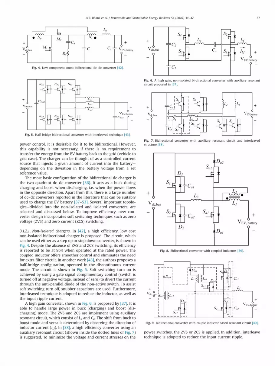
Fig. 4. Low component count bidirectional dc–dc converter [42].
Fig. 5. Half-bridge bidirectional converter with interleaved technique [43].
Fig. 6. A high gain, non-isolated bi-directional converter with auxiliary resonantcircuit proposed in [37].
Fig. 7. Bidirectional converter with auxiliary resonant circuit and interleavedstructure [38].
Fig. 8. Bidirectional converter with coupled inductors [39].
Fig. 9. Bidirectional converter with couple inductor based resonant circuit [40].
A.R. Bhatti et al. / Renewable and Sustainable Energy Reviews 54 (2016) 34–47 37
power control, it is desirable for it to be bidirectional. However,this capability is not necessary, if there is no requirement totransfer the energy from the EV battery back to the grid (vehicle togrid case). The charger can be thought of as a controlled currentsource that injects a given amount of current into the battery—depending on the deviation in the battery voltage from a setreference value.
The most basic configuration of the bidirectional dc charger isthe two quadrant dc–dc converter [36]. It acts as a buck duringcharging and boost when discharging, i.e. when the power flowsin the opposite direction. Apart from this, there is a large numberof dc–dc converters reported in the literature that can be suitablyused to charge the EV battery [37–53]. Several important topolo-gies—divided into the non-isolated and isolated converters, areselected and discussed below. To improve efficiency, new con-verter design incorporates soft switching techniques such as zerovoltage (ZVS) and zero current (ZCS) switching.
3.1.2.1. Non-isolated chargers. In [42], a high efficiency, low costnon-isolated bidirectional charger is proposed. The circuit, whichcan be used either as a step up or step down converter, is shown inFig. 4. Despite the absence of ZVS and ZCS switching, its efficiencyis reported to be at 95% when operated at the rated power. Thecoupled inductor offers smoother control and eliminates the needfor extra filter circuit. In another work [43], the authors proposes ahalf-bridge configuration, operated in the discontinuous currentmode. The circuit is shown in Fig. 5. Soft switching turn on isachieved by using a gate signal complimentary control (switch isturned off at negative voltage, instead of zero) to divert the currentthrough the anti-parallel diode of the non-active switch. To assistsoft switching turn off, snubber capacitors are used. Furthermore,interleaved technique is adopted to reduce the inductor, as well asthe input ripple current.
A high gain converter, shown in Fig. 6, is proposed by [37]. It isable to handle large power in buck (charging) and boost (dis-charging) mode. The ZVS and ZCS are implement using auxiliaryresonant circuit, which consist of La and Ca. The shift from buck toboost mode and versa is determined by observing the direction ofinductor current (iLf). In [38], a high efficiency converter using anauxiliary resonant circuit (shown inside the dotted lines of Fig. 7)is suggested. To minimize the voltage and current stresses on the
power switches, the ZVS or ZCS is applied. In addition, interleavetechnique is adopted to reduce the input current ripple.

S1
C2
Vdc,bus
+
_
C1L1
AC
R1
S2
D1
D2
Fig. 12. Single-phase half-bridge bidirectional inverter.
S1
Vdc,bus
+
_
C1
L1
AC
R1
S3
S2
S4
D1 D2
D3 D4
A.R. Bhatti et al. / Renewable and Sustainable Energy Reviews 54 (2016) 34–4738
Another suitable converter for EV charger is shown in Fig. 8[39]. The ZVS is realized using an extra inductor (L2), coupled withthe main inductor (L1), along with Sa1, Sa2, Da1 and Da2. Further-more, the circuit has the provision to select between the hard andsoft switching modes. In [40], the authors proposes a high effi-ciency, high gain converter, as shown in Fig. 9. The zero voltagetransient (ZVT) switching in both boost and buck modes ofoperations are applied to increase the efficiency. Furthermore, acoupled inductor based auxiliary resonant circuit (shown in dottedbox) is adopted to achieve fast dynamic response. In a separatework [41], the authors concentrated on designing a high efficiencycircuit with wide voltage range (Fig. 10). The ZVS mode is appliedin both boost and buck modes of operation. However the circuit isnot capable of ZCS turning off of the power switches. The coupledinductors in the circuit increase the gain of the circuit significantly.
3.1.2.2. Isolated chargers. Isolated converter is preferred over thenon-isolated types for high gain and galvanic isolation. From thefamily of isolated bidirectional converters, the dual active bridge(DAB) are the most suitable topology to be the interface betweenthe dc bus and the EV battery. A large number of variations for DABis reported in the literature [44–53]. The conventional DAB withlossless snubbers is shown in Fig. 11 [44]. Soft switching condi-tions are implemented in [44–51] and in [53]. In [44], the authorsproposes a ZVS DAB by using snubber capacitors across theswitches. However ZVS condition by using snubbers can beachievable for specific conditions only. The ZCS mode of switchingis not implemented, which leads to high turn off losses particularlyat higher switching frequencies. In [45,46], DAB with high voltageand high current conversion ratio is proposed. Voltage clamping isapplied to reduce voltage stress on the switches. Furthermore, aZVS–ZCS bidirectional DAB is proposed in [48]. A LC network uti-lizing the transformer leakage inductance and one capacitor areused to achieve ZVS and ZCS switching conditions. Input currentripple and output voltage ripple are minimized using LC filter
Fig. 10. Bi-directional converter with high voltage conversion ratio [41].
Fig. 11. The dual active bridge (DAB) isolated converter configuration [44].
Fig. 13. Single-phase full-bridge bidirectional inverter.
networks at the cost of increased complexity of the control system.In [49–51], the authors propose series resonant DAB converters,implementing ZVS or ZCS for most of the power switches for widevariations in the load. One or multiple number of LC resonantnetworks are used to execute ZVS or ZCS. However, the conductionloss of the circuit is high and decreases the efficiency of the circuitsignificantly.
3.1.3. Bidirectional inverterThe bidirectional inverter for EV charging has dual function: if
the power on the dc bus is to be fed back to the grid, it operates asa dc–ac converter (i.e. in inversion mode). On the other hand, ifpower needs to be drawn from grid to charge the dc bus, it has tobe configured as an ac–dc converter (rectification mode). Thus itmust be capable of operating in all four quadrants of the voltage/current regime [54]. Furthermore, it is desirable to operate theinversion mode at a controllable power factor [55,56].
The most basic topology is the single-phase half-bridge, shownin Fig. 12. It employs two switches to achieve double boost con-version at the dc bus. During the rectification mode, i.e. whenpower flows from the grid (ac source) to the dc bus, the currentflow through D1 and D2 for positive and negative half ac cycles,respectively. The voltage at the dc bus is approximately equal tothe peak-to-peak voltage of the ac source. For inversion, S1 and S2are turned on and off by pulse-width modulation (PWM) switch-ing. The PWM modulated voltage is low-pass filtered by L1 and R1

Fig. 14. An improved full-bridge bidirectional inverter with leakage currentreduction.
Fig. 15. Three-phase full-bridge bidirectional inverter.
S1
Vdc,bus
+
_
L1
AC
R1
S3
C2
C3
S2
S4
Cf
Fig. 16. Capacitor clamped three-level PWM converter.
Fig. 17. Bidirectional isolated ac–dc converter.
A.R. Bhatti et al. / Renewable and Sustainable Energy Reviews 54 (2016) 34–47 39
[57] to produce a sinusoidal waveform. Furthermore, ZVS can beutilized to improve the efficiency of converter [58].
Despite its simplicity, the half-bridge exhibits several draw-backs—most importantly, the switches experience high voltagestress. Furthermore, it produces harmonic currents, while the dcbus contains harmonics at twice of the grid frequency [59]. Toovercome these problems, the full bridge topology, shown inFig. 13 [57,60] is used. Operational-wise, it is similar to the half-bridge: D1, D2, D3, D4 act as rectifiers and produce dc common busvoltage during rectification. Alternatively, active rectification canbe achieved by PWM switching. The circuit can be made to operatein the inversion mode, in the way similar to the half-bridge [61].For an improved performance, a modified full-bridge inverter isproposed in [62]. The circuit is shown in Fig. 14. The input voltageis split-phase (120 Vrms/240 Vrms) single-phase grid, which isnormally used in North America. This circuit minimizes the dc-side leakage current, as well as reduces the common-mode elec-tromagnetic interference in the ac-side. For high power chargingapplication, the three-phase full-bridge, shown in Fig. 15 is used.The function and operation of the three-phase inverter is exactlylike a three separate single-phase circuits, connected to the samecapacitor and dc bus link. The output of half-bridge topology is7Vdc/2 whereas full-bridge topology produce output voltage of7Vdc. This suggests that for the same power level, the full-bridgethree-phase exhibits lower switch stress and losses compared tothe half-bridge topology.
3.1.3.1. Multilevel topology. Another class of type of bidirectionalinverter that can be suitably used for EV charging is the multileveltopology. These converters benefits from the lower voltage stres-ses on the switches and lower switching losses due to the reducedswitching frequency. In addition, it exhibits reduced harmonicsand electromagnetic interference. Despite these capabilities,multilevel inverter is physically more complex, especially whenthe voltage level is high. Extensive literature on multilevel
converter which comprises of the flying capacitor, diode clampedand cascaded multilevel converter are reported in [62–66]. As anexample, a single-phase, three level flying capacitor multilevelinverter shown in Fig. 16 [67]. It has the voltage stress in all fourswitches is clamped to half of the dc bus voltage.
3.1.3.2. Isolated inverter. Isolated inverter is less efficient comparedto non-isolated type. However, it is useful as it provides galvanicisolation between the converter and the grid. The most commontwo-stage topology consists of a rectifier with power factor cor-rection, followed by a high frequency isolated dc–dc converter[68,69]. Single-stage isolated inverter is proposed to reduce totalpart count, size and weight of two-stage isolated topology [70].One example of such circuit, shown in Fig. 17, is the single-stageinverter that employ a half-bridge and a full-bridge on ac side anddc side, respectively. For the switching, the authors in [68] usescombination of control scheme which are phase-shift and fre-quency modulation to obtain ZVS. To achieve power factor cor-rection, the inherently integrated LC input filter permit a reductionof harmonic disturbance on the ac side. In [70], the authors pro-pose an isolated bidirectional converter that comprises of twoactive bridges connected through a series resonant tank with ahigh frequency transformer which provide isolation and voltageconversion. The presence of resonant tank results in soft switch-ing, reduce switching losses, increase efficiency while the high

PV Arrayconverter with MPPT
Bidirectional Inverter
ac g
rid
Bidirectional dc charger
EV Battery
PV Array
=converter with MPPT
Bidirectional Inverter
ac g
rid
Bidirectional dc charger
EV Battery
PV Array dc-dc dc-dc converter with MPPT
Bidirectional Inverter
ac g
rid
Bidirectional dc charger
EV Battery
PV Arrayconverter with MPPT
Bidirectional Inverter
ac g
rid
EV Battery
Bidirectional dc charger
PV Array dc-dc
dc-dc
converter with MPPT
Bidirectional Inverter
ac g
rid==
Bidirectional dc charger
EV Battery
dc-dc
Fig. 18. The possible operating modes for the PV–grid charging system.
A.R. Bhatti et al. / Renewable and Sustainable Energy Reviews 54 (2016) 34–4740
frequency ac link increase power density. In [71], the authorspresent a three-phase isolated bidirectional inverter and a mod-ified space vector PWM algorithm to keep transformer in the volt–second balance. The converter is able to achieve buck–boost ac–dcbidirectional conversion with sinusoidal ac current. Single-stageisolated inverter is proposed to reduce total part count, size andweight of two-stage isolated topology [70].
3.2. Charging modes
When the EV is first plugged in, its battery's state of charge(SOC) is normally less than 100%. The central controller commandsthe charging processes based on the condition of the EV battery,the availability of PV power and the price of the grid electricity. Ingeneral, the charger operates in one of these five modes:
Mode 1 (Charging by PV only)If the PV energy is sufficient to charge the EV, the charging is
entirely done by the PV. It is carried out via the dc–dc converterwith MPPT and dc charger, as shown in Fig. 18(a). In this case, thecharging system is electrically disconnected from the grid. The dccharger is used to regulate the dc voltage to suit the chargingprofile of a particular EV.
Mode 2 (Charging by grid only: inverter in rectification)On the other extreme, if the PV is totally incapable of supplying
any power (in the case of zero or extremely low irradiance), the EVwill be charged directly from the grid. The ac power is first con-verted to dc using the bi-directional inverter, operated in therectification mode. The dc voltage is further conditioned by the dccharger to suit the EV voltage. This situation is shown in Fig. 18(b).
Mode 3 (Charging by PV and grid: inverter in rectification)

A.R. Bhatti et al. / Renewable and Sustainable Energy Reviews 54 (2016) 34–47 41
In cases where the PV is able to deliver certain portion ofenergy (but not sufficient for full independent charging), then boththe PV and grid contribute to the charging, as shown in Fig. 18(c).Typically, the amount of energy derived from the grid depends onhowmuch energy the PV can deliver. The deficit will be fulfilled bythe grid. Obviously, since the irradiance conditions is verydynamic, the controller has to continuously monitor the powerdelivered by the PV and accordingly adjust the intake from thegrid to ensure that the required power to the EV is sustained.
Mode 4 (No charging: inverter in inversion)When no EV is available for charging and the PV is generating
power, all the energy is sold to the grid via two step conversionprocesses, i.e. by the MPPT dc–dc converter and the bi-directionalinverter in inversion mode. This operation is shown in Fig. 18(d). Incertain situation, it may be more economical to operate in thismode, even if the EV is available for charging. This is when thefeed-in-tariff rate is much higher that made such propositionviable.
Mode 5 (Vehicle to grid: inverter in inversion)In this mode, the idea of transferring the power from vehicle to
grid (V2G) is introduced [2,70,72–85]. In certain hours of the day,the tariff is very high; thus if there is surplus energy from the EVthat is standing idly in parking lot, then energy can be fed from theEV to the grid. This can be done through the bi-directional dc–dccharger and the inverter as shown in Fig. 18(e). Although attrac-tive, this process can shorten the battery life. Thus it is not verycommon, unless the economic gain can be justified.
3.3. Practical PV–grid charging systems
Majority of PV–grid charging schemes are implemented in thelab scale, pilot and demonstration projects. For ease of referencing,their schemes are summarized in Table 1. It is clear that with thepassage of time, the PV–grid charging is becoming more complex—with numerous functions embedded into the system. With thesenew features, the overall system becomes more flexible [86].Furthermore, with the expected proliferation of the smart grid2
topologies [87], the charger must be adaptable and can be inte-grated into the utility systems readily. There are also efforts topromote the vehicle-to-vehicle (V2V) and vehicle-to-grid (V2G)concepts, as mentioned in [84,85]. The V2G idea is attractive,particularly if the payback during peak hours is considerable.Whilst it may be convenient for immediate or emergency char-ging, the V2V (as well as V2G) have to be exercised with cautiondue to the possible shortened battery life. Adding a battery storageunit in the system [25,27] is also beneficial to reduce grid burden,but at the expense of initial investment and maintenance.
4. PV-standalone charging
4.1. With intermediate storage battery
The PV-standalone refers to the charging of the EV solely usingPV, i.e. with the absence of the grid connectivity [101]. Due to theintermittency of the solar irradiance, this approach is not aspopular compared to the PV–grid charging methods. In a typicalset-up, the charging is achieved by connecting the PV to EV viaintermediate storage battery bank, as shown in Fig. 19. A directPV–EV connection (without storage) is also possible, but isimpractical because the charging has to be compromised when the
2 Smart grid refers to the electricity delivery system, which transports, con-verts and distributes the power efficiently (from producers to consumers), inte-grated with communications and information technology.
PV power is insufficient. On the other hand, the system withintermediate storage battery bank enables the excess energy to bestored and to be utilized when the PV power is unavailable [27].Another function of the storage battery is to smoothen the abruptchanges in the PV output power [102]. The main component is thecharge controller, which is basically a dc–dc converter with MPPTcapability. Since there is no connection to the grid, unidirectionalconverter is adequate.
4.2. Hybrid systems
Authors in [103] proposed a PV-standalone charger in con-junction with a fuel cell system. The conceptual diagram is shownin Fig. 20. The PV power is deployed into two separate tracks: 1) tocharge a valve-regulated traction battery for the EV and 2) tocharge a fuel cell vehicle. In the first track, the PV is used to chargethe energy storage element (which is a lead acid battery) and tomaintain it at the state of full charge. If the EV charging is required,the energy from the lead acid is transferred to the EV battery via adc–dc converter. On the other (separate) track, PV is utilized toproduce hydrogen through the electrolysis of water. The hydrogenis then used as the fuel to replenish the fuel cell. Using thisarrangement, the system has the ability to charge the EV duringthe daytime as well as at night.
In a separate work, authors in [104] proposed a hybrid powersystem to supply energy to EV without interruption as shown inFig. 21. The hybrid system consists of a PV generator and a protonexchange membrane fuel cell as sources and a battery bank forenergy storage. These energy sources are used to run the EVinduction motor. After providing mathematical models of eachcomponent in the system, the different parts of the proposedsystem are simulated using MATLAB/Simulink. Then the powermanagement control is applied in prioritize the sources forcharging.
4.3. PV on EV body
Authors in [105] propose another elegant solution: chargingusing PV cells embedded on the EV body. This concept is known asthe vehicle-integrated PV (VIPV). Thin film cells are mounted onthe roof of the EV and an on-board dc–dc converter is fitted tocharge the batteries [4]. The work in [106] propose a VIPV usingthe brushless permanent magnetic DC motor. However, theauthors conclude that these types of vehicles are not practical dueto the limited surface area; thus the power from the PV is insuf-ficient for the propulsion system. Despite this fact, the VIPV con-cept can be deployed in a normal EV to improve its efficiency up toabout 10–20% [105]. It can also be used to run the air-conditionersto cool the car during parking [107]. At the very least, the VIPVsystem is suitable for racing cars, recreational vehicles or tooperate auxiliary devices such as fan, audio players, igniters, etc.[108–110]. In a more revolutionized work, the silicon crystal withfixed quantum points are mixed with special paintings, andpainted on the car body [4]. Despite the low efficiency (less than2%), the future of this technology is exciting.
5. Future outlook and challenges
5.1. Modeling, optimization and control
Despite the numerous works on PV–grid charging strategies, itmust be acknowledged that PV is an intermittent source. Due tothe volatility of the solar irradiance, the consistency of the char-ging is unpredictable. Therefore, incorporating an optimizedenergy management function into the system is extremely crucial.

Table 1Summary of work related to practical PV–grid charging systems.
Ref. Author Scheme Features Remarks
[8], 2003 Abella et al. Portable PV charging system A portable system for demonstration purpose. Provides two user interfaces, calledthe charging towers to manage the system energy flow, user control and monitorthe EV charging. Besides providing power to grid (when surplus PV poweravailable), the grid-connected inverters provide islanding* protection as well.
Islanding detection techniques are available in [88].
[29,89], 2013,2012
Traube et al. ZVS–QSW Charger Zero voltage switching quasi square-wave (ZVS–QSW) operation is performed bybi-directional dc–dc charger to reduce switching losses. Instead of using thecurtailment**approach [30], high pass filters are used to control the inverteroutput power. Furthermore, EV batteries are used as energy storage devices.
Avoiding curtailment means reducing power wastage.
[90,91], 1994,1996
Lamb and Vaidya Automatic charging source shifting A dc–dc charger transfers the charging of EV from PV to grid during the last 20–30% of the charging phase to avoid the battery from experiencing unexpected PVoutput variations. Provides data acquisition system (PVDAS) to analyse dc–dccharging performance, effectiveness of grid interconnection and the carport sys-tem operation.
Non-extendable system for future demand.
[7], 2010 Gamboa et al. Multiple charging ports with differ-ent output levels
An extendable system having multiple charging ports with different levels (vari-able) of voltage output. Therefore, it can accommodate different types of EVs. Thepower control is done using dc–dc converter and algorithm unlike [91], whichuses solid state relays for the same purpose. Grid tied dc–ac inverter and ac–dcrectifier are used instead of using bi-directional inverter.
Efficiency of system is increased by reducing energy conver-sion stages using control algorithm.
[30], 2012 Traube et al. Bi-directional charger with 3 modesof operation
Uses bi-directional dc–dc charger capable of operating in three modes. (1) mode1: to charge EV battery only, (2) mode 2: to charge battery and support grid tocontrol any variation in inverter's output and (3) mode 3: when battery is fullycharged, the charger provides a support to grid to stable inverter output.
Used single bi-directional inverter unlike using two con-verters in [7].
[25,92], 2012,2014
Goli and Preetham ESU based charging setup with4 modes operation controlled by BMS
The system operates in a smart-grid environment. It has an additional energystorage unit (ESU), which is used for emergency charging during grid peak loadconditions. The operational modes are about similar to Section 3.2, but it has noV2G capability. Furthermore, BMS is used to keep EV battery safe from over-charging and to control the rate of charge. BMS is also responsible for switchingbetween grid and ESU to charge EV battery when the situation demands.
Using ESU reduces grid burden during peak load hours. ESUcharging through grid during off-peak time is controlled byBMS.
[93], 2010 Hamilton et al. Equal power sharing charging system An extendable charging system with smart energy conversion interface among PVsystem, grid and EV. The control algorithm works on the principle that an equalamount of power would be shared among all connected EVs, i.e. if grid is alreadyoverloaded and PV produces insufficient energy to charge EVs fully.
Equal power sharing is required because there is no ESU likedprovided by [25,92].
[27], 2010 Mesentea et al. Two separate smart chargingtechniques
Proposed two different approaches; (1) charging without batteries and (2) char-ging with batteries. In (1), the operation is like a normal PV–grid charging system.In (2), the system utilizes additional batteries for energy storage and chargingpurpose. Unlike [25], the additional batteries are charged through PV instead ofgrid. During low PV power, EV is charged through additional batteries, hencereducing grid dependency.
System mainly designed for electric scooter charging.
[87], 2010 Locment et al. Grid and battery emulators basedcharging scheme
This is an experimental system: it utilizes actual PV arrays but for the grid andbattery, emulators are used. Energy management system having a smart meter formeasuring energy and generating bills is incorporated. The smart meter is alsoused to sell the excess PV energy to the utility whenever the price of grid elec-tricity is high. Since the system is emulator-based, the demonstration unit isportable, wherever PV arrays are already available.
The bill generating mechanism is not included in [27].
[94], 2011 Tulpule DC micro-grid charging system withoptimized power flow
A dc micro grid (MG) with a supervisory control algorithm to decide 1) when tobegin charging and 2) which combination of sources would be more feasible forlow EV charging rates. It also includes a mechanism to purchase electricity fromthe grid when needed and selling to the utility at the time when surplus solarenergy is available.
No vehicle-to-vehicle (V2V) and vehicle-to grid (V2G)capability.
[84,85], 2014,2012
Ma andMohammed
Fuzzy logic based smart charging An intelligent fuzzy logic smart charging system for parking lots. It managesenergy in real time using forecasting models for PV output and EV powerrequirement. For accurate prediction, hourly data, which have been collected over15 years, are used. The system sets the charging priorities and the rate of charging.The priorities depend upon charging requirements of the EV like SOC and time of
Due to high nonlinearity of system, a fuzzy logic controller is agood solution. The V2V and V2G services are also introduced.
A.R.Bhatti
etal./
Renew
ableand
SustainableEnergy
Review
s54
(2016)34
–4742

stay etc. The rates are predicted using PV output power, EV power demand andgrid energy price.
[95], 2014 Fattori et al. EVLSA based EV charging analysiswith different charging modes
An EV Learning Static model (EVLSA) is built to check feasibility of EV chargingthrough grid connected PV system. This analysis is carried out under uncontrolledcharging, smart charging and V2G scenarios. Authors concluded under uncon-trolled charging, PV can cover only the small portion of EV demand as opposed tosmart charging scheme. Additionally V2G helps grid to cope with peak load inbetter way.
EVLSA is a linear optimization model used to detect the effectsof EVs on an energy system.
[96], 2014 Honarmand et al. MG based EV charging under IPL An energy management system for a micro grid (MG) to charge EVs. The MGconsists of an intelligent parking lot (IPL), PV system, wind turbine, micro-turbineand fuel cell. The IPL plays a role to prevent unexpected power mismatch in thepower system. And also it acts as an aggregator to facilitate interaction betweenEVs owners and micro-grid operator. Here EV batteries works as energy storageunits when these are idle and their owners get incentive by allowing V2Goperation when needed.
Besides MG, the main grid has also been involved to performG2V or V2G operation during the time of need.
[97], 2014 Liu et al. MG based EV charging Micro grid charging strategy to maximize the utilization of PV power. The work isdivided into three parts: the model of EV feasible charging region (FCR), themechanism of dynamical event triggering (DET) and the algorithm of real timepower allocation (RTPA) for EVs. Here the FCR model ensures that when EV leavesits battery SOC should be maximum. The DET mechanism can cut down the cal-culation frequency to avoid unnecessary calculation, while the RTPA is used toallocate the power to each EV.
Unlike previous studies, this work is based on the real-timedata acquisition without forecasting of PV output or EVcharging demand.
[98], 2014 Zhang et al. Day-time EV charging using PSO A day-time charging strategies for EVs using PV and main grid with absence ofbattery bank as energy storage device. The main objective to maximize PV utili-zation and reduction of EVs charging and operator electricity cost. This is achievedusing particle swarm optimization (PSO) algorithm.
Proposed method fails to manage the wastage of PV energywhen it is more than the need of EVs and grid.
[99], 2015 Honarmand et al. Stochastic type EV charging modelunder IPL
An intelligent parking lot (IPL) for EV which also acts as an aggregator between PVand distributed generators. A stochastic charging and discharging schedulingmodel is proposed using spinning reserves (micro-turbine and EVs) in order toeliminate generation and consumption mismatch. Moreover, EV owners couldearn profit by discharging their vehicles as well as having desired SOC in thedeparture time.
System uses two energy storage units: micro-turbine and EVs.
[100], 2015 Liu et al. MG based EV charging using multi-objectives economic dispatchapproach
A micro-grid (MG) for charging EVs using multi-objective economic dispatchapproach. The MG contains wind turbines, PV, diesel engines, fuel cells and bat-tery. The multi-objectives in the model are the lowest operating cost, the leastcarbon dioxide emissions, and the lowest pollutant treatment cost. The economicdispatch of the MG system in the presence of V2G operation is analyzed with animproved PSO algorithm under different charging modes.
Work concludes that coordinated charging and dischargingmode has better operational economics than the autonomouscharging mode.
* Islanding is the disconnection of system from the main grid without stopping the energy generation from the other sources like PV etc [88].** Curtailment is the process of operating away the PV from MPP, this causes wastage of [30]
A.R.Bhatti
etal./
Renew
ableand
SustainableEnergy
Review
s54
(2016)34
–4743

Fig. 19. PV-standalone charging system.
Fig. 20. PV docking alternate track system for EV charging [103].
PV Array
Energy storage
Inverterconverter
Fuel cell dc-dc
dc-dc dc-ac
converter
EV motor
Fig. 21. Hybrid PV system for EV.
A.R. Bhatti et al. / Renewable and Sustainable Energy Reviews 54 (2016) 34–4744
One area of interest is to produce an accurate prediction model forthe PV power output. This can be synchronized with a precisemodel of grid electricity pricing (based on dynamic tariff struc-tures), to ensure that maximum return is obtained by the chargingstation owner. The increasing interest in the energy managementsystems are demonstrated by the following works.
The work in [111] attempts to schedule the charging by com-promising the charging station owner's revenue and the EVowner's (customers) demands and costs. It considers two chargingscenarios, i.e. static and dynamic. For static charging, the EVcharging demand is provided to the station owner in advance. Indynamic charging scenario—which is more realistic, an EV maycome and leave at any time, without the prior knowledge of thestation owner. To achieve this, optimal schemes based on linearprogramming and heuristic algorithms are applied for the staticand dynamic problems, respectively. Although the dynamic sce-nario is more realistic, the solutions to the static problems can beused as a benchmark for performance evaluation. In [83], a real-time energy management for a PV–grid charging, based on fuzzylogic controller is proposed. The algorithm also allows for V2G and
V2V functionalities and aims at minimizing the charging rates. Theauthors use statistical and forecasting models to cope withuncertainties related to EV battery demand and to predict theavailability of PV power. In a separate work, authors in [112]proposes an energy management method for an hybrid powersource system within the EV charging system. The hybrid systemcomprises of a fuel cell as the main source, and two auxiliarystorage, i.e. super-capacitors and batteries. To manage the energyamong these source and storage components, the flatness controland fuzzy logic control are used. The former controls the energyflow between the main and the auxiliary sources, while the latteris for the power flow in the storage system i.e. between the super-capacitor and the battery.
The optimization of EV charging offers many opportunities forthe application soft computing methods. In [113], the authors usegenetic algorithm for an optimal integration of EV in micro-gridpower system, which comprises of PV, fuel call and micro-turbine.They utilize the prediction models to deal with uncertainties of PVpower generation and the variation in the tariff. The objectivefunctions are based on two modes. In the first mode, the grid istreated as a unidirectional generator that supplies the power tomicro-grid to fulfill the charging demand, but not vice versa. In thesecond mode, the grid is treated as a bidirectional generator unitand the micro-grid can exchange power with the main grid. Theobjective of work is to charge the customers with lowest price byutilizing the energy management system. It uses the availability ofEV to store low-price energy during light-load periods and thendeliver it to the grid during peak-load.
The authors in [98] use linear programming algorithm andparticle swarm optimization (PSO) algorithm to maximize PVpower utilization and to reduce the charging price. In addition, itattempts to minimize the operator electricity cost. For this, anideal charging load curve is built using the linear programmingalgorithm. This (optimal) ideal curve is used as the objective curveto realize the maximum PV power and minimum electricity cost.Then PSO regulates the charging price and adjusts charging load tobest fit the objective curve. Another optimal micro-grid energyscheduling is proposed in [114]. Although not used directly for EVcharging, the idea can be applied effectively. The proposed algo-rithm determines the day-ahead micro-grid scheduling and buildsa fuzzy expert system to control the power output of the storagesystem. To perform such tasks, two genetic algorithms areemployed. One of them generates the micro-grid scheduling anddetermines the fuzzy rules of the expert system, whereas the otheris used to tune the membership functions of fuzzy rules. In thisway, it is possible to optimize the expert system according to PVpower availability and electricity prices to fulfill EV demand forcheaper charging. In [115] authors proposed a market priceoriented energy management scheme for EV charging in smartgrid. The authors try to alleviate the peaks caused by the massadoption of EV by improving the utilization of renewable energyresources. The proposed scheme utilizes the grid's operatingcharacteristics model and considers the maximization of the profitexpectation of each market player (micro-grid operator and EVowner). The Signaling Game Theory is used to model the strategicuncertainties among the players on the basis of stochastic gen-eration/demand in the deregulated electricity market.
Despite their effectiveness, it must be noted that optimizing thePV charging system using the soft computing methods has severaldrawbacks. For example, the fuzzy logic controller is only suitablefor system with a few sources and limited number of EV to becharged. If number of power sources and EV are large, its rule tablebecomes more complicated and the algorithm needs largeexecution time. In addition, an accurate tuning of the fuzzy vari-ables is very difficult, even if assisted by techniques like geneticalgorithm. Similarly, even though the good results are obtained

A.R. Bhatti et al. / Renewable and Sustainable Energy Reviews 54 (2016) 34–47 45
from genetic algorithm and PSO, they exhibit high computationalcost, poor constraint handling abilities, problem-specific para-meter tuning and limited problem size [116].
5.2. Prospects of V2G and V2V
The idea of V2G is to charge the EV during low tariff and toexport the energy back to the grid when the tariff is much higher.Furthermore, V2V operation allows for the transfer of energy fromone EV battery to another directly, without the intermediary ofother source. The V2G and V2V operations are envisaged to be asolution to reduce the grid electricity price during peak loaddemand. Authors in [74] present V2G as a capacity enhancementas a possible method for the distribution system as well. Despitethese claims, in practice, V2G and V2V might not be feasible due toexcessive battery degradation. Also, installing smart communica-tion system between an EV and a grid incurs additional cost.However, a comprehensive economic argument in favor of smartchargers, V2G and V2V operations have yet emerged; this topic isworthy of future research.
5.3. Issue on the integration with smart grid system
Smart grid technologies—in which the renewables and EV arethe integral part, have been identified as the future trend in powersystems. For example, the power contributed by PV can reduce theburden of the grid, particularly at peak hours. On the other hand,high penetration of renewable sources has become a growingconcern for utilities as due to possible side-effects, namely systemreliability, power quality, protection and grid synchronizationfunctions [117]. These issues are closely related to the intermittentnature of PV. Handling these uncertainties in PV–EV charging isconsidered a significant challenge for the smart grid system andprovides exciting further investigations [115].
6. Conclusions
This paper reviews the PV–grid and PV-standalone EV chargingmethods proposed in various papers. It is noted, among the twostructures, the PV–grid is more popular due to its flexibility and itsinterruption-less operation. Also in this paper, the main hardwarecomponents, i.e. the dc–dc converter with MPPT, bi-directionalinverter and bi-directional dc charger are evaluated. Due to therapid development, it is not possible to cover all aspects related tothe EV charging infrastructure in a single work. Other topics—forexample, the economic and environmental impacts of PV and gridpowered EV charging are addressed elsewhere [9,86]. Further-more, issues such as the stability, reliability and PV–EV interac-tions require detailed analysis that may not be feasible for inclu-sion. For the energy management systems, researchers are highlyrelaying optimization algorithms and soft computing. However, itseems that the heuristic rule based charging strategies is a goodsolution for quick and accurate energy management as alreadybeen adopted by [92]. But, there is still a need to devise moreaccurate techniques for better utilization of available PV energy.
Acknowledgments
The authors would like to thank Universiti Teknologi Malaysiaand the Ministry of Higher Education, Malaysia for providing thefacilities and financial support (Research University Grant No.2409.03G11) to conduct this research.
References
[1] Galus MD, Andersson G. Demand management of grid connected plug-inhybrid electric vehicles (PHEV). In: Proceedings of IEEE energy 2030 con-ference, ENERGY; 2008. p. 1–8.
[2] Kelman C. Supporting increasing renewable energy penetration in Australia-the potential contribution of electric vehicles. In: Proceedings of 20th Aus-tralasian universities power engineering conference (AUPEC); 2010. p. 1–6.
[3] Barker PP, Bing JM. Advances in solar photovoltaic technology: an applica-tions perspective. In: Proceedings of power engineering society generalmeeting, vol. 2; 2005. p. 1955–60.
[4] Kadar P, Varga A. PhotoVoltaic EV charge station. In: Proceedings of IEEE 11thinternational symposium on applied machine intelligence and informatics(SAMI); 2013. p. 57–60.
[5] Branker K, Pathak MJM, Pearce JM. A review of solar photovoltaic levelizedcost of electricity. Renew Sustain Energy Rev 2011;15:4470–82.
[6] Van Roy J, Leemput N, Geth F, Salenbien R, Buscher J, Driesen J. Apartmentbuilding electricity system impact of operational electric vehicle chargingstrategies. IEEE Trans Sustain Energy 2013;5:264–72.
[7] Gamboa G, Hamilton C, Kerley R, Elmes S, Arias A, Shen J, et al. Controlstrategy of a multi-port, grid connected, direct-DC PV charging station forplug-in electric vehicles. In: Proceedings of IEEE energy conversion congressand exposition (ECCE); 2010. p. 1173–77.
[8] Alonso M, Abella, F. ChenloAbella MA, Chenlo F. Photovoltaic charging stationfor electrical vehicles. In: Proceedings of 3rd world conference on photo-voltaic energy conversion, vol.3; 2003. p. 2280-83.
[9] Tulpule PJ, Marano V, Yurkovich S, Rizzoni G. Economic and environmentalimpacts of a PV powered workplace parking garage charging station. ApplEnergy 2013;108:323–32.
[10] Chiang SJ, Hsin-Jang S, Ming-Chieh C. Modeling and Control of PV ChargerSystem With SEPIC Converter. IEEE Trans Ind Electron 2009;56:4344–53.
[11] Dharmakeerthi CH, Mithulananthan N, Saha TK. Modeling and planning ofEV fast charging station in power grid. In: Proceedings of power and energysociety general meeting; 2012. p. 1–8.
[12] Yilmaz M, Krein PT. Review of battery charger topologies, charging powerlevels, and infrastructure for plug-in electric and hybrid vehicles. IEEE TransPower Electron 2013;28:2151–69.
[13] Whittingham MS. History, evolution, and future status of energy storage.Proc IEEE. 2012;100:1518–34.
[14] Guerrero CPA, Jingshan L, Biller S, Guoxian X. Hybrid/electric vehicle batterymanufacturing: the state-of-the-art. In: Proceedings of IEEE conference onautomation science and engineering (CASE); 2010. p. 281-86.
[15] L. Ni. Energy storage and management for a small series plug-in hybridelectric vehicle [PhD dissertation]; 2010.
[16] Xiaopeng C, Weixiang S, Thanh Tu V, Zhenwei C, Kapoor A. An overview oflithium-ion batteries for electric vehicles. In: Proceedings of IPEC conferenceon power & energy; 2012. p. 230–35.
[17] Botsford C, Szczepanek A. Fast charging vs. slow charging: pros and cons forthe new age of electric vehicles. EVS24. Stavanger, Norway; 2009.
[18] Khan IA. Battery chargers for electric and hybrid vehicles. Power Electronicsin Transportation [Proceedings];1994. p. 103–112.
[19] Maggetto G, Van Mierlo J. Electric and electric hybrid vehicle technology: asurvey. Electric, hybrid and fuel cell vehicles (Ref No 2000/050), IEE Seminar;2000. p. 1–111.
[20] Fanney AH, Dougherty BP, Davis MW. Short-term characterization of build-ing integrated photovoltaic panels. J Sol Energy Eng 2003;125:13–20.
[21] Song J-H, An Y-S, Kim S-G, Lee S-J, Yoon J-H, Choung Y-K. Power outputanalysis of transparent thin-film module in building integrated photovoltaicsystem (BIPV). Energy Build 2008;40:2067–75.
[22] Benaouadj M, Aboubou A, Becherif M, Ayad MY, Bahri M. Recharging ofbatteries/supercapacitors hybrid source for electric vehicles applicationusing photovoltaic energy in a stand-alone point. In: Proceedings of firstinternational conference on renewable energies and vehicular technology(REVET); 2012. p. 161–66.
[23] Hawai‘i Natural Energy Institute School of Ocean and Earth Science andTechnology University of Hawai‘i, Organization UoHiER. Statewide andElectricity-Sector Models for Economic Assessments of Hawai‘i Clean EnergyPolicies. Hawai‘i Distributed Energy Resource Technologies for EnergySecurity, Award No DE-FC26-06NT42847; 2012.
[24] Naghizadeh N, Williamson SS. A comprehensive review of power electronicconverter topologies to integrate photovoltaics (PV), AC grid, and electricvehicles. In: Proceedings of transportation electrification conference andexpo (ITEC); 2013. p. 1–6.
[25] Preetham G, Shireen W. Photovoltaic charging station for Plug-In HybridElectric Vehicles in a smart grid environment. In: Proceedings of IEEE PESinnovative smart grid technologies (ISGT); 2012. p. 1–8.
[26] Tong SJ, Same A, Kootstra MA, Park JW. Off-grid photovoltaic vehicle chargeusing second life lithium batteries: An experimental and numerical inves-tigation. Appl Energy 2013;104:740–50.
[27] Mesentean S, Feucht W, Kula HG, Frank H. Smart charging of electric scootersfor home to work and home to education transports from grid connectedphotovoltaic-systems. In: Proceedings of IEEE international energy con-ference and exhibition (EnergyCon); 2010. p. 73–78.

A.R. Bhatti et al. / Renewable and Sustainable Energy Reviews 54 (2016) 34–4746
[28] Sears J, Roberts D, Glitman K. A comparison of electric vehicle Level 1 andLevel 2 charging efficiency. In: Proceedings of IEEE conference on technol-ogies for sustainability (SusTech); 2014. p. 255–58.
[29] Traube J., Fenglog L., Maksimovic D. Electric vehicle DC charger integratedwithin a photovoltaic power system. In: Proceedings of the twenty-seventhannual IEEE applied power electronics conference and exposition (APEC);2012. p. 352–58.
[30] Traube J., Fenglog L., Maksimovic D. Photovoltaic power system with inte-grated electric vehicle DC charger and enhanced grid support. In: Proceed-ings of the 15th international power electronics and motion control con-ference (EPE/PEMC); 2012. p. LS1d.5-1-LSd.5.
[31] Salam Z, Ahmed J, Merugu BS. The application of soft computing methods forMPPT of PV system: a technological and status review. Appl Energy2013;107:135–48.
[32] Eltawil MA, Zhao Z. MPPT techniques for photovoltaic applications. RenewSustain Energy Rev 2013;25:793–813.
[33] Bhatnagar P, Nema RK. Maximum power point tracking control techniques:state-of-the-art in photovoltaic applications. Renew Sustain Energy Rev2013;23:224–41.
[34] Reza Reisi A, Hassan Moradi M, Jamasb S. Classification and comparison ofmaximum power point tracking techniques for photovoltaic system: areview. Renew Sustain Energy Rev 2013;19:433–43.
[35] Ishaque K, Salam Z. A review of maximum power point tracking techniquesof PV system for uniform insolation and partial shading condition. RenewSustain Energy Rev 2013;19:475–88.
[36] Yu D, Xiaohu Z, Sanzhong B, Lukic S, Huang A. Review of non-isolated bi-directional DC-DC converters for plug-in hybrid electric vehicle charge sta-tion application at municipal parking decks. In: Proceedings of the twenty-fifth annual IEEE applied power electronics conference and exposition(APEC); 2010. p. 1145–51.
[37] Kwon M, Oh S, Choi S. High gain soft-switching bidirectional DC–DC con-verter for eco-friendly vehicles. IEEE Trans Power Electron 2014;29:1659–66.
[38] Han J, Lim C-S, Cho J-H, Kim R-Y, Hyun D-S. A high efficiency non-isolatedbidirectional DC–DC converter with zero-voltage-transition. In: Proceedingsof 39th annual conference of the IEEE industrial electronics society, IECON;2013. p. 198–203.
[39] Jiang L, Mi CC, Li S, Zhang M, Zhang X, Yin C. A Novel Soft-Switching Bidir-ectional DC–DC Converter With Coupled Inductors. IEEE Trans Ind Appl2013;49:2730–40.
[40] Mirzaei A, Jusoh A, Salam Z, Adib E, Farzanehfard H. Analysis and design of ahigh efficiency bidirectional DC–DC converter for battery and ultracapacitorapplications. Simul Model Pract Theory 2011;19:1651–67.
[41] Aamir M, Kim H-J. Analysis of ZVS non-isolated bidirectional DC-DC con-verter. In: Proceedings of IEEE 54th international midwest symposium oncircuits and systems (MWSCAS); 2011. p. 1–4.
[42] Sanchis-Kilders E, Ferreres A, Maset E, Ejea JB, Esteve V, Jordan J, et al.Bidirectional high-power high-efficiency non-isolated step-up dc-dc con-verter. In: Proceedings of the 37th IEEE power electronics specialists con-ference, PESC'06; 2006. p. 1–7.
[43] Zhang J, Kim R-Y, Lai J-S. High-power density design of a soft-switching high-power bidirectional DC–DC converter. In: Proceedings of the 37th IEEEpower electronics specialists conference, PESC'06; 2006. p. 1–7.
[44] Inoue S, Akagi H. A bidirectional DC–DC converter for an energy storagesystem with galvanic isolation. IEEE Trans Power Electron 2007;22:2299–306.
[45] Tan NM, Abe T, Akagi H. Topology and application of bidirectional isolatedDC–DC converters. In: Proceedings of IEEE 8th international conference onpower electronics and ECCE Asia (ICPE & ECCE); 2011. p. 1039–1046.
[46] Wu T-F, Chen Y-C, Yang J-G, Kuo C-L. Isolated bidirectional full-bridge DC–DCconverter with a flyback snubber. IEEE Trans Power Electron 2010;25:1915–22.
[47] Zhang Z, Thomsen OC, Andersen MA, Schmidt JD, Nielsen HR. Analysis anddesign of bi-directional DC–DC converter in extended run time DC UPSsystem based on fuel cell and supercapacitor. In: Proceedings of the twenty-fourth annual IEEE applied power electronics conference and exposition(APEC); 2009. p. 714-19.
[48] Chu C-L, Chen Y. ZVS–ZCS bidirectional full-bridge DC–DC converter. In:Proceedings of IEEE international conference on power electronics and drivesystems (PEDS); 2009. p. 1125–30.
[49] Li X, Bhat AK. Analysis and design of high-frequency isolated dual-bridgeseries resonant DC/DC converter. IEEE Trans Power Electron 2010;25:850–62.
[50] Jalbrzykowski S, Bogdan A, Citko T. A dual full-bridge resonant class-Ebidirectional DC–DC converter. IEEE Trans Ind Electron 2011;58:3879–83.
[51] Chen W, Rong P, Lu Z. Snubberless bidirectional dc–dc converter with newCLLC resonant tank featuring minimized switching loss. IEEE Trans IndElectron 2010;57:3075–86.
[52] Hirose T, Kimura T, Harada K, Matsuo H. An analysis of bidirectional super-posed dual active bridge DC–DC converter with synchronous rectifier. TEN-CON 2010–2010 IEEE Region 10 Conference; 2010. p. 1241-46.
[53] Zhu L. A novel soft-commutating isolated boost full-bridge ZVS-PWM DC–DCconverter for bidirectional high power applications. IEEE Trans Power Elec-tron 2006;21:422–9.
[54] Wu TF, Hsieh H-C. Digital control for a three-phase transformerless bi-directional photovoltaic inverter with wide inductance variation. In: Pro-ceedings of future energy electronics conference (IFEEC); 2013. p. 658–62.
[55] Singh B, Singh BN, Chandra A, Al-Haddad K, Pandey A, Kothari DP. A reviewof single-phase improved power quality AC–DC converters. IEEE Trans IndElectron 2003;50:962–81.
[56] Singh B, Singh BN, Chandra A, Al-Haddad K, Pandey A, Kothari DP. A reviewof three-phase improved power quality AC–DC converters. IEEE Trans IndElectron 2004;51:641–60.
[57] Lin B-R, Chen D-J, Tsay H-R. Bi-directional AC/DC converter based on neutralpoint clamped. In: Proceedings of IEEE international symposium on indus-trial electronics; 2001. p. 619–24. Proceedings ISIE 2001.
[58] Lee J-Y, Moon G-W, Youn M-J. Design of high quality AC/DC converter withhigh efficiency based on half bridge topology. In: Proceedings of IEEE powerelectronics specialists conference; 1998. PESC 98 Record 29th Annual IEEE;1998. p. 1054–60.
[59] Wong N, Kazerani M. A review of bidirectional on-board charger topologiesfor plugin vehicles. In: Proceedings of the 25th IEEE canadian conference onelectrical & computer engineering (CCECE); 2012. p. 1–6.
[60] Erb DC, Onar OC, Khaligh A. Bi-directional charging topologies for plug-inhybrid electric vehicles. In: Proceedings of the twenty-fifth annual IEEEapplied power electronics conference and exposition (APEC); 2010. p. 2066–72.
[61] Shi L, Meintz A, Ferdowsi M. Single-phase bidirectional AC–DC converters forplug-in hybrid electric vehicle applications. In: Proceedings of IEEE vehiclepower and propulsion conference, VPPC'08; 2008. p. 1–5.
[62] Dong D, Luo F, Boroyevich D, Mattavelli P. Leakage current reduction in asingle-phase bidirectional AC–DC full-bridge inverter. IEEE Trans PowerElectron 2012;27:4281–91.
[63] Lin B-R, Yang T. Single-phase half-bridge rectifier with power factor cor-rection. IEE Proc Electric Power Appl 2004:443–50.
[64] Lin B-R, Chen D-J, Hung T-L. Half-bridge neutral point diode clamped recti-fier for power factor correction. IEEE Trans Aerosp Electron Syst2002;38:1287–94.
[65] Lin B-R, Hung T-L. Single-phase half-bridge converter topology for powerquality compensation. IEE Proc Electric Power Appl 2002;149:351–9.
[66] Lin B, Hung T, Huang C. Bi-directional single-phase half-bridge rectifier forpower quality compensation. IEE Proc Electric Power Appl 2003;150:397–406.
[67] Lin B-R, Hou Y-L. High-power-factor single-phase capacitor clamped rectifier.IEE Proc Electric Power Appl 2001;148:214–24.
[68] Jauch F, Biela J. Single-phase single-stage bidirectional isolated ZVS AC–DCconverter with PFC. In: Proceedings of the 15th International power elec-tronics and motion control conference (EPE/PEMC), IEEE; 2012. p. LS5d. 1–LS5d. 1–8.
[69] Kim H-S, Ryu M-H, Baek J-W, Jung J-H. High-efficiency isolated bidirectionalAC–DC converter for a DC distribution system. IEEE Trans Power Electron2013;28:1642–54.
[70] Vaishnav SN, Krishnaswami H. Single-stage isolated bi-directional convertertopology using high frequency AC link for charging and V2G applications ofPHEV. In Proceedings of IEEE vehicle power and propulsion conference(VPPC); 2011. p. 1–4.
[71] Gu L, Jin K. A Three-phase isolated bidirectional AC/DC converter and itsmodified SVPWM algorithm; 2015.
[72] Habib S, Kamran M, Rashid U. Impact analysis of vehicle-to-grid technologyand charging strategies of electric vehicles on distribution networks – areview. J Power Sources. 2015;277:205–14.
[73] Mohammed O. Economic analysis of real-time large scale pevs networkpower flow control algorithm with the consideration of V2G services. IEEETrans Ind Appl 2014;50:4272–80.
[74] Chukwu UC, Mahajan SM. V2G parking lot with PV rooftop for capacityenhancement of a distribution system. IEEE Trans Sustain Energy2014;5:119–27.
[75] Lei S, Haiping X, Dongxu L, Zuzhi Z, Yuchen H. The photovoltaic chargingstation for electric vehicle to grid application in Smart Grids. In Proceedingsof IEEE 6th international conference on information and automation forsustainability (ICIAfS); 2012. p. 279–84.
[76] Elgammal AAA, Sharaf AM. Self-regulating particle swarm optimised con-troller for (photovoltaic-fuel cell) battery charging of hybrid electric vehicles.IET Electr Syst Transp 2012;2:77–89.
[77] Chang-Hua Z, Jin-Song M, Yong-Xing C, Xin C, Qi H, Qing-Chang Z. Theadequacy model and analysis of swapping battery requirement for electricvehicles. In Proceedings of power and energy society general meeting; 2012.p. 1–5.
[78] Stroehle P, Becher S, Lamparter S, Schuller A, Weinhardt C. The impact ofcharging strategies for electric vehicles on power distribution networks. In:Proceedings of the 8th international conference on the European energymarket (EEM); 2011. p. 51–6.
[79] Sortomme E, El-Sharkawi MA. Optimal charging strategies for unidirectionalvehicle-to-grid. IEEE Trans Smart Grid 2011;2:131–8.
[80] Green Ii RC, Wang L, Alam M. The impact of plug-in hybrid electric vehicleson distribution networks: a review and outlook. Renew Sustain Energy Rev2011;15:544–53.
[81] Sekyung H, Soohee H, Sezaki K. Development of an optimal vehicle-to-gridaggregator for frequency regulation. IEEE Trans Smart Grid 2010;1:65–72.
[82] Markel T, Kuss M, Simpson M. Value of plug-in vehicle grid support opera-tion. In: Proceeedings of IEEE conference on innovative technologies for anefficient and reliable electricity supply (CITRES); 2010. p. 325–32.

A.R. Bhatti et al. / Renewable and Sustainable Energy Reviews 54 (2016) 34–47 47
[83] Mohamed A, Salehi V, Tan M, Mohammed O. Real-time energy managementalgorithm for plug-in hybrid electric vehicle charging parks involving sus-tainable energy. IEEE Trans Sustain Energy 2014;5:577–86.
[84] Ma T, Mohammed O. Optimal charging of plug-in electric vehicles for a carpark infrastructure. IEEE Trans Ind Appl 2014:1.
[85] Tan M, Mohamed A, Mohammed O. Optimal charging of plug-in electricvehicles for a car park infrastructure. In: Proceedings of IEEE industryapplications society annual meeting (IAS); 2012. p. 1–8.
[86] Richardson DB. Electric vehicles and the electric grid: a review of modelingapproaches, impacts, and renewable energy integration. Renew SustainEnergy Rev 2013;19:247–54.
[87] Locment F, Sechilariu M, Forgez C. Electric vehicle charging system with PVgrid-connected configuration. In: Proceedings of IEEE vehicle power andpropulsion conference (VPPC); 2010. p. 1–6.
[88] Khamis A, Shareef H, Bizkevelci E, Khatib T. A review of islanding detectiontechniques for renewable distributed generation systems. Renew SustainEnergy Rev 2013;28:483–93.
[89] Traube J, Fenglong L, Maksimovic D, Mossoba J, Kromer M, Faill P, et al.Mitigation of solar irradiance intermittency in photovoltaic power systemswith integrated electric-vehicle charging functionality. IEEE Trans PowerElectron 2013;28:3058–67.
[90] Lamb HC, Stefanakos EK, Smith T, Krakow B, Hernandez C, Rodriguez R, et al.Efficient photovoltaic charging of electric vehicles. Southcon/94 conferencerecord; 1994. p. 47–52.
[91] Vaidya M, Stefanakos EK, Krakow B, Lamb HC, Arbogast T, Smith T. DirectDC–DC electric vehicle charging with a grid connected photovoltaic system.In: Proceedings of photovoltaic specialists conference; 1996. Conferencerecord of the twenty fifth IEEE; 1996. p. 1505-8.
[92] Goli P, Shireen W. PV powered smart charging station for PHEVs. RenewEnergy 2014;66:280–7.
[93] Hamilton C, Gamboa G, Elmes J, Kerley R, Arias A, Pepper M, et al. Systemarchitecture of a modular direct-DC PV charging station for plug-in electricvehicles. In: Proceedings of IECON 36th annual conference on IEEE industrialelectronics society; 2010. p. 2516–20.
[94] Pinak Tulpule MS. Control and optimization of energy flow in hybrid largescale systems—a microgrid for photovoltaic based PEV charging station [Ph.D. Dissertation]; 2011.
[95] Fattori F, Anglani N, Muliere G. Combining photovoltaic energy with electricvehicles, smart charging and vehicle-to-grid. Sol Energy 2014;110:438–51.
[96] Honarmand M, Zakariazadeh A, Jadid S. Integrated scheduling of renewablegeneration and electric vehicles parking lot in a smart microgrid. EnergyConvers Manag 2014;86:745–55.
[97] Liu N, Chen Q, Liu J, Lu X, Li P, Lei J, et al. A heuristic operation strategy forcommercial building micro-grids containing EVs and PV system. IEEE TransInd Electron 2014;62:2560–70.
[98] Zhang W, Ge W, Huang M, Jiang J. Optimal day-time charging strategies forelectric vehicles considering photovoltaic power system and distributiongrid constraints. Math Probl Eng 2015;2015:9.
[99] Honarmand M, Zakariazadeh A, Jadid S. Self-scheduling of electric vehicles inan intelligent parking lot using stochastic optimization. J Frankl Inst2015;352:449–67.
[100] Liu H, Ji Y, Zhuang H, Wu H. Multi-objective dynamic economic dispatch ofmicrogrid systems including vehicle-to-grid. Energies 2015;8:4476–95.
[101] Abu-jasser A. A stand-alone photovoltaic system, case study: a residence inGaza. J Appl Sci Environ Sanit 2010;5:81–91.
[102] Mossoba J, Kromer M, Faill P, Katz S, Borowy B, Nichols S, et al. Analysis ofsolar irradiance intermittency mitigation using constant DC voltage PV andEV battery storage. In: Proceedings of IEEE transportation electrificationconference and expo (ITEC); 2012. p. 1–6.
[103] Robalino DM, Kumar G, Uzoechi LO, Chukwu UC, Mahajan SM. MahajanDesign of a docking station for solar charged electric and fuel cell vehicles. In:Proceedings of the international conference on clean electrical power; 2009.655–60.
[104] Mokrani Z, Rekioua D, Rekioua T. Modeling, control and power managementof hybrid photovoltaic fuel cells with battery bank supplying electric vehicle.Int J Hydrog Energy 2014;39:15178–87.
[105] Letendre SE. Vehicle integrated photovoltaics: exploring the potential. In:Proceedings of the 23rd international electric vehicle symposium; 2007.
[106] V. Rattankumar N.P. Gopinath Solar powered car using Brushless DC hubmotor with advanced PIC microcontoller. In: Proceedings of internationalconference on emerging trends in electrical engineering and energy man-agement. ICETEEEM; 2012. p. 422–23.
[107] Giannouli M, Yianoulis P. Study on the incorporation of photovoltaic systemsas an auxiliary power source for hybrid and electric vehicles. Sol Energy2012;86:441–51.
[108] King RJ. Recent solar car technology developments including AustralianWorld Solar Challenge results. In: Proceedings of photovoltaic specialistsconference; 1991. Conference record of the twenty second IEEE 1991, vol.1. p.629–34 .
[109] Salameh ZM, Lynch WA. Multi-stage dual priority regulator for photovoltaicsystems. IEEE Trans Energy Convers 1989;4:308–13.
[110] Watt M. PV applications in Australia. In: Proceeding of photovoltaic specia-lists conference; 1996. Conference record of the twenty fifth IEEE 1996. p. 19–24.
[111] Chenrui J, Jian T, Ghosh P. Optimizing electric vehicle charging: a customer'sperspective. IEEE Trans Veh Technol 2013;62:2919–27.
[112] Zandi M, Payman A, Martin JP, Pierfederici S, Davat B, Meibody-Tabar F.Energy management of a fuel cell/supercapacitor/battery power source forelectric vehicular applications. IEEE Trans Veh Technol 2011;60:433–43.
[113] Changsong C, Shanxu D. Optimal integration of plug-in hybrid electric vehi-cles in microgrids. IEEE Trans Ind Inform 2014;10:1917–26.
[114] Fossati JP, Galarza A, Martín-Villate A, Echeverría JM, Fontán L. Optimalscheduling of a microgrid with a fuzzy logic controlled storage system. Int JElectr Power Energy Syst 2015;68:61–70.
[115] Zareen N, Mustafa MW. Real-time energy imbalance management scheme forelectric vehicles in the smart grid. Indian J Sci Technol 2015;8:170–81.
[116] Venter G. Review of optimization techniques. Encyclopedia of aerospaceengineering; 2010.
[117] Romero-Cadaval E, Spagnuolo G, Garcia Franquelo L, Ramos-Paja CA, Suntio T,Xiao WM. Grid-connected photovoltaic generation plants: components andoperation. IEEE Ind Electron Magaz 2013;7:6–20.


