Embed Size (px)
Citation preview
Calhoun: The NPS Institutional Archive
Theses and Dissertations Thesis Collection
1960-05-01
Electrical characteristics of a plasma arc torch.
Sherrod, H. C.
Rensselaer Polytechnic Institute
http://hdl.handle.net/10945/12087

iUDLEY KNOX II <ARY
AVAL POST ' jUATE SCHOOLWFREV f. J943-5H 1


ELECTRICAL CHARACTERISTICS
OF A PLASMA ARC TORCH
H, C Sherrod, Jr,
A Thesis Submitted to the Faculty
of the Department of Electrical Engineering
in Partial Fulfillment of the
Requirements for the Degree of
MASTER OF ELECTRICAL ENGINEERING
Approved by
Advisor
Rensselaer Polytechnic InstituteTroy, New York
May, 1960
DUDLEY KNOV LIBRARYNAVAL P0S1 ;r ouate schoolMONTEREY CA 93943-5101

TABLE OF CONTENTS
Page
LIST OP FIGURES iv
FOREWORD v
ABSTRACT vi
INTRODUCTION 1
A. Introduction and Historical Review . 1Be Statement of the Problem 4
II. THEORY . 9 O
A, Arcs, Plasmas and Temperature • • . . 6
B. Arc Volt-Ampere Characteristic • • . 9C a Typos of Plasma Torches 11
III. EXPERIMENTAL PROCEDURES. 13
A, Design of Subject Torch ....... 13B. Apparatus and Procedures 17
IV. RESULTS 20
V. DISCUSSION 25
A, Interpretation of Results 25B. Future Areas For Investigation ... 27
VI. APPENDIX I 30
VII. LITERATURE CITED AND BIBLIOGRAPHY ...... 32
A, Literature Cited 32B. Bibliography 33
iii

LIST OP FIGURES
Page
Figure I Types of Plasma Torches 12
Figure IIA Plasma Torch, . . 15
Figure IIB Plasma Torch In Operation 16
Figure III Wiring Diagram For Plasma Torch Set-Up. 18
Figure IV Volt-Ampere Characteristics ForTorch With Long (3-|") Anode 21
Figure V Volt-Ampere Characteristics ForTorch With Short (2-J
1' ) Anode 22
iv

PO REWARDThe author wishes to express his sincere grati-
tude to Dr. L. P. Winsor, his thesis advisor, whose
guidance, assistance and constructive criticism throughout
the course of this investigation have been a constant
source of inspiration; and to Dr. W. R. Beam, Head of the
Department of Electrical Engineering and others of his
staff for their cooperation, helpful advice and construc-
tive criticism. The author wishes to express his thanks
to Dr. E c F. Hippos and Dr. W. Savage for the use of the
Metallurgy Laboratory and equipment, to Dr. J. D. Cobine
of the General Electric Company for his valuable suggestions,
and to Mr. Jack Wells of the Department of Electric Engineer-
ing for his very fine work constructing the subject torch
and speedily repairing it when that became necessary.
To Mr. Jim Browning and his associates at the
Thermal Dynamics Corporation, Lebanon, Nov; Hampshire;
and to Mr. Cocozella of the AVCO Manufacturing Company,
Lawrence, Massachusetts, The author wishes to express his
sincere thanks for their suggestions concerning the design
of the subject torch.

Abstract
The specific problem in this investigation is the
study of the electrical characteristics of a plasma torch.
Plasma torches are not a. recent invention; however no develop-
ment was done until the mid 1950' s.
The discussion of the plasma torch in this paper
includes the basic design considerations for the torch
itself, the method of operation including limitations there
to, and some results obtained from the operation of the
torch. The results presented include the voltage-current
characteristics for different nozzle lengths and different
gap lengths. Some relative temperature measurements with
two different nozzles, the stability of the arc, and other
relative data are also presented. The main problem in-
volved in the operation of the torch, excessive anode heat-
ing, is discussed together with appropriate anode cooling
suggestions and time limitations on continuous operation
of the torch.
vi

.rl.
PART I
INTRODUCTION
Introc.uction and Historical Review
A plasma is defined as an ionized state of matter
in which the cone entrat ions of positive and negative ions
are equal. Plasmas vary from low temperature and therefore
low ion concentrations as in the fluorescent lamp through
medium temperature with rosultinc, medium ion concentrations
as found In the .lectric welding arc to relatively high
temper oturc and therefore hlph ion concentrations, as found
in the plasma torch.
The plasma torch Is a device presently capable of2*
producing temperatures of the order of 60000°F without
combustion. It is not a new device as there are comments on9
it dating back to the early 1900* s. However, there was no
application for the device at that time and therefore, no
work was done dti it. Additionally, techniques required to
fabricate highly refractory critical components for continu-
ous operation at hirh power levels had not been developed.
In the mid 1950* s, a very high temperature heat
source was required for the study of the nose cone re-entry
problem. When a nose cone re-enters the earth' s atmosphere,
the heat generated by the friction between the cone and the
adjacent air causes the air to disassociate into a plasma.
---Throughout this thesis, superscript numbers refer tothe similarly numbered items in PART VII, LITERATURECITED, used in support of statements preceding thesuperscript numbers.

2
This heating also causes ablation of the nose cone and
serious heating problems with the components in the cone.
The plasma torch was developed to provide a high tempera-
ture heat and plasma source so that heat transfer and
ablation studies could be made of nose cone models of
various shapes.
After development was under way toward using this2
device as a laboratory hoat source, others began to envi-
sion some diverse uses for it. The very high temperatures
existing within the device makes it possible to use it for
spraying one substance on to another. The object to be
sprayed is placed in fr^nt of the torch and the material, to
be deposited^ is put in the torch as a finely ground powder.
The intense heat in the plasma melts this immediately, making
it possible to spray, as with a paint spray gun, such high
melting point materials as tungsten carbide (2850°C) tungsten
(3350°C) and other materials of this type.
In addition to the spraying of one substance on to
another, it is now possible to manufacture parts from materia
al that is normally considered to be very difficult to work.
The material to be fabricated is put in the torch as a fine-
ly ground powder and sprayed on a form. The form is then
removed and the part is complete. Thicknesses can be quite
accurately controlled with this process.
High speed cutting of metal plate Is also easily
accomplished with a slightly different type of plasma torch.

One inch steel plate has been cut at twice the speed and12
one-half the cost of conventional oxygen cutting. The
resultant edge was quite smooth and free from foreign
material.
The largest part of the recent experimental work
with the plasma torch has been done by personnel primarily
interested in the heating characteristics of the device.14
Very recently, however, Thomas and Gates, have reported
on the electrical characteristics of the plasma torch.
They investigated the electrical characteristics of arcs
in Argcn and in Helium between a brass cathode and a
copper anode, and between a tungsten cathode and a copper
anode. The range of arc currents reported was 0-3000
amps DC and the arc gaps ranged up to two inches.
It is the purpose of this paper to investigate
the electrical characteristics of the plasma arc torch with
a different type of swirl chamber than that used above and
different electrodes. The effects of the various torch
parameters connected therewith, including gap, gas type,
gas flow, and anode length will be investigated and dis-
cussed.

4
B» Statement of the Problem
The Electrical Engineering Department of the
Rensselaer Polytechnic Institute decided in the early fall
1959 to expand Its plasma research activities to include
the plasma arc torch. An informal inquiry was made to an
organization which manufactures these devices commercially.
The price quoted by that organization for the torch power
supply and control console was about $5,000. A suitable
welding generator and auxiliary equipment was already
available at R.P.I., and it was felt that valuable know-
ledge could be gained from designing and building the
torch from the beginning. Therefore, It was decided that
the torch would be designed and built at R.P.I.14
The torch built by Thomas and Gates was de-
signed for operation at power levels of the order of three
megawatts. Consequently, the anode cooling system and the
swirl chamber among other parts required considerable
machining.
The torch to be built at R.P.I, was to be powered
by a welding generator with a continuous output of about
25 KW and it was felt that a satisfactory torch could be
built for this power level which would not require precise
machining. This would reduce the initial cost of the
torch and would facilitate modifications and repairs as
the investigation progressed^

5
It was decided that the R.P.I, torch would have
non-consumable electrodes, be of simple mechanical con-
struction, and be capable of continuous operation for
periods of 15-50 seconds at 15-25 KW input. The stability
of the arc, reliability of the torch, the volt-ampere
characteristic curves, temperature and noise were to be
investigatod as the gas type, flow, arc gap and anode length
were varied.
It was the writer' s desire to learn more about
arcs and plasmas in general and this now device in particu-
lar that caused him to undertake this project. Addition-
ally, it was desired to block in the limits of the various
parameters including gas type , gas flow, arc gap and anode
lengtho

6
PART II
THEORY
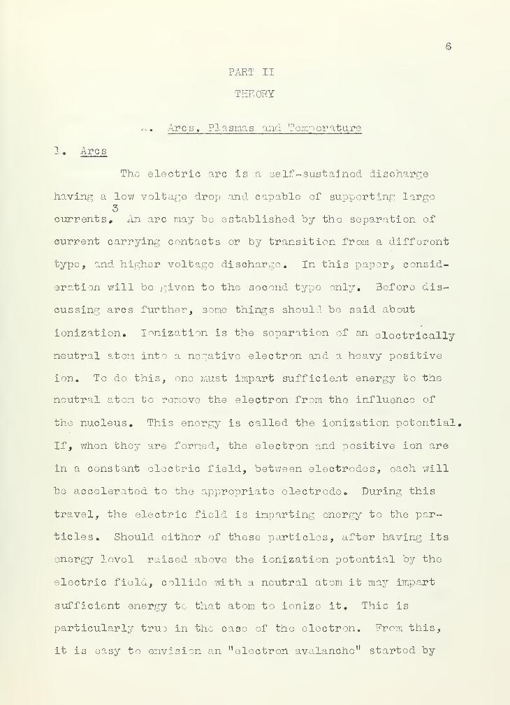
1. Arcs
A. Arcs, Plasmas and Temperature
The electric arc Is a self-sustained discharge
having a low voltage drop and capable of supporting large5
currents. An arc may be established by the separation of
current carrying contacts or by transition from a different
type, and higher voltage discharge. In this paper, consid-
eration will be given to the second type only. Before dis-
cussing arcs further, some things should be said about
Ionization. Ionization is the separation of an cloctrically
neutral atom Into a negative electron and a heavy positive
ion. To do this, one must impart sufficient energy to the
neutral atom to remove the electron from the influence of
the nucleus. This energy is called the ionization potential.
If, when they are formed, the electron and positive ion are
in a constant electric field, between electrodes, each will
be accelerated to the appropriate electrode. During this
travel, the electric field is imparting energy to the par-
ticles. Should either of these particles, after having its
energy level raised above the ionization potential by the
electric field, collide with a neutral atom it may impart
sufficient energy to that atom to ionize it. This is
particularly true in the case of the electron. From this,
it is easy to envision an "electron avalanche" started by

7
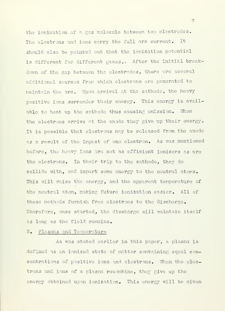
the ionization of a gas molecule between two electrodes.
The electrons and ions carry the full arc current. It
should also be pointed out that the ionization potential
is different for different gases » After the initial break-
down of the gap between the electrodes, there are several
additional sources from which electrons are generated to
maintain the arc Upon arrival at the cathode, the heavy-
positive ions surrender their energy. This energy is avail-
able to heat up the cathode thus causing emission, When
the electrons arrive at the anode they give up their energy.
It is possible that electrons may be released from the anode
as a result of tho impact of one electron. As was mentioned
before, the heavy ions are not as efficient ionizers as are
the electrons. In their trip to tho cathode, they do
collide with, and impart some energy to the neutral atoms.
This will raise the energy, and the apparent temperature of
the neutral atom, making future ionization easier. All of
these methods furnish free electrons to the discharge
Therefore, once started, the discharge will maintain itself
as long as the field remains,
2, Plasmas and Temperature
As was stated earlier in this paper, a plasma is
defined as an ionized state of matter containing equal con-
centrations of positive ions and electrons. When the elec-
trons and ions of a plasma recombine, they give up the
energy obtained upon ionization. This energy will be given

8"
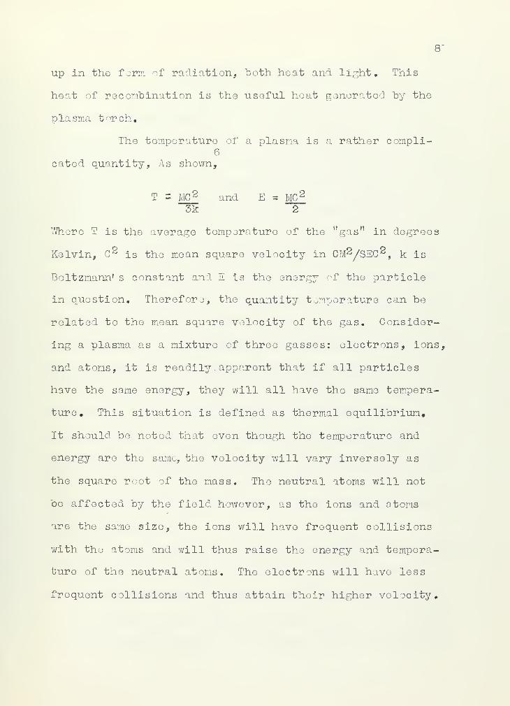
up in the form of radiation, both heat and light. This
heat of recombination is the useful heat generated by the
plasma torch.
The temperature of a plasma is a rather compli-6
cated quantity, As shown,
T S MC£ and E MC 2
3k 2
Where T is the average temperature of the "gas" in degrees
Kelvin, C 2 is the mean square velocity in CM2/SEC 2 , k is
Boltzmann' s constant and E is the energy of the particle
in question. Therefore, the quantity temperature can be
related to the mean square velocity of the gas. Consider-
ing a plasma as a mixture of three gasses: electrons, ions,
and atoms, it is readily .apparent that if all particles
have the same energy, they will all have the same tempera-
ture. This situation is defined as thermal equilibrium,
It should be noted that even though the temperature and
energy are the same, the velocity will vary inversely as
the square root of the mass. The neutral atoms will not
be affected by the field however, as the ions and atoms
are the same size, the ions will have frequent collisions
with the atoms and will thus raise the energy and tempera-
ture of the neutral atoms. The electrons will have less
frequent collisions and thus attain their higher velocity.

9
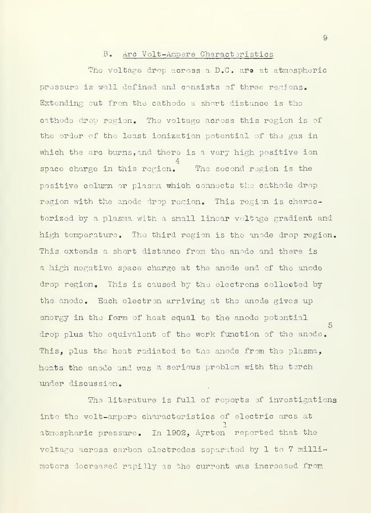
B. Arc Volt"Ampere Characteristics
The voltage drop across a D.C. ar« at atmospheric
pressure is well defined and consists of three regions.
Extending out from the cathode a short distance is the
cathode drop region. The voltage across this region is of
the order of the least ionization potential of the gas in
which the arc burns, and there is a very high positive ion4
space charge in this region. The second region is the
positive column or plasma which connects the cathode drop
region with the anode drop region. This region is charac-
terized by a plasma with a small linear voltage gradient and
high temperature. The third region is the anode drop region.
This extends a short distance from the anode and there is
a high negative space charge at tho anode end of the anode
drop region. This is caused by the electrons collected by
the anode. Each electron arriving at the anode gives up
energy in the form of heat equal to the anode potential5
drop plus the equivalent of the work function of the anode.
This, plus the heat radiated to the anode from the plasma,
heats tho anode and was a serious problem with the torch
under discussion.
The literature is full of reports of investigations
into the volt-ampere characteristics of electric arcs at1
atmospheric pressure. In 1902, Ayrton reported that the
voltage across carbon electrodes separated by 1 to 7 milli-
meters decreased rapidly as the current was increased from

10
2 amperes to about 15-20 amperes. Above about 20 amperes,
the arc became noisy, and the voltage increased slightly"11
with increasing current. Nottingham confirmed the basic
shape of these curves. This work was only done for cur-7
rents below 30 amperes. Finkelnburg confirmed the results
and carried the current to 100 amperes with carbon elec-8
trodes. He concluded that the decisive phenomena of the
carbon arc are determined by the conditions in the anode
drop region and that the increase of total arc voltage in
the high current carbon arc is caused by an increase of the
anode drop with increased current. He also noted that a
crater always formed on the positive carbon electrode.10
More recently, Jones, Skolnik, and Kowenhaven investigated
the electric arc between tungsten electrodes, separated up
to 1.0 inches for currents up to 100 amperes at atmospheric
pressure, in Argon and again in Helium. They reported the
same decreasing characteristic but reported no rising
characteristic below 100 amps, the limit of their investi-13
gat ions. Winsor reported a rise in arc voltage with arc
current above about 50 amps between a tungsten electrode
and a steel plate in an Argon atmosphere.
These characteristic' curves will be discussed
again later in this paper.

11
C. Types of Plasma Torches
A plasma torch is, as was said previously, a
device capable of creating high temperatures. To do this
an arc is established by an auxiliary device in a DC
field between two electrodes. Gas is 'passed -through --
the arc wherein the gas molecules are ionized. The gas
pressure inside of the torch then forces this plasma out
the front of the torch. Upon reaching the cooler atmosphere
outside of the torch, the electrons and ions recombine giv-
ing up energy. The part of this energy given up as heat
is the useful heat generated by the torch.
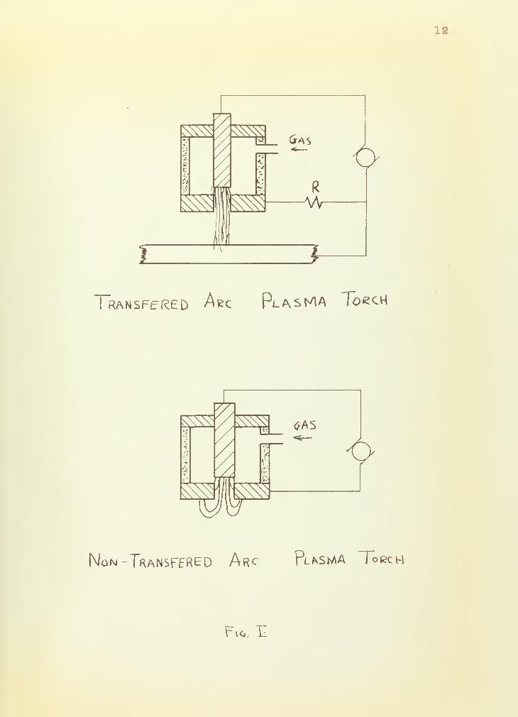
There are two types of plasma arc torches. These
are the transferred arc torch and the non-transferred arc
torch. Figure I shows these two types of torches.
In the transferred arc torch, the arc is originally
struck within the torch. After establishment, the arc is
transferred to the work. This type of torch is especially
useful in cutting.
In the non-transferred arc torch, the arc is
struck and maintained almost completely within the torch.
Usually, only the plasma is available for productive work.
This type of torch is especially suited for spraying and
as a high temperature heat source*
12
V
*I_ Gas
^I
\t£
6R
AAr
>
I RANSFtRED Aec Pl*sMA ToecH
^V
s>A
f\tfAS
&
OH
Q
Non-TranSFERED Arc Pla^MA Torch
*-»«. -L

13
PART III
EXPERIMENTAL PROCEDURES
A, Design of Subject Torch
The design of the torch was given very careful
consideration. The required torch was to have non-consum-
able electrodes, if possible, be of simple mechanical
construction to facilitate tho change of components and
ease of fabrication! and to be able to reproduce data.
Prior to completing the final design, two field trips were
made to organizations presently involved in plasma torch
research. These were The Thermal Dynamics Corporation,
Lebanon, Now Hampshire, and the AVCO Manufacturing Corpora-
tion, Lawrence, Massachusetts. In both cases, personnel
working with the torch were very helpful and offered val«0"\
uable suggestions. Additionally, the torch design used by14
Thomas and Gates was examined carefully.
In an attempt to satisfy the requirement for non-
consumable electrodes, Tungsten v/as chosen for the cathode
and carbon for the anode. Any metal or carbon could have
been used for the cathode but It was felt that Tungsten
would outlast other metals and perform the electron
emission functions of the cathode better than carbon. Like-
wise, a metal could hive been used for the anode in place
of carbon. Initially, it was hoped that if a sufficiently
large piece of carbon were used, no auxiliary cooling of
the anode would bo required. On this basis as well as its

14
ability to withstand high temperatures ^ carbon was chosen
for the anode.
At this point, all materials for the fabrication
and testing of the torch were available except the insulat-
ing sleeve which forms the body of the torch. An attempt was
made to use an available bake lite tube but this did not
give satisfactory results as the bakelite overheated badly
in a few seconds. The tests did indicate tho urgent re-
quirement for auxiliary anode cooling :,nd some changes in
the gas system. In this first model, the gas inlet ports
were installed perplndlcular to tho body of the torch. At
the conclusion of the tests, the anode was examined and it
exhibited uneven erosion. It was felt that the uneven ero-
sion was caused by the gas not swirling the arc properly.
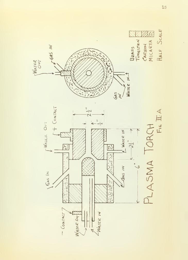
To correct these deficiencies, it was decided to make the
body of the torch from Micarta due to its excellent heat
resistant qualities and to install the gas ports at 45°
angles to the axial and transverse axes of the torch. This
tends to rotate the arc giving even wear to the electrodes.
After inclusion of a water jacket for anode cooling, the
design proved successful. No dimensions were found to be
critical, but axial symmetry is important for even burning.
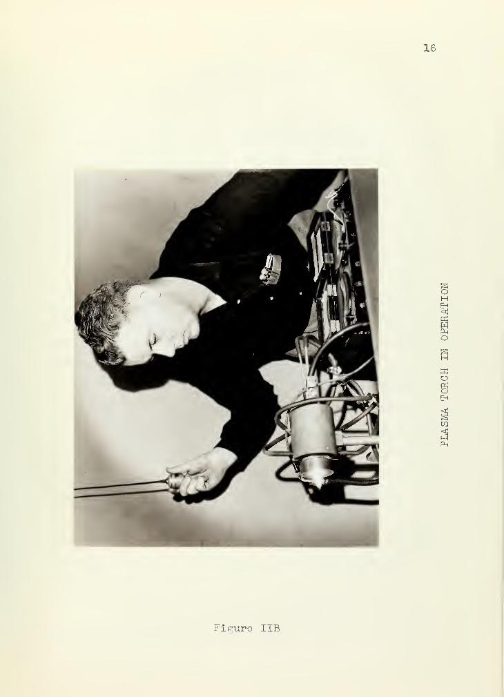
The final design as actually constructed and tested is
shown in Figure IIA, Figure IIB shows the plasma arc torch
in operation.

15
~^ .HAfc
"* <5 <*
v> & to <£ r ^ a01 1*C3V- S£
111
-J<

16
S3OHEn<KWP-.
O&H
O8
Ph
Figure IIB

17
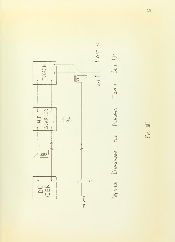
B. Apparatus and Procedure
The wiring diagram Tor the plasma torch set up is
shown in Figure III, None of the auxiliary equipment is
critical except that the DC power supply must have a droop-
ing voltage characteristic. The DC power supply used is a
Lincoln Welding generator rated at 600 amperes output with
current and voltage control and a no-lead voltage of about
115 VDC, The high frequency starter is a standard P&H
high frequency welding arc starter. The gas flowmeter is
an Oxweld L-22 Critical Orifice Flowmeter equipped with
Orifice #31, At 11 psig on the upstream gage, approxi-
mately 4 cfm of argon enters the torch. The meters used
are standard Weston meters, 0-150 VDC and 0-50 millivolts
with an 300 ampere shunt.
In obtaining the data reported herein, the pro-
cedure listed in Appendix I was used. The first data taken
is shown in Figure IV, The gap was set and then the points
were taken. After taking all of the points for a particu-
lar curve, the gap was rechecked and the inside of the anode
was checked for wear.
After taking the data shown in Figure IV, an un-
successful attempt was made to use Helium instead of Argon,
It was not possible to produce a stable arc at any gap
setting up to J-"
,
After the unsuccessful attempt with Helium, the
anode was shortened from 3-5-" to 2h" and the data shown in

18
<
\.£ i r <
o
v>
i
1
x < •—
>
\ '
/
k < i / l/f"
UJ
<t
<CL
l2
2<
C7~z
N

19
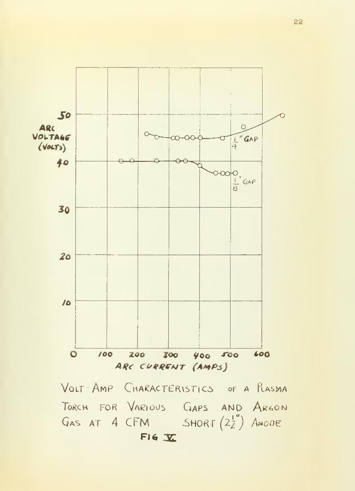
Figure V were taken. By this time a silvery-white coating,
later believed to he tungsten oxide was beginning to coat
the cathode and it was impossible to start the torch at
gaps greater than x" • It was felt that this coating was
caused by turning off the gas supply simultaneously with"
the electric power to the arc. This allowed the hot
tungsten cathode to cool in an atmosphere of air causing
the tungsten oxide to form. An attempt to polish this
oxide off was made however, this apparently contaminated
the cathode and reproducible results were not obtained after
that. Throughout the tests, the torch was run continuously
for periods up to 30 seconds. It would have been possible
to run it longer except for excess anode heating. If the
torch were left on in excess of 30 seconds, the water in
the anode cooling jacket would boil.

20
PART IV
RESULTS
At first, an attempt was made to use an argon gas
flow of l.CFM. This was unsuccessful at all gap lengths as
the arc did not rotate and thus eroded the anode unevenly
•
Additionally, apparently also due to the low gas flow,
excessive anode heating made it impossible to run the torch
for more than 15 seconds
«
Attempts were mado to operate at various gaps and
a gas flow of 6 CFM but these were also unsuccessful. The
gas flow was too high and blew the arc out.
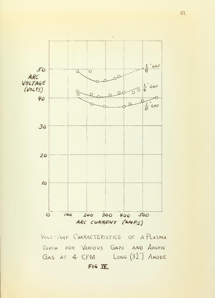
The results obtained included those shown in
Figures IV and V. Those volt-ampere curves were taken for
various gaps^ two different anode lengths and with a gas
flow of 4 CFM. The arc was easy to start, stable, anode
erosion was very small and quite even. Prior to taking the
data shown in Figure V, the inner face of the anode was
remachined removing all traces of erosion. After taking
the data, the anode inner face was examined, and it exhibited
negligible erosion. The sharp corners at the edge of the
chamfer were Intact, and the overall condition was fjuite
good. Negligible cathode damage occured during the test.
An attempt was made to use helium instead of
Argon. Full generator voltage was reajj.ired to maintain
the arc, and stable operation was never obtained for any gap.

21
SoARC
VoLfAte(Molts)
Jo
20
to
I"6AP
O /oo zoo 3oo Voo SQOARC CO**fA/T (*MP$)
Volt -Amp CHARACTERISTICS OF A Plasma
Torch FOR VWOUS GaP-S AND Arg°N
Gas at 4- CFM Lons (3z ) Anode

22
SoARC
V0LTA*?
to
30
2o
to
o o n
L"G*P4
rv o\^r V-f vv^>Y
^o-oo-o,
8
/oo zoo soo yoo ^oo4tfr cofRrAtT (amps)
too
VoLfAMP CHAeACT~tfUST|C5 of A PlASMA
Tokch for Various Gaps and Ar«.om
Gas at 4 CFM -SHORT (2/) Anode
FI6 3C

23
The arc reacted violently and was impossible to control.
The only readings obtained with Helium were 64 volts at
800 amperes and a :|-" gap. At the conclusion of the run
with Helium, the anode was examined, and deep erosion was
noted in two places. No cathode damage was observed,,
The P&H high frequency starter would not initiate
the arc with a gap greater than 3/3" so no data were obtained
for gaps above this value. No gap less than l/8" was used
as it was felt that irregularities on the anode or cathode
would greatly influence gap and the arc; and that the data
thus obtained would not be reproducible. As a result, all
data were taken for gaps of 5-/8", l/4" and 3/3", With Argon,
the arc was stable for all currents between 150 and 400
amps. The torch could be operated up to 30 seconds at 400
amperes with Argon gas which fulfilled the power input
requirement of the original design. With Argon gas at a
flow of 4 cubic feet per minute, negligible electrode ero-
sion was observed. This satisfies tn e non-consumablo
electrode requirement of the original design.
An attempt was made to run the torch with the
tungsten as the anode and the carbon as the cathode Stable
operation was not obtained and at the conclusion of the
test, the tungsten was examined. It exhibited deep pitting
around the edge e
Time did not permit quantitative temperature
measurements a However, a piece of 1/16" steel was placed

24
§" in front of the long anode for about 30 seconds. It
was heated red hot, but it never melted* Later, the other
end of the same piece of metal was placed ^-" in front of the
short anode, and a hole 5/8" in diameter was burned in it
after about 15 seconds. These two tests were conducted with
about 13 KW input to the torch and x" gap c
The gathering of data had to be stopped after
taking that shown in Figure V as it became impossible to
obtain reproducible data. As was previously stated, it is
felt that this was caused by the oxide coating on the
tungsten cathode Attempts were made, first by wire brush-
ing and then with emery paper, to polish the oxide coating
off of the tungsten cathode „ It was possible to remove the
coating but after doing so, it was not possible to get
reproducable data. Random variations of voltage, both
above and below those previously recorded were obtained.
It Is felt that this was caused by contamination of the
cathode «,

25
PART V
DISCUSSION
A Interpretation of Results
The results of this investigation indicate that
it Is feasible to build an inexpensive plasma arc torch
that will be stable and give reproducible results using
Argon gas. The arc was quite stable, anode erosion was
negligible, and the only thing that limited the continuous
operation of the torch was the severe heating of the anode.
The unsuccessful use of Helium was probably
caused by a combination of the following facts. The ioniza-
tion potential of Helium is approximately twice that of
Argon, This requires more voltage across the Helium arc
than the Argon arc. To give this addional voltage, the
output of the generator had to be considerably Increased,
When the Helium arc was finally started, current up to 800
amperes was noted. This greatly increased power input,
twice that originally anticipated, caused severe anode
heating and damage. The failure of the carbon anode at14
high currents agrees with investigations previously
made,,
The volt-ampere curves in Figure IV and Figure V
exhibit a negative slope for low values of current, a
minimum arc voltage drop with Its zero slope and finally
a positive slope as the current is increased from low to

26
high values. The voltage drop across the arc was increased
as the gap was increased from l/8" to 3/8". This agrees1,7,10,11
well with previous work in this area. The curves
for the short anode were flatter at the minimum points and
the l/8 n gap curve showed no rising characteristic below
525 amps. It is felt that the curves, particularly the one
for the 1/8" gap, of the short anode are not too reliable
because of the oxide coating on the cathode appearing at
the time. The attempts at melting steel definitely favor
the short anode c This is reasonable because with the short
anode the electrons and ions in the plasma have less chance
to recombine before leaving the torch and thus are avail-
able for useful work. It would therefore appear that any
torch designed for cutting should have as short an anode as
possible.
Preliminary investigations indicated that the
length of plasma extending from the torch was not a
funotion of the arc current or gap. It is felt that the
distance the plasma extends from the torch is a function
of gas flow.

27
B. Future Areas For Investigation
There are several problems connected, with the
plasma arc torch that bear further investigation. The
first, and most obvious from the data presented here is
a revision of the anode design to include more cooling.
Additionally, while making a change in the anode cooling
system design, it might be desirable to use another material
for the anode. A water cooled anode might be made from
two £" brass or copper plates spaced an inch or so apart
in the form of a doughnut. Between these plates, it would
be possible to place a spiral' baffle which would allow
the water to enter near the center and circulate around
leaving near the edge. Also, it might be desirable to
shape the orifice in the anode more along the lines of a
supersonic orifice. A refinement might be the plating of
the copper or brass anode described above with Tungsten
to increase the anode' s non-consumable property. The
effects of different diameter orifices and anode lengths
might also be investigated as well as improving on the
anode cooling techniques.
The second area requiring further investigation
is that of temperature. It is obvious that normal tempera-
ture measurement techniques are not useful in the range of
temperatures existing in this device. Two methods of
temperature measurement are immediately apparent. A water
cooled calorimeter might be used to measure the energy in


28
the plasma and a heat balance used to calculate the
effective temperature of the plasma. The second method
would be to Introduce a finely powdered material with the
gas and observe the material with a spectrograph as it
left the torch. If the band characteristics of the
material wure known, the temperature of the material would
then be known. After a satisfactory method of temperature
measurement is established, it will then be possible to
evaluate the various torch parameters, gap, gas type and
gas flow, in terms of efficient plasma generation.
A third area that invites further investigation is
that of different gas types. After the rmode cooling
problem is solved, it should be possible to use gas©s
other than Argon providing that a DC voltage source with
an open circuit voltage of approximately 200 volts is
available. If further work in this field is anticipated,
a new power supply and high frequency starter should be
obtained. The DC power supply should have an open circuit
voltage of 200-250 volts and a current rating of 1000
amperes. The high frequency starter should be capable of
breaking down a 1^-" gap and carrying 1000 amps*
After all of the problems listed above have been
satisfactorily solved, it should be possible to investigate
the spraying and cutting properties of the torch as the
various parameters, gas type, gas flow and gap are varied.

29
Additionally, it should be possible to use this torch
as a plasma generator in connection with Magnetohydro-
dynaraic experiments.

50
APPENDIX I
DETAILED OPERATING PROCEDURE
The operation of the torch can be broken down
into three phases
1, Preliminary
a. Adjust cooling water flow and check for
leaks.
b # Adjust gas pressure for desired gas
flow*
c. Start DC generator and adjust the open
circuit voltage for 95 volts.
d. Adjust the gap. This is done by
measuring the linear distance the cath-
ode Is moved back from anode and noting
that this is the hypotenuse of a 45°
right triangle. The arc gap Is one of
the legs of this triangle so the arc
gap is the linear travel divided by VTil
2. Start-up and Operation
a. Turn on gas and DC power to touch
(Switch SI in Figure III)
b Turn on high frequency starter (Switch
S2 in Figure III)
c. Turn off starter when torch fires.
d. Adjust generator current control to give
desired power input to torch.

31
g, Take desired readings concerning
operation of torch,
3. Shutdown
a. Turn off gas and DC to torch (Switch
SI in Figure III)
b. Turn off generator
o. Turn off all circuit breaker feeding the
equipment and turn off gas at the
cylinder.
d. Turn off cooling water but only after
anode is no longer hot to the touch.
Switch SI shown in Figure III should be kept
readily at hand since it can be used to stop the torch im-
mediate;!;/ in case of trouble.

32
PART VII
LITERATURE CITED AND BIBLIOGRAPHY
A. Literature Cited
1. Ayrton, H. "The Electric Arc" (book) 1902 D vanNostrand Co., Inc., New York, N.Y. p. 120-130
2. Browning, J. A. "Techniques for Producing Plasma Jets"A paper presented to the American Rocket Society-Northwestern Gas Dynamics Symposium, NorthwesternUniversity, Evanston, 111. on 24-26 August 1959
3. Cobine, J.D, "Gaseous Conductors" (book) 1958, DoverPublications Inc., New York, N.Y. p. 290
4. Cobine. op.cit. p. 302
5. Cobine. op.cit. p. 343
6 # Cobine. op.cit. p. 17
7. Finkelnburg, W. "The High Current Carbon Arc" FIATPinal Report 1052. p. 20
8. Finkelnburg. op.cit. p. 25-26
9. Giannini, G. M. "The Plasma Jet", The ScientificAmerican. August 1957
10. Jones, T. B.; Skolnik, M.; Kowenhaven, W. B.; "TheElectric Arc In Argon and Helium". AIEE TRANSACTIONS1953, Applications and Industry. Vol 72. p. 16-21
11.. Nottingham, W. B., "Normal Arc Characteristic Curves"
„
Physical Review. Vol 28 1926. p. 764-68
12. Thorpe, M. L e , "The Plasma Jet and Its Uses". Researchand Development. Vol II #1 January 1960. p. 5
13. Winsor, L. P., "A Study of Non-Consumable Electrodes"Sylvania Electric Products, Inc., (a company report)1955
14. Thomas J. K.'and Gates, H. X., "Plasma Jet ElectricalCharacteristics" A thesis submitted to the U. S.Naval Postgraduate School, Monterey, Calif., 1959

33.
B. Bibliography,
1. Bonner, R. H , and Jones, T. B. "Influence of AtmosphericWater Vapor on High Current DC Arcs" AIEE TRANS-ACTIONS, Part II, Applications and Industry Vol75, 1956 p, 162
2, Brogran, T. R„ "The Electric Arc Wind Tunnel - A ToolFor Atmospheric Reentry Research" AmericanRocket Society Journal Spet 1959 p. 648
3 a Cann, G. L. and Ducati, A. C. "Energy Content andIonization Level in an Argon Gas Jet Heated bya High Intensity Arc" Journal of Fluid MechanicsVol 4 part 5 Sept 1958 p. 529-537
4. Cobine, J. D. and Gallagher, C. J. "Current Density ofthe Arc Cathode Spot" Physical Review Vol 74Nov 1948 p. 1524
5 e Cobine, J. D., et.al. "The Reignition of Short Arcs atHigh Pressures" Journal of Applied PhysicsVol 10 1939 p. 420
6, Cobine, J. D. "The Nature of the Arc" Welding ResearchCouncil Bulletin Series #2 Apr 1949
7, Cobine, J. D. "Gaseous-Conduct ion, Phenomina and ThairApplication In Electrical Engineering" ElectricalEngineering, June 1950
8, Compton, K. T tt "The Theory of the Electric Arc" PhysicalReview Vol 21 1923 p. 266
9, Defense Metals Information Center "The Fabrication ofTungsten" DMIC Report 115 August 1959 DefenseMetals Information Center, Battelle MemorialInstitute, Columbus 1, Ohio
10e Druyvesteyn, M. J "Electron Emission of the Cathode ofan Arc". Nature Vol 137 1936 p. 580
11. Druyvesteyn, M. J. and Penning, F. M. "The Mechanismof Electrical Discharges in Gases of Low Pressure"Review of Modern Physics Vol 12 194G p. 87-173
12 o Fett, G. H. "The Cathode Drop of an Arc" Journal ofApplied Physics Vol 13 1941 p. 436

34
13. Finkelnberg, W. and Latil, J, P. "A Full AutomaticContinually Operating, Very High-Intensity, CarbonArc Lamp" Journal of the Optical Society ofAmerica Vol 44 1954 p,l
14. Finkelnberg, W. "The High Current Carbon Arc and itsMechanism" Journal of Applied Physics Vol 201949 p 468
15. Francis, V, J, and Jenkins, H. G. "Electrical Dischargesin Gases and their Applications" Physical Societyof London Vol 7 1940 p. 230
16. Haynes, J. R. "The Production of High Velocity MercuryVapor, Jets by Spark Discharge" Physical ReviewVol 73 1948 p.891
17. Hognoss, T, R. "Arc Heated Plasma for Laboratory Hyper-sonics" Astronautics, Vol 4 No. 3 March 1959 p. 40-47
18. Jones, F. L, "Electrical Discharges" Physical Societyof London Vol 8 1941 p. 338
19. Loeb, L. B. "Fundamental Processes of Electrical Dis-charges in Gases" (book) J. Wiley and Sons, 1939
20. Ludwig, H. C. "Plasma - Energy Transfer in Gas ShieldedWelding Arcs" Welding Journal Research SupplementVol 38 p. 296-S July 1959
21. Lunt, R. W. ; von Engel, A.| and Meek, J. M, "DischargePhenomena in Gases" Physical Society of LondonVol 8 1941 p. 338
22. MacKeown, S, S, "The Cathode Drop of an Arc" PhysicalReview Vol 34 1929 p. 611
23. Mack, J, A. "Plasma Arc Torch Fabricates Materials"Materials in Design Engineering, Mar 1959 p. 133
24. Reid, J. W. "The Plasma Jet; Research at 25,000°F"Machine Design Vol 30 No, 3 Feb 6, 1958 p. 22
25. Schrum, G. M, and Wiest, H. G, "Some Experiments withArcs Between Metal Electrodes" AIEE TRANSACTIONSVol 50 June 1931 p. 650-656
26. Schrum, G. M. and Wiest, H. G. "Experiments With ShortArcs" Electrical Engineering Vol 50 Oct 1931p.827-829
35
27. Skolnik, M. and Jones, T. B. "High Current TungstenArc in Argon, Helium and Their Mixtures"Welding Journal Research Supplement Jan 1953p 8 55-S
28. Smith, C. G. "The Mercury Arc Cathode" Physical ReviewVol 62 1942 p. 48
29. Suits, C. G, "Experiments With Arcs At AtmosphericPressure" Physical Review Vol 46 1934 p. 252
30. Suits, C. G. "Current Densities, Lumen. Efficiencyand Brightness in Argon, Nitrogen, Helium andHydrogen Arcs" Journal of Applied Physics Vol 101939 p. 730
31. Tonks, L. "The Rate of Vaporization of Mercury Promand Anchored Cathode Spot" Physical Review Vol 541938 p.634
32. Westinghouse Electric Corporation "High TemperaturePlasmas" Research and Development Letter Vol 3No. 5 Feb 1960
33. Winsor, L, P. ; and Lee, T. H. "Properties of a DC ArcIn A Magnetic Field" AIEE TRANSACTIONS Paper#56-132 May 1955