Embed Size (px)
Citation preview
ELECTROMAGNETIC COMPATIBILITY OF ELECTRIC POWER PLANT
ABSTRACTElectromagnetic compatibility is defined as the ability of the
device or system to function properly in its electromagneticenvironment without entering the intolerable electromagneticdisturbances into that environment. Due to the construction of theelectric power system, system components, such as power lines andsubstations, very often located near other installations that cannegatively affect their electrical and magnetic fields, orconductive, inductive and capacitive influence. In the case ofapproaching some other electrical installations, such as mosttelecommunication installations, it is necessary to perform theanalysis of electromagnetic compatibility and define any possibleeffects of the relevant infrastructure. The work is considered powerstation 10(20)/ 0,4 kV provided exclusively for cable (underground)medium voltage network and low voltage outputs, for connecting powerline in the vicinity of telecommunication installations anddiscussed the need for making the project for protection oftelecommunication installations.Keywords: Electromagnetic compatibility; Power plant;Telecommunication installation
1 INTRODUCTIONIn the past most of conventionally used electrical devices
(eg, DC motors, resistors ...) were represented by a linear load.Such a character of consumers has resulted in a very small influencebetween different equipment. Today, most consumer have non-linearcharacter (inverters, fluorescent lamps, computer equipment ...)which produces a certain level of interference and noise. Electricpower systems are becoming larger and with increasing installedcapacity, which ultimately leads to the increasing theelectromagnetic influence. This development leads to the electricalcabling needs of design and installation of more expensivecomponents in the system that are immune to the electromagneticinfluence. In order to implement reliable, efficient and economicalequipment that is resistant to electromagnetic influences isnecessary to conduct the analysis of electromagnetic compatibilityand implement a plan for implementing the same in the early phase ofthe project. Underlying the analysis involves calculation ofelectric and magnetic fields and low-frequency mutual conductive,inductive and capacitive effect of the installation. Electromagneticcompatibility describes the ability of selected power system to
operate without difficulty in enhanced electromagnetic environmentand at the same time does not affect the operation of other systemcomponents. The main source of each of the electromagnetic effectsare the main fields (electric and magnetic) and the current definedin the theory of electrodynamics. At low frequencies the electricand magnetic fields act independently while at higher frequenciessignificantly only propagating electromagnetic field. The electricfield is proportional to the voltage and therefore takes on greatervalue only in the vicinity of high voltage installations. In mostcases, electric fields do not play a significant role since thesame, struck any obstacle, significantly weaken or even completelydisappear. The magnetic field is proportional to current strength.In many cases, amounts of electricity can take high values, so theincreased risk from electromagnetic influences. An example of theelectromagnetic effect is flickering monitor in case of a CRTmonitor.2 TYPES OF ELECTROMAGNETIC INFLUENCES
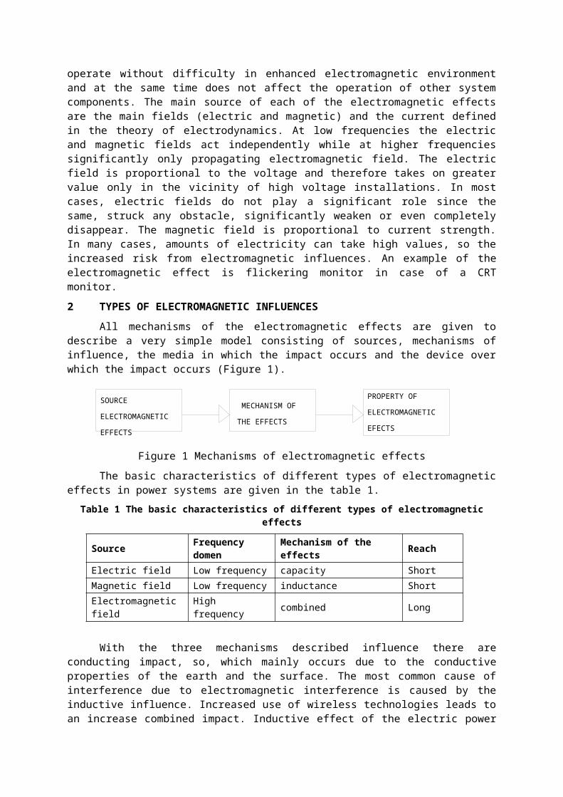
All mechanisms of the electromagnetic effects are given todescribe a very simple model consisting of sources, mechanisms ofinfluence, the media in which the impact occurs and the device overwhich the impact occurs (Figure 1).
Figure 1 Mechanisms of electromagnetic effectsThe basic characteristics of different types of electromagnetic
effects in power systems are given in the table 1.Table 1 The basic characteristics of different types of electromagnetic
effects
Source Frequency domen
Mechanism of the effects Reach
Electric field Low frequency capacity ShortMagnetic field Low frequency inductance ShortElectromagnetic field
High frequency combined Long
With the three mechanisms described influence there areconducting impact, so, which mainly occurs due to the conductiveproperties of the earth and the surface. The most common cause ofinterference due to electromagnetic interference is caused by theinductive influence. Increased use of wireless technologies leads toan increase combined impact. Inductive effect of the electric power
SOURCE
ELECTROMAGNETIC
EFFECTS
MECHANISM OF
THE EFFECTS
PROPERTY OF
ELECTROMAGNETIC
EFECTS
facility (Fig.2) on other infrastructure occurs via the mutualinductance between two or more circuits. Equivalent diagram thatdescribes this situation is shown in the figure 2.
Figure 2 Equivalent scheme of the inductive effect of powerfacilities to other installations
Current that flows through the power circuit creates a magneticfield proportional to current strength. This magnetic flux induceselectromotive force (VN) at a nearby conductor causing a disturbanceoccurs in a closed current loop circuit other installations. Thisform of interference is the most common. Size of inducedelectromotive force VN is proportional to the current close loopcircuit in the electric power facility and the mutual inductancebetween the respective two rounds. Mutual inductance between thepower building and other installations is determined by the geometryof the guide as well as the geometric distance between two lines in
installation
Z 0
LZ
power facilityM
L
L
M
M
NV
mutual inductancet
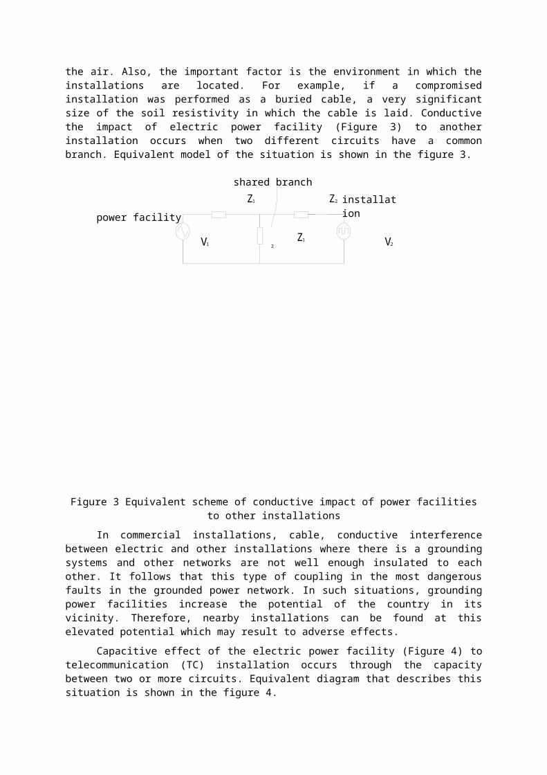
the air. Also, the important factor is the environment in which theinstallations are located. For example, if a compromisedinstallation was performed as a buried cable, a very significantsize of the soil resistivity in which the cable is laid. Conductivethe impact of electric power facility (Figure 3) to anotherinstallation occurs when two different circuits have a commonbranch. Equivalent model of the situation is shown in the figure 3.
Figure 3 Equivalent scheme of conductive impact of power facilitiesto other installations
In commercial installations, cable, conductive interferencebetween electric and other installations where there is a groundingsystems and other networks are not well enough insulated to eachother. It follows that this type of coupling in the most dangerousfaults in the grounded power network. In such situations, groundingpower facilities increase the potential of the country in itsvicinity. Therefore, nearby installations can be found at thiselevated potential which may result to adverse effects.
Capacitive effect of the electric power facility (Figure 4) totelecommunication (TC) installation occurs through the capacitybetween two or more circuits. Equivalent diagram that describes thissituation is shown in the figure 4.
installation
Z12
Z2
1Z
V1 2V
shared branch
power facility
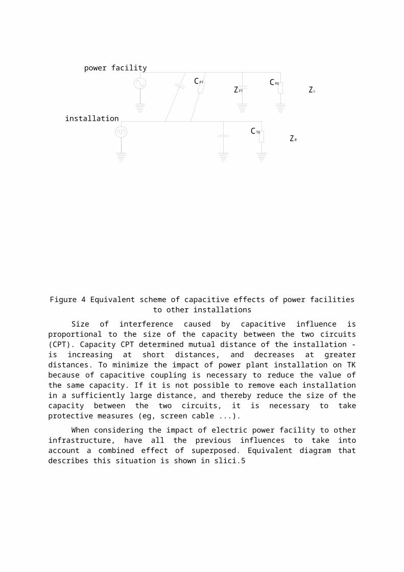
Figure 4 Equivalent scheme of capacitive effects of power facilitiesto other installations
Size of interference caused by capacitive influence isproportional to the size of the capacity between the two circuits(CPT). Capacity CPT determined mutual distance of the installation -is increasing at short distances, and decreases at greaterdistances. To minimize the impact of power plant installation on TKbecause of capacitive coupling is necessary to reduce the value ofthe same capacity. If it is not possible to remove each installationin a sufficiently large distance, and thereby reduce the size of thecapacity between the two circuits, it is necessary to takeprotective measures (eg, screen cable ...).
When considering the impact of electric power facility to otherinfrastructure, have all the previous influences to take intoaccount a combined effect of superposed. Equivalent diagram thatdescribes this situation is shown in slici.5
CPG
power facility
ZL
0Z
installationTGC
PTCPTZ
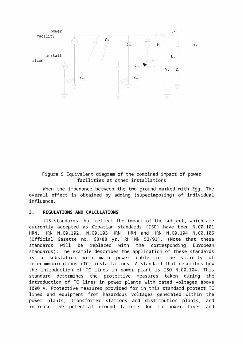
Figure 5 Equivalent diagram of the combined impact of powerfacilities at other installations
When the impedance between the two ground marked with Zgg. Theoverall effect is obtained by adding (superimposing) of individualinfluence.
3. REGULATIONS AND CALCULATIONSJUS standards that reflect the impact of the subject, which are
currently accepted as Croatian standards (ISO) have been N.C0.101HRN, HRN N.C0.102, N.C0.103 HRN, HRN and HRN N.C0.104 N.C0.105(Official Gazette no. 68/88 yr, RH NN 53/91). (Note that thesestandards will be replaced with the corresponding Europeanstandards). The example describes the application of these standardsis a substation with main power cable in the vicinity oftelecommunications (TC) installations. A standard that describes howthe introduction of TC lines in power plant is ISO N.C0.104. Thisstandard determines the protective measures taken during theintroduction of TC lines in power plants with rated voltages above1000 V. Protective measures provided for in this standard protect TClines and equipment from hazardous voltages generated within thepower plants, transformer stations and distribution plants, andincrease the potential ground failure due to power lines and
V N
M
M
L
L
Mpower facility
Z L
0Z
installation
Z PT
C PT PGC
C TG
GGZ Z GG
substations. According to these standards, the calculation impact ofinterference (noise) between the underground power cable andunderground TC line is not necessary to check if the power networkis performed with isolated neutral or compensated fault current.
Defines the number of sectors depending on the stress cone andthe spatial distribution of potential around the ground forgrounding, where:
- sector facilities, field fence in the plants on which theyapplied the measures of adjustment potential. The sector facilitiesdo not appear dangerous step and touch voltages.
- dangerous sector, an area outside the cone voltageinstallations in which the potential of exceeding 430 V. This sectoris determined by measurement or calculation that is verified bymeasurements for each individual case to determine the point atwhich the potential of the country below the 430 V high voltage
- sector of high voltage, a sector that includes the sector ofmachinery and dangerous sector
- harmless sector, a sector where the potential of the countryis less than 430 V
- security installation, installation with a higher dielectricstrength of telecommunication installations and devices.
It is necessary therefore counting conductive effect thatappears to TC infrastructure due to increasing potential soil aroundgrounding, inductive influence of the surrounding lines andcapacitive effects on the TC line. Since the distance between powerand telecommunication installations great to appear capacitiveeffect of the relevant infrastructure, it is ignored and has to becalculated and superimposed conductive and inductive effect.
Conductive grounding influence of a nearby plant substationcalculate the distribution of resources surrounding the land in caseof earth fault.
Inductive effect is calculated as the induced voltage mutualinductance associated medium voltage cable.
Voltage induced with mutual inductance, in general, is
(1)
where:- induced electromotive force (V),- mutual inductance (H),
- change current in time (A/s).
Since the current changes in time according to the relation:
(2)where:
- the maximum value (amplitude) of current,
- angular frequency current (2πf) (Hz),Derivative of the current in time and the taking effective current
, is obtained:
(3)In the case of approaching or crossing each other power lines
and TC lines, longitudinal induced electromotive force expressed involts, is calculated using the formula:
where: - induced electromotive force (V),- mutual inductance (H),- angular frequency current (2πf) (Hz),
- effective current value (kA),
- length approximation (km),- reduction factor.
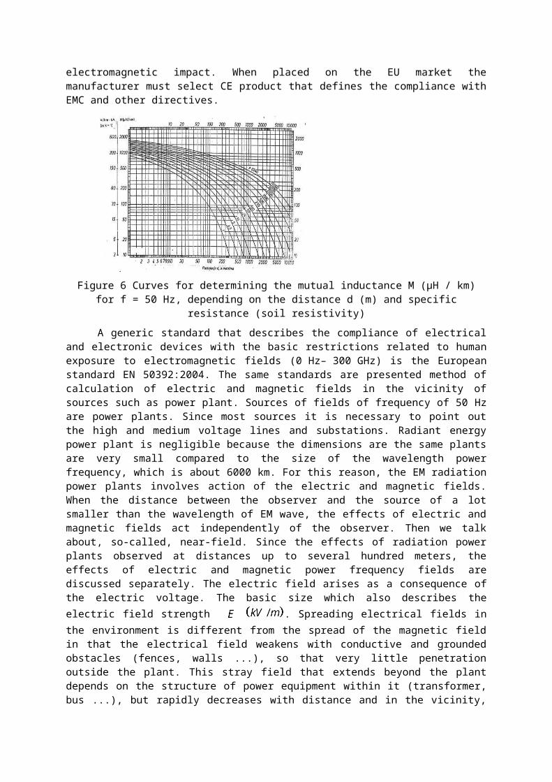
Reduction factor can have values from 0 to 1. The calculationwill be done with the value of the reduction factor . Thiscalculation is on the side of safety. Mutual inductance can beestimated from the following diagram (Figure 6) depending on thespecific resistance of the earth and the mutual distancetransmission lines and metal masses. The actual values of thelongitudinal induced electromotive force can be obtained bymeasuring the actual operation. European standards and directiveswere made in order that all products made or sold within theEuropean Union are subject to common standards and rules and as suchcan be used in the markets of member countries without furtherregulation. In the case of the European EMC Directive 89/336 asamended EU 91/263, 92/31 and 93/97 provides general standards forany product with the goal of electromagnetic compatibilityguaranteed with the use restrictions that limit the maximum emissionlevels of products and its minimal immunity to external
electromagnetic impact. When placed on the EU market themanufacturer must select CE product that defines the compliance withEMC and other directives.
Figure 6 Curves for determining the mutual inductance M (μH / km)for f = 50 Hz, depending on the distance d (m) and specific
resistance (soil resistivity)A generic standard that describes the compliance of electrical
and electronic devices with the basic restrictions related to humanexposure to electromagnetic fields (0 Hz– 300 GHz) is the Europeanstandard EN 50392:2004. The same standards are presented method ofcalculation of electric and magnetic fields in the vicinity ofsources such as power plant. Sources of fields of frequency of 50 Hzare power plants. Since most sources it is necessary to point outthe high and medium voltage lines and substations. Radiant energypower plant is negligible because the dimensions are the same plantsare very small compared to the size of the wavelength powerfrequency, which is about 6000 km. For this reason, the EM radiationpower plants involves action of the electric and magnetic fields.When the distance between the observer and the source of a lotsmaller than the wavelength of EM wave, the effects of electric andmagnetic fields act independently of the observer. Then we talkabout, so-called, near-field. Since the effects of radiation powerplants observed at distances up to several hundred meters, theeffects of electric and magnetic power frequency fields arediscussed separately. The electric field arises as a consequence ofthe electric voltage. The basic size which also describes theelectric field strength . Spreading electrical fields inthe environment is different from the spread of the magnetic fieldin that the electrical field weakens with conductive and groundedobstacles (fences, walls ...), so that very little penetrationoutside the plant. This stray field that extends beyond the plantdepends on the structure of power equipment within it (transformer,bus ...), but rapidly decreases with distance and in the vicinity,
but the plant is mostly negligible. The magnetic field arises as aconsequence of the flow of electricity. The basic size which alsodescribes the strength of the magnetic reinforced . Theeffects of magnetic fields observed by the size of which is calledmagnetic flux density . B (μT). Magnetic flux density andmagnetic field are related as follows:
(4)where: - magnetic flux density,- magnetic field strength,
- absolute permeability of vacuum ,
- relative permeability of media.
The main purpose of transformer substation is transformation ofvoltage levels within the transformer which are based on a magneticfield. The same field is largely enclosed in the core of thetransformer. Part of the magnetic fields are not enclosed in thecore and extends beyond it in the form of bulk flows. Thisespecially occurs in case of higher harmonics. Bulk density ofmagnetic fluxes depends on the size of the current (load), as wellas construction (shielding) and the transformer design andconstruction of the station building. It is particularly importantto point out that the transformer stations magnetic flux densitydecreases rapidly with distance from the station. For example,although immediately against the wall transformer station densitymagnetic flow can reach high values, but at a distance of severalmeters, the same size manifold decreases.
Consider substation 10(20)/0,4 kV with main cable which is inthe vicinity of telecommunication installations. Transformer stationtype DTS 10(20)/ 0,4 kV and intended solely for cable (underground)network MV and LV outputs. For the MV cable connector of substationand LV outputs, will be used, where possible, a cable trench. Entry-exit system will join the respective cell type cable XHE 49-A,section 3 x (1x150) mm2. Transformation voltage transformer shall be10(20)/ 0,4 kV power rating of 630 (1000) kVA. In case of thesubstation building is available additional space for the same powertransformer. Grounding transformer station is carried out basic andmain grounding. Basic electrode was placed in the foundations of thebuilding substation. The main ground electrode consists of twogrounding rings like the building station. The first ring was placed40 cm from the edge of the building substation at a depth of 40 cm.The second ring was placed 100 cm from the edge of the buildingsubstation at a depth of 60 cm. Earthing is done FeZn strip 30x4 mm.
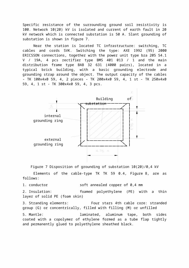
Specific resistance of the surrounding ground soil resistivity is100. Network 10(20) kV is isolated and current of earth fault in 20kV network which is connected substation is 50 A. Slant grounding ofsubstation is shown in figure 7.
Near the station is located TC infrastructure: switching, TCcables and cords SVK. Switching the type: AXE 1992 (95) 2000ERICSSON connections, together with the power unit type bza 205 54.1V / 19A, 4 pcs rectifier type BMS 401 013 / 1 and the maindistribution frame type BAB 32 631 (4000 pairs), located in atypical brick building, with a basic grounding electrode andgrounding strap around the object. The output capacity of the cables- TK 100x4x0 59, 4, 2 pieces - TK 200x4x0 59, 4, 1 st - TK 250x4x059, 4, 1 st - TK 300x4x0 59, 4, 3 pcs.
Figure 7 Disposition of grounding of substation 10(20)/0,4 kVElements of the cable-type TK TK 59 0.4, Figure 8, are as
follows:1. conductor soft annealed copper of 0,4 mm2. Insulation: foamed polyethylene (PE) with a thinlayer of solid PE (foam skin)3. Stranding elements: Four stars 4th cable core: strandedgroup (G) or concentrically, filled with filling (M) or unfilled 5. Mantle: laminated, aluminum tape, both sidescoated with a copolymer of ethylene formed as a tube flap tightlyand permanently glued to polyethylene sheathed black.
Building of substation
internal grounding ring
external grounding ring
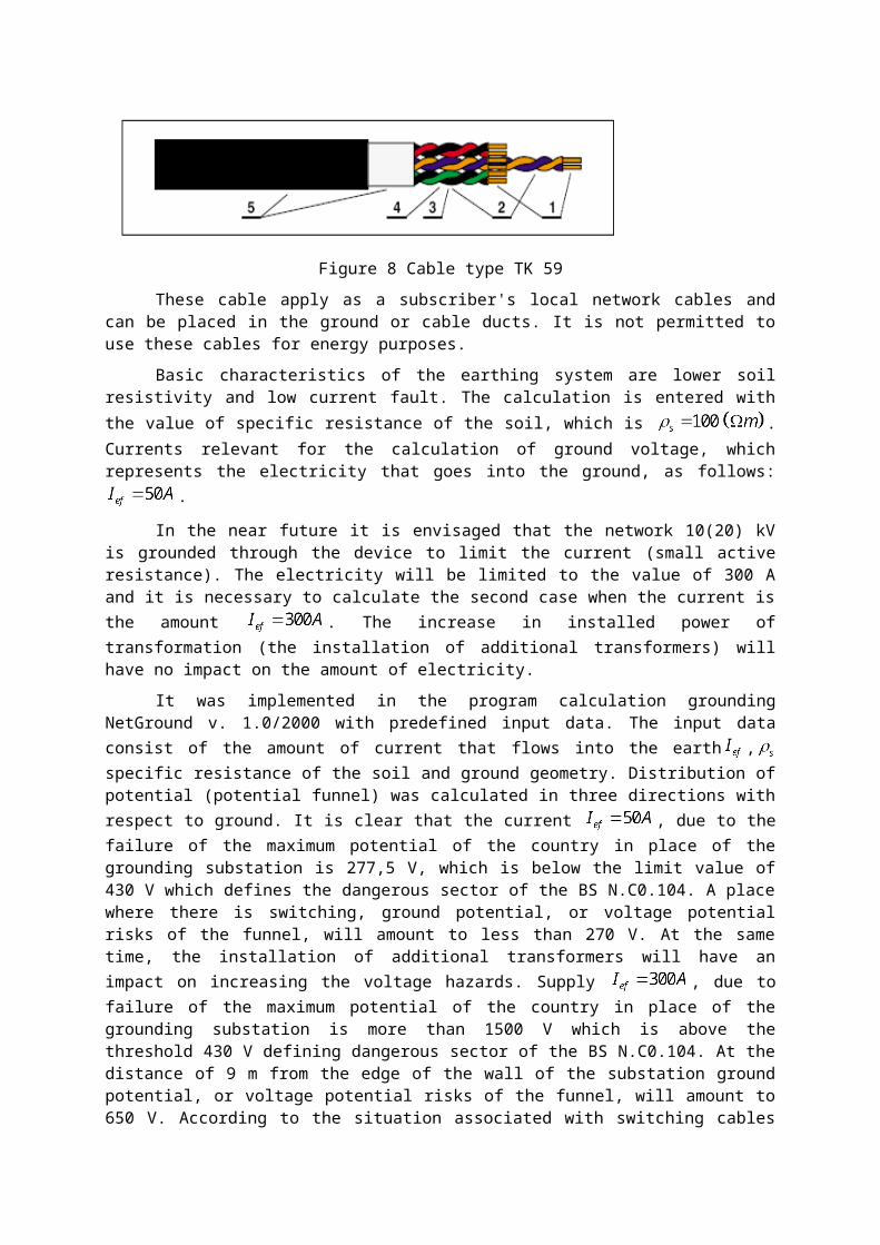
Figure 8 Cable type TK 59These cable apply as a subscriber's local network cables and
can be placed in the ground or cable ducts. It is not permitted touse these cables for energy purposes.
Basic characteristics of the earthing system are lower soilresistivity and low current fault. The calculation is entered withthe value of specific resistance of the soil, which is .Currents relevant for the calculation of ground voltage, whichrepresents the electricity that goes into the ground, as follows:
.
In the near future it is envisaged that the network 10(20) kVis grounded through the device to limit the current (small activeresistance). The electricity will be limited to the value of 300 Aand it is necessary to calculate the second case when the current isthe amount . The increase in installed power oftransformation (the installation of additional transformers) willhave no impact on the amount of electricity.
It was implemented in the program calculation groundingNetGround v. 1.0/2000 with predefined input data. The input dataconsist of the amount of current that flows into the earth ,specific resistance of the soil and ground geometry. Distribution ofpotential (potential funnel) was calculated in three directions withrespect to ground. It is clear that the current , due to thefailure of the maximum potential of the country in place of thegrounding substation is 277,5 V, which is below the limit value of430 V which defines the dangerous sector of the BS N.C0.104. A placewhere there is switching, ground potential, or voltage potentialrisks of the funnel, will amount to less than 270 V. At the sametime, the installation of additional transformers will have animpact on increasing the voltage hazards. Supply , due tofailure of the maximum potential of the country in place of thegrounding substation is more than 1500 V which is above thethreshold 430 V defining dangerous sector of the BS N.C0.104. At thedistance of 9 m from the edge of the wall of the substation groundpotential, or voltage potential risks of the funnel, will amount to650 V. According to the situation associated with switching cables
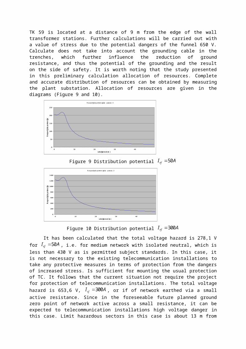
TK 59 is located at a distance of 9 m from the edge of the walltransformer stations. Further calculations will be carried out witha value of stress due to the potential dangers of the funnel 650 V.Calculate does not take into account the grounding cable in thetrenches, which further influence the reduction of groundresistance, and thus the potential of the grounding and the resulton the side of safety. It is worth noting that the study presentedin this preliminary calculation allocation of resources. Completeand accurate distribution of resources can be obtained by measuringthe plant substation. Allocation of resources are given in thediagrams (Figure 9 and 10).
Raspodjela potencijala - pravac 3
0
50
100
150
200
250
0 10 20 30 40udaljenost (m )
Rasp
odjela poten
cijala (V
)
Figure 9 Distribution potential Raspodjela potencijala - pravac 3
0
200
400
600
800
1000
1200
1400
0 10 20 30 40udaljenost (m )
Rasp
odjela p
oten
cijala (V
)
Figure 10 Distribution potential
It has been calculated that the total voltage hazard is 278,1 Vfor , i.e. for medium network with isolated neutral, which isless than 430 V as is permitted subject standards. In this case, itis not necessary to the existing telecommunication installations totake any protective measures in terms of protection from the dangersof increased stress. Is sufficient for mounting the usual protectionof TC. It follows that the current situation not require the projectfor protection of telecommunication installations. The total voltagehazard is 653,6 V, , or if of network earthed via a smallactive resistance. Since in the foreseeable future planned groundzero point of network active across a small resistance, it can beexpected to telecommunication installations high voltage danger inthis case. Limit hazardous sectors in this case is about 13 m from
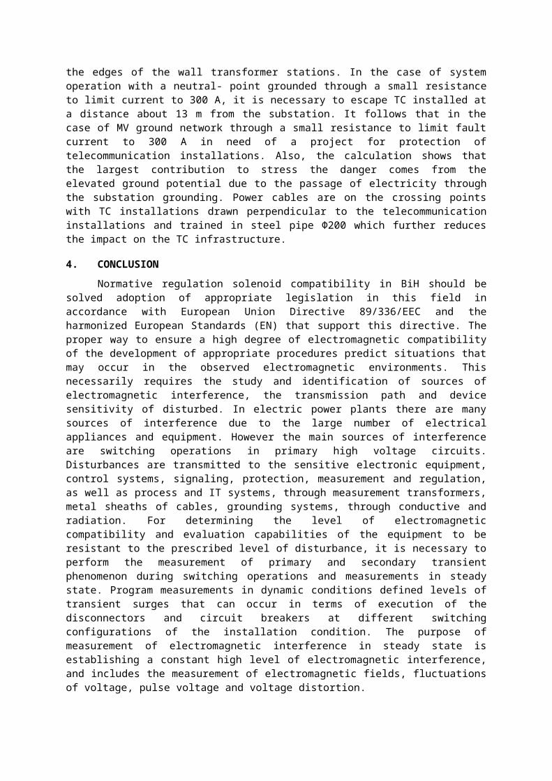
the edges of the wall transformer stations. In the case of systemoperation with a neutral- point grounded through a small resistanceto limit current to 300 A, it is necessary to escape TC installed ata distance about 13 m from the substation. It follows that in thecase of MV ground network through a small resistance to limit faultcurrent to 300 A in need of a project for protection oftelecommunication installations. Also, the calculation shows thatthe largest contribution to stress the danger comes from theelevated ground potential due to the passage of electricity throughthe substation grounding. Power cables are on the crossing pointswith TC installations drawn perpendicular to the telecommunicationinstallations and trained in steel pipe Φ200 which further reducesthe impact on the TC infrastructure.
4. CONCLUSIONNormative regulation solenoid compatibility in BiH should be
solved adoption of appropriate legislation in this field inaccordance with European Union Directive 89/336/EEC and theharmonized European Standards (EN) that support this directive. Theproper way to ensure a high degree of electromagnetic compatibilityof the development of appropriate procedures predict situations thatmay occur in the observed electromagnetic environments. Thisnecessarily requires the study and identification of sources ofelectromagnetic interference, the transmission path and devicesensitivity of disturbed. In electric power plants there are manysources of interference due to the large number of electricalappliances and equipment. However the main sources of interferenceare switching operations in primary high voltage circuits.Disturbances are transmitted to the sensitive electronic equipment,control systems, signaling, protection, measurement and regulation,as well as process and IT systems, through measurement transformers,metal sheaths of cables, grounding systems, through conductive andradiation. For determining the level of electromagneticcompatibility and evaluation capabilities of the equipment to beresistant to the prescribed level of disturbance, it is necessary toperform the measurement of primary and secondary transientphenomenon during switching operations and measurements in steadystate. Program measurements in dynamic conditions defined levels oftransient surges that can occur in terms of execution of thedisconnectors and circuit breakers at different switchingconfigurations of the installation condition. The purpose ofmeasurement of electromagnetic interference in steady state isestablishing a constant high level of electromagnetic interference,and includes the measurement of electromagnetic fields, fluctuationsof voltage, pulse voltage and voltage distortion.
5. LITERATURE[1] H. Salkić, V.Madžarevi., A.Muharemović, N. Mehinović“Calculation of
Low-frequency Magnetic Fields Distribution of a Transformer Stationin Stationary State”, XIV international symposium on electromagnetic fields inmechatronics, electrical and electronic engineering – ISEF’2009, 10-12 september 2009Arras France.
[2] H. Salkić, V. Madžarević, A. Muharemović, E. Hukić“Numerical Solvingand Experimental Measuring of Low frequency Electromagnetic Fieldsin Aspect of Exposure to Non-ionizing Electromagnetic Radiation”, The4th International Symposium onEnergy, Informatics and Cybernetics: EIC 2008In the ContextofThe 12th Multi-conference on Systemics, Cybernetics and Informatics: WMSCI 2008June29th – July 2nd, 2008 – Orlando, Florida, USA,Voll.II. pp 257-262
[3] H. Salkić, V. Madžarević, E. Hukić“Calculation and Measuring of Low-frequency Electric Field Distribution of 10(20)/0,4 kV, 630 kVATransformer Station”, 43rdinternational universities power engineering conference(UPEC2008) University of Padova, and the Department of IndustrialEngineering,University ofCassino September 1-4, 2008 Padova, Italy
[4] V.Madžarević, A.Muharemović, H.Salkić, M.Tešanović,M.Kasumović,A.Hmehmedović, ''EMC elektroenergetskih objekata'',Proračun i mjerenje niskofrekventnih električnih i magnetskih polja, ISBN 978-9958-609-59-6, COBISS.BH-ID 18186758
[5] H.Salkić, Z. Sikira, Z. Salkić, A,Softić, D.Bačinović, “Eliminationof electromagnetic interference in transformer station” 19.Internationalexpert meeting power engineering, Maribor,11-13.05.2010.g, Slovenija
[6] H.Salkić, V.Madžarević, M.Klarić, N. Mehinović, “Calculation andMeasuring of Quasi-Static Electromagnetic Field in ElectricFacilities”, EMF 2009 8th International Symposium on Electric and Magnetic FieldsFrom Numerical Models to Industrial Applications Mondovì, Italy, May 26-29,2009
[7] H. Salkić, V. Madžarević, A.Muharemović, N. Mehinović, “Low-frequency quasi-stationary electromagnetic fields of a transformerstation”, International Colloquium Power Frequency Electromagnetic Fields – ELFEMFSarajevo, Bosnia and Herzegovina, Paper 24, 3-4.6.2009
[8] V.Madžarević, A.Nuhanović, A.Muharemović, H.Salkić, Numericalcalculation of magnetic dissipation and power tranformers” “BoundaryElements XXVII: Incorporating Electrical Engineering andElectromagnetics” -WIT Transactions on Modelling and Simulation, pp.673-683. ISNN1743-355X, Vol. 39, 2005.
[9] Kapetanović, V.Madžarević, A.Muharemović , H.Salkić , “Exposure toLow Frequency Magnetic Fields of a Transformer Station” IJESSE –International Journal of Electrical Systems Science and Engineering, pp. 120-128, ISSN 2070-3953, Volume 1, Number 2, 2008
[10] A.Muharemovic, V.Madzarevic, H.Salkic, I.Turkovic, N.Mehinovic,“ Calculation of Low-frequency Magnetic Field Distribution of aTransformer Station in Stationary State” International Review on Modellingand Simulations (IReMoS) - December 2009 – Papers, Print ISSN 1974-9821, Cd-Rom ISSN1974-983X

[11] F. Božuta, M. Golubović, M. Milosavljević, J. Nahman, A. Ogorelec,S. Panić, Z. Pašić, P. Vujović i Ž. Zlatar, Aspekti zaštiteelektroenergetskog sistema, Sarajevo, 1988
[12] Tehničke preporuke za uzemljenje neutralne tačke u mreži 10,20 i 35kV, Elektroprenos Sarajevo.
[13] ISKRA fabrički katalog, Zaštita i automatitacija uelektroenergetici,1970.
.


![فرایند کار سرد.pot [Compatibility Mode]](https://img.pdfslide.net/doc/110x75/632153000c12e1161503bdb9/-pot-compatibility-mode.jpg)


![Chap012 [Compatibility Mode] - People@UTM](https://img.pdfslide.net/doc/110x75/63321bb4ac2998afa70a094f/chap012-compatibility-mode-peopleutm.jpg)
![Aula1_cap25 [Compatibility Mode].pdf](https://img.pdfslide.net/doc/110x75/6313b077aca2b42b580d43a6/aula1cap25-compatibility-modepdf.jpg)

![10 Communicatin Network.ppt [Compatibility Mode]](https://img.pdfslide.net/doc/110x75/6331ce7b7f0d9c38da0123ba/10-communicatin-networkppt-compatibility-mode.jpg)


![erikson-kuliah2 [Compatibility Mode]](https://img.pdfslide.net/doc/110x75/631a847c0255356abc08b712/erikson-kuliah2-compatibility-mode.jpg)