Embed Size (px)
Citation preview
electronics
Article
Electromagnetic Torque Ripple in Multiple Three-PhaseBrushless DC Motors for Electric Vehicles
Ihor Shchur 1 and Daniel Jancarczyk 2,*
Citation: Shchur, I.; Jancarczyk, D.
Electromagnetic Torque Ripple in
Multiple Three-Phase Brushless DC
Motors for Electric Vehicles.
Electronics 2021, 10, 3097. https://
doi.org/10.3390/electronics10243097
Academic Editor: Lucia Frosini
Received: 20 November 2021
Accepted: 10 December 2021
Published: 13 December 2021
Publisher’s Note: MDPI stays neutral
with regard to jurisdictional claims in
published maps and institutional affil-
iations.
Copyright: © 2021 by the authors.
Licensee MDPI, Basel, Switzerland.
This article is an open access article
distributed under the terms and
conditions of the Creative Commons
Attribution (CC BY) license (https://
creativecommons.org/licenses/by/
4.0/).
1 Department of Electric Mechatronics and Computer-Controlled Electromechanical Systems,Lviv Polytechnic National University, 79013 Lviv, Ukraine; [email protected]
2 Department of Computer Science and Automatics, University of Bielsko-Biala, 43-309 Bielsko-Biala, Poland* Correspondence: [email protected]
Abstract: This paper investigated an electromagnetic torque ripple level of BLDC drives with multiplethree-phase (TP) permanent magnet (PM) motors for electric vehicles. For this purpose, mathematicalmodels of PM machines of different armature winding sets-single (STP), dual (DTP), triple (TTP), andquadruple (QTP) ones of asymmetrical configuration and optimal angular displacement betweenwinding sets were developed and corresponding computer models in the Matlab/Simulink environ-ment were created. In conducted simulation, the influence of various factors on the electromagnetictorque ripple of the multiple-TP BLDC drives was investigated—degree of modularity, magneticcoupling between armature winding sets, and drive operation in open and closed-loop controlsystems. Studies have shown an increase of the electromagnetic torque ripple generated by onemodule in the multiple TP BLDC drives with magnetically coupled winding sets, due to additionalcurrent pulsations caused by magnetic interactions between the machine modules. However, the totalelectromagnetic torque ripples are much lower than in similar drives with magnetically insulatedwinding sets. Compared with the STP BLDC drive, the multiple TP BLDC drives with the sameoutput parameters showed a reduction of the electromagnetic torque ripple by 27.6% for the DTP,32.3% for the TTP, and 34.0% for the QTP BLDC drive.
Keywords: electric vehicle (EV); multiple three-phase permanent magnet (PM) motor; BLDC drive;electromagnetic torque ripple; fractional slot concentrated winding; magnetic coupling; self andmutual inductances; Matlab/Simulink model
1. Introduction
In recent years, the world has seen rapid development of electric vehicle (EV) engi-neering. Unlike cars, a number of new qualities characterize EVs, such as much higherefficiency, simplified design, especially of the mechanical transmission, increased automa-tion of all subsystems, improved handling, stability and safety, increased reliability, andreduced need for maintenance of all subsystems [1]. All these positive qualities of EVs canbe enhanced through new approaches to configuring their main subsystems and applyingappropriate control principles. One of the most productive of these approaches, in ourview, is a modular approach in the design of powertrain subsystems—on-board power sys-tems, electrical machines, and power semiconductor converters, which combine individualmodules and control power flows [2–5].
Multiphase and modular electric AC drives have become the subject of considerableinterest over the past two decades [6–8]. Modular asynchronous and then synchronouselectric machines were originally designed exclusively for use in high-power facilitieswith medium voltage levels that allowed them to be effectively controlled by means ofmodern power electronics. Among such applications are generators of powerful windturbines [9] and electric drives of powerful vehicles [10–12]. Known advantages of modulardrives in comparison with traditional three-phase ones include higher efficiency, reducedpower per module and phase, lower supply DC link voltage of the modules, reduced
Electronics 2021, 10, 3097. https://doi.org/10.3390/electronics10243097 https://www.mdpi.com/journal/electronics
Electronics 2021, 10, 3097 2 of 25
harmonic content of the DC current, and reduction of the torque ripple. In addition,modular drives have a much higher reliability and safety due to fault tolerance, theirproduction is cheaper, and maintenance and repair are easier [2,13]. For EVs, these benefitsare especially important. As the EV drive constantly works in the conditions of variablespeed and loading, the modular electric drive gives a chance for the work of variousnumber of modules with the maximum approximation of their loading to nominal values.In this case, the electric machine and the power inverter are characterized by the maximumvalues of their efficiency, which minimizes energy losses and increases the EV range ona single charge [14]. Compared to traditional drives for EVs, modular motor drives areinherently fault tolerant because failure in one of the modules does not lead to completeloss of control of the vehicle.
Modular electric machines with multiple windings have already been applied in thecases where a fault tolerant operation of EVs should be insured, e.g., for electric powersteering [15], electric aircraft [16], or unmanned EVs [17]. The positive qualities of suchdrives have led to the following solutions for the use of modular electric machines: inparticular modular three-phase (TP), in EVs drives with low and medium power levelsand low voltages [18]. However, it is associated with significant hardware and softwarecomplexity of such drive systems. To increase the popularity of modular drives for dif-ferent EVs, it is necessary to provide a good trade-off between the added complexity andpotential benefits.
To significantly simplify the modular multiple TP drive, we propose to use a modularbrushless DC motor (BLDCM) with permanent magnets (PM) [19]. Known advantagesof this drive are the use of a simpler design of an electric machine with PMs placedon the rotor surface, cheap point sensors of an angular position of the rotor, discretelow frequency switching of armature windings, and a simple control system [20]. Lowvoltage of the BLDCM modules allows us to use cheap MOSFET switches, including SiCMOSFET that guarantees operational safety and high efficiency [21,22]. In the traditionalTP version, the main disadvantage of a BLDCM is its electromagnetic torque ripple due tothe time harmonics of the armature currents that occur during the positional, often six-step,switching of the armature windings [23]. Many methods have been proposed to overcomethese ripples, which are widely represented in numerous works. They are associatedwith the use of special topologies of power semiconductor converters, hybrid, modular,cascade, etc. [24–26], and special advanced methods of switching the armature winding ofthe machine [27–29]. The electromagnetic torque ripple of the modular multiple TP BLDCdrive, to the best of the authors’ knowledge, has not been studied in detail. The influenceof certain factors in such drives contributes to both the increasing and decreasing of theelectromagnetic torque ripples produced by the separate machine modules. However,the total electromagnetic torque ripple can be much lower compared to a single-windingTP machine.
In this work, the ripple levels of the electromagnetic torque of BLDCMs with differentmodularity of their TP armature windings were investigated by mathematical modelingand computer simulation in the Matlab/Simulink environment. The accuracy of createdmodels is verified by means of comparing the simulation results with ones obtainedexperimentally for a Dual Three-Phase (DTP) BLDC drive. The influence of various factorson the electromagnetic torque ripple of the modular BLDCM, in particular the degree ofmodularity, the magnetic coupling between armature winding sets, and drive operation inopen and closed-loop control systems, is analyzed. The obtained results allow evaluatingand comparing the ripples of the electromagnetic torque produced by separate modulesand whole PM motors in different design variants and operating conditions of modularBLDC drives. Based on this, recommendations for building effective multiple TP BLDCdrives for EVs are formulated and further research directions are outlined.
The main contribution of this paper consists in the following: (i) the development ofsimple and at the same time sufficiently accurate mathematical models of multiple TP PMmachines; (ii) the creation of high-speed computer models of BLDC drives with different
Electronics 2021, 10, 3097 3 of 25
degrees of modularity; and (iii) relative estimation of the total electromagnetic torqueripple of modular BLDC drives for operating in open and closed control systems and inthe cases of absence and presence of magnetic couplings between the armature windingsets of modular PM machines.
This paper is organized in the following way. Section 2 describes the design featuresof multiple TP PM motors and highlights the system configuration of BLDC drives ofdifferent levels of modularity. Circular mathematical models of the modular BLDCMsare presented in Section 3. In Section 4, the developed computer models of the SingleThree-Phase (STP), DTP, Triple Three-Phase (TTP), and Quadruple Three-Phase (QTP)BLDC drives in the Matlab/Simulink software are described. Obtained simulation resultsof multiple TP BLDC drives operation are shown in Section 5. Section 6 is devoted to theexperimental verification of the DTP BLDC drive model. In Section 7, the obtained resultsare discussed in detail. Conclusions are presented in Section 8.
2. Design Features of Multiple TP PM Machines and Configuration of ModularBLDC Drives
Like other types of electric machines, modular BLDCM can have a different numberof individual machine modules of different phases, but most modules are made in threephases, and their number does not exceed four [7]. Machine modules can be completelyseparated in space, e.g., be placed on multiple stators. Then the magnetic coupling be-tween the individual modules is absent, and the operation of the modules is completelyindependent, which simplifies control and reduces the electromagnetic torque ripple [30].However, this configuration has much lower specific values (per unit of mass and volume)of power and torque. In magnetically coupled machine modules, the sets of the armaturewinding are placed on the common magnetic circuit, and such machine is characterizedby much higher specific power [31]. In this case, there are mutual influences of the indi-vidual modules of the machine on each other that lead to generation of additional higherharmonics of currents and, accordingly, to the increase in the electromagnetic torque rippleof the BLDCM [32]. To reduce these negative effects, various measures are applied, whichconcern the types of armature windings and the nature of their placement both within itsset and in relation to other sets.
In order to implement a large number of individual phase windings and reduce lossesin their winding ends, in modular BLDCM, it is advisable to use concentrated windingswith non-intersecting winding ends. In this case, to reduce a cogging torque, it will beeffective to use the fractional ratio of the number of slots per pole and phase [33]. Fractional-slot concentrated winding has a number of advantages over distributed windings intraditional electric machines, such as high winding factor, high copper packing factor, andhence, high efficiency, reduction in the likelihood of an interphase fault, and extremely lowcogging torque [34]. However, fractional-slot windings still generate a large number ofspace harmonics in the stator magnetic move force (MMF), which rotate at different speedsrelative to the rotor and hence cause many undesirable effects that include additional losses,acoustic noise, and vibrations.
The spatial arrangement of the stator winding sets in a modular AC machine maybe different: with the alternation of the phases of the same name of each set, with thesectoral arrangement of each set, and so on. Each of these solutions has its advantagesand disadvantages [35]. However, the direction of the first harmonic MMF vectors of thearmature winding sets is crucial. They can coincide in direction (symmetrical configuration)or be shifted by a certain angle (asymmetrical configuration) [6–8,10,12]. The multipleTP BLDCM of symmetrical configuration has all the advantages of modularity except thereduction of current and electromagnetic torque ripple. One can also obtain the latteruseful property in a machine of asymmetric configuration. Herewith, it can have two TP
Electronics 2021, 10, 3097 4 of 25
sets—DTP [12], three TP sets—TTP [36], or four TP sets—QTP [37] of armature winding.The offset angle between these TP sets should be
γ =π
3i(1)
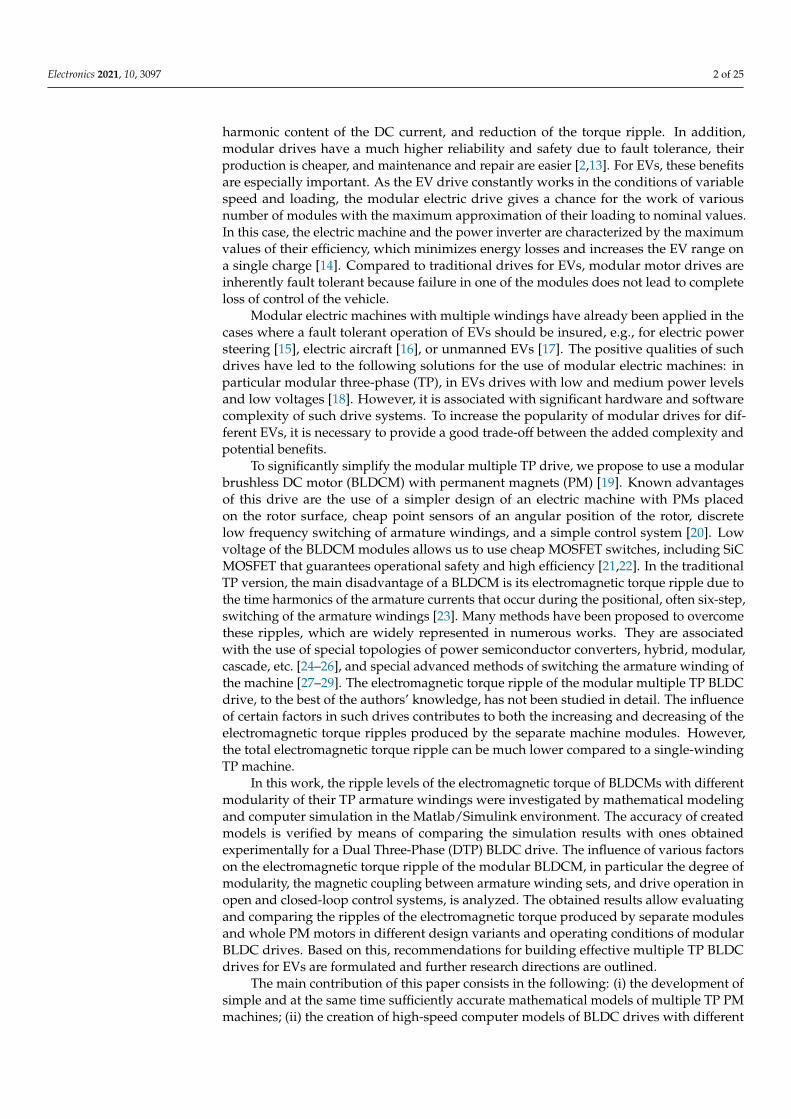
where i is the number of TP sets of the armature winding.Figure 1 shows the spatial arrangement of the vectors of the first harmonic of the PM
flux linkage of two sets of the armature winding for the DTP machines of symmetricaland asymmetrical configurations. The asymmetric DTP machine has two TP sets of thearmature winding with spatially shifted by 30 el. and isolated neutral points that eliminatethe electromagnetic torque ripple of the sixth harmonic [38].
Electronics 2021, 10, x FOR PEER REVIEW 4 of 26
DTP [12], three TP sets—TTP [36], or four TP sets—QTP [37] of armature winding. The
offset angle between these TP sets should be
πγ =
3 i (1)
where i is the number of TP sets of the armature winding.
Figure 1 shows the spatial arrangement of the vectors of the first harmonic of the PM
flux linkage of two sets of the armature winding for the DTP machines of symmetrical and
asymmetrical configurations. The asymmetric DTP machine has two TP sets of the arma-
ture winding with spatially shifted by 30° el. and isolated neutral points that eliminate the
electromagnetic torque ripple of the sixth harmonic [38].
1
23
56
4
ω
1
2
3
5
6
4
30о
ω
(a) (b)
Figure 1. Vectors of the first harmonic of the PM flux linkage of two armature winding sets for DTP PM machines of
symmetrical (a) and asymmetrical (b) configurations.
Figure 2 shows a general scheme of the studied modular BLDC drives with PM ma-
chines having a different number of machine modules of asymmetric configuration
(shown in different colors), which are offset by the angle γ (1). In the scheme, module 1 is
the TP armature winding set 1-2-3 is connected to the voltage source inverter VSI1, which
is powered by the battery B1; module 2 is the TP armature winding set 4-5-6 is connected
to the VSI2, which is powered by the battery B2; module 3 is the TP armature winding set
7-8-9 is connected to the VSI3, which is powered by the battery B3; module 4 is the TP
armature winding set 10-11-12 is connected to the VSI4, which is powered by the battery
B4.
Figure 1. Vectors of the first harmonic of the PM flux linkage of two armature winding sets for DTPPM machines of symmetrical (a) and asymmetrical (b) configurations.
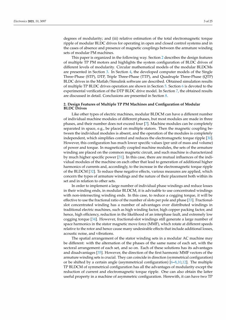
Figure 2 shows a general scheme of the studied modular BLDC drives with PMmachines having a different number of machine modules of asymmetric configuration(shown in different colors), which are offset by the angle γ (1). In the scheme, module 1 isthe TP armature winding set 1-2-3 is connected to the voltage source inverter VSI1, whichis powered by the battery B1; module 2 is the TP armature winding set 4-5-6 is connected tothe VSI2, which is powered by the battery B2; module 3 is the TP armature winding set 7-8-9is connected to the VSI3, which is powered by the battery B3; module 4 is the TP armaturewinding set 10-11-12 is connected to the VSI4, which is powered by the battery B4.
Electronics 2021, 10, x FOR PEER REVIEW 5 of 26
S11
S61
S31
S21
S51
S41
S12
S62
S32
S22
S52
S42
6
B1 B2
M
VSI1 VSI2
S13
S63
S33
S23
S53
S43
B3
VSI3
S14
S64
S34
S24
S54
S44
B4
VSI4
1
23
4
5
7
8
9
1011
12
Figure 2. Power circuit of the investigated BLDC drives with different number of machine modules
of asymmetrical configuration.
Further, the modular BLDC drives with DTP, TTP, and QTP PM machines of asym-
metrical configuration with the same nominal output parameters in comparison with the
traditional BLDC drive with the same parameters, but the PM machine with one TP wind-
ing—Single Three-Phase (STP) PM machine, will be investigated.
The sequence of steps of the proposed method for investigating the multiple TP
BLDC drives is presented in a flowchart in Figure 3.
Figure 2. Power circuit of the investigated BLDC drives with different number of machine modulesof asymmetrical configuration.
Electronics 2021, 10, 3097 5 of 25
Further, the modular BLDC drives with DTP, TTP, and QTP PM machines of asym-metrical configuration with the same nominal output parameters in comparison withthe traditional BLDC drive with the same parameters, but the PM machine with one TPwinding—Single Three-Phase (STP) PM machine, will be investigated.
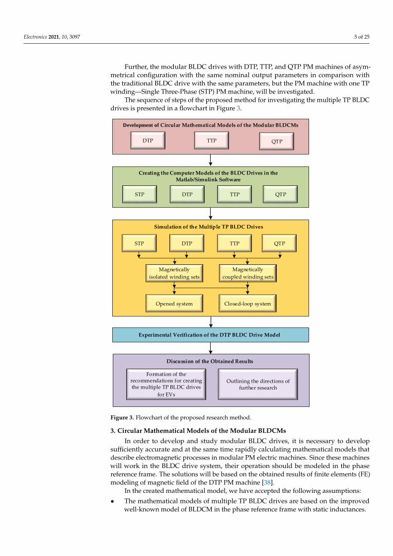
The sequence of steps of the proposed method for investigating the multiple TP BLDCdrives is presented in a flowchart in Figure 3.
Electronics 2021, 10, x FOR PEER REVIEW 6 of 26
Experimental Verification of the DTP BLDC Drive Model
DTP TTP QTP
Creating the Computer Models of the BLDC Drives in the Matlab/Simulink Software
STP
STP DTP TTP
Simulation of the Multiple TP BLDC Drives
QTP
Magnetically
isolated winding sets
Magnetically
coupled winding sets
Opened system Closed-loop system
DTP TTP QTP
Development of Circular Mathematical Models of the Modular BLDCMs
Discussion of the Obtained Results
Formation of the recommendations for creating the multiple TP BLDC drives
for EVs
Outlining the directions of further research
Figure 3. Flowchart of the proposed research method.
3. Circular Mathematical Models of the Modular BLDCMs
In order to develop and study modular BLDC drives, it is necessary to develop suf-
ficiently accurate and at the same time rapidly calculating mathematical models that de-
scribe electromagnetic processes in modular PM electric machines. Since these machines
will work in the BLDC drive system, their operation should be modeled in the phase ref-
erence frame. The solutions will be based on the obtained results of finite elements (FE)
modeling of magnetic field of the DTP PM machine [38].
In the created mathematical model, we have accepted the following assumptions:
The mathematical models of multiple TP BLDC drives are based on the improved
well-known model of BLDCM in the phase reference frame with static inductances.
Static self and mutual inductances are assumed to be constant and independent of
currents.
The mutual inductive coupling between the phases belonging to one set of the arma-
ture winding is absent, and between the phases belonging to different sets may have
different magnitude and sign depending on the angular displacement between the
phase pairs.
Figure 3. Flowchart of the proposed research method.
3. Circular Mathematical Models of the Modular BLDCMs
In order to develop and study modular BLDC drives, it is necessary to developsufficiently accurate and at the same time rapidly calculating mathematical models thatdescribe electromagnetic processes in modular PM electric machines. Since these machineswill work in the BLDC drive system, their operation should be modeled in the phasereference frame. The solutions will be based on the obtained results of finite elements (FE)modeling of magnetic field of the DTP PM machine [38].
In the created mathematical model, we have accepted the following assumptions:
• The mathematical models of multiple TP BLDC drives are based on the improvedwell-known model of BLDCM in the phase reference frame with static inductances.
Electronics 2021, 10, 3097 6 of 25
• Static self and mutual inductances are assumed to be constant and independentof currents.
• The mutual inductive coupling between the phases belonging to one set of the arma-ture winding is absent, and between the phases belonging to different sets may havedifferent magnitude and sign depending on the angular displacement between thephase pairs.
• The dependences of the self and mutual inductances on the angular position of therotor are not taken into account because the studied PM machines do not have asufficient polarity.
• The shape of the rotation electric move forces (EMF) consists of only the twolargest harmonics—the first and the third.
• All machine modules and their magnetic circuits are symmetrical.• Losses in steel and PMs are neglected.• The influence of the cogging component of the torque is not taken into account.
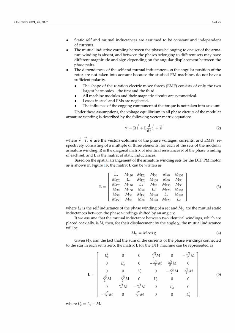
Under these assumptions, the voltage equilibrium in all phase circuits of the modulararmature winding is described by the following vector-matrix equation:
→v = R
→i + L
ddt
→i +
→e (2)
where→v,→i ,→e are the vectors-columns of the phase voltages, currents, and EMFs, re-
spectively, consisting of a multiple of three elements, for each of the sets of the modulararmature winding, R is the diagonal matrix of identical resistances R of the phase windingof each set, and L is the matrix of static inductances.
Based on the spatial arrangement of the armature winding sets for the DTP PM motor,as is shown in Figure 1b, the matrix L can be written as
L =
La M120 M120 M30 M90 M150M120 La M120 M150 M30 M90M120 M120 La M90 M150 M30M30 M150 M90 La M120 M120M90 M30 M150 M120 La M120M150 M90 M30 M120 M120 La
(3)
where La is the self inductance of the phase winding of a set and Mχ are the mutual staticinductances between the phase windings shifted by an angle χ.
If we assume that the mutual inductance between two identical windings, which areplaced coaxially, is M, then, for their displacement by the angle χ, the mutual inductancewill be
Mχ = M cosχ (4)
Given (4), and the fact that the sum of the currents of the phase windings connectedto the star in each set is zero, the matrix L for the DTP machine can be represented as
L =
L′a 0 0√
32 M 0 −
√3
2 M
0 L′a 0 −√
32 M
√3
2 M 0
0 0 L′a 0 −√
32 M
√3
2 M√
32 M −
√3
2 M 0 L′a 0 0
0√
32 M −
√3
2 M 0 L′a 0
−√
32 M 0
√3
2 M 0 0 L′a
(5)
where L′a = La −M.
Electronics 2021, 10, 3097 7 of 25
The values of the self and mutual inductances given in (5) are in good agreementwith the results obtained by FE modeling of the magnetic field of the studied DTP PMmachine, if we neglect the magnetic saturation and some explicit polarity in this electricmachine [38].
The obtained matrix (5) can be represented as the sum of two matrices: La, whichdescribes only the self inductances of the phase windings of the winding sets, and M,which describes the mutual inductances:
L = La + M = diag6[L′a] + M
0 0 0 0.866 0 −0.866
0 0 0 −0.866 0.866 0
0 0 0 0 −0.866 0.866
0.866 −0.866 0 0 0 0
0 0.866 −0.866 0 0 0
−0.866 0 0.866 0 0 0
(6)
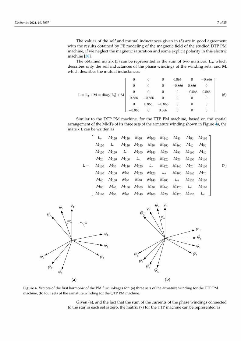
Similar to the DTP PM machine, for the TTP PM machine, based on the spatialarrangement of the MMFs of its three sets of the armature winding shown in Figure 4a, thematrix L can be written as
L =
La M120 M120 M20 M100 M140 M40 M80 M160
M120 La M120 M140 M20 M100 M160 M40 M80
M120 M120 La M100 M140 M20 M80 M160 M40
M20 M140 M100 La M120 M120 M20 M100 M140
M100 M20 M140 M120 La M120 M140 M20 M100
M140 M100 M20 M120 M120 La M100 M140 M20
M40 M160 M80 M20 M140 M100 La M120 M120
M80 M40 M160 M100 M20 M140 M120 La M120
M160 M80 M40 M140 M100 M20 M120 M120 La
(7)
Electronics 2021, 10, x FOR PEER REVIEW 9 of 26
(a) (b)
Figure 4. Vectors of the first harmonic of the PM flux linkages for: (a) three sets of the armature winding for the TTP PM
machine, (b) four sets of the armature winding for the QTP PM machine.
120 120 15 105 135 30 90 150 45 75 165
120 120 135 15 105 150 30 90 165 45 75
120 120 105 135 15 90 150 30 75 165 45
15 135 105 120 120 15 105 135 30 90 150
105 15 135 120 120 135 15 105
a
a
a
a
a
L M M M M M M M M M M M
M L M M M M M M M M M M
M M L M M M M M M M M M
M M M L M M M M M M M M
M M M M L M M M M M
L
150 30 90
135 105 15 120 120 105 135 15 90 150 30
30 150 90 15 135 105 120 120 15 105 135
90 30 150 105 15 135 120 120 135 15 105
150 90 30 135 105 15 120 120 105 135 15
45 165 75 30 150 90 15
a
a
a
a
M M
M M M M M L M M M M M M
M M M M M M L M M M M M
M M M M M M M L M M M M
M M M M M M M M L M M M
M M M M M M M 135 105 120 120
75 45 165 90 30 150 105 15 135 120 120
165 75 45 150 90 30 135 105 15 120 120
a
a
a
M M L M M
M M M M M M M M M M L M
M M M M M M M M M M M L
(9)
Given (4), as well as the fact that the sum of the currents of the phase windings con-
nected to the star in each section is equal to zero, the matrix (9) can be represented as
12diag
0 0 0 0.966 0.259 0.707 0.866 0 0.866 0.707 0.259 0.966
0 0 0 0.707 0.966 0.259 0.866 0.866 0 0.966 0.707 0.259
0 0 0 0.259 0.707 0.966 0 0.866 0.866 0.259 0.966 0.707
0.966 0.707 0.259 0 0 0 0.966 0.259 0.707 0.
aL
M
L
866 0 0.866
0.259 0.966 0.707 0 0 0 0.707 0.966 0.259 0.866 0.866 0
0.707 0.259 0.966 0 0 0 0.259 0.707 0.966 0 0.866 0.866
0.866 0.866 0 0.966 0.707 0.259 0 0 0 0.966 0.259 0.707
0 0.866 0.866 0.259 0.966 0.707 0 0 0 0.707 0.966
0.259
0.866 0 0.866 0.707 0.259 0.966 0 0 0 0.259 0.707 0.966
0.707 0.966 0.259 0.866 0.866 0 0.966 0.707 0.259 0 0 0
0.259 0.707 0.966 0 0.866 0.866 0.259 0.966 0.707 0 0 0
0.966 0.259 0.707 0.866 0 0.866 0.707 0.259 0.966 0 0 0
(10)
The electromagnetic torque of the DTP, TTP, and QTP PM machines can be expressed
as
Figure 4. Vectors of the first harmonic of the PM flux linkages for: (a) three sets of the armature winding for the TTP PMmachine, (b) four sets of the armature winding for the QTP PM machine.
Given (4), and the fact that the sum of the currents of the phase windings connectedto the star in each set is zero, the matrix (7) for the TTP machine can be represented as
Electronics 2021, 10, 3097 8 of 25
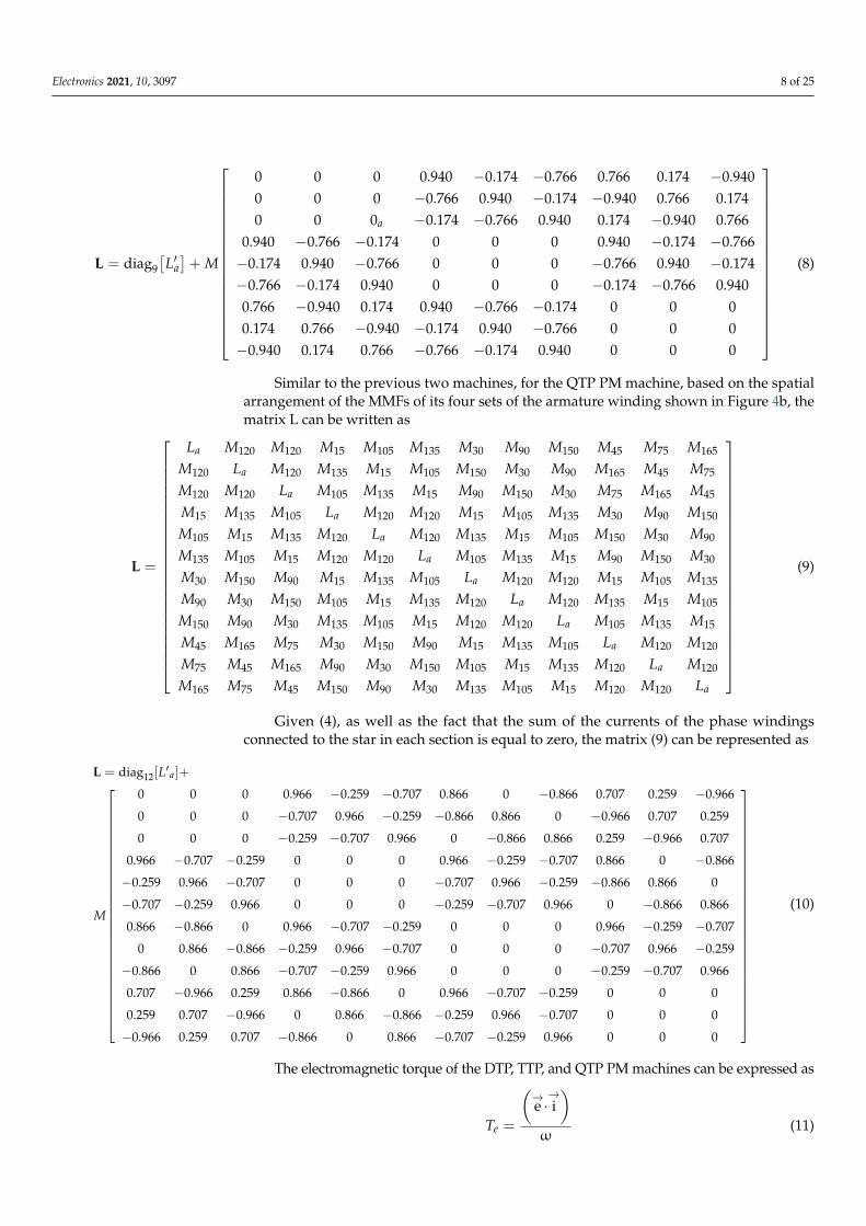
L = diag9[L′a]+ M
0 0 0 0.940 −0.174 −0.766 0.766 0.174 −0.9400 0 0 −0.766 0.940 −0.174 −0.940 0.766 0.1740 0 0a −0.174 −0.766 0.940 0.174 −0.940 0.766
0.940 −0.766 −0.174 0 0 0 0.940 −0.174 −0.766−0.174 0.940 −0.766 0 0 0 −0.766 0.940 −0.174−0.766 −0.174 0.940 0 0 0 −0.174 −0.766 0.9400.766 −0.940 0.174 0.940 −0.766 −0.174 0 0 00.174 0.766 −0.940 −0.174 0.940 −0.766 0 0 0−0.940 0.174 0.766 −0.766 −0.174 0.940 0 0 0
(8)
Similar to the previous two machines, for the QTP PM machine, based on the spatialarrangement of the MMFs of its four sets of the armature winding shown in Figure 4b, thematrix L can be written as
L =
La M120 M120 M15 M105 M135 M30 M90 M150 M45 M75 M165
M120 La M120 M135 M15 M105 M150 M30 M90 M165 M45 M75
M120 M120 La M105 M135 M15 M90 M150 M30 M75 M165 M45
M15 M135 M105 La M120 M120 M15 M105 M135 M30 M90 M150
M105 M15 M135 M120 La M120 M135 M15 M105 M150 M30 M90
M135 M105 M15 M120 M120 La M105 M135 M15 M90 M150 M30
M30 M150 M90 M15 M135 M105 La M120 M120 M15 M105 M135
M90 M30 M150 M105 M15 M135 M120 La M120 M135 M15 M105
M150 M90 M30 M135 M105 M15 M120 M120 La M105 M135 M15
M45 M165 M75 M30 M150 M90 M15 M135 M105 La M120 M120
M75 M45 M165 M90 M30 M150 M105 M15 M135 M120 La M120
M165 M75 M45 M150 M90 M30 M135 M105 M15 M120 M120 La
(9)
Given (4), as well as the fact that the sum of the currents of the phase windingsconnected to the star in each section is equal to zero, the matrix (9) can be represented as
L = diag12[L′a]+
M
0 0 0 0.966 −0.259 −0.707 0.866 0 −0.866 0.707 0.259 −0.966
0 0 0 −0.707 0.966 −0.259 −0.866 0.866 0 −0.966 0.707 0.259
0 0 0 −0.259 −0.707 0.966 0 −0.866 0.866 0.259 −0.966 0.707
0.966 −0.707 −0.259 0 0 0 0.966 −0.259 −0.707 0.866 0 −0.866
−0.259 0.966 −0.707 0 0 0 −0.707 0.966 −0.259 −0.866 0.866 0
−0.707 −0.259 0.966 0 0 0 −0.259 −0.707 0.966 0 −0.866 0.866
0.866 −0.866 0 0.966 −0.707 −0.259 0 0 0 0.966 −0.259 −0.707
0 0.866 −0.866 −0.259 0.966 −0.707 0 0 0 −0.707 0.966 −0.259
−0.866 0 0.866 −0.707 −0.259 0.966 0 0 0 −0.259 −0.707 0.966
0.707 −0.966 0.259 0.866 −0.866 0 0.966 −0.707 −0.259 0 0 0
0.259 0.707 −0.966 0 0.866 −0.866 −0.259 0.966 −0.707 0 0 0
−0.966 0.259 0.707 −0.866 0 0.866 −0.707 −0.259 0.966 0 0 0
(10)
The electromagnetic torque of the DTP, TTP, and QTP PM machines can be expressed as
Te =
(→e ·→i)
ω(11)
Electronics 2021, 10, 3097 9 of 25
where(→e ·→i)
is the dot product of the EMF and armature current vectors.
For the single-mass mechanical system with the moment of inertia J∑ reduced to themotor shaft, the equation of motion of the drive has the form
J∑dωdt
= Te − TL − bω (12)
where TL is the load torque of the drive and b is the coefficient of viscous friction.The position angle of the motor rotor is determined by integrating the angular velocity
at zero initial conditions:
θ =∫ωdt (13)
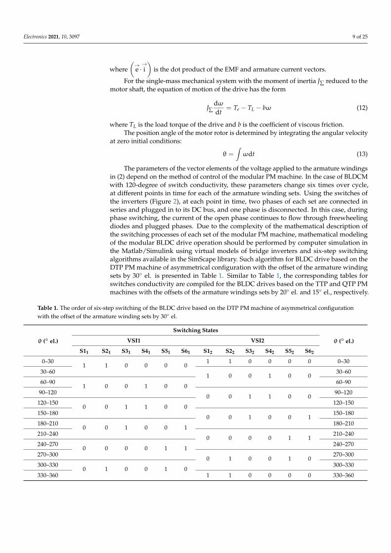
The parameters of the vector elements of the voltage applied to the armature windingsin (2) depend on the method of control of the modular PM machine. In the case of BLDCMwith 120-degree of switch conductivity, these parameters change six times over cycle,at different points in time for each of the armature winding sets. Using the switches ofthe inverters (Figure 2), at each point in time, two phases of each set are connected inseries and plugged in to its DC bus, and one phase is disconnected. In this case, duringphase switching, the current of the open phase continues to flow through freewheelingdiodes and plugged phases. Due to the complexity of the mathematical description ofthe switching processes of each set of the modular PM machine, mathematical modelingof the modular BLDC drive operation should be performed by computer simulation inthe Matlab/Simulink using virtual models of bridge inverters and six-step switchingalgorithms available in the SimScape library. Such algorithm for BLDC drive based on theDTP PM machine of asymmetrical configuration with the offset of the armature windingsets by 30 el. is presented in Table 1. Similar to Table 1, the corresponding tables forswitches conductivity are compiled for the BLDC drives based on the TTP and QTP PMmachines with the offsets of the armature windings sets by 20 el. and 15 el., respectively.
Table 1. The order of six-step switching of the BLDC drive based on the DTP PM machine of asymmetrical configurationwith the offset of the armature winding sets by 30 el.
θ ( el.)
Switching States
θ ( el.)VSI1 VSI2
S11 S21 S31 S41 S51 S61 S12 S22 S32 S42 S52 S62
0–301 1 0 0 0 0
1 1 0 0 0 0 0–30
30–601 0 0 1 0 0
30–60
60–901 0 0 1 0 0
60–90
90–1200 0 1 1 0 0
90–120
120–1500 0 1 1 0 0
120–150
150–1800 0 1 0 0 1
150–180
180–2100 0 1 0 0 1
180–210
210–2400 0 0 0 1 1
210–240
240–2700 0 0 0 1 1
240–270
270–3000 1 0 0 1 0
270–300
300–3300 1 0 0 1 0
300–330
330–360 1 1 0 0 0 0 330–360
Electronics 2021, 10, 3097 10 of 25
4. Computer Models of the STP, DTP, TTP and QTP BLDC Drives in theMatlab/Simulink Software
Computer models of the STP, DTP, TTP, and QTP BLDC drives are developed inthe Matlab/Simulink environment based on Equations (2)–(13) according to the sameapproach and differ only in a number of PM machine modules, their parameters, and theimplementation of mutual inductive couplings between the armature winding sets.
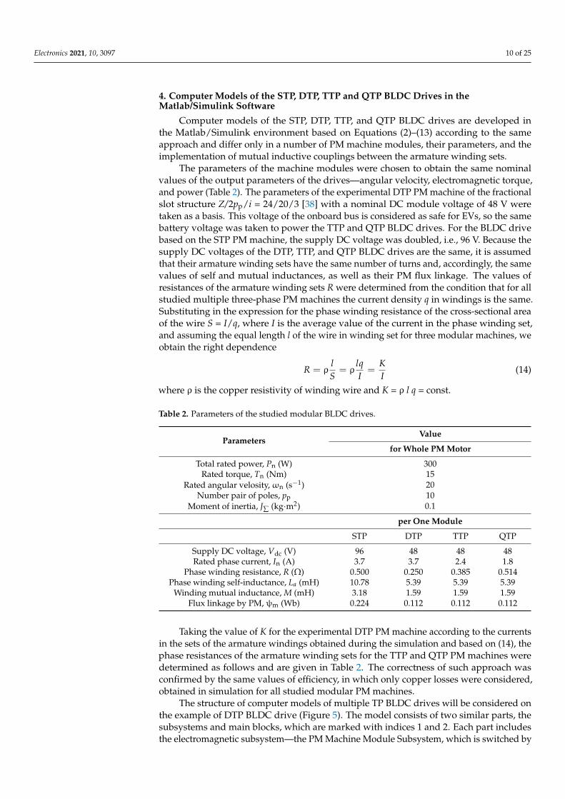
The parameters of the machine modules were chosen to obtain the same nominalvalues of the output parameters of the drives—angular velocity, electromagnetic torque,and power (Table 2). The parameters of the experimental DTP PM machine of the fractionalslot structure Z/2pp/i = 24/20/3 [38] with a nominal DC module voltage of 48 V weretaken as a basis. This voltage of the onboard bus is considered as safe for EVs, so the samebattery voltage was taken to power the TTP and QTP BLDC drives. For the BLDC drivebased on the STP PM machine, the supply DC voltage was doubled, i.e., 96 V. Because thesupply DC voltages of the DTP, TTP, and QTP BLDC drives are the same, it is assumedthat their armature winding sets have the same number of turns and, accordingly, the samevalues of self and mutual inductances, as well as their PM flux linkage. The values ofresistances of the armature winding sets R were determined from the condition that for allstudied multiple three-phase PM machines the current density q in windings is the same.Substituting in the expression for the phase winding resistance of the cross-sectional areaof the wire S = I/q, where I is the average value of the current in the phase winding set,and assuming the equal length l of the wire in winding set for three modular machines, weobtain the right dependence
R = ρlS= ρ
lqI=
KI
(14)
where ρ is the copper resistivity of winding wire and K = ρ l q = const.
Table 2. Parameters of the studied modular BLDC drives.
ParametersValue
for Whole PM Motor
Total rated power, Pn (W) 300Rated torque, Tn (Nm) 15
Rated angular velosity,ωn (s−1) 20Number pair of poles, pp 10
Moment of inertia, J∑ (kg·m2) 0.1
per One Module
STP DTP TTP QTP
Supply DC voltage, Vdc (V) 96 48 48 48Rated phase current, In (A) 3.7 3.7 2.4 1.8
Phase winding resistance, R (Ω) 0.500 0.250 0.385 0.514Phase winding self-inductance, La (mH) 10.78 5.39 5.39 5.39
Winding mutual inductance, M (mH) 3.18 1.59 1.59 1.59Flux linkage by PM, ψm (Wb) 0.224 0.112 0.112 0.112
Taking the value of K for the experimental DTP PM machine according to the currentsin the sets of the armature windings obtained during the simulation and based on (14), thephase resistances of the armature winding sets for the TTP and QTP PM machines weredetermined as follows and are given in Table 2. The correctness of such approach wasconfirmed by the same values of efficiency, in which only copper losses were considered,obtained in simulation for all studied modular PM machines.
The structure of computer models of multiple TP BLDC drives will be considered onthe example of DTP BLDC drive (Figure 5). The model consists of two similar parts, thesubsystems and main blocks, which are marked with indices 1 and 2. Each part includesthe electromagnetic subsystem—the PM Machine Module Subsystem, which is switched by
Electronics 2021, 10, 3097 11 of 25
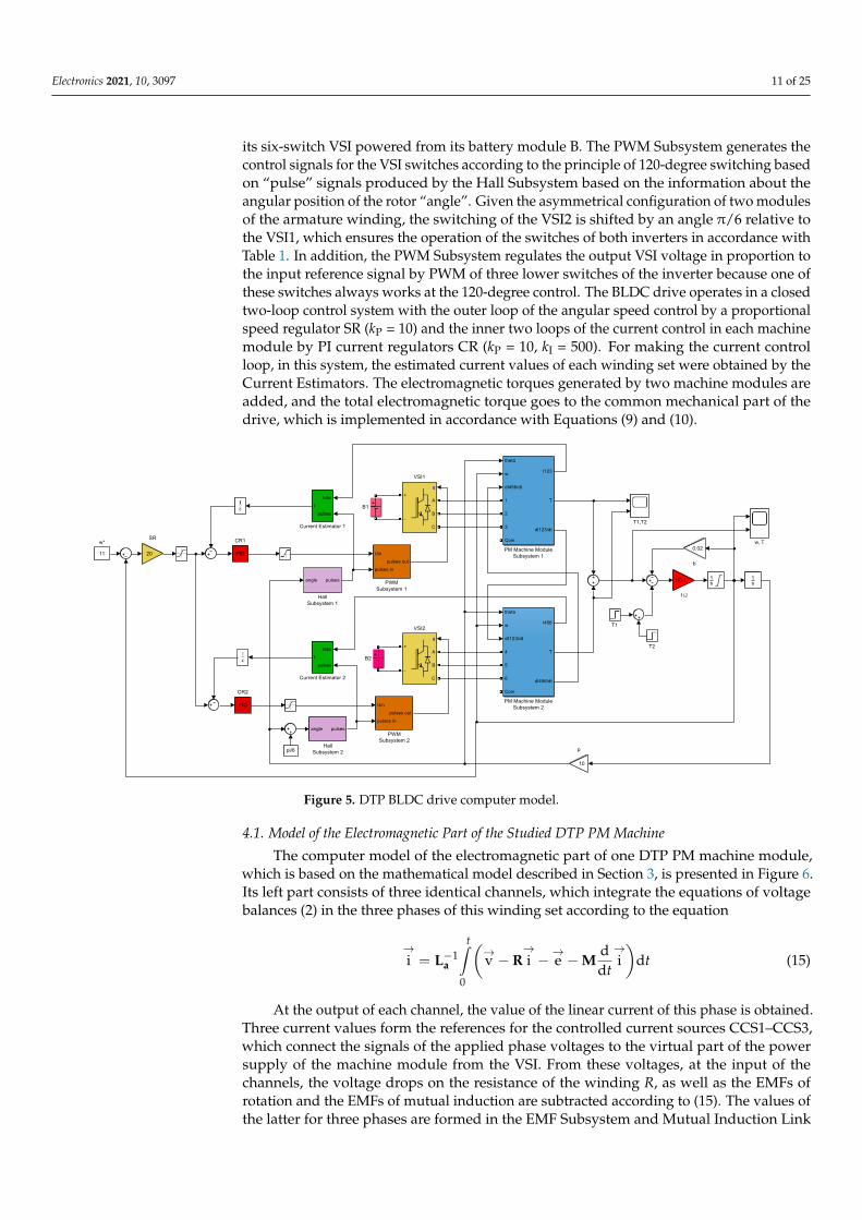
its six-switch VSI powered from its battery module B. The PWM Subsystem generates thecontrol signals for the VSI switches according to the principle of 120-degree switching basedon “pulse” signals produced by the Hall Subsystem based on the information about theangular position of the rotor “angle”. Given the asymmetrical configuration of two modulesof the armature winding, the switching of the VSI2 is shifted by an angle π/6 relative tothe VSI1, which ensures the operation of the switches of both inverters in accordance withTable 1. In addition, the PWM Subsystem regulates the output VSI voltage in proportion tothe input reference signal by PWM of three lower switches of the inverter because one ofthese switches always works at the 120-degree control. The BLDC drive operates in a closedtwo-loop control system with the outer loop of the angular speed control by a proportionalspeed regulator SR (kP = 10) and the inner two loops of the current control in each machinemodule by PI current regulators CR (kP = 10, kI = 500). For making the current controlloop, in this system, the estimated current values of each winding set were obtained by theCurrent Estimators. The electromagnetic torques generated by two machine modules areadded, and the total electromagnetic torque goes to the common mechanical part of thedrive, which is implemented in accordance with Equations (9) and (10).
Electronics 2021, 10, x FOR PEER REVIEW 12 of 26
subsystems and main blocks, which are marked with indices 1 and 2. Each part includes
the electromagnetic subsystem—the PM Machine Module Subsystem, which is switched
by its six-switch VSI powered from its battery module B. The PWM Subsystem generates
the control signals for the VSI switches according to the principle of 120-degree switching
based on “pulse” signals produced by the Hall Subsystem based on the information about
the angular position of the rotor “angle”. Given the asymmetrical configuration of two
modules of the armature winding, the switching of the VSI2 is shifted by an angle π/6
relative to the VSI1, which ensures the operation of the switches of both inverters in ac-
cordance with Table 1. In addition, the PWM Subsystem regulates the output VSI voltage
in proportion to the input reference signal by PWM of three lower switches of the inverter
because one of these switches always works at the 120-degree control. The BLDC drive
operates in a closed two-loop control system with the outer loop of the angular speed
control by a proportional speed regulator SR (kP = 10) and the inner two loops of the cur-
rent control in each machine module by PI current regulators CR (kP = 10, kI = 500). For
making the current control loop, in this system, the estimated current values of each wind-
ing set were obtained by the Current Estimators. The electromagnetic torques generated
by two machine modules are added, and the total electromagnetic torque goes to the com-
mon mechanical part of the drive, which is implemented in accordance with Equations (9)
and (10).
Figure 5. DTP BLDC drive computer model.
4.1. Model of the Electromagnetic Part of the Studied DTP PM Machine
The computer model of the electromagnetic part of one DTP PM machine module,
which is based on the mathematical model described in Section 3, is presented in Figure
6. Its left part consists of three identical channels, which integrate the equations of voltage
balances (2) in the three phases of this winding set according to the equation
-1
0
di v i e i d
d
t
ttaL R M (15)
Figure 5. DTP BLDC drive computer model.
4.1. Model of the Electromagnetic Part of the Studied DTP PM Machine
The computer model of the electromagnetic part of one DTP PM machine module,which is based on the mathematical model described in Section 3, is presented in Figure 6.Its left part consists of three identical channels, which integrate the equations of voltagebalances (2) in the three phases of this winding set according to the equation
→i = L−1
a
t∫0
(→v −R
→i −→e −M
ddt
→i)
dt (15)
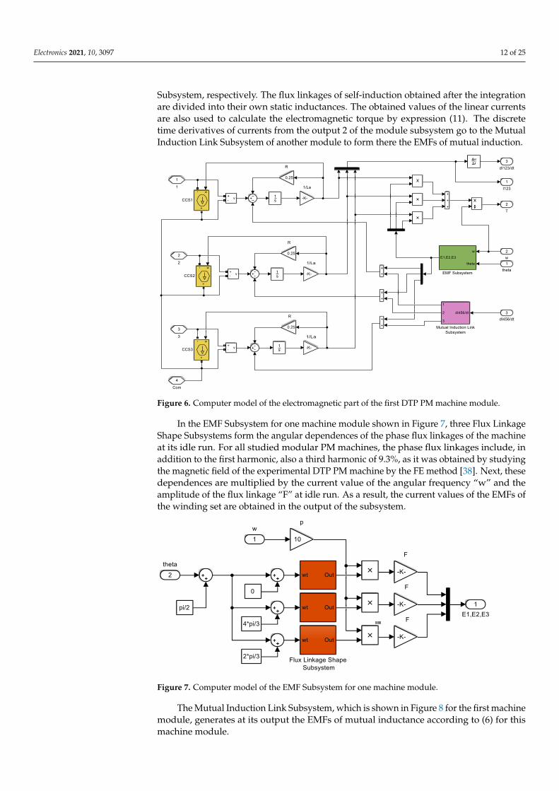
At the output of each channel, the value of the linear current of this phase is obtained.Three current values form the references for the controlled current sources CCS1–CCS3,which connect the signals of the applied phase voltages to the virtual part of the powersupply of the machine module from the VSI. From these voltages, at the input of thechannels, the voltage drops on the resistance of the winding R, as well as the EMFs ofrotation and the EMFs of mutual induction are subtracted according to (15). The values ofthe latter for three phases are formed in the EMF Subsystem and Mutual Induction Link
Electronics 2021, 10, 3097 12 of 25
Subsystem, respectively. The flux linkages of self-induction obtained after the integrationare divided into their own static inductances. The obtained values of the linear currentsare also used to calculate the electromagnetic torque by expression (11). The discretetime derivatives of currents from the output 2 of the module subsystem go to the MutualInduction Link Subsystem of another module to form there the EMFs of mutual induction.
Electronics 2021, 10, x FOR PEER REVIEW 13 of 26
Figure 6. Computer model of the electromagnetic part of the first DTP PM machine module.
At the output of each channel, the value of the linear current of this phase is obtained.
Three current values form the references for the controlled current sources CCS1–CCS3,
which connect the signals of the applied phase voltages to the virtual part of the power
supply of the machine module from the VSI. From these voltages, at the input of the chan-
nels, the voltage drops on the resistance of the winding R, as well as the EMFs of rotation
and the EMFs of mutual induction are subtracted according to (15). The values of the latter
for three phases are formed in the EMF Subsystem and Mutual Induction Link Subsystem,
respectively. The flux linkages of self-induction obtained after the integration are divided
into their own static inductances. The obtained values of the linear currents are also used
to calculate the electromagnetic torque by expression (11). The discrete time derivatives
of currents from the output 2 of the module subsystem go to the Mutual Induction Link
Subsystem of another module to form there the EMFs of mutual induction.
In the EMF Subsystem for one machine module shown in Figure 7, three Flux Link-
age Shape Subsystems form the angular dependences of the phase flux linkages of the
machine at its idle run. For all studied modular PM machines, the phase flux linkages
include, in addition to the first harmonic, also a third harmonic of 9.3%, as it was obtained
by studying the magnetic field of the experimental DTP PM machine by the FE method
[38]. Next, these dependences are multiplied by the current value of the angular frequency
“w” and the amplitude of the flux linkage “F” at idle run. As a result, the current values
of the EMFs of the winding set are obtained in the output of the subsystem.
Figure 7. Computer model of the EMF Subsystem for one machine module.
Figure 6. Computer model of the electromagnetic part of the first DTP PM machine module.
In the EMF Subsystem for one machine module shown in Figure 7, three Flux LinkageShape Subsystems form the angular dependences of the phase flux linkages of the machineat its idle run. For all studied modular PM machines, the phase flux linkages include, inaddition to the first harmonic, also a third harmonic of 9.3%, as it was obtained by studyingthe magnetic field of the experimental DTP PM machine by the FE method [38]. Next, thesedependences are multiplied by the current value of the angular frequency “w” and theamplitude of the flux linkage “F” at idle run. As a result, the current values of the EMFs ofthe winding set are obtained in the output of the subsystem.
Electronics 2021, 10, x FOR PEER REVIEW 13 of 26
Figure 6. Computer model of the electromagnetic part of the first DTP PM machine module.
At the output of each channel, the value of the linear current of this phase is obtained.
Three current values form the references for the controlled current sources CCS1–CCS3,
which connect the signals of the applied phase voltages to the virtual part of the power
supply of the machine module from the VSI. From these voltages, at the input of the chan-
nels, the voltage drops on the resistance of the winding R, as well as the EMFs of rotation
and the EMFs of mutual induction are subtracted according to (15). The values of the latter
for three phases are formed in the EMF Subsystem and Mutual Induction Link Subsystem,
respectively. The flux linkages of self-induction obtained after the integration are divided
into their own static inductances. The obtained values of the linear currents are also used
to calculate the electromagnetic torque by expression (11). The discrete time derivatives
of currents from the output 2 of the module subsystem go to the Mutual Induction Link
Subsystem of another module to form there the EMFs of mutual induction.
In the EMF Subsystem for one machine module shown in Figure 7, three Flux Link-
age Shape Subsystems form the angular dependences of the phase flux linkages of the
machine at its idle run. For all studied modular PM machines, the phase flux linkages
include, in addition to the first harmonic, also a third harmonic of 9.3%, as it was obtained
by studying the magnetic field of the experimental DTP PM machine by the FE method
[38]. Next, these dependences are multiplied by the current value of the angular frequency
“w” and the amplitude of the flux linkage “F” at idle run. As a result, the current values
of the EMFs of the winding set are obtained in the output of the subsystem.
Figure 7. Computer model of the EMF Subsystem for one machine module. Figure 7. Computer model of the EMF Subsystem for one machine module.
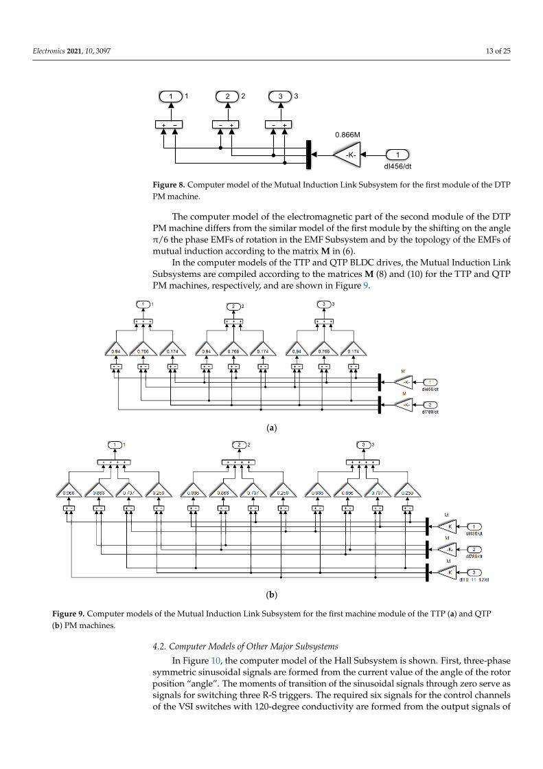
The Mutual Induction Link Subsystem, which is shown in Figure 8 for the first machinemodule, generates at its output the EMFs of mutual inductance according to (6) for thismachine module.
Electronics 2021, 10, 3097 13 of 25
Electronics 2021, 10, x FOR PEER REVIEW 14 of 26
The Mutual Induction Link Subsystem, which is shown in Figure 8 for the first ma-
chine module, generates at its output the EMFs of mutual inductance according to (6) for
this machine module.
Figure 8. Computer model of the Mutual Induction Link Subsystem for the first module of the DTP
PM machine.
The computer model of the electromagnetic part of the second module of the DTP
PM machine differs from the similar model of the first module by the shifting on the angle
π/6 the phase EMFs of rotation in the EMF Subsystem and by the topology of the EMFs of mutual induction according to the matrix M in (6).
In the computer models of the TTP and QTP BLDC drives, the Mutual Induction Link Subsystems are compiled according to the matrices M (8) and (10) for the TTP and QTP
PM machines, respectively, and are shown in Figure 9.
(a)
(b)
Figure 9. Computer models of the Mutual Induction Link Subsystem for the first machine module of the TTP (a) and QTP
(b) PM machines.
4.2. Computer Models of Other Major Subsystems
In Figure 10, the computer model of the Hall Subsystem is shown. First, three-phase
symmetric sinusoidal signals are formed from the current value of the angle of the rotor
position “angle”. The moments of transition of the sinusoidal signals through zero serve
Figure 8. Computer model of the Mutual Induction Link Subsystem for the first module of the DTPPM machine.
The computer model of the electromagnetic part of the second module of the DTPPM machine differs from the similar model of the first module by the shifting on the angleπ/6 the phase EMFs of rotation in the EMF Subsystem and by the topology of the EMFs ofmutual induction according to the matrix M in (6).
In the computer models of the TTP and QTP BLDC drives, the Mutual Induction LinkSubsystems are compiled according to the matrices M (8) and (10) for the TTP and QTPPM machines, respectively, and are shown in Figure 9.
Electronics 2021, 10, x FOR PEER REVIEW 14 of 26
The Mutual Induction Link Subsystem, which is shown in Figure 8 for the first ma-
chine module, generates at its output the EMFs of mutual inductance according to (6) for
this machine module.
Figure 8. Computer model of the Mutual Induction Link Subsystem for the first module of the DTP
PM machine.
The computer model of the electromagnetic part of the second module of the DTP
PM machine differs from the similar model of the first module by the shifting on the angle
π/6 the phase EMFs of rotation in the EMF Subsystem and by the topology of the EMFs of mutual induction according to the matrix M in (6).
In the computer models of the TTP and QTP BLDC drives, the Mutual Induction Link Subsystems are compiled according to the matrices M (8) and (10) for the TTP and QTP
PM machines, respectively, and are shown in Figure 9.
(a)
(b)
Figure 9. Computer models of the Mutual Induction Link Subsystem for the first machine module of the TTP (a) and QTP
(b) PM machines.
4.2. Computer Models of Other Major Subsystems
In Figure 10, the computer model of the Hall Subsystem is shown. First, three-phase
symmetric sinusoidal signals are formed from the current value of the angle of the rotor
position “angle”. The moments of transition of the sinusoidal signals through zero serve
Figure 9. Computer models of the Mutual Induction Link Subsystem for the first machine module of the TTP (a) and QTP(b) PM machines.
4.2. Computer Models of Other Major Subsystems
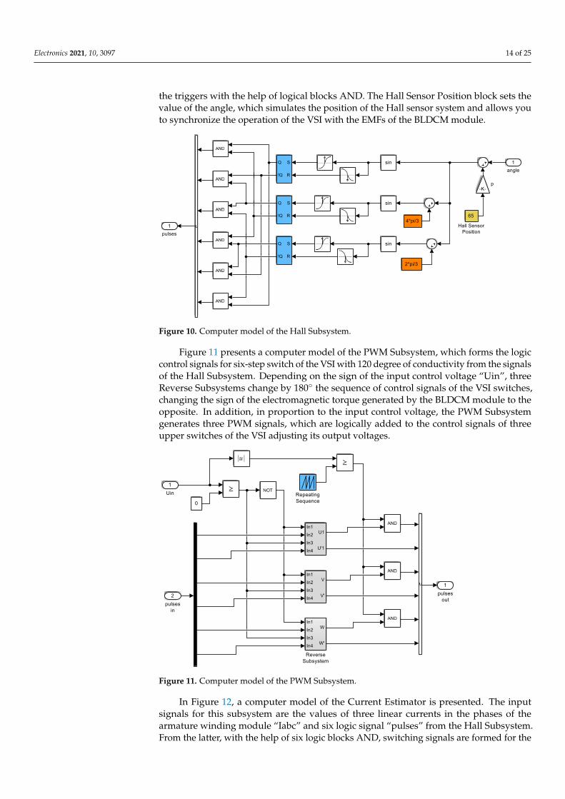
In Figure 10, the computer model of the Hall Subsystem is shown. First, three-phasesymmetric sinusoidal signals are formed from the current value of the angle of the rotorposition “angle”. The moments of transition of the sinusoidal signals through zero serve assignals for switching three R-S triggers. The required six signals for the control channelsof the VSI switches with 120-degree conductivity are formed from the output signals of
Electronics 2021, 10, 3097 14 of 25
the triggers with the help of logical blocks AND. The Hall Sensor Position block sets thevalue of the angle, which simulates the position of the Hall sensor system and allows youto synchronize the operation of the VSI with the EMFs of the BLDCM module.
Electronics 2021, 10, x FOR PEER REVIEW 15 of 26
as signals for switching three R-S triggers. The required six signals for the control channels
of the VSI switches with 120-degree conductivity are formed from the output signals of
the triggers with the help of logical blocks AND. The Hall Sensor Position block sets the
value of the angle, which simulates the position of the Hall sensor system and allows you
to synchronize the operation of the VSI with the EMFs of the BLDCM module.
Figure 10. Computer model of the Hall Subsystem.
Figure 11 presents a computer model of the PWM Subsystem, which forms the logic
control signals for six-step switch of the VSI with 120 degree of conductivity from the
signals of the Hall Subsystem. Depending on the sign of the input control voltage “Uin”,
three Reverse Subsystems change by 180° the sequence of control signals of the VSI
switches, changing the sign of the electromagnetic torque generated by the BLDCM mod-
ule to the opposite. In addition, in proportion to the input control voltage, the PWM Sub-
system generates three PWM signals, which are logically added to the control signals of
three upper switches of the VSI adjusting its output voltages.
Figure 11. Computer model of the PWM Subsystem.
In Figure 12, a computer model of the Current Estimator is presented. The input sig-
nals for this subsystem are the values of three linear currents in the phases of the armature
winding module “Iabc” and six logic signal “pulses” from the Hall Subsystem. From the
latter, with the help of six logic blocks AND, switching signals are formed for the six
Figure 10. Computer model of the Hall Subsystem.
Figure 11 presents a computer model of the PWM Subsystem, which forms the logiccontrol signals for six-step switch of the VSI with 120 degree of conductivity from the signalsof the Hall Subsystem. Depending on the sign of the input control voltage “Uin”, threeReverse Subsystems change by 180 the sequence of control signals of the VSI switches,changing the sign of the electromagnetic torque generated by the BLDCM module to theopposite. In addition, in proportion to the input control voltage, the PWM Subsystemgenerates three PWM signals, which are logically added to the control signals of threeupper switches of the VSI adjusting its output voltages.
Electronics 2021, 10, x FOR PEER REVIEW 15 of 26
as signals for switching three R-S triggers. The required six signals for the control channels
of the VSI switches with 120-degree conductivity are formed from the output signals of
the triggers with the help of logical blocks AND. The Hall Sensor Position block sets the
value of the angle, which simulates the position of the Hall sensor system and allows you
to synchronize the operation of the VSI with the EMFs of the BLDCM module.
Figure 10. Computer model of the Hall Subsystem.
Figure 11 presents a computer model of the PWM Subsystem, which forms the logic
control signals for six-step switch of the VSI with 120 degree of conductivity from the
signals of the Hall Subsystem. Depending on the sign of the input control voltage “Uin”,
three Reverse Subsystems change by 180° the sequence of control signals of the VSI
switches, changing the sign of the electromagnetic torque generated by the BLDCM mod-
ule to the opposite. In addition, in proportion to the input control voltage, the PWM Sub-
system generates three PWM signals, which are logically added to the control signals of
three upper switches of the VSI adjusting its output voltages.
Figure 11. Computer model of the PWM Subsystem.
In Figure 12, a computer model of the Current Estimator is presented. The input sig-
nals for this subsystem are the values of three linear currents in the phases of the armature
winding module “Iabc” and six logic signal “pulses” from the Hall Subsystem. From the
latter, with the help of six logic blocks AND, switching signals are formed for the six
Figure 11. Computer model of the PWM Subsystem.
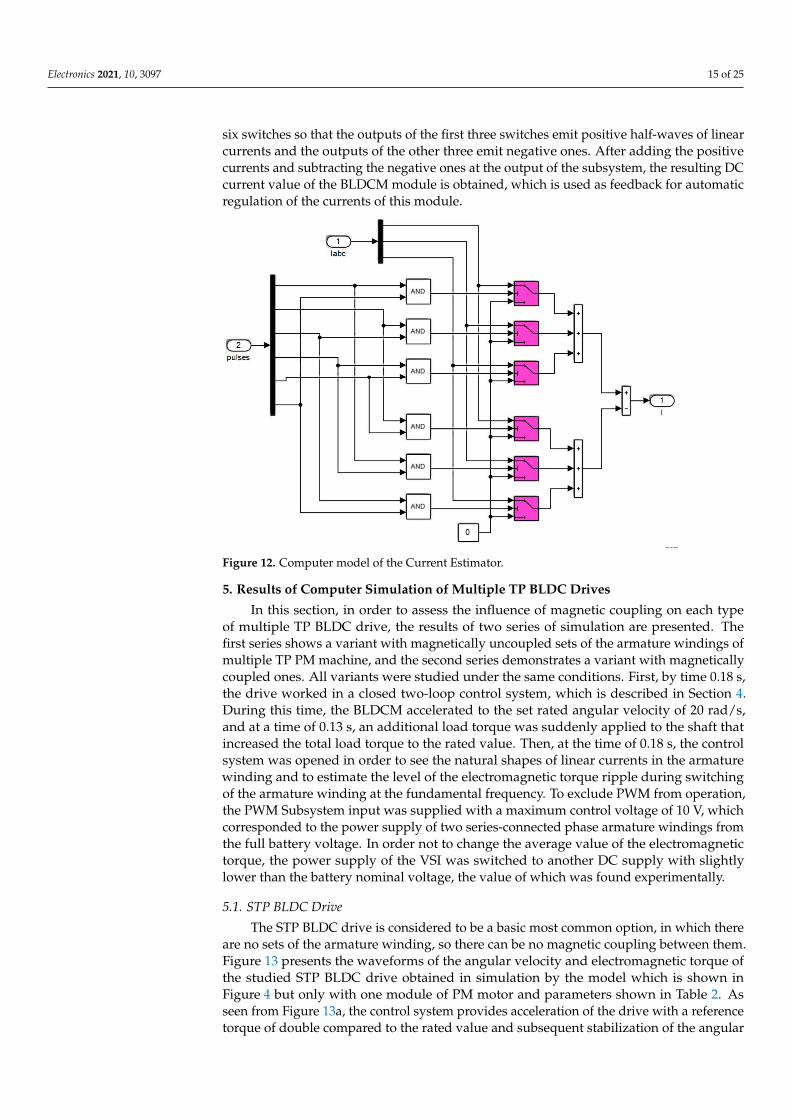
In Figure 12, a computer model of the Current Estimator is presented. The inputsignals for this subsystem are the values of three linear currents in the phases of thearmature winding module “Iabc” and six logic signal “pulses” from the Hall Subsystem.From the latter, with the help of six logic blocks AND, switching signals are formed for the
Electronics 2021, 10, 3097 15 of 25
six switches so that the outputs of the first three switches emit positive half-waves of linearcurrents and the outputs of the other three emit negative ones. After adding the positivecurrents and subtracting the negative ones at the output of the subsystem, the resulting DCcurrent value of the BLDCM module is obtained, which is used as feedback for automaticregulation of the currents of this module.
Electronics 2021, 10, x. https://doi.org/10.3390/xxxxx www.mdpi.com/journal/electronics
In Figure 12, a computer model of the Current Estimator is presented. The input sig-nals for this subsystem are the values of three linear currents in the phases of the armature winding module “Iabc” and six logic signal “pulses” from the Hall Subsystem. From the latter, with the help of six logic blocks AND, switching signals are formed for the six switches so that the outputs of the first three switches emit positive half-waves of linear currents and the outputs of the other three emit negative ones. After adding the positive currents and subtracting the negative ones at the output of the subsystem, the resulting DC current value of the BLDCM module is obtained, which is used as feedback for auto-matic regulation of the currents of this module.
Figure 12. Computer model of the Current Estimator.
5. Results of Computer Simulation of Multiple TP BLDC drives
Figure 12. Computer model of the Current Estimator.
5. Results of Computer Simulation of Multiple TP BLDC Drives
In this section, in order to assess the influence of magnetic coupling on each typeof multiple TP BLDC drive, the results of two series of simulation are presented. Thefirst series shows a variant with magnetically uncoupled sets of the armature windings ofmultiple TP PM machine, and the second series demonstrates a variant with magneticallycoupled ones. All variants were studied under the same conditions. First, by time 0.18 s,the drive worked in a closed two-loop control system, which is described in Section 4.During this time, the BLDCM accelerated to the set rated angular velocity of 20 rad/s,and at a time of 0.13 s, an additional load torque was suddenly applied to the shaft thatincreased the total load torque to the rated value. Then, at the time of 0.18 s, the controlsystem was opened in order to see the natural shapes of linear currents in the armaturewinding and to estimate the level of the electromagnetic torque ripple during switchingof the armature winding at the fundamental frequency. To exclude PWM from operation,the PWM Subsystem input was supplied with a maximum control voltage of 10 V, whichcorresponded to the power supply of two series-connected phase armature windings fromthe full battery voltage. In order not to change the average value of the electromagnetictorque, the power supply of the VSI was switched to another DC supply with slightlylower than the battery nominal voltage, the value of which was found experimentally.
5.1. STP BLDC Drive
The STP BLDC drive is considered to be a basic most common option, in which thereare no sets of the armature winding, so there can be no magnetic coupling between them.Figure 13 presents the waveforms of the angular velocity and electromagnetic torque ofthe studied STP BLDC drive obtained in simulation by the model which is shown inFigure 4 but only with one module of PM motor and parameters shown in Table 2. Asseen from Figure 13a, the control system provides acceleration of the drive with a referencetorque of double compared to the rated value and subsequent stabilization of the angular
Electronics 2021, 10, 3097 16 of 25
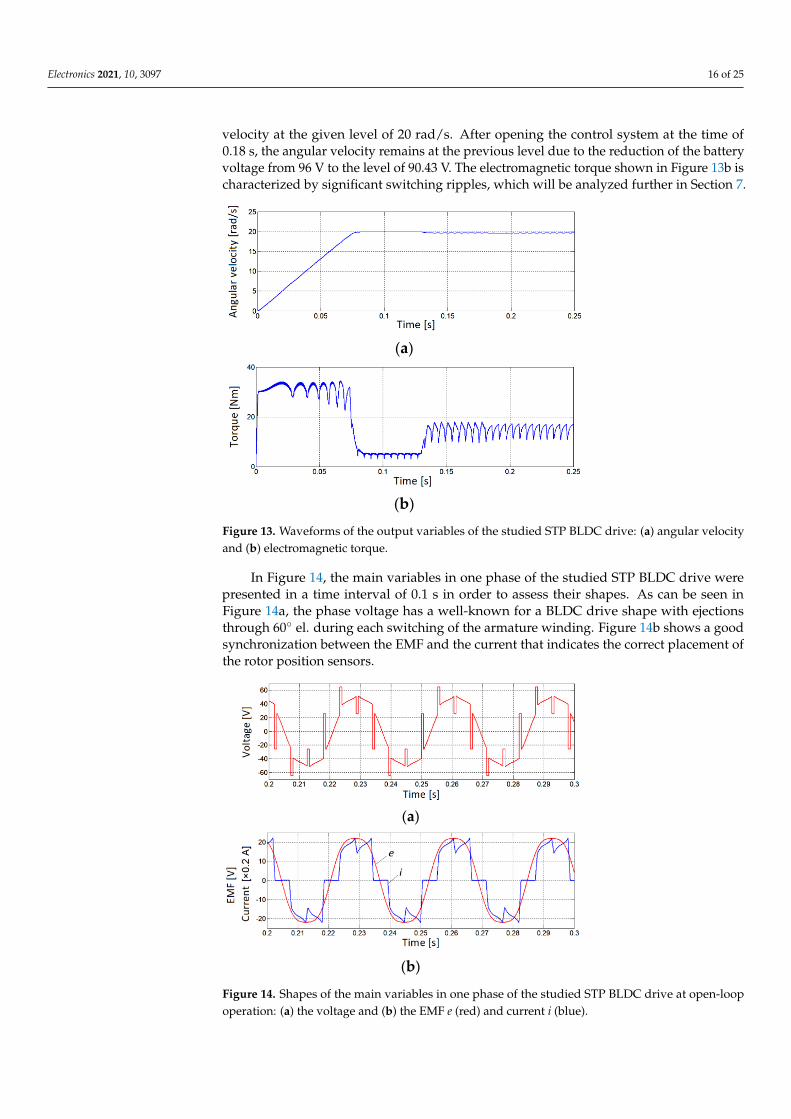
velocity at the given level of 20 rad/s. After opening the control system at the time of0.18 s, the angular velocity remains at the previous level due to the reduction of the batteryvoltage from 96 V to the level of 90.43 V. The electromagnetic torque shown in Figure 13b ischaracterized by significant switching ripples, which will be analyzed further in Section 7.
Electronics 2021, 10, x FOR PEER REVIEW 17 of 26
s, the angular velocity remains at the previous level due to the reduction of the battery
voltage from 96 V to the level of 90.43 V. The electromagnetic torque shown in Figure 13b
is characterized by significant switching ripples, which will be analyzed further in Section
7.
(a)
(b)
Figure 13. Waveforms of the output variables of the studied STP BLDC drive: (a) angular velocity
and (b) electromagnetic torque.
In Figure 14, the main variables in one phase of the studied STP BLDC drive were
presented in a time interval of 0.1 s in order to assess their shapes. As can be seen in Figure
14a, the phase voltage has a well-known for a BLDC drive shape with ejections through
60o el. during each switching of the armature winding. Figure 14b shows a good synchro-
nization between the EMF and the current that indicates the correct placement of the rotor
position sensors.
(a)
(b)
Figure 14. Shapes of the main variables in one phase of the studied STP BLDC drive at open-loop
operation: (a) the voltage and (b) the EMF e (red) and current i (blue).
5.2. DTP BLDC Drive
Figure 15 presents the waveforms of the main variables of the studied DTP BLDC
drive obtained in the simulation by the model shown in Figure 5. The parameters of the
drive corresponded to those in Table 2. To make the comparison easier, the waveforms of
Figure 13. Waveforms of the output variables of the studied STP BLDC drive: (a) angular velocityand (b) electromagnetic torque.
In Figure 14, the main variables in one phase of the studied STP BLDC drive werepresented in a time interval of 0.1 s in order to assess their shapes. As can be seen inFigure 14a, the phase voltage has a well-known for a BLDC drive shape with ejectionsthrough 60 el. during each switching of the armature winding. Figure 14b shows a goodsynchronization between the EMF and the current that indicates the correct placement ofthe rotor position sensors.
Electronics 2021, 10, x FOR PEER REVIEW 17 of 26
s, the angular velocity remains at the previous level due to the reduction of the battery
voltage from 96 V to the level of 90.43 V. The electromagnetic torque shown in Figure 13b
is characterized by significant switching ripples, which will be analyzed further in Section
7.
(a)
(b)
Figure 13. Waveforms of the output variables of the studied STP BLDC drive: (a) angular velocity
and (b) electromagnetic torque.
In Figure 14, the main variables in one phase of the studied STP BLDC drive were
presented in a time interval of 0.1 s in order to assess their shapes. As can be seen in Figure
14a, the phase voltage has a well-known for a BLDC drive shape with ejections through
60o el. during each switching of the armature winding. Figure 14b shows a good synchro-
nization between the EMF and the current that indicates the correct placement of the rotor
position sensors.
(a)
(b)
Figure 14. Shapes of the main variables in one phase of the studied STP BLDC drive at open-loop
operation: (a) the voltage and (b) the EMF e (red) and current i (blue).
5.2. DTP BLDC Drive
Figure 15 presents the waveforms of the main variables of the studied DTP BLDC
drive obtained in the simulation by the model shown in Figure 5. The parameters of the
drive corresponded to those in Table 2. To make the comparison easier, the waveforms of
Figure 14. Shapes of the main variables in one phase of the studied STP BLDC drive at open-loopoperation: (a) the voltage and (b) the EMF e (red) and current i (blue).
Electronics 2021, 10, 3097 17 of 25
5.2. DTP BLDC Drive
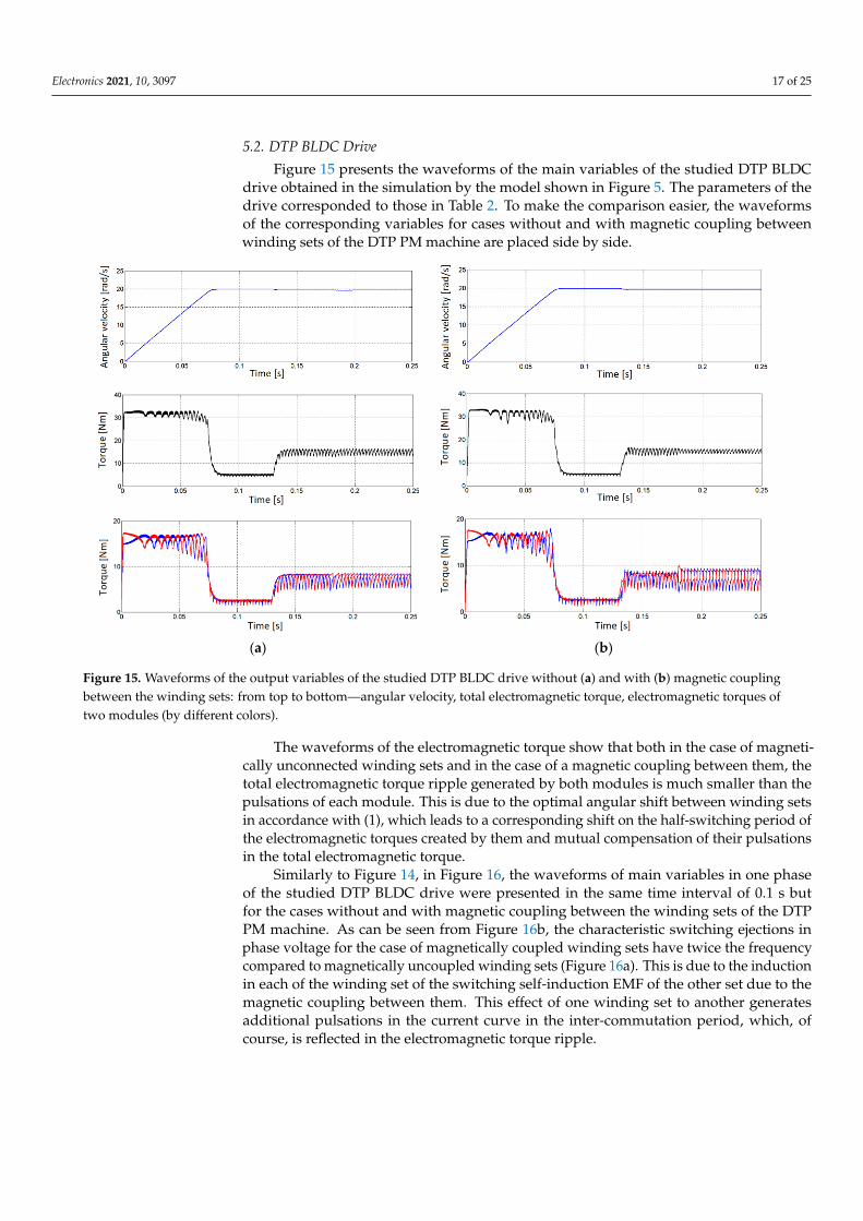
Figure 15 presents the waveforms of the main variables of the studied DTP BLDCdrive obtained in the simulation by the model shown in Figure 5. The parameters of thedrive corresponded to those in Table 2. To make the comparison easier, the waveformsof the corresponding variables for cases without and with magnetic coupling betweenwinding sets of the DTP PM machine are placed side by side.
Electronics 2021, 10, x FOR PEER REVIEW 18 of 26
the corresponding variables for cases without and with magnetic coupling between wind-
ing sets of the DTP PM machine are placed side by side.
(a) (b)
Figure 15. Waveforms of the output variables of the studied DTP BLDC drive without (a) and with (b) magnetic coupling
between the winding sets: from top to bottom—angular velocity, total electromagnetic torque, electromagnetic torques of
two modules (by different colors).
The waveforms of the electromagnetic torque show that both in the case of magneti-
cally unconnected winding sets and in the case of a magnetic coupling between them, the
total electromagnetic torque ripple generated by both modules is much smaller than the
pulsations of each module. This is due to the optimal angular shift between winding sets
in accordance with (1), which leads to a corresponding shift on the half-switching period
of the electromagnetic torques created by them and mutual compensation of their pulsa-
tions in the total electromagnetic torque.
Similarly to Figure 14, in Figure 16, the waveforms of main variables in one phase of
the studied DTP BLDC drive were presented in the same time interval of 0.1 s but for the
cases without and with magnetic coupling between the winding sets of the DTP PM ma-
chine. As can be seen from Figure 16b, the characteristic switching ejections in phase volt-
age for the case of magnetically coupled winding sets have twice the frequency compared
to magnetically uncoupled winding sets (Figure 16a). This is due to the induction in each
of the winding set of the switching self-induction EMF of the other set due to the magnetic
coupling between them. This effect of one winding set to another generates additional
pulsations in the current curve in the inter-commutation period, which, of course, is re-
flected in the electromagnetic torque ripple.
Figure 15. Waveforms of the output variables of the studied DTP BLDC drive without (a) and with (b) magnetic couplingbetween the winding sets: from top to bottom—angular velocity, total electromagnetic torque, electromagnetic torques oftwo modules (by different colors).
The waveforms of the electromagnetic torque show that both in the case of magneti-cally unconnected winding sets and in the case of a magnetic coupling between them, thetotal electromagnetic torque ripple generated by both modules is much smaller than thepulsations of each module. This is due to the optimal angular shift between winding setsin accordance with (1), which leads to a corresponding shift on the half-switching period ofthe electromagnetic torques created by them and mutual compensation of their pulsationsin the total electromagnetic torque.
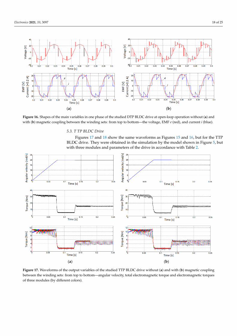
Similarly to Figure 14, in Figure 16, the waveforms of main variables in one phaseof the studied DTP BLDC drive were presented in the same time interval of 0.1 s butfor the cases without and with magnetic coupling between the winding sets of the DTPPM machine. As can be seen from Figure 16b, the characteristic switching ejections inphase voltage for the case of magnetically coupled winding sets have twice the frequencycompared to magnetically uncoupled winding sets (Figure 16a). This is due to the inductionin each of the winding set of the switching self-induction EMF of the other set due to themagnetic coupling between them. This effect of one winding set to another generatesadditional pulsations in the current curve in the inter-commutation period, which, ofcourse, is reflected in the electromagnetic torque ripple.
Electronics 2021, 10, 3097 18 of 25
Electronics 2021, 10, x FOR PEER REVIEW 18 of 26
the corresponding variables for cases without and with magnetic coupling between wind-
ing sets of the DTP PM machine are placed side by side.
(a) (b)
Figure 15. Waveforms of the output variables of the studied DTP BLDC drive without (a) and with (b) magnetic coupling
between the winding sets: from top to bottom—angular velocity, total electromagnetic torque, electromagnetic torques of
two modules (by different colors).
The waveforms of the electromagnetic torque show that both in the case of magneti-
cally unconnected winding sets and in the case of a magnetic coupling between them, the
total electromagnetic torque ripple generated by both modules is much smaller than the
pulsations of each module. This is due to the optimal angular shift between winding sets
in accordance with (1), which leads to a corresponding shift on the half-switching period
of the electromagnetic torques created by them and mutual compensation of their pulsa-
tions in the total electromagnetic torque.
Similarly to Figure 14, in Figure 16, the waveforms of main variables in one phase of
the studied DTP BLDC drive were presented in the same time interval of 0.1 s but for the
cases without and with magnetic coupling between the winding sets of the DTP PM ma-
chine. As can be seen from Figure 16b, the characteristic switching ejections in phase volt-
age for the case of magnetically coupled winding sets have twice the frequency compared
to magnetically uncoupled winding sets (Figure 16a). This is due to the induction in each
of the winding set of the switching self-induction EMF of the other set due to the magnetic
coupling between them. This effect of one winding set to another generates additional
pulsations in the current curve in the inter-commutation period, which, of course, is re-
flected in the electromagnetic torque ripple.
Electronics 2021, 10, x FOR PEER REVIEW 19 of 26
(a) (b)
Figure 16. Shapes of the main variables in one phase of the studied DTP BLDC drive at open-loop operation without (a)
and with (b) magnetic coupling between the winding sets: from top to bottom—the voltage, EMF e (red), and current i
(blue).
5.3. Т TP BLDC Drive
Figures 17 and 18 show the same waveforms as Figures 15 and 16, but for the ТTP
BLDC drive. They were obtained in the simulation by the model shown in Figure 5, but
with three modules and parameters of the drive in accordance with Table 2.
(a) (b)
Figure 17. Waveforms of the output variables of the studied TTP BLDC drive without (a) and with (b) magnetic coupling
between the winding sets: from top to bottom—angular velocity, total electromagnetic torque and electromagnetic torques
of three modules (by different colors).
Figure 16. Shapes of the main variables in one phase of the studied DTP BLDC drive at open-loop operation without (a) andwith (b) magnetic coupling between the winding sets: from top to bottom—the voltage, EMF e (red), and current i (blue).
5.3. T TP BLDC Drive
Figures 17 and 18 show the same waveforms as Figures 15 and 16, but for the TTPBLDC drive. They were obtained in the simulation by the model shown in Figure 5, butwith three modules and parameters of the drive in accordance with Table 2.
Electronics 2021, 10, x FOR PEER REVIEW 19 of 26
(a) (b)
Figure 16. Shapes of the main variables in one phase of the studied DTP BLDC drive at open-loop operation without (a)
and with (b) magnetic coupling between the winding sets: from top to bottom—the voltage, EMF e (red), and current i
(blue).
5.3. Т TP BLDC Drive
Figures 17 and 18 show the same waveforms as Figures 15 and 16, but for the ТTP
BLDC drive. They were obtained in the simulation by the model shown in Figure 5, but
with three modules and parameters of the drive in accordance with Table 2.
(a) (b)
Figure 17. Waveforms of the output variables of the studied TTP BLDC drive without (a) and with (b) magnetic coupling
between the winding sets: from top to bottom—angular velocity, total electromagnetic torque and electromagnetic torques
of three modules (by different colors).
Figure 17. Waveforms of the output variables of the studied TTP BLDC drive without (a) and with (b) magnetic couplingbetween the winding sets: from top to bottom—angular velocity, total electromagnetic torque and electromagnetic torquesof three modules (by different colors).
Electronics 2021, 10, 3097 19 of 25
Electronics 2021, 10, x FOR PEER REVIEW 19 of 26
(a) (b)
Figure 16. Shapes of the main variables in one phase of the studied DTP BLDC drive at open-loop operation without (a)
and with (b) magnetic coupling between the winding sets: from top to bottom—the voltage, EMF e (red), and current i
(blue).
5.3. Т TP BLDC Drive
Figures 17 and 18 show the same waveforms as Figures 15 and 16, but for the ТTP
BLDC drive. They were obtained in the simulation by the model shown in Figure 5, but
with three modules and parameters of the drive in accordance with Table 2.
(a) (b)
Figure 17. Waveforms of the output variables of the studied TTP BLDC drive without (a) and with (b) magnetic coupling
between the winding sets: from top to bottom—angular velocity, total electromagnetic torque and electromagnetic torques
of three modules (by different colors).
Electronics 2021, 10, x FOR PEER REVIEW 20 of 26
(a) (b)
Figure 18. Shapes of the main variables in one phase of the studied TTP BLDC drive at open-loop operation without (a)
and with (b) magnetic coupling between the winding sets: from top to bottom—the voltage, EMF e (red), and current i
(blue).
5.4. QTP BLDC Drive
Figures 19 and 20 show the analogous to previous modular drives waveforms for the
QTP BLDC drive obtained in the simulation.
(a) (b)
Figure 19. Waveforms of the output variables of the studied QTP BLDC drive without (a) and with (b) magnetic coupling
between the winding sets: from top to bottom—angular velocity, total electromagnetic torque and electromagnetic torques
of four modules (by different colors).
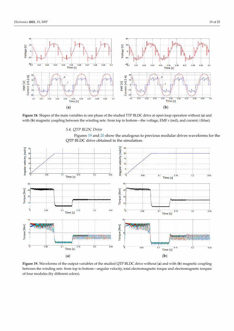
Figure 18. Shapes of the main variables in one phase of the studied TTP BLDC drive at open-loop operation without (a) andwith (b) magnetic coupling between the winding sets: from top to bottom—the voltage, EMF e (red), and current i (blue).
5.4. QTP BLDC Drive
Figures 19 and 20 show the analogous to previous modular drives waveforms for theQTP BLDC drive obtained in the simulation.
Electronics 2021, 10, x FOR PEER REVIEW 20 of 26
(a) (b)
Figure 18. Shapes of the main variables in one phase of the studied TTP BLDC drive at open-loop operation without (a)
and with (b) magnetic coupling between the winding sets: from top to bottom—the voltage, EMF e (red), and current i
(blue).
5.4. QTP BLDC Drive
Figures 19 and 20 show the analogous to previous modular drives waveforms for the
QTP BLDC drive obtained in the simulation.
(a) (b)
Figure 19. Waveforms of the output variables of the studied QTP BLDC drive without (a) and with (b) magnetic coupling
between the winding sets: from top to bottom—angular velocity, total electromagnetic torque and electromagnetic torques
of four modules (by different colors).
Figure 19. Waveforms of the output variables of the studied QTP BLDC drive without (a) and with (b) magnetic couplingbetween the winding sets: from top to bottom—angular velocity, total electromagnetic torque and electromagnetic torquesof four modules (by different colors).
Electronics 2021, 10, 3097 20 of 25
Electronics 2021, 10, x FOR PEER REVIEW 20 of 26
(a) (b)
Figure 18. Shapes of the main variables in one phase of the studied TTP BLDC drive at open-loop operation without (a)
and with (b) magnetic coupling between the winding sets: from top to bottom—the voltage, EMF e (red), and current i
(blue).
5.4. QTP BLDC Drive
Figures 19 and 20 show the analogous to previous modular drives waveforms for the
QTP BLDC drive obtained in the simulation.
(a) (b)
Figure 19. Waveforms of the output variables of the studied QTP BLDC drive without (a) and with (b) magnetic coupling
between the winding sets: from top to bottom—angular velocity, total electromagnetic torque and electromagnetic torques
of four modules (by different colors).
Electronics 2021, 10, x FOR PEER REVIEW 21 of 26
(a) (b)
Figure 20. Shapes of the main variables in one phase of the studied QTP BLDC drive at open-loop operation without (a)
and with (b) magnetic coupling between the winding sets: from top to bottom—the voltage, EMF e (red), and current i
(blue).
6. Experimental Verification of the DTP BLDC Drive Model
To verify the constructed mathematical and computer models of multiple-TP BLDC
drives, an experimental BLDC drive based on the DTP PM machine of asymmetrical con-
figuration with an external rotor was created, the photo of which is shown in Figure 21.
Parameters of the studied electric machine, determined experimentally and by modeling
of its magnetic field by the FE method [38], are used in the computer model of the DTP
PM machine shown in Figure 5.
Figure 21. Sample of the studied DTP PM machine.
As a rotor position sensor, a miniature absolute magnetic semiconductor encoder
AS5045 with a 12-bit code is used. This is a chip with integrated Hall elements, which is
mounted on the end of the fixed stator shaft. A cylindrical magnet is glued to a rotating
motor coupling. For six-step electronic switching of the two armature winding sets offset
by 30o el., the microcontroller selects discrete signals synchronized with the EMFs of these
sets from the data received via a serial interface from the specified sensor.
Two VSIs are built on MOSFET IRF3205 with IR2104 drivers, and a simple Arduino
PRO mini Atmega168 microcontroller controls their switching based on the rotor position.
The completely experimental stand is shown in Figure 22. The power supply of both
VSIs was carried out from two blocks of stabilized voltage PS-305D. The studied DTP PM
machine is jointed with a DC generator through a toothed belt mounted on the outer rotor
of the studied machine. The generator is loaded on a resistor that regulated the loading
torque of the drive.
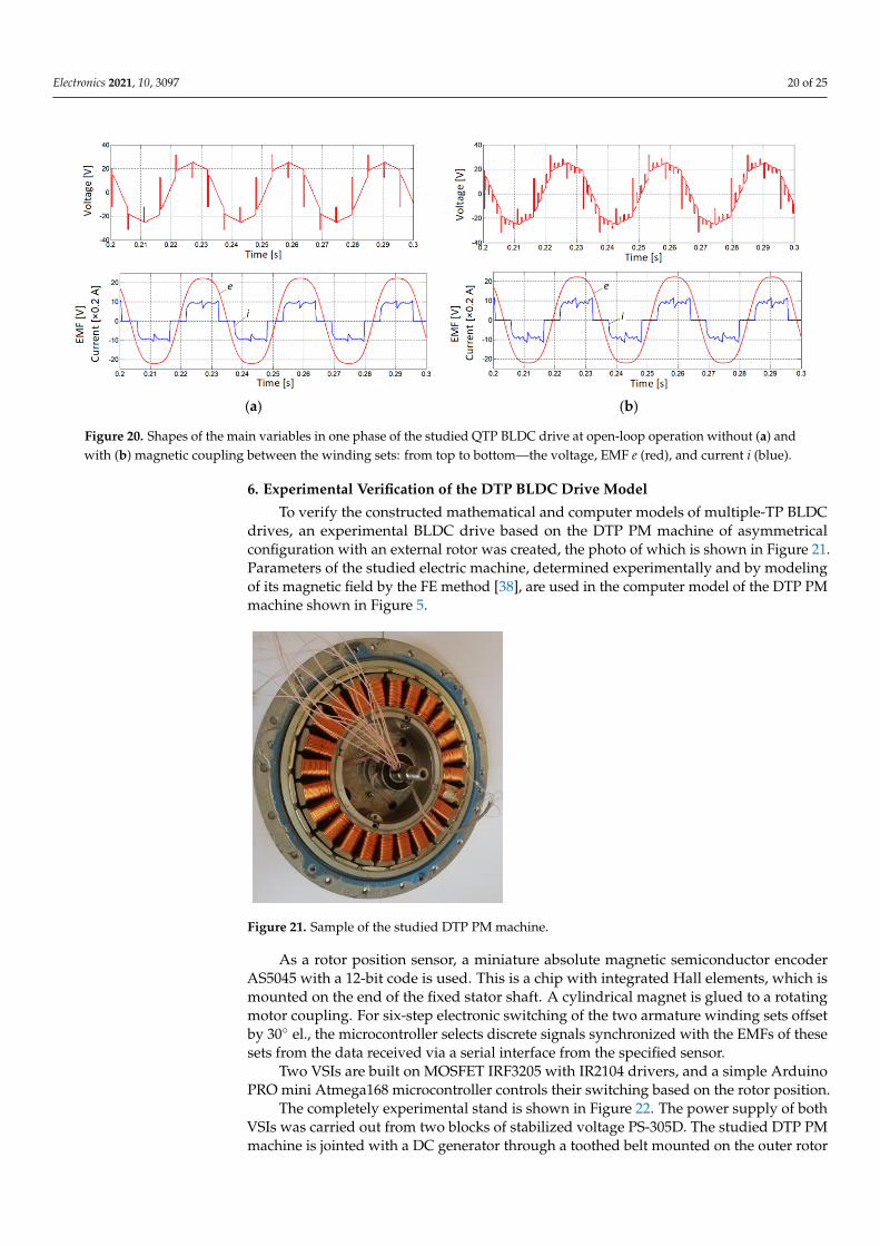
Figure 20. Shapes of the main variables in one phase of the studied QTP BLDC drive at open-loop operation without (a) andwith (b) magnetic coupling between the winding sets: from top to bottom—the voltage, EMF e (red), and current i (blue).
6. Experimental Verification of the DTP BLDC Drive Model
To verify the constructed mathematical and computer models of multiple-TP BLDCdrives, an experimental BLDC drive based on the DTP PM machine of asymmetricalconfiguration with an external rotor was created, the photo of which is shown in Figure 21.Parameters of the studied electric machine, determined experimentally and by modelingof its magnetic field by the FE method [38], are used in the computer model of the DTP PMmachine shown in Figure 5.
Electronics 2021, 10, x FOR PEER REVIEW 21 of 26
(a) (b)
Figure 20. Shapes of the main variables in one phase of the studied QTP BLDC drive at open-loop operation without (a)
and with (b) magnetic coupling between the winding sets: from top to bottom—the voltage, EMF e (red), and current i
(blue).
6. Experimental Verification of the DTP BLDC Drive Model
To verify the constructed mathematical and computer models of multiple-TP BLDC
drives, an experimental BLDC drive based on the DTP PM machine of asymmetrical con-
figuration with an external rotor was created, the photo of which is shown in Figure 21.
Parameters of the studied electric machine, determined experimentally and by modeling
of its magnetic field by the FE method [38], are used in the computer model of the DTP
PM machine shown in Figure 5.
Figure 21. Sample of the studied DTP PM machine.
As a rotor position sensor, a miniature absolute magnetic semiconductor encoder
AS5045 with a 12-bit code is used. This is a chip with integrated Hall elements, which is
mounted on the end of the fixed stator shaft. A cylindrical magnet is glued to a rotating
motor coupling. For six-step electronic switching of the two armature winding sets offset
by 30o el., the microcontroller selects discrete signals synchronized with the EMFs of these
sets from the data received via a serial interface from the specified sensor.
Two VSIs are built on MOSFET IRF3205 with IR2104 drivers, and a simple Arduino
PRO mini Atmega168 microcontroller controls their switching based on the rotor position.
The completely experimental stand is shown in Figure 22. The power supply of both
VSIs was carried out from two blocks of stabilized voltage PS-305D. The studied DTP PM
machine is jointed with a DC generator through a toothed belt mounted on the outer rotor
of the studied machine. The generator is loaded on a resistor that regulated the loading
torque of the drive.
Figure 21. Sample of the studied DTP PM machine.
As a rotor position sensor, a miniature absolute magnetic semiconductor encoderAS5045 with a 12-bit code is used. This is a chip with integrated Hall elements, which ismounted on the end of the fixed stator shaft. A cylindrical magnet is glued to a rotatingmotor coupling. For six-step electronic switching of the two armature winding sets offsetby 30 el., the microcontroller selects discrete signals synchronized with the EMFs of thesesets from the data received via a serial interface from the specified sensor.
Two VSIs are built on MOSFET IRF3205 with IR2104 drivers, and a simple ArduinoPRO mini Atmega168 microcontroller controls their switching based on the rotor position.
The completely experimental stand is shown in Figure 22. The power supply of bothVSIs was carried out from two blocks of stabilized voltage PS-305D. The studied DTP PMmachine is jointed with a DC generator through a toothed belt mounted on the outer rotor
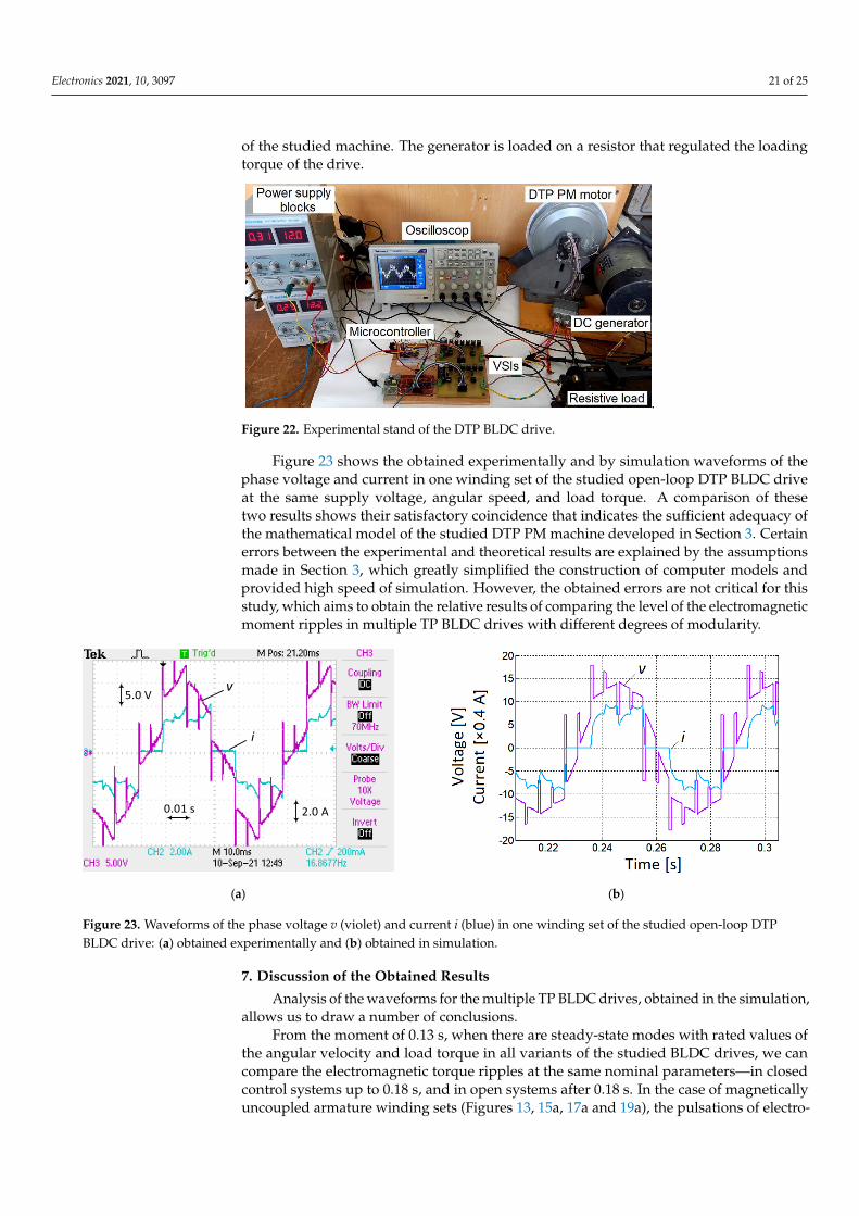
Electronics 2021, 10, 3097 21 of 25
of the studied machine. The generator is loaded on a resistor that regulated the loadingtorque of the drive.
Electronics 2021, 10, x FOR PEER REVIEW 22 of 26
.
Figure 22. Experimental stand of the DTP BLDC drive.
Figure 23 shows the obtained experimentally and by simulation waveforms of the
phase voltage and current in one winding set of the studied open-loop DTP BLDC drive
at the same supply voltage, angular speed, and load torque. A comparison of these two
results shows their satisfactory coincidence that indicates the sufficient adequacy of the
mathematical model of the studied DTP PM machine developed in Section 3. Certain er-
rors between the experimental and theoretical results are explained by the assumptions
made in Section 3, which greatly simplified the construction of computer models and pro-
vided high speed of simulation. However, the obtained errors are not critical for this
study, which aims to obtain the relative results of comparing the level of the electromag-
netic moment ripples in multiple TP BLDC drives with different degrees of modularity.
5.0 Vv
i
2.0 A0.01 s
(a) (b)
Figure 23. Waveforms of the phase voltage v (violet) and current i (blue) in one winding set of the studied open-loop DTP
BLDC drive: (a) obtained experimentally and (b) obtained in simulation.
7. Discussion of the Obtained Results
Analysis of the waveforms for the multiple TP BLDC drives, obtained in the simula-
tion, allows us to draw a number of conclusions.
From the moment of 0.13 s, when there are steady-state modes with rated values of
the angular velocity and load torque in all variants of the studied BLDC drives, we can
compare the electromagnetic torque ripples at the same nominal parameters—in closed
control systems up to 0.18 s, and in open systems after 0.18 s. In the case of magnetically
uncoupled armature winding sets (Figures 13, 15a, 17a, and 19a), the pulsations of elec-
tromagnetic torques generated by individual modules after opening the automatic control
systems remain at the same level as in closed control systems. At the same time, the total
electromagnetic torque of multiple TP BLDC drive in an open system has even slightly
Figure 22. Experimental stand of the DTP BLDC drive.
Figure 23 shows the obtained experimentally and by simulation waveforms of thephase voltage and current in one winding set of the studied open-loop DTP BLDC driveat the same supply voltage, angular speed, and load torque. A comparison of thesetwo results shows their satisfactory coincidence that indicates the sufficient adequacy ofthe mathematical model of the studied DTP PM machine developed in Section 3. Certainerrors between the experimental and theoretical results are explained by the assumptionsmade in Section 3, which greatly simplified the construction of computer models andprovided high speed of simulation. However, the obtained errors are not critical for thisstudy, which aims to obtain the relative results of comparing the level of the electromagneticmoment ripples in multiple TP BLDC drives with different degrees of modularity.
Electronics 2021, 10, x FOR PEER REVIEW 22 of 26
.
Figure 22. Experimental stand of the DTP BLDC drive.
Figure 23 shows the obtained experimentally and by simulation waveforms of the
phase voltage and current in one winding set of the studied open-loop DTP BLDC drive
at the same supply voltage, angular speed, and load torque. A comparison of these two
results shows their satisfactory coincidence that indicates the sufficient adequacy of the
mathematical model of the studied DTP PM machine developed in Section 3. Certain er-
rors between the experimental and theoretical results are explained by the assumptions
made in Section 3, which greatly simplified the construction of computer models and pro-
vided high speed of simulation. However, the obtained errors are not critical for this
study, which aims to obtain the relative results of comparing the level of the electromag-
netic moment ripples in multiple TP BLDC drives with different degrees of modularity.
5.0 Vv
i
2.0 A0.01 s
(a) (b)
Figure 23. Waveforms of the phase voltage v (violet) and current i (blue) in one winding set of the studied open-loop DTP
BLDC drive: (a) obtained experimentally and (b) obtained in simulation.
7. Discussion of the Obtained Results
Analysis of the waveforms for the multiple TP BLDC drives, obtained in the simula-
tion, allows us to draw a number of conclusions.
From the moment of 0.13 s, when there are steady-state modes with rated values of
the angular velocity and load torque in all variants of the studied BLDC drives, we can
compare the electromagnetic torque ripples at the same nominal parameters—in closed
control systems up to 0.18 s, and in open systems after 0.18 s. In the case of magnetically
uncoupled armature winding sets (Figures 13, 15a, 17a, and 19a), the pulsations of elec-
tromagnetic torques generated by individual modules after opening the automatic control
systems remain at the same level as in closed control systems. At the same time, the total
electromagnetic torque of multiple TP BLDC drive in an open system has even slightly
Figure 23. Waveforms of the phase voltage v (violet) and current i (blue) in one winding set of the studied open-loop DTPBLDC drive: (a) obtained experimentally and (b) obtained in simulation.
7. Discussion of the Obtained Results
Analysis of the waveforms for the multiple TP BLDC drives, obtained in the simulation,allows us to draw a number of conclusions.
From the moment of 0.13 s, when there are steady-state modes with rated values ofthe angular velocity and load torque in all variants of the studied BLDC drives, we cancompare the electromagnetic torque ripples at the same nominal parameters—in closedcontrol systems up to 0.18 s, and in open systems after 0.18 s. In the case of magneticallyuncoupled armature winding sets (Figures 13, 15a, 17a and 19a), the pulsations of electro-
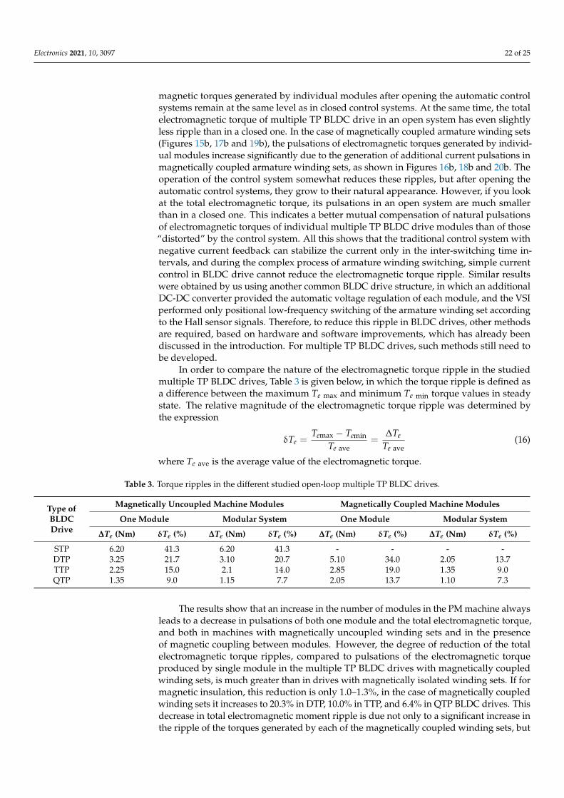
Electronics 2021, 10, 3097 22 of 25
magnetic torques generated by individual modules after opening the automatic controlsystems remain at the same level as in closed control systems. At the same time, the totalelectromagnetic torque of multiple TP BLDC drive in an open system has even slightlyless ripple than in a closed one. In the case of magnetically coupled armature winding sets(Figures 15b, 17b and 19b), the pulsations of electromagnetic torques generated by individ-ual modules increase significantly due to the generation of additional current pulsations inmagnetically coupled armature winding sets, as shown in Figures 16b, 18b and 20b. Theoperation of the control system somewhat reduces these ripples, but after opening theautomatic control systems, they grow to their natural appearance. However, if you lookat the total electromagnetic torque, its pulsations in an open system are much smallerthan in a closed one. This indicates a better mutual compensation of natural pulsationsof electromagnetic torques of individual multiple TP BLDC drive modules than of those“distorted” by the control system. All this shows that the traditional control system withnegative current feedback can stabilize the current only in the inter-switching time in-tervals, and during the complex process of armature winding switching, simple currentcontrol in BLDC drive cannot reduce the electromagnetic torque ripple. Similar resultswere obtained by us using another common BLDC drive structure, in which an additionalDC-DC converter provided the automatic voltage regulation of each module, and the VSIperformed only positional low-frequency switching of the armature winding set accordingto the Hall sensor signals. Therefore, to reduce this ripple in BLDC drives, other methodsare required, based on hardware and software improvements, which has already beendiscussed in the introduction. For multiple TP BLDC drives, such methods still need tobe developed.
In order to compare the nature of the electromagnetic torque ripple in the studiedmultiple TP BLDC drives, Table 3 is given below, in which the torque ripple is defined asa difference between the maximum Te max and minimum Te min torque values in steadystate. The relative magnitude of the electromagnetic torque ripple was determined bythe expression
δTe =Temax − Temin
Te ave=
∆Te
Te ave(16)
where Te ave is the average value of the electromagnetic torque.
Table 3. Torque ripples in the different studied open-loop multiple TP BLDC drives.
Type ofBLDCDrive
Magnetically Uncoupled Machine Modules Magnetically Coupled Machine Modules
One Module Modular System One Module Modular System
∆Te (Nm) δTe (%) ∆Te (Nm) δTe (%) ∆Te (Nm) δTe (%) ∆Te (Nm) δTe (%)
STP 6.20 41.3 6.20 41.3 - - - -DTP 3.25 21.7 3.10 20.7 5.10 34.0 2.05 13.7TTP 2.25 15.0 2.1 14.0 2.85 19.0 1.35 9.0QTP 1.35 9.0 1.15 7.7 2.05 13.7 1.10 7.3
The results show that an increase in the number of modules in the PM machine alwaysleads to a decrease in pulsations of both one module and the total electromagnetic torque,and both in machines with magnetically uncoupled winding sets and in the presenceof magnetic coupling between modules. However, the degree of reduction of the totalelectromagnetic torque ripples, compared to pulsations of the electromagnetic torqueproduced by single module in the multiple TP BLDC drives with magnetically coupledwinding sets, is much greater than in drives with magnetically isolated winding sets. If formagnetic insulation, this reduction is only 1.0–1.3%, in the case of magnetically coupledwinding sets it increases to 20.3% in DTP, 10.0% in TTP, and 6.4% in QTP BLDC drives. Thisdecrease in total electromagnetic moment ripple is due not only to a significant increase inthe ripple of the torques generated by each of the magnetically coupled winding sets, but
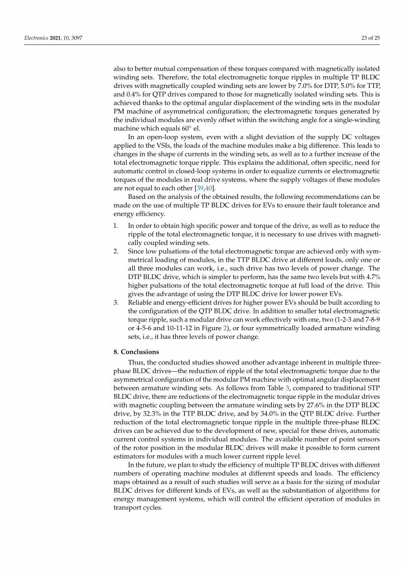
Electronics 2021, 10, 3097 23 of 25
also to better mutual compensation of these torques compared with magnetically isolatedwinding sets. Therefore, the total electromagnetic torque ripples in multiple TP BLDCdrives with magnetically coupled winding sets are lower by 7.0% for DTP, 5.0% for TTP,and 0.4% for QTP drives compared to those for magnetically isolated winding sets. This isachieved thanks to the optimal angular displacement of the winding sets in the modularPM machine of asymmetrical configuration; the electromagnetic torques generated bythe individual modules are evenly offset within the switching angle for a single-windingmachine which equals 60 el.
In an open-loop system, even with a slight deviation of the supply DC voltagesapplied to the VSIs, the loads of the machine modules make a big difference. This leads tochanges in the shape of currents in the winding sets, as well as to a further increase of thetotal electromagnetic torque ripple. This explains the additional, often specific, need forautomatic control in closed-loop systems in order to equalize currents or electromagnetictorques of the modules in real drive systems, where the supply voltages of these modulesare not equal to each other [39,40].
Based on the analysis of the obtained results, the following recommendations can bemade on the use of multiple TP BLDC drives for EVs to ensure their fault tolerance andenergy efficiency.
1. In order to obtain high specific power and torque of the drive, as well as to reduce theripple of the total electromagnetic torque, it is necessary to use drives with magneti-cally coupled winding sets.
2. Since low pulsations of the total electromagnetic torque are achieved only with sym-metrical loading of modules, in the TTP BLDC drive at different loads, only one orall three modules can work, i.e., such drive has two levels of power change. TheDTP BLDC drive, which is simpler to perform, has the same two levels but with 4.7%higher pulsations of the total electromagnetic torque at full load of the drive. Thisgives the advantage of using the DTP BLDC drive for lower power EVs.
3. Reliable and energy-efficient drives for higher power EVs should be built according tothe configuration of the QTP BLDC drive. In addition to smaller total electromagnetictorque ripple, such a modular drive can work effectively with one, two (1-2-3 and 7-8-9or 4-5-6 and 10-11-12 in Figure 2), or four symmetrically loaded armature windingsets, i.e., it has three levels of power change.
8. Conclusions
Thus, the conducted studies showed another advantage inherent in multiple three-phase BLDC drives—the reduction of ripple of the total electromagnetic torque due to theasymmetrical configuration of the modular PM machine with optimal angular displacementbetween armature winding sets. As follows from Table 3, compared to traditional STPBLDC drive, there are reductions of the electromagnetic torque ripple in the modular driveswith magnetic coupling between the armature winding sets by 27.6% in the DTP BLDCdrive, by 32.3% in the TTP BLDC drive, and by 34.0% in the QTP BLDC drive. Furtherreduction of the total electromagnetic torque ripple in the multiple three-phase BLDCdrives can be achieved due to the development of new, special for these drives, automaticcurrent control systems in individual modules. The available number of point sensorsof the rotor position in the modular BLDC drives will make it possible to form currentestimators for modules with a much lower current ripple level.
In the future, we plan to study the efficiency of multiple TP BLDC drives with differentnumbers of operating machine modules at different speeds and loads. The efficiencymaps obtained as a result of such studies will serve as a basis for the sizing of modularBLDC drives for different kinds of EVs, as well as the substantiation of algorithms forenergy management systems, which will control the efficient operation of modules intransport cycles.
Electronics 2021, 10, 3097 24 of 25
Author Contributions: Conceptualization, I.S. and D.J.; methodology, I.S.; software, D.J.; formalanalysis, I.S.; investigation, D.J.; writing—original draft preparation, I.S. and D.J.; experimentalverification, I.S.; writing—review and editing, I.S. and D.J.; supervision, I.S. All authors have readand agreed to the published version of the manuscript.
Funding: This research received no external funding.
Conflicts of Interest: The authors declare no conflict of interest.
References1. Skouras, T.A.; Gkonis, P.K.; Ilias, C.N.; Trakadas, P.T.; Tsampasis, E.G.; Zahariadis, T.V. Electrical vehicles: Current state of the art,
future challenges, and perspectives. Clean Technol. 2020, 2, 1–16. [CrossRef]2. Stippich, A.; van der Broeck, C.H.; Sewergin, A.; Wienhausen, A.H. Key components of modular propulsion systems for next
generation electric vehicles. CPSS Trans. Power Electron. Appl. 2020, 2, 249–258. [CrossRef]3. Shchur, I.; Turkovskyi, V. Integrated system of modular power supply and multilevel control of brushless DC motor for electric
vehicles. Nauk. Visnyk Natsionalnoho Hirnychoho Universytetu 2020, 6, 107–115. [CrossRef]4. Kuznetsov, B.; Bovdui, I.; Nikitina, T.; Kolomiets, V.; Kobilyanskiy, B. Multi-motor plant related electric drives robust control
synthesis. In Proceedings of the 2020 IEEE 4th International Conference on Intelligent Energy and Power Systems (IEPS), Istanbul,Turkey, 7–11 September 2020; pp. 242–245.
5. Shchur, I.; Kasha, L.; Bukavyn, M. Efficiency evaluation of single and modular cascade machines operation in electric vehicle. InProceedings of the 2020 IEEE 15th International Conference on Advanced Trends in Radioelectronics, Telecommunications andComputer Engineering (TCSET), Lviv-Slavske, Ukraine, 25–29 February 2020; pp. 156–161. [CrossRef]
6. Barrero, F.; Duran, M.J. Recent advances in the design, modeling, and control of multiphase machines, Part I. IEEE Trans. Ind.Electron. 2015, 63, 449–458. [CrossRef]
7. Galassini, A.; Costabeber, A.; Gerada, C.; Buticchi, G.; Barater, D. A modular speed-drooped system for high reliability integratedmodular motor drives. IEEE Trans. Ind. Appl. 2016, 52, 3124–3132. [CrossRef]
8. Zhao, W.; Xu, L.; Liu, G. Overview of permanent-magnet fault-tolerant machines: Topology and design. CES Trans. Electr. Mach.Syst. 2018, 2, 51–64. [CrossRef]
9. Zoric, I.; Jones, M.; Levi, E. Arbitrary power sharing among three-phase winding sets of multiphase machines. IEEE Trans. Ind.Electron. 2018, 65, 1128–1139. [CrossRef]
10. Patel, V.I.; Wang, J.; Nugraha, D.T.; Vuletic, R.; Tousen, J. Enhanced availability of drivetrain through novel multiphase permanent-magnet machine drive. IEEE Trans. Ind. Electron. 2016, 63, 469–480. [CrossRef]
11. Ahmad, M.; Wang, Z.; Yan, S.; Wang, C.; Wang, Z.; Zhu, C.; Qin, H. Comparative analysis of two and four current loops for vectorcontrolled dual-three phase permanent magnet synchronous motor. Electronics 2018, 7, 269. [CrossRef]
12. Eldeeb, H.; Abdelrahem, M.; Hackl, C.; Abdel-Khalik, A.S. Enhanced electromechanical modeling of asymmetrical dual three-phase IPMSM drives. In Proceedings of the 2018 IEEE 27th International Symposium on Industrial Electronics (ISIE), Cairns,Australia, 13–15 June 2018; pp. 126–132. [CrossRef]
13. Un-Noor, F.; Padmanaban, S.; Mihet-Popa, L.; Mollah, M.; Hossain, E. A comprehensive study of key electric vehicle (EV)components, technologies, challenges, impacts, and future direction of development. Energies 2017, 10, 1217. [CrossRef]
14. Negahdari, A.; Yepes, A.G.; Doval-Gandoy, J.; Toliyat, H.A. Efficiency enhancement of multiphase electric drives at light-loadoperation considering both converter and stator copper losses. IEEE Trans. Power Electron. 2019, 34, 1518–1525. [CrossRef]
15. Salem, A.; Narimani, M. A Review on multiphase drives for automotive traction applications. IEEE Trans. Transp. Electrif. 2019, 5,1329–1348. [CrossRef]
16. Basler, B.; Greiner, T.; Heidrich, P. Fault-tolerant strategies for double three-phase pmsm used in electronic power steering systems.In Proceedings of the 2015 IEEE Transportation Electrification Conference and Expo (ITEC), Dearborn, MI, USA, 14–17 June 2015;pp. 1–6. [CrossRef]
17. Cao, W.; Mecrow, B.C.; Atkinson, G.J.; Bennett, J.W.; Atkinson, D.J. Overview of electric motor technologies used for more electricaircraft (mea). IEEE Trans. Ind. Electron. 2012, 59, 3523–3531. [CrossRef]
18. Bogusz, P.; Korkosz, M.; Powrózek, A.; Prokop, J.; Wygonik, P. An analysis of properties of the BLDC motor for unmanned aerialvehicle hybrid drive. In Proceedings of the 2015 International Conference on Electrical Drives and Power Electronics (EDPE),Tatranska Lomnica, Slovakia, 21–23 September 2015; pp. 458–464. [CrossRef]
19. Shchur, I.; Turkovskyi, V. Open-end winding dual three-phase BLDC motor drive system with integrated hybrid battery-supercapacitor energy storage. In Proceedings of the 2021 IEEE 20th Conference on Modern Electrical and Energy Systems(MEES), Kremenchuk, Ukraine, 21–24 September 2021; p. 6.
20. Niapour, S.A.; Garjan, G.H.; Shafiei, M.; Feyzi, M.R.; Danyali, S.; Bahrami Kouhshahi, M. Review of permanent-magnet brushlessDC motor basic drives based on analysis and simulation study. Int. Rev. Electr. Eng. (IREE) 2014, 9, 930–957. [CrossRef]
21. Chang, F.; Ilina, O.; Lienkamp, M.; Voss, L. Improving the overall efficiency of automotive inverters using a multilevel convertercomposed of low voltage Si mosfets. IEEE Trans. Power Electron. 2019, 34, 3586–3602. [CrossRef]
Electronics 2021, 10, 3097 25 of 25
22. Guo, Q.; Zhang, C.; Li, L.; Wang, M.; Wang, T. Efficiency optimization control of permanent magnet synchronous motor systemwith SiC MOSFETs for electric vehicles. In Proceedings of the 2017 20th International Conference on Electrical Machines andSystems (ICEMS), Sydney, Australia, 11–14 August 2017; p. 5. [CrossRef]
23. Sumega, M.; Zoššák, Š.; Varecha, P.; Rafajdus, P. Sources of torque ripple and their influence in BLDC motor drives. Transp. Res.Procedia 2019, 40, 519–526. [CrossRef]
24. Vaiyapuri, V.; Jeevananthan, S. Hybrid converter topology for reducing torque ripple of BLDC Motor. IET Power Electron. 2017,10, 1572–1587. [CrossRef]
25. Naik, M.D.; Agrawal, V.; Naik, M.V.; Yadav, S.; Agarwal, A.; Jaiswal, R. Torque ripple reduction of BLDC motor using modularmultilevel converter. In Proceedings of the 2018 International Conference on Computing, Power and Communication Technologies(GUCON), Greater Noida, India, 28–29 September 2018; pp. 820–824. [CrossRef]
26. Doss, M.A.; Premkumar, E.; Kumar, G.R.; Hussain, J. Harmonics and torque ripple reduction of brushless DC motor (BLDCM)using cascaded H-bridge multilevel inverter. In Proceedings of the 2013 International Conference on Power, Energy and Control(ICPEC), Dindigul, India, 6–8 February 2013; pp. 296–299. [CrossRef]
27. Buja, G.; Bertoluzzo, M.; Keshri, R.K. Torque ripple-free operation of PM BLDC drives with petal-wave current supply. IEEETrans. Ind. Electron. 2015, 62, 4034–4043. [CrossRef]
28. Li, Z.; Kong, Q.; Cheng, S.; Liu, J. Torque ripple suppression of brushless DC motor drives using an alternating two-phase andthree-phase conduction mode. IET Power Electron. 2020, 13, 1622–1629. [CrossRef]
29. Xia, C.; Chen, H.; Li, X.; Shi, T. Direct self-control strategy for brushless DC motor with reduced torque ripple. IET Electr. PowerAppl. 2018, 12, 398–404. [CrossRef]
30. Tong, C.; Wu, F.; Zheng, P.; Yu, B.; Sui, Y.; Cheng, L. Investigation of magnetically isolated multiphase modular permanent-magnetsynchronous machinery series for wheel-driving electric vehicles. IEEE Trans. Magn. 2014, 50, 8203704. [CrossRef]
31. Zhang, H.; Wallmark, O. Evaluation of winding arrangements in electric machinery for modular electric drives. In Proceedingsof the 2016 IEEE 8th International Power Electronics and Motion Control Conference (IPEMC-ECCE Asia), Hefei, China,22–26 May 2016; pp. 2820–2825. [CrossRef]
32. Bogusz, P.; Korkosz, M.; Prokop, J. A study of dual-channel brushless DC motor with permanent magnets. In Proceedings of the2016 13th Selected Issues of Electrical Engineering and Electronics (WZEE), Rzeszow, Poland, 4–8 May 2016; p. 6.
33. Li, G.J.; Ren, B.; Zhu, Z.Q. Design guidelines for fractional slot multi-phase modular permanent magnet machines. IET Electr.Power Appl. 2017, 11, 1023–1031. [CrossRef]
34. Yokoi, Y.; Higuchi, T.; Miyamoto, Y. General formulation of winding factor for fractional-slot concentrated winding design. IETElectr. Power Appl. 2016, 10, 231–239. [CrossRef]
35. Keller, D.; Karayel, A.; Parspour, N. Comparison of two different winding sets for dual three-phase permanent magnet ma-chines. In Proceedings of the 2019 9th International Electric Drives Production Conference (EDPC), Esslingen, Germany,3–4 December 2019; p. 6. [CrossRef]
36. Yolacan, E.; Guven, M.K.; Aydin, M.; El-Refaie, A.M. Modeling and experimental verification of an unconventional 9-phaseasymmetric winding PM motor dedicated to electric traction applications. IEEE Access 2020, 8, 70182–70192. [CrossRef]
37. Dieterle, O.; Greiner, T. Impact of the magnetic coupling in a quadruple-star permanent magnet synchronous machine withsegmented stator windings. In Proceedings of the 2017 IEEE International Electric Machines and Drives Conference (IEMDC),Miami, FL, USA, 21–24 May 2017; p. 8. [CrossRef]
38. Makarchuk, O.; Kharchyshyn, B.; Kasha, L. Analysis of the magneto-mechanical characteristic of double three-phase PMSM.In Proceedings of the 2021 IEEE 3d Ukraine Conference on Electrical and Computer Engineering (UKRCON), Lviv, Ukraine,26–28 August 2021; pp. 333–338.
39. Yan, H.; Xu, Y.; Zou, J.; Wang, B.; Jiang, S. A maximum current sharing method for dual-redundancy brushless DC Motorcontrol. In Proceedings of the 2014 17th International Conference on Electrical Machines and Systems (ICEMS), Hangzhou, China,22–25 October 2014; pp. 1057–1061.
40. Bian, C.; Li, X.; Zhao, G. The peak current control of permanent magnet brushless DC machine with asymmetric dual-threephases. CES Trans. Electr. Mach. Syst. 2018, 2, 29–135.


