Embed Size (px)
Citation preview
E-M-AC3000-CP_25 Rotronic AG Bassersdorf, Switzerland
Document code Unit
AirChip 3000 Communication Protocol Options Description Document Type
Page 1 of 45 Document title
AirChip 3000 Communication Protocol Options
© 2016; Rotronic AG E-M-AC3000-CP_25
E-M-AC3000-CP_25 Rotronic AG Bassersdorf, Switzerland
Document code Unit
AirChip 3000 Communication Protocol Options Description Document Type
Page 2 of 45 Document title Table of Contents
1 OVERVIEW ........................................................................................................................... 3 2 AIRCHIP 3000 DIGITAL INTERFACE ................................................................................. 5 2.1 Communication schematic .................................................................................................... 5 2.2 Response time ...................................................................................................................... 5 3 RO-ASCII PROTOCOL ......................................................................................................... 6 3.1 Physical interface .................................................................................................................. 7 3.2 Command overview .............................................................................................................. 8 3.3 General command structure .................................................................................................. 9 3.4 RDD command: read values ............................................................................................... 12 3.5 REN command: change the RS-485 address ..................................................................... 15 3.6 HCA command: probe adjustment ...................................................................................... 16 3.7 LGC command: status and programming of the data recording function ........................... 19 3.8 ERD command: read recorded data ................................................................................... 22 3.9 TID command: set date and time for HL20 ......................................................................... 25 3.10 HRD command: read out data memory of HL20 ................................................................. 26 3.11 Configuration with the HW4 software .................................................................................. 27 4 MODBUS PROTOCOL ....................................................................................................... 28 4.1 Physical interface ................................................................................................................ 28 4.2 Data request structure ......................................................................................................... 29 4.3 Response structure and data encoding .............................................................................. 30 4.4 Configuration with the HW4 software .................................................................................. 32 5 I2C PROTOCOL ................................................................................................................. 33 5.1 Physical interface ................................................................................................................ 34 5.2 Data string structure and data encoding ............................................................................. 35 5.3 Configuration with the HW4 software .................................................................................. 37 6 CUSTOM PROTOCOL ....................................................................................................... 39 6.1 Physical interface ................................................................................................................ 39 6.2 Data request structure ......................................................................................................... 40 6.3 Configuration with the HW4 software .................................................................................. 41 6.4 Response structure ............................................................................................................. 43 7 DEVICE IDENTIFIERS ....................................................................................................... 44 8 DOCUMENT RELEASES ................................................................................................... 45
© 2016; Rotronic AG E-M-AC3000-CP_25
E-M-AC3000-CP_25 Rotronic AG Bassersdorf, Switzerland
Document code Unit
AirChip 3000 Communication Protocol Options Description Document Type
Page 3 of 45 Document title 1 OVERVIEW
The AirChip 3000 is a programmable, custom designed integrated circuit developed by ROTRONIC and is at the
core of an entire family of humidity-temperature measuring devices:
o HygroClip 2 (HC2) probes
o HC2-AW / HC2-AW-USB probes
o HF3 transmitters and thermo-hygrostats series
o HF4 transmitter series
o HF6 transmitter series
o HL20 data logger
o HP21 hand-held indicator
o HygroMet4
o Custom designed OEM products
RO-ASCII is the default communication protocol used by the HW4 software to communicate with an AirChip 3000
device. Users can always use this protocol to communicate directly with an AirChip 3000 device without HW4.
Starting with firmware version 1.3, the AirChip 3000 offers 3 additional communication protocol options:
o MODBUS: This protocol is applicable to all AirChip 3000 (except HC2-AW probes) devices that can be
connected to a RS-485 network
o I2C: This protocol complies with the standard I2C protocol and is meant for OEM users. When set to use the
I2C protocol, the AirChip 3000 always act as master writing to the bus. The AirChip 3000 does not allow the
networking of several devices and is limited to a one way communication where the AirChip 3000 device
automatically sends data during each refresh interval to an external device with I2C input. The I2C protocol
option is available with the HygroClip 2 probes (HC2) and with some OEM products.
o Custom: this is a simple protocol that can be customized by the user to provide compatibility of the AirChip
3000 device with an exiting communication system. The Custom protocol is applicable to all AirChip 3000
devices with a digital interface and allows RS-485 networking.
Important:
It is important to note that the Modbus, I2C and Custom protocols available with the AirChip 3000 devices are limited
to reading measurement data from the AirChip 3000 device. Functions such as device configuration, humidity and
temperature adjustment, etc. are not supported by these protocols.
© 2016; Rotronic AG E-M-AC3000-CP_25
E-M-AC3000-CP_25 Rotronic AG Bassersdorf, Switzerland
Document code Unit
AirChip 3000 Communication Protocol Options Description Document Type
Page 4 of 45 Document title IMPORTANT:
o The HW4 software is required to set the AirChip 3000 device to use any protocol other than RO-ASCII
o When communicating with the HW4 software the AirChip 3000 device automatically switches to the RO-ASCII
protocol (ROTRONIC standard).
o After using HW4 to configure the AirChip 3000 device to use one of the available protocols power down the
device. When the device is powered up, it automatically starts using the selected communication protocol as long
as it is not communicating with the HW4 software.
© 2016; Rotronic AG E-M-AC3000-CP_25
E-M-AC3000-CP_25 Rotronic AG Bassersdorf, Switzerland
Document code Unit
AirChip 3000 Communication Protocol Options Description Document Type
Page 5 of 45 Document title 2 AIRCHIP 3000 DIGITAL INTERFACE
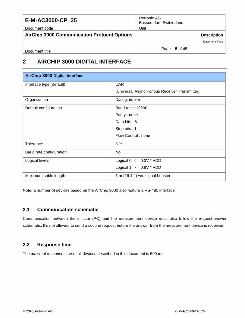
AirChip 3000 Digital interface
Interface type (default) UART
(Universal Asynchronous Receiver Transmitter)
Organization Dialog, duplex
Default configuration Baud rate : 19200
Parity : none
Data bits : 8
Stop bits : 1
Flow Control : none
Tolerance 3 %
Baud rate configuration: No
Logical levels Logical 0: < = 0.3V * VDD
Logical 1: > = 0.8V * VDD
Maximum cable length 5 m (16.4 ft) w/o signal booster
Note: a number of devices based on the AirChip 3000 also feature a RS-485 interface
2.1 Communication schematic
Communication between the initiator (PC) and the measurement device must also follow the request-answer
schematic. It’s not allowed to send a second request before the answer from the measurement device is received.
2.2 Response time
The maximal response time of all devices described in this document is 500 ms.
© 2016; Rotronic AG E-M-AC3000-CP_25
E-M-AC3000-CP_25 Rotronic AG Bassersdorf, Switzerland
Document code Unit
AirChip 3000 Communication Protocol Options Description Document Type
Page 6 of 45 Document title 3 RO-ASCII PROTOCOL
RO-ASCII is the default communication protocol used by both the AirChip 3000 devices and the HW4 software.
This document describes only some of the commands and functions available with the RO-ASCII communication
protocol. In particular, the following functions are not covered here:
• Device configuration
• 2-point temperature adjustment
These functions can be accessed with the ROTRONIC HW4 software.
Users who require additional functionality should contact ROTRONIC. Please note that some of the commands and
functions not included in this document require a certain amount of computations to be carried out by a device
external to the AirChip 3000 (such as a PC). A typical example is the 2-point temperature adjustment function of the
AirChip 3000.
© 2016; Rotronic AG E-M-AC3000-CP_25
E-M-AC3000-CP_25 Rotronic AG Bassersdorf, Switzerland
Document code Unit
AirChip 3000 Communication Protocol Options Description Document Type
Page 7 of 45 Document title 3.1 Physical interface
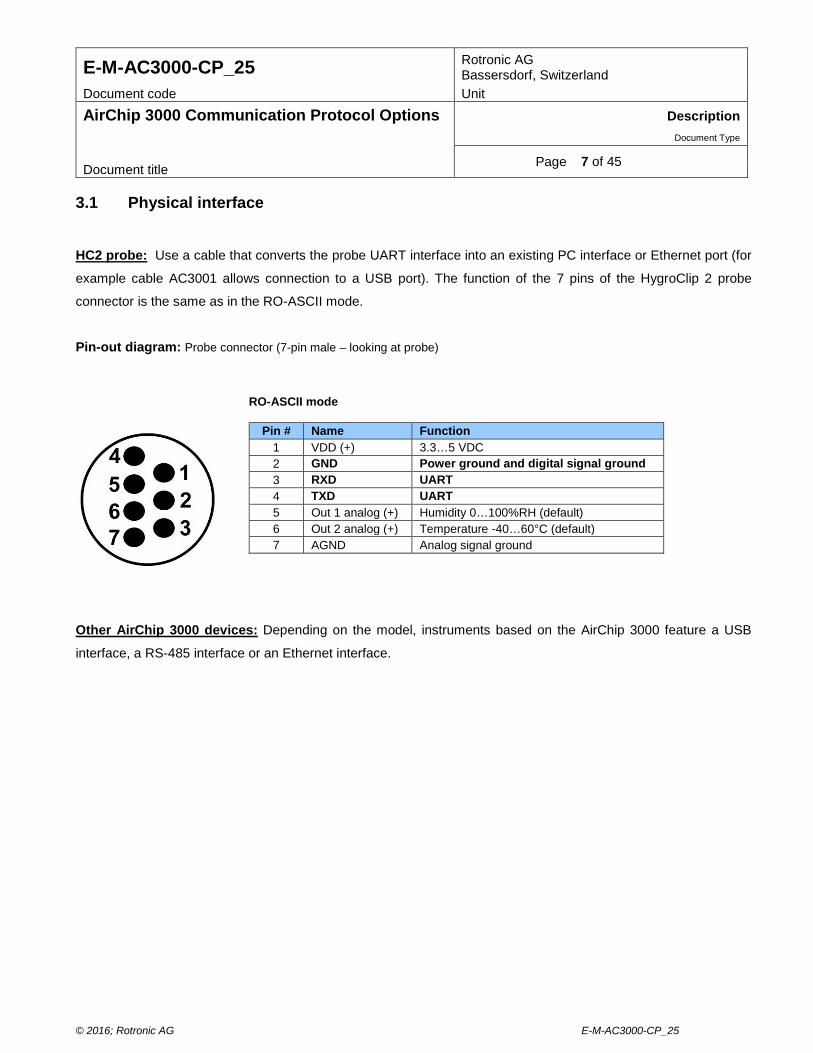
HC2 probe: Use a cable that converts the probe UART interface into an existing PC interface or Ethernet port (for
example cable AC3001 allows connection to a USB port). The function of the 7 pins of the HygroClip 2 probe
connector is the same as in the RO-ASCII mode.
Pin-out diagram: Probe connector (7-pin male – looking at probe)
Other AirChip 3000 devices: Depending on the model, instruments based on the AirChip 3000 feature a USB
interface, a RS-485 interface or an Ethernet interface.
RO-ASCII mode
Pin # Name Function 1 VDD (+) 3.3…5 VDC 2 GND Power ground and digital signal ground 3 RXD UART 4 TXD UART 5 Out 1 analog (+) Humidity 0…100%RH (default) 6 Out 2 analog (+) Temperature -40…60°C (default) 7 AGND Analog signal ground
© 2016; Rotronic AG E-M-AC3000-CP_25
E-M-AC3000-CP_25 Rotronic AG Bassersdorf, Switzerland
Document code Unit
AirChip 3000 Communication Protocol Options Description Document Type
Page 8 of 45 Document title 3.2 Command overview
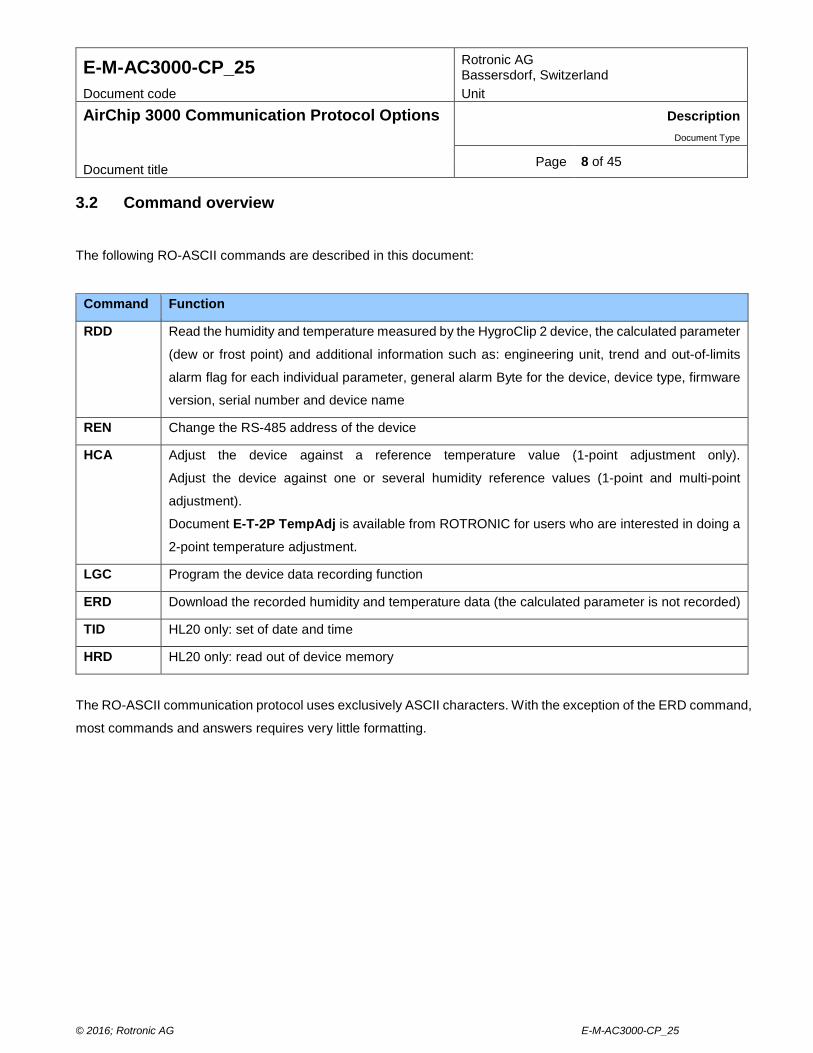
The following RO-ASCII commands are described in this document:
Command Function
RDD Read the humidity and temperature measured by the HygroClip 2 device, the calculated parameter
(dew or frost point) and additional information such as: engineering unit, trend and out-of-limits
alarm flag for each individual parameter, general alarm Byte for the device, device type, firmware
version, serial number and device name
REN Change the RS-485 address of the device
HCA Adjust the device against a reference temperature value (1-point adjustment only).
Adjust the device against one or several humidity reference values (1-point and multi-point
adjustment).
Document E-T-2P TempAdj is available from ROTRONIC for users who are interested in doing a
2-point temperature adjustment.
LGC Program the device data recording function
ERD Download the recorded humidity and temperature data (the calculated parameter is not recorded)
TID HL20 only: set of date and time
HRD HL20 only: read out of device memory
The RO-ASCII communication protocol uses exclusively ASCII characters. With the exception of the ERD command,
most commands and answers requires very little formatting.
© 2016; Rotronic AG E-M-AC3000-CP_25
E-M-AC3000-CP_25 Rotronic AG Bassersdorf, Switzerland
Document code Unit
AirChip 3000 Communication Protocol Options Description Document Type
Page 9 of 45 Document title 3.3 General command structure
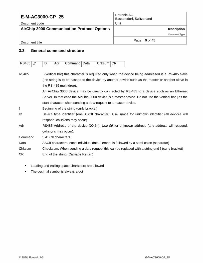
RS485 „{“ ID Adr Command Data Chksum CR
RS485 | (vertical bar) this character is required only when the device being addressed is a RS-485 slave
(the string is to be passed to the device by another device such as the master or another slave in
the RS-485 multi-drop).
An AirChip 3000 device may be directly connected by RS-485 to a device such as an Ethernet
Server. In that case the AirChip 3000 device is a master device. Do not use the vertical bar | as the
start character when sending a data request to a master device.
{ Beginning of the string (curly bracket)
ID Device type identifier (one ASCII character). Use space for unknown identifier (all devices will
respond, collisions may occur).
Adr RS485 Address of the device (00-64). Use 99 for unknown address (any address will respond,
collisions may occur).
Command 3 ASCII characters
Data ASCII characters, each individual data element is followed by a semi-colon (separator)
Chksum Checksum. When sending a data request this can be replaced with a string end } (curly bracket)
CR End of the string (Carriage Return)
Leading and trailing space characters are allowed
The decimal symbol is always a dot
© 2016; Rotronic AG E-M-AC3000-CP_25
E-M-AC3000-CP_25 Rotronic AG Bassersdorf, Switzerland
Document code Unit
AirChip 3000 Communication Protocol Options Description Document Type
Page 10 of 45 Document title Notes: o RS485
The vertical bar | is used to indicate that the command string is to be passed to another device connected by RS-
485 (multi-drop network with a master and one or several slaves). Upon receiving the string, the master device
strips the vertical bar and sends the rest of the string to the RS-485 driver.
Depending on the device, the stripped string may also be sent to the PC. The software used by the PC should
be designed so as not to confuse this string with an answer.
o Adr Address 99 can be used temporarily to communicate with a single device of unknown address. This address
causes the device to answer regardless of its address. The actual device address is returned as part of the
answer string. Address 99 should not be used when several devices are connected to a network.
© 2016; Rotronic AG E-M-AC3000-CP_25
E-M-AC3000-CP_25 Rotronic AG Bassersdorf, Switzerland
Document code Unit
AirChip 3000 Communication Protocol Options Description Document Type
Page 11 of 45 Document title o Checksum character calculation
Hex value of checksum character = [(sum of all character Hex values) AND 0x003F] + 0x0020
Note: AND = bitwise AND logical operation
This is equivalent to the following Visual Basic code lines:
Private Function Checksum(ByVal Data As String) As Char
Dim Sum, I As Integer
For I = 0 To Data.Length – 1
Sum += Asc(Data.Chars(i))
Next
Checksum = Chr(Sum Mod 64 + 32)
End Function
NOTE: The following characters are not used for the checksum calculation: RS485 character (|), the String end
(}) and (CR). The initial ({) must be counted.
Example: checksum character for the string {F09RDD = $
© 2016; Rotronic AG E-M-AC3000-CP_25
E-M-AC3000-CP_25 Rotronic AG Bassersdorf, Switzerland
Document code Unit
AirChip 3000 Communication Protocol Options Description Document Type
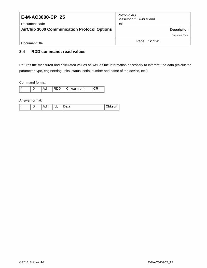
Page 12 of 45 Document title 3.4 RDD command: read values
Returns the measured and calculated values as well as the information necessary to interpret the data (calculated
parameter type, engineering units, status, serial number and name of the device, etc.)
Command format:
{ ID Adr RDD Chksum or } CR
Answer format:
{ ID Adr rdd Data Chksum
© 2016; Rotronic AG E-M-AC3000-CP_25
E-M-AC3000-CP_25 Rotronic AG Bassersdorf, Switzerland
Document code Unit
AirChip 3000 Communication Protocol Options Description Document Type
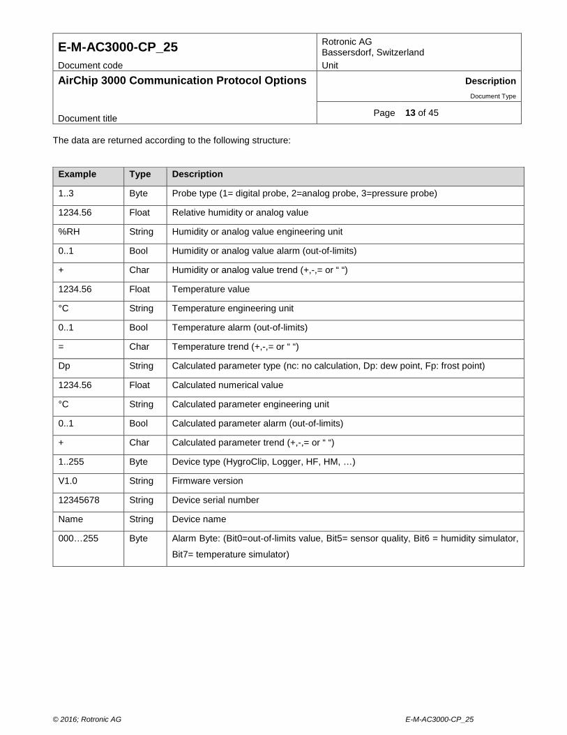
Page 13 of 45 Document title The data are returned according to the following structure:
Example Type Description
1..3 Byte Probe type (1= digital probe, 2=analog probe, 3=pressure probe)
1234.56 Float Relative humidity or analog value
%RH String Humidity or analog value engineering unit
0..1 Bool Humidity or analog value alarm (out-of-limits)
+ Char Humidity or analog value trend (+,-,= or “ “)
1234.56 Float Temperature value
°C String Temperature engineering unit
0..1 Bool Temperature alarm (out-of-limits)
= Char Temperature trend (+,-,= or “ “)
Dp String Calculated parameter type (nc: no calculation, Dp: dew point, Fp: frost point)
1234.56 Float Calculated numerical value
°C String Calculated parameter engineering unit
0..1 Bool Calculated parameter alarm (out-of-limits)
+ Char Calculated parameter trend (+,-,= or “ “)
1..255 Byte Device type (HygroClip, Logger, HF, HM, …)
V1.0 String Firmware version
12345678 String Device serial number
Name String Device name
000…255 Byte Alarm Byte: (Bit0=out-of-limits value, Bit5= sensor quality, Bit6 = humidity simulator,
Bit7= temperature simulator)
© 2016; Rotronic AG E-M-AC3000-CP_25
E-M-AC3000-CP_25 Rotronic AG Bassersdorf, Switzerland
Document code Unit
AirChip 3000 Communication Protocol Options Description Document Type
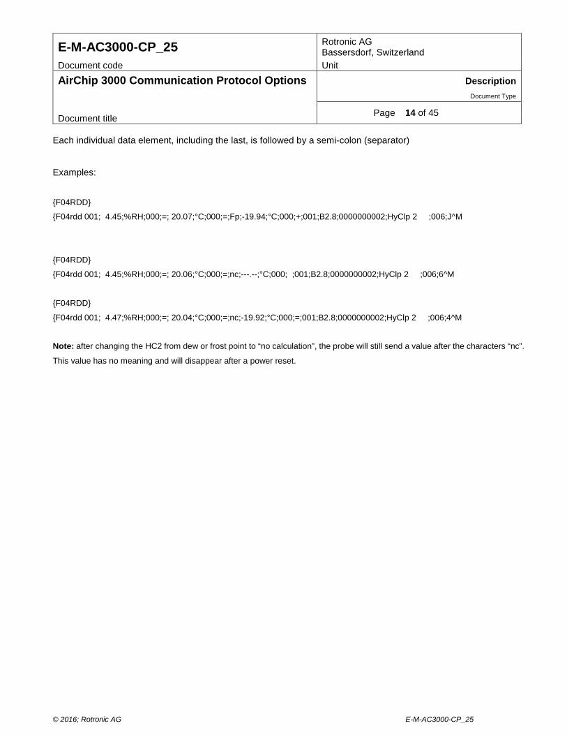
Page 14 of 45 Document title Each individual data element, including the last, is followed by a semi-colon (separator)
Examples:
{F04RDD}
{F04rdd 001; 4.45;%RH;000;=; 20.07;°C;000;=;Fp;-19.94;°C;000;+;001;B2.8;0000000002;HyClp 2 ;006;J^M
{F04RDD}
{F04rdd 001; 4.45;%RH;000;=; 20.06;°C;000;=;nc;---.--;°C;000; ;001;B2.8;0000000002;HyClp 2 ;006;6^M
{F04RDD}
{F04rdd 001; 4.47;%RH;000;=; 20.04;°C;000;=;nc;-19.92;°C;000;=;001;B2.8;0000000002;HyClp 2 ;006;4^M
Note: after changing the HC2 from dew or frost point to “no calculation”, the probe will still send a value after the characters “nc”.
This value has no meaning and will disappear after a power reset.
© 2016; Rotronic AG E-M-AC3000-CP_25
E-M-AC3000-CP_25 Rotronic AG Bassersdorf, Switzerland
Document code Unit
AirChip 3000 Communication Protocol Options Description Document Type
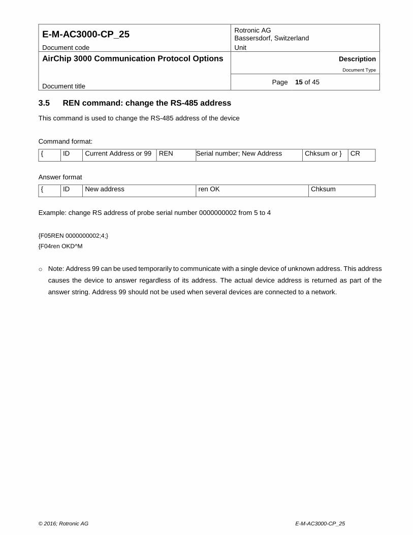
Page 15 of 45 Document title 3.5 REN command: change the RS-485 address
This command is used to change the RS-485 address of the device
Command format:
{ ID Current Address or 99 REN Serial number; New Address Chksum or } CR
Answer format
{ ID New address ren OK Chksum
Example: change RS address of probe serial number 0000000002 from 5 to 4
{F05REN 0000000002;4;}
{F04ren OKD^M
o Note: Address 99 can be used temporarily to communicate with a single device of unknown address. This address
causes the device to answer regardless of its address. The actual device address is returned as part of the
answer string. Address 99 should not be used when several devices are connected to a network.
© 2016; Rotronic AG E-M-AC3000-CP_25
E-M-AC3000-CP_25 Rotronic AG Bassersdorf, Switzerland
Document code Unit
AirChip 3000 Communication Protocol Options Description Document Type
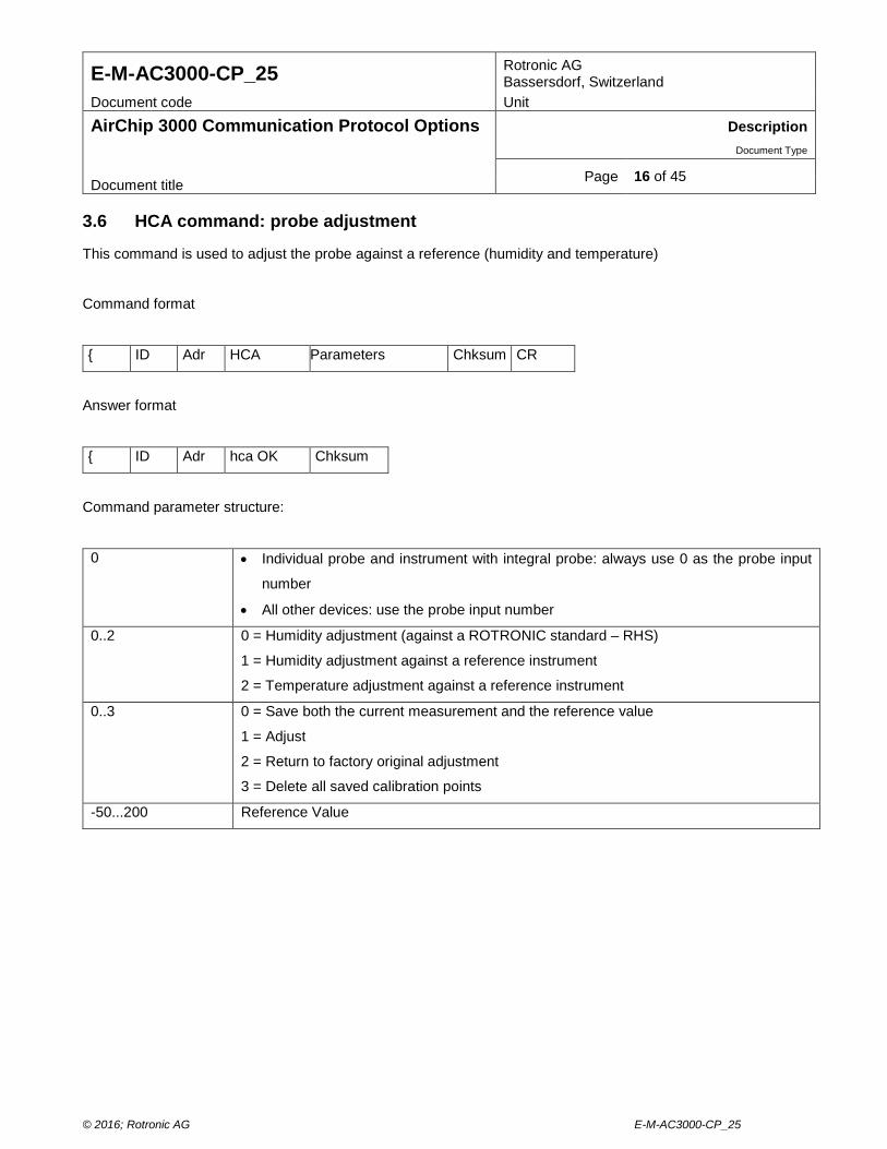
Page 16 of 45 Document title 3.6 HCA command: probe adjustment
This command is used to adjust the probe against a reference (humidity and temperature)
Command format
{ ID Adr HCA Parameters Chksum CR
Answer format
{ ID Adr hca OK Chksum
Command parameter structure:
0 • Individual probe and instrument with integral probe: always use 0 as the probe input
number
• All other devices: use the probe input number
0..2 0 = Humidity adjustment (against a ROTRONIC standard – RHS)
1 = Humidity adjustment against a reference instrument
2 = Temperature adjustment against a reference instrument
0..3 0 = Save both the current measurement and the reference value
1 = Adjust
2 = Return to factory original adjustment
3 = Delete all saved calibration points
-50...200 Reference Value
© 2016; Rotronic AG E-M-AC3000-CP_25
E-M-AC3000-CP_25 Rotronic AG Bassersdorf, Switzerland
Document code Unit
AirChip 3000 Communication Protocol Options Description Document Type
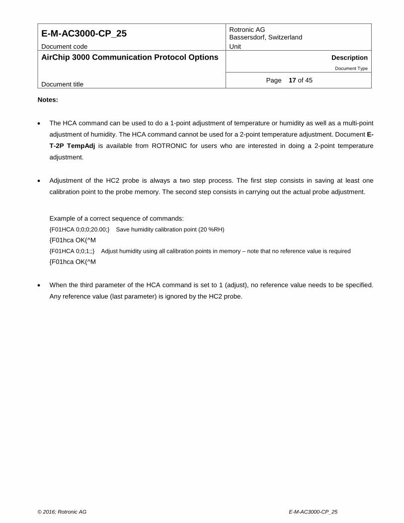
Page 17 of 45 Document title Notes:
• The HCA command can be used to do a 1-point adjustment of temperature or humidity as well as a multi-point
adjustment of humidity. The HCA command cannot be used for a 2-point temperature adjustment. Document E-T-2P TempAdj is available from ROTRONIC for users who are interested in doing a 2-point temperature
adjustment.
• Adjustment of the HC2 probe is always a two step process. The first step consists in saving at least one
calibration point to the probe memory. The second step consists in carrying out the actual probe adjustment.
Example of a correct sequence of commands: {F01HCA 0;0;0;20.00;} Save humidity calibration point (20 %RH)
{F01hca OK(^M {F01HCA 0;0;1;;} Adjust humidity using all calibration points in memory – note that no reference value is required
{F01hca OK(^M
• When the third parameter of the HCA command is set to 1 (adjust), no reference value needs to be specified.
Any reference value (last parameter) is ignored by the HC2 probe.
© 2016; Rotronic AG E-M-AC3000-CP_25
E-M-AC3000-CP_25 Rotronic AG Bassersdorf, Switzerland
Document code Unit
AirChip 3000 Communication Protocol Options Description Document Type
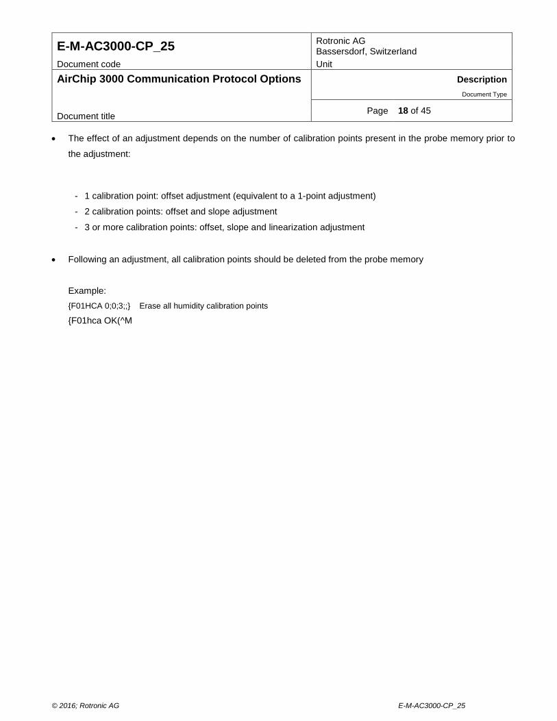
Page 18 of 45 Document title • The effect of an adjustment depends on the number of calibration points present in the probe memory prior to
the adjustment:
- 1 calibration point: offset adjustment (equivalent to a 1-point adjustment)
- 2 calibration points: offset and slope adjustment
- 3 or more calibration points: offset, slope and linearization adjustment
• Following an adjustment, all calibration points should be deleted from the probe memory
Example: {F01HCA 0;0;3;;} Erase all humidity calibration points {F01hca OK(^M
© 2016; Rotronic AG E-M-AC3000-CP_25
E-M-AC3000-CP_25 Rotronic AG Bassersdorf, Switzerland
Document code Unit
AirChip 3000 Communication Protocol Options Description Document Type
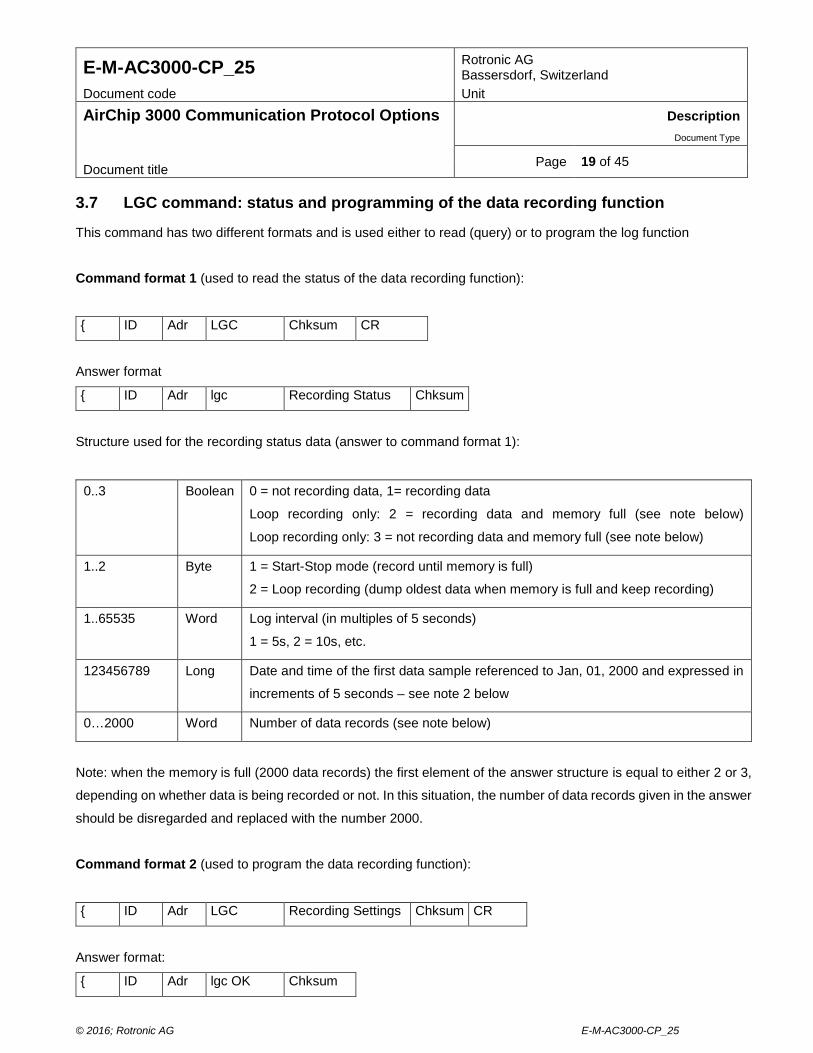
Page 19 of 45 Document title 3.7 LGC command: status and programming of the data recording function
This command has two different formats and is used either to read (query) or to program the log function
Command format 1 (used to read the status of the data recording function):
{ ID Adr LGC Chksum CR
Answer format
{ ID Adr lgc Recording Status Chksum
Structure used for the recording status data (answer to command format 1):
0..3 Boolean 0 = not recording data, 1= recording data
Loop recording only: 2 = recording data and memory full (see note below)
Loop recording only: 3 = not recording data and memory full (see note below)
1..2 Byte 1 = Start-Stop mode (record until memory is full)
2 = Loop recording (dump oldest data when memory is full and keep recording)
1..65535 Word Log interval (in multiples of 5 seconds)
1 = 5s, 2 = 10s, etc.
123456789 Long Date and time of the first data sample referenced to Jan, 01, 2000 and expressed in
increments of 5 seconds – see note 2 below
0…2000 Word Number of data records (see note below)
Note: when the memory is full (2000 data records) the first element of the answer structure is equal to either 2 or 3,
depending on whether data is being recorded or not. In this situation, the number of data records given in the answer
should be disregarded and replaced with the number 2000.
Command format 2 (used to program the data recording function):
{ ID Adr LGC Recording Settings Chksum CR
Answer format:
{ ID Adr lgc OK Chksum
© 2016; Rotronic AG E-M-AC3000-CP_25
E-M-AC3000-CP_25 Rotronic AG Bassersdorf, Switzerland
Document code Unit
AirChip 3000 Communication Protocol Options Description Document Type
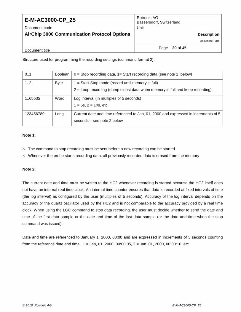
Page 20 of 45 Document title Structure used for programming the recording settings (command format 2):
0..1 Boolean 0 = Stop recording data, 1= Start recording data (see note 1 below)
1..2 Byte 1 = Start-Stop mode (record until memory is full)
2 = Loop recording (dump oldest data when memory is full and keep recording)
1..65535 Word Log interval (in multiples of 5 seconds)
1 = 5s, 2 = 10s, etc.
123456789 Long Current date and time referenced to Jan, 01, 2000 and expressed in increments of 5
seconds – see note 2 below
Note 1:
o The command to stop recording must be sent before a new recording can be started
o Whenever the probe starts recording data, all previously recorded data is erased from the memory
Note 2:
The current date and time must be written to the HC2 whenever recording is started because the HC2 itself does
not have an internal real time clock. An internal time counter ensures that data is recorded at fixed intervals of time
(the log interval) as configured by the user (multiples of 5 seconds). Accuracy of the log interval depends on the
accuracy or the quartz oscillator used by the HC2 and is not comparable to the accuracy provided by a real time
clock. When using the LGC command to stop data recording, the user must decide whether to send the date and
time of the first data sample or the date and time of the last data sample (or the date and time when the stop
command was issued).
Date and time are referenced to January 1, 2000, 00:00 and are expressed in increments of 5 seconds counting
from the reference date and time: 1 = Jan, 01, 2000, 00:00:05, 2 = Jan, 01, 2000, 00:00:10, etc.
© 2016; Rotronic AG E-M-AC3000-CP_25
E-M-AC3000-CP_25 Rotronic AG Bassersdorf, Switzerland
Document code Unit
AirChip 3000 Communication Protocol Options Description Document Type
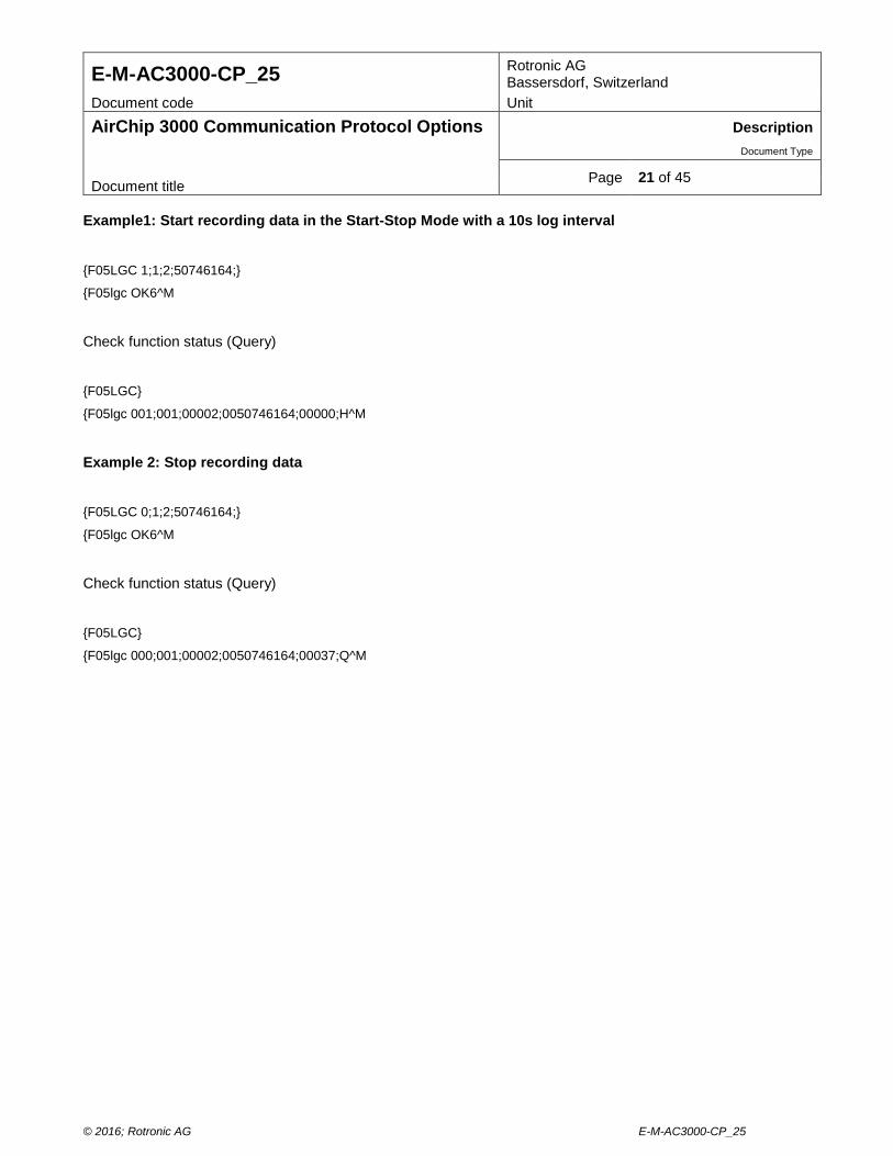
Page 21 of 45 Document title Example1: Start recording data in the Start-Stop Mode with a 10s log interval
{F05LGC 1;1;2;50746164;}
{F05lgc OK6^M
Check function status (Query)
{F05LGC}
{F05lgc 001;001;00002;0050746164;00000;H^M
Example 2: Stop recording data
{F05LGC 0;1;2;50746164;}
{F05lgc OK6^M
Check function status (Query)
{F05LGC}
{F05lgc 000;001;00002;0050746164;00037;Q^M
© 2016; Rotronic AG E-M-AC3000-CP_25
E-M-AC3000-CP_25 Rotronic AG Bassersdorf, Switzerland
Document code Unit
AirChip 3000 Communication Protocol Options Description Document Type
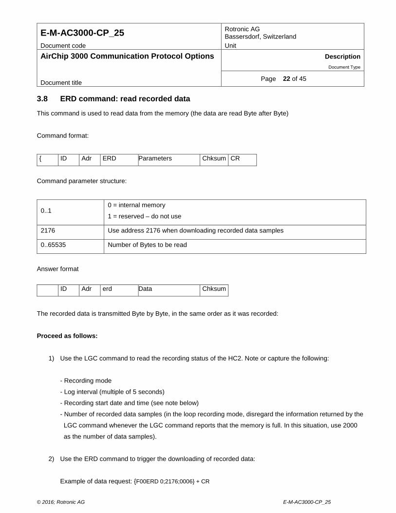
Page 22 of 45 Document title 3.8 ERD command: read recorded data
This command is used to read data from the memory (the data are read Byte after Byte)
Command format:
{ ID Adr ERD Parameters Chksum CR
Command parameter structure:
0..1 0 = internal memory
1 = reserved – do not use
2176 Use address 2176 when downloading recorded data samples
0..65535 Number of Bytes to be read
Answer format
The recorded data is transmitted Byte by Byte, in the same order as it was recorded:
Proceed as follows:
1) Use the LGC command to read the recording status of the HC2. Note or capture the following:
- Recording mode
- Log interval (multiple of 5 seconds)
- Recording start date and time (see note below)
- Number of recorded data samples (in the loop recording mode, disregard the information returned by the
LGC command whenever the LGC command reports that the memory is full. In this situation, use 2000
as the number of data samples).
2) Use the ERD command to trigger the downloading of recorded data:
Example of data request: {F00ERD 0;2176;0006} + CR
ID Adr erd Data Chksum
© 2016; Rotronic AG E-M-AC3000-CP_25
E-M-AC3000-CP_25 Rotronic AG Bassersdorf, Switzerland
Document code Unit
AirChip 3000 Communication Protocol Options Description Document Type
Page 23 of 45 Document title
Address 2176 is always the address of the first byte of the first recorded data sample. The above example
assumes that 2 data samples were recorded. The number of bytes to be downloaded (0006) is equal to 3
times the number of recorded data samples (each data sample uses 3 Bytes)
Example of reply: {F00erd 016;202;038;017;198;038;Y
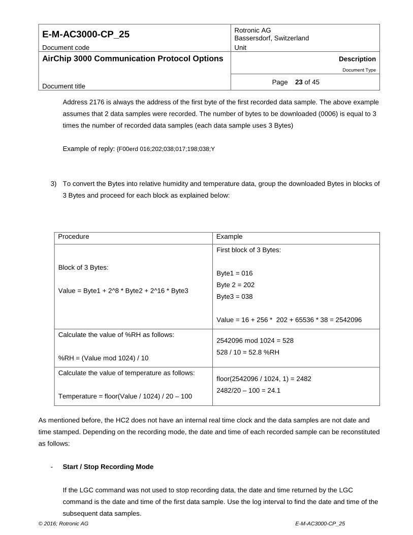
3) To convert the Bytes into relative humidity and temperature data, group the downloaded Bytes in blocks of
3 Bytes and proceed for each block as explained below:
Procedure Example
Block of 3 Bytes:
Value = Byte1 + 2^8 * Byte2 + 2^16 * Byte3
First block of 3 Bytes:
Byte1 = 016
Byte 2 = 202
Byte3 = 038
Value = 16 + 256 * 202 + 65536 * 38 = 2542096
Calculate the value of %RH as follows:
%RH = (Value mod 1024) / 10
2542096 mod 1024 = 528
528 / 10 = 52.8 %RH
Calculate the value of temperature as follows:
Temperature = floor(Value / 1024) / 20 – 100
floor(2542096 / 1024, 1) = 2482
2482/20 – 100 = 24.1
As mentioned before, the HC2 does not have an internal real time clock and the data samples are not date and
time stamped. Depending on the recording mode, the date and time of each recorded sample can be reconstituted
as follows:
- Start / Stop Recording Mode
If the LGC command was not used to stop recording data, the date and time returned by the LGC
command is the date and time of the first data sample. Use the log interval to find the date and time of the
subsequent data samples. © 2016; Rotronic AG E-M-AC3000-CP_25
E-M-AC3000-CP_25 Rotronic AG Bassersdorf, Switzerland
Document code Unit
AirChip 3000 Communication Protocol Options Description Document Type
Page 24 of 45 Document title
If the LGC command was used to stop recording data, the date and time returned by the LGC command is
the date and time of either the first or the last data sample, depending on which date and time was sent as
part of the LGC command. Depending on the situation, use the log interval to find the date and time of
either the subsequent or previous data samples.
- Loop Recording Mode
When less than 2,000 data samples have been recorded, proceed as for the Start / Stop Mode
When 2,000 data samples have been recorded the memory is full and it is very likely that the oldest data
samples have been erased to make room for additional data samples. In this situation, the first element of
the answer returned by the LGC command is equal to either 2 or 3. This indicates that 2,000 data samples
have been recorded. Make a note of the date and time when the ERD command was issued. Proceed as
follows to determine the time and date of the most recent data sample:
. Use both the recording start time and the value of the log interval to determine when data samples were
being recorded. Example: if the recording started exactly at the top of an hour with a log interval of 10
minutes, samples have been recorded at HH:00:00, HH:10:00, HH:20:00, etc. If the ERD command was
sent at 14:15:00, then the time of the latest data sample is 14:10:00.
. Knowing the date and time of the latest data sample, as well as the value of log interval, the date and
time of the preceding data samples can be found.
© 2016; Rotronic AG E-M-AC3000-CP_25
E-M-AC3000-CP_25 Rotronic AG Bassersdorf, Switzerland
Document code Unit
AirChip 3000 Communication Protocol Options Description Document Type
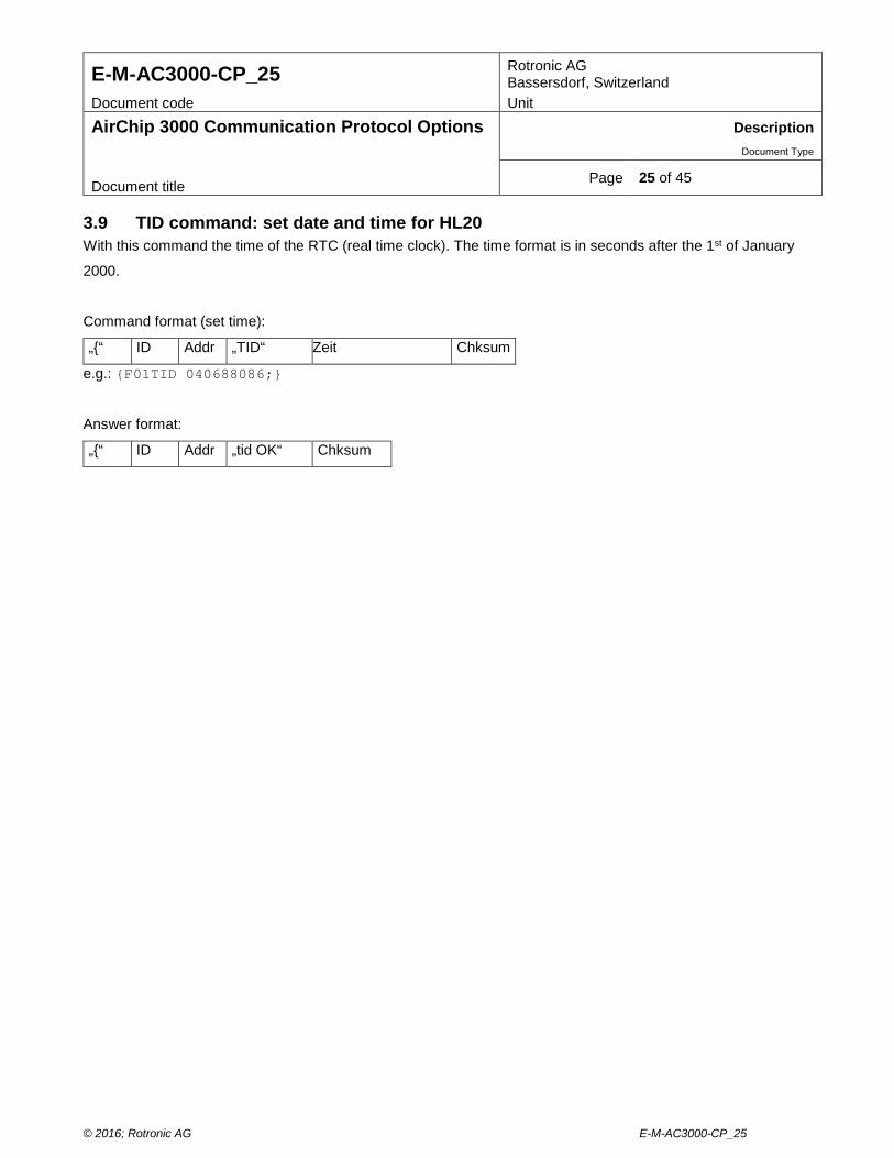
Page 25 of 45 Document title 3.9 TID command: set date and time for HL20 With this command the time of the RTC (real time clock). The time format is in seconds after the 1st of January
2000.
Command format (set time):
„{“ ID Addr „TID“ Zeit Chksum
e.g.: {F01TID 040688086;}
Answer format:
„{“ ID Addr „tid OK“ Chksum
© 2016; Rotronic AG E-M-AC3000-CP_25
E-M-AC3000-CP_25 Rotronic AG Bassersdorf, Switzerland
Document code Unit
AirChip 3000 Communication Protocol Options Description Document Type
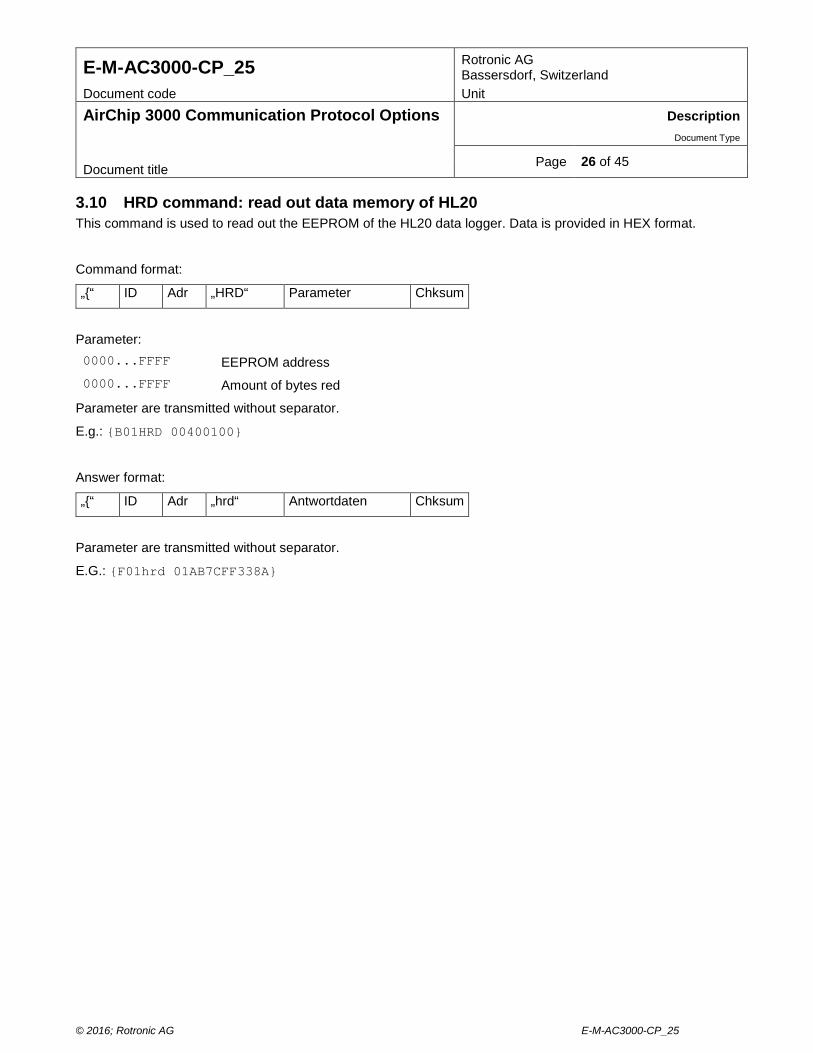
Page 26 of 45 Document title 3.10 HRD command: read out data memory of HL20 This command is used to read out the EEPROM of the HL20 data logger. Data is provided in HEX format.
Command format:
„{“ ID Adr „HRD“ Parameter Chksum
Parameter: 0000...FFFF EEPROM address 0000...FFFF Amount of bytes red
Parameter are transmitted without separator.
E.g.: {B01HRD 00400100}
Answer format:
„{“ ID Adr „hrd“ Antwortdaten Chksum
Parameter are transmitted without separator.
E.G.: {F01hrd 01AB7CFF338A}
© 2016; Rotronic AG E-M-AC3000-CP_25
E-M-AC3000-CP_25 Rotronic AG Bassersdorf, Switzerland
Document code Unit
AirChip 3000 Communication Protocol Options Description Document Type
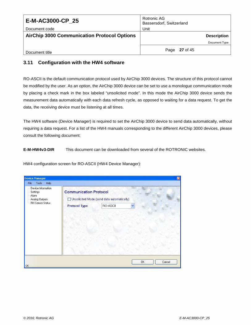
Page 27 of 45 Document title 3.11 Configuration with the HW4 software
RO-ASCII is the default communication protocol used by AirChip 3000 devices. The structure of this protocol cannot
be modified by the user. As an option, the AirChip 3000 device can be set to use a monologue communication mode
by placing a check mark in the box labeled “unsolicited mode”. In this mode the AirChip 3000 device sends the
measurement data automatically with each data refresh cycle, as opposed to waiting for a data request. To get the
data, the receiving device must be listening at all times.
The HW4 software (Device Manager) is required to set the AirChip 3000 device to send data automatically, without
requiring a data request. For a list of the HW4 manuals corresponding to the different AirChip 3000 devices, please
consult the following document:
E-M-HW4v3-DIR This document can be downloaded from several of the ROTRONIC websites.
HW4 configuration screen for RO-ASCII (HW4 Device Manager):
© 2016; Rotronic AG E-M-AC3000-CP_25
E-M-AC3000-CP_25 Rotronic AG Bassersdorf, Switzerland
Document code Unit
AirChip 3000 Communication Protocol Options Description Document Type
Page 28 of 45 Document title 4 MODBUS PROTOCOL
The AirChip 3000 Modbus protocol is limited to reading measurement data from the AirChip 3000, HC2-S and
AC3005 devices. Functions such as device configuration, humidity and temperature adjustment, etc. are not
supported by the AirChip 3000 Modbus protocol.
4.1 Physical interface
The Modbus protocol can be used only with an AirChip 3000 device that features a RS-485 interface. As with any
RS-485 network, the Modbus network should be installed as per the instructions provided in the following document:
E-DV04-RS485.01
Note:
The Modbus protocol and the RO-ASCII protocol used by the HW4 software cannot be used simultaneously on the
same RS-485 network. For RS-485 networks the addressing of the device must be individual for each device in the
network (can be set in the device manager).
© 2016; Rotronic AG E-M-AC3000-CP_25
E-M-AC3000-CP_25 Rotronic AG Bassersdorf, Switzerland
Document code Unit
AirChip 3000 Communication Protocol Options Description Document Type
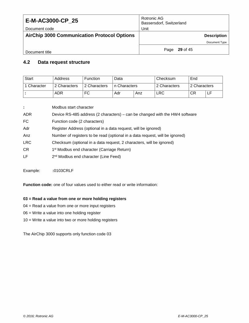
Page 29 of 45 Document title 4.2 Data request structure
Start Address Function Data Checksum End
1 Character 2 Characters 2 Characters n Characters 2 Characters 2 Characters
: ADR FC Adr Anz LRC CR LF
: Modbus start character
ADR Device RS-485 address (2 characters) – can be changed with the HW4 software
FC Function code (2 characters)
Adr Register Address (optional in a data request, will be ignored)
Anz Number of registers to be read (optional in a data request, will be ignored)
LRC Checksum (optional in a data request, 2 characters, will be ignored)
CR 1st Modbus end character (Carriage Return)
LF 2nd Modbus end character (Line Feed)
Example: :0103CRLF
Function code: one of four values used to either read or write information:
03 = Read a value from one or more holding registers
04 = Read a value from one or more input registers
06 = Write a value into one holding register
10 = Write a value into two or more holding registers
The AirChip 3000 supports only function code 03
© 2016; Rotronic AG E-M-AC3000-CP_25
E-M-AC3000-CP_25 Rotronic AG Bassersdorf, Switzerland
Document code Unit
AirChip 3000 Communication Protocol Options Description Document Type
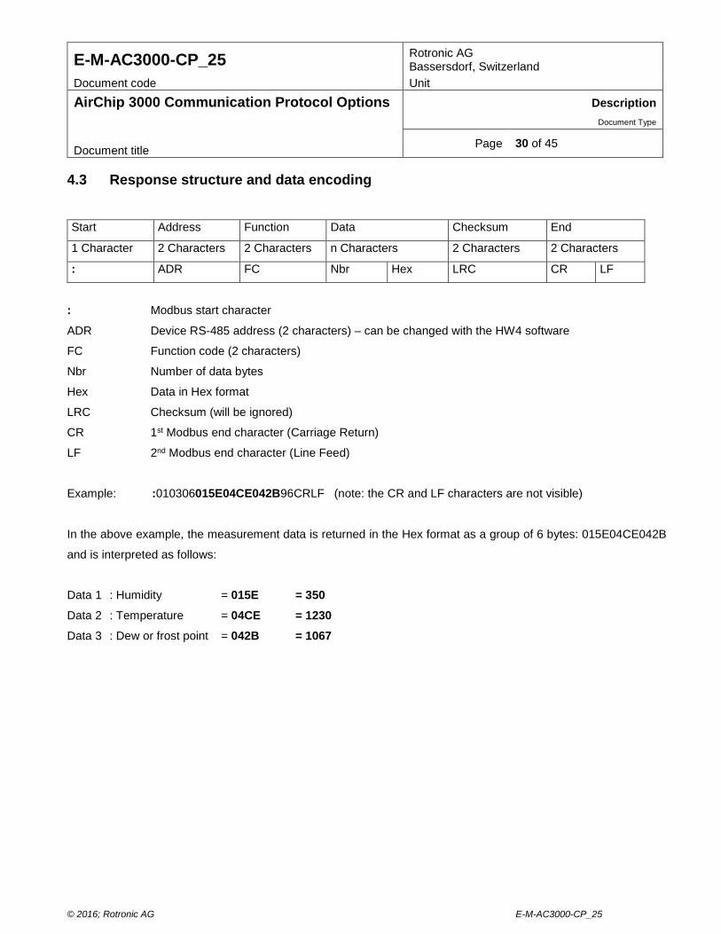
Page 30 of 45 Document title 4.3 Response structure and data encoding
Start Address Function Data Checksum End
1 Character 2 Characters 2 Characters n Characters 2 Characters 2 Characters
: ADR FC Nbr Hex LRC CR LF
: Modbus start character
ADR Device RS-485 address (2 characters) – can be changed with the HW4 software
FC Function code (2 characters)
Nbr Number of data bytes
Hex Data in Hex format
LRC Checksum (will be ignored)
CR 1st Modbus end character (Carriage Return)
LF 2nd Modbus end character (Line Feed)
Example: :010306015E04CE042B96CRLF (note: the CR and LF characters are not visible)
In the above example, the measurement data is returned in the Hex format as a group of 6 bytes: 015E04CE042B
and is interpreted as follows:
Data 1 : Humidity = 015E = 350 Data 2 : Temperature = 04CE = 1230
Data 3 : Dew or frost point = 042B = 1067
© 2016; Rotronic AG E-M-AC3000-CP_25
E-M-AC3000-CP_25 Rotronic AG Bassersdorf, Switzerland
Document code Unit
AirChip 3000 Communication Protocol Options Description Document Type
Page 31 of 45 Document title Please note that the HW4 software is used to determine which parameters are transmitted in the response (Data1
to 3) and in which sequence. The unit system used for both temperature and the calculated parameter (dew or frost
point) is also set with HW4 as part of the device configuration.
In the decimal format, the data are numerically scaled as follows:
Humidity : 0...100% = 0...1000 Temperature und calculated parameter : -100...600°C = 0...7000
In the above example of a response, the result is as follows:
Humidity = 35.0%
Temperature = 23.0°C
Dew or frost point = 6.7°C
© 2016; Rotronic AG E-M-AC3000-CP_25
E-M-AC3000-CP_25 Rotronic AG Bassersdorf, Switzerland
Document code Unit
AirChip 3000 Communication Protocol Options Description Document Type
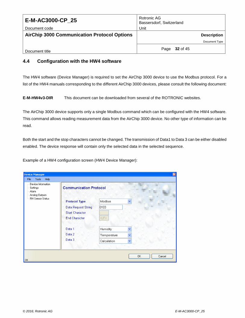
Page 32 of 45 Document title 4.4 Configuration with the HW4 software
The HW4 software (Device Manager) is required to set the AirChip 3000 device to use the Modbus protocol. For a
list of the HW4 manuals corresponding to the different AirChip 3000 devices, please consult the following document:
E-M-HW4v3-DIR This document can be downloaded from several of the ROTRONIC websites.
The AirChip 3000 device supports only a single Modbus command which can be configured with the HW4 software.
This command allows reading measurement data from the AirChip 3000 device. No other type of information can be
read.
Both the start and the stop characters cannot be changed. The transmission of Data1 to Data 3 can be either disabled
enabled. The device response will contain only the selected data in the selected sequence.
Example of a HW4 configuration screen (HW4 Device Manager):
© 2016; Rotronic AG E-M-AC3000-CP_25
E-M-AC3000-CP_25 Rotronic AG Bassersdorf, Switzerland
Document code Unit
AirChip 3000 Communication Protocol Options Description Document Type
Page 33 of 45 Document title 5 I2C PROTOCOL
The I2C protocol option is available only with the HygroClip 2 probes and some AirChip 3000 based OEM products.
While the structure of the data string generated by the AirChip 3000 fully complies with the I2C requirements, the
AirChip 3000 has the following limitations:
o The AirChip 3000 always acts as a I2C Master writing to the bus. After the START condition (S), a slave address
is sent. In accordance with the I2C protocol, this address is 7 bits long followed by an eighth bit which is the data
direction bit (R/W). With the AirChip 3000 this bit is always a ‘zero’ indicating a transmission (WRITE).The AirChip
3000 device sends a data string automatically with each data refresh cycle (unsolicited data), as opposed to
waiting for a data request. To get the data, the receiving device must be listening at all times
o In spite of the fact that the I2C data string includes an address, the AirChip 3000 is not addressable and
communication is limited to a single AirChip 3000 device (no networking of several devices, AirChip 3000 or
other).
o The I2C protocol can only be used to read measurement data from the AirChip 3000 device. Functions such as
device configuration, humidity and temperature adjustment, etc. are not supported.
© 2016; Rotronic AG E-M-AC3000-CP_25
E-M-AC3000-CP_25 Rotronic AG Bassersdorf, Switzerland
Document code Unit
AirChip 3000 Communication Protocol Options Description Document Type
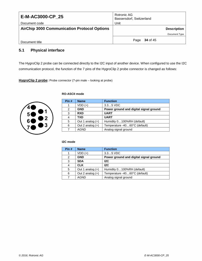
Page 34 of 45 Document title 5.1 Physical interface
The HygroClip 2 probe can be connected directly to the I2C input of another device. When configured to use the I2C
communication protocol, the function of the 7 pins of the HygroClip 2 probe connector is changed as follows:
HygroClip 2 probe: Probe connector (7-pin male – looking at probe)
RO-ASCII mode
Pin # Name Function 1 VDD (+) 3.3…5 VDC 2 GND Power ground and digital signal ground 3 RXD UART 4 TXD UART 5 Out 1 analog (+) Humidity 0…100%RH (default) 6 Out 2 analog (+) Temperature -40…60°C (default) 7 AGND Analog signal ground
I2C mode
Pin # Name Function 1 VDD (+) 3.3…5 VDC 2 GND Power ground and digital signal ground 3 SDA I2C 4 CLK I2C 5 Out 1 analog (+) Humidity 0…100%RH (default) 6 Out 2 analog (+) Temperature -40…60°C (default) 7 AGND Analog signal ground
© 2016; Rotronic AG E-M-AC3000-CP_25
E-M-AC3000-CP_25 Rotronic AG Bassersdorf, Switzerland
Document code Unit
AirChip 3000 Communication Protocol Options Description Document Type
Page 35 of 45 Document title Other AirChip 3000 devices:
Some AirChip 3000 based OEM products can be set to use the I2C protocol option. Please consult the hardware
manual of the device.
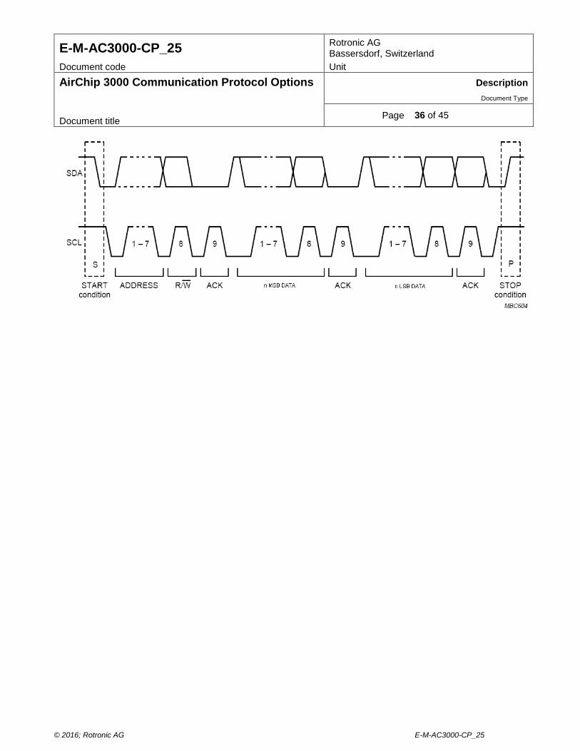
5.2 Data string structure and data encoding
STR ADDR HMSB HLSB TMSB TLSB CMSB CLSB STP
STR I2C Start Condition
ADDR Slave Address (MSB: 7-bit address + LSB: “zero” bit)
HMSB Relative humidity MSB
HLSB Relative humidity LSB
TMSB Temperature MSB
TLSB Temperature LSB
CMSB Calculated parameter MSB
CLSB Calculated parameter LSB
STP I2C Stop Condition
Every data byte is 8-bits long and is followed by an acknowledge bit (ACK). Data is transferred with the most
significant bit (MSB) first. The measurement data are transmitted in the Hex format and are numerically scaled as
follows in the decimal format:
Humidity : 0...100% = 0...1000 Temperature und calculated parameter : -100...600°C = 0...7000
Data Transfer example:
© 2016; Rotronic AG E-M-AC3000-CP_25
E-M-AC3000-CP_25 Rotronic AG Bassersdorf, Switzerland
Document code Unit
AirChip 3000 Communication Protocol Options Description Document Type
Page 36 of 45 Document title
© 2016; Rotronic AG E-M-AC3000-CP_25
E-M-AC3000-CP_25 Rotronic AG Bassersdorf, Switzerland
Document code Unit
AirChip 3000 Communication Protocol Options Description Document Type
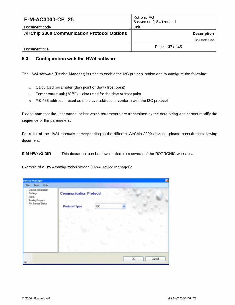
Page 37 of 45 Document title 5.3 Configuration with the HW4 software
The HW4 software (Device Manager) is used to enable the I2C protocol option and to configure the following:
o Calculated parameter (dew point or dew / frost point)
o Temperature unit (°C/°F) – also used for the dew or frost point
o RS-485 address – used as the slave address to conform with the I2C protocol
Please note that the user cannot select which parameters are transmitted by the data string and cannot modify the
sequence of the parameters.
For a list of the HW4 manuals corresponding to the different AirChip 3000 devices, please consult the following
document:
E-M-HW4v3-DIR This document can be downloaded from several of the ROTRONIC websites.
Example of a HW4 configuration screen (HW4 Device Manager):
© 2016; Rotronic AG E-M-AC3000-CP_25
E-M-AC3000-CP_25 Rotronic AG Bassersdorf, Switzerland
Document code Unit
AirChip 3000 Communication Protocol Options Description Document Type
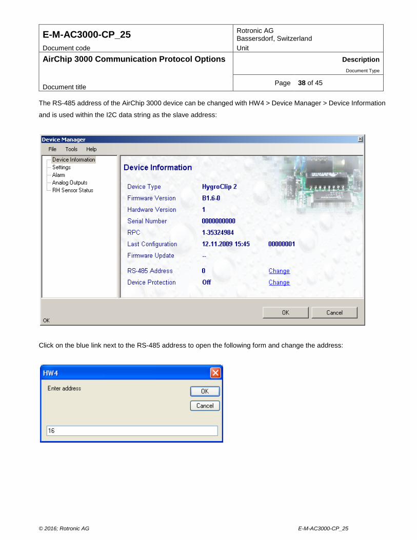
Page 38 of 45 Document title The RS-485 address of the AirChip 3000 device can be changed with HW4 > Device Manager > Device Information
and is used within the I2C data string as the slave address:
Click on the blue link next to the RS-485 address to open the following form and change the address:
© 2016; Rotronic AG E-M-AC3000-CP_25
E-M-AC3000-CP_25 Rotronic AG Bassersdorf, Switzerland
Document code Unit
AirChip 3000 Communication Protocol Options Description Document Type
Page 39 of 45 Document title 6 CUSTOM PROTOCOL
The Custom communication protocol can be used to provide compatibility of the AirChip 3000 device with an existing
communication system. The Custom communication protocol is limited to reading measurement data from the
AirChip 3000 device. Functions such as device configuration, humidity and temperature adjustment, etc. are not
supported.
The Custom protocol is applicable to all AirChip 3000 devices with a digital interface and allows RS-485 networking
6.1 Physical interface
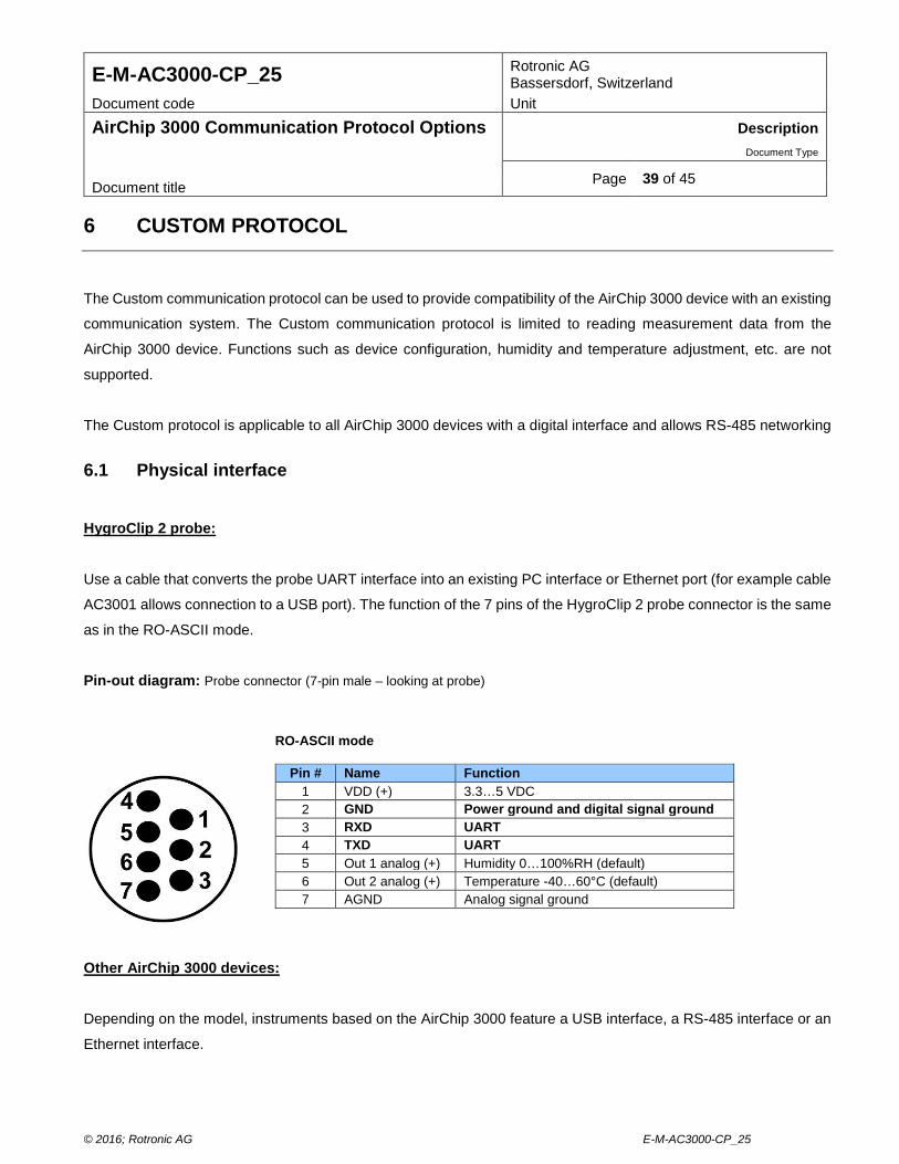
HygroClip 2 probe:
Use a cable that converts the probe UART interface into an existing PC interface or Ethernet port (for example cable
AC3001 allows connection to a USB port). The function of the 7 pins of the HygroClip 2 probe connector is the same
as in the RO-ASCII mode.
Pin-out diagram: Probe connector (7-pin male – looking at probe)
Other AirChip 3000 devices:
Depending on the model, instruments based on the AirChip 3000 feature a USB interface, a RS-485 interface or an
Ethernet interface.
RO-ASCII mode
Pin # Name Function 1 VDD (+) 3.3…5 VDC 2 GND Power ground and digital signal ground 3 RXD UART 4 TXD UART 5 Out 1 analog (+) Humidity 0…100%RH (default) 6 Out 2 analog (+) Temperature -40…60°C (default) 7 AGND Analog signal ground
© 2016; Rotronic AG E-M-AC3000-CP_25
E-M-AC3000-CP_25 Rotronic AG Bassersdorf, Switzerland
Document code Unit
AirChip 3000 Communication Protocol Options Description Document Type
Page 40 of 45 Document title 6.2 Data request structure
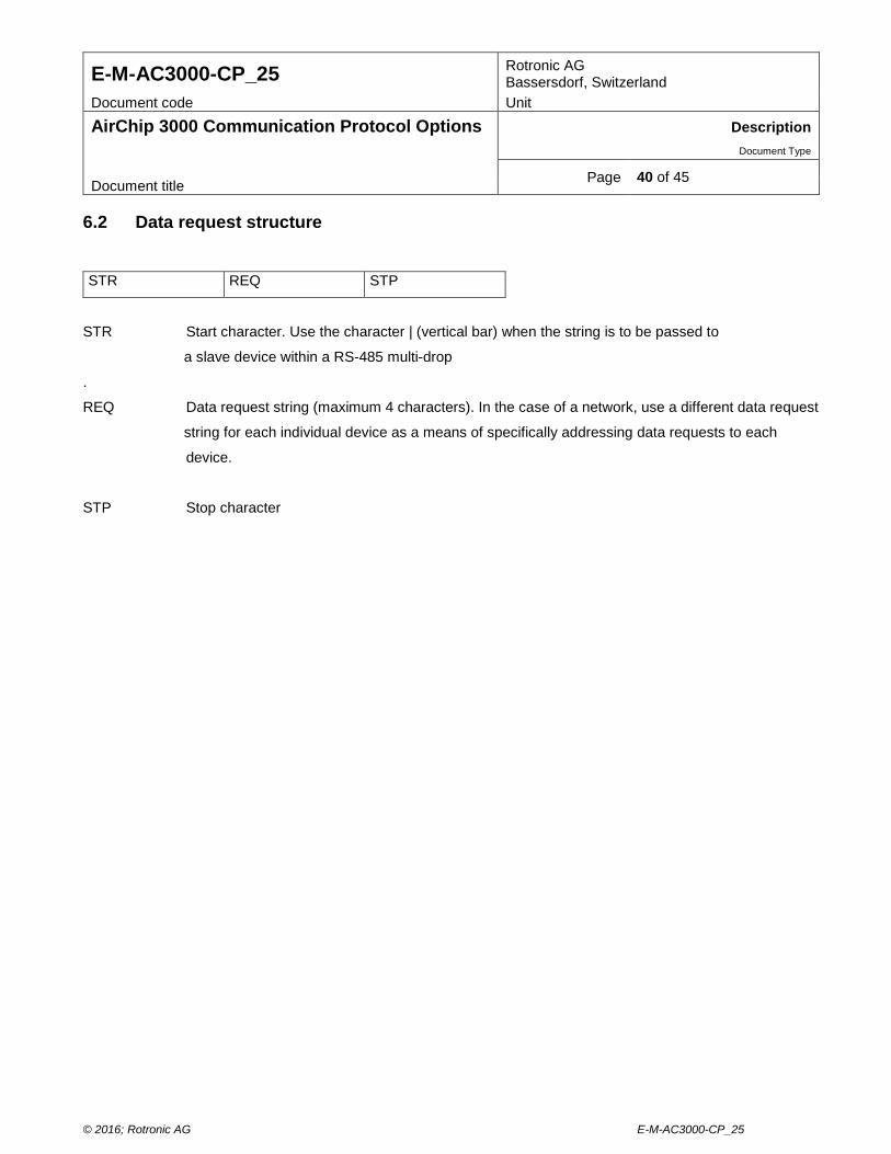
STR REQ STP
STR Start character. Use the character | (vertical bar) when the string is to be passed to
a slave device within a RS-485 multi-drop
.
REQ Data request string (maximum 4 characters). In the case of a network, use a different data request
string for each individual device as a means of specifically addressing data requests to each
device.
STP Stop character
© 2016; Rotronic AG E-M-AC3000-CP_25
E-M-AC3000-CP_25 Rotronic AG Bassersdorf, Switzerland
Document code Unit
AirChip 3000 Communication Protocol Options Description Document Type
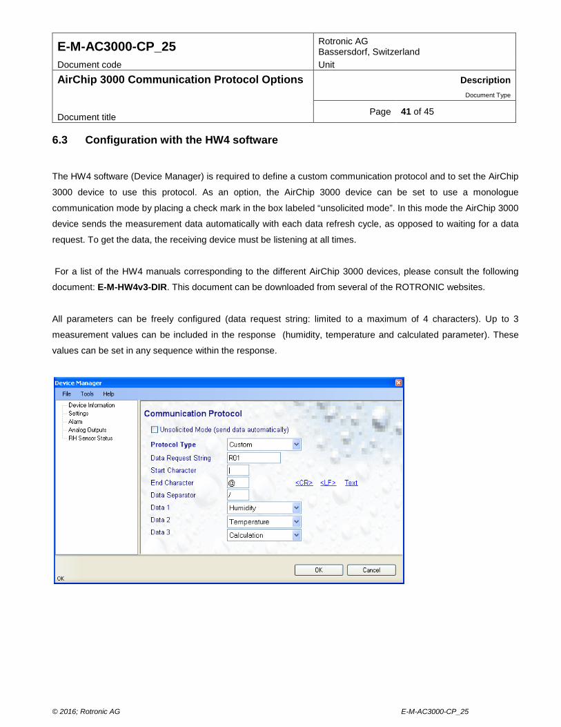
Page 41 of 45 Document title 6.3 Configuration with the HW4 software
The HW4 software (Device Manager) is required to define a custom communication protocol and to set the AirChip
3000 device to use this protocol. As an option, the AirChip 3000 device can be set to use a monologue
communication mode by placing a check mark in the box labeled “unsolicited mode”. In this mode the AirChip 3000
device sends the measurement data automatically with each data refresh cycle, as opposed to waiting for a data
request. To get the data, the receiving device must be listening at all times.
For a list of the HW4 manuals corresponding to the different AirChip 3000 devices, please consult the following
document: E-M-HW4v3-DIR. This document can be downloaded from several of the ROTRONIC websites.
All parameters can be freely configured (data request string: limited to a maximum of 4 characters). Up to 3
measurement values can be included in the response (humidity, temperature and calculated parameter). These
values can be set in any sequence within the response.
© 2016; Rotronic AG E-M-AC3000-CP_25
E-M-AC3000-CP_25 Rotronic AG Bassersdorf, Switzerland
Document code Unit
AirChip 3000 Communication Protocol Options Description Document Type
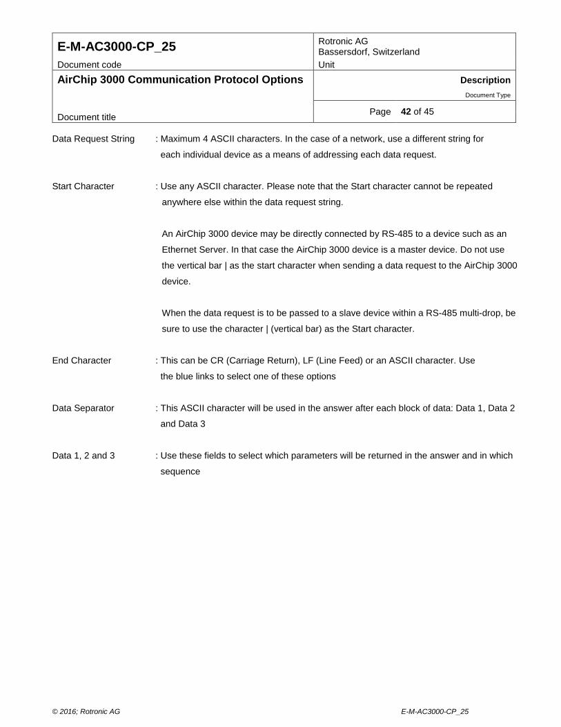
Page 42 of 45 Document title Data Request String : Maximum 4 ASCII characters. In the case of a network, use a different string for
each individual device as a means of addressing each data request.
Start Character : Use any ASCII character. Please note that the Start character cannot be repeated
anywhere else within the data request string.
An AirChip 3000 device may be directly connected by RS-485 to a device such as an
Ethernet Server. In that case the AirChip 3000 device is a master device. Do not use
the vertical bar | as the start character when sending a data request to the AirChip 3000
device.
When the data request is to be passed to a slave device within a RS-485 multi-drop, be
sure to use the character | (vertical bar) as the Start character.
End Character : This can be CR (Carriage Return), LF (Line Feed) or an ASCII character. Use
the blue links to select one of these options
Data Separator : This ASCII character will be used in the answer after each block of data: Data 1, Data 2
and Data 3
Data 1, 2 and 3 : Use these fields to select which parameters will be returned in the answer and in which
sequence
© 2016; Rotronic AG E-M-AC3000-CP_25
E-M-AC3000-CP_25 Rotronic AG Bassersdorf, Switzerland
Document code Unit
AirChip 3000 Communication Protocol Options Description Document Type
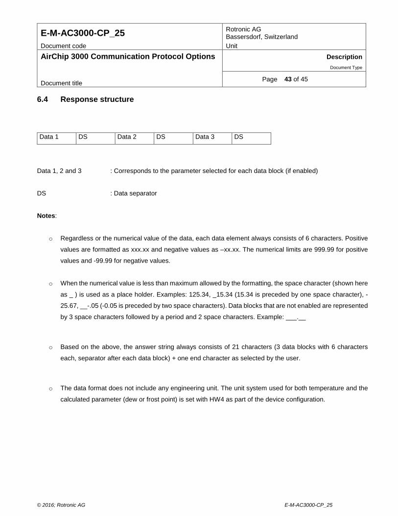
Page 43 of 45 Document title 6.4 Response structure
Data 1 DS Data 2 DS Data 3 DS
Data 1, 2 and 3 : Corresponds to the parameter selected for each data block (if enabled)
DS : Data separator
Notes:
o Regardless or the numerical value of the data, each data element always consists of 6 characters. Positive
values are formatted as xxx.xx and negative values as –xx.xx. The numerical limits are 999.99 for positive
values and -99.99 for negative values.
o When the numerical value is less than maximum allowed by the formatting, the space character (shown here
as _ ) is used as a place holder. Examples: 125.34, _15.34 (15.34 is preceded by one space character), -
25.67, __-.05 (-0.05 is preceded by two space characters). Data blocks that are not enabled are represented
by 3 space characters followed by a period and 2 space characters. Example: ___.__
o Based on the above, the answer string always consists of 21 characters (3 data blocks with 6 characters
each, separator after each data block) + one end character as selected by the user.
o The data format does not include any engineering unit. The unit system used for both temperature and the
calculated parameter (dew or frost point) is set with HW4 as part of the device configuration.
© 2016; Rotronic AG E-M-AC3000-CP_25
E-M-AC3000-CP_25 Rotronic AG Bassersdorf, Switzerland
Document code Unit
AirChip 3000 Communication Protocol Options Description Document Type
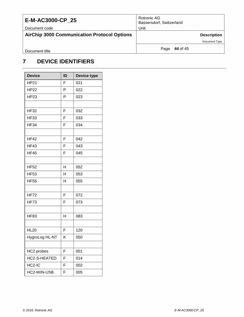
Page 44 of 45 Document title 7 DEVICE IDENTIFIERS
Device ID Device type
HP21 F 021
HP22 P 022
HP23 P 023
HF32 F 032
HF33 F 033
HF34 F 034
HF42 F 042
HF43 F 043
HF45 F 045
HF52 H 052
HF53 H 053
HF55 H 055
HF72 F 072
HF73 F 073
HF83 H 083
HL20 F 120
HygroLog HL-NT K 050
HC2 probes F 001
HC2-S-HEATED F 014
HC2-IC F 002
HC2-WIN-USB F 005
© 2016; Rotronic AG E-M-AC3000-CP_25
E-M-AC3000-CP_25 Rotronic AG Bassersdorf, Switzerland
Document code Unit
AirChip 3000 Communication Protocol Options Description Document Type
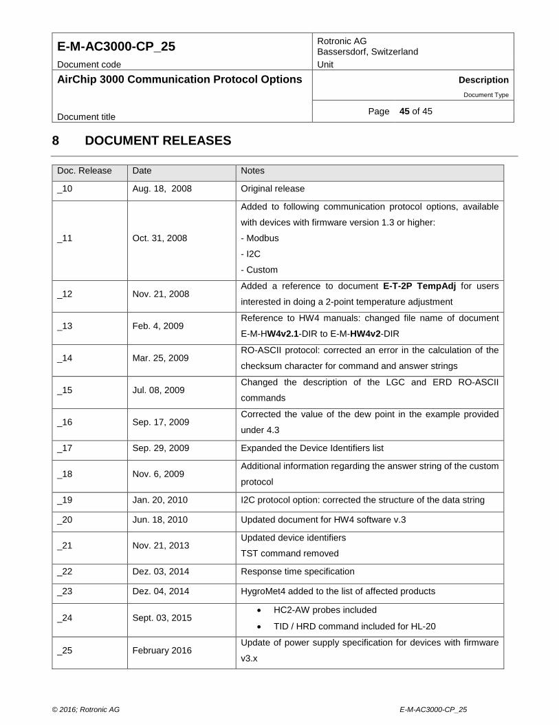
Page 45 of 45 Document title 8 DOCUMENT RELEASES
Doc. Release Date Notes
_10 Aug. 18, 2008 Original release
_11 Oct. 31, 2008
Added to following communication protocol options, available
with devices with firmware version 1.3 or higher:
- Modbus
- I2C
- Custom
_12 Nov. 21, 2008 Added a reference to document E-T-2P TempAdj for users
interested in doing a 2-point temperature adjustment
_13 Feb. 4, 2009 Reference to HW4 manuals: changed file name of document
E-M-HW4v2.1-DIR to E-M-HW4v2-DIR
_14 Mar. 25, 2009 RO-ASCII protocol: corrected an error in the calculation of the
checksum character for command and answer strings
_15 Jul. 08, 2009 Changed the description of the LGC and ERD RO-ASCII
commands
_16 Sep. 17, 2009 Corrected the value of the dew point in the example provided
under 4.3
_17 Sep. 29, 2009 Expanded the Device Identifiers list
_18 Nov. 6, 2009 Additional information regarding the answer string of the custom
protocol
_19 Jan. 20, 2010 I2C protocol option: corrected the structure of the data string
_20 Jun. 18, 2010 Updated document for HW4 software v.3
_21 Nov. 21, 2013 Updated device identifiers
TST command removed
_22 Dez. 03, 2014 Response time specification
_23 Dez. 04, 2014 HygroMet4 added to the list of affected products
_24 Sept. 03, 2015 • HC2-AW probes included
• TID / HRD command included for HL-20
_25 February 2016 Update of power supply specification for devices with firmware
v3.x
© 2016; Rotronic AG E-M-AC3000-CP_25