Embed Size (px)
Citation preview
UNESCO – EOLS
S
SAMPLE C
HAPTERS
EXERGY, ENERGY SYSTEM ANALYSIS AND OPTIMIZATION – Vol. I - Energetic and Exergetic Analysis of Complex Systems - G. Tsatsaronis and F. Cziesla
©Encyclopedia of Life Support Systems (EOLSS)
ENERGETIC AND EXERGETIC ANALYSIS OF COMPLEX SYSTEMS G. Tsatsaronis and F. Cziesla Institute for Energy Engineering, Technische Universität Berlin, Germany Keywords: Energy Analysis, Exergy Analysis, Avoidable Thermodynamic Inefficiencies, Steam Power Plant, Combined-Cycle Power Plant, Externally Coal-Fired Combined-Cycle Power Plant. Contents 1. Introduction 2. Steam Power Plant 2.1. Process Description 2.2. Energy Analysis 2.3. Exergy Analysis 2.4. Discussion and Conclusions 3. Combined-Cycle Power Plant 3.1. Process Description 3.2. Energy Analysis 3.3. Exergy Analysis 3.4. Discussion and Conclusions 4. Externally-Fired Combined-Cycle Power Plant 4.1. Process description 4.2. Exergy Analysis 4.3. Results and Discussion 5. Conclusions Glossary Bibliography Biographical Sketches Summary This chapter deals with the exergetic analysis of three different types of power plants. The potential for improvement is identified and changes for reducing the thermodynamic inefficiencies are discussed. 1. Introduction This chapter deals with energy analyses and detailed exergy analyses of complex energy conversion systems such as steam power plants and combined-cycle power plants. Of particular interest are the location and magnitude of the real thermodynamic inefficiencies (exergy destruction and exergy loss) and the effects that caused them. The exergy principles presented in Basic Exergy Concepts and Exergy Balance and Exergetic Efficiency are applied here to conduct detailed thermodynamic evaluation of complex energy systems. The system complexity, the interactions among the plant components, and the variety of equipment options make optimization of such systems
UNESCO – EOLS
S
SAMPLE C
HAPTERS
EXERGY, ENERGY SYSTEM ANALYSIS AND OPTIMIZATION – Vol. I - Energetic and Exergetic Analysis of Complex Systems - G. Tsatsaronis and F. Cziesla
©Encyclopedia of Life Support Systems (EOLSS)
considerably more difficult than that of the simple systems discussed in Exergy Analysis of Simple Systems. Commercially available computer programs were used to study the thermodynamic behavior of each system and to provide the mass flow rate, temperature, pressure, and chemical composition of each stream. All exergy values were computed using
0T = 288.15 K as the temperature and 0p = 1.013 bar as the pressure of the thermodynamic environment, as well as Model I (see Basic Exergy Concepts) for calculating standard molar chemical exergy values.
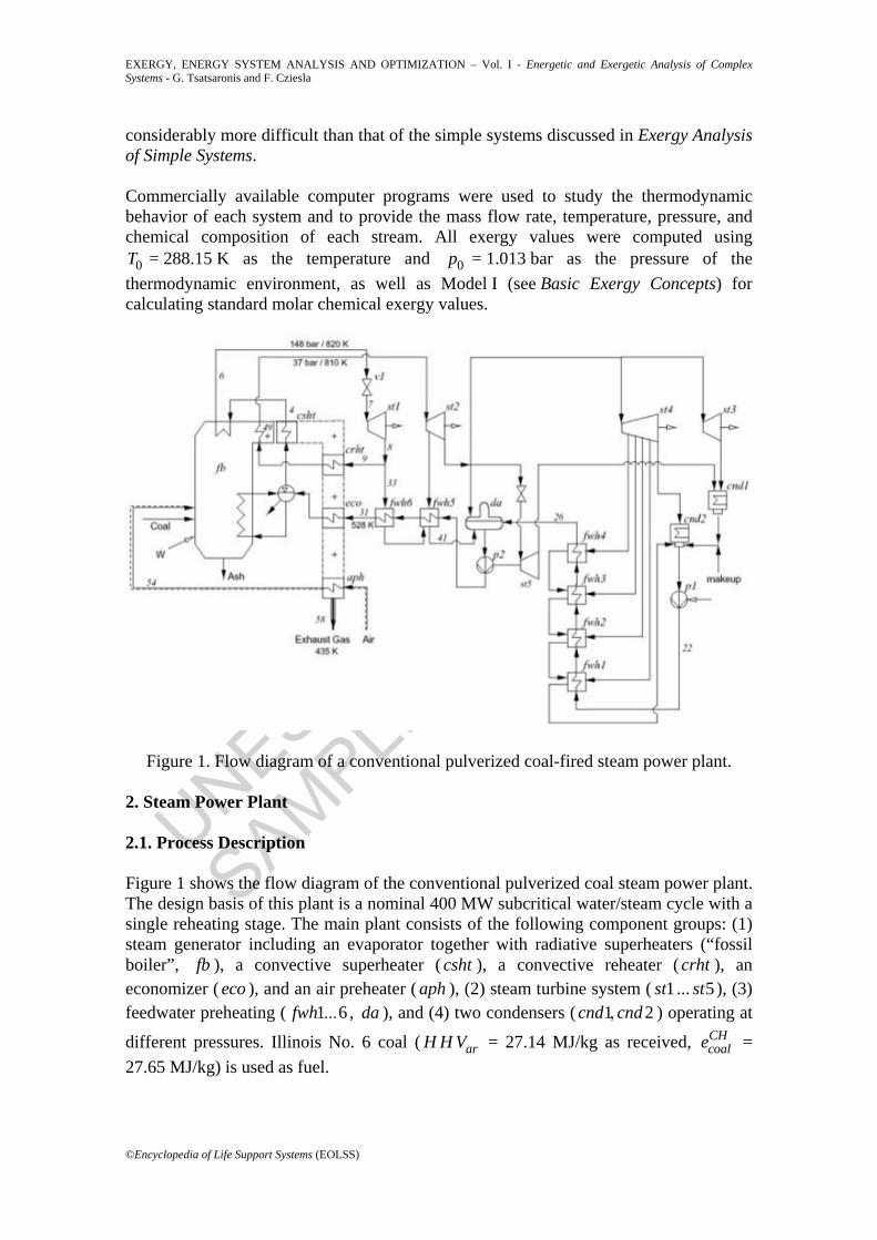
Figure 1. Flow diagram of a conventional pulverized coal-fired steam power plant. 2. Steam Power Plant 2.1. Process Description Figure 1 shows the flow diagram of the conventional pulverized coal steam power plant. The design basis of this plant is a nominal 400 MW subcritical water/steam cycle with a single reheating stage. The main plant consists of the following component groups: (1) steam generator including an evaporator together with radiative superheaters (“fossil boiler”, fb ), a convective superheater ( csht ), a convective reheater ( crht ), an economizer ( eco ), and an air preheater ( aph ), (2) steam turbine system ( 1st ... 5st ), (3) feedwater preheating ( 1 6fwh ... , da ), and (4) two condensers ( 1 2cnd cnd, ) operating at
different pressures. Illinois No. 6 coal ( arH H V = 27.14 MJ/kg as received, CHcoale =
27.65 MJ/kg) is used as fuel.
UNESCO – EOLS
S
SAMPLE C
HAPTERS
EXERGY, ENERGY SYSTEM ANALYSIS AND OPTIMIZATION – Vol. I - Energetic and Exergetic Analysis of Complex Systems - G. Tsatsaronis and F. Cziesla
©Encyclopedia of Life Support Systems (EOLSS)
The steam turbine system consists of a high-pressure ( 1st ), an intermediate-pressure ( 2st ), and a low-pressure section ( 3 4st st, ). The high-pressure section is supplied with 148 bar / 820 K steam (stream 6) from the steam generator. The exhaust steam from the high-pressure turbine at 37 bar is reheated to 810 K in the steam generator and returns to the intermediate-pressure turbine (IP). The IP exhaust steam is then routed to the two low-pressure steam turbines 3st and 4st from which it is condensed at the design pressures of 0.05 and 0.12 bar, respectively. A part of the IP exhaust steam is used in a steam turbine ( 5st ) to drive the feedwater pump 2p . The four steam turbines 1st to
4st together generate about 408 MW of power. The condensate from the condensers is pumped through the low-pressure feedwater preheating section ( 1fwh to 4fwh ). The deaerator ( da ) operates at 12 bar. Finally, the pump 2p supplies the feedwater to the high-pressure feedwater heaters ( 5 6fwh fwh, ) and to the economizer ( eco ) of the steam generator. 2.2. Energy Analysis Energy analysis identifies only energy transport to the surroundings in terms of thermodynamic inefficiency. Thus, energetic analysis of the steam power plant shown in Figure 1 leads to the conclusion that the thermodynamic inefficiencies are associated with (a) the energy transport from the condenser to the environment (47.5 % of
coalH H Vm ), (b) the rejection of the exhaust gas (10.5 % of coalH H Vm ) and the ash (1.7 % of coalH H Vm ) to the environment, (c) the heat transfer from the steam generator to the system surroundings (1.0 % of coalH H Vm ), and (d) the transport of the blow down and the vent streams to the system surroundings (0.3 % of coalH H Vm ). The resulting energetic efficiency of the overall plant (subscript tot ) is
39 0nettot
coal coal
W %H H Vm
η = = . . (1)
On the basis of energetic analysis, no suggestions for improving the performance of any adiabatic component in the entire plant can emerge since energy analysis cannot detect any thermodynamic inefficiencies in such components. In addition, energy analysis of the entire plant would misleadingly suggest that the largest potential for improving the overall efficiency of the steam power plant is associated with the condenser whereas exergy analysis correctly identifies the steam generator as the component with the highest inefficiencies. Energy analysis fails to recognize that a reduction in the thermal energy rejection in the condenser can be achieved only if the sum of exergy destructions in the remaining plant components is reduced. 2.3. Exergy Analysis The exergetic efficiency of the overall plant is
38 3nettot
coal air
W %E E
ε = = .+
, (2)
UNESCO – EOLS
S
SAMPLE C
HAPTERS
EXERGY, ENERGY SYSTEM ANALYSIS AND OPTIMIZATION – Vol. I - Energetic and Exergetic Analysis of Complex Systems - G. Tsatsaronis and F. Cziesla
©Encyclopedia of Life Support Systems (EOLSS)
where coalE , airE , and netW denote the exergy flow rates associated with coal, air and net electric output from the overall plant, respectively. Since the higher heating value is the primary contributor to the chemical exergy of a fossil fuel, the deviation in the values of energetic and exergetic efficiencies is relatively small. However, the conclusions deduced from energy and exergy analyses differ significantly.
Component ID F kE , [MW]
P kE , [MW]
kε [%]
D kE , [MW]
D ky , [%]
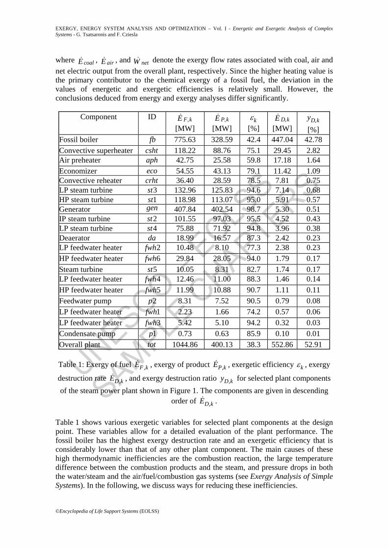
Fossil boiler fb 775.63 328.59 42.4 447.04 42.78 Convective superheater csht 118.22 88.76 75.1 29.45 2.82 Air preheater aph 42.75 25.58 59.8 17.18 1.64 Economizer eco 54.55 43.13 79.1 11.42 1.09 Convective reheater crht 36.40 28.59 78.5 7.81 0.75 LP steam turbine 3st 132.96 125.83 94.6 7.14 0.68 HP steam turbine 1st 118.98 113.07 95.0 5.91 0.57 Generator gen 407.84 402.54 98.7 5.30 0.51 IP steam turbine 2st 101.55 97.03 95.5 4.52 0.43 LP steam turbine 4st 75.88 71.92 94.8 3.96 0.38 Deaerator da 18.99 16.57 87.3 2.42 0.23 LP feedwater heater 2fwh 10.48 8.10 77.3 2.38 0.23 HP feedwater heater 6fwh 29.84 28.05 94.0 1.79 0.17 Steam turbine 5st 10.05 8.31 82.7 1.74 0.17 LP feedwater heater 4fwh 12.46 11.00 88.3 1.46 0.14 HP feedwater heater 5fwh 11.99 10.88 90.7 1.11 0.11 Feedwater pump 2p 8.31 7.52 90.5 0.79 0.08 LP feedwater heater 1fwh 2.23 1.66 74.2 0.57 0.06 LP feedwater heater 3fwh 5.42 5.10 94.2 0.32 0.03 Condensate pump 1p 0.73 0.63 85.9 0.10 0.01 Overall plant tot 1044.86 400.13 38.3 552.86 52.91
Table 1: Exergy of fuel ,F kE , exergy of product ,P kE , exergetic efficiency kε , exergy
destruction rate ,D kE , and exergy destruction ratio ,D ky for selected plant components of the steam power plant shown in Figure 1. The components are given in descending
order of ,D kE . Table 1 shows various exergetic variables for selected plant components at the design point. These variables allow for a detailed evaluation of the plant performance. The fossil boiler has the highest exergy destruction rate and an exergetic efficiency that is considerably lower than that of any other plant component. The main causes of these high thermodynamic inefficiencies are the combustion reaction, the large temperature difference between the combustion products and the steam, and pressure drops in both the water/steam and the air/fuel/combustion gas systems (see Exergy Analysis of Simple Systems). In the following, we discuss ways for reducing these inefficiencies.
UNESCO – EOLS
S
SAMPLE C
HAPTERS
EXERGY, ENERGY SYSTEM ANALYSIS AND OPTIMIZATION – Vol. I - Energetic and Exergetic Analysis of Complex Systems - G. Tsatsaronis and F. Cziesla
©Encyclopedia of Life Support Systems (EOLSS)
The exergy destruction due to combustion can be reduced by lowering the excess air and preheating the reactants. A part of the chemical exergy of coal is used to heat the nitrogen, the excess oxygen as well as the coal and air moisture to the combustion temperature. The lower the amounts of nitrogen, excess oxygen and moisture of the reactants, the less exergy destruction per unit of fuel (the lower the irreversibilities associated with direct heat transfer from the combustion products to these chemical substances). However, such measures affect the completeness of fossil fuel combustion and the maximum combustion temperature. Therefore, the measures to be taken to reduce the exergy destruction due to combustion must comply with constraints imposed by unburned fuel (exergy loss), materials used in the boiler, and maximum allowed
xNO emissions. The mass flow rate of air has also some impact on the temperature profile of the hot stream in the superheater, reheater, and economizer. Here, the combustion air is already preheated to 529 K in the air preheater aph and the value of the excess-air fraction ( ( ) 15air air stoich air stoich %n n n, ,− / = ) is at the lower limit to ensure good combustion of the pulverized solid fuel. Further preheating of the air and decreasing the excess-air fraction would decrease the exergy destruction in the fossil boiler. Further air preheating also reduces the exergy loss associated with the exhaust gas (58). However, low-temperature corrosion in the air preheater due to the presence of
2SO in the combustion products as well as the requirement for a high carbon-conversion degree in the combustion process impose additional constraints to the reduction of the minimum temperature of the exhaust gas, and of the excess-air fraction, respectively. Thermodynamic inefficiencies associated with heat transfer in the fossil boiler are mainly due to the large temperature difference between the hot combustion products and the water in the evaporator. The exergy destruction in the steam drum of the evaporator, where subcooled feedwater is mixed with water and steam at saturation temperature, is relatively small. The average temperature difference between the hot and the cold stream is a measure of the exergy destruction associated with heat transfer (see Exergy Balance and Exergetic Efficiency). With increasing pressure level, the heat of evaporation of water decreases and vanishes at the critical point. For constant values of the feedwater temperature 31T and superheater outlet temperature 6T , the shares of the heat transfer rate in the economizer, superheater, and reheater related to the total heat transfer rate in the steam generator increase with increasing pressure while the heat transfer rate in the evaporator decreases. Thus, with increasing pressure the temperature profiles in the steam generator are matched better. This leads to an increasing of the thermodynamic average temperature aT , at which heat is transferred to the water and steam, and to a decreasing of the exergy destruction rate associated with heat transfer. The higher the value of aT , the lower the temperature difference during heat transfer from the combustion gases to the steam. Also an increase in the steam generator inlet temperature 31T raises this thermodynamic average temperature. Such a change results in an improved thermodynamic performance of the economizer eco and the total steam generator when the exhaust temperature of the gas from the overall plant remains unchanged by increasing the air preheating.
UNESCO – EOLS
S
SAMPLE C
HAPTERS
EXERGY, ENERGY SYSTEM ANALYSIS AND OPTIMIZATION – Vol. I - Energetic and Exergetic Analysis of Complex Systems - G. Tsatsaronis and F. Cziesla
©Encyclopedia of Life Support Systems (EOLSS)
From a thermodynamic viewpoint, steam power plants with supercritical steam parameters are to be favored. However, the smaller temperature differences in the heat exchangers of the steam generator require a larger heat transfer area which also results in a larger total pressure drop. Even if the exergy destruction associated with friction is small compared with the other sources of thermodynamic inefficiencies in a plant, it should be noted that the pressure losses are covered by valuable (expensive) shaft work in the pumps or result in less useful work in the turbines. A large pressure at the inlet of the high-pressure turbine might lead to an unacceptably low value of the steam quality at the outlet of the low-pressure turbine. The steam quality also affects the efficiency of the low-pressure steam turbines. Hence, the steam temperature must also be increased and more than one reheater may be required in the steam generator. In the design of the plant shown in Figure 1, the reheater consists of a convective superheater ( crht ) and a radiative heat exchanger, which is included in the boundaries of the fossil boiler ( fb ). In the optimization of the steam power plant, the values of temperature and pressure of the main steam and reheat steam should be considered simultaneously. Reheating the exhaust steam from the high-pressure turbine results in an increase in the average temperature at which heat is transferred to the working fluid. Again, this improves the efficiency of the total plant. From the economic viewpoint, such a measure raises the investment cost of the power plant due to system complexity, larger heat transfer areas, and perhaps, the use of more expensive materials. The performance of the convective reheater (crht ) depends on the parameters of the main steam at the inlet to the HP turbine, the efficiency and the outlet pressure of the HP turbine, and the amount of steam used in the feedwater preheater 6fwh . All these parameters have an effect on the temperature of the steam in the reheater. The mass flow rate of steam 9 8 33m m m= − affects the slope of the temperature profile whereas the values of pressure and temperature at the inlet and outlet of the HP turbine affect the temperature differences in the reheater. The cost of material for the superheater and the reheater restrict the maximum steam temperature. Since lower pressure in the reheater causes lower mechanical stress in the material, a higher temperature might be selected for the reheat steam than for the main steam. Friction is the main cause of exergy destruction in turbines (see Exergy Analysis of Simple Systems). This effect is more significant at higher mass flow rates and lower temperature levels. The low-pressure turbines ( 3 4st st, ) have a lower exergetic efficiency than the high-pressure and the intermediate-pressure steam turbines. Partial condensation of steam in the last stages of the LP turbines disturbs the flow profiles across the blades. Water droplets can also slow down the rotor. The steam quality at the outlet of a low-pressure steam turbine decreases with increasing efficiency of the IP and LP turbines. Among all parts of a steam turbine, the pressure ratio in the LP turbines has the highest value. About 50 % of the gross electric power is generated in the two low-pressure turbines. Thus, improvements in these components are more significant for the overall efficiency than similar modifications in the HP or IP turbines. In recent years, significant performance improvements of steam turbines have been achieved through three-dimensional computational design of highly twisted blades, advanced blade materials, and new manufacturing processes.
UNESCO – EOLS
S
SAMPLE C
HAPTERS
EXERGY, ENERGY SYSTEM ANALYSIS AND OPTIMIZATION – Vol. I - Energetic and Exergetic Analysis of Complex Systems - G. Tsatsaronis and F. Cziesla
©Encyclopedia of Life Support Systems (EOLSS)
In the feedwater preheating section, the highest exergy destruction rate occurs in the deaerator ( da ; open-type feedwater heater). Exhaust steam from the intermediate-pressure turbine provides most of the energy required to increase the temperature of the low-pressure feedwater (26) to saturation conditions. The remaining energy is supplied by the return stream (41) from feedwater heater 5fwh . Large differences both in temperature ( 226T KΔ = ) and pressure ( 8p barΔ = ) between the entering streams result in this ineffectiveness. Low-pressure steam should be used for deaeration, for example by extracting steam at an appropriate pressure level from the LP turbine 4st . The exergy destruction in the closed-type feedwater heaters is due to (a) temperature differences between the feedwater and the steam, (b) mixing of hot streams with differences in temperature and pressure, and (c) pressure drops. In improving the thermodynamic performance of the overall plant, the steam generator inlet temperature and the number of feedwater heaters should be considered simultaneously. For a given temperature increase in the overall feedwater preheating section ( 31 22fwhT T TΔ = − ), the exergetic efficiency of the total plant increases when more feedwater heaters are being used. Because the temperature difference during heat exchange decreases in each feedwater heater, the exergy destruction also decreases. If the number of feedwater heaters is kept constant and both the steam generator inlet temperature 31T and the air preheater outlet temperature 54T are increased, an optimum temperature 31 optT , exists where a maximum efficiency of the total plant is achieved. Below this optimum temperature, an increase of 31T improves the thermodynamic performance of the steam generator. Above this optimum value, an increase in the exergy destruction rate due to larger temperature differences in the feedwater heaters outweighs the performance improvement in the steam generator. Optimal values for the steam generator inlet temperature and the number of feedwater heaters have to be determined not only from the thermodynamic but also from the economic viewpoint. The sum of the exergy losses associated with the streams rejected to the environment (exhaust gas, cooling water in the condenser, ash, and blow down) is 8.8 % of the exergy F totE , supplied to the overall plant by coal and air. A significant exergy stream is still associated with the exhaust gas (4.0 % of F totE , ). This loss should be reduced in a future design. The temperature of this stream depends on the combustion temperature, the heat transfer rate in the heat exchangers of the steam generator, and the steam generator inlet temperature 31T . For example, an increase in the feedwater temperature
31T improves the exergetic efficiency of the steam generator but requires an increase in the temperature of the preheated air (54) to keep the temperature of the exhaust gas at a low value. The purpose of a condenser in a power plant is to remove the entropy added to the working fluid in all the other plant components. Hence, the quantity of heat transferred to the cooling water is a consequence of the second law of thermodynamics and of the thermodynamic inefficiencies in the other plant components. To reduce the exergy rate rejected to the surroundings in the condenser (4.4 % of F totE , ) some of the exergy destruction in the total plant must be avoided. In addition, lower values of the condenser
UNESCO – EOLS
S
SAMPLE C
HAPTERS
EXERGY, ENERGY SYSTEM ANALYSIS AND OPTIMIZATION – Vol. I - Energetic and Exergetic Analysis of Complex Systems - G. Tsatsaronis and F. Cziesla
©Encyclopedia of Life Support Systems (EOLSS)
pressure increase the efficiency of the overall plant. The condenser pressure depends on the available mass flow rate and temperature of cooling water as well as on the finite temperature difference between the steam and the cooling water. Although these factors are site specific, it is very important to keep the pressure in the condenser as low as possible. In Figure 1, two condensers operating at different pressure levels are used. The cooling water flows in series through condensers 2cnd and 1cnd . At a given mass flow rate of cooling water, such an arrangement results in a lower average condenser pressure than parallel flow through the condensers. In general, exergy losses associated with ash, blow down, or vent streams are small. Depending on the type of steam generator, the ash is removed from the combustion chamber below or above the ash melting point. The physical exergy of ash might be further used for preheating process streams such as feedwater. Unburned carbon increases the chemical exergy of ash and may be reduced by increasing the excess air in the combustion process in the steam generator. 2.4. Discussion and Conclusions Some of the exergy destructions in a power plant are justified by operational, economic, environmental, or safety reasons. For example, if the steam generator operates at constant pressure, then the steam turbine load is controlled by varying the outlet pressure of the throttle valve at the inlet of the high-pressure steam turbine. For each load, the fuel flow rate and the pressure at the outlet of the feedwater pump 2p are adjusted to keep the pressure at the inlet of valve 1v at a constant value. It is apparent that increased throttling of the steam at partial load is unfavorable from the thermodynamic viewpoint. However, this information cannot be obtained from an energy balance of the throttling device, since the enthalpy rate across an adiabatic valve is constant ( 7 6H H= ). An exergy balance shows that the exergy destruction rate
1 6 7D vE E E, = − might be significant at partial load. Today, sliding-pressure control or a combination of fixed-pressure and sliding-pressure control is often applied in advanced steam power plants. - - -
TO ACCESS ALL THE 26 PAGES OF THIS CHAPTER, Visit: http://www.eolss.net/Eolss-sampleAllChapter.aspx
Bibliography Bejan A., Tsatsaronis G., and Moran M. (1996). Thermal Design and Optimization. New York: John Wiley & Sons. 542 p. [Contains an introduction to the exergy concept, applications, and exergy-aided cost minimization of energy conversion systems]
Brodyansky V.M., Sorin M.V., and Le Goff P. (1994). The efficiency of Industrial Processes: Exergy
UNESCO – EOLS
S
SAMPLE C
HAPTERS
EXERGY, ENERGY SYSTEM ANALYSIS AND OPTIMIZATION – Vol. I - Energetic and Exergetic Analysis of Complex Systems - G. Tsatsaronis and F. Cziesla
©Encyclopedia of Life Support Systems (EOLSS)
Analysis and Optimization. Amsterdam: Elsevier, 487p. [provides a detailed discussion of the concepts of exergy and coefficient of structural bonds.]
Cornelissen, R.L. and Hirs, G.G. (1998). Exergy Analysis in the Process Industry. in: Bejan, A. and Mamut, E. (Eds.) Thermodynamic Optimization of Complex Energy Systems. Dordrecht: Kluwer Academic Publishers. pp. 195-208. [In this article, an exergy analysis of a cryogenic air separation unit is discussed.]
Cziesla, F. and Tsatsaronis, G. (2003). Avoidable Thermodynamic Inefficiencies and Costs in Energy Conversion Systems. Part 2: Application to an Externally-Fired Combined-Cycle. in: Houbak N., Elmegaard B., Qvale B., and Moran M.J. (Eds.) Proceedings of the 16th International Conference on Efficiency, Costs, Optimization, Simulation and Environmental Impact of Energy Systems (ECOS 2003), June 30 - July 2, Copenhagen, Denmark, pp. 815-826. [Discusses an application of the concepts of avoidable thermodynamic inefficiencies and costs to a complex energy conversion system.]
Facchini B., Fiaschi, D., and Manfrida, G. (2000). Exergy Analysis of Combined-Cycles Using Latest Generation Gas Turbines. J. Eng. Gas Turbines and Power, 122:233–238, April. [Contains a detailed discussion of the exergy destruction associated with cooling the blades in advanced gas turbine systems.]
Kotas T.J. (1995). The Exergy Method of Thermal Plant Analysis. Malabar, Florida: Krieger Publishing Company. 328 p. [Provides a detailed discussion of the exergy concept and its applications.]
Krause, A. and Tsatsaronis, G. (1997), Thermodynamic and Exergoeconomic Evaluation of the Humid-Air Turbine Cycle, Proceedings of the International Conference on Thermodynamic Analysis and Improvement of Energy Systems, June 10-13, Beijing, China, pp. 111-118. [Contains an exergy analysis of a conceptual design of an advanced gas turbine system. An improved design is also discussed.]
Szargut J., Morris D.R., and Steward F.R. (1988). Exergy Analysis of Thermal, Chemical, and Metallurgical Processes. New York: Hemisphere, New York, 332 p. [In this reference the exergy concept and several applications are discussed.]
Tsatsaronis G. and Winhold M. (1984). Thermoeconomic Analysis of Power Plants. Palo Alto: Electric Power Research Institute, AP-3651, Research Project 2029-8, Final Report. 212 p. [Contains a detailed exergy analysis of a steam power plant including a parameter study which shows the effect of select variables on the exergetic efficiency of the total plant.]
Tsatsaronis, G. and Tawfik, T. and Lin, L. and Gallaspy, D.T. (1994). Exergetic Comparison of Two KRW-Based IGCC Power Plants J. Eng. Gas Turbines and Power, 116:291–299, April. [Contains a comparison of two integrated gasification combined-cycle power plants from the exergetic viewpoint.]
Tsatsaronis G., Gao Z., and Cziesla F. (2003). Avoidable Thermodynamic Inefficiencies and Costs in Energy Conversion Systems. Part 1: Methodology, in: Houbak N., Elmegaard B., Qvale B., and Moran M.J. (Eds.) Proceedings of the 16th International Conference on Efficiency, Costs, Optimization, Simulation and Environmental Impact of Energy Systems (ECOS 2003), June 30 - July 2, Copenhagen, Denmark, pp. 809-814. [Describes the calculation of avoidable thermodynamic inefficiencies and costs associated with selected plant components.] Biographical Sketches Professor George Tsatsaronis is the Bewag Professor of Energy Conversion and Protection of the Environment and the Director of the Institute for Energy Engineering at the Technical University of Berlin, Germany. He studied mechanical engineering at the National Technical University of Athens, Greece, receiving the Diploma in 1972. He continued at the Technical University of Aachen, Germany, where he received a Masters Degree in business administration in 1976, a Ph.D. in combustion from the Department of Mechanical Engineering in 1977, and a Dr. Habilitatus Degree in Thermoeconomics in 1985.
In the last twenty five years he has been responsible for numerous research projects and programs related to combustion, thermoeconomics (exergoeconomics), development, simulation and analysis of various energy-conversion processes (coal gasification, electricity generation, hydrogen production, cogeneration, solar energy-conversion, oil production in refineries and also from oil shale, carbon black production, etc) as well as optimization of the design and operation of energy systems with emphasis on power plants and
UNESCO – EOLS
S
SAMPLE C
HAPTERS
EXERGY, ENERGY SYSTEM ANALYSIS AND OPTIMIZATION – Vol. I - Energetic and Exergetic Analysis of Complex Systems - G. Tsatsaronis and F. Cziesla
©Encyclopedia of Life Support Systems (EOLSS)
cogeneration systems.
He is a Fellow of the American Society of Mechanical Engineers (ASME) and a member of the American Institute of Chemical Engineers, the German Association of University Professors and the Greek Society of Engineers. He is the Past Chairman of the Executive Committee of the International Centre for Applied Thermodynamics.
In 1977 he received for his Ph.D. Thesis, the Borchers Award from the Technical University of Aachen, Germany, and in 1994 and 1999 the E.F. Obert Best Paper Award from ASME. In 1997 he became a Honorary Professor at the North China Electric Power University and in 1998 he received from ASME the James Harry Potter Gold Medal for his work in exergoeconomics.
He currently serves as an associate editor of Energy - The International Journal (since 1986), Energy Conversion and Management (since 1995), International Journal of Applied Thermodynamics (since 1998), and International Journal of Energy, Environment and Economics (since 2001). He co-authored with A. Bejan and M. Moran the book Thermal Design and Optimization and published over 150 papers. Dr. Frank Cziesla is Senior Research Associate and Lecturer at the Institute for Energy Engineering, Technical University of Berlin, Germany. He received the Diploma in Chemical Engineering from the Technical University of Berlin in 1994. In the same year, he joined the Institute for Energy Engineering as a research associate. His research activities on the design of cost-effective energy conversion systems using exergy-based optimization techniques and knowledge-based approaches led to the Ph.D. degree in 1999. He spent the summer of 1997 at the School of Nuclear Engineering, Purdue University (USA) working on a combination of exergy-based optimization techniques and fuzzy systems.
His current research activities focus on the design and operation of cost-effective energy conversion systems using exergy-based analysis and optimization techniques (thermoeconomics) as well as principles taken from the fields of artificial intelligence (experts systems) and computational intelligence (fuzzy systems, evolutionary algorithms).
He lectures on energy engineering, power plant technology, thermal design and optimization as well as applications of computational intelligence in energy engineering.
Dr. Cziesla is a member of the German Association of Engineers (VDI, Verein Deutscher Ingenieure) and the Society for Chemical Engineering and Biotechnology (DECHEMA, Gesellschaft für Chemische Technik und Biotechnologie e.V.).


