Embed Size (px)
Citation preview
www.cafetinnova.org
Indexed in
Scopus Compendex and Geobase Elsevier, Chemical
Abstract Services-USA, Geo-Ref Information Services-USA,
List B of Scientific Journals, Poland,
Directory of Research Journals
ISSN 0974-5904, Volume 07, No. 05
October 2014, P.P.XXXXX
#XXXXX Copyright ©2014 CAFET-INNOVA TECHNICAL SOCIETY. All rights reserved.
Energy Comparison of LBW Structures With MRF Structures
S SAILEYSH SIVARAJA1 AND T S THANDAVAMOORTHY
2
1 Dept. of Civil Engineering, Dr MGR University, India,
2Dept. of Civil Engineering, Adhiparasakthi Engineering College, India,
Email: [email protected], [email protected]
Abstract: The paper presents the experimental investigation on the performance of the 1/3rd scale masonry model
of box type of size 2 m × 1 m × 1m without and with a roof slab as well as consisting of LBW (Load Bearing Wall)
and MRF (Moment Resisting Frame) arrangement, mounted on a shake table and impacting it with a pendulum
weighing 115 kg and 150 kg and measuring the acceleration of the building and the energy absorption capacity. The
representative prototype masonry was of size 6 m 3 m with roof height of 3 m. A brick masonry building was
constructed using cement-lime mortar of mix proportion 1:10:20. The Model-1A was constructed without roof slab
for LBW structures system. Model-1B was constructed without roof slab for MRF structures. Model-2A was
constructed with a roof slab for LBW system of size 2.1 m × 1.1 m, thickness of the slab being 35 mm. Model-2B
was constructed with a roof slab for MRF structures. From the velocity of impact the energy impacted to the
building was computed for each impact and the test was carried out till the building suffered extensive damages and
was unable to resist further impacts. The total energy absorbed by LBW buildings without roof slab (Model-1A) was
4,304 Nm after 23rd impacts; by MRF structures without roof slab (Model-1B) was 8,108 Nm after 40 impacts; by
the LBW building with roof slab (Model-2A) was 6,500 Nm after 35 impacts and by MRF building with a roof slab
(Model-2B) was 10,032 Nm after 38 impacts. Relevant conclusions drawn from the experimental programme are
also discussed in the paper.
Keywords: Masonry building, Scaled Bricks, LBW and MRF and Shock Table, Energy Absorption, Base
Acceleration.
1. Introduction:
A masonry wall can undergo in-plane shear stresses due
to gravity loads in the plane of the wall. Shear failure in
the form of diagonal cracks is observed due to this. The
brittle nature of masonry leads to sudden and
catastrophic collapse of walls when the wall experiences
out-of-plane failure. A masonry building with openings
and different types of roofing system is a complex
structure and it is very difficult to understand and
simulate the failure patterns of the building analytically,
especially when it is subjected to ground induced lateral
vibrations. To understand the complex behaviour of
masonry buildings during ground motion sophisticated
facilities such as a shaking table with data acquisition
systems with associated instrumentation are needed.
However, the test on a full-scale prototype is an
expensive proposition, especially when parametric
studies are to be carried out. In the context of the study
of earthquake resistant features, test on small scale
model becomes indispensable. Here, tests are conducted
on small scale models in order to obtain the response
characteristics of a geometrically similar full scale
prototype.
The primary objective of the test carried out here was to
develop a shock table and to study the base shock
resistance and failure patterns of simple box type
masonry-building models with and without roof slab.
IS: 13828 (1993) has defined a box type construction as
consisting of masonry wall along both the axes of the
building. The walls support vertical loads and also act
as shear wall for horizontal loads acting in any
direction. Jagadish et al. (2002) had fabricated a small
rectangular shock table to test the behaviour of (1/6)th
scale building models to base shock induced vibrations.
The primary objective was to study the failure pattern of
simple box type masonry building without any
earthquake resistant feature particularly the out-of-plane
(flexural) failure of the longer cross wall. Sivaraja et al
(2012) studied on the development in research relating
to masonry structures and an annotated bibliography
was prepared by reviewing the available literature. This
bibliography presented various aspects of research on
masonry structures. Deodhar and Patel (1996) worked
on behaviour of brick masonry in compression. They
studied different parameters like size of brick, role of
frog, and mortar thickness on crushing strength of brick
masonry. The conclusions were that large brick size
gave more strength and economy; hence only metric
1881 S SAILEYSH SIVARAJA AND T S THANDAVAMOORTHY
International Journal of Earth Sciences and Engineering
ISSN 0974-5904, Vol. 07, No. 05, October, 2014, pp. 1880-1890
bricks of size 200 mm 100 mm 100 mm should be
used in practice. Rectangular frog gave higher strength.
Frog was found to be more useful to increase load
carrying capacity of masonry in flexure and shear. A
joint thickness of 5 mm to 10 mm gave the maximum
strength. Higher mortar thickness reduced adhesion
between brick and mortar and consequently reduced the
strength of brick masonry. Balasubramanian et al (2005)
studied the damages suffered by brick masonry during
earthquakes. In the Bhuj earthquake, majority of the
masonry structures were damaged because they were
built with un-reinforced masonry. The code of practice
for brick masonry IS 4326 (1993) suggested the use of
lintel band to integrate the structure and thus introduced
a rigid box. Patil and Achawal (2000) investigated the
strength of brick masonry prisms constructed using low
strength bricks and cement mortar. The author discussed
the strength of bricks collected from different
geographical location of Marathawada region of
Maharashtra state of India. Brick strength ranged
between 3 to 7 MPa. Water absorption of bricks was an
independent parameter and did not depend on the
compressive strength of bricks. Compressive strength
of brick masonry prisms fabricated using brick samples
from different regions of Marathwada was determined
using cement mortars of various proportions. Increase in
mortar strength and brick strength both lead to increased
masonry strength according to Thomas (1971), but in
neither case in direct proportion. It is more economical
to increase brick strength rather than mortar strength for
improving the strength of the masonry. The paper
presents the development of a shock-table, its use to
study the base shock resistance and failure patterns of a
simple box type masonry building models with and
without roof slab consisting of LBW and MRF
structures (Figs. 1- 6). It also presents the conclusions
drawn there from.
2. EXPERIMENTAL PROGRAMME:
In this experimental investigation a shock table was
designed and fabricated to conduct test on one-third
scaled brick building model subjected to dynamic
loading as base excitation, and to study its behaviour
such as energy absorption capacity and various failure
modes under this excitation. Pertinent details of this
experimental investigation are presented in the
following sections.
2.1 Development of Shock Table:
A simple version of the shaking table was a shock table,
which was a horizontal table over which building
models could be built and tested under base shock
excitation. The shock table could be used to simulate the
cumulative effects of ground motion by subjecting it to
a series of base impacts. Using a simple pendulum
impact device (Fig. 7), it was possible to control the
magnitude of base shock. This helped in reproducing
the masonry building failure modes. Also, after each
shock it was possible to study the progress of failure of
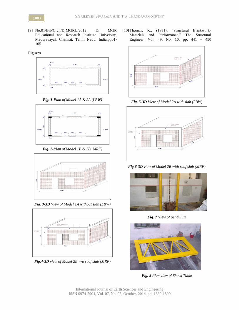
walls. Figure 8 showed the details of shock table. The
main components of the shock table were the channel
frame that supported the building model and the wheels
that allowed the motion. As for the wheels, a grooved
pulley was used so that it allowed for motion only in
one direction as it rolled over the rails. Inverted ‘T’
sections of size 50 mm 50 mm 6 mm were used as
rails. The rails were supported over a masonry wall of
23 cm thickness and 45 cm high. An angle section of
ISA 40 mm 40 mm 6 mm was used for stiffness as
shown in Fig. 8. An angle section of ISA 100 mm 100
mm 8 mm was used to support the table frame as
shown in Fig. 8. The total mass of the shock table with
wheels was 200 kg. The shock table was fabricated such
that the motion was perpendicular to the plane of the
cross walls (here longer walls), thus causing out-of-
plane vibrations in them (Sivaraja, 2006).
2.2 Construction of Scaled Building Models:
Openings were provided only in cross walls i.e., one
door and one window on the east wall and two windows
on the west wall; Windows were of size 0.30 m 0.45
m and 0.45 m .0.45 m; and Doors were 0.30 m 0.70
m. No openings were provided in shear wall (here
shorter walls). This paper deals only with the study of
out-of-plane (flexural) failure of the longer cross walls
(Balasubramanian, 2005). Slab was 35 mm thick and its
size was 2.10 m 1.10 m. MS welded mesh made with
3 mm rods with spacing at 50 mm center to center was
used as reinforcement for slab. Lintel band was 50 mm
thickness with 4 nos. of 3 mm MS rod as main
reinforcement and 2 mm MS wire at 50 mm c/c as
stirrups.
2.3 Base Impact Test:
The schematic diagram of the test setup with necessary
the instrumentation and vibration measurement was
shown lucidly. The base impact was very much useful
to simulate the effects of lateral ground motions on
building. In this experiment, pendulum impact device
was used for base shock. The input energy was
controlled by varying the height of release (h). The
pendulum weight of 150 kg and 115 kg were used for
models with and without roof slab, respectively. The
chord length of release of pendulum was varied from 30
cm to 75 cm. The weight of hammer was calculated as
10% of the total weight of shock table and masonry
model.
3. Discussion of Test Results:
The amount of energy imparted during each shock was
calculated by knowing the velocity of impact and mass
1882 Energy Comparison of LBW Structures with MRF Structures
International Journal of Earth Sciences and Engineering
ISSN 0974-5904, Vol. 07, No. 05, October, 2014, pp. 1880-1890
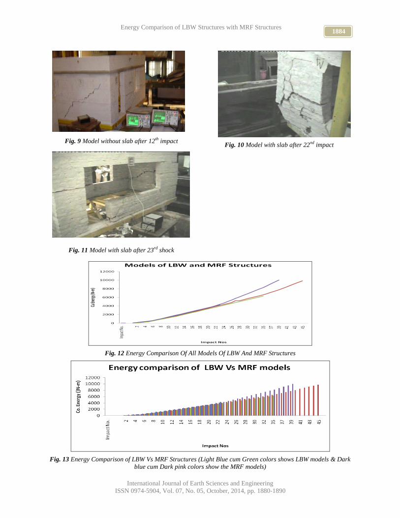
of the pendulum i.e., ½mv² where v = (2gh). Figures 9
to 11 shows the failure patterns of models. Figure 12
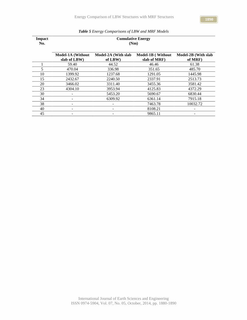
shows energy comparison of all Models. Figure 13
shows the energy comparison values of LBW and MRF
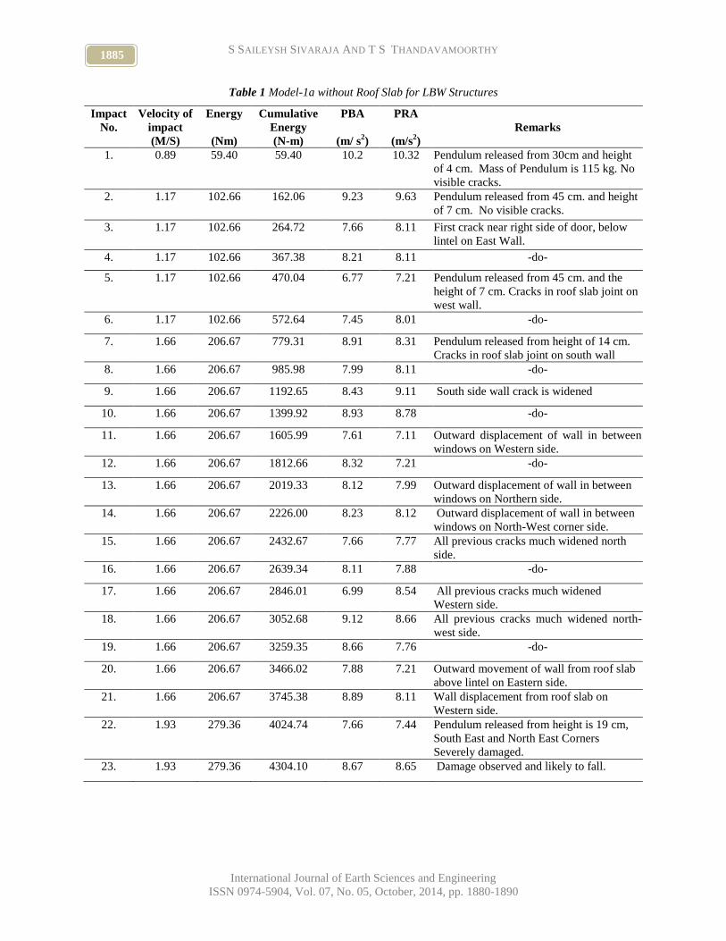
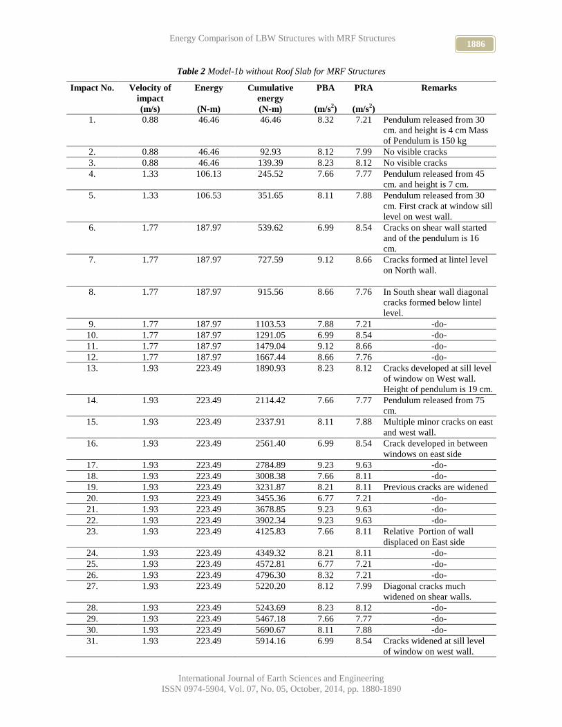
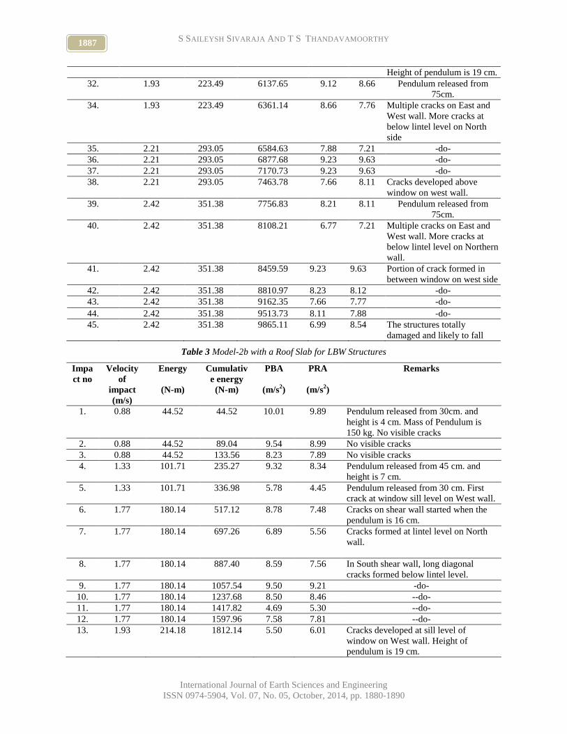
models. Tables 1 to 5 shows the details of Base Impact
Test conducted on all models, respectively. The remarks
columns in the tables describe the progress of collapse
and failure modes in detail sequentially. The total
energy absorbed by LBW buildings without roof slab
(Model-1A) was 4,304 Nm after 23 impacts. The energy
absorbed by MRF structures without roof slab (Model-
1B) was 8,108 Nm after 40 impacts. The energy
absorbed by the LBW building with roof slab (Model-
2A) was 6,500 Nm after 35 impacts. The energy
absorbed by MRF with a roof slab (Model-2B) was
10,032 Nm after 38 impacts. The Model-1A without
roof slab is less stiff than that of Modei-1B without roof
slab for MRF Structures. For the same velocity in the
impact, the energy capacity in the case of the Model-1B
is 88 per cent higher than that of the Model-1A.
Similarly the energy capacity in the case of the Model-
2B is 54 per cent higher than that of the Model-2A. This
shows that the sustainability of model with MRF
structures under base shock excitation is better than that
LBW structures.
As for failure pattern, there was a diagonal crack on
short wall as shown in Fig. 9 as well as at sill level at
window on the long wall. In the model shown in Fig.
10 there was extensive cracking on all walls. There
were two horizontal cracks on the right segment of
longer walls with the result the walls got displaced
relatively. There was separation of wall at lintel level
on the right segment. Corresponding to the horizontal
wall on the right segment there was also a horizontal
crack on the left segment. On the right side of the door
there was a diagonal crack from the sill of the window
down to the plinth. A diagonal crack was observed on
the right side short wall. The portion of the wall on the
western side of the model was severely damaged with
fragmented segment and the segments were rendered
out of plumb.
4. Conclusions
The experimental investigation has disclosed that
Model-1A without roof slab is less stiff than that of
Model-1B without roof slab for MRF Structures. For
the same velocity of the impact, the energy capacity in
the case of the Model-1B was 88 per cent higher than
that of the Model-1A. Similarly, the energy capacity in
the case of the Model-2B was 54 per cent higher than
that of the Model-2A. This showed that the
sustainability of model with MRF structures under base
shock excitation was better than that LBW structures.
The failure pattern mostly disclosed extensive cracking
of masonry with progressive increase in the number of
impacts. The crack pattern was so severe that the walls
become out-of-plumb and the walls were also
fragmented.
5. Acknowledgement
The authors express their deep gratitude to the
Reviewers Dr. V. Ramaswamy, Professor, Dept. of
Civil Engineering, Adhiparasakthi Engineering College,
Melmaruvathur, Tamils Nadu and Dr. P.N. Ragunath,
Professor, Civil and Strural Engineering, Annamalai
University, Chidambaram, Tamil Nadu for their
valuable comments. Sincere thanks are also due to Prof.
Dr. D.V. Reddy, Editor-in-Chief, International Journal
of Earth Science and Engineering, Suratkal, Karnataka
for his laudable interest in publishing this important
paper.
References
[1] Balasubramanian, R., Saileysh Sivaraja, S., Senthil,
R. and Santhakumar A.R. (2005), “Behaviour of
Masonry Building under base shock vibrations,’
National Symposium on Structural Dynamics,
Random Vibrations and Earthquake Engineering,”
(Ed.) C.S. Manokar and D. Roy, Indian Institute of
Science, Bangalore, India, pp 99-106.
[2] Deodhar, S.V and Patel, A.N., (1996), ”Behaviour
of Brick Masonry in Compression”, Journal of
Structural Engineering, Vol. 22, No. 4, pp. 221-
224.
[3] Patil, K.A. and Achawal, V.G., (2000), “Strength of
Brick Masonry Prisms Using Low Strength Bricks
and Cement Mortar”, Proceedings of 6th Inter-
national Seminar on Structural Masonry for
Developing Countries, Organised by the
Department of Civil Engineering, I.I.Sc.,
Bangalore, 11-13 October, pp. 134-137.
[4] IS: 4326, (1993), ”Bureau of Indian Standards,
New Delhi, India.
[5] IS: 13828 (1996), “Improving Earthquake
Resistance of Low Strength Masonry Buildings –
Guidelines,” Bureau of Indian Standards, New
Delhi, India.
[6] Jagdish K.S., Ragunath S. and Nanjunda Rao K.S.
(2002), ‘Shock Table Studies on Masonry Building
Model with Containment Reinforcement’, Journal
of Structural Engineering, Vol. 29, No.1, pp. 9-17.
[7] Saileysh Sivaraja, S., (2006), “Behaviour of Rat-
trap Bond Masonry Building Under Base Shock
Vibration,” M.S. Dissertation, Anna University,
Chennai, 2006, 54 pp.
[8] Saileysh Sivaraja S, Moses Aranganathan.S and
Thandavamoorthy.T.S, (2012), “Bibliography on
Masonry Structures-Technical Report”, (2012),
Technical Report No. Vol
1883 S SAILEYSH SIVARAJA AND T S THANDAVAMOORTHY
International Journal of Earth Sciences and Engineering
ISSN 0974-5904, Vol. 07, No. 05, October, 2014, pp. 1880-1890
[9] No:01/Bib/Civil/DrMGRU/2012, Dr MGR
Educational and Research Institute University,
Maduravayal, Chennai, Tamil Nadu, India.pp01-
105
[10] Thomas, K., (1971), “Structural Brickwork-
Materials and Performance,” The Structural
Engineer, Vol. 49, No. 10, pp. 441 – 450
Figures
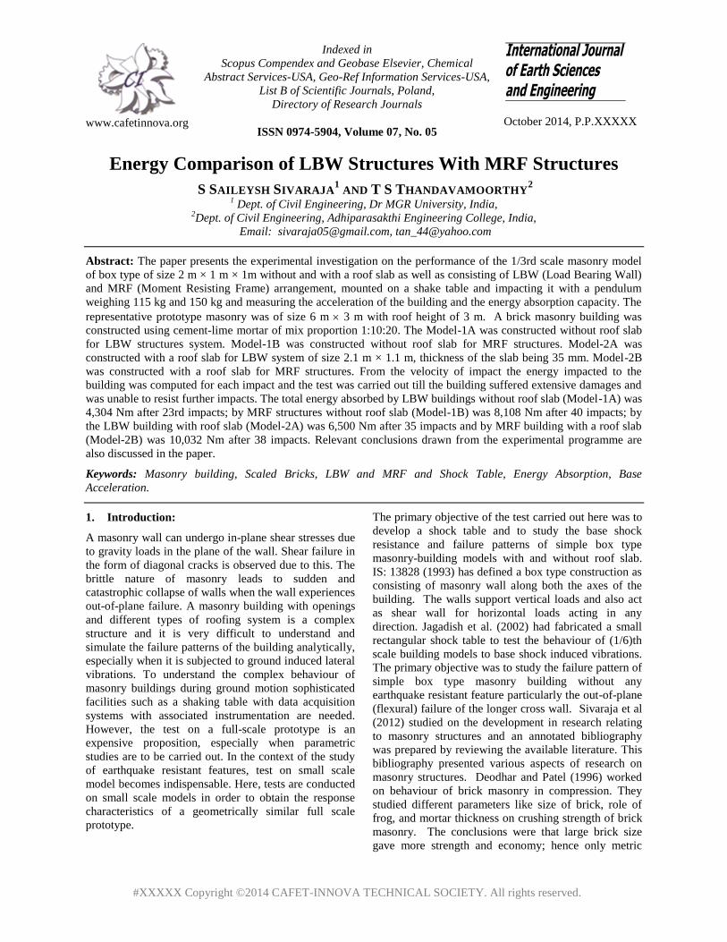
Fig. 1-Plan of Model 1A & 2A (LBW)
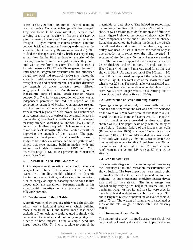
Fig. 2-Plan of Model 1B & 2B (MRF)
.
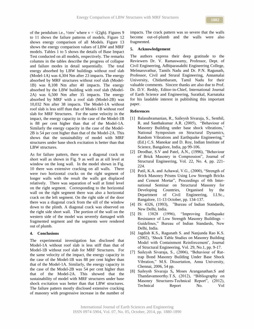
Fig. 3-3D View of Model 1A without slab (LBW)
Fig.4-3D view of Model 2B w/o roof slab (MRF)
Fig. 5-3D View of Model 2A with slab (LBW)
Fig.6-3D view of Model 2B with roof slab (MRF)
Fig. 7 View of pendulum
Fig. 8 Plan view of Shock Table
1884 Energy Comparison of LBW Structures with MRF Structures
International Journal of Earth Sciences and Engineering
ISSN 0974-5904, Vol. 07, No. 05, October, 2014, pp. 1880-1890
Fig. 9 Model without slab after 12th
impact
Fig. 10 Model with slab after 22nd
impact
Fig. 11 Model with slab after 23rd
shock
Fig. 12 Energy Comparison Of All Models Of LBW And MRF Structures
Fig. 13 Energy Comparison of LBW Vs MRF Structures (Light Blue cum Green colors shows LBW models & Dark
blue cum Dark pink colors show the MRF models)
1885 S SAILEYSH SIVARAJA AND T S THANDAVAMOORTHY
International Journal of Earth Sciences and Engineering
ISSN 0974-5904, Vol. 07, No. 05, October, 2014, pp. 1880-1890
Table 1 Model-1a without Roof Slab for LBW Structures
Impact
No.
Velocity of
impact
(M/S)
Energy
(Nm)
Cumulative
Energy
(N-m)
PBA
(m/ s2)
PRA
(m/s2)
Remarks
1. 0.89 59.40 59.40 10.2 10.32 Pendulum released from 30cm and height
of 4 cm. Mass of Pendulum is 115 kg. No
visible cracks.
2. 1.17 102.66 162.06 9.23 9.63 Pendulum released from 45 cm. and height
of 7 cm. No visible cracks.
3. 1.17 102.66 264.72 7.66 8.11 First crack near right side of door, below
lintel on East Wall.
4. 1.17 102.66 367.38 8.21 8.11 -do-
5. 1.17 102.66 470.04 6.77 7.21 Pendulum released from 45 cm. and the
height of 7 cm. Cracks in roof slab joint on
west wall.
6. 1.17 102.66 572.64 7.45 8.01 -do-
7. 1.66 206.67 779.31 8.91 8.31 Pendulum released from height of 14 cm.
Cracks in roof slab joint on south wall
8. 1.66 206.67 985.98 7.99 8.11 -do-
9. 1.66 206.67 1192.65 8.43 9.11 South side wall crack is widened
10. 1.66 206.67 1399.92 8.93 8.78 -do-
11. 1.66 206.67 1605.99 7.61 7.11 Outward displacement of wall in between
windows on Western side.
12. 1.66 206.67 1812.66 8.32 7.21 -do-
13. 1.66 206.67 2019.33 8.12 7.99 Outward displacement of wall in between
windows on Northern side.
14. 1.66 206.67 2226.00 8.23 8.12 Outward displacement of wall in between
windows on North-West corner side.
15. 1.66 206.67 2432.67 7.66 7.77 All previous cracks much widened north
side.
16. 1.66 206.67 2639.34 8.11 7.88 -do-
17. 1.66 206.67 2846.01 6.99 8.54 All previous cracks much widened
Western side.
18. 1.66 206.67 3052.68 9.12 8.66 All previous cracks much widened north-
west side.
19. 1.66 206.67 3259.35 8.66 7.76 -do-
20. 1.66 206.67 3466.02 7.88 7.21 Outward movement of wall from roof slab
above lintel on Eastern side.
21. 1.66 206.67 3745.38 8.89 8.11 Wall displacement from roof slab on
Western side.
22. 1.93 279.36 4024.74 7.66 7.44 Pendulum released from height is 19 cm,
South East and North East Corners
Severely damaged.
23. 1.93 279.36 4304.10 8.67 8.65 Damage observed and likely to fall.
1886 Energy Comparison of LBW Structures with MRF Structures
International Journal of Earth Sciences and Engineering
ISSN 0974-5904, Vol. 07, No. 05, October, 2014, pp. 1880-1890
Table 2 Model-1b without Roof Slab for MRF Structures
Impact No. Velocity of
impact
(m/s)
Energy
(N-m)
Cumulative
energy
(N-m)
PBA
(m/s2)
PRA
(m/s2)
Remarks
1. 0.88 46.46 46.46 8.32 7.21 Pendulum released from 30
cm. and height is 4 cm Mass
of Pendulum is 150 kg
2. 0.88 46.46 92.93 8.12 7.99 No visible cracks
3. 0.88 46.46 139.39 8.23 8.12 No visible cracks
4. 1.33 106.13 245.52 7.66 7.77 Pendulum released from 45
cm. and height is 7 cm.
5. 1.33 106.53 351.65 8.11 7.88 Pendulum released from 30
cm. First crack at window sill
level on west wall.
6. 1.77 187.97 539.62 6.99 8.54 Cracks on shear wall started
and of the pendulum is 16
cm.
7. 1.77 187.97 727.59 9.12 8.66 Cracks formed at lintel level
on North wall.
8. 1.77 187.97 915.56 8.66 7.76 In South shear wall diagonal
cracks formed below lintel
level.
9. 1.77 187.97 1103.53 7.88 7.21 -do-
10. 1.77 187.97 1291.05 6.99 8.54 -do-
11. 1.77 187.97 1479.04 9.12 8.66 -do-
12. 1.77 187.97 1667.44 8.66 7.76 -do-
13. 1.93 223.49 1890.93 8.23 8.12 Cracks developed at sill level
of window on West wall.
Height of pendulum is 19 cm.
14. 1.93 223.49 2114.42 7.66 7.77 Pendulum released from 75
cm.
15. 1.93 223.49 2337.91 8.11 7.88 Multiple minor cracks on east
and west wall.
16. 1.93 223.49 2561.40 6.99 8.54 Crack developed in between
windows on east side
17. 1.93 223.49 2784.89 9.23 9.63 -do-
18. 1.93 223.49 3008.38 7.66 8.11 -do-
19. 1.93 223.49 3231.87 8.21 8.11 Previous cracks are widened
20. 1.93 223.49 3455.36 6.77 7.21 -do-
21. 1.93 223.49 3678.85 9.23 9.63 -do-
22. 1.93 223.49 3902.34 9.23 9.63 -do-
23. 1.93 223.49 4125.83 7.66 8.11 Relative Portion of wall
displaced on East side
24. 1.93 223.49 4349.32 8.21 8.11 -do-
25. 1.93 223.49 4572.81 6.77 7.21 -do-
26. 1.93 223.49 4796.30 8.32 7.21 -do-
27. 1.93 223.49 5220.20 8.12 7.99 Diagonal cracks much
widened on shear walls.
28. 1.93 223.49 5243.69 8.23 8.12 -do-
29. 1.93 223.49 5467.18 7.66 7.77 -do-
30. 1.93 223.49 5690.67 8.11 7.88 -do-
31. 1.93 223.49 5914.16 6.99 8.54 Cracks widened at sill level
of window on west wall.
1887 S SAILEYSH SIVARAJA AND T S THANDAVAMOORTHY
International Journal of Earth Sciences and Engineering
ISSN 0974-5904, Vol. 07, No. 05, October, 2014, pp. 1880-1890
Height of pendulum is 19 cm.
32. 1.93 223.49 6137.65 9.12 8.66 Pendulum released from
75cm.
34. 1.93 223.49 6361.14 8.66 7.76 Multiple cracks on East and
West wall. More cracks at
below lintel level on North
side
35. 2.21 293.05 6584.63 7.88 7.21 -do-
36. 2.21 293.05 6877.68 9.23 9.63 -do-
37. 2.21 293.05 7170.73 9.23 9.63 -do-
38. 2.21 293.05 7463.78 7.66 8.11 Cracks developed above
window on west wall.
39. 2.42 351.38 7756.83 8.21 8.11 Pendulum released from
75cm.
40. 2.42 351.38 8108.21 6.77 7.21 Multiple cracks on East and
West wall. More cracks at
below lintel level on Northern
wall.
41. 2.42 351.38 8459.59 9.23 9.63 Portion of crack formed in
between window on west side
42. 2.42 351.38 8810.97 8.23 8.12 -do-
43. 2.42 351.38 9162.35 7.66 7.77 -do-
44. 2.42 351.38 9513.73 8.11 7.88 -do-
45. 2.42 351.38 9865.11 6.99 8.54 The structures totally
damaged and likely to fall
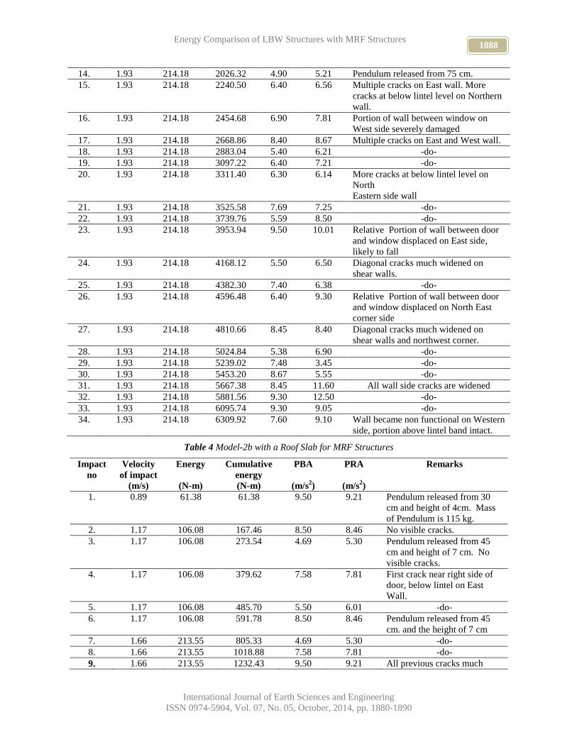
Table 3 Model-2b with a Roof Slab for LBW Structures
Impa
ct no
Velocity
of
impact
(m/s)
Energy
(N-m)
Cumulativ
e energy
(N-m)
PBA
(m/s2)
PRA
(m/s2)
Remarks
1. 0.88 44.52 44.52 10.01 9.89 Pendulum released from 30cm. and
height is 4 cm. Mass of Pendulum is
150 kg. No visible cracks
2. 0.88 44.52 89.04 9.54 8.99 No visible cracks
3. 0.88 44.52 133.56 8.23 7.89 No visible cracks
4. 1.33 101.71 235.27 9.32 8.34 Pendulum released from 45 cm. and
height is 7 cm.
5. 1.33 101.71 336.98 5.78 4.45 Pendulum released from 30 cm. First
crack at window sill level on West wall.
6. 1.77 180.14 517.12 8.78 7.48 Cracks on shear wall started when the
pendulum is 16 cm.
7. 1.77 180.14 697.26 6.89 5.56 Cracks formed at lintel level on North
wall.
8. 1.77 180.14 887.40 8.59 7.56 In South shear wall, long diagonal
cracks formed below lintel level.
9. 1.77 180.14 1057.54 9.50 9.21 -do-
10. 1.77 180.14 1237.68 8.50 8.46 --do-
11. 1.77 180.14 1417.82 4.69 5.30 --do-
12. 1.77 180.14 1597.96 7.58 7.81 --do-
13. 1.93 214.18 1812.14 5.50 6.01 Cracks developed at sill level of
window on West wall. Height of
pendulum is 19 cm.
1888 Energy Comparison of LBW Structures with MRF Structures
International Journal of Earth Sciences and Engineering
ISSN 0974-5904, Vol. 07, No. 05, October, 2014, pp. 1880-1890
14. 1.93 214.18 2026.32 4.90 5.21 Pendulum released from 75 cm.
15. 1.93 214.18 2240.50 6.40 6.56 Multiple cracks on East wall. More
cracks at below lintel level on Northern
wall.
16. 1.93 214.18 2454.68 6.90 7.81 Portion of wall between window on
West side severely damaged
17. 1.93 214.18 2668.86 8.40 8.67 Multiple cracks on East and West wall.
18. 1.93 214.18 2883.04 5.40 6.21 -do-
19. 1.93 214.18 3097.22 6.40 7.21 -do-
20. 1.93 214.18 3311.40 6.30 6.14 More cracks at below lintel level on
North
Eastern side wall
21. 1.93 214.18 3525.58 7.69 7.25 -do-
22. 1.93 214.18 3739.76 5.59 8.50 -do-
23. 1.93 214.18 3953.94 9.50 10.01 Relative Portion of wall between door
and window displaced on East side,
likely to fall
24. 1.93 214.18 4168.12 5.50 6.50 Diagonal cracks much widened on
shear walls.
25. 1.93 214.18 4382.30 7.40 6.38 -do-
26. 1.93 214.18 4596.48 6.40 9.30 Relative Portion of wall between door
and window displaced on North East
corner side
27. 1.93 214.18 4810.66 8.45 8.40 Diagonal cracks much widened on
shear walls and northwest corner.
28. 1.93 214.18 5024.84 5.38 6.90 -do-
29. 1.93 214.18 5239.02 7.48 3.45 -do-
30. 1.93 214.18 5453.20 8.67 5.55 -do-
31. 1.93 214.18 5667.38 8.45 11.60 All wall side cracks are widened
32. 1.93 214.18 5881.56 9.30 12.50 -do-
33. 1.93 214.18 6095.74 9.30 9.05 -do-
34. 1.93 214.18 6309.92 7.60 9.10 Wall became non functional on Western
side, portion above lintel band intact.
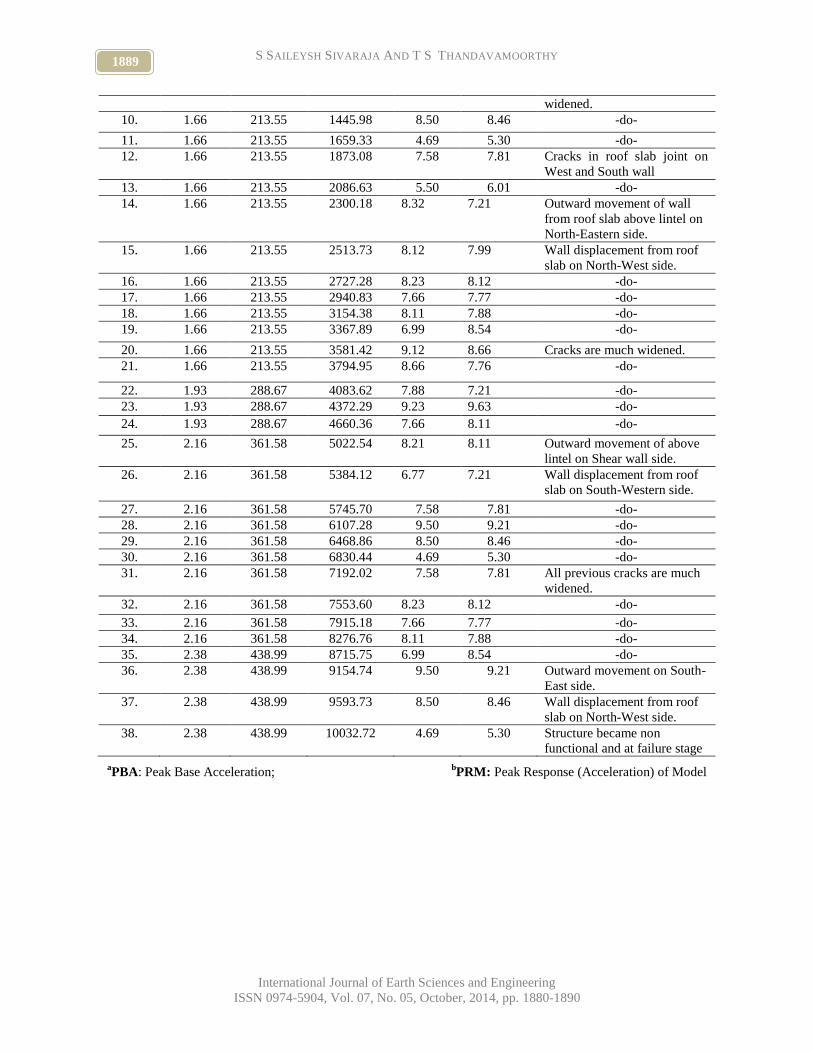
Table 4 Model-2b with a Roof Slab for MRF Structures
Impact
no
Velocity
of impact
(m/s)
Energy
(N-m)
Cumulative
energy
(N-m)
PBA
(m/s2)
PRA
(m/s2)
Remarks
1. 0.89 61.38 61.38 9.50 9.21 Pendulum released from 30
cm and height of 4cm. Mass
of Pendulum is 115 kg.
2. 1.17 106.08 167.46 8.50 8.46 No visible cracks.
3. 1.17 106.08 273.54 4.69 5.30 Pendulum released from 45
cm and height of 7 cm. No
visible cracks.
4. 1.17 106.08 379.62 7.58 7.81 First crack near right side of
door, below lintel on East
Wall.
5. 1.17 106.08 485.70 5.50 6.01 -do-
6. 1.17 106.08 591.78 8.50 8.46 Pendulum released from 45
cm. and the height of 7 cm
7. 1.66 213.55 805.33 4.69 5.30 -do-
8. 1.66 213.55 1018.88 7.58 7.81 -do-
9. 1.66 213.55 1232.43 9.50 9.21 All previous cracks much
1889 S SAILEYSH SIVARAJA AND T S THANDAVAMOORTHY
International Journal of Earth Sciences and Engineering
ISSN 0974-5904, Vol. 07, No. 05, October, 2014, pp. 1880-1890
widened.
10. 1.66 213.55 1445.98 8.50 8.46 -do-
11. 1.66 213.55 1659.33 4.69 5.30 -do-
12. 1.66 213.55 1873.08 7.58 7.81 Cracks in roof slab joint on
West and South wall
13. 1.66 213.55 2086.63 5.50 6.01 -do-
14. 1.66 213.55 2300.18 8.32 7.21 Outward movement of wall
from roof slab above lintel on
North-Eastern side.
15. 1.66 213.55 2513.73 8.12 7.99 Wall displacement from roof
slab on North-West side.
16. 1.66 213.55 2727.28 8.23 8.12 -do-
17. 1.66 213.55 2940.83 7.66 7.77 -do-
18. 1.66 213.55 3154.38 8.11 7.88 -do-
19. 1.66 213.55 3367.89 6.99 8.54 -do-
20. 1.66 213.55 3581.42 9.12 8.66 Cracks are much widened.
21. 1.66 213.55 3794.95 8.66 7.76 -do-
22. 1.93 288.67 4083.62 7.88 7.21 -do-
23. 1.93 288.67 4372.29 9.23 9.63 -do-
24. 1.93 288.67 4660.36 7.66 8.11 -do-
25. 2.16 361.58 5022.54 8.21 8.11 Outward movement of above
lintel on Shear wall side.
26. 2.16 361.58 5384.12 6.77 7.21 Wall displacement from roof
slab on South-Western side.
27. 2.16 361.58 5745.70 7.58 7.81 -do-
28. 2.16 361.58 6107.28 9.50 9.21 -do-
29. 2.16 361.58 6468.86 8.50 8.46 -do-
30. 2.16 361.58 6830.44 4.69 5.30 -do-
31. 2.16 361.58 7192.02 7.58 7.81 All previous cracks are much
widened.
32. 2.16 361.58 7553.60 8.23 8.12 -do-
33. 2.16 361.58 7915.18 7.66 7.77 -do-
34. 2.16 361.58 8276.76 8.11 7.88 -do-
35. 2.38 438.99 8715.75 6.99 8.54 -do-
36. 2.38 438.99 9154.74 9.50 9.21 Outward movement on South-
East side.
37. 2.38 438.99 9593.73 8.50 8.46 Wall displacement from roof
slab on North-West side.
38. 2.38 438.99 10032.72 4.69 5.30 Structure became non
functional and at failure stage
aPBA: Peak Base Acceleration;
bPRM: Peak Response (Acceleration) of Model
1890 Energy Comparison of LBW Structures with MRF Structures
International Journal of Earth Sciences and Engineering
ISSN 0974-5904, Vol. 07, No. 05, October, 2014, pp. 1880-1890
Table 5 Energy Comparisons of LBW and MRF Models
Impact
No.
Cumulative Energy
(Nm)
Model-1A (Without
slab of LBW)
Model-2A (With slab
of LBW)
Model-1B ( Without
slab of MRF)
Model-2B (With slab
of MRF)
1 59.40 44.52 46.46 61.38
5 470.04 336.98 351.65 485.70
10 1399.92 1237.68 1291.05 1445.98
15 2432.67 2240.50 2337.91 2513.73
20 3466.02 3311.40 3455.36 3581.42
23 4304.10 3953.94 4125.83 4372.29
30 - 5453.20 5690.67 6830.44
34 - 6309.92 6361.14 7915.18
38 - - 7463.78 10032.72
40 - - 8108.21 -
45 - - 9865.11 -


