Embed Size (px)
Citation preview

This work is licensed under a Creative Commons Attribution-NonCommercial 3.0 Unported License
Newcastle University ePrints - eprint.ncl.ac.uk
Grisales Diaz VH, Olivar Tost G. Energy efficiency of acetone, butanol, and
ethanol (ABE) recovery by heat-integrated distillation. Bioprocess and
Biosystems Engineering 2017
Copyright:
The final publication is available at Springer via https://doi.org/10.1007/s00449-017-1874-z
Date deposited:
22/02/2018
Embargo release date:
05 December 2018

1
Energy efficiency of acetone, butanol, and ethanol (ABE) recovery by heat-
integrated distillation
Victor Hugo Grisales Diaz1* and Gerard Olivar Tost2
1School of Chemical Engineering and Advanced Materials, Newcastle University, Newcastle
upon Tyne NE1 7RU, UK
2Faculty of Engineering and Architecture. Department of Electrical, Electronics and Computation
Engineering. Universidad Nacional de Colombia – Sede Manizales, Cra. 27 No. 64-60,
Manizales, Colombia.
Author information
Corresponding Author
*E-mail: [email protected]; [email protected].
Tel.:+ 573008720595

2
Abstract
Acetone, butanol, and ethanol (ABE) is an alternative biofuel. However, the energy requirement
of ABE recovery by distillation is considered elevated (>15.2 MJ fuel/Kg-ABE), due to the low
concentration of ABE from fermentation broths (between 15 and 30 g/l). In this work, in order to
reduce the energy requirements of ABE recovery, four processes of heat-integrated distillation
were proposed. The energy requirements and economic evaluations were performed using the
fermentation broths of several biocatalysts. Energy requirements of the processes with four
distillation columns and three distillation columns were similar (between 7.7 and 11.7 MJ
fuel/kg-ABE). Double-effect system (DED) with four columns was the most economical process
(0.12-0.16 $/kg-ABE). ABE recovery from dilute solutions by DED achieved energy
requirements between 6.1 and 8.7 MJ fuel/kg-ABE. Vapor compression distillation (VCD)
reached the lowest energy consumptions (between 4.7 and 7.3 MJ fuel/kg-ABE). Energy
requirements for ABE recovery DED and VCD were lower than that for integrated reactors. The
energy requirements of ABE production were between 1.3- and 2.0-fold higher than that for
alternative biofuels (ethanol or isobutanol). However, the energy efficiency of ABE production
was equivalent than that for ethanol and isobutanol (between 0.71 and 0.76) because of
hydrogen production in ABE fermentation.
Keywords: Biofuel; Distillation; Energy; Process Design; Economic Evaluation

3
Nomenclature
ABE, acetone, butanol, and ethanol
DE, double-effect
FABE, production flow of ABE [kg/h]
HS is the energy consumption of the separation [MJ/kg-ABE]
IRC, investment cost of recovery [$/kg-ABE]
LHV, lower heating value of solvents [MJ/kg-ABE]
M&S, Marshall and Swift equipment cost index
ORC, operational cost of recovery [$/kg-ABE]
Rs, the ABE yield [g-ABE/g-substrate]
TRC, total recovery cost [$/kg-ABE]
TIC, the total investment cost [$]
TOAC, the total operational annualized cost [$/year]
tri, payback period [year]
ta, annual operation time [h]
VC, vapor compression
VLE, vapor-liquid equilibrium
3DC, three distillation columns
3DC-VC, three distillation columns with vapor compression
4DC, three distillation columns
4DC-DE, four distillation columns with double-effect
5DC, five distillation columns

4
Introduction
During the last years, biotechnological production of butanol has been renewed due to
its biofuel potential [1]. The biotechnological production is traditionally performed by mesophilic
solvent-producing strains [2], such as Clostridium acetobutylicum, Clostridium beijerinckii,
Clostridium saccharobutylicum or Clostridium saccharoperbutylicum. These biocatalysts
produce acetone, butanol and ethanol (ABE). In the Chinese industrial process, ABE is
produced in the average ratio of 2.5:4.8:1 (calculated from stoichiometric reaction reported by Ni
and Sun [3]). The main advantage of traditional Clostridium is the ability to consume a wide
variety of substrates, such as glucose, sucrose, lactose, xylose, starch and glycerol [4].
To achieve a high conversion avoiding product inhibition, the substrate is fed at low
concentration (55-75 g/l) into the reactor. This characteristic makes steam consuming
operations, such as mash sterilization, downstream product recovery and wastewater treatment
energy demanding [5]. In order to reduce water usage for biobutanol production [3], vinasses
from distillation in Chinese industry are recycled into the reactor in ~40%.
Integrated reactors with separation units have been proposed to reduce energy
requirements, investment cost and vinasses production [6–10]. Qureshi et al. [6] reported that
liquid-liquid extraction and adsorption processes have the lowest energy requirements with 8.9
and 8.2 MJ/kg-butanol, respectively. In another study, pervaporation (9 MJ/kg-ABE) and liquid-
liquid extraction (14 MJ/Kg-ABE) were the integrated systems with the lowest energy
requirements [11].
Final purification of integrated and conventional reactors for biobutanol production is
traditionally carried out by distillation. These distillation systems have conventionally five stages.
In the first column, ABE is concentrated at 60 wt%. Acetone and ethanol are concentrated in
two columns, while butanol and water are concentrated finally in an azeotropic distillation
system of two columns. In azeotropic distillation, decantation is used to break the azeotropic
behavior of butanol and water [12]. A separation agent for decantation is not needed because
butanol is partially miscible in water.
A great steam consumption (13-25 kg-steam/kg-ABE) have been reported in Chinese
industrial processes [3]. In academic evaluations of distillation processes, based on industrial
processes, high-energy requirements have been reported commonly (24.2 MJ/kg-butanol [6] or

5
28 MJ/kg-butanol [13]). However, Jilin Cathy Industrial Biotech recently reported a low energy
requirement of distillation system of 6-7 kg-steam/kg-butanol [14]. The reasons for the
differences in the energy requirements are undefined.
Distillation can be integrated to reduce its energy requirement. Process integration in
distillation follows various routes such as: internal heat integrated distillation columns [15, 16],
vapor compression (VC) distillation [17, 18], petlyuk or dividing wall columns [19], double-effect
(DE) distillation [20, 21] and cyclic distillation [22, 23]. Among these alternatives, Kaufman et al.
[17] proposed a sequential system of multiple VC for ABE recovery (patented process).
Additionally, low energy requirements have reported in our previous work with DE (7.2 MJ/kg-
ABE) [24].
In this paper, four heat-integrated distillation systems were evaluated energetically.
Integrated distillation systems may need an investment higher than that for conventional
distillation; therefore, an economic analysis was performed. Considering biofuel application, the
energy efficiency of ABE recovery by distillation was compared with that for the dehydration of
alternative biofuels (isobutanol, ethanol and isopropanol, butanol and ethanol (IBE) [25, 26]).
Due to its high-energy efficiency (between 0.71 and 0.76), the distillation systems studied in this
work will provide a new baseline of energy requirements.
Methods
The simulations were performed in Aspen Plus®. RadFrac was the unity used for
distillation simulation. Trays selection was sieve's type. Pressure drop in the column was
calculated with tray rating of RadFrac. The base method in simulations was UNIQUAC-RK with
CO2 and H2 as Henry’s components.
The accuracy of UNIQUAC or NRTL liquid-liquid equilibrium (experimental data [27, 28])
using the binary parameters of vapor-liquid equilibrium (VLE) is very low (Fig. 1). Therefore, the
binary parameters of the decanter units must be different to the distillation units. The binary
parameters of distillation were APV73 LLE-ASPEN (Fig. 1). The parameters for butanol-water
mixture were those reported by Fisher and Gmehling [13, 29]
In all the distillation systems studied in this work, condensation heat was not used to
preheat the feed of ABE concentration columns. Instead, the exit from these distillation columns
was used to preheat their respective feed, maximizing the heat integration [25]. The distillation
6
processes after this integration achieved a waste mash temperature of 47 ºC (fermentation
temperature of 37 °C, minimum approach temperature of 10 °C), which is a temperature
suitable for solids concentration by filtration [30].
Butanol boiling point is high (117 °C). However, the azeotrope of minimum boiling point
of butanol and water increased the relative volatility of butanol at low concentrations. Indeed,
butanol has a relative volatility at low concentrations in water 2.3-fold higher than ethanol.
Consequently, butanol in all processes is recovered from the top of C1 column. Vinasses were
partially recycled to the reactor to reduce the substrate concentration (18 wt%) and water
requirements [3].
System with four distillation columns (4DC)
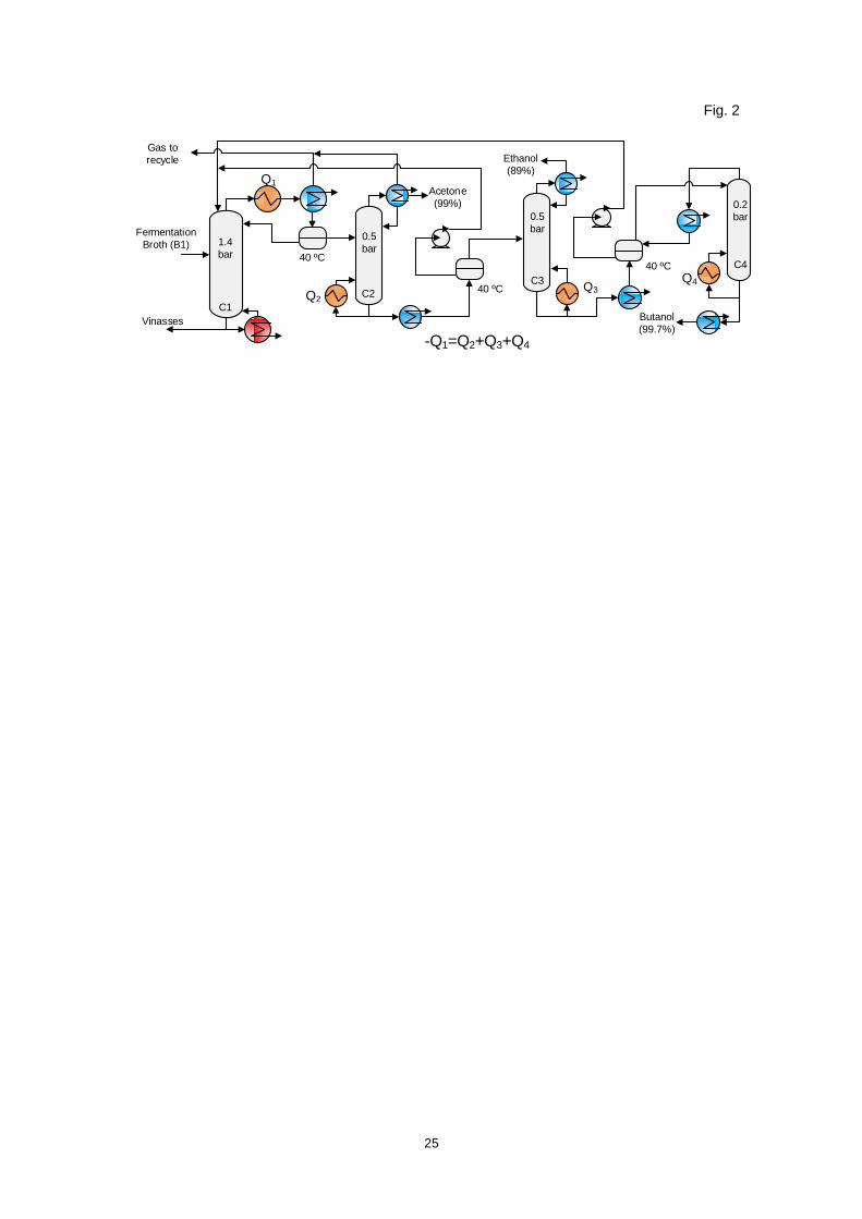
ABE in the 4DC process was separated sequentially based on its boiling point (Fig. 2).
Therefore, acetone, ethanol, and butanol were obtained in the columns C2, C3, and C4,
respectively. Due to butanol-water azeotrope, the top stream of C1 is not anhydrous. In this
work, the concentration of water at the top of C1 was reduced with a decanter (Fig. 2). The
reflux of C1 was the aqueous phase from decanter (Fig. 2). The organic phase from the
decanter was the stream fed to C2. In this way, the water concentration (~37 wt%) of organic
phase of the decanter depends mainly on the temperature of the decanter. An additional reflux
was not required. Ethanol and acetone were purified at the top of C2 and C3, respectively.
While, the bottoms were fed at their respective decanter (Fig. 2). Therefore, three decanters
were used. These decanters reduced the water concentration because the polar components,
acetone and ethanol, were recovered sequentially.
The binary azeotrope of butanol-water was broken in the decanter between the columns
C3 and C4 (Fig. 2). The temperature of decanters was fixed at 40 ºC because the distribution
coefficient was high at this point (Fig. 1). Butanol was produced in the bottoms of C4. The top of
C4 is condensed and recirculated to the decanter. The feed of C4 from the decanter was at the
top stage. For this reason, an additional reflux was not required. Conventionally, ABE is purified
using five distillation columns (5DC). In 5DC, the aqueous phase from the decanter is fed to a
fifth column. However, in this work to reduce the number of columns the aqueous phase was
recycled to C1 (Fig. 2). The Fig. 3 shows the composition profiles for each distillation column of
4DC system.

7
The condensation heat of columns at atmospheric pressure or higher may be used in
the boiler of another column if it operates at low-pressure. Low-pressure columns (C2, C3, and
C4) were proposed to use the heat of condensation of C1 column in their respective boilers. The
exchanger area of condensation and the diameter of columns increase a lower pressure of
operation. However, this effect is not necessary true in the acetone column (C2), due to the
increase of acetone volatility at low pressures [31–33] (Fig. 4). The total stage numbers of all
columns and processes are shown in Table 1. The total stage numbers of 4DC were 90. In all
cases, the total stages were chosen to avoid an excess of trays.
System with three distillation columns (3DC)
Total stages in the configuration with three distillation columns (3DC) were reduced
from 90 to 70 (Table 1). In the first column (C1), acetone and ethanol were obtained mainly at
the top stage (Fig. 5). A side stream from C1 was fed to the decanter (Fig. 5). The organic
phase, (~68 wt% of butanol and ~24% of water), was fed to butanol column (C3) and the
aqueous phase was recycled to C1. Acetone and ethanol were purified simultaneously in C2.
Butanol was purified in C3. The top of C3 was condensed and fed to the decanter to break the
butanol-water azeotrope.
Similar to 4DC, low-pressure operation were proposed for C2 and C3 columns. Butanol
was not present at the top of C1, making the condensation temperature at the top of this column
low (62 ºC). Consequently, heat integration using this heat of condensation is difficult. For this
reason, intermediate condensation in C1 (stage 15) was used to apply its heat in C2 and C3
boilers (Fig. 5).
Three distillation columns and vapor compression (3DC-VC)
3DC-VC is shown in Fig. 6. The configuration of streams in 3DC-VC was different to
3DC. In C1 column, one side stream was not used and the vapor on top of C1 column was split
into two streams. One stream was compressed and another was not. This effect was used to
reduce the compression work. The vapor compression was limited due to the high cost of
compressors. The condensation heat of compressed stream was applied in the boiler of C1
column. The condenser heat of vapor uncompressed was used in boilers of low-pressure
columns (C2 and C3).

8
In the columns C2 and C3 vapor compression was not considered due to the high-
temperature difference between its condenser and boiler (42-45 ºC). Acetone was obtained
from the top of C2 column. Ethanol was obtained from the top, and butanol was obtained from
the bottoms of C3 column. Composition profiles for each distillation column of 3DC-VC system
are shown in Fig. 7.
Four distillation columns with double-effect (4DC-DE)
4DC-DE was proposed in our previous study [24]. The stream after fermentation is
divided into two streams, then preheated and fed to columns C1-HP and C1-LP (Fig. 8). In this
system, columns C1 (1.1 bar) and C3 (1.2 bar) operated at a pressure moderately higher than
atmospheric pressure to improve the heat integration. Due to butanol and water azeotrope, C3
has no-condenser and the steam from the top of C3 is fed directly to C1-HP to reduce their
energy requirements. The heat of a side condenser in column C1 was used to apply its
condensation heat to the boiler of low-pressure columns (C1-LP (0.3 bar) and C2 (0.5 bar)). The
split ratio of the stream after fermentation was iterated until the sum between condensation heat
of C1 (Q1A) and boiler heat of C1-LP (Q1B) and C2 (Q2) become nil (Fig. 8). The total energy
consumption of 4DC was given by the steam requirements of columns C1 and C3.
Energy and economic evaluation
In this work, the energy requirements were reported in two different units: the sizing
units of heat exchangers that does not necessarily required steam from furnace are reported in
the units “MJ/kg-ABE” (Table 2), while the units of fuel requirements of heat exchangers and
compressors are “MJ fuel/kg-ABE” [24] (Table 3). The units “MJ fuel” of the units that required
vapor and electricity are calculated assuming efficiencies of 0.9 and 0.33, respectively [24]. CO2
production is proportional to fuel combustion. Therefore, a reduction in fuel requirement is
proportional to CO2 reduction. Heat integration was performed with 10 ºC of minimum approach
temperature. Compressor efficiency was 0.75.
Configurations were evaluated using dilute solutions with the ABE yield of Chinese
industrial. Butanol concentration in the reactor was assumed as 10 g/l (base case). Additionally,
ABE recovery from dilute solution produced by three hyper-butanol mutant strain was studied.
The butanol concentration in the reactor of all cases evaluated are reported in Table 3. The ABE
and hydrogen yield of microorganism processes were calculated using the theoretical yield of

9
stoichiometric reactions and the specific conversions. In this work, biomass and other sub-
products of low yield in the fermentation, e.g. acetic acid, and high boiling point were not
included in the estimation. Glucose conversion in the stoichiometric reactor was 0.83. The
specific glucose conversions to butanol, ethanol and acetone are estimated from the A:B:E ratio
reported in Table 3. The stoichiometric reactions for butanol or isobutanol, acetone and ethanol
production are:
6 12 6 2 2 4 102C H O CO H O C H O (1)
6 12 6 2 2 3 6 23 4C H O H O CO C H O H (2)
6 12 6 2 2 62 2C H O CO C H O (3)
In all simulations, the purities (mass fraction) of butanol, acetone, and ethanol were
0.997, 0.99, and 0.89, respectively. Non-condensable products were compressed and recycled
to the stripping column (10 stages). Cooling water (10000 kg/h) was used in the stripping
column to recover solvents from the non-condensable stream. The production of anhydrous
ethanol, isobutanol and IBE were not carried out in this study. The recovery cost per kg of
product (TRC) was calculated from:
TRC ICR OCR (4)
ri ABE a
TICICR
t F t
(5)
ABE a
TOACOCR
F t
(6)
where FABE is the production flow (kg-ABE/h), tri is the payback period (three years), ta is the
annual operation time (8150 h/y), TOAC is the total operational annualized cost ($/y), TIC is
total investment cost ($), IRC is the investment cost of recovery ($/kg-ABE) and ORC is the
operational cost of recovery ($/kg-ABE). Equipment cost was calculated with functions reported
by Douglas [34]. Costs of steam, cooling water, and electricity and Marshall and Swift
equipment cost index (M&S) were assumed as 16 $/ton, 0.006 $/kg and 0.126 $/kWh and 1625
(dimensionless), respectively. The production capacity of solvents was 5000 kg-ABE/h. Process
equipment was designed using stainless steel material. Ideal energy efficiency of separation
(IES) system was calculated as proposed [25] using:

10
cos
(LHV )S S
Glu e
R HIES
LHV
(7)
Where, LHV is the lower heating value of solvents and hydrogen (MJ fuel/kg-solvent),
HS is the energy consumption of the separation (MJ fuel/kg-solvent), and LHVGLUCOSE is the
lower heating value of glucose (16.45 MJ/kg [35]). The energy efficiency was considered ideal
because was not calculated the energy requirement of pretreatment and downstream. The yield
(Rs) was the mass of ABE recovery per mass of substrate consumed.
Results
The distillation process with the lowest energy requirements, 3DC-VC, achieved a fuel
requirement of 7.3 MJ fuel/kg-ABE (ABE yield and ratio of the Chinese industry, Table 2). The
coefficient of performance of the heat-pump was 8.6 (-) (the energy savings (MJ) divided by the
compression work (MJ)). 3DC-VC process reduced the fuel requirement in comparison with
3DC by 37 %. Consequently, ORC decreased by 33%. However, the TRC of 3DC-VC was
equivalent to that of 3DC (Table 3) due to the high investment cost of the compressors.
The most economical process or with the lowest TRC, 4DC-DE, achieved a fuel
requirement of 8.7 MJ fuel/kg-ABE. 4DC-DE reduced the energy requirements of 4DC by
25.6%. Although the energy requirements of 4DC-DE were 1.2-fold higher than that of 3DC-VC,
4DC-DE was the most economical option because the IRC was not increased drastically using
this heat integration. For instance, the IRC of 4DC-DE increased only by 1.4% with respect to
3DC, instead of the high number of stages of 4DC-DE (95, Table 1) and the operating pressure
of C1-LP (0.2 atm at the top). This low increment of IRC was achieved because 4DC-DE was
the distillation system with the lowest total boiler flux (23.9 MJ/kg-ABE, Table 2). Due to the low
butanol concentration (~10 g/l), total boiler heat flux was the most important factor in the
calculation of IRC. Given that C1-LP was operated to low pressure, the preheating of 4DC-DE
was the lowest (Table 2). In the preheating was achieved the biggest heat integration due to the
low solvent concentration (20 g-ABE/l), (between 14.9 and 15.1 MJ/kg-ABE, Table 2).
The main difference between 3DC and 4DC configurations was the total boiler heat of
the purification columns (C2, C3 and C4), Table 2. The sum of boiler heat of purification
columns of 4DC was 3.2 MJ/kg-ABE (Table 2). While with 3DC process, this sum was 1.7-fold
lower due to less unnecessary condensation). 4DC-DE and 3DC have the lowest boiler heat of

11
purification (between 1.5 and 1.9 MJ/kg ABE) because a vapor stream, instead of a liquid
stream, was fed to column C2.
Due to heat integration, the fuel consumption of 3DC and 4DC only depended on the
boiler heat of column C1. Consequently, the fuel requirements of purification columns were nil
and the energy requirements of 4DC and 3DC configurations were equivalents (~11.5 MJ
fuel/kg-ABE, Table 3). For this reason, ORC (related to fuel requirements) of both process was
similar. ORC was approximately 58% of TRC. Given that the total boiler heat flux of 3DC was
6.2% lower than that of 4DC (Table 2), the IRC of 3DC was 4% lower (Table 3).
The fuel requirements of 4DC-DE with the ratio achieved by C. acetobutylicum JB200,
C. beijirinkii BA10, and C. acetobutylicum SolRH were reduced from 8.7 MJ fuel/kg-ABE to 6.3
MJ fuel/kg-ABE, 6.5 MJ fuel/kg-ABE and 6.1 MJ fuel/kg-ABE, respectively (Table 3). This was to
be expected because of the high concentration of butanol in the fermentation broth (around 20
g/l). Consequently, the TRC was reduced between 22% and 25% (Table 3). The least energy
requirement and TRC were obtained using a hyper-butanol producing C. acetobutylicum JB200
(Table 3). Due to a higher butanol titer, vinasses recycle into the reactor was reduced from 67%
to 56.3% and 34.8% using the yield of C. beijirinkii BA101 and C. acetobutylicum JB200 with
respect to the base case, respectively.
Vinasses recycle was an important contribution of the low energy requirements
achieved in this work. At similar total ABE recovery, vinasses recycle reduced the energy
requirements by ~18.8% with respect to 4DC or 3DC process without vinasses recycle (data not
shown). This reduction was mainly achieved because of ethanol has the lowest relative volatility
and ethanol concentration is increased in the reactor with vinasses recycle (results not shown).
Energy efficiency of ABE processes without hydrogen combustion for 3DC-VC and
4DC-DE were between 0.59 and 0.66. Hydrogen production (LHV of hydrogen, Table 4) was
between 9 and 15% of total energy produced. Therefore, the efficiency increased to 0.71-0.76
with hydrogen combustion. Energy efficiency of 3DC-VC was between 4.8 and 5.8% higher than
that for 4DC-DE. The highest efficiency of the distillation process was achieved using C.
acetobutylicum JB200. Although C. beijirinkii BA101 has the lowest theoretical yield of
hydrogen, the stoichiometric ABE yield is higher than that of C. acetobutylicum SolRH. Hence,

12
the energy efficiency of C. beijirinkii BA101 and C. acetobutylicum SolRH was similar (4DC-DE
(0.71) and 3DC-VC (0.74-0.75)).
Discussion
In some Chinese industrial processes have been reported high energy requirements,
13-25 kg-steam/kg-ABE [3] or 30-58 MJ fuel/kg-ABE. The minimum energy requirements
reported for these processes (30 MJ fuel/kg-ABE) were similar to that of 4DC without heat
integration (28.9 MJ/kg-ABE). Hence, in these industrial processes, heat integration probably
was not used.
Energy consumption of distillation reported by Jilin Cathy Industrial Biotech is 6-7 kg-
steam/kg-butanol [14] (butanol concentration from the fermentation broth is not reported).
Assuming an efficiency of steam production of 0.9 and using the ratio of Chinese industry
reported by Ni [3], the fuel consumption was between 8-9.4 MJ-fuel/kg-ABE. Based on the low
energy consumption reported for this industrial process, a heat-integrated distillation system
may have been used. These energy requirements were equal to the fuel consumption achieved
for 3DC or 4DC with a butanol titer between 14 and 15 g/l (data not shown).
It is important mention that comparisons between energy requirements of different
distillation systems must be done at the same butanol concentration in the feed. This was
suggested because it was found that increments of the concentration of butanol from 10 to 20
g/l reduced the energy requirements 1.7 times.
In academy studies of distillation, the energy requirements reported for ABE recovery
were 15.2 MJ-fuel/kg-ABE using C. beijirinkii BA101 and a distillation system of 5DC (135 ideal
stages [5]). The total energy requirements of 3DC-VC and 4DC-DE were respectively 67.1%
and 58.6% lower than that of 5DC (Table 2) due to heat integration, vinasses recycle and the
high efficiency of the distillation systems studied in this work. In similar way, using the yield of C.
acetobutylicum SolRH, the energy requirements of 3DC-VC and 3DC were 60% and 38% than
that of 5DC (12.6 MJ-fuel/kg-ABE, Table 2), respectively. Remarkably, using 3DC the total
number stages of 5DC was reduced from 135 (ideal stages) to 70 (non-ideal stages).
Several energy analysis of integrated reactors have been reported in the literature [6,
11, 13]. From an energy point of view, the most attractive units reported by Qureshi et al. [6]
were adsorption, liquid extraction, and pervaporation. Energy requirements of liquid extraction

13
and adsorption reported by Qureshi et al. [6] for C. beijirinkii BA101 are 7.1 and 7.7 MJ fuel/kg-
ABE (calculated in this work from C. beijirinkii BA101 ratio), respectively. Energy consumption of
pervaporation reported by Groot et al. [11] and Qureshi et al. [6] are 10 and 10.9 MJ fuel kg-1
ABE, respectively (assuming an efficiency in energy production of 0.9).
Fuel consumption of 4DC-DE and 3DC-VC achieved in this work were 29.1 and 34.8%
and 17.9 and 10.7 % lower than that reported by Qureshi et al. [6], for liquid-liquid extraction and
adsorption, respectively. However, an integrated reactor may have a higher productivity of
solvents. Hence, an economic study of reaction and purification system is necessary [24]. On
the other hand, an integrated reactor is not 100% selective and requires a final purification. For
this reason, it can be coupled with the distillation processes studied in this work.
The lowest energy requirement in the literature was achieved with a vapor compression
system (membrane assisted vapor stripping (MAVS), 4.2-MJ-fuel/kg-ABE (3/6/1) at 2 wt% of
ABE [36, 37]). In the evaluation of MAVS, CO2 and H2 were non-included, the minimum
approach temperature was 5 ºC, the ratio of ABE was 3/6/1, ABE titer was 20 g/l, ethanol
recovery was 90% and nil pressure drop was assumed. Using the same assumptions reported
by [36, 37], the energy requirement of 3DC-VC were reduced from 7.3 to 4.5 MJ-fuel/kg-ABE.
Hence, the low energy requirements of MAVS were mainly achieved through heat integration by
vapor compression. A similar result was observed in our previous study for ethanol or isobutanol
dehydration [25]. However, it is important to mention that non-condensable, pressure drop,
among others, may have a different effect in MAVS and recycle of vinasses are not performed in
MAVS.
Due to biofuel application, the IES of ABE process was compared with ethanol,
isobutanol and IBE dehydration by heat-integrated distillation (Table 4). IBE anhydrous was
achieved in a new approach of heat-integrated distillation [26]. In this simultaneous azeotropic
and extractive distillation system, without an additional entrainer, butanol is used to break the
azeotropes of isopropanol-water and ethanol-water. In this approach, VC was used. The energy
requirements of IBE dehydration are between 1.3- and 1.6-fold lower than that of 3DC-VC
(Table 4). For this reason, the energy efficiency of IBE dehydration was the highest (0.79-0.80,
Table 4). Although IBE dehydration achieved the highest IES, it is worth noting that the effect of

14
CO2, the efficiency of stages, pressure drop and the energy requirements for the end purification
of IBE were not studied in our previous work [26].
Ethanol and isobutanol anhydrous (99.7 wt%) are achieved by extractive and azeotropic
distillation, respectively [25]. Glycerol is the extractant used in ethanol dehydration system [25].
The concentration of ethanol and isobutanol from broth are 10 and 2 wt% [25], respectively. The
TRC of isobutanol purification by VC was 1.07-fold lower than that of ABE purification by 3DC-
VC (C. acetobutylicum JB200, Table 3). The energy requirements of 3DC-VC were between 1.3
and 2.0-fold higher than that for ethanol and isobutanol dehydration (Table 4). However, due to
hydrogen synthesis, the IES of ABE production by 3DC-VC was only between 1.5 and 2.8 %
lower than that for ethanol and isobutanol dehydration (Table 4).
Conclusions
Conventionally, distillation is considered an inefficient alternative method for ABE
recovery. However, with the configurations investigated in this paper, distillation was an
alternative energetically attractive. The energy requirements were between 4.7 and 7.3 MJ
fuel/kg-ABE and 6.1 and 8.7 MJ fuel/kg-product using vapor compression distillation and
double-effect, respectively. The fuel requirements were reduced between 1.4- and 1.7- fold
when the butanol concentration rises from 10 to 20 g/l. The most economical option was double
effect distillation with recovery cost between 0.12 and 0.16 $/kg-product. The lowest energy
requirement and the highest efficiency for ABE recovery was achieved with C. acetobutylicum
JB200. The energy efficiency of ABE recovery was 1.5-2.8% lower than that of isobutanol or
ethanol.
Acknowledgments The authors thank Colombian Administrative Department of
Science, Technology, and Innovation (COLCIENCIAS) for the financial support that made this
work possible.
Conflict of interest
The authors declare that no competing interests exist.
References
1. Qureshi N, Saha BC, Cotta MA, Singh V (2013) An economic evaluation of biological
conversion of wheat straw to butanol: A biofuel. Energy Convers Manag 65:456–462.
doi: 10.1016/j.enconman.2012.09.015

15
2. Jang Y, Malaviya A, Cho C, et al (2012) Butanol production from renewable biomass by
clostridia. Bioresour Technol 123:653–663.
3. Ni Y, Sun Z (2009) Recent progress on industrial fermentative production of acetone–
butanol–ethanol by Clostridium acetobutylicum in China. Appl Microbiol Biotechnol
83:415–423. doi: 10.1007/s00253-009-2003-y
4. Ezeji TC, Qureshi N, Blaschek HP (2007) Bioproduction of butanol from biomass: from
genes to bioreactors. Curr Opin Biotechnol 18:220–227. doi:
10.1016/j.copbio.2007.04.002
5. Mariano AP, Filho RM (2012) Improvements in Biobutanol Fermentation and Their
Impacts on Distillation Energy Consumption and Wastewater Generation. Bioenergy Res
5:504–514. doi: 10.1007/s12155-011-9172-0
6. Qureshi N, Hughes S, Maddox IS, Cotta MA (2005) Energy-efficient recovery of butanol
from model solutions and fermentation broth by adsorption. Bioprocess Biosyst Eng
27:215–222. doi: 10.1007/s00449-005-0402-8
7. Li Q, Cai H, Hao B, et al (2010) Enhancing Clostridial Acetone-Butanol-Ethanol (ABE)
Production and Improving Fuel Properties of ABE-enriched Biodiesel by Extractive
Fermentation with Biodiesel. Appl Biochem Biotechnol 162:2381–2386. doi:
10.1007/s12010-010-9010-4
8. Shi Z, Zhang C, Chen J, Mao Z (2005) Performance evaluation of acetone-butanol
continuous flash extractive fermentation process. Bioprocess Biosyst Eng 27:175–183.
doi: 10.1007/s00449-004-0396-7
9. Chen Y, Ren H, Liu D, et al (2014) Enhancement of n-butanol production by in situ
butanol removal using permeating–heating–gas stripping in acetone–butanol–ethanol
fermentation. Bioresour Technol 164:276–284. doi: 10.1016/j.biortech.2014.04.107
10. Liu G, Wei W, Wu H, et al (2011) Pervaporation performance of PDMS/ceramic
composite membrane in acetone butanol ethanol (ABE) fermentation–PV coupled
process. J Memb Sci 373:121–129. doi: 10.1016/j.memsci.2011.02.042
11. Groot WJ, van der Lans RGJM, Luyben KCAM (1992) Technologies for butanol recovery
integrated with fermentations. Process Biochem 27:61–75. doi: 10.1016/0032-
9592(92)80012-R

16
12. Luyben WL (2008) Control of the Heterogeneous Azeotropic n -Butanol/Water Distillation
System. Energy & Fuels 22:4249–4258. doi: 10.1021/ef8004064
13. Mariano AP, Keshtkar MJ, Atala DIP, et al (2011) Energy requirements for butanol
recovery using the flash fermentation technology. Energy & Fuels 25:2347–2355. doi:
10.1021/ef200279v
14. Xue C, Zhao X-Q, Liu C-G, et al (2013) Prospective and development of butanol as an
advanced biofuel. Biotechnol Adv 31:1575–84. doi: 10.1016/j.biotechadv.2013.08.004
15. Matsuda K, Kawazuishi K, Kansha Y, et al (2011) Advanced energy saving in distillation
process with self-heat recuperation technology. Energy 36:4640–4645. doi:
10.1016/j.energy.2011.03.042
16. Kiran B, Jana AK, Samanta AN (2012) A novel intensified heat integration in
multicomponent distillation. Energy 41:443–453. doi: 10.1016/j.energy.2012.02.055
17. Kaufman B, Walther DC, Contag PR (2010) Multistage vapor compression distillation.
WO Pat. 126848 A1
18. Luo H, Bildea CS, Kiss A a. (2015) Novel Heat-Pump-Assisted Extractive Distillation for
Bioethanol Purification. Ind Eng Chem Res 54:2208–2213. doi: 10.1021/ie504459c
19. Ramírez-Márquez C, Segovia-Hernández JG, Hernández S, et al (2013) Dynamic
Behavior of Alternative Separation Processes for Ethanol Dehydration by Extractive
Distillation. Ind Eng Chem Res 52:17554–17561. doi: 10.1021/ie402834p
20. Bessa LCBA, Ferreira MC, Batista EAC, Meirelles AJA (2013) Performance and cost
evaluation of a new double-effect integration of multicomponent bioethanol distillation.
Energy 63:1–9. doi: 10.1016/j.energy.2013.10.006
21. Bessa LCB a., Batista FRM, Meirelles AJ a. (2012) Double-effect integration of
multicomponent alcoholic distillation columns. Energy 45:603–612. doi:
10.1016/j.energy.2012.07.038
22. Flodman HR, Timm DC (2012) Batch distillation employing cyclic rectification and
stripping operations. ISA Trans 51:454–60. doi: 10.1016/j.isatra.2011.12.003
23. Maleta VN, Kiss A a., Taran VM, Maleta B V. (2011) Understanding process
intensification in cyclic distillation systems. Chem Eng Process Process Intensif 50:655–
664. doi: 10.1016/j.cep.2011.04.002

17
24. Grisales Díaz VH, Olivar Tost G (2016) Butanol production from lignocellulose by
simultaneous fermentation, saccharification, and pervaporation or vacuum evaporation.
Bioresour Technol 218:174–182. doi: 10.1016/j.biortech.2016.06.091
25. Grisales Díaz VH, Olivar Tost G (2016) Ethanol and isobutanol dehydration by heat-
integrated distillation. Chem Eng Process Process Intensif 108:117–124. doi:
10.1016/j.cep.2016.07.005
26. Grisales Díaz VH, Olivar Tost G (2017) Energy efficiency of a new distillation process for
isopropanol, butanol, and ethanol (IBE) dehydration. Chem Eng Process Process
Intensif 112:56–61. doi: 10.1016/j.cep.2017.01.005
27. Marongiu B, Ferino I, Monaci R, et al (1984) Thermodynamic properties of aqueous non-
electrolyte mixtures. Alkanols + water systems. J Mol Liq 28:229–247. doi:
10.1016/0167-7322(84)80027-6
28. Zhang, Y.; Fu, J.; Zhang J (1992) Liquid-Liquid Equilibrium and Vapor-Liquid Equilibrium
for Containing Octylenic Aldehyde Systems. J Chem Ind Eng 43:98–104.
29. Fischer K, Gmehling J (1994) P-x and .gamma..infin. Data for the Different Binary
Butanol-Water Systems at 50.degree.C. J Chem Eng Data 39:309–315. doi:
10.1021/je00014a026
30. Humbird D, Davis R, Tao L, et al (2011) Process Design and Economics for Biochemical
Conversion of Lignocellulosic Biomass to Ethanol. Natl. Renew. Energy Lab.
31. Al-Sahhaf TA, Jabbar NJ (1993) Vapor-liquid equilibrium of the acetone-water-salt
system. J Chem Eng Data 38:522–526. doi: 10.1021/je00012a010
32. Reinders W, de Minjer CH (1947) Vapour-liquid equilibria in ternary systems. VI. The
system water-acetone-chloroform. Recl des Trav Chim des Pays-Bas 66:573–604. doi:
10.1002/recl.19470660906
33. Othmer DF, Chudgar MM, Levy SL (1952) Binary and Ternary Systems of Acetone,
Methyl Ethyl Ketone, and Water. Ind Eng Chem 44:1872–1881. doi:
10.1021/ie50512a042
34. Douglas JM (1988) Conceptual design of chemical processes, McGraw-Hil. New York
35. Ruggeri B, Tommasi T, Sanfilippo S (2015) BioH2 & BioCH4 Through Anaerobic
Digestion. doi: 10.1007/978-1-4471-6431-9
18
36. Vane LM, Alvarez FR (2013) Hybrid vapor stripping-vapor permeation process for
recovery and dehydration of 1-butanol and acetone/butanol/ethanol from dilute aqueous
solutions. Part 1. Process Simulations. J Chem Technol Biotechnol 88:1436–1447. doi:
10.1002/jctb.4087
37. Vane LM, Alvarez FR, Rosenblum L, Govindaswamy S (2013) Hybrid vapor stripping-
vapor permeation process for recovery and dehydration of 1-butanol and
acetone/butanol/ethanol from dilute aqueous solutions. Part 2. Experimental validation
with simple mixtures and actual fermentation broth. J Chem Technol Biotechnol
88:1436–1447. doi: 10.1002/jctb.4086
38. Qureshi N, Blaschek HP (2000) Using Clostridium beijerinckii BA101 Hyper-Butanol
Producing Mutant Strain and Recovery by Pervaporation. Appl Biochem Biotechnol
84:225–235. doi: doi.org/10.1385/ABAB:84-86:1-9:225
39. Nicolaou S a., Gaida SM, Papoutsakis ET (2010) A comparative view of metabolite and
substrate stress and tolerance in microbial bioprocessing: From biofuels and chemicals,
to biocatalysis and bioremediation. Metab Eng 12:307–331. doi:
10.1016/j.ymben.2010.03.004
40. Lu C, Zhao J, Yang S-T, Wei D (2012) Fed-batch fermentation for n-butanol production
from cassava bagasse hydrolysate in a fibrous bed bioreactor with continuous gas
stripping. Bioresour Technol 104:380–7. doi: 10.1016/j.biortech.2011.10.089

19
Tables
Table 1 Feed inlet stages and number of stages of the heat-integrated distillation processes studied in this work
Feed inlet stage
Column Distillation system
4DC 3CD 3DC-VC 4DC-DE
C1 1-3 21-23 1-3
C1-LP
1-3 C1-HP
15-21-23
C2 15 14 15 21 C3 12 1 20 1 C4 1
Number total of stagesb
Column Distillation system
4DC 3CD 3DC-VC 4DC-DE
C1 20 40 20 C1-LP
20
C1-HP
40 C2 30 20 30 25 C3 30 10 30 10 C4 10
Total 90 70 80 95 a stages from the top, b Murphree tray efficiency of 0.7

20
Table 2 Boiler heat flux of the ABE distillation systems and the yield of Chinese industry
Column 4DC 3CD 3DC-VC
4DC-DE
C1 10.6 10.3 10.5 - C1-LP - - - 7.8 C1-HP - - - 2.7 C2 0.91 0.78 1 0.46 C3 1.5 1.1 1.7 1.04 C4 0.83 - - -
Preheating of feed from fermentation
15.2 14.9 15.2 12
Total purification (C2-C4)
3.2 1.9 2.7 1.5
Total boiler heat (C1-C4)
13.8 12.1 13.2 11.9
Total heat exchangers
28.9 27.1 28.4 23.9

21
Table 3 Total recovery cost (TRC) and fuel requirement of ABE recovery by heat-integrated distillation a
Biocatalyst Butanol titer [g/l]
Solvent ratio: A/B/E
System ABE
recovery
Fuel requirement [MJ fuel/kg-
ABE]
IRC [$/kg-ABE]
ORC [$/kg-ABE]
TRC [$/kg-ABE]
Typical microorganisms
in Chinese industrial process
10 2.5/4.8/
1
4DC 0.970 11.7 0.084 0.113 0.197
3DC 0.969 11.5 0.078 0.111 0.189 3DC-VCD
0.970 7.3 0.115 0.075 0.190
4DC-DE 0.969 8.7 0.079 0.080 0.159
C. beijirinkii BA101
19.7 [38]
6/24.6/1
3DC 0.976 7.6 0.064 0.074 0.138
3DC-VCD
0.977 5.0 0.088 0.052 0.140
4DC-DE 0.980 6.3 0.064 0.059 0.123 5DC b - 15.2 - - -
C. acetobutylicum
SolRH
18.5 [39]
4/8.4/1
3DC 0.977 7.8 0.062 0.076 0.138
3DC-VCD
0.981 5.0 0.087 0.053 0.140
4DC-DE 0.977 6.5 0.063 0.061 0.124
5DC [5] b
- 12.6 - - -
C. acetobutylicum
JB200
20.4 [40]
5/9.2/1
3DC 0.977 7.0 0.059 0.069 0.128
3DC-VCD
0.976 4.7 0.083 0.050 0.133
4DC-DE 0.978 6.1 0.062 0.057 0.119
e. coli (isobutanol)
20 - VCD [25] 0.999 2.5 0.087 0.036 0.124
a Ethanol dehydration costs and energy recovery for anhydrous ethanol production were not included. b Calculated from reference [5]. IRC, investment cost of recovery. ORC, operational cost of recovery.

22
Table 4 Energy efficiency of biofuels recovery by heat-integrated distillation
Fermentation Recovery system
Biocatalyst
Yield (kg-
solvent/ kg-
glucose)
Energy recovery
(MJ fuel/kg-ABE)
LHV hydrogen (MJ/kg-ABE)
LHV solvents (MJ/kg-ABE)
Efficiency
ABE (In this work)
3DC-VC C. beijirinkii BA101
0.385 5.0 3.2 33.3 0.74
3DC-DE 0.385 6.3 3.2 33.3 0.71
3DC-VC C. acetobutylicum JB200
0.373 4.7 5.6 32.4 0.76
3DC-DE 0.373 6.1 5.6 32.4 0.72
3DC-VC C. acetobutylicum SolRH
0.374 5.0 5.3 32.5 0.75
3DC-DE 0.374 6.5 5.3 32.5 0.71
Isobutanol VC [25]
escherichia coli 0.41 3.7 - 34.4 0.77
DE [25] 0.41 5.7 - 34.4 0.72
Ethanol DE [25] saccharomyces
cerevisiae 0.51 3.4 - 27 0.73
VC [25] 0.51 2.5 - 27 0.76
IBE
VC [26] C. acetobutylicum
PJC4BK 0.39 2.9 3.9 32.7 0.80
VC [26] C. acetobutylicum
RH8 0.40 3.7 2.9 33.1 0.79

23
List of Figures
Fig. 1. Liquid-liquid equilibria (LLE) of butanol/water system to several temperatures.
Experimental data [27, 28]
Fig. 2. Heat-integrated configuration with four distillation columns (4DC) proposed by ABE
recovery. B1, flow from fermentation after preheating with vinasses. Q is the heat of condenser-
boiler. C is column. Unnamed exchanger units required cool water (blue) or steam (red). The
boiler-condenser units have an orange unit and the energy balance is at the bottom of the figure
Fig. 3. Composition profiles for each distillation column of system 4DC
Fig. 4. Vapor-liquid equilibria (VLE) of acetone/water system at several pressure. Continues
lines: UNIQUAC prediction (APV73 VLE-LIT Aspen Plus®). Points: experimental data [31–33].
The boiler-condenser units have an orange unit and the energy balance is at the bottom of the
figure
Fig. 5. Scheme with three distillation columns (3DC). B1, flow from fermentation after preheating
with vinasses. C is column. Q is the heat of condenser-boiler. Unnamed exchanger units
required cool water (blue) or steam (red)
Fig. 6. Configuration with three distillation columns and vapor compression (3DC-VC). B1, flow
from fermentation after preheating with vinasses. C is column. Q is the heat of condenser-boiler.
Unnamed exchanger units required cool water (blue) or steam (red). The boiler-condenser units
have an orange unit and the energy balance is at the bottom of the figure
Fig. 7. Composition profiles for each distillation column of system 3DC-VC
Fig. 8. Configuration with four distillation columns and double effect integration (4DC-DE). B1,
flow from fermentation after preheating with vinasses. C is column. HP and LP are high-
pressure and low-pressure, respectively. Q is the heat of condenser-boiler. The unnamed
exchanger units required cool water (blue) or steam (red). The boiler-condenser units have an
orange unit and the energy balance is at the bottom of the figure

24
Fig. 1
0
0.2
0.4
0.6
0.8
30 50 70 90
UNIQUAC-VLE-IG
NRTL-ELV-IG
UNIQUAC-LLE-ASPEN
UNIQUAC Ref. [32]
Experimental, Ref [34]
Experimental. Ref [35]
Azeotropes at several pressures
Bu
tan
ol (w
t%)
Temperature (°C)
25
Fig. 2
C1
1.4
bar
0.5
bar
C2
Acetone
(99%)
Ethanol
(89%)
0.5
bar
Q2
40 ºC
40 ºC
0.2
bar
C3
C440 ºC
Gas to
recycle
Fermentation
Broth (B1)
Vinasses Butanol
(99.7%)
Q1
-Q1=Q2+Q3+Q4
Q3
Q4

26
Fig. 3
0
0.06
0.12
0.18
0.24
0 5 10 15 20
Butanol
Acetone
Ethanol
0
0.25
0.5
0.75
1
0 10 20 30
ButanolAcetoneEthanolWater
0
0.3
0.6
0.9
0 10 20 30
Butanol
Ethanol
Water
0
0.25
0.5
0.75
1
0 2 4 6 8 10
Butanol Water
Stages number
Column 1
(Vapor)
Column 2
(Vapor)
Column 3
(Vapor)
Column 4 (Liquid)
Co
mp
ositio
n (
g/g
)C
om
po
sitio
n (
g/g
)C
om
po
sitio
n (
g/g
)C
om
po
sitio
n (
g/g
)

27
Fig. 4
Liquid acetone concentration (wt frx)
Va
po
r a
ceto
ne
co
nce
ntr
atio
n (
wt fr
x)0
0.2
0.4
0.6
0.8
1
0 0.2 0.4 0.6 0.8 1
40 Kpa
689.5
Kpa
101.3 Kpa
344.7 Kpa
689.5
kPa
40 kPa101.3 kPa
344.7 kPa

28
Fig. 5
Butanol (99.7%)
C1
1.1 bar
0.5 bar
C2
Acetone (99%)
40 ºC
0.1bar
C3Q2
Ethanol (89%)
Q3
Gas to recycle
Fermentation broth (B1)
Q1
Vinasses-Q1=Q2+Q3
V1

29
Fig. 6
C1
1.4bar
0.5 bar
C2
Acetone (99%)
Q1
40 ºC 0.2 bar
C3
CM
40 ºC
Ethanol (89%)
Gas to recycle
-Q0
-Q1A=Q2 +Q3Butanol (99.7%)
4.2 bar
Fermentation broth (B1)
Q0
Q2
Q3
-Q1A
Q1

30
Fig. 7
0,0
0,2
0,4
0,6
0,8
1,0
1 6 11 16 21
Butanol Acetone
Ethanol Water
0,0
0,2
0,4
0,6
0,8
1,0
1 6 11 16 21 26 31
Butanol Acetone
Ethanol Water
0,0
0,2
0,4
0,6
0,8
1,0
1 6 11 16 21 26 31
Butanol Acetone
Ethanol Water
Liqu
id c
ompo
sitio
n (g
/g)
Vap
or c
ompo
sitio
n (g
/g)
Liqu
id c
ompo
sitio
n (g
/g)
Stage number
Column 1
Column 2
Column 3

31
Fig. 8
Butanol (99.7%)
C1-HP
1.1 bar
0.5 bar
C2
Acetone (99%)
40 ºC
1.2bar
C3Ethanol (89%)
Gas to recycle
V1
Q1A
-Q1A=Q1B+Q2
C1-LP
0.2 bar 40 ºC
Q1B
Vinasses
Gas to
recycle
V1Fermentation
broth (B1)
Q2


