Embed Size (px)
Citation preview
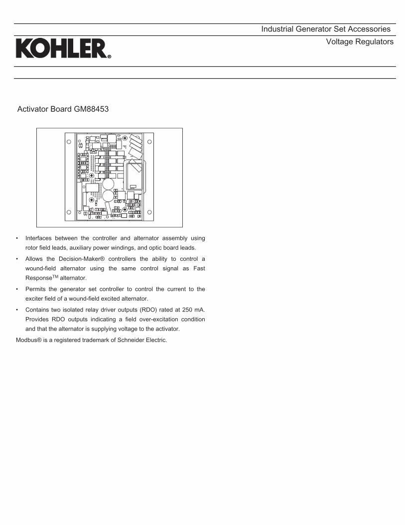
Engineering Submittal
For:
FRESENIUS MEDICAL CARE 150REOZJF
AZURA CHERRY HILL, NJ NARDONE ORDER # G200055
Customer: Nardone Electric 160 Olympia Ave
Woburn, MA 01801 USA
Phone: 781-935-2727 Fax: 781-391-3100
Jay Nardone

Generator Check List
Facility Address: Date: ____________ Return To:
_____________________________________ Nardone Electric
_____________________________________
_____________________________________
FMC Fac. Name:_______________________
FMC Fac. # ___________________________
CONTRACTOR’S GENERATOR INSTALLATION CHECKLISTPlease fill out the checklist to verify that all systems are complete and the unit is ready for start-up. When this form is complete and returned start-up will be scheduled.
GeneratorModel_________________________SER#____________________________ATSModel(s)___________________________SER#___________________________ATSModel(s)___________________________SER#___________________________*Remote Annunciator Powered and Communication Wire Terminated *Was Belden 9841 used as specified? *Power Wiring Complete: Generator *ATS *Start Wires Connected *Battery Charger Powered (non GFCI)* *Block Heater Powered (non GFCI) *Normal Utility Power is Present *Debris removed from inside all housings *Fuel Tank Filled (to 80% of capacity) *do not plug-in*NFPA-110 Required? Y N*If Yes, Is Emergency E-Stop button wired? Y N _________________________________________________________________________________
I hereby certify that the above work is complete:
Signature________________________________Print Name:______________________
Company _______________________________ Phone:__________________________
Requested Start-up Date: ___________________________________________________ Note: Electrical Contractor must be present at startup to handle any electrical issues that may arise. Oncescheduled, if for any reason the Generator is not ready for start-up, Electrical Contractor is not present at the startup, and the start-up is not able to proceed, the Contractor will be back charged by FMC-NA for the next visit.
Comments:______________________________________________________________________________________________________________________________________
2

TABLE OF CONTENTS GENERATOR SUBMITTAL
Bill of Materials Page# 4 Customer Control Connections Page# 6 Generator Spec Sheet Page# 7 Controller Spec Sheet Page# 12 Circuit Breakers Page# 16 Housing Spec Sheet Page# 26 Annunciator Spec Sheet Page# 36 Alternator Spec Sheet Page# 40 Emissions Data Sheet Page# 51 Generator Dimensions Page# 55 Controller Dimensions Page# 58 Housing Dimensions Page# 59 Tank Dimensions Page# 62 Pad Drawing Page# 63 Controller Wiring Page# 65 Miscellaneous Page# 77 Warranty Page# 86 Certifications Page# 88 ATS Info Page# 94


Generator Set Controller
Kohlerr APM402 ControllerGeneral Description and FunctionThe APM402 generator set controller provides advanced control,system monitoring, and system diagnostics for optimumperformance.
The APM402 controller meets NFPA 110, Level 1 whenequipped with the necessary accessories and installed perNFPA standards.
The APM402 controller uses a patented hybrid voltage regulatorand unique software logic to manage alternator thermal overloadprotection features normally requiring additional hardware.Additional features include:
D A digital display and pushbutton/rotary selector dial provideeasy local access to data.
D Measurements selectable in metric or English units.
D The controller can communicate directly with a personalcomputer via a network or serial configuration usingSiteTecht or Monitor III software.
D The controller supports Modbusr protocol. Use with serialbus or Ethernet networks. (Ethernet requires an externalModbusr/Ethernet converter module.)
D Scrolling display shows critical data at a glance.
D Digital display of power metering (kW and kVA).
D Integrated hybrid voltage regulator providing 0.5%regulation.
D Built-in alternator thermal overload protection.
Modbusr is a registered trademark of Schneider Electric.
Industrial Generator Set Accessories
APM402
G6-161 4/18b Page 1

G6-161 4/18b Page 2
FAULT
OFF/RESET AUTO RUN ALARM SILENCE/LAMP TEST
Volts L1 L2:480.0 V
Emergency Stop Switch
Digital Display
Master Control ButtonsOff- Reset/Auto/Runwith Lights
Pushbutton/RotarySelector Dial
Alarm Silence/LampTest Button with Light
Annunciator Fault LightRed- Shutdown,Yellow- Warning
USB CommunicationConnection
Alarm Horn (locatedinside the controller)
User Interface Controls and ComponentsD Emergency stop switchD Backlit LCD digital display with two lines of 12 characters
(see User Interface Displays for menus)D Alarm horn indicates generator set shutdown and warning faultsD Environmentally sealed membrane keypad with three master control
buttons with lightsd Off/Reset (red)d Auto (green)d Run (yellow)
D Pushbutton/rotary selector dial for menu navigationd Rotate dial to access main menusd Push dial and rotate to access sub menusd Press dial for 3 seconds to return to top of main menu
D Annunciator fault lightd System shutdown (red)d System warning (yellow)
D Alarm silence/lamp test buttond Alarm silenced Lamp test
D USB and RS-485 connectionsd Allows software upgradesd Provides access for diagnosticsd PC communication using SiteTecht or Monitor III software
D Dedicated user inputsd Remote emergency stop switchd Remote 2-wire start for transfer switchd Auxiliary shutdown
D Integrated hybrid voltage regulatorD Auto-resettable circuit protection mounted on circuit board.D One relay output standard. Optional five relay output available.D One analog and three digital inputs standard. Optional two inputs
available.NFPA 110 Requirements
In order to meet NFPA 110, Level 1 requirements, the generator setcontroller monitors the engine/generator functions/faults shown below.D Engine functions:
d Overcrankd Low coolant temperature warningd High coolant temperature warningd High coolant temperature shutdownd Low oil pressure shutdownd Low oil pressure warningd High engine speedd Low fuel (level or pressure) *d Low coolant leveld EPS supplying loadd High battery voltaged Low battery voltage
D General functions:d Master switch not in autod Battery charger fault *d Lamp testd Contacts for local and remote common alarmd Audible alarm silence buttond Remote emergency stop *
* Function requires optional input sensors or kits and is engine dependent,see Controller Displays as Provided by the Engine ECM.
User Interface DisplaysThe listing below has D denoting main menus and d denoting sub-menus.D Overview
d Software versiond Active shutdowns and warnings (if any are present)d Engine run time, total hoursd Average voltage line-to-lined Frequencyd Average currentd Coolant temperatured Fuel level or pressure *d Oil pressured Battery voltage
D Engine Meteringd Engine speedd Oil pressured Coolant temperatured Battery voltage
D Generator Meteringd Total power, VAd Total power, Wd Rated power, %d Voltage, L- L and L- N for all phasesd Current, L1, L2, L3d Frequency
D GenSet Informationd Generator set model numberd Generator set serial numberd Controller serial number
D GenSet Run Timed Engine run time, total hoursd Engine loaded, hoursd Number of engine startsd Total energy, kWh
D GenSet Systemd System voltaged System frequency, 50 or 60 Hzd System phase, single or three (wye or delta)d Power rating, kWd Amp ratingd Power type, standby or primed Measurement units, metric or English (user selectable)d Alarm silence, always or auto only (NFPA 110)d Manual speed adjust *
D GenSet Calibrationd Voltage, L- L and L- N for all phasesd Current, L1, L2, L3d Reset calibration
D Voltage Regulationd Adjust voltage, 10%
D Digital Inputsd Input settings and status
D Digital Outputsd Output settings and status
D Analog Inputsd Input settings and status
D Event Logd Event history (stores up to 1000 system events)
D Selector Switch (requires initial activation by SiteTecht)

G6-161 4/18b Page 3
Controller Features
D AC Output Voltage Regulator Adjustment. The voltageadjustment provides a maximum of 10% of the system voltage.
D Alarm Silence. The controller can be set up to silence the alarmhorn only when in the AUTO mode for NFPA-110 application orAlways for user convenience.
D Alternator Protection. The controller provides generator setoverload and short circuit protection matched to each alternator forthe particular voltage/phase configuration.
D Automatic Restart. The controller automatic restart feature initiatesthe start routine and recrank after a failed start attempt.
D Common Failure Relay. This relay is integrated on the controllercircuit board. Contacts are rated 2 amps at 32 VDC or 0.5 amp at120 VAC.
D Communication. Controller communication is available.
D Cyclic Cranking. The controller has programmable cyclic cranking.
D ECM Diagnostics. The controller displays engine ECM fault codedescriptions to help in engine troubleshooting.
D Engine Start Aid. The starting aid feature provides control for anoptional engine starting aid.
D Event Logging. The controller keeps a record (up to 1000 entries)for warning and shutdown faults. This fault information becomes astored record of system events and can be reset.
D Historical Data Logging. Total number of generator set successfulstarts is recorded and displayed.
D Integrated Hybrid Voltage Regulator. The voltage regulatorprovides 0.5% no-load to full-load regulation with three-phasesensing.
D Lamp Test. Press the alarm silence/lamp test button to verifyfunctionality of the indicator lights.
D LCD Display. Adjustable contrast for improving visibility.
D Measurement Units. The controller provides selection of English ormetric displays.
D Power Metering. Controller digital display provides kW and kVA.
D Programming Access (USB). Provides software upgrades anddiagnostics.
D Remote Reset. The remote reset function resets faults and allowsrestarting of the generator set without going to the master controlswitch off/reset position.
D Remote Monitoring Panel. The controller is compatible with theKohlerr Remote Serial Annunciator.
D Run Time Hourmeter. The generator set run time is displayed.
D Time Delay Engine Cooldown (TDEC). The TDEC provides a timedelay before the generator set shuts down.
D Time Delay Engine Start (TDES). The TDES provides a time delaybefore the generator set starts.
D Voltage Selection Menu. This menu provides the capability ofquickly switching controller voltage calibrations. Requires initialactivation using SiteTecht software. NOTE: Generator set outputleads require voltage reconnection.
Controller FunctionsThe following chart shows which functions cause a warning or shutdown.All functions are available as relay outputs.
Warning causes the fault light to show yellow and sounds the alarm hornsignaling an impending problem.
Shutdown causes the fault light to show red, sounds the alarm horn, andstops the generator set.
WarningFunction
ShutdownFunction
Engine FunctionsCritically high fuel level * d
ECM communication loss D
ECM diagnostics D D
Engine over speed D[
Engine start aid activeEngine under speed D
Fuel tank leak * d d
High battery voltage D
High coolant temperature D D[
High fuel level * d
Low battery voltage D
Low coolant level D
Low coolant temperature D
Low cranking voltage D
Low engine oil level * d d
Low fuel level (diesel models) * d d
Low fuel pressure (gas models) * d
Low oil pressure D D[
No coolant temperature signal D
No oil pressure signal D
Overcrank D[
Speed sensor fault D
General FunctionsAlarm horn silencedAnalog inputs d d
Battery charger fault * D
Chicago code active *Common fault (includes [) D
Common warning D
Digital inputs d d
Emergency stop D[
Engine cooldown (delay) activeEngine start delay activeEngine startedEngine stoppedEPS supplying load
Generator runningInput/output communication loss D
Internal failure D
Master switch not in auto D
NFPA 110 alarm active
Remote startSystem ready
Generator FunctionsAC sensing loss D D
Alternator protection D
Ground fault input * D
kW overload D
Locked rotor D
Overfrequency D
Overvoltage (each phase) D
Underfrequency D
Undervoltage (each phase) D
D Standard functiond Available user function* Function requires optional input sensors or kits and is engine dependent;
see Controller Displays as Provided by the Engine ECM.[ Items included with common fault shutdown

2018 by Kohler Co., All rights reserved.
DISTRIBUTED BY:
G6-161 4/18b Page 4
Controller Displaysas Provided by the
Engine ECM
Engine Manufacturer and Model
Kohler Diesel
(KDI M, TM*)
Kohler Diesel
(KDI TCR)
Kohler Gas(KG2204,KG2204T)
GM/PSI andKohler Gas(KG6208,KG6208T) DD/MTU Doosan
JohnDeere Volvo
Intake air pressure S/D DIntake air Temperature D D S/D D D DCoolant level D D D D D DCoolant temperature D C/S/D C/S/D C/S/D C/S/D C/S/D C/S/DCrankcase pressure DECM battery voltage S S/D S S SEngine model number S S S S S S SEngine serial number S S S S S S SEngine speed C/S/D C/S/D C/S/D C/S/D C/S/D C/S/D C/S/D C/S/DFuel pressure D C/S/D C/S C/S/D C/S[ C/S/DFuel rate S S S S SFuel temperature D S S/D SOil level S[ S/D[ S[ S[ S[
Oil pressure C/S/D D C/S/D C/S/D C/S/D C/S/D C/S/DOil temperature S D SDC = Value displayed on controller, S = Value displayed in Site Tech, D = ECU diagnostic is supported
* Electronic governor and ECM are optional on KDI M and TM engines.
[ Controller uses local analog input to obtain this information.
NOTE: REOZMD/ROZMC (Mitsubishi engines) have an ECM but do not send signals to the generator set controller.
NOTE: See the generator set specification sheet for engine model identification.
Controller SpecificationsD Power source with circuit protection: 12- or 24-volt DCD Power drain: 200 milliamps at 12 VDC or 100 milliamps at 24 VDCD Humidity range: 5% to 95% noncondensingD Operating temperature range: - 40 C to +70 C (- 40 F to +158 F)D Storage temperature range: - 40 C to +85 C (- 40 F to +185 F)D Standards:
d CE Directived NFPA 99d NFPA 110, Level 1d CSA 282-09d UL 508d ASTM B117 (salt spray test)
D Panel dimensions—W x H, 229 x 160 mm (9.0 x 6.3 in.)
Communication and PC SoftwareAvailable Options
Refer to G6-76 Monitor III Software and the communication literature foradditional communication and PC software information includingModbusr communication.
- Monitor III Software for Monitoring and Control(Windowsr-based user interface)
- Converter, Modbusr/Ethernet. Supports a power system usingcontrollers accessed via the Ethernet. Converter is supplied with anIP address by the site administrator. Refer to G6-79 for converterdetails.
- Converter, RS-232/RS-485. Supports a power system usingcontrollers accessed via a serial (RS-232) connection.
APM402 Available Options- Float/Equalize Battery Charger available with 6 or 10 amp output
for 12 or 24V DC voltage output. The 10 amp model providesNFPA 110 charging and alarming capability.
- Manual Speed Adjust available for applications using closedtransition ATS. Adjustment range for 60 Hz: 1751- 1849 rpm(58.2- 61.8 Hz) and for 50 Hz: 1451- 1549 rpm (48.2- 51.8 Hz).
- Prime Power Switch prevents battery drain during generator setnon-operation periods and when the generator set battery cannot bemaintained by an AC battery charger.
- Remote Emergency Stop Switch available as a wall mountedpanel to remotely shut down the generator set.
- Remote Monitoring Panel. The Kohlerr Remote SerialAnnunciator (RSA) enables the operator to monitor the status of thegenerator set from a remote location, which may be required forNFPA 99 and NFPA 110 installations, and up to four Automatictransfer switches.
- Run Relay provides a relay indicating that the generator set isrunning.
- Shunt Trip Wiring provides relay outputs to trip a shunt trip circuitbreaker and to signal the common fault shutdowns. Contacts ratedat 10 amps at 28 VDC or 120 VAC.
- Two Input/Five Output Module provides a generator set mountedpanel with two inputs and five relay outputs.
Modbusr is a registered trademark of Schneider Electric.
Windowsr is a registered trademark of Microsoft Corporation.
Availability is subject to change without notice. Kohler Co. reserves theright to change the design or specifications without notice and without anyobligation or liability whatsoever. Contact your local Kohlerr generatorset distributor for availability.
KOHLER CO., Kohler, Wisconsin 53044 USAPhone 920-457-4441, Fax 920-459-1646For the nearest sales and service outlet in theUS and Canada, phone 1-800-544-2444KOHLERPower.com

POWERPACT® P- and R-Frame Molded CaseCircuit Breakers (Standard or100% rated up to 2500A)
POWERPACT Molded Case Circuit Breakers lead the industry with proven, reliable protection and innovative design. Providingunparalleled performance and control, this generation of P- and R-frame circuit breakers features exclusive MICROLOGIC® TripUnits, which allow for a range of sophisticated applications formetering and monitoring. In addition, units can be interchanged toallow for maximum flexibility and are field-installable for easyupgrades as needed.The compact P- and R-frame circuit breakers permit smallerfootprint and higher density installations using I-LINE® Panelboardsand Switchboards. These circuit breakers are available in 100%rated construction up to 2500 A to meet a broad range ofcommercial and industrial application needs.
Full-Featured Performance
■ P-frame – 1200A available in both standard and 100% ratingswith sensor sizes 250–1200A. Interrupting ratings (AIR) G-35kAIR, J-65kAIR and L-100kAIR at 480 VAC
■ R-frame – 2500A available in both standard and 100% ratingswith sensor sizes 600–2500A. Interrupting ratings (AIR) G-35kAIR, J-65kAIR and L-100kAIR at 480 VAC
■ Compact breaker size allows for smaller footprint installationsusing I-LINE Panelboards and Switchboards. 9" width on P-frame designs and 15" width on R-frame designs provideincreased density installations
■ Most field-installable accessories are common to all frame sizesfor easier stocking and installation
■ Selection of four interchangeable MICROLOGIC Trip Units withPOWERLOGIC® power metering and monitoring capabilitiesavailable in advanced trip units
■ Compatible with POWERLOGIC® systems and high amperagepower circuit breakers
■ Built-in MODBUS® protocol provides an open communicationsplatform and eliminates the need to purchase additional,proprietary network solutions
■ Connection options include bus, cable or I-Line for installationflexibility
■ Additional options are available for 5-cycle closing, storedenergy mechanisms and draw-out mounting of 1200 A breakers
The most compact and innovative molded case circuit breakers
P-Frame 1200 A
R-Frame

Onboard Intelligence
For “smarter breakers,” a range of MICROLOGIC® Trip Unitsprovides advanced functionality, such as a communicationsinterface, and power metering and monitoring capabilities.With the appropriate MICROLOGIC Trip Unit, you cancommunicate with breakers, gather power information,monitor events and remotely control breakers based onpredetermined conditions, leading to substantial savings inelectrical system operating costs.These interchangeable, microprocessor-controlled, plug-indevices provide the next generation of protection, measure-ment and control functions, delivering not only greaterelectrical system safety but also improved system integrationand coordination.
MICROLOGIC® Trip Units
Order Number 0612HO0201© 2002 Schneider Electric All rights reserved
Contact your Square D sales representative for additional information. Or, visit www.SquareD.com.
MICROLOGIC 3.0 and 5.0■ Basic circuit protection including
long-time, instantaneous and optionalshort-time adjustments
MICROLOGIC 3.0A, 5.0A and 6.0A■ Long-time, instantaneous and optional
short-time adjustments■ Integrated ammeter and phase
loading bar graph■ LED trip indicator■ Zone selective interlocking with
downstream and upstream breakers■ Optional ground-fault protection■ Optional MODBUS® communications
interface
MICROLOGIC 5.0P and 6.0P■ Long-time, instantaneous and optional
short-time adjustments■ Advanced relay protection (current
imbalance, under/over voltage, etc.)■ Inverse Definite Minimum Time Lag
(IdmtL) long-time delay curve shapingfor improved coordination
■ Basic power metering and monitoringfunctions
■ Standard MODBUS communicationsinterface compatibility withPOWERLOGIC® installations
■ Standard GF alarm on 5.0P.6.0P has equipment ground-faulttripping protection
MICROLOGIC 5.0H and 6.0H■ All 5.0P and 6.0P functions■ Enhanced POWERLOGIC power
metering and monitoring capabilities■ Basic power quality (harmonic)
measurement■ Waveform capture
Choose the Model that Meets Your Needs
POWERPACT® P- and R-Frame Molded Case Circuit Breakers (Standard or 100% rated up to 2500 A)

Industrial Generator Set Accessories
Standard FeaturesD The line circuit breaker interrupts the generator set
output during a short circuit and protects the wiringwhen an overload occurs. Use the circuit breaker tomanually disconnect the generator set from the loadduring generator set service.
D Circuit breaker kits are mounted to the generator setand are provided with load-side lugs and neutral busbar.
D Kohler Co. offers a wide selection of molded-caseline circuit breaker kits including single, dual, andmultiple configurations for each generator set.
D Four types of line circuit breakers are available:(see page 2 for definitions and pages 3 and 4 forapplication details)
d Magnetic tripd Thermal magnetic tripd Electronic tripd Electronic with ground fault (LSIG) trip
D In addition, line circuit breakers are offered with 80%and 100% ratings.
D Single line circuit breaker kits allow circuit protectionof the entire electrical system load.
D Dual line circuit breaker kits allow circuit protectionof selected priority loads from the remainingelectrical system load.
D Multiple line circuit breaker kits with field connectionbarrier allow circuit protection for specialapplications (350- 2500 kW models and selected80- 300 kW models).
D Up to four line circuit breakers can be used on350- 2500 kW models.
D Line circuit breakers comply with the following codesand standards unless otherwise stated.
d UL 489 Molded Case Circuit Breakersd UL 1077 Supplementary Protectorsd UL 2200 Stationary Engine Generator Assemblies
Line Circuit Breakers 15- 3250 kW
Multiple Circuit Breaker Kit with Neutral Bus Bar180- 300 kW Model Shown
Single Circuit Breaker Kit with Neutral Bus Bar15- 300 kW Model Shown
Multiple Circuit Breaker Kits with Neutral Bus Bar350- 2250 kW Model Shown
(also applies to some 300 kW models)
Circuit Breaker Kits with Neutral Bus Bar800- 2500 kW KD Model Shown
G6-88 6/19p Page 1
Single Circuit Breaker Kit with Neutral Bus Bar

G6-88 6/19p Page 2
Line Circuit Breaker TypesMagnetic TripThe magnetic trip features an electromagnet in series with the loadcontacts and a moveable armature to activate the trip mechanism.When a sudden and excessive current such as a short circuitoccurs, the electromagnet attracts the armature resulting in aninstantaneous trip.
Thermal Magnetic TripThermal magnetic trip contains a thermal portion with a bimetallicstrip that reacts to the heat produced from the load current.Excessive current causes it to bend sufficiently to trip themechanism. The trip delay is dependent on the duration andexcess of the overload current. Elements are factory- calibrated.A combination of both thermal and magnetic features allows adelayed trip on an overload and an instantaneous trip on a shortcircuit condition.
Electronic TripThese line circuit breakers use electronic controls and miniaturecurrent transformers to monitor electrical currents and trip whenpreset limits are exceeded.
LI breakers are a combination of adjustable trip functions includinglong-time ampere rating, long-time delay, and instantaneouspickup. LSI breakers have all of the LI breaker features plusshort-time pickup, short-time delay, and defeatable instantaneouspickup. LSIG breakers have all of the LSI breaker features plusground-fault pickup and delay.
Electronic with Ground Fault TripThe ground fault trip feature is referred to as LSIG in thisdocument. Models with LSIG compare current flow in phase andneutral lines, and trip when current unbalance exists.
Ground fault trip units are an integral part of the circuit breakerand are not available as field-installable kits. The ground faultpickup switch sets the current level at which the circuit breakerwill trip after the ground fault delay. Ground fault pickup valuesare based on circuit breaker sensor plug only and not on therating plug multiplier. Changing the rating plug multiplier hasno effect on the ground fault pickup values.
80% Rated Circuit BreakerMost molded-case circuit breakers are 80% rated devices.An 80% rated circuit breaker can only be applied at 80% of itsrating for continuous loads as defined by NFPA 70. Circuitconductors used with 80% rated circuit breakers are requiredto be rated for 100% of the circuit breaker’s rating.
The 80% rated circuit breakers are typically at a lower costthan the 100% rated circuit breaker but load growth is limited.
100% Rated Circuit BreakerApplications where all UL and NEC restrictions are met can use100% rated circuit breakers where 100% rated circuits can carry100% of the circuit breaker and conductor current rating.
The 100% rated circuit breakers are typically at a higher costthan the 80% rated circuit breaker but have load growthpossibilities.
When applying 100% rated circuit breakers, comply with thevarious restrictions including UL Standard 489 and NECSection 210. If any of the 100% rated circuit breaker restrictionsare not met, the circuit breaker becomes an 80% rated circuitbreaker.
Line Circuit Breaker Options- Alarm SwitchThe alarm switch indicates that the circuit breaker is in a trippedposition caused by an overload, short circuit, ground fault, theoperation of the shunt trip, an undervoltage trip, or the push-to-trip pushbutton. The alarm resets when the circuit breaker isreset.
- Auxiliary ContactsThese switches send a signal indicating whether the maincircuit breaker contacts are in the open or closed position.
- Breaker Separators (350- 2500 kW)Provides adequate clearance between breaker circuits.
- Bus BarsBus bar kits offer a convenient way to connect load leads to thegenerator set when a circuit breaker is not present.15- 300 kW. Bus bar kits are available on alternators with leadsfor connection to the generator set when circuit breakers are notordered.350- 2500 kW. A bus bar kit is provided when no circuit breakeris ordered. Bus bars are also available in combination withcircuit breakers or other bus bars on the opposite side of thejunction box. On medium voltage (3.3 kV and above) units, abus bar kit is standard (not applicable to KD models).
- Field Connection BarrierProvides installer wiring isolation from factory connections.
- Ground Fault AnnunciationA relay contact for customer connection indicates a groundfault condition and is part of a ground fault alarm.
- Lockout Device (padlock attachment)This field-installable handle padlock attachment is available formanually operated circuit breakers. The attachment canaccommodate three padlocks and will lock the circuit breakerin the OFF position only.
- LugsVarious lug sizes are available to accommodate multiple cablesizes for connection to the neutral or bus bar.
- Overcurrent Trip SwitchThe overcurrent trip switch indicates that the circuit breaker hastripped due to overload, ground fault, or short circuit and returnsto the deenergized state when the circuit breaker is reset.
- Shunt Trip, 12 VDC or 24 VDCA shunt trip option provides a solenoid within the circuit breakercase that, when momentarily energized from a remote source,activates the trip mechanism. This feature allows the circuitbreaker to be tripped by customer-selected faults such asalternator overload or overspeed. The circuit breaker mustbe reset locally after being tripped. Tripping has priority overmanual or motor operator closing.
- Shunt Trip WiringConnects the shunt trip to the generator set controller.(standard on KD models with the APM802 controller)
- Undervoltage Trip, 12 VDC or 24 VDCThe undervoltage trips the circuit breaker when the controlvoltage drops below the preset threshold of 35%- 70% of therated voltage.
100% Rated Circuit BreakerElectronic Trip

G6-88 6/19p Page 4
15- 300 kW Line Circuit Breaker Specifications100% Rating Circuit Breaker
Alt. Model Ampere Range Trip Type
C. B.FrameSize
4D/4E
15- 150 Thermal magnetic
HD60- 150
Electronic LIElectronic LSIElectronic LSIG
60- 150
Electronic LI
HGElectronic LSIElectronic LSIG
4P/4PX4Q/4QX
15- 150 Thermal magnetic
HD60- 150
Electronic LIElectronic LSIElectronic LSIG
60- 150
Electronic LI
HGElectronic LSIElectronic LSIG
175- 250 Thermal magnetic JD
250
Electronic LI
JDElectronic LSIElectronic LSIG
250
Electronic LI
JGElectronic LSIElectronic LSIG
400
Electronic LI
LGElectronic LSIElectronic LSIG
4RX4S/4SX
4TX4V
4UA4M6226
15- 150 Thermal magnetic
HD60- 150
Electronic LI
Electronic LSI
Electronic LSIG
60- 150
Electronic LI
HGElectronic LSI
Electronic LSIG
175- 250 Thermal magnetic
JD250
Electronic LI
Electronic LSI
Electronic LSIG
250
Electronic LI
JGElectronic LSI
Electronic LSIG
400
Electronic LI
LGElectronic LSI
Electronic LSIG
600- 800Electronic LSI
PGElectronic LSIG
4UA4M6226
1000- 1200Electronic LSI
PGElectronic LSIG
1200Electronic LSI
PJElectronic LSIG
100% Rating Electrically Operated BreakersFor use as paralleling breakers with the APM603 controller.
Generator-Mounted P-Frame, 24VDC Electrically OperatedAlt. Model Amps Trip Unit Frame
4RX4S/4SX
4TX4V
250400600800
3.0 LI PJ5.0 LSI PJ3.0 LI PL
5.0 LSI PL
4UA4M6226
25040060080010001200
3.0 LI PJ
5.0 LSI PJ
3.0 LI PL
5.0 LSI PL
All circuit breakers listed in this table include line side bus and load sidelugs, 24VDC motor operators, 2 type C auxiliary contacts, and 1 type CSDE overcurrent switch contact. No second breakers are allowed incombination with these breakers.
Interrupting RatingsCircuit Breaker
Frame Size240 Volt,
kA480 Volt,
kA600 Volt,
kA
HD 25 18 14HG 65 35 18HJ 100 65 25JD 25 18 14JG 65 35 18JJ 100 65 25LA 42 30 22LG
65 35 18MGPGPJ 100 65 25PL 125 100 25
Circuit Breaker Lugs Per Phase (Al/Cu)Frame Size Ampere Range Wire Range
E(480 V max.) 30- 100
Up to two wire terminals fitting10-32 or 1/4-20 stud
H 15- 150 One #14 to 3/0
J175 One 1/0 to 4/0
200- 250 One 3/0 to 350 kcmil
LA 300- 400One #1 to 600 kcmil or
Two #1 to 250 kcmil
LG 400- 600 Two 2/0 to 500 kcmil AL/CUM 700-800 Three 3/0 to 500 kcmil
P600-800 Three 3/0 to 500 kcmil
1000-1200 Four 3/0 to 500 kcmilMechanical Load Lugs Included with H, J, and LG LSIG Neutrals
H 60- 150 One #14 to 3/0 AL/CUJ 250 One 3/0 to 350 kcmil AL/CU
LG 400- 600 Two 4/0 to 500 kcmil AL/CU
4SX
600-Electronic LSI
PG
P600-800 Three 3/0 to 500 kcmil
PG35
G6-88 6/19p Page 5
15- 300 kW Line Circuit Breaker Applications
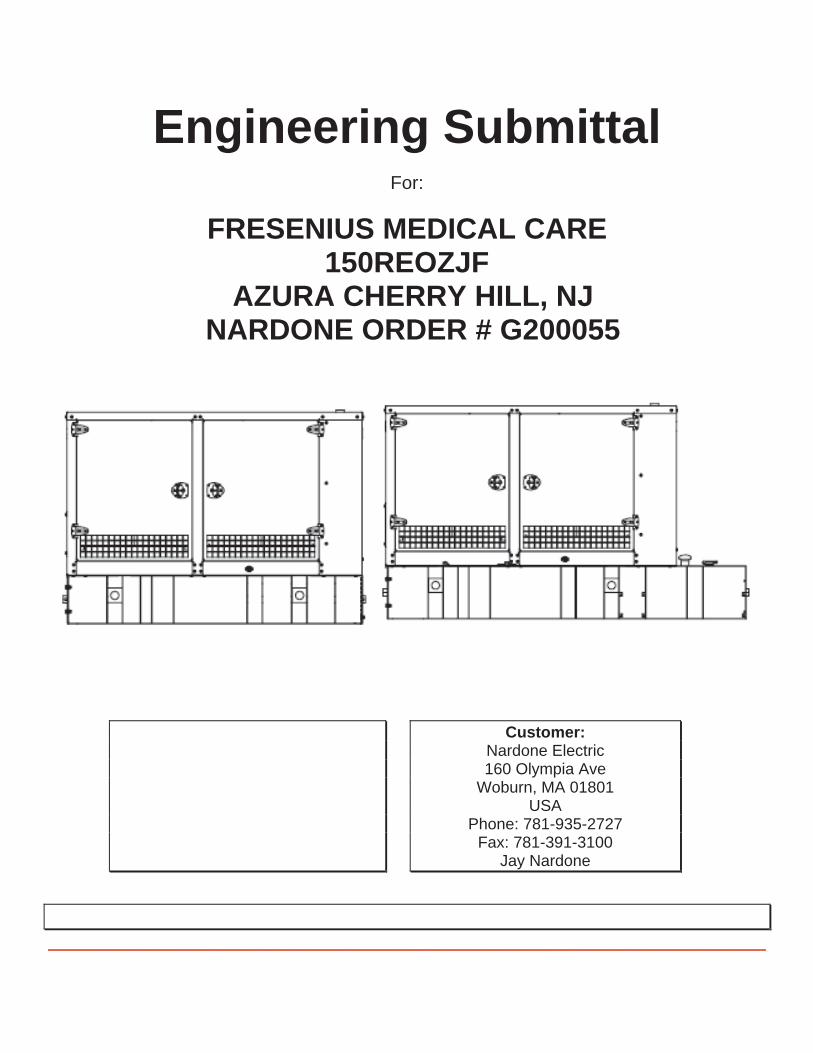
Single Circuit Breaker InstallationsA generator set with a single circuit breaker installed typicallyfeeds a single transfer switch and then a distribution panel.This allows protection of the entire system.
To RemainingBuilding Loads
To Priority Load(s)
Line C.B.
Single line circuit breaker configuration where circuit breaker cantrip causing all power to building loads including priority load tobe disrupted.
ATS
DistributionPanel
DistributionPanel
Multiple Circuit Breaker InstallationsA generator set with dual circuit breakers installed is used toseparate critical loads. Typically, one circuit breaker will feeda main transfer switch with noncritical loads and the other circuitbreaker will feed a second transfer switch that feeds critical orpriority loads. Multiple circuit breakers allow circuit protectionfor special applications.
To RemainingBuilding Loads
To Priority Load(s)
FirstLine C.B.
SecondLine C.B.
Dual line circuit breaker configuration where first circuit breakercan trip allowing second circuit breaker to continue supplyingpower to priority load(s).
ATS ATS
DistributionPanel
DistributionPanel
Circuit Breaker Combinations
AlternatorModel
FirstC. B.Frame
SecondC. B.Frame
ThirdC. B.Frame Trip Type
ALLexcept 4D/4E
H — —
AllJ — —
LA — —LG — —
4D/4EH — — Standard or LSIGH H — No LSIG
4P/4PX4Q/4QX
H
H or J
—
No LSIGJ —
LA —LG H, J or LG —
4RX4S/4SX
4TX4V
M — — AllP — — All
H or J H or J —
No LSIG
LAH, J, or
LA —
LGH, J, LA,
or LG —MP
H or J H or J H or J
4UA4M6226
M or P — — AllH or J H or J —
All
LA H, J, orLA
—
LGH, J, LA,
or LG —
M or PH, J, LA,
or LG —
P P —
No LSIG
H or J H or J H or J
LAH or J H or J
LAH, J, or
LA
LG
H or J H or J
LAH, J, or
LA
LGH, J, LA,
or LG
M or P
H or J H or J
LAH, J, or
LA
LGH, J, or
LG

1.51
1
CURRENT IN MULTIPLES OF Ir (Ir = LONG-TIME SETTING x In)
CURRENT IN MULTIPLES OF Ir (Ir = LONG-TIME SETTING x In)
.5 .6 .7 .8 .9 1.5
2 3 4 5 6 7 8 9 10 15 20 30 40 50 60 70 80 90 100
.5 .6 .7 .8 .9 2 3 4 5 6 7 8 9 10 15 20 30 40 50 60 70 80 90 100
200
300
400
500
6007008009001000
1500
2000
3000
4000
6000700080009000
5000
10000
.005
.006
.007
.008
.009.01
.015
.02
.03
.04
.05
.06
.07
.08
.09.1
.005
.006
.007
.008
.009
.01
.015
.02
.03
.04
.05
.06
.07
.08
.09
.1
.15
.2
.3
.4
.5
.6
.7
.8
.91
.15
.2
.3
.4
.5
.6
.7
.8
.91
1.5
2
3
4
5
6789
10
1.5
2
3
4
5
678910
15
20
30
40
50
60708090
100
15
20
30
40
50
60708090100
150
200
300
400
500
600700800900
1000
1500
2000
3000
4000
5000
6000700080009000
10000
TIM
E IN
SEC
ON
DS
CYCLE21
1 CYCLE
150
24
20
.5
24
16
128
8
6
4
2.51.5 2
3 5
10
4
2
1
16
0.4 OFF
0.3 OFF
0.2 OFF
0.1 OFF
0
LONG-TIME PICKUPx In = Ir
LONG-TIMEDELAY BANDS
SECONDS AT 6 x Ir
MAXIMUMUNRESTRAINED
SHORT-TIMEDELAY
SHORT-TIMEDELAY I2t OFF
(FIXED-TIME DELAY)SECONDS AT 10 x Ir
SHORT-TIMEPICKUP
x Ir
MICROLOGIC® 5.0/6.0 A/P/H TRIP UNITCHARACTERISTIC TRIP CURVE NO. 613-4
Long-time Pickup and DelayShort-time Pickup and I2t OFF Delay
The time-current curve information is to be usedfor application and coordination purposes only.
Curves apply from -30°C to +60°C ambienttemperature.
Notes:
1. There is a thermal-imaging effect that can actto shorten the long-time delay. The thermal-imaging effect comes into play if a currentabove the long-time delay pickup value existsfor a time and then is cleared by the tripping ofa downstream device or the circuit breakeritself. A subsequent overload will cause thecircuit breaker to trip in a shorter time thannormal. The amount of time delay reduction isinverse to the amount of time that has elapsedsince the previous overload. Approximately 20minutes is required between overloads tocompletely reset thermal-imaging.
2. The end of the curve is determined by theinterrupting rating of the circuit breaker.
3. With zone-selective interlocking on, short-timedelay utilized and no restraining signal, themaximum unrestrained short-time delay timeband applies regardless of the setting.
4. Total clearing times shown include theresponse times of the trip unit, the circuitbreaker opening, and the extinction of thecurrent.
5. For a withstand circuit breaker, instantaneouscan be turned OFF. See 613-7 forinstantaneous trip curve. See 613-10 forinstantaneous override values.
6. Overload indicator illuminates at 100%.
© 2000 Schneider Electric all rights reserved
Curve No. 0613TC0004December 2000
Drawing No. B48095-613-04Schneider Electric Brands

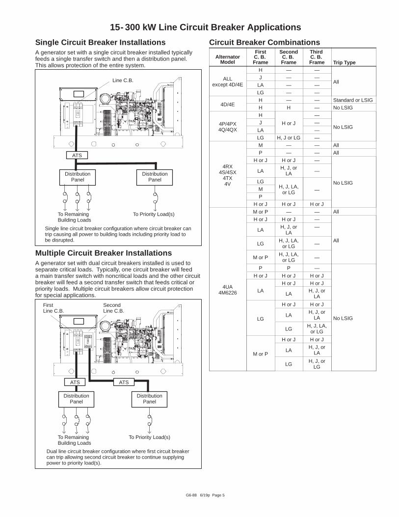
The battery charger is designed for operation with anengine cranking battery.
6 3/19c

3/19c
On battery voltage regulation ±1%;current is electronically limited


*Generator / fuel tank weights & dimensions stated do not include oak shipping skids. As a guide line please add Approximately 6 inches on each end and each side. Oak skid also adds approximately 6 inches of height and Depending on unit size, also include 700-900 lbs. for the weight of the skid. Please use this info as a guideline and not actual weights and dimensions.


D
Remote Serial Annunciator III (RSA III)for Kohlerr ControllersD Monitors the generator set equipped with one of the following
controllers:APM402 Decision-Makerr 3000APM603 Decision-Makerr 3500APM802 Decision-Makerr 6000Decision-Makerr 3+ Decision-Makerr 8000Decision-Makerr 550 KPC 1000
D Allows monitoring of the common alarm, remote testing of theautomatic transfer switch, and monitoring of the normal/emergency source for up to four ATS with any of the followingcontrollers:
Decision-Makerr MPACr 750, 1200, and 1500MPACr 1000 and 1500
D Configuration via a personal computer (PC) software.D Writable surfaces (white boxes in illustrations) for user-defined
selections.D Uses Modbusr RTU protocol.D Controller connections:
RS-485 for serial bus networkUSB port. Connect a personal computer and use KohlerrSiteTecht software to view events and adjust settings. *12-/24-volt DC power supply120/208 VAC power supply (available accessory)
D Meets the National Fire Protection Association StandardNFPA 110, Level 1.
DimensionsD Dimensions—W x H x D, mm (in.).
Surface Mounted:203 x 203 x 83 (8.0 x 8.0 x 3.3)Flush Mounted (Inside Wall):203 x 203 x 76 (8.0 x 8.0 x 3.0)Flush mounting plate W1: 254 (10.0)
* SiteTecht software is available to Kohler authorized distributors anddealers.
Modbusr is a registered trademark of Schneider Electric.
Industrial Generator Set Accessories
Remote Serial Annunciator III (RSA III)
Surface Mounted Flush Mounted
W W
W1D
H
H
RSA III
RSA III with Four ATS Controls
RSA III with a Single ATS Control
G6-139 4/19c
RSA III

G6-139 4/19c
Fault and Status Conditions Fault LEDs Fault HornSystem
Ready LEDGenerator
Running LEDCommunication
Status LEDOvercrank Shutdown Red On Red Off GreenHigh Engine Temperature Warning * Yellow On Red Green GreenHigh Engine Temperature Shutdown Red On Red Off GreenLow Oil Pressure Warning * Yellow On Red Green GreenLow Oil Pressure Shutdown Red On Red Off GreenOverspeed Shutdown Red On Red Off GreenEmergency Stop * Red On Red Off GreenLow Coolant Level/Aux. Shutdown Red On Red Off GreenLow Coolant Temperature * Yellow On Red Off GreenLow Cranking Voltage Yellow On Red Off GreenLow Fuel—Level or Pressure * Yellow On Red Green or Off GreenNot-In-Auto Red On Red Green or Off GreenCommon Fault Red On Green Green or Off GreenBattery Charger Fault (1) * Yellow On Red Green or Off GreenBattery Charger Fault (2) * Yellow On Green Green or Off GreenHigh Battery Voltage * Yellow Off Green Green or Off GreenLow Battery Voltage * Yellow Off Green Green or Off GreenUser Input #1 (Warning) Yellow Off Green Green or Off GreenUser Input #1 (Shutdown) Red On Green Off GreenUser Input #2 (Warning) Yellow Off Green Green or Off GreenUser Input #2 (Shutdown) Red On Green Off GreenUser Input #3 (Warning) (1) [ Yellow Off Green Green or Off GreenUser Input #3 (Shutdown) (1) [ Red On Green Off GreenUser Input #4 (Warning) (1) Yellow Off Green Green or Off GreenUser Input #4 (Shutdown) (1) Red On Green Off GreenUser Input #5 (Warning) (1) Yellow Off Green Green or Off GreenUser Input #5 (Shutdown) (1) Red On Green Off GreenEPS Supplying Load Yellow Off Green Green GreenCommunications Status (Fault mode) — Off Green or Red Green or Off RedATS Fault (RSA III with ATS Controls only) Red On Red or Yellow Green or Off GreenGreen LEDs appear as steady on when activated.Yellow LEDs slow flash when activated except steady on with EPS supplying load and high battery voltage.Red LEDs slow flash when activated except fast flash with loss of communication and not-in-auto.
SpecificationsD LED indicating lights for status, warning, and/or shutdown.D Power source with circuit protection: 12- or 24-volt DCD Power source with120/208 VAC, 50/60 Hz adapter (option)D Power draw: 200 mAD Humidity range: 0% to 95% noncondensingD Operating temperature range: - 20 C to +70 C
(- 4 F to +158 F)D Storage temperature range: - 40 C to +85 C
(- 40 F to +185 F)D Standards:
d NFPA 110, level 1d UL 508 recognizedd CE directived NFPA 99d ENS 61000- 4- 4d EN6II-4-4 fast transient immunity
D RS-485 Modbusr isolated port @ 9.6/19.2/38.4/57.6 kbps(default is 19.2 kbps)
D USB device portD NEMA 1 enclosure
(1) All generator set controllers except Decision-Makerr 3+ controller.(2) Decision-Makerr 3+ controller only.* May require optional kit or user-provided device to enable function and
LED indication.[ Digital input #3 is factory-set for high battery voltage on the
Decision-Makerr 3+ controller.Modbusr is a registered trademark of Schneider Electric.
ATS Controls (RSA III with ATS controls only)
D ATS position LED (normal or emergency)D Power source indicator LED (normal or emergency)D ATS fault LEDD Key-operated lock/unlock switch for Test featureD Test pushbutton
NFPA RequirementsD NFPA 110 compliantD Engine functions:
d High battery voltage warning *d High engine temperature shutdownd High engine temperature warning *d Low battery voltage warning *d Low coolant level/aux. shutdownd Low coolant temperature warning *d Low cranking voltaged Low fuel warning (level or pressure) *d Low oil pressure shutdownd Low oil pressure warning *d Overcrank shutdownd Overspeed shutdown
D General functions:d Audible alarm silenced Battery charger fault *d Lamp testd Master switch not-in-auto

G6-139 4/19c
Fault and Status LEDs and Lamp Test SwitchAlarm Horn. Horn sounds giving a minimum 90 dB at 0.1 m(0.3 ft.) audible alarm when a warning or shutdown faultcondition exists except on high/low battery voltage or EPSsupplying load.
Alarm Silenced. Red LED on lamp test switch lights whenalarm horn is deactivated by alarm silence switch.
Alarm Silence Switch. Lamp test switch quiets the alarmduring servicing. The horn will reactivate upon additional faults.
ATS Fault. Red LED lights when ATS fails to transfer.
Battery Charger Fail. LED lights if battery chargermalfunctions. Requires battery charger with alarm contact.
Battery Voltage Hi/Lo. LED flashes if battery or chargingvoltage drops below preset level. LED lights steady if batteryvoltage exceeds preset level.
Common Fault. LED lights when a single or multiplecommon faults occur.
Communication Status. Green LED lights indicatingannunciator communications functional. Red LED indicatescommunication fault.
EPS Supplying Load. LED lights when the Emergency PowerSystem (EPS) generator set is supplying the load (APM402,APM603, APM802, and Decision-Makerr 550, 3000, 3500,6000, and 8000 controllers) or when transfer switch is in theemergency position (Decision-Makerr 3+ controller).
Emergency Stop. LED lights and engine stops whenemergency stop is made. May require a local emergencystop switch on some Decision-Makerr 3+ controllers.
Generator Running. LED lights when generator set is inoperation.
High Engine Temperature. Red LED lights if engine has shutdown because of high engine coolant temperature. YellowLED lights if engine coolant temperature approaches shutdownrange. Requires warning sender on some models.
Lamp Test (Switch). Switch tests all the annunciator indicatorLEDs and horn.
Low Coolant Level/Aux. LED lights when engine coolant levelis below acceptable range on radiator-mounted generator setsonly. When used with a Decision-Makerr 3+ controller, the LEDindicates low coolant level or an auxiliary fault shutdown.Requires user-supplied low coolant level switch on remoteradiator models.
Low Coolant Temperature. LED lights if optional engine blockheater malfunctions and/or engine coolant temperature is toolow. Requires prealarm sender on some models.
Low Cranking Voltage. LED lights if battery voltage dropsbelow preset level during engine cranking.
Low Fuel (Level or Pressure). LED lights if fuel level in tankapproaches empty with diesel models or fuel pressure is low ongas models. Requires customer-supplied switch.
Low Oil Pressure. Red LED lights if generator set shuts downbecause of insufficient oil pressure. Yellow LED lights if engineoil pressure approaches shutdown range. Requires warningsender on some models.
Not In Auto. LED lights when the generator set controller is notset to automatic mode.
Overcrank. LED lights and cranking stops if engine does notstart in either continuous cranking or cyclic cranking modes.
Overspeed. LED lights if generator set shuts down because ofoverspeed condition.
System Ready. Green LED lights when generator set masterswitch is in AUTO position and the system senses no faults.Red LED indicates system fault.
User-Defined Digital Inputs #1- #5. Monitors five digitalauxiliary inputs (can be configured as warnings or shutdowns).User-defined digital inputs are selected via the RSA III masterfor local or remote (generator set or ATS). The user-defineddigital input can be assigned via PC using SiteTecht setupsoftware.

2014, 2016, 2018, 2019 by Kohler Co. All rights reserved.
DISTRIBUTED BY:
G6-139 4/19c
Accessories- Power source adapter kit 120/208 VAC, 50/60 Hz.- Modbusr/Ethernet converter GM41143-KP2 for serial to
Ethernet communication.- Communication module GM32644-KA1 or GM32644-KP1 is
required with Decision-Makerr 3+ controllers.
Modbusr is a registered trademark of Schneider Electric.
KOHLER CO., Kohler, Wisconsin 53044 USAPhone 920-457-4441, Fax 920-459-1646For the nearest sales and service outlet in theUS and Canada, phone 1-800-544-2444KOHLERPower.com
Availability is subject to change without notice. Kohler Co. reserves theright to change the design or specifications without notice and without anyobligation or liability whatsoever. Contact your local Kohlerr generatorset distributor for availability.


1TIB-102 4S12X 60 Hz 11/11p
TIB-102
TECHNICAL INFORMATION BULLETIN
Alternator Data SheetAlternator Model: 4S12X
Frequency: 60 HzSpeed: 1800 RPMLeads: 12 (6 Lead, 600 Volt)
kW* (kVA)
Class B Class F Class H
Voltage Power 80 C 90 C 95 C 105 C 130 C 125 C 150 C
L--N/L--L Phase Factor Connection Continuous Lloyds ABS Continuous Standby Continuous Standby
139/2403 0.8 Wye
146.5 155.0 160.0 168.0 181.0 178.5 189.0
277/480 (183.0) (193.5) (200.0) (210.0) (226.0) (223.0) (236.0)
127/2203 0.8 Wye
136.0 143.0 146.5 152.5 164.0 162.0 171.5
254/440 (170.0) (178.5) (183.0) (190.5) (205.0) (202.5) (214.0)
120/2083 0.8 Wye
130.0 136.5 139.0 144.0 154.5 152.5 161.5
240/416 (162.5) (170.5) (173.5) (180.0) (193.0) (190.5) (201.5)
110/1903 0.8 Wye
118.5 124.5 126.5 131.0 140.5 139.0 147.0
220/380 (148.0) (155.5) (158.0) (163.5) (175.5) (173.5) (183.5)
120/240 3 0.8 Delta130.0 136.5 139.0 144.0 154.5 152.5 161.5
(162.5) (170.5) (173.5) (180.0) (193.0) (190.5) (201.5)
120/240 1 1.0 Dogleg81.0 90.5 95.0 105.0 106.0 106.0 106.0
(81.0) (90.5) (95.0) (105.0) (106.0) (106.0) (106.0)
347/600 3 0.8 Wye135.0 143.0 147.0 155.0 172.0 168.0 180.0
(169.0) (179.0) (184.0) (194.0) (215.0) (210.0) (225.0)
* All data tested in accordance with IEEE Standard 115. Kohler Co. reserves the right to change the design or specifications without noticeand without any obligation or liability whatsoever.
Submittal Data: 139/240 Volts, 0.8 PF, 1800 RPM, 60 Hz, 3 Phase, 130 C Rise
Symbol PerUnit Ohms Symbol Value
Typical Cold Resistances Typical Time Constants
Phase Resistance 0.031 0.008 Armature Short Circuit Ta 0.012 sec.
Rotor Resistance 20.58 5.239 Transient Short Circuit T’d 0.154 sec.
Typical Reactances Transient Open Circuit T’do 1.728 sec.
Synchronous Typical Field Current
Direct Xd 4.982 1.268 Full Load IfFL 21.1 amps
Quadrature Xq 2.468 0.628 No Load IfNL 3.8 amps
Transient Typical Short Circuit Ratio 0.201
Unsaturated X’du 0.504 0.128 Harmonic Distortion
Saturated X’d 0.443 0.113 RMS Total Harmonic Distortion 4.04%
Subtransient Max. Single Harmonic 5th
Direct X’’d 0.171 0.044 Deviation Factor (No Load, L--L) <5%
Quadrature X’’q 0.169 0.043 Telephone Influence Factor <50
Negative Sequence X2 0.17 0.043 Insulation Class
Zero Sequence X0 0.013 0.003 per NEMA MG1--1.66 H
Phase Rotation ABC
120/208

TIB-1022 4S12X 60 Hz 11/11p
* All data tested in accordance with IEEE Standard 115. Kohler Co. reserves the right to change the design or specifications without noticeand without any obligation or liability whatsoever.
35
40
4S12X, 60 Hz, 139/240, 277/480 Volts, WyeTYPICAL MOTOR STARTING CHARACTERISTICS*
80
82
84
86
88
90
92
94
96
98
100
0 25 50 75 100 125 150 175 200
%E
ffic
ien
cy
Output (KW)
4S12X, 60 Hz, 139/240, 277/480 Volts, WyeTYPICAL ALTERNATOR EFFICIENCY*
0.8 PF
0
5
10
15
20
25
30
35
40
0 100 200 300 400 500 600 700
%V
olt
age
Dip
Locked Rotor KVA

3TIB-102 4S12X 60 Hz 11/11p
4S12X, 60 Hz, Low Wye or Delta ConnectionSHORT CIRCUIT DECREMENT CURVE

TIB-1024 4S12X 60 Hz 11/11p
4S12X, 60 Hz, High Wye ConnectionSHORT CIRCUIT DECREMENT CURVE


TIB-114 1150REOZJF 60 Hz 3/15i
TIB-114
TECHNICAL INFORMATION BULLETIN
Generator Set Sound Data SheetSound Pressure Data in dB(A)
GeneratorSet Model Hz Load Raw Exhaust
Open Unit,Isolated Exhaust
WeatherEnclosure
SoundEnclosure
Snow SoundEnclosure
150REOZJF 60100% Load 99.6 88.4 86.5 75.6 73.3
No Load 90.1 87.7 85.8 73.7 70.3
Note: Sound pressure data is the logarithmic average of eight perimeter measurement points at a distance of 7 m (23 ft.), except RawExhaust data which is a single measurement point at 1 m (3.3 ft.) from the mouth of a straight pipe exhaust.
Continued on next page
The generator set manufacturer reserves the right to change the design or specifications without notice and without any obligation or liability whatsoever. 2015 by Kohler Co. All rights reserved.

TIB-1142 150REOZJF 60 Hz 3/15i
150REOZJF 60 Hz
Sound Pressure Levels, dB(A)
LoadDistance,
m (ft)Enclosure
MeasurementClock Position
Octave Band Center Frequency (Hz) OverallLevel63 125 250 500 1000 2000 4000 8000
100%Load
7 (23) Snow Sound
3:00 55.4 63.4 63.3 66.9 61.8 59.8 58.1 50.5 71.21:30 58.0 65.7 61.3 69.0 66.1 63.1 62.1 53.6 73.4
12:00--Engine 55.8 64.3 65.8 71.6 66.3 64.4 64.1 55.9 75.010:30 59.2 67.2 65.0 71.0 66.6 64.1 62.0 54.1 74.99:00 57.6 65.2 63.6 68.3 65.2 64.3 64.5 54.9 73.57:30 49.2 59.5 64.6 67.2 65.0 62.7 64.6 55.3 72.5
6:00--Alternator 52.1 61.2 62.4 66.4 64.8 62.6 61.2 51.1 71.64:30 53.9 62.1 64.6 67.8 64.6 63.0 63.1 54.1 72.7
8--pos. log avg. 56.1 64.2 64.0 68.9 65.3 63.2 62.9 54.0 73.3
Sound Pressure Levels, dB(A)
LoadDistance,
m (ft) EnclosureMeasurementClock Position
Octave Band Center Frequency (Hz) OverallLevel63 125 250 500 1000 2000 4000 8000
100%Load 7 (23) Sound
3:00 53.2 63.0 66.7 70.3 67.0 66.9 63.2 55.4 74.81:30 61.7 66.3 67.6 72.4 66.7 65.5 61.7 52.8 75.9
12:00--Engine 59.5 64.6 66.0 70.4 68.6 66.7 64.4 53.2 75.310:30 57.5 64.1 69.1 72.2 67.4 66.6 65.1 55.8 76.29:00 59.6 66.5 70.0 69.5 66.8 66.7 65.0 57.7 75.77:30 61.8 68.0 68.3 68.2 67.4 66.5 64.1 56.7 75.4
6:00--Alternator 54.8 61.0 72.0 69.3 69.0 66.2 60.8 57.2 76.04:30 63.5 68.0 67.6 69.1 68.0 66.0 61.3 56.4 75.4
8--pos. log avg. 60.1 65.7 68.8 70.4 67.7 66.4 63.5 55.9 75.6
Sound Pressure Levels, dB(A)
Load Distance,m (ft)
Enclosure MeasurementClock Position
3:00 1:30 12:00Eng.
10:30 9:00 7:30 6:00Alt.
4:308--pos.
logavg.
100%Load 7 (23) Weather Overall Levels 86.5 87.4 81.3 87.6 86.9 87.3 85.4 86.6 86.5
Sound Pressure Levels, dB(A)
Load Distance,m (ft)
Open Unit,Isolated Exhaust
MeasurementClock Position
Octave Band Center Frequency (Hz) OverallLevel63 125 250 500 1000 2000 4000 8000
100%Load
7 (23)
3:00 54.7 64.5 79.1 79.3 80.8 82.6 78.9 75.2 88.41:30 51.4 65.6 72.8 81.2 82.8 83.6 81.2 76.3 89.3
12:00--Engine 51.6 63.0 75.6 80.0 75.4 75.0 70.9 65.3 83.210:30 48.5 61.8 74.2 79.1 85.3 83.6 81.9 76.3 89.59:00 48.4 61.1 76.5 81.6 81.8 82.9 80.8 76.2 88.87:30 47.5 63.3 79.6 81.0 82.4 82.4 81.2 76.1 89.2
6:00--Alternator 48.4 64.2 78.1 83.0 81.6 76.9 74.8 67.8 87.34:30 52.2 65.3 80.6 81.5 81.3 82.5 79.6 73.5 88.5
8--pos. log avg. 51.0 63.8 77.8 81.0 82.1 82.0 79.7 74.6 88.4
Sound Pressure Levels, dB(A)
LoadDistance,
m (ft) ExhaustOctave Band Center Frequency (Hz) Overall
Level63 125 250 500 1000 2000 4000 8000
100%Load 1 (3.3) Raw Exhaust (No Silencer) 65.9 77.8 83.6 88.2 92.8 94.7 93.6 91.2 99.6

TIB-114 3150REOZJF 60 Hz 3/15i
150REOZJF 60 Hz
Sound Pressure Levels, dB(A)
Load Distance,m (ft)
Enclosure MeasurementClock Position
Octave Band Center Frequency (Hz) OverallLevel63 125 250 500 1000 2000 4000 8000
NoLoad
7 (23) Snow Sound
3:00 50.2 58.1 60.8 65.1 60.0 54.8 48.3 40.0 68.21:30 51.6 59.1 59.7 68.4 62.0 57.8 51.7 43.3 70.4
12:00--Engine 50.4 60.4 65.0 70.5 63.1 61.2 54.6 45.3 72.810:30 52.1 60.2 62.8 69.9 62.6 59.1 52.7 43.5 72.09:00 51.5 59.3 61.7 66.0 60.5 56.9 51.2 42.3 69.17:30 48.1 57.7 61.9 63.8 61.6 56.5 52.2 44.3 68.3
6:00--Alternator 50.2 57.7 61.9 64.8 63.5 59.3 53.2 42.6 69.34:30 48.4 57.9 63.1 66.2 61.8 57.2 50.9 41.4 69.6
8--pos. log avg. 50.5 58.9 62.4 67.5 62.0 58.3 52.2 43.1 70.3
Sound Pressure Levels, dB(A)
LoadDistance,
m (ft)Enclosure
MeasurementClock Position
Octave Band Center Frequency (Hz) OverallLevel63 125 250 500 1000 2000 4000 8000
NoLoad 7 (23) Sound
3:00 49.4 59.2 64.9 69.6 65.5 64.3 55.2 48.8 73.01:30 47.8 56.9 66.6 71.7 66.0 63.8 55.7 46.9 74.3
12:00--Engine 51.7 58.9 65.4 70.1 67.6 64.6 57.4 47.8 73.810:30 49.2 57.7 68.3 71.7 65.7 63.8 57.1 48.1 74.69:00 53.0 59.2 68.4 68.1 64.1 63.4 56.5 48.8 73.07:30 53.2 60.4 63.6 67.6 65.5 63.6 56.5 47.5 72.0
6:00--Alternator 50.7 57.9 71.3 68.7 67.8 63.4 56.6 48.2 74.84:30 53.9 61.2 66.9 68.5 66.4 63.4 55.5 46.7 73.1
8--pos. log avg. 51.6 59.1 67.6 69.8 66.2 63.8 56.4 47.9 73.7
Sound Pressure Levels, dB(A)
LoadDistance,
m (ft)Enclosure
MeasurementClock Position
3:00 1:3012:00Eng.
10:30 9:00 7:306:00Alt.
4:308--pos.
logavg.
NoLoad 7 (23) Weather Overall Levels 85.0 86.9 83.0 86.3 86.4 86.7 84.2 86.2 85.8
Sound Pressure Levels, dB(A)
Load Distance,m (ft)
Open Unit,Isolated Exhaust
MeasurementClock Position
Octave Band Center Frequency (Hz) OverallLevel63 125 250 500 1000 2000 4000 8000
NoLoad
7 (23)
3:00 46.5 61.7 77.6 81.0 80.2 81.0 76.7 72.7 86.91:30 46.5 60.5 72.8 81.2 83.9 84.4 81.5 74.8 88.8
12:00--Engine 47.2 62.3 73.5 82.2 79.9 76.1 72.9 66.3 84.910:30 45.2 60.7 72.7 77.7 83.8 82.6 80.2 75.3 88.29:00 46.5 58.8 77.6 83.7 80.8 80.6 78.3 73.7 88.37:30 47.0 60.7 82.8 83.0 82.2 81.4 78.4 73.5 88.6
6:00--Alternator 46.4 62.2 79.8 80.7 80.4 76.0 72.3 65.4 86.14:30 48.1 60.2 79.3 82.1 81.6 80.5 78.2 73.1 88.1
8--pos. log avg. 46.7 61.0 78.3 81.7 81.9 81.1 78.2 72.9 87.7
Sound Pressure Levels, dB(A)
LoadDistance,
m (ft) ExhaustOctave Band Center Frequency (Hz) Overall
Level63 125 250 500 1000 2000 4000 8000
NoLoad 1 (3.3) Raw Exhaust (No Silencer) 62.7 74.5 79.1 83.8 83.4 82.0 80.2 75.7 90.1


1 150REOZJF 3/20 TIB-119
TIB-119
TECHNICAL INFORMATION BULLETIN
Enclosed Generator Set Exhaust System Data Sheet
ModelEnclosure
Type
Consumed Back
Pressure (in H20)
Consumed Back
Pressure (in Hg)
Back Pressure Limit(s) (in H20)
Back Pressure Limit(s) (in Hg)
Flex Exhaust Tube(s) Silencer Drawing
150REOZJF
All Weather & Sound
Enclosures &Snow
Package Enclosure
17.5 1.3 30.0 2.2 GM73885 GM71385 ADV-7825ADV-8763
1. Total system exhaust back pressure is applicable to generator sets equipped with Kohler standard enclosure packages.
2. For generator sets with multiple exhaust outlets, total system exhaust back pressure value represents each outlet.
3. The total system back pressure should not exceed the manufacturer’s recommended limit.
4. The total back pressure only includes exhaust components installed inside the Kohler enclosure. Customers must calculate any additional back pressure caused by piping, extensions, or components added after the silencer outlet. Refer to the installation manual for additional details.


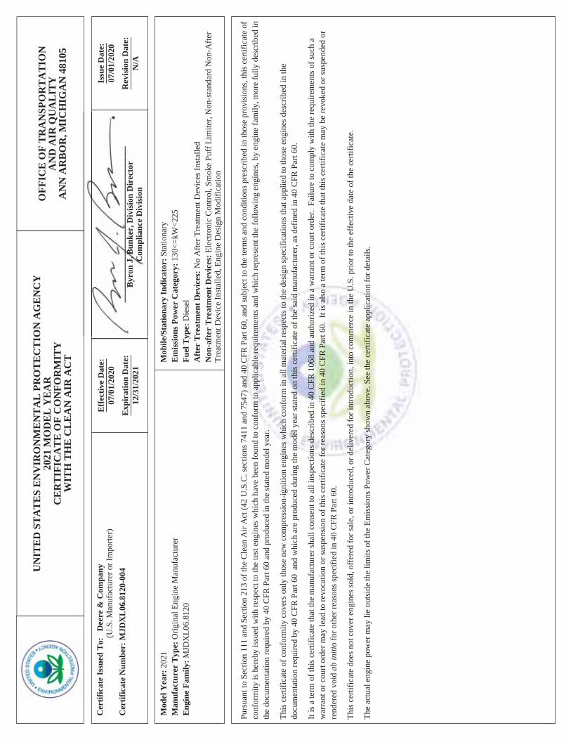
Model: John Deere, 6068HF285K Bore: 106mm (4.19 in.)Nameplate BHP @ 1800 RPM: 237 Stroke: 127mm (5.0 in.)Type: 4-Cycle, 6 Cylinder, Inline Displacement: 6.8 L (415 cu. in.)Aspiration: Turbocharged, Charge Air-CooledCompression Ratio 17.0:1 EPA Family: MJDXL06.8120
EPA Certificate: MJDXL06.8120-004
PERFORMANCE DATA:1/4
Standby1/2
Standby3/4
StandbyFull
StandbyEngine bkW @ Stated Load 44 89 133 177Fuel Consumption (g/kWh) 250 244 222 214Exhaust Gas Flow (m3/min) 34Exhaust Temperature (°C) 510
EXHAUST EMISSION DATA:HC (Total Unburned Hydrocarbons)NOx (Oxides of Nitrogen as NO2)CO (Carbon Monoxide)PM (Particulate Matter)
Data and specifications subject to change without notice.
TEST METHODS AND CONDITIONSThe emission data listed is measured from a laboratory test engine according to the test procedures of 40 CFR 89 or 40 CFR 1039, as applicable. The test engine is intended to represent nominal production hardware, and there is no guarantee that every production engine will have identical test results. The family parent data represents multiple ratings and this data may have been collected at a different engine speed and load. Emission results may vary due to engine manufacturing tolerances, engine operating conditions, fuels used, alternate test methods, or other conditions.
EPA D2 Cycle 5-mode weighted0.123.791.2
0.12
Values are in g/kWh unless otherwise noted
Table 2
150REOZJF60 HZ. DIESEL INDUSTRIAL GENERATOR SET
EMISSION DATA SHEETENGINE INFORMATION
Table 1
UN
ITE
D S
TA
TE
S E
NV
IRO
NM
EN
TA
L P
RO
TE
CT
ION
AG
EN
CY
2021
MO
DE
L Y
EA
RC
ER
TIF
ICA
TE
OF
CO
NFO
RM
ITY
WIT
H T
HE
CL
EA
N A
IR A
CT
OFF
ICE
OF
TR
AN
SPO
RT
AT
ION
AN
D A
IR Q
UA
LIT
YA
NN
AR
BO
R, M
ICH
IGA
N 4
8105
Cer
tific
ate
Issu
ed T
o:D
eere
& C
ompa
ny(U
.S. M
anuf
actu
rer o
r Im
porte
r)C
ertif
icat
e N
umbe
r: M
JDX
L06
.812
0-00
4
Eff
ectiv
e D
ate:
07/0
1/20
20
Exp
irat
ion
Dat
e:12
/31/
2021
____
____
____
____
____
____
_B
yron
J. B
unke
r, D
ivis
ion
Dir
ecto
rC
ompl
ianc
e D
ivis
ion
Issu
e D
ate:
07/0
1/20
20
Rev
isio
n D
ate:
N/A
Mod
el Y
ear:
202
1M
anuf
actu
rer
Typ
e: O
rigin
al E
ngin
e M
anuf
actu
rer
Eng
ine
Fam
ily: M
JDX
L06.
8120
Mob
ile/S
tatio
nary
Indi
cato
r: S
tatio
nary
Em
issi
ons P
ower
Cat
egor
y: 1
30<=
kW<2
25Fu
el T
ype:
Die
sel
Aft
er T
reat
men
t Dev
ices
: No
Afte
r Tre
atm
ent D
evic
es In
stal
led
Non
-aft
er T
reat
men
t Dev
ices
: Ele
ctro
nic
Con
trol,
Smok
e Pu
ff L
imite
r, N
on-s
tand
ard
Non
-Afte
rTr
eatm
ent D
evic
e In
stal
led,
Eng
ine
Des
ign
Mod
ifica
tion
Purs
uant
to S
ectio
n 11
1 an
d Se
ctio
n 21
3 of
the
Cle
an A
ir A
ct (4
2 U
.S.C
. sec
tions
741
1 an
d 75
47) a
nd 4
0 C
FR P
art 6
0, a
nd su
bjec
t to
the
term
s and
con
ditio
ns p
resc
ribed
in th
ose
prov
isio
ns, t
his c
ertif
icat
e of
conf
orm
ity is
her
eby
issu
ed w
ith re
spec
t to
the
test
eng
ines
whi
ch h
ave
been
foun
d to
con
form
to a
pplic
able
requ
irem
ents
and
whi
ch re
pres
ent t
he fo
llow
ing
engi
nes,
by e
ngin
e fa
mily
, mor
e fu
lly d
escr
ibed
inth
e do
cum
enta
tion
requ
ired
by 4
0 C
FR P
art 6
0 an
d pr
oduc
ed in
the
stat
ed m
odel
yea
r.
This
cer
tific
ate
of c
onfo
rmity
cov
ers o
nly
thos
e ne
w c
ompr
essi
on-ig
nitio
n en
gine
s whi
ch c
onfo
rm in
all
mat
eria
l res
pect
s to
the
desi
gn sp
ecifi
catio
ns th
at a
pplie
d to
thos
e en
gine
s des
crib
ed in
the
docu
men
tatio
n re
quire
d by
40
CFR
Par
t 60
and
whi
ch a
re p
rodu
ced
durin
g th
e m
odel
yea
r sta
ted
on th
is c
ertif
icat
e of
the
said
man
ufac
ture
r, as
def
ined
in 4
0 C
FR P
art 6
0.
It is
a te
rm o
f thi
s cer
tific
ate
that
the
man
ufac
ture
r sha
ll co
nsen
t to
all i
nspe
ctio
ns d
escr
ibed
in 4
0 C
FR 1
068
and
auth
oriz
ed in
a w
arra
nt o
r cou
rt or
der.
Fai
lure
to c
ompl
y w
ith th
e re
quire
men
ts o
f suc
h a
war
rant
or c
ourt
orde
r may
lead
to re
voca
tion
or su
spen
sion
of t
his c
ertif
icat
e fo
r rea
sons
spec
ified
in 4
0 C
FR P
art 6
0. I
t is a
lso
a te
rm o
f thi
s cer
tific
ate
that
this
cer
tific
ate
may
be
revo
ked
or su
spen
ded
orre
nder
ed v
oid
ab in
itio
for o
ther
reas
ons s
peci
fied
in 4
0 C
FR P
art 6
0.
This
cer
tific
ate
does
not
cov
er e
ngin
es so
ld, o
ffer
ed fo
r sal
e, o
r int
rodu
ced,
or d
eliv
ered
for i
ntro
duct
ion,
into
com
mer
ce in
the
U.S
. prio
r to
the
effe
ctiv
e da
te o
f the
cer
tific
ate.
The
actu
al e
ngin
e po
wer
may
lie
outs
ide
the
limits
of t
he E
mis
sion
s Pow
er C
ateg
ory
show
n ab
ove.
See
the
certi
ficat
e ap
plic
atio
n fo
r det
ails
.


To obtain warranty service, call 1-800-544-2444 for your nearest authorized Kohler service representative or write Kohler Co., ServiceDepartment, MS072, Kohler, WI 53044 USA.
KOHLER CO. SHALL NOT BE LIABLE FOR SPECIAL, INCIDENTAL, AND/OR CONSEQUENTIAL DAMAGES OF ANY KINDincluding, but not limited to, incidental and/or consequential labor costs, installation charges, telephone charges, ortransportation charges in connection with the replacement or repair of defective parts.
This is our exclusive written warranty. We make no other express warranty nor is anyone authorized to make any on our behalf.
ANY IMPLIED OR STATUTORY WARRANTY, INCLUDING ANY WARRANTY OF MERCHANTABILITY OR FITNESS FOR APARTICULAR PURPOSE, IS EXPRESSLY LIMITED TO THE DURATION OF THIS WARRANTY. Some states do not allowlimitations on how long an implied warranty lasts, or the exclusion or limitation of incidental and/or consequential damages,so the above limitation or exclusion may not apply to you.
This warranty gives you specific legal rights, and you may also have other rights which vary from state to state.
TP-5498 8/16f
Stationary Standby Industrial Generator SetExtended Five-Year or Three Thousand (3000)-Hour
Limited WarrantyYour Kohler product has been manufactured and inspected with care by experienced craftsmen. If you are the original end user,Kohler Co. warrants, for the period indicated below, each product to be free from defects in materials and workmanship. In the event of adefect in materials or workmanship, Kohler Co. will repair, replace, or make appropriate adjustment at Kohler Co.’s option if the product,upon Kohler Co.’s inspection, is found to be properly installed, maintained, and operated in accordance with Kohler Co.’s instructionmanuals. A Kohler distributor, dealer, or authorized service representative must perform startup.
Kohler Product Warranty CoverageStationary Standby Generator Set & Accessories Five (5) years from registered startup or three thousand (3000) hours
(whichever occurs first). Labor and travel charges are included in thewarranty for the first and second year of the five-year warranty.
This warranty is effective only upon Kohler Co.’s receipt of an extended warranty registration form and warranty fee withinone year of registered startup. The extended limited warranty start date is determined by the standard limited warranty requirementsand runs concurrent with the standard limited warranty during the first year. To receive extended limited warranty coverage, theprovisions of the standard limited warranty registration must be met.
KOHLER CO., Kohler, Wisconsin 53044Phone 920-457-4441, Fax 920-459-1646For the nearest sales/service outlet in theUS and Canada, phone 1-800-544-2444KOHLERPower.com
The following will not be covered by the warranty:1. Normal wear, routine tuneups, tuneup parts, adjustments,
and periodic service.2. Damage, including but not limited to damage caused by
accidents, improper installation or handling, faulty repairsnot performed by an authorized Kohler servicerepresentative, improper storage, or acts of God.
3. Damage caused by operation at speeds, or with fuel, loads,conditions, modifications or installation contrary to publishedspecifications.
4. Damage caused by negligent maintenance such as:a. Failure to provide the specified type and sufficient
quantity of lubricating oil.b. Failure to keep the air intake and cooling fin areas clean.c. Failure to service the air cleaner.d. Failure to provide sufficient coolant and/or cooling air.e. Failure to perform scheduled maintenance as
prescribed in supplied manuals.f. Failure to regularly exercise the generator set under load
(stationary applications only).5. Original installation charges and startup costs.6. Starting batteries and the following related expenses:
a. Labor charges related to battery service.b. Travel expenses related to battery service.
7. Engine coolant heaters, heater controls, and circulatingpumps after the first year of the warranty period.
8. Additional expenses for repairs performed after normalbusiness hours, i.e. overtime or holiday labor rates.
9. Rental of equipment during the performance of warrantyrepairs.
10. Removal and replacement of non-Kohler-suppliedoptions and equipment.
11. Non-Kohler replacement parts. Replacement of a failedKohler part with a non-Kohler part voids the warranty onthat part.
12. Radiators replaced rather than repaired.13. Fuel injection pumps not repaired by an authorized
Kohler service representative.14. Non-Kohler-authorized repair shop labor without prior
approval from Kohler Co. Warranty Department.15. Engine fluids such as fuel, oil, or coolant/antifreeze.16. Shop supplies such as adhesives, cleaning solvents,
and rags.17. Expenses incurred investigating performance
complaints unless the problem is caused by defectiveKohler materials or workmanship.
18. Maintenance items such as fuses, lamps, filters, sparkplugs, loose or leaking clamps, and adjustments.
19. Labor and travel charges for the third, fourth, and fifthyears of the warranty period.
20. Travel time and mileage exceeding 300 miles round trip.


G18-459 11/19

G18-459 11/19

G18-56 12/05b
Kohler Standby/Prime Generator Set Test Program
Testing is an integral part of quality assurance. In keeping with our uncompromising commitment to quality, safety,and reliability, every Kohler Standby/Prime power generator set undergoes an extensive series of prototype andproduction testing.
Prototype TestingPrototype testing includes the potentially destructivetests necessary to verify design, proper function ofprotective devices and safety features, and reliabilityexpectations. Kohler’s prototype testing includes thefollowing:
D Alternator temperature rise test per NEMAMG1-32.6. Standby and prime ratings of thealternator are established during this test.
D Maximum power test to assure that the primemover and alternator have sufficient capacity tooperate within specifications.
D Alternator overload test per NEMA MG1-32.8.
D Steady-state load test to ensure voltage regulationmeets or exceeds ANSI C84.1, NEMA MG1-32.17requirements and to verify compliance with steady-state speed control specifications.
D Transient test to verify speed controls meets orexceeds specifications.
D Transient load tests per NEMA MG1-32.18, andISO 8528 to verify specifications of transientvoltage regulation, voltage dip, voltage overshoot,recovery voltage, and recovery time.
D Motor starting tests per NEMA MG1-32.18.5 toevaluate capabilities of generator, exciter, andregulator system.
D Three-phase symmetrical short-circuit test perNEMA MG1-32.13 to demonstrate short circuitperformance, mechanical integrity, ability tosustain short-circuit current.
D Harmonic analysis, voltage waveform deviationper NEMA MG1-32.10 to confirm that thegenerator set is producing clean voltage withinacceptable limits.
D Generator set cooling and air flow tests to verifymaximum operating ambient temperature.
D Reliability tests to demonstrate product durability,followed by root cause analysis of discoveredfailures and defects. Corrective action is taken toimprove the design, workmanship, or components.
D Acoustical noise intensity and sound attenuationeffects tests.
Production Testing
In production, Kohler Standby/Prime generator setsare built to the stringent standards established by theprototype program. Every Kohler generator set is fullytested prior to leaving the factory. Production testingincludes the following:
D Stator and exciter winding high-potential test on allgenerators. Surge transient tests on stators forgenerators 180 kW or larger. Continuity andbalance tests on all rotors.
D One-step, full-load pickup tests to verify that theperformance of each generator set, regulator, andgovernor meets published specifications.
D Regulation and stability of voltage and frequencyare tested and verified at no load, 1/4 load, 1/2 load,3/4 load, and full-rated load.
D Voltage, amperage, frequency and power outputratings verified by full-load test.
D The proper operation of controller logic circuitry,prealarm warnings, and shutdown functions istested and verified.
D Any defect or variation from specificationdiscovered during testing is corrected and retestedprior to approval for shipment to the customer.
Torsional analysis data, to verify torsional effects are not detrimental and that the generator set will providedependable service as specified, is available upon request.
Kohler offers other testing at the customer’s request at an additional charge. These optional tests include powerfactor testing, customized load testing for specific application, witness testing, and a broad range ofMIL-STD-705c testing. A certified test report is also available at an additional charge.
KOHLER CO. Kohler, Wisconsin 53044Phone 920-565-3381, Fax 920-459-1646For the nearest sales/service outlet in theUS and Canada, phone 1-800-544-2444KohlerPowerSystemscom


•
••••••
••
••••
••
••
•
•
•
•

••
•
•
••••••••
®


•
••
•
•
•
••
••••
•
•


K C S A C V C 0 6 0 0 S

Decision-Makerr MPAC 1200
Automatic Transfer Switch Controller
Model KCS with Decision-Makerr MPAC 1200 Controller
G11-127 (MPAC 1200) 3/14 Page 1
Applicable Models
Model Description
KCS Standard-Transition Any Breaker ATS ]
KCP Programmed-Transition Any Breaker ATS ]
KCC Closed-Transition Any Breaker ATS w
KSS Standard-Transition Specific Breaker ATS ]
KSP Programmed-Transition Specific Breaker ATS ]
] Available with automatic or non-automatic controllerw Available with automatic controller only
Decision-Makerr MPAC 1200 ControllerStandard FeaturesD Microprocessor-based controllerD Environmentally sealed user interfaceD LCD display, 4 lines x 20 characters, backlitD Dynamic function keypad with tactile feedback pushbuttons
allows complete programming and viewing capability at thedoor
D LED indicators: Source available, transfer switch position,service required (fault), and not in auto
D Broadrange voltage sensing (208--600 VAC) on all phasesD Phase-to-phase sensing and monitoring with 0.5% accuracy
on both sourcesD Frequency sensing with 0.5% accuracy on both sourcesD Anti-single phasing protectionD Phase rotation sensing for three-phase systemsD Real-time clock with automatic adjust for daylight saving time
and leap yearD Run time clock and operation counterD Time-stamped event logD Fail-safe transfer for loaded test and exercise functionsD DIP switches: password disable and maintenanceD Isolated RS-485 ports for Modbus connections
(9.6, 19.2, and 57.6 kbps)D Modbusr RTU protocol (Modbus register map available)D USB port. Connect a personal computer and use Kohlerr
SiteTecht software to view events and adjust settings. *D Available in automatic and non-automatic versions; see
supervised transfer control switch on page 5
Programmable FeaturesD Programming and monitoring methods:
d Monitoring and password-protected programming at thedoor using the keypad and display
d Program using a PC with Kohlerr SiteTecht software(available to Kohler-authorized distributors and dealers)
D Over/undervoltage for all phases of the normal andemergency sources
D Over/underfrequency for the emergency sourceD Adjustable time delaysD Load/no load/auto-load test and load/no-load exercise
functionsD Programmable inputs and outputsD Load bank control for exercise or testD Time-based load control, nine individual time delays for
selected loadsD In-phase monitor (3-phase only)D Password protection, three security levelsD See pages 2 and 3 for additional programmable features
* SiteTech software is available to Kohler-authorized distributorsand dealers.Modbus is a registered trademark of Schneider Electric.
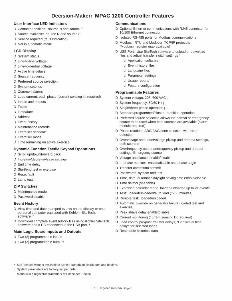
G11-127 (MPAC 1200) 3/14 Page 2
Decision-Makerr MPAC 1200 Controller FeaturesUser Interface LED IndicatorsD Contactor position: source N and source E
D Source available: source N and source E
D Service required (fault indication)
D Not in automatic mode
LCD DisplayD System status
D Line-to-line voltage
D Line-to-neutral voltage
D Active time delays
D Source frequency
D Preferred source selection
D System settings
D Common alarms
D Load current, each phase (current sensing kit required)
D Inputs and outputs
D Faults
D Time/date
D Address
D Event history
D Maintenance records
D Exerciser schedule
D Exerciser mode
D Time remaining on active exercise
Dynamic Function Tactile Keypad OperationsD Scroll up/down/forward/back
D Increase/decrease/save settings
D End time delay
D Start/end test or exercise
D Reset fault
D Lamp test
DIP SwitchesD Maintenance mode
D Password disable
Event HistoryD View time and date-stamped events on the display or on a
personal computer equipped with Kohlerr SiteTechtsoftware. *
D Download complete event history files using Kohler SiteTechsoftware and a PC connected to the USB port. *
Main Logic Board Inputs and OutputsD Two (2) programmable inputs
D Two (2) programmable outputs
CommunicationsD Optional Ethernet communications with RJ45 connector for
10/100 Ethernet connection
D Isolated RS-485 ports for Modbus communications
D Modbusr RTU and Modbusr TCP/IP protocols(Modbusr register map available)
D USB Port. Use SiteTech software to upload or downloadfiles and adjust transfer switch settings *
d Application software
d Event history files
d Language files
d Parameter settings
d Usage reports
d Feature configuration
Programmable FeaturesD System voltage, 208--600 VAC [
D System frequency, 50/60 Hz [
D Single/three-phase operation [
D Standard/programmed/closed-transition operation [
D Preferred source selection allows the normal or emergencysource to be used when both sources are available (alarmmodule required)
D Phase rotation: ABC/BAC/none selection with errordetection
D Overvoltage and undervoltage pickup and dropout settings,both sources
D Overfrequency and underfrequency pickup and dropoutsettings, Emergency source
D Voltage unbalance, enable/disable
D In-phase monitor: enable/disable and phase angle
D Transfer commit/no commit
D Passwords, system and test
D Time, date, automatic daylight saving time enable/disable
D Time delays (see table)
D Exerciser: calendar mode, loaded/unloaded up to 21 events
D Test: loaded/unloaded/auto load (1--60 minutes)
D Remote test: loaded/unloaded
D Automatic override on generator failure (loaded test andexercise)
D Peak shave delay enable/disable
D Current monitoring (current sensing kit required)D Load control pre/post-transfer delays, 9 individual time
delays for selected loadsD Resettable historical data
* SiteTech software is available to Kohler-authorized distributors and dealers.[ System parameters are factory-set per order.
Modbus is a registered trademark of Schneider Electric.

G11-127 (MPAC 1200) 3/14 Page 3
Decision-Makerr MPAC 1200 Controller Features, ContinuedProgrammable InputsD Forced transfer to OFF (programmed-transition models only;
requires load shed accessory)
D Inhibit transfer
D Low battery voltage (external battery supply modulerequired)
D Peak shave/area protection input
D Remote common fault
D Remote test
D Remote end time delay
D Remotely monitored inputs, four (4) available
Programmable OutputsD Alarm silenced
D Audible alarm
D Chicago alarm control
D Common alarm events
D Contactor position
D Exercise active
D Failure to acquire standby source
D Failure to transfer
D Generator engine start, source E
D I/O module faults
D In-phase monitor synch
D Load bank control
D Load control active (pre/post transfer delay, up to 9 outputs)
D Loss of phase fault, source N and E
D Low battery fault (external battery supply module required)
D Maintenance mode
D Non-emergency transfer
D Not in automatic mode
D Over/undervoltage faults, source N and E
D Peak shave/area protection active
D Phase rotation error, source N and E
D Preferred source supplying load
D Software-controlled relay outputs (four maximum)
D Source available, preferred and standby
D Standby source supplying load
D Test active
D Transfer switch auxiliary contact fault
D Transfer switch auxiliary contact open
D Voltage unbalance, source N and E
Voltage and Frequency Sensing
Parameter DefaultAdjustment
Range
Undervoltage dropout 90% of pickup 75%--98%
Undervoltage pickup 90% of nominal 85%--100%
Overvoltage dropout * 115% of nominal* 106%--135%
Overvoltage pickup 95% of dropout 95%--100%
Unbalance enable Disable Enable/Disable
Unbalance dropout 20% 5%--20%
Unbalance pickup 10% 3%--18%
Voltage dropout time 0.5 sec. 0.1--9.9 sec.
Underfrequency dropout [ 99% of pickup 95%--99%
Underfrequency pickup [ 90% of nominal 80%--95%
Overfrequency dropout [ 101% of pickup 101%--115%
Overfrequency pickup [ 110% of nominal 105%--120%
Frequency dropout time [ 3 sec. 0.1--15 sec.
* 690 volts, maximum. Default = 110% for 600 volt applications.[ Emergency source only
Adjustable Time DelaysTime Delay Default Adjustment Range
Engine start 3 sec. 0--6 sec. [
Engine cooldown 5 min.
0--60 min.Fail to acquire standby source 1 min.
Transfer, preferred to standby 3 sec.
Transfer, standby to preferred 15 min.
Transfer, off to standby 1 sec.1 sec. -- 60 min.
Transfer, off to preferred 1 sec.
Fail to synchronize 60 sec. 10 sec -- 15 min.
Auto load test termination aftertransfer
1 sec. 1 sec.--60 min.
Load Control Time Delays:
Pretransfer to preferred 0 sec.
0--60 min.Post-transfer to preferred 0 sec.
Pretransfer to standby 0 sec.
Post-transfer to standby 0 sec.
Note: Time delays are adjustable in 1 second increments, except asnoted.
[ Engine start time delay can be extended to 60 minutes with an ExternalBattery Supply Module Kit.

G11-127 (MPAC 1200) 3/14 Page 4
Accessory ModulesThe mounting kit holds up to five optional modules.
Module Current Draw Specifications, mAAlarm Module 75
Standard I/O Module 75
High Power I/O Module 100
Maximum Total Current * 300
* If an External Battery Module is installed, there is no currentrestriction.
- Standard Input/Output Module
InputsAvailable Inputs 2
Input Definition Contact closure
Current 5 mA Max
Connection Type Terminal Strip
Wire Size #14--24 AWG
Max Distance 700 feet
OutputsOutputs Available 6
Contact Type Form C (SPDT)
Contact Voltage Rating2 A @ 30 VDC500 mA @ 125 VAC
Connection Type Terminal Strip
Wire Size #14--24 AWG
- High-Power Input/Output Module
InputsAvailable Inputs 2
Input Definition Contact closure
Current 5 mA Max
Connection Type Terminal Strip
Wire Size #14--24 AWG
Max Distance 700 feet
OutputsOutputs Available 3
Contact Type Form C (SPDT)
Contact Voltage Rating
12 A @ 24 VDC12 A @ 250 VAC10 A @ 277 VAC2 A @ 480 VAC
Connection Type Terminal Strip
Wire Size #14--24 AWG
Environmental SpecificationsTemperature --40 C to 85 C (--40 F to 185 F)
Humidity 35% to 85% noncondensing
- Alarm ModuleD 90 dB Audible alarm
D Any alarm function can be programmed to trigger theaudible alarm
D Chicago alarm function
D Preferred source selection
D Supervised transfer control (supervised transfer controlswitch required)
D Connection for external alarm
External Alarm Connection SpecificationsWire Size #12--22 AWG Cu
Contact Voltage Rating500 mA @ 120 VAC
250 mA @ 240 VAC
- External Battery Supply ModuleD Energizes the ATS controls using an external battery
when no source power is available
D Allows extended engine start time delays
D Allows the use of any combination of accessory modules(no current draw restriction, maximum of five modulestotal)
D Connects to one or two batteries, 12 VDC or 24 VDCsystem
D Current draw, 140 mA @ 12 VDC, 86 mA @ 24 VDC
D Provides low external battery voltage indication to thetransfer switch controller
D Reverse-polarity protected

G11-127 (MPAC 1200) 3/14 Page 5
Other Controller AccessoriesAccessories are available either factory-installed or as loosekits, unless otherwise noted.
- Controller Disconnect SwitchD Disconnects power to the controller without disconnecting
the load
D Mounts inside the enclosure
- Current Sensing KitD Monitor current on all phases with 1% accuracy
- Digital MeterD Measure and display voltage, current, frequency, and
power for both sourcesD Programmable visual alarms for high voltage, low voltage,
and high currentD Three digital outputsD Serial port for optional network connectionsD Password-protected programming menusD Joystick operationD Factory-installed
- Ethernet CommunicationsD RJ-45 connectorD Supports Internet Protocol version 4 (IPv4)D Supports Modbus TCP/IP protocol
- Line-to-Neutral Voltage MonitoringD Monitors all line-to-neutral voltages
- Load Shed KitD Forced transfer from Emergency to OFF for
programmed-transition models
D Customer-supplied signal (contact closure) is required forthe forced transfer to OFF function
D Factory-installed only
- Padlockable User Interface CoverD Provides additional protection against unauthorized
access
D Cover standard on NEMA 3R enclosures
- RSA III Remote Serial AnnunciatorD Monitors the generator setD Monitors ATS common alarm, Normal source, and
Emergency source status and connectionD Allows remote testing of the ATSD For more information about RSA III features and
functions, see specification sheet G6--139
- Supervised Transfer Control SwitchD Standard on models with non-automatic controls
D Optional for models with automatic controls
D Auto, manual, and transfer positions
D Automatic and non-automatic modes
D Alarm module required
Supervised Transfer Control Switch Operation for Automatic and Non-Automatic Transfer Switches
Switch Position Automatic Switches Non-Automatic Switches
AUTO D Automatically transfers to the standby source, when available, if the preferred source is lost.
D Transfers back to the preferred source when it becomes available.
MANUAL D Automatically transfers to an available source ifthe connected source is lost.
D Test, peak shave, and loaded exercise commandswill transfer to the standby source.
D Does not automatically transfer back to preferredwhen both sources are available.
D Does not automatically transfer to an availablesource when the connected source is lost.
D Test, peak shave, and loaded exercise commandsare ignored.
D Does not automatically transfer back to preferredwhen both sources are available.
D Transfers only when the switch is manually movedto the TRANSFER position as described below.
TRANSFER(momentaryswitch position)
D Does not initiate an engine start sequence. Generator set engine must be signalled to start by an eventsuch as a loss of utility, loaded test, loaded exercise, etc.
D Allows transfer to the other source, if available. An event such as a loss of utility, loaded exercise, orloaded test must first initiate the transfer sequence.
D Time delays will operate. Wait for time delays to expire, or press the End Time Delay button.
D Operates pre- and post-transfer load control time delays if both sources are available.
D MANUAL TRANSFER is displayed when the ATS is ready to transfer.

DISTRIBUTED BY:
Kohler Power SystemsAsia Pacific Headquarters7 Jurong Pier RoadSingapore 619159Phone (65) 6264-6422, Fax (65) 6264-6455
KOHLER CO., Kohler, Wisconsin 53044 USAPhone 920-457-4441, Fax 920-459-1646For the nearest sales and service outlet in theUS and Canada, phone 1-800-544-2444KOHLERPower.com
Availability is subject to change without notice. Kohler Co. reserves theright to change the design or specifications without notice and withoutany obligation or liability whatsoever. Contact your local Kohlerr PowerSystems distributor for availability.
2014 by Kohler Co. All rights reserved.
G11-127 (MPAC 1200) 3/14 Page 6
Environmental SpecificationsOperating Temperature --20 C to 70 C (--4 F to 158 F)
Storage Temperature --40 C to 85 C (--40 F to 185 F)
Humidity 5% to 95% noncondensing
Main Board I/O SpecificationsOutput contact type Isolated form C (SPDT)
Output contact rating 1 amp @ 30 VDC, 500 mA @120VAC
I/O terminals wire size #12--24 AWG

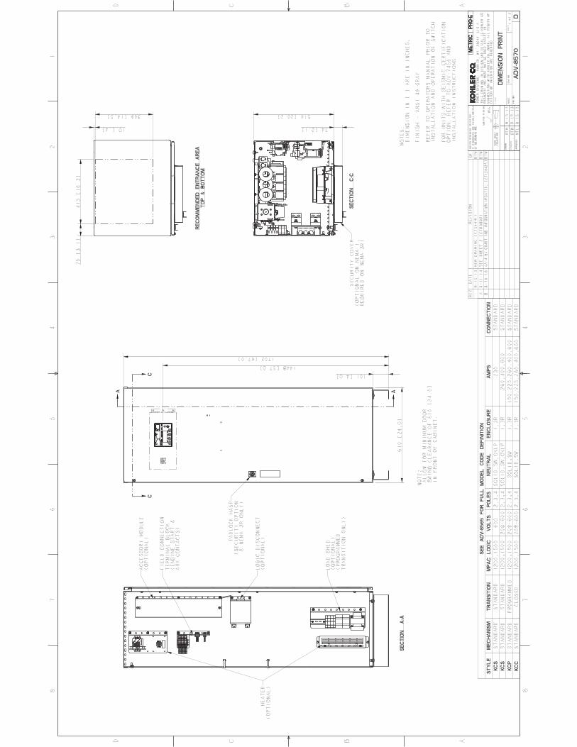


Transfer Switch Extended Five-YearLimited Warranty
Your Kohler product has been manufactured and inspected with care by experienced craftsmen. If you are the original end user,Kohler Co. warrants, for the period indicated below, each product to be free from defects in materials and workmanship. In the event of adefect in materials or workmanship, Kohler Co. will repair, replace, or make appropriate adjustment at Kohler Co.’s option if the product,upon Kohler Co.’s inspection, is found to be properly installed, maintained, and operated in accordance with Kohler Co.’s instructionmanuals. A Kohler distributor, dealer, or authorized service representative must perform startup.
Kohler Product Warranty Coverage
Transfer switch and factory-supplied Five (5) years from registered startup date.transfer switch accessories
Transfer switch main contacts Ten (10) years from the registered startup date.
This warranty is not effective unless a proper extended warranty registration form and warranty fee have been sent toKohler Co. within one year of registered startup. The extended warranty start date is determined by the standard warrantyrequirements and runs concurrent with the standard warranty during the first year. To receive extended warranty coverage, theprovisions of the standard warranty registration must be met.
TP-6086 4/15d
To obtain warranty service, call 1-800-544-2444 for your nearest authorized Kohler service representative or write Kohler Co., KohlerPower Systems Service Department, MS072, Kohler, WI 53044 USA.
KOHLER CO. SHALL NOT BE LIABLE FOR SPECIAL, INCIDENTAL, AND/OR CONSEQUENTIAL DAMAGES OF ANY KINDincluding, but not limited to, incidental and/or consequential labor costs, installation charges, telephone charges, ortransportation charges in connection with the replacement or repair of defective parts.
This is our exclusive written warranty. We make no other express warranty nor is anyone authorized to make any on our behalf.
ANY IMPLIED OR STATUTORY WARRANTY, INCLUDING ANY WARRANTY OF MERCHANTABILITY OR FITNESS FOR APARTICULAR PURPOSE, IS EXPRESSLY LIMITED TO THE DURATION OF THIS WARRANTY. Some states do not allowlimitations on how long an implied warranty lasts, or the exclusion or limitation of incidental and/or consequential damages,so the above limitation or exclusion may not apply to you.
This warranty gives you specific legal rights, and you may also have other rights which vary from state to state.
KOHLER CO. Kohler, Wisconsin 53044Phone 920-457-4441, Fax 920-459-1646For the nearest sales/service outlet in theUS and Canada, phone 1-800-544-2444KOHLERPower.com
The following will not be covered by the warranty:1. Normal wear, periodic service, and routine adjustments.2. Damage, including but not limited to damage caused by
accidents, improper installation or handling, faulty repairsnot performed by an authorized Kohler servicerepresentative, improper storage, or acts of God.
3. Damage caused by:a. Operation above or below rated capacity, voltage, or
frequency.b. Modifications.c. Installation contrary to published specifications and
codes.4. Damage caused by negligent maintenance such as:
a. Failure to provide a clean, dry environment.b. Failure to perform recommended exercising.c. Failure to perform scheduled maintenance as
prescribed in supplied manuals.d. Use of parts and/or procedures other than
factory-supplied or -approved replacement partsand/or procedures.
5. Non-Kohler replacement parts. Replacement of a failedKohler part with a non-Kohler part voids the warranty onthat part.
6. Original installation charges and startup costs.7. Additional expenses for repair after normal business
hours, i.e. overtime or holiday labor rates.8. Rental of equipment during performance of warranty
repairs.9. Removal and replacement of non-Kohler-supplied
options and equipment.10. Non-Kohler-authorized repair shop labor without prior
approval from Kohler Co. Warranty Department.11. Expenses incurred investigating performance complaints
unless the problem is caused by defective Kohlermaterials or workmanship.
12. Maintenance items such as fuses, lamps, andadjustments.
13. Labor and travel charges after the second year of thetransfer switch and accessories warranty period.
14. Labor and travel charges after the second year of thetransfer switch main contacts warranty period.
15. Travel time and mileage exceeding 300 miles round trip.


G18-414 2/20
Kohler Automatic Transfer Switch Test ProgramNon-Bypass Models
Testing is an integral part of quality assurance. In keeping with our uncompromising commitment to quality,safety, and reliability, every Kohler Automatic Transfer Switch (ATS) undergoes an extensive series ofperformance and production testing.
Performance Testing
All Kohler ATSs are UL1008 listed, which includesthe following performance tests:
D General – Normal OperationD OvervoltageD UndervoltageD OverloadD Temperature RiseD EnduranceD Dielectric Voltage – WithstandD Short Circuit WithstandD Short Circuit Close- OnD Dielectric Voltage – Withstand (repeated)D Strength of insulating base and support
EMC/EMI Immunity Verification
Controls and printed circuit board assemblies areevaluated to IEC and IEEE tests, including:
D EN61000- 4- 4 Fast Transient Immunity SeverityLevel 4
D EN61000- 4- 5 Surge Immunity Class 4 (voltagesensing and programmable inputs only)
D IEC Specifications for EMI/EMC Immunity:d CISPR 11, Radiated Emissions
d IEC 1000- 4- 2, Electrostatic Discharge
d IEC 1000- 4- 3, Radiated ElectromagneticFields
d IEC 1000- 4- 4, Electrical Fast Transients(Bursts)
d IEC 1000- 4- 5, Surge Voltage
d IEC 1000- 4- 6, Conducted RF Disturbances
d IEC 1000- 4- 8, Magnetic Fields
d IEC 1000- 4- 11, Voltage Dips and Interruptions
D IEEE 472 (ANSI C37.90A) Ring Wave Test
Production TestingEvery Kohler ATS is fully tested prior to leaving thefactory. Visual inspections are also performed bythe mechanism manufacturer as well as Kohlerpersonnel during assembly and final test.Production testing includes the following:
D Electrical operation testing on all ATSsD Verification of controller communicationD Verification of controller settingsD Voltage calibrationD Automatic transfer switch operation when Normal
source is lostd Verify engine start signald Verify transfer to Emergency position when
Emergency source is availableD Automatic Transfer switch operation when Normal
source returnsd Verify transfer to Normal positiond Verify engine start signal is removed
CSA CertificationCSA Certification is also available upon request.CSA certification includes the following additionaltest:
D Dielectric test at 1000V plus twice the maximumrated voltage
Options TestingThe operation of all installed options is verified.Tested options include:
D Input/Output ModulesD Supervised Transfer Control SwitchD Preferred Source SwitchD Load Shed, Normal and EmergencyD Line-to- Neutral MonitoringD Digital Meter setup and operationKohler offers other testing at the customer’s requestat an additional charge. These optional testsinclude customized load testing for specificapplication, witness testing, and contact resistancetesting. A certified test report is also available at anadditional charge.
KOHLER CO., Kohler, Wisconsin 53044Phone 920-457-4441, Fax 920-459-1646For the nearest sales/service outlet in theUS and Canada, phone 1-800-544-2444KOHLERPower.com