Embed Size (px)
Citation preview

Page 1 of 2
1 de julio de 2022
NÚMERO DE SUBASTA: CI-2022-05-04-4254 PROYECTO DE REPARACIONES GENERALES
35907 - ESC. DON LUIS MUÑOZ MARÍN
FELIZA RINCÓN, CARR. 3-979, CEIBA, PR 00742 +
35618 - ESC. SUPERIOR ISIDRO A. SÁNCHEZ URB BRISA DEL MAR CALLE 2, LUQUILLO, PR 00773
ADDENDUM #2
Estimados Licitadores: A tenor con orden ejecutiva 2021 – 021 y el Artículo 7.2.5 del Reglamento Uniforme de Compras y Subastas de Bienes, Obras y Servicios No Profesionales de la Administración de Servicios Generales del Gobierno de Puerto Rico se aclara lo siguiente para el proceso de adquisición referido.
1. Se enmienda el EXHIBIT J - Condiciones Especiales Suplementarias, Articulo II.G.1 – Instalaciones Temporeras, y se reemplaza el párrafo original con lo siguiente:
• “Se aclara que la OMEP/DEPR le requiere al Contratista la instalación
de una oficina temporera de inspección. A lo mínimo debe incluir lo siguiente:
a. Un área mínima de 100 pies cuadrados de espacio accesible, incluyendo una puerta con cerradura, adecuadamente iluminada, con servicio eléctrico y receptáculos para equipo de oficina.
b. Un escritorio y una silla, una mesa de aproximadamente 3’ x 6’, un archivo de 4 gavetas con cerradura, estante vertical para planos y fotocopiadora compartida.
c. Aire acondicionado, enchufes eléctricos de 110 V y servicio/conexión compartida a Internet según requerido.
d. Acceso a agua potable y servicios sanitarios.”
OFICINA PARA EL MEJORAMIENTO DE LAS ESCUELAS PÚBLICAS DE PUERTO RICO

Page 2 of 2
2. Se enmienda el FORMULARIO DE PROPUESTA (BID FORM) incluido en el
EXHIBIT A, y se reemplaza en su totalidad por un nuevo Formulario de Propuesta incluido y anejado a este ADDENDUM #2.
3. Se incluyen como parte de este ADDENDUM #2 los Key Plans.
4. Se enmienda la HOJA DE COTEJO DE PROPUESTA y se reemplaza en su
totalidad por un nuevo Hoja de Cotejo de Propuesta incluyendo índice de documentos requeridos.
5. En la INVITACION A SOMETER PROPUESTAS, se elimina el requerimiento de
someter cualificaciones ambientales con la propuesta según Articulo XI.iv.
6. Se enmienda el EXHIBIT J - Condiciones Especiales Suplementarias, Articulo II.C.1 – Instalaciones Temporeras, y se añade la siguiente oracion:
• “El contratista seleccionado deberá someter para aprobación de OMEP/DEPRE las siguientes cualificaciones ambientales antes de comenzar cualquier trabajo de mitigación y disposición de asbestos/plomo:
a. Certificación de Plomo de la EPA - Lead EPA RRP (Renovation, Reparation and Paint).
b. Evidencia de certificación en Manejo de Plomo 2 horas (Two hours course of Asbestos Awareness).
c. Evidencia de certificación Manejo de seguridad en manejo de hongo- (Two hours course of safety Mold Awareness).
d. Certificación de 30 horas OSHA (General o construcción) del supervisor designado por el contratista. Plan de seguridad específico al alcance de trabajo del proyecto.
7. Se enmienda el EXHIBIT K – Reference Technical Specifications y se reemplaza
en su totalidad por un nuevo EXHIBIT K – DRAWINGS AND REFERENCE TECHNICAL SPECIFICATIONS incluido y anejado a este ADDENDUM #2.
Los demás pronunciados de los pliegos de subasta permanecen inalterados. Este documento se hace formar parte de cada una de las compras referidas y debe ser entregado iniciado y firmado por el licitador acusando de recibido.
PO Box 195644 San Juan, Puerto Rico 00919-5644. Tel. (787) 281-7575
El Departamento de Educación no discrimina de ninguna manera por razón de edad, raza, color, sexo, nacimiento, condición de veterano,
ideología política o religiosa, origen o condición social, orientación sexual o identidad de género, discapacidad o impedimento físico o mental;
ni por ser víctima de violencia doméstica, agresión sexual o acecho.
20
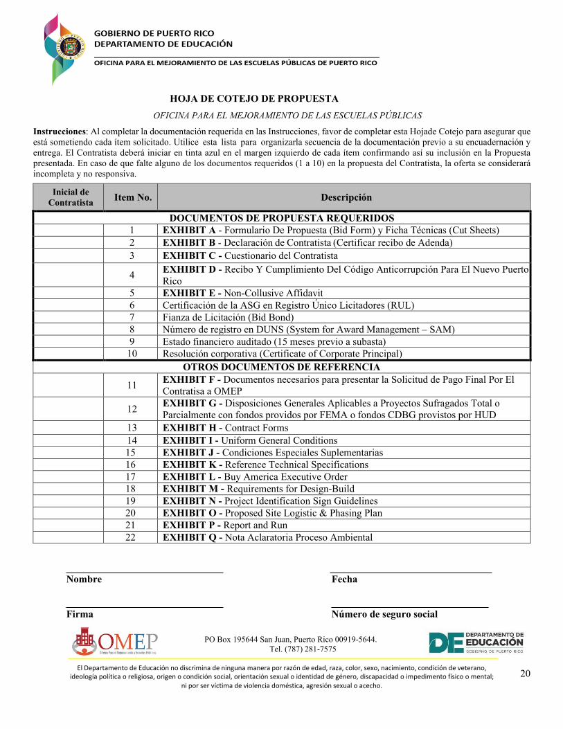
HOJA DE COTEJO DE PROPUESTA
OFICINA PARA EL MEJORAMIENTO DE LAS ESCUELAS PÚBLICAS
Instrucciones: Al completar la documentación requerida en las Instrucciones, favor de completar esta Hoja de Cotejo para asegurar que está sometiendo cada ítem solicitado. Utilice esta lista para organizar la secuencia de la documentación previo a su encuadernación y entrega. El Contratista deberá iniciar en tinta azul en el margen izquierdo de cada ítem confirmando así su inclusión en la Propuesta presentada. En caso de que falte alguno de los documentos requeridos (1 a 10) en la propuesta del Contratista, la oferta se considerará incompleta y no responsiva.
Inicial de
Contratista Item No. Descripción
DOCUMENTOS DE PROPUESTA REQUERIDOS
1 EXHIBIT A - Formulario De Propuesta (Bid Form) y Ficha Técnicas (Cut Sheets) 2 EXHIBIT B - Declaración de Contratista (Certificar recibo de Adenda) 3 EXHIBIT C - Cuestionario del Contratista
4 EXHIBIT D - Recibo Y Cumplimiento Del Código Anticorrupción Para El Nuevo Puerto Rico
5 EXHIBIT E - Non-Collusive Affidavit 6 Certificación de la ASG en Registro Único Licitadores (RUL) 7 Fianza de Licitación (Bid Bond) 8 Número de registro en DUNS (System for Award Management – SAM) 9 Estado financiero auditado (15 meses previo a subasta) 10 Resolución corporativa (Certificate of Corporate Principal)
OTROS DOCUMENTOS DE REFERENCIA
11
EXHIBIT F - Documentos necesarios para presentar la Solicitud de Pago Final Por El Contratisa a OMEP
12
EXHIBIT G - Disposiciones Generales Aplicables a Proyectos Sufragados Total o Parcialmente con fondos providos por FEMA o fondos CDBG provistos por HUD
13 EXHIBIT H - Contract Forms 14 EXHIBIT I - Uniform General Conditions 15 EXHIBIT J - Condiciones Especiales Suplementarias 16 EXHIBIT K - Reference Technical Specifications 17 EXHIBIT L - Buy America Executive Order 18 EXHIBIT M - Requirements for Design-Build 19 EXHIBIT N - Project Identification Sign Guidelines 20 EXHIBIT O - Proposed Site Logistic & Phasing Plan 21 EXHIBIT P - Report and Run 22 EXHIBIT Q - Nota Aclaratoria Proceso Ambiental
Nombre Fecha
Firma Número de seguro social

Exhibit A
Formulario dePropuesta (Bid Form)

EXHIBIT A FORMULARIO DE PROPUESTA (BID FORM)
1.2 Esta sección describe el alcance de los trabajos a ser cotizados:
Nota: El desglose es una guía para la cotización de los trabajos y no será el desglose final para emitir cualquier certificación de pago. Es responsabilidad del contratista verificar las cantidades en visita de campo. **EL CONTRATISTA ES RESPONSABLE DE LOS COSTOS DE TRANSPORTE MARITIMOS, AÉREOS Y/O TERRESTES A USARSE. ** *Los costos deberán considerar arbitrios, seguros, patentes, “overhead’’, ganancias, etc. ** Será responsabilidad del contratista corroborar las cantidades a cotizar para estos trabajos. ***El desglose de los trabajos a realizarse serán adjuntados al dorso **** Esta Propuesta tendrá una vigencia de sesenta (60) días a partir de la fecha de apertura de propuestas. ______________________________ ___________________________ Nombre de contratista Fecha ____________________________ ______________________________ Firma Número de seguro social patronal
Alcance de Trabajo
Número de Subasta CI-2022-05-03-4255 Nombre de Contratista
Nombre de la Escuela y Código
ESC. SUPERIOR URBANA NUEVA JOSEFA PASTRANA
(28571) Firma/Fecha
Descripción Unidad Costo
Diseño y Permisos LS $
Supervisión y visitas durante la construcción LS $
Site LS $
Edificios LS $
Condiciones Generales (General Conditions) LS $
Seguros (Insurance) LS $
Fianzas (Bonds) LS $
Impuestos (Taxes; Municipal + State) LS $
SUBTOTAL $
Allowance - HazMat Mitigation (Asbestos & Lead Based Paint) LS $30,000
Allowance - Mold Remediation / Termite Treatment LS $20,000
TOTAL $

SITE - ARCHITECTURAL & CIVIL WORKS
Item No. Description Quantity Unit Total
1 Repair Cement plaster on concrete fence, school front. 200 SF $
2Remove and replace ornamental steel fence, school front. (1
span - 10ft x 6ft)1 EA $
3Remove and replace galvanized steel double gates, parking.
(24ft x 7ft)2 EA $
4Remove and replace chain link fence north and west side of
school along perimeter wall. (height varies)1 LS $
5Remove and replace barbed wire on top of chain link fence,
north and west side of school. 1 LS $
6 Replace galvanized hinges of steel parking gate. 6 EA $
7Replace pedestrian galvanized steel gate. (Kinder - BLDG 07)
1 EA $
8
Paint all site surfaces including, but not limited
to,curbs,wheelstops,traffic/parking lines, traffic symbols,low
walls, fences and gates.
5,000 LF $
9
Backfill and compact with engineering soil for leveling uneven
area due to minor soil erosion, kitchen area. (exterior Dining
Hall area)
150 CY $
10
Backfill and compact with engineering soil for leveling uneven
area due to minor soil erosion, kindergarten playground area 200 CY $
11Mill and resurface kitchen parking. (patch damaged asphalt
next to BLDG 01)3100 SF $
Subtotal: $
SITE - MECHANICAL & ELECTRICAL WORKS
Item No. Description Quantity Unit Total
12
Remove parking luminaires, Cobra type. replace with new
LED equivalent fixtures, including all electrical components
and connections required for a complete, code compliant
installation.
6 EA $
13ALLOWANCE - Paint, install signs and repair/service of
electrical substation. 1 LS $ 5,000.00
Subtotal: $
EXHIBIT AFORMULARIO DE PROPUESTA (BID FORM)
DON LUIS MUÑOZ MARÍN
Page 1 of 6

DON LUIS MUÑOZ MARÍNPRDE #35907
BUILDING 01 - ARCHITECTURAL & CIVIL WORKS
Item No. Description Quantity Unit Total
Potable Water Tank
14ALLOWANCE - Paint exterior of water tank, chlorination and
repair/service, 50,000 gallons steel tank. 1 LS $ 10,000.00
15Replace pump room steel door 8 FT X 3 FT. (louver door,
frame and hardware)1 EA $
16 Replace/ repair tank anchoring points. 12 EA $
17 Replace tank level meter. 1 EA $
Kitchen, Storage and Dining Hall
18 Concrete floor repair, storage area. 180 SF $
19Replace Dining Hall doors, frames and hardware double
interior/exterior (8' X 3')4 EA $
20 Replace aluminum security windows (30 IN X 60 IN.) 1 LS $
Academic Building
21Replace steel louvered double door, hardware and frame (72
IN X 96 IN.)1 EA $
22 Repair cement plaster Kindergarten A2 wall. 1 LS $
23Replace aluminum louvers 4 FT X 4 FT A/C rooms exterior
walls.41 EA $
24Replace classrooms windows interior glass panels 2 FT X 2
FT. 1 LS $
25 Repair concrete floor. (Classroom A22 - 3ft x 3ft) 1 LS $
26Replace classrooms steel doors with vision glass, frame and
hardware frame (8 FT X 3 FT)5 EA $
27
Existing Group Restroom to be remodeled as necessary to
become ADA compliant restroom. (Bathroom partitions 30 IN
X 48 IN. to be Phenolic panels)
33 EA $
28Replace door vision glass panels in classrooms doors 3 IN X
24 IN. 2 EA $
29 Repair expansion joint 1 LS $
30 Mold remediation in Classroom A7. 1 LS $
31 Replace steel door closer. 1 EA $
32 Repair exposed concrete rebars. 240 SF $
33Repair/install new metal grid anchors on second floor hallway.
32 EA $
34 Repair/install ramp railing anchors. 20 EA $
Paint - Building 01
35Pressure wash, prep and paint building exterior. (All areas
and surfaces)1 LS $
36 Prep and paint interiors. (All areas and surfaces) 1 LS $
Subtotal: $
Page 2 of 6

DON LUIS MUÑOZ MARÍNPRDE #35907
BUILDING 01 - ROOF WATERPROOFING WORKS
Item No. Description Quantity Unit Total
37 Repair/ install new metal roof in rest area. 1 LS $
38
Remove existing waterproofing and install new code
compliant waterproofing system, including complete roof
drainage system (gutters, scuppers, downspouts, etc.),
temporary removal and reinstallation of HVAC system(s),
raising of existing MEP piping as necessary to meet minimum
height code, and installing new tie down/anchoring to secure
existing roof equipment.
1 LS $
Subtotal: $
BUILDING 01 - MECHANICAL & ELECTRICAL WORKS
Item No. Description Quantity Unit Total
Kitchen, Storage and Dining Hall
39
Remove existing and replace with new Walk-in Cooler and
Walk-in Freezer (14 FT X 10 FT X 8 FT) refrigeration system.
(motor and components). Similar to existing equipment or
approved equal.
2 EA $
40
Replace existing Packaged Type A/C Unit Dining Area Trane
THC 24 1 C 3, ducts exposed insulated above roof. 20 TON,
with similar to existing equipment or approved equal, including
all mechanical and electrical components, connections and
waterproofing required for a complete, code compliant
installation.
1 EA $
41Replace kitchen supply fan F2 LOREN COOK 180 ASP-T.
Similar to existing equipment or approved equal.1 EA $
42Replace storage supply fan F3 LOREN COOK 100 ASP-T.
Similar to existing equipment or approved equal.1 EA $
Academic Building
43Replace Chemistry Lab exhaust fan LOREN COOK 100 C 2B.
Similar to existing equipment or approved equal.1 EA $
44
Replace existing Package Type A/C Unit at Community Room
Trane TCH 037 C 3, 3 Tons, with similar to existing equipment
or approved equal, including all mechanical and electrical
components, connections and waterproofing required for a
complete, code compliant installation.
1 EA $
45
Replace existing Package Type A/C Unit at Library Trane
TCH 103 C 3, ducts exposed, insulated above roof. 8.5 Tons,
with similar to existing equipment or approved equal, including
all mechanical and electrical components, connections and
waterproofing required for a complete, code compliant
installation.
1 EA $
46
Replace existing Package Type A/C Unit at Language Lab
Trane TCH 074 C 3, 6 Tons, with similar to existing equipment
or approved equal, including all mechanical and electrical
components, connections and waterproofing required for a
complete, code compliant installation.
1 EA $
47
Replace existing Package Type A/C Unit at Computer Room
Trane TCH 103 C 3, 8.5 tons, with similar to existing
equipment or approved equal, including all mechanical and
electrical components, connections and waterproofing
required for a complete, code compliant installation.
1 EA $
Page 3 of 6

DON LUIS MUÑOZ MARÍNPRDE #35907
BUILDING 01 - MECHANICAL & ELECTRICAL WORKS
Item No. Description Quantity Unit Total
48
Replace Package Type A/C Unit at Administration Offices
Trane TCH 121 C 3, ducts exposed, insulated above roof. 1
EA, 10 Tons, with new code compliant system, including all
mechanical and electrical components, connections and
waterproofing required for a complete, code compliant
installation.
1 EA $
BUILDING 01 - MECHANICAL & ELECTRICAL WORKS
Item No. Description Quantity Unit Total
49
Install new (non-existing) A/C minisplit unit in Server Room,
12,000 BTU. including all mechanical and electrical
components, connections and waterproofing required for a
complete, code compliant installation.
1 EA $
50
Replace 2 FT X 4 FT fluorescent luminaire with new LED
equivalent fixtures, including all electrical components and
connections required for a complete, code compliant
installation.
41 EA $
51
A/C minisplit 5 TON, including all mechanical and electrical
components, connections and waterproofing required for a
complete, code compliant installation.
3 EA $
BUILDING 01 - MECHANICAL & ELECTRICAL WORKS
Item No. Description Quantity Unit Total
Potable Water Tank
52
Replace existing pumps system (3 pumps, power and control
panel, 75 GPM,170 TDH, 7.5 HP) with new equipment similar
or approved equal to existing.
1 LS $
53
Replace existing 30 KW electrical generator feeding Potable
Water Tank with new equipment similar or approved equal to
existing.
1 EA $
Subtotal: $
Page 4 of 6

DON LUIS MUÑOZ MARÍNPRDE #35907
BUILDING 02 (BASKETBALL COURT) - ARCHITECTURAL & CIVIL WORKS
Item No. Description Quantity Unit Total
Paint
54 SCOPE REMOVED $
55Pressure wash, prep and paint building exterior. (All areas
and surfaces)1 LS $
56 Prep and paint interiors. (All areas and surfaces) 1 LS $
57 Paint interior floor lines. 15300 SF $
58 Replace/repair basketball court siding and windows. 1 LS $
59 SCOPE REMOVED
60Replace steel doors, hardware and frames, 8 FT X 3 FT, boys’
and girls’ restrooms. 6 EA $
61Replace bathroom partitions doors, 30 IN X 60 IN. (phenolic
panels)4 EA $
62Replace, equal or better, basketball board motors and
controller. 2 EA $
63 Replace stage chair lifter. 1 EA $
64 Replace door lock, stage. 1 EA $
65 Replace steel doors, frames and hardware 8 FT X 3 FT. 7 EA $
66 Replace roll up door 10 FT X 12 FT. 1 EA $
67Replace double steel doors, frame and hardware, 8FT X 3 FT.
2 EA $
68 Repair cement plaster, basketball court hallway. 20 SF $
Subtotal: $
BUILDING 02 (BASKETBALL COURT) - ROOF WATERPROOFING WORKS
Item No. Description Quantity Unit Total
69Replace/ repair basketball court roofing area with new code
compliant roofing system. 1 LS $
Subtotal: $
Page 5 of 6

DON LUIS MUÑOZ MARÍNPRDE #35907
BUILDING 02 (BASKETBALL COURT) - MECHANICAL & ELECTRICAL WORKS
Item No. Description Quantity Unit Total
70
Replace 1 FT X 4 FT fluorescent luminaires with new LED
equivalent fixtures, including all electrical components and
connections required for a complete, code compliant
installation.
6 EA $
71
Replace existing basketball court Exhaust Fans, LOREN
COOK 48 HEF 10B, 19,500 CFM. Similar to existing
equipment or approved equal.
4 EA $
72
Replace existing stage spotlights and replace with new LED
equivalent fixtures, including all electrical components and
connections required for a complete, code compliant
installation.
4 EA $
73
Replace court luminaires, 400 W MH with new LED equivalent
fixtures, including all electrical components and connections
required for a complete, code compliant installation.16 EA $
74Replace existing water fountains with hi-low drinking fountain
type to meet ADA.1 EA $
75
Replace existing A/C units at classrooms (5 TON) with new
code compliant system, including all mechanical and electrical
components, connections and waterproofing required for a
complete, code compliant installation.
2 EA $
$
_____________________________
Name Date
_____________________________
Signature Employer Identification Number
4) Pricing for crack and spall repairs to be based on the "Typical Recommended Repairs" included in
Exhibit K .
_____________________________
_____________________________
5) As part of the backup documentation Bidders are to provide cut sheets of the products making up the basis of
their proposal including: A) Generator, B) Water fountain, C) Light fixtures, D) Plumbing fixtures, E) Kitchen
equipment, F) HVAC equipment, and G) Roofing system.
3) This Bidder accepts to perform all Work as specified or indicated in the Bidding Documents for the prices
submitted in Exhibit A (Bid Form) and within the times indicated in the Instructions to Bidders.
2) This Bid will remain subject to acceptance for sixty (60) days after the Bid Opening date.
Notes:
1) Items in gray require a Design-Build project delivery method and shall comply with Exhibit M of the Bid
Documents.
Page 6 of 6

INSERT BACK UP DOCUMENTATION - ITEM A - GENERATOR

INSERT BACK UP DOCUMENTATION - ITEM B - WATER FOUNTAIN

INSERT BACK UP DOCUMENTATION - ITEM C - LIGHT FIXTURES

INSERT BACK UP DOCUMENTATION - ITEM D - PLUMBING FIXTURES

INSERT BACK UP DOCUMENTATION - ITEM E - KITCHEN EQUIPMENT

INSERT BACK UP DOCUMENTATION - ITEM F - HVAC EQUIPMENT

INSERT BACK UP DOCUMENTATION - ITEM G - ROOFING SYSTEM
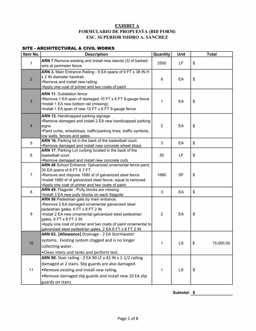
SITE - ARCHITECTURAL & CIVIL WORKS
Item No. Description Quantity Unit Total
1ARN 7 Remove existing and install new stands (3) of barbed
wire at perimeter fence2500 LF $
2
ARN 3. Main Entrance Railing - 9 EA spans of 9 FT x 38 IN H
x 2 IN diameter handrail.
•Remove and install new railing.
•Apply one coat of primer and two coats of paint
9 EA $
3
ARN 11. Substation fence
•Remove 1 EA span of damaged 10 FT x 6 FT 9-gauge fence
•Install 1 EA new bottom rail (missing)
•Install 1 EA span of new 10 FT x 6 FT 9-gauge fence
1 EA $
4
ARN 13. Handicapped parking signage
•Remove damaged and install 2 EA new handicapped parking
signs
•Paint curbs, wheelstops, traffic/parking lines, traffic symbols,
low walls, fences and gates.
2 EA $
5ARN 16. Parking lot in the back of the basketball court.
•Remove damaged and install new concrete wheel stops3 EA $
6
ARN 17. Parking Lot curbing located in the back of the
basketball court.
•Remove damaged and install new concrete curb
50 LF $
7
ARN 48 School Entrance: Galvanized ornamental fence paint,
30 EA spans of 8 FT X 7 FT.
•Remove and dispose 1680 sf of galvanized steel fence
•Install 1680 sf of galvanized steel fence, equal to removed
•Apply one coat of primer and two coats of paint
1680 SF $
8ARN 49. Flagpole - Pully blocks are missing.
•Install 3 EA new pully blocks on each flagpole 3 EA $
9
ARN 56 Pedestrian gate by main entrance.
•Remove 2 EA damaged ornamental galvanized steel
pedestrian gates, 6 FT x 8 FT 2 IN
•Install 2 EA new ornamental galvanized steel pedestrian
gates, 6 FT x 8 FT 2 IN
•Apply one coat of primer and two coats of paint ornamental to
galvanized steel pedestrian gates, 2 EA 6 FT x 8 FT 2 IN
2 EA $
10
ARN 65. [Allowance] Drainage - 2 EA Stormwater
systems. Existing system clogged and is no longer
collecting water.
•Clean inlets and tanks and perform test.
1 LS $ 15,000.00
11
ARN 90. Stair railing - 2 EA 90 LF x 42 IN x 1-1/2 railing
damaged at 2 stairs. Slip guards are also damaged.
•Remove exis*ng and install new railing.
•Remove damaged slip guards and install new 10 EA slip
guards on stairs
1 LS $
Subtotal: $
EXHIBIT AFORMULARIO DE PROPUESTA (BID FORM)
ESC. SUPERIOR ISIDRO A. SÁNCHEZ
Page 1 of 8
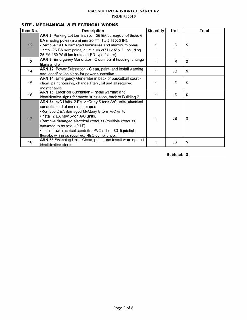
ESC. SUPERIOR ISIDRO A. SÁNCHEZPRDE #35618
SITE - MECHANICAL & ELECTRICAL WORKS
Item No. Description Quantity Unit Total
12
ARN 2. Parking Lot Luminaires - 25 EA damaged, of these 6
EA missing poles (aluminum 20 FT H x 5 IN X 5 IN).
•Remove 19 EA damaged luminaires and aluminum poles
•Install 25 EA new poles, aluminum 20' H x 5" x 5, including
25 EA 150-Watt luminaires (LED type fixture)
1 LS $
13ARN 6. Emergency Generator - Clean, paint housing, change
filters and oil. 1 LS $
14ARN 12. Power Substation - Clean, paint, and install warning
and identification signs for power substation.1 LS $
15ARN 14. Emergency Generator in back of basketball court -
clean, paint housing, change filters, oil and all required
maintenance
1 LS $
16ARN 15. Electrical Substation - Install warning and
identification signs for power substation, back of Building 21 LS $
17
ARN 54. A/C Units. 2 EA McQuay 5-tons A/C units, electrical
conduits, and elements damaged.
•Remove 2 EA damaged McQuay 5-tons A/C units
•Install 2 EA new 5-ton A/C units.
•Remove damaged electrical conduits (multiple conduits,
assumed to be total 40 LF)
•Install new electrical conduits, PVC sched 80, liquidtight
flexible, wiring as required. NEC compliance.
1 LS $
18ARN 63 Switching Unit - Clean, paint, and install warning and
identification signs.1 LS $
Subtotal: $
Page 2 of 8

ESC. SUPERIOR ISIDRO A. SÁNCHEZPRDE #35618
BASKETBALL COURT - ARCHITECTURAL & CIVIL WORKS
Item No. Description Quantity Unit Total
19
Prepare and paint all interior and exterior surfaces including,
but not limited to, walls, ceilings, metal doors/frames, steel
gates, handrails and guardrails, soffits/fascias, and court lines
1 LS $
20
ARN 30. Exterior Doors at Basketball Court
•Remove 4 EA of damaged steel double doors, 36 IN x 84 IN
•Install 4 EA of new steel double doors, 36 IN x 84 IN and
hardware Apply one coat of primer and two coats of paint.
1 LS $
21
ARN 35. Basketball Court - 50 FT x 100 FT floor paint.
•Clean and prep floor surface for paint and sealant.
•Apply paint for lines and surface.
1 LS $
22ARN 36. Fire Hose Case - 18 IN x 30 IN glass on fire cabinet.
•Install new glass on fire hose case1 LS $
23
ARN 38. Classroom 015 - Ceiling drywall plaster
•Remove 50 SF of damaged ceiling drywall plaster
•Install 50 SF of new ceiling drywall plaster
1 LS $
24
ARN 39 Classroom 015 concrete floor
•Repair 8 FT x 4 IN section of concrete floor, construct floor
drainage.
1 LS $
25 ARN 40. Back access steel door - Install new panic bar, 34 IN 1 EA $
26 ARN 41. Back Stairs - repair concrete finishing. 6 SF $
27ARN 42. Storage Room - install new hollow metal door. 38 IN
x 62 IN1 EA $
28 ARN 43 Repair cement plaster on access wall to stairs 3 LF $
29 ARN 44 Repair concrete plaster on wall and floor 8 SF $
30ARN 45 Remove damaged stainless steel stall partition door,
35 IN x 56 IN 1 EA $
31
ARN 45. Boy’s restroom, Toilet Partition Door, 1 EA, 35"x56"
•Remove damaged and install new stainless steel stall
partition door.
1 LS $
32
ARN 46. Boy’s restroom - 1 EA Ceramic sink and 1 EA lever
faucet.
•Remove damaged sink and lever faucet and replace with
new equivalent.
1 LS $
33ARN 47. Boy’s restroom - Ceramic tile, 12" x 12"
•Remove damaged and install new ceramic tile1 LS $
34
ARN 53. Exterior Eaves facing the South - 18 spans EA of 13-
FT X 3-FT X 6-IN eaves.
•Remove and replace cement board eaves (Plycem)
1 LS $
Subtotal: $
BASKETBALL COURT - ROOF WATERPROOFING WORKS
Item No. Description Quantity Unit Total
35ARN 38. Remove existing waterproofing system and replace
with code compliant system.1 LS $
Subtotal: $
Page 3 of 8

ESC. SUPERIOR ISIDRO A. SÁNCHEZPRDE #35618
BASKETBALL COURT - MECHANICAL & ELECTRICAL WORKS
Item No. Description Quantity Unit Total
36
ARN 32 Remove existing exhaust fans and replace with new
exhaust fans on roof and controls. 14800 CFM PENN, or
approved equal.
4 EA $
37
ARN 33. Remove existing 22 EA damaged Halide lights
damaged and replace with new LED fixtures, including all
electrical components and connections required for a
complete, code compliant installation.
22 EA $
38
ARN 34. Interior Exit Lights
•Remove damaged exit lights and install new exit lights,
vandal proof cover, impact cover.
4 EA $
39
ARN 37. Back hallway ceiling lights - 10 EA of 12 IN x 12 IN
ceiling lamps.
•Remove damaged ceiling lights in hallway and install LED
equivalent.
10 EA $
Subtotal: $
Page 4 of 8

ESC. SUPERIOR ISIDRO A. SÁNCHEZPRDE #35618
MAIN BUILDING ARCHITECTURAL & CIVIL WORKS
Item No. Description Quantity Unit Total
40
Prepare and paint all interior and exterior surfaces including,
but not limited to, walls, ceilings, metal doors/frames, steel
gates, handrails and guardrails, soffits/fascias, and court lines
1 LS $
41
ARN 4. Boys’ and Girls’ Restroom - 1st floor back of building /
Interior. 600 SF of ceiling drywall. Damaged by water intrusion
from roof.
•Remove 600 SF of damaged drywall from the ceiling of the
boys and girl’s restroom
•Install 600 SF of new drywall ceiling in the boys and girl’s
restroom
•Finish 600 SF of new drywall ceiling
•Prepare and paint interior and exterior surfaces including, but
not limited to, walls, ceilings, soffits/fascias, and doors/frames
1 LS $
42
ARN 5. Boy’s and Girl’s Restroom handicap stall partition - 1
EA stainless steel partition door in handicapped entrance 44
IN x 60 IN removed.
•Install 1 EA new stainless steel partition door (missing) in
handicapped stall, 44 IN x 60 IN
1 LS $
43
ARN 8. Exterior South Fascia of dining salon - Damaged
coverings for the electrical conduit lines. Cement board panels
detached
•Remove 40 FT section of detached cement board panels, 40
FT x 2 FT x 1
•Install new plycem fascia 40 FT x 2 FT x 1
•Install new plycem fascia to cover electrical conduit lines, 155
FT x 2 FT x 1 FT
1 LS $
44ARN 19. Remove damaged glass window (6" x 30") and install
new glass window1 EA $
45ARN 20. South back side: Repair damaged cement panel
fascia (2 FT x 14 IN.)1 EA $
46ARN 23. Repair damaged cement wall plaster over glass
windows, 10 EA sections x 50 SF EA10 EA $
47
ARN 25. Mechanic Classroom - Manual rolling doors.
•Remove 4 EA of roll up doors, 18 FT X 9 FT
•Install 4 EA new roll up doors, 18 FT X 9 FT
1 LS $
48
ARN 58. Library - Ceiling
•Remove 2 EA of areas of 8 FT x 15 FT damaged drywall
•Install 2 EA of areas of 8 FT x 15 FT new drywall
•Finish 2 EA of areas of 8 FT x 15 FT new drywall
1 LS $
49ARN 59. Library - Remove damaged cabinet and replace with
equivalent sized unit (Library) 1 EA $
50ARN 60. Library - Remove and replace damaged ceiling
drywall.1 LS $
51ARN 61. Dining Hall - Remove and replace damaged ceiling
drywall1 LS $
52 ARN 52. Install new school bell and system. 1 LS $
53ARN 67. Room 102 - Remove and replace damaged ceiling
drywall1 LS $
54ARN 68. Rooms 103,104,105,106,107,108,109 - Remove and
replace damaged ceiling drywall1 LS $
55ARN 74. Rooms115, 116 ,117, 118,120, 201, 202, 203, 204,
211, 212 - Remove and replace damaged ceiling drywall1 LS $
Page 5 of 8

ESC. SUPERIOR ISIDRO A. SÁNCHEZPRDE #35618
MAIN BUILDING ARCHITECTURAL & CIVIL WORKS
Item No. Description Quantity Unit Total
56
ARN 76. Girl’s restroom - 1 EA, louvered wooden door, 24 IN
x 80 IN.
•Remove 1 EA of a damaged louvered wooden door, 24 IN x
80 IN
•Install 1 EA of a new louvered wooden door, 24 IN x 80 IN
1 LS $
57ARN 77. Nursing Room - Remove and replace damaged
ceiling drywall1 LS $
58ARN 78. Boys Restroom front building - Replace missing
Stainless Steel partition,4'x5'x5'1 EA $
59ARN 79. Front Hallway - Remove and replace damaged
ceiling plaster5 SF $
60ARN 80. Open Classroom - Remove and replace damaged
ceiling drywall1 LS $
61
ARN 81. Classroom "Vida Indpendiente" - Kitchen cabinet
with single stainless-steel sink and single lever faucet was
damaged.
•Remove 1 EA of a stainless-steel sink and single lever faucet
and cabinet, 33 IN X 32 IN X 26 IN
•Install 1 EA new cabinet, 33 IN X 32 IN X 26 IN
•Install 1 EA new stainless-steel sink
•Install 1 EA new stainless-steel faucet
1 LS $
62
ARN 82. Dance Room - Mirror Panels damaged.
•Remove 4 EA damaged mirror wall panels, 4' x 8'
•Install 4 EA new mirror wall panels, 4' x 8'
4 EA $
63
ARN 84. School Handrails
•Remove 1000 LF of Handrail, 2 IN x 2 IN
•Install new 1000 LF of galvanized 2 IN x 2 IN handrail
1 LS $
64
ARN 85 : Classroom: Wood baseboard.
•Remove 110 LF x 3 IN of damaged wood base board
•Install 110 LF x 3 IN of new wood base board
1 LS $
65
ARN 86. Classrooms 218, 213, 214, 216 - damaged ceiling
drywall
•Remove damaged and install new ceiling drywall
2880 SF $
66ARN 87. Remove damaged glass sheet for the window, 6 IN
x26 IN ( classroom 217)1 EA $
67
ARN 87. Classroom 217 - Broken window glass window.
•Remove 1 EA of damaged broken glass, 26 IN x 6 IN
•Install 1 EA of new glass window, 26 IN x 6 IN
1 EA $
68 ARN 88. Mold remediation in Classrom 217. 1 LS $
69ARN pg. 49. Main Building, Roof Hatch - Replace 1 EA of
access hatch to roof, 3 FT x 3 FT1 LS $
Subtotal: $
Page 6 of 8

ESC. SUPERIOR ISIDRO A. SÁNCHEZPRDE #35618
MAIN BUILDING - ROOF WATERPROOFING WORKS
Item No. Description Quantity Unit Total
70
ARN 4. Remove existing waterproofing system and replace
with new code compliant waterproofing system, including
complete roof drainage system (gutters, scuppers,
downspouts, etc.), temporary removal and reinstallation of
HVAC system(s), raising of existing MEP piping as necessary
to meet minimum height code, and installing new tie
down/anchoring to secure existing roof equipment.
1 LS
Subtotal: $
MAIN BUILDING - MECHANICAL & ELECTRICAL WORKS
Item No. Description Quantity Unit Total
71ARN 18. Hojalateria (Bodyshop) classroom - Replace missing
exhaust fan 1 EA
72
ARN 21. Water Cistern located at the back of the dining hall,
600 gallons.
•Remove damaged 1 EA Water Cistern
•Replace and Install 1 EA Water Cistern & Pumps
1 LS
73
ARN 22. South side located in the back of the school: 2 EA
Electrical panel maintenance, signage, and lock.
•Install new warning and identification signs for electrical
panels
•Install new locks on 2 electrical panels
2 EA
74
ARN 24. South side Dining Room - Electrical conduit
detached.
•Remove electrical conduit and support 10 EA x 50 LF
•Install electrical conduit and support 10 EA x 50 LF
1 LS
75
ARN 26. Install missing exterior perimeter luminaire with new
LED fixtures, including all electrical components and
connections required for a complete, code compliant
installation.
1 EA
76ARN 27. Remove existing 14 EA 5 Ton A/C units and install
new code compliant Package A/C units. 1 LS
77ARN 29. Install electricity for new code compliant Package
A/C units (refer to ARN 27) . 1 LS
78 ARN 50. School Lobby - Repair cement plaster in ceiling 12 SF
79
ARN 51. Cistern
•Install 1 EA new steel door for cistern area, 36 IN x 80 IN
•Remove existing and install 1 EA new cistern pump system.
1 LS
80
ARN 55. School Lobby - Remove damaged 5 EA 14"x14"
ceiling mounted luminaires and replace with new LED
equivalent fixtures
5 EA
81ARN 57. Library - Replace missing plate covers and install
new bronze, floor electrical plate covers.3 EA
82
ARN 62. Dining Hall - 1 EA of fire hose cabinet was damaged.
•Remove 1 EA of damaged fire hose cabinet
•Install 1 EA of new fire hose cabinet 1 EA
Subtotal: $
Page 7 of 8

ESC. SUPERIOR ISIDRO A. SÁNCHEZPRDE #35618
MAIN BUILDING - MECHANICAL & ELECTRICAL WORKS
Item No. Description Quantity Unit Total
83
ARN 64. Administration Office - Fire alarm system & smoke
detectors are not functioning.
•Remove and replace Fire Alarm System & related equipment
1 LS
84
ARN 66. Ceiling fans - 4 EA per classroom.
•Remove 100 EA damaged ceiling fans.
•Install 100 EA new commercial grade ceiling fans
1 LS
85
ARN 70. Restroom and Mechanic Classrooms - 4 EA of
Exhaust Fans damaged.
•Remove 3 EA of damaged exhaust fans in Mechanic
Workshop and 1 EA of damaged exhaust fan in the restroom
•Install 3 EA of exhaust fans in the Mechanic Workshop and 1
EA of an exhaust fan in the restroom
4 EA
86
ARN 71. Mechanic Classroom - Remove existing 5-ton A/C
Unit and replace with new equipment similar or approved
equal to existing, including including all mechanical and
electrical components, connections and waterproofing
required for a complete, code compliant installation.
1 EA
87ARN 73. Mechanic Workshop - Exit sign damaged.
•Remove existing and install new exit sign.1 EA
88ARN75. Hallway near "Vida Independiente" Classroom -
Install and connect new fire hose cabinet1 EA
89ARN 83. Remove damaged fire hose cabinets and replace
with new ones (Hallway)4 EA
90
ARN pg. 48 - Remove 27 EA damaged 5-ton A/C units on roof
and replace with new equipment similar or approved equal to
existing, including including all mechanical and electrical
components, connections and waterproofing required for a
complete, code compliant installation.
1 LS
91ARN pg. 49. Dining Hall - Exhaust fans
•Remove 4 EA of damaged exhaust fans in the dining hall
•Install 4 EA of new exhaust fans in the dining hall
4 EA
Subtotal: $
_____________________________
Name Date
_____________________________
3) This Bidder accepts to perform all Work as specified or indicated in the Bidding Documents for the prices
submitted in Exhibit A (Bid Form) and within the times indicated in the Instructions to Bidders.
_____________________________
_____________________________
2) This Bid will remain subject to acceptance for sixty (60) days after the Bid Opening date.
Notes:
1) Items in gray require a Design-Build project delivery method and shall comply with Exhibit M of the Bid
Documents.
4) Pricing for crack and spall repairs to be based on the "Typical Recommended Repairs" included in
Exhibit K .
5) As part of the backup documentation Contractors are to provide cut sheets of the products making up the
basis of their proposal including: 1) Generator, 2) Water fountain, 3) Light fixture, 4) Plumbing fixture, 5) Kitchen
equipment, 6) HVAC equipment, and 7) Roofing system.
Page 8 of 8
_____________________________
Signature Employer Identification Number
_____________________________

INSERT BACK UP DOCUMENTATION - ITEM A - GENERATOR

INSERT BACK UP DOCUMENTATION - ITEM B - WATER FOUNTAIN

INSERT BACK UP DOCUMENTATION - ITEM C - LIGHT FIXTURES

INSERT BACK UP DOCUMENTATION - ITEM D - PLUMBING FIXTURES

INSERT BACK UP DOCUMENTATION - ITEM E - KITCHEN EQUIPMENT

INSERT BACK UP DOCUMENTATION - ITEM F - HVAC EQUIPMENT
INSERT BACK UP DOCUMENTATION - ITEM G - ROOFING SYSTEM

Exhibit B
Declaración deContratista

EXHIBIT B
DECLARACIÓN DEL CONTRATISTA
A: Oficina para el Mejoramiento de las Escuelas
Públicas: [email protected] PO Box 195644, San Juan, Puerto Rico 00919-5644
De: (Nombre de Contratista/Nombre de Representante Autorizado/Dirección Postal)
A. Información a. Fecha para la cual se estableció: b. La siguiente persona está autorizada para obligar legalmente al Contratista en aquellos
asuntos referentes a la Compra Informal y al contrato:
c. Título:
d. Teléfono:
e. Facsímil:
f. Dirección postal:
g. Correo electrónico para recibir notificaciones de OMEP:
h. Experiencia previa de la empresa y de sus representantes y oficiales, según requerido en el documento de Condiciones Especiales Suplementarias (EXHIBIT J) en la parte I, inciso F (2).
i. Experiencia del personal técnico según solicitado en las Condiciones Especiales Suplementarias (EXHIBIT J) en la Parte I, inciso F (4).
j. Equipo adecuado: Proveer resumen de inventario de herramientas, materiales y equipo disponible de conformidad con lo requerido en las Condiciones Especiales Suplementarias (EXHIBIT J), Parte I, inciso F (5)
k. Número de identificación de impuestos federales (Seguro Social Patronal): l. El Contratista es un(a): (marque con una equis)
Único propietario Corporación
Sociedad Otro (especifique)

m. Nombre de la compañía de seguros portadora del seguro de responsabilidad pública:
n. Nombre y dirección postal de la fiadora
o. Nombre y dirección del agente local:
Iniciales
B. Instrucciones al Contratista
El Contratista hace constar que recibió y examinó todos los documentos que se hacen formar parte de estas Instrucciones a los Contratista para el proyecto objeto de este proyecto.
Iniciales del Contratista
C. Adenda
El Contratista hace constar que recibió la siguiente adenda:
Adenda Núm. Fecha de publicación
1.
2.
3.
4.

Certifico haber recibido la adenda relacionada a este proyecto y declaro que acepto esta adenda y que cada cambio, si alguno, presentado como parte de la(s) misma(s) ha sido considerado en el costo del proyecto presentado en esta propuesta.
Iniciales del contratista
D. Visita a localización del proyecto
El Contratista hace constar que ha visitado, examinado y evaluado la localización y condiciones de terreno destinados para este proyecto.
E. Plan de Seguridad
El Contratista se compromete a hacer cumplir con un Plan de Seguridad adecuado para este tipo de Trabajo y que instalará aquellos rótulos que sean necesarios durante el desarrollo del Trabajo.
(Firma del individuo)
(Nombre impreso del individuo)
(Dirección Postal)

Exhibit C
Cuestionario delContratista
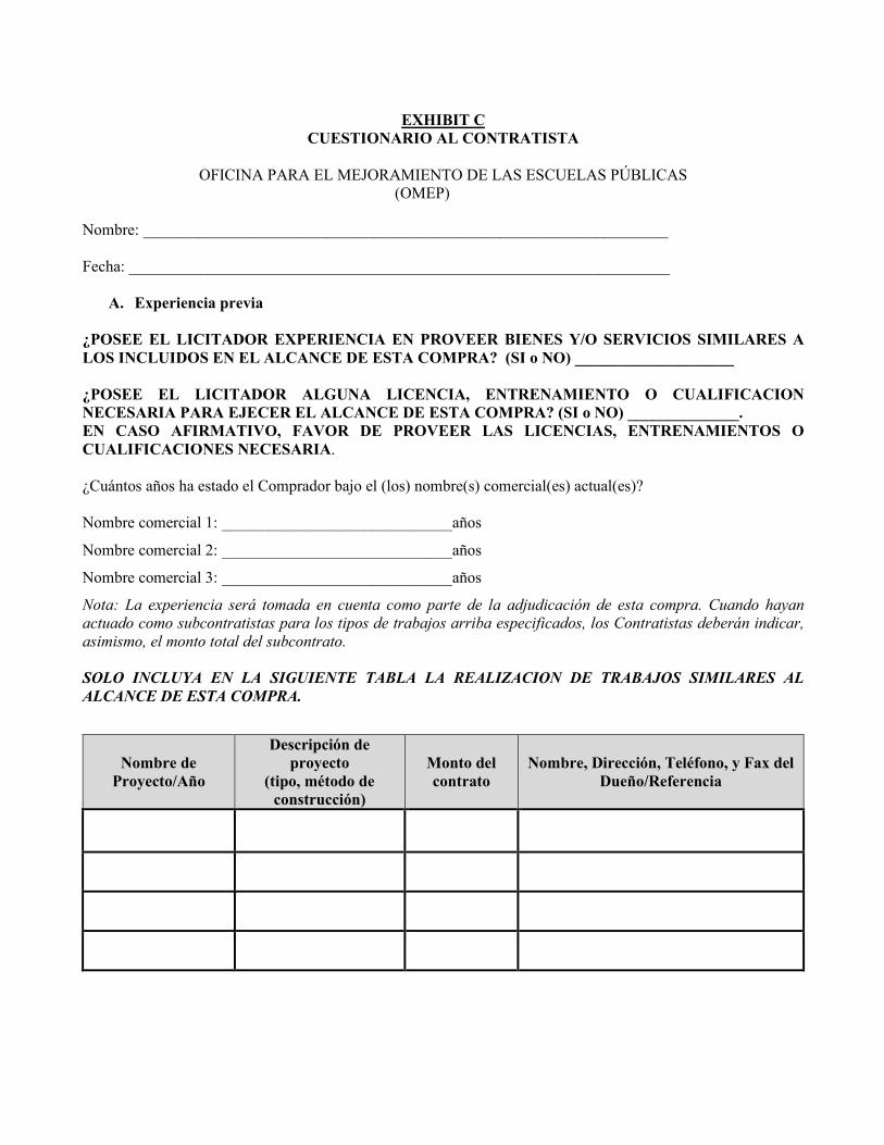
EXHIBIT C CUESTIONARIO AL CONTRATISTA
OFICINA PARA EL MEJORAMIENTO DE LAS ESCUELAS PÚBLICAS
(OMEP)
Nombre: __________________________________________________________________ Fecha: ____________________________________________________________________
A. Experiencia previa ¿POSEE EL LICITADOR EXPERIENCIA EN PROVEER BIENES Y/O SERVICIOS SIMILARES A LOS INCLUIDOS EN EL ALCANCE DE ESTA COMPRA? (SI o NO) ____________________ ¿POSEE EL LICITADOR ALGUNA LICENCIA, ENTRENAMIENTO O CUALIFICACION NECESARIA PARA EJECER EL ALCANCE DE ESTA COMPRA? (SI o NO) ______________. EN CASO AFIRMATIVO, FAVOR DE PROVEER LAS LICENCIAS, ENTRENAMIENTOS O CUALIFICACIONES NECESARIA. ¿Cuántos años ha estado el Comprador bajo el (los) nombre(s) comercial(es) actual(es)? Nombre comercial 1: _____________________________años
Nombre comercial 2: _____________________________años
Nombre comercial 3: _____________________________años
Nota: La experiencia será tomada en cuenta como parte de la adjudicación de esta compra. Cuando hayan actuado como subcontratistas para los tipos de trabajos arriba especificados, los Contratistas deberán indicar, asimismo, el monto total del subcontrato. SOLO INCLUYA EN LA SIGUIENTE TABLA LA REALIZACION DE TRABAJOS SIMILARES AL
ALCANCE DE ESTA COMPRA.
Nombre de Proyecto/Año
Descripción de proyecto
(tipo, método de construcción)
Monto del contrato
Nombre, Dirección, Teléfono, y Fax del Dueño/Referencia

B. Récord de Cumplimiento e Integridad a. ¿Ha tenido el Contratista una terminación de contrato por ‘default’ o incumplimiento?
______Sí _______No ¿O se ha llevado un juicio en contra del contratista en cualquier corte durante el periodo de cinco años previo a la fecha de entrega de propuestas? ______Sí _______No
Si la respuesta a cualquiera de estas preguntas es “Sí”, incluya para cada contrato envuelto en dicha situación el nombre y dirección postal del Cliente o Dueño, así como nombre de persona de contacto, título, número de teléfono y de facsímil, la naturaleza del trabajo, la cuantía del contrato, la razón para el ‘default’ y el día de terminación o juicio. Nombre de proyecto: ______________________________________________
Cliente o dueño
Nombre de cliente o dueño: __________________________________________
Dirección de cliente o dueño: _________________________________________
Persona de contacto:
Nombre de persona de contacto: ______________________________________
Título: ________________________________________________________________
Número de teléfono y facsímil: ________________________________________
Descripción de trabajo: ______________________________________________
_______________________________________________________________
________________________________________________________________
Cuantía de contrato: $__________________
Razón para el default: ____________________
Fecha de terminación: __________________
Día de juicio: ___________________________
Si se requiere espacio adicional para proveer esta información, incorpore una hoja aparte. La información adicional asociada al Récord de Cumplimiento e Integridad se incluye en el Anejo ________.
b. ¿Ha estado el Contratista involucrado en alguna demanda, acción, investigación o proceso judicial criminal, civil o administrativo que haya sido comenzado, esté pendiente a comenzar, haya sido resuelto o concluido durante el periodo de cinco años previo a la Fecha Límite para presentar propuestas?
______Sí _______No
Si la respuesta a esta pregunta es “Sí”, especifique la fecha o fechas de duración de la demanda, acción, investigación o proceso judicial; la naturaleza específica de la demanda, acción, investigación o proceso

judicial; la cuantía de los fondos envueltos, si alguna; los nombres de las partes envueltas; los nombres y direcciones postales completas de las cortes y agencias del orden público involucradas; el título y el número de caso de la demanda, acción, investigación o proceso judicial; la disposición o status actual; y cualquier sentencia, multa o penalidad impuesta.
Naturaleza especifica de la demanda, acción, investigación o proceso judicial:
________________________________________________________________
Fecha de la demanda, acción, investigación o proceso judicial:
________________________________________________________________
Cuantía de los fondos envueltos:
________________________________________________________________
Nombres de las partes envueltas:
________________________________________________________________
Nombres y direcciones postales completas de las cortes y agencias del orden público involucradas:
________________________________________________________________
Título y el número de caso de la demanda, acción, investigación o proceso judicial:
________________________________________________________________
Disposición o status actual:
________________________________________________________________
Sentencia, multa o penalidad impuesta:
________________________________________________________________
Si se requiere espacio adicional para proveer esta información, incorpore una hoja aparte. La información adicional asociada al Récord de Cumplimiento e Integridad continúa en el Anejo ________.
c. ¿Ha estado el Contratista involucrado en algún proyecto en el cual daños por errores u omisiones hayan sido evaluados durante el periodo de cinco años previo a la Fecha Límite para presentar propuestas?
______Sí _______No
Si la respuesta a esta pregunta es “Sí”, someta una descripción de los proyectos involucrados, el tiempo de contrato para cada proyecto, la cuantía total de los daños evaluados en cada proyecto, y una explicación con la(s) razón(es) por lo cual se produjo una evaluación de daños en cada caso.

Descripción de los proyectos involucrados: ________________________________________________________________
Tiempo de contrato para cada proyecto: ________________________________________________________________
Cuantía total de los daños evaluados en cada proyecto: ________________________________________________________________
Explicación con la(s) razón(es) por lo cual se produjo una evaluación de daños en cada caso: ___________ Si se requiere espacio adicional para proveer esta información, incorpore una hoja aparte. La información adicional asociada al Récord de Cumplimiento e Integridad continúa en el Anejo ________.
d. ¿Ha fallado el Contratista en completar un proyecto durante el periodo de cinco años previo a la Fecha Límite para presentar propuestas?
______Sí _______No
Si la respuesta a esta pregunta es “Sí”, incluya para cada contrato(s) relacionado(s) a dicho(s) proyecto(s), el nombre del Cliente o Dueño, así como su dirección postal, nombre de contacto de la persona, título, número de teléfono y facsímil, naturaleza del proyecto, y la razón por la cual no se completó el trabajo.
Cliente o dueño Nombre: _________________________________________________________
Dirección postal: ___________________________________________________
Persona de contacto
Nombre: _________________________________________________________
Título: ___________________________________________________________
Número de teléfono y facsímil: ________________________________________
Naturaleza del proyecto: _____________________________________________
________________________________________________________________
Razón(es) por la(s) cual(es) no se completó el trabajo:
________________________________________________________________
________________________________________________________________
Si se requiere espacio adicional para proveer esta información, incorpore una hoja aparte. La información adicional asociada al Récord de Cumplimiento e Integridad continúa en el Anejo ________.

Incluya una descripción sobre cualquier tipo de línea de negocio sobre la cual el Contratista tenga interés ________________________________________________________________
________________________________________________________________
________________________________________________________________
Nota: Las excepciones no necesariamente resultarán en la negación de una adjudicación, pero serán consideradas al momento de determinar la responsabilidad del Contratista. Proveer información falsa podría resultar en una acusación criminal o sanciones administrativas.
C. Experiencia del personal y otros
Provea el brochure del contratista con evidencia de proyectos similares realizados en los últimos cinco (5) años. Provea una lista de las facilidades de construcción, equipo y cualquier otro recurso que el Contratista posea para la realización de los trabajos de esta Propuesta. D. CAPACIDAD ECONOMICA
¿POSEE EL CAPACIDAD ECONOMICA PARA PROVEER LOS BIENES Y/O SERVICIOS INCLUIDOS EN EL ALCANCE DE ESTA COMPRA? (SI o NO) ______ Favor proveer último informe de los estados financieros su empresa o negocio. E. GARANTIA
LA OMEP REQUIERE QUE LAS OBRAS Y BIENES SEAN GARANTIZADAS POR UN MINIMO DE TRES ANOS INCLUYENDO MATERIALES, PIEZAS Y LABOR.
NO APLICA A SERVICIOS PROFESIONALES O NO PROFESIONALES
FAVOR DE INCLUIR UN CERTIFICADO DE GARANTIA JUNTO CON LOS PLIEGOS DE SUBASTA FIRMADO Y SELLADO POR SU EMPRESA O NEGOCIO QUE CUBRA EL MINIMO
REQUERIDO POR OMEP.
F. FECHA DE ENTREGA DE LA OBRA ¿SE COMPREMETE EL LICITADOR A ENTREGAR LA OBRA AL 100% DE
CUMPLIMIENTO CON LOS CODIGOS DE CONSTRUCCION VIGENTES DENTRO DEL PERIODO REQUERIDO DE 160 DÍAS CALENDARIO? (SI o NO) ______________________
SI ESTIMA QUE NO PUEDE COMPLETAR LA OBRA DENTRO DEL PERIODO DE 160
DÍAS CALENDARIOS INDICAR NUMERO DE DIAS CALENDARIO QUE LE TOMARA REALIZAR EL ALCANCE TOTAL DE LO SUBASTADO UNA VEZ ENTREGADA LA ORDEN DE PROCEDER. ________________ DIAS.

ADVERTENCIA: EL PROVEER UN NÚMERO SUPERIOR DE DÍAS CALENDARIO PARA COMPLETAR LA OBRA PUEDE AFECTAR LA EVALUACIÓN DE LA PROPUESTA DEL CONTRATISTA.
G. DISPONIBILIDAD DEL BIEN O SERVICIO Y COSTOS ASOCIADOS
¿El bien o servicio está disponible en Puerto Rico? (SI o NO) _________________
De responder NO, donde están disponible actualmente_____________________
Existen piezas de repuesto del bien ofrecido en Puerto Rico (SI o NO) __________
De responder NO, donde están disponible actualmente_____________________
FAVOR DE DESCRIBIR AQUELLOS COSTOS RELACIONADOS A LA IMPLEMENTACION DEL
ALCANCE DE ESTA COMPRA QUE A SU MEJOR ENTENDER NO HAYAN SIDO INCLUIDOS O
CONSIDERADOS Y PROVEA UN ESTIMADO DE TAL COSTO. (Ejemplo gastos de transportación,
consumo de combustible, gastos de mantenimiento, etc.)
____________________________________________________________________________________
____________________________________________________________________________________
____________________________________________________________________________________
____________________________________________________________________________________
________________________________

Exhibit D
Recibo yCumplimiento del
Código Anticorrupciónpara el nuevo Puerto
Rico

EXHIBIT D RECIBO Y CUMPLIMIENTO DEL CÓDIGO ANTICORRUPCIÓN PARA EL NUEVO PUERTO
RICO
OFICINA PARA EL MEJORAMIENTO DE LAS ESCUELAS PÚBLICAS (OMEP)
Yo, ___________________________________________________, mayor de edad, y residente de_________________________________, certifico por mí y por ______________________________________, el Contratista, so pena de perjurio, que a mi mejor entendimiento y creencia: En el cumplimiento a la Ley Núm. 2 de 4 de enero de 2018 según enmendada, y en representación del Contratista acredito haber recibido copia DEL CÓDIGO ANTICORRUPCIÓN PARA EL NUEVO PUERTO RICO. Luego de revisar la misma, certifico en nombre del Contratista que no hay impedimento legal identificado en mencionada ley que impida el otorgamiento de un contrato entre las partes. Para que así conste, formo la presente certificación en _____________, Puerto Rico, hoy _____ de _________ de _____. Firma del Contratista o su representante Nombre en letra de molde

Exhibit E
Non-Collusive Affidavit

EXHIBIT E NON-COLLUSIVE AFFIDAVIT
Commonwealth or Puerto Rico _______________________________________, being first duly sworn,
deposes says:
That he is ________________________________________________________ (an individual, a partner
of partnership or an officer of a corporation, etc.)
of the party making the foregoing proposal or bid, that such proposal or bid is genuine and not collusive or sham; that said bidder has not collude, conspired, connived or agreed, directly or indirectly, with any bidder, or person, to put in a sham bid or to refrain from bidding; that he has not in any manner, directly or indirectly, sought by agreement or collusion, or communication, or conference, with any person, or fix the price of affiant or of any other bidder, or to fix any overhead, profit or cost element of said bid price, or of that of any bidder, or to secure any advantage against the ______________________________________ (Name of Owner)
Proposed contract; and that all statement in said proposal or bid are true. In the City of ___________________________, Puerto Rico, this ___________________________ day of _________________________, 2022.
____________________________________ Name of Bidder
____________________________________ Signature of Bidder’s Representative
AFFIDAVIT NUMBER _____________________________ Sworn and subscribed to before me in the place and date above stated by ______________________________________________ of legal age an personally known to me.
(NOTARIAL SEAL) ______________________________________ NOTARY PUBLIC

Certificación de laASG en Registro Único
de Licitadores (RUL)

Fianza de Licitación(Bid Bond)

Número de registro enDUNS (System for
Award Management -SAM)

Estado FinancieroAuditado (15 meses
previo a subasta)

Resolución Corporativa

Exhibit KKey PlansTypical Recommended RepairsReference Technical Specifications

KEY PLANSDon Luis Muñoz Marín (Ceiba)
Superior Isidro A. Sánchez (Luquillo)

BUILDING 02(BASKETBALL COURT)
BUILDING 01
SUBSTATION
Don Luis Muñoz Marín (Ceiba) #35907

BLDG 04
BLDG 11
BLDG 05
BLDG 06
BLDG 08 BLDG 09
BLDG 02
BLDG 01 BLDG 07
BLDG 03
BLDG 10
BUILDING 02(BASKETBALL COURT)
Don Luis Muñoz Marín (Ceiba) #35907

BUILDING 02(BASKETBALL COURT)
BLDG 02 BLDG 03
Don Luis Muñoz Marín (Ceiba) #35907
BLDG 04
BLDG 05
BLDG 10 BLDG 11
BLDG 01 BLDG 07BLDG 06
BLDG 08 BLDG 09
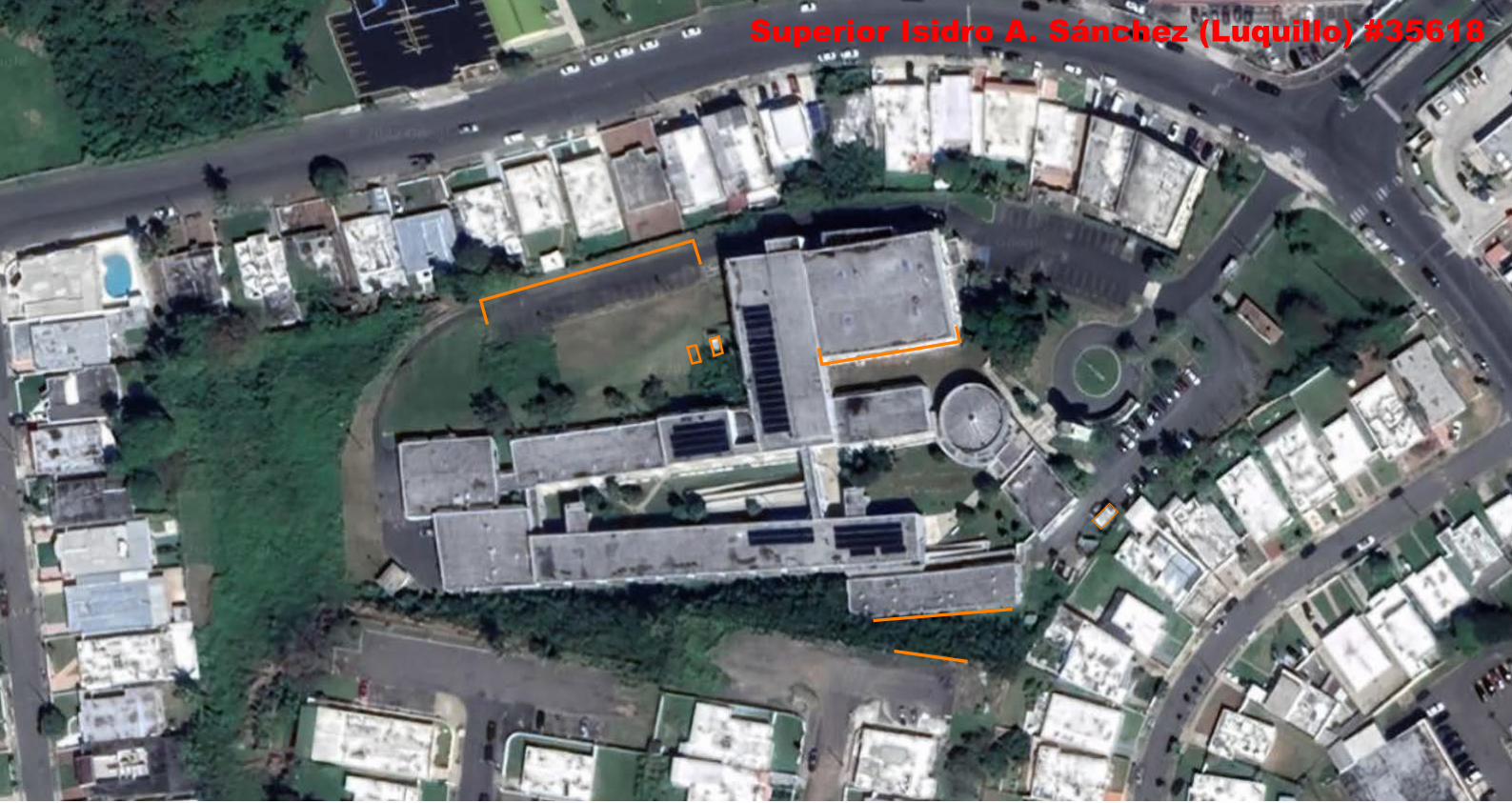
Superior Isidro A. Sánchez (Luquillo) #35618

Administration
Cafeteria
Substation
Generator
122123
Library
101 102 103 104 105 106 107 108 109
112113114115116117
118
119
120
110
111
Superior Isidro A. Sánchez (Luquillo) #35618

013
Girl'sRestroom
014
015
201 202 203 204 205 206 207 208 209 210 211
220219218
212217
213
214
215
216
Superior Isidro A. Sánchez (Luquillo) #35618

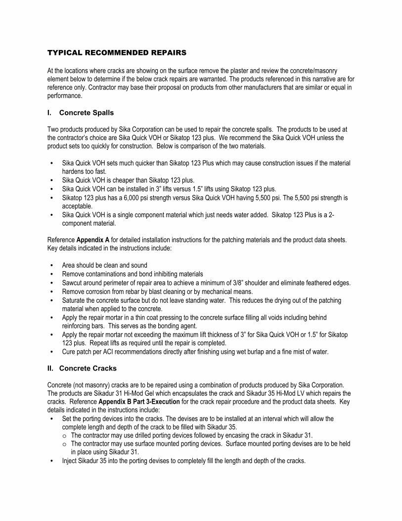
TYPICAL RECOMMENDED REPAIRS
TYPICAL RECOMMENDED REPAIRS
At the locations where cracks are showing on the surface remove the plaster and review the concrete/masonry element below to determine if the below crack repairs are warranted. The products referenced in this narrative are for reference only. Contractor may base their proposal on products from other manufacturers that are similar or equal in performance.
I. Concrete Spalls Two products produced by Sika Corporation can be used to repair the concrete spalls. The products to be used at the contractor’s choice are Sika Quick VOH or Sikatop 123 plus. We recommend the Sika Quick VOH unless the product sets too quickly for construction. Below is comparison of the two materials.
• Sika Quick VOH sets much quicker than Sikatop 123 Plus which may cause construction issues if the material hardens too fast.
• Sika Quick VOH is cheaper than Sikatop 123 plus.
• Sika Quick VOH can be installed in 3” lifts versus 1.5” lifts using Sikatop 123 plus.
• Sikatop 123 plus has a 6,000 psi strength versus Sika Quick VOH having 5,500 psi. The 5,500 psi strength is acceptable.
• Sika Quick VOH is a single component material which just needs water added. Sikatop 123 Plus is a 2-component material.
Reference Appendix A for detailed installation instructions for the patching materials and the product data sheets. Key details indicated in the instructions include:
• Area should be clean and sound
• Remove contaminations and bond inhibiting materials
• Sawcut around perimeter of repair area to achieve a minimum of 3/8” shoulder and eliminate feathered edges.
• Remove corrosion from rebar by blast cleaning or by mechanical means.
• Saturate the concrete surface but do not leave standing water. This reduces the drying out of the patching material when applied to the concrete.
• Apply the repair mortar in a thin coat pressing to the concrete surface filling all voids including behind reinforcing bars. This serves as the bonding agent.
• Apply the repair mortar not exceeding the maximum lift thickness of 3” for Sika Quick VOH or 1.5” for Sikatop 123 plus. Repeat lifts as required until the repair is completed.
• Cure patch per ACI recommendations directly after finishing using wet burlap and a fine mist of water. II. Concrete Cracks Concrete (not masonry) cracks are to be repaired using a combination of products produced by Sika Corporation. The products are Sikadur 31 Hi-Mod Gel which encapsulates the crack and Sikadur 35 Hi-Mod LV which repairs the cracks. Reference Appendix B Part 3-Execution for the crack repair procedure and the product data sheets. Key details indicated in the instructions include:
• Set the porting devices into the cracks. The devises are to be installed at an interval which will allow the complete length and depth of the crack to be filled with Sikadur 35. o The contractor may use drilled porting devices followed by encasing the crack in Sikadur 31. o The contractor may use surface mounted porting devices. Surface mounted porting devises are to be held
in place using Sikadur 31.
• Inject Sikadur 35 into the porting devises to completely fill the length and depth of the cracks.

• After the Sikadur 35 has cured the Sikadur 31 product and porting devises are to be removed and the area cleaned.
III. Masonry Cracks The concrete repair materials are not approved for masonry repairs. The cracks in the masonry are to be repaired by repointing the masonry joints and cracks with Type S masonry mortar. The mortar is to be pressed into the cracks to fill the face shells solid.

Co
nstr
ucti
on
Sika Corporation
SikaTop 123 Plus
Application
Instructions
Also to be used for SikaQuick VOH
Appendix A - Concrete Spall Repairs

Co
nstr
ucti
on
Sika Corporation
SikaTop 223 Plus
Two-component, polymer-modified,
portland cement based.
Fast-setting, non-sag mortar.
High performance repair mortar for
vertical and overhead surfaces.
Offers the additional benefit of FerroGard
901- A penetrating corrosion inhibitor.

Co
nstr
ucti
on
Sika Corporation
SikaTop 123 Plus
Where to use:
• On grade, above, and below grade on concrete and mortar.
• On vertical and overhead surfaces.
• As a structural repair material for: – Parking structures
– Industrial plants
– Water/waste water treatment facilities
– Roads, walkways, bridges, tunnels, dams, ramps, etc.

Co
nstr
ucti
on
Sika Corporation
SikaTop 123 Plus
Packaging: • “A” Comp: 1 gal
Jug of Dispersion.
• “B” Comp: 44 lb Multi-wall bag.
Coverage: • .39 cu. ft / unit.
• 674 cu. inches per unit.

Co
nstr
ucti
on
Sika Corporation
Surface Preparation
Cementitious Substrates: • Should be clean and sound.
• Remove contaminations and bond
inhibiting materials from repaired
area.
• Obtain exposed/fractured aggregate
surface ~1/16 to 1/8 inch profile
(ICRI CSP 5 & above).
• Substrate must be saturated surface
dry (SSD) with no standing water.

Co
nstr
ucti
on
Sika Corporation
Surface Preparation
Cementitious Substrates:
• Surface should be
cleaned and
roughened to
create a profile.

Co
nstr
ucti
on
Sika Corporation
Surface Preparation
Saw cut around perimeter of repair area to achieve a minimum 3/8” shoulder.
Eliminates feathered edges giving a clean repair transition

Co
nstr
ucti
on
Sika Corporation
Surface Preparation
Steel: • Remove all corrosion and
contaminants from exposed steel.
• Surface should be cleaned thoroughly by blast cleaning or mechanical means.
• Exposed steel should be cleaned to white steel.
• If half of the diameter is exposed, chip behind bar, ½” minimum for mortar only.

Co
nstr
ucti
on
Sika Corporation
Steel Preparation
Steel should be cleaned to a bright
metal finish.

Co
nstr
ucti
on
Sika Corporation
Tools Required
½” Drill Motor.
Low speed drill
400-600 rpm.
Large mixing paddle
Margin trowel

Co
nstr
ucti
on
Sika Corporation
Mixing
Pour “A” Component
into clean pail.
Leave approximately
1” of “A” Component
in jug.
Co
nstr
ucti
on
Sika Corporation
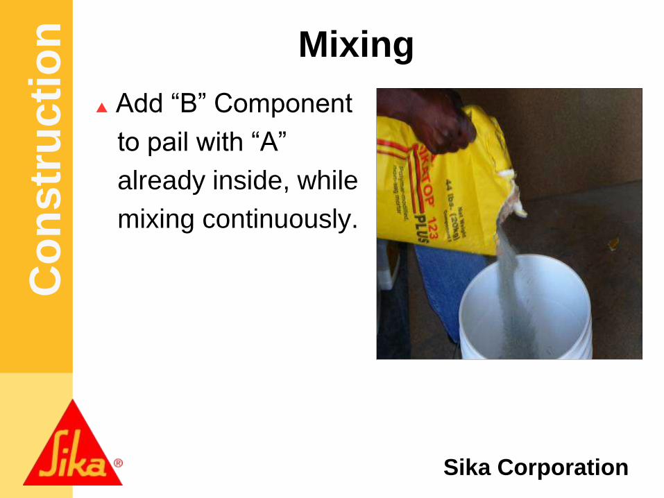
Mixing
Add “B” Component
to pail with “A”
already inside, while
mixing continuously.

Co
nstr
ucti
on
Sika Corporation
Mixing
1. Dispersion ¾ -1 gallon of
dispersion/Bag.
2. Start with adding liquid to
the mixing container.
3. Slowly add powder.
4. Once all the powder is
added mix for 3 minutes.
5. Do not add any more than
the recommended liquid.

Co
nstr
ucti
on
Sika Corporation
1. While mixing for 3
minutes stop to scrape
down the sides to insure
all material is fully mixed.
2. Add additional “A”Comp.
liquid for desired
consistency.
3. Most cases you will have
liquid left.
4. Thorough mixing and proper proportioning is
necessary.
Mixing

Co
nstr
ucti
on
Sika Corporation
Apply the mortar to
the patch area while
the Armatec 110
EpoCem is still wet.
If Armatec is not used
as a bonding agent,
SSD the surface and scrub coat the repair mortar
into the substrate filling all pores and voids.
ST 123+ Application

Co
nstr
ucti
on
Sika Corporation
ST 123+ Application
Apply SikaTop
repair mortar to
patch.
Press mortar
behind rebar and
make sure the
material is
consolidated and
compacted fully.

Co
nstr
ucti
on
Sika Corporation
ST 123+ Application
Complete filling
patch area.
Work mortar from
the center of the
patch to the
outside.
Co
nstr
ucti
on
Sika Corporation
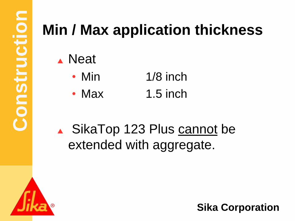
Min / Max application thickness
Neat
• Min 1/8 inch
• Max 1.5 inch
SikaTop 123 Plus cannot be
extended with aggregate.
Co
nstr
ucti
on
Sika Corporation
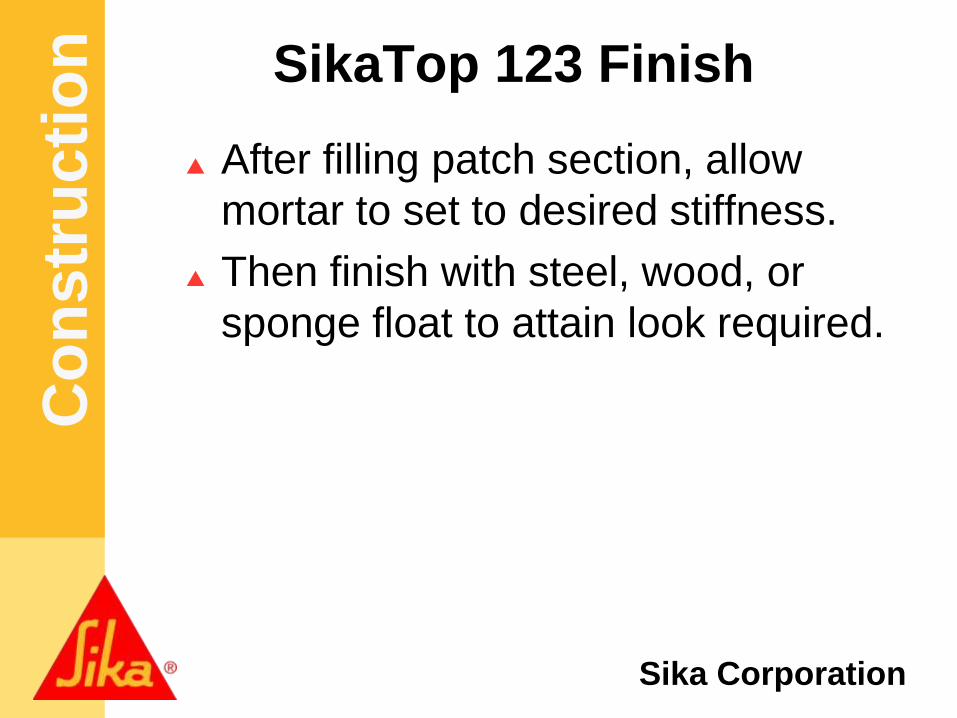
SikaTop 123 Finish
After filling patch section, allow
mortar to set to desired stiffness.
Then finish with steel, wood, or
sponge float to attain look required.

Co
nstr
ucti
on
Sika Corporation
Sikatop 123+ Finish
To assist in the
finishing of the
SikaTop use
SikaFilm.
• SikaFilm is a
finishing aid that
also retards
moisture
evaporation.

Co
nstr
ucti
on
Sika Corporation
SikaTop 123+ Finish
You can use a
steel trowel to
attain a smooth
surface.

Co
nstr
ucti
on
Sika Corporation
Sponge Float Finish
You can use
Sponge float to
attain a textured
surface.

Co
nstr
ucti
on
Sika Corporation
SikaTop Curing
Cure as per ACI recommendations.
Curing is required.
Moist cure with wet burlap
and polyethylene, a fine
mist of water.
Moist curing should
commence immediately after finishing.
Protect newly applied material from
direct sun light, wind, rain and frost.

Co
nstr
ucti
on
Sika Corporation
SikaTop 123 Plus
Sika Technical Data Sheets can be
obtained via:
www.sikaconstruction.com
Refer to data sheets for specific
information on each Sika product.

SIKAQUICK® VOHFAST SETTING, ONE COMPONENT, CEMENTITIOUS VERTICAL AND OVERHEAD REPAIR MORTAR
Application up to 3'' on vertical surfaces in one layer Overhead thickness up to 2'' Fiber reinforced and polymer modified containing corrosion inhibitor Low dust version available
Available inBag 44 lbs.

SIKAQUICK® VOHVERTICAL AND OVERHEAD REPAIR MORTAR
Sika Corporation201 Polito AvenueLyndhurst, NJ 07071Phone: 201-933-8800Fax: 201-933-6225
FOR MORE INFORMATION:Contact Sika: Phone 800.933.SIKA(7452) Website: usa.sika.com
APPLICATIONS � Fast repairs to overhead and vertical concrete and mortar
surfaces on grade, above and below grade. � Repair material for building facades, parking
structures, industrial plants, bridges, etc. � Fast setting repair material for new construction defects
BENEFITS � Minimal time required between lifts. � Fast finishing time � Available as low dust version � Time/labor-saving material; application up to
3 inches on vertical surfaces in one layer � Easy to use; just add water � High bond strength ensures excellent adhesion � High early and ultimate strength � Increased freeze/thaw durability and resistance to deicing salts � Suitable for exterior and interior applications � Not a vapor barrier � Overhead thickness up to 2" � Fiber reinforced and polymer modified � Contains corrosion inhibitor
© S
ika
Corp
orat
ion/
Ref
urbi
shm
ent/
06.13
03.2
/11/
2018
TYPICAL DATA � Shelf Life: One year in original, unopened bags � Storage Conditions: Store dry at 40°-95°F (4°-35°C) � Product Conditioning: Condition material to 65°-75°F before using. � Color: Concrete gray � Mixing Ratio: 6 - 6.5 pints/unit � Density (Wet mix): ~ 125 lbs. / cu. ft. � Application Time: Approximately 20 minutes. � Finishing Time: 20-30 minutes � Lift Height: Max: 3” Min: 1/8” � Time Between Lifts: After final set
LITERATURE � Product Data Sheet � Material Safety Data Sheet
*Always refer to Current Product Data Sheet and MSDS for detailed performance specifications prior to use.
Note: Advice on specific applications is available from the Technical Service Department of Sika Construction Products Division.
Mix to uniform consistency, no longer than 3 minutes
Moist cure and protect from elements immediately after finishing.
Finish with trowel, float, or sponge, depending on desired surface texture.
Scrub material into substrate, filling any pores and voids.

SIKAQUICK® VOHVERTICAL AND OVERHEAD REPAIR MORTAR
Sika Corporation201 Polito AvenueLyndhurst, NJ 07071Phone: 201-933-8800Fax: 201-933-6225
FOR MORE INFORMATION:Contact Sika: Phone 800.933.SIKA(7452) Website: usa.sika.com
APPLICATIONS � Fast repairs to overhead and vertical concrete and mortar
surfaces on grade, above and below grade. � Repair material for building facades, parking
structures, industrial plants, bridges, etc. � Fast setting repair material for new construction defects
BENEFITS � Minimal time required between lifts. � Fast finishing time � Available as low dust version � Overhead thickness up to 2" � Easy to use; just add water � High bond strength ensures excellent adhesion � High early and ultimate strength � Increased freeze/thaw durability and resistance to deicing salts � Suitable for exterior and interior applications � Time/labor-saving material; application up to 3
inches on vertical surfaces in one layer � Fiber reinforced and polymer modified � Contains corrosion inhibitor
© S
ika
Corp
orat
ion/
Ref
urbi
shm
ent/
06.13
03.2
/11/
2018
TYPICAL DATA � Shelf Life: One year in original, unopened bags � Storage Conditions: Store dry at 40°-95°F (4°-35°C) � Product Conditioning: Condition material to 65°-75°F before using. � Color: Concrete gray � Mixing Ratio: 6 - 6.5 pints/unit � Density (Wet mix): ~ 125 lbs. / cu. ft. � Application Time: Approximately 20 minutes. � Finishing Time: 20-30 minutes � Lift Height: Max: 3” Min: 1/8” � Time Between Lifts: After final set
LITERATURE � Product Data Sheet � Safety Data Sheet � CSI Specification
*Always refer to Current PDS and SDS for detailed performance specifications prior to use.
Note: Advice on specific applications is available from the Technical Service Department of Sika Construction Products Division.
Mix to uniform consistency, no longer than 3 minutes
Moist cure and protect from elements immediately after finishing.
Finish with trowel, float, or sponge, depending on desired surface texture.
Scrub material into substrate, filling any pores and voids.

Product Data SheetSikaTop®-123 PlusNovember 2020, Version 01.03020302040070000022
PRODUCT DATA SHEET
SikaTop®-123 PlusTwo-component, polymer-modified, cementitious, non-sag mortar plus Sika FerroGard® 901 penet-rating corrosion inhibitor
PRODUCT DESCRIPTIONSikaTop®-123 Plus is a two-component, polymer-modified, Portland cement-based, fast-setting, non-sag mortar. It is a high performance repair mortar for vertical and overhead surfaces and offers the additional benefit of Sika FerroGard® 901, a penetrating corrosion inhibitor included in its formulation.
USESOn grade, above and below grade on concrete and mortar.
▪
On vertical and overhead surfaces.▪As a structural repair material for parking structures, industrial plants, walkways, bridges, tunnels, dams and ramps.
▪
Approved for repairs over cathodic protection systems▪
CHARACTERISTICS / ADVANTAGESExtremely low shrinkage proven by four industry standard test methods.
▪
High compressive and flexural strengths.▪Increased freeze/thaw durability and resistance to deicing salts.
▪
Increased density - improved carbon dioxide resistance (carbonation) without adversely affecting water vapor transmission (not a vapor barrier).
▪
Enhanced with Sika FerroGard® 901, a penetrating corrosion inhibitor - reduces corrosion even in the adjacent concrete.
▪
Compatible with coefficient of thermal expansion of concrete - Passes ASTM C 884.
▪
APPROVALS / STANDARDSUSDA certifiable for incidental food contact▪ANSI/NSF Standard 61 potable water approved compliant.
▪
Tested per ICRI Guidline NO. 320.3R for inorganic repair material data sheet protocol
▪
PRODUCT INFORMATION
Packaging Component A 1 gal (3.68 L) jug - 4/cartonComponent B 44 lb. (20 kg) bag
Appearance / Color Gray powder
Shelf Life 12 months from date of production if stored properly in original, unopened and undamaged sealed packaging
Store dry at 40–95 °F (4–35 °C).Storage Conditions
1 / 6

Protect Component ‘B’ from moisture. If damp, discard materialProtect Component ‘A’ from freezing. If frozen, discard.
Product Data SheetSikaTop®-123 PlusNovember 2020, Version 01.03020302040070000022
2 / 6
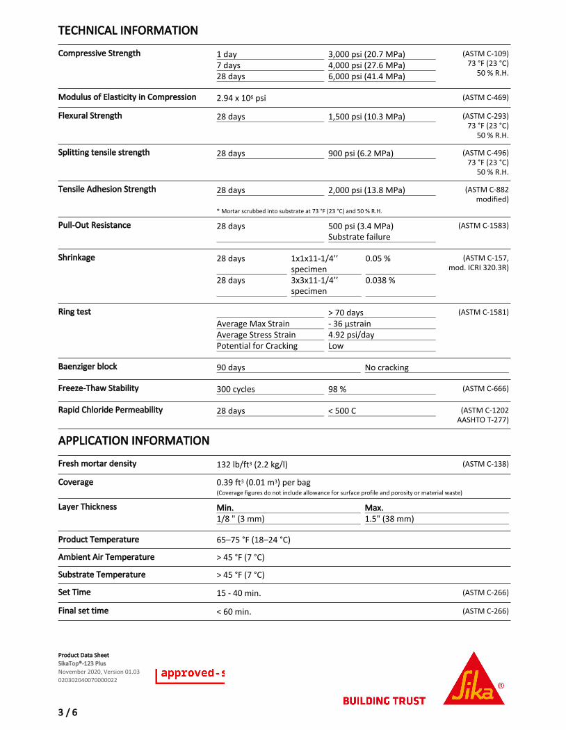
TECHNICAL INFORMATION
Compressive Strength 1 day 3,000 psi (20.7 MPa)7 days 4,000 psi (27.6 MPa)28 days 6,000 psi (41.4 MPa)
(ASTM C-109)73 °F (23 °C)
50 % R.H.
Modulus of Elasticity in Compression 2.94 x 10⁶ psi (ASTM C-469)
Flexural Strength 28 days 1,500 psi (10.3 MPa) (ASTM C-293)73 °F (23 °C)
50 % R.H.
Splitting tensile strength 28 days 900 psi (6.2 MPa) (ASTM C-496)73 °F (23 °C)
50 % R.H.
Tensile Adhesion Strength 28 days 2,000 psi (13.8 MPa) (ASTM C-882modified)
* Mortar scrubbed into substrate at 73 °F (23 °C) and 50 % R.H.
Pull-Out Resistance 28 days 500 psi (3.4 MPa)Substrate failure
(ASTM C-1583)
Shrinkage 28 days 1x1x11-1/4’’specimen
0.05 %
28 days 3x3x11-1/4’’specimen
0.038 %
(ASTM C-157,mod. ICRI 320.3R)
Ring test > 70 daysAverage Max Strain - 36 μstrainAverage Stress Strain 4.92 psi/dayPotential for Cracking Low
(ASTM C-1581)
Baenziger block 90 days No cracking
Freeze-Thaw Stability 300 cycles 98 % (ASTM C-666)
Rapid Chloride Permeability 28 days < 500 C (ASTM C-1202AASHTO T-277)
APPLICATION INFORMATION
Fresh mortar density 132 lb/ft3 (2.2 kg/l) (ASTM C-138)
Coverage 0.39 ft3 (0.01 m3) per bag(Coverage figures do not include allowance for surface profile and porosity or material waste)
Layer Thickness Min. Max.1/8 " (3 mm) 1.5" (38 mm)
Product Temperature 65–75 °F (18–24 °C)
Ambient Air Temperature > 45 °F (7 °C)
Substrate Temperature > 45 °F (7 °C)
Set Time 15 - 40 min. (ASTM C-266)
Final set time < 60 min. (ASTM C-266)
Product Data SheetSikaTop®-123 PlusNovember 2020, Version 01.03020302040070000022
3 / 6

Finishing time 20–60 minutesNote: All times start after adding Component ‘B’ to Component ‘A’ and are highly affected by temperature, relative humidity, substrate temperature, wind, sun and other job site conditions.
BASIS OF PRODUCT DATAResults may differ based upon statistical variations depending upon mixing methods and equipment, temperature, application methods, test methods, actual site conditions and curing conditions.
ENVIRONMENTAL, HEALTH AND SAFETYFor further information and advice regarding transportation, handling, storage and disposal of chemical products, user should refer to the actual Safety Data Sheets containing physical, environmental, toxicological and other safety related data. User must read the current actual Safety Data Sheets before using any products. In case of an emergency, call CHEMTREC at 1-800-424-9300, International 703-527-3887.
DIRECTIVE 2004/42/CE - LIMITATION OF EMISSIONS OF VOC
0 g/l (EPA method 24)
LIMITATIONSDo not use solvent-based curing compound.▪Size, shape and depth of repair must be carefully considered and consistent with practices recommended by ACI or ICRI.
▪
For additional information on substrate preparation, refer to ICRI Guideline No. 310.2R.
▪
If aggressive means of substrate preparation is employed, substrate strength should be tested in accordance with ACI 503 Appendix A prior to the repair application.
▪
As with all cement based materials, avoid contact with aluminum to prevent adverse chemical reaction and possible product failure. Insulate potential areas of contact by coating aluminum bars, rails, posts etc. with an appropriate epoxy such as Sikadur® 32, Hi-Mod.
▪
APPLICATION INSTRUCTIONSSURFACE PREPARATION
Surface preparationSurface must be clean and sound. Remove all deteriorated concrete, dirt, oil, grease, and other bond-inhibiting materials from the area to be repaired.
▪
Be sure repair area is not less than 1/8" (3 mm) in depth.
▪
Preparation work should be done by high pressure water blast, scabbler or other appropriate mechanical means to obtain an exposed aggregate surface profile of ±1/16" (1.6 mm) (CSP-5).
▪
To ensure optimum repair results, the effectiveness of decontamination and preparation should be assessed by a pull-off test.
▪
Saw cutting of edges is preferred and a dovetail is recommended.
▪
Substrate should be Saturated Surface Dry (SSD) with clean water prior to application. No standing water should remain during application.
▪
Priming
Reinforcing steel: Steel reinforcement should be thoroughly prepared by mechanical cleaning to remove all traces of rust. Where corrosion has occurred due to the presence of chlorides, the steel should be high pressure washed with clean water after mechanical cleaning. For priming of reinforcing steel use Sika® Armatec® 110 EpoCem (consult PDS).
▪
Concrete Substrate:
Prime the prepared substrate with a brush or sprayed ▪▪
Product Data SheetSikaTop®-123 PlusNovember 2020, Version 01.03020302040070000022
4 / 6
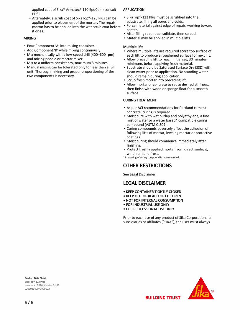
applied coat of Sika® Armatec® 110 EpoCem (consult PDS).Alternately, a scrub coat of SikaTop®-123 Plus can be applied prior to placement of the mortar. The repair mortar has to be applied into the wet scrub coat before it dries.
▪
MIXING
Pour Component ‘A’ into mixing container.▪Add Component ‘B’ while mixing continuously.▪Mix mechanically with a low-speed drill (400–600 rpm) and mixing paddle or mortar mixer.
▪
Mix to a uniform consistency, maximum 3 minutes.▪Manual mixing can be tolerated only for less than a full unit. Thorough mixing and proper proportioning of the two components is necessary.
▪
APPLICATION
SikaTop®-123 Plus must be scrubbed into the substrate, filling all pores and voids.
▪
Force material against edge of repair, working toward center.
▪
After filling repair, consolidate, then screed.▪Material may be applied in multiple lifts.▪
Multiple lifts
Where multiple lifts are required score top surface of each lift to produce a roughened surface for next lift.
▪
Allow preceding lift to reach initial set, 30 minutes minimum, before applying fresh material.
▪
Substrate should be Saturated Surface Dry (SSD) with clean water prior to application. No standing water should remain during application.
▪
Scrub fresh mortar into preceding lift.▪Allow mortar or concrete to set to desired stiffness, then finish with wood or sponge float for a smooth surface.
▪
CURING TREATMENT
As per ACI recommendations for Portland cement concrete, curing is required.
▪
Moist cure with wet burlap and polyethylene, a fine mist of water or a water based* compatible curing compound (ASTM C-309).
▪
Curing compounds adversely affect the adhesion of following lifts of mortar, leveling mortar or protective coatings.
▪
Moist curing should commence immediately after finishing.
▪
Protect freshly applied mortar from direct sunlight, wind, rain and frost.
▪
* Pretesting of curing compound is recommended.
OTHER RESTRICTIONSSee Legal Disclaimer.
LEGAL DISCLAIMER• KEEP CONTAINER TIGHTLY CLOSED • KEEP OUT OF REACH OF CHILDREN • NOT FOR INTERNAL CONSUMPTION • FOR INDUSTRIAL USE ONLY • FOR PROFESSIONAL USE ONLY Prior to each use of any product of Sika Corporation, its subsidiaries or affiliates (“SIKA”), the user must always
Product Data SheetSikaTop®-123 PlusNovember 2020, Version 01.03020302040070000022
5 / 6

read and follow the warnings and instructions on the product’s most current product label, Product Data Sheet and Safety Data Sheet which are available at usa.sika.com or by calling SIKA’s Technical Service Department at 1-800-933-7452. Nothing contained in any SIKA literature or materials relieves the user of the obligation to read and follow the warnings and instructions for each SIKA product as set forth in the current product label, Product Data Sheet and Safety Data Sheet prior to use of the SIKA product. SIKA warrants this product for one year from date of installation to be free from manufacturing defects and to meet the technical properties on the current Product Data Sheet if used as directed within the product’s shelf life. User determines suitability of product for intended use and assumes all risks. User’s and/or buyer’s sole remedy shall be limited to the purchase price or replacement of this product exclusive of any labor costs. NO OTHER WARRANTIES EXPRESS OR IMPLIED SHALL APPLY INCLUDING ANY WARRANTY OF MERCHANTABILITY OR FITNESS FOR A PARTICULAR PURPOSE. SIKA SHALL NOT BE LIABLE UNDER ANY LEGAL THEORY FOR SPECIAL OR CONSEQUENTIAL DAMAGES. SIKA SHALL NOT BE RESPONSIBLE FOR THE USE OF THIS PRODUCT IN A MANNER TO INFRINGE ON ANY PATENT OR ANY OTHER INTELLECTUAL PROPERTY RIGHTS HELD BY OTHERS. Sale of SIKA products are subject to the Terms and Conditions of Sale which are available at https://usa.sika.com/en/group/SikaCorp/termsandconditions.htmlor by calling 1-800-933-7452.
Sika Corporation201 Polito AvenueLyndhurst, NJ 07071Phone: +1-800-933-7452Fax: +1-201-933-6225usa.sika.com
Sika Mexicana S.A. de C.V.Carretera Libre Celaya Km. 8.5Fracc. Industrial BalvaneraCorregidora, QueretaroC.P. 76920Phone: 52 442 2385800Fax: 52 442 2250537
SikaTop-123Plus-en-US-(11-2020)-1-3.pdf
Product Data SheetSikaTop®-123 PlusNovember 2020, Version 01.03020302040070000022
6 / 6

Spec Component: SC-001-03/10 Sikadur 35, Hi-Mod LV
Sikadur 31, Hi-Mod Gel
DIVISION 3 -CONCRETE Section 03930 Concrete Rehabilitation
Epoxy-Injected Crack Repair
Part 1 - General 1.01 Summary
A. This specification describes the pressure injection of cracks with an epoxy resin adhesive.
1.02 Quality Assurance
A. Manufacturing qualifications: The manufacturer of the specified product shall be ISO 9001/9002 certified and have in existence a recognized ongoing quality assurance program independently audited on a regular basis.
B. Contractor qualifications: Contractor shall be qualified in the field of concrete repair and protection with a successful track record of 5 years or more. Contractor shall maintain qualified personnel who have received product training by a manufacturer's representative.
C. Install materials in accordance with all safety and weather conditions required by the manufacturer, or as modified by applicable rules and regulations of local, state and federal authorities having jurisdiction. Consult Material Safety Data Sheets for complete handling recommendations.
1.03 Delivery, Storage, and Handling
A. All materials must be delivered in original, unopened containers with the manufacturer's name, labels, product identification, and batch numbers. Damaged material must be removed from the site immediately.
B. Store all materials off the ground and protect from rain, freezing or excessive heat until ready for use.
C. Condition the specified product as recommended by the manufacturer.
1.04 Job Conditions
A. Environmental Conditions: Do not apply material if it is raining or snowing or if such conditions appear to be imminent. Minimum application temperature 40ºF (5ºC) and rising.
B. Protection: Precautions should be taken to avoid damage to any surface near the work zone due to mixing and handling of the specified product.
1.05 Submittals
A. Submit two copies of manufacturer's literature, to include: Product Data Sheets, and appropriate Material Safety Data Sheets (MSDS).
1.06 Warranty
A. Provide a written warranty from the manufacturer against defects of materials for a period of one (1) year, beginning with date of substantial completion of the project.
Appendix B - Concrete Crack Repairs

Part 2 - Products 2.01 Manufacturers
A. Sikadur 35 Hi-Mod LV, as manufactured by Sika Corporation, 1682 Marion Williamsport Road, Marion, Ohio 43302 is considered to conform to the requirements of this specification.
B. Sikadur 31 Hi-Mod Gel, as manufactured by Sika Corporation, 1682 Marion Williamsport Road, Marion, Ohio 43302 is considered to conform to the requirements of this specification
2.02 Materials
A. Epoxy resin adhesive for pressure injection of cracks shall be Sikadur 35 Hi-Mod LV:
1. Component “A” shall be a modified epoxy resin of the diglycidiether bisphenol A Type or containing suitable viscosity control agents. It shall not contain butyl glycidyl ether.
2. Component “B” shall be primarily a reaction product of a selected amine blend with an epoxy resin of the diglycidiether bisphenol A Type containing suitable viscosity control agents, pigments, and accelerators.
3. The ratio of component A: componet B shall be 2:1 by volume
4. The material shall not contain asbestos.
B. Epoxy resin adhesive for sealing of cracks & porting devices shall be Sikadur 31 Hi-Mod Gel.:
1. Component “A” shall be a modified epoxy resin of the diglycidiether bisphenol A Type or containing suitable viscosity control agents. It shall not contain butyl glycidyl ether.
2. Component “B” shall be primarily a reaction product of a selected amine blend with an epoxy resin of the diglycidiether bisphenol A type containing suitable viscosity control agents, pigments, and accelerators.
5. The ratio of Component A: Componet B shall be 1:1 by volume
6. The material shall not contain asbestos.
C. Porting devices as required for either manual or automated application. Porting devices for automated application shall be supplied from maufacturer of the pressure injection equipment.
2.03 Performance Criteria
A. Properties of the mixed epoxy resin adhesive used for the pressure injection grouting::
1. Pot Life: min. 25 minutes (60 gram mass) @ 73° F 2. Tack-FreeTime: 90oF (32oC) 1.5 to 2 hours 75oF (24oC) 3 to 3.5 hours 40oF (5oC) 14-16 hours
3. Viscosity: Approx. 375 cps.
4. Color: Clear, Amber B. Properties of the cured epoxy resin adhesive used for pressure injection of grout:
1. Compressive Strength (ASTM D-695) .min. a 3 day: 10,000 psi (69.9 MPa) b. 7 day: 11,000 psi (75.8 MPa) c. 28 day: 13,000 psi (89.6 MPa) Compressive Modulus, Psi : min. a. 7 day 320,000 psi (2,200 Mpa) 2. Shear Strength (ASTM D-732) a. 14 day: 5,100 psi (35 MPa) 3. Flexural Strength (ASTM D-790) min.
a. 14 day: 14,000 psi (97 MPa

Tangent Modulus of Elasticity in Bending min. b. 14 day: 370,000 psi (2,600 Mpa)
4. Bond Strength (ASTM C-882)
14 days (moist cure) min. a. Hardened Concrete to Hardened Concrete: 2,900 psi (15 Mpa)
5. Water Absorption (ASTM D-570) max.
a. 24 hour 0.90%
6. Tensile properties (ASTM D-638) min.
a. 7 day Tensile Strength 8,900 psi (61 Mpa)
Elongation at Break 5.4%
b. 14 day Modulus of Elasticity 4.1 x 10⁵ psi (2,800 Mpa)
C. Properties of the mixed epoxy resin adhesive used for sealing of cracks & porting devices::
1. Pot Life: min. 60 minutes (500 gram mass) @ 73° F 2. Tack-FreeTime: @73oF(23oC) 1.5 – 2.5 hours @ 30 mils thick Consistency: Non-Sag paste
3. Color: Concrete Gray D. Properties of the cured epoxy resin adhesive used for sealing of cracks & porting devices:
1. Compressive Strength (ASTM D-695) .min. @ 73F a 1 day: 13,000 psi (89.6 MPa) b. 3 day: 14,000 psi (96.5 MPa) c. 28 day: 16,000 psi (110.3 MPa) Compressive Modulus, Psi : min. a. 7 day 795,000 psi (5,485 Mpa) 2. Shear Strength (ASTM D-732) a. 14 day: 4,600 psi (31.7 MPa) 3. Flexural Strength (ASTM D-790) min.
a. 14 day: 6,100 psi (42 MPa) Tangent Modulus of Elasticity in Bending .min. b. 14 day: 1.67 x 10⁶ psi (11,520 MPa)
4. Bond Strength (ASTM C-882)
14 day (moist cure) min. a. Hardened Concrete to Hardened Concrete 2,900 psi (20 Mpa)
5. Water Absorption (ASTM D-570) max.
a. 24 hour 0.79%
6.Tensile properties (ASTM D-638) min.
a. 7 day Tensile Strength 3,300 psi (22.7 Mpa)
Elongation at Break 0.9%
Note: Tests above were performed with material & curing conditions at 73F & 45-55% relative humidity.

Part 3 - Execution 3.01 Mixing and Application
A. Mixing the epoxy resin adhesive for sealing the cracks & porting devices: Premix each component. Proportion equal parts by volume of Component “A” and Component “B” into a clean, dry mixing pail. Mix thoroughly for 3 minutes with a jiffy paddle on a low-speed (400-600 rpm) drill. Mix only that quantity of material that can be used within its potlife (60 minutes @ 73F).
B. Mixing of the epoxy resin adhesive used for the pressure injection grouting:
1. Manual: Proportion two parts by volume of Component “A” to one part Component “B” into a clean, dry mixing pail. Mix thoroughly for 3 minutes with a jiffy paddle on a low-speed (400-600 rpm) drill. Mix only that quantity of material that can be used within its potlife (20-30 minutes 73F).
C. Placement procedure:
1. The epoxy resin adhesive for sealing the cracks & porting device: Set the porting devices as required by the epuipment manufacturer. Spacing of the porting devices shall be accomplished as required to achieve the travel of the epoxy resin for the pressure injection grouting between ports and fill the cracks to the maximum. On structures open on both sides, provide porting devices on opposite sides at staggered elevations. Apply the mixed epoxy resin adhesive for sealing over cracks and around each porting device to provide an adequate seal to prevent the escape of the epoxy resin adhesive for the injection grouting. Where required by the Engineer, apply the epoxy resin adhesive for sealing in such a manner that minimal defacing or discoloration of the substrate shall result.
2. The epoxy resin adhesive for the pressure injection grouting:
Manual: Load the mixed epoxy resin adhesive for grouting into a disposable caulking cartridge or bulk-loading caulking gun. Inject the prepared cracks with a consant pressure in order to achieve maximum filling & penetration without the inclusion of air pockets or voids in the epoxy resin adhesive. Begin the pressure injection at the widest part of the crack being injected and continue until there is the appearance of epoxy resin adhesive at an adjacent port, thus indicating travel. When travel is indicated, to discontinue or continue the pressure injection from that port should be made by the contractor based on his experience, with the approval of the Engineer. Continue procedure until pressure injectable cracks has been filled.
Automated: Dispense the epoxy resin adhesive for grouting under constant pressure in accordance with prcedures recommended by the equipment manufacturerer as required to achieve maximum filling and penetration of the prepared cracks without the inclusion of air pockets or voids in the epoxy resin adhesive. The pressure injection of single or multiple ports, by use of a manifold system, is possible. This decision should be made by the contractor, with the approval of the Engineer. Continue the approved procedure until all pressure injectable cracks have been filled.
D. If penetration of any cracks is impossible, consult the Engineer before discontinuing the injection procedure. If modification of the proposed procedure is required to fill the cracks, submit said modification in writing to the Engineer for acceptance prior to proceeding.
E. Adhere to all limitations and cautions for the epoxy resin adhesive in the manufacturers current printed literature.
3.02 Cleaning
A. After the epoxy resin adhesive for grouting has cured, the epoxy resin adhesive for sealing cracks and porting devices shall be removed as required by the Engineer. Clean the substrate in a manner to produce a finish appearance acceptable to the Owner.
B. The uncured epoxy resin adhesive can be cleaned from tools with approved solvent. The cured epoxy resin adhesive can only be removed mechanically.
C. Leave finished work and work area in a neat, clean condition without evidence of spillovers onto adjacent areas.

Sikadur 35, Hi-Mod LV Crack Filler
Sikadur 31, Hi-Mod Gel
Cap Seal
SC001
1.Set porting devices over cracks. 2. Place mixed Sikadur 31, Hi-Mod Gel epoxy resin adhesive over cracks and
around each injection port a minimum of 1" wide by a ¼" thick. 3. Allow sufficient time for epoxy resin adhesive cap seal to set before injecting. 4. When the cap seal has cured, inject Sikadur 35, Hi-Mod LV with steady
pressure. 5. Use automated injection equipment or manual method.
12
4
Concrete Restoration Systems by Sika Corporation, 201 Polito Avenue, Lyndhurst, NJ 07071

The preceding specifications are provided by Sika Corporation as a guide for informational purposes only and are not intended to replace sound engineering practice and judgment and should not be relied upon for that purpose. SIKA CORPORATION MAKES NO WARRANTY OF ANY KIND, EITHER EXPRESS OR IMPLIED, AS TO THE ACCURACY, COMPLETENESS OR THE CONTENTS OF THESE GUIDE SPECIFICATIONS. Sika Corporation assumes no liability with respect to the provision or use of these guide specifications, nor shall any legal relationship be created by, or arise from, the provision of such specifications SIKA SHALL NOT BE RESPONSIBLE UNDER ANY LEGAL THEORY TO ANY THIRD PARTY FOR ANY DIRECT OR CONSEQUENTIAL DAMAGES OF ANY KIND ARISING FROM THE USE OF THESE GUIDE SPECIFICATIONS. The specifier, architect, engineer or design professional or contractor for a particular project bears the sole responsibility for the preparation and approval of the specifications and determining their suitability for a particular project or application. Prior to each use of any Sika product, the user must always read and follow the warnings and instructions on the product's most current Technical Data Sheet, product label and Material Safety Data Sheet which are available at www.sikaconstruction.com or by calling (201) 933-7452. Nothing contained in any Sika materials relieves the user of the obligation to read and follow the warnings and instructions for each Sika product as set forth in the current Technical Data Sheet, product label and Material Safety Data Sheet prior to product use.

Product Data SheetSikadur®-31 Hi-Mod Gel LPLOctober 2018, Version 01.01020204030010000107
PRODUCT DATA SHEET
Sikadur®-31 Hi-Mod Gel LPLHigh-modulus, high-strength, structural, extended pot life, epoxy paste adhesive
PRODUCT DESCRIPTIONSikadur®-31 Hi-Mod Gel LPL is a 2-component, 100 % solids, moisture-insensitive, high-modulus, high-strength, structural epoxy paste adhesive. It conforms to the current ASTM C-881, Types I and IV, Grade-3, Class-C and AASHTO M-235 specifications.
USESSikadur®-31 Hi-Mod Gel LPL may only be used by experienced professionals.
Structural bonding of concrete, masonry, metals, wood, etc. to a maximum glue line of 1/8 in. (3mm)
▪
Seals cracks and around injection ports prior to pressure-injection grouting
▪
Interior, vertical, and overhead repair of concrete as an epoxy mortar binder
▪
As a pick-proof sealant around windows, doors, lock-ups etc. inside correctional facilities
▪
CHARACTERISTICS / ADVANTAGESExtended pot life▪Moisture-tolerant before, during, and after cure▪High-modulus, high-strength, structural paste adhesive▪Excellent adhesion to concrete, masonry, metals, wood, and most structural materials
▪
Paste consistency ideal for vertical and overhead applications
▪
Fast-setting and strength-producing adhesive▪Convenient easy mix ratio A:B = 2:1 by volume▪
PRODUCT INFORMATION
Packaging 3 gal. (11 L) units
Color Concrete gray
Shelf Life 24 months in original, unopened containers
Storage Conditions Store dry at 40–95 °F (4–35 °C).Condition material to 65–75 °F (18–24 °C) before using.
Consistency Non-sag paste
TECHNICAL INFORMATION
1 / 4

Compressive Strength 36 hours 6,400 psi (41.4 MPa)2 day 7,000 psi (41.4 MPa)3 day 9,000 psi (48.3 MPa)
(ASTM D-695)73 °F (23 °C)
50 % R.H.
Slant Shear Strength Bond Strength Hardened Concrete to Hardened Concrete
2 days 2,000 psi (20.7 MPa)14 day (moist cure) 2,300 psi (20.0 MPa)
(ASTM C-882)73 °F (23 °C)
50 % R.H.
Heat Deflection Temperature 124 °F (51 °C)(7 days [fiber stress loading = 264 psi (1.8 MPa)]
(ASTM D-648)
APPLICATION INFORMATION
Mixing Ratio Component ‘A’ : Component ‘B’ = 2:1 by volume
Coverage 1 gal. yields 231 cu. in. of epoxy paste adhesive and grout. 1 gal. mixed with 1 gal. by loose volume of oven-dried aggregate yields approximately 346 cu. in. of epoxy mortar.
Pot Life Approximately 120 minutes at 73 °F (23 °C) (gal., L volume) Approximately 60 minutes at at 90 °F (32 °C) (gal., L volume)
Cure Time Tack-Free Time: 6–8 hours
APPLICATION INSTRUCTIONSSUBSTRATE PREPARATION
Surface must be clean and sound. It may be dry or damp, but free of standing water. Remove dust, laitance, grease, curing compounds, impregnations, waxes, foreign particles, disintegrated materials and any other contaminants. Preparation Work: Concrete - Sandblast or use other approved mechanical methods. Steel - Blast clean or use other equivalent mechanical means to achieve a white metal finish.
MIXING
Pre-mix each component. Proportion 1 part Component ‘B’ to 2 parts Component ‘A’ by volume into a clean pail. Mix thoroughly for 3 minutes with Sika paddle on low-speed (400–600 rpm) drill until uniform in color. Mix only that quantity that can be used within its pot life. To prepare an epoxy mortar: Slowly add up to 1 part by loose volume of an oven-dried aggregate to 1 part of the mixed Sikadur®-31 Hi-Mod Gel LPL and mix until uniform in consistency.
APPLICATION METHOD / TOOLS
As a structural adhesive - Apply the neat mixed Sikadur®-31 Hi-Mod Gel LPL, to the mating or nonmating prepared substrates. Work into the substrate for positive adhesion. Secure the bonded unit firmly into place until the adhesion has cured. Glue line should not
exceed 1/8 in. (3 mm). To seal cracks for injection grouting - Place the neat mixed material over the cracks to be pressure injected and around each injection port. Allow sufficient time to set before pressure injecting. For interior vertical and overhead patching - Place the prepared mortar in void, working the material into the prepared substrate, filling the cavity. Strike off level. Lifts should not exceed 1 in. (25 mm). As a pick-proof sealant - Use automated or manual method. Apply an appropriate size bead of material around the area being sealed. Seal with neat Sikadur®-31 Hi-Mod Gel LPL.
LIMITATIONSMinimum substrate and ambient temperature 40 °F (4 °C).
▪
Do not thin. Addition of solvents will prevent proper cure.
▪
Use oven-dried aggregate only.▪Maximum epoxy mortar thickness is 1 in. (25 mm) per lift.
▪
Epoxy mortar is for interior use only. Material is a vapor barrier after cure.
▪
Minimum age of concrete must be 21–28 days, depending upon curing and drying conditions, for mortar applications.
▪
Porous substrates must be tested for moisture-vapor transmission prior to mortar applications.
▪
Not for sealing cracks under hydrostatic pressure at the ▪
Product Data SheetSikadur®-31 Hi-Mod Gel LPLOctober 2018, Version 01.01020204030010000107
2 / 4

time of application.Not an aesthetic product. Color may alter due to variations in lighting and/or UV exposure.
▪
BASIS OF PRODUCT DATAResults may differ based upon statistical variations depending upon mixing methods and equipment, temperature, application methods, test methods, actual site conditions and curing conditions.
OTHER RESTRICTIONSSee Legal Disclaimer.
ENVIRONMENTAL, HEALTH AND SAFETYFor further information and advice regarding transportation, handling, storage and disposal of chemical products, user should refer to the actual Safety Data Sheets containing physical, environmental, toxicological and other safety related data. User must read the current actual Safety Data Sheets before using any products. In case of an emergency, call CHEMTREC at 1-800-424-9300, International 703-527-3887.
LEGAL DISCLAIMER• KEEP CONTAINER TIGHTLY CLOSED • KEEP OUT OF REACH OF CHILDREN • NOT FOR INTERNAL CONSUMPTION • FOR INDUSTRIAL USE ONLY • FOR PROFESSIONAL USE ONLY Prior to each use of any product of Sika Corporation, its subsidiaries or affiliates (“SIKA”), the user must always read and follow the warnings and instructions on the product’s most current product label, Product Data Sheet and Safety Data Sheet which are available at usa.sika.com or by calling SIKA’s Technical Service Department at 1-800-933-7452. Nothing contained in any SIKA literature or materials relieves the user of the obligation to read and follow the warnings and instructions for each SIKA product as set forth in the current product label, Product Data Sheet and Safety Data Sheet prior to use of the SIKA product. SIKA warrants this product for one year from date of installation to be free from manufacturing defects and to meet the technical properties on the current Product Data Sheet if used as directed within the product’s shelf life. User determines suitability of product for intended use and assumes all risks. User’s and/or buyer’s sole remedy shall be limited to the purchase price or replacement of this product exclusive of any labor costs. NO OTHER WARRANTIES EXPRESS OR IMPLIED SHALL APPLY INCLUDING ANY WARRANTY OF MERCHANTABILITY OR FITNESS FOR A PARTICULAR PURPOSE. SIKA SHALL NOT BE LIABLE UNDER ANY LEGAL THEORY FOR SPECIAL OR CONSEQUENTIAL DAMAGES. SIKA SHALL NOT BE RESPONSIBLE FOR THE USE OF THIS PRODUCT IN A MANNER TO INFRINGE ON ANY PATENT OR ANY OTHER INTELLECTUAL PROPERTY RIGHTS HELD BY OTHERS.
Product Data SheetSikadur®-31 Hi-Mod Gel LPLOctober 2018, Version 01.01020204030010000107
3 / 4

Sale of SIKA products are subject to the Terms and Conditions of Sale which are available at https://usa.sika.com/en/group/SikaCorp/termsandconditions.htmlor by calling 1-800-933-7452.
Sika Corporation201 Polito AvenueLyndhurst, NJ 07071Phone: +1-800-933-7452Fax: +1-201-933-6225usa.sika.com
Sika Mexicana S.A. de C.V.Carretera Libre Celaya Km. 8.5Fracc. Industrial BalvaneraCorregidora, QueretaroC.P. 76920Phone: 52 442 2385800Fax: 52 442 2250537
Sikadur-31Hi-ModGelLPL-en-US-(10-2018)-1-1.pdf
Product Data SheetSikadur®-31 Hi-Mod Gel LPLOctober 2018, Version 01.01020204030010000107
4 / 4

Product Data SheetSikadur®-35 Hi-Mod LVJuly 2021, Version 01.02020204030010000189
PRODUCT DATA SHEET
Sikadur®-35 Hi-Mod LVHigh modulus, low viscosity, high strength epoxy grouting/sealing/binder adhesive
PRODUCT DESCRIPTIONSikadur®-35 Hi-Mod LV is a 2-component, 100 % solids, moisture-tolerant, low-viscosity, high-strength, multipurpose, epoxy resin adhesive. It conforms to the current ASTM C-881, Types I, II, and IV, Grade-1, Class C* and AASHTO M-235 specifications.*except for gel time
USESSikadur®-35 Hi-Mod LV may only be used by experienced professionals.
Pressure-injection of cracks in structural concrete, masonry, wood, etc.
▪
Gravity-feed of cracks in horizontal concrete and masonry.
▪
Epoxy resin binder for epoxy mortar patching and overlay of interior, horizontal surfaces.
▪
Seal interior slabs and exterior above-grade slabs from water, chlorides, and mild chemical attack; also improves wearability.
▪
CHARACTERISTICS / ADVANTAGESSuper low viscosity.▪Convenient easy mix ratio A:B = 2:1 by volume.▪Unique, high-strength, structural adhesive for “can’t dry” surfaces.
▪
Deep penetrating and tenacious bonding of cracks in structural concrete.
▪
High-early-strength developing adhesive.▪Excellent chemical resistance in flooring systems.▪
PRODUCT INFORMATION
Packaging 3 gal. (11 L) units; 1 gal. (3.8 L) units; 12 fl. oz. (355 ml) units, 12/case
Color Clear, amber
Shelf Life 2 years in original, unopened containers.
Storage Conditions Store dry at 40–95 °F (4–35 °C). Condition material to 65–75 °F (18–24 °C) before using.
Viscosity Approx. 375 cps.
TECHNICAL INFORMATION
1 / 5

Compressive Strength Neat
40 °F (4 °C) 73 °F (23 °C) 90 °F (32 °C)4 hours - - -8 hours - 180 psi (1.2
MPa)3,200 psi (22.1 MPa)
16 hours - 4,500 psi (31.1 MPa)
6,300 psi (43.5 MPa)
1 day - 6,000 psi (41.4 MPa)
9,100 psi (62.8 MPa)
3 days 4,000 psi (27.6 MPa)
10,700 psi (73.8 MPa)
10,500 psi (72.5 MPa)
7 days 6,800 psi (46.9 MPa)
11,000 psi (75.9 MPa)
10,500 psi (72.5 MPa)
14 days 10,300 psi (71.1 MPa)
12,000 psi (82.8 MPa)
10,500 psi (72.5 MPa)
28 days 12,400 psi (85.6 MPa)
13,000 psi (89.7 MPa)
10,500 psi (72.5 MPa)
(ASTM D-695)50 % R.H.
Epoxy Mortar (1: 5)
40 °F (4 °C) 73 °F (23 °C) 90 °F (32 °C)4 hours - - 800 psi (5.5
MPa)8 hours - - 4,100 psi
(28.3 MPa)16 hours - 400 psi (2.8
MPa)5,700 psi (39.3 MPa)
1 day 120 psi (0.8 MPa)
5,000 psi (34.5 MPa)
6,900 psi (47.6 MPa)
3 days 6,200 psi (42.8 MPa)
6,800 psi (46.9 MPa)
7,000 psi (48.3 MPa)
7 days 6,300 psi (43.5 MPa)
7,900 psi (54.5 MPa)
8,800 psi (60.7 MPa)
14 days 6,800 psi (46.9 MPa)
8,500 psi (58.7 MPa)
8,800 psi (60.7 MPa)
28 days 7,000 psi (48.3 MPa)
8,600 psi (59.3 MPa)
8,800 psi (60.7 MPa)
(ASTM D-695)50 % R.H.
Modulus of Elasticity in Compression Neat Mortar7 days 3.2 x 10⁵ psi
(2,200 MPa)-
28 days - 8.1 x 10⁵ psi (5,600 MPa)
(ASTM D-695)73 °F (23 °C)
50 % R.H.
Flexural Strength Neat Mortar14 day 14,000 psi
(96,6 MPa)2,200 psi(15,2 MPa)
(ASTM D-790)73 °F (23 °C)
50 % R.H.
Modulus of Elasticity in Flexure Neat Mortar14 days 3.7 x 10⁵ psi
(2,600 MPa)9.5 X 10⁵ (6,500 MPa)
(ASTM D-790)73 °F (23 °C)
50 % R.H.
Product Data SheetSikadur®-35 Hi-Mod LVJuly 2021, Version 01.02020204030010000189
2 / 5

Tensile Strength Neat Mortar7 days 8,900 psi
(61.4 MPa)840 psi(5.8 MPa)
(ASTM D-638)73 °F (23 °C)
50 % R.H.
Tensile Modulus of Elasticity Neat Mortar14 days 4.1 X 10⁵ psi
(2800 MPa)7.6 X 10⁵ psi(5200 MPa)
(ASTM D-638)73 °F (23 °C)
50 % R.H.
Elongation at Break Neat Mortar7 day 5.4 % 0.3 %
(ASTM D-638)73 °F (23 °C)
50 % R.H.
Tensile Adhesion Strength 2 days (moist cure) 4,000 psi(27.6 MPa)
14 days (moist cure) 2,900 psi(20.0 MPa)
2 days (dry cure) 2,800 psi(19.3 MPa)
(ASTM C-882): Hardened concrete
to hardenedconcrete
73 °F (23 °C) 50 % R.H.
Shear Strength Neat Mortar14 days 5,100 psi
(35,2 MPa)2,300 psi(15.9 MPa)
(ASTM D-732)73 °F (23 °C)
50 % R.H.
Heat deflection temperature Neat Mortar7 day 124 °F (51 °C) 129 °F (54 °C)
(ASTM D-648)[fiber stress loading =
264 psi (1.8 MPa)]
Water Absorption 7 days 0.27 % (ASTM D-570)73 °F (23 °C)
50 % R.H.
APPLICATION INFORMATION
Mixing Ratio Component "A": Component "B" = 2:1 by volume.
Coverage 1 gal. yields 231 in3 of adhesive and grout. 1 gal. of adhesive, when mixed with 5 gal. by loose volume of oven-dried aggregate, yields approximately 808.5 in3 of epoxy mortar.
Pot Life Approx. 25 minutes (mass of 60 grams)
Cure Time Tack-Free Time 40 °F (4 °C) 73 °F (23 °C) 95 °F (35 °C)(3-5 mils) Neat 14–16 hours 3–3.5 hours 1.5–2 hours
Product Data SheetSikadur®-35 Hi-Mod LVJuly 2021, Version 01.02020204030010000189
3 / 5

BASIS OF PRODUCT DATAResults may differ based upon statistical variations depending upon mixing methods and equipment, temperature, application methods, test methods, actual site conditions and curing conditions.
LIMITATIONSMinimum substrate and ambient temperature 40ºF (4ºC).
▪
Do not thin with solvents. Consult Technical Service at 800-933-7452.
▪
Use oven-dried aggregate only.▪Maximum epoxy mortar thickness is 1.5 in. (38 mm) per lift.
▪
Epoxy mortar is for interior use only.▪Do not seal exterior slabs on grade.▪Minimum age of concrete must be 21–28 days, depending on curing and drying conditions, for mortar and to seal slabs.
▪
Porous substrates must be tested for moisture-vapor transmission prior to application.
▪
Not for injection of cracks under hydrostatic pressure at the time of application.
▪
Do not inject cracks greater than 1/4 in. (6 mm) Consult Technical Service.
▪
Not an aesthetic product. Color may alter due to variations in lighting and/or UV exposure.
▪
ENVIRONMENTAL, HEALTH AND SAFETYFor further information and advice regarding transportation, handling, storage and disposal of chemical products, user should refer to the actual Safety Data Sheets containing physical, environmental, toxicological and other safety related data. User must read the current actual Safety Data Sheets before using any products. In case of an emergency, call CHEMTREC at 1-800-424-9300, International 703-527-3887.
APPLICATION INSTRUCTIONSSUBSTRATE PREPARATION
Surface must be clean and sound. It may be dry or damp, but free of standing water. Remove dust, laitance, grease, curing compounds, impregnations, waxes, foreign particles and disintegrated materials. Concrete - Blast clean, shot blast or use other approved mechanical means to provide an open roughened texture. Steel - Should be cleaned and prepared thoroughly by blast cleaning.
MIXING
Proportion 1 part Component ‘B’ to 2 parts Component ‘A’ by volume into a clean pail. Mix thoroughly for 3 minutes with Sika Paddle on low-speed (400–600 rpm) drill until uniformly blended. Mix only that quantity that
can be used within its pot life. To prepare an epoxy mortar, slowly add 4–5 parts by loose volume of an ovendried aggregate to 1 part of the mixed Sikadur®-35 Hi-Mod LV and mix until uniform in consistency.
APPLICATION METHOD / TOOLS
To gravity feed cracks - Blow vee-notched crack clean with oil-free compressed air. Pour neat Sikadur®-35 Hi-Mod LV into vee-notched crack. Continue placement until completely filled. Seal underside of slab prior to filling if cracks reflect through. To pressure-inject cracks - Use automated injection equipment or manual method. Set appropriate injection ports based on system used. Seal ports and crack with Sikadur® 31, Hi-Mod Gel or Sikadur® 33. When the epoxy adhesive seal has cured, inject Sikadur®-35 Hi-Mod LV with steady pressure. Consult Technical Service for additional information. To seal slabs - Spread neat Sikadur®-35 Hi-Mod LV over slab. Allow penetration. Remove excess to prevent surface film. Seal interior slabs and above-grade exterior slabs only. For an epoxy mortar - Prime prepared surface with neat Sikadur®-35 Hi-Mod LV. Place prepared epoxy mortar before primer becomes tack-free. Place the epoxy mortar using trowels. Compact and level with vibrating screed or trowels. Finish with finishing trowel. Sikadur®-35 Hi-Mod LV mortar is for interior use only.
OTHER RESTRICTIONS
LEGAL DISCLAIMER• KEEP CONTAINER TIGHTLY CLOSED • KEEP OUT OF REACH OF CHILDREN • NOT FOR INTERNAL CONSUMPTION • FOR INDUSTRIAL USE ONLY • FOR PROFESSIONAL USE ONLY Prior to each use of any product of Sika Corporation, its subsidiaries or affiliates (“SIKA”), the user must always read and follow the warnings and instructions on the product’s most current product label, Product Data Sheet and Safety Data Sheet which are available at usa.sika.com or by calling SIKA’s Technical Service Department at 1-800-933-7452. Nothing contained in any SIKA literature or materials relieves the user of the obligation to read and follow the warnings and instructions for each SIKA product as set forth in the current product label, Product Data Sheet and Safety Data Sheet prior to use of the SIKA product. SIKA warrants this product for one year from date of installation to be free from manufacturing defects and to meet the technical properties on the current Product Data Sheet if used as directed within the product’s shelf life. User determines suitability of product for intended use and assumes all risks. User’s and/or buyer’s sole
Product Data SheetSikadur®-35 Hi-Mod LVJuly 2021, Version 01.02020204030010000189
4 / 5

remedy shall be limited to the purchase price or replacement of this product exclusive of any labor costs. NO OTHER WARRANTIES EXPRESS OR IMPLIED SHALL APPLY INCLUDING ANY WARRANTY OF MERCHANTABILITY OR FITNESS FOR A PARTICULAR PURPOSE. SIKA SHALL NOT BE LIABLE UNDER ANY LEGAL THEORY FOR SPECIAL OR CONSEQUENTIAL DAMAGES. SIKA SHALL NOT BE RESPONSIBLE FOR THE USE OF THIS PRODUCT IN A MANNER TO INFRINGE ON ANY PATENT OR ANY OTHER INTELLECTUAL PROPERTY RIGHTS HELD BY OTHERS. Sale of SIKA products are subject to the Terms and Conditions of Sale which are available at https://usa.sika.com/en/group/SikaCorp/termsandconditions.htmlor by calling 1-800-933-7452.
Sika Corporation201 Polito AvenueLyndhurst, NJ 07071Phone: +1-800-933-7452Fax: +1-201-933-6225usa.sika.com
Sika Mexicana S.A. de C.V.Carretera Libre Celaya Km. 8.5Fracc. Industrial BalvaneraCorregidora, QueretaroC.P. 76920Phone: 52 442 2385800Fax: 52 442 2250537
Sikadur-35Hi-ModLV-en-US-(07-2021)-1-2.pdf
Product Data SheetSikadur®-35 Hi-Mod LVJuly 2021, Version 01.02020204030010000189
5 / 5

REFERENCE TECHNICALSPECIFICATIONS

TECHNICAL SPECIFICATIONS INDEX
SECTION DESCRIPTION PAGES
05210 Steel Joists 08
05310 Steel Deck 12
Division 1 -
01300 General Requirements Administrative Requirements
06
01330 Submittals Procedure 05
01400 Quality Requirements 05
014219 Reference Standards 10
01500 Temporary Facilities and Controls 06
01600 Products Requirements 03
01700 Execution Requirements 04
Division 2 - 02 41 00
Site Work Selective Demolition
04
02700 Chain Link Fences 04
02763 Painted Pavement Markings 08
Division 3 - 03200
Concrete Concrete Reinforcement
03
03300 Cast-In-Place Concrete 11
03310 Concrete Works 25
035216 Lightweight Cellular Insulating Concrete 07
03732 Concrete Repair 04
03930 Concrete Rehabilitation Epoxy-Injected
Crack Repair
05
Division 4 - NO ITEMS ON THIS DIVISION
Division 5 -
05120
Metals
Structural Steel
14
05520
Handrails and Railings
02
05700 Ornamental Metals 03
05810 Expansion Joint Cover Assemblies 08
Division 6 - NO ITEMS ON THIS DIVISION
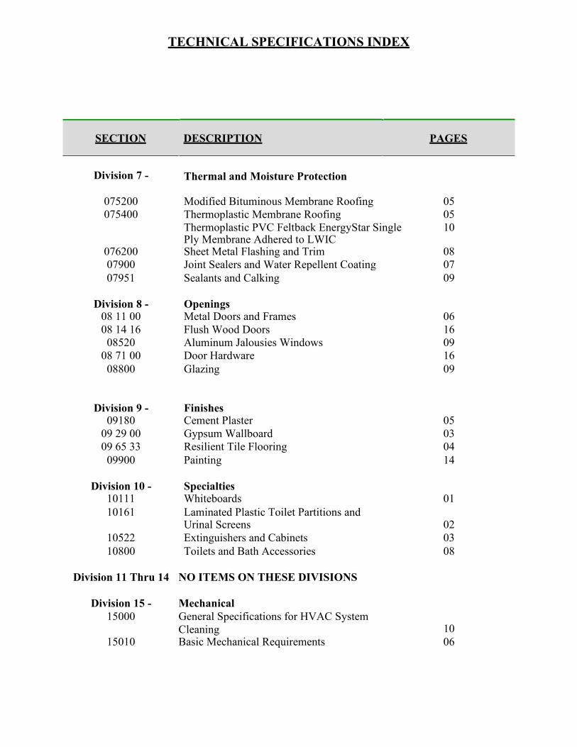
TECHNICAL SPECIFICATIONS INDEX
SECTION DESCRIPTION PAGES
083513 Accordion Folding Doors 04
Division 7 -
Thermal and Moisture Protection
075200 Modified Bituminous Membrane Roofing 05
075400 Thermoplastic Membrane Roofing 05
Thermoplastic PVC Feltback EnergyStar Single Ply Membrane Adhered to LWIC
10
076200 Sheet Metal Flashing and Trim 08
07900 Joint Sealers and Water Repellent Coating 07
07951 Sealants and Calking 09
Division 8 - 08 11 00
Openings Metal Doors and Frames
06
08 14 16 Flush Wood Doors 16
08520 Aluminum Jalousies Windows 09
08 71 00 Door Hardware 16
08800 Glazing 09
Division 9 - 09180
Finishes Cement Plaster
05
09 29 00 Gypsum Wallboard 03
09 65 33 Resilient Tile Flooring 04
09900 Painting 14
Division 10 - 10111
Specialties Whiteboards
01
10161 Laminated Plastic Toilet Partitions and Urinal Screens
02
10522 Extinguishers and Cabinets 03
10800 Toilets and Bath Accessories 08
Division 11 Thru 14 NO ITEMS ON THESE DIVISIONS
Division 15 -
15000
Mechanical
General Specifications for HVAC System
Cleaning
10
15010 Basic Mechanical Requirements 06

TECHNICAL SPECIFICATIONS INDEX
SECTION DESCRIPTION PAGES
Division 15 - 15050
Mechanical (Cont.’) Basic Mechanical Materials and Methods
14
15060 Hangers and Supports 11
15081 Duct Insulation 12
15083 Pipe Insulation 19
15110 Valves 22
15121 Pipe Expansion Fittings and Loops 08
15180 Heating and Cooling Piping 12
15400 Plumbing 12
15420 Drainage and Vent Piping 09
15720 Air Handling Units 07
15781 Packaged Rooftop Cooling Units 08
15801 General Specifications for A/C Works 14
15815 Metal Ducts 13
15820 Duct Accessories 11
15839 Ductwork 03
15855 Diffusers, Registers and Grilles 04
15990 Testing, Adjusting and Balancing 25
Division 16 - 16000
Electrical Electrical Work – General
06
16011 Panelboards 02
16020 Conduit Work 02
16030 Boxes 02
16040 Lighting Fixtures 10
16041 Wiring Devices 03
16050 Conductors 02
16060 Grounding and Bonding 04
16075 Electrical Identification 05
16095 Minor Electrical Demolition 05
16485 Lighting Contactors 01
16500 Time Switches 02
16540 Fire Alarm System 09 16600 Emergency Generator 15
CLARIFYING NOTE: All sections of technical specifications have been provided as PBA
reference to stipulates a minimum quality standard for materials, products, and
construction/installation procedures. Codes and regulations indicated on such sections
should be outdated. Therefore, any prospective bidder must consider, as part of his
proposal, all latest federal, state, and local laws, codes, and regulations, applicable for
each item of work included on this Contract.

01300 - 1
SECTION 01300
ADMINISTRATIVE REQUIREMENTS
1 GENERAL
1.1 SECTION INCLUDES
A. Coordination and project conditions.
B. Preconstruction meeting.
C. Site mobilization meeting.
D. Progress meetings.
E. Pre-installation meetings.
F. Cutting and patching.
G. Special procedures.
1.2 COORDINATION AND PROJECT CONDITIONS
A. Coordinate scheduling, submittals, and Work of various sections of Project
Manual to ensure efficient and orderly sequence of installation of interdependent
construction elements, with provisions for accommodating items installed later.
B. Verify utility requirements and characteristics of operating equipment are compatible
with building utilities. Coordinate work of various sections having interdependent
responsibilities for installing, connecting to, and placing in service, operating
equipment.
C. Coordinate space requirements, supports, and installation of mechanical and
electrical Work indicated diagrammatically on Drawings. Follow routing shown for
pipes, and conduit, as closely as practicable; place runs parallel with lines of
building. Utilize spaces efficiently to maximize accessibility for other installations,
for maintenance, and for repairs.
D. In finished areas except as otherwise indicated, conceal pipes, and wiring within
construction. Coordinate locations of fixtures and outlets with finish elements.
E. Coordinate completion and clean-up of Work of separate sections in preparation
for Substantial Completion.

01300 - 2
F. After Owner occupancy of premises, coordinate access to site for correction of
defective Work and Work not in accordance with Contract Documents, to minimize
disruption of Owner's activities.
1.3 PRECONSTRUCTION MEETING
A. Owner and Owner=s Representatives will schedule meeting after Notice of Award.
B. Attendance Required: Owner and Owner=s Representatives, Representatives of
Governmental or other regulatory Agencies, Architect/Engineer and his Consultants,
Contractor and Sub-Contractors as Pertinent to Agenda.
C. Agenda:
1. Execution of Owner-Contractor Agreement.
2. Submission of executed bonds and insurance certificates.
3. Distribution of Contract Documents.
4. Submission of list of Subcontractors, list of products, schedule of values,
and progress schedule.
5. Designation of personnel representing parties in Contract, and
Architect/Engineer.
6. Procedures and processing of field decisions, submittals, and substitutions,
applications for payments, proposal request, Change Orders, and Contract
closeout procedures.
7. Scheduling.
D. Record minutes and distribute copies within 4 days after meeting to participants.
1.4 SITE MOBILIZATION MEETING
A. Owner and Owner=s Representatives will schedule meeting at Project site prior to
Contractor occupancy.
B. Attendance Required: Owner and Owner=s Representatives, Representatives of
Governmental or other regulatory Agencies, Architect/Engineer and his Consultants,
Contractor and major Subcontractors.
C. Agenda:
1. Use of premises by Owner and Contractor.
2. Owner's requirements and occupancy.
3. Construction facilities and controls provided by Owner.
4. Temporary utilities provided by Owner.
5. Survey and building layout.
6. Security and housekeeping procedures.
7. Schedules.
8. Application for payment procedures.
9. Procedures for testing.

01300 - 3
10. Procedures for maintaining record documents.
11. Requirements for start-up of equipment.
12. Inspection and acceptance of equipment put into service during
construction period.
D. Record minutes and distribute copies within 4 days after meeting to participants.
1.5 PROGRESS MEETINGS
A. Schedule and administer meetings throughout progress of the Work at maximum
weekly intervals.
B. Owner and Owner=s Representatives will make arrangements for meetings,
prepare agenda with copies for participants, and preside at meetings.
C. Attendance Required: Owner and Owner=s Representatives, Job Superintendent,
Major Subcontractor and Suppliers, Representatives of Government or other
regulatory Agencies, Architect/Engineer As appropriate to agenda topics for each
meeting.
D. Agenda:
1. Review minutes of previous meetings.
2. Review of Work progress.
3. Field observations, problems, and decisions.
4. Identification of problems impeding planned progress.
5. Review of submittals schedule and status of submittals.
6. Review of off-site fabrication and delivery schedules.
7. Maintenance of progress schedule.
8. Corrective measures to regain projected schedules.
9. Planned progress during succeeding work period.
10. Coordination of projected progress.
11. Maintenance of quality and work standards.
12. Effect of proposed changes on progress schedule and coordination.
13. Other business relating to Work.
E. Record minutes and distribute copies within 4 days after meeting to participants.
1.6 PRE-INSTALLATION MEETINGS
A. When required in individual specification sections, convene pre-installation
meetings at Project site prior to commencing work of specific section.
B. Require attendance of parties directly affecting, or affected by, Work of specific
section.

01300 - 4
C. Notify Owner and Owner=s Representatives, Architect/Engineer four days in
advance of meeting date.
D. Prepare agenda and preside at meeting:
1. Review conditions of installation, preparation and installation procedures.
2. Review coordination with related work.
E. Record minutes and distribute copies within 4 days after meeting to participants.
2 PRODUCTS
Not Used.
3 EXECUTION
3.1 CUTTING AND PATCHING
A. Employ skilled and experienced installer to perform cutting and patching.
B. Execute cutting, fitting, and patching including excavation and fill, to complete
Work, and to:
1. Fit the several parts together, to integrate with other Work.
2. Uncover Work to install or correct ill-timed Work.
3. Remove and replace defective and non-conforming Work.
4. Provide openings in elements of Work for penetrations of mechanical and
electrical Work.
C. Execute work by methods to avoid damage to other Work, and to provide proper
surfaces to receive patching and finishing.
D. Cut masonry and concrete materials using masonry saw or core drill.
E. Restore Work with new products in accordance with requirements of Contract
Documents.
F. Fit Work tight to pipes, sleeves, ducts, conduit, and other penetrations through
surfaces.
G. Maintain integrity of wall, ceiling, or floor construction; completely seal voids.
H. Refinish surfaces to match adjacent finishes. For continuous surfaces, refinish to
nearest intersection; for assembly, refinish entire unit.

01300 - 5
I. Identify hazardous substances or conditions exposed during the Work to Owner
and Owner=s Representatives, Architect/Engineers for decision or remedy.
3.2 SPECIAL PROCEDURES
A. Materials: As specified in product sections; match existing with new products for
patching and extending work.
B. Employ skilled and experienced installer to perform alteration work.
C. Cut, move, or remove items as necessary for access to alterations and renovation
Work. Replace and restore at completion.
D. Remove unsuitable material not marked for salvage, including rotted wood,
corroded metals, and deteriorated masonry and concrete. Replace materials as
specified for finished Work.
E. Remove debris and abandoned items from area and from concealed spaces.
F. Prepare surface and remove surface finishes to permit installation of new work
and finishes.
G. Close openings in exterior surfaces to protect existing work from weather and
extremes of temperature and humidity.
H. Remove, cut, and patch Work in manner to minimize damage and to permit
restoring products and finishes to original or specified condition.
I. Refinish existing visible surfaces to remain in renovated rooms and spaces, to
specified condition for each material, with neat transition to adjacent finishes.
J. Where new Work abuts or aligns with existing, provide smooth and even
transition. Patch Work to match existing adjacent Work in texture and appearance.
K. When finished surfaces are cut so that smooth transition with new Work is not
possible, terminate existing surface along straight line at natural line of division
and submit recommendation to Architect/Engineer for review.
L. Where change of plane of 1/4 inch (6mm) or more occurs, request instructions
from Architect/Engineer.
M. Patch or replace portions of existing surfaces which are damaged, lifted,
discolored, or showing other imperfections.
N. Finish surfaces as specified in individual product sections.

01300 - 6
END OF SECTION

01330 - 1
SECTION 01330
SUBMITTAL PROCEDURES
1 GENERAL
1.1 SECTION INCLUDES
A. Submittal procedures.
B. Construction progress schedules.
C. Proposed products list.
D. Product data.
E. Shop drawings.
F. Samples.
G. Test reports.
H. Certificates.
I. Manufacturer's instructions.
J. Construction photographs.
1.2 SUBMITTAL PROCEDURES
A. Transmit each submittal with Architect/Engineer accepted form.
B. Sequentially number transmittal forms. Mark revised submittals with original number
and sequential alphabetic suffix.
C. Identify Project, Contractor, subcontractor and supplier; pertinent drawing and detail
number, and specification section number, appropriate to submittal.
D. Apply Contractor's stamp, signed or initialed certifying that review, approval,
verification of products required, field dimensions, adjacent construction Work, and
coordination of information is in accordance with requirements of the Work and
Contract Documents.
E. Schedule submittals to expedite Project, and deliver to Architect/Engineer at
[business address. Coordinate submission of related items.

01330 - 2
F. For each submittal for review, allow 15 days excluding delivery time to and from
Contractor.
G. Identify variations from Contract Documents and product or system limitations which
may be detrimental to successful performance of completed Work.
H. Allow space on submittals for Contractor and Architect/Engineer review stamps.
I. When revised for resubmission, identify changes made since previous submission.
J. Distribute copies of reviewed submittals as appropriate. Instruct parties to promptly
report inability to comply with requirements.
K. Submittals not requested will not be recognized or processed.
1.3 CONSTRUCTION PROGRESS SCHEDULES
A. Submit initial schedules within 15 days after date established in Notice to Proceed.
B. Submit revised Progress Schedules with each Application for Payment.
C. Submit computer generated horizontal bar chart with separate line for each major
portion of Work, identifying first work day of each week.
D. Show complete sequence of construction by activity, identifying Work of separate
stages and other logically grouped activities. Indicate early and late start, early and
late finish, float dates, and duration.
E. Indicate estimated percentage of completion for each item of Work at each
submission.
F. Distribute copies of reviewed schedules to Project site file, subcontractors, suppliers,
and other concerned parties.
G. Instruct recipients to promptly report, in writing, problems anticipated by projections
indicated in schedules.
H. Submit submittal dates for shop drawings, product data, and samples, including and
dates reviewed submittals will be required from Architect/Engineer. Indicate decision
dates for selection of finishes.
I. Indicate delivery dates for products identified under Allowances.
J. Revisions To Schedules:
1. Indicate progress of each activity to date of submittal, and projected
completion date of each activity.

01330 - 3
2. Identify activities modified since previous submittal, major changes in scope,
and other identifiable changes.
3. Prepare narrative report to define problem areas, anticipated delays, and
impact on Schedule. Report corrective action taken, or proposed, and its
effect including effect of changes on schedules of separate contractors.
1.4 PROPOSED PRODUCTS LIST
A. Within 15 days after date of Notice to Proceed, submit list of major products
proposed for use, with name of manufacturer, trade name, and model number of each
product.
B. For products specified only by reference standards, give manufacturer, trade name,
model or catalog designation, and reference standards.
1.5 PRODUCT DATA
A. Product Data: Submit to Architect/Engineer for review for limited purpose of
checking for conformance with information given and design concept expressed in
Contract Documents.
B. Submit number of copies Contractor requires, plus two copies Architect/Engineer
will retain.
C. Mark each copy to identify applicable products, models, options, and other data.
Supplement manufacturers' standard data to provide information specific to this
Project.
D. Indicate product utility and electrical characteristics, utility connection requirements,
and location of utility outlets for service for functional equipment and appliances.
E. After review, produce copies and distribute in accordance with SUBMITTAL
PROCEDURES article and for record documents described in Section 01700.
1.6 SHOP DRAWINGS
A. Shop Drawings: Submit to Architect/Engineer for review for limited purpose of
checking for conformance with information given and design concept expressed in
Contract Documents.
B. Indicate special utility and electrical characteristics, utility connection requirements,
and location of utility outlets for service for functional equipment and appliances.
C. After review, produce copies and distribute in accordance with SUBMITTAL
PROCEDURES article and for record documents described in Section 01700.

01330 - 4
1.7 SAMPLES
A. Samples: Submit to Architect/Engineer for review for limited purpose of checking for
conformance with information given and design concept expressed in Contract
Documents.
B. Samples For Selection as Specified in Product Sections:
1. Submit to Architect/Engineer for aesthetic, color, or finish selection.
2. Submit samples of finishes from full range of manufacturers' standard colors,
textures, and patterns for Architect/Engineer selection.
C. Submit samples to illustrate functional and aesthetic characteristics of Products, with
integral parts and attachment devices. Coordinate sample submittals for interfacing
work.
D. Include identification on each sample, with full Project information.
E. Submit number of samples specified in individual specification sections;
Architect/Engineer will retain one sample.
1.8 CERTIFICATES
A. When specified in individual specification sections, submit certification by
manufacturer, installation/application subcontractor, or Contractor to
Architect/Engineer, in quantities specified for Product Data.
B. Indicate material or product conforms to or exceeds specified requirements. Submit
supporting reference data, affidavits, and certifications as appropriate.
C. Certificates may be recent or previous test results on material or Product, but must be
acceptable to Architect/Engineer.
1.9 MANUFACTURER'S INSTRUCTIONS
A. When specified in individual specification sections, submit printed instructions for
delivery, storage, assembly, installation, adjusting, and finishing, to
Architect/Engineer in quantities specified for Product Data.
B. Indicate special procedures, perimeter conditions requiring special attention, and
special environmental criteria required for application or installation.
1.10 CONSTRUCTION PHOTOGRAPHS
A. Submit photographs with Application for Payment.
B. Photographs: two prints; color glossy 8 x 10 inch (200 x 250mm) size; with left edge
binding margin for three hole punch.
01330 - 5
C. Take two site photographs from differing directions and two interior photographs of
building indicating relative progress of the Work, 7 days maximum prior to
submitting.
D. Identify each print on back. Identify name of Project, contract number, orientation of
view, date and time of view, name and address of photographer, and photographer's
numbered identification of exposure.
E. Do not permit prints to be issued for any other purpose without specific written
approval from the Engineer/Architect.
F. Require the photographer to retain the negatives for at least one year following Date
of Substantial Completion and to provide additional prints to the Owner during that
period at the prevailing commercial rates for such prints.
2 PRODUCTS
Not Used.
3 EXECUTION
Not Used.
END OF SECTION

01400 - 1
SECTION 01400 QUALITY REQUIREMENTS
GENERAL
1.1 SECTION INCLUDES
1. Quality control and control of installation.
2. Tolerances
3. References.
4. Mock-up requirements.
5. Testing and inspection services.
6. Examination.
7. Preparation.
1.2 QUALITY CONTROL AND CONTROL OF INSTALLATION
1. Monitor quality control over suppliers, manufacturers, products, services, site
conditions, and workmanship, to produce Work of specified quality.
2. Comply with manufacturers' instructions, including each step in sequence.
3. When manufacturers' instructions conflict with Contract Documents, request
clarification from Owner’s Representatives before proceeding.
4. Comply with specified standards as minimum quality for the Work except where
more stringent tolerances, codes, or specified requirements indicate higher
standards or more precise workmanship.
5. Perform Work by persons qualified to produce required and specified quality.
6. Secure products in place with positive anchorage devices designed and sized to
withstand stresses, vibration, physical distortion, or disfigurement.
1.3 TOLERANCES
1. Monitor fabrication and installation tolerance control of products to produce
acceptable Work. Do not permit tolerances to accumulate.

01400 - 2
2. Comply with manufacturers' tolerances. When manufacturers' tolerances conflict
with Contract Documents, request clarification from Owner’s Representatives
before proceeding.
3. Adjust products to appropriate dimensions; position before securing products in
place.
1.4 REFERENCES
1. For products or workmanship specified by association, trade, or other consensus
standards, comply with requirements of standard, except when more rigid
requirements are specified or are required by applicable codes.
2. Conform to reference standard by date of issue current on date of Contract
Documents, except where specific date is established by code.
3. Obtain copies of standards where required by product specification sections.
4. When specified reference standards conflict with Contract Documents, request
clarification from Owner’s Representatives before proceeding.
5. Neither contractual relationships, duties, nor responsibilities of parties in Contract
nor those of Architect/Engineer shall be altered from Contract Documents by
mention or inference otherwise in reference documents.
1.5 MOCK-UP REQUIREMENTS
1. Tests will be performed under provisions identified in this section and identified
in respective product specification sections.
2. Assemble and erect specified items with specified attachment and anchorage
devices, flashings, seals, and finishes.
3. Accepted mock-ups shall be comparison standard for remaining Work.
4. Where mock-up has been accepted Architect and Owner’s Representatives and is
specified in product specification sections to be removed; remove mock-up and
clear area when directed to do so Owner’s Representatives.
1.6 TESTING AND INSPECTION SERVICES
1. Contractor will employ and pay for services of an independent testing agency or
laboratory acceptable to Owner’s Representative to perform specified testing.

01400 - 3
1. Prior to start of Work, submit testing laboratory name, address, and
telephone number, and names of full time specialist and responsible
officer.
2. Submit copy of report of laboratory facilities inspection made by Materials
Reference Laboratory of National Bureau of Standards during most recent
inspection, with memorandum of remedies of deficiencies reported by
inspection.
2. The independent firm will perform tests, inspections and other services specified
in individual specification sections and as required by Owner’s Representatives.
1. Laboratory: Authorized to operate in Puerto Rico.
2. Laboratory Staff: Maintain full time registered Engineer on staff to review
services.
3. Testing Equipment: Calibrated at reasonable intervals with devices of an
accuracy traceable to National Bureau of Standards or accepted values of
natural physical constants.
3. Testing, inspections and source quality control may occur on or off project site.
4. Testing and employment of testing agency or laboratory shall not relieve
Contractor of obligation to perform Work in accordance with requirements of
Contract Documents.
5. Re-testing or re-inspection required because of non-conformance to specified
requirements shall be performed by same independent firm on Owner’s
Representatives.
6. Agency Responsibilities:
1. Test samples of mixes submitted by Contractor.
2. Provide qualified personnel at site. Cooperate with Owner/s
Representatives, in performance of services.
3. Perform specified sampling and testing of products in accordance with
specified standards.
4. Ascertain compliance of materials and mixes with requirements of
Contract Documents.
5. Promptly notify Owner’s Representatives, of observed irregularities or
non-conformance of Work or products.
6. Perform additional tests required by Owner’s Representatives.
7. Attend preconstruction meetings and progress meetings.
7. Agency Reports: After each test, promptly submit five copies of report to Owner’s
Representatives, Architect/Engineer and to Contractor. When requested Owner’s
Representatives, provide interpretation of test results. Include the following:
1. Date issued.
2. Project title and number.
3. Name of inspector.

01400 - 4
4. Date and time of sampling or inspection.
5. Identification of product and specifications section.
6. Location in Project.
7. Type of inspection or test.
8. Date of test.
9. Results of tests.
10. Conformance with Contract Documents.
8. Limits On Testing Authority:
1. Agency or laboratory may not release, revoke, alter, or enlarge on
requirements of Contract Documents.
2. Agency or laboratory may not approve or accept any portion of the Work.
3. Agency or laboratory may not assume duties of Contractor.
4. Agency or laboratory has no authority to stop the Work.
PART 2 PRODUCTS
Not Used.
PART 3 EXECUTION
3.1 EXAMINATION
1. Verify existing site conditions and substrate surfaces are acceptable for
subsequent Work. Beginning new Work means acceptance of existing conditions.
2. Verify existing substrate is capable of structural support or attachment of new
Work being applied or attached.
3. Examine and verify specific conditions described in individual specification
sections.
4. Verify utility services are available, of correct characteristics, and in correct
locations.
3.2 PREPARATION
1. Clean substrate surfaces prior to applying next material or substance.
2. Seal cracks or openings of substrate prior to applying next material or substance.
3. Apply manufacturer required or recommended substrate primer, sealer, or
conditioner prior to applying new material or substance in contact or bond.

01400 - 5
END OF SECTION
PRBA MASTER SPECIFICATION GUIDELINES
PRBA Master Specification Guidelines 014219 - 1 Reference Standards
SECTION 014219 REFERENCE STANDARDS
PART 1 GENERAL 1.01 SECTION INCLUDES
A. Requirements relating to referenced standards. 1.02 QUALITY ASSURANCE
A. For products or workmanship specified by reference to a document or documents not included in the Project Manual, also referred to as reference standards, comply with requirements of the standard, except when more rigid requirements are specified or are required by applicable codes.
B. Comply with the reference standard of date of issue specified in the individual specification sections, except where a specific date is established by applicable code.
C. Should specified reference standards conflict with Contract Documents, request clarification from the Architect before proceeding.
D. Neither the contractual relationships, duties, or responsibilities of the parties in Contract nor those of the Architect shall be altered by Contract Documents by mention or inference otherwise in any reference document.

PRBA MASTER SPECIFICATION GUIDELINES
PRBA Master Specification Guidelines 014219 - 2 Reference Standards
PART 2 CONSTRUCTION INDUSTRY ORGANIZATION DOCUMENTS 1.03 3GPP SPECIFICATION - THE 3GPP SPECIFICATIONS (IOT OR MOBILE BROADBAND
STANDARD): 5G, GSM (GPRS, EDGE, EDGE+), W-CDMA (HSPA, HSPA+), LTE (LTE-ADVANCED, LTE-ADVANCED PRO), AND UMTS;CURRENT EDITION.
1.04 AA -- ALUMINUM ASSOCIATION, INC. 1.05 AABC -- ASSOCIATED AIR BALANCE COUNCIL 1.06 AAMA -- AMERICAN ARCHITECTURAL MANUFACTURERS ASSOCIATION 1.07 AASHTO -- AMERICAN ASSOCIATION OF STATE HIGHWAY AND TRANSPORTATION
OFFICIALS 1.08 AATCC -- AMERICAN ASSOCIATION OF TEXTILE CHEMISTS & COLORISTS 1.09 ABMA -- AMERICAN BEARING MANUFACTURERS ASSOCIATION, INC. 1.10 ACA -- AMERICAN COATINGS ASSOCIATION 1.11 ACG -- AABC COMMISSIONING GROUP 1.12 ACGIH -- AMERICAN CONFERENCE OF GOVERNMENTAL INDUSTRIAL HYGIENISTS 1.13 ACI -- AMERICAN CONCRETE INSTITUTE INTERNATIONAL 1.14 ACMA -- AMERICAN COMPOSITES MANUFACTURERS ASSOCIATION 1.15 ADC -- AIR DIFFUSION COUNCIL 1.16 AFPA -- AMERICAN FOREST AND PAPER ASSOCIATION 1.17 AGA -- AMERICAN GALVANIZERS ASSOCIATION, INC. 1.18 AGC -- ASSOCIATED GENERAL CONTRACTORS OF AMERICA 1.19 AGMA -- AMERICAN GEAR MANUFACTURERS ASSOCIATION 1.20 AHA -- AMERICAN HARDBOARD ASSOCIATION 1.21 AHRI -- AIR-CONDITIONING, HEATING, AND REFRIGERATION INSTITUTE 1.22 AI -- THE ASPHALT INSTITUTE 1.23 AIA -- THE AMERICAN INSTITUTE OF ARCHITECTS 1.24 AISC -- AMERICAN INSTITUTE OF STEEL CONSTRUCTION, INC. 1.25 AISI -- AMERICAN IRON AND STEEL INSTITUTE 1.26 AIST -- ASSOCIATION FOR IRON AND STEEL TECHNOLOGY 1.27 AITC -- AMERICAN INSTITUTE OF TIMBER CONSTRUCTION 1.28 ALI -- AMERICAN LADDER INSTITUTE 1.29 ALSC -- AMERICAN LUMBER STANDARDS COMMITTEE 1.30 AMCA -- AIR MOVEMENT AND CONTROL ASSOCIATION INTERNATIONAL, INC. 1.31 ANSI -- AMERICAN NATIONAL STANDARDS INSTITUTE
A. ANSI Z97.1 - American National Standard for Safety Glazing Materials Used in Buildings - Safety Performance Specifications and Methods of Test 2015 (Reaffirmed 2020).

PRBA MASTER SPECIFICATION GUIDELINES
PRBA Master Specification Guidelines 014219 - 3 Reference Standards
1.32 APA -- APA - THE ENGINEERED WOOD ASSOCIATION 1.33 APHA -- AMERICAN PUBLIC HEALTH ASSOCIATION 1.34 API -- AMERICAN PETROLEUM INSTITUTE 1.35 ARI -- AIR-CONDITIONING AND REFRIGERATION INSTITUTE (SEE AHRI) 1.36 ARRA -- ASPHALT RECYCLING AND RECLAIMING ASSOCIATION 1.37 ASA -- ACOUSTICAL SOCIETY OF AMERICA 1.38 ASCA -- ARCHITECTURAL SPRAY COATERS ASSOCIATION 1.39 ASCE -- AMERICAN SOCIETY OF CIVIL ENGINEERS
A. ASCE 7 - Minimum Design Loads and Associated Criteria for Buildings and Other Structures Most Recent Edition Cited by Referring Code or Reference Standard.
B. ASCE 7-16 - Minimum Design Loads and Associated Criteria for Buildings and Other Structures 2016.
1.40 ASHRAE -- AMERICAN SOCIETY OF HEATING, REFRIGERATING AND AIR-CONDITIONING ENGINEERS, INC. A. ASHRAE (FUND) - ASHRAE Handbook - Fundamentals Most Recent Edition Cited by
Referring Code or Reference Standard. B. ASHRAE (HVACA) - ASHRAE Handbook - HVAC Applications Most Recent Edition Cited by
Referring Code or Reference Standard. C. ASHRAE (REFR) - ASHRAE Handbook - Refrigeration Most Recent Edition Cited by Referring
Code or Reference Standard. D. ASHRAE (HVACS) - ASHRAE Handbook - HVAC Systems and Equipment Most Recent
Edition Cited by Referring Code or Reference Standard. E. ASHRAE Std 62.1 - Ventilation for Acceptable Indoor Air Quality Most Recent Edition Adopted
by Authority Having Jurisdiction, Including All Applicable Amendments and Supplements. F. ASHRAE Std 90.1 I-P - Energy Standard for Buildings Except Low-Rise Residential Buildings
Most Recent Edition Adopted by Authority Having Jurisdiction, Including All Applicable Amendments and Supplements.
1.41 ASME -- THE AMERICAN SOCIETY OF MECHANICAL ENGINEERS 1.42 ASPE -- AMERICAN SOCIETY OF PLUMBING ENGINEERS 1.43 ASSE -- AMERICAN SOCIETY OF SANITARY ENGINEERING 1.44 ASTM A SERIES -- ASTM INTERNATIONAL
A. ASTM A653/A653M - Standard Specification for Steel Sheet, Zinc-Coated (Galvanized) or Zinc-Iron Alloy-Coated (Galvannealed) by the Hot-Dip Process 2020.
1.45 ASTM B SERIES -- ASTM INTERNATIONAL 1.46 ASTM C SERIES -- ASTM INTERNATIONAL
A. ASTM C1036 - Standard Specification for Flat Glass 2021. B. ASTM C1048 - Standard Specification for Heat-Strengthened and Fully Tempered Flat Glass
2018. 1.47 ASTM D SERIES -- ASTM INTERNATIONAL
A. ASTM D4442 - Standard Test Methods for Direct Moisture Content Measurement of Wood and Wood-Based Materials 2020.
1.48 ASTM E SERIES -- ASTM INTERNATIONAL A. ASTM E84 - Standard Test Method for Surface Burning Characteristics of Building Materials
2021a.

PRBA MASTER SPECIFICATION GUIDELINES
PRBA Master Specification Guidelines 014219 - 4 Reference Standards
1.49 ASTM F SERIES -- ASTM INTERNATIONAL 1.50 ASTM G SERIES -- ASTM INTERNATIONAL 1.51 AWC -- AMERICAN WOOD COUNCIL
A. AWC (WFCM) - Wood Frame Construction Manual for One- and Two-Family Dwellings 2018. 1.52 AWI -- ARCHITECTURAL WOODWORK INSTITUTE 1.53 AWI/AWMAC/WI -- JOINT PUBLICATION OF ARCHITECTURAL WOODWORK
INSTITUTE/ARCHITECTURAL WOODWORK MANUFACTURERS ASSOCIATION OF CANADA/WOODWORK INSTITUTE A. AWI/AWMAC/WI (AWS) - Architectural Woodwork Standards, 2nd Edition 2014, with Errata
(2016).

PRBA MASTER SPECIFICATION GUIDELINES
PRBA Master Specification Guidelines 014219 - 5 Reference Standards
1.54 AWPA -- AMERICAN WOOD-PRESERVERS' ASSOCIATION 1.55 AWPB -- AMERICAN WOOD PRESERVERS BUREAU 1.56 AWS -- AMERICAN WELDING SOCIETY 1.57 AWWA -- AMERICAN WATER WORKS ASSOCIATION 1.58 BHMA -- BUILDERS HARDWARE MANUFACTURERS ASSOCIATION 1.59 BIA -- BRICK INDUSTRY ASSOCIATION 1.60 BICSI -- BUILDING INDUSTRY CONSULTING SERVICE INTERNATIONAL 1.61 BIFMA -- BUSINESS AND INSTITUTIONAL FURNITURE MANUFACTURERS ASSOCIATION 1.62 BOMA -- BUILDING OWNERS AND MANAGERS ASSOCIATION 1.63 C2C -- CRADLE TO CRADLE PRODUCTS INNOVATION INSTITUTE 1.64 CAGI -- COMPRESSED AIR AND GAS INSTITUTE 1.65 CAL -- STATE OF CALIFORNIA 1.66 CARB -- CALIFORNIA AIR RESOURCES BOARD 1.67 CFSEI - COLD-FORMED STEEL ENGINEERS INSTITUTE 1.68 CGA -- COMPRESSED GAS ASSOCIATION 1.69 CHPS -- COLLABORATIVE FOR HIGH PERFORMANCE SCHOOLS 1.70 CISCA -- CEILINGS & INTERIOR SYSTEMS CONSTRUCTION ASSOCIATION 1.71 CISPI -- CAST IRON SOIL PIPE INSTITUTE 1.72 CLFMI -- CHAIN LINK FENCE MANUFACTURERS INSTITUTE 1.73 CONSENSUSDOCS -- CONSENSUSDOCS, LLC 1.74 CRI -- CARPET AND RUG INSTITUTE 1.75 CRRC -- COOL ROOF RATING COUNCIL 1.76 CRSI -- CONCRETE REINFORCING STEEL INSTITUTE 1.77 CSA -- CSA GROUP (FORMERLY CSA INTERNATIONAL) 1.78 CSI/CSC -- CONSTRUCTION SPECIFICATIONS INSTITUTE/CONSTRUCTION
SPECIFICATIONS CANADA 1.79 CTA -- CONSUMER TECHNOLOGY ASSOCIATION (FORMERLY CONSUMER ELECTRONICS
ASSOCIATION) 1.80 CTI -- CERAMIC TILE INSTITUTE 1.81 CTI -- COOLING TECHNOLOGY INSTITUTE 1.82 DASMA -- DOOR & ACCESS SYSTEMS MANUFACTURERS' ASSOCIATION, INTERNATIONAL 1.83 DBIA -- THE DESIGN BUILD INSTITUTE OF AMERICA, INC. 1.84 DHI -- DOOR AND HARDWARE INSTITUTE 1.85 DIPRA - DUCTILE IRON PIPE RESEARCH ASSOCIATION 1.86 DOCSIS -- DATA-OVER-CABLE SERVICE INTERFACE SPECIFICATIONS 1.87 EIA -- ELECTRONIC INDUSTRIES ALLIANCE 1.88 EIA -- ENVIRONMENTAL INDUSTRY ASSOCIATION 1.89 EIMA -- EXTERIOR INSULATION MANUFACTURERS ASSOCIATION
A. ANSI/EIMA 99-A - Standard for Exterior Insulation and Finish Systems (EIFS) and EIFS with Drainage 2017.
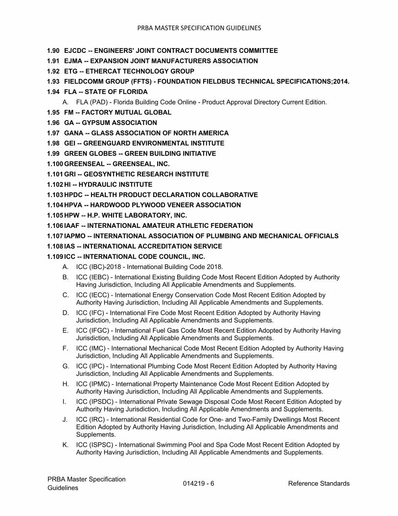
PRBA MASTER SPECIFICATION GUIDELINES
PRBA Master Specification Guidelines 014219 - 6 Reference Standards
1.90 EJCDC -- ENGINEERS' JOINT CONTRACT DOCUMENTS COMMITTEE 1.91 EJMA -- EXPANSION JOINT MANUFACTURERS ASSOCIATION 1.92 ETG -- ETHERCAT TECHNOLOGY GROUP 1.93 FIELDCOMM GROUP (FFTS) - FOUNDATION FIELDBUS TECHNICAL SPECIFICATIONS;2014. 1.94 FLA -- STATE OF FLORIDA
A. FLA (PAD) - Florida Building Code Online - Product Approval Directory Current Edition. 1.95 FM -- FACTORY MUTUAL GLOBAL 1.96 GA -- GYPSUM ASSOCIATION 1.97 GANA -- GLASS ASSOCIATION OF NORTH AMERICA 1.98 GEI -- GREENGUARD ENVIRONMENTAL INSTITUTE 1.99 GREEN GLOBES -- GREEN BUILDING INITIATIVE 1.100 GREENSEAL -- GREENSEAL, INC. 1.101 GRI -- GEOSYNTHETIC RESEARCH INSTITUTE 1.102 HI -- HYDRAULIC INSTITUTE 1.103 HPDC -- HEALTH PRODUCT DECLARATION COLLABORATIVE 1.104 HPVA -- HARDWOOD PLYWOOD VENEER ASSOCIATION 1.105 HPW -- H.P. WHITE LABORATORY, INC. 1.106 IAAF -- INTERNATIONAL AMATEUR ATHLETIC FEDERATION 1.107 IAPMO -- INTERNATIONAL ASSOCIATION OF PLUMBING AND MECHANICAL OFFICIALS 1.108 IAS -- INTERNATIONAL ACCREDITATION SERVICE 1.109 ICC -- INTERNATIONAL CODE COUNCIL, INC.
A. ICC (IBC)-2018 - International Building Code 2018. B. ICC (IEBC) - International Existing Building Code Most Recent Edition Adopted by Authority
Having Jurisdiction, Including All Applicable Amendments and Supplements. C. ICC (IECC) - International Energy Conservation Code Most Recent Edition Adopted by
Authority Having Jurisdiction, Including All Applicable Amendments and Supplements. D. ICC (IFC) - International Fire Code Most Recent Edition Adopted by Authority Having
Jurisdiction, Including All Applicable Amendments and Supplements. E. ICC (IFGC) - International Fuel Gas Code Most Recent Edition Adopted by Authority Having
Jurisdiction, Including All Applicable Amendments and Supplements. F. ICC (IMC) - International Mechanical Code Most Recent Edition Adopted by Authority Having
Jurisdiction, Including All Applicable Amendments and Supplements. G. ICC (IPC) - International Plumbing Code Most Recent Edition Adopted by Authority Having
Jurisdiction, Including All Applicable Amendments and Supplements. H. ICC (IPMC) - International Property Maintenance Code Most Recent Edition Adopted by
Authority Having Jurisdiction, Including All Applicable Amendments and Supplements. I. ICC (IPSDC) - International Private Sewage Disposal Code Most Recent Edition Adopted by
Authority Having Jurisdiction, Including All Applicable Amendments and Supplements. J. ICC (IRC) - International Residential Code for One- and Two-Family Dwellings Most Recent
Edition Adopted by Authority Having Jurisdiction, Including All Applicable Amendments and Supplements.
K. ICC (ISPSC) - International Swimming Pool and Spa Code Most Recent Edition Adopted by Authority Having Jurisdiction, Including All Applicable Amendments and Supplements.

PRBA MASTER SPECIFICATION GUIDELINES
PRBA Master Specification Guidelines 014219 - 7 Reference Standards
1.110 ICC-ES -- ICC EVALUATION SERVICE, INC. 1.111 ICEA -- INSULATED CABLE ENGINEERS ASSOCIATION 1.112 ICRI -- INTERNATIONAL CONCRETE REPAIR INSTITUTE 1.113 IEC -- INTERNATIONAL ELECTROTECHNICAL COMMISSION 1.114 IEEE -- INSTITUTE OF ELECTRICAL AND ELECTRONIC ENGINEERS 1.115 IES/IESNA -- ILLUMINATING ENGINEERING SOCIETY 1.116 IETF -- INTERNET ENGINEERING TASK FORCE 1.117 IGMA -- INSULATING GLASS MANUFACTURERS ALLIANCE 1.118 ILI -- INDIANA LIMESTONE INSTITUTE OF AMERICA, INC. 1.119 IMIAWC -- INTERNATIONAL MASONRY INDUSTRY ALL-WEATHER COUNCIL 1.120 ISA -- INSTRUMENT SOCIETY OF AMERICA 1.121 ISDI -- INSULATED STEEL DOOR INSTITUTE 1.122 ISFA - INTERNATIONAL SURFACE FABRICATORS ASSOCIATION 1.123 ISS -- IRON AND STEEL SOCIETY 1.124 ISSFA - INTERNATIONAL SOLID SURFACE FABRICATORS ASSOCIATION 1.125 ISO -- INTERNATIONAL STANDARDS ORGANIZATION 1.126 ITS -- INTERTEK TESTING SERVICES NA, INC. 1.127 ITU-T -- INTERNATIONAL TELECOMMUNICATIONS UNION -TELECOMMUNICATION
STANDARDIZATION SECTOR 1.128 IWBI -- INTERNATIONAL WELL BUILDING INSTITUTE 1.129 LPI -- LIGHTNING PROTECTION INSTITUTE 1.130 MBMA -- METAL BUILDING MANUFACTURERS ASSOCIATION 1.131 MFMA -- METAL FRAMING MANUFACTURERS ASSOCIATION 1.132 MIAMI -- MIAMI-DADE COUNTY
A. Miami (APD) - Approved Products Directory; Miami-Dade County Current Edition. 1.133 MPI -- MASTER PAINTERS INSTITUTE (MASTER PAINTERS AND DECORATORS
ASSOCIATION) A. MPI (APSM) - Master Painters Institute Architectural Painting Specification Manual Current
Edition.

PRBA MASTER SPECIFICATION GUIDELINES
PRBA Master Specification Guidelines 014219 - 8 Reference Standards
1.134 MSS -- MANUFACTURERS STANDARDIZATION SOCIETY OF THE VALVE AND FITTINGS INDUSTRY, INC.
1.135 NAAMM -- THE NATIONAL ASSOCIATION OF ARCHITECTURAL METAL MANUFACTURERS 1.136 NACE -- NACE INTERNATIONAL 1.137 NAGDM -- NATIONAL ASSOCIATION OF GARAGE DOOR MANUFACTURERS 1.138 NASSPA -- NORTH AMERICAN STEEL SHEET PILE ASSOCIATION 1.139 NBBI -- THE NATIONAL BOARD OF BOILER AND PRESSURE VESSEL INSPECTORS 1.140 NBI -- NEW BUILDINGS INSTITUTE 1.141 NCAA -- NATIONAL COLLEGIATE ATHLETIC ASSOCIATION 1.142 NCMA -- NATIONAL CONCRETE MASONRY ASSOCIATION 1.143 NCWPB - NATIONAL CERTIFIED PIPE WELDING BUREAU 1.144 NEBB -- NATIONAL ENVIRONMENTAL BALANCING BUREAU 1.145 NECA -- NATIONAL ELECTRICAL CONTRACTORS ASSOCIATION 1.146 NEMA -- NATIONAL ELECTRICAL MANUFACTURERS ASSOCIATION 1.147 NETA -- INTERNATIONAL ELECTRICAL TESTING ASSOCIATION 1.148 NFHS -- NATIONAL FEDERATION OF STATE HIGH SCHOOL ASSOCIATIONS: 1.149 NFPA -- NATIONAL FIRE PROTECTION ASSOCIATION 1.150 NFRC -- NATIONAL FENESTRATION RATING COUNCIL, INC. 1.151 NIBS -- NATIONAL INSTITUTE OF BUILDING SCIENCES 1.152 NIST -- NATIONAL INSTITUTE OF STANDARDS AND TECHNOLOGY (U.S. DEPARTMENT OF
COMMERCE) 1.153 NLA -- NATIONAL LIME ASSOCIATION 1.154 NPA -- NATIONAL PARTICLEBOARD ASSOCIATION 1.155 NPCA -- NATIONAL PAINT AND COATINGS ASSOCIATION 1.156 NRCA -- NATIONAL ROOFING CONTRACTORS ASSOCIATION 1.157 NSF -- NSF INTERNATIONAL (THE PUBLIC HEALTH AND SAFETY ORGANIZATION) 1.158 NSI -- NATURAL STONE INSTITUTE 1.159 NTMA -- NATIONAL TERRAZZO AND MOSAIC ASSOCIATION, INC., THE 1.160 NTMA -- NATIONAL TILE AND MARBLE ASSOCIATION 1.161 NWWDA -- NATIONAL WOOD WINDOW AND DOOR ASSOCIATION (NAME CHANGED TO
WDMA) 1.162 ORACLE -- ORACLE INTEGRATED CLOUD APPLICATIONS & PLATFORM SERVICES 1.163 PCA -- PORTLAND CEMENT ASSOCIATION 1.164 PCI -- PRECAST/PRESTRESSED CONCRETE INSTITUTE 1.165 PPI -- PLASTICS PIPE INSTITUTE 1.166 PR - COMMONWEALTH OF PUERTO RICO
A. Puerto Rico Building Code 2018 Ed. - Adopting (ICC) 2018 International Building Code with amendments.

PRBA MASTER SPECIFICATION GUIDELINES
PRBA Master Specification Guidelines 014219 - 9 Reference Standards
1.167 PTI -- POST-TENSIONING INSTITUTE 1.168 RCSC -- RESEARCH COUNCIL ON STRUCTURAL CONNECTIONS 1.169 RFCI -- RESILIENT FLOOR COVERING INSTITUTE 1.170 SAE -- SAE INTERNATIONAL 1.171 SBCA -- STRUCTURAL BUILDING COMPONENTS ASSOCIATION 1.172 SBCCI -- SOUTHERN BUILDING CODE CONGRESS INTERNATIONAL, INC. 1.173 SCAQMD -- SOUTH COAST AIR QUALITY MANAGEMENT DISTRICT 1.174 SCS - SCIENTIFIC CERTIFICATION SYSTEMS 1.175 SCTE -- SOCIETY OF CABLE TELECOMMUNICATIONS ENGINEERS 1.176 SDI -- STEEL DECK INSTITUTE 1.177 SDI -- STEEL DOOR INSTITUTE 1.178 SEFA -- SCIENTIFIC EQUIPMENT AND FURNITURE ASSOCIATION
A. SEFA 2 - Installations 2010. B. SEFA 3 - Laboratory Work Surfaces 2010. C. SEFA 7 - Laboratory Fixtures 2010. D. SEFA 8P - Laboratory Grade Polypropylene Casework 2014.
1.179 SJI -- STEEL JOIST INSTITUTE 1.180 SMACNA -- SHEET METAL AND AIR CONDITIONING CONTRACTORS' NATIONAL
ASSOCIATION, INC. 1.181 SPIB -- SOUTHERN PINE INSPECTION BUREAU, INC. 1.182 SPRI -- SINGLE PLY ROOFING INDUSTRY 1.183 SSPC -- SOCIETY FOR PROTECTIVE COATINGS 1.184 STI -- STEEL TANK INSTITUTE 1.185 SWRI -- SEALANT, WATERPROOFING AND RESTORATION INSTITUTE 1.186 TCNA -- TILE COUNCIL OF NORTH AMERICA, INC. 1.187 TIA -- TELECOMMUNICATIONS INDUSTRY ASSOCIATION 1.188 TMS -- THE MASONRY SOCIETY 1.189 TPI -- TRUSS PLATE INSTITUTE 1.190 UL -- UNDERWRITERS LABORATORIES INC.
A. UL (FRD) - Fire Resistance Directory Current Edition. 1.191 USGBC -- U.S. GREEN BUILDING COUNCIL 1.192 W3C SSG - WEB OF SERVICES STANDARDS COLLECTION (HTTP, XML, WSDL, UDDI, AND
OTHERS);CURRENT EDITION. 1.193 WDMA -- WINDOW AND DOOR MANUFACTURERS ASSOCIATION (FORMERLY NWWDA) 1.194 WI -- WOODWORK INSTITUTE PART 3 UNITED STATES GOVERNMENT AND RELATED AGENCIES DOCUMENTS 2.01 ATBCB -- US ARCHITECTURAL AND TRANSPORTATION BARRIERS COMPLIANCE BOARD
(THE ACCESS BOARD) 2.02 CFR -- CODE OF FEDERAL REGULATIONS
A. ADA Standards - Americans with Disabilities Act (ADA) Standards for Accessible Design 2010. B. 36 CFR 1191 - Americans with Disabilities Act (ADA) Accessibility Guidelines for Buildings and
Facilities; Architectural Barriers Act (ABA) Accessibility Guidelines current edition.

PRBA MASTER SPECIFICATION GUIDELINES
PRBA Master Specification Guidelines 014219 - 10 Reference Standards
C. 40 CFR 59, Subpart D - National Volatile Organic Compound Emission Standards for Architectural Coatings; U.S. Environmental Protection Agency current edition.
2.03 EPA -- ENVIRONMENTAL PROTECTION AGENCY 2.04 FAA -- FEDERAL AVIATION ADMINISTRATION 2.05 FDA -- FOOD AND DRUG ADMINISTRATION 2.06 FEMA -- U.S. FEDERAL EMERGENCY MANAGEMENT AGENCY 2.07 FHWA -- FEDERAL HIGHWAY ADMINISTRATION 2.08 FS -- FEDERAL SPECIFICATIONS AND STANDARDS (GENERAL SERVICES
ADMINISTRATION) 2.09 GSA -- U.S. GENERAL SERVICES ADMINISTRATION 2.10 HHS -- U.S. DEPARTMENT OF HEALTH AND HUMAN SERVICES, CENTERS FOR DISEASE
CONTROL AND PREVENTION 2.11 MIL -- MILITARY SPECIFICATIONS AND STANDARDS 2.12 PS -- PRODUCT STANDARDS 2.13 USAB -- UNITED STATES ACCESS BOARD
A. ABA Standards - ABA Accessibility Standards 2004, with Amendments (2015). 2.14 USDA -- UNITED STATES DEPARTMENT OF AGRICULTURE 2.15 USDHUD -- UNITED STATES DEPARTMENT OF HOUSING AND URBAN DEVELOPMENT 2.16 USGS -- UNITED STATES GEOLOGICAL SURVEY
END OF SECTION

01500 - 1
SECTION 01500
TEMPORARY FACILITIES AND CONTROLS
1 GENERAL
1.1 SECTION INCLUDES
A. Temporary Utilities:
1. Temporary electricity.
2. Temporary lighting for construction purposes.
3. Temporary ventilation.
4. Temporary Cooling.
5. Telephone service.
6. Facsimile service.
7. Temporary water service.
8. Temporary sanitary facilities.
B. Construction Facilities:
1. Field offices and sheds.
2. Vehicular access.
3. Parking.
4. Progress cleaning and waste removal.
5. Project identification.
C. Temporary Controls:
1. Barriers.
2. Enclosures and fencing.
3. Water control.
4. Erosion and sediment control.
D. Removal of utilities, facilities, and controls.
1.2 TEMPORARY ELECTRICITY
A. Cost: Provide and pay for power service required from utility source as needed for
construction operation.
B. Provide temporary electric feeder from electrical service at location as directed. Do
not disrupt Owner's use of service.
C. Complement existing power service capacity and characteristics as required for
construction operations.

01500 - 2
D. Provide power outlets, with branch wiring and distribution boxes located as required.
Provide flexible power cords as required for portable construction tools and
equipment.
E. Provide meter.
F. Permanent convenience receptacles may not be utilized during construction.
1.3 TEMPORARY LIGHTING FOR CONSTRUCTION PURPOSES
A. Provide and maintain incandescent lighting for construction operations to achieve
minimum lighting level of 2 watt/sq ft (21 watt/sq m)].
B. Provide and maintain 1 watt/sq ft (10.8 watt/sq m) lighting to exterior staging and
storage areas after dark for security purposes.
C. Provide and maintain 0.25 watt/sq ft (2.7 watt/sq m) HID lighting to interior work
areas after dark for security purposes.
D. Provide branch wiring from power source to distribution boxes with lighting
conductors, pigtails, and lamps for specified lighting levels.
E. Maintain lighting and provide routine repairs.
F. Permanent building lighting may not be utilized during construction.
1.4 TEMPORARY VENTILATION
A. Ventilate enclosed areas to achieve curing of materials, to dissipate humidity, and to
prevent accumulation of dust, fumes, vapors, or gases.
1.5 TEMPORARY COOLING
A. Provide and pay for cooling devices and cooling as needed to maintain specified
conditions for temporary offices and construction operations. As describe in the
Special Conditions.
1.6 TELEPHONE SERVICE
A. Provide, maintain, and pay for telephone service to field office at time of project
mobilization. As describe in the Special Conditions.
1.7 PHOTOCOPIER AND FACSIMILE SERVICE

01500 - 3
A. Provide, maintain and pay for photocopier and facsimile service and dedicated
telephone line to field office at time of project mobilization.
1.8 TEMPORARY WATER SERVICE
A. Provide and pay for suitable quality water service as needed to maintain specified
conditions for construction operations.
B. Extend branch piping with outlets located so water is available by hoses with
threaded connections.
1.9 TEMPORARY SANITARY FACILITIES
A. Provide and maintain required facilities and enclosures. Existing facility use is not
permitted. Provide facilities at time of project mobilization. As describe in Special
Conditions.
B. At end of construction, return existing facilities used for construction operations to
same or better condition as original condition.
1.10 FIELD OFFICES AND SHEDS
A. Offices: Weather tight, with lighting, electrical outlets, cooling and ventilating
equipment, and equipped with sturdy office furniture, drawing rack, and drawing
display table and other items. As describe in the Uniform General Conditions.
B. Provide space for Project meetings, with table and chairs. As describe in the Uniform
General Conditions.
C. Provide computer equipments for use by Owner’s Representatives as describe in the
Uniform General Conditions.
1.11 VEHICULAR ACCESS
A. Construct temporary access roads from public thoroughfares to serve construction
area.
B. Extend and relocate vehicular access as Work progress requires, provide detours as
necessary for unimpeded traffic flow.
C. Provide unimpeded access for emergency vehicles.
D. Provide and maintain access to fire hydrants and control valves free of obstructions.
E. Provide means of removing mud from vehicle wheels before entering streets.

01500 - 4
F. Do not use existing on-site roads for construction traffic.
1.12 PARKING
A. Arrange for and Provide temporary parking areas to accommodate construction
personnel, Owner’s Representative, and Architect/Engineer.
B. When site space is not adequate, provide additional off-site parking.
1.13 PROGRESS CLEANING AND WASTE REMOVAL
A. Contractor shall provide daily janitorial services.
B. Maintain areas free of waste materials, debris, and rubbish. Maintain site in clean and
orderly condition.
C. Remove debris and rubbish from closed or remote spaces, prior to enclosing spaces.
D. Broom and vacuum clean interior areas prior to start of surface finishing, and
continue cleaning to eliminate dust.
E. Collect and remove waste materials, debris, and rubbish from site periodically and
dispose off-site.
F. Open free-fall chutes are not permitted. Terminate closed chutes into appropriate
containers with lids.
1.14 PROJECT IDENTIFICATION
A. Project Identification Sign:
1. Provide 8 ft by 6 ft (2.4m x 1.8m) project sign of exterior grade plywood and
wood frame construction, painted, with exhibit lettering by professional sign
painter and self-adhesive corporate logo.
B. Design sign and structure to withstand 60 miles/hr (100 km/hr) wind velocity.
C. Installation:
1. Install project identification sign within 15 days after date fixed by Notice to
Proceed.
2. Erect at designated location.
3. Erect supports and framing on secure foundation, rigidly braced and framed
to resist wind loadings.
4. Install sign surface plumb and level, with butt joints. Anchor securely.
5. Paint exposed surfaces of sign, supports, and framing.

01500 - 5
D. Maintenance: Maintain signs and supports clean, repair deterioration and damage.
E. Removal: Remove signs, framing, supports, and foundations at completion of Project
and restore area.
1.15 BARRIERS
A. Provide barriers to prevent unauthorized entry to construction areas and to protect
existing facilities and adjacent properties from damage from construction operations
and demolition.
B. Provide barricades and covered walkways required by authorities having jurisdiction
for public rights-of-way.
C. Provide protection for plants designated to remain. Replace damaged plants.
D. Protect non-owned vehicular traffic, stored materials, site, and structures from
damage.
1.16 ENCLOSURES AND FENCING
A. Construction: Design, materials, paints will be selected by Owner’s representative.
B. Exterior Enclosures:
1. Provide temporary weather tight closure of exterior openings to accommodate
acceptable working conditions and protection for products, to allow for
maintenance of required ambient temperatures identified in individual
specification sections, and to prevent entry of unauthorized persons. Provide
access doors with self-closing hardware and locks.
1.17 WATER CONTROL
A. Grade site to drain. Maintain excavations free of water. Provide, operate, and
maintain pumping equipment.
B. Protect site from puddling or running water. Provide water barriers as required to
protect site from soil erosion
1.18 EROSION AND SEDIMENT CONTROL
A. Plan and execute construction by methods to control surface drainage from cuts and
fills, from borrow and waste disposal areas. Prevent erosion and sedimentation.
B. Minimize surface area of bare soil exposed at one time.

01500 - 6
C. Provide temporary measures to prevent water flow.
D. Construct fill and waste areas by selective placement to avoid erosive surface silts or
clays.
E. Periodically inspect earthwork to detect evidence of erosion and sedimentation;
promptly apply corrective measures.
1.19 REMOVAL OF UTILITIES, FACILITIES, AND CONTROLS
A. Remove temporary utilities, equipment, facilities, materials, prior to Substantial
Completion inspection.
B. Remove underground installations to minimum depth of 2 feet (600 mm). Grade site
as indicated.
C. Clean and repair damage caused by installation or use of temporary work.
D. Restore existing and permanent facilities used during construction to original
condition. Restore permanent facilities used during construction to specified
condition.
2 PRODUCTS
Not Used.
3 EXECUTION
Not Used.
END OF SECTION

01600 - 1
SECTION 01600
PRODUCT REQUIREMENTS
1 GENERAL
1.1 SECTION INCLUDES
A. Products.
B. Product delivery requirements.
C. Product storage and handling requirements.
D. Product options.
E. Product substitution procedures.
1.2 PRODUCTS
A. Furnish products of qualified manufacturers suitable for intended use.
B. Do not use materials and equipment removed from existing premises, except as
specifically permitted by Contract Documents.
C. Furnish interchangeable components from same manufacturer for components
being replaced.
1.3 PRODUCT DELIVERY REQUIREMENTS
A. Transport and handle products in accordance with manufacturer's instructions.
B. Promptly inspect shipments to ensure products comply with requirements,
quantities are correct, and products are undamaged.
C. Provide equipment and personnel to handle products by methods to prevent soiling,
disfigurement, or damage.
1.4 PRODUCT STORAGE AND HANDLING REQUIREMENTS
A. Store and protect products in accordance with manufacturers' instructions.
B. Store with seals and labels intact and legible.
C. Store sensitive products in weather tight, enclosures in an environment favorable to
product.

01600 - 2
D. For exterior storage of fabricated products, place on sloped supports above ground.
E. Cover products subject to deterioration with impervious sheet covering.
F. Store loose granular materials on solid flat surfaces in well-drained area. Prevent
mixing with foreign matter.
G. Provide equipment and personnel to store products by methods to prevent soiling,
disfigurement, or damage.
H. Arrange storage of products to permit access for inspection. Periodically inspect to
verify products are undamaged and are maintained in acceptable condition.
1.5 PRODUCT OPTIONS
A. Products Specified by Reference Standards or by Description Only: Any product
meeting those standards or description.
B. Products Specified by Naming One or More Manufacturers: Products of one of
manufacturers named and meeting specifications, no options or substitutions
allowed.
C. Products Specified by Naming One or More Manufacturers with Provision for
Substitutions: Submit request for substitution for any manufacturer not named in
accordance with the following article.
1.6 PRODUCT SUBSTITUTION PROCEDURES
A. Architect/Engineer will consider requests for Substitutions only within 15 days
after date of Owner-Contractor Agreement.
B. Substitutions may be considered when a product becomes unavailable through no
fault of Contractor.
C. Document each request with complete data substantiating compliance of proposed
Substitution with Contract Documents.
D. A request constitutes a representation that Bidder:
1. Has investigated proposed product and determined that it meets or exceeds
quality level of specified product.
2. Will provide same warranty for Substitution as for specified product.
3. Will coordinate installation and make changes to other Work which may be
required for the Work to be complete with no additional cost to Owner.
4. Waives claims for additional costs or time extension which may
subsequently become apparent.

01600 - 3
5. Will reimburse Owner and Architect/Engineer for review or redesign
services associated with re-approval by authorities having jurisdiction.
E. Substitutions will not be considered when they are indicated or implied on Shop
Drawing or Product Data submittals, without separate written request, or when
acceptance will require revision to Contract Documents.
F. Substitution Submittal Procedure:
1. Submit three copies of request for Substitution for consideration. Limit
each request to one proposed Substitution.
2. Submit Shop Drawings, Product Data, and certified test results attesting to
proposed product equivalence. Burden of proof is on proposer.
3. Architect/Engineer will notify Contractor in writing of decision to accept or
reject request.
2 PRODUCTS
Not Used
3 EXECUTION
Not Used.
END OF SECTION

01700 - 1
SECTION 01700
EXECUTION REQUIREMENTS
PART 1 GENERAL
1.1 SECTION INCLUDES
1. Closeout procedures.
2. Final cleaning.
3. Protecting installed construction.
4. Project record documents.
5. Operation and maintenance data.
6. Spare parts and maintenance products.
1.2 CLOSEOUT PROCEDURES
1. Submit written certification that Contract Documents have been reviewed, Work
has been inspected, and that Work is complete in accordance with Contract
Documents and ready for Architect/Engineer's review.
2. Provide submittals to Architect/Engineer required by authorities having
jurisdiction.
3. Submit final Application for Payment identifying total adjusted Contract Sum,
previous payments, and sum remaining due.
1.3 FINAL CLEANING
1. Execute final cleaning prior to final project assessment.
2. Clean equipment and fixtures to sanitary condition with cleaning materials
appropriate to surface and material being cleaned.
3. Clean debris from roofs, gutters, downspouts, and drainage systems.
4. Clean site; sweep paved areas, rake clean landscaped surfaces.
5. Remove waste and surplus materials, rubbish, and construction facilities from site.

01700 - 2
1.4 PROTECTING INSTALLED CONSTRUCTION
1. Protect installed Work and provide special protection where specified in
individual specification sections.
2. Provide protective coverings at walls, projections, jambs, sills, and soffits of
openings.
3. Protect finished floors, stairs, and other surfaces from traffic, dirt, wear, damage,
or movement of heavy objects, by protecting with durable sheet materials.
4. Prohibit traffic or storage upon waterproofed or roofed surfaces. When traffic or
activity is necessary, obtain recommendations for protection from waterproofing
or roofing material manufacturer.
5. Prohibit traffic from landscaped areas.
1.5 PROJECT RECORD DOCUMENTS
1. Maintain on site one set of the following record documents; record actual
revisions to the Work:
1. Drawings.
2. Specifications.
3. Addenda.
4. Change Orders and other modifications to the Contract.
5. Reviewed Shop Drawings, Product Data, and Samples.
6. Manufacturer's instruction for assembly, installation, and adjusting.
2. Ensure entries are complete and accurate, enabling future reference by Owner.
3. Store record documents separate from documents used for construction.
4. Record information concurrent with construction progress, not less than weekly.
5. Specifications: Legibly mark and record at each product section description of
actual products installed, including the following:
1. Manufacturer's name and product model and number.
2. Product substitutions or alternates utilized.
3. Changes made by Addenda and modifications.
6. Record Drawings and Shop Drawings: Legibly mark each item to record actual
construction including:
1. Measured depths of foundations in relation to finish first floor datum.
2. Measured horizontal and vertical locations of underground utilities and
appurtenances, referenced to permanent surface improvements.

01700 - 3
3. Measured locations of internal utilities and appurtenances concealed in
construction, referenced to visible and accessible features of the Work.
4. Field changes of dimension and detail.
5. Details not on original Contract drawings.
7. Submit documents to René Acosta-Arquitectos with claim for final Application
for Payment.
1.6 OPERATION AND MAINTENANCE DATA
1. Submit data bound in 8-1/2 x 11 inch text pages, capacity expansion binders with
durable plastic overs.
2. Prepare binder cover with printed title "OPERATION AND MAINTENANCE
INSTRUCTIONS", title of project , and subject matter of binder when multiple
binders are required.
3. Internally subdivide binder contents with permanent page dividers, logically
organized as described below; with tab titling clearly printed under reinforced
laminated plastic tabs.
4. Drawings: Provide with reinforced punched binder tab. Bind in with text; fold
larger drawings to size of text pages.
5. Contents: Prepare Table of Contents for each volume, with each product or system
description identified, typed on white paper, in three parts as follows:
1. Part 1: Directory, listing names, addresses, and telephone numbers of René
Acosta-Arquitectos, Contractor, Subcontractors, and major equipment
suppliers.
2. Part 2: Operation and maintenance instructions, arranged by system and
subdivided by specification section. For each category, identify names,
addresses, and telephone numbers of Subcontractors and suppliers.
Identify the following:
1. Significant design criteria.
2. List of equipment.
3. Parts list for each component.
4. Operating instructions.
5. Maintenance instructions for equipment and systems.
6. Maintenance instructions for special finishes, including
recommended cleaning methods and materials, and special
precautions identifying detrimental agents.
3. Part 3: Project documents and certificates, including the following:
1. Shop drawings and product data.
2. Air and water balance reports.
3. Certificates.
4. Photocopies of warranties.

01700 - 4
1.7 SPARE PARTS AND MAINTENANCE PRODUCTS
1. Furnish spare parts, maintenance, and extra products in quantities specified in
individual specification sections.
2. Deliver to Project site and place in location as directed; obtain receipt prior to
final payment.
1.8 PRODUCT WARRANTIES AND PRODUCT BONDS
1. Execute and assemble transferable warranty documents and bonds from
subcontractors, suppliers, and manufacturers.
2. Verify documents are in proper form, contain full information, and are notarized.
3. Co-execute submittals when required.
4. Include Table of Contents and assemble in three D side ring binder with durable
plastic cloth cover.
5. Submit prior to final Application for Payment.
6. Time Of Submittals:
1. Make other submittals within ten days after Date of Substantial
Completion, prior to final Application for Payment.
2. For items of Work for which acceptance is delayed beyond Date of
Substantial Completion, submit within ten days after acceptance, listing
date of acceptance as beginning of warranty or bond period.
PART 2 PRODUCTS
Not Used.
PART 3 EXECUTION
Not Used.
END OF SECTION

SECTION 02 41 00
SELECTIVE DEMOLITION
PART 1 – GENERAL
1.1 SECTION REQUIREMENTS
A. Extent of selective demolition work is indicated on drawings and demolition notes.
1.2 SUBMITTALS
A. Schedule:
1. Submit schedule indicating proposed methods and sequence of operations for selective
demolition work to Owner for review prior to commencement of work. Include
coordination for shut-off, capping, and continuation of utility services as required,
together with detail for dust and noise control protection.
2. Provide detailed sequence of demolition and removal work to ensure uninterrupted
progress of Owner’s on-site operations.
1.3 JOB CONDITIONS
A. Existing Conditions:
1. The Owner assumes no responsibility for actual condition of items or structures to be
demolished.
B. Storage and Sale: Storage or sale of removed items on site will not be permitted.
C. Provide temporary barricades and other forms of protection as required to protect Employees
and general public from injury due to selective demolition work.
D. Erect temporary covered passageways as required by authorities having jurisdiction.
E. Protect from damage existing finish work that is to remain in place and becomes exposed
during demolition operations.
F. Provide temporary weather protection during demolition and removal of existing construction
on exterior surfaces and installation of new construction to insure that no water leakage or
damage occurs to structure or interior areas of existing building.
G. Remove protections at completion of work.
H. Damage: Promptly repair damages caused to adjacent occupied facilities by demolition work
at no cost to Owner.

Selective Demolition
02 41 00 - 2
I. Traffic:
1. Conduct selective demolition operations and debris removal in a manner to ensure
minimum interference with other adjacent occupied or used facilities.
2. Do not close, block or otherwise obstruct other occupied or used facilities without written
permission from authorities having jurisdiction. Provide alternate routes around closed or
obstructed traffic ways if required by governing regulations.
J. Utilities:
1. Maintain existing utilities indicated to remain, keep in service and protect against damage
during demolition operations.
2. Do not interrupt existing utilities serving occupied or used facilities. Provide temporary
services during interruptions to existing utilities.
k. Environmental Controls: Use water sprinkling, temporary enclosures and/or other suitable
methods to limit dust and dirt rising and scattering in air to lowest practical level. Comply
with governing regulations pertaining to environmental protection.
L. Do not use water when it may create hazardous or objectionable conditions such as flooding
and pollution.
M. Partial Demolition and Removal: Items indicated to be removed. Contractor shall remove
from structure as work progresses.
N. Mechanical Demolition:
1. Disconnect, demolish and remove work as indicated on Construction Drawings.
2. Where pipe, ductwork, insulation, or equipment to remain is damaged or disturbed,
remove damaged portions and install new product of equal capacity and quality.
3. Remove indicated exposed pipe and ductwork in it’s entirely.
4. Remove indicated piping, A/C ducts from project.
5. Remove, store, clean, reinstall, reconnect, and make operational equipment indicated for
relocated.
O. Electrical Demolition:
1. Protect existing electrical equipment and installations indicated to remain. If damaged or
disturbed in the course of the work, remove damaged portions and install new products of
equal capacity, quality and functionality.

Selective Demolition
02 41 00 - 3
• Electrical Demolition (Cont.’):
2. Remove exposed electrical equipment and installations, indicated to be demolished, in
their entirely.
3. Remove demolished and removed materials from project site.
4. Remove, store, clean, reinstall, reconnect, and make operational components indicated for
relocation.
PART 2 – PRODUCTS (NOT APPLICABLE)
PART 3 – EXECUTION
3.1 INSPECTION:
A. Prior to commencement of selective demolition work, inspect areas in which work will be
performed. Photograph existing conditions to structure surfaces, equipment or to surrounding
properties, which could be misconstrued as damage resulting from selective demolition work;
file with Architect prior to starting work.
B. Erect and maintain dust-proof partitions and closures as required to prevent spread of dust or
fumes.
3.2 PREPARATION
A. Provide weatherproofing closures for exterior openings resulting from demolition work.
B. Locate, identify, stub off and disconnect utility services that are not indicated to remain.
3.3 DEMOLITION
A. Perform selective demolition work in a systematic manner. Use such methods as required to
complete work indicated on Drawings in accordance with demolition schedule and governing
regulations.
B. Demolish concrete and masonry in small sections. Cut concrete and masonry at junctures
with construction to remain using power-driven masonry saw or hand tools; do not use
power-driven impact tools.
C. Provide services for effective air and water pollution controls as required by local authorities
having jurisdiction.
D. If unanticipated mechanical, electrical which conflict with intended function or design are
encountered, investigate and measure both nature and extent of the conflict. Submit report to
Owner’s Representative in written with accurate details. Pending receipt of directive from

Selective Demolition
02 41 00 - 4
Architect rearrange selective demolition schedule as necessary to continue overall job
progress without delay.
3.4 DISPOSAL OF DEMOLISHED MATERIALS
A. Remove debris, rubbish and other materials resulting from demolition operations from
building site. Transport and legally dispose of materials off site.
B. If hazardous materials are encountered during demolition operations, comply with applicable
regulations, laws, and ordinances concerning removal, handling and protection against
exposure or environmental pollution.
C. Burning of removed materials is not permitted on project site.
3.5 CLEAN-UP AND REPAIR
A. Upon completion of demolition work, remove tools, equipment and demolished materials
from site. Remove protections and leave interior areas broom clean.
B. Repair demolition performed in excess of that required. Return structures and surfaces to
remain to condition existing prior to commencement of selective demolition work. Repair
adjacent construction or surfaces soiled or damage by selected demolition work.
END OF SECTION 02 41 00

SECTION 02711
CHAIN LINK FENCES
1. RELATED DOCUMENTS:
The general provisions of the Contract, including the General and Special Conditions apply
to the work specified in this section.
2. DESCRIPTION OF WORK:
The extent of chain link fences and gates is shown on the drawings.
3. QUALITY ASSURANCE:
Standards of Manufacture: Comply with the standards of the Chain link Fence
Manufacturer’s Institute.
Provide fences and gates as complete unit produced by a single manufacturer including
necessary erection accessories, fittings and fastenings.
4. SUBMITTALS:
Manufacturer’s Data: Submit for approval two (2) copies of manufacturer’s data,
specifications, and installation instructions for chain link fencing and gates.
5. GENERAL:
Pipe sizes indicated are commercial pipe sizes. Equivalent tubular sections, H-sections or
roll-formed sections may be substituted for pipe sections, if acceptable to the P.B.A.
6. MATERIALS AND FABRICATION:
a. Fabric: No. 9 gage (0.148”) steel wires, 2” mesh, with both top and bottom selvages
twisted and barbed. Provide one-piece fabric widths for fencing up to 12’ high. Fabric
finish, galvanized, ASTM A 392, Class I, with not less than 1.2 oz. zinc per square feet.
b. Rails & Framework: Galvanized steel, ASTM A120, with not less than 1.8 oz. zinc per
square feet.
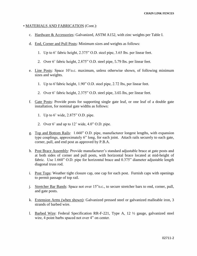
CHAIN LINK FENCES
02711-2
• MATERIALS AND FABRICATION (Cont.):
c. Hardware & Accessories: Galvanized, ASTM A152, with zinc weights per Table I.
d. End, Corner and Pull Posts: Minimum sizes and weights as follows:
1. Up to 6’ fabric height, 2.375” O.D. steel pipe, 3.65 lbs. per linear feet.
2. Over 6’ fabric height, 2.875” O.D. steel pipe, 5.79 lbs. per linear feet.
e. Line Posts: Space 10’o.c. maximum, unless otherwise shown, of following minimum
sizes and weights.
1. Up to 6’fabric height, 1.90” O.D. steel pipe, 2.72 lbs, per linear feet.
2. Over 6’ fabric height, 2.375” O.D. steel pipe, 3.65 lbs, per linear feet.
f. Gate Posts: Provide posts for supporting single gate leaf, or one leaf of a double gate
installation, for nominal gate widths as follows:
1. Up to 6’ wide, 2.875” O.D. pipe.
2. Over 6’ and up to 12’ wide, 4.0” O.D. pipe.
g. Top and Bottom Rails: 1.660” O.D. pipe, manufacturer longest lengths, with expansion
type couplings, approximately 6” long, for each joint. Attach rails securely to each gate,
corner, pull, and end post as approved by P.B.A.
h. Post Brace Assembly: Provide manufacturer’s standard adjustable brace at gate posts and
at both sides of corner and pull posts, with horizontal brace located at mid-height of
fabric. Use 1.660” O.D. pipe for horizontal brace and 0.375” diameter adjustable length
diagonal truss rod.
i. Post Tops: Weather tight closure cap, one cap for each post. Furnish caps with openings
to permit passage of top rail.
j. Stretcher Bar Bands: Space not over 15”o.c., to secure stretcher bars to end, corner, pull,
and gate posts.
k. Extension Arms (when shown): Galvanized pressed steel or galvanized malleable iron, 3
strands of barbed wire.
l. Barbed Wire: Federal Specification RR-F-221, Type A, 12 ½ gauge, galvanized steel
wire, 4 point barbs spaced not over 4” on center.

CHAIN LINK FENCES
02711-3
• MATERIALS AND FABRICATION (Cont.):
m. Gates: Provide horizontal and vertical members to ensure proper gate operation and for
attachment of fabric, hardware and accessories. Space so that frame members are not
more than 8’ apart. Fabricate gate perimeter frames of tubular members as follows:
1. Up to 6’-0” high, or leaf width under 8’: 1.660” O.D. steel pipe.
2. Over 6’-0” high or leaf width over 8’: 1.90” O.D. steel pipe.
Assemble gate frames by welding or with special fittings and rivets, for rigid
connections. Use same fabric as for fence. Install fabric with stretcher bars at vertical
edges. The Contractor shall attach stretchers to gate frame (at not more than 15”o.c.) and
hardware to provide security against removal or breakage. Provide diagonal cross-bracing
consisting of ⅜” diameter adjustable length truss rods on gates to provide frame rigidity
without sag or twist, if required.
n. Gate Hardware: Provide the following hardware and accessories for each gate:
• Hinges: Size and material to suit gate size, non-lift-off type, offset to permit 180º
gate opening. Provide 1-½ pair of hinges, for each leaf over 6’ nominal
height or over 8’ wide.
• Latch: Forked type or plunger-bar type to permit operation from either side of
gate. Provide padlock eye as integral part of latch.
• Padlock: One padlock equal as approved to Yale 871 ½ master keyed with the
building locksets.
• Wire Ties: For tying fabric to line posts, use wire ties spaced 12”o.c. For tying fabric
to rails and braces, use wire spaced 24”o.c. For tying fabric to tension
wire, use hog rings spaced 24”o.c.
Manufacturer’s standard procedure will be accepted if of equal strength and durability.
o. Concrete: Comply with applicable requirements of Division 3. Provide concrete with a
minimum 28 day compressive strength of 2500 psi.
7. INSTALLATION:
Do not begin installation and erection before final grading is completed, unless otherwise
permitted.
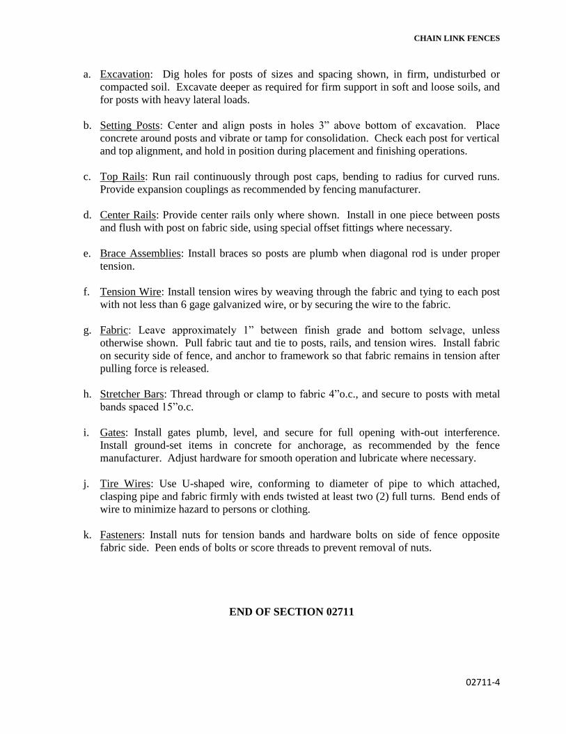
CHAIN LINK FENCES
02711-4
a. Excavation: Dig holes for posts of sizes and spacing shown, in firm, undisturbed or
compacted soil. Excavate deeper as required for firm support in soft and loose soils, and
for posts with heavy lateral loads.
b. Setting Posts: Center and align posts in holes 3” above bottom of excavation. Place
concrete around posts and vibrate or tamp for consolidation. Check each post for vertical
and top alignment, and hold in position during placement and finishing operations.
c. Top Rails: Run rail continuously through post caps, bending to radius for curved runs.
Provide expansion couplings as recommended by fencing manufacturer.
d. Center Rails: Provide center rails only where shown. Install in one piece between posts
and flush with post on fabric side, using special offset fittings where necessary.
e. Brace Assemblies: Install braces so posts are plumb when diagonal rod is under proper
tension.
f. Tension Wire: Install tension wires by weaving through the fabric and tying to each post
with not less than 6 gage galvanized wire, or by securing the wire to the fabric.
g. Fabric: Leave approximately 1” between finish grade and bottom selvage, unless
otherwise shown. Pull fabric taut and tie to posts, rails, and tension wires. Install fabric
on security side of fence, and anchor to framework so that fabric remains in tension after
pulling force is released.
h. Stretcher Bars: Thread through or clamp to fabric 4”o.c., and secure to posts with metal
bands spaced 15”o.c.
i. Gates: Install gates plumb, level, and secure for full opening with-out interference.
Install ground-set items in concrete for anchorage, as recommended by the fence
manufacturer. Adjust hardware for smooth operation and lubricate where necessary.
j. Tire Wires: Use U-shaped wire, conforming to diameter of pipe to which attached,
clasping pipe and fabric firmly with ends twisted at least two (2) full turns. Bend ends of
wire to minimize hazard to persons or clothing.
k. Fasteners: Install nuts for tension bands and hardware bolts on side of fence opposite
fabric side. Peen ends of bolts or score threads to prevent removal of nuts.
END OF SECTION 02711

02763 - 1
SECTION 02763
PAINTED PAVEMENT MARKINGS
1 PART GENERAL
1.1 SUMMARY
A. Section Includes:
1. Traffic lines and markings.
2. Legends.
3. Paint.
B. Related Sections:
1. Section 02740 Flexible Pavement.
1.2 REFERENCES
A. American Society for Testing and Materials:
1. ASTM D34 - Standard Guide for Chemical Analysis of White Pigments.
2. ASTM D126 - Standard Test Methods for Analysis of Yellow, Orange,
and Green Pigments Containing Lead Chromate and Chromium Oxide
Green.
3. ASTM D562 - Standard Test Method for Consistency of Paints Using the
Stormer Viscometer.
4. ASTM D711 - Standard Test Method for No-Pick-Up Time of Traffic
Paint.
5. ASTM D713 - Standard Practice for Conducting Road Service Tests on
Fluid Traffic Marking Materials.
6. ASTM D969 - Standard Test Method for Laboratory Determination of
Degree of Bleeding of Traffic Paint.
7. ASTM D1301 - Standard Test Methods for Chemical Analysis of White
Lead Pigments.
8. ASTM D1394 - Standard Test Methods for Chemical Analysis of White
Titanium Pigments.
9. ASTM D1475 - Standard test Method for Density of Liquid Coatings,
Inks, and Related Products.
10. ASTM D1640 - Standard Test Methods for Drying, Curing, or Film
Formation of Organic Coatings at Room Temperature.
11. ASTM D2202 - Standard Test Method for Slump of Sealants.
12. ASTM D2371 - Standard Test Method for Pigment Content of Solvent-
Reducible Paints.
13. ASTM D2621 - Standard Test Method for Infrared Identification of
Vehicle Solids From Solvent-Reducible Paints.
14. ASTM D2743 - Standard Practices for Uniformity of Traffic Paint Vehicle
Solids by Spectroscopy and Gas Chromatography.
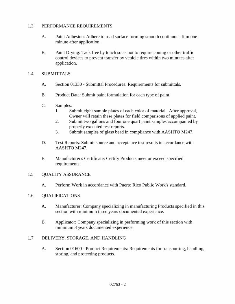
02763 - 2
1.3 PERFORMANCE REQUIREMENTS
A. Paint Adhesion: Adhere to road surface forming smooth continuous film one
minute after application.
B. Paint Drying: Tack free by touch so as not to require coning or other traffic
control devices to prevent transfer by vehicle tires within two minutes after
application.
1.4 SUBMITTALS
A. Section 01330 - Submittal Procedures: Requirements for submittals.
B. Product Data: Submit paint formulation for each type of paint.
C. Samples:
1. Submit eight sample plates of each color of material. After approval,
Owner will retain these plates for field comparisons of applied paint.
2. Submit two gallons and four one quart paint samples accompanied by
properly executed test reports.
3. Submit samples of glass bead in compliance with AASHTO M247.
D. Test Reports: Submit source and acceptance test results in accordance with
AASHTO M247.
E. Manufacturer's Certificate: Certify Products meet or exceed specified
requirements.
1.5 QUALITY ASSURANCE
A. Perform Work in accordance with Puerto Rico Public Work's standard.
1.6 QUALIFICATIONS
A. Manufacturer: Company specializing in manufacturing Products specified in this
section with minimum three years documented experience.
B. Applicator: Company specializing in performing work of this section with
minimum 3 years documented experience.
1.7 DELIVERY, STORAGE, AND HANDLING
A. Section 01600 - Product Requirements: Requirements for transporting, handling,
storing, and protecting products.

02763 - 3
B. Invert containers several days prior to use when paint has been stored more than 2
months. Minimize exposure to air when transferring paint. Seal drums and tanks
when not in use.
1.8 ENVIRONMENTAL REQUIREMENTS
A. Section 01600 - Product Requirements: Environmental conditions affecting
products on site.
B. Do not apply materials when surface and ambient temperatures are outside
temperature ranges required by paint product manufacturer.
C. Do not apply exterior coatings during rain or snow when relative humidity is
outside humidity ranges, or moisture content of surfaces exceed those required by
paint product manufacturer.
D. Volatile Organic Content (VOC). Do not exceed State or Environmental
Protection Agency maximum VOC on traffic paint.
1.9 WARRANTY
A. Section 01700 - Execution Requirements: Requirements for warranties.
B. Furnish three year manufacturer’s warranty for traffic paints.
1.10 MAINTENANCE SERVICE
A. Section 01700 - Execution Requirements: Requirements for maintenance service.
B. Furnish service and maintenance of traffic paints for three years from Date of
Substantial Completion.
2PART PRODUCTS
2.1 PAINTED PAVEMENT MARKINGS
A. Manufacturers:
1. “Traffic Paint” by Pervo Paint Company.
2. “Traffic Paint” by Pathmark Traffic Products.
3. Traffic and Zone Marking Paint” by PPG.
4. “Romark Traffic” by Glidden-Durkee.
5. Substitutions: Section 01600 - Product Requirements Not Permitted.
B. Paint: Ready mixed, conventional and fast dry waterborne traffic paints, lead-free,
non-toxic, NASSHTO Test Deck, minimum retroreflectance of 100 mcds,
durability rating of 6 or more after in place for 9 months; within following limits:

02763 - 4
1. Pigment, percent by weight: 60 plus or minus 2.
2. Vehicle, percent by weight: 40 plus or minus 2.
3. Non-Volatile, percent by weight of paint: 76.0.
4. Weight per gallon, pounds (kilograms) minimum 13.0 6.
5. Viscosity: 80-95Kreb Units at 77 degrees F (25 degrees C).
6. Grind (Hegman Guage), minimum Field Tested no tracking time under
ambient conditions: 20-90 seconds.
7. Dry Through Time, 15 mils (0.4 mm) wet at 90 percent relative humidity,
72 degrees F (22 degrees C), ASTM D1640: 125 minutes maximum.
8. VOC (Volatile Organic Content): One lbs/gal (120 g/L) maximum.
2.2 EQUIPMENT
A. Continuous Longitudinal Line Application Machine: Use application equipment
with following capabilities.
1. Dual nozzle paint gun to simultaneously apply parallel lines of indicated
width in solid or broken patterns or various combinations of those
patterns.
2. Measuring device to automatically and continuously measure length of
each line placed, to nearest foot (tenth of meter).
B. Machine Calibration:
1. Paint Line Measuring Device: Calibrate automatic line length gauges to
maintain tolerance of plus or minus 25 feet per mile (4.75 m per km).
2. Cycle Length/Paint Line Length Timer: Calibrate cycle length to maintain
tolerance of plus or minus 6 inches per 40 feet (12mm per m); calibrate
paint line length to maintain tolerance to plus or minus 3 inches per 10 feet
(25 mm per m).
3. Paint Guns: Calibrate to simultaneously apply paint binder at uniform
rates as specified with an allowable tolerance of plus or minus 1 mil.
C. Other Equipment:
1. For application of crosswalks, intersections, stop lines, legends and other
miscellaneous items by walk behind stripers, hand spray or stencil trucks,
apply with equipment meeting requirements of this section. Do not use
hand brushes or rollers.
2.3 SOURCE QUALITY CONTROL
A. Section 01400 - Quality Requirements: Testing, inspection and analysis
requirements.
B. Test and analyze traffic paints in accordance with ASTM D34, ASTM D126 and
ASTM D562.

02763 - 5
C. Allow witnessing of factory inspections and test at manufacturer’s test facility.
Notify Architect/Engineer at least seven days before inspections and tests are
scheduled.
3PART EXECUTION
3.1 EXAMINATION
A. Section 01300 - Administrative Requirements: Verification of existing conditions
before starting work.
B. Do not apply paint to concrete surfaces until concrete has cured for 28 days.
3.2 PREPARATION
A. Maintenance and Protection of Traffic:
1. Provide short term traffic control in accordance with Section 01500.
2. Prevent interference with marking operations and to prevent traffic on
newly applied markings before markings dry.
3. Maintain travel lanes between 7: 00 AM to 9: 00 AM, and between 4: 00
PM and 6: 00 PM.
4. Maintain access to existing businesses, and other properties requiring
access.
B. Surface Preparation.
1. Clean and dry paved surface prior to painting.
2. Blow or sweep surface free of dirt, debris, oil, grease or gasoline.
3. Spot location of final pavement markings as specified and as indicated on
Drawings by applying pavement spots 25 feet (8.0 m) on center.
4. Notify Architect/Engineer after placing pavement spots and minimum 3
days prior to applying traffic lines.
3.3 EXISTING WORK
A. Remove existing markings in an acceptable manner. Do not remove existing
pavement markings by painting over with blank paint. Remove by methods that
will cause least damage to pavement structure or pavement surface. Satisfactorily
repair any pavement or surface damage caused by removal methods.
B. Clean and repair existing lines and legends.
3.4 APPLICATION
A. Agitate paint for 1-15 minutes prior to application to ensure even distribution of
paint pigment.

02763 - 6
B. Dispense paint at 110 degrees F (43.3 degrees C) to wet-film thickness of 15 mils
(0.4 mm), except dispense edge markings to wet-film thickness of 12 mils (0.3
mm).
C. Apply markings to indicated dimensions at indicated locations.
D. Prevent splattering and over spray when applying markings.
E. Unless material is track free at end of paint application convoy, use traffic cones
to protect markings from traffic until track free. When vehicle crosses a marking
and tracks it or when splattering or over spray occurs, eradicate affected marking
and resultant tracking and apply new markings.
F. Collect and legally dispose of residues from painting operations.
3.5 APPLICATION TOLERANCES
A. Section 01400 - Quality Requirements: Tolerances.
B. Maximum Variation from Wet Film Thickness: 1 mil.
C. Maximum Variation from Wet Paint Line Width: Plus or minus 1/8 inch (3 mm).
D. Maintain cycle length for skip lines at tolerance of plus or minus 6 inches per 40
feet (12 mm per m) and line length of plus or minus 3 inches per 10 feet (25mm
per m).
3.6 FIELD QUALITY CONTROL
A. Section 01400 - Quality Requirements.
B. Inspect for incorrect location, insufficient thickness, line width, coverage,
retention, uncured or discolored material, and insufficient bonding.
C. Repair lines and markings, which after application and curing do not meet
following criteria:
1. Incorrect Location: Remove and replace incorrectly placed patterns.
2. Insufficient Thickness, Line Width, Paint Coverage, Glass Bead Coverage
or Retention: Prepare defective material by acceptably grinding or blast
cleaning to remove substantial amount of beads and to roughen marking
surface. Remove loose particles and debris. Apply new markings on
cleaned surface in accordance with this Section.
3. Uncured or Discolored Material, Insufficient Bonding: Remove defective
markings in accordance with this Section and clean pavement surface one
foot (300 mm) beyond affected area. Apply new markings on cleaned
surface in accordance with this Section.

02763 - 7
D. Replace defective pavement markings as specified throughout 3 year warranted
period. Replace markings damaged by anti-skid materials, studded tires, tire
chains, chemical deicers, or other loss of marking material regardless of cause.
E. A three member team will evaluate warranty provisions. Team will consist of one
member from Owner, one member from Contractor, and third person who is
mutually acceptable to Owner and Contractor. Any costs for third person will be
equally shared between Owner and Contractor. At least once each year, beginning
with year after acceptance, team shall:
1. Observe Owner taking readings by retroreflectometer, or review Owner
records of such evaluation. The number of readings will be as large as
necessary to ensure that minimum criteria are satisfied. Readings will be
during period from March 15 through October, when pavement is clean
and dry.
2. Determine magnitude of material loss.
F. Prepare list of defective areas and areas requiring additional inspection and
evaluation to decide where material may need replaced. Provide traffic control as
necessary if markings require more detailed evaluation.
G. Replace failed or defective markings in entire section of defective markings
within 30 days after notification when any of the following exists during warranty
period:
1. Average retroreflectivity within any 528 foot (161 m) section is less than
1225 mcd/m2/1x for white pavement markings and 100 mcd/m2/1x for
yellow pavement markings.
2. Marking is discolored or exhibits pigment loss, and is determined to be
unacceptable by three member team based on visual comparison with
beaded color plates.
3. More than 15 percent of area of continuous line, or more than 15 percent
of combined area of skip lines, within any 528 foot (161 m) section of
roadway is missing.
H. When eradication of existing paint lines is necessary, eradicate by shot blast or
water blast method. Do not gouge or groove pavement more than 1/16 inch (1.5
mm) during removal. Limit area of removal to area of marking plus 1 inch (25
mm) on all sides. Prevent damage to transverse and longitudinal joint sealers, and
repair any damage according to requirements in Section 02750 or Section 02740.
I. Maintain daily log showing work completed, results of above inspections or tests,
pavement and air temperatures, relative humidity, presence of any moisture on
pavement, and any material or equipment problems. Make legible entries in log in
ink, sign and submit by end of each work day. Enter environmental data into log
prior to starting work each day and at two additional times during day.

02763 - 8
3.7 PROTECTION OF FINISHED WORK
A. Section 01700 - Execution Requirements: Requirements for protecting finished
Work.
B. Protect painted pavement markings from vehicular and pedestrian traffic until
paint is dry and track free. Follow manufacturer's recommendations or use
minimum of 30 minutes. Consider barrier cones as satisfactory protection for
materials requiring more than 2 minutes dry time.
3.8 SCHEDULES
A. As indicated on drawings.
END OF SECTION

03200 - 1
SECTION 03200
CONCRETE REINFORCEMENT
PART 1 GENERAL
1.1 SUMMARY
1. Section Includes:
1. Reinforcing bars.
2. Welded wire fabric.
3. Reinforcement accessories.
2. Related Sections:
1. Section 03100 - Concrete Forms and Accessories.
2. Section 03300 - Cast-in-Place Concrete.
1.2 REFERENCES
1. American Concrete Institute:
1. ACI 301 - Specifications for Structural Concrete.
2. ACI 318 - Building Code Requirements for
Structural Concrete.
3. ACI 318M - Metric Building Code Requirements for
Structural Concrete.
4. ACI SP-66 - ACI Detailing Manual.
2. American Society for Testing and Materials:
1. ASTM A82 - Standard Specification for Steel Wire,
Plain, for Concrete Reinforcement.
2. ASTM A184/A184M - Standard Specification for
Fabricated Deformed Steel Bar Mats for Concrete
Reinforcement.
3. ASTM A497 - Standard Specification for Steel
Welded Wire Fabric, Deformed, for Concrete
Reinforcement.
4. ASTM A615/A615M - Standard Specification for
Deformed and Plain Billet-Steel Bars for Concrete
Reinforcement.
5. ASTM A616/A616M - Standard Specification for Rail-
Steel Deformed and Plain Bars for Concrete
Reinforcement.
3. Concrete Reinforcing Steel Institute:
1. CRSI - Manual of Standard Practice.
2. CRSI - Placing Reinforcing Bars.
1.3 SUBMITTALS
1. Section 01330 - Submittal Procedures: Submittal
procedures.

03200 - 2
2. Shop Drawings: Indicate bar sizes, spacings, locations,
and quantities of reinforcing steel and welded wire
fabric, bending and cutting schedules.
3. Certificates: Submit AWS qualification certificate for
welders employed on the Work.
4. Manufacturer's Certificate: Certify Products meet or
exceed specified requirements.
5. Submit certified copies of mill test report of
reinforcement materials analysis.
1.4 QUALITY ASSURANCE
1. Perform Work in accordance with CRSI - Manual of
Standard Practice ACI 301.
1.5 COORDINATION
1. Section 01300 - Administrative Requirements:
Coordination and project conditions.
2. Coordinate with placement of formwork, formed openings
and other Work.
PART 2 PRODUCTS
2.1 REINFORCEMENT
1. Reinforcing Steel: ASTM A615/A615M, 60 ksi (420 MPa)
yield grade; deformed billet steel bars, unfinished.
2. Stirrups Steel: ASTM A82, unfinished.
3. Welded Steel Wire Fabric: ASTM A497 Deformed Type; in
coiled rolls; unfinished.
2.2 ACCESSORY MATERIALS
1. Tie Wire: Minimum 16 gage annealed type.
2. Chairs, Bolsters, Bar Supports, Spacers: Sized and
shaped for strength and support of reinforcement during
concrete placement conditions including load bearing
pad on bottom to prevent vapor retarder puncture.
3. Special Chairs, Bolsters, Bar Supports, Spacers
Adjacent to Weather Exposed Concrete Surfaces: Plastic-

03200 - 3
coated steel type; size and shape to meet Project
conditions.
2.3 FABRICATION
1. Fabricate concrete reinforcement in accordance with
CRSI Manual of PracticeACI SP-66, ACI 318 and ANSI/ASTM
A184..
2. Weld reinforcement in accordance with AWS D1.4.
3. Locate reinforcement splices not indicated on Drawings,
at point of minimum stress. Review location of splices
with Architect/Engineer.
PART 3 EXECUTION
3.1 PLACEMENT
1. Place, support and secure reinforcement against
displacement. Do not deviate from required position.
2. Do not displace or damage vapor retarder.
3. Accommodate placement of formed openings.
4. Conform to applicable code for concrete cover over
reinforcement.
5. Bond and ground reinforcement in accordance with
requirements of Section 16060
3.2 FIELD QUALITY CONTROL
1. Section 01400 - Quality Requirements: Testing and
Inspection Services.
END OF SECTION

CAST-IN-PLACE CONCRETE 03300 - 1
SECTION 03300 - CAST-IN-PLACE CONCRETE
PART 1 - GENERAL
1.1 SUMMARY
A. Section includes cast-in-place concrete, including formwork, reinforcement, concrete materials,
mixture design, placement procedures, and finishes.
B. Related Sections:
1. Division 31 Section "Earth Moving" for drainage fill under slabs-on-grade.
1.2 SUBMITTALS
A. Product Data: For each type of product indicated.
B. LEED Submittals:
1. Product Data for Credit MR 4.1: For products having recycled content, documentation
indicating percentages by weight of postconsumer and pre-consumer recycled content.
a. Include statement indicating costs for each product having recycled content.
2. Design Mixtures for Credit ID 1.1: For each concrete mixture containing fly ash as a
replacement for Portland cement or other Portland cement replacements, and for
equivalent concrete mixtures that do not contain Portland cement replacements.
C. Design Mixtures: For each concrete mixture.
D. Steel Reinforcement Shop Drawings: Placing drawings that detail fabrication, bending, and
placement.
E. Formwork Shop Drawings: Prepared by or under the supervision of a qualified professional
engineer detailing fabrication, assembly, and support of formwork.
F. Welding certificates.
G. Material certificates: Signed by manufacturers certifying that each of the following items
complies with requirements:
1. Cementitious materials and aggregates.
2. Form materials and form-release agents.
3. Steel reinforcement and reinforcement accessories.
4. Fiber reinforcement.
5. Admixtures.
6. Water-stops.
7. Curing materials
8. Floor and slab treatments.
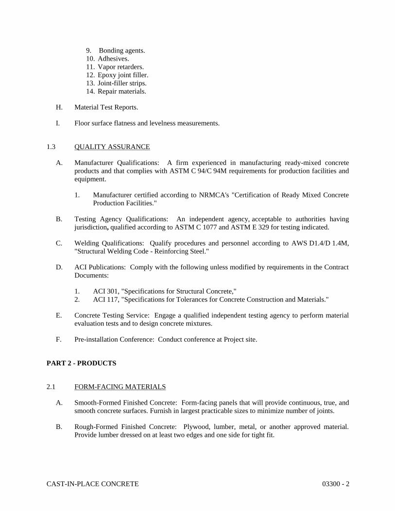
CAST-IN-PLACE CONCRETE 03300 - 2
9. Bonding agents.
10. Adhesives.
11. Vapor retarders.
12. Epoxy joint filler.
13. Joint-filler strips.
14. Repair materials.
H. Material Test Reports.
I. Floor surface flatness and levelness measurements.
1.3 QUALITY ASSURANCE
A. Manufacturer Qualifications: A firm experienced in manufacturing ready-mixed concrete
products and that complies with ASTM C 94/C 94M requirements for production facilities and
equipment.
1. Manufacturer certified according to NRMCA's "Certification of Ready Mixed Concrete
Production Facilities."
B. Testing Agency Qualifications: An independent agency, acceptable to authorities having
jurisdiction, qualified according to ASTM C 1077 and ASTM E 329 for testing indicated.
C. Welding Qualifications: Qualify procedures and personnel according to AWS D1.4/D 1.4M,
"Structural Welding Code - Reinforcing Steel."
D. ACI Publications: Comply with the following unless modified by requirements in the Contract
Documents:
1. ACI 301, "Specifications for Structural Concrete,"
2. ACI 117, "Specifications for Tolerances for Concrete Construction and Materials."
E. Concrete Testing Service: Engage a qualified independent testing agency to perform material
evaluation tests and to design concrete mixtures.
F. Pre-installation Conference: Conduct conference at Project site.
PART 2 - PRODUCTS
2.1 FORM-FACING MATERIALS
A. Smooth-Formed Finished Concrete: Form-facing panels that will provide continuous, true, and
smooth concrete surfaces. Furnish in largest practicable sizes to minimize number of joints.
B. Rough-Formed Finished Concrete: Plywood, lumber, metal, or another approved material.
Provide lumber dressed on at least two edges and one side for tight fit.

CAST-IN-PLACE CONCRETE 03300 - 3
2.2 STEEL REINFORCEMENT
A. Recycled Content of Steel Products: Provide products with an average recycled content of steel
products so postconsumer recycled content plus one-half of pre-consumer recycled content is
not less than 25 percent.
B. Reinforcing Bars: ASTM A 615/A 615M, Grade 60 (Grade 420), deformed.
1. Galvanized Reinforcing Bars: ASTM A 767/A 767M, Class I or Class II zinc coated
after fabrication and bending.
2. Epoxy-Coated Reinforcing Bars: ASTM A 775/A 775M, epoxy coated, with less than 2
percent damaged coating in each 12-inch (300-mm) bar length.
C. Plain-Steel Welded Wire Reinforcement: ASTM A 185/A 185M, plain, fabricated from as-
drawn steel wire into flat sheets.
D. Deformed-Steel Welded Wire Reinforcement: ASTM A 497/A 497M, flat sheet.
E. Galvanized-Steel Welded Wire Reinforcement: ASTM A 185/A 185M, plain, fabricated from
galvanized-steel wire into flat sheets.
F. Epoxy-Coated Welded Wire Reinforcement: ASTM A 884/A 884M, Class A coated, Type 1,
deformed steel.
G. Bar Supports: Bolsters, chairs, spacers, and other devices for spacing, supporting, and fastening
reinforcing bars and welded wire reinforcement in place. Manufacture bar supports from steel
wire, plastic, or precast concrete according to CRSI's "Manual of Standard Practice.
2.3 CONCRETE MATERIALS
A. Cementitious Material: Use the following cementitious materials, of the same type, brand, and
source, throughout Project:
1. Portland Cement: ASTM C 150, Type I or Type II or Type I/II, gray.
a. Fly Ash: ASTM C 618, Class F or C.
b. Ground Granulated Blast-Furnace Slag: ASTM C 989, Grade 100 or 120.
2. Blended Hydraulic Cement: ASTM C 595, Type IS, Portland blast-furnace slag,
Type IP, Portland-pozzolan, Type I (PM), pozzolan-modified Portland, and Type I (SM),
slag-modified Portland cement.
B. Normal-Weight Aggregates: ASTM C 33, graded.
1. Maximum Coarse-Aggregate Size: 1-1/2 inches (38 mm) at slabs on grade, 1 inch (25
mm), at columns and 3/4 inch (19 mm) at beams and slabs nominal.
2. Fine Aggregate: Free of materials with deleterious reactivity to alkali in cement.
C. Lightweight Aggregate: ASTM C 330, 3/8-inch (10-mm) nominal maximum aggregate size.
D. Water: ASTM C 94/C 94M and potable.

CAST-IN-PLACE CONCRETE 03300 - 4
2.4 ADMIXTURES
A. Air-Entraining Admixture: ASTM C 260.
B. Chemical Admixtures: Provide admixtures certified by manufacturer to be compatible with
other admixtures and that will not contribute water-soluble chloride ions exceeding those
permitted in hardened concrete. Do not use calcium chloride or admixtures containing calcium
chloride.
1. Water-Reducing Admixture: ASTM C 494/C 494M, Type A.
2. Retarding Admixture: ASTM C 494/C 494M, Type B.
3. Water-Reducing and Retarding Admixture: ASTM C 494/C 494M, Type D.
4. High-Range, Water-Reducing Admixture: ASTM C 494/C 494M, Type F.
5. High-Range, Water-Reducing and Retarding Admixture: ASTM C 494/C 494M,
Type G.
6. Plasticizing and Retarding Admixture: ASTM C 1017/C 1017M, Type II.
2.5 FIBER REINFORCEMENT
A. Synthetic Micro-Fiber: Monofilament or fibrillated polypropylene micro-fibers engineered and
designed for use in concrete, complying with ASTM C 1116/C 1116M, Type III, 1 to 2-1/4
inches (25 to 57 mm) long.
2.6 WATERSTOPS
A. Flexible Rubber Water-Stops: CE CRD-C 513, with factory-installed metal eyelets, for
embedding in concrete to prevent passage of fluids through joints. Factory fabricated corners,
intersections, and directional changes.
B. Chemically Resistant Flexible Water-Stops: Thermoplastic elastomeric rubber water-stops with
factory-installed metal eyelets, for embedding in concrete to prevent passage of fluids through
joints; resistant to oils, solvents, and chemicals. Factory fabricated corners, intersections, and
directional changes.
C. Flexible PVC Water-stops: CE CRD-C 572, with factory-installed metal eyelets, for embedding
in concrete to prevent passage of fluids through joints. Factory fabricated corners, intersections,
and directional changes.
D. Self-Expanding Butyl Strip Water-Stops: Manufactured rectangular or trapezoidal strip, butyl
rubber with sodium bentonite or other hydrophilic polymers, for adhesive bonding to concrete,
3/4 by 1 inch (19 by 25 mm).
E. Self-Expanding Rubber Strip Water-stops: Manufactured rectangular or trapezoidal strip,
bentonite-free hydrophilic polymer modified chloroprene rubber, for adhesive bonding to
concrete, 3/8 by 3/4 inch (10 by 19 mm).

CAST-IN-PLACE CONCRETE 03300 - 5
2.7 VAPOR RETARDERS
A. Sheet Vapor Retarder: ASTM E 1745, Class C. Include manufacturer's recommended adhesive
or pressure-sensitive tape.
B. Sheet Vapor Retarder: Polyethylene sheet, ASTM D 4397, not less than 10 mils (0.25 mm)
thick.
2.8 CURING MATERIALS
A. Evaporation Retarder: Waterborne, monomolecular film forming, manufactured for application
to fresh concrete.
B. Absorptive Cover: AASHTO M 182, Class 2, burlap cloth made from jute or kenaf, weighing
approximately 9 oz./sq. yd. (305 g/sq. m) when dry.
C. Moisture-Retaining Cover: ASTM C 171, polyethylene film or white burlap-polyethylene
sheet.
D. Water: Potable.
E. Clear, Waterborne, Membrane-Forming Curing Compound: ASTM C 309, Type 1, Class B,
dissipating.
F. Clear, Waterborne, Membrane-Forming Curing Compound: ASTM C 309, Type 1, Class B,
non-dissipating, certified by curing compound manufacturer to not interfere with bonding of
floor covering.
G. Clear, Solvent-Borne, Membrane-Forming Curing and Sealing Compound: ASTM C 1315,
Type 1, Class A.
H. Clear, Waterborne, Membrane-Forming Curing and Sealing Compound: ASTM C 1315,
Type 1, Class A.
2.9 RELATED MATERIALS
A. Expansion- and Isolation-Joint-Filler Strips: ASTM D 1751, asphalt-saturated cellulosic fiber or
ASTM D 1752, cork or self-expanding cork.
2.10 CONCRETE MIXTURES
A. Prepare design mixtures for each type and strength of concrete, proportioned on the basis of
laboratory trial mixture or field test data, or both, according to ACI 301.
B. Cementitious Materials: Use fly ash, pozzolan, ground granulated blast-furnace slag, and silica
fume as needed to reduce the total amount of Portland cement, which would otherwise be used,
by not less than 40 percent.
C. Admixtures: Use admixtures according to manufacturer's written instructions.

CAST-IN-PLACE CONCRETE 03300 - 6
1. Use water-reducing or plasticizing admixture in concrete, as required, for placement and
workability.
2. Use water-reducing and retarding admixture when required by high temperatures, low
humidity, or other adverse placement conditions.
3. Use water-reducing admixture in pumped concrete, concrete for heavy-use industrial
slabs and parking structure slabs, concrete required to be watertight, and concrete with a
water-cementitious materials ratio below 0.50.
D. Proportion normal-weight concrete mixture as follows:
1. Minimum Compressive Strength at 28 days: 4000 psi (27.6 MPa) w/c= 0.60 at
Foundations, walls, and stairs, 3000 psi (20.7 MPa) w/c = 0.7 at sidewalks, slabs on
ground, and miscellaneous architectural elements.
2. Maximum Water-Cementitious Materials Ratio: see item D.1 above.
3. Slump Limit: 4 inches (100 mm) and 8 inches (200 mm) for concrete with verified
slump of 2 to 4 inches (50 to 100 mm) before adding high-range water-reducing
admixture or plasticizing admixture, plus or minus 1 inch (25 mm).
4. Air Content: 5.5 percent, plus or minus 1.5 percent at point of delivery for 1-1/2-inch
(38-mm) nominal maximum aggregate size.
5. Air Content: 6 percent, plus or minus 1.5 percent at point of delivery for 3/4-inch (19-
mm) nominal maximum aggregate size.
6. Air Content: Do not allow air content of trowel-finished floors to exceed 3 percent.
7. Synthetic Micro-Fiber: Uniformly disperse in concrete mixture at manufacturer's
recommended rate, but not less than 1.5 lb/cu. yd. (0.90 kg/cu. m).
E. Proportion structural lightweight concrete mixture as follows:
1. Minimum Compressive Strength: 3000 psi (20.7 MPa) at 28 days.
2. Calculated Equilibrium Unit Weight: 110 lb/cu. ft. (1762 kg/cu. m), plus or minus 3
lb/cu. ft. (48.1 kg/cu. m) as determined by ASTM C 567.
3. Slump Limit: 4 inches (100 mm), plus or minus 1 inch (25 mm).
4. Air Content: 6 percent, plus or minus 2 percent at point of delivery for nominal
maximum aggregate size greater than 3/8 inch (10 mm).
5. Air Content: 7 percent, plus or minus 2 percent at point of delivery for nominal
maximum aggregate size 3/8 inch (10 mm) or less.
6. Air Content: Do not allow air content of trowel-finished floors to exceed 3 percent.
7. Synthetic Micro-Fiber: Uniformly disperse in concrete mixture at manufacturer's
recommended rate, but not less than 1.5 lb/cu. yd. (0.90 kg/cu. m).
2.11 FABRICATING REINFORCEMENT
A. Fabricate steel reinforcement according to CRSI's "Manual of Standard Practice."
2.12 CONCRETE MIXING
A. Ready-Mixed Concrete: Measure, batch, mix, and deliver concrete according to
ASTM C 94/C 94M and ASTM C 1116/C 1116M, and furnish batch ticket information.
CAST-IN-PLACE CONCRETE 03300 - 7
1. When air temperature is between 85 and 90 deg F (30 and 32 deg C), reduce mixing and
delivery time from 1-1/2 hours to 75 minutes; when air temperature is above 90 deg F (32
deg C), reduce mixing and delivery time to 60 minutes.
PART 3 - EXECUTION
3.1 FORMWORK
A. Design, erect, shore, brace, and maintain formwork, according to ACI 301, to support vertical,
lateral, static, and dynamic loads, and construction loads that might be applied, until structure
can support such loads.
B. Construct formwork so concrete members and structures are of size, shape, alignment,
elevation, and position indicated, within tolerance limits of ACI 117.
C. Chamfer exterior corners and edges of permanently exposed concrete.
3.2 EMBEDDED ITEMS
A. Place and secure anchorage devices and other embedded items required for adjoining work that
is attached to or supported by cast-in-place concrete. Use setting drawings, templates,
diagrams, instructions, and directions furnished with items to be embedded.
3.3 VAPOR RETARDERS
A. Sheet Vapor Retarders: Place, protect, and repair sheet vapor retarder according to
ASTM E 1643 and manufacturer's written instructions.
1. Lap joints 6 inches (150 mm) and seal with manufacturers’ recommended tape.
3.4 STEEL REINFORCEMENT
A. General: Comply with CRSI's "Manual of Standard Practice" for placing reinforcement.
1. Do not cut or puncture vapor retarder. Repair damage and reseal vapor retarder before
placing concrete.
3.5 JOINTS
A. General: Construct joints true to line with faces perpendicular to surface plane of concrete.
B. Construction Joints: Install so strength and appearance of concrete are not impaired, at
locations indicated or as approved by Architect.
CAST-IN-PLACE CONCRETE 03300 - 8
C. Contraction Joints in Slabs-on-Grade: Form weakened-plane contraction joints, sectioning
concrete into areas as indicated. Construct contraction joints for a depth equal to at least one-
fourth of concrete thickness as follows:
1. Grooved Joints: Form contraction joints after initial floating by grooving and finishing
each edge of joint to a radius of 1/8 inch (3.2 mm). Repeat grooving of contraction joints
after applying surface finishes. Eliminate groover tool marks on concrete surfaces.
2. Sawed Joints: Form contraction joints with power saws equipped with shatterproof
abrasive or diamond-rimmed blades. Cut 1/8-inch- (3.2-mm-) wide joints into concrete
when cutting action will not tear, abrade, or otherwise damage surface and before
concrete develops random contraction cracks.
D. Isolation Joints in Slabs-on-Grade: After removing formwork, install joint-filler strips at slab
junctions with vertical surfaces, such as column pedestals, foundation walls, grade beams, and
other locations, as indicated.
E. Water-Stops: Install in construction joints and at other joints indicated according to
manufacturer's written instructions.
3.6 CONCRETE PLACEMENT
A. Before placing concrete, verify that installation of formwork, reinforcement, and embedded
items is complete and that required inspections have been performed.
B. Deposit concrete continuously in one layer or in horizontal layers of such thickness that no new
concrete will be placed on concrete that has hardened enough to cause seams or planes of
weakness. If a section cannot be placed continuously, provide construction joints as indicated.
Deposit concrete to avoid segregation.
1. Consolidate placed concrete with mechanical vibrating equipment according to ACI 301.
C. Cold-Weather Placement: Comply with ACI 306.1.
D. Hot-Weather Placement: Comply with ACI 301.
3.7 FINISHING FORMED SURFACES
A. Rough-Formed Finish: As-cast concrete texture imparted by form-facing material with tie holes
and defects repaired and patched. Remove fins and other projections that exceed specified
limits on formed-surface irregularities.
1. Apply to concrete surfaces not exposed to public view.
B. Smooth-Formed Finish: As-cast concrete texture imparted by form-facing material, arranged in
an orderly and symmetrical manner with a minimum of seams. Repair and patch tie holes and
defects. Remove fins and other projections that exceed specified limits on formed-surface
irregularities.
1. Apply to concrete surfaces exposed to public view, to receive a rubbed finish, and to be
covered with a coating or covering material applied directly to concrete.

CAST-IN-PLACE CONCRETE 03300 - 9
C. Rubbed Finish: Apply the following to smooth-formed finished as-cast concrete where
indicated:
1. Smooth-Rubbed Finish: Not later than one day after form removal, moisten concrete
surfaces and rub with carborundum brick or another abrasive until producing a uniform
color and texture. Do not apply cement grout other than that created by the rubbing
process.
2. Grout-Cleaned Finish: Wet concrete surfaces and apply grout of a consistency of thick
paint to coat surfaces and fill small holes. Mix one part Portland cement to one and one-
half parts fine sand with a 1:1 mixture of bonding admixture and water. Add white
Portland cement in amounts determined by trial patches so color of dry grout will match
adjacent surfaces. Scrub grout into voids and remove excess grout. When grout whitens,
rub surface with clean burlap and keep surface damp by fog spray for at least 36 hours.
3. Cork-Floated Finish: Wet concrete surfaces and apply a stiff grout. Mix one part
Portland cement and one part fine sand with a 1:1 mixture of bonding agent and water.
Add white Portland cement in amounts determined by trial patches so color of dry grout
will match adjacent surfaces. Compress grout into voids by grinding surface. In a
swirling motion, finish surface with a cork float.
D. Related Unformed Surfaces: At tops of walls, horizontal offsets, and similar unformed surfaces
adjacent to formed surfaces, strike off smooth and finish with a texture matching adjacent
formed surfaces. Continue final surface treatment of formed surfaces uniformly across adjacent
unformed surfaces unless otherwise indicated.
3.8 FINISHING FLOORS AND SLABS
A. General: Comply with ACI 302.1R recommendations for screeding, restraightening, and
finishing operations for concrete surfaces. Do not wet concrete surfaces.
B. Scratch Finish: While still plastic, texture concrete surface that has been screeded and bull-
floated or darbied. Use stiff brushes, brooms, or rakes to produce profile amplitude of 1/4 inch
(6 mm) in one direction.
1. Apply scratch finish to surfaces indicated and to receive concrete floor toppings or to
receive mortar setting beds for bonded cementitious floor finishes.
C. Float Finish: Consolidate surface with power-driven floats or by hand floating if area is small
or inaccessible to power driven floats. Restraighten, cut down high spots, and fill low spots.
Repeat float passes and restraightening until surface is left with a uniform, smooth, granular
texture.
1. Apply float finish to surfaces as indicated or to receive trowel finish, and to be covered
with fluid-applied or sheet waterproofing, built-up or membrane roofing, or sand-bed
terrazzo.
D. Trowel Finish: After applying float finish, apply first troweling and consolidate concrete by
hand or power-driven trowel. Continue troweling passes and restraighten until surface is free of
trowel marks and uniform in texture and appearance. Grind smooth any surface defects that
would telegraph through applied coatings or floor coverings.

CAST-IN-PLACE CONCRETE 03300 - 10
1. Apply a trowel finish to surfaces exposed to view or to be covered with resilient flooring,
carpet, and ceramic or quarry tile set over a cleavage membrane, paint, or another thin-
film-finish coating system.
2. Finish and measure surface so gap at any point between concrete surface and an
unleveled, freestanding, 10-ft.- (3.05-m-) long straightedge resting on two high spots and
placed anywhere on the surface does not exceed 1/8 inch (3.2 mm).
E. Trowel and Fine-Broom Finish: Apply a first trowel finish to surfaces where ceramic or quarry
tile is to be installed by either thickset or thin-set method. While concrete is still plastic,
slightly scarify surface with a fine broom.
1. Comply with flatness and levelness tolerances for trowel-finished floor surfaces.
F. Broom Finish: Apply a broom finish to exterior concrete platforms, steps, ramps, and
elsewhere as indicated.
3.9 CONCRETE PROTECTING AND CURING
A. General: Protect freshly placed concrete from premature drying and excessive cold or hot
temperatures. Comply with ACI 306.1 for cold-weather protection and ACI 301 for hot-
weather protection during curing.
B. Evaporation Retarder: Apply evaporation retarder to unformed concrete surfaces if hot, dry, or
windy conditions cause moisture loss approaching 0.2 lb/sq. ft. x h (1 kg/sq. m x h) before and
during finishing operations. Apply according to manufacturer's written instructions after
placing, screeding, and bull floating or darbying concrete, but before float finishing.
C. Cure concrete according to ACI 308.1, by one or a combination of the following methods:
1. Moisture Curing: Keep surfaces continuously moist for not less than seven days.
2. Moisture-Retaining-Cover Curing: Cover concrete surfaces with moisture-retaining
cover for curing concrete, placed in widest practicable width, with sides and ends lapped
at least 12 inches (300 mm), and sealed by waterproof tape or adhesive. Cure for not less
than seven days. Immediately repair any holes or tears during curing period using cover
material and waterproof tape.
3. Curing Compound: Apply uniformly in continuous operation by power spray or roller
according to manufacturer's written instructions. Recoat areas subjected to heavy rainfall
within three hours after initial application. Maintain continuity of coating and repair
damage during curing period.
a. Removal: After curing period has elapsed, remove curing compound without
damaging concrete surfaces by method recommended by curing compound
manufacturer, unless manufacturer certifies curing compound will not interfere
with bonding of floor covering used on Project.
4. Curing and Sealing Compound: Apply uniformly to floors and slabs indicated in a
continuous operation by power spray or roller according to manufacturer's written
instructions. Recoat areas subjected to heavy rainfall within three hours after initial
application. Repeat process 24 hours later and apply a second coat. Maintain continuity
of coating and repair damage during curing period.

CAST-IN-PLACE CONCRETE 03300 - 11
3.10 CONCRETE SURFACE REPAIRS
A. Defective Concrete: Repair and patch defective areas when approved by Architect. Remove
and replace concrete that cannot be repaired and patched to Architect's approval.
3.11 FIELD QUALITY CONTROL
A. Testing and Inspecting: Owner will engage a qualified testing and inspecting agency to perform
field tests and inspections and prepare test reports.
END OF SECTION 03300


PRBA MASTER SPECIFICATION GUIDELINES
PRBA Master Specification 035216 Lightweight Cellular Guidelines Insulating Concrete (LWIC)
SECTION 03 52 16
LIGHTWEIGHT CELLULAR INSULATING CONCRETE (LWIC)
PART 1 - GENERAL 1.1 RELATED DOCUMENTS
A. Drawings and general provisions of the Contract, including all General and Supplementary Conditions apply to this section.
1.2 SUMMARY A. This section includes cast-in-place cellular lightweight insulating concrete for roof
decks, concrete, steel or approved existing roofing assemblies. B. Related Sections include: 1. Metal Decking, Division 05000 2. Rough Carpentry, Wood blocking and curbs, Division 06000 3. Roof Membrane, Division 07000 Single Ply Feltback PVC Membranes 1.3 DEFINITIONS A. Cellular Lightweight Insulating Concrete: Low-density concrete produced using
preformed foam. 1.4 REFERENCES A. ASTM C 150, Standard Specification for Portland Cement. B. ASTM C 138, Standard Test Method for Density (Unit Weight), Yield, and Air
Content (Gravimetric) of Concrete. C. ASTM C 172, Standard Practice for Sampling Freshly Mixed Concrete. D. ASTM E 329, Standard Specification for Agencies Engaged in Construction
Inspection, Testing or Special Inspection. E. ASTM C 495, Standard Test Method for Compressive Strength of Lightweight
Insulating Concrete. F. ASTM C 796, Standard Test Method for Foaming Agents for use in Producing
Cellular Concrete Using Preformed Foam. G. ASTM C 869, Standard Specification for Foaming Agents Used in Making
Preformed Foam for Cellular Concrete. H. ASTM C 578, Standard Specification for Rigid Cellular Polystyrene Thermal
Insulation.

PRBA MASTER SPECIFICATION GUIDELINES
PRBA Master Specification 035216 Lightweight Cellular Guidelines Insulating Concrete (LWIC)
I. ASTM C 177, Standard Test Method for Steady State Heat Flux Measurements
and Thermal Transmission Properties by Means of the Guarded Hot Plate Apparatus.
J. ASTM C 518, Standard Test Method for Steady State Thermal Transmission
Properties by Means of the Heat Flow Meter Apparatus. K. ASTM C 513, Standard Test Method for Obtaining and Testing Specimens of
Hardened Lightweight Insulating Concrete for Compressive Strength. L. ASTM C 1077, Standard Practice for Agencies Testing Concrete and Concrete
Aggregates for Use in Construction and Criteria for Testing Agency Evaluation. 1.5 SUBMITTALS A. Product data for the cellular lightweight insulating concrete and the polystyrene
insulating board indicating compliance with all applicable Approvals, Standards and required physical property values.
B. Florida Product Approval Number, 2020 Code Version, including HVHZ Approval. C. Miami Dade County, Notice of Product Acceptance - NOA D. Shop drawings indicating polystyrene insulation layout and thicknesses, slope and
drain locations, high and low point thickness from atop the structural deck. E. Applicator shall be a firm Approved in writing by the foam concentrate
Manufacturer. The Manufacturer provided Approval letter shall mention the project by name.
F. Certificates from manufacturers certifying that each of the following materials
comply with referenced standards: 1. Portland Cement 2. Foaming Agent 3. Admixtures 4. Expanded Polystyrene (EPS) Holey Board Insulation 1lb. minimum density. 1.6 QUALITY ASSURANCE A. Testing Agency Qualification: An independent testing agency shall be qualified in
accordance with ASTM C 1077 and ASTM E 329 for testing indicated. B. FM Global Approval: provide cellular lightweight insulating concrete that has been
evaluated by FM Approvals as part of a roof assembly and is listed in the FM RoofNav data base for Class 1 and non-combustible construction.
C. UL Fire Resistance Ratings: where indicated, provide cellular lightweight insulating
concrete identical to those assemblies tested for fire resistance per ASTM E 119 and listed in UL’s Fire Resistance Directory. The cellular lightweight insulating concrete shall be UL Classified and listed in the current UL Fire Resistant Design Directory under Category COXX, Floor and Roof Topping Mixtures.

PRBA MASTER SPECIFICATION GUIDELINES
PRBA Master Specification 035216 Lightweight Cellular Guidelines Insulating Concrete (LWIC)
D. The Applicator shall submit evidence that the proposed roof system meets the requirements of the local building code (Puerto Rico Building Code 2018) and has been tested and approved or listed by an approved, codified testing organization. These requirements are minimum standards, and no roofing work shall commence without written documentation of the system's compliance.
1.7 DELIVERY AND STORAGE
A. Deliver materials unopened in the manufacturer’s original packaging or by acceptable bulk delivery.
B. Materials shall be identifiable by manufacturers labeling. C. Where applicable materials shall bear the following Approval Marks: 1. Underwriters Laboratories - UL 2. Factory Mutual - FM 3. Local Building Code Conformance 1.8 PROJECT CONDITIONS .
A. Do not place during precipitation, or when there is a likely expectation that precipitation will occur. Do not place upon surfaces covered with water, debris, or other types of containments.
1.9 WARRANTY / GUARANTEE
A. Upon successful completion of the project, after all post installations have been completed, furnish the Owner a roof deck system manufacturer’s warranty. The warranty shall be a term type and shall be issued to the Owner at no additional cost. Specific items covered under the warranty shall include:
1. The actual resistance to heat flow through the roof insulation will be at least 80% of the designed thermal resistance, provided the insulation is dry and the roof membrane is free of leaks.
2. The roof insulation will remain in a re-roof able condition should the roof membrane require replacement during the original term of the warranty (excluding damage caused by fastener withdrawal during the removal of the roof cover).
3. The roof insulation will not cause structural damage to the building because of expansion from thermal or chemical reaction.
4. The roof insulation will not cause the roof membrane to leak because of vapor pressure build-up from batching (mixing) water used to produce the insulating concrete.
5. The roof insulation warranty period shall be 20 years from the date of substantial completion. 6. All thermoplastic PVC single ply Fleece Back 60 mils minimum membranes fully adhere using water-based adhesives to the LWIC to achieve an FM 1-525 PSF

PRBA MASTER SPECIFICATION GUIDELINES
PRBA Master Specification 035216 Lightweight Cellular Guidelines Insulating Concrete (LWIC)
uplift rating. Initial Solar Reflectance of 85. Membrane manufacture to provide a minimum 20-year NDL single ply warranty over the LWIC.
PART 2 - PRODUCTS 2.1 APPROVED LWIC MANUFACTURERS
A. Manufacturers whose products are listed and meet or exceed the requirements of this specification are approved for use.
B. Basis of Design: Celcore Incorporated, www.celcoreinc.com.
C. Manufacturers listed below may be considered, subject to compliance with the
specification:
1. Elastizell, Elastizell.com 2. Mearlcrete, Aerix Industries
2.2 MATERIALS A. Cement: Portland type l, I/ll meeting ASTM C150
B. Water: shall be clean, potable, free from injurious quantities of acid, alkali, salt, oil, organic matter, and other impurities. The maximum permissible chloride level is 250 ppm.
C. Foaming Agent: meeting ASTM C 869 when tested in accordance with ASTM C
796. Foam concentrate shall be labeled bearing FM, UL, and Local Construction Code Compliance. Approval Marks.
D. Admixtures: admixtures shall not be used unless approved in writing by the Foam
Manufacturer. E. Insulating Board: shall be a product of expanded polystyrene meeting ASTM C
578, 1 lb/ft³ nominal density with holes comprising approximately 3% of the gross surface area. Approved manufacturers include:
1. Carpenter Company: www.carpenter.com 2. Cellofoam North America: www.cellofoam.com 3. Dyplast Products, LLC: www.dyplastproducts.com 4. Insulfoam: www.insulfoam.com 5. All local approved equal meeting specifications. F. Curing Compound: as required by the insulating concrete manufacturer and
applied in accordance with the manufacturer’s instructions. 2.3 CELLULAR INSULATING CONCRETE
A. Mix materials in strict accordance with recommendations of the foam manufacturer to yield the proper physical properties. Use the minimum amount of mix water required to produce concrete having good placement and working properties.
B. Mix and pump the cellular lightweight insulating concrete into place using a batch

PRBA MASTER SPECIFICATION GUIDELINES
PRBA Master Specification 035216 Lightweight Cellular Guidelines Insulating Concrete (LWIC)
plant approved by the foam manufacturer. Thoroughly blend all materials before discharging the mixer.
C. Wet cast density: 38-42 lbs/ft³ (+/- 3 lbs/ft³) at the point of placement when sampled
in accordance ASTM C 172 except as modified by the applicable sections of ASTM C 495. End of hose wet density shall be determined in accordance ASTM C 138. Do not rod or vibrate sample.
D. Oven dry density: 26 - 36 lbs/ft³ when tested at 28 days in accordance with the
applicable sections of ASTM C 495. E. The cellular insulating concrete shall have a minimum 28-day compressive
strength of 300 -350 psi when tested in accordance with ASTM C 495. F. The insulating concrete deck shall be designed to provide an ¼” in 12 slope and
½” tapered crickets to drains. R-value of: R = 20 PART 3 - EXECUTION 3.1 EXAMINATION A. Structural Concrete Deck: verify that the surface of the structural concrete deck to
receive the cellular insulating concrete is free from any materials, debris, standing water, other coverings and/or substances that may prevent bond.
B. Steel Deck: examine the decking for inadequate anchorage, foreign materials,
debris, moisture, or unevenness that would prevent proper application or adequate bond. Report inadequacies for correction. Consult manufacturer for best venting practice.
3.2 PREPARATION
A. Cover and protect all equipment, stands, curbs, drains, etc., prior to beginning placement of the cellular insulating concrete.
B. Protect all elements that interface with or are beneath the insulating concrete
placement from application damage or disfigurement. 3.3 INSTALLATION
A. Place a slurry layer of cellular concrete to a minimum thickness of 1/8 inch over top of the approved substrate (concrete, steel or recovering conditions).
B. Immediately place the EPS holey board insulation into the fresh cellular concrete
layer in a manner which causes the boards underside to make full contact with the concrete. Cellular concrete shall be caused to enter the keying holes of the board. The insulation board shall be placed in a brick like pattern of staggered joints butted together.
C. When required, install the EPS holey board in a stepped configuration with
maximum steps of 1 inch. D. The installed EPS holey board layer shall be allowed to set overnight undisturbed

PRBA MASTER SPECIFICATION GUIDELINES
PRBA Master Specification 035216 Lightweight Cellular Guidelines Insulating Concrete (LWIC)
prior to receiving topping.
F. Place a minimum 2-inch-thick topping layer of cellular insulating concrete above the insulation board. Screed and hand finished the placement to a smooth surface.
G. Apply curing compound to the surface of the deck after topping placement once
the layer has hardened sufficiently to receive foot traffic without causing damage. Curing shall be applied at a rate and in a manner recommended by the foam manufacturer.
3.4 FIELD QUALITY CONTROL
A. End-of-hose wet density checks shall be taken every thirty minutes during placement. Density information shall be recorded by the placement foreman and kept as a written project record. Sampling shall be done in accordance ASTM C 172 except as modified by the applicable sections of ASTM C 495.
B. Cylindrical test specimen shall be cast during each day’s placement or at every
5,000 sq/ft of placement. Specimens shall be cast in accordance with the applicable sections of ASTM C 495. Do not rod. A set of test specimens shall be considered (6) 3 x 6 cylinders. (4) specimens of each set shall be tested for compressive strength and (2) shall be for oven-dry density determination. Testing shall be conducted at age 28 days in accordance with ASTM C 495.
C. Retesting for compressive strength and oven dry density, if required, shall be done
in accordance with ASTM C 513. 3.5 PROTECTION
A. The installed cellular insulating concrete roof deck shall be protected from work traffic for a minimum of 48 hours after topping placement. The roof deck shall be protected from concentrated loads of construction materials. Load distribution materials such as plywood shall be used by other trades when stocking materials.
B. Coordinate installation of the roof cover such that the installed insulating concrete
deck is not exposed for unnecessary extended periods of time. Membrane installation is recommended to begin within 3 to 7 days following roof deck topping placement.
3.6 REPAIRS
A. Where required to provide a surface condition acceptable to receive the roof cover, repairs to smooth the deck surface, correct depressions or fill divots shall be done in accordance with written guidance provided by the foam concentrate manufacturer.
3.7 DEFECTIVE WORK A. Remove and replace any area of the roof deck placement that fails to comply with
the requirements of the foam manufacturer, this specification or applicable product Approvals.

PRBA MASTER SPECIFICATION GUIDELINES
PRBA Master Specification 035216 Lightweight Cellular Guidelines Insulating Concrete (LWIC)
END OF SECTION 03 52 16

SECTION 03732
CONCRETE REPAIR
PART 1 - GENERAL
1.1 SECTION INCLUDES
A. Preparation of concrete and application of repair materials.
B. Rehabilitation and Restoration of concrete surfaces.
C. Repair of concrete internal reinforcement.
1.2 RELATED SECTIONS
A. Section 03300 – Cast-In-Place Concrete.
B. Section 04500 – Masonry Restoration and Cleaning.
1.3 REFERENCES
A. ASTM A82 Cold Drawn Steel Wire for Concrete Reinforcement.
B. ASTM A615/A615M Deformed and Plain Billet-Steel Bars for Concrete Reinforcement.
C. ASTM A616/A616M Rail-Steel Deformed and Plain Bars for Concrete Reinforcement.
D. ASTM A617/A617M Axle-Steel Deformed and Plain Bars for Concrete Reinforcement.
E. ASTM C33 Specifications for Concrete Aggregates.
F. ASTM C150 Portland Cement.
G. ASTM C404 Aggregates for Masonry Grouts.
H. ASTM C882 Bond Strength of Epoxy Resin Systems Used with Concrete.
I. ASTM D638 Test Method for Tensile Properties of Plastics.
J. ASTM D695 Compressive Properties of Rigid Plastics.
K. ASTM D790 Flexural Properties of Plastics and Electrical Insulating Materials.
L. AWS D1.4 Structural Welding Code for Reinforcing Steel
1.4 SUBMITTALS FOR REVIEW
A. Section 01300 Submittals: Procedures for submittals.
B. Product Data: Indicate product standards, physical and chemical characteristics, technical
specifications, limitations, maintenance instructions, and general recommendations regarding
each material.
1.5 SUBMITTALS FOR INFORMATION
A. Section 01300 – Submittals: Procedures for submittals.
B. Manufacturer’s Certificate: Certify that specified products meet or exceed specified
requirements.

CONCRETE REPAIR
03732 - 2
1.6 SUBMITTALS AT PROJECT CLOSEOUT
A. Accurately record actual locations of structural reinforcement repairs, and type of repair.
1.7 QUALITY ASSURANCE
A. Perform welding work in accordance with AWS D1.4.
B. Materials Manufacturer: Company specializing in manufacturing the products specified in
this Section with minimum five years documented experience.
C. Design reinforcement splices under direct supervision of a Professional Structural Engineer
experienced in design of this Work and licensed at the place where the Project is located or in
the Commonwealth of Puerto Rico.
D. Applicator: Company specializing in concrete repair approved by manufacturer.
1.8 DELIVERY, STORAGE, AND PROTECTION
A. Section 01600 Material and Equipment: Transport, handle, store, and protect products.
B. Comply with instructions for storage, shelf life limitations, and handling.
PART 2 - PRODUCTS
2.1 PATCHING MATERIALS
A. Epoxy Resin: Two-part epoxy adhesive containing 100 percent solids, meeting the following
minimum characteristics:
Characteristic Test Method Results
1. Bond Strength ASTM C882 2,700 psi. (18.6 MPa)
2. Tensile Strength ASTM D638 6,600 psi. (45 MPa)
3. Elongation ASTM D638 2 percent at 7 days at 70
degrees F (21 degrees C)
4. Flexural Strength ASTM D790 8,000 psi. (45 MPa)
5. Compressive Strength ASTM D695 6,500 psi. (55 MPa)
B. Bonding Agent: Polyvinyl acetate emulsion, dispersed in water while mixing, non-coagulant
in mix, water resistant when cured.
C. Portland Cement: ASTM C150, Type I, grey color.
D. Sand: ASTM C 33; uniformly graded, clean.
E. Water: Clean and potable.
F. Cleaning Agent: Commercial muriatic acid.
2.2 REINFORCEMENT MATERIALS
A. Reinforcing Steel: ASTM A615/A615M, 60 ksi (414 mPa) yield grade billet-steel deformed
bars, unfinished finish.
B. Stirrup Steel: ASTM A82.

CONCRETE REPAIR
03732 - 3
2.3 MIXING EPOXY MORTARS
A. Mix epoxy mortars in accordance with manufacturer’s instructions for purpose intended.
B. Mix components in clean equipment or containers. Conform to pot life and workability
limits.
2.4 MIXING CEMENTITIOUS MATERIALS
A. Mix cementitious [mortar] [grout] in accordance with manufacturer’s instructions for purpose
intended.
B. [Include] [Exclude] bonding agent as additive to mix.
PART 3 - EXECUTION
3.1 EXAMINATION
A. Verify that surfaces are ready to receive work.
B. Beginning of installation means acceptance of existing surfaces.
3.2 PREPARATION
A. Clean concrete surfaces of dirt, laitance, corrosion, or other contamination: wire brush using
acid; rinse surface and allow to dry.
B. Flush out cracks and voids muriatic acid to remove laitance and dirt. Chemically neutralize
by rinsing with water.
C. Provide temporary entry ports spaced to accomplish movement of fluids between ports; no
deeper than the depth of the crack to be filled or port size diameter no greater than the
thickness of the crack. Provide temporary seal at concrete surface to prevent leakage of
adhesive.
D. For areas patched with epoxy mortar, remove broken and soft concrete ¼ inch (6 mm) deep.
Remove corrosion from steel. Clean surfaces mechanically; wash with acid; rinse with water.
E. Sandblast clean the exposed reinforcement steel surfaces. Mechanically cut away damaged
portions of bar.
3.3 REPAIR WORK
A. Repair exposed structural, shrinkage, and settlement cracks of concrete as indicated on
Drawings by the epoxy injection method.
B. Repair spalls. Fill voids flush with surface. Apply surface finish.
C. Repair reinforcement by welding new bar reinforcement to existing reinforcement. Strength
of welded splices and reinforcement to exceed original stress values.

CONCRETE REPAIR
03732 - 4
3.4 INJECTION – EPOXY RESIN ADHESIVE
A. Inject adhesive into prepared ports under pressure using equipment appropriate for particular
application.
B. Begin injection at lower entry port and continue until adhesive appears in adjacent entry port.
Continue from port to port until entire crack is filled.
C. Remove temporary seal and excess adhesive.
D. Clean surfaces adjacent to repair and blend finish.
3.5 APPLICATION – EPOXY MORTAR
A. Trowel-applied mortar mix to an average thickness of ¼ inches (6mm). Tamp into place
filling voids at spalled areas.
B. For patching honeycomb, trowel mortar onto surface, work mortar into honeycomb to bring
surface flush with surrounding area. Finish trowel surface to match surrounding area.
C. Cover exposed steel reinforcement with epoxy mortar, feather edges to flush surface.
3.6 APPLICATION – CEMENTITIOUS MORTAR
A. Apply roller coating of bonding agent to dry concrete surfaces. Provide full surface coverage.
B. Apply cementitious mortar by steel trowel to an average thickness of ¼ inches (6mm). Tamp
into place filling voids at spalled areas. Work mix into honeycomb.
C. Damp cure cementitious mortar for four days.
3.7 FIELD QUALITY CONTROL
A. Test concrete for calcium chloride content during the execution of the Work.
END OF SECTION 03732

FOR REFERENCE ONLY

FOR REFERENCE ONLY

FOR REFERENCE ONLY

FOR REFERENCE ONLY

FOR REFERENCE ONLY

SECTION 05120
STRUCTURAL STEEL
PART 1 – GENERAL
1.1 RELATED DOCUMENTS
A. Drawings and general provisions of the Contract, including General and Supplementary
Conditions
B. Division 1 Specification Sections, apply to this Section.
1.2 SUMMARY
A. This Section includes structural steel.
B. This Section includes structural steel and architecturally exposed structural steel.
C. Related Sections: The following Sections contain requirements that relate to this Section:
1. Division 1 Section “Quality Control” for independent testing agency procedures and
administrative requirements.
2. Division 5 Section “Steel Deck” for field installation of shear connectors.
3. Division 5 Section “Metal Fabrications” for loose steel bearing plates and miscellaneous
steel framing.
4. Division 9 Section “Special Coatings” for surface preparation and priming requirements.
5. Division 9 Section “Painting” for surface preparation and priming requirements.
1.3 PERFORMANCE REQUIREMENTS
A. Structural Performance: Engineer structural steel connections required by the Contract
Documents to be selected or completed by the fabricator to withstand design loadings
indicated.
B. Engineering Responsibility: engage a fabricator who utilizes a qualified professional engineer
to prepare calculations, Shop Drawings, and other structural data for structural steel
connections.
1.4 SUBMITTALS
A. General: Submit each item in this Article according to the Conditions of the Contract and
Division 1 Specification Sections.
B. Product Data for each type of product specified.

STRUCTURAL STEEL
05120-2
C. Shop Drawings detailing fabrication of structural steel components.
1. Include details of cuts, connections, splices, camber, holes, and other pertinent data.
2. Indicated welds by standard AWS symbols, distinguishing between shop and filed welds,
and show size, length, and type of each weld.
3. Indicate type, size, and length of bolts, distinguishing between shop and field bolts.
Identify high strength bolted slip-critical, direct-tension, or tensioned shear/bearing
connections.
4. Include Shop Drawings signed and sealed by a qualified professional engineer
responsible for their preparation.
D. Qualification data for firms and persons specified in the “Quality Assurance” Article to
demonstrate their capabilities and experience. Include lists of completed projects with project
names and addresses, names and addresses of architects and owners, and other information
specified.
E. Mill test reports signed by manufacturers certifying that their products, including the
following, comply with requirements.
1. Structural steel, including chemical and physical properties.
2. Bolt, nuts, and washers, including mechanical properties and chemical analysis.
3. Direct-tension indicators.
4. Shear stud connectors.
5. Shop primers.
6. Non-shrink grout.
1.5 QUALITY ASSURANCE
A. Installer Qualifications: Engage an experienced installer who has completed structural steel
work similar in material, design, and extent to that indicated for this Project and with a record
of successful in-service performance.
B. Fabricator Qualifications: Engage a firm experienced in fabricating structural steel similar to
that indicated for this Project and with a record of successful in-service performance, as well
as sufficient production capacity to fabricate structural steel without delaying the Work.
1. Fabricator must participate in the AISC Quality Certification Program and be designated
an AISC Certified Plant as follows:
a. Category: Category I, conventional steel structures.
b. Category: Category II, complex steel building structures.
c. Fabricator shall be registered with and approved by authorities having jurisdiction.
C. Comply with applicable provisions of the following specifications and documents:
1. AISC’s “Specification for Structural Steel Buildings-Allowable Stress Design and Plastic
Design”.
2. AISC’s “Load and Resistance Factor Design (LFRD) Specification for Structural Steel
Buildings”.

STRUCTURAL STEEL
05120-3
3. AISC’s “Specification for Allowable Stress Design of Single-Angle Members”.
4. AISC’s “Specification for Load and Resistance Factor Design of Single-Angle
Members”.
5. AISC’s “Seismic Provisions for Structural Steel Buildings”.
6. ASTM A 6 (ASTM A 6M) “Specification for General Requirements for Rolled Steel
Plates, Shapes, Sheet Piling, and Bars for Structural Use”.
7. Research Council on Structural Connections’ (RCSC) “Specification for Structural Joints
Using ASTM A 325 or A 490 Bolts”.
8. Research Council on Structural Connections’ (RCSC) “Load and Resistance Factor
Design Specification for Structural Joints Using ASTM A 325 or A 490 Bolts”.
D. Professional Engineer Qualifications: A professional engineer who is legally authorized to
practice in the jurisdiction where Project is located and who is experienced in providing
engineering services of the kind indicated. Engineering services are defined as those
performed for projects with structural steel framing that are similar to that indicated for this
Project in material, design, and extent.
E. Welding Standards: Comply with applicable provisions of AWS D1.1 “Structural Welding
Code-Steel”.
1. Present evidence that each welder has satisfactorily passed AWS qualification tests for
welding processes involved and, if pertinent, has undergone recertification.
F. Mockups: Prior to installing architecturally exposed structural steel, construct mockups for
each form of construction and finish required to demonstrate aesthetic effects as well as
qualities of materials and execution. Build mockups to comply with the following
requirements, using materials indicated for final unit of Work.
1. Locate mockups on-site in the location and of the size indicated or, if not indicated, as
directed by Architect.
2. Notify Architect one week in advance of the dates and times when mockups will be
constructed.
3. Demonstrate the proposed range of aesthetic effects and workmanship of steel surfaces
and welded and bolted connections.
a. Coordinate finish painting requirements of mockups with Division 9 Section
“Painting”.
4. Obtain Architect’s approval of mockups before start of final unit of Work.
5. Retain and maintain mockups during construction in an undisturbed condition as a
standard for judging the completed Work.
a. When directed, demolish and remove mockups from Project site.
b. Approved mockups in an undisturbed condition at the time of Substantial Completion
may become part of the completed Work.
G. Pre-installation Conference: Conduct conference at Project site to comply with requirements
of Division 1 Section “Project Meetings”.

STRUCTURAL STEEL
05120-4
1.6 DELIVERY, STORAGE, AND HANDLING
A. Deliver structural steel to Project site in such quantities and at such times to ensure continuity
of installation.
B. Store materials to permit easy access for inspection and identification. Keep steel members
off ground by using pallets, platforms, or other supports. Protect steel members and packaged
materials from erosion and deterioration.
1. Store fasteners in a protected place. Clean and re-lubricate bolts and nuts that become
dry or rusty before use.
2. Do not store materials on structure in a manner that might cause distortion or damage to
members or supporting structures. Repair or replace damaged materials or structures as
directed.
1.7 SEQUENCING
A. Supply anchorage items to be embedded in or attached to other construction without delaying
the Work. Provide setting diagrams, templates, instructions, and directions, as required, for
installation.
PART 2 – PRODUCTS
2.1 MATERIALS
A. Structural Steel Shapes, Plates, and Bars: As follows:
1. Carbon Steel: ASTM A 36 (ASTM A 36M).
2. High-Strength, Low-Alloy Columbium-Vanadium Steel: ASTM A 572 (ASTM A 572M),
Grade 50.
3. High-Strength. Low-Alloy Structural Steel: ASTM A 588 (ASTM A 588M), Grade 50,
corrosion resistant.
B. Cold-Formed Structural Steel Tubing: ASTM A 500, Grade B.
C. Hot-Formed Structural Steel Tubing: ASTM A 501.
D. Steel Pipe: ASTM A 53, Type E or S, Grade B.
1. Weight Class: Standard.
2. Weight Class: Extra strong.
3. Weight Class: Double-extra strong.
4. Finish: Black
5. Finish: Galvanized.
6. Finish: Black, except where indicated to be galvanized.

STRUCTURAL STEEL
05120-5
E. Carbon-Steel Castings: ASTM A 27, Grade 65-35 (ASTM A 27M, Grade 450-240), medium-
strength carbon steel.
F. High-Strength Steel Castings: ASTM A 148, Grade 80-50 (ASTM A 148M), (Grade 550-
345).
G. Shear Connectors: ASTM A 108, Grade 1015 through 1020, headed-stud type, cold-finished
carbon steel, AWS D 1.1, Type B.
H. Anchor Rods, Bolts, Nuts, and Washers: As follows:
1. Un-headed Rods: ASTM A 36 (ASTM A 36M).
2. Un-headed Rods: ASTM A 572, Grade 50 (ASTM A 572M, Grade 345).
3. Un-headed Bolts: ASTM A 687, high strength.
4. Headed Bolts: ASTM A 307, Grade A (ASTM F 568, Property Class 4.6); carbon-steel,
hex-head bolts; and carbon-steel nuts.
5. Headed Bolts: ASTM A 325 (ASTM A 325M), Type 1, heavy hex steel structural bolts
and heavy hex carbon-steel nuts.
6. Headed Bolts: ASTM A 490 (ASTM A 490M), Type 1, heavy hex steel structural bolts
and heavy hex carbon-steel nuts.
7. Washers: ASTM A 36 (ASTM A 36M).
I. Non-high Strength Bolts, Nuts, and Washers: ASTM A 307, Grade A (ASTM F 568, Property
Class 4.6); carbon-steel, hex-head bolts; carbon-steel nuts: and flat, unhardened steel washers.
1. Finish: Plain, uncoated.
2. Finish: Hot-dip zinc-coating, ASTM A 153, Class C.
3. Finish: Mechanically deposited zinc-coating, ASTM B 695, Class 50.
J. High Strength Bolts, Nuts, and Washers: ASTM A 325 (ASTM A 325M), Type 1, heavy hex
steel structural bolts, heavy hex carbon-steel nuts, and hardened carbon-steel washers.
1. Finish: Plain, uncoated.
2. Finish: Hot-dip zinc-coating, ASTM A 153, Class C.
3. Finish: Mechanically deposited zinc-coating, ASTM B 695, Class 50.
4. Direct-Tension Indicators: ASTM F 959, Type 325.
a. Finish: Plain, uncoated.
b. Finish: Mechanically deposited zinc-coating, ASTM B 695, Class 50.
c. Finish: Mechanically deposited zinc-coating, ASTM B 695, Class 50, epoxy coated.
K. High-Strength Bolts, Nuts, and Washers: ASTM A 490 (ASTM A 490M), Type 1, heavy hex
steel structural bolts, heavy hex carbon-steel nuts, and hardened carbon-steel washers,
uncoated.
1. Direct-Tension Indicators: ASTM F 959, Type 490, uncoated.
L. Welding Electrodes: Comply with AWS requirements.

STRUCTURAL STEEL
05120-6
2.2 PRIMER
A. Primer Fast-curing, lead- and chromate-fee, universal modified-alkyd primer with good
resistance to normal atmospheric corrosion, complying with performance requirements of FS
TT-P-664.
B. Primer: SSPC-Paint 25; red iron oxide, zinc oxide, raw linseed oil and alkyd primer.
C. Primer, SSPC-Paint 23, Type I, latex primer.
D. Primer SSPC-Paint 15, Type I, red oxide.
E. Primer: Fabricator’s standard lead-and chromate-free, non-asphaltic, rust-inhibiting primer.
F. Primer: Non-asphaltic primer complying with SSPC’s “Painting System Guide No. 7.00”.
G. Galvanizing Repair Paint: High-zinc-dust-content paint for re-galvanizing welds and repair
painting galvanized steel, with dry film containing not less than 93 percent zinc dust by
weight, and complying with DODP-21035A or SSPC-Paint 20.
2.3 GROUT
A. Cement Grout: Portland cement, ASTM C 150, Type I; and clean, natural sand, ASTM C
404, Size No. 2. Mix at ratio of 1 part cement to 2-1/2 parts sand, by volume, with minimum
water required for placement and hydration.
B. Metallic, Shrinkage-Resistant Grout: Premixed, factory-packaged, ferrous aggregate grout,
complying with ASTM C 1107, of consistency suitable for application, and a 30 minute
working time.
C. Nonmetallic, Shrinkage-Resistant Grout: Premixed, nonmetallic, noncorrosive, non-staining
grout containing selected silica sands, Portland cement, shrinkage compensating agents,
plasticizing and water reducing agents, complying with ASTM C 1107, of consistency
suitable for application, and a 30-minute working time.
2.4 FABRICATION
A. Fabricate and assemble structural steel in shop to greatest extent possible. Fabricate
structural steel according to AISC specifications referenced in this Section and in Shop
Drawings.
1. Camber structural steel members where indicated.
2. Identify high-strength structural steel according to ASTM A 6 (ASTM A 6M) and
maintain markings until steel has been erected.
3. Mark and match-mark materials for field assembly.
4. Fabricate for delivery a sequence that will expedite erection and minimize field handling
of structural steel.
5. Complete structural steel assemblies, including welding of units, before starting shop-
priming operation.

STRUCTURAL STEEL
05120-7
6. Comply with fabrication tolerance limits of AISC’s “Code of Standard Practice for Steel
Buildings and Bridges” for structural steel.
B. Fabricate architecturally exposed structural steel with exposed surfaces smooth, square, and
free of surface blemishes, including pitting, rust and scale seam marks, roller marks, rolled
trade names, and roughness.
1. Remove blemishes by filling, grinding, or by welding and grinding, prior to cleaning,
treating and shop priming.
2. Comply with fabrication requirements, including tolerance limits, of AISC’s “Code of
Standard Practice for Steel Buildings and Bridges” for architecturally exposed structural
steel.
C. Thermal Cutting: Perform thermal cutting by machine to greatest extent possible.
1. Plane thermally cut edges to be welded.
D. Finishing: Accurately mill ends of columns and other members transmitting loads in bearing.
E. Shear Connectors: Prepare steel surfaces as recommended by manufacturer of shear
connectors: Use automatic end welding of headed-stud hear connectors according to AWS
D1.1 and manufacturer’s printed instructions.
F. Steel Wall Framing: Select true and straight members for fabricating steel wall framing to be
attached to structural steel framing. Straighten as required to provide uniform, square, and
true members in completed wall framing.
G. Welded Door Frames: Build up welded door frames attached to structural steel framing.
Weld exposed joints continuously and grind smooth. Plug-weld fixed steel bar stops to
frames. Secure removable stops to frames with countersunk, cross-recessed head machine
screws, uniformly spaced not more than 10 inches (250 mm) o.c., unless otherwise indicated.
H. Holes: Provide holes required for securing other work to structural steel framing and for
passage of other work through steel framing members, as shown on Shop Drawings.
1. Cut, drill, or punch holes perpendicular to metal surfaces. Do not flame-cut holes or
enlarge holes by burning. Drill holes in bearing plates.
2. Weld threaded nuts to framing and other specialty items as indicated to receive other
work.
2.5 SHOP CONNECTIONS
A. Shop installs and tightens non-high strength bolts, except where high-strength bolts are
indicated.
B. Shop installs and tightens high-strength bolts according to RCSC’s “Load and Resistance
Factor Design Specification for Structural Joints Using ASTM A 325 or A 490 Bolts”.

STRUCTURAL STEEL
05120-8
C. Shop installs and tightens high-strength bolts according to RCSC’s “Load and Resistance
Factor Design Specification for Structural Joints Using ASTM A 325 or A 490 Bolts”.
1. Bolts: ASTM A 325 (ASTM A 325M) high-strength bolts, unless otherwise indicated.
2. Bolts: ASTM A 490 (ASTM A 490M) high-strength bolts, unless otherwise indicated.
3. Connection Type: Snug tightened, unless indicated as slip-critical, direct-tension, or
tensioned shear/bearing connections.
4. Connection Type: Slip-critical, direct-tension, or tensioned shear/bearing connections as
indicated.
D. Weld Connections: Comply with AWS D1.1 for procedures, appearance and quality of welds,
and methods used in correcting welding work.
1. Assemble and weld built-up sections by methods that will maintain true alignment of
axes without warp.
2. Verify that weld sizes, fabrication sequence, and equipment used for architecturally
exposed structural steel will limit distortions to allowable tolerances. Prevent surface
bleeding of back-side welding on exposed steel surfaces. Grind smooth exposed fillet
welds ½ inch (13 mm) and larger. Grind flush butt welds. Dress exposed welds.
2.6 PREFABRICATED BUILDING COLUMNS
A. Definition: Prefabricated building columns consist of assemblies composed of load-bearing
structural steel members encased in manufacturer’s standard insulating material for fire
protection and wrapped in outer non-load bearing steel sheet enclosures.
B. Fire-Test-Response Characteristics: Provide prefabricated building column assemblies
identical to those of assemblies tested for the following fire-resistance ratings per ASTM E
119 by UL or another testing and inspecting agency acceptable to authorities having
jurisdiction. Identify columns with appropriate markings of applicable testing and inspecting
agency.
1. Fire-Resistance Rating: 4 hours.
2. Fire-Resistance Rating: 3 hours.
3. Fire-Resistance Rating: 2 hours.
4. Fire-Resistance Rating: As indicated.
C. Column Configuration: Provide columns of sizes and shapes indicated. Fabricate connections
to comply with details shown or required to suit type of structure indicated.
1. Concrete Fill: Structural concrete, manufacturer’s standard mix, with a minimum 28-day
compressive strength of 5000 psi (34.5 MPa), machine mixed and mechanically vibrated
during placement to produce a concrete core free of voids.
D. Available Manufacturers: Subject to compliance with requirements, manufacturers offering
prefabricated building columns that may be incorporated in the Work include, but are not
limited to, the following.

STRUCTURAL STEEL
05120-9
E. Manufacturers: Subject to compliance with requirements, provide prefabricated building
columns by one of the following:
1. Black Rock Column, Inc.
2. Dean Lally L.P.; Firetrol Division.
2.7 SHOP PRIMING
A. Shop prime steel surfaces, except the following:
1. Surface embedded in concrete or mortar. Extend priming of partially embedded members
to a depth of 2 inches (50 mm).
2. Surfaces to be field welded.
3. Surfaces to be high-strength bolted with slip-critical connections.
4. Surfaces to receive sprayed-on fireproofing.
5. Galvanized surfaces.
B. Surface Preparation: Clean surfaces to be painted. Remove loose rust, loose mill scale, and
spatter, slag, or flux deposits. Prepare surfaces according to SSPC specifications as follows:
1. SSPC-SP 2 “Hand Tool Cleaning”.
2. SSPC-SP 3 “Power Tool Cleaning”.
3. SSPC-SP 5 “White Metal Blast Cleaning”.
4. SSPC-SP 6 “Commercial Blast Cleaning”.
5. SSPC-SP 7 “Brush-Off Blast Cleaning”.
6. SSPC-SP 8 “Pickling”.
7. SSPC-SP 10 “Near-White Blast Cleaning”.
8. SSPC-SP 11 “Power Tool Cleaning to Bare Metal”.
C. Priming: Immediately after surface preparation, apply primer according to manufacturer’s
instructions and at rate recommended by SSPC to provide a dry film thickness of not less than
1.5 mils (0.038 mm). Use priming methods that result in full coverage of joints, corners,
edges, and exposed surfaces.
1. Stripe paint corners, crevices, bolts, welds, and sharp edges.
2. Apply 2 coats of shop paint to inaccessible surfaces after assembly or erection. Change
color of second coat to distinguish it from first.
D. Painting: Apply a 1-coat, non-asphaltic primer complying with SS PC’s “Painting System
Guide No. 7.00” to provide a dry film thickness of not less than 1.5 mils (0.038 mm).
2.8 GALVANIZING
A. Hot-Dip Galvanize Finish: Apply zinc coating by the hot-dip process to structural steel
indicated for galvanizing according to ASTM A 123.

STRUCTURAL STEEL
05120-10
2.9 SOURCE QUALITY CONTROL
A. Owner will engage and independent testing and inspecting agency to perform shop
inspections and test and to prepare test reports.
1. Testing agency will conduct and interpret test and state in each report whether test
specimens comply with or deviate from requirements.
2. Provide testing agency with access to places where structural steel Work is being
fabricated or produced so required inspection and testing can be accomplished.
B. Correct deficiencies in or remove and replace structural steel that inspections and test reports
indicate do not comply with specified requirements.
C. Additional testing, at Contractor’s expense, will be performed to determine compliance of
corrected Work with specified requirements.
D. Shop-bolted connections will be tested and inspected according to RCSC’s “Specification for
Structural Joints Using ASTM A 325 or A 490 Bolts”.
E. Shop-bolted connections will be tested and inspected according to RCSC’s “Load and
Resistance Factor Design Specification for Structural Joints Using ASTM A 325 or A 490
Bolts”.
1. Direct-tension indicator gaps will be verified to comply with ASTM F 959, Table 2.
F. In addition to visual inspection, shop-welded connections will be inspected and tested
according to AWS D1.1 and the inspection procedures listed below, at testing agency’s
option.
1. Liquid Penetrant Inspection: ASTM E 165.
2. Magnetic Particle Inspection: ASTM E 709; performed on root pass and on finished weld.
Cracks or zones of incomplete fusion or penetration will not be accepted.
3. Radiographic Inspection: ASTM E 94 and ASTM E 142; minimum quality level “2-2T”.
4. 4. Ultrasonic Inspection; ASTM E 164.
G. In addition to visual inspection, shop-welded shear connectors will be inspected and tested
according to requirements of AWS D1.1 for stud welding and as follows:
1. Bend tests will be performed when visual inspections reveal either less than a continuous
360 degree flash or welding repairs to any shear connector.
2. Tests will be conducted on additional shear connectors when weld fracture occurs on
shear connectors already tested, according to requirements of AWS D1.1.
PART 3 – EXECUTION
3.1 EXAMINATION
A. Before erection proceeds, and with the steel erector present, verify elevations of concrete and
masonry bearing surfaces and locations of anchorages for compliance with requirements.
STRUCTURAL STEEL
05120-11
B. Do not proceed with erection until unsatisfactory conditions have been corrected.
3.2 PREPARATION
A. Provide temporary shores, guys, braces, and other supports during erection to keep structural
steel secure, plumb, and in alignment against temporary construction loads and loads equal in
intensity to design loads. Remove temporary supports when permanent structural steel,
connections, and gracing are in place, unless otherwise indicated.
1. Do not remove temporary shoring supporting composite deck construction until cast-in-
place concrete has attained its design compressive strength.
3.3 ERECTION
A. Set structural steel accurately in locations and to elevations indicated and according to AISC
specifications referenced in this Section.
B. Base and Bearing Plates: Clean concrete and masonry bearing surfaces of bond-reducing
materials and roughen surfaces prior to setting base and bearing plates. Clean bottom surface
of base and bearing plates.
1. Set base and bearing plates for structural members on wedges, shims, or setting nuts as
required.
2. Tighten anchor bolts after supported members have been positioned and plumbed. Do
not remove wedges or shims but, if protruding, cut off flush with edge of base or bearing
plate prior to packing with grout.
3. Pack grout solidly between bearing surfaces and plates so no voids remain. Finish
exposed surfaces, protect installed materials, and allow to cure.
a. Comply with manufacturer’s instructions for proprietary grout materials.
C. Maintain erection tolerances of structural steel within AISC’s “Code of Standard Practice for
Steel Buildings and Bridges”.
1. Maintain erection tolerances of architecturally exposed structural steel within AISC’s
“Code of Standard Practice for Steel Buildings and Bridges”.
D. Align and adjust various members forming part of complete frame or structure before
permanently fastening. Before assembly, clean bearing surfaces and other surfaces that will
be in permanent contact. Perform necessary adjustments to compensate for discrepancies in
elevations and alignment.
1. Level and plumb individual members of structure.
2. Establish required leveling and plumbing measurements on mean operating temperature
of structure. Make allowances for difference between temperature al time of erection and
mean temperature at which structure will be when completed and in service.
E. Splice members only where indicated.

STRUCTURAL STEEL
05120-12
F. Remove erection bolts on welded, architecturally exposed structural steel; fill holes with plug
welds; and grind smooth at exposed surfaces.
G. Do not use thermal cutting during erection.
H. Finish sections thermally cut during erection equal to a sheared appearance.
I. Do not enlarge unfair holes in members by burning or by using drift pins. Ream holes that
must be enlarged to admit bolts.
3.4 FIELD CONNECTIONS
A. Install and tighten non-high strength bolts, except where high-strength bolts are indicated.
B. Install and tighten high-strength bolts according to RCSC’s “Specification for Structural
Joints Using ASTM A 325 or A 490 Bolts”.
C. Install and tighten high-strength bolts according to RCSC’s “Load and Resistance Factor
Design Specification for Structural Joints Using ASTM A 325 or A 490 Bolts”.
1. Bolts: ASTM A 325 (ASTM A 325M) high-strength bolts, unless otherwise indicated.
2. Bolts: ASTM A 490 (ASTM A 490M) high-strength bolts, unless otherwise indicated.
3. Connection Type: Snug tightened, unless indicated as slip-critical, direct-tension, or
tensioned shear/bearing connections.
4. Connection Type: Slip-critical, direct-tension, or tensioned shear/bearing connections as
indicated.
D. Weld Connections: Comply with AWS D1.1 for procedures, appearance and quality of welds,
and methods used in correcting welding work.
1. Comply with AISC specifications referenced in this Section for bearing, adequacy of
temporary connections, alignment, and removal of paint on surfaces adjacent to field
welds.
2. Assemble and weld built-up sections by methods that will maintain true alignment of
axes without warp.
3. Verify that weld sizes, fabrication sequence, and equipment used for architecturally
exposed structural steel will limit distortions to allowable tolerances. Prevent surface
bleeding of back-side welding on exposed steel surfaces. Grind smooth exposed fillet
welds ½ inch (13 mm) and larger. Grind flush butt welds. Dress exposed welds.
3.5 PREFABRICATED BUILDING COLUMNS
A. Install prefabricated building columns to comply with AISC specifications referenced in this
Section, manufacturer’s recommendations, and requirements of the testing and inspecting
agency that apply to the fire-resistance rating indicated.

STRUCTURAL STEEL
05120-13
3.6 FIELD QUALITY CONTROL
A. Owner will engage an independent testing and inspecting agency to perform field inspections
and tests and to prepare test reports.
1. Testing agency will conduct and interpret tests and state in each report whether tested
Work complies with or deviates from requirements.
B. Correct deficiencies in or remove and replace structural steel that inspections and test reports
indicate do not comply with specified requirements.
C. Additional testing, at Contractor’s expense, will be performed to determine compliance of
corrected Work with specified requirements.
D. Field-bolted connections will be tested and inspected according to RCSC’s “Specification for
Structural Joints Using ASTM A 325 or A 490 Bolts”.
E. Field-bolted connections will be tested and inspected according to RCSC’s “Load and
Resistance Factor Design Specification for Structural Joints Using ASTM A 325 or A 490
Bolts”.
1. Direct-tension indicator gaps will be verified to comply with ASTM F 959, Table 2.
F. In addition to visual inspection, field-welded connections will be inspected and tested
according to AWS D1.1 and the inspection procedures listed below, at testing agency’s
option.
1. Liquid Penetrate Inspection: ASTM E 165.
2. Magnetic Particle Inspection: ASTM E 709; performed on root pass and on finished
weld. Cracks or zones of incomplete fusion or penetration will not be accepted.
3. Radiographic Inspection: ASTM E 94 and ASTM E 142; minimum quality level “2-2T”.
4. Ultrasonic Inspection: ASTM E 164.
G. In addition to visual inspection, field-welded shear connectors will be inspected and tested
according to requirements of AWS D1.1 for stud welding and as follows:
1. Bend tests will be performed when visual inspections reveal either less than a continuous
360 degree flash or welding repairs to any shear connector.
2. Tests will be conducted on additional shear connectors when weld fracture occurs on
shear connectors already tested, according to requirements of AWS D1.1.
3.7 CLEANING
A. Touchup Painting: Immediately after erection, clean field welds, bolted connections, and
abraded areas of shop paint. Apply paint to exposed areas using same material as used for
shop painting.
1. Apply by brush or spray to provide a minimum dry film thickness of 1.5 mils (0.038
mm).

STRUCTURAL STEEL
05120-14
B. Touchup Painting: Cleaning and touchup painting of field welds, bolted connections, and
abraded areas of shop paint on structural steel are included in Division 9, Section “Painting”.
C. Galvanized Surfaces: Clean field welds, bolted connections, and abraded areas and apply
galvanizing repair paint according to ASTM A 780.
END OF SECTION 05120

DIVISION 5 – METALS
SECTION 05520 – HANDRAILS AND RAILINGS
1- RELATED DOCUMENTS:
The general provisions of the Contract, including General and Special Conditions, apply
to the work specified in this section.
2- DESCRIPTION OF WORK:
The extent of handrails and railing is shown on the drawings.
3- MATERIALS:
Steel Pipe: Standard weight, galvanized, ASTM A-120
4- FABRICATION:
Welded Connections: Cope intersections of rails and posts, excepts where otherwise
shown on drawings, weld joints and grind smooth.
Brackets, Flanges and Anchors: Provide galvanized cast metal brackets, flanges and
anchors for handrails supports. Furnish inserts as required for anchorage to concrete.
5- INSTALLATION:
Cutting, Fitting and Placement:
Perform cutting, drilling and fitting required for installation. Set the work accurately in
location, alignment and elevation, plumb, level, true and free of rack, measured from
established lines and levels.
Use welding connectors to join sections of railings. Grind joints smooth.
Adjust railing prior to securing in place to ensure proper matching at butting joints and
correct alignment throughout their length. Plumb posts in each direction. Secure posts
and rail ends to building construction as shown on drawings.
Secure handrails to walls with wall brackets. Locate brackets at not more than 8’ – 0”
o.c. use anchorage to secure wall brackets to building construction as follows:
For concrete anchorage, use bolt anchor expansion shields and lag bolts. For hollow
masonry anchorage, use toggle bolts having square heads.
05520 – 1

DIVISION 5 – METALS
SECTION 05520 – HANDRAILS AND RAILINGS (Cont.)
6- PAINTING:
Follow indications of Section 09900 for finishing of metals.
7- SUBMITTALS:
Shop Drawings:
Submit shop drawings for the fabrication and erection of handrails and railings. Show
anchorage and accessory items. Do not start fabrication until shop drawings are approved
in writing.
05520 - 2

SECTION 05700
ORNAMENTAL METALS
PART 1 - GENERAL
1.1 SUMMARY:
A. Related Sections:
1. Section 05740 – Ornamental Metal Restoration.
1.2 REFERENCES:
A. American Society for Testing and Materials (ASTM):
1. A 47: Malleable Iron Castings.
2. A 48: Gray Iron Castings.
3. A 576: Steel Bars, Carbon, Hot-Wrought, Special Quality.
B. Copper Development Association (CDA): Standards handbook-Copper and Copper Alloys.
C. Steel Structures Painting Council, National Association of Corrosion Engineers (SSPC): Steel
Structures Painting Manual.
1.3 SUBMITTALS:
A. Submit under provisions of Section 01340:
1. Shop Drawings:
a. Show dimensions, sizes, thicknesses, gauges, finishes, joining, attachments and
relationship of work to adjoining construction.
b. Show shop and erection details, including connections and fastenings.
2. Samples: Minimum 6 inch long samples of material and profile.
PART 2 - PRODUCTS
2.1 MATERIALS:
A. Steel: ASTM A 576.
B. Iron: ASTM A 48, Class 30, or ASTM A 47.

Ornamental Metal
05700 - 2
2.2 ACCESSORIES:
A. Fasteners: Material compatible with base metal; countersunk Phillips’s flat head where
exposed.
B. Paint: primer and touch-up for ferrous metals: SSPC Paint 15, Type 1, red oxide.
C. Anchoring Cement: There Products Thorogrip or accepted substitute.
2.3 FABRICATION:
A. Field Measurements: Prior to fabrication of items take required field measurements for
correct fit.
B. General:
1. Form metal work to shape and size with sharp lines, angles and arises. Details of metal,
details of assembly and support shall give ample strength and stiffness for intended
purpose.
2. Include supplementary parts necessary to complete each item.
3. Wherever possible, shops fit and assemble work to eliminate field jointing. Fit joints and
intersections accurately with proper fastenings.
4. Fabricate trim from longest lengths possible; locate joints symmetrically. Fit adjacent
pieces with hairline joints and aligned surfaces. Space exposed screws evenly and
symmetrically. Miter corners and angles of exposed moldings and frames.
C. Rails:
1. Fabricate with minimal joints. Fabricate and finish joints and slope transitions in shop.
Joint location is subject to Architect’s approval.
2. Miter ends of rail stock at corners and slope transitions.
D. Fastenings:
1. Conceal fastenings wherever possible.
2. Where screws must be used from permanent connections, use flat head type, countersunk,
with screw slots filled and finished smooth and flush.
E. Finishes:
1. Steel and iron: Shop paint steel and iron fabrications.
a. Surface preparation: SSPC SP2 or SP3.
b. Application: One coat; follow coating manufacturer’s directions.
c. Minimum dry film thickness: 2.0 mils.

Ornamental Metal
05700 - 3
PART 3 - EXECUTION
3.1 INSTALLATION:
A. Install items in accordance with approved Shop Drawings.
B. Install plumb and level, accurately finished, free from distortion and defects.
C. Install metal shapes with hairline joints, free from warp, waves, buckles, scratches and other
defects on exposed faces.
D. Install sleeved components with anchoring cement.
E. Isolate dissimilar metals from contact with bituminous paint, non-absorptive gasket, or other
approved method.
3.2 ADJUSTING:
A. Clean and touch up shop paint at welded and abraded surfaces.
3.3 SCHEDULE:
A. Ornamental Brass Handrail Components: As manufactured by LAVI Industries, or accepted
substitute.
1. Handrail: 2” Ø brass pipe.
2. Railing Posts: 2” Ø brass pipe.
3. Floor Corner Flange: 4” Ø brass lower flange No. 530/2.
4. Tee Ball Fitting: 3 3/16” brass fitting.
5. Angle Ball Fitting: 3 3/16” brass fitting.
B. Ornamental Kiosk’s: Fabricate according to drawings in material, profile and design.
Drawings indicate general concept; minor modifications will be required to the job conditions
and security system electrical adjust requirements.
C. Ornamental Kiosk’s Bronze Columns: Fabricate according to drawings in material, profile
and design. Drawings indicate general concept; minor modifications will be required to the
job conditions and security system electrical adjust requirements.
D. Ornamental Fountain’s Bronze Spouts: Fabricate according to drawings in material, profile
and design. Drawings indicate general concept; minor modifications will be required to the
job conditions and security system electrical adjust requirements.
E. Ornamental Columbus Monument Cast Stone Grate: Fabricate according to drawings in
material, profile and design. Drawings indicate general concept; minor modifications will be
required to the job conditions and security system electrical adjust requirements.
END OF SECTION

SECTION 05810
EXPANSION JOINT COVER ASSEMBLIES
PART 1 - GENERAL
1.1 RELATED DOCUMENTS
A. Drawing and general provisions of the Contract, including General and Supplementary
Conditions and Division 1 Specification Sections, apply to this Section.
1.2 SUMMARY
A. This Section includes the following:
1. Parking deck expansion joint cover assemblies.
2. Plaza deck expansion joint cover assemblies.
3. Floor expansion joint cover assemblies.
4. Wall expansion joint cover assemblies.
5. Ceiling expansion joint cover assemblies.
6. Soffit expansion joint cover assemblies.
7. Fire-rated expansion joint cover assemblies.
8. Seismic expansion joint cover assemblies. Equal to Twinline model SSR400.
9. Compression seals.
B. Related Sections: The following Sections contain requirements that relate to this Section:
1. Division 3 Section “Cast-In-Place Concrete” for cast in anchorage and frames for
expansion joints cover assemblies in concrete floors, parking decks, and walls.
2. Division 7 Section “Flashing and Sheet Metal” for sheet metal roof and wall expansion
joint systems.
3. Division 7 Section “Roof Accessories” for curb-type expansion joints.
4. Division 7 Section “Joint Sealants” for elastomeric sealants and preformed foam sealants
without metal frames.
5. Division 9 Sections for walls, partitions, ceilings, and floor finishes with expansion joints.
1.3 SUBMITTALS
A. General: Submit the following according to Conditions of the Contract and Division 1
Specification Sections.
B. Product data for each type of expansion joint cover assembly specified, including
manufacturer’s product specifications, installation instructions, details of construction relative
to materials, dimensions of individual components, profiles, and finishes.

EXPANSION JOINT COVER ASSEMBLIES
05810 - 2
C. Shop drawings showing fabrication and installation of expansion joint cover assembly
including plans, elevations, section, detail of components, joints, splices, and attachments to
other units of Work.
D. Samples for verification purposes in full-size units of each type of expansion joint cover
assembly indicated; in sets for each finish, color, texture, and pattern specified, showing full
range of variations expected in these characteristics:
1. Install elastomeric material for joints samples to verify color selected.
E. Single-Source Responsibility: Obtain expansion joint cover assemblies specified in this
Section from one source from a single manufacturer. Coordinate compatibility with
expansion joint cover assemblies specified in other sections.
F. Fire-Test-Response Characteristics: Where indicated, provide expansion joint cover
assemblies identical to those assemblies whose fire resistance has been determined per
ANSI/UL 263, NFPA 251, U.B.C. 431, or ASTM E 119, including hose stream test of
vertical wall assemblies, by a testing and inspecting agency acceptable to authorities having
jurisdiction.
1. Fire-Resistance Ratings: Not less than the rating of adjacent construction.
PART 2 - PRODUCTS
2.1 MANUFACTURERS
A. Available Products: Subject to compliance with requirements, products that may be
incorporated in the Work include, but are not limited to, the products specified in each
Expansion Joint Cover Assemblies Product Data Sheet at end of this Section.
2.2 MATERIALS
A. Aluminum: ASTM B 221 (ASTM B 221M), alloy 6063-T5 for extrusions; ASTM B 209
(ASTM B 209M), alloy 6061-T6, sheet and plate.
1. Protect aluminum surfaces to be placed in contact with cementitious materials with a
protective coating.
B. Bronze: ASTM B 455, alloy C38500 for extrusions; alloy C28000 Muntz Metal for plates.
C. Extruded Preformed Seals: Single or multicellular elastomeric profiles as classified under
ASTM D 2000, designed with or without continuous, longitudinal, internal baffles. Formed
to fit compatible frames, in color indicated or, if not indicated, as selected by ARCHITECT
from manufacturer’s standard colors.

EXPANSION JOINT COVER ASSEMBLIES
05810 - 3
D. Preformed Sealant: Manufacturer’s standard elastomeric sealant complying with ASTM C
920. Use T, factory-formed and-bonded to metal frames or anchor members; in color
indicated or, if not indicated, as selected by ARCHITECT from manufacturer’s standard
colors.
1. Joints 2 inches (50 mm) Wide and Less: Withstand plus or minus 35 percent movement
of the joint width without failure.
2. Joints Greater Than 2 inches (50 mm) to 4 inches (100 mm) Wide: Withstand plus or
minus 50 percent movement of the joint width without failure.
E. Seismic Seals: Typically for exterior application, two single-layered elastomeric profiles, one
interior and one exterior, as classified under ASTM D 2000; retained in a set of compatible
frames, in color indicated or, if not indicated, as selected by ARCHITECT from
manufacturer’s standard colors. At manufacturer’s option, omit interior profile for interior
application.
F. Fire Barriers: Designed for indicated or required dynamic structural movement without
material degradation or fatigue when tested according to ASTM E 1399. Tested in maximum
joint width condition with a field splice as a component of an expansion joint cover per
ANSI/UL 263, NFPA 251, U.B.C. 43-1, or ASTM e 119, including hose stream test of
vertical wall assemblies by a nationally recognized testing and inspecting agency acceptable
to authorities having jurisdiction.
G. Accessories: Manufacturer’s standard anchors, fasteners, set screws, spacers, flexible
moisture barrier and filler materials, drain tubes, lubricants, adhesive, and other accessories
compatible with material in contact, as indicated or required for complete installations.
2.3 EXPANSION JOINT COVER ASSEMBLIES
A. General: Provide expansion joint cover assemblies of design, basic profile, materials, and
operation indicated. Provide units comparable to those indicated or required to accommodate
joint size, variations in adjacent surfaces, and dynamic structural movement without material
degradation or fatigue when tested according to ASTM E 1399. Furnish units in longest
practicable lengths to minimize number of end joints. Provide hairline mitered corners where
joint changes directions or abuts other materials. Include closure materials and transition
pieces, tee-joints, comers, curbs, cross-connections, and other accessories as required to
provide continuous joint cover assemblies.
B. Moisture Barrier: Provide manufacturer’s continuous, standard, flexible vinyl moisture
barrier under covers at locations indicated.
C. Fire-Rated Joint Covers: Provide manufacturer’s continuous standard flexible fire barrier
seals at locations indicated to provide fire-resistive rating not less than the rating of adjacent
construction.

EXPANSION JOINT COVER ASSEMBLIES
05810 - 4
D. Coverless Fire Barrier: Provide manufacturer’s continuous standard flexible fire barrier seals
at locations indicated to provide fire-resistive rating not less than the rating of adjacent
construction.
E. Metal Floor-to-Floor Joint Cover Assemblies: Provide continuous extruded metal frames of
profile indicated with seating surface and raised floor rim or exposed trim strip to
accommodate flooring and concealed bolt and anchors embedded in concrete. Provide
assemblies formed to receive cover plates of design indicated and to receive filler materials
(if any) between raised rim of frame and edge of plate. Furnish depth and configuration to
suit type of construction and to produce a continuous flush wearing surface with adjoining
finish floor surface:
1. Partially Concealed Cover: Provide one frame on each side of joint, designed to
accommodate manufacturer’s floor cover plate and filler.
2. Exposed Cover: Provide one frame on each side of joint, designed to support floor plate
and filler.
3. Flat Cover Plates: Provide cover plates of profile and wearing surface indicated. Extend
flat plates to lap each side of joint.
a. Filler Insert: Furnish abrasive-resistant flexible gasket filler between edge of cover plate
and raised rim of frame to accommodate required movement.
4. Fixed Cover Plates: Attach one side of the cover plate to a frame or finished wearing
surface, with other side resting on other frame or finished wearing surface to allow free
movement.
5. Self-Centering Cover Plates: Concealed centering device with the cover plate secured in
or on top of frames as to have free movement on both sides.
6. Floor Cover Plate Wearing Surfaces: Provide cover plates with the following type of
wearing surfaces.
a. Plain.
b. Fluted.
c. Recessed to receive full thickness of flooring material.
d. Abrasive plate.
e. Adhesive filled plate.
f. Adhesive strip plate.
F. Floor-to-Wall Joints: Provide one frame on floor side of joint only. Provide wall side frame
where required by manufacturer’s design.
1. Angle Cover Plates: Attach angle cover plates for floor-to-wall joints to wall with
countersunk, flathead exposed fasteners secured to drilled-in-place anchor shields, unless
otherwise indicated, at spacing recommended by joint cover manufacturer.
G. Wall, Ceiling, and Soffit Joint Cover Assemblies: Provide interior wall and ceiling expansion
joint cover assemblies of same design and appearance. Provide exterior wall and soffit
expansion joint cover assemblies compatible with floor expansion joint cover assemblies
design and appearance.
1. Fixed Metal Cover Plates: Provide a concealed, continuously anchored frame fastened to
wall, ceiling, or soffit only on one side of joint. Extend cover to lap each side of joint and
EXPANSION JOINT COVER ASSEMBLIES
05810 - 5
to permit free movement on one side. Attach cover to frame with cover in close contact
with adjacent finish surfaces.
2. Floating Metal Cover Plates: Cover plate secured in or on top of frames to permit free
movement on both sides.
3. Self-Centering Cover Plates: Concealed centering device with the cover plate secured in
or on top of frames to permit free movement on both sides.
4. Flexible Filler: Secure the approved flexible filler between frames to compress and
expand with movement.
H. Joint Cover Assemblies with Preformed Seals: Provide joint cover assemblies consisting of
continuously anchored aluminum extrusions and continuous extruded preformed seals of
profile indicated or required to suit types of installation conditions shown. Furnish extrusions
designed to be embedded in or attached to concrete with lugs. Vulcanize or heat-weld splices
(if any) to ensure hermetic joint condition.
1. Cover Plate: Include extruded aluminum cover plate fastened to one side of joint and
extend plate to lap each side of joint to permit free movement with cover in close contact
with adjacent contact surfaces.
I. Joint Cover Assemblies with Elastomeric Sealant: Provide continuous cover joint assemblies
consisting of elastomeric sealant factory-bonded to extruded aluminum frames of profile
indicated or required to suit types of installation conditions shown. Provide frames for floor
joints with means for embedding in or anchoring to concrete without using exposed fasteners
and that will result in exposed surfaces of sealant and aluminum frames finishing flush with
adjacent finished floor surface without exposing anchors.
J. Compression Seals: Preformed, elastomeric extrusions having internal baffle system in sizes
and profiles shown or as recommended by the manufacturer. Provide lubricant and adhesive
for installation recommended by the manufacturer.
K. Foam Seal: Non-extruded, low-density, cross-linked, nitrogen-blown ethylene vinyl acetate
polyethylene copolymer foam; Evazote 380 E.S.P. Provide adhesive for installation
recommended by the manufacturer.
2.4 METAL FINISHES
A. General: Comply with NAAMM “Metal Finishes Manual” for finish designations and
application recommendations, except as otherwise indicated. Apply finishes to products in
factory after fabrication. Protect finishes on exposed surfaces before shipment.
B. Aluminum Finishes: Finish designations prefixed by AA conform to the system established
by the Aluminum Association for designating aluminum finishes.
1. Mill Finish: AA-M10 (unspecified mill finish).

EXPANSION JOINT COVER ASSEMBLIES
05810 - 6
2. Class II, Clear-Anodized Finish: AA-M12C22A31 [Mechanical Finish: as fabricated,
non-specular; Chemical Finish: etched, medium matte; Anodic Coating: Class II
ARCHITECTURAL, clear film thicker than 0.4 mil (0.01 mm)].
3. Class I, Color-Anodized Finish: AA-M12C22A42/A44 [Mechanical Finish: as fabricated,
non-specular; Chemical Finish: etched, medium matte; Anodic Coating: Class I
ARCHITECTURAL, film thicker than 0.7 mil (0.02 mm) with integral color or
electrolytically deposited color] complying with AAMA 606.1 or AAMA 608.1.
a. Color: As selected by ARCHITECT from within standard industry colors and color
density range.
4. Baked Enamel Finish: AA-C12C42R1x (Chemical finish: cleaned with inhibited
chemical; Chemical Finish: chemical conversion coating, acid chromate-fluoride-
phosphate pretreatment; Organic Coating: as specified below). Apply baked enamel
complying with paint manufacturer’s specifications for cleaning, conversion coating, and
painting.
a. Organic Coating: Thermosetting modified acrylic enamel primer/topcoat system
complying with AAMA 603.8 except with minimum dry film thickness of 1.5 mils
(0.04 mm), medium gloss.
b. Color: As selected by Architect from manufacturer’s standard colors.
5. High-Performance Organic Coating: AA-C12C42R1x (Chemical Finish: cleaned with
inhibited chemicals; Chemical Finish: chemical conversion coating, acid chromate-
fluoride-phosphate pretreatment; Organic Coating: as specified below). Prepare, pretreat,
and apply coating to exposed metal surfaces to comply with coating and resin
manufacturer’s instructions.
a. Fluoropolymer Two-Coat Coating System: Manufacturer’s standard two-coat
thermocured system, composed of specially formulated inhibitive primer and
fluoropolymer color topcoat containing not less than 70 percent polyvinylidene
fluoride resin by weight; complying with AAMA 605.2.
1) Resin Manufacturers: Subject to compliance with requirements, provide
fluoropolymer coating systems containing resins produced by one of the
following manufacturers:
a) Ausimont USA, Inc. (Hylar 5000).
b) Elf Atochem North America, Inc. (Kynar 500).
2) Color and Gloss: As selected by ARCHITECT from manufacturer’s standard
choices for color and gloss.
6. Factory-Primed Concealed Surfaces: Protect concealed metal surfaces to be placed in
contact with concrete or masonry with a shop coat of manufacturer’s standard primer on
the contact surfaces.

EXPANSION JOINT COVER ASSEMBLIES
05810 - 7
C. Bronze Finish: Comply with NAAMM “Metal Finishes Manual” for recommendations
relative to application and designations of finishes.
1. Natural Satin Finish: CDA Designation M32, mechanical finish, directional textured,
medium satin.
D. Stainless Steel Finishes: Comply with NAAMM “Metal Finishes Manual” for
recommendations relative to application and designations of finishes.
1. Bright, Cold-Rolled Unpolished Finish: AISI No. 2B finish.
2. Bright, Directional Polish: AISI No. 3 finish.
E. Factory Finish: Manufacturer’s standard factory finish.
PART 3 - EXECUTION
3.1 PREPARATION
A. Manufacturer’s Instructions: In addition to requirements of these specifications, comply with
manufacturer’s instructions and recommendations for phases of Work, including preparing
substrate, applying materials, and protecting installed units.
B. Coordinate and furnish anchorages, setting drawings, templates, and instructions for
installation of expansion joint cover assemblies to be embedded in or anchored to concrete or
to have recesses formed into edges of concrete slab for later placement and grouting-in of
frames.
C. Fastening to In-Place Construction: Provide anchorage devices and fasteners where necessary
to secure expansion joint cover assemblies to in-place construction, including threaded
fasteners with drilled-in expansion shields for masonry and concrete where anchoring
members are not embedded in concrete. Provide fasteners of metal, type, and size to suit type
of construction indicated and provide for secure attachment of expansion joint cover
assemblies.
3.2 INSTALLATION
A. Cutting, Fitting, and Placement: Perform cutting, drilling, and fitting required to install
expansion joint covers. Install joint cover assemblies in true alignment and proper
relationship to expansion joints and adjoining finished surfaces measured from established
lines and levels. Allow adequate free movement for thermal expansion and contraction of
metal to avoid buckling. Set floor covers at elevations to be flush with adjacent finished floor
materials. Locate wall, ceiling, roof, and soffit covers in continuous contact with adjacent
surfaces. Securely attach in place with required accessories. Locate anchors at interval
recommended by manufacturer, but not less than 3 inches (75 mm) from each end and not
more than 24 inches (600 mm) on center.

EXPANSION JOINT COVER ASSEMBLIES
05810 - 8
B. Continuity: Maintain continuity of expansion joint cover assemblies with a minimum number
of end joints and align metal members mechanically using splice joints. Cut and fit ends to
produce joints that will accommodate thermal expansion and contraction of metal to avoid
buckling of frames. Adhere-flexible filler materials (if any) to frames with adhesive or
pressure-sensitive tape as recommended by manufacturer.
C. Extruded Preformed Seals: Install seals complying with manufacturer’s instructions and with
minimum number of end joints. For straight sections provide preformed seals in continual
lengths. Vulcanize or heat-weld field splice joints in preformed seal material to provide
watertight joints using procedures recommended by manufacturer. Apply adhesive, epoxy, or
lubricant-adhesive approved by manufacturer to both frame interfaces before installing
preformed seal. Seal transitions according to manufacturer’s instructions.
D. Elastomeric Sealant Joint Assemblies: Seal end joints within continuous runs and joints at
transitions according to manufacturer’s directions to provide a watertight installation.
E. Seismic Seals: Install interior seals in continual lengths; vulcanize or heat-weld field splice
joints in interior seal material to provide watertight joints using manufacturer’s recommended
procedures. Install exterior seal in standard lengths. Seal transitions and end joints according
to manufacturer’s instructions.
F. Fire Barriers: Install fire barriers, including transitions and end joints, according to
manufacturer’s instructions so that fire-rated construction is continuous.
3.3 CLEANING AND PROTECTION
A. Do not remover protective covering until finish work in adjacent areas is complete. When
protective covering is removed, clean exposed metal surfaces to comply with manufacturer’s
instructions.
END OF SECTION 05810

(Project Name) 07 22 00-1 ROOF INSULATION
SECTION 07 22 00
ROOF INSULATION
PART 1 GENERAL
1.01 SUMMARY
A. Work shall include, but is not limited to, the following:
1. Preparation of existing (new) roof deck and all flashing substrates.
2. Thermal Barrier
3. Insulation
4. Cover-board
5. SBS Modified Bitumen Laminated Cover-board
6. All related materials and labor required to complete specified roofing
necessary to receive specified manufacturer’s warranty.
1.02 RELATED SECTIONS
A. Division 010000 – General Requirements
B. Division 011000 – Summary of Work
C. Division 071416 – Cold Fluid-Applied Waterproofing
D. Division 072713 – Modified Bituminous Sheet Vapor Retarders
Division 075216 – Styrene-Butadiene-Styrene (SBS) Modified Bitumen
Membrane Roofing
E. Division 075419 – Polyvinyl-Chloride (PVC) Roofing
F. Division 076200 – Sheet Metal Flashing and Trim
1.03 DEFINITIONS
A. ASTM D 1079-Definitions of Term Relating to Roofing and Waterproofing.
B. The National Roofing Contractors Association (NRCA) Roofing and
Waterproofing Manual, Fifth Edition Glossary.
1.04 REFERENCES
A. AMERICAN SOCIETY OF CIVIL ENGINEERS - Reference Document ASCE 7,
Minimum Design Loads for Buildings and Other Structures.
B. AMERICAN STANDARD OF TESTING METHODS (ASTM):
1. ASTM C 726 - Standard Specification for Mineral Wool Roof Insulation
Board.
2. ASTM C 1289 - Standard Specification for Faced Rigid Cellular
Polyisocyanurate Insulation Board.

(Project Name) 07 22 00-2 ROOF INSULATION
3. ASTM C 1325 – Standard Specification for Non-Asbestos Fiber-Mat
Reinforced Cementitious Backer Units.
4. ASTM D 41 - Standard Specification for Asphalt Primer Used in Roofing,
Damp proofing, and Waterproofing.
C. AMERICAN NATIONAL STANDARDS INSTITUTE (ANSI):
1. ANSI/SPRI FX-1, Standard Field Test Procedure for Determining the
Withdrawal Resistance of Roofing Fasteners.
2. ANSI/SPRI IA-1, Standard Field Test Procedure for Determining the
Mechanical Uplift Resistance of Insulation Adhesives over Various
Substrates.
3. ANSI/FM 4474- American National Standard for Evaluating the Simulated
Wind Resistance of Roof Assemblies Using Static Positive and/or
Negative Differential Pressures.
D. FACTORY MUTUAL (FM):
1. FM 4450 - Approval Standard - Class I Insulated Steel Roof Decks.
2. FM 4470 - Approval Standard - Class I Roof Covers.
E. INTERNATIONAL CODES COUNCIL (ICC):
1. Latest International Building Code (IBC).
F. NATIONAL ROOFING CONTRACTORS’ ASSOCIATION (NRCA).
G. UNDERWRITERS LABORATORY (UL):
1. UL 790 Standard Test Methods for Fire Tests of Roof Coverings.
2. UL 1256 – Fire Test of Roof Deck Constructions.
H. PUERTO RICO BUILDING CODE 2018
1.05 ACTION SUBMITTALS
A. Product Data Sheets: Submit manufacturer’s product data sheets, installation
instructions and/or general requirements for each component.
B. Safety Data Sheets: Submit manufacturer’s Safety Data Sheets (SDS) for each
component.
C. Sample/Specimen Warranty from the manufacturer and contractor.
D. Shop Drawings: Provide roof plan and applicable roof system detail drawings.
1.06 INFORMATIONAL SUBMITTALS
A. Contractor Certification: Submit written certification from roofing system
manufacturer certifying that the applicator is authorized by the manufacturer to
install the specified materials and system.
1.07 CLOSEOUT SUBMITTALS
A. Warranty: Provide manufacturers and contractor’s warranties upon substantial
completion of the roofing system.
1.08 QUALITY ASSURANCE

(Project Name) 07 22 00-3 ROOF INSULATION
A. MANUFACTURER QUALIFICATIONS:
1. Manufacture shall have 20 years of experience manufacturing roofing
materials.
2. Trained Technical Field Representatives, employed by the manufacturer,
independent of sales.
3. Provide reports in a timely manner of all site visit reports.
4. Provide specified warranty upon satisfactory project completion.
B. CONTRACTOR QUALIFICATIONS:
1. Contractor shall be authorized by the manufacturer to install specified
materials prior to the bidding period through satisfactory project
completion.
2. Applicators shall have completed projects of similar scope using same
materials as specified herein.
3. Contractor shall provide full time, on-site superintendent or foreman
experienced with the specified roof system through satisfactory project
completion.
4. Applicators shall be skilled in the application methods for all materials.
5. Contractor shall maintain a daily record, on-site, documenting material
installation and related project conditions.
6. Contractor shall maintain a copy of all submittal documents, on-site,
available at all times for reference.
1.09 DELIVERY, STORAGE AND HANDLING
A. Refer to each product data sheet or other published literature for specific
requirements.
B. Deliver materials and store them in their unopened, original packaging, bearing
the manufacturer's name, related standards, and any other specification or
reference accepted as standard.
C. Protect and store materials in a dry, well-vented, and weatherproof location. Only
materials to be used the same day shall be removed from this location.
D. When materials are to be stored outdoors, store away from standing water,
stacked on raised pallets or dunnage, at least 4 in or more above ground level.
Carefully cover storage with “breathable” tarpaulins to protect materials from
precipitation and to prevent exposure to condensation.
E. Properly dispose of all product wrappers, pallets, cardboard tubes, scrap, waste,
and debris. All damaged materials shall be removed from job site and replaced
with new, suitable materials.
1.10 SITE CONDITIONS
A. SAFETY:
1. The contractor shall be responsible for complying with all project-related
safety and environmental requirements.
2. Refer to NRCA CERTA recommendations, local codes and building
owner’s requirements for hot work operations.

(Project Name) 07 22 00-4 ROOF INSULATION
3. The contractor shall review project conditions and determine when and
where conditions are appropriate to utilize the specified liquid-applied, or
semi-solid roofing materials. When conditions are determined by the
contractor to be unsafe or undesirable to proceed, measures shall be
taken to prevent or eliminate the unsafe or undesirable exposures and
conditions, or equivalent approved materials and methods shall be
utilized to accommodate requirements and conditions.
4. The contractor shall review project conditions and determine when and
where conditions are appropriate to utilize the specified hot asphalt-
applied materials. When conditions are determined by the contractor to
be unsafe or undesirable to proceed, measures shall be taken to prevent
or eliminate the unsafe or undesirable exposures and conditions, or
equivalent approved materials and methods shall be utilized to
accommodate requirements and conditions.
5. The contractor shall refer to product Safety Data Sheets (SDS) for health,
safety, and environment related hazards, and take all necessary
measures and precautions to comply with exposure requirements.
B. ENVIRONMENTAL CONDITIONS:
1. Monitor substrate temperature and material temperature, as well as all
environmental conditions such as ambient temperature, moisture, sun,
cloud cover, wind, humidity, and shade. Ensure conditions are
satisfactory to begin work and ensure conditions remain satisfactory
during the installation of specified materials. Materials and methods shall
be adjusted as necessary to accommodate varying project conditions.
Materials shall not be installed when conditions are unacceptable to
achieve the specified results.
2. Precipitation and dew point: Monitor weather to ensure the project
environment is dry before, and will remain dry, during the application of
roofing materials. Ensure all roofing materials and substrates remain
above the dew point temperature as required to prevent condensation
and maintain dry conditions.
1.11 PERFORMANCE REQUIREMENTS
A. FIRE CLASSIFICATION:
1. Roof construction performance testing shall be in accordance with UL
1256, FM 4450, or FM 4470 to meet the specified requirements for
interior flame spread and fuel contribution.
a. Roof construction meets requirements of UL 1256, or FM Class 1.
B. ROOF SLOPE:
1. Finished roof slope shall be ¼ inch per foot (2 percent) minimum for roof
drainage.
C. ENERGY CONSERVATION REQUIREMENTS:
1. Polyisocyanurate Insulation "R" Value: Shall be determined in
accordance with ASTM C1289-11a.

(Project Name) 07 22 00-5 ROOF INSULATION
2. Thermal Resistance ‘R’ for the specified roof insulation system shall
include the continuous insulation (ci) above the roof deck.
a. Total Thermal Resistance R Value, continuous insulation (ci)
above-deck: R (20)
PART 2 PRODUCTS
2.01 MANUFACTURER
A. SINGLE SOURCE MANUFACTURER: All roofing materials shall be provided by
a single supplier with 20 years or more manufacturing history in the US.
1. Comply with the Manufacturer’s requirements as necessary to provide the
specified warranty.
B. PRODUCT QUALITY ASSURANCE PROGRAM: Manufacturer shall be an ISO
9001 registered company.
C. ACCEPTABLE MANUFACTURER:
1. SOPREMA, located at: 310 Quadral Dr.; Wadsworth, OH 44281; Tel:
800-356-3521; Tel: 330-334-0066; Website: www.soprema.us.
2. Acceptable Alternate Manufacturers: Hunter, RMax, Atlas
2.02 ROOFING SYSTEM
A. ROOFING SYSTEM BASIS OF DESIGN: The Applicator shall submit evidence
that the proposed roof system meets the requirements of the local building code
(Puerto Rico Building Code 2018) and has been tested and approved or listed by
an approved, codified testing organization. These requirements are minimum
standards, and no roofing work shall commence without written documentation of
the system's compliance.
2.03 THERMAL INSULATION SYSTEM
A. RIGID INSULATION
1. POLYISOCYANURATE INSULATION:
a. Flap Panels: Closed cell polyisocyanurate foam core bonded on
each side to a glass fiber-reinforced felt facer.
i. Thickness: 1.5 in minimum board thickness. Total
thickness to meet specified insulation system thermal
resistance ‘R’ value 20.
ii. Dimensions: 4 x 4 ft or 4 x 8 ft boards
iii. Meets or exceeds ASTM C1289, Type II, Class 1, (20 psi).
b. Tapered Panel: Closed cell polyisocyanurate foam core bonded
on each side to a glass fiber-reinforced felt facer, tapered to
provide slope.
i. Taper: 1/2 in per foot. Insulation, crickets, and saddles
provided with taper as required for positive roof slope.
ii. Dimensions: 4 x 4 ft boards

(Project Name) 07 22 00-6 ROOF INSULATION
B. COVER-BOARD
1. ASPHALTIC ROOF BOARD
a. Mineral fortified, asphaltic roof substrate board with glass fiber
facers. For use as roof cover-board and for vertical flashing
substrate. ASPHALTIC ROOF BOARD shall be manufactured by
the membrane supplier.
i. Thickness: 1/4 in
ii. Dimensions: 4 x 4 ft, and 4 x 8 ft acceptable for mechanical
attachment, insulation adhesive or asphalt application.
iii. Water absorption: Less than 1 percent per ASTM D994.
iv. Impact resistance: Included in FM Approvals per
4450/4470 for FM Severe Hail (SH) rating.
v. Compressive strength, psi (kPa) measured at 50 percent
compression, per ASTM C472:
a) ¼ in board: 1,320 (9,100)
vi. Puncture resistance, lbf (N) per ASTM E154:
a) ¼ in board: 100 (445)
2. GYPSUM ROOF BOARD
a. Georgia Pacific Gypsum LLC, DensDeck Prime Roof Board:
Gypsum core, glass fiber-faced, factory primed, roof Cover-board.
i. Thickness: 1/2 in
ii. Dimensions: 4 x 4 ft or 4 x 8 ft boards.
iii. Facer: Factory primed, glass fiber.
iv. Meets or exceeds ASTM C1177/C1177M.
C. INSULATION CANT AND TAPERED STRIP
1. CANT STRIP, MODIFIED BITUMEN
a. Modified bitumen cant strips.
2. TAPERED EDGE STRIP AND BOARDS:
a. Expanded perlite, blended with binders and fibers.
i. Dimensions: 6 in x 1/2 in, 12 in x 1/2 in, 1 in or 1-1/2 in, 18
in x 1 in or 1-1/2 in. Size as required.
ii. Meets or exceeds ASTM C728.
D. INSULATION ADHESIVE
1. POLYURETHANE FOAM INSULATION ADHESIVE
a. Two-component, polyurethane foam insulation adhesive, applied
in ribbons from cartridges or two-component bulk packaging with
pump-driven delivery system.
i. Ribbon size: 1/2 in to 3/4 in wide.
ii. Ribbon spacing: As required to meet specified wind uplift
resistance performance.
a) Field of Roof (Zone 1): 12 in on-centers
b) Perimeter of Roof (Zone 2): 6 in on-centers

(Project Name) 07 22 00-7 ROOF INSULATION
c) Corners of Roof (Zone 3): 4 in on-centers
2.04 ACCESSORIES
A. PRIMERS:
1. PRIMER: Asphalt cut-back primer. Primer for the preparation of
substrates for asphalt applications.
a. Meets or exceeds ASTM D41
b. VOC content: 350 g/L or less.
B. INSULATION FASTENERS AND PLATES
1. MP FASTENER and INSULATION PLATE: Insulation system fasteners
and metal stress plates.
2. HD FASTENER and IN INSULATION PLATE: Insulation system fasteners
and metal stress plates.
3. SFS isoweld Fastener and Plate: Non-penetrating membrane fastener
and plate.
4. Fastener and Plate: Insulation system fasteners and metal stress plates.
C. BOARD FASTENERS AND PLATES
1. #14 MP Fastener: Membrane base ply fastener.
2. #15 HD Fastener: Membrane base ply fastener.
3. #15 EL Fastener: Membrane base ply fastener.
4. 2 in SEAM PLATE: Membrane base ply seam plate.
5. 2.4 in SEAM PLATE: Membrane base ply seam plate.
PART 3 EXECUTION
3.01 EXAMINATION
A. Examination includes visual observations, qualitative analysis, and quantitative
testing measures as necessary to ensure conditions remain satisfactory
throughout the project.
B. Conduct qualitative insulation adhesive adhesion tests, or quantitative bonded
pull tests as necessary to ensure satisfactory adhesion is achieved.
C. The contractor shall examine all roofing substrates including, but not limited to:
insulation materials, roof decks, walls, curbs, rooftop equipment, fixtures, and
wood blocking.
D. The applicator shall not begin installation until conditions have been properly
examined and determined to be clean, dry and, otherwise satisfactory to receive
specified roofing materials.
E. During the application of specified materials, the applicator shall continue to
examine all project conditions to ensure conditions remain satisfactory to
complete the specified roofing system.

(Project Name) 07 22 00-8 ROOF INSULATION
3.02 PREPARATION
A. Before commencing work each day, the contractor shall prepare all roofing
substrates to ensure conditions are satisfactory to proceed with the installation of
specified roofing materials. Preparation of substrates includes, but is not limited
to, substrate repairs, securement of substrates, eliminating all incompatible
materials, and cleaning.
B. Where conditions are found to be unsatisfactory, work shall not begin until
conditions are made satisfactory to begin work. Commencing of work shall
indicate contractor’s acceptance of conditions.
3.03 PRIMER APPLICATION
A. Apply the appropriate specified primer to dry, compatible substrates as required
to enhance adhesion of new specified roofing materials.
B. Apply primer using brush, roller, or sprayer at the rate published on the product
data sheet.
C. Project conditions vary throughout the day. Monitor changing conditions, monitor
the drying time of primers, and monitor the adhesion of the membrane plies.
Adjust primer and membrane application methods as necessary to achieve the
desired results.
3.04 INSULATION CONCRETE ADHESIVE APPLICATION
1. Apply the specified two-component insulation adhesive to adhere
(Insulation Base Layer, Insulation Layers, Cover-board) to the deck and
insulation substrate(s).
2. Follow insulation adhesive product data sheets and published general
requirements for installation requirements.
3. Apply insulation adhesive in uniform ribbons, 1/2 in to 3/4 in wide.
4. Immediately install insulation components into insulation adhesive and
apply weight to ensure the materials maintain full contact with all ribbons
for complete adhesion. Do not allow insulation adhesive to skin-over
before placing the insulation materials into the adhesive.
5. Adhere the insulation system to meet the specified wind uplift resistance
performance and specified warranty requirements.
6. Minimum insulation adhesive ribbon spacing:
a. Field of Roof (Zone 1): 12 in on-centers.
b. Perimeter of Roof (Zone 2): 6 in on-centers.
c. Corners of Roof (Zone 3): 4 in on-centers.
3.05 INSULATION SYSTEM APPLICATION
A. Follow insulation system component product data sheets, published general
requirements and, approvals.

(Project Name) 07 22 00-9 ROOF INSULATION
B. Install all insulation system components on clean, dry, uniform and, properly
prepared substrates.
C. All insulation system boards shall be carefully installed and fitted against
adjoining sheets to form tight joints.
D. Insulation system boards that must be cut to fit shall be saw-cut or knife-cut in a
straight line, not broken. Chalk lines shall be used to cut insulation components.
Uneven or broken edges shall not be accepted. Remove dust and debris that
develops during cutting operations.
E. Stagger successive layers of insulation 12 in vertically and laterally to ensure
board joints do not coincide with joints from the layers above and below.
F. Crickets, saddles, and tapered edge strips shall be installed before installing
Cover-boards.
G. Install tapered insulation, saddles and crickets as required to ensure positive
slope for complete roof drainage.
H. Cover-boards shall be installed to fit tight against adjacent boards. When
required by the Cover-board manufacturer, a uniform gap shall be provided
between Cover-boards using a uniform guide placed between board joints to
form a gap between all boards during installation.
I. The finished insulation system surface shall be tight to, and flush with, adjacent
substrates to form a satisfactory substrate to install specified roof membrane and
flashings.
J. Install specified cants where required for membrane flashing transitions.
3.06 CLEAN-UP
A. Clean-up and properly dispose of waste and debris resulting from these
operations each day as required to prevent damages and disruptions to
operations.
END OF SECTION

PRBA MASTER SPECIFICATION GUIDELINES
PRBA Master Specification
Guidelines
Modified Bituminous Membrane
Roofing 075200 - 1
SECTION 075200 - MODIFIED BITUMINOUS MEMBRANE ROOFING
PART 1 GENERAL
1.01 SECTION INCLUDES
A. Modified bituminous roofing membrane, conventional application.
B. Insulation, flat and tapered.
C. Roofing cant strips and walkway pads.
1.02 REFERENCE STANDARDS
A. ASTM C728 - Standard Specification for Perlite Thermal Insulation Board 2017a (Reapproved 2022).
B. ASTM C1289 - Standard Specification for Faced Rigid Cellular Polyisocyanurate Thermal Insulation Board 2022.
C. ASTM D41/D41M - Standard Specification for Asphalt Primer Used in Roofing, Dampproofing, and Waterproofing 2011 (Reapproved 2016).
D. ASTM D312/D312M - Standard Specification for Asphalt Used in Roofing 2016a.
E. ASTM D4263 - Standard Test Method for Indicating Moisture in Concrete by the Plastic Sheet Method 1983 (Reapproved 2018).
F. ASTM D4586/D4586M - Standard Specification for Asphalt Roof Cement, Asbestos-Free 2007 (Reapproved 2018).
G. ASTM D6163/D6163M - Standard Specification for Styrene Butadiene Styrene (SBS) Modified Bituminous Sheet Materials Using Glass Fiber Reinforcements 2021.
H. ASTM E108 - Standard Test Methods for Fire Tests of Roof Coverings 2020a.
I. ASTM E1980 - Standard Practice for Calculating Solar Reflectance Index of Horizontal and Low-Sloped Opaque Surfaces 2011 (Reapproved 2019).
J. ASTM F2170 - Standard Test Method for Determining Relative Humidity in Concrete Floor Slabs Using in situ Probes 2019a.
K. FM (AG) - FM Approval Guide current edition.
L. NRCA (RM) - The NRCA Roofing Manual 2022.
M. UL (FRD) - Fire Resistance Directory Current Edition.
N. Puerto Rico Building Code 2018 Ed. - Adopting (ICC) 2018 International Building Code with amendments.
1.03 SUBMITTALS
A. Product Data: Provide manufacturer's catalog data for membrane and bitumen materials, base flashing materials, insulation, vapor retarder, and surfacing.
1. Sustainable Design Submittal: Include testing documentation of solar reflectance index.
B. Shop Drawings: Indicate joint or termination detail conditions, conditions of interface with other materials, setting plan for tapered insulation, and mechanical fastener layout.
C. Manufacturer's Installation Instructions: Indicate special procedures.
D. Manufacturer's Certificate: Certify that products meet or exceed specified requirements.
E. Installer's qualification statement.
F. Warranty: Submit manufacturer warranty and ensure forms have been completed in Owner's name and registered with manufacturer.
1.04 QUALITY ASSURANCE
A. Manufacturer Qualifications: Company specializing in manufacturing the products specified in this section with minimum twenty years of documented experience.
PRBA MASTER SPECIFICATION GUIDELINES
PRBA Master Specification
Guidelines
Modified Bituminous Membrane
Roofing 075200 - 2
B. Installer Qualifications: Company specializing in performing the work of this section with minimum three years documented experience, and approved by manufacturer.
C. The Applicator shall submit evidence that the proposed roof system meets the requirements of the local building code (Puerto Rico Building Code 2018) and has been tested and approved or listed by an approved, codified testing organization. These requirements are minimum standards, and no roofing work shall commence without written documentation of the system's compliance.
1.05 DELIVERY, STORAGE, AND HANDLING
A. Deliver materials in manufacturer's original containers, dry and undamaged, with seals and labels intact unless otherwise indicated.
B. Store materials in weather protected environment, clear of ground and moisture; ballast materials may be stored outdoors.
C. Ensure storage and staging of materials does not exceed static and dynamic load-bearing capacities of roof decking.
D. Protect foam insulation from direct exposure to sunlight.
1.06 FIELD CONDITIONS
A. Do not apply roofing membrane when environmental conditions are outside the ranges recommended by manufacturer.
B. Do not apply roofing membrane during unsuitable weather.
C. Do not apply roofing membrane to damp deck surface or when precipitation is expected or occurring.
D. Do not expose materials vulnerable to water or sun damage in quantities greater than can be weatherproofed the same day.
E. Schedule applications so that no partially completed sections of roof are left exposed at end of workday.
1.07 WARRANTY
A. Correct defective work within a 5 -year period after Date of Substantial Completion.
B. Provide 20-year manufacturer's material warranty to cover failure to prevent penetration of water.
PART 2 PRODUCTS
2.01 ROOFING - CONVENTIONAL APPLICATION
A. Modified Bituminous Membrane Roofing: Two-ply membrane, with insulation.
B. Roofing Assembly Requirements:
1. Solar Reflectance Index (SRI): 78, minimum, calculated in accordance with ASTM E1980, based on 3-year aged data.
a. Field applied coating may not be used to achieve specified SRI.
2. External Fire Exposure Classification: ASTM E108 Class A, UL (FRD) listed.
3. Internal Fire Spread Classification: Factory Mutual Class 1, FM-approved.
4. Wind Uplift Performance as per Roofing Application Standard (RAS) No. 128; Florida Building Code.
a. Roof System Design Pressures calculated as per ASCE 7.
b. Field of Roof (Zone 1): -88 psf
c. Perimeter of Roof (Zone 2): -117 psf
d. Corners of Roof (Zone 3): -160 psf.
5. Insulation Thermal Resistance (R-Value): 2 minimum; provide insulation of thickness required.
6. Surfacing: Mineral granules.
C. Acceptable Insulation Types - Constant Thickness Application: Any of the types specified.
1. Minimum 2 layers of polyisocyanurate board.
PRBA MASTER SPECIFICATION GUIDELINES
PRBA Master Specification
Guidelines
Modified Bituminous Membrane
Roofing 075200 - 3
2. Top layer of perlite board.
D. Acceptable Insulation Types - Tapered Application: Any of the types specified.
1. Tapered polyisocyanurate board covered with uniform thickness perlite board.
2.02 MEMBRANE AND SHEET MATERIALS
A. Membrane: Polymer modified asphalt, reinforced with nonwoven fabric; granule surfaced; with the following characteristics:
1. Minimum Quality: ASTM D6163/D6163M Type I; styrene-butadiene-styrene (SBS) modified, glass fiber reinforced.
2. Solar Reflectance: 0.78, minimum, initial, and 0.62, minimum, 3-year, certified by Cool Roof Rating Council.
3. Thermal Emissivity: 0.9, minimum, initial, and 0.9, minimum, 3-year, certified by Cool Roof Rating Council.
4. Color: White.
5. Thickness: 138 mils, .138 inch (3.5 mm).
6. Sheet Width: 39.4 inch (1000 mm).
B. Base Sheet: ASTM Type I; asphalt-coated glass fiber; unperforated.
C. Flexible Flashing Material: ASTM-D-6164, Type I; SBS modified, non-woven polyester reinforced and mineral granule top surface.
2.03 BITUMINOUS MATERIALS
A. Bitumen: Asphalt, ASTM D312/D312M Type IV; for adhering insulation, use Type III.
B. Asphalt Primer: ASTM D41/D41M, asphalt type.
C. Asphalt Roof Cement: ASTM D4586/D4586M, Type II, asbestos-free.
2.04 INSULATION
A. Perlite Board Insulation: Expanded perlite mineral aggregate complying with ASTM C728.
1. Board Thickness: 1/2 inch (12.7 mm).
2. Board Edges: Square.
3. Thermal Resistance, R-value (RSI-value): 1.4 (0.25) at 1/2 inch (12.7 mm) nominal thickness.
B. Polyisocyanurate (ISO) Board Insulation: Rigid cellular foam complying with ASTM C1289.
1. Classifications:
a. Type II: Faced with either cellulosic facers or glass fiber mat facers on both major surfaces of the core foam.
1) Class 1 - Faced with glass fiber reinforced cellulosic facers on both major surfaces of the core foam.
2) Compressive Strength: Classes 1-2-3, Grade 1 - 16 psi (110 kPa), minimum.
3) Thermal Resistance, R-value (RSI-value): At 1-1/2 inches (38 mm) thick; Class 1, Grades 1-2-3, 8.4 (1.48) at 75 degrees F (24 degrees C).
2. Board Size: 48 by 96 inches (1,220 by 2,440 mm).
3. Board Thickness: 1.5 inches (37.5 mm).
4. Tapered Board: Slope as indicated; minimum thickness 4.5 inch (114.3 mm); fabricate of fewest layers possible.
5. Board Edges: Square.
2.05 SURFACING MATERIALS - CONVENTIONAL APPLICATION
A. Walkway Pads: Suitable for maintenance traffic, contrasting color or otherwise visually distinctive from roof membrane.
1. Composition: Asphaltic with mineral granule surface.
2. Size: Manufacturers standard size.
3. Surface Color: Yellow.
2.06 ACCESSORIES
A. Cant and Edge Strips: Perlite board, compatible with roofing materials ; cants formed to 45

PRBA MASTER SPECIFICATION GUIDELINES
PRBA Master Specification
Guidelines
Modified Bituminous Membrane
Roofing 075200 - 4
degree angle.
B. Insulation Joint Tape: Glass fiber reinforced type as recommended by insulation manufacturer, compatible with roofing materials; 6 inches (152 mm) wide; self adhering.
C. Insulation Fasteners: Appropriate for purpose intended and approved by roofing manufacturer.
1. Length as required for thickness of insulation material and penetration of deck substrate, with metal washers.
D. Sealants: As recommended by membrane manufacturer.
PART 3 EXECUTION
3.01 EXAMINATION
A. Verify that surfaces and site conditions are ready to receive work.
B. Verify deck is supported and secure.
C. Verify deck is clean and smooth, flat, free of depressions, waves, or projections, properly sloped and suitable for installation of roof system.
D. Verify deck surfaces are dry.
E. Verify that roof openings, curbs, and penetrations through roof are solidly set, and cant strips are in place.
3.02 PREPARATION - CONCRETE DECK
A. Verify adjacent precast concrete roof members do not vary more than 1/4 inch (6 mm) in height, and grout keys are filled flush.
B. Fill surface honeycomb and variations with latex filler.
C. Do not begin work until elevated concrete substrate has cured at least 28 days and moisture content is five percent or less.
1. Test for Concrete Moisture Content: No beading water under plastic after 16 hours when tested in accordance with ASTM D4263.
2. Test for Relative Humidity in Concrete: Not greater than 75 percent when tested in accordance with ASTM F2170.
3.03 INSTALLATION - INSULATION, CONVENTIONAL
A. Attachment of Insulation on metal decks:
1. Mechanically fasten first layer of insulation to deck in accordance with roofing manufacturer's instruction and FM (AG) Factory Mutual requirements.
2. Embed each subsequent layer of insulation into flood coat mopping of hot bitumen in accordance with roofing and insulation manufacturers' instructions.
3. Use fastener type and fastening pattern as required to achieve wind resistance specified.
B. Attachment of Insulation on concrete decks:
1. Embed first layer of insulation in flood coat mopping of hot bitumen in accordance with roofing and insulation manufacturers' instructions.
2. Embed each subsequent layer of insulation into flood coat mopping of hot bitumen in accordance with roofing manufacturer's instructions and FM (AG) Factory Mutual requirements.
C. Lay subsequent layers of insulation with joints staggered minimum 6 inches (152 mm) from joints of preceding layer.
D. Place tapered insulation to the required slope pattern in accordance with manufacturer's instructions.
E. On metal deck, place boards parallel to flutes with insulation board edges bearing on deck flutes.
F. Lay boards with edges in moderate contact without forcing. Cut insulation to fit neatly to perimeter blocking and around penetrations through roof.
G. Tape joints of insulation in accordance with roofing and insulation manufacturers' instructions.

PRBA MASTER SPECIFICATION GUIDELINES
PRBA Master Specification
Guidelines
Modified Bituminous Membrane
Roofing 075200 - 5
H. At roof drains, use factory-tapered boards to slope down to roof drains over a distance of 18 inches (457 mm).
I. Do not apply more insulation than can be covered with membrane in same day.
3.04 INSTALLATION - MEMBRANE
A. Install modified bituminous membrane roofing system in accordance with manufacturer's recommendations and NRCA (RM) applicable requirements.
B. Install membrane; lap and seal edges and ends permanently waterproof.
C. Install smooth, free from air pockets, wrinkles, fish-mouths, or tears. Ensure full bond of membrane to substrate.
D. At end of day's operation, install waterproof cut-off. Remove cut-off before resuming roofing.
E. At intersections with vertical surfaces:
1. Extend membrane over cant strips and up a minimum of 8 inches (203 mm) onto vertical surfaces.
2. Apply flexible flashing over membrane.
F. Around roof penetrations, mop in and seal flanges and flashings with flexible flashing.
G. Coordinate installation of roof drains and sumps and related flashings.
3.05 FIELD QUALITY CONTROL
A. Provide daily on-site attendance of roofing and insulation manufacturer's representative during installation of this work.
3.06 CLEANING
A. Remove bituminous markings from finished surfaces.
B. In areas where finished surfaces are soiled by bitumen or other source of soiling caused by work of this section, consult manufacturer of surfaces for cleaning advice and comply with their documented instructions.
C. Repair or replace defaced or damaged finishes caused by work of this section.
3.07 PROTECTION
A. Protect installed roofing and flashings from construction operations.
B. Where traffic must continue over finished roof membrane, protect surfaces using durable materials.
END OF SECTION

PRBA MASTER SPECIFICATION GUIDELINES
PRBA Master Specification
Guidelines 075400 - 1 Thermoplastic Membrane Roofing
PART 1 GENERAL
1.01 SECTION INCLUDES
SECTION 075400 THERMOPLASTIC MEMBRANE ROOFING
A. Adhered system with thermoplastic roofing membrane.
B. Flashings.
C. Roofing cant strips, stack boots, roofing expansion joints, and walkway pads.
1.02 RELATED REQUIREMENTS
A. Section 035216 - Lightweight Insulating Concrete: Substrate for this section.
B. Section 076200 - Sheet Metal Flashing and Trim: Counterflashings and reglets.
C. Section 077200 - Roof Accessories: Roof-mounted units; prefabricated curbs.
1.03 REFERENCE STANDARDS
A. ASTM D4263 - Standard Test Method for Indicating Moisture in Concrete by the Plastic Sheet Method 1983 (Reapproved 2018).
B. ASTM D4434/D4434M - Standard Specification for Poly(Vinyl Chloride) Sheet Roofing 2021.
C. ASTM E1980 - Standard Practice for Calculating Solar Reflectance Index of Horizontal and Low-Sloped Opaque Surfaces 2011 (Reapproved 2019).
D. ASTM F2170 - Standard Test Method for Determining Relative Humidity in Concrete Floor Slabs Using in situ Probes 2019a.
E. FM (AG) - FM Approval Guide current edition.
F. FM DS 1-28 - Wind Design 2016.
G. NRCA (RM) - The NRCA Roofing Manual 2022.
H. NRCA (WM) - The NRCA Waterproofing Manual 2021.
I. Puerto Rico Building Code 2018 Ed. - Adopting (ICC) 2018 International Building Code with amendments.
1.04 SUBMITTALS
A. Product Data: Provide data indicating membrane materials, flashing materials and fasteners.
B. Shop Drawings: Submit drawings that indicate joint or termination detail conditions, conditions of interface with other materials, and walkway pad layout.
C. Manufacturer's Certificate: Certify that products meet or exceed specified requirements.
D. Manufacturer's Installation Instructions: Indicate membrane seaming precautions and perimeter conditions requiring special attention.
E. Manufacturer's qualification statement.
F. Installer's qualification statement.
G. Specimen Warranty: For approval.
H. Warranty Documentation:
1. Submit manufacturer warranty and ensure that forms have been completed in Owner's name and registered with manufacturer.
2. Submit installer's written verification that installation complies with warranty conditions for waterproof membrane.
1.05 QUALITY ASSURANCE
A. Manufacturer Qualifications: Company specializing in manufacturing products specified in this section with minimum five years of documented experience.

PRBA MASTER SPECIFICATION GUIDELINES
PRBA Master Specification
Guidelines 075400 - 2 Thermoplastic Membrane Roofing
B. Installer Qualifications: Company specializing in performing work of this section with at least three years of documented experience and approved by manufacturer.

PRBA MASTER SPECIFICATION GUIDELINES
PRBA Master Specification
Guidelines 075400 - 3 Thermoplastic Membrane Roofing
1.06 DELIVERY, STORAGE, AND HANDLING
A. Deliver materials in manufacturer's original containers, dry and undamaged, with seals and labels intact, unless otherwise indicated.
B. Store materials in weather protected environment, clear of ground and moisture.
C. Ensure storage and staging of materials does not exceed static and dynamic load-bearing capacities of roof decking.
D. Protect foam insulation from direct exposure to sunlight.
1.07 FIELD CONDITIONS
A. Do not apply roofing membrane during unsuitable weather.
B. Do not apply roofing membrane to damp deck surface or when precipitation is expected or occurring.
C. Do not expose materials vulnerable to water or sun damage in quantities greater than can be weatherproofed the same day.
D. Schedule applications so that no partially completed sections of roof are left exposed at end of workday.
1.08 WARRANTY
A. System Warranty: Provide manufacturer's system warranty agreeing to repair or replace roofing that leaks or is damaged due to wind or other natural causes.
1. Warranty Term: 20 years.
2. For repair and replacement include costs of both material and labor in warranty.
B. Roofing Contractor Warranty:
1. Warranty Term: 5 years.
2. For repair and replacement include costs of labor in warranty.
PART 2 PRODUCTS
2.01 ROOFING
A. Thermoplastic Membrane Roofing: One ply membrane, fully adhered, over insulation.
B. Roofing Assembly Requirements:
1. Solar Reflectance Index (SRI): 104, minimum, calculated in accordance with ASTM E1980.
a. Field applied coating may not be used to achieve specified SRI.
2. Factory Mutual Classification: Class 1 and windstorm resistance of 1-540, in accordance with FM DS 1-28.
3. Insulation Thermal Resistance (R-Value): R-20, minimum.
2.02 MEMBRANE ROOFING AND ASSOCIATED MATERIALS
A. Membrane Roofing Materials:
1. PVC: Polyvinyl chloride (PVC) complying with ASTM D4434/D4434M, Type II, sheet contains reinforcing fibers or reinforcing fabrics.
a. Thickness: 72 mil, .072 inch (1.8 mm), minimum.
2. Sheet Width: Factory fabricated into widest possible sheets.
3. Solar Reflectance: 0.83, minimum, initial, and 0.65, minimum, 3-year, certified by Cool Roof Rating Council.
4. Thermal Emissivity: 0.90, minimum, initial, and 0.79, minimum, 3-year, certified by Cool Roof Rating Council.
5. Color: White.
B. Seaming Materials: As recommended by membrane manufacturer.
C. Flexible Flashing Material: Material recommended by membrane manufacturer.
D. Perimeter Edge Flashing: Material recommended by membrane manufacturer.

PRBA MASTER SPECIFICATION GUIDELINES
PRBA Master Specification
Guidelines 075400 - 4 Thermoplastic Membrane Roofing
E. Separation Sheet: Material recommended by membrane manufacturer.
2.03 ACCESSORIES
A. Stack Boots: Prefabricated flexible boot and collar for pipe stacks through membrane; same material as membrane.
B. Cant and Edge Strips: As recommended by membrane manufacturer, compatible with roofing materials; cants formed to 45 degree angle.
C. Membrane Adhesive: As recommended by membrane manufacturer.
D. Surface Conditioner for Adhesives: Compatible with membrane and adhesives.
E. Fasteners and Anchors: Post-galvanized steel, aluminum or stainless steel. Avoid galvanic corrosion when mixing metal types. Fasteners for attachment of metal to masonry shall be expansion type fasteners with stainless steel pins.
1. Concrete fasteners and anchors: minimum embedment of 1-1/4 inch (32 mm); as approved by membrane manufacturer.
2. Wood fasteners and anchors used for flashing: minimum embedment of 1 inch (25 mm); as approved by membrane manufacturer.
F. Sealants: As recommended by membrane manufacturer.
G. Walkway Pads: Suitable for maintenance traffic, contrasting color or otherwise visually distinctive from roof membrane.
1. Composition: Roofing membrane manufacturer's standard.
PART 3 EXECUTION
3.01 EXAMINATION
A. Verify that surfaces and site conditions are ready to receive work.
B. Verify deck is supported and secure.
C. Verify deck is clean and smooth, flat, free of depressions, waves, or projections, properly sloped and suitable for installation of roof system.
D. Verify deck surfaces are dry and free of snow or ice.
E. Verify that roof openings, curbs, and penetrations through roof are solidly set, and cant strips are in place.
3.02 PREPARATION - CONCRETE DECK
A. Verify adjacent precast concrete roof members do not vary more than 1/4 inch (6 mm) in height. Verify grout keys are filled flush.
B. Fill surface honeycomb and variations with latex filler.
C. Do not begin work until elevated concrete substrate has cured at least 28 days and moisture content is five percent or less.
1. Test as Follows:
a. Concrete Moisture Content: No beading water under plastic after 16 hours when tested in accordance with ASTM D4263.
b. Relative Humidity in Concrete: Not greater than 75 percent when tested in accordance with ASTM F2170.
3.03 INSTALLATION, GENERAL
A. Perform work in accordance with manufacturer's instructions, NRCA (RM), and NRCA (WM) applicable requirements.
B. Do not apply roofing membrane during wet weather conditions.
C. Do not apply roofing membrane when ambient temperature is outside the temperature range recommended by manufacturer.
D. Do not apply roofing membrane to damp deck surface or when precipitation is expected or occurring.

PRBA MASTER SPECIFICATION GUIDELINES
PRBA Master Specification
Guidelines 075400 - 5 Thermoplastic Membrane Roofing
E. Do not expose materials vulnerable to water or sun damage in quantities greater than can be weatherproofed the same day.
F. Coordinate this work with installation of associated counterflashings installed by other sections as the work of this section proceeds.
3.04 INSTALLATION - MEMBRANE
A. Roll out membrane, free from wrinkles or tears. Place sheet into place without stretching.
B. Shingle joints on sloped substrate in direction of drainage.
C. Fully Adhered Application: Apply adhesive to substrate at rate recommended by membrane manufacturer. Fully embed membrane in adhesive except in areas directly over or within 3 inches (76 mm) of expansion joints. Fully adhere one roll before proceeding to adjacent rolls.
D. Overlap edges and ends and seal seams by contact adhesive, minimum 3 inches (76 mm) . Seal permanently waterproof. Weld cover strips at all seams that do not have a factory selvage edge. .
E. Hot-air weld seam overlaps as per membrane manufacturer's recommendations.
F. At intersections with vertical surfaces:
1. Extend membrane over cant strips and up a minimum of 4 inches (102 mm) onto vertical surfaces.
2. Fully adhere flexible flashing over membrane and up to nailing strips.
3. Secure flashing to nailing strips at 4 inches (102 mm) on center.
4. Insert flashing into reglets and secure.
G. Around roof penetrations, seal flanges and flashings with flexible flashing.
H. Install roofing expansion joints where indicated. Make joints watertight.
1. Install prefabricated joint components in accordance with manufacturer's instructions.
I. Coordinate installation of roof drains and sumps and related flashings.
3.05 CLEANING
A. Remove bituminous markings from finished surfaces.
B. In areas where finished surfaces are soiled by work of this section, consult manufacturer of surfaces for cleaning advice and comply with their documented instructions.
C. Repair or replace defaced or damaged finishes caused by work of this section.
3.06 PROTECTION
A. Protect installed roofing and flashings from construction operations.
B. Where traffic must continue over finished roof membrane, protect surfaces using durable materials.
END OF SECTION

1
Thermoplastic PVC Feltback EnergyStar Single Ply Membrane Adhered to LWIC
GENERAL CONDITIONS
DESCRIPTION
Scope of Work: Install a complete Thermoplastic PVC Feltback membrane adhered system including field membrane, base flashings, lightweight insulating cellular concrete and other related metal components. Existing roofing assemblies shall be completely removed.
Related Work: The work includes but is not limited to the installation of: Removal of existing roofing and insulation Substrate preparation Roof drains Vapor retarder Insulation Separation layers Roof membrane Fasteners Adhesive for flashings
Roof membrane flashings Walkways Metal Flashings Sealants
Upon successful completion of work the following warranties may be obtained:
Single Source Manufacturer’s Warranty Roofing Applicators Limited Labor Warranty
QUALITY ASSURANCE
The completer roofing system shall be applied only by a roofing applicator approved for the manufacturer
issuing the single source warranty.
A Technical Service Representative will review the installed roof system for the System Warranty requested.
All work pertaining to the installation of membrane, flashings, and accessories shall only be completed by
Applicator authorized in those procedures. Applicators must be prequalified prior to bidding scope of project.
Roofing membrane manufacturer must have a demonstrated performance history of producing PVC roof
membranes no less, in duration of years, than the warranty duration specified.
Roofing membrane and membrane flashings to be manufactured by membrane supplier and not private labeled.
Manufacturer to have a minimum ten years of experience recycling their membranes at the end of their
service life back into new membrane products. Provide a minimum of five reference projects completed with new membrane produced from recycled membrane.
Applicable code/insurance requirements shall be identified by the Owner or Owner’s representative.
SUBMITTALS
At the time of bidding, the Applicator shall submit to the Owner (or Representative) the following:
Copies of Specification.

2
Samples of each primary components to be used in the roof system and the manufacturer’s current product data sheet for each component.
Written approval by the insulation manufacturer (as applicable) for use of the product in the proposed system.
Sample copy Manufacture’s Corporation warranty. Sample copy of Applicator’s warranty. Safety Data Sheets (SDS) Product Data Sheets (PDS)
CODE REQUIREMENTS
The Applicator shall submit evidence that the proposed roof system meets the requirements of the local building code (Puerto Rico Building Code 2018) and has been tested and approved or listed by an approved, codified testing organization. These requirements are minimum standards, and no roofing work shall commence without written documentation of the system's compliance.
System shall be designed to meet the minimum wind design requirements of the applicable version of
ASCE 7.
Factory Mutual Research Corporation (FM) - Norwood, MA System shall be designed to meet 4470 requirements and the most recent versions of FM Global LPDS 1-28 and 1-29.
Underwriters Laboratories, Inc. - Northbrook, IL
Class A Assembly FMG RoofNav# 30112-0-51016 or 30112-0-51017 Windstorm rating.
PRODUCT DELIVERY, STORAGE, AND HANDLING
All products delivered to the job site shall be in the original unopened containers or wrappings bearing all seals and approvals.
Handle all materials to prevent damage. Place all materials on pallets and fully protect from moisture.
Membrane rolls shall be stored lying down on pallets and fully protected from the weather with clean
tarpaulins. Unvented tarpaulins are not accepted due to the potential accumulation of moisture beneath the tarpaulin which may affect the membrane weldability.
As a rule, all adhesives shall be stored at temperatures around 80°F (27°C) and protected while on the
roof. Read product data sheets and instructions contained on adhesive canisters for specific storage instructions.
All flammable materials shall be stored in a cool, dry area away from sparks and open flames. Follow
precautions outlined on containers and read product Safety Data Sheets (SDS).
Any materials which the Owner’s representative determine to be damaged are to be removed from the job site and replaced at no cost to the Owner.
Safety Data Sheets (SDS) shall be always available at the job site.
JOB CONDITIONS
Only as much of the new roofing as can be made weathertight each day, including all flashing and detail
work, shall be installed. All seams shall be heat welded before leaving the job site that day.
Temporary overnight tie-ins shall be installed at the end of each day's work and shall be completely removed (including any contaminated materials) before proceeding with the next day's work.
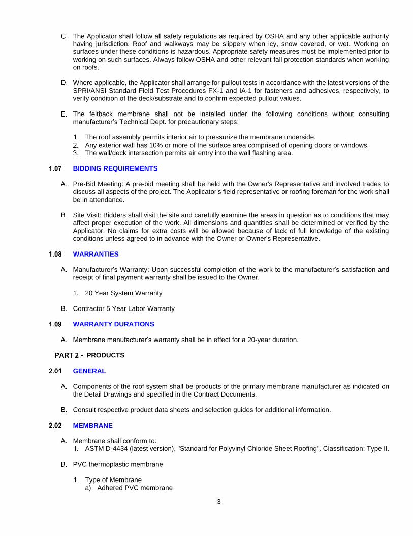
3
The Applicator shall follow all safety regulations as required by OSHA and any other applicable authority having jurisdiction. Roof and walkways may be slippery when icy, snow covered, or wet. Working on surfaces under these conditions is hazardous. Appropriate safety measures must be implemented prior to working on such surfaces. Always follow OSHA and other relevant fall protection standards when working on roofs.
Where applicable, the Applicator shall arrange for pullout tests in accordance with the latest versions of the
SPRI/ANSI Standard Field Test Procedures FX-1 and IA-1 for fasteners and adhesives, respectively, to verify condition of the deck/substrate and to confirm expected pullout values.
The feltback membrane shall not be installed under the following conditions without consulting
manufacturer’s Technical Dept. for precautionary steps:
The roof assembly permits interior air to pressurize the membrane underside. Any exterior wall has 10% or more of the surface area comprised of opening doors or windows. The wall/deck intersection permits air entry into the wall flashing area.
BIDDING REQUIREMENTS
Pre-Bid Meeting: A pre-bid meeting shall be held with the Owner's Representative and involved trades to
discuss all aspects of the project. The Applicator's field representative or roofing foreman for the work shall be in attendance.
Site Visit: Bidders shall visit the site and carefully examine the areas in question as to conditions that may
affect proper execution of the work. All dimensions and quantities shall be determined or verified by the Applicator. No claims for extra costs will be allowed because of lack of full knowledge of the existing conditions unless agreed to in advance with the Owner or Owner's Representative.
WARRANTIES
Manufacturer’s Warranty: Upon successful completion of the work to the manufacturer’s satisfaction and
receipt of final payment warranty shall be issued to the Owner.
1. 20 Year System Warranty
Contractor 5 Year Labor Warranty
WARRANTY DURATIONS
Membrane manufacturer’s warranty shall be in effect for a 20-year duration.
PRODUCTS
GENERAL
Components of the roof system shall be products of the primary membrane manufacturer as indicated on the Detail Drawings and specified in the Contract Documents.
Consult respective product data sheets and selection guides for additional information.
MEMBRANE
Membrane shall conform to:
ASTM D-4434 (latest version), "Standard for Polyvinyl Chloride Sheet Roofing". Classification: Type II.
PVC thermoplastic membrane
Type of Membrane a) Adhered PVC membrane

4
b) Adhered Feltback membrane
Membrane Thickness a) 60 mil (1.5 mm)
Color of Membrane
Adhered
a) EnergySmart White or approved equal
b) EnergySmart Reflective Gray or approved equal
INSULATIONS / ROOF BOARDS
Insulation 1. Rigid expanded polystyrene foam insulation board, meeting ASTM C-578 Type II or IX, minimum 20
psi compressive strength.
Lightweight Insulating Concrete
Celcore LWIC
Mearlcrete LWIC
Concrecel LWIC
ATTACHMENT COMPONENTS
Membrane Adhesive
Single-Step Membrane Adhesive: Water-based dispersion adhesive used to attach membrane.
Flashing Adhesive: Solvent-based reactivating adhesive used to attach membrane.
DECK PRIMERS
Vapor Retarder Primer SB: Solvent-based primer used to prime wood, concrete, primed gypsum boards and decks, prior to the application of self-adhered vapor retarders.
Vapor Retarder Primer WB: Polymer emulsion water-based primer used to prime wood, concrete, gypsum
decks, and approved gypsum boards prior to the application of self-adhered vapor retarders.
Vapor Retarder Primer TA: Blend of bitumen and solvent-based primer for use prior to applying torch-applied vapor retarders.
Vapor Retarder Primer BE: Bituminous emulsion (water based) primer for use prior to applying torch-applied
vapor retarders.
FLASHING MATERIALS
Wall / Curb Flashing
PVC Adhered Membrane
Flashing Membrane: Used over residual asphalt or other contaminated surfaces.

5
PVC Detail Membrane
Polymer Coated Metal
Adhesive: Solvent-based reactivating adhesive used to attach membrane to flashing substrate.
Perimeter Edge Flashing
Polymer clad: 24 gauge, G90 galvanized steel with PVC-coating on one side for heat-weldability.
Edge: Two-piece assembly of steel base rail and aluminum or steel snap-on fascia cover with spring clips.
Drip Edge: Two-piece assembly of galvanized steel cleat and PVC coated galvanized steel.
Coping: Aluminum or steel snap-on coping cover with concealed splice plates.
Miscellaneous Flashing
PVC circles: round circle patch.
Inside Corners – Injection molded inside corner.
Outside Corners – Injection molded outside corner.
Universal Stack - Injection molded stack/pipe boot to flash pipes, vent stacks and cylindrical penetrations.
Split A, B, C - Prefabricated stack/pipe boot open along one side to flash pipes, vent stacks and
cylindrical penetrations when access is obstructed.
Open Post Flashing - Prefabricated pipe boot open along one side to flash rooftop conduits, pipes, and cylindrical penetrations when access is obstructed.
Termination Bar - 3/4” wide extruded aluminum bar used to terminate roofing membranes at walls and
edges.
Liquid Flashing Primer - Two-component polymethyl methacrylate-based (PMMA) primer used to promote the adhesion of Liquid Flashing SW and Liquid Flashing WW over wood and concrete surfaces.
Liquid Flashing Fleece - Non-woven, needle-punched polyester fleece used as the reinforcement for
liquid flashing details.
Liquid Flashing Catalyst - Reactive agent based on dibenzoyl peroxide to induce curing of \Liquid Flashing SW, Liquid Flashing WW, and Liquid Flashing Primer when mixed.
Liquid Flashing SW (summer-grade white) Two-component polymethyl methacrylate-based (PMMA). The ambient temperature at application must be between 59°F (15°C) and 104°F (40°C). The surface temperature at application must be between 59°F (15°C) and 122°F (50°C).
WALKWAY PROTECTION
Polyester reinforced, 96 mil (2.4 mm) thick, weldable membrane with surface embossment similar to a chevron pattern. Used as a protection layer from rooftop traffic.

6
PVC, 79 mil (2.0 mm) thick, weldable membrane with pyramidal surface embossment. Used as a protection layer from rooftop traffic.
MISCELLANEOUS ACCESSORIES
Aluminum Tap - 2” (51 mm) wide pressure-sensitive aluminum tape used as a separation layer between
small areas of asphalt contamination and the membrane and as a bond-breaker under the coverstrip at joints.
Perimeter Warning Membrane - 4” (10.2 cm) wide yellow membrane used in required areas.
Seam Cleaner
Used to clean adhesive out of seams. It is not to be used as a general membrane cleaner. It is also used to clean metal and reactivate existing Liquid Flashing prior to the application of new Liquid Flashing.
Stop - 1” wide extruded aluminum, low profile bar used with certain fasteners to secure membrane to the
roof deck or to walls/curbs at terminations, penetrations and at angle changes of the substrate.
SEALANTS AND PITCH POCKET FILLERS
Moisture-cured, one-component polyurethane-based, non-sag elastomeric sealant used in wall, curb and drain terminations. It is also used as a sealant at pipe penetrations and under certain metal flashings or as a pourable sealer pocket filler.
MISCELLANEOUS FASTENERS AND ANCHORS
All fasteners, anchors, nails, straps, bars, etc. shall be post-galvanized steel, aluminum or stainless steel. Mixed metal type components shall be assembled in such a manner as to avoid galvanic corrosion. Fasteners for attachment of metal to masonry shall be expansion type fasteners with stainless steel pins.
RELATED MATERIALS
Wood Nailer - Code compliant wood nailers shall be installed at the perimeter of the entire roof and around
such other roof projections and penetrations as specified on Project Drawings. Thickness of nailers must match the height of the insulation and roof board to achieve a smooth transition.
EXECUTION
3.01 PRE-CONSTRUCTION CONFERENCE
The Applicator, Owner's Representative/Designer and Manufacturer(s) shall attend a pre-construction conference.
3.02 SUBSTRATE CONDITION
Applicator shall be responsible for acceptance or provision of proper substrate to receive new roofing materials.
Applicator shall verify that the work done under related sections meets the following conditions:
Roof drains and scuppers have been reconditioned or replaced (as applicable) and installed properly. Roof curbs, nailers, equipment supports, vents and other roof penetrations are properly secured and
prepared to receive new roofing materials.
The substrate shall be clean, smooth, dry, free of water, ice and snow and free of flaws, sharp edges, loose and foreign material, oil, grease and other contaminants. Roofing shall not start until all defects have been corrected.
3.03 SUBSTRATE PREPARATION

7
The roof deck and existing roof construction must be structurally sound to provide support for the new roof system. The Owner's Representative shall ensure that the roof deck is secured to the structural framing according to local building code or insurance requirements and in such a manner as to resist all anticipated loads in that location.
New Construction
Poured Structural Concrete Deck - The surface shall be dry and free of moisture, have a level finish,
and shall be free of dust, excess moisture, oil-based curing agents and loose debris. Under no circumstances shall a sealer be used in lieu of a curing agent. Sharp ridges or other projections above the surface shall be removed before roofing. In accordance with the ICRI Technical Guideline No. 310.2R-2013, newly poured concrete surfaces may be finished by forming, wood float, steel or power trowel, or broom finished to meet a concrete surface profile (CSP) of 2 – 5.
Poured Lightweight (Cellular or Insulating) Concrete Substrate - The surface shall be installed per
lightweight concrete manufacturer’s guidelines. The wet and dry densities shall be in accordance with the manufacturer's requirements. Sharp ridges or other projections above the surface shall be removed before roofing.
Precast / Prestressed Concrete Panel Deck - The surface shall have a smooth and level finish and shall
be free of dust, moisture, oil or loose debris. All joints between precast units shall be grouted. Any differentials in height between precast units shall be feathered for a smooth transition. Sharp ridges or other projections above the surface shall be removed before roofing.
Reroofing with Removal of Existing Roofing System
All existing roofing, base flashing, deteriorated wood blocking or deteriorated metal flashings shall be removed. Remove only that amount of roofing and flashing which can be made weathertight with new materials during a one-day period or before the onset of inclement weather.
Poured Structural Concrete Deck - The surface shall be dry and free of moisture, have a level finish,
and shall be free of dust, excess moisture, and loose debris. Sharp ridges or other projections above the surface shall be removed before roofing. In accordance with the ICRI Technical Guideline No. 310.2R-2013, newly poured concrete surfaces may be finished by forming, wood float, steel or power trowel, or broom finished to meet a CSP of 2 – 5.
Poured Lightweight (Cellular or Insulating) Concrete Substrate - Sharp ridges or other projections
above the surface shall be removed before roofing. Fastening for recover board shall be into structural deck below insulating fill (see steel/concrete deck requirements).
Precast / Prestressed Concrete Deck - The roof deck shall be smooth, even, free of dust, dirt, excess
moisture, or oil and be structurally sound. All joints between precast units shall be grouted. Any differentials in height between precast units shall be feathered for a smooth transition. Any deteriorated decking shall be repaired.
Recover Over Existing Bitumen Roofing - The Owner's Representative and Applicator shall determine the condition of the existing roof deck and old roof system. Areas with deteriorated decking or wet materials are to be removed and replaced.
3.04 WOOD NAILER INSTALLATION
Install continuous code compliant wood nailers at the perimeter of the entire roof and around roof projections and penetrations as shown on the Detail Drawings.
Wood nailers or wood blocking for penetrations, curbs, or snow protection systems shall be installed prior
to the installation of the roof membrane whenever possible. 3.05 INSULATION / EPS ROOF BOARD INSTALLATION
General Criteria:

8
Boards shall be installed according to local building code, insurance requirements, and manufacturer's instructions.
Boards shall be neatly cut to fit around penetrations and projections. Install tapered insulation in accordance with insulation manufacturer's shop drawings. Do not install more board than can be covered with membrane by the end of the day or the onset of
inclement weather. When two or more layers of insulation and/or roof boards are used, stagger joints at least 12” (30.5 cm)
in both directions between layers.
Lightweight Insulating Concrete - Install in accordance with selected manufacturer’s guidelines. 3.06 ADHERED FELTBACK PVC MEMBRANE INSTALLATION
The surface of the insulation, roof board, or substrate shall be inspected prior to installation of the feltback PVC 9 oz. roof membrane. The substrate shall be clean, dry, and free from debris and smooth with no surface roughness or contamination. Broken, delaminated, wet or damaged boards shall be removed and replaced. Tack welding of adhered membrane field sheets for purposes of temporary restraint during installation is not permitted and may result in voiding of manufacturer’s warranty.
Single-Step Membrane Adhesive:
Apply adhesive direct to substrate, rate may vary depending on porosity of substrate. Do not allow
adhesive to skin-over or surface-dry prior to installation of membrane.
Refer to Single-Step Membrane Adhesive Product Data Sheet and Adhered Systems: Water Based Adhesive Installation section of the Roofing Applicator’s Handbook for detailed installation instructions.
Flashing Adhesive 2170
Apply adhesive direct to substrate, rate may vary depending on porosity of substrate. Only an area
which can be completely covered in the same day's operations shall be coated with adhesive. The first layer of adhesive shall be allowed to dry completely prior to installing the membrane.
Refer to individual Product Data Sheets (PDS) and Adhered Systems: Solvent Based Adhesive
Installation section of Manufacturer’s Roofing Applicator’s Handbook for detailed installation instructions.
Water based field membrane 2121 Adhesive:
Apply adhesive direct to substrate, rate may vary depending on porosity of substrate. Do not allow
adhesive to skin-over or surface-dry prior to installation of membrane.
Refer to Adhered Systems: Water Based Adhesive Installation section of the manufacturer’s Roofing Applicator’s Handbook for detailed installation instructions.
3.07 HOT-AIR WELDING OF MEMBRANE OVERLAPS
All membrane overlaps shall be hot-air welded. The membrane shall be clean and dry prior to hot-air welding.
Field membrane overlaps for automatic machine-welding will vary in width depending on the plate and
fastener combination used. A minimum of 4” (10.2 cm) wide overlap is required when hand-welding details.
1” (25 mm) wide cross-section samples of welded seams shall be taken at least two times a day, once in the morning and once in the afternoon.
Refer to Welding section of manufacturer’s Roofing Applicator Handbook for detailed installation
instructions.

9
3.08 MEMBRANE FLASHING INSTALLATION
All flashings shall be installed concurrently with the roof membrane as the job progresses. No temporary flashings shall be allowed without the prior written approval of the Owner's Representative and Manufacturer. Approval shall only be for specific locations on specific dates. If any water is allowed to enter under the newly completed roofing, the affected area shall be removed and replaced at the Applicator's expense. Flashing shall be adhered to compatible, dry, and smooth surfaces free of dirt, dust, and debris. Use caution to ensure adhesive fumes are not drawn into the building.
All flashings should extend a minimum of 8” (20.3 cm) above finished roofing level. Submit requests for
exceptions in writing to the Owner's Representative and Manufacturer’s Technical Department for signed approval.
No bitumen shall be in contact with the membrane.
All flashing membranes shall be mechanically fastened along the counter-flashed top edge with perimeter
securement. Refer to manufacturer's installation instructions.
Flashings shall be terminated according to recommended details.
Refer to Typical Flashing Procedures section of the Manufacturer’s Roofing Applicator Handbook for detailed installation instructions.
3.09 CLAD METAL BASE FLASHINGS / EDGE METAL INSTALLATION
All flashings shall be installed concurrently with the roof membrane as the job progresses. No temporary flashings shall be allowed without the prior written approval of the Owner's Representative and or manufacturer’s acceptance. Approval shall only be for specific locations on specific dates. If any water is allowed to enter under the newly completed roofing due to incomplete flashings, the affected area shall be removed and replaced at the Applicator's expense.
Metal details, fabrication practices and installation methods shall conform to the applicable requirements of
the following:
ANSI SPRI ES-1 (latest issue). Sheet Metal and Air Conditioning Contractors National Association, Inc. (SMACNA) - latest issue.
Pre-formed metal flashing shall be installed according to metal manufacturer’s guidelines.
Metal, other than that provided by primary manufacturer is not covered under the warranty.
Clad and other metal flashings shall be formed and installed per the Detail Drawings. Refer to individual
Product Data Sheets (PDS) and Metal Flashings section of the membrane manufacturer’s Roofing Applicator Handbook for detailed installation instructions.
3.10 WALKWAY INSTALLATION
PVC Walkway-20: Probe all existing deck membrane seams which are to be covered by Walkway-20. Install walkway in straight lines by either adhering and welding or just welding to the field membrane.
3.11 TEMPORARY CUT-OFF
All flashings shall be installed concurrently with the roof membrane to maintain a watertight condition as the work progresses. All temporary cut-offs shall be constructed to provide a watertight seal. The new membrane shall be carried into the temporary cut-off. Temporary cut-off shall be sealed to the deck or substrate so that water will not be allowed to travel under the new or existing roofing. When work resumes, the contaminated membrane shall be cut out.

10
If inclement weather occurs while a temporary cut-off is in place, the Applicator shall provide the labor necessary to monitor the situation to maintain a watertight condition.
If any water is allowed to enter under the newly completed roofing, the affected area shall be removed and
replaced at the Applicator's expense. 3.12 COMPLETION
Prior to demobilization from the site, the work shall be reviewed by the Owner's Representative and the Applicator. All defects noted and non-compliances with the Specifications or the recommendations of the waterproofing membrane supplier shall be itemized in a punch list. These items must be corrected immediately by the Applicator to the satisfaction of the Owner's Representative and Membrane Manufacturer prior to demobilization.
All Warranties referenced in this Specification shall have been submitted and have been accepted by the
owner or owner’s representative at time of contract award. 3.13 DETAILS
(Project Name) 07 62 00-1 SHEET METAL FLASHING AND TRIM
SECTION 07 62 00
SHEET METAL FLASHING AND TRIM
PART 1 GENERAL
1.01 SUMMARY
A. Work shall include, but is not limited to, the following:
1. Preparation of existing (new) substrates.
2. Sheet metal flashings and sheet metal roof edge system.
3. All related materials and labor required to complete specified roofing
necessary to receive specified manufacturer’s warranty.
1.02 RELATED SECTIONS
A. Division 011000 – Summary of Work
B. Division 072200 – Roof Insulation
C. Division 072713 – Modified Bituminous Sheet Vapor Retarders
D. Division 075216 – Styrene-Butadiene-Styrene (SBS) Modified Bitumen
Membrane Roofing
E. Division 075419 – Polyvinyl-Chloride (PVC) Roofing
1.03 DEFINITIONS
A. ASTM D 1079-Definitions of Term Relating to Roofing, Waterproofing and
Waterproofing.
B. The National Roofing Contractors Association (NRCA) Roofing and
Waterproofing Manual, Fifth Edition Glossary.
1.04 REFERENCES
A. AMERICAN SOCIETY OF CIVIL ENGINEERS - Reference Document ASCE 7,
Minimum Design Loads for Buildings and Other Structures.
B. AMERICAN STANDARD OF TESTING METHODS (ASTM):
1. ASTM C 920 - Standard Specification for Elastomeric Joint Sealants
2. ASTM D 41 - Standard Specification for Asphalt Primer Used in Roofing,
Damp proofing, and Waterproofing.
3. ASTM D 4586 - Standard Specification for Asphalt Roof Cement,
Asbestos-Free.
C. AMERICAN NATIONAL STANDARDS INSTITUTE (ANSI)::
1. ANSI/SPRI/FM 4435/ES-1 Wind Design Standard for Edge System Used
with Low Slope Roofing System.

(Project Name) 07 62 00-2 SHEET METAL FLASHING AND TRIM
2. ANSI/SPRI FX-1, Standard Field Test Procedure for Determining the
Withdrawal Resistance of Roofing Fasteners.
D. INTERNATIONAL CODES COUNCIL (ICC):
1. Latest International Building Code (IBC).
E. NATIONAL ROOFING CONTRACTORS’ ASSOCIATION (NRCA) Roofing and
Waterproofing Manual.
F. SHEET METAL AND AIR CONDITIONING CONTRACTORS’ NATIONAL
ASSOCIATION INC. (SMACNA) Architectural Sheet Metal Manual.
G. PUERTO RICO BUILDING CODE 2018
1.05 ACTION SUBMITTALS
A. Product Data Sheets: Submit manufacturer’s product data sheets, installation
instructions and/or general requirements for each component.
B. Safety Data Sheets: Submit manufacturer’s Safety Data Sheets (SDS) for each
component.
C. Sample/Specimen Warranty from the manufacturer and contractor.
D. Shop Drawings: Provide roof plan and applicable roof system detail drawings.
1.06 INFORMATIONAL SUBMITTALS
A. Contractor Certification: Submit written certification from roofing system
manufacturer certifying that the applicator is authorized by the manufacturer to
install the specified materials and system.
1.07 CLOSEOUT SUBMITTALS
A. Warranty: Provide manufacturers and contractor’s warranties upon substantial
completion of the roofing system.
1.08 QUALITY ASSURANCE
A. MANUFACTURER QUALIFICATIONS:
1. Manufacture shall have 20 years of experience manufacturing roofing
materials.
2. Trained Technical Field Representatives, employed by the manufacturer,
independent of sales.
3. Provide reports in a timely manner of all site visit reports.
4. Provide specified warranty upon satisfactory project completion.
B. CONTRACTOR QUALIFICATIONS:
1. Contractor shall be authorized by the manufacturer to install specified
materials prior to the bidding period through satisfactory project
completion.
2. Applicators shall have completed projects of similar scope using same
materials as specified herein.

(Project Name) 07 62 00-3 SHEET METAL FLASHING AND TRIM
3. Contractor shall provide full time, on-site superintendent or foreman
experienced with the specified roof system through satisfactory project
completion.
4. Applicators shall be skilled in the application methods for all materials.
5. Contractor shall maintain a daily record, on-site, documenting material
installation and related project conditions.
6. Contractor shall maintain a copy of all submittal documents, on-site,
available at all times for reference.
1.09 DELIVERY, STORAGE AND HANDLING
A. Refer to each product data sheet or other published literature for specific
requirements.
B. Deliver materials and store them in their unopened, original packaging, bearing
the manufacturer's name, related standards, and any other specification or
reference accepted as standard.
C. Protect and store materials in a dry, well-vented, and weatherproof location. Only
materials to be used the same day shall be removed from this location.
D. When materials are to be stored outdoors, store away from standing water,
stacked on raised pallets or dunnage, at least 4 in or more above ground level.
Carefully cover storage with “breathable” tarpaulins to protect materials from
precipitation and to prevent exposure to condensation.
E. Properly dispose of all product wrappers, pallets, cardboard tubes, scrap, waste,
and debris. All damaged materials shall be removed from job site and replaced
with new, suitable materials.
1.10 SITE CONDITIONS
A. SAFETY:
1. The contractor shall be responsible for complying with all project-related
safety and environmental requirements.
2. The contractor shall refer to product Material Safety Data Sheets (MDS)
for health, safety, and environment related hazards, and take all
necessary measures and precautions to comply with exposure
requirements.
B. ENVIRONMENTAL CONDITIONS:
1. Monitor substrate temperature and material temperature, as well as all
environmental conditions such as ambient temperature, moisture, sun,
cloud cover, wind, humidity, and shade. Ensure conditions are
satisfactory to begin work and ensure conditions remain satisfactory
during the installation of specified materials. Materials and methods shall
be adjusted as necessary to accommodate varying project conditions.
Materials shall not be installed when conditions are unacceptable to
achieve the specified results.
2. Precipitation and dew point: Monitor weather to ensure the project
environment is dry before, and will remain dry, during the application of

(Project Name) 07 62 00-4 SHEET METAL FLASHING AND TRIM
roofing materials. Ensure all roofing materials and substrates remain
above the dew point temperature as required to prevent condensation
and maintain dry conditions.
1.11 PERFORMANCE REQUIREMENTS
A. ROOF EDGE SYSTEM:
1. Performance testing shall be in accordance with ANSI/SPRI/FM 4435/ES-
1 Wind Design Standard for Edges Systems Used with Low Slope
Roofing Systems.
a. Wind Load Determination:
i. Perimeter Region:
a) Horizontal: -0 psf
b) Vertical: -0 psf
ii. Corners Region:
a) Horizontal: -0 psf
b) Vertical: -0 psf
PART 2 PRODUCTS
2.01 MANUFACTURER
A. PRODUCT QUALITY ASSURANCE PROGRAM: Manufacturer shall be an ISO
9001 registered company. A ‘Quality Compliance Certificate (QCC) for
reporting/confirming the tested values of the SBS-Modified Bitumen Membrane
Materials will be supplied upon request.
B. ACCEPTABLE MANUFACTURER:
C. Contractor shall furnish all sheet metal flashings, counter flashings, roof edge
system, and all other related sheet metal flashings, fasteners and sealants
necessary to flash and counter flash the specified roofing system at all roof
terminations, transitions and penetrations.
D. Sheet metal flashing materials and fasteners shall be compatible with adjacent
materials, to accommodate all project related exposures.
E. Pre-Finished (Mill Finished) Sheet Metal Flashing Material: Aluminum
2.02 SHEET METAL FLASHING
A. SHEET METAL, ROOF EDGE SYSTEM:
1. Roof edge system shall include all components and associated fasteners
necessary to comply with specified performance requirements.
Contractor shall provide all other related fasteners and sealants
necessary for the roof edge system.
2. Cantilever Coping: Engineered two-piece fascia system with a formed
cleat and metal fascia.
a. Material: Aluminum

(Project Name) 07 62 00-5 SHEET METAL FLASHING AND TRIM
b. Gauge/Thickness: Minimum .040
c. Finish: Color selected from manufacturer’s color chart. Mill-
Finished Aluminum.
d. Tested per ANSI/SPRI ES-1 to meet or exceed design pressures
at roof edge.
e. FM Approved.
B. SHEET METAL, EXPANSION JOINT SYSTEM:
1. Expansion Joint Roof to Roof: Engineered expansion joint system with
formed anchor clips and metal cover.
a. Material: Aluminum, Galvanized Steel, Stainless Steel
b. Gauge/Thickness:
c. Finish: Color selected from manufacturer’s color chart. Mill-
Finished Aluminum.
2. Expansion Joint Roof to Wall: Engineered expansion joint system with
formed anchor clips and metal cover.
a. Material: Aluminum, Galvanized Steel, Stainless Steel
b. Gauge/Thickness:
c. Finish: Color selected from manufacturer’s color chart. Mill-
Finished Aluminum.
C. SHEET METAL, COUNTERFLASHING SYSTEM:
1. 1PC Counterflashing: Engineered counterflashing system with formed
counterflashing.
a. Material: Aluminum, Galvanized Steel, Stainless Steel
b. Gauge/Thickness:
c. Finish: Color selected from manufacturer’s color chart. Mill-
Finished Aluminum.
2. 2PC Counterflashing: Engineered counterflashing system with formed
receiver and counterflashing.
a. Receiver: Reglet, Surface-Mount, Adaptable Reglet, Adaptable
Surface, Thru-Wall
b. Material: Aluminum, Galvanized Steel, Stainless Steel
c. Gauge/Thickness:
d. Finish: Color selected from manufacturer’s color chart. Mill-
Finished Aluminum.
D. FASTENERS:
1. #9 Stainless Steel Screw w/ Neoprene Washer
a. Length as required.
2. #12 Galvanized Self-Drilling Screw:
a. Length as required.
3. Stainless Steel Ring Shank Nails:
a. Length as required.
4. 3/16” Tapcon Screws:
a. Length as required.

(Project Name) 07 62 00-6 SHEET METAL FLASHING AND TRIM
5. Flat Head Screw w/ Extruded Washer:
a. Length as required.
E. GENERAL PURPOSE ROOFING CEMENT AND MASTIC
1. SBS Mastic: Fiber-reinforced, roofing cement, packaged in 5-gallon pails.
General purpose roofing cement for low-slope roofing used for sealing
sheet metal flashings to SBS membranes.
a. VOC Content: 190 g/L or less.
b. Meets or exceeds ASTM D4586, Type I, Class II.
2. SBS Mastic: Fiber-reinforced, roofing cement, packaged in 10.4 oz caulk
tubes. General purpose roofing cement for low-slope roofing used for
sealing sheet metal flashings to SBS membranes.
a. VOC Content: 190 g/L or less.
b. Meets or exceeds ASTM D4586, Type I, Class II.
F. GENERAL PURPOSE SEALANT
1. General purpose, paintable, gun-grade, elastomeric, polyether moisture
curing sealant for sealing SBS and PVC membrane terminations, PVDF,
horizontal and vertical construction joints.
a. VOC Content: 20 g/L or less.
b. Meets or exceeds ASTM C920, Type S, Grade NS, Class 50.
c. Standard color, custom color.
2. Butyl Sealant: Butyl rubber and polyisobutylene water resistant sealant
for concealed sheet metal joints.
3. Butyl Sealant Tape: Butyl rubber and polyisobutylene water resistant
sealant tape for concealed sheet metal joints.
PART 3 EXECUTION
3.01 EXAMINATION
A. Examination includes visual observations, qualitative analysis, and quantitative
testing measures as necessary to ensure conditions remain satisfactory
throughout the project.
B. The contractor shall examine all roofing substrates including, but not limited to:
insulation materials, roof decks, walls, curbs, rooftop equipment, fixtures, and
wood blocking.
C. The applicator shall not begin installation until conditions have been properly
examined and determined to be clean, dry and, otherwise satisfactory to receive
specified roofing materials.
D. During the application of specified materials, the applicator shall continue to
examine all project conditions to ensure conditions remain satisfactory to
complete the specified roofing system.
3.02 PREPARATION
A. Before commencing work each day, the contractor shall prepare all roofing
substrates to ensure conditions are satisfactory to proceed with the installation of

(Project Name) 07 62 00-7 SHEET METAL FLASHING AND TRIM
specified roofing materials. Preparation of substrates includes, but is not limited
to, substrate repairs, securement of substrates, eliminating all incompatible
materials, and cleaning.
B. Where conditions are found to be unsatisfactory, work shall not begin until
conditions are made satisfactory to begin work. Commencing of work shall
indicate contractor’s acceptance of conditions.
3.03 PRIMER APPLICATION (SBS Modified Bitumen)
A. Examine all substrates, and conduct adhesion peel tests as necessary, to ensure
satisfactory adhesion is achieved when adhering membrane to sheet metal
flanges.
B. Apply the appropriate specified primer to dry, compatible substrates as required
to enhance adhesion of new specified roofing materials.
C. Apply primer using brush or roller at the rate published on the product data sheet.
D. Project conditions vary throughout the day. Monitor changing conditions, monitor
the drying time of primers, and monitor the adhesion of the membrane plies.
Adjust primer and membrane application methods as necessary to achieve the
desired results.
3.04 SHEET METAL FLASHING APPLICATION
A. Refer to manufacturer’s sheet metal flashing and roof edge system detail
drawings and follow product data sheets and published general requirements for
installation instructions.
B. General Requirements:
1. Follow the most recent edition of the SMACNA Architectural Sheet Metal
Manual for fabrication and installation requirements.
2. Follow the most recent edition of the NRCA Roofing and Waterproofing
Manual for fabrication and installation requirements for specified roofing
and flashing.
C. Isolate all metal components from ACQ treated wood or other incompatibles
material using specified membrane flashing materials.
D. Appliances such as lightning rods, signs, or antennae shall be separate from the
roof edge system.
3.05 GENERAL PURPOSE SEALANT
A. Refer to published installation instructions. Ensure sheet metal and adjacent
substrates are clean and free of oils, dust and other incompatible materials.
B. Apply general purpose, paintable, gun-grade, elastomeric, polyether moisture
curing sealant to seal SBS and PVC membrane terminations, exposed fasteners,
Kynar 500 PVDF, and other compatible sheet metal horizontal and vertical joints,
laps and transitions.
3.06 CLEAN-UP

(Project Name) 07 62 00-8 SHEET METAL FLASHING AND TRIM
A. Clean-up and properly dispose of waste and debris resulting from these
operations each day as required to prevent damages and disruptions to
operations.
END OF SECTION


DIVISION 7 – THERMAL AND MOISTURE PROTECTION
Section 07951 – SEALANTS AND CALKING
1. Related Documents:
The general provisions of the contract, including General and Special Conditions, apply to
the work specified in this section.
2. Description of Work:
The extent of each type of sealant and calking work is shown on the drawings.
The required applications of sealants and calking include, but are not necessarily limited
to, the following general locations:
Flashing reglets and retainers
Exterior wall joints
Masonry control joints, exterior and interior
Flooring joints
Isolation joints, between structure and other elements
Joints at penetrations of walls, decks and floors by piping and other services and
equipment
Joints between items of equipment and other construction
3. General:
Obtain elastomeric materials from only manufacturers who will, if required, send a
qualified technical representative to project movements for the temperature and condition
of the project at the time of installation.
Compressibility:
Specific hardnesses and compressibilities are intended to establish requirements for
normal or average conditions of installation and use. Wherever a range of hardness or
compressibility is available for a product, comply with the manufacturer’s
recommendations for the specific condition of use, except as otherwise directed.
Color:
Provide each concealed material in manufacturer’s standard color which has the best
overall performance characteristics for the application shown.
07951 -1
Rev. 9/80

DIVISION 7 – THERMAL AND MOISTURE PROTECTION
Section 07951 – Sealants and Calking
3. General: (Con’d)
Provide exposed materials Light Grey except where another color is indicated.
Compatibility:
Before purchase of the specified sealant, investigate its compatibility with the joint
surfaces, joint fillers and other materials behind or below the joint in the construction.
Provide only materials (manufacturer’s recommended variation of the specified
materials) which are known to be fully compatible with the actual installation condition,
as shown by manufacturer’s published data or certification.
Provide size and shape of preformed sealant units as shown or, if not shown, as
recommended by the manufacturer, either in his published data or upon consulation with
his technical representative.
4. One-Component Elastomeric Sealant:
One-Component Polysulfide Sealant:
Polysulfied based, one-part elastomeric sealant, complying with FS TT-S-00230 Class A,
Type 2 (non-sag) unless Type 1 is recommended by manufacturer for the application
shown.
Provide compound bearing the Thiokol Chemical Corp. seal of approval.
Products offered by manufacturers to comply with the requirements include the
following:
Ultratite 102; Cost Pro Seal
Flexiseal 900 Series; DAP, Inc.
Hornflex One-Component; W.R. Grace
Novacalk – 600; Novagard Corp.
Uniparseal; Parr Paint & Sealants
Rubber Calk 5000; Products Research & Chemical
Sonolastic 1-Part; Sonneborn
Thiotok Sealant R.M.; Toch Brothers
07951 – 2
Rev. 9/80

DIVISION 7 – THERMAL AND MOISTURE PROTECTION
Section 07951 – SEALANTS AND CALKING
4. One-Component Elastomeric Sealant: (Con’d)
Acid-Type Products offered by manufacturers to comply with the requirements, include the
following:
781 Building Sealant; Dow Corning
Silican Construction Sealant; General Electric Co.
5. Preformed Elastomeric Sealants:
Butyl Rubber Sealant Tape:
A partially-vulcanized, self-adhesive, non-staining, elastomeric butyl rubber tape
recommended by the manufacturer for waterproof construction when compressed 35% in
dynamically-moving joints; not less than 98% solids; no deterioration after 3000 hour test
in Atlas Weatherometer.
Products offered by manufacturers to comply with the requirements include the
following:
Betaseal 650 Tape; Essex Chemical
Duraribbon 1072; PPG Industries
176 Strucsureglaze; Presstile Interchem
PTI 606; Protective treatments
6. Miscellaneous Materials:
Joint Cleaner:
Provide the type of joint cleaning compound recommended by the sealant or calking
compound manufacturer for the joint surfaces to be cleaned.
Joint Primer/Sealer:
Provide the type of joint primer/sealer recommended by the sealant manufacturer for the
joint surfaces to be primed or sealed.
07951 – 3
Rev. 9/80

DIVISION 7 – THERMAL AND MOISTURE PROTECTION
Section 07951 – SEALANTS AND CALKING
6. Miscellaneous Materials: (Con’d)
Bond Breaker Tape:
Polyethylene tape or other plastic tape as recommended by the sealant manufacturer to be
applied to sealant-contact surfaces where bond to the substrate or joint filler must be
avoided for proper performance of sealant. Provide self-adhesive tape wherever
applicable.
Sealant Backer Rod:
Compressible rod stock of polyethylene foam, polyethylene jacketed polyurethane foam,
butyl rubber foam, neoprene foam or other flexible, permanent, durable non-absortive
material as recommended for compatibility with sealant by the sealant manufacturer; to
control the joint depth for sealant placement, to break bond of sealant at bottom of joint,
to form optimum shape of sealant bead on back side, and to provide a highly
compressible backer which will minimize the possibiltiy of sealant extrusion when joint
is compressed.
7. Joint Surface Preparation:
Clean joint surfaces immediately before installation of sealant or calking compound.
Remove dirt, insecure coatings, moisture and other substances which would interfere
with bond of sealat or calking compound.
For elastomeric sealants, do not proceed with installation of sealant over joint surfaces
which have been painted, lacquered, waterproofed or treated with water repellent or other
treatment or coating unles a laboratory test for durability (bond-cohesion), in compliance
with Paragraph 4, 3, 9 of FS TT-S-00227 has successfully demonstrated that sealant bond
is not impaired by the coating or treatment. If laboratory test has not been performed, or
shows bond interference, remove coating or treatment from joint surfaces before
installing sealant.
Each concrete and masonry joint surfaces to remove excess alkalinity, unless sealant
manufacturer’s printed instructions indicate that alkanity does not interfere with sealant
bond and performance. Each with 5% solution of muriatic acid; neutralize with diluted
ammonia solution, rince thoroughly with water and allow to dry before sealant
installation.
07951 – 4
Rev. 9/80

DIVISION 7 – THERMAL AND MOISTURE PROTECTION
Section 07951 – SEALANTS AND CALKING
7. Joint Surface Preparation: (Con’d)
Roughen joint surfaces on vitreous coated and similar non-porous materials, wherever
sealant manufacturer’s data indicates lower bond strength than for porous surfaces. Rub
with fine abrasive cloth or wool to produce a dull sheen.
The installer must examine the joint surfaces, backing, and anchorage of units forming
sealant rabbet, and the conditions under which the sealant work is to be performed, and
notify the Contractor in writing of any conditions detrimental to the proper and timely
completion of the work. Do not proceed with the sealant work until unsatisfactory
conditions have been corrected in a manner acceptable to the Installer.
8. Sample Installation:
Prepare a mock-up installation of every major type and use of sealant shown and
specified. Install sealant between materials matching those used on the project,
complying with conditions similar in every way to anticipated project conditions.
Prepare mock-up well in advance of scheduled installation, so that nominal cure-time is
allowed and final color adjustments can be made, if necessary.
9. Pre-Installation Meeting:
At Contractor’s direction, the sealant installer, Architect, sealant manufacturer’s technical
representative, and other trades involved in coordination with sealant work shall meet
with the Contractor at the project site to review the procedures and time schedule
proposed for installation of sealants in coordination with other work. Review every
major sealant application required on the project.
10. Weather Conditions:
Do not proceed with installation of liquid sealants under adverse weather conditions, or
when temperatures are below or above manufacturer’s recommended limitations for
installation. Proceed with the work only when forecasted weather conditions are
favorable for proper cure and development of high early bond strength. Wherever joint
width is affected by ambient temperature variations, install elastomeric sealants only
when temperatures are in the lower third of manufacturer’s recommended installation
temperature range, so that sealant will not be subjected to excessive elongation and bond
stress at extremely low temperatures. Coordinate time schedule with Contractor to avoid
delay of project.
07951 – 5
Rev. 9/80
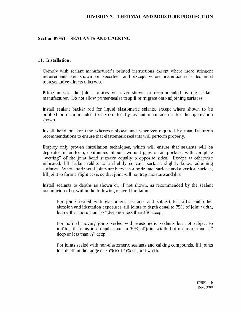
DIVISION 7 – THERMAL AND MOISTURE PROTECTION
Section 07951 – SEALANTS AND CALKING
11. Installation:
Comply with sealant manufacturer’s printed instructions except where more stringent
requirements are shown or specified and except where manufacturer’s technical
representative directs otherwise.
Prime or seal the joint surfaces wherever shown or recommended by the sealant
manufacturer. Do not allow primer/sealer to spill or migrate onto adjoining surfaces.
Install sealant backer rod for liquid elastomeric selants, except where shown to be
omitted or recommended to be omitted by sealant manufacturer for the application
shown.
Install bond breaker tape wherever shown and wherever required by manufacturer’s
recommendations to ensure that elastomeric sealants will perform properly.
Employ only proven installation techniques, which will ensure that sealants will be
deposited in uniform, continuous ribbons without gaps or air pockets, with complete
“wetting” of the joint bond surfaces equally o opposite sides. Except as otherwise
indicated, fill sealant rabbet to a slightly concave surface, slightly below adjoining
surfaces. Where horizontal joints are between a horizontal surface and a vertical surface,
fill joint to form a slight cave, so that joint will not trap moisture and dirt.
Install sealants to depths as shown or, if not shown, as recommended by the sealant
manufacturer but within the following general limitations:
For joints sealed with elastomeric sealants and subject to traffic and other
abrasion and identation exposures, fill joints to depth equal to 75% of joint width,
but neither more than 5/8” deep nor less than 3/8” deep.
For normal moving joints sealed with elastomeric sealants but not subject to
traffic, fill joints to a depth equal to 50% of joint width, but not more than ½”
deep or less than ¼” deep.
For joints sealed with non-elastomeric sealants and calking compounds, fill joints
to a depth in the range of 75% to 125% of joint width.
07951 – 6
Rev. 9/80

DIVISION 7 – THERMAL AND MOISTURE PROTECTION
Section 07951 – SEALANTS AND CALKING
11. Installation: (Con’d)
Spillage:
Do not allow sealants or compounds to overflow or spill onto adjoining surfaces, or to
migrate into the voids of adjoining surfaces including rough textures such as exposed
aggregate panels. Use masking tape or other precautionary devices to prevent staining of
adjoining surfaces, by either the primer/sealer of the sealant/calking compound.
Remove excess and spillage of compounds promptly as the work progresses. Clean the
adjoining surfaces by whatever means may be necessary to eliminate evidence of
spillage. Do not damage the adjoining surfaces or finishes.
Polysulfide Sealant Installation:
Comply with standards issued by Thiokol Chemical Corp., except wher more stringent
requirements have been show or specified, or issued as recommendations by the sealant
manufacturer.
12. Cure and Protection:
Cure sealants and calking compounds in compliance with manufacturer’s instructions and
recommendations, to obtain high early bond strength, internal cohesive strength and
surface durability.
The installer shall advise the Contractor of procedures required for the protection of
sealants and calking compounds during the construction period, so that they will be
without deterioration or damage (other than normal weathering) at the time or Owner’s
acceptance.
13. Tests for Performance:
After nominal cure of exterior joint sealants which are exposed to the weather, test for
water leaks. Flood the joint exposure with water directed from a ¾” garden hose held
perpendicular to wall face, 2’ – 0” from joint, connected to a water system with 30 psi
minimum normal water pressure. Move stream of water along joint at an aproximate rate
of 20 ft. per min.
07951 – 7
Rev. 9/80

DIVISION 7 – THERMAL AND MOISTURE PROTECTION
Section 07951 – SEALANTS AND CALKING
13. Tests for Performance: (Con’d)
Test approximately 5% of total joint system, in locations which are typical of every joint
condition, and which can be inspected easily for leakage on opposite face. Conduct tests
in the presence of the Architect, who will determine the actual percentage of joints to be
tested and the actual period of exposure to water from the hose, based upon the extent of
observed leakage, or lack thereof.
Repair sealant installation at leaks or, if leakage is excessive, replace sealant installation
as directed.
Wherever nature of observed leakage indicates the possibility of inadequate joint bond
strength, P.B.A. may direct that additional testing be performed at a time when joints
have been fully cured, folowed by natural exposure through both extreme temperatures
and returned to the lowest range of temperature in which it is feasible to conduct testing.
Repair or replace work as required.
14. Submittals:
Manufacturer’s Data, Sealants and Calking:
Submit 2 copies of manufacturer’s specifications, recommendations and installation
instructions for each type or sealant, calking compound and associated miscellaneous
material required. Include manufacturer’s published data, or letter of certification, or
certified test laboratory report indicating that each material complies with the
requirements and is intended generally for the applications shown. Show by transmittal
that one copy of each recommendation and installation has been distributed to the
Installer.
Samples, Sealants and Calking:
Submit 3, 12” long samples of each color required (except black) for each type of sealant
or calking compound exposed to view. Install sample between 2 strips of material similar
to or representative of typical surfaces where sealant or compound will be used, held
apart to represent typical joint widths.
07951 – 8
Rev. 9/80

DIVISION 7 – THERMAL AND MOISTURE PROTECTION
Section 07951 – SEALANTS AND CALKING
14. Submittals: (Con’d)
Guarantee, Sealants:
Submit 2 copies of written guarantee agreeing to repair or replace sealants which fail to
perform as air-tight and water-tight joints; or fail in joint adhesion, cohesion, abrasion
resistance, stain resistance, or general durability; or appear to deteriorate in any other
manner not clearly specified as an inherent quality of the material by submitted
manufacturer’s data. Provide guarantee for a period of 1 year, signed by the Installer and
Contractor.
07951 – 9
Rev. 9/80

SECTION 08 11 00
METAL DOORS AND FRAMES
PART 1 – GENERAL
1.1 SECTION REQUIREMENTS
A. The Contractor shall provide all material, labor and equipment necessary for this section as
required by the drawings and/or herein specified, but not limited to:
1. Hollow Metal Doors.
2. Formed Sheet Steel Frames.
3. Formed Sheet Steel Louvers in Hollow Metal.
4. Reinforcing, Supporting and Attachment devices for work of this section.
5. Underwriter Laboratories, Inc., Labeled Doors and Frames.
6. Reinforcing for Hardware as required.
7. Prime Painting for all doors and frames.
B. All material used in the fabrication of metal doors and frames shall be free form defects
impairing their strength, durability or appearance.
1.2 REFERENCED STANDARDS
A. American National Standards Institute (ANSI) in its test editions:
1. ANSI 156.1 - Butts and hinges
2. ANSI 156.2 - Bored & preassembled locks.
3. ANSI 156.3 - Exit devices.
4. ANSI 156.4 - Door control (Closers).
5. ANSI 156.5 - Auxiliary locks.
6. ANSI 156.6 - Architectural trim.
7. ANSI 156.13 - Mortise locks & latches.
METAL DOORS AND FRAMES
08 11 00 - 2
8. ANSI 156.16 - Auxiliary hardware.
9. ANSI 156.18 - Materials & finishes.
10. ANSI 117.1 - Providing accessibility and usability for physically
Handicapped people.
B. National Builders Hardware Association (NBHA):
1. Recommended Locations for Builders Hardware.
2. Basic Builders Hardware.
C. Builders Hardware Manufacturers Association:
1. Directory of Certified Locks & Latches.
2. Directory of Certified Door Closer.
D. National Fire Protection Association (NFPA):
1. NFPA 70 – National Electrical Code.
2. NFPA 80 – Fire Doors and Windows.
3. NFPA 101 – Life Safety Code.
E. Building Code (Reglamento de Edificación - P.R.):
1. Reglamento de Planificación Número 7.
2. Enmiendas al Reglamento de Edificación.
3. UBC-97
F. Código para la Prevención de Incendios del Cuerpo de Bomberos de P.R.
G. ASTM A 153-82 (87) – Standard Specification for Zinc Coating (Hot-Dip) on Iron and Steel
Hardware.
H. ASTM A 366/A 366M-91 – Standard Specification for Steel, Sheet, Carbon, Cold-Rolled,
Commercial Quality.
I. ASTM A 525-91b – Standard Specification for General Requirements for Steel Sheet, Zinc-
Coated (Galvanized) by the Hot-Dip Process.

METAL DOORS AND FRAMES
08 11 00 - 3
J. ASTM A 526/A 526M-90 – Standard Specification for Steel, Sheet, Zinc-Coated
(Galvanized) by the Hot-Dip Process, Commercial Quality.
K. ASTM A 568/A 568M-92 – Standard Specification for Steel, Sheet, Carbon, and High-
Strength, Low-Alloy, Hot-Rolled and Cold-Rolled.
L. ASTM A 569/A 569M-91a – Standard Specification for Steel, Carbon (0.15 Maximum
Percent), Hot-Rolled Sheet and Strip Commercial Quality.
M. ASTM B 749-85 (91) – Standard Specification for Lead and Lead Alloy sheet, Strip, and
Plate Products.
N. ASTM E 152-81a – Standard Methods of Fire Test of Door Assemblies.
O. NFPA 80 – Standard for fire Doors and Windows; National Fire Protection Association.
P. SDI 100 – Recommended Specifications; Standard Steel Doors and Frames; Steel Door
Institute.
Q. SDI 105 – Recommended Erection Instructions for Steel Frames; Steel Door Institute.
1.3 SHOP DRAWINGS
A. Submit copies of shop drawings as per section 01 33 23.
1. Drawings shall include sizes, details of construction, anchorage, methods of assembly,
hardware details and complete information regarding materials, gauges and finish.
2. Shop drawing revision indicates general conformance with design, but does not relieve
contractor of full responsibility for the correctness of the documents furnished or for
conformance with the detailed provisions of this specifications.
1.4 SAMPLES
A. Submit for approval corner sections of metal frames and hollow metal doors, indicating all
construction details, prime coat for frames and doors. Submit all required accessories and
anchors.
1.5 PAINTING
A. All steel doors and frames are to be thoroughly cleaned, primed and filled to present a smooth
surface, and given sufficient coats as required to receive finish painting.

METAL DOORS AND FRAMES
08 11 00 - 4
1.6 STORAGE
A. Doors and frames shall be stored in upright position under cover at the building site on wood
sills or on floors in a manner that will prevent damage.
1.7 LABELED WORK – FIRE PROTECTION
A. Doors and frames requiring labels as indicated on drawings shall meet the requirements for
the ratings noted in accordance with the established procedures of the Underwriter
Laboratories, Inc., no substitutions allowed.
PART 2 – PRODUCTS
2.1 MANUFACTURERS
A. The products specified under this section are intended to be the products of one single
manufacturer. Hardware location, hinge, backsets, etc., shall be the published standards of
one manufacturer unless specified differently in the Doors Hardware Section 08 71 00.
B. Products of the following manufacturers, provided they comply with requirements of the
contract documents, will be those considered, acceptable:
1. Amweld.
2. North American Door.
C. All other manufacturers which would like their products to be considered, Contractor shall
follows section 01 25 00 – Substitutions.
D. Contractor can purchase the Hollow Metal Doors and Frames from a qualified local
manufacturer or U.S. manufacturer’s representatives. Qualification of manufacturer is subject
to revision by the Architect based on the continued maintenance or quality standards required
by Owner, and the ability to service these products.
2.2 MATERIALS
A. Steel Sheets, Galvanized; ASTM A 526 and ASTM A 525, commercial quality, G60 zinc
coating mill phosphatized.
2.3 FABRICATION
A. General: Shop-fabricate assemblies to greatest extent possible, assuring that installed units
will be without warp, twist, bow or other defect in appearance or function.
B. Exposed Door Faces: Fabricate form cold-rolled steel.

METAL DOORS AND FRAMES
08 11 00 - 5
C. Frames: Fabricate from cold-rolled or hot-rolled steel.
D. Edge Channels, Stiffeners and Reinforcements: Fabricate from cold-rolled or hot-rolled steel.
E. Louvers: Fabricate blades from cold-rolled steel and frames from cold-rolled or hot-rolled
steel.
F. Perimeter (Exterior) Doors: Fabricate from galvanized steel.
G. Seal top and bottom edges integrally with door construction, or use minimum 16 gauge steel
channels to form flush closure.
H. Exposed Screws and bolts: Where required, provide only stainless steel countersunk, flat
Phillips-head fasteners.
2.4 STEEL DOORS
A. General: Fabricate steel doors in accordance with requirements of SDI 100.
B. Doors shall be fabricated from Galvanized Steel sheets of gauges herein after specified.
Interior doors shall be fabricated from Galvanized Steel.
C. Core Material: All interior doors shall be free of blemishes and spot welding marks with
honeycomb core of not more than ¾ inches cell. All exterior doors shall have a polystyrene
core.
D. Door Panels: Shall be of 16 gauge or of gauges shown on door schedule in contract drawings,
and joined together by means of a positive mechanical interlocking system at door edges.
E. Closure Channels: Top and bottom closure channels of 16 gauge steel running the full width
of the door to provide a flush cover top and bottom.
F. Meeting Styles: A flat bar astragal, continuous welded to active leaf of pair, shall be provided
at meeting style of door at pair openings.
G. Door Louvers: Sight-proof louvers: Stationary type for interior doors as scheduled; 22 gauge
Z-shaped, Y-shaped or inverted V-shaped blades set into 20 gauge frame.
2.5 STEEL FRAMES
A. General: Fabricate steel frames for scheduled openings, in styles and profiles as shown, using
concealed fasteners.
B. Frames shall be fabricated from Galvanized steel.
C. Frames shall be of 14 gauge or of gauges shown on door schedule in contract drawings,
notched, mitered and mechanically interlocked to a hairline joint at 45 degrees.
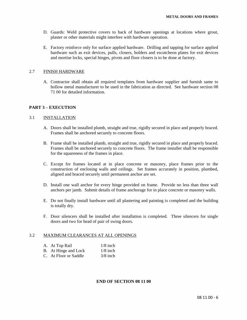
METAL DOORS AND FRAMES
08 11 00 - 6
D. Guards: Weld protective covers to back of hardware openings at locations where grout,
plaster or other materials might interfere with hardware operation.
E. Factory reinforce only for surface applied hardware. Drilling and tapping for surface applied
hardware such as exit devices, pulls, closers, holders and escutcheon plates for exit devices
and mortise locks, special hinges, pivots and floor closers is to be done at factory.
2.7 FINISH HARDWARE
A. Contractor shall obtain all required templates from hardware supplier and furnish same to
hollow metal manufacturer to be used in the fabrication as directed. See hardware section 08
71 00 for detailed information.
PART 3 – EXECUTION
3.1 INSTALLATION
A. Doors shall be installed plumb, straight and true, rigidly secured in place and properly braced.
Frames shall be anchored securely to concrete floors.
B. Frame shall be installed plumb, straight and true, rigidly secured in place and properly braced.
Frames shall be anchored securely to concrete floors. The frame installer shall be responsible
for the squareness of the frames in place.
C. Except for frames located at in place concrete or masonry, place frames prior to the
construction of enclosing walls and ceilings. Set frames accurately in position, plumbed,
aligned and braced securely until permanent anchor are set.
D. Install one wall anchor for every hinge provided on frame. Provide no less than three wall
anchors per jamb. Submit details of frame anchorage for in place concrete or masonry walls.
E. Do not finally install hardware until all plastering and painting is completed and the building
is totally dry.
F. Door silencers shall be installed after installation is completed. Three silencers for single
doors and two for head of pair of swing doors.
3.2 MAXIMUM CLEARANCES AT ALL OPENINGS
A. At Top Rail 1/8 inch
B. At Hinge and Lock 1/8 inch
C. At Floor or Saddle 3/8 inch
END OF SECTION 08 11 00


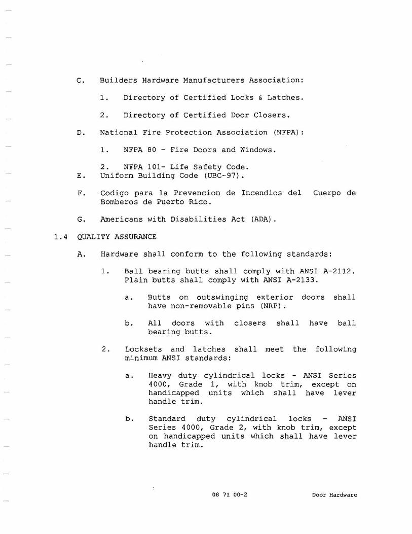


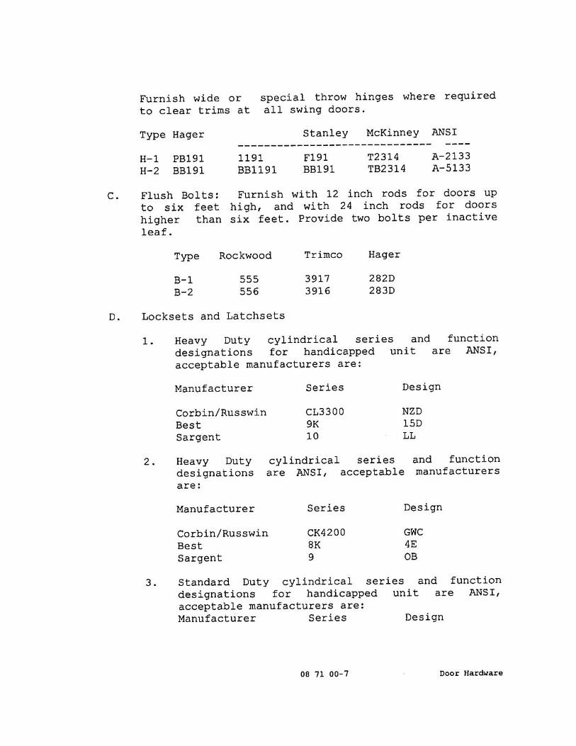

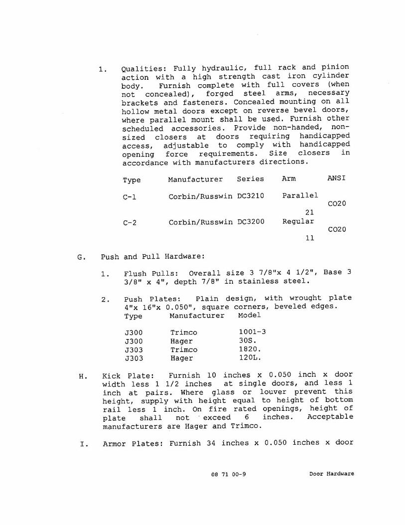


SECTION 08520
ALUMINUM JALOUSIES WINDOWS
PART 1 - GENERAL
1.1 RELATED DOCUMENTS
A. Drawings and general provisions of the Contract, including General and Supplementary
Conditions and Division 01 Specification Sections, apply to this Section.
1.2 SUMMARY
A. This Section includes operable aluminum jalousies windows for exterior locations, as indicated
on drawings
1.3 DEFINITIONS
A. Performance class designations shall be in accordance to AAMA/WDMA 101/I.S.2/NAFS:
1. AW: Architectural
2. HC: Heavy Commercial
3. C: Commercial
4. LC: Light Commercial
5. R: Residential
B. Performance grade number shall be in accordance to AAMA/WDMA 101/I.S.2/NAFS:
1. Design pressure number in pounds force per square foot (pascal) used to determine the
structural test pressure and water test pressure.
C. Structural Test Pressure: For uniform load structural test, is equivalent to 150 percent of the
design pressure.
D. Minimum Test Size: Smallest size permitted for performance class (gateway test size).
Products must be tested at minimum test size or at a size larger than minimum test size to
comply with requirements for performance class.
1.4 PERFORMANCE REQUIREMENTS
A. General: Provide aluminum windows capable of complying with performance requirements
indicated, based on testing manufacturer’s windows that are representative of those specified,
and that are of minimum test size indicated below:
1. Size indicated on drawings.
B. Structural Performance: Provide aluminum windows capable of withstanding the effects of the
following loads, based on testing units representative of those indicated for Project that pass
AAMA/WDMA 101/I.S.2/NAFS, Uniform Load Structural Test:

ALUMINUM JALOUSIES WINDOWS
08520 - 2
1. Design Wind Loads: Determine design wind loads applicable to Project from basic wind
speed indicated in miles per hour (meters per second) at 33 feet (10 m) above grade,
according to ASCE 7, Section 6.5, “Method 2-Analytical Procedure”, based on mean roof
heights above grade indicated on Drawings.
a. Basic Wind Speed: 120 mph (53.3 m/s).
C. Windborne-Debris Resistance: Provide aluminum windows capable of resisting impact from
windborne debris, based on the pass/fail criteria as determined from testing aluminum windows
identical to those specified, according to the latest ASTM code and requirements of authorities
having jurisdiction.
D. Thermal Movements: Provide aluminum windows, including anchorage, that allow for thermal
movements resulting from the following maximum change (range) in ambient and surface
temperatures by preventing buckling, opening of joints, overstressing of components, failure
of joint sealants, failure of connections, and other detrimental effects. Base engineering
calculation on surface temperatures of materials due to both solar heat gain and nighttime-sky
heat loss.
1. Temperature Change (Range): 120 ºF (67 ºC), ambient; 180 ºF (100 ºC) material surfaces.
1.5 SUBMITTALS
A. Product Data: Include construction details, material descriptions, and fabrication methods,
dimensions of individual components and profiles, hardware, finishes, and operating
instructions for each type of aluminum window indicated.
B. Shop Drawings: Include plans, elevations, sections, details, hardware, attachments to other
work, operational clearances, installation details, and the following:
1. Mullion details, including reinforcement and stiffeners.
2. Joinery details.
3. Expansion provisions.
4. Flashing and drainage details.
5. Weather-stripping details.
6. Thermal-break details.
7. Window System Operators: Show locations, mounting, and details for installing operator
components and controls.
C. Samples for Initial Selection: for units with factory-applied color finishes.
1. Include similar samples of hardware and accessories involving color selection.
D. Samples for Verification; for aluminum windows and components required, prepared on
Samples of size indicated below.
1. Operable Window: Full-size unit with factory-applied finish.
2. Hardware: Full-size units with factory-applied finishes.
3. Weather Stripping.

ALUMINUM JALOUSIES WINDOWS
08520 - 3
E. Product Schedule: for aluminum windows. Use same designations indicated on Drawings.
F. Warranty: Special Warranty specified in this Section.
1.6 QUALITY ASSURANCE
A. Installer Qualifications: An installer acceptable to aluminum window manufacturer for
installation of units required for this Project.
1. Installer’s responsibilities include providing professional engineering services needed to
assume engineering responsibility.
2. Engineering Responsibility: Preparation of data for aluminum windows, including Shop
Drawings, based on testing and engineering analysis of manufacturer’s standard units in
assemblies similar to those indicated for this Project.
B. Manufacturer Qualifications: A manufacturer capable of fabricating aluminum windows that
meet or exceed performance requirements indicated and of documenting this performance by
inclusion in lists and by labels, test reports, and calculations.
C. Source Limitations: Obtain aluminum windows through one source form a single manufacturer.
D. Products Options: Information on Drawings and in Specifications establishes requirements for
aluminum windows; aesthetic effects and performance characteristics. Aesthetic effects area
indicated by dimensions, arrangements, alignment, and profiles of components and assemblies
as they relate to sightlines, to one another, and to adjoining construction. Performance
characteristics are indicated by criteria subject to verification by one or more methods including
preconstruction testing, field testing, and in-service performance.
1.7 PROJECT CONDITIONS
A. Field Measurements: Verify aluminum window openings by field measurements before
fabrication and indicate measurements on Shop Drawings.
1. Established Dimensions: Where field measurements cannot be made without delaying the
Work, establish opening dimensions and proceed with fabricating aluminum windows
without field measurements. Coordinate wall construction to ensure that actual opening
dimensions correspond to established dimensions.
1.8 WARRANTY
A. Special Warranty: Manufacturer’s standard form in which manufacturer agrees to repair or
replace aluminum windows that fall in materials or workmanship within specified warranty
period.
1. Failures include, but are not limited to, the following:

ALUMINUM JALOUSIES WINDOWS
08520 - 4
a. Failure to meet performance requirements.
b. Structural failures including excessive deflection, water leakage, air infiltration, or
condensation.
c. Faulty operation of movable sash and hardware.
d. Deterioration of metals, other materials, and metal finishes beyond normal weathering.
PART 2 - PRODUCTS
2.1 MANUFACTURERS
A. Available Manufacturers: Subject to compliance with requirements, manufacturers offering
products that may be incorporated into the Work include, but are not limited to, the following:
1. Valcor / Samcor
2. Air Master Manufacturing Corp.
3. Tamcor Corp.
4. Submit local manufacturer for approval.
2.2 MATERIALS
A. Aluminum Extrusions: Alloy and temper recommended by aluminum window manufacturer
for strength, corrosion resistance, and application of required finish, but not less than
24,000-psi (165-MPa) ultimate tensile strength, not less than 16,000-psi (110-MPa) minimum
yield strength, and not less than 0.062-inch (1.6-mm) thickness at any location for the main
frame and sash members.
B. Fasteners: Aluminum, nonmagnetic stainless steel, epoxy adhesive, or other materials
warranted by manufacturer to be noncorrosive and compatible with aluminum window
members, trim, hardware, anchors, and other components.
1. Reinforcement: Where fasteners screw anchor into aluminum less than 0.125 inch (3.2 mm)
thick, reinforce interior with aluminum or nonmagnetic stainless steel to receive screw
threads, or provide standard, noncorrosive, pressed-in, splined grommet nuts.
2. Exposed Fasteners: Unless unavoidable for applying hardware, do not use exposed
fasteners. For application.
C. Anchors, Clips, and Accessories: Aluminum, nonmagnetic stainless steel, or zinc-coated steel
or iron complying with ASTM B 633 for SC 3 severe service conditions; provide sufficient
strength to withstand design pressure indicated.
D. Reinforcing Members: Aluminum, nonmagnetic stainless steel, or nickel/chrome-plated steel
complying with ASTM B 456 for Type SC 3 severe service conditions, or zinc-coated steel or
iron complying with ASTM B 633 for SC 3 severe serviced conditions; provide sufficient
strength to withstand design pressure indicated.

ALUMINUM JALOUSIES WINDOWS
08520 - 5
E. Compression-Type Weather Stripping: Provide compressible weather stripping designed for
permanently resilient sealing under bumper or wiper action and for complete concealment when
aluminum window is closed.
1. Weather-Stripping Material: Manufacturer’s standard system and materials complying
with AAMA/WDMA 101/I.S.2/NAFS.
F. Sliding-Type Weather Stripping: Provide woven-pile weather stripping of wool,
polypropylene, or nylon pile and resin-impregnated backing fabric. Comply with AAMA
701/702.
G. Replaceable Weather Seals: Comply with AAAMA 701/702.
H. Sealant: For sealants required within fabricated windows, provide window manufacturer’s
standard, permanently elastic, non-shrinking, and non-migrating type recommended by sealant
manufacturer for joint size and movement.
2.3 WINDOW
A. Window Type: As indicated on Construction Documents.
B. AAMA/WDMA Performance Requirements: Provide aluminum windows of performance
indicated that comply with AAMA/WDMA 101/I.S.2/NAFS.
C. Condensation-Resistance Factor (CRF): Provide aluminum windows tested for thermal
performance according to AAMA 1503, showing a CRF of 45.
D. Thermal Transmittance: Provide aluminum windows with a whole-window, U-factor
maximum indicated at 15-mph (24-km/h) exterior wind velocity and winter condition
temperatures when tested according to ASTM E 1423.
E. Solar Heat-Gain Coefficient (SHGC): Provide aluminum windows with a whole-window
SHGC maximum of 0.55, determined according to NFRC 200 procedures.
F. Sound Transmission Class (STC): Provide aluminum windows rated for not less than 35 STC
when tested for laboratory sound transmission loss according to ASTM E 90 and determined
by ASTM E 413.
G. Air Infiltration: Maximum rate not more than indicated when tested according to
AAMA/WDMA 101/I.S.2/NAFS, Air Infiltration Test.
H. Water Resistance: No water leakage as defined in AAMA/WDMA referenced test methods at
a water test pressure equaling that indicated, when tested according to AAMA/WDMA
101/I.S.2/NAFS, Water Resistance Test.
I. Forced-Entry Resistance: Comply with Performance Grade 40 requirements when tested
according to ASTM F 588.

ALUMINUM JALOUSIES WINDOWS
08520 - 6
2.4 BLADES
A. Louver Blades: Louver blades shall be approved equal to standard factory-installed aluminum
blades system from Titanica window, model 600A, thickness of 0.062”, manufactured by
Valcor / Samcor. Blade system must produces weather-tight seal and complies with
requirements for windborne-debris resistance and all aforementioned requirements for this
project.
2.5 HARDWARE
A. General: Provide manufacturer’s standard hardware fabricated from aluminum, stainless steel,
carbon steel complying with AAMA 907, or other corrosion-resistant material compatible with
aluminum; designed to smoothly operate, tightly close, and securely lock aluminum windows,
and sized to accommodate sash or ventilator weight and dimensions. Do not use aluminum in
frictional contact with other metals.
B. Counterbalancing Mechanism: Comply with AAMA 902.
C. Sill Cap/Track: Extruded-aluminum track with natural anodized finish, of thickness,
dimensions, and profile indicated; designed to comply with performance requirements
indicated and to drain to the exterior.
D. Locks and Latches: Designed to allow unobstructed movement of the sash across adjacent sash
in direction indicated and operated from the inside only.
E. Roller Assemblies: Low-friction design.
F. Butterfly-Type Rotary Operators: Comply with AAMA 901 when tested according to ASTM
E 405, Method A.
1. Operation Function: All ventilators move simultaneously and securely close at both jambs
without using additional manually controlled locking devices.
G. Four-or Six-Bar Friction Hinges (“projected Out-Swing” windows): Comply with AAMA 904.
1. Locking mechanism and handles for manual operation.
H. Limit Devices: Provide limit devices designed to restrict sash or ventilator opening.
I. Pole Operators (where applies): Tubular-shaped anodized aluminum; with rubber-capped lower
end and standard push-pull hook at top to match hardware design; of sufficient length to operate
window without reaching more than 60 inches (1500 mm) above floor; 1 pole operator and pole
hanger per room that has operable windows more than 72 inches (1800 mm) above floor.
2.6 INSECT SCREENS
A. General: Design windows and hardware to accommodate screens in a tight-fitting, removable
arrangement, with a minimum of exposed fasteners and latches. Fabricate insect screens to fully

ALUMINUM JALOUSIES WINDOWS
08520 - 7
integrate with window frame. Locate screens on inside of window and provide for each
operable exterior sash or ventilator.
B. Aluminum Insect Screen Frames: Manufacturer’s standard aluminum alloy complying with
SMA 1004. Fabricate frames with mitered or coped joints or corner extrusions, concealed
fasteners, and removable PVC spline/anchor concealing edge of frame.
1. Extruded-Aluminum or Aluminum Tubular Framing Sections and Cross Braces: Not less
than 0.040-inch (1.0-mm) wall thickness.
2. Finish: Match aluminum window members.
C. Aluminum Wire Fabric: 18-by-16 (1.1-by-1.3-mm) mesh of 0.011-inch-(0.28-mm-) diameter,
coated aluminum wire.
2.7 FABRICATION
A. Fabricate aluminum windows in sizes indicated. Include a complete system for assembling
components and anchoring windows.
B. Thermally Improved Construction: Fabricate aluminum windows with an integral, concealed,
low-conductance thermal barrier; located between exterior materials and window members
exposed on interior side; in a manner that eliminates direct metal-to-metal contact.
1. Provide thermal-break construction that has been in use for not less than three years and
has been tested to demonstrate resistance to thermal conductance and condensation and to
show adequate strength and security of glass retention.
2. Provide thermal barriers tested according to AAMA 505; determine the allowable design
shear flow per the appendix in AAMA 505.
3. Provide hardware with low conductivity or nonmetallic material for hardware bridging
thermal breaks at frame or vent sash.
C. Weather Stripping: Provide full-perimeter weather stripping for each operable sash and
ventilator.
D. Weep Holes: provide weep holes and internal passages to conduct infiltrating water to exterior.
E. Mullions: Provide mullions and cover plates as shown, matching window units, complete with
anchors for support to structure and installation of window units. Allow for erection tolerances
and provide for movement of window units due to thermal expansion and building deflections,
as indicated. Provide mullions and cover plates capable of withstanding design loads of
window units.
F. Sub-frames (where applies): Provide sub-frames with anchors for window units as shown, of
profile and dimensions indicated but not less than 0.062 inch (1.6 mm) thick extruded
aluminum. Miter or cope corners, and weld and dress smooth with concealed mechanical joint
fasteners. Finish to match window units. Provide sub-frames capable of withstanding design
loads of window units.

ALUMINUM JALOUSIES WINDOWS
08520 - 8
2.8 FINISHES, GENERAL
A. Comply with NAAMM’s “Metal Finishes Manual for Architectural and Metal Products” for
recommendations for applying and designating finishes.
B. Protect mechanical finishes on exposed surfaces from damage by applying a strippable,
temporary protective covering before shipping.
C. Appearance of Finished Work: Variations in appearance of abutting or adjacent pieces are
acceptable if they are within one-half of the range of approved Samples. Noticeable variations
in the same piece are not acceptable. Variations in appearance of other components are
acceptable if they are within the range of approved Samples and are assembled or installed to
minimize contrast.
2.9 ALUMINUM FINISHES
A. Finish designations prefixed by AA comply with the system established by the Aluminum
Association for designating aluminum finishes.
PART 3 - EXECUTION
3.1 EXAMINATION
A. Examine openings, substrates, structural support, anchorage, and conditions, with Installer
present, for compliance with requirements for installation tolerances and other conditions
affecting performance of work. Verify rough opening dimensions, levelness of sill plate, and
operational clearances. Examine wall flashings, vapor retarders, water and weather barriers,
and other built-in components to ensure a coordinated, weather-tight window installation.
1. Masonry Surfaces: Visibly dry and free of excess mortar, sand, and other construction
debris.
2. Proceed with installation only after unsatisfactory conditions have been corrected.
3.2 INSTALLATION
A. Comply with Drawings, Shop Drawings, and manufacturer’s written instructions for installing
windows, hardware, accessories, and other components.
B. Install windows level, plumb, square, true to line, without distortion or impeding thermal
movement, anchored securely in place to structural support, and in proper relation to wall
flashing and other adjacent construction.
C. Set sill members in bed of sealant or with gaskets, as indicated, for weather-tight construction.
D. Install windows and components to drain condensation, water penetrating joints, and moisture
migrating within windows to the exterior.

ALUMINUM JALOUSIES WINDOWS
08520 - 9
E. Separate aluminum and other corrodible surfaces from sources of corrosion or electrolytic
action at points of contact with other materials.
3.3 FIELD QUALITY CONTROL
A. Testing Agency: Engage a qualified testing agency to perform tests and inspections and prepare
test reports.
1. Testing and inspecting agency will interpret tests and state in each report whether tested
work complies with or deviates from requirements.
B. Testing Services: Testing and inspecting of installed windows shall take place as follows:
1. Testing Methodology: Testing of windows for air infiltration and water resistance shall be
performed according to AAMA 502, by applying same test pressures required to determine
compliance with AAMA/WDMA 101/I.S.2/NAFS in Part 1 “Performance Requirements”
Article.
2. Test Reports: Shall be prepared according to AAMA 502.
C. Remove and replace non-complying aluminum window and retest as specified above.
4.4 ADJUSTING, CLEANING, AND PROTECTION
A. Adjust operating sashes and ventilators, screens, hardware, operators, and accessories for a tight
fit at contact points and weather stripping for smooth operation and weather-tight closure.
Lubricate hardware and moving parts.
B. Clean aluminum surfaces immediately after installing windows. Avoid damaging protective
coatings and finishes. Remove excess sealants, dirt, and other substances.
C. Protect window surfaces from contact with contaminating substances resulting from
construction operations. In addition, monitor window surfaces adjacent to and below exterior
concrete and masonry surfaces during construction for presence of dirt, scum, alkaline deposits,
stains, or other contaminants. If contaminating substances do contact window surfaces, remove
contaminants immediately according to manufacturer’s written recommendations.
END OF SECTION 08520

SECTION 08800 - GLAZING
PART 1 - GENERAL
1.1 RELATED DOCUMENTS
A. Drawings and general provisions of the Contract, including General and Supplementary
Conditions and Division 1 Specification Sections, apply to this Section.
1.2 SUMMARY
A. This Section includes glazing for the following products and applications, including those
specified in other Sections where glazing requirements are specified by reference to this
Section:
1. Windows.
2. Doors.
1.3 DEFINITIONS
A. Manufacturers of Glass Products: Firms that produce primary glass, fabricated glass, or both, as
defined in referenced glazing publications.
B. Glass Thicknesses: Indicated by thickness designations in millimeters according to
ASTM C 1036.
C. Deterioration of Coated Glass: Defects developed from normal use that are attributed to the
manufacturing process and not to causes other than glass breakage and practices for maintaining
and cleaning coated glass contrary to manufacturer's written instructions. Defects include
peeling, cracking, and other indications of deterioration in metallic coating.
D. Deterioration of Insulating Glass: Failure of hermetic seal under normal use that is attributed to
the manufacturing process and not to causes other than glass breakage and practices for
maintaining and cleaning insulating glass contrary to manufacturer's written instructions.
Evidence of failure is the obstruction of vision by dust, moisture, or film on interior surfaces of
glass.
E. Deterioration of Laminated Glass: Defects developed from normal use that are attributed to the
manufacturing process and not to causes other than glass breakage and practices for maintaining
and cleaning laminated glass contrary to manufacturer's written instructions. Defects include
edge separation, delamination materially obstructing vision through glass, and blemishes
exceeding those allowed by referenced laminated-glass standard.
1.4 PERFORMANCE REQUIREMENTS
A. General: Provide glazing systems capable of withstanding normal thermal movement and wind
and impact loads (where applicable) without failure, including loss or glass breakage
attributable to the following: defective manufacture, fabrication, and installation; failure of

GLAZING 08800 - 2
sealants or gaskets to remain watertight and airtight; deterioration of glazing materials; or other
defects in construction.
B. Glass Design: Glass thickness designations indicated are minimums and are for detailing only.
Confirm glass thicknesses by analyzing Project loads and in-service conditions. Provide glass
lites in the thickness designations indicated for various size openings.
C. Thermal Movements: Provide glazing that allows for thermal movements resulting from the
following maximum change (range) in ambient and surface temperatures acting on glass
framing members and glazing components. Base engineering calculation on surface
temperatures of materials due to both solar heat gains and nighttime-sky heat loss.
D. Thermal and Optical Performance Properties: Provide glass with performance properties
specified based on manufacturer's published test data.
1.5 SUBMITTALS
A. Product Data: For each glass product and glazing material indicated.
B. Samples: For the following products, in the form of 12-inch- (300-mm-) square Samples for
glass and of 12-inch- (300-mm-) long Samples for sealants. Install sealant Samples between
two strips of material representative in color of the adjoining framing system.
C. Samples: For the following products, in the form of 12-inch- (300-mm-) square Samples for
glass.
1. Each color of laminated glass.
2. Each type of patterned glass.
D. Glazing Schedule: Use same designations indicated on Drawings for glazed openings in
preparing a schedule listing glass types and thicknesses for each size opening and location.
E. Product Certificates: Signed by manufacturers of glass and glazing products certifying that
products furnished comply with requirements.
F. Qualification Data: For installers.
G. Preconstruction Adhesion and Compatibility Test Report: From glazing sealant manufacturer
indicating glazing sealants were tested for adhesion to glass and glazing channel substrates and
for compatibility with glass and other glazing materials.
H. Product Test Reports: For each of the following types of glazing products:
1. Laminated glass.
2. Coated float glass.
I. Warranties: Special warranties specified in this Section.
1.6 QUALITY ASSURANCE

GLAZING 08800 - 3
A. Installer Qualifications: An experienced installer who has completed glazing similar in
material, design, and extent to that indicated for this Project; whose work has resulted in glass
installations with a record of successful in-service performance.
B. Source Limitations for Glass: Obtain the following through one source from a single
manufacturer for each glass type.
C. Elastomeric Glazing Sealant Product Testing: Obtain sealant test results for product test reports
in "Submittals" Article from a qualified testing agency based on testing current sealant
formulations within a 36-month period.
1. Test elastomeric glazing sealants for compliance with requirements specified by
reference to ASTM C 920, and where applicable, to other standard test methods.
D. Pre-installation Conference: Conduct conference at Project site to comply with requirements in
Division 1 Section "Project Management and Coordination."
1.7 DELIVERY, STORAGE, AND HANDLING
A. Protect glazing materials according to manufacturer's written instructions and as needed to
prevent damage to glass and glazing materials from condensation, temperature changes, direct
exposure to sun, or other causes.
B. For insulating-glass units that will be exposed to substantial altitude changes, comply with
insulating-glass manufacturer's written recommendations for venting and sealing to avoid
hermetic seal ruptures.
1.8 PROJECT CONDITIONS
A. Environmental Limitations: Do not proceed with glazing when ambient and substrate
temperature conditions are outside limits permitted by glazing material manufacturers and when
glazing channel substrates are wet from rain, frost, condensation, or other causes.
1. Do not install liquid glazing sealants when ambient and substrate temperature conditions
are outside limits permitted by glazing sealant manufacturer or below 40 deg F (4.4
deg C).
1.9 WARRANTY
A. Manufacturer's Special Warranty for Coated-Glass Products: Manufacturer's standard form,
made out to Owner and signed by coated-glass manufacturer agreeing to replace coated-glass
units that deteriorate as defined in "Definitions" Article, f.o.b. the nearest shipping point to
Project site, within specified warranty period indicated below.
1. Warranty Period: 5 years from date of Substantial Completion.

GLAZING 08800 - 4
PART 2 - PRODUCTS
2.1 MANUFACTURERS
A. In other Part 2 articles where titles below introduce lists, the following requirements apply to
product selection:
1. Available Products: Subject to compliance with requirements, products that may be
incorporated into the Work include, but are not limited to, products specified.
2. Products: Subject to compliance with requirements, provide one of the products
specified.
3. Product: Subject to compliance with requirements, provide product specified.
4. Available Manufacturers: Subject to compliance with requirements, manufacturers
offering products that may be incorporated into the Work include, but are not limited to,
manufacturers specified.
5. Manufacturers: Subject to compliance with requirements, provide products by one of the
manufacturers specified.
6. Basis-of-Design Product: The design for each glazing product is based on the product
named. Subject to compliance with requirements, provide either the named product or a
comparable product by one of the other manufacturers specified.
2.2 GLASS PRODUCTS
A. Annealed Float Glass: ASTM C 1036, Type I (transparent flat glass), Quality-Q3; of class
indicated.
1. Ultra-Clear (Low-Iron) Float Glass: Class I (clear); with a minimum 91 percent visible
light transmission and a minimum solar heat gain coefficient of 0.87.
a. Products:
1) AFG Industries Inc.; Krystal Klear.
2) Pilkington Building Products North America; Optiwhite.
3) PPG Industries, Inc.; Starphire.
4) Schott Corporation; Amiran.
B. Laminated Glass: ASTM C 1172, and complying with other requirements specified and with
the following:
1. Interlayer: Polyvinyl butyl of thickness indicated with a proven record of no tendency to
bubble, discolor, or lose physical and mechanical properties after laminating glass lutes
and installation.
a. For polyvinyl butyl interlayers, laminate lutes in autoclave with heat plus pressure.
2. Laminating Process: Fabricate laminated glass to produce glass free of foreign
substances and air or glass pockets.
3. Glass Products.

GLAZING 08800 - 5
2.3 GLAZING GASKETS
A. Dense Compression Gaskets: Molded or extruded gaskets of material indicated below,
complying with standards referenced with name of elastomer indicated below, and of profile
and hardness required to maintain watertight seal:
1. Neoprene, ASTM C 864.
2. EPDM, ASTM C 864.
3. Silicone, ASTM C 1115.
4. Thermoplastic polyolefin rubber, ASTM C 1115.
5. Any material indicated above.
B. Soft Compression Gaskets: Extruded or molded, closed-cell, integral-skinned gaskets of
material indicated below; complying with ASTM C 509, Type II, black; and of profile and
hardness required to maintain watertight seal:
1. Neoprene.
2. EPDM.
3. Silicone.
4. Thermoplastic polyolefin rubber.
5. Any material indicated above.
C. Lock-Strip Gaskets: Neoprene extrusions in size and shape indicated, fabricated into frames
with molded corner units and zipper lock-strips, complying with ASTM C 542, black.
2.4 GLAZING SEALANTS
A. General: Provide products of type indicated, complying with the following requirements:
1. Compatibility: Select glazing sealants that are compatible with one another and with
other materials they will contact, including glass products, seals of insulating-glass units,
and glazing channel substrates, under conditions of service and application, as
demonstrated by sealant manufacturer based on testing and field experience.
2. Suitability: Comply with sealant and glass manufacturers' written instructions for
selecting glazing sealants suitable for applications indicated and for conditions existing at
time of installation.
3. Colors of Exposed Glazing Sealants: As selected by Architect from manufacturer's full
range.
B. Elastomeric Glazing Sealants: Comply with ASTM C 920 and other requirements indicated for
each liquid-applied chemically curing sealant specified, including those referencing
ASTM C 920 classifications for type, grade, class, and uses related to exposure and joint
substrates.
2.5 GLAZING TAPES
A. Back-Bedding Mastic Glazing Tapes: Preformed, butyl-based elastomeric tape with a solids
content of 100 percent; non-staining and non-migrating in contact with nonporous surfaces;
with or without spacer rod as recommended in writing by tape and glass manufacturers for
application indicated; packaged on rolls with a release paper backing; and complying with
ASTM C 1281 and AAMA 800 for products indicated below:

GLAZING 08800 - 6
1. AAMA 804.3 tape, where indicated.
2. AAMA 806.3 tape, for glazing applications in which tape is subject to continuous
pressure.
3. AAMA 807.3 tape, for glazing applications in which tape is not subject to continuous
pressure.
B. Expanded Cellular Glazing Tapes: Closed-cell, PVC foam tapes; factory coated with adhesive
on both surfaces; packaged on rolls with release liner protecting adhesive; and complying with
AAMA 800 for the following types:
1. Type 1, for glazing applications in which tape acts as the primary sealant.
2. Type 2, for glazing applications in which tape is used in combination with a full bead of
liquid sealant.
2.6 MISCELLANEOUS GLAZING MATERIALS
A. General: Provide products of material, size, and shape complying with referenced glazing
standard, requirements of manufacturers of glass and other glazing materials for application
indicated, and with a proven record of compatibility with surfaces contacted in installation.
B. Cleaners, Primers, and Sealers: Types recommended by sealant or gasket manufacturer.
C. Setting Blocks: Elastomeric material with a Shore, Type A durometer hardness of 85, plus or
minus 5.
D. Spacers: Elastomeric blocks or continuous extrusions with a Shore, Type A durometer hardness
required by glass manufacturer to maintain glass lutes in place for installation indicated.
E. Edge Blocks: Elastomeric material of hardness needed to limit glass lateral movement (side
walking).
F. Cylindrical Glazing Sealant Backing: ASTM C 1330, Type O (open-cell material), of size and
density to control glazing sealant depth and otherwise produce optimum glazing sealant
performance.
G. Perimeter Insulation for Fire-Resistive Glazing: Identical to product used in test assembly to
obtain fire-resistance rating.
2.7 FABRICATION OF GLAZING UNITS
A. Fabricate glazing units in sizes required to glaze openings indicated for Project, with edge and
face clearances, edge and surface conditions, and bite complying with written instructions of
product manufacturer and referenced glazing publications, to comply with system performance
requirements.
B. Clean-cut or flat-grind vertical edges of butt-glazed monolithic lutes in a manner that produces
square edges with slight kerfs at junctions with outdoor and indoor faces.
C. Grind smooth and polish exposed glass edges and corners.
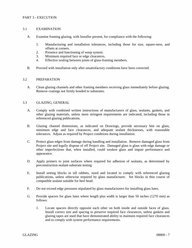
GLAZING 08800 - 7
PART 3 - EXECUTION
3.1 EXAMINATION
A. Examine framing glazing, with Installer present, for compliance with the following:
1. Manufacturing and installation tolerances, including those for size, square-ness, and
offsets at corners.
2. Presence and functioning of weep system.
3. Minimum required face or edge clearances.
4. Effective sealing between joints of glass-framing members.
B. Proceed with installation only after unsatisfactory conditions have been corrected.
3.2 PREPARATION
A. Clean glazing channels and other framing members receiving glass immediately before glazing.
Remove coatings not firmly bonded to substrates.
3.3 GLAZING, GENERAL
A. Comply with combined written instructions of manufacturers of glass, sealants, gaskets, and
other glazing materials, unless more stringent requirements are indicated, including those in
referenced glazing publications.
B. Glazing channel dimensions, as indicated on Drawings, provide necessary bite on glass,
minimum edge and face clearances, and adequate sealant thicknesses, with reasonable
tolerances. Adjust as required by Project conditions during installation.
C. Protect glass edges from damage during handling and installation. Remove damaged glass from
Project site and legally dispose of off Project site. Damaged glass is glass with edge damage or
other imperfections that, when installed, could weaken glass and impair performance and
appearance.
D. Apply primers to joint surfaces where required for adhesion of sealants, as determined by
preconstruction sealant-substrate testing.
E. Install setting blocks in sill rabbets, sized and located to comply with referenced glazing
publications, unless otherwise required by glass manufacturer. Set blocks in thin course of
compatible sealant suitable for heel bead.
F. Do not exceed edge pressures stipulated by glass manufacturers for installing glass lutes.
G. Provide spacers for glass lutes where length plus width is larger than 50 inches (1270 mm) as
follows:
1. Locate spacers directly opposite each other on both inside and outside faces of glass.
Install correct size and spacing to preserve required face clearances, unless gaskets and
glazing tapes are used that have demonstrated ability to maintain required face clearances
and to comply with system performance requirements.

GLAZING 08800 - 8
2. Provide 1/8-inch (3-mm) minimum bite of spacers on glass and use thickness equal to
sealant width. With glazing tape, use thickness slightly less than final compressed
thickness of tape.
H. Provide edge blocking where indicated or needed to prevent glass lutes from moving sideways
in glazing channel, as recommended in writing by glass manufacturer and according to
requirements in referenced glazing publications.
I. Set glass lutes in each series with uniform pattern, draw, bow, and similar characteristics.
J. Where wedge-shaped gaskets are driven into one side of channel to pressurize sealant or gasket
on opposite side, provide adequate anchorage so gasket cannot walk out when installation is
subjected to movement.
K. Square cut wedge-shaped gaskets at corners and install gaskets in a manner recommended by
gasket manufacturer to prevent corners from pulling away; seal corner joints and butt joints with
sealant recommended by gasket manufacturer.
3.4 TAPE GLAZING
A. Position tapes on fixed stops so that, when compressed by glass, their exposed edges are flush
with or protrude slightly above sightline of stops.
B. Install tapes continuously, but not necessarily in one continuous length. Do not stretch tapes to
make them fit opening.
C. Cover vertical framing joints by applying tapes to heads and sills first and then to jambs. Cover
horizontal framing joints by applying tapes to jambs and then to heads and sills.
D. Place joints in tapes at corners of opening with adjoining lengths butted together, not lapped.
Seal joints in tapes with compatible sealant approved by tape manufacturer.
E. Do not remove release paper from tape until just before each glazing unit is installed.
F. Apply heel bead of elastomeric sealant.
G. Center glass lutes in openings on setting blocks and press firmly against tape by inserting dense
compression gaskets formed and installed to lock in place against faces of removable stops.
Start gasket applications at corners and work toward centers of openings.
H. Apply cap bead of elastomeric sealant over exposed edge of tape.
3.5 GASKET GLAZING (DRY)
A. Fabricate compression gaskets in lengths recommended by gasket manufacturer to fit openings
exactly, with allowance for stretch during installation.
B. Insert soft compression gasket between glass and frame or fixed stop so it is securely in place
with joints miter cut and bonded together at corners.

GLAZING 08800 - 9
C. Center glass lutes in openings on setting blocks and press firmly against soft compression
gasket by inserting dense compression gaskets formed and installed to lock in place against
faces of removable stops. Start gasket applications at corners and work toward centers of
openings. Compress gaskets to produce a weather-tight seal without developing bending
stresses in glass. Seal gasket joints with sealant recommended by gasket manufacturer.
D. Install gaskets so they protrude past face of glazing stops.
3.6 SEALANT GLAZING (WET)
A. Install continuous spacers, or spacers combined with cylindrical sealant backing, between glass
lutes and glazing stops to maintain glass face clearances and to prevent sealant from extruding
into glass channel and blocking weep systems until sealants cure. Secure spacers or spacers and
backings in place and in position to control depth of installed sealant relative to edge clearance
for optimum sealant performance.
B. Force sealants into glazing channels to eliminate voids and to ensure complete wetting or bond
of sealant to glass and channel surfaces.
C. Tool exposed surfaces of sealants to provide a substantial wash away from glass.
3.7 LOCK-STRIP GASKET GLAZING
A. Comply with ASTM C 716 and gasket manufacturer's written instructions. Provide
supplementary wet seal and weep system, unless otherwise indicated.
3.8 CLEANING AND PROTECTION
A. Protect exterior glass from damage immediately after installation by attaching crossed streamers
to framing held away from glass. Do not apply markers to glass surface. Remove
nonpermanent labels, and clean surfaces.
B. Protect glass from contact with contaminating substances resulting from construction
operations, including weld splatter. If, despite such protection, contaminating substances do
come into contact with glass, remove substances immediately as recommended by glass
manufacturer.
C. Examine glass surfaces adjacent to or below exterior concrete and other masonry surfaces at
frequent intervals during construction, but not less than once a month, for buildup of dirt, scum,
alkaline deposits, or stains; remove as recommended in writing by glass manufacturer.
D. Remove and replace glass that is broken, chipped, cracked, or abraded or that is damaged from
natural causes, accidents, and vandalism, during construction period.
E. Wash glass on both exposed surfaces in each area of Project not more than four days before date
scheduled for inspections that establish date of Substantial Completion. Wash glass as
recommended in writing by glass manufacturer.
END OF SECTION 08800

SECTION 09 29 00
GYPSUM WALLBOARD
PART 1 - GENERAL
1.1 SECTION REQUIREMENTS
1. The work included in this Section consists of furnishing all labor, materials, and equipment
required for the installation of gypsum partitions and wall furring as shown on drawings and
specified herein.
2. Related work described elsewhere:
1. Unit masonry works (Section 04810)
2. Painting (Section 09900)
1.2 SUBMITTALS
1. Contractor shall submit for the Architect’s approval a complete set of shop drawings of each
type of assembly.
PART 2 - PRODUCTS
2.1 PRODUCT DELIVERY, STORAGE AND HANDLING
1. All materials shall be delivered in their original unopened packages and stored in an enclosed
shelter providing protection from damage and exposure to the elements. Damaged or
deteriorated materials shall be removed from the premises.
2.2 PRODUCTS
1. MANUFACTURERS:
a. US Gypsum, Co.
b. Gold Bond
c. Georgia Pacific
2. All materials shall be installed in strict accordance to manufacturer’s recommendations.
Materials specified herein as reference is from United States Gypsum Company.
a. Gypsum panels shall be “Firecode C” Sheetrock panels ½” inch thick with square edges,
48 inches wide by 96 inches high (minimum).
b. Corner reinforcement shall be Dura-A-Bead.
c. Control joints shall be No. 093.

Gypsum Wallboard
09 29 00 - 2
d. Casing beads shall be series 200.
e. Metal Studs shall be Style CWS, 20 gauge, 3-5/8 inches deep or as called for on
drawings.
f. Metal Runners shall be Style CWS, 20 gauge, 3-5/8 inches deep or as called for on
drawings.
g. Furring Channels shall be “Z” furring channels, 1-½ inches deep.
h. Joint treatment shall be Perf-A-Tape and All-Purpose Joint Compound.
i. Screws shall be type “S”, length as required.
j. Insulation, where called for on drawings, shall be USG “Thermatfiber”, 3 inches thick,
for gypsum partitions and Owens-Corning 703 “Semi-Rigid Insulation Board”, 1-½
inches thick, for gypsum wall furring.
PART 3 - EXECUTION
3.1 For Gypsum Partitions
1. Attach metal runners at floor and to structural elements above with suitable fasteners located
2 inches from each end and spaced 24 inches on center. Position studs vertically, engaging
floor and ceiling runners and spaced 24” on center. When necessary, splice studs with 8
inches nested lap and one (1) positive attachment per stud flange. Place studs in direct
contact with all door and window frame jambs, abutting partitions, partition corners and
existing construction elements. Anchor all studs adjacent to door and window frames,
partition intersections, and corners to ceiling and floor runner flanges with fastener tool.
Securely anchor studs to jamb and head anchor clips of door by bold or screw attachment.
Over doors and windows place horizontally a cut-to-length section of runner, with a web
flange bend at each end, and secure with one (1) positive attachment per flange. Position a
cut-to-length stud (extending to top runner) at vertical panel joints over door frame header.
2. Apply gypsum panels (parallel to studs). Position all edges over studs for parallel
application. Use maximum practical lengths to minimize end joints. Fit ends and edges
closely, but not forced together. Stagger joints on opposite sides of partition.
3. Space screws 12 inches O.C. to studs at joints and runners and 8 inches O.C. to studs in field
(fire-rated fastening).
4. Power drive with an electric screwdriver so screw heads provide a slight depression below
surface of gypsum panels without breaking face paper. Do not drive screws closer than 3/8
inches from edges and ends of board.
5. Apply joint treatment as per manufacturer’s recommendations.

Gypsum Wallboard
09 29 00 - 3
3.2 For Gypsum Wall Furring
1. Erect insulation and hold in place with 2 furring channels spaced 24 inches on centers.
2. Except at exterior corners attach narrow flanges of furring channels with concrete stub nails
or power driven fasteners spaced 24 inches on centers.
3. At exterior corners attach wide flange of furring channels to wall with short flange extending
beyond corner; start furring channel with a 3 inches strip of insulation followed by furring
channels in the normal manner.
4. At interior corners, space second channel no more than 12 inches from corner and curt
insulation to fit.
5. Hold insulation in plane until gypsum board panels are installed with 10 inches long staple
field fabricated from 18 gauge tie wire and inserted through slot in channel.
6. Apply treated wood blocking around window and door openings and as required for
attachment and support of fixtures and furnishings.
7. Apply gypsum panels parallel to channels, use maximum practical lengths. Fit ends closely
but not forced together.
8. Space screws 16 inches O.C. in field of panels and along abutting edges.
9. Power drive with an electric screwdriver so screw heads provide a slight depression below
surface of gypsum panels without breaking face paper. Do not drive screws closer than 3/8
inch from edges and ends of board.
10. Apply joint treatment as per manufacturer’s recommendations.
3.3 Clean Up
1. At the completion of the work, remove all rubbish, excess material, scaffolding, tools and
equipment from the building, leaving floors broom clean, and ready for the work of other
trades.
END OF SECTION 09 29 00

SECTION 09 65 33
RESILIENT TILE FLOORING
PART 1 - GENERAL
1.1 SECTION REQUIREMENTS
A. Provide vinyl tile flooring, vinyl bases and an underlayment for the leveling of concrete floors
as required and as specified herein and shown on drawings.
B. Related work described elsewhere:
1. Cast-in-Place Concrete Section 03 33 00.
1.2 QUALITY ASSURANCE
A. Manufacturer:
Provide each type of resilient flooring and accessories as produced by a single manufacturer,
including recommended primers, adhesives and leveling compounds.
B. Installer’s Qualifications:
Engage Installer who is trained and experienced for the installation of this work. No
allowance will be made for lack of skill on the part of the tile installer.
C. Product Specification Requirements:
Vinyl floor tile shall conform to Federal Specification SS-T-312B and NFPA 99.
1.3 SUBMITTALS
A. Product Data:
Submit manufacturer’s technical data for each type of resilient flooring and accessories.
B. Samples:
Submit manufacturer’s color charts in form of actual sections of resilient flooring, including
accessories, showing full range of colors and patterns available, for each type of resilient
flooring required.
C. Certification:
Installer shall submit certification that substrate has been properly prepared for receiving the
installation of the resilient flooring.

Resilient Tile Flooring
09 65 33 - 2
1.4 EXTRA MATERIALS
A. Furnish not less than one box for each 25 boxes or fraction thereof, for each type, color,
pattern and size installed. Materials shall be from same manufactured lot as materials
installed and enclosed in protective packaging with appropriate identifying labels.
PART 2 - PRODUCTS
2.1 MANUFACTURERS
A. Armstrong World Industries
B. Amtico International
C. Substitutions: As per approved substitution by Architect.
2.2. VINYL COMPOSITION TILE FLOORING
A. Provide vinyl composition tile Type IV, asbestos free. Class 1 with a flame spread less than
0.75.
B. Tile Size: 1/8 inch x 12 inches x 12 inches.
C. Armstrong excelon imperial texture.
2.3 VINYL COMPOSITION TILE ACCESSORIES
A. Vinyl Wall Base:
Provide vinyl cove base with matching end stops and preformed or molded corner units.
Base shall be 0.085 gauge and 4 inches in height (or as otherwise shown on the drawings).
Base shall bought in 100 foot length rolls only. Color to be selected by Architect.
B. Concrete Slab Primer:
Non-staining type as recommended by flooring manufacturer.
C. Leveling and Patching Compounds:
Use fast-setting underlayment as recommended Flooring Manufacturer for leveling of
concrete floors.
D. Adhesives:
Use as recommended by flooring manufacturer to suit material and substrate conditions.

Resilient Tile Flooring
09 65 33 - 3
PART 3 - EXECUTION
3.1 INSPECTION
A. Installer shall inspect subfloor surfaces to determine that they are satisfactory. As satisfactory
subfloor surface is defined as one that is smooth, free from cracks, holes, ridges, coatings
preventing adhesive bonds and other defects impairing performance or appearance. Do not
allow resilient flooring work to proceed until subfloor surfaces are satisfactory. Starting of
work will be construed as Installer’s acceptance of subfloor surfaces within any particular
area.
3.2 PREPARATION
A. Use the underlayment at the entire floor area is necessary for levelling the concrete floors.
Apply in single layer and assume a minimum thickness of 1/16 inch and a maximum
thickness of ¼ levelling.
B. Concrete floor surface should be clean and free of dirt, oil, grease, plaster, curing compounds
and other foreign matter. Concrete floor must be sufficiently cured and free of excessive
moisture or hydrostatic pressure. Dampen concrete floors with clean water. Do not leave
standing puddles or water. Apply underlayment while floor is still damp with. Allow to dry
before underlayment is applied.
C. Apply sufficient pressure to the underlayment with the trowel to secure adequate bonding to
the cleaned, damp-mopped.
D. Apply adhesive in compliance with manufacturer’s instructions.
3.3 INSTALLATION
A. Install resilient flooring in strict compliance with manufacturer’s printed instructions. Extend
resilient flooring into toe spaces, door reveals and into closets and similar openings.
B. Lay tile from center marks established with principal walls, discounting minor offsets, so that
tile at opposite edges of room area of equal width. Adjust as necessary to avoid use of cut
widths less than ½ tile at room perimeters. Lay tile with grain running in one direction and
square to room axis, unless otherwise indicated.
C. Match tiles for color and pattern by using tile from cartons in same sequence as manufactured
and packaged if so numbered.
D. Cut tile neatly around all fixtures. Broken, cracked, chipped, or deformed tiles are not
acceptable.
E. Adhere tile flooring to substrate using full spread of adhesive applied in compliance with
flooring manufacturer’s instructions.

Resilient Tile Flooring
09 65 33 - 4
3.4 INSTALLATION OF ACCESSORIES
A. Apply wall base to walls, columns, casework and other permanent fixtures in rooms or areas
where base is required.
B. When possible install base of same length as wall so as to minimize joints with preformed
corner units.
C. Tightly bond base to substrate throughout length of each piece, with continuous contact at
horizontal and vertical surfaces.
3.5 CLEANING AND PROTECTION
A. Clean floors using appropriate cleaner recommended by manufacturer.
B. Do not wash or wax floor until time period recommended by resilient flooring manufacturer
has elapsed to allow resilient flooring to become well-sealed in adhesive.
C. Remove any excess adhesive or other surface blemishes, using appropriate cleaner
recommended by resilient flooring manufacturers.
D. Protect flooring against damage during construction period.
E. Clean and wax resilient flooring.
END OF SECTION 09 65 33

DIVISION 9 – FINISHES
SECTION 09180 – CEMENT PLASTER
09180-1
1. RELATED DOCUMENTS:
The general provisions of the contract including General and Special Conditions, apply to
the work specified in this section.
2. DESCRIPTION OF WORK:
The extent of the Portland cement plaster work is shown on the drawings.
3. GENERAL:
Delivery and Storage of Materials:
Except for sand and water, deliver materials to the site in sealed containers or bags fully
identified with manufacturer’s name, brand, type and grade. Store materials in a dry,
well-ventilated space, under cover, off the ground and away from surfaces subject to
dampness or condensation.
Warm Weather Requirements:
Protect plaster against uneven and excessive evaporation and from strong blasts of dry
air, both natural and artificial. Apply and cure plaster as require by climatic and job
conditions to prevent rapid dry out. Provide suitable coverings, moist curing, barriers to
deflect sunlight and wind, or combinations of these, as required.
Ventilation Requirements:
Provide natural or mechanical means of ventilation to properly dry interior plaster during
and after application.
Sample Installation:
Prior to installation of plaster work, plaster sample section of each type of plaster
required for approval of the P.B.A. Demonstrate the proposed range of texture,
workmanship, and color if required, to be expected in the complete work.

DIVISION 9 – FINISHES
SECTION 09180 – CEMENT PLASTER
09180-2
4. MATERIALS:
Bonding Compound:
ASTM C 631 of FS MMM – B 350 or MIL Spec. – 19235.
For exterior use, provide bonding compound which is not affected by moisture on surface
or present in plaster base and suitable for temperature conditions at application time.
Aggregate:
Natural or manufactured sand, complying with ASTM C 144, except graded within the
following limits (expressed as the minimum and maximum percentage retained by weight
on U.S. Standard Sieves, plus or minus 2%); No. 4 Sieve – 0%, No. 8 Sieve – 0 to 16%,
No. 16 Sieve – 10 to 40%, No. 30 Sieve – 30 to 65%, No. Sieve – 95 to 100%.
Portland Cement:
ASTM C 150, Type I color gray unless otherwise called for by the finish schedule.
5. INSTALLATION:
General Requirements:
Contractor must examine all surfaces which are to receive plaster and all grounds and
other accessories which act as grounds or screeds, and shall notify the P.B.A. in writing,
of any conditions detrimental to the proper and timely completion of the work. Do not
proceed with the plaster work until unsatisfactory conditions have been corrected in a
manner acceptable to the Contractor.
Protect continuous work from rusting or soiling as a result of plastering operations.
Mix materials for a minimum of 2 minutes or until all ingredients present a uniform color
in the mixer. Use the minimum amount of water required to produce plaster of a
workable consistency. Use only clean water, free form impurities which might impair the
plaster work.
Hand apply plaster to the specified thickness. Machine application of plaster will not be
allowed, except where sprayed-on plaster is specified.

DIVISION 9 – FINISHES
SECTION 09180 – CEMENT PLASTER
09180-3
INSTALLATION: (CONT.)
Apply plaster to an entire wall or ceiling panel with interruptions occurring only at
junctions of plaster planes or at openings or expansion and control joints (if any). Where
the distance between such natural interruptions exceeds 20’ in either direction, plaster
application may be interrupted when the practical application limits is exceeded.
Where plaster abuts frames or other items of metal or wood which act as plaster ground,
and plaster is not terminated by a casing bead, tool edge of plaster to produce a small
uniform “V” joint.
Wherever a masonry wall abuts or adjoins the concrete framework, tool plaster to
produce a “V” joint.
Plaster work shall be finished level, plumb, square, and true, within a tolerance of 1/8
inch in 10 feet, without waves, cracks, blisters, pits, crazing, discoloration, projections, or
other imperfections. Plaster work shall be formed carefully around angles and contours,
and well up to screeds. Special care shall be taken to prevent sagging. There shall be no
visible junction marks in finish coat where one day’s work adjoins another. Finished
work shall be covered and protected in an approved manner to prevent damage.
Plaster Proportions: (By volume)
Sand 5 ¾ parts
Lime 1 part
Cement 1 1/3 parts
Hair or fiber may be used in the mix for the first (scratch) basecoat applied to metal lath.
Do not use more than one pound of hair or fiber per bag of cementitious material. Use
goat, cattle or deer hair or pure manila fiber, ½”to 2” long, free from grease, oil, dirt and
other impurities.
Accurately measure ingredients, including water, using measuring devices of known
volume. Do not use shovel or water buckets as measuring devices. Proportion successive
batches alike.
Place coat within a maximum of 2-1/2 hours after mixing, except during hot, dry weather,
reduce maximum placing time as required to prevent premature stiffening of plaster.
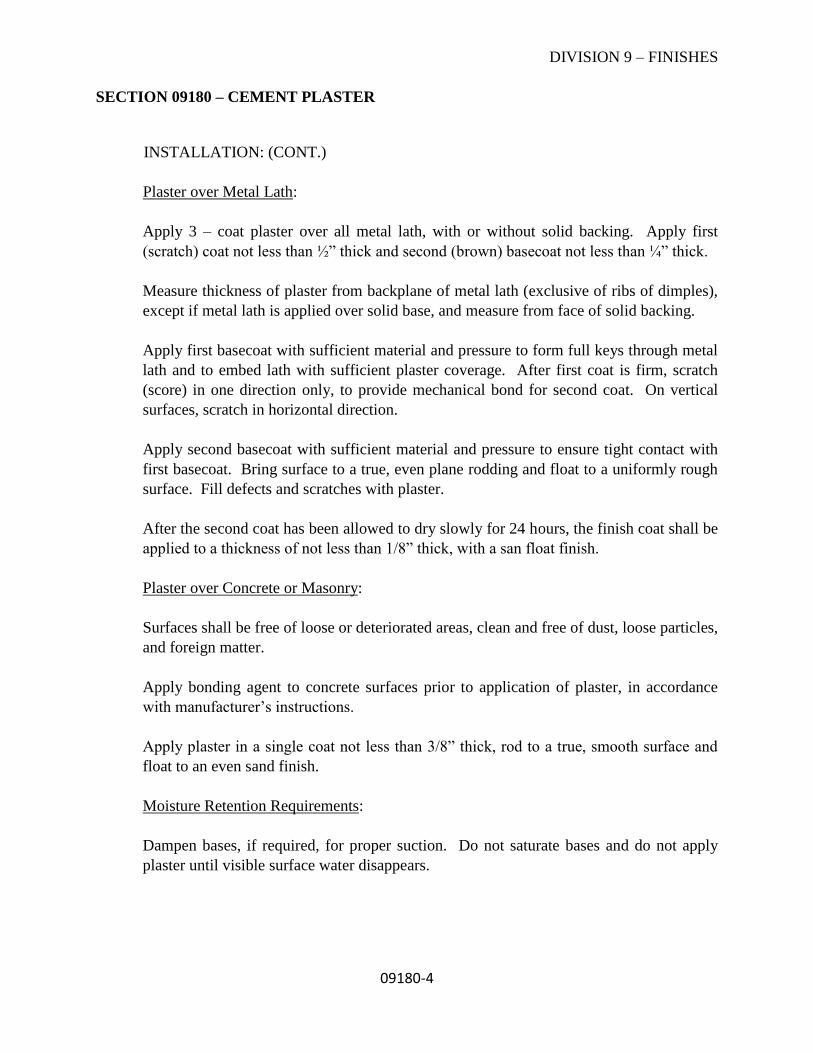
DIVISION 9 – FINISHES
SECTION 09180 – CEMENT PLASTER
09180-4
INSTALLATION: (CONT.)
Plaster over Metal Lath:
Apply 3 – coat plaster over all metal lath, with or without solid backing. Apply first
(scratch) coat not less than ½” thick and second (brown) basecoat not less than ¼” thick.
Measure thickness of plaster from backplane of metal lath (exclusive of ribs of dimples),
except if metal lath is applied over solid base, and measure from face of solid backing.
Apply first basecoat with sufficient material and pressure to form full keys through metal
lath and to embed lath with sufficient plaster coverage. After first coat is firm, scratch
(score) in one direction only, to provide mechanical bond for second coat. On vertical
surfaces, scratch in horizontal direction.
Apply second basecoat with sufficient material and pressure to ensure tight contact with
first basecoat. Bring surface to a true, even plane rodding and float to a uniformly rough
surface. Fill defects and scratches with plaster.
After the second coat has been allowed to dry slowly for 24 hours, the finish coat shall be
applied to a thickness of not less than 1/8” thick, with a san float finish.
Plaster over Concrete or Masonry:
Surfaces shall be free of loose or deteriorated areas, clean and free of dust, loose particles,
and foreign matter.
Apply bonding agent to concrete surfaces prior to application of plaster, in accordance
with manufacturer’s instructions.
Apply plaster in a single coat not less than 3/8” thick, rod to a true, smooth surface and
float to an even sand finish.
Moisture Retention Requirements:
Dampen bases, if required, for proper suction. Do not saturate bases and do not apply
plaster until visible surface water disappears.
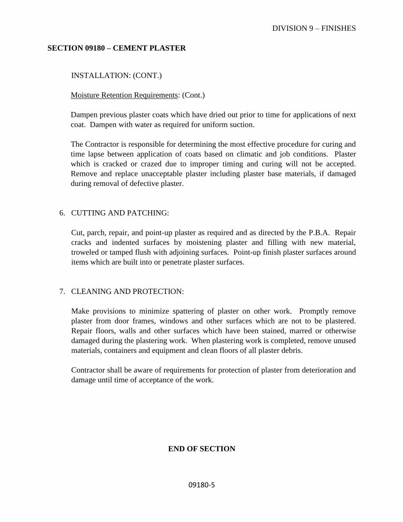
DIVISION 9 – FINISHES
SECTION 09180 – CEMENT PLASTER
09180-5
INSTALLATION: (CONT.)
Moisture Retention Requirements: (Cont.)
Dampen previous plaster coats which have dried out prior to time for applications of next
coat. Dampen with water as required for uniform suction.
The Contractor is responsible for determining the most effective procedure for curing and
time lapse between application of coats based on climatic and job conditions. Plaster
which is cracked or crazed due to improper timing and curing will not be accepted.
Remove and replace unacceptable plaster including plaster base materials, if damaged
during removal of defective plaster.
6. CUTTING AND PATCHING:
Cut, parch, repair, and point-up plaster as required and as directed by the P.B.A. Repair
cracks and indented surfaces by moistening plaster and filling with new material,
troweled or tamped flush with adjoining surfaces. Point-up finish plaster surfaces around
items which are built into or penetrate plaster surfaces.
7. CLEANING AND PROTECTION:
Make provisions to minimize spattering of plaster on other work. Promptly remove
plaster from door frames, windows and other surfaces which are not to be plastered.
Repair floors, walls and other surfaces which have been stained, marred or otherwise
damaged during the plastering work. When plastering work is completed, remove unused
materials, containers and equipment and clean floors of all plaster debris.
Contractor shall be aware of requirements for protection of plaster from deterioration and
damage until time of acceptance of the work.
END OF SECTION
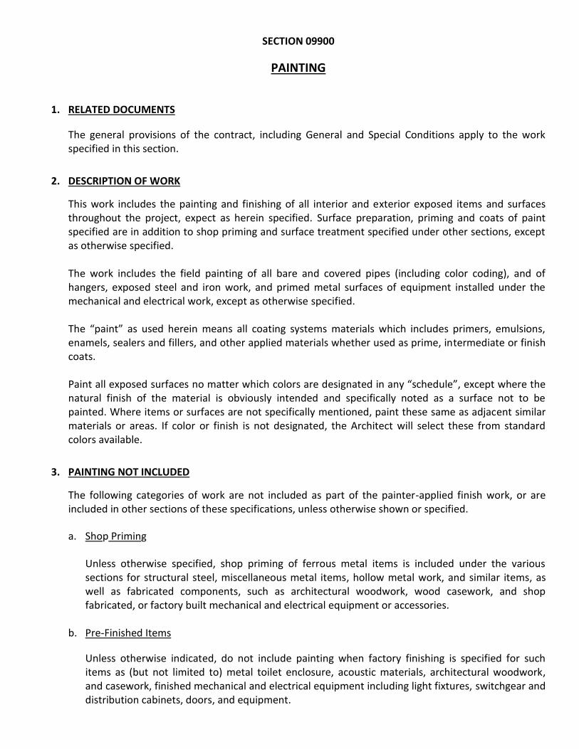
SECTION 09900
PAINTING
1. RELATED DOCUMENTS
The general provisions of the contract, including General and Special Conditions apply to the work specified in this section.
2. DESCRIPTION OF WORK
This work includes the painting and finishing of all interior and exterior exposed items and surfaces throughout the project, expect as herein specified. Surface preparation, priming and coats of paint specified are in addition to shop priming and surface treatment specified under other sections, except as otherwise specified. The work includes the field painting of all bare and covered pipes (including color coding), and of hangers, exposed steel and iron work, and primed metal surfaces of equipment installed under the mechanical and electrical work, except as otherwise specified. The “paint” as used herein means all coating systems materials which includes primers, emulsions, enamels, sealers and fillers, and other applied materials whether used as prime, intermediate or finish coats. Paint all exposed surfaces no matter which colors are designated in any “schedule”, except where the natural finish of the material is obviously intended and specifically noted as a surface not to be painted. Where items or surfaces are not specifically mentioned, paint these same as adjacent similar materials or areas. If color or finish is not designated, the Architect will select these from standard colors available.
3. PAINTING NOT INCLUDED
The following categories of work are not included as part of the painter-applied finish work, or are included in other sections of these specifications, unless otherwise shown or specified.
a. Shop Priming
Unless otherwise specified, shop priming of ferrous metal items is included under the various sections for structural steel, miscellaneous metal items, hollow metal work, and similar items, as well as fabricated components, such as architectural woodwork, wood casework, and shop fabricated, or factory built mechanical and electrical equipment or accessories.
b. Pre-Finished Items
Unless otherwise indicated, do not include painting when factory finishing is specified for such items as (but not limited to) metal toilet enclosure, acoustic materials, architectural woodwork, and casework, finished mechanical and electrical equipment including light fixtures, switchgear and distribution cabinets, doors, and equipment.

SECTION 09900
09900-2
c. Concealed Surfaces
Unless otherwise indicated, painting is not required or wall or ceiling surfaces in concealed areas and inaccessible areas, such as foundation spaces, furred areas, pipe spaces, duct shafts, as applicable to this project. Do not paint copper pipe, zinc-coated pipe, and zinc-coated ducts under insulation. Do not paint zinc-coated and copper pipe in concealed spaces.
d. Finished Metal Surfaces
Metal surfaces of anodized aluminum, stainless steel, chromium plate, copper, bronze, and similar finished materials will not require finish painting, except as otherwise specified.
e. Operating Parts and Labels
Do not paint any moving parts of operating units, mechanical and electrical parts, such as valve and damper operators, linkages, sink-ages, sensing devices, motor, and fan shafts, unless otherwise indicated. Do not paint over any code-required labels, such as Underwriters Laboratories and Factory Mutual, or any equipment identification, performance rating, name, or nomenclature plates.
4. GENERAL
a. Site Conditions
Starting of painting work will be construed as the Applicator’s acceptance of the surfaces within any area. Do not paint over dirt, rust, scale, grease, moisture, scuffed surfaces, or conditions otherwise detrimental to the formation of a durable paint film.
b. Atmospheric Conditions
Exterior paint shall not be applied when the temperature of the surface is below 45 degrees Fahrenheit or above 95 degrees Fahrenheit unless otherwise directed. Interior paint may be applied at any time, provided the surfaces to be painted are dry and the temperature can be kept above 45 degrees Fahrenheit during the application of ordinary paints, and between 65 degrees Fahrenheit and 95 degrees Fahrenheit during the application of enamels and varnishes. Paint shall not be applied during foggy or rainy weather or when, in the opinion of the PBA, the surfaces are not in proper condition for painting.
c. Delivery and Storage
Deliver all materials to the job site in original, new, and unopened packages and containers bearing manufacturer’s name and label, and application instructions thereon.

SECTION 09900
09900-3
d. Protection
Protect work of other trades, whether to be painted or not, against damage by the painting and finishing work. Leave all such work undamaged. Correct any damages by cleaning, repairing, or replacing, and repainting, as directed by the PBA. Provide “Wet Paint” signs as required to protect newly painted finishes. Remove temporary protective wrappings after completion of painting operations.
e. Clean Up
During the progress of the work, remove from the project all discarded paint materials, rubbish, cans, and rags. Upon completion of painting work, clean all paint spattered surfaces. Remove spattered paint by proper methods of washing and scraping, using care not to scratch or otherwise damage finished surfaces.
f. Colors
Prior to beginning work, the PBA will furnish a color schedule to the Contractor.

SECTION 09900
09900-4
5. MATERIAL – PAINT TECHNICAL DATA:
All proposed paint products and its respective complements (primers, sealers, etc.) to be applied on all project’s exposed surfaces (interior and exterior) must be submitted by Contractor for PBA approval. Such products must comply with the following characteristics and parameters:
PRODUCT No.
PRODUCT SPECIFICATIONS
1
100% Acrylic Flat
Exterior Paint
• Product Type: 100% Acrylic
• Percent of Solid by Weight: 54% ± 2%
• Percent of Solid by Volume: 36% ± 2%
• Coverage per Gallon at Recommended Film Thickness
(Range – Sq. Ft.): 400–450 sq. ft./gal.
• Recommended Film Dry Thickness: 1.5 mils
• Viscosity (KU): ≥ 105 Krebs Units (KU)
• Drying Time to Touch (Hr.); No more than 1 Hour
• Drying Time to Recoat (Hr.): No more than 4 Hours
• Percent of Pigments by Weight: 38% ± 2%
• Volatile Organic Compounds (VOC) - Grams/Liters: <1 g/L
2
100% Acrylic Flat
Interior Paint
• Product Type: 100% Acrylic
• Percent of Solid by Weight: 56% ± 2%
• Percent of Solid by Volume: 38% ± 2%
• Coverage per Gallon at Recommended Film Thickness
(Range – Sq. Ft.): 400–450 sq. ft./gal.
• Recommended Film Dry Thickness: 1.5 mils
• Viscosity (KU): ≥ 110 Krebs Units (KU)
• Drying Time to Touch (Hr.); No more than 1 Hour
• Drying Time to Recoat (Hr.): No more than 4 Hours
• Percent of Pigments by Weight: 41% ± 2%
• Volatile Organic Compounds (VOC) - Grams/Liters: <1 g/L

SECTION 09900
09900-5
• MATERIAL - PAINT TECHNICAL DATA (Cont.’):
PRODUCT No. PRODUCT SPECIFICATIONS
3
Satin Acrylic Paint
• Product Type: Acrylic Resin
• Percent of Solid by Weight: 52% ± 2%
• Percent of Solid by Volume: 38% ± 2%
• Coverage per Gallon at Recommended Film Thickness
(Range – Sq. Ft.): 400–450 sq. ft./gal.
• Recommended Film Dry Thickness: 1.5 mils
• Viscosity (KU): ≥ 105 Krebs Units (KU)
• Drying Time to Touch (Hr.); No more than 1 Hour
• Drying Time to Recoat (Hr.): No more than 4 Hours
• Percent of Pigments by Weight: 29% ± 2%
• Volatile Organic Compounds (VOC) - Grams/Liters: <100 g/L
4
Acrylic Semi-Gloss
Interior Paint
• Product Type: 100% Acrylic
• Percent of Solid by Weight: 49% ± 2%
• Percent of Solid by Volume: 36% ± 2%
• Coverage per Gallon at Recommended Film Thickness
(Range – Sq. Ft.): 400–450 sq. ft./gal.
• Recommended Film Dry Thickness: 1.4 mils
• Viscosity (KU): ≥ 110 Krebs Units (KU)
• Drying Time to Touch (Hr.); No more than 1 Hour
• Drying Time to Recoat (Hr.): No more than 4 Hours
• Percent of Pigments by Weight: 25.9% ± 2%
• Volatile Organic Compounds (VOC) - Grams/Liters: <50 g/L

SECTION 09900
09900-6
• MATERIAL - PAINT TECHNICAL DATA (Cont.’):
PRODUCT No.
PRODUCT SPECIFICATIONS
5
Enamel Paint for
Metals
• Product Type: Alkyd Oil Resin
• Percent of Solid by Weight: 67% ± 2%
• Percent of Solid by Volume: 51% ± 2%
• Coverage per Gallon at Recommended Film Thickness
(Range – Sq. Ft.): 450–500 sq. ft./gal.
• Recommended Film Dry Thickness: 1.4 mils
• Viscosity (KU): ≥ 70 Krebs Units (KU)
• Drying Time to Touch (Hr.); No more than 1.5 Hours
• Drying Time to Recoat (Hr.): No more than 8 Hours
• Percent of Pigments by Weight: 28% ± 2%
• Volatile Organic Compounds (VOC) - Grams/Liters: <400 g/L
6
Traffic Paint
• Product Type: Alkyd Resin
• Percent of Solid by Weight: 67% ± 2%
• Percent of Solid by Volume: 41% ± 2%
• Coverage per Gallon at Recommended Film Thickness
(Range – Ln. Ft.): 350 linear feet (4”)
• Recommended Film Dry Thickness: ≥3.0 mils
• Viscosity (KU): ≥ 70 Krebs Units (KU)
• Drying Time to Touch (Hr.): No more than 15 minutes
• Drying Time to Recoat (Hr.): No more than 1 Hour
• Percent of Pigments by Weight: 54% ± 2%
• Volatile Organic Compounds (VOC) - Grams/Liters: ≤500 g/L

SECTION 09900
09900-7
• MATERIAL - PAINT TECHNICAL DATA (Cont.’):
PRODUCT No.
PRODUCT SPECIFICATIONS
7
100% Acrylic
Floor Paint
• Product Type: 100% Acrylic
• Percent of Solid by Weight: 48% ± 2%
• Percent of Solid by Volume: 33% ± 2%
• Coverage per Gallon at Recommended Film Thickness
(Range – Sq. Ft.): 400–450 sq. ft./gal.
• Recommended Film Dry Thickness: 1.3 mils
• Viscosity (KU): ≥ 70 Krebs Units (KU)
• Drying Time to Touch (Hr.); No more than 1 Hour
• Drying Time to Recoat (Hr.): No more than 4 Hours
• Percent of Pigments by Weight: 29% ± 2%
• Volatile Organic Compounds (VOC) - Grams/Liters: ≤200 g/L
8
Primer
Change on Base Coat from
Oil to Satin or Flat
• Product Type: 100% Acrylic
• Percent of Solid by Weight: 53% ± 2%
• Percent of Solid by Volume: 36% ± 2%
• Coverage per Gallon at Recommended Film Thickness
(Range – Sq. Ft.): 400–450 sq. ft./gal
• Recommended Film Dry Thickness: 1.4 mils
• Viscosity (KU): ≥ 95 Krebs Units (KU)
• Drying Time to Touch (Hr.): No more than 1 Hour
• Drying Time to Recoat (Hr.): No more than 2 Hours
• Percent of Pigments by Weight: 35% ± 2%
• Volatile Organic Compounds (VOC) - Grams/Liters: ≤100 g/L

SECTION 09900
09900-8
• MATERIAL - PAINT TECHNICAL DATA (Cont.’):
PRODUCT No.
PRODUCT SPECIFICATIONS
9
Primer
Keeping Existing Base Coat
(Flat to Flat)
• Product Type: 100% Acrylic
• Percent of Solid by Weight: 49% ± 2%
• Percent of Solid by Volume: 37% ± 2%
• Coverage per Gallon at Recommended Film Thickness
(Range – Sq. Ft.): 400–450 sq. ft./gal
• Recommended Film Dry Thickness: 1.3 mils
• Viscosity (KU): ≥ 85 Krebs Units (KU)
• Drying Time to Touch (Hr.): No more than 1 Hour
• Drying Time to Recoat (Hr.): No more than 2 Hours
• Percent of Pigments by Weight: 24% ± 2%
• Volatile Organic Compounds (VOC) - Grams/Liters: ≤50 g/L
10
Primer for Galvanized Metals
• Product Type: Alkyd Resin
• Percent of Solid by Weight: 60% ± 2%
• Percent of Solid by Volume: 45% ± 2%
• Coverage per Gallon at Recommended Film Thickness
(Range – Sq. Ft.): 500–550 sq. ft./gal.
• Recommended Film Dry Thickness: 1.4 mils
• Viscosity (KU): ≥ 68 Krebs Units (KU)
• Drying Time to Touch (Hr.); No more than 15 minutes
• Drying Time to Recoat (Hr.): No more than 6 Hours
• Percent of Pigments by Weight: 45% ± 2%
• Volatile Organic Compounds (VOC) - Grams/Liters: <500 g/L

SECTION 09900
09900-9
• MATERIAL - PAINT TECHNICAL DATA (Cont.’):
PRODUCT No.
PRODUCT SPECIFICATIONS
11
Paint for Metals
(Acrylic Waterborne)
• Product Type: Acrylic
• Percent of Solid by Weight: 51% ± 2%
• Percent of Solid by Volume: 40% ± 2%
• Coverage per Gallon at Recommended Film Thickness
(Range – Sq. Ft.): 640 sq. ft./gal.@ 1 mil
• Recommended Film Dry Thickness: 1.4 mils
• Viscosity (KU): 85–90 Krebs Units (KU)
• Drying Time to Touch (Hr.): 12–15 minutes
• Drying Time to Recoat (Hr.): 2–4 Hours
• Percent of Pigments by Weight: 22% ± 2%
• Volatile Organic Compounds (VOC) - Grams/Liters: <200 g/L
6. MATERIAL TESTING
The right is reserved by the PBA to engage the services of a testing laboratory to perform all necessary test to verify that the paint submitted for approval by the Contractor complies with the requirements of this specifications.
7. SURFACE PREPARATION
a. General
Perform all preparation and cleaning procedures in strict accordance with the paint manufacturer’s instructions and as herein specified.
Remove all hardware, hardware accessories, machined surfaces, plates, lighting fixtures, and similar items in place and not to be finish painted or provide surface-applied protection prior to surface preparation and painting operations. Remove, if necessary, for the complete painting of the items and adjacent surfaces. Following completion of painting of each space or area, reinstall the removed items by workmen skilled in the trades involved.

SECTION 09900
09900-10
Clean surfaces to be painted before applying paint or surface treatments. Remove oil and grease with clean cloths and cleaning solvents prior to mechanical cleaning. Provide cleaning solvents of low toxicity and a flash point more than 100º F. Program the cleaning and painting so that dust and other contaminants from the cleaning process will not fall in wet, newly painted surfaces.
b. Cementitious Materials
Prepare cementitious surfaces of concrete, concrete block, cement plaster and cement-asbestos board to be painted by removing all efflorescence, chalk, dust, dirt, grease, oils, and by roughening as required to remove glaze.
Determine the alkalinity and moisture content of the surfaces to be painted by performing appropriate tests. If the surfaces are found to be sufficiently alkaline to cause blistering and burning of the finish paint, correct this condition by sponging the affected surfaces with a zinc sulphate solution of 2 lbs. zinc sulphate per gal. of water, or other acceptable method, before application of paint. Do not paint over surfaces where the moisture content exceeds 8% unless otherwise permitted in the manufacturer’s printed directions.
c. Wood
Clean wood surfaces to be painted of all dirt, oil, or other foreign substances with scrapers, mineral spirits, and sandpaper, as required. Sandpaper smooths those finished surfaces exposed to view, and dust off.
Prime, stain, or seal wood required to be job painted immediately upon delivery to job. Prime
edges, ends, face, undersides, and backsides of such wood, including cabinets, counters, cases, paneling, etc. Seal tops and bottoms of wood doors with a heavy coat of varnish or equivalent sealer immediately upon delivery to job.
Scrape and clean small, dry, seasoned knots and apply a thin coat of white shellac or other
approved sealer, before application of the priming coat.
After priming, fill holes and imperfections in finish surfaces with putty or plastic wood filler. Sandpaper smooth when dried.
d. Ferrous Metals
Clean non-galvanized, ferrous surfaces that have not been shop-coated of all oil, grease, dirt, loose mill scale and other foreign substances by solvent or mechanical cleaning, complying with SSPC recommendations.

SECTION 09900
09900-11
Touch-up all shop-applied prime coats which have damaged, or bare areas, where required by other sections of these specifications. Wire-brush, solvent clean, and touch up with the same primer as the shop coat.
8. MATERIALS PREPARATION:
Mix and prepare painting materials in strict accordance with the manufacturer’s directions. Store materials (not in actual use) in tightly covered containers. Maintain containers used in storage,
mixing, and application of paint in a clean condition, free of foreign materials and residue. Stir all materials before application to produce a mixture of uniform density, and as required during the
application of the materials. Do not stir any film which may form on the surfaces of materials into the material. Remove the film and, if necessary, strain the material before using.
9. APPLICATION:
“Exposed surfaces” shall mean areas visible when permanent of built-in fixtures, grilles, etc., area in place in areas scheduled to be painted.
Apply paint by brush, roller, or spray in accordance with the manufacturer’s directions. Spray paint uniformly with suitable equipment.
The number of coats and paint film thickness required is the same regardless of the application
method. Do not apply succeeding coats until the previous coat has completely dried. Apply additional coats when undercoats, stains, or other conditions show through the final coat of
paint, until the paint film is of uniform finish, color, and appearance.
a. Prime Coats
Before application of finish coats, apply a prime coat to material which is required to be painted or finished, and which has not been prime coated by others. Recoat primed and sealed walls and ceilings where there is evidence of suction spots or unsealed areas in first coat, to assure a finish coat with no burn through or other defects due to insufficient sealing.
b. Mechanical Applications
Apply each roller coat to provide the equivalent hiding as brush-applied coats. Use spray application (generally) on wire mesh and similar surfaces where hand brush work would be inferior.

SECTION 09900
09900-12
Wherever spray applications are used, apply each coat to provide the equivalent hiding of brush-applied coats. Do not double back with spray equipment for the purpose of building up film thickness of two (2) coats in one pass.
c. Completed Work
Match approved samples for color, texture, and coverage. Remove, refinish, or repaint work not in compliance with specified requirements.
Paint the back sides of access panels, removable or hinged covers to match the exposed surfaces. Finish exterior doors on tops, bottoms, and side edges the same as the exterior faces, unless otherwise indicated. Sand lightly between each succeeding enamel or varnish coat.
10. SUBMITTALS
a. Manufacturer’s Data
1. Submit two (2) copies of manufacturer’s specifications, including paint label analysis and application instructions for each material specified.
2. List each material and cross reference to the specific paint and finish system and application.
Identify by manufacturer’s catalog number and general classification. No painting work shall be done until this schedule has been finally approved.
b. Samples
1. On 12” x 12” hardboard, provide two (2) samples of each color and material, with texture to simulate actual conditions. Resubmit each sample as requested until required sheen, color, and texture is achieved.
2. On actual wood surfaces, provide two (2), 4” x 8” samples of each finish as required. Label and
identify each as to location and application.
11. SURFACES TO BE PAINTED
The exact locations and limits of the surfaces requiring the various types of finishes shall be as established in the Color Schedule. The paint required for the various types of surfaces shall be as follows:
a. Interior concrete, masonry, or plastered surfaces, except were indicated to receive and enamel finish: Two (2) coats exterior concrete and masonry paint.

SECTION 09900
09900-13
b. Interior concrete, masonry, or plastered surfaces, indicated to received enamel finish:
First coat – enamel under coater as recommended by manufacturer
Second and third coats – Semi-gloss enamel
c. Interior woodwork (enamel finish):
First coat – enamel under coater as recommended by the manufacturer Second and third coats – Semi-gloss enamel
d. Interior woodwork (natural finish):
First coat – Stain if required Second coat – Filler tinted to match stain if required by species of wood Third and fourth coats – Semi-gloss varnish
e. Miscellaneous metal items which are specified under other sections to receive finishes as
specified under this section or for which finishes are not specified under other sections:
First coat – shop primed; or one (1) coat of primer for galvanized or non-galvanized metal as the case may be Second and third coats – gloss enamel
f. Wainscots indicated to receive polyurethane finish: Two (2) coats polyurethane paint
12. GUARANTEE:
a. The Contractor shall perform all items of paint work included under this Contract as specified on this section and/ or as recommended by manufacturer’s paint products, and shall, without additional charges, replace any paint work or paint products/materials which develop defects, except because of vandalism or acts of God, within five (5) years from the date of final certificate of approval issued by the Public Buildings Authority (PBA).

SECTION 09900
09900-14
b. The Contractor shall also be responsible for any or all damages resulting from inadequate surface preparation, improper application procedures or any other work performed without PBA or manufacturer’s representative approval. In addition, the Contractor shall, without additional charges, repair all injuries to existing work caused by such conditions to the satisfaction of the PBA.
c. The Contractor shall submit to the PBA an official certification forms by paint products’ manufacturer (to be acquired and applied on project’s interior/exterior exposed surfaces included on contract) which guarantee that such products are free of defects occur due to faulty manufacture for a period of five (5) years from the date of final certificate of approval issued by the PBA. Also, the manufacturer shall guarantee that they will provide, without additional charges, all paint products, or materials necessary to replace all defective ones during such period.

SECTION 10111
Section 10111 10111-1
WHITEBOARDS
(Pizarra Blanca Para Marcadores)
a. Whiteboards: Whiteboards shall be of the composition type, four feet (4’) width x eight feet (8’) long, having the base made of temper treated ¼” thick hardboard. Panels are tempered on both sides resulting in hardboard impervious to moisture and warping. This panel shall comply with applicable Federal Specifications for similar kind of product.
b. Board Frame & Marker-Trough: One (1) inch faced heavy-duty wrap-around aluminum frame is affixed to the board, rounded at the corner for maximum strength and safety. A heavy gauge etched marker-trough is provided the full width of the whiteboard. All trim and marker-trough are neat extruded aluminum, etched and anodized with a satin finish.
c. Trim and Accessories: Fabricate frames and trim of not less than 0.062” thick aluminum alloy, rectangular (four feet (4’) long x eight feet (8’) width), to suit type of installation. Provide straight, single-length units wherever possible and keep joints to a minimum trim, accessories and fasteners with satin anodized finish AA-M31A31.
d. Fabrication & Assembly: Provide factory-built whiteboard units. Make joints only where total length exceeds maximum manufactured length. Fabricate with minimum number of joints, balanced around center of board, as acceptable to the Public Buildings Authority (PBA).

SECTION 10161
LAMINATED PLASTIC TOILET PARTITIONS AND
URINAL SCREENS
1. RELATED DOCUMENTS
The general provisions of the contract, including General and Special Conditions apply to the work
specified in this section.
2. DESCRIPTION OF WORK
The extent of the toilet partition work is shown on the drawings.
3. QUALITY ASSURANCE
Field Measurements
Take field measurements prior to preparation of shop drawings and fabrication, where possible, to
ensure proper fitting of the work.
Shop Assembly
Preassemble items in the shop to the greatest extent possible. Disassemble units only to the extent
necessary for transportation and handling limitations. Clearly mark units for reassembly and
coordinated installation.
4. SUBMITTALS
Manufacturer’s Data
Submit 2 copies of catalog cuts of hardware anchors, fastenings and other data as required.
Shop Drawings
Submit for approval of PBA shop drawings for the fabrication and erection of toilet partition
assemblies. Show all anchorage and accessory items, and finish.
Samples
Submit sample of hardware and accessories for approval. Submit 3 samples 6” x 6” of laminated
plastic.

LAMINATED PLASTIC TOILET PARTITIONS
AND URINAL SCREENS
10161 – 2
5. MATERIALS
Laminated Plastic
NEMA Standard LD-1, minimum 1/16” thick.
Contact Cement
As recommended by laminated plastic manufacturer.
Hardware and Accessories
See details on drawings. All bolts and screws shall be Monel bronze or chromium plated brass with
theft – resistant (one-way) type heads and nuts.
Plywood
1” thick Douglas fir, Ext. – DFPA-A-A, immersion treated
6. FABRICATION
Provide doors, panels, screens and pilaster fabricated for the partition system in accordance with
details shown on drawings and this specifications. Use one-piece laminated plastic with no splices or
joints. Cover all edges with laminated plastic.
7. INSTALLATION
Install partitions rigid, straight, plumb and level, with the panels laid out as shown. Secure panels to
supporting walls with not less than 3 angles, attached near top and bottom and at mid height at each
face of the panel. Secure pilasters to the floor with ¼” x 2” bolts and expansion shield. Fasten the
overhead brace to each pilaster with 2 bolts. Set tops of doors parallel with the overhead brace when
doors are in the closed position.
Adjust and lubricate hardware for proper operation after installation. Set hinges on out-swing doors
to return to the fully-closed position.
Wall-mounted Screens
Attach in the same way as panels. Set units so as to provide full support and to resist lateral impact.
Protection, Cleaning and Final Adjustments
Protect units during delivery, storage, and after erection so that there will be no indication of use or
damage at the time of acceptance. Replace damaged work as directed.
Perform all final adjustments to door hardware of the partition assembly just prior to final inspection.
Clean exposed surfaces of partitions, hardware, fittings and accessories.
END OF SECTION 10161

SECTION 10522
EXTINGUISHERS AND CABINETS
PART 1 – GENERAL
1.1 RELATED DOCUMENTS:
A. Drawings and general provisions of Contract, including General and Supplementary
Conditions and Division-1 Specification sections, apply to work of this section.
1.2 DESCRIPTION OF WORK:
A. Extent of fire extinguishers and cabinets is indicated on architectural drawings.
B. Definition: “Fire extinguishers” as used in this section refers to units which can be hand-
carried as opposed to those which are equipped with wheels or to fixed fire extinguishing
systems.
C. Types of products required include:
1. Fire extinguishers.
2. Fire extinguisher cabinets.
3. Mounting brackets
D. Fixed fire protection systems are specified in Section 15310.
1.3 QUALITY ASSURANCE:
A. Single Source Responsibility: Obtain products in this section form one manufacturer.
B. Coordination: Verify that fire extinguisher cabinets are sized o accommodate fire
extinguishers of type and capacity specified herein.
C. UL-Listed Products: Provide new portable fire extinguishers which are UL listed and bear UL
“Listing Mark” for type, rating, and classification of extinguisher specified herein.
1.4 SUBMITTALS:
A. Product Data: Submit product data for each type of product included in this section. For fire
extinguisher cabinets include roughing-in dimensions and details showing mounting methods,
relationships of box and trim to surrounding construction, door hardware, cabinet type and
materials, trim style and door construction, and panel style and materials.

EXTINGUISHERS AND CABINETS
10522 - 2
PART 2 – PRODUCTS
2.1 ACCEPTABLE MANUFACTURERS:
A. Available Manufacturers: Subject to compliance with requirements, manufacturers offering
products which may be incorporated in the work include, but are not limited to, the following:
1. J.L. Industries
2. Larsen’s Mfg. Co.
3. Johnson-Lee, Division of W.F. Lee Corp.
4. Muckle Manufacturing, Division of Technico, Inc.
5. Watrous, Inc.
2.2 FIRE EXTINGUISHERS:
A. General: Provide fire extinguishers for each extinguisher cabinet and other locations
indicated, in colors and finishes selected by Architect from manufacturer’s standard which
comply with requirements of governing authorities.
B. Abbreviations indicated below to identify extinguisher types related to UL classification and
rating system and not, necessarily to type and amount of extinguishing material contained in
extinguisher.
C. Carbon Dioxide Type: UL-rated 5-B:C, 5 lb. nominal capacity, in manufacturer’s standard
enameled metal container for Class B and Class C fires.
D. Carbon Dioxide Type: UL-rated 10-B:C, 10 lb nominal capacity, in manufacturer’s standard
enameled metal container, for Class B and Class C fires.
E. Multi-Purpose Dry Chemical Type: UL-rated 2A:10B:C, 5 lb. nominal capacity, in enameled
steel container, for Class at Class B and Class C fires.
2.3 MOUNTING BRACKETS:
A. Provide manufacturer’s standard brackets designed to prevent accidental dislodgement of
extinguisher, of sizes required for type and capacity of extinguisher specified herein, in
manufacturer’s standard plated finish.
1. Provide brackets for extinguishers not located in cabinets.
2.4 FIRE EXTINGUISHER CABINETS:
A. General: Provide fire extinguisher cabinets where indicated on architectural drawings, or
suitable size for housing fire extinguishers, of types and capacities indicated.

EXTINGUISHERS AND CABINETS
10522 - 3
B. Construction: Manufacturer’s standard enameled steel box, with trim, frame, door and
hardware to suite cabinet type, trim.
Painted Finish: Apply painted fin concealed surfaces of cabinet components except other than
a painted finish is indicated.
1. Color: Provide colors as selected by Architect manufacturer’s standard colors.
2. Preparation: Clean surfaces of dirt, grease, and rust or mill scale.
3. Baked Enamel Finish: Immediately after clean pretreatment, apply cabinet
manufacturer’s standard enamel finish system to the following surfaces:
a. Interior of cabinet.
b. Stainless Steel Finish: AISI No. 4 polished finish, with paper masking to protect
finish.
PART 3 – EXECUTION
3.1 INSTALLATION:
A. Install items included in this section in locations mounting heights indicated, or if not
indicated, at height to comply with applicable regulations of government authorities.
1. Prepare recesses in walls for fire extinguisher cabinet, as required by type, size and style
of cabinet and in accordance with manufacturer’s instructions.
2. Securely fasten mounting brackets and fire extinguishers cabinets to structure, square and
plumb, to comply manufacturer’s instructions.
END OF SECTION 10522
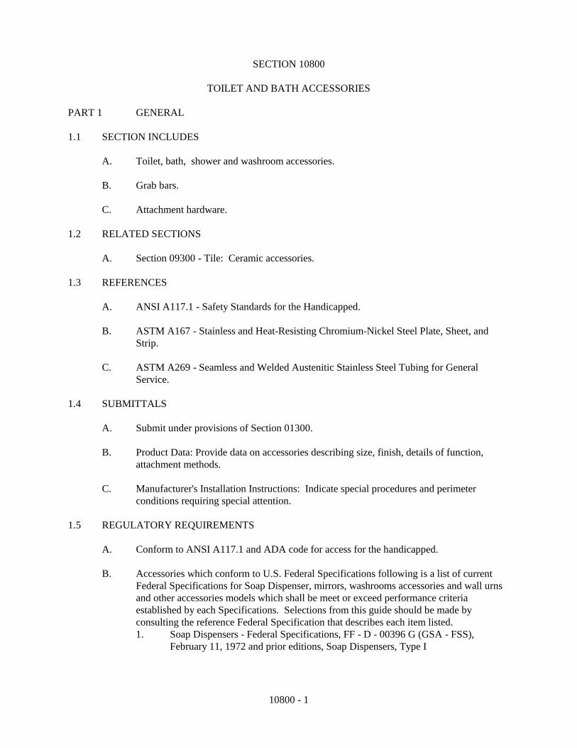
10800 - 1
SECTION 10800
TOILET AND BATH ACCESSORIES
PART 1 GENERAL
1.1 SECTION INCLUDES
A. Toilet, bath, shower and washroom accessories.
B. Grab bars.
C. Attachment hardware.
1.2 RELATED SECTIONS
A. Section 09300 - Tile: Ceramic accessories.
1.3 REFERENCES
A. ANSI A117.1 - Safety Standards for the Handicapped.
B. ASTM A167 - Stainless and Heat-Resisting Chromium-Nickel Steel Plate, Sheet, and
Strip.
C. ASTM A269 - Seamless and Welded Austenitic Stainless Steel Tubing for General
Service.
1.4 SUBMITTALS
A. Submit under provisions of Section 01300.
B. Product Data: Provide data on accessories describing size, finish, details of function,
attachment methods.
C. Manufacturer's Installation Instructions: Indicate special procedures and perimeter
conditions requiring special attention.
1.5 REGULATORY REQUIREMENTS
A. Conform to ANSI A117.1 and ADA code for access for the handicapped.
B. Accessories which conform to U.S. Federal Specifications following is a list of current
Federal Specifications for Soap Dispenser, mirrors, washrooms accessories and wall urns
and other accessories models which shall be meet or exceed performance criteria
established by each Specifications. Selections from this guide should be made by
consulting the reference Federal Specification that describes each item listed.
1. Soap Dispensers - Federal Specifications, FF - D - 00396 G (GSA - FSS),
February 11, 1972 and prior editions, Soap Dispensers, Type I

10800 - 2
2. Mirrors: Federal Specifications, DD - M 00411b (GSA-GSS), April 5,
1968 & Amendment - 1, April 7, 1970, mirrors - class 2, style E metal frame,
stainless steel - grade 1 type 304 stainless steel - grade 1 type 304 stainless steel.
3. Wash room accessories : Federal Specifications, WW-P-541/8A (GSA - FSS),
October 12, 1971 & Amendment - 1, June 17, 1974, Plumbing Fixtures
(Accessories, land use).
a. Type 1, class I, dispenser toilet tissue mounting R - Recessed style K
single roller mounted.
b. Type 1, class I, dispensers toilet tissue mounting P - Partitions mounted.
4. Federal Specification, WW-P-541b, interim amendment - 6, November 5, 1963,
Plumbing Fixtures, land use.
a. Type 541 : Tumber & toothbrush holder.
b. Type 452 : Turin Robe Hook
c. Type 457 : Toilet Paper Holder, Recessed
d. Type 458 : Grab bar vertical
e. Type 460 : Soap dish & bar, surfaced mounted
f. Type 461 : Medicine cabinet, Recessed
5. Federal Specification, WW-P-541b, September 20, 1954, Plumbing fixtures, land
use.
a. Type 416 : Tumbler & tooth brush holder
b. Type 421 : Double Coat Hook
c. Type 431 & 431m : metal towel bar
d. Type I : Class 3, dispensers, paper towel mounting, R -Recessed- Kind e.
e. Type II : Waste Receptacle mounting R - Recessed.
f. Type III : Class 2, Medicine cabinets swinging door, mounting R -
Recessed
g. Type IV : Class 1, towel bars surface mounted, concealed.
h. Type IV : Class 3, Soap dish & bar surfaced mounted, concealed.
i. Type IV : Class 3, Soap dish & bar surfaced mounted
j. Type VI : Class 4, Holders, Toothbrush & tumbler surfaced
mounted
k. Type VI : Class 2, Holders Soap Recessed
1.6 PRODUCT, DELIVERY, STORAGE AND HANDLING
A. Delivery items in manufacturer's original unopened protective packing.
B. Store material in original protective packaging to prevent soiling, physical damage, or
wetting.
C. Handle so as to prevent damage to finished surfaces.
D. Protection
1. Maintain protective covers on all units until installation is complete.
2. Remove protective covers at final clean-up of installation.
3. Use all means necessary to protect the materials of this Section before, during, and
after installation and to protect the work and materials of all other trades.
E. Replacements

10800 - 3
In the event of damage, immediately make all repairs and replacements necessary to the
approval of the Owner at no additional cost.
1.7 FIELD MEASUREMENTS
A. Verify that field measurements are as indicated on product data.
1.8 COORDINATION
A. Coordinate work under provisions of Section 01300.
B. Coordinate the work with the placement of internal wall reinforcement to receive anchor
attachments.
PART 2 PRODUCTS
2.1 MANUFACTURERS
A. Bobrick Washroom Equipment Inc.
B. Other acceptable manufacturers offering equivalent products.
1. Bradley Plumbing Fixtures.
2. American Dispenser Co., Inc.
2.2 MATERIALS
A. Stainless Steel Sheet: ASTM A167, Type 304.
B. Tubing: ASTM A269, stainless steel.
C. Fasteners, Screws, and Bolts: Hot dip galvanized, tamper-proof, and Security type.
D. Expansion Shields: Fiber, lead, or rudder as recommended by accessory manufacturer for
component and substrate.
2.3 FABRICATION
A. Weld and grind joints of fabricated components, smooth.
B. Form exposed surfaces from single sheet of stock, free of joints. Form surfaces flat
without distortion. Maintain surfaces without scratches or dents.
C. Fabricate grab bars of tubing, free of visible joints, return to wall with end attachment
flanges. Form bar with 1-1/2 inches (39 mm) clear of wall surface. Knurl grip surfaces.
D. Shop assemble components and package complete with anchors and fittings.
E. Provide steel anchor plates, adapters, and anchor components for installation.
F. Anchors and Fasteners
10800 - 4
Provide anchors and fasteners capable of developing a retaining force commensurate with
the strength of the accessory to be mounted, and well suited for use with the supporting
construction. Where exposed use fasteners with finish matching the accessory.
G. Finish: All accessory items shall be stainless steel with satin finish.
H. Design is based on use of products manufactured by several Manufacturer's and catalog
numbers of that manufacturer are given as an indication of the quality and style required.
Equal products by other manufacturer's approved by the Owner will be acceptable in
accordance with the General Conditions and Section 01300.
2.4 KEYING
A. Supply 2 keys for each accessory to Owner.
2.5 FINISHES
A. Stainless Steel: No. 4 satin luster finish.
B. Back paint components where contact is made with building finishes to prevent
electrolysis.
PART 3 EXECUTION
3.1 EXAMINATION
A. Verify site conditions under provisions of Section 01400.
B. Verify that site conditions are ready to receive work and dimensions are as indicated on
shop drawings and instructed by the manufacturer.
C. Verify exact location of accessories for installation.
D. Check opening scheduled to receive recessed units for correct dimensions, plumpness of
blocking or frames, preparation that would affect installation of accessories.
E. Check areas to receive surface mounted units for conditions that affect installation of
accessories.
F. Verify spacing of plumbing fixtures and toilet partitions that affect installation of
accessories.
G. Do not begin installation of washroom accessories until openings and surfaces are
acceptable.
H. Examine the area and conditions under which work of this section will be installed.
Correct conditions detrimental to proper and timely completion of the work. Do not
proceed until unsatisfactory conditions have been corrected.
3.2 PREPARATION

10800 - 5
A. Deliver inserts and rough-in frames to site for timely installation.
B. Provide templates and rough-in measurements as required.
C. Throughout construction of substrate surfaces, use all means necessary to ensure proper
and adequate provision for concealed support devices, and for finished openings, to
receive the work of this Section.
3.3 INSTALLATION
A. Install accessories in accordance with manufacturers' instructions and ANSI A117.1.
B. Install plumb and level, securely and rigidly anchored to substrate.
C. Drill holes to correct size and application that is concealed by item, with 1/4 in. tolerance.
D. Mount recessed accessories into wall openings with screws through cabinet side into wood
blocking, or sheet metal screws into metal frames or expansion bolts for concrete and
blocks.
E. Mount surface mounted accessories to back up with toggle bolts, plumb and align.
F. Install the work of this Section in strict accordance with the manufacturer's
recommendations as approved by the Owner. Anchoring all components plumb, level,
square, and firmly into position for long life under hard use.
3.4 Adjust and clean
A. Adjust accessories for proper operation.
B. After completion of installation, clean and polish all exposed surfaces.
C. Deliver keys and instruction sheets to Owner.
3.5 SCHEDULE
Bathroom accessories shall be furnished and installed in accordance with the Equipment and
Accessories Schedule shown on Drawings and the following list.
A. Dwelling units and handicapped dwelling units.
1. Medicine Cabinet
a. 16" x 22" Recess mounted with two plastic shelves medicine cabinet.
b. Polystyrene body material
c. Reversible
d. Stainless steel 304 door frame and back door
e. 3 float plate mirror
f. Piano hinge, tire 304 stainless steel (17 long)
g. Magnetic catch
h. Type III, class 2 designation

10800 - 6
i. Five year guarantee
2. Tooth Brush Holder (See specification 09300)
3. Soap Holder and Grab Bar (See Specification 09300)
4. Curtain Rod
a. Rod of 18 gauge type 304 satin finish stainless steel
b. 13" O.D.
c. Flanges of 20 gauge type 305 satin finish stainless steel, 3 1/8" O.D.
d. Escutcheons snap over flanges to provide permanent vandal - resistant
mounting
e. Concealed mounting
5. Toilet Paper Holders (See Specification 09300)
6. Towel Bar
7. Double Robe Hook
a. Surface mounted
b. Project 2" from wall
c. Satin finish stainless steel
d. Type 304 stainless steel heavy gauge 18 No. 4
e. Vandal - resistant escutcheons
B. Handicapped Dwelling Units
1. Grab bars
a. 1 1/4" dia, heavy duty
b. Concealed mounting
c. Heavy duty 18 gauge 304 stainless steel tubing
d. Welded 11 - gauge 304 stainless steel mounting flanges
e. Sustain loads over 1300 pounds (Designed and test), double FHA, VA, HEW
requirements
f. Satin finish
g. For grab bar configuration, and/or length and installation of position see
construction drawings.
h. Supply
i. Grab bar mounting kits for masonry walls and partition walls (stainless steel
machine screws, cap nuts, backing plate, corrosion resistant zinc plating drop
in anchors, etc.).
2. Folding Corner Shower Seat
a. Type 304 stainless steel
b. Satin finish
c. 3/4 return edges
d. Folds to vertical position when not in use
C. Administration Building
1. Toilet Paper Holders : Public Toilets
a. Single roll toilet tissue dispensers
b. Theft resistant service
c. 1/8" thick anodized aluminum
d. One piece construction with hinged arm and snap lock.
e. Tumbler lock secures spindles in place
f. Surface mounted and hold one standard toilet tissue roll
g. 6 1/2" W x 2" H x 4 7/8" D. Overall dimensions
2. Mirror
a. Fixed angle tilt mirror w/shelf

10800 - 7
b. Type 304 stainless steel polished to No. 8 architectural bright finish
c. 16" w x 24 h @ 40" A.F.F
3. Paper towel dispenser
a. Surface mounted
b. 400 multi - fold or 300 c - fold towels capacity
c. Type 304 stainless steel
d. Satin finish
e. Welded construction - seamless
f. Corners and burr - free edges
g. Non flexing double panel construction door with full length piano hinges
h. Tumber locks keyed alike to others units
i. Rough wall opening 15 5/8" h x 11 1/4" w x 4" d
j. Top of wall openings 51" from finish floor
4. Liquid Soap Dispenser
a. Horizontal surface mounted
b. Push in type value of chrome plated brass with neoprene "O" ring packings
c. Secured with lock
d. 40 oz. liquid soap capacity
e. Heavy gauge type 304 stainless steel
f. Satin finish
g. Unit Measures 8 3/16" W x 4 7/8" H x 2 7/8" D Valve Projects 2 1/2"
h. Top of wall opening in relation to lavatory mounting height
5. Waste Receptacle
a. Surface mounted
b. 16.5 gal. capacity
c. Removable leak proof heavy duty vinyl liner
d. Hinge Cover
e. Type 304 stainless steel
f. Satin finish exposed surfaces
g. Welded construction with seamless corners
h. Burr free edges
i. Unit measures 18" W x 23" H x 9" D
j. Top of wall opening 45" from finished floor
6. Grab Bars
a. Horizontal 1 1/4" (32mm) Dia. Stainless Steel b. Concealed Mounting c. Satin Finish d. 36" (914 mm) and 42" (1067 mm) lenghts
2.3 Washrooms accessories
A. Dwelling Units 1. Medicine Cabinet 2. Tooth Brush Holder 3. Soap Holder and Grab Bar 4. Curtain Rod 5. Toilet Paper Holder 6. Towel Bar 7. Double Robe Hook
B. Handicapped Dwelling Units
1. Medicine Cabinet

10800 - 8
2. Tooth Brush Holder 3. Soap Holder and Grab Bar 4. Curtain Rod 5. Toilet Paper Holder 6. Towel Bar 7. Double Robe Hook 8. Grab Bar : 84" Length @ 36" AFF - Horizontal 9. Grab Bar : 24" Length @ 36" AFF - Horizontal 10. Grab Bar : 60" Length @ 32" AFF - Horizontal 11. Grab Bar : 24" Length @ 40" AFF - Vertical 12. Grab Bar : 30" Length @ 33" AFF - Horizontal and Vertical 13. Grab Bar : 24" Length @ 40" AFF - Vertical 14. Grab Bar : 33" Length @ 36" AFF - Horizontal 15. Grab Bar : 24" Length @ 36" AFF - Horizontal 16. Folding Corner Shower Seat 17. All grab bars shall be 1 1/4" (32 mm) dia., 18 ga. and stainless steel 18. All Grab Bars, will be concealed Mounting Kits on Vandal Proof Screws 19. All grab bars shall be safely grip finish
C. Administration Building Toilets
1. Mirrors (16" x 24") 2. Paper Towel Dispenser 3. Liquid Soap Dispenser 4. Waste Receptacle 5. Sanitary Paper Holders 6. 48 length Handicapped Grab Bar with center post; only one end return 7. Grab Bar 36" and 42" length
END OF SECTION


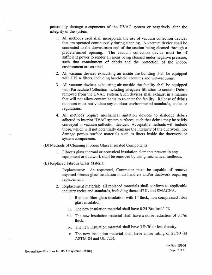


SECTION 15010
BASIC MECHANICAL REQUIREMENTS
A. GENERAL
1. RELATED DOCUMENTS
1.1 Drawings and general provisions of the Contract, including the General Conditions, the
Supplementary General Conditions, the Special Conditions, the Supplementary Special
Conditions and all Division-1 Specifications sections, apply to the Work of this Sections,
and the other sections of Division 15.
2. SUMMARY
2.1 This Section includes general administrative and procedural requirements for mechanical
installations. The following administrative and procedural requirements are included in
this Section to expand the requirements specified in Division 1:
2.1.1 Submittals. Coordination drawings. Record documents. Maintenance manuals.
Rough-in. Mechanical installations. Cutting and patching.
2.2 Related Sections: The following sections contain requirements that relate to this section:
2.2.1 Division 15 Section “ELECTRICAL REQUIREMENTS FOR MECHANICAL
EQUIPMENT”, for factory-installed motors, controllers, accessories, and
connections.
2.2.2 Division 15 Section “BASIC MECHANICAL MATERIALS AND METHODS”,
for materials and methods common to the remainder of Division 15, plus general
related specifications, including:
a. Access to mechanical installations.
b. Excavation for mechanical installations within the building boundaries, and
from building to utilities connections.
3. SUBMITTALS
3.1 General: Follow the procedures specified in Division 1 Section “SUBMITTALS”.
3.2 Increase, by the quantity listed below, the number of mechanical related shop drawings,
product data, and samples submitted, to allow for required distribution plus two copies of
each submittal required, which will be retained by the Mechanical Consulting Engineer.
3.2.1 Shop Drawings – Initial Submittal: 1 additional blue- or black-line prints.

BASIC MECHANICAL REQUIREMENTS
15010-2
• SUBMITTALS (Cont.’):
3.2.2 Shop Drawings – Final Submittal: 1 additional blue- or black-line prints.
3.2.3 Product Data: 1 additional copy of each item.
3.2.4 Samples: 1 additional as set.
3.3 Additional copies may be required by individual sections of these Specifications.
4. COORDINATION DRAWINGS
4.1 Prepared coordination drawings in accordance with Division 1 Section “PROJECT
COORDINATION”, to a scale of ¼” = 1’-0” or larger; detailing major elements,
components, and systems of mechanical equipment and materials in relationship with
other systems, installations, and building components. Indicate locations where the space
is limited for installation of access and where sequencing and coordination of the Work,
including (but not necessarily limited to) the following:
4.1.1 Indicate the proposed locations of piping, ductwork, equipment, and materials.
Include the following:
a. Clearances for installing and maintaining insulation.
b. Clearances for servicing and maintaining equipment, including tube removal,
filters removal, and space for equipment disassembly required for periodic
maintenance, as recommended by equipment manufacturers.
c. Equipment connections and support details.
d. Exterior wall and foundation penetrations.
e. Fire-rated wall and floor penetrations.
f. Sizes and locations of required concrete pads and bases.
g. Valve stem movement.
4.1.2 Indicate scheduling, sequencing, movement, and positioning of large equipment into
the building during construction.
4.1.3 Prepare floor plans, elevations, and details to indicate penetrations in floors, walls,
and ceilings, and their relationship to other penetrations and installations.
4.1.4 Prepare reflected ceiling plans to coordinate and integrate installations, air outlets and
inlets, light fixtures, communications systems components, sprinklers, and other
ceiling-mounted items.

BASIC MECHANICAL REQUIREMENTS
15010-3
5. RECORD DOCUMENTS
5.1 Prepare record documents in accordance with the requirements in Division 1 Section
“PROJECT CLOSE-OUT”. In addition to the requirements specified in Division 1,
indicate the following installed conditions:
5.1.1 Mains and branches of piping systems, with valves and control devices located
and numbered, concealed unions located, and with items requiring maintenance
located (e.g., traps, strainers, expansion compensators, tanks, etc.). Valve
location diagrams, complete with valve tag chart. Refer to Division 15 Section
“MECHANICAL IDENTIFICATION”. Indicate actual inverts and horizontal
locations of underground piping.
5.1.2 Equipment locations (exposed and concealed), dimensioned from prominent
building lines.
5.1.3 Approved substitutions, Contracts Modifications, and actual equipment and
materials installed.
5.1.4 Contract Modifications, actual equipment and materials installed.
5.2 Engaged the services of a Land Surveyor or Professional Engineer registered in the state
in which the project is located as specified in Division 1 Section “FIELD
ENGINEERING” to record and verify the locations and invert elevations or underground
installations.
6. MAINTENANCE MANUALS
6.1 Prepare maintenance manuals in accordance with Division 1 Section “PROJECT CLOSE-
OUT”. In addition to the requirements specified in Division 1, include the following
information for equipment items:
6.1.1 Description of function, normal operating characteristics and limitations,
performance curves, engineering data and tests, and complete nomenclature and
commercial numbers of replacement parts.
6.1.2 Manufacturer’s printed operating procedures to include start-up, break-in, and routine
and normal operating instructions; regulation, control, stopping, shutdown, and
emergency instructions; and summer and winter operating instructions.
6.1.3 Maintenance procedures for routine preventative maintenance and troubleshooting;
disassembly, repair, and reassemble; aligning and adjusting instructions.
6.1.4 Servicing instructions and lubrication charts and schedules.
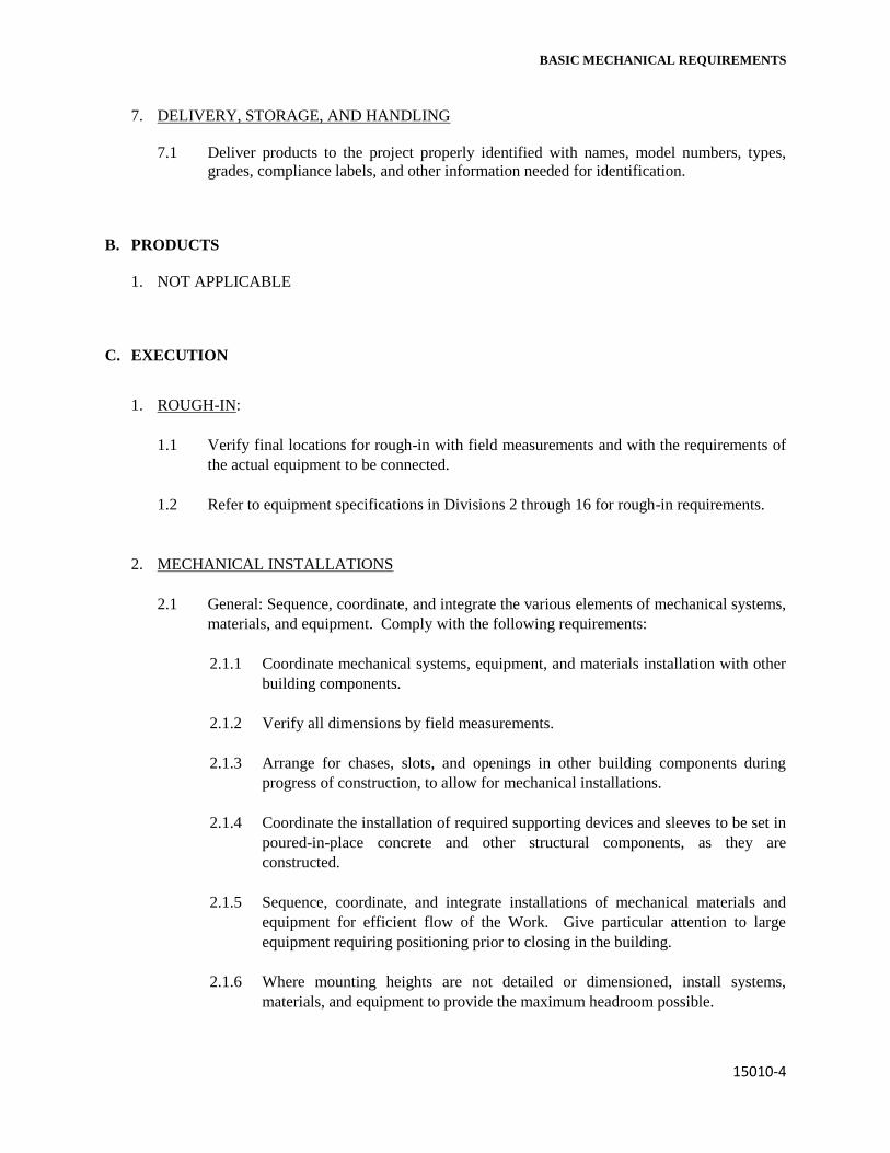
BASIC MECHANICAL REQUIREMENTS
15010-4
7. DELIVERY, STORAGE, AND HANDLING
7.1 Deliver products to the project properly identified with names, model numbers, types,
grades, compliance labels, and other information needed for identification.
B. PRODUCTS
1. NOT APPLICABLE
C. EXECUTION
1. ROUGH-IN:
1.1 Verify final locations for rough-in with field measurements and with the requirements of
the actual equipment to be connected.
1.2 Refer to equipment specifications in Divisions 2 through 16 for rough-in requirements.
2. MECHANICAL INSTALLATIONS
2.1 General: Sequence, coordinate, and integrate the various elements of mechanical systems,
materials, and equipment. Comply with the following requirements:
2.1.1 Coordinate mechanical systems, equipment, and materials installation with other
building components.
2.1.2 Verify all dimensions by field measurements.
2.1.3 Arrange for chases, slots, and openings in other building components during
progress of construction, to allow for mechanical installations.
2.1.4 Coordinate the installation of required supporting devices and sleeves to be set in
poured-in-place concrete and other structural components, as they are
constructed.
2.1.5 Sequence, coordinate, and integrate installations of mechanical materials and
equipment for efficient flow of the Work. Give particular attention to large
equipment requiring positioning prior to closing in the building.
2.1.6 Where mounting heights are not detailed or dimensioned, install systems,
materials, and equipment to provide the maximum headroom possible.

BASIC MECHANICAL REQUIREMENTS
15010-5
• MECHANICAL INSTALLATIONS (Cont.’):
2.1.7 Coordinate connection of mechanical systems with exterior underground and
overhead utilities and services. Comply with requirements of governing
regulations, franchised service companies, and controlling agencies. Provide
required connection for each service.
2.1.8 Install systems, materials, and equipment to conform with approved submittal
data, including coordination drawings, to greatest extent possible. Conform to
arrangements indicated by the Contract documents, recognizing that portions of
the Work are shown only in diagrammatic form. Where coordination
requirement’s conflict with individual system requirements, refer conflict to the
Architect.
2.1.9 Install systems, materials, and equipment level and plumb, parallel and
perpendicular to other building systems and components, where installed exposed
in finished spaces.
2.1.10 Install mechanical equipment to facilitate servicing, maintenance, and repair or
replacement of equipment components. As much as practicable, connect
equipment for ease of disconnecting, with minimum of interference with other
installations. Extend grease fittings to an accessible location.
2.1.11 Install access panel or doors where are concealed behind finished surfaces.
Access panels and doors where are concealed behind finished surfaces. Access
panels and doors are specified in Division 8 Section “ACCESS DOORS” and
Division 15 Section “BASIC MECHANICAL MATERIALS AND METHODS”.
2.1.12 Install systems, materials, and equipment giving right-of-way priority to systems
required to be installed at specified slope.
3. CUTTING AND PATCHING
3.1 General: Perform cutting and patching in accordance with Division 1 Section “CUTTING
AND PATCHING”. In addition to the requirements specified in Division 1, the
following requirements apply:
3.1.1 Protection of Installed Work: During cutting and patching operations, protect
adjacent installations.
3.2 Perform cutting, fitting, and patching of mechanical equipment and materials required to:
3.2.1 Uncover Work to provide for installation of ill-timed Work.
3.2.2 Remove and replace defective Work.
BASIC MECHANICAL REQUIREMENTS
15010-6
• CUTTING AND PATCHING (Cont.’):
3.2.3 Remove and replace Work not conforming to requirements of the Contract
Documents.
3.2.4 Remove samples of installed Work as specified for testing.
3.2.5 Install equipment and materials in existing structures.
END OF SECTION 15010

SECTION 15030
ELECTRICAL REQUIREMENTS FOR
MECHANICAL EQUIPMENT
A. GENERAL
1. RELATED DOCUMENTS
1.1 Drawings and general provisions of the Contract, including the General Conditions, the
Supplementary Special Conditions and all Division-1 Specifications sections, apply to the
Work of this Section, and the other sections of Division 15.
1.2 Related Sections: Separate electrical components and materials required for field
installation and electrical connections are specified in Division 16.
2. SUMMARY
2.1 This sections specifies the basic requirements for electrical components that are integral
part of packaged mechanical equipment. These components include, but are not limited
to factory installed motors, starters, and disconnect switches furnished as an integral part
of packaged mechanical equipment.
2.2 Specific electrical requirements (i.e., horsepower and electrical characteristics) for
mechanical equipment are specified within the individual equipment specification
sections.
2.3 Specific electrical requirements (i.e., horsepower and electrical characteristics) for
mechanical equipment are scheduled on the drawings.
3. REFERENCES
3.1 NEMA Standards MG 1: Motors and Generators.
3.2 NEMA Standards ICS 2: Industrial Control Devices, Controllers, and Assemblies.
3.3 NEMA Standard 250: Enclosures for Electrical Equipment.
3.4 NEMA Standard KS 1: Enclosed Switches.
3.5 Comply with National Electrical Code (NFPA 70). (Last Edition)

ELECTRICAL REQUIREMENTS FOR
MECHANICAL EQUIPMENT
15030-2
4. SUBMITTALS
4.1 No separate submittal is required. Submit product data for motor, starters, and other
electrical components with submittal data required for the equipment for which it serves,
as required by the individual equipment specification sections.
5. QUALITY ASSURANCE ELECT. REQUIREMENTS FOR MECH. EQUIP
5.1 Electrical components and materials shall be UL labeled.
B. PRODUCTS
1. MOTORS
1.1 The following are basic requirements for simple or common motors. For special motors,
more detailed and specific requirements are specified in the individual equipment
specifications.
1.1.1 Torque characteristic shall be sufficient to satisfactory accelerate the driven loads.
1.1.2 Motor sizes shall be large enough so that the driven load will not require the
motor to operate in the service factor range.
1.1.3 Two speed motors shall have two separate windings on poly-phase motors.
1.1.4 Temperature Rating: Rate for 40ºC environment with maximum 50ºC
temperature rise for continuous duty at full load (Class A Insulation).
1.1.5 Starting capability: Frequency of starts as indicated by automatic control system
and not less than five (5) evenly time spaced starts per hours for manually
controlled motors.
1.1.6 Service Factor: 1.15 for poly-phase motors and 1.35 for single-phase motors.
1.1.7 Motor construction: NEMA Standard MG 1, general purpose, continuous duty, “
Design “B” except “C” where required for high starting torque.
a. Frames: NEMA Standard No. 48 or 54; use driven equipment manufacturer’s
standards to suit specific application.
b. Bearings:
1) Ball or roller bearings with inner and outer shaft seals.
2) Re-greased, except permanently sealed where motor is normally
inaccessible for regular maintenance.

ELECTRICAL REQUIREMENTS FOR
MECHANICAL EQUIPMENT
15030-3
• MOTORS (Art. 1.1.7) – Cont.’
3) Designed to resist thrust loading where belt drives or other drives produce
lateral or axial thrust in motor.
4) For fractional horsepower, light duty motors, sleeve type bearings are
permitted.
c. Enclosure Type:
1) Open drip-proof motors for indoor use where satisfactorily housed or
remotely located during operation.
2) Guarded drip-proof motor where exposed to contact by employees or
building occupants.
3) Weather protected Type 1 for outdoor use, Type II where not housed.
d. Noise rating: “Quiet”.
e. Noise rating: “Quiet”, rating on motors located in occupied spaces of
building.
f. Efficiency: “Energy Efficient” motors shall have a minimum efficiency as
schedule in accordance with IEEE Standard 112, test method B. If efficiency
not specified, motors shall have a higher efficiency than “Average Standard
Industry Motors", in accordance with IEEE Standard 112, test method B.
g. Nameplate: Indicate the full identification of manufacturer, rating,
characteristics, construction, special features and similar information.
2. STARTERS, ELECTRICAL DEVICES, AND WIRING
2.1 MOTOR STARTER CHARACTERISTIC
2.1.1 Enclosure: NEMA 1, general purpose enclosures with padlock ears, except in wet
locations shall be NEMA 3R with conduit hubs, or units in hazardous locations
which shall have proper class and division.
2.1.2 Type and size of starter shall be as recommended by motor manufacturer and the
driven equipment manufacturer for applicable protection and startup conditions.
2.2 MANUAL SWITCHES SHALL HAVE
2.2.1 Pilot lights and extra positions for multi-speed motors.
2.2.2 Overload protection: Melting alloy type thermal overload relays.

ELECTRICAL REQUIREMENTS FOR
MECHANICAL EQUIPMENT
15030-4
2.3 MAGNETIC STARTERS
2.3.1 Maintained contact push buttons and pilot lights properly arranged for single
speed or multi-speed operation as indicated.
2.3.2 Trip-free thermal overload relays, each phase.
2.3.3 Interlocks, pneumatic switches and similar devices as required for coordination
with control requirements or Division 15 Controls Sections. 7.1.8 Failure by the
Contractor to submit shop drawings in sample time for checking, shall no claim
for extension by reason of such default will be allowed.
2.3.4 Built-in 120 volts control circuit transformer, fused from line side, where service
exceeds 240 volts.
2.3.5 Externally operated manual reset.
2.3.6 Under-voltage release or protection.
3. CAPACITORS
3.1 FEATURES
3.1.1 Individual unit cells all welded steel housing each capacitor internally fused non-
flammable synthetic liquid impregnate craft tissue insulation aluminum foil
electrodes.
3.1.2 KVAR size shall be as required to correct motor power factor to 90 percent or
better and shall be installed on all motors 1 horsepower and larger, that have an
uncorrected power factor of less than 85 percent at rated load.
3.2 DISCONNECT SWITCHES
3.2.1 Fusible switches: Fused, each phase; general duty; horsepower rated; non-teased
quick-make, quick-break mechanism; dead front line side shield; solder-less lugs
suitable for copper or aluminum conductors; spring reinforced fuse clips; electro
silver plated current carrying parts; hinged doors; operating lever arranged for
locking in the “Open” position; are quenchers; capacity and characteristics as
indicated.
3.2.2 Non-fusible switches: For equipment 2 horsepower and smaller, shall be
horsepower rated; toggle switch type; quantity of poled and voltage rating as
indicated. For equipment larger than 2 horsepower, switches shall be the same as
fusible type.

ELECTRICAL REQUIREMENTS FOR
MECHANICAL EQUIPMENT
15030-5
C. EXECUTION (Not Applicable)
END OF SECTION OF 15030


SECTION 15060
HANGERS AND SUPPORTS
PART 1 – GENERAL
1.1 RELATED DOCUMENTS
A. Drawings and general provisions of the Contract, including General and Supplementary
Conditions and Division 1 Specification Sections, apply to this Section.
1.2 SUMMARY
A. This Section includes hangers and supports for mechanical system piping and equipment.
B. Related Sections include the following:
1. Division 5 Section “Metal Fabrications” for materials for attaching hangers and supports
to building structure.
2. Division 13 Sections on fire-suppression piping for fire-suppression pipe hangers.
3. Division 15 Section “Mechanical Vibration Controls and Seismic Restraints” for
vibration isolation and seismic restraint devices.
1.3 DEFINITIONS
A. MSS: Manufacturers Standardization Society for the Valve and Fittings Industry.
B. Terminology: As defined in MSS SP-90, “Guidelines on Terminology for Pipe Hangers and
Supports”.
1.4 PERFORMANCE REQUIREMENTS
A. Design channel support systems for piping to support multiple pipes capable of supporting
combined weight of supported systems, system contents, and test water.
B. Design heavy-duty steel trapezes for piping to support multiple pipes capable of supporting
combined weight of supported systems, system contents, and test water.
C. Design seismic restraint hangers and supports for piping and equipment.
D. Design and obtain approval from authorities having jurisdiction for seismic restraint hangers
and supports for piping and equipment.

HANGERS AND SUPPORTS
15060-2
1.5 SUBMITTALS
A. Product Data: For each type of pipe hanger, channel support system component, and thermal-
hanger shield insert indicated.
B. Shop Drawings: Signed and sealed by a qualified professional engineer for multiple piping
support and trapeze hangers. Include design calculations and indicate size and characteristics
of components and fabrication details.
C. Welding Certificates: Copies of certificates for welding procedures and operators.
1.6 QUALITY ASSURANCE
A. Welding: Qualify processes and operators according to ASME Boiler and Pressure Vessel
Code: Section IX, “Welding and Brazing Qualifications”.
B. Engineering Responsibility: Design and preparation of Shop Drawings and calculations for
each multiple pipe support and trapeze by a qualified professional engineer.
C. Engineering Responsibility: Design and preparation of Shop Drawings and calculations for
each multiple pipe support, trapeze, and seismic restraint by a qualified professional engineer.
1. Professional Engineer Qualifications: A professional engineer who is legally qualified to
practice in jurisdiction where Project is located and who is experienced in providing
engineering services of the kind indicated. Engineering services are defined as those
performed for installations of hangers and supports that are similar to those indicated for
this Project in material, design, and extent.
PART 2 – PRODUCTS
2.1 MANUFACTURERS
A. Available Manufacturers: Subject to compliance with requirements, manufacturers offering
products that may be incorporated into the Work include, but are not limited to, the following:
B. Manufacturers: Subject to compliance with requirements, provide products by one of the
following:
1. Pipe Hangers:
a. AAA Technology and Specialties Co., Inc.
b. B-Line Systems, Inc.
c. Carpenter & Patterson, Inc.
d. Empire Tool & Manufacturing Co., Inc.
e. Globe Pipe Hanger Products, Inc.
f. Grinnell Corp.
g. GS Metals Corp.

HANGERS AND SUPPORTS
15060-3
• Article 2.1, B.1: Pipe Hangers (Cont.’):
h. Michigan Hanger Co., Inc.
i. National Pipe Hanger Corp.
j. PHD Manufacturing, Inc.
k. PHS Industries, Inc.
l. Piping Technology & Products, Inc.
2. Channel Support Systems:
a. B-Line Systems, Inc.
b. Grinnell Corp.; Power-Strut Unit
c. GS Metals Corp.
d. Michigan Hanger Co., Inc.; O-Strut Div.
e. National Pipe Hanger Corp.
f. Thomas & Betts Corp.
g. Unistrut Corp.
h. Wesanco, Inc.
3. Thermal-Hanger Shield Inserts:
a. Carpenter & Patterson, Inc.
b. Michigan Hanger Co., Inc.
c. PHS Industries, Inc.
d. Pipe Shields, Inc.
e. Rilco Manufacturing Co., Inc.
f. Value Engineered Products, Inc.
4. Powder-Actuated Fastener Systems:
a. Gunnebo Fastening Corp.
b. Hilti, Inc.
c. ITW Ramset/Red Head
d. Masterset Fastening Systems, Inc.
2.2 MANUFACTURED UNITS
A. Pipe Hangers, Supports, and Components: MSS SP-58, factory-fabricated components. Refer
to “Hanger and Support Applications” Article in Part 3 for where to use specific hanger and
support types.
1. Galvanized, Metallic Coatings: for piping and equipment that will not have field-applied
finish.
2. Nonmetallic Coatings: On attachments for electrolytic protection where attachments are
in direct contact with copper tubing.
B. Channel Support Systems: MFMA-2, factory-fabricated components for field assembly.
1. Coatings: Manufacturer’s standard finish, unless bare metal surfaces are indicated.

HANGERS AND SUPPORTS
15060-4
• Article 2.2B (Cont.’):
2. Nonmetallic Coatings: On attachments for electrolytic protection where attachments are
in direct contact with copper tubing.
C. Thermal-Hanger Shield Inserts: 100-psi (690-KPa) minimum compressive-strength
insulation, encased in sheet metal shield.
1. Material for Cold Piping: ASTM C 552, Type I cellular glass or water-repellent-treated,
ASTM C 533, Type I calcium silicate with vapor barrier.
2. Material for Cold Piping: ASTM C 552, Type I cellular glass with vapor barrier.
3. Material for Cold Piping: Water-repellent-treated, ASTM C 533, Type I calcium silicate
with vapor barrier.
4. Material for Hot Piping: ASTM C 552, Type I cellular glass or water-repellent-treated,
ASTM C 533, Type I calcium silicate.
5. Material for Hot Piping: ASTM C 552, Type I cellular glass.
6. Material for Hot Piping: Water-repellent-treated, ASTM C 533, Type I calcium silicate.
7. For Trapeze or Clamped System: Insert and shield cover entire circumference of pipe.
8. For Clevis or Band Hanger: insert and shield cover lower 180 degrees of pipe.
9. Insert Length: Extend 2 inches (50 mm) beyond sheet metal shield for piping operating
below ambient air temperature.
2.3 MISCELLANEOUS MATERIALS
A. Powder-Actuated Drive-Pin Fasteners: Powder-actuated-type, drive-pin attachments with
pull-out and shear capacities appropriate for supported loads and building materials where
used.
B. Mechanical-Anchor Fasteners: Insert-type attachments with pull-out and shear capacities
appropriate for supported loads and building materials where used.
C. Structural Steel: ASTM A 36/A 36M, steel plates, shapes, and bars, black and galvanized.
D. Grout: ASTM C 1107, Grade B, factory-mixed and packaged, non-shrink and nonmetallic,
dry, hydraulic-cement grout.
1. Characteristics: Post hardening and volume adjusting; recommended for both interior and
exterior applications.
2. Properties: Non-staining, noncorrosive, and nongaseous.
3. Design Mix: 5000-psi (34.5-MPa), 28 day compressive strength.
PART 3 – EXECUTION
3.1 HANGER AND SUPPORT APPLICATIONS
A. Specific hanger requirements are specified in Sections specifying equipment and systems.

HANGERS AND SUPPORTS
15060-5
• ARTICLE 3.1: HANGER AND SUPPORT APPLICATIONS (Cont.’)
B. Comply with MSS SP-69 for pipe hanger selections and applications that are not specified in
piping system Specification Sections.
C. Horizontal-Piping Hangers and Supports: Unless otherwise indicated and except as specified
in piping system Specification Sections, install the following types:
1. Adjustable Steel Clevis Hangers (MSS Type I): For suspension of non-insulated or
insulated stationary pipes, NPS ½ to NPS 30 (DN15 to DN 750).
2. Yoke-Type Pipe Clamps (MSS Type 2): For suspension of 120 to 450 deg F (49 to 232
deg C) pipes, NPS 4 to NPS 16 (DN100 to DN400), requiring up to 4 inches (100 mm) of
insulation.
3. Carbon or Alloy-Steel, Double-bolt Pipe Clamps (MSS Type 3): For suspension of pipes,
NPS ¾ to NPS 24 (DN20 to DN600), requiring clamp flexibility and up to 4 inches
(100 mm) of insulation.
4. Steel Pipe Clamps (MSS Type 4): For suspension of cold and hot pipes, NPS ½ to NPS
24 (DN15 to DN600), if little or no insulation is required.
5. Pipe Hangers (MSS Type 5): for suspension of pipes, NPS ½ to NPS 4 (DN15 to DN
100), to allow off-center closure for hanger installation before pipe erection.
6. Adjustable Swivel Split- or Solid-Ring Hangers (MSS Type 6): for suspension of non-
insulated stationary pipes, NPS ¾ to NPS 8 (DN20 to DN200).
7. Adjustable Steel Band Hangers (MSS Type 7): For suspension of non-insulated stationary
pipes, NPS ½ to NPS 8 (DN15 to DN200).
8. Adjustable Band Hangers (MSS Type 9): for suspension of non-insulated stationary
pipes, NPS ½ to NPS 8 (DN15 to DN200).
9. Adjustable Swivel-Ring Band Hangers (MSS Type 10): For suspension of non-insulated
stationary pipes, NPS ½ to NPS 2 (DN15 to DN50).
10. Split Pipe-Ring with or without Turnbuckle-Adjustment Hangers (MSS Type 11): For
suspension of non-insulated stationary pipes, NPS ⅜ to NPS 8 (DN10 to DN200).
11. Extension Hinged or Two-Bolt Split Pipe Clamps (MSS type 12): For suspension of non-
insulated stationary pipes, NPS ⅜ to NPS 8 (DN10 to DN80).
12. U-Bolts (MSS Type 24): For support of heavy pipe, NPS ½ to NPS 30 (DN15 to DN750).
13. Clips (MSS Type 26): For support of insulated pipes not subject to expansion or
contraction.
14. Pipe Saddle Supports (MSS Type 36): For support of pipes, NPS 4 to NPS 36 (DN100 to
DN900), with steel pipe base stanchion support and cast-iron floor flange.
15. Pipe Stanchion Saddles (MSS Type 37): For support of pipes, NPS 4 to NPS 36 (DN100
to DN900), with steel pipe base stanchion support and cast-iron floor flange and with U-
Bolt to retain pipe.
16. Adjustable Pipe Saddle Supports (MSS Type 38): For stanchion-type support for pipes,
NPS 2-½ to NPS 36 (DN65 to DN900), if vertical adjustment is required, with steel pipe
base stanchion support and cast-iron floor flange.
17. Single Pipe Rolls (MSS Type 41): For suspension of pipes, NPS 1 to NPS 30 (DN25 to
DN 750), from two rods if longitudinal movement caused by expansion and contraction
might occur.
18. Adjustable Roller Hangers (MSS Type 43): for suspension of pipes, NPS 2-½ to NPS 20
(DN65 to DN500), from single rod if horizontal movement caused by expansion and
contraction might occur.

HANGERS AND SUPPORTS
15060-6
• ARTICLE 3.1C (Cont.’):
19. Complete Pipe Rolls (MSS Type 44): For support of pipes, NPS 2 to NPS 42 (DN50 to
DN1050), if longitudinal movement caused by expansion and contraction might occur but
vertical adjustment is not necessary.
20. Pipe Roll and Plate Units (MSS Type 45): For support of pipes, NPS 2 to NPS 24 (DN50
to DN600), if small horizontal movement caused by expansion and contraction might
occur and vertical adjustment is not necessary.
21. Adjustable Pipe Roll and Base Units (MSS Type 46): For support of pipes, NPS 2 to NPS
30 (DN50 to DN750), if vertical and lateral adjustment during installation might be
required in addition to expansion and contraction.
D. Vertical-Piping Clamps: Unless otherwise indicated and except as specified in piping system
Specification Sections, install the following types:
1. Extension Pipe or Riser Clamps (MSS Type 8): For support of pipe risers, NPS ¾ to NPS
20 (DN20 to DN500).
2. Carbon- or Alloy-Steel Riser Clamps (MSS Type 42): For support of pipe risers, NPS ¾
to NPS 20 (DN20 to DN500), if longer ends are required for riser clamps.
E. Hanger-Rod Attachments: Unless otherwise indicated and except as specified in piping
system Specification Sections, install the following types:
1. Steel Turnbuckles (MSS Type 13): For adjustment up to 6 inches (150 mm) for heavy
loads.
2. Steel Clevises (MSS Type 14): For 120 to 450 deg F (49 to 232 deg C) piping
installations.
3. Swivel Turnbuckles (MSS Type 15): For use with MSS Type 11, split pipe rings.
4. Malleable-Iron Sockets (MSS Type 16): For attaching hanger rods to various types of
building attachments.
5. Steel Weld-less Eye Nuts (MSS Type 17): For 120 to 450 deg F (49 to 232 deg C) piping
installations.
F. Building Attachments: Unless otherwise indicated and except as specified in piping system
Specification Sections, install the following types:
1. Steel or Malleable Concrete Inserts (MSS Type 18): For upper attachment to suspend
pipe hangers from concrete ceiling.
2. Top-Beam C-Clamps (MSS Type 19): For use under roof installation with bar-joist
construction to attach to top flange of structural shape.
3. Side-Beam or Channel Clamps (MSS Type 20): For attaching to bottom flange of beams,
channels, or angles.
4. Center-Beam Clamps (MSS Type 21): For attaching to center of bottom flange of beams.
5. Welded Beam Attachments (MSS Type 22): for attaching to bottom of beams if loads are
considerable and rod sizes are large.
6. C-Clamps (MSS Type 23): For structural shapes.

HANGERS AND SUPPORTS
15060-7
• ARTICLE 3.1F (Cont.’):
7. Top-Beam Clamps (MSS Type 25): For top of beams if hanger rod is required tangent to
flange edge.
8. Side-Beam Clamps (MSS Type 27): For bottom of steel I-beams.
9. Steel-Beam Clamps with Eye Nuts (MSS Type 28): For attaching to bottom of steel I-
beams for heavy loads.
10. Linked-Steel Clamps with Eye Nuts (MSS Type 29): For attaching to bottom of steel I-
beams for heavy loads, with link extensions.
11. Malleable Beam Clamps with Extension Pieces (MSS Type 30): For attaching to
structural steel.
12. Welded-Steel Brackets: For support of pipes from below or for suspending from above by
using clip and rod. Use one of the following for indicated loads:
a. Light (MSS Type 31): 750 lb (340 kg).
b. Medium (MSS Type 32): 1500 lb (675 kg).
c. Heavy (MSS Type 33): 300 lib (1350 kg).
13. Side-Beam Brackets (MSS Type 34): For sides of steel or wooden beams.
14. Plate Lugs (MSS Type 57): For attaching to steel beams if flexibility at beam is required.
15. Horizontal Travelers (MSS Type 58): For supporting piping systems subject to linear
horizontal movement where head room is limited.
G. Saddles and Shields: Unless otherwise indicated and except as specified in piping system
Specification Sections, install the following types:
1. Steel Pipe-Covering Protection Saddles (MSS Type 39): To fill interior voids with
insulation that matches adjoining insulation.
2. Protection Shields (MSS Type 40): Of length recommended by manufacturer to prevent
crushing insulation.
3. Thermal-Hanger Shield Inserts: For supporting insulated pipe, 360-degree insert of high-
density, 100-psi (690-kPa) minimum compressive-strength, water-repellent-treated
calcium silicate or cellular-glass pipe insulation, same thickness as adjoining insulation
with vapor barrier and encased in 360-degree sheet metal shield.
H. Spring Hangers and Supports: Unless otherwise indicated and except as specified in piping
system Specification Sections, install the following types:
1. Restraint-Control Devices (MSS Type 47): Where indicated to control piping movement.
2. Spring Cushions (MSS Type 48): For light loads if vertical movement does not exceed 1-
¼ inches (32 mm).
3. Spring-Cushion Roll Hangers (MSS Type 49): For equipping Type 41 roll hanger with
springs.
4. Spring Sway Braces (MSS Type 50): To retard sway, shock, vibration, or thermal
expansion in piping systems.
5. Variable-Spring Hangers (MSS Type 51): Preset to indicated load and limit variability
factor to 25 percent to absorb expansion and contraction of piping system from hanger.

HANGERS AND SUPPORTS
15060-8
• ARTICLE 3.1H (Cont.’):
6. Variable-Spring Base Supports (MSS Type 52): Preset to indicated load and limit
variability factor to 25 percent to absorb expansion and contraction of piping system from
base support.
7. Variable-Spring Trapeze Hangers (MSS Type 53): Preset to indicated load and limit
variability factor to 25 percent to absorb expansion and contraction of piping system from
trapeze support.
8. Constant Supports: For critical piping stress and if necessary to avoid transfer of stress
from one support to another support, critical terminal, or connected equipment. Include
auxiliary stops for erection, hydrostatic test, and load-adjustment capability. These
supports include the following types:
a. Horizontal (MSS Type 54): Mounted horizontally.
b. Vertical (MSS Type 55): Mounted vertically.
c. Trapeze (MSS Type 56): Two vertical-type supports and one trapeze member.
3.2 HANGER AND SUPPORT INSTALLATION
A. Pipe Hanger and Support Installation: Comply with MSS SP-69 and MSS SP-89. Install
hangers, supports, clamps, and attachments as required to properly support piping from
building structure.
B. Channel Support System Installation: Arrange for grouping of parallel runs of piping and
support together on field-assembled channel systems.
1. Field assemble and install according to manufacturer’s written instructions.
C. Heavy-Duty Steel Trapeze Installation: Arrange form grouping of parallel runs of horizontal
piping and support together on field-fabricated, heavy-duty trapezes.
1. Pipes of Various Sizes: Support together and space trapezes for smallest pipe size or
install intermediate supports for smaller diameter pipes as specified above for individual
pipe hangers.
2. Field fabricated from ASTM A 36/A 36M, steel shapes selected for loads being
supported. Weld steel according to AWS D-1.1.
D. Install building attachments within concrete slabs or attach to structural steel. Space
attachments within maximum piping span length indicated in MSS SP-69. Install additional
attachments at concentrated loads, including valves, flanges, guides, strainers, and expansion
joints, and at changes in direction of piping. Install concrete inserts before concrete is placed;
fasten inserts to forms and install reinforcing bars through openings at top of inserts.
E. Install powder-actuated drive-pin fasteners in concrete after concrete is placed and completely
cured. Use operators that are licensed by powder-actuated tool manufacturer. Install
fasteners according to powder-actuated tool manufacturer’s operating manual.

HANGERS AND SUPPORTS
15060-9
• ARTICLE 3.2: HANGER AND SUPPORT INSTALLATION (Cont.’)
F. Install mechanical-anchor fasteners in concrete after concrete is placed and completely cured.
Install fasteners according to manufacturer’s written instructions.
G. Install hangers and supports complete with necessary inserts, bolts, rods, nuts, washers, and
other accessories.
H. Install hangers and supports to allow controlled thermal and seismic movement of piping
systems, to permit freedom of movement between pipe anchors, and to facilitate action of
expansion joints, expansion loops, expansion bends, and similar units.
I. Load Distribution: Install hangers and supports so that piping live and dead loads and stresses
from movement will not be transmitted to connected equipment.
J. Pipe Slopes: Install hangers and supports to provide indicated pipe slopes and so maximum
pipe deflections allowed by ASME B31.9, “Building Services Piping,” are not exceeded.
K. Insulated Piping: Comply with the following:
1. Attach clamps and spacers to piping.
a. Piping Operating above Ambient Air Temperature: Clamp may project through
insulation.
b. Piping Operating below Ambient Air Temperature: Use thermal-hanger shield insert
with clamp sized to match OD of insert.
c. Do not exceed pipe stress limits according to ASME B31.9.
2. Install MSS SP-58, Type 39 protection saddles, if insulation without vapor barrier is
indicated. Fill interior voids with insulation that matches adjoining insulation.
3. Install MSS SP-58, Type 40 protective shields on cold piping with vapor barrier. Shields
shall span are of 180 degrees.
a. Option: Thermal-hanger shield inserts may be used. Include steel weight-distribution
plate for pipe NPS 4 (DN100) and larger if pipe is installed on rollers.
4. Shield Dimensions for Pipe: Not less than the following:
a. NPS ¼ to NPS 3-½ (DN8 to DN90): 12 inches (305 mm) long and 0.048 inch (1.22
mm) thick.
b. NPS 4 (DN 100): 12 inches (305 mm) long and 0/06 inch (1.52 mm) thick.
c. NPS 5 and NPS 6 (DN125 and DN150): 18 inches (457 mm) long and 0.06 inch
(1.52 mm) thick.
d. NPS 8 to NPS 14 (DN200 to DN350): 24 inches (610 mm) long and 0.075 inch (1.91
mm) thick.
e. NPS 16 to NPS 24 (DN400 to DN600): 24 inches (610 mm) long and 0.105 inch
(2.67 mm) thick.

HANGERS AND SUPPORTS
15060-10
• ARTICLE 3.1K (Cont.’):
5. Pipes NPS 8 (DN200) and Larger: Include wood inserts.
6. Insert Material: Length at least as long as protective shield.
7. Thermal-Hanger Shields: Install with insulation same thickness as piping insulation.
3.3 EQUIPMENT SUPPORTS
A. Fabricate structural-steel stands to suspend equipment from structure above or to support
equipment above floor.
B. Grouting: Place grout under supports for equipment and make smooth bearing surface.
3.4 METAL FABRICATION
A. Cut, drill and fit miscellaneous metal fabrications for heavy-duty steel trapezes and
equipment supports.
B. Fit exposed connections together to form hairline joints. Field-weld connections that cannot
be shop-welded because of shipping size limitations.
C. Field Welding: Comply with AWS D1.1 procedures for shielded metal are welding,
appearance and quality of welds, and methods used in correcting welding work, and with the
following:
1. Use materials and methods that minimize distortion and develop strength and corrosion
resistance of base metals.
2. Obtain fusion without undercut or overlap.
3. Remove welding flux immediately.
4. Finish welds at exposed connections so no roughness shows after finishing and contours
of welded surfaces match adjacent contours.
3.5 ADJUSTING
A. Hanger Adjustment: Adjust hangers to distribute loads equally on attachments and to achieve
indicated slope of pipe.
3.6 PAINTING
A. Touching Up: Clean field welds and abraded areas of shop paint. Paint exposed areas
immediately after erecting hangers and supports. Use same materials as used for shop
painting. Comply with SSPC-PA 1 requirements for touching up field-painted surfaces.
1. Apply paint by brush or spray to provide a minimum dry film thickness of 2.0 mils (0.05
mm).

HANGERS AND SUPPORTS
15060-11
• ARTICLE 3.6: PAINTING (Cont.’)
B. Touching Up: Cleaning and touchup painting of field welds, bolted connections, and abraded
areas of shop paint on miscellaneous metal are specified in Division 9 Section “Painting”.
C. Galvanized Surfaces: Clean welds, bolted connections, and abraded areas and apply
galvanizing-repair paint to comply with ASTM A 780.
END OF SECTION 15060

SECTION 15081
DUCT INSULATION
PART 1 - GENERAL
1.1 RELATED DOCUMENTS
A. Drawings and general provisions of the Contract, including General and Supplementary
Conditions and Division I Specification Sections, apply to this Section.
1.2 SUMMARY
A. This Section includes semi-rigid and flexible duct, plenum, and breeching insulation; insulating
cements; field-applied jackets; accessories and attachments; and sealing compounds.
B. Related Sections include the following:
1. Division 7 Section “Fire-stopping” for fire-stopping materials and requirements for
penetrations through fire and smoke barriers.
2. Division 15 Section “Equipment Insulation” for insulation materials and application for
pumps, tanks, hydronic specialties, and other equipment.
3. Division 15 Section “Pipe Insulation” for insulation for piping systems.
4. Division 15 Section “Metal Ducts” for duct liner.
1.3 SUBMITTALS
A. Product Data: Identify thermal conductivity, thickness, and jackets (both factory and field
applied, if any), for each type of product indicated.
B. Shop Drawings: Show fabrication and installation details for the following:
1. Removable insulation sections at access panels.
2. Application of field-applied jackets.
3. Applications at linkages for control devices.
C. Samples: For each type of insulation and field-applied jacket. Identify each Sample, describing
product and intended use. Submit 12-inch (300 mm) square sections of each sample material.
1. Manufacturer’s Color Charts: Show the full range of colors available for each type of field-
applied finish material indicated.
D. Material Test Reports: From a qualified testing agency acceptable to authorities having
jurisdiction indicating, interpreting, and certifying test results for compliance of insulation
materials, sealers, attachments, cements, and jackets with requirements indicated. Include date
of tests.

DUCT INSULATION
15081-2
1.3 SUBMITTALS (Cont.’):
E. Installer Certificates: Signed by the Contractor certifying that installers comply with
requirements.
1.4 QUALITY ASSURANCE
A. Installer Qualifications: Skilled mechanics who have successfully completed an apprenticeship
program or another craft training program certified by the U.S. Department of Labor, Bureau
of Apprenticeship and Training.
B. Fire-Test-Response Characteristics: As determined by testing materials identical to those
specified in this Section according to ASTM E84, by a testing and inspecting agency acceptable
to authorities having jurisdiction. Factory label insulation and jacket materials and sealer and
cement material containers with appropriate markings of applicable testing and inspecting
agency.
1. Insulation Installed Indoors: Flame-spread rating of 25 or less and smoke-developed rating
of 50 or less.
2. Insulation Installed Outdoors. Flame-spread rating of 75 or less and smoke-developed
rating of 150 or less.
C. Mockups: Before installing insulation, build mockups for each type of insulation and finish
listed below to demonstrate quality of insulation application and finishes. Build mockups
according to the following requirements, using materials indicated for the completed Work:
1. Include the following mockups:
a. One 10-foot (3-m) section of rectangular straight duct.
b. One 90-degree square elbow and one 90-degree radius elbow.
c. One branch takeoff.
d. One transition fitting.
e. Four support hangers.
2. Build mockups with cutaway sections to allow observation of application details for
insulation materials, mastics, attachments, and jackets.
3. Build mockups in the location indicated or, if not indicated, as directed by Architect.
4. Notify Architect seven days in advance of dates and times when mockups will be
constructed.
5. Obtain Architect’s approval of mockups before starting insulation application.
6. Maintain mockups during construction in an undisturbed condition as a standard for
judging the completed Work.
7. Demolish and remove mockups when directed.
8. Approved mockups may become part of the completed Work if undisturbed at time of
Substantial Completion.
DUCT INSULATION
15081-3
1.5 DELIVERY, STORAGE AND HANDLING
A. Packaging: Ship insulation materials in containers marked by manufacturer with appropriate
ASTM specification designation, type and grade, and maximum use temperature.
1.6 COORDINATION
A. Coordinate clearance requirements with duct Installer for insulation application.
1.7 SCHEDULING
A. Schedule insulation application after testing duct systems. Insulation application may begin on
segments of ducts that have satisfactory test results.
PART 2 – PRODUCTS
2.1 MANUFACTURERS
A. Available Manufacturers: Subject to compliance with requirements, manufacturers offering
products that may be incorporated into the Work include, but are not limited to, the following:
B. Manufacturers: Subject to compliance with requirements, provide products by one of the
following:
1. Mineral-Fiber Insulation:
a. Certainteed Manson.
b. Knauf Fiberglass GmbH.
c. Owens-Corning Fiberglas Corp.
d. Schuller International, Inc.
2. Flexible Elastomeric Thermal Insulation:
a. Armstrong World Industries, Inc.
b. Rubatex Corp.
c. Armaflex, Inc.
3. Closed-Cell Phenolic-Foam Insulation:
a. Kooltherm Insulation Products, Ltd.
4. Calcium Silicate Insulation:
a. Owens-Corning Fiberglas Corp.
b. Pabco.
c. Schuller International, Inc.

DUCT INSULATION
15081-4
2.2 INSULATION MATERIALS
A. Mineral-Fiber Board Thermal Insulation: Glass fibers bonded with a thermosetting resin.
Comply with ASTM C 612, Type IB, without facing and with all-service jacket manufactured
from Kraft paper, reinforcing scrim, aluminum foil, and vinyl film.
B. Mineral-Fiber Blanket Thermal Insulation: Glass fibers bonded with a thermosetting resin.
Comply with ASTM C 553, Type II, without facing and with all-service jacket manufactured
from Kraft paper, reinforcing scrim, aluminum foil, and vinyl film.
C. Flexible Elastomeric Thermal Insulation: Closed-cell, sponge or expanded-rubber materials.
Comply with ASTM C 534, Type II for sheet materials.
1. Adhesive: As recommended by insulation material manufacturer.
2. Ultraviolet-Protective Coating: As recommended by insulation manufacturer.
D. Closed-Cell Phenolic-Foam Insulation: Block insulation of rigid, expanded, closed-cell
structure. Comply with ASTM C 1126, Type II, Grade 1.
E. Calcium Silicate Insulation: Flat-, curved-, and grooved-block sections of noncombustible,
inorganic, hydrous calcium silicate with a non-asbestos fibrous reinforcement. Comply with
ASTM C 533, Type I.
2.3 FIELD-APPLIED JACKETS
A. General: ASTM C 921, Type 1, unless otherwise indicated.
B. Foil and Paper Jacket: Laminated, glass-fiber-reinforced, flame-retardant Kraft paper and
aluminum foil.
C. PVC Jacket: High-impact, ultraviolet-resistant PVC; 20 mils (0.5 mm) thick; roll stock ready
for shop or field cutting and forming.
1. Adhesive: As recommended by insulation material manufacturer.
2. PVC Jacket Color: White or gray.
3. PVC Jacket Color: Custom color selected
D. Aluminum Jacket: Deep corrugated sheets manufactured from aluminum alloy complying with
ASTM B 209 (ASTM B 209M), and having an integrally bonded moisture barrier over entire
surface in contact with insulation. Metal thickness and corrugation dimensions are scheduled
at the end of this Section.
1. Finish: Smooth finish.
2. Finish: Cross-crimp corrugated finish.
3. Finish: Stucco-embossed finish.
4. Finish: Factory-painted finish.
5. Moisture Barrier: 1-mil (0.025-mm) thick, heat-bonded polyethylene and Kraft paper.

DUCT INSULATION
15081-5
2.3 FIELD-APPLIED JACKETS (Cont.’):
E. Stainless-Steel Jacket: Deep corrugated sheets of stainless steel complying with ASTM A666,
Type 304 or 316; 0.10 inch (2.5 mm) thick; and roll stock ready for shop or field cutting and
forming to indicate sizes.
1. Moisture Barrier: 1 mil (0.025 mm) thick, heat-bonded polyethylene and Kraft paper.
2. Moisture Barrier: 3 mil (0.075 mm) thick, heat-bonded polyethylene and Kraft paper.
3. Jacket Bands: Stainless steel, Type 304, ¾ inch (19 mm) wide.
2.4 ACCESSORIES AND ATTACHMENTS
A. Glass Cloth and Tape: Comply with MIL-C-20079H, type I for cloth and Type II for tape.
Woven glass-fiber fabrics, plain weave, pre-sized a minimum of 8 oz. /sq. yd. (270 g/sq.mt.).
1. Tape Width: 4 inches (100 mm).
B. Bands: ¾ inch (19 mm) wide, in one of the following materials compatible with jacket:
1. Stainless Steel: ASTM A 666, Type 304; 0.020 inch (0.5 mm) thick.
2. Galvanized Steel: 0.005 inch (0.13 mm) thick.
3. Aluminum: 0.007 inch (0.18 mm) thick.
4. Brass: 0.010 inch (0.25 mm) thick.
5. Nickel-Copper Alloy: 0.005 inch (0.13 mm) thick.
C. Wire: 0.080 inch (2.0 mm), nickel-copper alloy; 0.062 inch (1.6 mm), soft-annealed, stainless
steel; or 0.062 inch (1.6 mm), soft annealed, galvanized steel.
D. Weld-Attached Anchor Pins and Washers: Copper-coated steel pin for capacitor-discharge
welding and galvanized speed washer. Pin length sufficient for insulation thickness indicated.
1. Welded Pin Holding Capacity: 100 pd. (45 kg.) for direct pull perpendicular to the attached
surface.
E. Adhesive-Attached Anchor Pins and Speed Washers: Galvanized steel plate, pin, and washer
manufactured for attachment to duct and plenum with adhesive. Pin length sufficient for
insulation thickness indicated.
1. Adhesive: Recommended by the anchor pin manufacturer as appropriate for surface
temperatures of ducts, plenums, and breechings; and to achieve a holding capacity of 100
pd. (45 kg) fir direct pull perpendicular to the adhered surface.
F. Self-Adhesive Anchor Pins and Speed Washers: Galvanized steel plate, pin, and washer
manufactured for attachment to duct and plenum with adhesive. Pin length sufficient for
insulation thickness indicated.
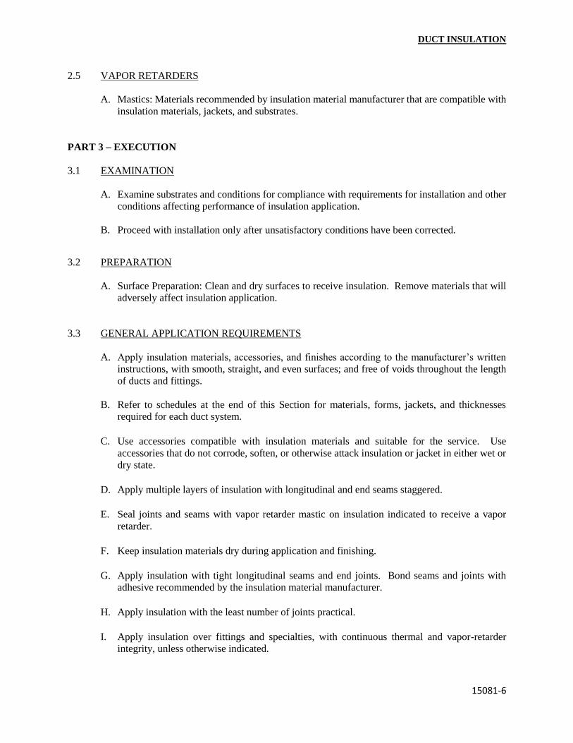
DUCT INSULATION
15081-6
2.5 VAPOR RETARDERS
A. Mastics: Materials recommended by insulation material manufacturer that are compatible with
insulation materials, jackets, and substrates.
PART 3 – EXECUTION
3.1 EXAMINATION
A. Examine substrates and conditions for compliance with requirements for installation and other
conditions affecting performance of insulation application.
B. Proceed with installation only after unsatisfactory conditions have been corrected.
3.2 PREPARATION
A. Surface Preparation: Clean and dry surfaces to receive insulation. Remove materials that will
adversely affect insulation application.
3.3 GENERAL APPLICATION REQUIREMENTS
A. Apply insulation materials, accessories, and finishes according to the manufacturer’s written
instructions, with smooth, straight, and even surfaces; and free of voids throughout the length
of ducts and fittings.
B. Refer to schedules at the end of this Section for materials, forms, jackets, and thicknesses
required for each duct system.
C. Use accessories compatible with insulation materials and suitable for the service. Use
accessories that do not corrode, soften, or otherwise attack insulation or jacket in either wet or
dry state.
D. Apply multiple layers of insulation with longitudinal and end seams staggered.
E. Seal joints and seams with vapor retarder mastic on insulation indicated to receive a vapor
retarder.
F. Keep insulation materials dry during application and finishing.
G. Apply insulation with tight longitudinal seams and end joints. Bond seams and joints with
adhesive recommended by the insulation material manufacturer.
H. Apply insulation with the least number of joints practical.
I. Apply insulation over fittings and specialties, with continuous thermal and vapor-retarder
integrity, unless otherwise indicated.

DUCT INSULATION
15081-7
3.3 GENERAL APPLICATION REQUIREMENTS (Cont.’):
J. Hangers and Anchors: Where vapor retarder is indicated, seal penetrations in insulation at
hangers, supports, anchors, and other projections with vapor-retarder mastic. Apply insulation
continuously through hangers and around anchor attachments.
K. Insulation Terminations: For insulation application where vapor retarders are indicated, seal
ends with a compound recommended by the insulation material manufacturer to maintain vapor
retarder.
L. Apply insulation with integral jackets as follows:
1. Pull jacket tight and smooth.
2. Joints and Seams: Cover with tape and vapor retarder as recommended by insulation
material manufacturer to maintain vapor seal.
3. Vapor-Retarder Mastics: Where vapor retarders are indicated, apply mastic on seams and
joints and at ends adjacent to duct flanges and fittings.
M. Cut insulation according to manufacturer’s written instructions to prevent compressing
insulation to less than 75 percent of its nominal thickness.
N. Install vapor-retarder mastic on ducts and plenums scheduled to receive vapor retarders.
1. Ducts with Vapor Retarders: Overlap insulation facing at seams and seal with vapor-
retarder mastic and pressure-sensitive tape having same facing as insulation. Repair
punctures, tears, and penetrations with tape or mastic to maintain vapor-retarder seal.
2. Ducts without Vapor Retarders: Overlap insulation facing at seams and secure with
outward clinching staples and pressure-sensitive tape having same facing as insulation.
O. Roof Penetrations: Apply insulation for interior applications to a point even with top of roof
flashing.
1. Seal penetrations with vapor-retarder mastic.
2. Apply insulation for exterior applications tightly joined to interior insulation ends.
3. Seal insulation to roof flashing with vapor-retarder mastic.
P. Interior Wall and Partition Penetrations: Apply insulation continuously through walls and
partitions, except fire-rated walls and partitions.
Q. Fire-Rated Wall and Partition Penetrations: Terminate insulation at fire/smoke damper sleeves
for fire-rated wall and partition penetrations.
R. Floor Penetrations: Terminate insulation at underside of floor assembly and at floor support at
top of floor.
1. For insulation indicated to have vapor retarders, taper termination and seal insulation ends
with vapor-retarder mastic.

DUCT INSULATION
15081-8
3.4 MINERAL-FIBER INSULATION APPLICATION
A. Blanket Applications for Ducts and Plenums: Secure blanket insulation with adhesive and
anchor pins and speed washers.
1. Apply adhesives according to manufacturer’s recommended coverage rates per square foot,
for 100 percent coverage of duct and plenum surfaces.
2. Apply adhesive to entire circumference of ducts and to all surfaces of fittings and
transitions.
3. Install anchor pins and speed washers on sides and bottom of horizontal ducts and sides of
vertical ducts as follows:
a. On duct sides with dimensions 18 inches (450 mm) and smaller, along longitudinal
centerline of duct. Space 3 inches (75 mm) maximum from insulation end joints, and
16 inches (400 mm) o.c.
b. On duct sides with dimensions larger than 18 inches (450 mm). Space 16 inches (400
mm) o.c. each way, and 3 inches (75 mm) maximum from insulation joints. Apply
additional pins and clips to hold insulation tightly against surface at cross bracing.
c. Anchor pins may be omitted from top surface of horizontal, rectangular ducts and
plenums.
d. Do not over compress insulation during installation.
4. Impale insulation over anchors and attach speed washers.
5. Cut excess portion of pins extending beyond speed washers or bend parallel with insulation
surface. Cover exposed pins and washers with tape matching insulation facing.
6. Create a facing lap for longitudinal seams and end joints with insulation by removing 2
inches (50 mm) from one edge and one end of insulation segment. Secure laps to adjacent
insulation segment with ½-inch (13 mm) staples, 1 inch (25 mm) o.c., and cover with
pressure-sensitive tape having same facing as insulation.
7. Overlap unfaced blankets a minimum of 2 inches (50 mm) on longitudinal seams and end
joints. Secure with steel band at end joints and spaced a maximum of 18 inches (450 mm)
o.c.
8. Apply insulation on rectangular duct elbows and transitions with a full insulation segment
for each surface. Apply insulation on round and flat-oval duct elbows with individually
mitered gores cut to fit the elbow.
9. Insulate duct stiffeners, hangers, and flanges that protrude beyond the insulation surface
with 6-inch (150 mm) wide strips of the same material used to insulate duct. Secure on
alternating sides of stiffener, hanger, and flange with anchor pins spaced 6 inches (150 mm)
o.c.
10. Apply vapor-retarder mastic to open joints, breaks, and punctures for insulation indicated
to receive vapor retarder.
B. Board Applications for Ducts and Plenums: Secure board insulation with adhesive and anchor
pins and speed washers.
1. Apply adhesives according to manufacturer’s recommended coverage rates per square foot,
for 100 percent coverage of duct and plenum surfaces.
2. Apply adhesive to entire circumference of ducts and to all surfaces of fittings and
transitions.
3. Space anchor pins as follows:
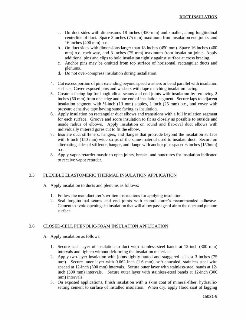
DUCT INSULATION
15081-9
a. On duct sides with dimensions 18 inches (450 mm) and smaller, along longitudinal
centerline of duct. Space 3 inches (75 mm) maximum from insulation end joints, and
16 inches (400 mm) o.c.
b. On duct sides with dimensions larger than 18 inches (450 mm). Space 16 inches (400
mm) o.c. each way, and 3 inches (75 mm) maximum from insulation joints. Apply
additional pins and clips to hold insulation tightly against surface at cross bracing.
c. Anchor pins may be omitted from top surface of horizontal, rectangular ducts and
plenums.
d. Do not over-compress insulation during installation.
4. Cut excess portion of pins extending beyond speed washers or bend parallel with insulation
surface. Cover exposed pins and washers with tape matching insulation facing.
5. Create a facing lap for longitudinal seams and end joints with insulation by removing 2
inches (50 mm) from one edge and one end of insulation segment. Secure laps to adjacent
insulation segment with ½-inch (13 mm) staples, 1 inch (25 mm) o.c., and cover with
pressure-sensitive tape having same facing as insulation.
6. Apply insulation on rectangular duct elbows and transitions with a full insulation segment
for each surface. Groove and score insulation to fit as closely as possible to outside and
inside radius of elbows. Apply insulation on round and flat-oval duct elbows with
individually mitered gores cut to fit the elbow.
7. Insulate duct stiffeners, hangers, and flanges that protrude beyond the insulation surface
with 6-inch (150 mm) wide strips of the same material used to insulate duct. Secure on
alternating sides of stiffener, hanger, and flange with anchor pins spaced 6 inches (150mm)
o.c.
8. Apply vapor-retarder mastic to open joints, breaks, and punctures for insulation indicated
to receive vapor retarder.
3.5 FLEXIBLE ELASTOMERIC THERMAL INSULATION APPLICATION
A. Apply insulation to ducts and plenums as follows:
1. Follow the manufacturer’s written instructions for applying insulation.
2. Seal longitudinal seams and end joints with manufacturer’s recommended adhesive.
Cement to avoid openings in insulation that will allow passage of air to the duct and plenum
surface.
3.6 CLOSED-CELL PHENOLIC-FOAM INSULATION APPLICATION
A. Apply insulation as follows:
1. Secure each layer of insulation to duct with stainless-steel bands at 12-inch (300 mm)
intervals and tighten without deforming the insulation materials.
2. Apply two-layer insulation with joints tightly butted and staggered at least 3 inches (75
mm). Secure inner layer with 0.062-inch (1.6 mm), soft-annealed, stainless-steel wire
spaced at 12-inch (300 mm) intervals. Secure outer layer with stainless-steel bands at 12-
inch (300 mm) intervals. Secure outer layer with stainless-steel bands at 12-inch (300
mm) intervals.
3. On exposed applications, finish insulation with a skim coat of mineral-fiber, hydraulic-
setting cement to surface of installed insulation. When dry, apply flood coat of lagging

DUCT INSULATION
15081-10
adhesive and press on one layer of glass cloth or tape. Overlap edges at least 1 inch (25
mm). Apply finish coat of lagging adhesive over glass cloth or tape. Thin the finish coat
to achieve smooth finish.
3.7 CALCIUM SILICATE INSULATION APPLICATION
A. Apply insulation according to the manufacturer’s written instructions and as follows:
1. Secure single layer of insulation to duct with stainless-steel bands. Tighten bands without
deforming the insulation material.
2. Apply two-layer insulation with joints tightly butted and staggered at least 3 inches (75
mm). Secure inner layer with 0.062-inch (1.6 mm), soft-annealed, stainless-steel wire.
Secure outer layer with stainless-steel bands.
3. On exposed applications, without metal jacket, finish insulation with a skim coat of
mineral-fiber, hydraulic-setting cement to surface of installed insulation. When dry, apply
flood coat of lagging adhesive and press on one layer of glass cloth or tape. Overlap edges
at least 1 inch (25 mm). Apply finish coat of lagging adhesive over glass cloth or tape.
Thin the finish coat to achieve smooth finish.
3.8 FIELD-APPLIED JACKET APPLICATION
A. Apply glass-cloth jacket, where indicated, directly over bare insulation or insulation with
factory-applied jackets.
1. Apply jacket smooth and tight to surface with 2-inch (50 mm) overlap at seams and joints.
2. Embed glass cloth between two 0.062-inch (1.6 mm) thick coats of jacket manufacturer’s
recommended adhesive.
3. Completely encapsulate insulation with jacket, leaving no exposed raw insulation.
3.9 FINISHES
A. Glass-Cloth Jacketed Insulation: Paint insulation finished with glass-cloth jacket as specified
in Division 9 Section “Painting”.
B. Flexible Elastomeric Thermal Insulation: After adhesive has fully cured, apply two coats of
insulation manufacturer’s recommended protective coating.
C. Color: final color as selected by Architect. Vary first and second coats to allow visual
inspection of the completed Work.
3.10 DUCT SYSTEM APPLICATIONS
A. Insulation materials and thicknesses are specified in schedules at the end of this Section.
B. Materials and thicknesses for systems listed below are specified in schedules at the end of this
Section.

DUCT INSULATION
15081-11
3.10 DUCT SYSTEM APPLICATIONS (Cont.’):
C. Insulate the following plenums and duct systems:
1. Indoor concealed supply, return, and outside air ductwork.
2. Indoor exposed supply, return, and outside air ductwork.
3. Outdoor exposed supply and return ductwork.
4. Indoor exposed range-hood exhaust ductwork.
5. Indoor concealed range-hood exhaust ductwork.
6. Indoor exposed oven and dishwasher exhaust ductwork.
7. Indoor concealed oven and dishwasher ductwork.
D. Items Not Insulated: Unless otherwise indicated, do not apply insulation in the following
systems, materials, and equipment:
1. Fibrous-glass ducts.
2. Metal ducts with duct liner.
3. Factory-insulated flexible ducts.
4. Factory-insulated plenums, casings, terminal boxes, and filter boxes and sections.
5. Flexible connectors.
6. Vibration control devices.
7. Testing agency labels and stamps.
8. Nameplates and data plates.
9. Access panels and doors in air-distribution systems.
3.11 INDOOR DUCT AND PLENUM APPLICATION SCHEDULE
A. Service: round or Rectangular supply and return air ducts, concealed and exposed
1. Material: Mineral-fiber blanket 0.75 pounds density.
2. Thickness: 2 inches (50 mm).
3. Number of Layers: One.
4. Field-Applied Jacket: Foil and paper.
5. Vapor Retarder Required: Yes.
B. Service: Round or Rectangular cold outside-air ducts, concealed and exposed.
1. Material: Mineral-fiber blanket 0.75 pounds density.
2. Thickness: 2 inches (50 mm).
3. Number of Layers: One.
4. Field-Applied Jacket: Foil and paper.
5. Vapor Retarder Required: Yes.
C. Service: Round or Rectangular, range-hood & dishwasher exhaust ducts, concealed & exposed.
1. Material: Calcium silicate.
2. Thickness: 2 inches (50 mm).
3. Number of Layers: Two.
4. Field-Applied Jacket: Glass cloth.

DUCT INSULATION
15081-12
3.11 INDOOR DUCT AND PLENUM APPLICATION SCHEDULE (Cont.’):
5. Vapor Retarder Required: Yes.
3.12 OUTDOOR DUCT AND PLENUM APPLICATION SCHEDULE
A. Service: Round or Rectangular supply, return & cold outside-air ducts.
1. Material: Mineral-fiber board 3 lbs, density.
2. Thickness: 2 inches (50 mm).
3. Number of Layers: Two.
4. Field-Applied Jacket: Glass cloth.
5. Field-Applied Jacket: Foil and paper.
6. Field-Applied Jacket: PVC.
7. Vapor Retarder Required: Yes.
8. Field-Applied Jacket: Aluminum.
a. Aluminum Thickness: 0.032 inch (0.8 mm).
b. Corrugation Dimension: 2-½ by 5/8 inch (64 by 16 mm).
END OF SECTION 15081

SECTION 15083
PIPE INSULATION
PART 1 – GENERAL
1.1 RELATED DOCUMENTS
A. Drawings and general provisions of the Contract, including General and Supplementary
Conditions and Division I Specification Sections, apply to this Section.
1.2 SUMMARY
A. This Section includes preformed, rigid and flexible pipe insulation; insulating cements; field-
applied jackets; accessories and attachments; and sealing compounds.
B. Related Sections include the following:
1. Division 2 Section “Hydronic Distribution” for loose-fill pipe insulation in underground
piping outside the building.
2. Division 2 Section “Steam Distribution” for loose-fill pipe insulation in underground
piping outside the building.
3. Division 7 Section “Fire-stopping” for fire-stopping materials and requirements for
penetrations through fire and smoke barriers.
4. Division 15 Section “Duct Insulation” for insulation for ducts and plenums.
5. Division 15 Section “Equipment Insulation” for insulation materials and application for
pumps, tanks, hydronic specialties, and other equipment.
6. Division 15 Section “Hangers and Supports” for pipe insulation shields and protection
saddles.
1.3 SUBMITTALS
A. Product Data: Identify thermal conductivity, thickness, and jackets (both factory and field
applied, if any), for each type of product indicated.
B. Shop Drawings: Show fabrication and installation details for the following:
1. Application of protective shields, saddles, and inserts at pipe hangers for each type of
insulation and hanger.
2. Attachment and covering of heat trace inside insulation.
3. Insulation application at pipe expansion joints for each type of insulation.
4. Insulation application at elbows, fittings, flanges, valves, and specialties for each type of
insulation.
5. Removable insulation at piping specialties and equipment connections.
6. Application of field-applied jackets.
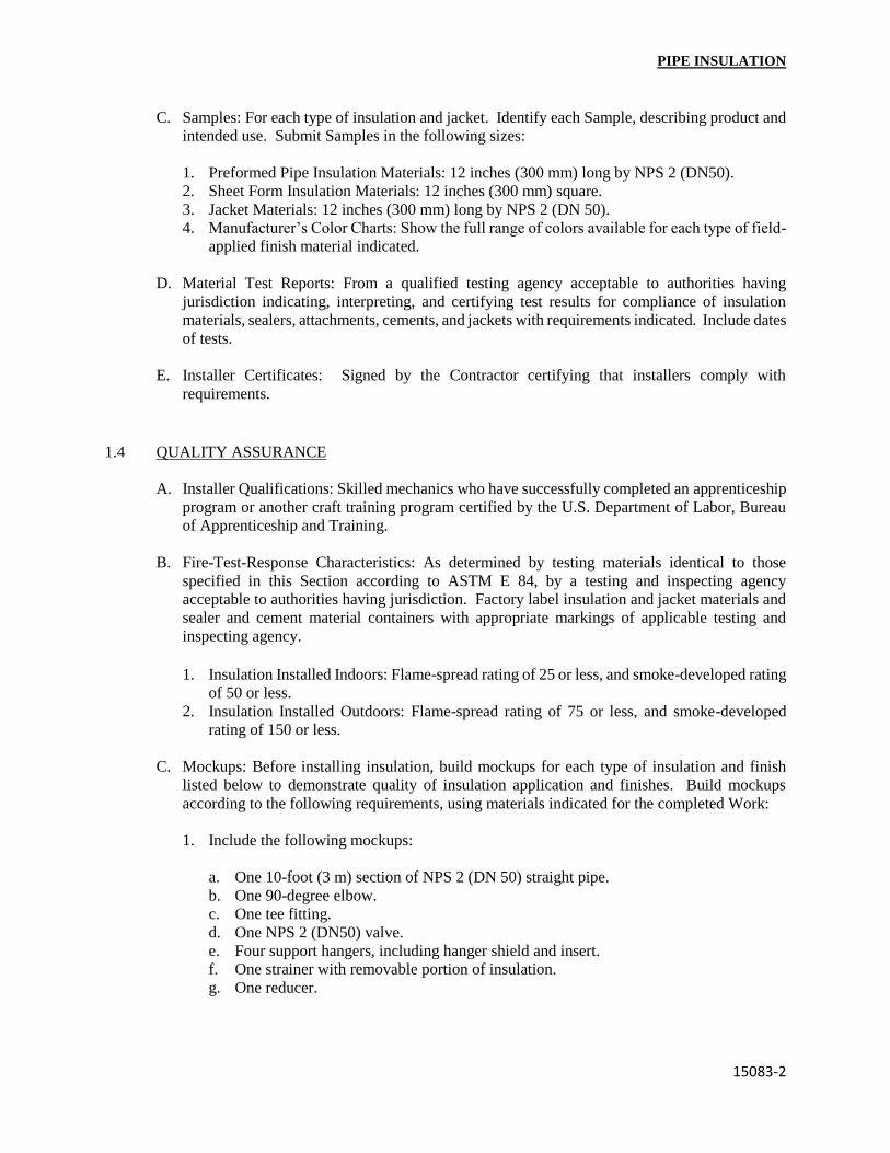
PIPE INSULATION
15083-2
C. Samples: For each type of insulation and jacket. Identify each Sample, describing product and
intended use. Submit Samples in the following sizes:
1. Preformed Pipe Insulation Materials: 12 inches (300 mm) long by NPS 2 (DN50).
2. Sheet Form Insulation Materials: 12 inches (300 mm) square.
3. Jacket Materials: 12 inches (300 mm) long by NPS 2 (DN 50).
4. Manufacturer’s Color Charts: Show the full range of colors available for each type of field-
applied finish material indicated.
D. Material Test Reports: From a qualified testing agency acceptable to authorities having
jurisdiction indicating, interpreting, and certifying test results for compliance of insulation
materials, sealers, attachments, cements, and jackets with requirements indicated. Include dates
of tests.
E. Installer Certificates: Signed by the Contractor certifying that installers comply with
requirements.
1.4 QUALITY ASSURANCE
A. Installer Qualifications: Skilled mechanics who have successfully completed an apprenticeship
program or another craft training program certified by the U.S. Department of Labor, Bureau
of Apprenticeship and Training.
B. Fire-Test-Response Characteristics: As determined by testing materials identical to those
specified in this Section according to ASTM E 84, by a testing and inspecting agency
acceptable to authorities having jurisdiction. Factory label insulation and jacket materials and
sealer and cement material containers with appropriate markings of applicable testing and
inspecting agency.
1. Insulation Installed Indoors: Flame-spread rating of 25 or less, and smoke-developed rating
of 50 or less.
2. Insulation Installed Outdoors: Flame-spread rating of 75 or less, and smoke-developed
rating of 150 or less.
C. Mockups: Before installing insulation, build mockups for each type of insulation and finish
listed below to demonstrate quality of insulation application and finishes. Build mockups
according to the following requirements, using materials indicated for the completed Work:
1. Include the following mockups:
a. One 10-foot (3 m) section of NPS 2 (DN 50) straight pipe.
b. One 90-degree elbow.
c. One tee fitting.
d. One NPS 2 (DN50) valve.
e. Four support hangers, including hanger shield and insert.
f. One strainer with removable portion of insulation.
g. One reducer.

PIPE INSULATION
15083-3
1.4 QUALITY ASSURANCE (Cont.’):
2. Build mockups with cutaway sections to allow observation of application details for
insulation materials, mastics, attachments, and jackets.
3. Build mockups in the location indicated or, if not indicted, as directed by Architect.
4. Notify Architect seven days in advance of dates and times when mockups will be
constructed.
5. Obtain Architect’s approval of mockups before starting insulation application.
6. Maintain mockups during construction in an undisturbed condition as a standard for
judging the completed Work.
7. Demolish and remove mockups when directed.
8. Approved mockups may become part of the completed Work if undisturbed at time of
Substantial Completion.
1.5 DELIVERY, STORAGE, AND HANDLING
A. Packaging: Ship insulation materials in containers marked by manufacturer with appropriate
ASTM specification designation, type and grade, and maximum use temperature.
1.6 COORDINATION
A. Coordinate size and location of supports, hangers, and insulation shields specified in Division
15 Section “Hangers and Supports”.
B. Coordinate clearance requirements with piping Installer for insulation application.
C. Coordinate installation and testing of steam or electric heat tracing.
1.7 SCHEDULING
A. Schedule insulation application after testing piping systems and, where required, after installing
and testing heat-trace tape. Insulation application may begin on segments of piping that have
satisfactory test results.
PART 2 – PRODUCTS
2.1 MANUFACTURERS
A. Available Manufacturers: Subject to compliance with requirements, manufacturers offering
products that may be incorporated into the Work include, but are not limited to, the following:
B. Manufacturers: Subject to compliance with requirements, provide products by one of the
following:

PIPE INSULATION
15083-4
1. Mineral-Fiber Insulation:
a. CertainTeed Manson.
b. Knouf Fiber Glass GmbH.
c. Owens-Corning Fiberglass Corp.
d. Schuller International, Inc.
2. Cellular-Glass Insulation:
a. Pittsburgh-Corning Corp.
3. Flexible Elastomeric Thermal Insulation:
a. Armstrong World Industries, Inc.
b. Rubatex Corp.
4. Polyolefin Insulation:
a. Armstrong World Industries, Inc.
b. IMCOA.
5. Closed-Cell Phenolic-Foam Insulation:
a. Kooltherm Insulation Products, Ltd.
6. Calcium Silicate Insulation:
a. Owens-Corning Fiberglass Corp.
b. Pabco.
c. Schuller International, Inc.
2.2 INSULATION MATERIALS
A. Mineral-Fiber Insulation: Glass fibers bonded with a thermosetting resin complying with the
following:
1. Preformed Pipe Insulation: Comply with ASTM C 547, Type 1, with factory-applied, all
purpose, vapor-retarder jacket.
2. Blanket Insulation: Comply with ASTM C 553, Type II, without facing.
3. Fire-Resistant Adhesive: Comply with MIL-A-3316C in the following classes and grades:
a. Class 1, Grade A for bonding glass cloth and tape to un-faced glass-fiber insulation,
for sealing edges of glass-fiber insulation, and for bonding lagging cloth to un-faced
glass-fiber insulation.
b. Class 2, Grade A for bonding glass-fiber insulation to metal surfaces.
4. Vapor-Retarder Mastics: Fire-and water-resistant, vapor-retarder mastic for indoor
applications. Comply with MIL-C-19565C, Type II.
5. Mineral-Fiber Insulating Cements: Comply with ASTM C 195.
6. Expanded or Exfoliated Vermiculite Insulating Cements: Comply with ASTM C 196.

PIPE INSULATION
15083-5
2.2 INSULATION MATERIALS (Cont.’):
7. Mineral-Fiber, Hydraulic-Setting Insulating and Finishing Cement: Comply with ASTM C
449/C 449M.
B. Cellular- Glass Insulation: Inorganic, foamed or cellulosed glass, annealed, rigid, hermetically
sealed cells, incombustible.
1. Preformed Pipe Insulation, without Jacket: Comply with ASTM C 552, Type II, Class 1.
2. Preformed Pipe Insulation, with Jacket: Comply with ASTM C 552, Type II, Class 2.
C. Flexible Elastomeric Thermal Insulation: Closed-cell, sponge- or expanded-rubber materials.
Comply with ASTM C 534, Type I for tubular materials and Type II for sheet materials.
1. Adhesive: As recommended by insulation material manufacturer.
2. Ultraviolet-Protective Coating: As recommended by insulation manufacturer.
D. Polyolefin Insulation: Unicellular polyethylene thermal plastic, preformed pipe insulation.
Comply with ASTM C 534, Type I, except for density.
1. Adhesive: As recommended by insulation material manufacturer.
E. Closed-Cell Phenolic-Foam Insulation: Preformed pipe insulation of rigid, expanded, closed-
cell structure. Comply with ASTM C 1126, Type III, Grade I.
F. Calcium Silicate Insulation: Preformed pipe sections of noncombustible, inorganic, hydrous
calcium silicate with a non-asbestos fibrous reinforcement. Comply with ASTM C533, Type I.
G. Prefabricated Thermal Insulating Fitting Covers: Comply with ASTM C 450 for dimensions
used in preforming insulation to cover valves, elbows, tees, and flanges.
2.3 FIELD-APPLIED JACKETS
A. General: ASTM C 921, Type 1, unless otherwise indicated.
B. Foil and Paper Jacket: Laminated, glass-fiber-reinforced, flame-retardant Kraft paper and
aluminum foil.
C. PVC Jacket: High-impact, ultraviolet-resistant PVC; 20 mils (0.5 mm) thick; roll stock ready
for shop or field cutting and forming.
1. Adhesive: As recommended by insulation material manufacturer.
2. PVC Jacket Color: White or gray.
3. PVC Jacket Color: Color-code piping jackets based on materials contained within the
piping system.
D. Heavy PVC Fitting Covers: Factory-fabricated fitting covers manufactured from 30-mil (0.75-
mm) thick, high-impact, ultraviolet-resistant PVC.

PIPE INSULATION
15083-6
2.3 FIELD-APPLIED JACKETS (Cont.’):
1. Shapes: 45 and 90 degree, short and long radius elbows, tees, valves, flanges, reducers,
end caps, soil pipe hubs, traps, mechanical joints, and P-trap and supply covers for
lavatories for the disabled.
2. Adhesive: As recommended by insulation material manufacturer.
E. Standard PVC Fitting Covers: Factory-fabricated fitting covers manufactured from 20-mil
(0.5-mm) thick, high-impact, ultraviolet-resistant PVC.
1. Shapes: 45 and 90 degree, short and long radius elbows, tees, valves, flanges, reducers,
end caps, soil-pipe hubs, traps, mechanical joints, and P-trap and supply covers for
lavatories for the disabled.
2. Adhesive: As recommended by insulation material manufacturer.
F. Aluminum Jacket: Factory cut and rolled to indicate sizes. Comply with ASTM B 209 (ASTM
B 209M), 3003 alloy, H-14 temper.
G. Aluminum Jacket: Aluminum roll stock, ready for shop or field cutting and forming to indicate
sizes. Comply with ASTM B 209 (ASTM B 209M), 3003 alloy, H-14 temper.
1. Finish and Thickness: Smooth finish, 0.010 inch (0.25 mm) thick.
2. Moisture Barrier: 1-mil-(0.025 mm) thick, heat-bonded polyethylene and Kraft paper.
3. Elbows: Preformed, 45 and 90 degree, short and long-radius elbows; same material,
finish, and thickness as jacket.
H. Stainless-Steel Jacket: ASTM A666, Type 304 or 316; 0.10 inch (2.5 mm) thick; and factory
cut and rolled to indicate sizes.
I. Stainless-Steel Jacket: ASTM A666, Type 304 or 316; 0.10 inch (2.5 mm) thick; and roll stock
ready for shop or field cutting and forming to indicate sizes.
1. Moisture Barrier: 3-mil (0.075 mm) thick, heat-bonded polyethylene and Kraft paper.
2. Elbows: Gore type, for 45 and 90 degree elbows in same material, finish, and thickness
as jacket.
3. Jacket Bands: Stainless steel, Type 304, ¾ inch (19 mm) wide.
2.4 ACCESSORIES AND ATTACHMENTS
A. Glass Cloth and Tape: Comply with MIL-C-20079H, Type I for cloth and Type II for tape.
Woven glass-fiber fabrics, plain weave, pre-sized a minimum of 8 oz. /sq. yd. (270 g/sq.mt.).
1. Tape Width: 4 inches (100 mm).
B. Bands: ¾ inch (19 mm) wide, in one of the following materials compatible with jacket:
1. Stainless Steel: ASTM A666, Type 304; 0.020 inch (0.5 mm) thick.
2. Galvanized Steel: 0.005 inch (0.13 mm) thick.
3. Aluminum: 0.007 inch (0.18 mm) thick.

PIPE INSULATION
15083-7
4. Brass: 0.010 inch (0.25 mm) thick.
5. Nickel-Copper Alloy: 0.005 inch (0.13 mm) thick.
C. Wire: 0.080-inch (2.0 mm), nickel-copper alloy; 0.062 inch (1.6 mm), soft-annealed, stainless
steel; or 0.062 inch (1.6 mm), soft-annealed, galvanized steel.
2.5 VAPOR RETARDERS
A. Mastics: Materials recommended by insulation material manufacturer that are compatible with
insulation materials, jackets, and substrates.
PART 3 – EXECUTION
3.1 EXAMINATION
A. Examine substrates and conditions for compliance with requirements for installation and other
conditions affecting performance of insulation application.
B. Proceed with installation only after unsatisfactory conditions have been corrected.
3.2 PREPARATION
A. Surface Preparation: Clean and dry pipe and fitting surfaces. Remove materials that will
adversely affect insulation application.
3.3 GENERAL APPLICATION REQUIREMENTS
A. Apply insulation materials, accessories, and finishes according to the manufacturer’s written
instructions; with smooth, straight, and even surfaces; free of voids throughout the length of
piping, including fittings, valves and specialties.
B. Refer to schedules at the end of this Section for materials, forms, jackets, and thicknesses
required for each piping system.
C. Use accessories compatible with insulation materials and suitable for the service. Use
accessories that do not corrode, soften, or otherwise attack insulation or jacket in either wet or
dry state.
D. Apply insulation with longitudinal seams at top and bottom of horizontal pipe runs.
E. Apply multiple layers of insulation with longitudinal and end seams staggered.
F. Do not weld brackets, clips, or other attachment devices to piping, fittings, and specialties.

PIPE INSULATION
15083-8
3.3 GENERAL APPLICATION REQUIREMENTS (Cont.’):
G. Seal joints and seams with vapor-retarder mastic on insulation indicated to receive a vapor
retarder.
H. Keep insulation materials dry during application and finishing.
I. Apply insulation with tight longitudinal seams and end joints. Bond seams and joints with
adhesive recommended by the insulation material manufacturer.
J. Apply insulation with the least number of joints practical.
K. Apply insulation over fittings, valves, and specialties, with continuous thermal and vapor-
retarder integrity, unless otherwise indicated. Refer to special instructions for applying
insulation over fittings, valves, and specialties.
L. Hangers and Anchors: Where vapor retarder is indicated, seal penetrations in insulation at
hangers, supports, anchors, and other projections with vapor-retarder mastic.
1. Apply insulation continuously through hangers and around anchor attachments.
2. For insulation application where vapor retarders are indicated, extend insulation on
anchor legs at least 12 inches (300 mm) from point of attachment to pipe and taper
insulation ends. Seal tapered ends with a compound recommended by the insulation
material manufacturer to maintain vapor retarder.
3. Install insert materials and apply insulation to tightly join the insert. Seal insulation to
insulation inserts with adhesive or sealing compound recommended by the insulation
material manufacturer.
4. Cover inserts with jacket material matching adjacent pipe insulation. Install shields over
jacket, arranged to protect the jacket from tear or puncture by the hanger, support, and
shield.
M. Insulation Terminations: For insulation application where vapor retarders are indicated, taper
insulation ends. Seal tapered ends with a compound recommended by the insulation material
manufacturer to maintain vapor retarder.
N. Apply adhesives and mastics at the manufacturer’s recommended coverage rate.
O. Apply insulation with integral jackets as follows:
1. Pull jacket tight and smooth.
2. Circumferential Joints: Cover with 3-inch (75 mm) wide strips, of same material as
insulation jacket. Secure strips with adhesive and outward clinching staples along both
edges of strip and spaced 4 inches (100 mm) o.c.
3. Longitudinal Seams: Overlap jacket seams at least 1-½ inches (40 mm). Apply insulation
with longitudinal seams at bottom of pipe. Clean and dry surface to receive self-sealing
lap. Staple laps with outward clinching staples along edge at 4 inches (100 mm) o.c.
a. Exception: Do not staple longitudinal laps on insulation having a vapor retarder.

PIPE INSULATION
15083-9
3.3 GENERAL APPLICATION REQUIREMENTS (Cont.’):
4. Vapor-Retarder Mastics: Where vapor retarders are indicated, apply mastic on seams and
joints and at ends adjacent to flanges, unions, valves, and fittings.
5. At penetrations in jackets for thermometers and pressure gages, fill and seal voids with
vapor-retarder mastic.
P. Roof Penetrations: Apply insulation for interior applications to a point even with top of roof
flashing.
1. Seal penetrations with vapor-retarder mastic.
2. Apply insulation for exterior application tightly joined to interior insulation ends.
3. Extend metal jacket of exterior insulation outside roof flashing at least 2 inches (50 mm)
below top of roof flashing.
4. Seal metal jacket to roof flashing with vapor-retarder mastic.
Q. Exterior Wall Penetrations: For penetrations of below-grade exterior walls, terminate insulation
flush with mechanical sleeve seal. Seal terminations with vapor-retarder mastic.
R. Interior Wall and Partition Penetrations: Apply insulation continuously through walls and
floors.
S. Fire-Rated Wall and Partition Penetrations: Apply insulation continuously through penetrations
of fire-rated walls and partitions.
1. Fire-stopping and fire-resistive joint sealers are specified in Division 7 Section “Fire-
stopping”.
T. Floor Penetrations: Apply insulation continuously through floor assembly.
1. For insulation with vapor retarders, seal insulation with vapor-retarder mastic where
floor supports penetrate vapor retarder.
3.4 MINERAL-FIBER INSULATION APPLICATION
A. Apply insulation to straight pipes and tubes as follows:
1. Secure each layer of preformed pipe insulation to pipe with wire, tape, or bands without
deforming insulation materials.
2. Where vapor retarders are indicated, seal longitudinal seams and end joints with vapor-
retarder mastic. Apply vapor retarder to ends of insulation at intervals of 15 to 20 feet (4.5
to 6m) to form a vapor retarder between pipe insulation segments.
3. For insulation with factory-applied jackets, secure laps with outward clinched staples at 6
inches (150 mm) o.c.
4. For insulation with factory-applied jackets with vapor retarders, do not staple longitudinal
tabs but secure tabs with additional adhesive as recommended by the insulation material
manufacturer and seal with vapor-retarder mastic.

PIPE INSULATION
15083-10
3.4 MINERAL-FIBER INSULATION APPLICATION (Cont.’):
B. Apply insulation to flanges as follows:
1. Apply preformed pipe insulation to outer diameter of pipe flange.
2. Make width of insulation segment the same as overall width of the flange and bolts, plus
twice the thickness of the pipe insulation.
3. Fill voids between inner circumference of flange insulation and outer circumference of
adjacent straight pipe segments with mineral-fiber blanket insulation.
4. Apply canvas jacket material with manufacturer’s recommended adhesive, overlapping
seams at least 1 inch (25 mm), and seal joints with vapor-retarder mastic.
C. Apply insulation to fittings and elbows as follows:
1. Apply pre-molded insulation sections of the same material as straight segments of pipe
insulation when available. Secure according to manufacturer’s written instructions.
2. When pre-molded insulation elbows and fittings are not available, apply mitered sections
of pipe insulation, or glass-fiber blanket insulation, to a thickness equal to adjoining pipe
insulation. Secure insulation materials with wire, tape, or bands.
3. Cover fittings with standard PVC fitting covers.
4. Cover fittings with heavy PVC fitting covers. Overlap PVC covers on pipe insulation
jackets at least 1 inch (25 mm) at each end. Secure fitting covers with manufacturer’s
attachments and accessories. Seal seams with tape and vapor-retarder mastic.
D. Apply insulation to valves and specialties as follows:
1. Apply pre-molded insulation sections of the same material as straight segments of pipe
insulation when available. Secure according to manufacturer’s written instructions.
2. When pre-molded insulation sections are not available, apply glass-fiber blanket insulation
to valve body. Arrange insulation to permit access to packing and to allow valve operation
without disturbing insulation. For check valves, arrange insulation for access to strainer
basket without disturbing insulation.
3. Apply insulation to flanges as specified for flange insulation application.
4. Use preformed standard PVC fitting covers for valve size where available. Secure fitting
covers with manufacturer’s attachments and accessories. Seal seams with tape and vapor-
retarder mastic.
5. Use preformed heavy PVC fitting covers for valve sizes where available. Secure fitting
covers with manufacturer’s attachments and accessories. Seal seams with tape and vapor-
retarder mastic.
6. For larger sizes where PVC fitting covers are not available, seal insulation with canvas
jacket and sealing compound recommended by the insulation material manufacturer.
3.5 CELLULAR-GLASS INSULATION APPLICATION
A. Apply insulation to straight pipes and tubes as follows:
1. Secure each layer of insulation to pipe with wire, tape, or bands without deforming
insulation materials.
2. Where vapor retarders are indicated, seal longitudinal seams and end joints with vapor-
retarder mastic.

PIPE INSULATION
15083-11
3.5 CELLULAR-GLASS INSULATION APPLICATION (Cont.’):
3. For insulation with factory-applied jackets, secure laps with outward clinched staples at 6
inches (150 mm) o.c.
4. For insulation with factory-applied jackets with vapor retarders, do not staple longitudinal
tabs but secure tabs with additional adhesive as recommended by the insulation material
manufacturer and seal with vapor-retarder mastic.
B. Apply insulation to flanges as follows:
1. Apply preformed pipe insulation to outer diameter of pipe flange.
2. Make width of insulation segment the same as overall width of the flange and bolts, plus
twice the thickness of the pipe insulation.
3. Fill voids between inner circumference of flange insulation and outer circumference of
adjacent straight pipe segments with cut sections of cellular-glass block insulation of the
same thickness as pipe insulation.
4. Apply canvas jacket material with manufacturer’s recommended adhesive, overlapping
seams at least 1 inch (25 mm), and seal joints with vapor-retarder mastic.
C. Apply insulation to fittings and elbows as follows:
1. Apply pre-molded insulation sections of the same material as straight segments of pipe
insulation when available. Secure according to manufacturer’s written instructions.
2. When pre-molded sections of insulation are not available, apply mitered sections of
cellular-glass insulation. Secure insulation materials with wire, tape, or bands.
3. Cover fittings with standard PVC fitting covers.
4. Cover fittings with heavy PVC fitting covers. Overlap PVC covers on pipe insulation
jackets at least 1 inch (25 mm) at each end. Secure fitting covers with manufacturer’s
attachments and accessories. Seal seams with tape and vapor-retarder mastic.
D. Apply insulation to valves and specialties as follows:
1. Apply pre-molded segments of cellular-glass insulation or glass-fiber blanket insulation to
valve body. Arrange insulation to permit access to packing and to allow valve operation
without disturbing insulation. For check valves, arrange insulation for access to strainer
basket without disturbing insulation.
2. Apply insulation to flanges as specified for flange insulation application.
3. Use preformed standard PVC fitting covers for valve sizes where available. Secure fitting
covers with manufacturer’s attachments and accessories. Seal seams with tape and vapor-
retarder mastic.
4. Use preformed heavy PVC fitting covers for valve sizes where available. Secure fitting
covers with manufacturer’s attachments and accessories. Seal seams with tape and vapor-
retarder mastic.
5. For larger sizes where PVC fitting covers are not available, seal insulation with canvas
jacket and sealing compound recommended by the insulation material manufacturer.
3.6 FLEXIBLE ELASTOMERIC THERMAL, INSULATION APPLICATION
A. Apply insulation to straight pipes and tubes as follows:

PIPE INSULATION
15083-12
1. Follow manufacturer’s written instructions for applying insulation.
2. Seal longitudinal seams and end joints with manufacturer’s recommended adhesive.
Cement to avoid openings in insulation that will allow passage of air to the pipe surface.
B. Apply insulation to flanges as follows:
1. Apply pipe insulation to outer diameter of pipe flange.
2. Make width of insulation segment the same as overall width of the flange and bolts, plus
twice the thickness of the pipe insulation.
3. Fill voids between inner circumference of flange insulation and outer circumference of
adjacent straight pipe segments with cut sections of sheet insulation of the same thickness
as pipe insulation.
4. Secure insulation to flanges and seal seams with manufacturer’s recommended adhesive.
Cement to avoid openings in insulation that will allow passage of air to the pipe surface.
C. Apply insulation to fittings and elbows as follows:
1. Apply mitered sections of pipe insulation.
2. Secure insulation materials and seal seams with manufacturer’s recommended adhesive.
Cement to avoid openings in insulation that will allow passage of air to the pipe surface.
D. Apply insulation to valves and specialties as follows:
1. Apply preformed valve covers manufactured of the same material as pipe insulation and
attached according to the manufacturer’s written instructions.
2. Apply cut segments of pipe and sheet insulation to valve body. Arrange insulation to permit
access to packing and to allow valve operation without disturbing insulation. For check
valves, fabricate removable sections of insulation arranged to allow access to stainer
basket.
3. Apply insulation to flanges as specified for flange insulation application.
4. Secure insulation to valves and specialties and seal seams with manufacturer’s
recommended adhesive. Cement to avoid openings in insulation that will allow passage of
air to the pipe surface.
3.7 POLYOLEFIN INSULATION APPLICATION
A. Apply insulation to straight pipes and tubes as follows:
1. Follow manufacturer’s written instructions for applying insulation.
2. For split tubes, seal longitudinal seams and end joints with manufacturer’s recommended
adhesive.
3. For self-adhesive insulation, staple longitudinal seams after sealing. Cement to avoid
openings in insulation that will allow passage of air to the pipe surface.
B. Apply insulation to flanges as follows:
1. Apply pipe insulation to outer diameter of pipe flange.
2. Make width of insulation segment the same as overall width of the flange and bolts, plus
twice the thickness of the pipe insulation.

PIPE INSULATION
15083-13
3.7 POLYOLEFIN INSULATION APPLICATION (Cont.’):
3. Fill voids between inner circumference of flange insulation and outer circumference of
adjacent straight pipe insulation.
4. Secure insulation to flanges and seal seams with manufacturer’s recommended adhesive.
Cement to avoid openings in insulation that will allow passage of air to the pipe surface.
C. Apply insulation to fittings and elbows as follows:
1. Apply mitered sections of polyolefin pipe insulation.
2. Secure insulation materials and seal seams with manufacturer’s recommended adhesive.
Cement to avoid openings in insulation that will allow passage of air to the pipe surface.
D. Apply insulation to valves and specialties as follows:
1. Apply preformed valve covers manufactured of the same material as pipe insulation and
attached according to the manufacturer’s written instructions.
2. Apply cut segments of polyolefin pipe and sheet insulation to valve body. Arrange
insulation to permit access to packing and to allow valve operation without disturbing
insulation. For check valves, fabricate removable sections of insulation arranged to allow
access to strainer basket.
3. Apply insulation to flanges as specified for flange insulation application.
4. Secure insulation to valves and specialties and seal seams with manufacturer’s
recommended adhesive. Cement to avoid openings in insulation that will allow passage of
air to the pipe surface.
3.8 CLOSED-CELL PHENOLIC-FOAM INSULATION APPLICATION
A. Apply insulation to straight pipes and tubes as follows:
1. Secure each layer of insulation to pipe with wire, tape, or bands without deforming
insulation materials.
2. Where vapor retarders are indicated, seal longitudinal seams and end joints with vapor-
retarder mastic.
3. For insulation with factory-applied jackets, secure laps with outward clinched staples at 6
inches (150 mm) o.c.
4. For insulation with factory-applied jackets with vapor retarders, do not staple longitudinal
tabs but secure tabs with additional adhesive as recommended by the insulation material
manufacturer and seal with vapor-retarder mastic.
B. Apply insulation to flanges as follows:
1. Apply preformed pipe insulation to outer diameter of pipe flange.
2. Make width of insulation segment the same as overall width of the flange and bolts, plus
twice the thickness of the pipe insulation.
3. Fill voids between inner circumference of flange insulation and outer circumference of
adjacent straight pipe segments with cut sections of block insulation of the same material
and thickness as pipe insulation.
4. Apply canvas jacket material with manufacturer’s recommended adhesive, overlapping
seams at least 1 inch (25 mm), and seal joints with vapor-retarder mastic.

PIPE INSULATION
15083-14
3.8 CLOSED-CELL PHENOLIC-FOAM INSULATION APPLICATION (Cont.’):
C. Apply insulation to fittings and elbows as follows:
1. Apply pre-molded insulation sections of the same material as straight segments of pipe
insulation when available. Secure according to manufacturer’s written instructions.
2. When pre-molded sections of insulation are not available, apply mitered sections of
phenolic-foam insulation. Secure insulation materials with wire, tape, or bands.
3. Cover fittings with standard PVC fitting covers.
4. Cover fittings with heavy PVC fitting covers. Overlap PVC covers on pipe insulation
jackets at least 1 inch (25 mm) at each end. Secure fitting covers with manufacturer’s
attachments and accessories. Seal seams with tape and vapor-retarder mastic.
D. Apply insulation to valves and specialties as follows:
1. Apply pre-molded insulation sections of the same material as straight segments of pipe
insulation when available. Secure according to manufacturer’s written instructions.
2. When pre-molded sections of insulation are not available, apply mitered segments of
phenolic-foam insulation to valve body. Arrange insulation to permit access to packing
and to allow valve operation without disturbing insulation. For check valves, arrange
insulation for access to strainer basket without disturbing insulation.
3. Apply insulation to flanges as specified for flange insulation application.
4. Use preformed standard PVC fitting covers for valve sizes where available. Secure fitting
covers with manufacturer’s attachments and accessories. Seal seams with tape and vapor-
retarder mastic.
5. Use preformed heavy PVC fitting covers for valve sizes where available. Secure fitting
covers with manufacturer’s attachments and accessories. Seal seams with tape and vapor-
retarder mastic.
6. For larger sizes where PVC fitting covers are not available, seal insulation with canvas
jacket and sealing compound recommended by the insulation material manufacturer.
3.9 CALCIUM SILICATE INSULATION APPLICATION
A. Apply insulation to straight pipes and tubes as follows:
1. Secure each layer of insulation to pipe with stainless-steel bands at 12 inch (300 mm)
intervals and tighten without deforming insulation materials.
2. Apply two layer insulation with joints tightly-butted and staggered at least 3 inches (75
mm). Secure inner layer with 0.062 inch (1.6 mm), soft-annealed, stainless steel wire
spaced at 12 inch (300 mm) intervals. Secure outer layer with stainless-steel bands at 12
inch (300 mm) intervals.
3. Apply a skim coat of mineral-fiber, hydraulic-settings cement to surface of installed
insulation. When dry, apply flood coat of lagging adhesive and press on one layer of glass
cloth or tape. Overlap edges at least 1 inch (25 mm). Apply finish coat of lagging adhesive
over glass cloth or tape. Thin the finish coat to achieve smooth finish.

PIPE INSULATION
15083-15
3.9 CALCIUM SILICATE INSULATION APPLICATION (Cont.’):
B. Apply insulation to flanges as follows:
1. Apply preformed pipe insulation to outer diameter of pipe flange.
2. Make width of insulation segment the same as overall width of the flange and bolts, plus
twice the thickness of the pipe insulation.
3. Fill voids between inner circumference of flange insulation and outer circumference of
adjacent straight pipe segments with cut sections of block insulation of the same material
adjacent straight pipe segments with cut sections of block insulation of the same material
and thickness as pipe insulation.
4. Finish flange insulation the same as pipe insulation.
C. Apply insulation to fittings and elbows as follows:
1. Apply pre-molded insulation sections of the same material as straight segments of pipe
insulation when available. Secure according to manufacturer’s written instructions.
2. When pre-molded sections of insulation are not available, apply mitered sections of
calcium silicate insulation. Secure insulation materials with stainless-steel wire.
3. Finish insulation of fittings the same as pipe insulation.
D. Apply insulation to valves and specialties as follows:
1. Apply mitered segments of calcium silicate insulation to valve body. Arrange insulation
to permit access to packing and to allow valve operation without disturbing insulation. For
check valves, arrange insulation for access to strainer basket without disturbing insulation.
2. Apply insulation to flanges as specified for flange insulation application.
3. Finish valve and specialty insulation the same as pipe insulation.
3.10 FIELD-APPLIED JACKET APPLICATION
A. Apply glass-cloth jacket, where indicated, directly over bare insulation or insulation with
factory-applied jackets.
1. Apply jacket smooth and tight to surface with 2-inch (50mm) overlap at seams and joints.
2. Embed glass cloth between two 0.062 inch (1.6 mm) thick coats of jacket manufacturer’s
recommended adhesive.
3. Completely encapsulate insulation with jacket, leaving no exposed raw insulation.
B. Foil and Paper Jackets: Apply foil and paper jackets where indicated.
1. Draw jacket material smooth and tight.
2. Apply lap or joints strips with the same material as jacket.
3. Secure jacket to insulation with manufacturer’s recommended adhesive.
4. Apply jackets with 1-½ inch (40 mm) laps at longitudinal seams and 3 inch (75 mm) wide
joint strips at end joints.
5. Seal openings, punctures, and breaks in vapor-retarder jackets and exposed insulation with
vapor-retarder mastic.

PIPE INSULATION
15083-16
3.10 FIELD-APPLIED JACKET APPLICATION (Cont.’):
C. Apply PVC jacket where indicated, with 1 inch (25 mm) overlap at longitudinal seams and end
joints. Seal with manufacturer’s recommended adhesive.
D. Apply metal jacket where indicated, with 2 inch (50 mm) overlap at longitudinal seams and
end joints. Overlap longitudinal seams arranged to shed water. Seal end joints with
weatherproof sealant recommended by insulation manufacturer. Secure jacket with stainless-
steel bands 12 inches (300 mm) o.c. and at end joints.
3.11 FINISHES
A. Glass-Cloth Jacketed Insulation: Paint insulation finished with glass cloth jacket as specified
in Division 9 Section “Painting”.
B. Flexible Elastomeric Thermal Insulation: After adhesive has fully cured, apply two coats of
the insulation manufacturer’s recommended protective coating.
C. Color: Final color as selected by Architect. Vary first and second coats to allow visual
inspection of the completed Work.
3.12 PIPING SYSTEM APPLICATIONS
A. Insulation materials and thicknesses are specified in schedules at the end of this Section.
B. Items Not Insulated: Unless otherwise indicated, do not apply insulation to the following
systems, materials, and equipment:
1. Flexible connectors.
2. Vibration-control devices.
3. Fire-suppression piping.
4. Drainage piping located in crawl spaces, unless otherwise indicated.
5. Below-grade piping, unless otherwise indicated.
6. Chrome-plated pipes and fittings, unless potential for personnel injury.
7. Air chambers, unions, strainers, check valves, plug valves, and flow regulators.
3.13 FIELD QUALITY CONTROL
A. Inspection: Owner will engage a qualified inspection agency to perform the following field
quality-control inspections, after installing insulation materials, jackets, and finishes, to
determine compliance with requirements.
B. Inspection: Engage a qualified inspection agency to perform the following field quality-control
inspections, after installing insulation materials, jackets, and finishes, to determine compliance
with requirements.
C. Inspection: Perform the following field quality-control inspections, after installing insulation
materials, jackets, and finishes, to determine compliance with requirements:
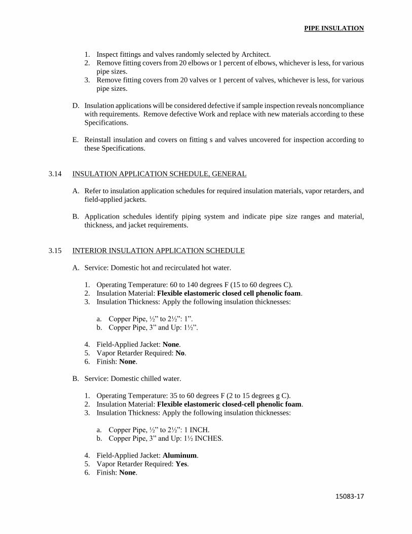
PIPE INSULATION
15083-17
1. Inspect fittings and valves randomly selected by Architect.
2. Remove fitting covers from 20 elbows or 1 percent of elbows, whichever is less, for various
pipe sizes.
3. Remove fitting covers from 20 valves or 1 percent of valves, whichever is less, for various
pipe sizes.
D. Insulation applications will be considered defective if sample inspection reveals noncompliance
with requirements. Remove defective Work and replace with new materials according to these
Specifications.
E. Reinstall insulation and covers on fitting s and valves uncovered for inspection according to
these Specifications.
3.14 INSULATION APPLICATION SCHEDULE, GENERAL
A. Refer to insulation application schedules for required insulation materials, vapor retarders, and
field-applied jackets.
B. Application schedules identify piping system and indicate pipe size ranges and material,
thickness, and jacket requirements.
3.15 INTERIOR INSULATION APPLICATION SCHEDULE
A. Service: Domestic hot and recirculated hot water.
1. Operating Temperature: 60 to 140 degrees F (15 to 60 degrees C).
2. Insulation Material: Flexible elastomeric closed cell phenolic foam.
3. Insulation Thickness: Apply the following insulation thicknesses:
a. Copper Pipe, ½” to 2½”: 1”.
b. Copper Pipe, 3” and Up: 1½”.
4. Field-Applied Jacket: None.
5. Vapor Retarder Required: No.
6. Finish: None.
B. Service: Domestic chilled water.
1. Operating Temperature: 35 to 60 degrees F (2 to 15 degrees g C).
2. Insulation Material: Flexible elastomeric closed-cell phenolic foam.
3. Insulation Thickness: Apply the following insulation thicknesses:
a. Copper Pipe, ½” to 2½”: 1 INCH.
b. Copper Pipe, 3” and Up: 1½ INCHES.
4. Field-Applied Jacket: Aluminum.
5. Vapor Retarder Required: Yes.
6. Finish: None.

PIPE INSULATION
15083-18
C. Service: Condensate drain piping.
1. Operating Temperature: 35 to 75 degrees F (2 to 24 degrees C).
2. Insulation Material: Flexible elastomeric.
3. Insulation Thickness: 1 inch.
4. Field-Applied Jacket: None.
5. Vapor Retarder Required: Yes.
6. Finish: None.
D. Service: Chilled-water supply and return.
1. Operating Temperature: 35 to 75 degrees F (2 to 24 degrees C).
2. Insulation Material: Flexible elastomeric Closed-cell phenolic foam.
3. Insulation Thickness: Apply the following insulation thicknesses:
a. Black Steel Pipe: ½” to 2½”: 1 INCH.
b. Black Steel Pipe: 3” and Up: 1½ INCHES.
4. Field-Applied Jacket: Aluminum.
5. Vapor Retarder Required: Yes.
6. Finish: None.
E. Service: Refrigerant suction and hot-gas piping.
1. Operating Temperature: 35 to 50 degrees F (2 to 10 degrees C).
2. Insulation Material: Flexible elastomeric Closed-cell phenolic foam.
3. Insulation Thickness: Apply the following insulation thicknesses:
a. Copper Pipe, ½” and Up: 1 INCH
4. Field-Applied Jacket: Aluminum.
5. Vapor Retarder Required: Yes.
6. Finish: No.
F. Service: Heating hot-water supply and return.
1. Operating Temperature: 100 to 200 degrees F (38 to 93 degrees C).
2. Insulation Material: Cellular glass, with jacket.
3. Insulation Thickness: Apply the following insulation thicknesses:
a. Black Steel and/or Copper Pipe, ½” to 2½”: 1½ INCHES
b. Black Steel and/or Copper Pipe, 3” and Up: 2 INCHES
4. Field-Applied Jacket: Aluminum.
5. Vapor Retarder Required: No.
6. Finish: None.

PIPE INSULATION
15083-19
3.16 EXTERIOR INSULATION APPLICATION SCHEDULE
A. This application schedule is for aboveground insulation outside the building. Loose-fill insulation,
for belowground piping, is specified in Division 2 piping distribution Sections.
B. Service: Refrigerant suction.
1. Operating Temperature: 35 to 50 degrees F (2 to 10 degrees C).
2. Insulation Material: Flexible elastomeric Closed-cell phenolic foam, such as Arma-Flex.
3. Insulation Thickness: Apply the following insulation thicknesses:
a. Copper Pipe, ½” and Up: 1 INCH.
4. Field-Applied Jacket: Aluminum None.
5. Vapor Retarder Required: Yes.
6. Finish: None.
C. Service: Chilled-water supply and return.
1. Operating Temperature: 35 to 75 degrees F (2 to 24 degrees C).
2. Insulation Material: Flexible elastomeric Closed-cell phenolic foam.
3. Insulation Thickness: Apply the following insulation thicknesses:
a. Black Steel and/or Copper Pipe, ½” to 2½”: 1 INCH.
b. Black Steel and/or Copper Pipe, 3” and Up: 1½ INCHES.
4. Field-Applied Jacket: Aluminum.
5. Vapor Retarder Required: Yes.
6. Finish: None.
D. Service: Heating hot-water supply and return.
1. Operating Temperature: 100 to 200 degrees F (38 to 104 degrees C).
2. Insulation Material: Flexible elastomeric Closed-cell phenolic foam.
3. Insulation Thickness: Apply the following insulation thicknesses:
a. Copper Pipe, ½” to 2½: 1 INCH.
b. Copper Pipe, 3” and Up: 1½ INCHES.
4. Field-Applied Jacket: Aluminum.
5. Vapor Retarder Required: No.
6. Finish: None.
END OF SECTION 15083

SECTION 15110
VALVES
PART 1 – GENERAL
1.1 RELATED DOCUMENTS
A. Drawings and general provisions of the Contract, including General and Supplementary
Conditions and Division 1 Specification Sections, apply to this Section.
1.2 SUMMARY
A. This Section includes the following general-duty valves:
1. Bronze angle valves.
2. Cast-iron angle valves.
3. Copper-alloy ball valves.
4. Ferrous-alloy ball valves.
5. Ferrous-alloy butterfly valves.
6. High-pressure butterfly valves.
7. Bronze check valves.
8. Gray-iron swing check valves.
9. Ferrous-alloy wafer check valves.
10. Spring-loaded, lift-disc check valves.
11. Bronze gate valves.
12. Cast-iron gate valves.
13. Bronze globe valves.
14. Cast-iron globe valves.
15. Cast-iron plug valves.
16. Resilient-seated, cast-iron, eccentric plug valves.
17. Chain-wheel actuators.
B. Related Sections include the following:
1. Division 2 piping Sections for general-duty and specialty valves for site construction
piping.
2. Division 13 fire-suppression piping and fire pump Sections for fire-protection valves.
3. Division 15 Section “Mechanical Identification” for valve tags and charts.
4. Division 15 Section “HVAC Instrumentation and Controls” for control valves and
actuators.
5. Division 15 piping Sections for specialty valves applicable to those Sections only.
1.3 DEFINITIONS
A. The following are standard abbreviations for valves:
1. CWP: Cold working pressure.

VALVES
15110-2
1.3 DEFINITIONS (Cont.’):
2. EPDM: Ethylene-propylene-dyne ter-polymer rubber.
3. NBR: Acrylonitrile-butadiene rubber.
4. PTFE: Poly-tetra-fluoro-ethylene plastic.
5. SWP: Steam working pressure.
6. TFE: Tetra-fluoro-ethylene plastic.
1.4 SUBMITTALS
A. Product Data: For each type of valve indicated. Include body, seating, and trim materials; valve
design; pressure and temperature classifications; end connections; arrangement; dimensions;
and required clearances. Include list indicating valve and its application. Include rated
capacities; shipping, installed and operating weights; furnished specialties; and accessories.
1.5 QUALITY ASSURANCE
A. ASME Compliance: ASME B31.9 for building services piping valves.
1. Exceptions: Domestic hot and cold-water, sanitary waste, and storm drainage piping
valves unless referenced.
B. ASME Compliance for Ferrous Valves: ASME B16.10 and ASME B16.34 for dimension and
design criteria.
C. NSF Compliance: NSF 61 for valve materials for potable-water service.
1.6 DELIVERY, STORAGE, AND HANDLING
A. Prepare valves for shipping as follows:
1. Protect internal parts against rust and corrosion.
2. Protect threads, flange faces, grooves, and weld ends.
3. Set angle, gate, and globe valves closed to prevent rattling.
4. Set ball and plug valves open to minimize exposure of functional surfaces.
5. Set butterfly valves closed or slightly open.
6. Block check valves in either closed or open position.
B. Use the following precautions during storage:
1. Maintain valve end protection.
2. Store valves indoors and maintain at higher than ambient dew-point temperature. If outdoor
storage is necessary, store valves off the ground in watertight enclosures.
C. Use sling to handle large valves; rig sling to avoid damage to exposed parts. Do not use hand-
wheels or stems as lifting or rigging points.

VALVES
15110-3
PART 2 – PRODUCTS
2.1 MANUFACTURERS
A. In other Part 2 articles where subparagraph titles below introduce lists, the following
requirements apply for product selection:
1. Available Manufacturers: Subject to compliance with requirements, manufacturers
offering products that may be incorporated into the Work include, but are not limited to,
the manufacturers specified.
2. Manufacturers: Subject to compliance with requirements, provide products by the
manufacturers specified.
2.2 VALVES, GENERAL
A. Refer to Part 3 “Valve Applications” Article for applications of valves.
B. Bronze Valves: NPS 2 (DN 50) and smaller with threaded ends, unless otherwise indicated.
C. Ferrous Valves: NPS 2-½ (DN 65) and larger with flanged ends, unless otherwise indicated.
D. Valve Pressure and Temperature Ratings: Not less than indicated and as required for system
pressures and temperatures.
E. Valve Sizes: Same as upstream pipe, unless otherwise indicated.
F. Valve Actuators:
1. Chain-wheel: For attachment to valves, of size and mounting height, as indicated in the
“Valve Installation” Article in Part 3.
2. Gear Drive: For quarter-turn valves NPS 8 (DN 200) and larger.
3. Hand-wheel: For valves other than quarter-turn types.
4. Lever Handle: For quarter-turn valves NPS 6 (DN 150) and smaller, except plug valves.
5. Wrench: For plug valves with square heads. Furnish Owner with 1 wrench for every 10
plug valves, for each size square plug head.
G. Extended Valve Stems: On insulated valves.
H. Valve Flanges: ASME B16.1 for cast-iron valves, ASME B16.5 for steel valves and ASME
B16.24 for bronze valves.
I. Valve Grooved Ends: AWWA C606.
1. Solder Joint: With sockets according to ASME B16.18.
a. Caution: Use solder with melting point below 840 deg F (454 deg C) for angle, check,
gate, and globe valves; below 421 deg F (216 deg C) for ball valves.

VALVES
15110-4
• 2.2 VALVES, GENERAL (Cont.’):
2. Threaded: With threads according to ASME B1.20.1.
J. Valve Bypass and Drain Connections: MSS SP-45.
2.3 BRONZE ANGLE VALVES
A. Available Manufacturers:
B. Manufacturers:
1. Type 1, Bronze Angle Valves with Metal Disc:
a. Cincinnati Valve Co.
b. Crane Co.; Crane Valve Group; Stockham Div.
c. Hammond Valve.
d. Milwaukee Valve Company.
e. NIBCO INC.
f. Red-White Valve Corp.
2. Type 2, Bronze Angle Valves with Nonmetallic Disc:
a. American Valve, Inc.
b. Cincinnati Valve Co.
c. Crane Co.; Crane Valve Group; Crane Valves.
d. Crane Co.; Crane Valve Group; Jenkins Valves.
e. Crane Co.; Crane Valve Group; Stockham Div.
f. Grinnell Corporation.
g. Hammond Valve.
h. NIBCO INC.
i. Powell, WM. Co.
3. Type 3, Bronze Angle Valves with Metal Disc and Renewable Seat:
a. Cincinnati Valve Co.
b. Crane Co.; Crane Valve Group; Crane Valves.
c. Crane Co.; Crane Valve Group; Jenkins Valves.
d. Crane Co.; Crane Valve Group; Stockham Div.
e. Grinnell Corporation.
f. Milwaukee Valve Company.
g. NIBCO INC.
C. Bronze Angle Valves, General: MSS SP-80, with ferrous-alloy hand-wheel.
D. Type 1, Class 125, 150 & 200 Bronze Angle Valves: Bronze body with bronze disc and
union-ring bonnet.
VALVES
15110-5
• 2.3 BRONZE ANGLE VALVES (Cont.’):
E. Type 2, Class 125, 150 & 200 Bronze Angle Valves: Bronze body with PTFE or TFE disc
and union-ring bonnet.
F. Type 3, Class 125, 150 & 200 Bronze Angle Valves: Bronze body with bronze disc and
renewable seat. Include union-ring bonnet.
2.4 CAST-IRON ANGLE VALVES
A. Available Manufacturers:
B. Manufacturers:
1. Type II, Cast-Iron Angle Valves with Metal Seats:
a. Crane Co.; Crane Valve Group; Crane Valves.
b. Crane Co.; Crane Valve Group; Jenkins Valves.
c. Crane Co.; Crane Valve Group; Stockham Div.
d. NIBCO INC.
C. Cast-Iron Angle Valves, General: MSS SP-85, Type II.
D. Class 125, Cast-Iron Angle Valves: Bronze mounted with gray-iron body and bronze seats.
E. Class 250, Cast-Iron Angle Valves: Bronze mounted with gray-iron body and bronze seats.
2.5 COPPER-ALLOY BALL VALVES
A. Available Manufacturers:
B. Manufacturers:
1. One-Piece, Copper-Alloy Ball Valves:
a. American Valve, Inc.
b. Conbraco Industries, Inc.; Apollo Div.
c. Crane Co.; Crane Valve Group; Jenkins Valves.
d. Crane Co.; Crane Valve Group; Stockham Div.
e. DynaQuip Controls.
f. Grinnell Corporation.
g. Jamesbury, Inc.
h. Kitz Corporation of America.
i. Legend Valve & Fitting
j. NIBCO INC.
k. Watts Industries, Inc.; Water Products Div.
2. Two-Piece, Copper-Alloy Ball Valves:

VALVES
15110-6
a. Conbraco Industries, Inc.; Apollo Div.
b. Crane Co.; Crane Valve Group; Crane Valves.
c. Crane Co.; Crane Valve Group; Jenkins Valves;
d. Crane Co.; Crane Valve Group; Stockham Div.
e. DynaQuip Controls.
f. Flow-Tek, Inc.
g. Grinnell Corporation.
h. Hammond Valve.
i. Honeywell Braukmann.
j. Jamesbury, Inc.
k. Jomar International, LTD.
l. Kitz Corporation of America.
m. Legend Valve & Fitting, Inc.
n. Milwaukee Valve Company.
o. Nexus Valve Specialties.
p. NIBCO INC.
q. R & M Energy Systems (Borger, TX).
r. Red-White Valve Corp.
s. Richards Industries; Marwin Ball Valves.
t. Watts Industries, Inc.; Water Products Div.
3. Three-Piece, Copper-Alloy Ball Valves:
a. Conbraco Industries, Inc.; Apollo Div.
b. DynaQuip Controls.
c. Grinnell Corporation.
d. Hammond Valve.
e. Jamesbury, Inc.
f. Kitz Corporation of America.
g. NIBCO Inc.
h. PBM, Inc.
i. Red-White Valve Corp.
j. Worcester Controls.
4. Safety-Exhaust, Copper-Alloy Ball Valves:
a. Conbraco Industries, Inc.; Apollo Div.
b. DynaQuip Controls.
c. Grinnell Corporation.
d. Hammond Valve.
e. Jamesbury, Inc.
f. Milwaukee Valve Company.
g. NIBCO INC.
C. Copper-Alloy Ball Valves, General: MSS SP-110.
D. One-Piece, Copper-Alloy Ball Valves: Brass or bronze body with chrome-plated bronze ball,
PTFE or TFE seats, and 400-psig (2760-kPa) minimum CWP rating.

VALVES
15110-7
• 2.5 COPPER-ALLOY BALL VALVES (Cont.’):
E. Two-Piece, Copper-Alloy Ball Valves: Brass or bronze body with full-port, chrome-plated
bronze ball; PTFE or TFE seats; and 600-psig (4140-kPa) minimum CWP rating and blowout-
proof stem.
F. Three-Piece, Copper-Alloy Ball Valves: Brass or bronze Forged body with full-port, chrome-
plated bronze ball; PTFE or TFE seats; and 600-psig (4140-kPa) minimum CWP rating and
blowout-proof stem.
G. Safety-Exhaust, Copper-Alloy Ball Valves: Two-piece bronze body with exhaust vent opening,
chrome-plated ball with vent, blowout-proof stem, locking handle, and working pressure rating
for compressed air of at least 125 psig (860 KPa) or of 400-psig (2760-kPa) CWP.
2.6 FERROUS-ALLOY BALL VALVES
A. Available Manufacturers:
B. Manufacturers:
1. American Valve, Inc.
2. Conbraco Industries, Inc.; Apollo Div.
3. Cooper Cameron Corp.; Copper Cameron Valves Div.
4. Crane Co.; Crane Valve Group; Stockham Div.
5. Flow-Tek, Inc.
6. Foster Valve Co.
7. Hammond Valve.
8. Jamesbury, Inc.
9. Jomar International, LTD.
10. Kitz Corporation of America.
11. KTM Products, Inc.
12. McCANNA, Incorporated.
13. Milwaukee Valve Company.
14. NIBCO INC.
15. PBM, Inc.
16. Richards Industries; Marwin Ball Valves.
17. Worcester Controls.
C. Ferrous-Alloy Ball Valves: General: MSS SP-72, with flanged ends.
D. Ferrous-Alloy Ball Valves: Class 150, full port.
E. Ferrous-Alloy Ball Valves: Class 300, full port.
2.7 FERROUS-ALLOY BUTTERFLY VALVES
A. Available Manufacturers:

VALVES
15110-8
B. Manufacturers:
1. Flangeless, Ferrous-Alloy Butterfly Valves:
a. American Valve, Inc.
b. Bray International, Inc.
c. Cooper Cameron Corp.; Copper Cameron Valves Div.
d. Crane Co.; Crane Valve Group; Center Line.
e. Crane Co.; Crane Valve Group; Stockham Div.
f. Dover Corp.; Dover Resources Company; Norriseal Div.
g. General Signal; DeZurik Unit.
h. Grinnell Corporation.
i. Hammond Valve.
j. Kitz Corporation of America.
k. Legend Valve & Fitting, Inc.
l. Metraflex Co.
m. Milwaukee Valve Company.
n. Mueller Steam Specialty.
o. NIBCO INC.
p. Process Development & Control.
q. Red-White Valve Corp.
r. Techno Corp.
s. Tyco International, Ltd.; Tyco Valves & Controls.
t. Watts Industries, Inc.; Water Products Div.
2. Single-Flange, Ferrous-Alloy Butterfly Valves:
a. American Valve, Inc.
b. Bray International, Inc.
c. Cooper Cameron Corp.; Cooper Cameron Valves Div.
d. Crane Co.; Crane Valve Group; Center Line.
e. Crane Co.; Crane Valve Group; Jenkins Valves.
f. Crane Co.; Crane Valve Group; Stockham Div.
g. Dover Corp.; dover Resources Company; Norriseal Div.
h. General Signal; DeZurik Unit.
i. Grinnell Corporation.
j. Hammond Valve.
k. Kitz Corporation of America.
l. Legend Valve & Fitting, Inc.
m. Metraflex Co.
n. Milwaukee Valve Company.
o. Mueller Steam Specialty.
p. NIBCO INC.
q. Process Development & Control.
r. Red-White Valve Corp.
s. Techno Corp.
t. Tyco International, Ltd.; Tyco Valves & Controls.
u. Watts Industries, Inc.; Water Products Div.

VALVES
15110-9
3. Flanged, Ferrous-Alloy Butterfly Valves:
a. Bray International, Inc.
b. Cooper Cameron Corp.; Cooper Cameron Valves Div.
c. Grinnell Corporation.
d. Mueller Steam Specialty.
e. Tyco International, Ltd.; Tyco Valves & Controls.
4. Grooved-End, Ductile-Iron Butterfly Valves:
a. Central Sprinkler Co.; Central Grooved Piping Products.
b. Grinnell Corporation.
c. Hammond Valve.
d. McWane, Inc.; Kennedy Valve Div.
e. Milwaukee Valve Company.
f. Mueller Steam Specialty.
g. NIBCO INC.
h. Victaulic Co. of America.
C. Ferrous-Alloy Butterfly Valves, General: MSS SP-67, Type I, for tight shutoff, with disc and
lining suitable for potable water, unless otherwise indicated.
D. Flangeless, 200-psig (1380-kPa) CWP Rating, Ferrous-Alloy Butterfly Valves: Wafer type
with one-piece stem.
E. Single-Flange, 200-psig (1380-kPa) CWP Rating, Ferrous-Alloy Butterfly Valves: Wafer-lug
type with one-piece stem.
F. Flanged, 200-psig (1380-kPa) CWP Rating, Ferrous-Alloy Butterfly Valves: Flanged-end type
with one-piece stem.
G. Grooved-End, 175-psig (1207-kPa) CWP Rating, Ferrous-Alloy Butterfly Valves: Ductile-iron
or steel body with grooved or shouldered ends.
2.8 BRONZE CHECK VALVES
A. Available Manufacturers:
B. Manufacturers:
1. Type I, Bronze, Horizontal Lift Check Valves with Metal Disc:
a. Cincinnati Valve Co.
b. Crane Co.; Crane Valve Group; Crane Valves.
c. Crane Co.; Crane Valve Group; Stockham Div.
d. Red-White Valve Corp.
e. Walworth co.

VALVES
15110-10
• 2.8 BRONZE CHECK VALVES (Cont.’):
2. Type 2, Bronze, Horizontal Lift Check Valves with Nonmetallic Disc:
a. Cincinnati Valve Co.
b. Crane Co.; Crane Valve Group; Crane Valves.
c. Crane Co.; Crane Valve Group; Jenkins Valves.
d. Crane Co.; Crane Valve Group; Stockham Div.
e. Walworth Co.
3. Type 1, Bronze, Vertical Lift Check Valves with Metal Disc:
a. Cincinnati Valve Co.
b. Crane Co.; Crane Valve Group; Crane Valves.
c. Crane Co.; Crane Valve Group; Jenkins Valves.
d. Red-White Valve Corp.
4. Type 2, Bronze, Vertical Lift Check Valves with Nonmetallic Disc:
a. Grinnell Corporation.
b. Kitz Corporation of America.
c. Milwaukee Valve Company.
5. Type 3, Bronze, Swing Check Valves with Metal Disc:
a. American Valve, Inc.
b. Cincinnati Valve Co.
c. Crane Co.; Crane Valve Group; Crane Valves.
d. Crane Co.; Crane Valve Group; Jenkins Valves.
e. Crane Co.; Crane Valve Group; Stockham Div.
f. Grinnell Corporation.
g. Hammond Valve.
h. Kitz Corporation of America.
i. Legend Valve & Fitting, Inc.
j. Milwaukee Valve Company.
k. NIBCO INC.
l. Powell, Wm. Co.
m. Red-White Valve Corp.
n. Walworth Co.
o. Watts Industries, Inc.; Water Products Div.
6. Type 4, Bronze, Swing Check Valves with Nonmetallic Disc:
a. Cincinnati Valve Co.
b. Crane Co.; Crane Valve Group; Crane Valves.
c. Crane Co.; Crane Valve Group; Jenkins Valves.
d. Crane Co.; Crane Valve Group; Stockham Div.
e. Grinnell Corporation.
f. Hammond Valve.
g. McWane, Inc.; Kennedy Valve Div.
h. Milwaukee Valve Company.

VALVES
15110-11
• 2.8 BRONZE CHECK VALVES (Cont.’):
i. NIBCO INC.
j. Red-White Valve Corp.
k. Walworth Co.
l. Watts Industries, Inc.; Water Products Div.
C. Bronze Check Valves, General: MSS SP-80.
D. Type 1, Class 200, Bronze, Horizontal Lift Check Valves: Bronze body with bronze disc and
seat.
E. Type 1, Class 200, Bronze, Vertical Lift Check Valves: Bronze body with bronze disc and seat.
F. Type 2, Class 200, Bronze, and Horizontal Lift Check Valves: Bronze body with nonmetallic
disc and bronze seat.
G. Type 2, Class 200, Bronze, and Vertical Lift Check Valves: Bronze body with nonmetallic disc
and bronze seat.
H. Type 3, Class 200, Bronze, and Swing Check Valves: Bronze body with bronze disc and seat.
I. Type 4, Class 200, Bronze, and Swing Check Valves: Bronze body with nonmetallic disc and
bronze seat.
2.9 GRAY-IRON SWING CHECK VALVES
A. Available Manufacturers:
B. Manufacturers:
1. Type 1, Gray-Iron Swing Check Valves with Metal Seats:
a. Cincinnati Valve Co.
b. Crane Co.; Crane Valve Group; Crane Valves.
c. Crane Co.; Crane Valve Group; Jenkins Valves.
d. Crane Co.; Crane Valve Group; Stockham Div.
e. Flomatic Valves.
f. Grinnell Corporation.
g. Hammond Valve.
h. Kitz Corporation of America.
i. Legend Valve & Fitting, Inc.
j. Milwaukee Valve Company.
k. Mueller Co.
l. NIBCO INC.
m. Powell, Wm. Co.
n. Red-White Valve Corp.
o. Walworth Co.
p. Watts Industries, Inc.; Water Products Div.

VALVES
15110-12
• 2.9 GRAY-IRON SWING CHECK VALVES (Cont.’):
2. Type II, Gray-Iron Swing Check Valves with Composition to Metal Seats:
a. Crane Co.; Crane Valve Group; Crane Valves.
b. Crane Co.; Crane Valve Group; Stockham Div.
c. Mueller Co.
d. Watts Industries, Inc.; Water Products Div.
3. Grooved-End, ductile-Iron Swing Check Valves:
a. Grinnell Corporation.
b. Mueller Co.
c. Victaulic Co. of America.
C. Gray-Iron Swing Check Valves, General: MSS SP-71.
D. Type I, Class 250, gray-iron, swing check valves with metal seats.
E. Type II, Class 250, gray-iron, swing check valves with composition to metal seats.
F. 175-psig (1207-kPa) CWP Rating, Grooved-End, Swing Check Valves: Ductile-iron body with
grooved or shouldered ends.
2.10 FERROUS-ALLOY WAFER CHECK VALVES
A. Available Manufacturers:
B. Manufacturers:
1. Single-Plate, Ferrous-Alloy, Wafer Check Valves:
a. Gestra, Inc.
b. McWane, Inc.; Kennedy Valve Div.
c. Mueller Co.
d. Techno Corp.
e. Tyco International, Ltd.; Tyco Valves & Controls.
f. Wheatley Gaso, Inc.
2. Dual-Plate, Ferrous-Alloy, Wafer Check Valves:
a. Crane Co.; Crane Valve Group; Crane Valves.
b. Crane Co.; Crane Valve Group; Stockham Div.
c. Flomatic Valves.
d. Gestra, Inc.
e. Grinnell Corporation.
f. Gulf Valve Co.
g. Metraflex Co.
h. Mueller Steam Specialty.

VALVES
15110-13
• 2.10 FERROUS-ALLOY WAFER CHECK VALVES (Cont.’):
i. NIBCO INC.
j. Red-White Valve Corp.
k. SSI Equipment, Inc.
l. Techno Corp.
m. Val-Matic Valve & Mfg. Corp.
n. Valve and Primer Corp.
o. Watts Industries, Inc.; Water Products Div.
3. Dual-Plate, Ferrous-Alloy, Wafer-Lug Check Valves:
a. Crane Co.; Crane Valve Group; Crane Vales.
b. Gulf Valve Co.
c. Valve and Primer Corp.
4. Dual-Plate, Ferrous-Alloy, Double-flanged-Type Check Valves:
a. Crane Co.; Crane Valve Group; Crane Valves.
b. Gulf Valve Co.
c. Techno Corp.
C. Ferrous-Alloy Wafer Check Valves, General: API 594, spring loaded.
D. Single-Plate, Class 125 or 150, Ferrous-Alloy, Wafer Check Valves: Flangeless body.
E. Single-Plate, Class 125 or 150, Ferrous-Alloy, Wafer-Lug Check Valves: Single-flange body.
F. Single-Plate, Class 125 or 150, Ferrous-Alloy, Double-Flanged Check Valves: Flanged-end
body.
G. Dual-Plate, Class 125 or 150, Ferrous-Alloy, Wafer Check Valves: Flangeless body.
H. Dual-Plate, Class 125 or 150, Ferrous-Alloy, Wafer-Lug Check Valves: Single-flange body.
I. Dual-Plate, Class 125 or 150, Ferrous-Alloy, Double-Flanged Check Valves: Flanged-end
body.
2.11 SPRING-LOADED, LIFT-DISC CHECK VALVES
A. Available Manufacturers:
B. Manufacturers:
1. Type I, Wafer Lift-Disc Check Valves:
a. Mueller Steam Specialty.

VALVES
15110-14
• 2.11 SPRING-LOADED, LIFT-DISC CHECK VALVES (Cont.’):
2. Type II, compact-Wafer, Lift-Disc Check Valves:
a. Durabla Fluid Technology, Inc.
b. Flomatic Valves.
c. GA Industries, Inc.
d. Grinnell Corporation.
e. Hammond Valve.
f. Metraflex Co.
g. Milwaukee Valve Company.
h. Mueller Steam Specialty.
i. Multiplex Manufacturing Co.
j. NIBCO INC.
k. SSI Equipment, Inc.
l. Val-Matic Valve & Mfg. Corp.
m. Valve and Primer Corp.
3. Type III, Globe Lift-Disc Check Valves:
a. Durabla Fluid Technology, Inc.
b. Flomatic Valves.
c. GA Industries, Inc.
d. Grinnell Corporation.
e. Hammond Valve.
f. Metraflex Co.
g. Milwaukee Valve Company.
h. Multiplex Manufacturing Co.
i. NIBCO INC.
j. SSI Equipment, Inc.
k. Val-Matic Valve & Mfg. Corp.
l. Valve and Primer Corp.
4. Type IV, Threaded Lift-Disc Check Valves:
a. Check-All Valve Mfg. Co.
b. Durable Fluid Technology, Inc.
c. Grinnell Corporation.
d. Legend Valve & Fitting, Inc.
e. Metraflex Co.
f. Milwaukee Valve Company.
g. Mueller Steam Specialty.
h. NIBCO INC.
i. Watts Industries, Inc.; Water Products Div.
C. Lift-Disc Check Valves, General: FCI 74-1, with spring-loaded bronze or alloy disc and bronze
or alloy seat.
D. Type I, Class 125, Wafer Lift-Disc Check Valves: Wafer style with cast-iron shell with
diameter matching companion flanges.

VALVES
15110-15
• 2.11 SPRING-LOADED, LIFT-DISC CHECK VALVES (Cont.’):
E. Type II, Class 125, Compact-Wafer, Lift-Disc Check Valves: Compact-wafer style with cast-
iron shell with diameter made to fit within bolt circle.
F. Type III, Class 125, Globe Lift-Disc Check Valves: Globe style with cast-iron shell and flanged
ends.
G. Type IV, Class 150, Threaded Lift-Disc Check Valves: Threaded style with bronze shell and
threaded ends.
2.12 BRONZE GATE VALVES
A. Available Manufacturers:
B. Manufacturers:
1. Type 1, Bronze, Non-Rising Stem Gate Valves:
a. American Valve, Inc.
b. Cincinnati Valve Co.
c. Crane Co.; Crane Valve Group; Crane Valves.
d. Crane Co.; Crane Valve Group; Jenkins Valves.
e. Crane Co.; Crane Valve Group; Stockham Div.
f. Grinnell Corporation.
g. Hammond Valve.
h. Kitz Corporation of America.
i. Legend Valve & Fitting, Inc.
j. Milwaukee Valve Company.
k. NIBCO INC.
l. Powell, Wm. Co.
m. Red-White Valve Corp.
n. Walworth Co.
o. Watts Industries, Inc.; Water Products Div.
2. Type 2, Bronze, Rising-Stem, Solid-Wedge Gate Valves:
a. American Valve, Inc.
b. Cincinnati Valve Co.
c. Crane Co.; Crane Valve Group; Crane Valves.
d. Crane Co.; Crane Valve Group; Jenkins Valves.
e. Crane Co.; Crane Valve Group; Stockham Div.
f. Grinnell Corporation.
g. Hammond Valve.
h. Kitz Corporation of America.
i. Milwaukee Valve Company.
j. NIBCO INC.
k. Powell, Wm. Co.
l. Red-Whire Valve Corp.
m. Walworth Co.

VALVES
15110-16
• 2.12 BRONZE GATE VALVES (Cont.’):
3. Type 3, Bronze, Rising-Stem, Split-Wedge Gate Valves:
a. Cincinnati Valve Co.
b. Crane Co.; Crane Valve Group; Jenkins Valves.
c. Grinnell Corporation.
d. NIBCO INC.
C. Bronze Gate Valves, General: MSS SP-80, with ferrous-alloy hand-wheel.
D. Type 1, Class 200, Bronze Gate Valves: Bronze body with non-rising stem and bronze solid
wedge and union-ring bonnet.
E. Type 2, Class 200, Bronze Gate Valves: Bronze body with rising stem and bronze solid wedge
and union-ring bonnet.
F. Type 3, Class 200, Bronze Gate Valves: Bronze body with rising stem and bronze split wedge
and union-ring bonnet.
2.13 CAST-IRON GATE VALVES
A. Available Manufacturers:
B. Manufacturers:
1. Type 1, Cast-Iron, Non-Rising Stem Gate Valves:
a. Cincinnati Valve Co.
b. Crane Co.; Crane Valve Group; Crane Valves.
c. Crane Co.; Crane Valve Group; Jenkins Valves.
d. Crane Co.; Crane Valve Group; Stockham Div.
e. Grinnell Corporation.
f. Hammond Valve.
g. Kitz Corporation of America.
h. Legend Valve & Fitting, Inc.
i. Milwaukee Valve Company.
j. NIBCO INC.
k. Powell, Wm. Co.
l. Red-White Valve Corp.
m. Walworth Co.
n. Watts Industries, Inc.; Water Products Div.
2. Type 1, Cast-Iron, Rising –Stem Gate Valves:
a. Cincinnati Valve Co.
b. Crane Co.; Crane Valve Group; Crane Valves.
c. Crane Co.; Crane Valve Group; Jenkins Valves.

VALVES
15110-17
• 2.13 CAST-IRON GATE VALVES (Cont.’):
d. Crane Co.; Crane Valve Group; Stockham Div.
e. Grinnell Corporation.
f. Hammond Valve.
g. Kitz Corporation of America.
h. Legend Valve & Fitting, Inc.
i. Milwaukee Valve Company.
j. NIBCO INC.
k. Powell, Wm. Co.
l. Red-White Valve Corp.
m. Walworth Co.
n. Watts Industries, Inc.; Water Products Div.
C. Cast-Iron Gate Valves, General: MSS SP-70, Type 1.
D. Class 125, NRS, Bronze-Mounted, and Cast-Iron Gate Valves: Cast-iron body with bronze
trim, non-rising stem, and solid-wedge disc.
E. Class 125, OS&Y, Bronze-Mounted, and Cast-Iron Gate Valves: Cast-iron body with bronze
trim, rising stem, and solid-wedge disc.
F. Class 250, NRS, Bronze-Mounted, and Cast-Iron Gate Valves: Cast-iron body with bronze
trim, non-rising stem, and solid-wedge disc.
G. Class 250, OS&Y, Bronze-Mounted, and Cast-Iron Gate Valves: Cast-iron body with bronze
trim, rising stem, and solid-wedge disc.
2.14 BRONZE GLOBE VALVES
A. Available Manufacturers:
B. Manufacturers:
1. Type 1, Bronze Globe Valves with Metal Disc:
a. Cincinnati Valve Co.
b. Crane Co.; Crane Valve Group; Crane Valves.
c. Crane Co.; Crane Valve Group; Jenkins Valves.
d. Crane Co.; Crane Valve Group; Stockham Div.
e. Grinnell Corporation.
f. Hammond Valve.
g. Kitz Corporation of America.
h. Legend Valve & Fitting, Inc.
i. Milwaukee Valve Company.
j. NIBCO INC.
k. Powell Wm. Co.
l. Red-White Valve Corp.
m. Walworth Co.

VALVES
15110-18
• 2.14 BRONZE GLOBE VALVES (Cont.’):
2. Type 2, Bronze Globe Valves with Nonmetallic Disc:
a. Cincinnati Valve Co.
b. Crane Co.; Crane Valve Group; Crane Valves.
c. Crane Co.; Crane Valve Group; Jenkins Valves.
d. Crane Co.; Crane Valve Group; Stockham Div.
e. Grinnell Corporation.
f. Hammond Valve.
g. Kitz Corporation of America.
h. McWane, Inc.; Kennedy Valve Div.
i. Milwaukee Valve Company.
j. NIBCO INC.
k. Powell, Wm. Co.
l. Red-White Valve Corp.
m. Walworth Co.
3. Type 3, Bronze Globe Valves with Renewable Seat and Metal Disc:
a. Cincinnati Valve Co.
b. Crane Co.; Crane Valve Group; Crane Valves.
c. Crane Co.; Crane Valve Group; Jenkins Valves.
d. Crane Co.; Crane Valve Group; Stockham Div.
e. Grinnell Corporation.
f. Hammond Valve.
g. Milwaukee Valve Company.
h. NIBCO INC.
i. Walworth Co.
C. Bronze Globe Valves, General: MSS SP-80, with ferrous-alloy hand-wheel.
D. Type 1, Class 200, Bronze Globe Valves: Bronze body with bronze disc and union-ring
bonnet.
E. Type 2, Class 200, Bronze Globe Valves: Bronze body with PTFE or TFE disc and union-
ring bonnet.
F. Type 3, Class 200, Bronze Globe Valves: Bronze body with bronze disc and renewable seat.
Include union-ring bonnet.
2.15 CAST-IRON GLOBE VALVES
A. Available Manufacturers.
B. Manufacturers:
1. Type 1, Cast-Iron Globe Valves with Metal Seats:
a. Cincinnati Valve Co.

VALVES
15110-19
• 2.15 CAST-IRON GLOBE VALVES (Cont.’):
b. Crane Co.; Crane Valve Group; Crane Valves.
c. Crane Co.; Crane Valve Group; Jenkins Valves.
d. Crane Co.; Crane Valve Group; Stockham Div.
e. Grinnell Corporation.
f. Hammond Valve.
g. Kitz Corporation of America.
h. Milwaukee Valve Company.
i. NIBCO INC.
j. Powell, Wm. Co.
k. Red-White Valve Corp.
l. Walworth Co.
C. Cast-Iron Globe Valves, General: MSS SP-85.
D. Type I, Class 125, Cast-Iron Globe Valves: Gray-Iron body with bronze seats.
E. Type 1, Class 250, Cast-Iron Globe Valves: Gray-Iron body with bronze seats.
2.16 CAST-IRON PLUG VALVES
A. Available Manufacturers:
B. Manufacturers:
1. Lubricated-Type, Cast-Iron Plug Valves:
a. Milliken Valve Co.; Inc.
b. Nordstrom Valves, Inc.
c. Olson Technologies; Homestead Div.
d. R & M Energy systems (Tomball, TX).
e. Walworth Co.
2. Non-Lubricated-Type, Cast-Iron Plug Valves:
a. General signal; DeZurik Unit.
b. Grinnell Corporation.
c. Mueller Flow Technologies.
d. Tyco International, Ltd.; Tyco Valves & Controls.
e. Wheatley Gaso, Inc.
f. Xomox Corporation.
C. Cast-Iron Plug Valves, General: MSS SP-78.
D. Class 125 or 150, lubricated-type, cast-iron plug valves.

VALVES
15110-20
2.17 RESILENT-SEATED, CAST-IRON, ECCENTRIC PLUG VALVES
A. Available Manufacturers:
B. Manufacturers:
1. General Signal; DeZurik Unit.
2. Milliken Valve Company.
3. Olson Technologies; Homestead Div.
4. Pratt, Henry Company.
5. Val-Matic Valve & Mfg. Corp.
C. Resilient-Seated, Cast-Iron, Eccentric Plug Valves, NPS 2-½ (DN 65) and Smaller: Design
similar to MSS SP-108, and rated for 175-psig (1207-kPa) minimum CWP.
D. Resilient-Seated, Cast-Iron, Eccentric Plug Valves, NPS 3 (DN 80) and Larger: MSS SP-108,
and rated for 175-psig (1207-kPa) minimum CWP.
1. Resilient Seating Material: Suitable for potable-water service, unless otherwise
indicated.
2.18 CHAINWHEEL ACTUATORS
A. Available Manufacturers:
B. Manufacturers:
1. Babbitt Steam Specialty Co.
2. Roto Hammer Industries, Inc.
C. Description: Valve actuation assembly with sprocket rim, brackets, and chain.
1. Sprocket Rim with Chain Guides: Ductile iron, of type and size required for valve.
Include zinc coating.
2. Brackets: Type, number, size, and fasteners required to mount actuator on valve.
3. Chain: Hot-dip, galvanized steel, of size required to fit sprocket rim.
PART 3 – EXECUTION
3.1 EXAMINATION
A. Examine piping system for compliance with requirements for installation tolerances and other
conditions affecting performance.
1. Proceed with installation only after unsatisfactory conditions have been corrected.

VALVES
15110-21
• 3.1 EXAMINATION (Cont.’):
B. Examine valve interior for cleanliness, freedom from foreign matter, and corrosion. Remove
special packing materials, such as blocks, used to prevent disc movement during shipping and
handling.
C. Operate valves in positions from fully open to fully close. Examine guides and seats made
accessible by such operations.
D. Examine threads on valve and mating pipe for form and cleanliness.
E. Examine mating flange faces for conditions that might cause leakage. Check bolting for
proper size, length, and material. Verify that gasket in of proper size that its material
composition is suitable for service, and that it is free form defects and damage.
F. Do not attempt to repair defective valves; replace with new valves.
3.2 VALVE APLICATIONS
A. Refer to piping Sections for specific valve applications. If valve applications are not indicated,
use the following:
1. Shutoff Service: Ball, butterfly, or gate, gate, or plug valves.
2. Throttling Service: Angle, ball, butterfly, or globe valves.
3. Pump Discharge: Spring-loaded, lift-disc check valves.
B. If valves with specified SWP classes or CWP ratings are not available, the same types of vales
with higher SWP class or CWP ratings may be substituted.
C. Select valves, except wafer and flangeless types, with the following end connections:
1. For Copper Tubing, NPS 2 (DN 50) and Smaller: Solder-joint or threaded ends, except
provide valves with threaded ends for heating hot water, steam, and steam condensate
services.
2. For Copper Tubing, NPS 2-½ to NPS 4 (DN 65 to DN 100): Flanged or threaded ends.
3. For Copper Tubing, NPS 5 (DN 125) and Larger: Flanged ends.
4. For Steel Piping, NPS 2 (DN 50) and Smaller: Threaded ends.
5. For Steel Piping, NPS 2-½ to NPS 4 (DN 65 to DN 100): Flanged ends.
6. For Steel Piping, NPS 5 (DN 125) and Larger: Flanged ends.
7. For Grooved-End, Copper Tubing and Steel Piping: Valve ends may be grooved.
Do not use for steam or steam condensate piping.
3.3 VALVE INSTALLATION
A. Piping installation requirements are specified in other division 15 Sections. Drawings indicate
general arrangement of piping, fittings, and specialties.
B. Install valves with unions or flanges at each piece of equipment arranged to allow service,
maintenance, and equipment removal without system shutdown.

VALVES
15110-22
• 3.3 VALVE INSTALLATION (Cont.’):
C. Locate valves for easy access and provide separate support where necessary.
D. Install valves in horizontal piping with stem at or above center of pipe.
E. Install valves in position to allow full stem movement.
F. Install chain-wheel operators on valves NPS 4 (DN 100) and larger and more than 96 inches
(2400 mm) above floor. Extend chains to 60 inches (1520 mm) above finished floor elevation.
G. Install check valves for proper direction of flow and as follows:
1. Swing Check Valves: in horizontal position with hinge pin level.
2. Dual-Plate Check Valves: In horizontal or vertical position, between flanges.
3. Lift Check Valves: With stem upright and plumb.
3.4 JOINT CONSTRUCTION
A. Refer to Division 15 Section “Basic Mechanical Materials and Methods” for basic piping joint
construction.
B. Grooved Joints: Assemble joints with keyed coupling housing, gasket, lubricant, and bolts
according to coupling and fitting manufacturer’s written instructions.
C. Soldered joints: Use ASTM B 813, water-flushable, lead-free flux; ASTM B 32, lead-free-
alloy solder; and ASTM B 828 procedure, unless otherwise indicated.
3.5 ADJUSTING
A. Adjust or replace valve packing after piping systems have been tested and put into service but
before final adjusting and balancing. Replace valves if persistent leaking occurs.
END OF SECTION 15110

SECTION 15121
PIPE EXPANSION FITTINGS AND LOOPS
PART 1 – GENERAL
1.1 RELATED DOCUMENTS
A. Drawings and general provisions of the Contract, including General and Supplementary Conditions
and Division 1 Specification Sections, apply to this Section.
1.2 SUMMARY
A. This Sections includes the following pipe expansion joints and expansion compensation devices
for mechanical piping systems:
1. Metal-bellows expansion joints.
2. Expansion compensators.
3. Rubber expansion joints.
4. Flexible-hose expansion joints.
5. Packed slip expansion joints.
6. Flexible ball joints.
7. Pipe bends and loops.
8. Alignment guides and anchors.
1.3 DEFINITIONS
A. BR: Butyl rubber.
B. Buna-N: Nitrile rubber.
C. CR: Chloro-sulfonated polyethylene synthetic rubber.
D. CSM: Chloro-sulfonyl-polyethylene rubber.
E. EPDM: Ethylene-propylene-dyne ter-polymer rubber.
F. NR: Natural rubber.
G. PTFE: Polytetrafluoroethylene plastic.
1.4 PERFORMANCE REQUIREMENTS
A. Compatibility: Products shall be suitable for piping system fluids, materials, working pressure, and
temperatures.

PIPE EXPANSION FITTINGS AND LOOPS
15121 - 2
B. Capability: Products shall absorb 200 percent of maximum axial movement between anchors.
1.5 SUBMITTALS
A. Product Data: for each type of pipe expansion joint and alignment guide indicated.
B. Shop Drawings: Signed and sealed by a qualified professional engineer.
1. Design Calculation: Calculate requirements for thermal expansion of piping systems and for
selecting and designing expansion joints, loops, and bends.
2. Anchor Details: Detail fabrication of each anchor indicated. Show dimensions and methods of
assembly and attachment to building structure.
3. Alignment guide Details: Detail field assembly and attachment to building structure.
4. Schedule: Indicate type, manufacturer’s number, size, material, pressure rating, end
connections, and location for each expansion joint.
C. Product Certificates: For each type of pipe expansion joint, signed by product manufacturer.
D. Welding certificates.
E. Operation and Maintenance Data: For pipe expansion joints to include in emergency, operation,
and maintenance manuals.
1.6 QUALITY ASSURANCE
A. Welding: Qualify procedures and personnel according to the following:
1. Steel Shapes and Plates: AWS D1.1, “Structural Welding Code – Steel”.
2. Welding to Piping: ASME Boiler and Pressure Vessel Code: Section IX.
PART 2 – PRODUCTS
2.1 MANUFACTURERS
A. In other Part 2 articles where titles below introduce lists, the following requirements apply to
product selection:
1. Available Manufacturers: Subject to compliance with requirements, manufacturers offering
products that may be incorporated into the work include, but are not limited to, manufacturers
specified.
2. Manufacturers: Subject to compliance with requirement, provide products by one of the
manufacturers specified.

PIPE EXPANSION FITTINGS AND LOOPS
15121 - 3
2.2 EXPANSION JOINTS
A. Metal-Bellows Expansion Joints: ASTM F 1120, circular-corrugated-bellows type with external
tie rods.
1. Manufacturers:
a. Adsco Manufacturing, LLC.
b. Anamet, Inc.
c. Badger Industries.
d. Expansion Joint Systems, Inc.
e. Flex-Hose Co., Inc.
f. Flexicraft Industries.
g. Flex-Pression, Ltd.
h. Flex-Weld, Inc.
i. Hyspan Precision Products, Inc.
j. Metraflex, Inc.
k. Piping Technology & Products, Inc.
l. Proco Products, Inc.
m. Senior Flexonics, Inc.; Pathway Division.
n. Tozen America Corp.
o. Unaflex Inc.
p. WahlcoMetroflex.
2. Metal-Bellows Expansion Joints for Copper Piping: Multiple-ply phosphor-bronze bellows,
copper pipe end connections, and brass shrouds.
3. Metal-Bellows Expansion Joints for Stainless-Steel Waterway: Single-ply stainless-steel
bellows, stainless-steel-pipe end connections, and steel shroud.
4. Metal-Bellows Expansion Joints for Steel Piping: Multiple-ply stainless-steel bellows, steel
pipe end connections, and carbon-steel shroud.
5. Minimum Pressure Rating: 175 psig (1200 kPa), unless otherwise indicated.
6. Configuration: Double-bellows type with base, unless otherwise indicated.
7. End Connections: Flanged or weld.
B. Expansion Compensators: Double-ply corrugated steel, stainless-steel, or copper-alloy bellows in
a housing with internal guides, anti-torque device, and removable end clip for positioning.
1. Manufacturers:
a. Adsco Manufacturing, LLC.
b. Flexicraft Industries.
c. Flex-Pression, Ltd.
d. Flex-Weld, Inc.
e. Hyspan Precision Products, Inc.
f. Metraflex, Inc.
g. Senior Flexonics, Inc.; Pathway Division.
h. Unaflex Inc.
2. Minimum Pressure Rating: 175 psig (1200 kPa), unless otherwise indicated.

PIPE EXPANSION FITTINGS AND LOOPS
15121 - 4
• ARTICLE 2.2A (Cont.):
3. Configuration for Copper Piping: Two-ply phosphor-bronze or stainless-steel bellows and
bronze or stainless-steel shroud.
4. Configuration for Steel Piping: Two-ply stainless-steel bellows and carbon-steel shroud.
5. End Connections for Copper Tubing NPS 2 (DN 50) and Smaller: Solder joint or threaded.
6. End Connections for Copper Tubing NPS 2-½ to NPS 4 (DN 65 to DN 100): Solder joint or
threaded.
7. End Connections for Steel Pipe NPS 2 (DN 50) and Smaller: Threaded.
8. End Connections for Steel Pipe NPS 2-½ to NPS 4 (DN 65 to DN 100): Flanged or
Welded.
C. Rubber Expansion Joints: ASTM F 1123, fabric-reinforced rubber with external control rods and
complying with FSA’s “Technical Handbook: Non-Metallic Expansion Joints and Flexible Pipe
Connectors”.
1. Manufacturers:
a. Flex-Hose Co., Inc.
b. Flexicraft Industries.
c. Flex-Weld, Inc.
d. Garlock Sealing Technologies.
e. General Rubber Corp.
f. Mason Industries, Inc.; Mercer Rubber Co.
g. Metraflex, Inc.
h. MG Piping Products Co.
i. Proco Products, Inc.
j. Red Valve Company, Inc.
k. Senior Flexonics, Inc.; Pathway Division.
l. Tozen America Corp.
m. Unaflex Inc.
n. Vibration Mountings & Controls, Inc.
2. Arch Type: Multiple arches.
3. Spherical Type: Multiple spheres.
a. Minimum Pressure and Temperature Ratings for NPS 1-½ to NPS 4 (DN 40 to DN 100):
[150 psig (1035 kPa) at 220 deg F (104 deg C).
b. Minimum Pressure and Temperature Ratings for NPS 5 and NPS 6 (DN 125 and DN 150):
[140 psig (966 kPa) at 200 deg F (93 deg C).
c. Minimum Pressure and Temperature Ratings for NPS 8 to NPS 12 (DN 200 to DN 300):
[140 psig (966 kPA) at 180 deg F (82 deg C).
4. Material: Buna-N
5. End Connections: Full-faced, integral, steel flanges with steel retaining rings.

PIPE EXPANSION FITTINGS AND LOOPS
15121 - 5
D. Flexible-Hose Expansion Joints: Manufactured assembly with two flexible-metal-hose legs joined
by long-radius, 180-degree return bend or center section of flexible hose; with inlet and outlet elbow
fittings, corrugated-metal inner hoses, and braided outer sheaths.
1. Manufacturers:
a. Flex-Hose Co., Inc.
b. Flexicraft Industries.
c. Flex-Pression, Ltd.
d. Metraflex, Inc.
2. Flexible-Hose Expansion Joints for Copper Piping: Copper-alloy fittings with solder joint end
connections.
a. NPS 2 (DN 50) and Smaller: Bronze hoses and single-braid bronze sheaths with 450 psig
at 70 deg F (3100 kPa at 21 deg C) and 340 psig at 450 deg F (2340 kPa at 232 deg C)
ratings.
b. NPS 2-½ to NPS 4 (DN 65 to DN 100): Stainless-steel hoses and single-braid, stainless-
steel sheaths with 300 psig at 70 deg F (2070 kPa at 21 deg C) and 225 psig at 450 deg F
(1550 kPa at 232 deg C) ratings.
c. NPS 2 (DN 50) and Smaller: Bronze hoses and double-braid bronze sheaths with 700 psig
at 70 deg F (4830 kPa at 21 deg C) and 500 psig at 450 deg F (3450 kPa at 232 deg C)
ratings.
d. NPS 2-½ to NPSW 4 (DN 65 to DN 100): Stainless-steel hoses and double-braid, stainless-
steel sheaths with 420 psig at 70 deg F (2890 kPa at 21 deg C) and 315 psig at 450 deg F
(2170 kPa at 232 deg C) ratings.
3. Flexible-Hose Expansion Joints for Steel Piping: Carbon-steel fittings with threaded end
connections for NPS 2 (DN 50) and smaller and flanged or welded end connections for
NPS 2-½ (DN 65) and larger.
a. NPS 2 (DN 50) and Smaller: Stainless-steel hoses and single-braid, stainless-steel sheaths
with 450 psig at 70 deg F (3100 kPa at 21 deg C) and 325 psig at 600 deg F (2250 kPa at
315 deg C) ratings.
b. NPS 2-½ to NPS 6 (DN 65 to DN 150): Stainless-steel hoses and single-braid, stainless-
steel sheaths with 200 psig at 70 deg F (1380 kPa at 21 deg C) and 145 psig at 600 deg F
(1000 kPa at 315 deg C) ratings.
c. NPS 8 to NPS 12 (DN 200 to DN 300): Stainless-steel hoses and single-braid, stainless-
steel sheaths with 125 psig at 70 deg F (860 kPa at 21 deg C) and 90 psig at 600 deg F (625
kPa at 315 deg C) ratings.
d. NPS 2 (DN 50) and Smaller: Stainless-steel hoses and double-braid, stainless-steel sheaths
with 700 psig at 70 deg F (4830 kPa at 21 deg C) and 515 psig at 600 deg F (3550 kPa at
315 deg C) ratings.
e. NPS 2-½ to NPS 6 (DN 65 to DN 150): Stainless-steel hoses and double-braid, stainless-
steel sheaths with sheaths with 275 psig at 70 deg F (1900 kPa at 21 deg C) and 200 psig
at 600 deg F (1380 kPa at 315 deg C) ratings.
f. NPS 8 (DN 200) and Larger: Stainless-steel hoses and double-braid, stainless-steel sheaths
with 165 psig at 70 deg F (1130 kPa at 21 deg C) and 120 psig at 600 deg F (830 kPa at
315 deg C) ratings.

PIPE EXPANSION FITTINGS AND LOOPS
15121 - 6
E. Packed Slip Expansion Joints: ASTM F 1007, carbon-steel, packing type designed for repacking
under pressure and pressure rated for 250 psig at 400 deg F (1725 kPa at 204 deg C) minimum.
Include asbestos-free PTFE packing, compound limit stops, and drip connection if used for steam
piping.
1. Manufacturers:
a. Adsco Manufacturing, LLC.
b. Advanced Thermal Systems, Inc.
c. Hyspan Precision Products, Inc.
2. Configuration: Double-joint class with base, unless otherwise indicated.
3. End Connections: Flanged or weld ends to match piping system.
F. Flexible Ball Joints: Carbon-steel assembly with asbestos-free composition packing, designed for
360-degree rotation and angular deflection, and 250 psig at 400 deg F (1725 kPa at 204 deg C)
minimum pressure rating; complying with ASME Boiler and Pressure Vessel Code: Section II,
“Materials”, and with ASME B31.9, “Building Services Piping”, for materials and design of
pressure-containing parts and bolting.
1. Angular Deflection for NPS 6 (DN 150) and Smaller: 30-degree minimum.
2. Angular Deflection for NPS 8 (DN 200) and Larger: 15-degree minimum.
3. End Connections for NPS 2 (DN 50) and Smaller: Threaded.
4. End Connections for NPS 2-½ (DN 65) and Larger: Flanged.
5. Manufacturers:
a. Advanced Thermal Systems, Inc.
b. Hyspan Precision Products, Inc.
2.3 ALIGNMENT GUIDES
A. Description: Steel, factory fabricated, with bolted two-section outer cylinder and base for
alignment of piping and two-section guiding spider for bolting to pipe.
1. Manufacturers:
a. Adsco Manufacturing, LLC.
b. Advanced Thermal Systems, Inc.
c. Flex-Hose Co., Ing.
d. Flexicraft Industries.
e. Flex-Weld, Inc.
f. Hyspan Precision Products, Inc.
g. Metraflex, Inc.
h. Piping Technology & Products, Inc.
i. Senior Flexonics, Inc.; Pathway Division.

PIPE EXPANSION FITTINGS AND LOOPS
15121 - 7
2.4 MATERIALS FOR ANCHORS
A. Steel Shapes and Plates: ASTM A 36/A 36M.
B. Bolts and Nuts: ASME B18.10 or ASTM A 183, steel, hex head.
C. Washers: ASTM F844, steel, pain, flat washers.
D. Mechanical Fasteners: Insert-wedge-type stud with expansion plug anchor for use in hardened
Portland cement concrete, and tension and shear capacities appropriate for application.
1. Stud: Threaded, zinc-coated carbon steel.
2. Expansion Plug: zinc-coated steel.
3. Washer and Nut: zinc-coated steel.
E. Chemical Fasteners: Insert-type-stud bonding system anchor for use with hardened Portland
cement concrete, and tension and shear capacities appropriate for application.
1. Bonding Material: ASTM C 881, Type IV, Grade 3, 2-componet epoxy resin suitable for
surface temperature of hardened concrete where fastener is to be installed.
2. Stud: ASTM A 307, zinc-coated carbon steel with continuous thread on stud, unless otherwise
indicated.
3. Washer and Nut: Zinc-coated steel.
F. Concrete: Portland Cement Mix, 3000 psi (20.7 MPa) minimum. Refer to Division 3 Section “Cast-
in-Place Concrete” for formwork, reinforcement, and concrete.
G. Grout: ASTM C 1107, factory-mixed and packaged, dry, hydraulic-cement, non-shrink,
nonmetallic grout; suitable for interior and exterior applications.
1. Properties: Non-staining, noncorrosive, and nongaseous.
2. Design Mix: 5000-psi (34.5-MPa), 28-day compressive strength.
PART 3 – EXECUTION
3.1 EXPANSION-JOINT INSTALLATION
A. Install manufactured, non-metallic expansion joints according to FSA’s “Technical Handbook:
Non-Metallic Expansion Joints and Flexible Pipe Connectors”.
B. Install expansion joints of sizes matching size of piping in which they are installed.
C. Install alignment guides to allow expansion and to avoid end-loading and torsional stress.
3.2 PIPE BEND AND LOOP INSTALLATION
A. Install pipe bends and loops cold-sprung in tension or compression as required to partly absorb
tension or compression produced during anticipated change in temperature.

PIPE EXPANSION FITTINGS AND LOOPS
15121 - 8
B. Attach pipe bends and loops to anchors.
1. Steel Anchors: Attach by welding. Comply with ASME B31.9 and ASME Boiler and Pressure
Vessel Code: Section IX, “Welding and Brazing Qualifications”.
2. Concrete Anchors: Attach by fasteners. Follow fastener manufacturer’s written instructions.
3.3 SWING CONNECTIONS
A. Connect risers and branch connections to mains with at least five pipe fittings, including tee in
main.
B. Connect risers and branch connections to terminal units with at least four pipe fittings, including
tee in riser.
C. Connect mains and branch connections to terminal units with at least four pipe fittings, including
tee in main.
3.4 ALIGNMENT-GUIDE INSTALLATION
A. Install guides on piping adjoining pipe expansion joints and bends and loops.
B. Attach guides to pipe and secure to building structure.
3.5 ANCHOR INSTALLATION
A. Install anchors at locations to prevent stresses from exceeding those permitted by ASME B31.9 and
to prevent transfer of loading and stresses to connected equipment.
B. Fabricate and install steel anchors by welding steel shapes, plates, and bars to piping and to
structure. Comply with ASME B31.9 and AWS D1.1.
C. Construct concrete anchors of poured-in-place concrete of dimensions indicated and include
embedded fasteners.
D. Install pipe anchors according to expansion-joint manufacturer’s written instructions if expansion
joints or compensators are indicated.
E. Use grout to form flat bearing surfaces for expansion fittings, guides, and anchors installed on or
in concrete.
END OF SECTION

SECTION 15180
HEATING AND COOLING PIPING
PART 1 – GENERAL
1.01 SUMMARY
A. This section provides the general requirements for heating and/or cooling piping and related
equipment or materials to be installed at aforementioned project.
1.02 SCOPE OF WORK
A. Furnish and install heating and cooling pipes, conforming in all aspects to the specifications,
schedules and plans or drawings or as indicated by Engineer or PBA representative.
B. Furnish and install any accessories required by heat and cooling pipes for proper operation of the
equipment’s as recommended by manufacturer or distributors and is not specific in drawings.
Check with Engineer or PBA representative for approval.
C. Pipes in this section include:
1. Heating water.
2. Cooling (Chilled) water.
3. Condensate
4. Refrigerant
5. Piping Specialties
i. Flow measuring devices – Venturi Type.
6. Refrigeration Specialties
i. Water Treatment Equipment & Materials.
ii. Glycol makeup units.
iii. Filter Feeder – Heating and cooling water systems.
iv. Chemical feed system – Condenser water.
v. System cleaning.
HEATING AND COOLING PIPING
15180 - 2
1.03 RELATED WORKS
A. Section 15050 – Basic Mechanical Materials and Methods.
B. Section 15075 – Mechanical Identification.
C. Section 15083 – Pipe Insulation.
D. Section 15950 – Testing, Adjusting and Balancing.
1.04 RELATED STANDARDS
A. ARI – Air Conditioning and Refrigeration Institute.
B. ASHRAE – American Society of Heating, Refrigeration and Air Conditioning Engineers.
C. ASTM – American Society of Testing Materials.
D. NEC – National Electrical Code.
E. NFPA – National Fire Protection Association.
F. NEMA – National Electric Manufacturers Association.
G. UL – United Laboratories.
H. OSHA – Office of Safety and Health Act
I. EPA – Environmental Protection Agency
1.05 SUBMITTALS
A. Submit three (3) copies of data for any kind of pipe expected to be used or indicated in drawing or
as specified for any applicable code.
B. Submittal shall include manufacturer data:
1. Weight, physical properties, thermal properties, electrical properties.
2. Drawing showing pipe configuration, connection size, overall dimension and field clearances
and pipe requirements.
3. Chemical analysis or material composition.
4. Installation recommendations.

HEATING AND COOLING PIPING
15180 - 3
1.06 QUALITY ASSURANCE
A. Inspect pipes delivered to site for damages.
B. Store with minimum handling and comply with manufacturer’s instruction for rigging, loading-
unloading and transportation.
C. Store and protect as indicated by manufacturer against weather or vandalism.
D. Keep materials and equipment free of debris and dirt.
PART 2 – PRODUCTS
2.01 STEEL PIPE
A. Heating, Cooling and Condenser water pipe allowed for all sizes.
1. ASTM A53, Grade B, seamless Schedule 40.
2. ASTM A106, Schedule 40 (for high temperature).
3. ASTM A120, Not permitted in any service.
2.02 COPPER PIPE & TUBING
1. Heating, Cooling piping allowed on sizes 2½” and smaller only.
2. ASTM B88 Type L hard drawn.
3. Drains and Condensate piping: Type DWV per ASTM-B306 or Type L hard ASTM B88.
4. Refrigerant: Type ACR per ASTM-B280.
5. Size pipe at 5’/100’ max. pressure drop.
2.03 FITTINGS
A. For steel pipe: flanged or butt weld for larger sizes, ASTM B31.
B. For copper water or drain: wrought copper or cast bronze. Lead free solder.
C. Refrigerant:
1. Brazed joint or flared.

HEATING AND COOLING PIPING
15180 - 4
2. Brazed joints: long radius wrought-copper or forged-brass sweat fittings. Do not use cast
sweat-type fittings. Cadmium free filler metal.
3. Flare joints: standard SAE forged brass short-shank.
D. Make all connections between ferrous and non-ferrous material through dielectric unions, fittings
or flanges. Install isolation valve upstream of dielectric.
2.05 PRESSURE GAUGES
A. Four and One-half inch minimum face diameter, ¼” NPT brass bottom mount, steel case, adjustable
steel pointer, accuracy 1% of full scale or better.
B. Stainless steel case, phosphorous bronze Bourdon tube and corrosion resistant movement.
C. Maximum range: approximately double the expected working pressure of the service.
D. Install with an isolation valve and a drain valve between the gauge and the isolation valve.
E. Install a pressure snubber in services with rapid pressure pulses.
F. White face with black lettering.
G. Calibration adjustment by screwdriver.
H. Acceptable manufacturers:
1. Ashcroft
2. Dwyer
3. Foxboro
4. Honeywell
5. U.S. Gauge
6. Johnson Controls
7. Weiss
8. Duro
9. Other as Engineer approved
2.06 THERMOMETERS
A. Painted vertical metal case with 8” long (min) reading scale, glass or Lucite face, adjustable multi-
angle housing and brass separable socket.
B. Bottom or back pipe thread connection.
C. Use thermal wells with heat transfer enhancement compound in piping services.
D. Range (s):

HEATING AND COOLING PIPING
15180 - 5
1. Heating Water: 50ºF to 300ºF with 2ºF scale divisions.
2. Cooling Water: 20ºF to 100ºF with 2 ºF scale divisions.
E. Accuracy: 1% of full scale or better.
F. Acceptable manufacturers:
1. Cooper
2. Davis
3. Duro
4. Weiss
5. Foxboro
6. Taylor
7. Other as Engineer approved
2.07 PIPING SPECIALTIES
A. ¼” or ½” MPT pressure temperature taps: Stainless steel for condensate services, brass or bronze
for water and air service, extended stem for insulated pipes.
B. Acceptable manufacturers:
1. Universal Lancaster
2. Sisco
3. Peterson Equipment Co.
C. Basket Strainers: Cast iron body with flanged connections and stainless steel easily removable
basket, ⅛”” staggered perforations, Hayward Model 72 or similar Kinney, Elliot or Zum.
D. Backflow Preventer:
1. Air gap fittings are the preferred method of preventing backflow. If a preventer is required
discuss with the Engineer.
2. Fire Protection entry – Double check assembly.
3. Irrigation service – Vacuum breaker.
E. Automatic Air Vents: High capacity float-type with brass or semi-steel body, copper float and
removable top for cleaning.
F. Expansion Tanks: Closed hydro-pneumatic diaphragm or bladder type, welded steel, rated for 125
psig, cleaned, prime coated, steel support saddles.
1. Acceptable expansion tank manufacturers:
HEATING AND COOLING PIPING
15180 - 6
i. Amtrol
ii. Armstrong
iii. Bell & Gossett
iv. Taco
v. Other as Engineer approved
G. Air Purger: Line size with automatic vent. Acceptable manufacturer: Amtrol.
H. Air Separators: Tangential type; fabricated, tested and stamped in accordance with the ASME code;
cast iron or steel tank, removable galvanized steel strainer, perforated stainless steel all collector
tube, 125 psig working pressure.
1. Acceptable manufacturers:
i. Taco
ii. Amtrol
iii. Bell & Gossett
iv. Other as Engineer approved
I. Relief Valves: Bronze or iron body, bronze trim, bronze lifting gear, ASME rated direct spring
loaded type, lever operated, non-adjustable factory set discharge pressure.
1. Acceptable Manufacturers:
i. McDonnell-Miller
ii. Bell & Gossett.
iii. Watts
iv. Other as Engineer approved.
J. Combination Check and Shut-off Valves: cast iron body, contoured disc, calibrated balancing
adjustment, back-seating valve stem. Install on discharge side of pump with stem up, suitable for
175 psig working pressure and 300 F operating temperature.
K. Pressure Reducing Valve: all bronze, adjustable spring and diaphragm; integral strainer, female
thread connections.
1. Acceptable manufacturers of pressure reducing valves:
i. Armstrong
ii. Bell & Gossett
iii. Fisher
iv. Taco
v. Other as Engineer approved.
2.08 REFRIGERATION SPECIALTIES
A. Filter-dryers:
HEATING AND COOLING PIPING
15180 - 7
1. Conform to ARI Standard 710.
2. Full flow replaceable core in sizes ½” and larger.
3. Sealed type in sizes smaller than ½”.
4. Use desiccant cores that will not plug, cake, channel, or break down, but remove water, acid,
and foreign material from the refrigerant.
5. Construct so that no desiccant can pass into the refrigerant lines.
6. Minimum bursting pressure, 1,500 psi.
7. Provide in liquid line to each evaporator.
B. Strainers:
1. Brass or cast iron body.
2. Not less than 60-mesh non-corrodible screen of a free area not less than ten times the pipe
diameter.
C. Sight Glass:
1. Provide in the liquid line preceding each expansion valve.
D. Discharge-line oil separator:
1. Rated capacity equal to or greater than that of the compressor.
2. Provide with an oil-float valve assembly or needle valve and orifice assembly, drain-line
shutoff valve, and sight glass.
3. Connect oil-return line to the compressor.
E. Charging valves:
1. General purpose type with brass body, flared or solder ends, and removable valve core. Provide
quick coupling connection at valve inlet.
F. Flow Measuring Devices:
1. Flow measuring devices 2” and smaller may be a combination measuring device and
balancing/shut off valve assembly or a separate venture with a remote balancing valve.
i. Device shall be non-ferrous pressure die-cast construction with sweat or threaded ends,
300 psi WSP at 250ºF.
ii. Venturi/ball valve with integral flow measuring tops, adjustable memory set, and full
size locking indicating handle.

HEATING AND COOLING PIPING
15180 - 8
iii. Orifice-type balancing devices are not acceptable.
iv. Minimum accuracy +/-3%.
v. Acceptable manufacturers:
a) Barco
b) Gerand
c) Preso
d) Flow Design
2. Flow measuring devices 2½” and larger shall consist of a venture unit and separate balancing
valve.
i. Cast steel with weld ends or machined steel for butt welding, 150 psi WSP at 250ºF.
ii. Venturi unit shall include manual shut-off valves and quick-disconnect fittings at meter
taps and shall be furnished with tags marked with Venturi size, station designations,
GPM, and meter reading for GPM.
iii. Orifice-type balancing devices are not acceptable.
iv. Bore sizes shall be selected so that meter read-out at specified flow rate is between 7”
and 27” w.g.
v. Minimum accuracy +/-3%.
vi. Acceptable manufacturers:
a) Barco
b) Gerand
c) Preso
3. Meter in High impact case to match Venturi output values.
2.09 WATER TREATMENT EQUIPMENT (if applies, in accordance to plans)
A. Chemical Feed System – Condenser Water:
1. Water treatment Subcontractor shall have been in business and providing water treatment
services in the geographical area for a minimum of 5 years.
2. System shall be a Total-Dissolved-Solids Bleed and Pulse Feed Treatment System for
automatic injection of Biocides and Inhibitors determined by the subcontractor. System shall
include but not be limited to: Makeup water meter, Dual Biocide feed with timer control and
two positive displacements pumps, Bleed solenoid valve, conductivity controller (bleed or
blow-down control by Beta Hydac, Pulsa Feeder or approved equal and automatic blow-down
valve.
3. Chemicals shall include but not be limited to: Inhibitor – 360 PPM organophosphate (Aqua
Chem. 8031) and Biocide – Level determined by subcontractor (Aqua Chem A576 or approved
equal) Clean, Flush and provide complete service for one full cooling season.

HEATING AND COOLING PIPING
15180 - 9
• ARTICLE 2.9A (Cont.’):
4. Contractor to furnish for inclusion the O&M manual:
i. Water test data on chemical concentrations.
ii. MSDS sheets and manufacturer and supplier of all chemicals used.
PART 3 – INSTALLATION
3.01 WORK PREPARATION
A. Contractor shall remove the existing pipes as indicated by Engineer.
1. Removing includes plumbing connections not necessary for futures works of new equipment’s.
Consult Engineer or PBA representative for complete scope of removing scope.
2. Final disposition of removed equipment and material shall complaint with Puerto Rico
environmental standards and regulations, and EPA.
B. Contractor shall to coordinate any work with PBA representative or Engineer.
C. Contractor shall coordinate any work to be executing out of regular offices hours.
D. Contractor shall be responsible by all necessary permissions and taxes in the transportation from
distributor or fabrication facilities to installation site.
E. Contractor shall be responsible for handling and disposal of any kind of hazardous material find it
in the pre-bid visit or in the installation process.
3.02 GENERAL
A. Automatic Air Vents shall be installed with ball type isolation valves upstream and unions on vent
discharge pipe.
B. Wye type strainers shall be installed upstream of control valves.
C. Coil valves and drains – All heating and cooling coils shall have ball type isolation valves and drain
valves with GHT, cap and chain.
D. Test refrigerant pipe in accordance with ARI standards. Pressure test only, Vacuum Testing is not
acceptable.
3.03 REFRIGERANT PIPE INSTALLATION
A. Pitch suction lines 1” in 15’ toward the compressor, install oil traps, consisting of short radius
fittings, at the bases of vertical suction lines.

HEATING AND COOLING PIPING
15180 - 10
B. Shop drawings: refrigerant piping sizing, layout and accessories.
3.04 SPECIAL DEVICES (if applies, in accordance to plans)
A. Install a pressure-temperature tap on each side of each of equipment as (pump, chillers, cooling
towers, AHU, heat transfer device, coils, radiators, radiant panels and others.
B. Install one hydronic balancing valve as defined above in series with each air handling unit coil,
heat exchanger, each section of fin tube radiators or radiant panels. A section is defined as that
assembly controlled by one stat/temperature control valve combination.
C. Expansion tanks, air separators and other devices heavier than 200 pounds may not be suspended
from overhead without written permission from the Structural Engineer.
D. Flow (paddle) Switches are not recommended. They may be used if required by equipment
manufacturer. The Engineer shall carefully and fully detail flow switch installation if used.
3.05 VALVES
Provide valves on lines before they enter and after they leave a relatively inaccessible basement,
crawl space or trench.
3.06 GAUGES AND THERMOMETERS
Calibrate all gauges and thermometers in the presence of the Engineer prior to installation.
3.07 DIELECTRIC UNIONS
Install dielectric fittings at connections between dissimilar metals. Install an isolation valve
upstream of dielectric.
3.08 FILTER FEEDERS
Provide filter feeders in the heating and cooling systems.
3.09 PRE-OPERATIONAL FLUSH AND CLEANING
A. Notify the Engineer five (5) work days in advance of starting the cleaning. Cleaning and flushing
of all systems shall take place in the presence of the District Project Manager or his designated
representative. “Certification of Work Certificate” documents the cleaning procedure and
personnel involved. The designated representative observing the cleaning shall sign the
certification. School personnel or custodial staffs are not authorized to witness the procedure.

HEATING AND COOLING PIPING
15180 - 11
• ARTICLE 3.09 (Cont.’):
B. Closed piping systems, heating water and chilled water, shall be cleaned using a cold alkaline
cleaning solution at normal system pumping pressures. At the Contractors option he may use
chemicals furnished by the Owner (at no additional cost to the contractor) or he may use
commercially available chemicals furnished by the contractor (at no additional cost to the School
District).
1. Owner furnished Cleaning Solution
i. Oz per 100 gal. of system volume
a) Tri-sodium phosphate (alkaline) 16 oz
b) Sodium Hydroxide (alkaline) 1 oz
c) Dawn dishwashing soap (surfactant) 1 oz
d) Sodium Sulfite (oxygen scavenger) 1 oz
C. Contractor Furnished Cleaning Solution
1. Alkaline cleaner supplied by one of the listed water treatment vendors. Submit the cleaner
formulation and complete manufacturer instructions on use of the cleaner. The alkaline cleaner
shall include sodium hydroxide and tri-sodium phosphate with surfactants and corrosion
inhibitors. Follow the manufacturer’s recommended concentrations for the system volumes.
D. The cleaning solution must begin with a minimum pH of 12.0.
E. Procedure to clean an entire hydronic system (if applies, in accordance to plans):
1. Isolate the expansion tank from all cleaning solutions.
2. Fill system with the alkaline cleaning solution. Make sure that the cleaning solution circulates
through all piping and heat transfer components in the hydronic system.
3. Circulate the alkaline cleaning solution in any heating water or chilled water system for 48
hours. Repair any leaks while circulating.
4. Drain the alkaline cleaning solution and fill the system with domestic cold water. Circulate
and flush as necessary until the circulated rinse water reaches a pH of 8.5 maximum at all end
points of the hydronic system.
5. When the rise water has reached 8.5 pH, remove and clean all piping strainers throughout the
system. Do not drain the rinse water from the piping system until the propylene glycol is ready
to be installed. The District Project Manager or representative must verify and approve the
cleanliness of the system. A minimum of three samples will be taken of each hydronic system.
The Contractor and the Owner will each retain one sample and one sample will be sent for
chemical analysis.

HEATING AND COOLING PIPING
15180 - 12
• ARTICLE 3.09 (Cont.’):
6. Drain and partially fill the hydronic system with clean domestic cold water. Install the
uninhibited propylene glycol to a concentration of 30%. The Owner will sample and install
the water treatment chemicals after the glycol is charged into the system – pH buffer, oxygen
scavenger, and corrosion inhibiting surfactant.
7. Before using the glycol feeder, thoroughly clean the tank of dirt, oil, grease, and solids. Fill
the tank completely full with domestic cold water and one gallon of chlorine bleach. Allow to
stand overnight. Rinse the tank free of chlorine.
8. Fill the glycol feeder with a solution of water and propylene glycol, 30% minimum or +9ºF or
lower freeze point. Maintain a full glycol tank (30% minimum) until the system have been
thoroughly vented of air and all of the leaks have been repaired. Leave a full tank of 30% PG
upon project completion.
9. Submit the “Certification of Work” and the quantity of propylene glycol that was charged into
the piping system. Transmit the information to the District Project Manager. Include a copy
of the “Certification of Work”, the propylene glycol quantity, the MSDS sheets, and the name
of the chemical supplier in the O&M Manuals.
10. Glycol feed system(s) – leave tanks filled with a 30% solution Uninhibited Polypropylene
Glycol.
11. Provide one (1) hour training on condenser water chemical system.
12. Deliver Venturi flow meter to Project Manager prior to installation of meter.
END OF SECTION

DIVISION 15 – MECHANICAL
15400-1
SECTION 15400
PLUMBING
1. SCOPE
All plumbing work and related items necessary to complete the work shown on drawings or
specified, or both, are a part of the contract.
2. IMPORTANT NOTES
It shall be the direct responsibility of the Contractor to become acquainted with all the
requirements of this project; and such requirements shall be as much a part of this contract
as though written herein.
3. RECORD DRAWINGS
The Contractor shall maintain a complete accurate record of any variations or changes to
the contract drawings during construction which may be necessary due to field conditions.
4. WORK INCLUDED
All plumbing work (inside and outside the buildings) including all exterior sanitary and
water piping. Also the complete gas storage and supply system; and solar water heating
systems, if shown in Contract Drawings.
All provisions for metering, as required or shown in the Contract, all sewage treatment
facilities and water pumping system, if shown in Contract Drawings.
All waste branches, soil stacks, soil branches, and vent lines within the buildings.
All work in connection with the water installation within buildings, and extending out to,
and Drawings. All fixtures specified on drawings as well as excavating and backfilling
required for pipe trenches, etc.
All roof flashing required for plumbing work. All work, materials, parts and piping for
roof drainage. Everything necessary for the completion and successful operation of the
work, whether or not herein definitely specified, or indicated on the drawings, shall be
furnished and installed as well and as faithfully as if so specified or so indicated.

DIVISION 15 – MECHANICAL
15400-2
SECTION 15400 – PLUMBING (Cont.’)
5. COMPLIANCE WITH MUNICIPAL AND COMMONWEALTH REGULATIONS
All work under this Division shall conform in every respect to Rules and Regulations of the
Department of Health of Puerto Rico, the P.R. Aqueduct and Sewer Authority and Puerto
Rico Environmental Quality Board, if applicable.
6. DRAWINGS
The drawings and specifications are intended to supplement each other so that any detail
shown on the drawings & not mentioned in the specifications or vice versa, shall be
executed the same as if mentioned in the specifications and shown on the drawings.
Everything necessary for the completions and successful operation of the work, whether or
not herein definitely specified or indicated on the drawings, shall be furnished and installed
as well and as faithfully as if specified or so indicated.
The Contractor, before installing any of this work, shall see that it does not interfere with
the clearances required for finished partitions, walls, etc., as shown in the drawings.
Work installed by the Contractor which interferes with or modifies the architectural or the
structural design as shown on the Contract Drawings shall be changed as directed by the
Authority and all costs incident to such changes shall be paid by the Contractor.
7. PRIOR TESTS
All concealed work must remain uncovered until required tests have been completed, but in
the event that the project constructions schedule requires it, the Contractor shall make
arrangement for prior test on the portion of the plumbing work involved. The Authority
shall be notified in advance of all prior tests and shall be represented at such tests. The cost
of these tests shall be paid by the Contractor.
8. EXCAVATION AND BACKFILL
Trenches for all underground pipe lines shall be excavated to the required depths, and bell
holes provided as necessary to insure uniform bearing. Excavations below required depth
shall be refilled with sand or gravel firmly compacted. Where rock is encountered, it shall
be excavated to a depth 3 inches below the lowermost part of the pipe and the space shall
be refilled to grade with sand or gravel and well tamped. After pipe lines have been tested,
inspected and approved by the Engineer, the trenches shall be filled with approved fill,
which shall be thoroughly tamped, and firmly compacted.

DIVISION 15 – MECHANICAL
15400-3
SECTION 15400 – PLUMBING (Cont.’)
9. MATERIALS
All inside soil, waste and vent piping and fittings for the building/s sanitary drainage
system/s shall be PVC, Schedule 40DWV (Drain, Waste & Vent) pipe and fittings in
accordance with latest edition of ASTM Standards D-2665 and D-2466 respectively.
All exterior building sewer piping and fittings (cloaca exterior) shall be PVC SDR-35
ASTM 3034 including connections required to the existing sanitary sewer facilities unless
otherwise specified in the plumbing site plan approved by the P.R.A.S.A. Joints shall be in
accordance with Federal Specifications WW-T-799a (L).
All galvanized piping shall be Schedule 40.
10. SUPPLY PIPING
All water supply pipes within the building shall be embedded in the chases, walls and/or in
the floor slabs. When embedded in the floor slabs the pipe lines shall be placed on top of
the reinforcing steel. Where copper tubing connects to steel or iron pipe the connections
shall be made with dielectric couplings. Sizes for all water distributing piping and
connection to fixtures shall be as shown on drawings.
11. SOIL, WASTE AND VENT PIPING
Soil, waste and vent stacks of sizes shown shall be run as indicated on the drawings and
shall extend a minimum of six (6) inches above the roof. All offset shall be made at an
angle of not more than 45º and all horizontal runs shall have a pitch of not less than 1/8” to
the foot unless otherwise approved by the Authority.
Branch, soil, waste and vent connections shall be run to the soil stack, waste stacks or vent
stacks as shown or required. Soil, waste, and vent piping shall be run as indicated on the
plans.
Changes in directions in drainage or waste piping shall be made by the appropriate use of
45º wye (Y), long or short sweep quarter bends, fifth, sixth, eight or sixteenth bends or by a
combination of these or equivalent fittings. Sanitary tees and short quarter bends may be
used in drainage or waste lines only where the direction of flow is from the horizontal to
the vertical. Long turn fittings shall be used whenever conditions permit. All horizontal
ventilation piping shall pitch toward the main.

DIVISION 15 – MECHANICAL
15400-4
SECTION 15400 – PLUMBING (Cont.)
12. ROOF DRAINAGE SYSTEM AND INSTALLATION
Materials and parts for roof drains shall be as specified in contract drawings. Interior
piping shall be DWV PVC schedule 40 with DWV fittings of PVC 1 type L.
12A. CLEANOUTS
All cleanouts shall be so located and installed so that they may be readily accessible and
removable for cleaning the lines, and the plugs shall have their threads well greased to
facilitate removal. Cleanouts are specified in Contract Drawings or herein.
13. HOSE BIBBS
Hose bibs are specified in Contract Drawings or herein.
14. GASKETS
Gasket material shall be Full-Faced for Cast Iron Flanges and Raised-Face for Steel
Flanges. Select materials to suit the service of the piping system and in accordance to their
respective ANSI standard (A 21.11, B16.20 or B16.21). Material chosen will not be
detrimentally affected by the chemical and thermal properties of the fluid being carried.
Materials containing asbestos are not acceptable.
15. HANGERS, ANCHORS AND GUIDES
All exposed piping shall be supported from the building structure, etc., by means of
approved hangers or brackets. Piping shall be supported to maintain required grading and
pitch of lines, to prevent vibrations and to secure piping in place, and shall be so arranged
as to provide for expansion and contraction.
Pipe hanger shall be secured to construction by approved iron inserts of adjustable type,
where hanger locations are determined; after concrete is poured, expansion shields and
bolts shall be used. These shall be of approved type.
16. OPEN ENDS
The Contractor shall keep all end of pipes, including those extending above roof, drains,
and fixtures closed with caps or plugs so as to prevent dirt of building materials from

DIVISION 15 – MECHANICAL
15400-5
SECTION 15400 – PLUMBING (Cont.)
• OPEN ENDS (Cont.’)
getting into pipe and traps. All temporary plugs or caps shall be removed at the completion
of the work.
17. BRONZE BALL VALVE
At each building service connections and where shown on the drawings the contractor shall
furnish properly placed water pipe, three-piece design ball valves, conforming to Federal
Specifications WW-V-35, Type II, Class A, Style 1, rated for 400 WOG pressure.
Bronze Ball Valves shall be equal to Nibco three-piece ball valve 595 series for full flow,
solder connections. The valves shall be furnished with type 316 stainless steel ball and
stem, and with Buna-N Seat.
Sizes for all water distributing piping and connections to fixture shall be as shown on
drawings.
All horizontal runs shall pitch toward the main.
18. LOCATION OF PLUMBING IN SLABS, WALLS AND CHASE
No parts of the plumbing shall be permitted to be exposed below the floor slabs, walls or
chases. Water closet elbows, shower drain traps and any other part of plumbing shall be of
such construction as to permit them to be completely embedded in the floor slabs, walls or
chases.
19. TESTS OF PLUMBING SYSTEM
Sanitary Drainage System: The entire piping of sanitary system in each building shall be
tested with water and proved tight to the satisfaction of the Engineer before trenches area
backfilled, piping covered, or fixtures connected.
For water tests, the connections to yard sewers and the piping of the sanitary system below
floors on ground shall be filled with water to the top of a vertical section of pipe ten feet
high and the water allowed to stand for at least 30 minutes for inspection, after which, if the
lines prove tight, the water shall be drawn off and the fixtures connected. Each vertical
stack of the sanitary system, with its branch waste and vent pipes, shall be tested
separately.

DIVISION 15 – MECHANICAL
15400-6
SECTION 15400 – PLUMBING (Cont.)
• TESTS OF PLUMBING SYSTEM (Cont.’)
Water Supply System: The entire water supply system shall be tested to a hydrostatic
pressure of 125 pounds per square inch and proved tight at this pressure before trenches
area backfilled and before fixtures area installed. Water supply piping, if in any way
concealed by structural work, shall be tested to the aforesaid pressure and proved tight
before pipes are concealed.
All repairs to piping system shall be made with new material. No caulking on screwed
joints, cracks, or holes will be acceptable. Where it becomes necessary to replace pieces of
pipe, such replacement shall be the same length as the defective parts.
20. GENERAL REQUIREMENTS
All parts of the plumbing system and associated equipment shall be tested and adjusted to
work properly and be left in good operating condition.
All testing instruments, gauges, pumps, and other equipment required or necessary for tests
shall be provided by the Contractor.
The Authority shall be notified in advance of all tests, and shall have a representative
present. Tests shall be conducted to his entire satisfaction.
All defects disclosed in the work by tests or otherwise shall be made good or the work
replaced without additional cost to the Authority.
Tests shall be repeated after any defects disclosed thereby have been made good or the
work replaced, if the Authority deems necessary.
21. GENERAL TEST FOR WATER SUPPLY AND PLUMBING SYSTEM
Prior to Requesting Final Inspection, the Contractor shall have the project water
distribution system connected to its indicated source of supply and in operation, with all
valves fully open. He shall also have installed temporary connections thru the meter box so
as to supply running water thru all interior and exterior pipe lines. A complete test shall be
made by the Engineer of all bibs, compression stops, shower valves, lawn faucets and other
fittings of the plumbing system.
All defective work discovered by this test shall be satisfactorily corrected by the
Contractor, before final acceptance of work. All the water consumed during the test shall
be at the Contractor’s expense.

DIVISION 15 – MECHANICAL
15400-7
SECTION 15400 – PLUMBING (Cont.)
22. PLUMBING FIXTURES
General Requirements:
The Contractor shall furnish and install fixtures in accordance with the fixture schedule
shown in Contract Drawings. Plumbing fixtures shall be of the best quality.
All material specified to be brass shall be thoroughly cleaned and polished.
Each fixture shall be separately trapped, using the type and size of trap called for under the
heading of “Fixture” of the type required by the plumbing code. The traps shall be of
approved type.
The Contractor shall erect the roughing-in of the soil, waste and water supply piping
strictly in accordance with the sanitary fixtures roughing-in measurements furnished in
advance by the designer.
Roughing-in shall include water supply, drainage, and necessary work required for the
installation of the fixtures. Floor drains shall be provided at all toilet rooms.
23. FIXTURE CONNECTIONS
All floor connections must comply with the requirements of the local plumbing regulations
except where herein otherwise specified. Connections between fixture with a floor outlet
and flange shall be made with non-asbestos composition filler which must be a germicide,
absolutely gas and fume proof, watertight, stain-proof, which does not harden or dry under
any extreme of climatic change, and must adhere to wet surfaces.
24. GUARANTEE
a. The Contractor shall leave the entire plumbing installation included under this Contract
in proper working conditions, and shall, without additional charge, replace any work,
materials and/or equipment or any of its component parts which develop defects, except
from ordinary use, within one (1) year from the date of final certificate of approval
issued by the Puerto Rico Aqueduct & Sewer Authority, the P.B.A. and other
applicable agencies.
b. The Contractor shall also be responsible for any or all damages resulting from defective
materials, and/or equipment, and shall, without additional charge, repair or replace all
injuries to existing work caused by such defects or replacements to the satisfaction of
the Authority.

DIVISION 15 – MECHANICAL
15400-8
SECTION 15400 – PLUMBING (Cont.)
c. The Contractor shall furnish certificates or guarantee from the manufacturers of
specialties to the effect that they will furnish new parts, fixtures, materials or equipment
where defects occur due to faulty manufacture for a period of one, (1) year from the
date of final certificate of approval issued by the Authority.
25. PLUMBING FIXTURES AND BATHROOM ACCESSORIES SCHEDULE
The Contractor shall furnish and install, at proposed male and/or female’s restrooms
(whichever applies), the plumbing fixtures and bathroom accessories indicated on plans, in
accordance to description shown on the following schedule:
NUMBER
DESCRIPTION
HEIGHT
LOCATION
COMMENTS
1
WATER CLOSET
1’-5” top
Toilets
Approved equal or similar to
American Standard Afwall,
1.128 GPF, manual flush
valve, elongated wall
mounted.
2
WATER CLOSET
FOR THE
HANDICAPPED
1’-7” top
Toilets
Same as Number 1 but shall
be installed at 19” from top of
rim to floor.
3
WATER CLOSET
FOR
KINDERGARTEN
0’-10” top
Toilets
Approved equal or similar to
American Standard Baby
Devoro, round front flush
valve toilet, less seat, 10”
rough-in. Rim height at 10”.
4
LAVATORY
SINK
2’-5” top
Toilets
Approved equal or similar to
American Standard Declyn
wall mount sink, 0.5 GPM,
Model 1340.119, pillar tap
metering faucet w/ extended
spout.
5
LAVATORY
SINK FOR THE
HANDICAPPED
2’-10” top
Toilets
Same as Number 4 but shall
be installed at 34” from floor
with automatic closing faucet.
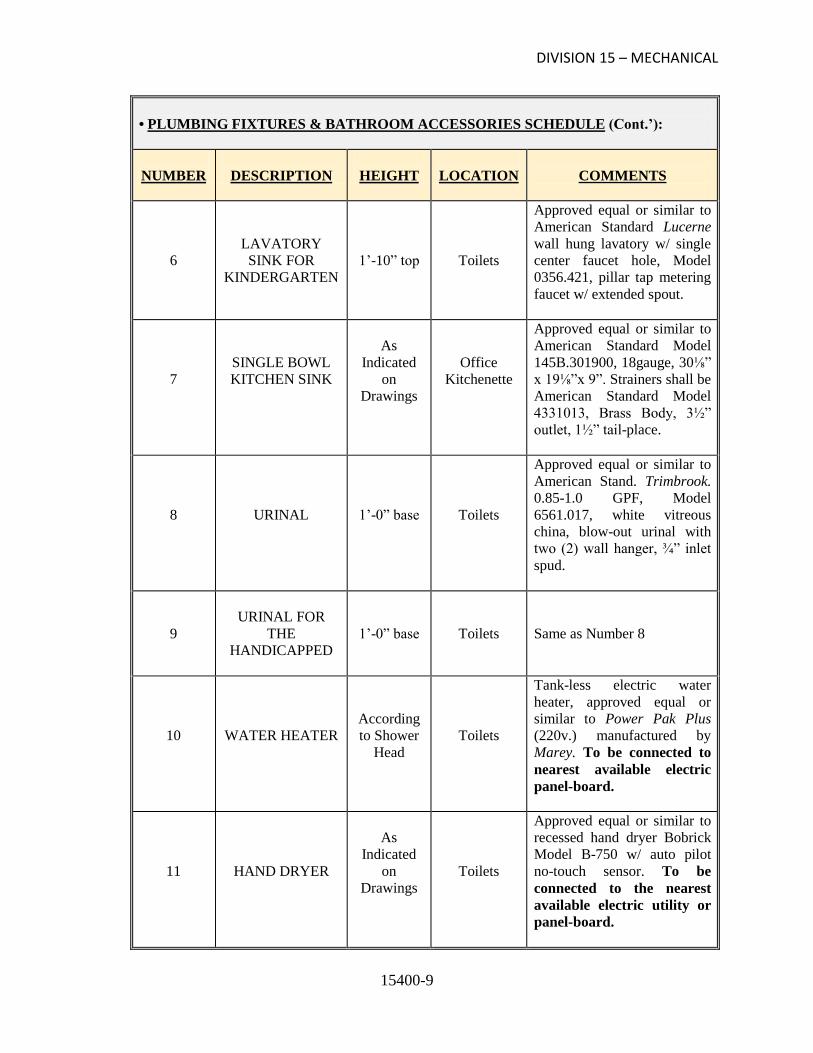
DIVISION 15 – MECHANICAL
15400-9
• PLUMBING FIXTURES & BATHROOM ACCESSORIES SCHEDULE (Cont.’):
NUMBER
DESCRIPTION
HEIGHT
LOCATION
COMMENTS
6
LAVATORY
SINK FOR
KINDERGARTEN
1’-10” top
Toilets
Approved equal or similar to
American Standard Lucerne
wall hung lavatory w/ single
center faucet hole, Model
0356.421, pillar tap metering
faucet w/ extended spout.
7
SINGLE BOWL
KITCHEN SINK
As
Indicated
on
Drawings
Office
Kitchenette
Approved equal or similar to
American Standard Model
145B.301900, 18gauge, 30⅛”
x 19⅛”x 9”. Strainers shall be
American Standard Model
4331013, Brass Body, 3½”
outlet, 1½” tail-place.
8
URINAL
1’-0” base
Toilets
Approved equal or similar to
American Stand. Trimbrook.
0.85-1.0 GPF, Model
6561.017, white vitreous
china, blow-out urinal with
two (2) wall hanger, ¾” inlet
spud.
9
URINAL FOR
THE
HANDICAPPED
1’-0” base
Toilets
Same as Number 8
10
WATER HEATER
According
to Shower
Head
Toilets
Tank-less electric water
heater, approved equal or
similar to Power Pak Plus
(220v.) manufactured by
Marey. To be connected to
nearest available electric
panel-board.
11
HAND DRYER
As
Indicated
on
Drawings
Toilets
Approved equal or similar to
recessed hand dryer Bobrick
Model B-750 w/ auto pilot
no-touch sensor. To be
connected to the nearest
available electric utility or
panel-board.

DIVISION 15 – MECHANICAL
15400-10
• PLUMBING FIXTURES & BATHROOM ACCESSORIES SCHEDULE (Cont.’):
NUMBER
DESCRIPTION
HEIGHT
LOCATION
COMMENTS
12
GRAB BAR (24”)
3’-0”
center
Toilet for
Disabled
1¼” diameter, stainless steel,
surface mounted with snap
flange. Approved equal or
similar to Bobrick Model B-
5806 series.
13
GRAB BAR (36”)
3’-0”
center
Toilet for
Disabled
1¼” diameter, stainless steel,
surface mounted with snap
flange. Approved equal or
similar to Bobrick Model B-
5806 series.
14
MIRROR
3’-4” base
Toilets
Approved equal or similar to
Bobrick Model B-165-1824,
18” x 24”.
15
TILTED MIRROR
FOR THE
HANDICAPPED
Complied
with ADA
Toilets
Approved equal or similar to
Bobrick Model B-293,
stainless steel, 18” x 30”.
16
MEDICINE
CABINET
Complied
with ADA
Toilets
Approved equal or similar to
Bobrick Model B-297,
surface-mounted, heavy-
gauge steel w/ mirror and
fixed shelves.
17
LAVATORY
WATER FAUCET
2’-5” base
Toilets
One-handle, 4” center set,
approved equal or similar to
American Standard Model
Colony-Soft No. 2275.509
(Polished Chrome).
18
KITCHEN SINK
FAUCET
As
Indicated
on Plans
Office
Kitchenette
One-metal lever handle, 8-½”
spout length, approved equal
or similar to American
Standard Model Colony-Soft
No. 417560.

DIVISION 15 – MECHANICAL
15400-11
• PLUMBING FIXTURES & BATHROOM ACCESSORIES SCHEDULE (Cont.’):
NUMBER
DESCRIPTION
HEIGHT
LOCATION
COMMENTS
19
SHOWER STALL
(Shower Head)
Complied
with ADA
Toilets
Soft hand system kit,
Approved Equal or Similar to
American Standard Model
1662.600.002, ½” pipe conn.,
30° spray adjustment, 4-arm
handle w/ vandal-proof
screws, ½” pipe size.
20
SHOWER SEAT
(Folding Corner)
Complied
with ADA
Toilets
Approved equal or similar to
Bobrick Model B-5193 w/
solidly fused plastic surface
and stainless steel frame.
Folds to vertical position
when not in use.
21
SHOWER
CURTAIN ROD
6’-0” top
Toilets
Approved equal or similar to
Bobrick Model B-6107
(heavy duty).
22
TOILET PAPER
HOLDER
As
Indicated
on Plans
Toilets
Approved equal or similar to
Bobrick Model B-288
(surface mounted).
23
PAPER TOWEL
DISPENSER &
WASTE
RECEPTACLE
Wall
Opening at
51” from
Finish
Floor
Toilets
Approved equal or similar to
Bobrick Model B-3944
(recessed mounted).
24
SOAP DISH
(For Shower)
As
Indicated
on Plans
Toilets
Approved equal or similar to
Bobrick Model B-4390,
stainless steel, heavy duty
recessed mounted with bar.
25
LIQUID SOAP
DISPENSER
As
Indicated
on Plans
Toilets
Approved equal or similar to
Bobrick Model B-2112
(surface mounted).

DIVISION 15 – MECHANICAL
15400-12
• PLUMBING FIXTURES & BATHROOM ACCESSORIES SCHEDULE (Cont.’):
NUMBER
DESCRIPTION
HEIGHT
LOCATION
COMMENTS
26
HOSE BIBB
As
Indicated
on
Drawings
Outside
Building
(On-Site)
Approved equal or similar to
Central Brass Model 576,
½”–14 PS, female, lock-
shield type with loose key
handle.
27
FLOOR DRAIN
N/A
Toilets
Approved equal or similar to
J.R. Smith 2010-A, cast iron
body with 5” Ø round grate
strainer, polished bronze with
vandal-proof screws.
28
CLEAN-OUT
(Flush with Floor)
N/A
Floor
PVC type body with bronze
countersunk plug and access
cover approved equal or
similar to J.R. Smith series
4810, round frame with
scoriated cover, nickel
bronze, furnished with
vandal-proof screws.
29
WALL TILE
As
Indicated
on Plans
Toilets
8” x 8” ceramic wall tiles
(ivory color), as specified on
Sections 09310 and 09311.
30
FLOOR TILE
As
Indicated
on Plans
Toilets
12” x 12” non-slip ceramic
floor tiles (ivory color), as
specified on Sections 09310
and 09311.

SECTION 15420
DRAINAGE AND VENT PIPING
PART 1 – GENERAL
1.1 RELATED DOCUMENTS
A. Drawings and general provisions of the Contract, including General and Supplementary
Conditions and Division 1 Specification Sections, apply to this Section.
1.2 SUMMARY
A. This Section includes sanitary drainage and vent piping, and storm drainage piping inside
building and to locations indicated.
1.3 DEFINITIONS
A. Sewerage Piping: Building sewer piping outside building that conveys sanitary sewage from
building.
B. Drainage Piping: Building sewer piping outside building that conveys storm drainage from
building.
C. Service Entrance Piping: Drainage piping at entry into building between outside building
sewer piping and inside drainage piping.
D. Drainage and Vent Piping: Piping inside building that conveys waste water and vapors from
fixtures and equipment throughout the building.
E. Force-Main Piping: Drainage piping, under pressure.
F. The following are industry abbreviations for plastic and other piping materials:
1. ABS: Acrylonitrile-butadiene-styrene.
2. EPDM: Ethylene-propylene-dyne polymer, rubber.
3. NBR: Acrylonitrile-butadiene rubber.
4. PVC: Polyvinyl chloride.
1.4 SYSTEM PERFORMANCE REQUIREMENTS
A. Provide components and installation capable of producing piping systems with the following
minimum working-pressure ratings, unless otherwise indicated:
1. Soil, Waste, and Vent Systems: 10-foot head of water.
2. Storm Drainage Systems: 10-foot head of water.

DRAINAGE AND VENT PIPING
15420-2
• SYSTEM PERFORMANCE REQUIREMENTS (Cont.’)
3. Sewage, Force-Main Piping Systems: 100 psig.
1.5 SUBMITTALS
A. Test Results and Reports: Specified in “Field Quality Control” Article.
1.6 QUALITY ASSURANCE
A. Provide listing/approval stamp, label, or other marking on piping made to specified standards.
B. Comply with ASME B31.9, “Building Service Piping”, for materials, products, and
installation.
C. Comply with NSF 14, “Plastics Piping Components and Related Materials”, for plastic piping
components. Include marking with “NSF-DWV” for plastic drain, waste, and vent piping;
“NSF-drain” for plastic drain piping; “NSF-tubular” for plastic continuous waste piping; and
“NSF-sewer” for plastic sewer piping.
PART 2 – PRODUCTS
2.1 PIPES AND TUBES
A. General: Applications of the following pipe and tube materials are indicated in Part 3 “Piping
Applications” Article.
B. Ductile-Iron Pipe: AWWA C151 with mechanical- or push-on-joint bell and plain spigot end,
unless plain, grooved, or flanged ends are indicated.
C. PVC Plastic Pipe: ASTM D 2665, Schedule 40
2.2 PIPE AND TUBE FITTINGS
A. General: Applications of the following pipe and tube fitting materials are indicated in Part 3
“Piping Applications” Article.
B. PVC Socket Fittings: ASTM D 2665, made to ASTM D 3311 drain, waste, and vent pipe
patterns.
2.3 JOINING MATERIALS
A. General: Applications of the following piping joining materials are indicated in Part 3 “Piping
Applications” Article.
B. Refer to Division 15 Section “Basic Mechanical Materials and Methods” for commonly used
joining materials.
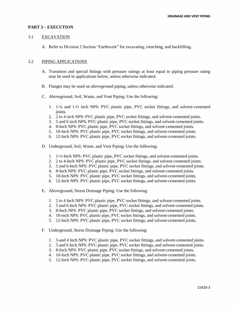
DRAINAGE AND VENT PIPING
15420-3
PART 3 – EXECUTION
3.1 EXCAVATION
A. Refer to Division 2 Section “Earthwork” for excavating, trenching, and backfilling.
3.2 PIPING APPLICATIONS
A. Transition and special fittings with pressure ratings at least equal to piping pressure rating
may be used in applications below, unless otherwise indicated.
B. Flanges may be used on aboveground piping, unless otherwise indicated.
C. Aboveground, Soil, Waste, and Vent Piping: Use the following:
1. 1-¼ and 1-½ inch NPS: PVC plastic pipe, PVC socket fittings, and solvent-cemented
joints.
2. 2 to 4 inch NPS: PVC plastic pipe, PVC socket fittings, and solvent-cemented joints.
3. 5 and 6 inch NPS: PVC plastic pipe, PVC socket fittings, and solvent-cemented joints.
4. 8-Inch NPS: PVC plastic pipe, PVC socket fittings, and solvent-cemented joints.
5. 10-Inch NPS: PVC plastic pipe, PVC socket fittings, and solvent-cemented joints.
6. 12-Inch NPS: PVC plastic pipe, PVC socket fittings, and solvent-cemented joints.
D. Underground, Soil, Waste, and Vent Piping: Use the following:
1. 1-½-Inch NPS: PVC plastic pipe, PVC socket fittings, and solvent-cemented joints.
2. 2 to 4-Inch NPS: PVC plastic pipe, PVC socket fittings, and solvent-cemented joints.
3. 5 and 6-Inch NPS: PVC plastic pipe, PVC socket fittings, and solvent-cemented joints.
4. 8-Inch NPS: PVC plastic pipe, PVC socket fittings, and solvent-cemented joints.
5. 10-Inch NPS: PVC plastic pipe, PVC socket fittings, and solvent-cemented joints.
6. 12-Inch NPS: PVC plastic pipe, PVC socket fittings, and solvent-cemented joints.
E. Aboveground, Storm Drainage Piping: Use the following:
1. 2 to 4 Inch NPS: PVC plastic pipe, PVC socket fittings, and solvent-cemented joints.
2. 5 and 6 Inch NPS: PVC plastic pipe, PVC socket fittings, and solvent-cemented joints.
3. 8-Inch NPS: PVC plastic pipe, PVC socket fittings, and solvent-cemented joints.
4. 10-inch NPS: PVC plastic pipe, PVC socket fittings, and solvent-cemented joints.
5. 12-Inch NPS: PVC plastic pipe, PVC socket fittings, and solvent-cemented joints.
F. Underground, Storm Drainage Piping: Use the following:
1. 3-and 4 Inch NPS: PVC plastic pipe, PVC socket fittings, and solvent-cemented joints.
2. 5 and 6 Inch NPS: PVC plastic pipe, PVC socket fittings, and solvent-cemented joints.
3. 8-Inch NPS: PVC plastic pipe, PVC socket fittings, and solvent-cemented joints.
4. 10-Inch NPS: PVC plastic pipe, PVC socket fittings, and solvent-cemented joints.
5. 12-Inch NPS: PVC plastic pipe, PVC socket fittings, and solvent-cemented joints.

DRAINAGE AND VENT PIPING
15420-4
• PIPING APPLICATIONS (Cont.’)
G. Aboveground, Sewage Force Mains: Use the following:
1. 2 to 4-Inch NPS: Galvanized steel pipe and cast-iron, threaded fittings.
2. 5 and 6-Inch NPS: Galvanized steel pipe and cast-iron, threaded fittings.
H. Underground, Sewage-Force-Main, Service Entrance Piping: Use the following:
1. 4 and 6-Inch NPS: Ductile-iron pipe; ductile-iron, mechanical or push-on-joint fittings;
rubber gaskets; and mechanical or push-on joints.
3.3 VALVE APPLICATIONS
A. Drawings indicate valve types to be used. Where specific valve types are not indicated, the
following requirements apply:
1. Shutoff Duty: Use gate, ball, or butterfly valves.
2. Throttling Duty: Use globe, ball, or butterfly valves.
B. Grooved-end butterfly valves may be used with grooved-end piping.
3.4 PIPING INSTALLATION, GENERAL
A. Refer to Division 15 Section “Basic Mechanical Materials and Methods” for basic piping
installation.
3.5 SERVICE ENTRANCE PIPING INSTALLATION
A. Refer to Division 2 Section “Sewerage and Drainage” for sanitary and storm sewer piping.
B. Extend building sanitary drain piping and connect to sanitary sewer piping in sizes and
locations indicated for service entrances into building. Install cleanout and extension to grade
at connections of building sanitary drains with building sanitary sewers.
C. Extend building storm drain piping and connect to storm sewer piping in sizes and locations
indicated for service entrances into building. Install cleanout and extension to grade at
connections of building storm drains and building storm sewers.
D. Extend building sanitary drain, force-main piping and connect to sanitary sewer piping in size
and location indicated for service entrance into building. Install cleanout, fitting with closure
plug or equivalent, inside building.
E. Extend building storm drain, force-main piping and connect to storm sewer piping in size and
location indicated for service entrance into building. Install cleanout, fitting with closure plug
or equivalent, inside building.

DRAINAGE AND VENT PIPING
15420-5
• SERVICE ENTRANCE PIPING INSTALLATIONS (Cont.’)
F. Ductile-Iron, Force-Main, Service Entrance Piping: Comply with AWWA C600. Install
buried piping inside building between wall and floor penetrations and connection to sewer
piping outside building with restrained joints. Anchor pipe to wall or floor. Install thrust-
block supports at vertical and horizontal offsets.
1. Encase piping with polyethylene film according to ASTM A 674 or AWWA C105.
G. Install cast-iron sleeve with water stop and mechanical sleeve seal at each service entrance
pipe penetration through foundation wall. Select number of interlocking rubber links required
to make installation watertight. Refer to Division 15 Section “Basic Mechanical Materials
and Methods” for sleeves and mechanical sleeve seals.
H. Install wall penetration system at each service entrance pipe penetration through foundation
wall. Make installation watertight. Refer to Division 15 Section “Basic Mechanical
Materials and Methods” for wall penetration systems.
3.6 DRAINAGE AND VENT PIPING INSTALLATION
A. Install cast-iron soil piping according to CISPI’s “Cast Iron Soil Pipe and Fittings
Handbook”, Chapter IV, “Installation of Cast Iron Soil Pipe and Fittings”.
B. Make changes in direction for drainage and vent piping using appropriate branches, bends,
and long-sweep bends. Sanitary tees and short-sweep ¼ bends may be used on vertical stacks
if change in direction of flow is from horizontal to vertical. Use long-tum, double Y-branch
and 1/8-bend fittings if 2 fixtures are installed back to back or side by side with common
drain pipe. Straight tees, elbows, and crosses may be used on vent lines. Do not make
change in direction of flow greater than 90 degrees. Use proper size of standard increasers
and reduces if different sizes of piping are connected. Reducing size of drainage piping in
direction of flow is prohibited.
C. Lay buried building drain piping beginning at low point of each system. Install true to grades
and alignment indicated, with unbroken continuity of invert. Place hub ends of piping
upstream. Install required gaskets according to manufacturer’s written instructions for use of
lubricants, cements, and other installation requirements. Maintain swab in piping and pull
past each joint as completed.
D. Install drainage and vent piping at the following minimum slopes, unless otherwise indicated:
1. Sanitary Building Drain: 2 percent downward in direction of flow for piping 3-inch NPS
and smaller, 1 percent downward in direction of flow for piping 4 inch NPS and larger.
2. Horizontal, Sanitary Drainage Piping: 2 percent downward in direction of flow.
3. Storm Building Drain: 1 percent downward in direction of flow.
4. Horizontal, Storm Drainage Piping: 2 percent downward in direction of flow.
5. Vent Piping: 1 percent down toward vertical fixture vent of toward vent stack.
E. Install force mains at elevations indicated.

DRAINAGE AND VENT PIPING
15420-6
• DRAINAGE AND VENT PIPING INSTALLATIONS (Cont.’)
F. Install engineered, sanitary drainage and vent systems in locations indicated and as follows:
1. Combination Waste and Vent: Comply with standards of authorities having jurisdiction.
2. Copper, Sovent, Single Stack: Comply with CDA 402/0, “Brass and Bronze Design
Handbook, Single-Stack Plumbing System.
3. Cast-Iron, Sovent, Single Stack, Comply with ASSE 1043 and sovent fitting
manufacturer’s written installation instructions.
4. Reduced-Size Venting: Comply with standards of authorities having jurisdiction.
G. Install engineered, controlled-flow, storm drainage systems in locations indicated. Comply
with standards of authorities having jurisdiction.
H. Sleeves are not required for cast-iron soil piping passing through concrete slab on grade if
slab is without membrane waterproofing.
I. Install ABS plastic drainage piping according to ASTM D 2661.
J. Install PVC plastic drainage piping according to ASTM D 2665.
K. Install underground, ABS and PVC plastic drainage piping according to ASTM D 2321.
3.7 JOINT CONSTRUCTION
A. Refer to Division 15 Section “Basic Mechanical Materials and Methods” for basic piping
joint construction.
B. Cast-Iron, Soil-Piping Joints: Make joints according to CISPI’s “Cast Iron Soil Pipe and
Fittings Handbook”, Chapter IV, “Installation of Cast Iron Soil Pipe and Fittings”.
1. Compression Joints: Make with rubber gasket matching class of pipe and fittings.
2. Hub-less Joints: Make with rubber gasket and sleeve or clamp.
C. Grooved Joints: Assemble joints with coupling, gasket, lubricant, and bolts according to
coupling and fitting manufacturer’s written instructions.
D. PVC Piping Joints: Join drainage piping according to ASTM D 2665.
E. Handling of Solvent Cements, Primers, and Cleaners: comply with procedures in ASTM F
402 for safe handling during joining of plastic pipe and fittings.
3.8 VALVE INSTALLATION
A. Shutoff Valves: Install shutoff valve on each pump discharge and where indicated. Use gate
or ball valves for piping 2-inch NPS and smaller. Use gate or butterfly valves for piping 2-½
inch NPS and larger.
B. Check Valves: Install swing check valve on each pump discharge, downstream from shutoff
valve.
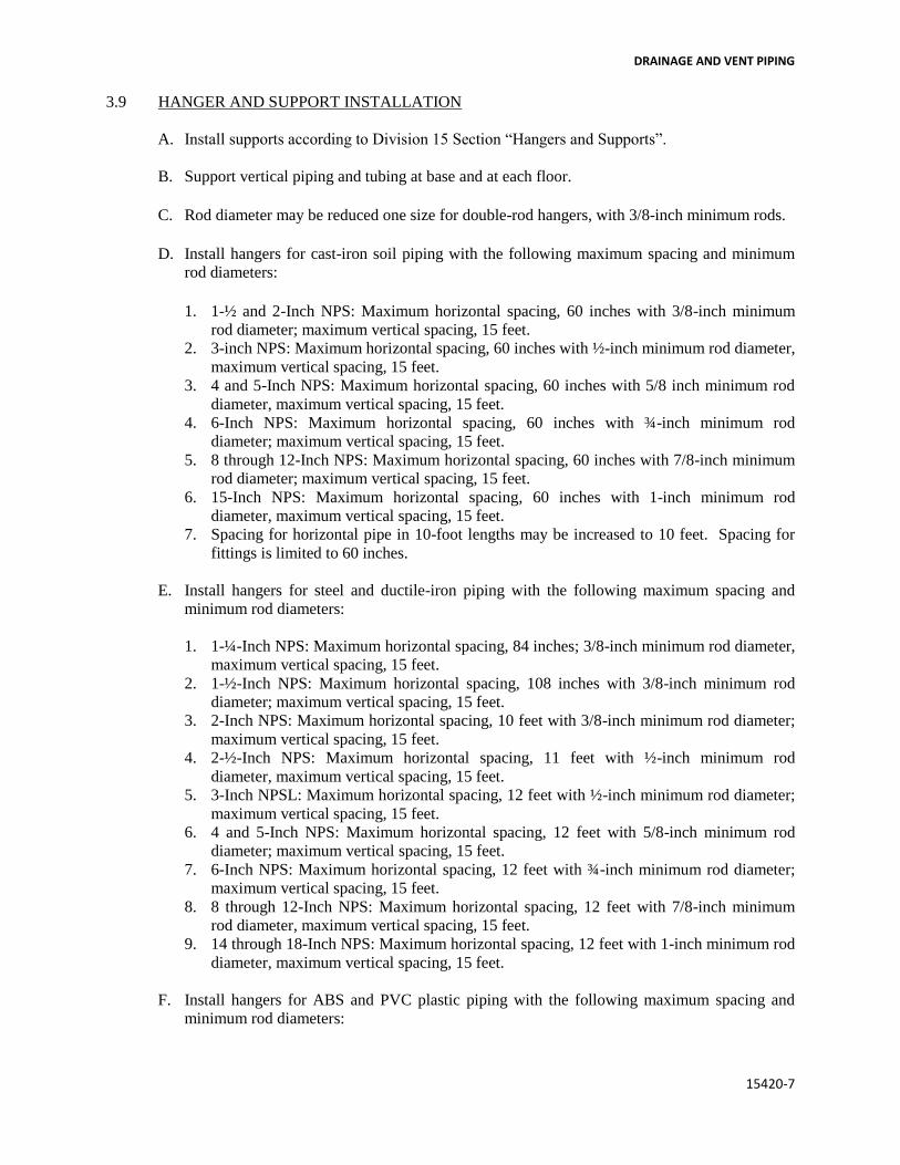
DRAINAGE AND VENT PIPING
15420-7
3.9 HANGER AND SUPPORT INSTALLATION
A. Install supports according to Division 15 Section “Hangers and Supports”.
B. Support vertical piping and tubing at base and at each floor.
C. Rod diameter may be reduced one size for double-rod hangers, with 3/8-inch minimum rods.
D. Install hangers for cast-iron soil piping with the following maximum spacing and minimum
rod diameters:
1. 1-½ and 2-Inch NPS: Maximum horizontal spacing, 60 inches with 3/8-inch minimum
rod diameter; maximum vertical spacing, 15 feet.
2. 3-inch NPS: Maximum horizontal spacing, 60 inches with ½-inch minimum rod diameter,
maximum vertical spacing, 15 feet.
3. 4 and 5-Inch NPS: Maximum horizontal spacing, 60 inches with 5/8 inch minimum rod
diameter, maximum vertical spacing, 15 feet.
4. 6-Inch NPS: Maximum horizontal spacing, 60 inches with ¾-inch minimum rod
diameter; maximum vertical spacing, 15 feet.
5. 8 through 12-Inch NPS: Maximum horizontal spacing, 60 inches with 7/8-inch minimum
rod diameter; maximum vertical spacing, 15 feet.
6. 15-Inch NPS: Maximum horizontal spacing, 60 inches with 1-inch minimum rod
diameter, maximum vertical spacing, 15 feet.
7. Spacing for horizontal pipe in 10-foot lengths may be increased to 10 feet. Spacing for
fittings is limited to 60 inches.
E. Install hangers for steel and ductile-iron piping with the following maximum spacing and
minimum rod diameters:
1. 1-¼-Inch NPS: Maximum horizontal spacing, 84 inches; 3/8-inch minimum rod diameter,
maximum vertical spacing, 15 feet.
2. 1-½-Inch NPS: Maximum horizontal spacing, 108 inches with 3/8-inch minimum rod
diameter; maximum vertical spacing, 15 feet.
3. 2-Inch NPS: Maximum horizontal spacing, 10 feet with 3/8-inch minimum rod diameter;
maximum vertical spacing, 15 feet.
4. 2-½-Inch NPS: Maximum horizontal spacing, 11 feet with ½-inch minimum rod
diameter, maximum vertical spacing, 15 feet.
5. 3-Inch NPSL: Maximum horizontal spacing, 12 feet with ½-inch minimum rod diameter;
maximum vertical spacing, 15 feet.
6. 4 and 5-Inch NPS: Maximum horizontal spacing, 12 feet with 5/8-inch minimum rod
diameter; maximum vertical spacing, 15 feet.
7. 6-Inch NPS: Maximum horizontal spacing, 12 feet with ¾-inch minimum rod diameter;
maximum vertical spacing, 15 feet.
8. 8 through 12-Inch NPS: Maximum horizontal spacing, 12 feet with 7/8-inch minimum
rod diameter, maximum vertical spacing, 15 feet.
9. 14 through 18-Inch NPS: Maximum horizontal spacing, 12 feet with 1-inch minimum rod
diameter, maximum vertical spacing, 15 feet.
F. Install hangers for ABS and PVC plastic piping with the following maximum spacing and
minimum rod diameters:

DRAINAGE AND VENT PIPING
15420-8
• HANGER AND SUPPORT INSTALLATION (Cont.’)
1. 1-½ and 2-Inch NPS: Maximum horizontal spacing, 48 inches with 3/8-inch minimum
rod diameter; maximum vertical spacing, 48 inches.
2. 4 and 5-Inch NPS: Maximum horizontal spacing, 48 inches with 5/8-inch minimum rod
diameter; maximum vertical spacing, 48 inches.
3. 6-Inch NPS: Maximum horizontal spacing, 48 inches with ¾-inch minimum rod
diameter; maximum vertical spacing, 48 inches.
4. 8 through 12-Inch NPS: Maximum horizontal spacing, 48 inches with 7/8-inch minimum
rod diameter; maximum vertical spacing, 48 inches.
G. Support piping and tubing not listed above according to MSS SP-69 and manufacturer’s
written instructions.
3.10 CONNECTIONS
A. Connect service entrance piping to exterior sewerage and drainage piping. Use transition
fitting to join dissimilar piping materials.
3.11 FIELD QUALITY CONTROL
A. Inspect drainage and vent piping as follows:
1. Do not enclose, cover, or put piping into operation until it is inspected and approved by
authorities having jurisdiction.
2. During installation, notify authorities having jurisdiction at least 24 hours before
inspection must be made. Perform tests specified below in presence of authorities having
jurisdiction.
a. Roughing-In Inspection: Arrange for inspection of piping before concealing or
closing-in after roughing-in and before setting fixtures.
b. Final Inspection: Arrange for final inspection by authorities having jurisdiction to
observe tests specified below and to ensure compliance with requirements.
3. Re-inspection: If authorities having jurisdiction find that piping will not pass test or
inspection, make required corrections and arrange for re-inspection.
4. Reports: Prepare inspection reports and have them signed by authorities having
jurisdiction.
B. Test drainage and vent piping according to procedures of authorities having jurisdiction or, in
absence of published procedure, as follows:
1. Test for leaks and defects in new piping and parts of existing piping that have been
altered, extended, or repaired. If testing is performed in segments, submit separate report
for each test, complete with diagram of portion of piping tested.
2. Leave uncovered and unconcealed new, altered, extended, or replaced drainage and vent
piping until it has been tested and approved. Expose work that has been covered or
concealed before it has been tested and approved.

DRAINAGE AND VENT PIPING
15420-9
• FIELD QUALITY CONTROL (Cont.’)
3. Roughing-In Plumbing Test Procedure: Test drainage and vent piping, except outside
leaders, on completion of roughing-in. Close openings in piping system and fill with
water to point of overflow, but not less than 10 feet of head. Water level must not drop
from 15 minutes before inspection starts through completion of inspection. Inspect joints
for leaks.
4. Finished Plumbing Test Procedure: After plumbing fixtures have been set and traps filled
with water, test connections and prove they are gastight and watertight. Plug vent-stack
openings on roof and building drains where they leave building. Introduce air into piping
system equal to pressure of 1-inch wg. Use U-tube or manometer inserted in trap of
water closet to measure this pressure. Air pressure must remain constant without
introducing additional air throughout period of inspection. Inspect plumbing fixture
connections for gas and water leaks.
5. Repair leaks and defects using new materials and retest piping or portion thereof until
satisfactory results are obtained.
6. Prepare reports for tests and required corrective action.
C. Test force-main piping according to procedures of authorities having jurisdiction or, in
absence of published procedure, as follows:
1. Leave uncovered and unconcealed new, altered, extended, or replaced force-main piping
until it has been tested and approved. Expose work that has been covered or concealed
before it has been tested and approved.
2. Cap and subject piping to static-water pressure of 50 psig above operating pressure,
without exceeding pressure rating of piping system materials. Isolate test source and
allow to stand for 4 hours. Leaks and loss in test pressure constitute defects that must be
repaired.
3. Repair leaks and defects using new materials and retest piping or portion thereof until
satisfactory results are obtained.
4. Prepare reports for test and required corrective action.
3.12 CLEANING AND PROTECTING
A. Clean interior of piping system. Remove dirt and debris as work progresses.
B. Protect drains during remainder of construction period to avoid clogging with dirt and debris
and to prevent damage from traffic and construction work.
C. Place plugs in ends of uncompleted piping at end of day and when work stops.
D. Exposed ABS and PVC Piping: Protect plumbing vents exposed to sunlight with 2 coats of
water-based latex paint.
END OF SECTION


Humacao Police Headquarters AEP-3344
15781 - 1 Packaged Rooftop Cooling Units
SECTION 15781
PACKAGED ROOFTOP COOLING UNITS
PART 1. GENERAL:
SUMMARY:
A. This section provides the general requirements for top roof package units and
related equipment and materials to be installed at Humacao Police
Headquarters.
SCOPE OF WORKS:
A. Furnish and install seven (7) roof top package units, conforming in all aspects to the specifications, schedules and plans or drawings.
B. Furnish and install any accessories required by roof top package units operation as recommended by manufacturer or distributors and is not specific in drawings. Check with Engineer for approval.
1. additional accessories include:
i. Roof curb adapter (if necessary)
ii. Duct works for proper connection between new supply and return and existing duct (transition).
C. Furnish and install thermostat controller in accordance with roof top package units.
D. Removing the existing top roof package units as indicated by Engineer or PBA representative.
E. Local balancing of air conditioning units to assure ventilation and static pressure. For reference used most remote air supply diffuser for measurements.
F. Final disposition of removing equipment and material conforming any law of local and federal agencies (OSHA, EPA, PREQB, other).
RELATED WORK:
A. Not Used
RELATED STANDARDS:
A. ARI- Air Conditioning and Refrigeration Institute
B. ASHRAE- American Society of Heating, Refrigeration and Air conditioning Engineers
C. ASTM- American society for Testing Materials
D. NEC- National Electrical Code

Humacao Police Headquarters AEP-3344
15781 - 2 Packaged Rooftop Cooling Units
E. NFPA- National Fire Protection Association
F. NEMA- National Electric Manufacturers Association
G. UL- United Laboratories
H. OSHA- Office of Safety and Health Act
I. EPA- Environmental Protection Agency
SUBMITTALS:
A. Submit three (3) copies of data for Roof Top packaged units.
B. Submittal shall include manufacturer data:
1. Package units capacities, weight, accessories, electrical requirements and wiring diagrams.
2. Drawing showing component layout, piping configuration, connection size, overall dimension and field clearances.
3. Psychometric chart and performance data at design temperatures and thermal loads.
4. Fan performance curves.
5. Data of filter media, filter performance, filter assembly and frames.
6. Installation recommendations.
7. Complete description of controls with sequencing data and wiring diagrams.
C. After roof top package units submittal approval send four (4) copies of:
1. Operation manuals.
2. Maintenance manuals, including troubleshooting.
3. Parts manual with exploded part list for each top roof package units.
4. Recommended list of spare parts.
QUALITY ASSURANCE:
A. Inspect roof top package units delivered to site for damages
B. Store with minimum handling and comply with manufacturer’s instruction for rigging, loading-unloading and transportation.
C. Store and protect as indicated by manufacturer against weather or vandalism.
D. Do not store top roof package units directly on ground.
E. Keep materials and equipment free of debris and dirt.
WARRANTY
A. Provide 1 year unconditional labor and parts warranty on any component of the units.
B. Provide 5 years unconditional parts warranty on compressor units.

Humacao Police Headquarters AEP-3344
15781 - 3 Packaged Rooftop Cooling Units
C. Submit warranty documentation and certification after start-up.
PART 2. PRODUCTS:
ROOF TOP PACKAGE UNITS-GENERAL
A. RTU shall be drawn thru type.
B. RTU shall be single-zone purpose.
C. RTU shall to complaint with ARI- 340/360 or latest edition.
D. Vibration isolation shall be supply at each fan-motor supports. Spring kind is recommended.
E. Components:
1. Casing
2. Fans
3. Compressor
4. Cooling coils
5. Condenser coils
6. Condenser fan and motors
7. Dampers
8. Fresh air intake
9. Bearing and Drives
10. Filters
11. Electric motors
12. Others
F. Capacities:
1. Supply CFM, Cooling coil capacity, External static pressure and Fresh air quantity shall be as indicated in drawings schedules.
2. Roof top package units shall be capable to supply air equal or below to 57 oF db at rated conditions.
3. Roof top package units shall be rated to 95 oF condenser ambient
temperature (No exception).
4. Roof top package units shall have an 11.5 EER (energy efficiency ratio) or better.
G. Acceptable manufacturers are (in alphabetic order):
1. Carrier
2. McQuay
3. Trane

Humacao Police Headquarters AEP-3344
15781 - 4 Packaged Rooftop Cooling Units
4. York
5. Other as Engineer approval.
COMPONENTS:
A. Casing:
1. External casing shall be fabricated of galvanized steel. Gauge 18 or better.
2. External casing shall be with removable panels and mechanical fastened.
3. Sections shall be assembled with compression gaskets between each frame member.
4. Casing leaks shall be no more than 0.5 CFM / ft2 of exposed cabinet area.
5. Casing panels shall withstand a positive or negative 4 in wg of static pressure without visible deflection.
6. Casing shall be double wall type.
7. Provide 1.5” insulation material between panel. Insulation shall meet NFPA-90A.
8. Pitch roof top for drain.
9. Provide access door of galvanized steel and flush mounted. Access door shall be gasketed and easy to remove.
10. Provide drain pan under cooling coil section and internally sloped. Drain pan
shall be of 304 stainless steel. Condensate connection shall be 1” minimum.
B. Fans:
1. Fans shall be forward / curved inclined.
2. Fan shall be double inlet and double width.
3. Manufacturer shall dynamically balance fan assembly.
4. Fan and motor shall be internally mounted in a steel base with mechanism for vibration absorption.
5. Manufacturer shall to certificate that fan rpm area under critical speed.
6. Fan speed shall not be more than 1,800 RPM, consult Engineer to other speeds.
7. Face velocity shall be less than 400 ft/min.
8. Provide neoprene connection to eliminate vibration transmission.
C. Compressors:
1. Compressor shall be hermetic type, direct drive, internally protected with internal high pressure relief.
2. The hermetic motor shall be suction gas cooled and have a voltage range of +/- 10% of unit name plate voltage.

Humacao Police Headquarters AEP-3344
15781 - 5 Packaged Rooftop Cooling Units
3. Compressor shall have vibration isolation spring or mounts.
D. Cooling coils:
1. Provide access (DOORS) to cooling coil at both sides of top roof package units.
2. Cooling coil fins shall have a minimum thickness of 0.0075 inches.
3. Cooling coils, tubes shall be seamless copper with nominal wall thickness of 0.025 inches.
4. Cooling coil assemblies shall be removable through access panels.
5. Cooling coil shall be direct expansion design.
E. Condenser coil:
1. Cooling coil fins shall have a minimum thickness of 0.0075 inches.
2. Cooling coils, tubes shall be seamless copper with nominal wall thickness of 0.025 inches.
3. Cooling coils shall have corrosion protective coating. Red Oxide treatment is not acceptable. Corrosion protective coating shall be for mild marine environment purpose.
4. Cooling coil shall be direct expansion design.
F. Condenser fan and motors:
1. Condenser fans shall be direct drive motors.
2. Condenser fans shall be propeller type.
3. Condenser fans shall include a heavy duty safety guard.
4. Condenser fans motors shall be totally enclosed (TEFC).
G. Dampers:
1. Dampers blades shall be of galvanized steel.
2. Damper blades shall rotate 90o and required one actuator.
H. Fresh air intake:
1. provide fresh air intake, manually operate to supply the required CFM as indicated in drawings and schedules.
I. Bearings and Drives:
1. Bearings to be used in fans shall be pillow block type, self-alignment and grease lubricated. Provide external connection for maintenance grease activities.
2. Bearings shall be 200,000 hours life at maximum operating conditions.
3. Shafts used in fans shall be hot rolled steel, solid type, ground and polish.
4. Fan assembly shall be V-belt drive type.

Humacao Police Headquarters AEP-3344
15781 - 6 Packaged Rooftop Cooling Units
5. V-belts drive shall be of cast iron or steel sheaves.
6. Sheaves shall be dynamically balanced.
7. Power band belts or matching set belts are not recommended.
8. If variable pitch sheaves are used, set belts at mid-position to get the required performance.
9. The minimum belts for drive system shall be two (2).
J. Filter section:
1. Filter section with side loading frames and clips.
2. Filters shall be UL 900 listed
3. Filters shall be 30 % efficiency.
4. Use angle filter arrangement with 2 inches disposable cartridges.
5. Manufacturer shall install differential pressure meter to read pressure drop across filter banks.
K. Electric motors:
1. Electric motor shall be 460 V, 3 Ø, 60 Hz (contractor have to make a field
voltage check before ordering, MEANS DOUBLE CHECK).
2. Electric motor shall be total enclosed fan cooled (TEFC) type.
3. Service factor for electric motor shall be 1.2.
4. Provide factory mounted disconnected switch.
L. Operating controls:
1. Provide low-voltage, adjustable thermostat to control compressor and condenser fan, and supply fan to maintain temperature setting.
i. Include system selector switch ON-COOL-OFF and fan control switch (ON-AUTO).
ii. Provide thermostat controller for the stages required to proper control of roof top unit.
iii. Locate thermostat in room as actual controls. Locate temperature sensing element (if required) on air return duct, next of exit of room routing thru top roof package unit.
2. 7 days, 24 hours programming capacity.
3. Touch screen configuration capability. Large display with backlight.
4. Temperature control of +/- 1oF of cooling range.
5. Provide 5 years warranty.
M. Others:
1. Equipment or materials included in this section are:

Humacao Police Headquarters AEP-3344
15781 - 7 Packaged Rooftop Cooling Units
i. Use PVC for drain and discharge to nearest roof drain.
ii. Roof Curb. Not Used – Roof Top Unit shall be with similar foot-print as existing unit. In case of different Roof Top Unit, Roof curb shall be 14” high, full perimeter curb with wood nailer.
PART 3. EXECUTION
WORK PREPARATION:
A. Contractor shall remove the existing roof top units.
1. Removing include electrical connection and plumbing connections not necessary for futures works or new equipment. Consult Engineer or PBA representative for complete scope of removing scope.
2. Final disposition of removed equipment and material shall in accordance with Puerto Rico environmental standards and regulations, and EPA.
B. Contractor shall to coordinate any work with PBA representative or Engineer.
C. Contractor shall coordinate any work to be executing out of regular offices hours as required by Engineer or PBA representative.
D. Contractor shall be responsible by all necessary permissions and taxes in the transportation from distributor or fabrication facilities to installation site.
E. Contractor shall be responsible for handling and disposal of any kind of hazardous material find it in the pre-bid visit or in the installation process.
INSTALLATION:
A. Install Roof Top Package Units according the manufacturer instructions and recommendations.
B. Roof Top Package units shall be located as indicated in drawings or existing site.
C. Roof Top package units shall be supported according with manufacturer instruction.
D. Contractor shall paint pipes and equipment as indicated by Engineer.
1. Air duct shall be insulated with white top termination.
2. Any water line for fire fighting purpose shall be safety red (if used).
E. Rigging of top roof package units shall be according manufacturer’s instruction and recommendation.
F. Rigging and lifting of any equipment of material shall be according OSHA standards and regulations.
START-UP:
A. Service factory trained representative (engineer or technician) shall be available on site for start-up of top roof package units.

Humacao Police Headquarters AEP-3344
15781 - 8 Packaged Rooftop Cooling Units
B. Factory start-up services shall be provide for as long a time as is necessary to provide proper operation of units.
C. Top roof package units shall be factory charged with the specified refrigerant and oil.
D. Contractor’s personnel and factory representative shall adjust and balance air flow to design conditions indicated in this specifications and/or drawings.
E. The factory representative shall train at least four (4) employees of PBA in the operation, maintenance and troubleshooting of top roof package units.
F. Contractor shall submit four (4) maintenance and operation manual to PBA representative or Engineer.
PERFORMANCE:
A. Use the Associated Air Balance Council (AABC) standards (last edition) for balancing works.
B. Manufacturer shall perform the standard run test under the supervision of Engineer or PBA representative. Data of test shall be certified and submitted to Engineer.
C. Balancing and adjustment shall be within 5% of design parameters.
D. Balancing works are limited to air side and readings shall be taken next of transitions of new duct and existing ones.
E. Contractor shall submit four (4) copies of certificate results of balancing test and adjustment by third party contractor.
END OF SECTION
15781
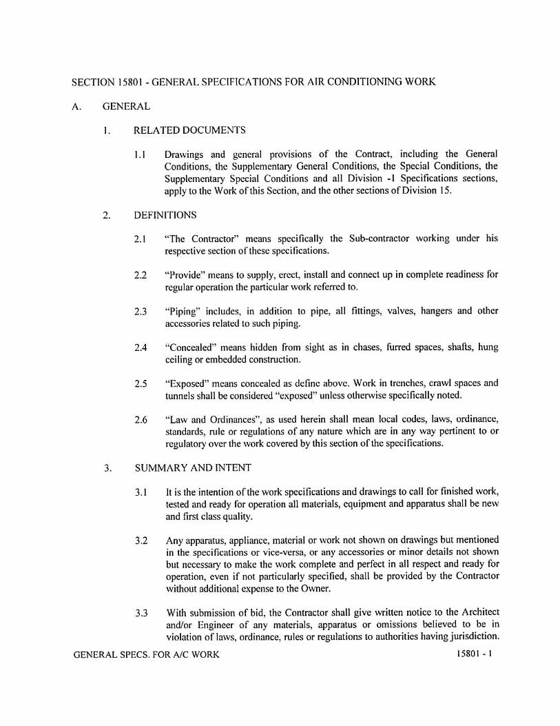


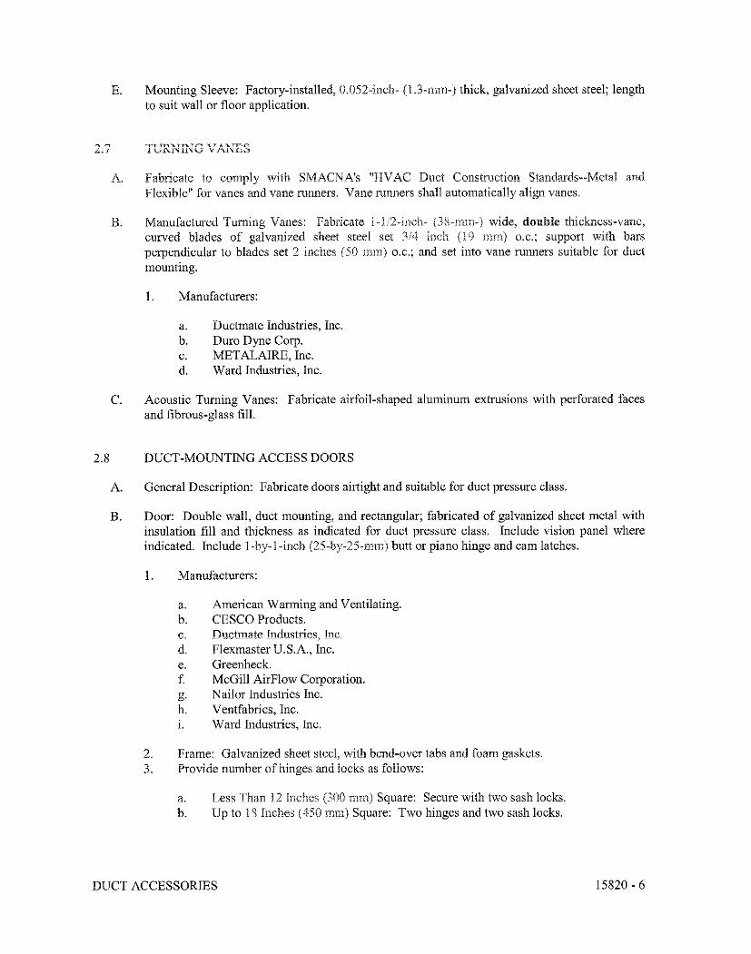
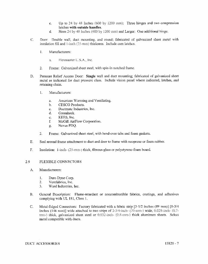


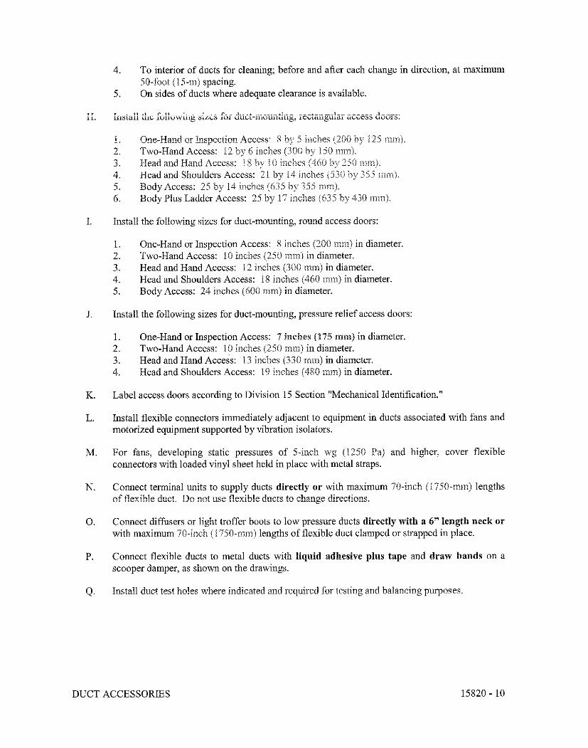


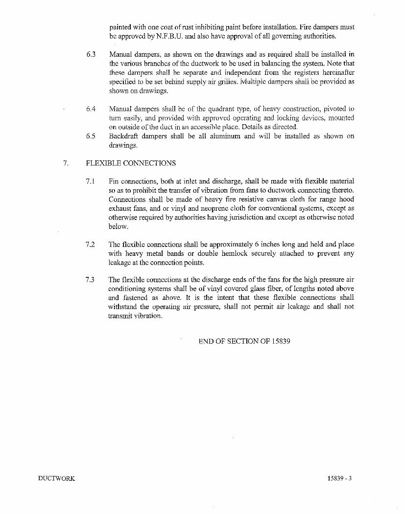


SECTION 16000
ELECTRICAL WORK – GENERAL
1. SCOPE
The work described in this section shall include the furnishing all labor, materials, equipment and
services to be rendered, and the installation of the complete electrical distribution system as shown in
the accompanying drawings and specified herein. Although the work might not be restricted to these,
it shall include the following:
a. High and low-voltage feeders, distribution system for power and lighting, panel-boards,
branch circuits, control switches, receptacles outlets, lighting fixtures, and any other system
or equipment shown in the drawings necessary for a complete and ready-to-use installation.
b. Grounding system.
c. Exterior underground conduits for power and telephone/CATV systems.
d. All concrete work for the protection of underground conduits.
e. Any other system or part of a system shown in the drawings.
2. GENERAL REQUIREMENTS
a. It shall be the direct responsibility of the Contractor to orient himself and become acquainted
with all the requirements of the Puerto Rico Electric Power Authority (PREPA) and the
Puerto Rico Telecommunication Regulations Board (JRT-PR) as they may pertain to this
project. Such requirements will be as much as part of this contracting as so stated herein.
b. The Contractor shall maintain a complete and accurate record of any variations or changes to
the contract drawings that may be necessary during the installation due to field or structural
conditions. At termination of the work, and prior to the final payment, the contractor shall
deliver these drawings for the architect's approval before liquidation of the contract. The
architect shall then incorporate the variations or changes into a set of sepia prints, as
originally issued, in such a manner that they will reproduce legibly, and any competent
person may readily comprehend them, as well as all the changes and revisions made during
the installation of the work. The work to be done in the sepia prints shall be performed by an
experienced draftsman. This revised set of sepia prints must be delivered to the owner prior
to the receipt of the final payment.
3. DRAWINGS
a. The drawings, which constitute an integral part of this contract, shall serve as the working
drawings. They will indicate the general layout of the complete electrical system, i.e. the
arrangements of the feeders, circuits, outlets, switches, controls, panel-boards, lighting
fixtures and any other work.

ELECTRICAL WORK – GENERAL
16000-2
b. A field verification of the scale dimensions in the plans will be carried out in the actual
locations, and all distances and levels will be governed by the actual field conditions.
c. The Contractor shall review the architectural, structural, and plumbing plans, etc., and shall
adjust the electrical work to conform to all conditions indicated thereon.
d. The discrepancies shown between different plans, between plans and actual field conditions
or between plans and specifications shall be promptly brought to the attention of the architect
or engineer for a decision.
e. All items not specifically mentioned in the specifications or noted in the drawings but that are
obviously necessary to make a complete working installation shall be included with no
additional cost to the Owner.
f. The Contractor shall submit to the architect or engineer detailed, dimensioned shop drawings
covering all items or equipment and brochures of the lighting fixtures. No equipment should
be put into manufacture (or ordered) until these shop drawings or brochures have been
approved by the architect or engineer.
4. MATERIALS
a. If the materials, equipment, apparatus or other products are specified by manufacturer, brand
name, type or catalog numbers, such designation will establish the standards of desired
quality and style, and shall be the basis for the bid.
b. If the Contractor desires, he (she) may submit a request to use any materials or products other
than those specified. The contractor shall provide a list of the proposed substitutions to the
owner’s representative to determine if such substitutions are equivalent in quality and style to
the ones initially specified.
c. The acceptance or rejection of the proposed substitutions shall be subject to the approval by
the architect or engineer.
d. The approvals of any submittal shall not relieve the Contractor from the responsibility of
furnishing materials and systems of the proper dimensions, capacities, sizes, quantities,
quality, and installation details to effectively comply with the requirements and intent of the
Contract Documents. Such approval shall not relieve this trade from the responsibility of
errors in submittals.
e. All submittals shall be presented sufficiently in advance to the field requirements to allow
ample time for checking. No claim for extension of time will be granted by reason of failure
in this respect.
5. SAMPLES
a. The Contractor shall submit samples of the following items to the architect or engineer for
their approval:

ELECTRICAL WORK – GENERAL
16000-3
1. Light switches: one of each type.
2. Receptacles and plugs: one of each type.
3. Wire and cable: `1-foot length of each type.
4. Conduit and conduit fittings: one of each type.
5. Switch plates or covers: one of each type.
6. Outlet boxes: one of each type.
7. Cable connectors and bushings: one of each type.
8. Plates: one of each type.
9. Lighting fixtures: one of each type.
b. All materials installed or work performed without the approval of materials will be done at
the risk of the contractor, and the cost of removal of such materials of work (if it is judged
unsatisfactory for any reason by the owner’s representative) shall be done at the expense of
the Contractor.
6. CODES, PERMITS AND INSPECTION
a. The Contractor shall contact and coordinate with the nearest PREPA and JRT-PR local
offices and the corresponding telecommunications services provider, all the details of the
related electrical and telephone/CATV installations for this project before the beginning of
such installations.
b. The installation work shall comply with all the laws applying to electrical installation in
effect in Puerto Rico, and the latest rules and regulations of the National Electrical Code, the
PREPA and the JRT-PR. The Contractor shall obtain all permits and certificates of inspection
and pay all the fees necessary for the execution of the work. After completion of the work,
the Contractor shall provide to the architect or engineer a certificate of final inspection and
approval from the PREPA and the JRT-PR local offices.
7. STANDARDS OF MATERIALS AND WORKMANSHIP
a. All materials and/or equipment described or found necessary for the electrical installation
shall be new and free from defects. They shall also be listed by the Underwriters
Laboratories (UL), Inc. and the National Electrical manufacturer’s Association (NEMA) as
conforming to their standards in every case where such standards have been established for
the particular type of material in question. The materials shall be in accordance with the
PREPA and JRT-PR standards. All materials and/or equipment shall be approved by the
architect or engineer.
b. The Contractor shall provide the services of an experienced licensed electrician, who shall
constantly be in charge of the work together with skilled workmen, fitters, helpers, and the
labor force required to properly unload, transfer, erect, connect, adjust, start, operate, and test
the system. The work shall be performed in a workman-like manner and shall be subject to
the approval of the architect or engineer.
ELECTRICAL WORK – GENERAL
16000-4
8. PROGRESS OF THE WORK
The electrical work shall progress in coordination with the progress of the construction work and shall
be completed as soon as the conditions of the building will permit.
9. SLEEVES, INSERTS AND OPENING
a. The Contractor shall layout and installs all required materials and/or equipment in advance to
the pouring of concrete floors, walls, and roofs. He (she) shall furnish and install all the
necessary sleeves or openings through floors or walls required for the passage of all conduits,
pipes or ducts to be installed by him (her).
b. The Contractor shall furnish and install the inserts and hangers required to support conduits,
pull boxes, etc.
c. If any material and/or equipment is not properly installed, the contractor shall do all the
necessary cutting and patching at his (her) own expense to rectify the errors, subject to the
approval of the architect or engineer.
10. TESTS
The tests listed below shall be made in the presence of the architect, engineer or owner’s
representative. All testing instruments and methods shall be subject to the approval of the architect,
engineer or owner’s representative. All necessary arrangements to obtain all instruments, assistance
personnel and materials necessary for the performance of the tests shall be made by the contractor.
a. The Contractor shall test all the wiring and shall leave the electrical installation free of
grounds, shorts, etc.
b. The Contractor shall also test all lighting fixtures and electrical apparatus or equipment to be
furnished under this section of the specifications.
c. Before and application for final acceptance of the work could be considered, all tests deemed
necessary to show proper execution of the work must have been performed and completed in
the presence of the architect, engineer or owner’s representative. The scheduling for all
testing procedures shall be arranged to suit the convenience of the architect, engineer or
owner’s representative. The scheduling for all testing procedures shall be arranged to suit the
convenience of the architect, engineer or owner’s representative.
d. The electrical work shall include the provision of any assistance (such as the removal of
panel-board trims and junction, and pull boxes covers) deemed necessary for the architect,
engineer or owner’s representative to demonstrate compliance with the requirements of the
drawings and specifications.
e. If the electricity-utilizing equipment supplied by other trades is energized, controlled or
otherwise made operative by the electric work wiring systems, the testing to demonstrate the
proper functional performance of such wiring systems shall be conducted by the trade
responsible for the equipment.

ELECTRICAL WORK – GENERAL
16000-5
f. Any test required in any section of the electrical specifications that is not listed here shall also
be the responsibility of the electrical contractor.
g. Any defects or deficiencies discovered in any of the electrical works shall be corrected by the
contractor.
11. TEMPORARY SERVICE
a. The Contractor shall provide and maintain a temporary electric service to be used during the
construction period. This service shall comprise with the required number of outlets and
extension cords with lamps and guards located as required, together with a supply of wiring-
run conveniently located and a temporary main switch with required fuses or breaker. The
arrangements for this supply shall be made with PREPA.
b. A temporary service of similar characteristics as the final service shall be provided by the
Contractor at his (her) own expense to perform all the tests required by the owner and/or the
different trades.
12. GUARANTEE
a. The Contractor shall leave the entire electrical installation included under this contract in
proper working conditions. He (She) shall also replace, without additional charge, any work,
materials and/or equipment or any of its component parts that develop defects different from
ordinary use, within one (1) year from the date of substantial acceptance of the project by the
Owner’s representative.
b. The Contractor shall also be responsible for any or all damages resulting from defective
materials and/or equipment, and shall repair or replace, without additional charge, all
damages to the existing work caused by such defects or replacement to the satisfaction of the
architect or engineer.
c. The Contractor shall provide a certificate of guarantee from the manufacturers of specialties
to the effect that they will furnish new parts or equipment in which defects occur due to faulty
manufacture, for a period of one (1) year from the date of substantial acceptance of the
project by the Owner’s representative.
d. If, at request of the architect or engineer, a part of electrical system is placed in service prior
to the date of substantial acceptance, that particular part of the system will then commence its
one-year period of guarantee. This guarantee will expire one year after such part of the
system was placed in service regardless to the date when the final acceptance or approval
(covering the entire system) is granted.
13. RECORD DRAWINGS AND INSTRUCTIONS BOOKLETS
a. The Contractor shall complete an exact detailed record of all changes or variations in the
electrical installation that take place during the progress of the work. The records shall

ELECTRICAL WORK – GENERAL
16000-6
include detailed plans or diagrams of the changes showing the method of connection, wiring
diagrams, etc.
b. The architect shall then incorporate into a set of sepia prints supplied by the owner all
changes and revisions made during the installation of the work. This set of sepia prints with
all changes, additions, and omissions listed thereon shall be returned to the owner upon
completion of the contract.
c. The Contractor shall also provide the architect or engineer with three copies of each
instruction booklet supplied by the manufacturer with their respective equipment upon the
completion of the work.
END OF SECTION 16000
SECTION 16011
PANELBOARDS
1. The Contractor shall supply and install the lighting and power panel-boards as indicated in the
drawings.
2. The panel-boards shall be of the dead-front type and shall be equipped with automatic circuit breakers
for each branch circuit as shown in the plans. The circuit breakers shall be of the thermal-magnetic
type, employing quick-make and quick-break toggle mechanism for manual operation as well as
automatic operation. The breaker-operating mechanism and handle shall be trip-free, thus, preventing
contacts from being held in a closed position against abnormal overloads or short circuits. The
automatic operation shall be indicated by the breaker handle assuming a clearly distinct position form
the manual “ON” and “OFF”. All circuit breakers shall be of the bolt-on type. Some breakers shall
be installed for ground-fault protection where so indicated.
3. The panels shall be provided with copper bus bars, rated at 1000A per square inch, maximum.
4. The panels shall be provided with a ground bus for connecting all ground wires or cables entering or
leaving the panel-board. The ground bus shall be similar to the bus used to connect the neutral
conductors. Single connectors shall not be used. It shall be a copper bus.
5. The panels shall have main protection when so listed. If not listed, only main lugs of the required
capacity shall be supplied.
6. The panels shall be mounted as indicated in the plans in an enclosing cabinet consisting of a code
gauge, steel-sheet box with trim and door. The door shall be manufactured from a commercial
galvanized steel sheet. The trim shall be manufactured from a one-piece, full-finished sheet (not
galvanized) and finished with two coats of paint, the first being a prime coat and the second, a finish
coat of neutral gray lacquer. The door shall be equipped with a flush-type4 combination lock and
catch, all locks keyed alike. Two keys shall be provided with each lock.
7. The doors shall be supplied with a full-length piano hinge in order to increase the rigidity, strength
and attractive appearance of the door.
8. All doors of forty-eight inches (48”) or more in height shall be supplied with two (2) flush-type locks.
9. The cabinets shall be of sufficient size to allow a gutter space of, at least, four inches (4”) on all sides.
10. The trim shall be fastenee3d to the cabinet by approved adjustable clamps and shall have a door
equipped with a chrome-plated latch.
11. The cabinets shall be provided with a suitable schedule form secured in an approved metal frame
pocket, with spaces for the names and numbers of the feeders that supply the panel and of every
branch circuit originating from the panel. The schedule form shall be protected by a piece of
transparent plastic material secured to the metal frame. The contractor shall be responsible for typing
out and inserting the schedule form in the metal pocket, and shall indicate the voltage (Example
120/208V).

PANELBOARDS
16011-2
12. All panel-boards shall have and identifying nameplate mounted on the outside of the trim.
Nameplate, including designation and voltage characteristics, shall be laminated phenolic with two
inches (2”) white letters on black background.
13. When two (2) or more panel-boards or cabinets are shown together in adjacent location, the top of all
the panel-boards or cabinets shall be aligned with the top of the biggest one, so that all the tops are
exactly at the same height from the finished floor.
14. The circuit breakers, the interior cover and the hot wires shall be identified with the corresponding
circuit number.
END OF SECTION 16011

SECTION 16020
CONDUIT WORK
1. All the wiring proposed for installation within the building or structures shall be installed in PVC
schedule 40 plastic conduit, except where otherwise EMT conduit, rigid galvanized steel conduit, or
metal raceway are deemed required as shown in the drawings. All exposed conduits shall consist of
heavy-walled rigid galvanized steel of the size indicated in the drawings. The use of flexible non-
metallic conduit (ENT) is not allowed. Exposed conduits above roof shall consist of PVC schedule
80.
2. Where noted in the drawings, all the underground wiring shall be installed in PVC schedule 40 plastic
conduit and encased in concrete as noted. Wherever plastic conduit is installed, the contractor will be
required to provide and additional wire of green insulation in every section of conduit for grounding
purposes only. This wire, as well as the proposed live and neutral wires, and wires for other purposes
shall be as described in the CONDUCTORS section of these specifications. The size and general
procedures for the installation of these conductors shall follow the descriptions in the Article 250 of
the NEC latest edition.
3. The route of the conduits shown in the layouts will be schematic and intended to indicate
interconnections between outlets. The exact routing shall be determined at the work site to conform
to its structural conditions.
4. The sizes of the conduits or tubing shall be as noted in the drawings and in accordance with the NEC
latest edition. Except where otherwise indicated, the minimum size of the conduits shall be three-
quarters of an inch (¾”).
5. All conduits, outlets, etc., shall be run in a concealed manner, except where otherwise noted in the
drawings.
6. In those cases where the conduits are run exposed, they shall be installed in a neat and workman-like
manner at right angles and parallel to the walls and partitions. Threaded conduit fittings shall be used
with the outlet boxes in all such cases.
7. If the conduits cannot be run in furred ceilings or floor fill, they shall be installed in the neutral axis of
the concrete beams or concrete floor construction.
8. All conduits shall be securely fastened to the outlet boxes and panels with approved locknuts and
bushings. Special attention shall be given to the full number of threads projecting through the conduit
to allow the bushing to butt up tight against the end of the threads. After that, the locknut shall be
screwed up to bring the bushing into a firm contact with the box. All joints shall be made with an
approved conduit coupling in such a manner that the ends of the conduit shall butt together to make
all the joints watertight throughout the system.
9. The conduit run to all panels shall be installed with the fewest possible number of crossings in a
straight line between the outlets; bends shall be avoided whenever possible.
10. All bends and offsets in conduits measuring up to ¾” can be performed at the work site if they are
made with an approved hickey or conduit-bending machine. In the case of conduits measuring 1” or

CONDUIT WORK
16020 - 2
more, the elbows or offsets made by the manufacturer shall be used unless the contractor in
authorized by the architect or engineer to make them at the work site using a conduit-bending
machine that will not deform, crush or damage the conduits. The inside and outside parts of all bends
and offsets shall be smooth and free from irregularities. The minimum radius of the bends shall be
six times the radius of the conduits.
11. All conduits shall be cut with a hacksaw, and the ends shall be reamed and squared. All threads shall
be cut and cleaned before reaming.
12. The maximum length of any conduit run between two outlets, boxes or cabinets shall not exceed 150
ft., including two (2) 90º bends.
13. All conduits shall be provided with metallic bushings in the panel boards, junction boxes, outlet
boxes, etc.
14. The bushings for conduits larger than 1” shall be of the metallic and plastic type, with an insulating
ring where the conductors touch the bushing. These bushings shall be of the grounded type and shall
be grounded.
15. The contractor shall take all possible precautions to prevent the accumulation of dirt, mortar, concrete
or any foreign matter within the conduits. Any accumulation of matter shall be properly cleaned
before the wiring work is done. If it cannot be cleaned, the conduit shall be replaced at the
contractor’s expense.
16. To prevent the accumulation of debris, water, and foreign particles, all installed conduits shall be
suitably plugged with bushings capped with a metal disk, a plastic cap or any other device approved
by the architect or engineer. Paper, tape, wood or concrete plugs will not be permitted. All conduits
shall be free of water after the wiring.
17. At the motor terminals and other electrical devices where so required, the contractor shall furnish and
install a piece of flexible seal-tight conduit of not less than 24” in length to be connected between the
conduit and the motor or device terminals.
18. All exposed conduits shall be properly secured at not more than 5’- 0” centers.
19. The expansion fittings shall be provided in the conduits system where required by the structural
conditions.
20. Concrete and watertight conduit fittings shall be used for all EMT conduits.
21. Unless otherwise indicated in the drawings, all exposed conduits below the hung-ceiling level shall
consist of heavy-walled, rigid, galvanized steel of the size indicated in the drawings.
22. Unless otherwise indicated in the drawings, all exposed conduits above hung ceiling level shall be
EMT type. The use of plastic conduits is not allowed in this area.
23. The openings for conduits and cables crossing through fire-rated wall must be fire-sealed to avoid any
possible spread of fire.
END OF SECTION
SECTION 16030
BOXES
1. All outlets, junctions, pull boxes, and fittings shall be galvanized or plated, and shall be
installed in a plumb, rigid and satisfactory manner with an alignment tolerance of 1/16”.
2. The ceiling outlets in slabs and metal-pan constructions shall consist of 4” octagonal concrete
ring with 2½” minimum depth and ¾” K.O. to fit the conduit; include cover with knock-outs.
When so advisable, 4” x 4” or larger outlet boxes equipped with a canopy cover may be used
instead of the octagonal boxes. The ceiling outlets shall be provide3d with a ⅜” fixture stud
when necessary to support the fixtures. The outlet boxes shall be flush with the ceiling
surface. A 4” x 4” x 2⅛” box with a cover shall be used in hung ceilings.
3. The wall outlets for lighting fixtures shall consist of 4” octagonal boxes, 2½” in depth (or
4”x4”x 2⅛” boxes) with canopy covers with ⅜” fixture studs and K.O. to fit the conduits.
4. The wall outlet boxes for convenience outlets, switches, and other devices shall measure
4”x4”x 2⅛” minimum with K.O. to fit the conduits. The outlet boxes shall be equipped with
raised covers of the required height and gang to bring them flush with the finished wall
surface. The installation of raised covers on the boxes prior to the pouring of the concrete to
be plastered will be strictly prohibited. In all cases, the raised covers shall be installed after
the forms are removed and shall have the same depth as the plaster thickness. If several
switches are indicated in adjacent positions, they will be ganged together in an outlet box of
the proper size, and only one switch plate will be installed, unless otherwise indicated. If
emergency power (red) and normal power (ivory) switches are indicated in adjacent position,
they shall not be ganged together; use individual outlet boxes. All wall outlets shall be
located at the height indicated in the plans.
5. Wall outlet boxes for electric ranges receptacles shall measure 5”x 5” x 2⅛” with 1”ø knock
outs to fit the conduits.
6. Where outlets at different levels are shown adjacent, they shall be installed in one vertical
line if possible.
7. The boxes for other outlets (like dryers, special purpose outlets, etc.) shall be of the size and
type recommended by the manufacturer of the device. The raised covers shall be of the
required size and gang to bring them flush with the finished wall surface. When located on
columns or over doors, they shall be set symmetrically to the columns or doors.
8. The contractor shall provide suitable approved junctions or pull boxes when so deemed
desirable for the insertion of conductors, or when so indicated. All junctions or pull boxes
not over 150 cu. in. in size shall be constructed similarly to the outlet boxes of not less than
#12 gauge steel sheet. All junctions or pull boxes over 150 cubic inches in size shall be
constructed as same as specified for the panel-boards cabinets, except that the covers will
have the same thickness as the boxes secured by screws or bolts instead of hinges.

16030 - BOXES
16030-2
9. All junctions and pull boxes must be accessible after the completion of the building.
10. The contractor shall provide a #12 (minimum) THHN green bonding jumper to every outlet
or junction box for grounding continuity. It shall be connected to the electrical device
grounding terminal and to the conduit grounding conductor.
END OF SECTION 16030

SECTION 16040
LIGHTING FIXTURES
• PART I – GENERAL
1.1 SECTION SCOPE:
This section includes all fluorescent, light-emitting diodes (LED) and high
intensity discharge (HID) luminaries required for proper illumination of
existing facilities (to be rehabilitated or remodeled) and/or new facilities (to
be constructed or installed), including fluorescent energy-efficiency ecologic
lamps, HID lamps, LED approved lamps, exit signs and emergency lighting
units, all in accordance to proposed lighting fixtures schedule indicated on
plans and specified mounting hardware, ballasts, lighting fixtures equipment
& miscellaneous accessories.
1.2 SUBMITTALS:
A. Product Data: For each type of lighting fixture indicated on plans and
arranged in order of fixture designation. Submittals must include data on
features, accessories and the following items:
1. Dimensions of fixtures.
2. Certified results of independent laboratory tests for fixtures and
lamps in terms of electrical ratings, photometric data and
photometric performance.
3. Fluorescent and HID ballasts
4. Emergency lighting unit battery and charger.
5. Types of lamps.
B. Shop Drawings: Show details of non-standard or custom-made fixtures.
Indicate dimensions, weights, method of field assembly, components,
features and accessories. Submit wiring diagrams indicating detail wiring
for fixtures and differentiate between manufacturer-installed and field-
installed wiring.
C. Samples for Verification: Submit samples of lighting fixtures as indicated
on lighting fixture schedule or as directed by inspector or PBA designated
representative. Samples must include the following:
1. Lamps: Specified units installed.
2. Ballast: Specified ballast type.
3. Accessories: As specified.

LIGHTING FIXTURES
Section 16040 - 2 of 10
D. Product Certificates: Signed by manufacturers of lighting fixtures
certifying that products comply with requirements.
E. Field Test Reports: Indicate and interpret test results for compliance with
performance requirements.
F. Maintenance Data: For lighting fixture to be included on maintenance
manuals, as specified on Division 1 (General Requirements).
1.3 WARRANTY:
A. General Warranty: Special warranty specified on this article shall not
deprive PBA of other rights may have under other provisions of the
Contract Documents and shall be in addition to, and run concurrent with,
other warranties made by Contractor under requirements stipulated on
aforementioned Contract Documents.
B. Special Warranty for Batteries: Written warranty executed by
manufacturer, agreeing to replace rechargeable batteries that fail in
materials or workmanship within a manufacturer’s standard period not less
than ten (10) years from date of Substantial Completion. Full warranty
must apply for first year and prorated warranty for the remaining years.
C. Special Warranties for Fluorescent Ballasts: Written warranty executed by
manufacturer, agreeing to replace fluorescent ballasts that fail in materials
or workmanship within a period of five (5) years from date of manufacture
but not less than four (4) years from date of Substantial Completion.
• PART II - PRODUCTS
2.1 FIXTURES AND FIXTURE COMPONENTS – GENERAL:
A. All lighting fixture products incorporated into project’s work (luminaries,
lamps, ballasts, mounting hardware, related equipment & accessories, etc.)
shall be furnished in strict compliance with the drawings, technical
specifications, details and all latest applicable electrical codes and
regulations.
B. All lighting fixture products incorporated into project’s work include, but
is not limited to the products indicated on lighting fixtures schedule shown
on drawings. All series, models or catalog numbers of the manufacturer
shall be indicated to establish standards of quality.
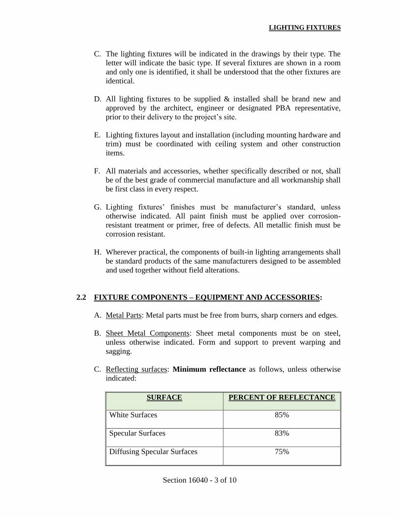
LIGHTING FIXTURES
Section 16040 - 3 of 10
C. The lighting fixtures will be indicated in the drawings by their type. The
letter will indicate the basic type. If several fixtures are shown in a room
and only one is identified, it shall be understood that the other fixtures are
identical.
D. All lighting fixtures to be supplied & installed shall be brand new and
approved by the architect, engineer or designated PBA representative,
prior to their delivery to the project’s site.
E. Lighting fixtures layout and installation (including mounting hardware and
trim) must be coordinated with ceiling system and other construction
items.
F. All materials and accessories, whether specifically described or not, shall
be of the best grade of commercial manufacture and all workmanship shall
be first class in every respect.
G. Lighting fixtures’ finishes must be manufacturer’s standard, unless
otherwise indicated. All paint finish must be applied over corrosion-
resistant treatment or primer, free of defects. All metallic finish must be
corrosion resistant.
H. Wherever practical, the components of built-in lighting arrangements shall
be standard products of the same manufacturers designed to be assembled
and used together without field alterations.
2.2 FIXTURE COMPONENTS – EQUIPMENT AND ACCESSORIES:
A. Metal Parts: Metal parts must be free from burrs, sharp corners and edges.
B. Sheet Metal Components: Sheet metal components must be on steel,
unless otherwise indicated. Form and support to prevent warping and
sagging.
C. Reflecting surfaces: Minimum reflectance as follows, unless otherwise
indicated:
SURFACE PERCENT OF REFLECTANCE
White Surfaces
85%
Specular Surfaces
83%
Diffusing Specular Surfaces
75%

LIGHTING FIXTURES
Section 16040 - 4 of 10
SURFACE PERCENT OF REFLECTANCE
Laminated Silver Metallized Film
90%
D. Lenses, diffusers, covers and globes: 100 percent virgin acrylic plastic or
annealed crystal glass, unless otherwise indicated.
1. Plastic: High resistance to yellowing and other changes due to
aging, exposure to heat and ultraviolet radiation.
2. Lens thickness: 0.125 inch (3 mm.) minimum, unless grater
thickness is indicated.
E. Connectors: Approved solder-less connectors shall be used in making
connections in the wiring within the fixtures or in connecting the fixtures
wiring to the wiring of the building.
F. Doors, frames and other internal access: Smooth operating, free from light
leakage under operating conditions, and arranged to permit re-lamping
without use of tools. Arrange access doors, frames, lenses, diffusers and
other pieces to prevent accidental falling during re-lamping and when
secured in operating position.
G. Support Components: Support Components must comply with Section
16000 (Electrical Work – General) or Section 26 00 00 (Basic Electrical
Materials and Methods), whichever applies, for channel & angle-iron
supports and non-metallic & angle supports.
1. Single-Stem Hangers: ½” (12 mm.) steel tubing with swivel ball
fitting and ceiling canopy. Finish same as fixture.
2. Twin-Stem Hangers: Two (2) ½” (12 mm.) steel tubes with single
canopy arranged to mount a single fixture. Finish same as fixture.
3. Rod Hangers: 3/16” (5 mm.) minimum diameter, cadmium-plated,
threaded steel rod.
4. Hook Hangers: Integrated assembly matched to fixture and line
voltage and equipped with threaded attachment, cord and locking-
type plug.
5. Aircraft Cable Support: Use cable, anchorages and intermediate
supports recommended by fixture manufacturer.

LIGHTING FIXTURES
Section 16040 - 5 of 10
2.3 FLUORESCENT LAMP BALLASTS:
A. Unless otherwise indicated, all ballast used in connection with the
ecologic T8 fluorescent lighting equipment shall be as follows:
1. Designed for type and quantity of lamps indicated at full light output
2. UL listed, thermally protected, resetting, Class P, non-PCB
3. Minimum line transient as shown in IEEE87, Category A and ANSI
62.41.
4. Ballast operates at 120V nominal (108V-132V) - 60 Hz. or 277V
nominal (249-305V) – 60 Hz.
5. Meets most recent (latest) Federal Efficiency Standard (Law 100-
357).
6. Meets FCC rules/regulations, Part 18, 15J for EMI/RFI.
7. Meets all requirements of ANSI C82.11.
8. Power factor equal or greater than 0.95. Maximum lamp current
crest factor of 1.7.
9. Ballast shall be electronic type with equal or less than 10% of total
harmonic distortion (THD≤10%).
10. Minimum 5-year ballast manufacturer’s warranty, in compliance
with special warranty indicated on Article 1.3.
11. A complete application data of the ballast and the submitted fixture
shall be included for approval as described.
2.4 HIGH-INTENSITY DISCHARGE LAMP BALLASTS:
A. Unless otherwise indicated, all HID lighting fixtures ballast shall comply
with ANSI C82.4 and includes the following parameters:
1. Type: High power factor (HPF) constant wattage.
2. Operating voltage: Must match system voltage.
3. Minimum starting temperature: Minus 22ºF (minus 30ºC) for single
lamp ballast.

LIGHTING FIXTURES
Section 16040 - 6 of 10
4. Normal ambient operating temperature: 104ºF (40ºC).
5. Open circuit operation that will not reduce average life.
6. Auxiliary, Instant-on, Quartz System: Automatically switches quartz
lamp on when fixture is initially energized and when momentary
power outages occur. Automatically turns quartz lamp off when HID
lamp reaches approximately 60 percent light output.
B. Encapsulation: Manufacturer’s standard epoxy-encapsulated model
designed to minimize audible fixture noise.
2.5 EXIT SIGNS:
A. Exit signs must comply with UL-924. Sign color and lettering size shall
comply with specifications issued by authorities having jurisdiction.
B. Internally Lighted Signs:
1. Lamps for AC operation: LED lamps with not less than 70,000 hours
rated lamp life.
2. Additional lamps for DC operation: Two (2) minimum bayonet-base
type for connection to external dc source.
C. Self-Powered Exit Signs (Battery Type):
1. Battery: Sealed, maintenance-free, nickel-cadmium type, in
compliance with special warranty indicated on Article 1.3.
2. Charger: Integral in a self-contained power pack, fully automatic,
solid-state type with sealed transfer relay.
3. Operation: Relay automatically energizes lamp from unit when
circuit voltage drops to 80 percent of nominal voltage or below.
When normal voltage is restored, relay disconnect lamps, and battery
is automatically recharged and floated on charger.
2.6 EMERGENCY LIGHTING UNITS:
A. Emergency lights must be self-contained units in compliance with UL-
924, including the following features:
1. Battery: Sealed, maintenance-free, lead-acid type with not less than
ten (10) years nominal life, in compliance with special warranty
indicated on Article 1.3.
2. Charger: fully automatic, solid-state type with sealed transfer relay.

LIGHTING FIXTURES
Section 16040 - 7 of 10
3. Operation: Relay automatically turn lamp on when supply circuit
voltage drops to 80 percent of nominal voltage or below. Lamp
automatically disconnect from battery when voltage approaches
deep-discharge level. When normal voltage is restored, relay
disconnect lamps, and battery is automatically recharged and floated
on charge.
4. Wire Guard: Where indicated, heavy-chrome-plated wire guard
arranged to protect lamp heads or fixtures.
5. Integral Time-Delay Relay: Arranged to hold unit on, for fixed
interval, after restoring electric power service interrupted by an
outage. Provides adequate time delay to permit any existing high-
intensity-discharge lamps to restrike and develop adequate output.
2.7 EMERGENCY FLUORESCENT POWER SUPPLY UNIT:
A. Internal Type: Power supply unit must be self-contained, modular, battery-
inverter unit factory mounted within fixture body, in compliance with UL-
924, including the following features:
1. Test switch and LED indicator light: Visible and accessible without
opening fixture or entering ceiling space.
2. Battery: Sealed, maintenance-free, nickel-cadmium type with not
less than ten (10) years nominal life, in compliance with special
warranty indicated on Article 1.3.
3. Charger: Fully automatic, solid-state constant current type.
4. Operation: Relay automatically energizes lamp from unit when
normal supply circuit voltage drops to 80 percent of nominal voltage
or below. When normal voltage is restored, relay disconnect lamps,
and battery is automatically recharged and floated on charger.
B. External Type: Power supply unit must be self-contained, modular,
battery-inverter unit, in compliance with UL-924, including the following
features:
1. Test switch and LED indicator light: Visible and accessible without
entering ceiling space.
2. Battery: Sealed, maintenance-free, nickel-cadmium type with not
less than ten (10) years nominal life, in compliance with special
warranty indicated on Article 1.3.
3. Charger: Fully automatic, solid-state constant current type.
4. Operation: Relay automatically energizes lamp from unit when
normal supply circuit voltage drops to 80 percent of nominal voltage
or below. When normal voltage is restored, relay disconnect lamps,
and battery is automatically recharged and floated on charger.
5. Housing: NEMA 250, Class 1 enclosure.

LIGHTING FIXTURES
Section 16040 - 8 of 10
2.8 LAMPS:
A. Fluorescent:
1. Unless otherwise indicated, all new fluorescent lamps shall be
deluxe color white, energy-saving & ecologic type, T8, correlated
color temperature (C.C.T.) of 4100ºK, color rendering index (C.R.I.)
equal or greater than 85, with electrode protectors, approved equal
to product manufactured by Phillips Co., GE Corp. or Sylvania.
2. Lamp Life: Rated average must be 20,000 hours at three (3) hours
per start, when used on rapid-start circuits.
B. High Intensity Discharge (HID):
Unless otherwise indicated, all new HID lamps shall be metal-halide,
correlated color temperature (C.C.T.) of 3600ºK, color rendering index
(C.R.I.) equal or greater than 70, 80% minimum reflecting efficiency,
approved equal to product manufactured by GE Corp., SIMCAR or
manufacturer specified on lighting fixtures schedule.
C. Light-Emitting Diode (LED):
LED lamps will be considered and properly accepted by PBA as substitute
of T-8 fluorescent or high-intensity discharge (HID) lamps, as long as
proposed LED lamps comply with aforementioned specifications and/or
any other specifications submitted for fluorescent or HID lamps on
lighting fixtures schedule.
• PART III – EXECUTION
3.1 FIXTURE INSTALLATION:
A. Set level, plumb and square with ceiling and walls, and secure according
to manufacturer’s written instructions and approved submittal materials.
Install lamps in each fixture.
B. The vandal-proof luminaries shall be installed strictly according to the
manufacturer recommendations and with vandal proof screws.
C. All luminaries that are not vandal-proof shall be installed using the
TAPCON Masonry Fastening System. This screw will be placed directly
into the concrete and has maximum anchor strength. The installer shall

LIGHTING FIXTURES
Section 16040 - 9 of 10
drill a hole in the concrete (through the mounting holes of the fixture)
using a drill bit of the size recommended by the manufacturer. A screw of
an approved size shall be used.
D. All rows of fixtures (flush, surface or suspended) shall be installed
accurately on straight line. The fastening and suspensions shall be firmly
set up so that the lines and lamps will be secured against normal vibrations
and will not be affected or distorted by the handling incident of the normal
maintenance.
E. Support for Fixtures: In or On Grid-Type Suspended Ceilings
1. Use grid for support
2. Install a minimum of four ceiling support system rods or wires for
each fixture. Locate not more than six (6) inches (150 mm.) from
fixture corners.
3. Support Clips: Fasten to fixtures and to ceiling grid members at or
near each fixture corner.
4. Fixtures of Sizes Less Than Ceiling Grid: Arrange as indicated on
reflected ceiling plans or center in acoustical panel, and support
fixtures independently with at least two (2) - ¾” (20 mm.) metal
channels spanning and secured to ceiling tees.
F. Suspended Fixture Support:
1. Pendants and Rods: Where longer than 48 inches (1,200 mm.), brace
to limit swinging.
2. Stem-Mounted, Single-Unit Fixtures: Suspend with twin-stem
hangers.
3. Continuous Rows: Use tubing or stem for wiring at one-point and
tubing or rod for suspension for each unit length of fixture chassis,
including one at each end. Suspend from cable installed according to
fixture manufacturer’s written instructions and details on drawings.
G. Air Handling Fixtures: Install with dampers closed.
H. Upon completion of the installation of the lighting equipment, it must be
in first-class operating order and in perfect condition. At the time of the
final inspection, the equipment must be complete, with the required
glassware or reflectors, which must be clean and free from defects.
3.2 CONNECTIONS:
A. Provide a 3”ø hole at the back plate of any surface mounted fluorescent
luminaries to access the outlet box.

LIGHTING FIXTURES
Section 16040 - 10 of 10
B. All lighting fixtures shall be grounded. Tighten electrical connectors and
terminals according to manufacturer’s published torque-tightening values.
If manufacturer’s torque values are not indicated, use those specified in
UL-486A and UL-486B.
C. After lighting fixtures and lighting equipment are connected to the wiring
system of the building or project, the wiring system and the fixtures or
equipment must be test free from short circuits and must show an
insulation resistance between conductors and ground, based on minimum
load, not less than resistance required by latest edition of NEC.
3.3 FIELD QUALITY CONTROL:
A. Inspect each installed fixture for damage. Replace damaged fixtures and
components.
B. Advance Notice: Give dates and times for field tests.
C. Provide instruments to make and record test results.
D. Tests: As follows
1. Verify normal operation of each fixture after installation.
2. Emergency Lighting: Interrupt electrical supply to demonstrate
proper operation.
3. Verify normal transfer to battery source and retransfer to normal.
4. Report results in writing.
E. Malfunctioning Fixtures and Components: Replace or repair, then retest.
Repeat procedures until units operate properly.
F. Corrosive fixtures must be replaced during warranty period.
3.4 CLEANING AND ADJUSTING:
A. Clean fixtures internally and externally after installation, using methods
and materials recommended by manufacturer.
B. Adjust installed fixtures to provide required light intensities.
END OF SECTION 16040

SECTION 16041
WIRING DEVICES
1. WALL SWITCHES
a. The Contractor shall provide and install all switches as shown in the plans and in accordance
with the swing of the doors. All switches shall be located on the strike side of the door,
unless otherwise indicated, and at the height indicated in the plans.
b. If several switches are indicated in adjacent position, they shall be ganged together in one
outlet box of the proper size and only one switch plate, unless otherwise indicated.
c. If emergency power (red) and normal power (ivory) switches are indicated in adjacent
position, they shall not be ganged together. They shall be installed in individual outlet boxes.
d. Except where otherwise indicated, all switches shall be as hereinafter specified.
1. SWITCH
Flush-toggle handles; 20 AMP and 120/277 volts A.C. quiet; back and side wiring,
industrial specification grade; heavy duty, tungsten rated, grounding type, with gold-
plated, oversize silver-cadmium oxide contacts; grain-oriented, extra-heavy duty
phosphor-bronze contact arms; super positive quiet action; extra-large binding head
terminal for #10, #12 and #14 wires; rigid steel strap, heavily plated, with washer type
plaster ears; switching mechanism, fully enclosed in a reinforced urea-molded body,
riveted to mounting. The cover plate shall be no. 302 stainless steel, non magnetic, satin
finish.
All switches shall be equal to:
Manufacturers
Name
Single Pole
Two Poles
Three-Way
Four-Way
Pass & Seymour 20AC1-I 20AC2-I 20AC3-I 20AC4-I
Hubble
1221I 1222I 1223I 1224I
Leviton
1221-2I 1222-2I 1223-2I 1224-2I
Eagle
2221V 2222V 2223V 2224V
General Electric
5951-2G 5952-2G 5953-2G 5954-2G
Bryant
4901-GI 4902-GI 4903-GI 4904-GI
Arrow Hart
1221I 1222I 1223I 1994I

WIRING DEVICES
16041-2
2. SWITCH WITH PILOT LIGHT
All specifications and catalog series are the same as above except for a red pilot light
handle (Switch On, Light On).
3. SWITCH WITH RED COLORED HANDLE
The switches that are energized by emergency circuits shall be red-colored and shall be
provided with polycarbonate red-colored plates equal to Slater catalog number SH-95071.
All specifications and catalog series are the same as above except for red colored handle.
2. WALL RECEPTACLES
a. The Contractor shall furnish and install all wall receptacles as indicated in the drawings and
hereinafter specified.
CONVENIENCE OUTLETS
Three-wires grounding, duplex receptacle industrial specification grade or extra hard use
specification grade, heavy duty, weather-proof where indicated in the plans, polarized 20 AMP,
125 volts, back and side wiring, U-ground, NEMA 5-20R type parallel slot, tow-ground terminal
screw with: break-off feature for two-circuits wiring; current carrying contacts, securely held in
body at four points to maintain rigidity when the break-off is employed; triple wiping phosphor-
bronze T-slot contacts; auto ground; body and cap must be of molded urea; terminal screws for
#10 and #12 wires; heavily reinforced arc-resistant urea body. The cover plate shall be no. 302
stainless steel, nonmagnetic, satin finish.
b. All receptacles shall be equal to:
Manufacturers
Name
20A,
Duplex
5-20R
20A, Duplex
Tamper
Resistant
20A,
Combination
125/250 V
20A, GFI
20A, Surge
Supp.
TVSS
Pass & Seymour
5362-I SG63-HI 5890-I 2091-SI 6362-ISP
Hubble
5362-I _______ 5492-I GF8300I _______
Leviton
5362-I _______ 5844-I 6898-HGI 8380-I
Eagle
5362-V _______ _______ _______ _______
General Electric
5362-2 GE8300-TI GE5492-2 SF(R)8322-2 5362-S-2
Bryant
5362-I _______ 5492-I GFR83FT-I _______
Arrow Hart
5362-1 _______ 5492-1 GF8300I _______

WIRING DEVICES
16041-3
c. All receptacles that are energized by emergency circuits shall be red-colored and shall be supplied
with polycarbonate red-colored plates equal to Slater catalog number SH-95101. All
specifications and catalog series shall be the same as above except for red colored face.
d. All the outlets outside the building shall be of the weather-proof type and ground fault-protected,
as indicated in the drawings.
e. All outlets for water coolers shall be ground fault protected. In addition, shall have a permanent
use type weatherproof cover.
f. The clock receptacles shall be Pass & Seymour 3733-SS.
g. All single receptacles shall be rated 20 Amps (unless otherwise indicated) and shall exhibit the
same characteristics of the 20 Amps convenience outlets.
h. Receptacles for clothes dryer, ranges and water heaters shall be equal to:
Manufacturers Name
30A Dryer
14-30R
50A Range
14-50R
30A Water Heater
6-30R
Pass & Seymour
5744 5754 5930
Hubble
9430A 9450A 9330
Leviton
278 279 5372
Eagle
1257 1258 1234
General Electric
4191-3 4181-3 4139
Bryant
9430-FR 9450-FR 9632-FR
Arrow Hart
5744N ________ 5700N
i. Commercial Specification Grade wiring devices are not accepted as substitutes.
j. Surge suppressor to be used for computer and electronic peripherals.
C. DEVICE PLATES
a. All plates for the wall convenience receptacles, switches, telephone, junction box outlets,
intercom facilities, etc. shall be no. 302 stainless steel satin finish, of the non-magnetic type.
b. The telephone outlet plates shall be provided with a rubber bushing in the center hole.
END OF SECTION 16041

SECTION 16050
CONDUCTORS
1. The Contractor shall furnish and install all conductors as specified herein and indicated in the
drawings.
2. Except where otherwise indicated in the drawings or specified, no conductor shall be smaller
than #12 AWG. All conductors shall be stranded.
3. Unless otherwise indicated, all conductors shall be of the moisture and heat resistant type
(THHN) rated 600 volts insulation 90ºC Cu.
4. All feeder and branch circuit conductors shall be color-coded as follows:
PHASE 120/208 V 277/480 V
Ø A Black Brown
Ø B Red Orange
Ø C Blue Yellow
Neutral White Gray
Ground Green Green
Note: Isolated ground conductors shall be green with yellow stripes.
5. All building wires shall be of the UL approved types. The conductors shall not be over six
months old. They shall also be suitable protected from weather or damage during their
storage and handling and shall be in first-class condition when installed.
6. All conductors shall be continuous from outlet to outlet, and so splices shall be made except
in the boxes. The conductors in the outlets shall be of sufficient length to allow making all
the device connections without any strain.
7. All conductors #6 AWG in size or smaller shall be factory-finished in the desired identifying
colors.
8. If not factory-finished in the desired color, all conductors #4 AWG in size or larger used in
branch circuits shall be identified by using tape in the desired color the last twelve inches
(12”) of every length conductor.
9. When used for underground installation, all conductors or cables, regardless of the type, shall
be protected by schedule 40 PVC conduits of the adequate size per NEC. They shall also be
embedded in a concrete encasement of a minimum thickness of four inches (4”) on all sides.
All underground feeders or branch circuits shall be RHw-2, XLP 90ºC Cu.
10. The Contractor shall provide a ground wire in all motor circuits for grounding purposes. He
(she) shall size it according to the latest edition of the National Electrical Code.

CONDUCTORS
16050-2
11. The Contractor shall provide a #12 THHN green bonding jumper between the receptacles
grounding terminal and the grounded outlet box for grounding continuity.
END OF SECTION 16050

16060 - 1
SECTION 16060
GROUNDING AND BONDING
1PART GENERAL
1.1 SUMMARY
A. Section Includes:
1. Rod electrodes.
2. Active electrodes.
3. Wire.
4. Grounding well components.
5. Exothermic connections.
B. Related Sections:
1. Section 02590 - Site Electrical: Site related grounding components for buildings
and facilities.
1.2 REFERENCES
A. Institute of Electrical and Electronics Engineers:
1. IEEE 142 - Recommended Practice for Grounding of Industrial and Commercial
Power Systems.
2. IEEE 1100 - Recommended Practice for Powering and Grounding Electronic
Equipment.
B. International Electrical Testing Association:
1. NETA ATS - Acceptance Testing Specifications for Electrical Power
Distribution Equipment and Systems.
C. National Fire Protection Association:
1. NFPA 70 - National Electrical Code.
2. NFPA 99 - Standard for Health Care Facilities.
1.3 SYSTEM DESCRIPTION
A. Grounding systems use the following elements as grounding electrodes:
1. Rod electrode.
1.4 PERFORMANCE REQUIREMENTS

16060 - 2
A. Grounding System Resistance: 5 ohms maximum.
1.5 SUBMITTALS
A. Product Data: Submit data on grounding electrodes and connections.
B. Test Reports: Indicate overall resistance to ground.
1.6 QUALITY ASSURANCE
A. Provide grounding materials conforming to requirements of NEC, IEEE 142, and UL
labeled.
B. Perform Work in accordance with PREPA 's standard.
C. Maintain one copy of each document on site.
1.7 QUALIFICATIONS
A. Installer: Company specializing in performing work of this section with minimum two
years experience.
1.8 DELIVERY, STORAGE, AND HANDLING
A. Section 01600 - Product Requirements: Requirements for transporting, handling, storing,
and protecting products.
B. Accept materials on site in original factory packaging, labeled with manufacturer's
identification.
C. Protect from weather and construction traffic, dirt, water, chemical, and mechanical
damage, by storing in original packaging.
1.9 COORDINATION
A. Section 01300 - Administrative Requirements: Requirements for coordination.
B. Complete grounding and bonding of building prior concrete placement.
2PART PRODUCTS
2.1 ROD ELECTRODES
A. Furnish materials in accordance with PREPA’s standards.
B. Product Description:
1. Material: Copper-clad steel.
2. Diameter: 3/4 inch.

16060 - 3
3. Length: 10 feet.
C. Connector: Connector for exothermic welded connection..
2.2 WIRE
A. Material: Stranded copper.
B. Foundation Electrodes: 4/0 AWG.
C. Grounding Electrode Conductor: Copper conductor bare.
D. Bonding Conductor: Copper conductor bare.
2.3 GROUNDING WELL COMPONENTS
A. Well Pipe: 8 inches by 24 inches long concrete pipe with belled end.
B. Well Cover: Fiberglass with legend "GROUND" embossed on cover.
2.4 EXOTHERMIC CONNECTIONS
A. Furnish materials in accordance with PREPA’s standards.
B. Product Description: Exothermic materials, accessories, and tools for preparing and
making permanent field connections between grounding system components.
3PART EXECUTION
3.1 EXAMINATION
A. Section 01300 - Administrative Requirements: Verification of existing conditions before
starting work.
B. Verify final backfill and compaction has been completed before driving rod electrodes.
3.2 PREPARATION
A. Remove surface contaminants at connection points.
3.3 INSTALLATION
A. Install in accordance with IEEE 142.
B. Install rod electrodes at locations as indicated on Drawings. Install additional rod
electrodes to achieve specified resistance to ground.
C. Install grounding and bonding conductors concealed from view.

16060 - 4
D. Install grounding well pipe with cover at rod locations as indicated on Drawings. Install
well pipe top flush with finished grade.
E. Install 4/0 AWG bare copper wire in foundation footing as indicated on Drawings.
F. Bond together metal siding not attached to grounded structure; bond to ground.
G. Bond together reinforcing steel and metal accessories in pool and fountain structures.
H. Equipment Grounding Conductor: Install separate, insulated conductor within each feeder
and branch circuit raceway. Terminate each end on suitable lug, bus, or bushing.
I. Connect to site grounding system. Refer to Section 02590.
J. Install continuous grounding using underground artificial station ground by means of
driven rods or buried electrodes.
K. Permanently ground entire light and power system in accordance with NEC, including
service equipment, distribution panels, lighting panelboards, switch and starter
enclosures, motor frames, grounding type receptacles, and other exposed non-current
carrying metal parts of electrical equipment.
L. Accomplish grounding of electrical system by using insulated grounding conductor
installed with feeders and branch circuit conductors in conduits. Size grounding
conductors in accordance with NEC. Install from grounding bus of serving panel to
ground bus of served panel, grounding screw of receptacles, lighting fixture housing,
light switch outlet boxes or metal enclosures of service equipment. Ground conduits by
means of grounding bushings on terminations at panelboards with installed number 12
conductor to grounding bus.
M. Install a ground loop as shown on plans consisting of #4/0 AWG bare copper conductor
installed at 3 ft. below final grade. Connect to this ground loop the electrical, telephone,
cable T V, and antenna grounding electrode conductors using Cadweld connection.
N. Permanently attach equipment and grounding conductors prior to energizing equipment.
3.4 FIELD QUALITY CONTROL
A. Section 01400 - Quality Requirements, 01700 - Execution Requirements: Field
inspecting, testing, adjusting, and balancing.
B. Inspect and test in accordance with NETA ATS, except Section 4.
C. Grounding and Bonding: Perform inspections and tests listed in NETA ATS, Section
7.13.
END OF SECTION
SECTION 16075
ELECTRICAL IDENTIFICATION
PART I - GENERAL
A. SUMMARY
1. Section Includes:
a. Nameplates.
b. Labels.
c. Wire markers.
d. Conduit markers.
e. Stencils
f. Underground Warning Tape.
g. Lockout Devices.
2. Related Sections:
a. Section 09900 – Paints and Coatings: Execution requirements for painting specified by
this section.
B. SUBMITTALS
1. Section 01330 – Submittal Procedures: Submittal procedures.
2. Product Data:
a. Submit manufacturer’s catalog literature for each product required.
b. Submit electrical identification schedule including list of wording, symbols, letter size,
color coding, tag number, location, and function.
c. Submit two samples of each type of identification products applicable to project.
d. Submit two nameplates, 4 x 4 inch in size illustrating materials and engraving quality.
3. Manufacturer’s Installation Instructions: Indicate installation instructions, special
procedures, and installation.
C. QUALITY ASSURANCE
1. Perform Work in accordance with PHA standard.
D. QUALIFICATIONS
1. Manufacturer: Company specializing in manufacturing Products specified in this section with
minimum three years documented experience.

ELECTRICAL IDENTIFICATION
16075-2
2. Installer: Company specializing in performing Work of this section with minimum three
years documented experience.
E. DELIVERY, STORAGE, AND HANDLING
1. Section 01600 – Product Requirements: Requirements for transporting, handling, storing, and
protecting products.
2. Accept identification products on site in original containers. Inspect for damage.
3. Accept materials on site in original factory packaging, labeled with manufacturer’s
identification, including product density and thickness.
4. Protect insulation from weather and construction traffic, dirt, water, chemical, and
mechanical damage, by storing in original wrapping.
F. ENVIRONMENTAL REQUIREMENTS
1. Section 01600 – Product Requirements: Environmental conditions affecting products on site.
2. Install nameplates only when ambient temperature and humidity conditions for adhesive are
within range recommended by manufacturer.
PART II - PRODUCTS
A. NAMEPLATES
1. Furnish materials in accordance with PHA standards.
2. Product Description: Laminated three-layer plastic with engraved black letters on white
contrasting background color.
3. Letter Size:
a. ⅛ inch high letters for identifying individual equipment and loads.
b. ¼ inch high letters for identifying grouped equipment and loads.
4. Minimum nameplate thickness: ⅛ inch.
B. LABELS
1. Furnish materials in accordance with standards.
2. Labels: Embossed adhesive tape, with 3/16 inch white letters on black background.

ELECTRICAL IDENTIFICATION
16075-3
C. WIRE MARKERS
1. Furnish materials in accordance with PHA standards.
2. Description: Cloth tape, split sleeve, or tubing type wire markers.
3. Legend:
a. Power and Lighting Circuits: Branch circuit or feeder number as indicated on Drawings.
b. Control Circuits: Control wire number as indicated on schematic and interconnection
diagrams.
D. CONDUIT AND RACEWAY MARKERS
1. Furnish materials in accordance with PHA standards.
2. Description: Stencils.
3. Color:
a. 480 Volt System: Black lettering on white background.
b. 208 Volt System: Black lettering on white background.
c. Fire Alarm System: Red lettering on white background.
d. Telephone/CATV System: Blue lettering on white background.
E. STENCILS
1. Furnish materials in accordance with PHA standards.
2. Stencils: With clean cut symbols and letters of following size:
a. Up to 2 inches Outside Diameter of Raceway: ½ inch high letters.
b. 2-½ to 6 inches Outside Diameter of Raceway: 1 inch high letters.
3. Stencil Paint: As specified in Section 09900, semi-gloss enamel, colors conforming to the
following:
a. Black lettering on white background.
b. White lettering on gray background.
c. Red lettering on white background.
d. Blue lettering on white background.
F. UNDERGROUND WARNING TAPE
1. Description: 4 inch wide plastic tape, detectable type, colored yellow with suitable warning
legend describing buried electrical lines as per PREPA and JRT regulations.

ELECTRICAL IDENTIFICATION
16075-4
G. LOCKOUT DEVICES
1. Lockout Hasps:
a. Manufacturers:
1. Substitutions: Section 01600 – Product Requirements.
b. Anodized aluminum hasp with erasable label surface; size minimum 7-¼ x 3 inches.
PART III - EXECUTION
A. PREPARATION
1. Degrease and clean surfaces to receive adhesive for identification materials.
2. Prepare surfaces in accordance with Section 09900 for stencil painting.
B. EXISTING WORK
1. Install identification on existing equipment to remain in accordance with this section.
2. Install identification on unmarked existing equipment.
3. Replace lost nameplates.
4. Re-stencil existing equipment.
C. INSTALLATION
1. Install identifying devices after completion of painting.
2. Nameplate Installation:
a. Install nameplate parallel to equipment lines.
b. Install nameplate for each electrical distribution and control equipment enclosure
with corrosive-resistant mechanical fasteners, or adhesive.
c. Install nameplates for each control panel and major control components located
outside panel with corrosive-resistant mechanical fasteners, or adhesive.
d. Secure nameplate to equipment front using screws, rivets, or adhesive.
e. Secure nameplate to inside surface of door on recessed panel-board in finished
locations.
f. Install nameplates for the following:
1. Switchboards.
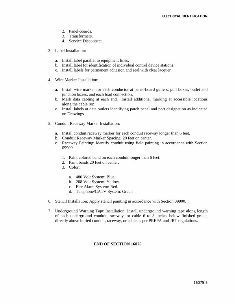
ELECTRICAL IDENTIFICATION
16075-5
2. Panel-boards.
3. Transformers.
4. Service Disconnect.
3. Label Installation:
a. Install label parallel to equipment lines.
b. Install label for identification of individual control device stations.
c. Install labels for permanent adhesion and seal with clear lacquer.
4. Wire Marker Installation:
a. Install wire marker for each conductor at panel-board gutters, pull boxes, outlet and
junction boxes, and each load connection.
b. Mark data cabling at each end. Install additional marking at accessible locations
along the cable run.
c. Install labels at data outlets identifying patch panel and port designation as indicated
on Drawings.
5. Conduit Raceway Marker Installation:
a. Install conduit raceway marker for each conduit raceway longer than 6 feet.
b. Conduit Raceway Marker Spacing: 20 feet on center.
c. Raceway Painting: Identify conduit using field painting in accordance with Section
09900.
1. Paint colored band on each conduit longer than 6 feet.
2. Paint bands 20 feet on center.
3. Color:
a. 480 Volt System: Blue.
b. 208 Volt System: Yellow.
c. Fire Alarm System: Red.
d. Telephone/CATV System: Green.
6. Stencil Installation: Apply stencil painting in accordance with Section 09900.
7. Underground Warning Tape Installation: Install underground warning tape along length
of each underground conduit, raceway, or cable 6 to 8 inches below finished grade,
directly above buried conduit, raceway, or cable as per PREPA and JRT regulations.
END OF SECTION 16075

SECTION 16095
MINOR ELECTRICAL DEMOLITION
PART 1 - GENERAL
1.1 SUMMARY
A. Section Includes:
1. Removal of existing electrical equipment, (including telephone, and fire alarm) wiring,
and conduit in areas to be remodeled; removal of designated construction; dismantling,
cutting and alterations for completion of the Work.
2. Disposal of materials.
3. Storage of removed materials.
4. Identification of utilities.
5. Salvaged items.
6. Protection of items to remain as indicated on Drawings.
7. Relocate existing equipment to accommodate construction.
1.2 SUBMITTALS
A. Section 01330 – Submittal Procedures: Requirements for submittals.
B. Shop Drawings: Indicate demolition and removal sequence and location of salvageable items;
location and construction of temporary work. Describe demolition removal procedures and
schedule.
1.3 QUALITY ASSURANCE
A. Perform Work in accordance with PHA standard.
1.4 PRE-INSTALLATION MEETINGS
A. Section 01300 – Administrative Requirements: Pre-installation meeting.
B. Convene minimum one week prior to commencing work of this section.

MINOR ELECTRICAL DEMOLITION
16095 - 2
1.5 SCHEDULING
A. Section 01300 – Administrative Requirements, 01323 – Network Analysis Schedules:
Requirements for scheduling.
B. Schedule work to coincide with new construction.
C. Cease operations immediately when structure appears to be in danger and notify
Architect/Engineer. Do not resume operations until directed.
1.6 COORDINATION
A. Section 01300 – Administrative Requirements: Requirements for coordination.
B. Conduct demolition to minimize interference with adjacent and occupied building areas.
C. Coordinate demolition work with PHA.
D. Coordinate and sequence demolition so as not to cause shutdown of operation of surrounding
areas.
E. Shut-down Periods
1. Arrange timing of shut-down periods of in service panels with PHA. Do not shut down
any utility without prior written approval.
2. Keep shut-down period to minimum or use intermittent period as directed by.
F. Identify salvage items in cooperation with Owner.
PART 2 – EXECUTION
2.1 EXAMINATION
A. Section 01300 – Administrative Requirements: Verification of existing conditions before
starting work.
B. Verify wiring and equipment indicated to be demolished serve only abandoned facilities.
C. Verify termination points for demolished services.

MINOR ELECTRICAL DEMOLITION
16095 - 3
2.2 PREPARATION
A. Erect, and maintain temporary safeguards, including warning signs and lights, barricades, and
similar measures, for protection of the public, Owner, Contractor’s employees, and existing
improvements to remain.
B. Temporary egress signage and emergency lighting.
C. Coordinate utility service outages with Utility Company.
D. Beginning of demolition means installer accepts existing conditions.
2.3 DEMOLITION
A. Demolition Drawings are based on casual field observation and existing record documents.
Report discrepancies to Owner before disturbing existing installation.
B. Remove exposed abandoned conduit, including abandoned conduit above accessible ceiling
finishes. Cut conduit flush with walls and floors, and patch surfaces.
C. Remove conduit, wire, boxes, and fastening devices to avoid any interference with new
installation.
D. Disconnect electrical systems in walls, floors, and ceilings scheduled for removal.
E. Reconnect equipment being disturbed by renovation work and required for continue service
to nearest available panel.
F. Disconnect or shut off service to areas where electrical work is to be removed. Remove
electrical fixtures, equipment, and related switches, outlets, conduit and wiring which are not
part of final project.
G. Install temporary wiring and connections to maintain existing systems in service during
construction.
H. Perform work on energized equipment or circuits with experienced and trained personnel.
I. Remove, relocate, and extend existing installations to accommodate new construction.
J. Repair adjacent construction and finishes damaged during demolition and extension work.
K. Remove exposed abandoned grounding and bonding components, fasteners and supports, and
electrical identification components, including abandoned components above accessible
ceiling finishes. Cut embedded support elements flush with walls and floors.
L. Clean and repair existing equipment to remain or to be reinstalled.
MINOR ELECTRICAL DEMOLITION
16095 - 4
M. Protect and retain power to existing active equipment remaining.
N. Cap abandoned empty conduit at both ends.
O. Fill with concrete all holes of outlets, switches, panel-boards, etc.
2.4 EXISTING PANELBOARDS TO REMAIN
A. Ring out circuits in existing panel affected by the Work. Where additional circuits are
needed, reuse circuits available for reuse. Install new breakers.
B. Tag unused circuits as spare.
C. Where existing circuits are indicated to be reused, use sensing measuring devices to verify
circuits feeding Project area or are not in use.
D. Remove existing wire no longer in use from panel to equipment.
E. Provide new updated directories where more than three circuits have been modified or
rewired.
2.5 SALVAGE ITEMS
A. Remove and protect items indicated in Schedule to be salvaged and turn over to PHA.
B. Items of salvageable value may be removed as work progresses. Transport salvaged items
form site as they are removed to the warehouse selected by PHA.
2.6 REUSABLE ELECTRICAL EQUIPMENT
A. Carefully remove equipment, materials, or fixtures which are to be reused.
B. Disconnect, remove, or relocate existing electrical material and equipment interfering with
new installation.
C. Relocate existing lighting fixtures as indicated on Drawings. Clean fixtures and re-lamp.
Test fixture to see if it is in good working condition before installation at new location.
2.7 CLEANING
A. Section 01700 – Execution Requirements: Requirements for cleaning.
B. Remove demolished materials as work progresses. Legally dispose.
C. Keep workplace neat.

MINOR ELECTRICAL DEMOLITION
16095 - 5
2.8 PROTECTION OF FINISHED WORK
A. Section 01700 – Execution Requirements: Requirements for protecting finished Work.
END OF SECTION 16095

SECTION 16485
LIGHTING CONTACTORS
a. Furnish and install where shown a lighting contactor in the plans.
b. The contactors shall be Square D Series 8903 Type S.
c. They shall be Two, Three, Four Poles or as required.
d. The contacts ratings shall be 30, 60, 100, 200 amperes, or as indicated in the plans, for all
types of ballast and tungsten lighting, resistive heating and motor loads.
e. They shall be U.L. approved as suitable for purpose specified and shown.
f. The contacts shall be totally enclosed, double break silver cadmium-oxide power contacts.
Contacts inspection and replacement shall be possible without disturbing line or load wiring.
g. The wiring shall be straight-through wiring with all terminals clearly marked.
h. The installation shall be exposed type or flush as required.
i. The enclosure shall be NEMA 1, 3R, 4, 4X or 12 as required to meet the conditions of
installation.
j. The contactor shall be provided with disconnecting means in the same enclosure if required.
k. The enclosure shall be provided with ON-OFF pushbuttons, control transformer, Hand-Off-
Auto Selector Switch, and red indicating light.
l. The coil shall be of the encapsulated type.
END OF SECTION 16485
16485-1

SECTION 16500
TIME SWITCHES
1. The timer system shall be able to accommodate the varying sunrise and sunset times by
simulating them through microprocessor control.
2. The timer system permits the programming of ON/OFF functions related to sunrise and
sunset at any point on Earth.
3. Programming must be set for the number of minutes before or after sunrise or sunset.
4. Programming must accommodate a maximum of four hundred (400) programmable control
events.
5. The time system shall be capable of accepting adjustable timed override for last minute,
nonrecurring program changes without disturbing existing programs.
6. The time system shall be capable of operating up to seven different programs plus daily
repeat, timed override, and immediate events.
7. The timer system shall have a panic button that activates programmed emergency operations.
8. The timer system shall provide sequenced restart after power failure.
9. Resolution for timed events shall be one minute
10. Time accuracy is to be based on line frequency (60 Hz).
11. The timer system shall have a power-failure back up provided by a lithium battery with a ten-
year shall life that retains programming for two years of accumulated power outages.
12. The timer system shall retain clock accuracy for 72 hour per power failure.
13. The timer system consists of a 24-vac transformer power a low-voltage timer unit that
connects to control relay units capable of operating loads (per pole) as follows:
a) 240 VAC, 6 A, General use.
b) 24 VDC to 250 VDC, 75 V A resistive.
c) 24 VDC, 5 A resistive.
d) 1/10 hp at 120 VAC across line motor starting.
e) ¼ hp at 240 VAC across line motor starting.
f) 360 VA pilot duty.

TIME SWITCHES
16500-2
14. Control relay units shall consist of four (4) single poles, normally open maintained contacts
with transient protection and four (4) manual override switches.
15. The connection between the timer unit and the control relay units shall be with signal cable
(Belden #9640 o equal) ten conductor shielded and jacketed. Data cable not to exceed 1000
feet. A maximum of seven of the control relay units may be wired in series-parallel
configuration as desired.
16. The control relay units shall be connected to lighting contactors for load switching. See-
lighting contactors.
17. Enclosure type shall be high-impact, high temperature (UL listed) plastic back box with
hinged, locking clear plastic front cover. Shall have knockouts of ½ inch.
18. Timer system shall be UL listed as Energy Management Equipment.
19. Availability: The timer system (and its individual components) shall be readily available
through local distributors in Puerto Rico.
20. Shall be equal or similar to Leviton model: time clock ALMA 001, transformer TR24,
control relay units LCM461.
21. The time switch (as) shall be installed in a terminal cabinet with door and key operated latch.
The cabinet dimensions shall be as required.
22. The contractors shall warrant any equipment installed under this specification to be free from
defects for a period of two (2) years from date of final acceptance.
23. The contractors shall provide a minimum of four (4) hours training for school district
personnel on proper operating procedures for the system.
END OF SECTION 16500

16540-1
SECTION 16540
FIRE ALARM SYSTEM
A. General Requirements
1. The requirements of the Contract Documents, including the General and Supplementary
General Condition and Division 1 – General Requirements shall apply to the work of this
section.
2. At the time of bid, all exceptions taken to these Specifications, all variances from these
Specifications and all substitutions of operating capabilities or equipment called for in
these Specifications shall be listed in writing and forwarded to the Engineer. Any such
exception, variances or substitutions that were not listed at the time of bid and are
identified in the submittal, shall be grounds for immediate disapproval without comment.
B. Scope
The work covered by this Section of the Specification shall include all labor, equipment,
materials and services to furnish and install a complete fire alarm. It shall be complete with
all-necessary hardware, software and memory. It shall be possible to permanently modify
the software on site by using the integral programmer. The system shall consist of, but no be
limited to, the following:
a. Fire alarm control panel Addressable
b. Manual fire alarm stations Addressable.
c. Smoke detectors Addressable.
d. Heat detectors Addressable.
e. Alarm Horn/Strobe

16540-2
FIRE ALARM SYSTEM (CONT.)
C. Applicable Codes and Standards
1. All equipment shall be U.L. listed for its intended use.
2. NFPA Standards 72.
3. The National Electric Code.
4. All other local codes and authorities having jurisdiction.
D. Related Documents
1. Secure permits and approvals prior to installation.
2. Prior to commencement and after completion of work, notify authorities having
jurisdiction.
3. Submit letter of approval for installation before requesting acceptance of system.
E. Related Work
1. The Contractor shall coordinate work in this Section with all related trades. Work and/or
equipment provided in other Sections and related to the fire alarm system shall include,
but not be limited to:
a. Duct smoke detectors shall be furnished, wired and connected by the electrical
contractor. The HVAC contractor shall furnish necessary duct opening to install the
duct smoke detectors.
b. Electrical contractors shall furnish conduit.
c. Fire alarm contractors shall provide wire and Cables.

16540-3
FIRE ALARM SYSTEM (CONT.)
F. Submittal
1. Provide list of all types of equipment and components provided.
2. Provide description of operation of the system, similar to that provided in part 2 of this
Section of the Specifications to include any and all exceptions, variances or substitutions
listed at the time of bid. Any such exceptions, variances or substitutions that were not
listed at the time of bid and are identified in the submittal, shall be grounds for immediate
disapproval without comment.
3. Provide manufacturer’s printed product data, catalog cuts description and special
installation procedures.
4. Provide samples of various items when requested.
5. Provide shop drawings as follows:
a. Drawing of the alarm control panel.
b. Single line riser diagrams showing all equipment and types number and size of all
conductors.
G. Warranty
1. Manufacturer shall guarantee the system equipment for a period of one (1) year from date
of final acceptance of the system.
2. The contractor shall guarantee all wiring and raceways to be free from inherent
mechanical or electrical defects for one (1) year from date of final acceptance of the
system.
3. The contractor shall warranty all materials, equipment, wiring, devices, installation and
workmanship, including service labor for one year from date of acceptance.
4. The supplier and/or contractor shall have sufficient stock of spare parts or devices on
hand and have a fully equipped service organization, base in Puerto Rico, capable of
guaranteeing response time within (6) hours of service and/or emergency calls. The
service shall be available (24) hours a day or (7) days a week, and (365) days a year for
the complete installed system.
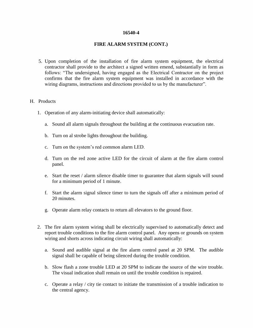
16540-4
FIRE ALARM SYSTEM (CONT.)
5. Upon completion of the installation of fire alarm system equipment, the electrical
contractor shall provide to the architect a signed written emend, substantially in form as
follows: “The undersigned, having engaged as the Electrical Contractor on the project
confirms that the fire alarm system equipment was installed in accordance with the
wiring diagrams, instructions and directions provided to us by the manufacturer”.
H. Products
1. Operation of any alarm-initiating device shall automatically:
a. Sound all alarm signals throughout the building at the continuous evacuation rate.
b. Turn on al strobe lights throughout the building.
c. Turn on the system’s red common alarm LED.
d. Turn on the red zone active LED for the circuit of alarm at the fire alarm control
panel.
e. Start the reset / alarm silence disable timer to guarantee that alarm signals will sound
for a minimum period of 1 minute.
f. Start the alarm signal silence timer to turn the signals off after a minimum period of
20 minutes.
g. Operate alarm relay contacts to return all elevators to the ground floor.
2. The fire alarm system wiring shall be electrically supervised to automatically detect and
report trouble conditions to the fire alarm control panel. Any opens or grounds on system
wiring and shorts across indicating circuit wiring shall automatically:
a. Sound and audible signal at the fire alarm control panel at 20 SPM. The audible
signal shall be capable of being silenced during the trouble condition.
b. Slow flash a zone trouble LED at 20 SPM to indicate the source of the wire trouble.
The visual indication shall remain on until the trouble condition is repaired.
c. Operate a relay / city tie contact to initiate the transmission of a trouble indication to
the central agency.

16540-5
FIRE ALARM SYSTEM (CONT.)
d. Sound and audible signal at the remote annunciator panel. The audible signal may be
silenced during the trouble condition.
3. Subsequent alarms, supervisory signals, or trouble activations shall repeat their respective
response sequence.
I. Materials
1. Fire Alarm control panel:
The addressable fire alarm panels shall be equal to Edwards Systems Technology EST-2
type and shall incorporate all control electronics, relays, and necessary modules and
components ins a semi-flush mounted cabinet. The operating controls and
zone/supervisory indicators shall be located behind locked door with viewing window.
All control modules shall be labeled, and all zone locations shall be identified. The
cabinet shall be steel, with a gray finish. The assembly shall contain a base panel, system
power supply and battery charger with optional modules suitable to meet the
requirements of these specifications.
The system shall be supervised, site programmable, and of modular design with
expansion modules to serve up to 192 detector and 188 remote modules, and four
notification appliance circuits convertible to power risers to serve remote multiple NAC
modules for zoned signal applications.
2. The Manual Station Addressable should be equal to EST Model SIGA-270 with vandal
proof cover with horn model ST11100. The SIGA-270 model features the familiar
“teardrop” design with simple positive pull action and sturdy die-cast metal body
manufactured to strict international quality standards for highest reliability.
3. The Addressable Heat Detector should be equal to an EST Model SIGA HRS. EST’s
Signature Series Model SIGA-HRS Intelligent Heat Detectors gather analog information
from their fixed temperature and / or rate-of-rise heat sensing elements and converts it
into digital signals. The detector’s on board microprocessor measures and analyses these
signals. It compares the information to historical readings and time patterns to make an
alarm decision.

16540-6
FIRE ALARM SYSTEM (CONT.)
4. The Addressable Smoke Detector shall be equal to EST Model SIGA-IPHS. The SIGA-
IPHS Intelligent 4D Multisensor Detector gathers analog information from each o its
three fire sensing elements (ionization, photoelectric, and heat) and covers it into digital
signals. The detector’s on-board microprocessor measures and analyzes these signals
separately with respect to a four element-time. This technology is called 4D. It
compares the information to historical readings, time patterns and several known fire
characteristics to make an alarm decision. The microprocessor in each detector shall
provide four additional benefits – Self-diagnostics and History log, Automatic device
mapping, Stand-alone operation and fast, stable communication and also the following
features:
a. Integrates three (3)- sensing technologies.
b. Non-volatile memory.
c. Automatic device mapping.
d. Electronic Addressing.
e. Environmental compensation.
f. Integral microprocessor – Intelligent detector.
g. Wide 0.67 – 3.70 % / FT. Sensitivity range window: Program the detector to operate
at any one of five (5) sensitivity settings within the window.
h. Pre-Alarm: The detector stores a pre-alarm a sensitivity value to alert local personnel
prior to the sensor reaching a full evacuation sensitivity.
i. Identification of dirty or defective detector.
j. Automatic day/night sensitivity adjustment: Makes detector more sensitive during
inactive nighttime periods.
k. Stand – Alone operation.
l. Stable design: Sensitivity remains stable with air velocity up to 500 ft. Min.
(2.53 m/sec) making it suitable for direct insertion in low velocity duct applications.
Design for high ambient temperature operation up to 100º F (38ºC).
m. Twin status leads.

16540-7
FIRE ALARM SYSTEM (CONT.)
n. Standards relay and fault isolator-mounting bases.
o. Design to ISO 9001 standards.
5. The horn and strobe fire annunciators shall be equal to EST Models 692-7A-003.
Combination signaling appliances are designed for use with compatible control
equipment associate with life safety and communications systems. These high quality
EST Horn/Strobes are part of a full line of attractive similarly styled fire alarm
Audible/Visual signals. The housing /bezel is finished in “Fire Red” and is made form
durable, fire retardant high impact Lexan. These supervised appliances come with wire
lead terminals type connections and are available in two flash intensity levels.
J. Acceptable Manufacturers
1. The catalog numbers used are those of Edwards Systems Technology (EST), Farmington,
CT, and constitute the type and quality of equipment to be furnished.
2. If equipment of another manufacturer is to be submitted for approval as equal, the
contractor shall, at the time of bid, list all exceptions taken to these Specifications, all
variances from these Specification and all substitutions of operating capabilities or
equipment called for in these Specifications and forward said list to the Engineer. Any
such exceptions, variances or substitutions that were not listed at the time of bid and are
identified in the submittal, shall be grounds for immediate disapproval without comment.
Final determination of compliance with this Specification shall rest with the Engineer,
who, at his discretion, may require proof of performance.
K. Execution
1. Installation:
a. The entire system shall be installed in a workmanlike manner, in accordance with
approved manufacturer’s wiring diagram. The contractor shall furnish all conduit,
wiring, outlet boxes, junction boxes, cabinets and similar devices necessary for the
complete installation. All wiring shall be of the type recommended by the
manufacturer, approved by the local Fire Department, and shall be installed in rigid,
threaded conduit throughout.

16540-8
FIRE ALARM SYSTEM (CONT.)
b. All penetration of floor slabs and firewalls shall be fire stopped in accordance with all
local fire codes.
c. End of Line Resistors: Shall be furnished as required for mounting as directed by the
manufacturer.
d. All wiring shall be color coded throughout, to National Electrical Code Standards.
e. The system shall be arranged to receive power from one three wire 120 Vac, 15 A
supply. All low voltage operation shall be provided from the fire alarm control panel.
f. Field Quality Control: The system shall be installed and fully tested under the
supervision of a trained manufacturer’s representative.
g. The system shall be demonstrated to perform all of the functions specified.
2. Test
a. Report of any field testing during installation shall be forwarded the Engineer.
b. Each individual system operation on a circuit by circuit basis shall be tested for its
complete operation. The procedure for testing the entire fire alarm system shall be set
forth with the consent of the code enforcement official, the Engineer and the
manufacturer.
3. Documentation and Training
a. The contractor shall compile and provide to the owners three (3) complete manuals
on the complete system to include operating and maintenance instruction, catalog cuts
of all equipment and components, as-built wiring diagrams and a manufacturer’s
suggested spare parts list.
b. In addition to the above manuals, the contractor shall provide the services of the
manufacturer’s trained representative for a period of four (4) hours to instruct the
owners’ designated personnel on the operation and maintenance of the entire system.
16540-9
FIRE ALARM SYSTEM (CONT.)
L. Experience and Qualifications
1. The manufacturer of equipment shall have 10 years experience manufacturing similar
equipment to that specified. He shall submit names, addresses and telephone numbers of
ten similar projects successfully completed.
2. Installing contractor shall have 10 years experience and shall be authorized distributor of
the equipment manufacturer. He shall summit similar information to that listed in item
one.
3. All technicians on the project shall have a minimum off 2 years experience on similar
equipment and shall be factory certified on the specific equipment being installed.
END OF SECTION

SECTION 16600
EMERGENCY GENERATOR
A. Emergency Generator:
1. Diesel Engine-Generator Set:
4-cycle, 1800 rpm, diesel engine generator set. Generator set ratings: ____ kW, ____ kVA at 0.8
PF, standby rating. System voltage of: _____ volts AC, three phases, four wire, 60 hertz.
2. Prototype Tests and Evaluation:
Prototype tests shall have been performed on a complete and functional unit, component level
type tests will not substitute for this requirement. Prototype testing shall comply with the
requirements of NFPA 110 for level 1 systems.
3. Performance:
Voltage regulation shall be plus or minus 0.5 percent for any constant load between no load and
rated load. Random voltage variation with any steady load from no load to full load shall not
exceed plus or minus 0.5 percent.
4. Frequency regulation shall be isochronous form steady state no load to steady state rated load.
Random frequency variation with any steady load from no load to full load shall not exceed plus
or minus 0.25%.
5. The diesel engine-generator set shall be capable of single step load pick up of 100% nameplate
kW and power factor, less applicable de-rating factors, with the engine-generator set at operating
temperature.
6. Motor starting capability shall be a minimum of ____ kVA. The generator set shall be capable of
sustaining a minimum of 90% of rated no load voltage with the specified kVA load at near zero
power factor applied to the generator set.
7. Engine:
The engine shall be diesel, 4 cycle, radiator and fan cooled. Minimum displacement shall be ___
cubic inches, with ___ cylinders. The horsepower rating of the engine at its minimum tolerance
level shall be sufficient to drive the alternator and all connected accessories. Two cycle engines
are not acceptable. Engine accessories and features shall include:
a) An electronic governor system shall provide automatic isochronous frequency regulation.

EMERGENCY GENERATOR
16600-2
Engine (Cont.)
b) Skid-mounted radiator and cooling system rated for full load operation in 122 degrees F (50
degrees C) ambient as measured at the generator air inlet. Radiator shall be provided with a
duct adapter flange. The cooling system shall be filled with 50/50 ethylene glycol/water
mixture by the equipment supplier. Rotating parts shall be guarded against accidental contact
per OSHA requirements.
c) An electric starter(s) capable of three complete cranking cycles without overheating.
d) Positive displacement, mechanical, full pressure, lubrication oil pump.
e) Full flow lubrication oil filters with replaceable spin-on canister elements and dipstick oil
level indicator.
f) An engine driven, mechanical, positive displacement fuel pump. Fuel filter with replaceable
spin-on canister element.
g) Replaceable dry element air cleaner with restriction indicator.
h) Flexible supply and return fuel lines.
i) Engine mounted battery charging alternator, 45 ampere minimum, and solid-state voltage
regulator.
8. AC Generator
a) The AC generator shall be; synchronous, four pole, 2/3 pitch, revolving field, drip-proof
construction, single pre-lubricated sealed bearing air cooled by a direct drive centrifugal
blower fan, and directly connected to the engine with flexible drive disc. All insulation
system components shall meet NEMA MGI temperature limits for Class H insulation system
for 120/208V and insulation class F for 277/480 V. Actual temperature rise measured by
resistance method at full load shall not exceed 80 degrees Centigrade.
b) The generator shall be capable of delivering rated output (kVA) at rated frequency and power
factor, at any voltage not more than 5 percent above or below rated voltage.
c) A permanent magnet generator (PMG) shall be included to provide a reliable source of
excitation power for optimum motor starting and short circuit performance. The PMG and
controls shall be capable of sustaining and regulating current supplied to a single phase or
three phase fault at approximately 300% of rated current for not more than 10 seconds.
d) Provide two embedded rtd per phase and temperature indication equipment.
9. Engine-Generator Set Control:
a) The generator set shall be provided with a microprocessor-based control system which is
designed to provide automatic starting, monitoring, and control functions for the generator

EMERGENCY GENERATOR
16600-3
set. The control system shall also be designed to allow local monitoring and control of the
generator set, and remote monitoring and control as described in this specification.
b) The control shall be mounted on the generator set. The control shall be vibration isolated and
prototype tested to verify the durability of all components in the system under the vibration
conditions encountered.
c) The control shall be UL508 listed, CSA282-M1989 certified, and meet IEC8528 part 4. All
switches, lamps and meters shall be oil-tight and dust-tight, and the enclosure door shall be
gasketed. There shall be no exposed points in the control (with the door open) that operate in
excess of 50 volts. The controls shall meet or exceed the requirements of Mil-Std 461C part
9, and IEC Std. 801.2, 801.3., and 801.5 for susceptibility, conducted, and radiated
electromagnetic emissions. The entire control shall be tested and meet the requirements of
IEEE587 for voltage surge resistance.
10. The generator set mounted control shall include the following features and functions:
a) Three position control switch labeled RUN/OFF/AUTO. In the RUN position the generator
set shall automatically start, and accelerate to rated speed and voltage. In the OFF position
the generator set shall immediately stop, bypassing all time delays. In the AUTO position the
generator set shall be ready to accept a signal from a remote device to start and accelerate to
rated speed and voltage.
b) Red “mushroom-head” push-button EMERGENCY STOP switch. Depressing the emergency
stop switch shall cause the generator set to immediately shut down, and be locked out from
automatic restarting.
c) Push-button RESET switch. The RESET switch shall be used to clear a fault and allow
restarting the generator set after it has shut down for any fault condition.
d) Push-button PANEL LAMP switch. Depressing the panel lamp switch shall cause the entire
panel to be lighted with DC control power. The panel lamps shall automatically be switched
off 10 minutes after the switch is depressed, or after the switch is depressed a second time.
11. Generator Set AC Output Metering:
The generator set shall be provided with a metering set including the following features and
functions: Digital metering set, 0.5% accuracy, to indicate generator RMS voltage and current,
frequency, output current, output KW, KW-hours, and power factor. Generator output voltage
shall be available in line-to-line and line-to-neutral voltages, and shall display all three phase
voltages (line to neutral or line to line) simultaneously.
12. Generator Set Alarm and Status Message Display:
The generator set shall be provided with alarm and status indicating lamps to indicate non-
automatic generator status, and existing alarm and shutdown conditions. The lamps shall be high-
intensity LED type. The lamp condition shall be clearly apparent under bright room lighting

EMERGENCY GENERATOR
16600-4
conditions. The generator set control shall indicate the existence of the following alarm and
shutdown conditions on a digital display panel:
Low oil pressure (alarm)
Los oil pressure (shutdown)
Oil pressure sender failure (alarm)
Low coolant temperature (alarm)
High coolant temperature (alarm)
High coolant temperature (shutdown)
Engine temperature sender failure (alarm)
Low coolant level (alarm or shutdown-selectable)
Fail to crank (shutdown)
Over-crank (shutdown)
Over-speed (shutdown)
Low DC voltage (alarm)
High DC voltage (alarm)
Weak battery (alarm)
Low fuel-day tank (alarm)
High AC voltage (shutdown)
Low AC voltage (shutdown)
Under frequency (shutdown)
Over current (warning)
Over current (shutdown)
Short circuit (shutdown)
Ground fault (alarm) (optional-when required by code or specified)
Over load (alarm)
Emergency stop (shutdown)
In addition, provisions shall be made for indication of two customer-specified alarm or shutdown
conditions. Labeling of the customer-specified alarm or shutdown conditions. Labeling of the
customer-specified alarm or shutdown conditions shall be of the same type and quality as the
above specified conditions. The non-automatic indicating lamp shall be red, and shall flash to
indicate that the generator set is not able to automatically respond to a command to start from a
remote location.
13. Engine Status Monitoring:
a) The following information shall be available from a digital status panel on the generator set
control:
• Engine oil pressure (psi or kPA)
• Engine coolant temperature (degrees F or C) both left and right bank temperature shall be
indicated on V-block engines.
• Engine oil temperature (degrees F or C)
• Engine speed (rpm)

EMERGENCY GENERATOR
16600-5
Engine Status Monitoring (Cont.)
• Number of hours of operation (hours)
• Number of start attempts
• Battery voltage (DC volts)
b) The control system shall also incorporate a data logging and display provision to allow
logging of the last 10 warning or shutdown indications on the generator set, as well as total
time of operation at various loads, as a percent of the standby rating of the generator set.
14. Control Functions:
a) The control system provided shall include a cycle cranking system, which allows for user
selected crank time, rest time, and number of cycles. Initial settings shall be for 3 cranking
periods of 15 seconds each, with 15 second rest period between cranking periods.
b) The control system shall include an idle mode control, which allows the engine to run in idle
mode in the RUN position only. In this mode, the alternator excitation system shall be
disabled.
c) The control system shall include an engine governor control, which functions to provide
steady state frequency regulations as noted elsewhere in this specification. The governor
control shall include adjustments for gain, damping, and a ramping function to control engine
speed and limit exhaust smoke while the unit is starting. The governor control shall be
suitable for use in paralleling applications without component changes.
d) The control system shall include time delay start (adjustable 0-300 seconds) and time delay
stop (adjustable 0-600 seconds) functions.
e) The control system shall include sender failure monitoring logic for speed sensing, oil
pressure, and engine temperature which is capable of discriminating between failed sender or
wiring components, and an actual failure conditions.
15. Alternator Control Functions:
a) The generator set shall include an automatic voltage regulation system which is matched and
prototype tested with the governing system provided. It shall be immune from disoperation
due to load-induced voltage waveform distortion and provide a pulse width modulated output
to the alternator exciter. The voltage regulation system shall be equipped with three-phase
RMS sensing and shall control buildup of AC generator voltage to provide a linear rise and
limit overshoot. The system shall include a torque-matching characteristic, which shall
reduce output voltage in proportion to frequency below a threshold of [58-59] HZ. The
voltage regulator shall include adjustments for gain, damping, and frequency roll-off.

EMERGENCY GENERATOR
16600-6
Alternator Control Functions (Cont.):
Adjustments shall be broad range, and made via digital raise-lower switches, with an alpha-
numeric LED readout to indicate setting level. The voltage regulation system shall include
provisions for reactive load sharing and electronic voltage matching for paralleling
applications. Motorized voltage adjust pot is not acceptable for voltage matching.
b) Controls shall be provided to monitor the output current of the generator set and initiate an
alarm when load current exceeds 110% of the rated current of the generator set on any phase
for more than 60 seconds. The controls shall shut down and lock out the generator set when
output current level approaches the thermal damage point of the alternator.
c) Controls shall be provided to monitor the KW load on the generator set, and initiate an alarm
condition when total load on the generator set exceeds the generator set rating for in excess of
five (5) seconds.
d) Controls shall include a load shed control, to operate a set of dry contacts (for use in shedding
customer load devices) when the generator set is overloaded.
e) An AC over/under voltage monitoring system which responds only to true RMS voltage
conditions shall be provided. The system shall initiate shutdown of the generator set when
alternator output voltage exceeds 110% of the operator –set voltage level for more than 10
seconds, or with no intentional delay when voltage exceeds 130%. Under voltage shutdown
shall occur when the output voltage of the alternator is less than 85% for more than 10
seconds.
f) A battery monitoring system shall be provided which initiates alarms when the DC control
and starting voltage is less than 25VDC or more than 32VDC. During engine starting, the
low voltage limit shall be disabled, and if DC voltage drops to less than 14.4 volts for more
than two seconds a “weak battery” alarm shall be initiated.
g) When required by National Electrical Code or indicated on project drawings, the control
System shall includes a ground-fault monitoring relay. The relay shall be adjustable form
100-1200 amps, and include adjustable time delay of 0-1.0 seconds. The relay shall be for
indication only, and not trip or shut down the generator set. Note bonding and grounding
requirements for the generator set, and provide relay which will function correctly in system
as installed.
16. Control Interfaces for Remote Monitoring:
All control and interconnection points from the generator set to remote components shall be
brought to a separate connection box. No field connections shall be made in the control enclosure
or in the AC power output enclosure. Provide the following features in the control system:
a) Form “C” dry common alarm contact set rated 2A @ 30VDC to indicate existence of any
alarm or shutdown condition on the generator set.
b) One set of contacts rated 2A @ 30VDC to indicate generator set is ready to load. The
contacts shall operate when voltage and frequency are greater than 90% of rated condition.

EMERGENCY GENERATOR
16600-7
c) A fused 10 amp switched 24VDC power supply circuit shall be provided for customer use.
DC power shall be available from this circuit whenever the generator set is running.
d) A fused 20 amp 24VDC power supply circuit shall be provided for customer use. DC power
shall be available from this circuit at all times from the engine starting/control batteries.
e) The control shall be provided with a direct serial communication link for the Lon Works
communication network interface as described elsewhere in this specification and shown on
the drawings.
17. Base:
a) The engine-generator set shall be mounted on a heavy duty steel base to maintain alignment
between components. The base shall incorporate a battery tray with hold-down clamps
within the rails.
B. Generator Set Auxiliary Equipment and Accessories:
1. Coolant Heater:
a) Engine mounted, thermostatically controlled, coolant heater(s) for each engine. Heater
voltage shall be as shown on the project drawings.
b) The coolant heater shall be installed on the engine with silicone hose connections. Steel
tubing shall be used for connections into the engine coolant system wherever the length of
pipe run exceeds 12 inches. The coolant heater installation shall be specifically designed to
provide proper venting of the system. The coolant heaters shall be installed using quick
disconnect couplers to isolate the heater for replacement of the heater element. The quick
disconnect/automatic sealing couplers shall allow the heater element to be replaced without
draining the engine cooling system or significant coolant loss.
c) The coolant heater shall be provided with a 24VDC thermostat, installed at the engine
thermostat housing. An AC power connection box shall be provided for a single AC power
connection to the coolant heater system.
d) The coolant heater(s) shall be sized as recommended by the engine manufacturer to warm the
engine to a minimum of 100F (40C) in a 40F ambient, in compliance with NFPA110
requirements.
2. Vibration Isolators:
a) Vibration isolators, spring/pad type, quantity as recommended by the generator set
manufacturer. Isolators shall include seismic restraints.

EMERGENCY GENERATOR
16600-8
3. Starting and Control Batteries:
a) Starting battery bank, calcium/lead antimony type, 24 volt DC, sized as recommended by the
generator set manufacturer, shall be supplied for each generator set with battery cables and
connectors.
4. Exhaust Silencer (s):
a) Exhaust muffler(s) shall be provided for each engine, size and type as recommended by the
generator set manufacturer. The mufflers shall be critical grade. Exhaust system shall be
installed according to the generator set manufacturers recommendations and applicable codes
and standards.
b) Contractor shall mount silencer over the unit an approved way so its weight is not supported
by the engine.
c) Flexible exhaust connection shall be provided as required for connection between engine
exhaust manifold and exhaust line.
d) Contractor shall mount and install all exhaust components as required for codes compliance.
All components shall be properly sized to assure proper operation without excessive back
pressure when installed. Make provisions as required for pipe expansion and contraction.
e) Contractor shall cover exhaust silencer and all indoor exhaust piping with a proper insulating
material approved by the Architect, in a manner not to interfere with flexible exhaust
connection.
f) The location and mounting of exhaust silencer shall be coordinated with the Architect prior to
installation.
5. Remote Annunciator:
Provide and install a 20-light LED remote alarm annunciator with horn, located at reception
office, as shown on the drawings and in a location which can be conveniently monitored by
facility personnel. The remote annunciator shall provide all the audible and visual alarms called
for by NFPA Standard 110 for level 1 systems; and in addition shall provide indications for high
battery voltage, low battery voltage, loss of normal power to the charger and low fuel level.
Spare lamps shall be provided to allow future addition of other alarm and status functions to the
annunciator. Provisions for labeling of the annunciator in a fashion consistent with the specified
functions shall be provided. Alarm silence and lamp test switch (es) shall be provided. LED
lamps shall be replaceable, and indicating lamp color shall be capable of changes needed for
specific application requirements. Alarm horn shall be switchable for all annunciation points.
Alarm horn (when switched on) shall sound for first fault, and all subsequent faults, regardless of
whether first fault has been cleared, in compliance with NFPA 110 3-5.6.2.

EMERGENCY GENERATOR
16600-9
6. Battery Charger:
A UL listed/CSA certified 10 amp voltage regulated battery charger shall be provided for each
engine-generator set. The charger may be located in the automatic transfer switch, or may be
wall mounted, at the discretion of the installer. Input AC voltage and DC output voltage shall be
as required. Chargers shall be equipped with float, taper and equalize charge settings.
Operational monitors shall provide visual output along with individual form C contacts rated at 4
amps, 120 VAC, 30VDC for remote indication of:
Loss of AC power – red light
Low battery voltage – red light
High battery voltage – red light
Power ON – green light (no relay contact)
Analog DC voltmeter and ammeter, 12 hour equalize charge timer, AC and DC fuses shall also be
provided on the charger.
7. Outdoor Weather-Protective Sound Attenuating Housing (If outdoor mounted):
a) The generator set shall be provided with a sound-attenuated housing which allows the
generator set to operate at full rated load in the ambient conditions previously specified. The
enclosure shall reduce the sound level of the generator set while operating at full rated load to
a maximum of ___ dBA at any location 7 meters from the generator set in a free field
environment. Housing shall be gauge 14 #304 stainless steel vandal proof.
b) The enclosure shall include hinged doors for access to both sides of the engine and alternator,
and the control equipment. Key-locking and pad lockable door latches shall be provided for
all doors. Door hinges shall be stainless steel.
c) The enclosure shall be provided with a critical exhaust silencer which is mounted inside of
the enclosure, and allows the generator set package to meet specified sound level
requirements. Silencer and exhaust shall include a rain cap and rain shield.
d) All sheet metal shall be primed for corrosion protection and finish painted with the
manufacturers standard color. All surfaces of all metal parts shall be primed and painted.
e) Painting of hoses, clamps, wiring harnesses, and other nonmetallic service parts shall not be
acceptable. Fasteners used shall be stainless steel, and designed to minimize marring of the
painted surface when removed for normal installation or service work.
C. Engine Fuel System:
1. Contractor shall provide all fuel system piping, which shall be black iron pipe and shall be sized
as required for proper fuel flow to engine. Contractor shall provide all supply, return, vent, and
fill lines as required along with all fittings. Provide flexible connections for connections fuel
system to engine.

EMERGENCY GENERATOR
16600-10
Engine Fuel System (Cont.’):
2. Provide a fuel day tank of minimum 50 gallons capacity, for each generator set. Day tank shall
be equipped for automatic unattended operation. The fuel transfer day tank shall be a standard
product of the manufacturer of the engine-generator set. The tank shall be UL listed, made of
aluminized steel with welded construction, and pressure tested to 3 PSI. The day tank shall
incorporate an integral fuel pump and motor; ¼ HP, 120/240 volt, 1-phase, 2 GPM with 20 foot
lift. Provide a hand operated pump to bypass the motor driven pump and valves, for emergency
use. The fuel day tank control shall be provided with On/Off/Emergency Run Switch, Test/Reset
Switch, AC Circuit Breaker, DC Circuit Breaker, and Indicator lamps:
Ready (green) – AC supply & DC control power available.
High Fuel (red) – Latching fault, indicates fuel level near overflow, shuts down pump,
and closes N/O dry contacts.
Low Fuel (red) – Latching fault, indicates pump failure or operating float switch failure,
Closes N/O dry contacts.
Low Fuel Shutdown (red) – latching fault, indicates near empty tank, closes N/O contacts
which may be used to shutdown generator set to avoid air in the injection system.
Overflow to basing (red) – Latching fault, indicates fuel in overflow/rupture basin, shuts
down pump, closes N/O dry contacts.
Spare (red) – with N/O and N/C dry contacts
Pump Running (green)
Contacts shall be rated not less than 2 amps at 30VDC and 0.5 amps at 120VAC. Provide
an overflow/rupture basin for the day tank with a minimum capacity of 150% of the day
tank volume. Include and overflow alarm to indicate fuel in the basin.
3. Contractor shall provide a 1000 gals. UL approved, outdoor mounted, fuel storage tank, gauges,
valves, tank filler cap with padlock fittings, tank vent fittings, and necessary items to comply with
E.P.A. and applicable codes and regulation. The tank shall be ¼” thick, minimum.
4. A low fuel supply and tank leak sensing device, to signal the electric set alarm annunciator panel
specified herein, shall be installed in the fuel tank. The sensing device shall be adjusted to signal
low fuel level when the tank contains less than a three (3) hour supply. The three hour supply
level shall be as recommended by the manufacturer of the electric set. A tank level meter shall be
installed in the generator room. Location to be determined by the Architect.
5. Contractor shall leave the storage tank full after the testing and approval of system.

EMERGENCY GENERATOR
16600-11
D. Automatic Transfer Switch
1. Transfer Switch Equipment:
Provide complete factory assembled transfer equipment with electronic controls designed for
surge voltage isolation, and including voltage sensors on all phases of both sources, linear
operator, permanently attached manual handles, positive mechanical and electrical interlocking,
and mechanically held contacts.
2. Transfer Switch Ratings:
a) Refer to the project drawings form specifications on the sizes and types of transfer switch
equipment, withstand and closing ratings, number of poles, voltage and ampere ratings,
enclosures, and accessories.
b) All transfer switches and accessories shall be UL listed and labeled, tested per UL Standard
1008, and CSA Approved. Transfer switches used for fire pump applications shall be
specifically listed for that service, per NFPA20.
c) Main contacts shall be rated for 600 Volts AC minimum.
d) Transfer switches shall be rated to carry 100 percent of rated current continuously in the
enclosure, in ambient temperatures of -40 to +50 degrees C, relative humidity up 95% (non-
condensing), and altitudes up to 10,000 feet (3000M).
e) Transfer switch equipment shall have withstand and closing rating (WCR) in RMS
symmetrical amperes greater than the available fault currents shown on the drawings. The
transfer switch and its upstream protection shall be coordinated. The transfer switch shall be
third-party listed and labeled for use with the specific protective device(s) installed in the
application.
3. Construction:
a) Transfer switches shall be double-throw, electrically and mechanically interlocked, and
mechanically held in both positions.
b) Transfer switches rated through 1000 amperes shall be equipped with permanently attached
manual operating handles and quick-break, quick-make over-center contact mechanisms
suitable for safe manual operation under load. Transfer switches over 1000 amperes shall be
equipped with manual operators for service use only under de-energized conditions.
c) Main switch contacts shall be high-pressure silver alloy. Contact assemblies shall have are
chutes for positive are extinguishing. Are chutes shall have insulating covers to prevent
interphase flashover. Provide one set Form C auxiliary contacts on both sides, operated by
transfer switch position, rated 10 amps 250 VAC.
d) Transfer switches shall be 4-poles, with a switched neutral pole. The neutral pole shall be of
the same construction and have the same ratings as the phase poles. All poles shall be

EMERGENCY GENERATOR
16600-12
switched simultaneously using a common crossbar. Equipment using add-on accessory
overlapping contacts are not acceptable.
e) Enclosures shall be UL listed. The enclosure shall provide NEC wire bend space. The
cabinet door shall be key-locking. Controls on cabinet door shall be key-operated.
f) Transfer switches shall be mounted in enclosures as designated on the drawings. If mounted
outdoors, the enclosure shall be NEMA 4 stainless steel. Separate enclosures shall be the
NEMA type specified. The cabinet shall provide required wire bend space at point of entry
as shown on the drawings. Manual operating handles and all control switches (other than
key-operated switches) shall be accessible to authorized personnel only by opening the key-
locking cabinet door. Transfer switches with manual operating handles and/or non key-
operated control switches located on outside of cabinet do not meet this specification and are
not acceptable.
4. Automatic Controls:
a) Transfer switches shall be provided with a fully automatic control system, and provisions for
manual operation as described in this section.
b) Control shall be solid-state and designed for a high level of immunity to power line surges
and transients, demonstrated by test to IEEE Standard 587-1980. The control shall have
optically isolated logic inputs, high isolation transformers for AC inputs, and relays on all
outputs.
c) Solid-state under-voltage sensors shall simultaneously monitor all phases of both sources.
Pick-up and drop-out settings shall be adjustable. Voltage sensors shall allow for adjustment
to sense partial loss of voltage on any phase. Voltage sensors shall have field calibration of
actual supply voltage to nominal system voltage.
d) Controls shall be provided with solid-state over voltage sensors, adjustable from 100-130% of
nominal, to monitor all phases of the normal and emergency sources. Provide adjustable time
delay of 0.5 to 2.2 sec.
e) Controls shall be provided with a solid-state over and under frequency sensor to monitor the
normal and emergency sources. Pickup bandwidth shall be adjustable from a minimum of +/-
4% to a maximum of +/- 20% of nominal frequency. Dropout shall be +/-5% of nominal
wider than pickup frequency bandwidth. Adjustable time delay shall be from 0.1 to 15 sec.
Automatic controls shall signal the engine-generator set to start upon signal from normal
source sensors. Solid-state time delay start, adjustable from 0 to 5 seconds (factory set at 2
seconds) shall avoid nuisance start-ups. Battery voltage starting contacts shall be gold, dry
type contacts factory wire to a field wiring terminal block.
f) Provide Phase Sequence Monitor and Balance module to protect against inadvertent phase
rotation hookup and monitor for voltage phase imbalance between phases.
g) The switch shall transfer when the emergency source reaches the set point voltage and
frequency. Provide a solid-state time delay on transfer, adjustable from 0 to 120 seconds.

EMERGENCY GENERATOR
16600-13
h) The switch shall retransfer the load to the normal source after a time delay retransfer,
adjustable form 0 to 30 minutes. Retransfer time delay shall be immediately bypassed if the
emergency power source fails.
i) Controls shall signal the engine-generator set to stop after a time delay, adjustable from 0 to
10 minutes, beginning on return to the normal source.
j) Power for transfer operation shall be from the source to which the load is being transferred.
k) The control shall include latching diagnostic indicators to pinpoint the last successful step in
the sequence of control functions, and to indicate the present status of the control functions in
real time, as follows:
Source 1 OK
Start Gen Set
Source 2 OK
Transfer Timing
Transfer Complete
Retransfer Timing
Retransfer Complete
Timing for Stop
l) The control shall include remote transfer inhibit and area protection features.
m) Transfer switches shall be equipped with a field adjustable controls to allow the operator to
control the transfer switch operating time during switching in both directions. The controls
shall control the time the load is isolated from both power sources, to allow load residual
voltage to decay before closure to the opposite source. The transfer switch operating speed
control feature shall have an adjustable range of 0 to 7.5 seconds. Phase angle monitor is not
acceptable substitute for this feature.
5. Front Panel Devices:
Provide devices mounted on cabinet front consisting of:
a) A key-operated selector switch to provide the following positions and functions:
b) Test – Simulates normal power loss to control for testing of generator set. Controls shall
provide for a test with or without load transfer.
c) Normal – Normal operating position.
d) Retransfer – Momentary position to override retransfer time delay and cause immediate
return to normal source, if available.
e) Transfer switch position and source available lamps.
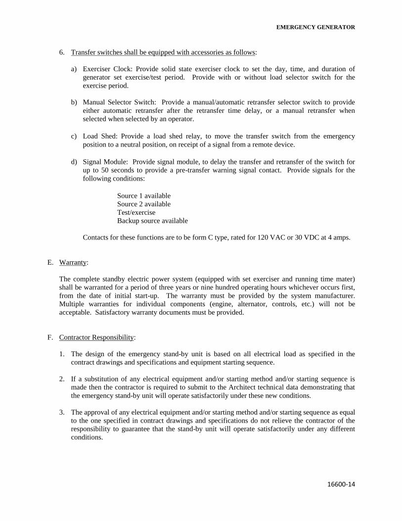
EMERGENCY GENERATOR
16600-14
6. Transfer switches shall be equipped with accessories as follows:
a) Exerciser Clock: Provide solid state exerciser clock to set the day, time, and duration of
generator set exercise/test period. Provide with or without load selector switch for the
exercise period.
b) Manual Selector Switch: Provide a manual/automatic retransfer selector switch to provide
either automatic retransfer after the retransfer time delay, or a manual retransfer when
selected when selected by an operator.
c) Load Shed: Provide a load shed relay, to move the transfer switch from the emergency
position to a neutral position, on receipt of a signal from a remote device.
d) Signal Module: Provide signal module, to delay the transfer and retransfer of the switch for
up to 50 seconds to provide a pre-transfer warning signal contact. Provide signals for the
following conditions:
Source 1 available
Source 2 available
Test/exercise
Backup source available
Contacts for these functions are to be form C type, rated for 120 VAC or 30 VDC at 4 amps.
E. Warranty:
The complete standby electric power system (equipped with set exerciser and running time mater)
shall be warranted for a period of three years or nine hundred operating hours whichever occurs first,
from the date of initial start-up. The warranty must be provided by the system manufacturer.
Multiple warranties for individual components (engine, alternator, controls, etc.) will not be
acceptable. Satisfactory warranty documents must be provided.
F. Contractor Responsibility:
1. The design of the emergency stand-by unit is based on all electrical load as specified in the
contract drawings and specifications and equipment starting sequence.
2. If a substitution of any electrical equipment and/or starting method and/or starting sequence is
made then the contractor is required to submit to the Architect technical data demonstrating that
the emergency stand-by unit will operate satisfactorily under these new conditions.
3. The approval of any electrical equipment and/or starting method and/or starting sequence as equal
to the one specified in contract drawings and specifications do not relieve the contractor of the
responsibility to guarantee that the stand-by unit will operate satisfactorily under any different
conditions.

EMERGENCY GENERATOR
16600-15
Contractor Responsibility (Cont.):
4. Any not satisfactory operation of the stand-by unit because of not complying with above
requirements shall be the responsibility of the contractor and any change in the characteristics
and/or size of the unit, to comply with above requirements, shall be borne by the contractor.
END OF SECTION 16600


