Embed Size (px)
Citation preview

Exhibit 1
Declaration of Paul Blanch
USCA Case #16-1081 Document #1636984 Filed: 09/21/2016 Page 1 of 278

1
UNITED STATES COURT OF APPEALS FOR THE DISTRICT OF COLUMBIA CIRCUIT
CITY OF BOSTON, ) DELEGATION )
) DOCKET NO. 16-1081 ) consolidated with ) 16-1098, 16-1103
TOWN OF DEDHAM, ) MASSACHUSETTS )
) RIVERKEEPER, INC. et al. ) PETITIONERS )
) v. )
) FEDERAL ENERGY REGULATORY ) COMMISSION )
DECLARATION OF PAUL M. BLANCH
Pursuant to 28 U.S.C. § 1746, Paul M. Blanch hereby declares as follows:
1. My name is Paul M. Blanch and I reside at 135 Hyde Road, West Hartford CT06117.
2. I am a registered Professional Engineer (inactive status) with more than 50 yearsof experience with nuclear safety and the construction and operation of nuclearpower plants.1 As such, I am intimately familiar with all federal regulationsgoverning the design and operation of nuclear power plants.
3. I was a consultant to the Chief Nuclear Officers at Indian Point while its presentowner, Entergy, operated it as well as its previous owners, Consolidated Edisonand the New York Power Authority.
4. I served as an expert witness for the Attorney General of the State of New Yorkfor the Nuclear Regulatory Commission proceedings on the license renewalapplications for Indian Point Units 2 and 3.
5. I also have extensive experience as a professional consultant on nuclear issues tothe top management of Northeast Utilities, Dominion Nuclear, Millstone NuclearPower Station, and Maine Yankee.
1 See attached CV.
USCA Case #16-1081 Document #1636984 Filed: 09/21/2016 Page 2 of 278

2
6. The expert opinions I express in this declaration are based on my thoroughanalysis of Entergy and NRC’s calculations, meetings with the NRC, FOIArequests, formal petitions, NRC Petition Review Board meetings, conference callswith the NRC and with PHMSA, and my review of hundreds of documentsrelated to the AIM project.
7. On September 27, 2014, I formally submitted my expert opinions to FERC relatedto the potential impact of the proposed Algonquin Incremental Market (AIM)pipeline expansion (FERC Docket No. CP14-96-000) on the safe operation of theIndian Point Nuclear Plant.
8. While I agree that Congress has given the NRC exclusive jurisdiction overnuclear power plant safety, here the NRC is not properly fulfilling its mandate toprotect the public and has never presented any reliable analysis to FERCsupporting their conclusions that the safety risk that placing the AIM pipeline nextto the Indian Point nuclear power plant is acceptable.
9. The NRC issues Regulatory Guides to provide acceptable means of satisfying therequirements of its regulations (10 CFR). For the identified external hazard asapplied in this case, the NRC issued Regulatory Guide 1.91 (RG 1.91) entitled“Evaluations of Explosions Postulated To Occur At Nearby Facilities And OnTransportation Routes Near Nuclear Power Plants”, which was last revised in2013.2 The intent of this guidance document is to ensure that adequate protectionis provided to the public from harm and radiation exposure from external events.This guide discusses how to calculate a blast radius from a nearby gas pipeline,the probability of a catastrophic gas pipeline failure, the impact of vapor clouds,heat generated and jet fires from a gas line failure. References are included in theRG for more detailed evaluations. There are no other methodologies approved bythe NRC for evaluating the impact of a gas line release other than RG 1.91.
10. ALOHA is a computer program developed by EPA for use in assessing the impactof chemical releases including releases from gas lines. However, the EPAspecifically prohibits the use of this program for modeling a “gas release from apipe that has broken in the middle and is leaking from both broken ends”, whichis the scenario that the NRC and Entergy analyzed in the ALOHA program.3 TheALOHA program is not mentioned or referenced in RG 1.91 as an acceptablemethod for calculating blast radius and risk, thus unapproved for this postulatedevent.
11. All analyses conducted by the NRC, Entergy, and its consultant, The RiskResearch Group, Inc., of the safety risk of placing the AIM pipeline next to IndianPoint, including the confirmatory and bounding analysis, relied primarily upon the
2 The 2013 version of NRC RG 1.91 is available on the NRC website at ADAMS database accession number: ML12170A980.
3 EPA Aloha User’s Manual (February 2007) at 146, available at https://nepis.epa.gov
USCA Case #16-1081 Document #1636984 Filed: 09/21/2016 Page 3 of 278
3
use of the ALOHA program. However, they have never provided a basis for deviating from the methods approved by the NRC in Regulatory Guide 1.91.
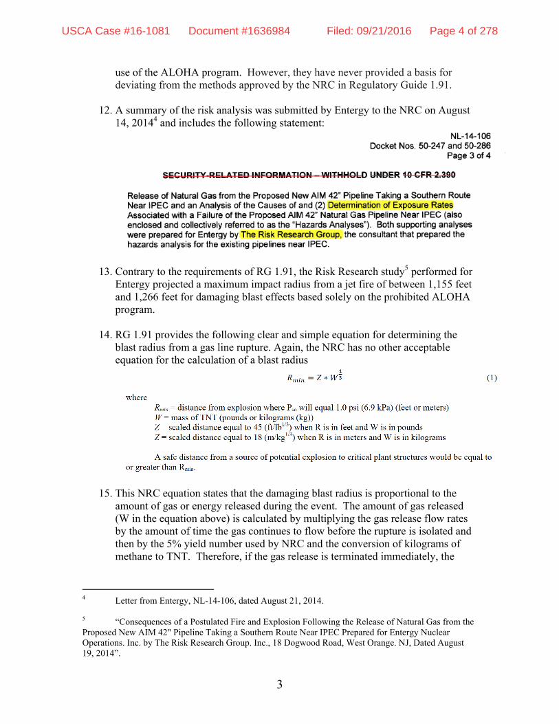
12. A summary of the risk analysis was submitted by Entergy to the NRC on August
14, 20144 and includes the following statement:
13. Contrary to the requirements of RG 1.91, the Risk Research study5 performed for Entergy projected a maximum impact radius from a jet fire of between 1,155 feet and 1,266 feet for damaging blast effects based solely on the prohibited ALOHA program.
14. RG 1.91 provides the following clear and simple equation for determining the
blast radius from a gas line rupture. Again, the NRC has no other acceptable equation for the calculation of a blast radius
15. This NRC equation states that the damaging blast radius is proportional to the amount of gas or energy released during the event. The amount of gas released (W in the equation above) is calculated by multiplying the gas release flow rates by the amount of time the gas continues to flow before the rupture is isolated and then by the 5% yield number used by NRC and the conversion of kilograms of methane to TNT. Therefore, if the gas release is terminated immediately, the
4 Letter from Entergy, NL-14-106, dated August 21, 2014. 5 “Consequences of a Postulated Fire and Explosion Following the Release of Natural Gas from the Proposed New AIM 42" Pipeline Taking a Southern Route Near IPEC Prepared for Entergy Nuclear Operations. Inc. by The Risk Research Group. Inc., 18 Dogwood Road, West Orange. NJ, Dated August 19, 2014”.
USCA Case #16-1081 Document #1636984 Filed: 09/21/2016 Page 4 of 278

4
blast radius will be small. If the release continues for a prolonged period, the blast radius will be much greater.
16. I obtained a copy of Entergy’s and the NRC’s calculations under the Freedom ofInformation Act. The calculations performed by Entergy and the NRC bothassumed that the gas flow in the AIM pipeline could be isolated and terminatedwithin 3 minutes. However, as explained in more detail in the Declaration ofpipeline safety expert Richard Kuprewicz, there is no basis for this unrealisticassumption.
17. The NRC stated in response to a FOIA request6 that the flow rates for gas releasedfrom a rupture of the AIM pipeline will be 376,000 kilograms per minute for thefirst minute, 200,000 kilograms per minute for the next minute, and 100,000kilograms per minute until the gas line is isolated. This statement originated7 fromthe Risk Research study dated August 19, 2014.
18. However, if one uses the flow rate numbers provided by NRC along with theNRC’s assumption that the gas flow will terminate within 3 minutes, thecalculation using the RG 1.91 equations results in a blast radius of about 1,905feet rather than the 1,155-1,266 foot blast radius calculated by Risk ResearchGroup using the ALOHA program. The NRC relied on this much lessconservative and unreliable blast radius in its safety assessment rather than theblast radius that would have been calculated using its own regulatory guidanceand stated assumptions.
19. My calculation using the above flow rates provided by the NRC and a realistic gasflow isolation time of 60 minutes in the equation from RG 1.91 results in a blastradius of greater than 4,000 feet, which would encompass the entire nuclear plantsite. Even assuming a less realistic isolation time of 30 minutes, the blast radiuswould be 3,255 feet, encompassing both reactor units 1 and 3 and most of reactorunit 2.
6 NRC internal email dated April 27, 2015:
7 Risk Research Group, Inc Analysis dated August 19, 2014
USCA Case #16-1081 Document #1636984 Filed: 09/21/2016 Page 5 of 278

5
20. A blast radius in the range of 3,000 to 4,000 feet would likely disable structures,systems and components (SSCs) that are necessary to prevent core melting andmajor radioactive releases to the environment. The impact on the Indian Point sitemay disable all safety systems similar to the catastrophic nuclear event atFukushima. None of the safety systems at Indian Point have been designed oranalyzed to withstand the projected blast effects.
21. On March 24, 2015, NRC Chairman Burns testified before Congress and wasquestioned by Congresswoman Lowey as to why the EPA’s ALOHA programwas used for this analysis rather than the methodology required by RG 1.91.8Chairman Burns stated that RG 1.91 could not be used for this analysis because itdid not address “vapor cloud” explosions and heat flux. This is an inaccuratestatement to a member of Congress by the NRC Chairman. RG 1.91 discusses“vapor clouds” and their impact 10 times in RG 1.91. References provided in theRG provide other guidance for addressing heat flux. None of the referencessuggest the use of ALOHA for evaluating the risk of a gas line release.
22. As a direct result of inquiries from Congressional Representatives to the NRCChairman questioning the NRC’s assumption of a 3-minute valve isolation time,the NRC conducted a “bounding” analysis assuming a gas release for one hour.This bounding analysis used an energy release inconsistent with previous values9
provided by the NRC and also used the prohibited ALOHA program. If the NRChad used its published release rates in the RG 1.91 equation the blast radius after60 minutes is calculated to be about 4,000 feet.
23. At the Turkey Point Nuclear facility in Florida, the NRC properly using RG 1.91analyzed the safety risk of a 22-inch gas line with an operating pressure of 722PSI.10 This analysis projected a blast radius of 3,097 feet. Comparatively, theAIM project involves a significantly larger pipeline (42 inches) with a higherdesign pressure of 850 psi and yet the NRC projected a blast radius of only about1,200 feet (less than half of the blast radius they calculated for a smaller diameterand lower pressure pipeline near Turkey Point).
24. NRC Regulatory Guide 1.91 specifies the probability of a catastrophic gaspipeline failure that the NRC finds to be acceptable to meet the NRC regulations.This regulatory guide clearly states that if the probability of a pipeline eventoccurs at a frequency of less than 1 in 10 million per year (1x10 -7 per year) thenthis risk is acceptable. I consider this risk to be reasonable if it is reliablycalculated in accordance with accepted engineering principles.
25. The NRC and Entergy both claim that the probability of a pipeline accident near
8 See video of testimony, available at https://www.youtube.com/watch?v=umWpVZTqoJE.
9 Internal NRC email from David Beaulieu dated April 27, 2015.
10 See attached Turkey Point Units 6 & 7 COL Application Part 2 – FSAR at 2.2-23 – 2.2-25.
USCA Case #16-1081 Document #1636984 Filed: 09/21/2016 Page 6 of 278

6
Indian Point is acceptable because they have calculated it to be less than 1 in 10 million per year (or 1 x 10⁻⁷ per year). However, it is my expert opinion that the actual failure probability of the AIM pipeline is in the range from 1 in 1000 to 1 in 10,000 per year, which is completely unacceptable and inconsistent with the requirements of 10 CFR Part 100 and RG 1.91. Put in perspective, according to NTSB statistics, there are approximately 37 million commercial airline flights per year with about 10 fatal crashes per year, or 1 crash in 3,700,000 commercial flights per year. The probability of a nuclear event at Indian Point due to a gas line failure is in the range of 1 in 1000 to 1 in 10,000 events per year, which is significantly greater than those of the commercial airline industry. This probability is completely unacceptable for a nuclear plant and ignores the NRC’s mandate to protect the public.
26. The NRC’s calculation of the probability of a pipeline explosion states:
27. The above clearly states that the failure rate, according to PHMSA data and the FEMA, DOT and EPA Handbook of Chemical Hazards Analysis Procedures, Section 11 (Reference 5) is projected to be 1.5 pipeline failures in 1000 per year (1.5 x 10 -3) within the proximity of Indian Point, a number that exceeds the NRC’s acceptable probability rate by a factor of more than 1000 times.
28. Without any reliable basis, the NRC and Entergy then reduced this unacceptable probability by citing Reference 5, Section 11 of RG 1.91 as a justification. The number they used for the failure rate for pipelines greater than 20 inches in diameter is accurate however the probability reductions citing 1 percent for a complete break, a 5 percent ignition rate, and a further reduction of at least an
USCA Case #16-1081 Document #1636984 Filed: 09/21/2016 Page 7 of 278

7
order of magnitude for an underground pipe are not discussed in Reference 5 and are otherwise unsupported. Pipeline safety expert, Richard Kuprewicz, explains in more detail in his Declaration why these assumptions are unrealistic.
29. A nuclear facility in Eunice, New Mexico was proposed to be located within 1.8miles of a 16-inch gas line operating at a pressure of less than 50 psi. Thispipeline in New Mexico has less than 5% of the capacity (flow) of the new AIMpipeline. The AIM pipeline will operate at a pressure 50 times greater than thepressure of the New Mexico pipeline found to present an unacceptable risk. Thisline is located at a significantly greater distance away from the Indian Pointnuclear facility. A study required by the NRC determined that the consequencesof a pipeline explosion near the proposed nuclear facility were unacceptable andnot in compliance with NRC regulations.11 This event was analyzed using thesame RG 1.91 requirements that should have been used for analyzing the AIMpipeline.
30. In conclusion, the NRC has underestimated the probability of a gas line accidentimpacting the Indian Point nuclear plant by at least a factor of 1000. Moreover,the NRC and Entergy have failed to provide any supportable documentation thatIndian Point can safely shut down the plants in the event of a gas line rupture, andEntergy has no emergency procedures in place at Indian Point to respond to a gasline rupture. The blast radius from a gas line rupture would likely encompass theentire Indian point site, disabling all vital equipment required to prevent coredamage and major radioactive releases to the environment.
31. It is my expert opinion that once gas is introduced into the AIM pipeline therewill be a grave and imminent danger to the surrounding area and residents. Theconsequences of a nuclear event at Indian Point may impact millions of lives inthe Hudson Valley and New York City and cause social and economic impacts inthe trillions of dollars range.12
32. It is my professional expert opinion that a transparent and independent riskanalysis must be conducted consistent with NRC regulations 10 CFR Part 50,Regulatory Guide 1.91, and the requirements of DOT/PHMSA 49 CFR §192.935and ASME B31.8(S) prior to pressurized gas being introduced into the AIMpipeline.
11 See attached Framatome ANP Calculation 32-2400572-02, "Natural Gas Pipeline Hazard Risk Determination" dated January 19, 2004.
12 This estimate is based on the contamination and land condemnation resulting from the Fukushima accident, recovery and disposal costs, and the estimated property values in the areas surrounding Indian Point.
USCA Case #16-1081 Document #1636984 Filed: 09/21/2016 Page 8 of 278

8
I declare under penalty of perjury that the foregoing is true and correct.
Executed on September 16, 2016.
______________________ Paul M. Blanch
USCA Case #16-1081 Document #1636984 Filed: 09/21/2016 Page 9 of 278

1. P. Blanch CV
2. Entergy to NRC re: Safety Evaluation Prepared in Response to AIM Project (August 21, 2014) Indian Point Safety Evaluation prepared by Energy (August 21, 2014).
3. Hazards Analysis: Consequences of Postulated Fire and Explosion Following Release of Natural Gas From Proposed AIM Pipeline, prepared for Entergy by Risk Research Group (August 19, 2014).
4. NRC Internal Email from D. Beaulieu to D. Pickett (April 27, 2015).
5. Turkey Point Units 6 and 7 COL Application, Part 2 -FSAR at 2.2.2-2.2.-25
6. Attachment 2: Calculation 32-2400572-02, “Natural Gas Pipeline Hazard Risk Determination” by Framatome ANP
USCA Case #16-1081 Document #1636984 Filed: 09/21/2016 Page 10 of 278

P. Blanch CV
USCA Case #16-1081 Document #1636984 Filed: 09/21/2016 Page 11 of 278
Resume Paul M. Blanch 135 Hyde Road,
West Hartford, CT 06117 860-236-0326
OVERVIEW
A 50+ year professional consulting to the top management of Northeast Utilities, Dominion Nuclear, Millstone Nuclear Power Station, Indian Point and Maine Yankee and with a distinguished career as an engineer, engineering manager and project coordinator for the construction and operation of nuclear power plants. Intimately familiar with all regulations governing the design and operation of commercial Nuclear Power Plants
An expert witness having provided research and testimony for numerous plaintiffs including the State of New York Attorney General, Three Mile Island, Vermont Yankee, Saint Lucie, Millstone, Seabrook, Indian Point and Davis Besse.
Provided testimony on behalf of federal and private nuclear workers before State and Federal Courts and the Merit Systems Protection Board (MSPB).
Developed computer research tools and programs to access, search and analyze publically available documents from the Nuclear Regulatory Commission (NRC).
EXPERIENCE
EXPERT WITNESS FOR RIVERKEEPER RELATED TO THE SAFETY AND FEASIBILITY OF COOLING TOWERS FOR INDIAN POINT UNITS 2 AND 3. --2015 T0 PRESENT
Provided expert testimony before the New York State court about the safety of Indian Point be required to install cooling towers in lieu of present once through cooling.
CONSULTANT TO NUMEROUS PUBLIC INTEREST GROUPS RELATED TO THE PROPOSED INSTALLATION OF A NEW NATURAL GAS LINE IN THE CLOSE PROXIMITY TO THE INDIAN POINT POWER PLANTS--2013 TO PRESENT
I continue to work with public interest groups, US Senators, Congresspersons, and other elected officials about the potential impact of a new 42-inch natural gas line crossing the Indian Point property. I am working with the NRC and have met with the NRC Chairman and other Commissioners for the purpose of conducting a risk assessment should a malfunction of the new gas line occur. Also working with the Department of Transportation (PHMSA), and the Federal Energy Regulatory
USCA Case #16-1081 Document #1636984 Filed: 09/21/2016 Page 12 of 278

Commission (FERC) and the NY Governor’s office.
EXPERT WITNESS FOR NEW STATE ATTORNEY GENERAL SUPPORTING NEW YORK’S POSITION RELATED TO THE RELICENSING OF INDIAN POINT UNITS 2 AND 3 (IP 2&3) –April 2007 to 2012
Provided expert witness research and testimony on behalf of the State of New York on the relicensing of the Indian Point units. Researched the design basis for IP 2&3 and provided the basis for age related contentions submitted on behalf of the State of New York to the NRC within the scope of the relicensing requirements of 10 CFR 54. The Atomic Safety Licensing Board accepted four out of five contentions related to buried piping systems, inaccessible cable qualification and the life management of vital transformers.
EXPERT WITNESS FOR VARIOUS PUBLIC INTEREST GROUPS SUPPORTING THEIR POSITION RELATED TO THE RELICENSING OF THE SEABROOK NUCLEAR PLANT -2010 to present
Provided expert witness research and testimony on behalf of various public interest groups opposing the relicensing of Seabrook.
EXPERT WITNESS FOR NEW ENGLAND COALITION (NEC) vs. ENTERGY NUCLEAR REVIEWING THE EXTENDED POWER UPRATE AND RELICENSING OF VERMONT YANKEE—2004 to present
Provided pro bono expert witness research and testimony on behalf of NEC opposing the 20% Extended Power Uprate (EPU) for Vermont Yankee (VY). Researched the design basis for VY and provided testimony before the Vermont Public Service Board, Public Service Commission, Atomic Safety and Licensing Board (ASLB) and the Advisory Committee for Reactor Safety (ACRS). Participated in meetings with Vermont Governor Douglas, Senators Leahy and Jeffords. Petitioned the NRC under 10 CFR 2.206 to request VY and the NRC identify any and all non-compliances with present NRC regulations and evaluate risks associated with identified non-compliances to the General Design Criteria of 10 CFR 50 Appendix A and other applicable NRC regulations.
EXPERT WITNESS FOR PLAINTIFFS IN FINESTONE vs. FLORIDA POWER AND LIGHT -AUGUST 2003 to JANUARY 2006
Provided expert witness and conducted extensive historical research to determine the quality and quantity of unmonitored releases from the St. Lucie nuclear plant. Discovered that the plant had significant unmonitored discharges to the environment in excess of those allowed by 10 CFR 20. Case dismissed via summary judgment in 2006.
USCA Case #16-1081 Document #1636984 Filed: 09/21/2016 Page 13 of 278

EMPLOYEE CONCERNS AND SAFETY CONCIOUS WORK ENVIRONMENT CONSULTANT -- February 2001 to February 2002
Consultant reporting to the Chief Nuclear Officer at Indian Point Unit 2 assisting in the evaluation of the plant’s Employee Concerns Program and an assessment of the Safety Conscious Work Environment. (SCWE) Work also includes assisting investigations of allegations related to employee discrimination and other technical and safety issues. Developed and implemented training programs for ECP and other site personnel.
EMPLOYEE CONCERNS AND SAFETY CONCIOUS WORK ENVIRONMENT CONSULTANT -- September 2000 to 2001
Consultant, reporting to the President of Maine Yankee Atomic Power Company. Primary responsibilities include the re-establishment of a Safety Conscious Work Environment (SCWE) and to act as an independent facilitator to resolve differences between employees and management. Evaluated the Employee Concerns Program making recommendations for improvement to the President. Conducted independent investigations of allegations received internally and referral allegations from the NRC.
EMPLOYEE CONCERNS AND SAFETY CONCIOUS WORK ENVIRONMENT CONSULTANT -- February 1997 to 2001
Consultant reporting to the President of Northeast Nuclear Energy Company assisting in the recovery of the three Millstone Units shut down due to safety problems. Primary responsibilities include the establishment of a Safety Conscious Work Environment (SCWE) and to act as an independent facilitator to resolve differences between employees and management. Coordinate many different groups at Millstone including executive management, legal, human resources and the Employee Concerns organization. Resolve differences at the lowest possible management level. Coordinate with ECP to investigate safety, technical and alleged harassment issues and review outcomes, to assure the investigation was conducted in an unbiased, fair and equitable manner. Coordinate corrective action with the appropriate management, legal and technical organizations. Worked closely with top management and corporate communications to coordinate efforts to regain public confidence with the operation and management of the Millstone site. Provide assistance with regulatory compliance issues and interface with various public interest groups in the Millstone area including State oversight and groups critical of the Millstone operations. Provide both formal and informal feedback to the
USCA Case #16-1081 Document #1636984 Filed: 09/21/2016 Page 14 of 278

NRC about the recovery of Millstone and the establishment of a Safety Conscious Work Environment.
Conducted training and made presentations to top nuclear executives about the need to maintain a Safety Conscious Work Environment when requested by the Nuclear Energy Institute and the Nuclear Regulatory Commission.
Made regular presentations to public interest groups, State of Connecticut oversight organizations and the Nuclear Regulatory Commission as to my personal assessment of the work environment at Millstone and the status of corrective actions.
Worked as a team member with other Millstone management providing overall strategic direction to the President to assist in the recovery of Millstone with specific emphasis on public confidence and the establishment of a SCWE.
Provide routine advice to outside legal organizations and other nuclear utility management with respect to dealing with employees raising safety concerns.
Conducted presentations (September 1999 and September 2000) to the Employee Concerns Program Forum providing a perspective on “whistleblower” issues and what management needs to do to properly address these issues.
Conducted presentation in September 2000, along with NRC Chairman Meserve, to the NRC and the NRC’s Inspector General’s staff on a proposal to resolve “High profile whistleblower” situations.
EXPERT WITNESS FOR PLAINTIFFS RELATED TO THE THREE MILE ISLAND 1979 ACCIDENT-1995 to 1998
Provided expert witness and conducted extensive historical research to determine the quality and quantity of unmonitored releases from the Three Mile Island plant. Discovered that the actual releases were more than 5 times the amount published by the NRC and the operator of TMI.
ENERGY CONSULTANT -- 1993 to 1997
Provided expert witness testimony and worked with the NRC to change Federal Regulations for the protection of individuals identifying safety issues at nuclear licensed facilities.
USCA Case #16-1081 Document #1636984 Filed: 09/21/2016 Page 15 of 278

Worked with the Office of the Inspector General of the NRC to provide major input to a revision of the recently passed federal "Energy Bill" providing additional protection to Nuclear Whistleblowers. Some personnel within the NRC have referred this to as “the Blanch Amendment”.
Provided advice to both attorneys and their clients to gain an understanding of the NRC and Department of Labor regulations governing the protection of whistleblowers under the Energy Reorganization Act
NORTHEAST UTILITIES -- 1972 to 1993
Supervisor of Electrical Engineering (Instrument and Control Engineering Branch) Responsible for programs to assure plant reliability and compliance with NRC regulations. Conducted periodic training of employees and contractors to maintain continued cognizance of all corporate and station procedures and regulations. Worked as both a supervisor of an engineering organization and directed the efforts of Stone and Webster and Bechtel to assure safety and compliance during the design and construction of Millstone Units 2 & 3. Primary interface between NU, Westinghouse and Stone and Webster for the conceptual design of electrical and process instrumentation systems during construction of Millstone Unit 3. Assured compliance with all NRC electrical standards and design criteria. Member of the Millstone Nuclear Review Board responsible to the president to assure compliance with all applicable regulations.
ACCOMPLISHMENTS
Directed the development of the first real time instrumentation monitoring system for practical use in commercial nuclear plants to assess the overall safety status of the plant and to provide information to remote facilities during emergency events. This effort resulted in the identification of many instrumentation problems not previously recognized or considered “undetectable failures." As a result of these efforts, and in face of strong opposition Rosemont and the nuclear industry, the NRC issued a Bulletin (90-01) requiring all utilities to monitor Rosemount transmitters used in safety applications. A supplement to the Bulletin was issued at the end of 1992. Recognized the inability of condensate pots to function under de-pressurization events as a direct result of NU's computerized instrument monitoring system. This is one of the most significant safety issues identified in the nuclear industry. Developed a water injection system into the reference legs that precluded the absorption of these gases. This solution was adopted by the entire nuclear industry.
USCA Case #16-1081 Document #1636984 Filed: 09/21/2016 Page 16 of 278

Developed a program to reduce or eliminate the need for periodic calibration of analog instrumentation and the elimination of the need for pressure transmitter response time testing. The formation of an ISA Standard activity (ISA 67.06) for the development of a standard for Performance Monitoring of Safety Related Instruments in Nuclear Power Plants was a direct result of these efforts.
Received a "First Use" award from Electric Power Research Institute (EPRI) for the application of Signal Validation for the identification of failed sensors during accident, as a direct result of developing and implementing signal validation for emergency computer systems.
Worked closely with the US General Accounting Office conducting its study related to the NRC’s handling of whistleblower issues in the nuclear industry and buried piping degradation.
Electrical plant and Reactor operator and Leading Petty Officer aboard the Nuclear Powered Submarine USS Patrick Henry (SSBN-599). Qualified electrical plant and reactor operator and instructor at Navy prototype reactor (S1C).
SPECIAL QUALIFICATIONS
Actively participated and contributed to studies conducted by the NRC and NU addressing the cultural problems at Northeast Utilities. Collaborated with the Fundamental Cause Assessment Team and the NRC’s Millstone Independent Review Group and provided insights as to the root causes of the problems effecting the NU nuclear organization.
Named Utility Engineer of the Year (1993) by Westinghouse Electric and Control Magazine for advancing the safety of nuclear power.
Publicly recognized in October 1992 by the Chairman of the NRC (Ivan Selin) for significant contributions to nuclear safety, related to the identification of the condensate pot problems on Boiling and Pressurized Water Reactors.
Testified before the US Senate Subcommittee about the failure of the NRC's regulatory practices and the NRC's mistreatment of Nuclear Whistleblowers. Instrumental in developing Connecticut's Nuclear Whistleblower Law effective October 1, 1992 which is the strongest Whistleblower Protection Law in the country. Discussed in Time Magazine (March 4, 1996) as a contributor to nuclear safety.
Featured on Page 1 of the Wall Street Journal (03/12/1998) as a Nuclear Safety Advocate assisting the successful recovery of Millstone Units 2 and 3.
USCA Case #16-1081 Document #1636984 Filed: 09/21/2016 Page 17 of 278

EDUCATION
BS Electrical Engineering, Magna Cum Laude, 1972, University of Hartford Graduate courses in Mechanical and Thermodynamic Engineering US Navy Submarine School, 1968 US Navy Nuclear Power School, 1965 US Navy Electronics Technician School, 1964
PROFESSIONAL ASSOCIATIONS
Vice Chairman, Institute of Nuclear Power Operations (INPO) Two Standards Activities in response to Three Mile Island including Post Accident Monitoring requirements.
Member of the ANS Standards Committee responsible for developing the requirements for seismic monitoring systems for nuclear power plants. (ANS 6.8.1 and ANS 6.8.2)
Worked with NEI (NUMARC) on the resolution of the common mode failures of Rosemont pressure transmitters.
Worked with the NRC and discovered (1992) a significant design error impacting all BWR’s. This was a deficiency in the design of level transmitters that would have produced non-conservative reactor level errors. These errors may have exceeded 35 feet. As a result, every BWR was required to make extensive modifications to resolve this major issue.
Chairman of Two Committees for the Institute for Nuclear Power Operations (INPO) related to Three Mile Island post accident monitoring requirements and emergency response facilities.
Member of ISA 67.04 for the development of Instrument Setpoints for Nuclear Power Plants
Registered Professional Engineer - California
USCA Case #16-1081 Document #1636984 Filed: 09/21/2016 Page 18 of 278

Entergy to NRC re: Safety Evaluation Prepared in Response to AIM Project (August 21, 2014)
Indian Point Safety Evaluation prepared by Energy (August 21, 2014).
USCA Case #16-1081 Document #1636984 Filed: 09/21/2016 Page 19 of 278

'~Entergy,
EntergQ Nuclear NortheastIndian Point Energy Center450 Broadway, GSBP.O. Box 249Buchanan, NY 10511-0249Tel (914) 254-2055
Fred DacimoVice PresidentOperations License Renewal
SECURITY-RELATED INFORMATION - WITHHOLD UNDER 10 CFR 2.390
NL-14-106
August 21, 2014
U.S. Nuclear Regulatory CommissionDocument Control Desk11545 Rockville Pike, TWFN-2 F1Rockville, MD 20852-2738
SUBJECT:
REFERENCES: 1.
10 C.F.R. 50.59 Safety Evaluation and Supporting Analyses Preparedin Response to the Algonquin Incremental Market Natural Gas ProjectIndian Point Nuclear Generating Unit Nos. 2 & 3Docket Nos. 50-247 and 50-286License Nos. DPR-26 and DPR-64
Algonquin Gas Transmission, LLC, Abbreviated Application of AlgonquinGas Transmission, LLC for a Certificate of Public Convenience andNecessity and For Related Authorizations, Docket No. CP14-96-000(Feb. 28, 2014) ("Certificate Application").
2. Algonquin Incremental Market Project Draft Environmental ImpactStatement Algonquin Gas Transmission, LLC, August 6, 2014, DocketNo. CP14-96-000, FERC/EIS-0254D
3. MOTION TO INTERVENE AND COMMENTS OF ENTERGY NUCLEARINDIAN POINT 1, LLC, ENTERGY NUCLEAR INDIAN POINT 2, LLC,ENTERGY NUCLEAR INDIAN POINT 3, LLC AND ENTERGY NUCLEAROPERATIONS, INC. Algonquin Gas Transmission, LLC) Docket No.CP14-96-000, April 8, 2014
Dear Sir or Madam:
As the Nuclear Regulatory Commission ("NRC") is aware, Algonquin Gas Transmission, LLC("AGT") has proposed to construct and operate a new natural gas pipeline near the Indian PointEntergy Center ("IPEC"). The Project, known as the Algonquin Incremental Market Project("AIM Project"), involves the construction and operation of about 37 miles of natural gas pipelineand associated facilities to expand natural gas transportation service to Connecticut, RhodeIsland, and Massachusetts. The majority of the pipeline facilities would replace existing
SECURITY-RELATED INFORMATION - WITHHOLD UNDER 10 CFR 2.390When Enclosure 2 is detached, the remainder of this letter
may be made publicly available
USCA Case #16-1081 Document #1636984 Filed: 09/21/2016 Page 20 of 278

NL-14-106Docket Nos. 50-247 and 50-286
Page 2 of 4
SECURITY-RELATED INFORMATION - WITHHOLD UNDER 10 CFR 2.390
Algonquin pipelines, but the Project also includes the installation of new 42-inch diameterpipeline near the southern boundary of IPEC to replace the existing 26-inch pipeline in vicinity ofIPEC which will remain in place but idled. On February 28, 2014, AGT filed a formal applicationwith the Federal Energy Regulatory Commission ("FERC" or "Agency") related to the AIMProject (Reference 1).
On August 6, 2014, FERC issued the draft environmental impact statement ("EIS") for the AIMProject (Reference 2). As it relates to IPEC, the draft EIS states as follows:
Based on our consultation with NRC, Entergy is required to assess any new safetyimpacts on its IPEC facility and provide that analysis to the NRC. Algonquin hascoordinated with Entergy to provide information about its proposed pipeline, and Entergyis currently performing a Hazards Analysis. To ensure that no new safety hazards wouldresult from the AIM Project, we are recommending that Algonquin file the finalconclusions regarding any potential safety-related conflicts with the IPEC based on theHazards Analysis performed by Entergy.
FERC's conclusions in the draft EIS were based, in part, on comments Entergy submitted toFERC to assist the Agency in identifying issues for evaluation in the EIS (Reference 3). Entergynoted in its comments to FERC that the existing AGT system has been operating safely next toIPEC for several decades, and evaluations of the potential hazards posed by the existingpipelines, conducted pursuant to NRC regulations and guidance, establish that the existingpipelines do not impair the safe operation of IPEC. The proposed AIM Project, however,expands the existing AGT system, including pipeline capacity and pressure. Thus, the potentialfor increased nuclear safety risks, including in terms of the probability and consequences of apotential malfunction or failure of the expanded natural gas pipeline near IPEC, must beevaluated and found to be acceptable in accordance with applicable NRC regulations.Accordingly, while such occurrences are unlikely, Entergy must analyze any increased risk andconsequences of such events prior to FERC's approval of the project. Entergy further notedthat, depending on the results of the analysis, prior NRC review and approval of the newhazards analysis could be required before the project can be approved by FERC. FERCreceived numerous other scoping comments from members of the public and governmentofficials concerning the safety of the Project and its proximity to IPEC. Thus, there is significantpublic interest in this project and its potential impacts on IPEC.
As noted in the EIS, Entergy has worked closely with AGT to better understand the scope of theproject and confer regarding means to avoid any potential adverse impacts to IPEC. As a directresult of those efforts, Entergy and AGT have agreed to a comprehensive set of design andinstallation enhancements for piping routed near IPEC. These enhancements include, but arenot limited to, thicker piping, thicker corrosion protection, greater burial depth, and installation ofprotective reinforced concrete mats to impede access to the buried piping.
Consistent with applicable NRC regulations and guidance, Entergy prepared the enclosed 10C.F.R. § 50.59 Safety Evaluation related to the proposed AIM Project. Entergy also preparedtwo supporting evaluations; (1) Consequences of a Postulated Fire and Explosion Following the
SECURITY-RELATED INFORMATION - WITHHOLD UNDER 10 CFR 2.390When Enclosure 2 is detached, the remainder of this letter
may be made publicly available
USCA Case #16-1081 Document #1636984 Filed: 09/21/2016 Page 21 of 278

NL-14-106Docket Nos. 50-247 and 50-286
Page 3 of 4
SECURITY-RELATED INFORMATION - WITHHOLD UNDER 10 CFR 2.390
Release of Natural Gas from the Proposed New AIM 42" Pipeline Taking a Southern RouteNear IPEC and an Analysis of the Causes of and (2) Determination of Exposure RatesAssociated with a Failure of the Proposed AIM 42" Natural Gas Pipeline Near IPEC (alsoenclosed and collectively referred to as the "Hazards Analyses"). Both supporting analyseswere prepared for Entergy by The Risk Research Group, the consultant that prepared thehazards analysis for the existing pipelines near IPEC.
As documented in the attached Hazards Analyses, Entergy has concluded that based on theproposed routing of the 42-inch pipeline further from safety related equipment at IPEC andaccounting for the substantial design and installation enhancements agreed to by AGT, theproposed AIM Project poses no increased risks to IPEC and there is no significant reduction inthe margin of safety. Accordingly, as documented in the enclosed 10 C.F.R. § 50.59 SafetyEvaluation, Entergy has concluded that the change in the design basis external hazardsanalysis associated with the proposed AIM Project does not require prior NRC approval.
Entergy's comments on the AIM Project draft EIS are due to be filed with FERC by September29, 2014. Given the current status of the AIM Project, Entergy believes this is the lastopportunity as a matter of right for Entergy to inform FERC as to the results of the HazardsAnalysis, whether additional mitigation is necessary, and whether prior NRC review andapproval is required. In addition, FERC requested that AGT file the final conclusions regardingany potential safety-related conflicts with IPEC based on the Hazards Analysis performed byEntergy by that same date.
As noted above, Entergy has determined that there are no increased risks to Indian Point and,pursuant to 10 CFR § 50.59, has concluded that prior NRC review and approval is not required.In our submittal to FERC we plan to point out that as part of the routine inspection program NRCalways has the right to review and challenge any analysis done pursuant to 10 CFR50.59. Unless NRC chooses to perform such a review we cannot guarantee that they wouldultimately concur with our position. Therefore we will suggest that prior to approving theProject, FERC should consider conferring with the NRC before reaching a conclusion regardingthe potential hazards posed by the AIM project on IPEC and whether any additional mitigation isnecessary. Accordingly, we are forwarding to the NRC the enclosed Safety Evaluation andHazards Analyses and are prepared to answer any questions NRC may have on the Analysesor support inspections of the same.
Please withhold the hazards analysis (Enclosure 2) under 10 CFR 2.390 as security relatedinformation.
SECURITY-RELATED INFORMATION - WITHHOLD UNDER 10 CFR 2.390When Enclosure 2 is detached, the remainder of this letter
may be made publicly available
USCA Case #16-1081 Document #1636984 Filed: 09/21/2016 Page 22 of 278

NL-14-106Docket Nos. 50-247 and 50-286
Page 4 of 4
SECURITY-RELATED INFORMATION -WITHHOLD UNDER 10 CFR 2.390
If you have any questions, or require additional information, please contact Mr. Robert Walpole,Regulatory Assurance Manager, at [914] 254-6710.
Sincerely,
FRD/sp
Enclosures: 1. 10 C.F.R. 50.59 Safety Evaluation
2 Hazards Analysis (SECURITY-RELATED INFORMATION - WITHHOLDUNDER 10 CFR 2.390
cc: Mr. Douglas Pickett, Senior Project Manager, NRC NRR DORLMr. William M. Dean, Regional Administrator, NRC Region 1NRC Resident InspectorMr. John B. Rhodes, President and CEO, NYSERDA w/o Enclosure 2Ms. Bridget Frymire, New York State Dept. of Public Service w/o Enclosure 2
SECURITY-RELATED INFORMATION - WITHHOLD UNDER 10 CFR 2.390When Enclosure 2 is detached, the remainder of this letter
may be made publicly available
USCA Case #16-1081 Document #1636984 Filed: 09/21/2016 Page 23 of 278

SECURITY-RELATED INFORMATION - WITHHOLD UNDER 10 CFR 2.390
ENCLOSURE 1 TO NL-14-106
10 C.F.R. 50.59 SAFETY EVALUATION
ENTERGY NUCLEAR OPERATIONS, INC.INDIAN POINT NUCLEAR GENERATING UNIT NOs. 2 and 3
DOCKET NOs. 50-247 50-286
SECURITY-RELATED INFORMATION - WITHHOLD UNDER 10 CFR 2.390When Enclosure 2 is detached, the remainder of this letter
may be made publicly available
USCA Case #16-1081 Document #1636984 Filed: 09/21/2016 Page 24 of 278

10 CFR 50.59 EVALUATION FoRMSheet 1 of 21
r
I. OVERVIEW / SIGNATURES'
Facility: IP2/IP3 Evaluation # / Rev. #:
Proposed Change I Document: Installation of a New 42" Natural Gas Pipeline South of IPEC
Description of Change: Installation of New 42" Natural Gas Pipeline South of Gypsum Plant andcrossing IPEC Property Near Switchyard / GT2/3 Fuel Oil Storage Tank.
Summary of Evaluation:
The proposed pipeline was evaluated under the criteria of 10 CFR 50.59 and the evaluation showsthat current Nuclear Regulatory Commission criteria were satisfied that would permit the pipeline to beinstalled without a license amendment requiring NRC approval
Backaround
The Indian Point Energy Center (IPEC) is traversed by two natural gas pipelines owned and operatedby Spectra Entergy. The pipelines are 26 in. and 30 in. in diameter and operated at a pressure of 600-650 psig and 600-750 psig, respectively. The two gas pipelines traverse the owner-controlled areaand are physically located closer to Indian Point Unit 3 (IP3) than Indian Point Unit 2 (IP2). The twolines are buried about 3 ft. deep in a trench formed in excavated rock. Portions of the pipelines at theshoreline of the Hudson River exit the trench and are above ground. The nearest approach of theburied portion of the pipelines to safety related structures, systems and components (SSC) is about400 ft. The nearest above ground portion is approximately 800 ft. from the nearest safety-relatedstructure (diesel generator building).
The initial licensee and the Atomic Energy Commission considered the hazards posed by thesepipelines during the initial licensing process of 1P3, and determined that the presence of the gaspipelines did not endanger the safe operation of IP3 (Reference 1). Section 2.2 of the AEC's safetyevaluation report (SER) for IP3 describes the Staff's conclusions regarding this analysis that therupture of these gas pipelines would not impair the safe operation of IP3 (Reference 2).
On September 27, 1997 the New York Power Authority (NYPA) submitted the Individual PlantExamination of External Events (IPEEE) report for IP3 (Reference 3). In that report, it evaluated thesusceptibility of IP3 to damage to the pipelines from seismic events. NYPA concluded that theprobability of occurrence was low enough that the pipelines could be screened out as a seismicvulnerability. NYPA also considered pipeline ruptures from other causes, such as an inadvertentoverpressure condition. Although NYPA stated that a vapor cloud rupture scenario could subjectsome IP3 structures to overpressures exceeding 1 psi, it concluded that the probability of anaccidental leak from the line leading to such an event was extremely low. The NRC Staff's evaluationof the IP3 IPEEE did not identify any concerns with that approach (Reference 4).
In March 2003, questions were raised regarding the safety of the existing natural gas pipelines thatpass through the Indian Point site, and suggested that they could be subject to sabotage. At therequest of NRC Region I, the NRC Staff reviewed the prior evaluations of the lines and associatedpotential external hazards to the safe operation of the facility. The Staff's review is documented in an
1 Signatures may be obtained via electronic processes (e.g., PCRS, ER processes), manual methods (e.g., Ink signature),
e-mail, or telecommunication. if using an e-mail or telecommunication, attach it to this form.
EN-LI-101-ATT-9.1, Rev. 11
USCA Case #16-1081 Document #1636984 Filed: 09/21/2016 Page 25 of 278

10 CFR 50.59 EVALUATION FORMSheet 2 of 21
April 25, 2003 NRC internal memorandum (Reference 5). The NRC Staff made an assessment of therisks associated with the potential for large releases of natural gas from the pipelines in the vicinity ofIP3 given the statements made in the IP3 IPEEE, and the focus of prior external hazards evaluationson the likelihood of an accidental pipe rupture. The NRC Staff also considered intentional acts todamage the line(s) in its gas pipeline hazard assessment, which is not available to the public forsecurity-related reasons. The NRC's April 25, 2003 memorandum states: "For a large rupture andresulting fire, the staff found that safety-related structures would not be significantly affected. Forunconfined vapor cloud ruptures, the staff found that the factors involved to achieve a rupture creatingsizeable overpressures make the probability for occurrence very low. However, the NRR staffbelieves that this aspect should be further evaluated by the Office of Nuclear Safety and IncidentResponse (NSIR) in conjunction with Region I"
In March 2008, the NRC Staff requested information from Entergy as a result of a concern from amember of the public that there are "weak spots" in the IPEC security defense/structure, including aNational Guard security position known as "Point 8." That request included any analyses orcalculations supporting Entergy's conclusions regarding the vulnerability of Point 8. In an April 23,2008 letter (ENOC-08-00021) to the NRC, Entergy explained that Point 8 encompasses the above-ground pressurized gas piping and valves that are part of the Algonquin natural gas pipelines in theOwner Controlled Area (OCA) at IPEC. It noted that although the IPEEE had examined an accidentalrupture of the gas pipelines, no evaluation of sabotage on the gas pipelines within Point 8 previouslyhad been performed. Entergy further explained that it had implemented additional compensatorymeasures to minimize the potential for such an event while it performed the additional assessmentrequested by NRC. Those measures are described in Entergy's April 23, 2008 letter.
As a follow-up to the Request for Information, Entergy completed an evaluation in August 2008 of theconsequences of an assumed rupture of the two gas pipelines as a result of a sabotage on Point 8.IPEC Engineering completed that evaluation using inputs from an analysis performed by RiskResearch Group, Inc. In that analysis, which Entergy submitted to the NRC on September 30, 2008(see ENOC-08-00046), Entergy considered the following hazards created by a postulated breach andrupture of the pressurized aboveground portions of the pipelines: (1),potential missiles, (2) an over-pressurization event, (3) a vapor cloud (or flash) fire, (4) a hypothetical vapor cloud explosion, and (5)a jet fire. Entergy's August 2008 evaluation concluded that "[tlhe concern that an attack on Point 8would result in a lot of damage and casualties is not substantiated to the extent the Security Plan andSafe Shutdown capabilities of the plants remain assured in the event of an attack and rupture of theexposed portions of the Algonquin natural gas pipelines within Point 8." The IP3 Updated Final SafetyAnalysis Report (UFSAR), Rev. 3, Section 2.2.2, discusses the pipelines and lists the 2008 report asa reference.
On October 25, 2010, a member of the public filed a 10 C.F.R. § 2.206 petition requesting that theNRC order Entergy to demonstrate that it has the capability to protect the public in the event of arupture, failure, or fire on the gas pipelines that cross the Indian Point site. The petition alsorequested that the NRC review all available information, and request any necessary information fromEntergy to ensure compliance with all NRC regulatory requirements related to external hazards. In aletter to the petitioner dated March 31, 2011, the NRC stated that it had reviewed previous licenseeand NRC reports related to this issue and "did not identify any violations of NRC regulations or anynew information that would change the staff's previous conclusion that the pipelines do not endangerthe safe or secure operation of IP2 or IP3."
EN-LI-101-ATT-9.1, Rev. 11
USCA Case #16-1081 Document #1636984 Filed: 09/21/2016 Page 26 of 278

10 CFR 50.59 EVALUATION FORMSheet 3 of 21
Proposed AIM Pipeline Expansion Project
Spectra Energy Transmission LLC / Algonquin Gas Transmission, LLC (hereinafter Spectra orAGT)has filed with FERC a proposal to expand its natural gas transmission capacity, discussedabove, by installing a new 42 inch diameter pipeline that transmits gas at higher pressures than thecurrent pipelines described above. For purposes of this evaluation, once installed the existing 26 inchpipeline and 30 inch pipeline are assumed to remain in use. The 42 inch pipeline is currentlyproposed to cross the Hudson River south of Indian Point, be routed on the west side of Broadwaywhere it enters the IPEC owner controlled area before passing under Broadway and near the IPECswitchyard and the Gas Turbine 2/3 Fuel Oil Storage Tank (GT 2/3 FOST) and eventually joining withthe existing natural gas pipelines. The proposed routing is referred to in this evaluation as the'southern route" (The term "southern route" is the term used by Spectra to describe the final selectedpipe routing for the new 42 inch pipeline). Only natural gas would be transmitted through thesepipelines (Reference 6). In response to certain issues identified by Entergy with regard to theproposed routing of the new 42-in pipeline near IPEC, Spectra has stated that it would take additionaldesign and construction measures on a - ...... . f the new pipeline to further limit thepotential for adverse effects on the continued safe operation of Indian Point.
While the proposed 42 inch pipeline is further from IP2 and IP3 structures, systems and components(SSC) within the Security Owner Control Area (SOCA) used to control access to the main plant areathan the existing pipelines, the new pipeline has a larger diameter than the existing lines and operatesat a higher pressure, and therefore is a change to the current licensing basis for external hazardslocated near IP2 and IP3. The potential effects of the proposed pipeline on IP2 and IP3 have beenevaluated using current NRC guidelines. Specifically, the Standard Format and Content RegulatoryGuide 1.70 identifies the information to be provided for offsite events that could create a plant hazard.The NUREG 0800 Standard Review Plan (SRP) sections 2.2.1 to 2.2.3 (Rev 3) further discussinformation to be assessed against current regulations and the descriptions and evaluations to beconsidered for acceptability. RG 1.91 Rev 2 provides guidance on how the evaluation should beperformed and states the evaluation is to consider structures, systems and components (SSC)important to safety as well as safety related SSCs.
Desiqn and Construction
1) Design
As discussed further below, the proposed southern routing must consider potential adverseeffects on SSCs important to safety nearer to the southern route, including the GT 2/3 Fuel OilStorage Tank (FOST), electrical switchyard (includes lines to and from Indian Point),Emergency Operations Facility (EOF)/ meteorological tower, and the city water tank.Additional features also considered, include the FLEX Storage Building, IP2 and IP3 SteamGenerator Mausoleums, and the fuel oil tanker. The design of the 42 inch gas pipeline is touse X-52 to X-65 steel, to require a wall thickness of 0.469 to 0.510 inches, and to bury thepipeline underground with a minimum of 3 feet to the surface from the top of the pipeline(References 7 and 8). Spectra Energy however, has indicated (Reference 8) that, in the areawhere a postulated pipeline rupture could adversely affect IPEC SSCs ITS, about 3935 feet ofthe pipeline would be of enhanced design and construction to further limit the already very lowpotential for a gas pipeline rupture. The pipeline design will incorporate the followingadditional design and construction features:
0 The Pipe Grade will be upgraded to X-70, (70,000 psig minimum yield strength and 82,000psig minimum tensile strength) and manufactured to API 5L standards like all pipeline.
EN-LI-101-ATT-9.1, Rev. 11
USCA Case #16-1081 Document #1636984 Filed: 09/21/2016 Page 27 of 278

10 CFR 50.59 EVALUA'iON FORMSheet 4 of 21
The 0.720 inch wt (thickness in inches), X-70 material operating at the maximum operatingpressure (MAOP) of 850 psi is over 40% greater wt than required by the United StatesDepartment of Transportation's Pipeline and Hazardous Materials Safety AdministrationNatural Gas Pipeline Minimum Federal Safety Standards (49 CFR Part 192) (the "DOTCode"). The resulting wt exceeds Class 4 requirements, the most stringent DOT Codeclassification. The actual length of the enhanced portion of the gas pipeline will be subjectto field survey verification of the proposed Algonquin Gas Transmission, LLC (AGT) 42inch diameter AIM Project pipeline shown in the enclosed report "Consequences of aPostulated Fire and Explosion Following the Release of Natural Gas from the ProposedNew AIM 42 inch Pipeline Taking a Southern Route Near IPEC" (hereinafter calledReport).
The following information was provided by Spectra (Reference 8) regarding the designenhancements:.
o The 0.720 inch X-70 piping is virtually impervious to one of the most frequent causes ofpipe rupture (excavation). The Pipeline Research Committee International (PRCI)report "Modified Criteria to Evaluate the Remaining Strength of Corroded Pipelines"documents the size of defect required to cause a pipeline rupture, based upon over100 pipe defect burst tests. ASME B31G "Manual for Determining Remaining Strengthof Corroded Pipelines" is a guideline used in the pipeline industry that applies thisresearch to predict pipe defect rupture pressure, including the Modified B31 G equation.There is also a PRCI report (PR-244-9729) "Reliability Based Prevention ofMechanical Damage to Pipelines" which is available to the public through the Centerfor Frontier Engineering Research (C-FER), and Section 6 provides a model, basedupon excavator data, which can be used to predict the force required to puncture apipeline. Puncture force is calculated from Equation 6.4 on p.28 of the referencedPRCI report (PR-244-9729), using a very conservatively low sample ultimate tensilestrength of 79,300 psi and a relatively sharp excavator tooth of 0.5 x 1.5 inches. Theweight of the excavator is based upon Figure 6.3 on p.31 of the PRCI report, but therequired excavator weight to damage the proposed enhanced piping is so great that itmust be extrapolated well beyond the end of the graph. If the curved relationship werecontinued, it would never reach the 508 kN (kilo newton) force required to puncture the0.720 inch wall pipe, but by projecting an over-conservative straight line to continue theupper right slope of the curve, an excavator weight of 193 tons at 508 kN would benecessary to damage the enhanced piping. The probability of excavator size comesfrom Figure 6.1 on p.30 of the PRCI report. This type excavator has not been seen atIPEC as can be demonstrated by the fact the largest Caterpillar backhoe (385CL) isless than half that size at 94 tons
o The criterion for whether a defect fails as a leak versus a rupture comes from NG-18research. The "Through Wall Collapse" (TWC) equation was developed many yearsago from analyses of numerous full-scale pressure tests of pipe by Dr. Kiefner andothers at Battelle. A puncture is nowhere close to the leak-rupture line, so it is veryapparent that a puncture of the pipe wall would only cause a leak and would notrupture the pipe.
EN-LI-101-ATT-9.1, Rev. 11
USCA Case #16-1081 Document #1636984 Filed: 09/21/2016 Page 28 of 278

10 CFR 50.59 EVALUATION FORM
Sheet 5 of 21
The Modified B31G equation is:
(b) Modified B31G. For z ! 50,
M = (1 + 0.6275z - 0.003375z2)1/2
For z > 50,
M = 0.032z + 3.3
SF = Sf. - O.85(d/t)/MI - 0.85(d/t)I
z = - /-t
Inputting a 70% depth defect with length of 20' into the above equation produces aminimum failure pressure SF = 1121 psig, whereas the maximum operating pressure ofthe pipeline is only 850 psig.
* All pipe is procured from vendors who have passed a stringent quality audit, and full-timemill inspection is performed by AGT during pipe production. AGT pipe specificationsrequire additional quality testing and integrity requirements above and beyond API-5Lstandards.
* Standard coating for all the pipe will be Fusion Bond Epoxy (FBE) coating 16 mils(thousands of an inch) nominal; 12 -14 mils is industry standard. Coating for the enhancedpipe will be a dual layer with FBE and Abrasion Resistant Overlay ("ARO"). AGT willspecify 25 mils of coating, consisting of 16 mils of FBE and 9 mils of ARO. ARO willprovide for enhanced protection during installation and provide additional externalcorrosion protection. Internal corrosion protection will also be provided (1.5 mils of FBE).
" A physical barrier to impede access to the buried piping will be installed above theenhanced pipe. Installation will include two (2) parallel sets of fiber-reinforced concreteslabs with dimensions of 3 feet wide by 8 feet long by 6 inch thick (a cross-sectional viewof the proposed design is provided in Appendix B, Exhibit C of the attached report). Yellowwarning tape will be placed at the top of the concrete slabs and another layer 1 foot abovethe pipe.
* The latest state of the art cathodic protection will be used on the pipeline.
Piping was or will be purchased to AGT Pipe standards ES-PP3.11 and/or ES-PP3D.3. Millinspection will follow standards IS-IP1.1, IS-IC1.1, and IS-IC2.1. Non-Destructive Examination("NDE") will follow APL-5L PSL-2 requirements as well as AGT Standards in the mill. All pipeis tested in the mill in accordance with AGT Standards,
2) Construction
The construction of the new pipeline is not going to result in any issues affecting plantoperation. The construction pathway will result in construction under the power lines from theswitchyard, but appropriate protective measures will be used to prevent interference with the
EN-LI-101-ATT-9.1, Rev. 11
USCA Case #16-1081 Document #1636984 Filed: 09/21/2016 Page 29 of 278

10 CFR 50.59 EVALUATION FoRM
Sheet 6 of 21
power lines. The construction pathway will not require construction above the existing gaspipeline and (per Reference 8):
" There will be no blasting for rock removal in the region of the enhanced design pipe.• The Broadway crossing on the west side of the tank will be made using an open cut
installation method. Spectra will ensure that traffic flow is maintained during construction,and access to the Indian Point facility is not impeded.
* Work near electrical power lines will follow industry standard practices and OSHAregulations.
* The enhanced gas pipeline would be buried to a minimum greater depth of 4 feet from thetop of the pipeline to the surface and buried 5 feet under Broadway.
* The pipeline coatings will be inspected electronically as the enhanced pipeline is loweredinto the ground. A coating fault test is normally performed to detect any faults prior tobackfill. In addition a Direct Current Voltage Gradient (DCVG) survey will be performed toensure coating integrity following enhanced pipe installation and partial backfill.
Spectra pipe installation welders must be qualified by destructive testing. To maintain theirqualification, they must have a qualifying weld inspected via non-destructive testing and foundto be acceptable at intervals not exceeding 6 months. A welder must re-qualify via destructivetesting every 2 years. The welder's qualifications and continuation of qualification must bedocumented. All pipeline/piping welding procedures shall be qualified by destructive testing.All welding (including temporary welds) will be in compliance with approved weldingprocedures and performed by an AGT approved qualified welder.
All field welds for enhanced gas pipeline shall also undergo Non Destructive Examinationwhich will include as a minimum 100% radiography of all field butt welds for Class Locations 1.The normal radiography requirement is 10% of all butt welds. All installed pipe will alsoundergo a full hydrostatic test in the field after installation to verify pipe integrity per the DOTCode requirements and AGT standards.
3) Ongoing Pipeline Maintenance and Monitoring ActivitiesSpectra monitors the cathodic protection levels on its pipeline system in accordance with the49 CFR § 192.465(a): "Each pipeline that is under cathodic protection must be tested at leastonce each calendar year, but with intervals not exceeding 15 months, to determine thecathodic protection meets the requirements of 49 CFR § 192.463." Spectra also performs anassessment of its pipeline system in high consequence areas in accordance with 49 CFR §192.921, which will include IPEC. Subsequent reassessments are done at a maximum of 7years in accordance with 49 CFR § 192.939. Cathodic protection surveys will confirm, at testsites installed along the pipeline, that cathodic protection voltage potentials are maintained atlevels necessary to prevent corrosion. Sophisticated inline inspection tools will be run throughthe pipeline at least once every seven years to identify internal and external corrosion, andother defects. These inspection tools continue to advance and can detect, size and locatepipe anomalies with high accuracy. Any defect noted by a tool run are tracked and correctedas necessary.
The methods used to prevent pipeline overpressure have been successful for many decadesat compressor stations. Spectra has stated that it never had a pipeline rupture attributable toover-pressuring a pipeline. There are multiple levels of protection:
EN-LI-101-ATT-9.1, Rev. 11
USCA Case #16-1081 Document #1636984 Filed: 09/21/2016 Page 30 of 278

10 CFR 50.59 EVALUATION FORM
Sheet 7 of 21
* The first level of protection is a precautionary alarm at 5 psi below the maximum allowableoperating pressure (MAOP) to alert the Gas Control center in Houston to determine if anyaction needs to be taken and to ensure conditions are under control.
" The automated control system for the compressor unit is set to ensure that the dischargepressure does not exceed the pipeline MAOP.
* It is extremely rare that pressure ever exceeds MAOP, but if this were to happen, a"critical" alarm would alert the local station attendant and the Gas Control center inHouston to take immediate manual control measures (e.g., slowing or shutting downcompressors, adjusting conditions at nearby facilities, etc.) to reduce pressure. Thesepersonnel are trained on how to respond to abnormal operating conditions.
* The Stony Point station control system is set to automatically shut down the unit andclose the unit isolation valves when pipeline pressure reaches MAOP for 305 consecutiveseconds.
* The Stony Point station control system is set to automatically shut down the unit andclose the unit isolation valves when pipeline pressure reaches MAOP + Ipsig for 10consecutive seconds.
* The turbine compressor units also have a manufacturer-installed, automatic shutdownsystem to protect the equipment from damage and the set point on this device is loweredto trigger at 15 psi above MAOP.
" In the very unlikely event that the pressure were to continue to climb, the standard overpressure protection ("OPP") system is in place to automatically shut down all compressorsat the station, and-this is set at the OPP limit specified in the DOT Code 49 CFR §192.169 (or 34 psi above MAOP for the new 42 inch pipeline).
* Relief valves are also in place at most compressor stations, as noted, but are part of anolder operating strategy and are not relied upon as the primary means of overpressureprotection (gas emissions and noise from relief valves are undesirable).
* The pressure control and overpressure devices are reliable, and the accuracy of setpoints is verified at periodic time intervals in accordance with the DOT Code.Maintenance records are audited by internal teams as well as the United StatesDepartment of Transportation's Pipeline and Hazardous Materials Safety Administrationauditors to ensure compliance.
4) Actions in the event of a rupture
The existing pipeline automation and control system, which will be used for the proposed new42 inch pipeline near IPEC, does not provide for an automatic isolation of the closest upstreamand downstream mainline valves upon the detection of a pipeline rupture. The two closestactuated valves are located at mile post 2.61 on the west side of the Hudson River and at milepost 5.47 just east of IPEC. They would require an operator to take action to close thesevalves. The system, however, is monitored 24 hours a day and an alarm would immediatelyalert the control point operator, located in Houston, Texas, of an event and isolation would beinitiated. This would result in all the gas between these valves at the time of closure being ableto vent or burn. The estimated time to respond to the alarm (less than one minute) and the
EN-LI-101-ATT-9.1, Rev. 11
USCA Case #16-1081 Document #1636984 Filed: 09/21/2016 Page 31 of 278

10 CFR 50.59 EVALUATION FORMSheet 8 of 21
closure time of the valves (about one minute) was used as the basis for an assumed closuretime of three minutes for the analysis performed in the attached report.
The next closest isolation valve locations are at the Stony Point Compressor Station mile post0.0 and at MLV 15 at mile post 10.52. Valve operation follows the requirements of the DOTCode and is tested on a periodic basis to ensure compliance with code requirements.
Evaluation Criteria
The Standard Format and Content Guide (RG 1.70) requires in Section 2.2.3.1 (Determination ofDesign Basis Events) that design basis events external to the nuclear plant be defined as thoseaccidents that have a probability of occurrence on the order of about lx10"7 per year or greater andhave potential consequences serious enough to affect the safety of the plant to the extent that Part100 guidelines could be exceeded. It further states:
* "The determination of the probability of occurrence of potential accidents should be based onan analysis of the available statistical data on the frequency of occurrence for the type ofaccident under consideration and on the transportation accident rates for the mode oftransportation used to carry the hazardous material. If the probability of such an accident is onthe order of 10"' per year or greater, the accident should be considered a design basis event,and a detailed analysis of the effects of the accident on the plant's safety-related structuresand components should be provided."
* Ruptures - Accidents involving detonations of high explosives, munitions, chemicals, or liquidand gaseous fuels should be considered for facilities and activities in the vicinity of the plantwhere such materials are processed, stored, used, or transported in quantity. Attention shouldbe given to potential accidental ruptures that could produce a blast overpressure on the orderof 1 psi or greater at the plant, using recognized quantity-distance relationships. Missilesgenerated in the rupture should also be considered.
* Flammable Vapor Clouds (Delayed Ignition) - Accidental releases of flammable liquids orvapors that result in the formation of unconfined vapor clouds should be considered. Assumingthat no immediate rupture occurs, the extent of the cloud and the concentrations of gas thatcould reach the plant under 'Worst-case" meteorological conditions should be determined. Anevaluation of the effects on the plant of detonation and deflagration of the vapor cloud shouldbe provided. Missiles generated in the rupture should also be considered.
* Fires - Accidents leading to high heat fluxes or to smoke, and nonflammable gas- or chemical-bearing clouds from the release of materials as the consequence of fires in the vicinity of theplant should be considered. Fires in adjacent industrial and chemical plants and storagefacilities and in oil and gas pipelines, brush and forest fires and fires from transportationaccidents should be evaluated as events that could lead to high heat fluxes or to the formationof such clouds.
* Missiles Generated by Events near the Site - Identify all missile sources resulting fromaccidental ruptures in the vicinity of the site. The presence of and operations at nearbyindustrial, transportation, and military facilities should be considered. Missile sources thatshould be considered with respect to the site include, among others, pipeline ruptures.
NUREG 0800 is the NRC Standard Review Plan (SRP) which provides the NRC review criteria andacceptance criteria. The current revision of SRP Section 2.2.3 acceptance criteria states
EN-LI-101-ATT-9.1, Rev. 11
USCA Case #16-1081 Document #1636984 Filed: 09/21/2016 Page 32 of 278

10 CFR 50.59 EVALUAT1ON FORM
Sheet 9 of 21
"Specific SRP acceptance criteria acceptable to meet the relevant requirements of the NRC'sregulations identified above are as follows for the review described in this SRP section. The SRPis not a substitute for the NRC's regulations, and compliance with it is not required. However, anapplicant is required to identify differences between the design features, analytical techniques,and procedural measures proposed for its facility and the SRP acceptance criteria and evaluatehow the proposed alternatives to the SRP acceptance criteria provide acceptable methods ofcompliance with the NRC regulations.
1. Event Probability
The identification of design-basis events resulting from the presence of hazardous materials oractivities in the vicinity of the plant or plants is acceptable if all postulated types of accidentsare included for which the expected rate of occurrence of potential exposures resultingradiological dose in excess of the 10 CFR 50.34(a)(1) as it relates to the requirements of 10CFR Part 100 is estimated to exceed the NRC staff objective of an order of magnitude of 10-7per year.
If data are not available to make an accurate estimate of the event probability, an expectedrate of occurrence of potential exposures resulting in radiological dose in excess of the 10CFR 50.34(a)(1) as relates to the requirements of 10 CFR Part 100, by an order of magnitudeof 10-6 per year is acceptable if, when combined with reasonable qualitative arguments, therealistic probability can be shown to be lower.
2. Design-Basis Events
The effects of design-basis events have been adequately considered, in accordance with 10CFR 100.20(b), if analyses of the effects of those accidents on the safety-related features ofthe plant or plants have been performed and measures have been taken (e.g., hardening, fireprotection) to mitigate the consequences of such events.
The SRP says that the "technical rationale for application of these acceptance criteria to the areas ofreview addressed by this SRP section is discussed in the following paragraphs:
1. Offsite hazards that have the potential to cause onsite accidents leading to the release ofsignificant quantities of radioactive fission products, and thus pose an undue risk of publicexposure, should have a sufficiently low probability of occurrence and should fall within thescope of the low-probability-of-occurrence required by 10 CFR 100.20(b) based on criterion of10 CFR 50.34(a)(1) as it relates to the requirements of 10 CFR Part 100.
2. Data are often not available to enable the accurate calculation of probabilities because of thelow probabilities associated with the events under consideration. Accordingly, the expectedrate of occurrence of potential exposures in excess of the 10 CFR 50.34 (a)(1) requirementsas they relate to the requirements of 10 CFR Part 100 guidelines by an order of magnitude of10-6 per year is acceptable if, when combined with reasonable qualitative arguments, therealistic probability can be shown to be lower.
Regulatory Guide ("RG") 1.91 describes methods for nuclear power plant licensees that the NRC Stafffinds acceptable for evaluating postulated failures at nearby facilities and transportation routes. Onemethod includes the calculation of minimum safe distance based on estimates of TNT-equivalentmass of potentially explosive materials. Once blast load effects are calculated, the safe distances can
EN-LI-101-ATT-9.1, Rev. 11
USCA Case #16-1081 Document #1636984 Filed: 09/21/2016 Page 33 of 278
10 CFR 50.59 EVALUATION FORMSheet 10 of 21
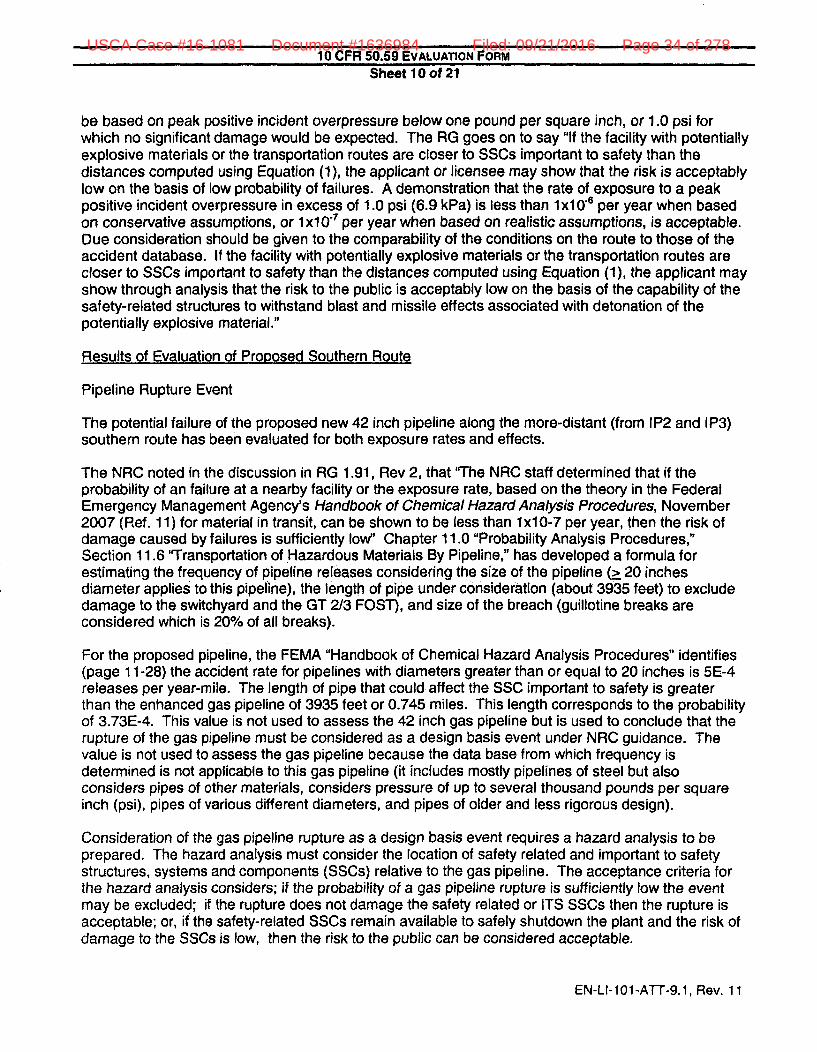
be based on peak positive incident overpressure below one pound per square inch, or 1.0 psi forwhich no significant damage would be expected. The RG goes on to say "If the facility with potentiallyexplosive materials or the transportation routes are closer to SSCs important to safety than thedistances computed using Equation (1), the applicant or licensee may show that the risk is acceptablylow on the basis of low probability of failures. A demonstration that the rate of exposure to a peakpositive incident overpressure in excess of 1.0 psi (6.9 kPa) is less than 1x10⁻⁸ per year when basedon conservative assumptions, or lxI07 per year when based on realistic assumptions, is acceptable.Due consideration should be given to the comparability of the conditions on the route to those of theaccident database. If the facility with potentially explosive materials or the transportation routes arecloser to SSCs important to safety than the distances computed using Equation (1), the applicant mayshow through analysis that the risk to the public is acceptably low on the basis of the capability of thesafety-related structures to withstand blast and missile effects associated with detonation of thepotentially explosive material."
Results of Evaluation of Proposed Southern Route
Pipeline Rupture Event
The potential failure of the proposed new 42 inch pipeline along the more-distant (from IP2 and IP3)southern route has been evaluated for both exposure rates and effects.
The NRC noted in the discussion in RG 1.91, Rev 2, that 'The NRC staff determined that if theprobability of an failure at a nearby facility or the exposure rate, based on the theory in the FederalEmergency Management Agency's Handbook of Chemical Hazard Analysis Procedures, November2007 (Ref. 11) for material in transit, can be shown to be less than lx10-7 per year, then the risk ofdamage caused by failures is sufficiently low" Chapter 11.0 "Probability Analysis Procedures,"Section 11.6 "Transportation of Hazardous Materials By Pipeline," has developed a formula forestimating the frequency of pipeline releases considering the size of the pipeline (> 20 inchesdiameter applies to this pipeline), the length of pipe under consideration (about 3935 feet) to excludedamage to the switchyard and the GT 2/3 FOST), and size of the breach (guillotine breaks areconsidered which is 20% of all breaks).
For the proposed pipeline, the FEMA "Handbook of Chemical Hazard Analysis Procedures" identifies(page 11-28) the accident rate for pipelines with diameters greater than or equal to 20 inches is 5E-4releases per year-mile. The length of pipe that could affect the SSC important to safety is greaterthan the enhanced gas pipeline of 3935 feet or 0.745 miles. This length corresponds to the probabilityof 3.73E-4. This value is not used to assess the 42 inch gas pipeline but is used to conclude that therupture of the gas pipeline must be considered as a design basis event under NRC guidance. Thevalue is not used to assess the gas pipeline because the data base from which frequency isdetermined is not applicable to this gas pipeline (it includes mostly pipelines of steel but alsoconsiders pipes of other materials, considers pressure of up to several thousand pounds per squareinch (psi), pipes of various different diameters, and pipes of older and less rigorous design).
Consideration of the gas pipeline rupture as a design basis event requires a hazard analysis to beprepared. The hazard analysis must consider the location of safety related and important to safetystructures, systems and components (SSCs) relative to the gas pipeline. The acceptance criteria forthe hazard analysis considers; if the probability of a gas pipeline rupture is sufficiently low the eventmay be excluded; if the rupture does not damage the safety related or ITS SSCs then the rupture isacceptable; or, if the safety-related SSCs remain available to safely shutdown the plant and the risk ofdamage to the SSCs is low, then the risk to the public can be considered acceptable.
EN-LI-101-ATT-9.1, Rev. 11
USCA Case #16-1081 Document #1636984 Filed: 09/21/2016 Page 34 of 278

10 CFR 50.59 EVALUATION FORM
Sheet 11 of 21
If the gas pipeline distances are sufficient to limit overpressure to less than 1.0 psi, the continuedcapability of safety related structures to withstand the effects of a gas pipeline rupture can be shown.
This hazards analysis considers the effects of the gas pipeline rupture to involve the approximately 3miles of pipeline between isolation valves and considers the event to be terminated by manual actionwithin 3 minutes after any pipeline rupture event by closing the closest isolation valves and limiting theevent to the gas between these valves. Further, local fire departments have been trained in largegasoline fires of the type postulated for IPEC security events and will therefore have the ability toaddress any secondary fires and fire damage that will be of a lesser size when the gas pipeline flowhas been terminated.
Evaluation of significance to margin of safety
The effects on safety related and important to safety (ITS) SSCs from a postulated gas pipeline failurecould come from (1) potential missiles, (2) an over-pressurization event, (3) a vapor cloud (or flash)fire, (4) a hypothetical vapor cloud explosion, and (5) a jet fire. The attached analysis of the effects ofa postulated gas pipeline failure and explosion along the southern route near IPEC is consistent withNRC guidance and demonstrates that there will be no damage to safety-related SSCs. However, theattached analysis also shows that certain SSCs important to safety (i.e., Switchyard with associatedtransmission lines, Gas Turbine 2/3 Fuel Oil Storage Tank (GT 2/3 FOST), City Water Tank, andEmergency Operations Facility (EOF) and meteorological tower) have to be evaluated for loss undercertain postulated rupture scenarios. Entergy is also considering potential impacts to the FLEXStorage Building, the fuel oil tanker, and the IP2 and IP3 steam generator mausoleums.
Regulatory Guide (RG) 1.91 Rev 2 defines an acceptable method for establishing the distancesbeyond which no adverse effect would occur based on a level of peak positive incident overpressure.The peak overpressure of 1.0 psi (6.9 kPa) is considered to define this distance and can be calculatedby
Rmin = Z * W1/3
whereRmin = distance from explosion where Ps, will equal 1.0 psi (6.9 kPa) (feet ormeters)W = mass of TNT (pounds or kilograms (kg))Z= scaled distance equal to 45 (ft/lb 1/3) when R is in feet and W is in poundsZ= scaled distance equal to 18 (m/kg 113) when R is in meters and W is inkilograms
The attached report contains the hazard evaluation which calculates the minimum safe distances froma vapor cloud explosion using the RG 1.91 formula (Table 10). The hazard evaluation alsoconservatively assumed damage to SSC important to safety from thermal radiation of 12.6 kW/m 2
(Table 4) due to a jet fire (immediate ignition of the release produces a jet fire anchored on thepipeline) and calculated the distance to achieve this value. The hazard analysis also defines themissile hazard based on historical industry pipeline failure data and demonstrates the delayed vaporcloud explosion (deflagration) is not a concern. The hazard evaluation is considered to be veryconservative since the methodologies used for calculating the overpressure distance and the selectionof the thermal radiation of 12.6 kW/m 2 (the distance that plastic melts / piloted ignition of wood are wellbelow the thermal radiation for building damage) The attached hazard analysis identifies distancesbeyond which damage is not postulated even in worst case ruptures as follows:
EN-LI-101-ATT-9.1, Rev. 11
USCA Case #16-1081 Document #1636984 Filed: 09/21/2016 Page 35 of 278

10 CFR 50.59 EVALUATION FORM
Sheet 12 of 21
Type of Effect Evalulated Exclusion Distance BasisJet fire 1266 ft (386 m) A heat flux of 12.6 kW/m 2 was chosen as
a basis for limiting postulated damageVapor Cloud explosion 1155 ft (352 m) A 1.0 psi overpressure will not occur at(detonation) greater distanceMissile 900 ft (274 m) The maximum distance that missiles
I have been observed
The first assessment assumes that these SSCs ITS could be damaged by a postulated explosion andevaluates whether there would be a significant reduction in the margin of safety. The assessment isto quantify potential effects assuming a postulated gas pipeline rupture and does not consider thefrequency of a gas pipeline rupture and explosion or the capability of SSC. The assessments arebased on the closest distances from the enhanced and unenhanced pipeline, as follows:
SSC ITS Closest distance from Closest distance non-enhancedenhanced gas pipeline gas pi9in
Switchyard 115 ft ( 35 m) >1266 ft (386 m)GT2/3 fuel tank 105 ft (32 m) >1266 ft (386 m)City water tank 1336 ft (407 m) >1266 ft (386 m)
Meteorological tower Not applicable 551 ft_(168 m)EOF 1002 ft(305 m) >1266 ft (522 m)
SOCA 1580 ft (482 m) >1580 ft (482 m)Backup Meteorological tower 1844 ft (562 m) >1266 ft (386 m)
SSC Of InterestFLEX Building 1033 ft (315 m) 1162 ft (354 m)
Unit 2 SG Mausoleum 1440 ft (439 m) >1266 ft (386 m)Unit 3 SG Mausoleum Not Applicable 477 ft (145 m)
The following assessment discusses the safety significance of a postulated loss of SSCs ITS from apostulated gas pipeline rupture. It concludes a loss of the SSCs important to safety would not result ina significant decrease in the margin of safety provided for public health and safety except for theassumed loss of the switchyard and GT 2/3 FOST which are more significant SSCs ITS.
A postulated gas pipeline rupture near the switchyard could cause total loss of the switchyardof the type that could occur with low probability events such as extreme natural phenomena(e.g., earthquake, tornado winds / missiles, hurricanes, etc.) that the switchyard is notprotected against. The potential loss of the switchyard can result in loss of offsite power to theplant and result in a generator or turbine trip with or without fast bus transfer to the turbinegenerator bus. This is considered a relatively high probability event and is analyzed in theUpdated Final Safety Analysis Report (UFSAR). The loss of offsite power would result inautomatic operation of the Emergency Diesel Generators (EDG) to provide essential power tocool down and shutdown each plant. The loss of offsite power is also considered as aninitiator of the station blackout event (SBO) where the three EDG (three for IP2 or three forIP3) at one plant are postulated to fail to start. Both IP2 and IP3 have a separate SBO dieselgenerator for such an event. - - . - f. ... .. ...
lion .The SBO event considers the ability to
restore the switchyard in determining the duration for which a SBO is evaluated. However,loss of the switchyard for an extended period of time due to a postulated pipeline rupture does
EN-LI-101-ATT-9.1, Rev. 11
USCA Case #16-1081 Document #1636984 Filed: 09/21/2016 Page 36 of 278

10 CFR 50.59 EVALUATION FORM
Sheet 13 of 21
not need to be considered for the SBO. NRC acceptance criteria for SBO (NUMARC 87-00)do not require consideration of low probability events such as severe natural phenomena orpipeline rupture for SBO. Therefore there would be no significant reduction in margin of safetydue to loss of the switchyard from the contribution of a switchyard failure due to a gas pipelinerupture.
A postulated gas pipeline rupture near the GT 2/3 FOST could cause loss of the tank. Thepurpose of the tank is to provide a supply of fuel oil to the IP2 and IP3 EDG so that they wouldhave an overall 7 day supply of fuel oil (it is presumed that additional fuel oil as well as backupgenerators could be made available in that time). The function of the GT 2/3 FOST is backedup by the ability to provide fuel oil from outside the plant. The gas pipeline rupture that couldcause loss of the GT 2/3 FOST could also result in loss of the switchyard due to their closeproximity. This will require the backup fuel oil from offsite to be provided as the primary meansof achieving a 7 day fuel oil supply. The gas pipeline rupture could also cause loss of the mainaccess gate to the site directly across from the switchyard but there are other access gates fordelivery of the fuel oil. The gate several hundred feet further south (it used to access IP3 whenthe two units were independent) could be blocked by the rupture since it is not too far from theGT 2/3 FOST. This gate has been blocked with two concrete barriers (a crane could be usedto remove them). To the north about 1850 feet is the gate used for access to IP2 when the twosites were independently owned and this gate is expected to be available. It is easilyaccessible by opening the gates in the owner controlled fence and manually opening theblocking bar used in place of concrete barriers. Although access is feasible, the dependencyon the offsite delivery results in a reduction in the margin of safety for the safety related EDG toprovide the power for plant shutdown. The tanker that is stored onsite to transport fuel oil fromthe GT 2/3 FOST is within the damage range but will be relocated to assure availability for allcases where the GT 2/3 FOST remains available. Therefore it is concluded that the reductionin the margin of safety is more significant assuming a pipeline failure that results in the loss of
* A postulated gas pipeline rupture will not cause loss of the city water tank because thedistance from the gas pipeline is sufficient to prevent loss of the tank (see above table) sincethe peak positive incident overpressure will not exceed 1.0 psi and the heat flux will notexceed 12.6 kW/m2. The city water tank functions as alternate water supply to the IP2 and IP3Auxiliary Feedwater Systems. It also serves as a backup for other SSCs, including the IP2Appendix R / SBO diesel. ..
111111 _Therefore there is no significant reduction in the margin ofsafety.
A postulated gas pipeline rupture could cause loss of the important to safety EmergencyOperations Facility (EOF) because it can see a heat flux of 12.6 kW/m2 and be exposed to anoverpressure in excess of 1 psi, as well as loss of the meteorological tower which is also withinboth exclusion distances. The function of the EOF is to act as a central command post for aplant emergency that meets the criteria for emergency responders to assemble. The functionof the meteorological tower is to provide weather information in the event of a plant emergencythat requires activation of the emergency response organization, it contains instrumentation forEntergy activation of the siren system and communications with the offsite assessment team.No gas pipeline rupture will cause any plant damage meeting the criteria for emergency
EN-LI-101-ATT-9.1, Rev. 11
USCA Case #16-1081 Document #1636984 Filed: 09/21/2016 Page 37 of 278

10 CFR 50.59 EVALUATION FORMSheet 14 of 21
planning to assemble in the EOF. The EOF is activated for Alert Emergency Level declarationor above. An Unusual Event would likely be declared in the event of a pipeline rupture thatresults in switchyard failure (Loss of all offsite AC power to 480 V safeguards buses (5A,2A/3A, 6A) for > 15 min) but the Alert Emergency Level criteria criteria would not be reached.The failure that does damage the meteorological tower would not result in damage to theswitchyard. Also, there is a backup meteorological tower (it does not contain the 60 meter and122 meter instruments), normal means to activate the siren systems from the counties,alternate communications with the assessment teams, and a backup EOF that would not beaffected by the rupture. There would therefore be no significant reduction in the margin ofsafety since the EOF and meteorological tower functions would not be required and backupsare available.
There is no damage to the SOCA which is beyond the exclusion distance for which the effectsof the gas pipeline explosion are considered for damage to SSCs. The SOCA boundary wasidentified for evaluation since the plant safety related SSCs are within the SOCA boundary andthe SOCA represents the outer security boundary. Therefore there is no damage to safetyrelated or security required SSCs.
In addition to the SSCs important to safety discussed above, other features have been considered.
* The building for storage of FLEX equipment (used for beyond design basis events) is requiredto address Fukushima orders. The building is constructed of reinforced concrete and wasdesigned for a tornado overpressure. It does not have a damage potential from vapor clouddetonation because the overall structural capability of the building is designed for 3.0 psioverpressure compared to the predicted overpressure which is only slightly over 1 psi. TheFLEX storage building is outside the postulated distance for a missile. The building is withinthe heat flux distance but the heat flux will not be great enough to affect the concrete and thereis no other equipment to be affected.
* The storage of the steam generators replaced on IP2 and 1P3 is in mausoleum buildings. TheUnit 3 mausoleums are subject to potential damage since they are within the exclusiondistance for heat flux, missile damage and overpressure. The Unit 3 building has 3 foot thickreinforced concrete walls supported by a pile foundation with reinforced concrete pile, an 18inch (average) thick reinforced concrete roof supported by metal decking and steel beams,and an 8 inch thick reinforced concrete grade slab. Although the structure contains radioactivematerial, analyses have demonstrated the failure of the structure would not result in releasesexceeding the limits in 10 CFR 20 (10 CFR 50.59 analysis dated May 1987). The Unit 2mausoleum is outside the exclusion distances and a postulated rupture would have no effect.
A rupture of the buried gas pipeline due to a sabotage event is not considered deterministically or inthe evaluation of frequency because the Rig ..... _...,• r . "
=-'. . . -' and due to the substantial difficulty of intentionally
causing an rupture of underground piping coupled with the extra design features that have beenincluded in the proposed enhanced pipeline design. A gas pipeline rupture of exposed (above-ground) portions of the pipeline due to sabotage, however, has been postulated at IPEC in the past inresponse to a concern, although there is no regulatory requirement to do so. Consistent with thisprecedent, a sabotage event is postulated, but limited to considerations of potential sabotage of aboveground piping. The above ground piping, however, is sufficiently far from any SSC important to safetyso that all SSCs are outside the exclusion areas of the hazard analysis.
EN-LI-101-ATT-9.1, Rev. 11
USCA Case #16-1081 Document #1636984 Filed: 09/21/2016 Page 38 of 278

10 CFR 50.59 EVALUATION FORMSheet 15 of 21
A gas pipeline rupture due to natural phenomena was also evaluated and is not considered torepresent a credible threat to the pipeline. Tornadoes and hurricanes do not present a threat to theburied pipeline due to winds or missiles. Missile impacts are resisted by the strength of the piping andthe 3 to 4 foot depth of the soil. Additionally, the effects of tornado missiles are not part of the IP2design basis and are restricted to a single missile at IP3. A seismic event has the potential to causeloss of supporting soils due to the potential liquefaction of the underlying soils and susceptibility toother damage that could cause loss of the pipeline. However, due to the rocky soil in this area atrelatively shallow depths combined with low seismicity, liquefaction of the underlying soil is not likely(Reference 9). As a result, the pipeline will be continuously supported along the entire length of burialby the soil and will tend to move in phase with the soil during an earthquake resulting in low stresses.The primary risks from ground movement hazards come from active seismic faults, landslides, longwall mine subsidence, and frost heaves in areas with deep frozen ground, none of which apply alongthe pipeline in the area near the Indian Point Facility. Therefore, a seismic event is not postulated toadversely affect the buried portion of the pipe.
The potential exists where the 26 / 30 inch pipeline will come together with the 42 inch pipeline for anexplosion in one of the three pipelines to cause an explosion in one or more of the other lines. Thiswould be possible in the above ground portion of the pipeline but the blasts would be sequential andthis distances are great enough that the effects would be acceptable. Experience has shown that therupture of one underground pipe would not affect another since the forces are upward. Also the linesare not close enough to even create this possibility until they reach the area where they are broughtabove ground. Therefore, a postulated simultaneous failure of the buried portions of the existing 26 /30 inch pipelines and new 42 inch pipeline is not a credible event.
Frequency of Events
The prior discussion indicates that the new gas pipeline represents no potential damage to safetyrelated SSC but a gas pipeline rupture could cause potential damage to SSCs ITS closer to theproposed southern route. The discussion also assesses the effects on the safety margin forprotection of the public for a postulated gas pipeline rupture. The following information shows that thefrequency of postulated gas pipeline ruptures that could damage SSCs ITS are, based in part on theenhanced design and installation features, sufficiently low and do not result in a significant reductionin the margin of safety. This is because they are excluded from consideration in accordance withNRC guidance due to the very low frequency of a gas pipeline rupture that could damage these SSCsITS and because the frequency is sufficiently low that the undamaged safety related SSCs can becredited with safely shutting down the plant, or because the SSCs are not within the distance wherethey could be damaged. The one exception to this being the Meteorological Tower, which is above10-6/yr. however, there is a backup Meteorological Tower and other means of obtainingmeteorological data (e.g., NOAA)
The frequency of a pipeline explosion was evaluated using industry data and correlating it to morerecent data. The frequency of a pipeline rupture and enhanced pipeline rupture is 1.32E-5 per mile-year and 1.98E-6 per mile-year, respectively. These are considered conservative values. Thefrequency of damage to the various SSCs ITS is calculated by the length of pipeline exposure and thefrequency of occurrence of the types of events. The results are as follows:
. .. _ _ _ _ _ __.... .. , . Event.; ,,.requency I /year
Switchyard .. .. _Jet fire 7.23E-7.... _ _ _ Vapor Cloud explosion 5.52E-8
Missile 1.32E-7
GT2/3 fuel tank / switchyard Jet fire 5.20E-7
EN-LI-101-ATT-9.1, Rev. 11
USCA Case #16-1081 Document #1636984 Filed: 09/21/2016 Page 39 of 278

10 CFR 50.59 EVALUATION FORMSheet 16 of 21
Vapor Cloud explosion 4.25E-8GT2/3 fuel tank Missile 1.51 E-8City water tank Jet fire Outside damage distance
Vapor Cloud explosion Outside damage distanceMissile Outside damage distance
Meteorological tower Jet fire 1..86E-6... ..... ________ Vapor Cloud explosion 1.51 E-7
Missile 2.06E-9EOF Jet fire 4.02E-7
Vapor Cloud explosion 2.79E-8Missile Outside damage distance
SOCA Jet fire Outside damage distanceVapor Cloud explosion Outside damage distanceMissile Outside damage distance
Backup Meteorological tower Jet fire Outside damage distanceVapor Cloud explosion Outside damage distanceMissile Outside damage distance
City Water Tank Jet fire Outside damage distanceVapor Cloud explosion Outside damage distanceMissile Outside damage distance
Othe S.SCotý Intferest.. ______________
FLEX Building Jet fire No exposed instruments for12.kW/m2 to damage
Vapor Cloud explosion Overpressure 1.19 psi buildingdesign for 3.0 psi
Missile Outside damage distanceUnit 2 SG Mausoleum Jet fire Outside damage distance
Vapor Cloud explosion Outside damage distanceMissile Outside damage distance
Unit 3 SG Mausoleum Jet fire 1.38E-6 (for thermal radiationthat would damage the building)
Vapor Cloud explosion 1.95E-7Missile 3.83E-8
Conclusion
Based on the considerations discussed above, the potential for an increase in risk to the public isacceptably low on the basis of:
* there is no damage to safety related SSC or plant security from a postulated pipeline rupture;
* the effect on SSCs ITS of a postulated gas pipeline rupture would not have a significant effecton plant safety because:
* The SSCs ITS have been shown to be sufficiently far away from a postulated gaspipeline failure so as to be unaffected by the failure, or
EN-LI-101-ATT-9.1, Rev. 11
USCA Case #16-1081 Document #1636984 Filed: 09/21/2016 Page 40 of 278

10 CFR 50.59 EVALUATION FORMSheet 17 of 21
Based on the agreed-upon pipeline design and construction enhancements, the lowfrequency of a gas pipeline rupture would preclude consideration of rupture withdamage to SSC ITS, with the exception of the Meteorological Tower where frequency isgreater that 1 OE-6. The meteorological tower, is not required for shutdown and theundamaged safety related SSCs can be credited with safely shutting down the plant.The meteorological tower also has backup capability and other means of obtainingmeteorological data are available (e.g., NOAA).
Therefore there is no significant reduction in the margin of safety with regard to public safety.
References
(1) Preliminary Safety Analysis Report (PSAR) for IP3, dated August 30, 1968, ADAMS AccessionNo. ML093480204 ("Gas Pipeline Fire" describing the design and construction of the gas lines.,operation and maintenance practices, postulated failure modes, and standoff distances providedto determine safety-related structures would not be affected).
(2) Safety Evaluation Report dated September, 21, 1973, ADAMS Accession No. ML072260465.
(3) New York Power Authority letter to NRC (IPN-97-132) Regarding Indian Point 3 Nuclear PowerPlant - Individual Plant Examination of External Events (IPEEE), dated September 26, 1997.
(4) Letter to M Kansler regarding "Review of Individual Plant Examination of External Events (TACNO. M83632),"' dated February 15, 2001
(5) Memorandum from Richard J. Laufer, Chief, Section 1, Project Directorate 1, Division of LicensingProject Management Office of Nuclear Reactor Regulation, NRC, to Peter Eselgroth, Chief,Branch 2, Division of Reactor Projects, Reg ion 1, NRC, "Subject: Review of Natural Gas Hazards,Indian Point Nuclear Generating Unit Nos. 2 and 3 (TAC Nos. MB8090 and MB8091)" (Apr. 25,2003) (ADAMS Accession No. ML 1223A040).
(6) Berk Donaldson, Algonquin Gas Transmission, LLC letter to Ms Kimberly D Bose, FERCregarding Algonquin Gas Transmission, LLC, Docket No. CP14-96-000, Abbreviated Applicationfor a Certificate of Public Convenience and Necessity and for Related Authorizations, datedFebruary 28, 2014
(7) Timothy C O'Brien, Spectra, E mail to Charles A. Moore, Morgan Lewis& Brockius, LLP, datedJuly 29, 20124
(8) Spectra Energy (Algonquin Gas Transmission) memorandum to Energy regarding Response toEntergy Document entitled "Pipeline Enhancements Being Evaluated to Mitigate a PipelineFailure" dated July 29, 2014.
(9) "Enercon Report of Liquefaction Potential Assessment' dated June 26, 2014 (IP-RPT-14-00010)
Is the validity of this Evaluation dependent on any other change? El Yes [ No
EN-LI-101-ATT-9.1, Rev. 11
USCA Case #16-1081 Document #1636984 Filed: 09/21/2016 Page 41 of 278
10 CFR 50.59 EVALUATION FORMSheet 18 of 21
If "Yes," list the required changes/submittals. The changes covered by this 50.59 Evaluationcannot be implemented without approval of the other identified changes (e.g., licenseamendment request). Establish an appropriate notification mechanism to ensure this actionis completed.
Based on the results of this 50.59 Evaluation, does the proposed change El Yes Z Norequire prior NRC approval?
Preparer Stephen Prussman/
Name (print) / Sigfature / CJnpany / Ddpartment / Date
Reviewer John Skonieczny/,•-v /g .. JA7"/ • c /92
Name (print) / Sidgature / Company rDeePment / Date.
OSRC: John Kirkpatrick/ . ;;;,/,Chairman's Nam prinvf/ nature / Date
Meetinq 14-13 on 8-18-2014OSRC Meeting #
EN-LI-101-ATT-9.1, Rev. 11
USCA Case #16-1081 Document #1636984 Filed: 09/21/2016 Page 42 of 278

10 CFR 50.59 EVALUATION FORMSheet 19 of 21
II. 50.59 EVALUATION
Does the proposed Change being evaluated represent a change to a method of evaluationONLY? If "Yes," Questions 1 - 7 are not applicable; answer only Ouestion 8. If "No," answer El Yesall questions below. ED No
Does the proposed Change:
1 Result in more than a minimal increase in the frequency of occurrence of an accident El Yespreviously evaluated in the UFSAR? [No
BASIS:
Currently, a 26 inch and 30 inch pipeline traverse the site along a route just south of theprotected area and the effects of a rupture of that pipeline has been evaluated. The addition of a42 inch pipeline south of the IPEC property that crosses IPEC property near the GT 2/3 Fuel OilStorage Tank (FOST) and Buchanan substation creates the possibility of a gas pipeline rupture.Gas pipelines have a low frequency of rupture. The new gas pipeline has been designed withthe latest methodology and a significant portion has been enhanced with additional features(e.g., deeper burial, thicker pipe, stronger materials, positive means to prevent excavation andabrasion resistance coating) intended to further reduce the frequency of gas pipeline rupture inthe area of Structures Systems and Components (SSC) important to safety (ITS). The frequencyis sufficiently low that the new gas pipeline will not result in more than a minimal increase in thefrequency of occurrence of an accident (gas pipeline rupture) currently evaluated in the UFSAR.
2. Result in more than a minimal increase in the likelihood of occurrence of a malfunction El Yesof a structure, system, or component important to safety previously evaluated in the Z NoUFSAR?
BASIS:
A rupture of the new gas pipeline could be the cause of a malfunction of a SSC previouslyevaluated. The new gas pipeline has been routed where a gas pipeline rupture could not causemalfunction of a safety related SSC or security provisions and therefore there would be noincrease in the likelihood of damage to those SSC. The routing is where a postulated rupturecould cause a malfunction of SSC's ITS (Switchyard with associated transmission lines, GasTurbine 2/3 Fuel Oil Storage Tank (GT 2/3 FOST), and Emergency Operations Facility (EOF)and meteorological tower) due to proximity. The likelihood of a gas pipeline rupture causingmalfunction of SSC ITS will be minimized by the gas pipeline design and maintenance as well asthe enhancement of a substantial portion of that gas pipeline routed near the SSC ITS. Theincrease in likelihood of a gas pipeline rupture affecting the SSCs ITS has been determined tohave a very low frequency. As a result, this new pipeline is not considered to result in a morethan minimal increase in the likelihood of occurrence of a malfunction of a SSCs important tosafety previously evaluated in the UFSAR.
3. Result in more than a minimal increase in the consequences of an accident previously El Yesevaluated in the UFSAR? [No
EN-LI-101-ATT-9.1, Rev. 11
USCA Case #16-1081 Document #1636984 Filed: 09/21/2016 Page 43 of 278

10 CFR 50.59 EVALUATION FORMSheet 20 of 21
BASIS:
The rupture of the gas pipeline previously considered in the UFSAR assessed if it could result inloss of safety related SSCs. This is the rupture of the 26 inch and 30 inch gas pipelines whichwere previously evaluated as acceptable during the original Licensing stage, and as during theperformance of the IPEEE as of acceptably low probability. It was evaluated for an abovegroundrupture as a potential security event and the evaluation concluded the effects were acceptable.The evaluation of the consequences of these prior ruptures showed there was no damage tosafety related SSCs. The effects of a gas pipeline rupture of the new 42 inch gas pipeline wereevaluated to determine whether the consequences of the previous evaluations were increased.The evaluation showed there was no damage to safety related SSCs due to gas pipeline ruptureand therefore there is no increase in consequences. The evaluation, performed usingmethodologies consistent with the current NRC guidance, looked at the effects on SSC importantto safety as well as safety related SSC. The evaluation shows that, due to the proximity of theproposed southern route to SSCs ITS, there was a potential for damage. However, it alsoshowed that the damage frequency was sufficiently low, according to NRC criteria, that it wasacceptable. Additionally, the evaluation of SSCs ITS was not an accident previously considered.Therefore there is no increase in consequences since the safety related SSCs are not damagedand the effects of damage to SSCs ITS were not previously evaluated and are acceptable. As aresult, it can be concluded that this activity will not result in a more than minimal increase in theconsequence of previously evaluated accidents.
4. Result in more than a minimal increase in the consequences of a malfunction of a LI Yesstructure, system, or component important to safety previously evaluated in the [ NoUFSAR?
BASIS:
The effects of a rupture in the new 42 inch gas pipeline have been evaluated to determine theeffects on SSCs ITS. The evaluation shows the frequency of a rupture affecting a SSCs ITShave been reduced to where a rupture will have no more than a minimal increase- in theconsequences of malfunction of the SSCs ITS affected. Natural phenomena with a probabilitygreater than the rupture of the gas pipeline can damage the SSCs ITS that the postulated gaspipeline rupture can affect. The ability of the plant to safely shutdown and maintain coldshutdown has been assessed with this damage. There is a minimal increase in theconsequence of a malfunction of the SCCs since a gas pipeline rupture has the lower frequency.Therefore, this activity will not result in a more than minimal increase in the consequences of amalfunction of a SSCs important to safety previously evaluated in the UFSAR.
5. Create a possibility for an accident of a different type than any previously evaluated in U Yes
the UFSAR? [ No
BASIS:
The previously considered rupture of the 26 and 30 inch pipelines is considered a similaraccident. A rupture of the new 42 inch gas pipeline has been evaluated and would not result indamage to a safety related SSC but could result in damage to SSC important to safety(Buchanan switchyard, the GT2/3 storage tank, and the EOF / meteorological tower). Loss ofthese components could not create the possibility of an accident of a different type thanpreviously evaluated since their loss has previously been evaluated. There are no other changesto the plant operations, operating procedures or site activities that could possibly create anaccident of a different type than previously evaluated. As a result, this activity does not create apossibility for an accident of a different type than previously evaluated in the UFSAR.
EN-LI-101-ATT-9.1, Rev. 11
USCA Case #16-1081 Document #1636984 Filed: 09/21/2016 Page 44 of 278

10 CFR 50.59 EVALUATION FORMSheet 21 of 21
6. Create a possibility for a malfunction of a structure, system, or component important to EL Yes
safety with a different result than any previously evaluated in the UFSAR? [ No
BASIS:
A rupture of the new 42 inch gas pipeline has been evaluated and would not result in damage toa safety related SSC but could result in damage to SSCs ITS. The potential for damage couldnot result in a malfunction with a different result that any previously considered in the UFSARbecause the potential damage is not different than previously evaluated and there is no damageto safety related SSC. Rupture of the pipeline is postulated to occur in normal operation since itis not postulated to occur as a result of a plant accident or natural phenomena. The malfunctionof SSCs ITS that could be affected by the gas pipeline is no different than those previouslyconsidered in the UFSAR. That failure is just a loss of the component since there is no interfacewith safety related SSC. Therefore the malfunction of the affected components would not have adifferent result than the rupture of these components as previously evaluated.
7. Result in a design basis limit for a fission product barrier as described in the UFSAR El Yesbeing exceeded or altered? [No
BASIS:
A rupture of the new 42 inch gas pipeline has been evaluated and would not result in damage toa safety related SSC and damage to a ITS would not affect the ability to safely shutdown. Thepostulated rupture of the new 42" gas pipline has no impact on fission product barriers.Therefore there will be no fission product barrier design basis limit approached.
8. Result in a departure from a method of evaluation described in the UFSAR used in El Yesestablishing the design bases or in the safety analyses? Z NoBASIS:This activity installs a new gas pipeline routed south of the IPEC plant and partially on IPECproperty. The UFSAR describes past evaluations of pipeline rupture but does not discuss themethodology. The new evaluation of the potential for rupture uses methodology consistent withpast evaluations and approved by NRC and evaluates the frequency of rupture usingmethodology consistent with the NRC criteria. Therefore, it is concluded there is no departurefrom past methodologies used for the plant and does not depart from a method of analysiscontained in the UFSAR.
If any of the above questions is checked "Yes," obtain NRC approval prior to implementing the changeby initiating a change to the Operating License In accordance with NMM Procedure EN-LI-1 03.
EN-LI-101-ATT-9.1, Rev. 11
USCA Case #16-1081 Document #1636984 Filed: 09/21/2016 Page 45 of 278

Hazards Analysis: Consequences of Postulated Fire and Explosion Following Release of Natural Gas
From Proposed AIM Pipeline, prepared for Entergy by Risk Research Group
(August 19, 2014).
USCA Case #16-1081 Document #1636984 Filed: 09/21/2016 Page 46 of 278
....... i,e-......,.,.· ...... · 7mlUlIiD WUIiII!A II "' ... PI
ENCLOSURE 2 TO NL-14-106
HAZARDS ANAlYSIS
EHTERGY NUCl£AR OPERATlOHS, INC. INO&AH POINT NUClEAR GENERATING UNIT~. 2" 3
[)()Q(ET NO&. 5().241SO-2811
MCIary.pfll,:tO'., 'nell ~llgua'''18''".RI'I1
USCA Case #16-1081 Document #1636984 Filed: 09/21/2016 Page 47 of 278

I ", -W' , 1 Inf<- 'h n. tMitN ... lind. ,. 6"'" 3M
£N'1'!AQY NUCLEAR MANAG~MENT MANUAL EN-DC-149
,
181 ACCEPTED, WORK MAV PAOC£EP o ACCEPTED AS NOTED AESlIBI I IALHPTAECIUIAEI), WORkMAV PROCEEO o ACCS'TEOASHOTEO~ITTALREOUAED o NOT ACCEPTED
$I
USCA Case #16-1081 Document #1636984 Filed: 09/21/2016 Page 48 of 278

n!E RISK RESeARCH GROUP, INC.
Consequences of a Postulated Fire and Explosion Following the Rei ..... of Natural Gas from the
Proposed New AIM 42" Pipeline Taking a Soutbern Route Near IPEC
Prepared for Entergy Nuclear Operations. Inc. by
The Risk Research Group. Inc. 18 Dogwood Road
Wcst Orange. NJ mon
Under Contract 10391690
51! I.Irt II,. .rIa IlfllM!"1'lON wmllCUJ UHO&I loun UiO
USCA Case #16-1081 Document #1636984 Filed: 09/21/2016 Page 49 of 278

!I
Coasequeoca of. Postuloted 1'1 .. ODd E>oploolon FoIlowl", the R~ or Natural Cas froM tile PropOled New AIM 42" PipeIIae
Taking a Southera Route Near IPEC
L Ovel'"
As I*t of die AIamquin IriuUDtiilal Marbt Projcd. (AlM Projcd.). Spectra Enqy (SpocIra) lIu ~ 10 .. all ~Un.Idy 37.6 mileII of new 42" IIItUrd PI pipeliae. PM of 1M prnpowI new 4l~ u.tunI au pipeliM .w be IOUkIdjust soudl «dill IDdiIa Point Eueru Cemet (IPEC).' Speen's ulsciat pq.IiDe ."tem inch""" 26~ Md 30" pipellncI which cross Ihc lPEC p!0jIU1)~. 65' dPt-of· ... yOQ tlleelltsidtoftlle Hudson River. Neat IPEC. two IUIICe5 _lUDkkred by S~ rlll'!be ..-42" pipeline; • "nDnber!:I1'OUIe" in 1I'bic:h !be plpdlDl would be rouBI"llIIIlMRIII AVr plpelhle n,bt-of .... y Md • "-wm rouIe" in. wbidllbe new pipdinII is routed fwtb« ..... y froIn !PEe, ~ oltbe IPSe JI!CIIIfty bmiar.2
As • repili, !be IOIiIbaD row: is ~y _ (ibgal froaIlPEC's _ill pIMl systelllil, IIrUCtUra IIIId COI'ijl c en" (SSC) witIWi tile Secaiity 0w1Ier CoMrolIed NI!Ii (SOCA) 1bIl.n SIIfety rdIi.a:I or b.ipUl_ to $1&1) Ih;m is tbn .... ! ... PI pipeline riabt-of-"J' • hs closest, Ihr.SOUIhcm to!M will be l(lplOXiinItdyl'lJO feet I'romlbcSOCA,' Speclraha IWiIId u..!be .... ,cbem ""* is !be pcdwu1 ( .. fiaIIwlemd) _ 4 Acxo« r,.!y, 1IIilI-..J.,..is COdIidas
!be risb Iftd potn'l'l consecp'""" or. pG'ndMec! I'aiIun:= of tile po,- ~ S<;JIIJbcna route pipelilIc, iDcbIdinJ a resultiq file -.Ifor explosion.. 011 Hfel:y-rellled _1mponanr_lO-saf'cIy sse. at LPEC.
1. Summ.ry
A bypoIlIotial nJptUre of !he JI'OPC*d __ 42'" MlInI. ... pipeline Iocded aIona; !be.outhem rouce can be peen" 9C j to JeMdt in • j« n-or claW file or,lIypocbetjce"y Md ~ unlikely, indttonMioa 01. vJpCl'cloud. MiDilcF~Mion llliJhtalto actOil, iii)' rupture. Nucl .... ReplllOi')' CminibsionOuidlDc:c foraploskliw pt6WII'~ in R .... WnyOaide 1.91.deems!he risk poled by web evaXI 10 be •• ,(1Il1 If tIicy do iJOl ~I in sQ.y_ .... ..., or iillpO(tallt [Q
..r.y SSCI bei,. exposed 10 o¥~ II CiS llIat euecd a 1 psi tbrcsboId or if ibe ~ llequr;i\Iq ofeYenil illas ibIIIIl~yearifCOXDUYlrive.umplma. 1ft mD or IO"lyWif mlIi1tic IISI.Iaiplkms .., mIde:. Similar cricem can be applilld for apowte to thermal rldiation (11 "'* fhaaceeclinl 12..6 tW/rd- .1IIe1leM. f1uM whith plutieDICII$) aDd miMilei (10 be
, • P\aIN I .
SeGI'P'TY FE nmlNR¥5 I'T'C'N Iiml'19I PIJIIIGIA 1,gFA.'U
I .... UJUSt 19,2014
USCA Case #16-1081 Document #1636984 Filed: 09/21/2016 Page 50 of 278

IKU .. ,' II'" I ie IN"UIIII'IKJfI WIIHNULU LlN""R 10 CjOA 2 iOO
outside a TeOI$onmJc strike wnc). The analysis of potenti:llly Iw::ardous events precipitated by pipeline!U(lUlre shows the threshold fordamace 10 safety·relalcd or importan! to safety SSCs witbin the SOCA will DQt be ex.:eeded bec:wse of!he dislance between the SOCA and the new pipeline.
Howcver, damage to certain SSCs import:llll: 10 safety located outside the SOCA and closer 100r ne;u- Ille proposed southem toUIe Jw mo been COIISidcred 10 determine whether the damace !hrr:sholds mighl be excceded should !he pipeline roptUn:. 'Thc:se SSC, include the electrical 5witmyanl with IrlnSmiuion lines, GT213 d~l fucl SIO!'Itc WIk,!he city watcrtank, the FLEX buildiD" theEn'lclicncl Opcrat:iona FllCility (EOf), the lDCleorolo,icailOwer and two lleam ,CIlCr.IlOr mausoleums. It is concluded, however. thaI such damage poses minimal or no increased risk 10 safe plan( opcmion lIS. with two e:tceptions, conservalive estimates of the frequency for hypotheticallbmatc lie below !he IO"'re- thtcJbold of concern or the SSCS in qucslion can witllsWld !he postulated damage. The c.tceplions penain to daauop to the meteoroJo,icallowcr lind the Unit J sleun ~or ~m. This risk is furtbercvalu.ued lIS required by 10 CFR 50.59 proceu. II is also concluded that the new pipeline wilillO! introduce additional risk II.S a result of lerrorism or dunage caused by leismic eYen!S.
As discussed further below, this IIIIllysii Ulkes ~il for I;CNin lKIditionlll pipeline deli(pl ilIlII iru;liIlatioa enllAlu;cmenu '11Wd to by Spcclra for a substantial ponion of thc pipeline DCU IPEC, includin, thicker pipi"" enh:w:ed coaosion rcsillmCC, deeper burial depth, and ~livc reinforced concrete malJ 10 be located ahoYe the bilried pipin&- Such measures subJtallliaily reduce the already·low p~i1ity ofpipclirte failures thaI could impact SSCS near the pipeline. For purposes of this awlys.is, the section of the pipeline with additional design and in.wlalioo 1TICII5lXe!1 is labeled as "CMIIICed":IIId tnlditional pipinc ;slabeled II! "'UnenlwIecd.H
The ~ ponion of !he pipeline is deplcled in green on Fi&we I. The tcnn "uncnbmced,M 110_, does not imply the pipinr; is vulnerable to failu~ ordumaje, II.S luch pipinJ is also of superior quality and ins!alled in :ICCOI'dancc with .u ~pplicable re,lIlltory requirelllCDlJ. ~
3. Sack&round
Two nallU:lli gas u:ansmission pipcliDCII. D 26" IIIId 30" pi~llne, owned IIIld opcllucd by Spectra Encrty,currernly cross the IPEe site:llona an uisli", pipclu.. ri&bt·o{·way (corridor), The potential threats posed by the JIO'tulatcd ruplure of these pipelines and the "''''aile of nlluno! sa" (u,..,ntill!y mc:!bllle) from them were ori,inaJly ~ddrcsKd in the lPJ Llcen.!ins proceu ItS
di.muclcd in the NRC Safety Eva[UllIion Report of Septembec, 9, [973 "'Two I\lllUrai au lines cross the HudJOCl Rivcr IIIId pilSslOOut640 feet fromlhe IJIdian Point 3 Con!ainment Structure. Beed on previous N'RC sllff review, failures ofthcse PI lines will not impair thc me operation
' Tho lantor Iniler ,., ... >IOrCd _ide Ibo SOCA 'llriU "" ""' .... to IIot:aricr. 1M! _old not be ~1Cd by tho ~101 f.iI," of tho ...... pipoli .. 1IId 1!Im!Ore i. "'" e"2lumd flllthc!:r in 1II"'epc>n.
Sec Appendix 8. E>.~il>il' A 1IId 8.
1& UI';IWxnQII '(1"""11:11<1:11111"" 10 C, .. 2.UG
The Risk Rescm:h Group, Jnc. 2 Ausust 19,2014
USCA Case #16-1081 Document #1636984 Filed: 09/21/2016 Page 51 of 278

", ....... ~ ••• " -ol·.'''' P"'I ... :,: •••• ." • " •• "" .. ~ .. ,
oIlnd1an PoiDt 3,~
IKI !JII1or r\Jt _ poi'Cd beC!IIlSO die predjeted ~ of InIjor !deale events _ below • 104(,.. IhiwlNld of toIk:elu.
Stible.-lIlly, a ~l ..... raised Mprdiallbe poatial impIdt from • pipeliDt I'IIpIWe ~ IPEC AI • laldl 01 jnCaItjtwoaJ Mel malicious acti.ity IIICl, Ilkac:l'ote, It "AI deciMd 10 r8-ova/ualc !he OJib-q : CI 01 OIIWII. PI ~ fi'onIlbe ~ 26" ..." 30" piptlbw ret.m 10 «poNd ~'ortbe pipeUac. I A stud)' performed. fw &laJy In 2001 [2j. wbldI iDdudod jet file, vlpOr cloud fire, IIId vapor cloud explotklllsoeo_b &om III ........ flilun:l oC ODe or both 01* exisdaa pipe:tinIII, coaduded .... "die ruptun= of die IIaIuraI lIS pipdiDa Ihat crou the IPEC (.iIe) fIId IIIbIeqoenr.!JniIion of the _d .. me.ed wUl tmUlt 1n..I)et fA mel injlll'Y or death UI....,.peopIcexposed UI ftaaIeI or Int1mctbennal ...... II wUllIOl, IIoRCoer, dwl ... y .. y~1tnII;NJe. £ .. in tbellllllblyen.aofab}'llOl!w:tieal YIpOI"doud elpIoIloII.saucoal ........ cobuildillpotMrtllmtbc"" I 6_"". L~ 'r-.ljKentIO!be pipolirM't will'DCI: ocaa'. A flluuaablenporcloud IR tbII =.,.1& !be pin is iulpobiible bccau# It. turbuIeat _*"o with wbid!. die ...... _ Qitl tba pipeliDt will OIIIy coar_ f1U11!1111b1e~C(Nl':c ... fItioaIcbecotbepoi!llolrell I ." The NRC miewed QDIl " ~ the requett ror fnfonnMiDa witb that _)'Iii.
In Japoll" 10 !be propnMd 0JiJIlNCti0a. of. "'" <U'" pipdlne aIoq !be toUIban -.lbi, , .... uation 01 tile poIeIId&I IMp.ct. on AI'ety "J.red IDd iqIortantcCD =#<t) ssc.1hat ~ be poted by thb: _ pi pi~1b= h.B beea P ..... td. II renecr. 111_ In !be IIIIdeIItliIliiq 01 !he c:oJl'CT'"M:f'e oflbe reieMe .-I ipitIon 01 n-.tIIe.-. ... eumnt rq"lttory .ridlQCe repdb:lfAldlevcatl PlO,1iIcd bylbe US Hudeaz'1iIep' 'Ity CI b ion (lJ, Tbcp I .iaI
impcII afllllln1ps IlII net lIId.theirq"""r ...... ipitiononSSCa IuepccIlDt IO.Kfety bw I~....., tn.n Iho SOCA-cbo lwilcbyud,1hc IIIIlflOrOIosk: towa", the ciIy "'Iter taok,lbe GT2fj diesel fIxIlC«I&C flak, tile fLEX baiktkJ&, tbe Emltpcy Opec ...... FKiIiIy (£OF) IWl !be lP2. aid IP3 ... aeoezllOl mIUIOIeunII 1ft: al .. CDI!IiMds Tbe dosest ctiMlD(IC1I 0{ theM.$SCI fropo _ popowd ...... hmllOUki pipeline ... pUll.' t ill T.ble I bcIDw.' These SSC5 paforllllhe I'olJowin& ftll!diorll:
• ill II lui Swttda)'ll'd~ Power co !he lhe iI provided r.om!he BuduNa swilcbymlby 131-tV f«den and two undcrpound Il.MV feederl. EJecuicai )IOWa"1UW4.t~d by
~=b~~doIedNlrdtJ2.2OOI. ~'I' ' __ pilloIla:llila
'NRC 110 1.91, eo,) .• oI~P I I_ ",ac.:..,..,.,FIdIIIIa ... OiITla I bIIkHI,,",-, Ko::r HIideIt Po.- na.. doll aoI ...... nqoM _i*n:a.oI:arorir1 ....... boIIIoIi:'I-"" ... ' 1,1:0 ; .. ~ I ' .. &ooqy ,"drely .... Ktionr_-'''p!pe , .... w .......... ,.....oo ... __ ....... • DiIIMea~ ..... Goop~
seClJNli 771 IU!P II C1'U'A.TION-wmt'" 0 '"e":tQ:CfJI ' '_I l Au,..I1!I,2014
USCA Case #16-1081 Document #1636984 Filed: 09/21/2016 Page 52 of 278

the $itc is niHIl to 14S ltV UJCIdeliYaed. to lila Buchauswkdlyud for dislribulion. Wbilc no.1fcty c\IIsatIlealion hal been auipd 10 1M switcbyard, it is cndiIed &$ •
pefcu'Cd soun:e of power aad 10 it it (lDIU;ldcred il1lpONllC to safecy Md it i ... t.1ded in the I8Cbnicallpecif_- (TS).
o M t Inlepcal T-. The ~ IOWet' Plo.ida '" n iaConnatioD IIIdIIII wind .-p8CId .. dinlctioa. to tile EOP UJCI die CONJOI mom. 1bM MnICt\IIe is C"OCIIk'md impodant 10 Mlely. 1"hen: is I bKltup meteoIoqicll. rower aod -.diet toteaStina -Jet .ka are ~IO pnn'ided by 1M NOAA il ~ of _ ~Iabilky.
• CIty W .... T..t: The city wl1eJ IIIIk pH)l'1dcs tile ""*''' W*r supply ror tbc IPl Md IP3 alXiliory reedwater syscems. II DIto HJVa IS • t.da'P forotller sse. iIIelucHioc tM. lP2 Append;" RIsarioD bll(itout AJC soun:c. The WIlt WAS dMipcd and evalulled III non-safety but is idmlitled u important 10 wl!1y for its f'unaioIII aod is included in the TS.
o GT 2J3 DIMI heI SIIII I T-.It: The diesel fuel oil ttnIt ptOYlda • backup fud oU supply for the IP2Md IP3 diesel PI ........ -ad its fuel. oil can Il1o be.:d by 1M fP2 ItId IP3 Appendix R/Nlion b~(SBO)d1csds. Tbe pIIIM: requirelllllffic;ift ~y of tud oil to run Ibc dieMIs for 7 days. ThiI .... is roquicecI by die T-drric.1 .s~ II is lin .... 10 iDduaay sIaIIIianb but is COIIIidered imponn 10 aaI'ery ........... eofjg fuIK:tion.
· n. FLEX Sf; I Bnf!db." ThiI buildi", will store tile FUOObIe -u oquipmeM far. BeyoacI Desi ... Bail AccidenI. u rctpaiIN by NRC'. poal-Fllbalbima actioa IIems. The bWId.lq is not $lCel:y related.
• 11M' 'S .,Opwuh.,hdIIty(EOl'): 1'blslaclluyprovidalrapomecenter rOl' piIt cl (be EmcI:JCIICy RapclUC T __ Theft.., ItftfII other facilitielllMd simuh_uly by tile Eme,'-i Rapome OrpftIzMicII'l. A '*kill' far Ihls t.:Uily is located orr·site.
• ... C_lIIar M II ' ... The unil2 _3 Iteam pnerMOr IIIIUIOIeuaa are robwI: oonc:me $InICtUres \.lied 10 howe the orIJIna1- JeaeraIOn.
II_BURllit LAlall ag'ATW!]-WftJ"IfttDII .... IOCN"M
• "11&1* 19,2014
USCA Case #16-1081 Document #1636984 Filed: 09/21/2016 Page 53 of 278

Table 1
Closest Distance 01' sse's from Proposed Pipeline Rd .. llve 10 the SOQthem Route f--'-
from proposed southern route
where underground . (Flgun 1)
4. The Proposed Pipeline
Crom propowl soutber:a route
where aboft ground (Fll"re 2)
rrom tl'1lllilillon! between the
enhlUlced and uni I 01
The proposed new pipeline: will ~ 42" in diameter with .. narmaI CIpCIatinJ p«::$Sun: of7S0 P";' mel a maximum opcmling pressure of 850 psi,. The southern route has t>eenscl«:te<i by Spoo.:tr .. u \he preferred route for this pipeline. iHld therefon: this is the route Iilat this lIIla/ysis IS ~ on. The roUle is shown in FiCUres I, 2:tnd J to&ctherwith the distances pre:lented in Table I.
sera'"In-"'" ATE" INI'CIIlMAlieN WI" 1110109 ""IBER HI OFR !.!l30
The Riltk Research Group. Inc. l August 19,2014
USCA Case #16-1081 Document #1636984 Filed: 09/21/2016 Page 54 of 278

Sli"ClJlUT'i:AF' A I E"'Nfl 'RUAl'lOIi » WltlII19L (HINDER 19 tEA 2n111O
Figure I
wEe'IBOYd'p' np" IN", ,,,MATI. ,tfj: WITMH' II I' 'INI 'E9'" [:FA 2 :wn
The Riot Rc. .... =h Group. Inc. , ""SUI! 19.1014
USCA Case #16-1081 Document #1636984 Filed: 09/21/2016 Page 55 of 278

Figure 2
The Ri~k Res=h Group, Inc. 7 Augus: 13. 2014
I'IU'! "uSa'BY !'R,'. I ,.c'lmIWE?/U 'L
USCA Case #16-1081 Document #1636984 Filed: 09/21/2016 Page 56 of 278

!ECUiil I f I lEtA I fO 1111 gAMAlION W. I MM'" I I I INj 'EA ", I:FA :t 39"
FiiUR J
The proposed 42~ pipeline will be of .t~t~ of the :In COIlIlruc:tion. wi th a - 393~ rt (1199 m) ,,,,pill ne21lPEC crVuu!«d with addit ional desian and iruUIJ Iation features. This segmen. i$
shown in Fipua 1 to 3: the .>ddilion~' dC!\ign and installation featu= ore detailed in Appcndi~ B-Analysil of the CaU$e$ of lind Oetmnin01icn of Expoloute R~I"" for. Failw'o! of the Propoocd 42" AIM Nalur;t/ Gu Pipeline llCat /PEe_ant! Elthibil$ A. B and C 10 !hI>! appendi.l..
In ..:Idition. consiltmt wilb DOT guidelin .. " ond ~it'emcntS, the pipelines will be periodically inspected internally for flaws and n:du.:ed wall thidnc$S lAin, ~m;ut pip. Aerial, vchicular ond wllkil:tS survc:)'I of the pipeline nlUte!< arc allO rn.de 10 detect: IN kaks (oftcn ~a1oo by deild vegetalionj .lIId. pcwlble Weats to pipcljnc iotcpity. All the ponioos of the pipeline ",kKc$t to IPEe will be buried in wide. cJc:ar 3J1d _il·mllll!;ed ri&bu of wly. the$o: poniom. of !he pl'O(XlSCd pipeline:ue unlikely to be dllRUFd by arelcss comlnlCtion orexca ... ation. Most lc;U:~Je io s:u pipelines muitS from smail pinh<.>lft;md .ignifl(:llnt ...... '<1:. of P do DOl 0CClII' unles. induced
£Eetm'i¥ A&~&8 fNF9RMo4'FI9f1 \t'I'fl1l 10"", UNCI .. 10 t fA a Jw
The RI~ir. Rc..o.:un:h Group. 1111:. , AUI\lSl 19. 21114
USCA Case #16-1081 Document #1636984 Filed: 09/21/2016 Page 57 of 278
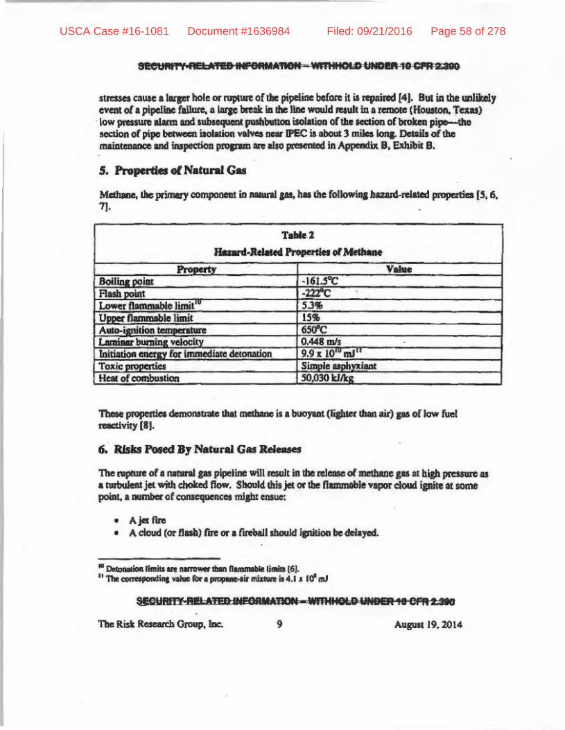
see""",,,' l M'U ... e ... A1I811 '; .. 11 I .. OlD 111111 .. 10 g A zag
strcssa QUIC .lqethole orr\JIIUIfC oftbe pipdine befoce il is repaiRId [4). Bill in !he UlliiUl.y cveM or • pipellDe failure. • IIIrJC break ia !he line would retuIt ill. rerQOle (Houstoft. Texas}
' low plUSUle aI.-m &Dd nbt",,'CIM pashb\IttOQ iwlllion oCtile IeClion oCbroMII pip. tho section of pipI= 11m. lID iIoIJLtion v.--_ !PEe is ILbout :) IIL.iIa Ioq. DetaiIt of the maial:eDIDCe mil iJupecUoD proez.a :IR also pcew:._ In Appendb. B. ~il8,
5. ProperileI of NaCunI G_
~ thoprimlryCOliIJlMC'Dt iIIL -.Ips. '* tllefolklwinlbuud-Rlatecl piopeati.s I'. 6, 7].
T .... ' Ih 4-ReI ..... Pi r .tleton.·n •
TbeIe pioputlcl dcmonHr:oIe IhII met ...... il • ~ (ljpIer thin air) pi or low """I nKUviIy 'IJ.
6. Risks Poeed By Natural Gas 'R.,., __ The I:IIplIII'e of. RIQIrII PI pipelilx will R$Uk in !be mease ollDelMne JU II hiah pmsare III .lWbuIeIIIjet with chobd Ilow. Should. thiljet uribe nllMJlblevapiM'cIoud ipUtett some point. • oolJlba: of c:omcqumces mi&hl ~
• AjcI: flJto • A cloud (or flail) rlJ'e or • rRlMJI sboc&Id lpUtion be ddayed,
II n.co.lcoo.llnoiis ore ..... _ ibon n. 1 I U. [61. " Tho ....... oz I .,Ii", oIIue ro.. p", I lir IIIiuIft iLl4.1 • 10'""
$lGUND M' HfIIIIPGRU'm,. '1JfRIlieLe WHelM,. e ..... UICI
, A\IIUIl19.1014
USCA Case #16-1081 Document #1636984 Filed: 09/21/2016 Page 58 of 278

lIiIlUISI,., A. 'ZIP !Nf91U'"ROM wma:91oD .. ID ..... " IIID
• v.., doud. aploliOllS JaU!ti,. from the cIefIlptioIl or ...... ioa of !be mcdIIM-a!r ,,,,",
• Missile ~ia MdItIoD 10 fI&a md upiolioa,lbB ~ of I plpdlDe mi&iU be accomp-ied b)' nLWile I"rlCl.-ion with trqrn.., of tbe pipeline bdat: IIIrowIl <:OIISidenble distmca
Plpel.im rupNIC uUpt result fnIm ~ IX' ~ or lCbmie-i............., ftilun of the pipeline. All u- f7I* ol eau.... _ enhaaIed mf ... """ below. II IIIauJd be DOted tbIIlpitloa ~ _ requlIe I pN-uiltia& soun:e bIlllIIiaJIt reIUh ftora 5pIrb a 7 I .. ~ melIi pieI:a OX" nx:b nib topIhez'.
I_fire ('-']
Ajtl Rae ii_ turbuIeIlc. clUfuioo I1Ime muJtina fnlm tile comiIIa17ioa 011 Nd. J&t ~ bavo DO MInoMM -d.y ratcb ruu jrwmol7y ;, wcN .. dy aMlJr*ion "'" will cb.., with 1M Ne!.', me.. r-. 'Ik lilt poMd b)' jcc rIla art.c beeaUM of 1ba IdF :x. nu.s ied 1 7 OIl u,..... F.... 'orequipmcnL SbouIdtbe .... jecimpl ..... upontlledoieol*en&etfOlawdia7bc plUIId. _ 01 ... mcJ ......... tbeosarpilll .... will diMis- _ tbejet will ~diroctecJ uponrd, 7hacb)' proto ..... , I tire wItb • horizmtai protIk tMl II paenll)'wldClr" sborter thMl -»d be IiIe _ for ID IIIIIIbI7nIcted -'leal jet [IO\.
CIMd'll'Cu_na b Dr(,,']
It. cloud 01' I1aab fin iI. tIMI_ file "",,'tin, fnlm IiIe ~ 01_ eloud of n. !2b!e lIS wirbouts.ipltDn!ftamclC~11 ,MIoIr..arcsukoflwl lerw, Nosipl'ieanl_ ... _ raIIk Iioat I ebId flI:e ..... two c ... 1In .-aU11111b for teulblD _ mja"te. tbe ialqril:yof __ eapJIed ja 01' Qpoa 10 ~ h wIII_ be chaIt.cIpd.. Pel.......,. cquIfcd.ia web Iflle IM)'sutfw ...... bums. bu ...... WIIhlII!be padoud."'scaIe ecldia mi&bc ~na-.bko .. _yrmmtbebul;oflllcdoud. ecM. P ·'),.locaIpocM'offue_ pouibla. Typic:ally in I cloud fire, Ih8 ft_ will burn itl ..,. bQ ao Iba lOWe. 1iIould!lle __ bea ruptured .. pipel_ aplite wilI __ 17: IboaId IIbo be IIOIed $hal "fill'''' pip I ..... tile poIIibillty oIaliFif_1lIIII file ....ttint: front de!a)'Od rcmcft ipjrjon is ummely low elM 10 1ba tue)_ MIIlIeollbe ..... wblda ...... Iy preel. f I d>e'-ioGoi IpmiNent ~ vapordoud.JKUMlIeYeI" (lOJ. TiIrnIfcn. the dep'ction oftbe ~ .:laud l:I'IIYeniDa the IPEC ,Ite is Iberd'GnI ~w: _ Il0l1 '"' pwaibilily here.
It. fllllball rmaltl from the rapid IWbuIeat combustion of rod .. ar apmdi.,., flI(\iW ball of name.. Normelly. boweYG'. it rauitl trora !be RleaIe ala JftSSIIrized liquid rIIher !han the rdease af_ .... iiUOId II' and sa!1 wiU 111M be COlIIidemI funIm- hen: 1111.
S'01RTY"I'lSISllI.AlIC»I 'MR17t)1D'V; "9.''35
The Risk R=; el, Omup, IDe. 10 It.upit19.2014
USCA Case #16-1081 Document #1636984 Filed: 09/21/2016 Page 59 of 278

qo,,· I." .. ",. ",' •. ~'. '",'. ii',,' "1'. '~.I""'" .....
v.,.,.. o-d £l"pl:""1 (6, 'J
There Dte Ibmo ~ rot 1 ~ipOI" cloud nplosion 161:
• Tberc aMI be 1 re1eue of i1ImmIIbIe l!IIIl:riaI into • CCIlp:$&ed IreI ot Ilea of hiJb ......... • tani'im must be drIIa)led 1O .. 1ow Ihe fCll"lnllion of ~ i~ mb.ture wiIh the fuel ....
COIII;ClQII:mw in d. n_obIe raaae • Tberc IIMItI be ~ ipirion IOIIIC8 oflUfficienI eneru 10 i&nlte the ~ .. IlIiullre.
VlpOrdoudGplosioas (MOQ:\I!"U' mule of cId1Iparicm otdelonlNw.. 1111 defJqntion. the: n-properln tbroIIF!be IIIIbunIed awh ....... mb._ • I bumina; W!1oeity IbIt is less ..... the sp.d. of-.i O;ajli~I._ .. __ i:n1llCb .aaplosioQ Will YIIY wiIb.!be combuIUnn race. Givallbe low fIIIM ~ of_"'''', IIliDiINI. owrpreIJIIIa Ire "peeled with deflIetllioDt of iliecba.,C IIId u-it hal bcCIII CODcll1dod _ ". def\qrIlion tnwlinf; tm:.up -"-" pi dcud 1rilllWUk in -aliaibJooVV«jHl' _"III~ A deflqntIotI '*' be iniClaled by • .-II; eDe!JY _
In I decorMtion, !be metb_air ~ Ii"OIII prnpt&M'1; IS • sbock_ tbII CCIZIp! : 'F" lbe uabmncd pwIr raiAture 10 cballCIlI ...... 11IlCS in Ibe ceUt «!he II1latlll'e ex-' the ...... lpitlon teaqli ... t.~. The sbockwaWl is thadore pMi'"incd by !be COIIIb.tio. reaction IbM folIcws it
A d.vw.Hion .. be.-:bleved ",lib I hip -11 IpsitioQ ...-ce cr by IIIIDe lCCelention wkbIn 1 hilhl)' ~ _OCIhi&b F1IOIIICI'II1II(Ict) ~I=e Hall"., ........ W"of """" .. c'.low racmily, I d..,....IM wkllia. FlIIJ'~' : air doud wlU d persill ",aide Ihc coapsted or !IKbuIeat_ (121. 'IlQ ............... _ FbI! rota pspipel.illelhll. tranaes _ IPI!C,. dekInItioII. wHI QOI drlwupoonwb_ClllllSidetbcjel: or the _of.Q I. 00n pro'lilkd b, nee..tjlceat to It. ripr of .. ,. Willi rapect to Wi' t:oa, teJIt pcdauwd on UIunI ... Mve ...... 1Ur. a hiP depe of eon&etIion is reqlr' _ 10 obUia biab fbmc ..-II _ _ prt lures with nalInI .. IIJ!; ocbI:r aperiulents r.iled.1O initiaIe II!. aplOliolr of II8lInI pi md .. !hIDe miANrelwiIIllir In • .enu-opm II*C nm ... CIlplorivc wu used .. at ipiIion _ll04J. 1'hus lbc~ -.ptar.n! illhltmr«b_ ... will II1II &iYe~ to .......... cloudaplolionl ..... CC'ltIncd (I, 15, 161
]. ThIt SlicLI'ariOllS reportS IndstUclies pi.,_ rdlowiD& me. 2OO!I1IuKcf-'d QpkItioa IUpISt "* bdIr cf lIla provide sllff'l:icol eon,alioa 10 r.atitIU fI_ Kt leruion IbIl miabt lelclrodctonalion 117:19]. fIamc .cell IItiou is~, likely 1II'hwelbid IIlIdapowlb MIll "ecidlious In:a ptWIil.
II f)( 0I0baI (161_!hot "Ibt lbIlo .... __ todo DO( ..... alipIIkIM or aea.Ie IIIIIIIoor (VaporCkNd ElplwiHJeo,a Ift. .............. .
SlCUftITY-kUAiBlINPONlAIION .WIIII'" " UHDBl10 eM I ns
The Risk Rmlltb Group, Inc. 11
USCA Case #16-1081 Document #1636984 Filed: 09/21/2016 Page 60 of 278

Si!CUAi! N¢Uilcu MNB •• 'iUri - "",BIOLO ',"MA liI"EA 2 M'
-The rupture Of buMinr; of' ps pipeline might ,,$0 fC;lult in larae fra&ments be;", thrown. COIDideroble d;lwlCe ! res [81 describes, I96S incident in Natchitoches, La. in which a his}! pressure pi pipeline T\lpt~ spliulng the pipe dOllJ' 215·(t (1l1rI) lenp/!. In the lubsequent blowout, Lhree pieo;es ofmetd weir;hin& Io'.! ton in all were thrown 130-360 fI:(40- 110m) from the point of NpIIIte. Similorly, a PHMSA order issued foIlowinr; ,2I2l2003 incident in Dlinois (PHMSA )·2003·IOOZ·H) briefly IIOtes that pipeliae I'npiml$ hid been tllrown.as far as 900 ft (274m). I) A leucr dist= was rcconkd-in an NTSB.repon (PAR·9S·(H) for a pipeline rupture in New Jeney in whid! fnogmcms (If the ru~ pipeline were thrown 144 m-(800 tt) Given this expcriCPCe-174 m (900 ft) is the Jf9ICst disWlCe nIXed iii the 1it~ for frDameIlII of the pipeline 10 be Ihrown.UUr fUpcure-*'Id the p_ distance of the pop v.d soutbern. rOIIte .0 main plan! s}'Slems aDd $tn>cI\I1e! in the SOCA (- USO ft or <112 m from the SOCA), missiles flOln a rupeureor burst oCtbuOIIwm roUte pipeline will IlOl el¥' .. p SSC$ inside the SOCA. til a4dirion. wilb respect 10 these fnlpeou. we would note that Section 16.2.1 of\he IP3 FSAR (201 sutes IhDt CJ:w I buiIdiDp aad IUlldu= at IP3 are desir;ned for tornado Ioadinp clllcuJaled lIisumina the siDlllltaneollS application 0( IllDgeniial wind velocity.of 300 mph. I ttaILSlatlonai velocity of 60 mph, a pRS5IIre ehmge (drop or inciaae) of 3 pi; in 3 sec., and postul~ tornado missiles with potential missiles iDcludiDIa.aoo.tb :IlItomobile. AcconIin&I)', we WQU[d condude that the implCt 0( pipe fta&meDts on safety related I~CTTIlI. structures and components II IPJ, the lIIIitdOKStlO the pipeline, is bouncIcd bytbC lCCIiarios COMldered in the FSAR.. Potential Unpi.ru of missiles on the: sse. impoi1ant 10 lafety OIItsLde the SOCA IIIId closer 10 .he southern route Ire di$C\l$U:d below.
The .-ete.ose or gali at high pTCIsure will of IDlQC Iliso blow off My soil or fiU cover above the pipeline and scour ;away earth from :ll'OIIDd the pipe,ine CJUlin&. cr~~.· BU! such action wi!! 1101 h_ SSCs wilhin the SOCA Of M:ll'!he sOI.uh"rn rou'" pipeline.
7. Rqulatory Guid.nce
The US Nucle;u ReJUlIltOfy CormnissiD!llw issued RqulalOr)' Guide 1.91 [31 that provides guidance fat the evaluation of poteDIiai eJlplosionl nul" IIIIClear power plants; other potenti:tl but les5er hanrds Iud! &S jet fifes were not add"'ll'ed.. bo\ftver.
" It wil, be!lOl ....... ddlaftCl is IaI dian rIIf' ~ bi:rwftt.W- p!1>pOSed. pipet .... ond sy$re"", smo;ucs .... ..... ""'''.IIIS iqM>noM lei ... r.ty .. "'" SOC". .
Se"H,!. i UP",Ncopp"mt, '<m:WL«ltD,WD'P1DCERUIB
The Risk Research Group. Inc. 12 Augwt 19,20\4
USCA Case #16-1081 Document #1636984 Filed: 09/21/2016 Page 61 of 278

-sEa.II",,' I anna... , .... _.,. • .,. D"3PIA .... • SST
Rqulator)'OuIde 1.91 COI)ef:IDI iUclfwkb bIaIt dMilp to IIIIcl_powerpb.t!l stnICtInS OCt:aioned by "iDc:ioieuI or ..nec.od PfISIUR (O'iCilpt Ire). dynwie (drill pnasllRl, bIastinducedarowd lIlOIioII ... biNI' tee! mlyiJeo. ... OfIllliM '-I*-Y COl'iCCi1U is wicb O~Cilpi~ TIle pWo __ u..t a-nJ. Daip Crileril ror JIIdar power pIII1U would be SMisftec! with rapecllO polcIdial..by I!uMit ..t uplolionll ir;
• 1'bI: distwn; baw I critical piG ~ IrId JOIUaI oflbe bl_1s IUftlcienI: to .void .. y illl?*lli'oman aplntlcs iCtbI~ be. I die .po.klnud lysIemI, ~ and".IIP'l I in:!pxcInI to IIfcIy _I!ICb!blt DO sysaa.1Inx:IUnI orcwlfOlllU imporIIm. to safely -W be upc!lCld: 10. _ ... ivel.y ckte:tm~ potid.lIe pcIk iDd6r:IIt 0_1*_"" Ulnc ... of I p'i.
The rep.tlillofy JUide Ibea Joel lID to "'* u..t If 1M ~ioII. eloIer 10 lysIemi. ~ and • "wP'l'I- '"~ I 1 DdIrIit 10 IIi'cty w. dIis miom.... safe d",*"" tl!en the risk of... • .. QUsed by IIftGp1oeionb KC i41l1'y low if;
• "Thccxposuce rille for....:ll in .~ d, b leu tI.! 1 X Irlyelrifuw.!'Ililive _!plioul are lIIed in 1he_JSi> or I " to·'/yar iffelllilrie ·$»I,_OM IR used.
LooIt..,spedflcaUy" explOlkn tUlIIi ..... OOCIII" 1OUowInI,,1 .. olllllllnll .-hom_ plfri'ee IbDGuidII OQIa!blt "pIua!emodd'nsbaaood an,ilelo:lp ... , -.I.~ . condidonIlbouid be cvaluas.l"'. 'I1Ie rcf&nnce roc JUdI; ...... 1 .. NUItEG C1V6410 [211. IIIIkeI expliek P, lion of die TNT .y-.:e mechocI for npor tloudl.lpbion bI..r modeIiD&- In disaJuinc1bcl-IIM4,_ Icdisplrsiol~. NUJlEO CRl64I0c,*ar::tcrlus ALOHA. .. bein& ~IDOItUleful roratilllMillldlemlcal ~eMeIIt IIId CO.C M'MInQ for short~ c:h.lic:aI aa::iclellb ......
s. Sotlwaft aDd Moddl
WNUlII!Cl.'CR·6U'(11 S IMOAU.II_ • ........,ofli.·· '~"IO!MAl.OHAn*I. 0( ...... 1III0I0Iy linIiIIIIaw ~.IIO' :, It., .......... 01 ....... ;. do&< ALOHA .... not ___ 1IWliII.C.l .... r iii ... _o/Jt<tIIII""lIoe,.... 8111 ... _1.,' . lo ...... itAPrOX. •• ,...., __ ........ BJt!I!ZB..,...... -'-I)'Il. • ......, bit ........... 1M ..... _* I'llrikClJIrd..,. GIlW ~ fIotJ oil lint b ,.. ..... ., ""-
The Risk Res Mch Choup. IDe. 11 Aup 19.201-4
USCA Case #16-1081 Document #1636984 Filed: 09/21/2016 Page 62 of 278

The ~equen<:es of the ~leuc sccrwios dcstribed jlftviously Me predi<Ud lUing the models contained wilbin ALOHA 5.4." and BREEZE lncidtnt ADalyst 1.2 IOftwate.
ALOHA ill 3. program desipcd to model ehcmieal ~l-. [I detmnines clIemia.I release niles and pnentes I vllridy of stCI1afio..speeifk outputs incilldlna threat WI'ICS for jet fLla. vapol" dood np\(lsioru and exposure 10 flammable plCi. ALOHA wu devcloped by Ibc US Environmental Protcdion Ajeoc:y (EP .... ) Iild Ibe US 0qIDrtmcnI olCOm=. National CX=Ue 0UJd .... tmospheric Adminislra(ion (NOAA). II WIS wed here 10 model jet names aod v~poI" dood dispersion butllOC vapor doud explolions. The mocIel in ALOHA WIS not used for v:aporeloud explosions because t1ic Regullllory Guide 131 cxplleltly deems a TNT equivalcm:y method to be ;l!llceeptable method for cstablishinr: the distan<:cs beyond whid! no adveneeffect of an explosion would be seen and bcausc of the eu:essive ~ltilm in the UIUmption mIIde In .... LOHA thlll the emile namm~b!c ronlCnlS of a buoyant plume of mcthllllC wiU be illYO!ved in." explosion. 1"lIU ooniJadi<:U the evidmce thai. detonalion will iDvoiw: muclt lmaller ~ of mcthane---lhe I!WS in a turbulent jct or lyinj: In Ihe wooded lire»
I· . .
in I ICpOn issued by the NOAA. IX>T [23].
BREEZE In;ident Analy" comprises I user-friendly Implemc:ntation olotber models widely U$Cd to dwatferi:r.e chcmical rete.e scenarios.. The models of conc:em here _ The Gal R~h ln$tilUle for jel nlllllCS, AFTOX fo .... apor cloud dispersion and !be US Army TNT Equivalence model for vapol" cloud elplo5ions.
The models within ALOHA S.4.4 and BREEZE Incident AaaI)'I1 1.2 software used to ch:lrllcterize the uocipRied and hypothelic:al ronsequero:es of the release of natUrIl gas from the proposed pipeline QQ»U\, ncar the !PEe site are lilled in Table 3. Thc boIIis for the $Clec:tioo of these IlIOCIcIs is abo prcsemcd in Table 3. "Where two modeIl were lIlCd 10 c:hon.tterize the same sunario. the results c:nn be OOIJlpued \0 provide I mellSUre of reL!SU~ IS 10 their validity.
SEQ! IflffY,.REI 41£OINfAflM&J'AN WllI"'''I" I INDE" 10 CPR 2 390
The Risk Research Group. 11K. AUJUliI 19. 2014
USCA Case #16-1081 Document #1636984 Filed: 09/21/2016 Page 63 of 278

;bAt I-r 'asaa IIQii _n"QUh_ ",ail"
T .... '
... 1 .91~
. ntNf'a tursacil ftIOdel&c, NUI.EO OV6410 (21]. ~ ALOMA. beiq--1mSC u.fuIfor~~." ,ikwJpI_ el<lenllIId ___ b' Ihart-dIInt!on cheaQl ~ckJ ." in ' .. /ba.... ie .. :.-:.... . ~-
m. 1.91 ell. ..........
SEvAi, I.U-no sa ORIIQICIN .. W:r II I' D 1M R !fJ CI!II2:3ID
11w Risk R= ... 0.0..,. k. " .... ..,... .,. 201"
USCA Case #16-1081 Document #1636984 Filed: 09/21/2016 Page 64 of 278
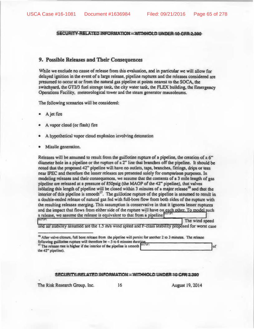
SIiCURi'tY AIiLATED INf"RMMIOIJI wmI~I" UNDrR to ern =I 200
9. Possible Releases and Their CoDliequence5
Wbile we uelude IIQ cause of re\e1l5e from thise¥alWllion. and in partkular we will :allow f« delayed ipliljon in the event of a l:v;e release. pipeline ruprum and Ihc releases consideml arc presumed 10 occur III or from !he: IIIIIUr.II gas pipeline at poinu ncare51 10 Ihc: SOCA. !he: switchyard,lhe OTllJ fuel slInge 1oInk.!he: city wiler Wlk. the FLEX buildlnS.1he I'.InclsencY OperatiON Facility. mcleorololicaltower and the Slum aencralor mausoleums.
The followin, scenarios will be coruidcn:d:
• AjetfICC
• A vlpot cloud (or flash) fICC
• A hypothetial vapor cloud explosioll involvill& detonalion
• Miuile~.
ReJe~ will be assumed 10 result from the CUillotille rupture of I pipeline., the !nation of a 6" diametu holc in I pipeline or thc ruplUreoh 2" line 1M! 1mndIc$ off the i . II should be noted . hive
" ]" . The JUilloti.nc is assumed 10 result in
I gas fed with full·bore now fi'om with This il COII5C1Variyc in thllt it
thaI flows
" .. "ftu ... hac","",,", fun bon: .. Icasc fftI .. tilt pipeline .. ill penN rot IIIOIher 210 llnin"_ "The .. 1_ followUlt: piIloI_1UpI\n wiJllIIorcr.:>te be - 5 10 6 II\inIoIoO .... ';,,~ "lbo .. 1_ ... ishi&hef iltllt illlerioro( ... Jipot ... i .. _ 1" ... lor tht 42- pipelinc~
S!CIIFtlT'f;;H!' AT!n INMAuA'!'10N _ Wl"NNOtD' IIJIDI!III 10 C~ :ta80
The Risk Research Group. Inc. 16 kip 19.2014
USCA Case #16-1081 Document #1636984 Filed: 09/21/2016 Page 65 of 278

CQIISeIjuences in 1M EPA Risk MlIIIlIgement Guidance (221. Alten'Wtlvc resulu wt:M obtUned ~illi !he 3 mil wind speed QIId [).cll\$l st/Ibilily pfOp!*d by the EPA. These lalter rneteorolotleal (XlOOilion, are more aJlJUnooll. Missile lenention will be assumed to
ocromlWlY rupture some ol the lime.
r.dt.tion at VllriOUS
to eonerete
Iqcat disIMC:e calculated lDI'thil
From Ihele r¢$ullS we can conclude thlt ill the event ol • jet rl!'e illl'01ving the CUillotine ruptUre ol the proposed. DlIlUI'lII F5 pipeline in proximity to the SOCA, petSOIIIIcl aerou the plant site dose to the point of ruptlft who are unable 10 quieldy tllce shelter will be Injured and might die. Ho.....,..er. the levels ofthennal ntdilltiOll seen loll_in, the pilliotine ruprur.; of the 42" pipeline will neither t:\I.UK pluto to mdt nor C;MUe the Spontoneooll iFition of wood within tile SOCA ". Similarly. I lesser release through • 6" di:mwtcr bole in tile pipelioe or from the UwmM guillotiDe rupture of. bypotbetical r line that brandies off Ilaqer pipeline will only Qpoll: petSOMd outdoors and _the p:lint of ruptUte to possible injllQ' or death. Thm will be /lO damage to equipment withill the SOCA.
Considering neJ;t possible dlllT\llge to the lDCIeCfOIockal tower. the GTl/3 die.\(] fuel storage tank, the eity Wlter W1k, !he FLEX building. the EOF, the steam jiWU3ttll mausoleums and ,wiK:byud. all located CIIIlSide the SOCA. IS I result of the rupture of I pipeline and jet rKC lit /he: cioxst points to these items. damage is usumed to oceur IS noted in Table 6. This damage might rt:$uJt f!'OIII engulfment ill fbma (e.g., in !he eyent DCa jet rife initiated on • pipeline on
to For eumplo. 01 .. pi; bel_a ,"" """" of 9 "" oM 6 &III ot Wmchcl.II:rCooIll1 AIrport. lImO.pIocric DO""~ion> wiIIIl wind JiIftd of • 3 mil "'" 0 air "","Iiii' .. Iwkc .. ~ u,hooc: .. iI/t I wt.r 'peod of 1.5 ..... om F I .. bility. Fwtl!mnoro. F ttabllily witt 110''''' """""" • ...:1 in .... do.y\inIe "",,10 0 ";11. " ~ .... ~ "~ell. l1li1110 ...... upooed .... ipmelllub .... SOCA_most ......... '" lies indoorJ belliw:l ......... '" watlo .""!be I/'anlIOrmm "'IIIIIcI be ~ ham this lbennal !;Idi.oon.
SEC''R1TY Ofl &ifF, 1""eRPlM'lSII VIm. rc~uc." 18 OFR 2W90
Tl1e Ru.1c; Re:seatCb Group. lev;. 17 AulllSt 19.2CH4
USCA Case #16-1081 Document #1636984 Filed: 09/21/2016 Page 66 of 278

SESO"', I ltELAI!Q .NFOFldA1=iON _1'I1I':lC:D' 'N"' .... cpa Z '91)
the proposed SOIIlhcm roule dira:t1y impiD&in& on ~ GT213 fue, 1!I!\It) and inteme !bermal radiation !hal ml&hl damage equipment IDIl. [I){ the fuel WIk, cause all!l\k vent fire. Withoul 1IIX00000ini for the very low probMility cl svcli evCIIU, pipcliM NpiUreI on the proposed southern route 0lU1d inlJoduce additiOll4l rWr. to equijllllellt IocDted away from the SOCA. This ~ddi(ional rilll: it. however, minimal as:
• No damroge 10 the aty water tmlk is lDtit:ipatcd sbould the pipeline. tuptul't= and a jet. fire ensue due to the IUbiIMli.aI dist!IneC between the lank and dosest point of the proposed pipeline cl,J36 fe(:t (-407 11'1). Similarly, no damage to the FlEX buildinj: I){ the Unit 2 stcam IC!\ef2lOl" mausoleum is antiapated lIS. tau!! of thcnnal rlIdiuion as the dutance between the pipeline and Ihese SSC. is 100 grul.
• D!IIlIlIge to the Iwitch)'llrd may 0CCUl from. jcI fire caused by IlUillotinc tupt~ of Ihe -42H pipeline at the point Closesl 10 the switchyard &lid u.wninl the jCl flCe is dllected toward the Jwitcll)'ltd 20 However, boch lP2 and IP3 have thtee emerscllCY di~l generators (with ,ufficienl di~ fuel stom! OfHiIc far!bese IMCfllIOIl! to run II 'ClL'lt 2 cia)'!) and an ApperlClk R/$1I1ioo blackoul diesel gmcralor with liddilional fucllO mitipte the loss of offlile power. 'Ihcnfore there will be more thlUtlwO clays to obtain additional fuel should boch the lwitcbyard and GT2I3 Cuel tank be unQYailable. However, a jeI; fll'C closc to the switchyanlllliJbt cause SimulWleOUl damaJe to both the switchyard and GT2I3 dic;scl fuel siOnIe tank, but IL'I di:$au.sed. further below, the probability of such IUt CYCDI involving !be cnhAnced pipeline. is below NRC', tl!n:5hoLd for furthcrcOIIIidewlon ••
• DIIlIlF to tile metcoroIoaica1 tower may also occut from. jet flCe caused by IIUiUlMinc rupture of the 42H pipeline at the poinl closest to the switd:!yard and auwnina the jet fire is dilectcd toward the tower?' The polallial ~ of dalllagc to the melcorolo~ lOwer, hoWC'lu, <;;111 be mitiptcd 115 the data il provides CIII be obtained froIII. other sourecs, Indudin& ~ bacll:up meteorological tower and weather forccmlin& lervices such lIS those provided by the NOAA.
• M the sse imporumt 10 safel)' closest 10 the proposed southern rouJe, dlllTlllle to the GT 213
j§~~~~~~~~,~,~om either ~ ",iUOIine rupture i .Im " .. I .-NRC',
The Risk ReSCil'ch Croup, [nc. " August 19,2014
USCA Case #16-1081 Document #1636984 Filed: 09/21/2016 Page 67 of 278

Sl!eUIiII .. R£lAT££IINFIi1"U~QPlwmlllmn IltmrS'" CPR 2 319
DIuiJqe to alemal instrummwiou.f .... i7~ ~igbl occur:lS a _ulta! elPOSure to II beat flw: a! 12.6 kW/~ or more subsequent to pi ~ roptu~;uK!!he ctealiOl\ ohp fhune. Suilding damage 10 the Unit] Sle:un lellClllloc IIOOIF IIIAUSOleum miJhlll10 occur :IS I result of heat flw:ct in excess of ) 1.5 kWImI. Such damII..,e. however is UIIlikely to be of COII5eCjIImICe liven lhe robII$t desicn of the Stnl<!rurt:.
Finally, we note thllt • jet fire origimKinJ from II ruptured .oove.JfOIItId portion a! the pipeline ~t of the SOC"," where the III:W 42~ pipdine will oonnect to the existin& riglu of wlY. will 001 cawse damqe 10 SSCs within the SOCA., the IIII:ICOrolOJicllllower, the GT213 ruellank, the city Wilier tank. the FLEX building, !he; EOF or switchyard. beclllSe of the distllnce between this above·poond portion orthe pipeline md the olherobj«ts (Fi.,..re 2, Tobie 7).
In lummllIY. as SSCs important 10 lafety miJht be exposed to thetmal radimlion in eo«:elS ora relevDllt thn::s.hold subsequent to pipeline TIIpCUre and icnilion of the ~leue. genen.l polelItial ClPOSure rales lor dartlaJc need 10 be determined.
Table 4
ConseqlHllces of ElI:pGSIln 10 Them!1II Radiltlion [II
.. ~ ;pi ..... iodoflned .. lilt _. Df a Ila:Ioc >I"'" rurf ..... ora ..emil """'~ Ills beCII CApOIoOd .. u ....... b$l.,. willi OIl Ipil/oIlOUfOO ptCOftII;' lilt ... tolli. _ =-ed ... lilt ... 1IriaI is hwed Illi.
SEGliAnY Rt! 4,U1INFORMOUION wmn leLb lIflbER Ie eFR U9D
The Risk Resean:h Otollp. iIIc. 19 ALlJUSI19,2014
USCA Case #16-1081 Document #1636984 Filed: 09/21/2016 Page 68 of 278

'U!l!"tI"W· RE' ,.:t:E9INFORMA'ME!lt hmlllQIoD UNQEM'O "fR 2 3ao
Tabl,5
Consequenca of J~I FiuScmariol
.1
The Risk Retcard! Gtoup. Inc. " August 19, 2014
USCA Case #16-1081 Document #1636984 Filed: 09/21/2016 Page 69 of 278

;;tOil] ,,,. "._ " ... ~. INB"lRM 'T~atl IJIaIIIIQU) IJMO£R to am' 391)
Table II
Potelltlal DIiIIIII~ It Cl05m DlslllnCfJ rtOm Proposed Pipeline In tbe Event or Pipeline Rupture and I Jet Fire
,
Table1
A Compllli5on of DI511ncu rrom Abo,-e"Ground Portion. of the Proposed Pipeline and the Impact DUlance 10. hHI nux or 12.6 kW/ml
• •
SEtUII:I'n IIII!~DIIIP!lIl:M ... "eN WFRMIElLOlfflBr.:fII IserRU90
The Ris .... Resean:h Group. Inc. 21 AUIUS! ~9. 2{)14
USCA Case #16-1081 Document #1636984 Filed: 09/21/2016 Page 70 of 278

Ima., AI!LAlIEU MHtflUillON wmllOI;;;D WII"11 C Ii a.181
Adouo:i file is tllticiplted IbouId a mcdI_ tdcac I.--alta: adda)'. This tu)' IlVOlve the lOUilellU of!be lIIdIuieat jet.1IId. cspaeiaiJ)' (Of jelllU: ~ IMlt verticil Of for ~ of Nllllier dl. $I s. tile· ... "".' oIa "'POl'cIoud tbIl isdbpcned. aboo~ .. phllDC_1JK! • MU. dfcets cliMip* (typieaI/J anu ~ 10 I). _Inc dIallJte IIIriIIaaI ,_1UINm _lib wIIidt the: ITICtbaaI: eDf tile: pipe IN wiJll'CIIIIt ill low nwtb_ (,<CeDI"'" dole to Ibe point 01 m-.
The: diIdIarJe rate ill a llelale IaIcr 1'1=1 c c will
WiIh 0eJayed ;piljcwl. a "'POl' cloIId fIR aDd !he ICOrd<.inI aDd deplfcim of ID.yp WOIIkI_ wiIbiJI dIoK puliud oItbcdoud whctctbe 1IIdhaM000,,·,.,aUonuccodlllle Iowa"n· , He limiI: ... U becaIaIe oIlbe ptII'ibility Ilaat n-ubIe 1"" kMI of. ,.. -Illiabt I.Ang Ibemaincloud.lbe Ylllllel'ilWe ami is typ' .!!,pIKed witbia I~"'q;w:, , •• ISO .. oCtile lower a.ma.bIe limic for 1!IedIaae.. While wda a file IlliPf.Iead to iIIj\IrJ aDd dath 10 "JIO'"'I pate I aodklcalfba, it_IdIMlt,-, .. ecppnntOf~¥apotdoudflrewili be oIlhort danliooI ("a r ... tm$ 0/....,......, _ tbau "tile total radiuioo iaan:epced by an objecI_. flaM fin Is , ........ ,!.!!)' »wer IIIIa from ,,' ajot flreM(JI 79. 16)). Apm tile ooaw.llisaol!hil dIaI_i&atioilollhe~ oI,doud fire IIIIOCIs k Itn:qed, 'I'hut wbUe !lib clood coukl travel very COIIIid ... b ... disc.nea ~ .. ~ tba wind apeaI tnd iir uabilityutbU .. oltde:acrrabkl),lIIebuo)'MlP9IIJCoIlIIl' ~"",lyjX 11 I !be fOlGlioo 01 a penilceal: n-atHc YtpDf cloud at II'INIId level Id ___ DIIe tbat -*I travel dowaIUIl to 1IIc SOCA.
The Risk Rmeardl Orwp. ine. " AIIJUSl19.2014
USCA Case #16-1081 Document #1636984 Filed: 09/21/2016 Page 71 of 278

SEeI:lRWI' RELOiii'eQ INFOlWAtlON WItHHOLD UNDiR 1" "fA 2 Jilt.
Vapor Cloud Exploslom
Table 8
Cooseq_ arOoud Fires
As noted above. It is not likely that llIly Klcue of mcth_ from a nalunJ PI pipeline will ~II in I. vapor cloud explosion :and lIIat. should this occur, it wlll enlllili. defiD&mtion with low resulting ~1UeS rather than i A detonaIion is h)'pO!hctieally poasible. howe¥er, in the turbulent air:mel within the belts of trees adjtleellt to a
with the • a !
;~'" • !be middle of ttw wooded area io 1ritidl.llammable IXK\CCntraDon of methQlle miabt be found.
Sl!cumn-RFI ATPO INfIOJIMHlON -WlTHMCltc tI/J!!A 18 el'fl U!III
The Risk RtlIe=b. Group. Inc. Anguli 19.2.014
USCA Case #16-1081 Document #1636984 Filed: 09/21/2016 Page 72 of 278

1-\ .. • .. ' 111:1. ' ... ·.1 .... • .. ''' .. ·,,' '."'." ... "".'.,., •••• "'.,~ •• , ~"""'" •
In evaJuutm,; VlIpor doud explosions, the critical dl$la.nces are:
• The $honest distance from the 42" pipeline.(the anwned. CCIlter of iIlI eaplosion in the Ililbulentjel} to a system, 5tnJc1lJR. or component importa.nt t01afety In tile SOCII. (the Prim:Iry Water StorDJC Tank or PWsn I" .. ,,,, I The shortest disWIce to the SOCA is - 482 m (I.s8O fi).
• For the 42' pipeline on the southern route. the shonCSl distance from the mid-poiAt oill! explosioa initif.ted in tree$ '0 the lIOI1heast of the riJiu of _y to • IJitem, sttucture or componmt important to ufcly (the PWsn isf'!iJ, ,'or 1&rJC reM:ucs.
• The ocher d.1suneu from the 42" pipeline 10 the safety-related or impomnllo safety sse, of concern are pre5epted in Tllble 1.
Vapor doud explosions w~ mod.elm lIIiDS US Anay TNT equivlklll eaplosioll modc:lllS implemmted wilhin BREEZE Incident Ana1}'$t. The mi.aimura. safe dilil.:lnCe$ beyond whidJ the ove.prusure win not exceed I psi wen: alsocalcuLated.llling e~atioo (I) ill the ReJUlalory Guide m)O. Th<: mas. of f1:.nunab1e materi.:IJ potentially iDvoLved. in III Q.plO&ioa is estimated lIIiltJ iIII aPJln*h suapsted by both !be PM Datr. Shcc:u 7-42 [16J and Woodwlfd 126\1lS dilected by the lteJulllOry Guide. F.3smtially Ibis leadilO IWO ')'pta of explosion foc each "!elISe an Q.p\Iliion i"volriDI the man of ~ ~ the upper and lower flammable limits in the turbulcrlt metlwJejetcn:alCd by a nIpIlIre of the pipeline and Q.plosiona inVQlvinS D ''volume with suffICient confinement or con&eIlioa ,0 aeate fbmo:: accelmtioo" [l6] web as !lull aeo,led. in the belts of trees adj:ICeDllO the proposed pipe.linc ri&b!-of,wIY. Theulcul:llion of the min of mctbane !hat miah' contribute 10 111'1 ClIplosloD is dc5cribed in fOO\nOleS to Table 10 and Appendix A; !he masses IIrC Iiso pmented In Appendix A. In applyinf; the TNT equivllerlcy mode .. , a yield Fill> ., asswnro as 511J1CS1ed in T:lble I of the R~pll.t!Ofy Guide. A alalplri50n of the minimwn safe di'''rII'M calculated usinC equllioo (I) in the RcpIatory OuiOo IUId the impl~1Ilion of the us lUrAy TNT eqllivalello;:y modcl in Brcae fnl:ident AnaI)"1 shows small bul consistent disc:R:panQcs. These are the result of D hiJher enerlY of Q.plosion beinC :assumed. for TNT in the J;illl:r. It sllould be noxed thar while portions of the roure ptOposed for the new 42M pipeline are now covered in tree&, once buill the pipeline willlic in a clear·cut 1000h wide corridor. No II'CCt or other CODJcslion thai mi&ht facilitate detona,ioI! of I natunll ps n:lease will therefore lie in ;lIl/IIII!di.tD proximity to the proposed pipeline. TbUl the uswnption 01 explosions anIma in belts of treeS is comavariYl!.
The CflIUcquenccs of these ovapi'C$$IIICS an: described. in Titbles 9 and 10; plots of the oy~W'e !hAt miJbt be experienced followin& the guillotine rupture 01 the propo5I>d 42" pipeline IlIkirIS the southern route are ~ed in fisura 4 ond .s .
.. Tho owtpreiSWD .... ca!ad • ..., wwai"l.lIIIfa:. ~.plol"" ruher thol. frft .ir uplo$icH\. "".. ..... 11.0 in
.IW>l'Y hil~ ooctpra.lftS bo,., predicltd.
lIeU", i i Af] • liD IMFDllll'1M)1I 'JI1'R1119b91MllliA 11 11m 7 '37
AliJUSlI9,2014
USCA Case #16-1081 Document #1636984 Filed: 09/21/2016 Page 73 of 278

S~I'IIT', *AEl:A I EO IUFG"." 'feN WI fMpjij 'tD UN'WA '" !:fA '1M
• Figure 4 depicts the CONeqUCQCeS of I hypodleticd Viper cloud aplosion initilled in the bell of tn:f:$ to the nIlMe:as. of the "2~ p$ pipeline llIkint the snuthem fQII'C. The epicenIU IIf the explosion it phlced. inihe middle IIf the belt IIf'rmI adjllCel1t .11 the pipeline in whid! • n~nuno.ble toncentr:Jlion IIf melh:me might pcrsi51 sbnuld ibis be allowed by the wind and release dirutinns and speeds.
• Figure !i depicts the c:omeq~ nf;l. hYJXMhetical npor cloud explosion initi~ in the twbulcnt jet nf rnethlll\e fllilowing the guillotine tuplure of the 42" IPS pipeline .WIlg the souohern fOIIte. The epicenter of the expllllion is p'-1 oro the plpcliDe at i5 closest point 10 • symtn, struerure (If component imporuom to nfety in thc SOCA.
In all c;ose<, thc ~lc:tlollS were rrulde usinl the US Anny TNT equivalence model within Sn::eze Incident Ana.lysis softWlln::. The sim ofthc wooded areas and thus !he Yolumes of nlltunll pi! iha.' might be caught wiibm them and the cakullllCd masses of natunLl IPS involved in Illypothefi<:al detonatioo are pruented in Appe:ndix A.
B.
!he SUillotl~ ~
in excess of I psi thcSOCA u
SSIlRR"¥ RSoAllig INI'OIN'U'ON _WITH.,,' D IINnER 10 "FR 203,"'
The Risk Research Group. Inc. " AUCUSl19.2014
USCA Case #16-1081 Document #1636984 Filed: 09/21/2016 Page 74 of 278

SEI" 'W' I, PE! 'I'D INF'CPlIA+lGN ~I'I'IIiIGLD UillI!ft III e .... Uti!
Table 10
CoASequellee!li or VIIPOr CIoIId ElplasI_
Scenulo Clift utnces-Diltaaees.1 "hkb. GiHII On rasun See. ,
.. ~oKCiaJO;:y or yield fleiG<,
SEGUflllV flet.M'EB IPlF'GAMMlGN \WRllla.,S ... PlBIIA to eftll Jill
26 August 19, 2014
USCA Case #16-1081 Document #1636984 Filed: 09/21/2016 Page 75 of 278
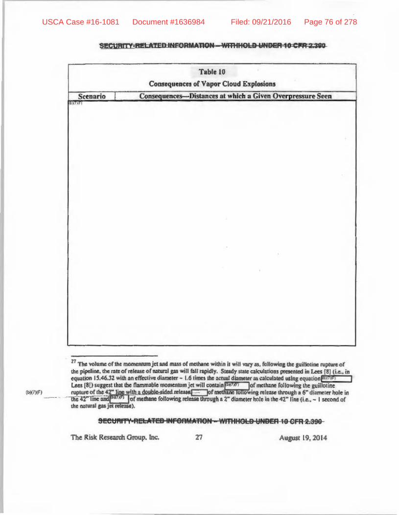
S!!CUM, "",1 IcRD 1NFOpnMlOti 'IMlMISlB YNDBPl1D CIIA lUlU
T.ble HI
ColISequcncH olVlpor Cloud Explosions
Scenario Co uencei!--DiSlIInees II ",hlch. Givetl Ov~ ..-ure Seen .. ,
II . " PI "II
(bl(7)(F) in I _of
9,etl"IT'( flEl::A'FE91I1FSAMA'RSli ' .... mlllSlB lINBER HI GFR 20999
The Risk Rese:IrdI Gmu.p. Inc. 27 Aupt 19,2014
USCA Case #16-1081 Document #1636984 Filed: 09/21/2016 Page 76 of 278
I iiECUAIT"t A_ornE! IIIFCI'IIMM'lCII '1IIt'lIIIOU IMIDER.II BFA 2:899
Coo.seqUeDees of II Vapor Cloud ExplOlllon Followina Eso.::apI: or MelhlllH! IIltet- lhe GuJllQllne Rupture of .42" Natura! Gill PlpeUne and Detonaooll or. Gas Cloud within the
TI'ft:!I to tbe Northwest of the Soutbern Route
~""FI ATE" INfORMATION _ wm IIlatC IlNOP8 10 ell .. Z '!Ji'>
ALlguo.l 19, Wl4
USCA Case #16-1081 Document #1636984 Filed: 09/21/2016 Page 77 of 278

SEC IIRII I REI n 'bw '~'FORIO lieN ."MMOtD UNgER 10 GP"I",,90
Consequ~ncCl or", Vapor Cloud EJ:plosioo aCter Ihe Delonalion or Melbane In the TurbulmtJet. Created after th~ Guillotine Ruplure ora 42" N.tuml Gil!! Pipeline that
I "'"~ , I Nk" lbe SmUbem ROtlie
Missile Genuallon
Given th~t migilcs might be thrown "-II fllr"-ll 274 III (900 ft) in the event ofpipeli.nl: rupture, the 5Witehyard. GT1J3 die5ei fueltlllk. the Unit} Sle:un cenentOl' mausoleum and meteorological lower must all be COIlsidered lI!I being vulnerable 10 missile damage should the pipr:line ruptute close 10 these objco;ts. 11I=fo",. we ~bo ex;un;ne the frequency of a gas pipeline rupl\lre ~I polnt! close 10 these sse,:uxI subsequent missile grnenll1ion.
Summary or Ihe Vulnel'lbUities to Risk!
P01a1tin! baz:m:ls wing from the rupture of the new 4r IllS pipelines th~1 exceed the magnitude threshold, for u~un: to thermal radi.:llion. explnsiOl1$:wd milisila are summarized in Table
SEeOAI114iELAIEO INFOI'lMMlON _WlE"Ie! 0 I'PI1l5R 111 C:FR a:9110
The Rbk Rcseoudl Group. Inc. Augusl 19. WI4
I
USCA Case #16-1081 Document #1636984 Filed: 09/21/2016 Page 78 of 278

SIilCUHII, HI' l'Y IIIFeflMA'fleN W",IIIO;;S tlNDiR lW 'FA 2 110
II, This I~blc: :Wo lists lluards !h;l\ do not el\cec:d this Ilwshold and the: bllSis for this oondll$ioJL For those: huilnb thaI exccI:d the "",plude tb~oId5. u.pClSlII'l! r.l1C:S ue dtlveloped in Appendix B and:u:e pruented in Table 13 below,
Tllble 11
Po1e!ltilll Hazards
{t:;(Mi
SF' Ii_Ii .. wei &TftlIH'ClIIM.u:JSPI 'l'JR'IIHOlD YNDEA 11 CilFH I ''0
The Risk Research Group. Inc. 30 August 19.2014
USCA Case #16-1081 Document #1636984 Filed: 09/21/2016 Page 79 of 278

8ecuR1Tt Rn qwp IN! QRSU'tIOIii WR'1'IHOLOD UNU," 10 aLA 2 _
Table 11
,pelllllTf"". "TI!D "f'OI"IMlION- wmlL!OLD UNBEft to ClA:L1IO
The Risk Re&eKdt Grvup, Ino;, " Aupast 19, lOt.
USCA Case #16-1081 Document #1636984 Filed: 09/21/2016 Page 80 of 278

Table 11
Potential Huanls
Uni1 2 steam p::ner.l10r malLSOlcum
Unit) ste;un generator m~lLSOleum
Unit 3 S1c:am jlcnerator mausoleum
Unit 3 steam aenerator mausoleum
!!!cElftm 41EEA' W lfff'eRMM'I€III "en 'i'0I B ];INSER 19 eFR 2.988
The Risk Researcll Group. Inc. l2 August 19.2014
USCA Case #16-1081 Document #1636984 Filed: 09/21/2016 Page 81 of 278

lO.Conseoatisms in the Analysis
COIISCI'VIlI;Ve iWumpliolll hllvebeen made in the modelillg lind ;mal)'!is of poIemial hna.rds llutt might follow the hypothetical rupture of II. IllIturru gas pipeline. These are sUlIUllarized in Tllble 12. In light of these cOIISCrvatislIU, we believe the Ippropriate and coBSCrv:uive threshold frequency of concern for pipeline rupture COlIpled with fire. e~plOlIion or missile getiertltion 11-Itrfyeur.
Table U
ConSH"Vlllti~ AssumpttOl1J Made
~~
" ~nical
The Risk Research Group, In~. II
andcxperu
i • Pres$ures on the downslream side and thus
flow tltes from the downltream lide will "' ... ~
turbulence and fiame temperlUUfe and thus the ITUlptirude of the
flame Of hypotheficlll
A1IgII$l19.2014
USCA Case #16-1081 Document #1636984 Filed: 09/21/2016 Page 82 of 278

1l.CllIIH:I aad LikeUbood of R,II I !I of N.turaI Gu .Dd Subsequeat Fire <d Explelio. Gr MiuiI, Gdet_1Ioa
The causes aod Jiblibood of!be NpCtIR of die proposed 41~ nalUI'II JII pipeline and 1I,1ne,,"" rIRS. de$onetions QI missile pnention '"' lIddtused In dcuIil in AppeIIdlx 8. The COIICII.u;Ions oIlhia -.I)'Iii. IS predict.:l pi.., conservDlM model!. ate pill CIIICCIIn Table I) wbidJ ilHlf is drawn !rom Tables 8-4 and 8·S in ApperIdilt 8.
II!CI;IN'fV P &1& ...... PU·:JION_wm.IN-D ' ..... e to CI1HiJIO
Aqusl 19,1014
USCA Case #16-1081 Document #1636984 Filed: 09/21/2016 Page 83 of 278

SECUN"'-It lSi LLI .. g .... emoN ':trmIIQLD.,.tLlEJIl 10 eM I ''''
T .... "
II ac-ddleirptWimity,"""11 )u ......... bodo die 0'nIJ dlosel AIel 011 ...... IaI\I( ~1Id die •• i<dojwd is pDIIibIe II; ~ _oIljB1: tIaaIo or ' '.
-SEetlNY: ... 1iAtID .traM1ATI(W -wmat::M D UMI'I!!. 10 Cfft ytg
AUlIiSI 19,2014
USCA Case #16-1081 Document #1636984 Filed: 09/21/2016 Page 84 of 278

1'111: rauill sIIow tbM. wilb two "~, !be ~ of all cvenIlIlhIt cniJIU ...... 11' ~ 10 .., or aafety-relfIIaI SJSII:n, SInICturu -'. Co .. I1 .. ·.' •• 0\IlI.idc: tile SOCA. lie below !he I~tye.r tIiIeaboJd for U)IlCe.A. The aa:tn:wa are pouibJe da!NJe 10 instnm\enUtlioa on !be m C "OkVN lOWer as, iaUIt orpipelinc NptUn Uidaarion ofajet tIamc mil poulble ....... 10 !be UoiI3 Sit.m """""MtH rn.Weum. As IICIIed earlier, however. tbaemnaia.,., low probabllilye-. Furibcrmtn.1Iw:.,1 ri,1 COi1IeCjIIMCCII Ord· ...... 10 tile s -oIojka!lower can be dli,-s as tile dati i1 JItO"ida em be obtaiaed fnIaTI alb« 5(III(tCI, m.:bICIiI1, a bIdtIlP m=, ~olociCallOWm' and 1Io'el'lbet foreculinl serviCes $UdI. .. 1bOM pco'Iided by !lie NOA.A. Similarly. d._I" 10 tIM Unit 3 s1eam JeIICflItOI' ~_ il bolb unliIceJ.y (lite IIZIICtIW is ruued) and w\I1 na( !lave ICtIous CORIeqUcoea (a Safdy EvalUilioa concluded ibal eyen ir the StnlCtlll'e were 10 fUJ. dole Itmilllnlpoted by NRC pUdelba woW! no1 be cur«k<').
."UNI' 911ATID II UJlIMJON WJaoIHO' U 'l"!lFII10~
36 A.up$l19,201'"
USCA Case #16-1081 Document #1636984 Filed: 09/21/2016 Page 85 of 278

12. Summary DbaaaIoa
The napIUI'e ohhe ~ 4r MItnl JU pipdine in or dole 10 tile lPEe site IIId swu1"erJ! ipioDoltlle IM>'t c mill Ii adJilt raul&. in ajc:tordoud rON MIl injarywdellcblO", 0. up!»"d 10 n- or imerae themIaI rwIialica. Sacb a rare will DOt, bowewa, d--ae II)'IICIII. strucaIn= or C~1aIl iInputant 10 safety widroia !be SOCA. SImiIIIi" iIIlbc: h)'pOthetlcli event ofa ¥aporcloud aplosloa \njrlered ..,. or ia¥oI¥1q a drcocIeIk:... no ItfUClIII'al dan!l!p 10 blliidinp in !be SOCA illlIticip.led as die ~ _Iia bw)'oild &be nrinimum safe dislMlCl' es&IbIisbed for luc:b a pipeline. A Iimilar CIlftdusIoa all be cnwn about 1Ili111le p:oet.doa.
"" ... SOCA-doo ,
SECUIIITV-RELATED II. ORIIATION - wmtftOU) UNDER 10 CFR 2.310
Au .... t 19.2014
USCA Case #16-1081 Document #1636984 Filed: 09/21/2016 Page 86 of 278

Rereieac:et
I. IIIIIian FoinI UIIiI3 HIEIe.- Power Plant, lndivMlual PIanl Ihuninllllon or&lmIaIl!venII (IPEE2),Sepwnber26,I991.
2. "'C'~ or file and &pIosioIt foIJowiq Ibc RdeUc 01 N ........ 0. m.. ~ AdjIIee# 10 IndiM Frut". Studype:dui.,1Cd fer Ealap, Indian PollltEMru CcnIer.AupC 14, .... .
4. Coapm. G.a. "CDrltinuoUI iDtptrtiM Ncoded 10 T_ Pipeline ConOIioa~, Plpdille MId GIIJ~, Dcc:enIbez' 1994, pp 30-34.
5. Su. N. Will Ad LewiI, RicMnl J~ St~ "Hazardous ',b,O!WI De$k l!.cfmnceH, Van NoItrud ReI"" New Yodl:, 1917.
6. ees.- fort::llemie&l Proc:asSIfcry, "Ciuidelines for Vapor Cloud F.plmioa. PIaIure B ... BLFV!!and Flash PiItS HIzIrm~, ~ed!d ..... , New Yodi:, 2010.
7. US NIEIaTRquIalotyCommlMiolt, "Fin: DyIIamics Toob~, NURJ!G.U:·', DmBIbu 2004.
I. Lees, FrWi: P., "loA Pft¥erllion in die Procless Industries", Buaerwud .. lleinenllM, Botton. , .... 9. "Oil and PI FiIes", UK Heallhlllll SdIly &ecutlwe. on 92 ~ 1992.
10. StIlt of CeliIomil, "2007 Guidance toe PIoIocoI for SdIool S. Risk AnIIysitR.
II. 0aIniI P. N~ "If ... I: : ale of Fin= and &pIosioil ProIecta. ~ Pri« .... tOr Ol~ 0... Chemical and Rer.d Fa:nllies~, Ebeorier,20IO.
12. J. K. TbomM, M. L Gooch;/; M1d R.J.DInn. "PI., I d1In 01. VIIjIOi'CIoocI Explc:.ion trom. CU .. , .... ~.IIIIO lit UlICOIlpAl:IIARI8 ,l'roc:a.Is.tccy ~ Vol 32, No. 2, pp 199-206. 2013.
13. R. J. Harris UId WIcb .. (t9l;9) aquoltld in 161 and 18J.
14. yOlhiIOmO ..... TawoNisbibara,MlfkA.GroeIheowi YOlhikazuNkui, 'SlUdyon aplosioll c:IIandezilla of naunI PI and methane in .emi-opm spaca for tile HTTR
SECtJRITY-RI!LATm IM'OItIIAT1ON - WITIftJt.O UNDER 10 CFR 2.380
The Rilk RM ell Group, h:. 3! AupslI9.2014
USCA Case #16-1081 Document #1636984 Filed: 09/21/2016 Page 87 of 278

a~7 ' .ran?? "'(111 • wmllOtD_tN , .. 10 CPR_zaIl
h)<kojt:t. pm:IIIclioa 1,.cc:n:o",N.:Jear EIoP_IaI.oo Daip. V,",,- 232, bwe I, JlII, 2004, Paps 111-119.
1$. W. W. Lowis, J. P. LewiI and P. M. 0uIrint, "LNO Faei1Itie1;,!be Real RUb", GIS Tech 2002.
16. FM GIobIo~ PIapert)' Lots Pre" ..... , o.w. Sh«D 7-042, October 201~.
17. Seatt o. 0. .... elL "2OlS BlIIlUrockl VIpOr CloIId E~' U!VIveli"l h Mystery of U. BIul'".ae.eo..PIper.
II. WID Ony, ''hnpIIIsibit aplof;ioJo: l1li 8u.:efdd bioi c~ned'", New ScieNisl. April 5, 2012.
19. Buoc:etickf M8j« ~ 1ll1'e1dption Bori "Expn.g MeeIo_m Ad¥ilOl')' Group Report", UK OOriii ...... A..-: 2«11.
20. IndiuI Poi .. UM 3 NIIClIw I'VwIr PIa. FinII SUeIy AuIJU Report.
22. U8 E".itoo.h' .... i"'I"<*dIoII~, "Ri* Mw pme. Ptopu" 0uidfIre~. EPA 550-8-99-OO!I, M ...... h 2009.
ll. NOAA. EPA mil DOT, "T.......,ve.' doaomenIation and software quality QIUfWIec: Cor project Elfle-ALOHAM
, Fc:br:_, 2006.
24. H-. S. R..J. C. a...,md 0 . 0. SII'iaiI:i&, 1993: Hazardouf I:'F Q *' I!IOdc:Ima; ~)'. ESl/nt-91-21, US Air Force En'; be 1lIOII SInioc: l.abi;M ..... y.
26. John L Woodwlld, '1!aiInatint obo ~ M_rL, VIIJ)OI" CIoIId", CaMrror~ ProccA Sakry, New YorIF: 1998.
27. US Fcdmi Et""'aaocy MInqImenI A.fm:J, "ReI'eitiiCt ManIoII to MId.- PotentIal Tenon. AUKb Apm. BuildlnpM, FEMA-426, Deaocnber 200].
Sl!CUMn' 6ELA.iBl .POI 6 IilikWi- Wlhll.el S UiI'DT' 11 CfR" I
The Rbk Raarm OiWP> Inc. J9 A"IUIt 69,2014
USCA Case #16-1081 Document #1636984 Filed: 09/21/2016 Page 88 of 278

UOJiii, ':lID II g"A'nOI'''''''''I.Ot.e 1::1111.,. II:C Ii j C
APPI!NOIX •
Val •• B" ern_ •• bk aou. ..... M I vlMdh.M .... Ua HJ~kII V..".. CJo.d bpi ' .. (Det-"i )
1. n. Risk ReIeII'I:b Ofoup. 1nc. A-I AilCUSl19,2014
USCA Case #16-1081 Document #1636984 Filed: 09/21/2016 Page 89 of 278
, ,
II the ...... 01 ""'_ poeonI i. "'" coasat<d ~ bol1.01I1." il caleulalal r.- Ibe .... """" orllot Ibnn"., ........ 1ooId _inl ... o-enp 10 '" vol ..... of .. _ in air. 'T1Ie htiCh< or~.1ooodo oriIIIia tile !laO ............... be 10 "'-•• Rt:1l<i .. III .... c\oMli, poino: ..... pipeline 10 .... IP3 c:oMI'OI ).IId;""
1. The Rilk Rescmh Gtoup, Inc. Augusl 19,2014
USCA Case #16-1081 Document #1636984 Filed: 09/21/2016 Page 90 of 278
---- - - ------------
APPENDIXB
Aaalysil of tile Caua of ad Detennlutloa or ExpoIure Rates for a F.Uure 01 the Proposed AIM 42" Natural Gas Pipeline near IPEe
B1. btroducdoD
Nuc:Ica P.qo"'wy ComJniuioa (NRC) replltioat ~ th8t lIIfet)'-relaIed..t izIIpoItIIU 10 Mfd)' __ lear pII"¥er pbnt structureI, 1JStemt. and ClOUiJI " cssCa) be 8f4N .... iud,. proI«ted IpWt dynamic dfec:1f -1IIIInI !rom. e.,upmmt taI_ md fiI:)q I:YCIIII and condkions thai: !ally oecuc outside IhI= IIIICInr power pilAt n-1Mrer __ iDdude /be eI&eui ofnplalion cllllllierWllt.I may be a..try r..tlltiel orcwrlotdon -"1 b: p..mtloo1 ~ mod., -...l PI pipet __ NRC replMjm. abo IWIIJIIR 111M !lie: PIIhIle anr:I PfOXImkJ olh ........ JeI.ccd 10 __ wotI'ity (e.J..llIl\aIp pipeU-) be"1IUd to ':1 ...... if. pbllldetIaoellll XI:OI1IIIIOdaIe(OjllDlWly~Nzlrdf.Ind iCUie risk of other buInb is very low.
inQP: Tn tad IIeIt f1w;ea to fuel oil tmker dill is usod 10 p_ wUl bcn:l~IOU
dIe~_.
!
The Ra.t Res:'r:h 0J0up.1nc. .-,
..... .
• Ibe:
....,
Au"", 19.2014
USCA Case #16-1081 Document #1636984 Filed: 09/21/2016 Page 91 of 278

seeal'" • "etA. eu .. IFS""'""..!!!!.. 'IJI'fI "leLB I;INBER t$ BFA 2.a9D
tO:l tIJc:nnltl radiatiollneal flux occasKlIled by pipeline rupture and the ignition of the natural gas released th.;t exceeds 12.6-kWlm1, or 10 the po&libilily they might be strU~k by missiles when \he pipeline ruptures. The 1-(15; overpressure is .. ~hnld of cnncr:m cmblished by!lu: Nuclcll1
• RcgWmlOry Commiuion in Regulatory Guide 1.111 [3]; the 12.6_kW/m1 helll flux is thai required In mell plaslii:.
tn accordance with applicable NRC pidance (ReJUlatory Guide 1.91). if SSCS important 10 safely may be dan!aged due to Q posrulalcd failure due 10 proximity 10 the bUIld. the licc:nsec lIlly show that the risk Is ICCeplIbly Inw on the blSwlhal thn:sholds for damage (e.g .. the I pM overpressure) lU'C not e:t~w or th:ll upo:s~ rnte! IIrC low; a demo!1.'lllllion that the cxpo;ml!e TIlle rordamagc is leu tJUIIl 1:1\:10" per yeu when based on cnmervltiw: asaumptions, tIC lx10·7
per year when hlSW on realislic lISsumptions, il IICCCpllble.
'" ailemalive means 10 provide
" Funhe:rmore, I
exceeded [28].
82. Purpose and Objective oflbis Report
niles foe ".
.1110 hIlS towC'< is
steam
The purpose of thi. report is 10 detcnnine ellpo:sure niles for failure of lhe AIM project 42" pipeli.Re, 10 be irutmlled IJong the snutbem roule ouuide of the main IPEC facility, Utd subsequent events llCCOIIIIMg for !Ix: .ubstnntial pipeline mil installation dC!iSD en!wJcements dilclLued below.
SE81::lRRV R& .. M&1i "IFgRMA+lQ~1 Wl1l4HO' 0 ttNOER to cEe 2 390
B.' AIIgIISI 111,2014
USCA Case #16-1081 Document #1636984 Filed: 09/21/2016 Page 92 of 278

SiCUHiI t"riiLAfi!O IftIiC_A'nOII wml,otD , ...... 10 CPR UIO
83. Stadstkal Aaalpis at the bpDnre Rata Cor. Fire aad ExpIosloa
The ~¥eraF NpIUR frequency ohll plpdlDel wltb I di.,..m of 36"' or _, is ~ 2.7' J;
10-3 hnUe.)'I'. J 1'hb fmqmney is ~ usIq US dati! fOC' nil MIn p IJmNnissioI. pipdme. wid! I fl' 1""0136" 01' _.qardIas 01 tile dlkolpipe mmufllClllrClDd in,s1.qMiM. wall tbirtnm, 00IIltin& IhIcbIesa m:I COW!Z" depdL. In¥otemc:nu ill !be detip IDd manutlCtUl'a 01 pipe IDd CXlii .. ioa proIeCtioft IUd ina dcd WIll I'h' l,W1' II1II coverdeptb hive III served to reduee .... Iikellbood of pipeline NpI1ift:t (29. 311l. N di_sed below, ........ ote Kame do of the jIlOpOWCId AD( pIpeI __ IPEC will be • daip~......t, lIMe-Ot·tbHrllnAallllloa. &ad Idled wipo''OInelllS In ~ aleYod .. _ ...... "., a 10_ rupwn hcp'Ol'ty will IIPPly to tbcse sqrDCnu of the ~ AIM pipi:lkIe.
When .ses:l",tbe US Dc,...lJadofT~ PiplliIII ... HwIrdous MateriaJ. SIfeIy ~ (PHMSA) cia. we lIOIetb.riD thc period I/IflfX1l1O 7/112014 onJ,2 oft!. 12 oosborc u..miuioa PI pipdlDe iUpIuM ill pipeJiaa willi. cfi_' of 36" or _ o«Umd in. pipeline i .... 1Ird afta: 1980. n. PMHSA _ilion allow ua to pmtictaNpCln fI~UIII'" for._<f2"' plpelloe cqtII1lO 131 J: I041ml1c.,.. •• 1bcpreclicud f ... qn .... ryot~iIIC .uptme
'AilDOllwdlll .... ...JIaWeIor¢'pipcli ... lo ........ 1I1 {; r 01"" ... _ ;"11 _ : ., Jblllll-mlJ, ill ' ....... be-cl .... IIIIIIJIIo.. ____ be , .... ~ •
... ij UiI,-IIII~, 01 .... NoMe: liIIIl'IIpIIII'* _ WI ...... .... inc pipooMI + I, ..... 10 obIIiII., 'lI_ofilocidatt£ntll'n)_u~ .. lforplpa_ wiIII.d' . _ .... 10 ".2" d' af .. p ,:1 d~\ tiM ...... 111--', ..... p·, d_ot"" ... __ & _ .... ...... ........ , jI ......... _01 ........... I 01]4-",_ • Two' I , it Clk Ilid Inn:
J. ........... Jar .... i .. iMp .... -af36-"'_ia"i. 1tI. n.. ........ dtoperbl iI!I2CI02lO7IiI2Ol .... po.II '.,."US C
; 'afn I' · ......... P de w..II!Iw.t)"t-.. 1i.(I'tIMSA). 1: ...... _" .... I:u.,.. .........
2.. DR.-I ...... otlllatrs .. f I I~fl" af""",_In'" .. dod.hnHot .. PHWSA2012 ...... n i IoaI~NJIOIl(lUSI ..... ~
lk ........ ' ; lIC'bca/c ...... ~dMdioridll .... o!t\IIXIIM(Il)..,._uP<*M' Il1o jIhIMIaf ........ oI... ....IoaI~ ...... oI:w ... _il... (34.151 .... ) .. ~ ..... lNriodl'llrwllicll....-. ... wm: ........ (IUJ'Ol"). Tk_b,,,I;: I~ I lICjol 2..75a 1u'1IiIIIc.,... TtriI; ... pnlloIioIIry ....... IICI .. -.. ........ ....adbo .. 1 ':r ''''11l1li II!o 34,1.51 _ of pIpoIiMotJ6~ or _ lot _ ... -. ...... 2(lO2.
two 6 0 ,otl.:'I: 1I_..-.I .. .....-.. ,.n-[29J ......... =1 fJO). niol:U ,... r-\IId _ ..... """'10"""" 0IIia/'acIDr1 ....... __ do. .'fIiIobi1ilJ ..... 108bI1II) or .... WIIik _ ............. be ......... __ • ~ poriodoililllo '" bo. 1 .... _I ; 0 "'" .. rlpellne":lobiIiIJ _ ... _ ...,.... .-IeI ... .w.tI _ ......... ..oer ........ '" be .....
I Til: ID_ ~ ft Ill,." "bl~II.nI""'- pipet_ -.Id _.".. ...... d,ha ..,. .... ."..,. of ....... alder Ii. I ... [J2~ '",. "",,","".uc-e 11"14 I t'f is Q~ ..,. dMllIIs ........... or~ dtoI __ liI. period 0111.- with Ihe~ofi'" .............. pttIofI. n.. .... "tllpn:ucd ... "_~.~ .. ,..._rlk.)UI'Io DR C .... ·'dM orpipe/ill.~ ... ,.....n.a. .... ,., d:r _1111 per\a!dot_ ..... or P\IIIi-Ihi ~ aaI _ilia IOIai ..... at",""iII In,.. II .......... ot .. jIlriod will ""leA dIM 1iI:r ........ II _.-d. I,.-W IIoc It .... of p;p;. -.N .... pttbj •• ~..tic-JcIra,.... _ ~
8-3
USCA Case #16-1081 Document #1636984 Filed: 09/21/2016 Page 93 of 278

!eebllill "!OUIeD Ii .. ORMATION - ","illoLO UND~ 10 CPR 20390
!\lid Ilsubscquclll. fIR: is therefore - 6. 6] ~ 10" Imllc.yr'; the predi<:ted frequency of a hypothctieal vapor cloud nplosiQO inV(llving ~ detolUllion foUowillJ I pipeline rupture is eomervalively estimlted as being less thon - S.9S x I\T7 {mile.yr'. Note that while descriptions of pipeline ruptUre IIIId fin: e~ often millce mention of "e.plos[oos", these appear 10 refer to the bunting of the pipeline [\$C,f Of to Isub:sequCIII ddillgralion of Q vapor cloud Dther than to a
10 a IIIon<r IaIIIh over.1oft&er pt'riod <211 bo caIaoIllOd. The caladalim of Ibo 1.31 a I~"")'J""""" rteq_y IIIUa "'" .f IhI= ob$ern1lolllh11 US E/IlrJ1ln(on.ioII Mlnini-.ion ...... ror ....... """'P"'1Ld noIn po pipel"'" P"'Jec:ta in lIIe,."iod 612611fX» 10 61»'14 (l2] ...... 1hat. wIom: pipeti"" ierIpI &Jd '" ....... It" Jftn. 3!l 'lIo of ....... pipell1e ilMli'<l!d pipelints of exeilISWtly36" "'" ""'"' ill dio.~. Now 36,763 mila 0( pipeti". ""'" ;nsullcd ia Ibo period 2OO(l.lO12. All"",",, n 'I ohhls il36" IX _ ill dilll\e.".. IU67 miles of J6" or ""olef diamoltr piptli ... ...ere inmJltd in !he period 20CJ0.1012. No .. i_ 2013 • lOW I>f 30'.151 miles 0116" "'" pWordia..- is illltailld ofwhick 12.367 IniIeJ _ inrWkd in 2000 "'" laler ond Ihuo 21.9U miles ioulallfld boron. 2001. The q.","" iI how .....,~I>f tIoiill.91U .,lIe pipeline lellth "II i",1al1td bel_~ 1980 and 1999, I9tO beint 1M)'COt in which "..,ked impro~ In piptJiao rtIiob~ity oppelt. Let us <:<><da.oti ... ly .......... tho pen:_&eo( pipdirw: 36" IX _ in ~ iaOll1ied t>el!n 200l a.u _ ;,walled ill 1M poric>:I19&o.1999 is idoftlioallO lilt ~ for In piptI ... iastaIIaIlrilft 2IlOO \hoi ..... ;"~kd ill tho period [9I().1999. Tltis ~ is21.3 •• T1H: IOIaIlenphofpipel ... of36" ""' ...... indiotMl_inJIIhd in ""'period 191(l.199911 lho:rcfoto! 21.9I4'IU13 or _ oi6S2 mila. TIll ~ killik oI'piptliAe 36~ IX more in distnner inKIlled III or atler J9IO..a IftOCIIIIa 2013 iI thamre (4M2 + 12167) "'" 17.5'0 oniles. n..~ It!tP ofl...:li pipet_ \co pIKe o_lIIt period 2OO1_20J3 II obtained by iIIIcrpolIIioo. II 12.105 lilies IIOIjq hI ... eslilllllOd 17.550 IIIiJes. of pIpti",ofJ6'"or ~ indiulaer _pmeaI illOll "",,_..ci_6661 .... ~ pmeIII i. 2OO:l. Tho 6661 ",lies pteseo\ in 2OO:l1Xlmprlses tho 46111 milu esli""~ II> bo present in 200l 1M (2111) of tho n.M1 miles "Iiml!fd II bolo, oddecl lathe period 1O/X).2COl,
Tho: pipoliM rupIIott frequency is IlI<n uIe.lalcd by <!i\'ld;."IM .... 1Db<r I>f """" .. ill piptn ... of l6'" or ...,.. In di''' .... 1er ud inoIaJl<d i. 1910 or afttt !hoi ~ i. "'Iim. pniod 2001_2014 (1_o11) .ylM •• po:nate of Iud! pipeline (12.106 noiles x 12.!I ]inti). Tho:.....,k (2I{ll,IOIS • ll.5)) is 1.32 xli)"' ............. 1e.)'J.
~ fJeqIoon:y iI .... lIlI~ by _ldplyiaJ II. nop!UIe h",,_y (I'» x Iv' - •. 1") loy doe ipAtion problbili<)' c:,:J, Tho Iador is <aIcuIMeoI ""'" PNMSA_ fOr ,..lrMImiIsinoa pipeli .... of36" or more io. dianoo .... for the I"riooI IIU2002 II> 7/11201<4. T""I .. n<pIURS w= lIa>tdod in Il1o 1l.5 l'<C period. Oflloae. JpJllc>w .....e1OTed 6 Ii ..... (Le., il50 • oflho inc;""nu~ Thi. ipilion problbilily iI in """Old. willi European ~pa",,,,,, (28] .
• Tbu Imj .. ncy iI <lIkoilied by moiliplyinJ I"" IIIp1"'" frequency (l.J1. Ill" l1l1I11.1") by I COI\lftVllI;"" ~llimlle of tile pnllooloililycf. Yipai' clolld delDllllioa fOIlow'l~.' mIjor releuo from, piper ... !be IoooIwr ~aI ... is ClIeulIrui .. 0.001. ThII w~ is ~ b-.l om .. ,hse!Ice of _iooo in lhe 65 tup!IreS of pipelil\eS 0(24· IX """" ill diAlnetorrffDf<led by PHMSA toet_ 1/111002II1II 7/11201. {il M i_ 010 tho PIIMSA or NTSB (Notional TJaIISjlOoWJoa Safely Boord) repMI on IIIHe j""ideoll "*' II> • deIooJIIioII..-Mexptodoot" ;,. PHMSA doo:u ... no "PP<"WJ II> mer lIJ Iha uplosi"" ,...neol'tho piptHIII: IX pouiblyll>. wpor cloud u;pIooion nlOilin, dofllpal~oriq. biIIomial .r .. lrito.Iion, Ihfia i,.5 'lIo Pf"Io.:d>iIiIy of.., de_ .... ~ ;,. 65 ~ if tile deIDMlioo. probaloilily IIO,C45. If "'" """-.... p<ObobiIity _ IoiJbct. lbo j>fObabllity of M dcIonaIIo ... QCee'Oc is 1IjIpIOX;lIIICely S '10 Of Ieos. T1tI-..kint; """"""loot i'IIq"""")' is IoiJbct Ibn tloe I .. 10" .. ilc·'.yeat'" heqllClll:)' cited .. In _r ~ probabilil)o of au.pl .. ;"" iUIIe SIaIe ofDlifonoia piclance pMocoI forsdlool .110 risk IIIIllyoil (10). Hen: tho dill ucdoocnpri .. rup!\ftI '" pipeliDcs o(lor' ill diameter "'" ~. ""!he nopIore of. 14~ pipeline mi;bt "'~Ilftoll in • ItIfbolentj« contolm"l c_ 1000 q of meI~a ... itlilto I\IItII1IabIe =&eo lho >b .. """ of delimit"" in .uck ""NfU "jIldlfd applicable ;" delCrm;"in.1he probability of d<IO".lioD ~ iIIe IUpi"",o(lltl" pipellDes.
6EGllftfN REDI eo MFOAMAIjON - WIIHHOLD tII.Deft 16 erR 2;596
The Risk Rcscarcli Group, Inc. A~( 19, 2014
USCA Case #16-1081 Document #1636984 Filed: 09/21/2016 Page 94 of 278

deIoaation. For aamp1e. tile pipdiDe incidalI cberibcd by PHMSA axn:ai.ve xtioo order J. 2011· 1018+H illIOted in the PHMSA ~d .. "'5C as baviIII frlvolwdlllupIOIIioa. The ClOI1ealve IICtion order ibcIf. Iao.eler. i;I6ICribef, tile 6Vml as iovolvilll rupcun ud I rRIHJI.
Vri"in,,, the set of nItIIrII PI trIIISlIIission pipeline rupnue now. that oc:cuzml ill lIIe period IllflOO2107/112014.IbcOominllllCMlMlofpipeliDcNptUre iDaU pipd_ JR found 10 be CJlIaaaI conosIon, .. . probIanIlIId excavatPi dImap (Tible B-1). In pipelines installed inoraftel: 1980. however. weKe thai c:omJlioa dil'l'Pl*'. 1_ of pipeli!le rupQni.
TIlWeB.l
CunroCltuplvulNManlG.lTn • d ...... !1 , ........ ' ....... ' .. 'Iac Pip M IIIIW ... -.. .. N Ita tbtOc:uwTell ... hrtM 1I1I2Otlte1/lJlt14
(PBMSADIU)
Spectra aM Entcqy have apccd 10 uurabcr olpipdiM enbIu_"*'u 10 I - J9J5 I'l (1199 m) Kp ... • 01 pipclillc near ftC in orna-IO l'urtbcr reduce tile 14ad)' low pmlic:leIl fnIqucnq of flilla aad addrus the above listed primIry CIIlSeS of pipeline r\lptUnI. The 10: '1;001 oflbis "eahInce4" pipeline it shown in Rate 1 of the main report. These IIIIdllionll Alet)' lCltlftl will be IIIItIIJecf InCI. iroplemenled to rUi,.. iolEma! and u.1enuiI canwioa. _¥11m Ihtaa. aboormal opea ..... dImIp from DItInI r_ (i.e., .a.mic) and ocher ~ WeI". 111 suamuy.1bcsc ~ iDcIude:
• The: pipeline will have 1&JU'1!r wall thickness incteain& il from 0.510" to 0.120" (I 41 .. incrIac)
SECUIi i f=MLA I ED 'W bH.lfAiION - WI II llQU) UHCIIIPIO CM.a..IeO
The Risk pes cb Oroup. IDe. .. , AIIJIDI19.2014
USCA Case #16-1081 Document #1636984 Filed: 09/21/2016 Page 95 of 278

SICtJRlT'i'wREIOATI!A INF<lrpI! mON wr. rr..a UNOCfiI 10 CfH LiiO
• The: pipeline wUl be X-70 $UItI (70.000 psi yieldstreJlllb). The mauud walIlh- ~ I
IUId die hi&ber yield Red matmi .. will toaetb«muk in,41"opentInz prewn IlWJin above !he pa.med 850 pail MAOP.
• The: X-nyinJ 0( 100 '" or,u welds mhppro'llli o/Iflfnlld)oplpbt by tninedX·n.y ...maidMs
• The plpditle will be buried 10, &fUICr depIb rrom !be nonnIIJ feel 10 a minimum of 4 feet &am IDe lOp ofllle pipeliM 10 nalurs1"{,J3 .. inaease).
• The ru.ion. boo hi epM.y (FBE) pipeline «II'l'OItion. COItq will be iDc:reased. .. AtJ. Abrasive Resistanl: Overlay (ARO) wiU be lidded over !he f'BE_in&-• Fiber reiafon:ed .... lOtte _ with wamlna l.,elayen p'-d OYef IDe pipeIiDc.
O!:uih of Specm'$ nonna1 dttija. inIulllllion IDII openIiol pn.c:Uoa MId ... .&diclonal desip MId iaI .. o ..... re-a are pn:snted. in EUIbIIS A IDII B: a CfOfS nctioMI xt.iilatic: or the ~ pipeline wid! reinCormcI COiICiete IlllllIIIIi WII1IinJ: rape is sbown in. ExhIbit C.
. While US plpel;iae iDeldellldMa do IXII .. low the developmellt 01 dilecl correIaI:iOlll II) caIn"_ !be precite pi..w.aity Impact oldJCSc additlooel feMuteI on pipe NpMC 1'requc:ncies7. Ibcre is strq eYkknaIlhM !be effect wUl be *PI«iabJe Em .. cia 1291.1 ..... 1 III-. n!pClIrt uI ov«aIl r.ilun freq , lei dccliae..ucuy wilen pipe waIIlbiekllCll Md eover depcb incase (fIpra 8-1. 8-1 .... 8-3). Thlteoaclulion illIoIppcaled lIy US PMHSA dau u.r.sIIow olllle 11 rupttn _ im'oIYiDaIlllllnl pi lrIRImistion pipelu.a 0136- or_lndila_ eoro~ in tile period 11112002 Co 7111lO1".uVyODe involved ptpeilDl!l wilh a waIl thida ~I' oIO..ror _: lbiseYUII. _ CIIIIed by aUMllWCtioncWect at ajoiDl. Slmllxly. wilh rapect 10 eorrotion II ballIeaI CX1l'IdIllkd IbM fa" "pi"" wiIb wall It-ki'n"tes pater lhIII (iU9 ia.) and wltb. cortOIloo COOIrOI. pooco:lura III. pIIcc. the eorroIioG coatroI ~ can be ___ 10 be ..... bkr Inl. UK.sa.IIIia have also dea-....m!bat by illllallinl' .... ~ Ibb IDII YWbIe W .. lr11. tape. die &(1)ll:~ncyo(pIpdIne rupIUlU_1oDed by w.maI iutafaeoce wUl be rn'I"*' by 95 "'13.4). F1IIIII1y. X·ra}'ln& of aU ___ II1I'I vtrific:alion of the rwIio&t .... by craiDed If· ~ ""i_ and !be pea«et walllllkimess ill die enhtncwl pipdiae will di!nWsb !be likelihood ifill Oefeds in fabrieMion or constnIClion DIit;hI: resuk in II. Sloftseqi!C1l( pipeline roph1te. 11.75 .. nw:Ioctian in !bepredlcled £leqIIe!IC}'ofpipeline rt!pIIR_ a resultof defea:u In ~ion 01' c:oamuction in die a:abInecod ~ of the pipeline .is ... umed here to rdloet!blle 1It4RV.I:tIICI ....
'AI.,' II ............ iIobIe 1M! reI ... che 1t ....... ~iItnoIor"'piptlhIn lO.,..,;/J:diaInoIon, ...u 10:"'-II1II CO¥K .......
The Risk Reseatdl Gt'oup.loe. B·' A1IpIII19,1014
USCA Case #16-1081 Document #1636984 Filed: 09/21/2016 Page 96 of 278

eteU"1 t 1 IIELAI ED INF'ORMAII' IN _ attn"' II n IJI~I:IP" 10 ep" Z.!!I!I
Figu~ D-I
Frequency of Pipeline Ruptul"t Ocaosioned by Exurn:rllnterfuence lIS. Functlnn nf Coyer Depth [tl'lmscribtd f!'lim Illl
t 0.25 ;::=======~~~=-=-=-=-====-=::~::::=-::
i 0.2
~ 0.15
i 0 ,1
; 1"'OS
o <n.5in. 31.5 10 J9.'
Co_ci ...
FiiUre D-2
~39.'·
Frequency of Pipeline RupCl.re Occuioned by li:xltmallnltrferenee U I Fundlon nrWIU Thk:kneq [fnQilCribtd frnm 211!
:;; O.I~
~ 0.1' • E O.U
~ 0.1
10.01 ;o~
10.0,
.: 0.02
o <~,
I I II
>0.2 _ <00.4 >0.4 _<,,(l.S9
Na ............ ,lIIc;kn ... (lnl
II
Th~ It.i~k ReKIirCb Group. Inc. 8-7
>Q.S9
USCA Case #16-1081 Document #1636984 Filed: 09/21/2016 Page 97 of 278

SIiCUAIT!-RFI aIFn INfORM rnQN wm n IOLD urwER 10 CFR 2.390
Fil\lre 8·3
Frequency ofCorrOlllon·lnductd Plpelinr Failure WI. Function of \V,II Tbidlnm [ll'IInS(rllHd from 2111
(1.25
i 0.1
f ~ 0.15
l 0.1
J .: O.!K
,
• MIOItipl,u.. ,he 1.95. I
The Ri.,k Rescan:b Group. Inc.
II
>O.lonc1coOA >O.'_<oO.SSI ... _ ..... '_lInl
we ...-rive :II, an ovaall cnhtl!lCed (I'.bj.e B.2).
"
• and leduc:e rupture ~ thai is U '10 of !lnll
0(·1.91:<
AIlJU!lI 19. :!OI4
USCA Case #16-1081 Document #1636984 Filed: 09/21/2016 Page 98 of 278

spC'If"n."p' 'TeD INFCRM'i"nON Wl1lI ... ;tD lilNDERotO elll Z:SSb
Tabl~ B·l
Relalivc Pipc:llne lbipture Frequenel After Enbaucemmts
Fllilur~ Cliuse fnK:1ion of Multiplier to Basls for Coalribl,lUon Ruplure Apply Errtd of Errecl -li:nllts Ellhanc:et1lenl Enhanctalnlt
Attributtd 10 Co_
J plllt)' uc:avation 0' Red~tjon for concreto mats and warnjn,
"" Fllbricalioniconsuuction 0.' Enllin=-U!, ,..t~ jud.&mcnl u 10
benefil of 100 ~ of aU _Ids being X-rayed and tbicket walls
T." t
l.d; u& DOW apply these frequclltics 10 Ihepipe1ine rupaue o~ts of concom. In calo;ulAtin& .... JIOIW"I: tales. the Jenp of piplllinc tIw lie within Ipocif"tC disUlnCcs of the SSC5 of concern <= determined. It is lWl,lmed thaI if pipelines were 10 rupture aIona these lengths and fltC. ovctpressure or miSlilo clarN.gc were to eRSlIC, damaso to the sse is poIlible. Tho Icngth$ were dctel11lined usin, Gooaie Earth. Detail. of the upDJUre rate cileuilltion:ll :ICC pmsenled in Table B·3.
SECURIfY MCAfEe INI ORNAIION - iillhFiOLD aNetA HI CFI'i UIIQ
The Risk; Rescan:h Group. [ne. B.' Al,lgustI9.2014
USCA Case #16-1081 Document #1636984 Filed: 09/21/2016 Page 99 of 278

-.: • l
" • 1 I " ! i ! • • t ' ! ~ J I .p " "
j i ~
•• 1 Ii t • -I
~ ] ,; •. 1 ! }
, ~H
~
" , 1
i H j ~
~ Jt I " J: ~
J( i I " ~ ~
, "I ~ ~ •• i
~ ~ , ! J ~t.a ~ ! ~ tiJi • 1 I. ~ ;;;
~
· l iJ'li ~
{ t ~ Ej" jit I 5ill I
£
~ tOOl", ~
~
J'Hj*~ ~ ~l! Pi, '1
0 jH.i~rlf 1 i'iHjlJo 1l.3 .!! . 'l:i~ • ~~m~iP ;l Jr "' ! "~ ~
USCA Case #16-1081 Document #1636984 Filed: 09/21/2016 Page 100 of 278

USCA Case #16-1081 Document #1636984 Filed: 09/21/2016 Page 101 of 278

iii" ~ .. !3 ~ -
fli ·j\1 -.i -~ .
i i 1 Jl •
1., • ;~ 5 ~ if 0
1
Ii ~ ! Q
• ~ ~ ~ ~
~ j
" j i' Ij t] f 0
! ~i j
~ ; • I
j! it ~ -
~ , •
Jj h] - • § ~ ... > ,
• I ~,
~A p 51
USCA Case #16-1081 Document #1636984 Filed: 09/21/2016 Page 102 of 278

SIiGWAwr AEl,t;FiiD ItlfGAIIllltflew .Wf!'N""1 n IINi&iH 10 CfR Z03!!O
Jet Fin: - EI«trlcal Swltdlyanl and tilt GT.2/J Diesel Flltl Oil Storage Tlilk
LookinJ fUJI .x I jet fim close to !he , .... itdlyan1 md COI'IIeZ'Vatively auumina: damage will mull with thermal nldi(llion in e.\ceu of 12.6 kW/ml ($ee Table 4 in the main report). we are ' concerned wilb a auillotine rupture of the mbaDccd 41H pipeline within 386 m (1266 1\)11 of !he swilcbyard. This dls~ InNlates into a COIICCm over Jllillotine rupture in a - lin In
(38~ ft) ImJtb of enblll\CCd 42" pipeline. An o.poslUe roue fOl' ruprure followed by ignitiOQ of 7.23 a IO"fyJ can be predicted for this length (Table 8-3). Events tIw mi&ht result in simuilaDeoll$ cI:uDap: to boI;b the IiwilCbyud and the OT2/) diesel fuel oil Itocq;e lank bave ~ e~posurc rate for TIlprure follOWed b;gnition of ~.20 J 100'/yr. This last roue is CAlculated assuming JUiUOI~ rupnue~:J Jlength of enhl1llCed 42" pipeline ... ilbin 386 m (1266 tt) of both the switcbyar lid ! OJ I I oilllOntgc tank.
Vapor Cloud ExpJlIISktlllnmviDll Detonllioll - Eltdricll Swltcbyard and GT 213 0I1eR1 Fut! 011 Storage Taak
of 4.ZS ..
Evt:nlS that mi",1 result in sinwhantOUS fud oil stoup I:mt.lt.al'e:l/l cxposun: llIte
. This lUI rate is aJcullllcd l$IlIIIIios auillotilll:O 42~ pipeline within tW;»; 101 both the
Jet Fire - Elllersency OperatlOM Facility (£OF)
Consiclerin& • jd rIM close to Emergency Operatioos Facility (EOF) :md cOII$CfYatively asrnminl damage to wirillJ and instrumcntution on the exterior of Ibis facility will result wilb Iherm.1 rodi.tion in e.\CCU of 12.6 kWIai' (see T.bl~" In the main repon). we iU"C coucemed wilb a l"iUotillC rupture or the ~cd 42" pipeline within 386 m (J266 1\) of the EOF. Thi$ dist= trlIIISlau:!I into _ (oncem 01'ct SUillotine ruprure in I @"'" IlenJlh of 42" pipelillC. All c~posUle file Cor rupture foitowN by ignition of 4.02 _ 1O.7/yr f;III be pmIicted for this k:DJtIt (Table B·3).
!\pf!IIBtl'''nE' 'RDINRlRMflmOFI 'tUT1I1 tl n •• N I'fR,DCFA'3QO
The Risk ReSClld! Group. Inc. B·13 Al,lpiSt 19.2014
USCA Case #16-1081 Document #1636984 Filed: 09/21/2016 Page 103 of 278

Vapor Cloud ElIplosioo involving Det(lU\l(lD - E",'rgenq Oper.ti(lns FllriIitr (EOF)
If instead f(lUows
by detoou:ion of 2. 79 ~
Jd Fire _ Meteorological T(lwer
tower lind
orllle 42" i
Vapor Ci(lud Explosi(ln Involving Delooltl(ln - Mete(lroklglcal TOlI"er
Jel Fire _ Unil 3 SIIWn (;eonalor Mau~leum
cIetooalion!I that result B-3).
A jet fin: dose to 1M Unit 3 !Iteam genen.1OC mllltJo!cum will mllil in thermal radillion in e~ce5S of 12.6 "W/ml (lee Table 4 in the main report) being incident onlhe StruClure. However, Siven tlris ili • robu:.t COllCICte with no atem.o.l wtntmen\alion, our concern is with higher
pipc!\ine. An exposun: rille for ruptute this IeDKth (Tible B-3),
with • disfaOO:!
II ulocn from tho doll , ... 42" pipeline preluted I. Toblo 5 of Ihe .... i.
.. . I
SeetfRI'I')'"R[UClEQ INfiil,iAJ1"rlN ·am_IgIoO ,mp5~ 10 CEA, 3QO
The Risk Rewarch Group, Inc. B-1 .. August 19, 2014
USCA Case #16-1081 Document #1636984 Filed: 09/21/2016 Page 104 of 278

SEGURitV RfiL ... 1 fig INFwkMAllON · Wmllrel e WilBER 1D "FA 2 390
Vapor Ooud Explosion In¥olvlul Detonation _ Vnit J Steam Generator i\-lausoItUIII
(1153 I I I j i resuitinoYerpres.un:s Q{ r pli Itihc mausoltwn that;ln: of cooctm. Anelpo'ure r:uc for rupture followed by detonation of 1.95)\ IO·'Iyr. <= be pt<:dictcd for thi.lengfh(Table B-3).
Thc:5C fn:qucncy calculations art $wrum.rized in Table B-4. These predictioll$ pmaining to the cxposure "Uti fur f~ IIIId explOliotl following a pipeline ruprure;m: highly CONefVDt;¥c in lIIal Ihe Q&wmptionl made in calcublin, the disWK:cl 01 which oYetpreSlUJtll RIld hi&h hc:at nuxcs C:IIl reidluc comervative (.ce Table 12 in the rrulin report). Consequtpt\)" the pipeline lengths used here to cakuilltc exposure fllles will:llso be o;onservllt;Ve. Ac..wdillj:ly we CWI <;OlIC'ludo mat the proposed pipeline Jalisfics NRC criteria pertaining 10 expiOlion (dtton:llion) risk :IIi, with two CJ:ccplioRl. the pmlit1cd fn:cr-ae~ of III)' poWllllcd eVCl\l il below thc to"'Jyear aittrioll csl.lblishcd in ReculalOry Guide 1.111 fordrcumstanccs in which conservative U5IllIlptioos;ue made. 1bc exceptions arc the met tower and Unit) steam genentor mausoleum. which could sufftr damage if a faiLure of ~ pipeline b; ~d 10 OCCUl" in the piping closest to the tower WI docs IlOI inc:ludo enhanced desicn {eatUfClI. HowtVtr. that pipil1l still meets pn:sclll dc:!ii&n criteria (EdUbits A and B) and abo has a very low probIIbility of failure. Further, even ill pipeline failure and dlllllilll' to the: mdeO!OJosical tower are postulaled, Lh.at event POSCiOO adcIitional rislr. to !PEC u there an: cslllblisbcd altcrnlllive means .D obt.aiD met~logk::a1 data in the o:vcnt 01:111 cmer,cnc:y. Simibrly. thermal damage to the cxterior of the Urn. 3 stc:am ccnci"ator mausoleum will not kave other cooseq\ICJICCII because this SIlUCtw:e is of rugccd concrete construction.
SECURITY BEUIiC jljffiP,uYO'I 'I/WHO! P I "I PEP 'D "FP 2 an"
The Ri.1r. Rescan:h Group, 1Dc:. B-IS August 19, 2014
USCA Case #16-1081 Document #1636984 Filed: 09/21/2016 Page 105 of 278

B4. LIkeIIbood aad COi1IlfJIIlDC. of PlpeIlae Rapture aDd Missile GeIleratiD.
Oiven thaJ prwimily to th~ PfOPO'ed toUtbc:m route. the swltcb)'ln1. GT2I3 diaeI. fiId SIOnJC LIIIk. Unil ] Slam ~ IDMliIoleulllD -1o&:\CIIl-mWI! all be l:ODSidcml u beiDa: potCaIiIll, YUIncnbIe to miuik dmlase 3boIdd tile pipdiDe ruptUre close to tbe$e SSC"t. All odIerlarFlJd (JJl)ttllliie ouISidetbe 27.4 m (900 ttl ct-..oethM milsilel c.n w thnrwn... The frequency of pipeline IUptvlllIld m.it&iIc a-adon .... be prMiCItd • tile product 01 tile pipel'-ruptII!e ~(I.93 J; la'hnile.yrUSlllllinJ the addllioMl saC.,- ralUres arc in pl_l md the condilioQal pRIblIbiIily 01 mil$iIe ,e:nenrion ilia pipeiiDe I1Ipture (0,.44"). The
Ii
i«UNn''''1!!LA1'!O INFONlA1'IOH WFFIIlIOI.DUHDEA 19 GFR2.all
TheRitkRr, .a:Oroup.lDc. 8.16 "1IJIIII19,2014
USCA Case #16-1081 Document #1636984 Filed: 09/21/2016 Page 106 of 278

tallltina rftlqQCllq' Is IbIUI &'71 • IIr1'1nUIe.yr. In lbe~oflbeteMb .ow ..... ,.1be lreqH Y~1De rupture IIId mi .. ;le~ is 5.1 • .l 10"'mile.yr(a ruptmermll'rey 0I1.32.l 1 1miIe.)'I" mulclpl~ by • 0.44 prob'bility of nUslle ............ ). Tbae fre'i ~nde, caIIIIOt be applied, bowever. wiIhoulatipin&: • prvbUIity Ibal the rniaiIe would .trike III. ~ of cmccm. An upper bound niH of1his prublbility can be _c' : 1 by arim ..... die qIe lilt>« ~:fed by !be objc:Q • lIS cIoIat poiallO !be pipelin6-Iporiq tile pouibUIty .... miHiIer; will r,u sbon of 01' fly _Ihe ob,ject III.d Wlmiq lila mIll;"" _ cqtIIi1yllkdy kI be Ihrown In all d.bt:cduoll. Tbae" i ........ pol bil ... IIId die ...... DpoIUlII ,... ror raisaile- • fav.-ioulSSCsarep , 1inTIbleB-.5. FfOIIIthenJlC*"'ruawecan eancIude that miNlle , [Ilion will COIII1ibute lllinimalllddidolwi ri&k.
SMtMIf'f'T1 &iiDK aflll\'RQU wmllQI.D LlMDU10CIIC& 5
B.n Aup! 19, 2014
USCA Case #16-1081 Document #1636984 Filed: 09/21/2016 Page 107 of 278
" " " -
-•
USCA Case #16-1081 Document #1636984 Filed: 09/21/2016 Page 108 of 278

USCA Case #16-1081 Document #1636984 Filed: 09/21/2016 Page 109 of 278

B5. Pottntial Acts ofTe. ,orlsm
NRC feIIIllliolU IOvernln. eva/uatioa of poIenIial exlemal hazmb do nor. requQ.:: c:on.idemioo of teI'fOrist·jnduc:ed failures, bill we would note tbIt:
• No .-wned rupture of the ptOp)Xd pipeline will case maIeriaI damaie 10 equipment willlin tile SOCA (securiry owner controlled _) _ 10 d-...e florn !he 50IItbent lOI.IIe
10 !be SOCA. FurdIe"POCe,!hoIe portions of tile pipeline do.est 10 !he SOCA lie UIIdeo:JtCIUIId on IPEC piopat). ThmdlHe. temorism !htt.I1O this section of pipe is IlOl credible and DOt considered further.
• The sqmmt of !be enhanced pipeline nell" lbe swkdlyanl. GT2I3 diesel L'ud storqe and EP ....... iCY 0pmti0nJ FlCllity wouJd also be 1a.16:d.IlIldety ...... with at '-t 4' of caYS' aDII mntoreed concrece 1IIlIU. Tberefcxl!, c.,.isteJrt with the ~lanptiOllS povidcd above • tarorism tbteM for this section of pipe is DOt CRdible IIIId not CODIidered funher.
• The abo\'C-poIIQd portion of the pipeline locaIed eIIl ofBm.lwIY IItbe point at whieb tile propoIe6 42" pipeline enters !be exls" ria/lI: of way is lIypo1herically 'I1llDenblc: 10 WIIUDD dImqe. 11owcve:r, thit. point iI so ~ from the SOCA aI sJ$lems, SII'IICtIJl'a MId COIIIpO(ICUI of 00IICIm DUbide !be SOCA !hit. fm= or explolioo there will not CIIIIIe material damIp 10 Iloera.
We conclude tbeadOle Iballbe proposed new pipeline wiU not inttoduce additional risk as • taUll of lerroriSlll. Of ocher WMIOD d-..
B6, Wvok EftDtJ
PMHSA md Ewopca\ 1291 data sbow pound. mo¥CIllellt hIlS been mpoolSible f« I number of pipeline ruptures. Wbile 1Irpt-dillMla pipelines lie 1w Slllceplible 10 poou.nd moulIDI!:oll (35J, the)' uestUl..w-.bI_1 of l:lrupwree¥«ltl in¥oIvinapi~ina; of36"0S' _ iDdlamaicr in tbe pc:riod 1111200210 7/U2014,OCOided by tbe PHMSA IVa attributed 10 dIU case (but in Ihi$ inMMce !lie pouad mo.cmcnt IVa not attributecIto. seismic 1YeDI). That aid, we caD conclude IIoat BIllie eveotl invoIvillJ the piopooed pi pipeliDe wi1IlIOI irIWdueo addilioftal risk l1li "The mqnitude of ~ in tile nonheai. is telatively low and would DOC pille a probIaa for I modc:ln weJded.steeI pipeline" [J6J. Funbermoo:e. the: pofeIIliDI for pipe ru~ u .. raul!: of -m movement ill. JClismic evem is low • the liquellCtic:W<:yclic hilUIe potaKiaI. otlbesoils abotre Ibt bed rock (oo$lte)~11O be low [3~ Fllially,"'~!II:Il: in evalllllinJ leisoaic evaKS at IPB:', .. Joa..of-offJIce power !til alrady been _'mccI [11, Ihus lIDy duna&e 10 tile switcllyard Of the GT2I3 diQellUel oil ~ taM: !hit miaht follow. hypotbetical.mmio-induced ntpttIR 01 the pipeline would not introduce risb dUll have IlOl been ev~1uAted previollsly.
The Risk ReseIIdJ Group, Inc. 8-20 AUJUst 19, 2014
USCA Case #16-1081 Document #1636984 Filed: 09/21/2016 Page 110 of 278

.CUM"l .... 1LM1D ."orulW'lON - WITI. IN n IW"U 10 CPR 203tO
87. Rd'ereaces
(HOle: the ",Lmhns wip!d 10 refa_ in thil appeodll_ coasisa:na with 1boIc used (or refQiAX$ ill the maia body or the RpOrt)
(I J IP3 IPEEE. 199.5.
13] US Nudew Rcpllcory ConuniMion, Pq .. la!ory Ouidc PG 1.91, ~E"h'·_ 0( Eqllalioni pomolMed 10 Ckcur 8( Dalby F.,;iIilia ... on ~Iaa 1l0llles Ne. NucIa£(IO-rPlMb" Revision 2, April 2013.
(101 S,* ofCalifomi&. "'1007 GuidInce fur ProiocoIlor Scboo! Skit Rilk AuI)"Ib".
IU] k:IMeI.~""'" Prof .. mal CorponIion, "P~ S1am ~Of SIOrap FICilIty. Dailll Pw:ItIp 1, '.2247 NSE.
[291 £010, 0.. PipI_Ine~ 1970-2010. Decalllbclr 2011.
[30] Celli« Ibro.-! 'I Pro- SWty. "G+k'inn lOrCbunii;aI~RUt
AMbU" • .-...ra. IDItltIiII: ofOlemk:al EIIp.cn, New yen. NY. 199$,
1311 US DwpallMiiI of~ """SlUofthe N..-tPl~I'" ~". 2013.
[321 US Enaa1li1b"1n1do11 ~ US Hilln! OMPipelhv= Ptojec:l:I, 7/1120104-(_Jlw". erdnMm'mfd'!' rL'ml.
133] Phil Hop .... a 11... "PIpeIjoe Risk "_Inr'; N:- G ... jdcli ..... ~. WTWAPJA Wddo:I Pipdi. S)'IapOfhIIa. S)'dar:y. AultnliI. April 3. 2009.
(34) vU.ne SIefIni,Zoc WIItiI m:1 Micbcl Aaon, "A Model. 10 EVINaie Pipeline Faih .. Pre", III :Iea bMed on [)alp I!Id 0pIqI .. CocxlitioDs", AIOIE, 2009 Sprinc ArnIaI MeetiR"
[3.51 EmIwR Su ••• Im., "Report or Uqac:factioa PNcnrU:1 ~ ___ , ~ for EDIeq:)' NucIeIr, Rcpxt IP·RPT·I4-000IO,JIIIII' 26, 201 ....
1361 Spocti"a EIw&Y Pac ..... "!., "llCftIIwtl hlCleft ,I MII"ket Projec:t a-ce ~ II. RelllblUcy DCl SIfety, FERC Dockel No CPI4·~u«lOO. f'ebruIry 2Ot4. ,
AUJUSlI9.2014
USCA Case #16-1081 Document #1636984 Filed: 09/21/2016 Page 111 of 278

SIC&4'" AtEA'EP aw a'."'NN Wil"h:'w~" 10 C'" 1 .to
ExhIbil A
to be Installed
The Spean SOP's inl:bide but 1M'!: DOl limited 10 the roUowin&:
The Risl: ReIcoudI Group. Inc:. B·" AuplI9.2014
USCA Case #16-1081 Document #1636984 Filed: 09/21/2016 Page 112 of 278

- ailOiUHRl 11 "= _aAM/,Il"" ~",eLO 'l!crRll ePft2:Mp
The Rid: Researdl Group. Inc. ,-n
makin, pcorilions 10 _10 be CIllIJIId by
August 19. 2014
USCA Case #16-1081 Document #1636984 Filed: 09/21/2016 Page 113 of 278

,eet ad 7 'fS .. e,."IIIII mlODIPI d'Dln~
.,. ...
"
'FC'IN,. F .... D ... 057'*""'".IIIIII.',.o' .. ItClCUia*
' -14 ""PM 19,2014
USCA Case #16-1081 Document #1636984 Filed: 09/21/2016 Page 114 of 278

......
!!CUN' i4tELAilL Ie: ClfUIMftON Wft'I"G~ 1,110 ... ,0 GftI ,.
8·2S
USCA Case #16-1081 Document #1636984 Filed: 09/21/2016 Page 115 of 278
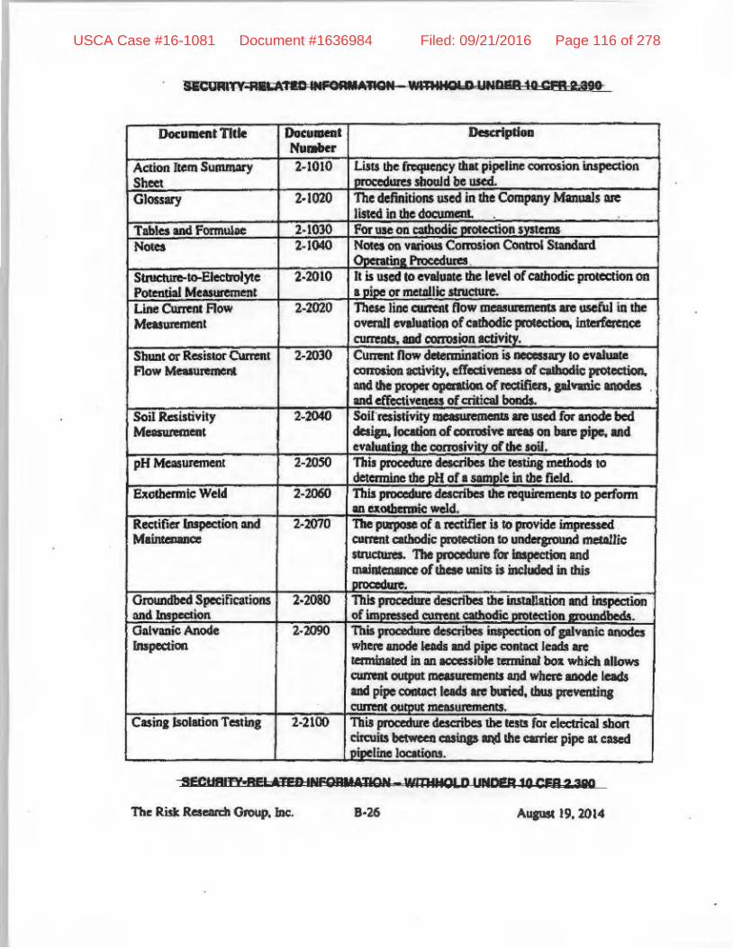
"CUM., p' ":I&I:IIUFQAfI'iJlQt4 *"IIIQI D UW''P_to crR Ute
-SFCUI'IIY"I nFDINFO'W"TION_wmIIOLD UNDEq 'OCQ?39I!
8·26 "1lJIISC 19, 2014
USCA Case #16-1081 Document #1636984 Filed: 09/21/2016 Page 116 of 278

'liD QiI ell'. me", Wlt'l1I1CLD tiME" to Q" LaW
iDlbc
•• CtI:,: f R'~~RIt·lION """'IS 0 !;»Ie-A 10CFhZoJIO
'-27 AI/IIISt 19.2014
USCA Case #16-1081 Document #1636984 Filed: 09/21/2016 Page 117 of 278

se=URI'I't "I 'HD IIPgR •• ''QOIt MAllgo n 'PI ua OfA "SO
SIGUAFn All eJlO II ORMADON _ wmll' D tINDeR IOCFH DiU
The Rislc Re$CIId! 0taup.1Dc. 8-28 Aupst 19,2014
USCA Case #16-1081 Document #1636984 Filed: 09/21/2016 Page 118 of 278

$&'-1 t""PtAJPO ".G ..... lI8N 'Mft1110' " '_+8 10 CPR%; N .
8·" Aup!ll. 19, 2Q14
USCA Case #16-1081 Document #1636984 Filed: 09/21/2016 Page 119 of 278
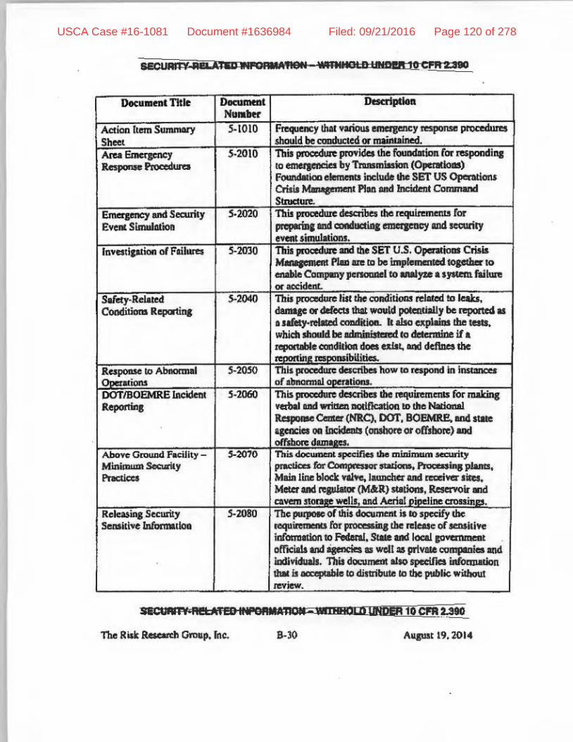
SECUAIt"e All &1"aD "Ii CfI.tifleN WlRllla' n 11N0I!ft 10 CFR 2;310
10 tbe public without
SIiC_,",,' "5 6i W INPGflMtmOII-.1 .101 0 UNDER 10 CFR_~~
The Risk RaeardI Group. inc, B,)O AllJlllt 19.2014
USCA Case #16-1081 Document #1636984 Filed: 09/21/2016 Page 120 of 278

· I
USCA Case #16-1081 Document #1636984 Filed: 09/21/2016 Page 121 of 278

sKUll i' P" ., & lIf'9FJIJIiROII WID.IN "',11191 to CP11203tU
~
pemm serricc fIJ4J« maine = 011 equlpnwnt wbI::fe !be IliltXpetlcd -Jizia .. stlrtUp 01" rei_ of
-..c .... , , i ;AlID III"OAII";"811 wm.t,." IIN1)!ft to Ph 2031D
The Ril/t Ra=h Group. Inc. B-J2 Auausr 19.20'4
USCA Case #16-1081 Document #1636984 Filed: 09/21/2016 Page 122 of 278

S!!CtJllln ••• ' +Til" ,mSIIII'lIGN 'mR.IDIiD utlD_ 10' F. Z A'
:sGI.IAI1. REI 'I"'I"'~IIMAUOM "M'ft.IQLD ..... 11 .. 10("'. n.
The Risk Raeardt Group. Inc. . 8-33 A\hIUI1 19.2014
USCA Case #16-1081 Document #1636984 Filed: 09/21/2016 Page 123 of 278

---------- --
-sicuRn' Ali 'I iU" CRMAMN wmWlOl;D WCl!!ft1tJCFA 2 lal
N_
Asscss1llllllt (SCCDA)
IdcntifICld pipeline sqmentS. 1hls in ........ dmt:e 1ritb NACE SP
CorloIion Direct All! Immt
situ", I , MiLA! & IItfM""'M1I 11m. .. CII;U ,-PH 10 CfR UtO
' .J< AIIJUS/. 19. 20'4
USCA Case #16-1081 Document #1636984 Filed: 09/21/2016 Page 124 of 278

I'
will be
5EC!JHII ' .... E! ..... nlFC ..... ·iAOIi "JmlllrJUI'M, S' 10 i:tRfiiO.
B·l~ AIIJIIIl 19. 2014
USCA Case #16-1081 Document #1636984 Filed: 09/21/2016 Page 125 of 278

1,C!'8'TY R51 .,.....U'O .. IAJlON UMUUOLD WfOM 10 GI" DIif
l\u ..... n .. ntSoI\_1z. U.e(sQvide
The Risk Rc:selUdJ QI'OIIp. Inc.
IIINnI PI pipeIineL of 1851 .• 1-1851..43 ~
muimllm
USCA Case #16-1081 Document #1636984 Filed: 09/21/2016 Page 126 of 278

.ECtAI • >M! ....... ED ",,.GIlII ,'liON- wmt..o' Eli .... 11 10 cpn 2aD
Sth.h',," ',& IIIFOnrU;noN 'oWl' 'Or D > 9"?M: to-CFfI-a.aIO
The Risk Rescuch Group, Inc. 8·)7 August 19, 2014
.; '~ .:;1
J~ " . >
USCA Case #16-1081 Document #1636984 Filed: 09/21/2016 Page 127 of 278

wml'mn'-'DEII'OCfftU.
•
<
SEOOII" rml "lib INftJ"«TlOl!l_ W""HQU) UND&i .0 CFA 203W
The Risk. Researth Group." B·lI AtJ&UII19.2014
USCA Case #16-1081 Document #1636984 Filed: 09/21/2016 Page 128 of 278

In lIddilion 10 !be above SOP'. AGT (Spccua) bas stMOdlbey will also irIcuponIIe !be followin, Hems dllriDs !he eqineeriDs. proeIIfCmena and c:onstruction ol1he AIM pipeline pn;!ject.
a) Quality ~ity Control (QAiQC) Proccd_ for !be ~ aian. procuremelU, fabrication tne1 tonItruellon.
b) The JUCSC.we oftbc 1111 CIIhodIc prorectlon (CP) systcma will be desiped and installed by :III experialced dUn! party COIIIlICtor and CP suneys will be CO!Idudcd in ~ with DOT Pan 192 requimnents.
c) A robusl AC milipdon.yscem will be eJlJinoered mil installed iA IlUi whcno !he pipeline will be iD:Italled IIdjacent, ~le:lllJld crosses hish YO"" pow¢ lme. in the uea~ D"EC. .
d) The pJpelille C(!OIin81 will be 100<lt insprtted elearonically uthe pipdial! is lowered into tbt 1fOWId..
c) All AllCmllinc Current Volraac Gradient (ACVG) or Direa CWIClIt VollqC Ofll!lient (DCVG) IUIVe)' will be performed to ensure co.tinc intepy follon, pipe inst:lllation lIId~ll.
o Wine lnI~ (1U) or smut Pia 1Um:)'5 will be conducted as defcribcd in the InlBlrily Maupment PIon and will be cooducted :aa often • requiml by FcdenaI Pipeline IDIeJriIy Rules and Rcpdllions and ASME 831.85.
Cl The pipeline wiD be piQlrolled. on l weekly basis per DOT Part 192 10 identify possible unapproved enc:roKhments on !he ROW.
SI;\lUfiIT't:RF' .".'" IN'!2RMMlQII .1"lllata tlMDEA w c'a' .... The Risk ReellfCb Oroup, Inc. B-19
USCA Case #16-1081 Document #1636984 Filed: 09/21/2016 Page 129 of 278

, .
UCltprry·PiiiOliD au CI*AfIClfl- wmnIUW ...... ' 10 CQ'"
II) Spectra Is llso • member of the 0II6-CIII1 (~call bd~ )'OIl diJ") s)'S1eII1 whldl is rnonirCftld. COIItirI'_ly by fuU-tl1llt: Inined palODlld who rapcMld 10 thae calls daily and appII)d cxca..oons _ ~ised by tnined itiiipCAJOtl.
i) 0peqtiiJs pn:uura will be limil.cd 10 tile pipdlne mWmum alIowIbIc operltla& pressure (MAOP) by tbo KCinuOQ ofMltomMie o.crp:essure aIanoI, shutdown of u~ 1:OI.!1 DIS and isoW:iDa devices.
j) Pipeline f.uwa wiD be ~ M!lOmHiclIiy aad iImIcodiIIe aIannI will be _10 Spa:tn'1 2N1 COIIIJOI opa ... wbo will tate tile lppi ..... iaIc action in ~ with Spa:tn's SOP' •.
k) .100'J0 old wekII aIont: dleKaa- ofpipc _IPEC _ will be radlosnPbed mil. appoo.cd by IfUIrd X..,.,. ....... nici ...
I) The completed pipeline .01 be AIbjede6 10 I bydrotUtllc test cm«i"''''''llly ror I houri ill IItCOrdIDcc wilb49 CFR 192 IDISpecua'I SOP's.
III) The pipcliDc .ol be pcriodicIIly swept: ol tnpped liquids ·usin&; I .... 01' pip _; ....... (or this pwpoie.
•
Sf"I.'.? .. ftDIHIOIIM':nQ1I wmttnul"' 410CFriD8i!
The Rllt R~~, IDe. ..... ALIIIIlt 19.2014
USCA Case #16-1081 Document #1636984 Filed: 09/21/2016 Page 130 of 278

&:sip
Si!ClUfi1 NJetAibi al ..... 1JOI'1 WRlIIIUWlIJNQ ... 10· .. '3lIO
Exhibit B
PlpeUlM Desip I:n~tI fTopaHd by Spmra ror IPEC
=::;." iO.";~",,!';;': pi,. is prowred from vcndon who have ,...od I .uinacnt qualicy.-lil. and
~ .. 10 API fun·time mill jLPSlr2 SlIIIdards.
, ......... API-'L
JUO ........ 'EUi' m iNPOAMATION - WIlIIIIIUSvn_.,u WrR 2 N ..
The Risk. Rescardt Ckoup. inc. '~ l Au,ust19.2014
USCA Case #16-1081 Document #1636984 Filed: 09/21/2016 Page 131 of 278

-IICU '" \is •• ''''' , rso;; .. "".I~" UMtzr" a .. LiN
£uRlItB
PI~ Del", bbuu-w Plop.e' b, SpednL for IKe
("1lnJ IIIIIMnVQ allln)
f------<;=-~
-
"
..... o.ide Uklonel_, .....
.. u"h- Specln
'* '" eellIdt ~.
""" ... ''''1' I -,&lIeOl "1'1011 ""' ..... WS .. t'CMa,ao ... , ........ 19. 2014
USCA Case #16-1081 Document #1636984 Filed: 09/21/2016 Page 132 of 278

"cern liEU " U~II ..... IGWt ... • t.epA Z I
Etblbll •
...,....., [)alp Ea .... cemnll p, i1I ~ by Spedni rill' l.PEC
-"'-
rrom Spectra f« 1hI' pipeline$. ilcJn shown (III \he l..c Pl'se of ibis EdUbii B)
VC'1ITt I 'T&iJ = hel, w,n.1OI r LIM·· ,'g II' M, ThcRilltR :: d,o-,. Iae.. ... , Ali,.. .'.20 ...
USCA Case #16-1081 Document #1636984 Filed: 09/21/2016 Page 133 of 278

Exhibit 8
I'iptl!ne Design Enh"n~mtJ\tI Proposed by Spedr" ror (PEe
;;;o;;- -T-.::;(/II R~" 10 Enlav~~Q~.:m:""~)~~[=:~:=j
1)'I1aII runs quite dry ...... -elllibiled~)' ,iJlll or iolema! a;nosion
I.
I.
seouNn -AltAliC IlPord lATI:" AmldXD UMlI"10Q ..... D .... AIIpM 19. 2014
USCA Case #16-1081 Document #1636984 Filed: 09/21/2016 Page 134 of 278

AdditionAl responle I'fom Spectra. regardin, seismic considerations;
''The poIeI1tial for geologic hazanls. iDcluding seismic events. 10 significantly :lCfeCl c:oamuction or opemion of the proposed Project fxililia is low. Althousb the Ramapo Faulliw been linked 10 ream canillpwc 00XtIf1'e!lCe in the IU'CI., the desip of the pipeline lakes ;1110 comideraion sitMpeclllc conditions, indudin& ellltbqu;ikes. The recorded lIIIIJIIitude 01 cartbquKes in the Project area is rclalivcly low and the growxI vibration would not pose a problem for a modem _Idcd-slccl pipcliDe~
s.&cual"'V ," Id liD 11L1 OillA I 'tION WI'I'l II I r:IUl UfIIC'ER 1111 :Fe 2 3VD
The Risk RCKlITI:b Group. I/Ic.. B-4S Aup! 19. 2014
1r-1 USCA Case #16-1081 Document #1636984 Filed: 09/21/2016 Page 135 of 278

,
SFCtIRJTY-REI UEn INfORMATION 8 WllhttOLC' tlN"E~ 11 QFR i.e9Q
Exhibit C
ACT Pipe Enh_ernent Cross-Section for EnleliY NOTTOSCALE
,~~- -------,------- ---"--
0. n<r wi. X70
"
!eetJ .. ln-HECAi EO IHI"O"MATlSfI iUllaHi" j i, INliER 1!rCfR"l:39U
The Ri.~1r. Rcscnn;h Group. Inc:. AUgIIll [9,2014
I I
USCA Case #16-1081 Document #1636984 Filed: 09/21/2016 Page 136 of 278

USCA Case #16-1081 Document #1636984 Filed: 09/21/2016 Page 137 of 278

USCA Case #16-1081 Document #1636984 Filed: 09/21/2016 Page 138 of 278

NRC Internal Email from D. Beaulieu to D. Pickett
(April 27, 2015)
USCA Case #16-1081 Document #1636984 Filed: 09/21/2016 Page 139 of 278

. . Heater, Keith
From: Sent To:
Cc
Beaulieu, David Monday, April 27, 2015 12:32 PM Pickett, Douglas; Miller, Chris; Mccoppin, Michael; Tammara, Seshagiri; Setzer, Thomas; Carpenter, Robert; Cylkowski, David; Banic, Merrilee; Beasley, Benjamin; Stuchell, Sheldon Trapp, James; Dudek, Michael; Wilson, George; Gray, Mel; Krohn, Paul; Montgomery, Richard; Burritt, Arthur
Subject: Indian Point Gas Line Isolation Time
PRB, Below are the excerpts that I discussed during today's PRB meeting:
1) Excerpts from the Indian Point 50.59 evaluation states, "The estimated time to respond to the alarm (less than one minute) and the closure time of the valves (about one minute) was used as the basis for an assumed closure time of three minutes for the analysis performed in the attached report."
2) National Transportation Safety Board 2011 report excerpt that states that "there is no DOT requirement for response time. n
3) Oak Ridge report from 2012 includes two separate statements about closure time: "The time between a pipeline break and RCV closure can vary from about 3 minutes for immediate leak or rupture detection to hours if field confirmation of a break is necessary to validate the closure decision." "Consequently, delays of about 1 O minutes will be required before RCV closure can be initiated for a typical line break scenario, if field verification of the break is not required."
Excerpts from various sections of the Indian Point 50.59 evaluation involving the 3 minute isolation time.
"This would result in all the gas between these valves at the time of closure being able to vent or bum. The estimated time to respond to the alarm (less than one minute) and the closure time of the valves (about one
· minute) was used as the basis for an assumed closure time of three minutes for the analysis performed in the attached report. n
"The next closest isolation valve locations are at the Stony Point Compressor Station mile post 0.0 and at MLV 15 at mile post 10.52. Valve operation follows the requirements of the DOT Code and is tested on a periodic basis to ensure compliance with code requirements."
"This hazards analysis considers the effects of the gas pipeline rupture to involve the approximately 3 miles of pipeline between isolation valves and considers the event to be terminated by manual action within 3 minutes after any pipeline rupture event by closing the closest isolation valves and limiting the event to the gas between these valves."
"In modeling releases and their consequences, we assume that the contents of a 3 mile length of gas pipeline are released at a pressure of 850psig (the MAOP of the 42" pipeline), that valves Isolating this length of pipeline will be closed within 3 minutes of a major release and that the interior of this pipeline is smooth."
"After valve closure, full bore release from the pipeline will persist for another 2 to 3 minutes. The release following guillotine rupture will therefore be - 5 to 6 minutes duration."
"Based on an average release rate of 1877 kg/s for a 360-second period. This rate comprises the release of 376,000 kg in the first minute (from ALOHA), a release of 200,000 kg in the next two minutes (accounting for the pressure drop) and 100,000 kg after valve closure. This last will take an additional 3 minutes after the valves are closed (from ALOHA)."
National Transportation Safety Board. 2011. Pacific Gas and Electric Company Natural Gas Transmission Pipeline Rupture and Fire. San Bruno. California. September 9. 2010. Pipeline Accident Report NTSB/PAR-11/01. Washington. DC. http://www.ntsb.gov/investigations/ AccidentReports/Reports/PAR 11O1. pdf
1
USCA Case #16-1081 Document #1636984 Filed: 09/21/2016 Page 140 of 278

Other than for pipelines with alternative maximum allowable operating pressures (MAOP), the regulations do not require a response time to isolate a ruptured gas line, nor do they explicitly require the use of ASVs or RCVs. The regulations give the pipeline operator discretion to decide whether ASVs or RCVs are needed in HCAs as long as they consider the factors listed under 49 CFR 192.935(c): Automatic shut-off valves (ASV) or Remote control valves (RCV). If an operator determines, based on a risk anaiysis, that an ASV or RCV would be an efficient means of adding protection to a high consequence area in the event of.a gas release, an operator must install the ASV or RCV. In making that determination, an operator must, at least, consider the following factors-swiftness of leak detection and pipe shutdown capabilities, the type of gas being transported, operating pressure, the rate of potential release, pipeline profile, the potential for ignition, and location of nearest response personnel.
Oak Ridge National Laboratory ORNLJTM-2012/411. "Studies for the Requirements of Automatic and Remotely Controlled Shutoff Valves on Hazardous Liquids and Natural Gas Pipelines with Respect to Public and Environmental Safety," December 2012. http://www.phmsa.dot.gov/pv obj cache/pv obj id 2C1 A725B08C5F72F305689E943053A96232AB200/filename/Fin al%20Valve Study.pdf
Conclusions from the "Cost Benefit Study of Remote Controlled Main Line Valves" (Sparks, 1998) follow. 1. Virtually all injuries caused by pipeline breaks occur at, or very near, the time of the initial rupture. Of 81 injury incidents reviewed (1970 to 1997 NTSB Incident Reports), 75 reported injuries at the initial rupture. Of the other six incidents, four occurred within 3 minutes of the rupture. It seems clear, therefore, that early valve closure time will have little or no effect on injuries sustained, and no effect on rupture severity. Valve closure will be "after the fact" as far as most injuries and damage are concerned. There is no evidence that prolonged blowdown of a ruptured line causes injuries. 2. Further, a line break does not immedi~tely evacuate the pipeline. Because of line pack (gas compressibility) some 5 to 10 minutes are normally required for low pressure alarms to be generated at Gas Control and/or nearby compressor stations. Delays depend upon break size and location, line size, operating pressure, and other operating and configurational variables. Additional time is then.required (a) to determine the cause of low line pressure (e.g., loss of compression, load transients, faulty instrumentation, line break, or other causes) and (b) to determine break location. This will likely consume an additional 5 minutes. Consequently, delays of about 10 minutes will be required before RCV closure can be initiated for a typical line break scenario, if. field verification of the break is not required. Early valve closure can, however, have a significant effect in reducing the volume of gas lost after a line break. Simulations show savings of about 50% for valve closure at 10 minutes versus closure at 40 minutes in a typical 30-inch/900-psi rupture scenario.
A different section of the Oak Ridge Report states: The decision to close a RCV involves evaluating the sensor data received at the remote location and determining whether a problem does, or does not, exist. The evaluation process includes consideration of realtime pressure and flow data and communications with the public, emergency responders, or company field personnel. If the operator determines that block valve closure is necessary, the operator initiates the closure procedure by sending a signal to the valve site via the communications link. The time between a pipeline break and RCV closure can vary from about 3 minutes for immediate leak or rupture detection to hours if field confirmation of a break is necessary to validate the closure decision.
DAVID BEAULIEU PROJECT MANAGER NRR/DPR/PGCB (bowl-yer) 301-415-3243 I 012014 I [email protected]
U.S. Nuclear Regulatory Commission
2
USCA Case #16-1081 Document #1636984 Filed: 09/21/2016 Page 141 of 278

Turkey Point Units 6 and 7 COL Application,
Part 2 - FSAR at 2.2.2-2.2.-25
USCA Case #16-1081 Document #1636984 Filed: 09/21/2016 Page 142 of 278

Turkey Point Units 6 & 7COL ApplicationPart 2 — FSAR
Revision 02.2-i
SECTION 2.2:NEARBY INDUSTRIAL, TRANSPORTATION, AND MILITARY FACILITIES
TABLE OF CONTENTS
2.2 NEARBY INDUSTRIAL, TRANSPORTATION, AND MILITARY FACILITIES .....................................................................................................2.2-1
2.2.1 LOCATIONS AND ROUTES ....................................................................2.2-12.2.2 DESCRIPTIONS .....................................................................................2.2-3
2.2.2.1 Description of Facilities ...............................................................2.2-32.2.2.2 Description of Products and Materials .........................................2.2-32.2.2.3 Description of Pipelines ..............................................................2.2-52.2.2.4 Description of Waterways ............................................................2.2-62.2.2.5 Description of Highways ..............................................................2.2-72.2.2.6 Description of Railroads ..............................................................2.2-82.2.2.7 Description of Airports .................................................................2.2-82.2.2.8 Projections of Industrial Growth ................................................2.2-15
2.2.3 EVALUATION OF POTENTIAL ACCIDENTS .......................................2.2-152.2.3.1 Determination of Design-Basis Events ......................................2.2-162.2.3.2 Effects of Design Basis Events .................................................2.2-46
2.2.4 COMBINED LICENSE INFORMATION .................................................2.2-472.2.5 REFERENCES .......................................................................................2.2-47
USCA Case #16-1081 Document #1636984 Filed: 09/21/2016 Page 143 of 278

Turkey Point Units 6 & 7COL ApplicationPart 2 — FSAR
Revision 02.2-ii
SECTION 2.2 LIST OF TABLES
Number Title
2.2-201 Description of Facilities — Products and Materials
2.2-202 Onsite Chemical Storage Units 1 through 7
2.2-203 Offsite Chemical Storage — Homestead Air Reserve Base
2.2-204 Units 6 & 7 Pipeline Information Summary
2.2-205 Hazardous Chemical Waterway Freight, Intracoastal Waterway, Miami to Key West, Florida
2.2-206 Aircraft Operations — Significant Factors
2.2-207 Units 1-5 Onsite Chemical Storage — Disposition
2.2-208 Units 6 & 7 Onsite Chemical Storage — Disposition
2.2-209 Offsite Chemicals, Disposition — Homestead Air Reserve Base
2.2-210 Transportation — Navigable Waterway, Turkey Point Lateral Pipeline, and Onsite Transportation Route — Disposition
2.2-211 Atmospheric Input data for the ALOHA Model
2.2-212 ALOHA Meteorological Sensitivity Analysis Inputs
2.2-213 Design Basis Events — Explosions
2.2-214 Design-Basis Events, Flammable Vapor Clouds (Delayed Ignition) and Vapor Cloud Explosions
2.2-215 Design-Basis Events, Toxic Vapor Clouds
USCA Case #16-1081 Document #1636984 Filed: 09/21/2016 Page 144 of 278

Turkey Point Units 6 & 7COL ApplicationPart 2 — FSAR
Revision 02-iii
SECTION 2.2 LIST OF FIGURES
Number Title
2.2-201 Site Vicinity Map
2.2-202 Airport and Airway Map
USCA Case #16-1081 Document #1636984 Filed: 09/21/2016 Page 145 of 278

Turkey Point Units 6 & 7COL ApplicationPart 2 — FSAR
Revision 02.2-1
2.2 NEARBY INDUSTRIAL, TRANSPORTATION, AND MILITARY FACILITIES
This section of the referenced DCD is incorporated by reference with the following
departures and/or supplements.
The purpose of this section is to establish whether the effects of potential
accidents onsite or in the vicinity of the site from present and projected industrial,
transportation, and military installations and operations should be used as design
basis events for plant design parameters related to the selected accidents.
Facilities and activities within the vicinity, 5 miles, of Turkey Point Units 6 & 7 were
considered to meet the guidance in RG 1.206. Facilities and activities at greater
distances are included as appropriate to their significance.
Subsection 2.2.1 of the DCD is renumbered as Subsection 2.2.4 and moved to
the end of Section 2.2. This is being done to accommodate the incorporation of
RG 1.206 numbering conventions for Section 2.2.
2.2.1 LOCATIONS AND ROUTES
Potential hazard facilities and routes within the vicinity (5 miles) of Units 6 & 7, and
airports within 10 miles of Units 6 & 7 are identified along with significant facilities
at a greater distance in accordance with RG 1.206, RG 1.91, RG 4.7, and relevant
sections of 10 CFR Parts 50 and 100.
An investigation of the potential external hazard facilities and operations within 5
miles of Units 6 & 7 concluded there is one significant industrial facility associated
with a military installation identified for further analysis. An evaluation of major
transportation routes within the vicinity of Units 6 & 7 identified one natural gas
transmission pipeline system and one navigable waterway for assessment
(References 204, 206, 207, and 208).
Potential hazard analysis of internal events includes Units 1 through 5 and onsite
chemical and chemical storage facilities associated with Units 6 & 7 along with an
onsite transportation route.
PTN COL 2.2-1
STD DEP 1.1-1
PTN COL 2.2-1PTN COL 3.5-1PTN COL 3.3-1
USCA Case #16-1081 Document #1636984 Filed: 09/21/2016 Page 146 of 278

Turkey Point Units 6 & 7COL ApplicationPart 2 — FSAR
Revision 02.2-2
A site vicinity map (Figure 2.2-201) details the following identified facilities and
road and waterway transportation routes:
Significant Industrial and Military Facilities Within 5 Miles
Turkey Point Units 1 through 5
Homestead Air Reserve Base
Transportation Routes Within 5 Miles
Onsite transportation route
Miami to Key West, Florida Intracoastal Waterway
Florida Gas Transmission Company, Turkey Point Lateral Pipeline and
Homestead Lateral Pipeline
An evaluation of nearby facilities and transportation routes within 10 miles of
Units 6 & 7 revealed that there are no additional facilities significant enough to be
identified as potential hazard facilities. (References 207, 224, and 225)
Potential hazard analyses of airports within 10 miles of Units 6 & 7 are identified
along with airway and military operation areas. There are two airports within 10
miles of the plant and one airway identified whose centerline is located
approximately 5.98 miles from the plant identified for further analysis.
(References 209, 210, 223, and 240)
Figure 2.2-202 illustrates the following identified airports and airway routes within
10 miles of Units 6 & 7, including:
Airport and Airway Routes Within 10 Miles
Turkey Point Heliport
Homestead Air Reserve Base
Ocean Reef Club Airport
Airway V-3
USCA Case #16-1081 Document #1636984 Filed: 09/21/2016 Page 147 of 278

Turkey Point Units 6 & 7COL ApplicationPart 2 — FSAR
Revision 02.2-3
There are no identified hazard facilities, routes, or activities greater than 10 miles
that are significant enough to be identified (References 207, 223, 224, 225, and
240).
Items illustrated in Figures 2.2-201 and 2.2-202 are described in
Subsection 2.2.2.
2.2.2 DESCRIPTIONS
Descriptions of the industrial, transportation, and military facilities located in the
vicinity of Units 6 & 7 and identified in Subsection 2.2.1 are provided in the
subsequent subsections in accordance with RG 1.206.
2.2.2.1 Description of Facilities
In accordance with RG 1.206, two facilities, along with the onsite chemical and
chemical storage facilities associated with Units 6 & 7, were identified for review:
Turkey Point Units 1 through 5
Homestead Air Reserve Base
Table 2.2-201 provides a concise description of each facility, including its primary
function and major products, as well as the number of people employed.
2.2.2.2 Description of Products and Materials
A more detailed description of each of these facilities, including a description of
the products and materials regularly manufactured, stored, used, or transported,
is provided in the following subsections. In accordance with RG 1.206, chemicals
stored or situated at distances greater than 5 miles from the plant do not need to
be considered unless they have been determined to have a significant impact on
the proposed facilities.
The South Florida Regional Planning Council, Emergency Management Division,
was contacted to obtain information regarding offsite chemical storage. The EPA’s
Envirofacts/Enviromapper database was also queried to ascertain if other facilities
of significance existed in addition to the facilities identified after evaluating the
Superfund Amendments and Reauthorization Act (SARA) Title III, Tier II reports
obtained from South Florida Regional Planning Council. Other than the Turkey
Point Units 1 through 5 site, there was only one identified external facility,
Homestead Air Reserve Base, within 5 miles of the Turkey Point site with
USCA Case #16-1081 Document #1636984 Filed: 09/21/2016 Page 148 of 278
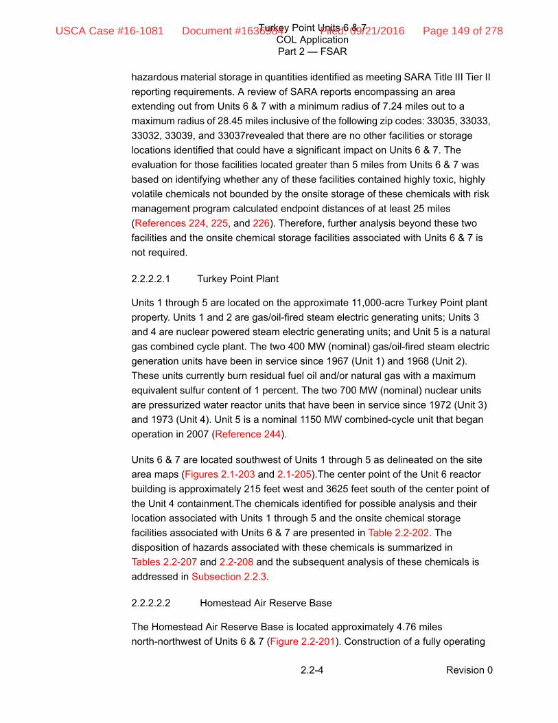
Turkey Point Units 6 & 7COL ApplicationPart 2 — FSAR
Revision 02.2-4
hazardous material storage in quantities identified as meeting SARA Title III Tier II
reporting requirements. A review of SARA reports encompassing an area
extending out from Units 6 & 7 with a minimum radius of 7.24 miles out to a
maximum radius of 28.45 miles inclusive of the following zip codes: 33035, 33033,
33032, 33039, and 33037revealed that there are no other facilities or storage
locations identified that could have a significant impact on Units 6 & 7. The
evaluation for those facilities located greater than 5 miles from Units 6 & 7 was
based on identifying whether any of these facilities contained highly toxic, highly
volatile chemicals not bounded by the onsite storage of these chemicals with risk
management program calculated endpoint distances of at least 25 miles
(References 224, 225, and 226). Therefore, further analysis beyond these two
facilities and the onsite chemical storage facilities associated with Units 6 & 7 is
not required.
2.2.2.2.1 Turkey Point Plant
Units 1 through 5 are located on the approximate 11,000-acre Turkey Point plant
property. Units 1 and 2 are gas/oil-fired steam electric generating units; Units 3
and 4 are nuclear powered steam electric generating units; and Unit 5 is a natural
gas combined cycle plant. The two 400 MW (nominal) gas/oil-fired steam electric
generation units have been in service since 1967 (Unit 1) and 1968 (Unit 2).
These units currently burn residual fuel oil and/or natural gas with a maximum
equivalent sulfur content of 1 percent. The two 700 MW (nominal) nuclear units
are pressurized water reactor units that have been in service since 1972 (Unit 3)
and 1973 (Unit 4). Unit 5 is a nominal 1150 MW combined-cycle unit that began
operation in 2007 (Reference 244).
Units 6 & 7 are located southwest of Units 1 through 5 as delineated on the site
area maps (Figures 2.1-203 and 2.1-205).The center point of the Unit 6 reactor
building is approximately 215 feet west and 3625 feet south of the center point of
the Unit 4 containment.The chemicals identified for possible analysis and their
location associated with Units 1 through 5 and the onsite chemical storage
facilities associated with Units 6 & 7 are presented in Table 2.2-202. The
disposition of hazards associated with these chemicals is summarized in
Tables 2.2-207 and 2.2-208 and the subsequent analysis of these chemicals is
addressed in Subsection 2.2.3.
2.2.2.2.2 Homestead Air Reserve Base
The Homestead Air Reserve Base is located approximately 4.76 miles
north-northwest of Units 6 & 7 (Figure 2.2-201). Construction of a fully operating
USCA Case #16-1081 Document #1636984 Filed: 09/21/2016 Page 149 of 278

Turkey Point Units 6 & 7COL ApplicationPart 2 — FSAR
Revision 02.2-5
military base (Homestead Army Air Field) began at the current Homestead Air
Reserve Base site in September of 1942 to serve as a maintenance and fueling
stopover for aircraft headed overseas during World War II.
Today, the 482nd Fighter Wing, the host unit of Homestead Air Reserve Base,
continues to support contingency and training operations of U.S. Southern
Command and a number of tenant units including Headquarters Special
Operations Command South, U.S. Coast Guard Maritime Safety and Security
Team, and an air and maritime unit of U.S. Customs and Border Protection. The
Homestead Air Reserve Base is a fully combat-ready unit capable of providing
F-16C multipurpose fighter aircraft, along with mission ready pilots and support
personnel, for short-notice worldwide deployment. In addition, the Homestead Air
Reserve Base is home to the most active North American Aerospace Defense
Command alert site in the continental United States, operated by a detachment of
F-15 fighter interceptors from the 125th Fighter Wing Florida Air National Guard.
The Homestead Air Reserve Base has 2365 total personnel including 267
active-duty personnel, 1245 Air Force Reserve Command and National Guard
personnel, 779 civilians, and 74 civilian contractors (References 202 and 203).
The chemicals stored at the Homestead Air Reserve Base identified for possible
analysis are presented in Table 2.2-203. The disposition of hazards associated
with these chemicals is summarized in Table 2.2-209 and the subsequent analysis
of these chemicals is addressed in Section 2.2.3.
2.2.2.3 Description of Pipelines
There are two natural gas transmission pipelines operated by Florida Gas
Transmission Company within 5 miles of the plant as depicted in Figure 2.2-201.
The Florida Gas Transmission Company owns and operates a high-pressure
natural gas pipeline system that serves FPL and other customers in south Florida.
Two of the pipelines, the Turkey Point Lateral and the Homestead Lateral, are
located within 5 miles of Units 6 & 7. A more detailed description of the pipelines
are presented in the following subsection, including the pipe size, age, operating
pressure, depth of burial, location and type of isolation valves, and type of gas or
liquid presently carried. Information pertaining to the various pipelines is also
presented in Table 2.2-204.
2.2.2.3.1 Florida Gas Transmission Company/Turkey Point Lateral Pipeline
The Florida Gas Transmission Company Turkey Point Lateral is a 24-inch
diameter pipeline that was installed in 1968. The pipeline operates at a maximum
USCA Case #16-1081 Document #1636984 Filed: 09/21/2016 Page 150 of 278

Turkey Point Units 6 & 7COL ApplicationPart 2 — FSAR
Revision 02.2-6
pressure of 722 pound-force per square inch gauge (psig) and provides gas
service to Turkey Point’s gas-fired power plants. The pipeline is buried to an
approximate depth of 42 inches below grade. The nearest isolation valve is
located approximately 11.8 miles from the south end of the 24-inch Turkey Point
Lateral. The isolation valve is manually operated. At the closest approach to
Units 6 & 7, the Turkey Point Lateral pipeline, depicted on Figure 2.2-201, passes
within approximately 4535 feet of the Unit 6 auxiliary building. The Turkey Point
Lateral transports natural gas and there are not any future plans to transport any
other products (Reference 204).
2.2.2.3.2 Florida Gas Transmission Company/Homestead Lateral Pipeline
The Florida Gas Transmission Company Homestead Lateral is a 6.625-inch
diameter pipeline that tees off of the 24-inch Turkey Point Lateral approximately
3 miles north of the Turkey Point site and extends in a westward direction to
provide gas service to the City of Homestead. The Homestead Lateral was
installed in 1985, and also operates at a maximum pressure of 722 psig. This
pipeline is buried to an approximate depth of 42 inches below grade. There is a
manually operated isolation valve located just downstream of the 24 inch by 6 inch
tee at the take-off of the Homestead Lateral. The Homestead Lateral transports
natural gas and there are not any future plans to transport any other products
(Reference 204). Because of the proximity and diameter of the Turkey Point
Lateral pipeline in comparison to the Homestead lateral pipeline, the Turkey Point
Lateral pipeline presents a greater hazard, and as such, the Turkey Point Lateral
pipeline analysis is bounding and no further analysis of the Homestead Lateral
pipeline is warranted.
2.2.2.4 Description of Waterways
Units 6 & 7 are located on the western shore of south Biscayne Bay. Biscayne Bay
is a shallow coastal lagoon located on the lower southeast coast of Florida
(Reference 258). The bay is approximately 38 miles long, approximately 11 miles
wide on average, and has an area of approximately 428 square miles
(References 259 and 260). On the southern portion of the Biscayne Bay where
Units 6 & 7 are located, the bay is approximately 8 miles wide and 9 miles long
and extensive sandbars exist. South Biscayne Bay is separated from Card Sound
to the south by a sandbar area encompassing the Arsenicker Keys and Cutter
Bank. The nearshore shallow areas of the western side of south Biscayne Bay are
generally less than 5 feet deep (Reference 205).
USCA Case #16-1081 Document #1636984 Filed: 09/21/2016 Page 151 of 278
Turkey Point Units 6 & 7COL ApplicationPart 2 — FSAR
Revision 02.2-7
The Biscayne Bay contains the Miami to Key West, Florida Intracoastal Waterway.
The only commodity transported on the Miami to Key West, Florida Intracoastal
Waterway is residual fuel oil. In 2005, there were 611,000 short tons of residual
fuel oil transported, and the entirety of this commodity was delivered to the Turkey
Point plant (Table 2.2-205, Reference 206).
The Turkey Point turning basin is approximately 300 feet wide, 1200 feet long and
approximately 20 feet deep (Reference 205)The Turkey Point fuel unloading dock
is located on the north side of the turning basin. The concrete constructed fuel oil
dock at the Turkey Point plant can handle one barge at a time. Residual fuel oil is
delivered exclusively by barges that typically are approximately 228 feet long, 54
feet wide, and have a draft of 6.5 feet when loaded. This size barge will transport
approximately 18,000 barrels of oil. Residual fuel oil is unloaded from the barges
to the two fuel oil storage tanks located north of the unloading dock. In a typical
week, five to seven deliveries of oil may be made and each delivery requires
about 5 hours to unload. Because the storage of residual fuel oil at the Turkey
Point site, two 268,000 barrel tanks, exceeds the quantity transported by a barge,
the storage tanks present a greater hazard, and as such, the analysis of residual
fuel oil located in the storage tanks is bounding and no further analysis of the
residual fuel oil transported by the barge is warranted.
2.2.2.5 Description of Highways
Miami-Dade County is traversed by several highways. Interstate 95, U.S.
Highway 1 and the Florida Turnpike (State Road 821) are the major transportation
routes for north-south traffic flow in the county. The major route for east-west
movement is U.S. Route 41 which crosses the middle of the county
(Reference 207). Main access to the Turkey Point site is Palm Drive (SW 344th
Street), which runs in an east-west direction along the northern boundary of the
Turkey Point site. Palm Drive provides a connection with U.S. Highway 1 and the
Florida Turnpike. There are no major highways within 5 miles of Units 6 & 7
(Figure 2.2-201, References 201 and 207).
To ascertain which hazardous materials may be transported on the roadways
within 5 miles of Units 6 & 7, the industries that may store hazardous
materials—and, hence, have either the materials transported to the site or
transported from the site—were identified through SARA Title III, Tier II reports as
described in Subsection 2.2.2.2. The only identified chemicals whose
transportation route may approach closer than 5 miles to Units 6 & 7 are those
chemicals transported onto the Turkey Point plant property. Of these chemicals,
gasoline was the only identified roadway transportation event that is not bounded
USCA Case #16-1081 Document #1636984 Filed: 09/21/2016 Page 152 of 278

Turkey Point Units 6 & 7COL ApplicationPart 2 — FSAR
Revision 02.2-8
by an event involving the onsite storage vessel for each identified chemical. Each
of the identified onsite chemicals that had the potential to explode, or form a
flammable or toxic vapor cloud, is analyzed to determine safe distances.
2.2.2.6 Description of Railroads
There are no railroads in the vicinity (5 miles) of Units 6 & 7 (Figure 2.2-201,
Reference 207).
2.2.2.7 Description of Airports
In accordance with RG 1.206 and RG 1.70, Homestead Air Reserve Base is the
only identified airport located within the vicinity (5 miles) of Units 6 & 7 other than
the Turkey Point Heliport located onsite. Further, RG 4.7 recommends that major
airports within 10 miles be identified. The Ocean Reef Club Airport is a small
private airport located approximately 7.4 miles from Units 6 & 7 (Figure 2.2-202,
References 223 and 240).
A more detailed description of each of these airports is presented in the
subsequent sections, including distance and direction from the site, number and
type of aircraft based at the airport, largest type of aircraft likely to land at the
airport facility, runway orientation and length, runway composition, hours
attended, and yearly operations where available. Information pertaining to airports
located within 10 miles of the site is presented in tabular form in Table 2.2-206. A
screening evaluation of the closest major airport in the region, Miami International
Airport, is also included in this table to ascertain whether this airport is or may be
of significance in the future.
2.2.2.7.1 Airports
2.2.2.7.1.1 Turkey Point Heliport
The Turkey Point site operates its own corporate heliport. The Turkey Point
heliport is located in the southeast corner of the Units 3 & 4 parking lot
approximately 3100 feet north of Units 6 & 7. The heliport is an approximate
22-foot by 22-foot concrete pad. The maximum gross weight of the helicopter
operated at the site, an Agusta A109E Power Helicopter, is 6600 pounds. There
were approximately 79 takeoffs and landing operations in 2007. As described in
Subsection 2.2.2.7.2, it is not expected that an aircraft of this weight and size
would have an impact on safety-related structures (References 227 and 228).
Further, the number of operations at the heliport, especially in comparison with
USCA Case #16-1081 Document #1636984 Filed: 09/21/2016 Page 153 of 278

Turkey Point Units 6 & 7COL ApplicationPart 2 — FSAR
Revision 02.2-9
other aviation facilities is infrequent. Due to the weight of the aircraft (thus low
penetration hazard) using the heliport and infrequent operations, no further
analysis of the heliport is warranted.
2.2.2.7.1.2 Homestead Air Reserve Base
Homestead Air Reserve Base is located approximately 4.76 miles north-northwest
from the proposed Units 6 & 7. The U.S. Air Force owns the airport, and the
airport is for private use, with permission required before landing. The airport has
a concrete/grooved runway, Runway 05/23, which is 11,200 feet long and 300 feet
wide. The runway headings are 50 degrees (Runway 05) and 230 degrees
(Runway 23). The traffic pattern for Runway 05 is right and the traffic pattern for
Runway 23 is left (Reference 209).
The Homestead Air Reserve Base has approximately 36,429 annual operations
and this projection is not expected to change over the period of the license
duration (Reference 208). Consistent with RG 1.206, the Homestead Air Reserve
Base located approximately 4.76 miles from the site, was considered because the
plant-to-airport distance is less than 5 miles.
Homestead Air Reserve Base indicated that the military aircraft onsite consisted
of F-16Cs with a wingspan of 32 feet 10 inches and F-15As with a wingspan of 42
feet 9 inches. The reported number of military operations was 24,902 per year.
The Homestead Air Reserve Base also indicated that there were 7430 operations
per year from U.S. Customs Border Patrol aircraft along with 4097 transient
aircraft operations per year (Reference 208).
2.2.2.7.1.3 Ocean Reef Club Airport
Ocean Reef Club Airport is a privately owned airport located 7.41 miles south
southeast from Units 6 & 7. The airport is an amenity associated with the Ocean
Reef Club. All aircraft must be registered and permission is required before
landing. There is no scheduled airline service associated with the airport and the
airport is unattended (Reference 242).
The airport has an asphalt runway that is 4500 feet long and 70 feet wide. The
runway headings are 40 degrees (Runway 04) and 220 degrees (Runway 22).
The landing pattern is to the left. There are approximately 25 aircraft based on the
site, 15 single-engine planes and 10 multi-engine planes. The plant-to-airport
distance criteria in accordance with NUREG-0800 is 500D2, where D is the
distance in statute miles from the site, for airports located within 5 to 10 statute
miles from the site, giving the airport a significance factor of 27,454 operations per
USCA Case #16-1081 Document #1636984 Filed: 09/21/2016 Page 154 of 278

Turkey Point Units 6 & 7COL ApplicationPart 2 — FSAR
Revision 02.2-10
year. The airport is an unattended private facility with just 25 aircraft based on the
field with no control tower (References 209 and 210). To reach a significance
factor of 27,454 operations, each aircraft would need to average approximately
1,098 operations per year. Therefore, it is reasonably assumed that the airport
operations at this facility meet the plant-to-airport distance/annual operations
criteria and no further evaluation is warranted.
2.2.2.7.2 Aircraft and Airway Hazards
There is one airport, Homestead Air Reserve Base, located approximately 4.76
miles from Units 6 & 7. The Homestead Air Reserve Base has approximately
36,429 annual operations and this projection is not expected to change over the
period of the license duration (Reference 208). As required by RG 1.206, an
aircraft hazard analysis should be provided for all airports with a plant-to-airport
distance less than 5 statute miles from the site.
The Units 6 & 7 site meets acceptance criteria 1.B. of Section 3.5.1.6 of
NUREG-0800—there are no military training routes or military operations areas
within 5 miles of the site. The centerline of the closest military training route,
IR-53, is approximately 11.5 nautical miles, 13.2 statute miles, from Units 6 & 7,
while the closest military operations area, Lake Placid military operations area, is
approximately 115 nautical miles or 132.3 statute miles from Units 6 & 7
(Reference 223).
The Units 6 & 7 site is located closer than 2 statute miles to the nearest edge of a
federal airway. The site is approximately 5.98 statute miles from the centerline of
airway V3/G439 as depicted in Figure 2.2-202. The width of a federal airway is
typically 8 nautical miles, 4 nautical miles (4.6 statute miles) on each side of the
centerline, placing the airway approximately 1.4 statute miles to the nearest edge
(Reference 211). The edge of the closest high altitude airway is located further
than 2 statute miles from Units 6 & 7 (Reference 240). Because of the proximity of
airway V3/G439 to Units 6 & 7, criteria 1.C. set in Section 3.5.1.6 of NUREG-0800
that the plant is at least 2 statute miles beyond the nearest edge of a federal
airway is not met.
Therefore, a calculation to determine the probability of an aircraft accident that
could possibly result in radiological consequences to the site was performed
following NUREG-0800 and DOE-STD-3014-96 to determine whether the
accident probability rate is less than an order of magnitude of 1E–07. The
probability of an aircraft crashing into the plant and its impact frequency evaluation
are estimated using a four-factor formula that considers: (1) the number of
USCA Case #16-1081 Document #1636984 Filed: 09/21/2016 Page 155 of 278

Turkey Point Units 6 & 7COL ApplicationPart 2 — FSAR
Revision 02.2-11
operations; (2) the probability that an aircraft will crash; (3) given a crash, the
probability that the aircraft crashes into a 1-square-mile area where the facility is
located; and (4) the size of the facility. In order to estimate aircraft crash
frequencies, this method applies the four-factor formula to two different flight
phases, near-airport activities or airport operations that considers takeoffs and
landings, and non-airport activities or in-flight phase operations (Reference 212).
This assessment of impact frequency assumes that all impacts will lead to facility
damage and a possible release of radioactive material.
Mathematically, the four-factor formula is:
Effective Area
The effective area was calculated using the method provided in the DOE
Standard, DOE–STD-3014-96 (Reference 212). For the AP1000 design, the
F = Σ Nijk * Pijk * fijk (x,y) * Aij (Equation 1)
Where,
F = estimated annual aircraft crash impact frequency for the
facility of interest (no./year)
Nijk = estimated annual number of site-specific aircraft operations
for each applicable summation parameter (no./year)
Pijk = aircraft crash rate (per takeoff or landing for near-airport
phases and per flight for the in-flight (non-airport) phase of
operation for each applicable summation parameter)
fijk(x,y) = aircraft crash location conditional probability (per square mile)
given a crash evaluated at the facility location for each
applicable summation parameter
Aij = the site-specific effective area for the facility of interest that
includes skid and fly-in effective areas (square miles) for each
applicable summation parameter, aircraft category or
subcategory, and flight phase for military aviation
i = (index for flight phases): i=1, 2, and 3 (takeoff, in-flight, and
landing)
j = (index for aircraft category or subcategory): j=1, 2, …, 11
k = (index for flight source): k=1, 2, …, k
Σ = Σk Σj Σi
ijk = site-specific summation over flight phase, i; aircraft category
or subcategory, j; and flight source, k
USCA Case #16-1081 Document #1636984 Filed: 09/21/2016 Page 156 of 278

Turkey Point Units 6 & 7COL ApplicationPart 2 — FSAR
Revision 02.2-12
safety-related structures are contained on the nuclear island which consists of the
containment or shield building and the auxiliary building. To calculate a
conservative estimate of the effective target area, a bounding building was used in
accordance with the DOE standard with the following assumptions:
The total footprint area of the safety-related structures was obtained to
estimate the equivalent width/length (W, L) of a bounding building, and thus
the building diagonal length, R.
For the AP1000 design, when determining the length, L of the bounding
building, the actual length of the auxiliary building, 254 feet, was used.
The total volume of the bounding building is obtained in order to estimate the
equivalent height of the rectangular bounding building.
In this calculation, the 78-foot wingspan was conservatively chosen to
represent military aircraft wingspan. Homestead Air Reserve Base indicated
that the military aircraft on site consisted of F-16Cs with a wingspan of 32 feet
10 inches and F-15As with a wingspan of 42 feet 9 inches (Reference 208).
Based on those assumptions, the effective areas for general aviation, air carrier,
air taxi and commuter, large military (takeoff), large military (landing), small
military (takeoff), and small military (landing) type of aircraft are 0.01730, 0.04309,
0.03859, 0.03775, 0.03660, 0.02166, and 0.02824 square miles, respectively.
Airport Operations Impact Frequency
Using the four-factor formula, the total impact frequency from airport operations,
which includes near airport activities and considers takeoffs and landings, into the
plant was determined to be 2.56E-07 per year. Even though most of the airport
operations are attributed to small military aircraft operations, the calculated impact
frequency was dominated by general aviation operations. The lower impact
frequency attributed to Homestead Air Reserve Base is largely due to the
orientation of the runway at Homestead Air Reserve Base. Crash location
probability values are primarily distributed about the x-axis, the extended runway
centerline—for military aircraft, this distribution is also dependent on the pattern
side of the runway. When the x-axis is placed along the center of the runway, the
Units 6 & 7 site lies nearly on the y-axis, accounting for the low crash location
probabilities for airport operations. In determining the airport operation frequency,
the following assumptions were formulated:
USCA Case #16-1081 Document #1636984 Filed: 09/21/2016 Page 157 of 278

Turkey Point Units 6 & 7COL ApplicationPart 2 — FSAR
Revision 02.2-13
Based on data received from Homestead Air Reserve Base, it was assumed
that for each aircraft category, 75 percent of the operations occurred on
Runway 05 and 25 percent of the operations occurred on Runway 23,
resulting in:
— 18,678 small military operations for Runway 05
— 6,226 small military operations for Runway 23
— 5,574 large military operations for Runway 05
— 1,858 large military operations for Runway 23
— 3,074 general aviation operations for Runway 05
— 1,026 general aviation operations for Runway 23
Non-Airport Operations Impact Frequency
For non-airport operations, or the in-flight phase, methods provided in DOE
Standard DOE-STD-3014-96 were used and the total impact frequency from
non-airport operations into the plant was determined to be 3.61E-06 per year
(Reference 212).
The determined impact frequency using this methodology is heavily weighted
towards general aviation aircraft due to the large probability, N * P * f(x,y), of
general aviation crashes throughout the continental United States. The analysis of
non-airport operations impact frequency was based on the four-factor formula, as
used for airport operations for the class of aircraft j:
Fj = Nj * Pj * fj (x,y) * Aj
Where, the product NP represents the expected number of in-flight crashes per
year; f(x,y) is the probability, given a crash, that the crash occurs in a
1-square-mile area surrounding the facility of interest, and A is the effective area
of the facility (Reference 212). For this calculation, the values of N * P * f(x,y)
selected are the continental U.S. averages.
Total Impact Frequency
This assessment led to a total impact frequency of 3.86E-06 per year when
considering both the airport and non-airport operations, which is greater than an
order of magnitude of 1E-07 per year. Therefore, consideration of whether the
USCA Case #16-1081 Document #1636984 Filed: 09/21/2016 Page 158 of 278

Turkey Point Units 6 & 7COL ApplicationPart 2 — FSAR
Revision 02.2-14
damage from the aircraft crash may result in radiological releases in excess of the
exposure guidelines in 10 CFR Part 100 was considered for general aviation and
commercial aircraft categories. The General Aviation category dominates the
impact frequency results. Studies of General Aviation and Commercial Aircraft
categories conclude that impacts from these categories are not likely to result in
core damage. In these instances (General Aviation and Commercial Aircraft
categories), crash probabilities are multiplied by appropriate conditional
probabilities of a radioactive material release exceeding 10 CFR Part 100
guidelines to obtain the consequence probabilities of such a release. The impact
of aircraft and aircraft missiles on substantial concrete structures has been
extensively studied and a core damage probability can reasonably be applied to
the calculated total impact frequency for the General Aviation and Commercial
Aircraft categories (References 227 and 228). NUREG/CR-4839 cites a
conditional core damage probability of 0.1 as a conservative estimate. Therefore,
for this calculation, a conditional core damage probability of 0.1 was
conservatively applied to the General Aviation and Commercial Aircraft
categories. Conservatively, a conditional core damage probability of 1.0 was
applied to the small and large military aviation categories.
Taking into account the conditional core damage probability, the rate of aircraft
accidents that could lead to radiological consequences in excess of the exposure
guidelines of 10 CFR 50.34(a)(1) is 4.86E-07 crashes per year. This includes the
following inherent conservatisms:
Shielding by adjacent structures, topographical features, and barriers was not
credited. The skid distance would virtually be eliminated, reducing the
effective area, if this were credited, because the nuclear island is shielded on
three sides and partially on the fourth side by other structures.
A conservative value of the conditional core damage probability was used.
General Aviation aircraft was not screened out, that is, a core damage
probability of zero was not applied to the general aviation class, even though
studies have shown they are not considered a significant hazard to nuclear
power stations because of their low weight and low penetration hazard.
DOE methodology has conservatisms built in. One example is in determining
the effective area of the bounding building where the heading of the crashing
aircraft with respect to the facility is assumed to be the worst case which is
perpendicular to the diagonal of the bounding rectangle regardless of direction
of actual flights.
USCA Case #16-1081 Document #1636984 Filed: 09/21/2016 Page 159 of 278

Turkey Point Units 6 & 7COL ApplicationPart 2 — FSAR
Revision 02.2-15
Therefore, a value of 4.86E-07 aircraft crashes per year that may lead to
radiological consequences meets the guidance in NUREG-0800, Section 3.5.1.6
which states that 10 CFR 100.1, 10 CFR 100.20, 10 CFR 100.21, 10 CFR 52.17,
and 10 CFR 52.79 requirements are met if the probability of aircraft accidents
resulting in radiological consequences greater than the 10 CFR Part 100
exposure guidelines is less than an order of magnitude of 1E-07 per year. The
value of 4.86E-07 aircraft crashes per year that may lead to radiological
consequences also meets RG 1.206 guidance, which states that plant design
should consider aircraft accidents that could lead to radiological consequences in
excess of the exposure guidelines of 10 CFR 50.34(a)(1) and 10 CFR 52.79 with
a probability of occurrence greater than an order of magnitude of 1E–07 per year.
2.2.2.8 Projections of Industrial Growth
The Units 6 & 7 site is located in unincorporated Miami-Dade County, Florida.
Miami-Dade County has adopted a Comprehensive Development Master Plan to
meet the requirements of the Local Government Comprehensive Planning and
Land Development Regulation Act, Chapter 163, Part II, Florida Statutes, and
Chapter 9J-5, Florida Administrative Code. The Comprehensive Development
Master Plan was last revised in October 2006.
The Comprehensive Development Master Plan Map illustrates the locations of
major institutional uses, communication facilities, and utilities of metropolitan
significance. The 2025 expansion area boundary delineated on the Land Use Plan
Map does not depict any future industrial area expansion within 5 miles of
Units 6 & 7 (Reference 213).
Thus, a review of Miami-Dade County’s Comprehensive Development Master
Plan does not indicate any future projections of new major industrial, military, or
transportation facilities located within the vicinity of the Units 6 & 7 site
(Reference 213).
2.2.3 EVALUATION OF POTENTIAL ACCIDENTS
An evaluation of the information provided in Subsections 2.2.1 and 2.2.2, for
potential accidents that should be considered as design basis events, and the
potential effects of those identified accidents on the nuclear plant in terms of
design parameters (e.g., overpressure, missile energies) and physical
phenomena (e.g., concentration of flammable or toxic clouds outside building
structures), was performed in accordance with the criteria in 10 CFR Parts 20,
USCA Case #16-1081 Document #1636984 Filed: 09/21/2016 Page 160 of 278

Turkey Point Units 6 & 7COL ApplicationPart 2 — FSAR
Revision 02.2-16
52.79, 50.34, 100.20, and 100.21, using the guidance contained in RG 1.78, 1.91,
4.7, and 1.206.
2.2.3.1 Determination of Design-Basis Events
RG 1.206 states that design basis events, internal and external to the nuclear
plant, are defined as those accidents that have a probability of occurrence on the
order of magnitude of 1E-07 per year or greater with potential consequences
serious enough to exceed the guidelines in 10 CFR Part 100 affecting the safety
of the plant. The following accident categories are considered in selecting design
basis events: explosions, flammable vapor clouds (delayed ignition), toxic
chemicals, fires, collisions with the intake structure, and liquid spills. On the basis
of the identification of industrial, transportation, and military facilities presented in
Subsections 2.2.1 and 2.2.2, the postulated accidents within these categories are
analyzed at the following locations:
Onsite chemical storage (Units 1 through 5)
Onsite chemical storage (Units 6 & 7)
Nearby chemical and fuel storage facilities (Homestead Air Reserve Base)
Nearby transportation routes (Florida Gas Transmission Company (Turkey
Point Lateral-natural gas transmission pipeline), and an onsite transportation
route)
2.2.3.1.1 Explosions
Accidents involving detonations of explosives, munitions, chemicals, liquid fuels,
and gaseous fuels are considered for facilities and activities either onsite or within
the vicinity of the plant, where such materials are processed, stored, used, or
transported in quantity. NUREG-1805 defines explosion as a sudden and violent
release of high-pressure gases into the environment. The strength of the wave is
measured in terms of overpressures (maximum pressure in the wave in excess of
normal atmospheric pressure). Explosions come in the form of detonations or
deflagrations. A detonation is the propagation of a combustion zone at a velocity
that is greater than the speed of sound in the un-reacted medium. A deflagration
is the propagation of a combustion zone at a velocity that is less than the speed of
sound in the un-reacted medium (Reference 214).
The effects of explosions are a concern in analyzing structural response to blast
pressures. The effects of blast pressure from explosions from nearby railways,
USCA Case #16-1081 Document #1636984 Filed: 09/21/2016 Page 161 of 278

Turkey Point Units 6 & 7COL ApplicationPart 2 — FSAR
Revision 02.2-17
highways, navigable waterways, or facilities to safety-related plant structures are
evaluated to determine if the explosion would have an adverse effect on plant
operation or would prevent safe shutdown of the plant.
2.2.3.1.1.1 Explosions /Trinitrotoluene Mass Equivalency
The onsite chemicals (Units 1 through 5 [Table 2.2-207] and Units 6 & 7
[Table 2.2-208]), offsite chemical storage (Homestead Air Reserve Base
[Table 2.2-209]), hazardous materials transported in pipelines (Turkey Point
Lateral [Table 2.2-210]), and hazardous materials potentially transported on
roadways (Table 2.2-210) were evaluated to ascertain which hazardous materials
had a defined flammability range, upper (UFLs) and lower (LFLs) flammability
limits, with a potential to explode upon detonation. Whether an explosion is
possible depends in large measure on the physical state of a chemical. In the
case of liquids, flammable and combustible liquids often appear to ignite as
liquids. However, it is actually the vapors above the liquid source that ignite. For
flammable liquids at atmospheric pressure, an explosion will occur only if the
non-oxidized, energized fluid is in the gas or vapor form at correct concentrations
in air. The concentrations of formed vapors or gases have an upper and lower
bound known as the UFL and the LFL. Below the LFL, the percentage volume of
fuel is too low to sustain propagation. Above the UFL, the percentage volume of
oxygen is too low to sustain propagation (Reference 215).
The postulated accidents, involving those hazardous materials determined to
have the potential to explode, involve the rupture of a vessel whereby the entire
contents of the vessel are released and an immediate deflagration/detonation
ensues. That is, upon immediate release, the contents of the vessel are assumed
to be capable of supporting an explosion upon detonation (e.g., flammable liquids
are present in the gas/vapor phase between the UFL and LFL). The trinitrotoluene
(TNT) mass equivalency methodology employed for determining the safe
distances, the minimum separation distance required for an explosive force to not
exceed 1 psi peak incident pressure, involve a compilation of principles and
criterion from RG 1.91, NUREG-1805, National Fire Protection Association
(NFPA) Code, and pertinent research papers.
The allowable and actual safe distances for hazardous materials transported or
stored were determined in accordance with RG 1.91, Revision 1. RG 1.91 cites
1 psi (6.9 kilopascal) as a conservative value of positive incident over pressure
below which no significant damage would be expected. RG 1.91 defines this safe
distance by the Hopkinson Scaling Law Relationship:
USCA Case #16-1081 Document #1636984 Filed: 09/21/2016 Page 162 of 278

Turkey Point Units 6 & 7COL ApplicationPart 2 — FSAR
Revision 02.2-18
R ≥ kW⅓ (Equation 2)
Where R is the distance in feet from an exploding charge of W pounds of
equivalent TNT and k is the scaled ground distance constant at a given
overpressure (for 1 psi, the value of the constant k is 45 ft/lb⅓).
The methodology for calculating, W, and hence the safe distance, R, is dependent
on the phase—solid, atmospheric liquid, or pressurized or liquefied gas—of the
chemical during storage and/or transportation.
Solids
For a solid substance not intended for use as an explosive but subject to
accidental detonation, RG 1.91 states that it is conservative to use a TNT mass
equivalent (W) in Equation 2 equal to the cargo mass.
Atmospheric Liquids
RG 1.91 states that it is limited to solid explosives and hydrocarbons liquefied
under pressure, and the guidance provided in determining W, the mass of the
substance that will produce the same blast effect as a unit mass of TNT, is specific
to solids. Therefore, the guidance for determining the TNT mass equivalent, W, in
RG 1.91, where the entire mass of the solid substance is potentially immediately
available for detonation, is not applicable to atmospheric liquids, where only that
portion in the vapor phase between the UFL and LFL is available to sustain an
explosion.
The methodology employed conservatively considers the maximum gas or vapor
volume within the storage vessel as explosive. Thus, for atmospheric liquid
storage, this maximum gas or vapor would involve the container to be completely
empty of liquid and filled only with air and fuel vapor at UFL conditions in
accordance with NUREG-1805. Therefore, for atmospheric liquids, the TNT mass
equivalent, W, was determined following guidance in NUREG-1805, where
W = (Mvapor * ∆Hc * Yf) / 2000 (Equation 3)
Where Mvapor is the flammable vapor mass (lbs), ∆Hc is the heat of
combustion of the substance (Btu/lb), 2000 is the heat of combustion of
TNT (Btu/lb), and Yf is the explosion yield factor. The yield factor is an
estimation of the explosion efficiency, or a measure of the portion of the
flammable material participating in the explosion. Conservatively, an
explosion yield factor of 100 percent was applied to account for a confined
USCA Case #16-1081 Document #1636984 Filed: 09/21/2016 Page 163 of 278

Turkey Point Units 6 & 7COL ApplicationPart 2 — FSAR
Revision 02.2-19
explosion (NUREG-1805). In reality, only a small portion of the vapor
within the flammability limits would be available for combustion and
potential explosion, and a 100 percent yield factor is not achievable
(Reference 216).
Pressurized or Liquefied Gases
For liquefied and pressurized gases, the entire mass is conservatively considered
as a flammable gas/vapor because a sudden tank rupture could entail the rapid
release and mixing of a majority of the contents and a confined explosion could
possibly ensue. For example, in the case of liquefied gases, the liquefied gas
would violently expand and mix with air while changing states from the liquid
phase to a vapor/aerosol phase. Therefore, in the case of pressurized or liquefied
gases, the entire mass is conservatively considered as available for detonation,
and the equivalent mass of TNT, W, is calculated in accordance with
NUREG-1805 (Equation 3) where the Mvapor is the flammable mass (pounds) and
the entire mass of the pressurized or liquefied gas is considered flammable.
Again, an explosion yield factor of 100 percent was conservatively assumed to
account for a confined explosion (NUREG-1805).
2.2.3.1.1.2 Boiling Liquid Expanding Vapor Explosions
A boiling liquid expanding vapor explosion (BLEVE) is an additional concern with
closed storage tanks that contain substances that are gases at ambient conditions
but are stored in a vessel under pressure in its saturated liquid/vapor form. The
NFPA defines a BLEVE as the failure of a major container into two or more pieces,
occurring at a moment when the contained liquid is at a temperature above its
boiling point at normal atmospheric pressure. If the chemical is above its boiling
point when the container fails, some or all of the liquid will flash-boil, that is,
instantaneously become a gas. This phase change forms blast waves with energy
equivalent to the change in internal energy of the liquid/vapor. This phenomenon
is called a BLEVE. If the chemical is flammable, a burning gas cloud called a
fireball may occur if a significant amount of the chemical flash-boils. Because
thermal radiation impacts a greater area than the overpressure, it is the more
significant threat, and therefore, thermal heat flux values are presented for
substances capable of producing a BLEVE (NUREG-1805).
The onsite chemicals (Units 1 through 5 [Table 2.2-207] and Units 6 & 7
[Table 2.2-208]), offsite chemical storage (Homestead Air Reserve Base,
[Table 2.2-209]), hazardous materials transported in pipelines (Turkey Point
Lateral [Table 2.2-210]), and hazardous materials potentially transported on
USCA Case #16-1081 Document #1636984 Filed: 09/21/2016 Page 164 of 278
Turkey Point Units 6 & 7COL ApplicationPart 2 — FSAR
Revision 02.2-20
roadways (Table 2.2-210) were evaluated to ascertain which hazardous materials
had a defined flammability range, upper and lower flammability limits, with a
potential to produce a BLEVE. That is, those chemicals stored in their saturated
liquid form but are gases at ambient conditions. The Areal Locations of Hazardous
Atmospheres (ALOHA) model was used to model the worst-case accidental
BLEVE for each chemical identified as capable of producing a BLEVE, calculated
as the thermal heat flux at the nearest safety-related structure. To model the
worst-case BLEVE in ALOHA, the meteorological conditions presented in
Table 2.2-212 were used as inputs and the determined worst-case meteorological
case for each substance was used as site atmospheric input for the BLEVE
analysis.
Other inputs/assumptions for the BLEVE analysis using the ALOHA model
include:
“Open Country” was selected for the ground roughness. The degree of
atmospheric turbulence influences how quickly a pollutant cloud moving
downwind will mix with the air around it and be diluted. In the case of a
BLEVE, the movement of a vapor cloud is not a consideration.
The “Threat at Point” function was selected with no crosswind in the ALOHA
modeling runs. This effectively models the chemical release as a direct-line
source from the spill site to the point of concern, the nearest safety-related
structure for Units 6 & 7.
The “Level of Concern” selected was 5.0 kilowatts per square meter (kW/m2).
At 5.0 kW/m2, second-degree burns are expected to occur within 60 seconds
(Reference 217). Further, the EPA has selected 5.0 kW/m2 for 40 seconds as
its level of concern for heat from fires in EPA’s Risk Management Program
Guidance for Offsite Consequence Analysis (Reference 220). Regarding
damage to structures, as a point of reference, the ignition threshold for wood
is 40 kW/m2 (NUREG-1805)
In each of the explosion scenario analyses in the subsequent subsections, the
described TNT mass equivalency methodology or BLEVE methodology was
employed to determine the safe distances. The effects of these explosion events
from both internal and external sources are summarized in Table 2.2-213, and are
described in the following subsections relative to the release source.
USCA Case #16-1081 Document #1636984 Filed: 09/21/2016 Page 165 of 278

Turkey Point Units 6 & 7COL ApplicationPart 2 — FSAR
Revision 02.2-21
2.2.3.1.1.3 Onsite Chemical Storage/Units 1 through 5
Units 6 & 7 are located close to the existing Units 1 through 5 chemical storage
locations. The hazardous materials stored on site that were identified for further
analysis with regard to explosion potential were acetylene, ammonium hydroxide,
hydrazine, hydrogen, and propane. A conservative analysis using the TNT
equivalency methods described in Subsection 2.2.3.1.1.1 was used to determine
safe distances for the identified hazardous materials. The results indicate that the
safe distances are less than the minimum separation distance from the nearest
safety-related structure, the Unit 6 auxiliary building, to each storage location. The
safe distance for acetylene is 1416 feet; for ammonium hydroxide, 296 feet; for
hydrazine, 170 feet; for hydrogen, 1098 feet; and for propane, 1299 feet
(Table 2.2-213). Acetylene is stored approximately 4300 feet; ammonium
hydroxide approximately 5079 feet; hydrazine approximately 2727 feet; hydrogen
approximately 3966 feet; and propane 4168 feet; from the nearest safety-related
structure for Units 6 & 7—the Unit 6 auxiliary building.Therefore, an explosion
from any of the onsite hazardous materials evaluated will not adversely affect the
safe operation or shutdown of Units 6 & 7.
Additionally, propane was identified for further analysis with regard to its potential
for forming a BLEVE. The propane tank located at Turkey Point site is determined
to bound propane storage at the Homestead Air Reserve Base due to the large
distance separating propane storage at the Homestead Air Reserve Base and
Units 6 & 7. A conservative analysis using the ALOHA model described in
Subsection 2.2.3.1.1.2 is used to determine the safe distance—the distance to the
thermal heat flux of 5 kW/m2 from the formation of a fireball. Inputs to the ALOHA
model also included the dimensions of the propane tank with a diameter of 3.08
feet and a length of 9.92 feet.The safe distance for propane is 603 feet.Propane is
stored 4168 feet from the nearest safety-related structure for Units 6 & 7—the
Unit 6 auxiliary building. The thermal radiation heat flux at the nearest
safety-related structure is 0.0878 kW/m2 and the calculated burn duration is 5
seconds. Therefore, the thermal radiation heat flux resulting from a BLEVE from
the storage of propane will not adversely affect the safe operation or shutdown of
Units 6 & 7.
2.2.3.1.1.4 Onsite Chemical Storage/Units 6 & 7
The chemicals associated with Units 6 & 7 that were identified for further analysis
with regard to explosion potential were methanol, hydrazine, morpholine, and the
hydrogen storage banks. A conservative analysis using the TNT equivalency
methods described in Subsection 2.2.3.1.1.1 was used to determine safe
USCA Case #16-1081 Document #1636984 Filed: 09/21/2016 Page 166 of 278
Turkey Point Units 6 & 7COL ApplicationPart 2 — FSAR
Revision 02.2-22
distances for the identified hazardous materials. The results indicate that the safe
distances are less than the minimum separation distance from the nearest
safety-related structure—the Unit 6 or Unit 7 auxiliary building—to each storage
location. The safe distance for methanol is 344 feet; for hydrazine, 153 feet; for
morpholine 136 feet; and for hydrogen, 544 feet (Table 2.2-213). Methanol is
stored at the FPL reclaimed water treatment facility approximately 5581 feet from
the nearest safety-related structure for Units 6 & 7—the Unit 7 auxiliary building.
Hydrazine and morpholine are stored approximately 218 feet; and hydrogen
approximately 560 feet from the nearest safety-related structure for Turkey Point
Units 6 & 7—the Unit 6 or Unit 7 auxiliary building. Therefore, an explosion from
any of the onsite hazardous materials evaluated will not adversely affect the safe
operation or shutdown of Units 6 & 7.
2.2.3.1.1.5 Nearby Facilities/Homestead Air Reserve Base
The Homestead Air Reserve Base, located approximately 4.76 miles (25,133 feet)
from the nearest safety-related structure for Units 6 & 7, the Unit 6 auxiliary
building, is the identified facility of concern within the vicinity of the Turkey Point
site as determined in Subsection 2.2.2.2.2. The hazardous materials stored at the
Homestead Air Reserve Base identified for further analysis were: gasoline,
hydrazine, jet fuel, and propane. A conservative analysis using the TNT
equivalency methods described in Subsection 2.2.3.1.1.1 is used to determine
safe distances for the identified hazardous materials.The results indicate that the
safe distances are less than the minimum separation distances from the Unit 6
auxiliary building to the storage locations for any of the identified chemicals
(Table 2.2-213). Propane resulted in the largest safe distance, 5,513 feet, which is
less than the distance of 4.76 miles (25,133 feet) to the nearest safety-related
structure for Units 6 & 7. Therefore, damaging overpressures from an explosion
resulting from a complete failure of the total stored quantity for each chemical
evaluated at Homestead Air Reserve Base would not adversely affect the
operation or shutdown of Units 6 & 7.
2.2.3.1.1.6 Transportation Routes/Roadways
The safety-related structure located closest to identified transportation
routes/roadways, the Unit 6 auxiliary building, is located approximately 2054 feet
(at its closest point of approach) from the onsite transportation delivery route for
gasoline. As detailed in Subsections 2.2.3.1.1.4 and 2.2.3.1.1.5, deliveries of
chemicals to the site were screened and determined to be bounded by the
evaluation performed for the onsite storage quantities. The maximum quantity of
gasoline assumed to be transported is 50,000 pounds (9,000 gallons) in
USCA Case #16-1081 Document #1636984 Filed: 09/21/2016 Page 167 of 278

Turkey Point Units 6 & 7COL ApplicationPart 2 — FSAR
Revision 02.2-23
accordance with RG 1.91. An evaluation was conducted using the TNT
equivalency methodologies described in Subsection 2.2.3.1.1.1 The results
indicate that the safe distance for this quantity of gasoline is 266 feet, which is less
than the minimum separation distance from the Unit 6 auxiliary building identified
above and in Table 2.2-213. Therefore, an explosion from potentially transported
hazardous materials on site will not adversely affect the safe operation or
shutdown of Units 6 & 7.
2.2.3.1.1.7 Transportation Routes/Pipelines
As described in Subsection 2.2.2.3, the Florida Gas Transmission Company owns
and operates a high-pressure natural gas transmission pipeline system that
serves FPL and other customers in south Florida. Two of the pipelines in this
system are located within 5 miles of Units 6 & 7. The closest pipeline, the Turkey
Point Lateral, represents the bounding condition. The nearest safety-related
structure, the Unit 6 auxiliary building, is 4535 feet away from the analyzed
release point, the closest approach of the nearest natural gas transmission
pipeline.
Experiments conducted in Germany (Reference 218) and by the Institution of Gas
Engineers (Reference 219) have indicated that detonations of mixtures of
methane (greater than 85 percent) with air do not present a credible outdoor
explosion event (Reference 216). Further, there have been no reported vapor
cloud explosions involving natural gas with high methane content—there have
been numerous reports of vapor clouds igniting resulting in flash fires without
overpressures (Reference 216). In evaluating similar research, Y. -D. Jo and Ahn
report that when leaked natural gas is not trapped and immediate ignition occurs,
only a jet fire will develop. Thus, the dominant hazards from natural gas pipelines
are from the heat effect of thermal radiation from a sustained jet fire and from
explosions where the natural gas vapor cloud becomes confined either outside or
by migration inside a building (Reference 245). Even though the immediate
ignition of natural gas resulting in overpressure events resulting from a ruptured
gas pipeline is considered an unlikely event, an evaluation was conservatively
conducted to evaluate a potential explosion from the natural gas transmission
pipeline.
The worst case scenario considered the immediate deflagration/detonation of the
released natural gas. That is, upon immediate release, the contents of the pipeline
are assumed to be capable of supporting an explosion upon detonation (i.e., the
gas is present in concentrations between the UFL and LFL). In this scenario, it
was assumed that the pipe had burst open, leaving the full cross-sectional area of
USCA Case #16-1081 Document #1636984 Filed: 09/21/2016 Page 168 of 278

Turkey Point Units 6 & 7COL ApplicationPart 2 — FSAR
Revision 02.2-24
the pipe completely exposed to the air. It was also assumed that the ignition
source existed at the break point. The safe distance to 1 psi overpressure is
calculated by determining the mass of natural gas released, whereby the TNT
mass equivalency methodology can then be employed as described in
Subsection 2.2.3.1.1.1.
In order to determine the mass of natural gas release, the maximum release rate
was determined. The release rate from a hole in a pipeline will vary over time;
however for safety assessments, it is useful to calculate the maximum release
rate of gas from the pipeline. A standard procedure for representing the maximum
discharge is to represent the discharge through the pipe as an orifice. The orifice
method always produces a larger value than the adiabatic or isothermal pipe
methods, ensuring a conservative safety design.
Once it was verified that choke flow conditions would occur for a postulated break
in the Florida Gas Transmission pipeline modeled, the maximum gas discharge
rate from the break in the pipeline was calculated using the following equation
which represents the release from the pipeline as an orifice.
Upon a complete pipeline rupture, the release rate of the gas (lb/s) will initially be
very large, but within seconds the release rate will drop to a fraction of the initial
release rate. Therefore, to estimate the amount of gas discharged for an
instantaneous release, the maximum discharge rate was conservatively assumed
to occur for a period of 5 seconds. This duration maintains the intent of the
instantaneous detonation as applied in the TNT analysis—any longer and
atmospheric dispersion effects will predominate resulting in a traveling vapor
cloud—while maximizing the amount of gas released for the TNT analysis. This is
also a conservative assumption given that the discharge rate will begin to
−γ+γ
+γ
γ=
11
0 12
RT
MWgCAPQ c
max (Equation 4)
where C = discharge coefficient (equals 1 for maximum case) A = area of the hole, ft2 gc = gravitational constant, ft·lbm/lbf·s
2 MW = molecular weight, lb/lbmol
R = ideal gas constant, ft·lbf/lbmol·°R T = initial pipeline temperature, °R
USCA Case #16-1081 Document #1636984 Filed: 09/21/2016 Page 169 of 278

Turkey Point Units 6 & 7COL ApplicationPart 2 — FSAR
Revision 02.2-25
decrease significantly immediately after the break occurs. The amount of gas
released was then determined by:
Using the flammable mass calculated by the above methodologies, the equivalent
mass of TNT can be calculated using Equations 2 and 3.
The results indicate that the safe distance, the distance to 1 psi, is less than the
minimum separation distance from the Unit 6 auxiliary building to the pipeline
break (Table 2.2-213). The safe distance of 3097 feet is less than the minimum
separation distance to the pipeline, 4535 feet. Therefore, the overpressure at the
nearest safety related structure, the Unit 6 auxiliary building, resulting from an
explosion due to immediate deflagration of natural gas vapor resulting from a
pipeline rupture is not significant. The results indicate that overpressures from an
explosion from a rupture in the Florida Gas Transmission Company Turkey Point
Lateral natural gas transmission pipeline will not adversely affect the safe
operation or shutdown of Units 6 & 7.
2.2.3.1.2 Flammable Vapor Clouds (Delayed Ignition)
Flammable materials in the liquid or gaseous state can form an unconfined vapor
cloud that can drift towards the plant before an ignition event. When a flammable
chemical is released into the atmosphere and forms a vapor cloud, it disperses as
it travels downwind. The portion of the cloud with a chemical concentration within
the flammable range (i.e., between the LFL and UFL) may burn if the cloud
encounters an ignition source. If the cloud burns fast enough to create a
detonation, an explosive force is generated. The speed at which the flame front
moves through the cloud determines whether it is considered a deflagration or a
detonation. Two possible events are evaluated—thermal radiation effects from
either a flash fire resulting from the ignition of a flammable vapor cloud or a jet fire
resulting from the rapid release of gas from a pipeline, and pressure effects
resulting from a vapor cloud explosion.
2.2.3.1.2.1 Flammable Vapor Cloud—Thermal Radiation
The onsite chemicals, Units 1 through 5 (Table 2.2-207) and Units 6 & 7
(Table 2.2-208); offsite chemical storage, Homestead Air Reserve Base,
(Table 2.2-209); hazardous materials transported in pipelines, Turkey Point
Lateral (Table 2.2-210); and hazardous materials potentially transported on
roadways (Table 2.2-210), were evaluated to ascertain which hazardous materials
Mass (lb) = Qmax (lb/s) x time (s) (Equation 5)
USCA Case #16-1081 Document #1636984 Filed: 09/21/2016 Page 170 of 278

Turkey Point Units 6 & 7COL ApplicationPart 2 — FSAR
Revision 02.2-26
had the potential to form flammable vapor clouds. In each scenario, those
chemicals with an identified flammability range, the ALOHA Version 5.4.1, air
dispersion model was used to determine the distances that the vapor cloud could
exist in the flammability range, thus presenting the possibility of ignition and
potential thermal radiation effects (Reference 217). The safe distance for
flammable vapor clouds was measured as the distance to the outer edge of the
LFL section of the cloud.
Conservative assumptions were used in the ALOHA analyses regarding both
meteorological inputs and identified scenarios (Tables 2.2-211 and 2.2-212). Each
postulated event was evaluated under a spectrum of meteorological conditions to
determine the worst-case meteorological condition. The spectrum of
meteorological parameters chosen for the meteorological sensitivity analysis was
selected based on the defined Pasquill meteorological stability classes
(Table 2.2-212). The meteorological sensitivity analysis includes the most stable
meteorological class, F, allowable with the ALOHA model. More stable
meteorological classes and lower wind speeds will prevent a formed chemical
vapor cloud from dispersing before reaching safety-related structures or the
control room.The inclusion of this selection of meteorological conditions in the
meteorological sensitivity analysis is conservative for Units 6 & 7 because the joint
frequency wind distribution classes at F stability, which contain windspeeds less
than 2 meters/second, occur at a frequency of approximately 3 percent annually.
Other assumptions for the ALOHA model include:
“Open Country” was selected for the ground roughness with the exception of
those chemicals stored north of Units 1 through 4 (ammonium hydroxide);
those chemicals stored at the PGS bulk gas storage area (hydrogen); and
those chemicals stored inside the turbine building (hydrazine and morpholine),
where “Urban or Forest” was selected. The degree of atmospheric turbulence
influences how quickly a pollutant cloud moving downwind will mix with the air
around it and will be diluted. Friction between the ground and air passing over
it is one cause of atmospheric turbulence. The rougher the ground surface, the
greater the ground roughness and the greater the turbulence that develops. A
chemical cloud generally travels farther across open country than over an
urban area or forest. The selection of “Open Country” is conservative because
the Turkey Point site meets the criteria for “Urban or Forest”—an area with
many friction-generating roughness elements, such as trees or small buildings
(e.g., industrial areas). The site layout and location of the chemicals stored
north of Units 1 through 4 and those stored at the PGS in relation to Units 6 &
USCA Case #16-1081 Document #1636984 Filed: 09/21/2016 Page 171 of 278

Turkey Point Units 6 & 7COL ApplicationPart 2 — FSAR
Revision 02.2-27
7 would entail a vapor cloud travel through or around plant structures, thus
“Urban or Forest” was selected for the determined worst-case meteorological
conditions. In the case of the chemicals store inside the turbine building, the
formed vapor clouds would need to travel through various friction generating
surface elements such as building components and a ventilation system, thus,
“Urban or Forest” is the appropriate selection.
The “Threat at Point” function was selected with no crosswind in the ALOHA
modeling runs. This effectively models the chemical release as a direct-line
source from the spill site to the point of concern, the nearest safety-related
structure for Units 6 & 7. These results represent the worst-case hazard levels
that could develop at that distance directly downwind of the source rather than
accounting for the prevailing meteorological conditions.
For each of the identified chemicals in the liquid state, it was conservatively
assumed that the entire contents of the vessel leaked, forming a
1-centimeter-thick puddle. This provided a significant surface area from which
to maximize evaporation and the formation of a vapor cloud.
For each of the identified chemicals in the gaseous state, it was conservatively
assumed that the entire contents of the vessel/pipeline are released over a
10-minute period into the atmosphere as a continuous direct source (40 CPR
68.25).
Guidance concerning flammable vapor clouds indicates that it is appropriate to
consider the distance to the LFL as the safe distance for flammable vapor clouds.
Generally, for flash fires the controlling factor for the amount of damage that a
receptor will suffer is whether the receptor is physically within the burning cloud.
This is because most flash fires do not burn very hot and the thermal radiation
generated outside of the burning cloud will generally not cause significant damage
due to the short duration (References 229 and 243). However, with the exception
of those chemicals stored inside the turbine building, conservatively, the thermal
radiation heat flux was calculated for each formed vapor cloud capable of ignition
resulting in a flash fire. Those chemicals stored inside the turbine building were
not evaluated because a fire in the turbine building does not affect safe shutdown
capability. Fire areas located in the turbine building are separated from the
safety-related areas of the nuclear island by a 3-hour fire barrier wall.
For this calculation, all of the mass of the vapor cloud is considered flammable
and at the upper explosive limit. This is a conservative assumption because the
upper explosive limit represents the highest percentage of fuel by volume in air
USCA Case #16-1081 Document #1636984 Filed: 09/21/2016 Page 172 of 278

Turkey Point Units 6 & 7COL ApplicationPart 2 — FSAR
Revision 02.2-28
(molar fraction) that can propagate a flame (Reference 215). The resulting
incident heat flux on the nearest safety-related structure is calculated using the
following equation presented in the Society of Fire Protection Engineers
Handbook of Fire Protection Engineering (Reference 221):
The following assumptions are used when calculating the radiant heat flux from a
resulting flash fire:
The temperature is assumed to be 40˚F, the mean extreme annual dry bulb
temperature for nearby Homestead Air Reserve Base (Reference 222). This
results in a conservative assumption as a lower ambient air temperature
corresponds to a denser fuel upon release and thus a larger fuel mass.
(Equation 6)
Where,
q = incident heat flux, kW/m²
= normalized dimensionless heat transfer rate
= fraction of combustion energy radiated to the
environment
= atmospheric transmissivity
= acceleration due to gravity, m/s²
= vapor density, kg/m³
= heat of combustion, kJ/kg
= initial vapor volume of fuel, m³
r = the distance between the fireball center and the
nearest safety-related structure, m—calculated as:
(Equation 7)
Where,
χ = horizontal separation of fireball center and nearest
safety-related structure, m
Z = height of fireball center above ground, m
h = nearest safety-related structure height above ground,
m
2
6/52/1
4"
rVhgf
q fff
πρτν
=q
ν
f
τg
fρ
fh
fV
( )[ ] 2/122 hZxr −+=
USCA Case #16-1081 Document #1636984 Filed: 09/21/2016 Page 173 of 278

Turkey Point Units 6 & 7COL ApplicationPart 2 — FSAR
Revision 02.2-29
The initial vapor cloud before ignition is assumed to be spherical and located
at the lower explosive limit distance away from the point of release—the
closest point that the vapor cloud can reach the nearest safety-related
structure and still burn.
The transmissivity of air is conservatively assumed to be one. This is
conservative because the water vapor and carbon dioxide will absorb thermal
radiation and depreciate the incident heat flux on the nearest safety-related
structure. Making the assumption that the transmissivity of air is one results in
neglecting those losses.
The fraction of combustion energy radiated to the environment is assumed to
be 20 percent (Reference 221).
The normalized dimensionless heat transfer rate, is assumed to be 0.0005,
the point at which η, non-dimensionless time, becomes asymptotic
(Reference 221).
The nearest safety-related structure is conservatively assumed to be a
blackbody—it absorbs all incident radiation.
It is assumed that once the maximum fireball diameter and height are
reached, they are maintained for the duration of the fireball.
2.2.3.1.2.2 Flammable Vapor Cloud—Explosions
Those identified chemicals with the potential to detonate are then evaluated to
determine the possible effects of a flammable vapor cloud explosion. ALOHA was
used to model the worst-case accidental vapor cloud explosion for the identified
chemicals, including the safe distances and overpressure effects at the nearest
safety-related structure. To model the worst-case vapor cloud explosion in
ALOHA, detonation was chosen as the ignition source. The evaluation was
conducted using the identical assumptions presented in Subsection 2.2.3.1.2.1 for
the ALOHA model. The safe distance was measured as the distance from the spill
site to the location where the pressure wave is at 1 psi overpressure.
The effects of flammable vapor clouds and vapor cloud explosions from internal
and external sources are summarized in Table 2.2-214 and are described in
following subsections relative to the release source.
ν
USCA Case #16-1081 Document #1636984 Filed: 09/21/2016 Page 174 of 278

Turkey Point Units 6 & 7COL ApplicationPart 2 — FSAR
Revision 02.2-30
2.2.3.1.2.3 Onsite Chemical Storage/Units 1 through 5
The hazardous materials stored on site that were identified for further analysis
with regard to forming a flammable vapor cloud capable of delayed ignition
following an accidental release of the hazardous material are acetylene,
ammonium hydroxide, hydrazine, hydrogen, and propane. As described in
Subsection 2.2.3.1.2.1, the ALOHA dispersion model was used to determine the
distance a vapor cloud could travel to reach the LFL boundary once a vapor cloud
has formed from an accidental release of the identified chemical. It was
conservatively assumed that the entire contents of the ammonium hydroxide,
hydrazine, and liquid propane vessels leaked forming a one-centimeter-thick
puddle; while, for acetylene and hydrogen, it was assumed that the entire
contents of the tank are released over a 10-minute period as a continuous direct
source. The results indicate that any plausible vapor cloud that could form and mix
sufficiently under stable atmospheric conditions would be below the LFL boundary
before reaching the nearest safety-related structure—the Unit 6 auxiliary building.
The distance to the LFL boundary for acetylene is 909 feet; for ammonium
hydroxide, 525 feet; for hydrazine, 42 feet; for hydrogen, 720 feet; and for
propane, the distance to the LFL boundary is 714 feet. Acetylene is stored
approximately 4300 feet; ammonium hydroxide, approximately 5079 feet;
hydrazine, approximately 2727 feet; hydrogen, approximately 3966 feet; and
propane approximately 4168 feet from the Unit 6 auxiliary building
(Table 2.2-214).
Further, as described in Subsection 2.2.3.1.2.1, the associated heat flux for each
flammable vapor cloud was determined from the point at which the vapor cloud
reaches the LFL to the nearest safety-related structure. The maximum incident
heat flux for acetylene is 0.162 kW/m2; for ammonium hydroxide, 0.900 kW/m2;
for hydrazine, 0.271 kW/m2; for hydrogen, 0.033 kW/m2 and for propane the
maximum incident heat flux is 0.090 kW/m2. These results are less than 5 kW/m2
level of concern defined by the EPA.
A vapor cloud explosion analysis was also completed following the methodology
as detailed in Subsection 2.2.3.1.2.2 in order to obtain safe distances. The results
concluded that the safe distance, the minimum distance required for an explosion
to have less than a 1 psi peak incident pressure, are less than the shortest
distance to the nearest safety-related structure for Units 6 & 7, the Unit 6 auxiliary
building, and the storage location of these chemicals. The safe distance for the
acetylene cylinders is 1242 feet; for ammonium hydroxide, 1407 feet; for one
hydrogen tube trailer, 828 feet; and for liquid propane, 1416 feet. For hydrazine,
no explosion occurs because the vapor pressure for hydrazine is sufficiently low
USCA Case #16-1081 Document #1636984 Filed: 09/21/2016 Page 175 of 278
Turkey Point Units 6 & 7COL ApplicationPart 2 — FSAR
Revision 02.2-31
that not enough vapor is released from the spill for a vapor cloud explosion to
occur. Each of these chemicals is stored at a greater distance from the nearest
safety-related structure than the calculated safe distance.
Therefore, a flammable vapor cloud with the possibility of ignition or explosion
formed from the onsite chemical storage for Units 1 through 5 analyzed will not
adversely affect the safe operation or shutdown of Units 6 & 7 (Table 2.2-214).
2.2.3.1.2.4 Onsite Chemical Storage/Units 6 & 7
The hazardous materials stored on site that were identified for further analysis
with regard to forming a flammable vapor cloud capable of delayed ignition
following an accidental release of the hazardous material are methanol,
hydrazine, morpholine, and hydrogen. As described in Subsection 2.2.3.1.2.1, the
ALOHA dispersion model was used to determine the distance a vapor cloud could
travel to reach the LFL boundary once a vapor cloud has formed from an
accidental release of the identified chemical. Because hydrazine and morpholine
are located inside the turbine building in a room with curbing, it was conservatively
assumed that the entire contents of the largest vessel for each identified scenario
leaked forming a puddle with the same area as the bermed area of the chemical
storage room. Further, for the chemicals located inside the turbine building, the
vapor cloud explosion analyses were conservatively modeled as if no building is
present. For the hydrogen storage banks, it was assumed that the entire contents
of all tubes in one bank are released over a 10-minute period as a continuous
direct source.
The results indicate that any plausible vapor cloud that could form and mix
sufficiently under stable atmospheric conditions would be below the LFL boundary
before reaching the nearest safety-related structure—the Unit 6 auxiliary building.
The distance to the LFL boundary for methanol is 177 feet; for hydrazine, less
than 33 feet; for morpholine, less than 33 feet; and for hydrogen, 351 feet.
Methanol is stored at the FPL reclaimed water treatment facility approximately
5581 feet; hydrazine and morpholine are stored approximately 218 feet; and
hydrogen is stored approximately 560 feet from the nearest safety-related
structure—either the Unit 6 or Unit 7 auxiliary building (Table 2.2-214).
Further, as described in Subsection 2.2.3.1.2.1, for those chemicals stored
outside the turbine building, the associated heat flux for each flammable vapor
cloud was determined from the point at which the vapor cloud reaches the LFL to
the nearest safety-related structure. The maximum incident heat flux for methanol
USCA Case #16-1081 Document #1636984 Filed: 09/21/2016 Page 176 of 278

Turkey Point Units 6 & 7COL ApplicationPart 2 — FSAR
Revision 02.2-32
is 0.592 kW/m2; and for hydrogen is 2.344 kW/m2. These results are less than 5
kW/m2 level of concern defined by the EPA.
A vapor cloud explosion analysis was also completed as detailed in
Subsection 2.2.3.1.2.2 to obtain safe distances. The results concluded that the
safe distance, the minimum distance required for an explosion to have less than a
1 psi peak incident pressure, are less than the shortest distance to the nearest
safety-related structure for Units 6 & 7, the Unit 6 auxiliary building, and the
storage location of these chemicals. The safe distance for the methanol is 444
feet; for hydrazine, no detonation; for morpholine, no detonation; and for
hydrogen, 528 feet. For hydrazine and morpholine, no detonation/explosion
occurs because the vapor pressures are sufficiently low that not enough vapor is
released from the spill for a vapor cloud explosion to occur. Each of these
chemicals is stored at a greater distance from the nearest safety-related structure
than the calculated safe distance. Therefore, a flammable vapor cloud with the
possibility of ignition or explosion formed from the storage of the onsite chemical
storage for Units 6 & 7 analyzed will not adversely affect the safe operation or
shutdown of Units 6 & 7 (Table 2.2-214).
2.2.3.1.2.5 Nearby Facilities/Homestead Air Reserve Base
The Homestead Air Reserve Base, located approximately 4.76 miles, 25,133 feet,
from the nearest safety-related structure, the Unit 6 auxiliary building, operates
within the vicinity of the Turkey Point site. The hazardous materials stored at
Homestead Air Reserve Base that were identified for further analysis with regard
to the potential for delayed ignition of a flammable vapor cloud formed following
the accidental release of a hazardous material are gasoline and propane. For
gasoline, it was conservatively assumed that the entire contents of the vessel
leaked and formed a 1-centimeter-thick puddle. Because solutions such as
gasoline cannot be modeled in the current version of ALOHA, as recommended
by the EPA, gasoline was modeled for flammable vapor cloud and vapor cloud
explosion analysis by selecting n-Heptane as a surrogate for gasoline in ALOHA's
chemical library. This selection is appropriate as the evaporation curves over a
range of temperatures for n-Heptane and gasoline are shown to be similar, and at
temperatures below 80°C, the evaporation of n-Heptane occurred at a faster rate
(Reference 246). In the case of propane, the entire contents of the tank are
assumed to be released over a 10-minute period as a continuous direct source.
The results using the methodology described in Subsection 2.2.3.1.2.1 concluded
that any plausible vapor cloud that could form and mix sufficiently under stable
atmospheric conditions is below the LFL boundary before reaching the Units 6 & 7
USCA Case #16-1081 Document #1636984 Filed: 09/21/2016 Page 177 of 278

Turkey Point Units 6 & 7COL ApplicationPart 2 — FSAR
Revision 02.2-33
site (Table 2.2-214). The greatest distance to the LFL boundary, 2190 feet, was for
propane, while the distance to the LFL boundary for gasoline was 396 feet.
Further, as described in Subsection 2.2.3.1.2.1, the associated heat flux for each
flammable vapor cloud was determined from the point at which the vapor cloud
reaches the LFL to the nearest safety-related structure. The maximum incident
heat flux for gasoline is 0.051 kW/m2; and for propane the maximum incident heat
flux is 0.078 kW/m2. These results are less than 5 kW/m2 level of concern defined
by the EPA (Table 2.2-214).
Because each of the identified chemicals has the potential to explode, a vapor
cloud explosion analysis was also performed as described in
Subsection 2.2.3.1.2.2. The results of the vapor cloud explosion analysis
concluded that the safe distance, the minimum distance required for an explosion
to have less than a 1 psi peak incident pressure, is less than the minimum
separation distance between the Unit 6 auxiliary building and the release point at
Homestead Air Reserve Base. The largest determined safe distance was for
propane, 4770 feet, while the determined safe distance for gasoline was
1260 feet. (Table 2.2-214)
Therefore, a flammable vapor cloud with the possibility of ignition or explosion
from the storage of chemicals at offsite facilities will not adversely affect the safe
operation or shutdown of Units 6 & 7.
2.2.3.1.2.6 Transportation Routes/Roadways
The nearest safety-related structure for Units 6 & 7, the Unit 6 auxiliary building, is
located approximately 2054 feet at its closest point of approach from the onsite
transportation delivery route for gasoline. The methodology presented in
Subsection 2.2.3.1.2.1 was used for determining the distance from the accidental
release site where the vapor cloud is within the flammability limits. It was
conservatively estimated that the vessel carried and released 50,000 pounds,
9000 gallons, of gasoline. The results for the 9000-gallon gasoline tanker
concluded that any plausible vapor cloud that can form and mix sufficiently under
stable atmospheric conditions will have a concentration less than the LFL before
reaching the nearest safety-related structure. The distance to the LFL boundary
for gasoline is 222 feet.
Further, as described in Subsection 2.2.3.1.2.1, the associated heat flux for the
formed flammable vapor cloud was determined from the point at which the vapor
cloud reaches the LFL to the nearest safety-related structure. The maximum
USCA Case #16-1081 Document #1636984 Filed: 09/21/2016 Page 178 of 278

Turkey Point Units 6 & 7COL ApplicationPart 2 — FSAR
Revision 02.2-34
incident heat flux for the 9000-gallon gasoline tanker is 2.776 kW/m2. These
results are less than 5 kW/m2 level of concern defined by the EPA.
Gasoline was also evaluated using the methodology presented in
Subsection 2.2.3.1.2.2 to determine the effects of a possible vapor cloud
explosion. The safe distance, the minimum separation distance required for an
explosion to have less than a 1 psi peak incident pressure impact from the drifted
gasoline vapor cloud, is less than the shortest distance to the onsite gasoline
delivery route. The safe distance for this quantity of gasoline was determined to
be 780 feet (Table 2.2-214).
Therefore, a flammable vapor cloud ignition or explosion from a 9000-gallon
gasoline tanker transported on site will not adversely affect the safe operation or
shutdown of Units 6 & 7.
2.2.3.1.2.7 Transportation Routes/Pipelines
The Florida Gas Transmission Company owns and operates a high-pressure
natural gas transmission pipeline system that serves FPL within the vicinity of
Units 6 & 7. At its closest distance, the Turkey Point Lateral pipeline passes within
approximately 4535 feet of the nearest safety-related structure for Units 6 &
7—the Unit 6 auxiliary building. To conservatively evaluate the consequences
from a potential flammable vapor cloud or vapor cloud explosion from a natural
gas transmission pipeline, a worst-case scenario was considered involving the
release of natural gas directly into the atmosphere resulting in a vapor cloud. Two
scenarios were considered for the postulated natural gas pipeline rupture. The
first scenario considered a formed vapor cloud that traveled toward Units 6 & 7.
As the vapor cloud travels towards Units 6 & 7, it is plausible that the cloud
concentration could become flammable along its path. As described in
Subsection 2.2.3.1.2.1, the ALOHA dispersion model was used to determine the
distance a vapor cloud could travel to reach the LFL boundary once a vapor cloud
has formed from an accidental release of natural gas (as methane) from the
pipeline. The pipeline release source module was selected in the ALOHA program
to model the natural gas release. The pipeline characteristics presented in
Table 2.2-204 and the gas pipeline temperature for the Turkey Point Lateral, 78°F,
are used as inputs to the ALOHA model. It was conservatively assumed that the
pipeline was “connected to an infinite tank source” and that the roughness of the
pipeline was “smooth” to model the break. The results concluded that under this
scenario, the plausible vapor cloud that could form will be below the LFL boundary
before reaching the nearest safety related structure for Units 6 & 7—the Unit 6
auxiliary building.
USCA Case #16-1081 Document #1636984 Filed: 09/21/2016 Page 179 of 278

Turkey Point Units 6 & 7COL ApplicationPart 2 — FSAR
Revision 02.2-35
Because of the possibility that the natural gas vapor cloud may become confined
either outside or by migration inside a building, a vapor cloud explosion analysis
was performed as described in Subsection 2.2.3.1.2.2 and the ALOHA pipeline
inputs from the preceding paragraph. The results of the vapor cloud explosion
analysis concluded that the safe distance, the minimum distance required for an
explosion to have less than 1 psi peak incident pressure, of 3033 feet, is less than
the separation distance, 4535 feet, between the Unit 6 auxiliary building and the
pipeline break.
As described in Subsection 2.2.3.1.1.7, when leaked natural gas is not trapped
and immediate ignition occurs, a jet fire will develop. A jet fire occurs when a
flammable chemical is rapidly released from an opening in a vessel or pipeline
and an immediate ignition occurs. The jet fire stabilizes to a point that is close to
the source of the release and continues to burn until the fuel source is stopped.
Thus, the jet fire scenario should be considered for determining safety distances
in the vicinity of natural gas pipelines. This is because in addition to producing
thermal radiation, the jet fire causes considerable convective heating in the region
beyond the flame tip. Additionally, the high velocity of the escaping gas into the jet
causes more efficient combustion to occur than in pool fires. Therefore a much
higher heat transfer rate could occur for a jet fire than in a pool fire flame.
The safe distance for a jet fire is measured as the distance from the fire to the
point where the thermal heat flux reaches 5.0 kW/m2. For the natural gas pipeline,
ALOHA was used to model the worst-case accidental release from a pipeline
resulting in a jet fire, including the safe distances and thermal heat flux effects on
the nearest safety related structure.
The thermal effect of a jet fire strongly depends on atmospheric conditions and the
impact radius for thermal radiation is primarily affected by wind speed, and
increases with decreasing wind speed. Thermal radiation is also affected by
atmospheric transmittivity. Atmospheric transmittivity is the measure of how much
thermal radiation from a fire is absorbed and scattered by water vapor and other
components in the atmosphere. To model the jet fire scenario in ALOHA, the worst
case meteorological conditions determined from the vapor cloud flammability and
explosion analyses for the pipeline was used as site atmospheric input for the jet
fire analysis. Because humidity is used to determine the atmospheric transmittivity
in the ALOHA model, the humidity levels were varied to determine the
atmospheric worst case in ALOHA for the jet fire scenario. The results of the jet
fire analysis concluded that the safe distance, the distance to 5 kW/m2, of 1035
feet, is less than the separation distance, 4535 feet, between the Unit 6 auxiliary
USCA Case #16-1081 Document #1636984 Filed: 09/21/2016 Page 180 of 278

Turkey Point Units 6 & 7COL ApplicationPart 2 — FSAR
Revision 02.2-36
building and the pipeline break. The maximum thermal radiation effects at the
nearest safety related structure for modeled jet fire scenario is 0.261 kW/m2.
Therefore, a jet fire or flammable vapor cloud ignition or explosion from a rupture
in the Turkey Point Lateral natural gas transmission pipeline will not adversely
affect the safe operation or shutdown of Units 6 & 7 (Table 2.2-214).
2.2.3.1.3 Toxic Chemicals
Accidents involving the release of toxic or asphyxiating chemicals from onsite
storage facilities and nearby mobile and stationary sources were considered.
Toxic chemicals known to be present on site or in the vicinity of the Turkey Point
site, or to be frequently transported in the vicinity, were evaluated.
The onsite chemicals, Units 1 through 5 (Table 2.2-207) and Units 6 & 7
(Table 2.2-208); offsite chemical storage, Homestead Air Reserve Base,
(Table 2.2-209); hazardous materials transported in pipelines, Turkey Point
Lateral (Table 2.2-210); and hazardous materials potentially transported on
roadways (Table 2.2-210) were evaluated to ascertain which hazardous materials
should be analyzed with respect to their potential to form a toxic or asphyxiating
vapor cloud following an accidental release.
The ALOHA air dispersion model was used to predict the concentrations of toxic
or asphyxiating chemical clouds as they disperse downwind for all facilities and
sources except for the Turkey Point Lateral natural gas pipeline. In the case of a
toxic vapor cloud, the maximum distance a cloud can travel before it disperses
enough to fall below the Immediately Dangerous to Life and Health (IDLH) or
other determined toxicity limit concentration in the vapor cloud was determined
using ALOHA. Asphyxiating chemicals were evaluated to determine if their
release resulted in the displacement of a significant fraction of the control room
air—defined by the Occupational Safety and Health Administration’s (OSHA)
definition of an oxygen-deficient atmosphere.)
The IDLH is defined by the National Institute of Occupational Safety and Health
(NIOSH) as a situation that poses a threat of exposure to airborne contaminants
when that exposure is likely to cause death or immediate or delayed permanent
adverse health effects, or prevent escape from such an environment. The IDLHs
are determined by NIOSH so that workers are able to escape such environments
without suffering permanent health damage. Where an IDLH was unavailable for a
toxic chemical, the time-weighted average or threshold limit value, promulgated
USCA Case #16-1081 Document #1636984 Filed: 09/21/2016 Page 181 of 278

Turkey Point Units 6 & 7COL ApplicationPart 2 — FSAR
Revision 02.2-37
by OSHA or adopted by the American Conference of Governmental Hygienists,
was used as the toxicity concentration level.
The ALOHA model was also used to predict the concentration of the chemical in
the control room following a chemical release to ensure that, under worst-case
scenarios, control room operators will have sufficient time to take appropriate
action. ALOHA is a diffusion model that permits temporal as well as spatial
variations in release terms and concentrations in the control room. The
concentrations in the control room are limited to a 60-minute period because, as
indicated in RG 1.78, the probability of a plume remaining within a given sector for
a long period of time is quite small.
The toxicity/asphyxiation analyses conducted using the ALOHA model was run
under a spectrum of standard meteorological conditions (selected stability class,
wind speed, time of day, and cloud cover) based on the defined Pasquill
meteorological stability classes (Tables 2.2-211 and 2.2-212). The meteorological
sensitivity analysis includes the most stable meteorological class, F, allowable
with the ALOHA model. The more stable the meteorological class and the lower
the wind speed, the less turbulence is generated, and therefore less mixing and
dilution of the formed pollutant cloud should occur. This is conservative for the
Turkey Point site because the joint frequency wind distribution classes at F
stability which contain wind speeds less than 2 meters/second, occur at a
frequency of approximately 3 percent annually.
Other atmospheric inputs/assumptions for the ALOHA model include:
“Open Country” was selected for the ground roughness with the exception of
those chemicals stored north of Units 1 through 4 (ammonium hydroxide and
sodium hypochlorite); those chemicals stored at the PGS bulk gas storage
area (nitrogen, hydrogen, and carbon dioxide); and those chemicals stored
inside the turbine building (hydrazine, morpholine, and sodium hypochlorite),
where “Urban or Forest” was selected. The degree of atmospheric turbulence
influences how quickly a pollutant cloud moving downwind will mix with the air
around it and will be diluted. Friction between the ground and air passing over
it is one cause of atmospheric turbulence. The rougher the ground surface, the
greater the ground roughness and the greater the turbulence that develops. A
chemical cloud generally travels farther across open country than over an
urban area or forest. The selection of “Open Country” is conservative because
the Turkey Point site meets the criteria for “Urban or Forest”—an area with
many friction-generating roughness elements, such as trees or small buildings
(e.g., industrial areas). The site layout and location of the chemicals stored
USCA Case #16-1081 Document #1636984 Filed: 09/21/2016 Page 182 of 278

Turkey Point Units 6 & 7COL ApplicationPart 2 — FSAR
Revision 02.2-38
north of Units 1 through 4 and those stored at the PGS in relation to Units 6 &
7 would entail a vapor cloud travel through or around plant structures, thus
“Urban or Forest” was selected for the determined worst-case meteorological
conditions. In the case of the chemicals stored inside the turbine building, the
formed vapor clouds would need to travel through various friction generating
surface elements such as building components and a ventilation system, thus,
“Urban or Forest” is the appropriate selection.
The “Threat at Point” function was selected with no crosswind for the ALOHA
modeling runs. This selection effectively models the chemical release as a
direct-line source from the spill site to the point of concern, the control room
intake. This is conservative because all of the chemicals, with the exception of
the onsite chemicals associated with Units 6 & 7, are stored to the north of
Units 6 & 7, and the predominant annual wind direction is from the east with
an annual frequency of approximately 17 percent—and when deriving the
toxicity level in the control room, RG 1.78 provides an allowance for taking into
account the prevailing meteorological conditions at the site.
Except for those chemicals stored inside the turbine building, for each of the
identified chemicals, it was conservatively assumed that the entire contents of
the vessel leaked, forming a 1-centimeter-thick puddle.
For those identified hazardous materials in the gaseous state, it was
conservatively assumed that the entire contents of the vessel or pipeline are
released over a 10-minute period into the atmosphere as a continuous direct
source (40 CFR 68.25).
For chemicals located inside the turbine building, the toxicity analyses are
conservatively modeled as if no building is present.
The effects of toxic chemical releases from internal and external sources are
summarized in Table 2.2-215 and are described in the following subsections
relative to the release sources.
2.2.3.1.3.1 Onsite Chemical Storage/Units 1 through 5
The hazardous materials stored onsite that were identified for further analysis with
regard to the potential of the formation of toxic vapor clouds formed following an
accidental release are acetylene (asphyxiant), ammonium hydroxide, argon
(asphyxiant), carbon dioxide, chlorine, hydrazine, hydrogen (asphyxiant), muriatic
acid, nitrogen gas (asphyxiant), liquid nitrogen (asphyxiant), oxygen (may create
USCA Case #16-1081 Document #1636984 Filed: 09/21/2016 Page 183 of 278
Turkey Point Units 6 & 7COL ApplicationPart 2 — FSAR
Revision 02.2-39
an oxygen enriched environment), propane, and sodium hypochlorite.As
described in Subsection 2.2.3.1.3, the identified hazardous materials were
analyzed using the ALOHA dispersion model to determine whether the formed
vapor cloud would reach the control room intake and what the concentration of the
toxic chemical may reach in the control room following an accidental release.
Acetylene, argon, carbon dioxide, chlorine, hydrogen, nitrogen, and oxygen
concentrations were determined at the control room following a 10-minute release
from the largest storage vessel. For each chemical in the liquid phase (ammonium
hydroxide, hydrazine, muriatic acid, liquid nitrogen, propane, and sodium
hypochlorite), the worst-case release scenario in each of the analyses included
the total loss of the largest vessel, resulting in an unconfined 1-centimeter-thick
puddle. In the case of each the asphyxiants or toxic gases, the maximum
concentration, under the determined worst-case meteorological conditions, at the
control room—45.9 parts per million (ppm) acetylene, 10.8 parts per minute (ppm)
argon, 93.3 ppm carbon dioxide, 0.824 ppm chlorine, 53.9 ppm hydrogen, 144
ppm nitrogen, 122 ppm liquid nitrogen, and 14.9 ppm oxygen—would not displace
enough oxygen for the control room to become an oxygen-deficient, or in the case
of oxygen an oxygen enriched, environment, nor would they be otherwise toxic at
these concentrations. Consistent with RG 1.78, asphyxiating chemicals should be
considered if their release results in a displacement of a significant fraction of
control room air—in accordance with the definition of oxygen-deficient
atmosphere provided by the OSHA. (Reference 230) The remaining chemical
analyses concluded that the control room will remain habitable for the determined
worst-case release scenario—239 ppm ammonium hydroxide (urban), 8.52 ppm
hydrazine, 0.966 ppm muriatic acid, 5.83 ppm propane, and 0.00467 ppm sodium
hypochlorite (urban). (Table 2.2-215) Therefore, the formation of a toxic vapor
cloud following an accidental release of the analyzed hazardous materials stored
on site will not adversely affect the safe operation or shutdown of Units 6 & 7.
2.2.3.1.3.2 Onsite Chemical Storage/Units 6 & 7
The hazardous materials stored on site that were identified for further analysis
with regard to the potential of the formation of toxic vapor clouds formed following
an accidental release are methanol, sodium hypochlorite (storage at FPL
reclaimed water treatment facility, cooling tower, and the turbine building),
hydrazine, morpholine, liquid nitrogen (asphyxiant), nitrogen (asphyxiant),
hydrogen (asphyxiant), liquid carbon dioxide, and carbon dioxide. As described in
Subsection 2.2.3.1.3, the identified hazardous materials were analyzed using the
ALOHA dispersion model to determine whether the formed vapor cloud would
reach the control room intake and what the concentration of the toxic chemical
USCA Case #16-1081 Document #1636984 Filed: 09/21/2016 Page 184 of 278

Turkey Point Units 6 & 7COL ApplicationPart 2 — FSAR
Revision 02.2-40
may reach in the control room following an accidental release. Liquid carbon
dioxide, carbon dioxide, hydrogen, and nitrogen concentrations were determined
at the control room following a 10-minute release from the largest storage vessel.
For each chemical stored in the turbine building in the liquid phase (hydrazine,
morpholine, and sodium hypochlorite) each of the analyses included the total loss
of the largest vessel, resulting in a puddle release whose area is equivalent to the
bermed area in the chemical storage room in the turbine building. For remaining
chemicals stored in the liquid phase, the worst-case release scenario included the
total loss of the largest vessel, resulting in an unconfined 1-centimeter-thick
puddle. In the case of each of the asphyxiants or toxic gases, the concentration
under the determined worst-case meteorological conditions at the control
room—1380 ppm carbon dioxide, 1400 ppm liquid carbon dioxide, 521 ppm
hydrogen, 363 ppm nitrogen, and 885 ppm liquid nitrogen—would not displace
enough oxygen for the control room to become oxygen-deficient, nor would they
be otherwise toxic at these concentrations. The remaining chemical analyses
indicate that the control room would remain habitable for the determined
worst-case release scenario—76.8 ppm methanol, 30.7 ppm hydrazine, 18.3 ppm
morpholine, 0.0412 ppm sodium hypochlorite (FPL reclaimed water treatment
facility), 0.349 ppm sodium hypochlorite (cooling tower), and 0.0454 ppm sodium
hypochlorite (turbine building) (Table 2.2-215). Therefore, the formation of a toxic
vapor cloud following an accidental release of the analyzed hazardous materials
stored on site would not adversely affect the safe operation or shutdown of Units 6
& 7.
2.2.3.1.3.3 Nearby Facilities/Homestead Air Reserve Base
The Homestead Air Reserve Base is approximately 4.76 miles, 25,133 feet, from
the Turkey Point site. The hazardous materials stored at Homestead Air Reserve
Base that are identified for further analysis with regard to the potential for forming
a toxic vapor cloud following an accidental release and traveling to the control
room are Halon 1301, oxygen (potential for creating an oxygen enriched
environment), gasoline, and propane.For Halon 1301 and gasoline, the
worst-case release scenario included the total loss of the largest vessel, resulting
in an unconfined 1-centimeter-thick puddle. Because solutions such as gasoline
cannot be modeled in the current version of ALOHA as recommended by the EPA,
gasoline was modeled for toxicity analysis by selecting n-Heptane as a surrogate
for gasoline in ALOHA's chemical library. This selection is appropriate as the
evaporation curves over a range of temperatures for n-Heptane and gasoline are
shown to be similar, and at temperatures below 80°C, the evaporation of
n-Heptane occurred at a faster rate (Reference 246). Oxygen and Propane
USCA Case #16-1081 Document #1636984 Filed: 09/21/2016 Page 185 of 278
Turkey Point Units 6 & 7COL ApplicationPart 2 — FSAR
Revision 02.2-41
concentrations are determined outside the control room following a 10-minute
release of the total quantity onsite. In the case of oxygen, the maximum
concentration under the determined worst-case meteorological condition at the
control room—5.31 ppm—would not displace enough air for the control room to
become an oxygen enriched environment. The chemical analysis indicates that
the distance the Halon 1301, gasoline, or propane vapor cloud could travel before
falling below the selected toxicity limit was less than the distance to the control
room for each meteorological condition analyzed (Table 2.2-215). Therefore, the
formation of a toxic vapor cloud following an accidental release of the analyzed
hazardous materials stored at an offsite facility will not adversely affect the safe
operation or shutdown of Units 6 & 7.
2.2.3.1.3.4 Transportation Routes/Roadways
The nearest control room for Units 6 & 7 is approximately 2084 feet at its closest
point of approach, from the onsite transportation delivery route for gasoline. As
detailed in Subsection 2.2.2.5, delivery of chemicals other than gasoline to the
Units 1 through 5 site are screened and determined to be bounded by the
evaluation performed for the Units 1 through 5 onsite storage quantities. The
methodology presented in Subsection 2.2.3.1.3 was used for determining the
distance from the release site to the point where the toxic vapor cloud reaches the
IDLH boundary. For gasoline, the time-weighted average toxicity limit was
conservatively used because no IDLH is available for this hazardous material. The
time-weighted average is the average value of exposure over the course of an
8-hour work shift. Gasoline was modeled for toxic analysis by selecting n-Heptane
in ALOHA’s chemical library. The maximum concentration of gasoline attained in
the control room during the first hour of the release was determined. In this
scenario, it was conservatively estimated that the transport vehicle lost the entire
contents—50,000 pounds, or 9000 gallons. The results concluded that any vapor
cloud that forms following an accidental release of gasoline at the closest
approach from the onsite transportation delivery route, and travels toward the
control room, will not achieve an airborne concentration greater than the
time-weighted average in the control room(Table 2.2-215). Therefore, the
formation of a toxic vapor cloud following an accidental release of gasoline
transported onsite will not adversely affect the safe operation or shutdown of
Units 6 & 7.
2.2.3.1.3.5 Transportation Routes/Pipelines
The Florida Gas Transmission Company owns and operates a high pressure
natural gas transmission pipeline system that serves FPL. At its closest distance,
USCA Case #16-1081 Document #1636984 Filed: 09/21/2016 Page 186 of 278

Turkey Point Units 6 & 7COL ApplicationPart 2 — FSAR
Revision 02.2-42
the Turkey Point Lateral pipeline passes within approximately 4535 feet of the
nearest control room for Units 6 & 7, the Unit 6 control room. Natural gas or its
main constituent, methane, is not considered toxic and there is no IDLH or other
toxicity limit identified. However, natural gas is considered an asphyxiant.
Therefore, an analysis is necessary for the natural gas transmission pipeline to
determine whether an oxygen-deficient environment exists in the control room
from the displacement of air. Utilizing the methodology and inputs described in
Subsections 2.2.3.1.3 and 2.2.3.1.2.7, natural gas (as methane) was analyzed
using the ALOHA dispersion model to determine whether the formed vapor cloud
would reach the control room intake and whether the concentration of the
asphyxiating chemical may reach levels in the control room which would displace
enough oxygen. The concentration under the determined worst-case
meteorological conditions at the control room—523 ppm will not displace enough
oxygen for the control room to become an oxygen-deficient atmosphere.
2.2.3.1.4 Fires
Accidents were considered in the vicinity of the Turkey Point site that could lead to
high heat fluxes or smoke, and nonflammable gas or chemical-bearing clouds
from the release of materials as a consequence of fires. Fires in adjacent
industrial plants and storage facilities—chemical, oil and gas pipelines; brush and
forest fires; and fires from transportation accidents—are evaluated as events that
could lead to high heat fluxes or to the formation of such clouds.
The nearest industrial site is the Homestead Air Reserve Base, located
approximately 4.76 miles from Units 6 & 7. Each of the chemicals stored at Units 1
through 7 and the Homestead Air Reserve Base along with the nearest natural
gas transmission pipeline, the Turkey Point Lateral, are evaluated in
Subsection 2.2.3.1.2 for potential effects, including heat fluxes where appropriate,
of accidental releases leading to a delayed ignition and/or explosion of any formed
vapor cloud. For each of the stored or transported hazardous materials evaluated,
the results concluded that any formed vapor cloud will dissipate below the LFL
before reaching the control room.Further, an evaluation of the heat flux from the
formed vapor cloud capable of ignition concluded that the resulting heat flux from
a flash fire or jet fire (Florida Gas Transmission pipeline) will be below the
5 kW/m2 threshold (Table 2.2-214). Therefore, it is not expected that there will be
any hazardous effects to Units 6 & 7 from fires or heat fluxes associated with the
operations at these facilities, transportation routes, or pipelines.
Further, the potential for an onsite fire from the residual fuel oil storage facilities
located at the Turkey Point site was evaluated to estimate the resulting heat flux.
USCA Case #16-1081 Document #1636984 Filed: 09/21/2016 Page 187 of 278

Turkey Point Units 6 & 7COL ApplicationPart 2 — FSAR
Revision 02.2-43
Subsection 2.2.3.1.2 does not include an evaluation of the heat flux from the
formation of a vapor cloud because the low vapor pressure of residual fuel oil
makes this a non-credible event. The incident heat flux was calculated using the
solid flame model presented in NUREG-1805. The solid flame model is based on
the assumption that the fire is a solid vertical cylinder that emits thermal radiation
laterally.The incident heat flux calculated from the solid flame model requires that
the average emissive power at the flame surface (kW/m2) and the configuration
factor along with the flame height be calculated. The methodology used to
calculate the average emissive power, flame height, configuration factor and
resultant incident heat flux is as follows:
Emissive Power
The emissive power (E) is the total surface radiation of the fire per unit area per
unit time (NUREG-1805).
E(kW/m2)= 58 (10-0.00823D) (Equation 8)
Where, D is the effective diameter of the pool fire for a noncircular pool and is
calculated from the surface area of the pool (Af) and is given by the following
equation:
D= (4Af/π)½ (Equation 9)
Flame Height
For open pool burning with no fire growth, the following correlation can be used to
determine the flame height of the fire (NUREG-1805).
Hf(m)= 0.235 Q0.4 – 1.02 D (Equation 10)
Where, D is the effective diameter of the fire (m) and Q is the heat release of the
fire determined by the following relationship:
Q = mn ∆Hc,eff Af (1-e-kβD) (Equation 11)
Where, mn is the mass loss rate per unit area per unit time (kg/m2-s); ∆Hc, eff is the
heat of combustion (kJ/kg); Af is the surface area of the pool (m2); and kβ is an
empirical constant (m-1).
USCA Case #16-1081 Document #1636984 Filed: 09/21/2016 Page 188 of 278

Turkey Point Units 6 & 7COL ApplicationPart 2 — FSAR
Revision 02.2-44
Configuration Factor
The configuration factor (F1-2) is a geometric quantity that accounts for the
fraction of the radiation leaving one surface that strikes another surface directly.
The configuration factor is a sum of the horizontal and vertical vectors and is a
value between 0 and 1. The factor approaches 1 as the distance between the
point of interest and the flame is decreased (NUREG-1805).
F1-2 = (F21-2,H + F2
1-2,V)½ (Equation 12)
Incident Heat Flux
The incident heat flux, Q”inc, to the target is given by (NUREG-1805):
Q”inc (kW/m2) = EF1-2 (Equation 13)
The following inputs and assumptions were used in determining the incident heat
flux:
It was conservatively assumed that the entire contents of one of the residual
fuel oil storage tanks, 268,000 barrels, completely ruptures spilling the entire
contents into the bermed area.
The terrain between the fire and the closest plant structure is assumed to be
flat with no obstructions.
It is assumed that it is an open pool fire and the entire surface of the fuel oil in
the bermed area is involved. The pool is assumed to be circular with an area
equivalent to the bermed area.
The fire is assumed to be a perfect black body with an emissivity of 1.
The transmissivity of air is assumed to be 1—this assumes that no thermal
radiation is absorbed by air.
The Unit 6 service building, located 3668 feet from the postulated fuel oil fire,
was conservatively used as the separation distance between the fire and
nearest building—although the service building is not a safety-related
structure, it was conservatively chosen as the structure of concern for
Units 6 & 7.
Using the method described above the incident heat flux for a postulated pool fire
involving the entire contents of the storage vessel would result in an incident heat
USCA Case #16-1081 Document #1636984 Filed: 09/21/2016 Page 189 of 278

Turkey Point Units 6 & 7COL ApplicationPart 2 — FSAR
Revision 02.2-45
flux of 0.0625 kW/m2 at the Unit 6 service building—below the selected 5.0 kW/m2
level of concern for heat from fires. Further, a dispersion analysis study concluded
that airborne pollutant concentration levels resulting from the postulated fire will
be below established ambient air quality standards before reaching Units 6 & 7.
Brush and forest fires were also considered consistent with RG 1.206. Units 6 & 7
are built on fill material to an elevation of approximately 25-26 feet NAVD 88. The
plant area consists of approximately 218 acres providing a cleared area consisting
of limited vegetative fuel for a fire of at least 600 feet wide surrounding the
Units 6 & 7 site safety-related structures. This provides a substantial defensible
zone in the unlikely event of a fire originating as a result of onsite or offsite
activities. Additionally, Units 6 & 7 is located south of Units 1 through 5 and are
within the cooling canals.These canals, which are approximately 100–150 feet
wide, encircle the Units 6 & 7 plant area. The canals are deep, primary return,
water canals leading to Units 1 through 4 cooling water intakes. Therefore, the
zone surrounding Units 6 & 7 is of sufficient size, especially when considering the
canals surrounding the plant area, to afford protection in the event of a fire. The
Florida Department of Agriculture and Consumer Services, Division of Forestry
recommends a defensible space of 30 feet (minimum) to 100 to 200 feet be
maintained around structures for protection against wildfires. In addition,
California has adopted regulations requiring a fire break of at least 30 feet and a
fuel break to 100 feet (References 231 and 232). The safety zone around Units 6
& 7 greatly exceeds these recommended distances, and therefore, it is not
expected that there will be any hazardous effects to Units 6 & 7 from fires or heat
fluxes associated with wild fires, fires in adjacent industrial plants, or from onsite
storage facilities.
2.2.3.1.5 Collisions with Intake Structure
Because Units 6 & 7 are located near a navigable waterway, an evaluation was
performed that considered the probability and potential effects of impacts on the
plant cooling water intake structure and enclosed pumps. The Units 6 & 7 makeup
water system consists of either reclaimed water provided from the Miami-Dade Water
and Sewer Department or saltwater makeup water from the radial collector wells to
the circulating water cooling system. The radial collector wells consist of a central
reinforced concrete caisson, extending below the Biscayne Bay seabed. The wells
are designed to induce infiltration from the nearby surface water source (Biscayne
Bay), combining the desirable features of extremely high well yields with induced
seabed filtration of suspended particulates. Thus, there is no intake structure
associated with either the reclaimed water pipeline or radial collector well system
USCA Case #16-1081 Document #1636984 Filed: 09/21/2016 Page 190 of 278

Turkey Point Units 6 & 7COL ApplicationPart 2 — FSAR
Revision 02.2-46
that would be damaged as a result of navigable waterway activities that would
affect the safe shutdown of Units 6 & 7.
2.2.3.1.6 Liquid Spills
The accidental release of oil or liquids that may be corrosive, cryogenic, or
coagulant was considered to determine if the potential exists for such liquids to be
drawn into the plant’s makeup water intake structure and circulating water system
or otherwise affect the plant’s safe operation. In the event that these liquids would
spill into the Biscayne Bay, they would not only be diluted by the large quantity of
Biscayne Bay water, but the only material shipped by barge, residual fuel oil, has
a specific gravity less than water and would float on top of the water. Therefore,
any spill in the Biscayne Bay will not affect the water supplied by the radial
collector wells and will not affect the safe operation or shutdown of Units 6 & 7.
2.2.3.1.6.1 Radiological Hazards
The hazard due to the release of radioactive material from Units 3 & 4 as a result
of normal operations or an unanticipated event will not threaten safety of the new
units. Smoke detectors, radiation detectors, and associated control equipment are
installed at various plant locations as necessary to provide the appropriate
operation of the systems. Radiation monitoring of the main control room
environment is provided by the radiation monitoring system. The habitability
systems for Units 6 & 7 are capable of maintaining the main control room
environment suitable for prolonged occupancy throughout the duration of the
postulated accidents that require protection from external fire, smoke, and
airborne radioactivity. Automatic actuation of the individual systems that perform a
habitability systems function is provided. In addition, safety-related structures,
systems, and components for Units 6 & 7 have been designed to withstand the
effects of radiological events and the consequential releases which will bound the
contamination from a release from either of these potential sources.
2.2.3.2 Effects of Design Basis Events
As concluded in the previous subsections, no events were identified that had a
probability of occurrence on the order of magnitude of 1E-07 or greater; and
potential consequences serious enough to affect the safety of the plant to the
extent that the guidelines in 10 CFR Part 100 could be exceeded. Thus, there are
no accidents associated with nearby industrial, transportation, or military facilities
that are considered design basis events.
USCA Case #16-1081 Document #1636984 Filed: 09/21/2016 Page 191 of 278
Turkey Point Units 6 & 7COL ApplicationPart 2 — FSAR
Revision 02.2-47
2.2.4 COMBINED LICENSE INFORMATION
This COL item is addressed in Subsections 2.2 through 2.2.3.
2.2.5 REFERENCES
201. FPL, Turkey Point Uprate Project, Site Certification Application, January
18, 2008.
202. U.S. Air Force, Homestead Air Reserve Base. Available at www.
homestead.afrc.af.mil/, accessed July 18, 2008.
203. Headquarters Air Force Reserve Command, Air Installation Compatible
Use Zone (AICUZ) Study for the Homestead Air Reserve Base, Florida,
October 2007.
204. Correspondence, Ron Moran, Florida Gas Transmission Company, to
David Wagner, Bechtel Power Corporation, Gas Line Operation
Parameters, February 15, 2008.
205. FPL, Turkey Point Plant Operations Manual for Fuel Oil Unloading, July
2005.
206. U.S. Army Corps of Engineers, Institute of Water Resources, Waterborne
Commerce of the United States, Part 1 — Waterways and Harbors Atlantic
Coast, 2005.
207. Rand McNally, Miami-Dade County Street Guide, 2008.
208. Homestead Air Reserve Base, Response to Freedom of Information Act
Request, FOIA#2008-002, May 2008.
209. Airnav.com. Available at http://www.airnav.com/, accessed February 15,
2008.
210. GCR & Associates, Inc., Airport IQ5010. Available at
http://www.gcr1.com/5010web/, accessed February 15, 2008.
STD DEP 1.1-1
PTN COL 2.2-1
USCA Case #16-1081 Document #1636984 Filed: 09/21/2016 Page 192 of 278

Turkey Point Units 6 & 7COL ApplicationPart 2 — FSAR
Revision 02.2-48
211. The National Airspace System. Available at
http://www.faa.gov/library/manuals/aviation/instrument_flying_handbook/
media/faa-h-8083-15-2.pdf, accessed November 16, 2006.
212. U.S. Department of Energy, Accident Analysis for Aircraft Crash into
Hazardous Facilities, DOE Standard, DOE-STD-3014-96, October 1996,
Reaffirmation May 2006.
213. Miami-Dade.gov, Adopted 2015-2025 Land Use Plan Map. Available at
http://www.miamidade.gov/planzone/CDMP_landuse_map.asp, accessed
October 23, 2008.
214. National Fire Protection Agency, NFPA 68, Guide for Venting of
Deflagrations, 2002.
215. National Fire Protection Agency, NFPA 921, Guide for Fire and Explosion
Investigations, 2008.
216. Factory Mutual Insurance Company, FM Global, Guidelines for Evaluating
the Effects of Vapor Cloud Explosions Using a TNT Equivalency Method,
May 2005.
217. Areal Locations of Hazardous Atmospheres (ALOHA), Version 5.4.1,
NOAA, February 2006.
218. Geiger, W., Generation and Propagation of Pressure Waves Due to
Unconfined Chemical Explosions and Their Impact on Nuclear Power
Plant Structures, Nuclear Engineering and Design, Volume 27, 1974.
219. Harris, R.J., and Wickens, M.J., Understanding Vapor Cloud Explosions —
An Experimental Study, The Institution of Gas Engineers, Special Projects
Division, Communication 1408, 55th Autumn Meeting, Kensington Town
Hall, November 1989.
220. U.S. EPA, Risk Management Program Guidance for Offsite Consequence
Analysis, EPA 550-B-99-009, April 1999.
221. DiNenno, P.J., The SFPE Handbook of Fire Protection Engineering, 2nd
Edition, Society of Fire Protection Engineers, June 1995.
USCA Case #16-1081 Document #1636984 Filed: 09/21/2016 Page 193 of 278

Turkey Point Units 6 & 7COL ApplicationPart 2 — FSAR
Revision 02.2-49
222. American Society of Heating, Refrigerating and Air-Conditioning
Engineers (ASHRAE), Design Conditions for Homestead AFB, FL, USA,
WMO# 722025, ASHRAE Handbook-Fundamentals, 2005.
223. U.S. Department of Transportation, Federal Aviation Administration
National Aeronautical Charting Office, United States Government Flight
Information Publication IFR Enroute Low Altitude—U.S., Panel L-19,
August 2007.
224. South Florida Regional Planning Council, Emergency Management,
Kunish, Donald, Response to Freedom of Information Act Request, SARA
Title III, Tier II reports, reporting year 2006, March 2008.
225. U.S. EPA Enviromapper database. Available at http://134.67.99.
109/wme/myWindow.asp?xl=80.5011043333333&yt=25.4872705&xr=-80.
4531043333333&yb=25.4512705, September 29, 2008 and November 6,
2008.
226. U.S. EPA, Chemical Emergency Preparedness and Prevention Office,
James C. Belke, Chemical accident risks in U.S. industry- A preliminary
analysis of accident risk data from U.S. hazardous chemical facilities,
September 25, 2000.
227. Sugano, T., et al., Local Damage to Reinforced Concrete Structures
Caused by Impact of Aircraft Engine Missiles, Nuclear Engineering and
Design 140, pp. 387–423, 1993.
228. Mizuno, et al., Investigation on Impact Resistance of Steel Plate
Reinforced Concrete Barriers against Aircraft Impact: Part 3 Analyses of
Full-Scale Aircraft Impact, 18th International Conference on Structural
Mechanics in Reactor Technology (SMiRT 18), August 2005.
229. Drs. Uijt de Haag, P.A.M., and Ale, B.J.M., Guideline for quantitative risk
assessment, “Purple book,” CPR 18E, December 2005.
230. Occupational Safety and Health Administration, Occupational and Health
Standards, Hazardous Materials, Hazardous Waste Operations and
Emergency Response Definitions, Title 29 Code of Federal Regulations
Part 1910.120(a)(3), April 3, 2006.
USCA Case #16-1081 Document #1636984 Filed: 09/21/2016 Page 194 of 278

Turkey Point Units 6 & 7COL ApplicationPart 2 — FSAR
Revision 02.2-50
231. Florida Department of Agriculture and Consumer Services, Division of
Forestry, Firewise Landscaping. Available at
http://www.fl-dof.com/wildfire/firewise_landscaping.html, accessed
November 19, 2008.
232. Defensible Space, 2005, California Code of Regulations Title 14 CCR,
Division 1.5, Chapter 7 Fire Protection, Subchapter 3, Article 3. Fire
Hazard Reduction Around Buildings and Structures Defensible Space. §
1299. Available at http://www.fire.ca.gov/CDFBOFDB/pdfs/
DefensibleSpaceRegulationsfinal12992_17_06.pdf, accessed March 22,
2007.
233. National Institute for Occupational Safety and Health (NIOSH), Center for
Disease Control and Prevention, NIOSH Pocket Guide to Chemical
Hazards, September 2005.
234. United States Coast Guard, Chemical Hazards Response Information
System, Commandant Instruction 16465.12C, 1999.
235. United States Environmental Protection Agency and the National Oceanic
and Atmospheric Administration’s Office of Response and Restoration,
Computer-Aided Management of Emergency Operation.
236. Matheson Tri-Gas, Liquid Nitrogen Material Safety Data Sheet, January
2007.
237. Mallinckrodt Baker, Inc., Sodium Molybdate Material Safety Data Sheet,
August 2005.
238. International Programme on Chemical Safety, Argon Data Sheet, May
2003.
239. Seinfeld, J.H., Atmospheric Chemistry and Physics of Air Pollution, John
Wiley & Sons, Inc., 1986.
240. U.S. Department of Transportation, Federal Aviation Administration
National Aeronautical Charting Office, United States Government Flight
Information Publication IFR Enroute High Altitude—U.S., Panel H-8, May
2007.
241. U.S. Department of Transportation, Federal Aviation Administration, FAA
Terminal Area Forecast: National Forecast 2006 (1)—Airport Operations,
USCA Case #16-1081 Document #1636984 Filed: 09/21/2016 Page 195 of 278

Turkey Point Units 6 & 7COL ApplicationPart 2 — FSAR
Revision 02.2-51
Miami International. Available at
http://tafpub.itworks-software.com/OperationsListPrint.asp?TABLE_NAME
=airportOperations&DisplayAll=undefined, accessed February 15, 2008.
242. Ocean Reef Club, ORC Airport. Available at
http://www.oceanreef.com/index.cfm?fuseaction=aboutus.airport&,
accessed December 16, 2008.
243. Canadian Society for Chemical Engineering, Risk
Assessment-Recommended Practices for Municipalities and Industry,
ISBN No. 0-920804-92-6, 2004.
244. Florida Power & Light, Ten-Year Power Plant Site Plan 2009–2018. Miami,
Florida. Available at http://www.fpl.com/about/ten_year/pdf/plan.pdf
_plan.shtml, accessed May 21, 2009.
245. Jo, Y. -D, and Ahn, B. J., Analysis of hazard areas associated with
high-pressure natural gas pipelines.
246. Fardad, D. and Ladommatos, N., Evaporation of hydrocarbon compounds,
including gasoline and diesel fuel, on heated metal surfaces, Department
of Mechanical Engineering, Brunel University, Uxbridge, UK, Proc Instn
Mech Engrs Vol 213 Part D, 1999.
247. The Chlorine Institute, Inc., Sodium Hypochlorite Manual Pamphlet 96,
Edition 2, May 2000.
248. Accepta Ltd., Accepta 2047 MSDS: Water Treatment Flocculant: High
molecular weight anionic liquid polymer, January 6, 2004.
249. Accepta Ltd., Accepta 2065 MSDS: Carbohydrazide based oxygen
scavenger boiler water treatment, January 6, 2004.
250. Accepta Ltd., Accepta 2090 MSDS: Flocculant: High molecular weight
liquid cationic polymer, January 6, 2004.
251. Nalco Company, pHREEdom® 5200M Scale/Deposit Inhibitor Product
Bulletin, March 30, 2006.
252. Nalco Company, 3D TRASAR 3DT102 Material Safety Data Sheet, June
27, 2005.
USCA Case #16-1081 Document #1636984 Filed: 09/21/2016 Page 196 of 278

Turkey Point Units 6 & 7COL ApplicationPart 2 — FSAR
Revision 02.2-52
253. Nalco Company, 3D TRASAR 3DT195 Material Safety Data Sheet, March
21, 2007.
254. Mallinckrodt Baker, Inc., Sodium Molybdate Material Safety Data Sheet,
May 19, 2008.
255. Nalco Company, 3D TRASAR 3DT155 Material Safety Data Sheet.
256. Chemical Safety Associates, Inc., RoClean P111 NSF MSDS, January
2006.
257. Chemical Safety Associates, Inc., RoClean P303 NSF MSDS, October
2007.
258. Langevin, C. D., Simulation of Ground-Water Discharge to Biscayne Bay,
Southeastern Florida, Water-Resources Investigations Report 00-4251,
U.S. Geological Survey 2001.
259. Wingard, G. L., et. al., Ecosystem History of Southern and Central
Biscayne Bay: Summary Report on Sediment Cove Analyses — Year Two,
Open File Report, U.S. Geological Survey, Report 2004-1312, October
2004.
260. Swarzenski, Peter, et. al., Novel geophysical and geochemical techniques
used to study submarine groundwater discharge in Biscayne Bay, Florida,
U.S. Geological Survey, Fact Sheet 2004-3117, September 2004.
USCA Case #16-1081 Document #1636984 Filed: 09/21/2016 Page 197 of 278

Turkey Point Units 6 & 7COL ApplicationPart 2 — FSAR
Revision 02.2-53
Source: References 201, 202, and 203
Table 2.2-201 Description of Facilities — Products and Materials
Site Concise DescriptionPrimary Function
Number of Persons
EmployedMajor Products
or Materials
Units 1 through 5 Units 1 & 2 are gas/oil- fired steam electric generating units; Units 3 & 4 are nuclear powered steam electric generating units; and Unit 5 is a natural gas combined-cycle plant.
Power Production 977 Electrical Power
Homestead Air Reserve Base
Homestead Air Reserve Base is a fully combat-ready unit capable of providing F-16C multipurpose fighter aircraft, along with mission ready pilots and support personnel, for short-notice worldwide deployment.
Military Installation
2365 N/A — Military Installation
PTN COL 2.2-1
USCA Case #16-1081 Document #1636984 Filed: 09/21/2016 Page 198 of 278

Turkey Point Units 6 & 7COL ApplicationPart 2 — FSAR
Revision 02.2-54
Table 2.2-202 (Sheet 1 of 5)Onsite Chemical Storage Units 1 through 7
MaterialToxicity Limit
IDLH(a)Maximum Quantity in
Largest ContainerPrimary Storage
Location
Units 1 through 5
Acetylene Gas Asphyxiant 150 pound cylinders(3,000 pounds total)
Welding Gas House
Ammonium Hydroxide 300 ppm (2) 20,000 gallon above ground storage tanks
East Side Unit 5 for SCR
Argon Gas Asphyxiant 150 pound cylinders(3,000 pounds total)
Welding Gas House
Boric Acid None Established
Fiber drums(66,660 pounds total)
Units 3 & 4 Central Receiving Warehouse/Boric Acid Room
Carbon Dioxide 40,000 ppm 150 pound cylinders(9,000 pounds total)
Compressed Gas House
Chlorine 10 ppm 150 pound cylinder Nuclear Sewage Treatment Area
Citric Acid None Established
500 pounds Water Treatment Area(Units 1 & 2)
Hydrated Lime(Calcium Hydroxide)
5 mg/m3(b) 35,000 pounds Fossils Storage Building
Hydrazine 50 ppm 1,100 gallons(2,215 gallons total)
Stores Drum Storage Area (Units 3 & 4)
Hydrogen Gas Asphyxiant (2) 45,000 standard cubic feet (2 Hydrogen Tube Trailers)
Stored in two Hydrogen Tube Trailers
Hydrogen Peroxide 75 ppm 5 gallon Primary Chemical Addition Area
Lead (in battery) 100 mg/m3
(as lead)
174,000 pounds Units 1 through 5 Battery Rooms/Land Utilization Fleet Service Shop
Lithium Hydroxide None Established
5 gallons Primary Chemical Addition Area
Lube Oil None Established
14,800 gallon storage tank (122,548 gallons total)
Units 3 & 4 Lube Oil Storage Tank/Lube Oil Reservoirs
Magnesium Oxide 750 mg/m3 20,000 pounds Fossils Storage Building
Mineral Oil 2,500 mg/m3 (2) 16,180 gallons(48,997 gallons total)
Unit 1 Main Transformer/Unit 2 Main Transformer
Muriatic Acid(Hydrochloric Acid)
50 ppm 110 gallons Units 1 & 2 Water Treatment Area
Nitrogen Gas Asphyxiant 100,000 cubic feet Gas House/Trailer
PTN COL 2.2-1
USCA Case #16-1081 Document #1636984 Filed: 09/21/2016 Page 199 of 278

Turkey Point Units 6 & 7COL ApplicationPart 2 — FSAR
Revision 02.2-55
Nitrogen– Liquid Asphyxiant 3,500 gal Units 3 & 4 N2 Dewar Tanks
Number 2 Fuel Oil/Diesel Fuel
None Established
4,300,000 gallon above ground storage tank (4,510,632 total)
Unit 5 Southeast Corner
Number 6 Fuel Oil (Residual Fuel Oil)
None Established
(2) 268,000 barrel (11,256,000 gallon) above ground storage tanks
Fossil Fuel Tank Farm-NE corner of site
Organometallic Magnesium Complex
None Established
134,000 pounds Units 1 & 2 East Side Chem Feed Area
Oxygen Gas May displace air and cause an oxygen enriched environment
150 pound cylinders(3,000 pounds total)
Welding Gas House
Propane 2,100 ppm 500 Gallons Units 1 & 2-NE of Metering Tanks
Silicone None Established
568 gallons(1,136 gallons total)
Unit 1 Power Potential Transformer/Unit 2 Power Potential Transformer
Sodium Bicarbonate None Established
50 pound bags(10,000 pounds total)
Unit 1 Boiler Dry Storage Warehouse
Sodium Hydroxide 10 mg/m3 Fiber drums(1,900 pounds total)
Units 1 & 2 Water Treatment Plant/Units 3 & 4 Central Receiving Warehouse
Sodium Hypochlorite 10 ppm as chlorine
6,000 gallon tank Unit 5 South of Cooling Tower
Sodium Molybdate 5 mg/m3 (as Mo) 80 gallons Unit 3 Condensate Polisher Bldg
Sodium Nitrite None Established
80 gallons Unit 3 Condensate Polisher Bldg
Sodium Tetraborate 1 mg/m3(b) 22,000 pounds Units 3 & 4 Dry Stores
Sulfuric Acid 15 mg/m3 6,000 gallons(12,500 gallons total)
Units 3 & 4 Water Treatment Plant/ Unit 5 South of Cooling Tower
Sulfuric Acid (Station Batteries)
15 mg/m3 2,913 pounds Units 1 & 2 Station Battery Rooms
Trisodium Phosphate-Liquid
None Established
300 gallons Unit 5- North of Steam Turbine
Table 2.2-202 (Sheet 2 of 5)Onsite Chemical Storage Units 1 through 7
MaterialToxicity Limit
IDLH(a)Maximum Quantity in
Largest ContainerPrimary Storage
Location
PTN COL 2.2-1
USCA Case #16-1081 Document #1636984 Filed: 09/21/2016 Page 200 of 278

Turkey Point Units 6 & 7COL ApplicationPart 2 — FSAR
Revision 02.2-56
Unleaded Gasoline 300 ppm(b) 2,000 gallon split tank(7,000 gallons total)
Vehicle Refueling Area/Land Utilization Vehicular Fuel Tank
Units 6 & 7
Anionic polymer None Established
900 gallons FPL Reclaimed Water Treatment Facility
Ferric Chloride (47% Solution)
1 mg/m3(c) 90,250 gallons FPL Reclaimed Water Treatment Facility
Lime (Ca(OH)2) 5 mg/m3(c) 23,000 gallons FPL Reclaimed Water Treatment Facility
Sulfuric Acid (93% Solution)
15 mg/m3 33,600 gallons FPL Reclaimed Water Treatment Facility/Cooling Tower/Turbine Building
Methanol 6,000 ppm 25,000 gallons FPL Reclaimed Water Treatment Facility
Sodium Hypochlorite (40% Solution)
10 ppm (as chlorine)
20,000 gallons FPL Reclaimed Water Treatment Facility/Cooling Tower/Turbine Building
Alum (49% Solution) None Established
30,000 gallons FPL Reclaimed Water Treatment Facility
Sodium Bisulfite (40% Solution)
5 mg/m3(c) 15,000 gallons FPL Reclaimed Water Treatment Facility
Sodium Hydroxide None Established
15,000 gallons FPL Reclaimed Water Treatment Facility
Polymer (25% Solution) None Established
275 gallon tote FPL Reclaimed Water Treatment Facility
Proprietary Scale Inhibitor(d)-Saltwater (Sodium salt of phosphonomethylate diamine)
None Established
10,000 gallons Cooling Towers
Proprietary Scale Inhibitor(d)-Saltwater (Calcium phosphate, zinc, iron, manganese)
None Established
12,200 gallons Cooling Towers
Proprietary Scale Inhibitor(d)-Transition from Saltwater to Reclaimed (Silica based scale inhibitor)
None Established
400 gallon tote Cooling Towers
Table 2.2-202 (Sheet 3 of 5)Onsite Chemical Storage Units 1 through 7
MaterialToxicity Limit
IDLH(a)Maximum Quantity in
Largest ContainerPrimary Storage
Location
PTN COL 2.2-1
USCA Case #16-1081 Document #1636984 Filed: 09/21/2016 Page 201 of 278

Turkey Point Units 6 & 7COL ApplicationPart 2 — FSAR
Revision 02.2-57
Proprietary Scale Inhibitor(d)-Reclaimed (High Stress Polymer with PSO)
None Established
12,000 gallons Cooling Towers
Proprietary Scale Inhibitor(d) (17.9% phosphoric acid)
1,000 mg/m3 800 gallons Turbine Building
Proprietary Dispersant(d) (Calcium phosphate, zinc, iron, manganese)
None Established
800 gallons Turbine Building
Proprietary Scale Inhibitor(d) (30% phosphoric acid)
1,000 mg/m3 800 gallons Turbine Building
Sodium Bisulfite (25% solution)
5 mg/m3(c) 80 gallons Turbine Building
Proprietary Reverse Osmosis Cleaning Chemical(d) (EDTA Salt, Percarbonate Salt, Phosphonic Acid, Tetrasodium Salt)
None Established
Fiber Drums Turbine Building
Proprietary Reverse Osmosis Cleaning Chemical(d) (Hydroxyalkanoic acid, Inorganic phosphate, EDTA Salt)
None Established
Fiber Drums Turbine Building
Hydrazine (35% solution)
50 ppm 800 gallons Turbine Building
Carbohydrazide None Established
800 gallons Turbine Building
Morpholine 1,400 ppm 800 gallons Turbine Building
No. 2 Diesel Fuel Oil None Established
60,000 gallons Diesel Generator Day Tanks/Diesel Generator Building/Annex Building
Liquid Nitrogen Asphyxiant 1,500 gallons Plant Gas Storage Area
Nitrogen Gas Asphyxiant 58 cubic feet Plant Gas Storage Area
Hydrogen Gas Asphyxiant 40,000 standard cubic feet (Tube Trailer)
Plant Gas Storage Area
Liquid Carbon Dioxide 40,000 ppm 6 tons Plant Gas Storage Area
Carbon Dioxide Gas 40,000 ppm 104,800 standard cubic feet
Plant Gas Storage Area
Table 2.2-202 (Sheet 4 of 5)Onsite Chemical Storage Units 1 through 7
MaterialToxicity Limit
IDLH(a)Maximum Quantity in
Largest ContainerPrimary Storage
Location
PTN COL 2.2-1
USCA Case #16-1081 Document #1636984 Filed: 09/21/2016 Page 202 of 278

Turkey Point Units 6 & 7COL ApplicationPart 2 — FSAR
Revision 02.2-58
Source: References 233, 234, 235, 236, 237, 248, 249, 250, 251, 252, 253, 254, 255, 256, and 257
Sodium Molybdate 5 mg/m3 (as Mo-TLV)
45 gallons Turbine Building
Ethylene Glycol None Established
45 gallons Turbine Building
(a) Immediately dangerous to life and health.(b) Threshold limit value/time-weighted average (TLV-TWA).(c) Time-weighted average (TWA)(d) Main constituents of proprietary treatment chemicals are listed.
Table 2.2-202 (Sheet 5 of 5)Onsite Chemical Storage Units 1 through 7
MaterialToxicity Limit
IDLH(a)Maximum Quantity in
Largest ContainerPrimary Storage
Location
PTN COL 2.2-1
USCA Case #16-1081 Document #1636984 Filed: 09/21/2016 Page 203 of 278

Turkey Point Units 6 & 7COL ApplicationPart 2 — FSAR
Revision 02.2-59
(a) Actual amount of compound in these cases is the maximum of the reported range on the SARA Title III, Tier II report. This range envelopes an order of magnitude and represents the greatest amount present at the facility during the reporting period.
(b) Threshold limit value/time-weighted average (TLV-TWA).
Source: References 224, 233, 234, and 235
Table 2.2-203Offsite Chemical Storage — Homestead Air Reserve Base
MaterialToxicity Limit
(IDLH)
Maximum Quantity in Largest Container(a)
(pounds)
Bromotrifluoromethane (Halon 1301) 40,000 ppm 5,440
Diethylene Glycol Monobutyl Ether None Established 30,625
Diesel Fuel Oil (High Sulfur) None Established 158,752
Gasoline 300 ppm(b) 137,104
Hydrazine 50 ppm 1,437
Jet Fuel 200 mg/m3(b) 23,251,606
Nitrogen (gas) Asphyxiant 21,648
Oxygen May displace air and cause an oxygen enriched environment
36,561
Propane 2,100 ppm 185,865
PTN COL 2.2-1
USCA Case #16-1081 Document #1636984 Filed: 09/21/2016 Page 204 of 278
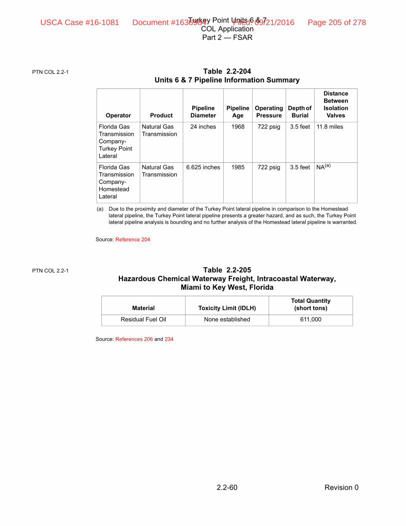
Turkey Point Units 6 & 7COL ApplicationPart 2 — FSAR
Revision 02.2-60
Source: Reference 204
Source: References 206 and 234
Table 2.2-204Units 6 & 7 Pipeline Information Summary
Operator ProductPipeline Diameter
Pipeline Age
Operating Pressure
Depth of Burial
Distance Between Isolation Valves
Florida Gas Transmission Company-Turkey Point Lateral
Natural Gas Transmission
24 inches 1968 722 psig 3.5 feet 11.8 miles
Florida Gas Transmission Company-Homestead Lateral
Natural Gas Transmission
6.625 inches 1985 722 psig 3.5 feet NA(a)
(a) Due to the proximity and diameter of the Turkey Point lateral pipeline in comparison to the Homestead lateral pipeline, the Turkey Point lateral pipeline presents a greater hazard, and as such, the Turkey Point lateral pipeline analysis is bounding and no further analysis of the Homestead lateral pipeline is warranted.
Table 2.2-205Hazardous Chemical Waterway Freight, Intracoastal Waterway,
Miami to Key West, Florida
Material Toxicity Limit (IDLH)Total Quantity(short tons)
Residual Fuel Oil None established 611,000
PTN COL 2.2-1
PTN COL 2.2-1
USCA Case #16-1081 Document #1636984 Filed: 09/21/2016 Page 205 of 278

Turkey Point Units 6 & 7COL ApplicationPart 2 — FSAR
Revision 02.2-61
(a) 500d2 movements per year for sites within 5 to 10 miles and 1000d2 movements per year for sites outside 10 miles.
(b) Consistent with RG 1.206, airports with a plant-to-airport distance less than 5 miles from the site is considered regardless of the projected annual operations.
(c) Because the projected number of operations is less than the calculated significance factor, an evaluation for this airport was not conducted.
Source: References 208, 209, 210, and 241
Table 2.2-206Aircraft Operations — Significant Factors
AirportNumber of Operations Distance from Site
SignificanceFactor(a)
Turkey Point Heliport 79 0.6 miles N/A(b)
Homestead Air Reserve Base 36,429 4.76 miles N/A(b)
Ocean Reef Club Airport(c) Sporadic 7.41 miles 27,454
Miami International Airport(c) 386,681(2005 operations)
545,558(2025 projected)
25.5 miles 651,832
PTN COL 2.2-1
USCA Case #16-1081 Document #1636984 Filed: 09/21/2016 Page 206 of 278

Turkey Point Units 6 & 7COL ApplicationPart 2 — FSAR
Revision 02.2-62
Table 2.2-207 (Sheet 1 of 3)Units 1-5 Onsite Chemical Storage — Disposition
Material Toxicity Limit (IDLH) Flammability Explosion Hazard Vapor Pressure Disposition
Acetylene Gas Asphyxiant 2.5–100 percent Vapor may explode 51.370 psi at –76˚F Toxicity Analysis—consider as asphyxiant
Flammability Analysis
Explosion Analysis
Ammonium Hydroxide
300 ppm (as ammonia) 15–28% None listed 854,548 Pa at 293.15˚K Toxicity Analysis
Flammability Analysis
Explosion Analysis
Argon Gas Asphyxiant Not flammable None listed 1,044.630 Pa @117.32˚K
Toxicity Analysis—consider as asphyxiant
Boric Acid None Established Not flammable None listed N/A-solid No further analysis required
Carbon Dioxide 40,000 ppm Not flammable None listed 907.299 psi @ 75˚F Toxicity Analysis and consider as asphyxiant
Chlorine 10 ppm Not flammable None listed 74.040 psi @ 50˚F Toxicity Analysis
Citric Acid None Established 0.28 kg/m3 (dust)–2.29 kg/m3 (dust)
None listed N/A-solid No further analysis required-low vapor pressure(a)
Hydrated Lime(Calcium Hydroxide)
5 mg/m3(b) Not flammable Noncombustible Solid in solution
Solid—in a solution No further analysis required(c)
Hydrazine 50 ppm 4.7–100 percent Vapor may explode 14.4 mm Hg @ 77˚F Toxicity Analysis
Flammability Analysis
Explosion Analysis
Hydrogen Gas Asphyxiant 4.0–75 percent Vapor may explode 1.231 psi @ –434˚F Toxicity Analysis—consider as asphyxiant
Flammability Analysis
Explosion Analysis
Hydrogen Peroxide 75 ppm Not flammable None listed 0.200 psi @ 90˚F Toxicity—screened from further analysis using criteria in RG 1.78—low volume
Lead (In battery) 100 mg/m3 (as lead) Not flammable None listed N/A-solid No further analysis required
PTN COL 2.2-1
USCA Case #16-1081 Document #1636984 Filed: 09/21/2016 Page 207 of 278

Turkey Point Units 6 & 7COL ApplicationPart 2 — FSAR
Revision 02.2-63
Lithium Hydroxide None Established Not flammable None listed N/A-Solid in solution No further analysis required
Lube Oil None Established Combustible-No flammable limits listed
None listed 0.100 psi @ 100˚F No further analysis required—low vapor pressure(a)
Magnesium Oxide 750 mg/m3 Not flammable None listed N/A-solid No further analysis required—low vapor pressure(a)
Mineral Oil 2,500 mg/m3 Combustible-No flammable limits listed
None listed <0.5mm Hg @ 68˚F No further analysis required—low vapor pressure(a)
Muriatic Acid(Hydrochloric Acid)
50 ppm Not flammable None listed 5.975 psi@ 90˚F Toxicity Analysis
Nitrogen Gas Asphyxiant Not flammable None listed 1.931 psi @ –344˚F Toxicity Analysis—consider as asphyxiant
Nitrogen- Liquid Asphyxiant Negligible None listed 1.931 psi @ –344˚F Toxicity Analysis—consider as asphyxiant
Number 2 Fuel Oil/Diesel Fuel
None Established 1.3–6.0 percent None listed 0.100 psi @ 100˚F No further analysis required—low vapor pressure(a)
Number 6 Fuel Oil (Residual Fuel Oil)
None Established 1–5 percent None listed 0.100 psi @ 100˚F No further analysis required—low vapor pressure(a)
Organometallic Magnesium Complex
None Established Not flammable None listed N/A-solid No further analysis required
Oxygen May displace air and cause an oxygen-enriched environment
Not flammable None listed 363, 385 Pa at 104.47˚K Toxicity Analysis—consider for oxygen-enriched environment
Propane 2,100 ppm 2.1–9.5 percent Vapor may explode 837,489 Pa at 293.15˚K Toxicity Analysis
Flammability Analysis
Explosion Analysis/BLEVE
Silicone None Established Not flammable None listed Not available No further analysis required
Sodium Bicarbonate None Established Not flammable None listed N/A-solid No further analysis required
Sodium Hydroxide No established IDLH for solution
Not flammable Noncombustible Solid in solution
Solid—in solution No further analysis required—low vapor pressure(d)
Table 2.2-207 (Sheet 2 of 3)Units 1-5 Onsite Chemical Storage — Disposition
Material Toxicity Limit (IDLH) Flammability Explosion Hazard Vapor Pressure Disposition
PTN COL 2.2-1
USCA Case #16-1081 Document #1636984 Filed: 09/21/2016 Page 208 of 278
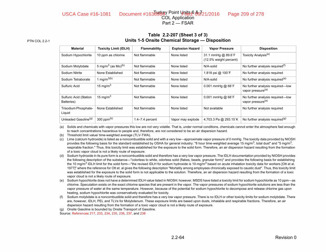
Turkey Point Units 6 & 7COL ApplicationPart 2 — FSAR
Revision 02.2-64
Sodium Hypochlorite 10 ppm as chlorine Not flammable None listed 31.1 mmHg @ 89.6˚F (12.5% weight percent)
Toxicity Analysis(e)
Sodium Molybdate 5 mg/m3 (as Mo)(b) Not flammable None listed N/A-solid No further analysis required(f)
Sodium Nitrite None Established Not flammable None listed 1.818 psi @ 100˚F No further analysis required
Sodium Tetraborate 1 mg/m3(b) Not flammable None listed N/A-solid No further analysis required(a)
Sulfuric Acid 15 mg/m3 Not flammable None listed 0.001 mmHg @ 68˚F No further analysis required—low vapor pressure(a)
Sulfuric Acid (Station Batteries)
15 mg/m3 Not flammable None listed 0.001 mmHg @ 68˚F No further analysis required—low vapor pressure(a)
Trisodium Phosphate- Liquid
None Established Not flammable None listed Not available No further analysis required
Unleaded Gasoline(g) 300 ppm(b) 1.4–7.4 percent Vapor may explode 4,703.3 Pa @ 293.15˚K No further analysis required(g)
(a) Solids and chemicals with vapor pressures this low are not very volatile. That is, under normal conditions, chemicals cannot enter the atmosphere fast enough to reach concentrations hazardous to people and, therefore, are not considered to be an air dispersion hazard.
(b) Threshold limit value/ time-weighted average (TLV-TWA).(c) Lime (calcium hydroxide) is listed as a noncombustible solid and with a very low—approximate vapor pressure of 0 mmHg. The toxicity data provided by NIOSH
provides the following basis for the standard established by OSHA for general industry: "8 hour time-weighted average 15 mg/m3, total dust" and "5 mg/m3, respirable fraction." Thus, this toxicity limit was established for the exposure to the solid form. Therefore, an air dispersion hazard resulting from the formation of a toxic vapor cloud is not a likely route of exposure.
(d) Sodium hydroxide in its pure form is a noncombustible solid and therefore has a very low vapor pressure. The IDLH documentation provided by NIOSH provides the following description of the substance—"colorless to white, odorless solid (flakes, beads, granular form)" and provides the following basis for establishing the 10 mg/m3 IDLH limit for the solid form—"the revised IDLH for sodium hydroxide is 10-mg/m3 based on acute inhalation toxicity data for workers [Ott et al. 1977]" where the reference for Ott et. al gives the following description "Mortality among employees chronically exposed to caustic dust". Thus, this toxicity limit was established for the exposure to the solid form is not applicable to the solution. Therefore, an air dispersion hazard resulting from the formation of a toxic vapor cloud is not a likely route of exposure.
(e) Sodium hypochlorite does not have a determined IDLH value listed in NIOSH; however, MSDS have listed a toxicity limit for sodium hypochlorite as 10 ppm—as chlorine. Speculation exists on the exact chlorine species that are present in the vapor. The vapor pressures of sodium hypochlorite solutions are less than the vapor pressure of water at the same temperature. However, because of the potential for sodium hypochlorite to decompose and release chlorine gas upon heating, sodium hypochlorite was conservatively evaluated for toxicity.
(f) Sodium molybdate is a noncombustible solid and therefore has a very low vapor pressure. There is no IDLH or other toxicity limits for sodium molybdate. There are, however, IDLH, PEL and TLVs for Molybdenum. These exposure limits are based upon dusts, inhalable and respirable fractions. Therefore, an air dispersion hazard resulting from the formation of a toxic vapor cloud is not a likely route of exposure.
(g) Onsite Gasoline is bounded by Onsite Transport of Gasoline.Source: References 217, 233, 234, 235, 236, 237, and 238
Table 2.2-207 (Sheet 3 of 3)Units 1-5 Onsite Chemical Storage — Disposition
Material Toxicity Limit (IDLH) Flammability Explosion Hazard Vapor Pressure Disposition
PTN COL 2.2-1
USCA Case #16-1081 Document #1636984 Filed: 09/21/2016 Page 209 of 278

Turkey Point Units 6 & 7COL ApplicationPart 2 — FSAR
Revision 02.2-65
Table 2.2-208 (Sheet 1 of 4)Units 6 & 7 Onsite Chemical Storage — Disposition
MaterialToxicity Limit
(IDLH) Flammability Explosion Hazard Vapor Pressure Disposition
FPL Reclaimed Water Treatment Facility
Anionic polymer None Established Not Flammable None Listed Solution No further analysis required—skin/eye irritant only.
Ferric Chloride (47% Solution) 1 mg/m3 (a) Not Flammable Noncombustible solid
Solid—in a solution No further analysis required—TWA established for solid salts—not applicable to solution.(b)
Lime (Ca(OH)2) 5 mg/m3 (a) Not Flammable Noncombustible solid in solution
Solid—in a solution No further analysis required.(c)
Sulfuric Acid (93% Solution) 15 mg/m3 Not Flammable None Listed 0.001 mm Hg @ 68°F No further analysis required.(d)
Methanol (Denitrification) 6,000 ppm 6–36 percent Vapor may explode 96 mmHg @ 68°F Toxicity Analysis
Flammability Analysis
Explosion Analysis
Sodium Hypochlorite (40% Solution) Disinfection
10 ppm as Cl2 Not Flammable None Listed 31.1 mmHg @ 89.6°F (12.5% Weight Percent)
Toxicity Analysis (e)
Alum (49% Solution) (Phosphorus Removal)
None established Not Flammable None Listed Solid—in a solution No further analysis required.
Sodium Bisulfite (40% Solution) (Dechlorination)
5 mg/m3 (a) Not Flammable None Listed Solid—in a solution No further analysis required. TWA established for solid—not applicable to solution.(f)
Sodium Hydroxide (50% Solution) 10 mg/m3 Not Flammable Noncombustible solid in solution
Solid—in a solution No further analysis required. TWA established for solid—not applicable to solution. (g)
Polymer (25% Solution) None established Not Flammable None Listed Solution No further analysis required—skin/eye irritant only.
Circulating Water System
Sodium Hypochlorite—(12 Trade Percent) 10 ppm as Chlorine
Not Flammable None Listed 31.1 mmHg @ 89.6°F (12.5% Weight Percent)
Toxicity Analysis (e)
Sulfuric Acid (93% Solution)—Saltwater 15 mg/m3 Not Flammable None Listed 0.001 mm Hg No further analysis required.(d)
Proprietary Scale Inhibitor—Saltwater (Sodium salt of phosphonomethylate diamine)
Does not contain any substance that has an exposure limit
Not Flammable None Listed Inhalation not a likely route of exposure
No further analysis required.
PTN COL 2.2-1
USCA Case #16-1081 Document #1636984 Filed: 09/21/2016 Page 210 of 278

Turkey Point Units 6 & 7COL ApplicationPart 2 — FSAR
Revision 02.2-66
Circulating Water System (cont.)
Proprietary Scale Inhibitor—Saltwater (Calcium phosphate, zinc, iron, manganese)
None Established Not Flammable None Listed Inhalation not a likely route of exposure
No further analysis required.
Proprietary Scale Inhibitor—Transition from Saltwater to Reclaimed (Silica based scale inhibitor)
None Established Not expected to burn unless all water is boiled away—remaining organics may be ignitable
None Listed Solution No further analysis required.
Proprietary Scale Inhibitor—Reclaimed (High Stress Polymer with PSO)
Does not contain any substance that has an exposure limit
Not Flammable None Listed 16 mmHg @ 100°F No further analysis required.
Service Water System
Sulfuric Acid (93% Solution) (pH Addition) 15 mg/m3 Not Flammable None Listed 0.001 mm Hg No further analysis required.(d)
Proprietary Scale Inhibitor (17.9% Phosphoric Acid)
1,000 mg/m3 Not Flammable None Listed water/phosphoric acid=0.03mmHg
No further analysis required.(h)
Proprietary Dispersant (Calcium phosphate, zinc, iron, manganese)
None Established Not Flammable None Listed Inhalation not a likely route of exposure
No further analysis required.
Sodium Hypochlorite (12 Trade Percent) 10 ppm as Cl2 Not Flammable None Listed 31.1 mmHg @ 89.6°F (12.5% Weight Percent)
Toxicity Analysis (e)
Demineralized Water System
Proprietary Scale Inhibitor—(30% Phosphoric Acid)
1,000 mg/m3 Not Flammable None Listed water/phosphoric acid=0.03mmHg
No further analysis required.(h)
Sodium Bisulfite (25% Solution) 5 mg/m3 (a) Not Flammable None Listed Solid—in a solution No further analysis required. TWA established for solid—not applicable to solution.(f)
Sulfuric Acid (93% Solution) 15 mg/m3 Not Flammable None Listed 0.001 mm Hg No further analysis required.(d)
Reverse Osmosis (RO) Cleaning Chemicals
Proprietary Reverse Osmosis Cleaning Chemical (EDTA Salt, Percarbonate Salt, Phosphonic Acid, Tetrasodium Salt)
None established Not Flammable None Listed Solid—in a solution No further analysis required.
Table 2.2-208 (Sheet 2 of 4)Units 6 & 7 Onsite Chemical Storage — Disposition
MaterialToxicity Limit
(IDLH) Flammability Explosion Hazard Vapor Pressure Disposition
PTN COL 2.2-1
USCA Case #16-1081 Document #1636984 Filed: 09/21/2016 Page 211 of 278

Turkey Point Units 6 & 7COL ApplicationPart 2 — FSAR
Revision 02.2-67
Reverse Osmosis (RO) Cleaning Chemicals (cont.)
Proprietary Reverse Osmosis Cleaning Chemical (Hydroxyalkanoic acid, Inorganic phosphate, EDTA Salt)
None established Not Flammable None Listed Solid—in a solution No further analysis required.
Steam Generator Blowdown System
Hydrazine-oxygen scavenger (35% solution)
50 ppm 4.7–100 percent Vapor may explode 14 mmHg @ 77°F Toxicity Analysis
Flammability Analysis
Explosion Analysis
Carbohydrazide—oxygen scavenger (Shut Down)
None established Not flammable-unless water is boiled away and chemical is heated
None Listed 12 mm Hg @ 20°C No further analysis required.
Morpholine 1,400 ppm(i) 1.4–11.2 percent Vapor may explode 6 mmHg @ 68°F Toxicity Analysis
Flammability Analysis
Explosion Analysis
Standby Diesel Fuel Oil System
No. 2 Diesel Fuel Oil-Diesel Generator Day Tank
None Established 1.3–6.0 percent None Listed 0.100 psi @ 100°F No further analysis required—low vapor pressure.(k)
No. 2 Diesel Fuel Oil-Ancillary Diesel Generator
None Established 1.3–6.0 percent None Listed 0.100 psi @ 100°F No further analysis required—low vapor pressure.(k)
No. 2 Diesel Fuel Oil-Diesel Fire Pump Day Tank
None Established 1.3–6.0 percent None Listed 0.100 psi @ 100°F No further analysis required—low vapor pressure.(k)
Fire Protection System
No. 2 Diesel Fuel Oil None Established 1.3–6.0 percent None Listed 0.100 psi @ 100°F No further analysis required—low vapor pressure.(k)
Plant Gas System
Nitrogen-Liquid Asphyxiant Negligible None Listed 1.931 psi @ -344°F Toxicity Analysis—consider as asphyxiant
Nitrogen Gas Asphyxiant Not Flammable None Listed 1.931 psi @ -344F° Toxicity Analysis—consider as asphyxiant
Hydrogen Gas Asphyxiant 4.0–75 percent Vapor may explode 1.231 psi @ -434°F Toxicity Analysis—consider as asphyxiant
Flammability Analysis
Explosion Analysis
Table 2.2-208 (Sheet 3 of 4)Units 6 & 7 Onsite Chemical Storage — Disposition
MaterialToxicity Limit
(IDLH) Flammability Explosion Hazard Vapor Pressure Disposition
PTN COL 2.2-1
USCA Case #16-1081 Document #1636984 Filed: 09/21/2016 Page 212 of 278

Turkey Point Units 6 & 7COL ApplicationPart 2 — FSAR
Revision 02.2-68
(a) Time Weighted Average (TWA)(b) Ferric chloride in its pure form is a noncombustible solid and therefore has a very low vapor pressure. The IDLH documentation provided by NIOSH provides the following basis for
establishing the 1 mg/m3 TWA limit—"The ACGIH…considers the salts to be irritants to the respiratory tract when inhaled as dusts and mists." Thus, this toxicity limit was established for the exposure to the solid form. Note, there is no IDLH established for this chemical. Therefore, an air dispersion hazard resulting from the formation of a toxic vapor cloud is not a likely route of exposure.
(c) Lime (calcium hydroxide) is listed as a noncombustible solid and with a very low– approximate vapor pressure of 0 mmHg. The toxicity data provided by NIOSH provides the following basis for the standard established by OSHA for general industry: "8 hour time-weighted average 15 mg/m3, total dust" and "5 mg/m3, respirable fraction." Thus, this toxicity limit was established for the exposure to the solid form. Therefore, an air dispersion hazard resulting from the formation of a toxic vapor cloud is not a likely route of exposure.
(d) Sulfuric acid has a very low vapor pressure and therefore an air dispersion hazard resulting from the formation of a toxic vapor cloud is not a likely route of exposure.(e) Sodium hypochlorite does not have a determined IDLH value listed in NIOSH; however, MSDS have listed a toxicity limit for sodium hypochlorite as 10 ppm—as chlorine. Speculation
exists on the exact chlorine species that are present in the vapor. The vapor pressures of sodium hypochlorite solutions are less than the vapor pressure of water at the same temperature. However, because of the potential for sodium hypochlorite to decompose and release chlorine gas upon heating, sodium hypochlorite was conservatively evaluated for toxicity.
(f) Sodium bisulfite in its pure form is a noncombustible solid and therefore has a very low vapor pressure. The IDLH documentation provided by NIOSH provides the following basis for establishing the 5 mg/m3 TWA limit—"the 5-mg/m3 limit was proposed because it represents a limit below that established for physical irritant particulates, and this limit reflects the irritant properties of sodium bisulfite. And, in the judgement of the ACGIH "inhalation of or contact with the dust would result in high local concentrations [of sodium bisulfite] in contact with high local concentrations of sensitive tissue. Thus, this toxicity limit was established for the exposure to the solid form is not applicable to the solution. Note, there is no IDLH established for this chemical. Therefore, an air dispersion hazard resulting from the formation of a toxic vapor cloud is not a likely route of exposure.
(g) Sodium hydroxide in its pure form is a noncombustible solid and therefore has a very low vapor pressure. The IDLH documentation provided by NIOSH provides the following description of the substance—"colorless to white, odorless solid (flakes, beads, granular form)" and provides the following basis for establishing the 10 mg/m3 IDLH limit for the solid form—"the revised IDLH for sodium hydroxide is 10-mg/m3 based on acute inhalation toxicity data for workers [Ott et al. 1977]" where the reference for Ott et. al gives the following description "Mortality among employees chronically exposed to caustic dust". Thus, this toxicity limit was established for the exposure to the solid form is not applicable to the solution. Therefore, an air dispersion hazard resulting from the formation of a toxic vapor cloud is not a likely route of exposure.
(h) Phosphoric acid in its pure form is a noncombustible solid and therefore has a very low vapor pressure. The IDLH documentation provided by NIOSH provides the following basis for the original IDLH of 10,000 mg/m3—according to the Manufacturing Chemists Association, phosphoric acid does not cause any systemic effect and the chance of pulmonary edema from mist or spray inhalation is very remote. And, the basis for the revised IDLH for phosphoric acid, 1,000 mg/m3, is based on acute oral toxicity data in animals. Therefore, an air dispersion hazard resulting from the formation of a toxic vapor cloud is not a likely route of exposure.
(i) The IDLH documentation provided by NIOSH states that based on health considerations and acute inhalation toxicity data in humans and animals, a value of 2000 ppm would have been appropriate for morpholine. However, the revised IDLH for morpholine is 1400 ppm based strictly on safety considerations (i.e., being 10% of the lower explosive limit of 1.4%)
(j) Not used.(k) Diesel Fuel has a low vapor pressure and therefore an air dispersion hazard resulting from the formation of a flammable vapor cloud is not a likely route of exposure.(l) Threshold Limit Value (TLV)(m) Sodium molybdate is a noncombustible solid and therefore has a very low vapor pressure. There is no IDLH or other toxicity limits for sodium molybdate. There are, however, IDLH,
PEL and TLVs for molybdenum. These exposure limits are based upon dusts, inhalable and respirable fractions. Therefore, an air dispersion hazard resulting from the formation of a toxic vapor cloud is not a likely route of exposure.
(n) Ethylene glycol has a low vapor pressure and therefore an air dispersion hazard resulting from the formation of a flammable vapor cloud is not a likely route of exposure.Source: References 217, 233, 234, 235, 247, 248, 249, 250, 251, 252, 253, 254, 255, 256, and 257
Plant Gas System (cont.)
Carbon Dioxide-Liquid 40,000 ppm Not Flammable None Listed 907.299 psi @ 75°F Toxicity Analysis—consider as asphyxiant
Carbon Dioxide Gas 40,000 ppm Not Flammable None Listed 907.299 psi @ 75°F Toxicity Analysis—consider as asphyxiant
Central Chilled Water System
Sodium Molybdate (Corrosion Inhibitor) 5 mg/m3 (as Mo) (l)
Not Flammable None Listed Solid in a solution No further analysis required (m)
Ethylene Glycol None Established 3.2–15.3 percent Vapor may explode 0.003 psi @ 90°F No further analysis required—low vapor pressure.(n)
Table 2.2-208 (Sheet 4 of 4)Units 6 & 7 Onsite Chemical Storage — Disposition
MaterialToxicity Limit
(IDLH) Flammability Explosion Hazard Vapor Pressure Disposition
PTN COL 2.2-1
USCA Case #16-1081 Document #1636984 Filed: 09/21/2016 Page 213 of 278

Turkey Point Units 6 & 7COL ApplicationPart 2 — FSAR
Revision 02.2-69
Table 2.2-209Offsite Chemicals, Disposition — Homestead Air Reserve Base
MaterialToxicity Limit
(IDLH) Flammability Explosion Hazard Vapor Pressure Disposition
Bromotrifluoromethane (Halon 1301)
40,000 ppm Not flammable None listed 1,436,150 Pa at 293.15˚K
Toxicity Analysis
Diesel Fuel Oil (High Sulfur) None Established 1.3–6.0 percent None listed 0.100 @ 100˚F No further analysis required-low vapor pressure(a)
(a) Solids and chemicals with vapor pressures this low are not very volatile. That is, under normal conditions, chemicals cannot enter the atmosphere fast enough to reach concentrations hazardous to people and, therefore, are not considered to be an air dispersion hazard.
Diethylene Glycol Monobutyl Ether
None Established Not flammable None listed 0.159 @ 220˚F No further analysis required
Gasoline 300 ppm(b)
(b) Threshold limit value/ time-weighted average (TLV-TWA).
1.4–7.4 percent Vapor may explode 4,703.3 Pa @ 293.15˚K
Toxicity Analysis
Flammability Analysis
Explosion Analysis
Hydrazine(c) 50 ppm 4.7–100 percent Vapor may explode 14.4 mm Hg @ 77˚F No further analysis required(c)
(c) Homestead Air Reserve Base storage of hydrazine and nitrogen is bounded by Turkey Point onsite storage of hydrazine and nitrogen.Source: References 217, 233, 234, and 235
Jet Fuel 200 mg/m3(b) 0.6–4.9 percent Vapor may explode 0.1 psi @ 100˚F Explosion Analysis—no flammability/toxicity analysis required low vapor pressure(a)
Nitrogen Gas(c) Asphyxiant Not flammable None listed 1.93 psi @ –344˚F No further analysis required(c)
Oxygen May displace air and cause an oxygen enriched environment
Not flammable None listed 363,385 Pa at 104.47˚K
Toxicity Analysis-consider for oxygen enriched environment
Propane 2,100 ppm 2.1–9.5 percent Vapor may explode 837,489 Pa at 293.15˚K
Toxicity Analysis
Flammability Analysis
Explosion Analysis
PTN COL 2.2-1
USCA Case #16-1081 Document #1636984 Filed: 09/21/2016 Page 214 of 278

Turkey Point Units 6 & 7COL ApplicationPart 2 — FSAR
Revision 02.2-70
Table 2.2-210Transportation — Navigable Waterway, Turkey Point Lateral Pipeline, and
Onsite Transportation Route — Disposition
MaterialToxicity Limit
(IDLH) Flammability Explosion Hazard Vapor Pressure Disposition
Navigable Waterway
Residual Fuel Oil None established
1–5 percent None listed 0.100 psi @ 100°F No further analysis required—hazard analysis bounded by residual fuel storage at Units 1–5 (a) (c)
(a) Solids and chemicals with vapor pressures this low are not very volatile. That is, under normal conditions, chemicals cannot enter the atmosphere fast enough to reach concentrations hazardous to people and, therefore, are not considered to be an air dispersion hazard.
Turkey Point Lateral Pipeline
Natural Gas (methane)
Asphyxiant 5–15 percent Vapor may explode 258,574.0 mm Hg @ 100°F
Toxicity Analysis-consider as asphyxiant
Flammability Analysis
Explosion Analysis
Onsite Transportation Route
Unleaded Gasoline 300 ppm(b)
(b) Threshold limit value/ time-weighted average (TLV-TWA).(c) As described in Subsection 2.2.2.4, because of the storage of residual fuel oil at the Turkey Point site, (2) 268,000 barrel tanks exceeds the quantity transported
by a barge, the analysis of residual fuel oil located in the storage tanks is bounding and, therefore, no further analysis is required.Source: References 217, 233, 234, and 235
1.4–7.4 percent Vapor may explode 4,703.3 Pa @ 293.15°K
Toxicity Analysis
Flammability Analysis
Explosion Analysis
PTN COL 2.2-1
USCA Case #16-1081 Document #1636984 Filed: 09/21/2016 Page 215 of 278

Turkey Point Units 6 & 7COL ApplicationPart 2 — FSAR
Revision 02.2-71
Source: References 217 and 240
Table 2.2-211 Atmospheric Input data for the ALOHA Model
Menu Parameter Input Basis
Site Atmospheric Data
Site Data Number of Air Exchanges
0.391 air exchanges per hour
Outdoor air exchange rate for control room
Site Data Date and Time June 21, 2007/June 20, 2008
See Table 2.2-212 for Times
June 21, 2007/June 20, 2008 at 12 noon was chosen because temperatures are highest in the summer during midday. Higher temperatures lead to a higher evaporation rate and thus a larger vapor cloud. The position of the sun for the date and time is used in determining the solar radiation, thus the summer solstice date will provide the most conservative assumption for solar radiation.
June 21, 2007/June 20, 2008 at 5 am was chosen for those Pasquill classes defined as “nighttime.”
Setup/Atmospheric Wind Measurement Height
10 meters ALOHA calculates a wind profile based on where the meteorological data is taken. ALOHA assumes that the meteorological station is at 10 meters. The National Weather Service usually reports wind speeds from a height of 10 meters. Wind rose data for this project was also taken at a height of 10 meters. Additionally, the surface wind speeds for determining the Pasquill Stability Class are defined at 10m.
Setup/Atmospheric Air Temperature 90.4ºF Air temperature influences ALOHA’s estimate of the evaporation rate from a puddle surface (the higher the air temperature, the more the puddle is warmed by the air above it, the higher the liquid’s vapor pressure is, and the faster the substance evaporates). The maximum annual normal (1% exceedance) annual dry bulb temperature calculated, 90.4˚F, was selected as a conservative value.
Setup/Atmospheric Inversion Height None An inversion is an atmospheric condition that serves to trap the gas below the inversion height thereby not allowing it to disperse normally. Inversion height has no affect on the heavy gas model. And, most inversions are at heights much greater than ground level.
Setup/Atmospheric Humidity 50% ALOHA uses the relative humidity values to estimate the atmospheric transmissivity value; estimate the rate of evaporation from a puddle; and make heavy gas dispersion computations. Atmospheric transmissivity is a measure of how much thermal radiation from a fire is absorbed and scattered by the water vapor and other atmospheric components.
PTN COL 2.2-1
USCA Case #16-1081 Document #1636984 Filed: 09/21/2016 Page 216 of 278

Turkey Point Units 6 & 7COL ApplicationPart 2 — FSAR
Revision 02.2-72
Source: References 217 and 239
Table 2.2-212ALOHA Meteorological Sensitivity Analysis Inputs
Stability ClassSurface Wind Speed
(m/s) Cloud Cover Date/Time
A 1.5 0% June 21, 2007/12 noon or June 20, 2008/12 noon
B 1.5 50% June 21, 2007/12 noon or June 20, 2008/12 noon
B 2 0% June 21, 2007/12 noon or June 20, 2008/12 noon
C 3 70% June 21, 2007/12 noon or June 20, 2008/12 noon
E 2 50% June 21, 2007/5 am or June 20, 2008/5 am
F 2 0% June 21, 2007/5 am or June 20, 2008/5 am
F 3(only modeled for vapor
clouds taking greater than 1 hour to reach the
control room)
0% June 21, 2007/5 am or June 20, 2008/5 am
C 3 50% June 21, 2007/12 noon or June 20, 2008/12 noon
D 3 50% June 21, 2007/5 am or June 20, 2008/5 am
C 5.5 0% June 21, 2007/12 noon or June 20, 2008/12 noon
D 5.5 50% June 21, 2007/12 noon or June 20, 2008/12 noon
PTN COL 2.2-1
USCA Case #16-1081 Document #1636984 Filed: 09/21/2016 Page 217 of 278

Turkey Point Units 6 & 7COL ApplicationPart 2 — FSAR
Revision 02.2-73
Table 2.2-213Design Basis Events — Explosions
SourceChemical Evaluated Quantity
Heat of Combustion
(Btu/lb)
Distance to Nearest
Safety-Related Structure
Safe Distance for Explosion to have less than 1 psi of
Peak Incident Pressure
Thermal Radiation Heat Flux Resulting from a BLEVE
Road: Onsite Transport Gasoline 50,000 pounds 18,720 Btu/lb 2,054 feet 266 feet N/A
Pipeline: Turkey Point Lateral
Natural Gas 30,302 pounds(b)
(b) Quantity of natural gas released over 5 seconds after a postulated pipeline rupture.
21,517 Btu/lb 4,535 feet 3,097 feet N/A
Onsite (Includes Units 1 thru through 5)
Acetylene 3,000 pounds 20,747 Btu/lb 4,300 feet 1,416 feet N/A
Ammonium Hydroxide
40,000 gallons 7,992 Btu/lb 5,079 feet 296 feet N/A
Hydrazine 1,100 gallons 8,345 Btu/lb 2,727 feet 170 feet N/A
Hydrogen 110,000 cubicfeet(c)
(c) Conservatively, the total hydrogen gas capacity for Units 1–5 was evaluated in lieu of the volume of the largest container.
50,080 Btu/lb 3,966 feet 1,098 feet N/A
Propane 500 gallons 19,782 Btu/lb 4,168 feet 1,299 feet 0.0878 kW/m2
Onsite (IncludesUnits 6 & 7)
Methanol 25,000 gallons 8,419 Btu/lb 5,581 feet 344 feet N/A
Hydrazine(35% solution)
800 gallons 8,345 Btu/lb 218 feet 153 feet N/A
Morpholine 800 gallons 20,000 Btu/lb 218 feet 136 feet N/A
Hydrogen(a)
(a) A simultaneous detonation of all the tubes contained in a 40,000 scf hydrogen tube bank is not a likely scenario. If a rupture and subsequent detonation of a single tube were to occur the event could likely trigger another tube failure and detonation, but these events would occur consecutively, not simultaneously. Therefore, detonation of mass from a single tube in hydrogen bank is the most plausible scenario; however, for conservatism, it was assumed that a catastrophic accident could result such that one-third of the tubes could rupture and detonate simultaneously.
13,334 standardcubic feet
50,080 Btu/lb 560 feet 544 feet N/A
Offsite (Homestead Air Reserve Base)
Gasoline 137,104 pounds 18,720 Btu/lb 25,133 feet 372 feet N/A
Jet Fuel 23,251,606pounds
18,540 Btu/lb 2,232 feet N/A
Propane 185,865 pounds 19,782 Btu/lb 5,513 feet N/A
PTN COL 2.2-1
USCA Case #16-1081 Document #1636984 Filed: 09/21/2016 Page 218 of 278

Turkey Point Units 6 & 7COL ApplicationPart 2 — FSAR
Revision 02.2-74
Table 2.2-214Design-Basis Events, Flammable Vapor Clouds (Delayed Ignition) and Vapor Cloud Explosions
SourceChemical Evaluated &
Quantity
Distance to Nearest
Safety-Related Structure Distance to LFL(a)
(a) Worst-case scenario meteorological condition was F stability class at two meters per second
Safe Distance for Vapor Cloud
Explosions (a)
Thermal Radiation Heat Flux at
Nearest Safety-Related
Structure
Road: Onsite Transport Gasoline(50,000 pounds)
2,054 feet 222 feet 780 feet 2.776 kW/m2
Pipeline: Turkey Point Lateral
Natural Gas 4,535 feet 750 feet 3,033 feet 0.261 kW/m2(b)
(b) Thermal radiation heat flux resulting from a jet fire at the pipeline break.
Onsite (Includes Units 1 through 5)
Acetylene (3,000 pounds)
4,300 feet 909 feet 1,242 feet 0.162 kW/m2
Ammonium Hydroxide(40,000 gal)
5,079 feet 525 feet(c)
(c) Urban or Forest ground roughness selected
1,407 feet (c) 0.900 kW/m2
Hydrazine (1,100 gal) 2,727 feet 42 feet No Detonation(d)
(d) “No detonation" is listed when ALOHA reports that there is no detonation of the formed vapor cloud-that is no part of the cloud is above the LEL at any time.
0.271 kW/m2
Hydrogen (45,000 scf) 3,966 feet 720 feet 828 feet 0.033 kW/m2
Propane (500 gal) 4,168 feet 714 feet 1,416 feet 0.090 kW/m2
Onsite (Includes Units 6 & 7) Hydrazine (800 gal)(35% solution)
218 feet < 33 feet(c) No Detonation(c)(d)
N/A
Hydrogen Tube Bank (40,000 scf)
560 feet 351 feet(c) 528 feet(c) 2.344 kW/m2
Methanol (25,000 gal) 5,581 feet 177 feet 444 feet 0.592 kW/m2
Morpholine (800 gal) 218 feet < 33 feet No Detonation(c)(d)
N/A
Offsite (Homestead Air Force Base)
Gasoline (137,104 lb) 25,133 feet 396 feet 1,260 feet 0.051 kW/m2
Propane (185,865 lb) 2,190 feet 4,770 feet 0.078 kW/m2
PTN COL 2.2-1
USCA Case #16-1081 Document #1636984 Filed: 09/21/2016 Page 219 of 278

Turkey Point Units 6 & 7COL ApplicationPart 2 — FSAR
Revision 02.2-75
Table 2.2-215 (Sheet 1 of 2)Design-Basis Events, Toxic Vapor Clouds
Source Chemical Quantity IDLH(a)
Distance to Nearest Control
Room (feet)Distance to IDLH (feet)
Maximum Control Room Concentration
(ppm)
Road: Onsite Transport Gasoline 50,000 pounds 300 ppm(b) 2,084 1,962 69.9(d)
Pipeline: Turkey Point Lateral
Natural Gas 2,036,620 pounds Asphyxiant 4,535 3,456 523
Onsite (Includes Units 1 through 5)
Acetylene 3,000 pounds Asphyxiant 4,331 2,169 45.9(d)
Ammonium Hydroxide(c)
40,000 gallons 300 ppm 5,110 15,312 239(d)(c)
Argon 3,000 pounds Asphyxiant 4,001 42 10.8(d)
Carbon Dioxide 9,000 pounds 40,000 ppm 4,001 672 93.3(d)
Chlorine 150 pounds 10 ppm 2,994 3,603 0.824(d)
Hydrazine 1,100 gallons 50 ppm 2,758 2,181 8.52(d)
Hydrogen 45,000 scf Asphyxiant 4,001 264 53.9(d)
Muriatic Acid 110 gallons 50 ppm 4,429 2,175 0.966(d)
Nitrogen Gas 100,000 scf Asphyxiant 3,596 396 144(d)
Nitrogen Liquid 3,500 gallons Asphyxiant 3,596 831 122(d)
Oxygen 3,000 pounds May displace airand cause an
oxygen enrichedenvironment
4,329 72 14.9(d)
Propane 500 gallons 2100 ppm 4,198 1,626 5.83(d)
Sodium Hypochlorite 6,000 gallons 10 ppm asChlorine
5,232 90 0.00467(c)(d)
PTN COL 2.2-1
USCA Case #16-1081 Document #1636984 Filed: 09/21/2016 Page 220 of 278

Turkey Point Units 6 & 7COL ApplicationPart 2 — FSAR
Revision 02.2-76
(a) Immediately Dangerous to Life or Health (IDLH)(b) Threshold Limit Value/ Time-Weighted Average (TLV-TWA)(c) Calculation was modeling selecting the Urban or Forest for Ground Roughness(d) Worst-case scenario meteorological condition was F stability class at two meters per second(e) Worst-case scenario meteorological condition was F stability class at three meters per second(f) Worst-case scenario meteorological condition was D stability class at 5.5 meters per second
Onsite (Includes Units 6 & 7)
Carbon Dioxide 12,160 pounds 40,000 ppm 561 feet 411 feet 1,380 ppm(c)(d)
Carbon Dioxide- Liquid
12,000 pounds 40,000 ppm 561 feet 951 feet 1,400 ppm(c)(d)
Hydrazine(35% solution)
800 gallons 50 ppm 253 feet 432 feet 30.7 ppm(c)(d)
Hydrogen Tube Bank 40,000 standardcubic feet
Asphyxiant 561 feet N/A 521 ppm(c)(d)
Methanol 25,000 gallons 6,000 ppm 5,660 feet 1,128 feet 76.8 ppm(d)
Morpholine 800 gallons 1,400 ppm 253 feet < 33 feet 18.3 ppm(c)(d)
Nitrogen 20,34.2 pounds Asphyxiant 561 feet N/A 363 ppm(c)(d)
Nitrogen-Liquid 1,500 gallons Asphyxiant 561 feet N/A 885 ppm(c)(d)
Sodium Hypochlorite (Reclaimed Water Treatment Facility)
20,000 gallons 10 ppm asChlorine
5,660 feet 306 feet 0.0412 ppm(d)
Sodium Hypochlorite (Cooling Tower)
12,000 gallons 10 ppm asChlorine
807 feet 240 feet 0.349 ppm(d)
Sodium Hypochlorite (Turbine Building)
800 gallons 10 ppm asChlorine
253 feet < 33 feet 0.0454 ppm(c)(d)
Offsite (Homestead Air Reserve Base)
Halon 1301 5,440 pounds 40,000 ppm 25,133 feet 156 feet 0.0154 ppm(e)
Gasoline 137,104 pounds 300 ppm(b) 3,210 feet 1.12 ppm(f)
Oxygen 36,561 pounds May displace airand cause an
oxygen enrichedenvironment
243 feet 5.31 ppm(e)
Propane 185,865 pounds 2,100 ppm 8,448 feet 11.2 ppm(e)
Table 2.2-215 (Sheet 2 of 2)Design-Basis Events, Toxic Vapor Clouds
Source Chemical Quantity IDLH(a)
Distance to Nearest Control
Room (feet)Distance to IDLH (feet)
Maximum Control Room Concentration
(ppm)
PTN COL 2.2-1
USCA Case #16-1081 Document #1636984 Filed: 09/21/2016 Page 221 of 278

Turkey Point Units 6 & 7COL ApplicationPart 2 — FSAR
Revision 02.2-77
Figure 2.2-201 Site Vicinity MapPTN COL 2.2-1
USCA Case #16-1081 Document #1636984 Filed: 09/21/2016 Page 222 of 278

Turkey Point Units 6 & 7COL ApplicationPart 2 — FSAR
Revision 02.2-78
Figure 2.2-202 Airport and Airway MapPTN COL 2.2-1
USCA Case #16-1081 Document #1636984 Filed: 09/21/2016 Page 223 of 278

Attachment 2: Calculation 32-2400572-02,
“Natural Gas Pipeline Hazard Risk Determination” by Framatome ANP
USCA Case #16-1081 Document #1636984 Filed: 09/21/2016 Page 224 of 278

ATTACHMENT 2
Calculation 32-2400572-02,"Natural Gas Pipeline Hazard Risk Determination"
USCA Case #16-1081 Document #1636984 Filed: 09/21/2016 Page 225 of 278

20697P.6 (2=002)
ACALCULATLON SUMMARY SHEET (CSS)FRAMATOME ANP
Document Identifier 32 - 2400572 - 02Title Natural Gas Pipeline Hazard Risk Determination
REVIEWED BY:PREPARED BY: METHOD: DETAILED CHECK [a INDEPENDENTCALCULATION
NAME S.T. Thomson NAME J.H. Snooks
SIGNATURE Ad aj d1i SIGNATURE
TITLE Sr Engineer DATE TITLE v Consultant DATE 1'
COST CENTER 41739 REF. PAGE(S) 9 TM STATEMENT. REVIEWER INDEPENDENCE
This document Including the information contained herein and any associated drawings, is the property of FramatorneANP, Inc. It contains confidential Information and may not be reproduced or copied in whole or in part nor may it befurnished to others without the expressed written permission of Framatome ANP, Inc., nor may any use be made of Itthat is or may be injurious to Framatome ANP, Inc. This document and any associated drawings and any copies thatmay have been made must be returned upon request.
PURPOSE AND REASON FOR REVISION 02:
This calculation has been revised to include the natural gas transmission Incident data and telephonic Incident notifications asan attachment. Also, the number of explosions was increased from six to seven to Include an incident where both an ignition
'explosion occurred (I.e., NRC no. 437627). Therefore, the estimated gas line rupture and subsequent hazards yearlylability was recalculated and has been revised to 9.44x1 04.
Document Pagination
Cover & Document 1-13 Attachment 6 26-27Attachment 1 14 Attachment 7 28Attachment 2 15-16 Attachment 8 29-31Attachment 3 17, including 17abc,def,g & h Attachment 9 32-37Attachment 4 18-23 Attachment 10 38-42Attachment 5 24-25 Attachment 11 43-45
THE FOLLOWING COMPUTER CODES HAVE BEEN USED IN THIS DOCUMENT: THE DOCUMENT CONTAINS ASSUMPTIONS THATMUST BE VERIFIED PRIOR TO USE ON SAFETY-
RELATED WORK
CODENERSIONIREV CODENERSIONMEV
_ YES F NOI , . _
Page 1 of 45. including pages 17a through 17h
USCA Case #16-1081 Document #1636984 Filed: 09/21/2016 Page 226 of 278

Document No. 32-2400572-02Natural Gas Pipeline Hazard Risk Determination Revision 21
Page 2 of 45
Record of Revisions
Affected Section Descriptionand/or Page(s) (Include changes to calculation attachments, microfiche, and electronic media)
Revision 01 Dated December 12, 2003.
Pg 2 Added Record of Revisions page as required by procedure.
Pg 3 Revised Table of Contents page numbers corresponding to calculation sections andattachments.
Attachment 4 (Pg Revised Section 6.0 to note use of a computer benchmark test case.21)
Attachment 10 (Pgs Added ALHOA benchmark test case.38-42)
Attachment 11 (Pgs Added Design Verification Checklist as required by procedure, effective43-45) I 126/2003.
Valid and current pages: 1-45
Revision 02 Dated January 16, 2004 - new CSSPg 2 Added Record of Revisions associated with Revision 2TOC, Pg 3 Table of Contents - Revised heading for Attachment 3Sec. 2.0, Pg 4 Vt paragraph, 4"' sentence - inserted '(transmitted)' after 4being sent".Sec. 3.0, Pg 5 For equation 'P', changed 'Missile impact' to 'Missile generation'.Sec. 5.0, Pg S Revised Input/Assumption No.3 - deleted 'and hence will be neglected in the
probabilistic evaluation' and added the following: 'If a rupture length is notf reported, it is assumed to be zero.'
Sec. 6.1, Pg 5 Revised wording for '1' (i.e.. included the word 'rupture').Sec. 6.1.1, Pg 6 3" paragraph, 6 sentence -added the following: - '(see Table 1, Note 8)'.Sec. 6.1.2, Pg 6 1' paragraph, 2" sentence - added 'be' between 'must' and 'an'. Revised the 1st
sentence of 2" paragraph and revised 'Rcl'.Sec. 6.1.A, Pg 7 Revised 'Sec. 6.2, Pg 8 Last sentence, changed 'detonation' to 'explosion' probability and revised 'P,,,L,
remd iW.
Sec. 6A., Pg 8 Revised 'P'Sec. 7.0, Pg 9 Revised yearly probability from 8.08x 10⁴ to 9.44x 10⁴, 2nd sentence of last
__ paragraph.Table 1, Pg 11 Revised table input and Notes 1, 3 and 4. Added Notes 5 through 8.Attachment 3 Revised Pg 17: added reference source information for the table attachment.
Also added pages 17abcdefg&h - Incidents and Telephonic Records 1998 -2001 as well as noted this on Pg 17.
Attachment 11 Replaced the Design Verification Checklist for Revision I with that for Revision2.
Valid and current pages: 145, including 17a,bcdefg&h
USCA Case #16-1081 Document #1636984 Filed: 09/21/2016 Page 227 of 278

Document No. 32-2400572.02Natural Gas Pipeline Hazard Risk Determination Revision 2 |
. Page 3 of 45
TABLE OF CONTENTS
1.0 PURPOSE AND OBJECTIVE .................................. 4
2.0 BACKGROUND..................................................................................................................4
3.0 METHOD OF ANALYSIS .5
4.0 ACCEPTANCE CRITERIA .5
5.0 INPUT & ASSUMPTIONS .5
6.0 ANALYSIS AND RESULTS .5
6.1 Probability of Pipeline Explosion .5
6.2 Probability of Missile Hazard .86.3 Probability of Thermal Hazard .8
6.4 Probability of Hazard due to Gas Pipeline .8
7.0 RESULTS AND CONCLUSIONS .9
8.0 REFERENCES .9
9.0 QUALITY ASSURANCE .10
Figure 1, Location of Pipeline near the Proposed NEF Site .. 12
Figure 2, NEF Site Plan .. 13
Attachment 1: Incident Summary Statistics from 1986 to 2002 . .14
Attachment 2: Incident Summary by Cause, 1998, 1999, 2000 and 2001 . .15
Attachment 3: Natural Gas Transmission Pipeline Annual Mileage and Incidents and TelephonicRecords 1998 -2001 .. 17
Attachment 4: Calculation of Distances DI and D2 . . 18
Attachment 5: Gas Line Telephone Chronology .. 24
Attachment 6: Fire Protection Handbook .. 26
Attachment 7: Seabrook Station UFSAR .. 28
Attachment 8: SFPE Handbook of Fire Protection Engineering . .29
Attachment 9: TVA PSAR, Hartsville Nuclear Plants .. 32
Attachment 10: ALOHA Benchmarking Test Case .. 38
Attachment 11: Design Verification Checklist .. 43
USCA Case #16-1081 Document #1636984 Filed: 09/21/2016 Page 228 of 278

. Document No. 32-2400572-02Natural Gas Pipeline Hazard Risk Determinatign Revision 2
Page 4of45
1.0 PURPOSE AND OBJECTIVE
This calculation evaluates the hazard at the proposed National Enrichment Facility (NEF) inEunice, New Mexico due to the presence of a natural gas pipeline.
The evaluation is part of the Integrated Safety Analysis (ISA) for the proposed site, as requiredby 10 CFR Part 70. It was performed in accordance with the Framatome ANP (FANP) QualityAssurance Program.
2.0 BACKGROUND
A 16-inch natural gas line runs along the southern boundary of Section 32, Township 21 South,Range 38 East, New Mexico Meridian, Lea County, New Mexico. The proposed NEF site(Figure 1) is situated north of New Mexico Highway 234 within Section 32. Sid RichardsonEnergy Services Co. (SRESCo), located in Jal, New Mexico, operates the pipeline. Informationgathered from SRESCo via telephone revealed that the pipeline is a low-pressure line (<50 psi)that carries "wet sour gas," which is unprocessed, field gas from the well being sent (transmitted)for processing (Attachment 5). The gas line is buried to a depth of about 3 feet. The gascomposition is approximately 72% methane, 11% ethane, 7% propane, and <1% hydrogensulfide. The gas line flow is between 200-500 thousand cubic feet per day. It is 14-15 miles inlength, with manual block valves at each end and in the middle. There also is a check valve atthe connection with the main service line located near Eunice and Highway 234. At its closestapproach, the pipeline is about 1800 feet (ft) from the Technical Services Building (TSB), thenearest critical NEF structure (Figures 1 and 2).,
Following a postulated rupture of a segment of the gas pipeline shown in Figure 1, natural gaswill be discharged into the atmosphere. The released gas mixes with the atmosphere and forms avapor cloud. Depending on the environmental conditions, this vapor cloud will rise (due tobuoyancy effects) and travel away from the rupture location. The vapor cloud may explode (ordetonate). When this occurs, the shock wave associated with such an explosion may create anoverpressure on plant structures. Also, the dynamic impulse from such an explosion may propelobjects or missiles in the vicinity of the explosion towards the NEF structures and maystructurally damage critical buildings. Alternatively, the vapor cloud may ignite and form afireball, resulting in radiant heat that could cause potential structural damage.
Based on the above discussion, the hazards posed by an accidental rupture of the gas pipelinetherefore consist of:
a. Overpressure on plant structures due to shock waves generated by detonation orexplosion of the gas cloud from mixing of the released gas and the atmosphere.
b. Impact by missiles propelled by air bursts from detonation or explosion of the gascloud.
c. Radiant heat flux on plant structures due to combustion of the gaslair mixture in thegas cloud (thermal impact).
USCA Case #16-1081 Document #1636984 Filed: 09/21/2016 Page 229 of 278

| Document No. 32-2400572-02 INatural Gas Pipeline Hazard Risk Determination I Revision 2
.I Page 5 of 45
3.0 METHOD OF ANALYSIS
This calculation uses a hazard model to estimate the likelihood of a gas line rupture andsubsequent hazards that could impact NEF plant operations. In its general form, the probability,P. of an incident occurring that affects plant structures is
P = PEXpiOSI.II + PMissile twmon+ P~hm. impCt
4.0 ACCEPTANCE CRITERIA
A natural gas pipeline incident is an external event. In accordance with NUREG-1520, Section3.4 (Reference 1), an external event is considered not credible if the probability of the eventinitiation is less than IO per year. If the probability is greater than 104 per year, the event isconsidered credible and must be evaluated further.
5.0 INPUT & ASSUMPTIONS
The analysis input and assumptions are as follows:
1. The pipeline diameter is 16 inches, with an operating pressure of 50 psi (Attachment5).
2. The gas released is methane, which is the major constituent of wet sour gas(Attachment 5).
3. Ruptures less than 0.1 foot in length are assumed to be unable to cause a plant hazard.If a rupture length is not reported, it is assumed to be zero.
4. The external walls of the proposed NEF buildings that house critical components aremade of concrete (Reference 10) and able to withstand an explosion as determined bythe safe separation distance in Regulatory Guide 1.91 (Reference 3).
6.0 ANALYSIS AND RESULTS
6.1 Probability of Pipeline Explosion
The general form for the probability of a pipeline explosion is
P=IxRcxD
where,I = gas line rupture incident rate per mileRC = conditional probability that a significant incident will occur given an incidentD = exposure distance in miles
USCA Case #16-1081 Document #1636984 Filed: 09/21/2016 Page 230 of 278

Document No. 32-2400572.02. Natural Gas Pipeline Hazard Risk Determination Revision 2
. . .Page 6 of 45 .
6.1.1 Probability of Pipeline Incident (I)
Historical data on pipeline accidents are available through the Office of Pipeline Safety (OPS)official website (Reference 7). Attachment I shows the incident summary statistics from 1986 to2002. Attachment 2 contains the incident summary by cause for years 1998, 1999, 2000, and2001. Data from these four years will be used to evaluate the yearly probability of a piperupture. The annual mileage of natural gas transmission pipelines in the country is given inAttachment 3. Only the "onshore" mileage is used in this evaluation.
Also available from the OPS website (Reference 7) are the detailed account of each reportedincident, including incident address, incident date, type of incident and rupture length for arupture incident as well as telephonic records of incidents involving chemical releases. Thetelephonic records contain information on incident description, and are used here to determinethe number of incidents that involve explosions.
Table I synthesizes the information in Attachments 1 through 3, the detailed transmissionincident accounts, and the telephonic incident notifications for years 1998 to 2001. Thetelephonic records for 1998 and 2001 are only from January to June of each year. The number ofon-shore rupture incidents and total mileage for these two years, as a result, are divided by two.The number of incidents that involve an explosion is determined from the telephonic records. Ifno telephonic records exist, or no mention is made of an explosion for an incident, no explosionis assumed for that incident. This is reasonable since an explosion would be reported if it didoccur (see Table 1, Note 8). Also, if a rupture length is not reported, it is assumed to be zero.Only rupture incidents with a rupture length of greater than 0.1 ft are able to cause a plant hazard(Input/Assumption 3).
From Table 1, the annual incident rupture rate is
I = 50 rupturesl873,305 miles = 5.73 x 10O5 ruptures/mile
Hence, the probability of rupture of the pipeline under evaluation is 5.73 x 10`5 ruptures per mile.
6.1.2 Conditional Probability of Significant Incident (Rc)
The conditional probability of a significant incident, Rc, has two parts. Given a pipelineincident, in this case a rupture, there must be an explosion (Rct), and given an explosion it mustbe substantial (Rc2) - i.e., be a detonation to affect plant buildings.
From Table 1, seven ruptures out of the 50 (with a rupture length greater than 0.1 foot) involvedexplosions. Hence the fraction of explosion events is
RcI = 7/50 = 0.14
* As of the date of this calculation, transmission data for 2002 to the present was available; however, telephonicincident notifications through 2001 were only available. Thercfore, this calculation is based on data between 1998and 2001.
USCA Case #16-1081 Document #1636984 Filed: 09/21/2016 Page 231 of 278

. Document No. 32-2400572-02Natural Gas Pipeline Hazard Risk Determination Revision 2
I Page 7 of 45
As stated above, given an explosion it must be significant - i.e., a detonation, but not everyexplosion is a detonation. Instead, most explosions are deflagrations, which produce much lesssevere consequences than a detonation. Reference 5 suggests a denotation rate, R. 2, given anexplosion of 0.28, which is considered conservative (Attachment 7). Therefore, in thiscalculation,
RC2 = 0.28
6.1.3 Exposure Distance (D)
The exposure distance, D, is a function of the safe separation distance. If an explosion occursbeyond the safe separation distance for a plant critical structure, then the structures will beunaffected.
The exposure distance has two parts: the distance to the gas upper and lower explosion limits(UEL and LEL), DI, and the safe separation distance, D2. Di is determined by employing thecomputer program ALOHA (Reference 6) to calculate the concentrations of gas from apostulated gas release along a direct pathway to the NEF. D2 is determined followingRegulatory Guide 1.91 (Reference 3) and using the ALOHA results.
As shown in Attachment 4, DI, the distance to the LEL is 4,095 ft and D2, the safe separationdistance, is 1,471 ft., for a total of 5,566 ft. This means that NEF critical structures must be atleast 5,566 ft (1.05 miles) from the point of explosion. Using this distance as a radius, thenswinging an arc from the approximate edge of the TSB, intersects the gas pipeline at two points(Figure 1). The distance of the cord between the two points is the exposure distance, D (Figure1), with the maximum distance possible being two times the radius. Hence, for conservatism,
D= 2x 1.05 =2.1 miles
6.1.4 Final Probability of Pipeline Explosion
The final probability of a pipeline explosion is
P~xpl,.in = 5.73 x 10⁵ ruptures (explosions)/mile x 0.14 x 0.28 x 2.1 mile = 4.72 x 10ruptures (explosions)
USCA Case #16-1081 Document #1636984 Filed: 09/21/2016 Page 232 of 278

Document No. 32-240057242Natural Gas Pipeline Hazard Risk Determination Revision 2
. . .Page 8 of 45 .
6.2 Probability of Missile Hazard
The missile generation hazard depends on the detonation strength (TNT-equivalent weight), thedynamic pressure impulse, the projectile mass, air drag, and the distance between the detonationcenter and the facility. Since none of these parameters for the proposed enrichment facility hasbeen established, it is conservatively assumed that every detonation will result in a hazard due tomissile impact. Accordingly, the probability of a hazard due to missile generation is the same asthe explosion probability previously calculated in Section 6.1, or
Pnissslegnerajidon = 4.72 x 10⁶ / year
6.3 Probability of Thermal Hazard
The thermal radiation hazard depends on the gas release rate, subsequent motion of the vaporcloud, flame temperature, flame speed, flame emissivity, air transmissivity, and distance betweenthe vapor cloud and the facility. The gas release rate and subsequent motion of the vapor cloudfor the present analysis are bounded by similar analysis involving a natural gas pipelineconducted by the Tennessee Valley Authority (TVA) at the Hartsville Nuclear Plants (Reference9). The pipeline in the TVA analysis had a larger diameter (22 vs. 16 inches) and a higheroperating pressure (560 vs. 50 psi). In addition, the TVA analysis used conservative values forflame temperature, flame speed, flame emissivity, and air transmissivity, all of which areapplicable to the present evaluation. Lastly, although the distance to the pipeline for the NEFsite is less than the TVA analysis (1800 ft vs. 2650 ft), considering other conservatisms as notedabove, the TVA results for the radiant heat flux would bound those for a detailed analysis of thepipeline near the NEF.
The worst-case heat flux to critical plant structures in the TVA analysis was less than 800 Btu/ft2(page 2.2-12m, Attachment 9). Based on the above argument, the radiant heat flux to theproposed NEF is also expected to be less than 800 Btu/ft2 . This is substantially less than the heatflux expected to cause any damage to the concrete NEF structures. From Reference 9 (page 2.2-121, Attachment 9), a heat flux of about 1750 Btu/ft2 would be needed to cause spontaneousignition of wood. The heat flux that would cause damage to concrete is expected to be muchhigher. Given the low gas pressure, any fireball would last a very short period of time before theflame front retreated back to the vicinity of the pipe, approximately 1800 ft from the NEF.Hence, there is no need to consider the hazard due to heat exposure from combustion of thegas/air mixture in the gas, resulting in a yearly probability of zero.
6.4 Probability of Hazard due to Gas Pipeline
The final probability of a hazard due to the natural gas pipeline in the vicinity of the proposedNEF site is the sum of the three hazards:
P = 4.72x 10⁴ /year+4.72x le /year+0 = 9.44x 10⁴/year
USCA Case #16-1081 Document #1636984 Filed: 09/21/2016 Page 233 of 278

Document No. 32-2400572-02Natural Gas Pipeline Hazard Risk Detennination Revision 2
Page9 of45
7.0 RESULTS AND CONCLUSIONS
A postulated rupture of the gas pipeline near the NEF could pose the following the hazards:
* Overpressure on plant structures due to shock waves generated by detonation orexplosion of the gas cloud from mixing of the released gas and the atmosphere.
* Impact by missiles propelled by air bursts from detonation or explosion of the gas cloud.
* Radiant heat flux on plant structures due to combustion of the gas/air mixture in the gascloud.
A hazard model estimated the likelihood of a gas line rupture and the subsequent hazards thatcould impact NEF plant operations. The yearly probability of these hazards is 9.44 x 10⁴ / year.Therefore, the event is considered credible in accordance with NUREG-1520 (Reference 1).
The objective of this calculation has been met.
8.0 REFERENCES
1. NUREG-1520, Standard Review Plan for the Review of a License Application for a FuelCycle Facility, Office of Nuclear Material Safety and Safeguards, U.S. NuclearRegulatory Commission, March 2002.
2. Framatome ANP Document 38-2400064-00, Letter from Mike Lynch dated September 9,2003, Urenco Authorization of Use of Documents for Design Inputs.
3. Regulatory Guide 1.91, Evaluations of Explosions Postulated to Occur on TransportationRoutes Near Nuclear Power Plants, Revision 1, February 1978.
4. Fire Protection Handbook, 17th Edition, 1991, National Fire Protection Association,Quincy, MA. (Attachment 6)
5. Seabrook Station Updated Final Safety Analysis Report (UFSAR), Table 2.2-15.(Attachment 7)
6. ALOHA (Areal Locations of Hazardous Atmospheres) User's Manual, August 1999,U.S. EPA, Chemical Emergency Preparedness and Prevention Office, Washington, D.C.20460 and National Oceanic Atmospheric Administration, Hazardous MaterialsResponse Division, Seattle, WA, 98115.
7. Office of Pipeline Safety website: http://ops.dot.gov (Attachments 1-3)
8. SFPE Handbook of Fire Protection Engineering, Second Edition, June 1995, Society ofFire Protection Engineers, Boston, MA; National Fire Protection Association, Quincy,MA. (Attachment 8)
9. Tennessee Valley Authority (TVA), Preliminary Safety Analysis Report (PSAR),Hartsville Nuclear Plants, Amendment 30 (Attachment 9).
10. Framatome ANP Document 38-5035284-01, Preliminary Basis of Design.
USCA Case #16-1081 Document #1636984 Filed: 09/21/2016 Page 234 of 278

Document No. 32-2400572-02Natural Gas Pipeline Hazard Risk Determination Revision 2
| Page 10 of 45
9.0 QUALITY ASSURANCE
In addition to Urenco supplied design inputs, FANP is also using design inputs supplied byLockwood Greene. Urenco has authorized FANP in writing (Reference 2) to use design inputsfrom Lockwood Greene for work in the preparation of the NEF License Application under thecontext of the FANP QA program.
USCA Case #16-1081 Document #1636984 Filed: 09/21/2016 Page 235 of 278

_ Document No. 32-2400572-02. Natural Gas Pipeline Hazard Risk Determination Revision 2
. _ Page 11 of 45
Table 1Pipeline Statistic for 1998 to 2001
(Source: Official website of Office of Pipeline Safety: ops.dot.gov, Reference 7)
1998 1999 2000 2001 ToalDRupture 24/2= 12 16 24 16t2=8 60Rupture>0.1' 21/2=11 11 22 11/2=6 50Total 295,598/2= 290,083 292,957 284,932/2 _ 873,305Mileage 147,799 142,466 .-No. Ignition 6 5 5 1 17No. 3 3 1 0 7Explosion
1. Only rupture incidents involving rupture lengths greater than 0.1 foot are considered. Unreported rupturelengths are assumed to be zero. (Input/Assumption 3)
2. Information on incident types (i.e., ruptures) is based on natural gas transmission incident data.3. Information on incidents and explosions is based on telephonic incident notifications. The number of ignitions
(fires) is for informational purposes. Ignition incidents include NRC Nos. (1998)420106,421437,427286.430284,436523,437627 (also associated with an explosion), (1999) 474992,487294, 490844,498467,506063,(2000) 527789,528256,534705,548619.549015 and (2001) 560330.
4. Two ruptures in 1998 (dated 1/26/98 and 3/20/98) were associated with off-shore incidents and not included inthe overall rupture total or in the rupture>0.1' total. Also note that in 1998, for one incident, (NRC no. 433654),two pipes ruptured; therefore, this was counted as two pipe ruptures in the rupture and rupture>0. I' totals.
5. Referring to Attachment 3 - Incidents and Telephonic Records 1998 - 2001, note that some incidents were notindicated to be a 'rupture' type incident on the transmission incident data report, although the telephonicincident notifications indicated a rupture occurred. Therefore if a rupture length of>0. 1' was associated with anon-shore, non-rupture incident type, it was counted in the rupture and rupture>0. ' totals. This applies to theyear 2000 (i.e., NRC No. 520444, dated 2/18/2000 - indicated to be a leak type incident).
6. Reported explosion incidents include NRC Nos. (1998) 424160,426483,437627, (1999) 472803,476123,491766 and (2000) 551181. Note that for NRC No. (1998) 437627, both a fire (ignition) and explosion werereported.
7. Although it has been assumed that rupture lengths <0..1 ' are unable to cause a plant hazard and unreportedrupture lengths are assumed to be zero, except for NRC No. 476123, six of the seven reported explosions areassociated with incident types that have no reported rupture length and/or are not indicated to be ruptures.However, they have been considered in the explosion total and used to determine RF. in Section 6.1.2 withoutincreasing the number of ruptures >0.1 (i.e., 50) in computing Rcl. [Note: The other explosion incidentindicated to be a rupture is NRC No. 551181: however, it has no reported rupture length.]
8. Refering to Note 3 above, for some of the ignition incidents (ife., NRC Nos. (1998) 421437,430284, (1999)487294,490844,498467 and (2000) 528256), the source of the ignition was reported as unknown and/or theincident may have been reported after the ignition started. Considering that no mention is made of anexplosion, in addition to various conservatisms used in this evaluation (eg., determination of P.,15 ik Dad .. ,inSection 6.2), it is reasonable not to include these incidents in the explosion total.
USCA Case #16-1081 Document #1636984 Filed: 09/21/2016 Page 236 of 278

Document No. 32-2400572-02Natural Gas Pipeline Hazard Risk Deternination Revision 2
.Page 12 of 45
Figure 1, Location of Pipeline near the Proposed NEF Site
Source: http://www.topozone.com
0 0.2 0.4 0.6 0.8 1 mi
USCA Case #16-1081 Document #1636984 Filed: 09/21/2016 Page 237 of 278

z0EI
a
O0.
0
0)a
Al.I
arF
.CD
3
02
I.'
0
vt
A)
ts
a
zp
00Cu0
6
la10)aCD,-0
CO)
:1)firo5.
USCA Case #16-1081 Document #1636984 Filed: 09/21/2016 Page 238 of 278

Document No. 32-2400572-02Natural Gas Pipeline Hazard Risk Determination R i
Page14 of 45
Attachment 1: Incident Summary Statistics from 1986 to 2002(For Informational Purposes)
OFFICE OF PIPELINE SAFETYNATURAL GAS PIPELINE OPERATORS
INCIDENT SUMMARY STATiSTICS BY YEAR1/1/1986 - 08/31i2003
TRANSMISSION OPERATORS
Year No. of Fatalities Injuries PropertyIncidents Damage
1986 83 6 20 $11,166,2621987 70 0 15 $4,720,4661988 89 2 11 $9,316,0781989 103 22 28 $20,458,9391990 89 0 17 $11,302,3161991 71 0 12 $11,931,2381992 74 3 15 $24,578,1651993 95 1 17 $23,035,2681994 81 0 22 $45,170,2931995 64 2 10 $9,957,750199 77 1 6 $13,078,4741997 73 1 5 $12,078,1171998 99 1 11 $44,487,3101999 54 2 8 $17,695,9372000 80 15 18 $17,868,2612001 86 2 5 $23,610,8832002 81 I 5 $24,365,559
Totals 1369 59 224 $324,821,316
Historical totals may change as OPS receives supplemental Information on Incidents.
USCA Case #16-1081 Document #1636984 Filed: 09/21/2016 Page 239 of 278

Document No. 32-2400572-02Natural Gas Pipeline Hazard Risk Determination Revision 2
Page 15 of.45
Attachment 2: Incident Summary by Cause, 1998, 1999, 2000 and 2001(For Informational Purposes)
OFFICE OF PIPELINE SAFETYTRANSMISSION PIPELINE
INCIDENT SUMMARY BY CAUSE111/1998 - 1213111998
(Natural Gas)
Cause No. of % of Prpry % ofIncidents Total DPamaesy Total Fatalities Injuries
____Incidents DmgsDamages____
CONSTRUCTIONIMATERIAL 19 19.19 $2,984,361 6.7 0 4DEFECT I____
CORROSION, EXTERNAL 8 8.08 $1,289,036 2.89 0 C0
CORROSION, INTERNAL 14 14.14 $3,259,500 7.32 0 0
DAMAGE BY OUTSIDE 37 37.37 $18,673,077 41.97 1 3FORCE__ _ _ _ _ _ _
OTHER 21 21.21 $18,281,336 41.09 0 4
TOTAL 99 $44,487,310 1 1
Historical totals may change as OPS receives supplemental information on incidents.
OFFICE OF PIPELINE SAFETYTRANSMISSION PIPELINE
INCIDENT SUMMARY BY CAUSE111/1999 - 12131/1999
(Natural Gas)
Cause Nof % Of % OfIncidento Total Property Total Fatalities Injuries
ncdnsIncidents Damages Damages____
CONSTRUCTIONIMATERIAL8 148 $65400 3. 0 0DEFECT 8_ 14.81 |6_6_4,800 37.6 _ 0
CORROSION, EXTERNAL 3 5.55 $465,000 2.62 0 0
CORROSION, INTERNAL 10 18.51 $3,352,000 18.94 0 0
CORROSION, NOT1 1.5$0 0 0SPECIFIED 1 .__5 ___ ° °
DAMAGE BY OUTSIDE 18 33.33 $5,684,100 32.12 1 2FO RCE I__ _ _ _ _ _ _ _ _ _ _ _ _ _ _ _ _
OTHER 14 25.92 $1,540,037 8.7 1 6'
TOTAL 54 $17,695,937 2 8
Historical totals may change as OPS receives supplemental information on Incidents.
USCA Case #16-1081 Document #1636984 Filed: 09/21/2016 Page 240 of 278

Document No. 32-2400572-02Natural Gas Pipeline Hazard Risk Determination Revision 2
Page 16 of 45
OFFICE OF PIPELINE SAFETYTRANSMISSION PIPELINE
INCIDENT SUMMARY BY CAUSE111,2000 - 12/3112000
(Natural Gas)
Cause .%of %of.Incident Total Property Total Fatalities InjuresIncident Incidents Damages Damages____
CONSTRUCTIONWMATERIAL 7 8.75 $591,043 3.3 0 0DEFECT 7 873.3 .
CORROSION, EXTERNAL 14 17.5 $3,475,500 19.45 0 0
CORROSION, INTERNAL 16 20 $2,635,086 14.74 12 2
CORROSION, NOT 1 1.25 $730,000 4.08 0 0SPECIFIED ___ ____
DAMAGE BY OUTSIDE 20 25 $3,164,161 17.7 3 7FO RCE _ _ _ _ _ _ _ _ _ _ _ _ _ _ _ _ _ _ _
OTHER 22 27.5 $7,272,471 40.7 0 9
TOTAL 80 $17,888,261 15 18
Historical totals may change as OPS receives supplemental information on Incidents.
OFFICE OF PIPELINE SAFETYTRANSMISSION PIPELINE
INCIDENT SUMMARY BY CAUSE11112001 - 13112001
(Natural Gas)
Cause No f % of % ofIncidents Total Property Total Fatalities Injuries
Incidents Damages Darnage
CONSTRUCTION/MATERIAL 12 13.95 $1,639,070 6.94 0 0DEFECT_____ __
CORROSION, EXTERNAL 7 8.13 $1,961,350 8.3 0 0
CORROSION, INTERNAL 9 10.46 $3,301,200 13.98 0 0
DAMAGE BY OUTSIDE 36 41.86 $14,807,928 62.71 0 0FO RCE _ _ _ _ _ _ _ _ _ _ _ _ _ _ _ _
OTHER 22 25.58 $1,901,335 8.05 2 5
TOTAL 86 $23,610,883 2 5
Historical totals may change as OPS receives supplemental Information on incidents.
USCA Case #16-1081 Document #1636984 Filed: 09/21/2016 Page 241 of 278

_ Document No. 32-2400572-02Natural Gas Pipeline Hazard Risk Determination Revision 2
Page 17 of 45
Attachment 3: Natural Gas Transmission Pipeline Annual Mileage
Office of Pipeline Safety
Natural Gas Transmission Pipeline Annual Mileage
Transmission GatheNo. of
Year Records Onshore Offshore Onshore Offshore1984 885 277,601 7,353 33,290 3,6711985 952 282,745 7,719 33,729 1,7401986 1,008 280,667 9,291 29,737 1,9581987 963 284,235 7,622 29,654 2,4771988 1,019 280,252 7,908 28,941 3,1011989 1,033 279,728 8,198 29,597 2,5471990 1,105 283,880 8,110 29,266 3,1541991 1,211 285,295 8,567 29,009 3,7041992 1,183 283,071 8,397 28,909 3,7201993 1,131 285,043 8,220 28,431 3,6251994 1,229 293,438 8,107 27,392 3,9121995 1,267 288,846 8,101 26,657 4,2621996 1,247 285,338 6,848 24,844 4,7611997 1,352 287,745 6,625 28,234 6,1611998 1,164 295,598 7,108 23,480 5,6731999 1,176 290,083 6,017 26,348 5,9162000 1,158 292,957 5,241 21,706 5,6822001 1,306 284,932 5,536 17,659 3,8652002 1,389 301,312 6,212 15,968 3,355
Source: http://ops.dot.gov/stats/GTANNUAL2.htm - Pipeline Statistics, Transmission AnnualMileage Totals (1984 - 2002).
USCA Case #16-1081 Document #1636984 Filed: 09/21/2016 Page 242 of 278
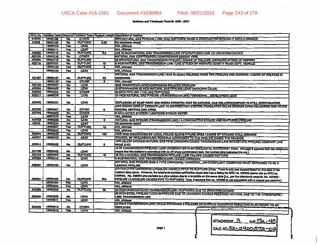
Incients and Telomnic Records 1998 2001
NRC No. I ien D Ote hore?. h T l Riiptre Length Oescrptlon of Incdent418580 19980105 No OTHER 201N NATURAL GAS PIPELINE/ UNE WAS RUPTURED WHEN A CONTRACTOR STRUCK FT WITH A GRADERNONE 19980108 No RUPTURE 0.35 No telepho record
19t0109 Yes ULEAK NIA. offshore19980111 Yes LEAK N/A, offshore
419522 19980113 No UPTURE 85 TRANSMISSION LINE PIPEIRUPTURED DU TO U01NOWN CAUSES420106 19980116 No - OTHER NATURAL GAS COMPRESSOR I COMPRESSOR CAUGHT FIRE420030 19980116 No IRUPTUR 20 INCH NATURAL GAS TRANSMISSION PIPEUNE i CAUSE OF RELEASE UNKNOWN ATTIME OF REPORT420718 19980121 No RUPTURE 15 6 INCH NATURAL GAS TRANSMISSION UNE/ LINE STRUCK BY HOWARD COUNTY ROAD DEPT. VEHICLE
. 19980126 Yes RUPTURE 6 NJA. offshore19980126 Yes LEAK OA, otffol
NATURAL GAS TRANSMISSION UHE I GAS IS BEING RELESED FROM THE PIPELINE AND BURNING I CAUSE OF RELEASE IS42143? 19980127 No RUPTURE 92 UNKNOWN
19980130 Yes OTHER S NA. offshoe424160 19980207 No LEAK _ _ __ AS -H1!AT!RXPLODED.CORR0SION RELATED PROBLEM425454 19980220 No LEAK SUBTEARANEn20 ION NT-URAL GAS PIPELINE LEAK/ UNKNOWN CAUSE425942 19980225 No OTHER 20 INCH PIPELINE /THE LINE RUPTURED426217 1t992 - -No LEAK __ 24 INCH NATURAL GAS PIPELINE (TRANSMISSION UNE) I UNKNOWN._.DEVELOPEDA LEAK
42U483 19980301 No LEAK EXPLOSION AT MLNP FIRST AND INGRIA STREETS IMAY BE NATURAL GAS RELATEDCOMPANY IS STIU INVESTIGATINGCAR DROVE OVER 2' FEEDOFF LINE TO DISTRIBUTION SYSTEM: REGULATOR VALVE BROKEN OPEN RELEASING ASWHIC
427286 19980307 No OTHER 0 IGNIED, SETTING CAR AFIRE.427385 19980308 No OTHER 8 INCH METER STATION / UGHTNING STRUCK METER
19980320 Yes LEAK NM, offshore429154 19980320 No LEAK 0 NATURAL GAS PIPEUINE (TRANSMISSION UNE) IA CONTRACTOR STRUCK AND RUPTURED PIPELINENONE 19980324 No LEAK _elphonlos
199eo327 Yes RUPTURE 13 N/ offshore19980328 Vs. LEUK .N/ hors
430284 19980329 No RUPTURE 159 FIRE WAS DISCOVERED BY LOCAL POLICE ALONG PIPUNE AREA ICAUSE OF AREAKIS STILL UNKNOW430957 19980402 No LEAK .__ RE 26 PIPELNE/CAUSE: POSSIBLE CORROSION TO THE PIPELINE CAUSE THE RELEASE
IOIN BELOW GROUND NATURAL GAS PIPE/UNKNOWN CAUSE/ TRANSMISSION LINE INTERSTATE PIPEUNI COMPANY __NE430914 10980402 No RUPTURE 8 NAME 2-AD12 IN TRANSMISSION PIPELINE I LEAK UNDERWATER IN INTERCOASTAL WATERWAY (Note: Althuh I eppeam from the telephonic
43176 1980408 No LEAK recd that tIs Indent Is assoclated with an off-shore (1te " lek, te Incdent data IIee N Is not.)431743 19900408 No RUPTURE 18 15 INCH NATURAL GAS TRANSMISSION PIPELINE / LINE FAILURE CAUSED RUPTURE432039 19900410 No LEAK 4 INCH NATURAL GAS TRANSMISSION UNE / CAUSE UNKNOWN
NATURAL GAS PIPELINE (SIZE & TYPE UNKNOWN) I UNKNOWN_..AN OVERFLIGHT OBSERVED WHAT APPEARED TO BE A433207 19980420 No LEAK LEAKING PIPELINE2 PIPES (TYPE UNKNOWN)/ LANDSLIDE CAUSED PIPES TO RUPTURE (Nte There Is only one Indent Dsted for this date In theIndCdent ta rpot HoWr, t teepho Iddent notfction pot abo hasa tng for NRC r 43355 (sa ty s NRC no.433654). NM 433655 so pertans toa pie ntWm due to a landslIte on ft me date ILb , per ft telephonic recoads: No. 433655.433654 19980422 No RUPTURE 700 PIPELINE i LANDSUDE CAUSED PIPE TO RUPTUREI. Thu. It appears that no. 433855 Is not associated with a natural s pipel.)
19980504 Yes LEAK NIA. offshor19980505 Ye LEAK NA. offshore
435589 19960506 No RUPTURE 3 30 INCH UNDERGROUND TRANSMISSION UNE I RUPTURED DUE TO UNKNOWN CAUSES22 INCH STEEL PIPELINE ILEAK IN PIPELINE DUE TO UNKNOWN CAIUSES RELEASED NAkTURAL GAS TO THE ATMOSPHERE435"8 1980508 No LEAK LNE. TRANSMSSN LINE
19980511 Yes __ __ ______ N/ ofshore22 INCH TRANSMISSION UNEI WHLEREPAIRINGARIELEASEANIGNITIONOCCURREDRESULTINGINANINJURYTOAN
43662 1998012 No OTHER EMPLOYEE _ _E__- 19980510 Ye LEAK . _ OShofshoe _
I
pmegI
IATTAGKM7NL.._.. '....SHTJ-qA±J.
CA0N03;tjc'c, 4Q a j b
USCA Case #16-1081 Document #1636984 Filed: 09/21/2016 Page 243 of 278

Inld.t andTeol bmloRecords 1995- 2001
NRO No. I In a IOffshore IInckenyrM MpueLnh I 9epr nietIYes _ILEAK I___IY oafsho
- a.,n. .n... ..... .rn..a..ne~s .. r~nrOlivat MOn.f.sqa *ientfltt P.n. AI-uh0rInIfIrnfltIAIn IWflfli *5 CYO*I fl@If437627 19980519 I NO I OTHER
IRUUTYUL"WWRIU gIru%";MIaavUI la MUIFJflIU MI~nlmm1flfi FI~I Il ,flrl .. m~-.
POCU .OWECD BYAPFIRE43900 19980530 I No I RUPTURE I 30-439772 19980502 No OTHER I
AiAUbft IL GAS PIF PROPER VALVE SEQUEN CE CAUSED A RELEASE OF NATURAL GAS
19950^0 No I OTHER Ir toecnio roo__1M. I FAK fN IIwWI 0WV-4.
I C __ __ __ _ __ __ I 1_Yes I LEA - .- NM shore_ No OTHER . NotWehac.
-_-_
l10Ctf7fA M. IFAK I INo t.nIhmlpe rewli1998707 No LEAK No tebphonic record19960707 No OTHER te F0o0cod10980711 No OTHER No hon_19980715 NO LEAK Not record19980715 NO OTHER Note? honrcecord18990717 No LEAK Nte 1phonrcord1998717 No LEAK No honiecd19980721 No OTHER No record1990723 LEAK No tel record19080723 YVs LEAK NWA, offshore19980723 Yes LEAK NIA, offsho19980727 No OTHER No telephoic record1998082 No LEAK to nicrect19980802 No LEAK No Idl Imh record19980890 No OTHER No telephonic record199808 No LEAK No lelei orecord19980814 No OTHER No tehpho t red199w818 No OTHER Notehonicreord19980825 No OTHER 0 Nolehonlc recordn19980825 Yes LEAK N/A. offshore1998028 No LEAK No t reord19980828 No RUPTURE No telephomcreword199803 No RUPTURE 20 No feyhonil record19980906 No RUPTURE 15 No telephon record19980917 Yes I LEAK NIA. ofshore19980920 Yes LEAK N fshore19980923 Yes LEAK WA,1998092 No LEAK No I hoohk rcd19980929 No OTHER No telphwrk NOW19980v92 Yes OTHER WA otfsho -19980930 7iis LEAK WA. vtish19981002 Yes OTHER W& ofshoe1998100 No RUPTURE Notv c reord19981006 Yes LEAK WA. fhPVMtOW8 No LEAK I_ NelptMIoc rococ
19951012 No I- 19981012 No RI
19981026 No I- 19981029 No RI
No I11 Rl
IN TtwOOrllo IUcoIUr.4-;r 10 INo telephonic reor
,No te? ehonic reordI 55 INoteephonrc recordNo .ecord.. smbmm tmmemw
I ATrACKMWZT.3 LP J-b I f
I A c N . a 7-.pe, 2
t-
USCA Case #16-1081 Document #1636984 Filed: 09/21/2016 Page 244 of 278

Inidente end TVephoni Recod 19 9 2001
NRC No. Inident Detw Offshore? Inident Typ. Rupture Lonith Desurption of Inciden1991123 No LEAK N_ otehonlneod19981130 Yos LEAK WA.=ofhore19981202 No OTHER . Notel record19981206 NO RUPTURE 80 No telephon reord19981207 No RUPTURE 33 No telephoncreor19981210 No RUPTURE 1 No telephonic recoad19981210 No OTHER Noehoc record19981213 No RUPTURE I Notelephoitecor19981216 No OTHER .Notelephonrcod19931217 No RUPTURE 29 Notelphork record19981221 No LEAK No ________ __469888 19990102 No RUPTURE 22INCHPIPEUNEITHEMATERALRELEASEDDUETOANUNKNOWNFAILURE ONTHELUNE
469420 19990103 NO OTHER 8 INCH TRANSMISSION PIPEUNE I UNKNOWNNONE 99 113 No LEAK Note_____ ____NONE 19990117 No LEAK __ _ _ _No_ _ _ _ _ _ ___ _ _ _ _ _
19990t17 Yes LEAK 0 WA offshore
471924 1990125 No LEAK _ _ 20 IPCH GAS PIPELINE I CORROSION OF UNE (Note: vckde eren tfouh ;ydf"ers betwen the Ircident end telephone ecords)472364 19990130 No LEAK 0 22 INOC STEEL BELOW GROUNDTRANSMISSION PIPELINE _ COUPLING ED
INSDE PLUMBING OF BUILDINGIPLUMBING CONTRACTOR TURNED GAS VALVE ON TO PURGE PLUMBING LINES CAUSING472803 19990202 No OTHER EXPLOSION WHEN PLUGGING IN WATER HEATERS
OPERATOR 10 19136 / 20 INCH TRANSMISSION PIPEUNE / THE CAUSE HAS NOT YET BEEN DETERMINED / THERE WAS NO FIRE472633 19990202 No RUPTURE 0 OR EXPLOSION4749 19990224 No LEAK COMPRESSOR STATION I FAILURE Of COMPRESSOR ENGINE GAS RELEASE AND FIRE 124 INCH PIPELINE475Z72 199902 No RUPTURE 26INCH NATURAL GAS TRANSINSSION PIPEUNE / FAILURE DUE TO UNKNOWN CAUSE
18 INCH NIATURAL GAS TRANSMISSION PIPEUINE I DOT REGULATED I NO SERVICESAFFECTED I FLANGE GASKET ON UINE475494 19990 No LEAK LUAKED475747 19990303 NO L BEIOW GROUND 361NTRANSMISSION PIPELINE/UNKNOWN DOT REGULATED PIPELINE476123 1990307 No RUPTURE 165 12 iNCH TRANSMISSION UNE RUPTURED AND EXPLODED
19990323 Yes LEAK WA.offsho __
3 INCH TRANSMISSION NATURAL GAS PIPELINE I THE LINE WAS STRUCK BY A 3RDPARTY CONTRACTOR I THERE WAS NO FIRE483495 1999052 No OTHER ._ OR EXPLOSION
NONE 19990513 No LEAK No fel id19990520 Yes LEAK NA. offs"
485403 19990528 No RUPTURE 2 INCH TRANSMSSION NE I CAUSE.UNKNOWN I UNE IS REGULAYED BY THE DOTSOURCE UNKNOWWN IGNmON AT PIPELINE STATIO1N UNDER INVESTIGATION UNKNOWN SIZE OF UNE/STATION IGNmON/NO
487294 19090613 No RUPTURE 10 INJlURtESINO BUILDINGS DAMAGEDNATURAL GAS PIPELINE /NGPL30INCH GULF COAST UNE RUPTURED CAUSING FIREUNDERGRQUND TRANSMISSION UNE T
490644 19990710 No RUPTURE 35 DOT REGULATED LINEMETER STATION EQUIPMENT FAIWRE RESULTED IN A BUILDING EXPLOSIONIALSO A PIPELINE IS RUPTURED INCIDENTS ARE
491788 19990718 No OTHER POSS1BLY RELATED494776 1999081 No RUPTURE 4 12 INCH NATURAL GAS PIPELINE UCAUE UNK/ RELEASED NATURAL GAS INTO ATMOSPHERE495259 19990814 No OTHER PURGING 20 INCH PIPELINE I LINE RUPTURED IN TWO PLACES DURING PURGING LINE IS DOT REGULATED495123 19990815 No LEAK 8 INCH PIPEUNEIDREDGING OPERATION496056 19990816 No LEAK . ABOVE GROUND 21N PIPING WITHIN PLANT/POSSIBLY DUE TO CRACK IN WELD
49023 19990t23 No RUPTURE 43 1tH BELOW GROND PIPELINE I CAUSE OF RELEASE IS UNDETERMINED TRANSMISSION LINE I NO SERVICE INTERRUPrEDNOE 1999828 NO LEAK No____ ltellephonic record
DOT REGULATED TRANSMISSION PIPEUNE I RELEASE FROM A 6 INCH BLOW OFFl 6 INCH UNE COMES OFF A 26 INCH LINE B497288 19990901 No OTHER ABOVE GROUND PIPELINE497979 19990908 Ye LEAK I _ N/A offshore
tellt
it,
page 3AlTACMEWll MC N3 7Sr i L4
..
USCA Case #16-1081 Document #1636984 Filed: 09/21/2016 Page 245 of 278

Inddent end TeleptMW Records 19 - 2001
NRC No. Irmident Date Offsho.e? Inlda Typ naih Dci d RodentTHERE IS A RUPTURE IN A 24 INCH PIPELINE/ CAUSE OF THE RUPTURE IS UNKNOWN/ GAS IGNITED AS A RESULT Or THE
49467 19990912 No RUPTURE 25 RUPTIRUJ DOT REGULATED LINE6 INCH GAS TRANSMISSION UNE / LINE HIT BY FARMING EQUIPMENT / RELEASEDNATURAL AS INTO ATMOSPHERE 'DOT REG
499554 19990913 No RUPTURE LINE NO. 20007
49923 19990920 No RUPTURE I SEMI TRUCK ROLLED INTO NATURAL GAS FACILITY AND BROKE A SMALL PIPELINE SIZE OF PIPE UNK / NO FREINO INJURIES1999093 Yes LEAK _ _ aflshwr
26 INCH NATURAL GAS PIPELINE RUPTURE/ REASON FOR RUPTURE IS UNKNOWN/ THIS IS A DOT REGULATED TRANSMISSION499904 19903 No RUPTURE 29 LINE
1p990925 Yes LEAK MA. ofshore601339 19991005 No OTHER 8 INCH STEEL TRANSMISSION GAS PIPEUNE/ DOT REGULATED/CONTRACTOR STRUCK WITH BACKHOE505595 19991016 Yes LEAK NA o
19991026 Yes LEAK NWA, oafshor503884 19991027 No LEAK 24INCH NATURAL GAS PIPEUNE(GATHE ING LINE) / UNKNOWN ... UNE WAS DISCOVERED LEAKINGNONE 19991103 No OTHER No elelIphonlro605133 19991109 No RUPTURE 24 INCH BELOW GROUND PIPELINE I RELEASE OCCURRED DUE TO UNKNOWN CAUSES507411 9 I91111 No LEAK A 12 INCH PIPELINE WAS RUPTURED BY A THIRD PARTY
10 INCH TRANSMISSION NATURAL GAS PIPELINE I THE LINE WAS STRUCK BY A 3fAD PARTY CAUSING THE LINE TO BLOW OUTr0595 19991111 No RUPTURE 6 TWO EMPLOYEES ARE MISSING
8 INCH TRANSMISSION NATURAL GAS PIPELINE I A BULLDOZER GOUGED THE UNE CAUSING A RELEASE / THERE WAS NO FIRE505500 19991111 No OTHER OR EXPLOSIONNONE 19991113 No LEAK No telephonic -ecd
_ .5 INCH TRANSMISSION NATURAL GAS PIPEUNE I THE LINE WAS STRUCK BY A CONTRACTOR CAUSING A RELEASE /A FIRE500083 19991117 No LEAK RESULTED508039 1 999 124 No OTHER _ olel
_ INCH.TRANSMISSION NATURAL GAS PIPELINE I A LEAK IN A VENT UNDER A HIGHWAY WAS DISCOVERED /THE CAUSE HAS5890 19991209 No LEAK NOT BEEN DETERMINED508805 19991210 No OTHER 12 INCH PIPELINE /THE MATERIAL RELEASED DURING MAINTENANCE WORK
NATURAL GAS PIPELINE I/3RD PARTY CONITRACTOR STRUCK LINE WITH BACKHOE I TRANSMISSION UINE I DOT REG. LINE509409 19991216 No RUPTURE 0.25 eN Same state h iddant and teephoereords but dieret conaerate to hcude)
1.o INCH NATURAL GAS TRANSMISSION PIPELINE/A THIRD PARTY STRUCK THE LINE CAUSING A RELEASE ITHERE WAS NO809538 19991220 No LEAK 0 FIRE OR EXPLOSION
BELOW GROUND 421N DOT REGULATED PIPELINE/PIPELINE WAS DUG UP TO REPAIR ND IT WAS DISCOVERED THAT PIPELINE515184 19991222 No LEAK NEEDS TO BE BLOWN DOWN PRIOR TO REP515860 19991231 Yes LEAK _NIA oth515947 20000101 No LEAK 0 UNKNOWN UNDERGROUND PIPELINE BREAK
THE MATERIAL RELEASED OUT OF A 20 INCH NATURAL GAS PIPEUNE DUE TO THIRY DAMAGE. THERE WAS NO FIRE OR518605 20000111 No OTHER EXPLOSION517700 20000124 No OTHER PRESSURE STATION CAME OFF LINE WHICH CAUSED A VALVE TO RELEASE NATURAL E TO HIGH PRESSURE517943 20000127 No RUPTURE 2 20 INCH GAS UNE RUPTURED518022 20000127 No RUPTURE 770000 2 INCH NATURALGAS PIPEEUNE / UNE BLEW OUT CAUSING RELEASE515173 20000129 No RUPTURE 50 NATURAL GAS PIPELINE RUPTURE OCCURRED
_ CALLER STATED THAT THERE HAS BEEN A RELEASE A 24 INCH TRANSMISSION LINEO UNKNOWN CAUSES (Not: teephonic513468 20000201 No RUPTURE 5 record for 2V22000)*518475 20000202_ No RUPTURE 40 10 INCH TRANSMISSION PIPELINE / UNE RUPTURED FOR UNKNOWN REASONS518851 20000205 No LEAK _RANSMISSION PIPELINE RUPTURE
ruLJ felA I CO OrTepTLJTATTY ,e.,.OtUK] MnITrX * i tlSl.t I ut .Ir ~ Asl an SYNCC .d. .aa .. .. . .
I1tM7A I fIflPI Un I I | A DaAMfItm@W WeIU £ fESR %7=l daLwitnftIS N I NU IA HF [FRMATFRIASFIi Rpll fl I T;A A -'AII A I fmM£ cuuu i~ EMC .0'z
20 1 ;8j 4 [ NO 1 OTHER 1 _ __ INCHHIGHPRESSURESTEELPIPELNE/PIPELINEDAMAGEDBY3RDPARI1. I
.1pe4
ATTAMEW --- M- iiI--,.7 -C r
1,
USCA Case #16-1081 Document #1636984 Filed: 09/21/2016 Page 246 of 278

Incidets and Telephonic Records 1998 2001
NRC No.520905
Il No? Iniddent Type I Rupture Len.gtho LEAK I _ _
DOWcA 241
kdentETO UNKNOWN CAUSES AT THIS TIMEULNE DEVELOPED 0
WA-TURAL GAS PIPELINE RUPTUREDODUETO UNKNOWN CAUSES. (Nate: In thetelephonIcrecords. NRr-no. 52080615 also InclOSISto hav occuredA hi th sam stt Ma NRC no. 520825 and on the sme dae gLe.. per the ephtonkc rod, no. 520506 b: 12 INCHPIPEINE TRANSMISSION UNFI RUPTURE IN LINE DUE TO UNMWOWN CAUSES. However, hI the IndM repoh fthee Is orgy onekitingforth st f Mlonthi date. Thus.Iappers tatno. 20 ob notaoaedwifth anatul spipele Therefore.thI Is
considered one Ibciet)620825 20000Z3 NoI RUPTUREJ 12NONE52126s_52237_52303_523107_
623850
No OTHERI 7 No RUPTURE 300
j No OTHER I6I No LEAK I 0
NC24
BEUtt0Pt2O
THE LINE AND RELEASED THE MATERIALFOR UNKNOWN REASONS
20000316 No LEAK2 No LEAK F00IOL= W MJ-_A . _.
20000322 No624202 20090327
__ ^v ^ ^.^ v^- S- - .s ^ -nT Mac024643- 2 MNot _.____-;_- ...LEAK 0 i I RUCKa nT A I RUEA CAUSINGU I HE nrlLCP.OO_ -- ----- - - . .-
525947 20000424 Yes LEAK I527237 20000426 Yes LEAK NLA olnhore527789 20000502 No OTHER DUI ING GAS THAT WAS PRESENT IN THE AREA IGNITED52256 20000507 No OTHER CALLER SAYS THERE WAS A FIRE NEAR A NATURAL GAS PIPELINENONE 20000513 No OTHER Notel record
529301 2000518 No OTHER 20 INCH KA PIPELNE STRUCK BY MINING COMPANYNONE 20000e03 No LEAK No teleoii rexord532311 20000614 No OTHER THIRD PARTY DAMAG£ ON 16 INCH GASLINE CAUSED RELEASE OF IATERIAUITRACTOR RIPPED HOLE IN LINE532481 20000817 Ts LEAK WA. dfhox532694 20000619 Yet LEAK N/ ofshor633053 20000622 No RUPTURE 26 ao telep c rooord633867 20000828 No RUPTURE 6 8 INCH PIPELINE TRANSMISSION' I UNKNOWN CAUSES
533922 20000829 Yes LEAK WA, oH share534181 20000702 No LEAK 30 INCH NATURAL GAS PIPEUNE I CAUSE:UNKNOWN534468 2000702 No RUPTURE 9 MATERIAL WAS RELEASED FROM A SIX INCH NATURAL GAS PIPELINE DUE TO UNKNOWN CAUSE.534097 20000703 No RUPTURE 36 NATURAL GAS UNE HAS BROKEN VALVE AND IS RELEASING MATERIAL telephonic record dated 7/I100)534U4 2000705 No RUPTURE 22 TUG BOW STRUCK GAS UNE CAUSING A RELEASE
20000705 Le LEAK WA, otfshome634705 20000707 _No LEAK 1A FIRE AT A METER STATION CAUSED A RELEASE OF NATURAL GAS534886 20000707 Yes LEAK N/A, offhoreNONE 20000715 No OTHER No teephonli record
635726 20000718 No OTHER LINE BLOCKAGE TO MAIN DISTRIBUTION UNE. CALLER BEUEVES A VALVE WAS LEFT SHUTTHE MATERIAL RELEASED OUT OF A l1IN NATURAL GAS PIPELINE DUE TO A THIRD PARTY PIECE OF CONSTRUCTION
536165 20000721 No OTHER EOUIPMENT STRIKIN THE LINE.536096 20000721 Yes LEAK N/A.offhore537404 200008o2 No RUPTURE 3 THE MATERIAL WAS RELEASING FROM Ala INCH STEEL PIPELINE DUE TO THE PIPELINE RUPTURING.NONE 20000804 No LEAK Natloteaornicordit.OMI SOAWM4A tI.k. I ICAl I010c II*= I CAIK
53917 :Lowwu *w rw r..
20um0015 _ .. I LEAK . -_ _sL No UEAK I____ E CALLER STATED THAT A PIPE CAME OUT OF A C0OUPLING DUE TO THE UN638990 4J ru Mr-~O.upiu up
539215 i 2a0005ls Yes LEAK lNIA. ashm"539219 d
I NNo LEAK _ _ 112 INCH -TRANSMI!I 4e n.w. .. au
--- ----INE HAS A lul' 1 11539697 1
1,1 itc on Ie7IIUEI UC IUATUR1AL GAS I: Luf" IQ 16
9402&Mea u s^ls« o-Q z v1n ne esnen ^SATenal^ r
200008 I No IoUwW uriujrfUN ol IN MAIN4 upb U4rd "cWJtu MA I ttlAL FiNVMII ATgD AnD rmMVPRPM I WAKt
A POTF N HISII .AJn RPLEAK _Vi- -ss "t.N.Ietr
_ _ _ __. _- - _ _ . ,_- . i
p g 5
I
USCA Case #16-1081 Document #1636984 Filed: 09/21/2016 Page 247 of 278

Incidents and TeolphIon Records 1998- 2001
NRC No. InWdent Dole Offshore? Incident T Rupture Length es of Incide540327 2000029_ NO LEAK _ THE CALLER STATED THAT A NATURAL GAS PIPELINE WAS RELEASING MATERIAL DUE TO CORROSION.
THE MATERIAL IS RELEASING DUE TO A PLANNED BLOWDOWN IN AN 8 INCH PIPELINE. THE BLOWDOWN HAD TO OCCUR TOAVERT A RUPTURE. THIS IS AN EMERO (NoW. Although the dties ore not the sme In the Irmident and teophonIc reports convate
541917 20000912 No OTHER hckde)543279 20000926 No RUPTURE THE MATERIAL RELEASED FROM A 12' GAS PIPELINE DUE TO UNKNOWN CAUSES.43441_ 20000927 No LEAK THE MATERIAL RELEASED FROM A NATURAL GAS PIPELINE DUE TO UNKNOWN REASONS.
543746 20000929 No RUPTURE 83.5 THE MATERIAL WAS RELEASED FROM A RUPTURED 30 INCH PIPELINE DUE TO UNKNOWN CAUSES.544293 20001003 No OTHER 2 NCH WKM GATE VALVE, SAFETY SEAL, THE BOLTS ON THE BONNET FAILED.545019 20001012 No LEAK THE MATERIAL RELEASED OUT OF A 24 INCH PIPE UNE DUE TO AN UNDETERMINED CAUSE.5467 20001028 No LEAK THE CALLER STATED THAT A PIPELINE VALVE IS RELEASING GAS. THE CAUSE IS UNKNOWN.546628 2000030 Yes LEAK _ WA. offshore
THE CALLER STATED THAT A NATURAL GAS DISTRIBUTION SYSTEM HAS LOST SERVICE TO SOME CUSTOMERS. THE CAUSE54089 20001113 No OTHER FOR THE SYSTEM FAILURE IS UNKNOWN.548441 20001116 Yes LEAK NA, ofshore
619 20001118 No LEAK FIRE IN TOWN BOARDER STATION IN THE HEATER NATURAL GAS DISTRIBUTION CENTER
548759_ 20001120 No OTHER . THE MATERIAL RELEASED FROM A RELIEF VALVE ON AN EMERGENCY SHUTDOWN DEVICE DUE TO UNKNOWN CAUSES.
549015 20t123 No OTHER THE CALLER IS REPORTING A FIRE IN A COMPRESSOR BUILDING DUE TO UNKNOWN CAUSES. THERM WAS NO EXPLOSION.549118 20001125 No LEAK LEAKINA22 INCH NATURAL GAS NE
THE CALLER STATED THAT A GAS UNE MAY HAVE A LEAK IN IT. AND THERE IS BUBBLE COMING FROM THE WATER (NOTE:549288 20001127 No LEAK Sane sate I Iident ad wtehoric records mnsentve to Indcde)N 20001128 No OTHER No telphoic record
549112 20001130 No RUPTURE 23 THE PIPELINE WAS DAMAGE DUE TO A THIRD PARTY. (POSSIBLY AN EMPLOYEE OR CONTRACTOR OF VALLEY TELEPHONE)A 30 INCH TRANSMISSION LINE HAS RUPTURED DUE TOUNDETERMINED CAUSE CAUSING NATUiA GAS TO EA M
549479 20001204 No RUPTURE 28.25 THE LINE INTO THE ATMOSPHERE.SO26S 2D001206 No LEAK THE MATERIAL IS LEAKING FROM A BALL VALVE DUE TO UNKNOWN CAUSES.550S98 20001209 No RUPTURE 78 A NATURAL GAS PIPELINE RUPTURED. THE CAUSE IS UNKNOWN.551181 2D001216 No RUPTURE EXPLOSION DUE UNKNOWN CAUSES AT AN UNDERGROUND STORAGE FACILITY551911 20001220 NO NO DATA CALLER STATED SRP DUG INTO A 32 INCH GAS TRANSMISSION LINES THE SRP WAS GRADING FOR A STREET552219 20001229 No RUPTURE 40 26 INCH NATURAL GAS PIPIUNE RUPTURED DUE TO UNKNOWN CAUSE552464 20010103 No LEAK _A TACKHOE HIT A 18 INCH NATURAL GAS PIENT WHILE EXCAVATING FOR ANOTHER LINE552627 20010104 No RUPTURE 120 THE CALLER REPORTS A RUPTURE OF A 22 INCH NATURAL GAS PIPELINE.
THE MATERIAL WAS RELEASED FROM A RUPTURED 18 INCH GAS LINE DUE TO UNKNOWN CAUSES. THE CAUSE FOR THE552669 20010104 No LEAK RELEASE IS UNDER INVESTIGATION
THE CALLER STATED THAT A FRONT END LOADER WENT OFF THE ROAD AND HIT A 20 INCH HIGHT PRESSURE GAS UNE.35e8 20010115 No OTHER PART OF AN ABOVE GROUND SPAN. GAS RELE
553737 20010118 No LEAK _ THE CALLER REPORTS A LEAKING NATURAL GAS PIPELINE POSSIBLY DUE TO SUSPECTED CORROSION.553780 20010116 No OTHER RELEASE DUE TO AN UNKNOWN CAUSE554695 20010125 No LEAK _ 6 INCH PIPEUNE FLOWUNE LINE DEVELOPED A PINHOLE leok DUE TO UNKNOWN CAUSES555048 20010129 No LEAK THE CALLER STATED THAT A 12 INCH NATURAL (AS TRANSMISSION PIPELINE RUPTURED, THE CAUSE IS UNKNOWN.
20010203 Yes LEAK _A-._____ __A THIRD PARTY CONTRACTOR STRUCK A UNDERGROUND a INCH NATURAL GAS TRANSMISSION UNE WITH A BACK HOE
555725 20010204 No RUPTURE 1 CAUSING NATURAL GS TO RELEASE FROM THE UNONE 20010208 No LEAK _ __ o __ ___le ___o_ -
558117 20010228 Yes OTHER INIA, o__shore-ITHI MATFRIAL WAR APrI PAitfl FmAil A 3101 PIJC fli EU Tf% A f2 A OLM-r C- ~.
Th
Its899 1 2001o30 I No I LEAK 1tTHE ..-. RIL \S RELEASED FRO .M .. A ---PLInF nlJF TIrn :AX. e. _m.uml. .MR, onreru. CMOs in _io ._clen_
,,. eleohonlo renofW r onama velyv kuludIal559149 1 20010310 I Yes I LEAK - A- Wf._hnm __ I _ '-' .. Lm _
NONE j 20010313 | No OK 1 No t ept-nrecord (NRte nons of the citIes norcnties match beene ndt nd ephonireols)trrw-�
paeg 6ATrAKMEWT.aC3 MM |
MCAL.NO. iv-a -.
I
USCA Case #16-1081 Document #1636984 Filed: 09/21/2016 Page 248 of 278

Inddenta a Telephoni Records 109 - 2001
NRC No. Inckdent Date Offshomo Incident Type re h Deecr o Irdden-BLOW DOWN VALVE AT A COMPRESSOR STATION DID NOT SHUT DUE TO EQUIPMENT PROBLEMS I COMPRESSOR STATION IS
5596 20010317 No OTHER PART OFAPIPELNE eNote: tel eord for3/1&2001559917 20010319 No OTHER ae h record (Nob No mod NRC n. h the telephonic record for alven date)
NATURAL GAS WAS RELEASED FROM A TRANSMISSION PIPELINE, DUE TO A SCHEDULED GAS CAUGHT56033 20010322 No OTHER MIRM
THE MATERIAL RELEASED OUT OF A 6 INCH STEEL TRANSMISSION PIPELINE DUE TO AN EXCAVATOR DAMAGING THE561008 20010028 No RUPTURE 0.66 PIPELNENONE 20010329 No RUPTURE No to1 onlcord (Notb: one of the Taxas dtie ard/orcomniles match betwn the hidnt and btelhn rc1orf)NONE 20010029 No LEAK No telephonic record (Note. none of the Texas etles eufdor counties match between the biddent anet teepcreport)561310 20010330 No LEAK A PIPELINE LEAK WAS DETECTED BY A MOTORIST
THE CALLER IS REPORTING THAT THE SUSPECTED RESPONSIBLE PARTY TOOK THE COVER OFF A 10 INCH PIPELINE AND661808 20010404 No OTHER PUNCTURED THE LINE WITH A DOZER BLADE
581796 20010404 No OTHER A CONTRACTOR HIT THE RESPONSIBLE PARTYS EIGHT INCH PIPELINE WITH A BULL DOZER CAUSING A RELEASE OF GAS.561742 20010404 No OTHER RELIEF VALVE ON TRANSMISSION LINE RELEASED GAS DUE TO OVER PRESSURIZATION.561893 20010405 No LEAK THE MATERIAL WAS RELEASED FROM A PIPELINE DUE TO A LEAK IN THE LINE FROM UNKNOWN CAUSES.561915 20010405 NO OTHER No telephonic rAd (Note No mtching NRC no n Ithe let ic records for given date.)562056 20010406 Yes LEAK MA. offshore562463 20010407 No OTHER No honorecord Note No mati NRC no. in the telephonlic ecomds for gten date.)563110 20010416 No LEAK THE MATERIAL IS LEAKING FROM A CRACKED 36 INCH UNDERGROUND TRANSMISSION PIPE.
564100 20010425 No OTHER RELEASE FROM THE LINE INTO THE ATMOSPHERE._ THE MATERIAL RELEASED ouT OF THE TWENTY FOUR INCH UNDERGROUND NATURAL GiAS PIPE DUE TO AN UNDETERMINED-
S54274 20010427 No LEAK CAUSE AT THIS TIME_THE MATERIAL RELEASED OUT OF A 20 INCH PIPEUINE DUE TIO A VALVE FAILURE. (NoiW: D~es*Vtln Is associated with NRC rim
656e31 20010504 No RUPTURE 16 56501. It vs that th NRC no. of 5651 bled In the Incident be a585794 20010511 No LEAK TRACTOR WITH DITCHING DEVICE STRUCK 12 INCH PIPEUNE565922 20010513 Yes LEAK RA, ecbhom56M30 20010521 No LEAK LEAK ON AN INTERSTATE AS PIPEUNE DUE PIPE DAMAG667182 20010524 Yes LEAK NA oesho567198 20010524 N RUPTURE THE CALLER STATED THAT COUNTY ROAD GRADER HIT A NATURAL GAS PIPEUNE AND CAUSED A LEAK.583 20010613 No RUPTURE N h crem569577 20010614 No LEAK No to redNONE 20010616 No OTHER Notelehc
570128 20010619 No LEAK No tellphe record570250 20010620 No LEAK N te ch anNONE 20010630 No LEAK No 1eleptson1 record572288 2001070B No OTHER t ic head574018 20010723 No LEAK No _e_ _c
NONE 20010724 No OTHER No telephonic rcoNONE 20010725 No LEAK No rcord-NONE 20010725 No OTHERNONE 20010729 No LEAK No rlond
575297 20010803 No LEAK 0 teo record675940 20010509 No LEAK No telphoric rtco678119 2001011 No RUPTURE 19 Notel ehoneirecordr76A520 I m1.6 No. LEmm.AK N ii* I_ .._ .5 as_ .. ,p WI - -- --676787 20010814 No LEAK __ No______ _eord___I___Pi________573077 1 20010815 I No I OTHER I ICNONE 1 2DOflR20 INo IL AK I t 'we e 1,
-� J -- I I � I � __________________________________________________
pe7
I;
A1TACWWMk3,Vf.LrTJ,4M
'I1,
USCA Case #16-1081 Document #1636984 Filed: 09/21/2016 Page 249 of 278

IncdeWns and Teeponic Records 1998- 2001
NRC No. Incident Date Offshore? Incident Typ Ruptr Lengftinck677245 20010821 No RUPTURE N to record677756 20010826 Yes LEAK N ofshore577808 20010826 Yes LEAK A.NONE 20010831 No LEAK Natal crowd578944 20010903 No RUPTURE 10 Ou579144 20010907 No RUPTURE I Ntelo h record58000 20010917 No LEAK Noten c recordNONE 20010920 Yes LEAK 101ofshor604993 20010921 No LEAK____ tee rowd580834 20010925 No RUPTURE 9 Noa e" rCeco=d582452 20011009 No LEAK telenirecodNONE 20011012 No RUPTURE 4 Notele n crecod883347 20011016 Na LEAK No record513s16 20011018 Yes LEAK584230 20011023 No OTHER No recordNONE 20011024 Yes LEAK NAeehfoeNONE 200tt106 NO OTHER .
585264 20011106 No OTHER tledhorncod685408 20011107 No OTHER telepon eo d585912 20011113 No LEAK tephordc nbcord586663 20011121 Yea LEAK WA. etish587965 20011206 No LEAK No telephonicoid587925 20011206 No LEAK telophonicoem588102 20011207 No LEAK telephoni nd588053 20011207 No RUPTURE 10 No tel record585285 20011210 No OTHER telophonic nd588431 20011212 No LEAKNofted recod588473 20011212 Na RUPTURE No td n5 8825 20011216 Nb RUPTURE 610 No tephOl I record
_ Notes: 1) For ionddckents (e.g.. 1998 throwh 5tMI m and vairos others). no NRC number is given in the incident date ieportTherefore, a cor n d e city, county undrorstate formation between the Incident deta report end telephonic Incident notfationrecords wans made to deternine the NRC number.
2) Abov ormation was compiled from the Oflice of Pipeline Safety webskIt httpi/ops.dot.gov - rom the Online Libroy - Accidenta Incident Date. Natural Gos TranribssIon Incident Date mid 1964 to 2001 and 1mm the OnIew Ibrary * Telephonic incident Notification.-1995-8 & 1992001 Te k Incident Notiffeations.
3 Ru unitsameasumedto Infeet (o. -unitsam not Idcted Inthetansmdentdarep
Y..
-MV
I
L9.5:a IAU=L -)% 11.
USCA Case #16-1081 Document #1636984 Filed: 09/21/2016 Page 250 of 278

. Document No. 32-240057202|Natural Gas Pipeline Hazard Risk Determination Revision 2
. Page 18 of 45
Attachment 4: Calculation of Distances Di and D2
1.0 PURPOSE AND OBJECTIVE
Calculate the exposure distance, D, which has two parts, the distance to the gas upper andlower explosion limits (UEL and LEL), Di, and the safe separation distance, D2.
2.0 METHOD OF ANALYSIS
Employ the computer program ALOHA (Reference 6) to calculate the concentrations ofnatural gas from a postulated gas release along a direct pathway to the NEF. Use themodel results to determine the distance to the upper and lower explosion limits (UEL andLEL), which is DI. Then estimate the safe separation distance, D2 from an explosionfollowing Regulatory Guide 1.91 (Reference 3).
ALOHA was developed jointly by the U.S. Environmental Protection Agency (EPA) andthe National Oceanic Atmospheric Administration (NOAA). The program predicts therates at which chemical vapors may escape into the atmosphere from broken gas pipes,leaking tanks, and evaporating puddles. It also predicts how the gas cloud disperses inthe atmosphere after an accidental release.
3.0 INPUT AND ASSUMPTIONS
The following assumptions were made relating to the dispersion and transport of thepipeline gas:
* The gas released is methane, which is the major constituent of wet sour gas(Attachment 5).
* The postulated gas release is a guillotine pipeline break such that the break hole sizeequals the pipe diameter.
* The pipe is connected to an infinite source because there are no automatic shut-offvalves in the pipeline (Attachment 5).
* The gas release is 1 hour; the maximum expected time before emergency crews arriveto shut off the source at a manual shut-off valve (Attachment 5).
* The pipe length is 200 times the pipe diameter, which is the minimum allowed byALOHA and considered to be very conservative.
* A delayed explosion from a drifting plume I hour after release is more severe than anin-place explosion because the gas plume is closer to the plant.
* The atmosphere is stable, with minimal dispersion and effects due to elevationchange.
USCA Case #16-1081 Document #1636984 Filed: 09/21/2016 Page 251 of 278

Document No. 32-2400572.02Natural Gas Pipeline Hazard Risk Determination Revision 21
. Page 19 of 45
* The distance from the gas release location to the plant is the "straight-line" distance,which is the shortest distance between the source and the plant measured on a plainsurface that excludes intervening ground elevation changes and building surfaces.
• The TNT equivalent weight of an exploding material is represented by the SFPEHandbook method (Reference 8).
4.0 ANALYSIS
The safety of structures from an explosion is evaluated by determining the safe separationdistance between the explosion and the structure. If there is sufficient separation suchthat structural damage is minimized, then the structure is assumed safe.
The method used to establish the safe separation distance is from Regulatory Guide 1.91(Reference 3), which is based on a level of peak positive incident overpressure,conservatively chosen at I pound per square inch (psi), and TNT equivalent energy in theform
R=45WI"3
where,
R = the safe separation distance in feet (ft), and
W = the TNT equivalent weight of the exploding material in pounds (Ibs).
To calculate the safe separation distance, therefore, requires the TNT equivalent of themass of methane volume released. For a continuous release such as postulated, this is themass of methane between its lower explosion limit (LEL) and upper explosion limits(UEL) of 5 - 15 % by volume (Reference 8). Note that 5% by volume is equivalent to50,000 parts per million (ppm) and 15 % by volume is equivalent to 150,000 ppm.Theses values are used as input to ALOHA (see Tables A2 and Al, respectively).
4.1 Methane Explosion Release Mass
The mass of methane released in its explosion range is calculated by using the "SustainedRelease Rate" determined by ALOHA and the distance/time relationship to reach theUEL and LEL such that
M = S (TLEL- Tun)
where,
M = mass of methane in pounds (Ibs)S = sustained release rate in pounds per minute (lbs/min)TuEL = time to reach the UEL in minutes (min)Tin = time to reach the LEL in minutes (min)
USCA Case #16-1081 Document #1636984 Filed: 09/21/2016 Page 252 of 278

Document No. 32-2400572-02Natural Gas Pipeline Hazard Risk Determination Revision 2
.Page 20 of 45
From ALOHA output Tables Al and A2, the Sustained Release Rate of methane at 50 psi(i.e., the maximum gas pipeline pressure) is 5,820 lbs/min. The respective distances to theUEL and LEL (referred to as the "LOC" on the printout) are 727 yards (2181 ft), and1365 yards (4095 ft). At the ALOHA input wind speed of 1 meter/second (m/s), or 3.28feet per second (ftls), the time to UEL and LEL is
TuEs = 2181 ft/ 3.2 fts /60 s/min = 11.08 O min, and
TOWE = 4095 ft / 3.28 ft/s 60 s/min = 20.81 min
Therefore,
M = 5,820 lbsJmin x (20.81 Inn - 11.08 min) = 56,629 lbs.
4.2 Methane Mass to Equivalent TNT
From the SFPE Handbook, Section 3, Chapter 16, Equations 12 and 13 (Reference 8), theTNT equivalent weight can be expressed as
W -=a(Mc XMr)4500
where,
Wxnf = TNT equivalent mass in kilograms (kg).at = yield, which is the fraction of available combustion energy.AHc = theoretical net heat of combustion in kilo-Joules per kilogram (kJ/kg).Mf = mass of flammable vapor released in kg.
From Reference 4 (Attachment 6), Table A-2, AH, is conservatively chosen to be thegross heat of combustion, which is 55.50 MJ/kg, or 55,500 kU/kg; Mf= 56,629 Ibs/ 2.2lbs/kg = 25,740 kg; and from Reference 8 (Attachment 8), the blast yield, a, is assumedto be 5%. Substituting,
O.05(55,500 .Kj( 5, 40kg)W -,V5 =15,873 kg =34,921 lbs
4500
4.3 Safe Separation Distance
From above, the safe separation distance, R, is
R = 45 (3 4,9 2 1)I3 = 1,471 ft
This means that plant critical structures must be at least 1,471 ft from the point ofexplosion.
USCA Case #16-1081 Document #1636984 Filed: 09/21/2016 Page 253 of 278

Document No. 32-2400572-02Natural Gas Pipeline Hazard Risk Determination Revision 2
Page 21 of 45
5.0 CONCLUSION
The value of DI is 4,095 ft (1,365 yards), which is shown in ALOHA output Table Aland is the distance from the gas release point to the LEL. The value of D2 is 1,471 ft.which is the safe separation distance.
6.0 COMPUTER PROGRAM BENCHMARK
Attachment 10 demonstrates that ALOHA, version 5.2.3, is correctly predicting resultson the installed computer, an IBM-compatible PC (ID#3W2BZ1) using MicrosoftWindows XP® Professional, Version 2002, operating system with a Pentium(R) 4processor.
USCA Case #16-1081 Document #1636984 Filed: 09/21/2016 Page 254 of 278

Document No. 32-2400572-02Natural Gas Pipellne Hazard Risk Detennination Revision 2
Page 22 of 45
Table AlALOHA Output, Methane UEL
Text Summary ALOHAP 5. 2.3
SITE DATA INFORMATION:Location: RUNICK, NEw MEXICOBuLldT g Air Exchanges Per Hours 0.50 (enclosed office)Time: October 10, 2003 1042 hours tSDT (using computer's clock)
CHICAL IFORMATION:Chemical IUnes METHME Mlecular Weight; 16.04 kg/lmolTLV-TWA: -unavail- DULX: -unavail-Footprint Level of Concerns 150000 ppmBoiling Point: -258.680 FVapor Pressure at Ambient Temperature: greater than I atmAnbient Saturation Concentration: 1,000.000 ppm or 100.0%
ATMOSPHERIC INFORMATION: (MANZL= INPUT OF DATAWind: 1 moetrs/sec from a at 10 metersNo Inversion HeightStability Class: F (user override)Air Temperatures 700 FRelative Humiditys 5% Ground Roughneass open countryCloud Cover. 0 tenths-
SOURCE STRENGTH INFORMATION:Pipe Diameter: 16 inches Pipe Length: 267 feetPipe Temperatures 70e F Pipe Press: 50 lbs/sq inPipe Roughness: smooth Role Area: 201 sq inUnbroken end of the pipe is connected to an infinite sourceRelease Durations ALOHA limited the duration to 1 hourMax Computed Release Rate: 7,640 pounds/minIax Average Sustained Release Rate: 5.820 pounds/min
(averaged over a minute or more)Total Amount Released: 34,P998 pounds
FOOTPRINT INFORQTION:Dispersion Module: GaussianUser-specified LOC: 150000 ppm.Max Threat Zone for LOC: 727 yards
USCA Case #16-1081 Document #1636984 Filed: 09/21/2016 Page 255 of 278

Document No. 32-2400572-02Natural Gas Pipeline Hazard Risk Determination Revision 2
. Page 23 of 45
Table A2ALOHA Output, Methane LEL
Text SSumary
SITE DATA INFORMATION:Location: EUNICE, NEW MEXICOBuilding Air Exchanges Per Hour: 0.30 (enclosed office)Time: October 10. 2003 1042 hours NOT (using computer's clock)
CHEMICAL INFORMATION:Chemical Name: METHANE Molecular Weights 16.04 kg/kmolTLV-TWA: -unavail- IDLB: -unavail-Footprint Level of Concern: 50000 ppmBoiling Point: -258.680 FVapor Pressure at Ambient Temperature: greater than I atm
* Ambient Saturation Concentration: 1,000,000 ppm or 100.0%
ATMOSPHERIC INFORMATION: (MANUAL INPUT OF DATA)Wind: 1 meters/rec frem a at 10 metersNo inversion HeightStability Class: F (user override)Air Temperature: 700 PRelative Humidity: 5% Ground Roughness: open countryCloud Cover- 0 tenths
SOURCE STRENGTH INFORMATION:I Fpe Diameter: L6 inches Pipe Length: 267 feet
Pipe Temperatures 70° F Pipe Press: 50 lbs/sq inPipe Roughness: smooth Bole Area: 201 sq inUnbroken end of the pipe is connected to an infinite sourceRelease Duration: AWOHA limited the duration to 1 hourMax Couputed Release Rate 7,640 pounds/minMax Average Sustaino d Release Raters.e20 pounds/min
(averaged ever a minute or more)Total Amount Released: 348,990 pounds
!FOOTgRnM NFrMPHTION:Dispersion Module: GaussianUser-specifiedf LOC: 50000 ppm.Max Threat Zone for LOC. 1365 yardc
I
USCA Case #16-1081 Document #1636984 Filed: 09/21/2016 Page 256 of 278

Document No. 32-2400572-02Natural Gas Pipeline Hazard Risk Determination Revision 2
. Page 24 of 45
Attachment 5: Gas Line Telephone Chronology
TELEPHONE CHRONOLOGYREGULATORY COMPLIANCE PROGRAMS- MARLBOROUGH
Call With See Below Date See BelowPhone # See Below Time See BelowBy J.H. Snooks PIDSubject LES-NM: Gas Lines
DISCUSSION:
6/30/2003 Reviewed gas line maps and was able to identify the closest gas line as the 16"Fullerton Loop Line, which nearly parallel to NM Rte 234-Tx Rte 176. Called"One Call" (800-321-2537) to get info on gas line owner. Dispatcher named threecompanies: Trinity C02, Texaco, and Sid Richardson Energy Services. Requestednumber for SR since gas maps were labeled as SR Called SR (505-395-2116), butno one available.
7/1/2003 Called SR again, spoke w/ Royce, who gave me general info. The gas line is lowpressure (< 50 psi) and carries "wet sour gas," which is unprocessed, field gas fromthe well being sent for processing. The gas line is buried to about 36", but couldvary more or less in sandy soil due to the wind. Royce said he would have someoneget back to me on characteristics of gas, e.g., percent methane, etc.
7/10/2003 Returned Royce Dunn's call. RD had additional info on gas line specs and gascharacteristics as follows: methane = 72%, ethane = 11%, propane = 7%, H2S =695ppm (<1%). The gas line flow is between 200-500 thousand cubic feet per day.It is 14-15 miles in length, with manual block valves at each end and in the middle.There also has a check valve at the connection with the main service line locatednear Eunice and Hwy 176. The likelihood of internal rupture is small because ofthe low pressure (<50psi).
8/2003 Called "One Call" (800-321-2537) to place a pipeline location request for Sections32 and 33. Used town ID# 838. One Call said there were three operators in area:Sid Richardson, Trinity, and Texaco. Companies will call in 2-5 business days withinfo. One Call confirmation number is 2003323641.
8/8/2003 Goose Armstrong from Sid Richardson responded to the One call inquiry to saythey had two pipelines in Sections 32 and 33, both running parallel to the southernboarder along Rte 234/176. One is 14-inch line that is "idle," i.e., in active. The
USCA Case #16-1081 Document #1636984 Filed: 09/21/2016 Page 257 of 278

Document No. 32-2400572-02 |Natural Gas Pipeline Hazard Risk Determination Revson 2
. ..Page 25 of 45
other is a 16-inch line carrying natural gas. [See 7/1 and 7/10 above for moredetails.]
8/8/2003 Brent Washington from Conoco-Phillips (505-390-3425) returned my many calls tovarious Conoco offices to get info on potential pipelines near Eunice. Brent saidthere were no known lines, but that he would conduct a site walk down on 8/1 toconfirm.
8/11/2003 Brent Washington from Conoco-Phillips (505-390-3425) called to say he walkedthe site and did not locate any Conoco-Phillips pipelines.
8/1312003 Lon Briley from Trinity Gas (442-661-0162) responded to the One Call inquiry andsaid Trinity had one carbon dioxide line crossing Section 32. The line carries liquidC02 at 2100 psi; the flow is about 15 MMcf per day. Briley said that there manualshut offs about 2 miles north and south of the site and that it would take 45 min to 1hr to close the values. There also is an electronic shut down system, but it wouldstill take about 45 min to 1 hr to shut off supply and "bleed the system." Altematecontact is Barry Petty (who Ed Maher has spoken to.) His tele no is 432-683-8262.
9/4/2003 Called Royce Dunn at Sid Richardson (505-395-2116) to ask if SR had a DOT riskreport in case of a leak like Trinity C02 gas. RD didn't know of any; he said therewouldn't be a fire or "blowout" explosion, like might occur in the C02 line becauseSR gas line is low pressure. RD gave the web site of the state agency responsiblefor oil sites: www.emnrd.state.nmn.us/ocdl.
USCA Case #16-1081 Document #1636984 Filed: 09/21/2016 Page 258 of 278

Document No. 32-2400572-02Natural Gas Pipeline Hazard Risk Determination Revision 2
. Page 26 of 45
Attachment 6: Fire Protection Handbook
W-
FireProtection
i Handbook'
Seventeenth Edition
Arthur L Cote, PE.-Editor-in-Cief
. Jim L LinvilleManaging Editor
._. c * -..
(iJl National Fwre Protection Association!5~PJA Quincy, Massachusetts
I.
USCA Case #16-1081 Document #1636984 Filed: 09/21/2016 Page 259 of 278

Document No. 32-2400572-02Natural Gas Pipeline Hazard Risk Determination Revision 2
. . Page 27 of 45
I
A-2 TABLES AND CHARTS
TABLE A-I. Mda, Of Cwv W andEW Meled ftopenl fr P~w Skrpk asbfiwesa wAlkweq
f.AN C~l C..W Oxyga~so- ' Tb -Laen Uqi Va
Mat ea N i 5d1. -mm atof Heoat w.dat 0 Hotal f M=s Umnp. Va-zalb- Cap-ty Capwtri
mIate"I. COanPoebi %W.2g O"Wcg (LL"c O.ftc 0Di rawe (V) OLIg tfr~g-C) (JGU"
i
cyd dww C,, - o 4.0 " 41S7 13.61 a4z -,325ecahydwnaPutMWMe - Cbtdlnc
dadacaln ClH,, 13524 45.49 42 1270 3235 5 30804 M CJ 142.28 474 44.24 1S 3486 174.1 2
dHnd.n.1, * 50.06 . 466 45.7 .*, 15.3 - 2U77. 10.
orw 17.6 791.0 7 1 46 .- S2S -diWomeemm 914 84.04 364 102 10.65 * 'O.36S 3 M -devq cyddc CI 140.26 48.30 43.17 -126 A=22 t74.deh Omer C"4. 74.12 36.75 3.7 13.04 2590 34.5 360f 244 dboWynok- -a
c 45.08 A6 3ss2s 13.24 i62 6 -
dm C, 166.30 450 42.79 13I5 3254 220. 260mu-tI. w4 v* ., * -
1.1___.d81Iya' _-. -__.__....~............__... . ___._.',14, 8.10 32.5 S3 14.10 t130 Z5. 578
d ll Wfda 0,34,50 .7&813, 2. 8S LI1 1530 1.843 -1. 770431NNW ,H , * .10 2.7 24.S 9.66 2543 0 404
1.4 34,, 38.1C 26.3 144 0.77 2.543 1,01.1 406Go * mm ' 30.07 8137 47.49 '12.5 3.725 IJ A'*"'1 C H ''' 46.07' 267 3 tS .2S4-76i 63 ?fdn) - .Si,--n. . _ . -..
wqy aae C,04,0, .38.10 2541 23.41 12.3 :1.15 . 77.2 '-367eV aCsa- O 0,91,0 1012 2744 25. 13.39 -1t1e - 110* 290eftt l CN * 45. 33 2 1A323 562 , 165 . -W bnweas Ca14 J06.16 43.00 40J3 12t 3 3.165 126.1 330e M C,H. 23.05 5030 47.17 13.76 3422 '-ItA -
YWn 0,4, C.07 10.17 17.06 13.22 1.23 107 ooOdde C2.0, 44AS RO.S 27V3 18.23 *1J16 *. 10.7 -
(eu4n Ihdle) - ctdom.th~n * ,_attwwo tia"Ve .. -
01,0 3003 -18.76 17.30 16.23 -168 -10.3 -CNdc a.Od 46.03 . L*3 4.6 13. 5 0134 100.5 476Easn 0.O 0.07 360.1 29.32 13.86 Z11S 31.4 338
IS CMH,,O. 18.1 5.5 14S8 1321 1.068 - -
C0 0C2.10 n.ss 16 1. 1216 t2t0.0 8U 0
p 0,H,, 10020 460? 44.56 12A. 3513 W4 316MIS 7 A,,, 8.1 4.44 44.31 1Z5 3A4 Z 913 317
9e CJ, 226.43 4725 43.05 12.70 3A42 287 226hwameuiskaxle CV,5S,0 162.38 3830 350 1.16 2.364 100.1 192
#*vrd301eE-41auffz*U)CA4,. 6MIT 48.31 44.74 12*8 A.8t 68.7 us
ww CS 64.1 47.D7 4444 12* 3,422 43. 333ydie 2,N, 80 5 4934 49A0 CN98 113.5 1180
tqmz* acid HN& 413 IS2M 14.77 79.40 0.168 35.7 630hydmgon H& '2.O 141.76 130.0 1635 00 -252fto~on a.e) - hyla-1c add4*ddwap e HON 27.83 136 13.05 4.62 1.AS 26.7 033hydoen sido K3S 34.08 48. 47.25 16.77 2817 a0.3 Sno styidt C.,, 714.04 t 11 0 1.297 2 -mdeSwmo CH,1N, 126.13 15.8 14.54 12.73 t.142metat.. CH4 . 13J8 35.5 S5.83 12.51 4Aeco -161.S -mOUanod CH.0 3. .22.28 10.04 13.2 t O 54* 10tmieheht. C- H,N, 14DMI0 2JI7 26.8 167 2.054 - -
Zwcu 0.14.0, 76.0 24. 21.2 18.03 1682 124A SW31t4,4h 31.05 34.16 352Z 1321 2l318 -43 -
(2yS)4It0t 4 _ kaaylt &a0hd#Oh* dibfor) - cdea-wf-RdOV sew C09O 46.0O 31.70 2364 13A4 2.04 -24.0 -
0i4 ew kfto CHO 7t2.10 3 3146 12.39 2441 70* 434lwOepica'en C,,He 142.19 4038 Sa3 12J5 ac35 244.7 323
1.02
s1*?
2.171.1.9*a2.34
.73
'31.74
I -L43
1s3
1.21
lots
GAD
1*3Z
147
1.751.52
1.4 - 1.29 -1.14
1.75 1.22.3 1.56Z.43 *1.56fit-: *1l.10
_ 1.182.LS 0.8
Z42 1.25
2*20 162.17 1.62.22 1*4201 -
224 1.062.18 1.57LOB8 1.65
- 14.42
1-~.00: .2.7 137
Z23 _- 1.61
- 3.43.3 I.A3
1.5 1.12
-
USCA Case #16-1081 Document #1636984 Filed: 09/21/2016 Page 260 of 278

Document No. 32-2400572-02Natural Gas Pipeline Hazard Risk Determination : Revision 2
Page 28 of 45 -
Attachment 7: Seabrook Station UFSAR
5141R10 UPDMTED FMR
TALtE 2.2 -15
PUFF RMtAIC MLYST5 PAAM VAESS
I
Probability that a release will occur (PI)*
Probability Ignition will be delayed (P2)**
Probability of Ignition at a critical point (P5)
Probability of unacceptable damage per criticalIgnition for a dtflagration (P6)
Probability of a detonation occurring per criticalIgnition, for a detonation (P6')***
Site Temperature
Propane Kass Release
Flasbitg Fraction
Propane Puff Woight CM)
Propane Vapor density at 1047F (Pga)
Detonability Limits of Propane
0I spills/year
0.24 delaysdignitions per spill
1.0
1.0
0.28
104*F
2.35x10 lb.
0.47E
.1l12xlOS lb.
0.107 lb./ftS
3.0 - 6.8S(Ref. 96)
. I
R Reference 70 gives an upper bound for boiler failures of 10- per yearand Reference 9S gives the failure rate for fixed location chlorinetanks as I0-5 pdr year, excluding seismic evnts. A value of 201 peryear is conservatively assumed.
** Study of rail car spills (Reference 70) abovs that 76 percent of thespills ignited within 100 ft of the release, hence, a value of 0.24delayed ignitions per spill.
R* Reference 71 suggests a detonation rate giving ignition of 0.2t. whichIs considered conservative.
j)
USCA Case #16-1081 Document #1636984 Filed: 09/21/2016 Page 261 of 278

Document No. 32-2400572-02Natural Gas Pipeline Hazard Risk Determination Revision 2
. Page -29 of 45
I
Attachment 8: SFPE Handbook of Fire Protection Engineering
SFPE Handbook ofFire Protection Engineering
Second Edition
Editoril Staff
Philt 1. DiNcnno. P.E. Hughes Associates. Inc.Cnig L Bcyler. PbDh) Hughes Assodates. Inc
ltichard L P. Custer. Custer Powell Inc.W. Douglas Walton, P.E.. National Institute of Standards and Technolgy
John M. Watts, Jr. PhD. Ihe Fire SWtfy InstituteDouula Dqysdale, PhD., University of Edinrh -
John R. Hallr. Phr), National Fire Protection Association
j M1 Na l Fm P: tecto Associationw Quhqr,. Marscuns
Sodety of re ?nstectlon EngpneraUnio n, Massachusets
USCA Case #16-1081 Document #1636984 Filed: 09/21/2016 Page 262 of 278

Document No. 32-2400572-02Natural Gas Pipeline Hazard Risk Determination Revision 2
. . Page 30 of 45
FLAMMABILITY LIMTS OF PREMIXED AND DIFFUSION FAMES 2-151
Ia::
-
owe
-ers
^.r4
-w bmoa
nok
Mdw
kftm
keon
Cjw.
Md WC,Wb _
erode r
e-. w a7sM to1ps
_ Dry te
wy a hfds oSFRamambft LowneTer 1emperi Umhls (rL). adftlhMOAutonltlNtatu (DJTJ cf hddl Gam nd WpoMw hAkutAbnosphelc PaSM3 (ContIuM
LknhcI . Jmtimb ofimblt-t_
La UZ TLCQ MTI rc cntenjtk L~ a VU I& AMrMSi 45 - 320 oropI am 4A 12 =
43.5 - - 400 S 13.2 14t 4CiA 100 - - 4 - - -
tSI "is T2 310Me WS - gm'0.75- - -
la 7.1 - 440 Nhroodme 3.4- 30 -1.2 .1- 470 6rounedu 1.3- 33 -
- T - 370 Nbgia 22 - 34 _1.0 vT -4 215 I4ftvpqwo 2.5- T7 -
04A3 - 128 205 a4Somm tOiS- 311.2 ?4 -26 22S OCte 0M5 - 13 220
ljj - - - FatV$ Ii- _ _ -
'.- - 5 bone 0.42- - -4.7 100 - - n.whe IA 7.3 -4a 2504* 75 - 4X NmUstacd - - - 3355* 40 - - 1c t '1.2 *92 140 3704.0 44 - - 3oft '1.4 - - 50
t1 t7.0 25 3SO ftkano .74 0372 - -1.4 V. - 350 pvopacrw p 2.16 - -tS 3.4 -81 460 Ppn 2.1 L5 -ta2 450
'1.7 'oi - - 1.Po 2.3 - - 410'0A2 "'.0 - 430 t-P t 22 - - _2.0 Sin - - ue 2 1t - -*. i - 465 n*(W rapict Ii a1.4 - - w- -t d 2.2 114 - 4400.e 4 - - 40 P 2 - - -
41.7 - - - PropytdI '24 - - -Z2 - - _ . tA I."D 00 1 TS
440 -44 D 2.4 11 - 460Ptuytmd¶Iddo '3.l - - -
1. U - 240 Pe4 S'°l fte - - -gm to 37 -
- - -. 35 12 - -S.0 150 -187 o P 2.4 - -32 1 - - C41.0 - - -1.7 - - - #M - 4 _IL7 "36 - 5 S- 247-
'4.2 - - 430 p-Tph 0.9 - - 53510 15 - - Trd 'O05 - - 20D1.5 .1 - - Td . 2A - - -1.2 '5. - - Tebri *0.4 O0 r us
"2S '20 - 88 k2aaSTbbwnue p 0 - - 4301.7 - 48 - T1621 0I - - - 3004'2 - - - Tob '1.2 '7.1 - 46047 - - - Tdocb4an - - - 5001.1 6.7 - 250 Tu2t Ul2 "40 30 420
'1.3 '7A 40 445 TdeIyatn 1.2 30 - -1.3 10 - - Tmehlngyo 01. "0* - -
3*2.1JmZ.bt 1.0 - - 420- 12 - -
8.0 - - 4 2 420an - 5 0-35- - 41-
-t 1 _ _ Twine 10.....- - -'22 - - - U1.7-e0'o6m - - 33tr*,w 2.0 95 - -41.2 - - - Wiytabae 2t6 - - -24 13 - - V ftrid 3.6 33 - -1.3 32 - - 0Xyln 1.1 6.4 - 630
'io - 4S 495 0ewene, tl.1 '64 - 465tsA so - - 0,VA&W p1 .1 I&$ - S30
- - - 315
by. 0c. y.3 . wV 97.12i C. V7WC "r.130. "7 v ac
l3.*:Ic rT.I-c r 7.1U'6
in. c43 :r-w. ' c -37CLwry "SIC r7.rC. T. 3 C.rw Ur.ic. *r.Mac
USCA Case #16-1081 Document #1636984 Filed: 09/21/2016 Page 263 of 278

Document No. 32-2400572-02Natural Gas Pipeline Hazard Risk Determination I Revision 2
Page 31 of 45
EIF EXPLOSION PROTECTION 3-325
actual quenching of the advancig flaws front In large we-olds. Some agents pmovide chemical inhibition effects (mostlikely via fteeradicat scavenging) In addition to dlluent andthermal bnefits but ibis chemical InhibitIon effectivenessis both fuel dependentY and dependent on the advancingiaame frnt Speed.'
Most of the suppression tast data suggest that the vaa -u aents have comparable affectiveness for slow to mod-
S late eltions. but that anunonium phosphate (and to absor extent potasstum bicarbonate) becomes decidedly
oe fctive for rapid dellagrations. However, Bastknchtl concludes that none of these agents, as presently used In
ospprsslon systm, can suppress explosions in gases withirc values exceeding 200 barmis. or In dusts with Ksrvahlsgreatrthan 300 barmns.
Recent tests aNIST 0 in a shok tube generting higlyturbulent games and quadsdetonation de onst thatthese high-challege explosios can be suppressed, pro-sided (1) agent can be dispersed uniformly ahead of theshock wave. and (21 gaseous agent concentrations ae
round 5 vol pe nt. e. about twice as hi as th Hln1so volumctrc conc'entration used for mmoeconvntional.less challonging. explosion suppression applications.
The choice tf agent must Involve ether considerationsbesides suppression effectiveness s determined by tsdata. Other relevant considerations Include agent retentiontime to Cope with repeated Ignitions gent compatibilitywith process materials. environmental Impact reulations,end potential toxicity effects at the agent design cencentranlan. U.S. regulations that define acceptable and unaccept-able suppression agents, from environmental and toxiidlyconsiderations, are descrlbed In ea glficnt new alternative policy for ozone-deplting chemicals$"
General guidelines for the design. Installation. andmaIntenance of a reliable and effoctive loson suppres-adon syst s can be found In the liteuature and i the
auals provided by system manufacturers. in addition.system manufacturers and approval oersnizstions ha" ewalth of unpublished test and Incident data that are oftenessentia in daveoping system sp as nd designs frSpecific applicationL
VAPOR CLOUD EXPLOSIONSRelease of* large quantity of flammable ps or vapor
into the atmospbere vill result, at least tempoi~. in theformation of a lmsnsle vapor cloud. ignition o vaporcoud may. under certain vaguely defined conditions.resultIn suEcciently rapid lame propagation to generate destrac-live verpressures and blast waves. Qualhtavely, the con-itios required for a vapor cloud explosion ere 1II a large
qfianftyof detonation-prone gashapor and (2)eiherauhlyesetic Ignition source or a highly obstructed envkonment
supportive of turulencenduced flame accelerationslMstoricalIyt3 all reported vapor cloud explosions
havwe Iinvdwed thne rease o at least tO0 kg eoflammabiegas.with a quantity of 1000 to tOW0.0 kg b1n most common.Ihe pes most often Involved have been ethylene. propane.
nd butane. According to Wlekomta conpilation of Ind-deot data.32 all of the reported vapor cloud explosions have, cmured in aesnlconflned envitonments such that build-g or other lge structures wre withi the vapor cloud ate lime et Ignition, Wielesdatta s~ugest that the pres-
cae etnluge buildin erstructurvewhln tihe coud Is aecessazy, but not suficdent, condition for an explodIon to
occur, since It least 15 of6 (22 percent) rerted Ignitionsin srameonfined environments resulted in lash f as op-posed to explosions (37 other Ignitions did result In explo-stonsi, Damage surveys indicatc that many of the vaporcloud explosions were deflagrations rather than detona-tion. On the other hand, analyses of pressuro waves gener-ated from fgame propauation through vapor douds (eg.. Led J133 Indicate that a speeds of dt least 100 mis areesmsary to 1pnrata potentialy destructive overprnssunusgrae than bot 0. atmL Thus, the most likl scenario Isthat flame speeds on the order ntae few hundrcd rns (corre-
to quadetenations) were generated inectui s * result ef lame acceeration aeound
buildings and structures.The most commonly used method' to assess blast wave
efdcts from vapor doud explosions Is to employ Ideal (pointsource) blast wave corrclations based On the bast wave en-argy. Le. the TNT equivalent ener. This enery Is given by
E - elfem, ,121
whomeJr E blast wave energy Mk)a - yield. La.. the fraction of available combustion en-
erY partipating In blast wave generationIW, e theoretical net heat of combustion (h/kg)nr -rass ofelammable vapor released (W
The cornsponding 1NT equivalent rass. kg. Wrr Is
Win - Ei50O kg (131
Figure 3-16.14 Is the Ideal blast wave overpressure ver-su dstance correlation used In conjunction with Equations12an 13. DIstances in Figure 3-16.14 ae scaled by the cuberoot of WTr In accordance with Ideal blast Wave theory.34The overpressures In Figure 3-16.24 ae reffected shockwave everpressure s aociated with elactions of the inci-dent scwave off solid surface perpendicular to thewave propagation direction Nominal building damage andpersonnel injury thretsholds ar also Indicated In Figure3-16.14 end In Table 3-I&S. More accurate and cornprehen-stve amase ssessrsents should be based on actual tc-tural dynamic loading calculations leading to Impulse-overpressure damage thresholds as described. for example.by Frckett and Davis. t7
Weforo Equations t2 and I3 can be used effectively,some guidance Is needed on the selection of appropriatevalues or the yield, a. Date compiled by Guganse andDavenport3 on the effective yields from Spproximately 20vapor doud explosions showed a spread o four orders ofmagnitude, with the highest value In one particularly dev-astint Incident being 25 to 50 pnt. Wierena'scompilstlons shows the effective yield io 'be About one per-cent tor releasesof l,000 to lO0.000 kg vapor. and obe in therange of t to 20 percent when sore than 10000 kg is re-leased. The yield in the Fitxough explosion tone of themost destructive and the most thoroughly Investigated andreported vapor cloud explodon to date) Is 4 to S percentbased on the 30 te 40 metric tons of cyclohexane releasedprior to Ignition. Thus, the specification ofyields for bistdamage prediction Is an exercise In risk assessment, with
Although the 7NI equivalency method IS p r orskt on In XeUnited Slats European oalen e otherm ehod&
I no=$
USCA Case #16-1081 Document #1636984 Filed: 09/21/2016 Page 264 of 278

Document No. 32-2400572-02Natural Gas Pipeline Hazard Risk Determination I Revision 2
- Page 32 of 45
Attachment 9: TVA PSAR, Hartsville Nuclear Plants
.I ~. . . . - .. ..- w
TVA
HARTSVILLE NUCLEAR PLANTS
DOCKE T NOS. STN-S0-5 18,519,520,521
PSAR AMENDMENT 30
6O# 002
USCA Case #16-1081 Document #1636984 Filed: 09/21/2016 Page 265 of 278

Documn N.32-2400572-02Natural Gas Pipeline Hazard Risk Determlnatlon Revision 2
-Paae 33 of 45
. -22
.2. 2. 1.5 g& Qispesine D~zrd
A qas pipeline Lstallation belaigiaq t.o the tdst Tenunesm-s'
Watural Gas Company (ETNCG) passes through the northern part of
the flartsvilte Site. As shown iA Figure 2.2-9 r the pipeline
crosses the site boundary near the northwest corner, enters a
compressor substation north-northeast of the plant, and leaves
the site at the northeast site boundary. Approximately 1.67
miles of pipe ilo within the eite boundary with a cloeent
approach of approximately 2,4SO feet to the nearest critical
plant structure.
An extensive investigation into the safety hazards Voted by
this pipeline has been conducted The, yearly probability of a
hazard to the plant was deterained In this investigation. Events
which could cause a hazard to the plant were identified in the
form of a hazard tree shown In rigure 2.2-10MT1. The hazards
from thermal radiation# blast overpressures missile generaeion,
and plant contamination by gas at an unaccepteble concentration
were &nalyzed to deterrine the probability of exceeding
acceptable levelo at the plant sIte. The yearly probability of
exceeding the acceptability criterLa (referred to as the hazard
probability) was calculated using *ophieticated analysis
tachniques. The analysis accountad Cor a broad range of
parameterm. such as leak location and size, time varying gas
cloud size. shape# end orientation relative to the plant,
aeteoroloqical conditions, and the time at which the gas cloud
Iqniteo-
nit was detervined that'the yearly probability of a hazard due
- to thermal radlitlon,, %Lae~l* gener ton# and plant contaF~Alition
-. ;227-l
_L
USCA Case #16-1081 Document #1636984 Filed: 09/21/2016 Page 266 of 278

Document No. 32-2400572-02Natural Gas Pipeline Hazard Risk Determination Revision 2
. . Page 34 of 4S
UNP- 1?
: by las at an unacceptable concentration is negligible. it was
also determined that the best estimate of the yeaity probability
of a peak reflectel overpressure of 2.4 psi at tha plant due to a67
qao cloud detonation was 0.16 s 1v *, assuming that unconfined |
natural qaj can detonate. (There Is some doubt that uncontined
natural gas can detonate. See section 2.2.3.0.6.3.3(3) for 1i,
further discussion. if unconfined naLUral gas cannot detonate,
then the probability of a 2.4-psi peak zeflected overiressura is f17sero.,
2.2.3.4.1 gu2ifilo PuErAPi1Q A natural gas pipeline
installation belonging to the East Tennessee Natural Gaso ETMG |7
Company passes through the northern part of the Hartsville site.
The pipeline was constructed In the early 19S0's and in part of a
network consisting of approximately 1000 miles of hajor pipelines
operated by XTNG. W7
The buried pipeline follows the terraln along its route. It
crosses the northwest plant perimeter at an elevation of
approximately 520 feot and rapidly rises to an elevation of
800 feet. it io nearly 200 feet in elevation above reactor
buildinq grade at Its point ot closest approach to a critical
plant structuro (diesel building for plant A, Unit 2).
The pipe ban An outside diameter of 22 inches and is operated
at A maxim=u pressure of 720 pulg at the compressor station. The
averaqe operating pressure at the point of closest approach Is
approximately 560 psig. The pipeline contains automatic
isolation valves. The nearest ones to th plIant art located
030676
* **------- -*- -
USCA Case #16-1081 Document #1636984 Filed: 09/21/2016 Page 267 of 278

Document No. 32-2400572-02Natural Gas Pipeline Hazard Risk Deterfnination Revision 2
. Page 35 of 45
ENP-17
The minimum clearance for all conditions was found to be 275
feet. This occurs for break point 12, stability class G, and a
wind speed of 7.5 miles per hour.
The minimum clearance for a given break point and stability class
is relatively insensitive to wind speed. This is evident by
compariuion of the data within each column of Table 2.2-1(T).
The time at which the minimum clearance condition occurs varies
considerably with wind speed.
The results described above are based on the expected plume
rise for each break point, stability class, wind speed, and time.
An analysis war also performed to determine the impact of
assuming worst-case estimates for Flume rise equation variables,
using the minimum clearance conditions (break point 12, stability
class G, 7.5 mph, 750 seconds). A worst-case clearance of 60
feet was obtained in the-ianalysis, which 1* described in the
f ollX ing paragraphs.
The result.-in Table 2.2-1(T) are calculated using the
nominal plume rise coefficients given by Briggs (Reference 10).
a maxiuma variation due to random factors of about 25 to 35
percent above or below the nominal rise can be expected. A
worst-case coefficient of sxty-five percent of the nominal was
therefore establiuhed as a lower bound on the plume rise due to
random variations.
The gas temperature after expansion in the atmosphere may be
less thin the surrounding air, as discussed in Section
2.2.3.4.4.1. This temperature differential is expected to be not
greater than 500 P. One hundred degrees Fahrenheit was
establbuhed as a conservative bound on the temperature
2.2-22 030676
USCA Case #16-1081 Document #1636984 Filed: 09/21/2016 Page 268 of 278

I Natural Gas Pipeline Hazard Risk DeterminationDocument No. 32-2400572-02
Revision 2. Page 36 of 45
ENP-17
differential for the worst-case. This differential reduces plume
rise uniformly by approximately twelve percent.
The clearances In Table 2.2-1 (T) are based on a vertical
temperature gradient of 7 degrees Ccn;igrade per 100 meters for
Stability Class G. The worst-case temperature gradient expected
at the site is 10 degrees Centigrade per 100 meters. Use of this
value results in plume rises approximately 90 percent less than
those.on which Table 2.2-1 T) is based.
when all of the above factors were combined, a worst-case
plume rise reduction of approximately 50 percent was obtained.
The corresponding worst-case clearance to the air intakes i 60
feet.
This demonstrated that the probability of a hazard due to gas
contamination is essentially zero, since gas at flammable
conceAtrations did not approach the plant air intakes under
worst-Case conditions.
2.2.3.4.6.2 Heat Exosgure lazard
The probability of a hazard at the plant due to heat exposure
was found to be negligible under worst-case conditions. aMazxiuznheat flux of 200 JDTu.ftx was obtained in the analysis.
This may be compared with a flux of approximately 1,750 BTU/ftz
'required for spontaneous ignition of wood (Reference 18). Since
* all of the critical plant surfaces exposed to the heat radiated
*from a.burning cloud are concrete, the maximum flux is well below
that Which would cause any damage.
The largest gas cloud flammable regions and lowest plumd
rises occur for low wind speeds under stable atmospheric (class
GI conditions. Theme conditions also give rise to the highest
heat fluxes. For a given break point and wind speed, the heat
..
. .*
it
,.I
2;2-22103
USCA Case #16-1081 Document #1636984 Filed: 09/21/2016 Page 269 of 278

Document No. 32-2400572-02Natural Gas Pipeline Hatard Risk Determination Revision 2
. Page 37 of 45
SNP-17
flux increases with ignition time until the gas cloud recedes
away from the plant. Analysis of the heat fluxes from various
pipe segments revealed that the maximum flux resulted from a
rupture in segment 14 (see Figure 2.-166(T), which has the
lowest elevation. This condition occurred for a wind speed of
0.6 miles per. hour and an ignition time of approximately 100
minutes after the start of gas release.
The maximum heat flux is based on the nominal Flume riso for
Stability Class G. If a worst-case reduction factor of
50 percent is applied to the nominal plume rise, as in the case
of the gas contamination hazard (Section 2.2.3.4.6.1), the
maximum heat flux Is less than 800 Btu/ftt. Thus, the worst-case
heat flux -L well below the flux which can cause damage to
critical plant structures.
2.2.314.66.3 LStopation Hazar!N The detonation hazard was
determined by calculating the yeajrly probaiity of exceeding the
structural capabilities of the safety-related structures at the
plant by. air blasts or missile impacts. Plant structural
capabilities given in the response to Question 130.22 were used
in these analyses. These established that a conservative value
for the most vulnerable safety-reiated structure was 2.4 psi peak
reflected pressure. Combinations of various rupture locations
(break points) meteorological conditions. and detonation times
were. evaluated in the estimation of hazard probability.
.2.2-32m030676
USCA Case #16-1081 Document #1636984 Filed: 09/21/2016 Page 270 of 278

Document No. 32-2400572-02Natural Gas Pipeline Hazard Risk Determination Revision 2
Page 38 of 45
Attachment 10: ALOHA Benchmarklng Test Case
1.0 OBJECTIVE
Verify that ALOHA 5.2.3 version is correctly predicting results on the installedcomputer, an IBM-compatible PC (JD#3W2BZl) using Microsoft Windows XPOProfessional, Version 2002, operating system with a Pentium(R) 4 processor.
2.0 TESTING METHOD AND ACCEPTANCE CRITERION
Select an example test case from the ALOHA User's Manual as a benchmark. Enter thetest case input data on the installed computer and then compare the example and installedcomputer results. The values should be identical.
3.0 RESULTS
User's Manual Example 3: A Pipe Source was chosen as the benchmark test case tocompare results because it is very similar to the postulated scenario being evaluated inthis calculation. Example 3 input data, as shown on user's manual pages 143 through149, was entered into the installed computer, with one exception: the internal computerclock was used instead of the example date and time to distinguish the two printedresults.
Copies of both the 'Footprint Plot" and 'Text Summary" from the user's manual (page40 in this calculation) and the installed computer output (pages 41 and 42 in thiscalculation) are attached. As shown, the plots are identical and the predicted numericalvalues on the text summaries are virtually identical. The only variations are in the "TotalAmount Released," where the Example 3 value is 84,565 pounds vs. 84,564 pounds forthe installed version and the user's manual text summary includes a default LOC (i.e.,from library: 50000 ppm). These difference are considered insignificant.
4.0 CONCLUSION
The installed ALOHA 5.2.3 version is correctly predicting results as designed.
USCA Case #16-1081 Document #1636984 Filed: 09/21/2016 Page 271 of 278

Document No. 32-2400572-02Natural Gas Pipeline Hizard Risk Determination | Revision 2
. I Page 39 of 45
ZA_-User's mianual
AUGUST 1999
,7o>q4-444S T x3m.a US. TOTGI~AL
, A-unonA .Oc agM AMD AThOOSPUMaIC
In ADMAnM1O ___
_ . .
aCds Eme enawd fteveMdo Ofn
Wh C 20400
Hazazltm. MwerfalsRtposc DIvIsbIn
Seaute. Was*pm WI2 id-
USCA Case #16-1081 Document #1636984 Filed: 09/21/2016 Page 272 of 278

Document No. 32-2400572-02Natural Gas Pipeline Hazard Risk Determination Revision 2
. Rape 40 of 45
S Choose Footprint from the Display menu.
ALOHA predicts that the concentration of methane may exceed 5,000 ppm for up toabout 190 yards downwind of the leaking pipe.
Ue~~ftpaWmkdou
IN ~ w
Your Text Sumrnary should now look lie the one below.
Locutien: PVMAtC OIe . (htt snleSwidOutdldigL- E'aKzg FW14w haib i .28 (stavtwudspeled) trldTime: ilovbmbW 17, . 11 143 owPT(inuehid
O*%eaico Iall 11,1W~ Polawa 61aI t: 18.0 k9LmoAIO1LV-?jW: -wnovatl- 10.0: -immiI-D.tnuLt LOC frmc LIt~wV: IM56 PP%Featp.Int Levul .f Caro" GM0 Wemfalling PaInMI -dwSO FVci- Preewae at ob lent TOWpW'to.S geatn 11- I St"Amient soutieuln conCinf74tl~fl 19904,106 mm or I0.1Z
Wind: 13 knots ti-am SE at 2 saetrs lb kwrsimn HMligtstalIutij egoazu a ir- 1uupardtAf 440 PRelative lsindit~t78l 41roand P4160*011045 open tVClowd Coval to teth
SOIRIZ STh0214 itfMtWI~t1:Pipe 01amltart S Iseu Iips Langth? ISM t..tPipe T~emprabzv "" F pipe Press: 166 Ito/sq On
Piela~ns:smooth Note Area 00.15 aloUrtvk~ ai ofto pipe Iv cnmeted to an Infinite insam
Natease DxvtIcns ftAIL limited M. d.aetsen, to I cn= COUqate Vlecs Ebt: 4,40 polwis/sinIt=c ftavage ~tustand Release Rota:t 1,43 pomuida/In
Coveraged wsvv g amit~ or mome)Total bossit Ratemosed: 454,115 pmrads
FcWWaZtf iI`Wftl IIt:0slpawSon rozdta. Souzzle
tir-pel ed IC: 5000 pt~1etZove fo Lac: EU1Wf
i
3RE
USCA Case #16-1081 Document #1636984 Filed: 09/21/2016 Page 273 of 278

Document No. 32-2400572-02-Natural Gas Pipeline Hazard Risk Determination Revision 2
Page 41 of 45
ALOEM 5.2 .3 fFootprint Window
Time: December 5. 2003 0822 hours PST fusing computer. clock)
Chemical anme: KLHMANE
Winds 15 knots from SE at 3 meters
FOOTPRINT IMPFORJMTXON3Dispersion Kodule: GaussianUser-specified LOCLOC500 ppmH= Threat Zone for LOC: 190 yards
yards
75
25
0
25
750 50 100 150 200
yards
USCA Case #16-1081 Document #1636984 Filed: 09/21/2016 Page 274 of 278

Document No. 32-2400572-02Natural Gas Pipeline Hazard Risk Determination Revislon 2
Page 42 of 45
Text Summary .A* aA 5.2.3 +
SITE DATA iNORSMATION:Locations PORTLAND. OROWBuilding Air Exchanges Per Hour: 1.26 (sheltered single storied)Time: December 5S 2003 0822 houra PST (using campnters elocX1
CHEMCAL INFOMMTIONsChemical Names METHANE Molecular Weightt 16.04.kg/kmolTLV-TA: -unavail- IDL: -unavail-Footprint Level of Cncoerns 5000 ppBoiling Points -258698° FVapor Presaure at Ambient Temperatures greater than 1 atmAmbient Saturation Concentration: 1.000,000 pp or 100.0%
ATMOSPHERIC INFORMATION: (MANUAL INPUT OF DATA)Wind: 15 knots from SE at 3 metersgo Inversion HeightStability Clauss D Air Temperatures 440 FRelative Humidity: 78% Ground Roughnessa open countryCloud Cover: 10 tenths
SOURCE STRENGTH ORMATON:Pipe Diameter: 8 inches Pipe Length: 1000 feetPipe Temperature: (44 F Pipe Press: 100 lbs/sq inPipe Roughness: smooth Role Areas 50.3 sg inUnbroken end of the pipe is connected to an Infinite sourceRelease DurationL ALOKA limited the duration to 1 hourMax Computed Release Rate: 4,430 pounds/minMax Average Sustained Release Rate: 1,430 poundsu/1n
Iaveraged over a minute or more)Total Amount Released: 54,564 pounds
FOOTPRINT INFORMATIONsDispersion Modules GaussianUser-specified LOC: 5000 ppmftx Threat Zone for LOC: 190 yards
USCA Case #16-1081 Document #1636984 Filed: 09/21/2016 Page 275 of 278

Document No. 32-2400572-02Natural Gas Pipeline Hazard Risk Determination Revision 2
Page 43 of 45
Attachment 11: Design Verification Checklist
USCA Case #16-1081 Document #1636984 Filed: 09/21/2016 Page 276 of 278
Natural Gas Pipellne Hazard Risk Determnination Document No. 32-2400572 -02, Rev. 2, Paoe 44 of 45
DESIGN VERIFICATION CHECKLISTRAMATOME ANP
Document Identifier 3a&- a-4o-L Sa-on--
Tite P2ojecL io __
I. Were the inputs correctly selected aid incorporated into design or 19 Y E N 0 N/Aanalysis?
2. Are assumptions necessary to perforrn the design or analysis activity Y 0 N 0 N/Aadequately described and reasonable? Where necessary, are theassumptions identified for subsequent re-verifcations when the detaileddesign activities are completed?
3. Are the appropriate quality and quality assurance requirements specified? II El N 0 N/AOr, for documents prepared per FANP procedures, have the proceduralrequirements been met?
4. If the design or analysis cites or Is required to cite requirements or Y 0 N E NWAcriteria based upon applicable codes, standards, specific regulatoryrequirements, Including issue and addenda, are these properly identified,and are the requirements/criteria for design or analysis met? .
5. Have applicable construction and operating experience been considered? UI Y 0 N N/A6. Have the design interface requirements been satisfied? El Y Q NWA N/A7. Was an appropriate design or analytical method used? w .Y O N O N/A8. Is the output reasonable compared to inputs? Y El N E0 N/A9. Are the specified parts, equipment and processes suitable for the 0 Y Ol N NIA
required application?10. Are the specified materials compatible with each other and the design 0 Y 03 N W N NA
environmental conditions to which the material will be exposed?
11. Have adequate maintenance features and requirements been specified? 0 Y 0 N N/A
12. Are accessibility and other design provisions adequate for performance of 0 Y 0 N N/Aneeded maintenance and repair?
13. Has adequate accessibility been provided to perform the in-service O Y 0 N NIAinspection expected to be required during the plant life?
14. Has the design properly considered radiation exposure to the public and 0 Y 0 N NIAplant personnel?
15. Are the acceptance criteria incorporated in the design documents 0 Y 0 N NI N/Asufficient to allow verification that design requirements have beensatisfactorily accomplished?
16. Have adequate preoperatlonal and subsequent periodic test 0 Y O N W1N/Arequirements been appropriately specified? _ .
17. Are adequate handling, storage, cleaning and shipping requirements 0 Y 0 N NWA.__ _ specified? -
18. Are adequate identification requirements specified? 0 Y V ... WOA N19. Is the document prepared and being released under the FANP Quality Y 0 N 0 N/A
Assurance Program? If not, are requirements for record preparationreview, approval, retention, etc., adequately specified?
USCA Case #16-1081 Document #1636984 Filed: 09/21/2016 Page 277 of 278

Natural Gas Ploellne Hazard Risk Determination Document No. 32-2400572 -02. RAv. 2. Pane 45 nf d4
1A DESIGN VERIFICATION CHECKLIST-RAMATOME ANP
Comments:1. Although Reg. Guide 1.91 (Ref. 3) does not address effects of airblasts associated w/pipelines, equation 1 of Reg. Guide1.91 (RakW113). used in the determination of the exposure distance (Section 6.1.3 on p. 7 and Attachment 4), is based on theconcept of TNT equivalence and applicable to hydrocarbons under pressure.
2. The benchmarking test case for the ALOHA program (Attachment 10) meets the requirements of FANP procedure 402-01,Section VII.C.
Note: Comments 1 and 2 are from the Design Verification Checklist attached to Revision 1 of this calculation.
Verified By. J.H. Snooks
%J Signature1fuqkat
Date'~-irst, Ml, Last) Printed / Typed Name-irst, MI, Last) Printed I Typed Name Date
USCA Case #16-1081 Document #1636984 Filed: 09/21/2016 Page 278 of 278


