Embed Size (px)
Citation preview

Experimental demonstration of the holographicincoherent-erasure joint-transform correlator
George Asimellis, MEMBER SPIETufts UniversityElectro-Optics Technology CenterMedford, Massachusetts 02155E-mail: [email protected]
Jehad Khoury, MEMBER SPIECharles L. Woods, * MEMBER SPIERome LaboratoryRL/EROPHanscom Air Force Base, Massachusetts
01731
Abstract. We report the first experimental realization of the incoherent-erasure joint-transform correlator operating on the erasure nonlinearitiesof degenerate four-wave mixing in a real-time holographic medium. Ourexperiment used the joint-transform spectrum produced on a shorter-wavelength laser beam to erase a longer-wavelength four-wave mixinghologram in Bi12GeO20. We demonstrate a transition from matched-filtercorrelation to phase-extraction correlation by increasing the erasurebeam intensity, in quantitative agreement with the weak-coupling photo-refractive model and simulation results. © 1997 Society of Photo-Optical Instru-mentation Engineers. [S0091-3286(97)02809-2]
Subject terms: nonlinear, all-optical joint-transform correlator; holographic era-sure.
Paper 20017 received Jan. 16, 1997; revised manuscript received Apr. 21, 1997;accepted for publication Apr. 21, 1997. This paper is a revision of a paperpresented at the SPIE conference on Photorefractive Fiber and Crystal Devices:Materials, Optical Properties, and Applications II, August 1996, Denver,Colorado. The paper presented there appears (unrefereed) in Proceedings ofSPIE Vol. 2849.
tortera
r-bleint-ut-
tolecando-s/s
rsrityintemic
ar-o-
ionveeddc-
am
g
estu-astingop-per
chndIE-sign
erethem-
ci-
ntho-af the
ity,terseityemof
ecttive
1 Introduction
The incoherent-erasure joint-transform correla~IEJTC!1–3 is an optical nonlinear device that can operaas fast as an electronically addressed device and has aidly tunable nonlinearity for optimum correlation perfomance with targets in a variety of input scenes. The tunaperformance is produced by the intensity-dependent jotransform erasure nonlinearity in a four-wave mixing oput. Nonlinearities are widely used in signal processingreduce scene noise and improve discrimination. One etronically addressed correlator recently developedfield-tested by Lockheed Martin in an ARPA-funded prgram operated4 at a correlation speed of up to 800 frameusing binary phase-only spatial light modulators~SLMs!.Electronically assisted optical joint-transform correlatoare also being developed for anticounterfeiting and secuapplications.5 However, the electronic serial processorsthese hybrid optoelectronic correlators increase syscomplexity, and their Fourier-plane SLMs reduce dynamrange.
On the other hand, all-optical correlators maintain pallel processing in a simple setup. All-optical real-time hlographic correlators can furnish high spatial resolutwith a large dynamic range. Early photorefracticorrelators6,7 worked as though they had classical matchfilters, which fail to recognize targets in backgrounclutter.8 Nonlinearities are offered by certain photorefrative JTCs that operate using two-beam coupling,9 but somefast materials of great interest do not produce two-becoupling.
*Visiting scientist from Lartec, Inc.~Concord, NH! and Tufts University.
2392 Opt. Eng. 36(9) 2392–2399 (September 1997) 0091-3286/97/$
p-
-
Every new, fast holographic medium, includinpolymers,10,11organics,12 and multiple quantum wells,13 of-fers four-wave mixing. Our incoherent-erasure JTC utilizfour-wave mixing, and thus can employ any real-time sarating erasable holographic medium, including new, fphotorefractive media. For example, an IEJTC usquantum-well photorefractive materials has a potentialerating speed of more than 10,000 correlationssecond.14
Even with conventional photorefractive materials suas BSO and BGO, our IEJTC can operate at millisecospeeds with low-power lasers. In addition to speed, theJTC has a number of advantages over our previous deof a four-wave mixing nonlinear correlator:15 saturativenonlinearity can be achieved at lower signal intensity, this no need of a phase-conjugate mirror, and above all,signal-bearing beam is totally independent of the holograwriting beams, including the wavelength, angles of indence, and joint-transform wave-vector selections.
The IEJTC borrows from the incoherent-to-cohereconversion16 technique to erase a coherent grating in a ptorefractive medium with the joint power spectrum ofscene and a reference signal. The saturating response ophotorefractive medium provides a tunable nonlinearwhich can be adjusted in real time from the matched-fillimit to the phase-extraction limit: this is possible becauthe severity of the nonlinearity is controlled by the intensratio of the erasure~incoherent! to the coherent beams. Thclassical matched filter is produced in the limit of low bearatio, whereas phase extraction is produced in the limithigh beam ratio. Such tunability may be applied to detsignals in various noise environments such as addiGaussian noise17 and clutter.18
10.00 © 1997 Society of Photo-Optical Instrumentation Engineers

cengionsidpau-
ofg
s
ichFoouh ae o, 3,
he
eate
-
byren
the
f
d
l
ducthe
ieram
and
areatss
the
lin-
ies
giesit
is
en-
Asimellis, Khoury, and Woods: Experimental demonstration . . .
In the following background theory section we introduthe model of the photorefractive holographic IEJTC, alowith the operating principles. In the experimental sectwe discuss the physics of the operation and device conerations, and we present the measured IEJTC outputterns, which quantitatively match our device physics simlations.
2 Background
A design of the holograph is shown in Fig. 1. A setbeams of wavelengthlc establishes a four-wave mixinarrangement. The temporally coherent plane-wave beamand 4 of wave vectorsk1 and k4 , respectively, write acoherent grating with wave vectorkc5k12k4 in the pho-torefractive medium. Beam 2 is the readout beam, whmay not be of the same wavelength as the write beams.the sake of simplicity we assume here that the readbeam is also atlc and counterpropagates beam 1. In succase, the diffracted output beam 3 is a phase conjugatthe write beam 4. The sum of intensities of beams 1, 2and 4 is called the coherent intensityI c .
The erasure beam of intensityI i and wavelengthl i istemporally incoherent to the four-wave mixing beams. Tinput plane SLM displays the scene images(x,y) and thereference imager (x,y), wherex andy are the spatial co-ordinates. A lensL1 produces the joint transform of thscene and the reference in the real-time holographic mrial. The joint transform is denoted byS(nx ,ny)1R(nx ,ny), wherenx andny are the spatial frequency coordinates.
In photorefractives, the generation of charge carriersabsorption of the erasure beam locally erases the cohegrating. The extent of this erasure is proportional tojoint-transform spectral intensityuR(nx ,ny)1S(nx ,ny)u2,causing the beam amplitudeA30 to become a function othe spatial frequencies,A3(nx ,ny). For weakly absorbedfour-wave mixing beams the IEJTC device theory1,2 pre-dicts that this modification can be expressed as
A305mc
A20
2gL, ~1!
Fig. 1 Set up of the incoherent erasure joint-transform correlator.
-t-
1
rt
f
-
t
A3~nx ,ny!5A30f ~nx ,ny!5A30@12d~nx ,ny!#, ~2!
wheremc is the four-wave mixing modulation index,gL isthe gain,f (nx ,ny) is the input-output transfer function, and(nx ,ny) is the modulation depth:
f ~nx ,ny!51
11r effE~nx ,ny!. ~3!
The functiond(nx ,ny) is a measure of the fractionareduction of the modulation indexmc . In Eq. ~3!,E(nx ,ny) is the normalized energy spectrum andr eff is theeffective beam ratio:2
E~nx ,ny!5uR~nx ,ny!1S~nx ,ny!u2
E02 ~4!
and
r eff5a il i
aclce~ac2a i !L
E02
~l i f 1!2
I i
I c, ~5!
wherea i and ac are the absorption coefficients atl i andlc , respectively,L is the effective crystal thickness, anE0 is the input-plane-integrated transmissivity. The prodr effE(nx ,ny) is the relative spectral energy incident on tcrystal.
The output plane is produced by the inverse Fourtransform of the modified phase-conjugate beA3(nx ,ny). The functionsf (nx ,ny) andd(nx ,ny) producethe nonlinear correlation patterns at the output planehave the following characteristics:
1. They represent a square-law receiver, since theyboth functions of signal intensity. This ensures ththe IEJTC mixes the spectra by producing croterms such asR(nx ,ny)S* (nx ,ny).
2. Their response to spectral intensity depends on aneffective beam ratior eff , an experimentally con-trolled parameter. Figure 2 shows the tunable nonearity provided by varying the beam ratio.
3. The modulation is linear for small spectral energ~weak erasure beam!, and the classical JTC limit isproduced as
d~nx ,ny!5reffE~nx ,ny!2@reffE~nx ,ny!#21••• . ~6!
4. The modulation saturates at large spectral ener~strong erasure beam!, and the phase-extraction limis produced as
f~nx ,ny!51
reffE~nx ,ny!S12
1
reffE~nx ,ny!1•••D. ~7!
As the spectral energy increases, the nonlinearitytransformed from the matched-filter correlator (r eff,1), as-sociated with the linear transformation of the spectral
2393Optical Engineering, Vol. 36 No. 9, September 1997

e.
ina
amtoge
anedthe
r at
he
ithby
er-ages,
,
ead-t
ller
gletion
ut
allywasksinm
iusa
Asimellis, Khoury, and Woods: Experimental demonstration . . .
ergy, to the phase-extraction correlator (r eff.1), associatedwith the saturated section of the modulation depth curv
3 Experimental
Our photorefractive IEJTC experimental setup is shownFig. 3. Four-wave mixing illumination was provided byHe-Ne laser atlc50.633mm, collimated at a waist 3 mmin diameter. The beam was subsequently split by a besplitter ~BS1! into two beams 1 and 4, of equal path,provide the coherent write beams. These beams impinon the ~1̄10! surface of a 3-mm-thick Bi12GeO20 ~BGO!crystal with beam 1 normal to the crystal and beam 4 atangle of 2uc520 deg. The readout beam 2 was providby retroreflecting beam 1. The absorption coefficient ofcrystal at 0.633mm was measured atac50.12 cm21. Theerasure illumination was provided by an argon ion lasel i50.514mm. The absorption coefficient of the BGOcrystal at 0.514mm was measured ata i54.7 cm21. Thetransform-lens focal length wasf 15500 mm. The output-
Fig. 2 Variation of modulation depth d(nx ,ny) with relative spectralenergy reffE(nx ,ny). Squares indicate the actual operating points inour experiment.
2394 Optical Engineering, Vol. 36 No. 9, September 1997
-
d
plane correlation pattern was formed by directing tphase-conjugate beam 3 with a beamsplitter (BS2) throughlensL2 and polarizerP1 .
The relative location of scene and reference images wrespect to the plane of the coherent grating is dictatedBragg-matching concerns: the joint transform is the intference pattern between the scene and the reference imwith a signal wave vectorks . Absorption of the joint trans-form erases the existing coherent gratingkc and writes on itthe complement ofks , resulting in two additional gratingskc6ks .
For a given set of wave-vector lengths@see Fig. 4~a!#,the phase mismatch between the new gratings and the rout grating~kc in our case! is minimized when the coheren(kc) and signal (ks) wave vectors are perpendicular.19 Inaddition, the signal wave vector should be much smathan the coherent one.~In our demonstration kc
53.45mm21 and ki50.044mm21, with grating periodsLc51.8mm andL i5142mm, respectively.! Such a con-dition is reasonably easy to satisfy, sincekc , given bylc/2 sinuc , is essentially defined by the half angleuc ,which can be much larger than the incoherent half anu i . The latter is defined by the scene-reference separa(2y0) and the Fourier-transform focal lengthf 1 : sinui
5y0 /f1.With Bragg-matching conditions fulfilled, the reado
beam is diffracted by three gratings,kc , kc1ks , and kc
2ks , as shown in Fig. 4~b!. Thekc6ks components carrythe correlation information on the carrier frequency ofkc ,whereas thekc component carries the dc.
The scene and reference signals were placed verticwith respect to each other, since the coherent gratinghorizontal. The images consisted of a set of similar disand a set of dissimilar disks, which were holes drilledthin metal foils. For the similar disks the radii were 0.5 mwith a center-to-center separation 2y051.8 mm@Fig. 5~a!#,whereas for the dissimilar disks the large disk had a radof 1 mm and the small disk had a radius of 0.5 mm, withslightly smaller center-to-center separation@Fig. 5~b!#.
Fig. 3 Experimental realization of the incoherent erasure joint-transform correlator.

ithta-es;02of
l
ne-rierill
g.ar
-
n-
m-
ec-heth,.as
canthecor-
In-ys-nd.thsnceofrent
m,the
rat-sureec-eri-ened
ngfewpectsity
int ofvis-wn
he
Asimellis, Khoury, and Woods: Experimental demonstration . . .
Although the experimental results were obtained wsimple and small disks at the input, practical implemention can be achieved with similarly sized complex imagcurrent SLMs have 40-mm pixel size, and newer ones 2mm; thus a 1003100 pixel image can be displayed in a32-mm area. The critical aspect is, however, the ratioscene-reference separation (2y0) to transform lens focalength (f 1), which defines the signal wave vectorks . Us-ing a larger-scale input image implies larger scereference separation, and thus a need for a longer Foutransform lens; otherwise larger aperture images wcorrespond to largerks and thus reduced Bragg matchinThis will be more pronounced in the higher-order nonlinecomponentskc6nks , wheren stands for the order of nonlinearity.
Fig. 4 (a) Phase diagram showing that mismatch is minimizedwhen the coherent (kc) and signal (ks) wave vectors are perpen-dicular. (b) Superposition of the coherent (kc) and signal (ks) grat-ings results in a three-component diffracted beam.
-
We varied the effective beam ratio, defined asr eff in Eq.~4!, by changing the output of the argon ion beam~green!intensity, and keeping the He-Ne, four-wave mixing intesity ~red! constant. The total red intensity~measured asaverage power divided by beam waist! was57.9 mW/cm2, whereas the green intensity was varied fro18.1 to 63.31 mW/cm2. The modulation index for the coherent beam alone wasmc50.32, and the gain (gL) was0.04. We report measurements for two values of the efftive beam intensity ratio, a low and a high one. With tparticular values for absorption coefficient, wavelengcrystal length, and coherent and erasure intensities, Eq~5!may be used to calculate that the low intensity ratio w0.56, whereas the high intensity ratio was 2.97. As wesee from Fig. 2, the low beam ratio corresponds toregion of linear response, whereas the high beam ratioresponds to the beginning of the saturating response.cluding the erasure intensity at the front surface of the crtal would decrease the modulation index to 0.032 a0.0092 for the low and high intensity ratios respectively
The erasure and four-wave mixing beam wavelengand grating spacings determine the correlation performaof the IEJTC. Our 3-mm-thick BGO crystal absorbs 75%the erasure energy, as opposed to just 6% of the coheenergy. The coherent grating periodLc is close to the peakof the steady-state diffraction efficiency for the red beaand the erasure grating spacing is close to the peak ofphotorefractive sensitivity for the green beam.20
For a single joint-spectrum erasure of the coherent ging, the response time is dominated by the green erabeam, which produces an erasure time of a few millisonds at our beam intensities. However, in practical expments it is required to rebuild the coherent grating betwetwo successive correlations. This buildup time is governby the coherent beam intensity: with the four-wave mixibeams alone the response time is on the order of aseconds at our beam intensities. This nonsymmetric ascan be addressed by raising the coherent beam intenduring the buildup cycle.
All experimental output results, such as those shownFig. 6 for the similar disks, are shown as the square roothe correlation-plane amplitude in order to enhance theible dynamic range. The dc spot with no erasure is shoin Fig. 6~a!, and the correlation planes with the low and t
Fig. 5 Input planes used in the demonstration: (a) set of similardisks, and (b) set of dissimilar disks.
2395Optical Engineering, Vol. 36 No. 9, September 1997

Asimellis, Khoury, and Woods: Experimental demonstration . . .
2396 Optical En
Fig. 6 Experimental results with similar disks: (a) dc component with no erasure beam, (b) correlationplane with low beam ratio, and (c) correlation plane with high beam ratio. Note that the square root ofthe correlation-plane amplitude is displayed.
d-areet.of
is
ks
edere
ultss
ear
thetionrst-
wnin-. 9.gh
redhethe
ointessof
et is
high beam ratio are shown in Figs. 6~b! and 6~c!, respec-tively. The 3-D peak amplitude arrays for the corresponing correlations generated from computer simulationsshown in Figs. 7~a! and 7~b!, respectively. The input planfor these simulations was an 25631024 array containing aits center an 1283256 array containing the disks of Fig5~a!. To display the output correlation, an isolated area
Fig. 7 Correlation-plane amplitude plots from computer simulationsusing low beam ratio (a) and using high beam ratio (b).
gineering, Vol. 36 No. 9, September 1997
1603160 pixels centered around the correlation peaksselected.
From the low-beam-ratio results for the similar dis@experimental, Fig. 6~b!, and numerical, Fig. 7~a!# we ob-serve a set of correlation peaks symmetrically positionaround the dc spot; the peaks have low intensity, and this no significant high-order correlation peak. These resindicate that in the low-intensity region the IEJTC performas a matched-filter correlator.
At the high beam ratio the IEJTC becomes a nonlincorrelator. We observe in Fig. 6~c! that the correlationpeaks are sharper and brighter; we note the rings aroundcorrelation peaks, as well as the second-order correlaspots at distances from the dc spot twice that of the fiorder correlation spots. The numerical results@Fig. 7~b!#are in good agreement with the experimental results.
Experimental results with the dissimilar disks are shoin Fig. 8, the low and the high beam ratios being shownFigs. 8~a! and 8~b!, respectively. Computer simulation results for the corresponding correlations are shown in FigThe 3-D peak amplitude arrays for the low and the hibeam ratio are shown in Figs. 9~a! and 9~b!, respectively.
The measurements in our experiment are slightly blurby geometric effects in the horizontal direction, since terase and write beams are not collinear. The deeperabsorption depth of the erasure beam, the more the jFourier transform becomes blurred. Thus medium thicknL is limited by two factors: by the absorption coefficientthe medium at the erasure wavelength~L should be com-parable to a i
21'2 mm! at the upper end, and by thFourier-transform sharpness at the lower end. This limithe depth of fieldz0 , which can be expressed as
z054l i
ph iS f 1
2y0D 2
. ~8!
d
ro-ks
ces
u-ar
enedcor-cor-
ionper
ingtalhexisat 0
d attu-x-
oneaktion
ss-
the
chforiblend
leon-r is
Asimellis, Khoury, and Woods: Experimental demonstration . . .
Our estimate ofz0 from our experiment is 0.25 mm, baseon using 2y0 as the scene-reference separation. Here,h i isthe corresponding refractive index.
We observe that at the low beam ratio the IEJTC pduces a set of correlation peaks for the dissimilar dis@Fig. 8~a!#, just as a matched-filter correlator [email protected]~a!#, whereas at the high beam ratio the IEJTC produonly rings @Fig. 8~b!#, characteristic of a high-
Fig. 8 Experimental results with dissimilar disks: (a) correlationplane with low beam ratio, and (b) correlation plane with high beamratio.
Fig. 9 Correlation-plane amplitude plots from computer simulationswith dissimilar disks using low beam ratio (a) and high beam ratio(b).
discrimination-ability edge-enhanced correlator. The nmerical results in Fig. 9 show that the IEJTC in the lineresponse region is expected to produce a set of broadcorrelation peaks, whereas in the saturating region therelation peaks disappear and only the rings around therelation peaks are visible.
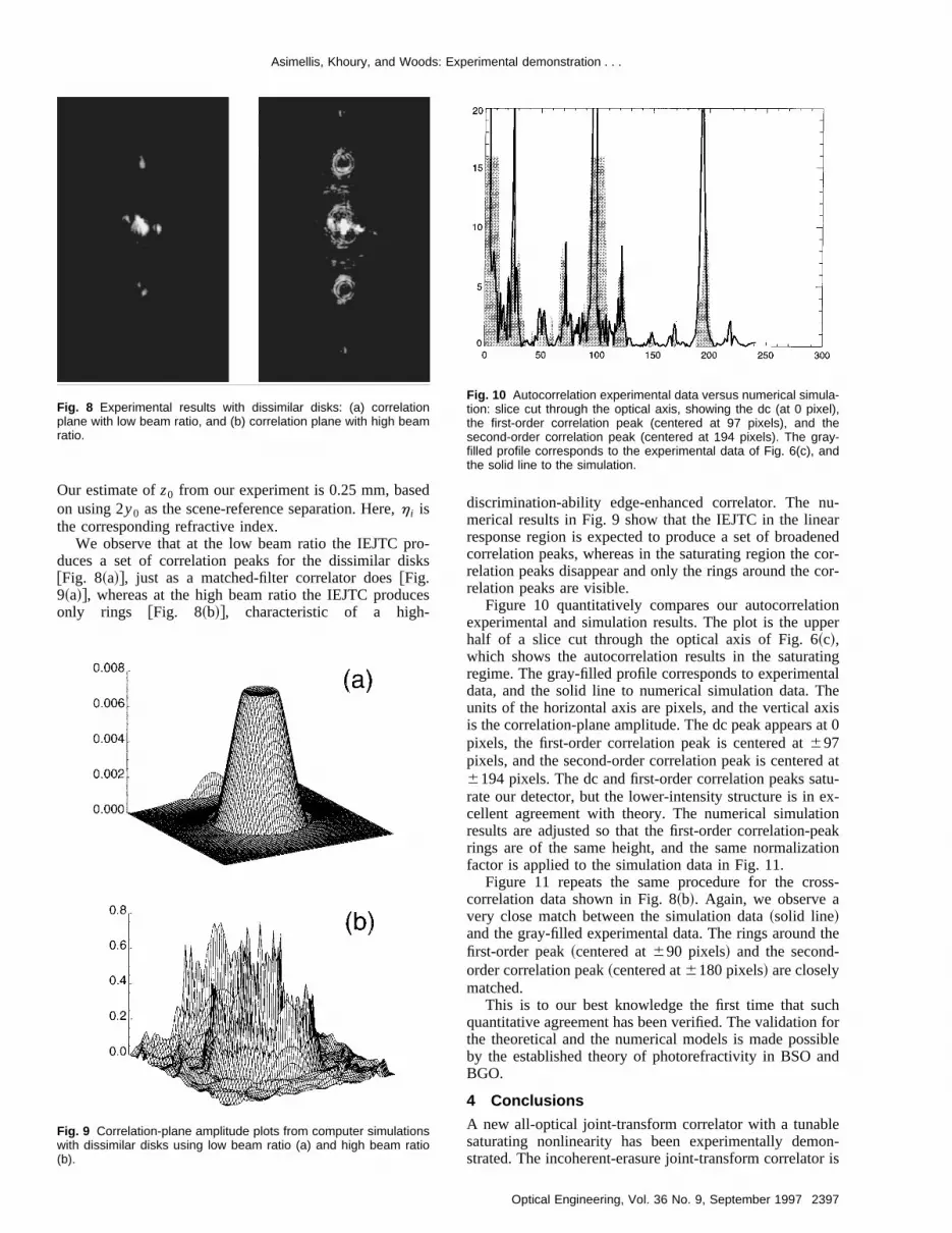
Figure 10 quantitatively compares our autocorrelatexperimental and simulation results. The plot is the uphalf of a slice cut through the optical axis of Fig. 6~c!,which shows the autocorrelation results in the saturatregime. The gray-filled profile corresponds to experimendata, and the solid line to numerical simulation data. Tunits of the horizontal axis are pixels, and the vertical ais the correlation-plane amplitude. The dc peak appearspixels, the first-order correlation peak is centered at697pixels, and the second-order correlation peak is centere6194 pixels. The dc and first-order correlation peaks sarate our detector, but the lower-intensity structure is in ecellent agreement with theory. The numerical simulatiresults are adjusted so that the first-order correlation-prings are of the same height, and the same normalizafactor is applied to the simulation data in Fig. 11.
Figure 11 repeats the same procedure for the crocorrelation data shown in Fig. 8~b!. Again, we observe avery close match between the simulation data~solid line!and the gray-filled experimental data. The rings aroundfirst-order peak~centered at690 pixels! and the second-order correlation peak~centered at6180 pixels! are closelymatched.
This is to our best knowledge the first time that suquantitative agreement has been verified. The validationthe theoretical and the numerical models is made possby the established theory of photorefractivity in BSO aBGO.
4 Conclusions
A new all-optical joint-transform correlator with a tunabsaturating nonlinearity has been experimentally demstrated. The incoherent-erasure joint-transform correlato
Fig. 10 Autocorrelation experimental data versus numerical simula-tion: slice cut through the optical axis, showing the dc (at 0 pixel),the first-order correlation peak (centered at 97 pixels), and thesecond-order correlation peak (centered at 194 pixels). The gray-filled profile corresponds to the experimental data of Fig. 6(c), andthe solid line to the simulation.
2397Optical Engineering, Vol. 36 No. 9, September 1997

eri-
eri-to-amor-y athese
tedss-ilarultsre-
rgeryed
nt-
he
nt-
ing
li-
ve
r-
-
e-
lz,of
u,
cal
eell
114
ni-
ds,
e-
ise
alical
e
Asimellis, Khoury, and Woods: Experimental demonstration . . .
capable of using any erasable real-time holographic mdium, which includes many new fast materials. Our expemental realization based on photorefractive BGO has vfied that the IEJTC can be tuned by the incoherent-coherent beam intensity ratio. With a small erasure-beintensity the IEJTC shows classical matched-filter perfmance, but simply by increasing the erasure beam bfactor of 3 one tunes to the saturation regime, whereIEJTC performs as a phase-extracting correlator. Increapeak intensity and discrimination ability was demonstraat the saturating regime. Autocorrelation and crocorrelation were demonstrated using similar and dissimimages. Significant features in the experimental resquantitatively agree with their corresponding simulationsults.
Acknowledgments
This research was performed at Rome Laboratory. GeoAsimellis is supported for this work by Rome Laboratocontract No. F 19628-92-K-0006. J. Khoury is supportby Rome Laboratory contract No. F 30602-94-C-0262.
References
1. J. Khoury, G. Asimellis, and C. Woods, ‘‘Incoherent-erasure joitransform correlator,’’Opt. Lett.20~22!, 2321–2323~1995!.
2. G. Asimellis, J. Khoury, and C. Woods, ‘‘Effects of saturation on tnonlinear incoherent-erasure joint-transform correlator,’’J. Opt. Soc.Am. A13~7!, 1345–1356~1996!.
3. G. Asimellis, J. Khoury, and C. Woods, ‘‘Photorefractive incohereerasure joint-transform correlator,’’Proc. SPIE 2849, 293–299~1996!.
4. J. L. Horner, USAF Rome Laboratories, Optical Signal ProcessBranch, Private Communication~1995!.
5. B. Javidi and J. Horner, ‘‘Optical pattern recognition system for vadation and security verification,’’Opt. Eng.33, 1752–1757~1994!.
6. J. O. White and A. Yariv, ‘‘Real time image processing via four-wamixing,’’ Appl. Phys. Lett.37, 5–7 ~1980!.
7. L. Pichon and J. P. Huignard, ‘‘Dynamic joint-Fourier-transform corelator by Bragg diffraction in photorefractive Bi22SiO20 crystals,’’Opt. Commun.36, 277–280~1981!.
8. K. H. Fielding and J. L. Horner, ‘‘Clutter effects on optical correlators,’’ Proc. SPIE1151, 130–137~1989!.
9. J. Khoury, M. Cronin-Golomb, P. Gianino, and C. Woods, ‘‘Photor
Fig. 11 Cross-correlation experimental data versus numerical simu-lation: slice cut through the optical axis showing the dc (at 0 pixel),the first-order correlation peak (centered at 90 pixels), and thesecond-order correlation peak (centered at 180 pixels). The gray-filled profile corresponds to the experimental data of Fig. 8(b), andthe solid line to the simulation.
2398 Optical Engineering, Vol. 36 No. 9, September 1997
-
d
fractive two-beam-coupling nonlinear joint-transform correlator,’’J.Opt. Soc. Am. B11, 2167–2174~1994!.
10. C. Halvorson, B. Kraabel, A. J. Heeger, B. L. Volodin, K. MeerhoSandalphon, and N. Peyghambarian, ‘‘Optical computing by usephotorefractive polymers,’’Opt. Lett.20, 76–78~1995!.
11. G. G. Malliaras, V. V. Krasnikov, H. I. Bolink, and G. Hadziioanno‘‘Transient behaviour of photorefractive gratings in a polymer,’’Appl.Phys. Lett.67, 455 ~1995!.
12. N. Hampp, R. Thoma, D. Oestrehelt, and C. Brauchle, ‘‘Biologiphotochrome bacteriorhodopsin and its genetic variant Asp96→Asnas media for optical pattern recognition,’’Appl. Opt.31, 1834–1841~1992!.
13. S. Boothroyd, L. Chan, J. Chrostowski, and A. Partovi, ‘‘Real timimage correlation using a photorefractive multiple quantum wstructure,’’ in OSA Annual Meeting of 1995, OSA Technical DigestSeries, Optical Society of America, Washington, paper WJJ2, p.~1995!.
14. H. Rajbenbach, ‘‘Dynamic holography in optical pattern recogtion,’’ Proc. SPIE2237, 329–346~1994!.
15. J. Khoury, J. Kane, G. Asimellis, M. Cronin-Golomb, and C. Woo‘‘All optical nonlinear joint Fourier transform correlator,’’Appl. Opt.33, 8216–8225~1994!.
16. Y. Shi, D. Psaltis, A. Marrakchi, and A. R. Tanguay, Jr., ‘‘Photorfractive incoherent-to-coherent optical converter,’’Appl. Opt. 22,3665–3667~1983!.
17. D. O. North, ‘‘An analysis of the factors which determine signal/nodiscriminations in pulsed carrier systems,’’Proc. IEEE 51, 1016–1027 ~1963!.
18. J. L. Horner and P. D. Gianino, ‘‘Phase-only matched filtering,’’Appl.Opt. 23, 812–816~1984!.
19. A. Marrakchi, A. R. Tanguay, Jr., J. Yu, and D. Psaltis, ‘‘Physiccharacterization of the photorefractive incoherent-to-coherent optconverter,’’Opt. Eng.24, 124–131~1985!.
20. G. C. Valley and M. K. Klein, ‘‘Optimal properties of photorefractivmaterials for optical data processing,’’Opt. Eng.22, 704–711~1983!.
George Asimellis graduated from the Na-tional University of Athens, Greece, with adiploma in physics in 1988, and from TuftsUniversity with a master’s in physics in1991. He is currently completing his PhDin the Electro-Optics Technology Center,Tufts University, working in photorefractivenonlinear optics, real-time holography,and device applications in all-optical joint-transform correlators. Mr. Asimellis is sup-ported by the Optical Signal Processing
Group at Rome Laboratory, Hanscom AFB. During his graduatework he published eight papers (six refereed) in scientific journals,made six conference presentations, and coinvented one U.S. patentdisclosure. A current update of Mr. Asimellis’s work, along with per-sonal information, can be found at his web page, at http://www.tufts.edu/;gasimel1.
Jehad Khoury obtained his MSc inelectro-optics from the Hebrew Universityof Jerusalem in 1983, and his PhD inphysics from Essex University in 1989. Hiswork on his PhD thesis was one of the ear-liest in the application of photorefractivenonlinear optics to optical signal process-ing. A few months after his graduation hejoined the technical staff of Rome labora-tory as a visiting scientist from Tufts Uni-versity, where his most recent appoint-
ment was associate research professor. Currently he is an adjunctprofessor with U. Mass Lowell University and the president ofLartec, Inc. He has already published nearly 85 technical papers inphotorefractive nonlinear optics and various areas of signal process-ing. He is the coinventor of 15 patents of which 10 have been is-sued. Among his most significant contributions is the first coimple-mentation of the optical lock-in amplifier, nonlinear opticalcompounding processors for noise reduction, and optical correla-tors. His current research interest includes photorefractive nonlinearoptics and signal processing with application to pattern recognition,biomedical optics, and nondestructive testing.

Asimellis, Khoury, and Woods: Experimental demonstration . . .
Charles L. Woods received a BA degreefrom Pomona College and MS and PhDdegrees from Harvard University. He is amember of the Optical Signal ProcessingGroup at Rome Laboratory, HanscomAFB, Massachusetts. His current researchinterests are low-power nonlinear opticsand pattern recognition.
2399Optical Engineering, Vol. 36 No. 9, September 1997