Embed Size (px)
Citation preview

lable at ScienceDirect
Marine and Petroleum Geology 51 (2014) 70e78
Contents lists avai
Marine and Petroleum Geology
journal homepage: www.elsevier .com/locate/marpetgeo
Experimental research on the mechanical properties of methanehydrate-bearing sediments during hydrate dissociation
Yongchen Song, Yiming Zhu, Weiguo Liu*, Jiafei Zhao, Yanghui Li, Yunfei Chen,Zhitao Shen, Yan Lu, Chongming JiKey Laboratory of Ocean Energy Utilization and Energy Conservation of Ministry of Education, School of Energy and Power Engineering, Dalian University ofTechnology, Dalian 116024, PR China
a r t i c l e i n f o
Article history:Received 17 October 2013Received in revised form26 November 2013Accepted 27 November 2013Available online 8 December 2013
Keywords:Methane hydrate-bearing sedimentsHydrate dissociationMechanical propertiesMohreCoulomb criterion
* Corresponding author. Tel.: þ86 411 84706795; faE-mail addresses: [email protected] (Y. Zhu)
0264-8172/$ e see front matter � 2013 Elsevier Ltd.http://dx.doi.org/10.1016/j.marpetgeo.2013.11.017
a b s t r a c t
This paper describes studies of the effect of hydrate dissociation on the safety and stability of methanehydrate-bearing sediments. Methane hydrates within the sediments were dissociating under the con-ditions of a confining pressure of 0.5 MPa, 1 MPa, 2 MPa and a temperature of �5 �C. After 6 h, 24 h, or48 h, a series of triaxial compression tests on methane hydrate-bearing sediments were performed. Thetests of ice-clay and sediments without hydrate dissociationwere performed for comparison. Focusing onthe mechanical properties of the sediments, the experimental results indicated that the shear strength ofthe ice-clay mixtures was lower than that of the methane hydrate-bearing sediments. The strength of thesediments was reduced by hydrate dissociation, and the strength tended to decrease further at the lowerconfining pressures. The secant modulus ES of the sediments dropped by 42.6% in the case of thedissociation time of the hydrate of 48 h at the confining pressure of 1 MPa; however, the decline of theinitial yield modulus E0 was only 9.34%. The slower hydrate dissociation rate contributed to reducing thefailure strength at a declining pace. Based on the MohreCoulomb strength theory, it was concluded thatthe decrease in strength was mainly affected by the cohesive reduction. Moreover, the mathematicalexpression of the MeC criterion related to the hydrate dissociation time was proposed. This researchcould be valuable for the safety and stability of hydrate deposits in a permafrost region.
� 2013 Elsevier Ltd. All rights reserved.
1. Introduction
The largest accumulations of natural gas on Earth are in the formof gas hydrate, which occur worldwide on continental and insularslopes and rises of active and passive margins, on continentalshelves of polar regions, and in deep-water environments of in-land lakes and seas; and recently, 3D seismic data and high-resolution seismic reflection data have provided informationabout the existence of gas hydrate around these regions(Kvenvolden, 1995; Kvenvolden et al., 1993; Rajan et al., 2013;Simonetti et al., 2013). The extensive applications of nature gashydrates in engineering include preconditioning of the fuel gasmixture before combustion (Ponnivalavan et al., 2013), natural gastransport and storage materials (Nam-Jin et al., 2010) and me-chanical separation of CO2 from combustion effluent (Theunissenet al., 2011). Methane hydrates, the solids composed of rigidcages of water molecules that enclose methane, represent an
x: þ86 411 84708015., [email protected] (W. Liu).
All rights reserved.
important possible future energy source (Darvish, 2004;Kvenvolden, 1988). Although the exploitation of methane hydratecan efficiently satisfy the increasing energy demand (Collet, 2002),there are still important difficult-to-solve issues, such as the naturaldisasters of submarine landslides and tsunamis and the increase ofthe greenhouse effect caused by the dissociation of hydrate (Kayenand Lee,1991; Brown et al., 2006; Blumier, 2000; Glasby, 2003; Kimet al., 2013). Therefore, it is essential to study the mechanicalproperties of methane hydrate-bearing sediments during hydratedissociation to guarantee the safety and stability of hydratedeposits.
The mechanical properties of hydrate-bearing sediments havebeen studied in recent years, along with the development oftechnology and the maturation of testing equipment. Durham et al.(2003) studied the creep characteristics of pure artificial methanehydrate, and the studies indicated that the strength of thesemethane hydrates were much stronger than ice under the sameconditions. Winters et al. (2004, 2007) indicated that the strengthwas enhanced in the case of the sediments containing hydrateunder the triaxial compression tests on artificial and undisturbedsamples of hydrate-bearing sediments, and a further study was

Figure 1. Grain size distribution curve of kaolin clay.
Y. Song et al. / Marine and Petroleum Geology 51 (2014) 70e78 71
made to investigate the shear strength characteristics of hydrateand ice and the dependence of the shear strength of hydrate-bearing sediment on the pore space contents. Hyodo et al. (2005,2007) found that the strength of artificial hydrate-bearing sedi-ments was affected by temperature, confining pressure, saturationof the hydrate and strain rate. Masui et al. (2005) andMiyazaki et al.(2009, 2010) reported that the shear strength and secant modulusof hydrate-bearing sediments increased with the increasing satu-ration of the hydrate, and that the shear strength increased withthe decrease of the porosity at the same degree of saturation.Subsequently, Masui et al. (2007) observed the mechanical prop-erties of gas hydrate samples from eastern Nankai Through and thesynthetic samples. They determined that the two specimens havethe same compressive strength, while there is a significant differ-ence between the two samples in the elastic modulus. Yu et al.(2011a,b) presented a constitutive model of the stressestrain formethane hydrate and methane hydrate-bearing sediment based onthe nonlinear elastic DuncaneChang model. Li et al. (2012) notedthat the cohesion decreases while the internal friction angle in-creases with the increasing hydrate content under a series oftriaxial compression tests on artificial methane hydrate-ice mix-tures. Liu et al. (2013) analyzed the strength difference between theCO2 and CH4 hydrate-bearing sediments to evaluate the safety ofthe CH4eCO2 replacement method.
Although there has been much research on the mechanicalproperties of hydrate-bearing sediments, the effect of hydratedissociation on the safety and stability of methane hydrate-bearingsediments has rarely been studied. To clarify the dependence of thestrength of hydrate-bearing sediment on the dissociation time, aseries of triaxial compression tests on artificial methane hydrate-bearing sediments with 40% porosity were performed underdifferent confining pressure and the differences between the sed-iments and ice-clay mixtures was studied.
2. Experimental methods
2.1. Specimen preparation
Ice powder and kaolin clay were used to produce the specimensin this study. Themethane hydrate for this study was manufacturedin a high-pressure chamber using methane and ice powder (Sternand Kirby, 1998). First, ice powder was manufactured by using anice crusher to break the prepared freezing distilled water. Then, astandard 60-mesh sievewas used to obtain the suitable ice powder,which had amean particle size of 250 mm. After that, the ice powderwas put into a pressure reactor, and then the reactor was filled with
methane gas of 99.99% purity until the pressure of the chamberreached to 8 MPa. Next, the reactor was put into the cold storage atthe constant temperature of �10 �C for 72 h, during which themethane gas and ice powder had been reacted completely to formmethane hydrate. According to the difference of the mass of themethane hydrate-ice mixture before and after hydrate dissociation,the calculated results of methane hydrate saturation were in therange of 25%e30%. Finally, the methane hydrate-bearing sedimentswere manufactured using the methane hydrate-ice mixture andkaolin clay, which was cooled in the cold storage as materials. Thegrain size distribution curve of kaolin, shown in Figure 1, wasanalyzed by a laser particle size analyzer. To obtain the cylindricalmethane hydrate-bearing sediment with 40% porosity whose sizewas 61.8 mm diameter � 125 mm height, 553 g of kaolin and 147 gof methane hydrate-ice mixture were evenly mixed, and then thefinal mixture was placed into a pressure moulding device to formthe specimen at a controlled axial load of 30 kN. Because of thenearly identical density between ice powder and the methanehydrate-icemixture, kaolin clay and pure ice powder weremixed inthe same proportion, that is, 553 g of kaolin and 147 g of pure icepowder, for making the ice-clay mixture samples. All the aboveprocesses were performed in the conditions of cold storage(�10 �C).
2.2. Triaxial testing apparatus
A DDW-600 triaxial testing device was used to conduct all thetests. The schematic diagram of the device is shown in Figure 2. Thisdevice consists of an axial loading system, a servo-control system, aconfining pressure control system, a temperature control systemand a computer control system, which can conduct strength tests,creep tests, stress relaxation tests and permeability experiments ofhydrate with various confining pressure, temperature, strain rateand saturation. Two pressure chambers have been originally usedto avoid the leakage of hydraulic oil due to the difference betweeninner and outer pressure in the structure of one pressure chamber.The technical indicators of the device are listed in Table 1.
The test sample is jacketed in the inside pressure chamber,which is covered by the outside pressure chamber. Then the tworespective pressure chambers are filled with hydraulic oil, whichcomes from the storage tank. The axial loading system is used to liftthe entire device to the proper height. Next, the high-precisionservo motors drive the plunger pumps forward or backward tomaintain the confining pressure of the two chambers required inexperiments. Meanwhile, a constant temperature bath provides thecirculating coolant liquid to cool the specimen down through the

Figure 2. The schematic diagram of the DDW-600 triaxial testing device. (1) Specimen; (2) thermocouple; (3) heat exchanger; (4) axial load cell; (5) air pressure line; (6) pressuregauge; (7) hydraulic oil tank; (8) plunger pump; (9) high-precision servo motor; (10) thermostatic bath; (11) computer.
Table 1The technical indicators of the triaxial testing device.
Technical indicators Value and unit
Maximum axial stress 600 kNAccuracy of axial stress �0.5%Maximum confining pressure 30 MPaAccuracy of confining pressure �1%Measurement range of axial deformation 0w50 mmMeasurement accuracy of axial deformation �0.1%Temperature control scope �20 �C w room
temperatureAccuracy of temperature control �0.5 �CRange of piston displacement 0w100 mmMeasurement accuracy of piston displacement �1%
Table 2Experimental conditions of the triaxial compression tests on the ice-clay mixture.
Temperature T (�C) Confining pressure s3 (MPa) Strain rate 3(%/min)
�5 0.5, 1, 2 1
Table 3Experimental conditions of the triaxial compression tests on the methane hydrate-bearing sediments.
Temperature T (�C) Confiningpressure s3 (MPa)
Strainrate 3(%/min)
Dissociation time (h)
�5 0.5, 1, 2 1 0, 6, 24, 48
Y. Song et al. / Marine and Petroleum Geology 51 (2014) 70e7872
heat exchanger, which is located in the inside pressure chamber.During the dissociation processes of the methane hydrate-bearingsediments, the confining pressure should remain unchanged. Thetemperature of the specimen is collected by a thermocouple, whichis placed in the inside chamber. During the shear process, the axialstress and the axial strain are controlled and measured by a loadcell and a displacement sensor, respectively. The amount of axialstrain rate is entered at the start of the test and then the shear testsare conducted automatically from start to finish by using thetriaxial testing software.
2.3. Test conditions
The test parameters are listed in Tables 2 and 3. The studies werefocused on the specimens with 40% porosity. Before the tests, theprepared samples were removed from the pressure moulding de-vice and timely connected to the upper and bottom pressure padswrapped with a rubber membrane. After jacketing the test samplein the inside pressure chamber, the two pressure chambers were inturn connected to the base by the use of seal ring and snap ring.Then the pressure chambers were filled with hydraulic oil throughthe confining pressure loading system. All of the specimens wereconsolidated at the confining pressure of 10 MPa for 2 h. Accordingto the steady criterion during the consolidation of saturated soil,the consolidation is completed when the deformation of specimenis less than 0.005 mm in an hour (Li, 2002). In our experiment, thedeformation of sediments was less than 0.005 mm in the last hourduring the 2 h of consolidation. So 2 h is long enough for consoli-date the sediments. To reducemethane hydrate decomposition, theabove processes were performed in cold storage (�10 �C). Whenthe drainage consolidation was completed, the confining pressureand temperature were adjusted to the set values (confining pres-sures of 0.5 MPa, 1 MPa, and 2 MPa and a temperature of �5 �C)according to the phase equilibrium conditions of methane hydrate,which would result in the dissociation of hydrate within themethane hydrate-bearing sediments. As listed in Table 3, after 6 h,24 h, or 48 h, the triaxial compression tests on the specimens overdifferent dissociation time were performed. For example, at theconfining pressure of 1 MPa and the temperature of �5 �C, thesediment was under shear after the hydrate dissociation of 6 h; foranother test, the sediment was sheared after 24 h at the sameconfining pressure and temperature. During each entire
decomposition process, the confining pressure and temperatureremained unchanged at the desired values through the confiningpressure control system and the heat exchanger, and the methanegas produced by decomposition entered into the pore space ofsamples and was kept to stay in the pore of sediment during longtine of dissociation under the conditions without drain. In addition,the tests on the ice-clay mixtures and themethane hydrate-bearingsediments without hydrate dissociation were immediately per-formed after the consolidation. All of the undrained triaxial sheartests were performed under the conditions of the temperature of�5 �C and a strain rate of 1%/min. The conditions of the confiningpressure were 0.5 MPa, 1 MPa, and 2 MPa. Obtaining the

Figure 3. Stressestrain curves of the 440 artificial methane hydrate-bearing sedi-ments and the ice-clay mixture.
Y. Song et al. / Marine and Petroleum Geology 51 (2014) 70e78 73
experiment data was conducted in time by the computer dataacquisition system.
3. Results and discussions
3.1. Stressestrain behaviors of methane hydrate-bearing sedimentsand ice-clay mixtures
Figure 3 shows the stressestrain curves of 440 (porosity of 40%)artificial methane hydrate-bearing sediments and ice-claymixturesbased on the triaxial compression tests. From Figure 3, all thecurves exhibited the shape of a hyperbola. However, strain hard-ening behavior of the methane hydrate-bearing sediments wasobserved, while the ice-clay mixture exhibited weak strain soft-ening type behavior. The phenomenon of strain hardening becamemore obvious with increasing confining pressure. This trend indi-cated that the deformation characteristic is affected by theconfining pressure and the existence of methane hydrate (Li et al.,2012). As shown in Figure 3, the deviator stresses of all the ice-claymixtures were lower than those of methane hydrate-bearing sed-iments (hydrate-clay). Winters noted that the shear strength ofspecimens increased if natural gas hydrate cemented the grains ofthe sediments, and that the enhancement of shear strength wasrelated to the experimental conditions (Winters et al., 2004). Basedon the analysis above, a possible explanation for our findings is thatthe cementation between methane hydrate and kaolin clay parti-cles had occurred during the sample preparation process, therebyenhancing the soil structure. This enhancement indicates that theshear strength would increase if the sediments contained methanehydrate in our experiments. Furthermore, the gap of the deviatorstress between the two types of specimens increased with the riseof the confining pressure. One reason of this findingmay be that theenhancement of the cementation caused by methane hydrate be-tween kaolin clay particles increased with the increase in theconfining pressure.
3.2. Effect of hydrate dissociation on the failure strength
Figure 4 shows the stressestrain curves of methane hydrate-bearing sediments at each dissociation stage under variousconfining pressures. The data in Figure 4 indicates that all speci-mens underwent elasticeplastic deformation. The deviator stressincreased rapidly with increasing axial strain at the initial periodand then reached a steady value. The deviator stress correspondingto 15% strain was taken as the failure strength due to the lack of apeak value during the compression.
Figure 5 shows the failure strength of the methane hydrate-bearing sediments versus the dissociation time of the hydrate.Obviously, the results indicate that the failure strength of themethane hydrate-bearing sediments decreasedwith the increase ofthemethane hydrate dissociation time at the confining pressures of0.5 MPa, 1 MPa and 2 MPa. The data accurately indicated that thestrength of the sediments was broken by the dissociation ofmethane hydrate. One reason for this behavior could be deducedfrom the observation that methane gas and water were producedby the dissociation of hydrate. The existence of methane gas in thepore spaces resulted in the rise of the pore pressure, which in turnresulted in the decrease in the sediment strength. The moremethane gas that is available for the successive hydrate dissocia-tion, the higher is the pore pressure, and the more weakening thatoccurs in the sediment strength. In our experiment, the porepressure value was measured by a pressure sensors located in thedrain hole. During the hydrate dissociation, the pore pressuregradually increased which indicated that free methane gas wasentering into the pore space; however, the pore pressure value did
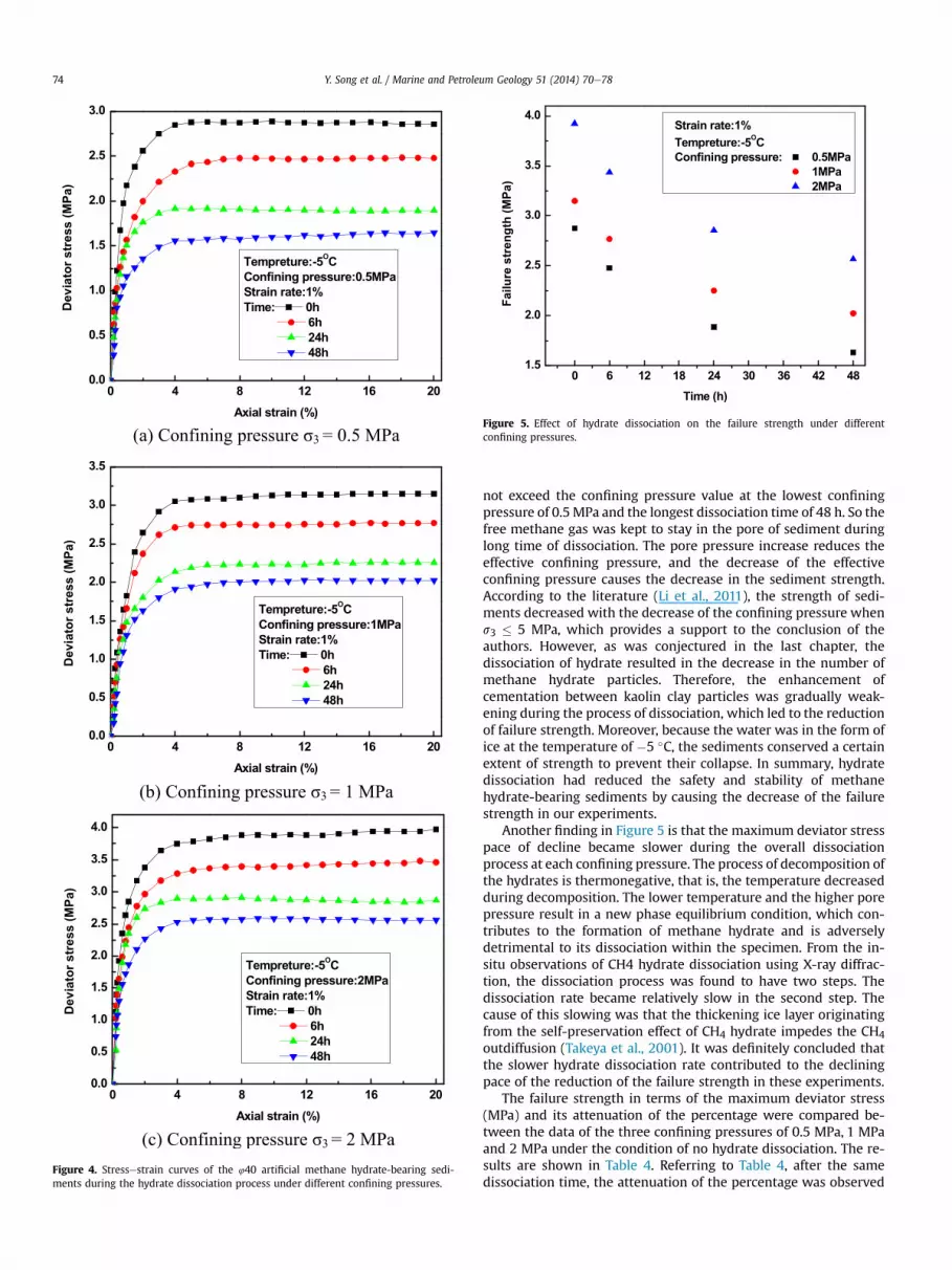
Figure 4. Stressestrain curves of the 440 artificial methane hydrate-bearing sedi-ments during the hydrate dissociation process under different confining pressures.
Figure 5. Effect of hydrate dissociation on the failure strength under differentconfining pressures.
Y. Song et al. / Marine and Petroleum Geology 51 (2014) 70e7874
not exceed the confining pressure value at the lowest confiningpressure of 0.5MPa and the longest dissociation time of 48 h. So thefree methane gas was kept to stay in the pore of sediment duringlong time of dissociation. The pore pressure increase reduces theeffective confining pressure, and the decrease of the effectiveconfining pressure causes the decrease in the sediment strength.According to the literature (Li et al., 2011), the strength of sedi-ments decreased with the decrease of the confining pressure whens3 � 5 MPa, which provides a support to the conclusion of theauthors. However, as was conjectured in the last chapter, thedissociation of hydrate resulted in the decrease in the number ofmethane hydrate particles. Therefore, the enhancement ofcementation between kaolin clay particles was gradually weak-ening during the process of dissociation, which led to the reductionof failure strength. Moreover, because the water was in the form ofice at the temperature of �5 �C, the sediments conserved a certainextent of strength to prevent their collapse. In summary, hydratedissociation had reduced the safety and stability of methanehydrate-bearing sediments by causing the decrease of the failurestrength in our experiments.
Another finding in Figure 5 is that the maximum deviator stresspace of decline became slower during the overall dissociationprocess at each confining pressure. The process of decomposition ofthe hydrates is thermonegative, that is, the temperature decreasedduring decomposition. The lower temperature and the higher porepressure result in a new phase equilibrium condition, which con-tributes to the formation of methane hydrate and is adverselydetrimental to its dissociation within the specimen. From the in-situ observations of CH4 hydrate dissociation using X-ray diffrac-tion, the dissociation process was found to have two steps. Thedissociation rate became relatively slow in the second step. Thecause of this slowing was that the thickening ice layer originatingfrom the self-preservation effect of CH4 hydrate impedes the CH4
outdiffusion (Takeya et al., 2001). It was definitely concluded thatthe slower hydrate dissociation rate contributed to the decliningpace of the reduction of the failure strength in these experiments.
The failure strength in terms of the maximum deviator stress(MPa) and its attenuation of the percentage were compared be-tween the data of the three confining pressures of 0.5 MPa, 1 MPaand 2 MPa under the condition of no hydrate dissociation. The re-sults are shown in Table 4. Referring to Table 4, after the samedissociation time, the attenuation of the percentage was observed

Table 4The maximum deviator stress and its percentage of attenuation.
Time (h) Confining pressure 0.5 MPa Confining pressure 1 MPa Confining pressure 2 MPa
Maximum deviatorstress (MPa)
Percentageof attenuation (%)
Maximumdeviator stress (MPa)
Percentageof attenuation (%)
Maximum deviatorstress (MPa)
Percentageof attenuation (%)
0 2.87 0 3.15 0 3.92 06 2.48 13.83 2.77 12.1 3.44 12.4824 1.89 34.35 2.25 28.55 2.85 27.2748 1.63 43.24 2.02 35.76 2.57 34.6
Y. Song et al. / Marine and Petroleum Geology 51 (2014) 70e78 75
to become greater at the lower confining pressure. For example, thefailure strength was 43.24% lower at the confining pressure of0.5 MPa, while it was 34.6% lower at the confining pressure of2 MPa. It appears that the lower the confining pressure is, the moresevere is the damage to the soil strength caused by hydrate disso-ciation. These results imply that the dissociation of hydrate reser-voirs buried in shallower soil could bring about more seriousdamage to the stability of the surrounding soil.
3.3. Effect of hydrate dissociation on the initial yield modulus E0and the secant modulus ES
Figures 6 and 7 show the initial yield modulus E0 and secantmodulus ES, respectively, of methane hydrate-bearing sedimentsversus the dissociation time of the hydrate at each confiningpressure. The corresponding deviator stress and axial strain at thepoint where the slope has an obvious change on the stressestraincurve are defined as the initial yield strength q0, and the initial yieldstrain 30, and their ratio is defined as the initial yield modulus E0,that is, E0 ¼ q0/ 30 (Zhu and Carbee, 1984). In general, the secantmodulus ES is defined as the slope of the line from the zero point tothe point where the deviator stress is one-third of the maximumdeviator stress.
From Figure 6 it can be clearly observed that E0 decreased onlyby a very small amount over the dissociation time. The decline of E0was only 9.28%, 9.34%, and 5.86% under the conditions of thedissociation time of 48 h and the confining pressures of 0.5 MPa,1 MPa, and 2 MPa, respectively. It seems that the dissociation ofhydrate did not have a significantly effect on the initial yieldmodulus E0 of methane hydrate-bearing sediments. In addition, E0increased with the increasing confining pressure at each
Figure 6. Effect of hydrate dissociation on the initial yield modulus E0 under differentconfining pressures.
dissociation stage. However, as shown in Figure 7, the secantmodulus ES exhibited a remarkable tendency to decrease during thehydrate dissociation. For example, ES dropped by 42.6% for thedissociation time of hydrate of 48 h at the confining pressure of1 MPa. It is generally known that secant modulus ES is a veryimportantmechanical parameter, so the lower value of ES under thesame axial strain implies the lower stress, which could cause alarger deformation of the methane hydrate-bearing sediments andserious damage to their safety and stability. That is, the mechanicalperformance of these specimens would be sharply weakeningwhile the methane hydrates start to dissociate. At later times, thepace of decline of ES became slower, which was similar to thebehavior of the maximum deviator stress in Figure 5 during thedissociation process at each confining pressure.
3.4. The analysis of the failure strength according to the MohreCoulomb strength theory
The MohreCoulomb strength criterion, which is called MeCcriterion for short, is themost widely used theory in soil mechanics.The theory holds that failure will occur when the shear stress on afailure plane reaches the shear strength. For cohesive soil, themathematical expression of MeC criterion is:
s ¼ cþ stan4 (1)
where c is the cohesive force and 4 is the internal friction angle.When the Mohr’s stress circle is tangent to the shear strength en-velope, the shear stress at the point of tangency is the shearstrength. At this time, the equation can be described by followingexpressions:
Figure 7. Effect of hydrate dissociation on the secant modulus Es under differentconfining pressures.

Y. Song et al. / Marine and Petroleum Geology 51 (2014) 70e7876
sin4 ¼ s1 � s3s1 þ s3 þ 2ccot4
(2)
s1 ¼ s3tan2�45
� þ 4
2
�þ 2ctan2
�45
� þ 4
2
�(3)
where s1 is the major principal stress and s3 is the confiningpressure.
As shown in Figure 8, Mohr’s stress circles under triaxialcompression tests are used to describe the failure behavior of themethane hydrate-bearing sediments. As shown in Table 5, based onthe analysis of the MohreCoulomb strength criterion, the data ofthe internal friction angle and the cohesive force over differentdissociation times was acquired. From Table 5, the cohesive forceand the internal friction angle both clearly decreased with theincreasing dissociation time. The cohesive force decreased sharply,while the internal friction angle reduced slightly. These findingssuggested that the failure strength reduction of methane hydrate-bearing sediments was mainly affected by the decrease in thecohesive force. The effect of the internal friction angle on the failurestrength is negligible.
Figure 8. The Mohr’s stress circles and the strength envelopes of m
By using the data fitting method, the relationships between thecohesive force, the internal friction angle and the dissociation timeare obtained. The relationship between the cohesive force and thedissociation time is exponential, while the relationship betweenthe internal friction angle and the dissociation time is linear:
c ¼ 0:472*exp� �t16:82
�þ 0:506 (4)
4 ¼ 14:812� 0:0187t (5)
where t is the dissociation time of the methane hydrate. The rela-tionship between tan 4 and the dissociation time is presented inthe same way:
tan4 ¼ 0:26445� 0:00035t (6)
Substituting Eqs. (4) and (6) into Eq. (1), the mathematicalexpression of MeC criterion becomes the following:
ethane hydrate-bearing sediments at each dissociation stage.

Table 5Parameters of strength obtained by MohreCoulomb strength theory.
Dissociation time (h) c (MPa) 4 (�) tan 4
0 0.9767 14.8943 0.26606 0.8435 14.5944 0.260424 0.6149 14.3809 0.256448 0.5366 13.9179 0.2478
Y. Song et al. / Marine and Petroleum Geology 51 (2014) 70e78 77
s ¼ 0:472*exp� �t16:82
�þ 0:506þ sð0:26445� 0:00035tÞ
(7)
Based on Eq. (7), the respective MohreCoulomb strength en-velopes of the methane hydrate-bearing sediment were calculated,and they are shown along with the Mohr’s stress circles in Figure 9.As shown in Figure 9, the mathematical expression of MeC crite-rion (7) could be used effectively to calculate the failure strength ofmethane hydrate-bearing sediments in a permafrost region. Theseresults could offer some useful recommendations for ensuring thesafety and stability of natural gas hydrate-bearing sediments.
4. Conclusions
In this study, a series triaxial compression tests on ice-claymixtures and artificial methane hydrate-bearing sediments with40% porosity were performed. The tests on methane hydrate-bearing sediments were performed over different hydrate dissoci-ation times. All the tests were performed under the conditions of atemperature of �5 �C and a strain rate of 1%/min. The confiningpressures used were 0.5 MPa, 1 MPa, and 2 MPa. The stressestraincurves of the ice-clay mixtures and artificial methane hydrate-bearing methane hydrate-bearing sediments were obtained. Theeffect of hydrate dissociation on the failure strength, yield modulusE0 and secant modulus ES were analyzed. Finally, the MohreCoulomb strength envelopes of methane hydrate-bearing sedi-ments were calculated at each dissociation stage based on theMohreCoulomb strength criterion. The following conclusions maybe made:
1. The failure strength of the ice-clay mixtures is lower than that ofthe methane hydrate-bearing sediments. This result suggests
Figure 9. The Mohr’s stress circles and the calculated MeC strength envelopes ofmethane hydrate-bearing sediments.
that there is cementation between methane hydrate and kaolinclay particles, thus enhancing the specimen structure. Further-more, the difference of the strengths between the two types ofspecimen increases with increasing confining pressure.
2. The strength of the methane hydrate-bearing sediments wasbroken by the dissociation of methane hydrate. Also, as methanehydrate is dissociating, the hydrate dissociation rate becomesslower. This slowing contributed to the slowing pace of reduc-tion of the failure strength.
3. The lower the confining pressure is, the more severe is thedamage to the sediment strength caused by hydrate dissocia-tion. This result indicates that the dissociation of the hydratereservoirs buried in shallower soil could bring about moreserious damage to the stability of the surrounding soil.
4. The initial yield modulus E0 of the methane hydrate-bearingsediment decreases by a very small amount, while the secantmodulus ES exhibits a significant decrease during the hydratedissociation.
5. Based on the MohreCoulomb strength criterion, the cohesiveforce of methane hydrate-bearing sediments decreases sharply,while the internal friction angle reduces slightly. It appears thatthe decrease of the shear strength was mainly affected by thecohesive force reduction during the hydrate dissociation pro-cess. It is calculated that the relationship between the cohesiveforce and the dissociation time is exponential, while the rela-tionship between the internal friction angle and the dissociationtime is linear.
The mechanical properties of methane hydrate-bearing sedi-ments were studied during the hydrate dissociation process. Thedissociation of methane hydrate is confirmed to lead to adverseeffects to the safety and stability of the sediments. The proposedmathematical expression of the MeC criterion considering the in-fluence of hydrate dissociation time could be useful for the safemining of hydrate in a permafrost region. Further research isrequired to observe the microstructure of the sediments through aCT scan; also, the effect of hydrate dissociation on the mechanicalproperties of methane hydrate-bearing sediments with differentsaturation should be investigated.
Acknowledgments
This study was supported by the Major National Science andTechnology Program (Grant No.2011ZX05026-004), the NationalHigh Technology Research and Development Program of China(863 Program) (Grant No.2013AA09250302), and the Natural Sci-ence Foundation of China (Grant No.51227005).
NomenclatureT temperature (�C)t dissociation time of hydrate (h)3 strain rate (%/min)s normal stress at failure plane (MPa)s1 major principal stress at failure (MPa)s3 confining pressure (MPa)s shear stress at failure (MPa)c cohesion force (MPa)4 internal friction angle (�)E0 initial yield modulus (MPa)ES secant modulus (MPa)
References
Blumier, T., 2000. “Frozen” methane escapes from the sea floor. Science 288 (5463),68e69.

Y. Song et al. / Marine and Petroleum Geology 51 (2014) 70e7878
Brown, H.E., Holbrook, W.S., Hornbach, M.J., et al., 2006. Slide structure and role ofgas hydrate at the northern boundary of the Storegga Slide, offshore Norway.Mar. Geol. 229 (3e4), 179e186.
Collet, T.S., 2002. Energy resource potential of natural gas hydrates. AAPG Bull. 86,1971e1992.
Darvish, M.P., 2004. Gas production from hydrate reservoirs and its modeling.J. Petrol. Technol. 71, 65e71.
Durham, W.B., Kirby, S.H., Stern, L.A., Zhang, W., 2003. The strength and rheology ofmethane clathrate hydrate. J. Geophys. Res. 108. ECV 2-1eECV 2-11.
Glasby, G.P., 2003. Potential impact on climate of the exploitation of methane hy-drate deposits offshore. Mar. Petrol. Geol. 20 (2), 163e175.
Hyodo, M., Nakata, Y., Yoshimoto, N., et al., 2005. Basic research on the mechanicalbehavior of methane hydrate-sediments mixture. J. Jpn. Geotech. Soc. SoilsFound. 45 (1), 75e85.
Hyodo, M., Nakata, Y., Yoshimoto, N., et al., 2007. Shear behavior of methanehydrate-bearing sand. In: The 17th International Offshore and Polar Engineer-ing Conference, Lisbon, Portugal.
Kayen, R.E., Lee, H.J., 1991. Pleistocene slope instability of gas hydrate-laden sedi-ment on the Beaufort sea margin. Mar. Geotechnol. 10, 125e141.
Kim, Y.G., Lee, S.M., Jin, Y.K., et al., 2013. The stability of gas hydrate field in thenortheastern continental slope of Sakhalin Island, Sea of Okhotsk, as inferredfrom analysis of heat flow data and its implication for slope failures. Mar. Petrol.Geol. 45, 198e207.
Kvenvolden, K.A., 1988. Methane hydrate e a major reservoir of carbon in theshallow geosphere. Chem. Geol. 71, 41e51.
Kvenvolden, K.A., Ginsburg, G.D., Soloviev, V.A., 1993. Worldwide distribution ofsubaquatic gas hydrates. Org. Geochem. 13, 32e40.
Kvenvolden, K.A., 1995. A review of the geochemistry of methane in natural gashydrate. Org. Geochem. 23 (11e12), 997e1008.
Li, J.P., 2002. The reliability of quick consolidated test. Geotech. Eng. Tech. 4, 205e208.
Li, Y.H., Song, Y.C., Yu, F., Liu, W.G., Wang, R., 2011. Effect of confining pressure onmechanical behavior of methane hydrate-bearing sediments. Petrol. Explor.Dev. 38 (5), 637e640.
Li, Y.H., Song, Y.C., Liu, W.G., Yu, F., 2012. Experimental research on the mechanicalproperties of methane hydrate-Ice mixture. Energies 5, 181e192.
Liu, W.G., Zhao, J.F., Luo, Y., Song, Y.C., et al., 2013. Experimental measurements ofmechanical properties of carbon dioxide hydrate-bearing sediments. Mar.Petrol. Geol. 46, 201e209.
Masui, A., Haneda, H., Ogata, Y., et al., 2005. The effect of saturation degree ofmethane hydrate on the shear strength of synthetic methane hydrate sedi-ments. In: The 5th International Conference on Gas Hydrates, Trondheim,Norway.
Masui, A., Haneda, H., Ogata, Y., et al., 2007. Mechanical properties of sandy sedi-ment containing marine gas hydrates in deep sea offshore Japan. In: The 17thInternational Offshore and Polar Engineering Conference, Lisbon, Portugal.
Miyazaki, K., Masui, A., Yamaguchi, T., et al., 2009. Strain-rate dependency of peakand residual strength of sediment containing synthetic methane hydrate intriaxial compression test. In: The 19th International Offshore and Polar Engi-neering Conference, Osaka, Japan.
Miyazaki, K., Masui, A., Sakamoto, Y., 2010. Effect of confining pressure on triaxialcompressive properties of artificial methane hydrate bearing sediments. In:Offshore Technology Conference, Houston, Texas, USA.
Nam-Jin, K., Jeong, H.L., Yil, S.C., Wongee, C., 2010. Formation enhancement ofmethane hydrate for natural gas transport and storage. Energy 35, 2717e2722.
Ponnivalavan, B., Rajnish, K., Praveen, L., 2013. Pre-combustion capture of carbondioxide in a fixed bed reactor using the clathrate hydrate process. Energy 50,364e373.
Rajan, A., Bunz, S., Mienert, J., Smith, A.J., 2013. Gas hydrate systems in petroleumprovinces of the SW-Barents Sea. Mar. Petrol. Geol. 46, 92e106.
Simonetti, A., Knapp, J.H., Sleeper, K., et al., 2013. Spatial distribution of gas hydratesfrom high-resolution seismic and core data, Woolsey Mound, Northern Gulf ofMexico. Mar. Petrol. Geol. 44, 21e33.
Stern, L.A., Kirby, S.H., 1998. Polycrystalline methane hydrate: synthesis from su-perheated ice and low temperature mechanical properties. Energy Fuels 12,201e211.
Takeya, S., Shimada, W., Kamata, Y., et al., 2001. In situ X-ray diffraction measure-ments of the self-preservation effect of CH4 hydrate. J. Phys. Chem. A 105,9756e9759.
Theunissen, T., Golombok, M., Brouwers, J.J.H., Bansal, G., 2011. Liquid CO2 dropletextraction from gases. Energy 36 (5), 2961e2967.
Winters, W.J., Pecher, I.A., Waite, W.F., et al., 2004. Physical properties and rockphysics models of sediment containing natural and laboratory-formed methanegas hydrate. Am. Mineral. 89 (8e9), 1221e1227.
Winters, W.J., Waite, W.F., Mason, D.H., et al., 2007. Methane gas hydrate effect onsediment acoustic and strength properties. J. Petrol. Sci. Eng. 56 (1e3), 127e135.
Yu, F., Song, Y.C., Li, Y.H., Liu, W.G., Lam, W.H., 2011a. Analysis of stressestrainbehavior and constitutive relation of methane hydrate-bearing sediments withvarious porosity. Int. J. Offshore Polar Eng. 21, 316e322.
Yu, F., Song, Y.C., Liu, W.G., Li, Y.H., Lam, W.H., 2011b. Analyses of stress strainbehavior and constitutive model of artificial methane hydrate. J. Petrol. Sci. Eng.77, 183e188.
Zhu, Y.L., Carbee, D.L., 1984. Uniaxial compressive strength of frozen silt underconstant deformation rates. Cold Regions Sci. Technol. 9, 3e15.


