Embed Size (px)
Citation preview
External Fixation of the Femur: Basic Concepts
Shyam Kishan, M.D., Sanjeev Sabharwal, M.D., Fred Behrens, M.D., Mark Reilly, M.D.,
and Michael Sirkin, M.D.
Summary: This article discusses the application of femoral external fixators, withemphasis on the cross sectional anatomy, mechanical considerations, and fixatorconfigurations. Safe, unsafe, and hazardous corridors are described, with recommen-dations for optimal and ideal pin placement. Fixator configurations and the biome-chanics are touched upon, with suggestions for difficult clinical situations such asosteopenic bone, small fracture fragments, and heavy patients. Key Words:Femoral external fixation—Safe corridors—Ideal pin plane.
Of all external fixators currently used, probably lessthan 10% are used to treat femoral lesions, and a majorityof these are used to treat pediatric lesions. Depending onthe nature of the clinical condition, its location, and thespecific mechanical demands, a wide variety of fixatorframes3,4 are used. These range from simple one planeunilateral frames to stabilize femoral shaft fractures, tomultiplane and length adjustable devices to manage com-plex limb deformities and length discrepancies. Thisdiscussion of the current use of femoral fixators willfocus on anatomic considerations, mechanical aspects,and preferred frame configurations.
RELEVANT ANATOMY
The principal structures that surround the femur andare vulnerable to drill/pin injuries are the femoral ves-sels, the femoral nerve, the sciatic nerve and its divisions,and the hip and the knee joints.12
The femoral nerve and the superficial femoral artery,which enter the lower extremity through the inguinalcanal, lie initially in an area that is rarely used for pininsertion. They quickly divide into several indistinctbranches and are rarely injured during the application ofthe fixator frame. In the proximal thigh, the saphenousnerve joins the superficial femoral vessels. Together they
take a course from a position anteromedial to the femoralshaft to a straight medial position in close adherence tothe bone in Hunter’s canal. Further distally, the saphe-nous nerve crosses toward the mid-aspect of the medialfemoral condyle where the infrapatellar branch splits offin a lateral direction. After exiting from Hunter’s canal,the femoral vessels continue to move posteriorly untilthey enter the popliteal fossa where they lie midwaybetween the femoral condyles. Through much of theircourse through the thigh, the femoral vessels are coveredand protected by the overlying sartorius muscle. Of allthe neurovascular structures in the thigh, the deep fem-oral vessels and the saphenous nerve are potentially mostvulnerable as they pass through Hunter’s canal because,in this location, their position is essentially fixed andthus, they are easily injured by drill or pin tips thatpenetrate the medial femoral cortex. While the positionand length of Hunter’s canal are variable, it can extend,according to one reliable study10 from about the mid-aspect of the femur to the distal one-sixth of its length.
In the trochanteric area, the sciatic nerve lies postero-medial to the femur. It soon splits into its femoral andperoneal branches, which assume a straight posteriorposition in the middle of the femur and then slightlydiverge as they approach the knee joint. The sciatic nerveand its branches, however, are never in direct contactwith the femur. They initially are separated from thebone by the gluteus maximus and further distally by thebiceps femoris.
The capsule of the hip joint extends in front down tothe base of the femoral neck and in the back to about half
From the Department of Orthopaedics, New Jersey Medical School,Newark, New Jersey, U.S.A.
Address correspondence and reprint requests to Fred Behrens, MD,90 Bergen Street DOC, #5200, Newark, NJ 07103-2499.
Techniques in Orthopaedics®
17(2):239–244 © 2002 Lippincott Williams & Wilkins, Inc., Philadelphia
239
way between the base of the neck and the subcapital area.The anterior extension of the knee joint, the suprapatellarpouch, extends on the average10 to about 6.3 cm abovethe proximal pole of the patella. Further distally, the kneejoint capsule inserts about 1 cm peripherally to thesuperior, lateral, medial, and posterior borders of thearticular cartilage of the knee joint. In its most distalmedial extension, it surrounds peripherally the origin ofthe medial collateral ligament, which remains extraar-ticular. The capsule forms a similar recess over thelateral femoral condyle. Practically speaking, this ex-traarticular area starts approximately 3 to 4 cm proximalto the most medial and most lateral extensions of thearticular cartilage.
SAFE CORRIDORS
In distinction from such bones as the tibia6 and theulna, the femur is surrounded by tendons, muscles, reti-nacular extensions, joint capsules, nerves, and vesselsalong its entire length. As it is essentially devoid of areaswhere the bone lies directly subcutaneous, most of thenoted structures can be injured by an incautiously placedpin or wire.12
For the purpose of this review we shall define “safecorridors”6 (Figs. 1,2,3,4,5,6,7), as areas through whichpins and wires can be safely inserted without injuring
major neurovascular structures. For all practical pur-poses, this corridor is delineated medially by a plane thatextends from the center of the femur through the lateralborder of the sartorius muscle, which protects the fem-oral neurovascular bundle throughout its course throughthe thigh. In the supine position, a good surface approx-imation of this landmark is represented by a straight linethat extends from the most medial aspect of the medialfemoral condyle to the anterior superior iliac spine. Theposterior border of the safe corridor is delineated by aplane that proximally extends straight posterior from themid-aspect of the intertrochanteric area and further dis-tally corresponds to the intermuscular septum betweenthe lateral and the posterior compartment. In the proneposition, the surface projection of this plane is repre-sented by a line that extends from the mid-aspect of theintertrochanteric area to the most lateral aspect of thelateral femoral condyle. Throughout its course, the sci-atic nerve lies medial to this plane. The knee joint,however, is excluded from this wedge shape safe corri-dor. Within the safe corridor, inserting pins through therectus femoris is undesirable because of a concern thatthis promotes soft tissue adhesions and thus leads to kneestiffness. It is important to remember that pins or wiresinserted through the safe corridor may injure or penetrate
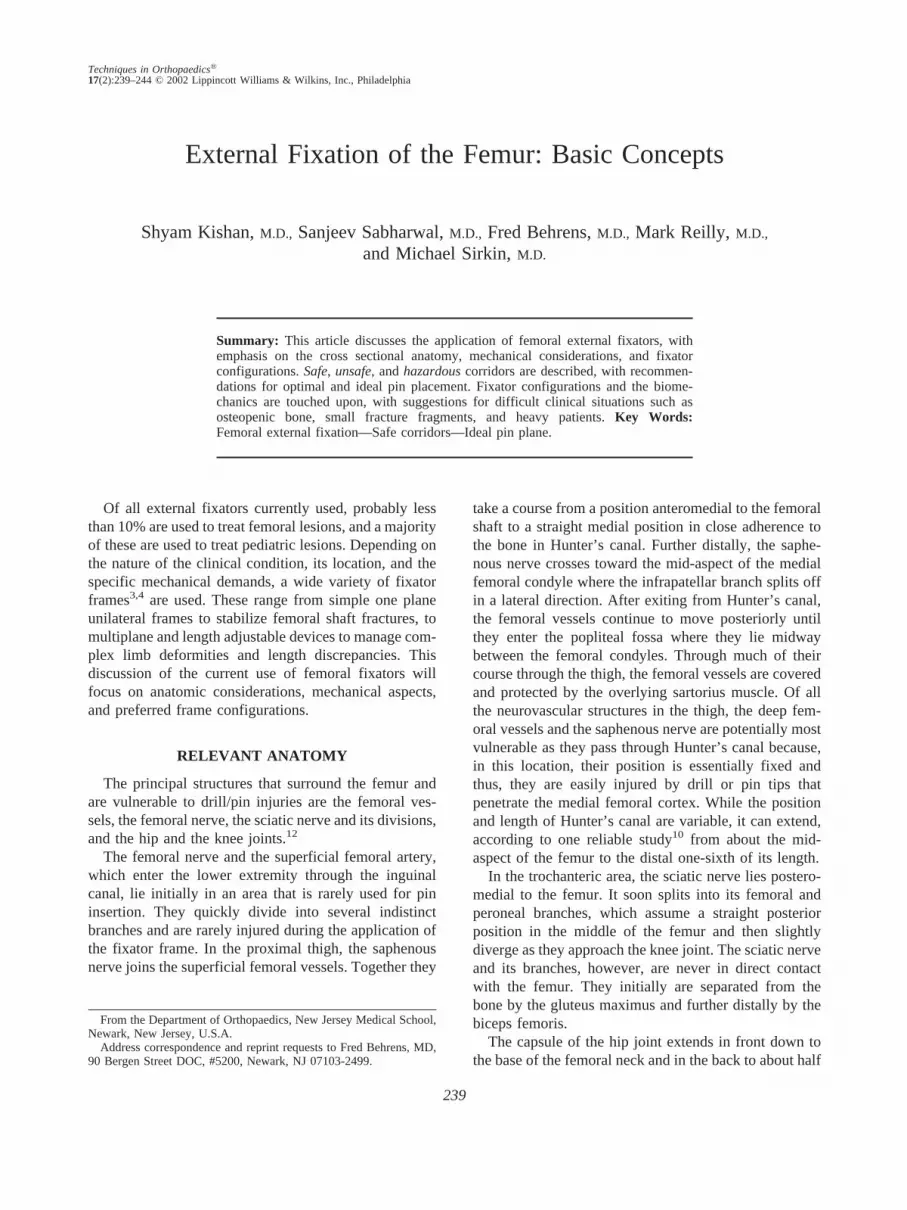
FIG. 1. Anterior-posterior and lateral diagrams of femur with keyneurovascular structures and cross sectional levels.
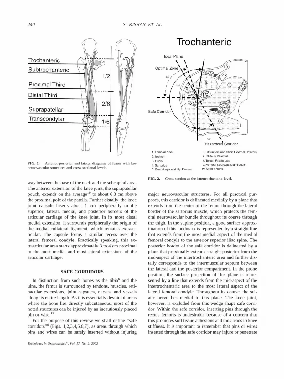
FIG. 2. Cross section at the intertrochanteric level.
240 S. KISHAN ET AL
Techniques in Orthopaedics®, Vol. 17, No. 2, 2002

vulnerable structures at the exit sites. This is particularlytrue for the hip joint, the knee joint, and Hunter’s Canal.
Posteromedially adjacent to the safe corridor, we haveincluded a “hazardous corridor,” which diminishes insize from the intertrochanteric area where it measures30° to the junction of the proximal and the mid-third ofthe femur where it terminates. This corridor may be usedin rare occasions for the insertion of transfixion wires/pins. While in most patients, the sciatic nerve will liemedial to this plane, only open exposure of the pin/wiretracks, however, will assure that an injury to the sciaticnerve is being avoided.
The anterolateral entry level quadrant of the thighrepresents an “optimal zone” for the placement of uni-lateral frames (Figs. 1,2,3,4,5,6,7). It is defined proxi-mally by a plane that lies approximately 20° lateral to thesagittal plane. Distally, it coincides with a plane thatextends from the center of the femur through the intra-muscular septum between the vastus intermedius and thevastus lateralis and always lies lateral to the lateralborder of the rectus femoris. Practically, the optimalzone is represented by a wedge that encompasses ap-proximately 70° near the trochanteric area and progres-
sively diminishes to approximately 10° at the lateralfemoral condyle. Within the optimal zone we have out-lined an “ideal plane for one plane unilateral frames”(Figs. 1,2,3,4,5,6,7). This plane extends from the centerof the femur through the junction between the vastusintermedius and the vastus lateralis peripherally. A uni-lateral fixator placed along this plane allows the patientto lie in bed with a physiologically slightly externallyrotated leg. It avoids pin interference with the abdomenproximally and is optimally placed to deal with theprevailing mechanical forces in the femur. By followingthe indistinct intramuscular septum between the vastusintermedius and the vastus lateralis (along the anterolat-eral approach to the thigh described by Henry), it mini-mizes pin/soft tissue irritation and, hopefully, quadricepsadhesions.
Basing findings on a number of the currently availableanatomic and radiographic studies,1,7,8,9,11 atlases, andtextbooks of the lower extremity, we have further de-picted the noted zones with the help of six cross sections(Fig. 1), through the thigh at the following levels: tro-chanteric (between the greater and lesser trochanter)(Fig. 2), (subtrochanteric just below the lesser trochan-ter) (Fig. 3), proximal third (Fig. 4), distal third (Fig. 5),suprapatellar (approximately 5 cm above the proximal
FIG. 3. Cross section at the subtrochanteric level.
FIG. 4. Cross section through the proximal third of the femur.
241EXTERNAL FIXATION OF THE FEMUR
Techniques in Orthopaedics®, Vol. 17, No. 2, 2002

pole of the patella) (Fig. 6), and transcondylar (justproximal to the superior pole of the patella) (Fig. 7). Dueto the wide anatomic variations that exist, the delineatedcorridors and their sizes at the various cross sections canonly represent a rough approximation.
In the trochanteric area (Fig. 2), the safe corridorencompasses approximately 190°. The hazardous pos-teromedial extension of this corridor is approximately30° to 40° because the sciatic nerve at this level liesmedial to the femur shaft. The medial limit of the optimalcorridor is approximately 70° with the “ideal” unilateralpin placement at approximately 60° to 70°. While moremedial pin placement is safe, it is not advised because itdoes interfere with hip flexion when the patient assumesa sitting position.
At the subtrochanteric (Fig. 3) level, the sartorius liesmore medial. This extends the safe corridor to approxi-mately 210°. Size and position of the optimal corridorand the ideal pin plane are unchanged.
At the junction of the proximal to the middle third(proximal third) (Fig. 4), the sartorius continues to movemedially, the sciatic nerve now lies straight posterior tothe femoral shaft, and the posterolateral intramuscular
septum moves more laterally. The safe corridor measuresapproximately 230° with the optimal corridor being 90°and the ideal pin plane staying at approximately 70°anterior to the frontal plane.
At the level of the distal third (Fig. 5), the safe corridorcontinues to move medially but retracts to approximately220°. The optimal corridor remains at 90° with the idealpin plane approximately 60° to 70°, still lies in theinterval between the vastus lateralis and the intermedius.
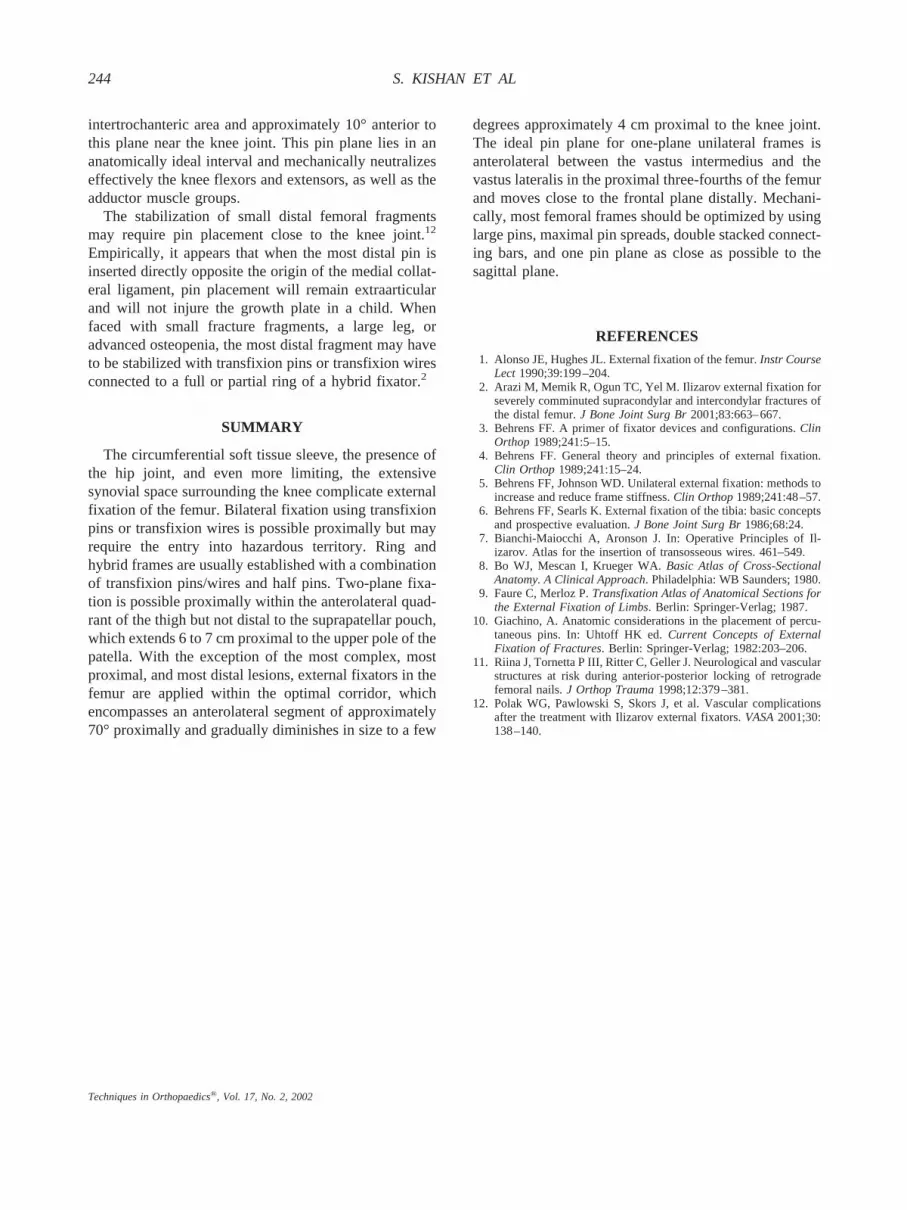
The appearance of the suprapatellar extension of theknee joint (suprapatellar) (Fig. 6), gives rise to an ante-rior unsafe corridor, which moves gradually in a lateraland posterior direction distally. At this level, the safecorridor is separated into a medial extension of approx-imately 60° and a lateral extension of approximately 80°to 90°. The optimal corridor is reduced to 50° with theideal pin plane lying close to its anterior border.
In the condylar area (transcondylar) (Fig. 7), the me-dial and lateral safe recesses diminish to approximately30° and the optimal corridor to approximately 20°. Me-dial and lateral corridors become obliterated approxi-mately 4 cm above the medial and lateral articularcartilage.
FIG. 5. Cross section through the distal third of the femur. FIG. 6. Cross section above the patella.
242 S. KISHAN ET AL
Techniques in Orthopaedics®, Vol. 17, No. 2, 2002

MECHANICAL CONSIDERATIONS
There are no mechanical studies that delineate themechanical forces applying at each femoral cross sec-tion. Qualitative measures such as the size and configu-ration of the muscle centers around the femoral shaft andthe fact that most thigh muscles activate the knee, asagittal hinge joint, make it obvious that at most levelsthe preponderance of forces apply in the sagittal plane. Inaddition, the adductor muscles exert substantial medialpull on proximal fragments, while the action of theiliotibial band applies an external rotation moment to thedistal femur.
It appears that a two plane fixator frame3,6 with aprincipal pin plane in the sagittal plane and the lesser inthe lateral aspect of the frontal plane, would ideallyneutralize the noted mechanical forces, while a mechan-ical optimal one plane unilateral frame would lie close towhat is identified as the ideal plane.
Because the mechanical forces that apply to femoralfragments are substantial, and because most unilateralfemoral frames are applied from a lateral direction, allmeans available to increase the mechanical properties ofa femoral fixator,5 particularly if applied in an adult,should be used to strengthen the frame. This includeslarge pin sizes, wide pin spread in each fragment, the use
of stacked bars and finally, the erection of a principal pinplane as close to the ideal plane as possible.
FIXATOR CONFIGURATIONS
Ring Fixators/Hybrid FramesFrom the trochanteric area to the knee, the safe corri-
dor permits the use of transfixion pins or wires at eachlevel.3,4 Due to its narrowness, the spread angle betweentransfixion implants is minimal. Proximally, the transfix-ion implants have to be inserted close to the sagittalplane, while around the knee they usually lie within afew degrees of the frontal plane. Because of the limitedmechanical effectiveness of close angle transfixion im-plants, most ring/hybrid frames in the femur are estab-lished with a combination of transfixion implants andhalf pins. Although ring/hybrid frames can be mostversatile and mechanically quite effective, they tend tobe time consuming to apply and can be uncomfortablefor the patient.
Two Plane Unilateral FramesThese frames usually consist of a pin plane applied
from a straight lateral direction and an anterolateral pinplane that is placed close to the anterior border of theoptimal corridor. The pins can be connected to longitu-dinal rods or be part of a circular or hemicircular con-struct. The use of a second pin plane is particularlyimportant in fractures with small proximal fragments andin osteopenic patients.
One Plane Unilateral FramesSuch frames are frequently used for the treatment of
femoral fractures in children and for the temporary im-mobilization of femoral fractures in adults, mostly inopen fractures. Most unilateral frames are applied from astraight lateral position, possibly because of habit andbecause it may be easier with this approach to maintainanatomic orientation. As this pin plane is mechanicallynot very effective, pin size and spread should be maxi-mized and in heavier adult patients or when faced withsmall fragments, a double rod should be used.5 Applyingthe frame 20° anterior to a straight lateral position isbetter tolerated by bedridden patients because a frame inthis position does not interfere with the physiologicalexternal rotation of the lower extremity.
In the authors’ view, the most effective one planeunilateral frames are applied in what is called the idealpin plane, which extends from the center of the femurthrough the indistinct musculoskeletal septum betweenthe vastus intermedius and the vastus lateralis so notedapproximately 70° anterior to the frontal plane in the
FIG. 7. Cross section at the transcondylar level.
243EXTERNAL FIXATION OF THE FEMUR
Techniques in Orthopaedics®, Vol. 17, No. 2, 2002
intertrochanteric area and approximately 10° anterior tothis plane near the knee joint. This pin plane lies in ananatomically ideal interval and mechanically neutralizeseffectively the knee flexors and extensors, as well as theadductor muscle groups.
The stabilization of small distal femoral fragmentsmay require pin placement close to the knee joint.12
Empirically, it appears that when the most distal pin isinserted directly opposite the origin of the medial collat-eral ligament, pin placement will remain extraarticularand will not injure the growth plate in a child. Whenfaced with small fracture fragments, a large leg, oradvanced osteopenia, the most distal fragment may haveto be stabilized with transfixion pins or transfixion wiresconnected to a full or partial ring of a hybrid fixator.2
SUMMARY
The circumferential soft tissue sleeve, the presence ofthe hip joint, and even more limiting, the extensivesynovial space surrounding the knee complicate externalfixation of the femur. Bilateral fixation using transfixionpins or transfixion wires is possible proximally but mayrequire the entry into hazardous territory. Ring andhybrid frames are usually established with a combinationof transfixion pins/wires and half pins. Two-plane fixa-tion is possible proximally within the anterolateral quad-rant of the thigh but not distal to the suprapatellar pouch,which extends 6 to 7 cm proximal to the upper pole of thepatella. With the exception of the most complex, mostproximal, and most distal lesions, external fixators in thefemur are applied within the optimal corridor, whichencompasses an anterolateral segment of approximately70° proximally and gradually diminishes in size to a few
degrees approximately 4 cm proximal to the knee joint.The ideal pin plane for one-plane unilateral frames isanterolateral between the vastus intermedius and thevastus lateralis in the proximal three-fourths of the femurand moves close to the frontal plane distally. Mechani-cally, most femoral frames should be optimized by usinglarge pins, maximal pin spreads, double stacked connect-ing bars, and one pin plane as close as possible to thesagittal plane.
REFERENCES
1. Alonso JE, Hughes JL. External fixation of the femur. Instr CourseLect 1990;39:199–204.
2. Arazi M, Memik R, Ogun TC, Yel M. Ilizarov external fixation forseverely comminuted supracondylar and intercondylar fractures ofthe distal femur. J Bone Joint Surg Br 2001;83:663–667.
3. Behrens FF. A primer of fixator devices and configurations. ClinOrthop 1989;241:5–15.
4. Behrens FF. General theory and principles of external fixation.Clin Orthop 1989;241:15–24.
5. Behrens FF, Johnson WD. Unilateral external fixation: methods toincrease and reduce frame stiffness. Clin Orthop 1989;241:48–57.
6. Behrens FF, Searls K. External fixation of the tibia: basic conceptsand prospective evaluation. J Bone Joint Surg Br 1986;68:24.
7. Bianchi-Maiocchi A, Aronson J. In: Operative Principles of Il-izarov. Atlas for the insertion of transosseous wires. 461–549.
8. Bo WJ, Mescan I, Krueger WA. Basic Atlas of Cross-SectionalAnatomy. A Clinical Approach. Philadelphia: WB Saunders; 1980.
9. Faure C, Merloz P. Transfixation Atlas of Anatomical Sections forthe External Fixation of Limbs. Berlin: Springer-Verlag; 1987.
10. Giachino, A. Anatomic considerations in the placement of percu-taneous pins. In: Uhtoff HK ed. Current Concepts of ExternalFixation of Fractures. Berlin: Springer-Verlag; 1982:203–206.
11. Riina J, Tornetta P III, Ritter C, Geller J. Neurological and vascularstructures at risk during anterior-posterior locking of retrogradefemoral nails. J Orthop Trauma 1998;12:379–381.
12. Polak WG, Pawlowski S, Skors J, et al. Vascular complicationsafter the treatment with Ilizarov external fixators. VASA 2001;30:138–140.
244 S. KISHAN ET AL
Techniques in Orthopaedics®, Vol. 17, No. 2, 2002


