Embed Size (px)
Citation preview
Department of Computer Science
EXTRACTION AND TRANSFORMATION OF DATA FROM SEMI-STRUCTURED TEXT
FILES USING A DECLARATIVE APPROACH
by
RICARDO FORTUNA RAMINHOS
Thesis submitted to Faculdade de Ciências e Tecnologia of the
Universidade Nova de Lisboa, in partial fulfilment
of the requirements for the degree of
Master in Computer Science
Supervisor: PhD João Moura Pires
Monte de Caparica, June 2007

- III-
Sumário
A problemática do ETL – Extracção (Extraction), Transformação (Transformation) e
Carregamento (Loading) está a tornar-se progressivamente menos específica do domínio
tradicional do data-warehousing, sendo estendida para o processamento de dados sob a
forma textual. A Internet surge como uma grande fonte de informação textual, seguindo
um formato semi-estruturado e facilmente compreensível, referindo-se a múltiplos
domínios, alguns dos quais altamente complexos.
Abordagens tradicionais ao ETL através do desenvolvimento específico de código fonte
para cada repositório de dados e baseadas em múltiplas interacções entre peritos do
domínio e da informática tornam-se soluções inadequadas, propícias a demorarem longos
períodos de tempo e fáceis de incorrer em erro.
Uma nova abordagem ao ETL é proposta, baseada na sua decomposição em duas fases:
ETD (Extracção, Transformação e Entrega de Dados) seguida de IL (Integração e
Carregamento). A proposta ETD é suportada por uma linguagem declarativa para a
representação das expressões ETD e uma aplicação gráfica para interacção com o perito
de domínio. Aquando da fase ETD é necessário sobretudo conhecimento de domínio,
enquanto que o conhecimento informático será centrado na fase IL, atribuindo os dados
processados às aplicações de destino, permitindo uma separação clara dos vários tipos
de conhecimento existentes.
Seguindo a abordagem ETD+IL, a arquitectura para um Módulo de Processamento de
Dados (DPM) é proposta, oferecendo uma solução completa para o processamento de
dados desde o momento em que um ficheiro é adquirido (também através de uma
abordagem declarativa) até à entrega dos dados. Um conjunto de ferramentas gráficas
também é proposto, permitindo a monitorização, controlo e rastreio dos dados nos vários
passos da solução.
A abordagem ETD+IL foi implementada, integrada, testada e validada no contexto de
uma solução de processamento de dados para um sistema do domínio espacial,
actualmente operacional na Agência Espacial Europeia para a missão Galileo.

- V-
Abstract
The Extraction, Transformation and Loading (ETL) problematic is becoming progressively
less specific to the traditional data-warehousing domain and is being extended to the
processing of textual data. The World Wide Web (WWW) appears as a major source of
textual information, following a human-readable semi-structured format, referring to
multiple domains, some of them highly complex. Traditional ETL approaches following the
development of specific source code for each data source and based on multiple domain /
computer-science experts interactions, become an inadequate solution, time consuming
and prone to error.
A novel approach to ETL is proposed, based on its decomposition in two phases: ETD
(Extraction, Transformation and Data Delivery) followed by IL (Integration and Loading).
The ETD proposal is supported by a declarative language for expressing ETD statements
and a graphical application for interacting with the domain expert. When applying ETD,
mainly domain expertise is required, while computer-science expertise will be centred in
the IL phase, linking the processed data to target system models, enabling a clearer
separation of concerns.
Following the ETD+IL approach a declarative Data Processing Module (DPM) architecture
is proposed that offers a complete data processing solution, from file download (also
using a declarative approach) to data delivery. A set of graphical tools are also proposed
that enable the monitoring, control and traceability of data through the whole data
processing solution.
The ETD+IL approach has been implemented, integrated, tested and validated in a full
data processing solution for a space domain system, currently operational at the
European Space Agency for the Galileo Mission.


- VII-
Dedicado ao principal entusiasta da minha tese…
O meu Avô

- IX-
Agradecimentos
Para a Lisa, pelo teu constante apoio e fantástica paciência durante os dois anos que esta
tese demorou a concluir. Prometo não iniciar o doutoramento nos próximos tempos...
Para os meus pais e irmã – Abílio, Clara e Raquel – pelo vosso apoio, educação e
constante presença na minha formação enquanto ser humano.
Para o meu amigo e orientador de tese Professor João Moura-Pires, que ensinou-me
muito enquanto engenheiro e sobretudo enquanto pessoa.
Para o meu amigo e colega Ricardo Ferreira, pela sua competência técnica e postura
sempre descontraída durante o nosso eforço conjunto no desenvolvimento do sistema
SESS.
Para o meu amigo e colega Nuno Viana, que introduziu-me no fantástico mundo do ETL,
tendo ainda paciência para rever esta tese.
Para o grupo de investigação CA3 – a minha primeira experiência profissional – onde fui
bem acolhido por todos os seus investigadores e com os quais aprendi bastante. Um
agradecimento especial à professora Rita Ribeiro, por confiar e apoiar o meu trabalho nos
muitos projectos em que participei no CA3: CESADS, EO-KES, SEIS, MODI e SESS.
Para os colegas do gabinete 236 – André Marques e Sérgio Agostinho – que ajudaram-
me a manter a sanidade mental nos últimos meses da tese. Espero que concluam as
vossas teses em breve.
A todos vós o meu muito obrigado!


- XI-
It is a capital mistake to theorize before one has data.
Insensibly one begins to twist facts to suit theories, instead of theories to suit facts.
A Scandal in Bohemia
Sir Arthur Conan Doyle

- XIII-
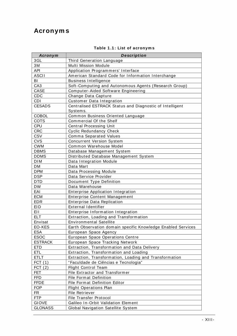
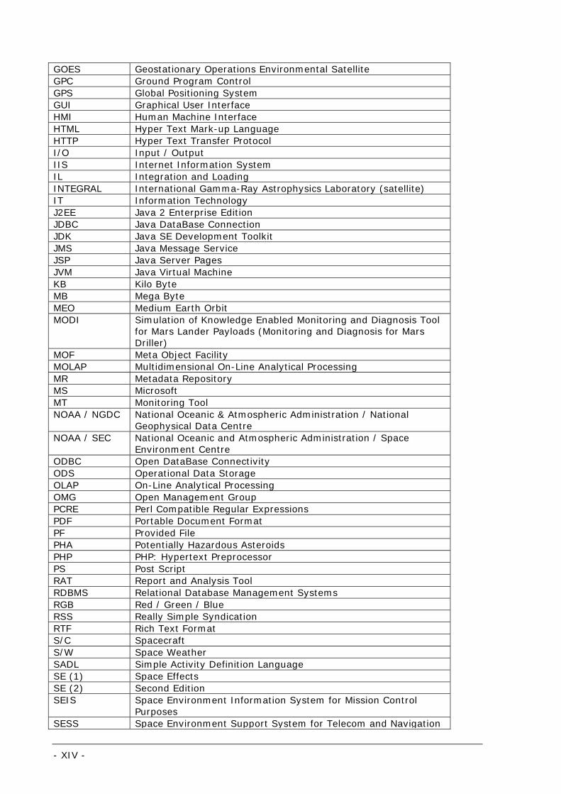
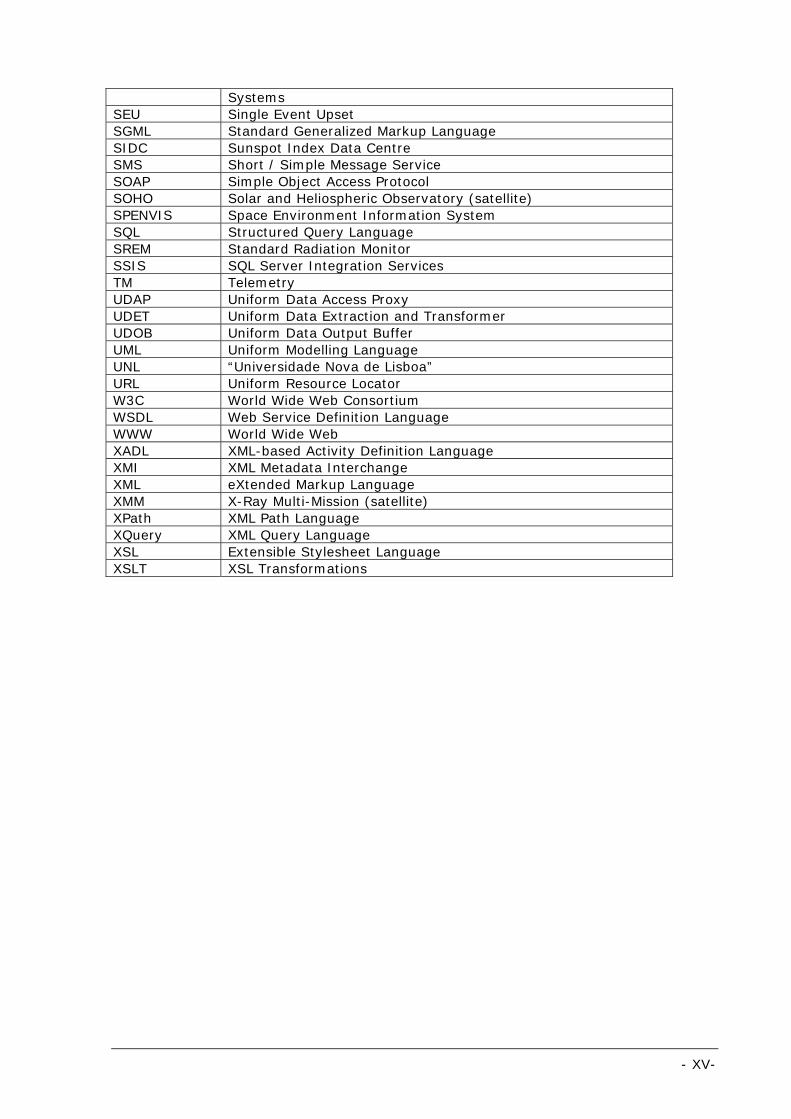
Acronyms
Table 1.1: List of acronyms
Acronym Description 3GL Third Generation Language 3M Multi Mission Module API Application Programmers’ Interface ASCII American Standard Code for Information Interchange BI Business Intelligence CA3 Soft-Computing and Autonomous Agents (Research Group) CASE Computer-Aided Software Engineering CDC Change Data Capture CDI Customer Data Integration CESADS Centralised ESTRACK Status and Diagnostic of Intelligent
Systems. COBOL Common Business Oriented Language COTS Commercial Of the Shelf CPU Central Processing Unit CRC Cyclic Redundancy Check CSV Comma Separated Values CVS Concurrent Version System CWM Common Warehouse Model DBMS Database Management System DDMS Distributed Database Management System DIM Data Integration Module DM Data Mart DPM Data Processing Module DSP Data Service Provider DTD Document Type Definition DW Data Warehouse EAI Enterprise Application Integration ECM Enterprise Content Management EDR Enterprise Data Replication EID External Identifier EII Enterprise Information Integration ELT Extraction, Loading and Transformation Envisat Environmental Satellite EO-KES Earth Observation domain specific Knowledge Enabled Services ESA European Space Agency ESOC European Space Operations Centre ESTRACK European Space Tracking Network ETD Extraction, Transformation and Data Delivery ETL Extraction, Transformation and Loading ETLT Extraction, Transformation, Loading and Transformation FCT (1) “Faculdade de Ciências e Tecnologia” FCT (2) Flight Control Team FET File Extractor and Transformer FFD File Format Definition FFDE File Format Definition Editor FOP Flight Operations Plan FR File Retriever FTP File Transfer Protocol GIOVE Galileo In-Orbit Validation Element GLONASS Global Navigation Satellite System
- XIV -
GOES Geostationary Operations Environmental Satellite GPC Ground Program Control GPS Global Positioning System GUI Graphical User Interface HMI Human Machine Interface HTML Hyper Text Mark-up Language HTTP Hyper Text Transfer Protocol I/O Input / Output IIS Internet Information System IL Integration and Loading INTEGRAL International Gamma-Ray Astrophysics Laboratory (satellite) IT Information Technology J2EE Java 2 Enterprise Edition JDBC Java DataBase Connection JDK Java SE Development Toolkit JMS Java Message Service JSP Java Server Pages JVM Java Virtual Machine KB Kilo Byte MB Mega Byte MEO Medium Earth Orbit MODI Simulation of Knowledge Enabled Monitoring and Diagnosis Tool
for Mars Lander Payloads (Monitoring and Diagnosis for Mars Driller)
MOF Meta Object Facility MOLAP Multidimensional On-Line Analytical Processing MR Metadata Repository MS Microsoft MT Monitoring Tool NOAA / NGDC National Oceanic & Atmospheric Administration / National
Geophysical Data Centre NOAA / SEC National Oceanic and Atmospheric Administration / Space
Environment Centre ODBC Open DataBase Connectivity ODS Operational Data Storage OLAP On-Line Analytical Processing OMG Open Management Group PCRE Perl Compatible Regular Expressions PDF Portable Document Format PF Provided File PHA Potentially Hazardous Asteroids PHP PHP: Hypertext Preprocessor PS Post Script RAT Report and Analysis Tool RDBMS Relational Database Management Systems RGB Red / Green / Blue RSS Really Simple Syndication RTF Rich Text Format S/C Spacecraft S/W Space Weather SADL Simple Activity Definition Language SE (1) Space Effects SE (2) Second Edition SEIS Space Environment Information System for Mission Control
Purposes SESS Space Environment Support System for Telecom and Navigation
- XV-
Systems SEU Single Event Upset SGML Standard Generalized Markup Language SIDC Sunspot Index Data Centre SMS Short / Simple Message Service SOAP Simple Object Access Protocol SOHO Solar and Heliospheric Observatory (satellite) SPENVIS Space Environment Information System SQL Structured Query Language SREM Standard Radiation Monitor SSIS SQL Server Integration Services TM Telemetry UDAP Uniform Data Access Proxy UDET Uniform Data Extraction and Transformer UDOB Uniform Data Output Buffer UML Uniform Modelling Language UNL “Universidade Nova de Lisboa” URL Uniform Resource Locator W3C World Wide Web Consortium WSDL Web Service Definition Language WWW World Wide Web XADL XML-based Activity Definition Language XMI XML Metadata Interchange XML eXtended Markup Language XMM X-Ray Multi-Mission (satellite) XPath XML Path Language XQuery XML Query Language XSL Extensible Stylesheet Language XSLT XSL Transformations
- XVI -
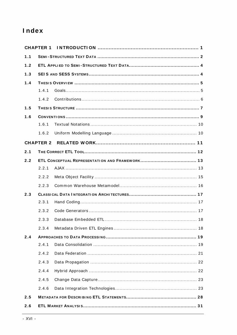
Index
CHAPTER 1 INTRODUCTION ................................................................ 1
1.1 SEMI-STRUCTURED TEXT DATA ....................................................................... 2
1.2 ETL APPLIED TO SEMI-STRUCTURED TEXT DATA................................................. 4
1.3 SEIS AND SESS SYSTEMS............................................................................. 4
1.4 THESIS OVERVIEW ....................................................................................... 5 1.4.1 Goals............................................................................................ 5
1.4.2 Contributions................................................................................. 6
1.5 THESIS STRUCTURE ...................................................................................... 7
1.6 CONVENTIONS ............................................................................................. 9 1.6.1 Textual Notations ......................................................................... 10
1.6.2 Uniform Modelling Language .......................................................... 10
CHAPTER 2 RELATED WORK............................................................... 11
2.1 THE CORRECT ETL TOOL.............................................................................. 12
2.2 ETL CONCEPTUAL REPRESENTATION AND FRAMEWORK....................................... 13 2.2.1 AJAX .......................................................................................... 13
2.2.2 Meta Object Facility ...................................................................... 15
2.2.3 Common Warehouse Metamodel..................................................... 16
2.3 CLASSICAL DATA INTEGRATION ARCHITECTURES............................................... 17 2.3.1 Hand Coding................................................................................ 17
2.3.2 Code Generators .......................................................................... 17
2.3.3 Database Embedded ETL ............................................................... 18
2.3.4 Metadata Driven ETL Engines ......................................................... 18
2.4 APPROACHES TO DATA PROCESSING............................................................... 19 2.4.1 Data Consolidation ....................................................................... 19
2.4.2 Data Federation ........................................................................... 21
2.4.3 Data Propagation ......................................................................... 22
2.4.4 Hybrid Approach .......................................................................... 22
2.4.5 Change Data Capture.................................................................... 23
2.4.6 Data Integration Technologies........................................................ 23
2.5 METADATA FOR DESCRIBING ETL STATEMENTS................................................. 28
2.6 ETL MARKET ANALYSIS............................................................................... 31
- XVII-
2.6.1 METAspectrum Market Summary .................................................... 31
2.6.2 Gartner Market Summary .............................................................. 33
2.7 ETL – STATE OF THE ART REPORT ................................................................. 34
2.8 SPACE ENVIRONMENT INFORMATION SYSTEM FOR MISSION CONTROL PURPOSES..... 36 2.8.1 Objectives ................................................................................... 37
2.8.2 Architecture................................................................................. 37
2.8.3 Data Processing Module................................................................. 38
2.8.4 Evaluation ................................................................................... 39
2.9 CONCLUSIONS ........................................................................................... 41
CHAPTER 3 DECOMPOSING ETL: THE ETD + IL APPROACH .................51
3.1 CLASSICAL ETL SOLUTIONS.......................................................................... 52
3.2 THESIS: THE ETD+IL APPROACH ................................................................. 54
3.3 REQUIREMENTS FOR ETD............................................................................. 55 3.3.1 Free, Open Source and Independent ............................................... 55
3.3.2 Completeness .............................................................................. 56
3.3.3 Separation of Concerns ................................................................. 56
3.3.4 User Friendliness .......................................................................... 57
3.3.5 Performance ................................................................................ 57
3.3.6 Scalability ................................................................................... 58
3.3.7 Modularity ................................................................................... 58
3.3.8 Reusability .................................................................................. 59
3.3.9 Metadata Driven........................................................................... 59
3.3.10 Correctness ................................................................................ 60
3.3.11 Validation................................................................................... 60
3.3.12 Data Traceability ......................................................................... 61
3.3.13 Fault Tolerance ........................................................................... 61
CHAPTER 4 DATA PROCESSING MODULE ............................................63
4.1 TECHNOLOGIES .......................................................................................... 64 4.1.1 XML ............................................................................................ 64
4.1.2 XML Schema................................................................................ 65
4.1.3 XPath ......................................................................................... 65
4.1.4 XSLT .......................................................................................... 65
- XVIII -
4.1.5 XQuery ....................................................................................... 66
4.1.6 Apache Tomcat HTTP Server .......................................................... 66
4.1.7 SOAP.......................................................................................... 66
4.1.8 Web Services............................................................................... 66
4.1.9 Java ........................................................................................... 66
4.1.10 Regular Expressions .................................................................... 67
4.1.11 Applying the Technologies ............................................................ 67
4.2 DATA PROCESSING MODULE ARCHITECTURE..................................................... 68 4.2.1 Scalability ................................................................................... 70
4.2.2 Load Balancing ............................................................................ 72
4.3 FILE RETRIEVER ENGINE.............................................................................. 73 4.3.1 Main Metadata Concepts................................................................ 77
4.4 ETD ENGINE............................................................................................. 83
4.5 DATA DELIVERY INTERFACE.......................................................................... 86
4.6 FFD EDITOR ............................................................................................. 88
4.7 DPM CONSOLE.......................................................................................... 89
4.8 LOG ANALYSER .......................................................................................... 91
4.9 SUMMARY ............................................................................................. 92
CHAPTER 5 THE FILE FORMAT DEFINITION LANGUAGE AND EDITOR 93
5.1 THE FILE FORMAT DEFINITION LANGUAGE....................................................... 94 5.1.1 Model ......................................................................................... 95
5.1.2 XML Schema Implementation......................................................... 98
5.1.3 Transformation Plugins.................................................................107
5.2 THE FFD EDITOR ..................................................................................... 108 5.2.1 Menu Functionalities and General Metadata.....................................112
5.2.2 Extraction ..................................................................................114
5.2.3 Transformation ...........................................................................126
5.2.4 Data Delivery .............................................................................128
5.2.5 Validation...................................................................................130
5.2.6 Recovery and Debug....................................................................131
5.3 LANGUAGE EXPRESSIVENESS AND EXTENSIBILITY............................................ 132
CHAPTER 6 CASE STUDIES............................................................... 133
6.1 VERSATILITY FOR MULTIPLE DOMAINS.......................................................... 134
- XIX-
6.1.1 Stock Trading Domain ................................................................. 134
6.1.2 Banking Domain......................................................................... 135
6.1.3 Geological Domain...................................................................... 136
6.1.4 Physical and Spatial Domains ....................................................... 137
6.2 SPACE ENVIRONMENT SUPPORT SYSTEM FOR TELECOM / NAVIGATION MISSIONS .. 139 6.2.1 Galileo Mission ........................................................................... 139
6.2.2 Objectives ................................................................................. 141
6.2.3 General Architecture ................................................................... 141
6.2.4 ETD+IL Integration and Usage in SESS.......................................... 143
CHAPTER 7 EVALUATION AND CONCLUSIONS ..................................149
7.1 CONCEPTUAL APPROACH EVALUATION........................................................... 150
7.2 REQUIREMENTS FOR ETD........................................................................... 151 7.2.1 Free, Open Source and Independent ............................................. 151
7.2.2 Completeness ............................................................................ 151
7.2.3 Separation of Concerns ............................................................... 152
7.2.4 User Friendliness ........................................................................ 152
7.2.5 Performance .............................................................................. 152
7.2.6 Scalability ................................................................................. 153
7.2.7 Modularity ................................................................................. 153
7.2.8 Reusability ................................................................................ 153
7.2.9 Metadata Driven......................................................................... 154
7.2.10 Correctness .............................................................................. 154
7.2.11 Validation................................................................................. 155
7.2.12 Data Traceability ....................................................................... 155
7.2.13 Fault Tolerance ......................................................................... 155
7.3 CONCLUSIONS ......................................................................................... 156
7.4 FUTURE WORK......................................................................................... 156
CHAPTER 8 REFERENCES ..................................................................159
8.1 REFERENCES ........................................................................................... 160
- XX -
ANNEXES
SESS DATA PROCESSING MODULE REQUIREMENTS …………………………….…. 163
AVAILABLE TRANSFORMATION OPERATIONS ……………………………………….. 166
REGULAR EXPRESSION LIBRARY (XML INSTANCE) ….……………………………. 167
SESS FILE FORMAT DEFINITION STATISTICS ……………………………………….. 168
- XXI-
Index of Figures
Figure 1.1: Part of a text file example containing exchange rates data [3] ....................................................2
Figure 1.2: Part of a text file example of solar activity events [2] ................................................................3
Figure 1.3: A text file example of flare, magnetic and proton forecasts [2] ...................................................3
Figure 2.1: A two-level framework (example for a library) ........................................................................ 14
Figure 2.2: MOF layers using UML and Java as comparison ....................................................................... 15
Figure 2.3: Common Warehouse Metamodel structure [24]....................................................................... 16
Figure 2.4: Data consolidation, federation and propagation....................................................................... 19
Figure 2.5: Push and pull modes of data consolidations ............................................................................ 20
Figure 2.6: Part of the scenario expressed with XADL............................................................................... 29
Figure 2.7: The syntax of SADL ............................................................................................................. 30
Figure 2.8: Part of the scenario expressed with SADL............................................................................... 30
Figure 2.9: METAspectrum evaluation [33] ............................................................................................. 32
Figure 2.10: Magic quadrant [34] for extraction, transformation and loading............................................... 34
Figure 2.11: SEIS system architecture modular breakdown....................................................................... 38
Figure 2.12: An abstract ETL architecture ............................................................................................... 41
Figure 2.13: Group1 Data Flow architecture [46-48] ................................................................................ 42
Figure 2.14: Sybase Transform On Demand architecture [49-51] .............................................................. 42
Figure 2.15: Sunopsis architecture [52-55]............................................................................................. 43
Figure 2.16: DB Software Laboratory’s Visual Importer Mapping [56, 57] ................................................... 44
Figure 2.17: iWay Data Migrator [58-61] ................................................................................................ 44
Figure 2.18: Informatica [28, 62] workflow example................................................................................ 45
Figure 2.19: SAS ETL Studio [63-65] workflow example ........................................................................... 45
Figure 2.20: Business Objects Data Integration (data patterns detection) [66]............................................ 46
Figure 2.21: Business Objects Data Integration (multi-user collaboration) [66] .......................................... 46
Figure 2.22: Business Objects Data Integration (impact analysis) [66] ...................................................... 47
Figure 2.23: DB Software Laboratory’s Visual Importer (scheduler) [56, 57] ............................................... 47
Figure 2.24: Sybase TransformOnDemand (scheduler) [49-51] ................................................................. 48
Figure 2.25: Informatica (management grid console) [28, 62] .................................................................. 48
Figure 2.26: DB Software Laboratory’s Visual Importer (text wizard) [56, 57]............................................. 49
Figure 2.27: Sybase TransformOnDemand (text data provider wizard) [49-51] ........................................... 49
- XXII -
Figure 2.28: SAS ETL (text wizard) [63-65] ............................................................................................ 50
Figure 3.1: Abstract architecture of a data warehouse.............................................................................. 52
Figure 3.2: ETL classical pipeline ........................................................................................................... 53
Figure 3.3: ETD + IL pipeline ................................................................................................................ 54
Figure 3.4: IL pipeline .......................................................................................................................... 55
Figure 4.1: Technology knowledge model ............................................................................................... 68
Figure 4.2: Data Processing Module architecture ..................................................................................... 69
Figure 4.3: FR versus ETD architecture .................................................................................................. 70
Figure 4.4: ETD versus Data Delivery architecture ................................................................................... 71
Figure 4.5: Load balancing architecture.................................................................................................. 72
Figure 4.6: FR Engine actions after being launched .................................................................................. 74
Figure 4.7: Scheduler actions................................................................................................................ 75
Figure 4.8: Data Service Provider Dispatcher actions ............................................................................... 76
Figure 4.9: Data Service Provider schema .............................................................................................. 77
Figure 4.10: Connection element........................................................................................................... 78
Figure 4.11: Provided File schema ......................................................................................................... 79
Figure 4.12: Source / File element (up) and Source / Database element (down).......................................... 80
Figure 4.13: WebMethod element .......................................................................................................... 80
Figure 4.14: Example of a FTP Query ..................................................................................................... 81
Figure 4.15: Example of a Binary Program Query .................................................................................... 81
Figure 4.16: Example of a Database Query ............................................................................................. 81
Figure 4.17: Example of a Web Service Query......................................................................................... 82
Figure 4.18: ScheduleOptions element ................................................................................................... 82
Figure 4.19: Routing element................................................................................................................ 83
Figure 4.20: ETD Engine input / output data flow .................................................................................... 83
Figure 4.21: Data Delivery package size................................................................................................. 84
Figure 4.22: ETD Engine tasks pipeline................................................................................................... 85
Figure 4.23: Generic Data Delivery schema ............................................................................................ 87
Figure 4.24: Example of Data element contents ...................................................................................... 88
Figure 4.25: DPM HMI interaction with FR and ETD engines ...................................................................... 89
Figure 4.26: DPM HMI logging subscription mechanism ............................................................................ 89
Figure 4.27: DPM Console - Data Service Provider metadata..................................................................... 90
- XXIII-
Figure 4.28: DPM Console – logging area................................................................................................ 91
Figure 4.29: Toolbars and filtering area .................................................................................................. 92
Figure 5.1: The File Format Definition model ........................................................................................... 95
Figure 5.2: General assumptions ........................................................................................................... 96
Figure 5.3: Section definition ................................................................................................................ 97
Figure 5.4: Sectioning algorithm............................................................................................................ 97
Figure 5.5: The FileFormatDefinition root element ................................................................................... 99
Figure 5.6: The Delimited element ....................................................................................................... 100
Figure 5.7: The SingleValue element.................................................................................................... 101
Figure 5.8: The Table element............................................................................................................. 102
Figure 5.9: The Validation element ...................................................................................................... 103
Figure 5.10: The Transformation element ............................................................................................. 104
Figure 5.11: The DataDelivery element ................................................................................................ 104
Figure 5.12: The Template element ..................................................................................................... 105
Figure 5.13: The Identifier element...................................................................................................... 105
Figure 5.14: The MappingIdentifier element .......................................................................................... 106
Figure 5.15: The GraphicalDisplay element ........................................................................................... 107
Figure 5.16: Transformation definition.................................................................................................. 108
Figure 5.17: The FFD Editor ETD tabs................................................................................................... 109
Figure 5.18: A graphical layout............................................................................................................ 109
Figure 5.19: Extract tab layout............................................................................................................ 110
Figure 5.20: Transform tab layout ....................................................................................................... 111
Figure 5.21: Data Delivery tab layout................................................................................................... 112
Figure 5.22: FFD File menu................................................................................................................. 112
Figure 5.23: Open FFD… options.......................................................................................................... 113
Figure 5.24: File Format Definition Metadata form ................................................................................. 114
Figure 5.25: Marking a text area for section creation.............................................................................. 115
Figure 5.26: Default section creation.................................................................................................... 116
Figure 5.27: Interacting with section delimiters ..................................................................................... 117
Figure 5.28: Transforming a line oriented delimiter into relative .............................................................. 117
Figure 5.29: A relative to previous section start delimiter ....................................................................... 117
Figure 5.30: Transforming a relative delimiter into line oriented .............................................................. 117
- XXIV -
Figure 5.31: Defining a section Start Delimiter based on a string pattern.................................................. 118
Figure 5.32: Defining a Contiguous Section based on a string pattern ...................................................... 118
Figure 5.33: Pattern Definition form..................................................................................................... 118
Figure 5.34: Applying a text pattern (left) or advanced regular expression (right) to an input file text ......... 119
Figure 5.35: Contiguous Section after applying a simple text pattern ....................................................... 119
Figure 5.36: Data types and validation rules (single value wizard) ........................................................... 120
Figure 5.37: Single Value Wizard – Defining the single value type ........................................................... 121
Figure 5.38: Single Value Wizard – Prefix based (left) or prefix and suffix based (right) single value............ 121
Figure 5.39: Single value representation .............................................................................................. 122
Figure 5.40: Table Wizard – Defining the table type............................................................................... 122
Figure 5.41: Defining a character delimited table................................................................................... 123
Figure 5.42: Table Wizard – Defining a fix width table with 3 columns (left) and defining a regular expression
table (right).............................................................................................................................. 123
Figure 5.43: Selecting a Table node after creating a table field................................................................ 124
Figure 5.44: Selecting a Column Table ................................................................................................. 124
Figure 5.45: Mapping By Content sectioning definitions to regular expressions.......................................... 125
Figure 5.46: Mapping a single value definition with PREFIX and SUFFIX to a regular expression .................. 125
Figure 5.47: Mapping a character delimited table to a regular expression ................................................. 125
Figure 5.48: Mapping a fixed width table to a regular expression............................................................. 125
Figure 5.49: Regular Expression Library concept ................................................................................... 126
Figure 5.50: Regular Expression Library (contiguous section wizard)........................................................ 126
Figure 5.51: FFD Editor’s Transformation step....................................................................................... 127
Figure 5.52: FFD Editor's Data Delivery step ......................................................................................... 128
Figure 5.53: Identifier picker form ....................................................................................................... 129
Figure 5.54: An empty template (SW parameters) with a parameter identifier defined ............................... 130
Figure 5.55: Comparing the sample file with the test set files.................................................................. 131
Figure 6.1: Part of text file example containing stock information [77] ..................................................... 135
Figure 6.2: Part of text file example containing exchange rates [3].......................................................... 135
Figure 6.3: Part of text file containing earthquakes occurrences data [78] ................................................ 136
Figure 6.4: Part of text file containing volcano daily alerts [79] ............................................................... 136
Figure 6.5: Part of a text file example of solar activity events [2] ............................................................ 137
Figure 6.6: A text file example of flare, magnetic and proton forecasts [2] ............................................... 137
Figure 6.7: Part of a text file example of potentially hazardous asteroids [80]........................................... 138
- XXV-
Figure 6.8: Galileo cluster (artist's impression)...................................................................................... 139
Figure 6.9: Galileo spacecraft prototypes in orbit (artist's impression): GIOVE-A (left side) and GIOVE-B (right
side)........................................................................................................................................ 140
Figure 6.10: SESS Common and Mission infrastructure interaction (Mission perspective) ............................ 141
Figure 6.11: Generic SESS infrastructure.............................................................................................. 142
Figure 6.12: Section frequency per input file ......................................................................................... 145
Figure 6.13: Field frequency per input file............................................................................................. 145
Figure 6.14: Transformation frequency per input file .............................................................................. 146
Figure 6.15: Frequency of identifiers per input file ................................................................................. 146
- XXVI -
Index of Tables
Table 1.1: List of acronyms................................................................................................................. XIII
Table 4.1: Data Delivery format for a single EID...................................................................................... 86
Table 4.2: Data Delivery format for multiple EID (mapping)...................................................................... 86
Table 5.1: Thread priority definition example ........................................................................................ 106
Table 6.1: SESS Data Service Providers and associated Provided Files ..................................................... 144
Table 8.1: DPM global requirements .................................................................................................... 163
Table 8.2: ETD Engine requirements .................................................................................................... 163
Table 8.3: FFD Editor requirements ..................................................................................................... 164
Table 8.4: FR requirements ................................................................................................................ 164
Table 8.5: Available transformation operations...................................................................................... 166
Table 8.6: SESS File Format Definition statistics.................................................................................... 168
- 1 -
Chapter 1 Introduction
This chapter introduces the ETL problematic for dealing with semi-structured
text files and provides a first motivation for a novel approach to ETL that
separates domain expertise from computer expertise.
SEIS and SESS space domain systems are presented, where the author
carried out his first activities in the ETL domain and where the novel approach
to ETL has been developed and validated.
The thesis is briefly described, focusing on its goals / requirements and
expected author’s contributions for the ETL community.
Finally, the report’s structure is presented, as well as the used conventions.
Introduction
- 2 -
ETL stands for Extraction, Transformation and Loading of data from a data source to a
normalized data target, usually applied to the data warehousing / integration domains
[1]. In a recent past the ETL problematic has mainly focused on database sources, but
currently a secondary data source – textual data – is emerging, becoming a relevant data
source by itself, instead of a mere supporting data source. This change has been mainly
motivated by the continuous evolution of the World Wide Web (WWW), a major
repository of textual information, that is organized and presented in such a way that is
human readable and easily understood.
Scientific data is an important subset of textual data, organized in a semi-structured
format (e.g. tabular format). Space environment data1 is one example of such data that
is available in multiple Hyper Text Transfer Protocol (HTTP) and File Transfer Protocol
(FTP) servers like the National Oceanic & Atmospheric Administration / National
Geophysical Data Centre (NOAA/NGDC) [2]. Currently, no ETL solution exists, so that a
domain expert without computer-science expertise, can use in an intuitive way for
managing automatic retrieval and data extraction from text files.
1.1 Semi-Structured Text Data
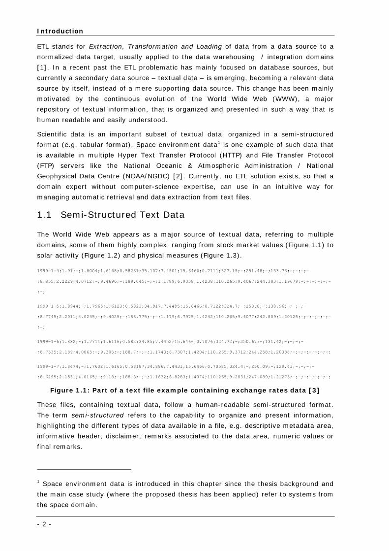
The World Wide Web appears as a major source of textual data, referring to multiple
domains, some of them highly complex, ranging from stock market values (Figure 1.1) to
solar activity (Figure 1.2) and physical measures (Figure 1.3).
1999-1-4;1.91;-;1.8004;1.6168;0.58231;35.107;7.4501;15.6466;0.7111;327.15;-;251.48;-;133.73;-;-;-;-
;8.855;2.2229;4.0712;-;9.4696;-;189.045;-;-;1.1789;6.9358;1.4238;110.265;9.4067;244.383;1.19679;-;-;-;-;-;-
;-;
1999-1-5;1.8944;-;1.7965;1.6123;0.5823;34.917;7.4495;15.6466;0.7122;324.7;-;250.8;-;130.96;-;-;-;-
;8.7745;2.2011;4.0245;-;9.4025;-;188.775;-;-;1.179;6.7975;1.4242;110.265;9.4077;242.809;1.20125;-;-;-;-;-;-
;-;
1999-1-6;1.882;-;1.7711;1.6116;0.582;34.85;7.4452;15.6466;0.7076;324.72;-;250.67;-;131.42;-;-;-;-
;8.7335;2.189;4.0065;-;9.305;-;188.7;-;-;1.1743;6.7307;1.4204;110.265;9.3712;244.258;1.20388;-;-;-;-;-;-;-;
1999-1-7;1.8474;-;1.7602;1.6165;0.58187;34.886;7.4431;15.6466;0.70585;324.4;-;250.09;-;129.43;-;-;-;-
;8.6295;2.1531;4.0165;-;9.18;-;188.8;-;-;1.1632;6.8283;1.4074;110.265;9.2831;247.089;1.21273;-;-;-;-;-;-;-;
Figure 1.1: Part of a text file example containing exchange rates data [3]
These files, containing textual data, follow a human-readable semi-structured format.
The term semi-structured refers to the capability to organize and present information,
highlighting the different types of data available in a file, e.g. descriptive metadata area,
informative header, disclaimer, remarks associated to the data area, numeric values or
final remarks.
1 Space environment data is introduced in this chapter since the thesis background and
the main case study (where the proposed thesis has been applied) refer to systems from
the space domain.
Semi-Structured Text Data
- 3-
Commonly, text files are made available by diverse Data Service Providers (DSP) -
external organizations following their internal priorities, funding allocation and even
individual good-will. This results in non-normalized file formats, not obeying any standard
besides a possible local one used by each individual provider.
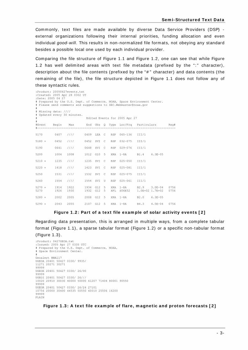
Comparing the file structure of Figure 1.1 and Figure 1.2, one can see that while Figure
1.2 has well delimited areas with text file metadata (prefixed by the “:” character),
description about the file contents (prefixed by the “#” character) and data contents (the
remaining of the file), the file structure depicted in Figure 1.1 does not follow any of
these syntactic rules. :Product: 20050427events.txt :Created: 2005 Apr 28 0302 UT :Date: 2005 04 27 # Prepared by the U.S. Dept. of Commerce, NOAA, Space Environment Center. # Please send comments and suggestions to [email protected] # # Missing data: //// # Updated every 30 minutes. # Edited Events for 2005 Apr 27 # #Event Begin Max End Obs Q Type Loc/Frq Particulars Reg# #------------------------------------------------------------------------------- 5170 0407 //// 0409 LEA C RSP 065-136 III/1 5180 + 0452 //// 0452 SVI C RSP 032-075 III/1 5190 0641 //// 0648 SVI C RSP 029-076 III/1 5200 1004 1008 1012 G10 5 XRA 1-8A B1.4 6.3E-05 5210 + 1235 //// 1235 SVI C RSP 025-050 III/1 5220 + 1418 //// 1423 SVI C RSP 025-081 III/1 5250 1531 //// 1532 SVI C RSP 025-075 III/1 5260 1554 //// 1554 SVI U RSP 025-061 III/1 5270 + 1914 1922 1934 G12 5 XRA 1-8A B2.9 3.0E-04 0756 5270 1926 1930 1932 G12 5 XFL S06E52 1.0E+02 1.7E+02 0756 5280 + 2002 2005 2008 G12 5 XRA 1-8A B2.0 6.3E-05 5290 + 2043 2055 2107 G12 5 XRA 1-8A B4.3 4.5E-04 0756
Figure 1.2: Part of a text file example of solar activity events [2]
Regarding data presentation, this is arranged in multiple ways, from a complete tabular
format (Figure 1.1), a sparse tabular format (Figure 1.2) or a specific non-tabular format
(Figure 1.3). :Product: 0427GEOA.txt :Issued: 2005 Apr 27 0335 UTC # Prepared by the U.S. Dept. of Commerce, NOAA, # Space Environment Center. # Geoalert WWA117 UGEOA 20401 50427 0330/ 9935/ 11271 20271 30271 99999 UGEOE 20401 50427 0330/ 26/00 99999 UGEOI 20401 50427 0330/ 26/// 10020 20910 30030 40000 50000 61207 71404 80001 90550 99999 UGEOR 20401 50427 0330/ 26/24 27101 10756 20000 30400 44535 50550 60010 25506 16200 99999 PLAIN
Figure 1.3: A text file example of flare, magnetic and proton forecasts [2]
Introduction
- 4 -
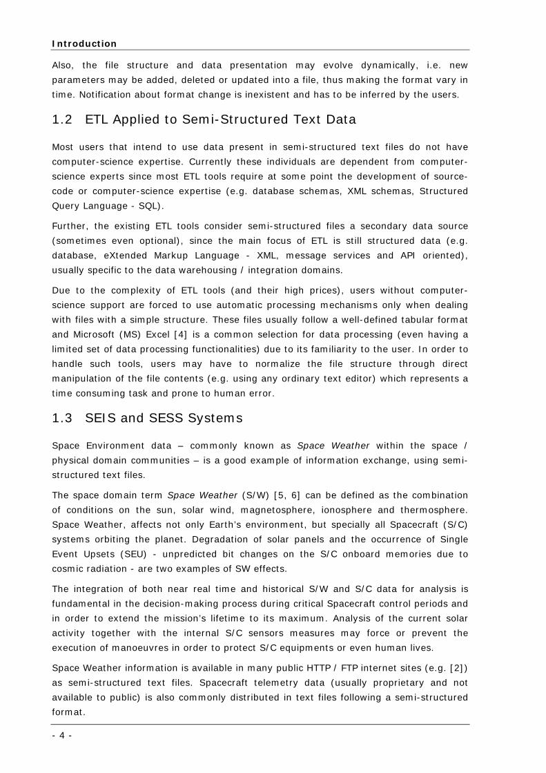
Also, the file structure and data presentation may evolve dynamically, i.e. new
parameters may be added, deleted or updated into a file, thus making the format vary in
time. Notification about format change is inexistent and has to be inferred by the users.
1.2 ETL Applied to Semi-Structured Text Data
Most users that intend to use data present in semi-structured text files do not have
computer-science expertise. Currently these individuals are dependent from computer-
science experts since most ETL tools require at some point the development of source-
code or computer-science expertise (e.g. database schemas, XML schemas, Structured
Query Language - SQL).
Further, the existing ETL tools consider semi-structured files a secondary data source
(sometimes even optional), since the main focus of ETL is still structured data (e.g.
database, eXtended Markup Language - XML, message services and API oriented),
usually specific to the data warehousing / integration domains.
Due to the complexity of ETL tools (and their high prices), users without computer-
science support are forced to use automatic processing mechanisms only when dealing
with files with a simple structure. These files usually follow a well-defined tabular format
and Microsoft (MS) Excel [4] is a common selection for data processing (even having a
limited set of data processing functionalities) due to its familiarity to the user. In order to
handle such tools, users may have to normalize the file structure through direct
manipulation of the file contents (e.g. using any ordinary text editor) which represents a
time consuming task and prone to human error.
1.3 SEIS and SESS Systems
Space Environment data – commonly known as Space Weather within the space /
physical domain communities – is a good example of information exchange, using semi-
structured text files.
The space domain term Space Weather (S/W) [5, 6] can be defined as the combination
of conditions on the sun, solar wind, magnetosphere, ionosphere and thermosphere.
Space Weather, affects not only Earth’s environment, but specially all Spacecraft (S/C)
systems orbiting the planet. Degradation of solar panels and the occurrence of Single
Event Upsets (SEU) - unpredicted bit changes on the S/C onboard memories due to
cosmic radiation - are two examples of SW effects.
The integration of both near real time and historical S/W and S/C data for analysis is
fundamental in the decision-making process during critical Spacecraft control periods and
in order to extend the mission’s lifetime to its maximum. Analysis of the current solar
activity together with the internal S/C sensors measures may force or prevent the
execution of manoeuvres in order to protect S/C equipments or even human lives.
Space Weather information is available in many public HTTP / FTP internet sites (e.g. [2])
as semi-structured text files. Spacecraft telemetry data (usually proprietary and not
available to public) is also commonly distributed in text files following a semi-structured
format.
Thesis Overview
- 5-
The Space Environment Support System for Telecom and Navigation Missions (SESS) [7]
is a multi-mission decision support system, capable of providing near real-time
monitoring and visualization [8], in addition to offline historical analysis [9] of S/W and
S/C data, events and alarms to Flight Control Teams (FCT). The main goal of the system
is to provide S/C and S/W data integration to Flight Control Teams and is explained in
detail in Chapter 6.
This system is based on the Space Environment Information System for Mission Control
Purposes (SEIS) [9] experience, a single-mission decision support system prototype that
also enables SW and SC data integration.
The author has participated in the development of both systems. In SEIS the author was
responsible for the partial definition of metadata ETL scripts for processing input data
files (relevant in the system’s scope), while in SESS, the author was responsible for the
complete development of the declarative ETL solution.
1.4 Thesis Overview
This section introduces the thesis Extraction and Transformation of Data from Semi-
Structured Text Files Using a Declarative Approach main goals and the author’s expected
contributions for the ETL computer-science community. The thesis proposes a new
approach to ETL, enabling a clearer separation of concerns, dividing ETL in domain tasks
(ETD - Extraction, Transformation and Data Delivery) and technical tasks (IL -
Integration and Loading).
1.4.1 Goals
The ETL solution envisaged for the SESS system followed a primary guideline that the
implementation of specific source code or computer-science expertise would not be
required from domain experts. Instead a declarative approach was suggested, based on
different types of metadata, that the domain user should instantiate, using specific
visualization tools. In this manner, the data processing pipeline could be directly used
and maintained only by domain experts without computer-science expertise.
The thesis’s analysis, design and implementation has occurred and been applied in the
scope of the SESS system. Following this new approach to ETL (described in detail in
Chapter 3) a set of thirteen high-level requirements has been derived for attaining a
ready-to-use data processing solution for domain experts:
o Open Source: The solution shall be implemented using open-source technologies,
presented as a no acquisition cost solution, accessible to anyone. Furthermore, the
solution shall be developed using software independent from the operating system;
o Completeness: A full data processing solution shall be available comprising data
retrieval, data processing and overall management of the data processing solution;
o Separation of Concerns: The domain user shall be able to use and maintain the
data processing pipeline without requiring computer-science expertise. All domain
procedures and definitions shall be represented recurring to a high-level declarative
Introduction
- 6 -
language. No specific source-code shall be required to implement the processing of a
single text file;
o User Friendliness: A graphical application shall be available, making use of the
declarative language in a transparent way to the end user;
o Performance: Data retrieval and data processing shall have a reduced response
time while preserving both CPU and network bandwidth resources;
o Scalability: Both data retrieval and data processing must be capable of handling
multiple simultaneous downloads and processing requests, respectively;
o Modularity: The solution architecture and implementation shall be as modular as
possible, clearly separating domain from technical tasks. Further, there shall be a
clear separation between logic and presentation layers, easing future maintenance
tasks;
o Reusability: System modules shall be designed and implemented focusing on
reutilization as much as possible. Such approach shall be applied for factoring
common behaviour / functionalities within the data processing solution itself or for
reusing entirely / partially system components in the solution of other problems;
o Metadata Driven: The data processing solution shall be metadata driven, which
means that all processes for executing and managing the data retrieval and ETD
pipeline are based on metadata;
o Correctness: Data typing facilities and validation rules shall be available during the
entire ETD process, in order for the outcome to be valid. These data quality
mechanisms shall be applied iteratively in the Extraction, Transformation and Data
Delivery steps;
o Data Traceability: It shall be possible to trace-back a processed datum value, to the
originally downloaded file;
o Fault Tolerance: In case of failure during download, the recovery of the failed file
shall be retried. If an error occurs during the data processing the administrator must
be notified and other data processing operations shall be resumed;
o Validation: After performing the ETD specifications based on a primary input file, the
FFD generality shall be tested with a larger set of text files belonging to the same
class of files.
1.4.2 Contributions
With this thesis, the author’s expected contributions for the ETL community are classified
within three categories:
o Rethink ETL: This thesis presents a new paradigm to ETL that separates ETD
domain-expertise tasks from computer-science IL tasks, such that ETL = ETD + IL.
Such approach, envisages the creation of a declarative language for representing ETD
statements to be applied to input text files and a graphical tool that enables an easy
Thesis Structure
- 7-
manipulation of the declarative language, making it transparent to a domain user
(without computer-science expertise).
This new approach does not intend to trigger a revolution in the current ETL
paradigm. Instead, it provides a localized contribution, expecting to ease the data
processing process for semi-structured data, available in text files, using a specialized
tool suite, which can be effectively handled by common non-expert users;
o Propose a complete architecture for ETD+IL: The proposed architecture shall
enable a complete data processing solution based on ETD. Besides ETD supporting
applications, such solution shall comprise an engine for file download (also based on
declarative assertions) and management tools that enable the control, visualization
and data traceability of the processing pipeline execution;
o Implementation and validation of the proposed architecture and tools:
Finally, the declarative data processing module shall be implemented, integrated,
tested and validated in the scope of a real operational system (not a prototype
application). Special attention shall be taken to the graphical application
implementation that interacts with the domain user for defining ETD metadata scripts
without resource to computer-science expertise.
Further, a state of the art survey shall be conducted evaluating the current ETL trends
within the research, open-source and commercial domains for the most relevant
applications.
1.5 Thesis Structure
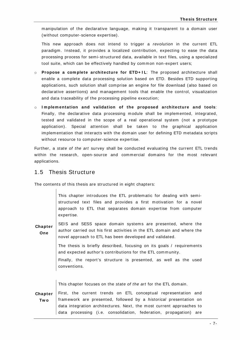
The contents of this thesis are structured in eight chapters:
Chapter
One
This chapter introduces the ETL problematic for dealing with semi-
structured text files and provides a first motivation for a novel
approach to ETL that separates domain expertise from computer
expertise.
SEIS and SESS space domain systems are presented, where the
author carried out his first activities in the ETL domain and where the
novel approach to ETL has been developed and validated.
The thesis is briefly described, focusing on its goals / requirements
and expected author’s contributions for the ETL community.
Finally, the report’s structure is presented, as well as the used
conventions.
Chapter
Two
This chapter focuses on the state of the art for the ETL domain.
First, the current trends on ETL conceptual representation and
framework are presented, followed by a historical presentation on
data integration architectures. Next, the most current approaches to
data processing (i.e. consolidation, federation, propagation) are
Introduction
- 8 -
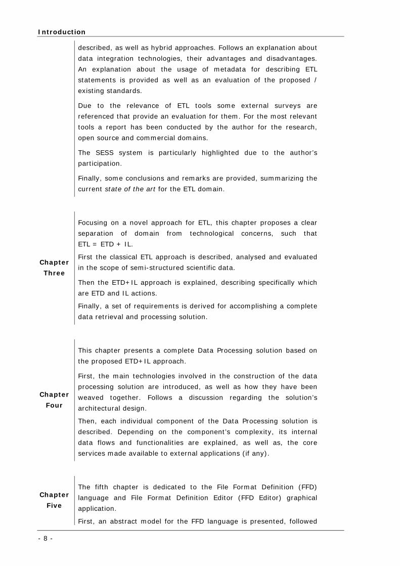
described, as well as hybrid approaches. Follows an explanation about
data integration technologies, their advantages and disadvantages.
An explanation about the usage of metadata for describing ETL
statements is provided as well as an evaluation of the proposed /
existing standards.
Due to the relevance of ETL tools some external surveys are
referenced that provide an evaluation for them. For the most relevant
tools a report has been conducted by the author for the research,
open source and commercial domains.
The SESS system is particularly highlighted due to the author’s
participation.
Finally, some conclusions and remarks are provided, summarizing the
current state of the art for the ETL domain.
Chapter
Three
Focusing on a novel approach for ETL, this chapter proposes a clear
separation of domain from technological concerns, such that
ETL = ETD + IL.
First the classical ETL approach is described, analysed and evaluated
in the scope of semi-structured scientific data.
Then the ETD+IL approach is explained, describing specifically which
are ETD and IL actions.
Finally, a set of requirements is derived for accomplishing a complete
data retrieval and processing solution.
Chapter
Four
This chapter presents a complete Data Processing solution based on
the proposed ETD+IL approach.
First, the main technologies involved in the construction of the data
processing solution are introduced, as well as how they have been
weaved together. Follows a discussion regarding the solution’s
architectural design.
Then, each individual component of the Data Processing solution is
described. Depending on the component’s complexity, its internal
data flows and functionalities are explained, as well as, the core
services made available to external applications (if any).
Chapter
Five
The fifth chapter is dedicated to the File Format Definition (FFD)
language and File Format Definition Editor (FFD Editor) graphical
application.
First, an abstract model for the FFD language is presented, followed
Conventions
- 9-
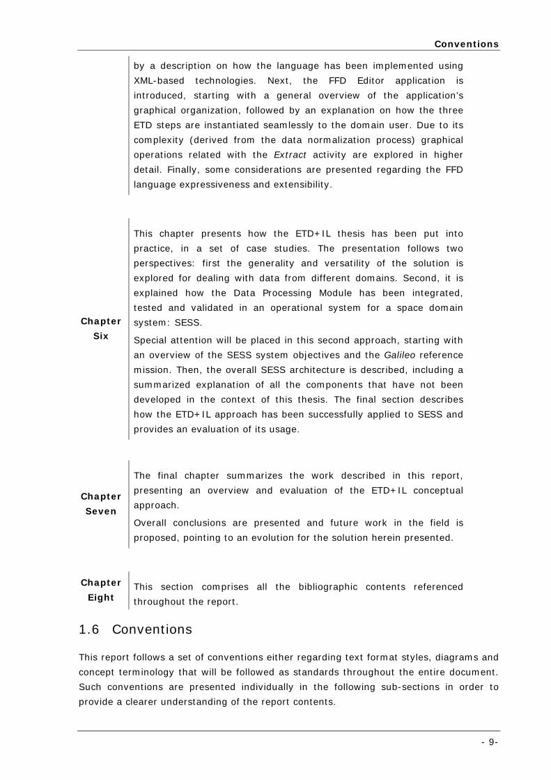
by a description on how the language has been implemented using
XML-based technologies. Next, the FFD Editor application is
introduced, starting with a general overview of the application’s
graphical organization, followed by an explanation on how the three
ETD steps are instantiated seamlessly to the domain user. Due to its
complexity (derived from the data normalization process) graphical
operations related with the Extract activity are explored in higher
detail. Finally, some considerations are presented regarding the FFD
language expressiveness and extensibility.
Chapter
Six
This chapter presents how the ETD+IL thesis has been put into
practice, in a set of case studies. The presentation follows two
perspectives: first the generality and versatility of the solution is
explored for dealing with data from different domains. Second, it is
explained how the Data Processing Module has been integrated,
tested and validated in an operational system for a space domain
system: SESS.
Special attention will be placed in this second approach, starting with
an overview of the SESS system objectives and the Galileo reference
mission. Then, the overall SESS architecture is described, including a
summarized explanation of all the components that have not been
developed in the context of this thesis. The final section describes
how the ETD+IL approach has been successfully applied to SESS and
provides an evaluation of its usage.
Chapter
Seven
The final chapter summarizes the work described in this report,
presenting an overview and evaluation of the ETD+IL conceptual
approach.
Overall conclusions are presented and future work in the field is
proposed, pointing to an evolution for the solution herein presented.
Chapter
Eight This section comprises all the bibliographic contents referenced
throughout the report.
1.6 Conventions
This report follows a set of conventions either regarding text format styles, diagrams and
concept terminology that will be followed as standards throughout the entire document.
Such conventions are presented individually in the following sub-sections in order to
provide a clearer understanding of the report contents.
Introduction
- 10 -
1.6.1 Textual Notations
The thesis document is divided into chapters, where each presents an individual issue
(e.g. domain description, problem description or technical solution) that can be analysed
in isolation. Each chapter starts with a summary page where the main contents of the
chapter are described. Within each chapter a set of headings, following a hierarchical
numeric notation, structures the chapter contents. Each heading comprises text that may
be formatted in one of three ways:
o Regular text: A set of textual statements without a particular relevance over the
others;
o Bold text: Highlights a particular text statement, focusing the attention on it;
o Italics text: Refers to a specific domain statement (usually technical) or to a colloquial
expression.
Footnote text is also introduced whenever a complementary explanation is required, but
without diverting the attention from the main text.
Acronyms are widely used throughout this report due to the massive presence of
scientific terms. All acronym expressions are summarized in Table 1.1 and are introduced
as required in the text. The first time an acronym is referenced a full explanation shall be
provided while in the remaining references only the acronym is used.
1.6.2 Uniform Modelling Language
The Unified Modelling Language (UML) [10, 11] is a non-proprietary specification
language for object modelling, in the field of software engineering. UML is a general-
purpose modelling language that includes a standardized graphical notation used to
create an abstract model of a system, referred to as an UML model. UML is extensible,
offering the stereotype mechanism for customization.
Since UML is a widely accepted de facto standard by the computer-science community for
diagram representation, whenever possible, diagrams presented in the scope of this
thesis (mainly State Diagrams2) shall be UML compliant.
2 State Diagrams are a finite state machine represented as a directed graph, where each
node can be mapped to a high-level computation state / operation, where connections
between nodes represent a change between states.
- 11 -
Chapter 2 Related Work
This chapter focuses on the state of the art for the ETL domain.
First, the current trends on ETL conceptual representation and framework are
presented, followed by a historical presentation on data integration
architectures. Next, the most current approaches to data processing (i.e.
consolidation, federation, propagation) are described, as well as hybrid
approaches. Follows an explanation about data integration technologies, their
advantages and disadvantages. An explanation about the usage of metadata
for describing ETL statements is provided as well as an evaluation of the
proposed / existing standards.
Due to the relevance of ETL tools some external surveys are referenced that
provide an evaluation for them. For the most relevant tools a report has been
conducted by the author for the research, open source and commercial
domains.
The SESS system is particularly highlighted due to the author’s participation.
Finally, some conclusions and remarks are provided, summarizing the current
state of the art for the ETL domain.
Related Work
- 12 -
The development of a new information system poses many challenges and doubts to the
team responsible for its implementation. A significant part is related with the ETL
component, responsible for the acquisition and normalization of data. During the
requirement / design phases, commonly, five questions drive the implementation of an
ETL component:
1. Can an existing Commercial off-the-shelf (COTS) solution be reused?
2. Must a custom solution be developed, specifically for this problem?
3. What is the cost (time and man-power) associated?
4. How robust shall the application be?
5. Is the application easy to maintain and extend?
In order to answer the first question, a survey is usually conducted regarding the state of
the art for the ETL domain. Depending on the budget associated to the information
system a higher evaluation effort may be placed in research / open-source applications
or in commercial applications. An alternative to the COTS approach passes by developing
a custom ETL solution (usually very specific). This last approach is frequent when the ETL
component must follow a strict set of requirements that are found to be too specific.
The decision on using a COTS approach or developing an ETL component from scratch is
also influenced according four main parameters: associated cost (third question),
required robustness level (fourth question), maintainability and extensibility issues (fifth
question).
2.1 The Correct ETL Tool
Unfortunately, practice has shown that the choice of the correct ETL tool is
underestimated, minimized and sometimes even ignored. This happens frequently, since
the choice becomes not a technological but a management issue, where research and
open-source are rejected due to its lack of credibility and a commercial tool is selected,
having many times the associated cost as the only criterion for the evaluation.
According to the Gartner ETL evaluation report [12], in-house development procedures
and poor management decisions when selecting an appropriate ETL tool consume up to
70% of the resources of a information system project (e.g. a data warehouse).
An example of an incorrect selection of a ETL tool in a real-world situation, taken from
[13], is described next. This shows how an upgrade to an appropriate ETL component
contributed greatly to cost savings in the order of $2.5 billion in a single year:
There are few companies that have been more aggressive than Motorola in pursuing e-
business. Motorola become public last year that one of its corporate-wide goals - a
strategic rather than a tactical one - was to get all spending into electronic systems. But,
in order to make this kind of progress, the company has had to lean heavily on a
business intelligence initiative.
Chet Phillips, IT director for BI at Motorola was the responsible for this initiative. "At the
beginning of 2002, the procurement leaders at Motorola were given a goal to drop $2.5
ETL Conceptual Representation and Framework
- 13-
billion worth of spend out of the cost structure on the direct and indirect side, and they
needed a way of looking at spend comprehensively," Phillips says.
Gathering the spend in one location would provide the visibility and decision support that
the procurement leaders needed; in the way of such aggregation, however, was
Motorola's reliance on many different enterprise systems: three version levels of Oracle,
SAP (particularly within the semiconductor organization), and Ariba on the indirect
procurement side.
Motorola already had an enterprise application integration tool from vendor webMethods
that touched a lot of different systems, but Phillips explains how, by nature, it couldn't fit
the need at hand. "EAI communicates between the different systems -- it's transaction-
level data interaction," Phillips says.
To go deeper in getting the data out, Motorola got an ETL tool from BI vendor
Informatica. Phillips describes the benefits of the tool. "By using its capability to pull data
as opposed to requesting that source systems push data, we covered ground quickly
without using intensive IT resources and we had minimal intrusion on source systems."
Motorola's BI project handed the baton off to the procurement organization, which could
now examine $48 billion dollars worth of spending, one million purchase orders, and six
million receipts at the desired level of detail. For its part, the procurement organization
has come through for the corporation. Motorola reaped $2.5 billion in cost savings last
year thanks to its new e-procurement tools and processes, and expects to save more this
year.
2.2 ETL Conceptual Representation and Framework
Work in the area of ETL conceptual representation and methodology standardization has
been limited to a few initiatives that practice has shown to be too academic, vague and /
or complex. Thus, despite some efforts, no ETL conceptual representation or
methodology is commonly agreed among the research, open-source and commercial ETL
community. In the next three sub-sections some of these standards are presented that
have been partially adopted.
2.2.1 AJAX
Significant work has been developed in the area of conceptual representation of ETL
processes [14-16] and ETL methodology [17-19] by computer science researchers from
the University of Ioannina. Both works were envisaged in order to ease the
documentation and formalization effort, for ETL at the early stages of data warehousing
definition (not describing technical details regarding the actual implementation of ETL
tasks). A set of graphic symbols has been suggested for conceptual representation of ETL
primitives like concepts, instances, transformations, relations and data flows.
The same researchers proposed a general methodology for dealing with ETL processes
[20] (following the proposed ETL conceptual representation), based on a two-layered
design that attempts to separate the logical and physical levels.
Related Work
- 14 -
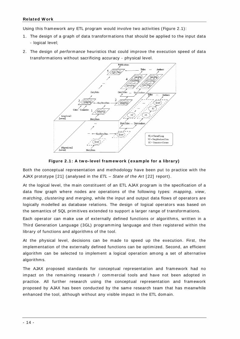
Using this framework any ETL program would involve two activities (Figure 2.1):
1. The design of a graph of data transformations that should be applied to the input data
- logical level;
2. The design of performance heuristics that could improve the execution speed of data
transformations without sacrificing accuracy - physical level.
Figure 2.1: A two-level framework (example for a library)
Both the conceptual representation and methodology have been put to practice with the
AJAX prototype [21] (analysed in the ETL – State of the Art [22] report).
At the logical level, the main constituent of an ETL AJAX program is the specification of a
data flow graph where nodes are operations of the following types: mapping, view,
matching, clustering and merging, while the input and output data flows of operators are
logically modelled as database relations. The design of logical operators was based on
the semantics of SQL primitives extended to support a larger range of transformations.
Each operator can make use of externally defined functions or algorithms, written in a
Third Generation Language (3GL) programming language and then registered within the
library of functions and algorithms of the tool.
At the physical level, decisions can be made to speed up the execution. First, the
implementation of the externally defined functions can be optimized. Second, an efficient
algorithm can be selected to implement a logical operation among a set of alternative
algorithms.
The AJAX proposed standards for conceptual representation and framework had no
impact on the remaining research / commercial tools and have not been adopted in
practice. All further research using the conceptual representation and framework
proposed by AJAX has been conducted by the same research team that has meanwhile
enhanced the tool, although without any visible impact in the ETL domain.
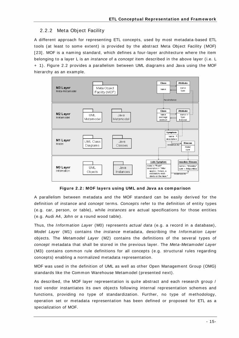
ETL Conceptual Representation and Framework
- 15-
2.2.2 Meta Object Facility
A different approach for representing ETL concepts, used by most metadata-based ETL
tools (at least to some extent) is provided by the abstract Meta Object Facility (MOF)
[23]. MOF is a naming standard, which defines a four-layer architecture where the item
belonging to a layer L is an instance of a concept item described in the above layer (i.e. L
+ 1). Figure 2.2 provides a parallelism between UML diagrams and Java using the MOF
hierarchy as an example.
Figure 2.2: MOF layers using UML and Java as comparison
A parallelism between metadata and the MOF standard can be easily derived for the
definition of instance and concept terms. Concepts refer to the definition of entity types
(e.g. car, person, or table), while instances are actual specifications for those entities
(e.g. Audi A4, John or a round wood table).
Thus, the Information Layer (M0) represents actual data (e.g. a record in a database),
Model Layer (M1) contains the instance metadata, describing the Information Layer
objects. The Metamodel Layer (M2) contains the definitions of the several types of
concept metadata that shall be stored in the previous layer. The Meta-Metamodel Layer
(M3) contains common rule definitions for all concepts (e.g. structural rules regarding
concepts) enabling a normalized metadata representation.
MOF was used in the definition of UML as well as other Open Management Group (OMG)
standards like the Common Warehouse Metamodel (presented next).
As described, the MOF layer representation is quite abstract and each research group /
tool vendor instantiates its own objects following internal representation schemes and
functions, providing no type of standardization. Further, no type of methodology,
operation set or metadata representation has been defined or proposed for ETL as a
specialization of MOF.
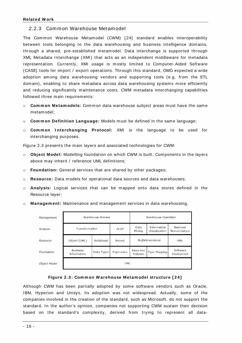
Related Work
- 16 -
2.2.3 Common Warehouse Metamodel
The Common Warehouse Metamodel (CWM) [24] standard enables interoperability
between tools belonging to the data warehousing and business intelligence domains,
through a shared, pre-established metamodel. Data interchange is supported through
XML Metadata Interchange (XMI) that acts as an independent middleware for metadata
representation. Currently, XMI usage is mostly limited to Computer-Aided Software
(CASE) tools for import / export operations. Through this standard, OMG expected a wide
adoption among data warehousing vendors and supporting tools (e.g. from the ETL
domain), enabling to share metadata across data warehousing systems more efficiently
and reducing significantly maintenance costs. CWM metadata interchanging capabilities
followed three main requirements:
o Common Metamodels: Common data warehouse subject areas must have the same
metamodel;
o Common Definition Language: Models must be defined in the same language;
o Common Interchanging Protocol: XMI is the language to be used for
interchanging purposes.
Figure 2.3 presents the main layers and associated technologies for CWM:
o Object Model: Modelling foundation on which CWM is built. Components in the layers
above may inherit / reference UML definitions;
o Foundation: General services that are shared by other packages;
o Resource: Data models for operational data sources and data warehouses;
o Analysis: Logical services that can be mapped onto data stores defined in the
Resource layer;
o Management: Maintenance and management services in data warehousing.
Figure 2.3: Common Warehouse Metamodel structure [24]
Although CWM has been partially adopted by some software vendors such as Oracle,
IBM, Hyperion and Unisys, its adoption was not widespread. Actually, some of the
companies involved in the creation of the standard, such as Microsoft, do not support the
standard. In the author’s opinion, companies not supporting CWM sustain their decision
based on the standard’s complexity, derived from trying to represent all data-
Classical Data Integration Architectures
- 17-
warehousing and business intelligence features, becoming too general and loosing its
practical focus on the way.
2.3 Classical Data Integration Architectures
Historically, four main approaches have been followed for solving the data integration
problem [25-27]: hand coding, code generators, database embedded ETL and metadata
driven ETL engines.
2.3.1 Hand Coding
Since the dawn of data processing, integration issues have been solved through the
development of custom hand-coded programs [25-27], developed in-house or by
consulting programming teams.
Although this approach appears at start as a low cost solution, it quickly evolves to a
costly, hard to maintain and time consuming task. This usually happens, since all the
relevant knowledge is represented at the low-level source code, making it hard to
understand, maintain and update, being specially prone to error during maintenance
tasks. The problem is even increased for those legacy systems where the original team
that developed the code is not available any more.
In the middle of 1990 decade, this paradigm started to be replaced by a number of third
party products (code generators and engine-based tools) from specialized vendors in
data integration and ETL.
Surprisingly, even though ETL tools have been developed for over 10 years and are now
mature products, hand coding still persists as a significant contribution for solving
transformation problems. These efforts still proliferate in many legacy environments,
low-budget data migration projects or when dealing with very specific ETL scenarios.
Although hand-coded ETL provides unlimited flexibility, it has an associated cost: the
creation of an ETL component from scratch that may be hard to maintain and evolve in a
near-future depending on the ETL component complexity.
2.3.2 Code Generators
Code generators [25-27] were the first early attempt to increase data processing
efficiency, replacing possible inefficient source-code developed manually. Code
generation frameworks have been proposed, presenting a graphical front-end where
users can map processes and data flows and then generate automatically source code
(such as C or Common Business Oriented Language - COBOL) as the resulting run-time
solution, that can be compiled and executed on various platforms.
Generally, ETL code-generating tools can handle more complex processing than their
engine-based counterparts. Compiled code is generally accepted as the fastest of
solutions and also enables organizations to distribute processing across multiple
platforms to optimize performance.
Related Work
- 18 -
Although code generators usually offer visual development environments, they are
sometimes not as easy to use as engine-based tools, and can lengthen overall
development times in direct comparisons with engine-based tools.
Code generators were a step-up from hand-coding for developers, but this approach did
not gain widespread adoption since solution requirements and Information Technology
(IT) architecture complexity arose and the issues around code maintenance and
inaccuracies in the generation process led to higher rather than lower costs.
2.3.3 Database Embedded ETL
With its origins in the early code generators, Database Management System (DBMS)
vendors have embedded ETL capabilities in their products, using the database as engine
and SQL as supporting language [25-27].
Some DBMS vendors have opted to include third party ETL tools that leverage common
database functionality, such as stored procedures and enhanced SQL, increasing the
transformation and aggregation power. This enabled third party ETL tools to optimize
performance by exploiting the parallel processing and scalability features of DBMS.
Other DBMS vendors offer ETL functions that mirror features available in ETL specialist
vendors. Many database vendors offer graphical development tools that exploit the ETL
capabilities of their database products, competing directly with third party ETL solution
providers.
Database-centric ETL solutions vary considerably in quality and functionality. To some
extent, these products have exposed the lack of capability of SQL and database-specific
extensions (e.g., PL/SQL, stored procedures) to handle cross-platform data issues, XML
data, data quality, profiling and business logic needed for enterprise data integration.
Further, most organisations do not wish to be dependent on a single proprietary vendor’s
engine. However, for some specific scenarios, the horsepower of the relational database
can be effectively used for data integration, with better results compared to metadata
driven ETL engines.
2.3.4 Metadata Driven ETL Engines
Informatica [28] pioneered a new data integration approach by presenting a data server,
or engine powered by open, interpreted metadata as the main driver for transformation
processing [25-27]. This approach addresses complexity and meets performance needs,
also enabling re-use and openness since it is metadata driven. Other ETL tool vendors
have also adopted this approach since, through other types of engines and languages,
becoming the current trend on ETL data processing.
Many of these engine-based tools have integrated metadata repositories that can
synchronize metadata from source systems, target databases and other business
intelligence tools. Most of these tools automatically generate metadata at every step of
the process and enforce a consistent metadata-driven methodology that developers must
follow. Proprietary scripting languages are used for representing metadata, running
within a generally rigid centralised ETL server. These engines use language interpreters
to process ETL workflows at run-time, defined by developers in a graphical environment
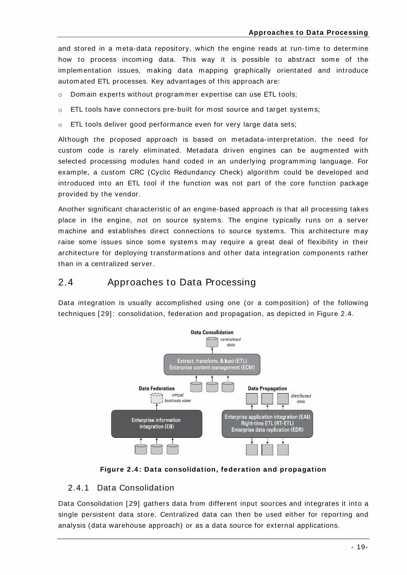
Approaches to Data Processing
- 19-
and stored in a meta-data repository, which the engine reads at run-time to determine
how to process incoming data. This way it is possible to abstract some of the
implementation issues, making data mapping graphically orientated and introduce
automated ETL processes. Key advantages of this approach are:
o Domain experts without programmer expertise can use ETL tools;
o ETL tools have connectors pre-built for most source and target systems;
o ETL tools deliver good performance even for very large data sets;
Although the proposed approach is based on metadata-interpretation, the need for
custom code is rarely eliminated. Metadata driven engines can be augmented with
selected processing modules hand coded in an underlying programming language. For
example, a custom CRC (Cyclic Redundancy Check) algorithm could be developed and
introduced into an ETL tool if the function was not part of the core function package
provided by the vendor.
Another significant characteristic of an engine-based approach is that all processing takes
place in the engine, not on source systems. The engine typically runs on a server
machine and establishes direct connections to source systems. This architecture may
raise some issues since some systems may require a great deal of flexibility in their
architecture for deploying transformations and other data integration components rather
than in a centralized server.
2.4 Approaches to Data Processing
Data integration is usually accomplished using one (or a composition) of the following
techniques [29]: consolidation, federation and propagation, as depicted in Figure 2.4.
Figure 2.4: Data consolidation, federation and propagation
2.4.1 Data Consolidation
Data Consolidation [29] gathers data from different input sources and integrates it into a
single persistent data store. Centralized data can then be used either for reporting and
analysis (data warehouse approach) or as a data source for external applications.
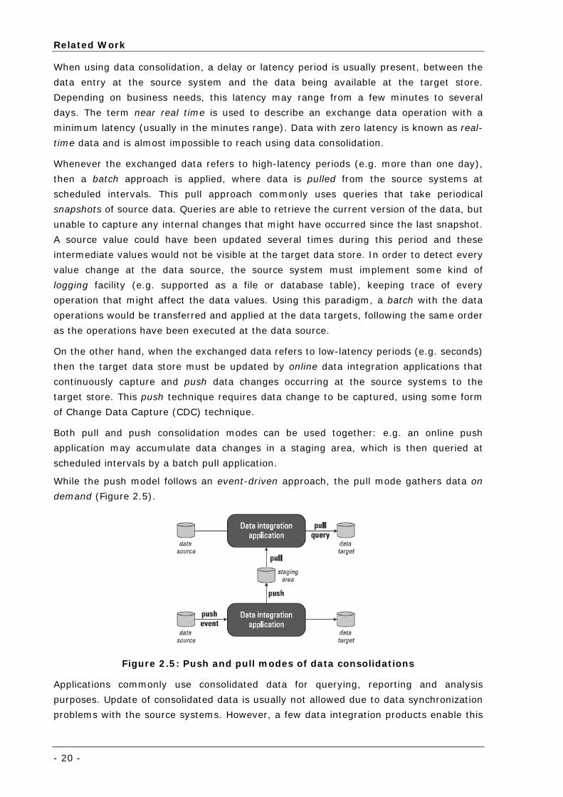
Related Work
- 20 -
When using data consolidation, a delay or latency period is usually present, between the
data entry at the source system and the data being available at the target store.
Depending on business needs, this latency may range from a few minutes to several
days. The term near real time is used to describe an exchange data operation with a
minimum latency (usually in the minutes range). Data with zero latency is known as real-
time data and is almost impossible to reach using data consolidation.
Whenever the exchanged data refers to high-latency periods (e.g. more than one day),
then a batch approach is applied, where data is pulled from the source systems at
scheduled intervals. This pull approach commonly uses queries that take periodical
snapshots of source data. Queries are able to retrieve the current version of the data, but
unable to capture any internal changes that might have occurred since the last snapshot.
A source value could have been updated several times during this period and these
intermediate values would not be visible at the target data store. In order to detect every
value change at the data source, the source system must implement some kind of
logging facility (e.g. supported as a file or database table), keeping trace of every
operation that might affect the data values. Using this paradigm, a batch with the data
operations would be transferred and applied at the data targets, following the same order
as the operations have been executed at the data source.
On the other hand, when the exchanged data refers to low-latency periods (e.g. seconds)
then the target data store must be updated by online data integration applications that
continuously capture and push data changes occurring at the source systems to the
target store. This push technique requires data change to be captured, using some form
of Change Data Capture (CDC) technique.
Both pull and push consolidation modes can be used together: e.g. an online push
application may accumulate data changes in a staging area, which is then queried at
scheduled intervals by a batch pull application.
While the push model follows an event-driven approach, the pull mode gathers data on
demand (Figure 2.5).
Figure 2.5: Push and pull modes of data consolidations
Applications commonly use consolidated data for querying, reporting and analysis
purposes. Update of consolidated data is usually not allowed due to data synchronization
problems with the source systems. However, a few data integration products enable this
Approaches to Data Processing
- 21-
writing capability, providing ways to handle possible data conflicts between the updated
data in the consolidated data store and the origin source systems.
Data consolidation allows for large volumes of data to be transformed (restructured,
reconciled, cleansed and aggregated) as it flows from source systems to the target data
store. As disadvantages, this approach requires intensive computing power to support
the data consolidation process, network bandwidth for transferring data and disk space
required for the target data store.
Data consolidation is the main approach used by data warehousing applications to build
and maintain an operational data store and an enterprise data warehouse, while the ETL
technology is one of the most common technologies used to support data consolidation.
Besides ETL, another way of accomplishing data consolidation is by using the Enterprise
Content Management (ECM) technology. Most ECM solutions put their focus on
consolidation and management of unstructured data such as documents, reports and
Web pages3.
2.4.2 Data Federation
Data Federation [29] enables a unified virtual view of one or more data sources. When a
query is issued to this virtual view, a data federation engine distributes the query
through the data sources, retrieves and integrates the resulting data according to the
virtual view before outputting the results back. Data federation always pulls data on-
demand basis from source systems, according to query invocation. Data transformations
are performed after extracting the information from the data sources.
Enterprise Information Integration (EII) is a technology that enables a federated
approach. Metadata is the key element in a federated system, which is used by the
federation engine to access data sources. This metadata may have different types of
complexity. Simple metadata configurations may consist only of the definition of the
virtual view, explaining how this is mapped into the data sources. In more complex
situations, it may describe the existing data load in the data sources and which access
paths should be used for access (in this way, the federated solution may greatly optimize
the access to the source data). Some federated engines may use metadata even further,
describing additional business rules like semantic relationships between data elements
crosscutting to the source systems (e.g. customer data, where a common customer
identifier may be mapped to various customer keys used in other source systems).
The main advantage of the federated approach is that it provides access to data,
removing the need to consolidate it into another data store, i.e. when the cost of data
consolidation outweighs the business benefits it provides. Data federation can be
specially useful when data security policies and license restrictions prevent source data
from being copied. However, data federation is not suited for dealing with large amounts
of data, when significant quality problems may be present at the data sources, or when
3 ECM will not be further discussed since ETL is the main technology for data
consolidation.
Related Work
- 22 -
the performance impact and overhead of accessing multiple data sources at runtime
becomes a performance bottleneck.
2.4.3 Data Propagation
The main focus of data propagation applications [29] is to copy data from one location to
another. These applications usually operate online and push data to the target location
using an event-driven approach.
Updates from source to target systems may be performed either asynchronously or
synchronously. While synchronous propagation requires that data updates occur within
the same transaction, an asynchronous propagation is independent from the update
transaction at the data source. Regardless from the synchronization type, propagation
guarantees the delivery of the data to the target system.
Enterprise Application Integration (EAI) and Enterprise Data Replication (EDR) are two
examples of technologies that support data propagation.
The key advantage of data propagation is that it can be used for real-time / near-real-
time data movement and can also be used for workload balancing, backup and recovery.
Data propagation tools vary considerably in terms of performance, data restructuring and
cleansing capabilities. Some tools may support the movement and restructuring of high
volume of data, whereas EAI products are often limited in these two features. This
partially happens since enterprise data replication has a data-centric architecture,
whereas EAI is message or transaction-centric.
2.4.4 Hybrid Approach
Data integration applications [29] may not be limited to a single data integration
technique, but use a hybrid approach that involves several integration techniques.
Customer Data Integration (CDI) - where the objective is to provide a harmonized view
of customer information - is a good example of this approach. A simple example of CDI is
a consolidated customer data store that holds customer data captured from different data
sources. The information entry latency in the consolidated database will depend on
whether data is consolidated online or through batch. Another possible approach to CDI
the use of data federation where a virtual customer view is defined according to the data
sources. This view could be used by external applications to access customer information.
The federated approach may use metadata to relate customer information based on a
common key. An hybrid data consolidation and data federation approach could also be
possible: common customer data (e.g. name, address) could be consolidated into a
single store and the remaining customer fields (e.g. customer orders), usually unique,
could be federated. This scenario could be extended even further through data
propagation, e.g. if a customer updates his or her name and address during a
transaction, this change could be sent to the consolidated data store and then
propagated to other source systems, such as a retail store customer database.
Approaches to Data Processing
- 23-
2.4.5 Change Data Capture
Both data consolidation and data propagation create (to some extent) copies of source
data, requiring a way to identify and handle data changes that occur in source systems.
Two approaches are common to this purpose: rebuild the target data store on a regular
basis, keeping data minimally synchronized between source and target systems (which is
impractical, except for small data stores) or perform some form of Change Data Capture
(CDC) [29] capability.
If a timestamp is available at the source data for the date of the last modification, this
could be used to locate the data that has been changed since the CDC application last
executed. However, unless a new record or version of the data is created at each
modification, the CDC application will only be able to identify the most recent change for
each individual record and not all possible changes that might have occurred between
application runs. If no timestamp exists associated to the source data, then in order to
enable CDC, data sources must be modified either to create a timestamp or to maintain a
separate data file or message queue of data changes.
CDC can be implemented through various ways. In Relational Database Management
Systems (RDBMS) a common approach is to add database update triggers, that take a
copy of the modified data or isolate data changes through the DBMS recovery log.
Triggers may have a highly negative impact on the performance of source applications,
since the trigger and the data update processing is usually performed within the same
physical transaction, thus increasing the transaction latency. Processing of the recovery
log, causes less impact, since this is usually an asynchronous task independent from the
data update.
In non-DBMS applications (e.g. document based) time stamping and versioning are quite
common, which eases the CDC task. When a document is created or modified, the
document metadata is usually updated to reflect the date and time of the event. Many
unstructured data systems also create a new version of a document each time this is
modified.
2.4.6 Data Integration Technologies
As previously introduced, several technologies are available for implementing the data
integration techniques described above: Extract, Transform and Load (ETL), Enterprise
Information Integration (EII), Enterprise Application Integration (EAI) and Enterprise
Data Replication (EDR). Follows a review of each technology.
2.4.6.1 Extract, Transform and Load (ETL)
The ETL technology provides means of extracting data from source systems transforming
it accordingly and loading the results into a target data store. Databases and files are the
most common inputs and outputs for this technology.
ETL is the main consolidation support for data integration. Data can be gathered either
using a schedule-based pull mode or based on event detection. When using the pull
mode, data consolidation is performed in batch, while if applying the push technique the
Related Work
- 24 -
propagation of data changes to the target data store is performed online. Depending on
the input and output data formats, data transformation may require just a few or many
steps: e.g. date formatting, arithmetic operations, record restructuring, data cleansing or
content aggregation. Data loading may result on a complete refresh of the target store or
may be performed gradually by multiple updates at the target destination. Common
interfaces for data loading are Open DataBase Connectivity (ODBC), Java DataBase
Connectivity (JDBC), Java Message Service (JMS), native database and application
interfaces.
The first ETL solutions were limited to running batch jobs at pre-defined scheduled
intervals, capturing data from file or database sources and consolidate it into a data
warehouse (or relational staging area). Over the last years, a wide set of new features
has been introduced, providing customization and extension to the ETL tools capabilities.
Follows some significant examples:
o Multiple data sources (e.g. databases, text files, legacy data, application packages,
XML files, web services, unstructured data);
o Multiples data targets (e.g. databases, text files, web services);
o Improved data transformation (e.g. data profiling and data quality management,
standard programming languages, DBMS engine exploitation);
o Better management (e.g. job scheduling and tracking, metadata management, error
recovery);
o Better performance (e.g. parallel processing, load balancing, caching);
o Better visual development interfaces.
2.4.6.1.1 Tuning ETL
ETL is a traditional data integration technique widely used in information systems.
However, for some specific cases, variations to standard ETL could increase performance
drastically, taking advantage of RDBMS technology and special tuning features. Besides
traditional ETL, two new trends exist:
o ELT (Extraction, Loading and Transformation): Oracle and Sunopsis are the
leaders of this technology, where data is loaded into a staging area database and only
than can transformations take place. The ELT technology has been constrained by
database capabilities. Since ELT had its origins with RDBMS, the technology tended to
be suitable for just one database platform. ELT also lacked functionality, as vendors
were more concerned with building a database rather than an ELT tool. Sunopsis was
the only exception of an ELT tool not owned by an RDBMS vendor… until it was
acquired by Oracle;
o ETLT (Extraction, Transformation, Loading and Transformation): Informatica is
the leader of this technology, which consists on a database pushdown optimization to
traditional ETL. This consists on a standard ETL process to a target database, where
further transformations are performed (for performance reasons) before moving
Approaches to Data Processing
- 25-
information into the target tables. Microsoft SQL Server Integration Services (SSIS)
also has good ETLT capabilities with the SQL Server database.
Summarizing, while ELT presents itself as a novel approach that takes advantages of
database optimization, ETLT can be considered as a simple extension of ETL with some
tuning functionalities.
Comparing both ETL and ELT [30] the following advantages can be identified regarding
ELT:
o ELT leverages the RDBMS engine for scalability;
o ELT keeps all data in the RDBMS all the time;
o ELT is parallelized according to the data set, and disk I/O is usually optimized at the
engine level for faster throughput;
o ELT can achieve three to four times the throughput rates on the appropriately tuned
RDBMS platform.
while the key negative points are [30]:
o ELT relies on proper database tuning and proper data model architecture;
o ELT can easily use 100% of the hardware resources available for complex and huge
operations;
o ELT can not balance the workload;
o ELT can not reach out to alternate systems (all data must exist in the RDBMS before
ELT operations take place);
o ELT easily increases disk storage requirements;
o ELT can take longer to design and implement;
o More steps (less complicated per step) but usually resulting in more SQL code.
Finally, the key advantages of ETL towards ELT are presented [30]:
o ETL can balance the workload / share the workload with the RDBMS;
o ETL can perform more complex operations;
o ETL can scale with separate hardware;
o ETL can handle partitioning and parallelism independent of the data model, database
layout, and source data model architecture;
o ETL can process data in-stream, as it transfers from source to target.
while the key negative points are [30]:
o ETL requires separate and equally powerful hardware in order to scale;
o ETL can bounce data to and from the target database, requires separate caching
mechanisms, which sometimes do not scale to the magnitude of the data set.
Related Work
- 26 -
2.4.6.2 Enterprise Information Integration (EII)
Enterprise Information Integration [29] provides a virtual view of dispersed data,
supporting the data federation approach for data integration. This view can be used for
on-demand querying over transactional data, data warehouse and / or unstructured
information.
EII enables applications to see dispersed data sets as a single database, abstracting the
complexities of retrieving data from multiple sources, heterogeneous semantics and data
formats, and disparate data interfaces.
EII products have evolved from two different technological backgrounds – relational
DBMS and XML, but the current trend of the industry is to support both approaches, via
SQL (ODBC and JDBC) and XML (XML Query Language - XQuery - and XML Path
Language - XPath) data interfaces.
EII products with strong DBMS background take advantage of the research performed in
developing Distributed Database Management Systems (DDBMS) that has the objective
of providing transparent, full read / write permissions over distributed data. A key issue
in DDBMS is the performance impact over distributed processing for mission-critical
applications (specially when supporting write access to distributed data). To overcome
this problem, most EII products provide only read access to heterogeneous data and just
a few tools allow limited update capabilities.
Another important performance option is the ability of EII products to cache results and
allow administrators to define rules that determine when the data in the cache is valid or
needs to be refreshed.
2.4.6.3 EII versus ETL
EII data federation cannot replace the traditional ETL data consolidation approach used
for data warehousing, due to performance and data consistency issues of a fully
federated data warehouse. Instead EII should be used to extend data warehousing to
address specific needs.
When using complex query processing that requires access to operational transaction
systems, this may affect the performance of the operation applications running on those
systems. EII increases performance in these situations by sending simpler and more
specific queries to the operational systems.
A potential problem with EII arises when transforming data from multiple source
systems, since data relationship may be complex / confuse and the data quality may be
poor, not allowing a good federated access. These issues point out the need of a more
rigorous approach in the system modelling and analysis for EII. Follows a set of
circumstances when EII may be a more appropriate alternative for data integration than
ETL [29]:
o Direct write access to the source data: Updating a consolidated copy of the
source data is generally not advisable due to data integrity issues. Some EII products
enable this type of data update;
Approaches to Data Processing
- 27-
o It is difficult to consolidate the original source data: For widely heterogeneous
data and content, it may be impossible to bring all the structured and unstructured
data together in a single consolidated data store;
o Federated queries cost less than data consolidation: The cost and performance
impact of using federated queries should be compared with the network, storage, and
maintenance costs of using ETL to consolidate data in a single store. When the source
data volumes are too large to justify consolidation, or when only a small percentage
of the consolidated data is ever used, a federated solution is more appropriate.
The arguments in favour of ETL compared to EII are [29]:
o Read-only access to reasonably stable data is required: Creating regular
snapshots of the data source isolates users from the ongoing changes to source data,
defining a stable set of data that can be used for analysis and reporting;
o Users need historical or trend data: Operational data sources may not have a
complete history available at all times (e.g. sliding window approach). This historical
can be built up over time through the ETL data consolidation process;
o Data access performance and availability are key requirements: Users want
fast access to local data for complex query processing and analysis;
o User needs are repeatable and can be predicted in advance: When most of the
performed queries are well defined, repeated in time, and require access to only a
known subset of the source data, it makes sense to create a copy of the data in a
consolidated data store for its manipulation;
o Data transformation is complex: Due to performance issues it is inadvisable to
perform complex data transformation as part of an EII federated query.
2.4.6.4 Enterprise Application Integration (EAI)
Enterprise Application Integration [29] provides a set of standard interfaces that allow
application systems to communicate and exchange business transactions, messages and
data, accessing data transparently, abstracting from its location and format logic.
EAI supports the data propagation approach for data integration and is usually used for
real-time operational transaction processing. Access to application sources can be
performed through several technologies like web services, Microsoft .NET interfaces or
JMS.
EAI was designed for propagating small amounts of data between applications (not
supporting complex data structures handled by ETL products), either synchronously or
asynchronously, within the scope of a single business transaction. If an asynchronous
propagation is used, then business transactions may be broken into multiple lower-level
transactions (e.g. a travel request could be broken down into airline, hotel and car
reservations, although in a coordinated way).
Related Work
- 28 -
2.4.6.5 EAI versus ETL
EAI and ETL are not competing technologies and in many situations are used together to
complement one another [29]: EAI can be a data source for ETL and ETL can be a service
to EAI. The main objective of EAI is to provide transparent access to a wide set of
applications. Therefore an EAI-to-ETL interface could be used to give ETL access to
application data, e.g. through web service communication. Using this interface, custom
point-to-point adapters for these data source applications would not be required to be
developed for ETL purposes. In the opposite architectural configuration, the interface
could also be used as a data target by an ETL application.
Currently, most of these interfaces are still in their early stages of development and in
many cases, instead of an EAI-to-ETL interface, organizations use EAI to create data
files, which are then fed into the ETL application.
2.4.6.6 Enterprise Data Replication (EDR)
The Enterprise Data Replication technology [29] is less known than ETL, EII or EAI, even
being widely used in data integration projects. This lack of visibility happens since EDR is
often packaged together with other solutions (e.g. all major DBMS vendors use data
replication capabilities in their products as many CDC-based solutions that also offer data
replication facilities). EDR is not limited only to data integration purposes but is also used
for backup and recovery, data mirroring and workload balancing.
Some EDR products, support two-way synchronous data propagation between multiple
databases. Also, online data transformation is a common property of EDR tools, when
data is flowing between two databases.
The major difference between EDR and EAI approaches is that EDR data replication is
used for transferring a considerable amount of data between databases, while EAI is
designed for moving messages and transactions between applications.
A hybrid approach with a data replication tool and ETL tool is very common: e.g. EDR can
be used to continuously capture and transfer large data sets into a staging area and on a
regular basis, this data is extracted from the staging area (by a batch tool that
consolidates the data) into a data warehouse infrastructure.
2.5 Metadata for Describing ETL Statements
The metadata driven ETL design is the most common data processing architecture among
ETL tools. The key feature in this design is the metadata definition that provides a
language for expressing ETL statements and when instantiated, instructs which
operations shall be performed by the ETL engine. The structure and semantics of this
language does not follow any specific standard, since none has been commonly accepted
so far for describing ETL tasks. Depending on the type of ETL tool (research, open-source
or commercial) one of four approaches are usually followed for the representation of ETL
metadata (or a combination of them):
1. Proprietary metadata: Private metadata definition (e.g. binary) that is not made
available to the public domain. Usually used in the ETL commercial domain;
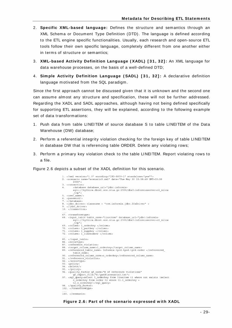
Metadata for Describing ETL Statements
- 29-
2. Specific XML-based language: Defines the structure and semantics through an
XML Schema or Document Type Definition (DTD). The language is defined according
to the ETL engine specific functionalities. Usually, each research and open-source ETL
tools follow their own specific language, completely different from one another either
in terms of structure or semantics;
3. XML-based Activity Definition Language (XADL) [31, 32]: An XML language for
data warehouse processes, on the basis of a well-defined DTD;
4. Simple Activity Definition Language (SADL) [31, 32]: A declarative definition
language motivated from the SQL paradigm.
Since the first approach cannot be discussed given that it is unknown and the second one
can assume almost any structure and specification, these will not be further addressed.
Regarding the XADL and SADL approaches, although having not being defined specifically
for supporting ETL assertions, they will be explained, according to the following example
set of data transformations:
1. Push data from table LINEITEM of source database S to table LINEITEM of the Data
Warehouse (DW) database;
2. Perform a referential integrity violation checking for the foreign key of table LINEITEM
in database DW that is referencing table ORDER. Delete any violating rows;
3. Perform a primary key violation check to the table LINEITEM. Report violating rows to
a file.
Figure 2.6 depicts a subset of the XADL definition for this scenario.
Figure 2.6: Part of the scenario expressed with XADL
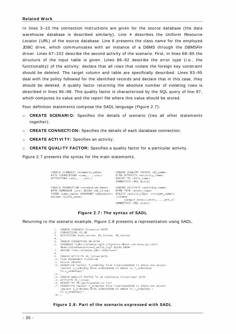
Related Work
- 30 -
In lines 3–10 the connection instructions are given for the source database (the data
warehouse database is described similarly). Line 4 describes the Uniform Resource
Locator (URL) of the source database. Line 8 presents the class name for the employed
JDBC drive, which communicates with an instance of a DBMS through the DBMSFin
driver. Lines 67–102 describe the second activity of the scenario. First, in lines 68–85 the
structure of the input table is given. Lines 86–92 describe the error type (i.e., the
functionality) of the activity: declare that all rows that violate the foreign key constraint
should be deleted. The target column and table are specifically described. Lines 93–95
deal with the policy followed for the identified records and declare that in this case, they
should be deleted. A quality factor returning the absolute number of violating rows is
described in lines 96–98. This quality factor is characterized by the SQL query of line 97,
which computes its value and the report file where this value should be stored.
Four definition statements compose the SADL language (Figure 2.7):
o CREATE SCENARIO: Specifies the details of scenario (ties all other statements
together);
o CREATE CONNECTION: Specifies the details of each database connection;
o CREATE ACTIVITY: Specifies an activity;
o CREATE QUALITY FACTOR: Specifies a quality factor for a particular activity.
Figure 2.7 presents the syntax for the main statements.
Figure 2.7: The syntax of SADL
Returning to the scenario example, Figure 2.8 presents a representation using SADL.
Figure 2.8: Part of the scenario expressed with SADL
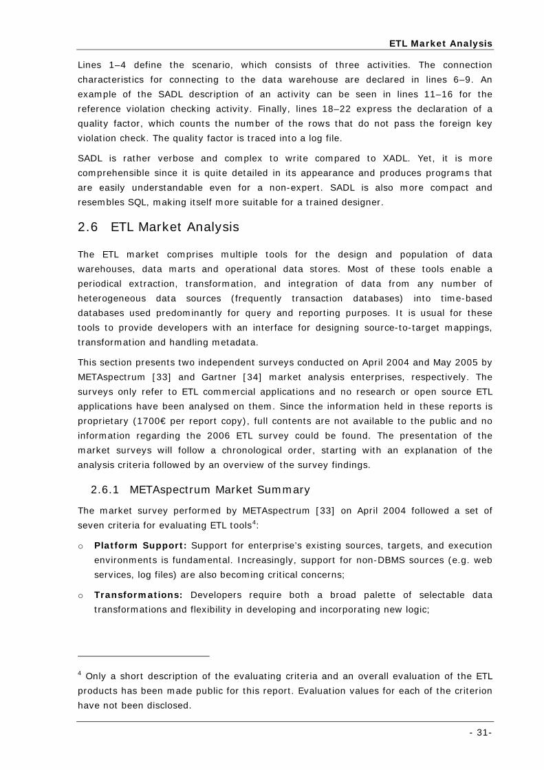
ETL Market Analysis
- 31-
Lines 1–4 define the scenario, which consists of three activities. The connection
characteristics for connecting to the data warehouse are declared in lines 6–9. An
example of the SADL description of an activity can be seen in lines 11–16 for the
reference violation checking activity. Finally, lines 18–22 express the declaration of a
quality factor, which counts the number of the rows that do not pass the foreign key
violation check. The quality factor is traced into a log file.
SADL is rather verbose and complex to write compared to XADL. Yet, it is more
comprehensible since it is quite detailed in its appearance and produces programs that
are easily understandable even for a non-expert. SADL is also more compact and
resembles SQL, making itself more suitable for a trained designer.
2.6 ETL Market Analysis
The ETL market comprises multiple tools for the design and population of data
warehouses, data marts and operational data stores. Most of these tools enable a
periodical extraction, transformation, and integration of data from any number of
heterogeneous data sources (frequently transaction databases) into time-based
databases used predominantly for query and reporting purposes. It is usual for these
tools to provide developers with an interface for designing source-to-target mappings,
transformation and handling metadata.
This section presents two independent surveys conducted on April 2004 and May 2005 by
METAspectrum [33] and Gartner [34] market analysis enterprises, respectively. The
surveys only refer to ETL commercial applications and no research or open source ETL
applications have been analysed on them. Since the information held in these reports is
proprietary (1700€ per report copy), full contents are not available to the public and no
information regarding the 2006 ETL survey could be found. The presentation of the
market surveys will follow a chronological order, starting with an explanation of the
analysis criteria followed by an overview of the survey findings.
2.6.1 METAspectrum Market Summary
The market survey performed by METAspectrum [33] on April 2004 followed a set of
seven criteria for evaluating ETL tools4:
o Platform Support: Support for enterprise’s existing sources, targets, and execution
environments is fundamental. Increasingly, support for non-DBMS sources (e.g. web
services, log files) are also becoming critical concerns;
o Transformations: Developers require both a broad palette of selectable data
transformations and flexibility in developing and incorporating new logic;
4 Only a short description of the evaluating criteria and an overall evaluation of the ETL
products has been made public for this report. Evaluation values for each of the criterion
have not been disclosed.
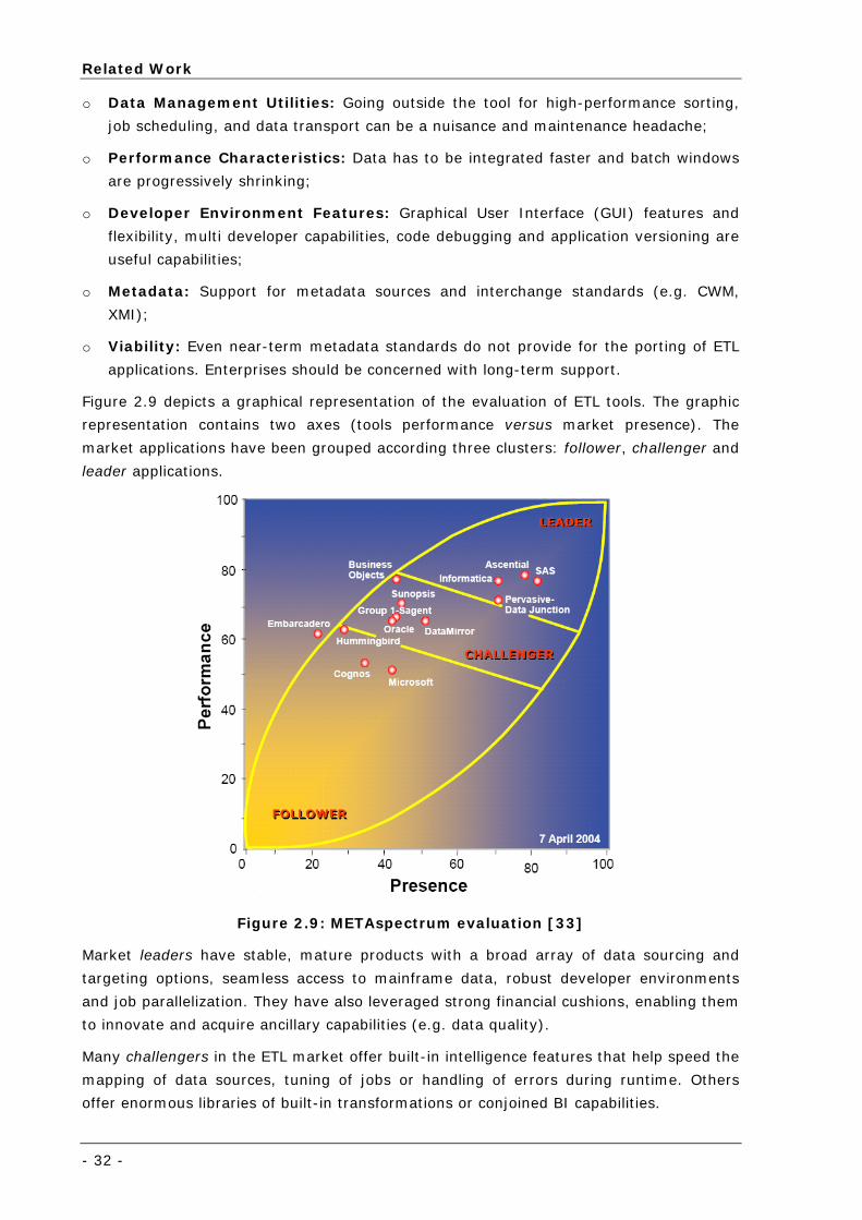
Related Work
- 32 -
o Data Management Utilities: Going outside the tool for high-performance sorting,
job scheduling, and data transport can be a nuisance and maintenance headache;
o Performance Characteristics: Data has to be integrated faster and batch windows
are progressively shrinking;
o Developer Environment Features: Graphical User Interface (GUI) features and
flexibility, multi developer capabilities, code debugging and application versioning are
useful capabilities;
o Metadata: Support for metadata sources and interchange standards (e.g. CWM,
XMI);
o Viability: Even near-term metadata standards do not provide for the porting of ETL
applications. Enterprises should be concerned with long-term support.
Figure 2.9 depicts a graphical representation of the evaluation of ETL tools. The graphic
representation contains two axes (tools performance versus market presence). The
market applications have been grouped according three clusters: follower, challenger and
leader applications.
Figure 2.9: METAspectrum evaluation [33]
Market leaders have stable, mature products with a broad array of data sourcing and
targeting options, seamless access to mainframe data, robust developer environments
and job parallelization. They have also leveraged strong financial cushions, enabling them
to innovate and acquire ancillary capabilities (e.g. data quality).
Many challengers in the ETL market offer built-in intelligence features that help speed the
mapping of data sources, tuning of jobs or handling of errors during runtime. Others
offer enormous libraries of built-in transformations or conjoined BI capabilities.
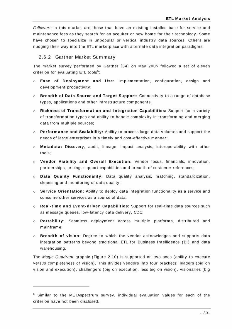
ETL Market Analysis
- 33-
Followers in this market are those that have an existing installed base for service and
maintenance fees as they search for an acquirer or new home for their technology. Some
have chosen to specialize in unpopular or vertical industry data sources. Others are
nudging their way into the ETL marketplace with alternate data integration paradigms.
2.6.2 Gartner Market Summary
The market survey performed by Gartner [34] on May 2005 followed a set of eleven
criterion for evaluating ETL tools5:
o Ease of Deployment and Use: Implementation, configuration, design and
development productivity;
o Breadth of Data Source and Target Support: Connectivity to a range of database
types, applications and other infrastructure components;
o Richness of Transformation and Integration Capabilities: Support for a variety
of transformation types and ability to handle complexity in transforming and merging
data from multiple sources;
o Performance and Scalability: Ability to process large data volumes and support the
needs of large enterprises in a timely and cost-effective manner;
o Metadata: Discovery, audit, lineage, impact analysis, interoperability with other
tools;
o Vendor Viability and Overall Execution: Vendor focus, financials, innovation,
partnerships, pricing, support capabilities and breadth of customer references;
o Data Quality Functionality: Data quality analysis, matching, standardization,
cleansing and monitoring of data quality;
o Service Orientation: Ability to deploy data integration functionality as a service and
consume other services as a source of data;
o Real-time and Event-driven Capabilities: Support for real-time data sources such
as message queues, low-latency data delivery, CDC;
o Portability: Seamless deployment across multiple platforms, distributed and
mainframe;
o Breadth of vision: Degree to which the vendor acknowledges and supports data
integration patterns beyond traditional ETL for Business Intelligence (BI) and data
warehousing.
The Magic Quadrant graphic (Figure 2.10) is supported on two axes (ability to execute
versus completeness of vision). This divides vendors into four brackets: leaders (big on
vision and execution), challengers (big on execution, less big on vision), visionaries (big
5 Similar to the METAspectrum survey, individual evaluation values for each of the
criterion have not been disclosed.
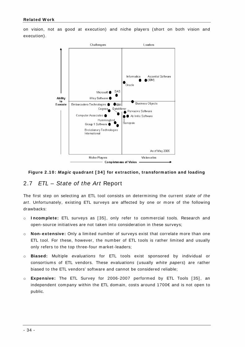
Related Work
- 34 -
on vision, not as good at execution) and niche players (short on both vision and
execution).
Figure 2.10: Magic quadrant [34] for extraction, transformation and loading
2.7 ETL – State of the Art Report
The first step on selecting an ETL tool consists on determining the current state of the
art. Unfortunately, existing ETL surveys are affected by one or more of the following
drawbacks:
o Incomplete: ETL surveys as [35], only refer to commercial tools. Research and
open-source initiatives are not taken into consideration in these surveys;
o Non-extensive: Only a limited number of surveys exist that correlate more than one
ETL tool. For these, however, the number of ETL tools is rather limited and usually
only refers to the top three-four market-leaders;
o Biased: Multiple evaluations for ETL tools exist sponsored by individual or
consortiums of ETL vendors. These evaluations (usually white papers) are rather
biased to the ETL vendors’ software and cannot be considered reliable;
o Expensive: The ETL Survey for 2006-2007 performed by ETL Tools [35], an
independent company within the ETL domain, costs around 1700€ and is not open to
public.
ETL – State of the Art Report
- 35-
In order to provide an independent and public solution for the previously mentioned
drawbacks (at least to some extend6) the author has conducted a report describing the
state of the art for the ETL domain [22]. Due to its length (around 200 pages) the
complete document was not directly included in this report, just the information
regarding the ETL background, data integration approaches and technologies, as part of
the current chapter. All specific information regarding the ETL applications that were
analysed is available uniquely at the report.
The ETL – State of the Art report [22] covers the following theoretical / business aspects
of ETL:
o ETL conceptual representation and framework;
o Classical data integration architectures, comprised by (i) Hand Coding, (ii) Code
Generators, (iii) Database Embedded ETL and (iv) Metadata Driven ETL Engines;
o Approaches to data processing, comprised by (i) Data Consolidation, (ii) Data
Federation, (iii) Data Propagation, (iv) Change Data Capture and (v) Hybrid
Approaches;
o Data Integration Technologies, comprised by (i) ETL, ELT and ETLT, (ii) Enterprise
Information Integration (EII), (iii) Enterprise Application Integration (EAI) and (iv)
Enterprise Data Replication (EDR);
o Metadata languages for describing ETL statements.
Further, an individual analysis of ETL applications has been performed according to three
domains: research / academic, open-source and commercial. Follows a list with all the
applications described in the report, grouped by their development domain:
o Research ETL Tools: AJAX, ARKTOS, Clio, DATAMOLD, IBHIS, IBIS, InFuse,
INTELLICLEAN, NoDoSe and Potter's Wheel;
o Open Source ETL Tools: Enhydra Octopus, Jitterbit, KETL, Pentaho Data
Integration: Kettle Project, Pequel ETL Engine and Talend Open Studio;
o Commercial ETL Tools: Business Objects Data Integrator, Cognos DecisionStream,
DataMirror Transformation Server, DB Software Laboratory's Visual Importer Pro,
DENODO, Embarcadero Technologies DT/Studio, ETI Solution v5, ETL Solutions
Transformation Manager, Group1 Data Flow, Hummingbird Genio, IBM Websphere
Datastage, Informatica PowerCenter, IWay Data Migrator, Microsoft SQL Server 2005,
Oracle Warehouse Builder, Pervasive Data Integrator, SAS ETL, Stylus Studio,
Sunopsis Data Conductor, Sybase TransformOnDemand.
6 Some of the applications could not be properly evaluated due to the shortage of
technical information and / or unavailability of software for public usage.
Related Work
- 36 -
2.8 Space Environment Information System for Mission Control Purposes
The space environment and its effects are being progressively taking into account in
spacecraft manufacture from the earliest design phases until reaching the operational
state. Most of these space effects on the spacecraft (long-term effects or temporal
effects) can be predicted with acceptable accuracy thanks to space environment models
and tools developed for this purpose at design time. This is the case of the Space
Environment Information System (SPENVIS) [36], which provides access to several
models and tools to produce a space environment specification for any space mission
(e.g. particle fluxes, atomic oxygen degradation).
On the other hand, and during the operational phase of the spacecraft, some anomalies
due to space environment effects or to unpredictable space weather events can occur
and affect spacecraft behaviour. These anomalies are mainly originated by the solar
activity (e.g. Solar Protons Events, Coronal Mass Ejections), whose are not evaluated
during the system design with the same level of accuracy as the effects produced by the
well-known space environment. Solar events and its effects are predicted with difficulty,
and the spacecraft anomalies caused by the space environment are not always assigned
to it, due to the lack of proper operational tools that are able to integrate and correlate
space environment information and housekeeping data of the spacecraft simultaneously.
Scientific and navigation spacecrafts, orbiting in Medium Earth Orbit (MEO), are a good
example on how the space environment models, may not be as realistic as in other orbits
due to the high variation of the environment at this altitude. The continuous operation of
the payload on these spacecrafts is a critical issue due the nature of the supplied
products.
Access to the space environment and space weather databases, together with a deep
knowledge of the space environment design, i.e. spacecraft shielding information,
radiation testing data, house-keeping telemetry designed to monitor the behaviour of the
spacecraft systems versus the space environment effects, will help to increase the life-
time of spacecraft missions and improve the construction of the next generation of
spacecrafts.
Such data integration systems require both real-time and historical data from multiple
sources (possibly with different formats) that must be correlated by a space-domain
expert, through visual inspection, using monitoring and reporting tools.
This is the main principle of the SEIS system7, developed for the European Space Agency
(ESA) [37] by UNINOVA [38] as prime contractor and DEIMOS Engenharia [39] as sub-
contractor. The author participated in the system’s implementation as UNINOVA team
member and was responsible for the partial definition of metadata ETL scripts for
processing input data files that were found relevant in the system’s scope.
7 This is also the main principle for the SESS system.

Space Environment Information System for Mission Control Purposes
- 37-
2.8.1 Objectives
SEIS is a multi-mission decision support system, capable of providing near real-time
monitoring [8] and visualization (in addition to offline historical analysis [9]) of space
weather and spacecraft data, events and alarms to FCTs responsibles of the International
Gamma-Ray Astrophysics Laboratory (Integral), Environmental Satellite (Envisat) and X-
Ray Multi-Mission (XMM) satellites. Since the Integral S/C has been selected as reference
mission, all SEIS services – offline and online – will be available, while Envisat and XMM
teams will only benefit from a fraction of all the services available for the Integral
mission.
The following list outlines SEIS’s core services:
o Reliable Space Weather and Spacecraft data integration;
o Inclusion of Space Weather and Space Weather effects estimations generated by a
widely accepted collection of physical Space Weather models;
o Near real-time alarm triggered events, based on rules extracted from the Flight
Operations’ Plan (FOP) which capture users’ domain knowledge;
o Near real-time visualization of ongoing Space Weather and Spacecraft conditions
through the SEIS Monitoring Tool (MT) [8];
o Historical data visualization and correlation analysis (including automatic report
design, generation and browsing) using state-of-art On-Line Analytical Processing
(OLAP) client/server technology - SEIS Reporting and Analysis Tool (RAT) [9].
2.8.2 Architecture
In order to provide users with the previously mentioned set of services, the system
architecture depicted in Figure 2.11 was envisaged, which is divided d in several modules
according to their specific roles:
o Data Processing Module: Responsible for file retrieval, parameter extraction and
further transformations applied to all identified data, ensuring it meets the online and
offline availability constraints, whilst having reusability and maintainability issues in
mind (further detailed on in the following section);
o Data Integration Module (DIM): Acts as the system’s supporting infrastructure
database, providing integrated data services to the SEIS client applications, using
three multi-purpose databases: Data Warehouse (DW) [27], Operational Data
Storage (ODS) and Data Mart (DM);
o Forecasting Module (3M): A collection of forecast and estimation models capable of
generating Space Environment [40] and Spacecraft data estimations. Interaction with
any of these models is accomplished using remote Web Services’ invocation, which
relies on XML message-passing mechanisms;
o Metadata Module (MR): SEIS is a metadata driven system, comprising a central
metadata repository [41], that provides all SEIS applications with means of accessing
shared information and configuration files;
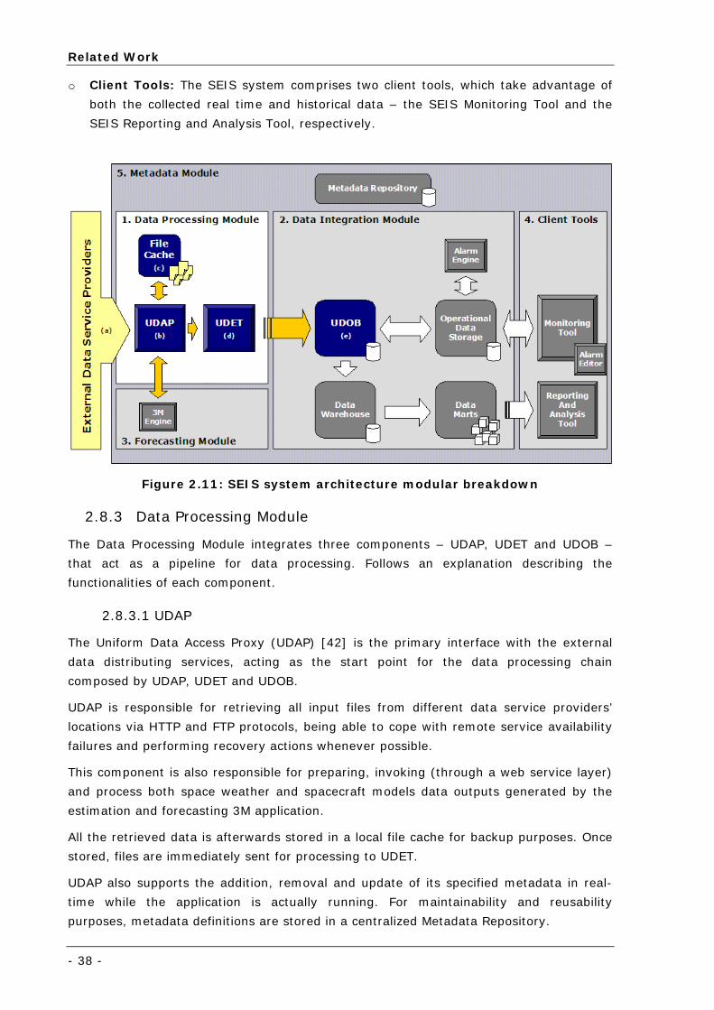
Related Work
- 38 -
o Client Tools: The SEIS system comprises two client tools, which take advantage of
both the collected real time and historical data – the SEIS Monitoring Tool and the
SEIS Reporting and Analysis Tool, respectively.
Figure 2.11: SEIS system architecture modular breakdown
2.8.3 Data Processing Module
The Data Processing Module integrates three components – UDAP, UDET and UDOB –
that act as a pipeline for data processing. Follows an explanation describing the
functionalities of each component.
2.8.3.1 UDAP
The Uniform Data Access Proxy (UDAP) [42] is the primary interface with the external
data distributing services, acting as the start point for the data processing chain
composed by UDAP, UDET and UDOB.
UDAP is responsible for retrieving all input files from different data service providers’
locations via HTTP and FTP protocols, being able to cope with remote service availability
failures and performing recovery actions whenever possible.
This component is also responsible for preparing, invoking (through a web service layer)
and process both space weather and spacecraft models data outputs generated by the
estimation and forecasting 3M application.
All the retrieved data is afterwards stored in a local file cache for backup purposes. Once
stored, files are immediately sent for processing to UDET.
UDAP also supports the addition, removal and update of its specified metadata in real-
time while the application is actually running. For maintainability and reusability
purposes, metadata definitions are stored in a centralized Metadata Repository.
Space Environment Information System for Mission Control Purposes
- 39-
Although UDAP can be considered an engine for input files download, it has been
integrated into a graphical application that enables the user to control file download at
data service provider and input file level. Further, a graphical component is available that
enables the visualization of all download actions performed by UDAP as well as the
responses of UDET to data processing requests. Besides visualization, this component
also enables filtering and querying of logging data.
The application has been implemented using Microsoft .NET [43] and Internet
Information System (IIS) [44] technologies.
2.8.3.2 UDET
The Unified Data Extractor and Transformer (UDET) [42] is the second component in the
chain of the Data Processing pipeline. The main goal of UDET is data processing, which
includes performing extraction and transformation activities according to user declarative
definitions – File Format Definition (FFD) - for online and offline data files received from
UDAP. After processing, the results are sent to the respective UDOB (Uniform Data
Output Buffer) offline or near real-time instance.
The application has been implemented using Microsoft .NET and IIS technologies and can
be executed in one of two ways:
o Web Service: Provides a transparent data processing mechanism, capable of
accepting data processing requests and delivering processed data into the respective
target UDOB. Since the processing tasks are mainly processor intensive, the
deployment scenario should at least comprise two UDET-UDOB instances, one for
processing and delivering of near real-time data and the other for offline data
processing;
o Portable library: Extraction and transformation logic has been gathered in a
common package that can be used by external applications. The FFD Editor, capable
of creating, editing and test FFDs given an example input file, would be the main user
application for this library. However, due to time constraints this application has not
been developed in the scope of SEIS.
2.8.3.3 UDOB
The Uniform Data Output Buffer (UDOB) [42] constitutes the endpoint component for the
Data Processing Module, also known as Staging Area. The primary role of UDOB is to
behave as an intermediate data buffer on which the same data is made available to both
the ODS, DW or any other data retrieving client.
UDOB has been implemented using Microsoft .NET [43], IIS [44] and SQL Server [45]
technologies.
2.8.4 Evaluation
Although the SEIS system (and all its underlying components) has been enormously
successful in practice, it was a prototype system and some restrictions and simplifications
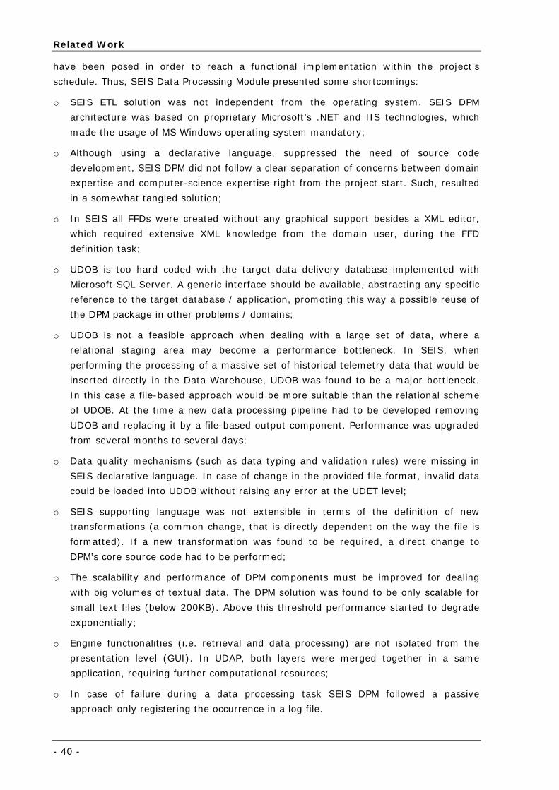
Related Work
- 40 -
have been posed in order to reach a functional implementation within the project’s
schedule. Thus, SEIS Data Processing Module presented some shortcomings:
o SEIS ETL solution was not independent from the operating system. SEIS DPM
architecture was based on proprietary Microsoft’s .NET and IIS technologies, which
made the usage of MS Windows operating system mandatory;
o Although using a declarative language, suppressed the need of source code
development, SEIS DPM did not follow a clear separation of concerns between domain
expertise and computer-science expertise right from the project start. Such, resulted
in a somewhat tangled solution;
o In SEIS all FFDs were created without any graphical support besides a XML editor,
which required extensive XML knowledge from the domain user, during the FFD
definition task;
o UDOB is too hard coded with the target data delivery database implemented with
Microsoft SQL Server. A generic interface should be available, abstracting any specific
reference to the target database / application, promoting this way a possible reuse of
the DPM package in other problems / domains;
o UDOB is not a feasible approach when dealing with a large set of data, where a
relational staging area may become a performance bottleneck. In SEIS, when
performing the processing of a massive set of historical telemetry data that would be
inserted directly in the Data Warehouse, UDOB was found to be a major bottleneck.
In this case a file-based approach would be more suitable than the relational scheme
of UDOB. At the time a new data processing pipeline had to be developed removing
UDOB and replacing it by a file-based output component. Performance was upgraded
from several months to several days;
o Data quality mechanisms (such as data typing and validation rules) were missing in
SEIS declarative language. In case of change in the provided file format, invalid data
could be loaded into UDOB without raising any error at the UDET level;
o SEIS supporting language was not extensible in terms of the definition of new
transformations (a common change, that is directly dependent on the way the file is
formatted). If a new transformation was found to be required, a direct change to
DPM’s core source code had to be performed;
o The scalability and performance of DPM components must be improved for dealing
with big volumes of textual data. The DPM solution was found to be only scalable for
small text files (below 200KB). Above this threshold performance started to degrade
exponentially;
o Engine functionalities (i.e. retrieval and data processing) are not isolated from the
presentation level (GUI). In UDAP, both layers were merged together in a same
application, requiring further computational resources;
o In case of failure during a data processing task SEIS DPM followed a passive
approach only registering the occurrence in a log file.
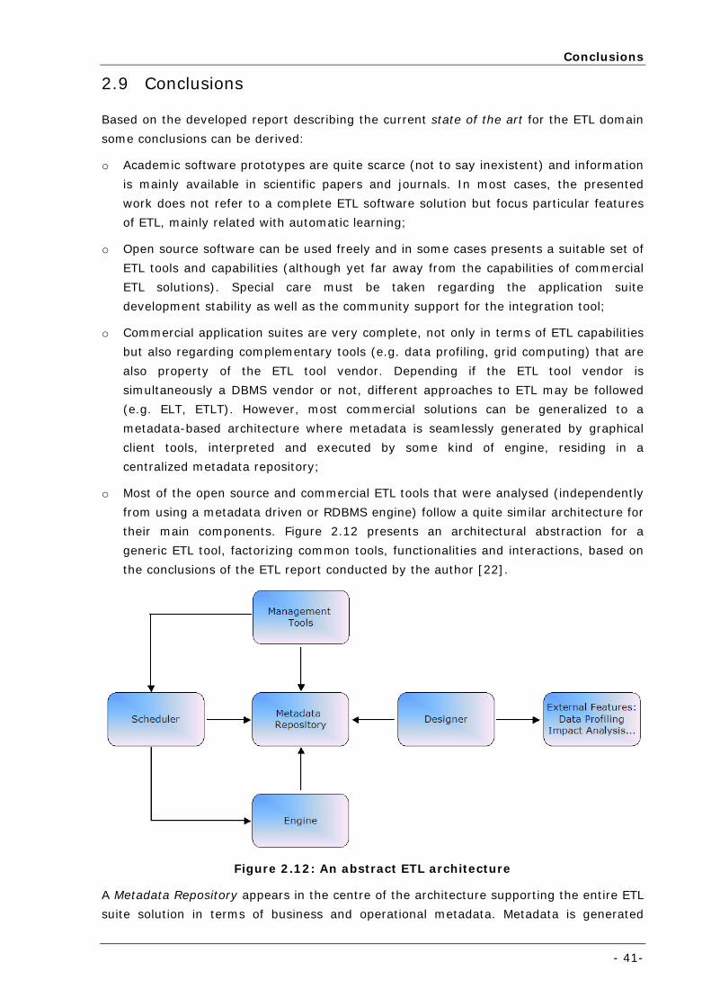
Conclusions
- 41-
2.9 Conclusions
Based on the developed report describing the current state of the art for the ETL domain
some conclusions can be derived:
o Academic software prototypes are quite scarce (not to say inexistent) and information
is mainly available in scientific papers and journals. In most cases, the presented
work does not refer to a complete ETL software solution but focus particular features
of ETL, mainly related with automatic learning;
o Open source software can be used freely and in some cases presents a suitable set of
ETL tools and capabilities (although yet far away from the capabilities of commercial
ETL solutions). Special care must be taken regarding the application suite
development stability as well as the community support for the integration tool;
o Commercial application suites are very complete, not only in terms of ETL capabilities
but also regarding complementary tools (e.g. data profiling, grid computing) that are
also property of the ETL tool vendor. Depending if the ETL tool vendor is
simultaneously a DBMS vendor or not, different approaches to ETL may be followed
(e.g. ELT, ETLT). However, most commercial solutions can be generalized to a
metadata-based architecture where metadata is seamlessly generated by graphical
client tools, interpreted and executed by some kind of engine, residing in a
centralized metadata repository;
o Most of the open source and commercial ETL tools that were analysed (independently
from using a metadata driven or RDBMS engine) follow a quite similar architecture for
their main components. Figure 2.12 presents an architectural abstraction for a
generic ETL tool, factorizing common tools, functionalities and interactions, based on
the conclusions of the ETL report conducted by the author [22].
Figure 2.12: An abstract ETL architecture
A Metadata Repository appears in the centre of the architecture supporting the entire ETL
suite solution in terms of business and operational metadata. Metadata is generated
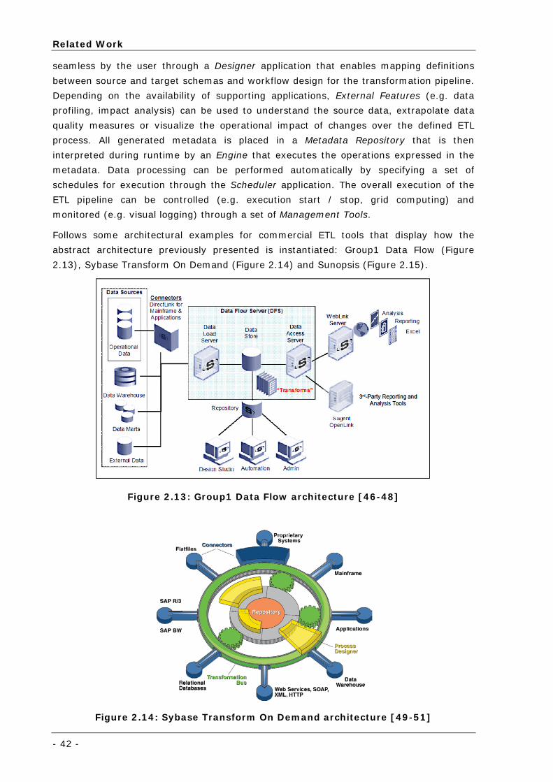
Related Work
- 42 -
seamless by the user through a Designer application that enables mapping definitions
between source and target schemas and workflow design for the transformation pipeline.
Depending on the availability of supporting applications, External Features (e.g. data
profiling, impact analysis) can be used to understand the source data, extrapolate data
quality measures or visualize the operational impact of changes over the defined ETL
process. All generated metadata is placed in a Metadata Repository that is then
interpreted during runtime by an Engine that executes the operations expressed in the
metadata. Data processing can be performed automatically by specifying a set of
schedules for execution through the Scheduler application. The overall execution of the
ETL pipeline can be controlled (e.g. execution start / stop, grid computing) and
monitored (e.g. visual logging) through a set of Management Tools.
Follows some architectural examples for commercial ETL tools that display how the
abstract architecture previously presented is instantiated: Group1 Data Flow (Figure
2.13), Sybase Transform On Demand (Figure 2.14) and Sunopsis (Figure 2.15).
Figure 2.13: Group1 Data Flow architecture [46-48]
Figure 2.14: Sybase Transform On Demand architecture [49-51]
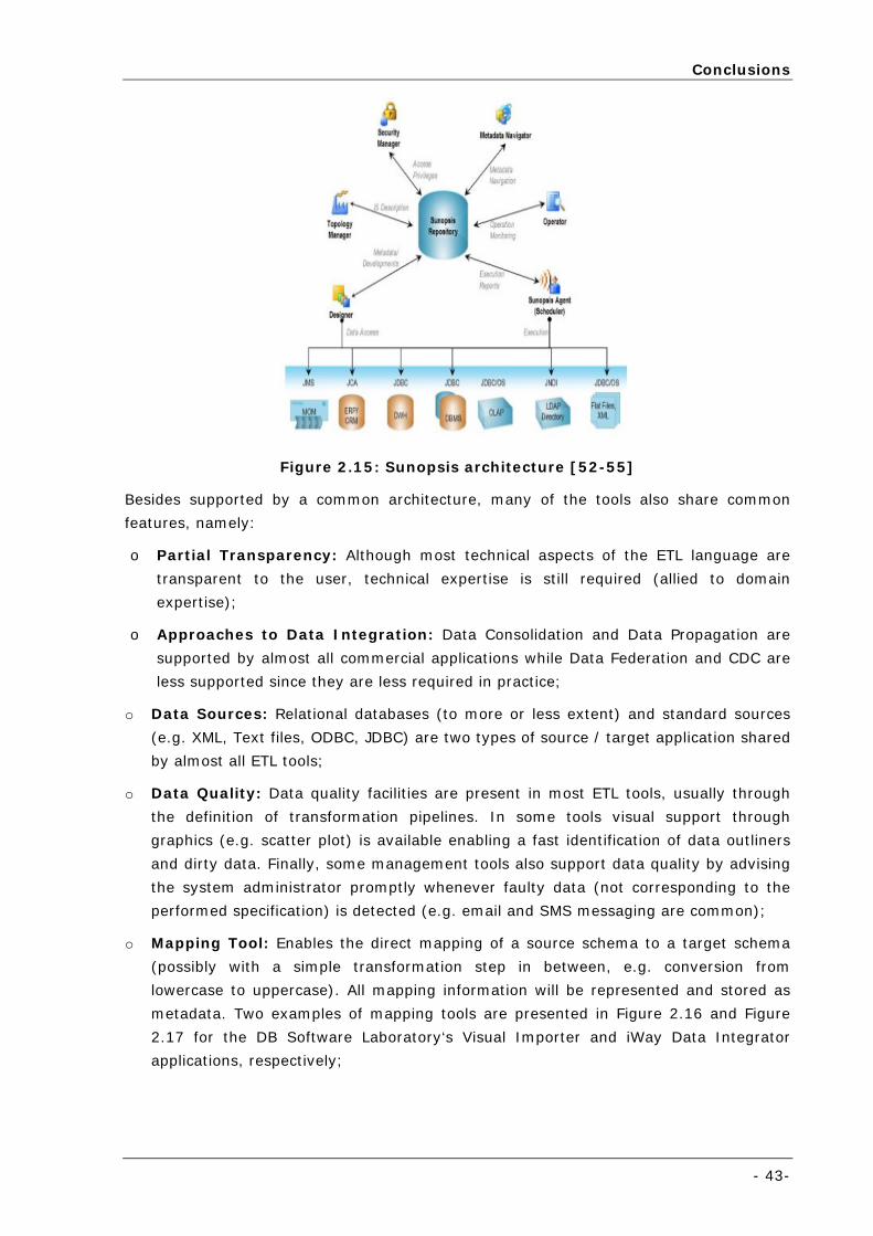
Conclusions
- 43-
Figure 2.15: Sunopsis architecture [52-55]
Besides supported by a common architecture, many of the tools also share common
features, namely:
o Partial Transparency: Although most technical aspects of the ETL language are
transparent to the user, technical expertise is still required (allied to domain
expertise);
o Approaches to Data Integration: Data Consolidation and Data Propagation are
supported by almost all commercial applications while Data Federation and CDC are
less supported since they are less required in practice;
o Data Sources: Relational databases (to more or less extent) and standard sources
(e.g. XML, Text files, ODBC, JDBC) are two types of source / target application shared
by almost all ETL tools;
o Data Quality: Data quality facilities are present in most ETL tools, usually through
the definition of transformation pipelines. In some tools visual support through
graphics (e.g. scatter plot) is available enabling a fast identification of data outliners
and dirty data. Finally, some management tools also support data quality by advising
the system administrator promptly whenever faulty data (not corresponding to the
performed specification) is detected (e.g. email and SMS messaging are common);
o Mapping Tool: Enables the direct mapping of a source schema to a target schema
(possibly with a simple transformation step in between, e.g. conversion from
lowercase to uppercase). All mapping information will be represented and stored as
metadata. Two examples of mapping tools are presented in Figure 2.16 and Figure
2.17 for the DB Software Laboratory‘s Visual Importer and iWay Data Integrator
applications, respectively;
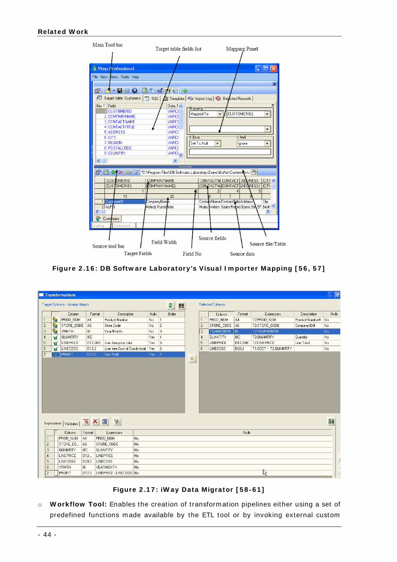
Related Work
- 44 -
Figure 2.16: DB Software Laboratory’s Visual Importer Mapping [56, 57]
Figure 2.17: iWay Data Migrator [58-61]
o Workflow Tool: Enables the creation of transformation pipelines either using a set of
predefined functions made available by the ETL tool or by invoking external custom
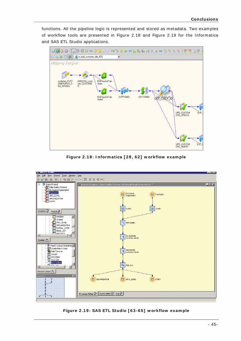
Conclusions
- 45-
functions. All the pipeline logic is represented and stored as metadata. Two examples
of workflow tools are presented in Figure 2.18 and Figure 2.19 for the Informatica
and SAS ETL Studio applications.
Figure 2.18: Informatica [28, 62] workflow example
Figure 2.19: SAS ETL Studio [63-65] workflow example
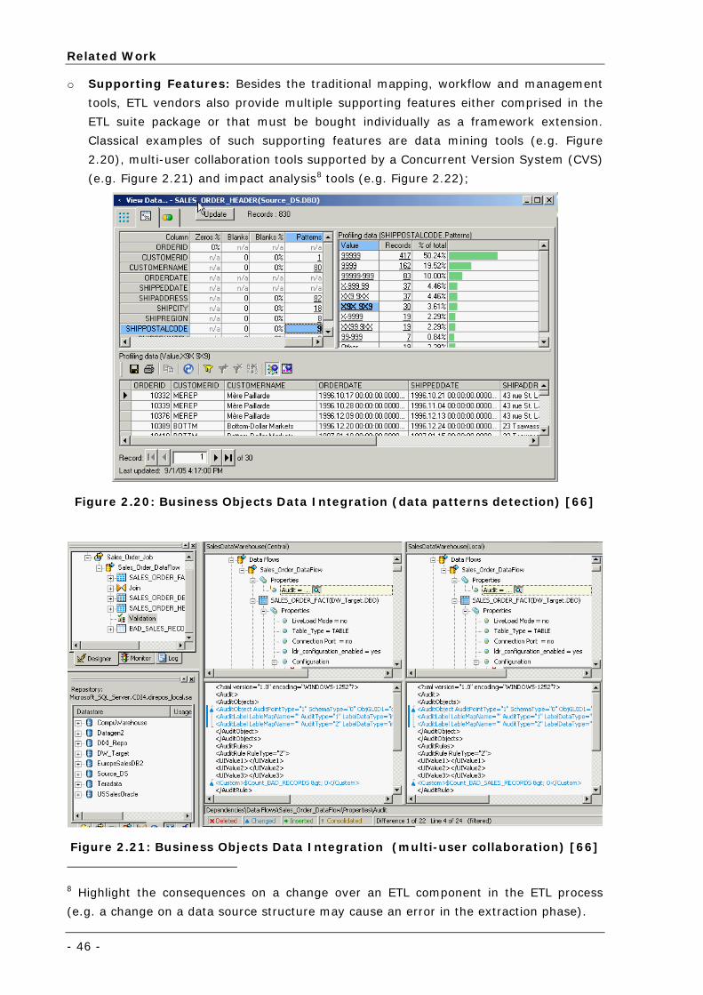
Related Work
- 46 -
o Supporting Features: Besides the traditional mapping, workflow and management
tools, ETL vendors also provide multiple supporting features either comprised in the
ETL suite package or that must be bought individually as a framework extension.
Classical examples of such supporting features are data mining tools (e.g. Figure
2.20), multi-user collaboration tools supported by a Concurrent Version System (CVS)
(e.g. Figure 2.21) and impact analysis8 tools (e.g. Figure 2.22);
Figure 2.20: Business Objects Data Integration (data patterns detection) [66]
Figure 2.21: Business Objects Data Integration (multi-user collaboration) [66]
8 Highlight the consequences on a change over an ETL component in the ETL process
(e.g. a change on a data source structure may cause an error in the extraction phase).
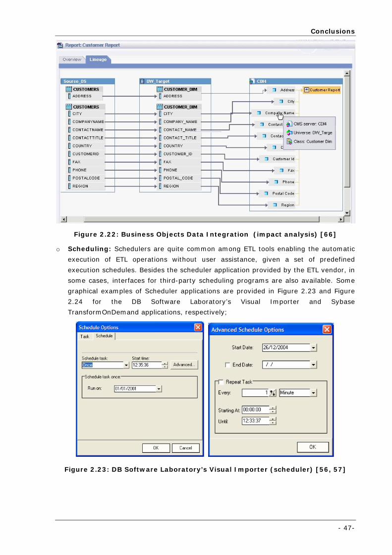
Conclusions
- 47-
Figure 2.22: Business Objects Data Integration (impact analysis) [66]
o Scheduling: Schedulers are quite common among ETL tools enabling the automatic
execution of ETL operations without user assistance, given a set of predefined
execution schedules. Besides the scheduler application provided by the ETL vendor, in
some cases, interfaces for third-party scheduling programs are also available. Some
graphical examples of Scheduler applications are provided in Figure 2.23 and Figure
2.24 for the DB Software Laboratory’s Visual Importer and Sybase
TransformOnDemand applications, respectively;
Figure 2.23: DB Software Laboratory’s Visual Importer (scheduler) [56, 57]
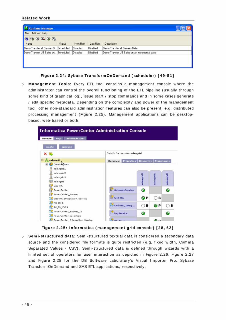
Related Work
- 48 -
Figure 2.24: Sybase TransformOnDemand (scheduler) [49-51]
o Management Tools: Every ETL tool contains a management console where the
administrator can control the overall functioning of the ETL pipeline (usually through
some kind of graphical log), issue start / stop commands and in some cases generate
/ edit specific metadata. Depending on the complexity and power of the management
tool, other non-standard administration features can also be present, e.g. distributed
processing management (Figure 2.25). Management applications can be desktop-
based, web-based or both;
Figure 2.25: Informatica (management grid console) [28, 62]
o Semi-structured data: Semi-structured textual data is considered a secondary data
source and the considered file formats is quite restricted (e.g. fixed width, Comma
Separated Values - CSV). Semi-structured data is defined through wizards with a
limited set of operators for user interaction as depicted in Figure 2.26, Figure 2.27
and Figure 2.28 for the DB Software Laboratory’s Visual Importer Pro, Sybase
TransformOnDemand and SAS ETL applications, respectively;
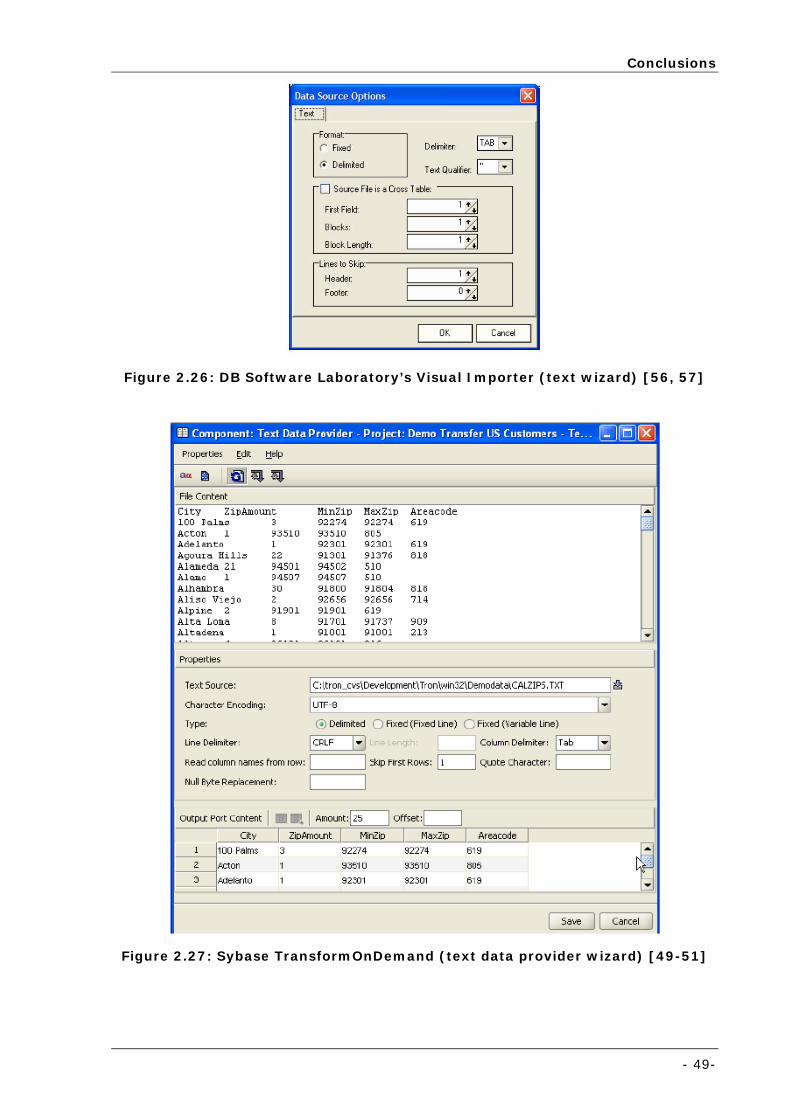
Conclusions
- 49-
Figure 2.26: DB Software Laboratory’s Visual Importer (text wizard) [56, 57]
Figure 2.27: Sybase TransformOnDemand (text data provider wizard) [49-51]
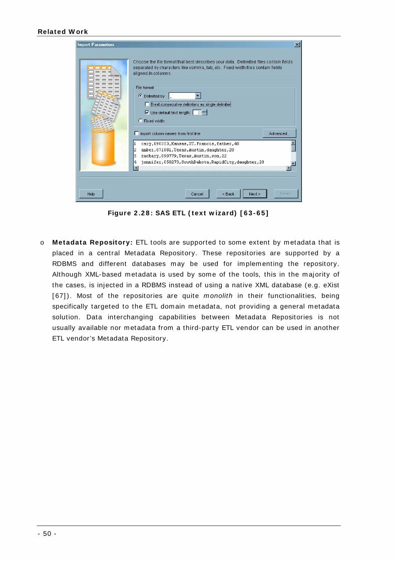
Related Work
- 50 -
Figure 2.28: SAS ETL (text wizard) [63-65]
o Metadata Repository: ETL tools are supported to some extent by metadata that is
placed in a central Metadata Repository. These repositories are supported by a
RDBMS and different databases may be used for implementing the repository.
Although XML-based metadata is used by some of the tools, this in the majority of
the cases, is injected in a RDBMS instead of using a native XML database (e.g. eXist
[67]). Most of the repositories are quite monolith in their functionalities, being
specifically targeted to the ETL domain metadata, not providing a general metadata
solution. Data interchanging capabilities between Metadata Repositories is not
usually available nor metadata from a third-party ETL vendor can be used in another
ETL vendor’s Metadata Repository.
- 51 -
Chapter 3 Decomposing ETL: The ETD
+ IL Approach
Focusing on a novel approach for ETL, this chapter proposes a clear
separation of domain from technological concerns, such that ETL = ETD + IL.
First the classical ETL approach is described, analysed and evaluated in the
scope of semi-structured scientific data.
Then the ETD+IL approach is explained, describing specifically which are ETD
and IL actions.
Finally, a set of requirements is derived for accomplishing a complete data
retrieval and processing solution.
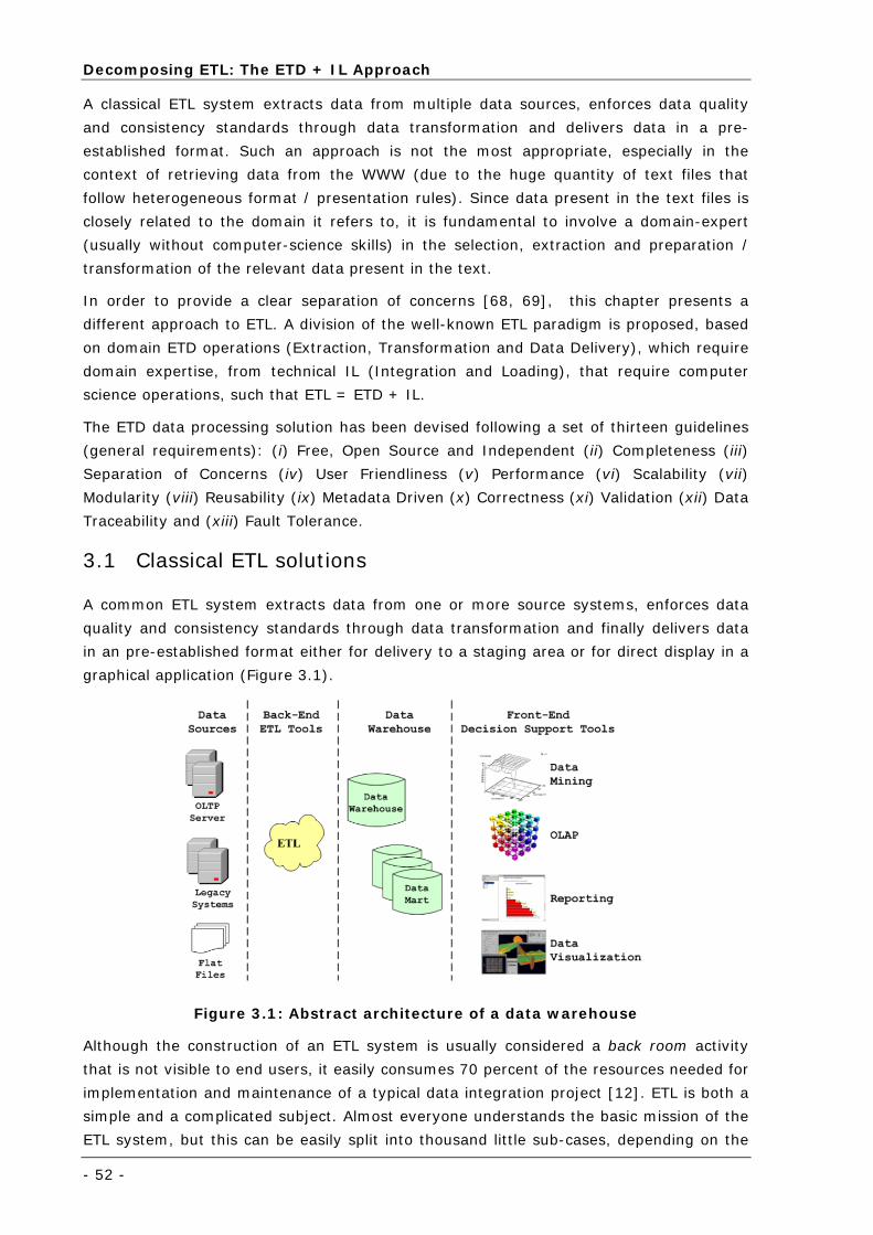
Decomposing ETL: The ETD + IL Approach
- 52 -
A classical ETL system extracts data from multiple data sources, enforces data quality
and consistency standards through data transformation and delivers data in a pre-
established format. Such an approach is not the most appropriate, especially in the
context of retrieving data from the WWW (due to the huge quantity of text files that
follow heterogeneous format / presentation rules). Since data present in the text files is
closely related to the domain it refers to, it is fundamental to involve a domain-expert
(usually without computer-science skills) in the selection, extraction and preparation /
transformation of the relevant data present in the text.
In order to provide a clear separation of concerns [68, 69], this chapter presents a
different approach to ETL. A division of the well-known ETL paradigm is proposed, based
on domain ETD operations (Extraction, Transformation and Data Delivery), which require
domain expertise, from technical IL (Integration and Loading), that require computer
science operations, such that ETL = ETD + IL.
The ETD data processing solution has been devised following a set of thirteen guidelines
(general requirements): (i) Free, Open Source and Independent (ii) Completeness (iii)
Separation of Concerns (iv) User Friendliness (v) Performance (vi) Scalability (vii)
Modularity (viii) Reusability (ix) Metadata Driven (x) Correctness (xi) Validation (xii) Data
Traceability and (xiii) Fault Tolerance.
3.1 Classical ETL solutions
A common ETL system extracts data from one or more source systems, enforces data
quality and consistency standards through data transformation and finally delivers data
in an pre-established format either for delivery to a staging area or for direct display in a
graphical application (Figure 3.1).
Figure 3.1: Abstract architecture of a data warehouse
Although the construction of an ETL system is usually considered a back room activity
that is not visible to end users, it easily consumes 70 percent of the resources needed for
implementation and maintenance of a typical data integration project [12]. ETL is both a
simple and a complicated subject. Almost everyone understands the basic mission of the
ETL system, but this can be easily split into thousand little sub-cases, depending on the
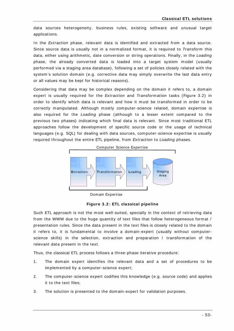
Classical ETL solutions
- 53-
data sources heterogeneity, business rules, existing software and unusual target
applications.
In the Extraction phase, relevant data is identified and extracted from a data source.
Since source data is usually not in a normalized format, it is required to Transform this
data, either using arithmetic, date conversion or string operations. Finally, in the Loading
phase, the already converted data is loaded into a target system model (usually
performed via a staging area database), following a set of policies closely related with the
system’s solution domain (e.g. corrective data may simply overwrite the last data entry
or all values may be kept for historical reasons).
Considering that data may be complex depending on the domain it refers to, a domain
expert is usually required for the Extraction and Transformation tasks (Figure 3.2) in
order to identify which data is relevant and how it must be transformed in order to be
correctly manipulated. Although mostly computer-science related, domain expertise is
also required for the Loading phase (although to a lesser extent compared to the
previous two phases) indicating which final data is relevant. Since most traditional ETL
approaches follow the development of specific source code or the usage of technical
languages (e.g. SQL) for dealing with data sources, computer-science expertise is usually
required throughout the entire ETL pipeline, from Extraction to Loading phases.
Extraction Transformation Loading
Domain Expertise
Computer Science Expertise
StagingArea
Figure 3.2: ETL classical pipeline
Such ETL approach is not the most well-suited, specially in the context of retrieving data
from the WWW due to the huge quantity of text files that follow heterogeneous format /
presentation rules. Since the data present in the text files is closely related to the domain
it refers to, it is fundamental to involve a domain-expert (usually without computer-
science skills) in the selection, extraction and preparation / transformation of the
relevant data present in the text.
Thus, the classical ETL process follows a three-phase iterative procedure:
1. The domain expert identifies the relevant data and a set of procedures to be
implemented by a computer-science expert;
2. The computer-science expert codifies this knowledge (e.g. source code) and applies
it to the text files;
3. The solution is presented to the domain-expert for validation purposes.
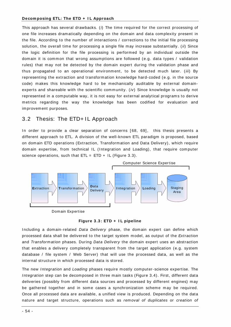
Decomposing ETL: The ETD + IL Approach
- 54 -
This approach has several drawbacks. (i) The time required for the correct processing of
one file increases dramatically depending on the domain and data complexity present in
the file. According to the number of interactions / corrections to the initial file processing
solution, the overall time for processing a single file may increase substantially. (ii) Since
the logic definition for the file processing is performed by an individual outside the
domain it is common that wrong assumptions are followed (e.g. data types / validation
rules) that may not be detected by the domain expert during the validation phase and
thus propagated to an operational environment, to be detected much later. (iii) By
representing the extraction and transformation knowledge hard-coded (e.g. in the source
code) makes this knowledge hard to be mechanically auditable by external domain-
experts and shareable with the scientific community. (iv) Since knowledge is usually not
represented in a computable way, it is not easy for external analytical programs to derive
metrics regarding the way the knowledge has been codified for evaluation and
improvement purposes.
3.2 Thesis: The ETD+IL Approach
In order to provide a clear separation of concerns [68, 69], this thesis presents a
different approach to ETL. A division of the well-known ETL paradigm is proposed, based
on domain ETD operations (Extraction, Transformation and Data Delivery), which require
domain expertise, from technical IL (Integration and Loading), that require computer
science operations, such that ETL = ETD + IL (Figure 3.3).
Extraction TransformationData Delivery
Domain Expertise
Computer Science Expertise
StagingArea
Integration Loading
Figure 3.3: ETD + IL pipeline
Including a domain-related Data Delivery phase, the domain expert can define which
processed data shall be delivered to the target system model, as output of the Extraction
and Transformation phases. During Data Delivery the domain expert uses an abstraction
that enables a delivery completely transparent from the target application (e.g. system
database / file system / Web Server) that will use the processed data, as well as the
internal structure in which processed data is stored.
The new Integration and Loading phases require mostly computer-science expertise. The
Integration step can be decomposed in three main tasks (Figure 3.4). First, different data
deliveries (possibly from different data sources and processed by different engines) may
be gathered together and in some cases a synchronization scheme may be required.
Once all processed data are available, a unified view is produced. Depending on the data
nature and target structure, operations such as removal of duplicates or creation of
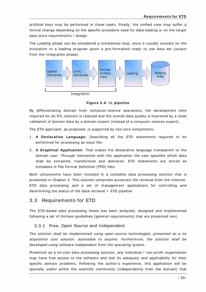
Requirements for ETD
- 55-
artificial keys may be performed in these tasks. Finally, the unified view may suffer a
format change depending on the specific procedure used for data loading or on the target
data store requirements / design.
The Loading phase can be considered a mechanical step, since it usually consists on the
invocation to a loading program given a pre-formatted ready to use data set (output
from the Integration phase).
Figure 3.4: IL pipeline
By differentiating domain from computer-science operations, the development time
required for an ETL solution is reduced and the overall data quality is improved by a close
validation of domain data by a domain-expert (instead of a computer-science expert).
The ETD approach, as proposed, is supported by two core components:
1. A Declarative Language: Describing all the ETD statements required to be
performed for processing an input file;
2. A Graphical Application: That makes the declarative language transparent to the
domain user. Through interaction with the application the user specifies which data
shall be extracted, transformed and delivered. ETD statements are stored as
metadata in File Format Definition (FFD) files.
Both components have been included in a complete data processing solution that is
presented in Chapter 4. This solution comprises automatic file retrieval from the Internet,
ETD data processing and a set of management applications for controlling and
determining the status of the data retrieval + ETD pipeline.
3.3 Requirements for ETD
The ETD-based data processing thesis has been analysed, designed and implemented
following a set of thirteen guidelines (general requirements) that are presented next.
3.3.1 Free, Open Source and Independent
The solution shall be implemented using open-source technologies, presented as a no
acquisition cost solution, accessible to anyone. Furthermore, the solution shall be
developed using software independent from the operating system.
Presented as a no-cost data processing solution, any individual / non-profit organization
may have free access to the software and test its adequacy and applicability for their
specific domain problems. Following the author’s experience, this application will be
specially useful within the scientific community (independently from the domain) that
Decomposing ETL: The ETD + IL Approach
- 56 -
require a free simple data processing tool for data analysis purposes and are usually
limited by a low / inexistent budget.
Although the proposed software has been used in practice and in a real operational
environment, the ETD related software is not presented as a closed final package. On the
contrary, in the author’s perspective, the software package is presented as a first kick-off
solution, open to discussion, refinement and extension within the software community.
Thus, the solution shall be implemented using open source technologies, not only in
terms of the software specifically developed for this package, but also regarding all its
internal software components implemented by external developers. This way, the data
processing solution is open to future extensions, developed by third parties.
Finally, by presenting a solution independent of the operating system, no limitation is
posed to the end user, regarding any special operating system, version or release.
3.3.2 Completeness
A complete data processing solution shall be available comprising data retrieval, data
processing and overall management of the data processing solution.
Although the ETD + IL approach, supported by a declarative language and graphical
editor, are the main focus of this thesis, it would have a rather limited applicability if only
these two components (language and editor) would be available. In order to be
considered complete, the solution should comprise at least five core components:
o Declarative language for representing ETD assertions;
o Graphical editor for the creation of FFDs based on graphical interaction and notations,
making the ETD language transparently to the user;
o A data retrieval service that enables the automatic acquisition of data files based on a
scheduler scheme;
o A data processing service that enables the automatic processing of data files
according to the FFDs previously defined;
o Management tools for monitoring and controlling the data retrieval and processing
pipeline.
3.3.3 Separation of Concerns
The domain user shall be able to use and maintain the data processing pipeline without
requiring computer-science expertise. All domain procedures and definitions shall be
represented recurring to a high-level declarative language. No specific source-code shall
be required to implement the processing of a single text file.
Most data processing solutions (currently available) require computer-science expertise
(e.g. programming effort, database or XML schemas, querying languages), to some
extent. Such solutions, highly restrict the number of tool users to those that have
knowledge / access to computer-science expertise. Domain experts that do not fit in this
profile, have to execute their data processing tasks using non-dedicated tools like text
Requirements for ETD
- 57-
editors and performing a set of non-automated steps, prone to error that may alter /
corrupt the data contents.
In order not to restrict users, the proposed data processing solution shall not require
computer-science expertise either at a low-level (e.g. programming effort) or high-level
(e.g. interpreting XML and XML documents). For the envisaged solution, all programming
tasks shall be replaced by ETD procedures and definitions represented in a high-level
XML based declarative language. This language although closer to the end user, shall also
not be manipulated directly, but made transparent by using a graphical application,
providing a clear separation of concerns from domain to computer-science expertise.
3.3.4 User Friendliness
A graphical application shall be available, making use of the declarative language in a
transparent way to the end user.
In order to accomplish a clear separation of concerns between domain and computer-
science expertise, it is fundamental, that the supporting ETD language and its XML
representation, be masked from the nominal user. Thus user friendliness takes particular
importance during the File Format Definition creation, test and debug tasks. A set of
gestures, graphical notations (e.g. icons, colours) and wizards shall be used to allow
users to interact with will the tool and express how the Extraction, Transformation and
Data Delivery steps shall be represented given a sample input file.
Although with a minor degree of importance, the proposed graphical management tools
shall also be user friendly (in terms of enabling an intuitive monitoring and control of the
data retrieval and processing pipeline).
3.3.5 Performance
Data retrieval and data processing shall have a reduced response time while preserving
both CPU and network bandwidth resources.
The data processing solution requires good performance either for data processing and
data retrieval (which can be measured by the amount of time required for processing) or
retrieving a file, respectively.
Regarding data processing performance, two boundary cases, yet common, shall be
considered: frequent requests for processing small data files and rare requests for
processing large data files (e.g. 3 Megabytes in length). For each input file, the time
required for its processing shall be linearly dependent to the file’s length.
Data retrieval requests shall be kept to a minimum in case of retrial attempts. Depending
on the type of data available in the input files, the number of retrials in case of failure
shall be customized accordingly. As an example, real-time data files that may be
overwritten every 5 minutes shall have less data retrial attempts when considering
summary data files that may be available for retrieval during various weeks / months.
Decomposing ETL: The ETD + IL Approach
- 58 -
3.3.6 Scalability
Both data retrieval and data processing must be capable of handling multiple
simultaneous downloads and processing requests, respectively.
Scalability is a fundamental requirement for data retrieval and processing, especially for
load balancing purposes.
When dealing with load balancing issues, data processing takes a special relevance
compared to data retrieval. For architectures where the number of provided files to
process is very high, or where each provided file requires a long processing time, the
data processing tasks must be parallelized and coordinated through different machines /
CPUs. Otherwise, a processing bottleneck will occur and all data processing requests shall
be affected, namely delayed. This situation becomes even more critical when real-time
data is being handled, which can not be delayed or its relevance will be lost / diminished.
A similar solution must be applied to the data retrieval process, whenever the number of
provided files to retrieve is very high, or when each provided file requires a long retrieval
time, due to its length. In these cases, the data retrieval effort must be parallelized
through different network connections, in order not to reach a network bottleneck
situation.
For situations that involve proprietary data, both data retrieval and processing
components must be customizable and scalable enough that individual subsets of
provided files can be retrieved and processed using specific network connections and
CPUs, respectively. The data processing solution shall also be able to cope with mixed
public and private sets of data, separating both data retrieval and processing pipelines.
3.3.7 Modularity
The solution architecture and implementation shall be as modular as possible, clearly
separating the ETD pipeline from the IL pipeline. Further, there shall be a clear
separation between logic and presentation layers, easing future maintenance tasks.
Data retrieval and data processing shall be separated in two independent services that
may be installed in different machines. In both cases the services provided by each
engine shall be self-contained, not being limited to the retrieval / processing logic but
also enabling to control the service execution as retrieving logging information for
monitoring and debug purposes.
The graphical presentation layer for both engines, shall be decoupled from their logical
layer, through independent applications. While the logical layer shall execute
continuously, the graphical layer may be executed only on user request. Such separation
shall be performed in a way that a remote machine may be used for monitoring and / or
controlling the status of both engines.
A generic interface shall be proposed for Data Delivery, abstracting completely the
Integration and Loading processes, which are highly coupled with the target database /
application that receives all processed data.
Requirements for ETD
- 59-
3.3.8 Reusability
System modules shall be designed and implemented focusing on reutilization as much as
possible. Such approach shall be applied for factoring common behaviour / functionalities
within the data processing solution itself or for reusing entirely / partially system
components in the solution of other problems.
The data processing components shall consider reusability requirements, from the early
requirement / design phases, in order to be implemented as generic as possible,
abstracting domain specific characteristics.
During system design, four main components / libraries have been selected as good
candidates for reutilization, within the data processing solution itself:
o All ETD logic shall be factorized in a single library, common to the application
responsible for FFD creation as well as for the data processing engine;
o Both data retrieval and processing tasks produce a considerable amount of logging
data that can be used for debug purposes or for performing data traceability. All low-
level logging logic (i.e. reading and writing) shall be developed in a single library,
shared by both engines, guaranteeing that all log files follow the same format and
rules. A similar approach shall be followed for the graphical presentation of logging
data. A graphical component shall be developed that enables the presentation of log
events with filtering and querying capabilities;
o Since all data retrieval and processing metadata is codified in XML format, a library
for reading, writing and querying XML is required by multiple applications. This library
shall constitute an extra layer, closer to the developer, compared to Java’s XML
facilities that are to low-level;
o Regular expressions shall be massively used within the data processing solution either
in the FFD creation step or when applying them for actual data processing.
Further, the entire data processing solution, due to its generic implementation shall
enable (with the correct metadata configuration) reusability as a freely COTS package for
data processing.
3.3.9 Metadata Driven
The data processing solution shall be metadata driven, which means that all processes
for executing and managing the data retrieval and ETD pipeline are based on metadata.
As previously pointed, the pipeline formed by the data retrieval and ETD engines shall be
a generic solution, capable of being customized for handling data from different domains.
The customization of the data processing solution shall be performed through the
creation / edition of metadata instances, for a given pre-defined set of generic concepts
that describe the structure, data types and rules that each metadata instance shall
follow. XML technology shall be used for storing metadata instances, while concepts shall
be represented via XML Schema.
Decomposing ETL: The ETD + IL Approach
- 60 -
Good examples of metadata (in this context) are the FFDs used for file processing,
application’s configuration files and scheduling information for the files to be retrieved.
Metadata acts, in a very simplistic way, as a set of configuration files that specify how
the pipeline shall react and execute.
The interaction between the domain user and technical metadata shall be made
transparent. Depending on the type of metadata, specific editors shall be used. For
example, when dealing with data retrieval metadata a form like graphical application
shall be presented to the user to insert the metadata (independently from the internal
format in which it will be stored). However when dealing with the creation of FFDs, a
specialized graphical application shall be used.
Metadata definitions can also be used for describing default data flow operations at
application start (e.g. start / stop of a file retrieval action), describe the pipeline
architectural configuration (e.g. number and location of the data retrieval and data
processing components) or merely store user preferences settings.
3.3.10 Correctness
Data typing facilities and validation rules shall be available during the entire ETD process,
in order for the outcome of ETD to be valid. These data quality mechanisms shall be
applied iteratively in the Extraction, Transformation and Data Delivery steps.
The input files’ structure is not static and may evolve in time. Commonly changes are
motivated by the addition and / or removal of a new parameter (e.g. a column in a
table).
During the data processing tasks such changes must be detected as soon as possible
within the ETD pipeline. The file structure and data correctness, shall be initially validated
at the Extract phase by the inclusion of data typing mechanisms for all extracted data
(e.g. String, Numeric, Date) and validation rules. Such validation rules may be relative to
the file structure itself (e.g. a section cannot be empty, a section must contain between 5
to 15 lines) or to data boundary conditions (e.g. string parameter values must have at
least 5 characters in length, integer parameter values must be inferior to 1000). During
the transformation phase, data typing shall also be applied to all the input values of each
transformation function before its execution.
If an error is detected, the file processing shall be stopped and the system administrator
shall be notified by email.
Correctness is a very important requirement since it prevents that corrupted / invalid
data are propagated to the Data Delivery phase. Without any validation / data typing
scheme, a subtle change in the file format could result in string values to be delivered
where date values were expected, as an example.
3.3.11 Validation
After performing the ETD specifications based on a primary input file, the FFD generality
shall be tested with a larger set of text files belonging to the same class of files.
Requirements for ETD
- 61-
Each FFD shall be created with a specialized editor (based on a primary sample input file)
where the domain user annotates all relevant data to extract, the transformation pipeline
and how processed data shall be delivered. However, and since only one input file is used
in the process, the ETD assertions defined for the file may be over fitted (not general
enough) for processing all input files from that class.
In order to produce FFD metadata, which is generic enough, more than one text file shall
be used in the FFD validation. If the FFD is found not to be general enough then the
domain user can perform modifications, before making it available for online data
processing.
3.3.12 Data Traceability
It shall be possible to trace-back a processed datum value, to the originally downloaded
file.
Depending on the processing logic present in the FFD metadata, slight modifications to
the input file structure, may cause incorrect values to be propagated into Data Delivery
(if no validation / data typing restrictions are imposed).
Due to the possible high number of concurrent data processing requests, from multiple
input files, it may not be intuitive which input file and FFD version caused an incorrect
data delivery. Thus, data traceability methods are required to identify both the FFD
(whose logic shall be corrected) as the input file that raised the incorrect data delivery
(for posterior testing). Data traceability shall be performed via logging information made
available by the data retrieval and the processing engines, as well as the Data Delivery
interface.
Since input files are mostly overwritten or become unavailable at the source Data Service
Provider site (after some time), in order to accomplish complete data traceability, a
cache directory shall keep all the retrieved input files, as downloaded from the Data
Service Provider site.
3.3.13 Fault Tolerance
In case of failure during download, the recovery of the failed file shall be retried. If an
error occurs during the data processing the administrator must be notified and other data
processing operations shall be resumed.
Since many scientific Data Service Providers are maintained with limited / inexistent
budget resources, data availability cannot be guaranteed by the provider nor any
notification scheme is implemented, that warns Data Service Provider clients about site
unavailability periods or modifications to the input files structure.
Regarding data availability issues, the data retrieval solution shall enable retrial and
recovery of input data, based on the data nature present in the files. In case of real-time
data the number of attempts shall be reduced (e.g. up to 5 minutes), otherwise real-time
relevance can be lost. However, if summary data is available, data values are considered
constant and are usually available during long periods (e.g. months), so multiple retries
can be attempted during this period.

Decomposing ETL: The ETD + IL Approach
- 62 -
The occurrence of data processing failures is usually related with a change on the file’s
structure. On failure the data processing activity shall stop and the administrator shall be
notified about the error.
Independently from the type of failure, the application shall log the failure event,
disregard the related task and resume other data retrieval / processing tasks. The
occurrence of a failure shall be transparent to any other data retrieval and data
processing requests.
- 63 -
Chapter 4 Data Processing Module
This chapter presents a complete Data Processing solution based on the
proposed ETD+IL approach.
First, the main technologies involved in the construction of the data
processing solution are introduced, as well as how they have been weaved
together. Follows a discussion regarding the solution’s architectural design.
Then, each individual component of the Data Processing solution is described.
Depending on the component’s complexity, its internal data flows and
functionalities are explained, as well as, the core services made available to
external applications (if any).
Data Processing Module
- 64 -
This chapter presents a data processing solution based on the requirements established
for the ETD+IL approach, discussed in Chapter 3. The solution is described as complete
since it is not limited only to the core ETD components (i.e. FFD Editor application and its
supporting FFD language), but comprises a set of applications that enable:
o Automatic data retrieval from data service providers;
o Creation and customization of metadata related with data retrieval;
o Controlling the data retrieval / ETD pipeline;
o Monitoring the data retrieval / ETD pipeline.
Such solution is based on open-source and platform-independent technologies that are
presented next as well as how they have been weaved together. Then, the internal
architecture for the solution is described, with all its internal server services and client
tools. Special attention will be placed on the scalability and performance of the data
processing solution. Follows an individual presentation of all system components, starting
with server services and followed by the client tools9. For some applications, the
explanation of their functioning shall be supported with the description of some internal
metadata concepts.
Although referenced, ETD core components will not be presented in much extent in this
chapter since Chapter 5 is dedicated to them.
4.1 Technologies
This section presents the main technologies used in the development of the data
processing solution. All technologies have been evaluated according to its current usage
in information systems, technological maturation level and following the requirement of
open-source and platform-independent software.
4.1.1 XML
XML [70] is a meta markup language that provides an open standard for describing
documents containing structured information. XML allows tags to be defined by the data
publisher or application developer.
By providing a common method for identifying data, XML is expected to become the
dominant format for data transformation, exchange and integration. XML’s core syntax
became a World Wide Web Consortium (W3C) recommendation in 1998 and since then
XML has rapidly been adopted.
Using XML, information publishers can define new tags and attribute names at will.
Rather than being constrained to defining a particular set of data, XML is able to work
with DTDs and XML Schema to define any number of documents that form a language of
their own. Thousands of specific document vocabularies have already been created using
9 Only the main functionalities / interactions regarding the client tools are presented in
the scope of this report.

Technologies
- 65-
XML to meet the specific needs of various industries including financial, legal publishing
and health care.
XML documents do not contain processing specifications or limitations and can be freely
exchanged across multiple platforms, databases and applications as long the subscriber
data stores and applications are XML-aware. Any system, mobile device or application
that speaks XML can access and manipulate data present in a XML document at will.
4.1.2 XML Schema
In order to specify and validate an XML document, a schema language is required. A
schema file shall define a set of rules to which an XML document must conform, in order
to be considered valid (according to that schema).
Since XML is essentially a subset of the Standard Generalized Markup Language (SGML),
the first approach (as a schema language) was to use DTD. However, the DTD language
is quite limited, specially in terms of data types. As solution, the W3C proposed XML
Schema, a much more powerful and XML-based language that enables constraints about
the structure, content of elements and attributes of the document, as well as creation of
data types, allowing a much richer description of the intended XML documents.
4.1.3 XPath
XPath (XML Path Language) is a syntax for accessing fragments of an XML document,
somewhat like a simple query language. This syntax allows retrieving and transforming
branches of an XML document tree, though several axis, node tests, predicates, functions
and operators. XPath is not a technology per se, meaning that it is not used on its own,
but in several XML related technologies such as XSL and XQuery. Moreover XPath is
supported by most XML parsers and XML-related engines.
4.1.4 XSLT
XSLT (eXtensible Stylesheet Language Transformations) is a language for transforming
XML documents. Given an input XML file and an XSLT style sheet, an XSLT processor
generates an output (XML or non-XML) file.
Since XSLT is a language, an XSLT style sheet consists in a set of rules, which specify
how the input tree elements are mapped into an output file. The mapping can be a copy,
transformation or simply ignoring the content. Generating an XML file, it is possible to
port documents from one application to another with different input / output formats.
Otherwise, generating non-XML files it is possible (although not limited to) to create
reports or other end-user documents such as (plain) text, Hyper Text Mark-up Language
(HTML), Post Script (PS), Rich Text Format (RTF) or even Portable Document Format
(PDF) documents.
XSLT processing can be performed server-side using a library, client-side using a modern
web browser or during development, using an XML specialized editor.
Data Processing Module
- 66 -
4.1.5 XQuery
XQuery (XML Query Language) is a query language for extracting and manipulating
collections of data from an XML document or database. Other than querying, it also
comprises some functional programming features. It is closely related to XPath and XSLT,
since it uses XPath expressions, and just like in XSLT, the result output can be an XML
document or non-XML content.
4.1.6 Apache Tomcat HTTP Server
The Apache Software Foundation is a non-profit organization. It is well-known thanks to
the Apache HTTP Server (usually know as Apache) and is the most worldwide used HTTP
server. This foundation supports a large number of open-source projects, including
Apache Tomcat, a web container software that implements the Web component contract
of the J2EE (Java 2 Enterprise Edition) architecture, namely the servlet and JSP (Java
Server Pages) specifications. Following these requirements an environment is created
where Java code can execute within the Web Server and interact with remote
applications. Apache Tomcat is a standalone server supported by a single JVM (Java
Virtual Machine).
4.1.7 SOAP
SOAP (Simple Object Access Protocol) is a protocol for exchanging XML-based messages
(usually) through HTTP. While the use of HTTP is not mandatory, it is the most common,
due to its friendliness to firewalls. As long as SOAP is using HTTP, problems with security
should be kept to a minimum, since the HTTP port (80 or 8080) is usually open. SOAP
can be used to simply exchange messages or to implement client/server applications.
Since it is based on HTTP and XML, SOAP is platform independent and simple to
implement, based on the various HTTP and XML tools, libraries and applications.
Together with HTTP, SOAP is used as the basis of the Web Service stack.
4.1.8 Web Services
The W3C defines a web service as a software application designed to support
interoperable machine-to-machine interaction over a network. Web services are
frequently just Application Programmer Interfaces (APIs) that can be accessed over a
network (such as the Internet) and executed on a remote system hosting the requested
services.
The W3C web service definition uses SOAP-formatted XML envelopes and have their
interfaces described by a Web Service Definition Language (WSDL).
4.1.9 Java
Java is an object-oriented programming language developed by Sun Microsystems. Java
applications are platform-independent since they are compiled to bytecode, which is
compiled to native machine code at runtime. This programming language is widely used
and support is highly available within the computer-science community. Graphical
applications can also be developed using Java, which can be customized to present a
Technologies
- 67-
Java standard look and feel or use the graphical settings of the platform where the
program executes.
4.1.10 Regular Expressions
The origins of regular expressions10 [71-73] lie in automata theory and formal language
theory, both of which are part of theoretical computer science. These fields study models
of computation (automata) and ways to describe and classify formal languages.
A regular expression is a textual statement, applied to a text, usually for pattern
matching purposes. In a very simplistic way, a regular expression can be considered as a
wildcard that expresses a matching criterion (e.g. *.txt to find all text files in a file
manager). A match is a piece of text (sequence of bytes or characters) which obeys to
the rules specified by the matching expression and the by the regular expression
processing software as well.
“\b[A-Z0-9._%-]+@[A-Z0-9.-]+\.[A-Z]{2,4}\b” is an example of a complex
regular expression pattern. It describes a series of letters, digits, dots, underscores,
percentage signs and hyphens, followed by an @ sign, followed by another series of
letters, digits and hyphens, finally followed by a single dot and between two and four
letters. I.e. the pattern describes an email address. With this regular expression pattern,
the user can search through a text file to find email addresses, or verify if a given string
(text applied to the regular expression) resembles an email address.
A regular expression engine is a piece of software that can process regular expressions,
trying to match the pattern to a given string. Different regular expression engines are not
fully compatible between each other. The most popular regular expression syntax was
introduced by Perl 5. Recent regular expression engines are very similar, but not
identical, to the one of Perl 5. Examples are the open source Perl Compatible Regular
Expressions (PCRE) engine (used in many tools and languages like PHP), the .NET
regular expression library, and the regular expression package included with version 1.5
and later of the Java Development Toolkit (JDK).
4.1.11 Applying the Technologies
This section presents a Knowledge Model that correlates all the technologies previously
presented (Figure 4.1). As easily depicted, most of the technologies are XML-related
(either directly or indirectly).
XML Schema is used for validating XML documents both in terms of structure and data
typing. XPath is used for querying XML documents, accessing information in specific well-
known nodes of the XML tree. On the other hand XSLT is used for transforming XML
documents, usually for rendering the outputs of a query (through the XQuery language)
to a specific format as HTML.
10 Usually, abbreviated to Regex or Regexp.
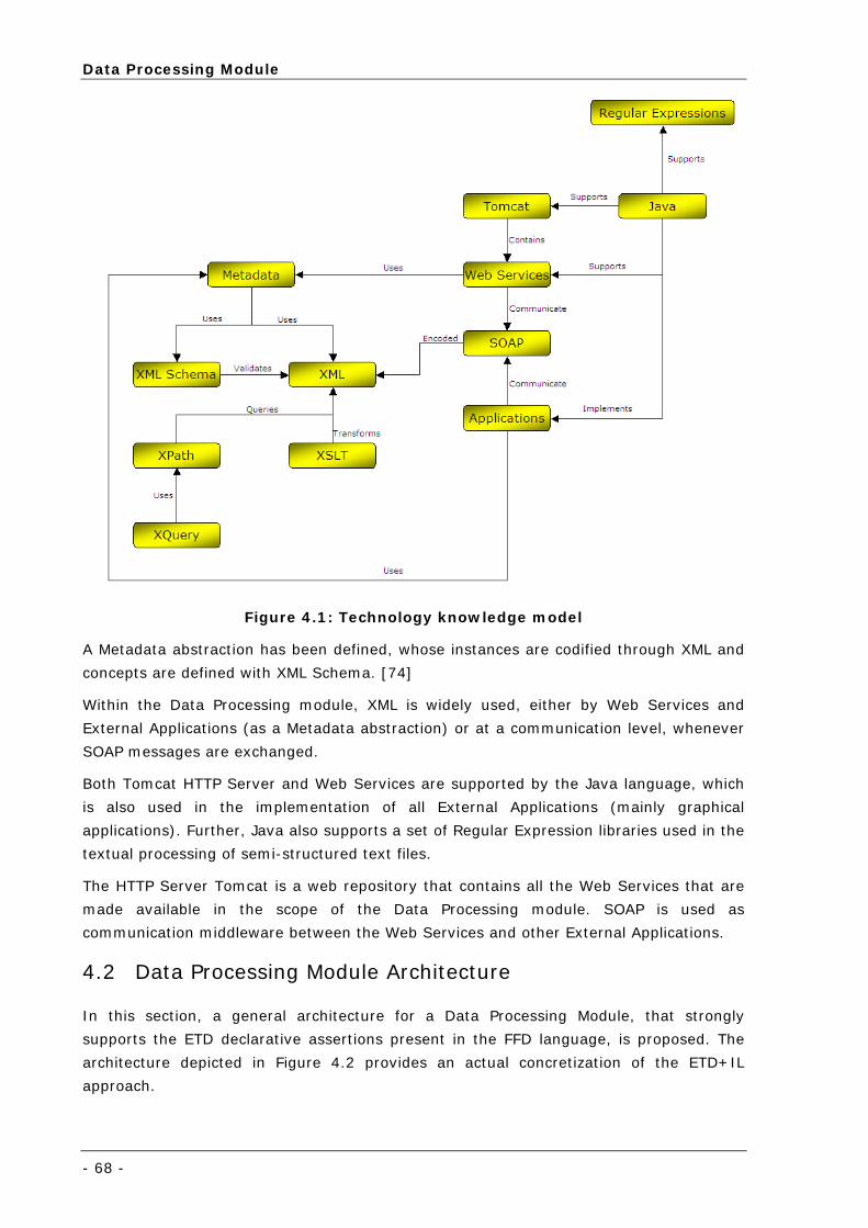
Data Processing Module
- 68 -
Figure 4.1: Technology knowledge model
A Metadata abstraction has been defined, whose instances are codified through XML and
concepts are defined with XML Schema. [74]
Within the Data Processing module, XML is widely used, either by Web Services and
External Applications (as a Metadata abstraction) or at a communication level, whenever
SOAP messages are exchanged.
Both Tomcat HTTP Server and Web Services are supported by the Java language, which
is also used in the implementation of all External Applications (mainly graphical
applications). Further, Java also supports a set of Regular Expression libraries used in the
textual processing of semi-structured text files.
The HTTP Server Tomcat is a web repository that contains all the Web Services that are
made available in the scope of the Data Processing module. SOAP is used as
communication middleware between the Web Services and other External Applications.
4.2 Data Processing Module Architecture
In this section, a general architecture for a Data Processing Module, that strongly
supports the ETD declarative assertions present in the FFD language, is proposed. The
architecture depicted in Figure 4.2 provides an actual concretization of the ETD+IL
approach.
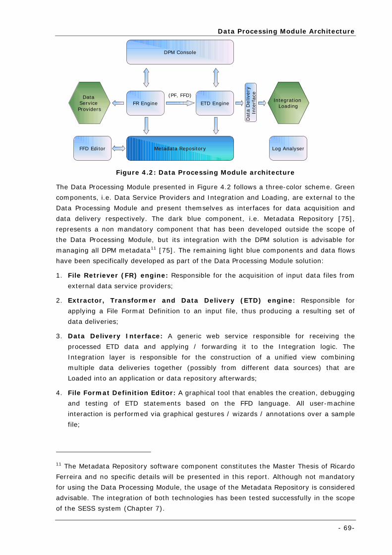
Data Processing Module Architecture
- 69-
FR Engine ETD Engine
Metadata Repository
Integration Loading
Data
Deliv
ery
In
terf
ace
DPM Console
(PF, FFD)
FFD Editor
Data Service Providers
Log Analyser
Figure 4.2: Data Processing Module architecture
The Data Processing Module presented in Figure 4.2 follows a three-color scheme. Green
components, i.e. Data Service Providers and Integration and Loading, are external to the
Data Processing Module and present themselves as interfaces for data acquisition and
data delivery respectively. The dark blue component, i.e. Metadata Repository [75],
represents a non mandatory component that has been developed outside the scope of
the Data Processing Module, but its integration with the DPM solution is advisable for
managing all DPM metadata11 [75]. The remaining light blue components and data flows
have been specifically developed as part of the Data Processing Module solution:
1. File Retriever (FR) engine: Responsible for the acquisition of input data files from
external data service providers;
2. Extractor, Transformer and Data Delivery (ETD) engine: Responsible for
applying a File Format Definition to an input file, thus producing a resulting set of
data deliveries;
3. Data Delivery Interface: A generic web service responsible for receiving the
processed ETD data and applying / forwarding it to the Integration logic. The
Integration layer is responsible for the construction of a unified view combining
multiple data deliveries together (possibly from different data sources) that are
Loaded into an application or data repository afterwards;
4. File Format Definition Editor: A graphical tool that enables the creation, debugging
and testing of ETD statements based on the FFD language. All user-machine
interaction is performed via graphical gestures / wizards / annotations over a sample
file;
11 The Metadata Repository software component constitutes the Master Thesis of Ricardo
Ferreira and no specific details will be presented in this report. Although not mandatory
for using the Data Processing Module, the usage of the Metadata Repository is considered
advisable. The integration of both technologies has been tested successfully in the scope
of the SESS system (Chapter 7).
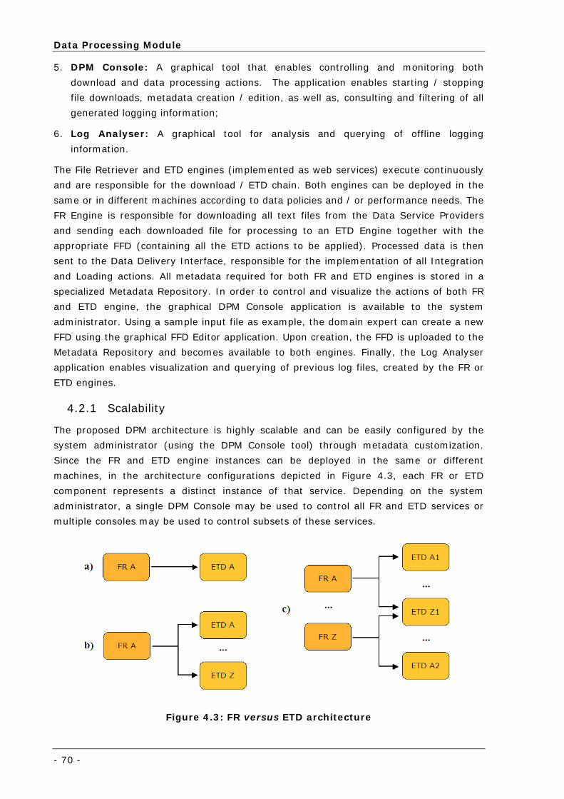
Data Processing Module
- 70 -
5. DPM Console: A graphical tool that enables controlling and monitoring both
download and data processing actions. The application enables starting / stopping
file downloads, metadata creation / edition, as well as, consulting and filtering of all
generated logging information;
6. Log Analyser: A graphical tool for analysis and querying of offline logging
information.
The File Retriever and ETD engines (implemented as web services) execute continuously
and are responsible for the download / ETD chain. Both engines can be deployed in the
same or in different machines according to data policies and / or performance needs. The
FR Engine is responsible for downloading all text files from the Data Service Providers
and sending each downloaded file for processing to an ETD Engine together with the
appropriate FFD (containing all the ETD actions to be applied). Processed data is then
sent to the Data Delivery Interface, responsible for the implementation of all Integration
and Loading actions. All metadata required for both FR and ETD engines is stored in a
specialized Metadata Repository. In order to control and visualize the actions of both FR
and ETD engine, the graphical DPM Console application is available to the system
administrator. Using a sample input file as example, the domain expert can create a new
FFD using the graphical FFD Editor application. Upon creation, the FFD is uploaded to the
Metadata Repository and becomes available to both engines. Finally, the Log Analyser
application enables visualization and querying of previous log files, created by the FR or
ETD engines.
4.2.1 Scalability
The proposed DPM architecture is highly scalable and can be easily configured by the
system administrator (using the DPM Console tool) through metadata customization.
Since the FR and ETD engine instances can be deployed in the same or different
machines, in the architecture configurations depicted in Figure 4.3, each FR or ETD
component represents a distinct instance of that service. Depending on the system
administrator, a single DPM Console may be used to control all FR and ETD services or
multiple consoles may be used to control subsets of these services.
Figure 4.3: FR versus ETD architecture
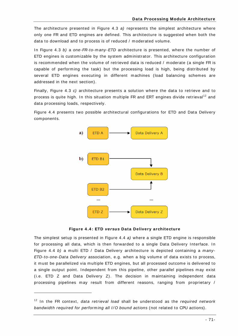
Data Processing Module Architecture
- 71-
The architecture presented in Figure 4.3 a) represents the simplest architecture where
only one FR and ETD engines are defined. This architecture is suggested when both the
data to download and to process is of reduced / moderated volume.
In Figure 4.3 b) a one-FR-to-many-ETD architecture is presented, where the number of
ETD engines is customizable by the system administrator. This architecture configuration
is recommended when the volume of retrieved data is reduced / moderate (a single FR is
capable of performing the task) but the processing load is high, being distributed by
several ETD engines executing in different machines (load balancing schemes are
addressed in the next section).
Finally, Figure 4.3 c) architecture presents a solution where the data to retrieve and to
process is quite high. In this situation multiple FR and ERT engines divide retrieval12 and
data processing loads, respectively.
Figure 4.4 presents two possible architectural configurations for ETD and Data Delivery
components.
Figure 4.4: ETD versus Data Delivery architecture
The simplest setup is presented in Figure 4.4 a) where a single ETD engine is responsible
for processing all data, which is then forwarded to a single Data Delivery Interface. In
Figure 4.4 b) a multi ETD / Data Delivery architecture is depicted containing a many-
ETD-to-one-Data Delivery association, e.g. when a big volume of data exists to process,
it must be parallelized via multiple ETD engines, but all processed outcome is delivered to
a single output point. Independent from this pipeline, other parallel pipelines may exist
(i.e. ETD Z and Data Delivery Z). The decision in maintaining independent data
processing pipelines may result from different reasons, ranging from proprietary /
12 In the FR context, data retrieval load shall be understood as the required network
bandwidth required for performing all I/O bound actions (not related to CPU actions).
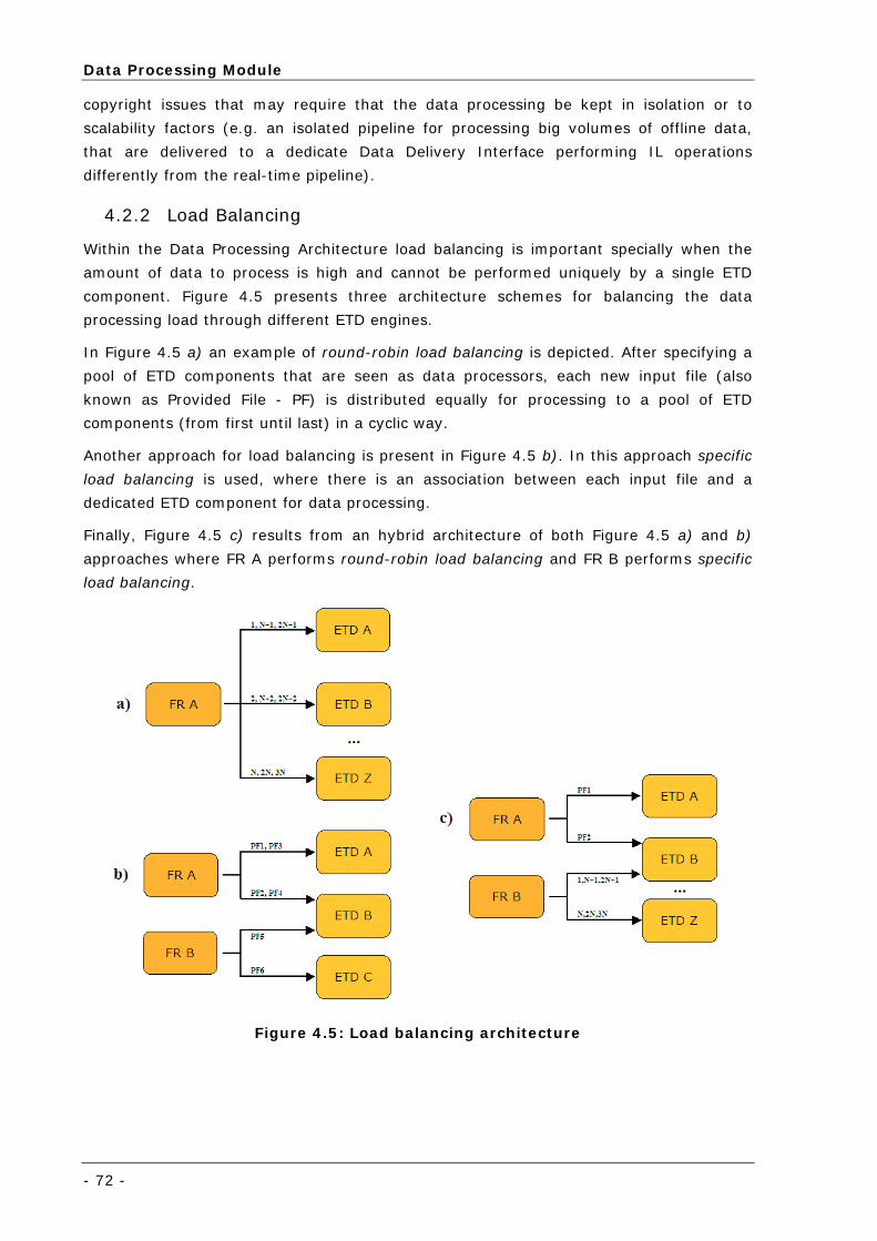
Data Processing Module
- 72 -
copyright issues that may require that the data processing be kept in isolation or to
scalability factors (e.g. an isolated pipeline for processing big volumes of offline data,
that are delivered to a dedicate Data Delivery Interface performing IL operations
differently from the real-time pipeline).
4.2.2 Load Balancing
Within the Data Processing Architecture load balancing is important specially when the
amount of data to process is high and cannot be performed uniquely by a single ETD
component. Figure 4.5 presents three architecture schemes for balancing the data
processing load through different ETD engines.
In Figure 4.5 a) an example of round-robin load balancing is depicted. After specifying a
pool of ETD components that are seen as data processors, each new input file (also
known as Provided File - PF) is distributed equally for processing to a pool of ETD
components (from first until last) in a cyclic way.
Another approach for load balancing is present in Figure 4.5 b). In this approach specific
load balancing is used, where there is an association between each input file and a
dedicated ETD component for data processing.
Finally, Figure 4.5 c) results from an hybrid architecture of both Figure 4.5 a) and b)
approaches where FR A performs round-robin load balancing and FR B performs specific
load balancing.
Figure 4.5: Load balancing architecture
File Retriever Engine
- 73-
4.3 File Retriever Engine
The File Retriever engine enables the automatic retrieval of data files based on time-
schedulers and has been implemented as a Web Service. The engine contains all the logic
required for remote file acquisition and enables remote control through a set of web
methods defined as a public API. House-keeping log information is also made available to
external applications through a simple subscription service, where external applications,
after registration, receive periodically all logging events that take place at the engine (in
XML format). The application is highly metadata oriented, specially regarding the Data
Service Provider and Provided File metadata concepts (described in detail in the
following sub-section).
At the Data Service Provider level, the user can specify the connector type for reaching
the Data Service Provider: HTTP, FTP, Web Service, Binary file or Database (through
JDBC). Although the connector holds specific metadata (regarding each particular
connection), when executed by the File Retriever Engine, these details are abstracted
since a common connection interface is implemented by each connector type. Data
requests, storage of the downloaded contents into the cache directory, occurrence of
retrieval errors and possible retrial operations are some examples of operations
performed by the File Retriever, where the specific data connector is made abstract.
At the Provided File level, a reference to the FFD that will be used for processing the file
is available, as the source file path / SQL query / or web service arguments, depending
on the related Data Service Provider connection type. For each Provided File it is also
possible to specify the path for the target file to be stored (in the local cache) and which
type of schedule shall be used for retrieving the file. Finally, each Provided File may have
a set of relations to a pool of dedicated ETD engines for processing.
Figure 4.6 presents the performed tasks by the FR Engine when initiated.
At application start, the first action to be executed is a query to the Metadata Repository,
requesting all the Data Service Providers and related Provided Files metadata and store
them as XML files in a local folder. If a connection to the Metadata Repository is not
available at the web service start up, but previously saved metadata is available, then
the application is started according to this metadata. Otherwise, if no metadata is locally
available, nor a connection to the Metadata Repository can be established, then the web
service is not initiated.
Then, each declared Data Service Provider is analysed according to the Active Boolean
flag element. If inactive, all Data Service Provider and related Provided Files information
is disregarded. Otherwise a DSP dispatcher thread, that will manage all downloads for
that specific Data Service Provider, is initiated. After launching the dispatcher thread, all
Provided Files are processed and for those set to Active, the retrieval time for the next
file request is calculated (depending on the type of scheduling that has been defined for
the provided file). The schedule request is then added to a time-based queue belonging
to the scheduler thread. When all Data Service Providers and Provided Files have been
iterated, the Scheduler thread is initiated, analysing the requests stored in its queue.
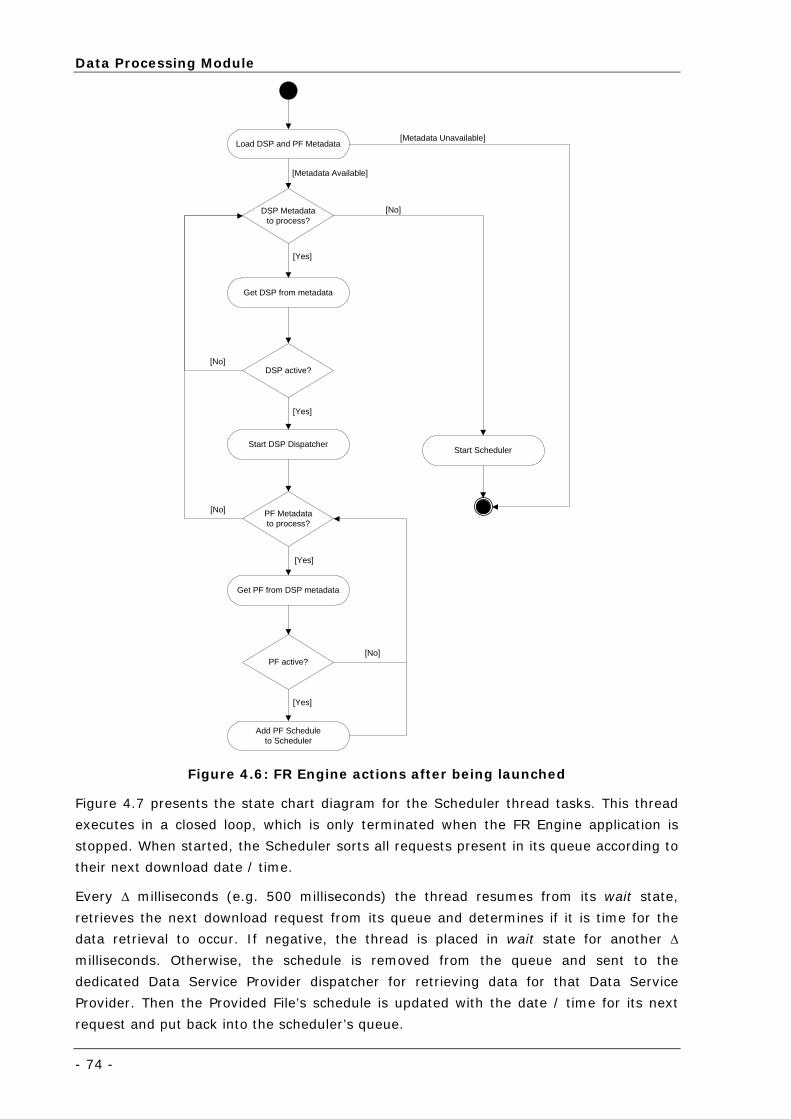
Data Processing Module
- 74 -
Load DSP and PF Metadata
DSP Metadatato process?
Get DSP from metadata
DSP active?
PF active?
Start DSP Dispatcher
PF Metadatato process?
Add PF Scheduleto Scheduler
Start Scheduler
Get PF from DSP metadata
[Yes]
[Yes]
[Yes]
[Yes]
[No]
[No]
[No]
[No]
[Metadata Unavailable]
[Metadata Available]
Figure 4.6: FR Engine actions after being launched
Figure 4.7 presents the state chart diagram for the Scheduler thread tasks. This thread
executes in a closed loop, which is only terminated when the FR Engine application is
stopped. When started, the Scheduler sorts all requests present in its queue according to
their next download date / time.
Every Δ milliseconds (e.g. 500 milliseconds) the thread resumes from its wait state,
retrieves the next download request from its queue and determines if it is time for the
data retrieval to occur. If negative, the thread is placed in wait state for another Δ
milliseconds. Otherwise, the schedule is removed from the queue and sent to the
dedicated Data Service Provider dispatcher for retrieving data for that Data Service
Provider. Then the Provided File’s schedule is updated with the date / time for its next
request and put back into the scheduler’s queue.
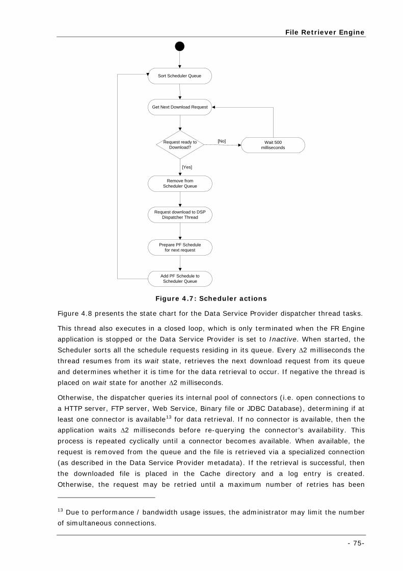
File Retriever Engine
- 75-
Sort Scheduler Queue
Get Next Download Request
Request ready toDownload?
Wait 500milliseconds
Request download to DSPDispatcher Thread
Remove fromScheduler Queue
Add PF Schedule toScheduler Queue
Prepare PF Schedulefor next request
[No]
[Yes]
Figure 4.7: Scheduler actions
Figure 4.8 presents the state chart for the Data Service Provider dispatcher thread tasks.
This thread also executes in a closed loop, which is only terminated when the FR Engine
application is stopped or the Data Service Provider is set to Inactive. When started, the
Scheduler sorts all the schedule requests residing in its queue. Every Δ2 milliseconds the
thread resumes from its wait state, retrieves the next download request from its queue
and determines whether it is time for the data retrieval to occur. If negative the thread is
placed on wait state for another Δ2 milliseconds.
Otherwise, the dispatcher queries its internal pool of connectors (i.e. open connections to
a HTTP server, FTP server, Web Service, Binary file or JDBC Database), determining if at
least one connector is available13 for data retrieval. If no connector is available, then the
application waits Δ2 milliseconds before re-querying the connector’s availability. This
process is repeated cyclically until a connector becomes available. When available, the
request is removed from the queue and the file is retrieved via a specialized connection
(as described in the Data Service Provider metadata). If the retrieval is successful, then
the downloaded file is placed in the Cache directory and a log entry is created.
Otherwise, the request may be retried until a maximum number of retries has been
13 Due to performance / bandwidth usage issues, the administrator may limit the number
of simultaneous connections.
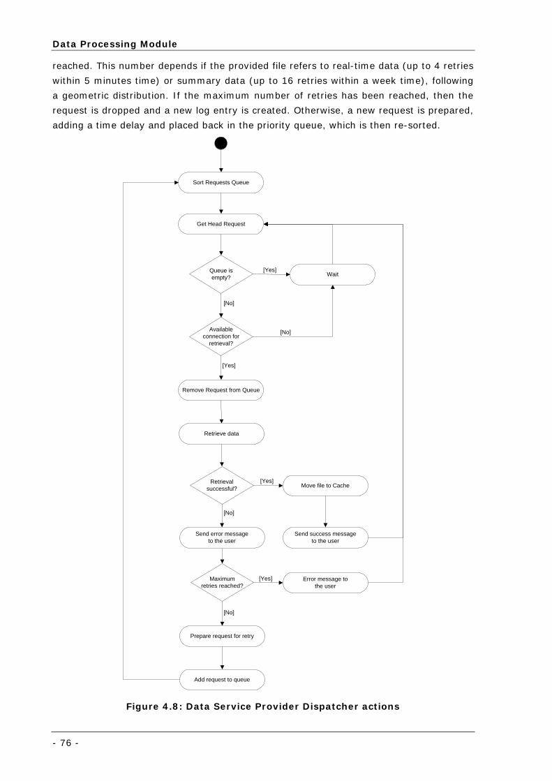
Data Processing Module
- 76 -
reached. This number depends if the provided file refers to real-time data (up to 4 retries
within 5 minutes time) or summary data (up to 16 retries within a week time), following
a geometric distribution. If the maximum number of retries has been reached, then the
request is dropped and a new log entry is created. Otherwise, a new request is prepared,
adding a time delay and placed back in the priority queue, which is then re-sorted.
Get Head Request
Sort Requests Queue
Queue isempty? Wait
Availableconnection for
retrieval?
Remove Request from Queue
Retrieve data
Retrievalsuccessful? Move file to Cache
Send success messageto the user
Send error messageto the user
Maximumretries reached?
Prepare request for retry
Error message tothe user
Add request to queue
[Yes]
[No]
[Yes]
[No]
[Yes]
[No]
[No]
[Yes]
Figure 4.8: Data Service Provider Dispatcher actions
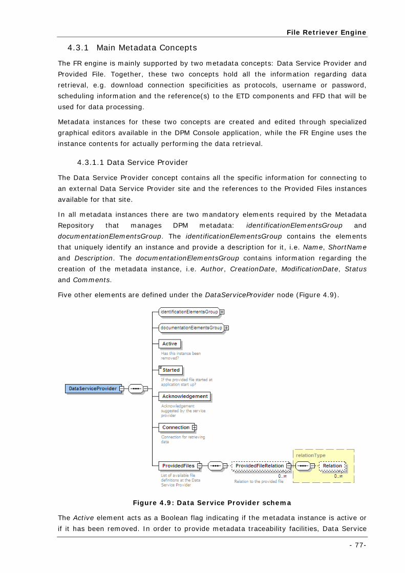
File Retriever Engine
- 77-
4.3.1 Main Metadata Concepts
The FR engine is mainly supported by two metadata concepts: Data Service Provider and
Provided File. Together, these two concepts hold all the information regarding data
retrieval, e.g. download connection specificities as protocols, username or password,
scheduling information and the reference(s) to the ETD components and FFD that will be
used for data processing.
Metadata instances for these two concepts are created and edited through specialized
graphical editors available in the DPM Console application, while the FR Engine uses the
instance contents for actually performing the data retrieval.
4.3.1.1 Data Service Provider
The Data Service Provider concept contains all the specific information for connecting to
an external Data Service Provider site and the references to the Provided Files instances
available for that site.
In all metadata instances there are two mandatory elements required by the Metadata
Repository that manages DPM metadata: identificationElementsGroup and
documentationElementsGroup. The identificationElementsGroup contains the elements
that uniquely identify an instance and provide a description for it, i.e. Name, ShortName
and Description. The documentationElementsGroup contains information regarding the
creation of the metadata instance, i.e. Author, CreationDate, ModificationDate, Status
and Comments.
Five other elements are defined under the DataServiceProvider node (Figure 4.9).
Figure 4.9: Data Service Provider schema
The Active element acts as a Boolean flag indicating if the metadata instance is active or
if it has been removed. In order to provide metadata traceability facilities, Data Service
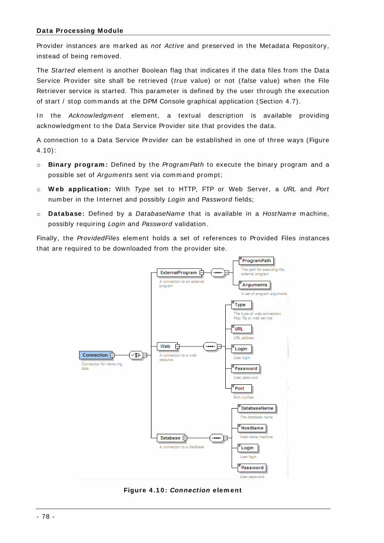
Data Processing Module
- 78 -
Provider instances are marked as not Active and preserved in the Metadata Repository,
instead of being removed.
The Started element is another Boolean flag that indicates if the data files from the Data
Service Provider site shall be retrieved (true value) or not (false value) when the File
Retriever service is started. This parameter is defined by the user through the execution
of start / stop commands at the DPM Console graphical application (Section 4.7).
In the Acknowledgment element, a textual description is available providing
acknowledgment to the Data Service Provider site that provides the data.
A connection to a Data Service Provider can be established in one of three ways (Figure
4.10):
o Binary program: Defined by the ProgramPath to execute the binary program and a
possible set of Arguments sent via command prompt;
o Web application: With Type set to HTTP, FTP or Web Server, a URL and Port
number in the Internet and possibly Login and Password fields;
o Database: Defined by a DatabaseName that is available in a HostName machine,
possibly requiring Login and Password validation.
Finally, the ProvidedFiles element holds a set of references to Provided Files instances
that are required to be downloaded from the provider site.
Figure 4.10: Connection element
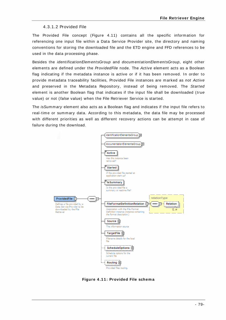
File Retriever Engine
- 79-
4.3.1.2 Provided File
The Provided File concept (Figure 4.11) contains all the specific information for
referencing one input file within a Data Service Provider site, the directory and naming
conventions for storing the downloaded file and the ETD engine and FFD references to be
used in the data processing phase.
Besides the identificationElementsGroup and documentationElementsGroup, eight other
elements are defined under the ProvidedFile node. The Active element acts as a Boolean
flag indicating if the metadata instance is active or if it has been removed. In order to
provide metadata traceability facilities, Provided File instances are marked as not Active
and preserved in the Metadata Repository, instead of being removed. The Started
element is another Boolean flag that indicates if the input file shall be downloaded (true
value) or not (false value) when the File Retriever Service is started.
The isSummary element also acts as a Boolean flag and indicates if the input file refers to
real-time or summary data. According to this metadata, the data file may be processed
with different priorities as well as different recovery actions can be attempt in case of
failure during the download.
Figure 4.11: Provided File schema
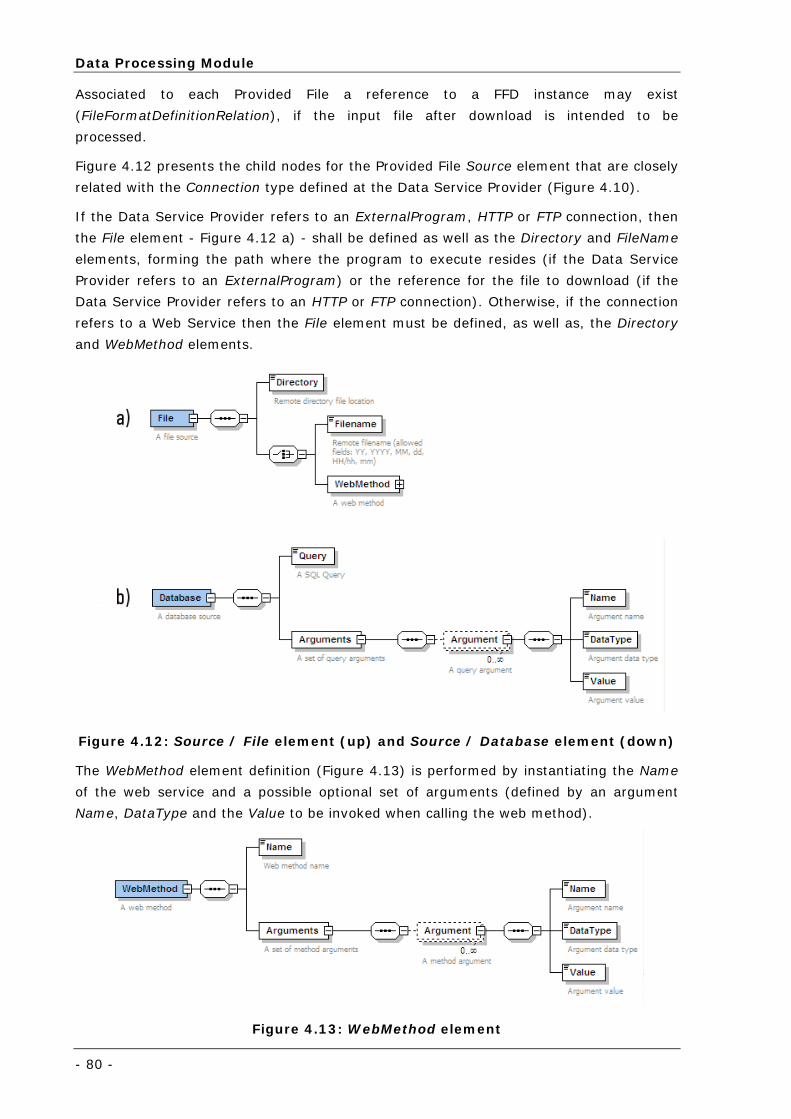
Data Processing Module
- 80 -
Associated to each Provided File a reference to a FFD instance may exist
(FileFormatDefinitionRelation), if the input file after download is intended to be
processed.
Figure 4.12 presents the child nodes for the Provided File Source element that are closely
related with the Connection type defined at the Data Service Provider (Figure 4.10).
If the Data Service Provider refers to an ExternalProgram, HTTP or FTP connection, then
the File element - Figure 4.12 a) - shall be defined as well as the Directory and FileName
elements, forming the path where the program to execute resides (if the Data Service
Provider refers to an ExternalProgram) or the reference for the file to download (if the
Data Service Provider refers to an HTTP or FTP connection). Otherwise, if the connection
refers to a Web Service then the File element must be defined, as well as, the Directory
and WebMethod elements.
Figure 4.12: Source / File element (up) and Source / Database element (down)
The WebMethod element definition (Figure 4.13) is performed by instantiating the Name
of the web service and a possible optional set of arguments (defined by an argument
Name, DataType and the Value to be invoked when calling the web method).
Figure 4.13: WebMethod element
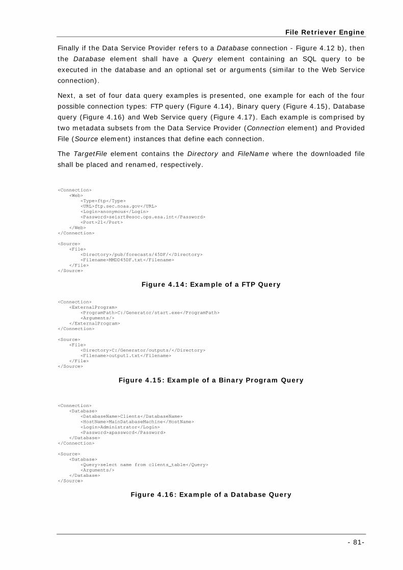
File Retriever Engine
- 81-
Finally if the Data Service Provider refers to a Database connection - Figure 4.12 b), then
the Database element shall have a Query element containing an SQL query to be
executed in the database and an optional set or arguments (similar to the Web Service
connection).
Next, a set of four data query examples is presented, one example for each of the four
possible connection types: FTP query (Figure 4.14), Binary query (Figure 4.15), Database
query (Figure 4.16) and Web Service query (Figure 4.17). Each example is comprised by
two metadata subsets from the Data Service Provider (Connection element) and Provided
File (Source element) instances that define each connection.
The TargetFile element contains the Directory and FileName where the downloaded file
shall be placed and renamed, respectively.
<Connection> <Web> <Type>ftp</Type> <URL>ftp.sec.noaa.gov</URL> <Login>anonymous</Login> <Password>[email protected]</Password> <Port>21</Port> </Web> </Connection> <Source> <File> <Directory>/pub/forecasts/45DF/</Directory> <Filename>MMDD45DF.txt</Filename> </File> </Source>
Figure 4.14: Example of a FTP Query
<Connection> <ExternalProgram> <ProgramPath>C:/Generator/start.exe</ProgramPath> <Arguments/> </ExternalProgram> </Connection> <Source> <File> <Directory>C:/Generator/outputs/</Directory> <Filename>output1.txt</Filename> </File> </Source>
Figure 4.15: Example of a Binary Program Query
<Connection> <Database> <DatabaseName>Clients</DatabaseName> <HostName>MainDatabaseMachine</HostName> <Login>Administrator</Login> <Password>apassword</Password> </Database> </Connection> <Source> <Database> <Query>select name from clients_table</Query> <Arguments/> </Database> </Source>
Figure 4.16: Example of a Database Query
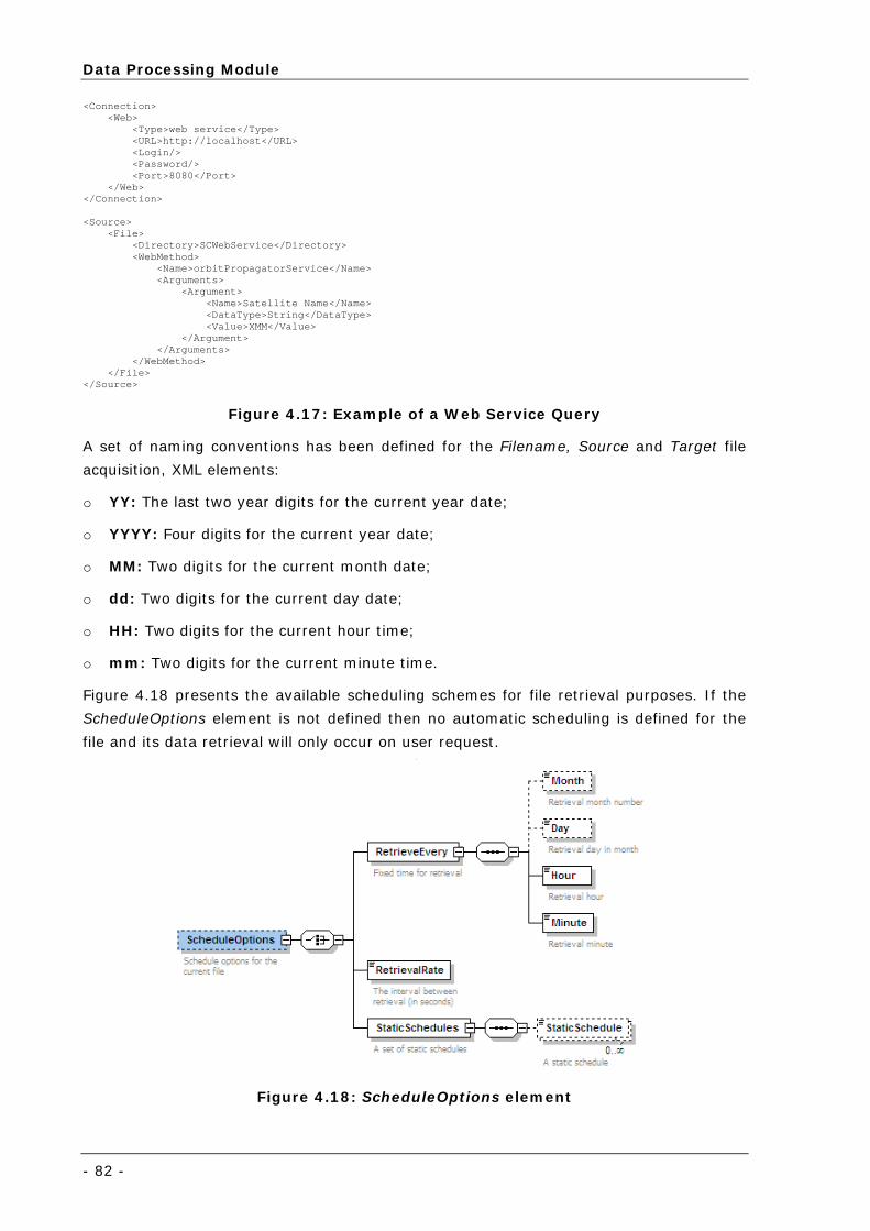
Data Processing Module
- 82 -
<Connection> <Web> <Type>web service</Type> <URL>http://localhost</URL> <Login/> <Password/> <Port>8080</Port> </Web> </Connection> <Source> <File> <Directory>SCWebService</Directory> <WebMethod> <Name>orbitPropagatorService</Name> <Arguments> <Argument> <Name>Satellite Name</Name> <DataType>String</DataType> <Value>XMM</Value> </Argument> </Arguments> </WebMethod> </File> </Source>
Figure 4.17: Example of a Web Service Query
A set of naming conventions has been defined for the Filename, Source and Target file
acquisition, XML elements:
o YY: The last two year digits for the current year date;
o YYYY: Four digits for the current year date;
o MM: Two digits for the current month date;
o dd: Two digits for the current day date;
o HH: Two digits for the current hour time;
o mm: Two digits for the current minute time.
Figure 4.18 presents the available scheduling schemes for file retrieval purposes. If the
ScheduleOptions element is not defined then no automatic scheduling is defined for the
file and its data retrieval will only occur on user request.
Figure 4.18: ScheduleOptions element
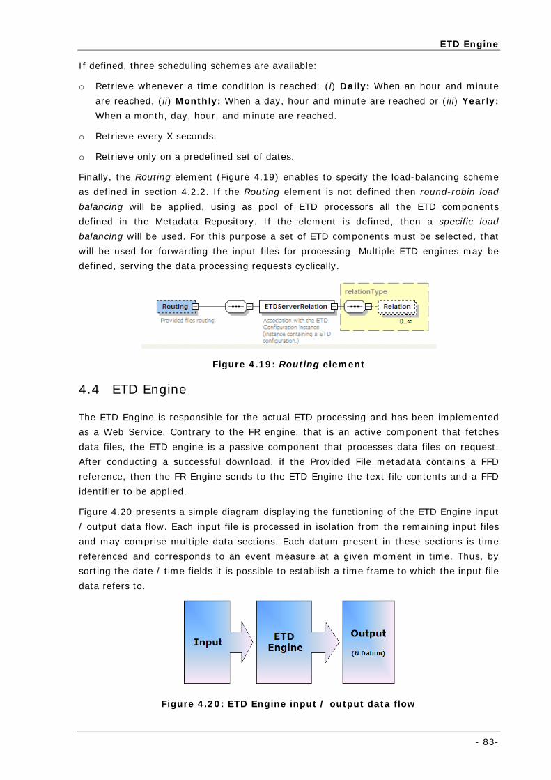
ETD Engine
- 83-
If defined, three scheduling schemes are available:
o Retrieve whenever a time condition is reached: (i) Daily: When an hour and minute
are reached, (ii) Monthly: When a day, hour and minute are reached or (iii) Yearly:
When a month, day, hour, and minute are reached.
o Retrieve every X seconds;
o Retrieve only on a predefined set of dates.
Finally, the Routing element (Figure 4.19) enables to specify the load-balancing scheme
as defined in section 4.2.2. If the Routing element is not defined then round-robin load
balancing will be applied, using as pool of ETD processors all the ETD components
defined in the Metadata Repository. If the element is defined, then a specific load
balancing will be used. For this purpose a set of ETD components must be selected, that
will be used for forwarding the input files for processing. Multiple ETD engines may be
defined, serving the data processing requests cyclically.
Figure 4.19: Routing element
4.4 ETD Engine
The ETD Engine is responsible for the actual ETD processing and has been implemented
as a Web Service. Contrary to the FR engine, that is an active component that fetches
data files, the ETD engine is a passive component that processes data files on request.
After conducting a successful download, if the Provided File metadata contains a FFD
reference, then the FR Engine sends to the ETD Engine the text file contents and a FFD
identifier to be applied.
Figure 4.20 presents a simple diagram displaying the functioning of the ETD Engine input
/ output data flow. Each input file is processed in isolation from the remaining input files
and may comprise multiple data sections. Each datum present in these sections is time
referenced and corresponds to an event measure at a given moment in time. Thus, by
sorting the date / time fields it is possible to establish a time frame to which the input file
data refers to.
Figure 4.20: ETD Engine input / output data flow
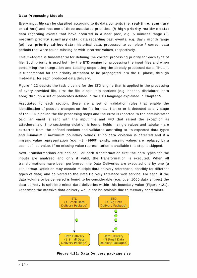
Data Processing Module
- 84 -
Every input file can be classified according to its data contents (i.e. real-time, summary
or ad-hoc) and has one of three associated priorities: (i) high priority realtime data:
data regarding events that have occurred in a near past, e.g. 5 minutes range (ii)
medium priority summary data: data regarding past events, e.g. day / month range
(iii) low priority ad-hoc data: historical data, processed to complete / correct data
periods that were found missing or with incorrect values, respectively.
This metadata is fundamental for defining the correct processing priority for each type of
file. Such priority is used both by the ETD engine for processing the input files and when
performing the Integration and Loading steps using the already processed data. Thus, it
is fundamental for the priority metadata to be propagated into the IL phase, through
metadata, for each produced data delivery.
Figure 4.22 depicts the task pipeline for the ETD engine that is applied in the processing
of every provided file. First the file is split into sections (e.g. header, disclaimer, data
area) through a set of predicates defined in the ETD language explained in Chapter 5.
Associated to each section, there are a set of validation rules that enable the
identification of possible changes on the file format. If an error is detected at any stage
of the ETD pipeline the file processing stops and the error is reported to the administrator
(e.g. an email is sent with the input file and FFD that raised the exception as
attachments). If no sectioning violation is found, fields – single values and tabular - are
extracted from the defined sections and validated according to its expected data types
and minimum / maximum boundary values. If no data violation is detected and if a
missing value representation (e.g. –1, -9999) exists, missing values are replaced by a
user-defined value. If no missing value representation is available this step is skipped.
Next, transformations are applied. For each transformation first the data types for the
inputs are analysed and only if valid, the transformation is executed. When all
transformations have been performed, the Data Deliveries are executed one by one (a
File Format Definition may contain multiple data delivery references, possibly for different
types of data) and delivered to the Data Delivery Interface web service. For each, if the
data volume to be delivered is found to be considerable (e.g. over 1000 data entries) the
data delivery is split into minor data deliveries within this boundary value (Figure 4.21).
Otherwise the massive data delivery would not be scalable due to memory constraints.
Figure 4.21: Data Delivery package size
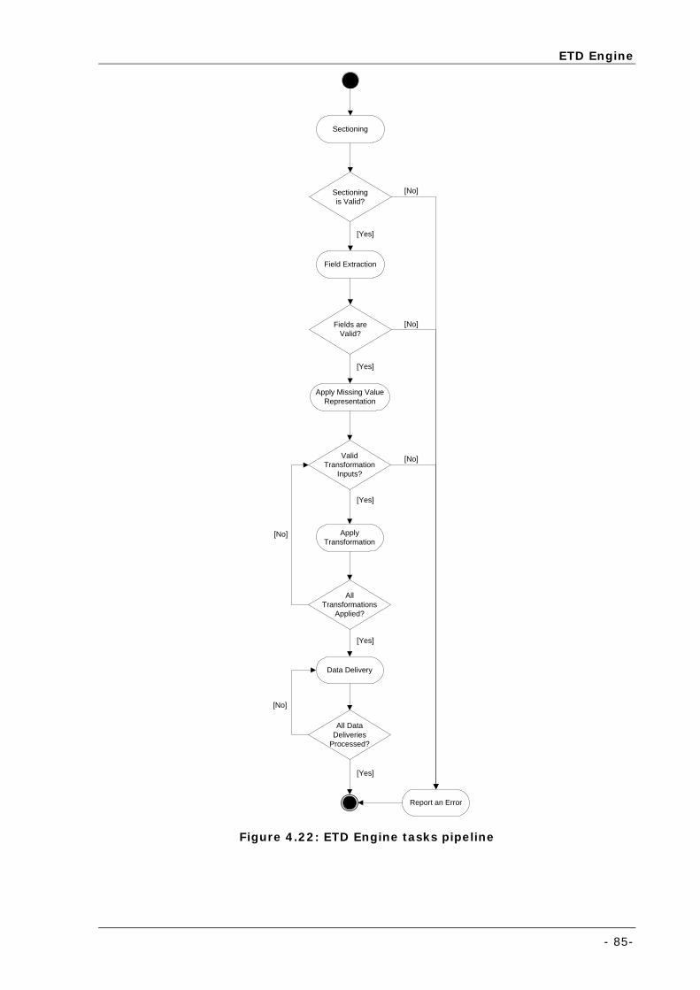
ETD Engine
- 85-
Field Extraction
Sectioning
ApplyTransformation
ValidTransformation
Inputs?
Fields areValid?
Sectioningis Valid?
Apply Missing ValueRepresentation
Data Delivery
Report an Error
[Yes]
[Yes]
[No]
[No]
[No]
[Yes]
AllTransformations
Applied?
All DataDeliveries
Processed?
[Yes]
[Yes]
[No]
[No]
Figure 4.22: ETD Engine tasks pipeline
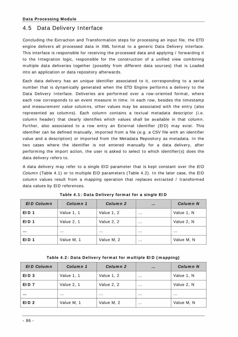
Data Processing Module
- 86 -
4.5 Data Delivery Interface
Concluding the Extraction and Transformation steps for processing an input file, the ETD
engine delivers all processed data in XML format to a generic Data Delivery interface.
This interface is responsible for receiving the processed data and applying / forwarding it
to the Integration logic, responsible for the construction of a unified view combining
multiple data deliveries together (possibly from different data sources) that is Loaded
into an application or data repository afterwards.
Each data delivery has an unique identifier associated to it, corresponding to a serial
number that is dynamically generated when the ETD Engine performs a delivery to the
Data Delivery Interface. Deliveries are performed over a row-oriented format, where
each row corresponds to an event measure in time. In each row, besides the timestamp
and measurement value columns, other values may be associated with the entry (also
represented as columns). Each column contains a textual metadata descriptor (i.e.
column header) that clearly identifies which values shall be available in that column.
Further, also associated to a row entry an External Identifier (EID) may exist. This
identifier can be defined manually, imported from a file (e.g. a CSV file with an identifier
value and a description) or imported from the Metadata Repository as metadata. In the
two cases where the identifier is not entered manually for a data delivery, after
performing the import action, the user is asked to select to which identifier(s) does the
data delivery refers to.
A data delivery may refer to a single EID parameter that is kept constant over the EID
Column (Table 4.1) or to multiple EID parameters (Table 4.2). In the later case, the EID
column values result from a mapping operation that replaces extracted / transformed
data values by EID references.
Table 4.1: Data Delivery format for a single EID
EID Column Column 1 Column 2 … Column N
EID 1 Value 1, 1 Value 1, 2 … Value 1, N
EID 1 Value 2, 1 Value 2, 2 … Value 2, N
… … … … …
EID 1 Value M, 1 Value M, 2 … Value M, N
Table 4.2: Data Delivery format for multiple EID (mapping)
EID Column Column 1 Column 2 … Column N
EID 3 Value 1, 1 Value 1, 2 … Value 1, N
EID 7 Value 2, 1 Value 2, 2 … Value 2, N
… … … … …
EID 2 Value M, 1 Value M, 2 … Value M, N
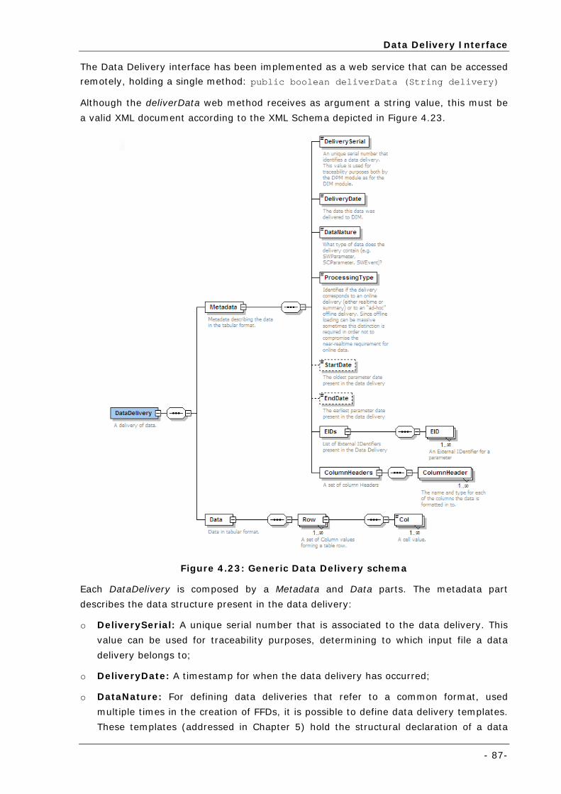
Data Delivery Interface
- 87-
The Data Delivery interface has been implemented as a web service that can be accessed
remotely, holding a single method: public boolean deliverData (String delivery)
Although the deliverData web method receives as argument a string value, this must be
a valid XML document according to the XML Schema depicted in Figure 4.23.
Figure 4.23: Generic Data Delivery schema
Each DataDelivery is composed by a Metadata and Data parts. The metadata part
describes the data structure present in the data delivery:
o DeliverySerial: A unique serial number that is associated to the data delivery. This
value can be used for traceability purposes, determining to which input file a data
delivery belongs to;
o DeliveryDate: A timestamp for when the data delivery has occurred;
o DataNature: For defining data deliveries that refer to a common format, used
multiple times in the creation of FFDs, it is possible to define data delivery templates.
These templates (addressed in Chapter 5) hold the structural declaration of a data
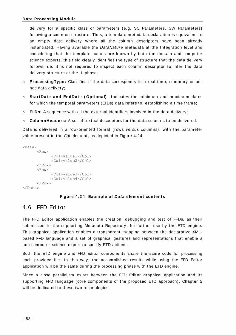
Data Processing Module
- 88 -
delivery for a specific class of parameters (e.g. SC Parameters, SW Parameters)
following a common structure. Thus, a template metadata declaration is equivalent to
an empty data delivery where all the column descriptors have been already
instantiated. Having available the DataNature metadata at the Integration level and
considering that the template names are known by both the domain and computer
science experts, this field clearly identifies the type of structure that the data delivery
follows, i.e. it is not required to inspect each column descriptor to infer the data
delivery structure at the IL phase;
o ProcessingType: Classifies if the data corresponds to a real-time, summary or ad-
hoc data delivery;
o StartDate and EndDate (Optional): Indicates the minimum and maximum dates
for which the temporal parameters (EIDs) data refers to, establishing a time frame;
o EIDs: A sequence with all the external identifiers involved in the data delivery;
o ColumnHeaders: A set of textual descriptors for the data columns to be delivered.
Data is delivered in a row-oriented format (rows versus columns), with the parameter
value present in the Col element, as depicted in Figure 4.24.
<Data>
<Row> <Col>value1</Col> <Col>value2</Col>
</Row> <Row>
<Col>value3</Col> <Col>value4</Col>
</Row> </Data>
Figure 4.24: Example of Data element contents
4.6 FFD Editor
The FFD Editor application enables the creation, debugging and test of FFDs, as their
submission to the supporting Metadata Repository, for further use by the ETD engine.
This graphical application enables a transparent mapping between the declarative XML-
based FFD language and a set of graphical gestures and representations that enable a
non computer-science expert to specify ETD actions.
Both the ETD engine and FFD Editor components share the same code for processing
each provided file. In this way, the accomplished results while using the FFD Editor
application will be the same during the processing phase with the ETD engine.
Since a close parallelism exists between the FFD Editor graphical application and its
supporting FFD language (core components of the proposed ETD approach), Chapter 5
will be dedicated to these two technologies.
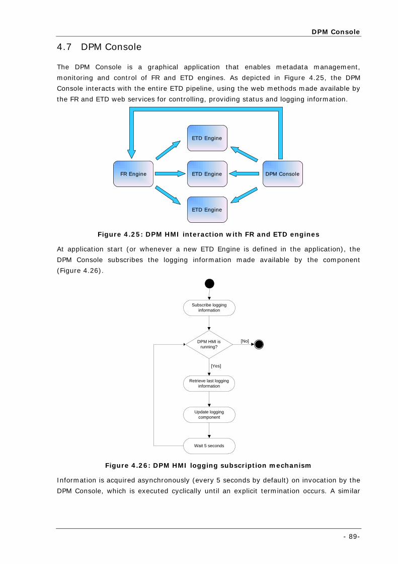
DPM Console
- 89-
4.7 DPM Console
The DPM Console is a graphical application that enables metadata management,
monitoring and control of FR and ETD engines. As depicted in Figure 4.25, the DPM
Console interacts with the entire ETD pipeline, using the web methods made available by
the FR and ETD web services for controlling, providing status and logging information.
FR Engine ETD Engine
ETD Engine
ETD Engine
DPM ConsoleFR Engine ETD Engine
ETD Engine
ETD Engine
DPM Console
Figure 4.25: DPM HMI interaction with FR and ETD engines
At application start (or whenever a new ETD Engine is defined in the application), the
DPM Console subscribes the logging information made available by the component
(Figure 4.26).
Subscribe logginginformation
DPM HMI isrunning?
Retrieve last logginginformation
Update loggingcomponent
Wait 5 seconds
[No]
[Yes]
Figure 4.26: DPM HMI logging subscription mechanism
Information is acquired asynchronously (every 5 seconds by default) on invocation by the
DPM Console, which is executed cyclically until an explicit termination occurs. A similar
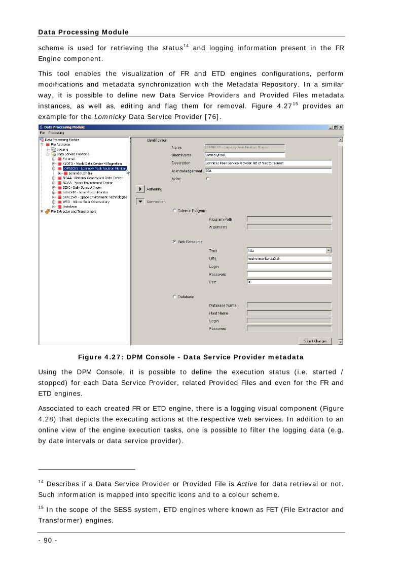
Data Processing Module
- 90 -
scheme is used for retrieving the status14 and logging information present in the FR
Engine component.
This tool enables the visualization of FR and ETD engines configurations, perform
modifications and metadata synchronization with the Metadata Repository. In a similar
way, it is possible to define new Data Service Providers and Provided Files metadata
instances, as well as, editing and flag them for removal. Figure 4.2715 provides an
example for the Lomnicky Data Service Provider [76].
Figure 4.27: DPM Console - Data Service Provider metadata
Using the DPM Console, it is possible to define the execution status (i.e. started /
stopped) for each Data Service Provider, related Provided Files and even for the FR and
ETD engines.
Associated to each created FR or ETD engine, there is a logging visual component (Figure
4.28) that depicts the executing actions at the respective web services. In addition to an
online view of the engine execution tasks, one is possible to filter the logging data (e.g.
by date intervals or data service provider).
14 Describes if a Data Service Provider or Provided File is Active for data retrieval or not.
Such information is mapped into specific icons and to a colour scheme.
15 In the scope of the SESS system, ETD engines where known as FET (File Extractor and
Transformer) engines.
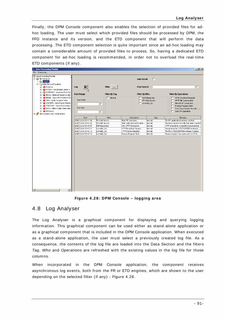
Log Analyser
- 91-
Finally, the DPM Console component also enables the selection of provided files for ad-
hoc loading. The user must select which provided files should be processed by DPM, the
FFD instance and its version, and the ETD component that will perform the data
processing. The ETD component selection is quite important since an ad-hoc loading may
contain a considerable amount of provided files to process. So, having a dedicated ETD
component for ad-hoc loading is recommended, in order not to overload the real-time
ETD components (if any).
Figure 4.28: DPM Console – logging area
4.8 Log Analyser
The Log Analyser is a graphical component for displaying and querying logging
information. This graphical component can be used either as stand-alone application or
as a graphical component that is included in the DPM Console application. When executed
as a stand-alone application, the user must select a previously created log file. As a
consequence, the contents of the log file are loaded into the Data Section and the filters
Tag, Who and Operations are refreshed with the existing values in the log file for those
columns.
When incorporated in the DPM Console application, the component receives
asynchronous log events, both from the FR or ETD engines, which are shown to the user
depending on the selected filter (if any) - Figure 4.28.
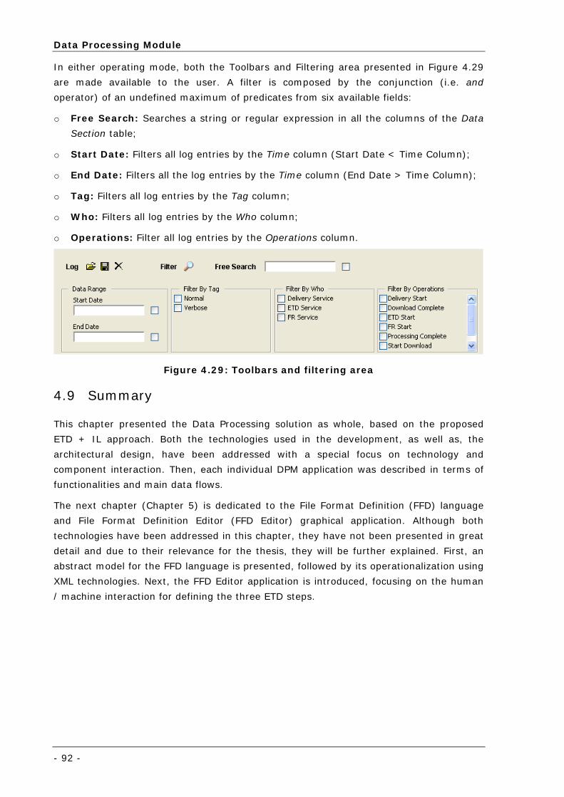
Data Processing Module
- 92 -
In either operating mode, both the Toolbars and Filtering area presented in Figure 4.29
are made available to the user. A filter is composed by the conjunction (i.e. and
operator) of an undefined maximum of predicates from six available fields:
o Free Search: Searches a string or regular expression in all the columns of the Data
Section table;
o Start Date: Filters all log entries by the Time column (Start Date < Time Column);
o End Date: Filters all the log entries by the Time column (End Date > Time Column);
o Tag: Filters all log entries by the Tag column;
o Who: Filters all log entries by the Who column;
o Operations: Filter all log entries by the Operations column.
Figure 4.29: Toolbars and filtering area
4.9 Summary
This chapter presented the Data Processing solution as whole, based on the proposed
ETD + IL approach. Both the technologies used in the development, as well as, the
architectural design, have been addressed with a special focus on technology and
component interaction. Then, each individual DPM application was described in terms of
functionalities and main data flows.
The next chapter (Chapter 5) is dedicated to the File Format Definition (FFD) language
and File Format Definition Editor (FFD Editor) graphical application. Although both
technologies have been addressed in this chapter, they have not been presented in great
detail and due to their relevance for the thesis, they will be further explained. First, an
abstract model for the FFD language is presented, followed by its operationalization using
XML technologies. Next, the FFD Editor application is introduced, focusing on the human
/ machine interaction for defining the three ETD steps.
- 93 -
Chapter 5 The File Format Definition
Language and Editor
The fifth chapter is dedicated to the File Format Definition (FFD) language and
File Format Definition Editor (FFD Editor) graphical application.
First, an abstract model for the FFD language is presented, followed by a
description on how the language has been implemented using XML-based
technologies. Next, the FFD Editor application is introduced, starting with a
general overview of the application’s graphical organization, followed by an
explanation on how the three ETD steps are instantiated seamlessly to the
domain user. Due to its complexity (derived from the data normalization
process) graphical operations related with the Extract activity are explored in
higher detail. Finally, some considerations are presented regarding the FFD
language expressiveness and extensibility.
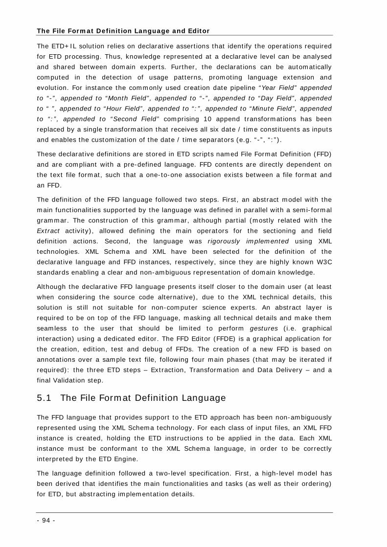
The File Format Definition Language and Editor
- 94 -
The ETD+IL solution relies on declarative assertions that identify the operations required
for ETD processing. Thus, knowledge represented at a declarative level can be analysed
and shared between domain experts. Further, the declarations can be automatically
computed in the detection of usage patterns, promoting language extension and
evolution. For instance the commonly used creation date pipeline “Year Field” appended
to “-”, appended to “Month Field”, appended to “-”, appended to “Day Field”, appended
to “ ”, appended to “Hour Field”, appended to “:”, appended to “Minute Field”, appended
to “:”, appended to “Second Field” comprising 10 append transformations has been
replaced by a single transformation that receives all six date / time constituents as inputs
and enables the customization of the date / time separators (e.g. “-”, “:”).
These declarative definitions are stored in ETD scripts named File Format Definition (FFD)
and are compliant with a pre-defined language. FFD contents are directly dependent on
the text file format, such that a one-to-one association exists between a file format and
an FFD.
The definition of the FFD language followed two steps. First, an abstract model with the
main functionalities supported by the language was defined in parallel with a semi-formal
grammar. The construction of this grammar, although partial (mostly related with the
Extract activity), allowed defining the main operators for the sectioning and field
definition actions. Second, the language was rigorously implemented using XML
technologies. XML Schema and XML have been selected for the definition of the
declarative language and FFD instances, respectively, since they are highly known W3C
standards enabling a clear and non-ambiguous representation of domain knowledge.
Although the declarative FFD language presents itself closer to the domain user (at least
when considering the source code alternative), due to the XML technical details, this
solution is still not suitable for non-computer science experts. An abstract layer is
required to be on top of the FFD language, masking all technical details and make them
seamless to the user that should be limited to perform gestures (i.e. graphical
interaction) using a dedicated editor. The FFD Editor (FFDE) is a graphical application for
the creation, edition, test and debug of FFDs. The creation of a new FFD is based on
annotations over a sample text file, following four main phases (that may be iterated if
required): the three ETD steps – Extraction, Transformation and Data Delivery – and a
final Validation step.
5.1 The File Format Definition Language
The FFD language that provides support to the ETD approach has been non-ambiguously
represented using the XML Schema technology. For each class of input files, an XML FFD
instance is created, holding the ETD instructions to be applied in the data. Each XML
instance must be conformant to the XML Schema language, in order to be correctly
interpreted by the ETD Engine.
The language definition followed a two-level specification. First, a high-level model has
been derived that identifies the main functionalities and tasks (as well as their ordering)
for ETD, but abstracting implementation details.
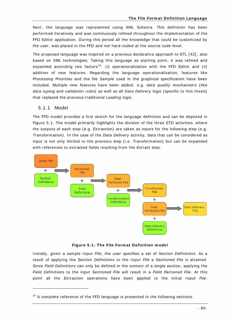
The File Format Definition Language
- 95-
Next, the language was represented using XML Schema. This definition has been
performed iteratively and was continuously refined throughout the implementation of the
FFD Editor application. During this period all the knowledge that could be customized by
the user, was placed in the FFD and not hard-coded at the source code level.
The proposed language was inspired on a previous declarative approach to ETL [42], also
based on XML technologies. Taking this language as starting point, it was refined and
expanded according two factors16: (i) operationalization with the FFD Editor and (ii)
addition of new features. Regarding the language operationalization, features like
Processing Priorities and the file Sample used in the graphical specification have been
included. Multiple new features have been added: e.g. data quality mechanisms (like
data typing and validation rules) as well as all Data Delivery logic (specific to this thesis)
that replaced the previous traditional Loading logic.
5.1.1 Model
The FFD model provides a first sketch for the language definition and can be depicted in
Figure 5.1. The model primarily highlights the division of the three ETD activities, where
the outputs of each step (e.g. Extraction) are taken as inputs for the following step (e.g.
Transformation). In the case of the Data Delivery activity, data that can be considered as
input is not only limited to the previous step (i.e. Transformation) but can be expanded
with references to extracted fields resulting from the Extract step.
Figure 5.1: The File Format Definition model
Initially, given a sample Input File, the user specifies a set of Section Definitions. As a
result of applying the Section Definitions to the Input File a Sectioned File is attained.
Since Field Definitions can only be defined in the context of a single section, applying the
Field Definitions to the input Sectioned File will result in a Field Partioned File. At this
point all the Extraction operations have been applied to the initial Input File.
16 A complete reference of the FFD language is presented in the following sections.
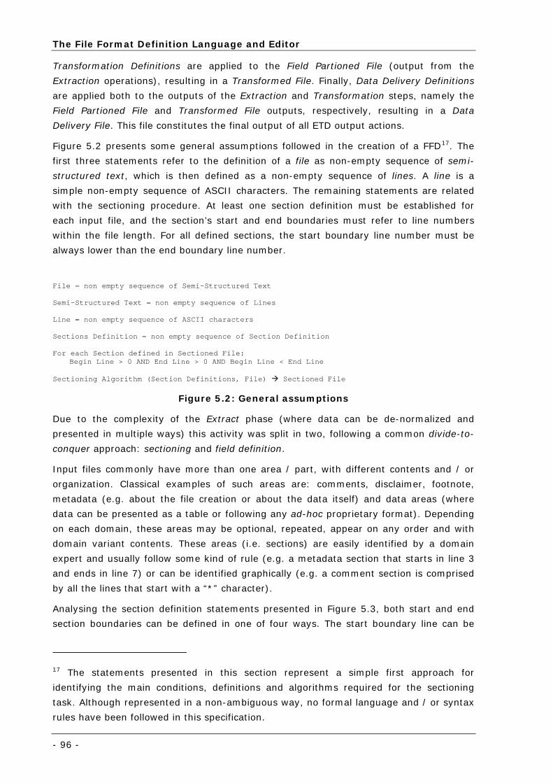
The File Format Definition Language and Editor
- 96 -
Transformation Definitions are applied to the Field Partioned File (output from the
Extraction operations), resulting in a Transformed File. Finally, Data Delivery Definitions
are applied both to the outputs of the Extraction and Transformation steps, namely the
Field Partioned File and Transformed File outputs, respectively, resulting in a Data
Delivery File. This file constitutes the final output of all ETD output actions.
Figure 5.2 presents some general assumptions followed in the creation of a FFD17. The
first three statements refer to the definition of a file as non-empty sequence of semi-
structured text, which is then defined as a non-empty sequence of lines. A line is a
simple non-empty sequence of ASCII characters. The remaining statements are related
with the sectioning procedure. At least one section definition must be established for
each input file, and the section’s start and end boundaries must refer to line numbers
within the file length. For all defined sections, the start boundary line number must be
always lower than the end boundary line number.
File = non empty sequence of Semi-Structured Text Semi-Structured Text = non empty sequence of Lines
Line = non empty sequence of ASCII characters
Sections Definition = non empty sequence of Section Definition For each Section defined in Sectioned File:
Begin Line > 0 AND End Line > 0 AND Begin Line < End Line Sectioning Algorithm (Section Definitions, File) Sectioned File
Figure 5.2: General assumptions
Due to the complexity of the Extract phase (where data can be de-normalized and
presented in multiple ways) this activity was split in two, following a common divide-to-
conquer approach: sectioning and field definition.
Input files commonly have more than one area / part, with different contents and / or
organization. Classical examples of such areas are: comments, disclaimer, footnote,
metadata (e.g. about the file creation or about the data itself) and data areas (where
data can be presented as a table or following any ad-hoc proprietary format). Depending
on each domain, these areas may be optional, repeated, appear on any order and with
domain variant contents. These areas (i.e. sections) are easily identified by a domain
expert and usually follow some kind of rule (e.g. a metadata section that starts in line 3
and ends in line 7) or can be identified graphically (e.g. a comment section is comprised
by all the lines that start with a “*” character).
Analysing the section definition statements presented in Figure 5.3, both start and end
section boundaries can be defined in one of four ways. The start boundary line can be
17 The statements presented in this section represent a simple first approach for
identifying the main conditions, definitions and algorithms required for the sectioning
task. Although represented in a non-ambiguous way, no formal language and / or syntax
rules have been followed in this specification.
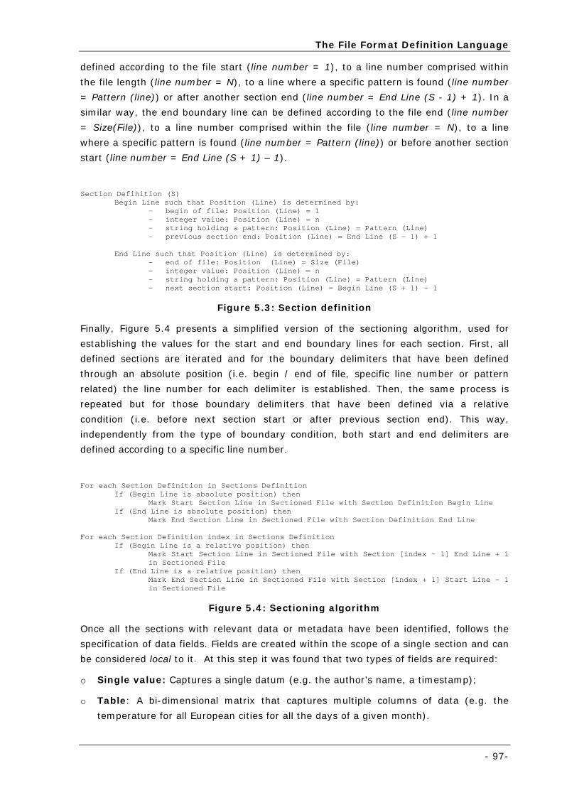
The File Format Definition Language
- 97-
defined according to the file start (line number = 1), to a line number comprised within
the file length (line number = N), to a line where a specific pattern is found (line number
= Pattern (line)) or after another section end (line number = End Line (S - 1) + 1). In a
similar way, the end boundary line can be defined according to the file end (line number
= Size(File)), to a line number comprised within the file (line number = N), to a line
where a specific pattern is found (line number = Pattern (line)) or before another section
start (line number = End Line (S + 1) – 1).
Section Definition (S)
Begin Line such that Position (Line) is determined by: - begin of file: Position (Line) = 1 - integer value: Position (Line) = n - string holding a pattern: Position (Line) = Pattern (Line) - previous section end: Position (Line) = End Line (S – 1) + 1
End Line such that Position (Line) is determined by:
- end of file: Position (Line) = Size (File) - integer value: Position (Line) = n - string holding a pattern: Position (Line) = Pattern (Line) - next section start: Position (Line) = Begin Line (S + 1) - 1
Figure 5.3: Section definition
Finally, Figure 5.4 presents a simplified version of the sectioning algorithm, used for
establishing the values for the start and end boundary lines for each section. First, all
defined sections are iterated and for the boundary delimiters that have been defined
through an absolute position (i.e. begin / end of file, specific line number or pattern
related) the line number for each delimiter is established. Then, the same process is
repeated but for those boundary delimiters that have been defined via a relative
condition (i.e. before next section start or after previous section end). This way,
independently from the type of boundary condition, both start and end delimiters are
defined according to a specific line number.
For each Section Definition in Sections Definition
If (Begin Line is absolute position) then Mark Start Section Line in Sectioned File with Section Definition Begin Line
If (End Line is absolute position) then Mark End Section Line in Sectioned File with Section Definition End Line
For each Section Definition index in Sections Definition
If (Begin Line is a relative position) then Mark Start Section Line in Sectioned File with Section [index - 1] End Line + 1 in Sectioned File
If (End Line is a relative position) then Mark End Section Line in Sectioned File with Section [index + 1] Start Line – 1 in Sectioned File
Figure 5.4: Sectioning algorithm
Once all the sections with relevant data or metadata have been identified, follows the
specification of data fields. Fields are created within the scope of a single section and can
be considered local to it. At this step it was found that two types of fields are required:
o Single value: Captures a single datum (e.g. the author’s name, a timestamp);
o Table: A bi-dimensional matrix that captures multiple columns of data (e.g. the
temperature for all European cities for all the days of a given month).
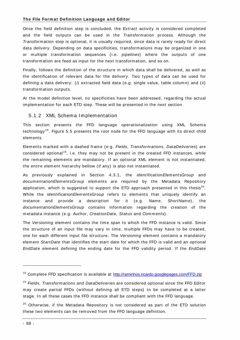
The File Format Definition Language and Editor
- 98 -
Once the field definition step is concluded, the Extract activity is considered completed
and the field outputs can be used in the Transformation process. Although the
Transformation step is optional, it is usually required, since data is rarely ready for direct
data delivery. Depending on data specificities, transformations may be organized in one
or multiple transformation sequences (i.e. pipelines) where the outputs of one
transformation are feed as input for the next transformation, and so on.
Finally, follows the definition of the structure in which data shall be delivered, as well as
the identification of relevant data for the delivery. Two types of data can be used for
defining a data delivery: (i) extracted field data (e.g. single value, table column) and (ii)
transformation outputs.
At the model definition level, no specificities have been addressed, regarding the actual
implementation for each ETD step. These will be presented in the next section.
5.1.2 XML Schema Implementation
This section presents the FFD language operationalization using XML Schema
technology18. Figure 5.5 presents the root node for the FFD language with its direct child
elements.
Elements marked with a dashed frame (e.g. Fields, Transformations, DataDeliveries) are
considered optional19, i.e. they may not be present in the created FFD instances, while
the remaining elements are mandatory. If an optional XML element is not instantiated,
the entire element hierarchy bellow (if any) is also not instantiated.
As previously explained in Section 4.3.1, the identificationElementsGroup and
documentationElementsGroup elements are required by the Metadata Repository
application, which is suggested to support the ETD approach presented in this thesis20.
While the identificationElementsGroup refers to elements that uniquely identify an
instance and provide a description for it (e.g. Name, ShortName), the
documentationElementsGroup contains information regarding the creation of the
metadata instance (e.g. Author, CreationDate, Status and Comments).
The Versioning element contains the time span to which the FFD instance is valid. Since
the structure of an input file may vary in time, multiple FFDs may have to be created,
one for each different input file structure. The Versioning element contains a mandatory
element StartDate that identifies the start date for which the FFD is valid and an optional
EndDate element defining the ending date for the FFD validity period. If the EndDate
18 Complete FFD specification is available at http://raminhos.ricardo.googlepages.com/FFD.zip
19 Fields, Transformations and DataDeliveries are considered optional since the FFD Editor
may create partial FFDs (without defining all ETD steps) to be completed at a latter
stage. In all these cases the FFD instance shall be compliant with the FFD language.
20 Otherwise, if the Metadata Repository is not considered as part of the ETD solution
these two elements can be removed from the FFD language definition.
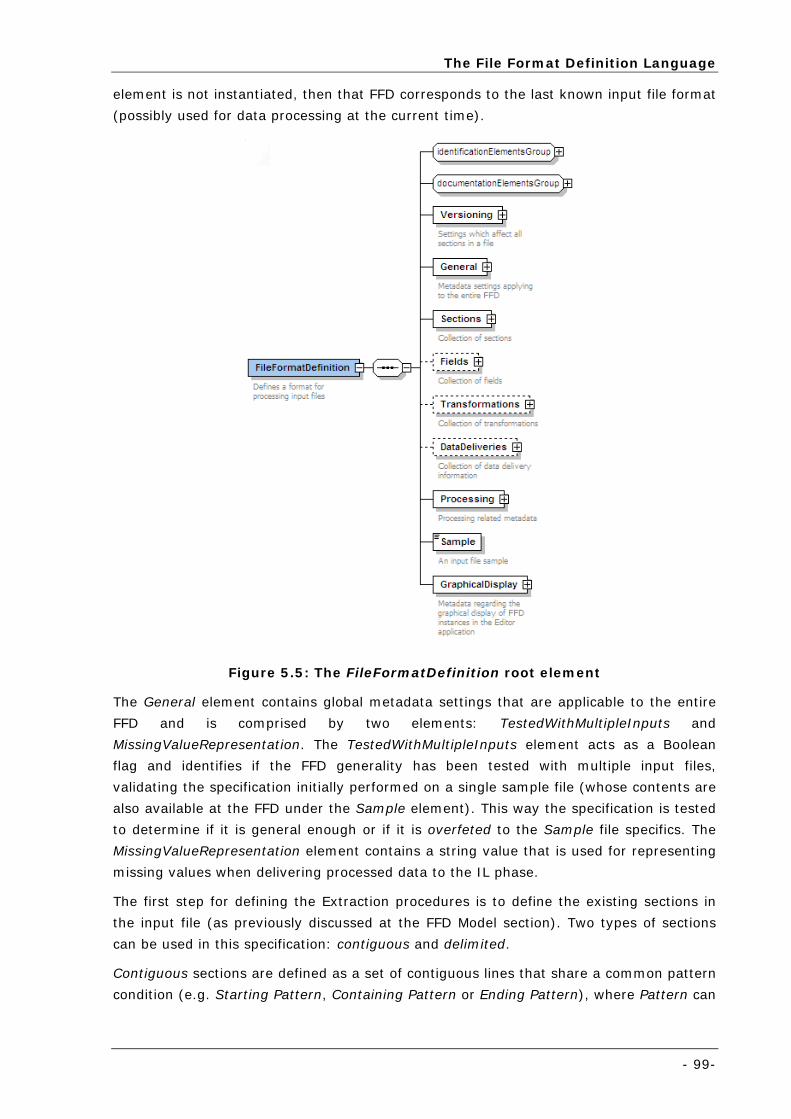
The File Format Definition Language
- 99-
element is not instantiated, then that FFD corresponds to the last known input file format
(possibly used for data processing at the current time).
Figure 5.5: The FileFormatDefinition root element
The General element contains global metadata settings that are applicable to the entire
FFD and is comprised by two elements: TestedWithMultipleInputs and
MissingValueRepresentation. The TestedWithMultipleInputs element acts as a Boolean
flag and identifies if the FFD generality has been tested with multiple input files,
validating the specification initially performed on a single sample file (whose contents are
also available at the FFD under the Sample element). This way the specification is tested
to determine if it is general enough or if it is overfeted to the Sample file specifics. The
MissingValueRepresentation element contains a string value that is used for representing
missing values when delivering processed data to the IL phase.
The first step for defining the Extraction procedures is to define the existing sections in
the input file (as previously discussed at the FFD Model section). Two types of sections
can be used in this specification: contiguous and delimited.
Contiguous sections are defined as a set of contiguous lines that share a common pattern
condition (e.g. Starting Pattern, Containing Pattern or Ending Pattern), where Pattern can
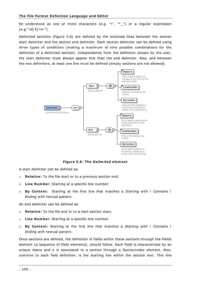
The File Format Definition Language and Editor
- 100 -
be understood as one or more characters (e.g. “!”, “*_”) or a regular expression
(e.g.“\d{4}\s+”).
Delimited sections (Figure 5.6) are defined by the enclosed lines between the section
start delimiter and the section end delimiter. Each section delimiter can be defined using
three types of conditions (making a maximum of nine possible combinations for the
definition of a delimited section). Independently from the definition chosen by the user,
the start delimiter must always appear first than the end delimiter. Also, and between
the two delimiters, at least one line must be defined (empty sections are not allowed).
Figure 5.6: The Delimited element
A start delimiter can be defined as:
o Relative: To the file start or to a previous section end;
o Line Number: Starting at a specific line number;
o By Content: Starting at the first line that matches a Starting with / Contains /
Ending with textual pattern.
An end delimiter can be defined as:
o Relative: To the file end or to a next section start;
o Line Number: Starting at a specific line number;
o By Content: Starting at the first line that matches a Starting with / Contains /
Ending with textual pattern.
Once sections are defined, the definition of fields within these sections through the Fields
element (a sequence of Field elements), should follow. Each Field is characterized by an
unique Name and it is associated to a section through a SectionIndex element. Also,
common to each field definition, is the starting line within the section text. This line
The File Format Definition Language
- 101-
number (offset) indicates the first line of the section text from which data is considered
in the definition of the field contents.
A SingleValue (Figure 5.7) can be defined in one of two ways:
o Delimiters: The user specifies prefix and / or suffix strings that will act as
boundaries for determining the single field value;
o RegularExpression: The user specifies a regular expression that captures the single
field. If the regular expression captures more than one value, only the first result
shall be considered.
Figure 5.7: The SingleValue element
Single values (and table columns) may have an optional MissingValue representation.
During the processing, missing values are replaced by a custom value defined by the
user (e.g. “” - empty string) indicating that the value is missing (e.g. due to a sensor
failure).
The definition logic of a Table field is depicted in Figure 5.8. A table field can be defined
through one of three ways:
o FixedWidth: Defines a set of column breaks (numeric positions in the text) that
specify boundaries for each column. A minimum of one column break must be defined
(resulting in a table with two columns). No maximum number of column breaks is
established, so N column breaks can be defined (resulting in a table with N + 1
columns);
o CharDelimited: Defines a delimiter character that specifies the boundaries for each
column;
o RegularExpression: Specifies a regular expression that captures all table columns.
Each group21 in the regular expression is mapped to a table column.
21 Defined by a regular expression statement between brackets.
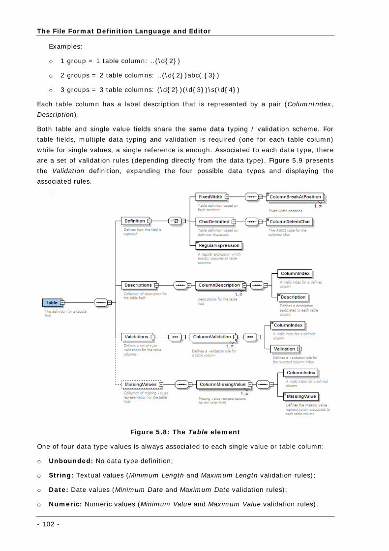
The File Format Definition Language and Editor
- 102 -
Examples:
o 1 group = 1 table column: ..(\d{2})
o 2 groups = 2 table columns: ..(\d{2})abc(.{3})
o 3 groups = 3 table columns: (\d{2})(\d{3})\s(\d{4})
Each table column has a label description that is represented by a pair (ColumnIndex,
Description).
Both table and single value fields share the same data typing / validation scheme. For
table fields, multiple data typing and validation is required (one for each table column)
while for single values, a single reference is enough. Associated to each data type, there
are a set of validation rules (depending directly from the data type). Figure 5.9 presents
the Validation definition, expanding the four possible data types and displaying the
associated rules.
Figure 5.8: The Table element
One of four data type values is always associated to each single value or table column:
o Unbounded: No data type definition;
o String: Textual values (Minimum Length and Maximum Length validation rules);
o Date: Date values (Minimum Date and Maximum Date validation rules);
o Numeric: Numeric values (Minimum Value and Maximum Value validation rules).
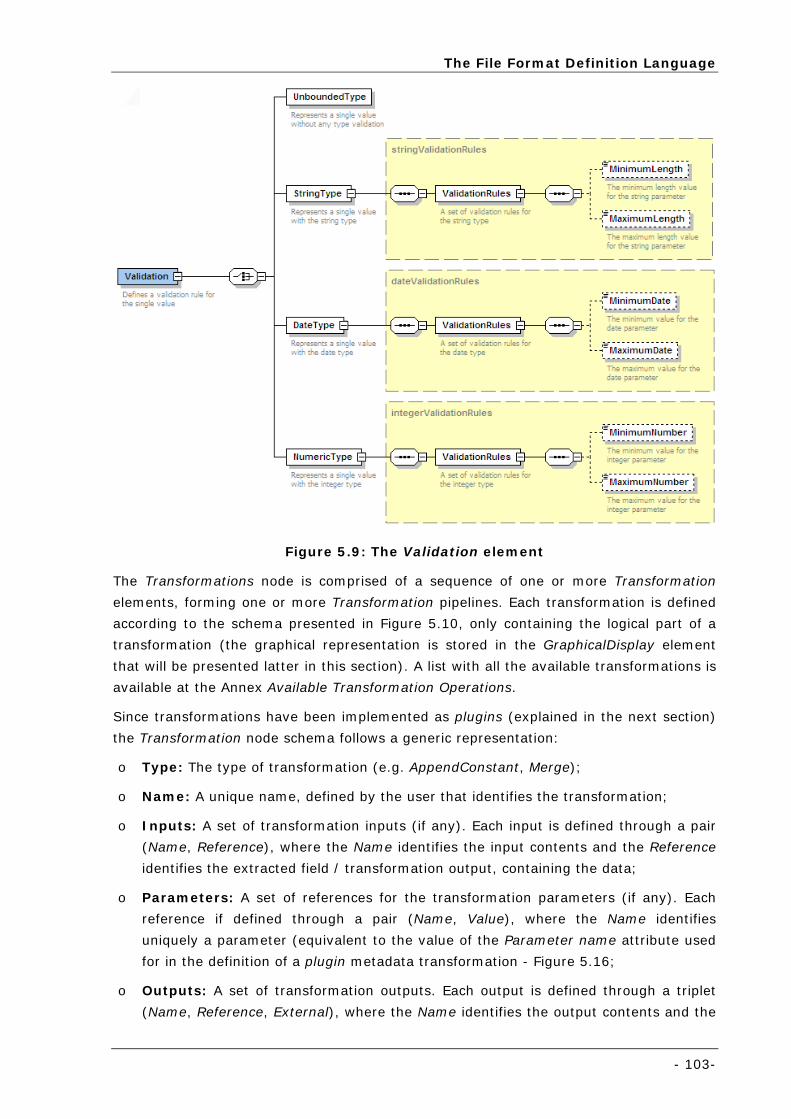
The File Format Definition Language
- 103-
Figure 5.9: The Validation element
The Transformations node is comprised of a sequence of one or more Transformation
elements, forming one or more Transformation pipelines. Each transformation is defined
according to the schema presented in Figure 5.10, only containing the logical part of a
transformation (the graphical representation is stored in the GraphicalDisplay element
that will be presented latter in this section). A list with all the available transformations is
available at the Annex Available Transformation Operations.
Since transformations have been implemented as plugins (explained in the next section)
the Transformation node schema follows a generic representation:
o Type: The type of transformation (e.g. AppendConstant, Merge);
o Name: A unique name, defined by the user that identifies the transformation;
o Inputs: A set of transformation inputs (if any). Each input is defined through a pair
(Name, Reference), where the Name identifies the input contents and the Reference
identifies the extracted field / transformation output, containing the data;
o Parameters: A set of references for the transformation parameters (if any). Each
reference if defined through a pair (Name, Value), where the Name identifies
uniquely a parameter (equivalent to the value of the Parameter name attribute used
for in the definition of a plugin metadata transformation - Figure 5.16;
o Outputs: A set of transformation outputs. Each output is defined through a triplet
(Name, Reference, External), where the Name identifies the output contents and the
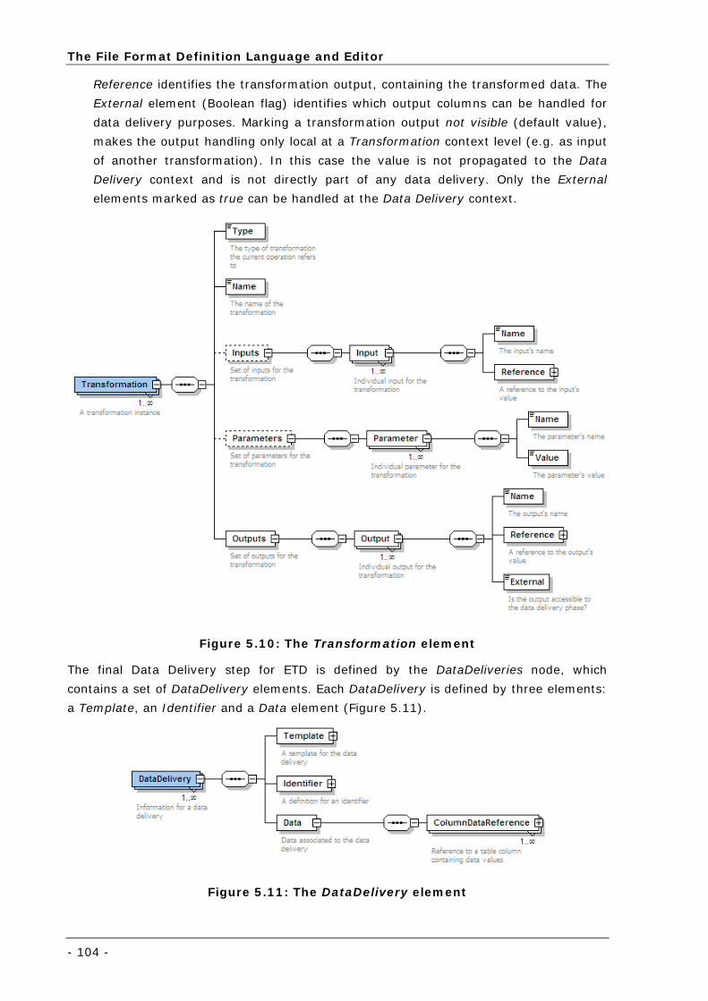
The File Format Definition Language and Editor
- 104 -
Reference identifies the transformation output, containing the transformed data. The
External element (Boolean flag) identifies which output columns can be handled for
data delivery purposes. Marking a transformation output not visible (default value),
makes the output handling only local at a Transformation context level (e.g. as input
of another transformation). In this case the value is not propagated to the Data
Delivery context and is not directly part of any data delivery. Only the External
elements marked as true can be handled at the Data Delivery context.
Figure 5.10: The Transformation element
The final Data Delivery step for ETD is defined by the DataDeliveries node, which
contains a set of DataDelivery elements. Each DataDelivery is defined by three elements:
a Template, an Identifier and a Data element (Figure 5.11).
Figure 5.11: The DataDelivery element
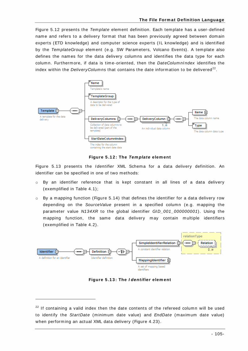
The File Format Definition Language
- 105-
Figure 5.12 presents the Template element definition. Each template has a user-defined
name and refers to a delivery format that has been previously agreed between domain
experts (ETD knowledge) and computer science experts (IL knowledge) and is identified
by the TemplateGroup element (e.g. SW Parameters, Volcano Events). A template also
defines the names for the data delivery columns and identifies the data type for each
column. Furthermore, if data is time-oriented, then the DateColumnIndex identifies the
index within the DeliveryColumns that contains the date information to be delivered22.
Figure 5.12: The Template element
Figure 5.13 presents the Identifier XML Schema for a data delivery definition. An
identifier can be specified in one of two methods:
o By an identifier reference that is kept constant in all lines of a data delivery
(exemplified in Table 4.1);
o By a mapping function (Figure 5.14) that defines the identifier for a data delivery row
depending on the SourceValue present in a specified column (e.g. mapping the
parameter value N134XR to the global identifier GID_001_000000001). Using the
mapping function, the same data delivery may contain multiple identifiers
(exemplified in Table 4.2).
Figure 5.13: The Identifier element
22 If containing a valid index then the date contents of the refereed column will be used
to identify the StartDate (minimum date value) and EndDate (maximum date value)
when performing an actual XML data delivery (Figure 4.23).
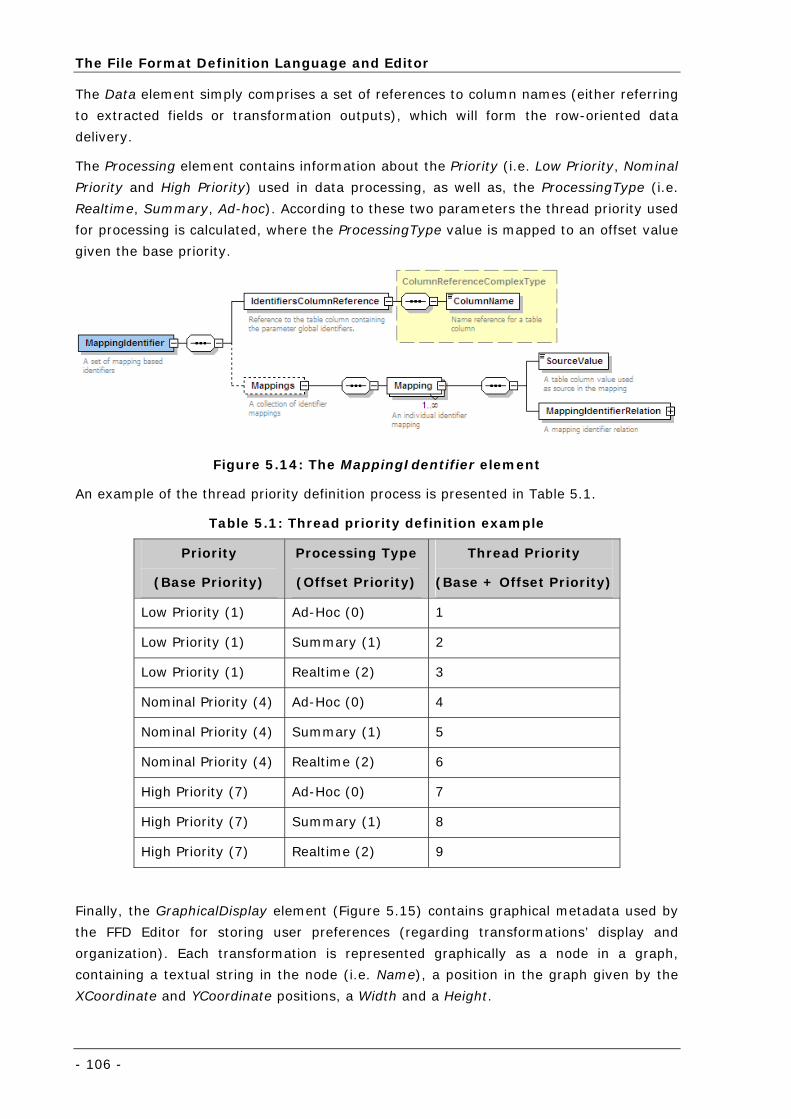
The File Format Definition Language and Editor
- 106 -
The Data element simply comprises a set of references to column names (either referring
to extracted fields or transformation outputs), which will form the row-oriented data
delivery.
The Processing element contains information about the Priority (i.e. Low Priority, Nominal
Priority and High Priority) used in data processing, as well as, the ProcessingType (i.e.
Realtime, Summary, Ad-hoc). According to these two parameters the thread priority used
for processing is calculated, where the ProcessingType value is mapped to an offset value
given the base priority.
Figure 5.14: The MappingIdentifier element
An example of the thread priority definition process is presented in Table 5.1.
Table 5.1: Thread priority definition example
Priority
(Base Priority)
Processing Type
(Offset Priority)
Thread Priority
(Base + Offset Priority)
Low Priority (1) Ad-Hoc (0) 1
Low Priority (1) Summary (1) 2
Low Priority (1) Realtime (2) 3
Nominal Priority (4) Ad-Hoc (0) 4
Nominal Priority (4) Summary (1) 5
Nominal Priority (4) Realtime (2) 6
High Priority (7) Ad-Hoc (0) 7
High Priority (7) Summary (1) 8
High Priority (7) Realtime (2) 9
Finally, the GraphicalDisplay element (Figure 5.15) contains graphical metadata used by
the FFD Editor for storing user preferences (regarding transformations’ display and
organization). Each transformation is represented graphically as a node in a graph,
containing a textual string in the node (i.e. Name), a position in the graph given by the
XCoordinate and YCoordinate positions, a Width and a Height.
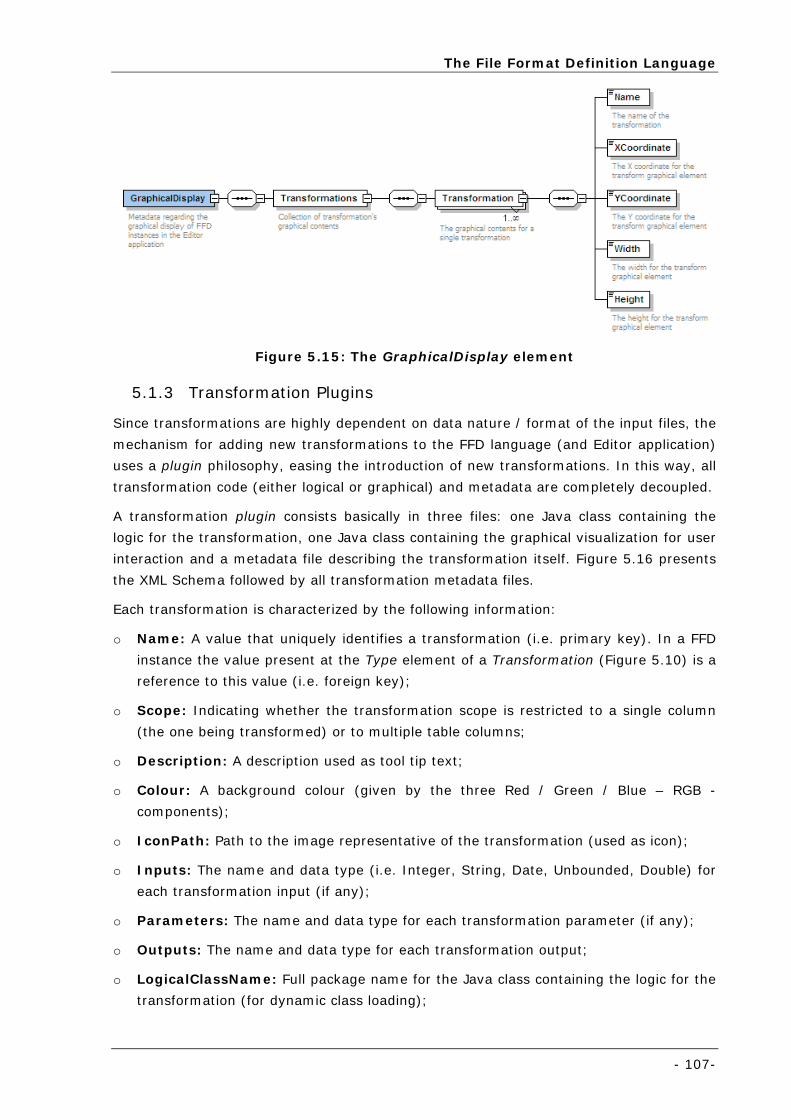
The File Format Definition Language
- 107-
Figure 5.15: The GraphicalDisplay element
5.1.3 Transformation Plugins
Since transformations are highly dependent on data nature / format of the input files, the
mechanism for adding new transformations to the FFD language (and Editor application)
uses a plugin philosophy, easing the introduction of new transformations. In this way, all
transformation code (either logical or graphical) and metadata are completely decoupled.
A transformation plugin consists basically in three files: one Java class containing the
logic for the transformation, one Java class containing the graphical visualization for user
interaction and a metadata file describing the transformation itself. Figure 5.16 presents
the XML Schema followed by all transformation metadata files.
Each transformation is characterized by the following information:
o Name: A value that uniquely identifies a transformation (i.e. primary key). In a FFD
instance the value present at the Type element of a Transformation (Figure 5.10) is a
reference to this value (i.e. foreign key);
o Scope: Indicating whether the transformation scope is restricted to a single column
(the one being transformed) or to multiple table columns;
o Description: A description used as tool tip text;
o Colour: A background colour (given by the three Red / Green / Blue – RGB -
components);
o IconPath: Path to the image representative of the transformation (used as icon);
o Inputs: The name and data type (i.e. Integer, String, Date, Unbounded, Double) for
each transformation input (if any);
o Parameters: The name and data type for each transformation parameter (if any);
o Outputs: The name and data type for each transformation output;
o LogicalClassName: Full package name for the Java class containing the logic for the
transformation (for dynamic class loading);
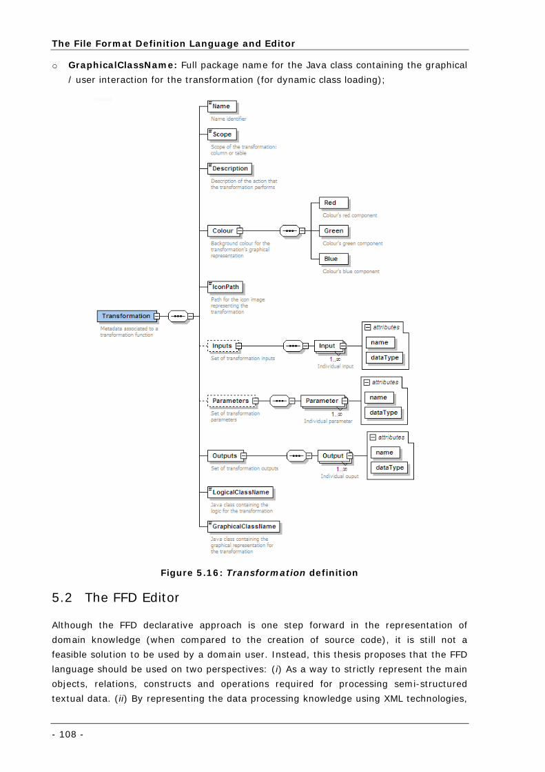
The File Format Definition Language and Editor
- 108 -
o GraphicalClassName: Full package name for the Java class containing the graphical
/ user interaction for the transformation (for dynamic class loading);
Figure 5.16: Transformation definition
5.2 The FFD Editor
Although the FFD declarative approach is one step forward in the representation of
domain knowledge (when compared to the creation of source code), it is still not a
feasible solution to be used by a domain user. Instead, this thesis proposes that the FFD
language should be used on two perspectives: (i) As a way to strictly represent the main
objects, relations, constructs and operations required for processing semi-structured
textual data. (ii) By representing the data processing knowledge using XML technologies,
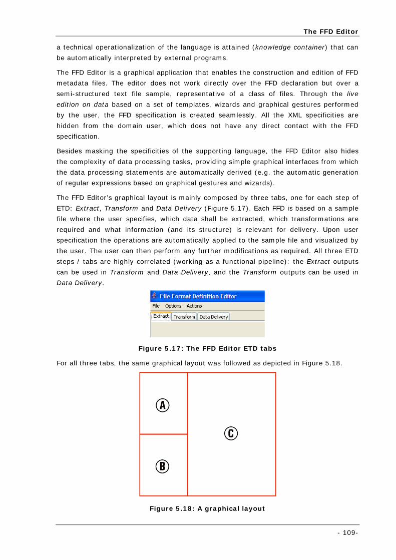
The FFD Editor
- 109-
a technical operationalization of the language is attained (knowledge container) that can
be automatically interpreted by external programs.
The FFD Editor is a graphical application that enables the construction and edition of FFD
metadata files. The editor does not work directly over the FFD declaration but over a
semi-structured text file sample, representative of a class of files. Through the live
edition on data based on a set of templates, wizards and graphical gestures performed
by the user, the FFD specification is created seamlessly. All the XML specificities are
hidden from the domain user, which does not have any direct contact with the FFD
specification.
Besides masking the specificities of the supporting language, the FFD Editor also hides
the complexity of data processing tasks, providing simple graphical interfaces from which
the data processing statements are automatically derived (e.g. the automatic generation
of regular expressions based on graphical gestures and wizards).
The FFD Editor’s graphical layout is mainly composed by three tabs, one for each step of
ETD: Extract, Transform and Data Delivery (Figure 5.17). Each FFD is based on a sample
file where the user specifies, which data shall be extracted, which transformations are
required and what information (and its structure) is relevant for delivery. Upon user
specification the operations are automatically applied to the sample file and visualized by
the user. The user can then perform any further modifications as required. All three ETD
steps / tabs are highly correlated (working as a functional pipeline): the Extract outputs
can be used in Transform and Data Delivery, and the Transform outputs can be used in
Data Delivery.
Figure 5.17: The FFD Editor ETD tabs
For all three tabs, the same graphical layout was followed as depicted in Figure 5.18.
Figure 5.18: A graphical layout
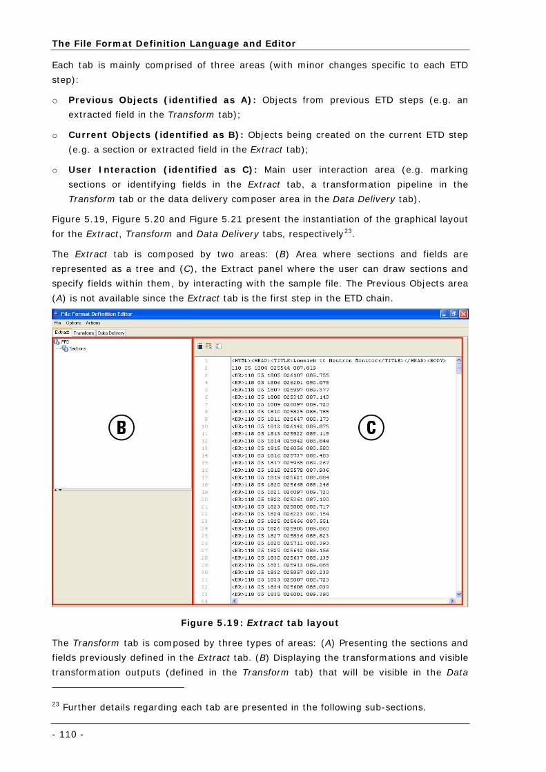
The File Format Definition Language and Editor
- 110 -
Each tab is mainly comprised of three areas (with minor changes specific to each ETD
step):
o Previous Objects (identified as A): Objects from previous ETD steps (e.g. an
extracted field in the Transform tab);
o Current Objects (identified as B): Objects being created on the current ETD step
(e.g. a section or extracted field in the Extract tab);
o User Interaction (identified as C): Main user interaction area (e.g. marking
sections or identifying fields in the Extract tab, a transformation pipeline in the
Transform tab or the data delivery composer area in the Data Delivery tab).
Figure 5.19, Figure 5.20 and Figure 5.21 present the instantiation of the graphical layout
for the Extract, Transform and Data Delivery tabs, respectively23.
The Extract tab is composed by two areas: (B) Area where sections and fields are
represented as a tree and (C), the Extract panel where the user can draw sections and
specify fields within them, by interacting with the sample file. The Previous Objects area
(A) is not available since the Extract tab is the first step in the ETD chain.
Figure 5.19: Extract tab layout
The Transform tab is composed by three types of areas: (A) Presenting the sections and
fields previously defined in the Extract tab. (B) Displaying the transformations and visible
transformation outputs (defined in the Transform tab) that will be visible in the Data
23 Further details regarding each tab are presented in the following sub-sections.
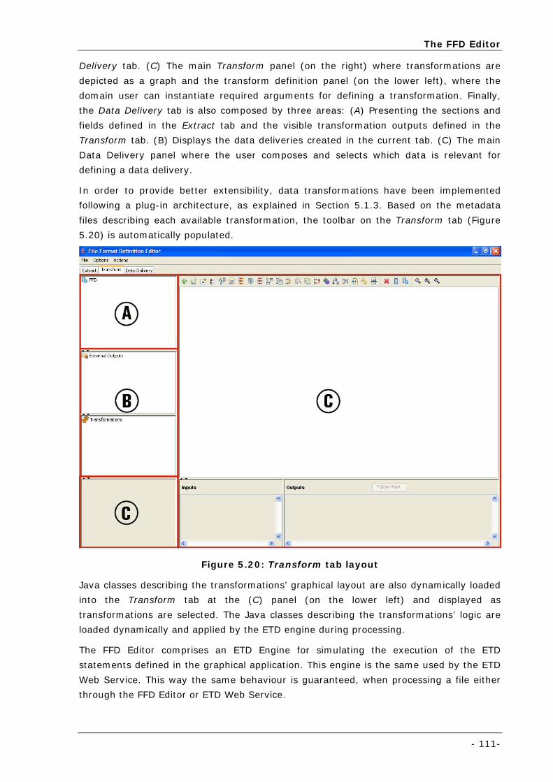
The FFD Editor
- 111-
Delivery tab. (C) The main Transform panel (on the right) where transformations are
depicted as a graph and the transform definition panel (on the lower left), where the
domain user can instantiate required arguments for defining a transformation. Finally,
the Data Delivery tab is also composed by three areas: (A) Presenting the sections and
fields defined in the Extract tab and the visible transformation outputs defined in the
Transform tab. (B) Displays the data deliveries created in the current tab. (C) The main
Data Delivery panel where the user composes and selects which data is relevant for
defining a data delivery.
In order to provide better extensibility, data transformations have been implemented
following a plug-in architecture, as explained in Section 5.1.3. Based on the metadata
files describing each available transformation, the toolbar on the Transform tab (Figure
5.20) is automatically populated.
Figure 5.20: Transform tab layout
Java classes describing the transformations’ graphical layout are also dynamically loaded
into the Transform tab at the (C) panel (on the lower left) and displayed as
transformations are selected. The Java classes describing the transformations’ logic are
loaded dynamically and applied by the ETD engine during processing.
The FFD Editor comprises an ETD Engine for simulating the execution of the ETD
statements defined in the graphical application. This engine is the same used by the ETD
Web Service. This way the same behaviour is guaranteed, when processing a file either
through the FFD Editor or ETD Web Service.
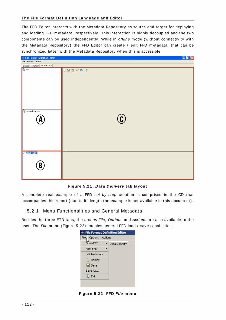
The File Format Definition Language and Editor
- 112 -
The FFD Editor interacts with the Metadata Repository as source and target for deploying
and loading FFD metadata, respectively. This interaction is highly decoupled and the two
components can be used independently. While in offline mode (without connectivity with
the Metadata Repository) the FFD Editor can create / edit FFD metadata, that can be
synchronized latter with the Metadata Repository when this is accessible.
Figure 5.21: Data Delivery tab layout
A complete real example of a FFD set-by-step creation is comprised in the CD that
accompanies this report (due to its length the example is not available in this document).
5.2.1 Menu Functionalities and General Metadata
Besides the three ETD tabs, the menus File, Options and Actions are also available to the
user. The File menu (Figure 5.22) enables general FFD load / save capabilities:
Figure 5.22: FFD File menu
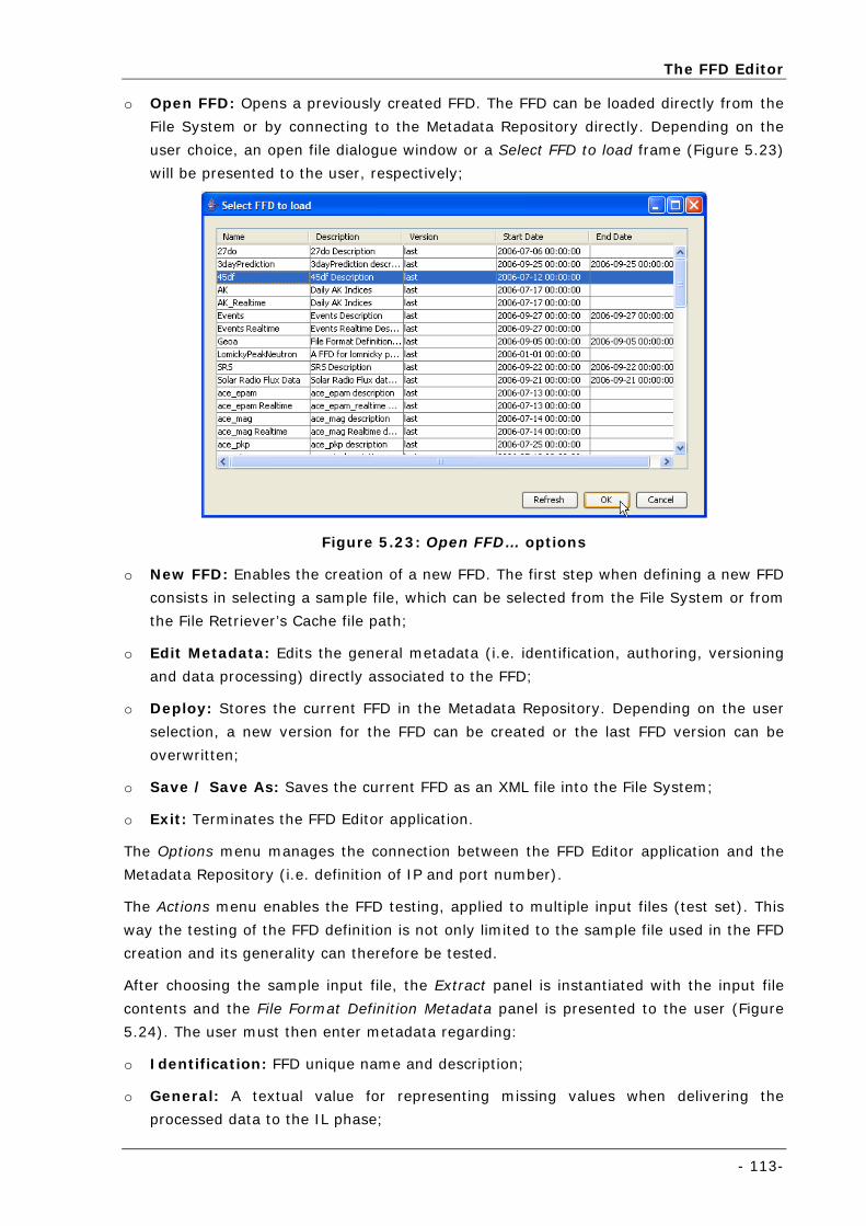
The FFD Editor
- 113-
o Open FFD: Opens a previously created FFD. The FFD can be loaded directly from the
File System or by connecting to the Metadata Repository directly. Depending on the
user choice, an open file dialogue window or a Select FFD to load frame (Figure 5.23)
will be presented to the user, respectively;
Figure 5.23: Open FFD… options
o New FFD: Enables the creation of a new FFD. The first step when defining a new FFD
consists in selecting a sample file, which can be selected from the File System or from
the File Retriever’s Cache file path;
o Edit Metadata: Edits the general metadata (i.e. identification, authoring, versioning
and data processing) directly associated to the FFD;
o Deploy: Stores the current FFD in the Metadata Repository. Depending on the user
selection, a new version for the FFD can be created or the last FFD version can be
overwritten;
o Save / Save As: Saves the current FFD as an XML file into the File System;
o Exit: Terminates the FFD Editor application.
The Options menu manages the connection between the FFD Editor application and the
Metadata Repository (i.e. definition of IP and port number).
The Actions menu enables the FFD testing, applied to multiple input files (test set). This
way the testing of the FFD definition is not only limited to the sample file used in the FFD
creation and its generality can therefore be tested.
After choosing the sample input file, the Extract panel is instantiated with the input file
contents and the File Format Definition Metadata panel is presented to the user (Figure
5.24). The user must then enter metadata regarding:
o Identification: FFD unique name and description;
o General: A textual value for representing missing values when delivering the
processed data to the IL phase;
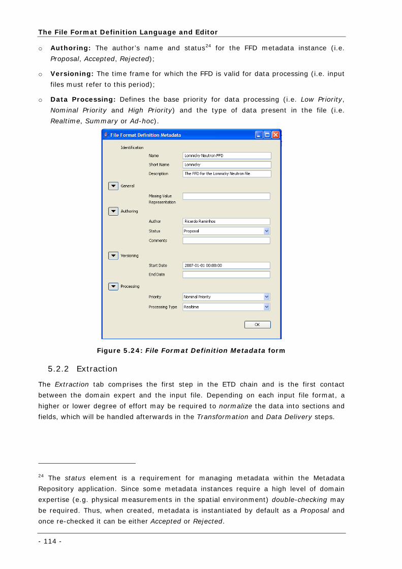
The File Format Definition Language and Editor
- 114 -
o Authoring: The author’s name and status24 for the FFD metadata instance (i.e.
Proposal, Accepted, Rejected);
o Versioning: The time frame for which the FFD is valid for data processing (i.e. input
files must refer to this period);
o Data Processing: Defines the base priority for data processing (i.e. Low Priority,
Nominal Priority and High Priority) and the type of data present in the file (i.e.
Realtime, Summary or Ad-hoc).
Figure 5.24: File Format Definition Metadata form
5.2.2 Extraction
The Extraction tab comprises the first step in the ETD chain and is the first contact
between the domain expert and the input file. Depending on each input file format, a
higher or lower degree of effort may be required to normalize the data into sections and
fields, which will be handled afterwards in the Transformation and Data Delivery steps.
24 The status element is a requirement for managing metadata within the Metadata
Repository application. Since some metadata instances require a high level of domain
expertise (e.g. physical measurements in the spatial environment) double-checking may
be required. Thus, when created, metadata is instantiated by default as a Proposal and
once re-checked it can be either Accepted or Rejected.
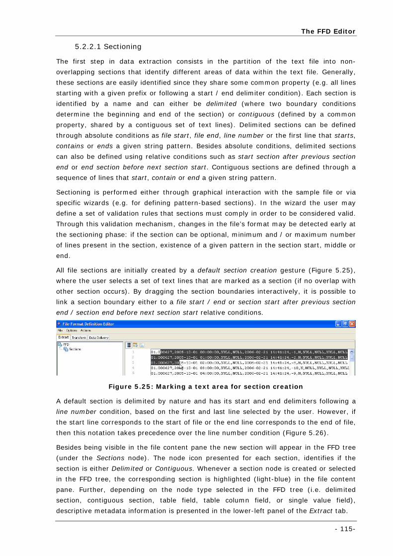
The FFD Editor
- 115-
5.2.2.1 Sectioning
The first step in data extraction consists in the partition of the text file into non-
overlapping sections that identify different areas of data within the text file. Generally,
these sections are easily identified since they share some common property (e.g. all lines
starting with a given prefix or following a start / end delimiter condition). Each section is
identified by a name and can either be delimited (where two boundary conditions
determine the beginning and end of the section) or contiguous (defined by a common
property, shared by a contiguous set of text lines). Delimited sections can be defined
through absolute conditions as file start, file end, line number or the first line that starts,
contains or ends a given string pattern. Besides absolute conditions, delimited sections
can also be defined using relative conditions such as start section after previous section
end or end section before next section start. Contiguous sections are defined through a
sequence of lines that start, contain or end a given string pattern.
Sectioning is performed either through graphical interaction with the sample file or via
specific wizards (e.g. for defining pattern-based sections). In the wizard the user may
define a set of validation rules that sections must comply in order to be considered valid.
Through this validation mechanism, changes in the file’s format may be detected early at
the sectioning phase: if the section can be optional, minimum and / or maximum number
of lines present in the section, existence of a given pattern in the section start, middle or
end.
All file sections are initially created by a default section creation gesture (Figure 5.25),
where the user selects a set of text lines that are marked as a section (if no overlap with
other section occurs). By dragging the section boundaries interactively, it is possible to
link a section boundary either to a file start / end or section start after previous section
end / section end before next section start relative conditions.
Figure 5.25: Marking a text area for section creation
A default section is delimited by nature and has its start and end delimiters following a
line number condition, based on the first and last line selected by the user. However, if
the start line corresponds to the start of file or the end line corresponds to the end of file,
then this notation takes precedence over the line number condition (Figure 5.26).
Besides being visible in the file content pane the new section will appear in the FFD tree
(under the Sections node). The node icon presented for each section, identifies if the
section is either Delimited or Contiguous. Whenever a section node is created or selected
in the FFD tree, the corresponding section is highlighted (light-blue) in the file content
pane. Further, depending on the node type selected in the FFD tree (i.e. delimited
section, contiguous section, table field, table column field, or single value field),
descriptive metadata information is presented in the lower-left panel of the Extract tab.
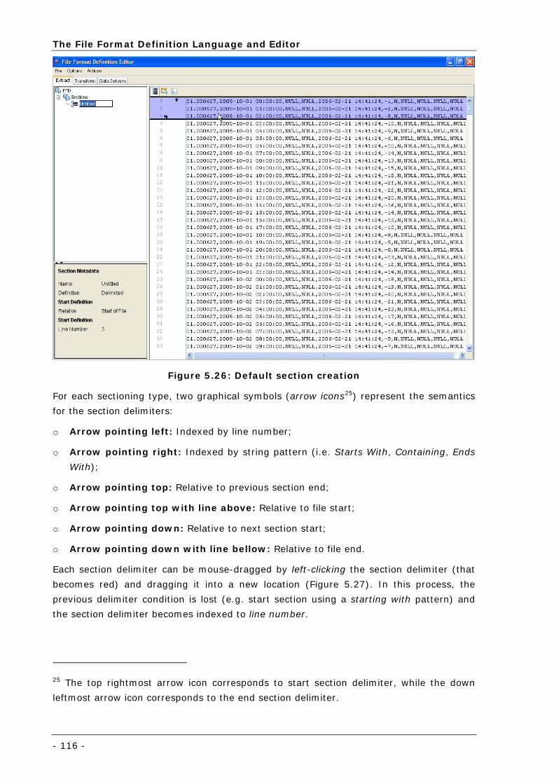
The File Format Definition Language and Editor
- 116 -
Figure 5.26: Default section creation
For each sectioning type, two graphical symbols (arrow icons25) represent the semantics
for the section delimiters:
o Arrow pointing left: Indexed by line number;
o Arrow pointing right: Indexed by string pattern (i.e. Starts With, Containing, Ends
With);
o Arrow pointing top: Relative to previous section end;
o Arrow pointing top with line above: Relative to file start;
o Arrow pointing down: Relative to next section start;
o Arrow pointing down with line bellow: Relative to file end.
Each section delimiter can be mouse-dragged by left-clicking the section delimiter (that
becomes red) and dragging it into a new location (Figure 5.27). In this process, the
previous delimiter condition is lost (e.g. start section using a starting with pattern) and
the section delimiter becomes indexed to line number.
25 The top rightmost arrow icon corresponds to start section delimiter, while the down
leftmost arrow icon corresponds to the end section delimiter.
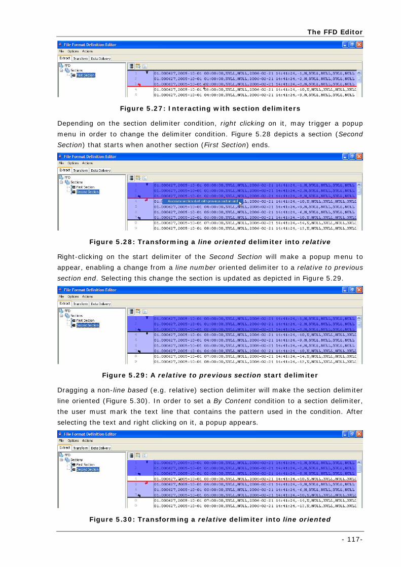
The FFD Editor
- 117-
Figure 5.27: Interacting with section delimiters
Depending on the section delimiter condition, right clicking on it, may trigger a popup
menu in order to change the delimiter condition. Figure 5.28 depicts a section (Second
Section) that starts when another section (First Section) ends.
Figure 5.28: Transforming a line oriented delimiter into relative
Right-clicking on the start delimiter of the Second Section will make a popup menu to
appear, enabling a change from a line number oriented delimiter to a relative to previous
section end. Selecting this change the section is updated as depicted in Figure 5.29.
Figure 5.29: A relative to previous section start delimiter
Dragging a non-line based (e.g. relative) section delimiter will make the section delimiter
line oriented (Figure 5.30). In order to set a By Content condition to a section delimiter,
the user must mark the text line that contains the pattern used in the condition. After
selecting the text and right clicking on it, a popup appears.
Figure 5.30: Transforming a relative delimiter into line oriented
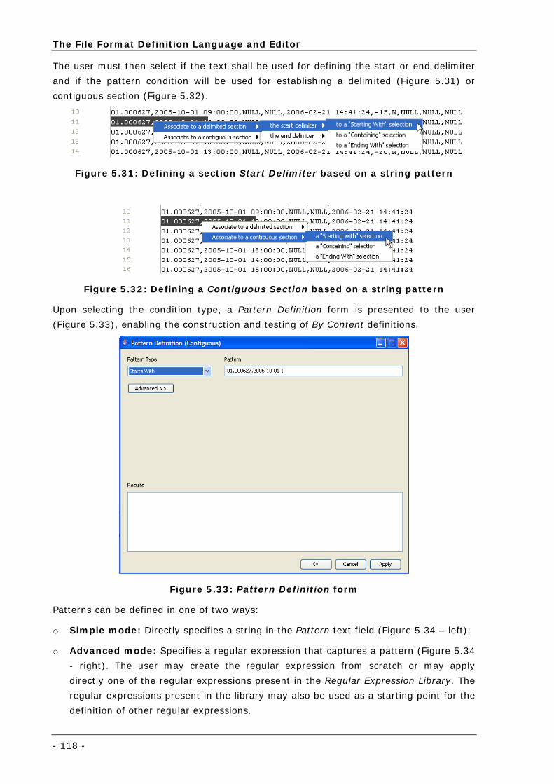
The File Format Definition Language and Editor
- 118 -
The user must then select if the text shall be used for defining the start or end delimiter
and if the pattern condition will be used for establishing a delimited (Figure 5.31) or
contiguous section (Figure 5.32).
Figure 5.31: Defining a section Start Delimiter based on a string pattern
Figure 5.32: Defining a Contiguous Section based on a string pattern
Upon selecting the condition type, a Pattern Definition form is presented to the user
(Figure 5.33), enabling the construction and testing of By Content definitions.
Figure 5.33: Pattern Definition form
Patterns can be defined in one of two ways:
o Simple mode: Directly specifies a string in the Pattern text field (Figure 5.34 – left);
o Advanced mode: Specifies a regular expression that captures a pattern (Figure 5.34
- right). The user may create the regular expression from scratch or may apply
directly one of the regular expressions present in the Regular Expression Library. The
regular expressions present in the library may also be used as a starting point for the
definition of other regular expressions.
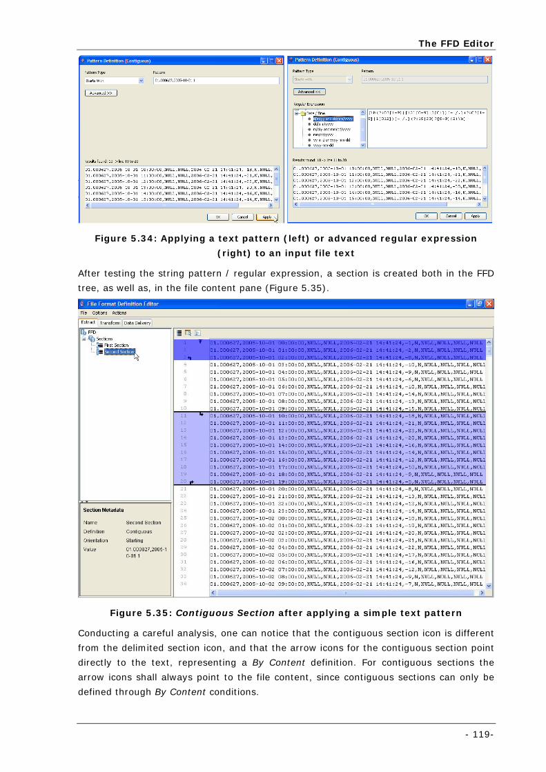
The FFD Editor
- 119-
Figure 5.34: Applying a text pattern (left) or advanced regular expression
(right) to an input file text
After testing the string pattern / regular expression, a section is created both in the FFD
tree, as well as, in the file content pane (Figure 5.35).
Figure 5.35: Contiguous Section after applying a simple text pattern
Conducting a careful analysis, one can notice that the contiguous section icon is different
from the delimited section icon, and that the arrow icons for the contiguous section point
directly to the text, representing a By Content definition. For contiguous sections the
arrow icons shall always point to the file content, since contiguous sections can only be
defined through By Content conditions.
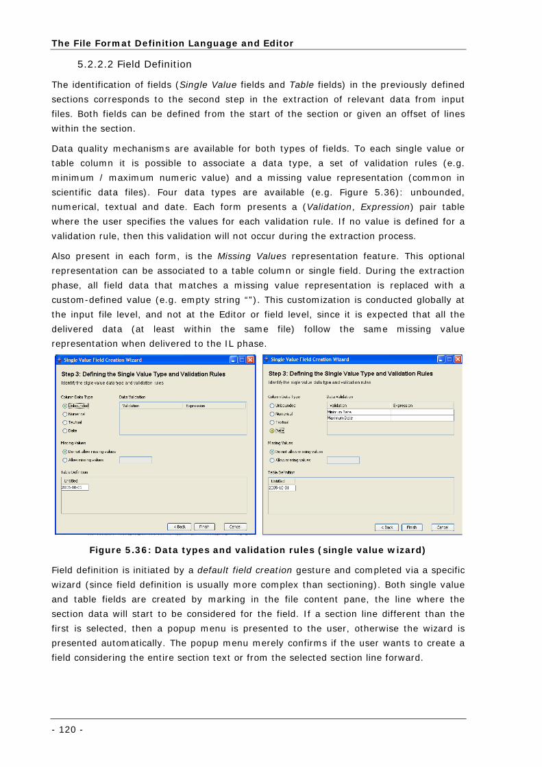
The File Format Definition Language and Editor
- 120 -
5.2.2.2 Field Definition
The identification of fields (Single Value fields and Table fields) in the previously defined
sections corresponds to the second step in the extraction of relevant data from input
files. Both fields can be defined from the start of the section or given an offset of lines
within the section.
Data quality mechanisms are available for both types of fields. To each single value or
table column it is possible to associate a data type, a set of validation rules (e.g.
minimum / maximum numeric value) and a missing value representation (common in
scientific data files). Four data types are available (e.g. Figure 5.36): unbounded,
numerical, textual and date. Each form presents a (Validation, Expression) pair table
where the user specifies the values for each validation rule. If no value is defined for a
validation rule, then this validation will not occur during the extraction process.
Also present in each form, is the Missing Values representation feature. This optional
representation can be associated to a table column or single field. During the extraction
phase, all field data that matches a missing value representation is replaced with a
custom-defined value (e.g. empty string “”). This customization is conducted globally at
the input file level, and not at the Editor or field level, since it is expected that all the
delivered data (at least within the same file) follow the same missing value
representation when delivered to the IL phase.
Figure 5.36: Data types and validation rules (single value wizard)
Field definition is initiated by a default field creation gesture and completed via a specific
wizard (since field definition is usually more complex than sectioning). Both single value
and table fields are created by marking in the file content pane, the line where the
section data will start to be considered for the field. If a section line different than the
first is selected, then a popup menu is presented to the user, otherwise the wizard is
presented automatically. The popup menu merely confirms if the user wants to create a
field considering the entire section text or from the selected section line forward.
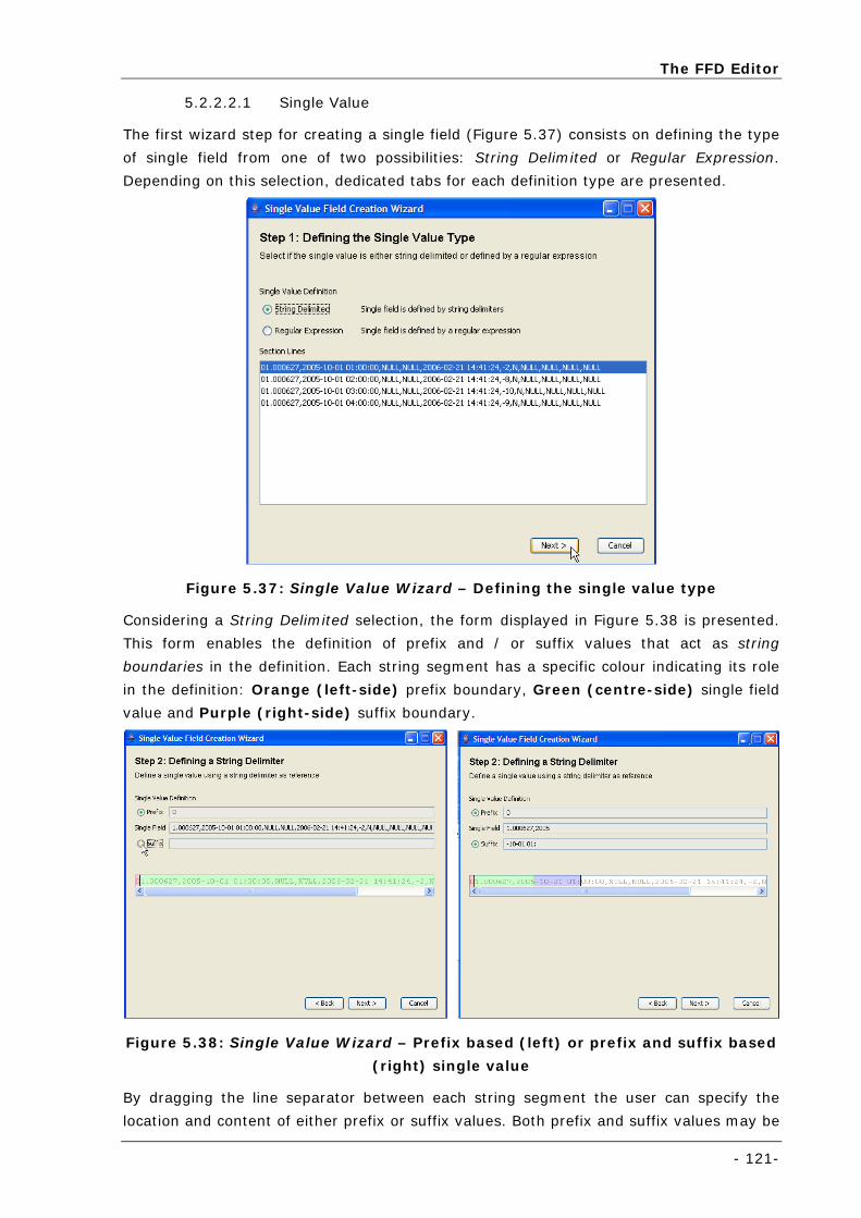
The FFD Editor
- 121-
5.2.2.2.1 Single Value
The first wizard step for creating a single field (Figure 5.37) consists on defining the type
of single field from one of two possibilities: String Delimited or Regular Expression.
Depending on this selection, dedicated tabs for each definition type are presented.
Figure 5.37: Single Value Wizard – Defining the single value type
Considering a String Delimited selection, the form displayed in Figure 5.38 is presented.
This form enables the definition of prefix and / or suffix values that act as string
boundaries in the definition. Each string segment has a specific colour indicating its role
in the definition: Orange (left-side) prefix boundary, Green (centre-side) single field
value and Purple (right-side) suffix boundary.
Figure 5.38: Single Value Wizard – Prefix based (left) or prefix and suffix based
(right) single value
By dragging the line separator between each string segment the user can specify the
location and content of either prefix or suffix values. Both prefix and suffix values may be
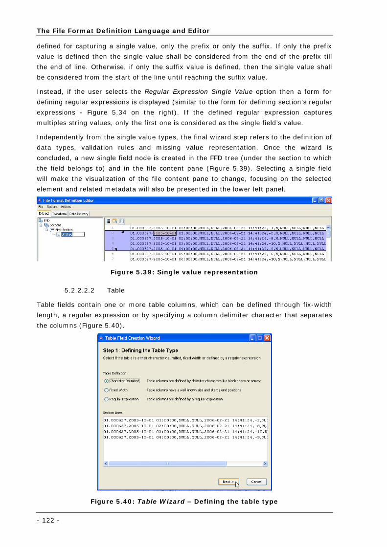
The File Format Definition Language and Editor
- 122 -
defined for capturing a single value, only the prefix or only the suffix. If only the prefix
value is defined then the single value shall be considered from the end of the prefix till
the end of line. Otherwise, if only the suffix value is defined, then the single value shall
be considered from the start of the line until reaching the suffix value.
Instead, if the user selects the Regular Expression Single Value option then a form for
defining regular expressions is displayed (similar to the form for defining section’s regular
expressions - Figure 5.34 on the right). If the defined regular expression captures
multiples string values, only the first one is considered as the single field’s value.
Independently from the single value types, the final wizard step refers to the definition of
data types, validation rules and missing value representation. Once the wizard is
concluded, a new single field node is created in the FFD tree (under the section to which
the field belongs to) and in the file content pane (Figure 5.39). Selecting a single field
will make the visualization of the file content pane to change, focusing on the selected
element and related metadata will also be presented in the lower left panel.
Figure 5.39: Single value representation
5.2.2.2.2 Table
Table fields contain one or more table columns, which can be defined through fix-width
length, a regular expression or by specifying a column delimiter character that separates
the columns (Figure 5.40).
Figure 5.40: Table Wizard – Defining the table type
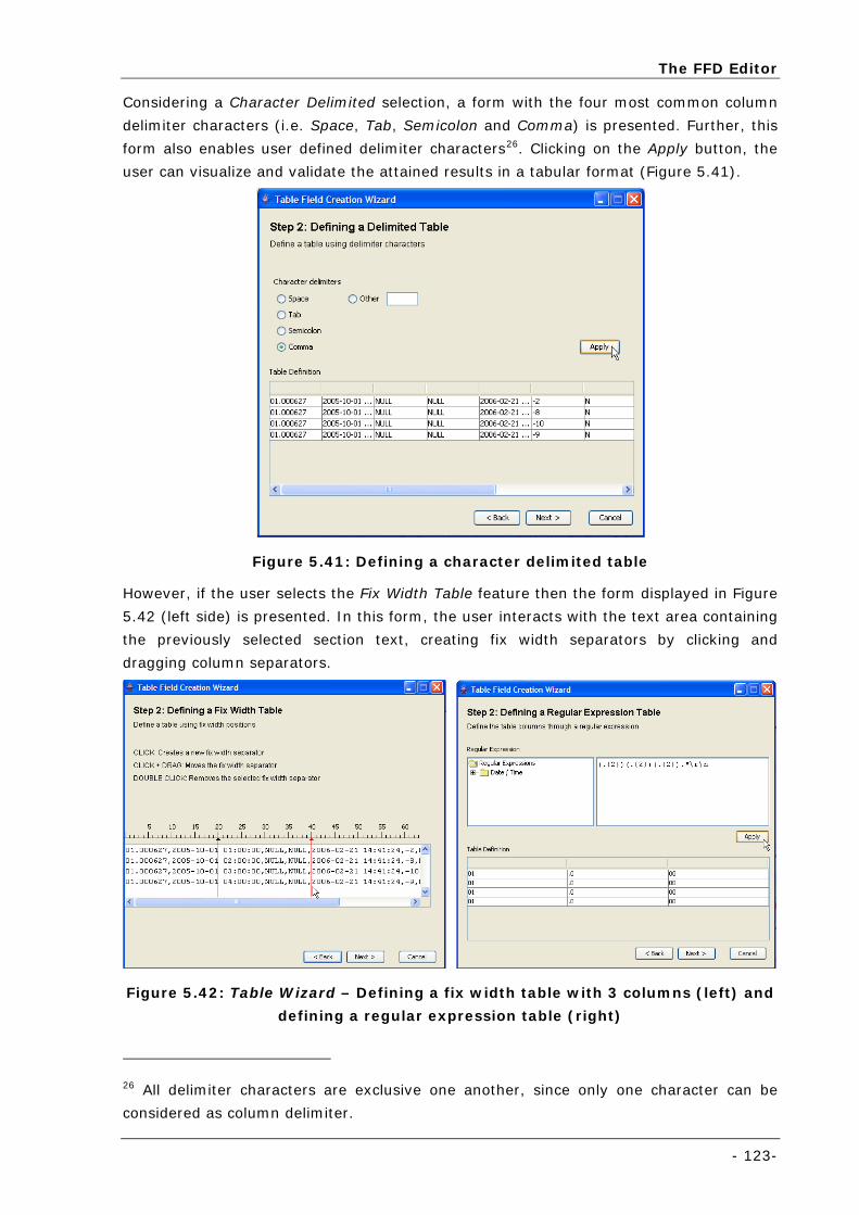
The FFD Editor
- 123-
Considering a Character Delimited selection, a form with the four most common column
delimiter characters (i.e. Space, Tab, Semicolon and Comma) is presented. Further, this
form also enables user defined delimiter characters26. Clicking on the Apply button, the
user can visualize and validate the attained results in a tabular format (Figure 5.41).
Figure 5.41: Defining a character delimited table
However, if the user selects the Fix Width Table feature then the form displayed in Figure
5.42 (left side) is presented. In this form, the user interacts with the text area containing
the previously selected section text, creating fix width separators by clicking and
dragging column separators.
Figure 5.42: Table Wizard – Defining a fix width table with 3 columns (left) and
defining a regular expression table (right)
26 All delimiter characters are exclusive one another, since only one character can be
considered as column delimiter.
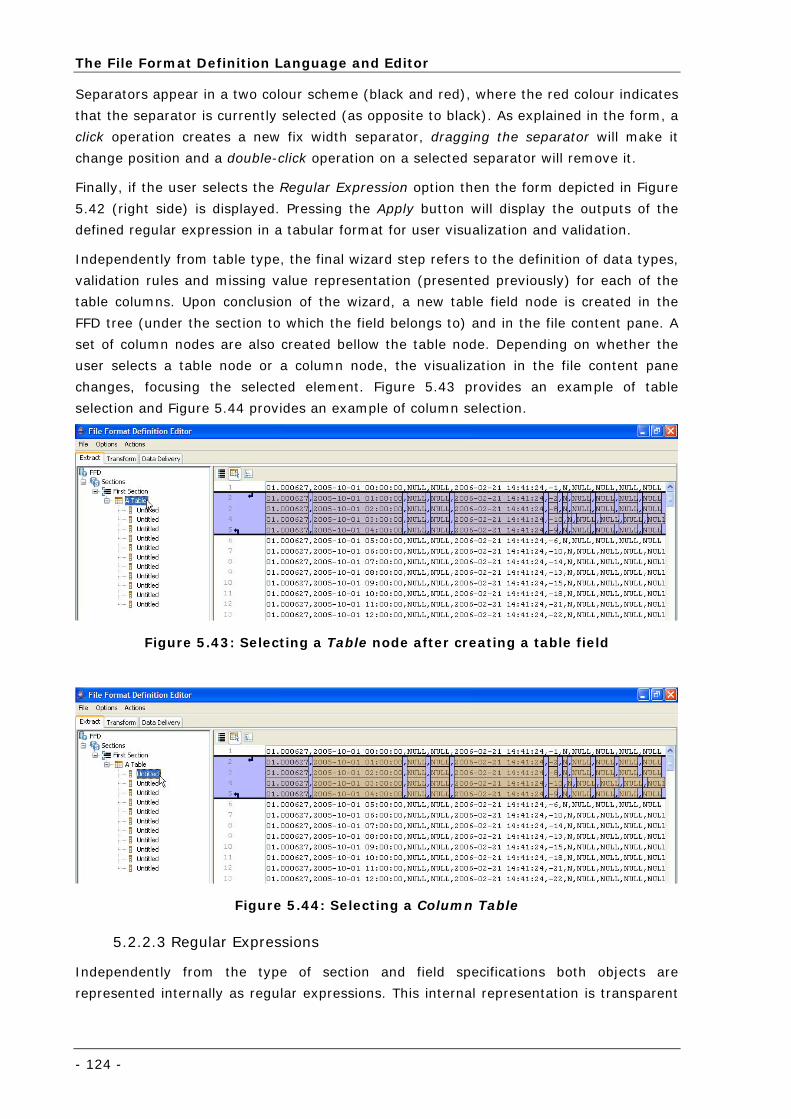
The File Format Definition Language and Editor
- 124 -
Separators appear in a two colour scheme (black and red), where the red colour indicates
that the separator is currently selected (as opposite to black). As explained in the form, a
click operation creates a new fix width separator, dragging the separator will make it
change position and a double-click operation on a selected separator will remove it.
Finally, if the user selects the Regular Expression option then the form depicted in Figure
5.42 (right side) is displayed. Pressing the Apply button will display the outputs of the
defined regular expression in a tabular format for user visualization and validation.
Independently from table type, the final wizard step refers to the definition of data types,
validation rules and missing value representation (presented previously) for each of the
table columns. Upon conclusion of the wizard, a new table field node is created in the
FFD tree (under the section to which the field belongs to) and in the file content pane. A
set of column nodes are also created bellow the table node. Depending on whether the
user selects a table node or a column node, the visualization in the file content pane
changes, focusing the selected element. Figure 5.43 provides an example of table
selection and Figure 5.44 provides an example of column selection.
Figure 5.43: Selecting a Table node after creating a table field
Figure 5.44: Selecting a Column Table
5.2.2.3 Regular Expressions
Independently from the type of section and field specifications both objects are
represented internally as regular expressions. This internal representation is transparent
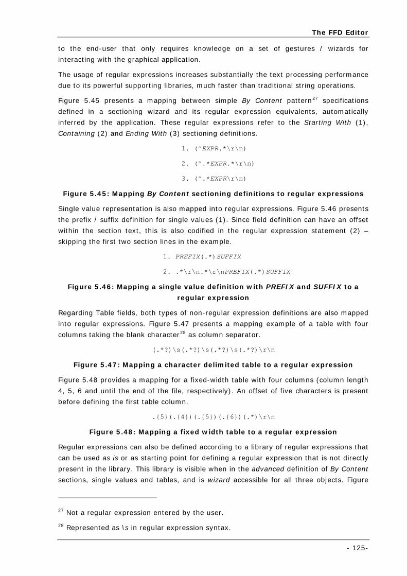
The FFD Editor
- 125-
to the end-user that only requires knowledge on a set of gestures / wizards for
interacting with the graphical application.
The usage of regular expressions increases substantially the text processing performance
due to its powerful supporting libraries, much faster than traditional string operations.
Figure 5.45 presents a mapping between simple By Content pattern27 specifications
defined in a sectioning wizard and its regular expression equivalents, automatically
inferred by the application. These regular expressions refer to the Starting With (1),
Containing (2) and Ending With (3) sectioning definitions.
1. (^EXPR.*\r\n)
2. (^.*EXPR.*\r\n)
3. (^.*EXPR\r\n)
Figure 5.45: Mapping By Content sectioning definitions to regular expressions
Single value representation is also mapped into regular expressions. Figure 5.46 presents
the prefix / suffix definition for single values (1). Since field definition can have an offset
within the section text, this is also codified in the regular expression statement (2) –
skipping the first two section lines in the example.
1. PREFIX(.*)SUFFIX
2. .*\r\n.*\r\nPREFIX(.*)SUFFIX
Figure 5.46: Mapping a single value definition with PREFIX and SUFFIX to a
regular expression
Regarding Table fields, both types of non-regular expression definitions are also mapped
into regular expressions. Figure 5.47 presents a mapping example of a table with four
columns taking the blank character28 as column separator.
(.*?)\s(.*?)\s(.*?)\s(.*?)\r\n
Figure 5.47: Mapping a character delimited table to a regular expression
Figure 5.48 provides a mapping for a fixed-width table with four columns (column length
4, 5, 6 and until the end of the file, respectively). An offset of five characters is present
before defining the first table column.
.{5}(.{4})(.{5})(.{6})(.*)\r\n
Figure 5.48: Mapping a fixed width table to a regular expression
Regular expressions can also be defined according to a library of regular expressions that
can be used as is or as starting point for defining a regular expression that is not directly
present in the library. This library is visible when in the advanced definition of By Content
sections, single values and tables, and is wizard accessible for all three objects. Figure
27 Not a regular expression entered by the user.
28 Represented as \s in regular expression syntax.
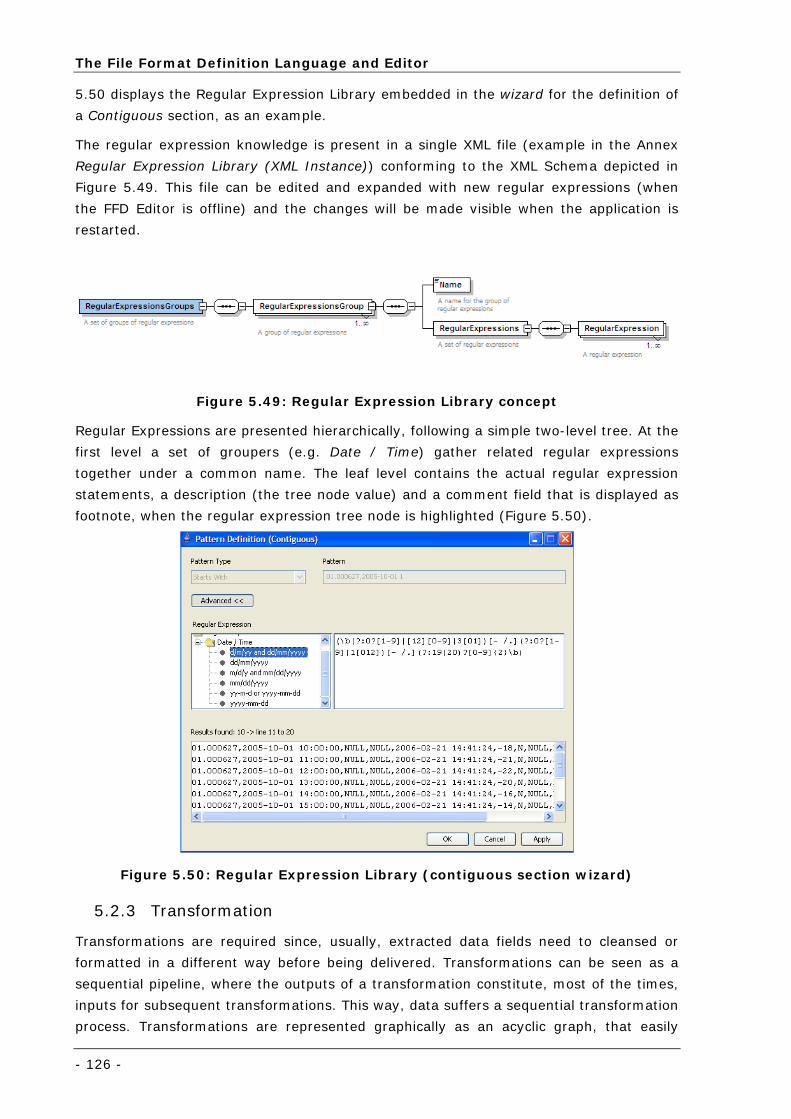
The File Format Definition Language and Editor
- 126 -
5.50 displays the Regular Expression Library embedded in the wizard for the definition of
a Contiguous section, as an example.
The regular expression knowledge is present in a single XML file (example in the Annex
Regular Expression Library (XML Instance)) conforming to the XML Schema depicted in
Figure 5.49. This file can be edited and expanded with new regular expressions (when
the FFD Editor is offline) and the changes will be made visible when the application is
restarted.
Figure 5.49: Regular Expression Library concept
Regular Expressions are presented hierarchically, following a simple two-level tree. At the
first level a set of groupers (e.g. Date / Time) gather related regular expressions
together under a common name. The leaf level contains the actual regular expression
statements, a description (the tree node value) and a comment field that is displayed as
footnote, when the regular expression tree node is highlighted (Figure 5.50).
Figure 5.50: Regular Expression Library (contiguous section wizard)
5.2.3 Transformation
Transformations are required since, usually, extracted data fields need to cleansed or
formatted in a different way before being delivered. Transformations can be seen as a
sequential pipeline, where the outputs of a transformation constitute, most of the times,
inputs for subsequent transformations. This way, data suffers a sequential transformation
process. Transformations are represented graphically as an acyclic graph, that easily
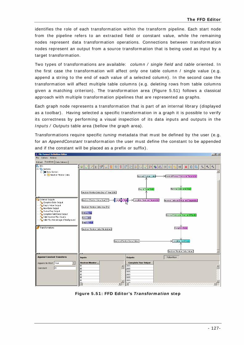
The FFD Editor
- 127-
identifies the role of each transformation within the transform pipeline. Each start node
from the pipeline refers to an extracted field or constant value, while the remaining
nodes represent data transformation operations. Connections between transformation
nodes represent an output from a source transformation that is being used as input by a
target transformation.
Two types of transformations are available: column / single field and table oriented. In
the first case the transformation will affect only one table column / single value (e.g.
append a string to the end of each value of a selected column). In the second case the
transformation will affect multiple table columns (e.g. deleting rows from table columns
given a matching criterion). The transformation area (Figure 5.51) follows a classical
approach with multiple transformation pipelines that are represented as graphs.
Each graph node represents a transformation that is part of an internal library (displayed
as a toolbar). Having selected a specific transformation in a graph it is possible to verify
its correctness by performing a visual inspection of its data inputs and outputs in the
Inputs / Outputs table area (bellow the graph area).
Transformations require specific tuning metadata that must be defined by the user (e.g.
for an AppendConstant transformation the user must define the constant to be appended
and if the constant will be placed as a prefix or suffix).
Figure 5.51: FFD Editor’s Transformation step
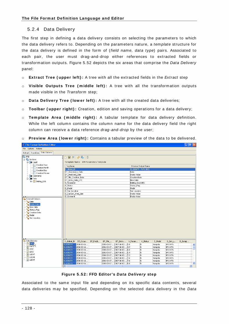
The File Format Definition Language and Editor
- 128 -
5.2.4 Data Delivery
The first step in defining a data delivery consists on selecting the parameters to which
the data delivery refers to. Depending on the parameters nature, a template structure for
the data delivery is defined in the form of (field name, data type) pairs. Associated to
each pair, the user must drag-and-drop either references to extracted fields or
transformation outputs. Figure 5.52 depicts the six areas that comprise the Data Delivery
panel:
o Extract Tree (upper left): A tree with all the extracted fields in the Extract step
o Visible Outputs Tree (middle left): A tree with all the transformation outputs
made visible in the Transform step;
o Data Delivery Tree (lower left): A tree with all the created data deliveries;
o Toolbar (upper right): Creation, edition and saving operations for a data delivery;
o Template Area (middle right): A tabular template for data delivery definition.
While the left column contains the column name for the data delivery field the right
column can receive a data reference drag-and-drop by the user;
o Preview Area (lower right): Contains a tabular preview of the data to be delivered.
Figure 5.52: FFD Editor's Data Delivery step
Associated to the same input file and depending on its specific data contents, several
data deliveries may be specified. Depending on the selected data delivery in the Data
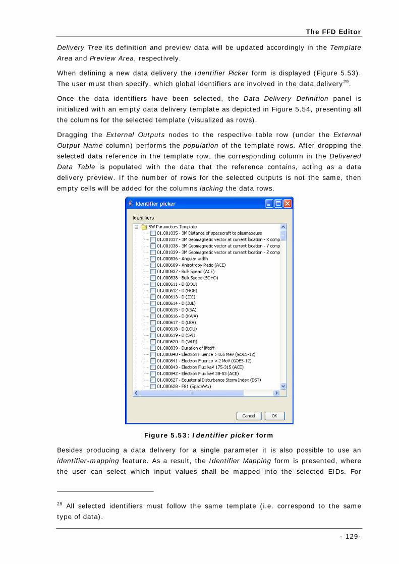
The FFD Editor
- 129-
Delivery Tree its definition and preview data will be updated accordingly in the Template
Area and Preview Area, respectively.
When defining a new data delivery the Identifier Picker form is displayed (Figure 5.53).
The user must then specify, which global identifiers are involved in the data delivery29.
Once the data identifiers have been selected, the Data Delivery Definition panel is
initialized with an empty data delivery template as depicted in Figure 5.54, presenting all
the columns for the selected template (visualized as rows).
Dragging the External Outputs nodes to the respective table row (under the External
Output Name column) performs the population of the template rows. After dropping the
selected data reference in the template row, the corresponding column in the Delivered
Data Table is populated with the data that the reference contains, acting as a data
delivery preview. If the number of rows for the selected outputs is not the same, then
empty cells will be added for the columns lacking the data rows.
Figure 5.53: Identifier picker form
Besides producing a data delivery for a single parameter it is also possible to use an
identifier-mapping feature. As a result, the Identifier Mapping form is presented, where
the user can select which input values shall be mapped into the selected EIDs. For
29 All selected identifiers must follow the same template (i.e. correspond to the same
type of data).
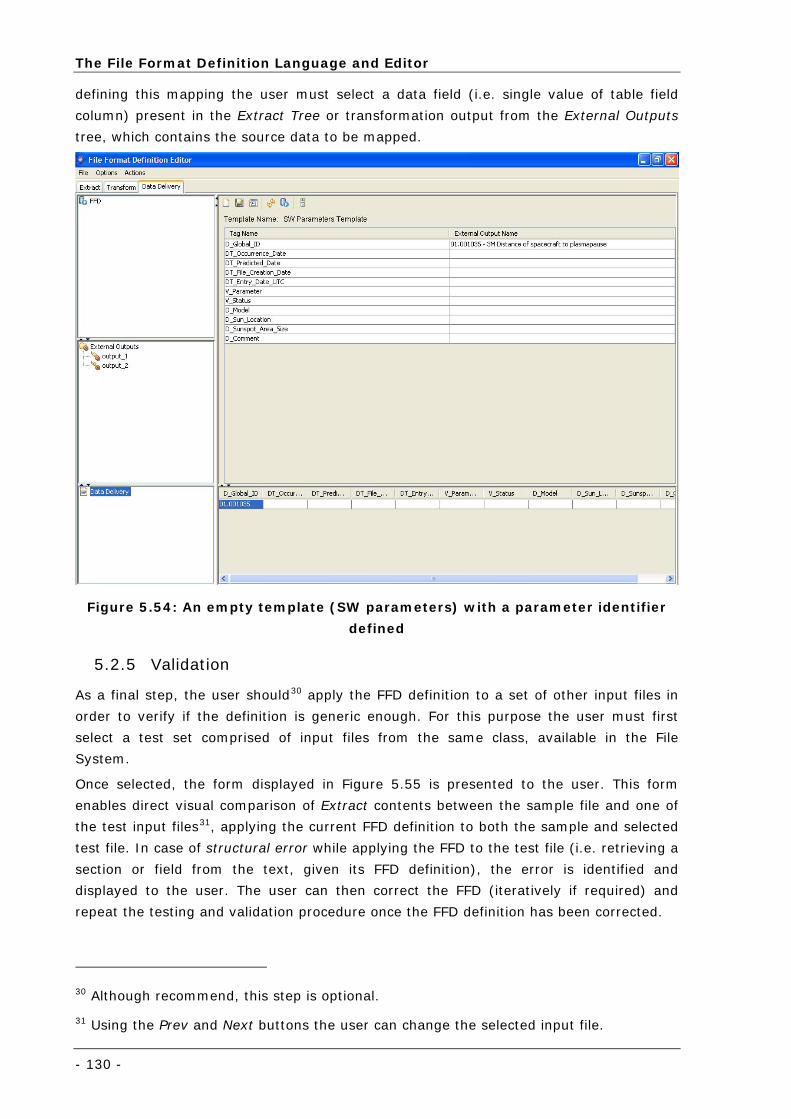
The File Format Definition Language and Editor
- 130 -
defining this mapping the user must select a data field (i.e. single value of table field
column) present in the Extract Tree or transformation output from the External Outputs
tree, which contains the source data to be mapped.
Figure 5.54: An empty template (SW parameters) with a parameter identifier
defined
5.2.5 Validation
As a final step, the user should30 apply the FFD definition to a set of other input files in
order to verify if the definition is generic enough. For this purpose the user must first
select a test set comprised of input files from the same class, available in the File
System.
Once selected, the form displayed in Figure 5.55 is presented to the user. This form
enables direct visual comparison of Extract contents between the sample file and one of
the test input files31, applying the current FFD definition to both the sample and selected
test file. In case of structural error while applying the FFD to the test file (i.e. retrieving a
section or field from the text, given its FFD definition), the error is identified and
displayed to the user. The user can then correct the FFD (iteratively if required) and
repeat the testing and validation procedure once the FFD definition has been corrected.
30 Although recommend, this step is optional.
31 Using the Prev and Next buttons the user can change the selected input file.
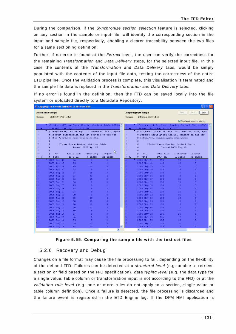
The FFD Editor
- 131-
During the comparison, if the Synchronize section selection feature is selected, clicking
on any section in the sample or input file, will identify the corresponding section in the
input and sample file, respectively, enabling a clearer traceability between the two files
for a same sectioning definition.
Further, if no error is found at the Extract level, the user can verify the correctness for
the remaining Transformation and Data Delivery steps, for the selected input file. In this
case the contents of the Transformation and Data Delivery tabs, would be simply
populated with the contents of the input file data, testing the correctness of the entire
ETD pipeline. Once the validation process is complete, this visualisation is terminated and
the sample file data is replaced in the Transformation and Data Delivery tabs.
If no error is found in the definition, then the FFD can be saved locally into the file
system or uploaded directly to a Metadata Repository.
Figure 5.55: Comparing the sample file with the test set files
5.2.6 Recovery and Debug
Changes on a file format may cause the file processing to fail, depending on the flexibility
of the defined FFD. Failures can be detected at a structural level (e.g. unable to retrieve
a section or field based on the FFD specification), data typing level (e.g. the data type for
a single value, table column or transformation input is not according to the FFD) or at the
validation rule level (e.g. one or more rules do not apply to a section, single value or
table column definition). Once a failure is detected, the file processing is discarded and
the failure event is registered in the ETD Engine log. If the DPM HMI application is
The File Format Definition Language and Editor
- 132 -
executing during the failure event, this logging information is also delivered to the
application and displayed in the ETD engine graphical log.
The FFD Editor is an active component in the recovery and debugging process. At
program start, the user is asked if the application should inspect the ETD logs since its
last execution. If affirmative, the FFD Editor processes the log files (starting from the
date the FFD Editor last processed the logging data) and if a processing error is detected,
that FFD is loaded into the application, together with the input file that raised the failure
and displayed in debug mode. In debug mode the user can inspect the faulty input file
and compare it to the sample file used in the FFD creation.
Once the FFD is corrected, a new version can be uploaded into the Metadata Repository
and the DPM HMI application can be used to perform the processing of the file in an ad-
hoc manner. Input files that have previously been downloaded but failed processing, can
then be reprocessed using the corrected FFD, which is made available via the Metadata
Repository.
5.3 Language Expressiveness and Extensibility
In the scope of the SESS system (presented in detail in section 6.2) the expressiveness
and extensibility of the ETD approach and FFD language has been put to practice in a
real-world scenario.
The metadata required for the definition of Sections and Fields were found to be simple
and sufficient for all the 62 input files encountered in the context of the system. For a
great part of them (the simplest ones) regular expression expertise was not required and
other, simpler specifications were found to be more suitable (e.g. prefix / suffix field
definition, table definition based on delimiter characters).
Data typing and validation rule mechanisms provided an added value to the FFD
specification, enabling the detection of changes in the format of input files that were not
caught at structural level time (i.e. during execution of the steps of extracting sections
and fields). The usefulness of these mechanisms was verified by three times (during the
development of the system), where format changes were detected and noisy data was
prevented from being forward to the IL layer.
Starting with an initial set of 15 transformations, due to file format needs, an extra set of
5 transformations was developed. Both the FFD language and FFD Editor application
proved to be quite easy to extend in this regard. Only a simple metadata file and two
Java classes had to be created per new transformation, for the FFD Editor and ETD
Engine to be able to recognize them and process data accordingly. No change to the FFD
language was required for the new transformations.
The data delivery metadata proved to be quite generic. In the specific case of SESS, the
FFD language was defined prior to the structural definition of the data delivery templates
that would exchange data between the ETD and IL layers. No modification to the FFD
language was required once the structure for the templates was agreed.
- 133 -
Chapter 6 Case Studies
This chapter presents how the ETD+IL thesis has been put into practice, in a
set of case studies. The presentation follows two perspectives: first the
generality and versatility of the solution is explored for dealing with data from
different domains. Second, it is explained how the Data Processing Module
has been integrated, tested and validated in an operational system for a
space domain system: SESS.
Special attention will be placed in this second approach, starting with an
overview of the SESS system objectives and the Galileo reference mission.
Then, the overall SESS architecture is described, including a summarized
explanation of all the components that have not been developed in the
context of this thesis. The final section describes how the ETD+IL approach
has been successfully applied to SESS and provides an evaluation of its
usage.
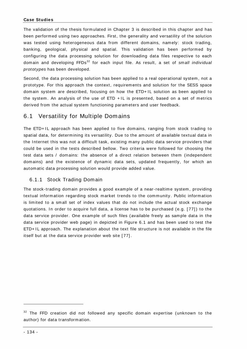
Case Studies
- 134 -
The validation of the thesis formulated in Chapter 3 is described in this chapter and has
been performed using two approaches. First, the generality and versatility of the solution
was tested using heterogeneous data from different domains, namely: stock trading,
banking, geological, physical and spatial. This validation has been performed by
configuring the data processing solution for downloading data files respective to each
domain and developing FFDs32 for each input file. As result, a set of small individual
prototypes has been developed.
Second, the data processing solution has been applied to a real operational system, not a
prototype. For this approach the context, requirements and solution for the SESS space
domain system are described, focusing on how the ETD+IL solution as been applied to
the system. An analysis of the use of ETD +IL is presented, based on a set of metrics
derived from the actual system functioning parameters and user feedback.
6.1 Versatility for Multiple Domains
The ETD+IL approach has been applied to five domains, ranging from stock trading to
spatial data, for determining its versatility. Due to the amount of available textual data in
the Internet this was not a difficult task, existing many public data service providers that
could be used in the tests described bellow. Two criteria were followed for choosing the
test data sets / domains: the absence of a direct relation between them (independent
domains) and the existence of dynamic data sets, updated frequently, for which an
automatic data processing solution would provide added value.
6.1.1 Stock Trading Domain
The stock-trading domain provides a good example of a near-realtime system, providing
textual information regarding stock market trends to the community. Public information
is limited to a small set of index values that do not include the actual stock exchange
quotations. In order to acquire full data, a license has to be purchased (e.g. [77]) to the
data service provider. One example of such files (available freely as sample data in the
data service provider web page) in depicted in Figure 6.1 and has been used to test the
ETD+IL approach. The explanation about the text file structure is not available in the file
itself but at the data service provider web site [77].
32 The FFD creation did not followed any specific domain expertise (unknown to the
author) for data transformation.
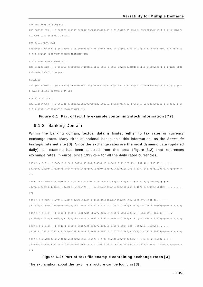
Versatility for Multiple Domains
- 135-
ABN|ABN Amro Holding N.V.
ADS|000937102|||||0.009878||37705190000|1635800000|23.05|0|23.05|23.05|23.05|1635800000|1|1|1|1|1|1|1|NYSE|
US0009371024|20040310|NL|USD
AEG|Aegon N.V. Ord
Shares|007924103|||||0.005017||19150809543.7776|1514377800|14.32|0|14.32|14.32|14.32|1514377800|1|0.8831|1|
1|1|1|1|NYSE|US0079241032|20040310|NL|USD
AIB|Allied Irish Banks PLC
ADS|019228402|||||0.003357||12816008574|845941160|30.3|0|30.3|30.3|30.3|845941160|1|1|0.5|1|1|1|1|NYSE|US01
92284026|20040310|IE|USD
AL|Alcan
Inc.|013716105|||||0.004335||16548947877.28|366695056|45.13|0|45.13|45.13|45.13|366695056|1|1|1|1|1|1|1|NYS
E|CA0137161059|20040310|CA|USD
ALA|Alcatel S.A.
ADS|013904305|||||0.005121||19548332381.05955|1284301318|17.02|0|17.02|17.02|17.02|1284301318|1|0.8943|1|1|
1|1|1|NYSE|US0139043055|20040310|FR|USD
Figure 6.1: Part of text file example containing stock information [77]
6.1.2 Banking Domain
Within the banking domain, textual data is limited either to tax rates or currency
exchange rates. Many sites of national banks hold this information, as the Banco de
Portugal Internet site [3]. Since the exchange rates are the most dynamic data (updated
daily), an example has been selected from this area (Figure 6.2) that references
exchange rates, in euros, since 1999-1-4 for all the daily rated currencies.
1999-1-4;1.91;-;1.8004;1.6168;0.58231;35.107;7.4501;15.6466;0.7111;327.15;-;251.48;-;133.73;-;-;-;-
;8.855;2.2229;4.0712;-;9.4696;-;189.045;-;-;1.1789;6.9358;1.4238;110.265;9.4067;244.383;1.19679;-;-;-;-;-;-
;-;
1999-1-5;1.8944;-;1.7965;1.6123;0.5823;34.917;7.4495;15.6466;0.7122;324.7;-;250.8;-;130.96;-;-;-;-
;8.7745;2.2011;4.0245;-;9.4025;-;188.775;-;-;1.179;6.7975;1.4242;110.265;9.4077;242.809;1.20125;-;-;-;-;-;-
;-;
1999-1-6;1.882;-;1.7711;1.6116;0.582;34.85;7.4452;15.6466;0.7076;324.72;-;250.67;-;131.42;-;-;-;-
;8.7335;2.189;4.0065;-;9.305;-;188.7;-;-;1.1743;6.7307;1.4204;110.265;9.3712;244.258;1.20388;-;-;-;-;-;-;-;
1999-1-7;1.8474;-;1.7602;1.6165;0.58187;34.886;7.4431;15.6466;0.70585;324.4;-;250.09;-;129.43;-;-;-;-
;8.6295;2.1531;4.0165;-;9.18;-;188.8;-;-;1.1632;6.8283;1.4074;110.265;9.2831;247.089;1.21273;-;-;-;-;-;-;-;
1999-1-8;1.8406;-;1.7643;1.6138;0.58187;34.938;7.4433;15.6466;0.7094;324;-;250.15;-;130.09;-;-;-;-
;8.59;2.1557;4.0363;-;9.165;-;188.84;-;-;1.1659;6.7855;1.4107;110.265;9.3043;249.293;1.20736;-;-;-;-;-;-;-;
1999-1-11;1.8134;-;1.7463;1.6104;0.58167;35.173;7.4433;15.6466;0.7044;323.4;-;249.7;-;126.33;-;-;-;-
;8.5585;2.1257;4.032;-;9.0985;-;188.9655;-;-;1.1569;6.791;1.4005;110.265;9.2329;251.013;1.22081;-;-;-;-;-;-
;-;
Figure 6.2: Part of text file example containing exchange rates [3]
The explanation about the text file structure can be found in [3].
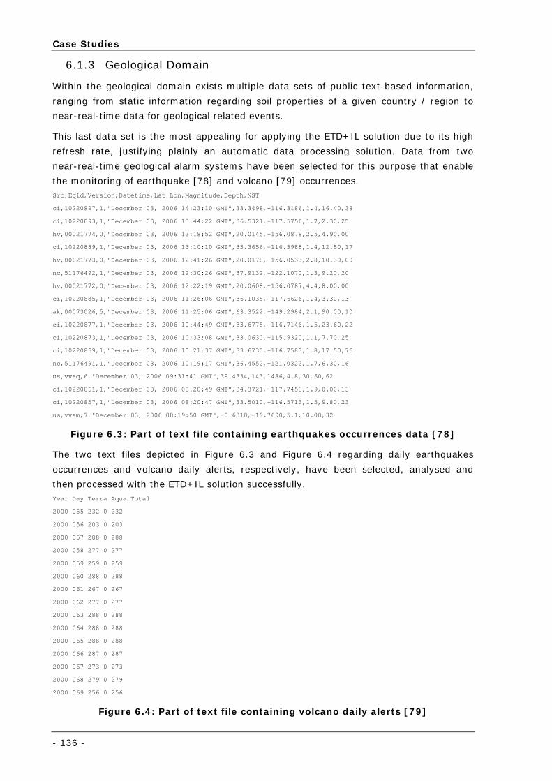
Case Studies
- 136 -
6.1.3 Geological Domain
Within the geological domain exists multiple data sets of public text-based information,
ranging from static information regarding soil properties of a given country / region to
near-real-time data for geological related events.
This last data set is the most appealing for applying the ETD+IL solution due to its high
refresh rate, justifying plainly an automatic data processing solution. Data from two
near-real-time geological alarm systems have been selected for this purpose that enable
the monitoring of earthquake [78] and volcano [79] occurrences. Src,Eqid,Version,Datetime,Lat,Lon,Magnitude,Depth,NST
ci,10220897,1,"December 03, 2006 14:23:10 GMT",33.3498,-116.3186,1.4,16.40,38
ci,10220893,1,"December 03, 2006 13:44:22 GMT",36.5321,-117.5756,1.7,2.30,25
hv,00021774,0,"December 03, 2006 13:18:52 GMT",20.0145,-156.0878,2.5,4.90,00
ci,10220889,1,"December 03, 2006 13:10:10 GMT",33.3656,-116.3988,1.4,12.50,17
hv,00021773,0,"December 03, 2006 12:41:26 GMT",20.0178,-156.0533,2.8,10.30,00
nc,51176492,1,"December 03, 2006 12:30:26 GMT",37.9132,-122.1070,1.3,9.20,20
hv,00021772,0,"December 03, 2006 12:22:19 GMT",20.0608,-156.0787,4.4,8.00,00
ci,10220885,1,"December 03, 2006 11:26:06 GMT",36.1035,-117.6626,1.4,3.30,13
ak,00073026,5,"December 03, 2006 11:25:06 GMT",63.3522,-149.2984,2.1,90.00,10
ci,10220877,1,"December 03, 2006 10:44:49 GMT",33.6775,-116.7146,1.5,23.60,22
ci,10220873,1,"December 03, 2006 10:33:08 GMT",33.0630,-115.9320,1.1,7.70,25
ci,10220869,1,"December 03, 2006 10:21:37 GMT",33.6730,-116.7583,1.8,17.50,76
nc,51176491,1,"December 03, 2006 10:19:17 GMT",36.4552,-121.0322,1.7,6.30,16
us,vvaq,6,"December 03, 2006 09:31:41 GMT",39.4334,143.1486,4.8,30.60,62
ci,10220861,1,"December 03, 2006 08:20:49 GMT",34.3721,-117.7458,1.9,0.00,13
ci,10220857,1,"December 03, 2006 08:20:47 GMT",33.5010,-116.5713,1.5,9.80,23
us,vvam,7,"December 03, 2006 08:19:50 GMT",-0.6310,-19.7690,5.1,10.00,32
Figure 6.3: Part of text file containing earthquakes occurrences data [78]
The two text files depicted in Figure 6.3 and Figure 6.4 regarding daily earthquakes
occurrences and volcano daily alerts, respectively, have been selected, analysed and
then processed with the ETD+IL solution successfully. Year Day Terra Aqua Total
2000 055 232 0 232
2000 056 203 0 203
2000 057 288 0 288
2000 058 277 0 277
2000 059 259 0 259
2000 060 288 0 288
2000 061 267 0 267
2000 062 277 0 277
2000 063 288 0 288
2000 064 288 0 288
2000 065 288 0 288
2000 066 287 0 287
2000 067 273 0 273
2000 068 279 0 279
2000 069 256 0 256
Figure 6.4: Part of text file containing volcano daily alerts [79]
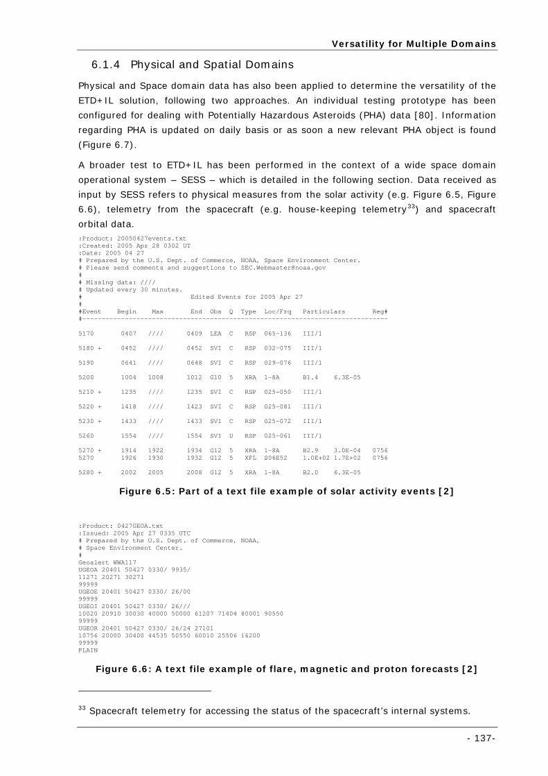
Versatility for Multiple Domains
- 137-
6.1.4 Physical and Spatial Domains
Physical and Space domain data has also been applied to determine the versatility of the
ETD+IL solution, following two approaches. An individual testing prototype has been
configured for dealing with Potentially Hazardous Asteroids (PHA) data [80]. Information
regarding PHA is updated on daily basis or as soon a new relevant PHA object is found
(Figure 6.7).
A broader test to ETD+IL has been performed in the context of a wide space domain
operational system – SESS – which is detailed in the following section. Data received as
input by SESS refers to physical measures from the solar activity (e.g. Figure 6.5, Figure
6.6), telemetry from the spacecraft (e.g. house-keeping telemetry33) and spacecraft
orbital data. :Product: 20050427events.txt :Created: 2005 Apr 28 0302 UT :Date: 2005 04 27 # Prepared by the U.S. Dept. of Commerce, NOAA, Space Environment Center. # Please send comments and suggestions to [email protected] # # Missing data: //// # Updated every 30 minutes. # Edited Events for 2005 Apr 27 # #Event Begin Max End Obs Q Type Loc/Frq Particulars Reg# #------------------------------------------------------------------------------- 5170 0407 //// 0409 LEA C RSP 065-136 III/1 5180 + 0452 //// 0452 SVI C RSP 032-075 III/1 5190 0641 //// 0648 SVI C RSP 029-076 III/1 5200 1004 1008 1012 G10 5 XRA 1-8A B1.4 6.3E-05 5210 + 1235 //// 1235 SVI C RSP 025-050 III/1 5220 + 1418 //// 1423 SVI C RSP 025-081 III/1 5230 + 1433 //// 1433 SVI C RSP 025-072 III/1 5260 1554 //// 1554 SVI U RSP 025-061 III/1 5270 + 1914 1922 1934 G12 5 XRA 1-8A B2.9 3.0E-04 0756 5270 1926 1930 1932 G12 5 XFL S06E52 1.0E+02 1.7E+02 0756 5280 + 2002 2005 2008 G12 5 XRA 1-8A B2.0 6.3E-05
Figure 6.5: Part of a text file example of solar activity events [2]
:Product: 0427GEOA.txt :Issued: 2005 Apr 27 0335 UTC # Prepared by the U.S. Dept. of Commerce, NOAA, # Space Environment Center. # Geoalert WWA117 UGEOA 20401 50427 0330/ 9935/ 11271 20271 30271 99999 UGEOE 20401 50427 0330/ 26/00 99999 UGEOI 20401 50427 0330/ 26/// 10020 20910 30030 40000 50000 61207 71404 80001 90550 99999 UGEOR 20401 50427 0330/ 26/24 27101 10756 20000 30400 44535 50550 60010 25506 16200 99999 PLAIN
Figure 6.6: A text file example of flare, magnetic and proton forecasts [2]
33 Spacecraft telemetry for accessing the status of the spacecraft’s internal systems.
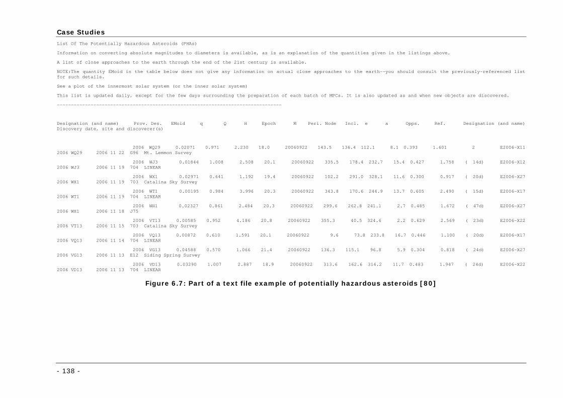
Case Studies
- 138 -
List Of The Potentially Hazardous Asteroids (PHAs)
Information on converting absolute magnitudes to diameters is available, as is an explanation of the quantities given in the listings above.
A list of close approaches to the earth through the end of the 21st century is available.
NOTE:The quantity EMoid in the table below does not give any information on actual close approaches to the earth--you should consult the previously-referenced list for such details.
See a plot of the innermost solar system (or the inner solar system)
This list is updated daily, except for the few days surrounding the preparation of each batch of MPCs. It is also updated as and when new objects are discovered.
--------------------------------------------------------------------------------
Designation (and name) Prov. Des. EMoid q Q H Epoch M Peri. Node Incl. e a Opps. Ref. Designation (and name) Discovery date, site and discoverer(s)
2006 WQ29 0.02071 0.971 2.230 18.0 20060922 143.5 136.4 112.1 8.1 0.393 1.601 2 E2006-X11 2006 WQ29 2006 11 22 G96 Mt. Lemmon Survey
2006 WJ3 0.01844 1.008 2.508 20.1 20060922 335.5 178.4 232.7 15.4 0.427 1.758 ( 14d) E2006-X12 2006 WJ3 2006 11 19 704 LINEAR
2006 WX1 0.02971 0.641 1.192 19.4 20060922 102.2 291.0 328.1 11.6 0.300 0.917 ( 20d) E2006-X27 2006 WX1 2006 11 19 703 Catalina Sky Survey
2006 WT1 0.00195 0.984 3.996 20.3 20060922 343.8 170.6 244.9 13.7 0.605 2.490 ( 15d) E2006-X17 2006 WT1 2006 11 19 704 LINEAR
2006 WH1 0.02327 0.861 2.484 20.3 20060922 299.6 262.8 241.1 2.7 0.485 1.672 ( 47d) E2006-X27 2006 WH1 2006 11 18 J75
2006 VT13 0.00585 0.952 4.186 20.8 20060922 355.3 40.5 324.6 2.2 0.629 2.569 ( 23d) E2006-X22 2006 VT13 2006 11 15 703 Catalina Sky Survey
2006 VQ13 0.00872 0.610 1.591 20.1 20060922 9.6 73.8 233.8 16.7 0.446 1.100 ( 20d) E2006-X17 2006 VQ13 2006 11 14 704 LINEAR
2006 VG13 0.04588 0.570 1.066 21.4 20060922 136.3 115.1 96.8 5.9 0.304 0.818 ( 24d) E2006-X27 2006 VG13 2006 11 13 E12 Siding Spring Survey
2006 VD13 0.03290 1.007 2.887 18.9 20060922 313.6 162.6 314.2 11.7 0.483 1.947 ( 24d) E2006-X22 2006 VD13 2006 11 13 704 LINEAR
Figure 6.7: Part of a text file example of potentially hazardous asteroids [80]
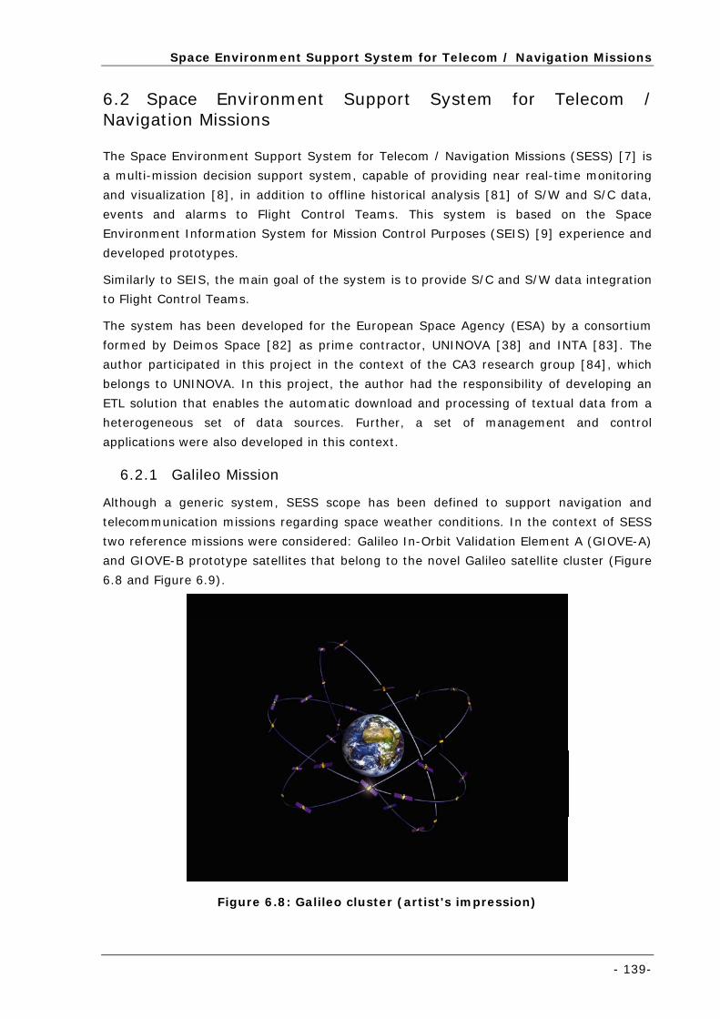
Space Environment Support System for Telecom / Navigation Missions
- 139-
6.2 Space Environment Support System for Telecom / Navigation Missions
The Space Environment Support System for Telecom / Navigation Missions (SESS) [7] is
a multi-mission decision support system, capable of providing near real-time monitoring
and visualization [8], in addition to offline historical analysis [81] of S/W and S/C data,
events and alarms to Flight Control Teams. This system is based on the Space
Environment Information System for Mission Control Purposes (SEIS) [9] experience and
developed prototypes.
Similarly to SEIS, the main goal of the system is to provide S/C and S/W data integration
to Flight Control Teams.
The system has been developed for the European Space Agency (ESA) by a consortium
formed by Deimos Space [82] as prime contractor, UNINOVA [38] and INTA [83]. The
author participated in this project in the context of the CA3 research group [84], which
belongs to UNINOVA. In this project, the author had the responsibility of developing an
ETL solution that enables the automatic download and processing of textual data from a
heterogeneous set of data sources. Further, a set of management and control
applications were also developed in this context.
6.2.1 Galileo Mission
Although a generic system, SESS scope has been defined to support navigation and
telecommunication missions regarding space weather conditions. In the context of SESS
two reference missions were considered: Galileo In-Orbit Validation Element A (GIOVE-A)
and GIOVE-B prototype satellites that belong to the novel Galileo satellite cluster (Figure
6.8 and Figure 6.9).
Figure 6.8: Galileo cluster (artist's impression)
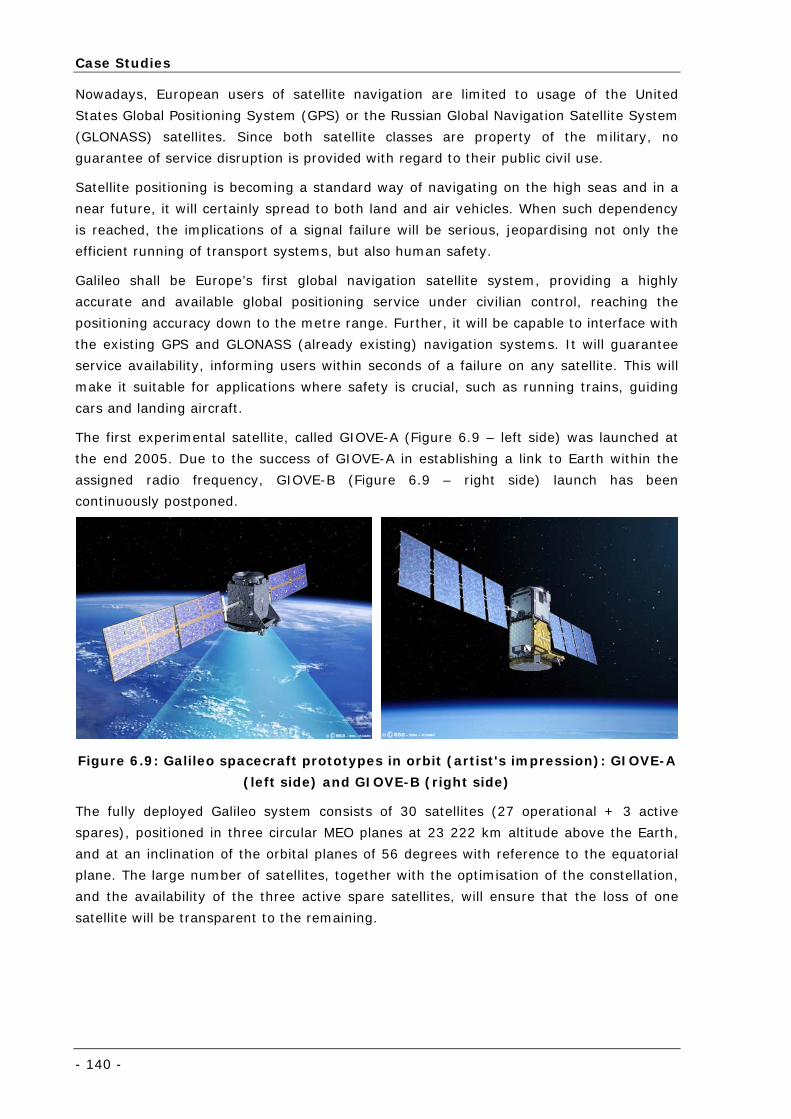
Case Studies
- 140 -
Nowadays, European users of satellite navigation are limited to usage of the United
States Global Positioning System (GPS) or the Russian Global Navigation Satellite System
(GLONASS) satellites. Since both satellite classes are property of the military, no
guarantee of service disruption is provided with regard to their public civil use.
Satellite positioning is becoming a standard way of navigating on the high seas and in a
near future, it will certainly spread to both land and air vehicles. When such dependency
is reached, the implications of a signal failure will be serious, jeopardising not only the
efficient running of transport systems, but also human safety.
Galileo shall be Europe’s first global navigation satellite system, providing a highly
accurate and available global positioning service under civilian control, reaching the
positioning accuracy down to the metre range. Further, it will be capable to interface with
the existing GPS and GLONASS (already existing) navigation systems. It will guarantee
service availability, informing users within seconds of a failure on any satellite. This will
make it suitable for applications where safety is crucial, such as running trains, guiding
cars and landing aircraft.
The first experimental satellite, called GIOVE-A (Figure 6.9 – left side) was launched at
the end 2005. Due to the success of GIOVE-A in establishing a link to Earth within the
assigned radio frequency, GIOVE-B (Figure 6.9 – right side) launch has been
continuously postponed.
Figure 6.9: Galileo spacecraft prototypes in orbit (artist's impression): GIOVE-A
(left side) and GIOVE-B (right side)
The fully deployed Galileo system consists of 30 satellites (27 operational + 3 active
spares), positioned in three circular MEO planes at 23 222 km altitude above the Earth,
and at an inclination of the orbital planes of 56 degrees with reference to the equatorial
plane. The large number of satellites, together with the optimisation of the constellation,
and the availability of the three active spare satellites, will ensure that the loss of one
satellite will be transparent to the remaining.
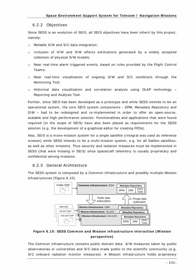
Space Environment Support System for Telecom / Navigation Missions
- 141-
6.2.2 Objectives
Since SESS is an evolution of SEIS, all SEIS objectives have been inherit by this project,
namely:
o Reliable S/W and S/C data integration;
o Inclusion of S/W and S/W effects estimations generated by a widely accepted
collection of physical S/W models;
o Near real-time alarm triggered events, based on rules provided by the Flight Control
Teams;
o Near real-time visualization of ongoing S/W and S/C conditions through the
Monitoring Tool;
o Historical data visualization and correlation analysis using OLAP technology –
Reporting and Analysis Tool.
Further, since SEIS has been developed as a prototype and while SESS intends to be an
operational system, the core SEIS system components - DPM, Metadata Repository and
DIM – had to be redesigned and re-implemented in order to offer an open-source,
scalable and high performance solution. Functionalities and applications that were found
required (in the scope of SEIS) have also been placed as requirements for the SESS
solution (e.g. the development of a graphical editor for creating FFDs).
Also, SEIS is a mono-mission system for a single satellite (Integral was used as reference
mission) while SESS intends to be a multi-mission system, e.g. for all Galileo satellites,
as well as other missions. Thus security and isolation measures must be implemented in
SESS (that were missing in SEIS) since spacecraft telemetry is usually proprietary and
confidential among missions.
6.2.3 General Architecture
The SESS system is composed by a Common infrastructure and possibly multiple Mission
infrastructures (Figure 6.10).
Mission Infrastructure: XMM Metadata Repository
DPM DIM ClientTools
Mission Infrastructure: TELSAT Metadata Repository
DPM DIM ClientTools
Common Infrastructure: ESA
Mission Infrastructure: GALILEO
Public datasubscription
Private datapublication
XMM DSP
TELSAT DSP
GALILEO DSP
Metadata Repository
DPM DIM ClientTools
Metadata Repository
DPM DIM ClientTools
Public DSP
Figure 6.10: SESS Common and Mission infrastructure interaction (Mission
perspective)
The Common infrastructure contains public domain data: S/W measures taken by public
observatories or universities and S/C data made public to the scientific community (e.g.
S/C onboard radiation monitor measures). A Mission infrastructure holds proprietary
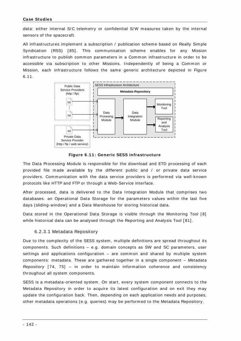
Case Studies
- 142 -
data: either internal S/C telemetry or confidential S/W measures taken by the internal
sensors of the spacecraft.
All infrastructures implement a subscription / publication scheme based on Really Simple
Syndication (RSS) [85]. This communication scheme enables for any Mission
infrastructure to publish common parameters in a Common infrastructure in order to be
accessible via subscription to other Missions. Independently of being a Common or
Mission, each infrastructure follows the same generic architecture depicted in Figure
6.11.
SESS Infrastructure Architecture
DataProcesing
Module
DataIntegration
Module
MonitoringTool
Reportingand
AnalysisTool
Metadata Repository
Public DataService Providers
(http / ftp)
txt
txt
...
Private DataService Provider
(http / ftp / web service)
txt
Figure 6.11: Generic SESS infrastructure
The Data Processing Module is responsible for the download and ETD processing of each
provided file made available by the different public and / or private data service
providers. Communication with the data service providers is performed via well-known
protocols like HTTP and FTP or through a Web-Service interface.
After processed, data is delivered to the Data Integration Module that comprises two
databases: an Operational Data Storage for the parameters values within the last five
days (sliding-window) and a Data Warehouse for storing historical data.
Data stored in the Operational Data Storage is visible through the Monitoring Tool [8]
while historical data can be analysed through the Reporting and Analysis Tool [81].
6.2.3.1 Metadata Repository
Due to the complexity of the SESS system, multiple definitions are spread throughout its
components. Such definitions – e.g. domain concepts as SW and SC parameters, user
settings and applications configuration – are common and shared by multiple system
components: metadata. These are gathered together in a single component – Metadata
Repository [74, 75] – in order to maintain information coherence and consistency
throughout all system components.
SESS is a metadata-oriented system. On start, every system component connects to the
Metadata Repository in order to acquire its latest configuration and on exit they may
update the configuration back. Then, depending on each application needs and purposes,
other metadata operations (e.g. queries) may be performed to the Metadata Repository.
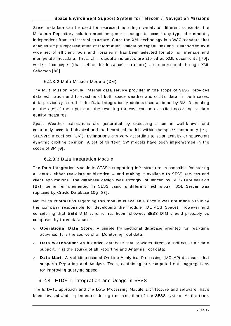
Space Environment Support System for Telecom / Navigation Missions
- 143-
Since metadata can be used for representing a high variety of different concepts, the
Metadata Repository solution must be generic enough to accept any type of metadata,
independent from its internal structure. Since the XML technology is a W3C standard that
enables simple representation of information, validation capabilities and is supported by a
wide set of efficient tools and libraries it has been selected for storing, manage and
manipulate metadata. Thus, all metadata instances are stored as XML documents [70],
while all concepts (that define the instance’s structure) are represented through XML
Schemas [86].
6.2.3.2 Multi Mission Module (3M)
The Multi Mission Module, internal data service provider in the scope of SESS, provides
data estimation and forecasting of both space weather and orbital data. In both cases,
data previously stored in the Data Integration Module is used as input by 3M. Depending
on the age of the input data the resulting forecast can be classified according to data
quality measures.
Space Weather estimations are generated by executing a set of well-known and
commonly accepted physical and mathematical models within the space community (e.g.
SPENVIS model set [36]). Estimations can vary according to solar activity or spacecraft
dynamic orbiting position. A set of thirteen SW models have been implemented in the
scope of 3M [9].
6.2.3.3 Data Integration Module
The Data Integration Module is SESS’s supporting infrastructure, responsible for storing
all data - either real-time or historical – and making it available to SESS services and
client applications. The database design was strongly influenced by SEIS DIM solution
[87], being reimplemented in SESS using a different technology: SQL Server was
replaced by Oracle Database 10g [88].
Not much information regarding this module is available since it was not made public by
the company responsible for developing the module (DEIMOS Space). However and
considering that SEIS DIM scheme has been followed, SESS DIM should probably be
composed by three databases:
o Operational Data Store: A simple transactional database oriented for real-time
activities. It is the source of all Monitoring Tool data;
o Data Warehouse: An historical database that provides direct or indirect OLAP data
support. It is the source of all Reporting and Analysis Tool data;
o Data Mart: A Multidimensional On-Line Analytical Processing (MOLAP) database that
supports Reporting and Analysis Tools, containing pre-computed data aggregations
for improving querying speed.
6.2.4 ETD+IL Integration and Usage in SESS
The ETD+IL approach and the Data Processing Module architecture and software, have
been devised and implemented during the execution of the SESS system. At the time,
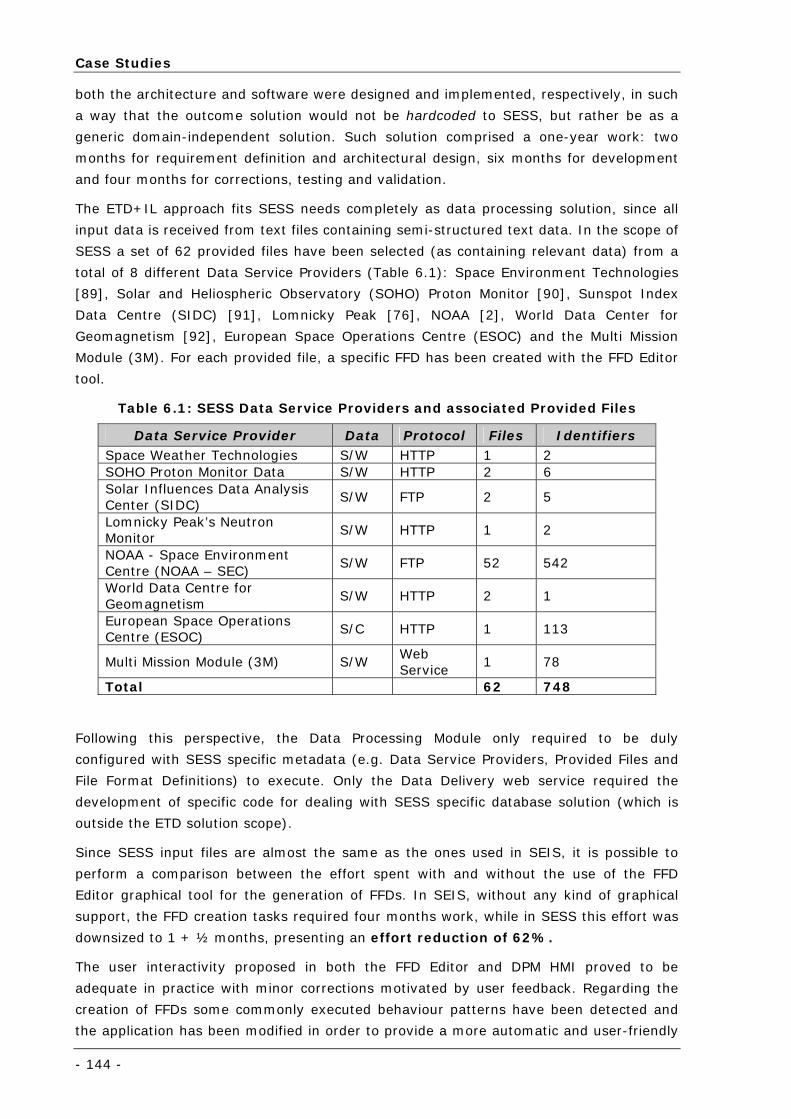
Case Studies
- 144 -
both the architecture and software were designed and implemented, respectively, in such
a way that the outcome solution would not be hardcoded to SESS, but rather be as a
generic domain-independent solution. Such solution comprised a one-year work: two
months for requirement definition and architectural design, six months for development
and four months for corrections, testing and validation.
The ETD+IL approach fits SESS needs completely as data processing solution, since all
input data is received from text files containing semi-structured text data. In the scope of
SESS a set of 62 provided files have been selected (as containing relevant data) from a
total of 8 different Data Service Providers (Table 6.1): Space Environment Technologies
[89], Solar and Heliospheric Observatory (SOHO) Proton Monitor [90], Sunspot Index
Data Centre (SIDC) [91], Lomnicky Peak [76], NOAA [2], World Data Center for
Geomagnetism [92], European Space Operations Centre (ESOC) and the Multi Mission
Module (3M). For each provided file, a specific FFD has been created with the FFD Editor
tool.
Table 6.1: SESS Data Service Providers and associated Provided Files
Data Service Provider Data Protocol Files Identifiers Space Weather Technologies S/W HTTP 1 2 SOHO Proton Monitor Data S/W HTTP 2 6 Solar Influences Data Analysis Center (SIDC)
S/W FTP 2 5
Lomnicky Peak’s Neutron Monitor
S/W HTTP 1 2
NOAA - Space Environment Centre (NOAA – SEC)
S/W FTP 52 542
World Data Centre for Geomagnetism
S/W HTTP 2 1
European Space Operations Centre (ESOC)
S/C HTTP 1 113
Multi Mission Module (3M) S/W Web Service
1 78
Total 62 748
Following this perspective, the Data Processing Module only required to be duly
configured with SESS specific metadata (e.g. Data Service Providers, Provided Files and
File Format Definitions) to execute. Only the Data Delivery web service required the
development of specific code for dealing with SESS specific database solution (which is
outside the ETD solution scope).
Since SESS input files are almost the same as the ones used in SEIS, it is possible to
perform a comparison between the effort spent with and without the use of the FFD
Editor graphical tool for the generation of FFDs. In SEIS, without any kind of graphical
support, the FFD creation tasks required four months work, while in SESS this effort was
downsized to 1 + ½ months, presenting an effort reduction of 62%.
The user interactivity proposed in both the FFD Editor and DPM HMI proved to be
adequate in practice with minor corrections motivated by user feedback. Regarding the
creation of FFDs some commonly executed behaviour patterns have been detected and
the application has been modified in order to provide a more automatic and user-friendly
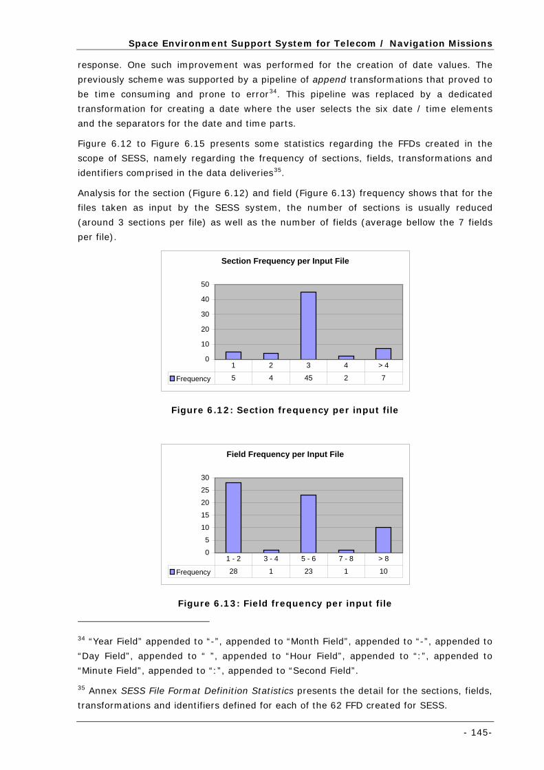
Space Environment Support System for Telecom / Navigation Missions
- 145-
response. One such improvement was performed for the creation of date values. The
previously scheme was supported by a pipeline of append transformations that proved to
be time consuming and prone to error34. This pipeline was replaced by a dedicated
transformation for creating a date where the user selects the six date / time elements
and the separators for the date and time parts.
Figure 6.12 to Figure 6.15 presents some statistics regarding the FFDs created in the
scope of SESS, namely regarding the frequency of sections, fields, transformations and
identifiers comprised in the data deliveries35.
Analysis for the section (Figure 6.12) and field (Figure 6.13) frequency shows that for the
files taken as input by the SESS system, the number of sections is usually reduced
(around 3 sections per file) as well as the number of fields (average bellow the 7 fields
per file).
Section Frequency per Input File
0
10
20
30
40
50
Frequency 5 4 45 2 7
1 2 3 4 > 4
Figure 6.12: Section frequency per input file
Field Frequency per Input File
0
5
10
15
20
25
30
Frequency 28 1 23 1 10
1 - 2 3 - 4 5 - 6 7 - 8 > 8
Figure 6.13: Field frequency per input file
34 “Year Field” appended to “-”, appended to “Month Field”, appended to “-”, appended to
“Day Field”, appended to “ ”, appended to “Hour Field”, appended to “:”, appended to
“Minute Field”, appended to “:”, appended to “Second Field”.
35 Annex SESS File Format Definition Statistics presents the detail for the sections, fields,
transformations and identifiers defined for each of the 62 FFD created for SESS.
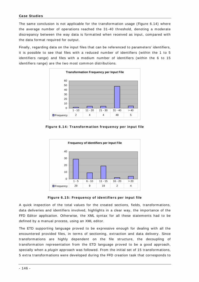
Case Studies
- 146 -
The same conclusion is not applicable for the transformation usage (Figure 6.14) where
the average number of operations reached the 31-40 threshold, denoting a moderate
discrepancy between the way data is formatted when received as input, compared with
the data format required for output.
Finally, regarding data on the input files that can be referenced to parameters’ identifiers,
it is possible to see that files with a reduced number of identifiers (within the 1 to 5
identifiers range) and files with a medium number of identifiers (within the 6 to 15
identifiers range) are the two most common distributions.
Transformation Frequency per Input File
0
10
20
30
40
50
60
Frequency 2 4 4 48 5
1 - 10 11 - 20 21 - 30 31 - 40 > 40
Figure 6.14: Transformation frequency per input file
Frequency of Identifiers per Input File
0
10
20
30
40
Frequency 29 9 19 2 4
1 - 5 6 - 10 11 - 15 16 - 20 > 20
Figure 6.15: Frequency of identifiers per input file
A quick inspection of the total values for the created sections, fields, transformations,
data deliveries and identifiers involved, highlights in a clear way, the importance of the
FFD Editor application. Otherwise, the XML syntax for all these statements had to be
defined by a manual process, using an XML editor.
The ETD supporting language proved to be expressive enough for dealing with all the
encountered provided files, in terms of sectioning, extraction and data delivery. Since
transformations are highly dependent on the file structure, the decoupling of
transformation representation from the ETD language proved to be a good approach,
specially when a plugin approach was followed. From the initial set of 15 transformations,
5 extra transformations were developed during the FFD creation task that corresponds to
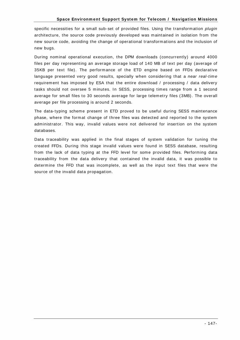
Space Environment Support System for Telecom / Navigation Missions
- 147-
specific necessities for a small sub-set of provided files. Using the transformation plugin
architecture, the source code previously developed was maintained in isolation from the
new source code, avoiding the change of operational transformations and the inclusion of
new bugs.
During nominal operational execution, the DPM downloads (concurrently) around 4000
files per day representing an average storage load of 140 MB of text per day (average of
35KB per text file). The performance of the ETD engine based on FFDs declarative
language presented very good results, specially when considering that a near real-time
requirement has imposed by ESA that the entire download / processing / data delivery
tasks should not oversee 5 minutes. In SESS, processing times range from a 1 second
average for small files to 30 seconds average for large telemetry files (3MB). The overall
average per file processing is around 2 seconds.
The data-typing scheme present in ETD proved to be useful during SESS maintenance
phase, where the format change of three files was detected and reported to the system
administrator. This way, invalid values were not delivered for insertion on the system
databases.
Data traceability was applied in the final stages of system validation for tuning the
created FFDs. During this stage invalid values were found in SESS database, resulting
from the lack of data typing at the FFD level for some provided files. Performing data
traceability from the data delivery that contained the invalid data, it was possible to
determine the FFD that was incomplete, as well as the input text files that were the
source of the invalid data propagation.


- 149 -
Chapter 7 Evaluation and Conclusions
The final chapter summarizes the work described in this report, presenting an
overview and evaluation of the ETD+IL conceptual approach.
Overall conclusions are presented and future work in the field is proposed,
pointing to an evolution for the solution herein presented.
Evaluation and Conclusions
- 150 -
The final chapter summarizes the work described in this report, focusing on the
evaluation of the proposed conceptual approach and its supporting prototype application.
The initial conceptual approach and the requirements previously established in Chapter 3
are revisited and each is discussed regarding its degree of accomplishment. Finally, some
conclusions are presented as well as future work, mostly regarding application evolution.
7.1 Conceptual Approach Evaluation
In order to provide a clear separation of concerns, this report presented a different
approach to ETL, separating domain ETD operations that require domain expertise from
technical IL that require computer science operations, such that ETL = ETD + IL. This
approach intends to ease the data processing process for semi-structured data, available
in text files, using a specialized tool suite, which can be effectively handled by non-expert
users.
Including a domain-related Data Delivery phase, the domain expert can define which
processed data shall be delivered to the target system model, as output of the Extraction
and Transformation phases. During Data Delivery the domain expert uses an abstraction
that enables a delivery completely transparent from the target application that will use
the processed data, as well as the internal structure in which processed data is stored.
The new Integration and Loading phases require uniquely computer-science expertise.
The Integration step can be decomposed in three main tasks. First, different data
deliveries may be gathered together. Then, a unified view is produced where operations
such removal of duplicates or creation of artificial keys may be performed. Finally, the
unified view may suffer a format change depending on the specific procedure used for
data loading or on the target data store requirements / design. The Loading phase simply
consists on the invocation of a loading program given a pre-formatted data set (output
from the Integration phase).
The conceptual approach has been put to practice and taken as foundation for the
requirement, analysis, design, development and validation phases, in the development of
the DPM solution.
Differentiating domain from computer-science operations, the development time required
for an ETL solution is reduced and the overall data quality is improved by a close
validation of domain data by a domain-expert (instead of a computer-science expert). It
was possible to determine the validity and usefulness of separating domain from
technical expertise, in the scope of the SESS system, where a drastic reduction in the
FFD production time has took place (compared with a similar effort performed for the
SEIS system, not following this approach). Further, FFDs have not only been created
faster but also contain extra domain expertise (e.g. data quality) making them more
valuable and complete.
The validation for the conceptual approach has been performed in two ways: (i) The
generality and versatility of the solution was tested using heterogeneous data from
different domains. As result a set of small individual prototypes has been developed. (ii)
The data processing solution has been applied to a real operational system (SESS), not a
Requirements for ETD
- 151-
prototype. The approach was suitable for SESS, since all input data is received from text
files containing semi-structured text data. In the scope of this system a set of 62
provided files have been selected as containing relevant data from a total of 8 different
Data Service Providers. For each provided file a specific FFD has been created with the
FFD Editor tool by an external domain expert (not the author of the DPM solution).
Following this perspective, the Data Processing Module only required to be duly
configured with SESS specific metadata to execute. Only the Data Delivery web service
required the development of specific code for dealing with SESS specific database
solution (which is outside the ETD solution scope).
The user interactivity proposed in both the FFD Editor and DPM HMI proved to be
adequate in practice with minor corrections motivated by user feedback. The ETD
supporting language also proved to be expressive enough for dealing with all the
encountered provided files, in terms of sectioning, extraction and data delivery.
Since transformations are highly dependent on the data nature / format present in the
input files, the mechanism for adding new transformations to the FFD language (and
Editor application) using a plugin philosophy, proved to be a good approach, easing the
introduction of new transformations.
7.2 Requirements for ETD
In order to implement a suitable DPM solution according to the ETD + IL conceptual
approach, a set of thirteen requirements have been proposed in Chapter 3. Follows an
individual evaluation for each according to their accomplishment.
7.2.1 Free, Open Source and Independent
The solution shall be implemented using open-source technologies, presented as a no
acquisition cost solution, accessible to anyone. Furthermore, the solution shall be
developed using software independent from the operating system. (Accomplished)
In the development of the data processing solution only free, open source and OS
independent software has been used. Three technologies have mainly contributed for
attaining this requirement: Java programming language, XML technologies / libraries
(following W3C open standards) and the public Tomcat Web Server for managing
application communication through web services.
External software components (e.g. graph visualization libraries) with lesser relevance in
the overall development context have also followed these three guidelines. This way, the
entire data processing solution, independent from the application, component or
package, is open to future extensions, developed by third parties.
7.2.2 Completeness
A complete data processing solution shall be available comprising data retrieval, data
processing and overall management of the data processing solution. (Accomplished)
Although the FFD declarative language and the FFD graphical editor are the cornerstone
technologies for the ETD + IL approach, other three applications have been developed in
Evaluation and Conclusions
- 152 -
order to attain a complete data processing solution: (i) the File Retriever web service,
responsible for all data retrieval tasks, (ii) the ETD web service, responsible for all data
processing, (iii) the DPM HMI application, which provides overall management of the data
processing solution. Together, these three components comprise a complete data
processing solution.
7.2.3 Separation of Concerns
The domain user shall be able to use and maintain the data processing pipeline without
requiring computer-science expertise. All domain procedures and definitions shall be
represented recurring to a high-level declarative language. No specific source-code shall
be required to implement the processing of a single text file. (Accomplished)
The separation of domain from technical computer-science knowledge has been a
constant throughout the thesis execution. No computer-science expertise (e.g.
programming effort, database or XML schemas, querying languages) is required for
representing the ETD domain knowledge. All technical tasks are comprised to the IL
layer.
Programming tasks have been replaced by ETD procedures and definitions, represented
in the FFD language, which are then made transparent to the user via the FFD Editor
graphical application.
Further, the domain user can manage the entire data processing pipeline through the
DPM HMI application. With DPM HMI the metadata creation / edition process is simplified
(i.e. XML and communication details are abstracted) and the user can control and
monitor the data processing execution and status, respectively.
7.2.4 User Friendliness
A graphical application shall be available, making use of the declarative language in a
transparent way to the end user. (Accomplished)
For accomplishing this requirement, the FFD Editor application has been developed.
Special care has been taken with the human-machine interaction, where a set of
gestures, graphical notations (e.g. icons, colours) and wizards has been implemented.
Instead of creating explicitly a FFD instance given the FFD language constructs, the user
performs annotations over a sample file and the FFD definitions are inferred from them,
enabling a greater independence between application interaction and metadata
representation.
Although with lesser relevance, the same guidelines have been applied to the DPM HMI
graphical application, enabling an intuitive monitoring and control of the data retrieval
and processing pipeline.
7.2.5 Performance
Data retrieval and data processing shall have a reduced response time while preserving
both CPU and network bandwidth resources. (Accomplished)
Requirements for ETD
- 153-
The developed DPM solution accomplished good performance for performing data
retrieval and data processing tasks, measured by the time required for retrieving and
processing a file, respectively.
Considering both cases, the data processing task is the one that is mostly dependent of a
good performance. In this respect, the processing performance has been tunned in order
for the DPM solution to work in two common extreme scenarios: frequent requests for
processing small data files and non-frequent requests for processing large data files (i.e.
3 Megabytes in length).
7.2.6 Scalability
Both data retrieval and data processing must be capable of handling multiple
simultaneous downloads and processing requests, respectively. (Accomplished)
The DPM architecture has been devised in order to be scalable when the number of files
to retrieve and / or data load to process increases. The architectural setup for the DPM
solution is very dynamical and multiple FR and ETD instances may be placed in different
Internet connections and machines, to increase the data retrieval and data processing
throughput, respectively.
Special attention has been placed in the scalability for the data processing task, since it
represents the most common case. Three load balancing schemes have been created in
order to ease the data processing distribution over different ETD instances executing on
different machines: (i) Specific-routing where files are processed in specific ETD engines
(ii) Restricted Round-Robin where files are processed by one processor from a pool of
ETD engines (a subset of all the available ETD instances), cyclically (iii) Unrestricted
Round-Robin where files are processed by one processor from a pool with all the ETD
engines available, cyclically.
7.2.7 Modularity
The solution architecture and implementation shall be as modular as possible, clearly
separating the ETD pipeline from the IL pipeline. Further, there shall be a clear
separation between logic and presentation layers, easing future maintenance tasks.
(Accomplished)
The solution has been developed as modular as possible with different web services for
each of the retrieval (FR web service), ETD (ETD web service) and IL (Data Delivery
Interface web service) tasks that may be deployed in different machines. These three
components represent the logical layer presented in the conceptual approach, that is
kept in isolation from the graphical layer: DPM HMI, FFD Editor and Log Analyser.
7.2.8 Reusability
System modules shall be designed and implemented focusing on reutilization as much as
possible. Such approach shall be applied for factoring common behaviour / functionalities
within the data processing solution itself or for reusing entirely / partially system
components in the solution of other problems. (Accomplished)
Evaluation and Conclusions
- 154 -
The data processing components have been implemented according to the reusability
requirement, developed as generic as possible, abstracting domain specific
characteristics. This concern has been mainly visible in the implementation of four main
components / libraries:
o The component responsible for FFD interpretation and file processing has been
developed as a separated library that is used both by the FFD Editor application at
design time and by the ETD engine at execution time;
o A logging component for both low-level read / write logic and graphical interaction
with filtering and querying capabilities has been developed and used by the FR web
service (logical part), ETD web service (logical part), DPM HMI (graphical part) and
Log Analyser (graphical part);
o An XML library has been created, presenting an extra layer (closer to the developer)
compared to Java’s XML facilities that are to low-level. Since all data retrieval and
processing metadata is codified in XML format, the usage of this library is crosscutting
to the entire DPM solution;
o In a similar way a library for regular expressions has been developed that is used at
FFD design time and at the actual data processing.
Further, since the entire data processing solution is generic by itself, not containing
specific domain knowledge hardcoded to its components, with the correct metadata
configuration the DPM solution can be reused as a COTS package for data processing.
7.2.9 Metadata Driven
The data processing solution shall be metadata driven, which means that all processes
for executing and managing the data retrieval and ETD pipeline are based on metadata.
(Accomplished)
The DPM is a metadata-oriented solution, where metadata is used to instantiate the
generic data processing pipeline according to each domain needs. Both data retrieval and
data processing tasks are executed according to the defined metadata. Although
omnipresent in all system components, metadata is made transparent as much as
possible to the end user, through the use of graphical applications.
A Metadata Repository is proposed for storing and supporting all metadata operations.
However, DPM is not dependent on this module and can use metadata as stand-alone
files without resource to other application besides the File System.
7.2.10 Correctness
Data typing facilities and validation rules shall be available during the entire ETD process,
in order for the outcome of ETD to be valid. These data quality mechanisms shall be
applied iteratively in the Extraction, Transformation and Data Delivery steps.
(Accomplished)
Data correctness has been implemented in the DPM prototype by including data types
and validation rules in all three phases of the ETD process.
Requirements for ETD
- 155-
During the SESS system execution time in three occasions errors were detected due to
the usage of data typing and validation rules, contributing for the detection of file format
changes without propagating invalid values into the IL layer.
7.2.11 Validation
After performing the ETD specifications based on a primary input file, the FFD generality
shall be tested with a larger set of text files belonging to the same class of files.
(Accomplished)
Since the FFD specification is based on a single sample input file, it may not be generic
enough for processing all the data files within that class. For this reason, when
concluding a FFD and prior to the saving / deployment operation, the FFD Editor
application suggests the domain user to test the FFD generality using multiple input files.
If errors are detected, these are displayed to the user to modify the initial specification
before making it available for online data processing.
7.2.12 Data Traceability
It shall be possible to trace-back a processed datum value, to the originally downloaded
file. (Accomplished)
A data traceability scheme has been implemented in the DPM solution that comprises the
entire data retrieval, ETD and IL pipeline. At data retrieval (FR engine) for each download
operation a timestamp, original file location and file location within the FR Cache are
stored. At the ETD level both the file name and FFD used in the data processing are kept
together with timestamps for all major processing steps. Further, all data deliveries
contain a unique serial number that is stored internally at the ETD engine log and is
propagated to the IL layer. This way, traceability can be further expanded beyond the IL
layer, if sufficient metadata is kept, linking each datum to the data delivery serial
number.
With this metadata it is possible to trace-back any processed datum value received at the
IL layer to the original downloaded file present at the FR Cache.
7.2.13 Fault Tolerance
In case of failure during download, the recovery of the failed file shall be retried. If an
error occurs during the data processing the administrator must be notified and other data
processing operations shall be resumed. (Accomplished)
Special emphasis has been placed in the data retrieval process in case of error during
retrieval, attaining a balanced trade-off between data recovery versus network
saturation. Thus, depending on the type of data (i.e. realtime or summary) the number
and frequency of retrials is customized accordingly.
In case of error (when applying a FFD to an input file) the system administrator is
notified by email, containing as attachment the input file that raised the error and a
reference to the FFD that failed processing.
Evaluation and Conclusions
- 156 -
7.3 Conclusions
This section provides some final remarks that summarise the work performed in the
scope of the thesis and described in the current report.
First, a study on the current state of the art has been conducted. This study was focused
both on research, open-source and commercial ETL tools / work currently underway.
Following these findings a set of requirements, difficulties and opportunities have been
identified when dealing with semi-structured textual data. According to these, a
conceptual approach that proposes the separation of ETL in domain-related and
technical-related parts has been suggested. In order to prove the feasibility and
correctness of the proposed approach, a set of high-level requirements has been defined,
that was followed during the development of the application software.
Two software components were identified as being closely related with the ETL+IL
approach: a language that enables the representation of ETD statements and a graphical
application that hides the language technical details from the domain user. However, in
order to have a generic data processing solution that can be handled as an independent
COTS, software components for data retrieval, monitoring and controlling the processing
pipeline have been developed.
The software development has occurred in the context of the space domain SESS system
(not a prototype) that was also taken as case study for the validation of the conceptual
approach and software. The results attained in the context of SESS, were quite positive
in terms of the proposed separation of concerns, as well as, the software produced as
result of the thesis operationalization. The conceptual approach generality was also
validated with data from different domains, through the creation of a set of simple
prototypes.
7.4 Future Work
Although the conceptual approach feasibility and applicability have already been proved
in practice, further enhancements can yet be introduced, mainly at the graphical
applications level, through the inclusion of new functionalities as well as improving the
user-machine interaction already existent. Follows some ideas of possible application
enhancements:
1. The File Retriever application enables the download of web pages by defining
specifically the URL where the page resides. However, for processing multiple web
pages accessible via a common index web page, multiple Provided File metadata
instances have to be created. The development of a web crawler that would iterate
over all the pages accessible via direct links and try to process them using a FFD,
would consist on a more user-friendly way of dealing with multiple related web
pages;
2. The file processing could be optimized for very large text files (above the 3,5 MB
threshold). Currently, during the processing, the entire textual data is placed in
memory, making it non-scalable for large volumes of textual data. Further, the
Future Work
- 157-
parallel execution of independent transformation pipelines should be explored, in
order to also increase the processing performance;
3. The Extract panel in the FFD Editor application should be redefined as a plugin and a
common interface should be agreed. This way it may be possible to introduce
specialized Extract panels, depending on the type of semi-structured textual data.
XML and HTML files are two possible examples. When using a XML source, through
user interaction with the XML file, XQuery and XSLT statements could be
automatically inferred. For an HTML source the rendered HTML content could be
presented to the user, making the HTML syntax transparent. According to user
interaction with the HTML page, parsing statements would be automatically inferred
that took the HTML syntax into consideration;
4. The extension of the four data types currently existing for defining data quality (i.e.
unbounded, numerical, textual and date) would be an interesting feature. The
creation of custom data types (e.g. enumerations) should follow a plugin approach
with logical and a graphical Java classes (similar to the transformation plugin
scheme). The graphical class would consist on a panel that could be inserted in a
generic data type frame within the FFD Editor application;
5. Currently, the user must explicitly define sections, single value and table fields. The
FFD Editor application should propose (even in a simple way) a way to section a file
and propose a set of fields. In a similar way, some data quality features could be
automatically inferred, such the data type associated to a single value or table
column;
6. It would be useful to have data validation rules that relate different data fields and /
or transformation outputs. A rule editor, global to the entire FFD, could provide a way
to compare fields, using arithmetic and logic operators in the process. If a data
validation rule is triggered, a message would be presented to the user if using the
FFD Editor or reported in the application log, if in the operational mode;
7. In the current version of the FFD Editor, the domain user must specify each
transformation operation one-by-one. Due to the complexity of some files, a
considerable amount of data transformations may be required, becoming a long and
tedious process for the user. This process could be to some extend automated by
enabling the application to propose a possible transformation pipeline. This proposal
would be based on the output results (including the field value and data quality
metrics like data type and validation rules) provided by the user, the available input
set of extracted fields / transformation outputs and the transformation library
definitions;
8. In the Transformation tab all the available transformations are present in a single
toolbar. This schema is only feasible if the number of transformations is limited (as is
the current case). Instead, transformations should be selected from a graphical
control containing a tree where transformations would be grouped by type /
functionality (similar to the scheme used for representing regular expressions). In
Evaluation and Conclusions
- 158 -
this case the toolbar would be used just for storing the most common
transformations;
9. Although sufficient in the scope of SESS, the scheme of having all the transformations
at a same flat level is not scalable for files that require long set of transformations in
a same pipeline. Both the FFD language and FFD Editor should enable a customizable
multi-level approach for organizing transformations in a more simple and intuitive
way;
10. Data delivery templates can only be created outside the FFD Editor application as
metadata instances in the Metadata Repository. It should be possible for the domain
user to define a data delivery template in a graphical way inside the FFD Editor
application that could be then deployed to the Metadata Repository;
11. It could be an interesting feature to introduce user annotations (i.e. comments) and
associate them to ETD elements (e.g. sections, fields, transformations);
12. The practical impact of including a filtering cache for dealing with repeated input data
prior to the ETD process execution should be evaluated. A duplicated data unit can be
a database record if data is providing from a database or a text line if the provider is
a text file. With the current solution all data filtering must be performed either using
a binary data service provider, that guarantees by itself no data repetition, or by
processing all data (even repeated) without distinction and then performing the data
filtering at the IL layer, resulting in unnecessary processing.
- 159 -
Chapter 8 References
This section comprises all the bibliographic contents referenced throughout
the report.
References
- 160 -
8.1 References
1. Caserta, J. and R. Kimball, The Data Warehouse ETL Toolkit: Practical Techniques for Extracting, Cleaning, Conforming and Delivering Data, ed. J.W. Sons. 2004.
2. Service, N.S.a.I. National Environmental Satellite, Data and Information Service (NESDIS). 2006 [cited; Available from: http://www.nesdis.noaa.gov/.
3. Portugal, B.d. Exchange Rates. 2006 [cited; Available from: http://www.bportugal.pt/rates/cambtx/cambtx_e.htm.
4. Microsoft. Microsoft Excel. 2006 [cited; Available from: http://office.microsoft.com/en-us/excel/default.aspx.
5. Daily, E. Space Weather: A Brief Review. in SOLSPA: The Second Solar Cycle and Space Weather Euroconference. 2002. Vico Equense, Italy.
6. Schmieder, B., et al. Climate and Weather of the Sun Earth System: CAWSES. in SOLSPA: The Second Solar Cycle and Space Weather Euroconference. 2002.
7. ESA. Space Environment Support System for Telecom/Navigation Missions (SESS). 2006 [cited; Available from: http://telecom.esa.int/telecom/www/object/index.cfm?fobjectid=20470.
8. Moura-Pires, J., M. Pantoquilho, and N. Viana. Space Environment Information System for Mission Control Purposes: Real-Time Monitoring and Inference of Spacecraf Status. in 2004 IEEE Multiconference on CCA/ISIC/CACSD. 2004. Taipei, Taiwan.
9. Pantoquilho, M., et al. SEIS: A Decision Support System for Optimizing Spacecraft Operations Strategies. in IEEE Aerospace Conference. 2005. Montana, USA.
10. Booch, G., J. Rumbaugh, and I. Jacobson, The Unified Modelling Language User Guide. Object Technology, ed. Addison-Wesley. 1999.
11. Fowler, M. and K. Scott, UML Distilled - A Brief Guide to the Standard Object Modelling Language. Object Technology, ed. Addison-Wesley. 2000.
12. Barlas, D., Gartner Ranks ETL. Line56 - The E-Business Executive Daily, 2003. 13. Barlas, D. Motorola's E-Business Intelligence. Line56 - The E-Business Executive Daily 2003
[cited; Available from: http://www.line56.com/articles/default.asp?NewsID=5104. 14. Vassiliadis, P. and A. Simitsis. Conceptual modelling for ETL processes. in DOLAP. 2002. 15. Vassiliadis, P., A. Simitsis, and S. Skiadopoulos. On the Logical Modelling of ETL Processes.
in CAiSE 2002. 2002. Toronto, Canada. 16. Simitsis, A. and P. Vassiliadis. A Methodology for the Conceptual Modelling of ETL
Processes. in Decision Systems Engineering Workshop (DSE'03) in conjunction with the 15th Conference on Advanced Information Systems Engineering (CAiSE '03). 2003. Klagenfurt, Austria.
17. Vassiliadis, P. A Framework for the Design of ETL Scenarios. in 15th Conference on Advanced Information Systems Engineering (CAiSE '03). 2003. Klagenfurt, Austria.
18. Vassiliadis, P. A Generic and Customizable Framework for the Design of ETL Scenarios. in Information Systems. 2005.
19. Vassiliadis, P., A. Simitsis, and S. Skiadopoulos. Modelling ETL Activities as Graphs. in 4th International Workshop on the Design and Management of Data Warehouses (DMDW'2002) in conjunction with CAiSE’02. 2002. Toronto, Canada.
20. Galhardas, H., et al. Declarative Data Cleaning: Language, Model and Algorithms. in The 27th VLDB Conference. 2001. Rome, Italy.
21. Galhardas, H., et al. AJAX: An Extensible Data Cleaning Tool. in SIGMOD 2000. 2000. 22. Raminhos, R. ETL - State of the Art. 2007 [cited; Available from:
http://raminhos.ricardo.googlepages.com/RFRETLStateoftheArt.pdf. 23. Group, O.M. Meta-Object Facility. 2002 [cited; Available from:
http://www.omg.org/technology/documents/formal/mof.htm. 24. OMG. Common Warehouse Metamodel. 2003 [cited; Available from:
http://www.omg.org/technology/documents/formal/cwm.htm. 25. Informatica, How to Obtain Flexible, Cost-effective Scalability and Performance through
Pushdown Processing. 2007. 26. Ltd, E.S., Transformation Manager: Meta-data Driven Flexible Data Transforms For any
Environment. 2005. 27. Kimball, R. and M. Ross, The Data Warehouse Toolkit: The Complete Guide to
Multidimensional Modelling, ed. Wiley. 2002. 28. Informatica. PowerCenter 8. 2006 [cited; Available from:
http://www.informatica.com/products/powercenter/default.htm. 29. White, C. Data Integration: Using ETL, EAI and EII Tools to Create an Integrated Enterprise.
2005 [cited; Available from:
References
- 161-
http://whitepapers.zdnet.com/whitepaper.aspx?&docid=278917&promo=Data%20Acquisition%20-%20ETL.
30. Linstedt, D. ETL, ELT - Challenges and Metadata. 2006 [cited; Available from: http://www.b-eye-network.com/blogs/linstedt/archives/2006/12/etl_elt_challen.php.
31. Vassiliadis, P., et al., ARKTOS: A Tool For Data Cleaning and Transformation in Data Warehouse Environments. IEEE Data Engineering Bulletin, 2000.
32. Vassiliadis, P., et al., ARKTOS: Towards the Modeling, Design, Control and Execution of ETL Processes. Information Systems 26, 2001.
33. Group, M. ETL Tools METAspectrum Evaluation. 2004 [cited; Available from: http://www.sas.com/offices/europe/czech/technologies/enterprise_intelligence_platform/Metagroup_ETL_market.pdf.
34. Friedman, T. and B. Gassman. Magic Quadrant for Extraction, Transformation and Loading. 2005 [cited; Available from: http://mediaproducts.gartner.com/reprints/oracle/127170.html.
35. Tools, E. ETL Tool Survey 2006-2007. 2007 [cited; Available from: http://www.etltool.com/etlsurveybackground.htm.
36. ESA. SPENVIS - Space Environment Information System. 2006 [cited; Available from: http://www.spenvis.oma.be/spenvis/.
37. ESA. ESA. 2007 [cited; Available from: http://www.esa.int. 38. UNINOVA. Instituto de Desenvolvimento de Novas Tecnologias. 2006 [cited; Available from:
http://www.uninova.pt/website/. 39. Engenharia, D. Deimos Engenharia. 2006 [cited; Available from: http://www.deimos.pt/. 40. Belgian Institute for Space Aeronomy, Space Applications Services, and P.S. Institute.
SPENVIS - Space Environment Information System. 1998 [cited 2004; Available from: http://www.spenvis.oma.be/spenvis/.
41. Ferreira, R., et al. XML Based Metadata Repository for Information Systems. in EPIA 2005 - 12th Portuguese Conference on Artificial Intelligence, Covilhã. 2005. Covilhã, Portugal.
42. Viana, N., Extraction and Transformation of Data from Semi-structured Text Files in Real-Time, in Departamento de Informática. 2005, UNL/FCT – Universidade Nova de Lisboa / Faculdade de Ciências e Tecnologia: Caparica.
43. Microsoft. Microsoft .NET. 2006 [cited; Available from: http://www.microsoft.com/net/default.mspx.
44. Microsoft. Microsoft Internet Information Services. 2003 [cited; Available from: http://www.microsoft.com/windowsserver2003/iis/default.mspx.
45. Microsoft. Microsoft SQL Server 2005. 2006 [cited; Available from: http://www.microsoft.com/sql/default.mspx.
46. Software, G. Data Flow. 2007 [cited; Available from: http://www.g1.com/Products/Data-Integration/.
47. Software, G., Data Flow Data Integration Solution - Turn Disparate Data into Valuable Information. 2007.
48. Software, G. Sagent Data Flow from Group 1 Software: an extract from the Bloor Research report, Data Integration, Volume 1. 2007 [cited.
49. Solonde. TransformOnDemand. 2006 [cited; Available from: http://cms.solonde.com/cms/front_content.php?idcat=31.
50. Solonde, Information Integration Architecture. 2007. 51. Solonde, TransformOnDemand User Guide. 2007. 52. Sunopsis. Sunopsis Data Conductor. 2006 [cited; Available from:
http://www.sunopsis.com/corporate/us/products/sunopsis/snps_dc.htm. 53. Consulting, R.M. Sunopsis Data Conductor : Creating an Oracle Project. 2006 [cited;
Available from: http://www.rittmanmead.com/2006/11/16/sunopsis-data-conductor-creating-an-oracle-project/.
54. Consulting, R.M. Moving Global Electronics Data using Sunopsis. 2006 [cited; Available from: http://www.rittmanmead.com/2006/11/30/moving-global-electronics-data-using-sunopsis/.
55. Consulting, R.M. Getting Started with Sunopsis Data Conductor. 2006 [cited; Available from: http://www.rittmanmead.com/2006/11/10/getting-started-with-sunopsis-data-conductor/.
56. Laboratory, D.S. Visual Importer Professional. 2006 [cited; Available from: http://www.dbsoftlab.com/e107_plugins/content/content.php?content.50.
57. Laboratory, D.S., Visual Importer Professional & Enterprise User Manual. 2006. 58. iWay. DataMigrator. 2007 [cited; Available from: http://www.iwaysoftware.com/index.html. 59. IWay, Data Integration Solutions. 2007. 60. iWay, dm71demo. 2007.
References
- 162 -
61. iWay, iWay Adapter Administration for UNIX, Windows, OpenVMS, OS/400, OS/390 and z/OS. 2007.
62. Informatica, Enterprise Data Integration. 2007. 63. SAS. SAS Data Integration. 2006 [cited; Available from:
http://www.sas.com/technologies/dw/index.html. 64. Institute, S., SAS 9.1.3 ETL Studio: User's Guide. 2004. 65. SAS, SAS ETL Studio - Fact Sheet. 2007. 66. BusinessObjects. Data Integrator. 2006 [cited; Available from:
http://www.businessobjects.com/products/dataintegration/dataintegrator/default.asp. 67. Meier, W. eXist - Open Source Native XML Database. 2006 [cited; Available from:
http://exist.sourceforge.net. 68. Cocoon, A. The Apache Cocoon Project. 2006 [cited; Available from:
http://cocoon.apache.org/. 69. Dijkstra, E., Notes on Structured Programming, A. Press, Editor. 1972. 70. W3C. Extensible Markup Language (XML) 1.0 (Fourth Edition). 2006 [cited; Available from:
http://www.w3.org/TR/2006/REC-xml-20060816/. 71. Wood, D., Theory of Computation, ed. J.W. Sons. 1987. 72. Info, R.E. Regular Expressions Info. 2007 [cited; Available from: http://www.regular-
expressions.info/. 73. Hopcroft, J. and J. Ullman, Introduction to Automata Theory, Languages, and Computation,
ed. Addison-Wesley. 1979. 74. Ferreira, R. and J. Moura-Pires. Extensible Metadata Repository for Information Systems and
Enterprise Applications. in ICEIS 2007 - 9 th International Conference on Enterprise Information Systems. 2007. Funchal, Portugal.
75. Ferreira, R., Extensible Metadata Repository for Information Systems, in Departamento de Informática. 2007, UNL/FCT – Universidade Nova de Lisboa / Faculdade de Ciências e Tecnologia: Caparica.
76. Physics, I.o.E. Lomnicky Stit Neutron Monitor. 2006 [cited; Available from: http://neutronmonitor.ta3.sk/.
77. NYSEData. NYSE Index Weightings. 2006 [cited; Available from: http://www.nysedata.com/nysedata/Default.aspx?tabID=154.
78. Program, E.H. Latest Earthquakes: Feeds & Data. 2006 [cited; Available from: http://earthquake.usgs.gov/eqcenter/recenteqsww/catalogs/.
79. Hawaii, U.o. MODVOLC - Near Real Time Thermal Monitoring of Global Hot-Spots. 2006 [cited; Available from: http://modis.higp.hawaii.edu/cgi-bin/modis/modisnew.cgi.
80. Harvard, U.o. List Of The Potentially Hazardous Asteroids (PHAs). 2006 [cited; Available from: http://cfa-www.harvard.edu/iau/lists/PHACloseApp.html.
81. Pantoquilho, M., et al. SEIS: a decision support system for optimizing spacecraft operations strategies. in IEEE Aerospace Conference. 2005. Montana, USA.
82. Space, D. Deimos Space. 2006 [cited; Available from: http://www.deimos-space.com. 83. INTA. 2006 [cited; Available from: http://www.inta.es/. 84. CA3. CA3 - Soft Computing and Autonomous Agents. 2006 [cited; Available from:
http://www2.uninova.pt/ca3/. 85. Winer, D. Really Simple Syndication (RSS) 2.0 Specification. 2002 [cited; Available from:
http://blogs.law.harvard.edu/tech/rss. 86. W3C. XML Schema Part 0: Primer Second Edition. 2004 [cited; Available from:
http://www.w3.org/TR/xmlschema-0/. 87. Pantoquilho, M.B., A Space Environment Information System for Mission Control Purposes:
System Analysis and Data Integration Design, in Departamento de Informática. 2005, UNL/FCT – Universidade Nova de Lisboa / Faculdade de Ciências e Tecnologia: Caparica.
88. Oracle. Warehouse Builder. 2006 [cited; Available from: http://www.oracle.com/technology/products/warehouse/index.html.
89. Technologies, S.E. Space Environment Technologies. 2006 [cited; Available from: http://www.spacewx.com.
90. Park, C. SOHO Proton Monitor. 2006 [cited; Available from: http://umtof.umd.edu/pm/. 91. Index, W.D.C.f.t.S. SIDC - Daily Sunspot Index. 2006 [cited; Available from:
ftp://omaftp.oma.be/. 92. Magnetism, W.D.C.f. World Data Center for Magnetism (Kyoto). 2006 [cited; Available from:
http://swdcdb.kugi.kyoto-u.ac.jp/.
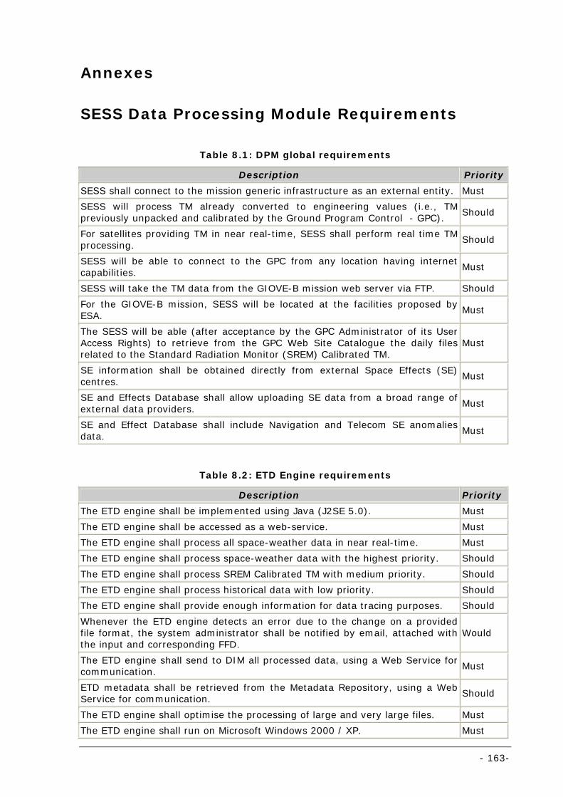
- 163-
Annexes
SESS Data Processing Module Requirements
Table 8.1: DPM global requirements
Description Priority
SESS shall connect to the mission generic infrastructure as an external entity. Must SESS will process TM already converted to engineering values (i.e., TM previously unpacked and calibrated by the Ground Program Control - GPC). Should
For satellites providing TM in near real-time, SESS shall perform real time TM processing. Should
SESS will be able to connect to the GPC from any location having internet capabilities. Must
SESS will take the TM data from the GIOVE-B mission web server via FTP. Should For the GIOVE-B mission, SESS will be located at the facilities proposed by ESA. Must
The SESS will be able (after acceptance by the GPC Administrator of its User Access Rights) to retrieve from the GPC Web Site Catalogue the daily files related to the Standard Radiation Monitor (SREM) Calibrated TM.
Must
SE information shall be obtained directly from external Space Effects (SE) centres. Must
SE and Effects Database shall allow uploading SE data from a broad range of external data providers. Must
SE and Effect Database shall include Navigation and Telecom SE anomalies data. Must
Table 8.2: ETD Engine requirements
Description Priority
The ETD engine shall be implemented using Java (J2SE 5.0). Must The ETD engine shall be accessed as a web-service. Must The ETD engine shall process all space-weather data in near real-time. Must
The ETD engine shall process space-weather data with the highest priority. Should The ETD engine shall process SREM Calibrated TM with medium priority. Should
The ETD engine shall process historical data with low priority. Should The ETD engine shall provide enough information for data tracing purposes. Should
Whenever the ETD engine detects an error due to the change on a provided file format, the system administrator shall be notified by email, attached with the input and corresponding FFD.
Would
The ETD engine shall send to DIM all processed data, using a Web Service for communication. Must
ETD metadata shall be retrieved from the Metadata Repository, using a Web Service for communication. Should
The ETD engine shall optimise the processing of large and very large files. Must The ETD engine shall run on Microsoft Windows 2000 / XP. Must
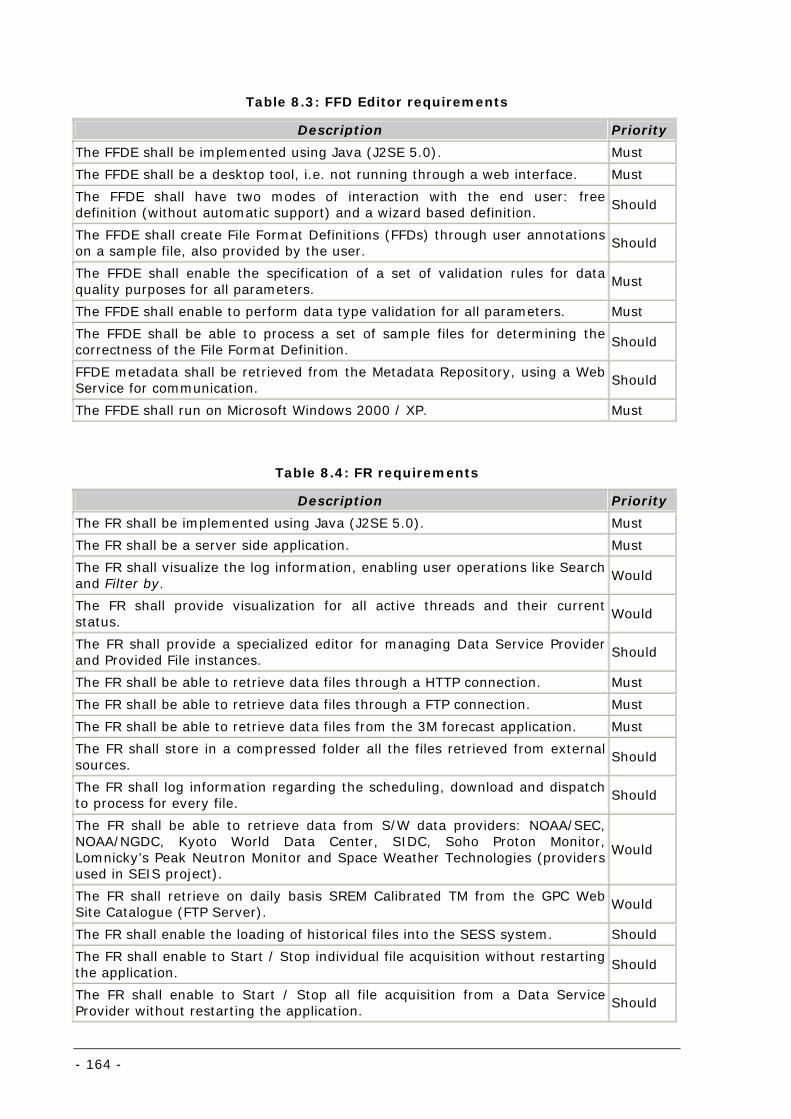
- 164 -
Table 8.3: FFD Editor requirements
Description Priority The FFDE shall be implemented using Java (J2SE 5.0). Must The FFDE shall be a desktop tool, i.e. not running through a web interface. Must
The FFDE shall have two modes of interaction with the end user: free definition (without automatic support) and a wizard based definition. Should
The FFDE shall create File Format Definitions (FFDs) through user annotations on a sample file, also provided by the user. Should
The FFDE shall enable the specification of a set of validation rules for data quality purposes for all parameters. Must
The FFDE shall enable to perform data type validation for all parameters. Must
The FFDE shall be able to process a set of sample files for determining the correctness of the File Format Definition. Should
FFDE metadata shall be retrieved from the Metadata Repository, using a Web Service for communication. Should
The FFDE shall run on Microsoft Windows 2000 / XP. Must
Table 8.4: FR requirements
Description Priority The FR shall be implemented using Java (J2SE 5.0). Must
The FR shall be a server side application. Must The FR shall visualize the log information, enabling user operations like Search and Filter by. Would
The FR shall provide visualization for all active threads and their current status. Would
The FR shall provide a specialized editor for managing Data Service Provider and Provided File instances. Should
The FR shall be able to retrieve data files through a HTTP connection. Must The FR shall be able to retrieve data files through a FTP connection. Must
The FR shall be able to retrieve data files from the 3M forecast application. Must The FR shall store in a compressed folder all the files retrieved from external sources. Should
The FR shall log information regarding the scheduling, download and dispatch to process for every file. Should
The FR shall be able to retrieve data from S/W data providers: NOAA/SEC, NOAA/NGDC, Kyoto World Data Center, SIDC, Soho Proton Monitor, Lomnicky’s Peak Neutron Monitor and Space Weather Technologies (providers used in SEIS project).
Would
The FR shall retrieve on daily basis SREM Calibrated TM from the GPC Web Site Catalogue (FTP Server). Would
The FR shall enable the loading of historical files into the SESS system. Should The FR shall enable to Start / Stop individual file acquisition without restarting the application. Should
The FR shall enable to Start / Stop all file acquisition from a Data Service Provider without restarting the application. Should
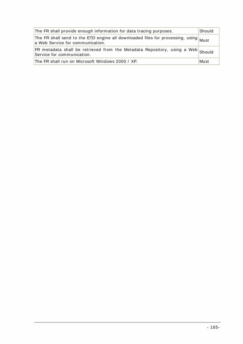
- 165-
The FR shall provide enough information for data tracing purposes. Should
The FR shall send to the ETD engine all downloaded files for processing, using a Web Service for communication. Must
FR metadata shall be retrieved from the Metadata Repository, using a Web Service for communication. Should
The FR shall run on Microsoft Windows 2000 / XP. Must
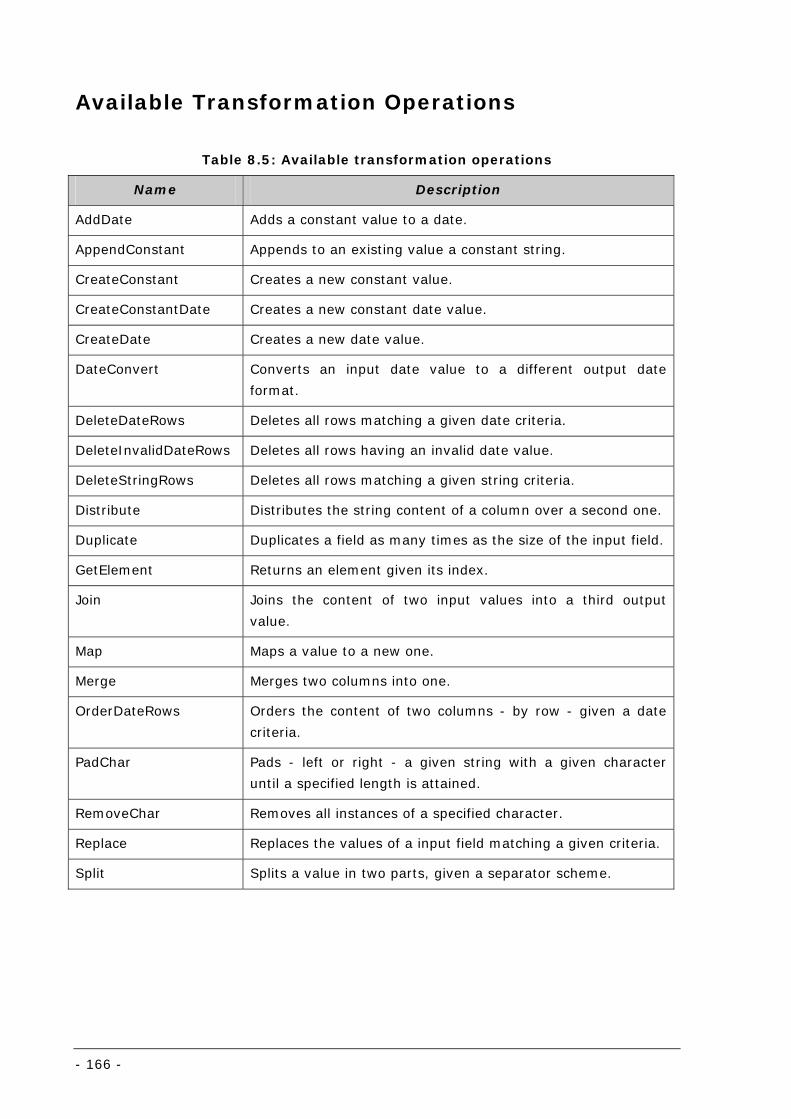
- 166 -
Available Transformation Operations
Table 8.5: Available transformation operations
Name Description
AddDate Adds a constant value to a date.
AppendConstant Appends to an existing value a constant string.
CreateConstant Creates a new constant value.
CreateConstantDate Creates a new constant date value.
CreateDate Creates a new date value.
DateConvert Converts an input date value to a different output date
format.
DeleteDateRows Deletes all rows matching a given date criteria.
DeleteInvalidDateRows Deletes all rows having an invalid date value.
DeleteStringRows Deletes all rows matching a given string criteria.
Distribute Distributes the string content of a column over a second one.
Duplicate Duplicates a field as many times as the size of the input field.
GetElement Returns an element given its index.
Join Joins the content of two input values into a third output
value.
Map Maps a value to a new one.
Merge Merges two columns into one.
OrderDateRows Orders the content of two columns - by row - given a date
criteria.
PadChar Pads - left or right - a given string with a given character
until a specified length is attained.
RemoveChar Removes all instances of a specified character.
Replace Replaces the values of a input field matching a given criteria.
Split Splits a value in two parts, given a separator scheme.
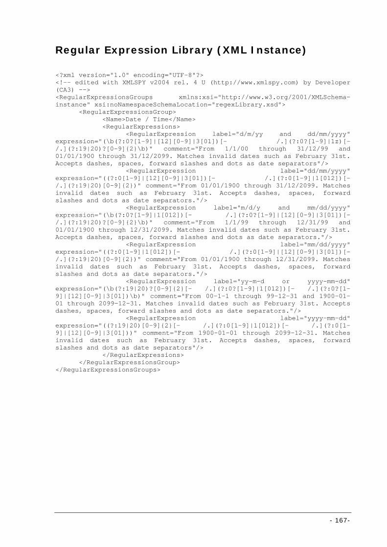
- 167-
Regular Expression Library (XML Instance)
<?xml version="1.0" encoding="UTF-8"?> <!-- edited with XMLSPY v2004 rel. 4 U (http://www.xmlspy.com) by Developer (CA3) --> <RegularExpressionsGroups xmlns:xsi="http://www.w3.org/2001/XMLSchema-instance" xsi:noNamespaceSchemaLocation="regexLibrary.xsd"> <RegularExpressionsGroup> <Name>Date / Time</Name> <RegularExpressions> <RegularExpression label="d/m/yy and dd/mm/yyyy" expression="(\b(?:0?[1-9]|[12][0-9]|3[01])[- /.](?:0?[1-9]|1z)[- /.](?:19|20)?[0-9]{2}\b)" comment="From 1/1/00 through 31/12/99 and 01/01/1900 through 31/12/2099. Matches invalid dates such as February 31st. Accepts dashes, spaces, forward slashes and dots as date separators"/> <RegularExpression label="dd/mm/yyyy" expression="((?:0[1-9]|[12][0-9]|3[01])[- /.](?:0[1-9]|1[012])[- /.](?:19|20)[0-9]{2})" comment="From 01/01/1900 through 31/12/2099. Matches invalid dates such as February 31st. Accepts dashes, spaces, forward slashes and dots as date separators."/> <RegularExpression label="m/d/y and mm/dd/yyyy" expression="(\b(?:0?[1-9]|1[012])[- /.](?:0?[1-9]|[12][0-9]|3[01])[- /.](?:19|20)?[0-9]{2}\b)" comment="From 1/1/99 through 12/31/99 and 01/01/1900 through 12/31/2099. Matches invalid dates such as February 31st. Accepts dashes, spaces, forward slashes and dots as date separators."/> <RegularExpression label="mm/dd/yyyy" expression="((?:0[1-9]|1[012])[- /.](?:0[1-9]|[12][0-9]|3[01])[- /.](?:19|20)[0-9]{2})" comment="From 01/01/1900 through 12/31/2099. Matches invalid dates such as February 31st. Accepts dashes, spaces, forward slashes and dots as date separators."/> <RegularExpression label="yy-m-d or yyyy-mm-dd" expression="(\b(?:19|20)?[0-9]{2}[- /.](?:0?[1-9]|1[012])[- /.](?:0?[1-9]|[12][0-9]|3[01])\b)" comment="From 00-1-1 through 99-12-31 and 1900-01-01 through 2099-12-31. Matches invalid dates such as February 31st. Accepts dashes, spaces, forward slashes and dots as date separators."/> <RegularExpression label="yyyy-mm-dd" expression="((?:19|20)[0-9]{2}[- /.](?:0[1-9]|1[012])[- /.](?:0[1-9]|[12][0-9]|3[01]))" comment="From 1900-01-01 through 2099-12-31. Matches invalid dates such as February 31st. Accepts dashes, spaces, forward slashes and dots as date separators"/> </RegularExpressions> </RegularExpressionsGroup> </RegularExpressionsGroups>
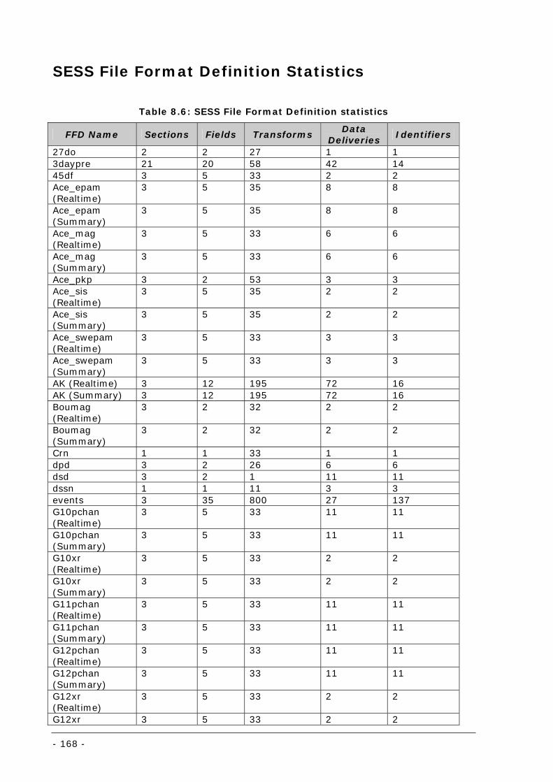
- 168 -
SESS File Format Definition Statistics
Table 8.6: SESS File Format Definition statistics
FFD Name Sections Fields Transforms Data
Deliveries Identifiers
27do 2 2 27 1 1 3daypre 21 20 58 42 14 45df 3 5 33 2 2 Ace_epam (Realtime)
3 5 35 8 8
Ace_epam (Summary)
3 5 35 8 8
Ace_mag (Realtime)
3 5 33 6 6
Ace_mag (Summary)
3 5 33 6 6
Ace_pkp 3 2 53 3 3 Ace_sis (Realtime)
3 5 35 2 2
Ace_sis (Summary)
3 5 35 2 2
Ace_swepam (Realtime)
3 5 33 3 3
Ace_swepam (Summary)
3 5 33 3 3
AK (Realtime) 3 12 195 72 16 AK (Summary) 3 12 195 72 16 Boumag (Realtime)
3 2 32 2 2
Boumag (Summary)
3 2 32 2 2
Crn 1 1 33 1 1 dpd 3 2 26 6 6 dsd 3 2 1 11 11 dssn 1 1 11 3 3 events 3 35 800 27 137 G10pchan (Realtime)
3 5 33 11 11
G10pchan (Summary)
3 5 33 11 11
G10xr (Realtime)
3 5 33 2 2
G10xr (Summary)
3 5 33 2 2
G11pchan (Realtime)
3 5 33 11 11
G11pchan (Summary)
3 5 33 11 11
G12pchan (Realtime)
3 5 33 11 11
G12pchan (Summary)
3 5 33 11 11
G12xr (Realtime)
3 5 33 2 2
G12xr 3 5 33 2 2
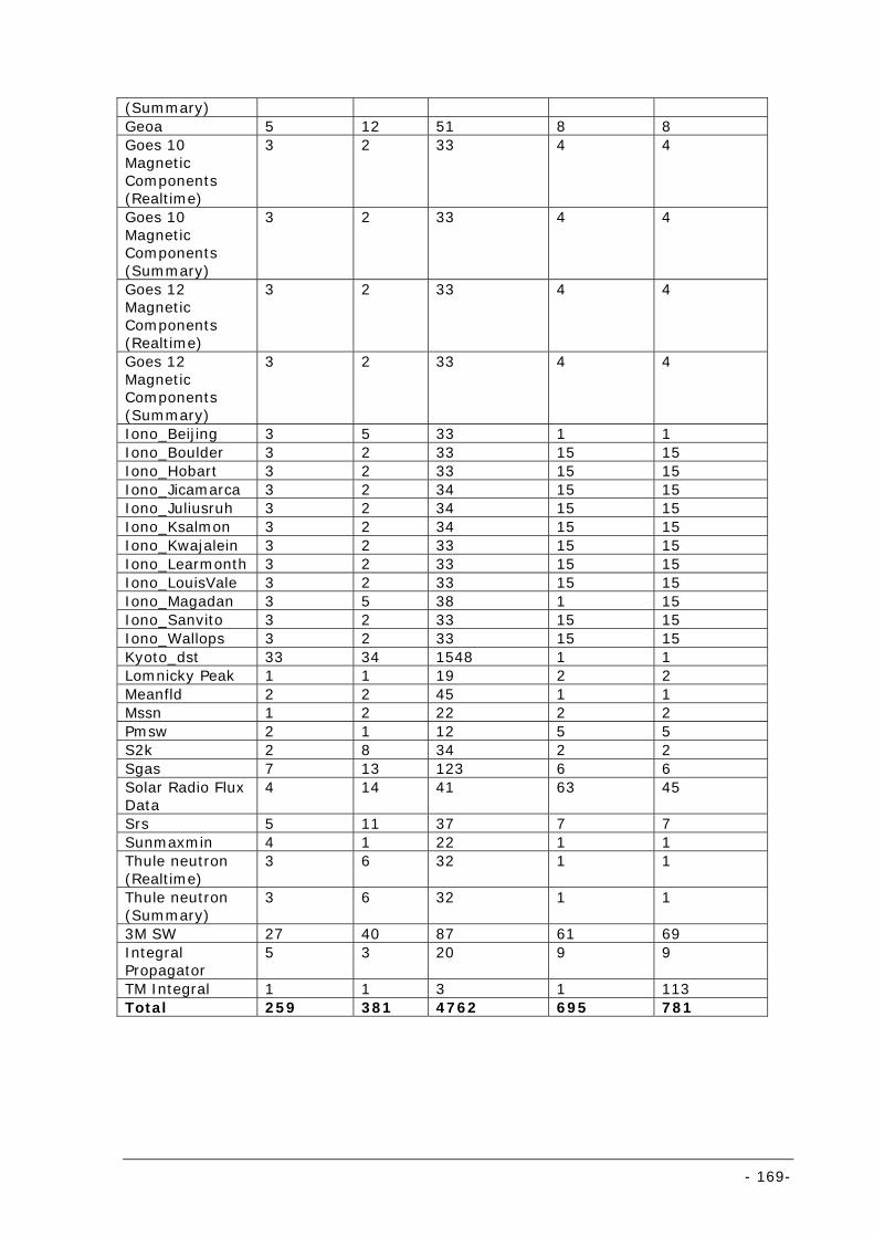
- 169-
(Summary) Geoa 5 12 51 8 8 Goes 10 Magnetic Components (Realtime)
3 2 33 4 4
Goes 10 Magnetic Components (Summary)
3 2 33 4 4
Goes 12 Magnetic Components (Realtime)
3 2 33 4 4
Goes 12 Magnetic Components (Summary)
3 2 33 4 4
Iono_Beijing 3 5 33 1 1 Iono_Boulder 3 2 33 15 15 Iono_Hobart 3 2 33 15 15 Iono_Jicamarca 3 2 34 15 15 Iono_Juliusruh 3 2 34 15 15 Iono_Ksalmon 3 2 34 15 15 Iono_Kwajalein 3 2 33 15 15 Iono_Learmonth 3 2 33 15 15 Iono_LouisVale 3 2 33 15 15 Iono_Magadan 3 5 38 1 15 Iono_Sanvito 3 2 33 15 15 Iono_Wallops 3 2 33 15 15 Kyoto_dst 33 34 1548 1 1 Lomnicky Peak 1 1 19 2 2 Meanfld 2 2 45 1 1 Mssn 1 2 22 2 2 Pmsw 2 1 12 5 5 S2k 2 8 34 2 2 Sgas 7 13 123 6 6 Solar Radio Flux Data
4 14 41 63 45
Srs 5 11 37 7 7 Sunmaxmin 4 1 22 1 1 Thule neutron (Realtime)
3 6 32 1 1
Thule neutron (Summary)
3 6 32 1 1
3M SW 27 40 87 61 69 Integral Propagator
5 3 20 9 9
TM Integral 1 1 3 1 113 Total 259 381 4762 695 781


![[Type text] [Type text] [Type text] - Halaman utama Website](https://img.pdfslide.net/doc/110x75/6312eee6c72bc2f2dd03d889/type-text-type-text-type-text-halaman-utama-website-.jpg)


![N I [Type text] [Type text] [Type text](https://img.pdfslide.net/doc/110x75/635769693cd558f04e04d194/n-i-type-text-type-text-type-text.jpg)


