Embed Size (px)
Citation preview
FA-9600 Command
Version 2.3 - Higher
OPERATION
MANUAL
2
Table of Contents
1. Communication Settings....................................................................................................................... 4 1-1. Communication Method .............................................................................................................. 4 1-2. Changing Status Report Destination Addresses ........................................................................ 5
2. Command Flow Examples.................................................................................................................... 6 2-1. Checking FA-9600 Start-up......................................................................................................... 6 2-2. Requesting FA-9600 Video Status .............................................................................................. 6 2-3. Changing Audio Gain Settings .................................................................................................... 6 2-4. Reporting FA-9600 Status Change ............................................................................................. 6
3. Command Format ................................................................................................................................. 7 3-1. Setting Commands ...................................................................................................................... 7 3-2. Command Response .................................................................................................................. 7 3-3. ID Code ....................................................................................................................................... 8 3-4. Video Setting Command List ...................................................................................................... 8 3-5. Audio Setting Command List ...................................................................................................... 9 3-6. Other Command List ................................................................................................................... 9
4. Video Setting Commands ...................................................................................................................10 4-1. Dynamic Range, Color Space and 3D LUT Conversions .........................................................10 4-2. In Gamma Curve .......................................................................................................................10 4-3. In Color Space ..........................................................................................................................11 4-4. Out Gamma Curve ....................................................................................................................11 4-5. Out Color Space ........................................................................................................................12 4-6. 3D-LUT Data .............................................................................................................................12 4-7. In/Out Dynamic Range for 3D-LUT Mode .................................................................................13 4-8. Gain Adjustment ........................................................................................................................13 4-9. SDR Gain Adjustment ...............................................................................................................13 4-10. Gain Simultaneous Mode ........................................................................................................14 4-11. OOTF IN for HLG ....................................................................................................................14 4-12. OOTF IN System Gamma for HLG .........................................................................................14 4-13. OOTF IN Display Peak for HLG ..............................................................................................15 4-14. OOTF IN Display Black for HLG .............................................................................................15 4-15. OOTF OUT for HLG ................................................................................................................15 4-16. OOTF OUT System Gamma for HLG .....................................................................................16 4-17. OOTF OUT Display Peak for HLG ..........................................................................................16 4-18. OOTF OUT Display Black for HLG .........................................................................................16 4-19. Optional Function (OOTF RGB) ..............................................................................................17 4-20. Optional Function (Operation) .................................................................................................17 4-21. Optional Function (System Gamma) .......................................................................................17 4-22. Optional Function (SDR SONY) ..............................................................................................18 4-23. KNEE (RGB) CLIP White Clip .................................................................................................18 4-24. KNEE (RGB) CLIP White Knee Type .....................................................................................18 4-25. KNEE (RGB) CLIP White Output Clip .....................................................................................19 4-26. KNEE (RGB) CLIP White Knee Slope ....................................................................................19 4-27. KNEE (RGB) CLIP White Knee Point .....................................................................................19 4-28. KNEE Saturation Enable .........................................................................................................20 4-29. KNEE Saturation Level ...........................................................................................................20 4-30. KNEE (RGB) CLIP Black Clip .................................................................................................20 4-31. KNEE (RGB) CLIP Black Output Clip .....................................................................................21
5. Audio Commands ...............................................................................................................................22 5-1. Audio Polarity ............................................................................................................................22 5-2. Audio MAPPING .......................................................................................................................22 5-3. Audio Master Gain ....................................................................................................................23 5-4. Audio Gain ................................................................................................................................23
3
5-5. Audio Master Delay ...................................................................................................................23 5-6. Audio Delay ...............................................................................................................................24 5-7. Audio Delay ADJUST FS SELECT ...........................................................................................24 5-8. FA-96AES-UBL Polarity ............................................................................................................24 5-9. FA-96AES-UBL MAPPING .......................................................................................................25 5-10. FA-96AES-UBL Master Gain ..................................................................................................25 5-11. FA-96AES-UBL Gain ..............................................................................................................25 5-12. FA-96ANA-AUD Polarity .........................................................................................................26 5-13. FA-96ANA-AUD MAPPING ....................................................................................................26 5-14. FA-96ANA-AUD Input Master Gain ........................................................................................26 5-15. FA-96ANA-AUD Input Gain.....................................................................................................27 5-16. FA-96ANA-AUD Output Master Gain ......................................................................................27 5-17. FA-96ANA-AUD Output Gain ..................................................................................................27 5-18. FA-96MADI MAPPING ............................................................................................................28 5-19. FA-96MADI Master Gain .........................................................................................................28 5-20. FA-96MADI Gain .....................................................................................................................28
6. Other Commands ...............................................................................................................................29 6-1. Power On (with Specifying FA-9600 Software Version) ...........................................................29 6-2. Event Load ................................................................................................................................29 6-3. Event Save ................................................................................................................................29 6-4. Video Status Request ...............................................................................................................29 6-5. Audio 1 Status Request ............................................................................................................30 6-6. Audio 2 Status Request ............................................................................................................30 6-7. Audio Option Status Request ....................................................................................................30
7. Status Messages from FA-9600 .........................................................................................................31 7-1. Video Status Message (for Protocol Number 3) .......................................................................31
7-1-1. Input / Output Status Examples in Messages ....................................................................33 7-2. Video Status Message (for Protocol Number 2) .......................................................................34 7-3. Video Status Message (for Protocol Number 1) .......................................................................35 7-4. Video Status Message (for Protocol Number 0) .......................................................................36 7-5. Audio 1 Status Message ...........................................................................................................37 7-6. Audio 2 Status Message ...........................................................................................................37 7-7. Audio Option Status Message (FA-96AES-UBL) ......................................................................38 7-8. Audio Option Status Message (FA-96ANA-AUD) .....................................................................38 7-9. Audio Option Status Message (FA-96MADI) ............................................................................39
4
1. Communication Settings
FA-9600 units can be controlled using dedicated commands over LAN.
Dynamic Range Control / Color Converter and Audio menu settings can be changed by these
commands.
1-1. Communication Method
Communication Interface
Ethernet: IEEE802.3u/ab (100BASE-TX / 1000BASE-T)
Control Command
Command Devices send control commands to FA-9600 using TCP packets.
(See Sec 3 “Command Format” for details on commands and its format)
Response to Command (FA-9600)
FA-9600 sends “ACK” after properly receiving a command, or an error message in other cases
using TCP packets. (See Sec. 3-2 “Command Response.”)
Destination Address
FA-9600 IP address: 192.168.0.10 (default) (Use the current FA-9600 IP address.))
Connection Timeout (Keep-Alive Idle)
10-180 sec (default: 120 sec) (See the next page for changing setting.)
No response comes back before the timeout limit while establishing the TCP connection with
an FA-9600, the command transmitter waits 750 seconds while detecting packets. If no
packets are still received, the connection is forced to close.
Number of Command Connections
A single FA-9600 unit can simultaneously receive commands from up to two control points.
Status Request
Command Devices send status request messages (TCP) to FA-9600.
Response to Status Request (FA-9600)
FA-9600 sends status messages (UDP) in response to request. (See Sec. 7 “Status Messages
from FA-9600)
Status Report (FA-9600)
When the FA-9600 status or settings change, FA-9600 sends a status report to two destinations
(UDP). Status report messages have the same syntax as those for status response messages.
Destination Address
Destination 1: 0. 0. 0. 0 (default) (To change the address, see next page.)
Destination 2: 0. 0. 0. 0 (default) (To change the address, see next page.))
UDP port: 60000 (default) (To change the number, see the nest page.))
Two destinations are defined in the Web GUI - Network Settings tab. (See next page)
Change targets are parameter values that can be changed by commands (excluding event
control) and input/output formats.
The time intervals for detecting changes are 500 to 1000 msec (depending on the software
performance.)
5
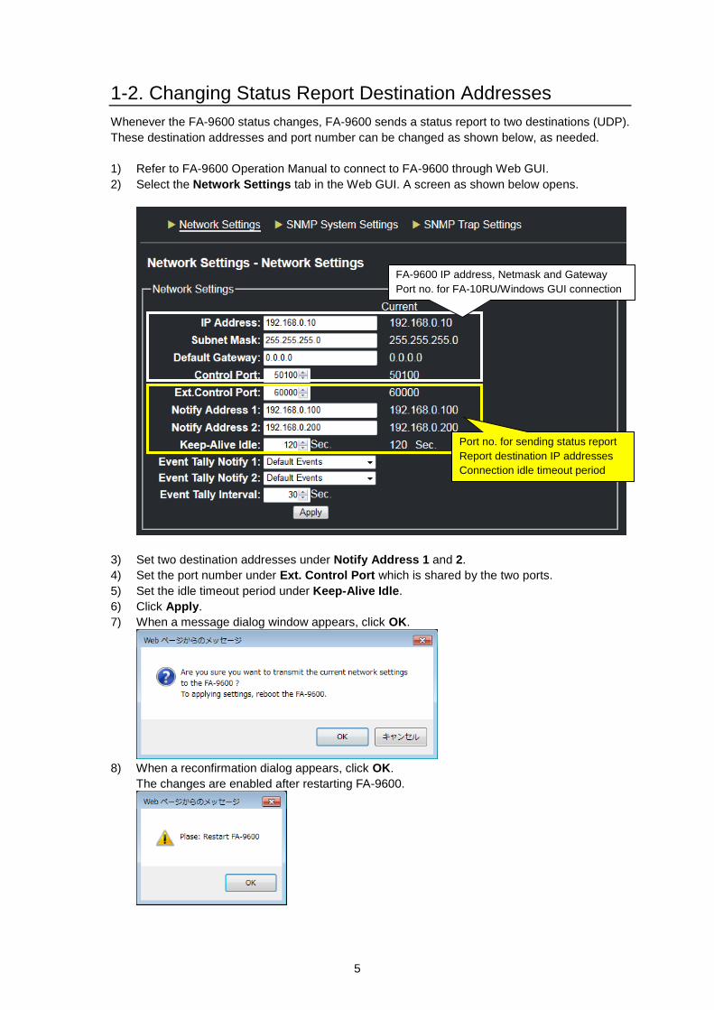
1-2. Changing Status Report Destination Addresses
Whenever the FA-9600 status changes, FA-9600 sends a status report to two destinations (UDP).
These destination addresses and port number can be changed as shown below, as needed.
1) Refer to FA-9600 Operation Manual to connect to FA-9600 through Web GUI.
2) Select the Network Settings tab in the Web GUI. A screen as shown below opens.
3) Set two destination addresses under Notify Address 1 and 2.
4) Set the port number under Ext. Control Port which is shared by the two ports.
5) Set the idle timeout period under Keep-Alive Idle.
6) Click Apply.
7) When a message dialog window appears, click OK.
8) When a reconfirmation dialog appears, click OK.
The changes are enabled after restarting FA-9600.
FA-9600 IP address, Netmask and Gateway
Port no. for FA-10RU/Windows GUI connection
Port no. for sending status report
Report destination IP addresses
Connection idle timeout period
6
2. Command Flow Examples
2-1. Checking FA-9600 Start-up
1) Command Device issues a Power On command to Command Device. The Power On
command can also specify the protocol compatible with your FA-9600 software version. (See
Sec. 6-1 “ Power On”)
2) FA-9600 sends “ACK” to Command Device. (See Sec. 3-2. “Command Response”)
Start command control with this request command and send the next command after receiving “ACK.”
2-2. Requesting FA-9600 Video Status
1) Command Device issues a status request to FA-9600. (See Sec. 6-4 “Video Status Request.”)
2) FA-9600 sends “ACK” to Command Device.
3) FA-9600 send a status message in response to the command. (See Sec. 7-1 “Video Status “)
4) Command Device sends “ACK” to FA-9600.
Use this flow example whenever requesting FA-9600 status after restart.
2-3. Changing Audio Gain Settings
1) Command Device issues an Audio Gain Setting command to FA-9600. (See Sec. 5-4 “Audio
Gain”)
2) FA-9600 sends “ACK” to Command Device.
Send the next command after receiving “ACK” from FA-9600.
2-4. Reporting FA-9600 Status Change
1) FA-9600 issues a status message to two specified destinations. (See Sec. 7 “Status Messages
from FA-9600”)
2) The destination devices send “ACK” to FA-9600.
If no “ACK” returns, FA-9600 re-sends the status message up to three times.
7
3. Command Format
3-1. Setting Commands
Command Example
<Command code>,<ID code>,<Item code>,<Value>[CR][LF]
Commands sent from Command Devices to FA-9600 are composed of 4 variables, using commas
as a separator as shown above.
< > Denotes a command variable in which an actual value is entered.
Command code Denotes a command string.
ID code Denotes an FA-9600 menu category. (See next page)
Item code Represents an FA-9600 menu parameter.
Value Represents an FA-9600 menu parameter value.
[CR][LF] Denotes a newline character to be added at the end of Command statements.
Only ASCII characters are available (Case-sensitive).
Command Example
Dynamic Range Conv,FS1,Gamma Curve Enable,1[CR][LF]
(Setting Command that enables the FS1 Dynamic Range / Color Space conversion.)
See Secs 4 and 5 for each Setting Command details.
See Sec. 6 for Status Request and other command details
3-2. Command Response
Normal Response
Return message: ACK[CR][LF]
Error Response
Any of the following error messages is returned if a command is not properly received.
Return message: ERR<Error code>[CR][LF]
Error code Description
01 Command error
02 ID code error
03 Item code error
04 Value error
90 Uncontrollable (External control disabled)
97 Setting error
98 Number of items error
99 Timeout error (ACK[CR][LF] not returned within time limit)
8
3-3. ID Code
The following values are used for <ID code>.
Value Description
FS1 FS1 control
FS2 FS2 control
EMB1 FS1 embedded audio control
EMB2 FS2 embedded audio control
AES AES (digital audio) control
COM FS1 and FS2, or EMB1 and EMB2 shared control
ADLY G1 Audio delay group 1 (Ch1-Ch16)
ADLY G2 Audio delay group 2 (Ch17-Ch32)
SlotB Option slot B that represents FA-96AES-UBL, FA-96ANA-AUD or FA-96MADI.
3-4. Video Setting Command List
Add [CR][LF] at the end of commands.
See Sec. 4 “Video Setting Commands.”
*1 Available commands when FA-9600 is in 3D LUT mode.
*2 Available commands when HLG BT.2100 is set for input or output gamma curve.
Command statement *1 *2 Refer to
Dynamic Range CONV,<ID code>,Gamma Curve Enable,<Value> FS1 4-1
Dynamic Range CONV,<ID code>,EOTF DeGamma,<Value> 4-2
Color Space CONV,<ID code>,In Color Space,<Value> 4-3
Dynamic Range CONV,<ID code>,OETF Gamma,<Value> 4-4
Color Space CONV,<ID code>,Out Color Space,<Value> 4-5
Dynamic Range CONV,<ID code>,DRC 3DLUT,<Value> 4-6
Dynamic Range CONV,<ID code>,IO Range,<Value> 4-7
Dynamic Range CONV,<ID code>,Dynamic Range Gain,<Value> 4-8
Dynamic Range CONV,<ID code>,SDR Gain,<Value> 4-9
Dynamic Range CONV,<ID code>,Simul Mode,<Value> 4-10
Dynamic Range CONV,<ID code>,Convert Mode,<Value> 4-11
Dynamic Range CONV,<ID code>,OOTF IN System Gamma,<Value> 4-12
Dynamic Range CONV,<ID code>,OOTF IN Display Peak,<Value> 4-13
Dynamic Range CONV,<ID code>,OOTF IN Display Black,<Value> 4-14
Dynamic Range CONV,<ID code>,OOTF OUT Mode,<Value> 4-15
Dynamic Range CONV,<ID code>,OOTF OUT System Gamma,<Value> 4-16
Dynamic Range CONV,<ID code>,OOTF OUT Display Peak,<Value> 4-17
Dynamic Range CONV,<ID code>,OOTF OUT Display Black,<Value> 4-18
Dynamic Range CONV,<ID code>,OOTF RGB,<Value> 4-19
Dynamic Range CONV,<ID code>,OOTF FOR SR-Live,<Value> 4-20
Dynamic Range CONV,<ID code>,System Gamma,<Value> 4-21
Dynamic Range CONV,<ID code>,SDR(SONY),<Value> 4-22
Knee Clip,<ID code>,White Clip Enable,<Value> 4-23
Knee Clip,<ID code>,Knee Type,<Value> 4-24
Knee Clip,<ID code>,White Clip,<Value> 4-25
Knee Clip,<ID code>,Knee Slop,<Value> 4-26
Knee Clip,<ID code>,Knee Point,<Value> 4-27
Knee Clip,<ID code>,Knee Saturation Enable,<Value> 4-28
Knee Clip,<ID code>,Knee Saturation Level,<Value> 4-29
9
Knee Clip,<ID code>,Black Clip Enable,<Value> 4-30
Knee Clip,<ID code>,Black Clip,<Value> 4-31
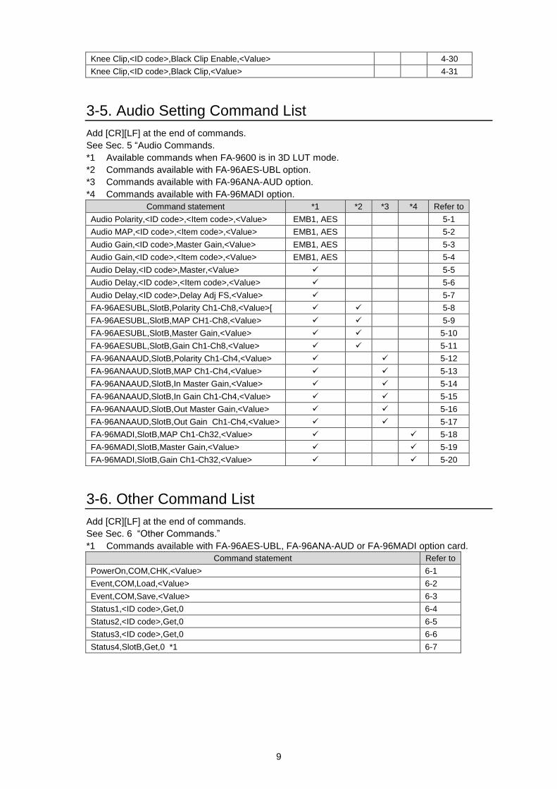
3-5. Audio Setting Command List
Add [CR][LF] at the end of commands.
See Sec. 5 “Audio Commands.
*1 Available commands when FA-9600 is in 3D LUT mode.
*2 Commands available with FA-96AES-UBL option.
*3 Commands available with FA-96ANA-AUD option.
*4 Commands available with FA-96MADI option.
Command statement *1 *2 *3 *4 Refer to
Audio Polarity,<ID code>,<Item code>,<Value> EMB1, AES 5-1
Audio MAP,<ID code>,<Item code>,<Value> EMB1, AES 5-2
Audio Gain,<ID code>,Master Gain,<Value> EMB1, AES 5-3
Audio Gain,<ID code>,<Item code>,<Value> EMB1, AES 5-4
Audio Delay,<ID code>,Master,<Value> 5-5
Audio Delay,<ID code>,<Item code>,<Value> 5-6
Audio Delay,<ID code>,Delay Adj FS,<Value> 5-7
FA-96AESUBL,SlotB,Polarity Ch1-Ch8,<Value>[ 5-8
FA-96AESUBL,SlotB,MAP CH1-Ch8,<Value> 5-9
FA-96AESUBL,SlotB,Master Gain,<Value> 5-10
FA-96AESUBL,SlotB,Gain Ch1-Ch8,<Value> 5-11
FA-96ANAAUD,SlotB,Polarity Ch1-Ch4,<Value> 5-12
FA-96ANAAUD,SlotB,MAP Ch1-Ch4,<Value> 5-13
FA-96ANAAUD,SlotB,In Master Gain,<Value> 5-14
FA-96ANAAUD,SlotB,In Gain Ch1-Ch4,<Value> 5-15
FA-96ANAAUD,SlotB,Out Master Gain,<Value> 5-16
FA-96ANAAUD,SlotB,Out Gain Ch1-Ch4,<Value> 5-17
FA-96MADI,SlotB,MAP Ch1-Ch32,<Value> 5-18
FA-96MADI,SlotB,Master Gain,<Value> 5-19
FA-96MADI,SlotB,Gain Ch1-Ch32,<Value> 5-20
3-6. Other Command List
Add [CR][LF] at the end of commands.
See Sec. 6 “Other Commands.”
*1 Commands available with FA-96AES-UBL, FA-96ANA-AUD or FA-96MADI option card.
Command statement Refer to
PowerOn,COM,CHK,<Value> 6-1
Event,COM,Load,<Value> 6-2
Event,COM,Save,<Value> 6-3
Status1,<ID code>,Get,0 6-4
Status2,<ID code>,Get,0 6-5
Status3,<ID code>,Get,0 6-6
Status4,SlotB,Get,0 *1 6-7
10
4. Video Setting Commands
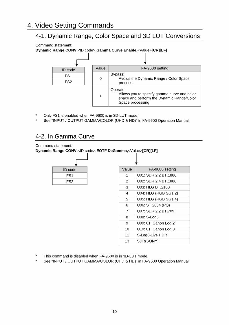
4-1. Dynamic Range, Color Space and 3D LUT Conversions
Command statement:
Dynamic Range CONV,<ID code>,Gamma Curve Enable,<Value>[CR][LF]
* Only FS1 is enabled when FA-9600 is in 3D-LUT mode.
* See “INPUT / OUTPUT GAMMA/COLOR (UHD & HD)” in FA-9600 Operation Manual.
4-2. In Gamma Curve
Command statement:
Dynamic Range CONV,<ID code>,EOTF DeGamma,<Value>[CR][LF]
* This command is disabled when FA-9600 is in 3D-LUT mode.
* See “INPUT / OUTPUT GAMMA/COLOR (UHD & HD)” in FA-9600 Operation Manual.
Value FA-9600 setting
0 Bypass:
Avoids the Dynamic Range / Color Space process.
1
Operate: Allows you to specify gamma curve and color space and perform the Dynamic Range/Color Space processing
ID code
FS1
FS2
Value FA-9600 setting
1 U01: SDR 2.2 BT.1886
2 U02: SDR 2.4 BT.1886
3 U03: HLG BT.2100
4 U04: HLG (RGB SG1.2)
5 U05: HLG (RGB SG1.4)
6 U06: ST 2084 (PQ)
7 U07: SDR 2.2 BT.709
8 U08: S-Log3
9 U09: 01_Canon Log 2
10 U10: 01_Canon Log 3
11 S-Log3-Live HDR
13 SDR(SONY)
ID code
FS1
FS2
11
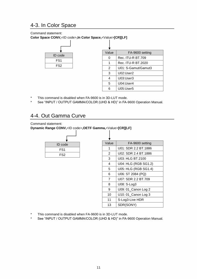
4-3. In Color Space
Command statement:
Color Space CONV,<ID code>,In Color Space,<Value>[CR][LF]
* This command is disabled when FA-9600 is in 3D-LUT mode.
* See “INPUT / OUTPUT GAMMA/COLOR (UHD & HD)” in FA-9600 Operation Manual.
4-4. Out Gamma Curve
Command statement:
Dynamic Range CONV,<ID code>,OETF Gamma,<Value>[CR][LF]
* This command is disabled when FA-9600 is in 3D-LUT mode.
* See “INPUT / OUTPUT GAMMA/COLOR (UHD & HD)” in FA-9600 Operation Manual.
Value FA-9600 setting
0 Rec. ITU-R BT.709
1 Rec. ITU-R BT.2020
2 U01: S-Gamut/Gamut3
3 U02:User2
4 U03:User3
5 U04:User4
6 U05:User5
ID code
FS1
FS2
Value FA-9600 setting
1 U01: SDR 2.2 BT.1886
2 U02: SDR 2.4 BT.1886
3 U03: HLG BT.2100
4 U04: HLG (RGB SG1.2)
5 U05: HLG (RGB SG1.4)
6 U06: ST 2084 (PQ)
7 U07: SDR 2.2 BT.709
8 U08: S-Log3
9 U09: 01_Canon Log 2
10 U10: 01_Canon Log 3
11 S-Log3-Live HDR
13 SDR(SONY)
ID code
FS1
FS2
12
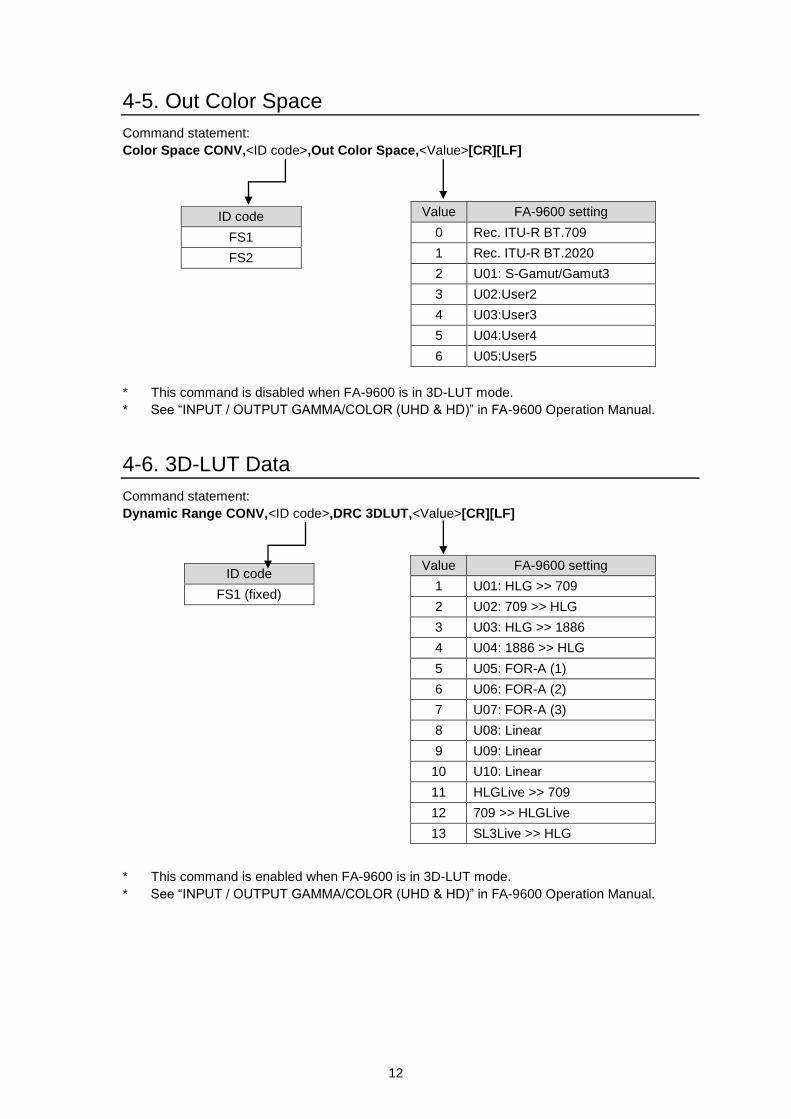
4-5. Out Color Space
Command statement:
Color Space CONV,<ID code>,Out Color Space,<Value>[CR][LF]
* This command is disabled when FA-9600 is in 3D-LUT mode.
* See “INPUT / OUTPUT GAMMA/COLOR (UHD & HD)” in FA-9600 Operation Manual.
4-6. 3D-LUT Data
Command statement:
Dynamic Range CONV,<ID code>,DRC 3DLUT,<Value>[CR][LF]
* This command is enabled when FA-9600 is in 3D-LUT mode.
* See “INPUT / OUTPUT GAMMA/COLOR (UHD & HD)” in FA-9600 Operation Manual.
Value FA-9600 setting
0 Rec. ITU-R BT.709
1 Rec. ITU-R BT.2020
2 U01: S-Gamut/Gamut3
3 U02:User2
4 U03:User3
5 U04:User4
6 U05:User5
ID code
FS1
FS2
Value FA-9600 setting
1 U01: HLG >> 709
2 U02: 709 >> HLG
3 U03: HLG >> 1886
4 U04: 1886 >> HLG
5 U05: FOR-A (1)
6 U06: FOR-A (2)
7 U07: FOR-A (3)
8 U08: Linear
9 U09: Linear
10 U10: Linear
11 HLGLive >> 709
12 709 >> HLGLive
13 SL3Live >> HLG
ID code
FS1 (fixed)
13
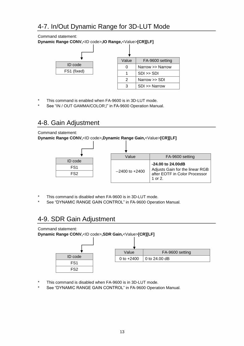
4-7. In/Out Dynamic Range for 3D-LUT Mode
Command statement:
Dynamic Range CONV,<ID code>,IO Range,<Value>[CR][LF]
* This command is enabled when FA-9600 is in 3D-LUT mode.
* See “IN / OUT GAMMA/COLOR」” in FA-9600 Operation Manual.
4-8. Gain Adjustment
Command statement:
Dynamic Range CONV,<ID code>,Dynamic Range Gain,<Value>[CR][LF]
* This command is disabled when FA-9600 is in 3D-LUT mode.
* See “DYNAMIC RANGE GAIN CONTROL” in FA-9600 Operation Manual.
4-9. SDR Gain Adjustment
Command statement:
Dynamic Range CONV,<ID code>,SDR Gain,<Value>[CR][LF]
* This command is disabled when FA-9600 is in 3D-LUT mode.
* See “DYNAMIC RANGE GAIN CONTROL” in FA-9600 Operation Manual.
Value FA-9600 setting
--2400 to +2400
-24.00 to 24.00dB
Adjusts Gain for the linear RGB after EOTF in Color Processor 1 or 2.
ID code
FS1
FS2
Value FA-9600 setting
0 to +2400 0 to 24.00 dB
ID code
FS1
FS2
ID code
FS1 (fixed)
Value FA-9600 setting
0 Narrow >> Narrow
1 SDI >> SDI
2 Narrow >> SDI
3 SDI >> Narrow
14
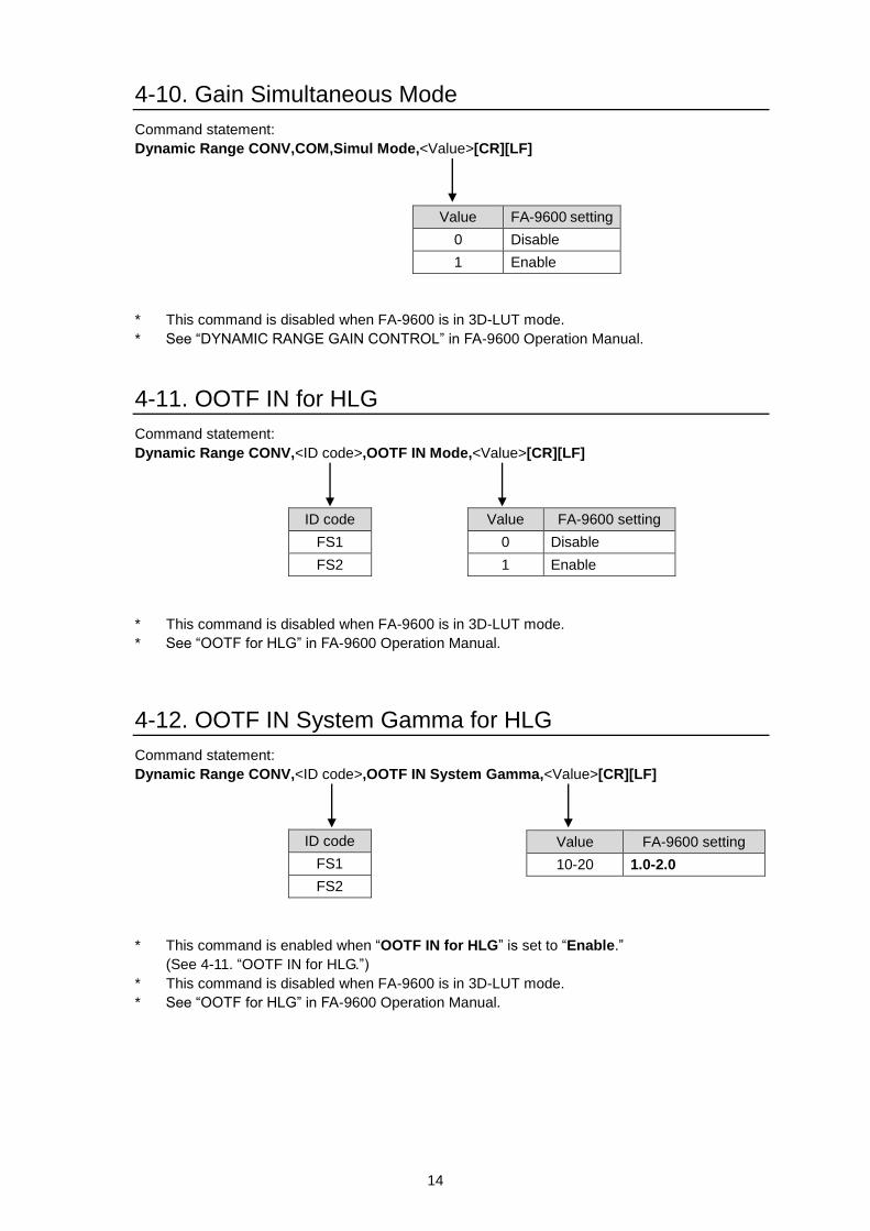
4-10. Gain Simultaneous Mode
Command statement:
Dynamic Range CONV,COM,Simul Mode,<Value>[CR][LF]
* This command is disabled when FA-9600 is in 3D-LUT mode.
* See “DYNAMIC RANGE GAIN CONTROL” in FA-9600 Operation Manual.
4-11. OOTF IN for HLG
Command statement:
Dynamic Range CONV,<ID code>,OOTF IN Mode,<Value>[CR][LF]
* This command is disabled when FA-9600 is in 3D-LUT mode.
* See “OOTF for HLG” in FA-9600 Operation Manual.
4-12. OOTF IN System Gamma for HLG
Command statement:
Dynamic Range CONV,<ID code>,OOTF IN System Gamma,<Value>[CR][LF]
* This command is enabled when “OOTF IN for HLG” is set to “Enable.”
(See 4-11. “OOTF IN for HLG.”)
* This command is disabled when FA-9600 is in 3D-LUT mode.
* See “OOTF for HLG” in FA-9600 Operation Manual.
Value FA-9600 setting
0 Disable
1 Enable
Value FA-9600 setting
0 Disable
1 Enable
ID code
FS1
FS2
Value FA-9600 setting
10-20 1.0-2.0
ID code
FS1
FS2
15
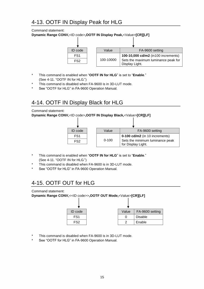
4-13. OOTF IN Display Peak for HLG
Command statement:
Dynamic Range CONV,<ID code>,OOTF IN Display Peak,<Value>[CR][LF]
* This command is enabled when “OOTF IN for HLG” is set to “Enable.”
(See 4-11. “OOTF IN for HLG.”)
* This command is disabled when FA-9600 is in 3D-LUT mode.
* See “OOTF for HLG” in FA-9600 Operation Manual.
4-14. OOTF IN Display Black for HLG
Command statement:
Dynamic Range CONV,<ID code>,OOTF IN Display Black,<Value>[CR][LF]
* This command is enabled when “OOTF IN for HLG” is set to “Enable.”
(See 4-11. “OOTF IN for HLG.”)
* This command is disabled when FA-9600 is in 3D-LUT mode.
* See “OOTF for HLG” in FA-9600 Operation Manual.
4-15. OOTF OUT for HLG
Command statement:
Dynamic Range CONV,<<ID code>>,OOTF OUT Mode,<Value>[CR][LF]
* This command is disabled when FA-9600 is in 3D-LUT mode.
* See “OOTF for HLG” in FA-9600 Operation Manual.
Value FA-9600 setting
100-10000
100-10,000 cd/m2 (in100 increments)
Sets the maximum luminance peak for Display Light.
Value FA-9600 setting
0-100
0-100 cd/m2 (in 10 increments)
Sets the minimum luminance peak for Display Light.
Value FA-9600 setting
0 Disable
2 Enable
ID code
FS1
FS2
ID code
FS1
FS2
ID code
FS1
FS2
16
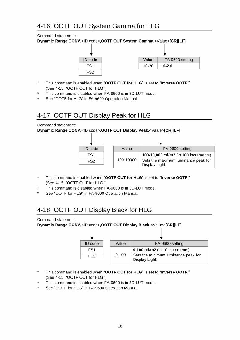
4-16. OOTF OUT System Gamma for HLG
Command statement:
Dynamic Range CONV,<ID code>,OOTF OUT System Gamma,<Value>[CR][LF]
* This command is enabled when “OOTF OUT for HLG” is set to “Inverse OOTF.”
(See 4-15. “OOTF OUT for HLG.”)
* This command is disabled when FA-9600 is in 3D-LUT mode.
* See “OOTF for HLG” in FA-9600 Operation Manual.
4-17. OOTF OUT Display Peak for HLG
Command statement:
Dynamic Range CONV,<ID code>,OOTF OUT Display Peak,<Value>[CR][LF]
* This command is enabled when “OOTF OUT for HLG” is set to “Inverse OOTF.”
(See 4-15. “OOTF OUT for HLG.”)
* This command is disabled when FA-9600 is in 3D-LUT mode.
* See “OOTF for HLG” in FA-9600 Operation Manual.
4-18. OOTF OUT Display Black for HLG
Command statement:
Dynamic Range CONV,<ID code>,OOTF OUT Display Black,<Value>[CR][LF]
* This command is enabled when “OOTF OUT for HLG” is set to “Inverse OOTF.”
(See 4-15. “OOTF OUT for HLG.”)
* This command is disabled when FA-9600 is in 3D-LUT mode.
* See “OOTF for HLG” in FA-9600 Operation Manual.
Value FA-9600 setting
10-20 1.0-2.0
ID code
FS1
FS2
Value FA-9600 setting
100-10000
100-10,000 cd/m2 (in 100 increments)
Sets the maximum luminance peak for Display Light.
ID code
FS1
FS2
Value FA-9600 setting
0-100
0-100 cd/m2 (in 10 increments)
Sets the minimum luminance peak for Display Light.
ID code
FS1
FS2
17
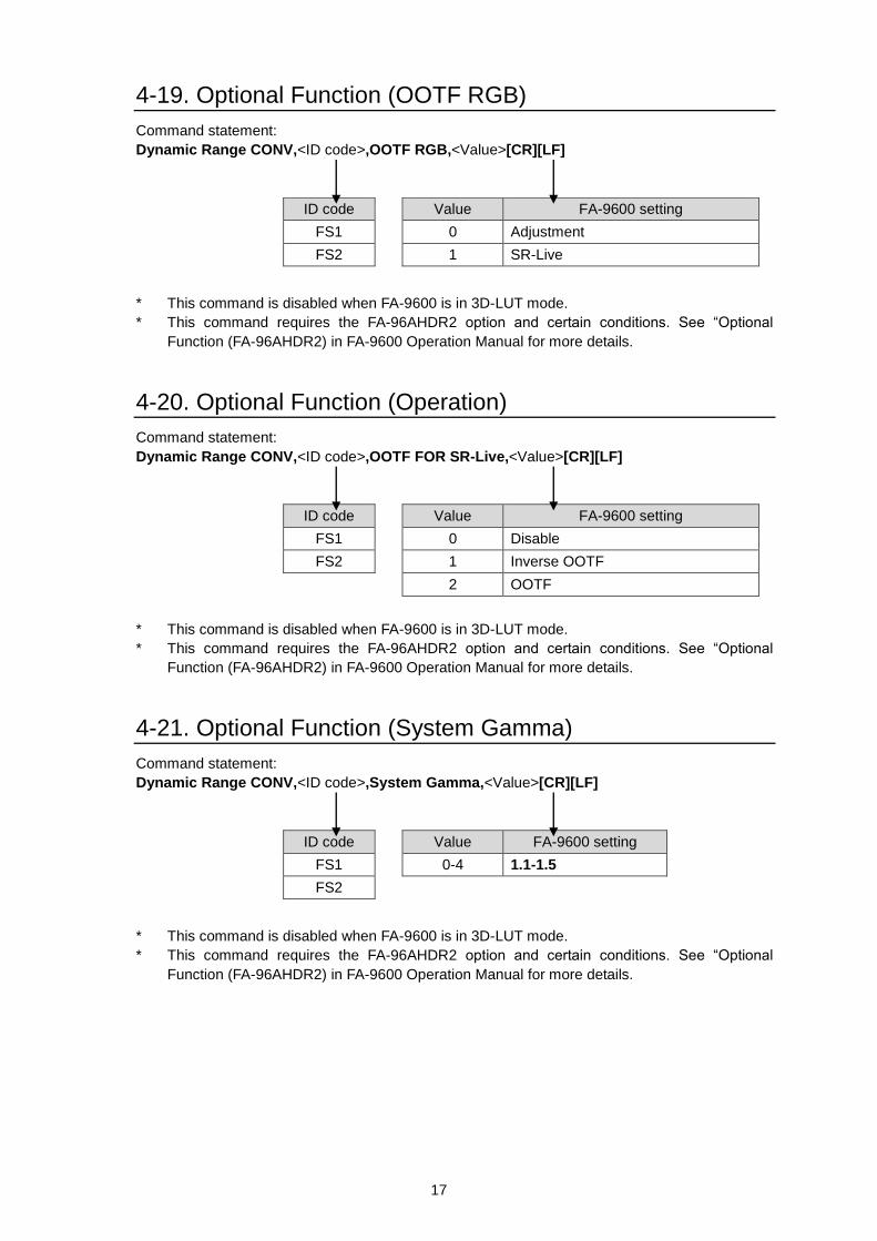
4-19. Optional Function (OOTF RGB)
Command statement:
Dynamic Range CONV,<ID code>,OOTF RGB,<Value>[CR][LF]
* This command is disabled when FA-9600 is in 3D-LUT mode.
* This command requires the FA-96AHDR2 option and certain conditions. See “Optional
Function (FA-96AHDR2) in FA-9600 Operation Manual for more details.
4-20. Optional Function (Operation)
Command statement:
Dynamic Range CONV,<ID code>,OOTF FOR SR-Live,<Value>[CR][LF]
* This command is disabled when FA-9600 is in 3D-LUT mode.
* This command requires the FA-96AHDR2 option and certain conditions. See “Optional
Function (FA-96AHDR2) in FA-9600 Operation Manual for more details.
4-21. Optional Function (System Gamma)
Command statement:
Dynamic Range CONV,<ID code>,System Gamma,<Value>[CR][LF]
* This command is disabled when FA-9600 is in 3D-LUT mode.
* This command requires the FA-96AHDR2 option and certain conditions. See “Optional
Function (FA-96AHDR2) in FA-9600 Operation Manual for more details.
Value FA-9600 setting
0 Disable
1 Inverse OOTF
2 OOTF
ID code
FS1
FS2
Value FA-9600 setting
0 Adjustment
1 SR-Live
ID code
FS1
FS2
Value FA-9600 setting
0-4 1.1-1.5
ID code
FS1
FS2
18
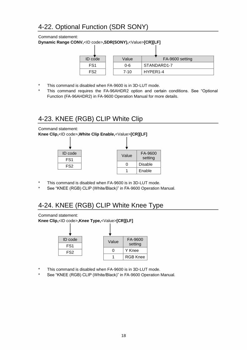
4-22. Optional Function (SDR SONY)
Command statement:
Dynamic Range CONV,<ID code>,SDR(SONY),<Value>[CR][LF]
* This command is disabled when FA-9600 is in 3D-LUT mode.
* This command requires the FA-96AHDR2 option and certain conditions. See “Optional
Function (FA-96AHDR2) in FA-9600 Operation Manual for more details.
4-23. KNEE (RGB) CLIP White Clip
Command statement:
Knee Clip,<ID code>,White Clip Enable,<Value>[CR][LF]
* This command is disabled when FA-9600 is in 3D-LUT mode.
* See “KNEE (RGB) CLIP (White/Black)” in FA-9600 Operation Manual.
4-24. KNEE (RGB) CLIP White Knee Type
Command statement:
Knee Clip,<ID code>,Knee Type,<Value>[CR][LF]
* This command is disabled when FA-9600 is in 3D-LUT mode.
* See “KNEE (RGB) CLIP (White/Black)” in FA-9600 Operation Manual.
Value FA-9600 setting
0 Disable
1 Enable
ID code
FS1
FS2
Value FA-9600 setting
0 Y Knee
1 RGB Knee
ID code
FS1
FS2
Value FA-9600 setting
0-6 STANDARD1-7
7-10 HYPER1-4
ID code
FS1
FS2
19
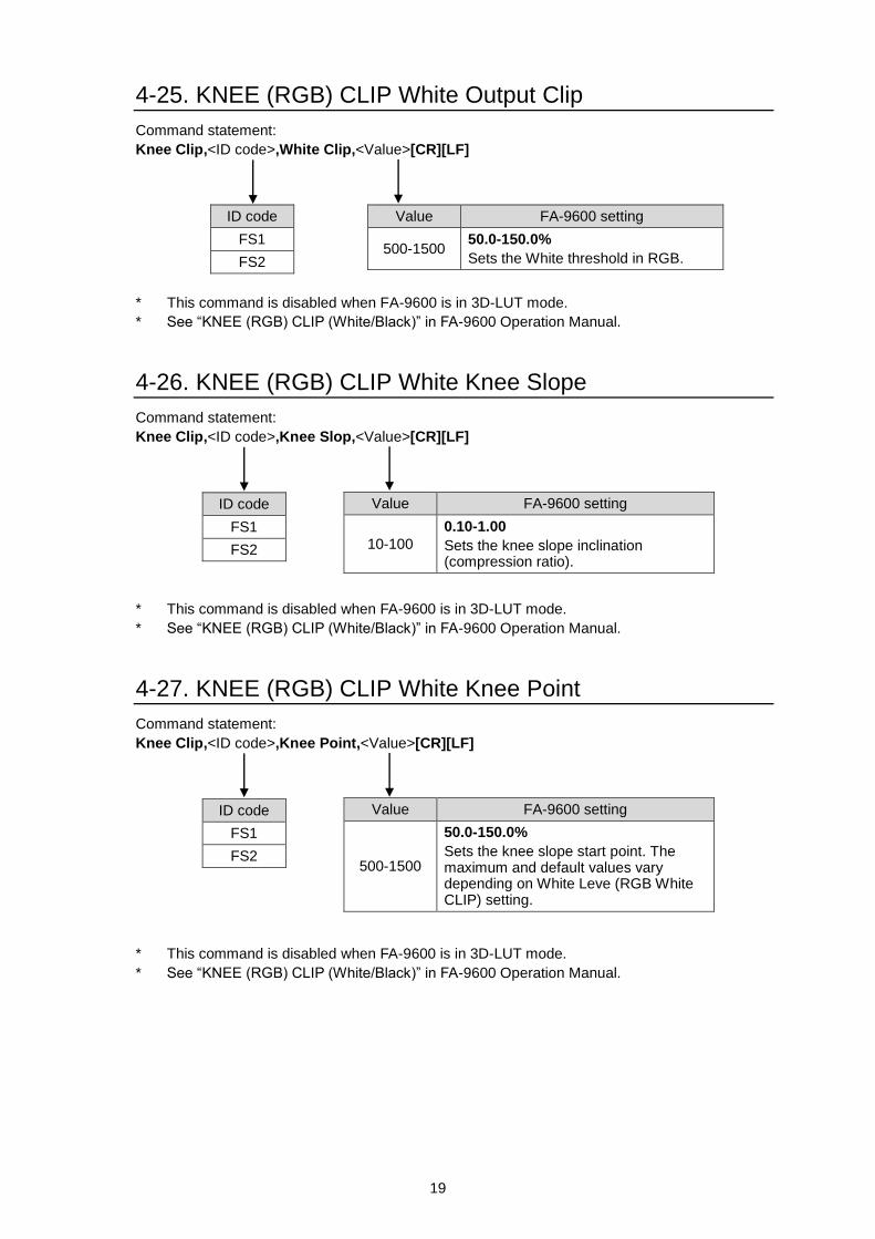
4-25. KNEE (RGB) CLIP White Output Clip
Command statement:
Knee Clip,<ID code>,White Clip,<Value>[CR][LF]
* This command is disabled when FA-9600 is in 3D-LUT mode.
* See “KNEE (RGB) CLIP (White/Black)” in FA-9600 Operation Manual.
4-26. KNEE (RGB) CLIP White Knee Slope
Command statement:
Knee Clip,<ID code>,Knee Slop,<Value>[CR][LF]
* This command is disabled when FA-9600 is in 3D-LUT mode.
* See “KNEE (RGB) CLIP (White/Black)” in FA-9600 Operation Manual.
4-27. KNEE (RGB) CLIP White Knee Point
Command statement:
Knee Clip,<ID code>,Knee Point,<Value>[CR][LF]
* This command is disabled when FA-9600 is in 3D-LUT mode.
* See “KNEE (RGB) CLIP (White/Black)” in FA-9600 Operation Manual.
Value FA-9600 setting
500-1500 50.0-150.0%
Sets the White threshold in RGB.
Value FA-9600 setting
10-100
0.10-1.00
Sets the knee slope inclination (compression ratio).
ID code
FS1
FS2
Value FA-9600 setting
500-1500
50.0-150.0%
Sets the knee slope start point. The maximum and default values vary depending on White Leve (RGB White CLIP) setting.
ID code
FS1
FS2
ID code
FS1
FS2
20
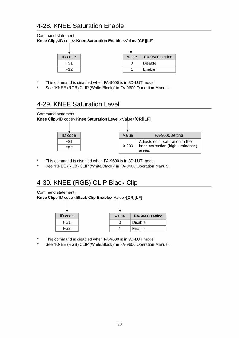
4-28. KNEE Saturation Enable
Command statement:
Knee Clip,<ID code>,Knee Saturation Enable,<Value>[CR][LF]
* This command is disabled when FA-9600 is in 3D-LUT mode.
* See “KNEE (RGB) CLIP (White/Black)” in FA-9600 Operation Manual.
4-29. KNEE Saturation Level
Command statement:
Knee Clip,<ID code>,Knee Saturation Level,<Value>[CR][LF]
* This command is disabled when FA-9600 is in 3D-LUT mode.
* See “KNEE (RGB) CLIP (White/Black)” in FA-9600 Operation Manual.
4-30. KNEE (RGB) CLIP Black Clip
Command statement:
Knee Clip,<ID code>,Black Clip Enable,<Value>[CR][LF]
* This command is disabled when FA-9600 is in 3D-LUT mode.
* See “KNEE (RGB) CLIP (White/Black)” in FA-9600 Operation Manual.
Value FA-9600 setting
0 Disable
1 Enable
ID code
FS1
FS2
Value FA-9600 setting
0 Disable
1 Enable
ID code
FS1
FS2
Value FA-9600 setting
0-200 Adjusts color saturation in the knee correction (high luminance) areas.
ID code
FS1
FS2
21
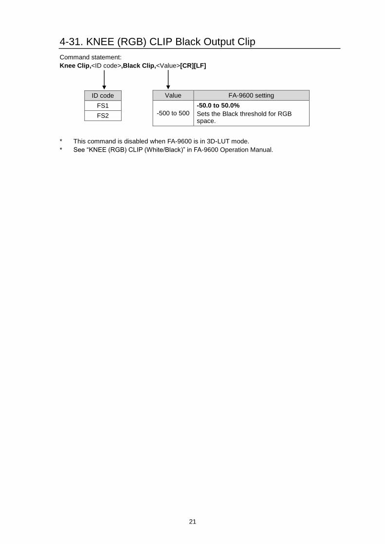
4-31. KNEE (RGB) CLIP Black Output Clip
Command statement:
Knee Clip,<ID code>,Black Clip,<Value>[CR][LF]
* This command is disabled when FA-9600 is in 3D-LUT mode.
* See “KNEE (RGB) CLIP (White/Black)” in FA-9600 Operation Manual.
Value FA-9600 setting
-500 to 500
-50.0 to 50.0%
Sets the Black threshold for RGB space.
ID code
FS1
FS2
22
5. Audio Commands
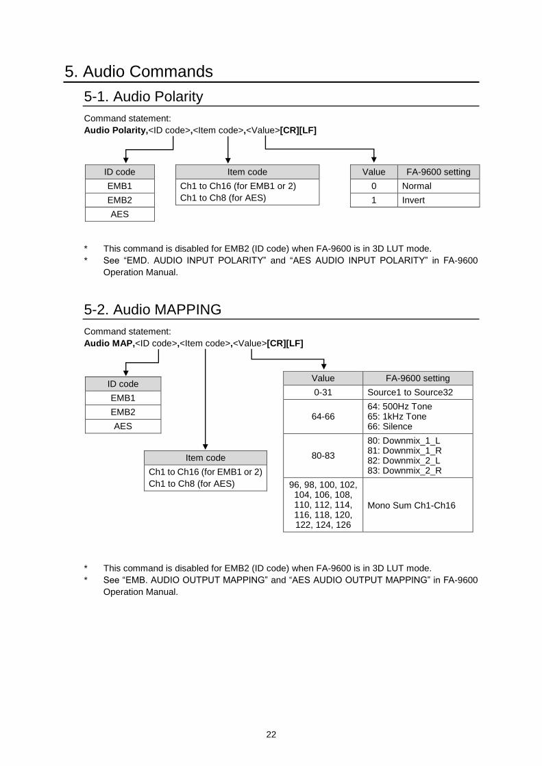
5-1. Audio Polarity
Command statement:
Audio Polarity,<ID code>,<Item code>,<Value>[CR][LF]
* This command is disabled for EMB2 (ID code) when FA-9600 is in 3D LUT mode.
* See “EMD. AUDIO INPUT POLARITY” and “AES AUDIO INPUT POLARITY” in FA-9600
Operation Manual.
5-2. Audio MAPPING
Command statement:
Audio MAP,<ID code>,<Item code>,<Value>[CR][LF]
* This command is disabled for EMB2 (ID code) when FA-9600 is in 3D LUT mode.
* See “EMB. AUDIO OUTPUT MAPPING” and “AES AUDIO OUTPUT MAPPING” in FA-9600
Operation Manual.
Value FA-9600 setting
0 Normal
1 Invert
ID code
EMB1
EMB2
AES
Item code
Ch1 to Ch16 (for EMB1 or 2)
Ch1 to Ch8 (for AES)
Value FA-9600 setting
0-31 Source1 to Source32
64-66 64: 500Hz Tone 65: 1kHz Tone 66: Silence
80-83
80: Downmix_1_L 81: Downmix_1_R 82: Downmix_2_L 83: Downmix_2_R
96, 98, 100, 102, 104, 106, 108, 110, 112, 114, 116, 118, 120, 122, 124, 126
Mono Sum Ch1-Ch16
ID code
EMB1
EMB2
AES
Item code
Ch1 to Ch16 (for EMB1 or 2)
Ch1 to Ch8 (for AES)
23
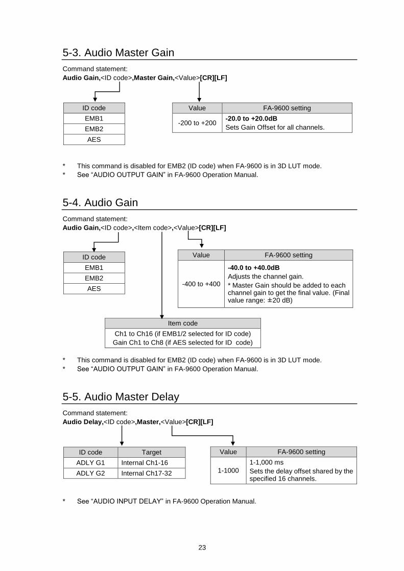
5-3. Audio Master Gain
Command statement:
Audio Gain,<ID code>,Master Gain,<Value>[CR][LF]
* This command is disabled for EMB2 (ID code) when FA-9600 is in 3D LUT mode.
* See “AUDIO OUTPUT GAIN” in FA-9600 Operation Manual.
5-4. Audio Gain
Command statement:
Audio Gain,<ID code>,<Item code>,<Value>[CR][LF]
* This command is disabled for EMB2 (ID code) when FA-9600 is in 3D LUT mode.
* See “AUDIO OUTPUT GAIN” in FA-9600 Operation Manual.
5-5. Audio Master Delay
Command statement:
Audio Delay,<ID code>,Master,<Value>[CR][LF]
* See “AUDIO INPUT DELAY” in FA-9600 Operation Manual.
Value FA-9600 setting
-200 to +200 -20.0 to +20.0dB
Sets Gain Offset for all channels.
ID code
EMB1
EMB2
AES
Value FA-9600 setting
-400 to +400
-40.0 to +40.0dB
Adjusts the channel gain.
* Master Gain should be added to each channel gain to get the final value. (Final value range: ±20 dB)
ID code
EMB1
EMB2
AES
Item code
Ch1 to Ch16 (if EMB1/2 selected for ID code)
Gain Ch1 to Ch8 (if AES selected for ID code)
Value FA-9600 setting
1-1000
1-1,000 ms
Sets the delay offset shared by the specified 16 channels.
ID code Target
ADLY G1 Internal Ch1-16
ADLY G2 Internal Ch17-32
24
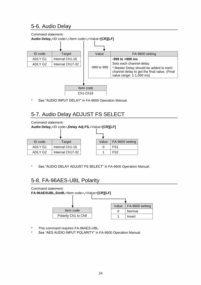
5-6. Audio Delay
Command statement:
Audio Delay,<ID code>,<Item code>,<Value>[CR][LF]
* See “AUDIO INPUT DELAY” in FA-9600 Operation Manual.
5-7. Audio Delay ADJUST FS SELECT
Command statement:
Audio Delay,<ID code>,Delay Adj FS,<Value>[CR][LF]
* See “AUDIO DELAY ADJUST FS SELECT” in FA-9600 Operation Manual.
5-8. FA-96AES-UBL Polarity
Command statement:
FA-96AESUBL,SlotB,<Item code>,<Value>[CR][LF]
* This command requires FA-96AES-UBL.
* See “AES AUDIO INPUT POLARITY” in FA-9600 Operation Manual.
Value FA-9600 setting
-999 to 999
-999 to +999 ms
Sets each channel delay.
* Master Delay should be added to each channel delay to get the final value. (Final value range: 1-1,000 ms)
ID code Target
ADLY G1 Internal Ch1-16
ADLY G2 Internal Ch17-32
Item code
Ch1-Ch16
Value FA-9600 setting
0 FS1
1 FS2
Value FA-9600 setting
0 Normal
1 Invert
Item code
Polarity Ch1 to Ch8
ID code Target
ADLY G1 Internal Ch1-16
ADLY G2 Internal Ch17-32
25
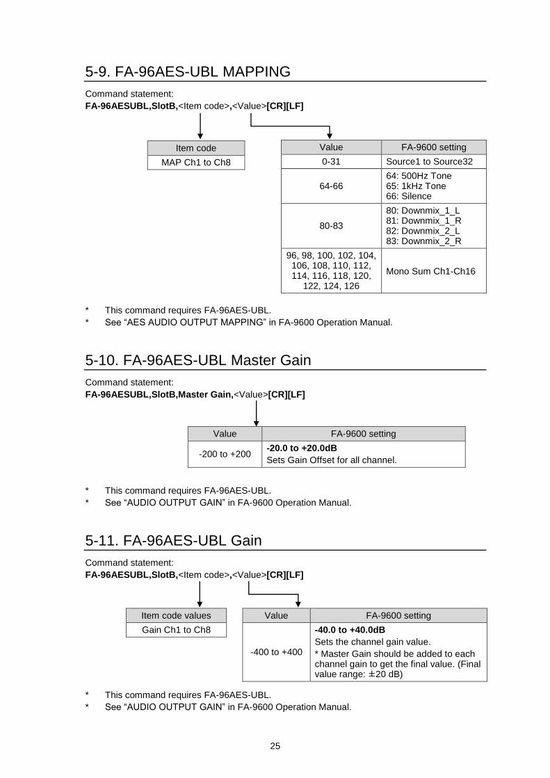
5-9. FA-96AES-UBL MAPPING
Command statement:
FA-96AESUBL,SlotB,<Item code>,<Value>[CR][LF]
* This command requires FA-96AES-UBL.
* See “AES AUDIO OUTPUT MAPPING” in FA-9600 Operation Manual.
5-10. FA-96AES-UBL Master Gain
Command statement:
FA-96AESUBL,SlotB,Master Gain,<Value>[CR][LF]
* This command requires FA-96AES-UBL.
* See “AUDIO OUTPUT GAIN” in FA-9600 Operation Manual.
5-11. FA-96AES-UBL Gain
Command statement:
FA-96AESUBL,SlotB,<Item code>,<Value>[CR][LF]
* This command requires FA-96AES-UBL.
* See “AUDIO OUTPUT GAIN” in FA-9600 Operation Manual.
Value FA-9600 setting
0-31 Source1 to Source32
64-66 64: 500Hz Tone 65: 1kHz Tone 66: Silence
80-83
80: Downmix_1_L 81: Downmix_1_R 82: Downmix_2_L 83: Downmix_2_R
96, 98, 100, 102, 104, 106, 108, 110, 112, 114, 116, 118, 120,
122, 124, 126
Mono Sum Ch1-Ch16
Item code
MAP Ch1 to Ch8
Value FA-9600 setting
-200 to +200 -20.0 to +20.0dB
Sets Gain Offset for all channel.
Value FA-9600 setting
-400 to +400
-40.0 to +40.0dB
Sets the channel gain value.
* Master Gain should be added to each channel gain to get the final value. (Final value range: ±20 dB)
Item code values
Gain Ch1 to Ch8
26
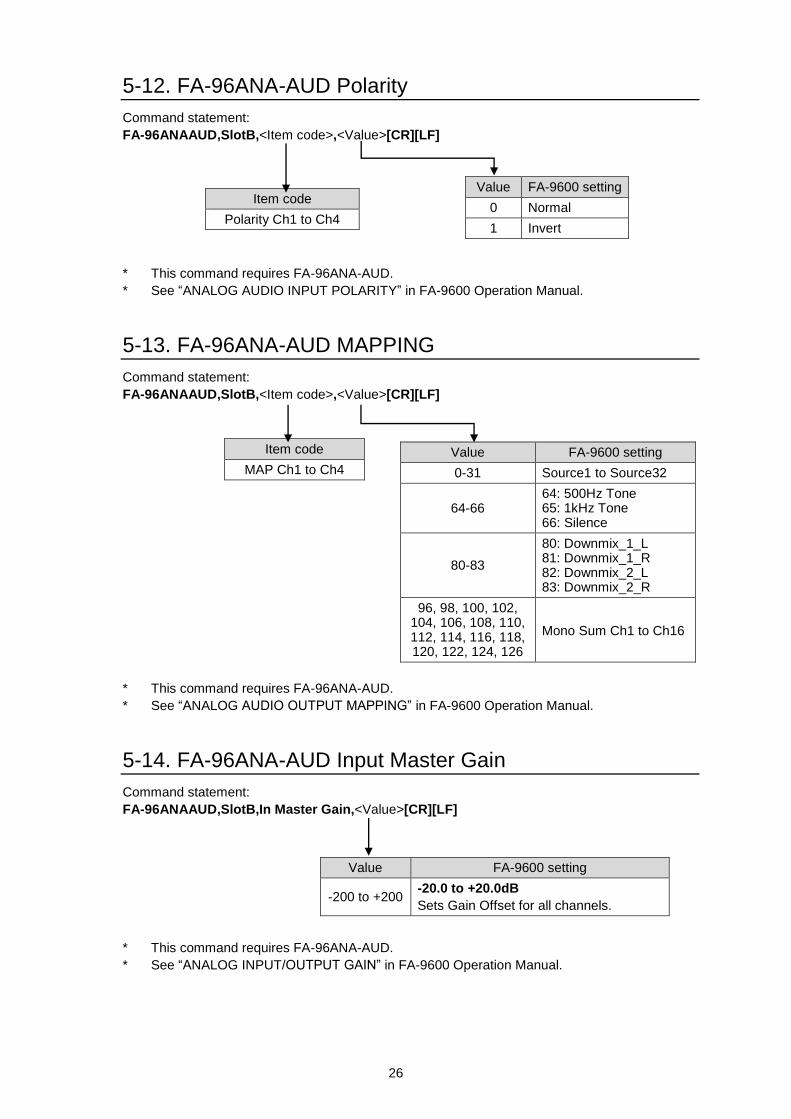
5-12. FA-96ANA-AUD Polarity
Command statement:
FA-96ANAAUD,SlotB,<Item code>,<Value>[CR][LF]
* This command requires FA-96ANA-AUD.
* See “ANALOG AUDIO INPUT POLARITY” in FA-9600 Operation Manual.
5-13. FA-96ANA-AUD MAPPING
Command statement:
FA-96ANAAUD,SlotB,<Item code>,<Value>[CR][LF]
* This command requires FA-96ANA-AUD.
* See “ANALOG AUDIO OUTPUT MAPPING” in FA-9600 Operation Manual.
5-14. FA-96ANA-AUD Input Master Gain
Command statement:
FA-96ANAAUD,SlotB,In Master Gain,<Value>[CR][LF]
* This command requires FA-96ANA-AUD.
* See “ANALOG INPUT/OUTPUT GAIN” in FA-9600 Operation Manual.
Value FA-9600 setting
0 Normal
1 Invert
Item code
Polarity Ch1 to Ch4
Value FA-9600 setting
0-31 Source1 to Source32
64-66 64: 500Hz Tone 65: 1kHz Tone 66: Silence
80-83
80: Downmix_1_L 81: Downmix_1_R 82: Downmix_2_L 83: Downmix_2_R
96, 98, 100, 102, 104, 106, 108, 110, 112, 114, 116, 118, 120, 122, 124, 126
Mono Sum Ch1 to Ch16
Item code
MAP Ch1 to Ch4
Value FA-9600 setting
-200 to +200 -20.0 to +20.0dB
Sets Gain Offset for all channels.
27
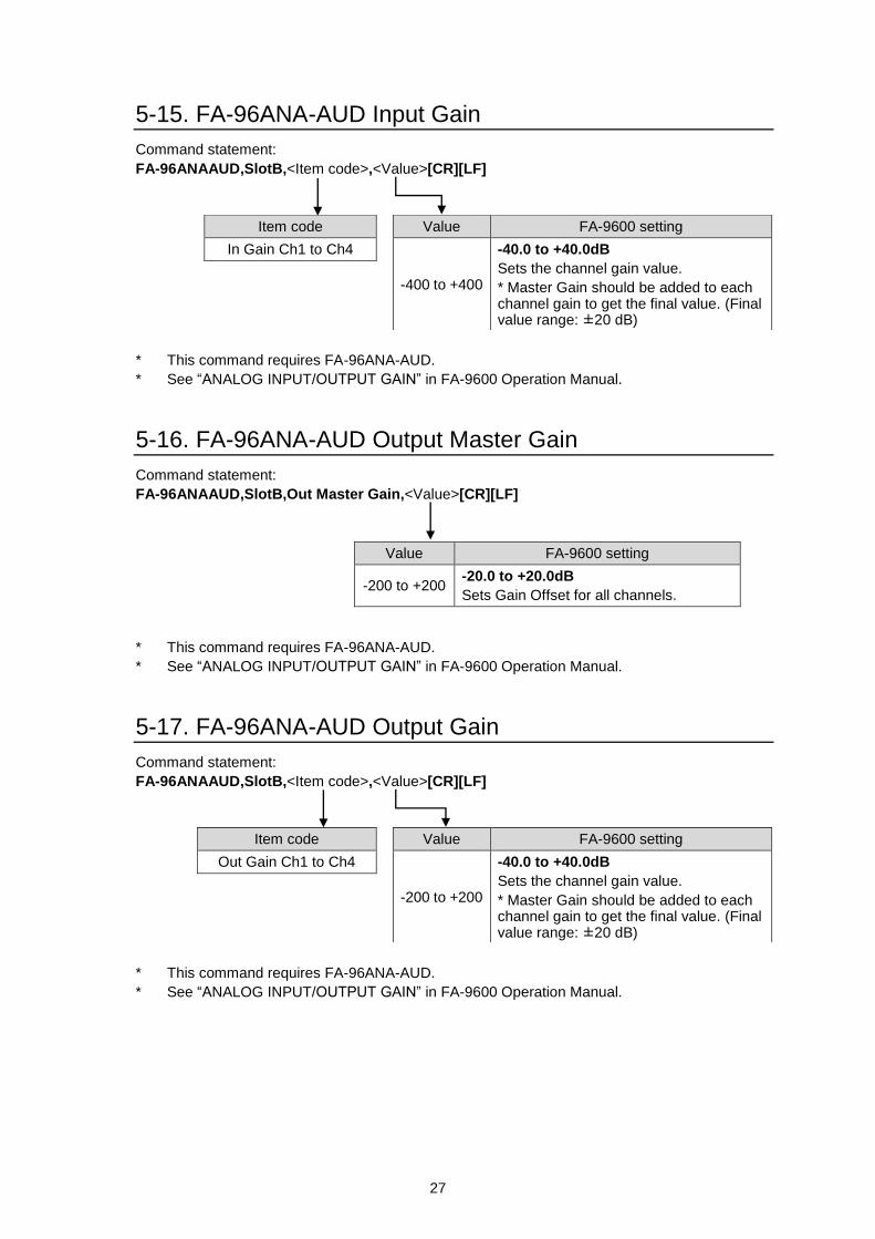
5-15. FA-96ANA-AUD Input Gain
Command statement:
FA-96ANAAUD,SlotB,<Item code>,<Value>[CR][LF]
* This command requires FA-96ANA-AUD.
* See “ANALOG INPUT/OUTPUT GAIN” in FA-9600 Operation Manual.
5-16. FA-96ANA-AUD Output Master Gain
Command statement:
FA-96ANAAUD,SlotB,Out Master Gain,<Value>[CR][LF]
* This command requires FA-96ANA-AUD.
* See “ANALOG INPUT/OUTPUT GAIN” in FA-9600 Operation Manual.
5-17. FA-96ANA-AUD Output Gain
Command statement:
FA-96ANAAUD,SlotB,<Item code>,<Value>[CR][LF]
* This command requires FA-96ANA-AUD.
* See “ANALOG INPUT/OUTPUT GAIN” in FA-9600 Operation Manual.
Value FA-9600 setting
-400 to +400
-40.0 to +40.0dB
Sets the channel gain value.
* Master Gain should be added to each channel gain to get the final value. (Final value range: ±20 dB)
Item code
In Gain Ch1 to Ch4
Value FA-9600 setting
-200 to +200 -20.0 to +20.0dB
Sets Gain Offset for all channels.
Value FA-9600 setting
-200 to +200
-40.0 to +40.0dB
Sets the channel gain value.
* Master Gain should be added to each channel gain to get the final value. (Final value range: ±20 dB)
Item code
Out Gain Ch1 to Ch4
28
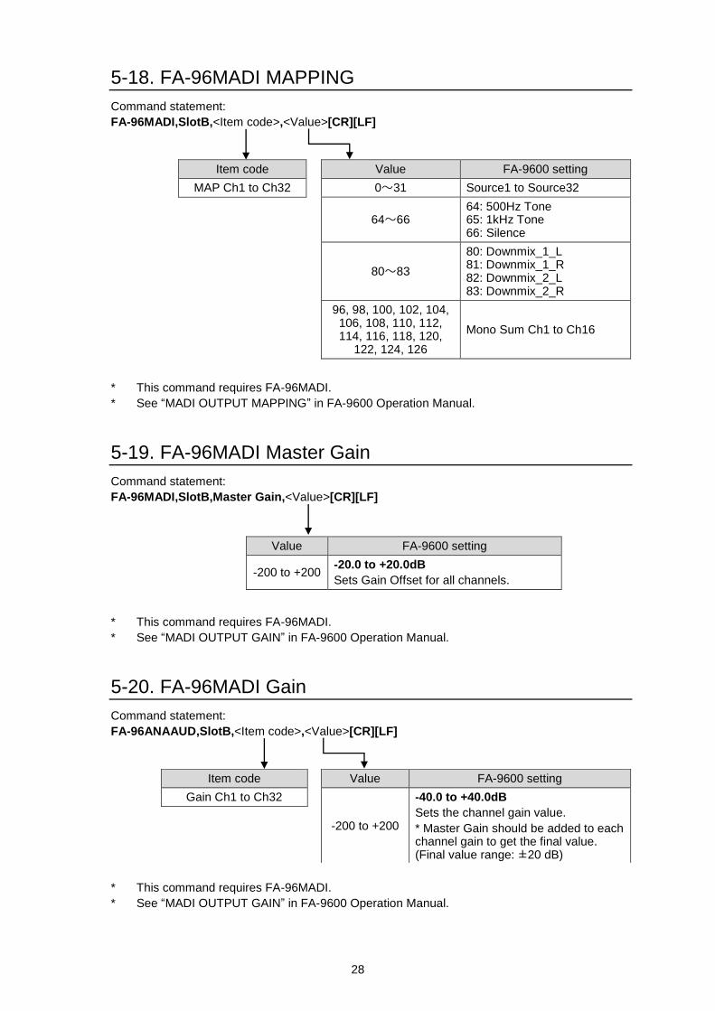
5-18. FA-96MADI MAPPING
Command statement:
FA-96MADI,SlotB,<Item code>,<Value>[CR][LF]
* This command requires FA-96MADI.
* See “MADI OUTPUT MAPPING” in FA-9600 Operation Manual.
5-19. FA-96MADI Master Gain
Command statement:
FA-96MADI,SlotB,Master Gain,<Value>[CR][LF]
* This command requires FA-96MADI.
* See “MADI OUTPUT GAIN” in FA-9600 Operation Manual.
5-20. FA-96MADI Gain
Command statement:
FA-96ANAAUD,SlotB,<Item code>,<Value>[CR][LF]
* This command requires FA-96MADI.
* See “MADI OUTPUT GAIN” in FA-9600 Operation Manual.
Value FA-9600 setting
0~31 Source1 to Source32
64~66 64: 500Hz Tone 65: 1kHz Tone 66: Silence
80~83
80: Downmix_1_L 81: Downmix_1_R 82: Downmix_2_L 83: Downmix_2_R
96, 98, 100, 102, 104, 106, 108, 110, 112, 114, 116, 118, 120,
122, 124, 126
Mono Sum Ch1 to Ch16
Item code
MAP Ch1 to Ch32
Value FA-9600 setting
-200 to +200 -20.0 to +20.0dB
Sets Gain Offset for all channels.
Value FA-9600 setting
-200 to +200
-40.0 to +40.0dB
Sets the channel gain value.
* Master Gain should be added to each channel gain to get the final value. (Final value range: ±20 dB)
Item code
Gain Ch1 to Ch32
29
6. Other Commands
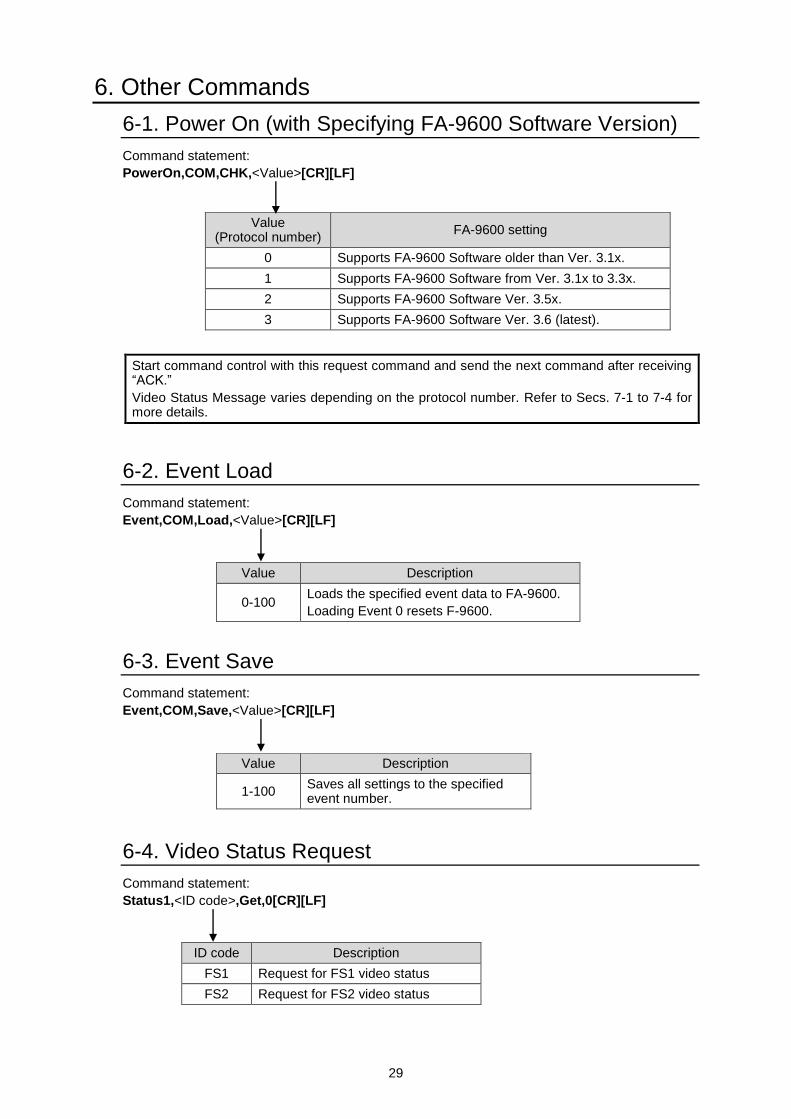
6-1. Power On (with Specifying FA-9600 Software Version)
Command statement:
PowerOn,COM,CHK,<Value>[CR][LF]
Start command control with this request command and send the next command after receiving “ACK.”
Video Status Message varies depending on the protocol number. Refer to Secs. 7-1 to 7-4 for more details.
6-2. Event Load
Command statement:
Event,COM,Load,<Value>[CR][LF]
6-3. Event Save
Command statement:
Event,COM,Save,<Value>[CR][LF]
6-4. Video Status Request
Command statement:
Status1,<ID code>,Get,0[CR][LF]
Value Description
0-100 Loads the specified event data to FA-9600.
Loading Event 0 resets F-9600.
Value Description
1-100 Saves all settings to the specified event number.
ID code Description
FS1 Request for FS1 video status
FS2 Request for FS2 video status
Value (Protocol number)
FA-9600 setting
0 Supports FA-9600 Software older than Ver. 3.1x.
1 Supports FA-9600 Software from Ver. 3.1x to 3.3x.
2 Supports FA-9600 Software Ver. 3.5x.
3 Supports FA-9600 Software Ver. 3.6 (latest).
30
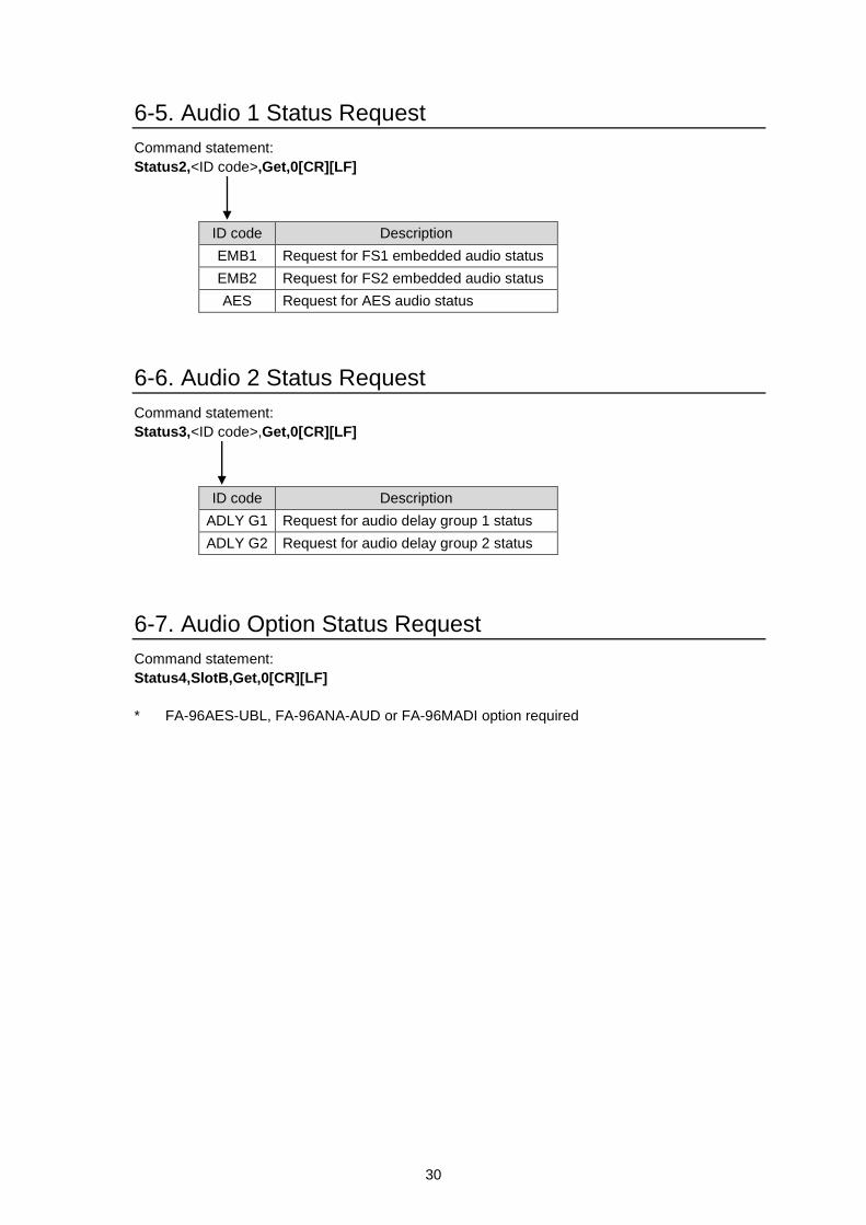
6-5. Audio 1 Status Request
Command statement:
Status2,<ID code>,Get,0[CR][LF]
6-6. Audio 2 Status Request
Command statement:
Status3,<ID code>,Get,0[CR][LF]
6-7. Audio Option Status Request
Command statement:
Status4,SlotB,Get,0[CR][LF]
* FA-96AES-UBL, FA-96ANA-AUD or FA-96MADI option required
ID code Description
EMB1 Request for FS1 embedded audio status
EMB2 Request for FS2 embedded audio status
AES Request for AES audio status
ID code Description
ADLY G1 Request for audio delay group 1 status
ADLY G2 Request for audio delay group 2 status
31
7. Status Messages from FA-9600
FA-9600 issues a status message whenever the either of the following conditions is met:
1. FA-9600 receives a status request command from a Command Device.
2. FA-9600 status changes by other means than the remote commands. (Status report)
FA-9600 sends status messages using UDP/IP protocols.
For Condition 2 (status report), FA-9600 detects changes at 500 - 1000 msec intervals. If any change is
detected, only the changed item status is reported.
Send ACK[CR][LF] when receiving status report messages. Otherwise, FA-9600 re-transmits the
message up to three times at 1 sec intervals and no ACK is still returned, FA-9600 performs the timeout
processing.
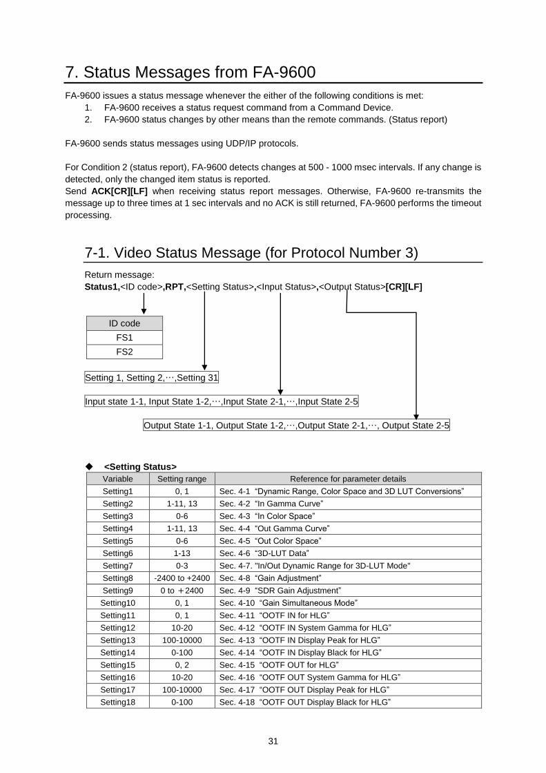
7-1. Video Status Message (for Protocol Number 3)
Return message:
Status1,<ID code>,RPT,<Setting Status>,<Input Status>,<Output Status>[CR][LF]
ID code
FS1
FS2
Setting 1, Setting 2,…,Setting 31
Input state 1-1, Input State 1-2,…,Input State 2-1,…,Input State 2-5
Output State 1-1, Output State 1-2,…,Output State 2-1,…, Output State 2-5
<Setting Status>
Variable Setting range Reference for parameter details
Setting1 0, 1 Sec. 4-1 “Dynamic Range, Color Space and 3D LUT Conversions”
Setting2 1-11, 13 Sec. 4-2 “In Gamma Curve”
Setting3 0-6 Sec. 4-3 “In Color Space”
Setting4 1-11, 13 Sec. 4-4 “Out Gamma Curve”
Setting5 0-6 Sec. 4-5 “Out Color Space”
Setting6 1-13 Sec. 4-6 “3D-LUT Data”
Setting7 0-3 Sec. 4-7. "In/Out Dynamic Range for 3D-LUT Mode"
Setting8 -2400 to +2400 Sec. 4-8 “Gain Adjustment”
Setting9 0 to +2400 Sec. 4-9 “SDR Gain Adjustment”
Setting10 0, 1 Sec. 4-10 “Gain Simultaneous Mode”
Setting11 0, 1 Sec. 4-11 “OOTF IN for HLG”
Setting12 10-20 Sec. 4-12 “OOTF IN System Gamma for HLG”
Setting13 100-10000 Sec. 4-13 “OOTF IN Display Peak for HLG”
Setting14 0-100 Sec. 4-14 “OOTF IN Display Black for HLG”
Setting15 0, 2 Sec. 4-15 “OOTF OUT for HLG”
Setting16 10-20 Sec. 4-16 “OOTF OUT System Gamma for HLG”
Setting17 100-10000 Sec. 4-17 “OOTF OUT Display Peak for HLG”
Setting18 0-100 Sec. 4-18 “OOTF OUT Display Black for HLG”
32
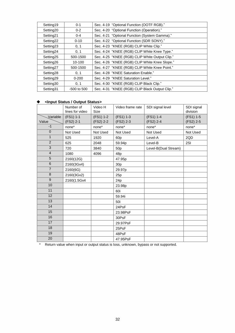
Setting19 0-1 Sec. 4-19 “Optional Function (OOTF RGB).”
Setting20 0-2 Sec. 4-20 “Optional Function (Operation).”
Setting21 0-4 Sec. 4-21 “Optional Function (System Gamma).”
Setting22 0-10 Sec. 4-22 “Optional Function (SDR SONY).”
Setting23 0, 1 Sec. 4-23 “KNEE (RGB) CLIP White Clip.”
Setting24 0, 1 Sec. 4-24 “KNEE (RGB) CLIP White Knee Type.”
Setting25 500-1500 Sec. 4-25 “KNEE (RGB) CLIP White Output Clip.”
Setting26 10-100 Sec. 4-26 “KNEE (RGB) CLIP White Knee Slope.”
Setting27 500-1500 Sec. 4-27 “KNEE (RGB) CLIP White Knee Point.”
Setting28 0, 1 Sec. 4-28 “KNEE Saturation Enable.”
Setting29 0-200 Sec. 4-29 “KNEE Saturation Level.”
Setting30 0, 1 Sec. 4-30 “KNEE (RGB) CLIP Black Clip.”
Setting31 -500 to 500 Sec. 4-31 “KNEE (RGB) CLIP Black Output Clip.”
<Input Status / Output Status>
Number of
lines for video
Video H
Size
Video frame rate SDI signal level SDI signal
division
Variable
Value
(FS1) 1-1
(FS2) 2-1
(FS1) 1-2
(FS2) 2-2
(FS1) 1-3
(FS2) 2-3
(FS1) 1-4
(FS2) 2-4
(FS1) 1-5
(FS2) 2-5
-1 none* none* none* none* none*
0 Not Used Not Used Not Used Not Used Not Used
1 525 1920 60p Level-A 2QD
2 625 2048 59.94p Level-B 2SI
3 720 3840 50p Level-B(Dual Stream)
4 1080 4096 48p
5 2160(12G) 47.95p
6 2160(3Gx4) 30p
7 2160(6G) 29.97p
8 2160(3Gx2) 25p
9 2160(1.5Gx4 24p
10 23.98p
11 60i
12 59.94i
13 50i
14 24PsF
15 23.98PsF
16 30PsF
17 29.97PsF
18 25PsF
19 48PsF
20 47.95PsF
* Return value when input or output status is loss, unknown, bypass or not supported.
33
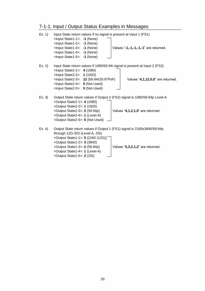
7-1-1. Input / Output Status Examples in Messages
Ex. 1) Input State return values if no signal is present at Input 1 (FS1)
<Input State1-1>: -1 (None)
<Input State1-2>: -1 (None)
<Input State1-3>: -1 (None) Values “-1,-1,-1,-1,-1” are returned.
<Input State1-4>: -1 (None)
<Input State1-5>: -1 (None)
Ex. 2) Input State return values if 1080/59.94i signal is present at Input 2 (FS2)
<Input State2-1>: 4 (1080)
<Input State2-2>: 1 (1920)
<Input State2-3>: 12 (59.94i/29.97PsF) Values “4,1,12,0,0” are returned.
<Input State2-4>: 0 (Not Used)
<Input State2-5>: 0 (Not Used)
Ex. 3) Output State return values if Output 2 (FS2) signal is 1080/59.94p Level-A
<Output State2-1>: 4 (1080)
<Output State2-2>: 1 (1920)
<Output State2-3>: 2 (59.94p) Values “4,1,2,1,0” are returned.
<Output State2-4>: 1 (Level-A)
<Output State2-5>: 0 (Not Used)
Ex. 4) Output State return values if Output 1 (FS1) signal is 2160x3840/59.94p
through 12G-SDI (Level-A, 2SI)
<Output State1-1>: 5 (2160 (12G))
<Output State1-2>: 3 (3840)
<Output State1-3>: 2 (59.94p) Values “5,3,2,1,2” are returned.
<Output State1-4>: 1 (Level-A)
<Output State1-5>: 2 (2SI)
34
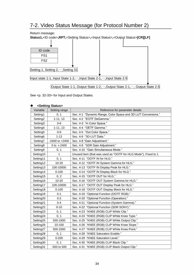
7-2. Video Status Message (for Protocol Number 2)
Return message:
Status1,<ID code>,RPT,<Setting Status>,<Input Status>,<Output Status>[CR][LF]
ID code
FS1
FS2
Setting 1, Setting 2,…,Setting 31
Input state 1-1, Input State 1-2,…,Input State 2-1,…,Input State 2-5
Output State 1-1, Output State 1-2,…,Output State 2-1,…, Output State 2-5
See <p. 32-33> for Input and Output States.
<Setting Status>
Variable Setting range Reference for parameter details
Setting1 0, 1 Sec. 4-1 “Dynamic Range, Color Space and 3D LUT Conversions.”
Setting2 1-11, 13 Sec. 4-2 “EOTF DeGamma.”
Setting3 0-6 Sec. 4-3 “In Color Space.”
Setting4 1-11, 13 Sec. 4-4 “OETF Gamma.”
Setting5 0-6 Sec. 4-5 “Out Color Space.”
Setting6 1-13 Sec. 4-6 “3D-LUT Data.”
Setting7 -2400 to +2400 Sec. 4-8 “Gain Adjustment.”
Setting8 0 to +2400 Sec. 4-9 “SDR Gain Adjustment.”
Setting9 0, 1 Sec. 4-10 “Gain Simultaneous Mode.”
Setting10 1 Unused item (that was used as "OOTF for HLG Mode"). Fixed to 1
Setting11 0, 1 Sec. 4-11 “OOTF IN for HLG.”
Setting12 10-20 Sec. 4-12 “OOTF IN System Gamma for HLG.”
Setting13 100-10000 Sec. 4-13 “OOTF IN Display Peak for HLG.”
Setting14 0-100 Sec. 4-14 “OOTF IN Display Black for HLG.”
Setting15 0, 2 Sec. 4-15 “OOTF OUT for HLG.”
Setting16 10-20 Sec. 4-16 “OOTF OUT System Gamma for HLG.”
Setting17 100-10000 Sec. 4-17 “OOTF OUT Display Peak for HLG.”
Setting18 0-100 Sec. 4-18 “OOTF OUT Display Black for HLG.”
Setting19 0-1 Sec. 4-19 “Optional Function (OOTF RGB).”
Setting20 0-2 Sec. 4-20 “Optional Function (Operation).”
Setting21 0-4 Sec. 4-21 “Optional Function (System Gamma).”
Setting22 0-10 Sec. 4-22 “Optional Function (SDR SONY).”
Setting23 0, 1 Sec. 4-23 “KNEE (RGB) CLIP White Clip.”
Setting24 0, 1 Sec. 4-24 “KNEE (RGB) CLIP White Knee Type.”
Setting25 500-1500 Sec. 4-25 “KNEE (RGB) CLIP White Output Clip.”
Setting26 10-100 Sec. 4-26 “KNEE (RGB) CLIP White Knee Slope.”
Setting27 500-1500 Sec. 4-27 “KNEE (RGB) CLIP White Knee Point.”
Setting28 0, 1 Sec. 4-28 “KNEE Saturation Enable.”
Setting29 0-200 Sec. 4-29 “KNEE Saturation Level.”
Setting30 0, 1 Sec. 4-30 “KNEE (RGB) CLIP Black Clip.”
Setting31 -500 to 500 Sec. 4-31 “KNEE (RGB) CLIP Black Output Clip.”
35
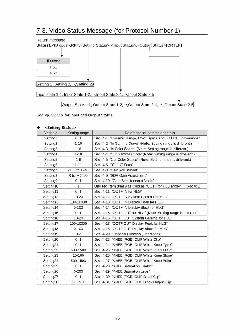
7-3. Video Status Message (for Protocol Number 1)
Return message:
Status1,<ID code>,RPT,<Setting Status>,<Input Status>,<Output Status>[CR][LF]
ID code
FS1
FS2
Setting 1, Setting 2,…,Setting 28
Input state 1-1, Input State 1-2,…,Input State 2-1,…,Input State 2-5
Output State 1-1, Output State 1-2,…,Output State 2-1,…, Output State 2-5
See <p. 32-33> for Input and Output States.
<Setting Status>
Variable Setting range Reference for parameter details
Setting1 0, 1 Sec. 4-1 “Dynamic Range, Color Space and 3D LUT Conversions”
Setting2 1-10 Sec. 4-2 “In Gamma Curve” (Note: Setting range is different.)
Setting3 1-6 Sec. 4-3 “In Color Space” (Note: Setting range is different.)
Setting4 1-10 Sec. 4-4 “Out Gamma Curve” (Note: Setting range is different.)
Setting5 1-6 Sec. 4-5 “Out Color Space” (Note: Setting range is different.)
Setting6 1-11 Sec. 4-6 “3D-LUT Data”
Setting7 -2400 to +2400 Sec. 4-8 “Gain Adjustment”
Setting8 0 to +2400 Sec. 4-9 “SDR Gain Adjustment”
Setting9 0, 1 Sec. 4-10 “Gain Simultaneous Mode”
Setting10 1 Unused item (that was used as "OOTF for HLG Mode"). Fixed to 1
Setting11 0, 1 Sec. 4-11 “OOTF IN for HLG”
Setting12 10-20 Sec. 4-12 “OOTF IN System Gamma for HLG”
Setting13 100-10000 Sec. 4-13 “OOTF IN Display Peak for HLG”
Setting14 0-100 Sec. 4-14 “OOTF IN Display Black for HLG”
Setting15 0, 1 Sec. 4-15 “OOTF OUT for HLG” (Note: Setting range is different.)
Setting16 10-20 Sec. 4-16 “OOTF OUT System Gamma for HLG”
Setting17 100-10000 Sec. 4-17 “OOTF OUT Display Peak for HLG”
Setting18 0-100 Sec. 4-18 “OOTF OUT Display Black for HLG”
Setting19 0-2 Sec. 4-20 “Optional Function (Operation)”
Setting20 0, 1 Sec. 4-23 “KNEE (RGB) CLIP White Clip”
Setting21 0, 1 Sec. 4-24 “KNEE (RGB) CLIP White Knee Type”
Setting22 500-1500 Sec. 4-25 “KNEE (RGB) CLIP White Output Clip”
Setting23 10-100 Sec. 4-26 “KNEE (RGB) CLIP White Knee Slope”
Setting24 500-1500 Sec. 4-27 “KNEE (RGB) CLIP White Knee Point”
Setting25 0, 1 Sec. 4-28 “KNEE Saturation Enable”
Setting26 0-200 Sec. 4-29 “KNEE Saturation Level”
Setting27 0, 1 Sec. 4-30 “KNEE (RGB) CLIP Black Clip”
Setting28 -500 to 500 Sec. 4-31 “KNEE (RGB) CLIP Black Output Clip”
36
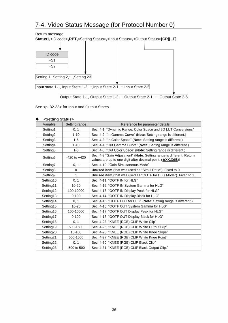
7-4. Video Status Message (for Protocol Number 0)
Return message:
Status1,<ID code>,RPT,<Setting Status>,<Input Status>,<Output Status>[CR][LF]
ID code
FS1
FS2
Setting 1, Setting 2,…,Setting 23
Input state 1-1, Input State 1-2,…,Input State 2-1,…,Input State 2-5
Output State 1-1, Output State 1-2,…,Output State 2-1,…, Output State 2-5
See <p. 32-33> for Input and Output States.
<Setting Status>
Variable Setting range Reference for parameter details
Setting1 0, 1 Sec. 4-1 “Dynamic Range, Color Space and 3D LUT Conversions”
Setting2 1-10 Sec. 4-2 “In Gamma Curve” (Note: Setting range is different.)
Setting3 1-6 Sec. 4-3 “In Color Space” (Note: Setting range is different.)
Setting4 1-10 Sec. 4-4 “Out Gamma Curve” (Note: Setting range is different.)
Setting5 1-6 Sec. 4-5 “Out Color Space” (Note: Setting range is different.)
Setting6 -420 to +420 Sec. 4-8 “Gain Adjustment” (Note: Setting range is different. Return
values are up to one digit after decimal point. (±XX.XdB))
Setting7 0, 1 Sec. 4-10 “Gain Simultaneous Mode”
Setting8 0 Unused item (that was used as "Simul Ratio"). Fixed to 0
Setting9 1 Unused item (that was used as "OOTF for HLG Mode"). Fixed to 1
Setting10 0, 1 Sec. 4-11 “OOTF IN for HLG”
Setting11 10-20 Sec. 4-12 “OOTF IN System Gamma for HLG”
Setting12 100-10000 Sec. 4-13 “OOTF IN Display Peak for HLG”
Setting13 0-100 Sec. 4-14 “OOTF IN Display Black for HLG”
Setting14 0, 1 Sec. 4-15 “OOTF OUT for HLG” (Note: Setting range is different.)
Setting15 10-20 Sec. 4-16 “OOTF OUT System Gamma for HLG”
Setting16 100-10000 Sec. 4-17 “OOTF OUT Display Peak for HLG”
Setting17 0-100 Sec. 4-18 “OOTF OUT Display Black for HLG”
Setting18 0, 1 Sec. 4-23 “KNEE (RGB) CLIP White Clip”
Setting19 500-1500 Sec. 4-25 “KNEE (RGB) CLIP White Output Clip”
Setting20 10-100 Sec. 4-26 “KNEE (RGB) CLIP White Knee Slope”
Setting21 500-1500 Sec. 4-27 “KNEE (RGB) CLIP White Knee Point”
Setting22 0, 1 Sec. 4-30 “KNEE (RGB) CLIP Black Clip”
Setting23 -500 to 500 Sec. 4-31 “KNEE (RGB) CLIP Black Output Clip.”
37
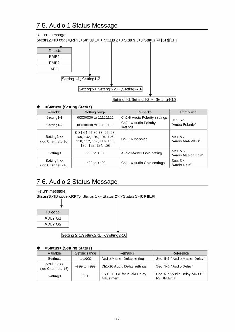
7-5. Audio 1 Status Message
Return message:
Status2,<ID code>,RPT,<Status 1>,< Status 2>,<Status 3>,<Status 4>[CR][LF]
ID code
EMB1
EMB2
AES
Setting1-1, Setting1-2
Setting2-1,Setting2-2,…,Setting2-16
Setting4-1,Setting4-2,…,Setting4-16
<Status> (Setting Status)
Variable Setting range Remarks Reference
Setting1-1 00000000 to 11111111 Ch1-8 Audio Polarity settings Sec. 5-1
“Audio Polarity” Setting1-2 00000000 to 11111111 Ch9-16 Audio Polarity
settings
Setting2-xx
(xx: Channel1-16)
0-31,64-66,80-83, 96, 98,
100, 102, 104, 106, 108,
110, 112, 114, 116, 118,
120, 122, 124, 126
Ch1-16 mapping Sec. 5-2
“Audio MAPPING”
Setting3 -200 to +200 Audio Master Gain setting Sec. 5-3
“Audio Master Gain”
Setting4-xx
(xx: Channel1-16) -400 to +400 Ch1-16 Audio Gain settings
Sec. 5-4
“Audio Gain”
7-6. Audio 2 Status Message
Return message:
Status3,<ID code>,RPT,<Status 1>,<Status 2>,<Status 3>[CR][LF]
ID code
ADLY G1
ADLY G2
Setting 2-1,Setting2-2,…,Setting2-16
<Status> (Setting Status)
Variable Setting range Remarks Reference
Setting1 1-1000 Audio Master Delay setting Sec. 5-5 “Audio Master Delay“
Setting2-xx
(xx: Channel1-16) -999 to +999 Ch1-16 Audio Delay settings Sec. 5-6 “Audio Delay”
Setting3 0, 1 FS SELECT for Audio Delay
Adjustment.
Sec. 5-7 “Audio Delay ADJUST
FS SELECT“
38
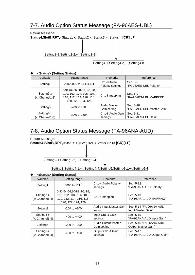
7-7. Audio Option Status Message (FA-96AES-UBL)
Return Message:
Status4,SlotB,RPT,<Status1>,<Status2>,<Status3>,<Status4>[CR][LF]
Setting2-1,Setting2-2,…,Setting2-8
Setting4-1,Setting4-2,…,Setting4-8
<Status> (Setting Status)
Variable Setting range Remarks Reference
Setting1 00000000 to 11111111 Ch1-8 Audio
Polarity settings
Sec. 5-8
“FA-96AES-UBL Polarity”
Setting2-x
(x: Channel1-8)
0-31,64-66,80-83, 96, 98,
100, 102, 104, 106, 108,
110, 112, 114, 116, 118,
120, 122, 124, 126
Ch1-8 mapping Sec. 5-9
“FA-96AES-UBL MAPPING”
Setting3 -200 to +200 Audio Master
Gain setting
Sec. 5-10
“FA-96AES-UBL Master Gain”
Setting4-x
(x: Channel1-8) -400 to +400
Ch1-8 Audio Gain
settings
Sec. 5-11
“FA-96AES-UBL Gain”
7-8. Audio Option Status Message (FA-96ANA-AUD)
Return Message:
Status4,SlotB,RPT,<Status1>,<Status2>,<Status3 to 6>[CR][LF]
Setting2-1,Setting2-2,…,Setting 2-4
Setting3,Setting4-1,…,Setting4-4,Setting5,Setting6-1,…,Setting6-4
<Status> (Setting Status)
Variable Setting range Remarks Reference
Setting1 0000 to 1111 Ch1-4 Audio Polarity
settings
Sec. 5-12
“FA-96ANA-AUD Polarity”
Setting2-x
(x: Channel1-4)
0-31,64-66,80-83, 96, 98,
100, 102, 104, 106, 108,
110, 112, 114, 116, 118,
120, 122, 124, 126
Ch1-4 mapping Sec. 5-13
“FA-96ANA-AUD MAPPING”
Setting3 -200 to +200 Audio Input Master Gain
setting
Sec. 5-14 “FA-96ANA-AUD
Input Master Gain”
Setting4-x
(x: Channel1-4) -400 to +400
Input Ch1-4 Gain
settings
Sec. 5-15
“FA-96ANA-AUD Input Gain”
Setting5 -200 to +200 Audio Output Master
Gain setting
Sec. 5-16 “FA-96ANA-AUD
Output Master Gain”
Setting6-x
(x: Channel1-4) -400 to +400
Output Ch1-4 Gain
settings
Sec. 5-17
“FA-96ANA-AUD Output Gain”
39
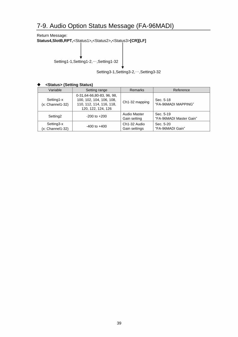
7-9. Audio Option Status Message (FA-96MADI)
Return Message:
Status4,SlotB,RPT,<Status1>,<Status2>,<Status3>[CR][LF]
Setting1-1,Setting1-2,…,Setting1-32
Setting3-1,Setting3-2,…,Setting3-32
<Status> (Setting Status)
Variable Setting range Remarks Reference
Setting1-x
(x: Channel1-32)
0-31,64-66,80-83, 96, 98,
100, 102, 104, 106, 108,
110, 112, 114, 116, 118,
120, 122, 124, 126
Ch1-32 mapping Sec. 5-18
“FA-96MADI MAPPING”
Setting2 -200 to +200 Audio Master
Gain setting
Sec. 5-19
“FA-96MADI Master Gain”
Setting3-x
(x: Channel1-32) -400 to +400
Ch1-32 Audio
Gain settings
Sec. 5-20
“FA-96MADI Gain”


