Embed Size (px)
Citation preview
Optics and Lasers in Engineering 41 (2004) 827–847
Fabrication of high-aspect-ratio microstructuresusing excimer laser
Ampere A. Tsenga,*, Ying-Tung Chenb, Kung-Jeng Mab
aDepartment of Mechanical and Aerospace Engineering, Arizona State University, P.O. Box 876106,
Tempe, Arizona 85287-6106, USAbDepartment of Mechanical Engineering, Chung Cheng Institute of Technology, Tashi, Taiwan, ROC
Received 14 February 2003; accepted 16 May 2003
Abstract
An excimer laser micromachining system is developed to study the ablation of high-aspect-
ratio microstructures. The study examines the ablation efficiency, specifically, the impact of
changing major laser operating parameters on the resulting microstructural shapes and
morphology. The study focuses on glass, although results on silicon and aluminum are also
included for comparison. In ablating grooved structures, the ablation depth has been observed
to be linearly proportional to the operating parameters, such as the pulse number and fluence.
The results specifically indicate that ablation at low fluence and high repetition rates tends to
form a V-shaped cross-section or profile, while a U-shaped profile can be obtained at high
fluence and low repetition rate. The ablation rate or ablated volume has then been quantified
based on the ablation depth measured and the ablated profile observed. The threshold fluence
has also been obtained by extrapolating experimental data of ablation rate. The extrapolation
accuracy has been established by the good agreement between the extrapolated value and the
one predicted by Beer’s law. Moreover, a one-dimensional analytical solution has been
adopted to predict the ablated volume so as to compare with the experimental data. The
reasonable agreement between the two indicates that a simple analytical solution can be used
for guiding or controlling further laser operations in ablating glass structures. Finally, the
experimental results have shown that increasing the repetition rate favors the morphology of
ablated surfaces, though the effect of repetition rate on ablation depth is insignificant.
r 2003 Elsevier Ltd. All rights reserved.
Keywords: Ablation; Ablation rate; Excimer laser; Fluence; Glass substrate; Microgroove
ARTICLE IN PRESS
*Corresponding author. Fax: +1-480-965-1384.
E-mail address: [email protected] (A.A. Tseng).
0143-8166/03/$ - see front matter r 2003 Elsevier Ltd. All rights reserved.
doi:10.1016/S0143-8166(03)00062-9
1. Introduction
Excimer lasers are pulsed gas lasers that use a mixture of gases to provide emissionat a series of discrete wavelengths in the UV region of the spectrum. The word‘‘excimer’’ is a contraction of the term ‘‘excited dimer’’. This describes a diatomicmolecule that is bound in its electronically excited upper state, but is repulsive oronly weakly bound in its lower ground state. Excimer lasers are increasingly beingused for machining micro-structures and devices [1,2]. In micromachining, excimerlasers remove the material from a substrate through an ablation mechanism. Theyare capable of making microstructures with feature sizes on the order of 1 mm andthey are applicable for all kinds of materials, including polymers, metals, andceramics [3,4].
Ablation can be one or a mix of two processes: ‘‘photothermal’’ and‘‘photochemical’’. A photochemical or electronic process is often referred to as anon-thermal process because the removal of material is caused by a direct breakingof atomic bonds as energy is absorbed. In contrast, the absorbed laser energy isconverted to lattice vibrational energy (thermal) to melt and vaporize the material ina photothermal process. To directly break atomic bonding, the intensity of the laserbeam should be higher than a threshold value, which is mainly dependant on thematerial to be ablated and the wavelength of the laser. At intensities below theablation threshold, the absorbed energy heats the substrate and raises the substratetemperature higher than its boiling or sublimation point. Consequently, the materialbegins to liberate. Both the photothermal and photochemical processes liberatemolecular-sized material from the surface. The two processes can occur in varyingdegrees of combination in micromachining that uses high-intensity excimer lasers[5,6].
The photochemical process normally dominates for ablation of polymers, whichhave relatively low thresholds, while the photothermal process dominates forablation of ceramics and metals, which possess high thresholds [7,5]. The typicalfeature size created by a photothermal process is larger than that produced by aphotochemical process, and the temperature profile resulting from this thermalprocess can often produce extensive damage in the heat-affected zone surroundingthe melted or vaporized region. By minimizing the heat-affected zone or theundesired thermal effect, a feature size in microscale levels can be accomplished.Thus, the photochemical process is preferred in micromachining. Also, since theablation depth per pulse is often greater than the optical absorption depth and thepulse length is far shorter than the thermal diffusion time scale, the amount ofresidual energy left in the substrate is typically small.
Since the laser technology has improved substantially over the past decade,excimer lasers now possess relatively high pulse energies, short pulse lengths, andhigh average and peak powers as compared to other laser sources. These attributesmake them the most efficient and popular ablation tool as well as a powerhouse formicromachining applications. One of the most widely known applications is theinkjet-printer nozzle, which is a successful commercialized product in the area ofmicroscale fluidic devices. In addition to many other industrial applications recently,
ARTICLE IN PRESSA.A. Tseng et al. / Optics and Lasers in Engineering 41 (2004) 827–847828
laser micromachining has also been successfully applied to many medical or clinicalprocesses, such as retinal photocoagulation, angioplasty, corneal sculpting, andcartilage or nerve treatment [3,4].
To further enhance the applications of excimer lasers, a better understanding ofthe nature of their micromachining process is required. In the present study, anArgon–Fluorine (ArF) excimer laser is selected because of its short wavelength. Alaser projection system is developed to ablate high-aspect-ratio microstructures. Thestudy examines the ablation efficiency through experiments and analytical models.Specifically, the impact of varying major operating parameters, including pulsefluence, pulse repetition rate, and pulse number, on the resulting microstructuralshapes and morphology is studied. The threshold fluence is also studied using bothexperimental data and theoretical prediction. Finally, recommendations are includedfor future improvement of ablation process by excimer laser.
2. Experiment setup
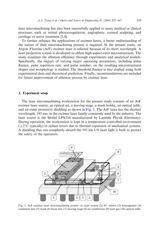
The laser micromachining workstation for the present study consists of an ArFexcimer laser source, an optical set, a moving stage, a mask holder, an optical table,and an outer protective shielding as shown in Fig. 1. The ArF laser has the shortestwavelength, 193 nm; in the excimer laser family commonly used by the industry. Thelaser source is the Model LPX210 manufactured by Lambda Physik (Germany).During operation, the workstation is kept in a temperature controlled environment(72�C typically) to reduce errors due to thermal expansion of mechanical systems.A shielding that can completely absorb the 193 nm UV laser light is built to protectthe safety of the operators.
ARTICLE IN PRESS
Fig. 1. ArF excimer laser micromachining system: (1) laser source (2) 45� mirror (3) homogenizer (4)
condenser lens (5) mask (6) focus lens (7) moving stage (8) air conditioner (9) laser gas (10) optical table.
A.A. Tseng et al. / Optics and Lasers in Engineering 41 (2004) 827–847 829
The workstation can perform both projection printing and direct writing. Onlyprojection printing is considered for the present study. The essence of a projectionprinting system is the ability to illuminate the mask with a uniform fluence, whichrelies entirely upon the uniformity of the laser beam itself. In the present projectionsystem, the beam is conditioned to achieve a uniform energy distribution at theobject plane, using a 7� 7 fixed-array homogenizer. The homogenizer produces a12� 23 mm uniform illumination at the mask plane with an intensity variation lessthan 75% RMS. Projection lenses of various magnifications are used to transfer thepattern of the mask onto the sample, which is mounted on a precision air-bearingXY stage. The 7� 7 fixed-array homogenizer, made by MicroLas (Germany),provides a 40% transmission rate for the laser light and transforms a Gaussian laserbeam energy distribution to a uniform distribution. The projection and focus lensesare made of UV grade fused silica, provided by CVI (USA) with a resolution betterthan 2:0 mm; a focus depth of 14:0 mm and 90% transmission rate at a wavelength of193 nm:
In the present setup for projection printing, a mask having slot-shaped openings isused to quantify micromachining characteristics. The mask is made of 200-mm thick304 stainless steel and is chemically etched to produce 200-mm wide slots. Theprojection lens has a 10� demagnification and a maximum field size of 1:2� 2:3 mmcan be obtained based on the 12� 23 mm beam source from the homogenizer. Thus,the slot pattern printed onto the sample is expected to be 20 mm wide. Duringablation, the maximum fluences or energy densities at the sample with the 10�lenses are kept at values lower than 2:5 J=cm2; the corresponding maximum fluenceprovided at the mask is below 0:025 J=cm2 and should not cause any damage to themask. The conventional chrome-on-quartz mask can also be used because the UVgrade fused quartz has a transmission rate higher than 90% at a wavelength of193 nm:
The ranges of the operating parameters, including repetition rate, pulse number,fluence (energy density), and duration time, are listed in Table 1. The duration ofeach pulse is fixed at 20 ns: The specific values of the operating parameters can all bepreset by a PC-base controller. To guarantee high machining quality, the focusdistance must be readjusted according to each sample thickness to preserveperpendicular contact between the laser beam and the sample surface. Duringablation, the positioning stage can move in both X and Y directions and rotateabout the y-axis. The Z-axis movement is for finer focus adjustment. The XY planeis always kept perpendicular to the laser beam during operation. The workstation
ARTICLE IN PRESS
Table 1
Operating parameters of laser ablation
Parameter (units) Range
Fluence ðJ=cm2Þ 1:4; 1:7; 2:1; 2:4Duration time (ns) 20
Repetition rate (Hz) 1; 2; 5; 10Pulse number 50; 100; 150; 200; 250
A.A. Tseng et al. / Optics and Lasers in Engineering 41 (2004) 827–847830
enclosure and frame are all mounted on an optical table equipped with a vibrationisolation system, which reduces vibration induced by the ambient environmentduring operation.
3. Results and discussions
The material considered is borosilicate glass (BK7), supplied by VWR Scientific.Single-crystal silicon and 2024 aluminum are also evaluated, but their results aremerely used for comparison. The typical sample size used in the present study is25 mm2 in area and 0:2 mm in thickness. After machining, an oxide layer or debris isoften accumulated on the machined surface and must be discarded, so that it doesnot erroneously affect sample analysis or measurements. A solution of 10% HF and90% distilled water can effectively clean the debris. After cleaning, the machinedprofiles are measured and examined. The duration of each pulse in all of theexperiments is set at 20 ns:
3.1. Effects of material properties
The ablation characteristics are primarily dictated by the laser/material interac-tions as well as the laser parameters, especially the fluence, repetition rate, pulsenumber, and duration time. Fig. 2 shows the scanning electronic microscope (SEM)micrographs of the surface morphology of the three materials after ablation at afluence of 2:4 J=cm2 and a repetition rate of 10 Hz with two different pulse numbers,150 and 250. The micrographs were taken by a Philips Model 515 SEM. Since glass isa dielectric material, a thin gold film (3–5 nm thick) is coated on the ablated glasssample by vacuum evaporation to make it conductive for SEM observation. Asshown in the figure, the ablation depth of aluminum or silicon is less than that ofglass. Also, the trench surface of either aluminum or silicon is more irregular thanthat of glass.
As mentioned earlier, since the threshold values of both metals and ceramics arerelatively high, the ablation of these materials is primarily a thermal or photothermalprocess. Consequently, their associated thermal properties are important in theinterpretation of their ablation results. Based on the material properties shown inTable 2, the melting temperature of aluminum is relatively low ð660�CÞ as comparedto silicon ð1410�CÞ; and its thermal conductivity ð238 W=m KÞ is higher than bothglass ð1:1 W=m KÞ and silicon ð157 W=m KÞ: Thus, the heat converted by laserenergy does not accumulate fast enough to melt aluminum. Consequently, theablation depth of aluminum is smaller than that of glass, and the thermally affectedsurface of the machined or ablated grooves is more irregular. The thermalconductivity of silicon ð157 W=m KÞ is lower than that of aluminum, but it has ahigher melting temperature ð1410�CÞ: The combination of these two propertiesmakes silicon’s ablation rate or depth similar to that of aluminum. On the otherhand, not only the thermal conductivity of glass ð1:1 W=m KÞ is significantly lowerthan those of silicon and aluminum, but also its glass-transition temperature ð820�CÞ
ARTICLE IN PRESSA.A. Tseng et al. / Optics and Lasers in Engineering 41 (2004) 827–847 831
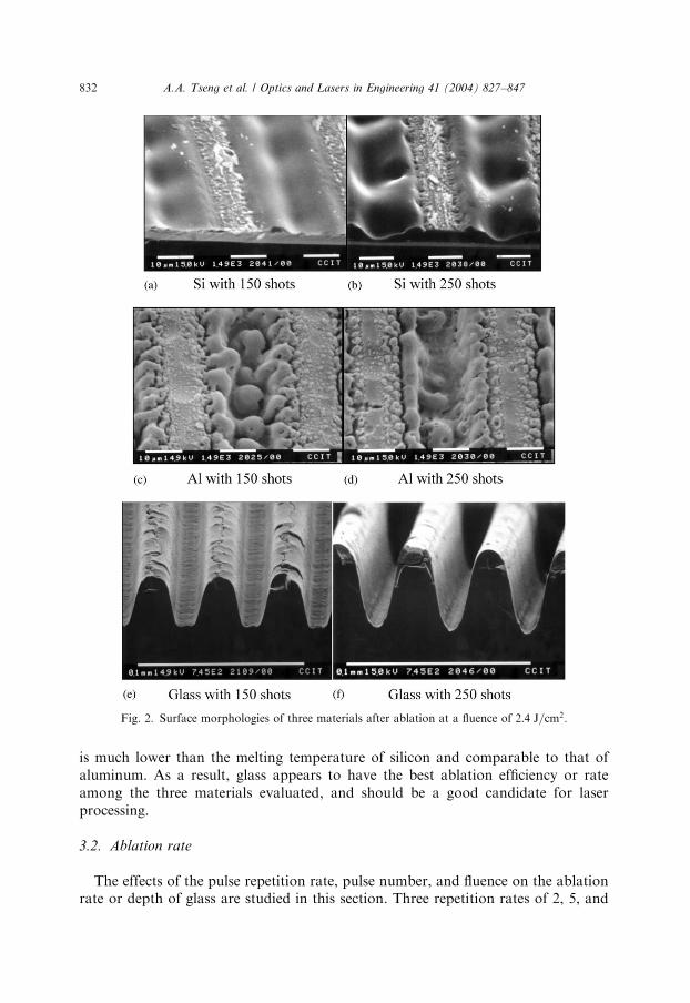
is much lower than the melting temperature of silicon and comparable to that ofaluminum. As a result, glass appears to have the best ablation efficiency or rateamong the three materials evaluated, and should be a good candidate for laserprocessing.
3.2. Ablation rate
The effects of the pulse repetition rate, pulse number, and fluence on the ablationrate or depth of glass are studied in this section. Three repetition rates of 2, 5, and
ARTICLE IN PRESS
Fig. 2. Surface morphologies of three materials after ablation at a fluence of 2:4 J=cm2:
A.A. Tseng et al. / Optics and Lasers in Engineering 41 (2004) 827–847832
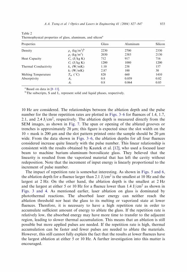
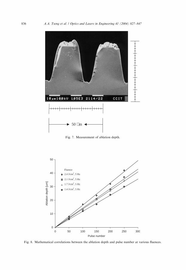
10 Hz are considered. The relationships between the ablation depth and the pulsenumber for the three repetition rates are plotted in Figs. 3–6 for fluences of 1.4, 1.7,2.1, and 2:4 J=cm2; respectively. The ablation depth is measured directly from theSEM images, as shown in Fig. 7. The span or opening of the ablated grooves ortrenches is approximately 20 mm; this figure is expected since the slot width on the10�mask is 200 mm and the slot pattern printed onto the sample should be 20 mmwide. From the data shown in Figs. 3–6, the ablation depths for all four fluencesconsidered increase quite linearly with the pulse number. This linear relationship isconsistent with the results obtained by Kautek et al. [12], who used a focused laserbeam to machine barium–aluminum–borosilicate glass. They believed that thelinearity is resulted from the vaporized material that has left the cavity withoutredeposition. Note that the increment of input energy is linearly proportional to theincrement of pulse number.
The impact of repetition rate is somewhat interesting. As shown in Figs. 5 and 6,the ablation depth for a fluence larger than 2:1 J=cm2 is the smallest at 10 Hz and thelargest at 2 Hz: On the other hand, the ablation depth is the smallest at 2 Hzand the largest at either 5 or 10 Hz for a fluence lower than 1:4 J=cm2 as shown inFigs. 3 and 4. As mentioned earlier, laser ablation on glass is dominated byphotothermal reactions. The absorbed laser energy can neither reach theablation threshold nor heat the glass to its melting or vaporized state at lowerfluences. Therefore, it is necessary to have a high repetition rate in order toaccumulate sufficient amount of energy to ablate the glass. If the repetition rate isrelatively low, the absorbed energy may have more time to transfer to the adjacentregion, leading to slower thermal accumulation. This means that an ablation is stillpossible but more applied pulses are needed. If the repetition rate is high, thermalaccumulation can be faster and fewer pulses are needed to ablate the materials.However, this still cannot fully explain the fact that the results at lower fluences havethe largest ablation at either 5 or 10 Hz: A further investigation into this matter isencouraged.
ARTICLE IN PRESS
Table 2
Thermophysical properties of glass, aluminum, and silicona
Properties Glass Aluminum Silicon
Density rs ðkg=m3Þb 2230 2700 2330
rl ðkg=m3Þ 2030 2385 2130
Heat Capacity Cs ðJ=kg KÞ 712 917 716
Cl ðJ=kg KÞ 1200 1080 1200
Thermal Conductivity ks ðW=mKÞ 1.10 238 157
kl ðW=mKÞ 2.87 100 30
Melting Temperature Tm ð�CÞ 820 660 1410
Absorptivity As 0.8 0.059 0.02
Al 0.8 0.064 0.05
aBased on data in [8–11].bThe subscripts, S and L, represent solid and liquid phases, respectively.
A.A. Tseng et al. / Optics and Lasers in Engineering 41 (2004) 827–847 833
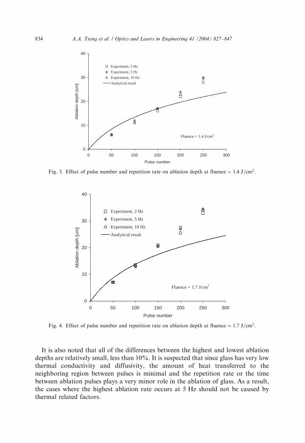
It is also noted that all of the differences between the highest and lowest ablationdepths are relatively small, less than 10%. It is suspected that since glass has very lowthermal conductivity and diffusivity, the amount of heat transferred to theneighboring region between pulses is minimal and the repetition rate or the timebetween ablation pulses plays a very minor role in the ablation of glass. As a result,the cases where the highest ablation rate occurs at 5 Hz should not be caused bythermal related factors.
ARTICLE IN PRESS
0
10
20
30
40
0 50 100 150 200 250 300
Pulse number
Abl
atio
n de
pth
[um
]
Experiment, 2 Hz
Experiment, 5 Hz
Experiment, 10 Hz
Analytical result
Fluence = 1.4 J/cm2
Fig. 3. Effect of pulse number and repetition rate on ablation depth at fluence ¼ 1:4 J=cm2:
0
10
20
30
40
0 50 100 150 200 250 300
Pulse number
Abl
atio
n de
pth
[um
]
Experiment, 2 Hz
Experiment, 5 Hz
Experiment, 10 Hz
Analytical result
Fluence = 1.7 J/cm2
Fig. 4. Effect of pulse number and repetition rate on ablation depth at fluence ¼ 1:7 J=cm2:
A.A. Tseng et al. / Optics and Lasers in Engineering 41 (2004) 827–847834
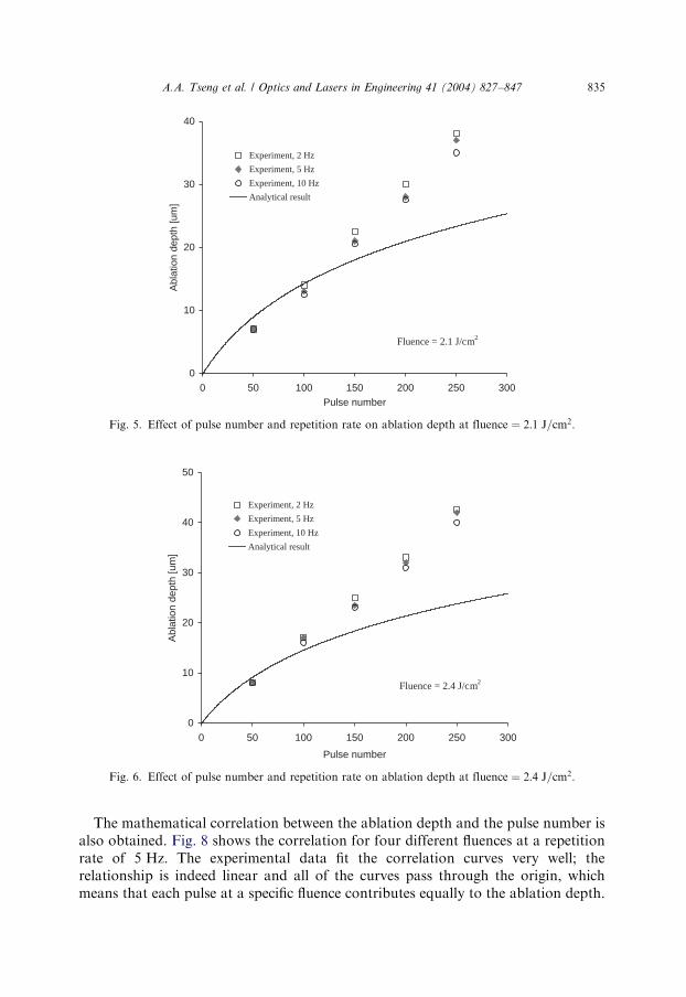
The mathematical correlation between the ablation depth and the pulse number isalso obtained. Fig. 8 shows the correlation for four different fluences at a repetitionrate of 5 Hz: The experimental data fit the correlation curves very well; therelationship is indeed linear and all of the curves pass through the origin, whichmeans that each pulse at a specific fluence contributes equally to the ablation depth.
ARTICLE IN PRESS
0
10
20
30
40
0 50 100 150 200 250 300Pulse number
Abl
atio
n de
pth
[um
]
Experiment, 2 Hz
Experiment, 5 Hz
Experiment, 10 Hz
Analytical result
Fluence = 2.1 J/cm2
Fig. 5. Effect of pulse number and repetition rate on ablation depth at fluence ¼ 2:1 J=cm2:
0
10
20
30
40
50
0 50 100 150 200 250 300
Pulse number
Abl
atio
n de
pth
[um
]
Experiment, 2 Hz
Experiment, 5 Hz
Experiment, 10 Hz
Analytical result
Fluence = 2.4 J/cm2
Fig. 6. Effect of pulse number and repetition rate on ablation depth at fluence ¼ 2:4 J=cm2:
A.A. Tseng et al. / Optics and Lasers in Engineering 41 (2004) 827–847 835
ARTICLE IN PRESS
0
10
20
30
40
50
0 50 100 150 200 250 300
Pulse number
Abl
atio
n de
pth
[um
]
2.4 J/cm2
2.1 J/cm2
1.7 J/cm2
1.4 J/cm2
Fluence
2.4 J/cm2, 5 Hz
2.1 J/cm2, 5 Hz
1.7 J/cm2, 5 Hz
1.4 J/cm2, 5 Hz
Fig. 8. Mathematical correlations between the ablation depth and pulse number at various fluences.
50 µm
Fig. 7. Measurement of ablation depth.
A.A. Tseng et al. / Optics and Lasers in Engineering 41 (2004) 827–847836
The corresponding slopes for fluence at 1.4, 1.7, 2.1, and 2:4 J=cm2 are 0.119, 0.136,0.143, and 0:164 mm; respectively. Physically, the slope represents the ablation depthrate (per pulse). The slope values obtained further attest our earlier inference that thelarger the fluence, the higher the ablation rate. Note that the correlation coefficientsfor each curve fitting shown in Fig. 8 are all higher than 0.99, which means theablation depth correlates with the pulse number almost perfectly. The coefficient R isused to gauge the accuracy of correlation and always lies between �1 and þ1: Avalue of zero occurs when the two variables are totally independent of each other,while it reaches 1 when the two variables correlate perfectly, i.e., no deviation fromthe linear curve [13].
3.3. Threshold fluence
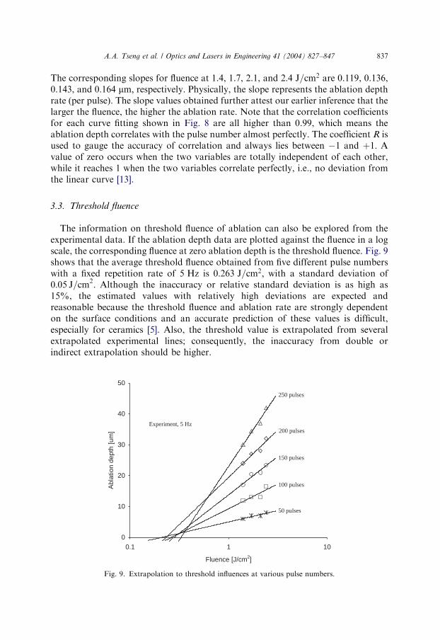
The information on threshold fluence of ablation can also be explored from theexperimental data. If the ablation depth data are plotted against the fluence in a logscale, the corresponding fluence at zero ablation depth is the threshold fluence. Fig. 9shows that the average threshold fluence obtained from five different pulse numberswith a fixed repetition rate of 5 Hz is 0:263 J=cm2; with a standard deviation of0:05 J=cm2: Although the inaccuracy or relative standard deviation is as high as15%, the estimated values with relatively high deviations are expected andreasonable because the threshold fluence and ablation rate are strongly dependenton the surface conditions and an accurate prediction of these values is difficult,especially for ceramics [5]. Also, the threshold value is extrapolated from severalextrapolated experimental lines; consequently, the inaccuracy from double orindirect extrapolation should be higher.
ARTICLE IN PRESS
0
10
20
30
40
50
0.1 1 10
Fluence [J/cm2]
Abl
atio
n de
pth
[um
]
Experiment, 5 Hz
250 pulses
200 pulses
150 pulses
100 pulses
50 pulses
Fig. 9. Extrapolation to threshold influences at various pulse numbers.
A.A. Tseng et al. / Optics and Lasers in Engineering 41 (2004) 827–847 837
The accuracy of the threshold value just obtained will be further studied bycomparing it with the value calculated by the well-known Beer’s law:
Dd ¼ lnðFi=FtÞ=a; ð1Þ
where Dd is the ablation depth per pulse, a is the absorption coefficient, Fi and Ft arethe incident and threshold fluences, respectively. If the threshold value of0:263 J=cm2 is reliable, it can be used to predict Dd by Beer’s law shown inEq. (1). The predicted Dd should be consistent with the one extrapolated from theexperimental data shown in Fig. 8.
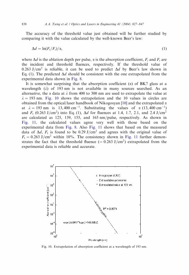
It is somewhat surprising that the absorption coefficient ðaÞ of BK7 glass at awavelength ðlÞ of 193 nm is not available in many sources searched. As analternative, the a data at l from 400 to 300 nm are used to extrapolate the value atl ¼ 193 nm: Fig. 10 shows the extrapolation and the 10 values in circles areobtained from the optical/laser handbook of Nikogosyan [10] and the extrapolated aat l ¼ 193 nm is 13; 400 cm�1: Substituting the values of a ð13; 400 cm�1Þand Ft ð0:263 J=cm2Þ into Eq. (1), Dd for fluences at 1.4, 1.7, 2.1, and 2:4 J=cm2
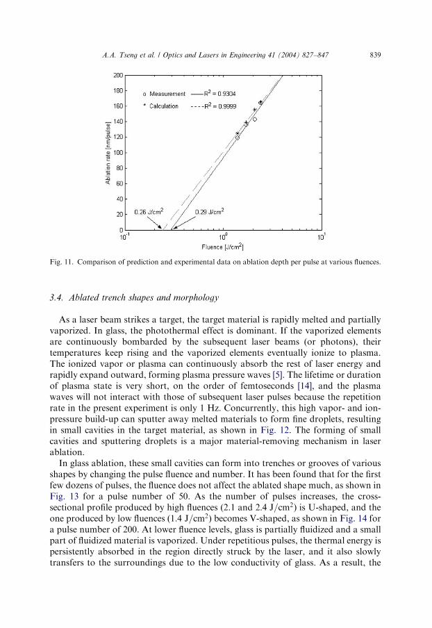
are calculated as 125, 139, 155, and 165 nm=pulse; respectively. As shown inFig. 11, the calculated values agree very well with those based on theexperimental data from Fig. 8. Also Fig. 11 shows that based on the measureddata of Dd; Ft is found to be 0:29 J=cm2 and agrees with the original value ofFt ¼ 0:263 J=cm2 within 10%. The consistency shown in Fig. 11 further demon-strates the fact that the threshold fluence ð¼ 0:263 J=cm2Þ extrapolated from theexperimental data is reliable and accurate.
ARTICLE IN PRESS
Fig. 10. Extrapolation of absorption coefficient at a wavelength of 193 nm:
A.A. Tseng et al. / Optics and Lasers in Engineering 41 (2004) 827–847838
3.4. Ablated trench shapes and morphology
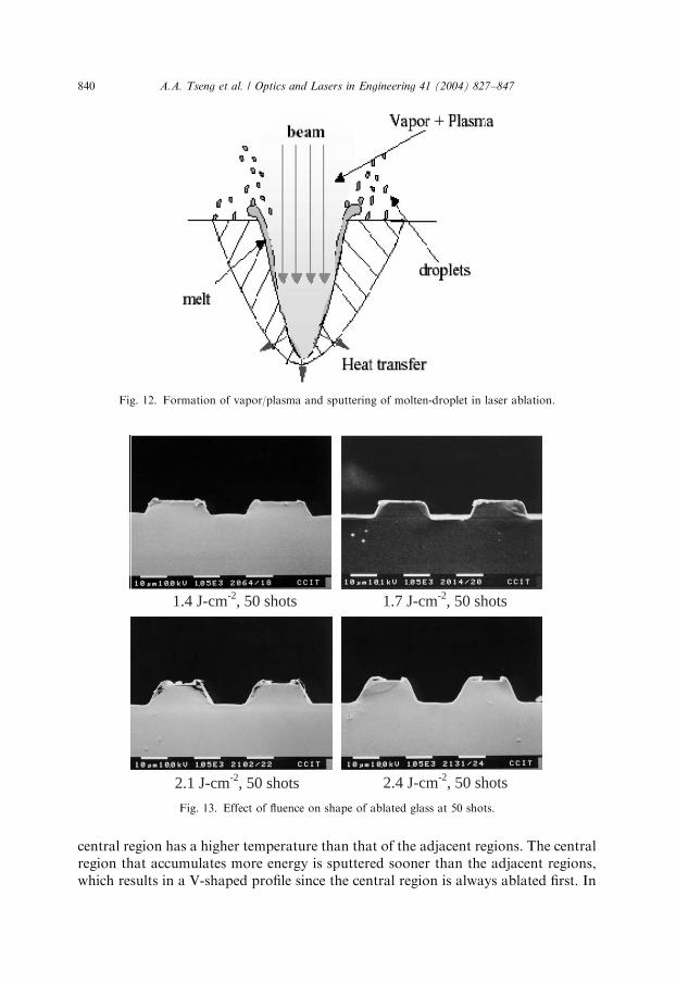
As a laser beam strikes a target, the target material is rapidly melted and partiallyvaporized. In glass, the photothermal effect is dominant. If the vaporized elementsare continuously bombarded by the subsequent laser beams (or photons), theirtemperatures keep rising and the vaporized elements eventually ionize to plasma.The ionized vapor or plasma can continuously absorb the rest of laser energy andrapidly expand outward, forming plasma pressure waves [5]. The lifetime or durationof plasma state is very short, on the order of femtoseconds [14], and the plasmawaves will not interact with those of subsequent laser pulses because the repetitionrate in the present experiment is only 1 Hz: Concurrently, this high vapor- and ion-pressure build-up can sputter away melted materials to form fine droplets, resultingin small cavities in the target material, as shown in Fig. 12. The forming of smallcavities and sputtering droplets is a major material-removing mechanism in laserablation.
In glass ablation, these small cavities can form into trenches or grooves of variousshapes by changing the pulse fluence and number. It has been found that for the firstfew dozens of pulses, the fluence does not affect the ablated shape much, as shown inFig. 13 for a pulse number of 50. As the number of pulses increases, the cross-sectional profile produced by high fluences (2.1 and 2:4 J=cm2) is U-shaped, and theone produced by low fluences ð1:4 J=cm2Þ becomes V-shaped, as shown in Fig. 14 fora pulse number of 200. At lower fluence levels, glass is partially fluidized and a smallpart of fluidized material is vaporized. Under repetitious pulses, the thermal energy ispersistently absorbed in the region directly struck by the laser, and it also slowlytransfers to the surroundings due to the low conductivity of glass. As a result, the
ARTICLE IN PRESS
Fig. 11. Comparison of prediction and experimental data on ablation depth per pulse at various fluences.
A.A. Tseng et al. / Optics and Lasers in Engineering 41 (2004) 827–847 839
central region has a higher temperature than that of the adjacent regions. The centralregion that accumulates more energy is sputtered sooner than the adjacent regions,which results in a V-shaped profile since the central region is always ablated first. In
ARTICLE IN PRESS
1.4 J-cm-2, 50 shots 1.7 J-cm-2, 50 shots
2.1 J-cm-2, 50 shots 2.4 J-cm-2, 50 shots
Fig. 13. Effect of fluence on shape of ablated glass at 50 shots.
Fig. 12. Formation of vapor/plasma and sputtering of molten-droplet in laser ablation.
A.A. Tseng et al. / Optics and Lasers in Engineering 41 (2004) 827–847840
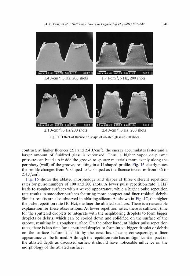
contrast, at higher fluences (2.1 and 2:4 J=cm2), the energy accumulates faster and alarger amount of fluidized glass is vaporized. Thus, a higher vapor or plasmapressure can build up inside the groove to sputter materials more evenly along theperiphery (wall) of the groove, resulting in a U-shaped profile. Fig. 15 clearly notesthe profile changes from V-shaped to U-shaped as the fluence increases from 0.6 to2:4 J=cm2:
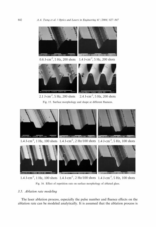
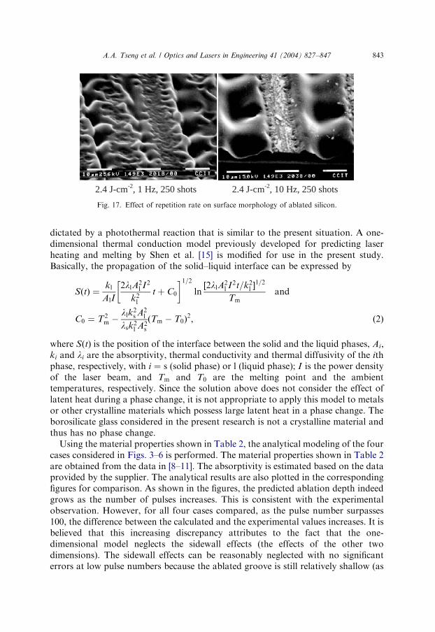
Fig. 16 shows the ablated morphology and shapes at three different repetitionrates for pulse numbers of 100 and 200 shots. A lower pulse repetition rate ð1 HzÞleads to rougher surfaces with a waved appearance, while a higher pulse repetitionrate results in smoother surfaces featuring more compact and finer residual debris.Similar results are also observed in ablating silicon. As shown in Fig. 17, the higherthe pulse repetition rate ð10 HzÞ; the finer the ablated surfaces. There is a reasonableexplanation for these observations. At lower repetition rates, there is sufficient timefor the sputtered droplets to integrate with the neighboring droplets to form biggerdroplets or debris, which can be cooled down and solidified on the surface of thegroove, resulting in a rougher surface. On the other hand, at higher pulse repetitionrates, there is less time for a sputtered droplet to form into a bigger droplet or debrison the surface before it is hit by the next laser beam; consequently, a finerappearance can be formed. Although the repetition rate has no significant impact onthe ablated depth as discussed earlier, it should have noticeable influence on themorphology of the ablated surface.
ARTICLE IN PRESS
1.4 J-cm-2, 5 Hz, 200 shots 1.7 J-cm-2, 5 Hz, 200 shots
2.1 J-cm-2, 5 Hz/200 shots 2.4 J-cm-2, 5 Hz, 200 shots
Fig. 14. Effect of fluence on shape of ablated glass at 200 shots.
A.A. Tseng et al. / Optics and Lasers in Engineering 41 (2004) 827–847 841
3.5. Ablation rate modeling
The laser ablation process, especially the pulse number and fluence effects on theablation rate can be modeled analytically. It is assumed that the ablation process is
ARTICLE IN PRESS
1.4 J-cm-2, 5 Hz, 200 shots0.6 J-cm-2, 5 Hz, 200 shots
2.1 J-cm-2, 5 Hz, 200 shots 2.4 J-cm-2, 5 Hz, 200 shots
Fig. 15. Surface morphology and shape at different fluences.
1.4 J-cm-2, 1 Hz, 100 shots -2 , 2 Hz/100 shots -2, 5 Hz, 100 shots1.4 J-cm 1.4 J-cm
1.4 J-cm-2, 1 Hz, 100 shots -2 , 2 Hz/100 shots -2, 5 Hz, 100 shots1.4 J-cm 1.4 J-cm
Fig. 16. Effect of repetition rate on surface morphology of ablated glass.
A.A. Tseng et al. / Optics and Lasers in Engineering 41 (2004) 827–847842
dictated by a photothermal reaction that is similar to the present situation. A one-dimensional thermal conduction model previously developed for predicting laserheating and melting by Shen et al. [15] is modified for use in the present study.Basically, the propagation of the solid–liquid interface can be expressed by
SðtÞ ¼kl
AlI
2llA2l I
2
k2l
t þ C0
� �1=2ln
½2llA2l I2t=k2
l 1=2
Tmand
C0 ¼ T2m �
llk2s A2
l
lsk2l A2
s
ðTm � T0Þ2; ð2Þ
where SðtÞ is the position of the interface between the solid and the liquid phases, Ai;ki and li are the absorptivity, thermal conductivity and thermal diffusivity of the ithphase, respectively, with i ¼ s (solid phase) or l (liquid phase); I is the power densityof the laser beam, and Tm and T0 are the melting point and the ambienttemperatures, respectively. Since the solution above does not consider the effect oflatent heat during a phase change, it is not appropriate to apply this model to metalsor other crystalline materials which possess large latent heat in a phase change. Theborosilicate glass considered in the present research is not a crystalline material andthus has no phase change.
Using the material properties shown in Table 2, the analytical modeling of the fourcases considered in Figs. 3–6 is performed. The material properties shown in Table 2are obtained from the data in [8–11]. The absorptivity is estimated based on the dataprovided by the supplier. The analytical results are also plotted in the correspondingfigures for comparison. As shown in the figures, the predicted ablation depth indeedgrows as the number of pulses increases. This is consistent with the experimentalobservation. However, for all four cases compared, as the pulse number surpasses100, the difference between the calculated and the experimental values increases. It isbelieved that this increasing discrepancy attributes to the fact that the one-dimensional model neglects the sidewall effects (the effects of the other twodimensions). The sidewall effects can be reasonably neglected with no significanterrors at low pulse numbers because the ablated groove is still relatively shallow (as
ARTICLE IN PRESS
2.4 J-cm-2, 1 Hz, 250 shots 2.4 J-cm-2, 10 Hz, 250 shots
Fig. 17. Effect of repetition rate on surface morphology of ablated silicon.
A.A. Tseng et al. / Optics and Lasers in Engineering 41 (2004) 827–847 843
shown in Fig. 13). On the other hand, at higher pulse numbers and fluences, thegroove becomes deeper (as shown in Fig. 14) and the sidewall effects becomesignificant. Thus, the one-dimensional heat transfer model is no longer reliable. Themeasured and calculated ablation depths are in closer agreement for laser pulses lessthan 150.
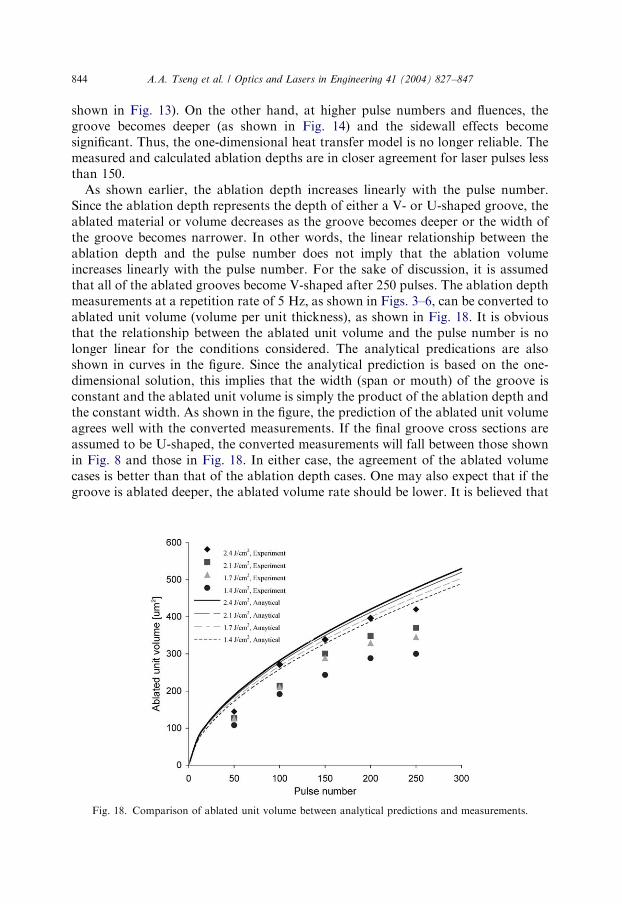
As shown earlier, the ablation depth increases linearly with the pulse number.Since the ablation depth represents the depth of either a V- or U-shaped groove, theablated material or volume decreases as the groove becomes deeper or the width ofthe groove becomes narrower. In other words, the linear relationship between theablation depth and the pulse number does not imply that the ablation volumeincreases linearly with the pulse number. For the sake of discussion, it is assumedthat all of the ablated grooves become V-shaped after 250 pulses. The ablation depthmeasurements at a repetition rate of 5 Hz; as shown in Figs. 3–6, can be converted toablated unit volume (volume per unit thickness), as shown in Fig. 18. It is obviousthat the relationship between the ablated unit volume and the pulse number is nolonger linear for the conditions considered. The analytical predications are alsoshown in curves in the figure. Since the analytical prediction is based on the one-dimensional solution, this implies that the width (span or mouth) of the groove isconstant and the ablated unit volume is simply the product of the ablation depth andthe constant width. As shown in the figure, the prediction of the ablated unit volumeagrees well with the converted measurements. If the final groove cross sections areassumed to be U-shaped, the converted measurements will fall between those shownin Fig. 8 and those in Fig. 18. In either case, the agreement of the ablated volumecases is better than that of the ablation depth cases. One may also expect that if thegroove is ablated deeper, the ablated volume rate should be lower. It is believed that
ARTICLE IN PRESS
Fig. 18. Comparison of ablated unit volume between analytical predictions and measurements.
A.A. Tseng et al. / Optics and Lasers in Engineering 41 (2004) 827–847844
when the groove depth reaches a certain limit, the ablation volume rate mayeventually decrease to an insignificantly small value.
4. Concluding remarks
A study using an excimer laser to machine high-aspect-ratio glass microstructuresis presented and many fabrication issues that are often encountered in excimerprojection ablation have also been addressed. The experimental study, using an ArFexcimer laser, examines the ablation rates by varying several major operatingparameters. The linear relationship between the ablation depth and pulse numberhas been identified. A similar relationship between the ablation depth and pulsefluence is also observed. Although the pulse repetition rate has no significant effectson the ablation depth, it has a noticeable impact on the morphology of the ablatedsurface. Results have indicated that increasing the repetition rate favors themorphology of ablated surfaces; however, sometimes the resulting debris or residueis hard to remove.
It is understood that the development of ablation processes relies on boththeoretical and experimental investigations. In the theoretical portion, a simpleanalytical model is used to predict the ablation volume for comparison with theexperimental measurements. A good agreement has been found between theprediction and the measured data on the ablated volume, but not on the ablateddepth. Because the analytical model is based on a one-dimensional assumption, itdoes not accurately predict the profile variation of the ablated grooves. In thepresent study, it has been found that ablation at a relatively low fluence tends toform a V-shaped profile, while a U-shaped profile is ablated mainly at higherfluences.
The present study indicates that the materials of choice for excimer laser ablationshould have low thermal conductivity and low melting temperature. Glass is one ofthe materials with these properties as compared to silicon and aluminum. Thepresent study also indicates that the excimer laser micromachining system developedshould be capable of making intricate glass-based microdevices to satisfy the needsof the photonics and communications industries. Furthermore, Further developmentin ablating intricate glass components should be encouraged.
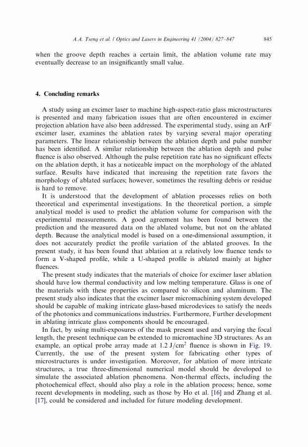
In fact, by using multi-exposures of the mask present used and varying the focallength, the present technique can be extended to micromachine 3D structures. As anexample, an optical probe array made at 1:2 J=cm2 fluence is shown in Fig. 19.Currently, the use of the present system for fabricating other types ofmicrostructures is under investigation. Moreover, for ablation of more intricatestructures, a true three-dimensional numerical model should be developed tosimulate the associated ablation phenomena. Non-thermal effects, including thephotochemical effect, should also play a role in the ablation process; hence, somerecent developments in modeling, such as those by Ho et al. [16] and Zhang et al.[17], could be considered and included for future modeling development.
ARTICLE IN PRESSA.A. Tseng et al. / Optics and Lasers in Engineering 41 (2004) 827–847 845
Acknowledgements
The authors gratefully acknowledge the support of this study by the US NationalScience Foundation under Grant No. DMI-0002466 and CMS-0115828. A specialthanks is to ROC National Science Council under Grant No. NSC90-2811-E-002-007 for providing funding for the first author to stay in Taiwan in 2001. Theassistance from Mr. Jong-Seung Park of Arizona State University in computationsshould be specifically acknowledged.
References
[1] Metev SM, Veiko VP. Laser-assisted microtechnology. Berlin, Germany: Springer; 1994.
[2] Bado P, Clark W, Said A. Introduction to micromachining handbook. Ann Arbor, MI: Clark MXR,
2001. (also in http://64.227.154.50/Industrial/Handbook/Index.htm).
[3] Endert H, Patzel R, Basting D. Excimer laser: a new tool for precision micromachining. Opt
Quantum Electron 1995;27:1319–35.
[4] Gu B, Hunter R, Wall D, Frechette M. Laser micromachining technology for device manufacturing.
Med Device Diagn Ind 1998;12(11):62–8 (also in http://www.devicelink.com/mddi/archive/98/11/
007.html).
[5] Duley WW. UV lasers: effects and applications in materials science. New York, NY: Cambridge
University; 1996.
[6] P*atzel R. An introduction to excimer lasers. In: Photonics handbook, 44th ed. Pittsfield, MA: Laurin
Publishing, 2002. p. 247–52.
[7] Laude LD, editor. Excimer lasers. Dordrecht, Netherlands: Kluwer Academic, 1994.
[8] Boyer HE, Gall TL, editors. Metals handbook, Desk ed. Metal Park, OH: American Society for
Metals, 1985.
[9] Bansal NP, Doremus RH. Handbook of glass properties. New York: Academic Press; 1986.
ARTICLE IN PRESS
Fig. 19. Glass probe array micromachined by laser ablation.
A.A. Tseng et al. / Optics and Lasers in Engineering 41 (2004) 827–847846
[10] Nikogosyan DN. Properties of optical and laser-related materials a handbook. New York, NY:
Wiley; 1997.
[11] Kovacs TA. Micromachined transducers sourcebook. New York, NY: McGraw-Hill; 1998.
[12] Kautek W, Kruger J, Lenzer M, Sartania S, Spielmann C, Krausz F. Laser ablation of dielectrics with
pulse duration 20 fs and 3 ps: Appl Phys Lett 1996;69(21):3146–8.
[13] Coleman HW, Steele WG. Experimentation and uncertainty analysis for engineers. New York, NY:
Wiley; 1989.
[14] Rubahn HG. Laser applications in surface science and technology. New York, NY: Wiley; 1999.
[15] Shen ZH, Zhang SY, Lu J, Ni XW. Mathematical modeling of laser induced heating and melting in
solids. Opt Laser Technol 2001;33:533–7.
[16] Ho JR, Grigoropoulos CP, Humphrey JAC. Computational study of heat transfer and gas dynamics
in the pulsed laser evaporation of metals. J Appl Phys 1995;78(7):4696–709.
[17] Zhang W, Yao YL, Chen K. Modeling and analysis of UV laser micromachining of copper. Int J Adv
Manufact Technol 2001;18(5):323–31.
Ampere A. Tseng is a Professor of Mechanical Engineering at Arizona State University. He was a recipient
of the Superior Performance Award of Martin Marietta Laboratories, RCA Service Award, and Alcoa
Foundation Research Award, and ASU 1999–2000 Faculty Award. Dr. Tseng was the Chair of the ASME
Materials Division and of the 2000 NSF Workshop on Manufacturing of Micro-Electro-Mechanical
Systems Workshop. Currently, Dr. Tseng is a fellow of ASME and the Chair of its Industrial Committee.
Ying-Tung Chen is an instructor of Mechanical Engineering at Chung Cheng Institute of Technology,
Taiwan. He received his M.S. degree Chung Cheng Institute of Technology in May 2000. Currently, he is
working on laser fabrication of three-dimensional microstructures.
K.J. Ma is an associate professor of Mechanical Engineering at Chung Hua University, Taiwan. He
received his Ph.D. degree at the University of Birmingham (UK) in July 1997. After he returned from UK
to Taiwan in September 1997, he worked for four years at Chung-Cheng Institute of Technology and set
up excimer laser micromachining system. The research fields of Dr. Ma include surface modification of
materials by various energy beams and biosensor fabrication.
ARTICLE IN PRESSA.A. Tseng et al. / Optics and Lasers in Engineering 41 (2004) 827–847 847


