Embed Size (px)
Citation preview

Copyright © 2006 by Connectivity Systems, IncorporatedAll Rights Reserved RESTRICTED RIGHTS LEGEND Use, duplication, or disclosure by the Government is subject to the restrictions as set forth in subparagraph (c)(1)(ii) of the Rights in Technical Data and Computer Software clause at DFARS 252.227-7013. This material contains confidential and proprietary material of Connectivity Systems, Inc. and may not be used in any way without written authorization from Connectivity Systems, Inc.. This material may not be reproduced, in whole or in part, in any way, without prior written permission from Connectivity Systems, Inc.. Permission is hereby granted to copy and distribute this document as follows: • Each copy must be a complete and accurate copy. • All copyright notices must be retained. • No modifications may be made. • Use of each copy is restricted to the evaluation and/or promotion of
Connectivity Systems, Inc.’s BIM-FAQS/ASO product or in accordance with a license agreement.
Online User’s Guide, Version 5 Release 3A May 2006 Published by Connectivity Systems, Inc. 8120 State Route 138, Williamsport OH 43164 Phone: 800-795-4914 Fax: 740-986-6022 E-Mail: [email protected]: http://www.e-vse.com
Contents
About This Guide . . . . . . . . . . . . . . . . . . . . . . . . . . . . . . . . . . . . . . . . . . . . . . . . . . . . . ATG.1In This Chapter . . . . . . . . . . . . . . . . . . . . . . . . . . . . . . . . . . . . . . . . . . . . . . ATG.1Purpose . . . . . . . . . . . . . . . . . . . . . . . . . . . . . . . . . . . . . . . . . . . . . . . . . . . . ATG.1Organization . . . . . . . . . . . . . . . . . . . . . . . . . . . . . . . . . . . . . . . . . . . . . . . . ATG.1Conventions Used in This Guide . . . . . . . . . . . . . . . . . . . . . . . . . . . . . . . . . ATG.2Diagnostic Procedures . . . . . . . . . . . . . . . . . . . . . . . . . . . . . . . . . . . . . . . . . ATG.3
Introduction. . . . . . . . . . . . . . . . . . . . . . . . . . . . . . . . . . . . . . . . . . . . . . . . . . . . . . . . . . . . . .1.1In This Chapter . . . . . . . . . . . . . . . . . . . . . . . . . . . . . . . . . . . . . . . . . . . . . . . . . 1.1BIM-FAQS/ASO Advantages . . . . . . . . . . . . . . . . . . . . . . . . . . . . . . . . . . . . . . . . . . 1.1Programmer Aids . . . . . . . . . . . . . . . . . . . . . . . . . . . . . . . . . . . . . . . . . . . . . . . . 1.2Spooler Queue Overview . . . . . . . . . . . . . . . . . . . . . . . . . . . . . . . . . . . . . . . . . . 1.3Console Support Function . . . . . . . . . . . . . . . . . . . . . . . . . . . . . . . . . . . . . . . . . 1.4Online Password Security Feature . . . . . . . . . . . . . . . . . . . . . . . . . . . . . . . . . . . 1.5Extensive Online Message and Help Facility . . . . . . . . . . . . . . . . . . . . . . . . . . 1.5Console Display . . . . . . . . . . . . . . . . . . . . . . . . . . . . . . . . . . . . . . . . . . . . . . . . . 1.9
FAQS/ASO Online Interfaces . . . . . . . . . . . . . . . . . . . . . . . . . . . . . . . . . . . . . . . . . . . . . . .2.1In This Chapter . . . . . . . . . . . . . . . . . . . . . . . . . . . . . . . . . . . . . . . . . . . . . . . . . 2.1FAQSMAIN . . . . . . . . . . . . . . . . . . . . . . . . . . . . . . . . . . . . . . . . . . . . . . . . . . . . 2.1BIM$TICI (CICS) . . . . . . . . . . . . . . . . . . . . . . . . . . . . . . . . . . . . . . . . . . . . . . . 2.5
Online User’s Guide i
Connectivity Systems
Accessing/Exiting BIM$TICI from CICS . . . . . . . . . . . . . . . . . . . . . . . . . . . . . . . . . . . . . 2.6BIM$TIDR (VTAM/BTAM/CICS/XPCC) . . . . . . . . . . . . . . . . . . . . . . . . . . . . 2.7FAQSVMX (VMCF) . . . . . . . . . . . . . . . . . . . . . . . . . . . . . . . . . . . . . . . . . . . . 2.11FAQSIUX (IUCV) . . . . . . . . . . . . . . . . . . . . . . . . . . . . . . . . . . . . . . . . . . . . . . 2.13FAQSICX (ICCF) . . . . . . . . . . . . . . . . . . . . . . . . . . . . . . . . . . . . . . . . . . . . . . 2.15CMS Support Modules . . . . . . . . . . . . . . . . . . . . . . . . . . . . . . . . . . . . . . . . . . 2.16FAQS/ASO VM/CMS Shutdown . . . . . . . . . . . . . . . . . . . . . . . . . . . . . . . . . . 2.17
Online Panels. . . . . . . . . . . . . . . . . . . . . . . . . . . . . . . . . . . . . . . . . . . . . . . . . . . . . . . . . . . . .3.1In This Chapter . . . . . . . . . . . . . . . . . . . . . . . . . . . . . . . . . . . . . . . . . . . . . . . . . 3.1Overview . . . . . . . . . . . . . . . . . . . . . . . . . . . . . . . . . . . . . . . . . . . . . . . . . . . . . . 3.1BIM-FAQS/ASO Commands . . . . . . . . . . . . . . . . . . . . . . . . . . . . . . . . . . . . . . . . . . . 3.1Accessing BIM-FAQS/ASO . . . . . . . . . . . . . . . . . . . . . . . . . . . . . . . . . . . . . . . . . . . . . . . . . . . . 3.2Accessing the Menu System . . . . . . . . . . . . . . . . . . . . . . . . . . . . . . . . . . . . . . . 3.2BIM-FAQS/ASO Online Menu . . . . . . . . . . . . . . . . . . . . . . . . . . . . . . . . . . . . . . . . . 3.4Moving Between Display Panels . . . . . . . . . . . . . . . . . . . . . . . . . . . . . . . . . . . 3.5Moving Between Display and Menu Panels . . . . . . . . . . . . . . . . . . . . . . . . . . . 3.5Moving Within the Menu System . . . . . . . . . . . . . . . . . . . . . . . . . . . . . . . . . . . 3.5
Security and User Configuration. . . . . . . . . . . . . . . . . . . . . . . . . . . . . . . . . . . . . . . . . . . . .4.1In This Chapter . . . . . . . . . . . . . . . . . . . . . . . . . . . . . . . . . . . . . . . . . . . . . . . . . 4.1Overview . . . . . . . . . . . . . . . . . . . . . . . . . . . . . . . . . . . . . . . . . . . . . . . . . . . . . . 4.1User Profiles . . . . . . . . . . . . . . . . . . . . . . . . . . . . . . . . . . . . . . . . . . . . . . . . . . . 4.3Accessing User Configuration Panels . . . . . . . . . . . . . . . . . . . . . . . . . . . . . . . . 4.5SCTY Main Panel . . . . . . . . . . . . . . . . . . . . . . . . . . . . . . . . . . . . . . . . . . . . . . . 4.6Configuration Panel 1 . . . . . . . . . . . . . . . . . . . . . . . . . . . . . . . . . . . . . . . . . . . . 4.8Configuration Panel 2: Pre-ESA 2.1 Only . . . . . . . . . . . . . . . . . . . . . . . . . . . . 4.11User Profile Record 1 . . . . . . . . . . . . . . . . . . . . . . . . . . . . . . . . . . . . . . . . . . . 4.14User Profile Record 2 . . . . . . . . . . . . . . . . . . . . . . . . . . . . . . . . . . . . . . . . . . . 4.17User Profile Record 3 . . . . . . . . . . . . . . . . . . . . . . . . . . . . . . . . . . . . . . . . . . . 4.21
Connectivity Systems, Inc.—Copyright © 2006Use Pursuant to Company Instructions
ii BIM-FAQS/ASO
.
User Profile Record 4 . . . . . . . . . . . . . . . . . . . . . . . . . . . . . . . . . . . . . . . . . . . 4.24User Profile Record 5 . . . . . . . . . . . . . . . . . . . . . . . . . . . . . . . . . . . . . . . . . . . 4.28User Profile Record 5 Fields . . . . . . . . . . . . . . . . . . . . . . . . . . . . . . . . . . . . . . 4.29User Profile Record 6 . . . . . . . . . . . . . . . . . . . . . . . . . . . . . . . . . . . . . . . . . . . 4.30User Profile Record 6 Fields . . . . . . . . . . . . . . . . . . . . . . . . . . . . . . . . . . . . . . 4.31User Profile Record 7 . . . . . . . . . . . . . . . . . . . . . . . . . . . . . . . . . . . . . . . . . . . 4.32User Profile Record 8 . . . . . . . . . . . . . . . . . . . . . . . . . . . . . . . . . . . . . . . . . . . 4.34User Profile Record 9: Pre-ESA 2.1 . . . . . . . . . . . . . . . . . . . . . . . . . . . . . . . . 4.35Extended Security: File Definition . . . . . . . . . . . . . . . . . . . . . . . . . . . . . . . . . 4.39Console Extended Security Member List . . . . . . . . . . . . . . . . . . . . . . . . . . . . 4.41Console Extended Security Member Maintenance . . . . . . . . . . . . . . . . . . . . . 4.43Extended Security Activation For a User . . . . . . . . . . . . . . . . . . . . . . . . . . . . 4.45Extended Security: Console Filtering . . . . . . . . . . . . . . . . . . . . . . . . . . . . . . . 4.47Online Security Panel . . . . . . . . . . . . . . . . . . . . . . . . . . . . . . . . . . . . . . . . . . . 4.48Console Filter Member List . . . . . . . . . . . . . . . . . . . . . . . . . . . . . . . . . . . . . . 4.49Console Filter Member Maintenance . . . . . . . . . . . . . . . . . . . . . . . . . . . . . . . 4.51Editing Console Filter Members . . . . . . . . . . . . . . . . . . . . . . . . . . . . . . . . . . . 4.53Console Filter Add/Copy . . . . . . . . . . . . . . . . . . . . . . . . . . . . . . . . . . . . . . . . . 4.54Defining an Expression . . . . . . . . . . . . . . . . . . . . . . . . . . . . . . . . . . . . . . . . . . 4.57
Using the Menu System . . . . . . . . . . . . . . . . . . . . . . . . . . . . . . . . . . . . . . . . . . . . . . . . . . . .5.1In This Chapter . . . . . . . . . . . . . . . . . . . . . . . . . . . . . . . . . . . . . . . . . . . . . . . . . 5.1Overview . . . . . . . . . . . . . . . . . . . . . . . . . . . . . . . . . . . . . . . . . . . . . . . . . . . . . . 5.1Menu Entries . . . . . . . . . . . . . . . . . . . . . . . . . . . . . . . . . . . . . . . . . . . . . . . . . . . 5.1Accessing Product Features . . . . . . . . . . . . . . . . . . . . . . . . . . . . . . . . . . . . . . . . 5.4Selecting Current Console Display Options . . . . . . . . . . . . . . . . . . . . . . . . . . . 5.6Overview . . . . . . . . . . . . . . . . . . . . . . . . . . . . . . . . . . . . . . . . . . . . . . . . . . . . . . 5.8Command Access . . . . . . . . . . . . . . . . . . . . . . . . . . . . . . . . . . . . . . . . . . . . . . . 5.8CICS Print Report Interface (CPR) . . . . . . . . . . . . . . . . . . . . . . . . . . . . . . . . . . 5.8BIM-EDIT Interface (EDIT) . . . . . . . . . . . . . . . . . . . . . . . . . . . . . . . . . . . . . . . 5.9BIM-EPIC Interface (EPIC) . . . . . . . . . . . . . . . . . . . . . . . . . . . . . . . . . . . . . . 5.10 BIM-FAQS/PCS Interface (PCS) . . . . . . . . . . . . . . . . . . . . . . . . . . . . . . . . . . 5.11
Connectivity Systems, Inc.—Copyright © 2006Use Pursuant to Company Instructions
Online User’s Guide
Connectivity Systems
Using Spooler Commands . . . . . . . . . . . . . . . . . . . . . . . . . . . . . . . . . . . . . . . . . . . . . . . . . .6.1In This Chapter . . . . . . . . . . . . . . . . . . . . . . . . . . . . . . . . . . . . . . . . . . . . . . . . . 6.1Overview . . . . . . . . . . . . . . . . . . . . . . . . . . . . . . . . . . . . . . . . . . . . . . . . . . . . . . 6.1Spooler Commands and Options . . . . . . . . . . . . . . . . . . . . . . . . . . . . . . . . . . . . 6.9Spooler Queue Selection Criteria . . . . . . . . . . . . . . . . . . . . . . . . . . . . . . . . . . 6.10PALTER Command . . . . . . . . . . . . . . . . . . . . . . . . . . . . . . . . . . . . . . . . . . . . . 6.12PDELETE Command . . . . . . . . . . . . . . . . . . . . . . . . . . . . . . . . . . . . . . . . . . . 6.13Using the Full-Panel Display . . . . . . . . . . . . . . . . . . . . . . . . . . . . . . . . . . . . . . 6.13PDISPLAY Command . . . . . . . . . . . . . . . . . . . . . . . . . . . . . . . . . . . . . . . . . . . 6.14PHOLD Command . . . . . . . . . . . . . . . . . . . . . . . . . . . . . . . . . . . . . . . . . . . . . 6.16PRELEASE Command . . . . . . . . . . . . . . . . . . . . . . . . . . . . . . . . . . . . . . . . . . 6.17D A Panel . . . . . . . . . . . . . . . . . . . . . . . . . . . . . . . . . . . . . . . . . . . . . . . . . . . . . 6.18POWER Display Menu and SPOOL Display Menu . . . . . . . . . . . . . . . . . . . . 6.20Displaying Spooler Members . . . . . . . . . . . . . . . . . . . . . . . . . . . . . . . . . . . . . 6.25
Online Displays and Reports . . . . . . . . . . . . . . . . . . . . . . . . . . . . . . . . . . . . . . . . . . . . . . . .7.1In This Chapter . . . . . . . . . . . . . . . . . . . . . . . . . . . . . . . . . . . . . . . . . . . . . . . . . 7.1Overview . . . . . . . . . . . . . . . . . . . . . . . . . . . . . . . . . . . . . . . . . . . . . . . . . . . . . . 7.1AO Command (AO) . . . . . . . . . . . . . . . . . . . . . . . . . . . . . . . . . . . . . . . . . . . . . 7.2ASO Command . . . . . . . . . . . . . . . . . . . . . . . . . . . . . . . . . . . . . . . . . . . . . . . . . 7.4Command Line Open (CURSOR) . . . . . . . . . . . . . . . . . . . . . . . . . . . . . . . . . . . 7.9Procedure . . . . . . . . . . . . . . . . . . . . . . . . . . . . . . . . . . . . . . . . . . . . . . . . . . . . . . 7.9ESA 2.1 Console Display . . . . . . . . . . . . . . . . . . . . . . . . . . . . . . . . . . . . . . . . 7.12D C Command Options . . . . . . . . . . . . . . . . . . . . . . . . . . . . . . . . . . . . . . . . . 7.14Console Log Display (D L and D F) . . . . . . . . . . . . . . . . . . . . . . . . . . . . . . . . 7.15D L and D F Command Options . . . . . . . . . . . . . . . . . . . . . . . . . . . . . . . . . . . 7.16Split Console Display (D S) . . . . . . . . . . . . . . . . . . . . . . . . . . . . . . . . . . . . . . 7.21Control Block Display (DEBUG) . . . . . . . . . . . . . . . . . . . . . . . . . . . . . . . . . . 7.27Virtual Storage Display (DSPLY or DISPLAY) . . . . . . . . . . . . . . . . . . . . . . . 7.28DASD Record Display (DUMP) . . . . . . . . . . . . . . . . . . . . . . . . . . . . . . . . . . . 7.31Altering the DASD Record . . . . . . . . . . . . . . . . . . . . . . . . . . . . . . . . . . . . . . . 7.35Fast Transient Load Reports (FTL) . . . . . . . . . . . . . . . . . . . . . . . . . . . . . . . . . 7.36Help Display (HELP) . . . . . . . . . . . . . . . . . . . . . . . . . . . . . . . . . . . . . . . . . . . 7.41
Connectivity Systems, Inc.—Copyright © 2006Use Pursuant to Company Instructions
iv BIM-FAQS/ASO
.
Held Lines Removed from Console Display (K E) . . . . . . . . . . . . . . . . . . . . . . . . . . . . . . . . . . . . . . . . . . . . . . . . . . . . . . . . 7.42Library List (LIBLIST) . . . . . . . . . . . . . . . . . . . . . . . . . . . . . . . . . . . . . . . . . . 7.43Librarian Display Menu (LIBR) . . . . . . . . . . . . . . . . . . . . . . . . . . . . . . . . . . . 7.46I/O List Display (LISTIO) . . . . . . . . . . . . . . . . . . . . . . . . . . . . . . . . . . . . . . . . 7.55Volume Table of Contents (LVTOC) . . . . . . . . . . . . . . . . . . . . . . . . . . . . . . . . 7.58Default Partition Allocation Report (MAP) . . . . . . . . . . . . . . . . . . . . . . . . . . 7.61Menu Display (MENU) . . . . . . . . . . . . . . . . . . . . . . . . . . . . . . . . . . . . . . . . . . 7.62Message Display (MSG) . . . . . . . . . . . . . . . . . . . . . . . . . . . . . . . . . . . . . . . . . 7.63Online Message Panel . . . . . . . . . . . . . . . . . . . . . . . . . . . . . . . . . . . . . . . . . . . 7.65Set Operator Mode (OP) . . . . . . . . . . . . . . . . . . . . . . . . . . . . . . . . . . . . . . . . . 7.67Query PF Key (Q PF) . . . . . . . . . . . . . . . . . . . . . . . . . . . . . . . . . . . . . . . . . . . 7.69Set Online PF Keys (SET PF) . . . . . . . . . . . . . . . . . . . . . . . . . . . . . . . . . . . . . . . . . . . . . . . . . . . . . 7.70Set POWER PF Keys (MENU 2.R) . . . . . . . . . . . . . . . . . . . . . . . . . . . . . . . . 7.72Updating the POWER PFKEY Display Alter Panel . . . . . . . . . . . . . . . . . . . . 7.74Query Message Management Settings (Q SET) . . . . . . . . . . . . . . . . . . . . . . . 7.75Scroll Split Panel (SCROLL) . . . . . . . . . . . . . . . . . . . . . . . . . . . . . . . . . . . . . 7.76Scroll Split Panel with Stop/Start (SCROLLS) . . . . . . . . . . . . . . . . . . . . . . . . 7.77Screen command (SCREEN) . . . . . . . . . . . . . . . . . . . . . . . . . . . . . . . . . . . . . . 7.78User Profile and System Configuration Display (SCTY) . . . . . . . . . . . . . . . . 7.80Sign-On Command (SINON) . . . . . . . . . . . . . . . . . . . . . . . . . . . . . . . . . . . . . 7.82Disk and Tape Drive Volumes (VOLUME) . . . . . . . . . . . . . . . . . . . . . . . . . . 7.84Reset CICS-Dialed Terminal Back to VM . . . . . . . . . . . . . . . . . . . . . . . . . . . 7.86Reset VTAM-Controlled Terminal Back to VTAM . . . . . . . . . . . . . . . . . . . . 7.86Online Command Definition . . . . . . . . . . . . . . . . . . . . . . . . . . . . . . . . . . . . . . 7.87Online Command File Directory List . . . . . . . . . . . . . . . . . . . . . . . . . . . . . . . 7.87 Online Commands Directory List . . . . . . . . . . . . . . . . . . . . . . . . . . . . . . . . . . 7.89Lock Table Display . . . . . . . . . . . . . . . . . . . . . . . . . . . . . . . . . . . . . . . . . . . . . 7.90Lock Request Table . . . . . . . . . . . . . . . . . . . . . . . . . . . . . . . . . . . . . . . . . . . . . 7.93Sample Resource Names Panel . . . . . . . . . . . . . . . . . . . . . . . . . . . . . . . . . . . . 7.94Accessing the Resource Owners Panel . . . . . . . . . . . . . . . . . . . . . . . . . . . . . . 7.95Defining SYSOUT Archival Files . . . . . . . . . . . . . . . . . . . . . . . . . . . . . . . . . . 7.97
Connectivity Systems, Inc.—Copyright © 2006Use Pursuant to Company Instructions
Online User’s Guide v
Connectivity Systems
SYSOUT Option . . . . . . . . . . . . . . . . . . . . . . . . . . . . . . . . . . . . . . . . . . . . . . . 7.98Browsing SYSOUT Archival Files . . . . . . . . . . . . . . . . . . . . . . . . . . . . . . . . 7.100Scanning SYSOUT Archival Files:Scan PF Key . . . . . . . . . . . . . . . . . . . . . 7.103Maintaining SYSOUT Archival Files . . . . . . . . . . . . . . . . . . . . . . . . . . . . . . 7.105VSAM Display (VSAM) . . . . . . . . . . . . . . . . . . . . . . . . . . . . . . . . . . . . . . . . 7.105
Extended Map/Debug Support . . . . . . . . . . . . . . . . . . . . . . . . . . . . . . . . . . . . . . . . . . . . . .8.1In This Chapter . . . . . . . . . . . . . . . . . . . . . . . . . . . . . . . . . . . . . . . . . . . . . . . . . 8.1Map/Debug Menu . . . . . . . . . . . . . . . . . . . . . . . . . . . . . . . . . . . . . . . . . . . . . . . 8.2Debug Panels . . . . . . . . . . . . . . . . . . . . . . . . . . . . . . . . . . . . . . . . . . . . . . . . . . . 8.2Static Partition Debug Display . . . . . . . . . . . . . . . . . . . . . . . . . . . . . . . . . . . . . 8.4Partition Information Debug Display . . . . . . . . . . . . . . . . . . . . . . . . . . . . . . . . 8.6Task Information Debug Display . . . . . . . . . . . . . . . . . . . . . . . . . . . . . . . . . . . . 8.9Task Dataspace Debug Display . . . . . . . . . . . . . . . . . . . . . . . . . . . . . . . . . . . . 8.12Dataspace Display . . . . . . . . . . . . . . . . . . . . . . . . . . . . . . . . . . . . . . . . . . . . . . 8.14Dynamic Class Debug Display . . . . . . . . . . . . . . . . . . . . . . . . . . . . . . . . . . . . 8.16Dynamic Partition by Class Debug Display . . . . . . . . . . . . . . . . . . . . . . . . . . 8.18Debug Status Display . . . . . . . . . . . . . . . . . . . . . . . . . . . . . . . . . . . . . . . . . . . 8.21Menu Access . . . . . . . . . . . . . . . . . . . . . . . . . . . . . . . . . . . . . . . . . . . . . . . . . . 8.21Map GETVIS Panels . . . . . . . . . . . . . . . . . . . . . . . . . . . . . . . . . . . . . . . . . . . . 8.24List of Panels . . . . . . . . . . . . . . . . . . . . . . . . . . . . . . . . . . . . . . . . . . . . . . . . . . 8.24Static Partition GETVIS Map Display . . . . . . . . . . . . . . . . . . . . . . . . . . . . . . 8.25Timed Redisplay Option . . . . . . . . . . . . . . . . . . . . . . . . . . . . . . . . . . . . . . . . . 8.28System GETVIS Map Display . . . . . . . . . . . . . . . . . . . . . . . . . . . . . . . . . . . . 8.29Dynamic Class GETVIS Map Display . . . . . . . . . . . . . . . . . . . . . . . . . . . . . . 8.31Dynamic Partition by Class GETVIS Map Display . . . . . . . . . . . . . . . . . . . . 8.33GETVIS Map Hole Display . . . . . . . . . . . . . . . . . . . . . . . . . . . . . . . . . . . . . . 8.36SVA Phase Chart Display . . . . . . . . . . . . . . . . . . . . . . . . . . . . . . . . . . . . . . . . 8.39Map Panels . . . . . . . . . . . . . . . . . . . . . . . . . . . . . . . . . . . . . . . . . . . . . . . . . . . 8.42List of Map Panels . . . . . . . . . . . . . . . . . . . . . . . . . . . . . . . . . . . . . . . . . . . . . . 8.42Static Partition Map Display . . . . . . . . . . . . . . . . . . . . . . . . . . . . . . . . . . . . . . 8.43System Map Display . . . . . . . . . . . . . . . . . . . . . . . . . . . . . . . . . . . . . . . . . . . . 8.45Dynamic Class Map Display . . . . . . . . . . . . . . . . . . . . . . . . . . . . . . . . . . . . . . 8.47
Connectivity Systems, Inc.—Copyright © 2006Use Pursuant to Company Instructions
vi BIM-FAQS/ASO
.
Dynamic Partition by Class Map Display . . . . . . . . . . . . . . . . . . . . . . . . . . . . 8.50
Index. . . . . . . . . . . . . . . . . . . . . . . . . . . . . . . . . . . . . . . . . . . . . . . . . . . . . . . . . . . . . . . . . . IN.1
Connectivity Systems, Inc.—Copyright © 2006Use Pursuant to Company Instructions
Online User’s Guide

Connectivity Systems
Connectivity Systems, Inc.—Copyright © 2006Use Pursuant to Company Instructions
viii BIM-FAQS/ASO
About This Guide
In This Chapter
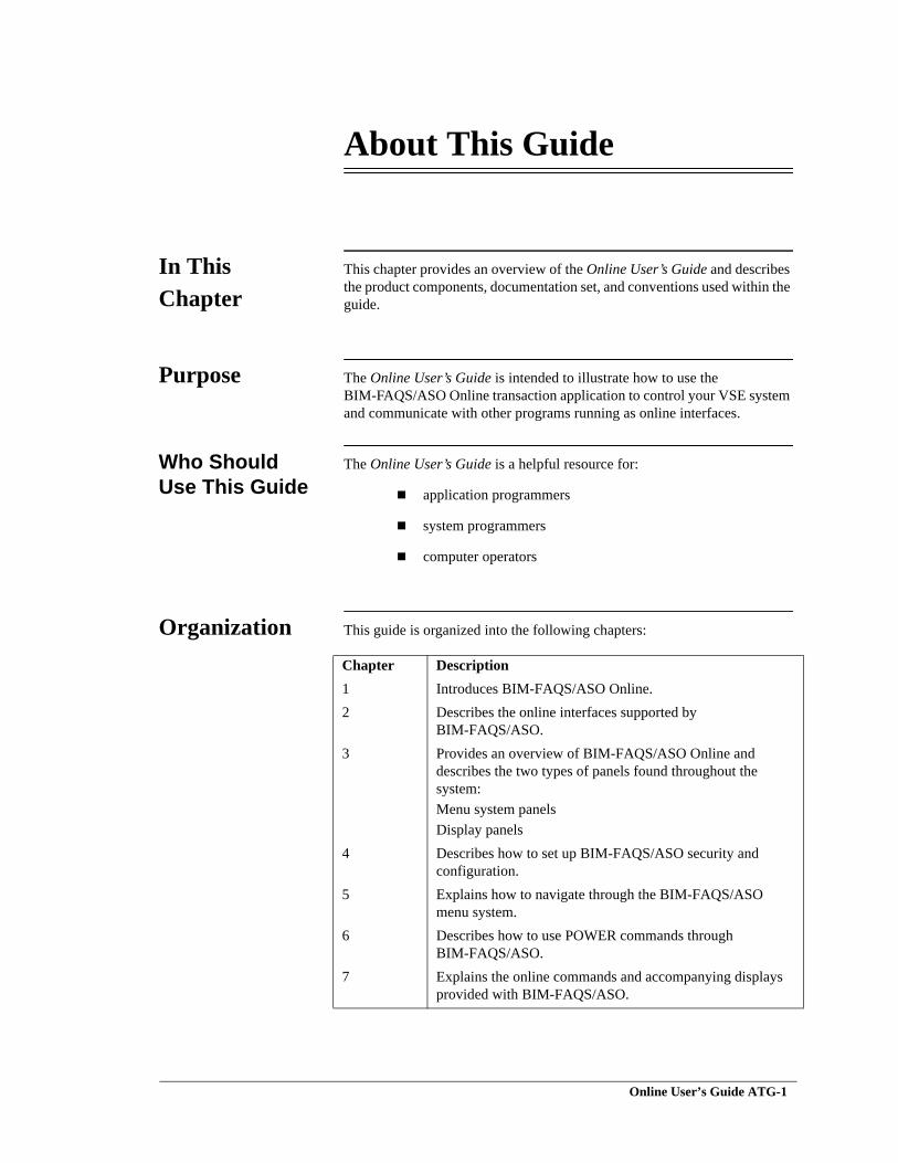
This chapter provides an overview of the Online User’s Guide and describes the product components, documentation set, and conventions used within the guide.
Purpose The Online User’s Guide is intended to illustrate how to use the BIM-FAQS/ASO Online transaction application to control your VSE system and communicate with other programs running as online interfaces.
Who Should Use This Guide
The Online User’s Guide is a helpful resource for:
application programmers
system programmers
computer operators
Organization This guide is organized into the following chapters:
Chapter Description1 Introduces BIM-FAQS/ASO Online.2 Describes the online interfaces supported by
BIM-FAQS/ASO.3 Provides an overview of BIM-FAQS/ASO Online and
describes the two types of panels found throughout the system:Menu system panelsDisplay panels
4 Describes how to set up BIM-FAQS/ASO security and configuration.
5 Explains how to navigate through the BIM-FAQS/ASO menu system.
6 Describes how to use POWER commands through BIM-FAQS/ASO.
7 Explains the online commands and accompanying displays provided with BIM-FAQS/ASO.
Online User’s Guide ATG-1
Connectivity Systems
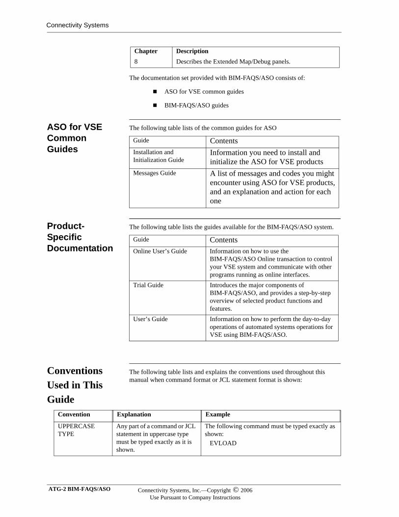
The documentation set provided with BIM-FAQS/ASO consists of:
ASO for VSE common guides
BIM-FAQS/ASO guides
ASO for VSE Common Guides
The following table lists of the common guides for ASO
Product-Specific Documentation
The following table lists the guides available for the BIM-FAQS/ASO system.
Conventions Used in This Guide
The following table lists and explains the conventions used throughout this manual when command format or JCL statement format is shown:
8 Describes the Extended Map/Debug panels.Chapter Description
Guide ContentsInstallation and Initialization Guide
Information you need to install and initialize the ASO for VSE products
Messages Guide A list of messages and codes you might encounter using ASO for VSE products, and an explanation and action for each one
Guide ContentsOnline User’s Guide Information on how to use the
BIM-FAQS/ASO Online transaction to control your VSE system and communicate with other programs running as online interfaces.
Trial Guide Introduces the major components of BIM-FAQS/ASO, and provides a step-by-step overview of selected product functions and features.
User’s Guide Information on how to perform the day-to-day operations of automated systems operations for VSE using BIM-FAQS/ASO.
Convention Explanation Example
UPPERCASE TYPE
Any part of a command or JCL statement in uppercase type must be typed exactly as it is shown.
The following command must be typed exactly as shown: EVLOAD
ATG-2 BIM-FAQS/ASO Connectivity Systems, Inc.—Copyright © 2006Use Pursuant to Company Instructions
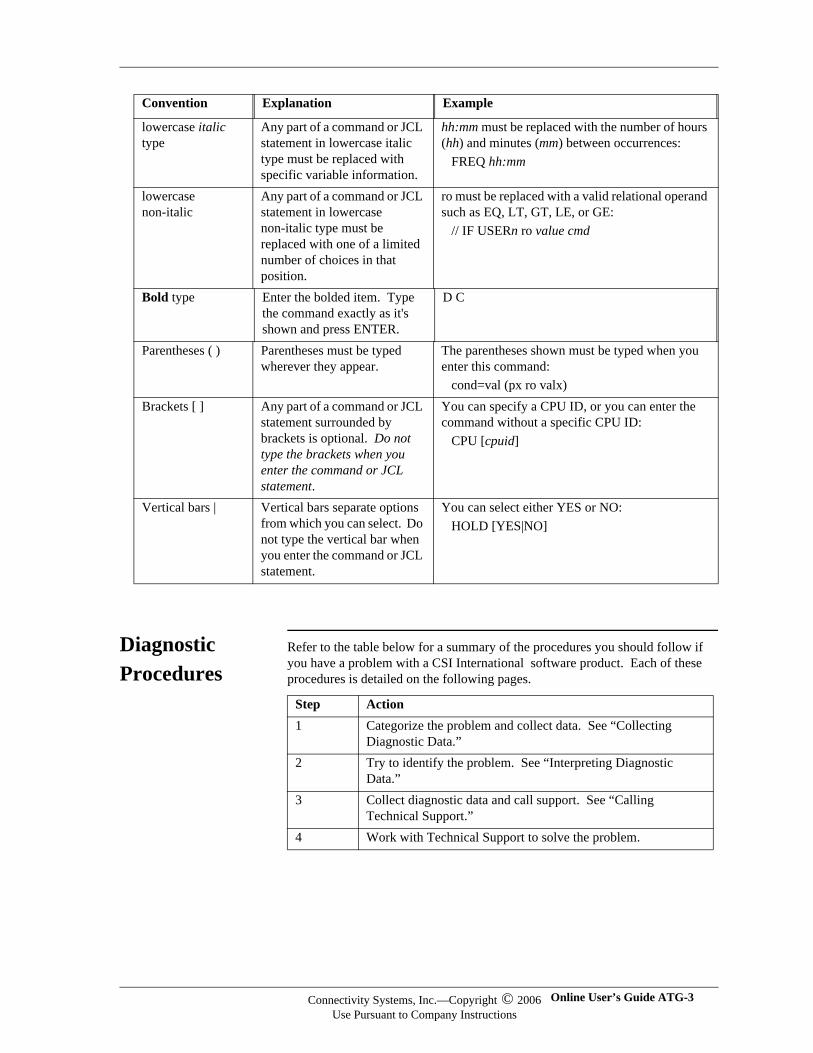
Diagnostic Procedures
Refer to the table below for a summary of the procedures you should follow if you have a problem with a CSI International software product. Each of these procedures is detailed on the following pages.
lowercase italic type
Any part of a command or JCL statement in lowercase italic type must be replaced with specific variable information.
hh:mm must be replaced with the number of hours (hh) and minutes (mm) between occurrences: FREQ hh:mm
lowercase non-italic
Any part of a command or JCL statement in lowercase non-italic type must be replaced with one of a limited number of choices in that position.
ro must be replaced with a valid relational operand such as EQ, LT, GT, LE, or GE: // IF USERn ro value cmd
Bold type Enter the bolded item. Type the command exactly as it's shown and press ENTER.
D C
Parentheses ( ) Parentheses must be typed wherever they appear.
The parentheses shown must be typed when you enter this command: cond=val (px ro valx)
Brackets [ ] Any part of a command or JCL statement surrounded by brackets is optional. Do not type the brackets when you enter the command or JCL statement.
You can specify a CPU ID, or you can enter the command without a specific CPU ID: CPU [cpuid]
Vertical bars | Vertical bars separate options from which you can select. Do not type the vertical bar when you enter the command or JCL statement.
You can select either YES or NO: HOLD [YES|NO]
Convention Explanation Example
Step Action1 Categorize the problem and collect data. See “Collecting
Diagnostic Data.”2 Try to identify the problem. See “Interpreting Diagnostic
Data.”3 Collect diagnostic data and call support. See “Calling
Technical Support.”4 Work with Technical Support to solve the problem.
Connectivity Systems, Inc.—Copyright © 2006Use Pursuant to Company Instructions
Online User’s Guide ATG-3
Connectivity Systems
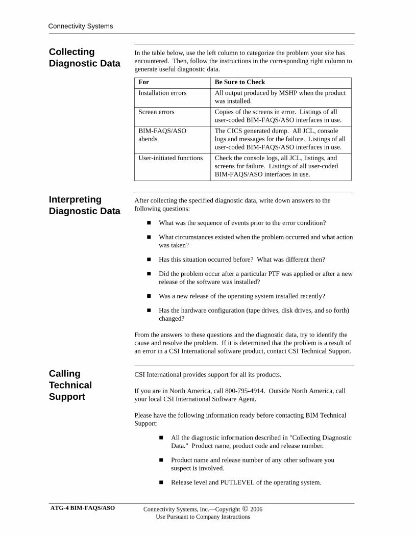
Collecting Diagnostic Data
In the table below, use the left column to categorize the problem your site has encountered. Then, follow the instructions in the corresponding right column to generate useful diagnostic data.
Interpreting Diagnostic Data
After collecting the specified diagnostic data, write down answers to the following questions:
What was the sequence of events prior to the error condition?
What circumstances existed when the problem occurred and what action was taken?
Has this situation occurred before? What was different then?
Did the problem occur after a particular PTF was applied or after a new release of the software was installed?
Was a new release of the operating system installed recently?
Has the hardware configuration (tape drives, disk drives, and so forth) changed?
From the answers to these questions and the diagnostic data, try to identify the cause and resolve the problem. If it is determined that the problem is a result of an error in a CSI International software product, contact CSI Technical Support.
Calling Technical Support
CSI International provides support for all its products.
If you are in North America, call 800-795-4914. Outside North America, call your local CSI International Software Agent.
Please have the following information ready before contacting BIM Technical Support:
All the diagnostic information described in "Collecting Diagnostic Data." Product name, product code and release number.
Product name and release number of any other software you suspect is involved.
Release level and PUTLEVEL of the operating system.
For Be Sure to CheckInstallation errors All output produced by MSHP when the product
was installed.Screen errors Copies of the screens in error. Listings of all
user-coded BIM-FAQS/ASO interfaces in use.BIM-FAQS/ASO abends
The CICS generated dump. All JCL, console logs and messages for the failure. Listings of all user-coded BIM-FAQS/ASO interfaces in use.
User-initiated functions Check the console logs, all JCL, listings, and screens for failure. Listings of all user-coded BIM-FAQS/ASO interfaces in use.
ATG-4 BIM-FAQS/ASO Connectivity Systems, Inc.—Copyright © 2006Use Pursuant to Company Instructions

Your name, telephone number and extension (if any).
Your company name.
Connectivity Systems, Inc.—Copyright © 2006Use Pursuant to Company Instructions
Online User’s Guide ATG-5

Connectivity Systems
ATG-6 BIM-FAQS/ASO Connectivity Systems, Inc.—Copyright © 2006Use Pursuant to Company Instructions
Chapter 1
Introduction
In This Chapter
This chapter provides an overview of BIM-FAQS/ASO Online. It also provides information about contacting CSI International Technical Support and Documentation.
BIM-FAQS/ASO Advantages
DOS/VSE offers more functions and facilities with each new version. The major new features and enhancements that have been incorporated into VSE have made it a much more viable and strategic operating system for the future. As VSE matures, the number of new control blocks, internal tables, and system components continues to grow in size and complexity, making it more difficult to effectively manage and control your VSE system.
The BIM-FAQS/ASO Online transaction provides a powerful and extremely valuable online tool that gives you better control of your VSE system. Remote console services, online debugging and fix-it facilities, job and system monitoring capabilities, and several other online system tools are available to increase the effectiveness and productivity of application programmers, system programmers, and computer operators. The BIM-FAQS/ASO Online transaction is available as an interactive application under:
BTAM
CICS
ICCF
VTAM
VM/CMS
HTML (CGI)
BIM-GSS REXX
To aid in use and flexibility, you can use BIM-FAQS/ASO Online as a command-driven system, a menu-driven system, or a combination of both. Menu-driven systems are invaluable to new users or end users, but the more familiar you become with a product, the more restrictive a menu system can become.
Online User’s Guide 1-1
Connectivity Systems
BIM-FAQS/ASO Benefits
Programmer Aids
Several programmer productivity aids are supported to assist and improve overall program development. Various online reports provide programmers with instant, real-time reports that were previously available only through batch utilities and operator action on the system console. The following can be displayed on a BIM-FAQS/ASO terminal:
Sorted VTOC display (LVTOC)
Label information report (LSERV)
Current logical unit assignments (LISTIO)
Current library definition chain (LIBLIST)
Library, sub-library, and member display (LIBR)
VSAM Catalog, Volume, Cluster display (VSAM)
Display/Alter Storage and Disk Records
The storage display/alter and disk record display/alter facilities allow system programmers to identify problems as they occur and immediately correct them. The disk record display facility (DUMP) is also a helpful programmer tool as an online alternative to the VSE DITTO utility.
ASO J (Job Monitor Report)
The Job Monitor Report (ASO J) enables programmers to monitor the current execution status of their jobs. It also serves as a valuable system monitor and problem determination tool, displaying the overall job activity in the system so that users can quickly identify inactive or hung tasks.
For Pre-ESA 2.1 systems, the command is PRTY J.
Online Reports In addition to the ASO J report, BIM-FAQS/ASO provides several other system activity reports so that system programmers can monitor potential system problems and performance bottlenecks before they occur. These online reports include:
Phase Fetch/Load Activity Report (FTL).
Current GETVIS Allocation and USAGE Report (MAP GETVIS).
DEBUG Report. This report lists the tasks currently being executed in the system, and the address of the major VSE control blocks for each.
1-2 BIM-FAQS/ASO Connectivity Systems, Inc.—Copyright © 2006Use Pursuant to Company Instructions
Spooler Queue Display Facility
Spooler Queue Overview
A powerful and efficient spooler queue display facility is available to allow users to list the spooler RDR, LST, PUN, and XMT queues online for both POWER or SPRI .
View Actual Contents of Spooler Queue Members
You can view the contents of the spooler RDR, PUN, XMT, and LST queue members. Members can be updated and resubmitted into the RDR queue using the full-screen editor facility. Members can also be transferred to a CMS file for editing.
Active Member Display
Active member display is provided to allow viewing of a LST member while the job is still running. For example, it is often necessary to know what has been printed to SYSLST for CICS while it is running.
Connectivity Systems, Inc.—Copyright © 2006Use Pursuant to Company Instructions
Online User’s Guide 1-3
Connectivity Systems
Console Capabilites
Console Support Function
The console support function allows programmers and operators to view the current system console and redisplay previous console activity directly from any BIM-FAQS/ASO terminal. Programmers can monitor all job-related console messages from a BIM-FAQS/ASO session, alleviating needless operator interruptions. The console redisplay command can be used to eliminate the slow and costly console redisplay from the main system console. The split panel console display (D S,S) divides the terminal into two separate panels, displaying a condensed job activity report in the top window and the current console image in the second window.
The command D S,W displays a window showing the statistics at the upper right corner of the screen, with the normal console display continuing on the rest of the screen.
Message Routing Facility
The message routing facility restricts which console messages are displayed on a terminal. You can direct Console messages to a specific terminal based on the partition from which they originate, a specific message identifier, or a generic class of console messages.
To perform message routing, VSE/ESA 2.1 users should use the BIM-FAQS/ASO console filtering feature.
Enter Operator Commands
In addition to displaying console activity at any terminal, you can enter operator commands or respond to outstanding console replies directly from BIM-FAQS/ASO. This permits programmers to control the execution of their jobs from their own terminal without requiring operator intervention. The entire system can be controlled from any local or remote attached 3270 terminal that has access to the VSE system. System programmers with remote terminals at home can now correct problems and control the system using BIM-FAQS/ASO rather than instructing an operator what to do over the phone.
1-4 BIM-FAQS/ASO Connectivity Systems, Inc.—Copyright © 2006Use Pursuant to Company Instructions
Online Capabilities
Online Password Security Feature
An online password security feature enables installations to tailor the online capabilities of BIM-FAQS/ASO to the individual needs of each user at any time. An optional logging facility is also available to log the BIM-FAQS/ASO user ID on the system console of the terminal operator entering operator commands or console replies directly from BIM-FAQS/ASO.
Extensive Online Message and Help Facility
BIM-FAQS/ASO also provides an extensive online message and help facility. Messages and help panels are displayed by accessing the FAQSMSGS VSAM message file, which is provided on the installation tape. Messages and help panels can be added to this file through the batch program FAQSERRM. IBM messages may also be viewed online.
With VSE/ESA 2.1, FAQSMSG is no longer used for online message explanation retrieval. BIM-FAQS/ASO uses the IBM EXPLAIN facility for online message explanation viewing. All pre-ESA 2.1 versions of BIM-FAQS/ASO continue to use the FAQSMSG VSAM file for viewing message explanations online.
Connectivity Systems, Inc.—Copyright © 2006Use Pursuant to Company Instructions
Online User’s Guide 1-5
Connectivity Systems
BIM-FAQS/ASO Command Overview
Command Description
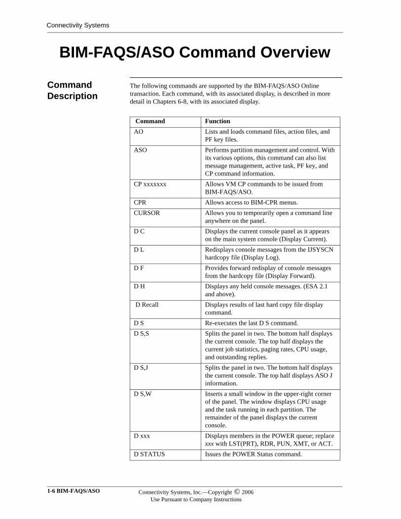
The following commands are supported by the BIM-FAQS/ASO Online transaction. Each command, with its associated display, is described in more detail in Chapters 6-8, with its associated display.
Command FunctionAO Lists and loads command files, action files, and
PF key files.ASO Performs partition management and control. With
its various options, this command can also list message management, active task, PF key, and CP command information.
CP xxxxxxx Allows VM CP commands to be issued from BIM-FAQS/ASO.
CPR Allows access to BIM-CPR menus.CURSOR Allows you to temporarily open a command line
anywhere on the panel.D C Displays the current console panel as it appears
on the main system console (Display Current).D L Redisplays console messages from the IJSYSCN
hardcopy file (Display Log).D F Provides forward redisplay of console messages
from the hardcopy file (Display Forward).D H Displays any held console messages. (ESA 2.1
and above). D Recall Displays results of last hard copy file display
command. D S Re-executes the last D S command.D S,S Splits the panel in two. The bottom half displays
the current console. The top half displays the current job statistics, paging rates, CPU usage, and outstanding replies.
D S,J Splits the panel in two. The bottom half displays the current console. The top half displays ASO J information.
D S,W Inserts a small window in the upper-right corner of the panel. The window displays CPU usage and the task running in each partition. The remainder of the panel displays the current console.
D xxx Displays members in the POWER queue; replace xxx with LST(PRT), RDR, PUN, XMT, or ACT.
D STATUS Issues the POWER Status command.
1-6 BIM-FAQS/ASO Connectivity Systems, Inc.—Copyright © 2006Use Pursuant to Company Instructions
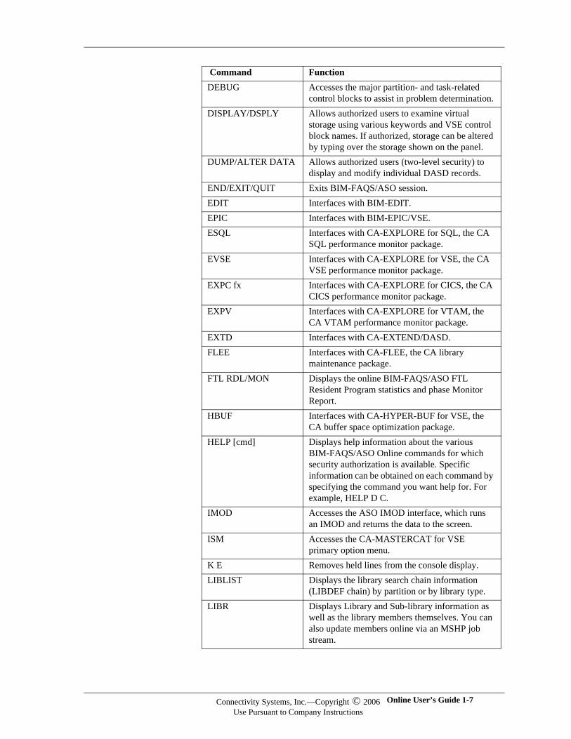
DEBUG Accesses the major partition- and task-related control blocks to assist in problem determination.
DISPLAY/DSPLY Allows authorized users to examine virtual storage using various keywords and VSE control block names. If authorized, storage can be altered by typing over the storage shown on the panel.
DUMP/ALTER DATA Allows authorized users (two-level security) to display and modify individual DASD records.
END/EXIT/QUIT Exits BIM-FAQS/ASO session.EDIT Interfaces with BIM-EDIT.EPIC Interfaces with BIM-EPIC/VSE.ESQL Interfaces with CA-EXPLORE for SQL, the CA
SQL performance monitor package.EVSE Interfaces with CA-EXPLORE for VSE, the CA
VSE performance monitor package.EXPC fx Interfaces with CA-EXPLORE for CICS, the CA
CICS performance monitor package.EXPV Interfaces with CA-EXPLORE for VTAM, the
CA VTAM performance monitor package.EXTD Interfaces with CA-EXTEND/DASD.FLEE Interfaces with CA-FLEE, the CA library
maintenance package.FTL RDL/MON Displays the online BIM-FAQS/ASO FTL
Resident Program statistics and phase Monitor Report.
HBUF Interfaces with CA-HYPER-BUF for VSE, the CA buffer space optimization package.
HELP [cmd] Displays help information about the various BIM-FAQS/ASO Online commands for which security authorization is available. Specific information can be obtained on each command by specifying the command you want help for. For example, HELP D C.
IMOD Accesses the ASO IMOD interface, which runs an IMOD and returns the data to the screen.
ISM Accesses the CA-MASTERCAT for VSE primary option menu.
K E Removes held lines from the console display.LIBLIST Displays the library search chain information
(LIBDEF chain) by partition or by library type.LIBR Displays Library and Sub-library information as
well as the library members themselves. You can also update members online via an MSHP job stream.
Command Function
Connectivity Systems, Inc.—Copyright © 2006Use Pursuant to Company Instructions
Online User’s Guide 1-7
Connectivity Systems
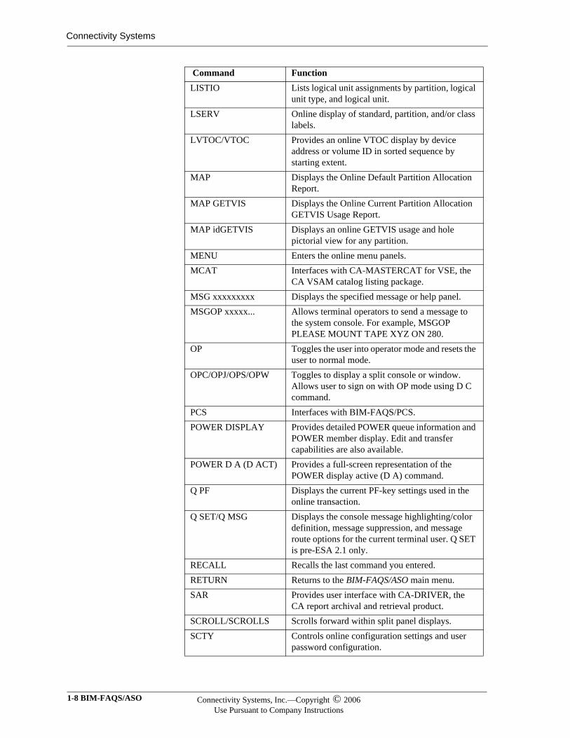
LISTIO Lists logical unit assignments by partition, logical unit type, and logical unit.
LSERV Online display of standard, partition, and/or class labels.
LVTOC/VTOC Provides an online VTOC display by device address or volume ID in sorted sequence by starting extent.
MAP Displays the Online Default Partition Allocation Report.
MAP GETVIS Displays the Online Current Partition Allocation GETVIS Usage Report.
MAP idGETVIS Displays an online GETVIS usage and hole pictorial view for any partition.
MENU Enters the online menu panels.MCAT Interfaces with CA-MASTERCAT for VSE, the
CA VSAM catalog listing package.MSG xxxxxxxxx Displays the specified message or help panel.MSGOP xxxxx... Allows terminal operators to send a message to
the system console. For example, MSGOP PLEASE MOUNT TAPE XYZ ON 280.
OP Toggles the user into operator mode and resets the user to normal mode.
OPC/OPJ/OPS/OPW Toggles to display a split console or window. Allows user to sign on with OP mode using D C command.
PCS Interfaces with BIM-FAQS/PCS.POWER DISPLAY Provides detailed POWER queue information and
POWER member display. Edit and transfer capabilities are also available.
POWER D A (D ACT) Provides a full-screen representation of the POWER display active (D A) command.
Q PF Displays the current PF-key settings used in the online transaction.
Q SET/Q MSG Displays the console message highlighting/color definition, message suppression, and message route options for the current terminal user. Q SET is pre-ESA 2.1 only.
RECALL Recalls the last command you entered.RETURN Returns to the BIM-FAQS/ASO main menu.SAR Provides user interface with CA-DRIVER, the
CA report archival and retrieval product.SCROLL/SCROLLS Scrolls forward within split panel displays.SCTY Controls online configuration settings and user
password configuration.
Command Function
1-8 BIM-FAQS/ASO Connectivity Systems, Inc.—Copyright © 2006Use Pursuant to Company Instructions
Console Display
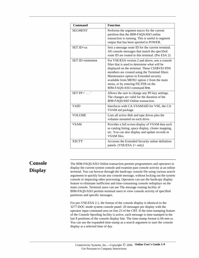
The BIM-FAQS/ASO Online transaction permits programmers and operators to display the current system console and examine past console activity at an online terminal. You can browse through the hardcopy console file using various search arguments to quickly locate any console message, without locking out the system console or impacting other processing. Operators can use the hardcopy display feature to eliminate inefficient and time-consuming console redisplays on the main console. Terminal users can use The message routing facility of BIM-FAQS/ASO permits terminal users to view console activity of specified partitions and specific messages.
For pre-VSE/ESA 2.1, the format of the console display is identical to the 3277-DOC mode system console panel: 20 messages per display with the operator input command area on line 23 of the CRT. If the time-stamping feature of the Console Spooling facility is active, each message is time-stamped in the last 8 positions of the console display line. The time-stamp format is hh:mm:ss. You can use the expanded time-stamp as a search argument to start the console display at a selected time of day.
SEGMENT Performs the segment macro for the current partition that the BIM-FAQS/ASO online transaction is running. This is useful to segment output that has been spooled to POWER.
SET ID=xx Sets a message route ID for the current terminal. All console messages that match the specified route ID are routed to this terminal. (Pre ESA 2)
SET ID=xxxxxxxx For VSE/ESA version 2 and above, sets a console filter that is used to determine what will be displayed on the terminal. These CSS$VIO PDS members are created using the Terminal filters Maintenance option in Extended security available from MENU option 2 from the main menu, or by entering FILTER on the BIM-FAQS/ASO command line.
SET PF=' . . . ' Allows the user to change any PF-key settings. The changes are valid for the duration of the BIM-FAQS/ASO Online transaction.
VAID Interfaces with CA-VSAMAID for VSE, the CA VSAM aid package.
VOLUME Lists all active disk and tape drives plus the volumes mounted on each drive.
VSAM Provides a full screen display of VSAM data such as catalog listing, space display, cluster mapping, etc. You can also display and update records in VSAM files.
XSCTY Accesses the Extended Security online definition panels. (VSE/ESA 2+ only)
Command Function
Connectivity Systems, Inc.—Copyright © 2006Use Pursuant to Company Instructions
Online User’s Guide 1-9
Connectivity Systems
For VSE/ESA 2.1, the console still resembles the IBM DOC mode console, except that the number of messages on screen is determined by the terminal model. Beginning with ESA 2.1, time-stamping is supplied by ESA console routines, which BIM-FAQS/ASO displays if the characters that the time stamp overlays are blanks.
Multiple Console Support
The BIM-FAQS/ASO Online transaction provides multiple operator console support by allowing terminal operators to enter VSE operator commands and respond to outstanding partition replies directly from BIM-FAQS/ASO under control of CICS, ICCF, VTAM, CMS or from a browser (CGI). BIM-FAQS/ASO supports a sign-on password security facility to restrict the operator reply facility to privileged users. The level of security that can be defined ranges from full-console support to restricting an operator to viewing specific partitions or replying to limited console replies.
VSE operator commands can be entered from BIM-FAQS/ASO using two different methods. You can:
Precede a console command or reply with the prefix OP followed by a space. The BIM-FAQS/ASO Online transaction removes the OP prefix from the beginning of the command and passes the command to the supervisor. After the command is submitted, a D C command is automatically executed so that you can view the current console panel.
Place the session into operator mode. Enter OP with no other operands. Once the session is in operator mode, any command entered which is not one of the BIM-FAQS/ASO keyword commands (suc as ASO, CP, D, or HELP), is passed directly to the supervisor as an operator reply.
The BIM-FAQS/ASO Online transaction performs an automatic redisplay of the current console at a predefined timer interval so that the BIM-FAQS/ASO terminal appears as an alternate system console to the user. From BIM-FAQS/ASO, you can:
Cancel jobs
Issue POWER or SPRI requests
Respond to outstanding messages
Enter operator commands
You can perform all these tasks just as you would from a main system console. BIM-FAQS/ASO refreshes the current console automatically so that you can monitor the activity of the system. The automatic timed-redisplay interval is set in the security record for each user ID.
To reset the BIM-FAQS/ASO terminal from operator mode, enter the OP command with no additional parameters. A PF key can be defined to OP to toggle the terminal into and out of operator mode. When the terminal is in operator mode, the OPERATOR MODE message is highlighted on the bottom of the panel. Likewise, when timed redisplay is active for a terminal, the message
1-10 BIM-FAQS/ASO Connectivity Systems, Inc.—Copyright © 2006Use Pursuant to Company Instructions
TIMED DISPLAY is displayed on the bottom of the panel to remind the user that the BIM-FAQS/ASO application is in timed redisplay mode. However, TIMED DISPLAY is removed from the bottom of the console display when the maximum idle time (as specified in the user's security) has been exceeded.
Note:Note:The timed redisplay facility is not implemented under ICCF due to ICCF restrictions.
Terminal Support
BIM-FAQS/ASO supports 3270-type architecture terminals. Extended color terminals are supported and can be tailored for each user. Terminals that support extended attributes are also supported like the color terminal with the exception of no color. BIM-FAQS/ASO supports the Reverse, Blink, and Underscore attributes. Model 3 (33 line terminals), Model 4 (43 line terminals), and Model 5 (132 column terminals) are all supported in the CMS, CICS, ICCF, and VTAM interfaces. The SCTY function, however, is not supported on Model 5 (132 column) terminals except when you use the SCREEN command to change the screen to an 80 column display.
Browser Support
BIM-FAQS/ASO access is now available including console line colors and full functionality via the internet by using any browser. You can use a CGI that is defined to TCP/IP for VSE ™ (Connectivity Systems, Inc) or an IPSERVER (DATA21) to access BIM-FAQS/ASO. The BIM-GSS CGI queues the execution of the BIMTCPFQ IMOD to BIM$CGRX. This IMOD converts HTML code to 3270 and issues a request to FAQXFUNC which processes the requests and then returns to the IMOD. The IMOD then converts the results back into HTML and indicates to the CGI that the request is complete and data is ready to receive. The CGI (either BIM$CGIC, IPSERVER, or BIM$CGIP for CGILOAD) then returns the results to the HTTP daemon and IP stack being used, where it is sent back to the browser.
You can pass parameters that determine the number of lines per screen and the initial user ID to sign on to as well as the first command to process.
For information and scripts to define the browsers, see the Technical Support area of the CSI website, under Product Fixes for BIM-FAQS/ASO, URL: www.e-vse.com.
GETVIS Requirements
The BIM-FAQS/ASO Online transaction must perform a CDLOAD request for the FAQSTUPD phase to:
Process BIM-FAQS/PCS requests
Display POWER queues and members within the POWER queues
Process the online LSERV command
Process security, message displays, help panels, and menu panels
Process OEM product requests
Perform online message display
Connectivity Systems, Inc.—Copyright © 2006Use Pursuant to Company Instructions
Online User’s Guide 1-11
Connectivity Systems
A minimum of 150K of GETVIS is necessary for BIM-FAQS/ASO Online to function (if VSAM files are left open more is required). Additional GETVIS is required to edit POWER members. A minimum of 100K is required but large members need more GETVIS. The menu-driven system requires 137K of GETVIS for phases. If OEM products are used, another 100K of GETVIS is necessary.
When using the CMS interface, the FAQSVMCF or FAQSIUCV modules are CDLOADed into the partition GETVIS. These modules require an additional 80K to 100K from the partition GETVIS.
There are additional temporary GETVIS requirements of 20K for VM and VTAM users. POWER queue displays require 2K; member displays require 4K per user, and a variable amount for larger members in POWER 2.3. For example, a 100,000-line member will require approximately 4K additional GETVIS. The menu-driven system requires approximately 22K per user and additional GETVIS for multiple levels.
Approximately 70 - 100K of GETVIS per user is an appropriate starting amount. You will need more GETVIS to edit large POWER members. For CMS interface users, you will also need 256K of PFIXed storage for every 10 users. BIM-FAQS/ASO Online also requires GETVIS for CDLOADed phases and storage areas which have been included in the 75-100K per user figure.
I/O Buffers to 8K
BIM-FAQS/ASO interfaces support input/output buffers up to 8K, enabling faster data transfer and longer, better displays.
1-12 BIM-FAQS/ASO Connectivity Systems, Inc.—Copyright © 2006Use Pursuant to Company Instructions
Chapter 2
FAQS/ASO Online Interfaces
In This Chapter
This chapter describes the online interfaces that BIM-FAQS/ASO supports.
FAQSMAIN FAQSMAIN is a BIM-FAQS/ASO program used to communicate with other programs running as online interfaces. FAQSMAIN can run in a dynamic or a static partition as a main task or a subtask.
Supported Interfaces
Currently, FAQSMAIN supports the following interfaces, explained later in this chapter:
BIM$TIDR, which runs as a VTAM application, a BTAM interface, a CICS interface via BIM$TICI, or an XPCC interface for online access to other BIMVSE products.
FAQSVMX, a BIM-FAQS/ASO VMCF interface.
FAQSIUX, a BIM-FAQS/ASO IUCV interface.
FAQSICX, a BIM-FAQS/ASO ICCF interactive partition.
FAQXFUNC, a BIM-FAQS/ASO IMOD and HTML interface.
Benefits of FAQSMAIN
Prior to FAQSMAIN, if multiple interfaces were being used in different partitions, duplicate copies of CDLOADed phases would exist in each partition.
Using FAQSMAIN saves on partition GETVIS usage. For example, on a VSE/ESA machine, if you are running FAQSMAIN in partition C3, BIM$TIDR is running in partition Z2, and FAQSVMX is running in partition F8, only the FAQSMAIN partition will use GETVIS for CDLOADed phases. The partition GETVIS used for BIM$TIDR and FAQSVMX is for terminal buffers and TWAs (Temporary Work Areas), and for SDF (150K).
BIM$TIDR also uses SDF resources, so running it in the same partition as FAQSMAIN will reduce storage requirements.
Online User’s Guide 2-1
Connectivity Systems
Running As Main Task
Execute the following to run FAQSMAIN as a main task:
// JOB FAQSMAIN
// LIBDEF *,SEARCH=lib.sublib
// EXEC FAQSMAIN,SIZE=FAQSMAIN
/&
Running As Subtask
Use BIM$UTTS to subtask FAQSMAIN under a long-running task or subtask it under the BIM-FAQS/PCS scheduler, JCLSCHED. The subtask FAQSMAIN can run under JSCHED, but it is not recommended. For information about BIM$UTTS and JCLSCHED, see the BIM-FAQS (ASO and PCS) Installation and Initialization Guide.
Terminating FAQSMAIN
Enter FAQS SHU,Y,M to terminate FAQSMAIN from BIM-FAQS/ASO Online. If FAQSMAIN is a subtask, terminate the main task.
Running FAQSMAIN in Multiple Partitions
It is now possible to run FAQSMAIN in multiple partitions with the use of the new execution parameter, ID=<name>. You can identify each FAQSMAIN to XPCC with a different ID and you can access FAQSMAIN individually from any interface You can select which FAQSMAIN to access from the CICS/VTAM/BTAM main menu or by using the ID=<name> parameter from the IUCV interface or from your initial call to the HTML Interface. Running FAQSMAIN in multiple partitions allows you to:
Isolate some users from others, such as systems users from application programmers.
Spread the workload out between partitions, allowing better use of the system in a multi CPU environment.
Provide the ability of one BIM-FAQS/ASO partition to shutdown and restart another.
Separate users using one interface method from another, such as VTAM BIM-FAQS/ASO users from CMS or HTML users.
FAQSMAIN Initialization Parameters
You can provide parameters during start up to configure how a particular FAQSMAIN partition is established:
NAME=xxxxxxxx is used to determine the name of this FAQSMAIN partition. This name appears on the lower right hand corner of the terminal for BIM-FAQS/ASO sessions. The default is the CPUID or the VSE virtual machine name if VSE is running under VM.
ID=iiiiiiii is used to define the XPCC communications identifier for this FAQSMAIN partition. For interfaces other than VMCF this can be used to allow you to have multiple FAQSMAIN partitions spreading out the workload and allowing better use of resources.
2-2 BIM-FAQS/ASO Connectivity Systems, Inc.—Copyright © 2006Use Pursuant to Company Instructions
USERS=nnnn is used to determine the maximum number of BIM-FAQS/ASO users to allowed to access this FAQSMAIN partition simultaneously with a default of 84.
STATS=ccc/aaa is used to determine the screen color and attributes for the BIM-FAQS/ASO status display area for this FAQSMAIN job. Possible color values are:
Possible attributes are:
All Parameters for FAQSMAIN now require only 1 character instead of the entire parameter name. This allows room for more parameters, particularly when using BIM$UTTS to run multiple phases as subtasks.
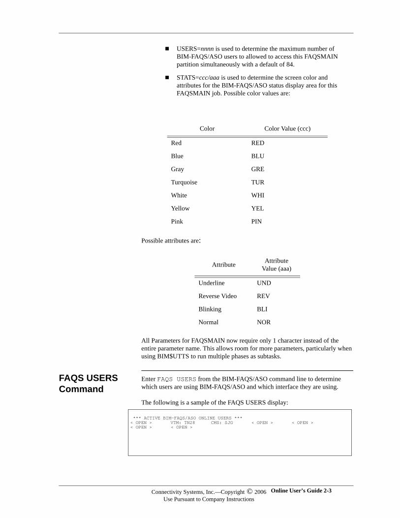
FAQS USERS Command
Enter FAQS USERS from the BIM-FAQS/ASO command line to determine which users are using BIM-FAQS/ASO and which interface they are using.
The following is a sample of the FAQS USERS display:
Color Color Value (ccc)
Red RED
Blue BLU
Gray GRE
Turquoise TUR
White WHI
Yellow YEL
Pink PIN
Attribute Attribute Value (aaa)
Underline UND
Reverse Video REV
Blinking BLI
Normal NOR
*** ACTIVE BIM-FAQS/ASO ONLINE USERS *** < OPEN > VTM: TN28 CMS: SJG < OPEN > < OPEN > < OPEN > < OPEN >
Connectivity Systems, Inc.—Copyright © 2006Use Pursuant to Company Instructions
Online User’s Guide 2-3
Connectivity Systems
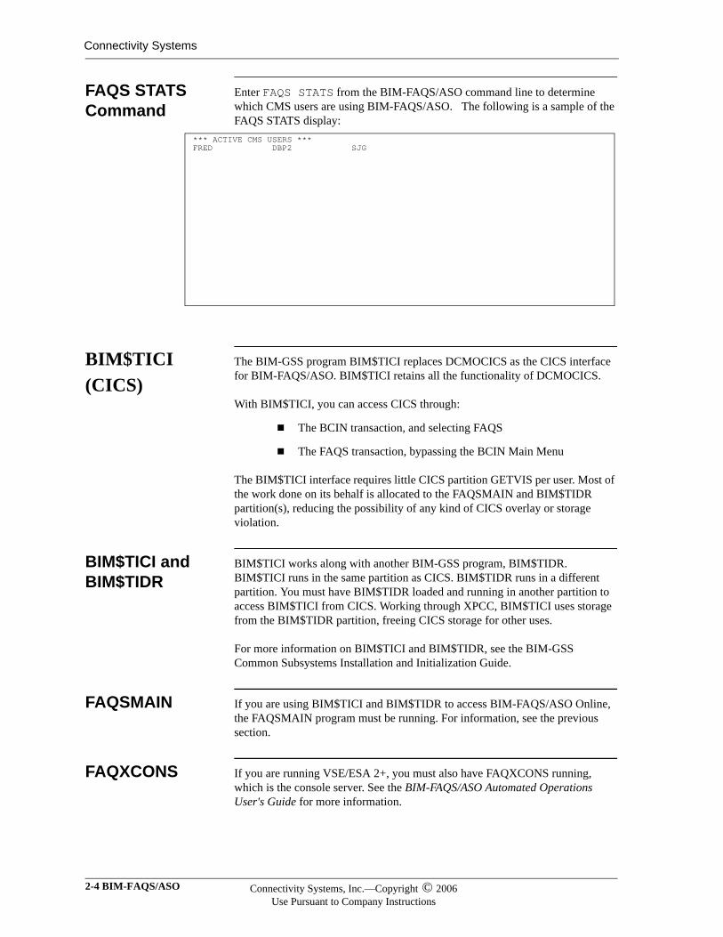
FAQS STATS Command
Enter FAQS STATS from the BIM-FAQS/ASO command line to determine which CMS users are using BIM-FAQS/ASO. The following is a sample of the FAQS STATS display:
BIM$TICI (CICS)
The BIM-GSS program BIM$TICI replaces DCMOCICS as the CICS interface for BIM-FAQS/ASO. BIM$TICI retains all the functionality of DCMOCICS.
With BIM$TICI, you can access CICS through:
The BCIN transaction, and selecting FAQS
The FAQS transaction, bypassing the BCIN Main Menu
The BIM$TICI interface requires little CICS partition GETVIS per user. Most of the work done on its behalf is allocated to the FAQSMAIN and BIM$TIDR partition(s), reducing the possibility of any kind of CICS overlay or storage violation.
BIM$TICI and BIM$TIDR
BIM$TICI works along with another BIM-GSS program, BIM$TIDR. BIM$TICI runs in the same partition as CICS. BIM$TIDR runs in a different partition. You must have BIM$TIDR loaded and running in another partition to access BIM$TICI from CICS. Working through XPCC, BIM$TICI uses storage from the BIM$TIDR partition, freeing CICS storage for other uses.
For more information on BIM$TICI and BIM$TIDR, see the BIM-GSS Common Subsystems Installation and Initialization Guide.
FAQSMAIN If you are using BIM$TICI and BIM$TIDR to access BIM-FAQS/ASO Online, the FAQSMAIN program must be running. For information, see the previous section.
FAQXCONS If you are running VSE/ESA 2+, you must also have FAQXCONS running, which is the console server. See the BIM-FAQS/ASO Automated Operations User's Guide for more information.
*** ACTIVE CMS USERS *** FRED DBP2 SJG
2-4 BIM-FAQS/ASO Connectivity Systems, Inc.—Copyright © 2006Use Pursuant to Company Instructions
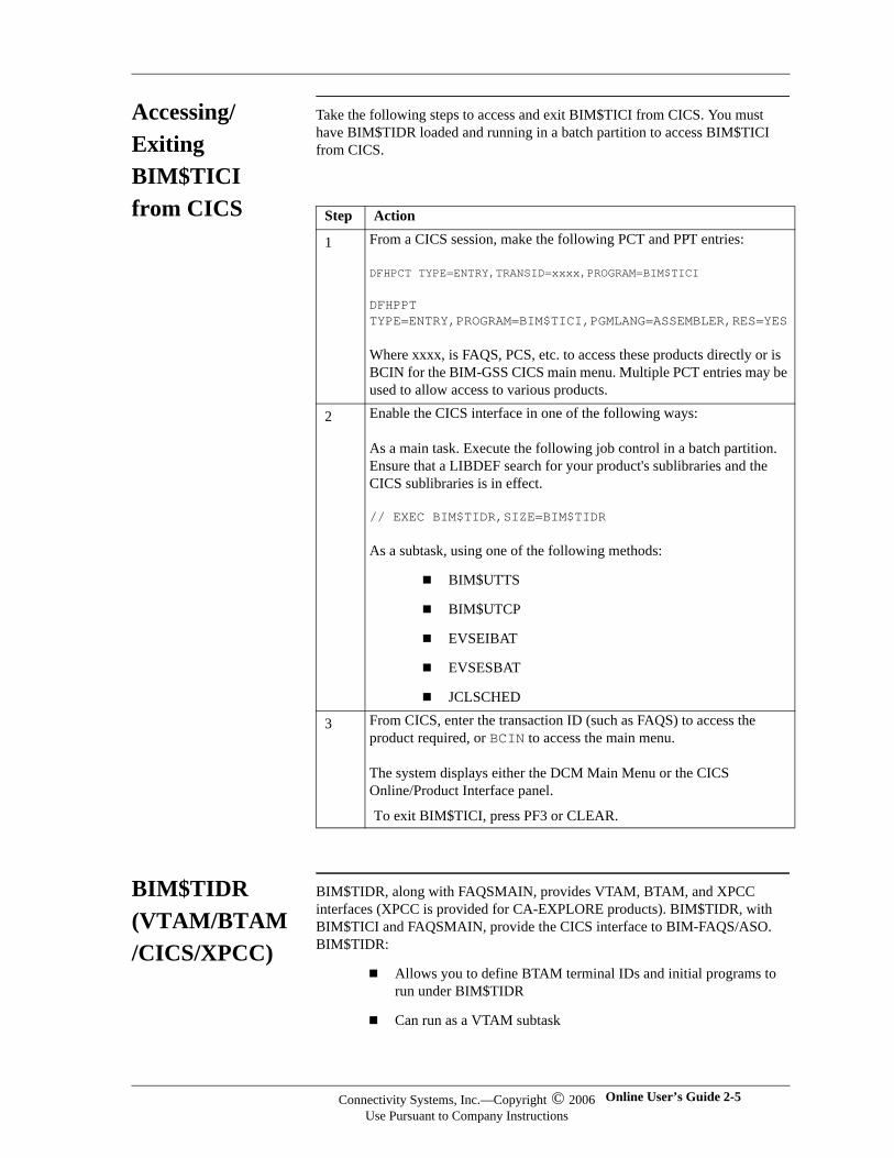
Accessing/Exiting BIM$TICI from CICS
Take the following steps to access and exit BIM$TICI from CICS. You must have BIM$TIDR loaded and running in a batch partition to access BIM$TICI from CICS.
BIM$TIDR (VTAM/BTAM/CICS/XPCC)
BIM$TIDR, along with FAQSMAIN, provides VTAM, BTAM, and XPCC interfaces (XPCC is provided for CA-EXPLORE products). BIM$TIDR, with BIM$TICI and FAQSMAIN, provide the CICS interface to BIM-FAQS/ASO. BIM$TIDR:
Allows you to define BTAM terminal IDs and initial programs to run under BIM$TIDR
Can run as a VTAM subtask
Step Action
1 From a CICS session, make the following PCT and PPT entries:
DFHPCT TYPE=ENTRY,TRANSID=xxxx,PROGRAM=BIM$TICI
DFHPPT TYPE=ENTRY,PROGRAM=BIM$TICI,PGMLANG=ASSEMBLER,RES=YES
Where xxxx, is FAQS, PCS, etc. to access these products directly or is BCIN for the BIM-GSS CICS main menu. Multiple PCT entries may be used to allow access to various products.
2 Enable the CICS interface in one of the following ways:
As a main task. Execute the following job control in a batch partition. Ensure that a LIBDEF search for your product's sublibraries and the CICS sublibraries is in effect.
// EXEC BIM$TIDR,SIZE=BIM$TIDR
As a subtask, using one of the following methods:
BIM$UTTS
BIM$UTCP
EVSEIBAT
EVSESBAT
JCLSCHED
3 From CICS, enter the transaction ID (such as FAQS) to access the product required, or BCIN to access the main menu.
The system displays either the DCM Main Menu or the CICS Online/Product Interface panel.
To exit BIM$TICI, press PF3 or CLEAR.
Connectivity Systems, Inc.—Copyright © 2006Use Pursuant to Company Instructions
Online User’s Guide 2-5
Connectivity Systems
Can run as a standalone interface in a batch partition
FAQSMAIN If you are using BIM$TIDR to access BIM-FAQS/ASO Online, the FAQSMAIN program must be running. For further information, see the first section of this chapter.
BTAM You can use BIM$TIDR with FAQSMAIN as a BIM-FAQS/ASO BTAM interface.
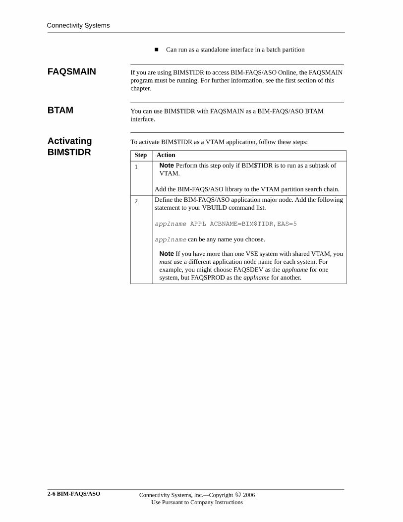
Activating BIM$TIDR
To activate BIM$TIDR as a VTAM application, follow these steps:
Step Action
1 Note Perform this step only if BIM$TIDR is to run as a subtask of VTAM.
Add the BIM-FAQS/ASO library to the VTAM partition search chain.
2 Define the BIM-FAQS/ASO application major node. Add the following statement to your VBUILD command list.
applname APPL ACBNAME=BIM$TIDR,EAS=5
applname can be any name you choose.
Note If you have more than one VSE system with shared VTAM, you must use a different application node name for each system. For example, you might choose FAQSDEV as the applname for one system, but FAQSPROD as the applname for another.
2-6 BIM-FAQS/ASO Connectivity Systems, Inc.—Copyright © 2006Use Pursuant to Company Instructions
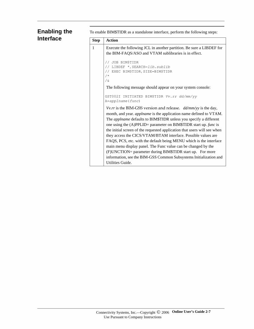
Enabling the Interface
To enable BIM$TIDR as a standalone interface, perform the following steps:
Step Action
1 Execute the following JCL in another partition. Be sure a LIBDEF for the BIM-FAQS/ASO and VTAM sublibraries is in effect.
// JOB BIM$TIDR// LIBDEF *,SEARCH=lib.sublib// EXEC BIM$TIDR,SIZE=BIM$TIDR/*/&
The following message should appear on your system console:
GST002I INITIATED BIM$TIDR Vv.rr dd/mm/yy A=applname(func)
Vv.rr is the BIM-GSS version and release. dd/mm/yy is the day, month, and year. applname is the application name defined to VTAM. The applname defaults to BIM$TIDR unless you specify a different one using the (A)PPLID= parameter on BIM$TIDR start up. func is the initial screen of the requested application that users will see when they access the CICS/VTAM/BTAM interface. Possible values are FAQS, PCS, etc. with the default being MENU which is the interface main menu display panel. The Func value can be changed by the (F)UNCTION= parameter during BIM$TIDR start up. For more information, see the BIM-GSS Common Subsystems Initialization and Utilities Guide.
Connectivity Systems, Inc.—Copyright © 2006Use Pursuant to Company Instructions
Online User’s Guide 2-7
Connectivity Systems
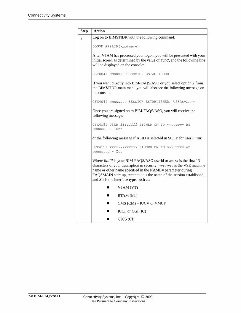
2 Log on to BIM$TIDR with the following command:
LOGON APPLID(applname)
After VTAM has processed your logon, you will be presented with your initial screen as determined by the value of 'func', and the following line will be displayed on the console:
GST004I uuuuuuuu SESSION ESTABLISHED
If you went directly into BIM-FAQS/ASO or you select option 2 from the BIM$TIDR main menu you will also see the following message on the console:
GFX404I uuuuuuuu SESSION ESTABLISHED, USERS=nnnn
Once you are signed on to BIM-FAQS/ASO, you will receive the following message:
GFX415I USER iiiiiiii SIGNED ON TO vvvvvvvv AS uuuuuuuu - Xtt
or the following message if ASID is selected in SCTY for user iiiiiiii:
GFX415I xxxxxxxxxxxxx SIGNED ON TO vvvvvvvv AS uuuuuuuu - Xtt
Where iiiiiiii is your BIM-FAQS/ASO userid or xx..xx is the first 13 characters of your description in security , vvvvvvvv is the VSE machine name or other name specified in the NAME= parameter during FAQSMAIN start up, uuuuuuuu is the name of the session established, and Xtt is the interface type, such as:
VTAM (VT)
BTAM (BT)
CMS (CM) – IUCV or VMCF
ICCF or CGI (IC)
CICS (CI).
Step Action
2-8 BIM-FAQS/ASO Connectivity Systems, Inc.—Copyright © 2006Use Pursuant to Company Instructions
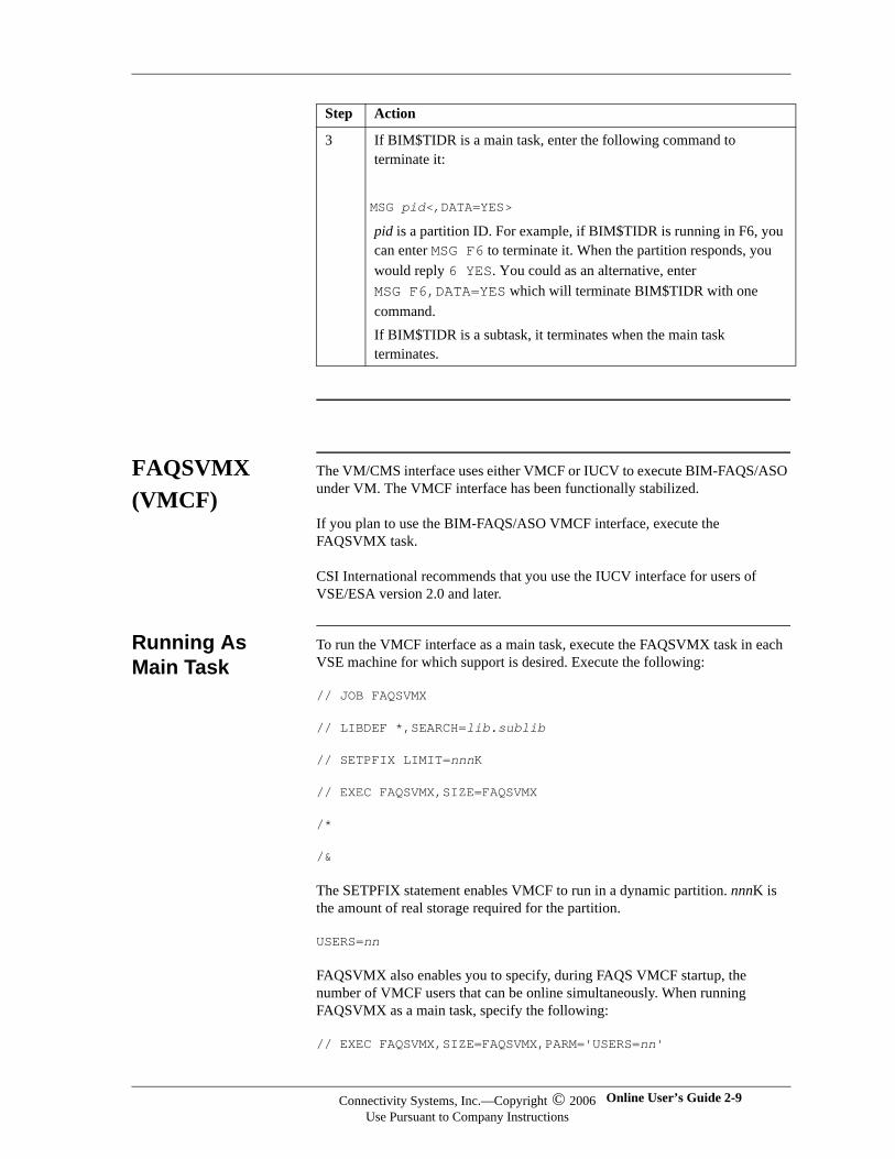
FAQSVMX (VMCF)
The VM/CMS interface uses either VMCF or IUCV to execute BIM-FAQS/ASO under VM. The VMCF interface has been functionally stabilized.
If you plan to use the BIM-FAQS/ASO VMCF interface, execute the FAQSVMX task.
CSI International recommends that you use the IUCV interface for users of VSE/ESA version 2.0 and later.
Running As Main Task
To run the VMCF interface as a main task, execute the FAQSVMX task in each VSE machine for which support is desired. Execute the following:
// JOB FAQSVMX
// LIBDEF *,SEARCH=lib.sublib
// SETPFIX LIMIT=nnnK
// EXEC FAQSVMX,SIZE=FAQSVMX
/*
/&
The SETPFIX statement enables VMCF to run in a dynamic partition. nnnK is the amount of real storage required for the partition.
USERS=nn
FAQSVMX also enables you to specify, during FAQS VMCF startup, the number of VMCF users that can be online simultaneously. When running FAQSVMX as a main task, specify the following:
// EXEC FAQSVMX,SIZE=FAQSVMX,PARM='USERS=nn'
3 If BIM$TIDR is a main task, enter the following command to terminate it:
MSG pid<,DATA=YES>
pid is a partition ID. For example, if BIM$TIDR is running in F6, you can enter MSG F6 to terminate it. When the partition responds, you would reply 6 YES. You could as an alternative, enter MSG F6,DATA=YES which will terminate BIM$TIDR with one command.If BIM$TIDR is a subtask, it terminates when the main task terminates.
Step Action
Connectivity Systems, Inc.—Copyright © 2006Use Pursuant to Company Instructions
Online User’s Guide 2-9
Connectivity Systems
When running FAQSVMX as a subtask of JCLSCHED, specify the following in the JCLSCHED.CTL file:
AUTO $FAQSVMX,PARM='USERS=nn'
In both cases, nn is the number of users to allow online at one time (maximum of 40). During startup, the message MAXIMUM INTERFACE USERS: nn is displayed.
PFIX Storage To calculate the amount of PFIX storage required, multiply the maximum number of users you expect to be online at the same time by 24K and then add 10K. This means for 10 users FAQSVMX would require 250K. A good rule of thumb is to assume 256K for each 10 users, so 1 megabyte is the amount of PFIX required for FAQSVMX if you had a total of 40 users.
FAQSMAIN If you are using FAQSVMX to run your VMCF interface, the FAQSMAIN program must also be running. For information, see the first section of this chapter.
FAQXCONS If you are running VSE/ESA 2+ you must also have FAQXCONS running, which is the console server. See the BIM-FAQS/ASO Automated Operations User's Guide for more information.
FAQSIUX (IUCV)
The VM/CMS interface uses either VMCF or IUCV to execute BIM-FAQS/ASO under VM.
The IUCV (Inter-User Communications Vehicle) interface permits two virtual machines to communicate with one another using the special IUCV command. BIM-FAQS/ASO offers IUCV support in addition to VMCF support because the VMCF support in the supervisor is single-threaded whereas IUCV is multi-threaded. Using the IUCV option rather than VMCF to communicate with CMS users can eliminate the conflict that arises when using the BIM-FAQS/ASO VMCF option at the same time as the VSE/VMCF system.
The CMS portion of the BIM-FAQS/ASO IUCV facility is performed by the supplied BIM-FAQS/ASO module. BIM-FAQS/ASO executes the CMS module to establish the CMS linkage to the VSE system with which you want to communicate. The VSE IUCV support is provided with the FAQSIUX phase. This requires you to execute the FAQSIUX task in all VSE systems to be supported.
FAQSIUX VSE Support
The BIM-FAQS/ASO VM IUCV interface can run only on VSE/ESA 2.1 and above. and only as a main task.
Note:Note:For users running VSE/ESA 2.0 and above, we recommend that you use the IUCV interface.
2-10 BIM-FAQS/ASO Connectivity Systems, Inc.—Copyright © 2006Use Pursuant to Company Instructions
To run the IUCV interface, execute the FAQSIUX task in each VSE machine for which you want support. Execute the following:
// LIBDEF *,SEARCH=lib.sublib
// SETPFIX LIMIT=nnnK
// EXEC FAQSIUX,SIZE=FAQSIUX,PARM='USERS=nn'
/*
SETPFIX enables VMCF or IUCV to run in a dynamic partition. nnnK is the amount of real storage required for the partition.
USERS=nn is the number of users to allow online at one time. The default is 10. For VMCF, the maximum number of users is 40. For IUCV, there is no maximum. During startup, the message MAXIMUM INTERFACE USERS: nn is displayed
To calculate the amount of PFIX storage required, multiply the maximum number of users you expect to be online at the same time by 24K and then add 10K. This means for 10 users FAQSIUX would require 250K. A good rule of thumb is to assume 256K for each 10 users.
FAQSMAIN If you are using FAQSIUX to run your IUCV interface, the FAQSMAIN program must also be running. For information about FAQSMAIN, see the first section of this chapter.
FAQXCONS If you are running VSE/ESA 2+ you must also have FAQXCONS running, which is the console server. See the BIM-FAQS/ASO Automated Operations User's Guide for more information.
FAQSICX (ICCF)
The BIM-FAQS/ASO Online application also runs directly under the ICCF program in an ICCF interactive partition named FAQSICX. To execute the BIM-FAQS/ASO ICCF Online application, enter $FAQS while in an ICCF session. The BIM-FAQS/ASO ICCF phase is loaded from the core-image library and executed by FAQSICX.
Note:Note:For users running VSE/ESA 2.0 and above, we recommend that you use the IUCV interface.
Sample ICCF Procedure
To ensure that ICCF allocates sufficient problem program area and partition GETVIS in the FAQSICX, create an ICCF procedure to reserve the proper storage.
The following sample procedure ensures sufficient problem program area and sufficient partition GETVIS for the BIM-FAQS/ASO ICCF application in the ICCF interactive partition:
Connectivity Systems, Inc.—Copyright © 2006Use Pursuant to Company Instructions
Online User’s Guide 2-11
Connectivity Systems
/OPTION GETVIS=P-32K/LOAD FAQSICX
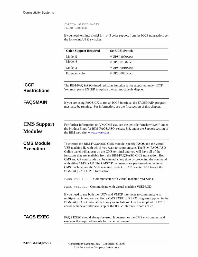
If you need terminal model 3, 4, or 5 color support from the ICCF transaction, set the following UPSI switches:
ICCF Restrictions
The BIM-FAQS/ASO timed redisplay function is not supported under ICCF. You must press ENTER to update the current console display.
FAQSMAIN If you are using FAQSICX to run an ICCF interface, the FAQSMAIN program must also be running. For information, see the first section of this chapter.
CMS Support Modules
For further information on VM/CMS use, see the text file “cmshowto.txt” under the Product Fixes for BIM-FAQS/ASO, release 5.3, under the Support section of the BIM web site, www.e-vse.com .
CMS Module Execution
To execute the BIM-FAQS/ASO CMS module, specify FAQS and the virtual VSE machine ID with which you want to communicate. The BIM-FAQS/ASO Online panel will appear on the CMS terminal and you will have all of the functions that are available from the BIM-FAQS/ASO CICS transaction. Both CMS and CP commands can be entered at any time by preceding the command with either CMS or CP. The CMS/CP commands are performed on the local CMS machine, not the VSE machine. Press CLEAR or enter EOJ to exit the BIM-FAQS/ASO CMS transaction.
FAQS VSESIPO - Communicate with virtual machine VSESIPO.
FAQS VSEPROD - Communicate with virtual machine VSEPROD.
If you need to use both the IUCV and VMCF interfaces to communicate to multiple machines, you can find a CMS EXEC or REXX program supplied in the BIM-FAQS/ASO installation library as an A-book. Use the supplied EXEC to access whichever interface is up or the IUCV interface if both are up.
FAQS EXEC FAQS EXEC should always be used. It determines the CMS environment and executes the required module for that environment.
Color Support Required Set UPSI Switch
Model 5 // UPSI 1000xxxxModel 4 // UPSI 0100xxxx
Model 3 // UPSI 0010xxxx
Extended color // UPSI 0001xxxx
2-12 BIM-FAQS/ASO Connectivity Systems, Inc.—Copyright © 2006Use Pursuant to Company Instructions
FAQS/ASO VM/CMS Shutdown
There are two ways of shutting down the BIM-FAQS/ASO VM support in the VSE machine. You can:
1. Terminate the partition in which it is running. The FAQSVM/FAQSIUX STXIT AB routine will recognize that the partition is terminating and perform a forced shutdown of BIM-FAQS/ASO VM.
2. Shut down BIM-FAQS/ASO VM support via the BIM-FAQS/ASO CMS transaction. You can specify an immediate shutdown from CMS which will shut down BIM-FAQS/ASO VM regardless of any other linked CMS users. You can also specify a delayed shutdown to delay the BIM-FAQS/ASO termination until all current users are disconnected from BIM-FAQS/ASO.
FAQS SHU,Y - Shut down immediately.
FAQS SHU,N - Shut down, but let tasks end.
Any user can request a task list of all CMS users currently linked to the BIM-FAQS/ASO VM interface by issuing the FAQS STAT command. This lists all CMS users currently linked to the VSE machine through BIM-FAQS/ASO.
FAQS STAT - Display active BIM-FAQS/ASO VM users.
CMS/CP Commands
The CMS user can issue any CMS or CP command by preceding the command with CMS or CP. The BIM-FAQS/ASO CMS transaction performs the command within the CMS machine. If you enter the CMS command with no operands, the CMS machine enters CMS SUBSET mode. When you issue the RETURN command, the last BIM-FAQS/ASO panel will be displayed.
If you want to enter a CP command to the VSE machine rather than the CMS machine, you must issue the ASO CP command, not just the CP prefix. This will cause the CP command to be issued on the VSE machine. For pre-ESA 2.1 installations, the command is PRTY CP.
Important:Be careful when using the ASO CP (or PRTY CP) command.
Connectivity Systems, Inc.—Copyright © 2006Use Pursuant to Company Instructions
Online User’s Guide 2-13

Connectivity Systems
2-14 BIM-FAQS/ASO Connectivity Systems, Inc.—Copyright © 2006Use Pursuant to Company Instructions
Chapter 3
Online Panels
In This Chapter
This chapter provides an overview of the BIM-FAQS/ASO Online system.
Overview BIM-FAQS/ASO Online consists of two types of panels:
Menu system
Displays
Menu system panels show a menu or are used to alter data. The BIM-FAQS/ASO Main Menu and the User Configuration panel are examples of menu system panels.
Display panels are used to control BIM-FAQS/ASO features and set up BIM-FAQS/ASO Online. You typically issue online commands from display panels.
BIM-FAQS/ASO Commands
To execute BIM-FAQS/ASO Online commands, type the command at the command prompt and press ENTER.
The command prompt on a display panel looks like the following, with the cursor positioned below the prompt:
ENTER BIM-FAQS/ASO COMMAND
On a menu system panel, the command prompt looks like the following, with the cursor positioned to the right of the prompt:
==>
Online User’s Guide 3-1
Connectivity Systems
Accessing BIM-FAQS/ASO Online
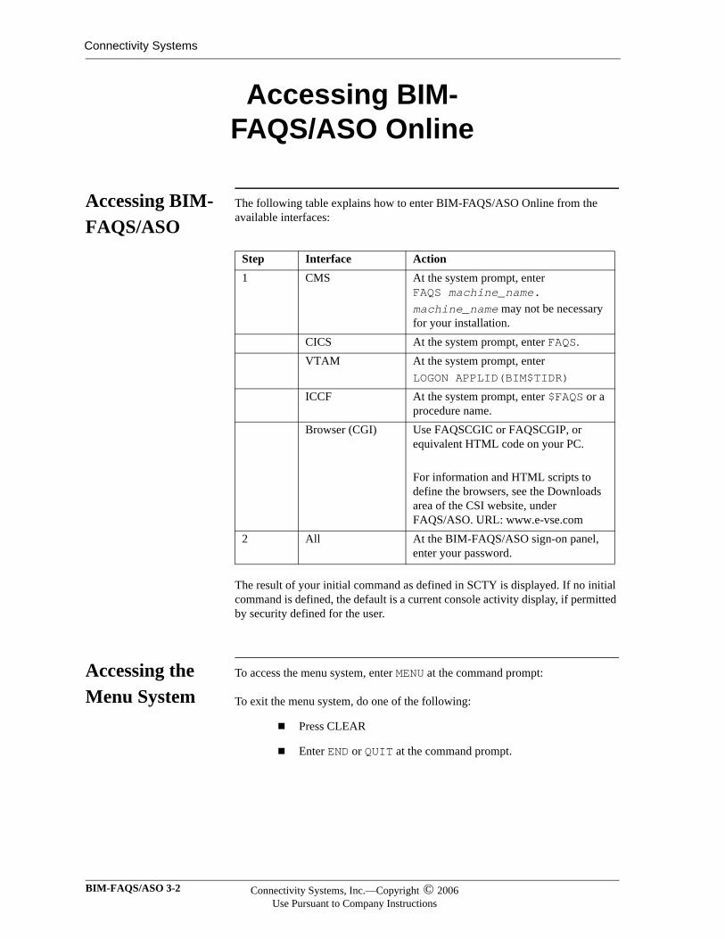
Accessing BIM-FAQS/ASO
The following table explains how to enter BIM-FAQS/ASO Online from the available interfaces:
The result of your initial command as defined in SCTY is displayed. If no initial command is defined, the default is a current console activity display, if permitted by security defined for the user.
Accessing the Menu System
To access the menu system, enter MENU at the command prompt:
To exit the menu system, do one of the following:
Press CLEAR
Enter END or QUIT at the command prompt.
Step Interface Action1 CMS At the system prompt, enter
FAQS machine_name.machine_name may not be necessary for your installation.
CICS At the system prompt, enter FAQS.VTAM At the system prompt, enter
LOGON APPLID(BIM$TIDR)
ICCF At the system prompt, enter $FAQS or a procedure name.
Browser (CGI) Use FAQSCGIC or FAQSCGIP, or equivalent HTML code on your PC.
For information and HTML scripts to define the browsers, see the Downloads area of the CSI website, under FAQS/ASO. URL: www.e-vse.com
2 All At the BIM-FAQS/ASO sign-on panel, enter your password.
BIM-FAQS/ASO 3-2 Connectivity Systems, Inc.—Copyright © 2006Use Pursuant to Company Instructions
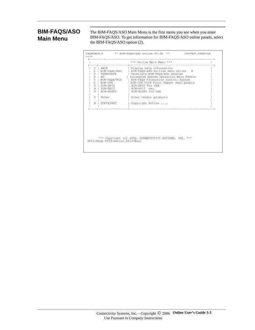
BIM-FAQS/ASO Main Menu
The BIM-FAQS/ASO Main Menu is the first menu you see when you enter BIM-FAQS/ASO. To get information for BIM-FAQS/ASO online panels, select the BIM-FAQS/ASO option (2).
FAQMENU0.0 ** BIM-FAQS/ASO Online V5.3A ** ID=VB31.PROFILE ===> +-----------------------------------------------------------------------+ | *** Online Main Menu *** | +----+-----------------+------------------------------------------------+ | 1 | HELP | Display help information | | 2 | BIM-FAQS/ASO | BIM-FAQS/ASO On-line menu driver P | | 3 | TERMINATE | Terminate BIM-FAQS/ASO Session | | 4 | AO | Automated System Operation Menu Panels | | 5 | BIM-FAQS/PCS | BIM-FAQS Production Control System | | C | BIM-CPR | BIM-CPR CICS Print Report menu panels | | O | BIM-EPIC | BIM-EPIC For VSE | | R | BIM-EDIT | BIM-EDIT nm: | | S | BIM-ALERT | BIM-ALERT for VSE | | | | | | V | Other | Other vendor products | | | | | | N | COPYRIGHT | Copyright Notice .... | | | | | +----+-----------------+------------------------------------------------+
*** Copyright (c) 2002, CONNECTIVITY SYSTEMS, INC. *** PF01=Help PF03=Return PF12=Exit
Connectivity Systems, Inc.—Copyright © 2006Use Pursuant to Company Instructions
Online User’s Guide 3-3
Connectivity Systems
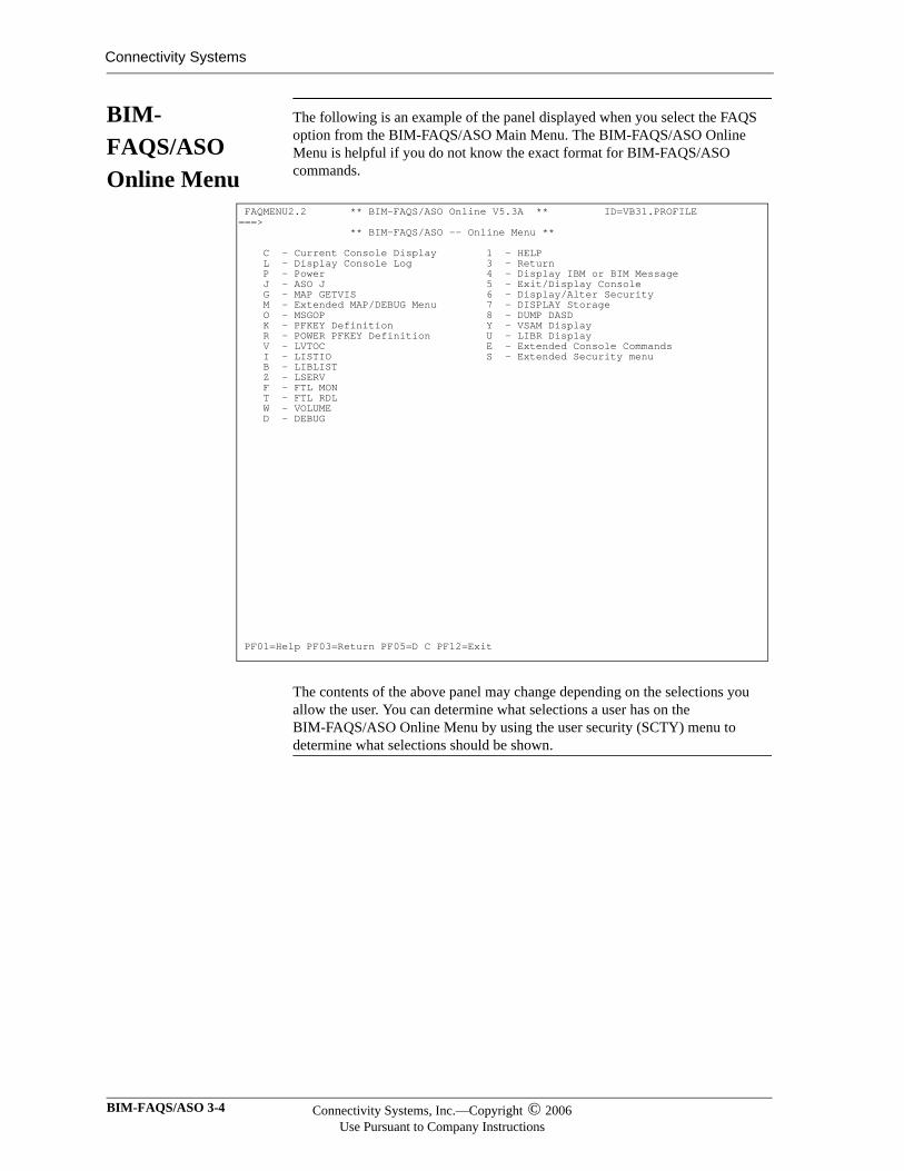
BIM-FAQS/ASO Online Menu
The following is an example of the panel displayed when you select the FAQS option from the BIM-FAQS/ASO Main Menu. The BIM-FAQS/ASO Online Menu is helpful if you do not know the exact format for BIM-FAQS/ASO commands.
The contents of the above panel may change depending on the selections you allow the user. You can determine what selections a user has on the BIM-FAQS/ASO Online Menu by using the user security (SCTY) menu to determine what selections should be shown.
FAQMENU2.2 ** BIM-FAQS/ASO Online V5.3A ** ID=VB31.PROFILE ===> ** BIM-FAQS/ASO -- Online Menu ** C - Current Console Display 1 - HELP L - Display Console Log 3 - Return P - Power 4 - Display IBM or BIM Message J - ASO J 5 - Exit/Display Console G - MAP GETVIS 6 - Display/Alter Security M - Extended MAP/DEBUG Menu 7 - DISPLAY Storage O - MSGOP 8 - DUMP DASD K - PFKEY Definition Y - VSAM Display R - POWER PFKEY Definition U - LIBR Display V - LVTOC E - Extended Console Commands I - LISTIO S - Extended Security menu B - LIBLIST Z - LSERV F - FTL MON T - FTL RDL W - VOLUME D - DEBUG PF01=Help PF03=Return PF05=D C PF12=Exit
BIM-FAQS/ASO 3-4 Connectivity Systems, Inc.—Copyright © 2006Use Pursuant to Company Instructions
Moving Around in BIM-FAQS/ASO Online
Moving Between Display Panels
The first display panel you access in BIM-FAQS/ASO Online is the current console activity panel. To move to a different panel, enter a command on the command line. You can also use one of the command-defined PF keys.
Press CLEAR to return to the current console activity panel from any other display panel.
Moving Between Display and Menu Panels
To move from a display panel to a menu system panel, enter MENU at the command prompt. The BIM-FAQS/ASO Main Menu is displayed.
To move from a menu system panel to a display panel, press PF12. If you execute an online command from a menu system panel, the current console activity panel is displayed.
Switching between online displays and the menu system causes fragmentation and high overhead. Be aware of where you are in the menu system and the relationship between online commands and the menu system.
Moving Within the Menu System
To return to the previous menu system panel, press PF3.
To go to another panel, enter the requested data on the panel you are currently on, and press ENTER.
To move from a menu to an input panel (still within the menu system), select a menu option. To select a menu option, do one of the following:
Place the cursor on the option you want and press ENTER. This is not valid for the HTML (browser) interface. In this case you either blank out the option or enter the selection character on the command line at the top of the screen. For underscore delineated options, insert the character specified for selection, which is usually either and 'X' or an 'S'.
Enter the option number or letter on the command line and press ENTER.
Press the PF key that corresponds to a menu option.
Enter the name of the option on the command line and press ENTER. You can also enter any online command on this command line to access other BIM-FAQS/ASO features.
Connectivity Systems, Inc.—Copyright © 2006Use Pursuant to Company Instructions
Online User’s Guide 3-5
Connectivity Systems
Fast-Path Commands
A fast-path command consists of multiple option numbers and letters separated by periods. An example of a fast-path command is
MENU 2.P
MENU is a command name, and 2 and P are options. For example, if this command were entered from the current console, with the default BIM-FAQS/ASO Main Menu, the next panel accessed would be the BIM-FAQS/ASO (represented by Option 2 on the BIM-FAQS/ASO Main Menu) POWER (represented by Option P on the BIM-FAQS/ASO Online Menu) display. You also can use fast-path commands to move to other products.
Return Key The Return key default is PF3. But you may redefine the Return key by entering a new PF-key value in the RETURN KEY= field of the PF Key Settings/Alter display panel. You may redefine the Return key
Temporarily, by pressing PF5
Permanently, by pressing PF6
Pressing PF5 (temporary redefinition) redefines the Return key for your current BIM-FAQS/ASO session. Pressing PF6 (permanent redefinition) redefines the Return key for your current and subsequent BIM-FAQS/ASO sessions.
Note that redefining the Return key does not change the Return key default of PF3 for the BIM-FAQS/ASO Online Menu displays. No matter how you have redefined the Return key, PF3=RETURN is the default for all BIM-FAQS/ASO Online menus at all times.
BIM-FAQS/ASO 3-6 Connectivity Systems, Inc.—Copyright © 2006Use Pursuant to Company Instructions
Chapter 4
Security and User
Configuration
In This Chapter
This chapter encompasses BIM-FAQS/ASO security and configuration.
Overview The BIM-FAQS/ASO Online transaction is controlled by user profiles and a configuration record. The system stores the user profiles in the CSS$VIO PDS (partitioned dataset). This PDS file can be shared across multiple VSE systems without the overhead of VSAM.
User profiles allow for automatic sign on if desired, which avoids confusing the end user with many user profiles and procedures to remember. The configuration record allows you to tailor, set security, and control some display color for all users.
For VSE/ESA 2+ users, you can control the majority of the display using console filters described later in this manual. You can control the majority of security for individual users by defining security entries and optionally defining extended security entries.
Backing Up and Restoring CSS$VIO
You can use BIM$PUTL, the BIM-GSS utility, to back up and restore CSS$VIO. The commands BACKUP and RESTORE allow you to backup and restore CSS$VIO or any PDS. Each command allows you to use member masking to perform a partial PDS backup or restore.
For information about the BIM$PUTL BACKUP and RESTORE commands, see the BIM-GSS Installation and Utilities Guide.
Activating Security Definitions
To activate security definitions, you must activate the USE SCTY ENTRY NOT ONLY PROFILE field on Configuration Panel 1. If this field is not activated, problems occur, especially with a BIM-FAQS/ASO reinstallation. For more information, see the section, Configuration Panel 1 Fields, later in this chapter.
Online User’s Guide 4-1
Connectivity Systems
Resetting Security
If you cannot sign on because of a probable security definition problem, use the FAQSUTIL program. With this program's INITIALIZE PW parameter, you can deactivate the USE SCTY ENTRY NOT ONLY PROFILE field (that is, turn off the security switch). Add a PROFILE password if one does not exist. Leave current users defined as they were. If problems occur, you can use the RECOVER parameter.
ONLY Command
The ONLY command enables a BIM-FAQS/ASO terminal user to access only a specific set of instructions, and then exit BIM-FAQS/ASO after completion. The ONLY command is used as a prefix to any other BIM-FAQS/ASO online command:
ONLY cmd
cmd is another BIM-FAQS/ASO Online command that performs a particular function (D LST) or accesses a particular screen (MENU) or product (PCS). Once you exit whatever cmd has given you access to, you also exit BIM-FAQS/ASO.
ONLY can be used as part of sign on to restrict a user to a specific command, function, or product. For example, OEPIC (that is, ONLY EPIC) would give a user direct access to BIM-EPIC (bypassing the BIM-FAQS/ASO console display) and would terminate the user's BIM-FAQS/ASO session as soon as the user exited BIM-EPIC. OEPIC, in this case, needs to be defined as an online command that would consist of “ONLY EPIC”. See BIM-FAQS/ASO Online Command Definition and Maintenance panel for more information. You can also use the shortcut AO I.O to reach this panel.
BIM-FAQS/ASO 4-2 Connectivity Systems, Inc.—Copyright © 2006Use Pursuant to Company Instructions
User Profiles and Passwords
User Profiles Users are created online using the security displays. You add profiles or model profiles after a current user ID's security definition.
For an explanation of how to define users, refer to the section, User Profile Record 1.
Models Modeling allows you to copy one user's profile definitions to a new user and to group users with the same security definition.
Modeling also makes it easier to change several profiles that are modeled after a specific user. You can change the model ID and that will change all profiles that use that model ID.
Important:If you change a profile that is part of a group sharing a common model ID, you will change all the profiles in that group.
Passwords Passwords are used in conjunction with user IDs to further restrict the use of particular user IDs. You can establish these passwords through security. Users enter passwords at sign on (when automatic sign on is not enabled).
Accessing Profiles Online
You must execute the initialize or convert function (as done by FAQSUTIL) before the BIM-FAQS/ASO Online transaction can be used. Initialization is performed automatically at installation.
Automatic Sign On
The automatic sign on facility allows you to bypass the SINON panel. You must be defined to use automatic sign on for the following to occur. When you sign on to BIM-FAQS/ASO, the transaction searches the CSS$VIO PDS to find an entry that matches the user ID. If an entry is found, you are automatically signed on using that user ID.
BIM-FAQS/ASO uses the 3-character CICS operator sign on ID (or the 8 character user ID with an optional patch), 8 character CMS user ID, the 4-character ICCF logon ID, or the US= value for CGI as the user ID. You can also use the USER= value specified in the DATA parameter of the LOGIN APPLID statement or as part of a USSTAB entry to use automatic sign on for the VTAM interface. If an entry is not found, the SINON panel is displayed and you must supply a user ID and password, if security is active.
You can set up a password so that only a user that has logged on from CICS, CMS, BTAM/VTAM, or ICCF can use the same user ID to sign on again. This allows you to use the same user ID to sign on, but you must also enter a specific password to do so. See the section User Profile Record 1 Fields, for information about how to use passwords in conjunction with automatic sign on features.
Connectivity Systems, Inc.—Copyright © 2006Use Pursuant to Company Instructions
Online User’s Guide 4-3
Connectivity Systems
Security Displays
Online security, accessed by the SCTY command, has a complete help facility for its online panels. To access help, press PF01 on any panel. You can fill in required switches and blanks on security panels and update them in the PDS file with PF05.
A user profile contains information such as the initial command executed at sign on, which interfaces and commands can be used, PF-key settings, and which partitions can be replied to.
For pre-ESA 2 systems, a user profile also contains message highlighting, message suppression, and message routing. These have been replaced with console filters and extended security for VSE/ESA 2+ users.
BIM-FAQS/ASO 4-4 Connectivity Systems, Inc.—Copyright © 2006Use Pursuant to Company Instructions
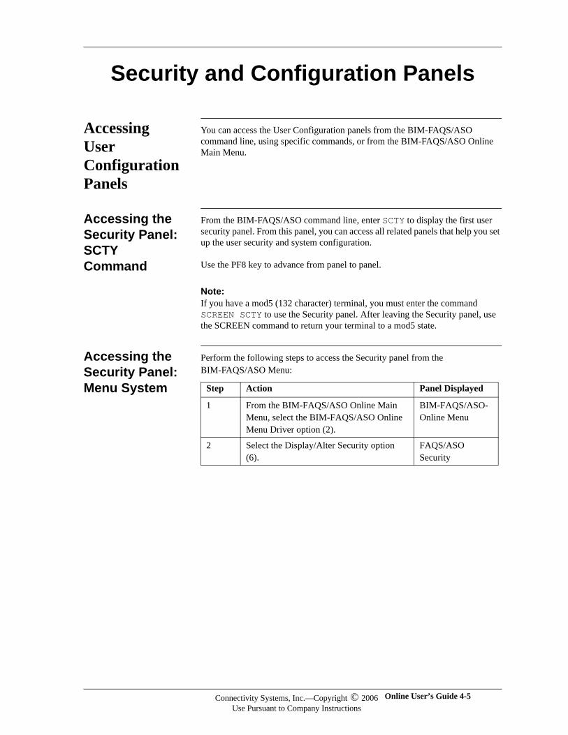
Security and Configuration Panels
Accessing User Configuration Panels
You can access the User Configuration panels from the BIM-FAQS/ASO command line, using specific commands, or from the BIM-FAQS/ASO Online Main Menu.
Accessing the Security Panel:SCTY Command
From the BIM-FAQS/ASO command line, enter SCTY to display the first user security panel. From this panel, you can access all related panels that help you set up the user security and system configuration.
Use the PF8 key to advance from panel to panel.
Note:Note:If you have a mod5 (132 character) terminal, you must enter the command SCREEN SCTY to use the Security panel. After leaving the Security panel, use the SCREEN command to return your terminal to a mod5 state.
Accessing the Security Panel:Menu System
Perform the following steps to access the Security panel from the BIM-FAQS/ASO Menu:
Step Action Panel Displayed
1 From the BIM-FAQS/ASO Online Main Menu, select the BIM-FAQS/ASO Online Menu Driver option (2).
BIM-FAQS/ASO-Online Menu
2 Select the Display/Alter Security option (6).
FAQS/ASO Security
Connectivity Systems, Inc.—Copyright © 2006Use Pursuant to Company Instructions
Online User’s Guide 4-5
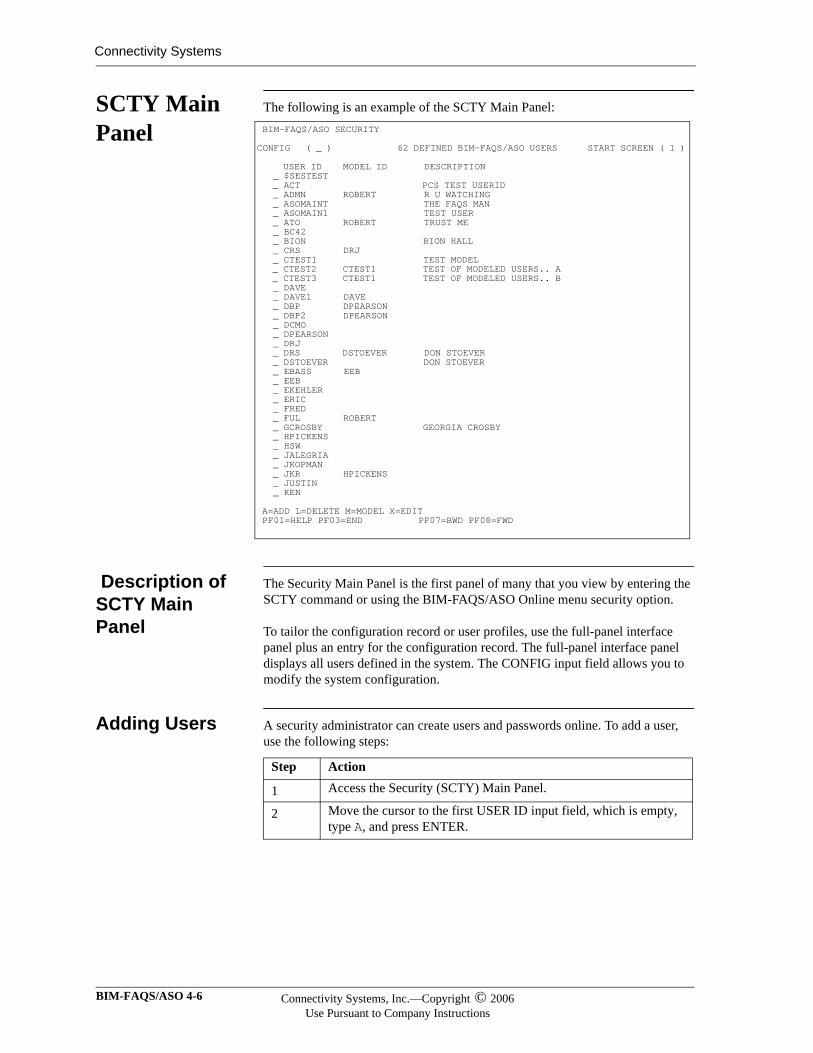
Connectivity Systems
SCTY Main Panel
The following is an example of the SCTY Main Panel:
Description of SCTY Main Panel
The Security Main Panel is the first panel of many that you view by entering the SCTY command or using the BIM-FAQS/ASO Online menu security option.
To tailor the configuration record or user profiles, use the full-panel interface panel plus an entry for the configuration record. The full-panel interface panel displays all users defined in the system. The CONFIG input field allows you to modify the system configuration.
Adding Users A security administrator can create users and passwords online. To add a user, use the following steps:
BIM-FAQS/ASO SECURITY CONFIG ( _ ) 62 DEFINED BIM-FAQS/ASO USERS START SCREEN ( 1 ) USER ID MODEL ID DESCRIPTION _ $SESTEST _ ACT PCS TEST USERID _ ADMN ROBERT R U WATCHING _ ASOMAINT THE FAQS MAN _ ASOMAIN1 TEST USER _ ATO ROBERT TRUST ME _ BC42 _ BION BION HALL _ CRS DRJ _ CTEST1 TEST MODEL _ CTEST2 CTEST1 TEST OF MODELED USERS.. A _ CTEST3 CTEST1 TEST OF MODELED USERS.. B _ DAVE _ DAVE1 DAVE _ DBP DPEARSON _ DBP2 DPEARSON _ DCMO _ DPEARSON _ DRJ _ DRS DSTOEVER DON STOEVER _ DSTOEVER DON STOEVER _ EBASS EEB _ EEB _ EKEHLER _ ERIC _ FRED _ FUL ROBERT _ GCROSBY GEORGIA CROSBY _ HPICKENS _ HSW _ JALEGRIA _ JKOPMAN _ JKR HPICKENS _ JUSTIN _ KEN A=ADD L=DELETE M=MODEL X=EDIT PF01=HELP PF03=END PF07=BWD PF08=FWD
Step Action
1 Access the Security (SCTY) Main Panel.
2 Move the cursor to the first USER ID input field, which is empty, type A, and press ENTER.
BIM-FAQS/ASO 4-6 Connectivity Systems, Inc.—Copyright © 2006Use Pursuant to Company Instructions
To model a new user after an existing user, use the following steps:
Modeling Users Modeling allows you to group users that need the same security definition together. By grouping users, it is easier to change them.
Important:If you change a user that has a model ID, the other users that share that model ID are changed too.
Deleting Users Use the following steps to delete a single user or multiple users:
SCTY userid To go directly to a user’s security panels, use the SCTY userid command.
Step Action
1 Access the Security (SCTY) Main Panel.
2 Move the cursor to the user ID you want to use as a model, type M to the left of it, and press ENTER.
Step Action
1 Access the Security (SCTY) Main Panel.
2 Move the cursor to the USER IDs you want to delete, type L, and press ENTER.
If you enter L for multiple USER IDs, the users are deleted when you reach the end of the panel or when you process an Add, Edit, or Model command.
Connectivity Systems, Inc.—Copyright © 2006Use Pursuant to Company Instructions
Online User’s Guide 4-7
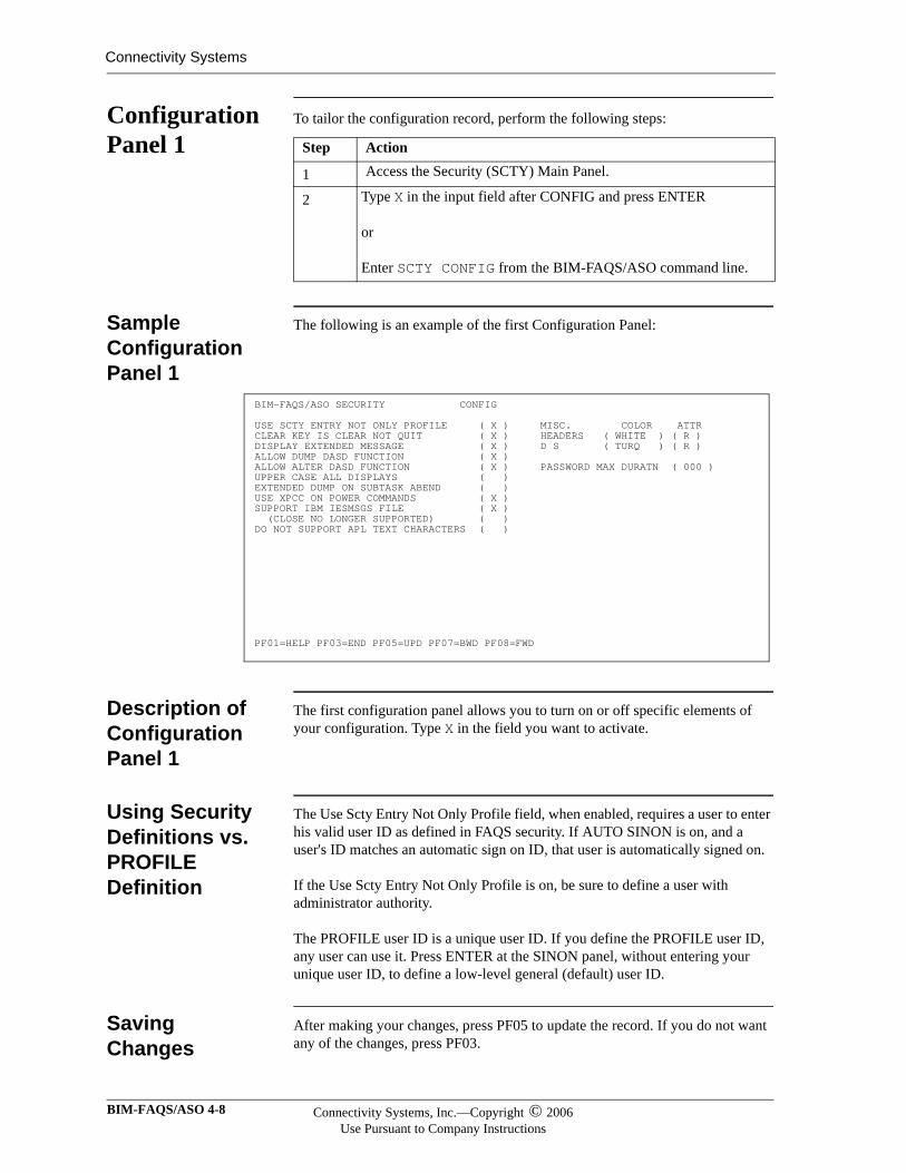
Connectivity Systems
Configuration Panel 1
To tailor the configuration record, perform the following steps:
Sample Configuration Panel 1
The following is an example of the first Configuration Panel:
Description of Configuration Panel 1
The first configuration panel allows you to turn on or off specific elements of your configuration. Type X in the field you want to activate.
Using Security Definitions vs. PROFILE Definition
The Use Scty Entry Not Only Profile field, when enabled, requires a user to enter his valid user ID as defined in FAQS security. If AUTO SINON is on, and a user's ID matches an automatic sign on ID, that user is automatically signed on.
If the Use Scty Entry Not Only Profile is on, be sure to define a user with administrator authority.
The PROFILE user ID is a unique user ID. If you define the PROFILE user ID, any user can use it. Press ENTER at the SINON panel, without entering your unique user ID, to define a low-level general (default) user ID.
Saving Changes
After making your changes, press PF05 to update the record. If you do not want any of the changes, press PF03.
Step Action
1 Access the Security (SCTY) Main Panel.
2 Type X in the input field after CONFIG and press ENTER
or
Enter SCTY CONFIG from the BIM-FAQS/ASO command line.
BIM-FAQS/ASO SECURITY CONFIG USE SCTY ENTRY NOT ONLY PROFILE ( X ) MISC. COLOR ATTR CLEAR KEY IS CLEAR NOT QUIT ( X ) HEADERS ( WHITE ) ( R ) DISPLAY EXTENDED MESSAGE ( X ) D S ( TURQ ) ( R ) ALLOW DUMP DASD FUNCTION ( X ) ALLOW ALTER DASD FUNCTION ( X ) PASSWORD MAX DURATN ( 000 ) UPPER CASE ALL DISPLAYS ( ) EXTENDED DUMP ON SUBTASK ABEND ( ) USE XPCC ON POWER COMMANDS ( X ) SUPPORT IBM IESMSGS FILE ( X ) (CLOSE NO LONGER SUPPORTED) ( ) DO NOT SUPPORT APL TEXT CHARACTERS ( ) PF01=HELP PF03=END PF05=UPD PF07=BWD PF08=FWD
BIM-FAQS/ASO 4-8 Connectivity Systems, Inc.—Copyright © 2006Use Pursuant to Company Instructions
Configuration Panel 1 Fields
The following table describes the fields in the Configuration Panel 1:
Field DescriptionUSE SCTY ENTRY NOT ONLY PROFILE Turns security definitions on or off. If security is off, a
user ID of PROFILE must be defined in the system. This PROFILE user ID is used for anyone entering BIM-FAQS/ASO. In other words, if this field is on, you should use the security definition for a user rather than assigning that user the generic PROFILE user definition.
CLEAR KEY IS CLEAR NOT QUIT If this field is on, the CLEAR key means 'to clear the panel' for the full-panel POWER queue display. By default, the CLEAR key is used to exit a panel.
DISPLAY EXTENDED MESSAGE If extended message support is on, extended message explanations are displayed for error messages when possible. This requires extra GETVIS and creates overhead.
ALLOW DUMP DASD FUNCTION Universal security for the BIM-FAQS/ASO DASD DUMP feature. If this is set off, no one can display DASD data online via BIM-FAQS/ASO.
ALLOW ALTER DASD FUNCTION Universal security for the BIM-FAQS/ASO DASD ALTER feature. If this is set off, no one can alter DASD data online via BIM-FAQS/ASO.
UPPER CASE ALL DISPLAYS Uppercase help panels and the message display facility. BIM-FAQS/ASO provides this field for language translators that use lowercase letters for translation.
EXTENDED DUMP ON SUBTASK ABEND This field should be off unless requested by CSI International to get extended dump or trace information.
USE XPCC ON POWER COMMANDS You can use XPCC or XECB to communicate to POWER for altering the POWER queue file.
SUPPORT IBM IESMSGS FILE Set this field to be on if the IBM IESMSGS file is to be supported. This field should be on unless the file does not exist in your system or GETVIS space is critical.
(CLOSE NO LONGER SUPPORTED) BIM-FAQS/ASO installations on VSE/ESA 2.1 require you to use the IBM EXPLAIN utility to view message explanations online.
Note All pre-ESA 2.1 versions of BIM-FAQS/ASO continue to use the FAQSMSG file for viewing message explanations online.
PASSWORD MAX DURATN Number of days before a password must be changed.
000 indicates that PASSWORD MAX DURATN is disabled -- passwords have indefinite life.
Connectivity Systems, Inc.—Copyright © 2006Use Pursuant to Company Instructions
Online User’s Guide 4-9
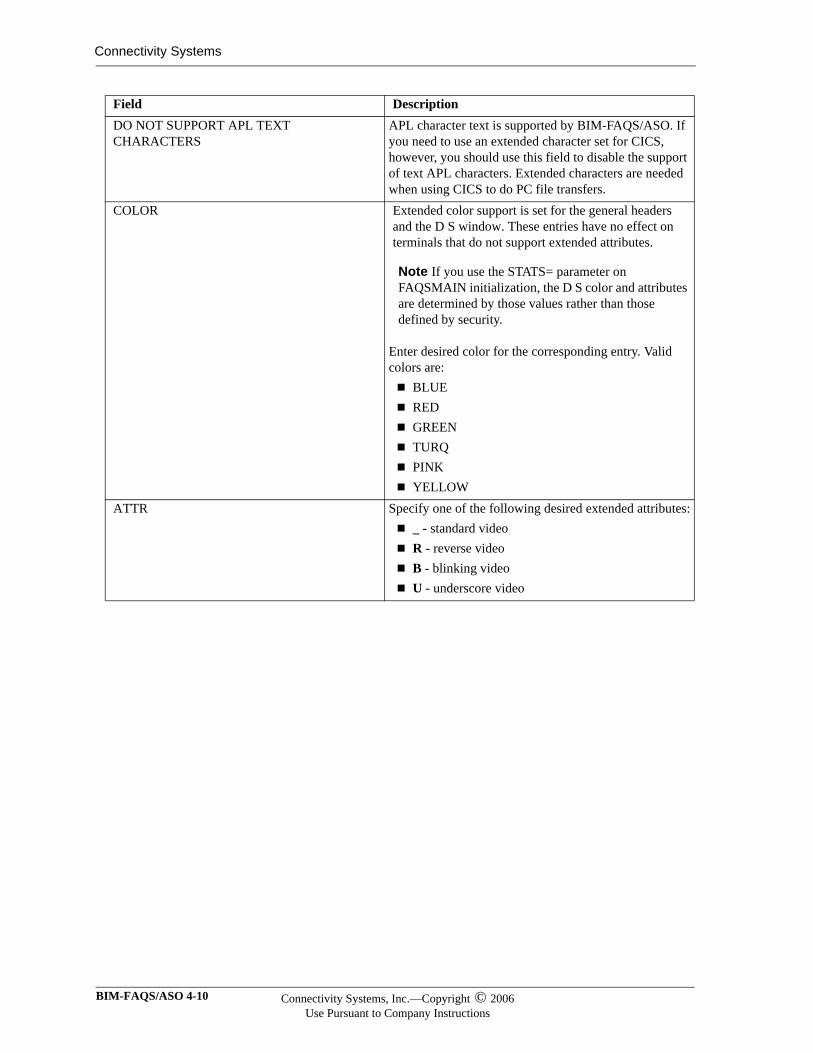
Connectivity Systems
DO NOT SUPPORT APL TEXT CHARACTERS
APL character text is supported by BIM-FAQS/ASO. If you need to use an extended character set for CICS, however, you should use this field to disable the support of text APL characters. Extended characters are needed when using CICS to do PC file transfers.
COLOR Extended color support is set for the general headers and the D S window. These entries have no effect on terminals that do not support extended attributes.
Note If you use the STATS= parameter on FAQSMAIN initialization, the D S color and attributes are determined by those values rather than those defined by security.
Enter desired color for the corresponding entry. Valid colors are:
BLUEREDGREENTURQPINKYELLOW
ATTR Specify one of the following desired extended attributes:_ - standard videoR - reverse videoB - blinking videoU - underscore video
Field Description
BIM-FAQS/ASO 4-10 Connectivity Systems, Inc.—Copyright © 2006Use Pursuant to Company Instructions
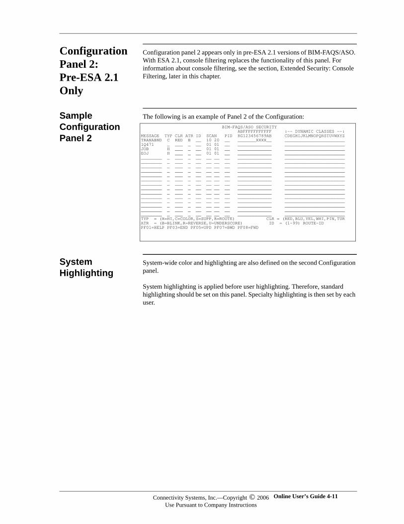
Configuration Panel 2: Pre-ESA 2.1 Only
Configuration panel 2 appears only in pre-ESA 2.1 versions of BIM-FAQS/ASO. With ESA 2.1, console filtering replaces the functionality of this panel. For information about console filtering, see the section, Extended Security: Console Filtering, later in this chapter.
Sample Configuration Panel 2
The following is an example of Panel 2 of the Configuration:
System Highlighting
System-wide color and highlighting are also defined on the second Configuration panel.
System highlighting is applied before user highlighting. Therefore, standard highlighting should be set on this panel. Specialty highlighting is then set by each user.
BIM-FAQS/ASO SECURITY ABFFFFFFFFFFF :-- DYNAMIC CLASSES --: MESSAGE TYP CLR ATR ID SCAN PID RG123456789AB CDEGHIJKLMNOPQRSTUVWXYZ TRANABND C RED B __ 10 20 __ _______XXXX__ _______________________ 1Q471 _ ___ _ __ 01 01 __ _____________ _______________________ JOB H ___ _ __ 01 01 __ _____________ _______________________ EOJ H ___ _ __ 01 01 __ _____________ _______________________ ________ _ ___ _ __ __ __ __ _____________ _______________________ ________ _ ___ _ __ __ __ __ _____________ _______________________ ________ _ ___ _ __ __ __ __ _____________ _______________________ ________ _ ___ _ __ __ __ __ _____________ _______________________ ________ _ ___ _ __ __ __ __ _____________ _______________________ ________ _ ___ _ __ __ __ __ _____________ _______________________ ________ _ ___ _ __ __ __ __ _____________ _______________________ ________ _ ___ _ __ __ __ __ _____________ _______________________ ________ _ ___ _ __ __ __ __ _____________ _______________________ ________ _ ___ _ __ __ __ __ _____________ _______________________ ________ _ ___ _ __ __ __ __ _____________ _______________________ ________ _ ___ _ __ __ __ __ _____________ _______________________ ________ _ ___ _ __ __ __ __ _____________ _______________________ ________ _ ___ _ __ __ __ __ _____________ _______________________ TYP = (H=HI,C=COLOR,S=SUPP,R=ROUTE) CLR = (RED,BLU,YEL,WHI,PIN,TUR ATR = (B=BLINK,R=REVERSE,U=UNDERSCORE) ID = (1-99) ROUTE-ID PF01=HELP PF03=END PF05=UPD PF07=BWD PF08=FWD
Connectivity Systems, Inc.—Copyright © 2006Use Pursuant to Company Instructions
Online User’s Guide 4-11
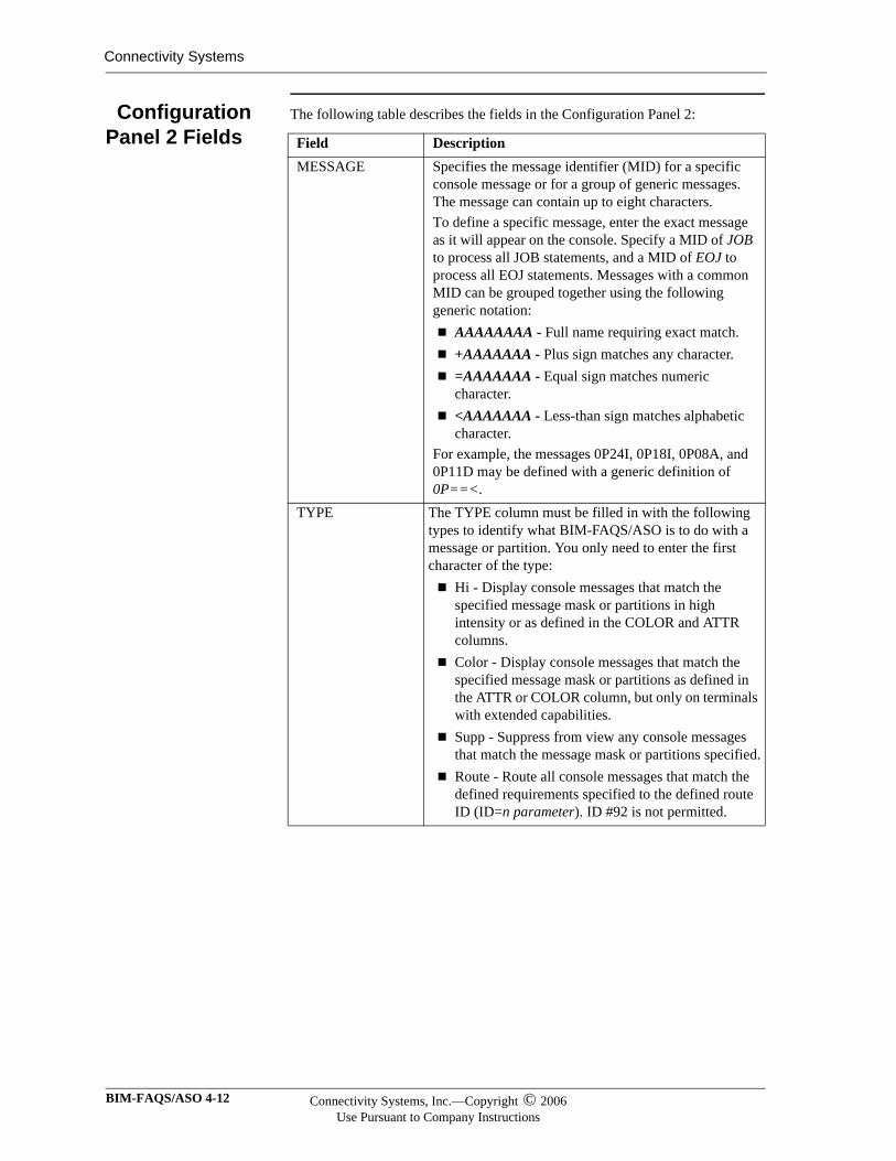
Connectivity Systems
Configuration Panel 2 Fields
The following table describes the fields in the Configuration Panel 2:
Field DescriptionMESSAGE Specifies the message identifier (MID) for a specific
console message or for a group of generic messages. The message can contain up to eight characters. To define a specific message, enter the exact message as it will appear on the console. Specify a MID of JOB to process all JOB statements, and a MID of EOJ to process all EOJ statements. Messages with a common MID can be grouped together using the following generic notation:
AAAAAAAA - Full name requiring exact match.+AAAAAAA - Plus sign matches any character.=AAAAAAA - Equal sign matches numeric character.<AAAAAAA - Less-than sign matches alphabetic character.
For example, the messages 0P24I, 0P18I, 0P08A, and 0P11D may be defined with a generic definition of 0P==<.
TYPE The TYPE column must be filled in with the following types to identify what BIM-FAQS/ASO is to do with a message or partition. You only need to enter the first character of the type:
Hi - Display console messages that match the specified message mask or partitions in high intensity or as defined in the COLOR and ATTR columns.Color - Display console messages that match the specified message mask or partitions as defined in the ATTR or COLOR column, but only on terminals with extended capabilities.Supp - Suppress from view any console messages that match the message mask or partitions specified.Route - Route all console messages that match the defined requirements specified to the defined route ID (ID=n parameter). ID #92 is not permitted.
BIM-FAQS/ASO 4-12 Connectivity Systems, Inc.—Copyright © 2006Use Pursuant to Company Instructions
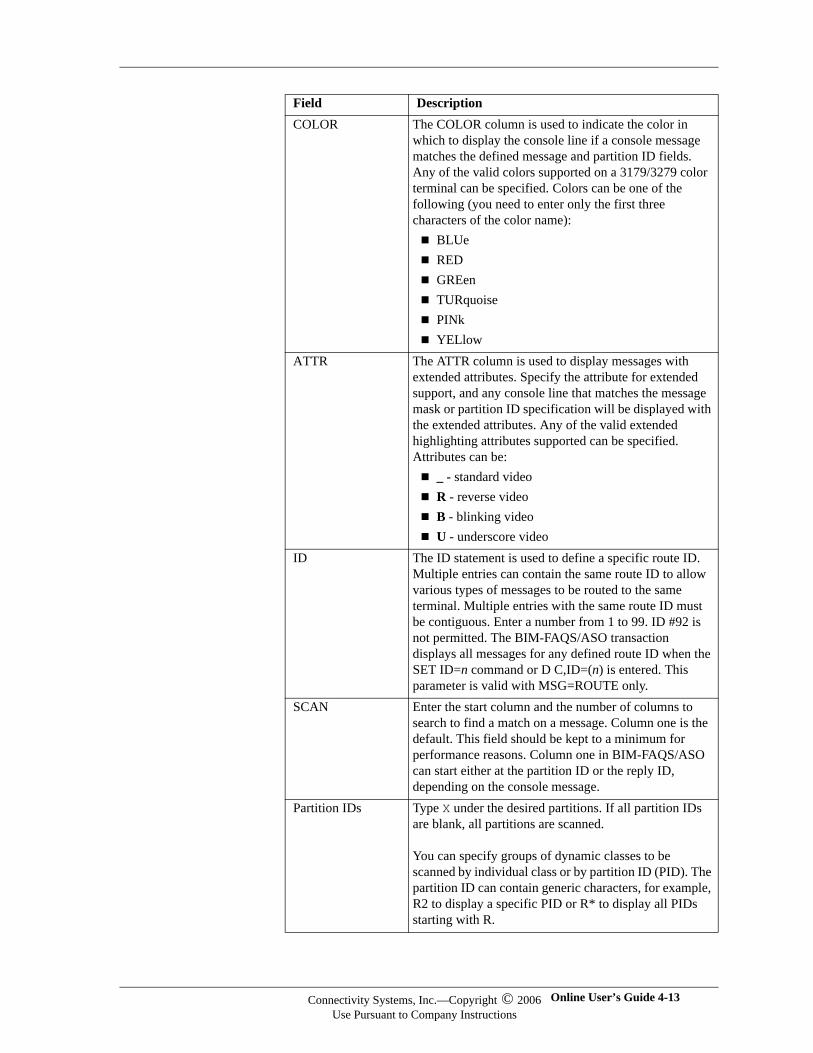
COLOR The COLOR column is used to indicate the color in which to display the console line if a console message matches the defined message and partition ID fields. Any of the valid colors supported on a 3179/3279 color terminal can be specified. Colors can be one of the following (you need to enter only the first three characters of the color name):
BLUeREDGREenTURquoisePINkYELlow
ATTR The ATTR column is used to display messages with extended attributes. Specify the attribute for extended support, and any console line that matches the message mask or partition ID specification will be displayed with the extended attributes. Any of the valid extended highlighting attributes supported can be specified. Attributes can be:
_ - standard videoR - reverse videoB - blinking videoU - underscore video
ID The ID statement is used to define a specific route ID. Multiple entries can contain the same route ID to allow various types of messages to be routed to the same terminal. Multiple entries with the same route ID must be contiguous. Enter a number from 1 to 99. ID #92 is not permitted. The BIM-FAQS/ASO transaction displays all messages for any defined route ID when the SET ID=n command or D C,ID=(n) is entered. This parameter is valid with MSG=ROUTE only.
SCAN Enter the start column and the number of columns to search to find a match on a message. Column one is the default. This field should be kept to a minimum for performance reasons. Column one in BIM-FAQS/ASO can start either at the partition ID or the reply ID, depending on the console message.
Partition IDs Type X under the desired partitions. If all partition IDs are blank, all partitions are scanned.
You can specify groups of dynamic classes to be scanned by individual class or by partition ID (PID). The partition ID can contain generic characters, for example, R2 to display a specific PID or R* to display all PIDs starting with R.
Field Description
Connectivity Systems, Inc.—Copyright © 2006Use Pursuant to Company Instructions
Online User’s Guide 4-13
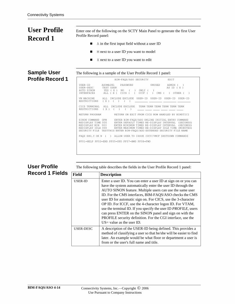
Connectivity Systems
User Profile Record 1
Enter one of the following on the SCTY Main Panel to generate the first User Profile Record panel:
A in the first input field without a user ID
M next to a user ID you want to model
X next to a user ID you want to edit
Sample User Profile Record 1
The following is a sample of the User Profile Record 1 panel:
User Profile Record 1 Fields
The following table describes the fields in the User Profile Record 1 panel:
BIM-FAQS/ASO SECURITY EDIT USER-ID ASOMAIN1 PASSWORD UNUSED ADMIN ( ) USER-DESC TEST USER AS ID ( X ) AUTO SINON YES ( X ) NO ( ) ONLY ( ) INTERFACES ALL ( X ) CICS ( ) ICCF ( ) CMS ( ) OTHER ( ) VM MACHINE ALL INCLUDE EXCLUDE USER-ID USER-ID USER-ID USER-ID RESTRICTIONS ( X ) ( ) ( ) ________ ________ ________ ________ CICS TERMINAL ALL INCLUDE EXCLUDE TERM TERM TERM TERM TERM TERM RESTRICTIONS ( X ) ( ) ( ) ____ ____ ____ ____ ____ ____ RETURN PROGRAM RETURN ON EXIT FROM CICS NOW HANDLED BY BIM$TICI SINON COMMAND OPW ENTER BIM-FAQS/ASO ONLINE INITIAL ENTRY COMMAND REDISPLAY TIME 000 ENTER DEFAULT TIMED RE-DISPLAY INTERVAL (SECONDS) REDISPLAY MIN 003 ENTER MINIMUM TIMED RE-DISPLAY INTERVAL (SECONDS) REDISPLAY IDLE 000 ENTER MAXIMUM TIMED RE-DISPLAY IDLE TIME (MINUTES) SECURITY FILE TESTTHIS ENTER BIM-FAQS/ASO EXTENDED SECURITY FILE NAME FAQS SHU,Y OR N ( ) ALLOW USER TO ISSUE IUCV/VMCF SHUTDOWN COMMANDS PF01=HELP PF03=END PF05=UPD PF07=BWD PF08=FWD
Field DescriptionUSER-ID Enter a user ID. You can enter a user ID at sign on or you can
have the system automatically enter the user ID through the AUTO SINON feature. Multiple users can use the same user ID. For the CMS interfaces, BIM-FAQS/ASO checks the CMS user ID for automatic sign on. For CICS, use the 3-character OP ID. For ICCF, use the 4-character logon ID. For VTAM, use the terminal ID. If you specify the user ID PROFILE, users can press ENTER on the SINON panel and sign on with the PROFILE security definition. For the CGI interface, use the US= value as the user ID.
USER-DESC A description of the USER-ID being defined. This provides a method of classifying a user so that he/she will be easier to find later. An example would be what floor or department a user is from or the user's full name and title.
BIM-FAQS/ASO 4-14 Connectivity Systems, Inc.—Copyright © 2006Use Pursuant to Company Instructions
PASSWORD Enter a maximum of eight characters for a password that is required when signing on to BIM-FAQS/ASO, if you are not using AUTO SINON mode. This field displays one of three descriptions:
UNUSED - No password is defined. This is the initial value for the password field; once a password is entered, UNUSED does not appear again.SET - A password is defined.NOT SET - A password was defined and has since been removed. A password is currently not defined, meaning that the password is defined as blanks).
Note The panel does not display the password value when you enter it.
ADMIN Type X in the ADMIN field to allow this user to enter into and use the BIM-FAQS/ASO online security.
AS ID Type X in the AS ID to allow this user to use the first 12-13 characters of the USER-DESC field defined for sign on/sign off and console logging purposes instead of the USER-ID and interface type.
AUTO SINON A match occurs when the 3-character CICS operator sign on ID, 8-character CMS user ID, VTAM terminal ID, the US= value as the user ID for CGI,or the 4-character ICCF logon ID matches the FAQS user ID. AUTO SINON allows one of three options:
YES - Allows automatic sign on if a match is found.NO - Disallows automatic sign on if a match is found.ONLY - Allows automatic sign on if a match is found, but the user ID cannot be entered on the SINON panel. The system requires automatic signon only for this user ID. Password entry is not available for this user.
If you want to require a password, you must use the YES or NO options of AUTO SINON.
INTERFACES Type X after ALL to allow all interfaces to be used for this user ID. Alternatively, select each interface you want by typing X after each interface.
Field Description
Connectivity Systems, Inc.—Copyright © 2006Use Pursuant to Company Instructions
Online User’s Guide 4-15
Connectivity Systems
VM MACHINE
Type X under ALL to allow access to all VM machines (ignore if not under VM). To restrict USER-ID, type X under INCLUDE or EXCLUDE and specify machine names or masks under USER-ID. Generics are supported. BIM-FAQS/ASO Online security supports the following generic search argument formats for VM machine IDs:
AAAAAAAA - Full name requiring exact match.*ABC - Any name ending with ABC.ABC* - ABC followed by any characters.AB*CD - AB followed by any string followed by CD.+AAAAAAA - Plus sign matches any character.=AAAAAAA - Equal sign matches numeric character.<AAAAAAA - Less-than sign matches alphabetic character.
CICS TERMINAL
Type X under ALL to allow access to all CICS terminals (ignore if not under CICS). To restrict USER-ID, type X under INCLUDE or EXCLUDE and specify terminal names or masks under USER-ID. Generics are supported.
RETURN PROGRAM
This field is no longer supported. The system, when returning from BIM-FAQS/ASO using the CICS interface, determines the return program from the PARM= parameter specified when entering the BIM-GSS CICS interface.
SINON COMMAND
Specify up to eight characters to be used as the initial command displayed after sign on. You can also specify a filter name in this field. For information about console filters, see the section, Extended Security: Console Filtering, later in this chapter.
REDISPLAY TIME
Specify from 0 to 255 for the redisplay time to be used on an OP command. 0 means the OP command will not go into timed redisplay by default.
REDISPLAY MIN
Specify from 0 to 255 for the minimum redisplay time to be used on an OP command. 0 disallows the use of timed redisplay.
REDISPLAY IDLE
Specify from 0 to 255 for the number of minutes that BIM-FAQS/ASO will allow timed redisplay to be idle on an OP command. Idle is a user not pressing ENTER or a PF-key. 0 allows timed redisplay to go on indefinitely. When the user activates timed redisplay, a TIMED DISPLAY message is displayed at the bottom of the console display until the maximum idle time, as specified in this field, has been exceeded.
SECURITY FILE
This field is for the name of the BIM-FAQS/ASO extended security file definition, if any, to be used for this user.
FAQS SHU,Y OR N
Type X in this field to allow a user to issue the FAQS SHU command. This command allows the user to terminate FAQSVMX, FAQSIUX, BIM$TIDR, or FAQSMAIN.
Field Description
BIM-FAQS/ASO 4-16 Connectivity Systems, Inc.—Copyright © 2006Use Pursuant to Company Instructions
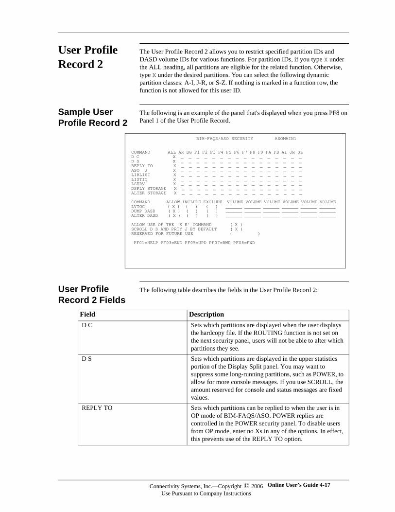
User Profile Record 2
The User Profile Record 2 allows you to restrict specified partition IDs and DASD volume IDs for various functions. For partition IDs, if you type X under the ALL heading, all partitions are eligible for the related function. Otherwise, type X under the desired partitions. You can select the following dynamic partition classes: A-I, J-R, or S-Z. If nothing is marked in a function row, the function is not allowed for this user ID.
Sample User Profile Record 2
The following is an example of the panel that's displayed when you press PF8 on Panel 1 of the User Profile Record.
User Profile Record 2 Fields
The following table describes the fields in the User Profile Record 2:
BIM-FAQS/ASO SECURITY ASOMAIN1 COMMAND ALL AR BG F1 F2 F3 F4 F5 F6 F7 F8 F9 FA FB AI JR SZ D C X _ _ _ _ _ _ _ _ _ _ _ _ _ _ _ _ D S X _ _ _ _ _ _ _ _ _ _ _ _ _ _ _ _ REPLY TO X _ _ _ _ _ _ _ _ _ _ _ _ _ _ _ _ ASO J X _ _ _ _ _ _ _ _ _ _ _ _ _ _ _ _ LIBLIST X _ _ _ _ _ _ _ _ _ _ _ _ _ _ _ _ LISTIO X _ _ _ _ _ _ _ _ _ _ _ _ _ _ _ _ LSERV X _ _ _ _ _ _ _ _ _ _ _ _ _ _ _ _ DSPLY STORAGE X _ _ _ _ _ _ _ _ _ _ _ _ _ _ _ _ ALTER STORAGE X _ _ _ _ _ _ _ _ _ _ _ _ _ _ _ _ COMMAND ALLOW INCLUDE EXCLUDE VOLUME VOLUME VOLUME VOLUME VOLUME VOLUME LVTOC ( X ) ( ) ( ) ______ ______ ______ ______ ______ ______ DUMP DASD ( X ) ( ) ( ) ______ ______ ______ ______ ______ ______ ALTER DASD ( X ) ( ) ( ) ______ ______ ______ ______ ______ ______ ALLOW USE OF THE 'K E' COMMAND ( X ) SCROLL D S AND PRTY J BY DEFAULT ( X ) RESERVED FOR FUTURE USE ( ) PF01=HELP PF03=END PF05=UPD PF07=BWD PF08=FWD
Field DescriptionD C Sets which partitions are displayed when the user displays
the hardcopy file. If the ROUTING function is not set on the next security panel, users will not be able to alter which partitions they see.
D S Sets which partitions are displayed in the upper statistics portion of the Display Split panel. You may want to suppress some long-running partitions, such as POWER, to allow for more console messages. If you use SCROLL, the amount reserved for console and status messages are fixed values.
REPLY TO Sets which partitions can be replied to when the user is in OP mode of BIM-FAQS/ASO. POWER replies are controlled in the POWER security panel. To disable users from OP mode, enter no Xs in any of the options. In effect, this prevents use of the REPLY TO option.
Connectivity Systems, Inc.—Copyright © 2006Use Pursuant to Company Instructions
Online User’s Guide 4-17
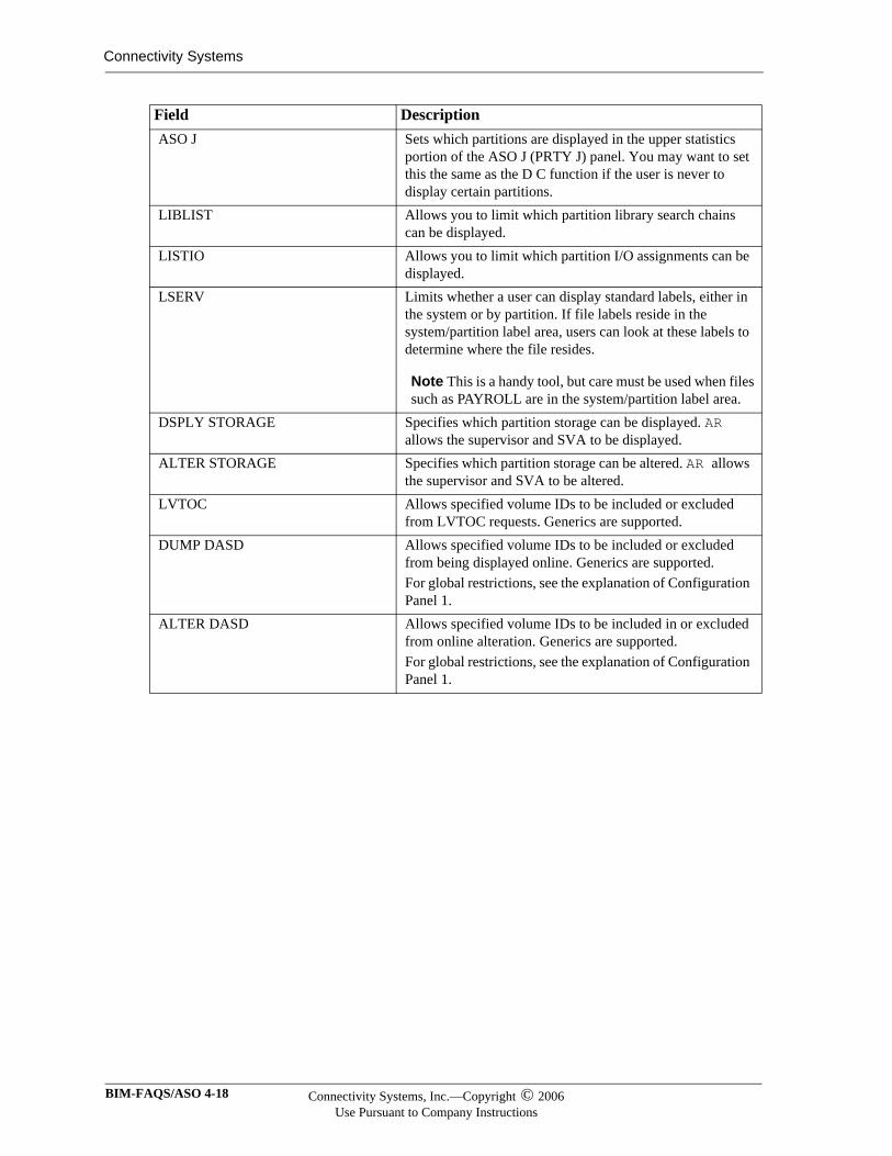
Connectivity Systems
ASO J Sets which partitions are displayed in the upper statistics portion of the ASO J (PRTY J) panel. You may want to set this the same as the D C function if the user is never to display certain partitions.
LIBLIST Allows you to limit which partition library search chains can be displayed.
LISTIO Allows you to limit which partition I/O assignments can be displayed.
LSERV Limits whether a user can display standard labels, either in the system or by partition. If file labels reside in the system/partition label area, users can look at these labels to determine where the file resides.
Note This is a handy tool, but care must be used when files such as PAYROLL are in the system/partition label area.
DSPLY STORAGE Specifies which partition storage can be displayed. AR allows the supervisor and SVA to be displayed.
ALTER STORAGE Specifies which partition storage can be altered. AR allows the supervisor and SVA to be altered.
LVTOC Allows specified volume IDs to be included or excluded from LVTOC requests. Generics are supported.
DUMP DASD Allows specified volume IDs to be included or excluded from being displayed online. Generics are supported. For global restrictions, see the explanation of Configuration Panel 1.
ALTER DASD Allows specified volume IDs to be included in or excluded from online alteration. Generics are supported. For global restrictions, see the explanation of Configuration Panel 1.
Field Description
BIM-FAQS/ASO 4-18 Connectivity Systems, Inc.—Copyright © 2006Use Pursuant to Company Instructions
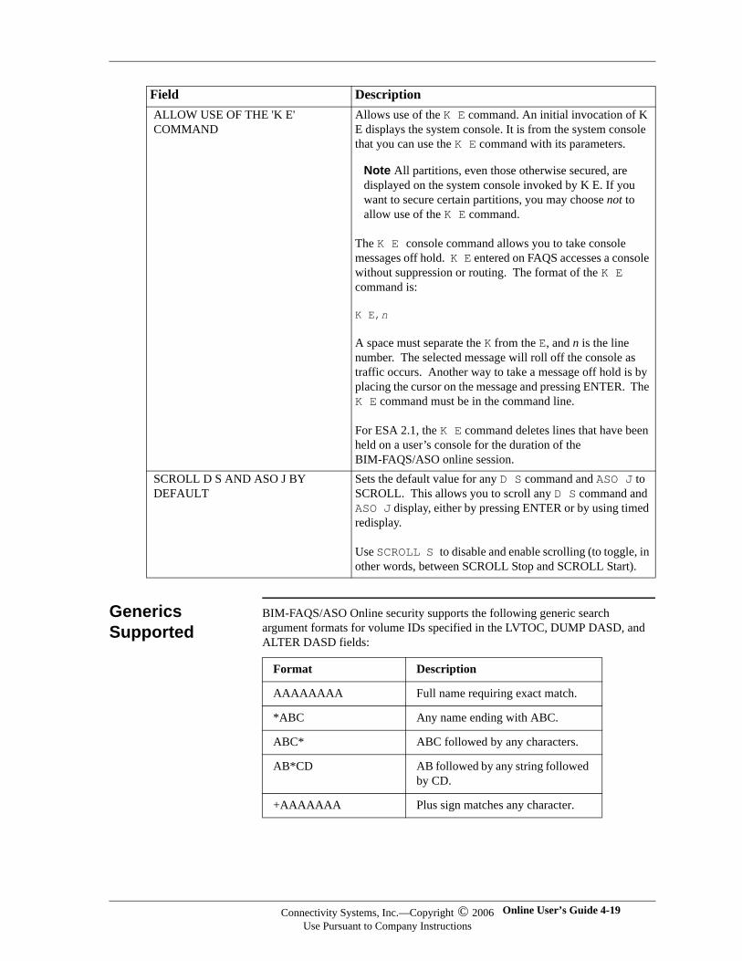
Generics Supported
BIM-FAQS/ASO Online security supports the following generic search argument formats for volume IDs specified in the LVTOC, DUMP DASD, and ALTER DASD fields:
ALLOW USE OF THE 'K E' COMMAND
Allows use of the K E command. An initial invocation of K E displays the system console. It is from the system console that you can use the K E command with its parameters.
Note All partitions, even those otherwise secured, are displayed on the system console invoked by K E. If you want to secure certain partitions, you may choose not to allow use of the K E command.
The K E console command allows you to take console messages off hold. K E entered on FAQS accesses a console without suppression or routing. The format of the K E command is:
K E,n
A space must separate the K from the E, and n is the line number. The selected message will roll off the console as traffic occurs. Another way to take a message off hold is by placing the cursor on the message and pressing ENTER. The K E command must be in the command line.
For ESA 2.1, the K E command deletes lines that have been held on a user’s console for the duration of the BIM-FAQS/ASO online session.
SCROLL D S AND ASO J BY DEFAULT
Sets the default value for any D S command and ASO J to SCROLL. This allows you to scroll any D S command and ASO J display, either by pressing ENTER or by using timed redisplay.
Use SCROLL S to disable and enable scrolling (to toggle, in other words, between SCROLL Stop and SCROLL Start).
Field Description
Format Description
AAAAAAAA Full name requiring exact match.
*ABC Any name ending with ABC.
ABC* ABC followed by any characters.
AB*CD AB followed by any string followed by CD.
+AAAAAAA Plus sign matches any character.
Connectivity Systems, Inc.—Copyright © 2006Use Pursuant to Company Instructions
Online User’s Guide 4-19

Connectivity Systems
=AAAAAAA Equal sign matches numeric character.
<AAAAAAA Less-than sign matches alphabetic character.
Format Description
BIM-FAQS/ASO 4-20 Connectivity Systems, Inc.—Copyright © 2006Use Pursuant to Company Instructions
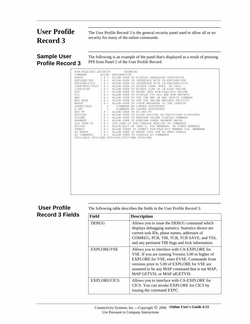
User Profile Record 3
The User Profile Record 3 is the general security panel used to allow all or no security for many of the online commands.
Sample User Profile Record 3
The following is an example of the panel that's displayed as a result of pressing PF8 from Panel 2 of the User Profile Record:
User Profile Record 3 Fields
The following table describes the fields in the User Profile Record 3:
BIM-FAQS/ASO SECURITY ASOMAIN1 COMMAND ALLOW EXPLANATION DEBUG ( X ) ALLOW USER TO DISPLAY DEBUGGING STATISTICS EXPLORE/VSE ( X ) ALLOW USER TO INTERFACE WITH CA-EXPLORE/VSE EXPLORE/CICS ( X ) ALLOW USER TO INTERFACE WITH CA-EXPLORE/CICS VSAM/MCAT/VAID ( X ) ALLOW USER TO ACCESS VSAM, MCAT, OR VAID LIBR/FLEE ( X ) ALLOW USER TO ACCESS LIBR OR CA-FLEE ONLINE PCS ( X ) ALLOW USER TO ENTER INTO BIM-FAQS/PCS ONLINE FTL ( X ) ALLOW USER TO DISPLAY FTL RDL AND MON REPORTS MAP ( X ) ALLOW USER TO USE THE MAP OR MAP GETVIS COMMAND MSG XXXX ( X ) ALLOW USER TO USE THE ONLINE MESSAGE FACILITY MSGOP ( X ) ALLOW USER TO ISSUE MESSAGES TO THE CONSOLE QSEEK/DASD ( ) (COMMAND NO LONGER SUPPORTED) Q SET ( ) (COMMAND NO LONGER SUPPORTED) SET PF ( X ) ALLOW USER TO DO SET PF ROUTING ( X ) ALLOW USER TO ALTER ROUTING OR PARTITIONS DISPLAYED VOLUME ( X ) ALLOW USER TO PERFORM VOLUME DISPLAY COMMAND SEGMENT ( X ) ALLOW USER TO PERFORM POWER SEGMENT MACRO LOG USER-ID ( X ) LOG USER-ID FOR CONSOLE REPLIES OR COMMANDS EDITOR ( X ) ALLOW EDIT OF IMOD'S, PDS MEMBERS, OR POWER MEMBERS SUBMIT ( X ) ALLOW USERS TO SUBMIT BIM-FAQS/PCS MEMBER VIA .MEMNAME AO MENUS ( X ) ALLOW USER TO ENTER INTO THE AO MENU PANELS AO COMMANDS ( X ) ALLOW USER TO CONSOLE AO COMMANDS PF01=HELP PF03=END PF05=UPD PF07=BWD PF08=FWD
Field DescriptionDEBUG Allows you to issue the DEBUG command which
displays debugging statistics. Statistics shown are current task IDs, phase names, addresses of COMREG, PCB, TIB, TCB, TCB SAVE, and TSS, and any pertinent TIB flags and lock information.
EXPLORE/VSE Allows you to interface with CA-EXPLORE for VSE. If you are running Version 5.00 or higher of EXPLORE for VSE, enter EVSE. Commands from versions prior to 5.00 of EXPLORE for VSE are assumed to be any MAP command that is not MAP, MAP GETVIS, or MAP idGETVIS.
EXPLORE/CICS Allows you to interface with CA-EXPLORE for CICS. You can invoke EXPLORE for CICS by issuing the command EXPC.
Connectivity Systems, Inc.—Copyright © 2006Use Pursuant to Company Instructions
Online User’s Guide 4-21

Connectivity Systems
VSAM/VAID/MCAT Allows you to interface to CA-VSAMAID for VSE Online (VAID), CA-MASTERCAT for VSE Online (MCAT), or BIM-FAQS/ASO -- VSAM Display Menu (VSAM).
LIBR/FLEE Allows you to access CA-FLEE (FLEE) or BIM-FAQS/ASO Library Display Panel (LIBR).
PCS Allows you to interface with BIM-FAQS/PCS, which is invoked with the command PCS. Extended password support is provided for BIM-FAQS/PCS.
FTL Allows you to issue the FTL commands FTL RDL and FTL MON. These commands provide statistics on phase load counts, load point, length, page faults, and mode.
MAP Allows the use of the BIM-FAQS/ASO MAP command. The MAP command displays default partition allocations and the job name that is currently executing.
MSG XXXX Allows access to the BIM-FAQS/ASO FAQSMSG file and the IBM IESMSGS file. BIMVSE product line messages and IBM messages are available. The FAQSMSG file also contains various help panels, including your own messages and explanations.
Note With VSE/ESA 2.1, you can no longer use the FAQSMSG VSAM file to access BIM-FAQS/ASO online message explanations. Instead, you must use IBM’s EXPLAIN facility. If the EXPLAIN facility is not already active, enter EXPLAIN ON from a BIM-FAQS/ASO command line (in operator mode) to activate it. Enter MSG xxxx to access a message explanation. xxxx is a message ID -- for example, GJJ999.
All pre-ESA 2.1 versions of BIM-FAQS/ASO continue to use the FAQSMSG file for viewing message explanations online.
MSGOP MSGOP enables you to communicate with an operator through the system console. This can be helpful if it is not abused. If not used properly, operators may become annoyed.
Q SET Pre-ESA 2.1 only. Allows users to view the current highlighting, routing, and suppression settings. If suppression is used to suppress a user ID or other privileged information, Q SET should be off.
SET PF Allows users to perform SET PF functions.
Field Description
BIM-FAQS/ASO 4-22 Connectivity Systems, Inc.—Copyright © 2006Use Pursuant to Company Instructions
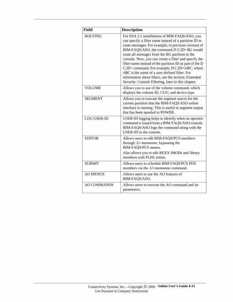
ROUTING For ESA 2.1 installations of BIM-FAQS/ASO, you can specify a filter name instead of a partition ID to route messages. For example, in previous versions of BIM-FAQS/ASO, the command D C,ID=BG would route all messages from the BG partition to the console. Now, you can create a filter and specify the filter name instead of the partition ID as part of the D C,ID= command. For example, D C,ID=ABC, where ABC is the name of a user-defined filter. For information about filters, see the section, Extended Security: Console Filtering, later in this chapter.
VOLUME Allows you to use of the volume command, which displays the volume ID, CUU, and device type.
SEGMENT Allows you to execute the segment macro for the current partition that the BIM-FAQS/ASO online interface is running. This is useful to segment output that has been spooled to POWER.
LOG USER-ID USER-ID logging helps to identify when an operator command is issued from a BIM-FAQS/ASO console. BIM-FAQS/ASO logs the command along with the USER-ID to the console.
EDITOR Allows users to edit BIM-FAQS/PCS members through .U=memname, bypassing the BIM-FAQS/PCS menus. Also allows you to edit REXX IMODs and library members with FLEE online.
SUBMIT Allows users to schedule BIM-FAQS/PCS PDS members via the .U=memname command.
AO MENUS Allows users to use the AO features of BIM-FAQS/ASO.
AO COMMANDS Allows users to execute the AO command and its parameters.
Field Description
Connectivity Systems, Inc.—Copyright © 2006Use Pursuant to Company Instructions
Online User’s Guide 4-23
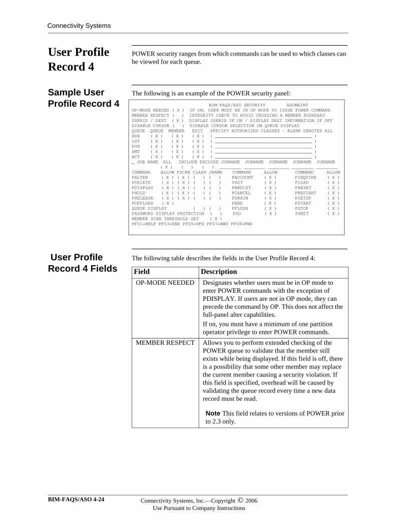
Connectivity Systems
User Profile Record 4
POWER security ranges from which commands can be used to which classes can be viewed for each queue.
Sample User Profile Record 4
The following is an example of the POWER security panel:
User Profile Record 4 Fields
The following table describes the fields in the User Profile Record 4:
BIM-FAQS/ASO SECURITY ASOMAINT OP-MODE NEEDED ( X ) IF ON, USER MUST BE IN OP MODE TO ISSUE POWER COMMAND MEMBER RESPECT ( ) INTEGRITY CHECK TO AVOID CROSSING A MEMBER BOUNDARY USERID / DEST ( X ) DISPLAY USERID IF ON / DISPLAY DEST INFORMATION IF OFF DISABLE CURSOR ( ) DISABLE CURSOR SELECTION ON QUEUE DISPLAY QUEUE QUEUE MEMBER EDIT SPECIFY AUTHORIZED CLASSES - BLANK DENOTES ALL RDR ( X ) ( X ) ( X ) ( ____________________________________ ) LST ( X ) ( X ) ( X ) ( ____________________________________ ) PUN ( X ) ( X ) ( X ) ( ____________________________________ ) XMT ( X ) ( X ) ( X ) ( ____________________________________ ) ACT ( X ) ( X ) ( X ) ( ____________________________________ ) _ JOB NAME ALL INCLUDE EXCLUDE JOBNAME JOBNAME JOBNAME JOBNAME JOBNAME ( X ) ( ) ( ) ________ ________ ________ ________ ________ COMMAND ALLOW FSCRN CLASS JNAME COMMAND ALLOW COMMAND ALLOW PALTER ( X ) ( X ) ( ) ( ) PACCOUNT ( X ) PINQUIRE ( X ) PDELETE ( X ) ( X ) ( ) ( ) PACT ( X ) PLOAD ( X ) PDISPLAY ( X ) ( X ) ( ) ( ) PBRDCST ( X ) PRESET ( X ) PHOLD ( X ) ( X ) ( ) ( ) PCANCEL ( X ) PRESTART ( X ) PRELEASE ( X ) ( X ) ( ) ( ) PDRAIN ( X ) PSETUP ( X ) POFFLOAD ( X ) PEND ( X ) PSTART ( X ) QUEUE DISPLAY ( ) ( ) PFLUSH ( X ) PSTOP ( X ) PASSWORD DISPLAY PROTECTION ( ) PGO ( X ) PXMIT ( X ) MEMBER SCAN THRESHOLD SET ( X ) PF01=HELP PF03=END PF05=UPD PF07=BWD PF08=FWD
Field DescriptionOP-MODE NEEDED Designates whether users must be in OP mode to
enter POWER commands with the exception of PDISPLAY. If users are not in OP mode, they can precede the command by OP. This does not affect the full-panel alter capabilities. If on, you must have a minimum of one partition operator privilege to enter POWER commands.
MEMBER RESPECT Allows you to perform extended checking of the POWER queue to validate that the member still exists while being displayed. If this field is off, there is a possibility that some other member may replace the current member causing a security violation. If this field is specified, overhead will be caused by validating the queue record every time a new data record must be read.
Note This field relates to versions of POWER prior to 2.3 only.
BIM-FAQS/ASO 4-24 Connectivity Systems, Inc.—Copyright © 2006Use Pursuant to Company Instructions
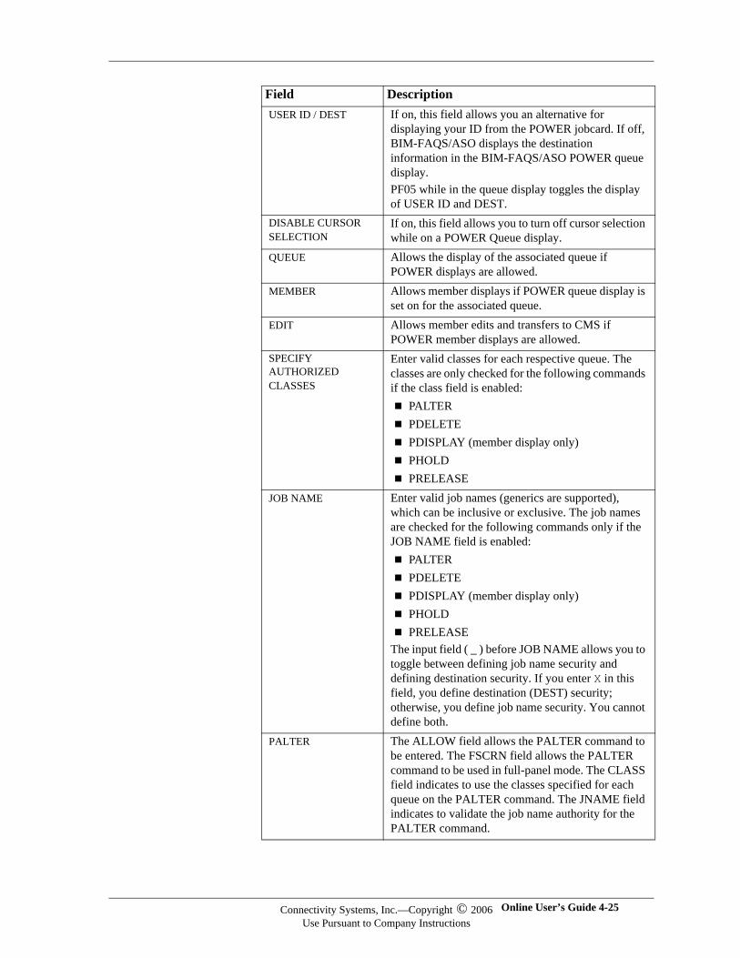
USER ID / DEST If on, this field allows you an alternative for displaying your ID from the POWER jobcard. If off, BIM-FAQS/ASO displays the destination information in the BIM-FAQS/ASO POWER queue display. PF05 while in the queue display toggles the display of USER ID and DEST.
DISABLE CURSOR SELECTION
If on, this field allows you to turn off cursor selection while on a POWER Queue display.
QUEUE Allows the display of the associated queue if POWER displays are allowed.
MEMBER Allows member displays if POWER queue display is set on for the associated queue.
EDIT Allows member edits and transfers to CMS if POWER member displays are allowed.
SPECIFY AUTHORIZED CLASSES
Enter valid classes for each respective queue. The classes are only checked for the following commands if the class field is enabled:
PALTERPDELETEPDISPLAY (member display only)PHOLDPRELEASE
JOB NAME Enter valid job names (generics are supported), which can be inclusive or exclusive. The job names are checked for the following commands only if the JOB NAME field is enabled:
PALTERPDELETEPDISPLAY (member display only)PHOLDPRELEASE
The input field ( _ ) before JOB NAME allows you to toggle between defining job name security and defining destination security. If you enter X in this field, you define destination (DEST) security; otherwise, you define job name security. You cannot define both.
PALTER The ALLOW field allows the PALTER command to be entered. The FSCRN field allows the PALTER command to be used in full-panel mode. The CLASS field indicates to use the classes specified for each queue on the PALTER command. The JNAME field indicates to validate the job name authority for the PALTER command.
Field Description
Connectivity Systems, Inc.—Copyright © 2006Use Pursuant to Company Instructions
Online User’s Guide 4-25
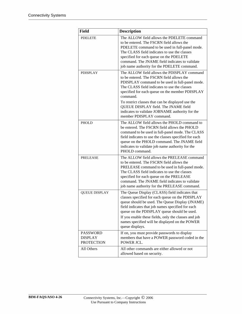
Connectivity Systems
PDELETE The ALLOW field allows the PDELETE command to be entered. The FSCRN field allows the PDELETE command to be used in full-panel mode. The CLASS field indicates to use the classes specified for each queue on the PDELETE command. The JNAME field indicates to validate job name authority for the PDELETE command.
PDISPLAY The ALLOW field allows the PDISPLAY command to be entered. The FSCRN field allows the PDISPLAY command to be used in full-panel mode. The CLASS field indicates to use the classes specified for each queue on the member PDISPLAY command.To restrict classes that can be displayed use the QUEUE DISPLAY field. The JNAME field indicates to validate JOBNAME authority for the member PDISPLAY command.
PHOLD The ALLOW field allows the PHOLD command to be entered. The FSCRN field allows the PHOLD command to be used in full-panel mode. The CLASS field indicates to use the classes specified for each queue on the PHOLD command. The JNAME field indicates to validate job name authority for the PHOLD command.
PRELEASE The ALLOW field allows the PRELEASE command to be entered. The FSCRN field allows the PRELEASE command to be used in full-panel mode. The CLASS field indicates to use the classes specified for each queue on the PRELEASE command. The JNAME field indicates to validate job name authority for the PRELEASE command.
QUEUE DISPLAY The Queue Display (CLASS) field indicates that classes specified for each queue on the PDISPLAY queue should be used. The Queue Display (JNAME) field indicates that job names specified for each queue on the PDISPLAY queue should be used.If you enable these fields, only the classes and job names specified will be displayed on the POWER queue displays.
PASSWORD DISPLAY PROTECTION
If on, you must provide passwords to display members that have a POWER password coded in the POWER JCL.
All Others All other commands are either allowed or not allowed based on security.
Field Description
BIM-FAQS/ASO 4-26 Connectivity Systems, Inc.—Copyright © 2006Use Pursuant to Company Instructions

MEMBER SCAN THRESHOLD SET
If on, the system restricts scans during displays of POWER members to 20,000 lines per scan attempt. This restriction prevents scanning of large members, which holds resources for extended periods of time. We recommend that you set MEMBER SCAN THRESHOLD.
Field Description
Connectivity Systems, Inc.—Copyright © 2006Use Pursuant to Company Instructions
Online User’s Guide 4-27
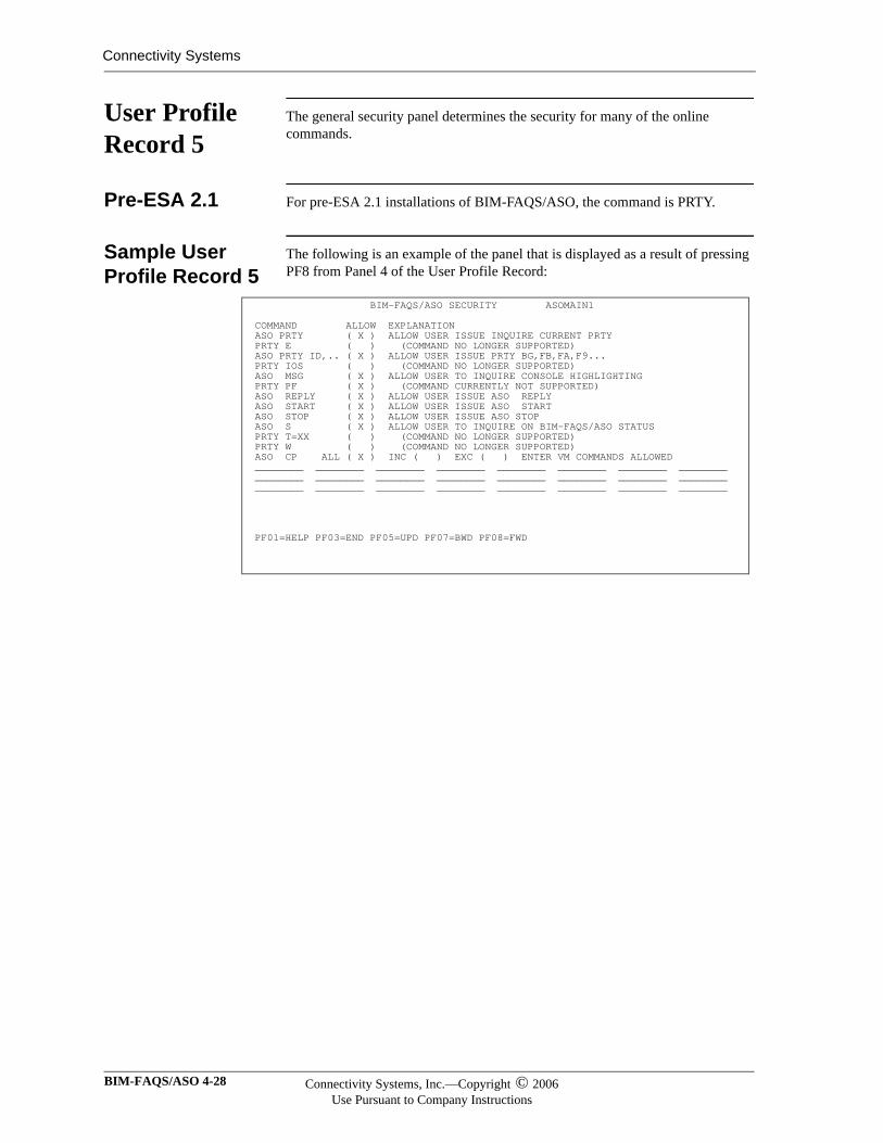
Connectivity Systems
User Profile Record 5
The general security panel determines the security for many of the online commands.
Pre-ESA 2.1 For pre-ESA 2.1 installations of BIM-FAQS/ASO, the command is PRTY.
Sample User Profile Record 5
The following is an example of the panel that is displayed as a result of pressing PF8 from Panel 4 of the User Profile Record:
BIM-FAQS/ASO SECURITY ASOMAIN1 COMMAND ALLOW EXPLANATION ASO PRTY ( X ) ALLOW USER ISSUE INQUIRE CURRENT PRTY PRTY E ( ) (COMMAND NO LONGER SUPPORTED) ASO PRTY ID,.. ( X ) ALLOW USER ISSUE PRTY BG,FB,FA,F9... PRTY IOS ( ) (COMMAND NO LONGER SUPPORTED) ASO MSG ( X ) ALLOW USER TO INQUIRE CONSOLE HIGHLIGHTING PRTY PF ( X ) (COMMAND CURRENTLY NOT SUPPORTED) ASO REPLY ( X ) ALLOW USER ISSUE ASO REPLY ASO START ( X ) ALLOW USER ISSUE ASO START ASO STOP ( X ) ALLOW USER ISSUE ASO STOP ASO S ( X ) ALLOW USER TO INQUIRE ON BIM-FAQS/ASO STATUS PRTY T=XX ( ) (COMMAND NO LONGER SUPPORTED) PRTY W ( ) (COMMAND NO LONGER SUPPORTED) ASO CP ALL ( X ) INC ( ) EXC ( ) ENTER VM COMMANDS ALLOWED ________ ________ ________ ________ ________ ________ ________ ________ ________ ________ ________ ________ ________ ________ ________ ________ ________ ________ ________ ________ ________ ________ ________ ________ PF01=HELP PF03=END PF05=UPD PF07=BWD PF08=FWD
BIM-FAQS/ASO 4-28 Connectivity Systems, Inc.—Copyright © 2006Use Pursuant to Company Instructions
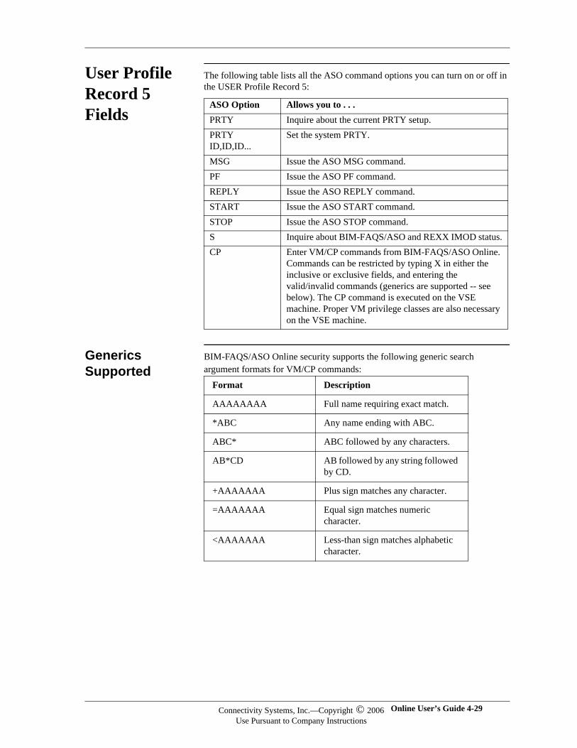
User Profile Record 5 Fields
The following table lists all the ASO command options you can turn on or off in the USER Profile Record 5:
Generics Supported
BIM-FAQS/ASO Online security supports the following generic search argument formats for VM/CP commands:
ASO Option Allows you to . . .PRTY Inquire about the current PRTY setup.PRTY ID,ID,ID...
Set the system PRTY.
MSG Issue the ASO MSG command.PF Issue the ASO PF command.REPLY Issue the ASO REPLY command.START Issue the ASO START command.STOP Issue the ASO STOP command.S Inquire about BIM-FAQS/ASO and REXX IMOD status.CP Enter VM/CP commands from BIM-FAQS/ASO Online.
Commands can be restricted by typing X in either the inclusive or exclusive fields, and entering the valid/invalid commands (generics are supported -- see below). The CP command is executed on the VSE machine. Proper VM privilege classes are also necessary on the VSE machine.
Format Description
AAAAAAAA Full name requiring exact match.
*ABC Any name ending with ABC.
ABC* ABC followed by any characters.
AB*CD AB followed by any string followed by CD.
+AAAAAAA Plus sign matches any character.
=AAAAAAA Equal sign matches numeric character.
<AAAAAAA Less-than sign matches alphabetic character.
Connectivity Systems, Inc.—Copyright © 2006Use Pursuant to Company Instructions
Online User’s Guide 4-29
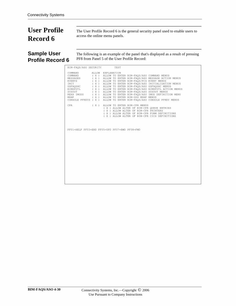
Connectivity Systems
User Profile Record 6
The User Profile Record 6 is the general security panel used to enable users to access the online menu panels.
Sample User Profile Record 6
The following is an example of the panel that's displayed as a result of pressing PF8 from Panel 5 of the User Profile Record:
BIM-FAQS/ASO SECURITY TEST COMMAND ALLOW EXPLANATION COMMAND ( X ) ALLOW TO ENTER BIM-FAQS/ASO COMMAND MENUS MESSAGES ( X ) ALLOW TO ENTER BIM-FAQS/ASO MESSAGE ACTION MENUS EVENTS ( X ) ALLOW TO ENTER BIM-FAQS/PCS EVENT MENUS INIT ( X ) ALLOW TO ENTER BIM-FAQS/ASO INITIALIZATION MENUS GSFAQSHC ( X ) ALLOW TO ENTER BIM-FAQS/ASO GSFAQSHC MENUS BIM$PUTL ( X ) ALLOW TO ENTER BIM-FAQS/ASO BIM$PUTL ACTION MENUS SYSOUT ( X ) ALLOW TO ENTER BIM-FAQS/ASO SYSOUT MENUS REXX IMODS ( X ) ALLOW TO ENTER BIM-FAQS/ASO IMOD DEFINITION MENU MSHP ( X ) ALLOW TO ENTER BIM-GSS MSHP MENUS CONSOLE PFKEYS ( X ) ALLOW TO ENTER BIM-FAQS/ASO CONSOLE PFKEY MENUS CPR ( X ) ALLOW TO ENTER BIM-CPR MENUS ( X ) ALLOW ALTER OF BIM-CPR QUEUE ENTRIES ( X ) ALLOW ALTER OF BIM-CPR PRINTERS ( X ) ALLOW ALTER OF BIM-CPR FORM DEFINITIONS ( X ) ALLOW ALTER OF BIM-CPR CICS DEFINITIONS PF01=HELP PF03=END PF05=UPD PF07=BWD PF08=FWD
BIM-FAQS/ASO 4-30 Connectivity Systems, Inc.—Copyright © 2006Use Pursuant to Company Instructions
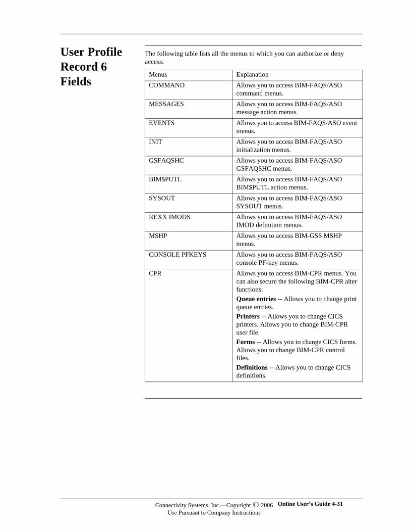
User Profile Record 6 Fields
The following table lists all the menus to which you can authorize or deny access:
Menus ExplanationCOMMAND Allows you to access BIM-FAQS/ASO
command menus.MESSAGES Allows you to access BIM-FAQS/ASO
message action menus.EVENTS Allows you to access BIM-FAQS/ASO event
menus.INIT Allows you to access BIM-FAQS/ASO
initialization menus.GSFAQSHC Allows you to access BIM-FAQS/ASO
GSFAQSHC menus.BIM$PUTL Allows you to access BIM-FAQS/ASO
BIM$PUTL action menus.SYSOUT Allows you to access BIM-FAQS/ASO
SYSOUT menus.REXX IMODS Allows you to access BIM-FAQS/ASO
IMOD definition menus.MSHP Allows you to access BIM-GSS MSHP
menus.CONSOLE PFKEYS Allows you to access BIM-FAQS/ASO
console PF-key menus.CPR Allows you to access BIM-CPR menus. You
can also secure the following BIM-CPR alter functions:Queue entries -- Allows you to change print queue entries.Printers -- Allows you to change CICS printers. Allows you to change BIM-CPR user file.Forms -- Allows you to change CICS forms. Allows you to change BIM-CPR control files.Definitions -- Allows you to change CICS definitions.
Connectivity Systems, Inc.—Copyright © 2006Use Pursuant to Company Instructions
Online User’s Guide 4-31
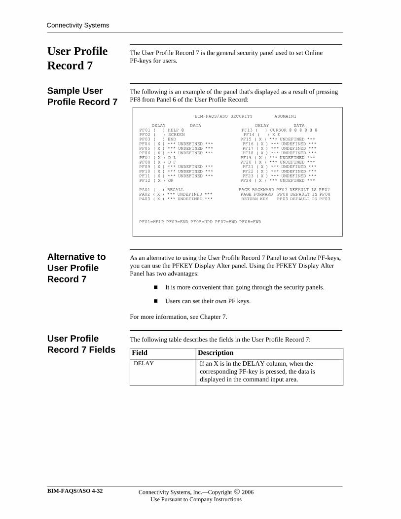
Connectivity Systems
User Profile Record 7
The User Profile Record 7 is the general security panel used to set Online PF-keys for users.
Sample User Profile Record 7
The following is an example of the panel that's displayed as a result of pressing PF8 from Panel 6 of the User Profile Record:
Alternative to User Profile Record 7
As an alternative to using the User Profile Record 7 Panel to set Online PF-keys, you can use the PFKEY Display Alter panel. Using the PFKEY Display Alter Panel has two advantages:
It is more convenient than going through the security panels.
Users can set their own PF keys.
For more information, see Chapter 7.
User Profile Record 7 Fields
The following table describes the fields in the User Profile Record 7:
BIM-FAQS/ASO SECURITY ASOMAIN1
DELAY DATA DELAY DATA PF01 ( ) HELP @ PF13 ( ) CURSOR @ @ @ @ @ @ PF02 ( ) SCREEN PF14 ( ) K E PF03 ( ) END PF15 ( X ) *** UNDEFINED *** PF04 ( X ) *** UNDEFINED *** PF16 ( X ) *** UNDEFINED *** PF05 ( X ) *** UNDEFINED *** PF17 ( X ) *** UNDEFINED *** PF06 ( X ) *** UNDEFINED *** PF18 ( X ) *** UNDEFINED *** PF07 ( X ) D L PF19 ( X ) *** UNDEFINED *** PF08 ( X ) D F PF20 ( X ) *** UNDEFINED *** PF09 ( X ) *** UNDEFINED *** PF21 ( X ) *** UNDEFINED *** PF10 ( X ) *** UNDEFINED *** PF22 ( X ) *** UNDEFINED *** PF11 ( X ) *** UNDEFINED *** PF23 ( X ) *** UNDEFINED *** PF12 ( X ) OP PF24 ( X ) *** UNDEFINED *** PA01 ( ) RECALL PAGE BACKWARD PF07 DEFAULT IS PF07 PA02 ( X ) *** UNDEFINED *** PAGE FORWARD PF08 DEFAULT IS PF08 PA03 ( X ) *** UNDEFINED *** RETURN KEY PF03 DEFAULT IS PF03 PF01=HELP PF03=END PF05=UPD PF07=BWD PF08=FWD
Field DescriptionDELAY If an X is in the DELAY column, when the
corresponding PF-key is pressed, the data is displayed in the command input area.
BIM-FAQS/ASO 4-32 Connectivity Systems, Inc.—Copyright © 2006Use Pursuant to Company Instructions
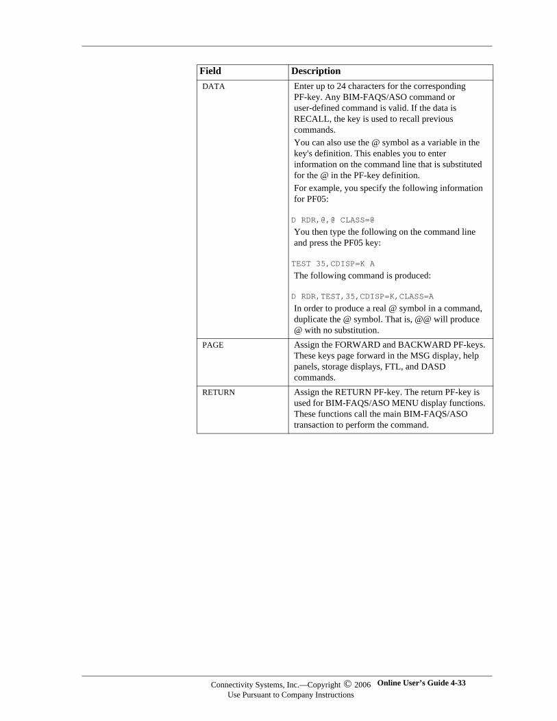
DATA Enter up to 24 characters for the corresponding PF-key. Any BIM-FAQS/ASO command or user-defined command is valid. If the data is RECALL, the key is used to recall previous commands.You can also use the @ symbol as a variable in the key's definition. This enables you to enter information on the command line that is substituted for the @ in the PF-key definition.For example, you specify the following information for PF05:
D RDR,@,@ CLASS=@
You then type the following on the command line and press the PF05 key:
TEST 35,CDISP=K A
The following command is produced:
D RDR,TEST,35,CDISP=K,CLASS=A
In order to produce a real @ symbol in a command, duplicate the @ symbol. That is, @@ will produce @ with no substitution.
PAGE Assign the FORWARD and BACKWARD PF-keys. These keys page forward in the MSG display, help panels, storage displays, FTL, and DASD commands.
RETURN Assign the RETURN PF-key. The return PF-key is used for BIM-FAQS/ASO MENU display functions. These functions call the main BIM-FAQS/ASO transaction to perform the command.
Field Description
Connectivity Systems, Inc.—Copyright © 2006Use Pursuant to Company Instructions
Online User’s Guide 4-33
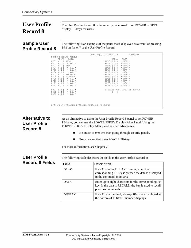
Connectivity Systems
User Profile Record 8
The User Profile Record 8 is the security panel used to set POWER or SPRI display PF-keys for users.
Sample User Profile Record 8
The following is an example of the panel that's displayed as a result of pressing PF8 on Panel 7 of the User Profile Record:
Alternative to User Profile Record 8
As an alternative to using the User Profile Record 8 panel to set POWER PF-keys, you can use the POWER PFKEY Display Alter Panel. Using the POWER PFKEY Display Alter panel has two advantages:
It is more convenient than going through security panels.
Users can set their own POWER PF-keys.
For more information, see Chapter 7.
User Profile Record 8 Fields
The following table describes the fields in the User Profile Record 8:
BIM-FAQS/ASO SECURITY ASOMAIN1 POWER DISPLAY PFKEYS DELAY DATA DELAY DATA PF01 ( ) HELP PF13 ( X ) * N/A * PF02 ( X ) * N/A * PF14 ( X ) * N/A * PF03 ( ) END PF15 ( X ) * N/A * PF04 ( X ) * N/A * PF16 ( X ) * N/A * PF05 ( X ) * N/A * PF17 ( X ) * N/A * PF06 ( X ) * N/A * PF18 ( X ) * N/A * PF07 ( ) BACKWARD PF19 ( X ) * N/A * PF08 ( ) FORWARD PF20 ( X ) * N/A * PF09 ( X ) * N/A * PF21 ( X ) * N/A * PF10 ( X ) * N/A * PF22 ( X ) * N/A * PF11 ( X ) * N/A * PF23 ( X ) * N/A * PF12 ( X ) * N/A * PF24 ( X ) * N/A * PA01 ( X ) * N/A * DISPLAY PF01-PF12 AT BOTTOM PA02 ( X ) * N/A * ( ) PA03 ( X ) * N/A * PF01=HELP PF03=END PF05=UPD PF07=BWD PF08=FWD
Field DescriptionDELAY If an X is in the DELAY column, when the
corresponding PF key is pressed the data is displayed in the command input area.
DATA Enter up to eight characters for the corresponding PF key. If the data is RECALL, the key is used to recall previous commands.
DISPLAY If an X is in the field, PF keys 01-12 are displayed at the bottom of POWER member displays.
BIM-FAQS/ASO 4-34 Connectivity Systems, Inc.—Copyright © 2006Use Pursuant to Company Instructions
User Profile Record 9: Pre-ESA 2.1
User Profile Record 9 appears only in pre-ESA 2.1 versions of BIM-FAQS/ASO. With ESA 2.1, console filtering replaces the functionality of this panel. For information about console filtering, see the section, Extended Security: Console Filtering, later in this chapter.
Message Highlighting and Color Support
BIM-FAQS/ASO supports the high intensity display facility of 3270-type terminals plus extended and color highlighting on 3179/3279-type terminals for selected messages.
Message Highlighting
The message highlighting feature causes BIM-FAQS/ASO to highlight messages that match a specified message type or partition on the terminal for easy viewing. All JOB statements, EOJ statements, cancel messages, or other type of exceptional console activity can be highlighted or displayed in color on the terminal.
Color Support Color support depends on BIM-FAQS/ASO knowing it is working with a color terminal. BIM-FAQS/ASO issues a VM Diagnose command to determine terminal type. This Diagnose command is only supported on VM/SP 3 and above. If you are using a color terminal under VM/SP2, you must specify the parameter COL when initiating BIM-FAQS/ASO from CMS. For example, FAQS VSE3 COL would be used.
With CICS, you must use the FEATURE parameter in the TCT for the terminal to generate it as a color terminal. The EXTDS option must be specified. Below is a sample TCT entry.
COLRTERM DFHTCT TYPE=TERMINAL,TRMIDNT=L2D0,LVUNIT=1,TRMSTAT=TRANSCEIVE,XTIOAL=160,TCTUAL=32,FEATURE=(COLOR,EXTDS,HILIGHT)
If you are running ICCF, set an UPSI switch to notify BIM-FAQS/ASO to display in COLOR.
// UPSI 1000xxxx Switch for Model 5 terminal
// UPSI 0100xxxx Switch for Model 4 terminal
// UPSI 0010xxxx Switch for Model 3 terminal
// UPSI 0001xxxx Switch for Extended Color
Message Suppression
Message suppression entries in the highlighting panel define messages to be suppressed from the BIM-FAQS/ASO console display. When BIM-FAQS/ASO finds a match on the specified message, the line is suppressed from the display. Message suppression allows the deletion of needless messages that only add to the confusion of the console display as well as security messages that should not be viewed.
Connectivity Systems, Inc.—Copyright © 2006Use Pursuant to Company Instructions
Online User’s Guide 4-35
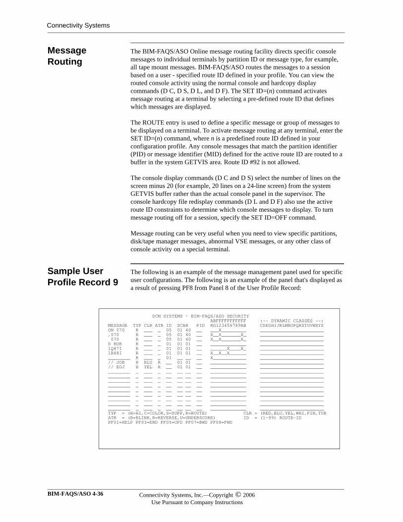
Connectivity Systems
Message Routing
The BIM-FAQS/ASO Online message routing facility directs specific console messages to individual terminals by partition ID or message type, for example, all tape mount messages. BIM-FAQS/ASO routes the messages to a session based on a user - specified route ID defined in your profile. You can view the routed console activity using the normal console and hardcopy display commands (D C, D S, D L, and D F). The SET ID=(n) command activates message routing at a terminal by selecting a pre-defined route ID that defines which messages are displayed.
The ROUTE entry is used to define a specific message or group of messages to be displayed on a terminal. To activate message routing at any terminal, enter the SET ID=(n) command, where n is a predefined route ID defined in your configuration profile. Any console messages that match the partition identifier (PID) or message identifier (MID) defined for the active route ID are routed to a buffer in the system GETVIS area. Route ID #92 is not allowed.
The console display commands (D C and D S) select the number of lines on the screen minus 20 (for example, 20 lines on a 24-line screen) from the system GETVIS buffer rather than the actual console panel in the supervisor. The console hardcopy file redisplay commands (D L and D F) also use the active route ID constraints to determine which console messages to display. To turn message routing off for a session, specify the SET ID=OFF command.
Message routing can be very useful when you need to view specific partitions, disk/tape manager messages, abnormal VSE messages, or any other class of console activity on a special terminal.
Sample User Profile Record 9
The following is an example of the message management panel used for specific user configurations. The following is an example of the panel that's displayed as a result of pressing PF8 from Panel 8 of the User Profile Record:
DCM SYSTEMS - BIM-FAQS/ASO SECURITY ABFFFFFFFFFFF :-- DYNAMIC CLASSES --: MESSAGE TYP CLR ATR ID SCAN PID RG123456789AB CDEGHIJKLMNOPQRSTUVWXYZ ON 070 R ___ _ 05 01 40 __ ___X_________ _______________________ ,070 R ___ _ 05 01 40 __ X__X_______X_ _______________________ 070 R ___ _ 05 01 40 __ X__X_______X_ _______________________ D RDR R ___ _ 01 01 01 __ _____________ _______________________ 1Q47I R ___ _ 01 01 01 __ ______X____X_ _______________________ 1R88I R ___ _ 01 01 01 __ X__X__X______ _______________________ ________ R ___ _ 01 __ __ __ X____________ _______________________ // JOB H BLU R __ 01 01 __ _____________ _______________________ // EOJ H YEL R __ 01 01 __ _____________ _______________________ ________ _ ___ _ __ __ __ __ _____________ _______________________ ________ _ ___ _ __ __ __ __ _____________ _______________________ ________ _ ___ _ __ __ __ __ _____________ _______________________ ________ _ ___ _ __ __ __ __ _____________ _______________________ ________ _ ___ _ __ __ __ __ _____________ _______________________ ________ _ ___ _ __ __ __ __ _____________ _______________________ ________ _ ___ _ __ __ __ __ _____________ _______________________ ________ _ ___ _ __ __ __ __ _____________ _______________________ ________ _ ___ _ __ __ __ __ _____________ _______________________ TYP = (H=HI,C=COLOR,S=SUPP,R=ROUTE) CLR = (RED,BLU,YEL,WHI,PIN,TUR ATR = (B=BLINK,R=REVERSE,U=UNDERSCORE) ID = (1-99) ROUTE-ID PF01=HELP PF03=END PF05=UPD PF07=BWD PF08=FWD
BIM-FAQS/ASO 4-36 Connectivity Systems, Inc.—Copyright © 2006Use Pursuant to Company Instructions
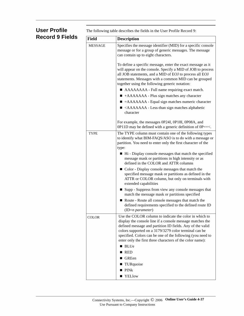
User Profile Record 9 Fields
The following table describes the fields in the User Profile Record 9:
Field DescriptionMESSAGE Specifies the message identifier (MID) for a specific console
message or for a group of generic messages. The message can contain up to eight characters.
To define a specific message, enter the exact message as it will appear on the console. Specify a MID of JOB to process all JOB statements, and a MID of EOJ to process all EOJ statements. Messages with a common MID can be grouped together using the following generic notation:
AAAAAAAA - Full name requiring exact match.+AAAAAAA - Plus sign matches any character=AAAAAAA - Equal sign matches numeric character<AAAAAAA - Less-than sign matches alphabetic character
For example, the messages 0P24I, 0P18I, 0P08A, and 0P11D may be defined with a generic definition of 0P==<.
TYPE The TYPE column must contain one of the following types to identify what BIM-FAQS/ASO is to do with a message or partition. You need to enter only the first character of the type:
Hi - Display console messages that match the specified message mask or partitions in high intensity or as defined in the COLOR and ATTR columnsColor - Display console messages that match the specified message mask or partitions as defined in the ATTR or COLOR column, but only on terminals with extended capabilitiesSupp - Suppress from view any console messages that match the message mask or partitions specifiedRoute - Route all console messages that match the defined requirements specified to the defined route ID (ID=n parameter)
COLOR Use the COLOR column to indicate the color in which to display the console line if a console message matches the defined message and partition ID fields. Any of the valid colors supported on a 3179/3279 color terminal can be specified. Colors can be one of the following (you need to enter only the first three characters of the color name):
BLUeREDGREenTURquoisePINkYELlow
Connectivity Systems, Inc.—Copyright © 2006Use Pursuant to Company Instructions
Online User’s Guide 4-37
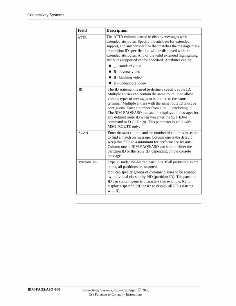
Connectivity Systems
ATTR The ATTR column is used to display messages with extended attributes. Specify the attribute for extended support, and any console line that matches the message mask or partition ID specification will be displayed with the extended attributes. Any of the valid extended highlighting attributes supported can be specified. Attributes can be:
_ - standard videoR - reverse videoB - blinking videoU - underscore video
ID The ID statement is used to define a specific route ID. Multiple entries can contain the same route ID to allow various types of messages to be routed to the same terminal. Multiple entries with the same route ID must be contiguous. Enter a number from 1 to 99, excluding 92. The BIM-FAQS/ASO transaction displays all messages for any defined route ID when you enter the SET ID=n command or D C,ID=(n). This parameter is valid with MSG=ROUTE only.
SCAN Enter the start column and the number of columns to search to find a match on message. Column one is the default. Keep this field to a minimum for performance reasons. Column one in BIM-FAQS/ASO can start at either the partition ID or the reply ID, depending on the console message.
Partition IDs Type X under the desired partitions. If all partition IDs are blank, all partitions are scanned.You can specify groups of dynamic classes to be scanned by individual class or by PID (partition ID). The partition ID can contain generic characters (for example, R2 to display a specific PID or R* to display all PIDs starting with R).
Field Description
BIM-FAQS/ASO 4-38 Connectivity Systems, Inc.—Copyright © 2006Use Pursuant to Company Instructions
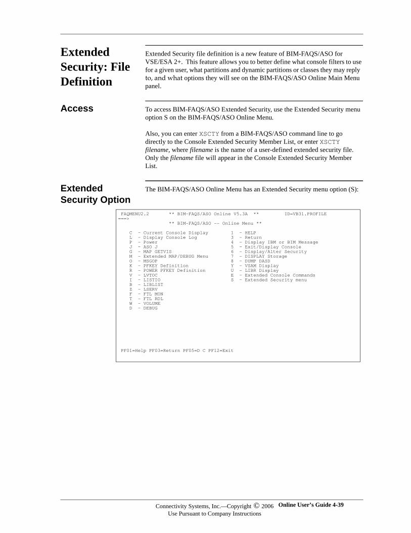
Extended Security: File Definition
Extended Security file definition is a new feature of BIM-FAQS/ASO for VSE/ESA 2+. This feature allows you to better define what console filters to use for a given user, what partitions and dynamic partitions or classes they may reply to, and what options they will see on the BIM-FAQS/ASO Online Main Menu panel.
Access To access BIM-FAQS/ASO Extended Security, use the Extended Security menu option S on the BIM-FAQS/ASO Online Menu.
Also, you can enter XSCTY from a BIM-FAQS/ASO command line to go directly to the Console Extended Security Member List, or enter XSCTY filename, where filename is the name of a user-defined extended security file. Only the filename file will appear in the Console Extended Security Member List.
Extended Security Option
The BIM-FAQS/ASO Online Menu has an Extended Security menu option (S):
FAQMENU2.2 ** BIM-FAQS/ASO Online V5.3A ** ID=VB31.PROFILE ===> ** BIM-FAQS/ASO -- Online Menu ** C - Current Console Display 1 - HELP L - Display Console Log 3 - Return P - Power 4 - Display IBM or BIM Message J - ASO J 5 - Exit/Display Console G - MAP GETVIS 6 - Display/Alter Security M - Extended MAP/DEBUG Menu 7 - DISPLAY Storage O - MSGOP 8 - DUMP DASD K - PFKEY Definition Y - VSAM Display R - POWER PFKEY Definition U - LIBR Display V - LVTOC E - Extended Console Commands I - LISTIO S - Extended Security menu B - LIBLIST Z - LSERV F - FTL MON T - FTL RDL W - VOLUME D - DEBUG
PF01=Help PF03=Return PF05=D C PF12=Exit
Connectivity Systems, Inc.—Copyright © 2006Use Pursuant to Company Instructions
Online User’s Guide 4-39
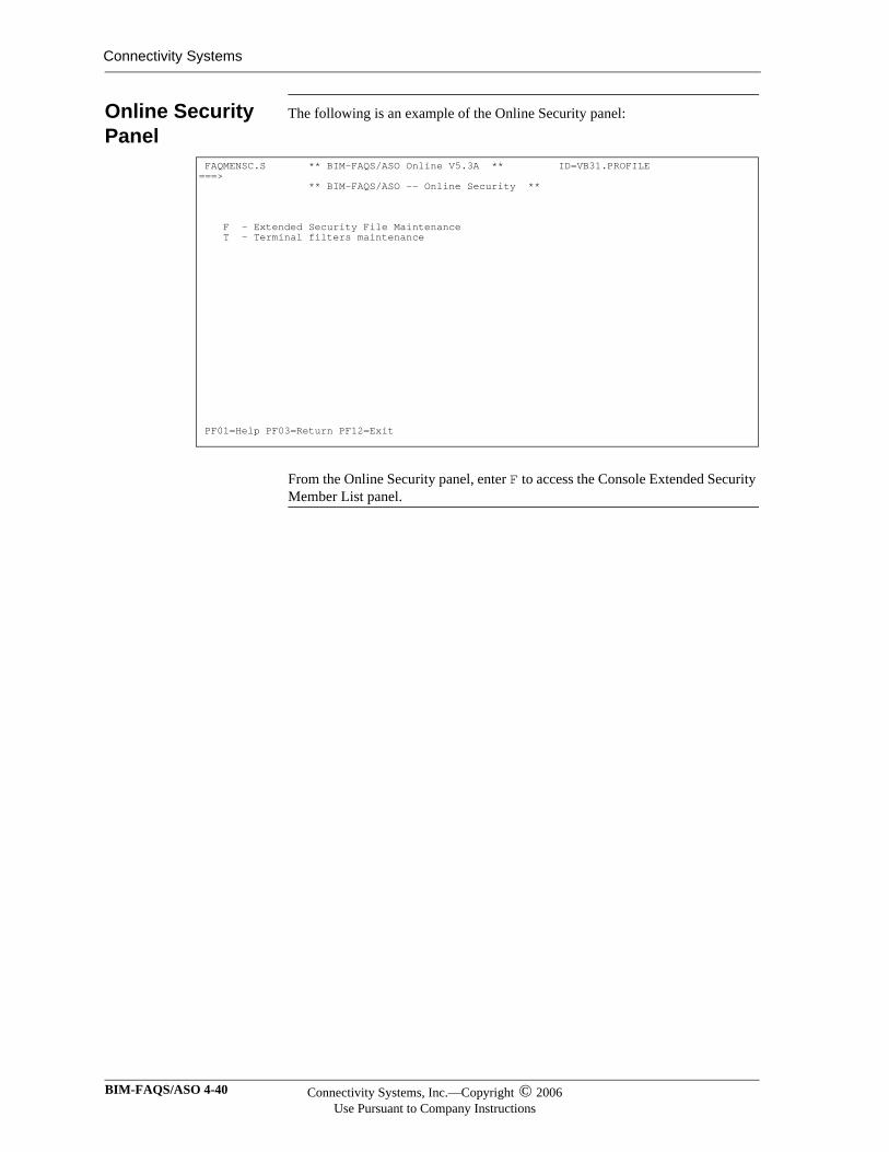
Connectivity Systems
Online Security Panel
The following is an example of the Online Security panel:
From the Online Security panel, enter F to access the Console Extended Security Member List panel.
FAQMENSC.S ** BIM-FAQS/ASO Online V5.3A ** ID=VB31.PROFILE ===> ** BIM-FAQS/ASO -- Online Security ** F - Extended Security File Maintenance T - Terminal filters maintenance PF01=Help PF03=Return PF12=Exit
BIM-FAQS/ASO 4-40 Connectivity Systems, Inc.—Copyright © 2006Use Pursuant to Company Instructions
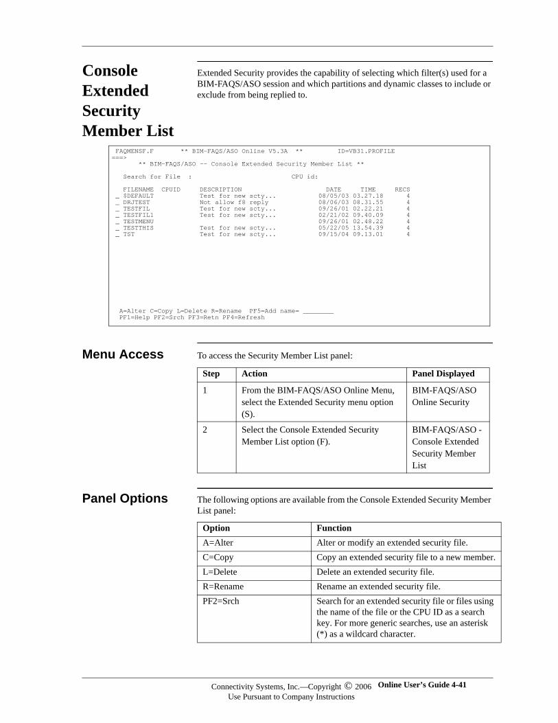
Console Extended Security Member List
Extended Security provides the capability of selecting which filter(s) used for a BIM-FAQS/ASO session and which partitions and dynamic classes to include or exclude from being replied to.
Menu Access To access the Security Member List panel:
Panel Options The following options are available from the Console Extended Security Member List panel:
FAQMENSF.F ** BIM-FAQS/ASO Online V5.3A ** ID=VB31.PROFILE ===> ** BIM-FAQS/ASO -- Console Extended Security Member List ** Search for File : CPU id: FILENAME CPUID DESCRIPTION DATE TIME RECS _ $DEFAULT Test for new scty... 08/05/03 03.27.18 4 _ DRJTEST Not allow f8 reply 08/06/03 08.31.55 4 _ TESTFIL Test for new scty... 09/26/01 02.22.21 4 _ TESTFIL1 Test for new scty... 02/21/02 09.40.09 4 _ TESTMENU 09/26/01 02.48.22 4 _ TESTTHIS Test for new scty... 05/22/05 13.54.39 4 _ TST Test for new scty... 09/15/04 09.13.01 4 A=Alter C=Copy L=Delete R=Rename PF5=Add name= ________ PF1=Help PF2=Srch PF3=Retn PF4=Refresh
Step Action Panel Displayed
1 From the BIM-FAQS/ASO Online Menu, select the Extended Security menu option (S).
BIM-FAQS/ASO Online Security
2 Select the Console Extended Security Member List option (F).
BIM-FAQS/ASO - Console Extended Security Member List
Option FunctionA=Alter Alter or modify an extended security file.C=Copy Copy an extended security file to a new member.L=Delete Delete an extended security file.R=Rename Rename an extended security file.PF2=Srch Search for an extended security file or files using
the name of the file or the CPU ID as a search key. For more generic searches, use an asterisk (*) as a wildcard character.
Connectivity Systems, Inc.—Copyright © 2006Use Pursuant to Company Instructions
Online User’s Guide 4-41

Connectivity Systems
PF5= Add name= ____ Add a new extended security file to the console extended security member list. Type in a 1- to 8-character name and press PF5.
Option Function
BIM-FAQS/ASO 4-42 Connectivity Systems, Inc.—Copyright © 2006Use Pursuant to Company Instructions
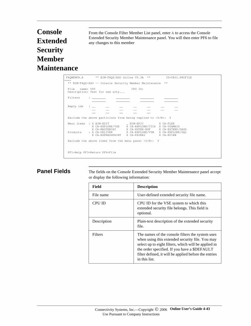
Console Extended Security Member Maintenance
From the Console Filter Member List panel, enter A to access the Console Extended Security Member Maintenance panel. You will then enter PF6 to file any changes to this member
Panel Fields The fields on the Console Extended Security Member Maintenance panel accept or display the following information:
FAQMENFA.A ** BIM-FAQS/ASO Online V5.3A ** ID=VB31.PROFILE ===> ** BIM-FAQS/ASO -- Console Security Member Maintenance ** File name: TST CPU ID: Description: Test for new scty... Filters : ________ ________ ________ ________ ________ ________ ________ ________ Reply ids : __ __ __ __ __ __ __ __ __ __ __ __ __ __ __ __ __ __ __ Exclude the above partitions from being replied to <Y/N>: Y Menu items : X BIM-EDIT _ BIM-EPIC X CA-FLEE X CA-EXPLORE/VSE X CA-EXPLORE/CICS X CA-VSAMAID X CA-MASTERCAT X CA-HYPER-BUF X CA-EXTEND/DASD Products : X CA-DELIVER X CA-EXPLORE/VTM X CA-EXPLORE/SQL X CA-EXPRESSPRINT X CA-FAVER2 X CA-RVIEW Exclude the above items from the menu panel <Y/N>: Y PF1=Help PF3=Return PF6=File
Field Description
File name User-defined extended security file name.
CPU ID CPU ID for the VSE system to which this extended security file belongs. This field is optional.
Description Plain-text description of the extended security file.
Filters The names of the console filters the system uses when using this extended security file. You may select up to eight filters, which will be applied in the order specified. If you have a $DEFAULT filter defined, it will be applied before the entries in this list.
Connectivity Systems, Inc.—Copyright © 2006Use Pursuant to Company Instructions
Online User’s Guide 4-43
Connectivity Systems
Reply ids Up to 19 partitions and/or dynamic classes that the users of this file may or may not reply to depending on if this is an inclusive or exclusive list. You may also use generics by specifying an asterisk (*) as the second character in any individual entry.
Exclude… If you specify Y for this field, the above reply ID list is excluded, rather than included, partitions and/or classes.
Menu Items The BIM-FAQS/ASO Main Menu panel options are listed here. If you specify X next to a menu option, BIM-FAQS/ASO includes the menu option on the Main Menu panel.
Products Products from other vendors are listed here. If you specify X next to a product option, the product option is included on the Main Menu panel. This provides security in addition to the category entries in the security file (SCTY).
Exclude ... If you specify Y for this field the above Menu items and Products list is excluded, rather than included for the users of this extended security file.
Field Description
BIM-FAQS/ASO 4-44 Connectivity Systems, Inc.—Copyright © 2006Use Pursuant to Company Instructions
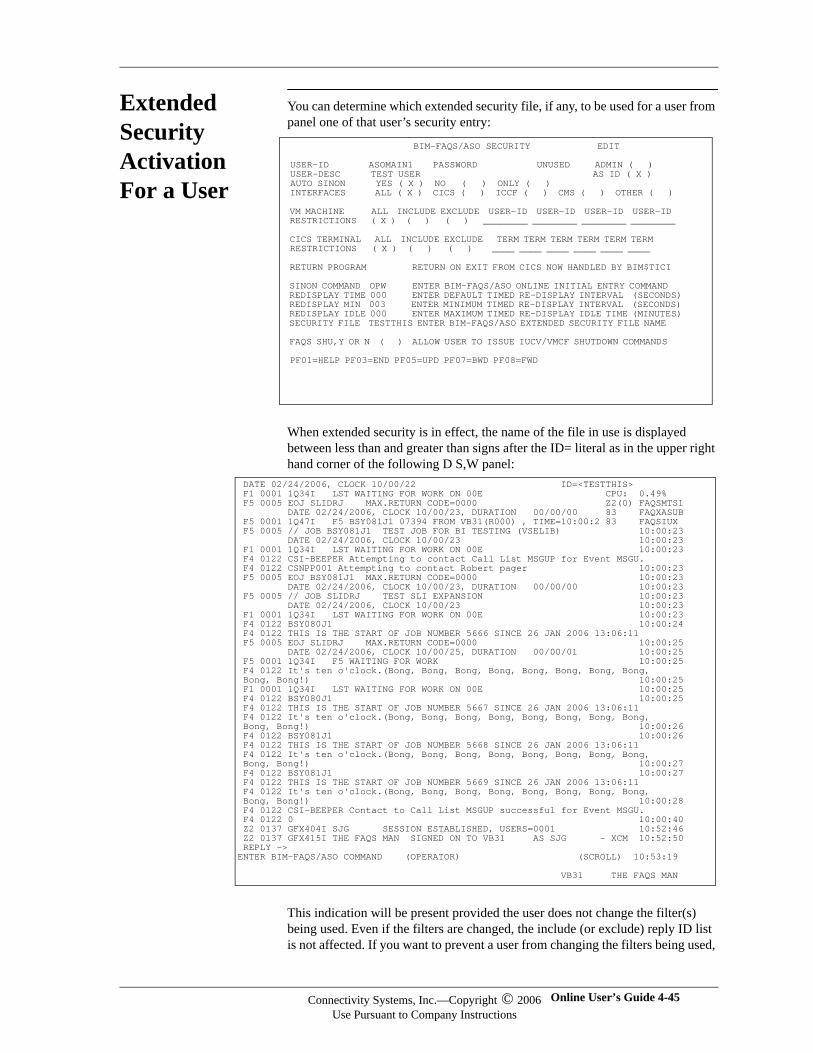
Extended Security Activation For a User
You can determine which extended security file, if any, to be used for a user from panel one of that user’s security entry:
When extended security is in effect, the name of the file in use is displayed between less than and greater than signs after the ID= literal as in the upper right hand corner of the following D S,W panel:
This indication will be present provided the user does not change the filter(s) being used. Even if the filters are changed, the include (or exclude) reply ID list is not affected. If you want to prevent a user from changing the filters being used,
BIM-FAQS/ASO SECURITY EDIT USER-ID ASOMAIN1 PASSWORD UNUSED ADMIN ( ) USER-DESC TEST USER AS ID ( X ) AUTO SINON YES ( X ) NO ( ) ONLY ( ) INTERFACES ALL ( X ) CICS ( ) ICCF ( ) CMS ( ) OTHER ( ) VM MACHINE ALL INCLUDE EXCLUDE USER-ID USER-ID USER-ID USER-ID RESTRICTIONS ( X ) ( ) ( ) ________ ________ ________ ________ CICS TERMINAL ALL INCLUDE EXCLUDE TERM TERM TERM TERM TERM TERM RESTRICTIONS ( X ) ( ) ( ) ____ ____ ____ ____ ____ ____ RETURN PROGRAM RETURN ON EXIT FROM CICS NOW HANDLED BY BIM$TICI SINON COMMAND OPW ENTER BIM-FAQS/ASO ONLINE INITIAL ENTRY COMMAND REDISPLAY TIME 000 ENTER DEFAULT TIMED RE-DISPLAY INTERVAL (SECONDS) REDISPLAY MIN 003 ENTER MINIMUM TIMED RE-DISPLAY INTERVAL (SECONDS) REDISPLAY IDLE 000 ENTER MAXIMUM TIMED RE-DISPLAY IDLE TIME (MINUTES) SECURITY FILE TESTTHIS ENTER BIM-FAQS/ASO EXTENDED SECURITY FILE NAME FAQS SHU,Y OR N ( ) ALLOW USER TO ISSUE IUCV/VMCF SHUTDOWN COMMANDS PF01=HELP PF03=END PF05=UPD PF07=BWD PF08=FWD
DATE 02/24/2006, CLOCK 10/00/22 ID=<TESTTHIS> F1 0001 1Q34I LST WAITING FOR WORK ON 00E CPU: 0.49% F5 0005 EOJ SLIDRJ MAX.RETURN CODE=0000 Z2(0) FAQSMTS1 DATE 02/24/2006, CLOCK 10/00/23, DURATION 00/00/00 83 FAQXASUB F5 0001 1Q47I F5 BSY081J1 07394 FROM VB31(R000) , TIME=10:00:2 83 FAQSIUX F5 0005 // JOB BSY081J1 TEST JOB FOR BI TESTING (VSELIB) 10:00:23 DATE 02/24/2006, CLOCK 10/00/23 10:00:23 F1 0001 1Q34I LST WAITING FOR WORK ON 00E 10:00:23 F4 0122 CSI-BEEPER Attempting to contact Call List MSGUP for Event MSGU. F4 0122 CSNPP001 Attempting to contact Robert pager 10:00:23 F5 0005 EOJ BSY081J1 MAX.RETURN CODE=0000 10:00:23 DATE 02/24/2006, CLOCK 10/00/23, DURATION 00/00/00 10:00:23 F5 0005 // JOB SLIDRJ TEST SLI EXPANSION 10:00:23 DATE 02/24/2006, CLOCK 10/00/23 10:00:23 F1 0001 1Q34I LST WAITING FOR WORK ON 00E 10:00:23 F4 0122 BSY080J1 10:00:24 F4 0122 THIS IS THE START OF JOB NUMBER 5666 SINCE 26 JAN 2006 13:06:11 F5 0005 EOJ SLIDRJ MAX.RETURN CODE=0000 10:00:25 DATE 02/24/2006, CLOCK 10/00/25, DURATION 00/00/01 10:00:25 F5 0001 1Q34I F5 WAITING FOR WORK 10:00:25 F4 0122 It's ten o'clock.(Bong, Bong, Bong, Bong, Bong, Bong, Bong, Bong, Bong, Bong!) 10:00:25 F1 0001 1Q34I LST WAITING FOR WORK ON 00E 10:00:25 F4 0122 BSY080J1 10:00:25 F4 0122 THIS IS THE START OF JOB NUMBER 5667 SINCE 26 JAN 2006 13:06:11 F4 0122 It's ten o'clock.(Bong, Bong, Bong, Bong, Bong, Bong, Bong, Bong, Bong, Bong!) 10:00:26 F4 0122 BSY081J1 10:00:26 F4 0122 THIS IS THE START OF JOB NUMBER 5668 SINCE 26 JAN 2006 13:06:11 F4 0122 It's ten o'clock.(Bong, Bong, Bong, Bong, Bong, Bong, Bong, Bong, Bong, Bong!) 10:00:27 F4 0122 BSY081J1 10:00:27 F4 0122 THIS IS THE START OF JOB NUMBER 5669 SINCE 26 JAN 2006 13:06:11 F4 0122 It's ten o'clock.(Bong, Bong, Bong, Bong, Bong, Bong, Bong, Bong, Bong, Bong!) 10:00:28 F4 0122 CSI-BEEPER Contact to Call List MSGUP successful for Event MSGU. F4 0122 0 10:00:40 Z2 0137 GFX404I SJG SESSION ESTABLISHED, USERS=0001 10:52:46 Z2 0137 GFX415I THE FAQS MAN SIGNED ON TO VB31 AS SJG - XCM 10:52:50 REPLY -> ENTER BIM-FAQS/ASO COMMAND (OPERATOR) (SCROLL) 10:53:19 VB31 THE FAQS MAN
Connectivity Systems, Inc.—Copyright © 2006Use Pursuant to Company Instructions
Online User’s Guide 4-45

Connectivity Systems
remove the X next to ROUTING on the third panel of his/her BIM-FAQS/ASO security (SCTY) entry.
BIM-FAQS/ASO 4-46 Connectivity Systems, Inc.—Copyright © 2006Use Pursuant to Company Instructions
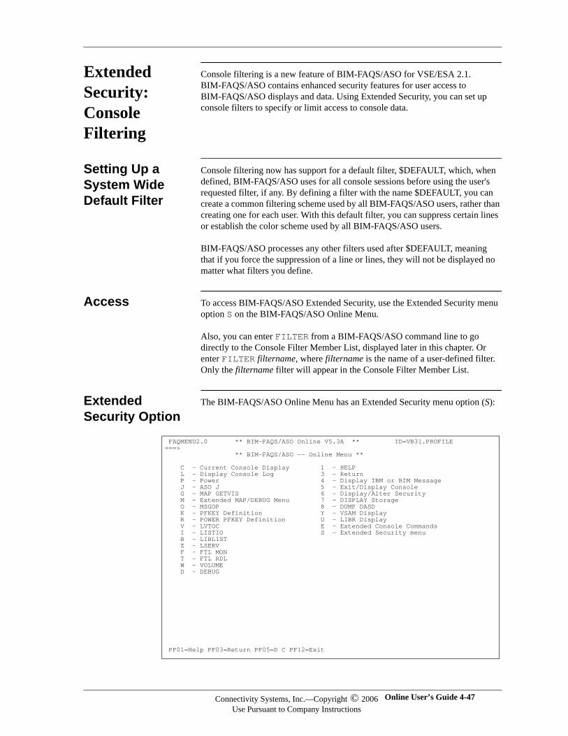
Extended Security: Console Filtering
Console filtering is a new feature of BIM-FAQS/ASO for VSE/ESA 2.1. BIM-FAQS/ASO contains enhanced security features for user access to BIM-FAQS/ASO displays and data. Using Extended Security, you can set up console filters to specify or limit access to console data.
Setting Up a System Wide Default Filter
Console filtering now has support for a default filter, $DEFAULT, which, when defined, BIM-FAQS/ASO uses for all console sessions before using the user's requested filter, if any. By defining a filter with the name $DEFAULT, you can create a common filtering scheme used by all BIM-FAQS/ASO users, rather than creating one for each user. With this default filter, you can suppress certain lines or establish the color scheme used by all BIM-FAQS/ASO users.
BIM-FAQS/ASO processes any other filters used after $DEFAULT, meaning that if you force the suppression of a line or lines, they will not be displayed no matter what filters you define.
Access To access BIM-FAQS/ASO Extended Security, use the Extended Security menu option S on the BIM-FAQS/ASO Online Menu.
Also, you can enter FILTER from a BIM-FAQS/ASO command line to go directly to the Console Filter Member List, displayed later in this chapter. Or enter FILTER filtername, where filtername is the name of a user-defined filter. Only the filtername filter will appear in the Console Filter Member List.
Extended Security Option
The BIM-FAQS/ASO Online Menu has an Extended Security menu option (S):
FAQMENU2.0 ** BIM-FAQS/ASO Online V5.3A ** ID=VB31.PROFILE ===> ** BIM-FAQS/ASO -- Online Menu ** C - Current Console Display 1 - HELP L - Display Console Log 3 - Return P - Power 4 - Display IBM or BIM Message J - ASO J 5 - Exit/Display Console G - MAP GETVIS 6 - Display/Alter Security M - Extended MAP/DEBUG Menu 7 - DISPLAY Storage O - MSGOP 8 - DUMP DASD K - PFKEY Definition Y - VSAM Display R - POWER PFKEY Definition U - LIBR Display V - LVTOC E - Extended Console Commands I - LISTIO S - Extended Security menu B - LIBLIST Z - LSERV F - FTL MON T - FTL RDL W - VOLUME D - DEBUG
PF01=Help PF03=Return PF05=D C PF12=Exit
Connectivity Systems, Inc.—Copyright © 2006Use Pursuant to Company Instructions
Online User’s Guide 4-47
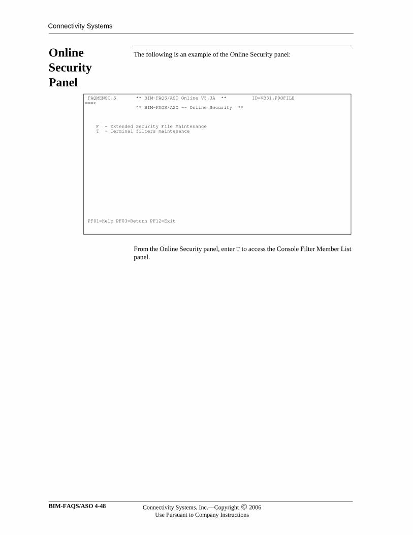
Connectivity Systems
Online Security Panel
The following is an example of the Online Security panel:
From the Online Security panel, enter T to access the Console Filter Member List panel.
FAQMENSC.S ** BIM-FAQS/ASO Online V5.3A ** ID=VB31.PROFILE ===> ** BIM-FAQS/ASO -- Online Security ** F - Extended Security File Maintenance T - Terminal filters maintenance PF01=Help PF03=Return PF12=Exit
BIM-FAQS/ASO 4-48 Connectivity Systems, Inc.—Copyright © 2006Use Pursuant to Company Instructions
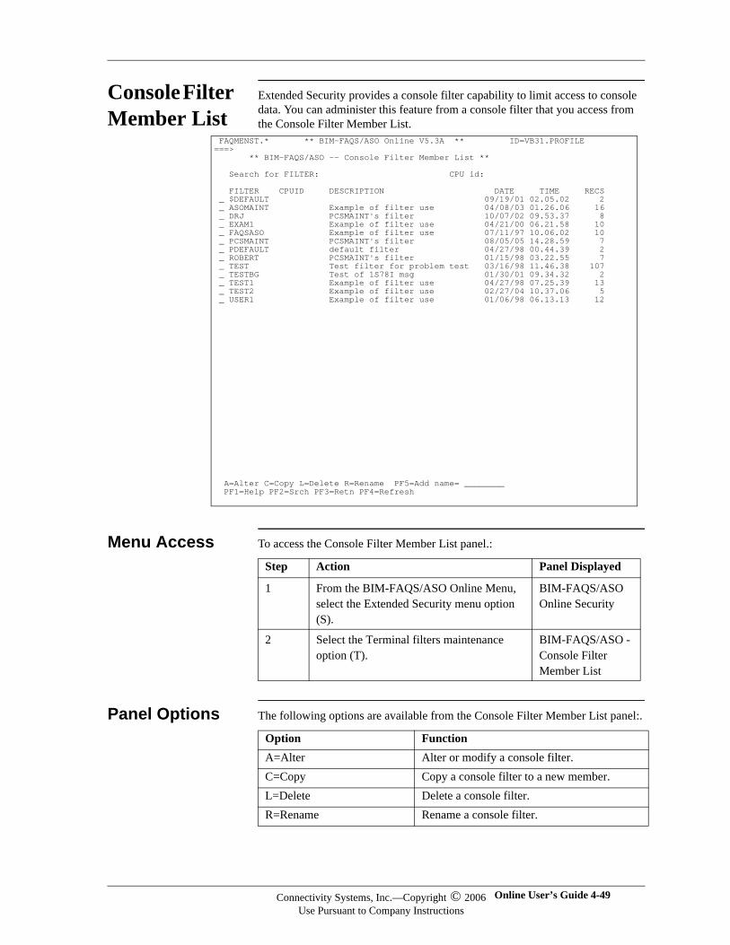
Console Filter Member List
Extended Security provides a console filter capability to limit access to console data. You can administer this feature from a console filter that you access from the Console Filter Member List.
Menu Access To access the Console Filter Member List panel.:
Panel Options The following options are available from the Console Filter Member List panel:.
FAQMENST.* ** BIM-FAQS/ASO Online V5.3A ** ID=VB31.PROFILE ===> ** BIM-FAQS/ASO -- Console Filter Member List ** Search for FILTER: CPU id: FILTER CPUID DESCRIPTION DATE TIME RECS _ $DEFAULT 09/19/01 02.05.02 2 _ ASOMAINT Example of filter use 04/08/03 01.26.06 16 _ DRJ PCSMAINT's filter 10/07/02 09.53.37 8 _ EXAM1 Example of filter use 04/21/00 06.21.58 10 _ FAQSASO Example of filter use 07/11/97 10.06.02 10 _ PCSMAINT PCSMAINT's filter 08/05/05 14.28.59 7 _ PDEFAULT default filter 04/27/98 00.44.39 2 _ ROBERT PCSMAINT's filter 01/15/98 03.22.55 7 _ TEST Test filter for problem test 03/16/98 11.46.38 107 _ TESTBG Test of 1S78I msg 01/30/01 09.34.32 2 _ TEST1 Example of filter use 04/27/98 07.25.39 13 _ TEST2 Example of filter use 02/27/04 10.37.06 5 _ USER1 Example of filter use 01/06/98 06.13.13 12 A=Alter C=Copy L=Delete R=Rename PF5=Add name= ________ PF1=Help PF2=Srch PF3=Retn PF4=Refresh
Step Action Panel Displayed
1 From the BIM-FAQS/ASO Online Menu, select the Extended Security menu option (S).
BIM-FAQS/ASO Online Security
2 Select the Terminal filters maintenance option (T).
BIM-FAQS/ASO - Console Filter Member List
Option FunctionA=Alter Alter or modify a console filter.C=Copy Copy a console filter to a new member.L=Delete Delete a console filter.R=Rename Rename a console filter.
Connectivity Systems, Inc.—Copyright © 2006Use Pursuant to Company Instructions
Online User’s Guide 4-49

Connectivity Systems
PF2=Srch Search for a filter or filters using the filter name or CPU ID as a search key. For more generic searches, use an asterisk (*) as a wildcard character.
PF5= Add name= ____ Add a new console filter to the console filter member list. Type in a 1- to 8-character name and press PF5.
BIM-FAQS/ASO 4-50 Connectivity Systems, Inc.—Copyright © 2006Use Pursuant to Company Instructions
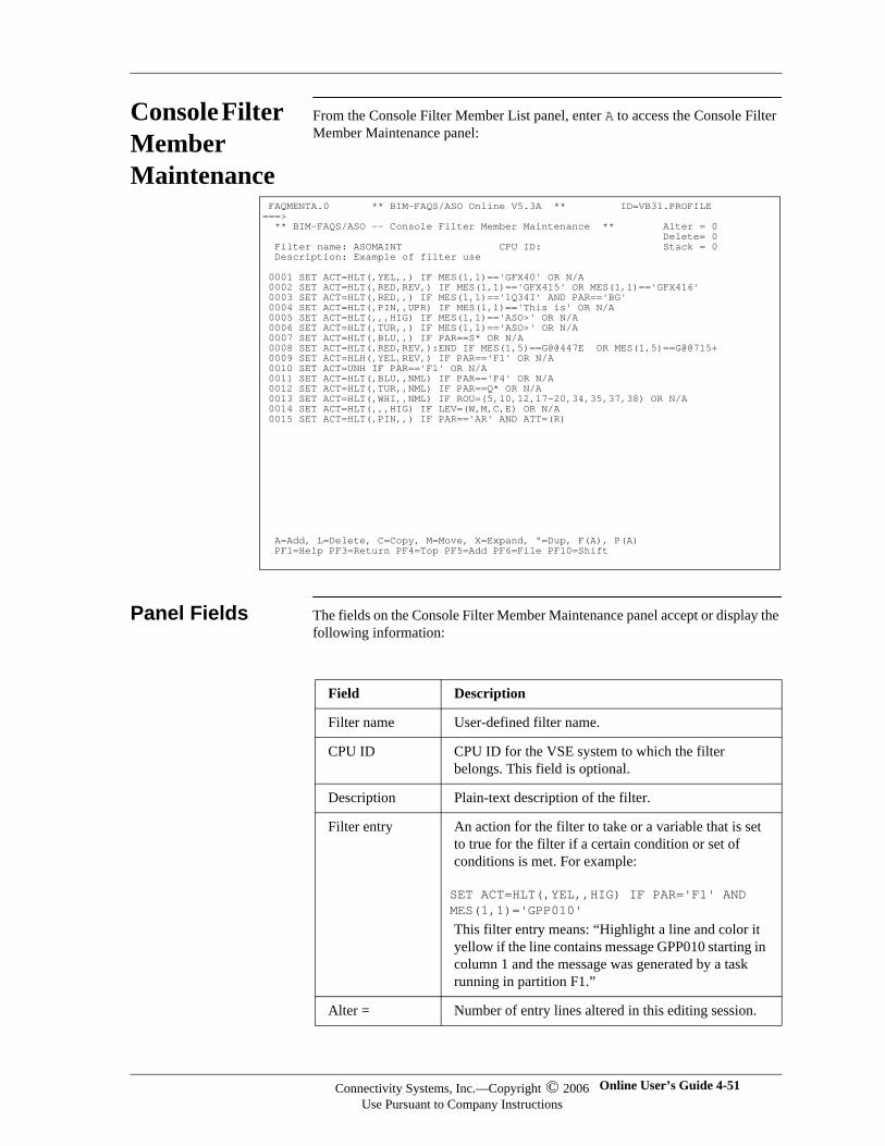
Console Filter Member Maintenance
From the Console Filter Member List panel, enter A to access the Console Filter Member Maintenance panel:
Panel Fields The fields on the Console Filter Member Maintenance panel accept or display the following information:
FAQMENTA.0 ** BIM-FAQS/ASO Online V5.3A ** ID=VB31.PROFILE ===> ** BIM-FAQS/ASO -- Console Filter Member Maintenance ** Alter = 0 Delete= 0 Filter name: ASOMAINT CPU ID: Stack = 0 Description: Example of filter use 0001 SET ACT=HLT(,YEL,,) IF MES(1,1)=='GFX40' OR N/A 0002 SET ACT=HLT(,RED,REV,) IF MES(1,1)=='GFX415' OR MES(1,1)=='GFX416' 0003 SET ACT=HLT(,RED,,) IF MES(1,1)=='1Q34I' AND PAR=='BG' 0004 SET ACT=HLT(,PIN,,UPR) IF MES(1,1)=='This is' OR N/A 0005 SET ACT=HLT(,,,HIG) IF MES(1,1)=='ASO>' OR N/A 0006 SET ACT=HLT(,TUR,,) IF MES(1,1)=='ASO>' OR N/A 0007 SET ACT=HLT(,BLU,,) IF PAR==S* OR N/A 0008 SET ACT=HLT(,RED,REV,):END IF MES(1,5)==G@@447E OR MES(1,5)==G@@715+ 0009 SET ACT=HLH(,YEL,REV,) IF PAR=='F1' OR N/A 0010 SET ACT=UNH IF PAR=='F1' OR N/A 0011 SET ACT=HLT(,BLU,,NML) IF PAR=='F4' OR N/A 0012 SET ACT=HLT(,TUR,,NML) IF PAR==Q* OR N/A 0013 SET ACT=HLT(,WHI,,NML) IF ROU=(5,10,12,17-20,34,35,37,38) OR N/A 0014 SET ACT=HLT(,,,HIG) IF LEV=(W,M,C,E) OR N/A 0015 SET ACT=HLT(,PIN,,) IF PAR=='AR' AND ATT=(R)
A=Add, L=Delete, C=Copy, M=Move, X=Expand, "=Dup, F(A), P(A) PF1=Help PF3=Return PF4=Top PF5=Add PF6=File PF10=Shift
Field Description
Filter name User-defined filter name.
CPU ID CPU ID for the VSE system to which the filter belongs. This field is optional.
Description Plain-text description of the filter.
Filter entry An action for the filter to take or a variable that is set to true for the filter if a certain condition or set of conditions is met. For example:
SET ACT=HLT(,YEL,,HIG) IF PAR='F1' AND MES(1,1)='GPP010'
This filter entry means: “Highlight a line and color it yellow if the line contains message GPP010 starting in column 1 and the message was generated by a task running in partition F1.”
Alter = Number of entry lines altered in this editing session.
Connectivity Systems, Inc.—Copyright © 2006Use Pursuant to Company Instructions
Online User’s Guide 4-51
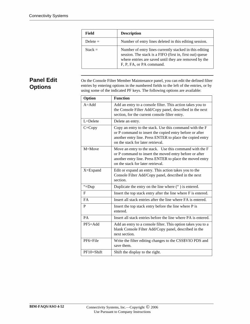
Connectivity Systems
Panel Edit Options
On the Console Filter Member Maintenance panel, you can edit the defined filter entries by entering options in the numbered fields to the left of the entries, or by using some of the indicated PF keys. The following options are available:
Delete = Number of entry lines deleted in this editing session.
Stack = Number of entry lines currently stacked in this editing session. The stack is a FIFO (first in, first out) queue where entries are saved until they are removed by the F, P, FA, or PA command.
Field Description
Option FunctionA=Add Add an entry to a console filter. This action takes you to
the Console Filter Add/Copy panel, described in the next section, for the current console filter entry.
L=Delete Delete an entry.C=Copy Copy an entry to the stack. Use this command with the F
or P command to insert the copied entry before or after another entry line. Press ENTER to place the copied entry on the stack for later retrieval.
M=Move Move an entry to the stack. Use this command with the F or P command to insert the moved entry before or after another entry line. Press ENTER to place the moved entry on the stack for later retrieval.
X=Expand Edit or expand an entry. This action takes you to the Console Filter Add/Copy panel, described in the next section.
“=Dup Duplicate the entry on the line where (“ ) is entered.F Insert the top stack entry after the line where F is entered.FA Insert all stack entries after the line where FA is entered.P Insert the top stack entry before the line where P is
entered.PA Insert all stack entries before the line where PA is entered.PF5=Add Add an entry to a console filter. This option takes you to a
blank Console Filter Add/Copy panel, described in the next section.
PF6=File Write the filter editing changes to the CSS$VIO PDS and save them.
PF10=Shift Shift the display to the right.
BIM-FAQS/ASO 4-52 Connectivity Systems, Inc.—Copyright © 2006Use Pursuant to Company Instructions
Editing Console Filter Members
When you edit a console filter, BIM-FAQS/ASO keeps track of the number of:
Additions during the editing session, in the Alter field
Deletions during the editing session, in the Delete field
Entries in the stack during the editing session, in the Stack field
If you want to save your editing changes, press PF6 (File). This option files your changes in the filter’s PDS member. If you don’t want to save your changes, press PF3 (Return) to quit. You’ll be prompted with the message “Press PF3 key” again to confirm quit. Press PF3 again to exit the console filter without making any changes to it.
Connectivity Systems, Inc.—Copyright © 2006Use Pursuant to Company Instructions
Online User’s Guide 4-53
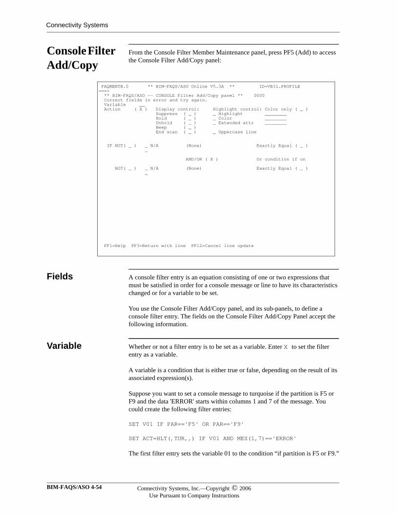
Connectivity Systems
Console Filter Add/Copy
From the Console Filter Member Maintenance panel, press PF5 (Add) to access the Console Filter Add/Copy panel:
Fields A console filter entry is an equation consisting of one or two expressions that must be satisfied in order for a console message or line to have its characteristics changed or for a variable to be set.
You use the Console Filter Add/Copy panel, and its sub-panels, to define a console filter entry. The fields on the Console Filter Add/Copy Panel accept the following information.
Variable Whether or not a filter entry is to be set as a variable. Enter X to set the filter entry as a variable.
A variable is a condition that is either true or false, depending on the result of its associated expression(s).
Suppose you want to set a console message to turquoise if the partition is F5 or F9 and the data 'ERROR' starts within columns 1 and 7 of the message. You could create the following filter entries:
SET V01 IF PAR=='F5' OR PAR=='F9'
SET ACT=HLT(,TUR,,) IF V01 AND MES(1,7)=='ERROR'
The first filter entry sets the variable 01 to the condition “if partition is F5 or F9.”
FAQMENTB.0 ** BIM-FAQS/ASO Online V5.3A ** ID=VB31.PROFILE ===> ** BIM-FAQS/ASO -- CONSOLE Filter Add/Copy panel ** 0000 Correct fields in error and try again. Variable __ Action ( X ) Display control: Highlight control: Color only ( _ ) Suppress ( _ ) _ Highlight ________ Hold ( _ ) _ Color ________ Unhold ( _ ) _ Extended attr ________ Beep ( _ ) End scan ( _ ) _ Uppercase line IF NOT( _ ) _ N/A (None) Exactly Equal ( _ ) _ AND/OR ( X ) Or condition if on NOT( _ ) _ N/A (None) Exactly Equal ( _ ) _
PF1=Help PF3=Return with line PF12=Cancel line update
BIM-FAQS/ASO 4-54 Connectivity Systems, Inc.—Copyright © 2006Use Pursuant to Company Instructions
In the definition of console filters, a variable provides a way to specify more than two decisions before a console message or line is changed. Variables provide complex filtering without complex specifications involving parentheses or other operators that slow down message handling. A variable can be set or reset as often as desired. You can also set multiple variables at the beginning of a filter definition and use them as needed in other filter entries.
Action Action is whether or not a filter entry is to be set as an action. Enter X to set the filter entry as an action.
An action is a change made to the characteristics of a console message or line when one or more expressions is satisfied. An action can change either console display or console highlighting -- or both
Display Control The Display Control are options affecting the display of a line or message on the console. To select a display option, place an X next to it.
Highlight Control
Highlight Control are options affecting how a console line or message is formatted when it’s displayed. To view the settings available for the Highlight, Color, and Extended attr options, place your cursor in the field to the left of the option and press ENTER. Then to select one of the listed settings, place an X next to it and press PF3 (Return).
Option DescriptionSuppress Suppress a message from the console.Hold Hold a message on the console for operator
intervention.Unhold Disable holding a message on the display.
For example, you can unhold whole dynamic classes.
Beep Enable terminal beep signal. End scan Stop filtering for this message once this filter
is encountered and the result is true.
Option DescriptionColor only An X specifies to change the console line only if the
terminal supports color.Highlight Choose one of the following settings:
NormalHigh
Connectivity Systems, Inc.—Copyright © 2006Use Pursuant to Company Instructions
Online User’s Guide 4-55
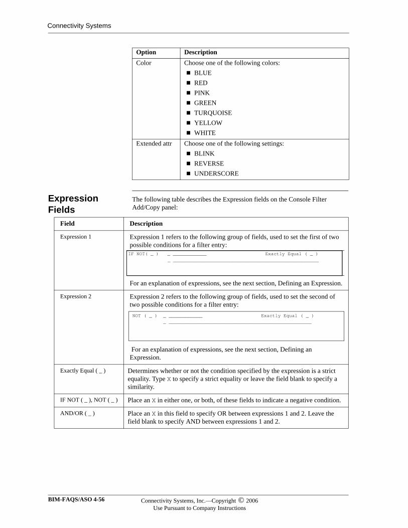
Connectivity Systems
Expression Fields
The following table describes the Expression fields on the Console Filter Add/Copy panel:
Color Choose one of the following colors:BLUE RED PINK GREENTURQUOISEYELLOWWHITE
Extended attr Choose one of the following settings:BLINKREVERSEUNDERSCORE
Option Description
Field Description
Expression 1 Expression 1 refers to the following group of fields, used to set the first of two possible conditions for a filter entry:
For an explanation of expressions, see the next section, Defining an Expression.
Expression 2 Expression 2 refers to the following group of fields, used to set the second of two possible conditions for a filter entry:
For an explanation of expressions, see the next section, Defining an Expression.
Exactly Equal ( _ ) Determines whether or not the condition specified by the expression is a strict equality. Type X to specify a strict equality or leave the field blank to specify a similarity.
IF NOT ( _ ), NOT ( _ ) Place an X in either one, or both, of these fields to indicate a negative condition.
AND/OR ( _ ) Place an X in this field to specify OR between expressions 1 and 2. Leave the field blank to specify AND between expressions 1 and 2.
IF NOT( _ ) _ ____________ Exactly Equal ( _ ) _ ____________________________________________________
NOT ( _ ) _ ____________ Exactly Equal ( _ ) _ ___________________________________________________
BIM-FAQS/ASO 4-56 Connectivity Systems, Inc.—Copyright © 2006Use Pursuant to Company Instructions
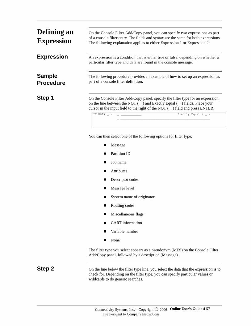
Defining an Expression
On the Console Filter Add/Copy panel, you can specify two expressions as part of a console filter entry. The fields and syntax are the same for both expressions. The following explanation applies to either Expression 1 or Expression 2.
Expression An expression is a condition that is either true or false, depending on whether a particular filter type and data are found in the console message.
Sample Procedure
The following procedure provides an example of how to set up an expression as part of a console filter definition.
Step 1 On the Console Filter Add/Copy panel, specify the filter type for an expression on the line between the NOT ( _ ) and Exactly Equal ( _ ) fields. Place your cursor in the input field to the right of the NOT ( _ ) field and press ENTER.
You can then select one of the following options for filter type:
Message
Partition ID
Job name
Attributes
Descriptor codes
Message level
System name of originator
Routing codes
Miscellaneous flags
CART information
Variable number
None
The filter type you select appears as a pseudonym (MES) on the Console Filter Add/Copy panel, followed by a description (Message).
Step 2 On the line below the filter type line, you select the data that the expression is to check for. Depending on the filter type, you can specify particular values or wildcards to do generic searches.
IF NOT( _ ) _ ____________ Exactly Equal ( _ ) _ ____________________________________________________
Connectivity Systems, Inc.—Copyright © 2006Use Pursuant to Company Instructions
Online User’s Guide 4-57
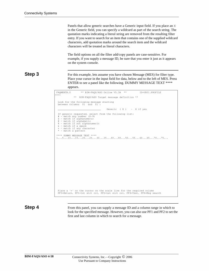
Connectivity Systems
Panels that allow generic searches have a Generic input field. If you place an X in the Generic field, you can specify a wildcard as part of the search string. The quotation marks indicating a literal string are removed from the resulting filter entry. If you want to search for an item that contains one of the supplied wildcard characters, add quotation marks around the search item and the wildcard characters will be treated as literal characters.
The field options on all the filter add/copy panels are case-sensitive. For example, if you supply a message ID, be sure that you enter it just as it appears on the system console.
Step 3 For this example, lets assume you have chosen Message (MES) for filter type. Place your cursor in the input field for data, below and to the left of MES. Press ENTER to see a panel like the following. DUMMY MESSAGE TEXT **** appears.
Step 4 From this panel, you can supply a message ID and a column range in which to look for the specified message. However, you can also use PF1 and PF2 to set the first and last column in which to search for a message.
FAQMENTB.0 ** BIM-FAQS/ASO Online V5.3A ** ID=VB31.PROFILE ===> ** BIM-FAQS/ASO Target message definition ** Look for the following message starting between columns 01 and 01 : ______________________________ Generic ( X ) - X if yes If generic requested, select from the following list: # - match any number (0-9) $ - match if alphanumeric @ - match if alphabetic % - match if not alphanumeric & - match if a space + - match if any character * - match a pattern **** DUMMY MESSAGE TEXT **** 1...5...10...15...20...25...30...35...40...45...50...55...60...65...70...75... Place a '+' or the cursor on the scale line for the required column PF3=Return, PF1=1st strt col, PF2=Lst strt col, PF4=Text, PF6=Msg search
BIM-FAQS/ASO 4-58 Connectivity Systems, Inc.—Copyright © 2006Use Pursuant to Company Instructions
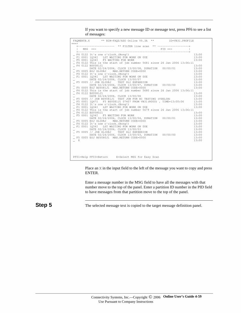
If you want to specify a new message ID or message text, press PF6 to see a list of messages:
Place an X in the input field to the left of the message you want to copy and press ENTER.
Enter a message number in the MSG field to have all the messages with that number move to the top of the panel. Enter a partition ID number in the PID field to have messages from that partition move to the top of the panel.
Step 5 The selected message text is copied to the target message definition panel.
FAQMENTB.6 ** BIM-FAQS/ASO Online V5.3A ** ID=VB31.PROFILE ===> +---------------------- ** FILTER line scan ** -------------------+ | MSG ==> PID ==> | +-------------------------------------------------------------------+ _ F4 0122 It's one o'clock.(Bong!) 13:00 _ F1 0001 1Q34I LST WAITING FOR WORK ON 00E 13:00 _ F5 0001 1Q34I F5 WAITING FOR WORK 13:00 _ F4 0122 This is the start of job number 5681 since 26 Jan 2006 13:06:11 _ F4 0122 BSY081J1 13:00 _ DATE 02/24/2006, CLOCK 13/00/08, DURATION 00/00/01 13:00 _ F5 0005 EOJ SLIDRJ MAX.RETURN CODE=0000 13:00 _ F4 0122 It's one o'clock.(Bong!) 13:00 _ F1 0001 1Q34I LST WAITING FOR WORK ON 00E 13:00 _ DATE 02/24/2006, CLOCK 13/00/07 13:00 _ F5 0005 // JOB SLIDRJ TEST SLI EXPANSION 13:00 _ DATE 02/24/2006, CLOCK 13/00/07, DURATION 00/00/00 13:00 _ F5 0005 EOJ BSY081J1 MAX.RETURN CODE=0000 13:00 _ F4 0122 This is the start of job number 5680 since 26 Jan 2006 13:06:11 _ F4 0122 BSY081J1 13:00 _ DATE 02/24/2006, CLOCK 13/00/06 13:00 _ F5 0005 // JOB BSY081J1 TEST JOB FOR BI TESTING (VSELIB) 13:00 _ F5 0001 1Q47I F5 BSY081J1 07407 FROM VB31(R000) , TIME=13:00:06 13:00 _ F4 0122 It's one o'clock.(Bong!) 13:00 _ F1 0001 1Q34I LST WAITING FOR WORK ON 00E 13:00 _ F4 0122 This is the start of job number 5679 since 26 Jan 2006 13:06:11 _ F4 0122 BSY080J1 13:00 _ F5 0001 1Q34I F5 WAITING FOR WORK 13:00 _ DATE 02/24/2006, CLOCK 13/00/04, DURATION 00/00/01 13:00 _ F5 0005 EOJ SLIDRJ MAX.RETURN CODE=0000 13:00 _ F4 0122 It's one o'clock.(Bong!) 13:00 _ F1 0001 1Q34I LST WAITING FOR WORK ON 00E 13:00 _ DATE 02/24/2006, CLOCK 13/00/03 13:00 _ F5 0005 // JOB SLIDRJ TEST SLI EXPANSION 13:00 _ DATE 02/24/2006, CLOCK 13/00/03, DURATION 00/00/00 13:00 _ F5 0005 EOJ BSY080J1 MAX.RETURN CODE=0000 13:00 _ X 13:00 PF01=Help PF03=Return X=Select MSG for Easy Scan
Connectivity Systems, Inc.—Copyright © 2006Use Pursuant to Company Instructions
Online User’s Guide 4-59
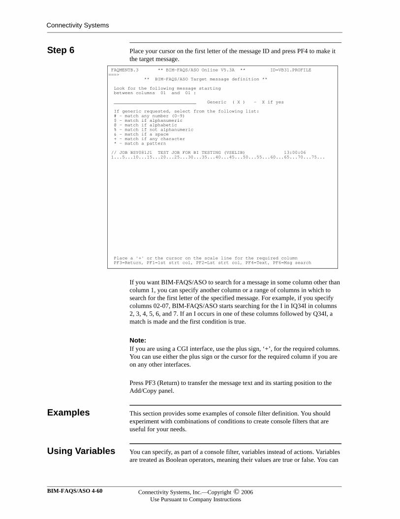
Connectivity Systems
Step 6 Place your cursor on the first letter of the message ID and press PF4 to make it the target message.
If you want BIM-FAQS/ASO to search for a message in some column other than column 1, you can specify another column or a range of columns in which to search for the first letter of the specified message. For example, if you specify columns 02-07, BIM-FAQS/ASO starts searching for the I in IQ34I in columns 2, 3, 4, 5, 6, and 7. If an I occurs in one of these columns followed by Q34I, a match is made and the first condition is true.
Note:Note:If you are using a CGI interface, use the plus sign, ‘+’, for the required columns. You can use either the plus sign or the cursor for the required column if you are on any other interfaces.
Press PF3 (Return) to transfer the message text and its starting position to the Add/Copy panel.
Examples This section provides some examples of console filter definition. You should experiment with combinations of conditions to create console filters that are useful for your needs.
Using Variables You can specify, as part of a console filter, variables instead of actions. Variables are treated as Boolean operators, meaning their values are true or false. You can
FAQMENTB.3 ** BIM-FAQS/ASO Online V5.3A ** ID=VB31.PROFILE ===> ** BIM-FAQS/ASO Target message definition ** Look for the following message starting between columns 01 and 01 : ______________________________ Generic ( X ) - X if yes If generic requested, select from the following list: # - match any number (0-9) $ - match if alphanumeric @ - match if alphabetic % - match if not alphanumeric & - match if a space + - match if any character * - match a pattern // JOB BSY081J1 TEST JOB FOR BI TESTING (VSELIB) 13:00:06 1...5...10...15...20...25...30...35...40...45...50...55...60...65...70...75... Place a '+' or the cursor on the scale line for the required column PF3=Return, PF1=1st strt col, PF2=Lst strt col, PF4=Text, PF6=Msg search
BIM-FAQS/ASO 4-60 Connectivity Systems, Inc.—Copyright © 2006Use Pursuant to Company Instructions
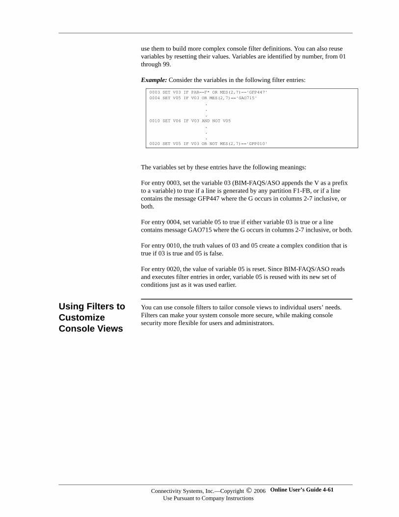
use them to build more complex console filter definitions. You can also reuse variables by resetting their values. Variables are identified by number, from 01 through 99.
Example: Consider the variables in the following filter entries:
The variables set by these entries have the following meanings:
For entry 0003, set the variable 03 (BIM-FAQS/ASO appends the V as a prefix to a variable) to true if a line is generated by any partition F1-FB, or if a line contains the message GFP447 where the G occurs in columns 2-7 inclusive, or both.
For entry 0004, set variable 05 to true if either variable 03 is true or a line contains message GAO715 where the G occurs in columns 2-7 inclusive, or both.
For entry 0010, the truth values of 03 and 05 create a complex condition that is true if 03 is true and 05 is false.
For entry 0020, the value of variable 05 is reset. Since BIM-FAQS/ASO reads and executes filter entries in order, variable 05 is reused with its new set of conditions just as it was used earlier.
Using Filters to Customize Console Views
You can use console filters to tailor console views to individual users’ needs. Filters can make your system console more secure, while making console security more flexible for users and administrators.
0003 SET V03 IF PAR==F* OR MES(2,7)=='GFP447' 0004 SET V05 IF V03 OR MES(2,7)=='GAO715' . . . 0010 SET V06 IF V03 AND NOT V05 . . . 0020 SET V05 IF V03 OR NOT MES(2,7)=='GPP010'
Connectivity Systems, Inc.—Copyright © 2006Use Pursuant to Company Instructions
Online User’s Guide 4-61
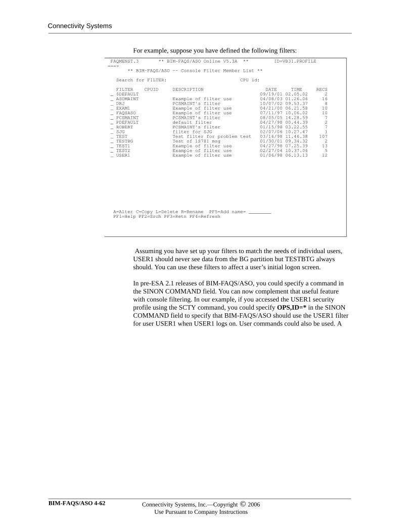
Connectivity Systems
For example, suppose you have defined the following filters:
Assuming you have set up your filters to match the needs of individual users, USER1 should never see data from the BG partition but TESTBTG always should. You can use these filters to affect a user’s initial logon screen.
In pre-ESA 2.1 releases of BIM-FAQS/ASO, you could specify a command in the SINON COMMAND field. You can now complement that useful feature with console filtering. In our example, if you accessed the USER1 security profile using the SCTY command, you could specify OPS,ID=* in the SINON COMMAND field to specify that BIM-FAQS/ASO should use the USER1 filter for user USER1 when USER1 logs on. User commands could also be used. A
FAQMENST.3 ** BIM-FAQS/ASO Online V5.3A ** ID=VB31.PROFILE ===> ** BIM-FAQS/ASO -- Console Filter Member List ** Search for FILTER: CPU id: FILTER CPUID DESCRIPTION DATE TIME RECS _ $DEFAULT 09/19/01 02.05.02 2 _ ASOMAINT Example of filter use 04/08/03 01.26.06 16 _ DRJ PCSMAINT's filter 10/07/02 09.53.37 8 _ EXAM1 Example of filter use 04/21/00 06.21.58 10 _ FAQSASO Example of filter use 07/11/97 10.06.02 10 _ PCSMAINT PCSMAINT's filter 08/05/05 14.28.59 7 _ PDEFAULT default filter 04/27/98 00.44.39 2 _ ROBERT PCSMAINT's filter 01/15/98 03.22.55 7 _ SJG filter for SJG 02/07/06 10.27.47 1 _ TEST Test filter for problem test 03/16/98 11.46.38 107 _ TESTBG Test of 1S78I msg 01/30/01 09.34.32 2 _ TEST1 Example of filter use 04/27/98 07.25.39 13 _ TEST2 Example of filter use 02/27/04 10.37.06 5 _ USER1 Example of filter use 01/06/98 06.13.13 12
A=Alter C=Copy L=Delete R=Rename PF5=Add name= ________ PF1=Help PF2=Srch PF3=Retn PF4=Refresh
BIM-FAQS/ASO 4-62 Connectivity Systems, Inc.—Copyright © 2006Use Pursuant to Company Instructions
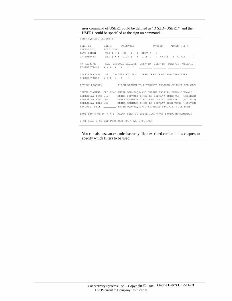
user command of USER1 could be defined as ‘D S,ID=USER1”, and then USER1 could be specified as the sign on command.
You can also use an extended security file, described earlier in this chapter, to specify which filters to be used.
BIM-FAQS/ASO SECURITY USER-ID USER1 PASSWORD UNUSED ADMIN ( X ) USER-DESC TEST DESC AUTO SINON YES ( X ) NO ( ) ONLY ( ) INTERFACES ALL ( X ) CICS ( ) ICCF ( ) CMS ( ) OTHER ( ) VM MACHINE ALL INCLUDE EXCLUDE USER-ID USER-ID USER-ID USER-ID RESTRICTIONS ( X ) ( ) ( ) ________ ________ ________ ________ CICS TERMINAL ALL INCLUDE EXCLUDE TERM TERM TERM TERM TERM TERM RESTRICTIONS ( X ) ( ) ( ) ____ ____ ____ ____ ____ ____ RETURN PROGRAM ________ ALLOW RETURN TO ALTERNATE PROGRAM ON EXIT FOR CICS SINON COMMAND OPS,ID=* ENTER BIM-FAQS/ASO ONLINE INITIAL ENTRY COMMAND REDISPLAY TIME 010 ENTER DEFAULT TIMED RE-DISPLAY INTERVAL (SECONDS) REDISPLAY MIN 005 ENTER MINIMUM TIMED RE-DISPLAY INTERVAL (SECONDS) REDISPLAY IDLE 000 ENTER MAXIMUM TIMED RE-DISPLAY IDLE TIME (MINUTES) SECURITY FILE ________ ENTER BIM-FAQS/ASO EXTENDED SECURITY FILE NAME FAQS SHU,Y OR N ( X ) ALLOW USER TO ISSUE IUCV/VMCF SHUTDOWN COMMANDS PF01=HELP PF03=END PF05=UPD PF07=BWD PF08=FWD
Connectivity Systems, Inc.—Copyright © 2006Use Pursuant to Company Instructions
Online User’s Guide 4-63

Connectivity Systems
BIM-FAQS/ASO 4-64 Connectivity Systems, Inc.—Copyright © 2006Use Pursuant to Company Instructions
Chapter 5
Using the Menu System
In This Chapter
This chapter explains how to navigate through the BIM-FAQS/ASO menu system.
Basic Concepts
Overview You can access BIM-FAQS/ASO functions and features by entering commands from the BIM-FAQS/ASO command line. However, if you are unfamiliar with BIM-FAQS/ASO commands, you can also access most BIM-FAQS/ASO functions and features using a menu system.
Menu Entries Most of the menu entries have corresponding commands which access the same function or feature.
For information about BIM-FAQS/ASO commands, see Chapter 7, “Online Displays and Reports.” Listings of menu entries and corresponding commands are provided later in this chapter.
Using the MENU Command
The MENU command accesses the online menu panels. Enter MENU from the BIM-FAQS/ASO command line to access the BIM-FAQS/ASO Main Menu. From this menu you can access:
BIM-FAQS/ASO Online. Select the FAQS option to access the BIM-FAQS/ASO Online Menu.
Automated systems operations panels. See Chapter 4, “Security and User Configuration,” for information about authorizing users to access this feature.
Online User’s Guide 5-1
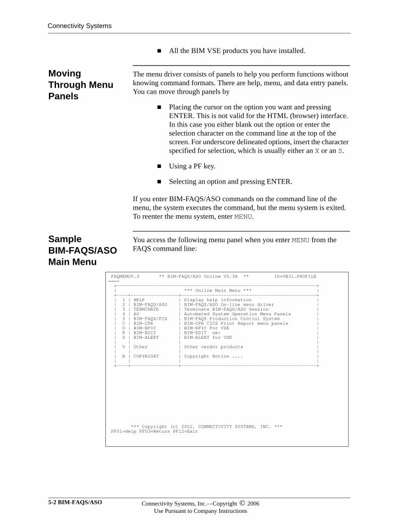
Connectivity Systems
All the BIM VSE products you have installed.
Moving Through Menu Panels
The menu driver consists of panels to help you perform functions without knowing command formats. There are help, menu, and data entry panels. You can move through panels by
Placing the cursor on the option you want and pressing ENTER. This is not valid for the HTML (browser) interface. In this case you either blank out the option or enter the selection character on the command line at the top of the screen. For underscore delineated options, insert the character specified for selection, which is usually either an X or an S.
Using a PF key.
Selecting an option and pressing ENTER.
If you enter BIM-FAQS/ASO commands on the command line of the menu, the system executes the command, but the menu system is exited. To reenter the menu system, enter MENU.
Sample BIM-FAQS/ASO Main Menu
You access the following menu panel when you enter MENU from the FAQS command line:
FAQMENU0.3 ** BIM-FAQS/ASO Online V5.3A ** ID=VB31.PROFILE ===> +-----------------------------------------------------------------------+ | *** Online Main Menu *** | +----+-----------------+------------------------------------------------+ | 1 | HELP | Display help information | | 2 | BIM-FAQS/ASO | BIM-FAQS/ASO On-line menu driver | | 3 | TERMINATE | Terminate BIM-FAQS/ASO Session | | 4 | AO | Automated System Operation Menu Panels | | 5 | BIM-FAQS/PCS | BIM-FAQS Production Control System | | C | BIM-CPR | BIM-CPR CICS Print Report menu panels | | O | BIM-EPIC | BIM-EPIC For VSE | | R | BIM-EDIT | BIM-EDIT nm: | | S | BIM-ALERT | BIM-ALERT for VSE | | | | | | V | Other | Other vendor products | | | | | | N | COPYRIGHT | Copyright Notice .... | | | | | +----+-----------------+------------------------------------------------+
*** Copyright (c) 2002, CONNECTIVITY SYSTEMS, INC. *** PF01=Help PF03=Return PF12=Exit
5-2 BIM-FAQS/ASO Connectivity Systems, Inc.—Copyright © 2006Use Pursuant to Company Instructions
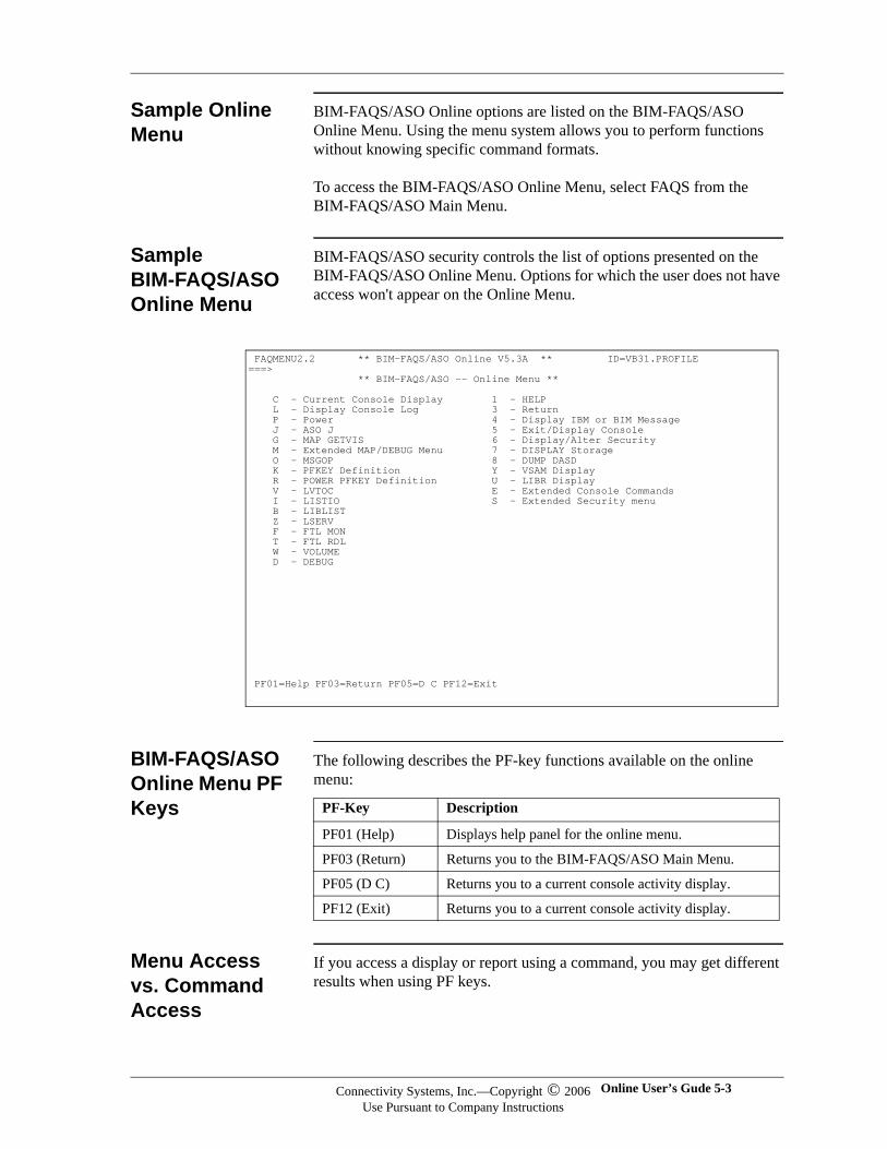
Sample Online Menu
BIM-FAQS/ASO Online options are listed on the BIM-FAQS/ASO Online Menu. Using the menu system allows you to perform functions without knowing specific command formats.
To access the BIM-FAQS/ASO Online Menu, select FAQS from the BIM-FAQS/ASO Main Menu.
Sample BIM-FAQS/ASO Online Menu
BIM-FAQS/ASO security controls the list of options presented on the BIM-FAQS/ASO Online Menu. Options for which the user does not have access won't appear on the Online Menu.
BIM-FAQS/ASO Online Menu PF Keys
The following describes the PF-key functions available on the online menu:
Menu Access vs. Command Access
If you access a display or report using a command, you may get different results when using PF keys.
FAQMENU2.2 ** BIM-FAQS/ASO Online V5.3A ** ID=VB31.PROFILE ===> ** BIM-FAQS/ASO -- Online Menu ** C - Current Console Display 1 - HELP L - Display Console Log 3 - Return P - Power 4 - Display IBM or BIM Message J - ASO J 5 - Exit/Display Console G - MAP GETVIS 6 - Display/Alter Security M - Extended MAP/DEBUG Menu 7 - DISPLAY Storage O - MSGOP 8 - DUMP DASD K - PFKEY Definition Y - VSAM Display R - POWER PFKEY Definition U - LIBR Display V - LVTOC E - Extended Console Commands I - LISTIO S - Extended Security menu B - LIBLIST Z - LSERV F - FTL MON T - FTL RDL W - VOLUME D - DEBUG
PF01=Help PF03=Return PF05=D C PF12=Exit
PF-Key Description
PF01 (Help) Displays help panel for the online menu.
PF03 (Return) Returns you to the BIM-FAQS/ASO Main Menu.
PF05 (D C) Returns you to a current console activity display.
PF12 (Exit) Returns you to a current console activity display.
Connectivity Systems, Inc.—Copyright © 2006Use Pursuant to Company Instructions
Online User’s Gude 5-3
Connectivity Systems
Be aware that GETVIS fragmentation occurs when you move out of the menu system using a command and then back again.
Accessing Product Features
You can use the BIM-FAQS/ASO Online Main Menu to access all the BIM-FAQS/ASO product features.
Selecting Menu Options
To select a menu option, do one of the following:
Place the cursor on the option you want and press ENTER. This is not valid for the HTML (browser) interface. In this case you either blank out the option or enter the selection character on the command line at the top of the screen. For underscore delineated options, insert the character specified for selection, which is usually either an X or an S.
Enter the selection number or letter on the command line and press ENTER.
Press the PF-key that corresponds to a menu item.
Enter any BIM-FAQS/ASO command on the command line (===>).
Menu Options The following table explains the menu options, the commands these options correspond to, and the panels displayed:
Option Name Display
C Current Console Display Current console display menu
L Display Console Log Console log display menu
P Power POWER display menu
J ASO J Job Overview report
G MAP GETVIS Static Partition GETVIS MAP Display
M Extended MAP/DEBUG Menu or MAP
Online MAP/DEBUG Menu or Default Partition Allocation Display
O MSGOP Operator message panel
K PFKEY Definition PFKEY Display/Alter
R POWER PFKEY Definition POWER PFKEY Display/Alter
V LVTOC LVTOC Menu Display
I LISTIO LISTIO display menu
B LIBLIST LIBLIST display menu
Z LSERV LSERV display menu
5-4 BIM-FAQS/ASO Connectivity Systems, Inc.—Copyright © 2006Use Pursuant to Company Instructions
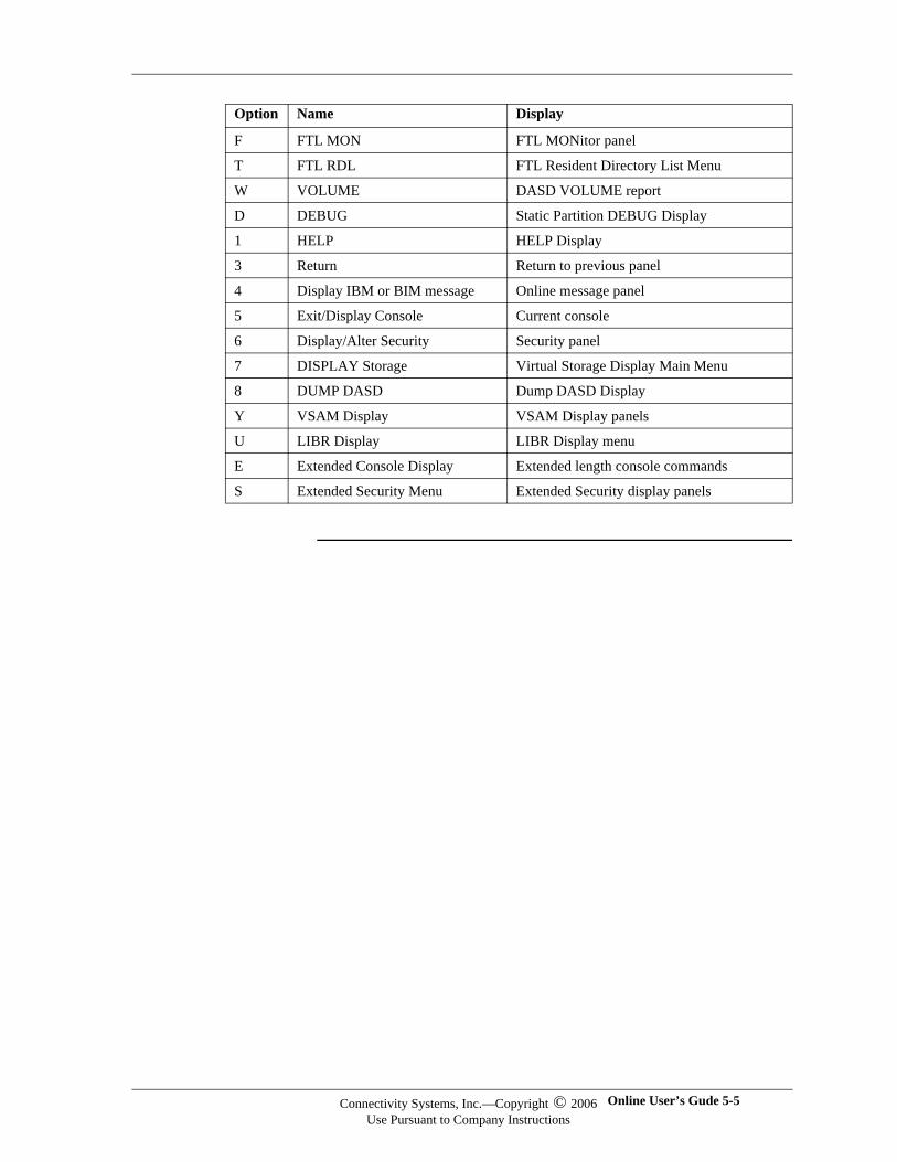
F FTL MON FTL MONitor panel
T FTL RDL FTL Resident Directory List Menu
W VOLUME DASD VOLUME report
D DEBUG Static Partition DEBUG Display
1 HELP HELP Display
3 Return Return to previous panel
4 Display IBM or BIM message Online message panel
5 Exit/Display Console Current console
6 Display/Alter Security Security panel
7 DISPLAY Storage Virtual Storage Display Main Menu
8 DUMP DASD Dump DASD Display
Y VSAM Display VSAM Display panels
U LIBR Display LIBR Display menu
E Extended Console Display Extended length console commands
S Extended Security Menu Extended Security display panels
Option Name Display
Connectivity Systems, Inc.—Copyright © 2006Use Pursuant to Company Instructions
Online User’s Gude 5-5
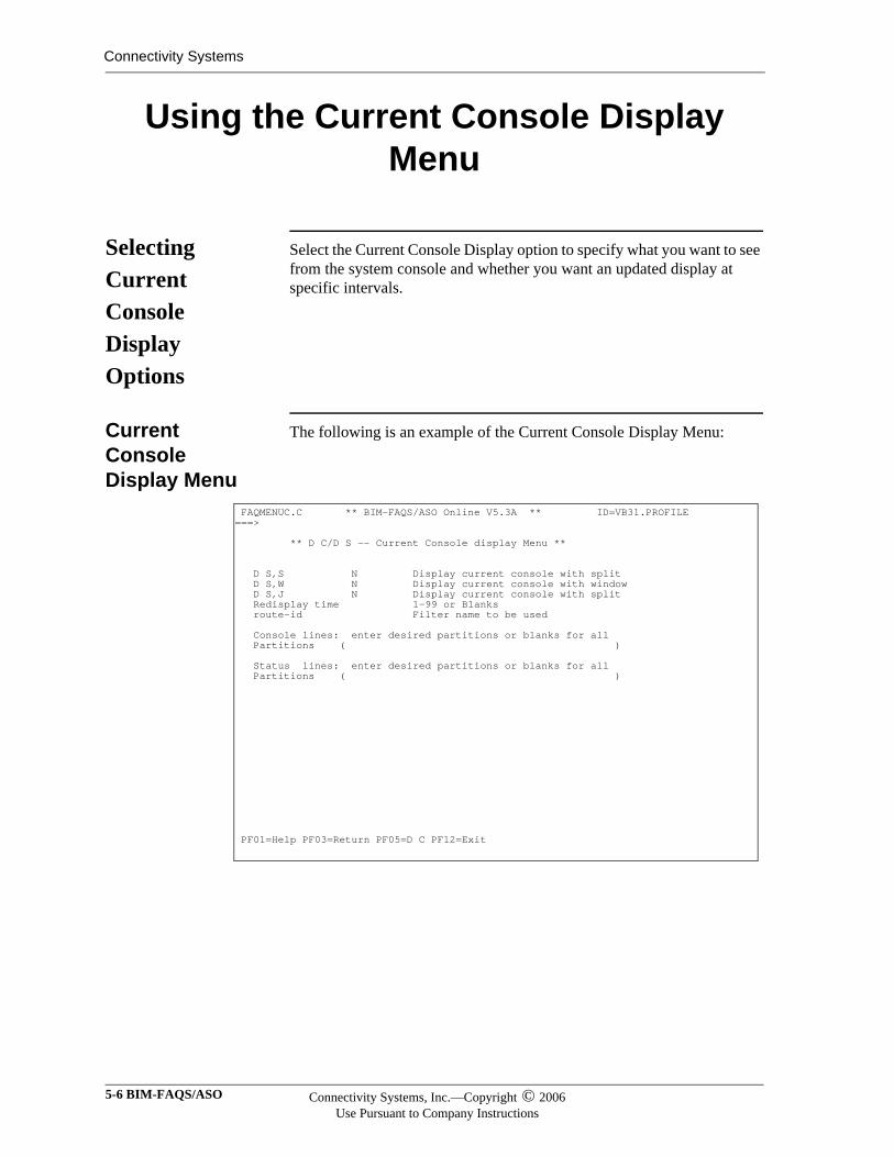
Connectivity Systems
Using the Current Console Display Menu
Selecting Current Console Display Options
Select the Current Console Display option to specify what you want to see from the system console and whether you want an updated display at specific intervals.
Current Console Display Menu
The following is an example of the Current Console Display Menu:
FAQMENUC.C ** BIM-FAQS/ASO Online V5.3A ** ID=VB31.PROFILE ===> ** D C/D S -- Current Console display Menu ** D S,S N Display current console with split D S,W N Display current console with window D S,J N Display current console with split Redisplay time 1-99 or Blanks route-id Filter name to be used Console lines: enter desired partitions or blanks for all Partitions ( ) Status lines: enter desired partitions or blanks for all Partitions ( )
PF01=Help PF03=Return PF05=D C PF12=Exit
5-6 BIM-FAQS/ASO Connectivity Systems, Inc.—Copyright © 2006Use Pursuant to Company Instructions
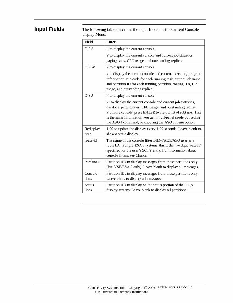
Input Fields The following table describes the input fields for the Current Console display Menu:
Field Enter
D S,S N to display the current console.
Y to display the current console and current job statistics, paging rates, CPU usage, and outstanding replies.
D S,W N to display the current console.
Y to display the current console and current executing program information, run code for each running task, current job name and partition ID for each running partition, routing IDs, CPU usage, and outstanding replies.
D S,J N to display the current console.
Y to display the current console and current job statistics, duration, paging rates, CPU usage, and outstanding replies. From the console, press ENTER to view a list of subtasks. This is the same information you get in full-panel mode by issuing the ASO J command, or choosing the ASO J menu option.
Redisplay time
1-99 to update the display every 1-99 seconds. Leave blank to show a static display.
route-id The name of the console filter BIM-FAQS/ASO uses as a route ID. For pre-ESA 2 systems, this is the two digit route ID specified for the user’s SCTY entry. For information about console filters, see Chapter 4.
Partitions Partition IDs to display messages from those partitions only (Pre-VSE/ESA 2 only). Leave blank to display all messages.
Console lines
Partition IDs to display messages from those partitions only. Leave blank to display all messages
Status lines
Partition IDs to display on the status portion of the D S,x display screens. Leave blank to display all partitions.
Connectivity Systems, Inc.—Copyright © 2006Use Pursuant to Company Instructions
Online User’s Gude 5-7
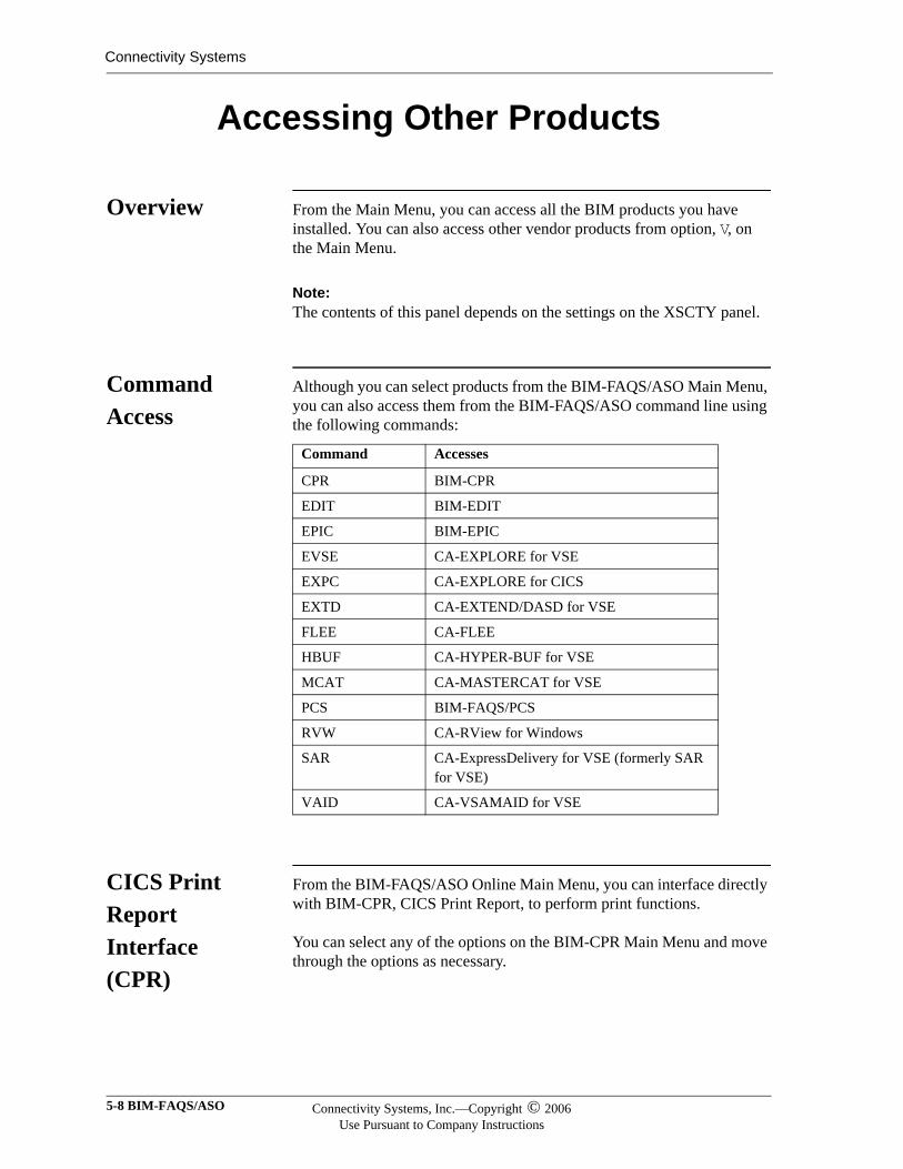
Connectivity Systems
Accessing Other Products
Overview From the Main Menu, you can access all the BIM products you have installed. You can also access other vendor products from option, V, on the Main Menu.
Note:Note:The contents of this panel depends on the settings on the XSCTY panel.
Command Access
Although you can select products from the BIM-FAQS/ASO Main Menu, you can also access them from the BIM-FAQS/ASO command line using the following commands:
CICS Print Report Interface (CPR)
From the BIM-FAQS/ASO Online Main Menu, you can interface directly with BIM-CPR, CICS Print Report, to perform print functions.
You can select any of the options on the BIM-CPR Main Menu and move through the options as necessary.
Command Accesses
CPR BIM-CPR
EDIT BIM-EDIT
EPIC BIM-EPIC
EVSE CA-EXPLORE for VSE
EXPC CA-EXPLORE for CICS
EXTD CA-EXTEND/DASD for VSE
FLEE CA-FLEE
HBUF CA-HYPER-BUF for VSE
MCAT CA-MASTERCAT for VSE
PCS BIM-FAQS/PCS
RVW CA-RView for Windows
SAR CA-ExpressDelivery for VSE (formerly SAR for VSE)
VAID CA-VSAMAID for VSE
5-8 BIM-FAQS/ASO Connectivity Systems, Inc.—Copyright © 2006Use Pursuant to Company Instructions
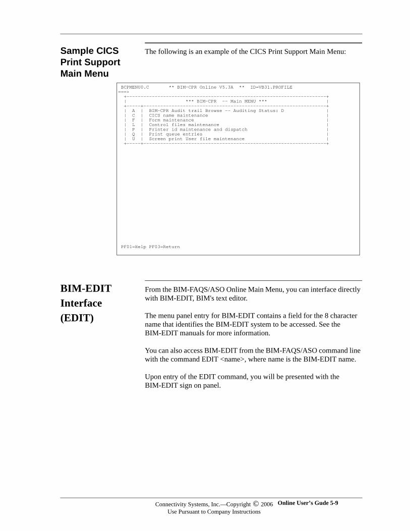
Sample CICS Print Support Main Menu
The following is an example of the CICS Print Support Main Menu:
BIM-EDIT Interface (EDIT)
From the BIM-FAQS/ASO Online Main Menu, you can interface directly with BIM-EDIT, BIM's text editor.
The menu panel entry for BIM-EDIT contains a field for the 8 character name that identifies the BIM-EDIT system to be accessed. See the BIM-EDIT manuals for more information.
You can also access BIM-EDIT from the BIM-FAQS/ASO command line with the command EDIT <name>, where name is the BIM-EDIT name.
Upon entry of the EDIT command, you will be presented with the BIM-EDIT sign on panel.
BCPMENU0.C ** BIM-CPR Online V5.3A ** ID=VB31.PROFILE ===> +-----------------------------------------------------------------------+ | *** BIM-CPR -- Main MENU *** | +-----+-----------------------------------------------------------------+ | A | BIM-CPR Audit trail Browse -- Auditing Status: D | | C | CICS name maintenance | | F | Form maintenance | | L | Control files maintenance | | P | Printer id maintenance and dispatch | | Q | Print queue entries | | U | Screen print User file maintenance | +-----+-----------------------------------------------------------------+
PF01=Help PF03=Return
Connectivity Systems, Inc.—Copyright © 2006Use Pursuant to Company Instructions
Online User’s Gude 5-9
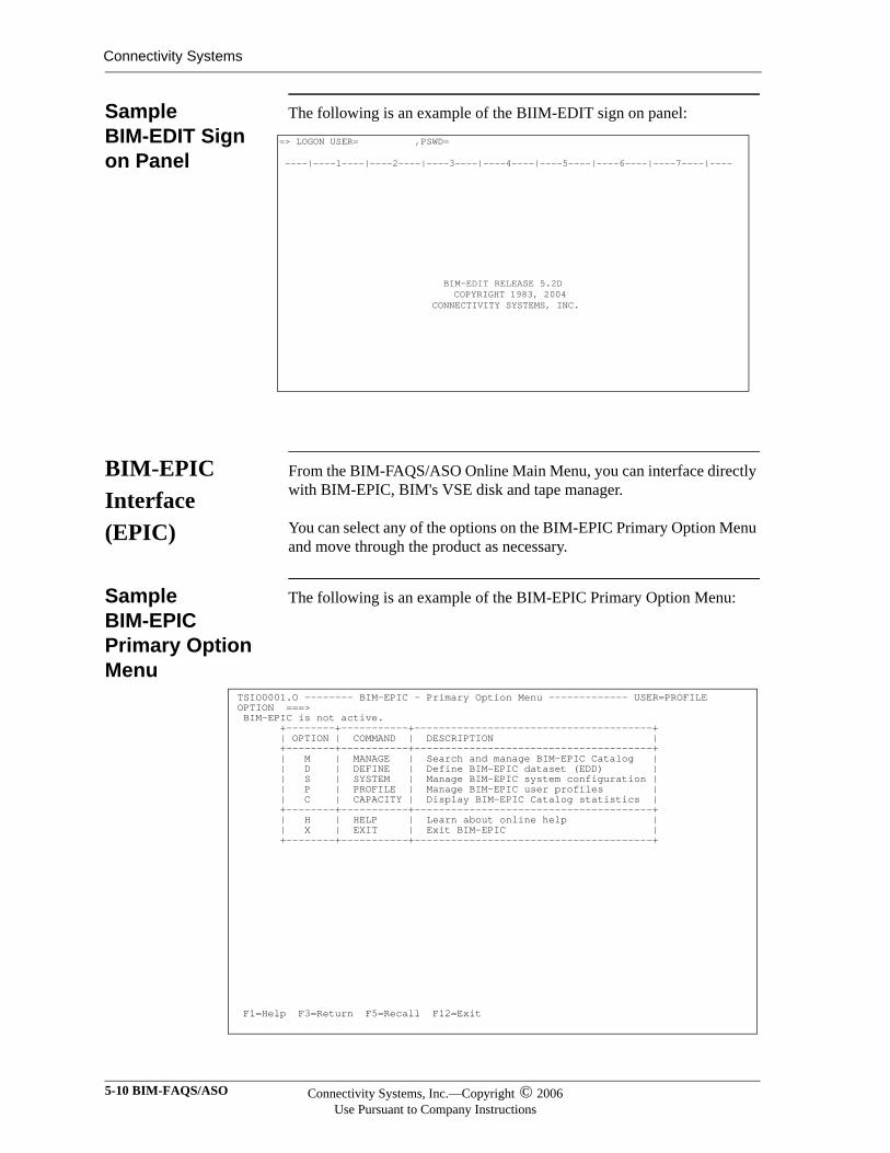
Connectivity Systems
Sample BIM-EDIT Sign on Panel
The following is an example of the BIIM-EDIT sign on panel:
BIM-EPIC Interface (EPIC)
From the BIM-FAQS/ASO Online Main Menu, you can interface directly with BIM-EPIC, BIM's VSE disk and tape manager.
You can select any of the options on the BIM-EPIC Primary Option Menu and move through the product as necessary.
Sample BIM-EPIC Primary Option Menu
The following is an example of the BIM-EPIC Primary Option Menu:
=> LOGON USER= ,PSWD= ----|----1----|----2----|----3----|----4----|----5----|----6----|----7----|---- BIM-EDIT RELEASE 5.2D COPYRIGHT 1983, 2004 CONNECTIVITY SYSTEMS, INC.
TSIO0001.O -------- BIM-EPIC - Primary Option Menu ------------- USER=PROFILE OPTION ===> BIM-EPIC is not active. +--------+-----------+---------------------------------------+ | OPTION | COMMAND | DESCRIPTION | +--------+-----------+---------------------------------------+ | M | MANAGE | Search and manage BIM-EPIC Catalog | | D | DEFINE | Define BIM-EPIC dataset (EDD) | | S | SYSTEM | Manage BIM-EPIC system configuration | | P | PROFILE | Manage BIM-EPIC user profiles | | C | CAPACITY | Display BIM-EPIC Catalog statistics | +--------+-----------+---------------------------------------+ | H | HELP | Learn about online help | | X | EXIT | Exit BIM-EPIC | +--------+-----------+---------------------------------------+
F1=Help F3=Return F5=Recall F12=Exit
5-10 BIM-FAQS/ASO Connectivity Systems, Inc.—Copyright © 2006Use Pursuant to Company Instructions
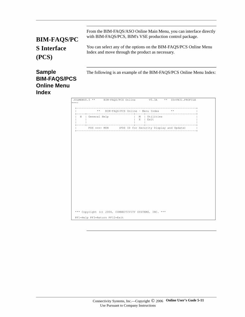
BIM-FAQS/PCS Interface (PCS)
From the BIM-FAQS/ASO Online Main Menu, you can interface directly with BIM-FAQS/PCS, BIM's VSE production control package.
You can select any of the options on the BIM-FAQS/PCS Online Menu Index and move through the product as necessary.
Sample BIM-FAQS/PCS Online Menu Index
The following is an example of the BIM-FAQS/PCS Online Menu Index:
JOLMENU0.5 ** BIM-FAQS/PCS Online V5.3A ** ID=VB31.PROFILE ===> +-----------------------------------------------------------------------+ | ** BIM-FAQS/PCS Online - Menu Index ** | +-----+----------------------------+-----+------------------------------+ | H | General Help | M | Utilities | | | | X | Exit | | | | | | +-----+----------------------------+-----+------------------------------+ | PDS ===> MON (PDS ID for Security Display and Update) | +-----------------------------------------------------------------------+ *** Copyright (c) 2006, CONNECTIVITY SYSTEMS, INC. *** PF1=Help PF3=Return PF12=Exit
Connectivity Systems, Inc.—Copyright © 2006Use Pursuant to Company Instructions
Online User’s Gude 5-11

Connectivity Systems
5-12 BIM-FAQS/ASO Connectivity Systems, Inc.—Copyright © 2006Use Pursuant to Company Instructions
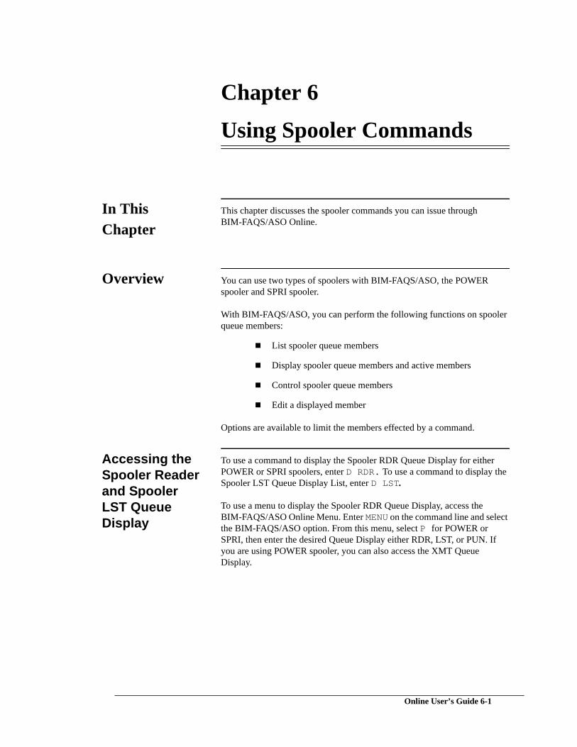
Chapter 6
Using Spooler Commands
In This Chapter
This chapter discusses the spooler commands you can issue through BIM-FAQS/ASO Online.
Overview You can use two types of spoolers with BIM-FAQS/ASO, the POWER spooler and SPRI spooler.
With BIM-FAQS/ASO, you can perform the following functions on spooler queue members:
List spooler queue members
Display spooler queue members and active members
Control spooler queue members
Edit a displayed member
Options are available to limit the members effected by a command.
Accessing the Spooler Reader and Spooler LST Queue Display
To use a command to display the Spooler RDR Queue Display for either POWER or SPRI spoolers, enter D RDR. To use a command to display the Spooler LST Queue Display List, enter D LST.
To use a menu to display the Spooler RDR Queue Display, access the BIM-FAQS/ASO Online Menu. Enter MENU on the command line and select the BIM-FAQS/ASO option. From this menu, select P for POWER or SPRI, then enter the desired Queue Display either RDR, LST, or PUN. If you are using POWER spooler, you can also access the XMT Queue Display.
Online User’s Guide 6-1
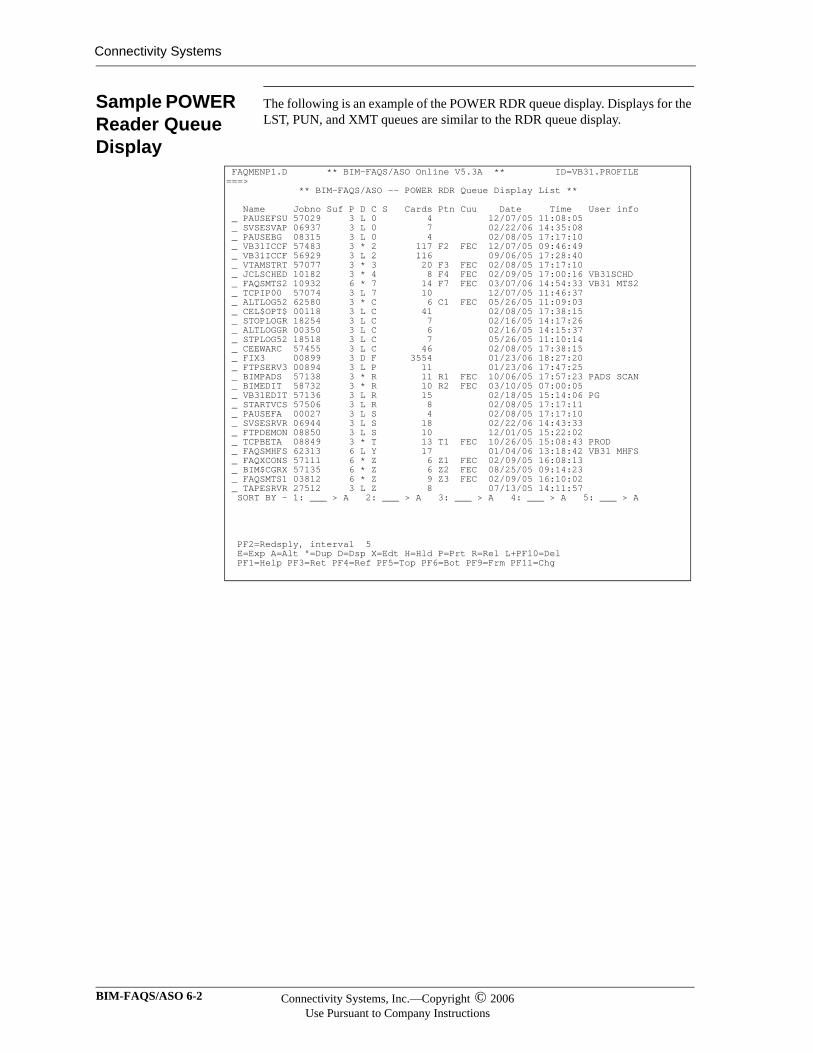
Connectivity Systems
Sample POWER Reader Queue Display
The following is an example of the POWER RDR queue display. Displays for the LST, PUN, and XMT queues are similar to the RDR queue display.
FAQMENP1.D ** BIM-FAQS/ASO Online V5.3A ** ID=VB31.PROFILE ===> ** BIM-FAQS/ASO -- POWER RDR Queue Display List ** Name Jobno Suf P D C S Cards Ptn Cuu Date Time User info _ PAUSEFSU 57029 3 L 0 4 12/07/05 11:08:05 _ SVSESVAP 06937 3 L 0 7 02/22/06 14:35:08 _ PAUSEBG 08315 3 L 0 4 02/08/05 17:17:10 _ VB31ICCF 57483 3 * 2 117 F2 FEC 12/07/05 09:46:49 _ VB31ICCF 56929 3 L 2 116 09/06/05 17:28:40 _ VTAMSTRT 57077 3 * 3 20 F3 FEC 02/08/05 17:17:10 _ JCLSCHED 10182 3 * 4 8 F4 FEC 02/09/05 17:00:16 VB31SCHD _ FAQSMTS2 10932 6 * 7 14 F7 FEC 03/07/06 14:54:33 VB31 MTS2 _ TCPIP00 57074 3 L 7 10 12/07/05 11:46:37 _ ALTLOG52 62580 3 * C 6 C1 FEC 05/26/05 11:09:03 _ CEL$OPT$ 00118 3 L C 41 02/08/05 17:38:15 _ STOPLOGR 18254 3 L C 7 02/16/05 14:17:26 _ ALTLOGGR 00350 3 L C 6 02/16/05 14:15:37 _ STPLOG52 18518 3 L C 7 05/26/05 11:10:14 _ CEEWARC 57455 3 L C 46 02/08/05 17:38:15 _ FIX3 00899 3 D F 3554 01/23/06 18:27:20 _ FTPSERV3 00894 3 L P 11 01/23/06 17:47:25 _ BIMPADS 57138 3 * R 11 R1 FEC 10/06/05 17:57:23 PADS SCAN _ BIMEDIT 58732 3 * R 10 R2 FEC 03/10/05 07:00:05 _ VB31EDIT 57136 3 L R 15 02/18/05 15:14:06 PG _ STARTVCS 57506 3 L R 8 02/08/05 17:17:11 _ PAUSEFA 00027 3 L S 4 02/08/05 17:17:10 _ SVSESRVR 06944 3 L S 18 02/22/06 14:43:33 _ FTPDEMON 08850 3 L S 10 12/01/05 15:22:02 _ TCPBETA 08849 3 * T 13 T1 FEC 10/26/05 15:08:43 PROD _ FAQSMHFS 62313 6 L Y 17 01/04/06 13:18:42 VB31 MHFS _ FAQXCONS 57111 6 * Z 6 Z1 FEC 02/09/05 16:08:13 _ BIM$CGRX 57135 6 * Z 6 Z2 FEC 08/25/05 09:14:23 _ FAQSMTS1 03812 6 * Z 9 Z3 FEC 02/09/05 16:10:02 _ TAPESRVR 27512 3 L Z 8 07/13/05 14:11:57 SORT BY - 1: ___ > A 2: ___ > A 3: ___ > A 4: ___ > A 5: ___ > A PF2=Redsply, interval 5 E=Exp A=Alt "=Dup D=Dsp X=Edt H=Hld P=Prt R=Rel L+PF10=Del PF1=Help PF3=Ret PF4=Ref PF5=Top PF6=Bot PF9=Frm PF11=Chg
BIM-FAQS/ASO 6-2 Connectivity Systems, Inc.—Copyright © 2006Use Pursuant to Company Instructions
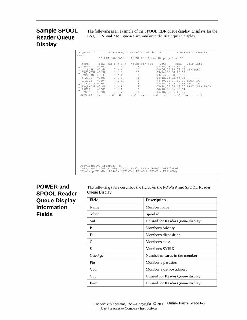
Sample SPOOL Reader Queue Display
The following is an example of the SPOOL RDR queue display. Displays for the LST, PUN, and XMT queues are similar to the RDR queue display.
POWER and SPOOL Reader Queue Display Information Fields
The following table describes the fields on the POWER and SPOOL Reader Queue Display:
FAQMENP1.D ** BIM-FAQS/ASO Online V5.3A ** ID=VBSPRI.ASOMAINT ===> ** BIM-FAQS/ASO -- SPOOL RDR Queue Display List ** Name Jobno Suf P D C S Cards Ptn Cuu Date Time User info _ PAUSE 00202 3 L 0 8 04/18/05 05:54:16 _ JCLSCHED 00160 7 * 4 11 04/06/05 13:02:16 VB31SCHD _ FAQSMTS1 00138 3 * 7 10 03/24/05 08:40:02 _ FAQXCONS 00133 3 * B 8 03/24/05 08:05:19 _ YPAUSE 00203 3 L D 8 04/18/05 05:55:13 _ RPAUSE 00204 3 L D 8 04/18/05 05:56:00 TEST JOB _ RPAUSEIT 00207 3 L D 8 04/18/05 09:07:48 TEST JOB _ FAQSMTS2 00140 3 * R 8 03/24/05 08:43:00 TEST USER INFO _ PAUSE 00205 3 L R 8 04/18/05 06:06:04 _ PAUSE 00206 3 L W 8 04/18/05 06:12:09 SORT BY - 1: ___ > A 2: ___ > A 3: ___ > A 4: ___ > A 5: ___ > A PF2=Redsply, interval 5 E=Exp A=Alt "=Dup D=Dsp X=Edt H=Hld P=Prt R=Rel L+PF10=Del PF1=Help PF3=Ret PF4=Ref PF5=Top PF6=Bot PF9=Frm PF11=Chg
Field Description
Name Member name
Jobno Spool id
Suf Unused for Reader Queue display
P Member's priority
D Member's disposition
C Member's class
S Member's SYSID
Cds/Pgs Number of cards in the member
Ptn Member’s partition
Cuu Member’s device address
Cpy Unused for Reader Queue display
Form Unused for Reader Queue display
Connectivity Systems, Inc.—Copyright © 2006Use Pursuant to Company Instructions
Online User’s Guide 6-3
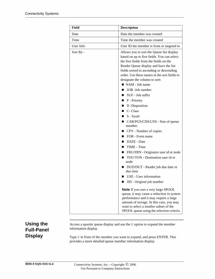
Connectivity Systems
Using the Full-Panel Display
Access a spooler queue display and use the E option to expand the member information display.
Type E in front of the member you want to expand, and press ENTER. This provides a more detailed queue member information display.
Date Date the member was created
Time Time the member was created
User Info User ID the member is from or targeted to
Sort By - Allows you to sort the Queue list display based on up to five fields. You can select the five fields from the fields on the Reader Queue display and have the list fields sorted in ascending or descending order. Use these names in the sort fields to designate the column to sort:
NAM - Job name JOB -Job number SUF - Job suffix P - Priority D -Disposition C- Class S - Sysid CAR/PGS/CDS/LNS - Size of queue member CPY - Number of copies FOR - Form name DATE - Date TIME - Time FRU/FRN - Originator user id or node TOU/TON - Destination user id or node DUD/DUT - Reader job due date or due time USE - User information JID - Original job number
Note If you sort a very large SPOOL queue, it may cause a reduction in system performance and it may require a large amount of storage. In this case, you may want to select a smaller subset of the SPOOL queue using the selection criteria.
Field Description
BIM-FAQS/ASO 6-4 Connectivity Systems, Inc.—Copyright © 2006Use Pursuant to Company Instructions
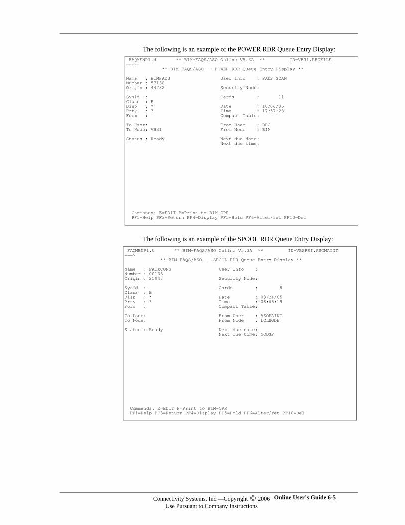
The following is an example of the POWER RDR Queue Entry Display:
The following is an example of the SPOOL RDR Queue Entry Display:
FAQMENP1.d ** BIM-FAQS/ASO Online V5.3A ** ID=VB31.PROFILE ===> ** BIM-FAQS/ASO -- POWER RDR Queue Entry Display ** Name : BIMPADS User Info : PADS SCAN Number : 57138 Origin : 44732 Security Node: Sysid : Cards : 11 Class : R Disp : * Date : 10/06/05 Prty : 3 Time : 17:57:23 Form : Compact Table: To User: From User : DRJ To Node: VB31 From Node : BIM Status : Ready Next due date: Next due time:
Commands: E=EDIT P=Print to BIM-CPR PF1=Help PF3=Return PF4=Display PF5=Hold PF6=Alter/ret PF10=Del
FAQMENP1.0 ** BIM-FAQS/ASO Online V5.3A ** ID=VBSPRI.ASOMAINT ===> ** BIM-FAQS/ASO -- SPOOL RDR Queue Entry Display ** Name : FAQXCONS User Info : Number : 00133 Origin : 25947 Security Node: Sysid : Cards : 8 Class : B Disp : * Date : 03/24/05 Prty : 3 Time : 08:05:19 Form : Compact Table: To User: From User : ASOMAINT To Node: From Node : LCLNODE Status : Ready Next due date: Next due time: NODSP
Commands: E=EDIT P=Print to BIM-CPR PF1=Help PF3=Return PF4=Display PF5=Hold PF6=Alter/ret PF10=Del
Connectivity Systems, Inc.—Copyright © 2006Use Pursuant to Company Instructions
Online User’s Guide 6-5
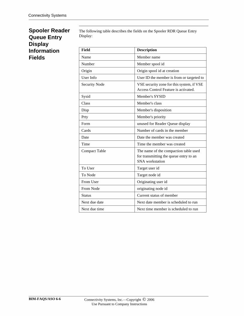
Connectivity Systems
Spooler Reader Queue Entry Display Information Fields
The following table describes the fields on the Spooler RDR Queue Entry Display:
Field Description
Name Member name
Number Member spool id
Origin Origin spool id at creation
User Info User ID the member is from or targeted to
Security Node VSE security zone for this system, if VSE Access Control Feature is activated.
Sysid Member's SYSID
Class Member's class
Disp Member's disposition
Prty Member's priority
Form unused for Reader Queue display
Cards Number of cards in the member
Date Date the member was created
Time Time the member was created
Compact Table The name of the compaction table used for transmitting the queue entry to an SNA workstation
To User Target user id
To Node Target node id
From User Originating user id
From Node originating node id
Status Current status of member
Next due date Next date member is scheduled to run
Next due time Next time member is scheduled to run
BIM-FAQS/ASO 6-6 Connectivity Systems, Inc.—Copyright © 2006Use Pursuant to Company Instructions
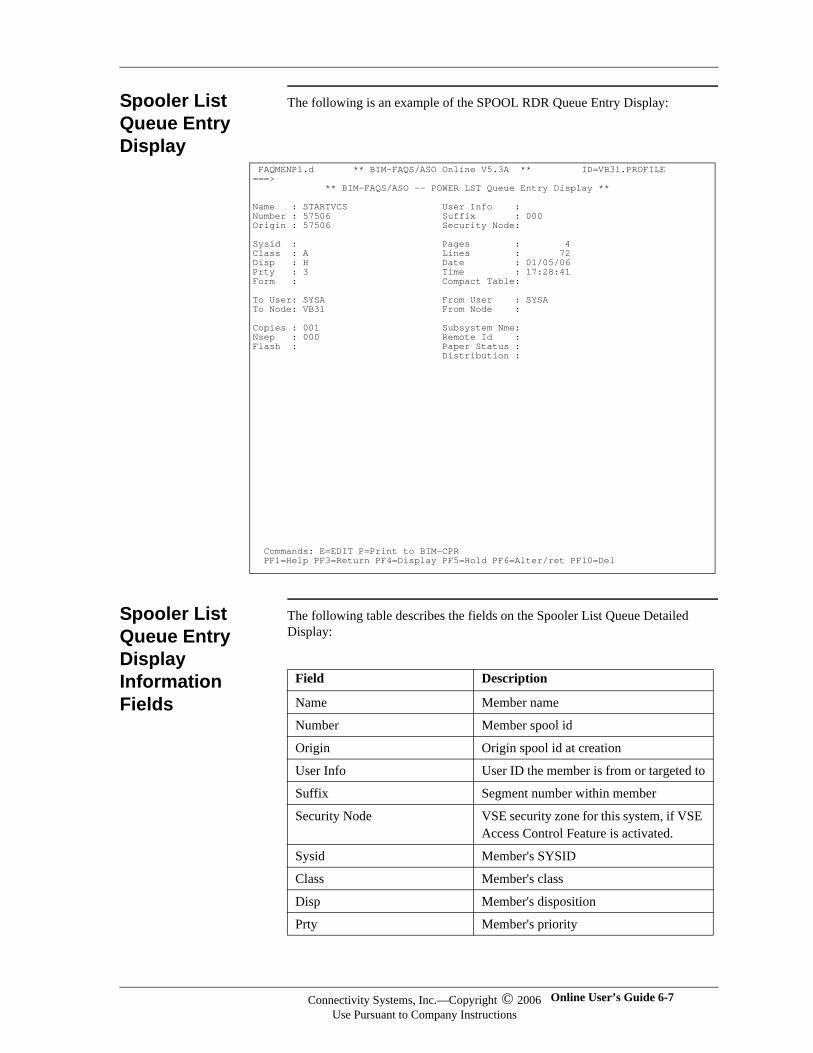
Spooler List Queue Entry Display
The following is an example of the SPOOL RDR Queue Entry Display:
Spooler List Queue Entry Display Information Fields
The following table describes the fields on the Spooler List Queue Detailed Display:
FAQMENP1.d ** BIM-FAQS/ASO Online V5.3A ** ID=VB31.PROFILE ===> ** BIM-FAQS/ASO -- POWER LST Queue Entry Display ** Name : STARTVCS User Info : Number : 57506 Suffix : 000 Origin : 57506 Security Node: Sysid : Pages : 4 Class : A Lines : 72 Disp : H Date : 01/05/06 Prty : 3 Time : 17:28:41 Form : Compact Table: To User: SYSA From User : SYSA To Node: VB31 From Node : Copies : 001 Subsystem Nme: Nsep : 000 Remote Id : Flash : Paper Status : Distribution : Commands: E=EDIT P=Print to BIM-CPR PF1=Help PF3=Return PF4=Display PF5=Hold PF6=Alter/ret PF10=Del
Field Description
Name Member name
Number Member spool id
Origin Origin spool id at creation
User Info User ID the member is from or targeted to
Suffix Segment number within member
Security Node VSE security zone for this system, if VSE Access Control Feature is activated.
Sysid Member's SYSID
Class Member's class
Disp Member's disposition
Prty Member's priority
Connectivity Systems, Inc.—Copyright © 2006Use Pursuant to Company Instructions
Online User’s Guide 6-7
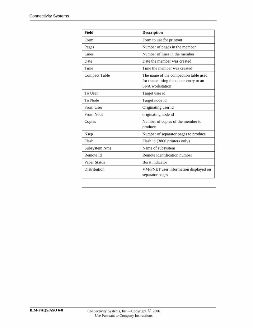
Connectivity Systems
Form Form to use for printout
Pages Number of pages in the member
Lines Number of lines in the member
Date Date the member was created
Time Time the member was created
Compact Table The name of the compaction table used for transmitting the queue entry to an SNA workstation
To User Target user id
To Node Target node id
From User Originating user id
From Node originating node id
Copies Number of copies of the member to produce
Nsep Number of separator pages to produce
Flash Flash id (3800 printers only)
Subsystem Nme Name of subsystem
Remote Id Remote identification number
Paper Status Burst indicator
Distribution VM/PNET user information displayed on separator pages
Field Description
BIM-FAQS/ASO 6-8 Connectivity Systems, Inc.—Copyright © 2006Use Pursuant to Company Instructions
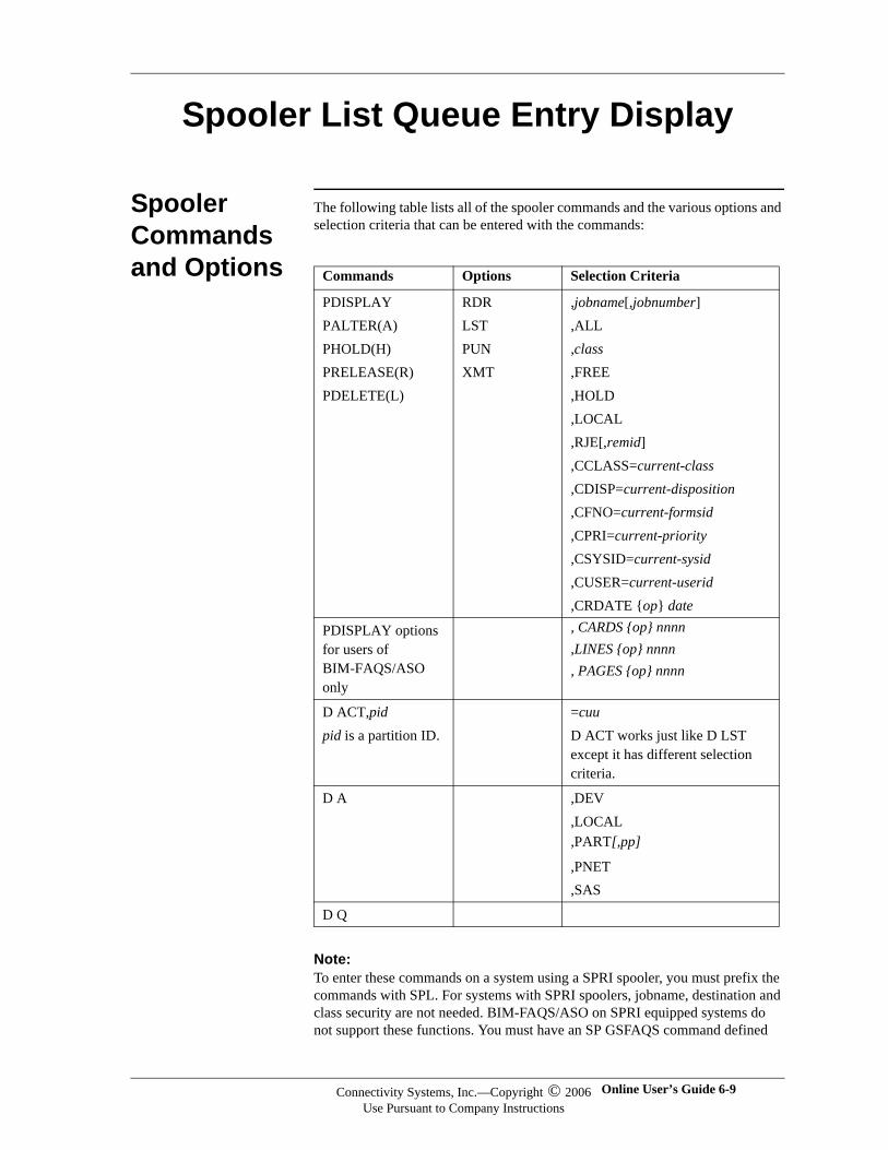
Spooler List Queue Entry Display
Spooler Commands and Options
The following table lists all of the spooler commands and the various options and selection criteria that can be entered with the commands:
Note:Note:To enter these commands on a system using a SPRI spooler, you must prefix the commands with SPL. For systems with SPRI spoolers, jobname, destination and class security are not needed. BIM-FAQS/ASO on SPRI equipped systems do not support these functions. You must have an SP GSFAQS command defined
Commands Options Selection Criteria
PDISPLAYPALTER(A)PHOLD(H)PRELEASE(R)PDELETE(L)
RDRLSTPUNXMT
,jobname[,jobnumber],ALL,class,FREE,HOLD,LOCAL,RJE[,remid],CCLASS=current-class,CDISP=current-disposition,CFNO=current-formsid,CPRI=current-priority,CSYSID=current-sysid,CUSER=current-userid,CRDATE {op} date
PDISPLAY options for users of BIM-FAQS/ASO only
, CARDS {op} nnnn,LINES {op} nnnn, PAGES {op} nnnn
D ACT,pidpid is a partition ID.
=cuuD ACT works just like D LST except it has different selection criteria.
D A ,DEV,LOCAL,PART[,pp]
,PNET,SAS
D Q
Connectivity Systems, Inc.—Copyright © 2006Use Pursuant to Company Instructions
Online User’s Guide 6-9
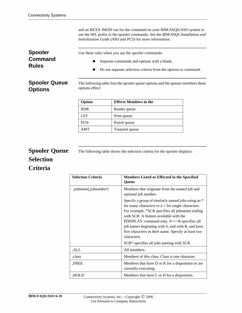
Connectivity Systems
and an REXX IMOD run for the command on your BIM-FAQS/ASO system to use the SPL prefix to the spooler commands. See the BIM-FAQS Installation and Initialization Guide (ASO and PCS) for more information.
Spooler Command Rules
Use these rules when you use the spooler commands:
Separate commands and options with a blank.
Do not separate selection criteria from the options or command.
Spooler Queue Options
The following table lists the spooler queue options and the queues members these options effect:
Spooler Queue Selection Criteria
The following table shows the selection criteria for the spooler displays:
Option Effects Members in the
RDR Reader queue
LST Print queue
PUN Punch queue
XMT Transmit queue
Selection Criteria Members Listed or Effected in the Specified Queue
,jobname[,jobnumber] Members that originate from the named job and optional job number.Specify a group of similarly named jobs using an * for many characters or a + for single characters. For example, *SCR specifies all jobnames ending with SCR. A feature available with the PDISPLAY command only, S+++R specifies all job names beginning with S, end with R, and have five characters in their name. Specify at least two characters.SCR* specifies all jobs starting with SCR.
,ALL All members.
,class Members of this class. Class is one character.
,FREE Members that have D or K for a disposition or are currently executing.
,HOLD Members that have L or H for a disposition.
BIM-FAQS/ASO 6-10 Connectivity Systems, Inc.—Copyright © 2006Use Pursuant to Company Instructions
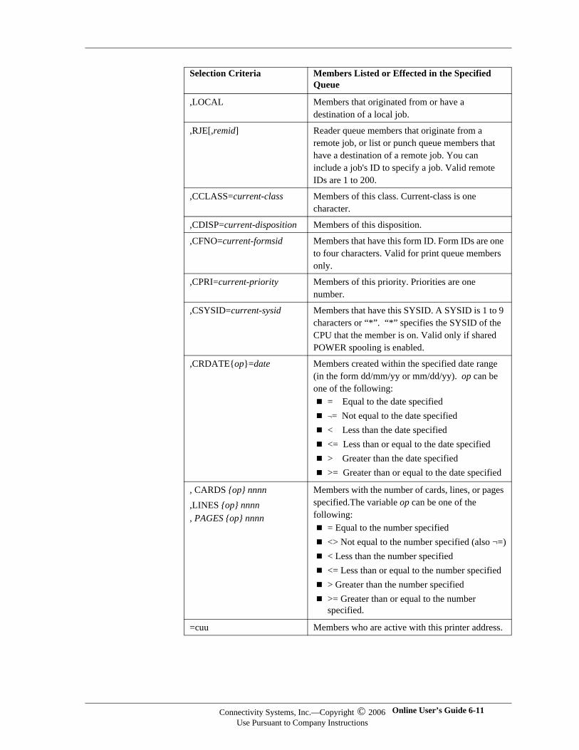
,LOCAL Members that originated from or have a destination of a local job.
,RJE[,remid] Reader queue members that originate from a remote job, or list or punch queue members that have a destination of a remote job. You can include a job's ID to specify a job. Valid remote IDs are 1 to 200.
,CCLASS=current-class Members of this class. Current-class is one character.
,CDISP=current-disposition Members of this disposition.
,CFNO=current-formsid Members that have this form ID. Form IDs are one to four characters. Valid for print queue members only.
,CPRI=current-priority Members of this priority. Priorities are one number.
,CSYSID=current-sysid Members that have this SYSID. A SYSID is 1 to 9 characters or “*”. “*” specifies the SYSID of the CPU that the member is on. Valid only if shared POWER spooling is enabled.
,CRDATE{op}=date Members created within the specified date range (in the form dd/mm/yy or mm/dd/yy). op can be one of the following:
= Equal to the date specified¬= Not equal to the date specified< Less than the date specified<= Less than or equal to the date specified> Greater than the date specified>= Greater than or equal to the date specified
, CARDS {op} nnnn,LINES {op} nnnn, PAGES {op} nnnn
Members with the number of cards, lines, or pages specified.The variable op can be one of the following:
= Equal to the number specified <> Not equal to the number specified (also ¬=) < Less than the number specified <= Less than or equal to the number specified > Greater than the number specified>= Greater than or equal to the number specified.
=cuu Members who are active with this printer address.
Selection Criteria Members Listed or Effected in the Specified Queue
Connectivity Systems, Inc.—Copyright © 2006Use Pursuant to Company Instructions
Online User’s Guide 6-11
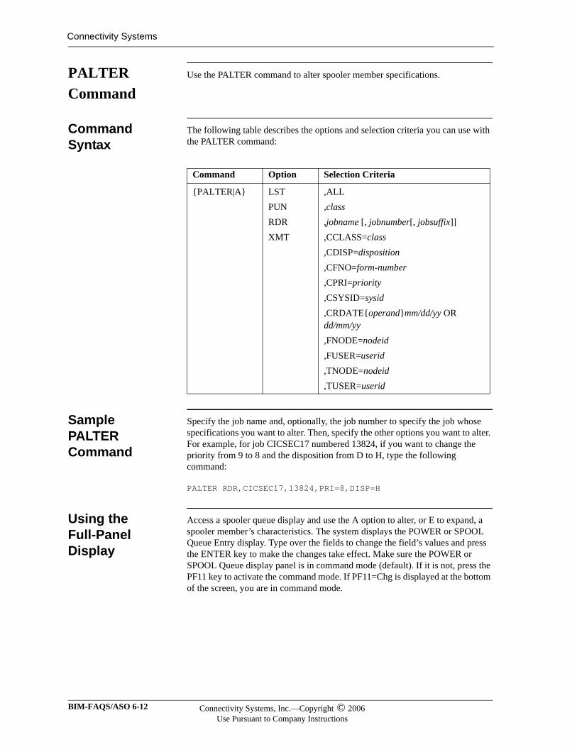
Connectivity Systems
PALTER Command
Use the PALTER command to alter spooler member specifications.
Command Syntax
The following table describes the options and selection criteria you can use with the PALTER command:
Sample PALTER Command
Specify the job name and, optionally, the job number to specify the job whose specifications you want to alter. Then, specify the other options you want to alter. For example, for job CICSEC17 numbered 13824, if you want to change the priority from 9 to 8 and the disposition from D to H, type the following command:
PALTER RDR,CICSEC17,13824,PRI=8,DISP=H
Using the Full-Panel Display
Access a spooler queue display and use the A option to alter, or E to expand, a spooler member’s characteristics. The system displays the POWER or SPOOL Queue Entry display. Type over the fields to change the field’s values and press the ENTER key to make the changes take effect. Make sure the POWER or SPOOL Queue display panel is in command mode (default). If it is not, press the PF11 key to activate the command mode. If PF11=Chg is displayed at the bottom of the screen, you are in command mode.
Command Option Selection Criteria
{PALTER|A} LSTPUNRDRXMT
,ALL,class,jobname [, jobnumber[, jobsuffix]],CCLASS=class,CDISP=disposition,CFNO=form-number,CPRI=priority,CSYSID=sysid,CRDATE{operand}mm/dd/yy OR dd/mm/yy,FNODE=nodeid,FUSER=userid,TNODE=nodeid,TUSER=userid
BIM-FAQS/ASO 6-12 Connectivity Systems, Inc.—Copyright © 2006Use Pursuant to Company Instructions
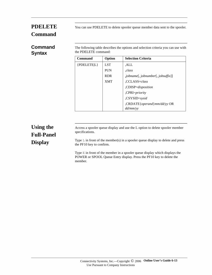
PDELETE Command
You can use PDELETE to delete spooler queue member data sent to the spooler.
Command Syntax
The following table describes the options and selection criteria you can use with the PDELETE command:
Using the Full-Panel Display
Access a spooler queue display and use the L option to delete spooler member specifications.
Type L in front of the member(s) in a spooler queue display to delete and press the PF10 key to confirm.
Type E in front of the member in a spooler queue display which displays the POWER or SPOOL Queue Entry display. Press the PF10 key to delete the member.
Command Option Selection Criteria
{PDELETE|L} LSTPUNRDRXMT
,ALL,class,jobname[, jobnumber[, jobsuffix]],CCLASS=class,CDISP=disposition,CPRI=priority,CSYSID=sysid,CRDATE{operand}mm/dd/yy OR dd/mm/yy
Connectivity Systems, Inc.—Copyright © 2006Use Pursuant to Company Instructions
Online User’s Guide 6-13
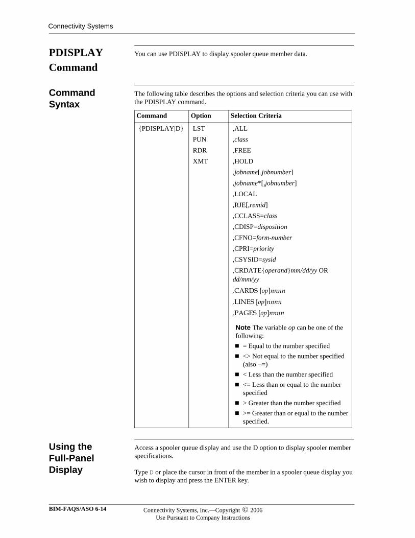
Connectivity Systems
PDISPLAY Command
You can use PDISPLAY to display spooler queue member data.
Command Syntax
The following table describes the options and selection criteria you can use with the PDISPLAY command.
Using the Full-Panel Display
Access a spooler queue display and use the D option to display spooler member specifications.
Type D or place the cursor in front of the member in a spooler queue display you wish to display and press the ENTER key.
Command Option Selection Criteria
{PDISPLAY|D} LSTPUNRDRXMT
,ALL,class,FREE,HOLD,jobname[,jobnumber],jobname*[,jobnumber],LOCAL,RJE[,remid],CCLASS=class,CDISP=disposition,CFNO=form-number,CPRI=priority,CSYSID=sysid,CRDATE{operand}mm/dd/yy OR dd/mm/yy
,CARDS [op]nnnn ,LINES [op]nnnn ,PAGES [op]nnnn
Note The variable op can be one of the following:
= Equal to the number specified <> Not equal to the number specified (also ¬=) < Less than the number specified <= Less than or equal to the number specified > Greater than the number specified >= Greater than or equal to the number specified.
BIM-FAQS/ASO 6-14 Connectivity Systems, Inc.—Copyright © 2006Use Pursuant to Company Instructions

Type E in front of the member in a spooler queue display which displays the POWER or SPOOL Queue Entry display. Press the PF4 key to display the member.
For users of 132 character per line screens (MOD5), when members are displayed they will appear in 80 column (RDR and PUN), or 132 column (LST) by default. XMT member display will be determined by the type of member. To change the display type, use the SCREEN command to toggle between 80 and 132 column sizes. This does not change the current size for the BIM-FAQS/ASO console display. The two SCREEN commands are independent of each other.
Connectivity Systems, Inc.—Copyright © 2006Use Pursuant to Company Instructions
Online User’s Guide 6-15
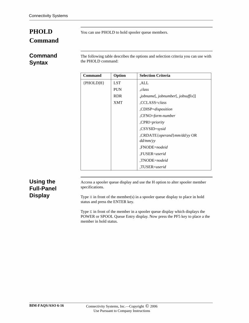
Connectivity Systems
PHOLD Command
You can use PHOLD to hold spooler queue members.
Command Syntax
The following table describes the options and selection criteria you can use with the PHOLD command:
Using the Full-Panel Display
Access a spooler queue display and use the H option to alter spooler member specifications.
Type H in front of the member(s) in a spooler queue display to place in hold status and press the ENTER key.
Type E in front of the member in a spooler queue display which displays the POWER or SPOOL Queue Entry display. Now press the PF5 key to place a the member in hold status.
Command Option Selection Criteria
{PHOLD|H} LSTPUNRDRXMT
,ALL,class,jobname[, jobnumber[, jobsuffix]],CCLASS=class,CDISP=disposition,CFNO=form-number,CPRI=priority,CSYSID=sysid,CRDATE{operand}mm/dd/yy OR dd/mm/yy,FNODE=nodeid,FUSER=userid,TNODE=nodeid,TUSER=userid
BIM-FAQS/ASO 6-16 Connectivity Systems, Inc.—Copyright © 2006Use Pursuant to Company Instructions
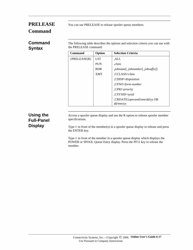
PRELEASE Command
You can use PRELEASE to release spooler queue members.
Command Syntax
The following table describes the options and selection criteria you can use with the PRELEASE command:
Using the Full-Panel Display
Access a spooler queue display and use the R option to release spooler member specifications.
Type R in front of the member(s) in a spooler queue display to release and press the ENTER key.
Type E in front of the member in a spooler queue display which displays the POWER or SPOOL Queue Entry display. Press the PF11 key to release the member.
Command Option Selection Criteria
{PRELEASE|R} LSTPUNRDRXMT
,ALL,class,jobname[, jobnumber[, jobsuffix]],CCLASS=class,CDISP=disposition,CFNO=form-number,CPRI=priority,CSYSID=sysid,CRDATE{operand}mm/dd/yy OR dd/mm/yy
Connectivity Systems, Inc.—Copyright © 2006Use Pursuant to Company Instructions
Online User’s Guide 6-17
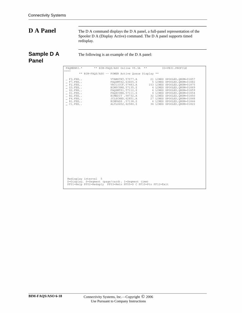
Connectivity Systems
D A Panel The D A command displays the D A panel, a full-panel representation of the Spooler D A (Display Active) command. The D A panel supports timed redisplay.
Sample D A Panel
The following is an example of the D A panel:
FAQMENP2.* ** BIM-FAQS/ASO Online V5.3A ** ID=VB31.PROFILE ===> ** BIM-FAQS/ASO -- POWER Active Queue Display ** _ F3,FEE,, VTAMSTRT,57077,A 21 LINES SPOOLED,QNUM=01857 _ F7,FEE,, FAQSMTS2,63605,Z 5 LINES SPOOLED,QNUM=01882 _ F2,FEE,, VB31ICCF,57483,A 153 LINES SPOOLED,QNUM=01875 _ Z3,FEE,, BIM$CGRX,57135,Z 4 LINES SPOOLED,QNUM=01869 _ Z2,FEE,, FAQSMTS1,57112,Z 6 LINES SPOOLED,QNUM=01859 _ Z1,FEE,, FAQXCONS,57111,Z 4 LINES SPOOLED,QNUM=01854 _ R2,FEE,, BIMEDIT ,58732,A 32 LINES SPOOLED,QNUM=01850 _ F4,FEE,, JCLSCHED,62851,A 27 LINES SPOOLED,QNUM=01848 _ R1,FEE,, BIMPADS ,57138,Z 6 LINES SPOOLED,QNUM=01846 _ C1,FEE,, ALTLOG52,62580,Z 36 LINES SPOOLED,QNUM=01822 Redisplay interval 5 D=Display, S=Segment (page/card). I=Segment (imm) PF01=Help PF02=Redsply PF03=Retn PF05=D C PF10=Ptn PF12=Exit
BIM-FAQS/ASO 6-18 Connectivity Systems, Inc.—Copyright © 2006Use Pursuant to Company Instructions
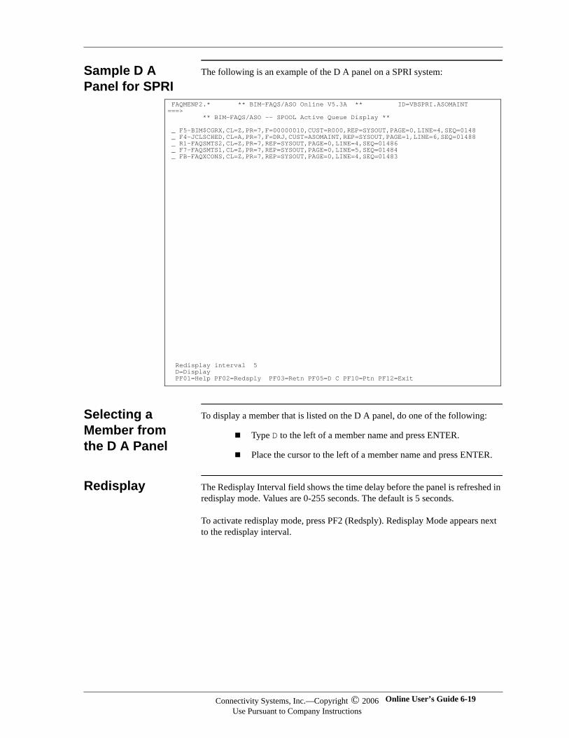
Sample D A Panel for SPRI
The following is an example of the D A panel on a SPRI system:
Selecting a Member from the D A Panel
To display a member that is listed on the D A panel, do one of the following:
Type D to the left of a member name and press ENTER.
Place the cursor to the left of a member name and press ENTER.
Redisplay The Redisplay Interval field shows the time delay before the panel is refreshed in redisplay mode. Values are 0-255 seconds. The default is 5 seconds.
To activate redisplay mode, press PF2 (Redsply). Redisplay Mode appears next to the redisplay interval.
FAQMENP2.* ** BIM-FAQS/ASO Online V5.3A ** ID=VBSPRI.ASOMAINT ===> ** BIM-FAQS/ASO -- SPOOL Active Queue Display ** _ F5-BIM$CGRX,CL=Z,PR=7,F=00000010,CUST=R000,REP=SYSOUT,PAGE=0,LINE=4,SEQ=0148 _ F4-JCLSCHED,CL=A,PR=7,F=DRJ,CUST=ASOMAINT,REP=SYSOUT,PAGE=1,LINE=6,SEQ=01488 _ R1-FAQSMTS2,CL=Z,PR=7,REP=SYSOUT,PAGE=0,LINE=4,SEQ=01486 _ F7-FAQSMTS1,CL=Z,PR=7,REP=SYSOUT,PAGE=0,LINE=5,SEQ=01484 _ FB-FAQXCONS,CL=Z,PR=7,REP=SYSOUT,PAGE=0,LINE=4,SEQ=01483 Redisplay interval 5 D=Display PF01=Help PF02=Redsply PF03=Retn PF05=D C PF10=Ptn PF12=Exit
Connectivity Systems, Inc.—Copyright © 2006Use Pursuant to Company Instructions
Online User’s Guide 6-19
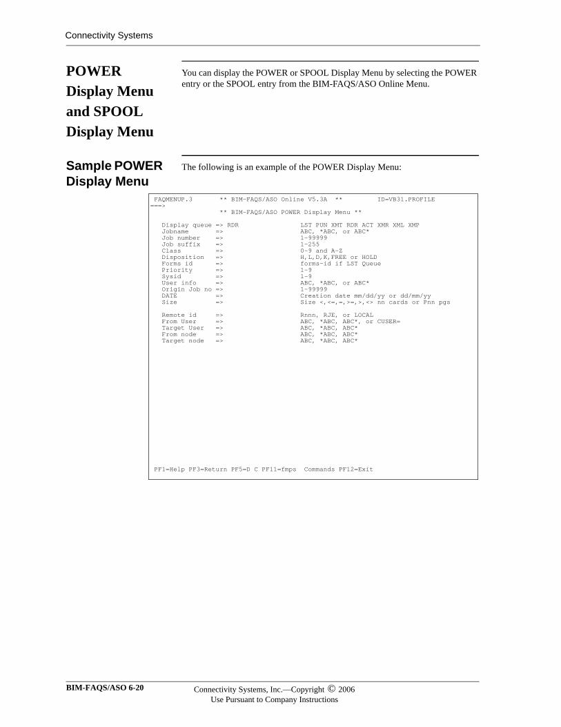
Connectivity Systems
POWER Display Menu and SPOOL Display Menu
You can display the POWER or SPOOL Display Menu by selecting the POWER entry or the SPOOL entry from the BIM-FAQS/ASO Online Menu.
Sample POWER Display Menu
The following is an example of the POWER Display Menu:
FAQMENUP.3 ** BIM-FAQS/ASO Online V5.3A ** ID=VB31.PROFILE ===> ** BIM-FAQS/ASO POWER Display Menu ** Display queue => RDR LST PUN XMT RDR ACT XMR XML XMP Jobname => ABC, *ABC, or ABC* Job number => 1-99999 Job suffix => 1-255 Class => 0-9 and A-Z Disposition => H,L,D,K,FREE or HOLD Forms id => forms-id if LST Queue Priority => 1-9 Sysid => 1-9 User info => ABC, *ABC, or ABC* Origin Job no => 1-99999 DATE => Creation date mm/dd/yy or dd/mm/yy Size => Size <,<=,=,>=,>,<> nn cards or Pnn pgs Remote id => Rnnn, RJE, or LOCAL From User => ABC, *ABC, ABC*, or CUSER= Target User => ABC, *ABC, ABC* From node => ABC, *ABC, ABC* Target node => ABC, *ABC, ABC* PF1=Help PF3=Return PF5=D C PF11=fmps Commands PF12=Exit
BIM-FAQS/ASO 6-20 Connectivity Systems, Inc.—Copyright © 2006Use Pursuant to Company Instructions
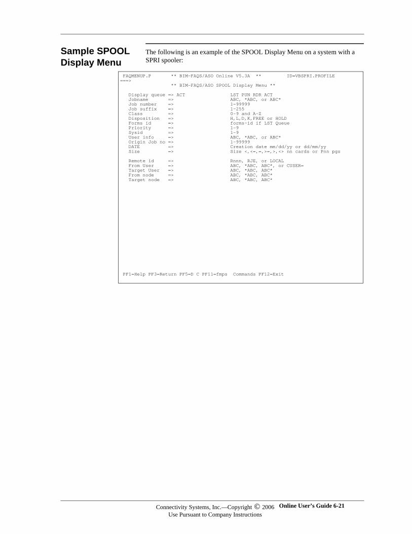
Sample SPOOL Display Menu
The following is an example of the SPOOL Display Menu on a system with a SPRI spooler:
FAQMENUP.P ** BIM-FAQS/ASO Online V5.3A ** ID=VBSPRI.PROFILE ===> ** BIM-FAQS/ASO SPOOL Display Menu ** Display queue => ACT LST PUN RDR ACT Jobname => ABC, *ABC, or ABC* Job number => 1-99999 Job suffix => 1-255 Class => 0-9 and A-Z Disposition => H,L,D,K,FREE or HOLD Forms id => forms-id if LST Queue Priority => 1-9 Sysid => 1-9 User info => ABC, *ABC, or ABC* Origin Job no => 1-99999 DATE => Creation date mm/dd/yy or dd/mm/yy Size => Size <,<=,=,>=,>,<> nn cards or Pnn pgs Remote id => Rnnn, RJE, or LOCAL From User => ABC, *ABC, ABC*, or CUSER= Target User => ABC, *ABC, ABC* From node => ABC, *ABC, ABC* Target node => ABC, *ABC, ABC* PF1=Help PF3=Return PF5=D C PF11=fmps Commands PF12=Exit
Connectivity Systems, Inc.—Copyright © 2006Use Pursuant to Company Instructions
Online User’s Guide 6-21
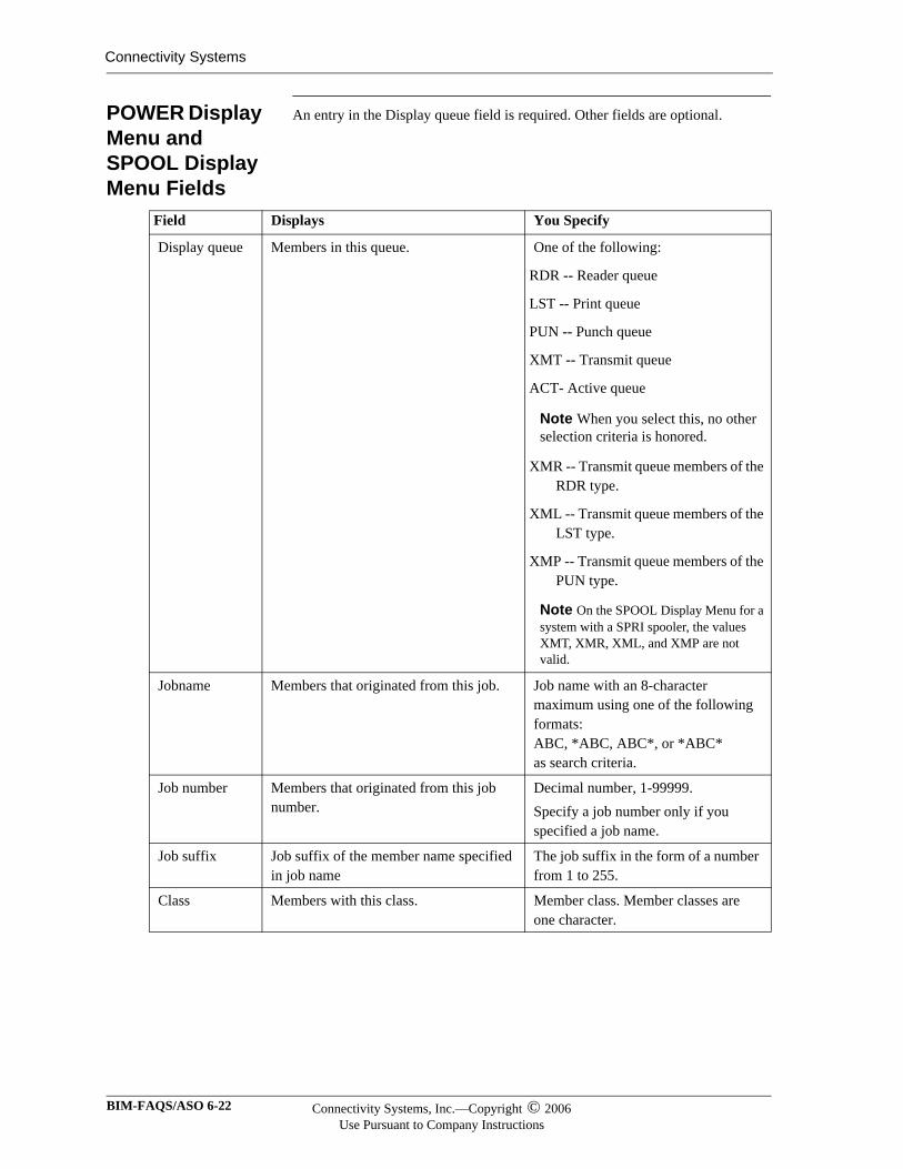
Connectivity Systems
POWER Display Menu and SPOOL Display Menu Fields
An entry in the Display queue field is required. Other fields are optional.
Field Displays You Specify
Display queue Members in this queue. One of the following:
RDR -- Reader queue
LST -- Print queue
PUN -- Punch queue
XMT -- Transmit queue
ACT- Active queue
Note When you select this, no other selection criteria is honored.
XMR -- Transmit queue members of the RDR type.
XML -- Transmit queue members of the LST type.
XMP -- Transmit queue members of the PUN type.
Note On the SPOOL Display Menu for a system with a SPRI spooler, the values XMT, XMR, XML, and XMP are not valid.
Jobname Members that originated from this job. Job name with an 8-character maximum using one of the following formats:ABC, *ABC, ABC*, or *ABC*as search criteria.
Job number Members that originated from this job number.
Decimal number, 1-99999.Specify a job number only if you specified a job name.
Job suffix Job suffix of the member name specified in job name
The job suffix in the form of a number from 1 to 255.
Class Members with this class. Member class. Member classes are one character.
BIM-FAQS/ASO 6-22 Connectivity Systems, Inc.—Copyright © 2006Use Pursuant to Company Instructions
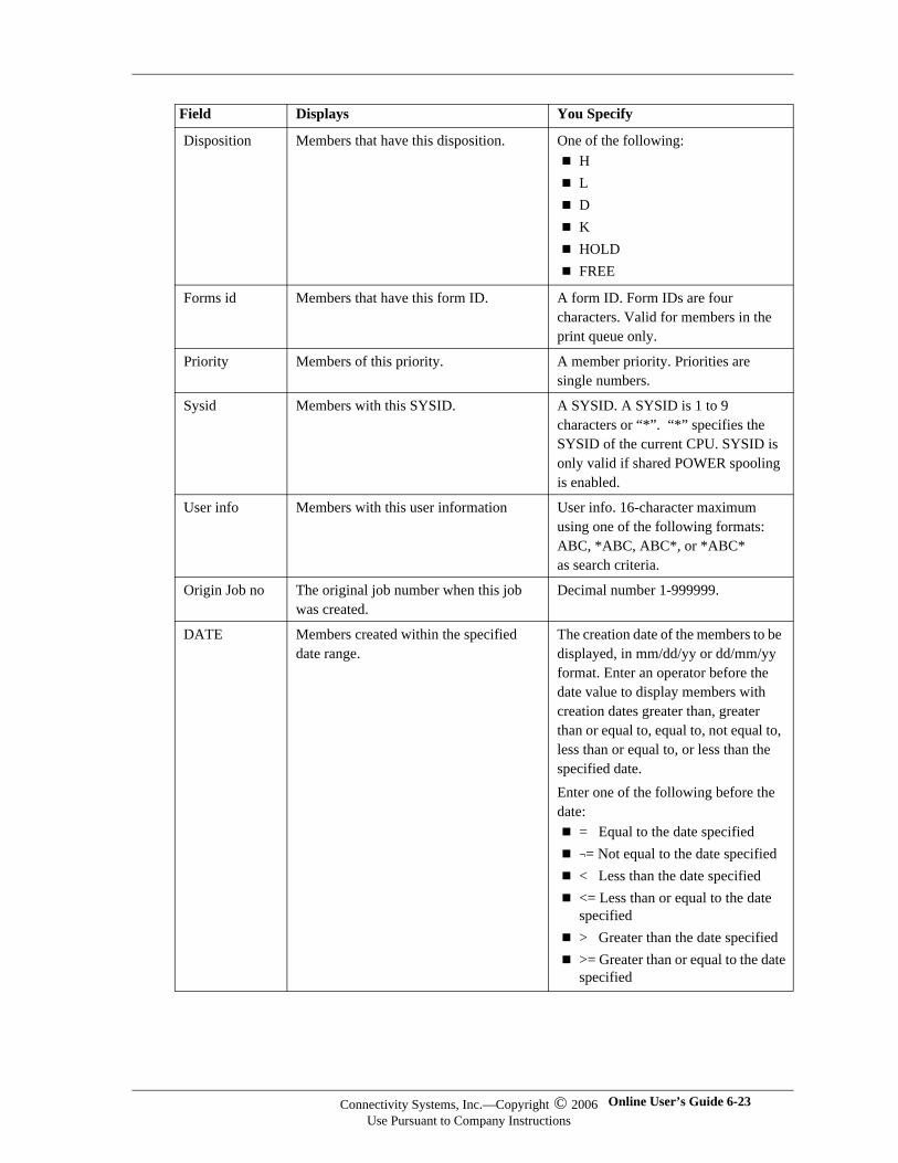
Disposition Members that have this disposition. One of the following:HLDKHOLDFREE
Forms id Members that have this form ID. A form ID. Form IDs are four characters. Valid for members in the print queue only.
Priority Members of this priority. A member priority. Priorities are single numbers.
Sysid Members with this SYSID. A SYSID. A SYSID is 1 to 9 characters or “*”. “*” specifies the SYSID of the current CPU. SYSID is only valid if shared POWER spooling is enabled.
User info Members with this user information User info. 16-character maximum using one of the following formats:ABC, *ABC, ABC*, or *ABC*as search criteria.
Origin Job no The original job number when this job was created.
Decimal number 1-999999.
DATE Members created within the specified date range.
The creation date of the members to be displayed, in mm/dd/yy or dd/mm/yy format. Enter an operator before the date value to display members with creation dates greater than, greater than or equal to, equal to, not equal to, less than or equal to, or less than the specified date. Enter one of the following before the date:
= Equal to the date specified¬= Not equal to the date specified< Less than the date specified<= Less than or equal to the date specified> Greater than the date specified>= Greater than or equal to the date specified
Field Displays You Specify
Connectivity Systems, Inc.—Copyright © 2006Use Pursuant to Company Instructions
Online User’s Guide 6-23
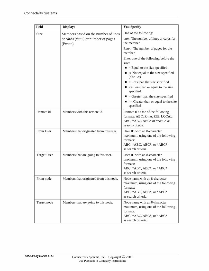
Connectivity Systems
Size Members based on the number of lines or cards (nnnn) or number of pages (Pnnnn)
One of the following: nnnn The number of lines or cards for the member. Pnnnn The number of pages for the member. Enter one of the following before the size:
= Equal to the size specified <> Not equal to the size specified (also ¬=) < Less than the size specified <= Less than or equal to the size specified > Greater than the size specified >= Greater than or equal to the size specified
Remote id Members with this remote id. Remote ID. One of the following formats: ABC, Rnnn, RJE, LOCAL, ABC, *ABC, ABC* or *ABC* as search criteria.
From User Members that originated from this user. User ID with an 8-character maximum, using one of the following formats:ABC, *ABC, ABC*, or *ABC*as search criteria.
Target User Members that are going to this user. User ID with an 8-character maximum, using one of the following formats:ABC, *ABC, ABC*, or *ABC*as search criteria.
From node Members that originated from this node. Node name with an 8-character maximum, using one of the following formats:ABC, *ABC, ABC*, or *ABC*as search criteria.
Target node Members that are going to this node. Node name with an 8-character maximum, using one of the following formats:ABC, *ABC, ABC*, or *ABC*as search criteria.
Field Displays You Specify
BIM-FAQS/ASO 6-24 Connectivity Systems, Inc.—Copyright © 2006Use Pursuant to Company Instructions
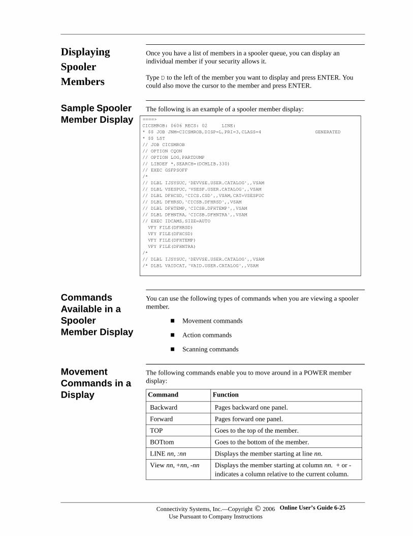
Displaying Spooler Members
Once you have a list of members in a spooler queue, you can display an individual member if your security allows it.
Type D to the left of the member you want to display and press ENTER. You could also move the cursor to the member and press ENTER.
Sample Spooler Member Display
The following is an example of a spooler member display:
Commands Available in a Spooler Member Display
You can use the following types of commands when you are viewing a spooler member.
Movement commands
Action commands
Scanning commands
Movement Commands in a Display
The following commands enable you to move around in a POWER member display:
====>CICSMROB: 0606 RECS: 02 LINE:* $$ JOB JNM=CICSMROB,DISP=L,PRI=3,CLASS=4 GENERATED* $$ LST// JOB CICSMROB// OPTION CQON// OPTION LOG,PARTDUMP// LIBDEF *,SEARCH=(DCMLIB.330)// EXEC GSFPSOFF/*// DLBL IJSYSUC,'DEVVSE.USER.CATALOG',,VSAM// DLBL VSESPUC,'VSESP.USER.CATALOG',,VSAM// DLBL DFHCSD,'CICS.CSD',,VSAM,CAT=VSESPUC// DLBL DFHRSD,'CICSB.DFHRSD',,VSAM// DLBL DFHTEMP,'CICSB.DFHTEMP',,VSAM// DLBL DFHNTRA,'CICSB.DFHNTRA',,VSAM// EXEC IDCAMS,SIZE=AUTO VFY FILE(DFHRSD) VFY FILE(DFHCSD) VFY FILE(DFHTEMP) VFY FILE(DFHNTRA)/*// DLBL IJSYSUC,'DEVVSE.USER.CATALOG',,VSAM/* DLBL VAIDCAT,'VAID.USER.CATALOG',,VSAM
Command Function
Backward Pages backward one panel.
Forward Pages forward one panel.
TOP Goes to the top of the member.
BOTtom Goes to the bottom of the member.
LINE nn, :nn Displays the member starting at line nn.
View nn, +nn, -nn Displays the member starting at column nn. + or - indicates a column relative to the current column.
Connectivity Systems, Inc.—Copyright © 2006Use Pursuant to Company Instructions
Online User’s Guide 6-25
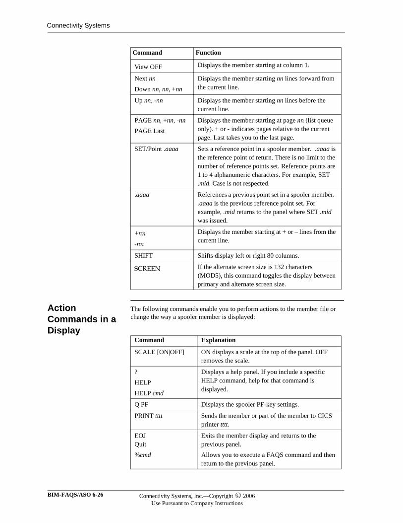
Connectivity Systems
Action Commands in a Display
The following commands enable you to perform actions to the member file or change the way a spooler member is displayed:
View OFF Displays the member starting at column 1.
Next nnDown nn, nn, +nn
Displays the member starting nn lines forward from the current line.
Up nn, -nn Displays the member starting nn lines before the current line.
PAGE nn, +nn, -nnPAGE Last
Displays the member starting at page nn (list queue only). + or - indicates pages relative to the current page. Last takes you to the last page.
SET/Point .aaaa Sets a reference point in a spooler member. .aaaa is the reference point of return. There is no limit to the number of reference points set. Reference points are 1 to 4 alphanumeric characters. For example, SET .mid. Case is not respected.
.aaaa References a previous point set in a spooler member. .aaaa is the previous reference point set. For example, .mid returns to the panel where SET .mid was issued.
+nn -nn
Displays the member starting at + or – lines from the current line.
SHIFT Shifts display left or right 80 columns.
SCREEN If the alternate screen size is 132 characters (MOD5), this command toggles the display between primary and alternate screen size.
Command Function
Command Explanation
SCALE [ON|OFF] ON displays a scale at the top of the panel. OFF removes the scale.
?HELPHELP cmd
Displays a help panel. If you include a specific HELP command, help for that command is displayed.
Q PF Displays the spooler PF-key settings.
PRINT tttt Sends the member or part of the member to CICS printer tttt.
EOJQuit%cmd
Exits the member display and returns to the previous panel.Allows you to execute a FAQS command and then return to the previous panel.
BIM-FAQS/ASO 6-26 Connectivity Systems, Inc.—Copyright © 2006Use Pursuant to Company Instructions
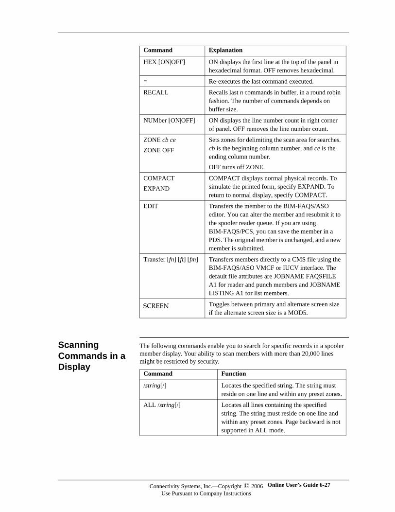
Scanning Commands in a Display
The following commands enable you to search for specific records in a spooler member display. Your ability to scan members with more than 20,000 lines might be restricted by security.
HEX [ON|OFF] ON displays the first line at the top of the panel in hexadecimal format. OFF removes hexadecimal.
= Re-executes the last command executed.
RECALL Recalls last n commands in buffer, in a round robin fashion. The number of commands depends on buffer size.
NUMber [ON|OFF] ON displays the line number count in right corner of panel. OFF removes the line number count.
ZONE cb ceZONE OFF
Sets zones for delimiting the scan area for searches. cb is the beginning column number, and ce is the ending column number.OFF turns off ZONE.
COMPACTEXPAND
COMPACT displays normal physical records. To simulate the printed form, specify EXPAND. To return to normal display, specify COMPACT.
EDIT Transfers the member to the BIM-FAQS/ASO editor. You can alter the member and resubmit it to the spooler reader queue. If you are using BIM-FAQS/PCS, you can save the member in a PDS. The original member is unchanged, and a new member is submitted.
Transfer [fn] [ft] [fm] Transfers members directly to a CMS file using the BIM-FAQS/ASO VMCF or IUCV interface. The default file attributes are JOBNAME FAQSFILE A1 for reader and punch members and JOBNAME LISTING A1 for list members.
SCREEN Toggles between primary and alternate screen size if the alternate screen size is a MOD5.
Command Explanation
Command Function
/string[/] Locates the specified string. The string must reside on one line and within any preset zones.
ALL /string[/] Locates all lines containing the specified string. The string must reside on one line and within any preset zones. Page backward is not supported in ALL mode.
Connectivity Systems, Inc.—Copyright © 2006Use Pursuant to Company Instructions
Online User’s Guide 6-27
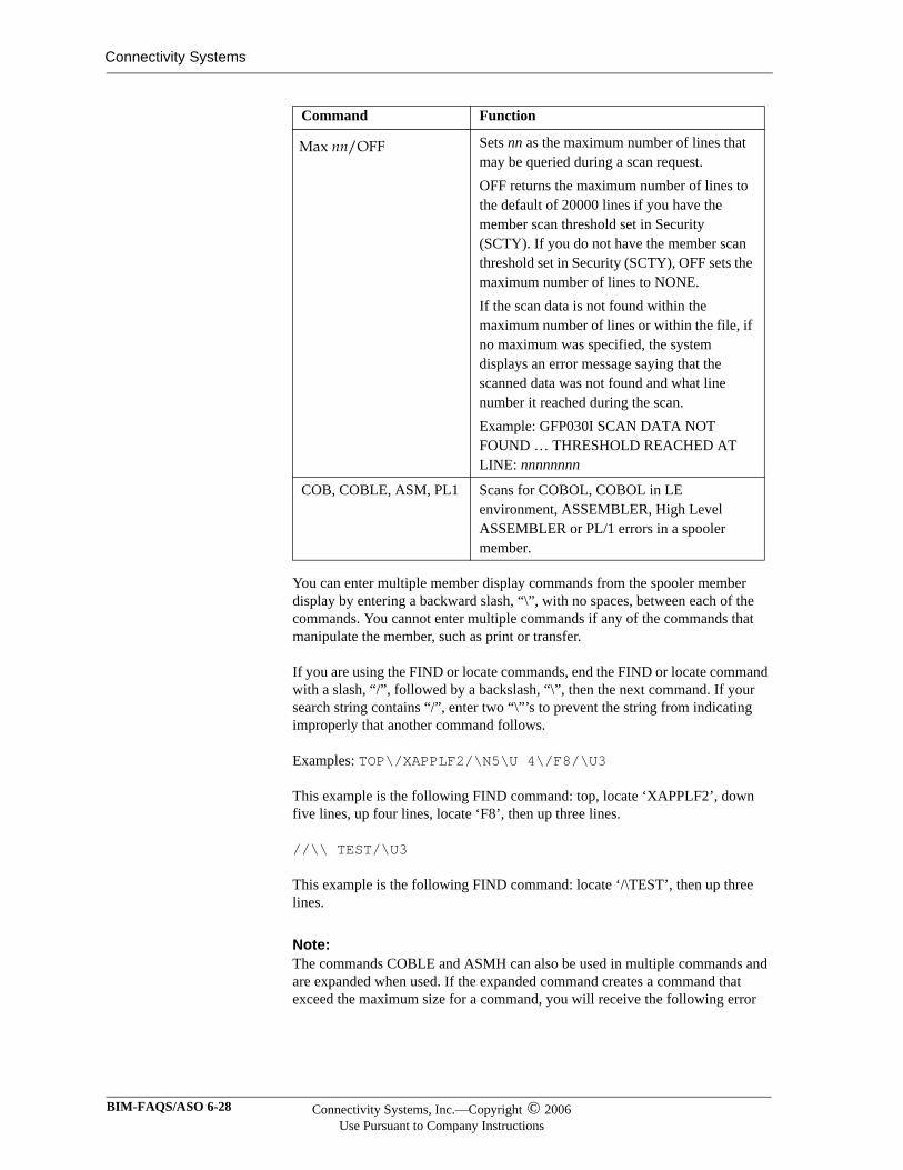
Connectivity Systems
You can enter multiple member display commands from the spooler member display by entering a backward slash, “\”, with no spaces, between each of the commands. You cannot enter multiple commands if any of the commands that manipulate the member, such as print or transfer.
If you are using the FIND or locate commands, end the FIND or locate command with a slash, “/”, followed by a backslash, “\”, then the next command. If your search string contains “/”, enter two “\”’s to prevent the string from indicating improperly that another command follows.
Examples: TOP\/XAPPLF2/\N5\U 4\/F8/\U3
This example is the following FIND command: top, locate ‘XAPPLF2’, down five lines, up four lines, locate ‘F8’, then up three lines.
//\\ TEST/\U3
This example is the following FIND command: locate ‘/\TEST’, then up three lines.
Note:Note:The commands COBLE and ASMH can also be used in multiple commands and are expanded when used. If the expanded command creates a command that exceed the maximum size for a command, you will receive the following error
Max nn/OFF Sets nn as the maximum number of lines that may be queried during a scan request. OFF returns the maximum number of lines to the default of 20000 lines if you have the member scan threshold set in Security (SCTY). If you do not have the member scan threshold set in Security (SCTY), OFF sets the maximum number of lines to NONE. If the scan data is not found within the maximum number of lines or within the file, if no maximum was specified, the system displays an error message saying that the scanned data was not found and what line number it reached during the scan. Example: GFP030I SCAN DATA NOT FOUND … THRESHOLD REACHED AT LINE: nnnnnnnn
COB, COBLE, ASM, PL1 Scans for COBOL, COBOL in LE environment, ASSEMBLER, High Level ASSEMBLER or PL/1 errors in a spooler member.
Command Function
BIM-FAQS/ASO 6-28 Connectivity Systems, Inc.—Copyright © 2006Use Pursuant to Company Instructions

message: GFP025I INVALID COLUMN SPECIFICATION
Connectivity Systems, Inc.—Copyright © 2006Use Pursuant to Company Instructions
Online User’s Guide 6-29

Connectivity Systems
BIM-FAQS/ASO 6-30 Connectivity Systems, Inc.—Copyright © 2006Use Pursuant to Company Instructions
Chapter 7
Online Displays and Reports
In This Chapter
This chapter explains the online commands and accompanying displays that BIM-FAQS/ASO provides.
Overview BIM-FAQS/ASO helps increase the efficiency of your VSE system by providing the following online features:
Online console interface
Online displays and reports
Message routing
Online Console Interface
The console interface provided by BIM-FAQS/ASO allows you to view the console and enter operator and POWER commands, and partition replies.
Online Displays and Reports
The online displays and reports allow you to monitor your system's partition and DASD activity.
Message Routing
The message routing feature allows you to send messages to those who are interested in the messages. The message text and user ID determine where a message is sent.
For VSE/ESA version 2 and above, you can specify a filter name to route messages instead of specifying a partition ID. For example, in previous versions of BIM-FAQS/ASO, the command D C,ID=BG would route all messages from the BG partition to the console. Now, you can create a filter and specify the filter name instead of the partition ID as part of the D C,ID= command -- for example, D C,ID=ABC where ABC is the name of a user-defined filter.
For information about using filters, see Chapter 4, “Security and User Configuration.”
Online User’s Guide 7-1
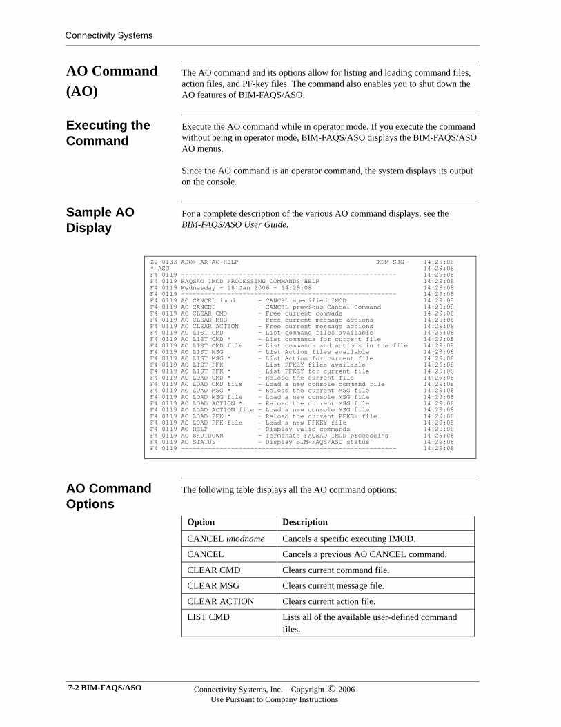
Connectivity Systems
AO Command (AO)
The AO command and its options allow for listing and loading command files, action files, and PF-key files. The command also enables you to shut down the AO features of BIM-FAQS/ASO.
Executing the Command
Execute the AO command while in operator mode. If you execute the command without being in operator mode, BIM-FAQS/ASO displays the BIM-FAQS/ASO AO menus.
Since the AO command is an operator command, the system displays its output on the console.
Sample AO Display
For a complete description of the various AO command displays, see the BIM-FAQS/ASO User Guide.
AO Command Options
The following table displays all the AO command options:
Z2 0133 ASO> AR AO HELP XCM SJG 14:29:08 * ASO 14:29:08 F4 0119 -------------------------------------------------------- 14:29:08 F4 0119 FAQSAO IMOD PROCESSING COMMANDS HELP 14:29:08 F4 0119 Wednesday - 18 Jan 2006 - 14:29:08 14:29:08 F4 0119 -------------------------------------------------------- 14:29:08 F4 0119 AO CANCEL imod - CANCEL specified IMOD 14:29:08 F4 0119 AO CANCEL - CANCEL previous Cancel Command 14:29:08 F4 0119 AO CLEAR CMD - Free current commads 14:29:08 F4 0119 AO CLEAR MSG - Free current message actions 14:29:08 F4 0119 AO CLEAR ACTION - Free current message actions 14:29:08 F4 0119 AO LIST CMD - List command files available 14:29:08 F4 0119 AO LIST CMD * - List commands for current file 14:29:08 F4 0119 AO LIST CMD file - List commands and actions in the file 14:29:08 F4 0119 AO LIST MSG - List Action files available 14:29:08 F4 0119 AO LIST MSG * - List Action for current file 14:29:08 F4 0119 AO LIST PFK - List PFKEY files available 14:29:08 F4 0119 AO LIST PFK * - List PFKEY for current file 14:29:08 F4 0119 AO LOAD CMD * - Reload the current file 14:29:08 F4 0119 AO LOAD CMD file - Load a new console command file 14:29:08 F4 0119 AO LOAD MSG * - Reload the current MSG file 14:29:08 F4 0119 AO LOAD MSG file - Load a new console MSG file 14:29:08 F4 0119 AO LOAD ACTION * - Reload the current MSG file 14:29:08 F4 0119 AO LOAD ACTION file - Load a new console MSG file 14:29:08 F4 0119 AO LOAD PFK * - Reload the current PFKEY file 14:29:08 F4 0119 AO LOAD PFK file - Load a new PFKEY file 14:29:08 F4 0119 AO HELP - Display valid commands 14:29:08 F4 0119 AO SHUTDOWN - Terminate FAQSAO IMOD processing 14:29:08 F4 0119 AO STATUS - Display BIM-FAQS/ASO status 14:29:08 F4 0119 -------------------------------------------------------- 14:29:08
Option Description
CANCEL imodname Cancels a specific executing IMOD.
CANCEL Cancels a previous AO CANCEL command.
CLEAR CMD Clears current command file.
CLEAR MSG Clears current message file.
CLEAR ACTION Clears current action file.
LIST CMD Lists all of the available user-defined command files.
7-2 BIM-FAQS/ASO Connectivity Systems, Inc.—Copyright © 2006Use Pursuant to Company Instructions
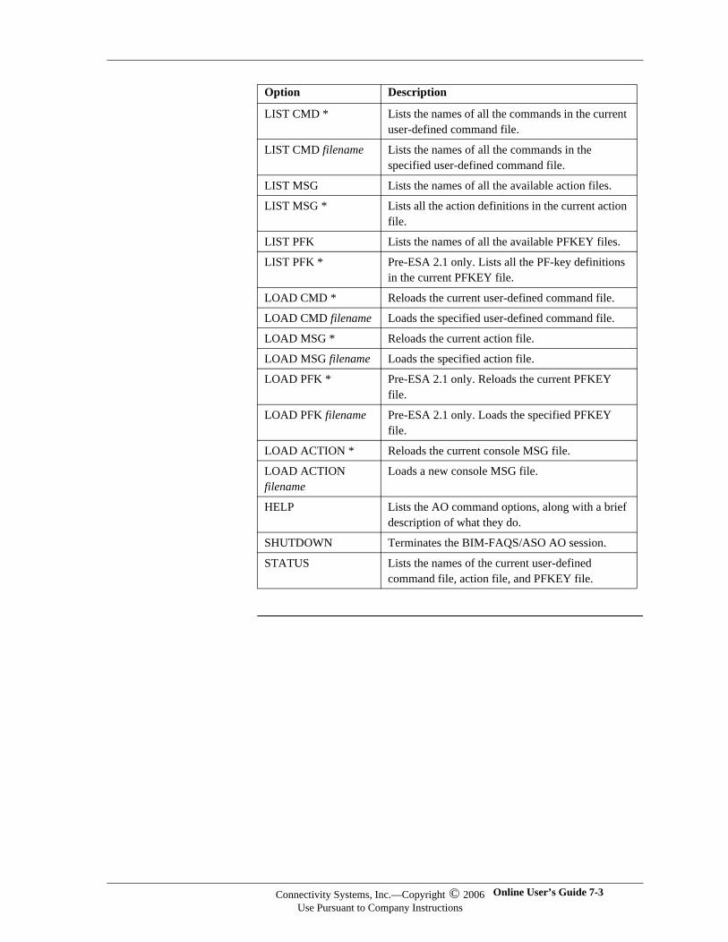
LIST CMD * Lists the names of all the commands in the current user-defined command file.
LIST CMD filename Lists the names of all the commands in the specified user-defined command file.
LIST MSG Lists the names of all the available action files.
LIST MSG * Lists all the action definitions in the current action file.
LIST PFK Lists the names of all the available PFKEY files.
LIST PFK * Pre-ESA 2.1 only. Lists all the PF-key definitions in the current PFKEY file.
LOAD CMD * Reloads the current user-defined command file.
LOAD CMD filename Loads the specified user-defined command file.
LOAD MSG * Reloads the current action file.
LOAD MSG filename Loads the specified action file.
LOAD PFK * Pre-ESA 2.1 only. Reloads the current PFKEY file.
LOAD PFK filename Pre-ESA 2.1 only. Loads the specified PFKEY file.
LOAD ACTION * Reloads the current console MSG file.
LOAD ACTION filename
Loads a new console MSG file.
HELP Lists the AO command options, along with a brief description of what they do.
SHUTDOWN Terminates the BIM-FAQS/ASO AO session.
STATUS Lists the names of the current user-defined command file, action file, and PFKEY file.
Option Description
Connectivity Systems, Inc.—Copyright © 2006Use Pursuant to Company Instructions
Online User’s Guide 7-3
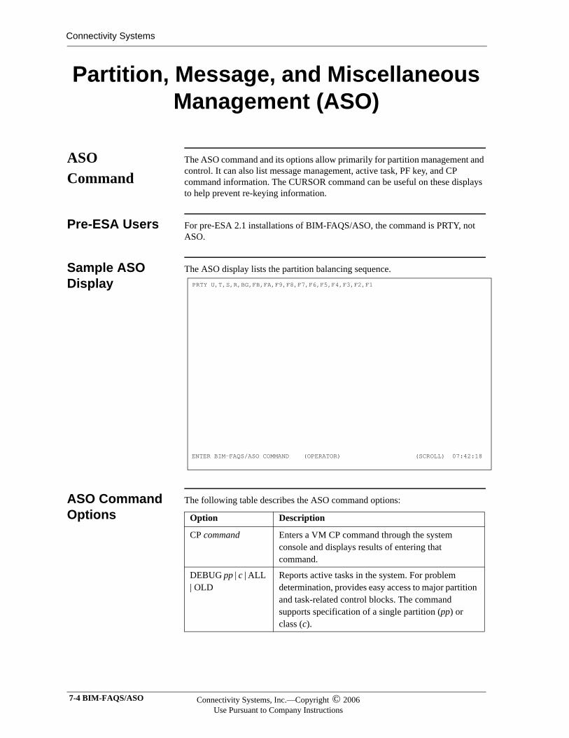
Connectivity Systems
Partition, Message, and Miscellaneous Management (ASO)
ASO Command
The ASO command and its options allow primarily for partition management and control. It can also list message management, active task, PF key, and CP command information. The CURSOR command can be useful on these displays to help prevent re-keying information.
Pre-ESA Users For pre-ESA 2.1 installations of BIM-FAQS/ASO, the command is PRTY, not ASO.
Sample ASO Display
The ASO display lists the partition balancing sequence.
ASO Command Options
The following table describes the ASO command options:
PRTY U,T,S,R,BG,FB,FA,F9,F8,F7,F6,F5,F4,F3,F2,F1 ENTER BIM-FAQS/ASO COMMAND (OPERATOR) (SCROLL) 07:42:18
Option Description
CP command Enters a VM CP command through the system console and displays results of entering that command.
DEBUG pp | c | ALL | OLD
Reports active tasks in the system. For problem determination, provides easy access to major partition and task-related control blocks. The command supports specification of a single partition (pp) or class (c).
7-4 BIM-FAQS/ASO Connectivity Systems, Inc.—Copyright © 2006Use Pursuant to Company Instructions
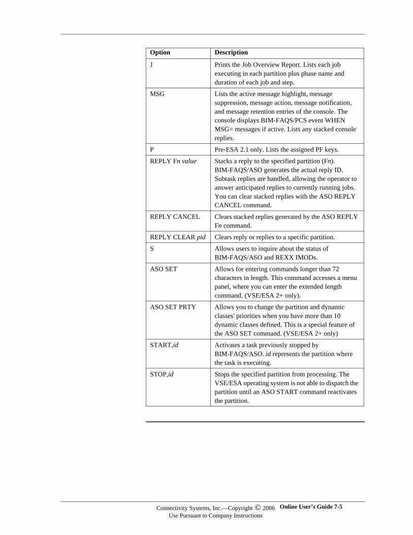
J Prints the Job Overview Report. Lists each job executing in each partition plus phase name and duration of each job and step.
MSG Lists the active message highlight, message suppression, message action, message notification, and message retention entries of the console. The console displays BIM-FAQS/PCS event WHEN MSG= messages if active. Lists any stacked console replies.
P Pre-ESA 2.1 only. Lists the assigned PF keys.
REPLY Fn value Stacks a reply to the specified partition (Fn). BIM-FAQS/ASO generates the actual reply ID. Subtask replies are handled, allowing the operator to answer anticipated replies to currently running jobs. You can clear stacked replies with the ASO REPLY CANCEL command.
REPLY CANCEL Clears stacked replies generated by the ASO REPLY Fn command.
REPLY CLEAR pid Clears reply or replies to a specific partition.
S Allows users to inquire about the status of BIM-FAQS/ASO and REXX IMODs.
ASO SET Allows for entering commands longer than 72 characters in length. This command accesses a menu panel, where you can enter the extended length command. (VSE/ESA 2+ only).
ASO SET PRTY Allows you to change the partition and dynamic classes' priorities when you have more than 10 dynamic classes defined. This is a special feature of the ASO SET command. (VSE/ESA 2+ only)
START,id Activates a task previously stopped by BIM-FAQS/ASO. id represents the partition where the task is executing.
STOP,id Stops the specified partition from processing. The VSE/ESA operating system is not able to dispatch the partition until an ASO START command reactivates the partition.
Option Description
Connectivity Systems, Inc.—Copyright © 2006Use Pursuant to Company Instructions
Online User’s Guide 7-5
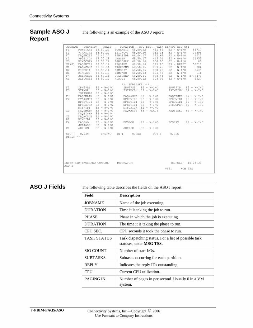
Connectivity Systems
Sample ASO J Report
The following is an example of the ASO J report:
ASO J Fields The following table describes the fields on the ASO J report:
JOBNAME DURATION PHASE DURATION CPU SEC. TASK STATUS SIO CNT F1 POWSTART 68.50.23 POWRNET3 68.50.22 481.53 82 - W-I/O 88717 F3 VTAMSTRT 68.50.20 ISTINCVT 68.50.20 062.18 82 - W-I/O 29896 F7 FAQSMTS2 06.44.17 BIM$TIDR 06.44.17 022.64 82 - W-I/O 1610 F2 VB31ICCF 68.50.18 DFHSIP 68.50.17 445.01 82 - W-I/O 11352 Z3 BIM$CGRX 68.50.16 BIM$CGRX 68.50.16 000.00 82 - W-I/O 107 Z2(0) FAQSMTS1 68.50.16 FAQSIUX 68.50.16 195.85 83 - READY 58210 Z1 FAQXCONS 68.50.16 FAQXCONS 68.50.16 003.25 82 - W-I/O 304 R2 BIMEDIT 68.50.16 BIMEDIT 68.50.16 000.20 82 - W-I/O 2545 R1 BIMPADS 68.50.13 BIMPADS 68.50.13 001.46 82 - W-I/O 111 F4 JCLSCHED 68.50.16 JCLSCHED 68.50.16 978.44 82 - W-I/O 5777470 C1 ALTLOG52 68.50.12 ALRTL1 68.50.12 003.02 82 - W-I/O 5527 *** SUBTASKS *** F1 IPW$$LS 82 - W-I/O IPW$$S1 82 - W-I/O IPW$$TD 82 - W-I/O F3 VTAMRP 82 - W-I/O ISTPDCLU 82 - W-I/O ISTMTINV 82 - W-I/O ISTINMLS 82 - W-I/O F7 FAQSMAIN 82 - W-I/O FAQXASUB 82 - W-I/O FAQSTSKG 82 - W-I/O F2 EVA10MST 82 - W-I/O DFHEVID2 82 - W-I/O DFHEVID1 82 - W-I/O DFHEVID1 82 - W-I/O DFHEVID1 82 - W-I/O DFHEVID1 82 - W-I/O DFHSKTSK 82 - W-I/O DFHEVID1 82 - W-I/O DTSCOPCM 82 - W-I/O DTSNTFY 82 - W-I/O DTSCHIGH 82 - W-I/O Z2 FAQSMAIN 82 - W-I/O FAQXASUB 83 - READY FAQSTSKG 82 - W-I/O FAQSTSKP 82 - W-I/O Z1 FAQXCSUB 82 - W-I/O R2 BIMLIBR 82 - W-I/O F4 FAQSAO 82 - W-I/O PCSLOG 82 - W-I/O PCSSRV 82 - W-I/O JCLTASK 82 - W-I/O C1 AXPLQM 82 - W-I/O AXPLIO 82 - W-I/O CPU : 0.93% PAGING IN : 0/SEC OUT : 0/SEC REPLY -> ENTER BIM-FAQS/ASO COMMAND (OPERATOR) (SCROLL) 15:24:30 ASO J VB31 XCM SJG
Field Description
JOBNAME Name of the job executing.
DURATION Time it is taking the job to run.
PHASE Phase in which the job is executing.
DURATION The time it is taking the phase to run.
CPU SEC. CPU seconds it took the phase to run.
TASK STATUS Task dispatching status. For a list of possible task statuses, enter MSG TSS.
SIO COUNT Number of start I/Os.
SUBTASKS Subtasks occurring for each partition.
REPLY Indicates the reply IDs outstanding.
CPU Current CPU utilization.
PAGING IN Number of pages in per second. Usually 0 in a VM system.
7-6 BIM-FAQS/ASO Connectivity Systems, Inc.—Copyright © 2006Use Pursuant to Company Instructions
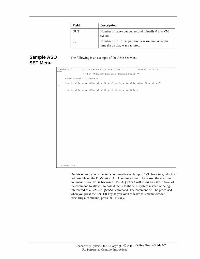
Sample ASO SET Menu
The following is an example of the ASO Set Menu
On this screen, you can enter a command or reply up to 123 characters, which is not possible on the BIM-FAQS/ASO command line. The reason the maximum command is not 126 is because BIM-FAQS/ASO will insert an 'OP ' in front of the command to allow it to pass directly to the VSE system instead of being interpreted as a BIM-FAQS/ASO command. The command will be processed when you press the ENTER key. If you wish to leave this menu without executing a command, press the PF3 key.
OUT Number of pages out per second. Usually 0 in a VM system.
(n) Number of CEC that partition was running on at the time the display was captured.
Field Description
FAQMENCM.* ** BIM-FAQS/ASO Online V5.3A ** ID=VB31.PROFILE ===> ** BIM-FAQS/ASO Extended Command Panel ** Enter command to process 1...5...10....5...20....5...30....5...40....5...50....5...60....5...70 Cmd: ....5...80....5...90....5..100....5..110....5..120... PF3=Return
Connectivity Systems, Inc.—Copyright © 2006Use Pursuant to Company Instructions
Online User’s Guide 7-7
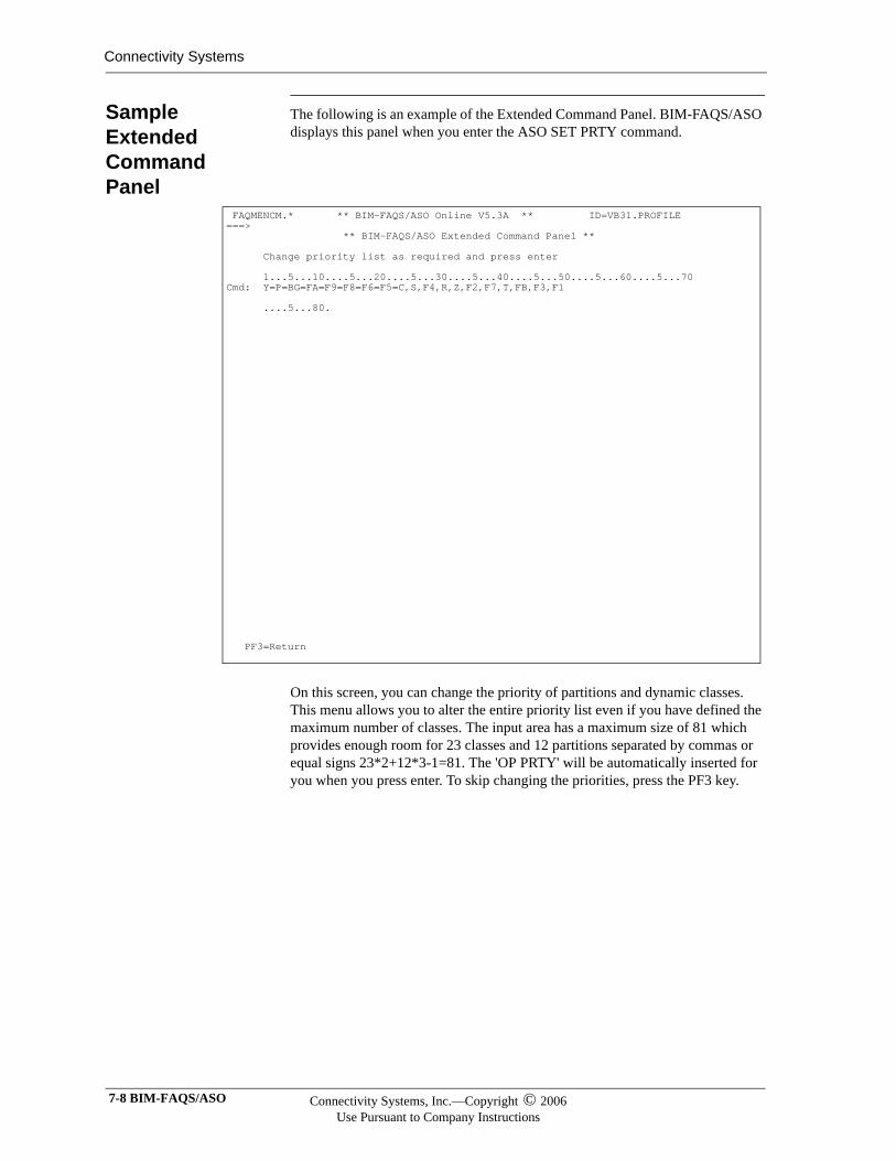
Connectivity Systems
Sample Extended Command Panel
The following is an example of the Extended Command Panel. BIM-FAQS/ASO displays this panel when you enter the ASO SET PRTY command.
On this screen, you can change the priority of partitions and dynamic classes. This menu allows you to alter the entire priority list even if you have defined the maximum number of classes. The input area has a maximum size of 81 which provides enough room for 23 classes and 12 partitions separated by commas or equal signs 23*2+12*3-1=81. The 'OP PRTY' will be automatically inserted for you when you press enter. To skip changing the priorities, press the PF3 key.
FAQMENCM.* ** BIM-FAQS/ASO Online V5.3A ** ID=VB31.PROFILE ===> ** BIM-FAQS/ASO Extended Command Panel ** Change priority list as required and press enter 1...5...10....5...20....5...30....5...40....5...50....5...60....5...70 Cmd: Y=P=BG=FA=F9=F8=F6=F5=C,S,F4,R,Z,F2,F7,T,FB,F3,F1 ....5...80. PF3=Return
7-8 BIM-FAQS/ASO Connectivity Systems, Inc.—Copyright © 2006Use Pursuant to Company Instructions
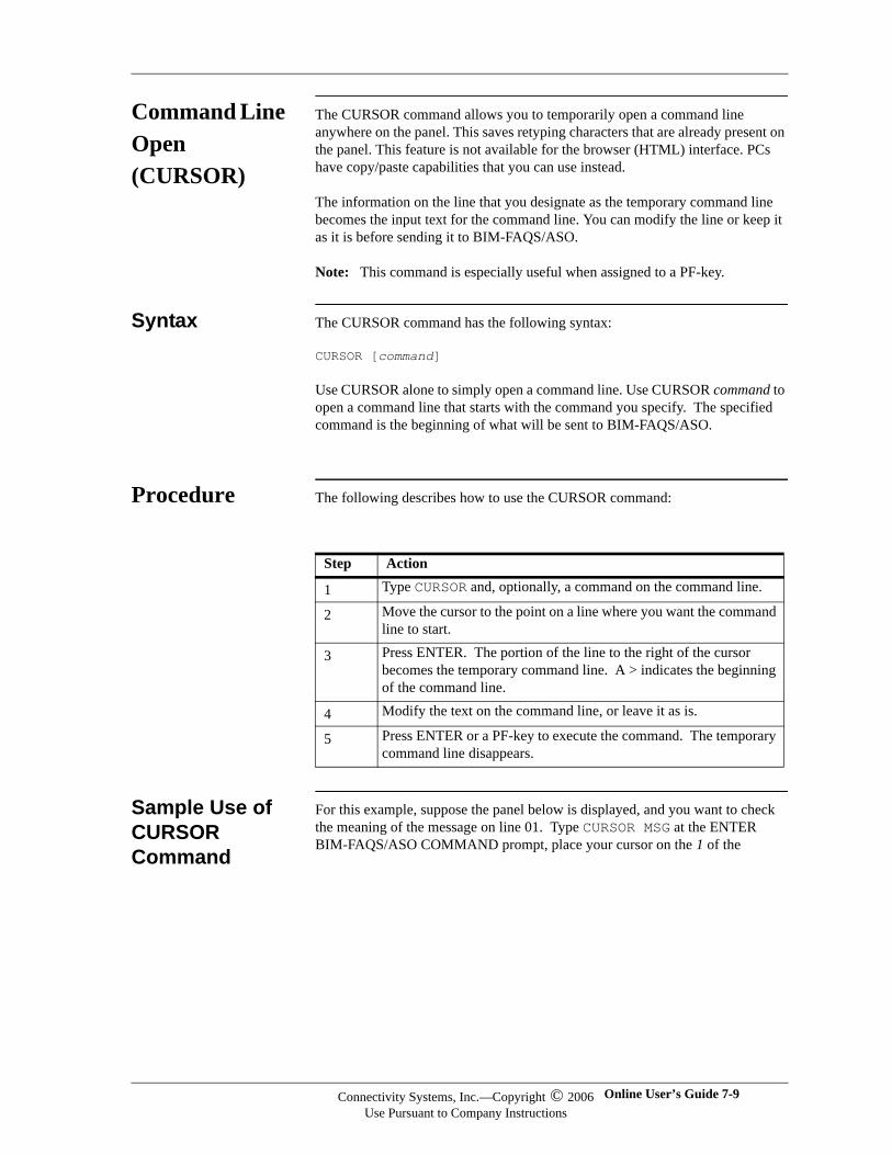
Command Line Open (CURSOR)
The CURSOR command allows you to temporarily open a command line anywhere on the panel. This saves retyping characters that are already present on the panel. This feature is not available for the browser (HTML) interface. PCs have copy/paste capabilities that you can use instead.
The information on the line that you designate as the temporary command line becomes the input text for the command line. You can modify the line or keep it as it is before sending it to BIM-FAQS/ASO.
Note: This command is especially useful when assigned to a PF-key.
Syntax The CURSOR command has the following syntax:
CURSOR [command]
Use CURSOR alone to simply open a command line. Use CURSOR command to open a command line that starts with the command you specify. The specified command is the beginning of what will be sent to BIM-FAQS/ASO.
Procedure The following describes how to use the CURSOR command:
Sample Use of CURSOR Command
For this example, suppose the panel below is displayed, and you want to check the meaning of the message on line 01. Type CURSOR MSG at the ENTER BIM-FAQS/ASO COMMAND prompt, place your cursor on the 1 of the
Step Action
1 Type CURSOR and, optionally, a command on the command line.
2 Move the cursor to the point on a line where you want the command line to start.
3 Press ENTER. The portion of the line to the right of the cursor becomes the temporary command line. A > indicates the beginning of the command line.
4 Modify the text on the command line, or leave it as is.
5 Press ENTER or a PF-key to execute the command. The temporary command line disappears.
Connectivity Systems, Inc.—Copyright © 2006Use Pursuant to Company Instructions
Online User’s Guide 7-9
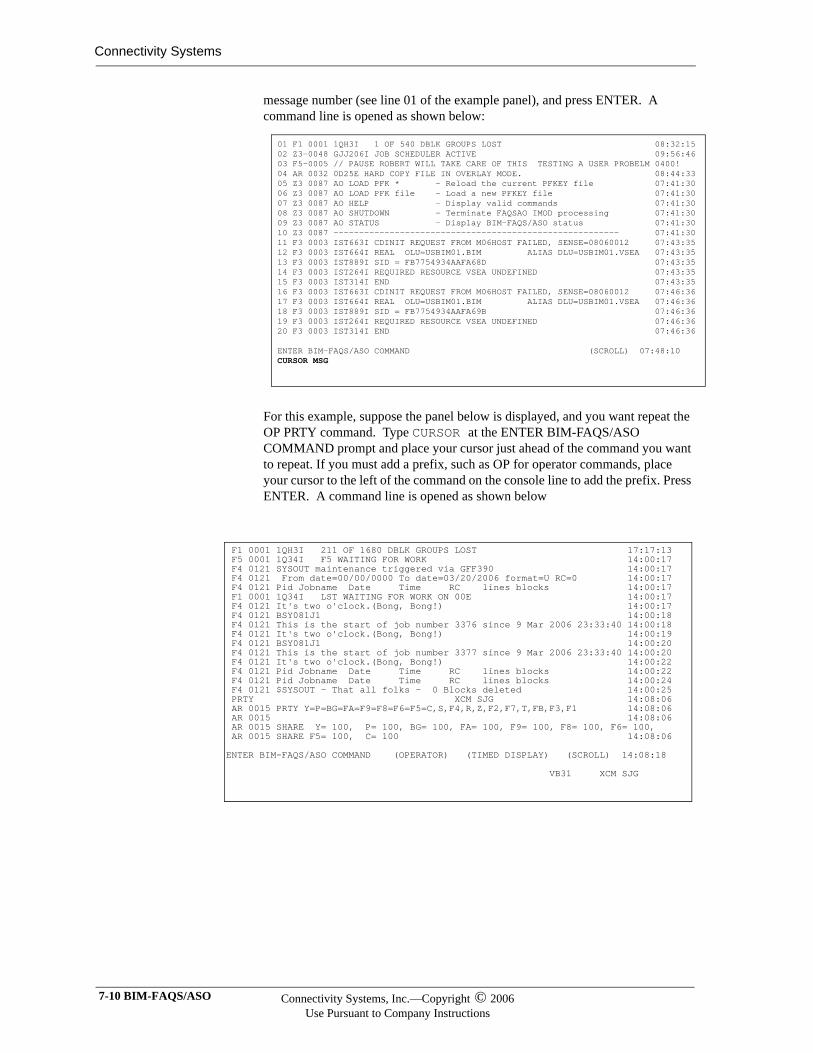
Connectivity Systems
message number (see line 01 of the example panel), and press ENTER. A command line is opened as shown below:
For this example, suppose the panel below is displayed, and you want repeat the OP PRTY command. Type CURSOR at the ENTER BIM-FAQS/ASO COMMAND prompt and place your cursor just ahead of the command you want to repeat. If you must add a prefix, such as OP for operator commands, place your cursor to the left of the command on the console line to add the prefix. Press ENTER. A command line is opened as shown below
01 F1 0001 1QH3I 1 OF 540 DBLK GROUPS LOST 08:32:1502 Z3-0048 GJJ206I JOB SCHEDULER ACTIVE 09:56:4603 F5-0005 // PAUSE ROBERT WILL TAKE CARE OF THIS TESTING A USER PROBELM 0400! 04 AR 0032 0D25E HARD COPY FILE IN OVERLAY MODE. 08:44:3305 Z3 0087 AO LOAD PFK * - Reload the current PFKEY file 07:41:3006 Z3 0087 AO LOAD PFK file - Load a new PFKEY file 07:41:3007 Z3 0087 AO HELP - Display valid commands 07:41:3008 Z3 0087 AO SHUTDOWN - Terminate FAQSAO IMOD processing 07:41:3009 Z3 0087 AO STATUS - Display BIM-FAQS/ASO status 07:41:3010 Z3 0087 -------------------------------------------------------- 07:41:3011 F3 0003 IST663I CDINIT REQUEST FROM M06HOST FAILED, SENSE=08060012 07:43:3512 F3 0003 IST664I REAL OLU=USBIM01.BIM ALIAS DLU=USBIM01.VSEA 07:43:3513 F3 0003 IST889I SID = FB7754934AAFA68D 07:43:3514 F3 0003 IST264I REQUIRED RESOURCE VSEA UNDEFINED 07:43:3515 F3 0003 IST314I END 07:43:3516 F3 0003 IST663I CDINIT REQUEST FROM M06HOST FAILED, SENSE=08060012 07:46:3617 F3 0003 IST664I REAL OLU=USBIM01.BIM ALIAS DLU=USBIM01.VSEA 07:46:3618 F3 0003 IST889I SID = FB7754934AAFA69B 07:46:3619 F3 0003 IST264I REQUIRED RESOURCE VSEA UNDEFINED 07:46:3620 F3 0003 IST314I END 07:46:36 ENTER BIM-FAQS/ASO COMMAND (SCROLL) 07:48:10 CURSOR MSG
F1 0001 1QH3I 211 OF 1680 DBLK GROUPS LOST 17:17:13 F5 0001 1Q34I F5 WAITING FOR WORK 14:00:17 F4 0121 SYSOUT maintenance triggered via GFF390 14:00:17 F4 0121 From date=00/00/0000 To date=03/20/2006 format=U RC=0 14:00:17 F4 0121 Pid Jobname Date Time RC lines blocks 14:00:17 F1 0001 1Q34I LST WAITING FOR WORK ON 00E 14:00:17 F4 0121 It's two o'clock.(Bong, Bong!) 14:00:17 F4 0121 BSY081J1 14:00:18 F4 0121 This is the start of job number 3376 since 9 Mar 2006 23:33:40 14:00:18 F4 0121 It's two o'clock.(Bong, Bong!) 14:00:19 F4 0121 BSY081J1 14:00:20 F4 0121 This is the start of job number 3377 since 9 Mar 2006 23:33:40 14:00:20 F4 0121 It's two o'clock.(Bong, Bong!) 14:00:22 F4 0121 Pid Jobname Date Time RC lines blocks 14:00:22 F4 0121 Pid Jobname Date Time RC lines blocks 14:00:24 F4 0121 $SYSOUT - That all folks - 0 Blocks deleted 14:00:25 PRTY XCM SJG 14:08:06 AR 0015 PRTY Y=P=BG=FA=F9=F8=F6=F5=C,S,F4,R,Z,F2,F7,T,FB,F3,F1 14:08:06 AR 0015 14:08:06 AR 0015 SHARE Y= 100, P= 100, BG= 100, FA= 100, F9= 100, F8= 100, F6= 100, AR 0015 SHARE F5= 100, C= 100 14:08:06 ENTER BIM-FAQS/ASO COMMAND (OPERATOR) (TIMED DISPLAY) (SCROLL) 14:08:18 VB31 XCM SJG
7-10 BIM-FAQS/ASO Connectivity Systems, Inc.—Copyright © 2006Use Pursuant to Company Instructions
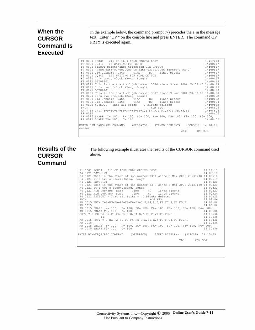
When the CURSOR Command Is Executed
In the example below, the command prompt (>) precedes the 1 in the message text. Enter “OP “ on the console line and press ENTER. The command OP PRTY is executed again.
Results of the CURSOR Command
The following example illustrates the results of the CURSOR command used above.
F1 0001 1QH3I 211 OF 1680 DBLK GROUPS LOST 17:17:13 F5 0001 1Q34I F5 WAITING FOR WORK 14:00:17 F4 0121 SYSOUT maintenance triggered via GFF390 14:00:17 F4 0121 From date=00/00/0000 To date=03/20/2006 format=U RC=0 14:00:17 F4 0121 Pid Jobname Date Time RC lines blocks 14:00:17 F1 0001 1Q34I LST WAITING FOR WORK ON 00E 14:00:17 F4 0121 It's two o'clock.(Bong, Bong!) 14:00:17 F4 0121 BSY081J1 14:00:18 F4 0121 This is the start of job number 3376 since 9 Mar 2006 23:33:40 14:00:18 F4 0121 It's two o'clock.(Bong, Bong!) 14:00:19 F4 0121 BSY081J1 14:00:20 F4 0121 This is the start of job number 3377 since 9 Mar 2006 23:33:40 14:00:20 F4 0121 It's two o'clock.(Bong, Bong!) 14:00:22 F4 0121 Pid Jobname Date Time RC lines blocks 14:00:22 F4 0121 Pid Jobname Date Time RC lines blocks 14:00:24 F4 0121 $SYSOUT - That all folks - 0 Blocks deleted 14:00:25 PRTY XCM SJG 14:08:06 AR > 15 PRTY Y=P=BG=FA=F9=F8=F6=F5=C,S,F4,R,Z,F2,F7,T,FB,F3,F1 14:08:06 AR 0015 14:08:06 AR 0015 SHARE Y= 100, P= 100, BG= 100, FA= 100, F9= 100, F8= 100, F6= 100, AR 0015 SHARE F5= 100, C= 100 14:08:06 ENTER BIM-FAQS/ASO COMMAND (OPERATOR) (TIMED DISPLAY) (SCROLL) 14:10:12 cursor VB31 XCM SJG
F1 0001 1QH3I 211 OF 1680 DBLK GROUPS LOST 17:17:13 F4 0121 BSY081J1 14:00:18 F4 0121 This is the start of job number 3376 since 9 Mar 2006 23:33:40 14:00:18 F4 0121 It's two o'clock.(Bong, Bong!) 14:00:19 F4 0121 BSY081J1 14:00:20 F4 0121 This is the start of job number 3377 since 9 Mar 2006 23:33:40 14:00:20 F4 0121 It's two o'clock.(Bong, Bong!) 14:00:22 F4 0121 Pid Jobname Date Time RC lines blocks 14:00:22 F4 0121 Pid Jobname Date Time RC lines blocks 14:00:24 F4 0121 $SYSOUT - That all folks - 0 Blocks deleted 14:00:25 PRTY XCM SJG 14:08:06 AR 0015 PRTY Y=P=BG=FA=F9=F8=F6=F5=C,S,F4,R,Z,F2,F7,T,FB,F3,F1 14:08:06 AR 0015 14:08:06 AR 0015 SHARE Y= 100, P= 100, BG= 100, FA= 100, F9= 100, F8= 100, F6= 100, AR 0015 SHARE F5= 100, C= 100 14:08:06 PRTY Y=P=BG=FA=F9=F8=F6=F5=C,S,F4,R,Z,F2,F7,T,FB,F3,F1 14:10:36 14: 14:10:36 AR 0015 PRTY Y=P=BG=FA=F9=F8=F6=F5=C,S,F4,R,Z,F2,F7,T,FB,F3,F1 14:10:36 AR 0015 14:10:36 AR 0015 SHARE Y= 100, P= 100, BG= 100, FA= 100, F9= 100, F8= 100, F6= 100, AR 0015 SHARE F5= 100, C= 100 14:10:36 ENTER BIM-FAQS/ASO COMMAND (OPERATOR) (TIMED DISPLAY) (SCROLL) 14:15:29 VB31 XCM SJG
Connectivity Systems, Inc.—Copyright © 2006Use Pursuant to Company Instructions
Online User’s Guide 7-11
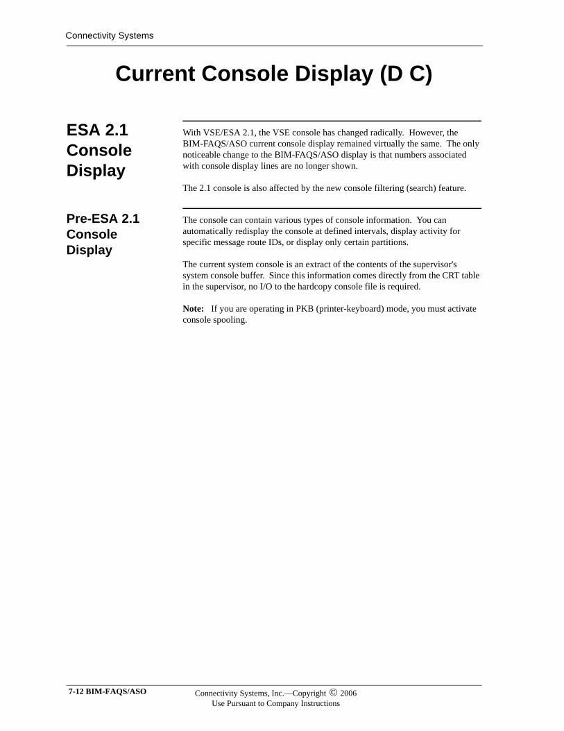
Connectivity Systems
Current Console Display (D C)
ESA 2.1 Console Display
With VSE/ESA 2.1, the VSE console has changed radically. However, the BIM-FAQS/ASO current console display remained virtually the same. The only noticeable change to the BIM-FAQS/ASO display is that numbers associated with console display lines are no longer shown.
The 2.1 console is also affected by the new console filtering (search) feature.
Pre-ESA 2.1 Console Display
The console can contain various types of console information. You can automatically redisplay the console at defined intervals, display activity for specific message route IDs, or display only certain partitions.
The current system console is an extract of the contents of the supervisor's system console buffer. Since this information comes directly from the CRT table in the supervisor, no I/O to the hardcopy console file is required.
Note: If you are operating in PKB (printer-keyboard) mode, you must activate console spooling.
7-12 BIM-FAQS/ASO Connectivity Systems, Inc.—Copyright © 2006Use Pursuant to Company Instructions
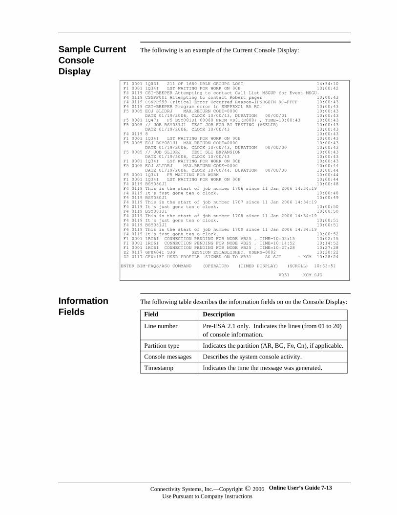
Sample Current Console Display
The following is an example of the Current Console Display:
Information Fields
The following table describes the information fields on on the Console Display:
F1 0001 1QH3I 211 OF 1680 DBLK GROUPS LOST 14:34:10 F1 0001 1Q34I LST WAITING FOR WORK ON 00E 10:00:42 F4 0119 CSI-BEEPER Attempting to contact Call List MSGUP for Event MSGU. F4 0119 CSNPP001 Attempting to contact Robert pager 10:00:43 F4 0119 CSNPP999 Critical Error Occurred Reason=IPNRGETN RC=FFFF 10:00:43 F4 0119 CSI-BEEPER Program error in SNPPRXCL BA RC. 10:00:43 F5 0005 EOJ SLIDRJ MAX.RETURN CODE=0000 10:00:43 DATE 01/19/2006, CLOCK 10/00/43, DURATION 00/00/01 10:00:43 F5 0001 1Q47I F5 BSY081J1 00080 FROM VB31(R000) , TIME=10:00:43 10:00:43 F5 0005 // JOB BSY081J1 TEST JOB FOR BI TESTING (VSELIB) 10:00:43 DATE 01/19/2006, CLOCK 10/00/43 10:00:43 F4 0119 8 10:00:43 F1 0001 1Q34I LST WAITING FOR WORK ON 00E 10:00:43 F5 0005 EOJ BSY081J1 MAX.RETURN CODE=0000 10:00:43 DATE 01/19/2006, CLOCK 10/00/43, DURATION 00/00/00 10:00:43 F5 0005 // JOB SLIDRJ TEST SLI EXPANSION 10:00:43 DATE 01/19/2006, CLOCK 10/00/43 10:00:43 F1 0001 1Q34I LST WAITING FOR WORK ON 00E 10:00:43 F5 0005 EOJ SLIDRJ MAX.RETURN CODE=0000 10:00:44 DATE 01/19/2006, CLOCK 10/00/44, DURATION 00/00/00 10:00:44 F5 0001 1Q34I F5 WAITING FOR WORK 10:00:44 F1 0001 1Q34I LST WAITING FOR WORK ON 00E 10:00:44 F4 0119 BSY080J1 10:00:48 F4 0119 This is the start of job number 1706 since 11 Jan 2006 14:34:19 F4 0119 It's just gone ten o'clock. 10:00:48 F4 0119 BSY080J1 10:00:49 F4 0119 This is the start of job number 1707 since 11 Jan 2006 14:34:19 F4 0119 It's just gone ten o'clock. 10:00:50 F4 0119 BSY081J1 10:00:50 F4 0119 This is the start of job number 1708 since 11 Jan 2006 14:34:19 F4 0119 It's just gone ten o'clock. 10:00:51 F4 0119 BSY081J1 10:00:51 F4 0119 This is the start of job number 1709 since 11 Jan 2006 14:34:19 F4 0119 It's just gone ten o'clock. 10:00:52 F1 0001 1RC6I CONNECTION PENDING FOR NODE VB25 , TIME=10:02:15 10:02:15 F1 0001 1RC6I CONNECTION PENDING FOR NODE VB25 , TIME=10:14:52 10:14:52 F1 0001 1RC6I CONNECTION PENDING FOR NODE VB25 , TIME=10:27:28 10:27:28 Z2 0117 GFX404I SJG SESSION ESTABLISHED, USERS=0002 10:28:22 Z2 0117 GFX415I USER PROFILE SIGNED ON TO VB31 AS SJG - XCM 10:28:24 ENTER BIM-FAQS/ASO COMMAND (OPERATOR) (TIMED DISPLAY) (SCROLL) 10:33:51 VB31 XCM SJG
Field Description
Line number Pre-ESA 2.1 only. Indicates the lines (from 01 to 20) of console information.
Partition type Indicates the partition (AR, BG, Fn, Cn), if applicable.
Console messages Describes the system console activity.
Timestamp Indicates the time the message was generated.
Connectivity Systems, Inc.—Copyright © 2006Use Pursuant to Company Instructions
Online User’s Guide 7-13
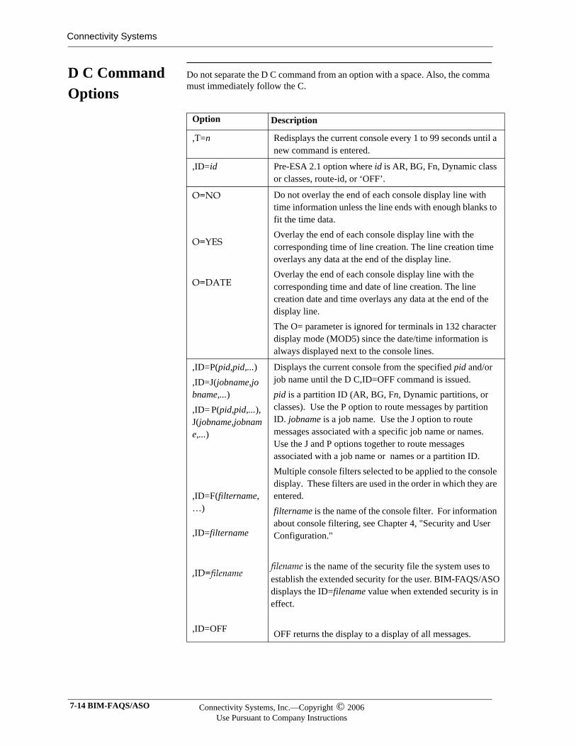
Connectivity Systems
D C Command Options
Do not separate the D C command from an option with a space. Also, the comma must immediately follow the C.
Option Description
,T=n Redisplays the current console every 1 to 99 seconds until a new command is entered.
,ID=id Pre-ESA 2.1 option where id is AR, BG, Fn, Dynamic class or classes, route-id, or ‘OFF’.
O=NO
O=YES
O=DATE
Do not overlay the end of each console display line with time information unless the line ends with enough blanks to fit the time data. Overlay the end of each console display line with the corresponding time of line creation. The line creation time overlays any data at the end of the display line. Overlay the end of each console display line with the corresponding time and date of line creation. The line creation date and time overlays any data at the end of the display line. The O= parameter is ignored for terminals in 132 character display mode (MOD5) since the date/time information is always displayed next to the console lines.
,ID=P(pid,pid,...),ID=J(jobname,jobname,...),ID= P(pid,pid,...), J(jobname,jobname,...)
,ID=F(filtername,…)
,ID=filtername
,ID=filename
,ID=OFF
Displays the current console from the specified pid and/or job name until the D C,ID=OFF command is issued. pid is a partition ID (AR, BG, Fn, Dynamic partitions, or classes). Use the P option to route messages by partition ID. jobname is a job name. Use the J option to route messages associated with a specific job name or names. Use the J and P options together to route messages associated with a job name or names or a partition ID.Multiple console filters selected to be applied to the console display. These filters are used in the order in which they are entered.filtername is the name of the console filter. For information about console filtering, see Chapter 4, "Security and User Configuration."
filename is the name of the security file the system uses to establish the extended security for the user. BIM-FAQS/ASO displays the ID=filename value when extended security is in effect.
OFF returns the display to a display of all messages.
7-14 BIM-FAQS/ASO Connectivity Systems, Inc.—Copyright © 2006Use Pursuant to Company Instructions
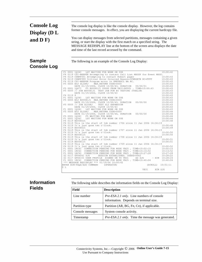
Console Log Display (D L and D F)
The console log display is like the console display. However, the log contains former console messages. In effect, you are displaying the current hardcopy file.
You can display messages from selected partitions, messages containing a given string, or start the display with the first match on a specified string. The MESSAGE REDISPLAY line at the bottom of the screen area displays the date and time of the last record accessed by the command.
Sample Console Log
The following is an example of the Console Log Display:
Information Fields
The following table describes the information fields on the Console Log Display:
F1 0001 1Q34I LST WAITING FOR WORK ON 00E 10:00:42 F4 0119 CSI-BEEPER Attempting to contact Call List MSGUP for Event MSGU. F4 0119 CSNPP001 Attempting to contact Robert pager 10:00:43 F4 0119 CSNPP999 Critical Error Occurred Reason=IPNRGETN RC=FFFF 10:00:43 F4 0119 CSI-BEEPER Program error in SNPPRXCL BA RC. 10:00:43 F5 0005 EOJ SLIDRJ MAX.RETURN CODE=0000 10:00:43 DATE 01/19/2006, CLOCK 10/00/43, DURATION 00/00/01 10:00:43 F5 0001 1Q47I F5 BSY081J1 00080 FROM VB31(R000) , TIME=10:00:43 10:00:43 F5 0005 // JOB BSY081J1 TEST JOB FOR BI TESTING (VSELIB) 10:00:43 DATE 01/19/2006, CLOCK 10/00/43 10:00:43 F4 0119 8 10:00:43 F1 0001 1Q34I LST WAITING FOR WORK ON 00E 10:00:43 F5 0005 EOJ BSY081J1 MAX.RETURN CODE=0000 10:00:43 DATE 01/19/2006, CLOCK 10/00/43, DURATION 00/00/00 10:00:43 F5 0005 // JOB SLIDRJ TEST SLI EXPANSION 10:00:43 DATE 01/19/2006, CLOCK 10/00/43 10:00:43 F1 0001 1Q34I LST WAITING FOR WORK ON 00E 10:00:43 F5 0005 EOJ SLIDRJ MAX.RETURN CODE=0000 10:00:44 DATE 01/19/2006, CLOCK 10/00/44, DURATION 00/00/00 10:00:44 F5 0001 1Q34I F5 WAITING FOR WORK 10:00:44 F1 0001 1Q34I LST WAITING FOR WORK ON 00E 10:00:44 F4 0119 BSY080J1 10:00:48 F4 0119 This is the start of job number 1706 since 11 Jan 2006 14:34:19 F4 0119 It's just gone ten o'clock. 10:00:48 F4 0119 BSY080J1 10:00:49 F4 0119 This is the start of job number 1707 since 11 Jan 2006 14:34:19 F4 0119 It's just gone ten o'clock. 10:00:50 F4 0119 BSY081J1 10:00:50 F4 0119 This is the start of job number 1708 since 11 Jan 2006 14:34:19 F4 0119 It's just gone ten o'clock. 10:00:51 F4 0119 BSY081J1 10:00:51 F4 0119 This is the start of job number 1709 since 11 Jan 2006 14:34:19 F4 0119 It's just gone ten o'clock. 10:00:52 F1 0001 1RC6I CONNECTION PENDING FOR NODE VB25 , TIME=10:02:15 10:02:15 F1 0001 1RC6I CONNECTION PENDING FOR NODE VB25 , TIME=10:14:52 10:14:52 F1 0001 1RC6I CONNECTION PENDING FOR NODE VB25 , TIME=10:27:28 10:27:28 Z2 0117 GFX404I SJG SESSION ESTABLISHED, USERS=0002 10:28:22 Z2 0117 GFX415I USER PROFILE SIGNED ON TO VB31 AS SJG - XCM 10:28:24 F1 0001 1RC6I CONNECTION PENDING FOR NODE VB25 , TIME=10:40:04 10:40:04 *** MESSAGE REDISPLAY *** 01/19/06 10:00:42 ENTER BIM-FAQS/ASO COMMAND (OPERATOR) (SCROLL) 10:51:11 D L VB31 XCM SJG
Field Description
Line number Pre-ESA 2.1 only. Line numbers of console information. Depends on terminal size.
Partition type Partition (AR, BG, Fn, Cn), if applicable.
Console messages System console activity.
Timestamp Pre-ESA 2.1 only. Time the message was generated.
Connectivity Systems, Inc.—Copyright © 2006Use Pursuant to Company Instructions
Online User’s Guide 7-15
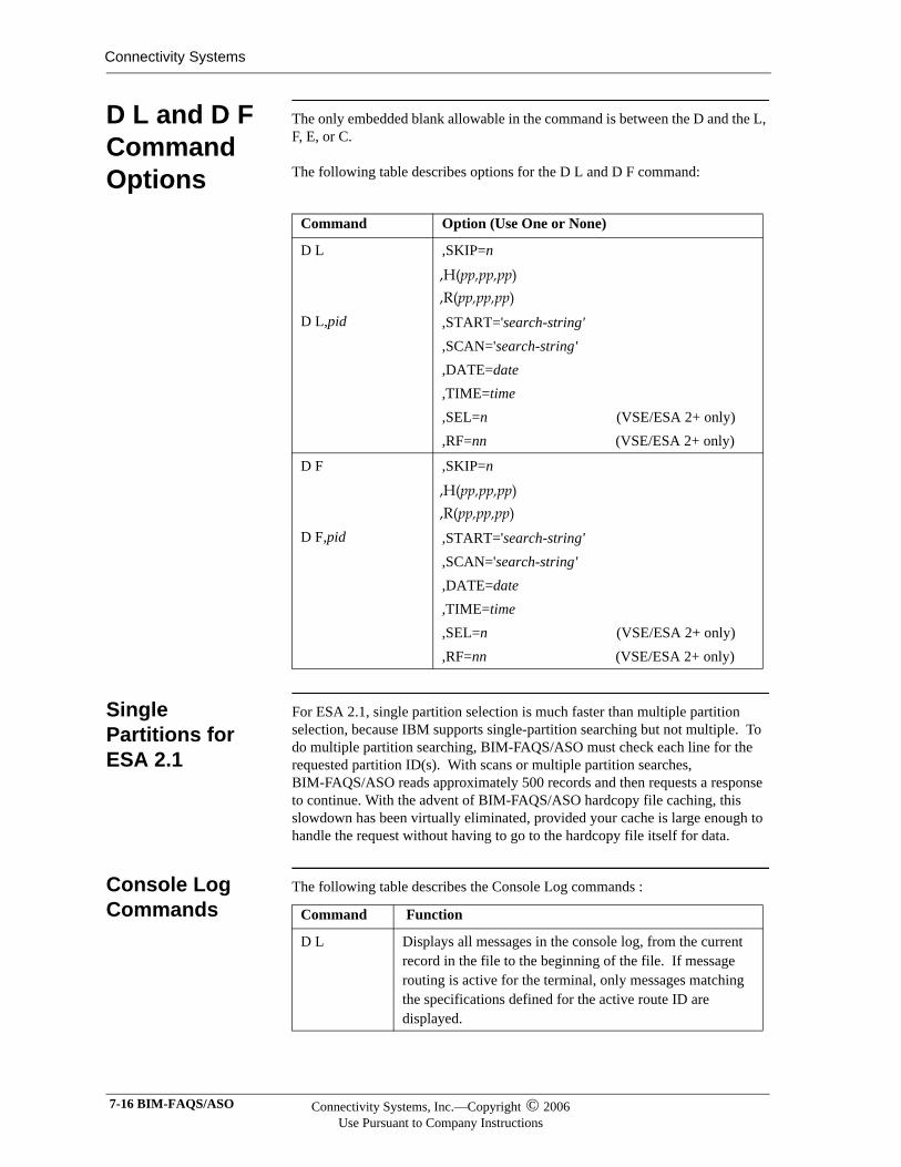
Connectivity Systems
D L and D F Command Options
The only embedded blank allowable in the command is between the D and the L, F, E, or C.
The following table describes options for the D L and D F command:
Single Partitions for ESA 2.1
For ESA 2.1, single partition selection is much faster than multiple partition selection, because IBM supports single-partition searching but not multiple. To do multiple partition searching, BIM-FAQS/ASO must check each line for the requested partition ID(s). With scans or multiple partition searches, BIM-FAQS/ASO reads approximately 500 records and then requests a response to continue. With the advent of BIM-FAQS/ASO hardcopy file caching, this slowdown has been virtually eliminated, provided your cache is large enough to handle the request without having to go to the hardcopy file itself for data.
Console Log Commands
The following table describes the Console Log commands :
Command Option (Use One or None)
D L
D L,pid
,SKIP=n
,H(pp,pp,pp) ,R(pp,pp,pp) ,START='search-string',SCAN='search-string',DATE=date,TIME=time,SEL=n (VSE/ESA 2+ only),RF=nn (VSE/ESA 2+ only)
D F
D F,pid
,SKIP=n
,H(pp,pp,pp) ,R(pp,pp,pp) ,START='search-string',SCAN='search-string',DATE=date,TIME=time,SEL=n (VSE/ESA 2+ only) ,RF=nn (VSE/ESA 2+ only)
Command Function
D L Displays all messages in the console log, from the current record in the file to the beginning of the file. If message routing is active for the terminal, only messages matching the specifications defined for the active route ID are displayed.
7-16 BIM-FAQS/ASO Connectivity Systems, Inc.—Copyright © 2006Use Pursuant to Company Instructions
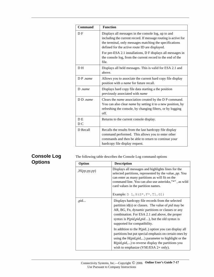
Console Log Options
The following table describes the Console Log command options
D F Displays all messages in the console log, up to and including the current record. If message routing is active for the terminal, only messages matching the specifications defined for the active route ID are displayed.For pre-ESA 2.1 installations, D F displays all messages in the console log, from the current record to the end of the file.
D H Displays all held messages. This is valid for ESA 2.1 and above.
D P .name Allows you to associate the current hard copy file display position with a name for future recall.
D .name Displays hard copy file data starting a the position previously associated with name
D D .name Clears the name association created by the D P command. You can also clear name by setting it to a new position, by refreshing the console, by changing filters, or by logging off.
D ED C
Returns to the current console display.
D Recall Recalls the results from the last hardcopy file display command performed. This allows you to enter other commands and then be able to return to continue your hardcopy file display request.
Command Function
Option Description
,H(pp,pp,pp) Displays all messages and highlights lines for the selected partitions, represented by the value, pp. You can enter as many partitions as will fit on the command line. You can also use asterisks,”*” , as wild card values in the partition names.
Example: D L,H(S*,F*,T1,G1)
,pid... Displays hardcopy file records from the selected partition id(s) or classes. The value of pid may be AR, BG, Fn, dynamic partitions or classes or any combination. For ESA 2.1 and above, the proper syntax is P(pid,pid,pid…), but the old syntax is supported for compatibility.In addition to the P(pid..) option you can display all partitions but put special emphasis on certain ones by using the H(pid,pid,...) parameter to highlight or the R(pid,pid,...) to reverse display the partitions you wish to emphasize (VSE/ESA 2+ only).
Connectivity Systems, Inc.—Copyright © 2006Use Pursuant to Company Instructions
Online User’s Guide 7-17
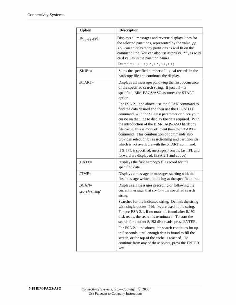
Connectivity Systems
,R(pp,pp,pp) Displays all messages and reverse displays lines for the selected partitions, represented by the value, pp. You can enter as many partitions as will fit on the command line. You can also use asterisks,”*” , as wild card values in the partition names. Example: D L,R(S*,F*,T1,G1)
,SKIP=n Skips the specified number of logical records in the hardcopy file and continues the display.
,START= Displays all messages following the first occurrence of the specified search string. If just ,S= is specified, BIM-FAQS/ASO assumes the START option.For ESA 2.1 and above, use the SCAN command to find the data desired and then use the D L or D F command, with the SEL= n parameter or place your cursor on that line to display the data required. With the introduction of the BIM-FAQS/ASO hardcopy file cache, this is more efficient than the START= command. This combination of commands also provides selection by search-string and partition ids which is not available with the START command.If S=IPL is specified, messages from the last IPL and forward are displayed. (ESA 2.1 and above)
,DATE= Displays the first hardcopy file record for the specified date.
,TIME= Displays a message or messages starting with the first message written to the log at the specified time.
,SCAN='search-string'
Displays all messages preceding or following the current message, that contain the specified search string.Searches for the indicated string. Delimit the string with single quotes if blanks are used in the string. For pre-ESA 2.1, if no match is found after 8,192 disk reads, the search is terminated. To start the search for another 8,192 disk reads, press ENTER.For ESA 2.1 and above, the search continues for up to 5 seconds, until enough data is found to fill the screen, or the top of the cache is reached. To continue from any of these points, press the ENTER key.
Option Description
7-18 BIM-FAQS/ASO Connectivity Systems, Inc.—Copyright © 2006Use Pursuant to Company Instructions
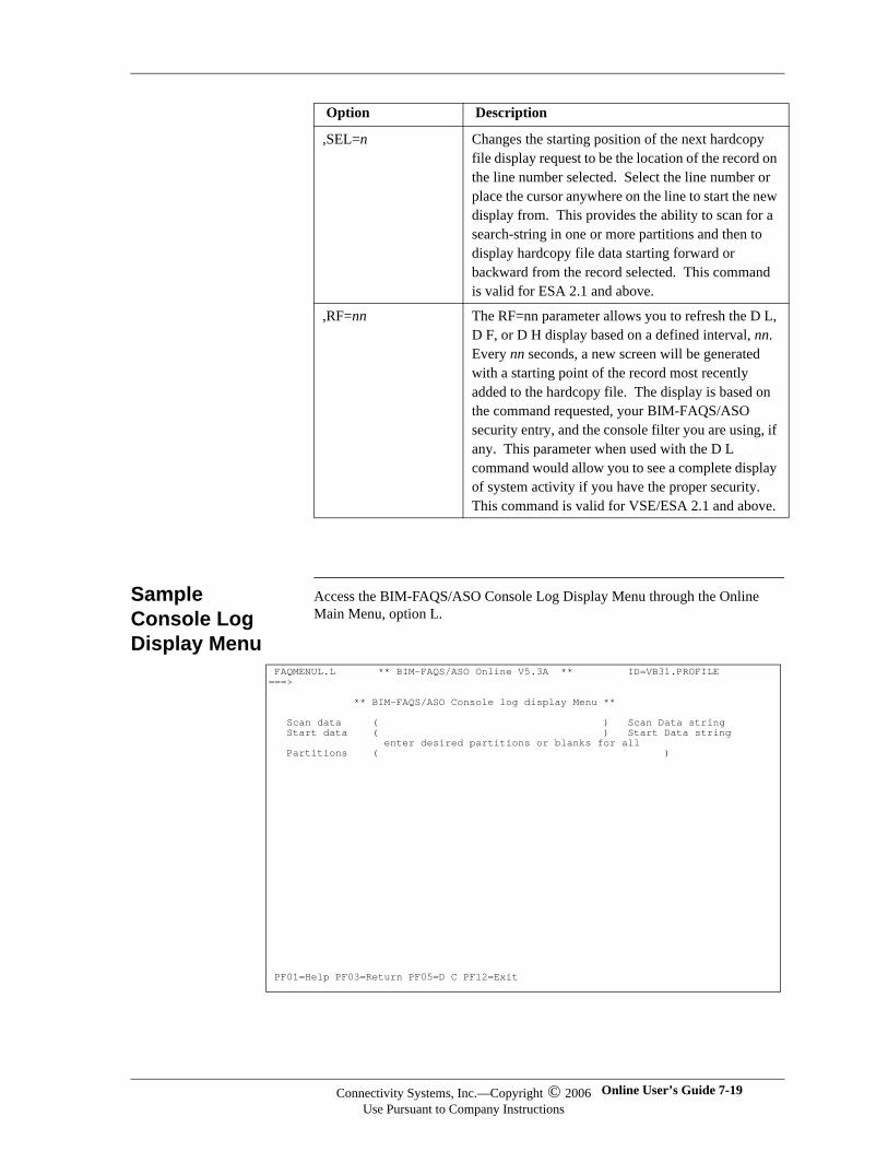
Sample Console Log Display Menu
Access the BIM-FAQS/ASO Console Log Display Menu through the Online Main Menu, option L.
,SEL=n Changes the starting position of the next hardcopy file display request to be the location of the record on the line number selected. Select the line number or place the cursor anywhere on the line to start the new display from. This provides the ability to scan for a search-string in one or more partitions and then to display hardcopy file data starting forward or backward from the record selected. This command is valid for ESA 2.1 and above.
,RF=nn The RF=nn parameter allows you to refresh the D L, D F, or D H display based on a defined interval, nn. Every nn seconds, a new screen will be generated with a starting point of the record most recently added to the hardcopy file. The display is based on the command requested, your BIM-FAQS/ASO security entry, and the console filter you are using, if any. This parameter when used with the D L command would allow you to see a complete display of system activity if you have the proper security. This command is valid for VSE/ESA 2.1 and above.
Option Description
FAQMENUL.L ** BIM-FAQS/ASO Online V5.3A ** ID=VB31.PROFILE ===> ** BIM-FAQS/ASO Console log display Menu ** Scan data ( ) Scan Data string Start data ( ) Start Data string enter desired partitions or blanks for all Partitions ( )
PF01=Help PF03=Return PF05=D C PF12=Exit
Connectivity Systems, Inc.—Copyright © 2006Use Pursuant to Company Instructions
Online User’s Guide 7-19
Connectivity Systems
BIM-FAQS/ASO Console Log Display Menu Fields
All fields are optional. The default displays all messages in the console log.
For pre-ESA 2.1, if no match is found after 8,192 disk reads, the search is terminated. To start the search for another 8,192 disk reads, press ENTER.
The following table describe the function of the Console Log Display Menu fields:
Field Enter Displays
Scan data Search string. All messages preceding the current message, that contain the specified search string.
Start data First occurrence of the specified text.
All messages preceding the first occurrence of the specified search string.
Partitions Partition ID. IDs are AR,BG, or Fn.
Messages from the specified partition IDs. Specify as many partition IDs as you want.
7-20 BIM-FAQS/ASO Connectivity Systems, Inc.—Copyright © 2006Use Pursuant to Company Instructions
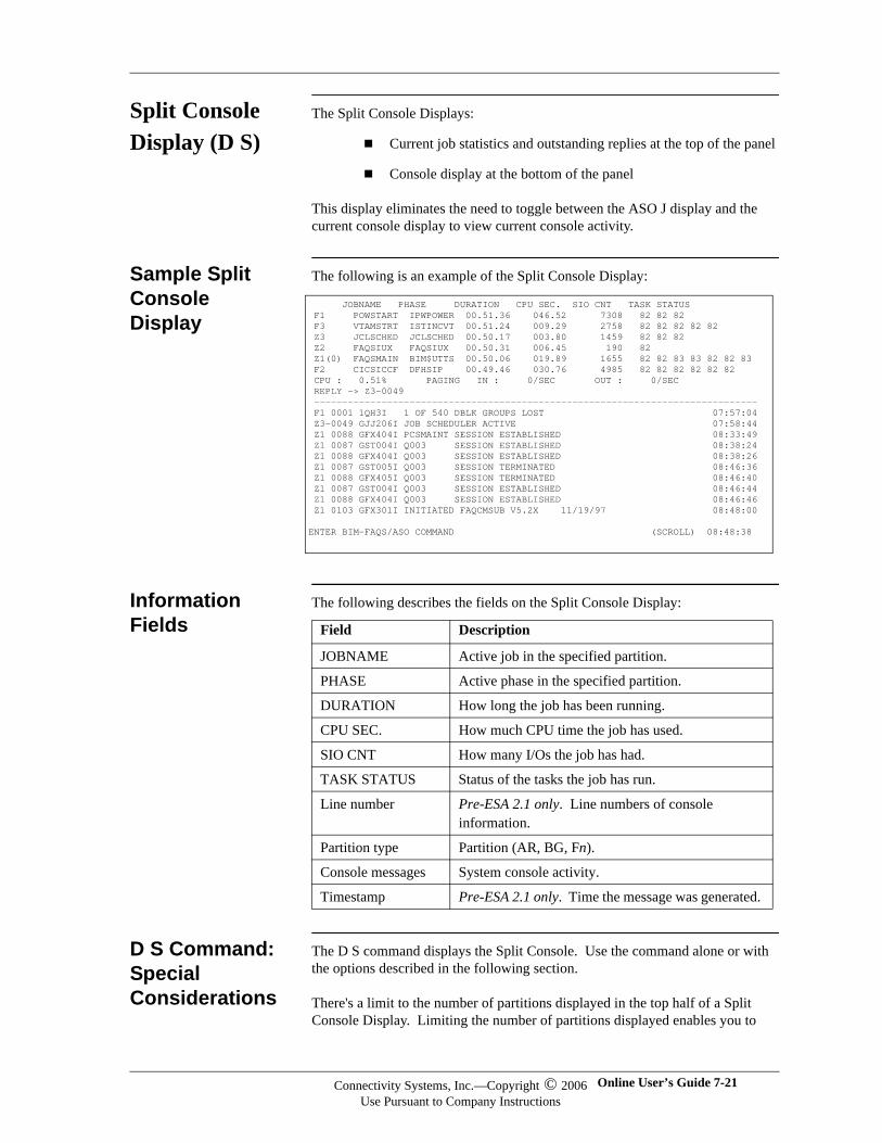
Split Console Display (D S)
The Split Console Displays:
Current job statistics and outstanding replies at the top of the panel
Console display at the bottom of the panel
This display eliminates the need to toggle between the ASO J display and the current console display to view current console activity.
Sample Split Console Display
The following is an example of the Split Console Display:
Information Fields
The following describes the fields on the Split Console Display:
D S Command: Special Considerations
The D S command displays the Split Console. Use the command alone or with the options described in the following section.
There's a limit to the number of partitions displayed in the top half of a Split Console Display. Limiting the number of partitions displayed enables you to
JOBNAME PHASE DURATION CPU SEC. SIO CNT TASK STATUS F1 POWSTART IPWPOWER 00.51.36 046.52 7308 82 82 82 F3 VTAMSTRT ISTINCVT 00.51.24 009.29 2758 82 82 82 82 82 Z3 JCLSCHED JCLSCHED 00.50.17 003.80 1459 82 82 82 Z2 FAQSIUX FAQSIUX 00.50.31 006.45 190 82 Z1(0) FAQSMAIN BIM$UTTS 00.50.06 019.89 1655 82 82 83 83 82 82 83 F2 CICSICCF DFHSIP 00.49.46 030.76 4985 82 82 82 82 82 82 CPU : 0.51% PAGING IN : 0/SEC OUT : 0/SEC REPLY -> Z3-0049 ------------------------------------------------------------------------------- F1 0001 1QH3I 1 OF 540 DBLK GROUPS LOST 07:57:04 Z3-0049 GJJ206I JOB SCHEDULER ACTIVE 07:58:44 Z1 0088 GFX404I PCSMAINT SESSION ESTABLISHED 08:33:49 Z1 0087 GST004I Q003 SESSION ESTABLISHED 08:38:24 Z1 0088 GFX404I Q003 SESSION ESTABLISHED 08:38:26 Z1 0087 GST005I Q003 SESSION TERMINATED 08:46:36 Z1 0088 GFX405I Q003 SESSION TERMINATED 08:46:40 Z1 0087 GST004I Q003 SESSION ESTABLISHED 08:46:44 Z1 0088 GFX404I Q003 SESSION ESTABLISHED 08:46:46 Z1 0103 GFX301I INITIATED FAQCMSUB V5.2X 11/19/97 08:48:00 ENTER BIM-FAQS/ASO COMMAND (SCROLL) 08:48:38
Field Description
JOBNAME Active job in the specified partition.
PHASE Active phase in the specified partition.
DURATION How long the job has been running.
CPU SEC. How much CPU time the job has used.
SIO CNT How many I/Os the job has had.
TASK STATUS Status of the tasks the job has run.
Line number Pre-ESA 2.1 only. Line numbers of console information.
Partition type Partition (AR, BG, Fn).
Console messages System console activity.
Timestamp Pre-ESA 2.1 only. Time the message was generated.
Connectivity Systems, Inc.—Copyright © 2006Use Pursuant to Company Instructions
Online User’s Guide 7-21
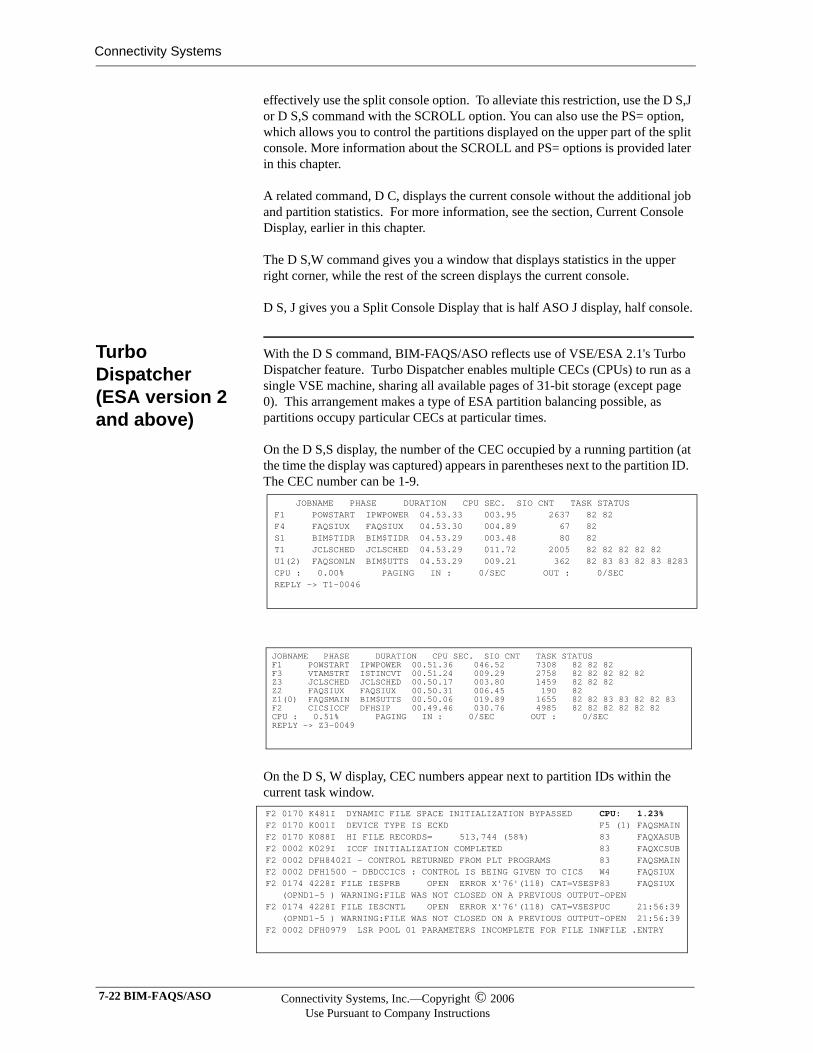
Connectivity Systems
effectively use the split console option. To alleviate this restriction, use the D S,J or D S,S command with the SCROLL option. You can also use the PS= option, which allows you to control the partitions displayed on the upper part of the split console. More information about the SCROLL and PS= options is provided later in this chapter.
A related command, D C, displays the current console without the additional job and partition statistics. For more information, see the section, Current Console Display, earlier in this chapter.
The D S,W command gives you a window that displays statistics in the upper right corner, while the rest of the screen displays the current console.
D S, J gives you a Split Console Display that is half ASO J display, half console.
Turbo Dispatcher (ESA version 2 and above)
With the D S command, BIM-FAQS/ASO reflects use of VSE/ESA 2.1's Turbo Dispatcher feature. Turbo Dispatcher enables multiple CECs (CPUs) to run as a single VSE machine, sharing all available pages of 31-bit storage (except page 0). This arrangement makes a type of ESA partition balancing possible, as partitions occupy particular CECs at particular times.
On the D S,S display, the number of the CEC occupied by a running partition (at the time the display was captured) appears in parentheses next to the partition ID. The CEC number can be 1-9.
On the D S, W display, CEC numbers appear next to partition IDs within the current task window.
JOBNAME PHASE DURATION CPU SEC. SIO CNT TASK STATUS F1 POWSTART IPWPOWER 04.53.33 003.95 2637 82 82 F4 FAQSIUX FAQSIUX 04.53.30 004.89 67 82 S1 BIM$TIDR BIM$TIDR 04.53.29 003.48 80 82 T1 JCLSCHED JCLSCHED 04.53.29 011.72 2005 82 82 82 82 82 U1(2) FAQSONLN BIM$UTTS 04.53.29 009.21 362 82 83 83 82 83 8283 CPU : 0.00% PAGING IN : 0/SEC OUT : 0/SEC REPLY -> T1-0046
JOBNAME PHASE DURATION CPU SEC. SIO CNT TASK STATUS F1 POWSTART IPWPOWER 00.51.36 046.52 7308 82 82 82 F3 VTAMSTRT ISTINCVT 00.51.24 009.29 2758 82 82 82 82 82 Z3 JCLSCHED JCLSCHED 00.50.17 003.80 1459 82 82 82 Z2 FAQSIUX FAQSIUX 00.50.31 006.45 190 82 Z1(0) FAQSMAIN BIM$UTTS 00.50.06 019.89 1655 82 82 83 83 82 82 83 F2 CICSICCF DFHSIP 00.49.46 030.76 4985 82 82 82 82 82 82 CPU : 0.51% PAGING IN : 0/SEC OUT : 0/SEC REPLY -> Z3-0049
F2 0170 K481I DYNAMIC FILE SPACE INITIALIZATION BYPASSED CPU: 1.23% F2 0170 K001I DEVICE TYPE IS ECKD F5 (1) FAQSMAIN F2 0170 K088I HI FILE RECORDS= 513,744 (58%) 83 FAQXASUB F2 0002 K029I ICCF INITIALIZATION COMPLETED 83 FAQXCSUB F2 0002 DFH8402I - CONTROL RETURNED FROM PLT PROGRAMS 83 FAQSMAIN F2 0002 DFH1500 - DBDCCICS : CONTROL IS BEING GIVEN TO CICS W4 FAQSIUX F2 0174 4228I FILE IESPRB OPEN ERROR X'76'(118) CAT=VSESP83 FAQSIUX (OPND1-5 ) WARNING:FILE WAS NOT CLOSED ON A PREVIOUS OUTPUT-OPEN F2 0174 4228I FILE IESCNTL OPEN ERROR X'76'(118) CAT=VSESPUC 21:56:39 (OPND1-5 ) WARNING:FILE WAS NOT CLOSED ON A PREVIOUS OUTPUT-OPEN 21:56:39 F2 0002 DFH0979 LSR POOL 01 PARAMETERS INCOMPLETE FOR FILE INWFILE .ENTRY
7-22 BIM-FAQS/ASO Connectivity Systems, Inc.—Copyright © 2006Use Pursuant to Company Instructions
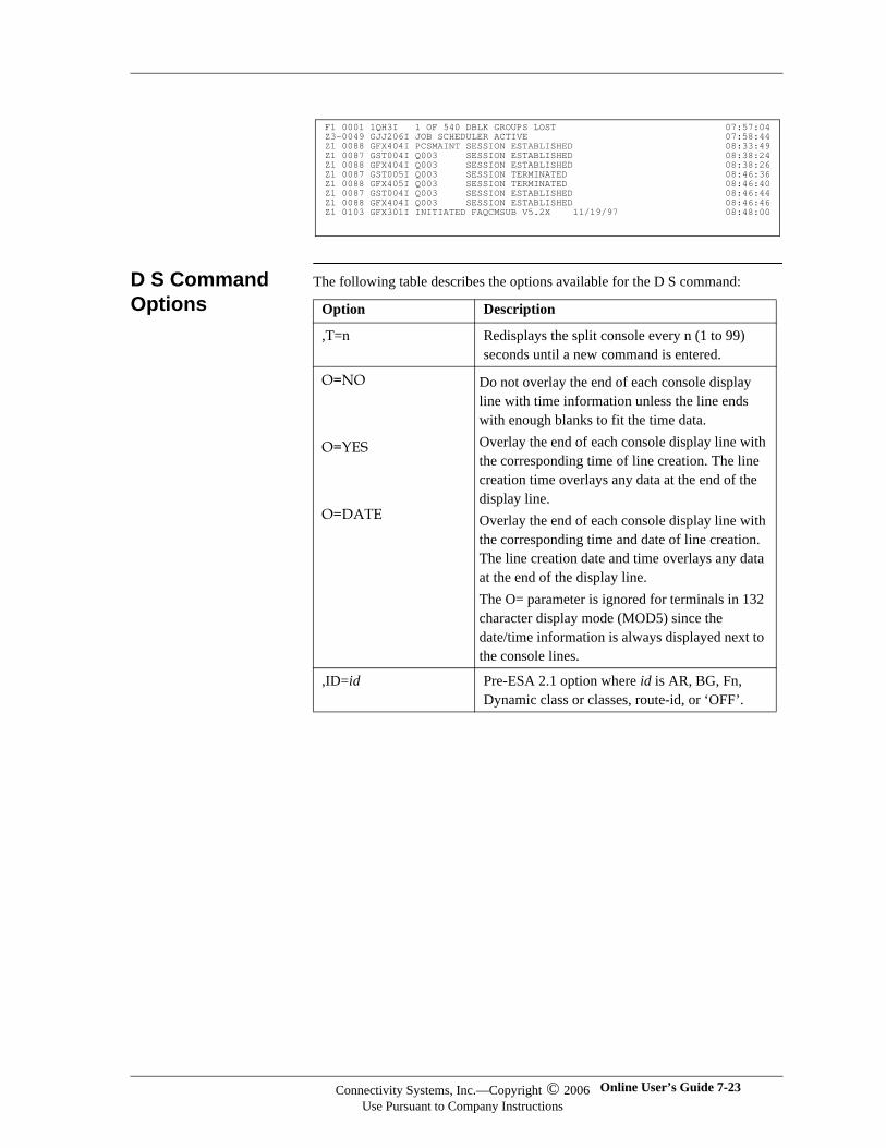
D S Command Options
The following table describes the options available for the D S command:
F1 0001 1QH3I 1 OF 540 DBLK GROUPS LOST 07:57:04 Z3-0049 GJJ206I JOB SCHEDULER ACTIVE 07:58:44 Z1 0088 GFX404I PCSMAINT SESSION ESTABLISHED 08:33:49 Z1 0087 GST004I Q003 SESSION ESTABLISHED 08:38:24 Z1 0088 GFX404I Q003 SESSION ESTABLISHED 08:38:26 Z1 0087 GST005I Q003 SESSION TERMINATED 08:46:36 Z1 0088 GFX405I Q003 SESSION TERMINATED 08:46:40 Z1 0087 GST004I Q003 SESSION ESTABLISHED 08:46:44 Z1 0088 GFX404I Q003 SESSION ESTABLISHED 08:46:46 Z1 0103 GFX301I INITIATED FAQCMSUB V5.2X 11/19/97 08:48:00
Option Description
,T=n Redisplays the split console every n (1 to 99) seconds until a new command is entered.
O=NO
O=YES
O=DATE
Do not overlay the end of each console display line with time information unless the line ends with enough blanks to fit the time data. Overlay the end of each console display line with the corresponding time of line creation. The line creation time overlays any data at the end of the display line. Overlay the end of each console display line with the corresponding time and date of line creation. The line creation date and time overlays any data at the end of the display line. The O= parameter is ignored for terminals in 132 character display mode (MOD5) since the date/time information is always displayed next to the console lines.
,ID=id Pre-ESA 2.1 option where id is AR, BG, Fn, Dynamic class or classes, route-id, or ‘OFF’.
Connectivity Systems, Inc.—Copyright © 2006Use Pursuant to Company Instructions
Online User’s Guide 7-23
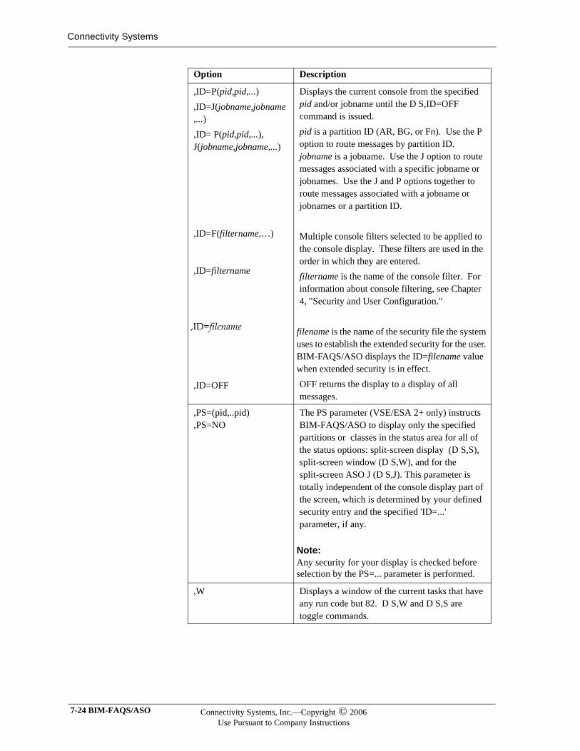
Connectivity Systems
,ID=P(pid,pid,...),ID=J(jobname,jobname,...),ID= P(pid,pid,...), J(jobname,jobname,...)
,ID=F(filtername,…)
,ID=filtername
,ID=filename
,ID=OFF
Displays the current console from the specified pid and/or jobname until the D S,ID=OFF command is issued. pid is a partition ID (AR, BG, or Fn). Use the P option to route messages by partition ID. jobname is a jobname. Use the J option to route messages associated with a specific jobname or jobnames. Use the J and P options together to route messages associated with a jobname or jobnames or a partition ID.
Multiple console filters selected to be applied to the console display. These filters are used in the order in which they are entered.filtername is the name of the console filter. For information about console filtering, see Chapter 4, "Security and User Configuration."
filename is the name of the security file the system uses to establish the extended security for the user. BIM-FAQS/ASO displays the ID=filename value when extended security is in effect. OFF returns the display to a display of all messages.
,PS=(pid,..pid),PS=NO
The PS parameter (VSE/ESA 2+ only) instructs BIM-FAQS/ASO to display only the specified partitions or classes in the status area for all of the status options: split-screen display (D S,S), split-screen window (D S,W), and for the split-screen ASO J (D S,J). This parameter is totally independent of the console display part of the screen, which is determined by your defined security entry and the specified 'ID=...' parameter, if any.
Note:Note:Any security for your display is checked before selection by the PS=... parameter is performed.
,W Displays a window of the current tasks that have any run code but 82. D S,W and D S,S are toggle commands.
Option Description
7-24 BIM-FAQS/ASO Connectivity Systems, Inc.—Copyright © 2006Use Pursuant to Company Instructions
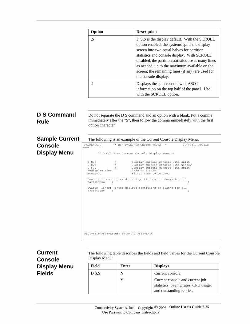
D S Command Rule
Do not separate the D S command and an option with a blank. Put a comma immediately after the "S", then follow the comma immediately with the first option character.
Sample Current Console Display Menu
The following is an example of the Current Console Display Menu:
Current Console Display Menu Fields
The following table describes the fields and field values for the Current Console Display Menu:
,S D S,S is the display default. With the SCROLL option enabled, the systems splits the display screen into two equal halves for partition statistics and console display. With SCROLL disabled, the partition statistics use as many lines as needed, up to the maximum available on the screen; the remaining lines (if any) are used for the console display.
,J Displays the split console with ASO J information on the top half of the panel. Use with the SCROLL option.
Option Description
FAQMENUC.C ** BIM-FAQS/ASO Online V5.3A ** ID=VB31.PROFILE ===> ** D C/D S -- Current Console Display Menu ** D S,S N Display current console with split D S,W N Display current console with window D S,J N Display current console with split Redisplay time 1-99 or Blanks route-id Filter name to be used Console lines: enter desired partitions or blanks for all Partitions ( ) Status lines: enter desired partitions or blanks for all Partitions ( )
PF01=Help PF03=Return PF05=D C PF12=Exit
Field Enter Displays
D S,S NY
Current console. Current console and current job statistics, paging rates, CPU usage, and outstanding replies.
Connectivity Systems, Inc.—Copyright © 2006Use Pursuant to Company Instructions
Online User’s Guide 7-25
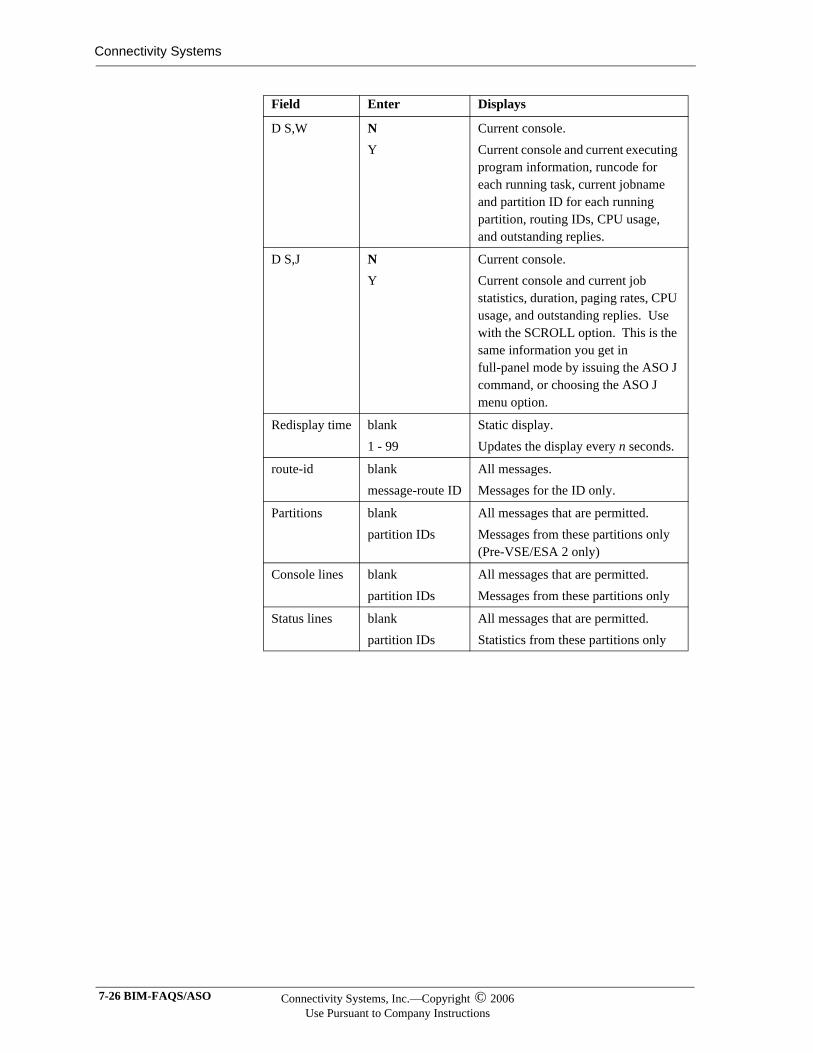
Connectivity Systems
D S,W NY
Current console.Current console and current executing program information, runcode for each running task, current jobname and partition ID for each running partition, routing IDs, CPU usage, and outstanding replies.
D S,J NY
Current console. Current console and current job statistics, duration, paging rates, CPU usage, and outstanding replies. Use with the SCROLL option. This is the same information you get in full-panel mode by issuing the ASO J command, or choosing the ASO J menu option.
Redisplay time blank1 - 99
Static display. Updates the display every n seconds.
route-id blankmessage-route ID
All messages. Messages for the ID only.
Partitions blankpartition IDs
All messages that are permitted. Messages from these partitions only(Pre-VSE/ESA 2 only)
Console lines blankpartition IDs
All messages that are permitted.Messages from these partitions only
Status lines blankpartition IDs
All messages that are permitted.Statistics from these partitions only
Field Enter Displays
7-26 BIM-FAQS/ASO Connectivity Systems, Inc.—Copyright © 2006Use Pursuant to Company Instructions
Control Block Display (DEBUG)
The DEBUG command accesses the FAQS Control Block Display, which is a report of all tasks active in the system. The display provides easy access to all the major partition and task-related control blocks to assist in problem determination. The command has the following syntax:
DEBUG pp | c | ALL
pp is a single partition. c is a dynamic class. ALL displays all active partitions.
DEBUG Displays
The DEBUG command displays information in the formats and panels shown in Chapter 8, "Extended Map/Debug Support."
Accessing the FAQS Control Block Display
To use a command to display the FAQS Control Block Display, enter DEBUG or ASO DEBUG.
To use a menu to display the FAQS Control Block display, access the BIM-FAQS/ASO Online Menu. Enter MENU on the command line and select the FAQS option. From this menu, select the DEBUG option.
Connectivity Systems, Inc.—Copyright © 2006Use Pursuant to Company Instructions
Online User’s Guide 7-27
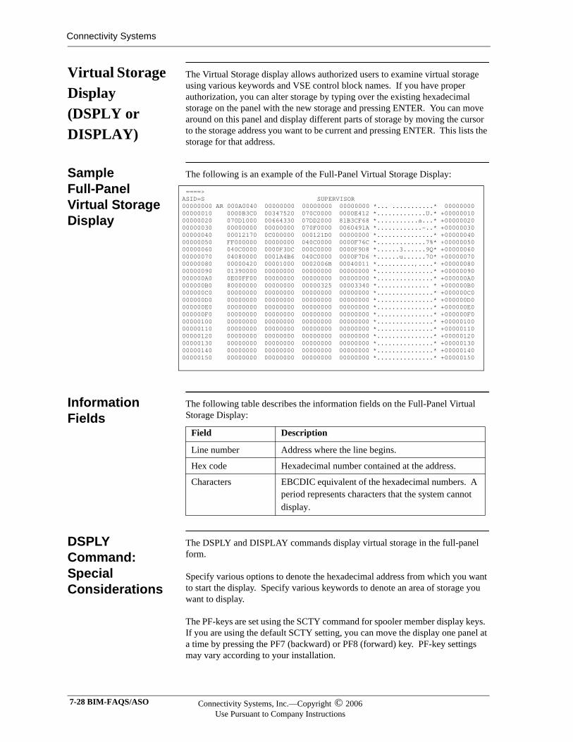
Connectivity Systems
Virtual Storage Display (DSPLY or DISPLAY)
The Virtual Storage display allows authorized users to examine virtual storage using various keywords and VSE control block names. If you have proper authorization, you can alter storage by typing over the existing hexadecimal storage on the panel with the new storage and pressing ENTER. You can move around on this panel and display different parts of storage by moving the cursor to the storage address you want to be current and pressing ENTER. This lists the storage for that address.
Sample Full-Panel Virtual Storage Display
The following is an example of the Full-Panel Virtual Storage Display:
Information Fields
The following table describes the information fields on the Full-Panel Virtual Storage Display:
DSPLY Command: Special Considerations
The DSPLY and DISPLAY commands display virtual storage in the full-panel form.
Specify various options to denote the hexadecimal address from which you want to start the display. Specify various keywords to denote an area of storage you want to display.
The PF-keys are set using the SCTY command for spooler member display keys. If you are using the default SCTY setting, you can move the display one panel at a time by pressing the PF7 (backward) or PF8 (forward) key. PF-key settings may vary according to your installation.
====> ASID=S SUPERVISOR 00000000 AR 000A0040 00000000 00000000 00000000 *... ...........* 00000000 00000010 0000B3C0 00347520 070C0000 0000E412 *.............U.* +00000010 00000020 070D1000 00664330 07DD2000 81B3CF68 *...........a...* +00000020 00000030 00000000 00000000 070F0000 0060491A *............-..* +00000030 00000040 00012170 0C000000 000121D0 00000000 *...............* +00000040 00000050 FF000000 00000000 040C0000 0000F76C *.............7%* +00000050 00000060 040C0000 0000F3DC 000C0000 0000F9D8 *......3......9Q* +00000060 00000070 04080000 0001A4B6 040C0000 0000F7D6 *......u......7O* +00000070 00000080 00000420 00001000 0002006B 00040011 *..........,....* +00000080 00000090 01390000 00000000 00000000 00000000 *...............* +00000090 000000A0 0E00FF00 00000000 00000000 00000000 *...............* +000000A0 000000B0 80000000 00000000 00000325 00003340 *.............. * +000000B0 000000C0 00000000 00000000 00000000 00000000 *...............* +000000C0 000000D0 00000000 00000000 00000000 00000000 *...............* +000000D0 000000E0 00000000 00000000 00000000 00000000 *...............* +000000E0 000000F0 00000000 00000000 00000000 00000000 *...............* +000000F0 00000100 00000000 00000000 00000000 00000000 *...............* +00000100 00000110 00000000 00000000 00000000 00000000 *...............* +00000110 00000120 00000000 00000000 00000000 00000000 *...............* +00000120 00000130 00000000 00000000 00000000 00000000 *...............* +00000130 00000140 00000000 00000000 00000000 00000000 *...............* +00000140 00000150 00000000 00000000 00000000 00000000 *...............* +00000150
Field Description
Line number Address where the line begins.
Hex code Hexadecimal number contained at the address.
Characters EBCDIC equivalent of the hexadecimal numbers. A period represents characters that the system cannot display.
7-28 BIM-FAQS/ASO Connectivity Systems, Inc.—Copyright © 2006Use Pursuant to Company Instructions
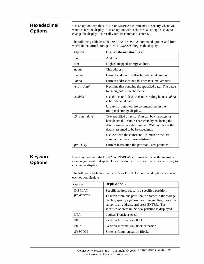
Hexadecimal Options
Use an option with the DSPLY or DISPLAY commands to specify where you want to start the display. Use an option within the virtual storage display to change the display. To recall your last command, enter ?.
The following table lists the DISPLAY or DSPLY command options and from where in the virtual storage BIM-FAQS/ASO begins the display:
Keyword Options
Use an option with the DSPLY or DISPLAY commands to specify an area of storage you want to display. Use an option within the virtual storage display to change the display.
The following table lists the DSPLY or DISPLAY command options and what each option displays:
Option Display storage starting at
Top Address 0.
Bot Highest mapped storage address.
aaaaa This address.
+nnnn Current address plus this hexadecimal amount.
-nnnn Current address minus this hexadecimal amount.
/scan_data/ Next line that contains the specified data. The value for scan_data is in characters.
/x'hhhh'/ Use the second slash to denote trailing blanks. hhhh is hexadecimal data.Use /scan_data / on the command line in the full-panel storage display.
,S='scan_data' Text specified by scan_data can be characters or hexadecimal. Denote characters by enclosing the data in single quotation marks. Without quotes the data is assumed to be hexadecimal.Use ,S= with the command. ,S must be the last command in the command-string.
pid,+C,@ Current instruction the partition PSW points to.
Option Displays the ...
DISPLAY pid,address
Specific address space in a specified partition.To move from one partition to another in the storage display, specify a pid on the command line, move the cursor to an address, and press ENTER. The specified address in the new partition is displayed.
LTA Logical Transient Area.
PIB Partition Information Block.
PIB2 Partition Information Block extension.
SYSCOM Systems Communication Block.
Connectivity Systems, Inc.—Copyright © 2006Use Pursuant to Company Instructions
Online User’s Guide 7-29
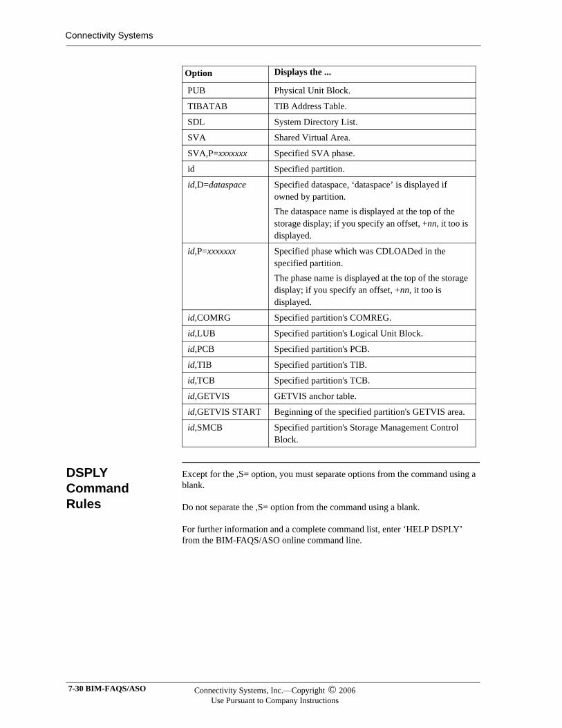
Connectivity Systems
DSPLY Command Rules
Except for the ,S= option, you must separate options from the command using a blank.
Do not separate the ,S= option from the command using a blank.
For further information and a complete command list, enter ‘HELP DSPLY’ from the BIM-FAQS/ASO online command line.
PUB Physical Unit Block.
TIBATAB TIB Address Table.
SDL System Directory List.
SVA Shared Virtual Area.
SVA,P=xxxxxxx Specified SVA phase.
id Specified partition.
id,D=dataspace Specified dataspace, ‘dataspace’ is displayed if owned by partition.The dataspace name is displayed at the top of the storage display; if you specify an offset, +nn, it too is displayed.
id,P=xxxxxxx Specified phase which was CDLOADed in the specified partition.The phase name is displayed at the top of the storage display; if you specify an offset, +nn, it too is displayed.
id,COMRG Specified partition's COMREG.
id,LUB Specified partition's Logical Unit Block.
id,PCB Specified partition's PCB.
id,TIB Specified partition's TIB.
id,TCB Specified partition's TCB.
id,GETVIS GETVIS anchor table.
id,GETVIS START Beginning of the specified partition's GETVIS area.
id,SMCB Specified partition's Storage Management Control Block.
Option Displays the ...
7-30 BIM-FAQS/ASO Connectivity Systems, Inc.—Copyright © 2006Use Pursuant to Company Instructions
DASD Record Display (DUMP)
The DASD Record Display allows authorized users (two-level security) to display and alter individual DASD records. DASD Record Display supports CKD and FBA devices.
To alter DASD, you must dump the record first.
Syntax The syntax for the command to display DASD records is:
DUMP cuu|volid,address,[S=nn/KEY|D=‘cc’/xxxx]
Separate the command from the device option with a blank.
Do not separate the device option from the address option with a blank.
Required Parameters
The following table explains the required parameters for the DUMP command:
Optional Parameters
The following table explains the optional parameters for the DUMP command. Specify only one of the following two optional parameters:
Parameter Explanation
cuu,volid Device address, volume ID. You must specify either a device address or a volume ID.
address DASD location of the record, displayed in cylinder-head-record format (cccc-hhh-rrrr) for CKD devices and relative block number format (bbbbbbbb) for FBA or VFBA devices. For example:
CKD device: DUMP 150,807-0-1
FBA device: DUMP 501,1789
You can also enter the cylinder-head-record format or relative block number format in hexadecimal by entering an X in front of the cylinder-head-record or relative block number.
Example: DUMP DOCRES x0002-0c-21
Parameter Explanation
S=nn/KEY Displays the record starting at +nn characters from the beginning. If you specify S=KEY, the display will reflect a search only through the data, not the key.
D=‘cc’/xxxx Scans groups of records for an ASCII character string (‘cc’) or an EBCDIC character string (xxxx). Either cc or xxxx can be up to 40 characters long.
Connectivity Systems, Inc.—Copyright © 2006Use Pursuant to Company Instructions
Online User’s Guide 7-31
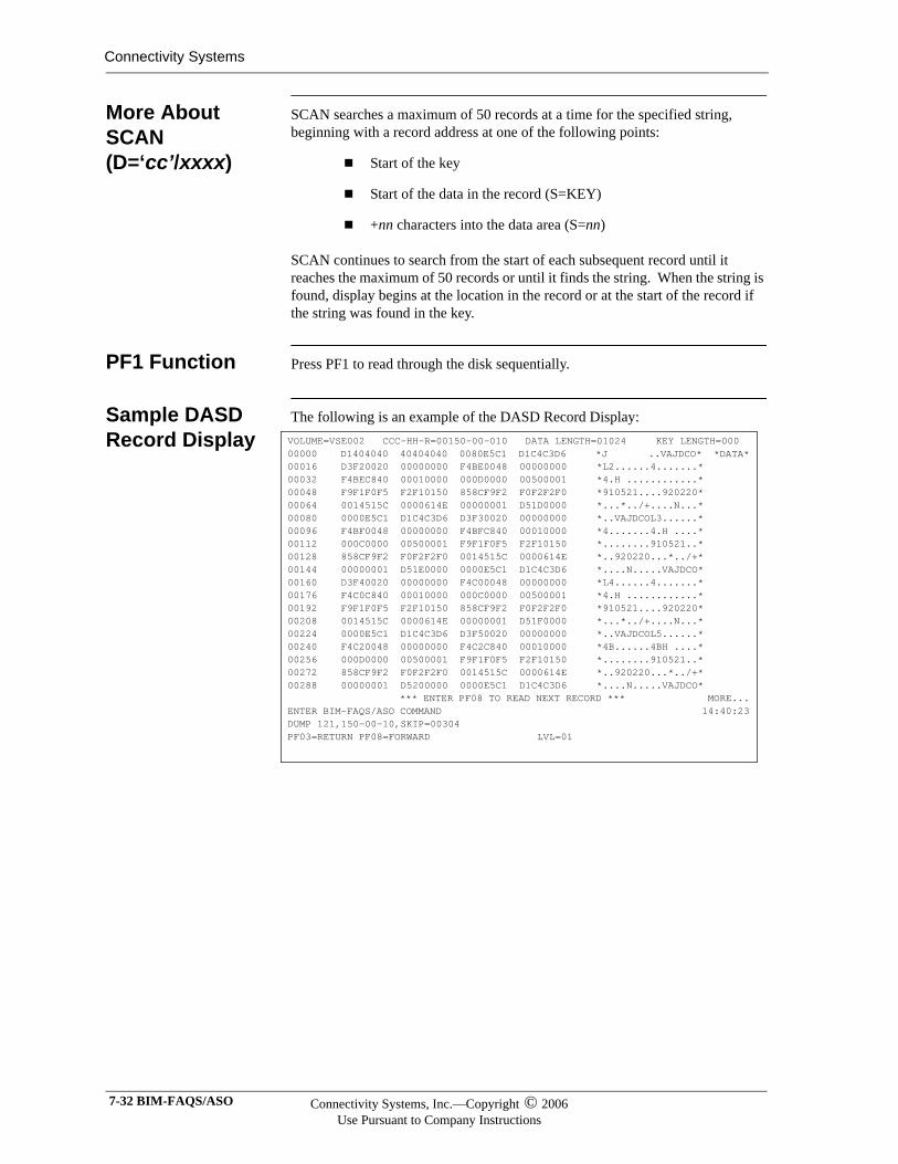
Connectivity Systems
More About SCAN (D=‘cc’/xxxx)
SCAN searches a maximum of 50 records at a time for the specified string, beginning with a record address at one of the following points:
Start of the key
Start of the data in the record (S=KEY)
+nn characters into the data area (S=nn)
SCAN continues to search from the start of each subsequent record until it reaches the maximum of 50 records or until it finds the string. When the string is found, display begins at the location in the record or at the start of the record if the string was found in the key.
PF1 Function Press PF1 to read through the disk sequentially.
Sample DASD Record Display
The following is an example of the DASD Record Display:VOLUME=VSE002 CCC-HH-R=00150-00-010 DATA LENGTH=01024 KEY LENGTH=00000000 D1404040 40404040 0080E5C1 D1C4C3D6 *J ..VAJDCO* *DATA*00016 D3F20020 00000000 F4BE0048 00000000 *L2......4.......*00032 F4BEC840 00010000 000D0000 00500001 *4.H ............*00048 F9F1F0F5 F2F10150 858CF9F2 F0F2F2F0 *910521....920220*00064 0014515C 0000614E 00000001 D51D0000 *...*../+....N...*00080 0000E5C1 D1C4C3D6 D3F30020 00000000 *..VAJDCOL3......*00096 F4BF0048 00000000 F4BFC840 00010000 *4.......4.H ....*00112 000C0000 00500001 F9F1F0F5 F2F10150 *........910521..*00128 858CF9F2 F0F2F2F0 0014515C 0000614E *..920220...*../+*00144 00000001 D51E0000 0000E5C1 D1C4C3D6 *....N.....VAJDCO*00160 D3F40020 00000000 F4C00048 00000000 *L4......4.......*00176 F4C0C840 00010000 000C0000 00500001 *4.H ............*00192 F9F1F0F5 F2F10150 858CF9F2 F0F2F2F0 *910521....920220*00208 0014515C 0000614E 00000001 D51F0000 *...*../+....N...*00224 0000E5C1 D1C4C3D6 D3F50020 00000000 *..VAJDCOL5......*00240 F4C20048 00000000 F4C2C840 00010000 *4B......4BH ....*00256 000D0000 00500001 F9F1F0F5 F2F10150 *........910521..*00272 858CF9F2 F0F2F2F0 0014515C 0000614E *..920220...*../+*00288 00000001 D5200000 0000E5C1 D1C4C3D6 *....N.....VAJDCO* *** ENTER PF08 TO READ NEXT RECORD *** MORE...ENTER BIM-FAQS/ASO COMMAND 14:40:23DUMP 121,150-00-10,SKIP=00304PF03=RETURN PF08=FORWARD LVL=01
7-32 BIM-FAQS/ASO Connectivity Systems, Inc.—Copyright © 2006Use Pursuant to Company Instructions
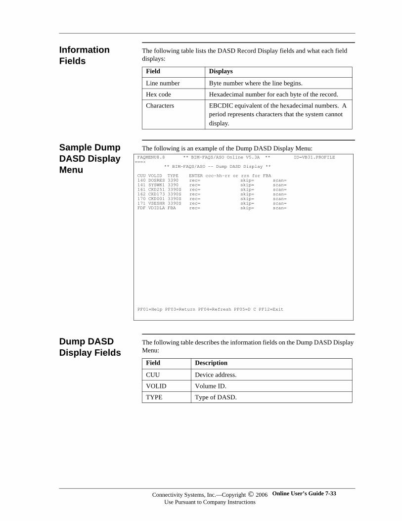
Information Fields
The following table lists the DASD Record Display fields and what each field displays:
Sample Dump DASD Display Menu
The following is an example of the Dump DASD Display Menu:
Dump DASD Display Fields
The following table describes the information fields on the Dump DASD Display Menu:
Field Displays
Line number Byte number where the line begins.
Hex code Hexadecimal number for each byte of the record.
Characters EBCDIC equivalent of the hexadecimal numbers. A period represents characters that the system cannot display.
FAQMENU8.8 ** BIM-FAQS/ASO Online V5.3A ** ID=VB31.PROFILE ===> ** BIM-FAQS/ASO -- Dump DASD Display ** CUU VOLID TYPE ENTER ccc-hh-rr or rrn for FBA 140 DOSRES 3390 rec= skip= scan= 141 SYSWK1 3390 rec= skip= scan= 161 CKD251 3390S rec= skip= scan= 162 CKD173 3390S rec= skip= scan= 170 CKD001 3390S rec= skip= scan= 171 VSESHR 3390S rec= skip= scan= FDF VDIDLA FBA rec= skip= scan=
PF01=Help PF03=Return PF04=Refresh PF05=D C PF12=Exit
Field Description
CUU Device address.
VOLID Volume ID.
TYPE Type of DASD.
Connectivity Systems, Inc.—Copyright © 2006Use Pursuant to Company Instructions
Online User’s Guide 7-33
Connectivity Systems
record= DASD address of the record you want to display.For CKD devices, enter the DASD record address as a decimal or hexadecimal cylinder-head-record number. To enter a hexadecimal cylinder-head-record number , enter an X before the number.
For FBA devices, enter the DASD record address as a decimal or hexadecimal relative-block number. To enter a hexadecimal relative-block number , enter an X before the number.
Field Description
7-34 BIM-FAQS/ASO Connectivity Systems, Inc.—Copyright © 2006Use Pursuant to Company Instructions
Altering the DASD Record
Use the ALTER DATA command in the display to alter 1 to 16 bytes of DASD storage, starting at the relative decimal displacement.
Note: Before altering DASD, you must dump the record to be altered.
ALTER DATA Command Syntax
The following is the syntax for the command:
ALTER {DATA | KEY},+nn,V=xx,R=yy
ALTER DATA Command Options
The following table describes the command options available for the ALTER DATA command:
Option Description
+nn Where to start the replacement. This is a relative displacement from the current storage displayed. Use decimal characters for this offset value.
xx 1 to 16 bytes to verify. You must verify at least the first byte of the data to be altered. You do not need to verify the same number of bytes that are being replaced.
yy 1 to 16 bytes of replacement data. Enter two hexadecimal characters (0 through F) for each byte to be changed.
Connectivity Systems, Inc.—Copyright © 2006Use Pursuant to Company Instructions
Online User’s Guide 7-35
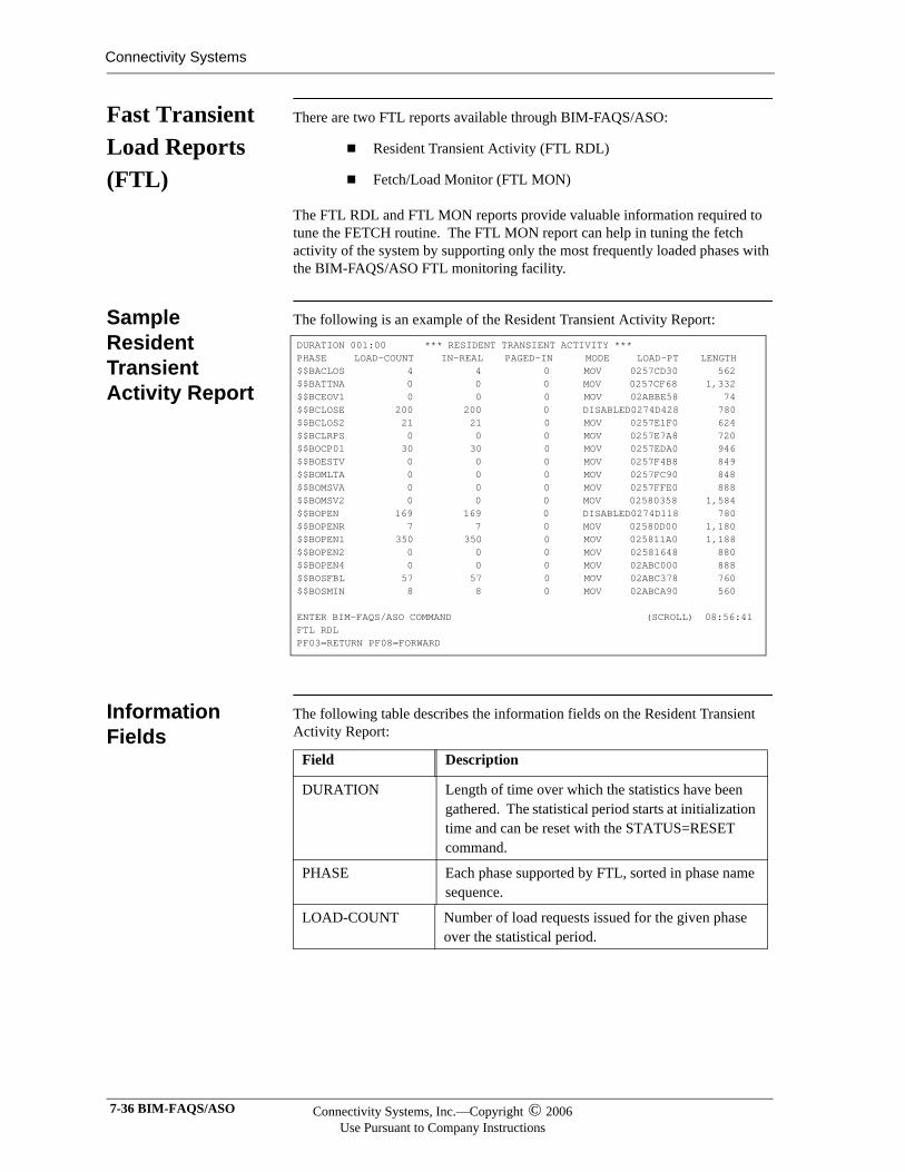
Connectivity Systems
Fast Transient Load Reports (FTL)
There are two FTL reports available through BIM-FAQS/ASO:
Resident Transient Activity (FTL RDL)
Fetch/Load Monitor (FTL MON)
The FTL RDL and FTL MON reports provide valuable information required to tune the FETCH routine. The FTL MON report can help in tuning the fetch activity of the system by supporting only the most frequently loaded phases with the BIM-FAQS/ASO FTL monitoring facility.
Sample Resident Transient Activity Report
The following is an example of the Resident Transient Activity Report:
Information Fields
The following table describes the information fields on the Resident Transient Activity Report:
DURATION 001:00 *** RESIDENT TRANSIENT ACTIVITY *** PHASE LOAD-COUNT IN-REAL PAGED-IN MODE LOAD-PT LENGTH $$BACLOS 4 4 0 MOV 0257CD30 562 $$BATTNA 0 0 0 MOV 0257CF68 1,332 $$BCEOV1 0 0 0 MOV 02ABBE58 74 $$BCLOSE 200 200 0 DISABLED0274D428 780 $$BCLOS2 21 21 0 MOV 0257E1F0 624 $$BCLRPS 0 0 0 MOV 0257E7A8 720 $$BOCP01 30 30 0 MOV 0257EDA0 946 $$BOESTV 0 0 0 MOV 0257F4B8 849 $$BOMLTA 0 0 0 MOV 0257FC90 848 $$BOMSVA 0 0 0 MOV 0257FFE0 888 $$BOMSV2 0 0 0 MOV 02580358 1,584 $$BOPEN 169 169 0 DISABLED0274D118 780 $$BOPENR 7 7 0 MOV 02580D00 1,180 $$BOPEN1 350 350 0 MOV 025811A0 1,188 $$BOPEN2 0 0 0 MOV 02581648 880 $$BOPEN4 0 0 0 MOV 02ABC000 888 $$BOSFBL 57 57 0 MOV 02ABC378 760 $$BOSMIN 8 8 0 MOV 02ABCA90 560 ENTER BIM-FAQS/ASO COMMAND (SCROLL) 08:56:41 FTL RDL PF03=RETURN PF08=FORWARD
Field Description
DURATION Length of time over which the statistics have been gathered. The statistical period starts at initialization time and can be reset with the STATUS=RESET command.
PHASE Each phase supported by FTL, sorted in phase name sequence.
LOAD-COUNT Number of load requests issued for the given phase over the statistical period.
7-36 BIM-FAQS/ASO Connectivity Systems, Inc.—Copyright © 2006Use Pursuant to Company Instructions
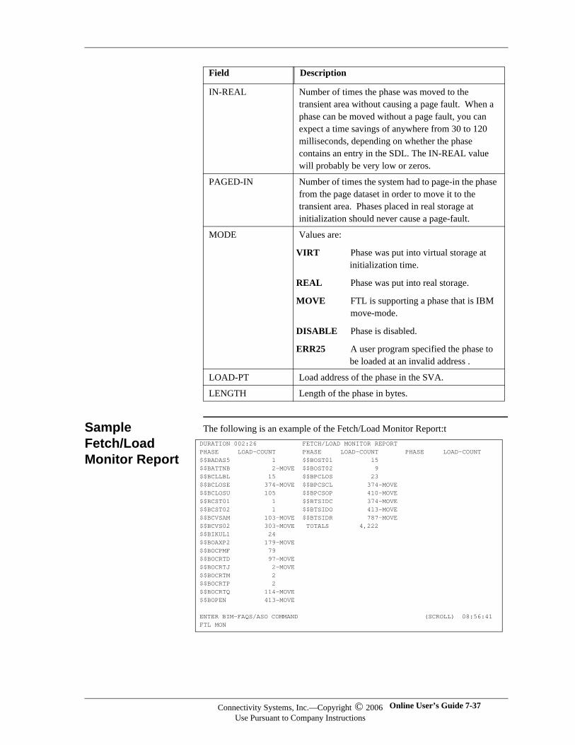
Sample Fetch/Load Monitor Report
The following is an example of the Fetch/Load Monitor Report:t
IN-REAL Number of times the phase was moved to the transient area without causing a page fault. When a phase can be moved without a page fault, you can expect a time savings of anywhere from 30 to 120 milliseconds, depending on whether the phase contains an entry in the SDL. The IN-REAL value will probably be very low or zeros.
PAGED-IN Number of times the system had to page-in the phase from the page dataset in order to move it to the transient area. Phases placed in real storage at initialization should never cause a page-fault.
MODE Values are:
VIRT Phase was put into virtual storage at initialization time.
REAL Phase was put into real storage.
MOVE FTL is supporting a phase that is IBM move-mode.
DISABLE Phase is disabled.
ERR25 A user program specified the phase to be loaded at an invalid address .
LOAD-PT Load address of the phase in the SVA.
LENGTH Length of the phase in bytes.
Field Description
DURATION 002:26 FETCH/LOAD MONITOR REPORTPHASE LOAD-COUNT PHASE LOAD-COUNT PHASE LOAD-COUNT$$BADAS5 1 $$BOST01 15$$BATTNB 2-MOVE $$BOST02 9$$BCLLBL 15 $$BPCLOS 23$$BCLOSE 374-MOVE $$BPCSCL 374-MOVE$$BCLOSU 105 $$BPCSOP 410-MOVE$$BCST01 1 $$BTSIDC 374-MOVE$$BCST02 1 $$BTSIDO 413-MOVE$$BCVSAM 103-MOVE $$BTSIDR 787-MOVE$$BCVS02 303-MOVE TOTALS 4,222$$BIKUL1 24$$BOAXP2 179-MOVE$$BOCPMF 79$$BOCRTD 97-MOVE$$BOCRTJ 2-MOVE$$BOCRTM 2$$BOCRTP 2$$BOCRTQ 114-MOVE$$BOPEN 413-MOVE
ENTER BIM-FAQS/ASO COMMAND (SCROLL) 08:56:41 FTL MON
Connectivity Systems, Inc.—Copyright © 2006Use Pursuant to Company Instructions
Online User’s Guide 7-37
Connectivity Systems
Fetch/Load Monitor Report Fields
The following table describes the Fetch-Load Monitor report fields:
FTL Command Options
The following table describes the FTL Command options.
Note:Note:Do not separate the command from the ,N= option with a blank. Do separate the (phase) option from the command with a blank.
Field Description
DURATION Length of time over which the statistics have been gathered. The statistical period starts at initialization time and can be reset with the STATUS=RESET command.
PHASE Name of each nonresident phase loaded during the statistical period. About 200 phase names can be supported in each page obtained for the monitor facility. Subsequent phases are not entered in the monitor list in an overload situation. Unsupported phases are not recorded. To avoid this situation, use the STATUS=RESET command to periodically clear the monitor list.The system marks phases in the SVA either SVA or MOVE. Phases in the SDL are marked SDL.
LOAD-COUNT Number of fetch or load requests issued for the phase over the time period.
Options Description
,N=n Displays only the phases with load counts greater than or equal to n.
(phase) Displays all phases beginning with this generic phase name. For example, FTL ($JOB) displays all phases with names beginning $JOB.
7-38 BIM-FAQS/ASO Connectivity Systems, Inc.—Copyright © 2006Use Pursuant to Company Instructions
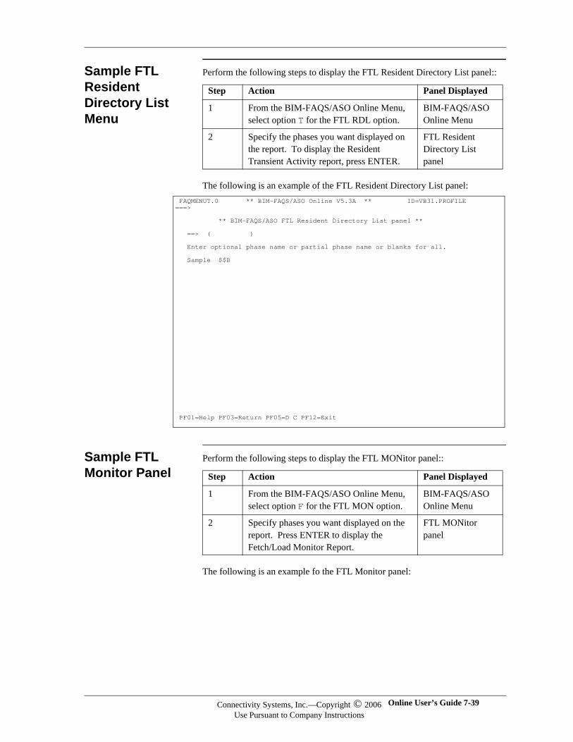
Sample FTL Resident Directory List Menu
Perform the following steps to display the FTL Resident Directory List panel::
The following is an example of the FTL Resident Directory List panel:
Sample FTL Monitor Panel
Perform the following steps to display the FTL MONitor panel::
The following is an example fo the FTL Monitor panel:
Step Action Panel Displayed
1 From the BIM-FAQS/ASO Online Menu, select option T for the FTL RDL option.
BIM-FAQS/ASO Online Menu
2 Specify the phases you want displayed on the report. To display the Resident Transient Activity report, press ENTER.
FTL Resident Directory List panel
FAQMENUT.0 ** BIM-FAQS/ASO Online V5.3A ** ID=VB31.PROFILE ===> ** BIM-FAQS/ASO FTL Resident Directory List panel ** ==> ( ) Enter optional phase name or partial phase name or blanks for all. Sample $$B
PF01=Help PF03=Return PF05=D C PF12=Exit
Step Action Panel Displayed
1 From the BIM-FAQS/ASO Online Menu, select option F for the FTL MON option.
BIM-FAQS/ASO Online Menu
2 Specify phases you want displayed on the report. Press ENTER to display the Fetch/Load Monitor Report.
FTL MONitor panel
Connectivity Systems, Inc.—Copyright © 2006Use Pursuant to Company Instructions
Online User’s Guide 7-39
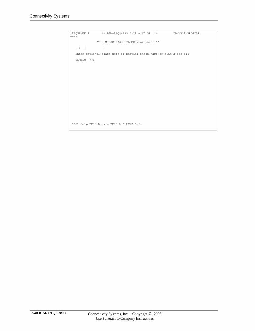
Connectivity Systems
FAQMENUF.F ** BIM-FAQS/ASO Online V5.3A ** ID=VB31.PROFILE ===> ** BIM-FAQS/ASO FTL MONitor panel ** ==> ( ) Enter optional phase name or partial phase name or blanks for all. Sample $$B
PF01=Help PF03=Return PF05=D C PF12=Exit
7-40 BIM-FAQS/ASO Connectivity Systems, Inc.—Copyright © 2006Use Pursuant to Company Instructions
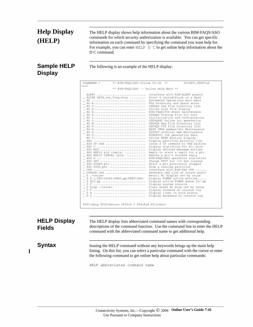
Help Display (HELP)
The HELP display shows help information about the various BIM-FAQS/ASO commands for which security authorization is available. You can get specific information on each command by specifying the command you want help for. For example, you can enter HELP D C to get online help information about the D C command.
Sample HELP Display
The following is an example of the HELP display:
HELP Display Fields
The HELP display lists abbreviated command names with corresponding descriptions of the command function. Use the command line to enter the HELP command with the abbreviated command name to get additional help.
Syntax Issuing the HELP command without any keywords brings up the main help listing. On this list, you can select a particular command with the cursor or enter the following command to get online help about particular commands:
HELP abbreviated command name
FAQMENHP.* ** BIM-FAQS/ASO Online V5.3A ** ID=VB31.PROFILE ===> ** BIM-FAQS/ASO -- Online Help Menu ** ALERT ............................ Interface with BIM-ALERT panels _ ALTER DATA,+nn,V=xx,R=yy ......... Alter a record/block on a dasd _ AO ............................... Automated Operations main menu _ AO A.............................. PDS Directory and Space stats _ AO C.............................. GSFAQS Cmd File Directory List _ AO D.............................. Online Lock file display _ AO E.............................. BIM-FAQS/PCS Event maintenance _ AO G.............................. GSFAQS Startup File Dir List _ AO I.............................. Initialization and Configuration _ AO L.............................. GSFAQSHC Online jcl generation _ AO M.............................. GSFAQS Msg File Directory List _ AO P.............................. GSFAQS Pfk File Directory List _ AO R.............................. REXX IMOD member/dir Maintenance _ AO S.............................. SYSOUT archival mem Maintenance AO U.............................. BIM$PUTL job generation menu AO V.............................. Online MSHP History Display _ ASO .............................. Display partition priority list _ ASO CP cmd ....................... Issue a CP command to VSE machine _ ASO J ............................ Display statistics for all ptns _ ASO MSG........................... Display defined message entries _ ASO REPLY pid <reply> ............ Reply or stack a reply for a ptn _ ASO REPLY CANCEL <pid> ........... Remove a ptn's stacked reply _ ASO S ............................ BIM-FAQS/ASO operation statistics _ ASO SET .......................... Change PRTY for >10 dyn classes _ ASO START,ptn .................... Start a ptn previously stopped _ ASO STOP,ptn ..................... Stop a running partition _ CPR .............................. Interface with BIM-GSS CPR ...... _ CURSOR cmd ....................... Generate cmd line at cursor postn _ D .<value> Recall HC display ref by value _ D A <,DEV|LOCAL|PART,pp|PNET|SAS> Display POWER active entries..... _ D ACT,pp ......................... Display active POWER queue for pp _ D C .............................. Display system console _ D Drop .<value> Clear saved HC disp ref by value _ D F .............................. Display forward on console log _ D H .............................. Display lines in hold status _ D L .............................. Display backward on console log PF01=Help PF03=Return PF05=D C PF8=Fwd PF12=Exit
Connectivity Systems, Inc.—Copyright © 2006Use Pursuant to Company Instructions
Online User’s Guide 7-41
Connectivity Systems
Held Lines Removed from Console Display (K E)
The K E command removes lines from the console display.
For pre-ESA 2.1, the K E command removes lines from the console display by letting the lines scroll off the display instead of being held there. In other words, the command turns off the hold.
Syntax The command syntax for the K E command is as follows:
K E[,line_number]
Use the K E command without parameters to release the line the cursor is on and all lines procede it.
Specify a line number with the K E command to release that line from the system console display. For example, to release the message shown on line 8 of the display, execute the following command:
K E,8
For ESA 2.1 and above, if you change your console ID= or sign off/on to BIM-FAQS/ASO, the system may return the held lines to the top of the screen. To remove them, you would use the K E command again. The K E command without a line number specified will clear all held lines from the cursor position to the top of the screen. To clear one line only, you must specify the line number. The line number is determined by the display lines only, not by the statistics data such as on the D S,S or D S,J screens. If you want to delete the first console line use K E,1 even if the first line is in the middle of the screen after the D S,x data.
Disabling theK E Command
To disallow the use of the K E command, use Security User Profile Record 2. See Chapter 4, "Security and User Configuration," for more information on the security field that can disallow the use of the K E command.
7-42 BIM-FAQS/ASO Connectivity Systems, Inc.—Copyright © 2006Use Pursuant to Company Instructions
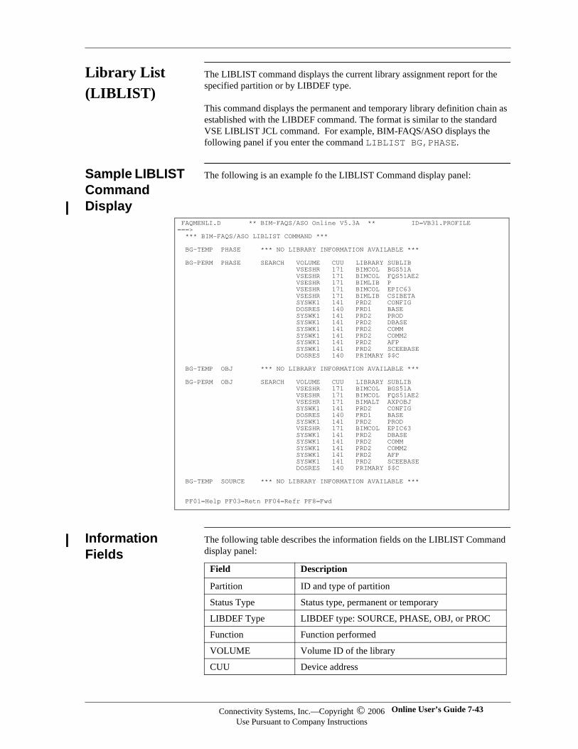
Library List (LIBLIST)
The LIBLIST command displays the current library assignment report for the specified partition or by LIBDEF type.
This command displays the permanent and temporary library definition chain as established with the LIBDEF command. The format is similar to the standard VSE LIBLIST JCL command. For example, BIM-FAQS/ASO displays the following panel if you enter the command LIBLIST BG,PHASE.
Sample LIBLIST Command Display
The following is an example fo the LIBLIST Command display panel:
Information Fields
The following table describes the information fields on the LIBLIST Command display panel:
FAQMENLI.D ** BIM-FAQS/ASO Online V5.3A ** ID=VB31.PROFILE ===> *** BIM-FAQS/ASO LIBLIST COMMAND *** BG-TEMP PHASE *** NO LIBRARY INFORMATION AVAILABLE *** BG-PERM PHASE SEARCH VOLUME CUU LIBRARY SUBLIB VSESHR 171 BIMCOL BGS51A VSESHR 171 BIMCOL FQS51AE2 VSESHR 171 BIMLIB P VSESHR 171 BIMCOL EPIC63 VSESHR 171 BIMLIB CSIBETA SYSWK1 141 PRD2 CONFIG DOSRES 140 PRD1 BASE SYSWK1 141 PRD2 PROD SYSWK1 141 PRD2 DBASE SYSWK1 141 PRD2 COMM SYSWK1 141 PRD2 COMM2 SYSWK1 141 PRD2 AFP SYSWK1 141 PRD2 SCEEBASE DOSRES 140 PRIMARY $$C BG-TEMP OBJ *** NO LIBRARY INFORMATION AVAILABLE *** BG-PERM OBJ SEARCH VOLUME CUU LIBRARY SUBLIB VSESHR 171 BIMCOL BGS51A VSESHR 171 BIMCOL FQS51AE2 VSESHR 171 BIMALT AXPOBJ SYSWK1 141 PRD2 CONFIG DOSRES 140 PRD1 BASE SYSWK1 141 PRD2 PROD VSESHR 171 BIMCOL EPIC63 SYSWK1 141 PRD2 DBASE SYSWK1 141 PRD2 COMM SYSWK1 141 PRD2 COMM2 SYSWK1 141 PRD2 AFP SYSWK1 141 PRD2 SCEEBASE DOSRES 140 PRIMARY $$C BG-TEMP SOURCE *** NO LIBRARY INFORMATION AVAILABLE *** PF01=Help PF03=Retn PF04=Refr PF8=Fwd
Field Description
Partition ID and type of partition
Status Type Status type, permanent or temporary
LIBDEF Type LIBDEF type: SOURCE, PHASE, OBJ, or PROC
Function Function performed
VOLUME Volume ID of the library
CUU Device address
Connectivity Systems, Inc.—Copyright © 2006Use Pursuant to Company Instructions
Online User’s Guide 7-43
Connectivity Systems
LIBLIST Command Options
The following table lists the LIBLIST command option and what each option displays:
LIBLIST Command Examples
The following tables lists examples and explainations of the LIBLIST commands:
LIBRARY Name of the library
SUBLIB Name of the related sublibrary
Option Displays ...
BGFnCnALL
Library definition chain for an individual partition or all partitions.
PHASEOBJECTSOURCEPROC
Type of LIBDEF specified.
Example Explanation
LIBLIST BG Lists all LIBDEFs for BG
LIBLIST F1,PHASE
Lists only the phase LIBDEFs for F1
LIBLIST SOURCE Lists source LIBDEFs for all partitions
7-44 BIM-FAQS/ASO Connectivity Systems, Inc.—Copyright © 2006Use Pursuant to Company Instructions
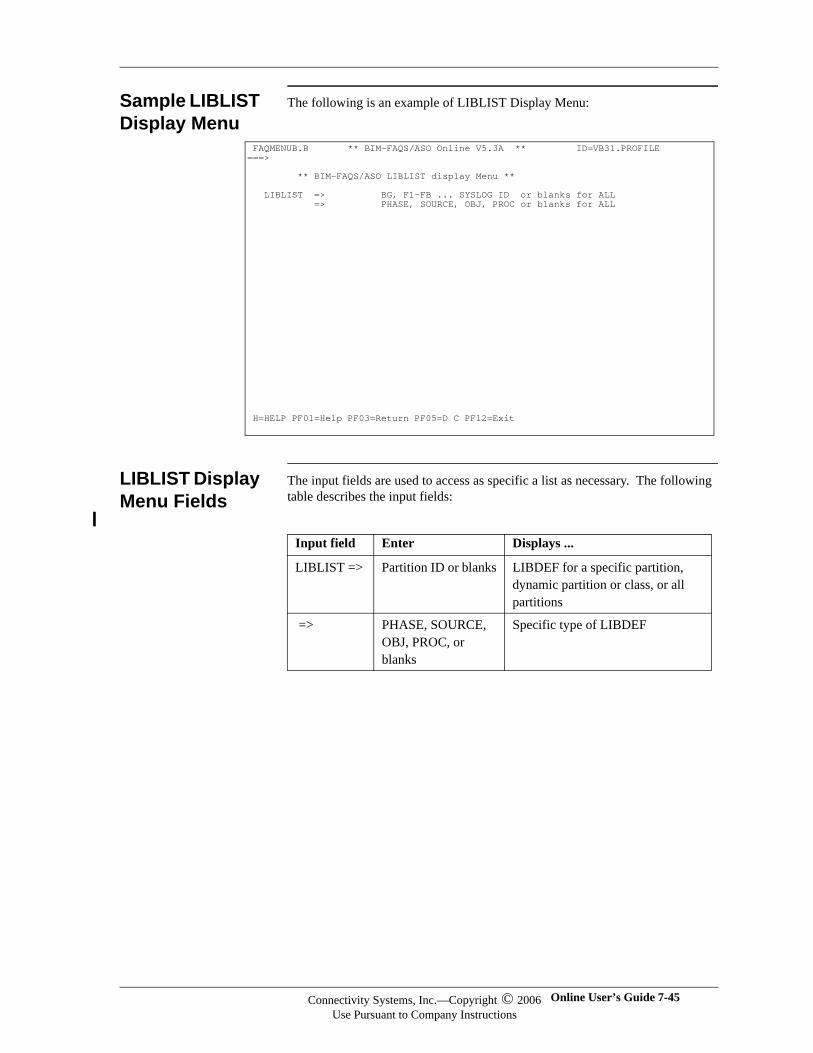
Sample LIBLIST Display Menu
The following is an example of LIBLIST Display Menu:
LIBLIST Display Menu Fields
The input fields are used to access as specific a list as necessary. The following table describes the input fields:
FAQMENUB.B ** BIM-FAQS/ASO Online V5.3A ** ID=VB31.PROFILE ===> ** BIM-FAQS/ASO LIBLIST display Menu ** LIBLIST => BG, F1-FB ... SYSLOG ID or blanks for ALL => PHASE, SOURCE, OBJ, PROC or blanks for ALL
H=HELP PF01=Help PF03=Return PF05=D C PF12=Exit
Input field Enter Displays ...
LIBLIST => Partition ID or blanks LIBDEF for a specific partition, dynamic partition or class, or all partitions
=> PHASE, SOURCE, OBJ, PROC, or blanks
Specific type of LIBDEF
Connectivity Systems, Inc.—Copyright © 2006Use Pursuant to Company Instructions
Online User’s Guide 7-45
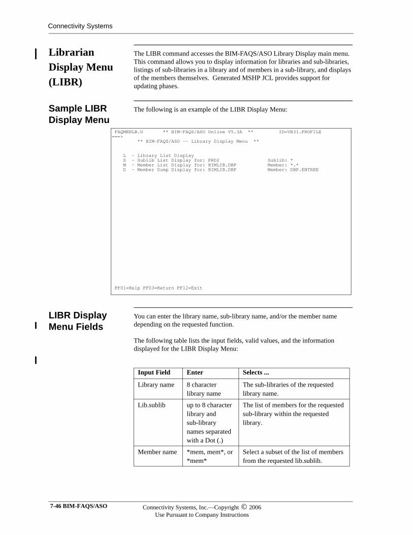
Connectivity Systems
Librarian Display Menu (LIBR)
The LIBR command accesses the BIM-FAQS/ASO Library Display main menu. This command allows you to display information for libraries and sub-libraries, listings of sub-libraries in a library and of members in a sub-library, and displays of the members themselves. Generated MSHP JCL provides support for updating phases.
Sample LIBR Display Menu
The following is an example of the LIBR Display Menu:
LIBR Display Menu Fields
You can enter the library name, sub-library name, and/or the member name depending on the requested function.
The following table lists the input fields, valid values, and the information displayed for the LIBR Display Menu:
FAQMENLB.U ** BIM-FAQS/ASO Online V5.3A ** ID=VB31.PROFILE ===> ** BIM-FAQS/ASO -- Library Display Menu ** L - Library List Display S - Sublib List Display for: PRD2 Sublib: * M - Member List Display for: BIMLIB.DBP Member: *.* D - Member Dump Display for: BIMLIB.DBP Member: DBP.ENTREE
PF01=Help PF03=Return PF12=Exit
Input Field Enter Selects ...
Library name 8 character library name
The sub-libraries of the requested library name.
Lib.sublib up to 8 character library and sub-library names separated with a Dot (.)
The list of members for the requested sub-library within the requested library.
Member name *mem, mem*, or *mem*
Select a subset of the list of members from the requested lib.sublib.
7-46 BIM-FAQS/ASO Connectivity Systems, Inc.—Copyright © 2006Use Pursuant to Company Instructions
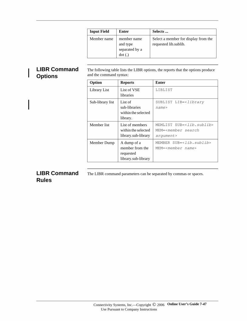
LIBR Command Options
The following table lists the LIBR options, the reports that the options produce and the command syntax:
LIBR Command Rules
The LIBR command parameters can be separated by commas or spaces.
Member name member name and type separated by a dot (.)
Select a member for display from the requested lib.sublib.
Input Field Enter Selects ...
Option Reports Enter
Library List List of VSE libraries
LIBLIST
Sub-library list List of sub-libraries within the selected library.
SUBLIST LIB=<library name>
Member list List of members within the selected library.sub-library
MEMLIST SUB=<lib.sublib>MEM=<member search argument>
Member Dump A dump of a member from the requested library.sub-library
MEMBER SUB=<lib.sublib>MEM=<member name>
Connectivity Systems, Inc.—Copyright © 2006Use Pursuant to Company Instructions
Online User’s Guide 7-47
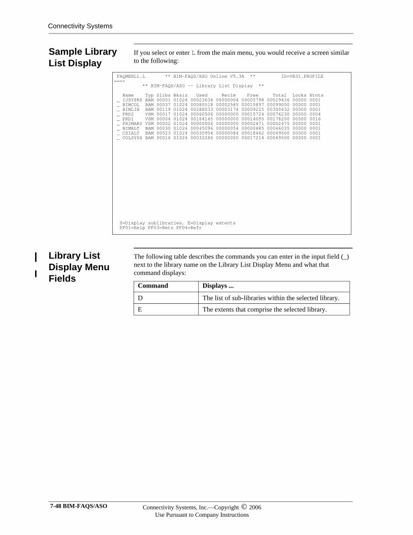
Connectivity Systems
Sample Library List Display
If you select or enter L from the main menu, you would receive a screen similar to the following:
Library List Display Menu Fields
The following table describes the commands you can enter in the input field (_) next to the library name on the Library List Display Menu and what that command displays:
FAQMENL1.L ** BIM-FAQS/ASO Online V5.3A ** ID=VB31.PROFILE ===> ** BIM-FAQS/ASO -- Library List Display ** Name Typ Slibs Bksiz Used Reclm Free Total Locks Xtnts _ IJSYSRS BAM 00001 01024 00023634 00000004 00005798 00029436 00000 0001 _ BIMCOL BAM 00037 01024 00080518 00002585 00015897 00099000 00000 0001 _ BIMLIB BAM 00119 01024 00288033 00003174 00009225 00300432 00000 0001 _ PRD2 VSM 00017 01024 00060506 00000000 00015724 00076230 00000 0004 _ PRD1 VSM 00004 01024 00164145 00000000 00014055 00178200 00000 0016 _ PRIMARY VSM 00002 01024 00000004 00000000 00002471 00002475 00000 0001 _ BIMALT BAM 00030 01024 00045096 00000054 00000885 00046035 00000 0001 _ CSIALT BAM 00023 01024 00030954 00000084 00018462 00049500 00000 0001 _ COLSYS6 BAM 00016 01024 00032286 00000000 00017214 00049500 00000 0001
S=Display sublibraries, E=Display extents PF01=Help PF03=Retn PF04=Refr
Command Displays ...
D The list of sub-libraries within the selected library.
E The extents that comprise the selected library.
7-48 BIM-FAQS/ASO Connectivity Systems, Inc.—Copyright © 2006Use Pursuant to Company Instructions
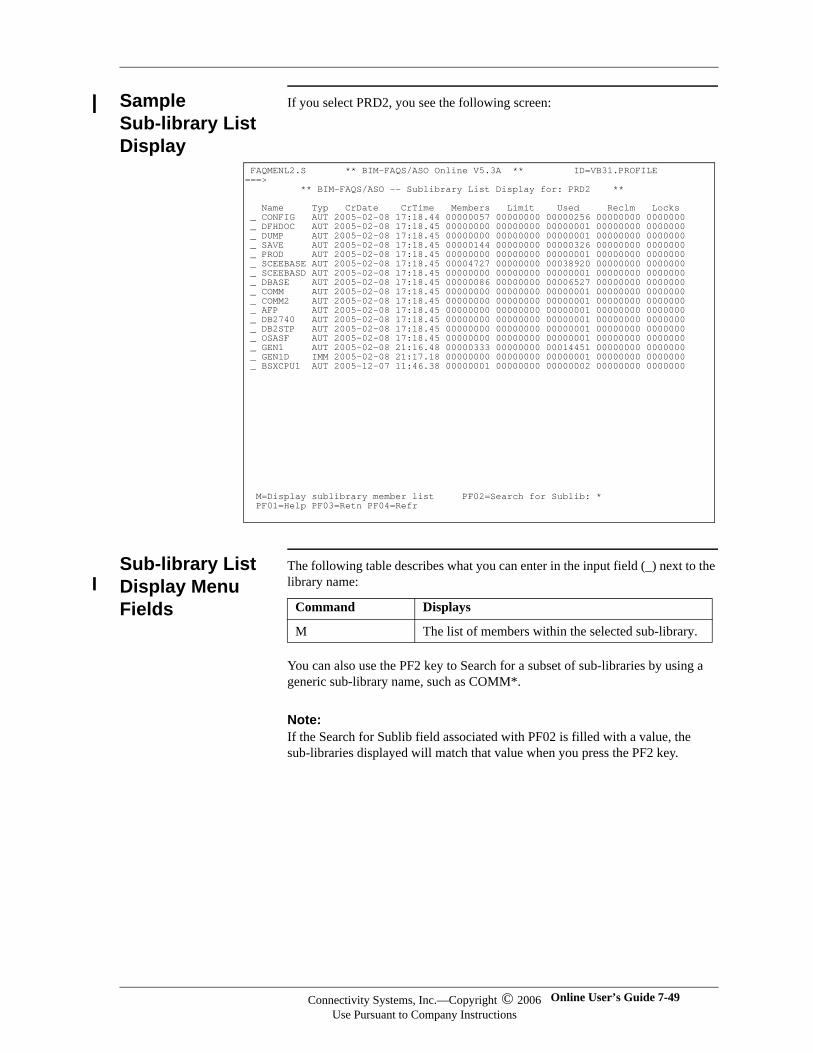
Sample Sub-library List Display
If you select PRD2, you see the following screen:
Sub-library List Display Menu Fields
The following table describes what you can enter in the input field (_) next to the library name:
You can also use the PF2 key to Search for a subset of sub-libraries by using a generic sub-library name, such as COMM*.
Note:Note:If the Search for Sublib field associated with PF02 is filled with a value, the sub-libraries displayed will match that value when you press the PF2 key.
FAQMENL2.S ** BIM-FAQS/ASO Online V5.3A ** ID=VB31.PROFILE ===> ** BIM-FAQS/ASO -- Sublibrary List Display for: PRD2 ** Name Typ CrDate CrTime Members Limit Used Reclm Locks _ CONFIG AUT 2005-02-08 17:18.44 00000057 00000000 00000256 00000000 0000000 _ DFHDOC AUT 2005-02-08 17:18.45 00000000 00000000 00000001 00000000 0000000 _ DUMP AUT 2005-02-08 17:18.45 00000000 00000000 00000001 00000000 0000000 _ SAVE AUT 2005-02-08 17:18.45 00000144 00000000 00000326 00000000 0000000 _ PROD AUT 2005-02-08 17:18.45 00000000 00000000 00000001 00000000 0000000 _ SCEEBASE AUT 2005-02-08 17:18.45 00004727 00000000 00038920 00000000 0000000 _ SCEEBASD AUT 2005-02-08 17:18.45 00000000 00000000 00000001 00000000 0000000 _ DBASE AUT 2005-02-08 17:18.45 00000086 00000000 00006527 00000000 0000000 _ COMM AUT 2005-02-08 17:18.45 00000000 00000000 00000001 00000000 0000000 _ COMM2 AUT 2005-02-08 17:18.45 00000000 00000000 00000001 00000000 0000000 _ AFP AUT 2005-02-08 17:18.45 00000000 00000000 00000001 00000000 0000000 _ DB2740 AUT 2005-02-08 17:18.45 00000000 00000000 00000001 00000000 0000000 _ DB2STP AUT 2005-02-08 17:18.45 00000000 00000000 00000001 00000000 0000000 _ OSASF AUT 2005-02-08 17:18.45 00000000 00000000 00000001 00000000 0000000 _ GEN1 AUT 2005-02-08 21:16.48 00000333 00000000 00014451 00000000 0000000 _ GEN1D IMM 2005-02-08 21:17.18 00000000 00000000 00000001 00000000 0000000 _ BSXCPU1 AUT 2005-12-07 11:46.38 00000001 00000000 00000002 00000000 0000000
M=Display sublibrary member list PF02=Search for Sublib: * PF01=Help PF03=Retn PF04=Refr
Command Displays
M The list of members within the selected sub-library.
Connectivity Systems, Inc.—Copyright © 2006Use Pursuant to Company Instructions
Online User’s Guide 7-49
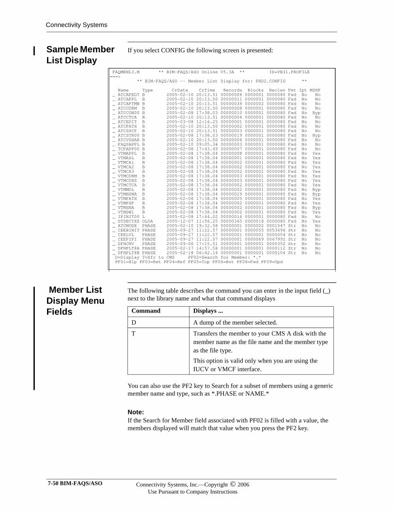
Connectivity Systems
Sample Member List Display
If you select CONFIG the following screen is presented:
Member List Display Menu Fields
The following table describes the command you can enter in the input field (_) next to the library name and what that command displays
You can also use the PF2 key to Search for a subset of members using a generic member name and type, such as *.PHASE or NAME.*
Note:Note:If the Search for Member field associated with PF02 is filled with a value, the members displayed will match that value when you press the PF2 key.
FAQMENL3.M ** BIM-FAQS/ASO Online V5.3A ** ID=VB31.PROFILE ===> ** BIM-FAQS/ASO -- Member List Display for: PRD2.CONFIG ** Name Type CrDate CrTime Records Blocks Reclen Fmt Ipt MSHP _ ATCAPEDT B 2005-02-10 20:13.51 00000004 0000001 0000080 Fxd No No _ ATCAPPL B 2005-02-10 20:13.50 00000011 0000001 0000080 Fxd No No _ ATCAPTMN B 2005-02-10 20:13.51 00000038 0000002 0000080 Fxd No No _ ATCCDRM B 2005-02-10 20:13.50 00000008 0000001 0000080 Fxd No No _ ATCCON00 B 2005-02-08 17:38.03 00000010 0000001 0000080 Fxd No Byp _ ATCCTCA B 2005-02-10 20:13.51 00000004 0000001 0000080 Fxd No No _ ATCEDIT B 2005-03-08 12:16.25 00000001 0000001 0000080 Fxd No No _ ATCPATH B 2005-02-10 20:13.50 00000002 0000001 0000080 Fxd No No _ ATCSSCP B 2005-02-10 20:13.51 00000003 0000001 0000080 Fxd No No _ ATCSTR00 B 2005-02-08 17:38.03 00000019 0000001 0000080 Fxd No Byp _ ATCVSHAR B 2005-02-10 20:13.50 00000004 0000001 0000080 Fxd No No _ FAQSAPPL B 2005-02-10 09:05.34 00000003 0000001 0000080 Fxd No No _ TCPAPP00 B 2005-02-08 17:43.49 00000007 0000001 0000080 Fxd No No _ VTMAPPL B 2005-02-08 17:38.04 00000008 0000001 0000080 Fxd No Yes _ VTMASL B 2005-02-08 17:38.04 00000001 0000001 0000080 Fxd No Yes _ VTMCA1 B 2005-02-08 17:38.04 00000002 0000001 0000080 Fxd No Yes _ VTMCA2 B 2005-02-08 17:38.04 00000002 0000001 0000080 Fxd No Yes _ VTMCA3 B 2005-02-08 17:38.04 00000002 0000001 0000080 Fxd No Yes _ VTMCDRM B 2005-02-08 17:38.04 00000003 0000001 0000080 Fxd No Yes _ VTMCDRS B 2005-02-08 17:38.04 00000003 0000001 0000080 Fxd No Yes _ VTMCTCA B 2005-02-08 17:38.04 00000002 0000001 0000080 Fxd No Yes _ VTMMDL B 2005-02-08 17:38.04 00000002 0000001 0000080 Fxd No Byp _ VTMNSNA B 2005-02-08 17:38.04 00000029 0000001 0000080 Fxd No Byp _ VTMPATH B 2005-02-08 17:38.04 00000005 0000001 0000080 Fxd No Yes _ VTMPSF B 2005-02-08 17:38.04 00000002 0000001 0000080 Fxd No Yes _ VTMSNA B 2005-02-08 17:38.04 00000002 0000001 0000080 Fxd No Byp _ VTMSW1 B 2005-02-08 17:38.04 00000002 0000001 0000080 Fxd No Yes _ IPINIT00 L 2005-02-08 17:44.02 00000016 0000001 0000080 Fxd No No _ DTSECTXS OLDA 2005-12-07 11:56.25 00000365 0000018 0000080 Fxd No Yes _ ATCMODE PHASE 2005-02-10 19:32.58 00000001 0000002 0001547 Str No No _ CEEBINIT PHASE 2005-09-27 11:22.57 00000001 0000055 0053696 Str No No _ CEELVL PHASE 2005-09-27 11:22.57 00000001 0000001 0000054 Str No No _ CEEPIPI PHASE 2005-09-27 11:22.57 00000001 0000069 0067992 Str No No _ DFHCNV PHASE 2005-09-06 17:15.51 00000001 0000001 0000352 Str No No _ DFHPLT8A PHASE 2005-02-17 14:57.58 00000001 0000001 0000112 Str No No _ DFHPLT8B PHASE 2005-02-18 06:42.14 00000001 0000001 0000104 Str No No D=Display T=Xfr to CMS PF02=Search for Member: *.* PF01=Hlp PF03=Ret PF04=Ref PF05=Top PF06=Bot PF08=Fwd PF09=Upd
Command Displays ...
D A dump of the member selected.
T Transfers the member to your CMS A disk with the member name as the file name and the member type as the file type. This option is valid only when you are using the IUCV or VMCF interface.
7-50 BIM-FAQS/ASO Connectivity Systems, Inc.—Copyright © 2006Use Pursuant to Company Instructions
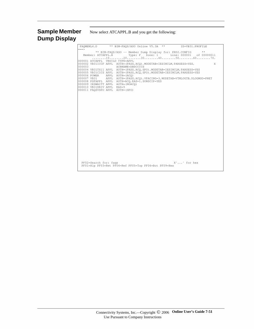
Sample Member Dump Display
Now select ATCAPPL.B and you get the following:
FAQMENL4.D ** BIM-FAQS/ASO Online V5.3A ** ID=VB31.PROFILE ===> ** BIM-FAQS/ASO -- Member Dump Display for: PRD2.CONFIG ** Member: ATCAPPL.B Type: F Zone: 1 Line: 000001 of 00000011 ........10........20........30........40........50........60........70. 000001 ATCAPPL VBUILD TYPE=APPL 000002 VB31ICCF APPL AUTH=(PASS,ACQ),MODETAB=IESINCLM,PARSESS=YES, X 000003 ACBNAME=DBDCCICS 000004 VB31TS11 APPL AUTH=(PASS,ACQ,SPO),MODETAB=IESINCLM,PARSESS=YES 000005 VB31CICS APPL AUTH=(PASS,ACQ,SPO),MODETAB=IESINCLM,PARSESS=YES 000006 POWER APPL AUTH=(ACQ) 000007 VB31 APPL AUTH=(PASS,ACQ),VPACING=3,MODETAB=VTMLOGTB,DLOGMOD=PNET 000008 PSFAPPL APPL AUTH=ACQ,EAS=1,SONSCIP=YES 000009 IESWAITT APPL AUTH=(NOACQ) 000010 VB31DRIV APPL EAS=5 000011 FAQSVSPO APPL AUTH=(SPO) PF02=Search for: faqs X'...' for hex PF01=Hlp PF03=Ret PF04=Ref PF05=Top PF06=Bot PF09=Hex
Connectivity Systems, Inc.—Copyright © 2006Use Pursuant to Company Instructions
Online User’s Guide 7-51
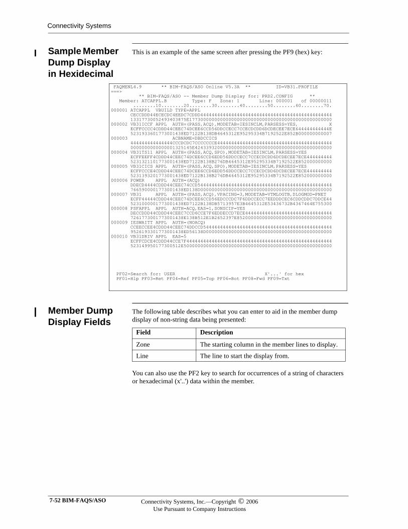
Connectivity Systems
Sample Member Dump Display in Hexidecimal
This is an example of the same screen after pressing the PF9 (hex) key:
Member Dump Display Fields
The following table describes what you can enter to aid in the member dump display of non-string data being presented:
You can also use the PF2 key to search for occurrences of a string of characters or hexadecimal (x'..') data within the member.
FAQMENL4.9 ** BIM-FAQS/ASO Online V5.3A ** ID=VB31.PROFILE ===> ** BIM-FAQS/ASO -- Member Dump Display for: PRD2.CONFIG ** Member: ATCAPPL.B Type: F Zone: 1 Line: 000001 of 00000011 ........10........20........30........40........50........60........70. 000001 ATCAPPL VBUILD TYPE=APPL CECCDDD44ECECDC4EEDC7CDDD44444444444444444444444444444444444444444444444 13317730052493403875E177300000000000000000000000000000000000000000000000 000002 VB31ICCF APPL AUTH=(PASS,ACQ),MODETAB=IESINCLM,PARSESS=YES, X ECFFCCCC4CDDD44CEEC74DCEE6CCD56DDCCECC7CCECDCDD6DCDECEE7ECE644444444444E 5231933601773001438ED7122B138DB4645312E95295334B7192522E852B000000000007 000003 ACBNAME=DBDCCICS 444444444444444CCCDCDC7CCCCCCCE44444444444444444444444444444444444444444 0000000000000001325145E4243393200000000000000000000000000000000000000000 000004 VB31TS11 APPL AUTH=(PASS,ACQ,SPO),MODETAB=IESINCLM,PARSESS=YES ECFFEEFF4CDDD44CEEC74DCEE6CCD6EDD56DDCCECC7CCECDCDD6DCDECEE7ECE444444444 5231321101773001438ED7122B138B276DB4645312E95295334B7192522E852000000000 000005 VB31CICS APPL AUTH=(PASS,ACQ,SPO),MODETAB=IESINCLM,PARSESS=YES ECFFCCCE4CDDD44CEEC74DCEE6CCD6EDD56DDCCECC7CCECDCDD6DCDECEE7ECE444444444 5231393201773001438ED7122B138B276DB4645312E95295334B7192522E852000000000 000006 POWER APPL AUTH=(ACQ) DDECD4444CDDD44CEEC74CCD544444444444444444444444444444444444444444444444 7665900001773001438ED138D00000000000000000000000000000000000000000000000 000007 VB31 APPL AUTH=(PASS,ACQ),VPACING=3,MODETAB=VTMLOGTB,DLOGMOD=PNET ECFF44444CDDD44CEEC74DCEE6CCD56EDCCCDC7F6DDCCECC7EEDDDCEC6CDDCDDC7DDCE44 5231000001773001438ED7122B138DB5713957E3B4645312E53436732B4367464E755300 000008 PSFAPPL APPL AUTH=ACQ,EAS=1,SONSCIP=YES DECCDDD44CDDD44CEEC7CCD6CCE7F6EDDECCD7ECE4444444444444444444444444444444 7261773001773001438E138B512E1B2652397E8520000000000000000000000000000000 000009 IESWAITT APPL AUTH=(NOACQ) CCEECCEE4CDDD44CEEC74DDCCD5444444444444444444444444444444444444444444444 9526193301773001438ED56138D000000000000000000000000000000000000000000000 000010 VB31DRIV APPL EAS=5 ECFFCDCE4CDDD44CCE7F4444444444444444444444444444444444444444444444444444 523149950177300512E50000000000000000000000000000000000000000000000000000 PF02=Search for: USER X'...' for hex PF01=Hlp PF03=Ret PF04=Ref PF05=Top PF06=Bot PF08=Fwd PF09=Txt
Field Description
Zone The starting column in the member lines to display.
Line The line to start the display from.
7-52 BIM-FAQS/ASO Connectivity Systems, Inc.—Copyright © 2006Use Pursuant to Company Instructions
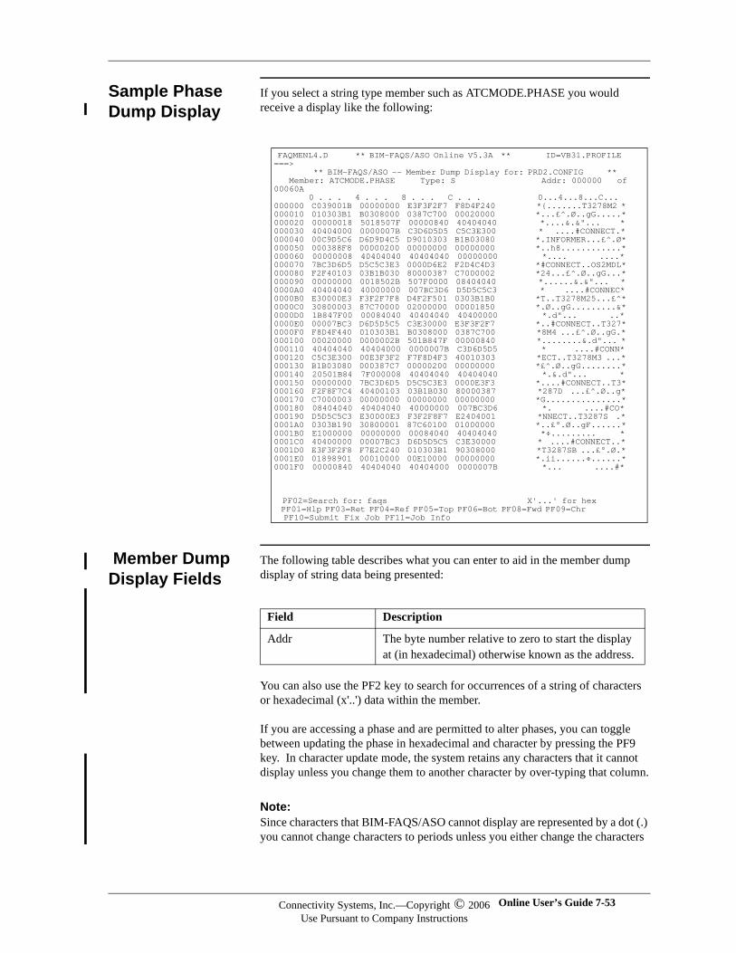
Sample Phase Dump Display
If you select a string type member such as ATCMODE.PHASE you would receive a display like the following:
Member Dump Display Fields
The following table describes what you can enter to aid in the member dump display of string data being presented:
You can also use the PF2 key to search for occurrences of a string of characters or hexadecimal (x'..') data within the member.
If you are accessing a phase and are permitted to alter phases, you can toggle between updating the phase in hexadecimal and character by pressing the PF9 key. In character update mode, the system retains any characters that it cannot display unless you change them to another character by over-typing that column.
Note:Note:Since characters that BIM-FAQS/ASO cannot display are represented by a dot (.) you cannot change characters to periods unless you either change the characters
FAQMENL4.D ** BIM-FAQS/ASO Online V5.3A ** ID=VB31.PROFILE ===> ** BIM-FAQS/ASO -- Member Dump Display for: PRD2.CONFIG ** Member: ATCMODE.PHASE Type: S Addr: 000000 of 00060A 0 . . . 4 . . . 8 . . . C . . . 0...4...8...C... 000000 C039001B 00000000 E3F3F2F7 F8D4F240 *{.......T3278M2 * 000010 010303B1 B0308000 0387C700 00020000 *...£^.Ø..gG.....* 000020 00000018 5018507F 00000840 40404040 *....&.&"... * 000030 40404000 0000007B C3D6D5D5 C5C3E300 * ....#CONNECT.* 000040 00C9D5C6 D6D9D4C5 D9010303 B1B03080 *.INFORMER...£^.Ø* 000050 000388F8 00000200 00000000 00000000 *..h8............* 000060 00000008 40404040 40404040 00000000 *.... ....* 000070 7BC3D6D5 D5C5C3E3 0000D6E2 F2D4C4D3 *#CONNECT..OS2MDL* 000080 F2F40103 03B1B030 80000387 C7000002 *24...£^.Ø..gG...* 000090 00000000 0018502B 507F0000 08404040 *......&.&"... * 0000A0 40404040 40000000 007BC3D6 D5D5C5C3 * ....#CONNEC* 0000B0 E30000E3 F3F2F7F8 D4F2F501 0303B1B0 *T..T3278M25...£^* 0000C0 30800003 87C70000 02000000 00001850 *.Ø..gG.........&* 0000D0 1B847F00 00084040 40404040 40400000 *.d"... ..* 0000E0 00007BC3 D6D5D5C5 C3E30000 E3F3F2F7 *..#CONNECT..T327* 0000F0 F8D4F440 010303B1 B0308000 0387C700 *8M4 ...£^.Ø..gG.* 000100 00020000 0000002B 501B847F 00000840 *........&.d"... * 000110 40404040 40404000 0000007B C3D6D5D5 * ....#CONN* 000120 C5C3E300 00E3F3F2 F7F8D4F3 40010303 *ECT..T3278M3 ...* 000130 B1B03080 000387C7 00000200 00000000 *£^.Ø..gG........* 000140 20501B84 7F000008 40404040 40404040 *.&.d"... * 000150 00000000 7BC3D6D5 D5C5C3E3 0000E3F3 *....#CONNECT..T3* 000160 F2F8F7C4 40400103 03B1B030 80000387 *287D ...£^.Ø..g* 000170 C7000003 00000000 00000000 00000000 *G...............* 000180 08404040 40404040 40000000 007BC3D6 *. ....#CO* 000190 D5D5C5C3 E30000E3 F3F2F8F7 E2404001 *NNECT..T3287S .* 0001A0 0303B190 30800001 87C60100 01000000 *..£°.Ø..gF......* 0001B0 E1000000 00000000 00084040 40404040 *÷......... * 0001C0 40400000 00007BC3 D6D5D5C5 C3E30000 * ....#CONNECT..* 0001D0 E3F3F2F8 F7E2C240 010303B1 90308000 *T3287SB ...£°.Ø.* 0001E0 01898901 00010000 00E10000 00000000 *.ii......÷......* 0001F0 00000840 40404040 40404000 0000007B *... ....#* PF02=Search for: faqs X'...' for hex PF01=Hlp PF03=Ret PF04=Ref PF05=Top PF06=Bot PF08=Fwd PF09=Chr PF10=Submit Fix Job PF11=Job Info
Field Description
Addr The byte number relative to zero to start the display at (in hexadecimal) otherwise known as the address.
Connectivity Systems, Inc.—Copyright © 2006Use Pursuant to Company Instructions
Online User’s Guide 7-53

Connectivity Systems
to another displayable character first or alter the characters using the hexadecimal display.
More Information
Each LIBR panel has extensive help available by pressing the PF1 key. Here you will find information about commands available and the functions of the defined PF keys.
7-54 BIM-FAQS/ASO Connectivity Systems, Inc.—Copyright © 2006Use Pursuant to Company Instructions
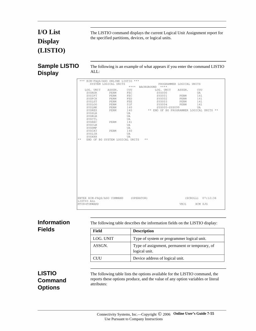
I/O List Display (LISTIO)
The LISTIO command displays the current Logical Unit Assignment report for the specified partitions, devices, or logical units.
Sample LISTIO Display
The following is an example of what appears if you enter the command LISTIO ALL:
Information Fields
The following table describes the information fields on the LISTIO display:
LISTIO Command Options
The following table lists the options available for the LISTIO command, the reports these options produce, and the value of any option variables or literal attributes:
*** BIM-FAQS/ASO ONLINE LISTIO *** SYSTEM LOGICAL UNITS PROGRAMMER LOGICAL UNITS **** BACKGROUND **** LOG. UNIT ASSGN. CUU LOG. UNIT ASSGN. CUU SYSRDR PERM FEC SYS000 UA SYSIPT PERM FEC SYS001 PERM 141 SYSPCH PERM FED SYS002 PERM 141 SYSLST PERM FEE SYS003 PERM 141 SYSLOG PERM 01F SYS004 PERM 141 SYSLNK PERM 140 SYS005-SYS099 UA SYSRES PERM 140 ** END OF BG PROGRAMMER LOGICAL UNITS ** SYSSLB UA SYSRLB UA SYSCTL UA SYSREC PERM 141 SYSCLB UA SYSDMP UA SYSCAT PERM 140 SYSLIB UA SYSXXX UA ** END OF BG SYSTEM LOGICAL UNITS ** ENTER BIM-FAQS/ASO COMMAND (OPERATOR) (SCROLL) 07:12:36 LISTIO ALL PF08=FORWARD VB31 XCM SJG
Field Description
LOG. UNIT Type of system or programmer logical unit.
ASSGN. Type of assignment, permanent or temporary, of logical unit.
CUU Device address of logical unit.
Connectivity Systems, Inc.—Copyright © 2006Use Pursuant to Company Instructions
Online User’s Guide 7-55
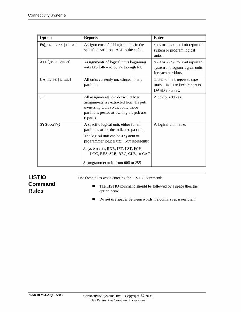
Connectivity Systems
LISTIO Command Rules
Use these rules when entering the LISTIO command:
The LISTIO command should be followed by a space then the option name.
Do not use spaces between words if a comma separates them.
Option Reports Enter
Fn[,ALL | SYS | PROG] Assignments of all logical units in the specified partition. ALL is the default.
SYS or PROG to limit report to system or program logical units.
ALL[,SYS | PROG] Assignments of logical units beginning with BG followed by Fn through F1.
SYS or PROG to limit report to system or program logical units for each partition.
UA[,TAPE | DASD] All units currently unassigned in any partition.
TAPE to limit report to tape units. DASD to limit report to DASD volumes.
cuu All assignments to a device. These assignments are extracted from the pub ownership table so that only those partitions posted as owning the pub are reported.
A device address.
SYSxxx,(Fn) A specific logical unit, either for all partitions or for the indicated partition.The logical unit can be a system or programmer logical unit. xxx represents:
A system unit, RDR, IPT, LST, PCH, LOG, RES, SLB, REC, CLB, or CAT
A programmer unit, from 000 to 255
A logical unit name.
7-56 BIM-FAQS/ASO Connectivity Systems, Inc.—Copyright © 2006Use Pursuant to Company Instructions
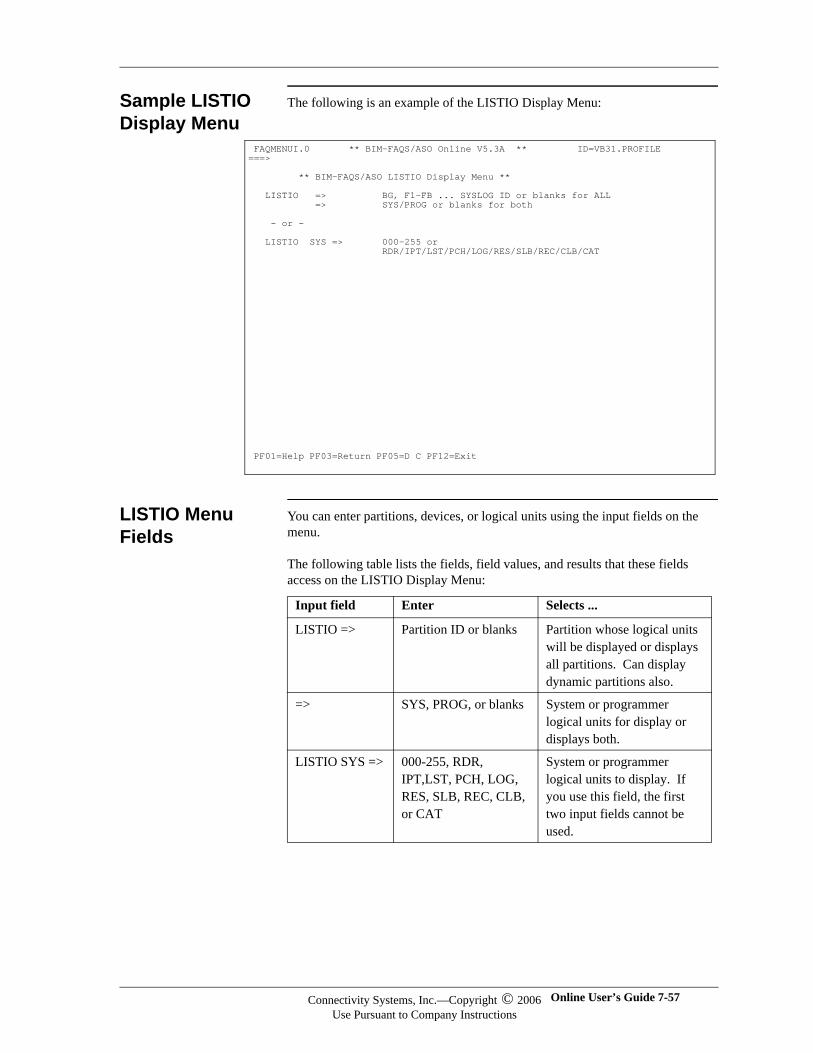
Sample LISTIO Display Menu
The following is an example of the LISTIO Display Menu:
LISTIO Menu Fields
You can enter partitions, devices, or logical units using the input fields on the menu.
The following table lists the fields, field values, and results that these fields access on the LISTIO Display Menu:
FAQMENUI.0 ** BIM-FAQS/ASO Online V5.3A ** ID=VB31.PROFILE ===> ** BIM-FAQS/ASO LISTIO Display Menu ** LISTIO => BG, F1-FB ... SYSLOG ID or blanks for ALL => SYS/PROG or blanks for both - or - LISTIO SYS => 000-255 or RDR/IPT/LST/PCH/LOG/RES/SLB/REC/CLB/CAT
PF01=Help PF03=Return PF05=D C PF12=Exit
Input field Enter Selects ...
LISTIO => Partition ID or blanks Partition whose logical units will be displayed or displays all partitions. Can display dynamic partitions also.
=> SYS, PROG, or blanks System or programmer logical units for display or displays both.
LISTIO SYS => 000-255, RDR, IPT,LST, PCH, LOG, RES, SLB, REC, CLB, or CAT
System or programmer logical units to display. If you use this field, the first two input fields cannot be used.
Connectivity Systems, Inc.—Copyright © 2006Use Pursuant to Company Instructions
Online User’s Guide 7-57
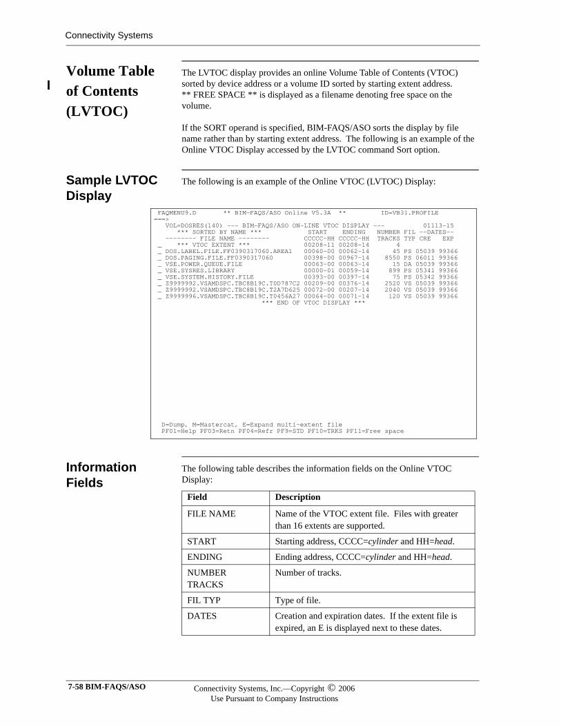
Connectivity Systems
Volume Table of Contents (LVTOC)
The LVTOC display provides an online Volume Table of Contents (VTOC) sorted by device address or a volume ID sorted by starting extent address. ** FREE SPACE ** is displayed as a filename denoting free space on the volume.
If the SORT operand is specified, BIM-FAQS/ASO sorts the display by file name rather than by starting extent address. The following is an example of the Online VTOC Display accessed by the LVTOC command Sort option.
Sample LVTOC Display
The following is an example of the Online VTOC (LVTOC) Display:
Information Fields
The following table describes the information fields on the Online VTOC Display:
FAQMENU9.D ** BIM-FAQS/ASO Online V5.3A ** ID=VB31.PROFILE ===> VOL=DOSRES(140) --- BIM-FAQS/ASO ON-LINE VTOC DISPLAY --- 01113-15 *** SORTED BY NAME *** START ENDING NUMBER FIL --DATES-- -------- FILE NAME -------- CCCCC-HH CCCCC-HH TRACKS TYP CRE EXP _ *** VTOC EXTENT *** 00208-11 00208-14 4 _ DOS.LABEL.FILE.FF0390317060.AREA1 00060-00 00062-14 45 PS 05039 99366 _ DOS.PAGING.FILE.FF0390317060 00398-00 00967-14 8550 PS 06011 99366 _ VSE.POWER.QUEUE.FILE 00063-00 00063-14 15 DA 05039 99366 _ VSE.SYSRES.LIBRARY 00000-01 00059-14 899 PS 05341 99366 _ VSE.SYSTEM.HISTORY.FILE 00393-00 00397-14 75 PS 05342 99366 _ Z9999992.VSAMDSPC.TBC8B19C.T0D787C2 00209-00 00376-14 2520 VS 05039 99366 _ Z9999992.VSAMDSPC.TBC8B19C.T2A7D625 00072-00 00207-14 2040 VS 05039 99366 _ Z9999996.VSAMDSPC.TBC8B19C.T0456A27 00064-00 00071-14 120 VS 05039 99366 *** END OF VTOC DISPLAY ***
D=Dump, M=Mastercat, E=Expand multi-extent file PF01=Help PF03=Retn PF04=Refr PF9=STD PF10=TRKS PF11=Free space
Field Description
FILE NAME Name of the VTOC extent file. Files with greater than 16 extents are supported.
START Starting address, CCCC=cylinder and HH=head.
ENDING Ending address, CCCC=cylinder and HH=head.
NUMBER TRACKS
Number of tracks.
FIL TYP Type of file.
DATES Creation and expiration dates. If the extent file is expired, an E is displayed next to these dates.
7-58 BIM-FAQS/ASO Connectivity Systems, Inc.—Copyright © 2006Use Pursuant to Company Instructions
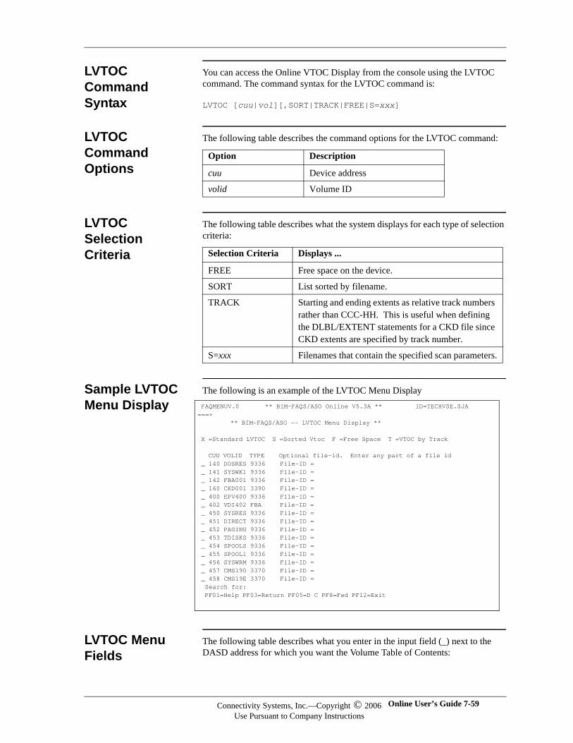
LVTOC Command Syntax
You can access the Online VTOC Display from the console using the LVTOC command. The command syntax for the LVTOC command is:
LVTOC [cuu|vol][,SORT|TRACK|FREE|S=xxx]
LVTOC Command Options
The following table describes the command options for the LVTOC command:
LVTOC Selection Criteria
The following table describes what the system displays for each type of selection criteria:
Sample LVTOC Menu Display
The following is an example of the LVTOC Menu Display
LVTOC Menu Fields
The following table describes what you enter in the input field (_) next to the DASD address for which you want the Volume Table of Contents:
Option Description
cuu Device address
volid Volume ID
Selection Criteria Displays ...
FREE Free space on the device.
SORT List sorted by filename.
TRACK Starting and ending extents as relative track numbers rather than CCC-HH. This is useful when defining the DLBL/EXTENT statements for a CKD file since CKD extents are specified by track number.
S=xxx Filenames that contain the specified scan parameters.
FAQMENUV.0 ** BIM-FAQS/ASO Online V5.3A ** ID=TECHVSE.SJA ===> ** BIM-FAQS/ASO -- LVTOC Menu Display ** X =Standard LVTOC S =Sorted Vtoc F =Free Space T =VTOC by Track CUU VOLID TYPE Optional file-id. Enter any part of a file id _ 140 DOSRES 9336 File-ID = _ 141 SYSWK1 9336 File-ID = _ 142 FBA001 9336 File-ID = _ 160 CKD001 3390 File-ID = _ 400 EPV400 9336 File-ID = _ 402 VDI402 FBA File-ID = _ 450 SYSRES 9336 File-ID = _ 451 DIRECT 9336 File-ID = _ 452 PAGING 9336 File-ID = _ 453 TDISKS 9336 File-ID = _ 454 SPOOLS 9336 File-ID = _ 455 SPOOL1 9336 File-ID = _ 456 SYSWRM 9336 File-ID = _ 457 CMS190 3370 File-ID = _ 458 CMS19E 3370 File-ID = Search for: PF01=Help PF03=Return PF05=D C PF8=Fwd PF12=Exit
Connectivity Systems, Inc.—Copyright © 2006Use Pursuant to Company Instructions
Online User’s Guide 7-59
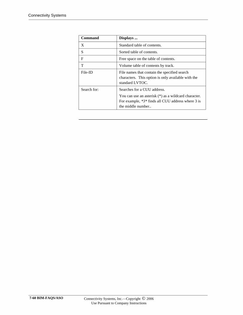
Connectivity Systems
Command Displays ...
X Standard table of contents.
S Sorted table of contents.
F Free space on the table of contents.
T Volume table of contents by track.
File-ID File names that contain the specified search characters. This option is only available with the standard LVTOC.
Search for: Searches for a CUU address. You can use an asterisk (*) as a wildcard character. For example, *3* finds all CUU address where 3 is the middle number..
7-60 BIM-FAQS/ASO Connectivity Systems, Inc.—Copyright © 2006Use Pursuant to Company Instructions
MAP Reports
Default Partition Allocation Report (MAP)
The MAP command displays information in the formats and panels shown in Chapter 8, "Extended Map/Debug Support."
Current Partition Allocation Report (MAP GETVIS)
The MAP GETVIS command displays information in the formats and panels shown in Chapter 8, "Extended Map/Debug Support."
Current Partition Allocation Report by Partition (MAP FnGETVIS)
The MAP Fn GETVIS command displays information in the formats and panels shown in Chapter 8, “Extended MAP/DEBUG Support”.
Connectivity Systems, Inc.—Copyright © 2006Use Pursuant to Company Instructions
Online User’s Guide 7-61
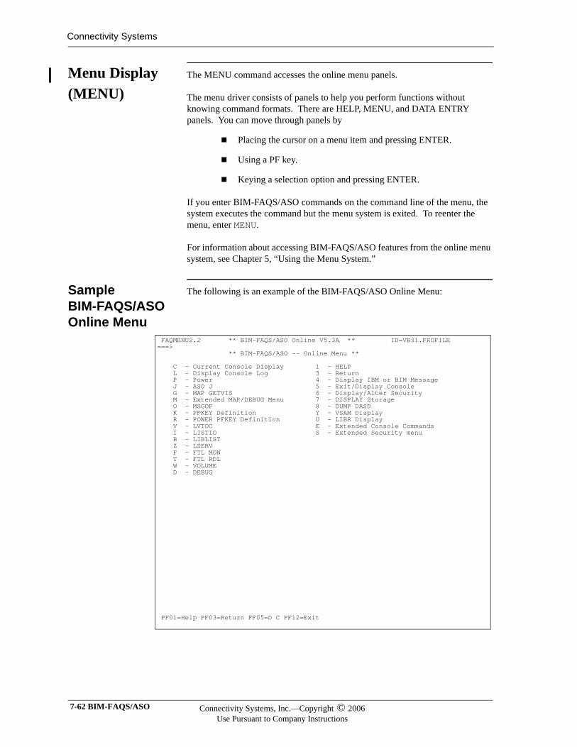
Connectivity Systems
Menu Display (MENU)
The MENU command accesses the online menu panels.
The menu driver consists of panels to help you perform functions without knowing command formats. There are HELP, MENU, and DATA ENTRY panels. You can move through panels by
Placing the cursor on a menu item and pressing ENTER.
Using a PF key.
Keying a selection option and pressing ENTER.
If you enter BIM-FAQS/ASO commands on the command line of the menu, the system executes the command but the menu system is exited. To reenter the menu, enter MENU.
For information about accessing BIM-FAQS/ASO features from the online menu system, see Chapter 5, “Using the Menu System.”
Sample BIM-FAQS/ASO Online Menu
The following is an example of the BIM-FAQS/ASO Online Menu:
FAQMENU2.2 ** BIM-FAQS/ASO Online V5.3A ** ID=VB31.PROFILE ===> ** BIM-FAQS/ASO -- Online Menu ** C - Current Console Display 1 - HELP L - Display Console Log 3 - Return P - Power 4 - Display IBM or BIM Message J - ASO J 5 - Exit/Display Console G - MAP GETVIS 6 - Display/Alter Security M - Extended MAP/DEBUG Menu 7 - DISPLAY Storage O - MSGOP 8 - DUMP DASD K - PFKEY Definition Y - VSAM Display R - POWER PFKEY Definition U - LIBR Display V - LVTOC E - Extended Console Commands I - LISTIO S - Extended Security menu B - LIBLIST Z - LSERV F - FTL MON T - FTL RDL W - VOLUME D - DEBUG PF01=Help PF03=Return PF05=D C PF12=Exit
7-62 BIM-FAQS/ASO Connectivity Systems, Inc.—Copyright © 2006Use Pursuant to Company Instructions
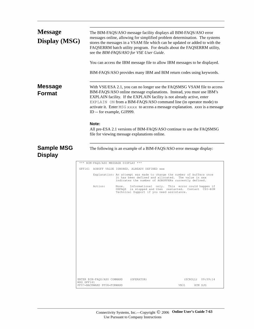
Message Display (MSG)
The BIM-FAQS/ASO message facility displays all BIM-FAQS/ASO error messages online, allowing for simplified problem determination. The systems stores the messages in a VSAM file which can be updated or added to with the FAQSERRM batch utility program. For details about the FAQSERRM utility, see the BIM-FAQS/ASO for VSE User Guide.
You can access the IBM message file to allow IBM messages to be displayed.
BIM-FAQS/ASO provides many IBM and BIM return codes using keywords.
Message Format
With VSE/ESA 2.1, you can no longer use the FAQSMSG VSAM file to access BIM-FAQS/ASO online message explanations. Instead, you must use IBM’s EXPLAIN facility. If the EXPLAIN facility is not already active, enter EXPLAIN ON from a BIM-FAQS/ASO command line (in operator mode) to activate it. Enter MSG xxxx to access a message explanation. xxxx is a message ID -- for example, GJJ999.
Note:Note:All pre-ESA 2.1 versions of BIM-FAQS/ASO continue to use the FAQSMSG file for viewing message explanations online.
Sample MSG Display
The following is an example of a BIM-FAQS/ASO error message display:
*** BIM-FAQS/ASO MESSAGE DISPLAY *** GFF161 AOBUFF VALUE IGNORED, ALREADY DEFINED xxx Explanation: An attempt was made to change the number of buffers once it has been defined and allocated. The value in xxx indicates the number of AOBUFFERs currently defined. Action: None. Informational only. This error could happen if GSFAQS is stopped and then restarted. Contact CSI-BIM Technical Support if you need assistance. ENTER BIM-FAQS/ASO COMMAND (OPERATOR) (SCROLL) 09:59:14 MSG GFF161 PF07=BACKWARD PF08=FORWARD VB31 XCM SJG
Connectivity Systems, Inc.—Copyright © 2006Use Pursuant to Company Instructions
Online User’s Guide 7-63
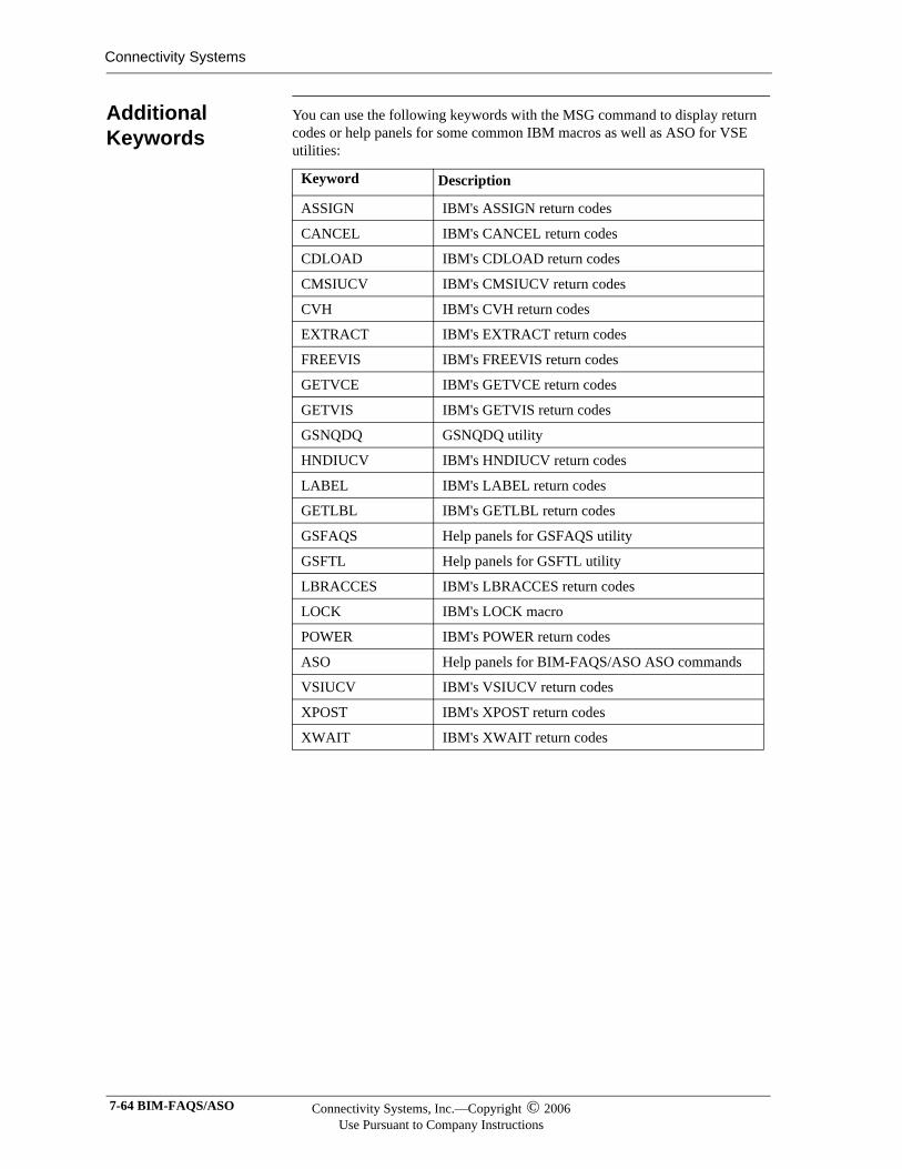
Connectivity Systems
Additional Keywords
You can use the following keywords with the MSG command to display return codes or help panels for some common IBM macros as well as ASO for VSE utilities:
Keyword Description
ASSIGN IBM's ASSIGN return codes
CANCEL IBM's CANCEL return codes
CDLOAD IBM's CDLOAD return codes
CMSIUCV IBM's CMSIUCV return codes
CVH IBM's CVH return codes
EXTRACT IBM's EXTRACT return codes
FREEVIS IBM's FREEVIS return codes
GETVCE IBM's GETVCE return codes
GETVIS IBM's GETVIS return codes
GSNQDQ GSNQDQ utility
HNDIUCV IBM's HNDIUCV return codes
LABEL IBM's LABEL return codes
GETLBL IBM's GETLBL return codes
GSFAQS Help panels for GSFAQS utility
GSFTL Help panels for GSFTL utility
LBRACCES IBM's LBRACCES return codes
LOCK IBM's LOCK macro
POWER IBM's POWER return codes
ASO Help panels for BIM-FAQS/ASO ASO commands
VSIUCV IBM's VSIUCV return codes
XPOST IBM's XPOST return codes
XWAIT IBM's XWAIT return codes
7-64 BIM-FAQS/ASO Connectivity Systems, Inc.—Copyright © 2006Use Pursuant to Company Instructions
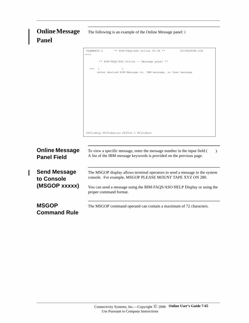
Online Message Panel
The following is an example of the Online Message panel: i
Online Message Panel Field
To view a specific message, enter the message number in the input field ( ). A list of the IBM message keywords is provided on the previous page.
Send Message to Console (MSGOP xxxxx)
The MSGOP display allows terminal operators to send a message to the system console. For example, MSGOP PLEASE MOUNT TAPE XYZ ON 280.
You can send a message using the BIM-FAQS/ASO HELP Display or using the proper command format.
MSGOP Command Rule
The MSGOP command operand can contain a maximum of 72 characters.
FAQMENU4.4 ** BIM-FAQS/ASO Online V5.3A ** ID=TECHVSE.SJA ===> ** BIM-FAQS/ASO Online -- Message panel ** ==> ( ) enter desired BIM Message or, IBM message, or User message PF01=Help PF03=Return PF05=D C PF12=Exit
Connectivity Systems, Inc.—Copyright © 2006Use Pursuant to Company Instructions
Online User’s Guide 7-65
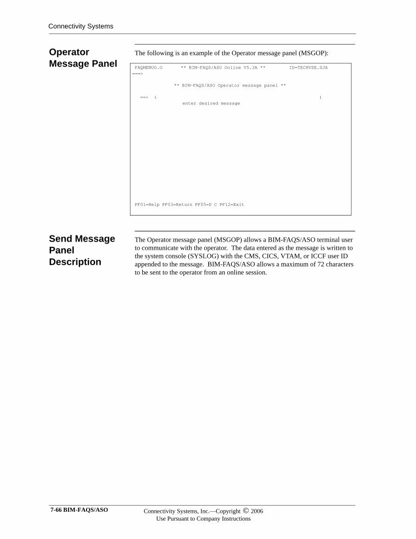
Connectivity Systems
Operator Message Panel
The following is an example of the Operator message panel (MSGOP):
Send Message Panel Description
The Operator message panel (MSGOP) allows a BIM-FAQS/ASO terminal user to communicate with the operator. The data entered as the message is written to the system console (SYSLOG) with the CMS, CICS, VTAM, or ICCF user ID appended to the message. BIM-FAQS/ASO allows a maximum of 72 characters to be sent to the operator from an online session.
FAQMENUO.O ** BIM-FAQS/ASO Online V5.3A ** ID=TECHVSE.SJA ===> ** BIM-FAQS/ASO Operator message panel ** ==> ( ) enter desired message PF01=Help PF03=Return PF05=D C PF12=Exit
7-66 BIM-FAQS/ASO Connectivity Systems, Inc.—Copyright © 2006Use Pursuant to Company Instructions
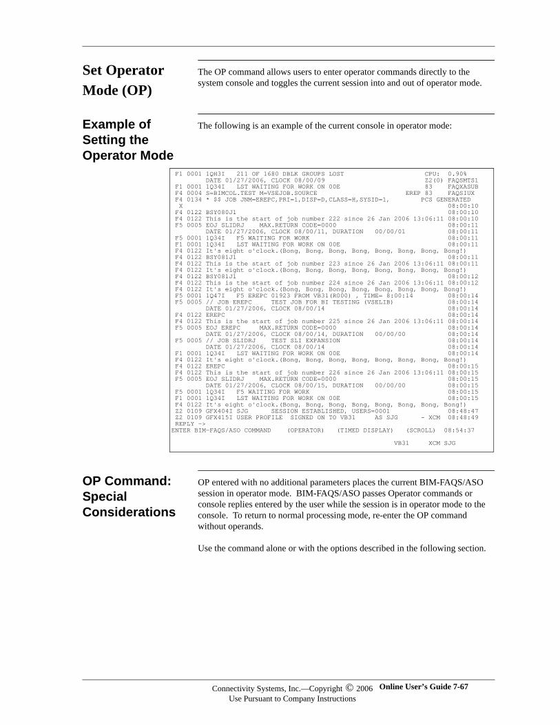
Set Operator Mode (OP)
The OP command allows users to enter operator commands directly to the system console and toggles the current session into and out of operator mode.
Example of Setting the Operator Mode
The following is an example of the current console in operator mode:
OP Command: Special Considerations
OP entered with no additional parameters places the current BIM-FAQS/ASO session in operator mode. BIM-FAQS/ASO passes Operator commands or console replies entered by the user while the session is in operator mode to the console. To return to normal processing mode, re-enter the OP command without operands.
Use the command alone or with the options described in the following section.
F1 0001 1QH3I 211 OF 1680 DBLK GROUPS LOST CPU: 0.90% DATE 01/27/2006, CLOCK 08/00/09 Z2(0) FAQSMTS1 F1 0001 1Q34I LST WAITING FOR WORK ON 00E 83 FAQXASUB F4 0004 S=BIMCOL.TEST M=VSEJOB.SOURCE EREP 83 FAQSIUX F4 0134 * $$ JOB JNM=EREPC,PRI=1,DISP=D,CLASS=H,SYSID=1, PCS GENERATED X 08:00:10 F4 0122 BSY080J1 08:00:10 F4 0122 This is the start of job number 222 since 26 Jan 2006 13:06:11 08:00:10 F5 0005 EOJ SLIDRJ MAX.RETURN CODE=0000 08:00:11 DATE 01/27/2006, CLOCK 08/00/11, DURATION 00/00/01 08:00:11 F5 0001 1Q34I F5 WAITING FOR WORK 08:00:11 F1 0001 1Q34I LST WAITING FOR WORK ON 00E 08:00:11 F4 0122 It's eight o'clock.(Bong, Bong, Bong, Bong, Bong, Bong, Bong, Bong!) F4 0122 BSY081J1 08:00:11 F4 0122 This is the start of job number 223 since 26 Jan 2006 13:06:11 08:00:11 F4 0122 It's eight o'clock.(Bong, Bong, Bong, Bong, Bong, Bong, Bong, Bong!) F4 0122 BSY081J1 08:00:12 F4 0122 This is the start of job number 224 since 26 Jan 2006 13:06:11 08:00:12 F4 0122 It's eight o'clock.(Bong, Bong, Bong, Bong, Bong, Bong, Bong, Bong!) F5 0001 1Q47I F5 EREPC 01923 FROM VB31(R000) , TIME= 8:00:14 08:00:14 F5 0005 // JOB EREPC TEST JOB FOR BI TESTING (VSELIB) 08:00:14 DATE 01/27/2006, CLOCK 08/00/14 08:00:14 F4 0122 EREPC 08:00:14 F4 0122 This is the start of job number 225 since 26 Jan 2006 13:06:11 08:00:14 F5 0005 EOJ EREPC MAX.RETURN CODE=0000 08:00:14 DATE 01/27/2006, CLOCK 08/00/14, DURATION 00/00/00 08:00:14 F5 0005 // JOB SLIDRJ TEST SLI EXPANSION 08:00:14 DATE 01/27/2006, CLOCK 08/00/14 08:00:14 F1 0001 1Q34I LST WAITING FOR WORK ON 00E 08:00:14 F4 0122 It's eight o'clock.(Bong, Bong, Bong, Bong, Bong, Bong, Bong, Bong!) F4 0122 EREPC 08:00:15 F4 0122 This is the start of job number 226 since 26 Jan 2006 13:06:11 08:00:15 F5 0005 EOJ SLIDRJ MAX.RETURN CODE=0000 08:00:15 DATE 01/27/2006, CLOCK 08/00/15, DURATION 00/00/00 08:00:15 F5 0001 1Q34I F5 WAITING FOR WORK 08:00:15 F1 0001 1Q34I LST WAITING FOR WORK ON 00E 08:00:15 F4 0122 It's eight o'clock.(Bong, Bong, Bong, Bong, Bong, Bong, Bong, Bong!) Z2 0109 GFX404I SJG SESSION ESTABLISHED, USERS=0001 08:48:47 Z2 0109 GFX415I USER PROFILE SIGNED ON TO VB31 AS SJG - XCM 08:48:49 REPLY -> ENTER BIM-FAQS/ASO COMMAND (OPERATOR) (TIMED DISPLAY) (SCROLL) 08:54:37 VB31 XCM SJG
Connectivity Systems, Inc.—Copyright © 2006Use Pursuant to Company Instructions
Online User’s Guide 7-67
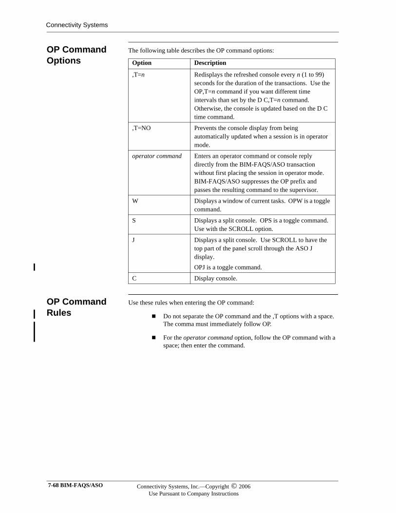
Connectivity Systems
OP Command Options
The following table describes the OP command options:
OP Command Rules
Use these rules when entering the OP command:
Do not separate the OP command and the ,T options with a space. The comma must immediately follow OP.
For the operator command option, follow the OP command with a space; then enter the command.
Option Description
,T=n Redisplays the refreshed console every n (1 to 99) seconds for the duration of the transactions. Use the OP,T=n command if you want different time intervals than set by the D C,T=n command. Otherwise, the console is updated based on the D C time command.
,T=NO Prevents the console display from being automatically updated when a session is in operator mode.
operator command Enters an operator command or console reply directly from the BIM-FAQS/ASO transaction without first placing the session in operator mode. BIM-FAQS/ASO suppresses the OP prefix and passes the resulting command to the supervisor.
W Displays a window of current tasks. OPW is a toggle command.
S Displays a split console. OPS is a toggle command. Use with the SCROLL option.
J Displays a split console. Use SCROLL to have the top part of the panel scroll through the ASO J display. OPJ is a toggle command.
C Display console.
7-68 BIM-FAQS/ASO Connectivity Systems, Inc.—Copyright © 2006Use Pursuant to Company Instructions
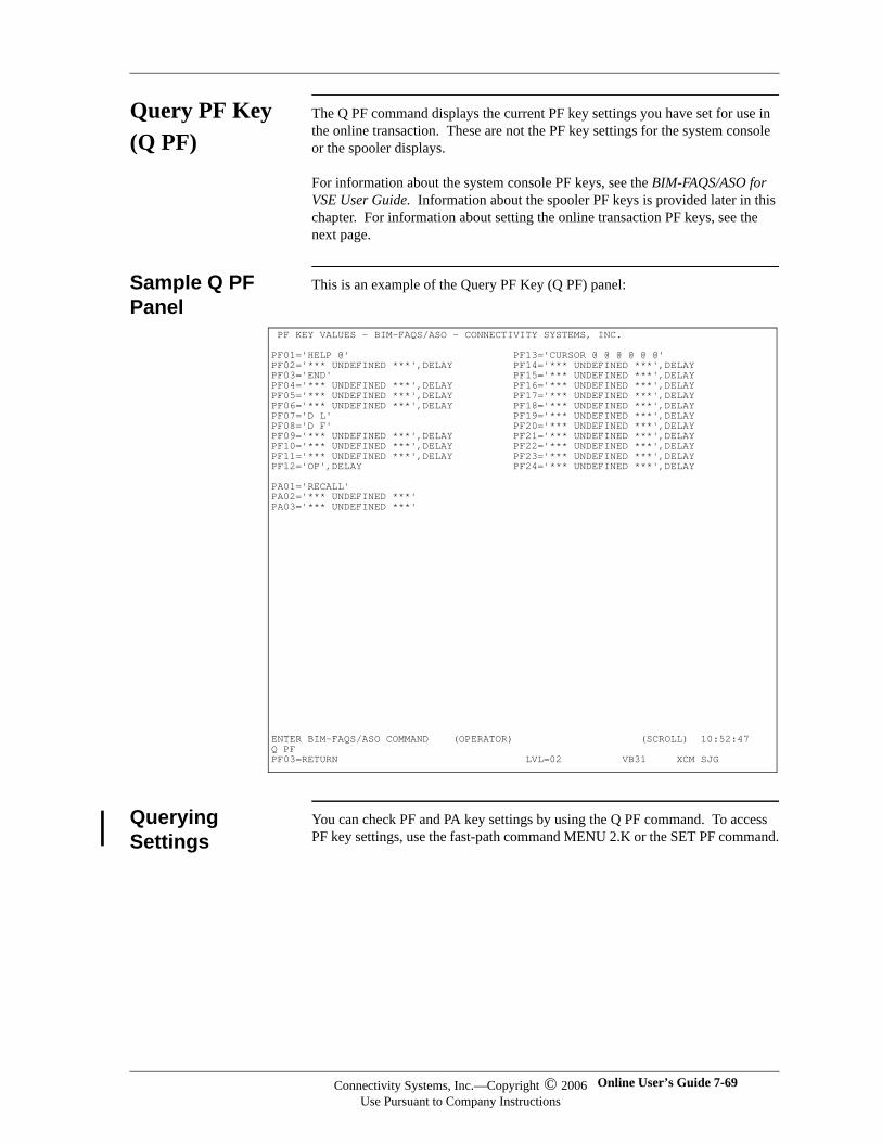
Query PF Key (Q PF)
The Q PF command displays the current PF key settings you have set for use in the online transaction. These are not the PF key settings for the system console or the spooler displays.
For information about the system console PF keys, see the BIM-FAQS/ASO for VSE User Guide. Information about the spooler PF keys is provided later in this chapter. For information about setting the online transaction PF keys, see the next page.
Sample Q PF Panel
This is an example of the Query PF Key (Q PF) panel:
Querying Settings
You can check PF and PA key settings by using the Q PF command. To access PF key settings, use the fast-path command MENU 2.K or the SET PF command.
PF KEY VALUES - BIM-FAQS/ASO - CONNECTIVITY SYSTEMS, INC. PF01='HELP @' PF13='CURSOR @ @ @ @ @ @' PF02='*** UNDEFINED ***',DELAY PF14='*** UNDEFINED ***',DELAY PF03='END' PF15='*** UNDEFINED ***',DELAY PF04='*** UNDEFINED ***',DELAY PF16='*** UNDEFINED ***',DELAY PF05='*** UNDEFINED ***',DELAY PF17='*** UNDEFINED ***',DELAY PF06='*** UNDEFINED ***',DELAY PF18='*** UNDEFINED ***',DELAY PF07='D L' PF19='*** UNDEFINED ***',DELAY PF08='D F' PF20='*** UNDEFINED ***',DELAY PF09='*** UNDEFINED ***',DELAY PF21='*** UNDEFINED ***',DELAY PF10='*** UNDEFINED ***',DELAY PF22='*** UNDEFINED ***',DELAY PF11='*** UNDEFINED ***',DELAY PF23='*** UNDEFINED ***',DELAY PF12='OP',DELAY PF24='*** UNDEFINED ***',DELAY PA01='RECALL' PA02='*** UNDEFINED ***' PA03='*** UNDEFINED ***' ENTER BIM-FAQS/ASO COMMAND (OPERATOR) (SCROLL) 10:52:47 Q PF PF03=RETURN LVL=02 VB31 XCM SJG
Connectivity Systems, Inc.—Copyright © 2006Use Pursuant to Company Instructions
Online User’s Guide 7-69

Connectivity Systems
Set Online PF Keys (SET PF)
The PF KEY Display Alter panel gives you an alternative to using the User Profile Record 6 panel to set online PF keys. Online PF keys are for your use when you are in the BIM-FAQS/ASO Online transaction. These are not the PF key settings for the system console or the spooler displays, such as POWER and SPRI.
Using the PF KEY Display Alter panel has two advantages:
More convenient than going through the security panels
User can set their own PF keys
For details about the user profile, see Chapter 4, “Security and User Configuration.” For information about the system console PF keys, see the BIM-FAQS/ASO for VSE User Guide. For information about the spooler PF keys, see the next section.
Sample PFKEY Display Alter Panel
The following is an example of the PFKEY Display Alter Panel:
Data Field In the data field, enter the command that should be executed when you press the PF key.
Enter up to 24 characters. Any BIM-FAQS/ASO command or user-defined command is valid. RECALL is a special value that displays the previously executed command again.
You can also use the @ symbol as a variable in the key's definition. This enables you to enter information on the command line that is substituted for the @ in the PF key definition.
For example, you specify the following information for PF05:
FAQMENUK.K ** BIM-FAQS/ASO Online V5.3A ** ID=TECHVSE.SJA ===> ** BIM-FAQS/ASO -- PFKEY Display/Alter ** Data Delay Data Delay PF01 = FLEE ( ) PF13 = CURSOR @ @ @ @ ( ) PF02 = POWER LST FREE ( X ) PF14 = CURSOR MSG ( ) PF03 = ASO J ( ) PF15 = ASO J ( ) PF04 = DSPLY ( ) PF16 = DSPLY ( ) PF05 = TEST ( X ) PF17 = D C ( ) PF06 = D RDR ( X ) PF18 = D RDR ( X ) PF07 = D L ( ) PF19 = D L ( ) PF08 = D F ( ) PF20 = D F ( ) PF09 = LVTOC ( X ) PF21 = LVTOC ( X ) PF10 = VOLUME ( ) PF22 = VOLUME ( ) PF11 = MAP GETVIS ( ) PF23 = MAP GETVIS ( ) PF12 = OP ( ) PF24 = OP ( ) PA01 = RECALL ( ) Page Backward = PF 07 default=PF07 PA02 = RECALL ( ) Page Forward = PF 08 default=PF08 PA03 = RECALL ( ) Return key = PF 03 default=PF03 PF01=Help PF03=Return PF05=Temporary Update PF06=Permanent Update
7-70 BIM-FAQS/ASO Connectivity Systems, Inc.—Copyright © 2006Use Pursuant to Company Instructions
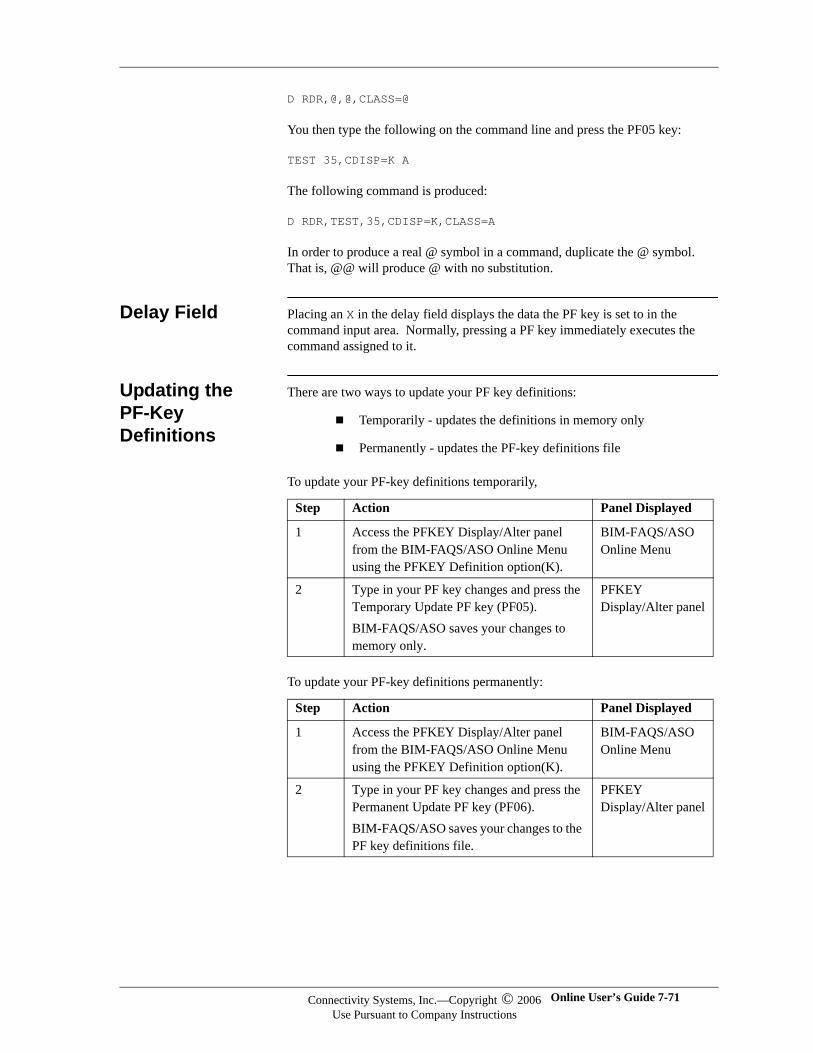
D RDR,@,@,CLASS=@
You then type the following on the command line and press the PF05 key:
TEST 35,CDISP=K A
The following command is produced:
D RDR,TEST,35,CDISP=K,CLASS=A
In order to produce a real @ symbol in a command, duplicate the @ symbol. That is, @@ will produce @ with no substitution.
Delay Field Placing an X in the delay field displays the data the PF key is set to in the command input area. Normally, pressing a PF key immediately executes the command assigned to it.
Updating the PF-Key Definitions
There are two ways to update your PF key definitions:
Temporarily - updates the definitions in memory only
Permanently - updates the PF-key definitions file
To update your PF-key definitions temporarily,
To update your PF-key definitions permanently:
Step Action Panel Displayed
1 Access the PFKEY Display/Alter panel from the BIM-FAQS/ASO Online Menu using the PFKEY Definition option(K).
BIM-FAQS/ASO Online Menu
2 Type in your PF key changes and press the Temporary Update PF key (PF05).BIM-FAQS/ASO saves your changes to memory only.
PFKEY Display/Alter panel
Step Action Panel Displayed
1 Access the PFKEY Display/Alter panel from the BIM-FAQS/ASO Online Menu using the PFKEY Definition option(K).
BIM-FAQS/ASO Online Menu
2 Type in your PF key changes and press the Permanent Update PF key (PF06).BIM-FAQS/ASO saves your changes to the PF key definitions file.
PFKEY Display/Alter panel
Connectivity Systems, Inc.—Copyright © 2006Use Pursuant to Company Instructions
Online User’s Guide 7-71
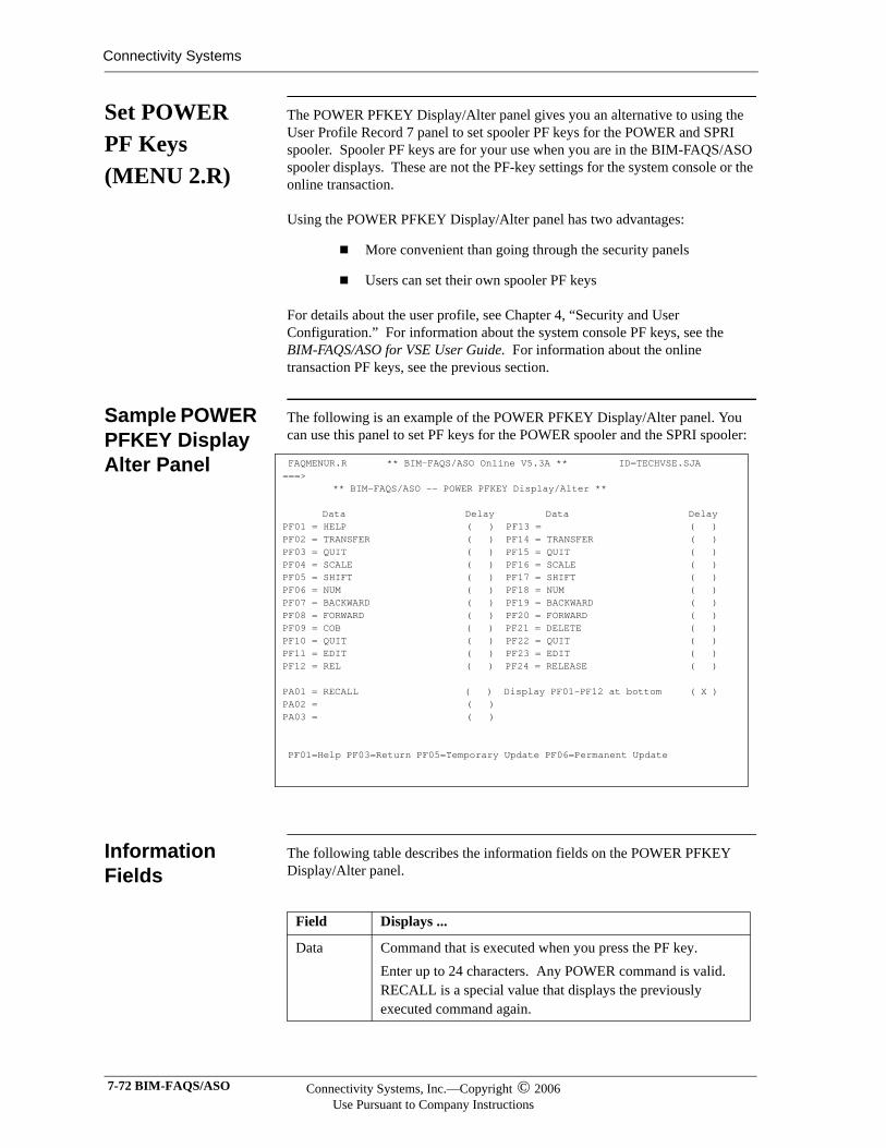
Connectivity Systems
Set POWER PF Keys (MENU 2.R)
The POWER PFKEY Display/Alter panel gives you an alternative to using the User Profile Record 7 panel to set spooler PF keys for the POWER and SPRI spooler. Spooler PF keys are for your use when you are in the BIM-FAQS/ASO spooler displays. These are not the PF-key settings for the system console or the online transaction.
Using the POWER PFKEY Display/Alter panel has two advantages:
More convenient than going through the security panels
Users can set their own spooler PF keys
For details about the user profile, see Chapter 4, “Security and User Configuration.” For information about the system console PF keys, see the BIM-FAQS/ASO for VSE User Guide. For information about the online transaction PF keys, see the previous section.
Sample POWER PFKEY Display Alter Panel
The following is an example of the POWER PFKEY Display/Alter panel. You can use this panel to set PF keys for the POWER spooler and the SPRI spooler:
Information Fields
The following table describes the information fields on the POWER PFKEY Display/Alter panel.
FAQMENUR.R ** BIM-FAQS/ASO Online V5.3A ** ID=TECHVSE.SJA ===> ** BIM-FAQS/ASO -- POWER PFKEY Display/Alter ** Data Delay Data Delay PF01 = HELP ( ) PF13 = ( ) PF02 = TRANSFER ( ) PF14 = TRANSFER ( ) PF03 = QUIT ( ) PF15 = QUIT ( ) PF04 = SCALE ( ) PF16 = SCALE ( ) PF05 = SHIFT ( ) PF17 = SHIFT ( ) PF06 = NUM ( ) PF18 = NUM ( ) PF07 = BACKWARD ( ) PF19 = BACKWARD ( ) PF08 = FORWARD ( ) PF20 = FORWARD ( ) PF09 = COB ( ) PF21 = DELETE ( ) PF10 = QUIT ( ) PF22 = QUIT ( ) PF11 = EDIT ( ) PF23 = EDIT ( ) PF12 = REL ( ) PF24 = RELEASE ( ) PA01 = RECALL ( ) Display PF01-PF12 at bottom ( X ) PA02 = ( ) PA03 = ( ) PF01=Help PF03=Return PF05=Temporary Update PF06=Permanent Update
Field Displays ...
Data Command that is executed when you press the PF key.Enter up to 24 characters. Any POWER command is valid. RECALL is a special value that displays the previously executed command again.
7-72 BIM-FAQS/ASO Connectivity Systems, Inc.—Copyright © 2006Use Pursuant to Company Instructions

Delay Data the PF key is set to in the command input area. Normally, pressing a PF key immediately executes the command assigned to it.Place an X in the column to activate the delay.
Field Displays ...
Connectivity Systems, Inc.—Copyright © 2006Use Pursuant to Company Instructions
Online User’s Guide 7-73
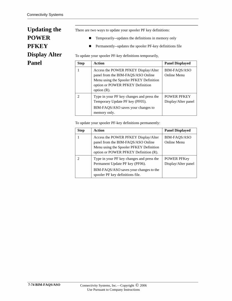
Connectivity Systems
Updating the POWER PFKEY Display Alter Panel
There are two ways to update your spooler PF key definitions:
Temporarily--updates the definitions in memory only
Permanently--updates the spooler PF-key definitions file
To update your spooler PF-key definitions temporarily,
To update your spooler PF-key definitions permanently:
Step Action Panel Displayed
1 Access the POWER PFKEY Display/Alter panel from the BIM-FAQS/ASO Online Menu using the Spooler PFKEY Definition option or POWER PFKEY Definition option (R).
BIM-FAQS/ASO Online Menu
2 Type in your PF key changes and press the Temporary Update PF key (PF05).BIM-FAQS/ASO saves your changes to memory only.
POWER PFKEY Display/Alter panel
Step Action Panel Displayed
1 Access the POWER PFKEY Display/Alter panel from the BIM-FAQS/ASO Online Menu using the Spooler PFKEY Definition option or POWER PFKEY Definition (R).
BIM-FAQS/ASO Online Menu
2 Type in your PF key changes and press the Permanent Update PF key (PF06).BIM-FAQS/ASO saves your changes to the spooler PF key definitions file.
POWER PFKey Display/Alter panel
7-74 BIM-FAQS/ASO Connectivity Systems, Inc.—Copyright © 2006Use Pursuant to Company Instructions
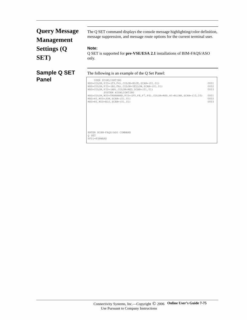
Query Message Management Settings (Q SET)
The Q SET command displays the console message highlighting/color definition, message suppression, and message route options for the current terminal user.
Note:Note:Q SET is supported for pre-VSE/ESA 2.1 installations of BIM-FAQS/ASO only.
Sample Q SET Panel
The following is an example of the Q Set Panel: USER HIGHLIGHTINGMSG=COLOR,PID=(F9,F4),COLOR=BLUE,SCAN=(01,01) 0001MSG=COLOR,PID=(BG,FA),COLOR=YELLOW,SCAN=(01,01) 0002MSG=COLOR,PID=(AR),COLOR=RED,SCAN=(01,01) 0003 SYSTEM HIGHLIGHTING MSG=COLOR,MID=TRANABND,PID=(F9,F8,F7,F6),COLOR=RED,HI=BLINK,SCAN=(10,20) 0001MSG=HI,MID=JOB,SCAN=(01,01) 0002MSG=HI,MID=EOJ,SCAN=(01,01) 0003
ENTER BIKM-FAQS/ASO COMMANDQ SETPF01=FORWARD
Connectivity Systems, Inc.—Copyright © 2006Use Pursuant to Company Instructions
Online User’s Guide 7-75
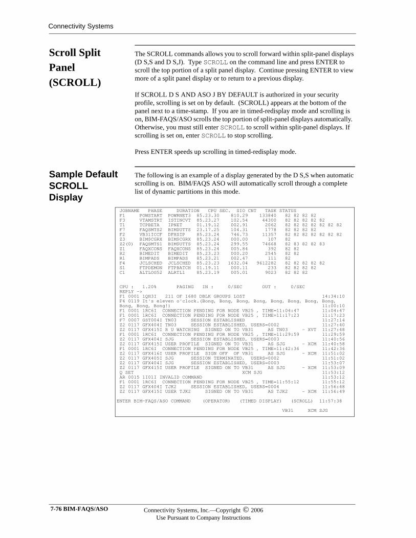
Connectivity Systems
Scroll Split Panel (SCROLL)
The SCROLL commands allows you to scroll forward within split-panel displays (D S,S and D S,J). Type SCROLL on the command line and press ENTER to scroll the top portion of a split panel display. Continue pressing ENTER to view more of a split panel display or to return to a previous display.
If SCROLL D S AND ASO J BY DEFAULT is authorized in your security profile, scrolling is set on by default. (SCROLL) appears at the bottom of the panel next to a time-stamp. If you are in timed-redisplay mode and scrolling is on, BIM-FAQS/ASO scrolls the top portion of split-panel displays automatically. Otherwise, you must still enter SCROLL to scroll within split-panel displays. If scrolling is set on, enter SCROLL to stop scrolling.
Press ENTER speeds up scrolling in timed-redisplay mode.
Sample Default SCROLL Display
The following is an example of a display generated by the D S,S when automatic scrolling is on. BIM/FAQS ASO will automatically scroll through a complete list of dynamic partitions in this mode.
JOBNAME PHASE DURATION CPU SEC. SIO CNT TASK STATUS F1 POWSTART POWRNET3 85.23.30 810.29 133840 82 82 82 82 F3 VTAMSTRT ISTINCVT 85.23.27 102.54 44300 82 82 82 82 82 T1 TCPBETA IPNET 01.19.12 002.91 2062 82 82 82 82 82 82 82 F7 FAQSMTS2 BIM$UTTS 23.17.25 104.31 1778 82 82 82 82 F2 VB31ICCF DFHSIP 85.23.24 746.73 11357 82 82 82 82 82 82 82 Z3 BIM$CGRX BIM$CGRX 85.23.24 000.00 107 82 Z2(0) FAQSMTS1 BIM$UTTS 85.23.24 299.55 74668 82 83 82 82 83 Z1 FAQXCONS FAQXCONS 85.23.24 005.84 392 82 82 R2 BIMEDIT BIMEDIT 85.23.23 000.20 2545 82 82 R1 BIMPADS BIMPADS 85.23.21 002.47 111 82 F4 JCLSCHED JCLSCHED 85.23.23 1632.04 9612282 82 82 82 82 82 S1 FTPDEMON FTPBATCH 01.19.11 000.11 233 82 82 82 82 C1 ALTLOG52 ALRTL1 85.23.19 005.01 9023 82 82 82 CPU : 1.20% PAGING IN : 0/SEC OUT : 0/SEC REPLY -> F1 0001 1QH3I 211 OF 1680 DBLK GROUPS LOST 14:34:10 F4 0119 It's eleven o'clock.(Bong, Bong, Bong, Bong, Bong, Bong, Bong, Bong, Bong, Bong, Bong!) 11:00:10 F1 0001 1RC6I CONNECTION PENDING FOR NODE VB25 , TIME=11:04:47 11:04:47 F1 0001 1RC6I CONNECTION PENDING FOR NODE VB25 , TIME=11:17:23 11:17:23 F7 0007 GST004I TN03 SESSION ESTABLISHED 11:27:14 Z2 0117 GFX404I TN03 SESSION ESTABLISHED, USERS=0002 11:27:40 Z2 0117 GFX415I R U WATCHING SIGNED ON TO VB31 AS TN03 - XVT 11:27:48 F1 0001 1RC6I CONNECTION PENDING FOR NODE VB25 , TIME=11:29:59 11:29:59 Z2 0117 GFX404I SJG SESSION ESTABLISHED, USERS=0003 11:40:56 Z2 0117 GFX415I USER PROFILE SIGNED ON TO VB31 AS SJG - XCM 11:40:58 F1 0001 1RC6I CONNECTION PENDING FOR NODE VB25 , TIME=11:42:36 11:42:36 Z2 0117 GFX416I USER PROFILE SIGN OFF OF VB31 AS SJG - XCM 11:51:02 Z2 0117 GFX405I SJG SESSION TERMINATED, USERS=0002 11:51:02 Z2 0117 GFX404I SJG SESSION ESTABLISHED, USERS=0003 11:53:07 Z2 0117 GFX415I USER PROFILE SIGNED ON TO VB31 AS SJG - XCM 11:53:09 Q SET XCM SJG 11:53:12 AR 0015 1I01I INVALID COMMAND 11:53:12 F1 0001 1RC6I CONNECTION PENDING FOR NODE VB25 , TIME=11:55:12 11:55:12 Z2 0117 GFX404I TJK2 SESSION ESTABLISHED, USERS=0004 11:56:48 Z2 0117 GFX415I USER TJK2 SIGNED ON TO VB31 AS TJK2 - XCM 11:56:49 ENTER BIM-FAQS/ASO COMMAND (OPERATOR) (TIMED DISPLAY) (SCROLL) 11:57:38 VB31 XCM SJG
7-76 BIM-FAQS/ASO Connectivity Systems, Inc.—Copyright © 2006Use Pursuant to Company Instructions
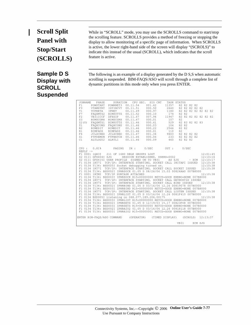
Scroll Split Panel with Stop/Start (SCROLLS)
While in “SCROLL” mode, you may use the SCROLLS command to start/stop the scrolling feature. SCROLLS provides a method of freezing or stopping the display to allow monitoring of a specific page of information. When SCROLLS is active, the lower right-hand side of the screen will display “(SCROLS)” to indicate this instead of the usual (SCROLL), which indicates that the scroll feature is active.
Sample D S Display with SCROLL Suspended
The following is an example of a display generated by the D S,S when automatic scrolling is suspended. BIM-FAQS/ASO will scroll through a complete list of dynamic partitions in this mode only when you press ENTER.
JOBNAME PHASE DURATION CPU SEC. SIO CNT TASK STATUS F1 POWSTART POWRNET3 00.11.54 001.62 11357 82 82 82 82 F3 VTAMSTRT ISTINCVT 00.11.51 000.50 2640 82 82 82 82 82 T1 TCPBETA IPNET 00.11.49 000.97 1180 82 82 82 82 82 82 82 F7 FAQSMTS2 BIM$UTTS 00.11.52 000.10 174 82 82 F2 VB31ICCF DFHSIP 00.11.47 007.94 11947 82 82 82 82 82 82 82 Z3 BIM$CGRX BIM$CGRX 00.11.47 000.01 107 82 Z2(0) FAQSMTS1 BIM$UTTS 00.11.46 000.61 529 82 83 82 82 83 Z1 FAQXCONS FAQXCONS 00.11.46 000.03 104 82 82 R2 BIMEDIT BIMEDIT 00.11.46 000.22 2546 82 82 R1 BIMPADS BIMPADS 00.11.46 000.01 110 82 F4 JCLSCHED JCLSCHED 00.11.47 001.34 9403 82 82 82 82 S1 FTPDEMON FTPBATCH 00.11.46 000.06 233 82 82 82 82 C1 ALTLOG52 ALRTL1 00.11.46 000.09 460 82 82 82 CPU : 0.81% PAGING IN : 0/SEC OUT : 0/SEC REPLY -> F1 0001 1QH3I 211 OF 1680 DBLK GROUPS LOST 12:01:45 Z2 0111 GFX404I SJG SESSION ESTABLISHED, USERS=0002 12:10:16 Z2 0111 GFX415I USER PROFILE SIGNED ON TO VB31 AS SJG - XCM 12:10:17 F1 0134 1RT7I TCP/IP: INTERFACE STARTING, SOCKET CALL INITAPI ISSUED 12:10:38 F1 0134 T134: BSD005I Socket debugging turned on. 12:10:38 F1 0134 1RT7I TCP/IP: INTERFACE STARTING, SOCKET CALL SOCKET ISSUED 12:10:38 F1 0134 T134: BSD002I IPNRSOCK 01.05 D 08/26/04 15.03 00824AA0 007B8000 F1 0001 1RTMI TCP/IP SUBTASK ATTACHED 12:10:38 F1 0134 T134: BSD003I IPNRSOCK R15=00000000 RETCD=GOOD ERRNO=NONE 007B8000 F1 0134 1RT7I TCP/IP: INTERFACE STARTING, SOCKET CALL GETHOSTID ISSUED F1 0134 1RT7I TCP/IP: INTERFACE STARTING, SOCKET CALL BIND ISSUED 12:10:38 F1 0134 T134: BSD002I IPNRBIND 01.05 D 03/16/04 12.26 00819078 007B0000 F1 0134 T134: BSD003I IPNRBIND R15=00000000 RETCD=GOOD ERRNO=NONE 007B8000 F1 0134 1RT7I TCP/IP: INTERFACE STARTING, SOCKET CALL LISTEN ISSUED 12:10:38 F1 0134 T134: BSD002I IPNRLIST 01.05 D 03/16/04 12.26 0081F410 007B0000 F1 0134 BSD005I Listening on 068.077.189.206,00175 12:10:38 F1 0134 T134: BSD003I IPNRLIST R15=00000000 RETCD=GOOD ERRNO=NONE 007B0000 F1 0134 T134: BSD002I IPNRSETS 01.05 D 12/19/03 15.17 00823F08 007B0000 F1 0134 T134: BSD003I IPNRSETS R15=00000000 RETCD=GOOD ERRNO=NONE 007B0000 F1 0134 T134: BSD002I IPNRAIO2 01.05 D 03/16/04 12.26 00818118 007B8000 F1 0134 T134: BSD003I IPNRAIO2 R15=00000001 RETCD=GOOD ERRNO=NONE 007B0000 ENTER BIM-FAQS/ASO COMMAND (OPERATOR) (TIMED DISPLAY) (SCROLS) 12:13:37 VB31 XCM SJG
Connectivity Systems, Inc.—Copyright © 2006Use Pursuant to Company Instructions
Online User’s Guide 7-77
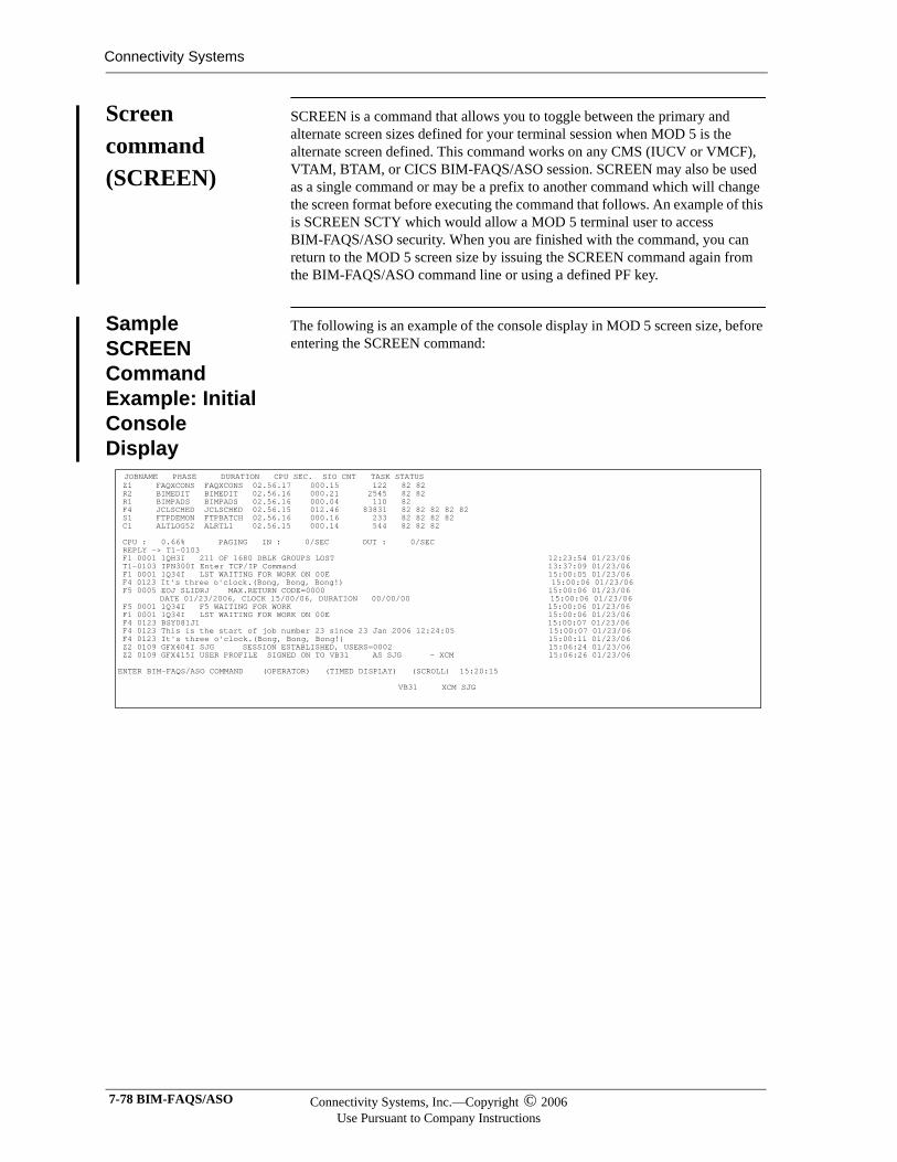
Connectivity Systems
Screen command (SCREEN)
SCREEN is a command that allows you to toggle between the primary and alternate screen sizes defined for your terminal session when MOD 5 is the alternate screen defined. This command works on any CMS (IUCV or VMCF), VTAM, BTAM, or CICS BIM-FAQS/ASO session. SCREEN may also be used as a single command or may be a prefix to another command which will change the screen format before executing the command that follows. An example of this is SCREEN SCTY which would allow a MOD 5 terminal user to access BIM-FAQS/ASO security. When you are finished with the command, you can return to the MOD 5 screen size by issuing the SCREEN command again from the BIM-FAQS/ASO command line or using a defined PF key.
Sample SCREEN Command Example: Initial Console Display
The following is an example of the console display in MOD 5 screen size, before entering the SCREEN command:
JOBNAME PHASE DURATION CPU SEC. SIO CNT TASK STATUS Z1 FAQXCONS FAQXCONS 02.56.17 000.15 122 82 82 R2 BIMEDIT BIMEDIT 02.56.16 000.21 2545 82 82 R1 BIMPADS BIMPADS 02.56.16 000.04 110 82 F4 JCLSCHED JCLSCHED 02.56.15 012.46 83831 82 82 82 82 82 S1 FTPDEMON FTPBATCH 02.56.16 000.16 233 82 82 82 82 C1 ALTLOG52 ALRTL1 02.56.15 000.14 544 82 82 82 CPU : 0.66% PAGING IN : 0/SEC OUT : 0/SEC REPLY -> T1-0103 F1 0001 1QH3I 211 OF 1680 DBLK GROUPS LOST 12:23:54 01/23/06 T1-0103 IPN300I Enter TCP/IP Command 13:37:09 01/23/06 F1 0001 1Q34I LST WAITING FOR WORK ON 00E 15:00:05 01/23/06 F4 0123 It's three o'clock.(Bong, Bong, Bong!) 15:00:06 01/23/06 F5 0005 EOJ SLIDRJ MAX.RETURN CODE=0000 15:00:06 01/23/06 DATE 01/23/2006, CLOCK 15/00/06, DURATION 00/00/00 15:00:06 01/23/06 F5 0001 1Q34I F5 WAITING FOR WORK 15:00:06 01/23/06 F1 0001 1Q34I LST WAITING FOR WORK ON 00E 15:00:06 01/23/06 F4 0123 BSY081J1 15:00:07 01/23/06 F4 0123 This is the start of job number 23 since 23 Jan 2006 12:24:05 15:00:07 01/23/06 F4 0123 It's three o'clock.(Bong, Bong, Bong!) 15:00:11 01/23/06 Z2 0109 GFX404I SJG SESSION ESTABLISHED, USERS=0002 15:06:24 01/23/06 Z2 0109 GFX415I USER PROFILE SIGNED ON TO VB31 AS SJG - XCM 15:06:26 01/23/06 ENTER BIM-FAQS/ASO COMMAND (OPERATOR) (TIMED DISPLAY) (SCROLL) 15:20:15 VB31 XCM SJG
7-78 BIM-FAQS/ASO Connectivity Systems, Inc.—Copyright © 2006Use Pursuant to Company Instructions
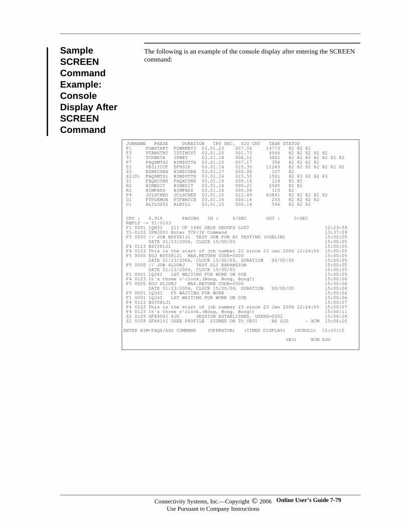
Sample SCREEN Command Example: Console Display After SCREEN Command
The following is an example of the console display after entering the SCREEN command:
JOBNAME PHASE DURATION CPU SEC. SIO CNT TASK STATUS F1 POWSTART POWRNET3 03.01.23 007.06 14773 82 82 82 F3 VTAMSTRT ISTINCVT 03.01.20 001.73 4566 82 82 82 82 82 T1 TCPBETA IPNET 03.01.18 006.12 3602 82 82 82 82 82 82 82 F7 FAQSMTS2 BIM$UTTS 03.01.20 007.17 358 82 82 82 82 F2 VB31ICCF DFHSIP 03.01.14 015.35 11245 82 82 82 82 82 82 82 Z3 BIM$CGRX BIM$CGRX 03.01.17 000.00 107 82 Z2(0) FAQSMTS1 BIM$UTTS 03.01.16 015.55 1501 82 83 82 82 83 Z1 FAQXCONS FAQXCONS 03.01.16 000.15 124 82 82 R2 BIMEDIT BIMEDIT 03.01.16 000.21 2545 82 82 R1 BIMPADS BIMPADS 03.01.16 000.04 110 82 F4 JCLSCHED JCLSCHED 03.01.15 012.49 83841 82 82 82 82 82 S1 FTPDEMON FTPBATCH 03.01.16 000.16 233 82 82 82 82 C1 ALTLOG52 ALRTL1 03.01.15 000.14 546 82 82 82 CPU : 0.91% PAGING IN : 0/SEC OUT : 0/SEC REPLY -> T1-0103 F1 0001 1QH3I 211 OF 1680 DBLK GROUPS LOST 12:23:54 T1-0103 IPN300I Enter TCP/IP Command 13:37:09 F5 0005 // JOB BSY081J1 TEST JOB FOR BI TESTING (VSELIB) 15:00:05 DATE 01/23/2006, CLOCK 15/00/05 15:00:05 F4 0123 BSY081J1 15:00:05 F4 0123 This is the start of job number 22 since 23 Jan 2006 12:24:05 15:00:05 F5 0005 EOJ BSY081J1 MAX.RETURN CODE=0000 15:00:05 DATE 01/23/2006, CLOCK 15/00/05, DURATION 00/00/00 15:00:05 F5 0005 // JOB SLIDRJ TEST SLI EXPANSION 15:00:05 DATE 01/23/2006, CLOCK 15/00/05 15:00:05 F1 0001 1Q34I LST WAITING FOR WORK ON 00E 15:00:05 F4 0123 It's three o'clock.(Bong, Bong, Bong!) 15:00:06 F5 0005 EOJ SLIDRJ MAX.RETURN CODE=0000 15:00:06 DATE 01/23/2006, CLOCK 15/00/06, DURATION 00/00/00 15:00:06 F5 0001 1Q34I F5 WAITING FOR WORK 15:00:06 F1 0001 1Q34I LST WAITING FOR WORK ON 00E 15:00:06 F4 0123 BSY081J1 15:00:07 F4 0123 This is the start of job number 23 since 23 Jan 2006 12:24:05 15:00:07 F4 0123 It's three o'clock.(Bong, Bong, Bong!) 15:00:11 Z2 0109 GFX404I SJG SESSION ESTABLISHED, USERS=0002 15:06:24 Z2 0109 GFX415I USER PROFILE SIGNED ON TO VB31 AS SJG - XCM 15:06:26 ENTER BIM-FAQS/ASO COMMAND (OPERATOR) (TIMED DISPLAY) (SCROLL) 15:25:15 VB31 XCM SJG
Connectivity Systems, Inc.—Copyright © 2006Use Pursuant to Company Instructions
Online User’s Guide 7-79
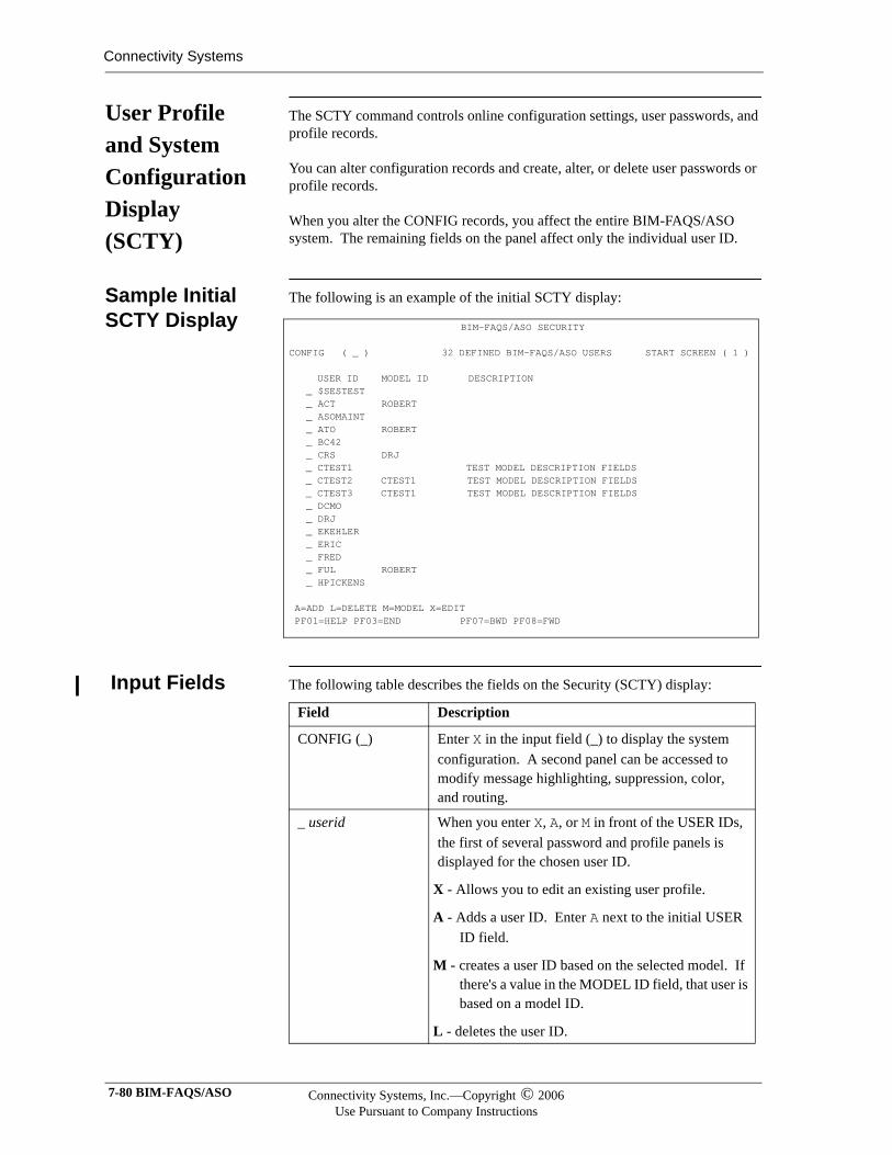
Connectivity Systems
User Profile and System Configuration Display (SCTY)
The SCTY command controls online configuration settings, user passwords, and profile records.
You can alter configuration records and create, alter, or delete user passwords or profile records.
When you alter the CONFIG records, you affect the entire BIM-FAQS/ASO system. The remaining fields on the panel affect only the individual user ID.
Sample Initial SCTY Display
The following is an example of the initial SCTY display:
Input Fields The following table describes the fields on the Security (SCTY) display:
BIM-FAQS/ASO SECURITY CONFIG ( _ ) 32 DEFINED BIM-FAQS/ASO USERS START SCREEN ( 1 ) USER ID MODEL ID DESCRIPTION _ $SESTEST _ ACT ROBERT _ ASOMAINT _ ATO ROBERT _ BC42 _ CRS DRJ _ CTEST1 TEST MODEL DESCRIPTION FIELDS _ CTEST2 CTEST1 TEST MODEL DESCRIPTION FIELDS _ CTEST3 CTEST1 TEST MODEL DESCRIPTION FIELDS _ DCMO _ DRJ _ EKEHLER _ ERIC _ FRED _ FUL ROBERT _ HPICKENS A=ADD L=DELETE M=MODEL X=EDIT PF01=HELP PF03=END PF07=BWD PF08=FWD
Field Description
CONFIG (_) Enter X in the input field (_) to display the system configuration. A second panel can be accessed to modify message highlighting, suppression, color, and routing.
_ userid When you enter X, A, or M in front of the USER IDs, the first of several password and profile panels is displayed for the chosen user ID.
X - Allows you to edit an existing user profile.
A - Adds a user ID. Enter A next to the initial USER ID field.
M - creates a user ID based on the selected model. If there's a value in the MODEL ID field, that user is based on a model ID.
L - deletes the user ID.
7-80 BIM-FAQS/ASO Connectivity Systems, Inc.—Copyright © 2006Use Pursuant to Company Instructions

Defining Security Profiles
The SCTY command allows you to enter user profile and system configuration information. To access a specific user profile, enter SCTY userid. To access the BIM-FAQS/ASO Online configuration, enter SCTY CONFIG.
For more detailed explanations of the configuration panels and user profile panels, see Chapter 4, “Security and User Configuration.”\
Connectivity Systems, Inc.—Copyright © 2006Use Pursuant to Company Instructions
Online User’s Guide 7-81
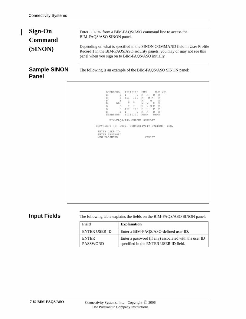
Connectivity Systems
Sign-On Command (SINON)
Enter SINON from a BIM-FAQS/ASO command line to access the BIM-FAQS/ASO SINON panel.
Depending on what is specified in the SINON COMMAND field in User Profile Record 1 in the BIM-FAQS/ASO security panels, you may or may not see this panel when you sign on to BIM-FAQS/ASO initially.
Sample SINON Panel
The following is an example of the BIM-FAQS/ASO SINON panel:
Input Fields The following table explains the fields on the BIM-FAQS/ASO SINON panel:
BBBBBBBB IIIIIIII MMM MMM (R) B B I I M M M M B B III III M M M M B B I I M M M B BB I I M M M M B B I I M M M M M B B III III M M M M B B I I M M M M BBBBBBBB IIIIIIII MMMM MMMM BIM-FAQS/ASO ONLINE SUPPORT COPYRIGHT (C) 2002, CONNECTIVITY SYSTEMS, INC. ENTER USER ID ENTER PASSWORD NEW PASSWORD VERIFY
Field Explanation
ENTER USER ID Enter a BIM-FAQS/ASO-defined user ID.
ENTER PASSWORD
Enter a password (if any) associated with the user ID specified in the ENTER USER ID field.
7-82 BIM-FAQS/ASO Connectivity Systems, Inc.—Copyright © 2006Use Pursuant to Company Instructions
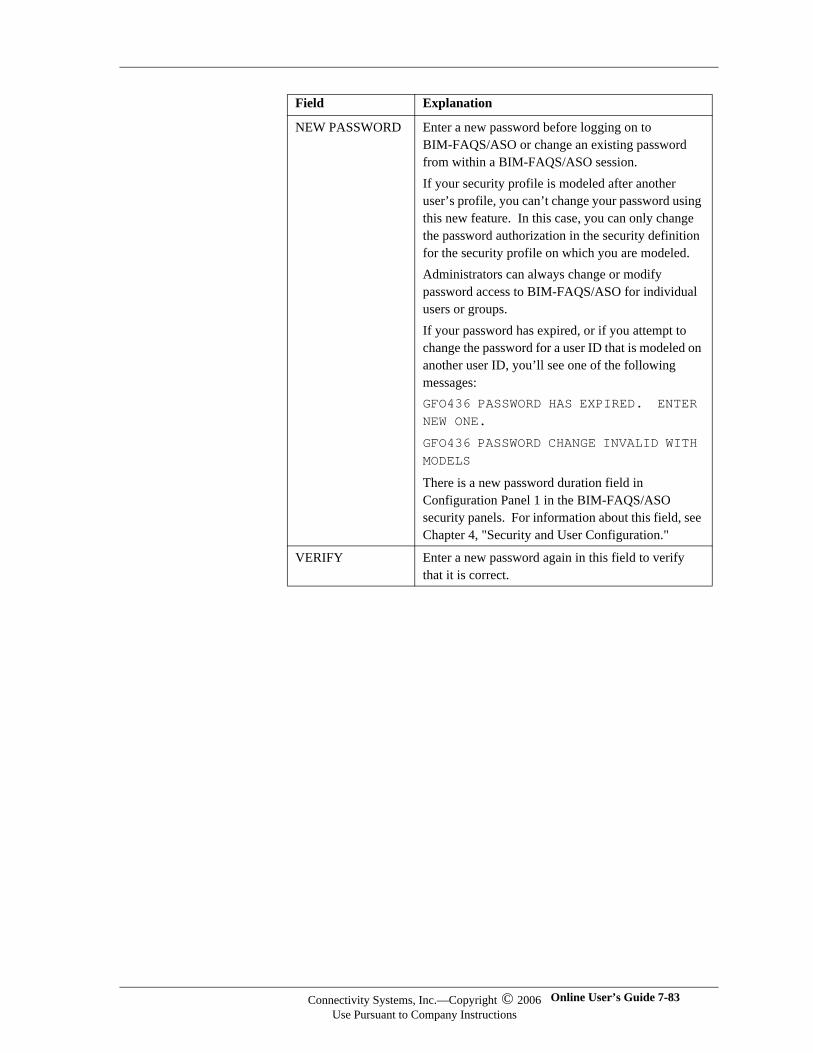
NEW PASSWORD Enter a new password before logging on to BIM-FAQS/ASO or change an existing password from within a BIM-FAQS/ASO session. If your security profile is modeled after another user’s profile, you can’t change your password using this new feature. In this case, you can only change the password authorization in the security definition for the security profile on which you are modeled.Administrators can always change or modify password access to BIM-FAQS/ASO for individual users or groups.If your password has expired, or if you attempt to change the password for a user ID that is modeled on another user ID, you’ll see one of the following messages:GFO436 PASSWORD HAS EXPIRED. ENTER NEW ONE.
GFO436 PASSWORD CHANGE INVALID WITH MODELS
There is a new password duration field in Configuration Panel 1 in the BIM-FAQS/ASO security panels. For information about this field, see Chapter 4, "Security and User Configuration."
VERIFY Enter a new password again in this field to verify that it is correct.
Field Explanation
Connectivity Systems, Inc.—Copyright © 2006Use Pursuant to Company Instructions
Online User’s Guide 7-83
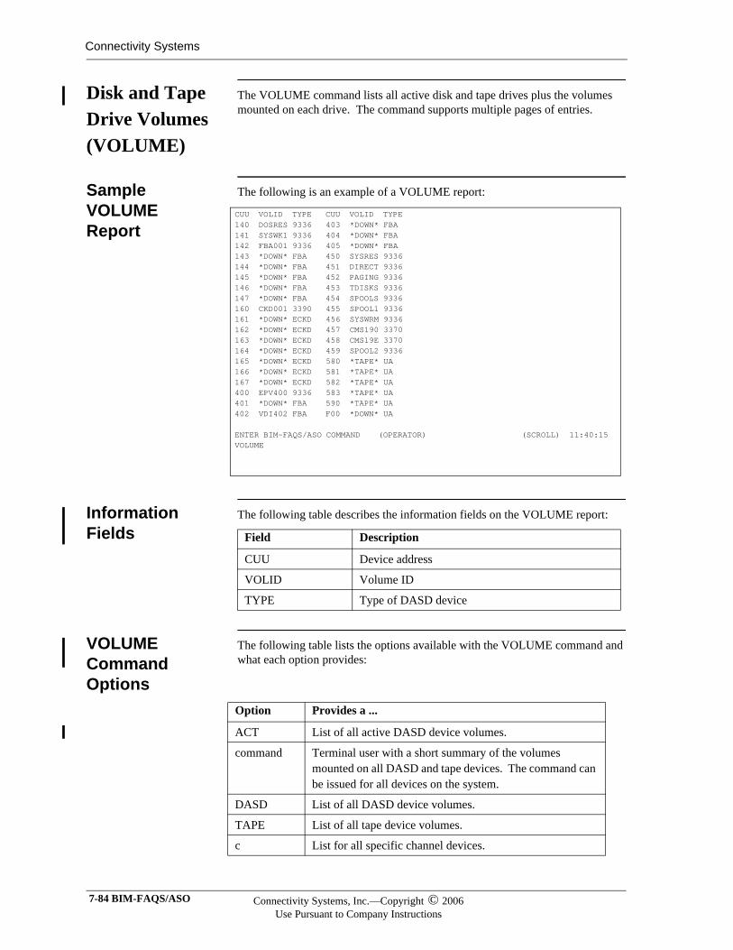
Connectivity Systems
Disk and Tape Drive Volumes (VOLUME)
The VOLUME command lists all active disk and tape drives plus the volumes mounted on each drive. The command supports multiple pages of entries.
Sample VOLUME Report
The following is an example of a VOLUME report:
Information Fields
The following table describes the information fields on the VOLUME report:
VOLUME Command Options
The following table lists the options available with the VOLUME command and what each option provides:
CUU VOLID TYPE CUU VOLID TYPE 140 DOSRES 9336 403 *DOWN* FBA 141 SYSWK1 9336 404 *DOWN* FBA 142 FBA001 9336 405 *DOWN* FBA 143 *DOWN* FBA 450 SYSRES 9336 144 *DOWN* FBA 451 DIRECT 9336 145 *DOWN* FBA 452 PAGING 9336 146 *DOWN* FBA 453 TDISKS 9336 147 *DOWN* FBA 454 SPOOLS 9336 160 CKD001 3390 455 SPOOL1 9336 161 *DOWN* ECKD 456 SYSWRM 9336 162 *DOWN* ECKD 457 CMS190 3370 163 *DOWN* ECKD 458 CMS19E 3370 164 *DOWN* ECKD 459 SPOOL2 9336 165 *DOWN* ECKD 580 *TAPE* UA 166 *DOWN* ECKD 581 *TAPE* UA 167 *DOWN* ECKD 582 *TAPE* UA 400 EPV400 9336 583 *TAPE* UA 401 *DOWN* FBA 590 *TAPE* UA 402 VDI402 FBA F00 *DOWN* UA ENTER BIM-FAQS/ASO COMMAND (OPERATOR) (SCROLL) 11:40:15 VOLUME
Field Description
CUU Device address
VOLID Volume ID
TYPE Type of DASD device
Option Provides a ...
ACT List of all active DASD device volumes.
command Terminal user with a short summary of the volumes mounted on all DASD and tape devices. The command can be issued for all devices on the system.
DASD List of all DASD device volumes.
TAPE List of all tape device volumes.
c List for all specific channel devices.
7-84 BIM-FAQS/ASO Connectivity Systems, Inc.—Copyright © 2006Use Pursuant to Company Instructions
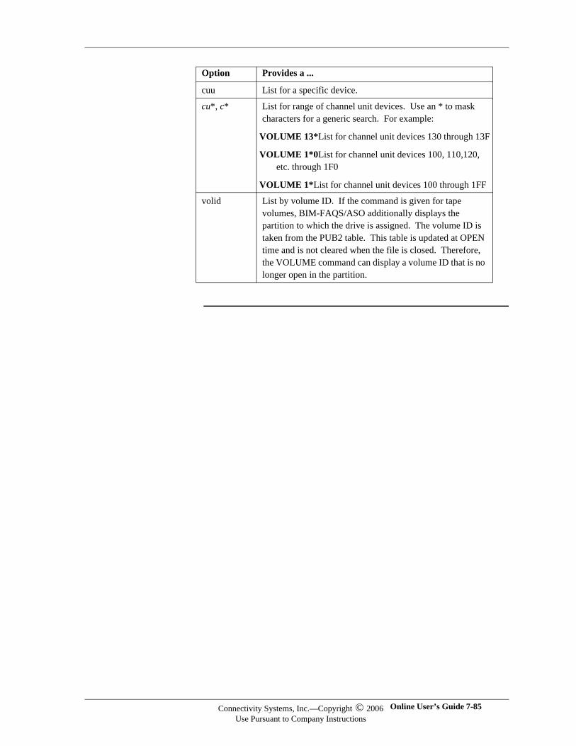
cuu List for a specific device.
cu*, c* List for range of channel unit devices. Use an * to mask characters for a generic search. For example:
VOLUME 13*List for channel unit devices 130 through 13F
VOLUME 1*0List for channel unit devices 100, 110,120, etc. through 1F0
VOLUME 1*List for channel unit devices 100 through 1FF
volid List by volume ID. If the command is given for tape volumes, BIM-FAQS/ASO additionally displays the partition to which the drive is assigned. The volume ID is taken from the PUB2 table. This table is updated at OPEN time and is not cleared when the file is closed. Therefore, the VOLUME command can display a volume ID that is no longer open in the partition.
Option Provides a ...
Connectivity Systems, Inc.—Copyright © 2006Use Pursuant to Company Instructions
Online User’s Guide 7-85
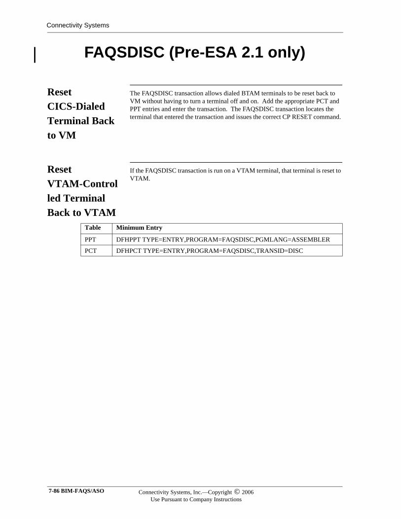
Connectivity Systems
FAQSDISC (Pre-ESA 2.1 only)
Reset CICS-Dialed Terminal Back to VM
The FAQSDISC transaction allows dialed BTAM terminals to be reset back to VM without having to turn a terminal off and on. Add the appropriate PCT and PPT entries and enter the transaction. The FAQSDISC transaction locates the terminal that entered the transaction and issues the correct CP RESET command.
Reset VTAM-Controlled Terminal Back to VTAM
If the FAQSDISC transaction is run on a VTAM terminal, that terminal is reset to VTAM.
Table Minimum Entry
PPT DFHPPT TYPE=ENTRY,PROGRAM=FAQSDISC,PGMLANG=ASSEMBLER
PCT DFHPCT TYPE=ENTRY,PROGRAM=FAQSDISC,TRANSID=DISC
7-86 BIM-FAQS/ASO Connectivity Systems, Inc.—Copyright © 2006Use Pursuant to Company Instructions
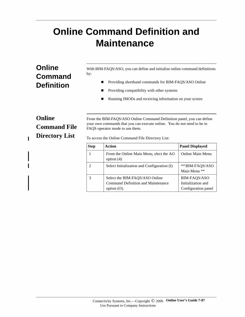
Online Command Definition and Maintenance
Online Command Definition
With BIM-FAQS/ASO, you can define and initialize online command definitions by:
Providing shorthand commands for BIM-FAQS/ASO Online
Providing compatibility with other systems
Running IMODs and receiving information on your screen
Online Command File Directory List
From the BIM-FAQS/ASO Online Command Definition panel, you can define your own commands that you can execute online. You do not need to be in FAQS operator mode to use them.
To access the Online Command File Directory List:
Step Action Panel Displayed
1 From the Online Main Menu, elect the AO option (4)
Online Main Menu
2 Select Initialization and Configuration (I) ** BIM-FAQS/ASO Main Menu **
3 Select the BIM-FAQS/ASO Online Command Definition and Maintenance option (O).
BIM-FAQS/ASO Initialization and Configuration panel
Connectivity Systems, Inc.—Copyright © 2006Use Pursuant to Company Instructions
Online User’s Guide 7-87
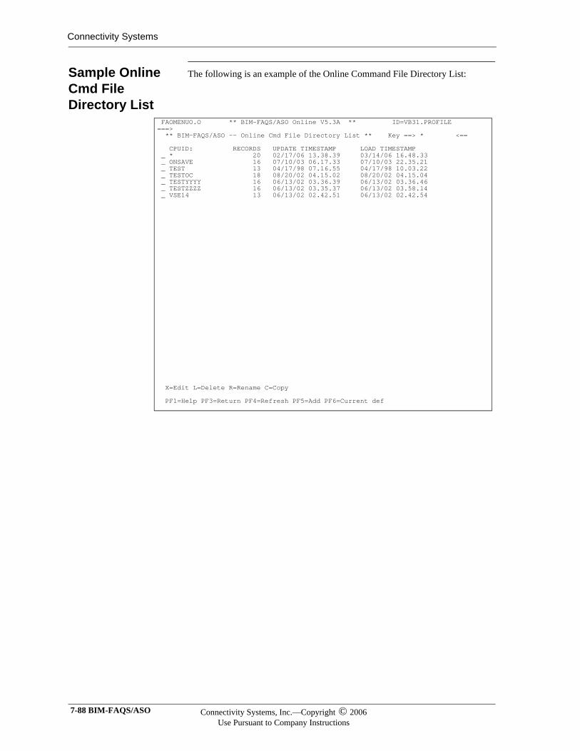
Connectivity Systems
Sample Online Cmd File Directory List
The following is an example of the Online Command File Directory List:
FAOMENUO.O ** BIM-FAQS/ASO Online V5.3A ** ID=VB31.PROFILE ===> ** BIM-FAQS/ASO -- Online Cmd File Directory List ** Key ==> * <== CPUID: RECORDS UPDATE TIMESTAMP LOAD TIMESTAMP _ * 20 02/17/06 13.38.39 03/14/06 16.48.33 _ ONSAVE 16 07/10/03 06.17.33 07/10/03 22.35.21 _ TEST 13 04/17/98 07.16.55 04/17/98 10.03.22 _ TESTOC 18 08/20/02 04.15.02 08/20/02 04.15.04 _ TESTYYYY 16 06/13/02 03.36.39 06/13/02 03.36.46 _ TESTZZZZ 16 06/13/02 03.35.37 06/13/02 03.58.14 _ VSE14 13 06/13/02 02.42.51 06/13/02 02.42.54 X=Edit L=Delete R=Rename C=Copy PF1=Help PF3=Return PF4=Refresh PF5=Add PF6=Current def
7-88 BIM-FAQS/ASO Connectivity Systems, Inc.—Copyright © 2006Use Pursuant to Company Instructions
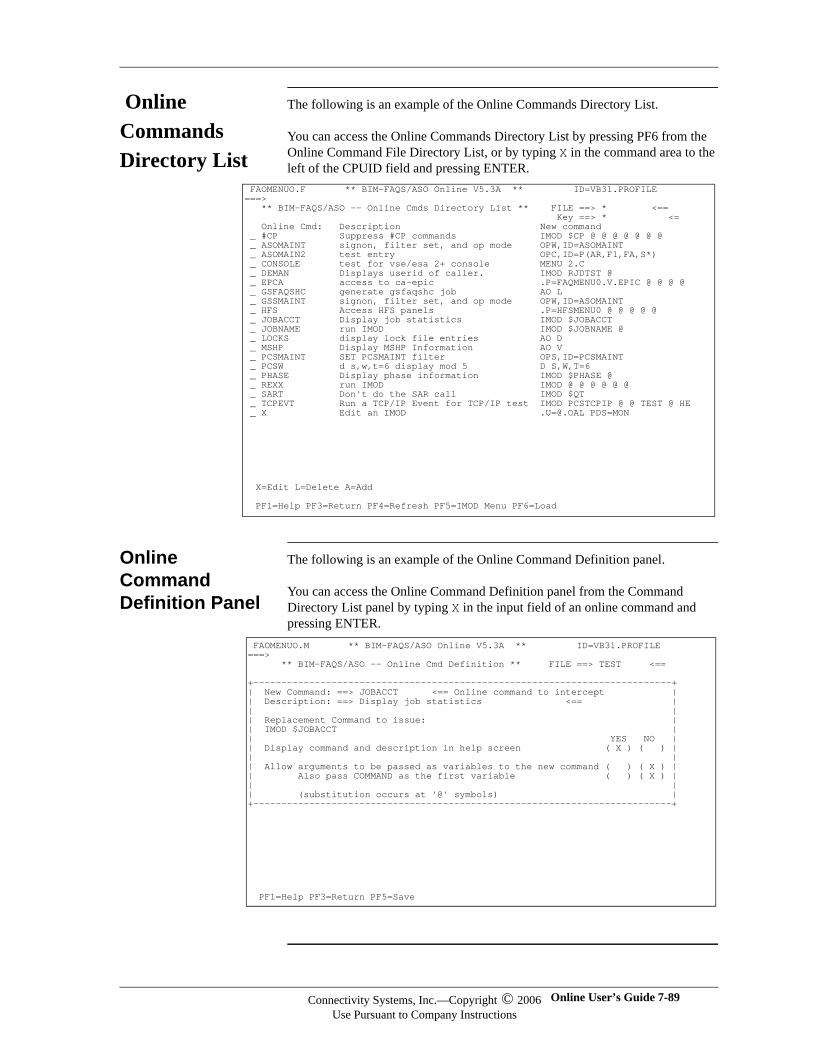
Online Commands Directory List
The following is an example of the Online Commands Directory List.
You can access the Online Commands Directory List by pressing PF6 from the Online Command File Directory List, or by typing X in the command area to the left of the CPUID field and pressing ENTER.
Online Command Definition Panel
The following is an example of the Online Command Definition panel.
You can access the Online Command Definition panel from the Command Directory List panel by typing X in the input field of an online command and pressing ENTER.
FAOMENUO.F ** BIM-FAQS/ASO Online V5.3A ** ID=VB31.PROFILE ===> ** BIM-FAQS/ASO -- Online Cmds Directory List ** FILE ==> * <== Key ==> * <= Online Cmd: Description New command _ #CP Suppress #CP commands IMOD $CP @ @ @ @ @ @ @ _ ASOMAINT signon, filter set, and op mode OPW,ID=ASOMAINT _ ASOMAIN2 test entry OPC,ID=P(AR,F1,FA,S*) _ CONSOLE test for vse/esa 2+ console MENU 2.C _ DEMAN Displays userid of caller. IMOD RJDTST @ _ EPCA access to ca-epic .P=FAQMENU0.V.EPIC @ @ @ @ _ GSFAQSHC generate gsfaqshc job AO L _ GSSMAINT signon, filter set, and op mode OPW,ID=ASOMAINT _ HFS Access HFS panels .P=HFSMENU0 @ @ @ @ @ _ JOBACCT Display job statistics IMOD $JOBACCT _ JOBNAME run IMOD IMOD $JOBNAME @ _ LOCKS display lock file entries AO D _ MSHP Display MSHP Information AO V _ PCSMAINT SET PCSMAINT filter OPS,ID=PCSMAINT _ PCSW d s,w,t=6 display mod 5 D S,W,T=6 _ PHASE Display phase information IMOD $PHASE @ _ REXX run IMOD IMOD @ @ @ @ @ @ _ SART Don't do the SAR call IMOD $QT _ TCPEVT Run a TCP/IP Event for TCP/IP test IMOD PCSTCPIP @ @ TEST @ HE _ X Edit an IMOD [email protected] PDS=MON
X=Edit L=Delete A=Add PF1=Help PF3=Return PF4=Refresh PF5=IMOD Menu PF6=Load
FAOMENUO.M ** BIM-FAQS/ASO Online V5.3A ** ID=VB31.PROFILE ===> ** BIM-FAQS/ASO -- Online Cmd Definition ** FILE ==> TEST <== +---------------------------------------------------------------------------+ | New Command: ==> JOBACCT <== Online command to intercept | | Description: ==> Display job statistics <== | | | | Replacement Command to issue: | | IMOD $JOBACCT | | YES NO | | Display command and description in help screen ( X ) ( ) | | | | Allow arguments to be passed as variables to the new command ( ) ( X ) | | Also pass COMMAND as the first variable ( ) ( X ) | | | | (substitution occurs at '@' symbols) | +---------------------------------------------------------------------------+
PF1=Help PF3=Return PF5=Save
Connectivity Systems, Inc.—Copyright © 2006Use Pursuant to Company Instructions
Online User’s Guide 7-89
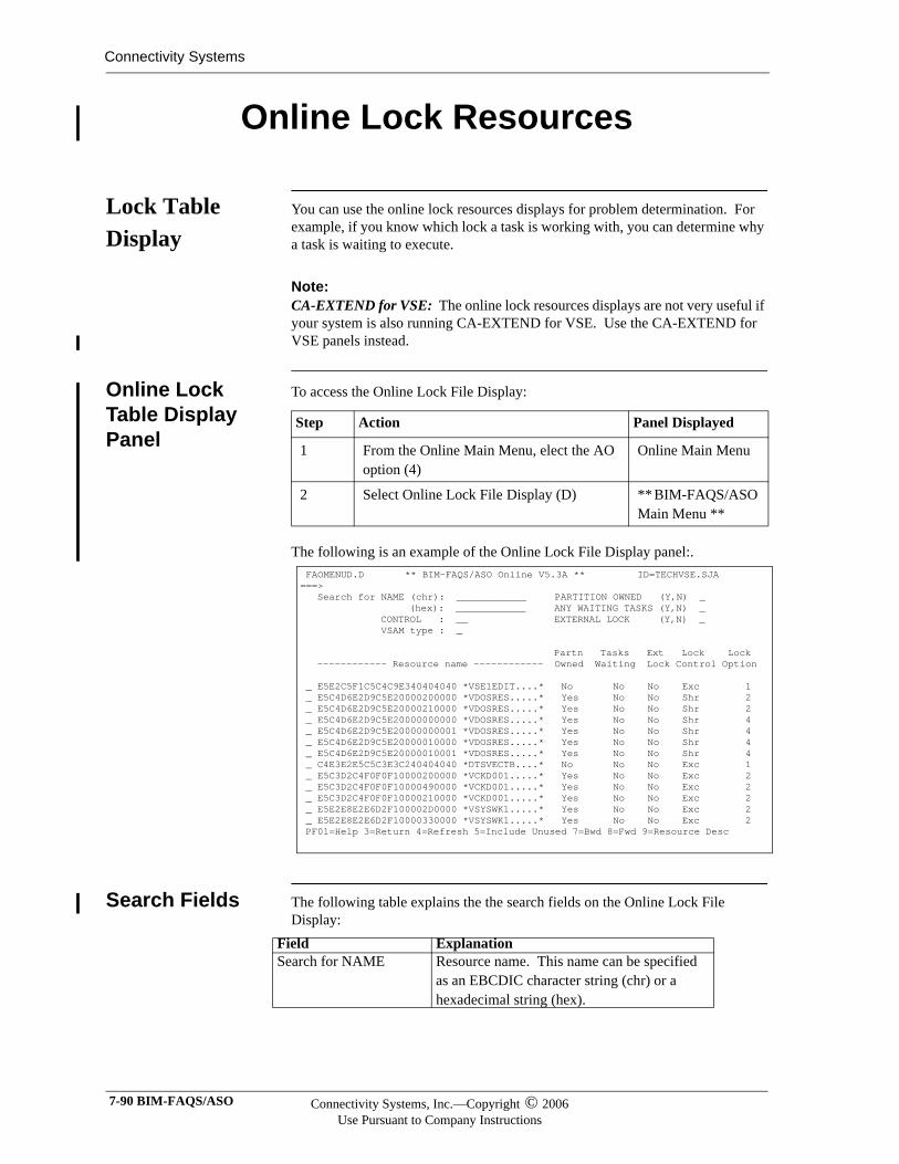
Connectivity Systems
Online Lock Resources
Lock Table Display
You can use the online lock resources displays for problem determination. For example, if you know which lock a task is working with, you can determine why a task is waiting to execute.
Note:Note:CA-EXTEND for VSE: The online lock resources displays are not very useful if your system is also running CA-EXTEND for VSE. Use the CA-EXTEND for VSE panels instead.
Online Lock Table Display Panel
To access the Online Lock File Display:
The following is an example of the Online Lock File Display panel:.
Search Fields The following table explains the the search fields on the Online Lock File Display:
Step Action Panel Displayed
1 From the Online Main Menu, elect the AO option (4)
Online Main Menu
2 Select Online Lock File Display (D) ** BIM-FAQS/ASO Main Menu **
FAOMENUD.D ** BIM-FAQS/ASO Online V5.3A ** ID=TECHVSE.SJA ===> Search for NAME (chr): ____________ PARTITION OWNED (Y,N) _ (hex): ____________ ANY WAITING TASKS (Y,N) _ CONTROL : __ EXTERNAL LOCK (Y,N) _ VSAM type : _ Partn Tasks Ext Lock Lock ------------ Resource name ------------ Owned Waiting Lock Control Option _ E5E2C5F1C5C4C9E340404040 *VSE1EDIT....* No No No Exc 1 _ E5C4D6E2D9C5E20000200000 *VDOSRES.....* Yes No No Shr 2 _ E5C4D6E2D9C5E20000210000 *VDOSRES.....* Yes No No Shr 2 _ E5C4D6E2D9C5E20000000000 *VDOSRES.....* Yes No No Shr 4 _ E5C4D6E2D9C5E20000000001 *VDOSRES.....* Yes No No Shr 4 _ E5C4D6E2D9C5E20000010000 *VDOSRES.....* Yes No No Shr 4 _ E5C4D6E2D9C5E20000010001 *VDOSRES.....* Yes No No Shr 4 _ C4E3E2E5C5C3E3C240404040 *DTSVECTB....* No No No Exc 1 _ E5C3D2C4F0F0F10000200000 *VCKD001.....* Yes No No Exc 2 _ E5C3D2C4F0F0F10000490000 *VCKD001.....* Yes No No Exc 2 _ E5C3D2C4F0F0F10000210000 *VCKD001.....* Yes No No Exc 2 _ E5E2E8E2E6D2F100002D0000 *VSYSWK1.....* Yes No No Exc 2 _ E5E2E8E2E6D2F10000330000 *VSYSWK1.....* Yes No No Exc 2 PF01=Help 3=Return 4=Refresh 5=Include Unused 7=Bwd 8=Fwd 9=Resource Desc
Field ExplanationSearch for NAME Resource name. This name can be specified
as an EBCDIC character string (chr) or a hexadecimal string (hex).
7-90 BIM-FAQS/ASO Connectivity Systems, Inc.—Copyright © 2006Use Pursuant to Company Instructions
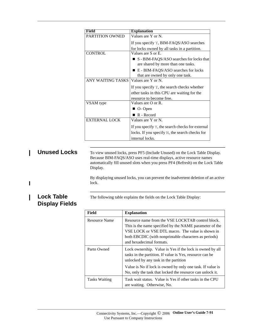
Unused Locks To view unused locks, press PF5 (Include Unused) on the Lock Table Display. Because BIM-FAQS/ASO uses real-time displays, active resource names automatically fill unused slots when you press PF4 (Refresh) on the Lock Table Display.
By displaying unused locks, you can prevent the inadvertent deletion of an active lock.
Lock Table Display Fields
The following table explains the fields on the Lock Table Display:
PARTITION OWNED Values are Y or N.If you specify Y, BIM-FAQS/ASO searches for locks owned by all tasks in a partition.
CONTROL Values are S or E.S - BIM-FAQS/ASO searches for locks that are shared by more than one tasks.E - BIM-FAQS/ASO searches for locks that are owned by only one task.
ANY WAITING TASKS Values are Y or N.If you specify Y, the search checks whether other tasks in this CPU are waiting for the resource to become free.
VSAM type Values are O or R.O- Open R - Record
EXTERNAL LOCK Values are Y or N.If you specify Y, the search checks for external locks. If you specify N, the search checks for internal locks.
Field Explanation
Field Explanation
Resource Name Resource name from the VSE LOCKTAB control block. This is the name specified by the NAME parameter of the VSE LOCK or VSE DTL macro. The value is shown in both EBCDIC (with nonprintable characters as periods) and hexadecimal formats.
Partn Owned Lock ownership. Value is Yes if the lock is owned by all tasks in the partition. If value is Yes, resource can be unlocked by any task in the partition Value is No if lock is owned by only one task. If value is No, only the task that locked the resource can unlock it.
Tasks Waiting Task wait status. Value is Yes if other tasks in the CPU are waiting. Otherwise, No.
Connectivity Systems, Inc.—Copyright © 2006Use Pursuant to Company Instructions
Online User’s Guide 7-91
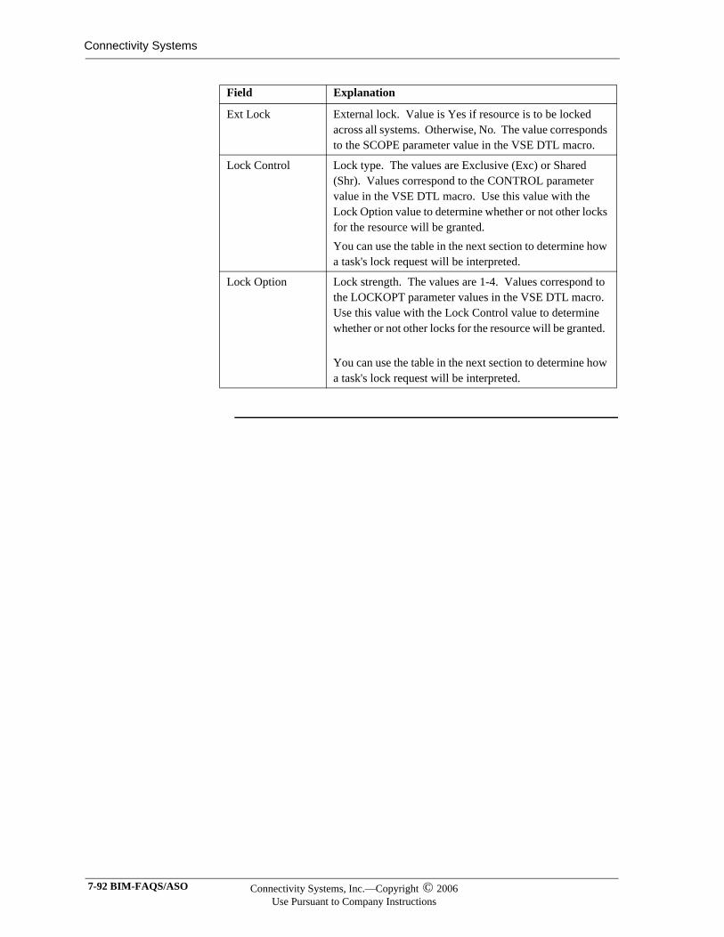
Connectivity Systems
Ext Lock External lock. Value is Yes if resource is to be locked across all systems. Otherwise, No. The value corresponds to the SCOPE parameter value in the VSE DTL macro.
Lock Control Lock type. The values are Exclusive (Exc) or Shared (Shr). Values correspond to the CONTROL parameter value in the VSE DTL macro. Use this value with the Lock Option value to determine whether or not other locks for the resource will be granted. You can use the table in the next section to determine how a task's lock request will be interpreted.
Lock Option Lock strength. The values are 1-4. Values correspond to the LOCKOPT parameter values in the VSE DTL macro. Use this value with the Lock Control value to determine whether or not other locks for the resource will be granted.
You can use the table in the next section to determine how a task's lock request will be interpreted.
Field Explanation
7-92 BIM-FAQS/ASO Connectivity Systems, Inc.—Copyright © 2006Use Pursuant to Company Instructions
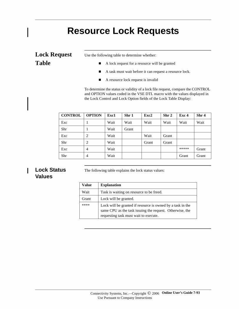
Resource Lock Requests
Lock Request Table
Use the following table to determine whether:
A lock request for a resource will be granted
A task must wait before it can request a resource lock.
A resource lock request is invalid
To determine the status or validity of a lock file request, compare the CONTROL and OPTION values coded in the VSE DTL macro with the values displayed in the Lock Control and Lock Option fields of the Lock Table Display:
Lock Status Values
The following table explains the lock status values:
CONTROL OPTION Exc1 Shr 1 Exc2 Shr 2 Exc 4 Shr 4
Exc 1 Wait Wait Wait Wait Wait Wait
Shr 1 Wait Grant
Exc 2 Wait Wait Grant
Shr 2 Wait Grant Grant
Exc 4 Wait ***** Grant
Shr 4 Wait Grant Grant
Value Explanation
Wait Task is waiting on resource to be freed.
Grant Lock will be granted.
**** Lock will be granted if resource is owned by a task in the same CPU as the task issuing the request. Otherwise, the requesting task must wait to execute.
Connectivity Systems, Inc.—Copyright © 2006Use Pursuant to Company Instructions
Online User’s Guide 7-93
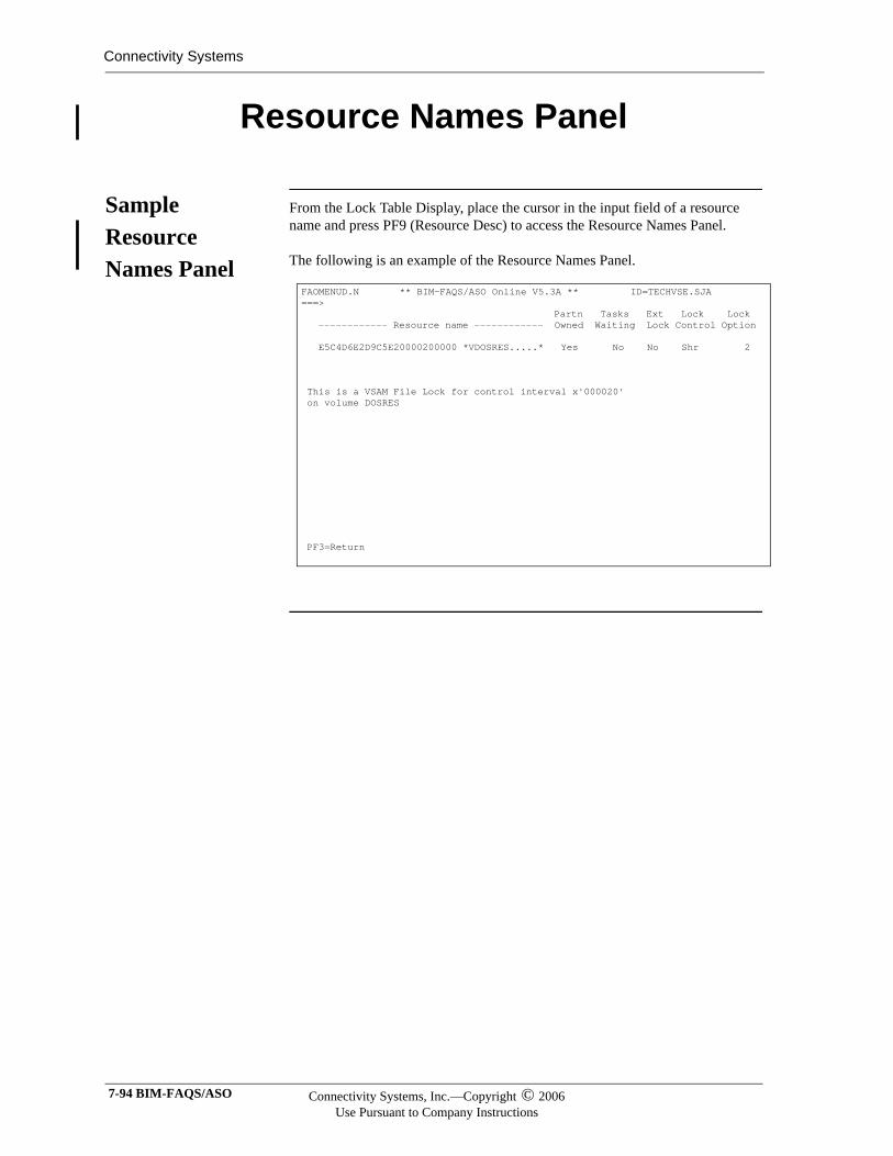
Connectivity Systems
Resource Names Panel
Sample Resource Names Panel
From the Lock Table Display, place the cursor in the input field of a resource name and press PF9 (Resource Desc) to access the Resource Names Panel.
The following is an example of the Resource Names Panel.
FAOMENUD.N ** BIM-FAQS/ASO Online V5.3A ** ID=TECHVSE.SJA ===> Partn Tasks Ext Lock Lock ------------ Resource name ------------ Owned Waiting Lock Control Option E5C4D6E2D9C5E20000200000 *VDOSRES.....* Yes No No Shr 2 This is a VSAM File Lock for control interval x'000020' on volume DOSRES PF3=Return
7-94 BIM-FAQS/ASO Connectivity Systems, Inc.—Copyright © 2006Use Pursuant to Company Instructions
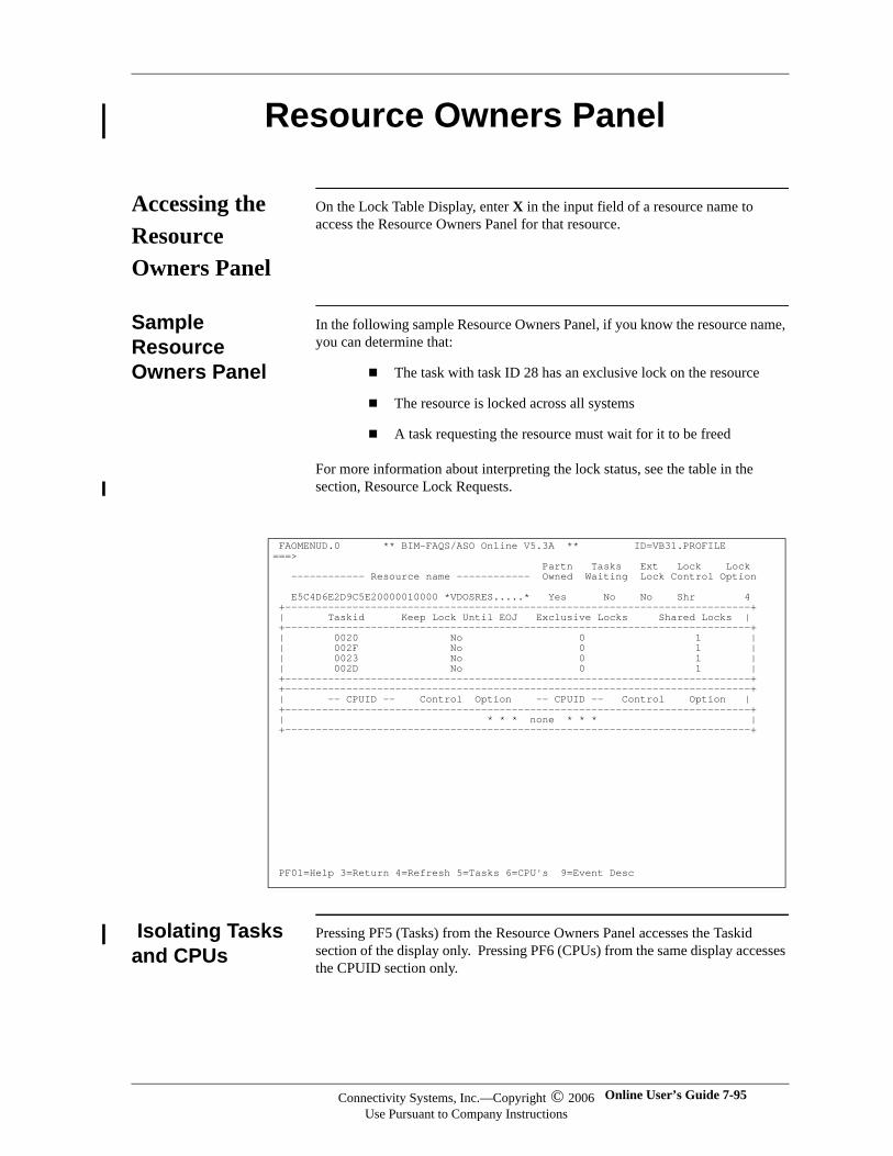
Resource Owners Panel
Accessing the Resource Owners Panel
On the Lock Table Display, enter X in the input field of a resource name to access the Resource Owners Panel for that resource.
Sample Resource Owners Panel
In the following sample Resource Owners Panel, if you know the resource name, you can determine that:
The task with task ID 28 has an exclusive lock on the resource
The resource is locked across all systems
A task requesting the resource must wait for it to be freed
For more information about interpreting the lock status, see the table in the section, Resource Lock Requests.
Isolating Tasks and CPUs
Pressing PF5 (Tasks) from the Resource Owners Panel accesses the Taskid section of the display only. Pressing PF6 (CPUs) from the same display accesses the CPUID section only.
FAOMENUD.0 ** BIM-FAQS/ASO Online V5.3A ** ID=VB31.PROFILE ===> Partn Tasks Ext Lock Lock ------------ Resource name ------------ Owned Waiting Lock Control Option E5C4D6E2D9C5E20000010000 *VDOSRES.....* Yes No No Shr 4 +----------------------------------------------------------------------------+ | Taskid Keep Lock Until EOJ Exclusive Locks Shared Locks | +----------------------------------------------------------------------------+ | 0020 No 0 1 | | 002F No 0 1 | | 0023 No 0 1 | | 002D No 0 1 | +----------------------------------------------------------------------------+ +----------------------------------------------------------------------------+ | -- CPUID -- Control Option -- CPUID -- Control Option | +----------------------------------------------------------------------------+ | * * * none * * * | +----------------------------------------------------------------------------+
PF01=Help 3=Return 4=Refresh 5=Tasks 6=CPU's 9=Event Desc
Connectivity Systems, Inc.—Copyright © 2006Use Pursuant to Company Instructions
Online User’s Guide 7-95
Connectivity Systems
Scrollable Fields
If the Taskid or CPUID entry (or both) extend beyond the current display boundaries, a command line, ===, will appear to the left of either field name indicating that you can scroll forward (PF7) or backward (PF8) within that section. You can also use the TOP and BOTtom line commands when you see the ===> command line.
Task, CPUs, and Locks
There will always be at least one task associated with a lock. There may or may not be a CPU associated with the lock.
Note:Note:Two tasks cannot have exclusive locks on the same resource at the same time.
7-96 BIM-FAQS/ASO Connectivity Systems, Inc.—Copyright © 2006Use Pursuant to Company Instructions
SYSOUT Archival Files
Defining SYSOUT Archival Files
BIM-FAQS/ASO enables you to search and browse SYSOUT Archival files with online panels. Use the SYSOUT archival facility to archive end-of-job reports to a PDS and to access them online. CSS$ARC is the PDS that contains the SYSOUT archival files.
You can delete and browse SYSOUT files using line commands. You can also search for SYSOUT files or refresh the current menu display with PF keys.
Requirements You must allocate the CSS$ARC file prior to enabling SYSOUT archival. If you already have CSS$ARC allocated because of previous product installations, you do not need to reallocate it.
CSS$ARC requires 1 4K block or 8 FBA blocks per archived report. To allow for 500 archived reports in CSS$ARC, allocate 500 4K blocks or 4000 FBA blocks. This is equivalent to 50 tracks of 3380 DASD (10 4K blocks per track).
You must include DLBL and EXTENT statements for CSS$ARC in your system standard labels. Define CSS$ARC as a sequential file. Specify the volser and omit the logical unit.
Sample JCL The following is an example of the DLBL and EXTENT statements for CSS$ARC on a 3380 DASD:
// DLBL CSS$ARC, 'file.id',99/365
// EXTENT ,RES001,1,0,7680,50
file.id is the file identifier you assign to CSS$ARC. We recommend you use a file identifier that suggests this PDS's function.
No standard assignments are required for CSS$ARC because the BIM$PUTL utility dynamically assigns a free logical unit if one is needed.
Activation BIM-FAQS/ASO uses the fields in its startup file to initialize the BIM-FAQS/ASO SYSOUT archival facility.
Connectivity Systems, Inc.—Copyright © 2006Use Pursuant to Company Instructions
Online User’s Guide 7-97
Connectivity Systems
Accessing SYSOUT Archival Files
SYSOUT Option
To access the SYSOUT Archival History lists, select AO (4) from the Online Main Menu. Then select the SYSOUT option (S) from the BIM-FAQS/ASO Main Menu. BIM-FAQS/ASO displays the Sysout Archival Scan Setup Menu. To access the SYSOUT Archival History Lists from this menu, press PF2.
If you get the message GFF390 CSS$ARC - 75 percent full, nnnnnn DATA BLOCKS, and nnnnn USED BLOCKS, you can use and modify a REXX EXEC designed to automatically maintain the number of SYSOUT archival files. For a description of the REXX EXEC that performs SYSOUT file maintenance, see ‘‘Maintaining SYSOUT Archival Files’’ on page -105. For more information about making backups and formatting, see the ASO for VSE Installation and Initialization Guide and the BIM-GSS Installation and Utilities Guide.
Selecting SYSOUT Archival Files
You can select SYSOUT archival files to browse, print, and delete. You can also view a subset of the list of files.
7-98 BIM-FAQS/ASO Connectivity Systems, Inc.—Copyright © 2006Use Pursuant to Company Instructions
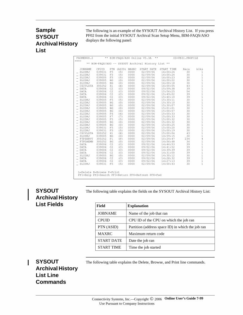
Sample SYSOUT Archival History List
The following is an example of the SYSOUT Archival History List. If you press PF02 from the initial SYSOUT Archival Scan Setup Menu, BIM-FAQS/ASO displays the following panel:
SYSOUT Archival History List Fields
The following table explains the fields on the SYSOUT Archival History List:
SYSOUT Archival History List Line Commands
The following table explains the Delete, Browse, and Print line commands.
FAOMENUS.2 ** BIM-FAQS/ASO Online V5.3A ** ID=VB31.PROFILE ===> ** BIM-FAQS/ASO -- SYSOUT Archival History List ** JOBNAME CPUID PTN (ASID) MAXRC START DATE START TIME Recs blks _ SLIDRJ 039031 F5 (5) 0000 02/09/06 16:00:26 30 1 _ SLIDRJ 039031 F5 (5) 0000 02/09/06 16:00:24 30 1 _ SLIDRJ 039005 F5 (5) 0000 02/09/06 16:00:23 30 1 _ SLIDRJ 039005 BG (0) 0000 02/09/06 16:00:22 30 1 _ SLIDRJ 039005 BG (0) 0000 02/09/06 16:00:18 30 1 _ CSIVLSTA 300252 X1 (X) 0000 02/09/06 16:00:05 43 1 _ DATA 039006 C2 (C) 0000 09/02/06 15:59:38 39 1 _ DATA 039006 C2 (C) 0000 09/02/06 15:56:25 54 1 _ DATA 039006 C2 (C) 0000 09/02/06 15:49:02 39 1 _ DATA 039006 C2 (C) 0000 09/02/06 15:40:10 39 1 _ SLIDRJ 039005 F5 (5) 0000 02/09/06 15:30:11 30 1 _ SLIDRJ 039005 BG (0) 0000 02/09/06 15:30:10 30 1 _ SLIDRJ 039005 BG (0) 0000 02/09/06 15:30:07 30 1 _ SLIDRJ 039005 BG (0) 0000 02/09/06 15:01:01 30 1 _ SLIDRJ 039005 BG (0) 0000 02/09/06 15:00:57 30 1 _ SLIDRJ 039005 F6 (6) 0000 02/09/06 15:00:33 30 1 _ SLIDRJ 039005 F7 (7) 0000 02/09/06 15:00:33 30 1 _ SLIDRJ 039005 F5 (5) 0000 02/09/06 15:00:32 30 1 _ SLIDRJ 039005 BG (0) 0000 02/09/06 15:00:32 30 1 _ SLIDRJ 039005 BG (0) 0000 02/09/06 15:00:25 30 1 _ SLIDRJ 039031 F5 (5) 0000 02/09/06 15:00:20 30 1 _ SLIDRJ 039031 F5 (5) 0000 02/09/06 15:00:19 30 1 _ CSIVLSTA 300252 X1 (X) 0000 02/09/06 15:00:04 43 1 _ SLIDRJ 039005 BG (0) 0000 02/09/06 14:59:15 30 1 _ FTPSERVT 300252 P1 (P) 0000 02/09/06 10:24:47 234 4 _ FTPDAEMN 300252 BG (0) 0000 02/09/06 14:56:48 34 1 _ DATA 039006 C2 (C) 0000 09/02/06 14:46:53 39 1 _ DATA 039006 C2 (C) 0000 09/02/06 14:41:52 39 1 _ DATA 039006 C2 (C) 0000 09/02/06 14:39:39 39 1 _ DATA 039006 C2 (C) 0000 09/02/06 14:31:00 39 1 _ SLIDRJ 039005 BG (0) 0000 02/09/06 14:30:12 30 1 _ DATA 039006 C2 (C) 0000 09/02/06 14:28:32 39 1 _ DATA 039006 C2 (C) 0000 09/02/06 14:27:13 39 1 _ SLIDRJ 039031 F5 (5) 0000 02/09/06 14:00:43 30 1 L=Delete B=Browse P=Print PF1=Help PF2=Search PF3=Return PF4=Refresh PF8=Fwd
Field Explanation
JOBNAME Name of the job that ran
CPUID CPU ID of the CPU on which the job ran
PTN (ASID) Partition (address space ID) in which the job ran
MAXRC Maximum return code
START DATE Date the job ran
START TIME Time the job started
Connectivity Systems, Inc.—Copyright © 2006Use Pursuant to Company Instructions
Online User’s Guide 7-99
Connectivity Systems
Enter line commands (L, B, P) in the input field to the left of the SYSOUT filename you want to effect.
Browsing SYSOUT Archival Files
The Browse line command on the SYSOUT Archival History List accesses a SYSOUT archival file.
SYSOUT Archival History File Browse Panel
The SYSOUT Archival History File Browse panel allows you to see the SYSOUT file. The SYSOUT file contains the following information:
Job statistics by step
BIM-FAQS/ASO Phase Load List report or CA-FLEE Maintenance Summary report
Core-image library search sequence
CA-HYPERBUF VSAM close statistics
Console Summary report
For more information about the SYSOUT Archival History List, see the Console Spooling Report described in the BIM-FAQS/ASO User Guide.
Sample SYSOUT Archival History File Browse Panel
The SYSOUT Archival History File Browse panel contains the sub-reports:
Job Statistics by Step report,
FLEE/VSE Phase Load List report
Library Libdef Search Sequence
Console Summary report
Command Function
DELETE (L) Deletes a SYSOUT file from the SYSOUT Archival History List.
BROWSE (B) Accesses a SYSOUT file to browse.
PRINT (P) Submits a SYSOUT file for a batch print job. The output from this batch print utility is the report you can see online from the SYSOUT Archival History File Browse panel in the section ‘‘SYSOUT Archival History File Browse Panel’’ on page -100.
7-100 BIM-FAQS/ASO Connectivity Systems, Inc.—Copyright © 2006Use Pursuant to Company Instructions
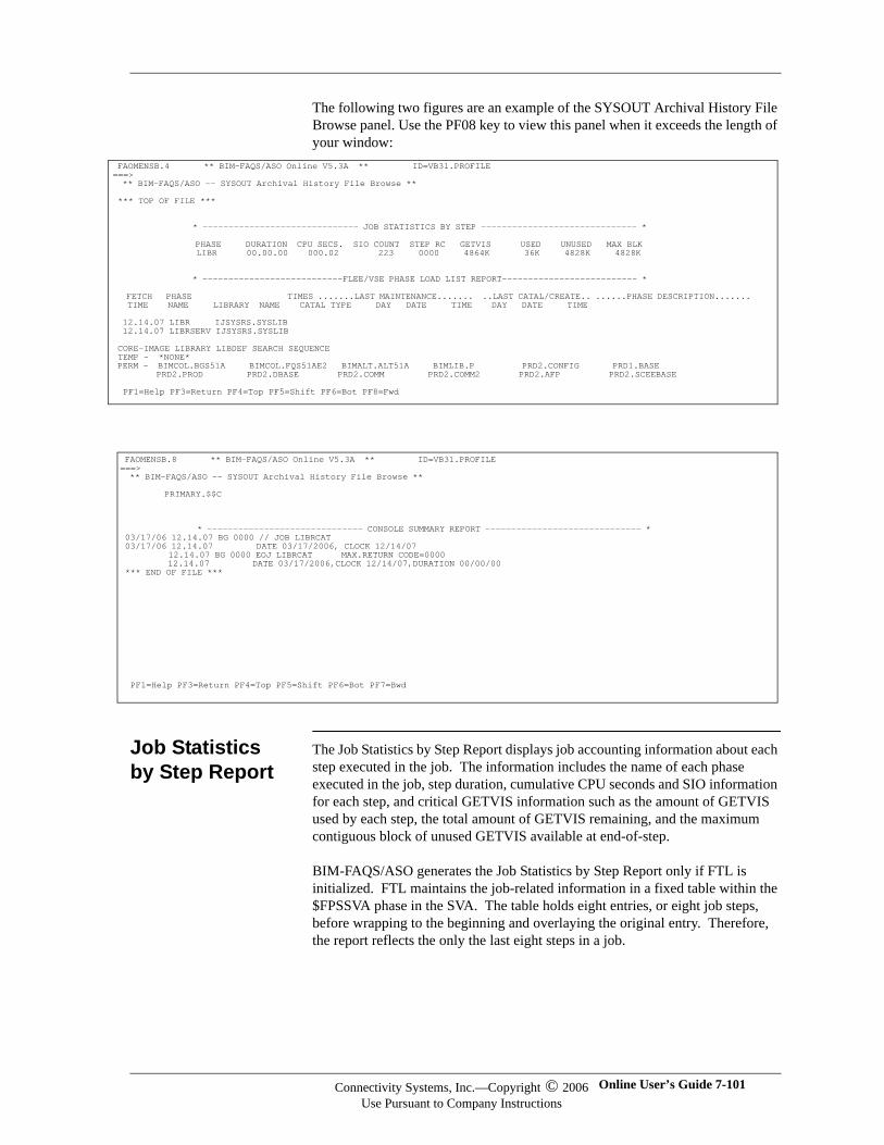
=
The following two figures are an example of the SYSOUT Archival History File Browse panel. Use the PF08 key to view this panel when it exceeds the length of your window:
Job Statistics by Step Report
The Job Statistics by Step Report displays job accounting information about each step executed in the job. The information includes the name of each phase executed in the job, step duration, cumulative CPU seconds and SIO information for each step, and critical GETVIS information such as the amount of GETVIS used by each step, the total amount of GETVIS remaining, and the maximum contiguous block of unused GETVIS available at end-of-step.
BIM-FAQS/ASO generates the Job Statistics by Step Report only if FTL is initialized. FTL maintains the job-related information in a fixed table within the $FPSSVA phase in the SVA. The table holds eight entries, or eight job steps, before wrapping to the beginning and overlaying the original entry. Therefore, the report reflects the only the last eight steps in a job.
FAOMENSB.4 ** BIM-FAQS/ASO Online V5.3A ** ID=VB31.PROFILE ==> ** BIM-FAQS/ASO -- SYSOUT Archival History File Browse ** *** TOP OF FILE *** * ------------------------------ JOB STATISTICS BY STEP ------------------------------ * PHASE DURATION CPU SECS. SIO COUNT STEP RC GETVIS USED UNUSED MAX BLK LIBR 00.00.00 000.02 223 0000 4864K 36K 4828K 4828K * ---------------------------FLEE/VSE PHASE LOAD LIST REPORT-------------------------- * FETCH PHASE TIMES .......LAST MAINTENANCE....... ..LAST CATAL/CREATE.. ......PHASE DESCRIPTION....... TIME NAME LIBRARY NAME CATAL TYPE DAY DATE TIME DAY DATE TIME 12.14.07 LIBR IJSYSRS.SYSLIB 12.14.07 LIBRSERV IJSYSRS.SYSLIB CORE-IMAGE LIBRARY LIBDEF SEARCH SEQUENCE TEMP - *NONE* PERM - BIMCOL.BGS51A BIMCOL.FQS51AE2 BIMALT.ALT51A BIMLIB.P PRD2.CONFIG PRD1.BASE PRD2.PROD PRD2.DBASE PRD2.COMM PRD2.COMM2 PRD2.AFP PRD2.SCEEBASE PF1=Help PF3=Return PF4=Top PF5=Shift PF6=Bot PF8=Fwd
FAOMENSB.8 ** BIM-FAQS/ASO Online V5.3A ** ID=VB31.PROFILE ===> ** BIM-FAQS/ASO -- SYSOUT Archival History File Browse ** PRIMARY.$$C * ------------------------------ CONSOLE SUMMARY REPORT ------------------------------ * 03/17/06 12.14.07 BG 0000 // JOB LIBRCAT 03/17/06 12.14.07 DATE 03/17/2006, CLOCK 12/14/07 12.14.07 BG 0000 EOJ LIBRCAT MAX.RETURN CODE=0000 12.14.07 DATE 03/17/2006,CLOCK 12/14/07,DURATION 00/00/00 *** END OF FILE *** PF1=Help PF3=Return PF4=Top PF5=Shift PF6=Bot PF7=Bwd
Connectivity Systems, Inc.—Copyright © 2006Use Pursuant to Company Instructions
Online User’s Guide 7-101
Connectivity Systems
FLEE/VSE Phase Load List Report
The FLEE/VSE Phase Load List Report lists the name of each phase, the time the phase was loaded, and the library it was retrieved from. This not only can eliminate many questions about from which library a phase really was loaded, but can also serve as a tuning tool by identifying the number of library directories searched before finding each phase.
GSFAQS also interfaces with the Computer Associates library maintenance package FLEE to provide maintenance summary information for each phase. This maintenance information includes the number of times the phase was cataloged, the last maintenance type, date and time, the last catalog or creation date and time, and the phase description.
BIM-FAQS/ASO prints the Phase Load List Summary report only if FTL is supporting the GSFAQS phases. To support the required GSFAQS phases with FTL, specify the BIM-FAQS/ASO command at GSFTL initialization. FTL maintains a wraparound table in the SYSTEM GETVIS of the most recent phases loaded by a job. The default size of this table is 512 bytes per partition.
Library LIBDEF Search Sequence Report
The Library LIBDEF Search Sequence Report lists the library and sublibrary names in the temporary and permanent core-image library search chain as they exist at end-of-job time. To find the number of library directories that were actually searched before each phase was found, match the library name to the directory search chain. This report is only printed when the Phase Load List Summary Report is generated.
Console Summary Report
On the Console Summary Report, all console activity is time-stamped for a chronological history of console reads and writes. AR (Attention Routine) messages that occur during the execution of a job can be included in the Console Summary Report along with the normal partition console activity if you specify AR logging at console spooling initialization.
7-102 BIM-FAQS/ASO Connectivity Systems, Inc.—Copyright © 2006Use Pursuant to Company Instructions
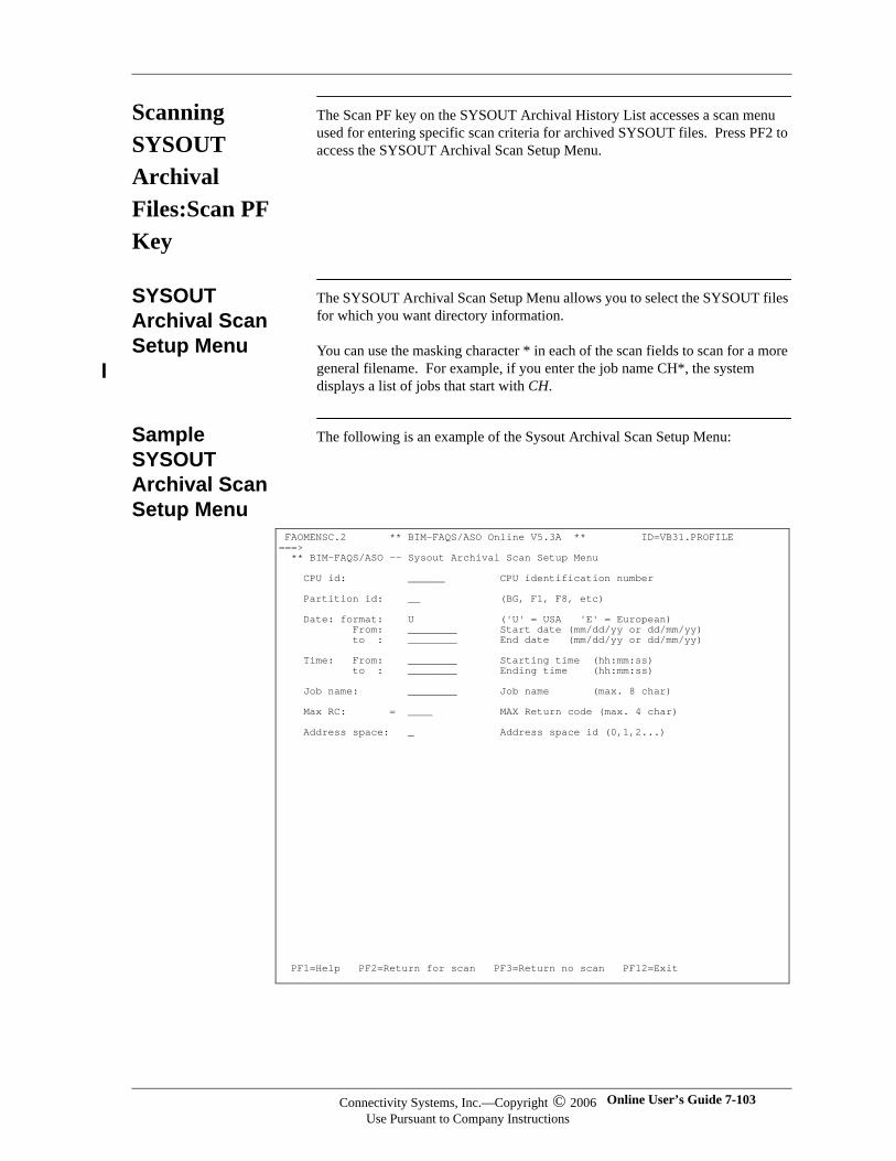
Scanning SYSOUT Archival Files:Scan PF Key
The Scan PF key on the SYSOUT Archival History List accesses a scan menu used for entering specific scan criteria for archived SYSOUT files. Press PF2 to access the SYSOUT Archival Scan Setup Menu.
SYSOUT Archival Scan Setup Menu
The SYSOUT Archival Scan Setup Menu allows you to select the SYSOUT files for which you want directory information.
You can use the masking character * in each of the scan fields to scan for a more general filename. For example, if you enter the job name CH*, the system displays a list of jobs that start with CH.
Sample SYSOUT Archival Scan Setup Menu
The following is an example of the Sysout Archival Scan Setup Menu:
FAOMENSC.2 ** BIM-FAQS/ASO Online V5.3A ** ID=VB31.PROFILE ===> ** BIM-FAQS/ASO -- Sysout Archival Scan Setup Menu CPU id: ______ CPU identification number Partition id: __ (BG, F1, F8, etc) Date: format: U ('U' = USA 'E' = European) From: ________ Start date (mm/dd/yy or dd/mm/yy) to : ________ End date (mm/dd/yy or dd/mm/yy) Time: From: ________ Starting time (hh:mm:ss) to : ________ Ending time (hh:mm:ss) Job name: ________ Job name (max. 8 char) Max RC: = ____ MAX Return code (max. 4 char) Address space: _ Address space id (0,1,2...) PF1=Help PF2=Return for scan PF3=Return no scan PF12=Exit
Connectivity Systems, Inc.—Copyright © 2006Use Pursuant to Company Instructions
Online User’s Guide 7-103
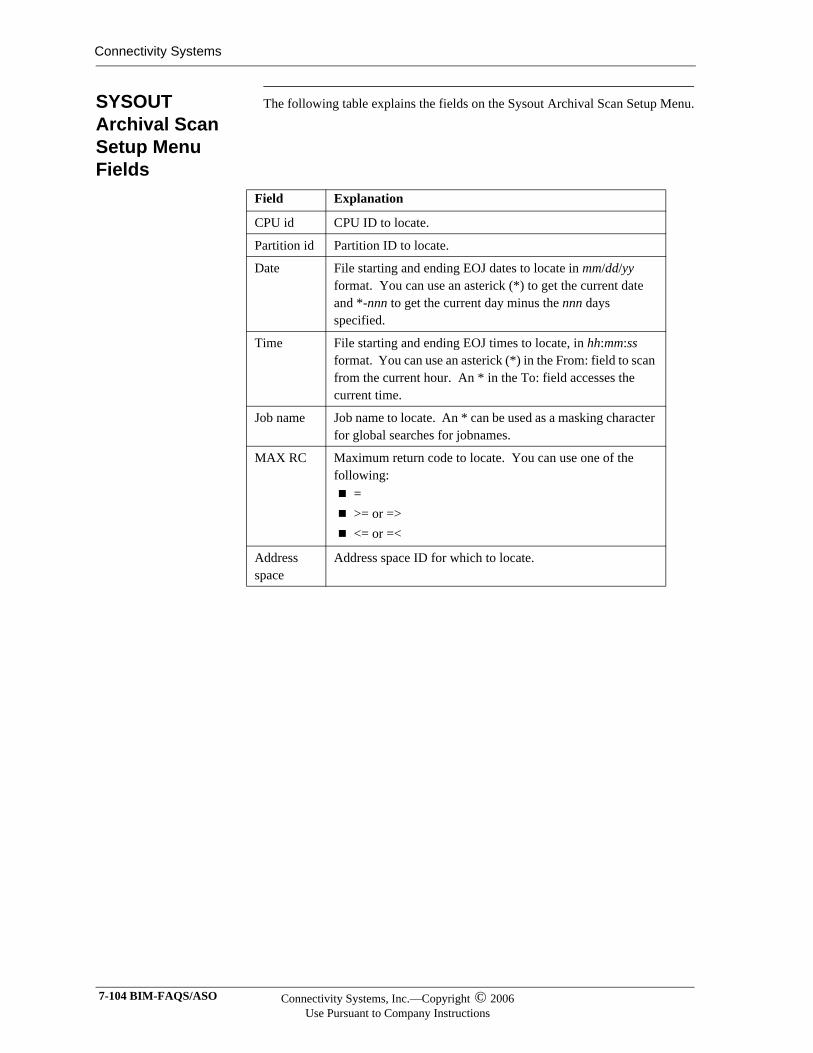
Connectivity Systems
SYSOUT Archival Scan Setup Menu Fields
The following table explains the fields on the Sysout Archival Scan Setup Menu.
Field Explanation
CPU id CPU ID to locate.
Partition id Partition ID to locate.
Date File starting and ending EOJ dates to locate in mm/dd/yy format. You can use an asterick (*) to get the current date and *-nnn to get the current day minus the nnn days specified.
Time File starting and ending EOJ times to locate, in hh:mm:ss format. You can use an asterick (*) in the From: field to scan from the current hour. An * in the To: field accesses the current time.
Job name Job name to locate. An * can be used as a masking character for global searches for jobnames.
MAX RC Maximum return code to locate. You can use one of the following:
=>= or =><= or =<
Address space
Address space ID for which to locate.
7-104 BIM-FAQS/ASO Connectivity Systems, Inc.—Copyright © 2006Use Pursuant to Company Instructions
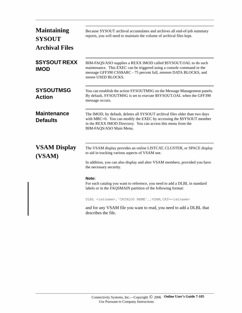
Maintaining SYSOUT Archival Files
Because SYSOUT archival accumulates and archives all end-of-job summary reports, you will need to maintain the volume of archival files kept.
$SYSOUT REXX IMOD
BIM-FAQS/ASO supplies a REXX IMOD called $SYSOUT.OAL to do such maintenance. This EXEC can be triggered using a console command or the message GFF390 CSS$ARC - 75 percent full, nnnnnn DATA BLOCKS, and nnnnn USED BLOCKS.
SYSOUTMSG Action
You can establish the action SYSOUTMSG on the Message Management panels. By default, SYSOUTMSG is set to execute $SYSOUT.OAL when the GFF390 message occurs.
Maintenance Defaults
The IMOD, by default, deletes all SYSOUT archival files older than two days with MRC=0. You can modify the EXEC by accessing the $SYSOUT member in the REXX IMOD Directory. You can access this menu from the BIM-FAQS/ASO Main Menu.
VSAM Display (VSAM)
The VSAM display provides an online LISTCAT, CLUSTER, or SPACE display to aid in tracking various aspects of VSAM use.
In addition, you can also display and alter VSAM members, provided you have the necessary security.
Note:Note:For each catalog you want to reference, you need to add a DLBL in standard labels or in the FAQSMAIN partition of the following format:
DLBL <catname>,'CATALOG NAME',,VSAM,CAT=<catname>
and for any VSAM file you want to read, you need to add a DLBL that describes the file.
Connectivity Systems, Inc.—Copyright © 2006Use Pursuant to Company Instructions
Online User’s Guide 7-105
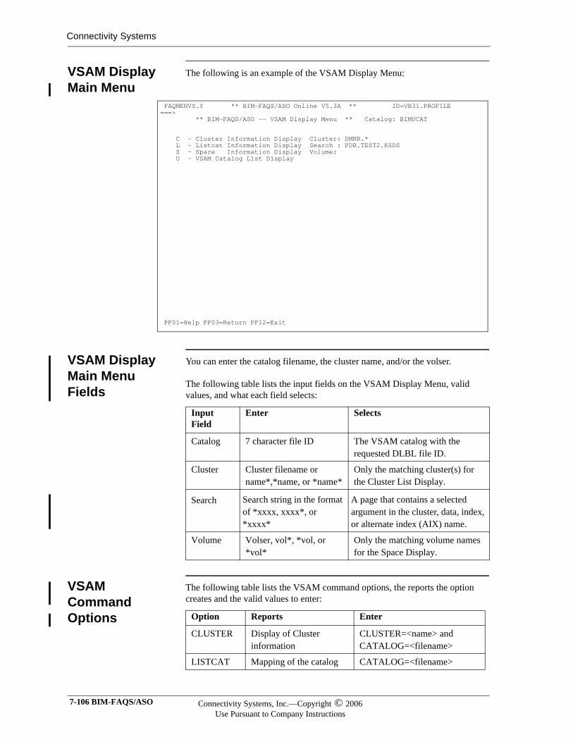
Connectivity Systems
VSAM Display Main Menu
The following is an example of the VSAM Display Menu:
VSAM Display Main Menu Fields
You can enter the catalog filename, the cluster name, and/or the volser.
The following table lists the input fields on the VSAM Display Menu, valid values, and what each field selects:
VSAM Command Options
The following table lists the VSAM command options, the reports the option creates and the valid values to enter:
FAQMENVS.Y ** BIM-FAQS/ASO Online V5.3A ** ID=VB31.PROFILE ===> ** BIM-FAQS/ASO -- VSAM Display Menu ** Catalog: BIMUCAT C - Cluster Information Display Cluster: DMNR.* L - Listcat Information Display Search : PDB.TEST2.KSDS S - Space Information Display Volume: U - VSAM Catalog List Display
PF01=Help PF03=Return PF12=Exit
Input Field
Enter Selects
Catalog 7 character file ID The VSAM catalog with the requested DLBL file ID.
Cluster Cluster filename or name*,*name, or *name*
Only the matching cluster(s) for the Cluster List Display.
Search Search string in the format of *xxxx, xxxx*, or *xxxx*
A page that contains a selected argument in the cluster, data, index, or alternate index (AIX) name.
Volume Volser, vol*, *vol, or *vol*
Only the matching volume names for the Space Display.
Option Reports Enter
CLUSTER Display of Cluster information
CLUSTER=<name> andCATALOG=<filename>
LISTCAT Mapping of the catalog CATALOG=<filename>
7-106 BIM-FAQS/ASO Connectivity Systems, Inc.—Copyright © 2006Use Pursuant to Company Instructions

VSAM Command Rules
The VSAM command parameters can be separated by commas or spaces.
Sample Cluster List Display Menu
The following is an example fo the VSAM Cluster List Display Menu:
Cluster List Menu Fields
The following table describes what you can enter in the input field (_) next to the cluster name:
SPACE Description of volumes VOLUME=<volser>CATALOG=<filename>
CATALOG List of defined catalogs
Option Reports Enter
FAQMENV1.0 ** BIM-FAQS/ASO Online V5.3A ** ID=VB31.PROFILE ====> ** BIM-FAQS/ASO -- VSAM Cluster List ** Catalog: BIMUCAT _ BIM.USER.CATALOG _ VB26.ALERT.AXPCTL.V51 _ VB26.ALERT.ALERTXP.V51 _ VB26.ALERT.S1SCTY.V51 _ VB26.ALERT.S1SMS##.V51 _ VB26.ALERT.S1SAUDT.V51 _ JMSTR.JRNL.CNTRL _ RECOV.TEST.CMPBKP2 _ VB31ICCF.ALERT.S1SCTY.V52 _ VB31ICCF.ALERT.ALERTXP.V52 _ VB31.ALERT.AXPCTL.V52 _ DMNR.KSDS.EXTR _ VB26TS11.ALERT.ALERTXP.V51 _ VB26TS11.ALERT.S1SCTY.V51 _ VB26TS11.ALERT.S1SMS##.V51 _ VB26TS11.ALERT.S1SAUDT.V51 _ EAM.TEST.VSAM _ VSHAR.CICS.CNTL _ VB26.ALERT.AXPCTL.V52 _ VB26CICS.DFHNTRA _ VB26CICS.DFHRSD _ VB26CICS.DFHTEMP _ VB27ICCF.ALERT.S1SMS##.V51 _ VB27ICCF.ALERT.S1SCTY.V60 _ VB27.ALERT.AXPCTL.V60 _ VB27ICCF.ALERT.S1SAUDT.V51 _ VB27ICCF.ALERT.ALERTXP.V51 _ VB27ICCF.ALERT.S1SCTY.V51 _ VB27.ALERT.AXPLOG1.V51 _ VB27.ALERT.AXPLOG3.V51 _ VB27.ALERT.AXPCTL.V51 _ TEST.MOSS.SEARCH.IDX _ VB31.ALERT.AXPLOG3.V52 _ VB31.ALERT.AXPLOG1.V52 _ VB26.ALERT.S1SCTY.V52 _ ARMAN.CICSTEST.UJRNBKUP D=Display cluster info, R=Read file Search for *.* PF01=Help PF03=Retn PF04=Refr PF08=Fwd
Command Displays ...
D Information for the selected cluster in the VSAM Cluster Display.
Connectivity Systems, Inc.—Copyright © 2006Use Pursuant to Company Instructions
Online User’s Guide 7-107
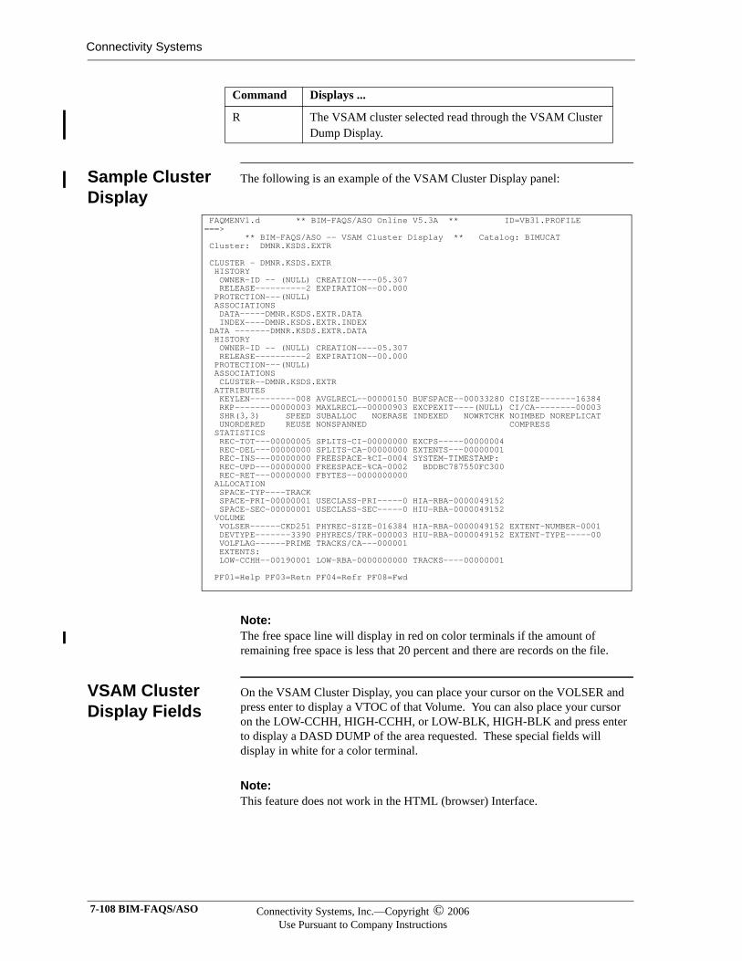
Connectivity Systems
Sample Cluster Display
The following is an example of the VSAM Cluster Display panel:
Note:Note:The free space line will display in red on color terminals if the amount of remaining free space is less that 20 percent and there are records on the file.
VSAM Cluster Display Fields
On the VSAM Cluster Display, you can place your cursor on the VOLSER and press enter to display a VTOC of that Volume. You can also place your cursor on the LOW-CCHH, HIGH-CCHH, or LOW-BLK, HIGH-BLK and press enter to display a DASD DUMP of the area requested. These special fields will display in white for a color terminal.
Note:Note:This feature does not work in the HTML (browser) Interface.
R The VSAM cluster selected read through the VSAM Cluster Dump Display.
Command Displays ...
FAQMENV1.d ** BIM-FAQS/ASO Online V5.3A ** ID=VB31.PROFILE ===> ** BIM-FAQS/ASO -- VSAM Cluster Display ** Catalog: BIMUCAT Cluster: DMNR.KSDS.EXTR CLUSTER - DMNR.KSDS.EXTR HISTORY OWNER-ID -- (NULL) CREATION----05.307 RELEASE----------2 EXPIRATION--00.000 PROTECTION---(NULL) ASSOCIATIONS DATA-----DMNR.KSDS.EXTR.DATA INDEX----DMNR.KSDS.EXTR.INDEX DATA -------DMNR.KSDS.EXTR.DATA HISTORY OWNER-ID -- (NULL) CREATION----05.307 RELEASE----------2 EXPIRATION--00.000 PROTECTION---(NULL) ASSOCIATIONS CLUSTER--DMNR.KSDS.EXTR ATTRIBUTES KEYLEN---------008 AVGLRECL--00000150 BUFSPACE--00033280 CISIZE-------16384 RKP-------00000003 MAXLRECL--00000903 EXCPEXIT----(NULL) CI/CA--------00003 SHR(3,3) SPEED SUBALLOC NOERASE INDEXED NOWRTCHK NOIMBED NOREPLICAT UNORDERED REUSE NONSPANNED COMPRESS STATISTICS REC-TOT---00000005 SPLITS-CI-00000000 EXCPS-----00000004 REC-DEL---00000000 SPLITS-CA-00000000 EXTENTS---00000001 REC-INS---00000000 FREESPACE-%CI-0004 SYSTEM-TIMESTAMP: REC-UPD---00000000 FREESPACE-%CA-0002 BDDBC787550FC300 REC-RET---00000000 FBYTES--0000000000 ALLOCATION SPACE-TYP----TRACK SPACE-PRI-00000001 USECLASS-PRI-----0 HIA-RBA-0000049152 SPACE-SEC-00000001 USECLASS-SEC-----0 HIU-RBA-0000049152 VOLUME VOLSER------CKD251 PHYREC-SIZE-016384 HIA-RBA-0000049152 EXTENT-NUMBER-0001 DEVTYPE-------3390 PHYRECS/TRK-000003 HIU-RBA-0000049152 EXTENT-TYPE-----00 VOLFLAG------PRIME TRACKS/CA---000001 EXTENTS: LOW-CCHH--00190001 LOW-RBA-0000000000 TRACKS----00000001 PF01=Help PF03=Retn PF04=Refr PF08=Fwd
7-108 BIM-FAQS/ASO Connectivity Systems, Inc.—Copyright © 2006Use Pursuant to Company Instructions
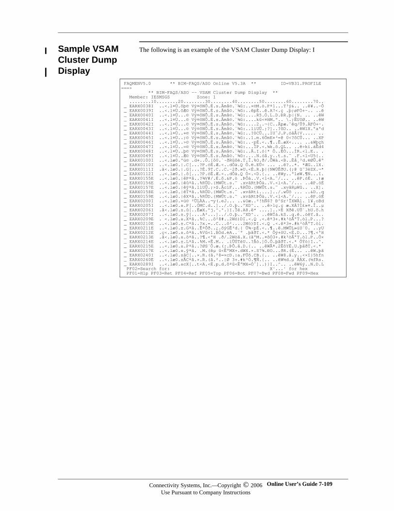
Sample VSAM Cluster Dump Display
The following is an example of the VSAM Cluster Dump Display: I
FAQMENV5.0 ** BIM-FAQS/ASO Online V5.3A ** ID=VB31.PROFILE ===> ** BIM-FAQS/ASO -- VSAM Cluster Dump Display ** Member: IESMSGS Zone: 1 ........10........20........30........40........50........60........70.. _ EARX0038I ..<.l¤Ù.õþ© Vý¤öNÖ.É.s.Ãmå©.`¾ü:..שM.ò.Pº1...T³ý&.. ..ë¥..-Ô _ EARX0039I ..<.l¤Ù.õÆ© Vý¤öNÖ.É.s.Ãmå©.`¾ü:..ëpÈ..ë.A7<.ç .þ;øFÒ+-.. ..ë _ EARX0040I ..<.l¤Ù...© Vý¤öNÖ.É.s.Ãmå©.`¾ü:....R5.Ó.L.D.ÐR.þ|{N. .. ..ëW _ EARX0041I ..<.l¤Ù...© Vý¤öNÖ.É.s.Ãmå©.`¾ü:....kü<¤HM.".. \.;ËU0Ø.. ..ëW _ EARX0042I ..<.l¤Ù...© Vý¤öNÖ.É.s.Ãmå©.`¾ü:....2..¬{C..Äpæ.¨ëq/Ü9.ÀFÒ+-. _ EARX0043I ..<.l¤Ù...© Vý¤öNÖ.É.s.Ãmå©.`¾ü:..lìUÜ.;?]..?öD.. ..ëWlX.°a"d _ EARX0044I ..<.l¤Ù..+© Vý¤öNÖ.É.s.Ãmå©.`¾ü:..?öCÜ...IU¨J.P.óäÅ{V..... .. _ EARX0045I ..<.l¤Ù..;© Vý¤öNÖ.É.s.Ãmå©.`¾ü:..1.m.6ÕmE÷³=@ 0<?öCÜ... ..XP _ EARX0046I ..<.l¤Ù..>© Vý¤öNÖ.É.s.Ãmå©.`¾ü:..·pÉ.<..¶..Ë.æX<.... ..&Wþçh _ EARX0047I ..<.l¤Ù..=© Vý¤öNÖ.É.s.Ãmå©.`¾ü:...ÌP.<.¼k.ö.QL.. ..ë>ki.áÊd4 _ EARX0048I ..<.l¤Ù..þ© Vý¤öNÖ.É.s.Ãmå©.`¾ü:..Ä.I.ó|* Ö..ËÒ...ÌR.<l.E.. . _ EARX0049I ..<.l¤Ù..Æ© Vý¤öNÖ.É.s.Ãmå©.`¾ü:....N.óä.y..t.s.¯ .F.<l<U5{.. _ EARX0100I ..<.læ0."ú© .d÷..Ö.[õ0.`·ðRüöè.T.Ï.%O.ð/.ÔWà.<B..È帳d.®ØÜ.ë° _ EARX0110I ..<.læ0.|.C[...?P.óÉ.Æ.<..dÕà.Q Ö.®.EÛ< ... ..ë?..ª. *ÆG..lX. _ EARX0111I .à<.læ0.|.G[...?É.9T.C..C.-2ð.»U.<É.R.þ|{NWÙËðU.(;@ û¨3èZX.¬* _ EARX0112I ..<.læ0.|.ô[...?P.óÉ.Æ.<..dÕà.Q Ò<.<D.{.. ..ëWy..°løW.¶N...ï. _ EARX0155E ..<.læ0.|ëPºä..?¾V#/.É.ö.&P.ò .ÞÕà..V.<l<A.¨/... ..ëP.óÉ. .)æ _ EARX0156E ..<.læ0.|ëûºä..%RÜD.{MWÜt.s.¯ .xvãRtÞÕà..V.<l<A.¨/... ..ëP.óÉ _ EARX0157E ..<.læ0.|ëÿºä.lìUÜ.;>S.ÃcìF...%RÜD.{MWÜt.s.¯ .xvãRµWü.. ..X]. _ EARX0158E ..<.læ0.|ëTºä..%RÜD.{MWÜt.s.¯ .xvãRti....]../.wÜö ... ..&D..q _ EARX0159E ..<.læ0.|ëXºä..%RÜD.{MWÜt.s.¯ .xvãRtÞÕà..V.<l<A.¨/... ..ëP.óÉ _ EARX0200I ..<.læ0.×ú© ²ÜLÀA..¬y(.eJ... ..&Oæ..²!hÑ$? Ð^Sr¹ÎXWÀl. 1¥.oBd _ EARX0205I ..<.læ0.±.P[..ÓMC.d..]../.O.þ..^XD^.. ..ë>lç.ç æ.XÁ?Ì£»¤.Ï..µ _ EARX0206I .ä<.læ0.±.û[..ËæX."j.^.".}I.Ïë.A8.ë* ....]..>È Xðë.UÛ`.hU.ö.h _ EARX0207I ..<.læ0.±.ÿ[....A²...]../.O.þ..^XD^.. ..ëWÍà.kS..q.ê..òêY.ã.. _ EARX0209E . <.læ0.±.Xºä..%C...õ²8#..2Wó)DI.<.Q .<.ëº3+.#k³òÄ°T.òl.P...? _ EARX0210E ..<.læ0.±.Cºä..?x.=..C...õ²....2Wó)DI.<.Q .<.ëº3+.#k³òÄ°T.òl. _ EARX0211E ..<.læ0.±.Gºä..˺Ôð..¿.öýG˳d.{ ܾ·pÉ.<..¶..ë.MWÜL»úU´0. ..yU _ EARX0212E .ç<.læ0.±.ôºä..%Vü<l.BÒd.èA..´° .þäðT.<.* Ôý+õU.<É.D...?¶.<"H _ EARX0213E .ä<.læ0.±.õºä..?¶.<"H .ð/.2Wòä.X.(ä°M..¤õÓ3+.#k³òÄ°T.òl.P..Õ× _ EARX0214E ..<.læ0.±.Lºä..%M.+Ë.M.. .iÜÚTèU..?Åò.]Ó.Ô.þäðT.<.* ÔÝò}I..^. _ EARX0215E ..<.læ0.±.Pºä..?ØS´Õ.æ.(;.ÞÔ.ä.D.{.. ..ëWĪ.2ÊôYÉ.U.þäðT.<.* _ EARX0217E ..<.læ0.±.ÿºä. .M.(ëµ ü<Ë°MX+.dWX.×.S7¾.ÐO...ðR.(É... ..ëW.þä _ EARX0240I ..<.læ0.±äC[..×.R.(ä.²8=×cD.:a.FÜö.CB.{.. ..ëW8.ä.y..<×î}5hfn _ EARX0260E ..<.læ0.±ÄCºä.×.R.(ä.²..|Ø 3+.#k³Ó.¶Ñ.{.. ..ëW½d.µ ÃÀX.(½fRs. _ EARX0289I ..<.læ0.±cX[..t<A.<É.p.d.ôºü<Ë°MX=Ó¨]..)}I..^.. ..ëW6ý..N.D.L PF02=Search for: X'...' for hex PF01=Hlp PF03=Ret PF04=Ref PF05=Top PF06=Bot PF07=Bwd PF08=Fwd PF09=Hex
Connectivity Systems, Inc.—Copyright © 2006Use Pursuant to Company Instructions
Online User’s Guide 7-109
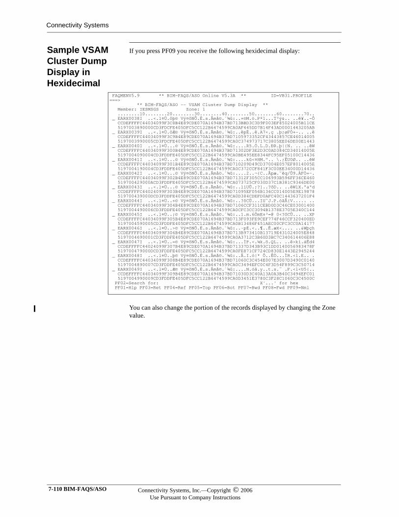
Connectivity Systems
Sample VSAM Cluster Dump Display in Hexidecimal
If you press PF09 you receive the following hexidecimal display:
You can also change the portion of the records displayed by changing the Zone value.
FAQMENV5.9 ** BIM-FAQS/ASO Online V5.3A ** ID=VB31.PROFILE ===> ** BIM-FAQS/ASO -- VSAM Cluster Dump Display ** Member: IESMSGS Zone: 1 ........10........20........30........40........50........60........70.. _ EARX0038I ..<.l¤Ù.õþ© Vý¤öNÖ.É.s.Ãmå©.`¾ü:..שM.ò.Pº1...T³ý&.. ..ë¥..-Ô CCDEFFFFC44034099F3C8B4E89CDE070A1694B37BD713BBD3C3D9F003EF85024005B11CE 5197003890000CD3FDCFE405DFC5CC122B6474599CA0AF445DD7B14F43AD0001443205AB _ EARX0039I ..<.l¤Ù.õÆ© Vý¤öNÖ.É.s.Ãmå©.`¾ü:..ëpÈ..ë.A7<.ç .þ;øFÒ+-.. ..ë CCDEFFFFC44034099F3C9B4E89CDE070A1694B37BD7105973352CF43443857CE46014005 5197003990005CD3FDCFE405DFC5CC122B6474599CA0C374973717C3805EE06DE00E1443 _ EARX0040I ..<.l¤Ù...© Vý¤öNÖ.É.s.Ãmå©.`¾ü:....R5.Ó.L.D.ÐR.þ|{N. .. ..ëW CCDEFFFFC44034099F300B4E89CDE070A1694B37BD71302DF3E2D3C0AD384CD34014005E 5197004090004CD3FDDFE405DFC5CC122B6474599CA0BE495EE8344FC95EF05100C14436 _ EARX0041I ..<.l¤Ù...© Vý¤öNÖ.É.s.Ãmå©.`¾ü:....kü<¤HM.".. \.;ËU0Ø.. ..ëW CCDEFFFFC44034099F301B4E89CDE070A1694B37BD710209D49CD37004E057EF8014005E 5197004190004CD3FDDFE405DFC5CC122B6474599CA0C372CCF841F3C00EE34000D14436 _ EARX0042I ..<.l¤Ù...© Vý¤öNÖ.É.s.Ãmå©.`¾ü:....2..¬{C..Äpæ.¨ëq/Ü9.ÀFÒ+-. CCDEFFFFC44034099F302B4E89CDE070A1694B37BD71312F305CC106993B596FF36CE460 519700429000ACD3FDDFE405DFC5CC122B6474599CA073725CF030D37C1B381C9346DE00 _ EARX0043I ..<.l¤Ù...© Vý¤öNÖ.É.s.Ãmå©.`¾ü:..lìUÜ.;?]..?öD.. ..ëWlX.°a"d CCDEFFFFC44024099F303B4E89CDE070A1694B37BD71095EF056B136CC014005E9E19878 519700439000DCD3FDDFE405DFC5CC122B6474599CA0D384CDEFD0AFC40C1443637201F4 _ EARX0044I ..<.l¤Ù..+© Vý¤öNÖ.É.s.Ãmå©.`¾ü:..?öCÜ...IU¨J.P.óäÅ{V..... .. CCDEFFFFC44034099F304B4E89CDE070A1694B37BD7106CCF311CEBD0D3C46CE03001400 5197004490006CD3FDDFE405DFC5CC122B6474599CA0CFC3CC3094B1378E3705E340C144 _ EARX0045I ..<.l¤Ù..;© Vý¤öNÖ.É.s.Ãmå©.`¾ü:..1.m.6ÕmE÷³=@ 0<?öCÜ... ..XP CCDEFFFFC44034099F305B4E89CDE070A1694B37BD713F093FE9CEF774F46CCF320400ED 5197004590005CD3FDDFE405DFC5CC122B6474599CA0B13486F451AEC00CFC3CC0A14177 _ EARX0046I ..<.l¤Ù..>© Vý¤öNÖ.É.s.Ãmå©.`¾ü:..·pÉ.<..¶..Ë.æX<.... ..&Wþçh CCDEFFFFC44034099F306B4E89CDE070A1694B37BD713B973410B13719E431024005E848 5197004690001CD3FDDFE405DFC5CC122B6474599CA0A3712C3B60D3BC7C340614406E88 _ EARX0047I ..<.l¤Ù..=© Vý¤öNÖ.É.s.Ãmå©.`¾ü:...ÌP.<.¼k.ö.QL.. ..ë>ki.áÊd4 CCDEFFFFC44024099F307B4E89CDE070A1694B37BD71337D343B93C1DD0140056983478F 519700479000DCD3FDDFE405DFC5CC122B6474599CA0FE871CF724CD830E1443E2945244 _ EARX0048I ..<.l¤Ù..þ© Vý¤öNÖ.É.s.Ãmå©.`¾ü:..Ä.I.ó|* Ö..ËÒ...ÌR.<l.E.. . CCDEFFFFC44034099F308B4E89CDE070A1694B37BD71060C3C454E007E3007D3490C0140 5197004890007CD3FDDFE405DFC5CC122B6474599CA0C3494EFC0C4F3D54F899C3C50714 _ EARX0049I ..<.l¤Ù..Æ© Vý¤öNÖ.É.s.Ãmå©.`¾ü:....N.óä.y..t.s.¯ .F.<l<U5{.. CCDEFFFFC44034099F309B4E89CDE070A1694B37BD71030D3C40A13A0A3B40C3494EFC01 5197004990009CD3FDDFE405DFC5CC122B6474599CA0D3451E3780C3F28C1060C3C4500C PF02=Search for: X'...' for hex PF01=Hlp PF03=Ret PF04=Ref PF05=Top PF06=Bot PF07=Bwd PF08=Fwd PF09=Nml
7-110 BIM-FAQS/ASO Connectivity Systems, Inc.—Copyright © 2006Use Pursuant to Company Instructions
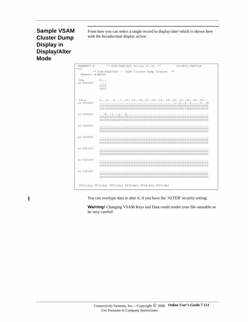
Sample VSAM Cluster Dump Display in Display/Alter Mode
From here you can select a single record to display/alter which is shown here with the hexadecimal display active:
You can overtype data to alter it, if you have the 'ALTER' security setting.
Warning! Changing VSAM Keys and Data could render your file unusable so be very careful!
FAQMENV5.9 ** BIM-FAQS/ASO Online V5.3A ** ID=VB31.PROFILE ===> ** BIM-FAQS/ASO -- VSAM Cluster Dump Display ** Member: BIMUCAT Key 0... +x'000000' .... 0000 0003 Data 0...4...8...C..10..14..18..1C..20..24..28..2C..30..34..38..3C... +x'000000' ............................................L..Z..X..O.....ö...M 00000000000000000000000000000000000000000000D00E00E00D00300C000D 00030000000000000000000000000000000000000000301901700600003C0034 +x'000040' ...M...4...q...q................................................ 000D000F00090009000100000000000000000000000000000000000000000000 0034003400480048000C00180000000000000000000000000000000000000000 +x'000080' ................................................................ 0000000000000000000000000000000000000000000000000000000000000000 0000000000000000000000000000000000000000000000000000000000000000 +x'0000C0' ................................................................ 0000000000000000000000000000000000000000000000000000000000000000 0000000000000000000000000000000000000000000000000000000000000000 +x'000100' ................................................................ 0000000000000000000000000000000000000000000000000000000000000000 0000000000000000000000000000000000000000000000000000000000000000 +x'000140' ................................................................ 0000000000000000000000000000000000000000000000000000000000000000 0000000000000000000000000000000000000000000000000000000000000000 +x'000180' ................................................................ 0000000000000000000000000000000000000000000000000000000000000000 0000000000000000000000000000000000000000000000000000000000000000 PF01=Hlp PF03=Ret PF04=Ref PF06=Wrt PF08=Fwd PF09=Nml
Connectivity Systems, Inc.—Copyright © 2006Use Pursuant to Company Instructions
Online User’s Guide 7-111
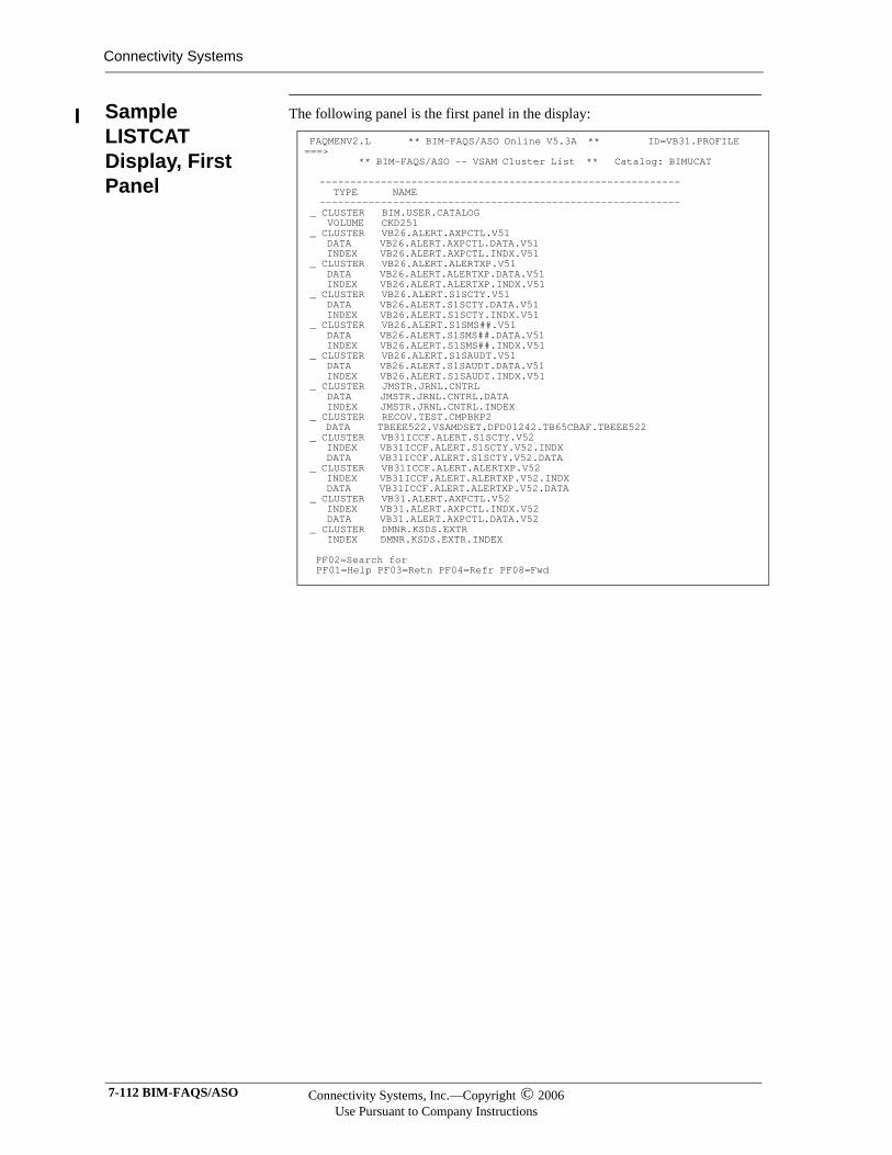
Connectivity Systems
Sample LISTCAT Display, First Panel
The following panel is the first panel in the display:
FAQMENV2.L ** BIM-FAQS/ASO Online V5.3A ** ID=VB31.PROFILE ===> ** BIM-FAQS/ASO -- VSAM Cluster List ** Catalog: BIMUCAT ----------------------------------------------------------- TYPE NAME ----------------------------------------------------------- _ CLUSTER BIM.USER.CATALOG VOLUME CKD251 _ CLUSTER VB26.ALERT.AXPCTL.V51 DATA VB26.ALERT.AXPCTL.DATA.V51 INDEX VB26.ALERT.AXPCTL.INDX.V51 _ CLUSTER VB26.ALERT.ALERTXP.V51 DATA VB26.ALERT.ALERTXP.DATA.V51 INDEX VB26.ALERT.ALERTXP.INDX.V51 _ CLUSTER VB26.ALERT.S1SCTY.V51 DATA VB26.ALERT.S1SCTY.DATA.V51 INDEX VB26.ALERT.S1SCTY.INDX.V51 _ CLUSTER VB26.ALERT.S1SMS##.V51 DATA VB26.ALERT.S1SMS##.DATA.V51 INDEX VB26.ALERT.S1SMS##.INDX.V51 _ CLUSTER VB26.ALERT.S1SAUDT.V51 DATA VB26.ALERT.S1SAUDT.DATA.V51 INDEX VB26.ALERT.S1SAUDT.INDX.V51 _ CLUSTER JMSTR.JRNL.CNTRL DATA JMSTR.JRNL.CNTRL.DATA INDEX JMSTR.JRNL.CNTRL.INDEX _ CLUSTER RECOV.TEST.CMPBKP2 DATA TBEEE522.VSAMDSET.DFD01242.TB65CBAF.TBEEE522 _ CLUSTER VB31ICCF.ALERT.S1SCTY.V52 INDEX VB31ICCF.ALERT.S1SCTY.V52.INDX DATA VB31ICCF.ALERT.S1SCTY.V52.DATA _ CLUSTER VB31ICCF.ALERT.ALERTXP.V52 INDEX VB31ICCF.ALERT.ALERTXP.V52.INDX DATA VB31ICCF.ALERT.ALERTXP.V52.DATA _ CLUSTER VB31.ALERT.AXPCTL.V52 INDEX VB31.ALERT.AXPCTL.INDX.V52 DATA VB31.ALERT.AXPCTL.DATA.V52 _ CLUSTER DMNR.KSDS.EXTR INDEX DMNR.KSDS.EXTR.INDEX PF02=Search for PF01=Help PF03=Retn PF04=Refr PF08=Fwd
7-112 BIM-FAQS/ASO Connectivity Systems, Inc.—Copyright © 2006Use Pursuant to Company Instructions
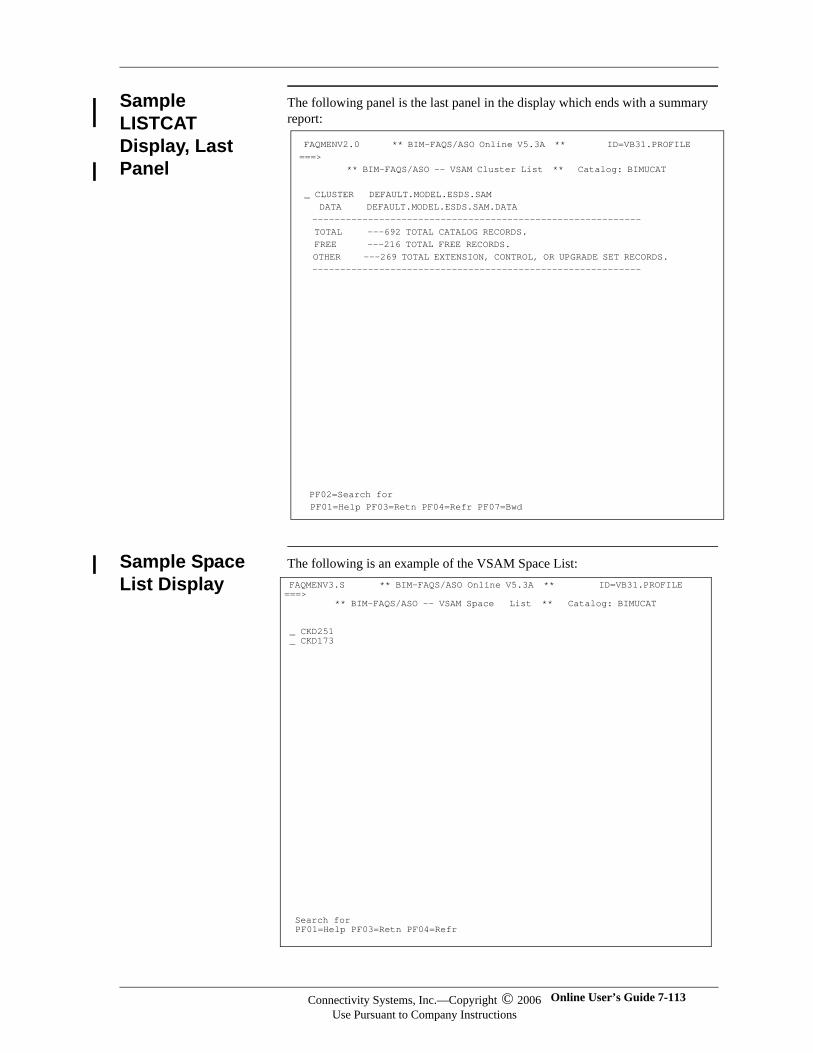
Sample LISTCAT Display, Last Panel
The following panel is the last panel in the display which ends with a summary report:
Sample Space List Display
The following is an example of the VSAM Space List:
FAQMENV2.0 ** BIM-FAQS/ASO Online V5.3A ** ID=VB31.PROFILE ===> ** BIM-FAQS/ASO -- VSAM Cluster List ** Catalog: BIMUCAT _ CLUSTER DEFAULT.MODEL.ESDS.SAM DATA DEFAULT.MODEL.ESDS.SAM.DATA ----------------------------------------------------------- TOTAL ---692 TOTAL CATALOG RECORDS. FREE ---216 TOTAL FREE RECORDS. OTHER ---269 TOTAL EXTENSION, CONTROL, OR UPGRADE SET RECORDS. -----------------------------------------------------------
PF02=Search for PF01=Help PF03=Retn PF04=Refr PF07=Bwd
FAQMENV3.S ** BIM-FAQS/ASO Online V5.3A ** ID=VB31.PROFILE ===> ** BIM-FAQS/ASO -- VSAM Space List ** Catalog: BIMUCAT _ CKD251 _ CKD173
Search for PF01=Help PF03=Retn PF04=Refr
Connectivity Systems, Inc.—Copyright © 2006Use Pursuant to Company Instructions
Online User’s Guide 7-113
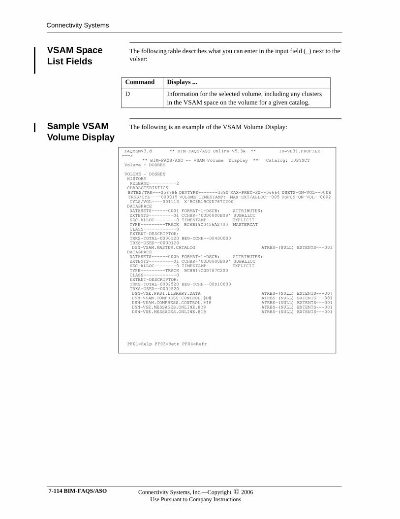
Connectivity Systems
VSAM Space List Fields
The following table describes what you can enter in the input field (_) next to the volser:
Sample VSAM Volume Display
The following is an example of the VSAM Volume Display:
Command Displays ...
D Information for the selected volume, including any clusters in the VSAM space on the volume for a given catalog.
FAQMENV3.d ** BIM-FAQS/ASO Online V5.3A ** ID=VB31.PROFILE ===> ** BIM-FAQS/ASO -- VSAM Volume Display ** Catalog: IJSYSCT Volume : DOSRES VOLUME - DOSRES HISTORY RELEASE----------2 CHARACTERISTICS BYTES/TRK---058786 DEVTYPE-------3390 MAX-PREC-SZ--56664 DSETS-ON-VOL--0008 TRKS/CYL----000015 VOLUME-TIMESTAMP: MAX-EXT/ALLOC--005 DSPCS-ON-VOL--0002 CYLS/VOL----001113 X'BC8B19C0D787C200' DATASPACE DATASETS------0001 FORMAT-1-DSCB: ATTRIBUTES: EXTENTS---------01 CCHHR-'00D0000B08' SUBALLOC SEC-ALLOC--------0 TIMESTAMP EXPLICIT TYPE---------TRACK BC8B19C0456A2700 MASTERCAT CLASS------------0 EXTENT-DESCRIPTOR: TRKS-TOTAL-0000120 BEG-CCHH--00400000 TRKS-USED--0000120 DSN-VSAM.MASTER.CATALOG ATRBS-(NULL) EXTENTS---003 DATASPACE DATASETS------0005 FORMAT-1-DSCB: ATTRIBUTES: EXTENTS---------01 CCHHR-'00D0000B09' SUBALLOC SEC-ALLOC--------0 TIMESTAMP EXPLICIT TYPE---------TRACK BC8B19C0D787C200 CLASS------------0 EXTENT-DESCRIPTOR: TRKS-TOTAL-0002520 BEG-CCHH--00D10000 TRKS-USED--0002520 DSN-VSE.PRD1.LIBRARY.DATA ATRBS-(NULL) EXTENTS---007 DSN-VSAM.COMPRESS.CONTROL.@D@ ATRBS-(NULL) EXTENTS---001 DSN-VSAM.COMPRESS.CONTROL.@I@ ATRBS-(NULL) EXTENTS---001 DSN-VSE.MESSAGES.ONLINE.@D@ ATRBS-(NULL) EXTENTS---001 DSN-VSE.MESSAGES.ONLINE.@I@ ATRBS-(NULL) EXTENTS---001 PF01=Help PF03=Retn PF04=Refr
7-114 BIM-FAQS/ASO Connectivity Systems, Inc.—Copyright © 2006Use Pursuant to Company Instructions
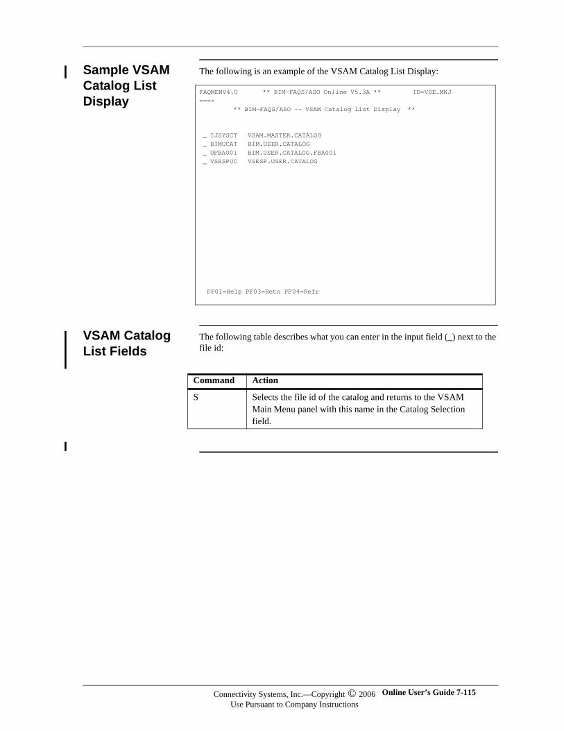
Sample VSAM Catalog List Display
The following is an example of the VSAM Catalog List Display:
VSAM Catalog List Fields
The following table describes what you can enter in the input field (_) next to the file id:
FAQMENV4.U ** BIM-FAQS/ASO Online V5.3A ** ID=VSE.MKJ ===> ** BIM-FAQS/ASO -- VSAM Catalog List Display ** _ IJSYSCT VSAM.MASTER.CATALOG _ BIMUCAT BIM.USER.CATALOG _ UFBA001 BIM.USER.CATALOG.FBA001 _ VSESPUC VSESP.USER.CATALOG PF01=Help PF03=Retn PF04=Refr
Command Action
S Selects the file id of the catalog and returns to the VSAM Main Menu panel with this name in the Catalog Selection field.
Connectivity Systems, Inc.—Copyright © 2006Use Pursuant to Company Instructions
Online User’s Guide 7-115

Connectivity Systems
7-116 BIM-FAQS/ASO Connectivity Systems, Inc.—Copyright © 2006Use Pursuant to Company Instructions
Chapter 8
Extended Map/Debug
Support
In This Chapter
This chapter explains the Extended Map/Debug panels.
Overview The Extended Map/Debug panels provide access to information about the extended map, GETVIS, and debug support.
On each of the Map/Debug panels, there are areas, other than the input fields, that you can tab to. If you tab to one of these areas and press ENTER, that location in storage is displayed. This is similar to the DSPLY command described in Chapter 7, “Online Displays and Reports.” For example, if you tab to a control block address and press ENTER, BIM-FAQS/ASO displays that address's control block storage area. An example of storage display is provided later in this chapter.
Online User’s Guide 8-1
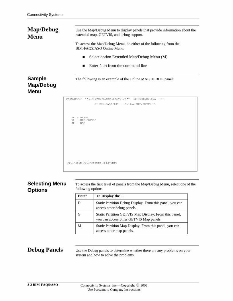
Connectivity Systems
Map/Debug Menu
Use the Map/Debug Menu to display panels that provide information about the extended map, GETVIS, and debug support.
To access the Map/Debug Menu, do either of the following from the BIM-FAQS/ASO Online Menu:
Select option Extended Map/Debug Menu (M)
Enter 2.M from the command line
Sample Map/Debug Menu
The following is an example of the Online MAP/DEBUG panel:
Selecting Menu Options
To access the first level of panels from the Map/Debug Menu, select one of the following options:
Debug Panels Use the Debug panels to determine whether there are any problems on your system and how to solve the problems.
FAQMENMP.M ** BIM-FAQS/ASO Online V5.3A ** ID=TECHVSE.SJA ===>
** BIM-FAQS/ASO -- Online MAP/DEBUG **
D - DEBUG G - MAP GETVIS M - MAP PF01=Help PF03=Return PF12=Exit
Enter To Display the ...
D Static Partition Debug Display. From this panel, you can access other debug panels.
G Static Partition GETVIS Map Display. From this panel, you can access other GETVIS Map panels.
M Static Partition Map Display. From this panel, you can access other map panels.
8-2 BIM-FAQS/ASO Connectivity Systems, Inc.—Copyright © 2006Use Pursuant to Company Instructions
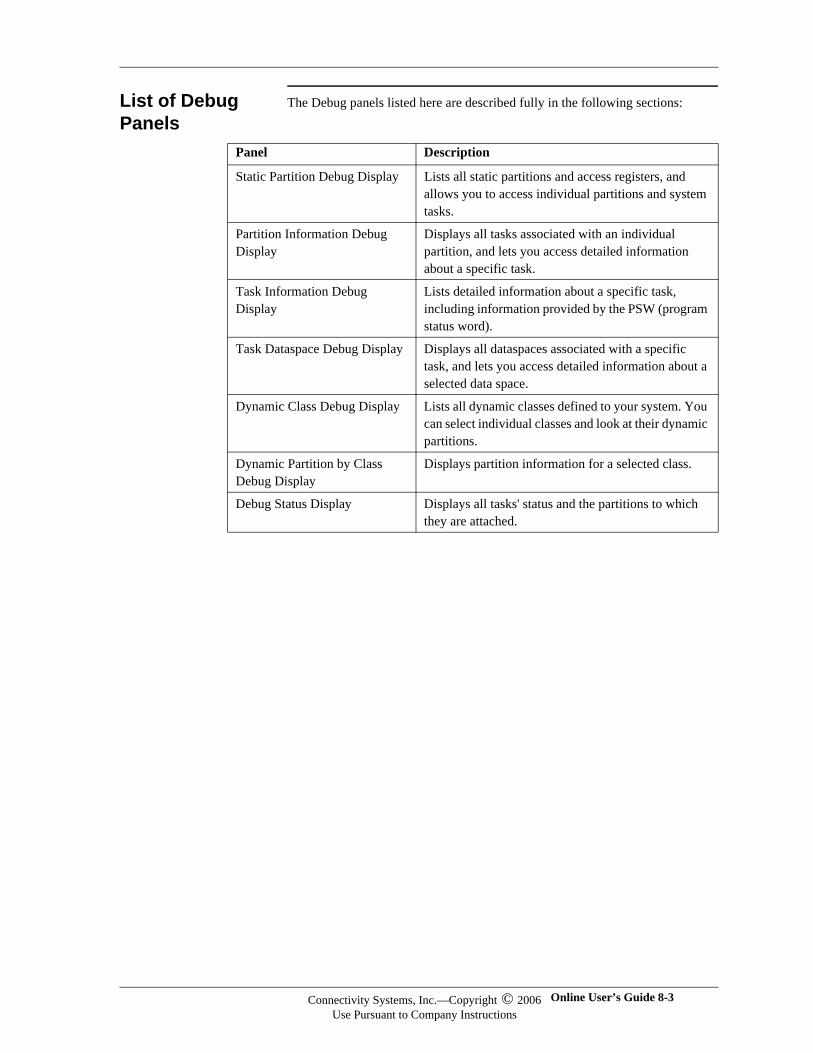
List of Debug Panels
The Debug panels listed here are described fully in the following sections:
Panel Description
Static Partition Debug Display Lists all static partitions and access registers, and allows you to access individual partitions and system tasks.
Partition Information Debug Display
Displays all tasks associated with an individual partition, and lets you access detailed information about a specific task.
Task Information Debug Display
Lists detailed information about a specific task, including information provided by the PSW (program status word).
Task Dataspace Debug Display Displays all dataspaces associated with a specific task, and lets you access detailed information about a selected data space.
Dynamic Class Debug Display Lists all dynamic classes defined to your system. You can select individual classes and look at their dynamic partitions.
Dynamic Partition by Class Debug Display
Displays partition information for a selected class.
Debug Status Display Displays all tasks' status and the partitions to which they are attached.
Connectivity Systems, Inc.—Copyright © 2006Use Pursuant to Company Instructions
Online User’s Guide 8-3
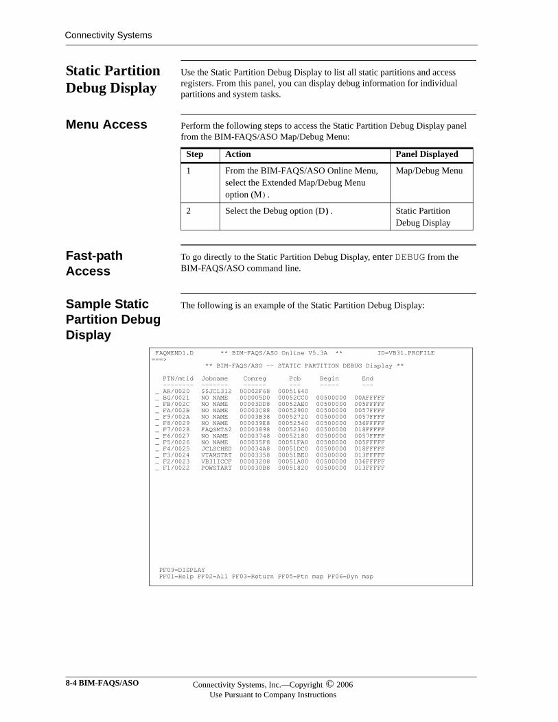
Connectivity Systems
Static Partition Debug Display
Use the Static Partition Debug Display to list all static partitions and access registers. From this panel, you can display debug information for individual partitions and system tasks.
Menu Access Perform the following steps to access the Static Partition Debug Display panel from the BIM-FAQS/ASO Map/Debug Menu:
Fast-path Access
To go directly to the Static Partition Debug Display, enter DEBUG from the BIM-FAQS/ASO command line.
Sample Static Partition Debug Display
The following is an example of the Static Partition Debug Display:
Step Action Panel Displayed
1 From the BIM-FAQS/ASO Online Menu, select the Extended Map/Debug Menu option (M).
Map/Debug Menu
2 Select the Debug option (D). Static Partition Debug Display
FAQMEND1.D ** BIM-FAQS/ASO Online V5.3A ** ID=VB31.PROFILE ===> ** BIM-FAQS/ASO -- STATIC PARTITION DEBUG Display ** PTN/mtid Jobname Comreg Pcb Begin End -------- ------- ------ --- ----- --- _ AR/0020 $$JCL312 00002F68 00051640 _ BG/0021 NO NAME 000005D0 00052CC0 00500000 00AFFFFF _ FB/002C NO NAME 00003DD8 00052AE0 00500000 005FFFFF _ FA/002B NO NAME 00003C88 00052900 00500000 0057FFFF _ F9/002A NO NAME 00003B38 00052720 00500000 0057FFFF _ F8/0029 NO NAME 000039E8 00052540 00500000 036FFFFF _ F7/0028 FAQSMTS2 00003898 00052360 00500000 018FFFFF _ F6/0027 NO NAME 00003748 00052180 00500000 0057FFFF _ F5/0026 NO NAME 000035F8 00051FA0 00500000 005FFFFF _ F4/0025 JCLSCHED 000034A8 00051DC0 00500000 018FFFFF _ F3/0024 VTAMSTRT 00003358 00051BE0 00500000 013FFFFF _ F2/0023 VB31ICCF 00003208 00051A00 00500000 036FFFFF _ F1/0022 POWSTART 000030B8 00051820 00500000 013FFFFF
PF09=DISPLAY PF01=Help PF02=All PF03=Return PF05=Ptn map PF06=Dyn map
8-4 BIM-FAQS/ASO Connectivity Systems, Inc.—Copyright © 2006Use Pursuant to Company Instructions
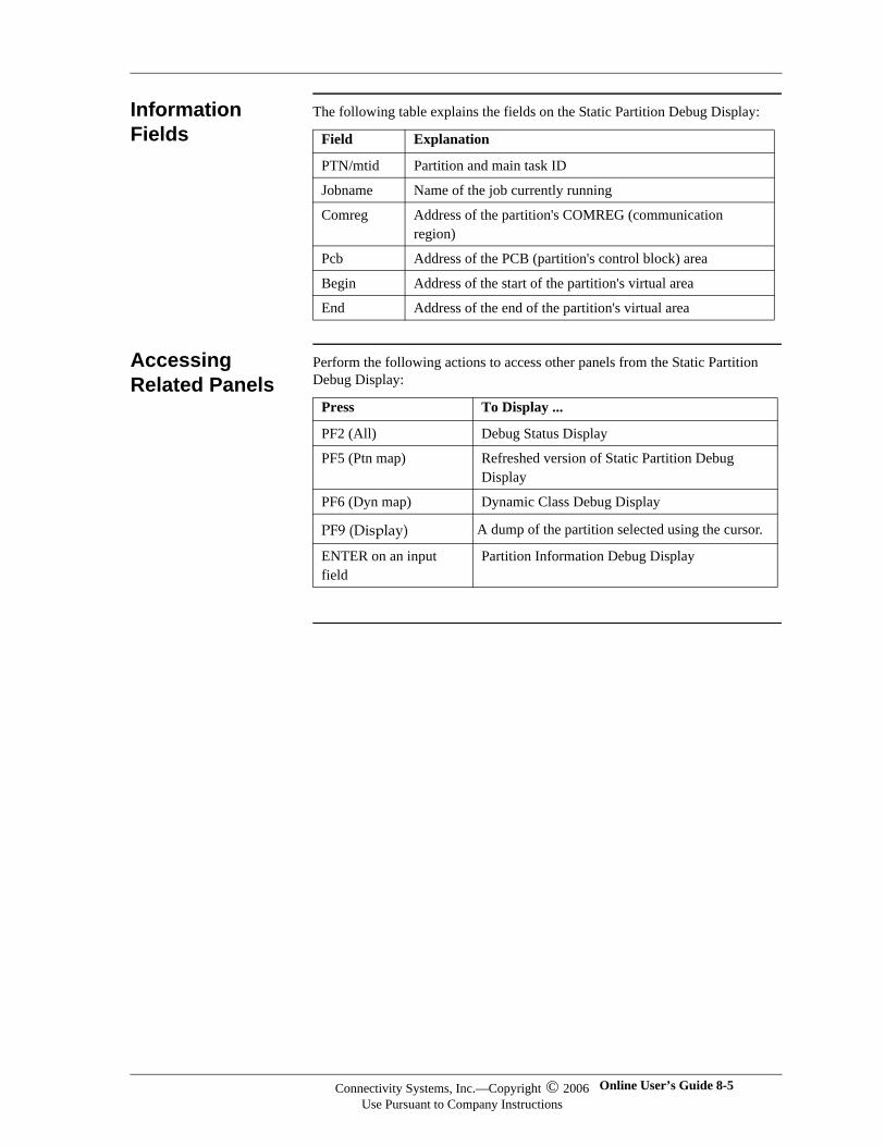
Information Fields
The following table explains the fields on the Static Partition Debug Display:
Accessing Related Panels
Perform the following actions to access other panels from the Static Partition Debug Display:
Field Explanation
PTN/mtid Partition and main task ID
Jobname Name of the job currently running
Comreg Address of the partition's COMREG (communication region)
Pcb Address of the PCB (partition's control block) area
Begin Address of the start of the partition's virtual area
End Address of the end of the partition's virtual area
Press To Display ...
PF2 (All) Debug Status Display
PF5 (Ptn map) Refreshed version of Static Partition Debug Display
PF6 (Dyn map) Dynamic Class Debug Display
PF9 (Display) A dump of the partition selected using the cursor.
ENTER on an input field
Partition Information Debug Display
Connectivity Systems, Inc.—Copyright © 2006Use Pursuant to Company Instructions
Online User’s Guide 8-5
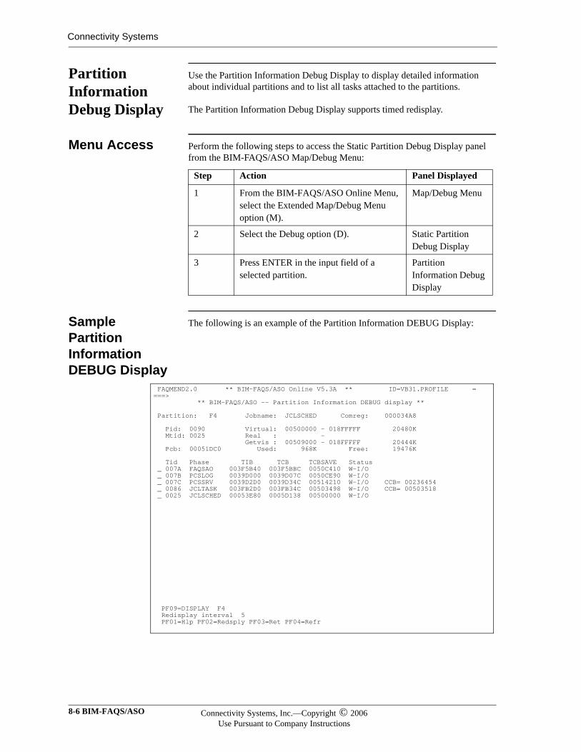
Connectivity Systems
Partition Information Debug Display
Use the Partition Information Debug Display to display detailed information about individual partitions and to list all tasks attached to the partitions.
The Partition Information Debug Display supports timed redisplay.
Menu Access Perform the following steps to access the Static Partition Debug Display panel from the BIM-FAQS/ASO Map/Debug Menu:
Sample Partition Information DEBUG Display
The following is an example of the Partition Information DEBUG Display:
Step Action Panel Displayed
1 From the BIM-FAQS/ASO Online Menu, select the Extended Map/Debug Menu option (M).
Map/Debug Menu
2 Select the Debug option (D). Static Partition Debug Display
3 Press ENTER in the input field of a selected partition.
Partition Information Debug Display
FAQMEND2.0 ** BIM-FAQS/ASO Online V5.3A ** ID=VB31.PROFILE ====> ** BIM-FAQS/ASO -- Partition Information DEBUG display ** Partition: F4 Jobname: JCLSCHED Comreg: 000034A8 Pid: 0090 Virtual: 00500000 - 018FFFFF 20480K Mtid: 0025 Real : - Getvis : 00509000 - 018FFFFF 20444K Pcb: 00051DC0 Used: 968K Free: 19476K Tid Phase TIB TCB TCBSAVE Status _ 007A FAQSAO 003F5B40 003F5BBC 0050C410 W-I/O _ 007B PCSLOG 0039D000 0039D07C 0050CE90 W-I/O _ 007C PCSSRV 0039D2D0 0039D34C 00514210 W-I/O CCB= 00236454 _ 0086 JCLTASK 003FB2D0 003FB34C 00503498 W-I/O CCB= 00503518 _ 0025 JCLSCHED 00053E80 0005D138 00500000 W-I/O
PF09=DISPLAY F4 Redisplay interval 5 PF01=Hlp PF02=Redsply PF03=Ret PF04=Refr
8-6 BIM-FAQS/ASO Connectivity Systems, Inc.—Copyright © 2006Use Pursuant to Company Instructions
Information Fields
The following table explains the fields on the Partition Information Debug Display:
Task Display Line Fields
Each task display line on the Partition Information Debug Display contains the following fields:
Field Explanation
Partition Partition
Jobname Name of the job currently running
Comreg Address of the partition's COMREG (communication region)
Pid Partition ID
Mtid Partition main task ID
Pcb Address of the PCB (partition's control block) area
Virtual Address of the start and end of the partition's virtual area, and the associated length
Real Address of the start and end of the partition's real area, and the associated length
Getvis Address of the start and end of the partition's GETVIS area, and the associated length
Used Amount of allocated GETVIS area that is currently in use
Free Amount of allocated GETVIS area that is currently free to be used
Field Explanation
Tid The entry's task ID.
Phase Name of the phase currently running.
TIB Address of the TIB (Task Information Block) associated with this task.
TCB Address of the TCB (Task Control Block) associated with this task.
TCBSAVE
Address of the Task Control Block save area associated with this task.
Status Current status of the task. Indicates whether the task is ready to run or is waiting on a resource or the posting of a CCB/ECB. If this task is waiting on I/O, then information related to the address of the I/O is also provided (CCB=...).
Connectivity Systems, Inc.—Copyright © 2006Use Pursuant to Company Instructions
Online User’s Guide 8-7
Connectivity Systems
Timed Redisplay Options
The following options allow you to activate or modify the timed redisplay option for the Partition Information DEBUG Display:
Accessing Related Panels
Perform the following actions to access other panels from the Partition Information Debug Display:
Option Explanation
Redisplay Interval: Time delay before the screen is refreshed in redisplay mode.Values are 0-255 seconds. 5 is the default.
PF02=Redsply Activates redisplay mode. Redisplay Mode appears next to the redisplay interval.
Press To Display ...
PF4 (Refresh) Refreshed version of Partition Information Debug Display
ENTER on an input field
Task Information Debug Display, which shows detailed information about the selected task.For information about the Task Information Debug Display, see the next section.
8-8 BIM-FAQS/ASO Connectivity Systems, Inc.—Copyright © 2006Use Pursuant to Company Instructions
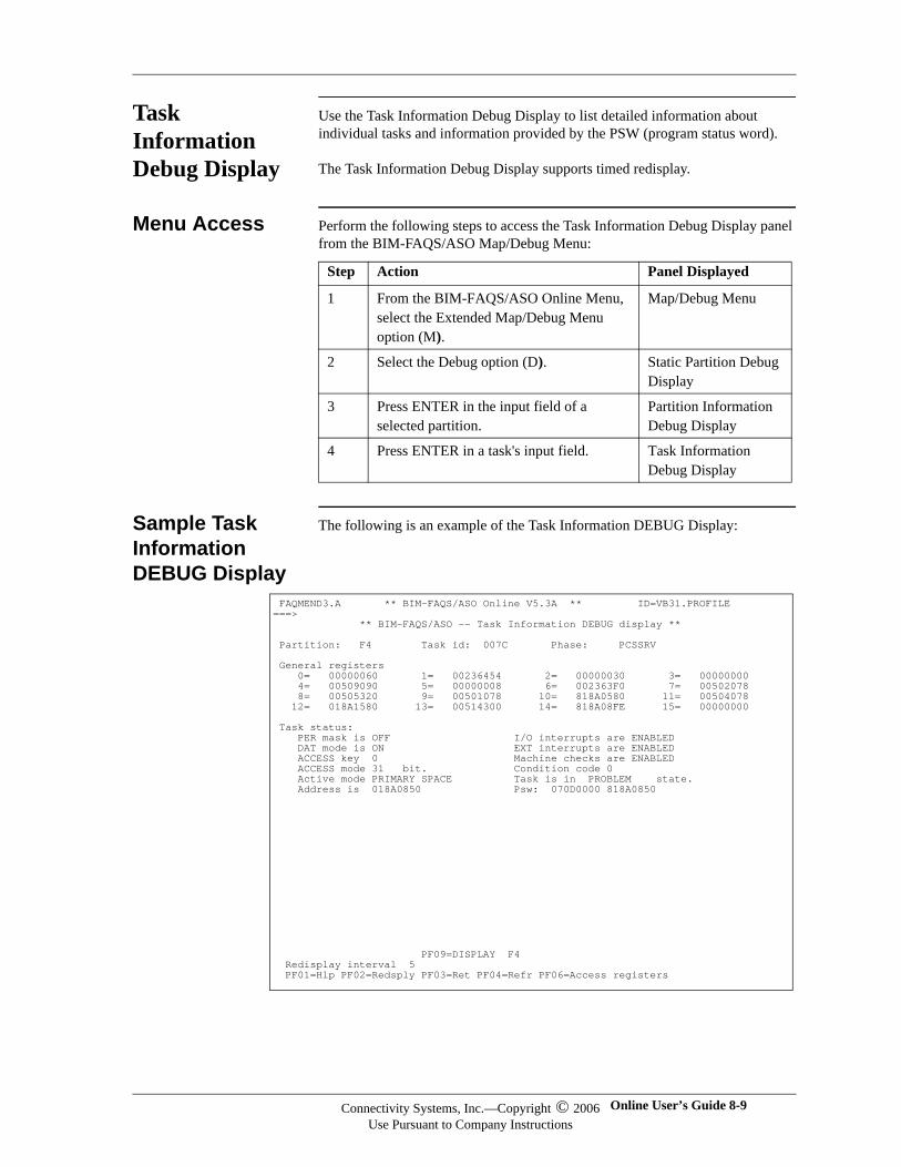
Task Information Debug Display
Use the Task Information Debug Display to list detailed information about individual tasks and information provided by the PSW (program status word).
The Task Information Debug Display supports timed redisplay.
Menu Access Perform the following steps to access the Task Information Debug Display panel from the BIM-FAQS/ASO Map/Debug Menu:
Sample Task Information DEBUG Display
The following is an example of the Task Information DEBUG Display:
Step Action Panel Displayed
1 From the BIM-FAQS/ASO Online Menu, select the Extended Map/Debug Menu option (M).
Map/Debug Menu
2 Select the Debug option (D). Static Partition Debug Display
3 Press ENTER in the input field of a selected partition.
Partition Information Debug Display
4 Press ENTER in a task's input field. Task Information Debug Display
FAQMEND3.A ** BIM-FAQS/ASO Online V5.3A ** ID=VB31.PROFILE ===> ** BIM-FAQS/ASO -- Task Information DEBUG display ** Partition: F4 Task id: 007C Phase: PCSSRV General registers 0= 00000060 1= 00236454 2= 00000030 3= 00000000 4= 00509090 5= 00000008 6= 002363F0 7= 00502078 8= 00505320 9= 00501078 10= 818A0580 11= 00504078 12= 018A1580 13= 00514300 14= 818A08FE 15= 00000000 Task status: PER mask is OFF I/O interrupts are ENABLED DAT mode is ON EXT interrupts are ENABLED ACCESS key 0 Machine checks are ENABLED ACCESS mode 31 bit. Condition code 0 Active mode PRIMARY SPACE Task is in PROBLEM state. Address is 018A0850 Psw: 070D0000 818A0850
PF09=DISPLAY F4 Redisplay interval 5 PF01=Hlp PF02=Redsply PF03=Ret PF04=Refr PF06=Access registers
Connectivity Systems, Inc.—Copyright © 2006Use Pursuant to Company Instructions
Online User’s Guide 8-9
Connectivity Systems
Task Information Fields
The following fields on the Task Information Debug Display contain information about tasks:
Task Status Fields
The following fields on the Task Information Debug Display provide task status information:
Field Explanation
Partition Partition this task is associated with.
Task id Entry's task ID.
Phase Name of the phase currently running in this task.
General Registers General registers associated with this task, as found in the TCBSAVE (Task Control Block save area). Use PF06 (Access registers) to display the Access registers.
Access Registers Access registers associated with this task, as found in the TCBARSAV (Task Control Block save area). Use PF06 (General registers) to display the General registers.
Field Explanation
PER mask is Program-event recording interrupts are enabled (ON), or disabled (OFF).
DAT mode is Either dynamic-address translation of logical and instruction addresses is invoked (ON), or all addresses are treated as real addresses (OFF).
ACCESS key Key used to compare with the key of a storage area, to determine whether this task can perform the requested function.
ACCESS mode Determines whether effective address range is 24-bit, 0-FFFFFF or 31-bit, 0-7FFFFFFF.
Active mode One of the following:REAL mode (active anytime DAT mode is OFF)PRIMARY SPACE modeSECONDARY SPACE modeACCESS REGISTER modeHOME SPACE mode
Address is Address of the next instruction to be executed when this task is dispatched by the supervisor.
I/O interrupts are Determines whether I/O interrupts are permitted (ENABLED) or not (DISABLED).
EXT interrupts are
Determines whether external interrupts are permitted (ENABLED) or not (DISABLED).
8-10 BIM-FAQS/ASO Connectivity Systems, Inc.—Copyright © 2006Use Pursuant to Company Instructions
Timed Redisplay Options
The following options allow you to activate or modify the timed redisplay option for the Task Information DEBUG Display:
Accessing Related Panels
The following table lists the PF keys and the panels you can access from the Task Information Debug Display:
Machine checks are
Determines whether machine check interrupts are permitted (ENABLED) or not (DISABLED).
Condition code Current condition code for this task. Possible value is 0, 1, 2, or 3.
Task is in ... state Current state of the task. Values are WAIT, PROBLEM, and SUPERVISOR.
Psw Task's current program status word, which was used to determine the task status information.
Field Explanation
Option Explanation
Redisplay Interval: Time delay before the screen is refreshed in redisplay mode.Values are 0-255 seconds. 5 is the default.
PF02=Redisplay Activates redisplay mode. Redisplay Mode appears next to the redisplay interval.
Press To Display ...
PF4 (Refresh) Refreshed version of Task Information Debug Display
PF5 (Data spaces) Task Dataspace Debug Display, which shows detailed information about the task's data spaces. This PF key option appears only when the task owns several data spaces.
PF6 (Access/General registers) Access registers or general registers (toggle)
PF9 (Display) Storage for the partition that you select. This can be used instead of the cursor, such as when using the CGI interface.
Connectivity Systems, Inc.—Copyright © 2006Use Pursuant to Company Instructions
Online User’s Guide 8-11
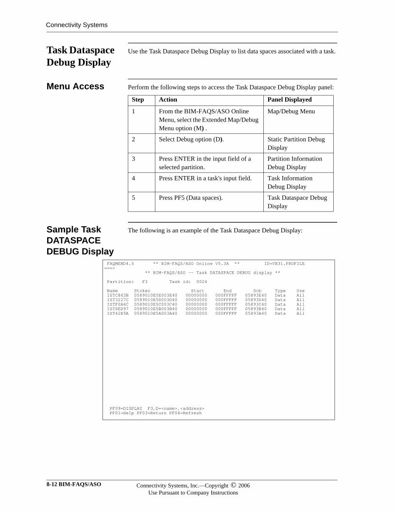
Connectivity Systems
Task Dataspace Debug Display
Use the Task Dataspace Debug Display to list data spaces associated with a task.
Menu Access Perform the following steps to access the Task Dataspace Debug Display panel:
Sample Task DATASPACE DEBUG Display
The following is an example of the Task Dataspace Debug Display:
Step Action Panel Displayed
1 From the BIM-FAQS/ASO Online Menu, select the Extended Map/Debug Menu option (M) .
Map/Debug Menu
2 Select Debug option (D). Static Partition Debug Display
3 Press ENTER in the input field of a selected partition.
Partition Information Debug Display
4 Press ENTER in a task's input field. Task Information Debug Display
5 Press PF5 (Data spaces). Task Dataspace Debug Display
FAQMEND4.5 ** BIM-FAQS/ASO Online V5.3A ** ID=VB31.PROFILE ===> ** BIM-FAQS/ASO -- Task DATASPACE DEBUG display ** Partition: F3 Task id: 0024 Name Stoken Start End Scb Type Use ISTC863B 0589010E5E003E40 00000000 000FFFFF 05893E40 Data All IST3227C 0589010E5D003D40 00000000 000FFFFF 05893D40 Data All ISTF0A6C 0589010E5C003C40 00000000 000FFFFF 05893C40 Data All IST6ED97 0589010E5B003B40 00000000 000FFFFF 05893B40 Data All IST42E9A 0589010E5A003A40 00000000 000FFFFF 05893A40 Data All
PF09=DISPLAY F3,D=<name>,<address> PF01=Help PF03=Return PF04=Refresh
8-12 BIM-FAQS/ASO Connectivity Systems, Inc.—Copyright © 2006Use Pursuant to Company Instructions
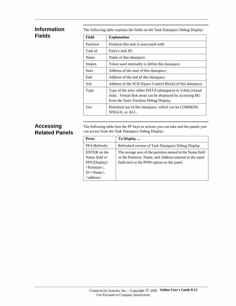
Information Fields
The following table explains the fields on the Task Dataspace Debug Display:
Accessing Related Panels
The following table lists the PF keys or actions you can take and the panels you can access from the Task Dataspace Debug Display:
Field Explanation
Partition Partition this task is associated with.
Task id Entry's task ID.
Name Name of this dataspace.
Stoken Token used internally to define this dataspace.
Start Address of the start of this dataspace.
End Address of the end of this dataspace.
Scb Address of the SCB (Space Control Block) of this dataspace.
Type Type of the area: either DATA (dataspace) or Vdisk (virtual disk). Virtual disk areas can be displayed by accessing BG from the Static Partition Debug Display.
Use Permitted use of this dataspace, which can be COMMON, SINGLE, or ALL.
Press To Display ...
PF4 (Refresh) Refreshed version of Task Dataspace Debug Display
ENTER on the Name field or PF9 (Display) <Partition>, D=<Name>, <address>
The storage area of the partition named in the Name field or the Partition, Name, and Address entered in the input field next to the PF09 option on the panel.
Connectivity Systems, Inc.—Copyright © 2006Use Pursuant to Company Instructions
Online User’s Guide 8-13
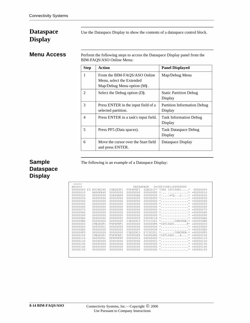
Connectivity Systems
Dataspace Display
Use the Dataspace Display to show the contents of a dataspace control block.
Menu Access Perform the following steps to access the Dataspace Display panel from the BIM-FAQS/ASO Online Menu:
Sample Dataspace Display
The following is an example of a Dataspace Display:
Step Action Panel Displayed
1 From the BIM-FAQS/ASO Online Menu, select the Extended Map/Debug Menu option (M) .
Map/Debug Menu
2 Select the Debug option (D). Static Partition Debug Display
3 Press ENTER in the input field of a selected partition.
Partition Information Debug Display
4 Press ENTER in a task's input field. Task Information Debug Display
5 Press PF5 (Data spaces). Task Dataspace Debug Display
6 Move the cursor over the Start field and press ENTER.
Dataspace Display
====> ASID=3 DATASPACE D=IST15681+00000000 00000000 F3 E5C4E240 C9E2E3F1 F5F6F8F1 02AC0107 *VDS IST15681....* 00000000 00000010 DE00FE40 00000000 00000000 00040000 *... ............* +00000010 00000020 00000000 02A64AD8 000000A8 00000000 *.....w¢Q...y....* +00000020 00000030 00000000 00000000 00000000 00000000 *................* +00000030 00000040 00000000 00000000 00000000 00000000 *................* +00000040 00000050 00000000 00000000 00000000 00000000 *................* +00000050 00000060 00000000 00000000 00000000 00000000 *................* +00000060 00000070 00000000 00000000 00000000 00000000 *................* +00000070 00000080 00000000 00000000 00000000 00000000 *................* +00000080 00000090 00000000 00000000 00000000 00000000 *................* +00000090 000000A0 00000000 00000000 00000003 00000C18 *................* +000000A0 000000B0 00000000 00000000 C3E2D9C3 D7C1C201 *........CSRCPAB.* +000000B0 000000C0 C9E2E3F1 F5F6F8F1 00040000 000000F8 *IST15681.......8* +000000C0 000000D0 00000001 00000000 00000000 00000000 *................* +000000D0 000000E0 00000000 00000000 00000000 00000000 *................* +000000E0 000000F0 00000000 00000000 C3E2D9C3 D7C5C201 *........CSRCPEB.* +000000F0 00000100 C9E2E3F1 F5F6F8F1 000000F8 00000480 *IST15681...8....* +00000100 00000110 00000001 FFFFFFFF 00000003 04000000 *................* +00000110 00000120 00040000 000C0000 000C0000 00000003 *................* +00000120 00000130 00000004 00000000 00000000 00000000 *................* +00000130 00000140 00000000 00000000 00000000 00000000 *................* +00000140 00000150 00000000 00000000 00000000 00000000 *................* +00000150
8-14 BIM-FAQS/ASO Connectivity Systems, Inc.—Copyright © 2006Use Pursuant to Company Instructions

Information Fields
The fields on the Dataspace Display are not labeled. They contain the following information:
Field Explanation
Line number Address where the line begins.
Hex code Hexadecimal number contained at the address.
Characters EBCDIC equivalent of the hexadecimal numbers. A period represents characters that the system cannot display.
Connectivity Systems, Inc.—Copyright © 2006Use Pursuant to Company Instructions
Online User’s Guide 8-15
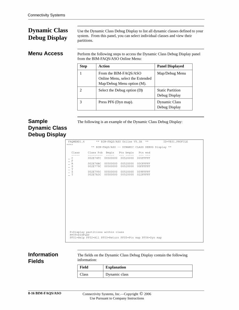
Connectivity Systems
Dynamic Class Debug Display
Use the Dynamic Class Debug Display to list all dynamic classes defined to your system. From this panel, you can select individual classes and view their partitions.
Menu Access Perform the following steps to access the Dynamic Class Debug Display panel from the BIM-FAQS/ASO Online Menu:
Sample Dynamic Class Debug Display
The following is an example of the Dynamic Class Debug Display:
Information Fields
The fields on the Dynamic Class Debug Display contain the following information:
Step Action Panel Displayed
1 From the BIM-FAQS/ASO Online Menu, select the Extended Map/Debug Menu option (M).
Map/Debug Menu
2 Select the Debug option (D) Static Partition Debug Display
3 Press PF6 (Dyn map). Dynamic Class Debug Display
FAQMEND1.6 ** BIM-FAQS/ASO Online V5.3A ** ID=VB31.PROFILE ===> ** BIM-FAQS/ASO -- DYNAMIC CLASS DEBUG Display ** Class Class Pcb Begin Ptn begin Ptn end ----- --------- ----- --- ----- --- --- _ C 002E74FC 00500000 00520000 005FFFFF _ P _ R 002E76BC 00500000 00520000 00CFFFFF _ S 002E779C 00500000 00520000 00FFFFFF _ Y _ Z 002E795C 00500000 00520000 009FFFFF _ T 002E7A3C 00500000 00520000 022FFFFF
P=Display partitions within class PF09=DISPLAY PF01=Help PF02=All PF03=Return PF05=Ptn map PF06=Dyn map
Field Explanation
Class Dynamic class
8-16 BIM-FAQS/ASO Connectivity Systems, Inc.—Copyright © 2006Use Pursuant to Company Instructions
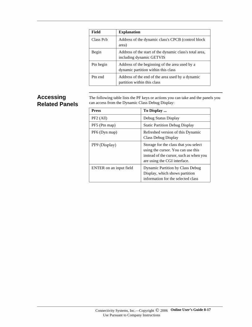
Accessing Related Panels
The following table lists the PF keys or actions you can take and the panels you can access from the Dynamic Class Debug Display:
Class Pcb Address of the dynamic class's CPCB (control block area)
Begin Address of the start of the dynamic class's total area, including dynamic GETVIS
Ptn begin Address of the beginning of the area used by a dynamic partition within this class
Ptn end Address of the end of the area used by a dynamic partition within this class
Field Explanation
Press To Display ...
PF2 (All) Debug Status Display
PF5 (Ptn map) Static Partition Debug Display
PF6 (Dyn map) Refreshed version of this Dynamic Class Debug Display
PF9 (Display) Storage for the class that you select using the cursor. You can use this instead of the cursor, such as when you are using the CGI interface.
ENTER on an input field Dynamic Partition by Class Debug Display, which shows partition information for the selected class
Connectivity Systems, Inc.—Copyright © 2006Use Pursuant to Company Instructions
Online User’s Guide 8-17
Connectivity Systems
Dynamic Partition by Class Debug Display
The Dynamic Partition by Class Debug Display shows partition information for a specific dynamic partition.
Menu Access Perform the following steps to access the Dynamic Partition by Class Debug Display panel from the BIM-FAQS/ASO Online Menu:
Step Action Panel Displayed
1 From the BIM-FAQS/ASO Online Menu, select the Extended Map/Debug Menu option (M).
Map/Debug Menu
2 Select the Debug option (D). Static Partition Debug Display
3 Press PF6 (Dyn map). Dynamic Class Debug Display
4 Press ENTER in the input field of a selected class.
Dynamic Partition by Class Debug Display
8-18 BIM-FAQS/ASO Connectivity Systems, Inc.—Copyright © 2006Use Pursuant to Company Instructions
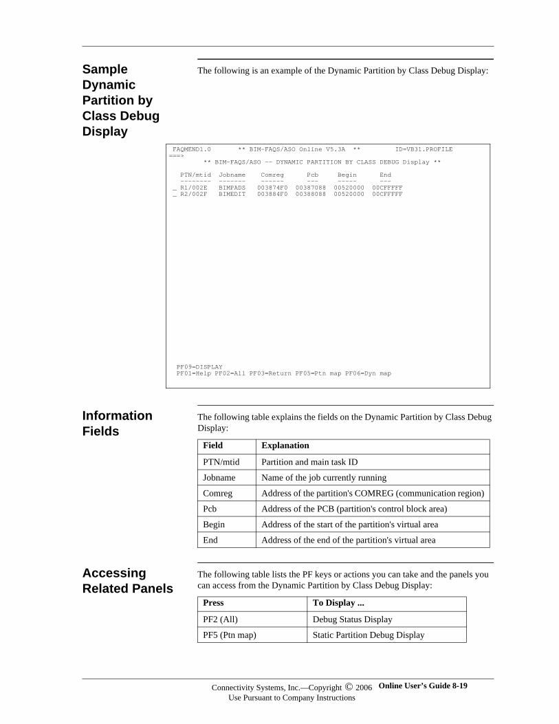
Sample Dynamic Partition by Class Debug Display
The following is an example of the Dynamic Partition by Class Debug Display:
Information Fields
The following table explains the fields on the Dynamic Partition by Class Debug Display:
Accessing Related Panels
The following table lists the PF keys or actions you can take and the panels you can access from the Dynamic Partition by Class Debug Display:
FAQMEND1.0 ** BIM-FAQS/ASO Online V5.3A ** ID=VB31.PROFILE ===> ** BIM-FAQS/ASO -- DYNAMIC PARTITION BY CLASS DEBUG Display ** PTN/mtid Jobname Comreg Pcb Begin End -------- ------- ------ --- ----- --- _ R1/002E BIMPADS 003874F0 00387088 00520000 00CFFFFF _ R2/002F BIMEDIT 003884F0 00388088 00520000 00CFFFFF
PF09=DISPLAY PF01=Help PF02=All PF03=Return PF05=Ptn map PF06=Dyn map
Field Explanation
PTN/mtid Partition and main task ID
Jobname Name of the job currently running
Comreg Address of the partition's COMREG (communication region)
Pcb Address of the PCB (partition's control block area)
Begin Address of the start of the partition's virtual area
End Address of the end of the partition's virtual area
Press To Display ...
PF2 (All) Debug Status Display
PF5 (Ptn map) Static Partition Debug Display
Connectivity Systems, Inc.—Copyright © 2006Use Pursuant to Company Instructions
Online User’s Guide 8-19

Connectivity Systems
PF6 (Dyn map) Dynamic Class Debug Display
PF9 (Display) Storage for the partition that you select using the cursor You can use this instead of the cursor, such as when you are using the CGI interface.
ENTER in selected field Partition Information Debug Display
Press To Display ...
8-20 BIM-FAQS/ASO Connectivity Systems, Inc.—Copyright © 2006Use Pursuant to Company Instructions
Debug Status Display
Use the Debug Status Display to list all tasks' statuses and the partitions they are attached to. If you have a color terminal, this panel uses different colors to indicate the status of each task, as well as the corresponding text.
The Debug Status Display supports timed redisplay.
Menu Access Perform the following steps to access the Debug Status Display panel from the BIM-FAQS/ASO Online Menu:
Fast-path Access
To go directly to the Debug Status Display, enter DEBUG ALL from the BIM-FAQS/ASO command line.
Step Action Panel Displayed
1 From the BIM-FAQS/ASO Online Menu, select the Extended Map/Debug Menu option (M).
Map/Debug Menu
2 Select the Debug option (D). Status Partition Debug Display
3 Press PF2 (All). Debug Status Display
Connectivity Systems, Inc.—Copyright © 2006Use Pursuant to Company Instructions
Online User’s Guide 8-21
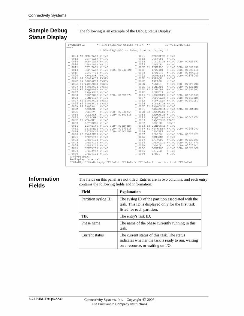
Connectivity Systems
Sample Debug Status Display
The following is an example of the Debug Status Display:
Information Fields
The fields on this panel are not titled. Entries are in two columns, and each entry contains the following fields and information:
FAQMEND5.2 ** BIM-FAQS/ASO Online V5.3A ** ID=VB31.PROFILE ===> ** BIM-FAQS/ASO -- Debug Status display ** _ 0004 AR PMR-TASK W-I/O _ 0081 DTSCOPCM W-I/O _ 0012 CST-TASK W-I/O _ 0082 DTSNTFY W-I/O _ 0014 FCP-TASK W-I/O _ 0083 DTSCHIGH W-I/O CCB= 00AA649C _ 0010 DSP-TASK WAITI _ 0023 DFHSIP W-I/O _ 0011 SPT-TASK W-I/O _ 005E F1 IPW$$LS W-I/O CCB= 00501838 _ 0013 HCF-TASK W-I/O CCB= 0004DFB0 _ 006F IPW$$S1 W-I/O CCB= 0050E110 _ 001F VSYS--31 W-I/O _ 0078 IPW$$TD W-I/O CCB= 0050A010 _ 0020 AR-TASK W-I/O _ 0022 POWRNET3 W-I/O CCB= 00379040 _ 0021 BG $JOBACCT PWSRV _ 007D C1 AXPLQM W-I/O _ 002B FA $JOBACCT PWSRV _ 007E AXPLIO W-I/O _ 002A F9 $JOBACCT PWSRV _ 002D ALRTL1 W-I/O CCB= 003FD000 _ 0029 F8 $JOBACCT PWSRV _ 002E R1 BIMPADS W-I/O CCB= 00521BB0 _ 0063 F7 FAQSMAIN W-I/O _ 007F R2 BIMLIBR W-I/O CCB= 0069A60C _ 0087 FAQXASUB W-I/O _ 002F BIMEDIT W-I/O _ 0088 FAQSTSKG W-I/O CCB= 005BED74 _ 0076 S1 MSGXDRIV W-I/O CCB= 0054904C _ 0028 BIM$TIDR W-I/O _ 0077 FTPDTASK W-I/O CCB= 0066CBD4 _ 0027 F6 $JOBACCT PWSRV _ 008A FTPXTASK W-I/O CCB= 0066C0FC _ 0026 F5 $JOBACCT PWSRV _ 0034 FTPBATCH W-I/O _ 007A F4 FAQSAO W-I/O _ 006E Z1 FAQXCSUB W-I/O _ 007B PCSLOG W-I/O _ 0031 FAQXCONS W-I/O CCB= 002BA7B8 _ 007C PCSSRV W-I/O CCB= 00236454 _ 006D Z2 FAQSMAIN W-I/O _ 0086 JCLTASK W-I/O CCB= 00503518 _ 0084 FAQXASUB W-I/O _ 0025 JCLSCHED W-I/O _ 0085 FAQSTSKG W-I/O CCB= 005C1A74 _ 005F F3 VTAMRP W-I/O _ 0089 FAQSTSKP READY _ 0060 ISTPDCLU W-I/O _ 0032 FAQSIUX READY _ 0061 ISTMTINV W-I/O CCB= 003B45D4 _ 0033 Z3 BIM$CGRX W-I/O _ 0062 ISTINMLS W-I/O CCB= 00555618 _ 0068 T1 MSGXDRIV W-I/O CCB= 0056808C _ 0024 ISTINCVT W-I/O CCB= 003C0BB8 _ 0064 CSOCKET W-I/O _ 0070 F2 EVA10MST W-I/O _ 0067 FILEIO W-I/O CCB= 0052012C _ 0071 DFHEVID2 W-I/O _ 006A COMMAND W-I/O _ 0072 DFHEVID1 W-I/O _ 0069 SPINCPU W-I/O CCB= 0052028C _ 0073 DFHEVID1 W-I/O _ 0066 OPENCLOS W-I/O CCB= 00537770 _ 0074 DFHEVID1 W-I/O _ 006B UPDATE W-I/O CCB= 00520ECC _ 0075 DFHEVID1 W-I/O _ 006C CONTROL W-I/O CCB= 005205C0 _ 0079 DFHSKTSK W-I/O _ 0065 DRIVER W-I/O _ 0080 DFHEVID1 W-I/O _ 0030 IPNET W-I/O PF09=DISPLAY Redisplay interval: 5 PF01=Hlp PF02=Redsply PF03=Ret PF04=Refr PF06=Incl inactive task PF08=Fwd
Field Explanation
Partition syslog ID The syslog ID of the partition associated with the task. This ID is displayed only for the first task listed for each partition.
TIK The entry's task ID.
Phase name The name of the phase currently running in this task.
Current status The current status of this task. The status indicates whether the task is ready to run, waiting on a resource, or waiting on I/O.
8-22 BIM-FAQS/ASO Connectivity Systems, Inc.—Copyright © 2006Use Pursuant to Company Instructions
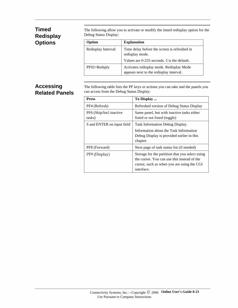
Timed Redisplay Options
The following allow you to activate or modify the timed redisplay option for the Debug Status Display:
Accessing Related Panels
The following table lists the PF keys or actions you can take and the panels you can access from the Debug Status Display:
Option Explanation
Redisplay Interval: Time delay before the screen is refreshed in redisplay mode.Values are 0-255 seconds. 5 is the default.
PF02=Redsply Activates redisplay mode. Redisplay Mode appears next to the redisplay interval.
Press To Display ...
PF4 (Refresh) Refreshed version of Debug Status Display
PF6 (Skip/Incl inactive tasks)
Same panel, but with inactive tasks either listed or not listed (toggle)
S and ENTER on input field Task Information Debug Display.Information about the Task Information Debug Display is provided earlier in this chapter.
PF8 (Forward) Next page of task status list (if needed)
PF9 (Display) Storage for the partition that you select using the cursor. You can use this instead of the cursor, such as when you are using the CGI interface.
Connectivity Systems, Inc.—Copyright © 2006Use Pursuant to Company Instructions
Online User’s Guide 8-23
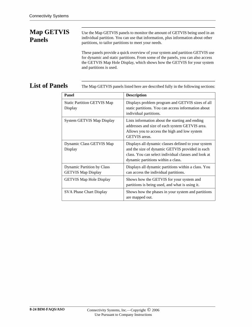
Connectivity Systems
Map GETVIS Panels
Use the Map GETVIS panels to monitor the amount of GETVIS being used in an individual partition. You can use that information, plus information about other partitions, to tailor partitions to meet your needs.
These panels provide a quick overview of your system and partition GETVIS use for dynamic and static partitions. From some of the panels, you can also access the GETVIS Map Hole Display, which shows how the GETVIS for your system and partitions is used.
List of Panels The Map GETVIS panels listed here are described fully in the following sections:
Panel Description
Static Partition GETVIS Map Display
Displays problem program and GETVIS sizes of all static partitions. You can access information about individual partitions.
System GETVIS Map Display Lists information about the starting and ending addresses and size of each system GETVIS area. Allows you to access the high and low system GETVIS areas.
Dynamic Class GETVIS Map Display
Displays all dynamic classes defined to your system and the size of dynamic GETVIS provided in each class. You can select individual classes and look at dynamic partitions within a class.
Dynamic Partition by Class GETVIS Map Display
Displays all dynamic partitions within a class. You can access the individual partitions.
GETVIS Map Hole Display Shows how the GETVIS for your system and partitions is being used, and what is using it.
SVA Phase Chart Display Shows how the phases in your system and partitions are mapped out.
8-24 BIM-FAQS/ASO Connectivity Systems, Inc.—Copyright © 2006Use Pursuant to Company Instructions
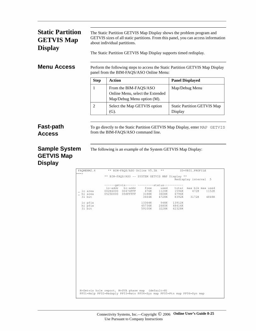
Static Partition GETVIS Map Display
The Static Partition GETVIS Map Display shows the problem program and GETVIS sizes of all static partitions. From this panel, you can access information about individual partitions.
The Static Partition GETVIS Map Display supports timed redisplay.
Menu Access Perform the following steps to access the Static Partition GETVIS Map Display panel from the BIM-FAQS/ASO Online Menu:
Fast-path Access
To go directly to the Static Partition GETVIS Map Display, enter MAP GETVIS from the BIM-FAQS/ASO command line.
Sample System GETVIS Map Display
The following is an example of the System GETVIS Map Display:
Step Action Panel Displayed
1 From the BIM-FAQS/ASO Online Menu, select the Extended Map/Debug Menu option (M).
Map/Debug Menu
2 Select the Map GETVIS option (G).
Static Partition GETVIS Map Display
FAQMENM2.4 ** BIM-FAQS/ASO Online V5.3A ** ID=VB31.PROFILE ===> ** BIM-FAQS/ASO -- SYSTEM GETVIS MAP Display ** Redisplay interval 5 ------getvis------ ---------status----------- lo-addr hi-addr free used total max blk max used _ lo area 002E6000 00474FFF 476K 1120K 1596K 472K 1152K _ hi area 0525D000 058FFFFF 3188K 3608K 6796K 31 bit 3664K 4728K 8392K 3172K 4848K lo pfix 13364K 548K 13912K hi pfix 45736K 2680K 48416K 31 bit 59100K 3228K 62328K H=Getvis hole report, M=SVA phase map (default=H) PF01=Help PF02=Redsply PF03=Retn PF04=Sys map PF05=Ptn map PF06=Dyn map
Connectivity Systems, Inc.—Copyright © 2006Use Pursuant to Company Instructions
Online User’s Guide 8-25
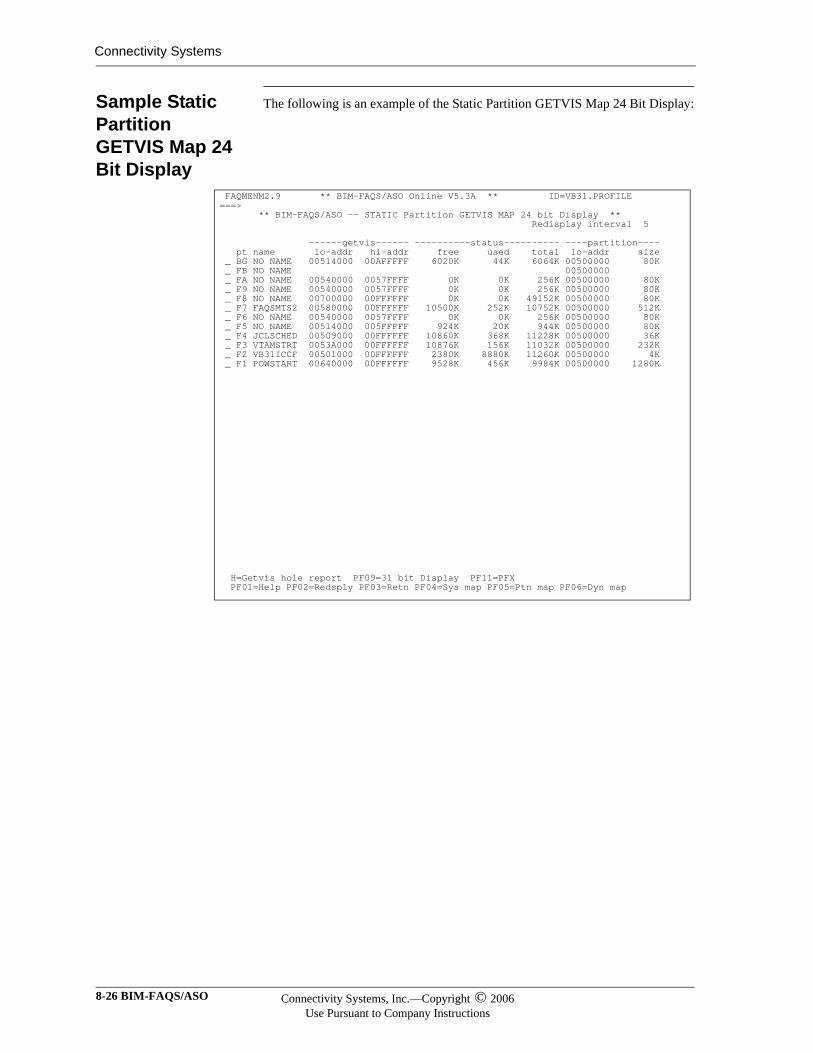
Connectivity Systems
Sample Static Partition GETVIS Map 24 Bit Display
The following is an example of the Static Partition GETVIS Map 24 Bit Display:
FAQMENM2.9 ** BIM-FAQS/ASO Online V5.3A ** ID=VB31.PROFILE ===> ** BIM-FAQS/ASO -- STATIC Partition GETVIS MAP 24 bit Display ** Redisplay interval 5 ------getvis------ ----------status---------- ----partition---- pt name lo-addr hi-addr free used total lo-addr size _ BG NO NAME 00514000 00AFFFFF 6020K 44K 6064K 00500000 80K _ FB NO NAME 00500000 _ FA NO NAME 00540000 0057FFFF 0K 0K 256K 00500000 80K _ F9 NO NAME 00540000 0057FFFF 0K 0K 256K 00500000 80K _ F8 NO NAME 00700000 00FFFFFF 0K 0K 49152K 00500000 80K _ F7 FAQSMTS2 00580000 00FFFFFF 10500K 252K 10752K 00500000 512K _ F6 NO NAME 00540000 0057FFFF 0K 0K 256K 00500000 80K _ F5 NO NAME 00514000 005FFFFF 924K 20K 944K 00500000 80K _ F4 JCLSCHED 00509000 00FFFFFF 10860K 368K 11228K 00500000 36K _ F3 VTAMSTRT 0053A000 00FFFFFF 10876K 156K 11032K 00500000 232K _ F2 VB31ICCF 00501000 00FFFFFF 2380K 8880K 11260K 00500000 4K _ F1 POWSTART 00640000 00FFFFFF 9528K 456K 9984K 00500000 1280K H=Getvis hole report PF09=31 bit Display PF11=PFX PF01=Help PF02=Redsply PF03=Retn PF04=Sys map PF05=Ptn map PF06=Dyn map
8-26 BIM-FAQS/ASO Connectivity Systems, Inc.—Copyright © 2006Use Pursuant to Company Instructions
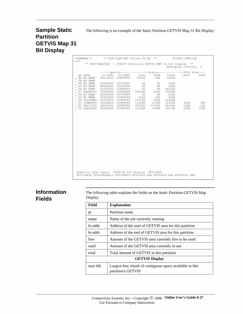
Sample Static Partition GETVIS Map 31 Bit Display
The following is an example of the Static Partition GETVIS Map 31 Bit Display:
Information Fields
The following table explains the fields on the Static Partition GETVIS Map Display:
FAQMENM2.0 ** BIM-FAQS/ASO Online V5.3A ** ID=VB31.PROFILE ===> ** BIM-FAQS/ASO -- STATIC Partition GETVIS MAP 31 bit Display ** Redisplay interval 5 ------getvis------ ----------status---------- ----PFIX Size---- pt name lo-addr hi-addr free used total limit used _ BG NO NAME 00514000 00AFFFFF 6020K 44K 6064K _ FB NO NAME _ FA NO NAME 00540000 0057FFFF 0K 0K 256K _ F9 NO NAME 00540000 0057FFFF 0K 0K 256K _ F8 NO NAME 00700000 036FFFFF 0K 0K 49152K _ F7 FAQSMTS2 00580000 018FFFFF 19348K 620K 19968K _ F6 NO NAME 00540000 0057FFFF 0K 0K 256K _ F5 NO NAME 00514000 005FFFFF 924K 20K 944K _ F4 JCLSCHED 00509000 018FFFFF 19476K 968K 20444K _ F3 VTAMSTRT 0053A000 013FFFFF 11408K 3720K 15128K 424K 76K _ F2 VB31ICCF 00501000 036FFFFF 24156K 27040K 51196K 144K 32K _ F1 POWSTART 00640000 013FFFFF 12128K 1948K 14076K 200K 120K H=Getvis hole report PF09=24 bit Display PF11=GVS PF01=Help PF02=Redsply PF03=Retn PF04=Sys map PF05=Ptn map PF06=Dyn map
Field Explanation
pt Partition name
name Name of the job currently running
lo-addr Address of the start of GETVIS area for this partition
hi-addr Address of the end of GETVIS area for this partition
free Amount of the GETVIS area currently free to be used
used Amount of the GETVIS area currently in use
total Total amount of GETVIS in this partitionGETVIS Display
max blk Largest free chunk of contiguous space available in this partition's GETVIS
Connectivity Systems, Inc.—Copyright © 2006Use Pursuant to Company Instructions
Online User’s Guide 8-27
Connectivity Systems
Timed Redisplay Option
The following allow you to activate or modify the timed redisplay option for the Static Partition GETVIS Map Display:
Accessing Related Panels
The following table lists the PF keys or actions you can take and the panels you can access from the Static Partition GETVIS Map Display:
max used Maximum amount of GETVIS used in this area since the start of this job
PFIX Size Display
Limit The maximum amount of pfix area that is currently in use.
Used The amount of the available pfix area that is currently in use. Partition Display
Lo-addr The address of the start of the partition.
Size The size of problem program area for the currently executing phase.
Field Explanation
Option Explanation
Redisplay Interval: Time delay before the screen is refreshed in redisplay mode.Values are 0-255 seconds. 5 is the default.
PF02=Redisplay Activates redisplay mode. Redisplay Mode appears next to the redisplay interval.
Press To Display
PF4 (Sys map) System GETVIS Map Display
PF5 (Ptn map) Refreshed version of Static Partition GETVIS Map Display
PF6 (Dyn map) Dynamic Class GETVIS Map Display
PF09=24 bit displayPF09=31 bit display
Toggle between a 24- or 31-bit display.In 31-bit display mode, you are also seeing the 24-bit display information.
PF11=PTNPF11=PFX PF11=GVS
Toggle between a partition status pfix size, or GETVIS status display mode. This changes the display of the right column on the panel.
H and ENTER in an input field
GETVIS Map Hole Display for a specific partition
8-28 BIM-FAQS/ASO Connectivity Systems, Inc.—Copyright © 2006Use Pursuant to Company Instructions
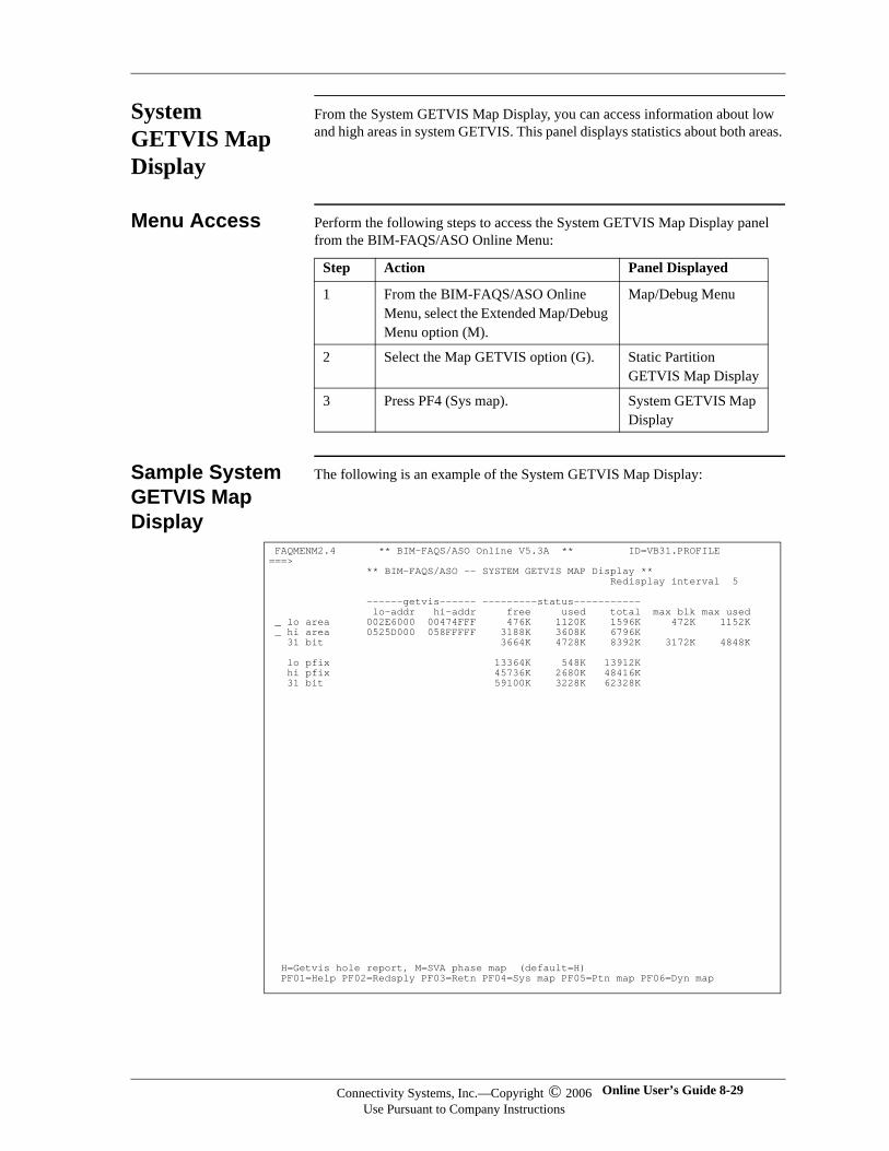
System GETVIS Map Display
From the System GETVIS Map Display, you can access information about low and high areas in system GETVIS. This panel displays statistics about both areas.
Menu Access Perform the following steps to access the System GETVIS Map Display panel from the BIM-FAQS/ASO Online Menu:
Sample System GETVIS Map Display
The following is an example of the System GETVIS Map Display:
Step Action Panel Displayed
1 From the BIM-FAQS/ASO Online Menu, select the Extended Map/Debug Menu option (M).
Map/Debug Menu
2 Select the Map GETVIS option (G). Static Partition GETVIS Map Display
3 Press PF4 (Sys map). System GETVIS Map Display
FAQMENM2.4 ** BIM-FAQS/ASO Online V5.3A ** ID=VB31.PROFILE ===> ** BIM-FAQS/ASO -- SYSTEM GETVIS MAP Display ** Redisplay interval 5 ------getvis------ ---------status----------- lo-addr hi-addr free used total max blk max used _ lo area 002E6000 00474FFF 476K 1120K 1596K 472K 1152K _ hi area 0525D000 058FFFFF 3188K 3608K 6796K 31 bit 3664K 4728K 8392K 3172K 4848K lo pfix 13364K 548K 13912K hi pfix 45736K 2680K 48416K 31 bit 59100K 3228K 62328K H=Getvis hole report, M=SVA phase map (default=H) PF01=Help PF02=Redsply PF03=Retn PF04=Sys map PF05=Ptn map PF06=Dyn map
Connectivity Systems, Inc.—Copyright © 2006Use Pursuant to Company Instructions
Online User’s Guide 8-29
Connectivity Systems
Information Fields
The following table explains the fields on the System GETVIS Map Display:
Accessing Related Panels
The following table lists the PF keys or actions you can take and the panels you can access from the System GETVIS Map Display:
Field Explanation
lo-addr Address of the start of this area of system GETVIS
hi-addr Address of the end of this area of system GETVIS
free Amount of system GETVIS area currently free to be used
used Amount of system GETVIS area currently in use
total Total amount of system GETVIS in this area
max blk Largest free chunk of contiguous space available in this area
max used
Maximum amount of system GETVIS used in this area since the last IPL
Press To Display ...
PF4 (Sys map) Refreshed version of System GETVIS Map Display
PF5 (Ptn map) Static Partition GETVIS Map Display
PF6 (Dyn map) Dynamic Class GETVIS Map Display
H and ENTER in selected field
GETVIS Map Hole Display for an individual area
M and ENTER in selected field
SVA Phase Chart Display for an individual area
8-30 BIM-FAQS/ASO Connectivity Systems, Inc.—Copyright © 2006Use Pursuant to Company Instructions
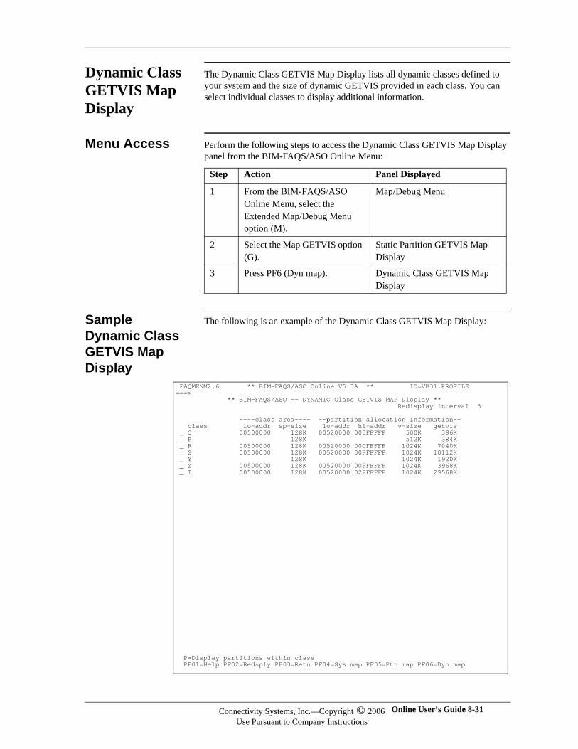
Dynamic Class GETVIS Map Display
The Dynamic Class GETVIS Map Display lists all dynamic classes defined to your system and the size of dynamic GETVIS provided in each class. You can select individual classes to display additional information.
Menu Access Perform the following steps to access the Dynamic Class GETVIS Map Display panel from the BIM-FAQS/ASO Online Menu:
Sample Dynamic Class GETVIS Map Display
The following is an example of the Dynamic Class GETVIS Map Display:
Step Action Panel Displayed
1 From the BIM-FAQS/ASO Online Menu, select the Extended Map/Debug Menu option (M).
Map/Debug Menu
2 Select the Map GETVIS option (G).
Static Partition GETVIS Map Display
3 Press PF6 (Dyn map). Dynamic Class GETVIS Map Display
FAQMENM2.6 ** BIM-FAQS/ASO Online V5.3A ** ID=VB31.PROFILE ===> ** BIM-FAQS/ASO -- DYNAMIC Class GETVIS MAP Display ** Redisplay interval 5 ----class area---- --partition allocation information-- class lo-addr sp-size lo-addr hi-addr v-size getvis _ C 00500000 128K 00520000 005FFFFF 500K 396K _ P 128K 512K 384K _ R 00500000 128K 00520000 00CFFFFF 1024K 7040K _ S 00500000 128K 00520000 00FFFFFF 1024K 10112K _ Y 128K 1024K 1920K _ Z 00500000 128K 00520000 009FFFFF 1024K 3968K _ T 00500000 128K 00520000 022FFFFF 1024K 29568K P=Display partitions within class PF01=Help PF02=Redsply PF03=Retn PF04=Sys map PF05=Ptn map PF06=Dyn map
Connectivity Systems, Inc.—Copyright © 2006Use Pursuant to Company Instructions
Online User’s Guide 8-31
Connectivity Systems
Information Fields
The following table explains the fields on the Dynamic Class GETVIS Display:
Accessing Related Panels
The following table lists the PF keys or actions you can take and the panels you can access from Dynamic Class GETVIS Map Display:
Field Explanation
class Dynamic class
lo-addr Address of the start of dynamic class's GETVIS area
sp-size Length of the dynamic class's GETVIS area, including dynamic GETVIS
lo-addr Address of the beginning of the area used by a dynamic partition within this class
hi-addr Address of the end of the area used by a dynamic partition within this class
v-size Amount of virtual area assigned as a standard for each dynamic partition's problem program area for this class
getvis Amount of GETVIS area assigned as a standard for each dynamic partition within this class
Press To Display
PF4 (Sys map) System GETVIS Map Display
PF5 (Ptn map) Static Partition GETVIS Map Display
PF6 (Dyn map) Refreshed version of Dynamic Class GETVIS Map Display
P and ENTER in an input field
Dynamic Partition by Class GETVIS Map Display for an individual area
8-32 BIM-FAQS/ASO Connectivity Systems, Inc.—Copyright © 2006Use Pursuant to Company Instructions
Dynamic Partition by Class GETVIS Map Display
The Dynamic Partition by Class GETVIS Map Display lists all dynamic partitions within a class and lets you access information about individual partitions within the class.
The Dynamic Partition by Class GETVIS Map Display supports timed redisplay.
Menu Access Perform the following steps to access the Dynamic Partition by Class GETVIS Map Display panel from the BIM-FAQS/ASO Online Menu:
Step Action Panel Displayed
1 From the BIM-FAQS/ASO Online Menu, select the Extended Map/Debug Menu option (M).
Map/Debug Menu
2 Select the Map GETVIS option (G). Static Partition GETVIS Map Display
3 Press PF6 (Dyn map). Dynamic Class GETVIS Map Display
4 Enter P in a class's input field. Dynamic Partition by Class GETVIS Map Display
Connectivity Systems, Inc.—Copyright © 2006Use Pursuant to Company Instructions
Online User’s Guide 8-33
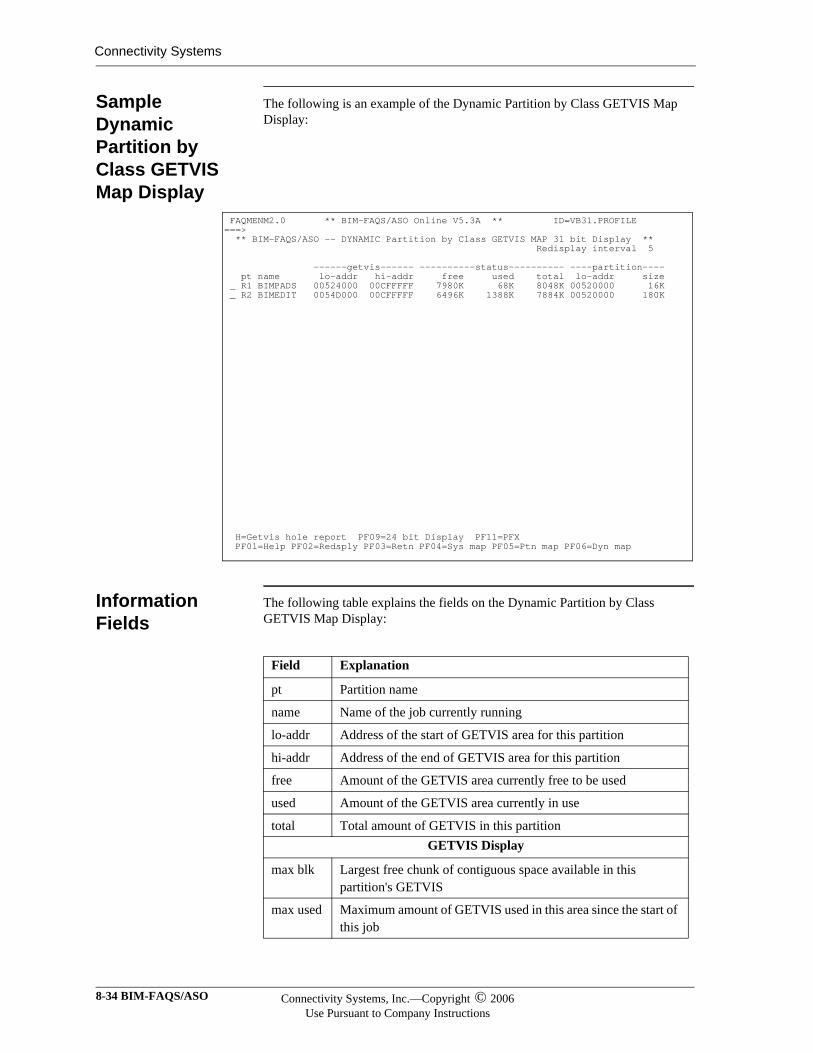
Connectivity Systems
Sample Dynamic Partition by Class GETVIS Map Display
The following is an example of the Dynamic Partition by Class GETVIS Map Display:
Information Fields
The following table explains the fields on the Dynamic Partition by Class GETVIS Map Display:
FAQMENM2.0 ** BIM-FAQS/ASO Online V5.3A ** ID=VB31.PROFILE ===> ** BIM-FAQS/ASO -- DYNAMIC Partition by Class GETVIS MAP 31 bit Display ** Redisplay interval 5 ------getvis------ ----------status---------- ----partition---- pt name lo-addr hi-addr free used total lo-addr size _ R1 BIMPADS 00524000 00CFFFFF 7980K 68K 8048K 00520000 16K _ R2 BIMEDIT 0054D000 00CFFFFF 6496K 1388K 7884K 00520000 180K
H=Getvis hole report PF09=24 bit Display PF11=PFX PF01=Help PF02=Redsply PF03=Retn PF04=Sys map PF05=Ptn map PF06=Dyn map
Field Explanation
pt Partition name
name Name of the job currently running
lo-addr Address of the start of GETVIS area for this partition
hi-addr Address of the end of GETVIS area for this partition
free Amount of the GETVIS area currently free to be used
used Amount of the GETVIS area currently in use
total Total amount of GETVIS in this partitionGETVIS Display
max blk Largest free chunk of contiguous space available in this partition's GETVIS
max used Maximum amount of GETVIS used in this area since the start of this job
8-34 BIM-FAQS/ASO Connectivity Systems, Inc.—Copyright © 2006Use Pursuant to Company Instructions
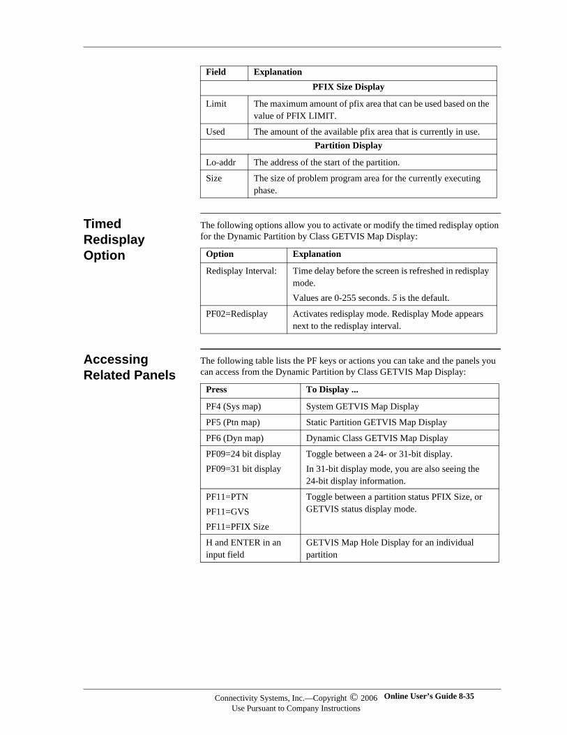
Timed Redisplay Option
The following options allow you to activate or modify the timed redisplay option for the Dynamic Partition by Class GETVIS Map Display:
Accessing Related Panels
The following table lists the PF keys or actions you can take and the panels you can access from the Dynamic Partition by Class GETVIS Map Display:
PFIX Size Display
Limit The maximum amount of pfix area that can be used based on the value of PFIX LIMIT.
Used The amount of the available pfix area that is currently in use. Partition Display
Lo-addr The address of the start of the partition.
Size The size of problem program area for the currently executing phase.
Field Explanation
Option Explanation
Redisplay Interval: Time delay before the screen is refreshed in redisplay mode.Values are 0-255 seconds. 5 is the default.
PF02=Redisplay Activates redisplay mode. Redisplay Mode appears next to the redisplay interval.
Press To Display ...
PF4 (Sys map) System GETVIS Map Display
PF5 (Ptn map) Static Partition GETVIS Map Display
PF6 (Dyn map) Dynamic Class GETVIS Map Display
PF09=24 bit displayPF09=31 bit display
Toggle between a 24- or 31-bit display.In 31-bit display mode, you are also seeing the 24-bit display information.
PF11=PTNPF11=GVSPF11=PFIX Size
Toggle between a partition status PFIX Size, or GETVIS status display mode.
H and ENTER in an input field
GETVIS Map Hole Display for an individual partition
Connectivity Systems, Inc.—Copyright © 2006Use Pursuant to Company Instructions
Online User’s Guide 8-35
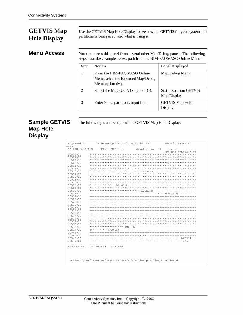
Connectivity Systems
GETVIS Map Hole Display
Use the GETVIS Map Hole Display to see how the GETVIS for your system and partitions is being used, and what is using it.
Menu Access You can access this panel from several other Map/Debug panels. The following steps describe a sample access path from the BIM-FAQS/ASO Online Menu:
Sample GETVIS Map Hole Display
The following is an example of the GETVIS Map Hole Display:
Step Action Panel Displayed
1 From the BIM-FAQS/ASO Online Menu, select the Extended Map/Debug Menu option (M).
Map/Debug Menu
2 Select the Map GETVIS option (G). Static Partition GETVIS Map Display
3 Enter H in a partition's input field. GETVIS Map Hole Display
FAQMENM3.A ** BIM-FAQS/ASO Online V5.3A ** ID=VB31.PROFILE ===> ** BIM-FAQS/ASO -- GETVIS MAP Hole display for F4 phase: -------- PF09=Map getvis high 00509000 **************************************************************** 0050B000 **************************************************************** 0050D000 **************************************************************** 0050F000 ***********************************************b**************** 00511000 **************************************************************** 00513000 **** ***************** * * * * * * ***************************** 00515000 ********************** * * * * *PCSRES-------------------------- 00517000 ------------- * ************************************************ 00519000 **************************************************************** 0051B000 **************************************************************** 0051D000 **************************************************************** 0051F000 ****************BIM$RXPM--------------------------- * * * * * ** 00521000 **************************************************************** 00523000 ***************************** FAQSXUFN-------------------------- 00525000 ---------------------------------------- * * *FAOXSFN----------- 00527000 ---------------------------------------------------------------- 00529000 ---------------------------------------------------------------- 0052B000 ---------------------------------------------------------------- 0052D000 ---------------------------------------------------------------- 0052F000 ---------------------------------------------------------------- 00531000 ---------------------------------------------------------------- 00533000 ---------------------------------------------------------------- 00535000 ---------------------------------------------------------------- 00537000 -----------***************************************************** 00539000 **************************************************************** 0053B000 **************************************************************** 0053D000 ********************BIM$OILB------------------------------------ 0053F000 a>* * * * *FAOXUFN---------------------------------------------- 00541000 ---------------------------------------------------------------- 00543000 ------------------------------AXPX10---------------------------- 00545000 -------------------------------------------------------AXPHJ4--- 00547000 -------------------------------------------------------->*c----> a=$SOCKOPT b=IJDANCHX c=AXPHJ5 PF01=Help PF02=Adr PF03=Rtn PF04=Rfrsh PF05=Top PF06=Bot PF08=Fwd
8-36 BIM-FAQS/ASO Connectivity Systems, Inc.—Copyright © 2006Use Pursuant to Company Instructions
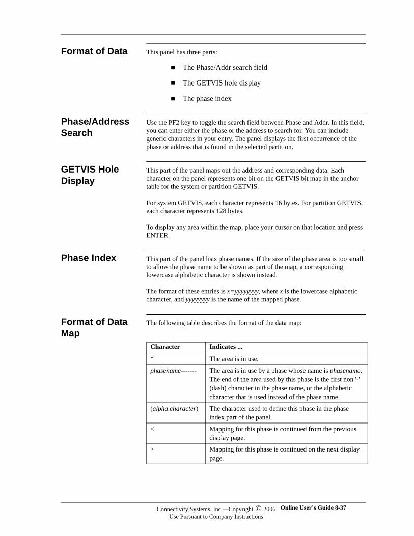
Format of Data This panel has three parts:
The Phase/Addr search field
The GETVIS hole display
The phase index
Phase/Address Search
Use the PF2 key to toggle the search field between Phase and Addr. In this field, you can enter either the phase or the address to search for. You can include generic characters in your entry. The panel displays the first occurrence of the phase or address that is found in the selected partition.
GETVIS Hole Display
This part of the panel maps out the address and corresponding data. Each character on the panel represents one bit on the GETVIS bit map in the anchor table for the system or partition GETVIS.
For system GETVIS, each character represents 16 bytes. For partition GETVIS, each character represents 128 bytes.
To display any area within the map, place your cursor on that location and press ENTER.
Phase Index This part of the panel lists phase names. If the size of the phase area is too small to allow the phase name to be shown as part of the map, a corresponding lowercase alphabetic character is shown instead.
The format of these entries is x=yyyyyyyy, where x is the lowercase alphabetic character, and yyyyyyyy is the name of the mapped phase.
Format of Data Map
The following table describes the format of the data map:
Character Indicates ...
* The area is in use.
phasename------- The area is in use by a phase whose name is phasename. The end of the area used by this phase is the first non '-' (dash) character in the phase name, or the alphabetic character that is used instead of the phase name.
(alpha character) The character used to define this phase in the phase index part of the panel.
< Mapping for this phase is continued from the previous display page.
> Mapping for this phase is continued on the next display page.
Connectivity Systems, Inc.—Copyright © 2006Use Pursuant to Company Instructions
Online User’s Guide 8-37
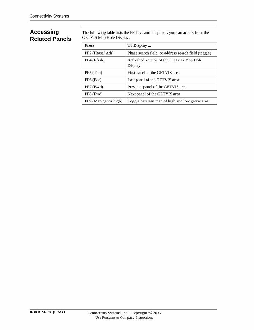
Connectivity Systems
Accessing Related Panels
The following table lists the PF keys and the panels you can access from the GETVIS Map Hole Display:
Press To Display ...
PF2 (Phase/ Adr) Phase search field, or address search field (toggle)
PF4 (Rfrsh) Refreshed version of the GETVIS Map Hole Display
PF5 (Top) First panel of the GETVIS area
PF6 (Bot) Last panel of the GETVIS area
PF7 (Bwd) Previous panel of the GETVIS area
PF8 (Fwd) Next panel of the GETVIS area
PF9 (Map getvis high) Toggle between map of high and low getvis area
8-38 BIM-FAQS/ASO Connectivity Systems, Inc.—Copyright © 2006Use Pursuant to Company Instructions
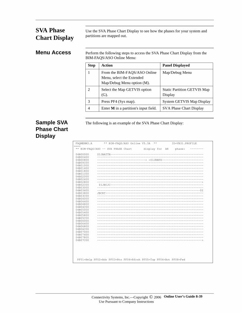
SVA Phase Chart Display
Use the SVA Phase Chart Display to see how the phases for your system and partitions are mapped out.
Menu Access Perform the following steps to access the SVA Phase Chart Display from the BIM-FAQS/ASO Online Menu:
Sample SVA Phase Chart Display
The following is an example of the SVA Phase Chart Display:
Step Action Panel Displayed
1 From the BIM-FAQS/ASO Online Menu, select the Extended Map/Debug Menu option (M).
Map/Debug Menu
2 Select the Map GETVIS option (G).
Static Partition GETVIS Map Display
3 Press PF4 (Sys map). System GETVIS Map Display
4 Enter M in a partition's input field. SVA Phase Chart Display
FAQMENM3.A ** BIM-FAQS/ASO Online V5.3A ** ID=VB31.PROFILE ===> ** BIM-FAQS/ASO -- SVA PHASE Chart display for AR phase: -------- 04B00000 $IJBATTN-------------------------------------------------------- 04B00400 ---------------------------------------------------------------- 04B00800 -----------------------------> <$IJBBPX------------------------- 04B00C00 ---------------------------------------------------------------- 04B01000 ---------------------------------------------------------------- 04B01400 ---------------------------------------------------------------- 04B01800 ---------------------------------------------------------------- 04B01C00 ---------------------------------------------------------------- 04B02000 ---------------------------------------------------------------- 04B02400 ---------------------------------------------------------------- 04B02800 ---------------------------------------------------------------> 04B02C00 $IJBCJC-------------------------------------------------------- 04B03000 ---------------------------------------------------------------- 04B03400 --------------------------------------------------------------$I 04B03800 JBCRT----------------------------------------------------------- 04B03C00 ---------------------------------------------------------------- 04B04000 ---------------------------------------------------------------- 04B04400 ---------------------------------------------------------------- 04B04800 ---------------------------------------------------------------- 04B04C00 ---------------------------------------------------------------- 04B05000 ---------------------------------------------------------------- 04B05400 ---------------------------------------------------------------- 04B05800 ---------------------------------------------------------------- 04B05C00 ---------------------------------------------------------------- 04B06000 ---------------------------------------------------------------- 04B06400 ---------------------------------------------------------------- 04B06800 ---------------------------------------------------------------- 04B06C00 ---------------------------------------------------------------- 04B07000 ---------------------------------------------------------------- 04B07400 ---------------------------------------------------------------- 04B07800 ---------------------------------------------------------------- 04B07C00 ---------------------------------------------------------------> PF01=Help PF02=Adr PF03=Rtn PF04=Rfrsh PF05=Top PF06=Bot PF08=Fwd
Connectivity Systems, Inc.—Copyright © 2006Use Pursuant to Company Instructions
Online User’s Guide 8-39
Connectivity Systems
Format of Data This panel has three main parts:
The phase/address search field
The phase chart
The phase index
Phase/Address Search
Use the PF2 key to toggle the search field between Phase and Addr. In this field, you can enter either the phase or the address for which you want to search. You can include generic characters in your entries. The panel displays the first occurrence of the phase or address that is found in the selected partition.
Phase Chart This part of the panel maps out the address and corresponding data. Each character on the panel represents one bit on the GETVIS bit map in the anchor table for the system or partition GETVIS.
For system GETVIS, each character represents 16 bytes. For partition GETVIS, each character represents 128 bytes.
To display any area within the map, place your cursor on that location and press ENTER.
Phase Index This part of the panel lists phase names. If the size of the phase area is too small to allow the phase name to be shown as part of the map, a corresponding lowercase alphabetic character is shown instead.
The format of these entries is x=yyyyyyyy, where x is the lowercase alphabetic character, and yyyyyyyy is the name of the mapped phase.
Format of Data Map
The format of the data map is described in the following table:
Character Indicates
phasename------- The area is in use by a phase whose name is phasename. The end of the area used by this phase is the first non '-' (dash) character in the phasename, or the alphabetic character that is used instead of the phasename.
(alpha character)
The character used to define this phase in the phase index part of the panel.
< Mapping for this phase is continued from the previous display page.
> Mapping for this phase is continued on the next display page.
8-40 BIM-FAQS/ASO Connectivity Systems, Inc.—Copyright © 2006Use Pursuant to Company Instructions
Accessing Related Panels
The following table lists the PF keys and the panels you can access from the SVA Phase Chart Display:
Press To Display
PF2 (Phase/ Adr) Phase search field or address search field (toggle)
PF4 (Rfrsh) Refreshed version of the SVA Phase Chart Display
PF5 (Top) First panel of the GETVIS area
PF6 (Bot) Last panel of the GETVIS area
PF7 (Bwd) Previous panel of the GETVIS area
PF8 (Fwd) Next panel of the GETVIS area
Connectivity Systems, Inc.—Copyright © 2006Use Pursuant to Company Instructions
Online User’s Guide 8-41
Connectivity Systems
Map Panels The Map panels show the makeup of your system as it is defined at IPL. The values provided in Map panels are generally different than the current values provided by the GETVIS Map panels.
The Map panels provide the starting, ending, and size of real area for an individual partition and the mapping of the individual parts that make up your system.
List of Map Panels
The Map panels listed here are described fully in the following sections:
Panel Description
Static Partition Map Display
Displays problem program and GETVIS sizes of all static partitions. You can access individual partitions.
System Map Display Provides a map of the general areas that make up your system, and lets you access the individual elements.
Dynamic Class Map Display
Displays all dynamic classes defined to your system and the size of dynamic GETVIS provided in each class. You can select individual classes and look at dynamic partitions within a class.
Dynamic Partition by Class Map Display
Lists all dynamic partitions within a class. You can access individual partitions.
8-42 BIM-FAQS/ASO Connectivity Systems, Inc.—Copyright © 2006Use Pursuant to Company Instructions
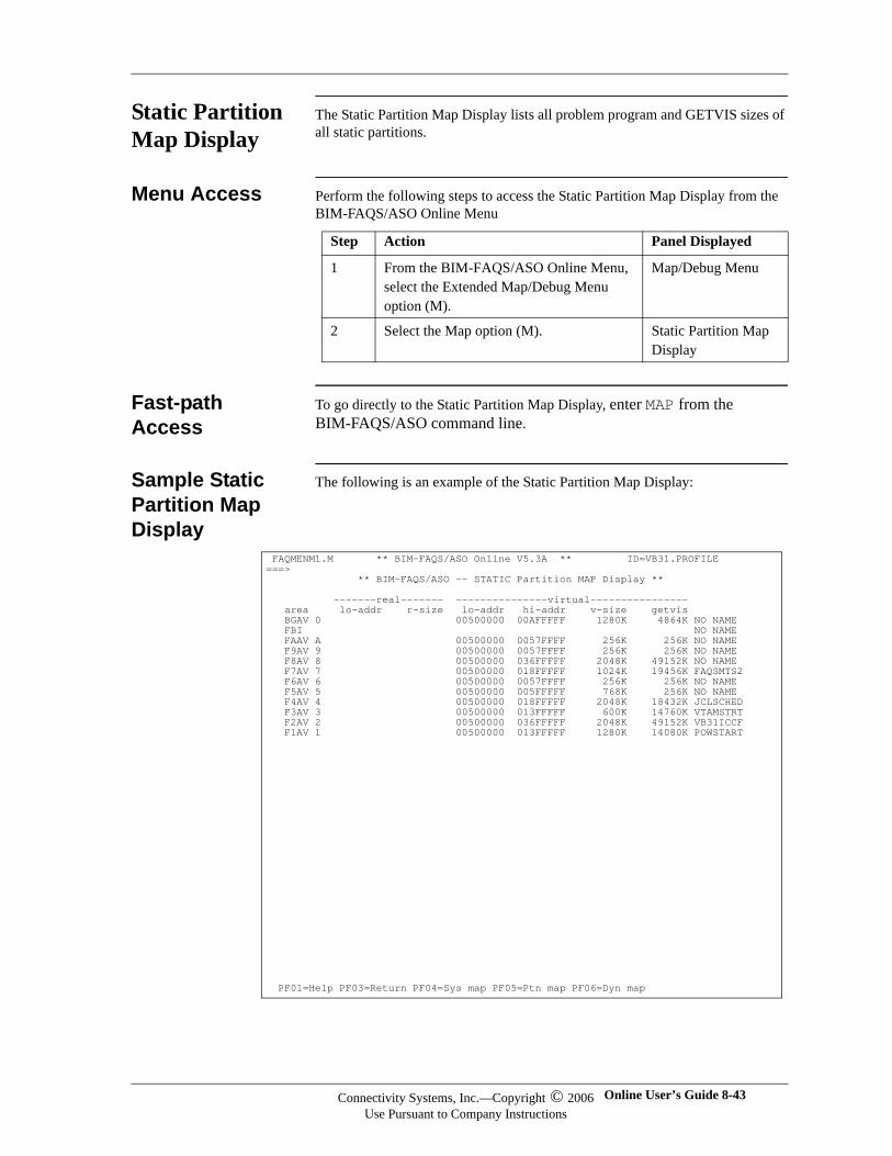
Static Partition Map Display
The Static Partition Map Display lists all problem program and GETVIS sizes of all static partitions.
Menu Access Perform the following steps to access the Static Partition Map Display from the BIM-FAQS/ASO Online Menu
Fast-path Access
To go directly to the Static Partition Map Display, enter MAP from the BIM-FAQS/ASO command line.
Sample Static Partition Map Display
The following is an example of the Static Partition Map Display:
Step Action Panel Displayed
1 From the BIM-FAQS/ASO Online Menu, select the Extended Map/Debug Menu option (M).
Map/Debug Menu
2 Select the Map option (M). Static Partition Map Display
FAQMENM1.M ** BIM-FAQS/ASO Online V5.3A ** ID=VB31.PROFILE ===> ** BIM-FAQS/ASO -- STATIC Partition MAP Display ** -------real------- ---------------virtual---------------- area lo-addr r-size lo-addr hi-addr v-size getvis BGAV 0 00500000 00AFFFFF 1280K 4864K NO NAME FBI NO NAME FAAV A 00500000 0057FFFF 256K 256K NO NAME F9AV 9 00500000 0057FFFF 256K 256K NO NAME F8AV 8 00500000 036FFFFF 2048K 49152K NO NAME F7AV 7 00500000 018FFFFF 1024K 19456K FAQSMTS2 F6AV 6 00500000 0057FFFF 256K 256K NO NAME F5AV 5 00500000 005FFFFF 768K 256K NO NAME F4AV 4 00500000 018FFFFF 2048K 18432K JCLSCHED F3AV 3 00500000 013FFFFF 600K 14760K VTAMSTRT F2AV 2 00500000 036FFFFF 2048K 49152K VB31ICCF F1AV 1 00500000 013FFFFF 1280K 14080K POWSTART PF01=Help PF03=Return PF04=Sys map PF05=Ptn map PF06=Dyn map
Connectivity Systems, Inc.—Copyright © 2006Use Pursuant to Company Instructions
Online User’s Guide 8-43
Connectivity Systems
Information Fields
The following table explains the fields on the Static Partition Map Display:
Accessing Related Panels
The following table lists the PF keys and the panels you can access from the Static Partition Map Display:
Field Explanation
area Name/description of the static partition
lo-addr Address of the start of real area that has been pre-allocated for this partition
r-size Amount of the real area that was pre-allocated
lo-addr Address of the start of this partition's virtual area, as defined during IPL
hi-addr Address of the end of this partition's virtual area, as defined during IPL
v-size Amount of virtual area defined
getvis Total amount of virtual area pre-defined as GETVIS area
(jobname) Name of the job currently running
Press To Display ...
PF4 (Sys map) System Map Display
PF5 (Ptn map) Refreshed version of Static Partition Map Display
PF6 (Dyn map) Dynamic Class Map Display
8-44 BIM-FAQS/ASO Connectivity Systems, Inc.—Copyright © 2006Use Pursuant to Company Instructions
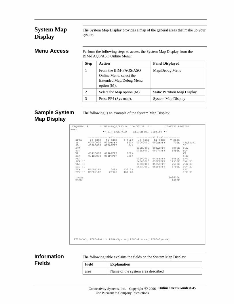
System Map Display
The System Map Display provides a map of the general areas that make up your system.
Menu Access Perform the following steps to access the System Map Display from the BIM-FAQS/ASO Online Menu:
Sample System Map Display
The following is an example of the System Map Display:
Information Fields
The following table explains the fields on the System Map Display:
Step Action Panel Displayed
1 From the BIM-FAQS/ASO Online Menu, select the Extended Map/Debug Menu option (M).
Map/Debug Menu
2 Select the Map option (M). Static Partition Map Display
3 Press PF4 (Sys map). System Map Display
FAQMENM1.4 ** BIM-FAQS/ASO Online V5.3A ** ID=VB31.PROFILE ===> ** BIM-FAQS/ASO -- SYSTEM MAP Display ** ------------real------------ ----------virtual---------- area lo-addr hi-addr r-size lo-addr hi-addr v-size SP 00000000 0009FFFF 640K 00000000 000AFFFF 704K $$A$SUPI SD 000A0000 000AFFFF 64K SD SVA 000B0000 004AFFFF 4096K SVA SGV 002E6000 00474FFF 1596K SGV VP 00490000 004AFFFF 128K VP SHR 004B0000 004FFFFF 320K SHR PRV 00500000 04AFFFFF 71680K PRV SVA HI 04B00000 058FFFFF 14336K SVA HI VLB HI 04B00000 0525CFFF 7540K VLB HI SGV HI 0525D000 058FFFFF 6796K SGV HI PFX USED/LIM 548K 13912K PFX PFX HI USED/LIM 2696K 48416K PFX HI TOTAL 409600K USED 1600K PF01=Help PF03=Return PF04=Sys map PF05=Ptn map PF06=Dyn map
Field Explanation
area Name of the system area described
Connectivity Systems, Inc.—Copyright © 2006Use Pursuant to Company Instructions
Online User’s Guide 8-45
Connectivity Systems
Accessing Related Panels
The following table lists the PF keys and the panels you can access from the System Map Display:
lo-addr Address of the start of real area used to contain the defined area
hi-addr Address of the end of the real area used to contain the defined area
r-size Amount of the real storage used to define this area
lo-addr Address of the start of the virtual area used to contain the defined area
hi-addr Address of the end of the virtual area used to contain the defined area
v-size Amount of virtual storage used to define this area
(description) Description of the defined area
Field Explanation
Press To Display
PF4 (Sys map) Refreshed version of System Map Display
PF5 (Ptn map) Static Partition Map Display
PF6 (Dyn map) Dynamic Class Map Display
8-46 BIM-FAQS/ASO Connectivity Systems, Inc.—Copyright © 2006Use Pursuant to Company Instructions
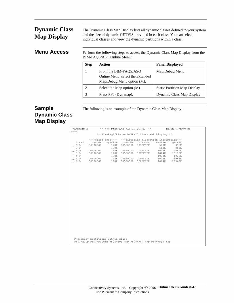
Dynamic Class Map Display
The Dynamic Class Map Display lists all dynamic classes defined to your system and the size of dynamic GETVIS provided in each class. You can select individual classes and view the dynamic partitions within a class.
Menu Access Perform the following steps to access the Dynamic Class Map Display from the BIM-FAQS/ASO Online Menu:
Sample Dynamic Class Map Display
The following is an example of the Dynamic Class Map Display:
Step Action Panel Displayed
1 From the BIM-FAQS/ASO Online Menu, select the Extended Map/Debug Menu option (M).
Map/Debug Menu
2 Select the Map option (M). Static Partition Map Display
3 Press PF6 (Dyn map). Dynamic Class Map Display
FAQMENM1.0 ** BIM-FAQS/ASO Online V5.3A ** ID=VB31.PROFILE ===> ** BIM-FAQS/ASO -- DYNAMIC Class MAP Display ** ----class area---- ---partition allocation information--- class lo-addr sp-size lo-addr hi-addr v-size getvis _ C D 00500000 128K 00520000 005FFFFF 500K 396K _ P D 128K 512K 384K _ R D 00500000 128K 00520000 00CFFFFF 1024K 7040K _ S D 00500000 128K 00520000 00FFFFFF 1024K 10112K _ Y D 128K 1024K 1920K _ Z D 00500000 128K 00520000 009FFFFF 1024K 3968K _ T D 00500000 128K 00520000 022FFFFF 1024K 29568K P=Display partitions within class PF01=Help PF03=Return PF04=Sys map PF05=Ptn map PF06=Dyn map
Connectivity Systems, Inc.—Copyright © 2006Use Pursuant to Company Instructions
Online User’s Guide 8-47
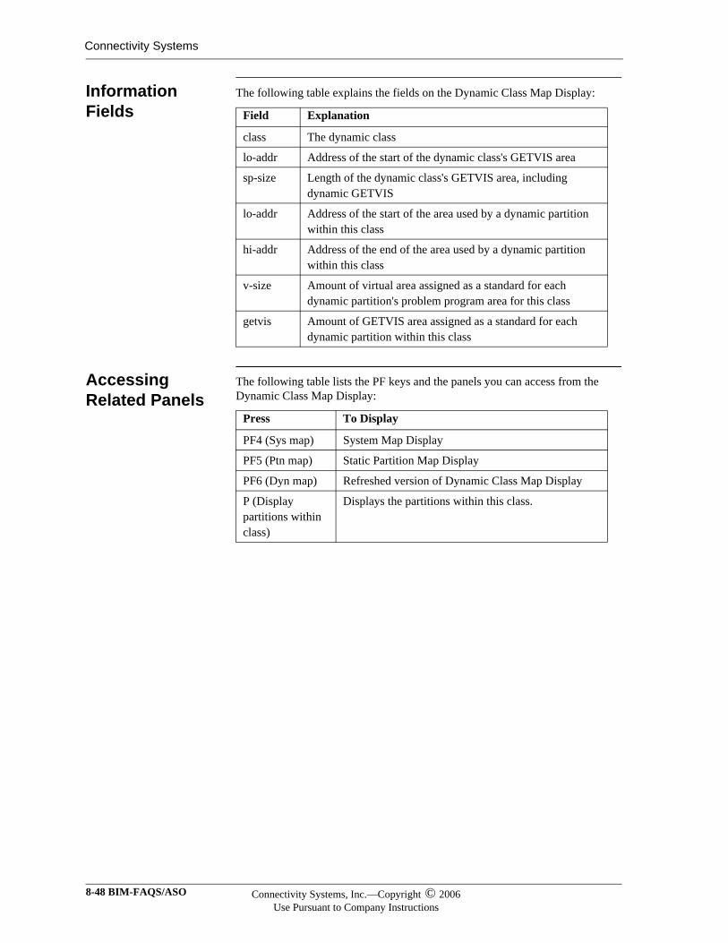
Connectivity Systems
Information Fields
The following table explains the fields on the Dynamic Class Map Display:
Accessing Related Panels
The following table lists the PF keys and the panels you can access from the Dynamic Class Map Display:
Field Explanation
class The dynamic class
lo-addr Address of the start of the dynamic class's GETVIS area
sp-size Length of the dynamic class's GETVIS area, including dynamic GETVIS
lo-addr Address of the start of the area used by a dynamic partition within this class
hi-addr Address of the end of the area used by a dynamic partition within this class
v-size Amount of virtual area assigned as a standard for each dynamic partition's problem program area for this class
getvis Amount of GETVIS area assigned as a standard for each dynamic partition within this class
Press To Display
PF4 (Sys map) System Map Display
PF5 (Ptn map) Static Partition Map Display
PF6 (Dyn map) Refreshed version of Dynamic Class Map Display
P (Display partitions within class)
Displays the partitions within this class.
8-48 BIM-FAQS/ASO Connectivity Systems, Inc.—Copyright © 2006Use Pursuant to Company Instructions
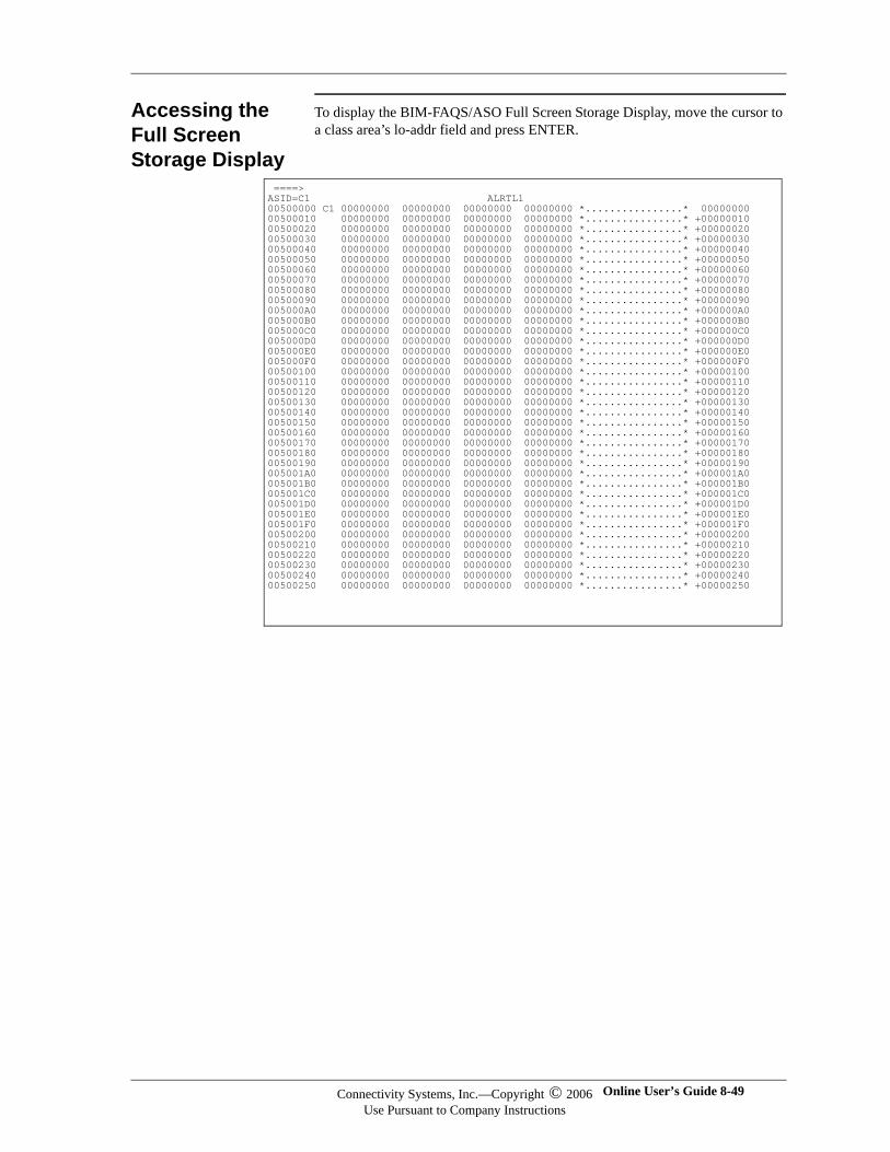
Accessing the Full Screen Storage Display
To display the BIM-FAQS/ASO Full Screen Storage Display, move the cursor to a class area’s lo-addr field and press ENTER.
====> ASID=C1 ALRTL1 00500000 C1 00000000 00000000 00000000 00000000 *................* 00000000 00500010 00000000 00000000 00000000 00000000 *................* +00000010 00500020 00000000 00000000 00000000 00000000 *................* +00000020 00500030 00000000 00000000 00000000 00000000 *................* +00000030 00500040 00000000 00000000 00000000 00000000 *................* +00000040 00500050 00000000 00000000 00000000 00000000 *................* +00000050 00500060 00000000 00000000 00000000 00000000 *................* +00000060 00500070 00000000 00000000 00000000 00000000 *................* +00000070 00500080 00000000 00000000 00000000 00000000 *................* +00000080 00500090 00000000 00000000 00000000 00000000 *................* +00000090 005000A0 00000000 00000000 00000000 00000000 *................* +000000A0 005000B0 00000000 00000000 00000000 00000000 *................* +000000B0 005000C0 00000000 00000000 00000000 00000000 *................* +000000C0 005000D0 00000000 00000000 00000000 00000000 *................* +000000D0 005000E0 00000000 00000000 00000000 00000000 *................* +000000E0 005000F0 00000000 00000000 00000000 00000000 *................* +000000F0 00500100 00000000 00000000 00000000 00000000 *................* +00000100 00500110 00000000 00000000 00000000 00000000 *................* +00000110 00500120 00000000 00000000 00000000 00000000 *................* +00000120 00500130 00000000 00000000 00000000 00000000 *................* +00000130 00500140 00000000 00000000 00000000 00000000 *................* +00000140 00500150 00000000 00000000 00000000 00000000 *................* +00000150 00500160 00000000 00000000 00000000 00000000 *................* +00000160 00500170 00000000 00000000 00000000 00000000 *................* +00000170 00500180 00000000 00000000 00000000 00000000 *................* +00000180 00500190 00000000 00000000 00000000 00000000 *................* +00000190 005001A0 00000000 00000000 00000000 00000000 *................* +000001A0 005001B0 00000000 00000000 00000000 00000000 *................* +000001B0 005001C0 00000000 00000000 00000000 00000000 *................* +000001C0 005001D0 00000000 00000000 00000000 00000000 *................* +000001D0 005001E0 00000000 00000000 00000000 00000000 *................* +000001E0 005001F0 00000000 00000000 00000000 00000000 *................* +000001F0 00500200 00000000 00000000 00000000 00000000 *................* +00000200 00500210 00000000 00000000 00000000 00000000 *................* +00000210 00500220 00000000 00000000 00000000 00000000 *................* +00000220 00500230 00000000 00000000 00000000 00000000 *................* +00000230 00500240 00000000 00000000 00000000 00000000 *................* +00000240 00500250 00000000 00000000 00000000 00000000 *................* +00000250
Connectivity Systems, Inc.—Copyright © 2006Use Pursuant to Company Instructions
Online User’s Guide 8-49
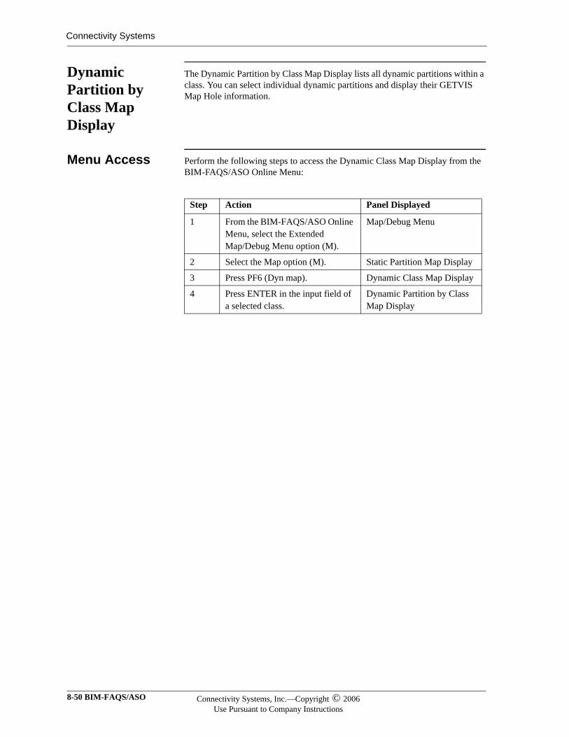
Connectivity Systems
Dynamic Partition by Class Map Display
The Dynamic Partition by Class Map Display lists all dynamic partitions within a class. You can select individual dynamic partitions and display their GETVIS Map Hole information.
Menu Access Perform the following steps to access the Dynamic Class Map Display from the BIM-FAQS/ASO Online Menu:
Step Action Panel Displayed
1 From the BIM-FAQS/ASO Online Menu, select the Extended Map/Debug Menu option (M).
Map/Debug Menu
2 Select the Map option (M). Static Partition Map Display
3 Press PF6 (Dyn map). Dynamic Class Map Display
4 Press ENTER in the input field of a selected class.
Dynamic Partition by Class Map Display
8-50 BIM-FAQS/ASO Connectivity Systems, Inc.—Copyright © 2006Use Pursuant to Company Instructions
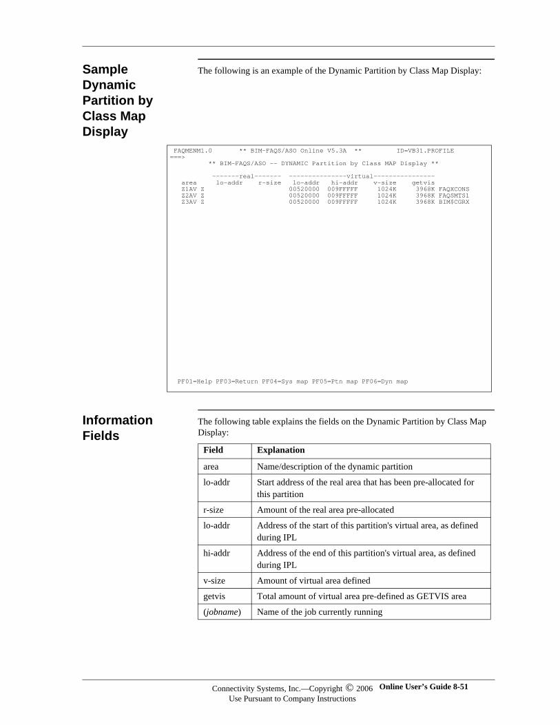
Sample Dynamic Partition by Class Map Display
The following is an example of the Dynamic Partition by Class Map Display:
Information Fields
The following table explains the fields on the Dynamic Partition by Class Map Display:
FAQMENM1.0 ** BIM-FAQS/ASO Online V5.3A ** ID=VB31.PROFILE ===> ** BIM-FAQS/ASO -- DYNAMIC Partition by Class MAP Display ** -------real------- ---------------virtual---------------- area lo-addr r-size lo-addr hi-addr v-size getvis Z1AV Z 00520000 009FFFFF 1024K 3968K FAQXCONS Z2AV Z 00520000 009FFFFF 1024K 3968K FAQSMTS1 Z3AV Z 00520000 009FFFFF 1024K 3968K BIM$CGRX
PF01=Help PF03=Return PF04=Sys map PF05=Ptn map PF06=Dyn map
Field Explanation
area Name/description of the dynamic partition
lo-addr Start address of the real area that has been pre-allocated for this partition
r-size Amount of the real area pre-allocated
lo-addr Address of the start of this partition's virtual area, as defined during IPL
hi-addr Address of the end of this partition's virtual area, as defined during IPL
v-size Amount of virtual area defined
getvis Total amount of virtual area pre-defined as GETVIS area
(jobname) Name of the job currently running
Connectivity Systems, Inc.—Copyright © 2006Use Pursuant to Company Instructions
Online User’s Guide 8-51
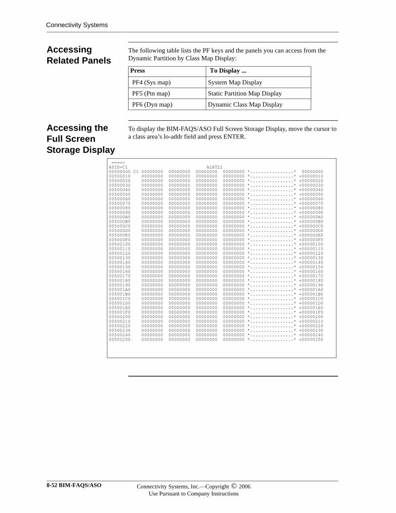
Connectivity Systems
Accessing Related Panels
The following table lists the PF keys and the panels you can access from the Dynamic Partition by Class Map Display:
Accessing the Full Screen Storage Display
To display the BIM-FAQS/ASO Full Screen Storage Display, move the cursor to a class area’s lo-addr field and press ENTER.
Press To Display ...
PF4 (Sys map) System Map Display
PF5 (Ptn map) Static Partition Map Display
PF6 (Dyn map) Dynamic Class Map Display
====> ASID=C1 ALRTL1 00500000 C1 00000000 00000000 00000000 00000000 *................* 00000000 00500010 00000000 00000000 00000000 00000000 *................* +00000010 00500020 00000000 00000000 00000000 00000000 *................* +00000020 00500030 00000000 00000000 00000000 00000000 *................* +00000030 00500040 00000000 00000000 00000000 00000000 *................* +00000040 00500050 00000000 00000000 00000000 00000000 *................* +00000050 00500060 00000000 00000000 00000000 00000000 *................* +00000060 00500070 00000000 00000000 00000000 00000000 *................* +00000070 00500080 00000000 00000000 00000000 00000000 *................* +00000080 00500090 00000000 00000000 00000000 00000000 *................* +00000090 005000A0 00000000 00000000 00000000 00000000 *................* +000000A0 005000B0 00000000 00000000 00000000 00000000 *................* +000000B0 005000C0 00000000 00000000 00000000 00000000 *................* +000000C0 005000D0 00000000 00000000 00000000 00000000 *................* +000000D0 005000E0 00000000 00000000 00000000 00000000 *................* +000000E0 005000F0 00000000 00000000 00000000 00000000 *................* +000000F0 00500100 00000000 00000000 00000000 00000000 *................* +00000100 00500110 00000000 00000000 00000000 00000000 *................* +00000110 00500120 00000000 00000000 00000000 00000000 *................* +00000120 00500130 00000000 00000000 00000000 00000000 *................* +00000130 00500140 00000000 00000000 00000000 00000000 *................* +00000140 00500150 00000000 00000000 00000000 00000000 *................* +00000150 00500160 00000000 00000000 00000000 00000000 *................* +00000160 00500170 00000000 00000000 00000000 00000000 *................* +00000170 00500180 00000000 00000000 00000000 00000000 *................* +00000180 00500190 00000000 00000000 00000000 00000000 *................* +00000190 005001A0 00000000 00000000 00000000 00000000 *................* +000001A0 005001B0 00000000 00000000 00000000 00000000 *................* +000001B0 005001C0 00000000 00000000 00000000 00000000 *................* +000001C0 005001D0 00000000 00000000 00000000 00000000 *................* +000001D0 005001E0 00000000 00000000 00000000 00000000 *................* +000001E0 005001F0 00000000 00000000 00000000 00000000 *................* +000001F0 00500200 00000000 00000000 00000000 00000000 *................* +00000200 00500210 00000000 00000000 00000000 00000000 *................* +00000210 00500220 00000000 00000000 00000000 00000000 *................* +00000220 00500230 00000000 00000000 00000000 00000000 *................* +00000230 00500240 00000000 00000000 00000000 00000000 *................* +00000240 00500250 00000000 00000000 00000000 00000000 *................* +00000250
8-52 BIM-FAQS/ASO Connectivity Systems, Inc.—Copyright © 2006Use Pursuant to Company Instructions
Index
Symbols
$FAQS command, ICCF interface, 2-15$SYSOUT IMOD, 7-105
A
accessingFAQS/ASO, 3-2profiles online, 4-3security configuration panels, 4-5security online, 4-4SYSOUT archival lists, 7-98
action, console, 4-55activating
security definitions, 4-1adding
user profiles, 4-3administrator authority, security, 4-8, 4-14ADMN, 4-14ALTER DASD, 4-9, 4-18ALTER DATA command, 7-35alter storage, 4-17AO command
user profile, 4-23AO menus, 4-23APL text characters, 4-10archival, system output, 7-97ASM error scan, 6-28ASO command, 7-4
CP command, 7-4DEBUG, 7-27J, 7-21split console, 7-21
ASO online menu, 3-2ATTR, 4-11attributes, messages
blinking video, 4-13, 4-37, 4-38reverse video, 4-13, 4-37, 4-38standard video, 4-13, 4-37, 4-38underscore video, 4-13, 4-37, 4-38
authorizing menu accessBIM$PUTL, 4-31CICS print, 4-31COMMAND, 4-31
CONSOLE PFKEYS, 4-31CPR, 4-31EVENTS, 4-31GSFAQSHC, 4-31INIT, 4-31MESSAGES, 4-31MSHP, 4-31REXX IMODS, 4-31SYSOUT, 4-31
AUTO SINON, 4-15automatic signon, 4-3, 4-8, 4-15
B
benefitsFAQS/ASO, 1-2
BIM$PUTL menu, 4-31BIM$TICI, 2-5BIM$TIDR, 2-7
termination, 4-16BIM$TIDR see also FAQSMAINBIM-EDIT interface, 5-9BIM-EPIC interface, 5-10browser
support, 1-11browsing SYSOUT archival files, 7-100BTAM
BIM$TIDR, 2-7interface, 2-7reset terminals to VM, 7-86
BTAM see also FAQSMAINbuffer capacity, for interfaces, 1-12
C
CDLOAD, 1-11, 2-1CICS
extended character set, 4-10operator signon, 4-3, 4-15print menu, 4-31terminal, 4-16
CICS interfaceBIM$TICI, 2-5
CKD devices, 7-31CLEAR key, 4-9closing FAQSMSG/IESMSGS VSAM files, 4-9CMS
CP commands, 2-17FAQS STATS, 2-4, 2-17FAQS USERS, 2-3interface shutdown, FAQS SHU, 2-17user ID, 4-3, 4-14
Online User’s Guide Index-1
COB error scan, 6-28color support
console display, 4-13POWER queue displays, 4-10terminal types, 4-35
COMMAND menu, 4-31commands
ASO, 7-4conventions, ATG-2CPR, 5-8CURSOR, 7-9D A, 6-18D C, 7-12D F, 7-15D L, 7-15D S, 7-21DEBUG, 7-27, 8-4DSPLY, 7-28DUMP, 7-31EDIT, 5-9EPIC, 5-10FTL, 7-36HELP, 7-41K E, 7-42LIBLIST, 7-43LIBR, 7-46Librarian, 7-46LISTIO, 7-55LVTOC, 7-58MAP, 8-43MAP FnGETVIS, 7-61MAP GETVIS, 8-25MENU, 5-1, 7-62MSG, 7-63MSGOP xxxxx, 7-65ONLY, 4-2OP, 7-67PCS, 5-11Q PF, 7-69Q SET, 7-75SCROLL, 7-76SCROLLS, 7-77SCTY, 7-80SET PF, 7-70, 7-72SINON, 7-82VOLUME, 7-84VSAM, 7-105
COMPACT command, 6-27COMREG
address, 4-21CONFIG, 7-80configuration record, 4-1console
display fields, 7-21log display, 7-15send message to, 7-65split, 7-21support, 1-9
console action, 4-55Console Extended Security
Member List panel, 4-41Member Maintenance panel, 4-43
Console Extended Security Member List panel, 4-41
Console Extended Security Member Maintenance panel,4-43Console Filter Add/Copy panel, 4-54Console Filter Member List panel, 4-49Console Filter Member Maintenance panel, 4-51Console filtering
accessing, 4-47Add/Copy panel, 4-54Extended Security menu option, 4-47filter entry defined, 4-54introduction, 4-47Member List panel, 4-49Member Maintenance panel, 4-51Online Security panel, 4-48variable defined, 4-54
console filteringconsole action defined, 4-55examples, 4-60expression defined, 4-57highlighting, 4-55Target Message Definition panel, 4-59
CONSOLE PFKEYS menu, 4-31Console Summary report, 7-102Control Block Display, 7-27conversion
security, 4-2CPR
command, 5-8interface, 5-8menu, 4-31
CPUassociated with locks, 7-95percentage, 7-21, 7-25seconds, 7-6
current console display, 5-4, 5-6, 7-12current hardcopy file display, 7-15CURSOR command, 7-9
D
D A command, 6-9, 6-18D ACT command, 6-9D C command
,ID=, 4-13, 7-14,ID=id, 7-14,T=n, 7-14console log, 7-17description, 7-12Online Menu, 5-3user profile, 4-17
D E command, 7-17D F command
,pid, 7-16description, 7-15
D H command, 7-17
Index-2 BIM-FAQS/ASO
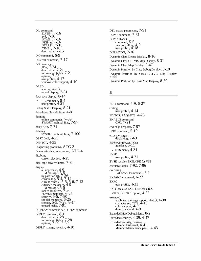
D L command,DATE=, 7-16,pid, 7-16,SCAN=, 7-16,SKIP=n, 7-16,START=, 7-16,TIME=, 7-16description, 7-15
D Q command, 6-9D Recall command, 7-17D S command
,ID=, 7-24description, 7-21information fields, 7-21options, 7-23user profile, 4-17window, color support, 4-10
DASDaltering, 4-18record display, 7-31
dataspace display, 8-14DEBUG command, 8-4
user profile, 4-21Debug Status Display, 8-21default profile definition, 4-8defining
online commands, 7-89SYSOUT archival files, 7-97
delay field, 7-71deleting
SYSOUT archival files, 7-100DEST field, 4-25DFHTCT, 4-35Diagnosing problems, ATG-3Diagnostic data, interpreting, ATG-4disabling
cursor selection, 4-25disk, tape drive volumes, 7-84display
all uppercase, 4-9BIM message, 5-5by partition ID, 7-26console log, 5-4, 7-12current console, 5-5, 5-6, 7-12extended messages, 4-9IBM message, 5-5locked resources, 7-90POWER members, 6-25security, 5-5, 7-80spooler members, 6-25storage, 5-5, 7-28, 8-14unused locks, 7-91
DISPLAY command see DSPLY commandDSPLY command, 8-1
description, 7-28information fields, 7-28options, 7-29–7-30
DSPLY storage, security, 4-18
DTL macro parameters, 7-91DUMP command, 7-31DUMP DASD
command, 5-5function, allow, 4-9user profile, 4-18
DURATION, 7-36Dynamic Class Debug Display, 8-16Dynamic Class GETVIS Map Display, 8-31Dynamic Class Map Display, 8-47Dynamic Partition by Class Debug Display, 8-18Dynamic Partition by Class GETVIS Map Display,8-33Dynamic Partition by Class Map Display, 8-50
E
EDIT command, 5-9, 6-27editing
user profile, 4-14EDITOR, FAQS/PCS, 4-23ENABLE command
CPU, 7-21end-of-job reports, 7-97EPIC command, 5-10error messages
displaying, 7-63ES/Server (FAQS/PCS)
interface, 5-11EVENTS menu, 4-31EVSE
user profile, 4-21EVSE see also EXPLORE for VSEexclusive locks, 7-92, 7-96executing
FAQS/ASOcommands, 3-1EXPAND command, 6-27EXPC
user profile, 4-21EXPC see also EXPLORE for CICSEXTDS, DFHTCT option, 4-35extended
attributes, message support, 4-13, 4-38character set, CICS, 4-10color support, 4-35dump on abend, 4-9
Extended Map/Debug Menu, 8-2Extended security, 4-39, 4-47Extended Security, console
Member List panel, 4-41Member Maintenance panel, 4-43
Online User’s Guide Index-3
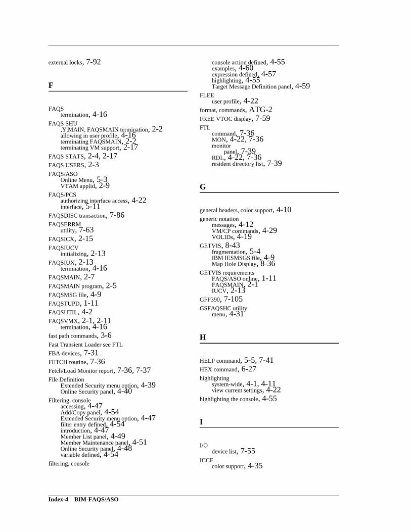
external locks, 7-92
F
FAQStermination, 4-16
FAQS SHU,Y,MAIN, FAQSMAIN termination, 2-2allowing in user profile, 4-16terminating FAQSMAIN, 2-2terminating VM support, 2-17
FAQS STATS, 2-4, 2-17FAQS USERS, 2-3FAQS/ASO
Online Menu, 5-3VTAM applid, 2-9
FAQS/PCSauthorizing interface access, 4-22interface, 5-11
FAQSDISC transaction, 7-86FAQSERRM
utility, 7-63FAQSICX, 2-15FAQSIUCV
initializing, 2-13FAQSIUX, 2-13
termination, 4-16FAQSMAIN, 2-7FAQSMAIN program, 2-5FAQSMSG file, 4-9FAQSTUPD, 1-11FAQSUTIL, 4-2FAQSVMX, 2-1, 2-11
termination, 4-16fast path commands, 3-6Fast Transient Loader see FTLFBA devices, 7-31FETCH routine, 7-36Fetch/Load Monitor report, 7-36, 7-37File Definition
Extended Security menu option, 4-39Online Security panel, 4-40
Filtering, consoleaccessing, 4-47Add/Copy panel, 4-54Extended Security menu option, 4-47filter entry defined, 4-54introduction, 4-47Member List panel, 4-49Member Maintenance panel, 4-51Online Security panel, 4-48variable defined, 4-54
filtering, console
console action defined, 4-55examples, 4-60expression defined, 4-57highlighting, 4-55Target Message Definition panel, 4-59
FLEEuser profile, 4-22
format, commands, ATG-2FREE VTOC display, 7-59FTL
command, 7-36MON, 4-22, 7-36monitor
panel, 7-39RDL, 4-22, 7-36resident directory list, 7-39
G
general headers, color support, 4-10generic notation
messages, 4-12VM/CP commands, 4-29VOLIDs, 4-19
GETVIS, 8-43fragmentation, 5-4IBM IESMSGS file, 4-9Map Hole Display, 8-36
GETVIS requirementsFAQS/ASO online, 1-11FAQSMAIN, 2-1IUCV, 2-13
GFF390, 7-105GSFAQSHC utility
menu, 4-31
H
HELP command, 5-5, 7-41HEX command, 6-27highlighting
system-wide, 4-1, 4-11view current settings, 4-22
highlighting the console, 4-55
I
I/Odevice list, 7-55
ICCFcolor support, 4-35
Index-4 BIM-FAQS/ASO
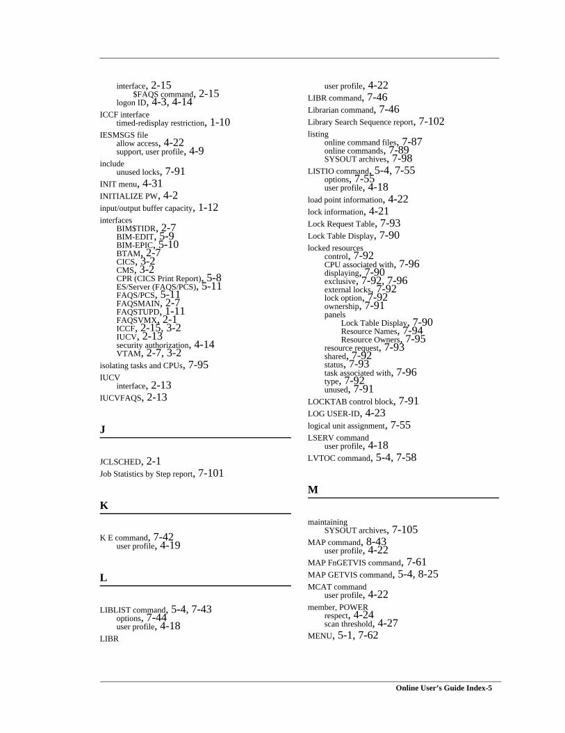
interface, 2-15$FAQS command, 2-15
logon ID, 4-3, 4-14ICCF interface
timed-redisplay restriction, 1-10IESMSGS file
allow access, 4-22support, user profile, 4-9
includeunused locks, 7-91
INIT menu, 4-31INITIALIZE PW, 4-2input/output buffer capacity, 1-12interfaces
BIM$TIDR, 2-7BIM-EDIT, 5-9BIM-EPIC, 5-10BTAM, 2-7CICS, 3-2CMS, 3-2CPR (CICS Print Report), 5-8ES/Server (FAQS/PCS), 5-11FAQS/PCS, 5-11FAQSMAIN, 2-7FAQSTUPD, 1-11FAQSVMX, 2-1ICCF, 2-15, 3-2IUCV, 2-13security authorization, 4-14VTAM, 2-7, 3-2
isolating tasks and CPUs, 7-95IUCV
interface, 2-13IUCVFAQS, 2-13
J
JCLSCHED, 2-1Job Statistics by Step report, 7-101
K
K E command, 7-42user profile, 4-19
L
LIBLIST command, 5-4, 7-43options, 7-44user profile, 4-18
LIBR
user profile, 4-22LIBR command, 7-46Librarian command, 7-46Library Search Sequence report, 7-102listing
online command files, 7-87online commands, 7-89SYSOUT archives, 7-98
LISTIO command, 5-4, 7-55options, 7-55user profile, 4-18
load point information, 4-22lock information, 4-21Lock Request Table, 7-93Lock Table Display, 7-90locked resources
control, 7-92CPU associated with, 7-96displaying, 7-90exclusive, 7-92, 7-96external locks, 7-92lock option, 7-92ownership, 7-91panels
Lock Table Display, 7-90Resource Names, 7-94Resource Owners, 7-95
resource request, 7-93shared, 7-92status, 7-93task associated with, 7-96type, 7-92unused, 7-91
LOCKTAB control block, 7-91LOG USER-ID, 4-23logical unit assignment, 7-55LSERV command
user profile, 4-18LVTOC command, 5-4, 7-58
M
maintainingSYSOUT archives, 7-105
MAP command, 8-43user profile, 4-22
MAP FnGETVIS command, 7-61MAP GETVIS command, 5-4, 8-25MCAT command
user profile, 4-22member, POWER
respect, 4-24scan threshold, 4-27
MENU, 5-1, 7-62
Online User’s Guide Index-5
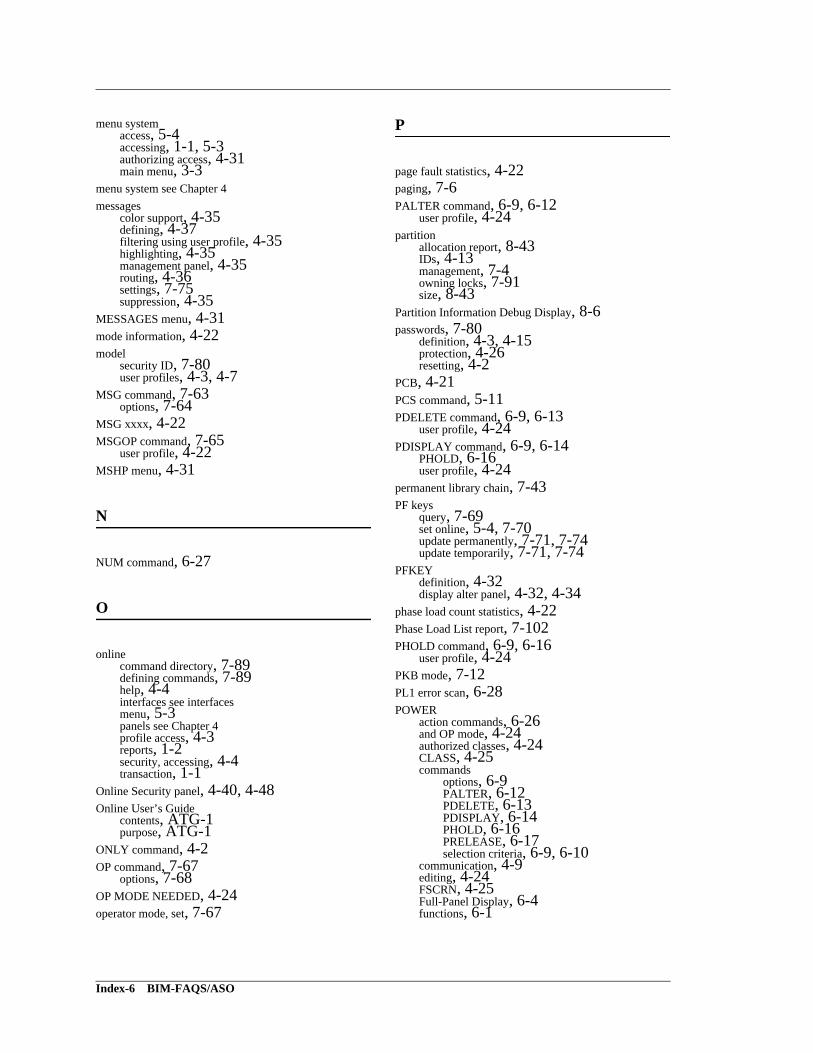
menu systemaccess, 5-4accessing, 1-1, 5-3authorizing access, 4-31main menu, 3-3
menu system see Chapter 4messages
color support, 4-35defining, 4-37filtering using user profile, 4-35highlighting, 4-35management panel, 4-35routing, 4-36settings, 7-75suppression, 4-35
MESSAGES menu, 4-31mode information, 4-22model
security ID, 7-80user profiles, 4-3, 4-7
MSG command, 7-63options, 7-64
MSG xxxx, 4-22MSGOP command, 7-65
user profile, 4-22MSHP menu, 4-31
N
NUM command, 6-27
O
onlinecommand directory, 7-89defining commands, 7-89help, 4-4interfaces see interfacesmenu, 5-3panels see Chapter 4profile access, 4-3reports, 1-2security, accessing, 4-4transaction, 1-1
Online Security panel, 4-40, 4-48Online User’s Guide
contents, ATG-1purpose, ATG-1
ONLY command, 4-2OP command, 7-67
options, 7-68OP MODE NEEDED, 4-24operator mode, set, 7-67
P
page fault statistics, 4-22paging, 7-6PALTER command, 6-9, 6-12
user profile, 4-24partition
allocation report, 8-43IDs, 4-13management, 7-4owning locks, 7-91size, 8-43
Partition Information Debug Display, 8-6passwords, 7-80
definition, 4-3, 4-15protection, 4-26resetting, 4-2
PCB, 4-21PCS command, 5-11PDELETE command, 6-9, 6-13
user profile, 4-24PDISPLAY command, 6-9, 6-14
PHOLD, 6-16user profile, 4-24
permanent library chain, 7-43PF keys
query, 7-69set online, 5-4, 7-70update permanently, 7-71, 7-74update temporarily, 7-71, 7-74
PFKEYdefinition, 4-32display alter panel, 4-32, 4-34
phase load count statistics, 4-22Phase Load List report, 7-102PHOLD command, 6-9, 6-16
user profile, 4-24PKB mode, 7-12PL1 error scan, 6-28POWER
action commands, 6-26and OP mode, 4-24authorized classes, 4-24CLASS, 4-25commands
options, 6-9PALTER, 6-12PDELETE, 6-13PDISPLAY, 6-14PHOLD, 6-16PRELEASE, 6-17selection criteria, 6-9, 6-10
communication, 4-9editing, 4-24FSCRN, 4-25Full-Panel Display, 6-4functions, 6-1
Index-6 BIM-FAQS/ASO
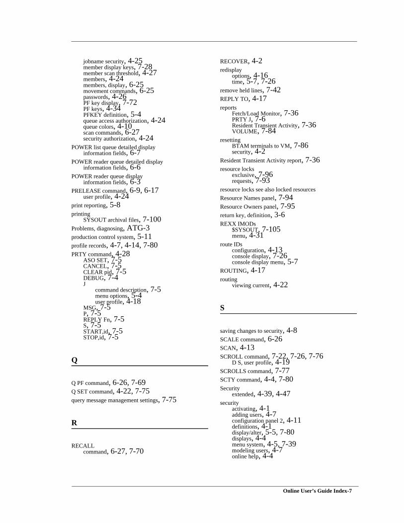
jobname security, 4-25member display keys, 7-28member scan threshold, 4-27members, 4-24members, display, 6-25movement commands, 6-25passwords, 4-26PF key display, 7-72PF keys, 4-34PFKEY definition, 5-4queue access authorization, 4-24queue colors, 4-10scan commands, 6-27security authorization, 4-24
POWER list queue detailed displayinformation fields, 6-7
POWER reader queue detailed displayinformation fields, 6-6
POWER reader queue displayinformation fields, 6-3
PRELEASE command, 6-9, 6-17user profile, 4-24
print reporting, 5-8printing
SYSOUT archival files, 7-100Problems, diagnosing, ATG-3production control system, 5-11profile records, 4-7, 4-14, 7-80PRTY command, 4-28
ASO SET, 7-5CANCEL, 7-5CLEAR pid, 7-5DEBUG, 7-4J
command description, 7-5menu options, 5-4user profile, 4-18
MSG, 7-5P, 7-5REPLY Fn, 7-5S, 7-5START,id, 7-5STOP,id, 7-5
Q
Q PF command, 6-26, 7-69Q SET command, 4-22, 7-75query message management settings, 7-75
R
RECALLcommand, 6-27, 7-70
RECOVER, 4-2redisplay
options, 4-16time, 5-7, 7-26
remove held lines, 7-42REPLY TO, 4-17reports
Fetch/Load Monitor, 7-36PRTY J, 7-6Resident Transient Activity, 7-36VOLUME, 7-84
resettingBTAM terminals to VM, 7-86security, 4-2
Resident Transient Activity report, 7-36resource locks
exclusive, 7-96requests, 7-93
resource locks see also locked resourcesResource Names panel, 7-94Resource Owners panel, 7-95return key, definition, 3-6REXX IMODs
$SYSOUT, 7-105menu, 4-31
route IDsconfiguration, 4-13console display, 7-26console display menu, 5-7
ROUTING, 4-17routing
viewing current, 4-22
S
saving changes to security, 4-8SCALE command, 6-26SCAN, 4-13SCROLL command, 7-22, 7-26, 7-76
D S, user profile, 4-19SCROLLS command, 7-77SCTY command, 4-4, 7-80Security
extended, 4-39, 4-47security
activating, 4-1adding users, 4-7configuration panel 2, 4-11definitions, 4-1display/alter, 5-5, 7-80displays, 4-4menu system, 4-5, 7-39modeling users, 4-7online help, 4-4
Online User’s Guide Index-7
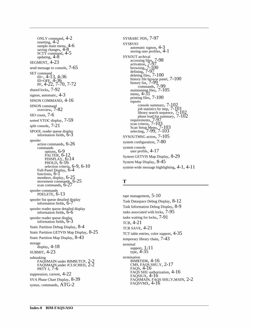
ONLY command, 4-2resetting, 4-2sample main menu, 4-6saving changes, 4-8SCTY command, 4-5updating, 4-8
SEGMENT, 4-23send message to console, 7-65SET command
ID=, 4-13, 4-36ID=OFF, 4-36PF, 4-22, 7-70, 7-72
shared locks, 7-92signon, automatic, 4-3SINON COMMAND, 4-16SINON command
overview, 7-82SIO count, 7-6sorted VTOC display, 7-59split console, 7-21SPOOL reader queue display
information fields, 6-3spooler
action commands, 6-26commands
options, 6-9PALTER, 6-12PDISPLAY, 6-14PHOLD, 6-16selection criteria, 6-9, 6-10
Full-Panel Display, 6-4functions, 6-1members, display, 6-25movement commands, 6-25scan commands, 6-27
spooler commandsPDELETE, 6-13
spooler list queue detailed displayinformation fields, 6-7
spooler reader queue detailed displayinformation fields, 6-6
spooler reader queue displayinformation fields, 6-3
Static Partition Debug Display, 8-4Static Partition GETVIS Map Display, 8-25Static Partition Map Display, 8-43storage
display, 4-18SUBMIT, 4-23subtasking
FAQSMAIN under BIM$UTCP, 2-2FAQSMAIN under JCLSCHED, 2-2PRTY J, 7-6
suppression, current, 4-22SVA Phase Chart Display, 8-39syntax, commands, ATG-2
SYS$ARC PDS, 7-97SYS$VIO
automatic signon, 4-3storing user profiles, 4-1
SYSOUT archivalaccessing files, 7-98activation, 7-97browsing, 7-100defining, 7-97deleting files, 7-100history file browse panel, 7-100history list, 7-99
commands, 7-99maintaining files, 7-105menu, 4-31printing files, 7-100reports
console summary, 7-102job statistics by step, 7-101library search sequence, 7-102phase load list summary, 7-102
requirements, 7-97scan criteria, 7-103Scan Setup Menu, 7-103selecting, 7-99, 7-103
SYSOUTMSG action, 7-105system configuration, 7-80system console
user profile, 4-17System GETVIS Map Display, 8-29System Map Display, 8-45system-wide message highlighting, 4-1, 4-11
T
tape management, 5-10Task Dataspace Debug Display, 8-12Task Information Debug Display, 8-9tasks associated with locks, 7-95tasks waiting for locks, 7-91TCB, 4-21TCB SAVE, 4-21TCT table entries, color support, 4-35temporary library chain, 7-43terminal
support, 1-11type, 4-35
terminationBIM$TIDR, 4-16CMS, FAQS SHU,Y, 2-17FAQS, 4-16FAQS SHU authorization, 4-16FAQSIUX, 4-16FAQSMAIN, FAQS SHU,Y,MAIN, 2-2FAQSVMX, 4-16
Index-8 BIM-FAQS/ASO
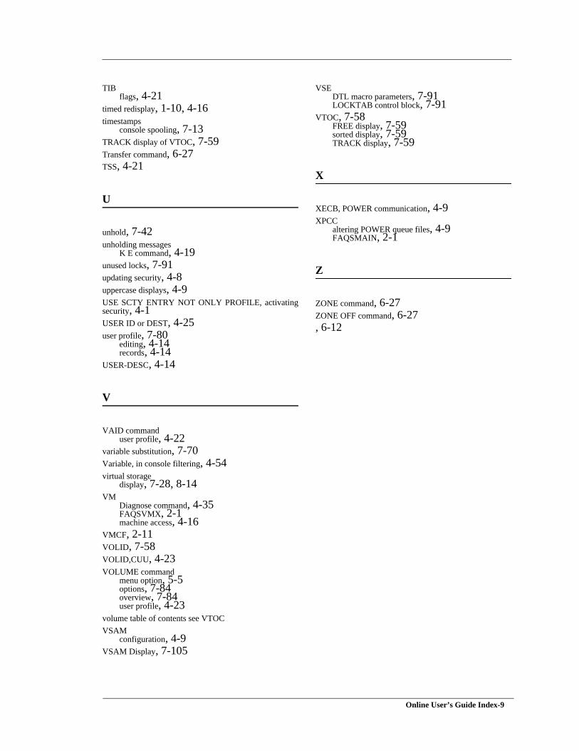
TIBflags, 4-21
timed redisplay, 1-10, 4-16timestamps
console spooling, 7-13TRACK display of VTOC, 7-59Transfer command, 6-27TSS, 4-21
U
unhold, 7-42unholding messages
K E command, 4-19unused locks, 7-91updating security, 4-8uppercase displays, 4-9USE SCTY ENTRY NOT ONLY PROFILE, activatingsecurity, 4-1USER ID or DEST, 4-25user profile, 7-80
editing, 4-14records, 4-14
USER-DESC, 4-14
V
VAID commanduser profile, 4-22
variable substitution, 7-70Variable, in console filtering, 4-54virtual storage
display, 7-28, 8-14VM
Diagnose command, 4-35FAQSVMX, 2-1machine access, 4-16
VMCF, 2-11VOLID, 7-58VOLID,CUU, 4-23VOLUME command
menu option, 5-5options, 7-84overview, 7-84user profile, 4-23
volume table of contents see VTOCVSAM
configuration, 4-9VSAM Display, 7-105
VSEDTL macro parameters, 7-91LOCKTAB control block, 7-91
VTOC, 7-58FREE display, 7-59sorted display, 7-59TRACK display, 7-59
X
XECB, POWER communication, 4-9XPCC
altering POWER queue files, 4-9FAQSMAIN, 2-1
Z
ZONE command, 6-27ZONE OFF command, 6-27, 6-12
Online User’s Guide Index-9

Index-10 BIM-FAQS/ASO


