Embed Size (px)
Citation preview
Fault Ride Through operation of a DFIG wind farm connected through VSC HVDC
A. Arulampalam, Dept. of Electrical and Electronic
Engineering, University of Peradeniya,
Peradeniya, Sri Lanka. [email protected]
G. Ramtharan, Garrad Hassan and Partners Limited,
Bristol B2 0QD, United Kingdom.
J.B. Ekanayake, Centre for Integrated Renewable Energy
Generation and Supply, School of Engineering,
Cardiff University, United Kingdom. [email protected]
A.P. Tennakoon,
Asset Management Hydro Division, Ceylon Electricity Board,
Kandy, Sri Lanka. [email protected]
S.G. Abeyratne, Dept. of Electrical and Electronic
Engineering, University of Peradeniya,
Peradeniya, Sri Lanka. [email protected]
N. Jenkins, Centre for Integrated Renewable Energy
Generation and Supply, School of Engineering,
Cardiff University, United Kingdom. [email protected]
Abstract—The electromechanical transients during a deloading of a DFIG turbine and the Fault Ride Through (FRT) capability of a DFIG wind farm connected through HVDC transmission lines are discussed. The electromechanical oscillations during a deloading operation of a DFIG wind turbine generator are simulated using BLADED software. Then power reduction control during a fault was achieved by reducing the power from the wind farm as a whole and by deloading the individual wind generator. A new power blocking technique applied at the offshore converter station was used to reduce the wind farm power output. Simultaneous control of the wind farm and wind turbine power outputs enabled a smooth power reduction during the fault.
Keywords-FRT, DFIG, HVDC, power blocking, de loading, electromechanical torsional oscillation in wind turbine.
I. INTRODUCTION All large wind farms connecting to the power system
network are required to fulfill the Grid Code requirements. Fault Ride Through (FRT) and continuous reactive power support are two of the main requirements [1 - 3]. It is now recognized that variable speed wind turbine generators are preferred over fixed speed generators for satisfying the grid code requirements. In the last decade Doubly Fed Induction Generators (DFIG) were extensively installed. Issues related to maximum power tracking, power quality, FRT, mechanical stress and reactive power compensation are documented [4 - 9].
With increasing wind farm ratings, especially offshore, limitations on the High Voltage AC transmission are reported [10 - 12]. The VSC based High Voltage DC (HVDC) transmission is considered as a good alternative for connection of large offshore wind farms. Inherent control capabilities of the VSC HVDC can be used to support the Grid Code requirements. In this technology, cost is a compromising factor and power losses are significantly high. The developments in power electronics devices and multilevel
inverters are expected to reduce the cost and losses of VSC HVDC schemes in near future [13 - 15].
A smooth FRT requirement and continuous reactive power compensation can be achieved for a large wind farm connected through a VSC HVDC transmission line. In the event of a fault, power from the wind farm has to be reduced either by de-loading the generator [16] or blocking the power at the wind farm side converter [17]. In addition to transferring active power, the grid side converter is controlled to supply reactive power according to the Grid Code requirements.
The wind farm generator can be de-loaded in two ways. Electrical deloading is possible by controlling its active power output or mechanical deloading can be done through pitch control. Mechanical deloading is much slower than the electrical. However when rapid deloading is carried out by controlling electrical output power, an electromechanical (torsional) fluctuation will occur due to blade movements. Therefore studying the electromechanical interaction is also important to achieve a smooth FRT operation.
This paper addresses DFIG wind generator electromechanical transient performance and wind farm’s FRT operations with VSC HVDC transmission. For a rapid deloading operation, aerodynamics and structural dynamics of the DFIG turbine was studied using Bladed software and the results are discussed. Further the DFIG with VSC HVDC was modeled in EMTDC/PSCAD and the FRT operation was checked in the simulation.
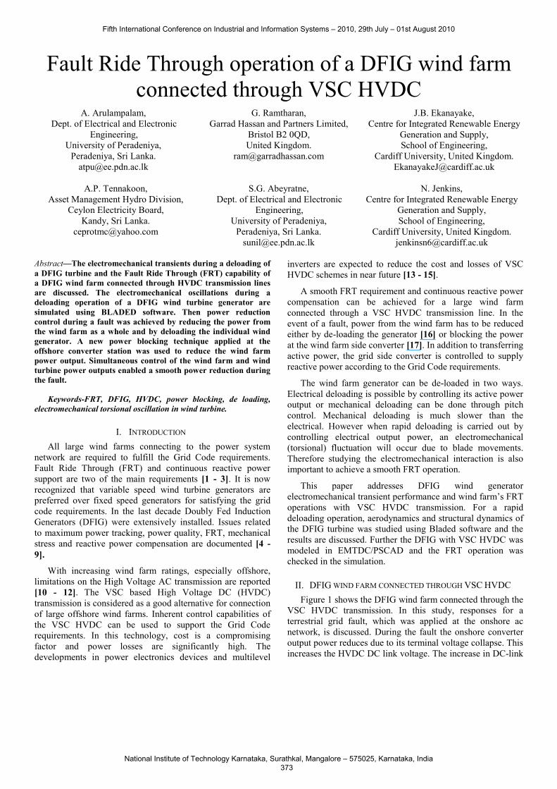
II. DFIG WIND FARM CONNECTED THROUGH VSC HVDC Figure 1 shows the DFIG wind farm connected through the
VSC HVDC transmission. In this study, responses for a terrestrial grid fault, which was applied at the onshore ac network, is discussed. During the fault the onshore converter output power reduces due to its terminal voltage collapse. This increases the HVDC DC link voltage. The increase in DC-link
Fifth International Conference on Industrial and Information Systems – 2010, 29th July – 01st August 2010
National Institute of Technology Karnataka, Surathkal, Mangalore – 575025, Karnataka, India 373
voltage was used to block the offshore converter power output and to deload the wind turbine generators.
dcvoffv
onv
offV onVsV
totalP
rV
,r rP Q
dcge
nV
−
Figure 1. DFIG wind farm connected through VSC HVDC
III. EFFECT ON AERODYNAMICS AND STRUCTURAL DYNAMICS WHEN DE-LOADING A DFIG
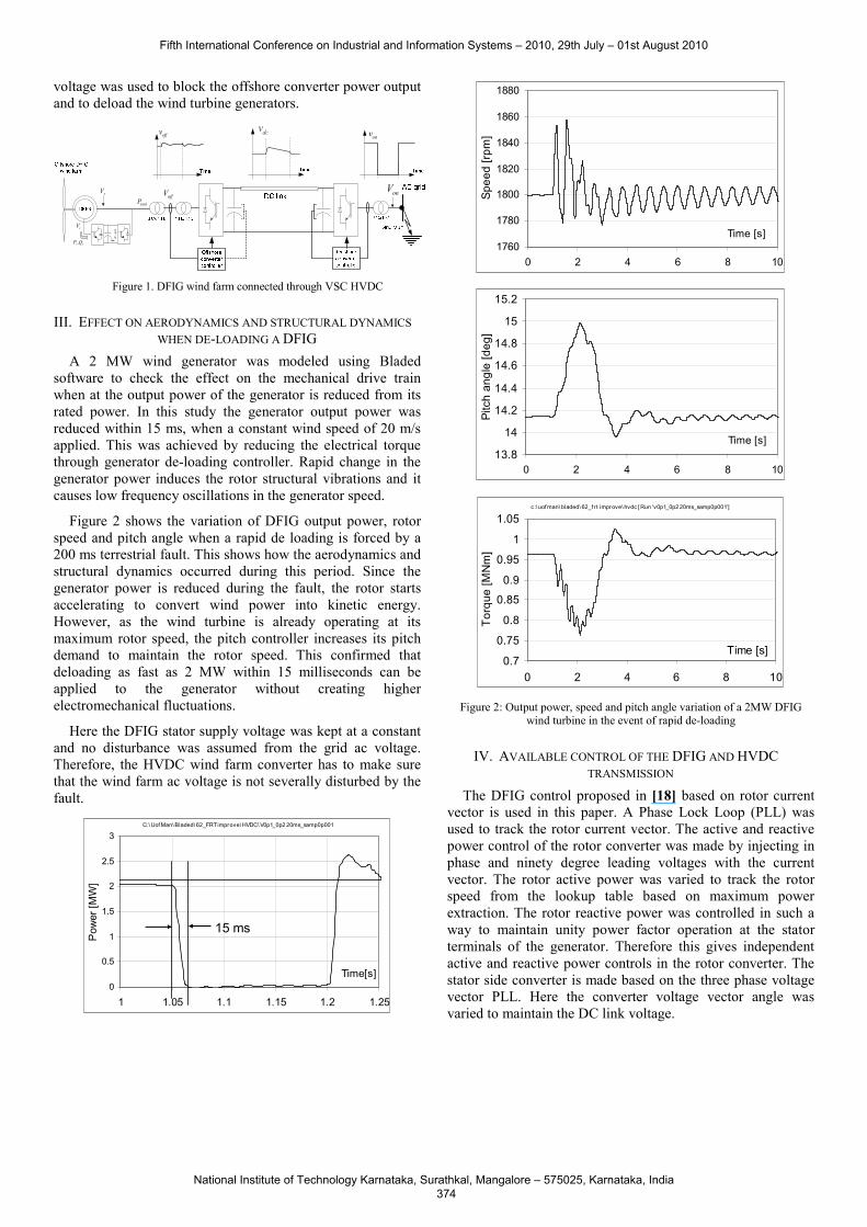
A 2 MW wind generator was modeled using Bladed software to check the effect on the mechanical drive train when at the output power of the generator is reduced from its rated power. In this study the generator output power was reduced within 15 ms, when a constant wind speed of 20 m/s applied. This was achieved by reducing the electrical torque through generator de-loading controller. Rapid change in the generator power induces the rotor structural vibrations and it causes low frequency oscillations in the generator speed.
Figure 2 shows the variation of DFIG output power, rotor speed and pitch angle when a rapid de loading is forced by a 200 ms terrestrial fault. This shows how the aerodynamics and structural dynamics occurred during this period. Since the generator power is reduced during the fault, the rotor starts accelerating to convert wind power into kinetic energy. However, as the wind turbine is already operating at its maximum rotor speed, the pitch controller increases its pitch demand to maintain the rotor speed. This confirmed that deloading as fast as 2 MW within 15 milliseconds can be applied to the generator without creating higher electromechanical fluctuations.
Here the DFIG stator supply voltage was kept at a constant and no disturbance was assumed from the grid ac voltage. Therefore, the HVDC wind farm converter has to make sure that the wind farm ac voltage is not severally disturbed by the fault.
C:\ Uof Man\ Bladed\ 62_FRT improve\ HVDC\ V0p1_0p2 20ms_samp0p001
0
0.5
1
1.5
2
2.5
3
1 1.05 1.1 1.15 1.2 1.25
Time[s]
Pow
er [M
W]
15 ms
1760
1780
1800
1820
1840
1860
1880
0 2 4 6 8 10
Time [s]
Spee
d [rp
m]
13.8
14
14.2
14.4
14.6
14.8
15
15.2
0 2 4 6 8 10
Time [s]
Pitc
h an
gle
[deg
]
c:\ uof man\ bladed\ 62_f rt improve\ hvdc [ Run 'v0p1_0p2 20ms_samp0p001']
0.7
0.75
0.8
0.85
0.9
0.95
1
1.05
0 2 4 6 8 10
Time [s]
Torq
ue [M
Nm
]
Figure 2: Output power, speed and pitch angle variation of a 2MW DFIG
wind turbine in the event of rapid de-loading
IV. AVAILABLE CONTROL OF THE DFIG AND HVDC TRANSMISSION
The DFIG control proposed in [18] based on rotor current vector is used in this paper. A Phase Lock Loop (PLL) was used to track the rotor current vector. The active and reactive power control of the rotor converter was made by injecting in phase and ninety degree leading voltages with the current vector. The rotor active power was varied to track the rotor speed from the lookup table based on maximum power extraction. The rotor reactive power was controlled in such a way to maintain unity power factor operation at the stator terminals of the generator. Therefore this gives independent active and reactive power controls in the rotor converter. The stator side converter is made based on the three phase voltage vector PLL. Here the converter voltage vector angle was varied to maintain the DC link voltage.
Fifth International Conference on Industrial and Information Systems – 2010, 29th July – 01st August 2010
National Institute of Technology Karnataka, Surathkal, Mangalore – 575025, Karnataka, India 374
The VSC HVDC was controlled to maintain the offshore wind farm ac network frequency at a set value while maintaining the offshore grid voltage at its rated value. The ac voltage control is achieved by reactive power control and the wind farm active power was passed to the DC-link while maintaining the ac network frequency to its set value. The onshore or grid side converter control described in [17] was implemented. The DC-link voltage was maintained by the grid side converter by its active power control. The grid side converter reactive power was controlled to satisfy the grid code requirement.
V. PROPOSED ADDITION ON THE DFIG AND HVDC OFFSHORE CONVERTER CONTROLS FOR SMOOTH FRT OPERATIONS
In this paper, a new control is proposed to the HVDC offshore converter to control the phase angle and frequency. Further hybrid operation of power blocking by offshore converter and deloading operation of DFIG are discussed with simulation results. A. Addition on the HVDC offshore converter control
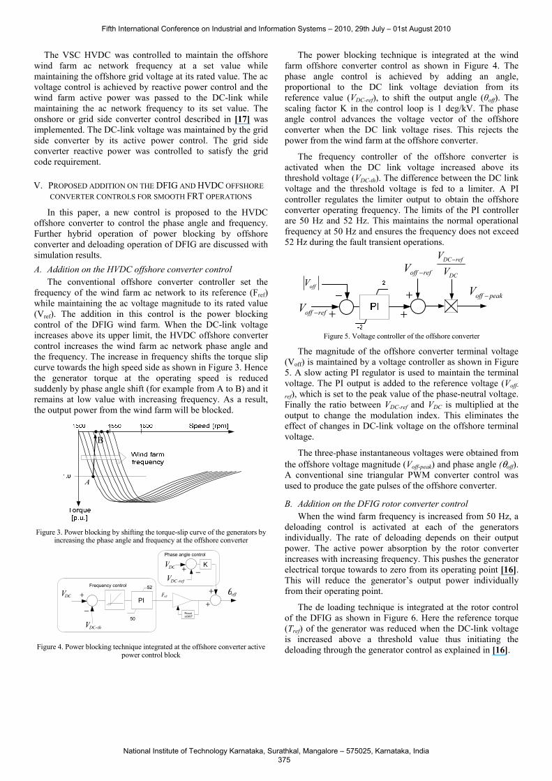
The conventional offshore converter controller set the frequency of the wind farm ac network to its reference (Fref) while maintaining the ac voltage magnitude to its rated value (Vref). The addition in this control is the power blocking control of the DFIG wind farm. When the DC-link voltage increases above its upper limit, the HVDC offshore converter control increases the wind farm ac network phase angle and the frequency. The increase in frequency shifts the torque slip curve towards the high speed side as shown in Figure 3. Hence the generator torque at the operating speed is reduced suddenly by phase angle shift (for example from A to B) and it remains at low value with increasing frequency. As a result, the output power from the wind farm will be blocked.
A
Figure 3. Power blocking by shifting the torque-slip curve of the generators by
increasing the phase angle and frequency at the offshore converter
Figure 4. Power blocking technique integrated at the offshore converter active
power control block
The power blocking technique is integrated at the wind farm offshore converter control as shown in Figure 4. The phase angle control is achieved by adding an angle, proportional to the DC link voltage deviation from its reference value (VDC-ref), to shift the output angle (θoff). The scaling factor K in the control loop is 1 deg/kV. The phase angle control advances the voltage vector of the offshore converter when the DC link voltage rises. This rejects the power from the wind farm at the offshore converter.
The frequency controller of the offshore converter is activated when the DC link voltage increased above its threshold voltage (VDC-th). The difference between the DC link voltage and the threshold voltage is fed to a limiter. A PI controller regulates the limiter output to obtain the offshore converter operating frequency. The limits of the PI controller are 50 Hz and 52 Hz. This maintains the normal operational frequency at 50 Hz and ensures the frequency does not exceed 52 Hz during the fault transient operations.
off peakV −
DC ref
DC
VV
−
+−
+
offV
off refV −
+
off refV −
Figure 5. Voltage controller of the offshore converter
The magnitude of the offshore converter terminal voltage (Voff) is maintained by a voltage controller as shown in Figure 5. A slow acting PI regulator is used to maintain the terminal voltage. The PI output is added to the reference voltage (Voff-
ref), which is set to the peak value of the phase-neutral voltage. Finally the ratio between VDC-ref and VDC is multiplied at the output to change the modulation index. This eliminates the effect of changes in DC-link voltage on the offshore terminal voltage.
The three-phase instantaneous voltages were obtained from the offshore voltage magnitude (Voff-peak) and phase angle (θoff). A conventional sine triangular PWM converter control was used to produce the gate pulses of the offshore converter.
B. Addition on the DFIG rotor converter control When the wind farm frequency is increased from 50 Hz, a
deloading control is activated at each of the generators individually. The rate of deloading depends on their output power. The active power absorption by the rotor converter increases with increasing frequency. This pushes the generator electrical torque towards to zero from its operating point [16]. This will reduce the generator’s output power individually from their operating point.
The de loading technique is integrated at the rotor control of the DFIG as shown in Figure 6. Here the reference torque (Tref) of the generator was reduced when the DC-link voltage is increased above a threshold value thus initiating the deloading through the generator control as explained in [16].
offθDC V
−
+PI
50
52
offF
Resetat 360o
DCV
+
+
+ −
Phase angle control
Frequency controlDC-ref V
DC-thV
K
B
Fifth International Conference on Industrial and Information Systems – 2010, 29th July – 01st August 2010
National Institute of Technology Karnataka, Surathkal, Mangalore – 575025, Karnataka, India 375
spTrω
dcv
Figure 6. Deloading technique integrated at the rotor converter control of the
individual DFIGs [16]
As a result of both (i) power blocking at wind farm side HVDC converter station and (ii) deloading at each generator terminal the wind farm output power reduces smoothly. The new addition in this paper is (i) power blocking at the HVDC offshore converter and (ii) hybrid operation of both of these controllers. In both cases the torque slip curve is pushed towards high speed. The HVDC offshore converter uses the possible wind farm ac network frequency limit to increase the FRT operation by storing the energy in the rotor inertia. The individual generator control further shift the torque slip curves towards higher speeds to store further energy in the rotating rotor mass. As a result the power from the wind farm is reduced to match with the transferable power of the faulted network. Therefore the proposed control technique will not only have smooth FRT operation but also increase the electrically operating boundaries of the DFIG wind farm.
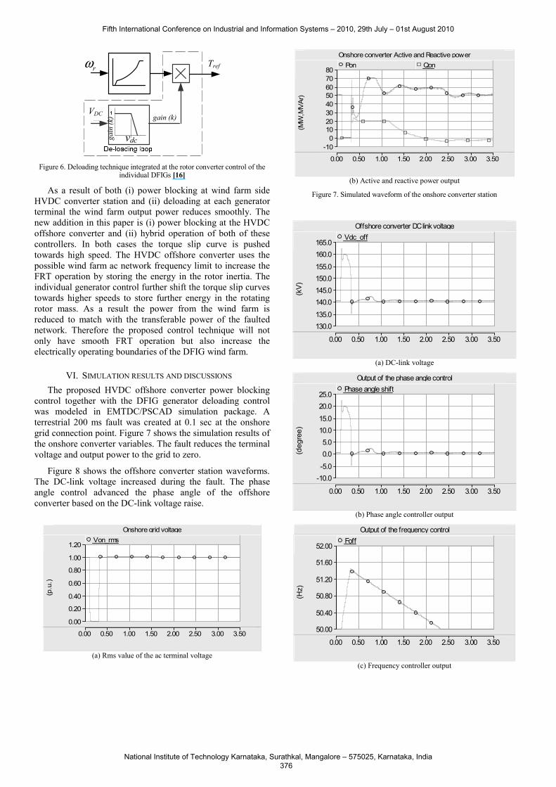
VI. SIMULATION RESULTS AND DISCUSSIONS The proposed HVDC offshore converter power blocking
control together with the DFIG generator deloading control was modeled in EMTDC/PSCAD simulation package. A terrestrial 200 ms fault was created at 0.1 sec at the onshore grid connection point. Figure 7 shows the simulation results of the onshore converter variables. The fault reduces the terminal voltage and output power to the grid to zero.
Figure 8 shows the offshore converter station waveforms. The DC-link voltage increased during the fault. The phase angle control advanced the phase angle of the offshore converter based on the DC-link voltage raise.
Onshore grid voltage
0.00 0.50 1.00 1.50 2.00 2.50 3.00 3.50
0.00
0.20
0.40
0.60
0.80
1.00
1.20
(p.u
.)
Von_rms
(a) Rms value of the ac terminal voltage
Onshore converter Active and Reactive power
0.00 0.50 1.00 1.50 2.00 2.50 3.00 3.50
-10 0
10 20 30 40 50 60 70 80
(MW
,MVA
r)
Pon Qon
(b) Active and reactive power output
Figure 7. Simulated waveform of the onshore converter station
Offshore converter DC link voltage
0.00 0.50 1.00 1.50 2.00 2.50 3.00 3.50
130.0 135.0
140.0 145.0 150.0 155.0
160.0 165.0
(kV)
Vdc_off
(a) DC-link voltage
Output of the phase angle control
0.00 0.50 1.00 1.50 2.00 2.50 3.00 3.50
-10.0 -5.0
0.0 5.0
10.0 15.0
20.0 25.0
(deg
ree)
Phase angle shift
(b) Phase angle controller output
Output of the frequency control
0.00 0.50 1.00 1.50 2.00 2.50 3.00 3.50
50.00
50.40
50.80
51.20
51.60
52.00
(Hz)
Foff
(c) Frequency controller output
vdc gain
(k) gain (k)
Tref
VDC
Fifth International Conference on Industrial and Information Systems – 2010, 29th July – 01st August 2010
National Institute of Technology Karnataka, Surathkal, Mangalore – 575025, Karnataka, India 376
Offshore converter Active and Reactive power
0.00 0.50 1.00 1.50 2.00 2.50 3.00 3.50
-20 -10
0 10 20 30 40 50 60 70 80
(MW
,MVA
r)
Poff Qoff
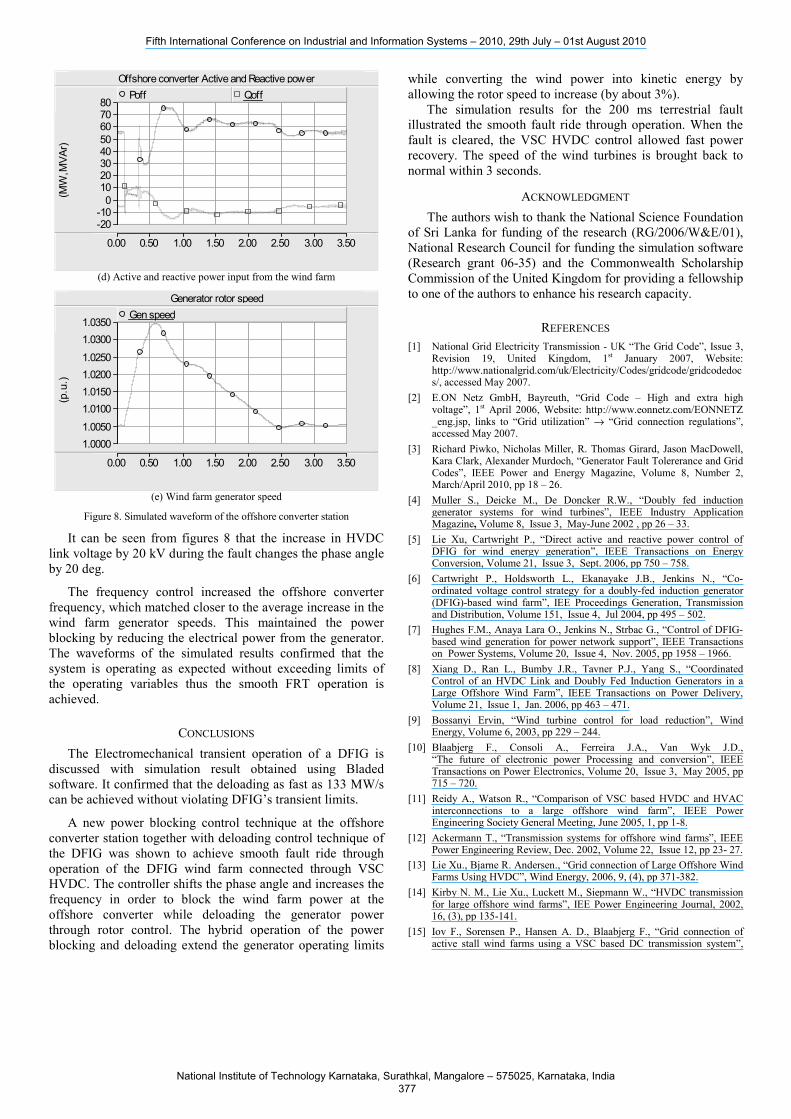
(d) Active and reactive power input from the wind farm
Generator rotor speed
0.00 0.50 1.00 1.50 2.00 2.50 3.00 3.50
1.0000 1.0050
1.0100 1.0150 1.0200 1.0250
1.0300 1.0350
(p.u
.)
Gen speed
(e) Wind farm generator speed
Figure 8. Simulated waveform of the offshore converter station
It can be seen from figures 8 that the increase in HVDC link voltage by 20 kV during the fault changes the phase angle by 20 deg.
The frequency control increased the offshore converter frequency, which matched closer to the average increase in the wind farm generator speeds. This maintained the power blocking by reducing the electrical power from the generator. The waveforms of the simulated results confirmed that the system is operating as expected without exceeding limits of the operating variables thus the smooth FRT operation is achieved.
CONCLUSIONS The Electromechanical transient operation of a DFIG is
discussed with simulation result obtained using Bladed software. It confirmed that the deloading as fast as 133 MW/s can be achieved without violating DFIG’s transient limits.
A new power blocking control technique at the offshore converter station together with deloading control technique of the DFIG was shown to achieve smooth fault ride through operation of the DFIG wind farm connected through VSC HVDC. The controller shifts the phase angle and increases the frequency in order to block the wind farm power at the offshore converter while deloading the generator power through rotor control. The hybrid operation of the power blocking and deloading extend the generator operating limits
while converting the wind power into kinetic energy by allowing the rotor speed to increase (by about 3%).
The simulation results for the 200 ms terrestrial fault illustrated the smooth fault ride through operation. When the fault is cleared, the VSC HVDC control allowed fast power recovery. The speed of the wind turbines is brought back to normal within 3 seconds.
ACKNOWLEDGMENT The authors wish to thank the National Science Foundation
of Sri Lanka for funding of the research (RG/2006/W&E/01), National Research Council for funding the simulation software (Research grant 06-35) and the Commonwealth Scholarship Commission of the United Kingdom for providing a fellowship to one of the authors to enhance his research capacity.
REFERENCES [1] National Grid Electricity Transmission - UK “The Grid Code”, Issue 3,
Revision 19, United Kingdom, 1st January 2007, Website: http://www.nationalgrid.com/uk/Electricity/Codes/gridcode/gridcodedocs/, accessed May 2007.
[2] E.ON Netz GmbH, Bayreuth, “Grid Code – High and extra high voltage”, 1st April 2006, Website: http://www.eonnetz.com/EONNETZ _eng.jsp, links to “Grid utilization” → “Grid connection regulations”, accessed May 2007.
[3] Richard Piwko, Nicholas Miller, R. Thomas Girard, Jason MacDowell, Kara Clark, Alexander Murdoch, “Generator Fault Tolererance and Grid Codes”, IEEE Power and Energy Magazine, Volume 8, Number 2, March/April 2010, pp 18 – 26.
[4] Muller S., Deicke M., De Doncker R.W., “Doubly fed induction generator systems for wind turbines”, IEEE Industry Application Magazine, Volume 8, Issue 3, May-June 2002 , pp 26 – 33.
[5] Lie Xu, Cartwright P., “Direct active and reactive power control of DFIG for wind energy generation”, IEEE Transactions on Energy Conversion, Volume 21, Issue 3, Sept. 2006, pp 750 – 758.
[6] Cartwright P., Holdsworth L., Ekanayake J.B., Jenkins N., “Co-ordinated voltage control strategy for a doubly-fed induction generator (DFIG)-based wind farm”, IEE Proceedings Generation, Transmission and Distribution, Volume 151, Issue 4, Jul 2004, pp 495 – 502.
[7] Hughes F.M., Anaya Lara O., Jenkins N., Strbac G., “Control of DFIG-based wind generation for power network support”, IEEE Transactions on Power Systems, Volume 20, Issue 4, Nov. 2005, pp 1958 – 1966.
[8] Xiang D., Ran L., Bumby J.R., Tavner P.J., Yang S., “Coordinated Control of an HVDC Link and Doubly Fed Induction Generators in a Large Offshore Wind Farm”, IEEE Transactions on Power Delivery, Volume 21, Issue 1, Jan. 2006, pp 463 – 471.
[9] Bossanyi Ervin, “Wind turbine control for load reduction”, Wind Energy, Volume 6, 2003, pp 229 – 244.
[10] Blaabjerg F., Consoli A., Ferreira J.A., Van Wyk J.D., “The future of electronic power Processing and conversion”, IEEE Transactions on Power Electronics, Volume 20, Issue 3, May 2005, pp 715 – 720.
[11] Reidy A., Watson R., “Comparison of VSC based HVDC and HVAC interconnections to a large offshore wind farm”, IEEE Power Engineering Society General Meeting, June 2005, 1, pp 1-8.
[12] Ackermann T., “Transmission systems for offshore wind farms”, IEEE Power Engineering Review, Dec. 2002, Volume 22, Issue 12, pp 23- 27.
[13] Lie Xu., Bjarne R. Andersen., “Grid connection of Large Offshore Wind Farms Using HVDC”, Wind Energy, 2006, 9, (4), pp 371-382.
[14] Kirby N. M., Lie Xu., Luckett M., Siepmann W., “HVDC transmission for large offshore wind farms”, IEE Power Engineering Journal, 2002, 16, (3), pp 135-141.
[15] Iov F., Sorensen P., Hansen A. D., Blaabjerg F., “Grid connection of active stall wind farms using a VSC based DC transmission system”,
Fifth International Conference on Industrial and Information Systems – 2010, 29th July – 01st August 2010
National Institute of Technology Karnataka, Surathkal, Mangalore – 575025, Karnataka, India 377

European conference on Power Electronics and Applications, Sept. 2005, pp 1-10.
[16] Ramtharan G., Arulampalam A., Ekanayake J.B., Huges F.M., Jenkins N., “Fault ride through of fully rated converter wind turbines with AC and DC transmission systems”, IET proceedings on Renewable Power Generation, Volume 3, Issue 4, December 2009, pages 426 – 438.
[17] Arulampalam A., Ramtharan G., Caliao N., Ekanayake J.B., Jenkins N., “Simulated onshore-Fault Ride Through of offshore wind farms connected through VSC HVDC”, Journal of Wind Engineering, Volume 32, Issue No. 2, March 2008, page 103-114.
[18] Tennakoon A.P., Arulampalam A., Helder L., Ekanayake J.B., Abeyratna S.G., “Operations of DFIG with simplified rotor current reference model and solution to the recent grid code requirements”, 35th Annual Conference of the IEEE Industrial Electronics Society (IECON 2009), 3rd – 5th November 2009, Porto, Portugal, Pages 3993 – 3997.
APPENDIX Induction generator parameters (on its base): Capacity: 2MW, Terminal voltage: 0.69kV, Frequency: 50Hz, Stator resistance: 0.00488 p.u., Rotor resistance: 0.00549 p.u., Stator leakage reactance: 0.09241 p.u., Rotor leakage reactance: 0.09955 p.u., Magnetising reactance: 3.95279 p.u.
Wind turbine terminal transformer parameters (on its base): Rated capacity: 2.0 MVA, Turns ratio: 0.69kV/13.8kV, Leakage reactance: 0.05 p.u., Frequency: 50Hz.
Wind farm substation transformer parameters (on its base): Rated capacity: 100MVA, Turns ratio: 13.8kV/62.5kV, Leakage reactance: 0.10 p.u., Frequency: 50Hz.
HVDC line parameters: Rated DC-link voltage: 140 kV, DC-link capacitor (one side): 75 µF, Effective line resistance: 0.5 Ohm, Effective line inductance: 5 mH.
Grid connection substation transformer parameters (on its base): Rated capacity: 100MVA, Turns ratio: 62.5kV/132kV, Leakage reactance: 0.10 p.u., Frequency: 50Hz.
BIOGRAPHIES Arulampalam Atputharajah obtained B.Sc.Eng. (Hons) Degree in 1997 from the University of Peradeniya, Sri Lanka and PhD from UMIST, United Kingdom in 2003. He is a senior lecturer in the Department of Electrical and Electronic Engineering, University of Peradeniya, Sri Lanka. After his PhD based on FACTS devices and their controls, he carried out research on HVDC interconnection of wind farms at University of Manchester in 2007 and Micro Grid concepts at
UMIST in 2004 and 2002. He is a Senior Member of the IEEE, Charted Engineer and Member of the Institution of Engineers Sri Lanka. His research interests are Power systems blackouts, FACTS devices, power electronics, power quality, renewable power generations and energy storages.
G. Ramtharan received the B.Eng (Hons). degree in electrical and electronic engineering from the University of Peradeniya, Peradeniya, Sri Lanka, in 2002, and PhD degree from University of Manchester, Manchester, United Kingdom in 2008. He is now working for GL Garrad Hassan part of the Electrical group. He is responsible for electrical machine and converter design and modeling for wind turbines. His research interests include power electronic converters, electrical machines and wind turbines. He has co-authored many journal and
conference papers
Janaka Ekanayake received the B.Sc.Eng.(Hons) Degree in Electrical and Electronic Engineering from the University of Peradeniya in 1990 and PhD in Electrical Engineering from University of Manchester Institute of Science and Technology (UMIST), U.K. in 1995. He is presently attached to the Cardiff University, UK and is actively contributing to the research programmes of the Low Carbon Research Institute of the UK and the Institute of Energy of Cardiff University. Prior to that he was
a Professor in the Department of Electrical and Electronic Engineering, University of Peradeniya. His research interests include power electronics, FACTS devices and renewable energy sources such as wind and small hydro schemes. He is a Senior Member of the IEEE, Charted Engineer, Member of the IESL and IET. He has co-authored many journal and conference papers and two books. His recent book on Wind Turbine: Modeling and Control discuss about the different wind turbine technologies and grid interconnection technologies such as point to point HVDC and multi-terminal HVDC connections.
A.P.Tennakoon received the B.Sc.Eng. Degree in Electrical and Electronic Engineering in 1985 and M.Sc.Eng. Degree in 2004 from University of Peradeniya, Sri Lanka. He is at present attached to the Ceylon Electricity Board as the Chief Engineer-Protection in the Hydro Power Division. Currently he is pursuing a PhD research on Grid connection of Doubly Fed Induction Generators for wind energy applications at the University of Peradeniya. He is a member of the IEEE, Charted Engineer and Member
of the Institution of Engineers Sri Lanka. S. G. Abeyratne was born in Matale, Sri-Lanka on 17th December 1960. He received the B.Sc.(Eng.) Degree in Electrical and Electronic Engineering from the University of Peradeniya in 1987, and M. Eng and Ph.D in Electrical and Electronics Engineering from the Gifu University Japan in 1992 and 1997 respectively. Currently he is a senior lecturer with the dept. of Electrical and Electronics Engineering, University of Peradeniya, Sri-Lanka. He is a Member of the IEEE. His research interests include Power
Electronics Applications, Electric Motor Drives, Wind and Solar Energy Systems.
Nicholas Jenkins (SM’97–F’05) received the B.Sc. degree from Southampton University, Southampton, U.K., the M.Sc. degree from Reading University, Reading, U.K., and the Ph.D. degree from Imperial College London, London, U.K., in 1974, 1975, and 1986, respectively. From 1992 to 2008, Nick Jenkins was at the University of Manchester (UMIST). In March 2008 he moved to Cardiff University where he is now Professor of Renewable Energy. His previous career included 14 years industrial experience, of which 5 years were in developing countries. His final
position in industry was as Projects Director for Wind Energy Group, a manufacturer of large wind turbines. While at University he has developed teaching and research activities in both electrical power engineering and renewable energy. He is a Fellow of the IET, IEEE and Royal Academy of Engineering and the Shimizu Visiting Professor to the Atmosphere and Energy Program at Stanford University.
Fifth International Conference on Industrial and Information Systems – 2010, 29th July – 01st August 2010
National Institute of Technology Karnataka, Surathkal, Mangalore – 575025, Karnataka, India 378


